1000508323 Catalog
2016-09-04
: Pdf 1000508323-Catalog 1000508323-Catalog B4 unilog
Open the PDF directly: View PDF ![]() .
.
Page Count: 124 [warning: Documents this large are best viewed by clicking the View PDF Link!]
- Front Cover
- Inside Cover
- Table of Contents
- Here to Serve
- World-Wide Solutions
- Condensed Production Capabilities
- Applications & Products
- 1 Industrial Ethernet
- Industrial Ethernet TOC
- Industrial Ethernet Category 5e - 2 Pair Unshielded Twisted Pair Cable
- Industrial Ethernet Category 5e - 4 Pair Unshielded Twisted Pair Cable
- Industrial Ethernet Category 5e - 4 Pair PLTC Unshielded Twisted Pair Cable
- Industrial Ethernet Category 5e - 2 Pair F/UTP Shielded Twisted Pair Cable
- Industrial Ethernet Category 5e - 4 Pair F/UTP Shielded Twisted Pair Cable
- Industrial Ethernet Category 5e - 4 Pair Enhanced F/UTP Shielded Twisted Pair Cable
- Industrial Ethernet Category 5e - 4 Pair CCW®
- Industrial Ethernet Category 5e - 4 Pair SF/UTP Shielded Twisted Pair Cable
- Industrial Ethernet Category 5e Outside Plant Cable
- Industrial Ethernet Category 5e - 4 Pair Outside Plant Armored Cable
- Industrial Ethernet Category 5e Interlocking Armored Cable
- Industrial Ethernet Category 6 - 4 Pair Unshielded Twisted Pair Cable
- Industrial Ethernet Category 6 - 4 Pair Enhanced Unshielded Twisted Pair Cable
- Industrial Ethernet Category 6 - 4 Pair F/UTP Shielded Twisted Pair Cable
- Industrial Ethernet Category 6 - 4 Pair Outside Plant Cable
- Optical Fiber Code Cross-Reference
- Fiber Specification and Selection
- Tight Buffer Distribution Riser Cable Type OFNR, CSA FT4, Indoor*
- Tight Buffer Distribution Plenum Cable Type OFNP, CSA FT6, Indoor*
- Tight Buffer Distribution Interlock Armored Riser Cable Type OFCR, CSA FT4, Indoor*
- Tight Buffer Distribution Interlock Armored Plenum Cable Type OFCP, CSA FT6, Indoor*
- Tight Buffer Distribution Riser Cable Type OFNR, CSA FT4, Indoor/Outdoor*
- Tight Buffer Distribution Plenum Cable Dry Water Block, Type OFNP, CSA FT6, Indoor/Outdoor*
- Loose Tube Single Jacket Plenum Cable Type OFNP, CSA FT6, Indoor/Outdoor*
- Loose Tube Single Jacket Cable Outdoor*
- Loose Tube Dual Jacket Cable Outdoor*
- 2 Industrial Communication Protocol Cables
- 3 Industrial Instrumentation and Control
- Instrumentation & Control TOC
- FREP® FR-EPR/CPE, Instrumentation, Shielded 600 V, UL Type TC, Overall Shielded Pairs/Triads
- FREP® FR-EPR/CPE, Instrumentation, Shielded 600 V, UL Type TC, Individual and Overall Shielded Pairs
- FREP® FR-EPR/CPE, Instrumentation, Shielded 600 V, UL Type TC, Individual and Overall Shielded Triad
- GenFree® XLPE/LSZH, Instrumentation, Shielded 600 V, UL Type TC-LS, Overall Shielded Pairs/Triads
- GenFree® XLPE/LSZH, Instrumentation, Shielded 600 V, UL Type TC-LS, Individual and Overall Shielded
- GenFree® XLPE/LSZH, Instrumentation, Shielded 600 V, UL Type TC-LS, Individual and Overall Shielded
- FREP® FR-EPR/CPE, Control, Unshielded 600 V, UL Type TC-ER1—E-2 Color Code
- FREP® FR-EPR/CPE, Control, Unshielded 600 V, UL Type TC-ER1—E-1 Color Code
- FREP® FR-EPR/CPE, Control, Shielded 600 V, UL Type TC-ER1, Overall Shielded—E-2 Color Code
- FREP®a FR-EPR/CPE, Low-Voltage Power, Unshielded 600 V, UL Type TC-ER1—Method 4 Color Code
- GenFree® XLPE/LSZH, Control 600 V, UL Type TC-LS-ER1—E-2 Color Code
- GenFree® XLPE/LSZH, Control, Shielded 600 V, UL Type TC-LS-ER1, Overall Shielded—E-2 Color Code
- GenFree® XLPE/LSZH, Low-Voltage Power, Unshielded 600 V, UL Type TC-LS-ER—Method 4 Color Code
- TC-Flex™ Tray Cable 18 AWG (1,0 mm²) — 16 AWG (1,5 mm²) UL Type WTTC 1000 V or Type TC-ER 600 V or T
- TC-Flex™ Tray Cable 14 AWG (2,5 mm²) – 10 AWG (6,0 mm²) UL Type WTTC 1000 V or Type TC-ER 600 V or
- TC-Flex™ Shielded Tray Cable 18 AWG (1,0 mm²) — 16 AWG (1,5 mm²) UL Type WTTC 1000 V or Type TC-ER 6
- TC-Flex™ Shielded Tray Cable 14 AWG (2,5 mm²) — 2 AWG (35,0 mm²) UL Type WTTC 1000 V or Type TC-ER 6
- 4 Portable & Temporary
Power Cord
- Super Vu-Tron® Type SO
- Super Vu-Tron® Multi-Conductor Type SOOW
- Super Vu-Tron® Multi-Conductor Type SOOW
- Super Vu-Tron® Single Conductor
- Super Vu-Tron® Multi-Conductor Type W Round
- Super Vu-Tron® Type G and Type G-GC Round
- Super Vu-Tron® Canadian Type G-GC Round
- Super Vu-Tron® III Types SJOOW/SOOW
- Super Vu-Tron® Supreme Types SJOOW/SOOW
- Super Vu-Tron® Supreme Types SJOOW/SOOW with GenClean™
- 5 Variable Frequency Drives
- Variable Frequency Drive TOC
- CCW® Armored Power, 3/C VFD and 4/C
- CCW® Armored Power, 3/C VFD and 4/C
- CCW® Armored Power, 3/C VFD
- CCW® Armored Power, 1000 V, 3/C VFD
- CCW® Armored Power, 2.4 kV, Nonshielded, 3/C VFD
- CCW® Armored Power, 5 kV 133%/8 kV 100%, Shielded, 3/C VFD
- CCW® Armored Power, 5 kV 133%/8 kV 100%, Shielded, 3/C VFD
- CCW® Armored Power, 8 kV 133%, Shielded, 3/C VFD
- CVTC® VFD - Flexible Motor Supply Cable
- CVTC® VFD - Flexible Motor Supply Cable
- CVTC® VFD - Flexible Motor Supply Cable
- CVTC® VFD
- CVTC® VFD
- 6 Technical Information
- Catalog Number Index
- One Company
- CSR
- Notes
- Minimize Your Risk
- Back Cover

All information in this catalog is presented solely as a guide to product selection and is believed to be reliable. All printing errors are subject to correction in subsequent
releases of this catalog. Although General Cable has taken precautions to ensure the accuracy of the product specifications at the time of publication, the specifications
of all products contained herein are subject to change without notice.
GENERAL CABLE, 17 FREE, CAROL BRAND, CCW, CVTC, EXZEL, FREP, GENCLEAN, GENFREE, GENSPEED, GENSPEED 10 MTP, GEPCO BRAND, NEXTGEN,
SUPER VU-TRON, TC-FLEX and TRU-MARK are trademarks of General Cable Technologies Corporation.
HART is a registered trademark of the HART Communication Foundation. ControlNet and DeviceNet are registered trademarks of Open DeviceNet Vendor Association,
INC. (ODVA). Hytrel, Kevlar, Mylar and Tefzel are registered trademarks of E.I. du Pont de Nemours and Company. Foundation Fieldbus is a trademark of Fieldbus
Foundation. Seriplex is a registered trademark of Square D. SOCAPEX is a trademark of Amphenol Corporation.
© 2015. General Cable Technologies Corporation.
Highland Heights, KY 41076
All rights reserved. Printed in USA.
Industrial Automation
SERVING THE NEEDS OF THE INDUSTRIAL AUTOMATION MARKET
QUALITY
General Cable is
committed to meeting
customer requirements
through continuous
quality improvements.
As a significant part
of our commitment to
quality, General Cable’s
manufacturing facilities
are certified to the ISO 9001:2000 quality standard. Our
telecommunications cable manufacturing facility has received
TL 9000 quality standards registration as a supplement to
the ISO program. This quality system is based on the ISO
9001 program with added telecommunications-specific
performance metrics. We strive to provide value optimization
through innovation and quality solutions.
• Our in-house testing capabilities are extensive, with
strict adherence to our product specifications as well as
industry standards.
• Cables are safety listed and verified.
• Third-party testing labs like ETL and UL are utilized
to quantify and confirm our quality and provide final
qualification data that sets the foundation for our
extended product warranty.
• General Cable products have stood the test of time with
proven reliability and performance.
CUSTOMER SERVICE
General Cable is dedicated to customer service and
satisfaction. Call our team of professionally trained sales
associates with any questions to meet your application needs.
8009503512 GENERALCABLE.COM
This catalog contains in-depth information
on the most comprehensive line of
automation cables available today.
It features the latest information on
products, along with detailed technical
and specification data in indexed sections
— with an easy-to-use “spec-on-a-page”
format. The “spec-on-a-page” format was
developed to meet your needs. It features
up-to-the-minute product information,
from applications and constructions to
detailed technical and specification data.
There’s also a comprehensive technical
section for additional assistance. And,
of course, if you need any further data,
General Cable’s Customer Service staff
provides the answers you need quickly
and efficiently.

1
INTRODUCTION ......................25
GENERAL CABLE PRODUCT SOLUTIONS FOR:
Industrial Ethernet ................................. 6-28
Multi-Conductor Category 5e Industrial Ethernet .... 8-18
Multi-Conductor Category 6 Industrial Ethernet .... 19-22
Fiber Optic ....................................23-28
Industrial Communication Protocol Cables ........... 29-41
Coax and Twinax ...............................32-33
Multi-Paired/Conductor Shielded ................34-40
Multi-Paired/Conductor Unshielded ................. 41
Instrumentation & Control Cable .................... 42-60
Instrumentation
FREP® (Specs 2100, 2150, 2200) ..................44-46
GenFree® (Specs 2600, 2625, 2650) ............... 47-49
Control
FREP® (Specs 4300, 4310, 4325, 4350) ............50-53
GenFree® (Specs 4900, 4925, 4950) ...............54-56
TC-Flex™ (Specs 4775, 4780, 4785, 4790) ........... 57-60
Portable Power and Cord ...........................61-71
Super Vu-Tron® ................................ 62-70
Super Vu-Tron® with GenClean™ .....................71
Variable Frequency Drive (VFD) .................... 72-96
CCW®
Specs 9600, 9605, 9615, 9675, 9700, 9800, 9805, 9815
.... 76-91
CVTC®
Specs 4560, 4565, 4570, 4575, 4580
.................. 92-96
Technical Information................................. 97
Industrial Automation General Cable to Belden
Cross-Reference ....................................98-99
Industrial Communication Protocol Cables
Cross-Reference ...................................100-112
Catalog Number Index...............................113-117
Table of Contents
2
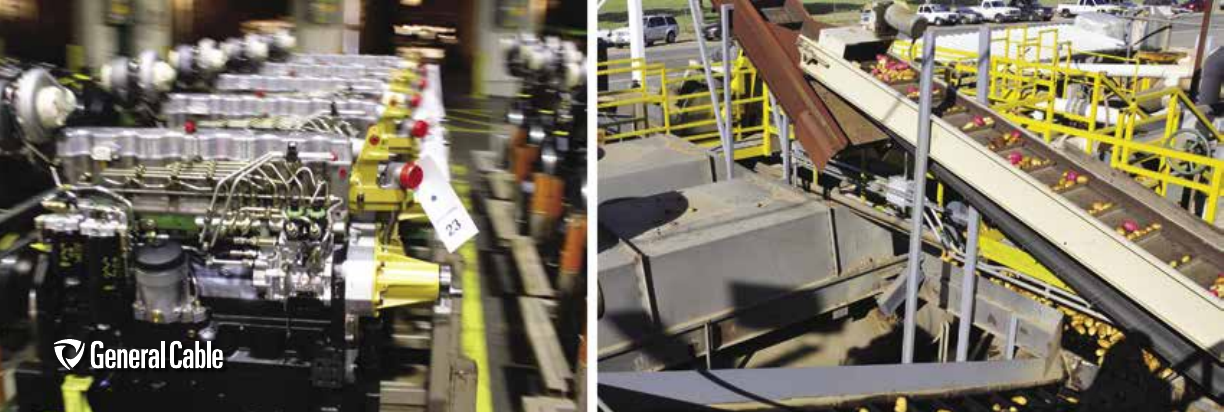
For more than 165 years, General Cable
has provided wire and cable solutions that
keep goods moving, products assembled
and services delivered around the world.
Through innovative design and engineering
expertise, General Cable delivers the
wire and cables that maintain ongoing
productivity for an array of industrial
automation and electrical distribution
customers that represent a virtual “who’s
who” of the markets we serve.
General Cable recognizes and values the
importance of total customer satisfaction,
and we have the experience and know-how
to achieve it. Our people may come to work
for us, but on the job, our Wire Wizards work
for you. Put us to work and see what we can
do for you.
AUTOMOTIVE & CONSUMER PRODUCTS • HEALTH CARE & MEDICAL DEVICE MANUFACTURERS • PULP & PAPER
INDUSTRIAL EQUIPMENT MANUFACTURERS • LIFTS & CRANES • MAINTENANCE & REPAIR OPERATIONS
MINING EQUIPMENT MANUFACTURERS • PLANTS & FACILITIES MANAGEMENT • PUMPS & FOUNTAINS
PORTABLE & TEMPORARY POWER GENERATION • MILITARY • REFRIGERATION & FREEZER MANUFACTURERS
Here to Serve
2

3
Uniquely positioned to respond to the evolving needs of
industrial applications, General Cable works side-by-side
with customers to design innovative, cost-effective solu-
tions that meet exact specifications while providing value-
added services. Backed by an organization that is flexible
and responsive with a commitment to maintaining lasting
customer relationships, you can count on General Cable
for superior service and support.
General Cable is always searching for new and better ways
to put quality in your product. The right mix of R&D experi-
ence, manufacturing expertise and stringent testing by the
most qualified team of engineers ensures that every cable
meets industry standards and offers the highest quality
possible. Our Lean Six Sigma philosophy eliminates waste,
non-value-added processes and sources of variation while
reducing cycle-time and improving capacity, space utiliza-
tion and productivity.
• ISO 9001 certified manufacturing facilities
• Ongoing process control and production management
• Quality assurance initiatives and rigorous performance
standards
• R&D and innovative material development expertise
• Stringent in-house and third-party testing
World-Class Service & Support
Commitment to Quality & the Environment
• Innovative cable designs for any industrial application
• Superior engineering expertise and production processes
• Advanced vertical integration capabilities
• Strong supply chain and inventory support
• Dedicated service, technical support and sales expertise
General Cable is an environmentally conscious company
committed to reducing and, where possible, eliminating
hazardous substances. Through environmentally sound
materials and production processes, our facilities have
fully implemented an ISO 14001-equivalent environmental
management system with strict oversight. All applicable
products meet RoHS standards, and we consistently work
to comply with evolving REACH requirements pertaining
to wire and cable products and materials. Our revolution-
ary 17 FREE® line of halogen-free datacom, fiber, cord and
electronics cables features substantiated green properties
and may qualify for credits under environmental incentive
programs.
As a Fortune 500 company with approximately 14,000 associates globally and 38 manufacturing facilities operating in
core markets around the world, General Cable is positioned to meet the needs of today’s industrial automation and electri-
cal distribution customers with a diverse, industry-leading global product offering—whenever and wherever it’s needed.
Our products comply with major safety and performance standards and regulations around the world—from UL, IEEE,
ODVA and IEC to TIA, TÜV, RoHS and CSA.
Whether it’s data, power, signal or control in the office, on the factory floor, inside the wind turbine or onboard an oil rig,
General Cable has the electronic, industrial, data, fiber and specialty cable to keep power and information flowing and
goods and services moving while ensuring maximum safety, value and long-term reliability. From special wire colors, print
legends and TRU-Mark® sequential footage marking to unique materials and manufacturing requirements, General Cable
has the people, equipment and experience to produce the custom cable you need.
World-Wide Single Source Solutions

4
Condensed Production Capabilities –
Copper Products
Please consult your General Cable representative for additional
information on product designs and constructions.
Conductor:
Size Range (Multi-Conductor): 26 AWG thru 4/0 AWG
Size Range (Single Conductor): 28 AWG thru 1000 kcmil
Construction: Stranded and Solid
Material: Copper, Copper Covered Steel, Galvanized
Steel, Copper Alloy, Silver Plated Copper
Coating: Tin, Silver, Nickel
Insulation:
Low Temp Ranges:
Ethylene Propylene Rubber: Flexible (-40°C to +105°C)
Tyrene Butadiene Rubber: Flexible (-55°C to +60°C)
PVC:
– Semi-Rigid, Conventional, Flexible, Clear, PVC/Nylon
(-35°C to +105°C)
– For Plenum Cables, 75˚C
Polyethylene: LD, HD, Solid, Chemical Foam,
Gas Injection, Flame-Retardant (-76°C to +80°C)
Polypropylene: Solid, Chemical Foam (-25°C to +105°C)
Zero-Halogen Polyolefin: Solid or Foam (-40°C to +105°C)
High Temp Ranges:
FEP (-100°C to +200°C), PVDF (-40°C to +150°C), Halar
(-74°C to +150°C), Tefzel® (-50°C to +150°C), PVC (-40°C
to +105°C), TPR (-65°C to + 125°C), Hytrel® (-40°C to
+105°C), Nylon (-65°C to +125°C)
Identification:
Stripes or number printing, multiple color combinations
using 1, 2 or 3 spiral stripes, number/legend printing
(online), band marking (online or offline), up to 144 color
combinations plus 1 or 2 spiral or parallel
TRU-Mark® sequential footage marking
Twinning: 10 AWG thru 28 AWG
Cabling:
500 MCM thru 28 AWG, 2 to 100 conductors, 1.25”
maximum cable core diameter
Shielding:
Braid or serve; combination of braid and aluminum shield,
braid coverage up to 98%
Materials: Nylon, Fiberglass, Tinned Copper, Bare
Copper, Silver Plated Copper, Aluminum, Bronze, Kevlar®,
Aluminum and Aluminum Mylar® Tape Options
Jacketing:
Up to 3.75" in cable diameter, 108" max. reel take-up
CPE: Flexible, oil resistance, flame-retardant (-50°C to +105°C)
Neoprene: Flexible, oil resistance, flame-retardant
(-55°C to +90°C)
Silicone: High temperature ignition wire jacket (200°C)
PVC: Conventional, flexible, oil resistance, UV-resistant
Polyolefin: LD, MD, HD, solid, flame-retardant, zero-halogen
Other: TPR, Polyurethane, FR-Polyurethane, FEP, Halar,
SOLEF, Tefzel
Packaging:
– Reels, Plastic or Wood up to 72” diameter
– Reel-in-a-Box
– Spool-Pac®
– Pull-Pac®
Testing:
– Complete mechanical and electrical/electronic testing
– Capabilities in accordance with UL, CSA, ETL and MSHA
requirements
– General Cable’s Willimantic, CT; Highland Heights, KY;
and Indianapolis, IN laboratories have a wide range of
mechanical test capabilities, including fire testing
Certifications:
– UL Listed
– CSA Approvals
– ETL
– IEEE
– AWM
– ODVA
– TIA
– MSHA
– TÜV
– RoHS/CE Compliant
– REACH

5
Applications & Products
Manufacturing Floor
Carol® Brand Cord
- Type SOOW – 300 V and 600 V Rubber Portable Cord
- Type SEOOW – 600 V Plastic Portable Cord (junior available)
- Type STOW – 600 V Plastic Portable Cord (junior available)
- Welding Cable
- Bus Drop Cable
- MTW Hook-Up Wire
- Industrial Flex Cables – 2 kV
- Type SOOW – 300 V and 600 V Rubber Portable Cord with
17 FREE®
Industrial & Specialty
- Instrumentation Tray Cables – 300 V and 600 V
- Control & Power Tray Cables – 600 V
- Variable Frequency Drive (VFD) Cables
- CCW® Armored Power and Instrumentation Cables
- Single Conductor Low-Voltage Cables
- Medium-Voltage Power Cables – 2.4 kV – 35 kV
- Industrial Armored Cables – 600 V – 35 kV
NextGen® Brand Fiber
- LSZH Tight Buffer Distribution
- LSZH Loose Tube
- LSZH Heavy-Duty Breakout
- LSZH Heavy-Duty Armored Breakout
- LSZH Extra-Heavy-Duty Breakout
- LSZH Extra-Heavy-Duty Armored Breakout
Carol® Brand Electronics
- EXZEL® High-Endurance Multi-Conductor & Multi-Pair Cable
(Foil, Braid Shield)
- EXZEL High-Endurance LSZH Multi-Conductor & Multi-Pair
Cable (Foil, Braid Shield)
- Communication and Control Multi-Conductor & Multi-Pair Cable
(Unshielded, Shielded)
- Power Limited Tray Cable
- Coaxial Cable – Types RG-6, RG-11 and RG-59 Plenum Rated
- Twinaxial Cable
- DeviceNet Cable
- PVC Hook-Up Wire
- Computer Multi-Conductor & Multi-Pair Cable
(Unshielded, Shielded)
- Type RG-59 Standard & Siamese Coaxial Cables with 17 FREE
Datacom
- Carol Brand & GenSPEED® Category 6 Cable – UTP and F/UTP
(ScTP)
- Carol Brand & GenSPEED Category 5e Cable – UTP and F/UTP
(ScTP)
- GenSPEED Category 6 and 5e Cable with 17 FREE
Data Center
Datacom
- GenSPEED® 10 MTP™ Category 6A 10 Gig Cable
- Carol Brand & GenSPEED Category 6 Cable – UTP and F/UTP
(ScTP)
- Central Office Cable
- GenSPEED 10,000 Category 6a and 6 with 17 FREE
Carol® Brand Electronics
- Access Control Cable
- Type RG-59 Standard and Siamese Coaxial Cables with 17 FREE
NextGen® Brand Fiber
- Tight Buffer Distribution
- Tight Buffer Distribution Interlock Armored
- Tight Buffer Breakout
- Tight Buffer Simplex
- Tight Buffer Duplex
- Loose Tube
- LSZH Tight Buffer Distribution with 17 FREE
Industrial
- Single Conductor Low-Voltage for Battery Back-Up
Back Office
Datacom
- Carol Brand & GenSPEED Category 6 Cable – UTP and F/UTP (ScTP)
- Carol Brand & GenSPEED Category 5e Cable – UTP and F/UTP (ScTP)
- Central Office Cable
- GenSPEED Category 6 and 5e Cable with 17 FREE
NextGen® Brand Fiber
- Tight Buffer Distribution
- Tight Buffer Distribution Interlock Armored
- Tight Buffer Breakout
- Tight Buffer Simplex
- Tight Buffer Duplex
- Loose Tube
- LSZH Tight Buffer Distribution with 17 FREE
Carol® Brand Electronics
- Fire Alarm Cable
- Coaxial Cable – Types RG-6 and RG-59
Carol® Brand Cord
- Thermostat Wire – 105 V
- Lamp Cord
- Cordsets
Conference/Training Center
Gepco® Brand Commercial Cables
- Component Video RGB Coaxial Cable
- Composite Access Control Cable – Video + Audio or Data
- High-Definition Coaxial Cable – HDTV
- Speaker & Control Multi-Conductor Cable – Shielded, Unshielded
- Microphone Cable
- Automation Control Cable
- Lighting Control Cable
Security Office
Carol® Brand Electronics
- Access Control Cable
- Security Multi-Conductor Cable – Shielded
- Coaxial Cable – Types RG-6, RG-11 and RG-59
- Burglar Alarm Cable
Datacom
- GenSPEED 10 MTP Category 6A 10 Gig Cable
- Carol Brand & GenSPEED Brand Category 6 Cable
- Central Office Cable
- GenSPEED 10,000 Category 6a and 6 with 17 FREE
6
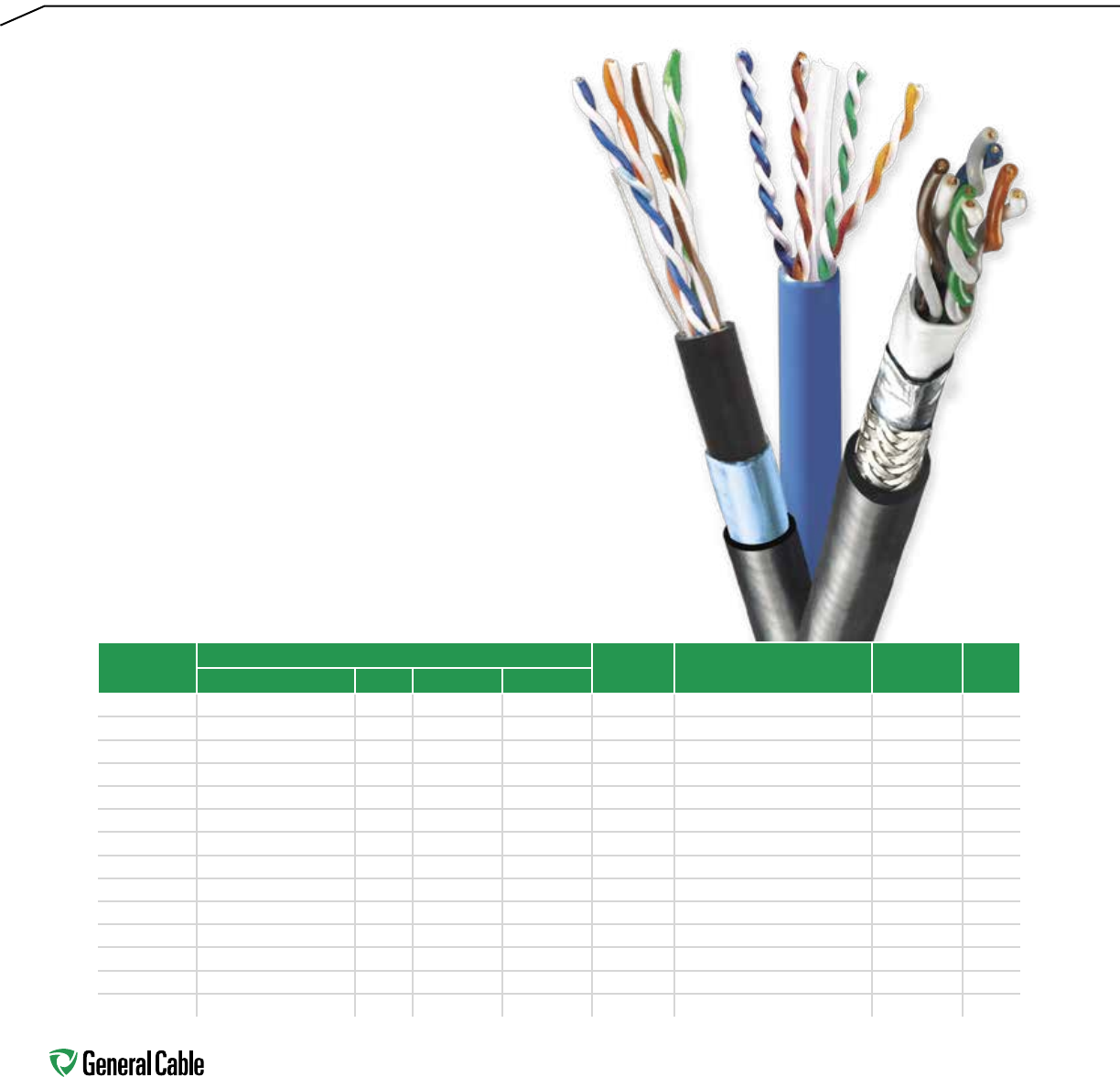
Industrial Ethernet
The presence of harsh conditions and
demanding applications in industrial
environments makes choosing a high quality
industrial Ethernet cable with the appropriate
features critical. General Cable's new line of
industrial Ethernet wire makes that decision easy
by providing cables that meet the needs of harsh
conditions on the plant floor by offering sustainable
solutions in Category 5e and 6 cables.
Whatever your needs, General Cable has you covered.
Whether it's a Category 5e or Category 6, unshielded,
shielded, armored or outside plant, General Cable's
offering of industrial Ethernet product is the perfect
cable for an imperfect environment.
Part Number Product Construction Conductor
Type Jacket Grade 600 V AWM CMR
Category Pairs Shielded Unshielded
GCR1402 5e - UTP 2 • Solid Industrial - PVC • •
GCR1404 5e - UTP 4 • Solid Industrial - PVC • •
GCR1408 5e - UTP PLTC 4 • Solid Industrial - PVC • •
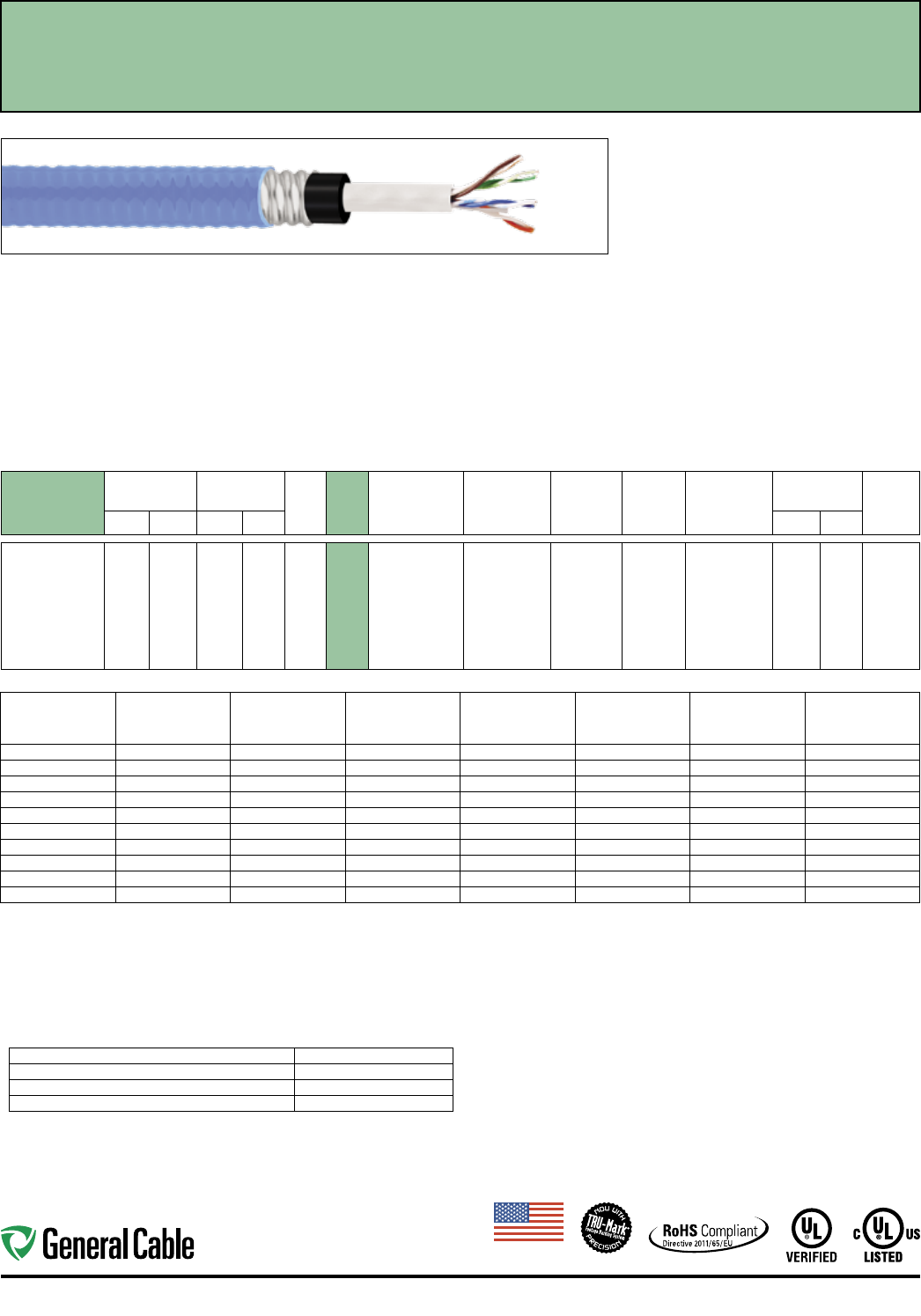
GCR1410 5e - UTP, Armored 4 • Solid Interlocked Armor • •
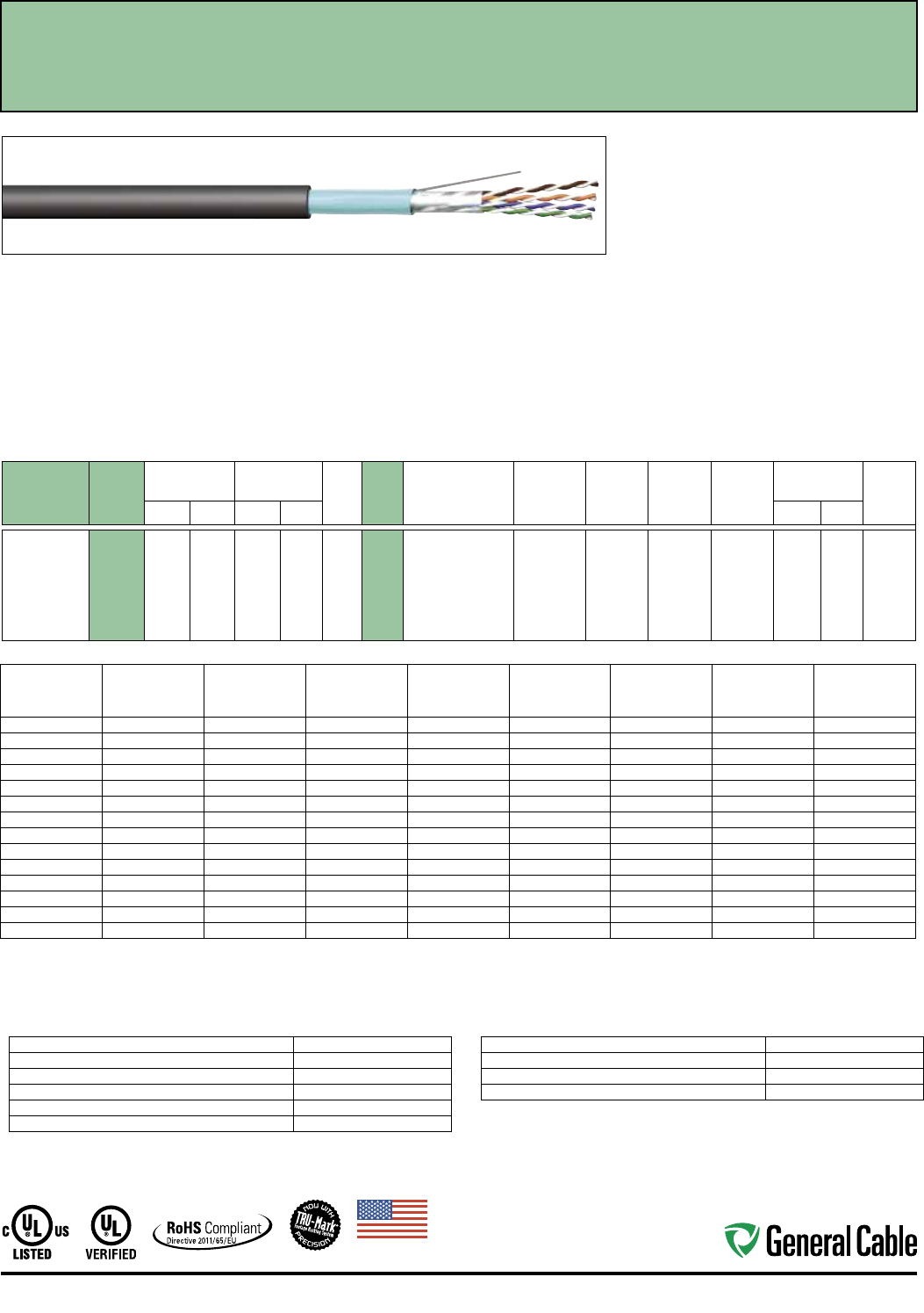
GCR1403 5e - F/UTP 2 • Solid Industrial - PVC • •
GCR1419 5e - F/UTP 4 • Solid Industrial - PVC •
GCR1405 5e - F/UTP Enhanced 4 • Solid Industrial - PVC • •
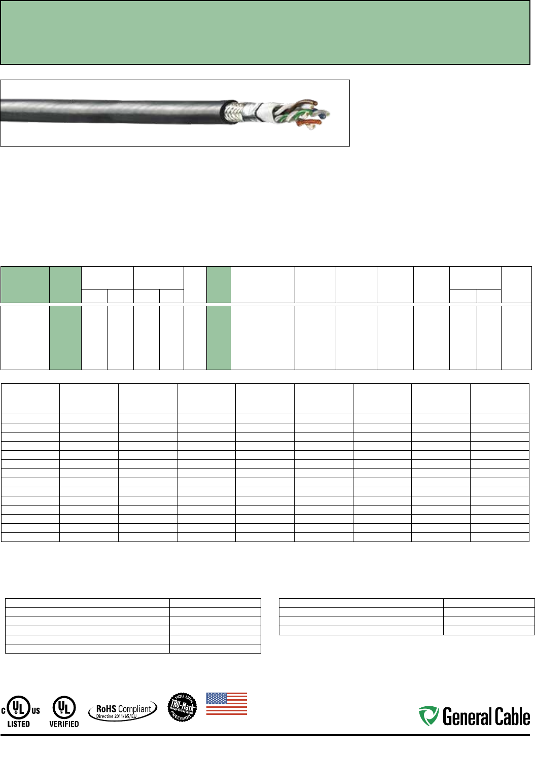
GCR1407 5e - SF/UTP Enhanced 4 • Solid Industrial - PVC • •
5136100 5e - OSP 4 • Solid OSP - Halogen Free
5136101 5e - OSP, Armored 4 • Solid OSP - Halogen Free Armor
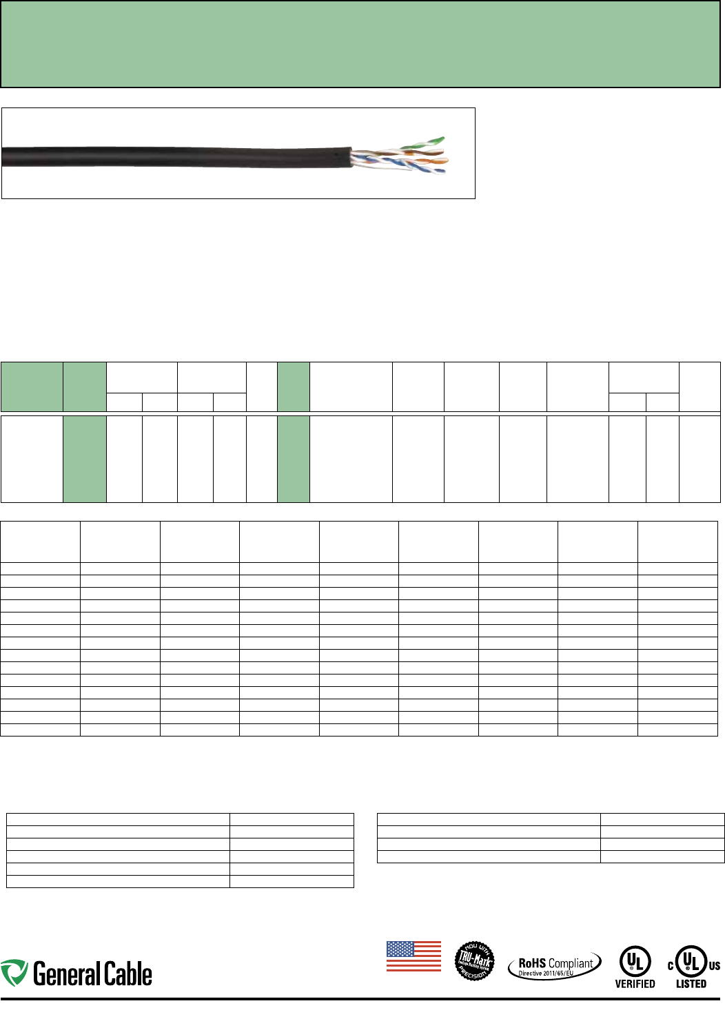
GCR1440 6 - UTP 4 • Solid Industrial - PVC •
GCR1450 6 - UTP Enhanced 4 • Solid Industrial - PVC • •
GCR1452 6 - F/UTP 4 • Solid Industrial - PVC • •
7136100 6 - OSP 4 • Solid OSP - Halogen Free

7
Table of Contents
INDUSTRIAL ETHERNET
CATALOG NO. DESCRIPTION PAGE
Category 5e GCR1402 Cat 5e UTP 2 Pair 600 V AWM 8
GCR1404 Cat 5e UTP 4 Pair 600 V AWM 9
GCR1408 Cat 5e 22 UTP PLTC 4 Pair 600 V AWM 10
GCR1403 Cat 5e F/UTP 2 Pair 600 V AWM 11
GCR1419 Cat 5e F/UTP 4 Pair 12
GCR1405 Cat 5e F/UTP 4 Pair Enhanced 600 V AWM 13
9899.CT02104000 Cat 5e CCW® 14
GCR1407 Cat 5e SF/UTP 4 Pair 600 V AWM 15
5136100 Cat 5e OSP 4 Pair 16
5136101 Cat 5e OSP Armored 4 Pair 17
GCR1410 Cat 5e Interlocking Armored 4 Pair 18
Category 6 GCR1440 Cat 6 UTP 4 Pair 19
GCR1450 Cat 6 UTP 4 Pair Enhanced 600 V AWM 20
GCR1452 Cat 6 F/UTP 4 Pair 600 V AWM 21
7136100 Cat 6 OSP 4 Pair 22
Fiber Optic NextGen® Brand Plus Corning® 23-24
Optical Fiber Cross-Reference
Tight Buffer Distribution Riser Cable, Indoor 25
Tight Buffer Distribution Plenum Cable, Indoor 25
Tight Buffer Distribution Interlock Armored 26
Riser Cable, Indoor
Tight Buffer Distribution Interlock Armored 26
Plenum Cable, Indoor
Tight Buffer Distribution Riser Cable, Indoor/Outdoor 27
Tight Buffer Distribution Plenum Cable, Indoor/Outdoor 27
Loose Tube Single Jacket Plenum Cable, Indoor/Outdoor 27
Loose Tube Single Jacket Cable, Outdoor 28
Loose Tube Dual Jacket Cable, Outdoor 28
Made
in
U.S.A.
8
Ethernet Industrial Automation
CATALOG
NUMBER
SPEC
NUMBER
NOMINAL
O.D.
CABLE WEIGHT
MFT NO.
PAIRS
COND.
AWG
SIZE
PAIR
COLOR
CODE
INSULATION
MATERIAL
SHIELD
COVERAGE RIPCORD
JACKET
MATERIAL
JACKET
THICKNESS JACKET
COLORSINCHES mm LBS kg INCHES mm
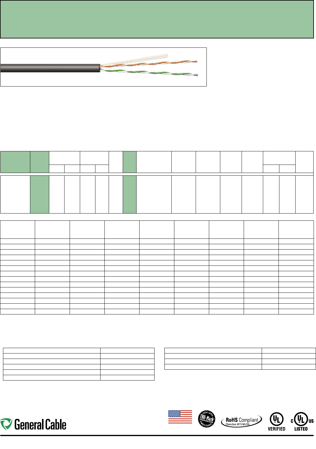
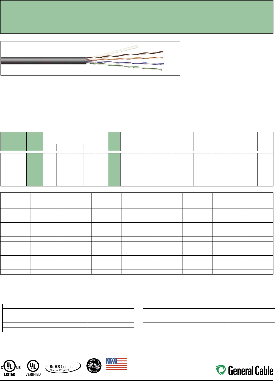
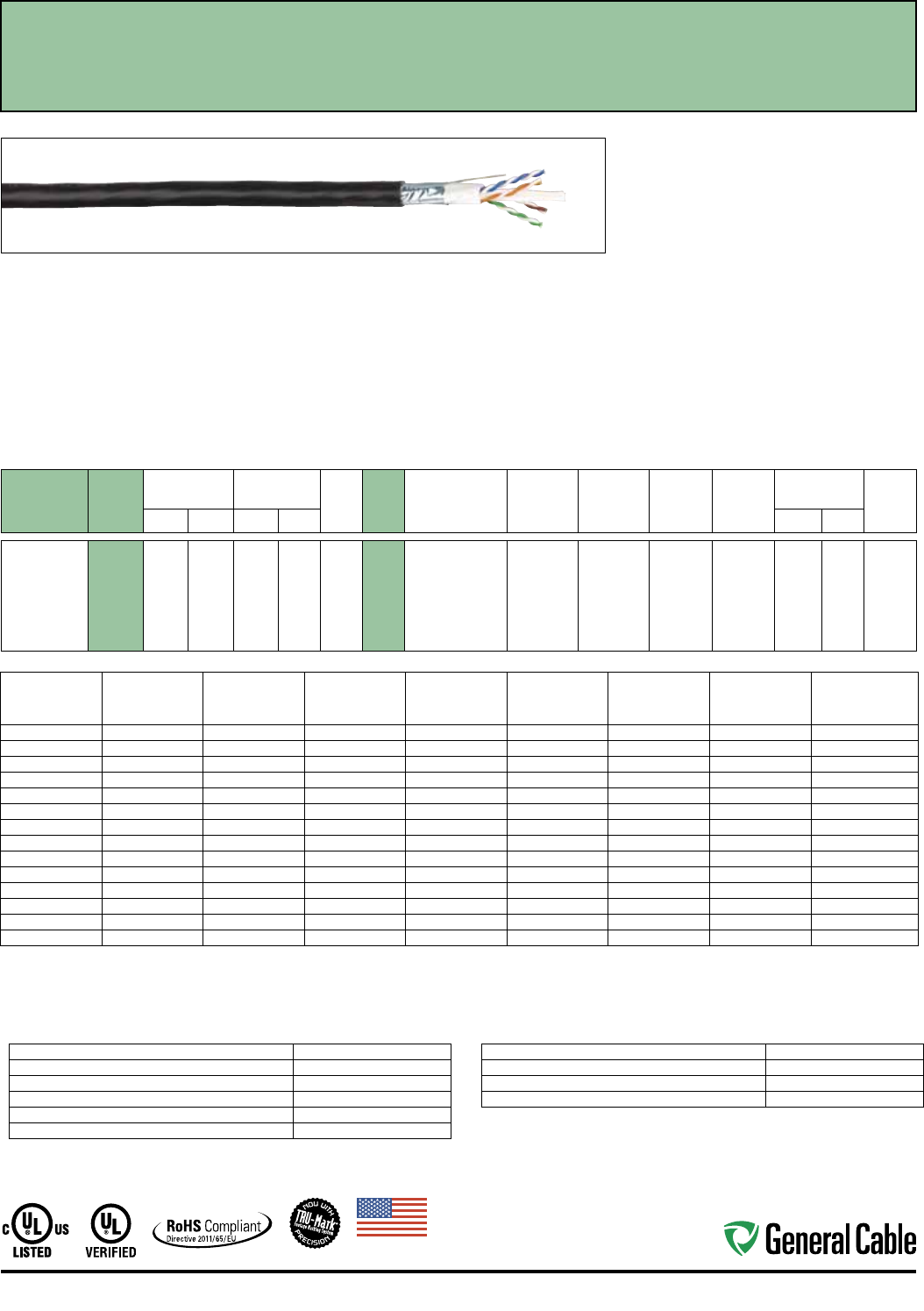
GCR1402 7507
0.200 5.080 18 8 2 24 1: Orange/White,
Orange
2: Green/White,
Green
HDPE Unshielded Polyester Oil- and
Sunlight-
Resistant
PVC
0.032 0.813 Red,
Black
Industrial Ethernet Category 5e - 2 Pair
Unshielded Twisted Pair Cable
Frequency
(MHz)
Insertion Loss
(dB/100 m)
Next
(dB)
PSNext
(dB)
ACR
(dB/100 m)
PSACR
(dB/100 m)
ACRF
(dB/100 m)
PSACRF
(dB/100 m)
Return Loss
(dB)
max. min. min. min. min. min. min. min.
1 2.0 65.3 62.3 63.3 60.3 63.8 60.8 20.0
4 4.1 56.3 53.3 52.2 49.2 51.7 48.7 23.6
10 6.5 50.3 47.3 43.8 40.8 43.8 40.8 26.0
16 8.2 47.3 44.3 39.0 36.1 39.7 36.7 26.0
20 9.3 45.8 42.8 36.5 33.5 37.7 34.7 26.0
25 10.4 44.3 41.3 33.9 30.9 35.8 32.8 25.5
31.25 11.7 42.9 39.9 31.2 28.2 33.9 30.9 25.0
62.5 17.0 38.4 35.4 21.4 18.4 27.8 24.8 23.5
100 22.0 35.3 32.3 13.3 10.3 23.8 20.8 22.5
155 28.1 32.4 29.4 4.4 1.4 20.0 17.0 18.8
200 32.4 30.8 27.8 — — 17.8 14.8 18.0
250 36.9 29.3 26.3 — — 15.8 12.8 17.3
300 41.0 28.1 25.1 — — 14.3 11.3 16.6
350 44.9 27.1 24.1 — — 12.9 9.9 16.3
Values over 200 Mhz are for informational purposes.
ELECTRICAL CHARACTERISTICS
Maximum DC Resistance 8.9 Ohms/100 m @ 20˚ C
Maximum DC Resistance Unbalance, Ind Pair 3%
Maximum Mutual Capacitance 17 pF/ft @ 1 KHz
Maximum Delay Skew 45 ns/100 m
Nominal Velocity of Propagation 70% Speed of Light
Characteristic Impedence (Frequency 1-200 MHz) Ohms: 100±15
MECHANICAL CHARACTERISTICS
Maximum Pulling Force 20 lbs.
Minimum Bend Radius 0.25"
Installation Temperature Rating -20˚C to +75˚C
Operation Temperature Rating -40˚C to +75˚C
Applications:
• IEEE 802.3: 100 BASE-TX, 10 BASE-T, PoE, PoE+
• CDDI, Token Ring, ATM
• Broadband and Baseband Analog Video
• Voice, T1
• Harsh Industrial Environments
• ODVA EtherNet/IP™
Compliances:
• UL Verified to ANSI/TIA 568-C.2 Category 5e
• NEC/CEC Type: UL Listed CMX OUTDOOR - CMR
• NEC/CEC Type CMR (UL 1666)
• UL AWM Style 21047 (UL: 75°C, 600 V)
• UV RES per UL 444
• RoHS II Compliant (EU DIRECTIVE 2011/65/EU)
Features and Benefits:
• Third-party verified for guaranteed performance
• TRU-Mark® print legend
• Industrial-grade oil- and sunlight-resistant jacket
Print Legend:
****GENERAL CABLE* GCR1402 INDUSTRIAL CAT 5E
2PR/24AWG RISER C(UL)US CMX OUTDOOR - CMR 75C
UV RES---VERIFIED (UL) ANSI/TIA-568C.2 CAT-5E AWM
21047 75C 600 V---FT4 OIL RES ODVA ETHERNET/IP
(TM) VEN 1293 PAT 5767441 ##-## ######## CAT 5E
Made
in
U.S.A.
9
Industrial Automation Ethernet
CATALOG
NUMBER
SPEC
NUMBER
NOMINAL
O.D.
CABLE WEIGHT
MFT NO.
PAIRS
COND.
AWG
SIZE
PAIR
COLOR
CODE
INSULATION
MATERIAL
SHIELD
COVERAGE RIPCORD
JACKET
MATERIAL
JACKET
THICKNESS JACKET
COLORSINCHES mm LBS kg INCHES mm
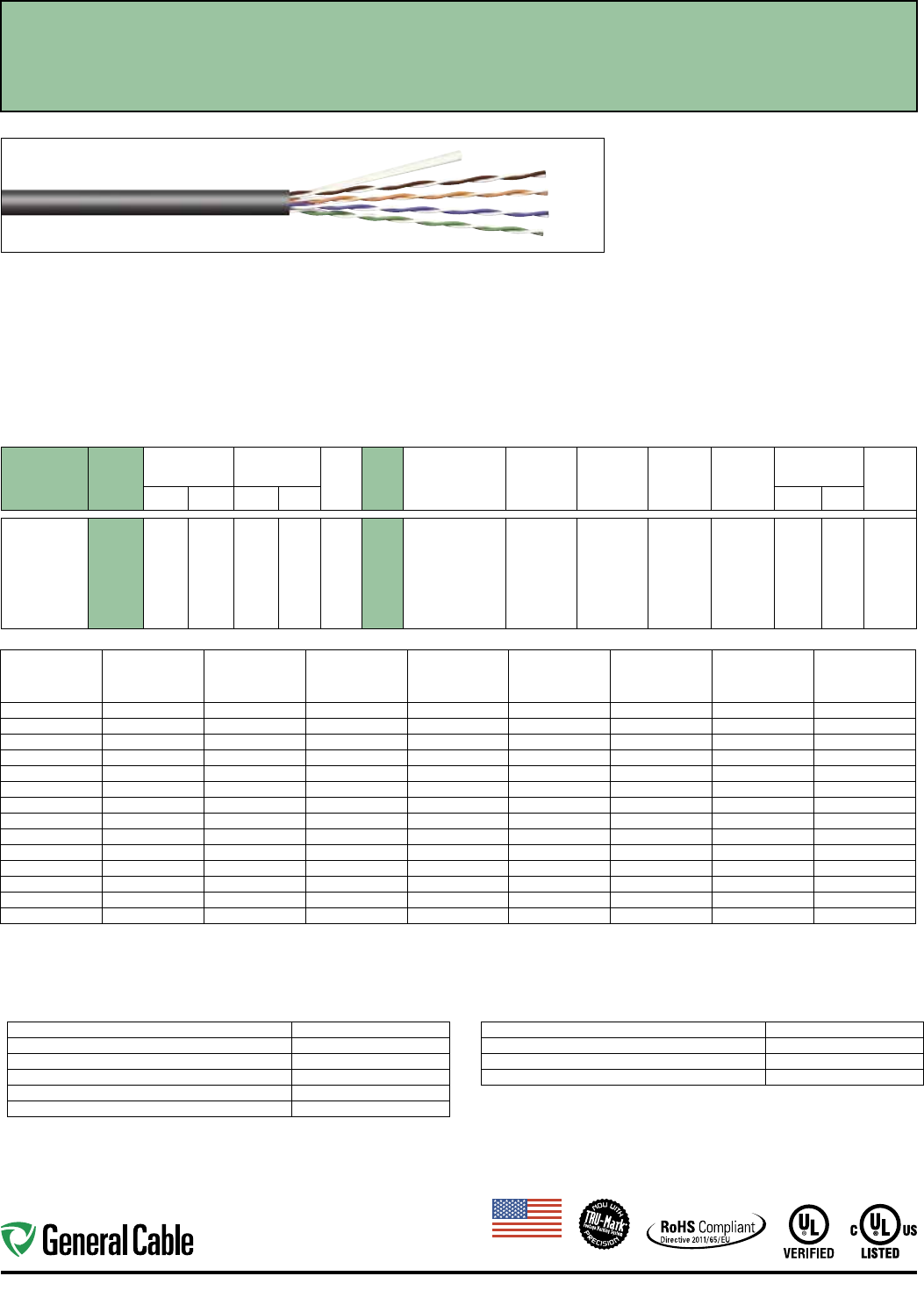
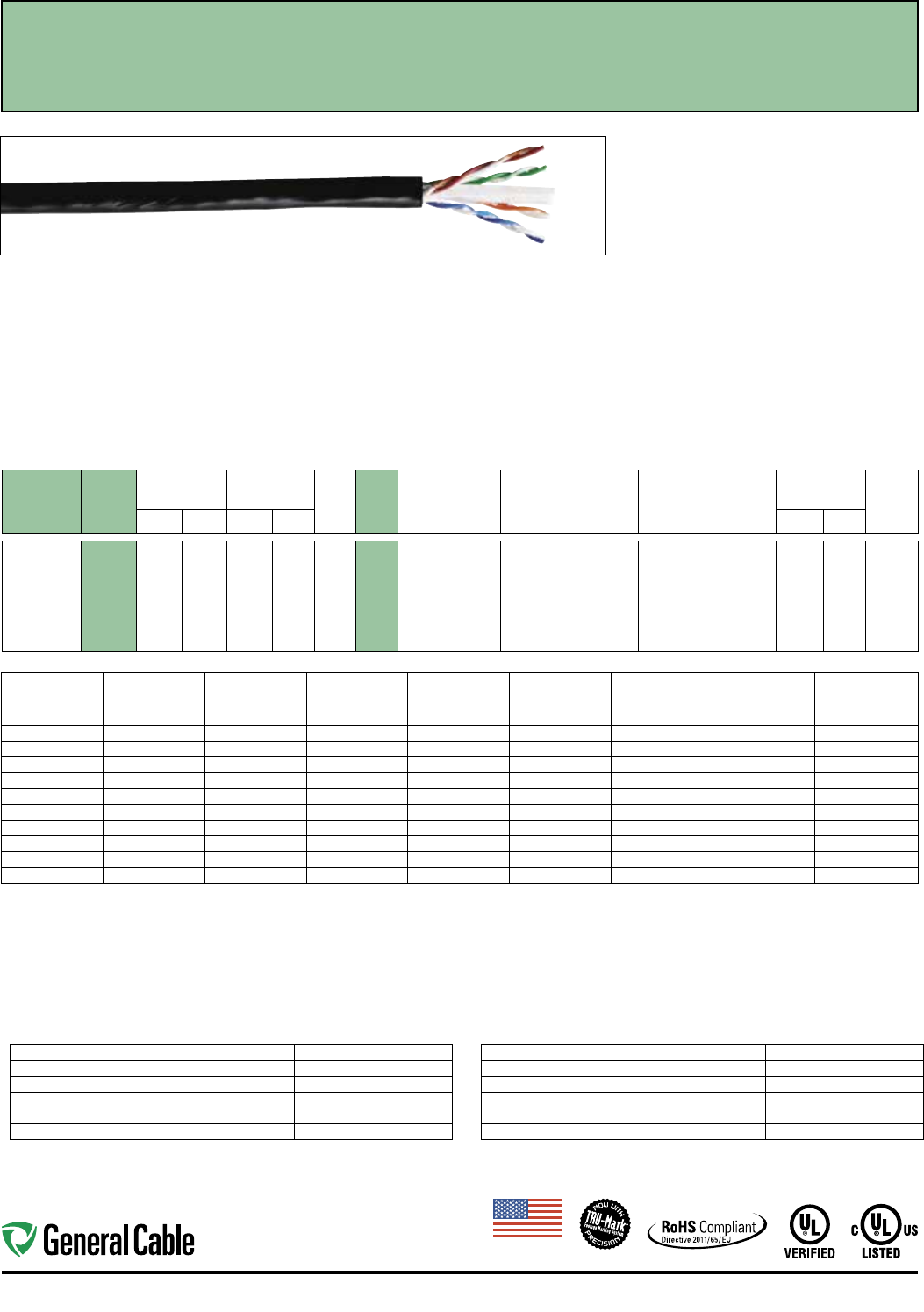
GCR1404 7500
0.225 5.715 24 11 4 24 1: Blue/White, Blue
2: Orange/White,
Orange
3: Green/White,
Green
4: Brown/White,
Brown
HDPE Unshielded Polyester Oil- and
Sunlight-
Resistant
PVC
0.032 0.813 Red,
Black
Industrial Ethernet Category 5e - 4 Pair
Unshielded Twisted Pair Cable
Frequency
(MHz)
Insertion Loss
(dB/100 m)
Next
(dB)
PSNext
(dB)
ACR
(dB/100 m)
PSACR
(dB/100 m)
ACRF
(dB/100 m)
PSACRF
(dB/100 m)
Return Loss
(dB)
max. min. min. min. min. min. min. min.
1 2.0 65.3 62.3 63.3 60.3 63.8 60.8 20.0
4 4.1 56.3 53.3 52.2 49.2 51.7 48.7 23.6
10 6.5 50.3 47.3 43.8 40.8 43.8 40.8 26.0
16 8.2 47.3 44.3 39.0 36.1 39.7 36.7 26.0
20 9.3 45.8 42.8 36.5 33.5 37.7 34.7 26.0
25 10.4 44.3 41.3 33.9 30.9 35.8 32.8 25.5
31.25 11.7 42.9 39.9 31.2 28.2 33.9 30.9 25.0
62.5 17.0 38.4 35.4 21.4 18.4 27.8 24.8 23.5
100 22.0 35.3 32.3 13.3 10.3 23.8 20.8 22.5
155 28.1 32.4 29.4 4.4 1.4 20.0 17.0 18.8
200 32.4 30.8 27.8 — — 17.8 14.8 18.0
250 36.9 29.3 26.3 — — 15.8 12.8 17.3
300 41.0 28.1 25.1 — — 14.3 11.3 16.6
350 44.9 27.1 24.1 — — 12.9 9.9 16.3
Values over 200 Mhz are for informational purposes.
ELECTRICAL CHARACTERISTICS
Maximum DC Resistance 8.9 Ohms/100 m @ 20˚ C
Maximum DC Resistance Unbalance, Ind Pair 3%
Maximum Mutual Capacitance 17 pF/ft @ 1 KHz
Maximum Delay Skew 45 ns/100 m
Nominal Velocity of Propagation 70% Speed of Light
Characteristic Impedence (Frequency 1-200 MHz) Ohms: 100±15
MECHANICAL CHARACTERISTICS
Maximum Pulling Force 25 lbs.
Minimum Bend Radius 1.00"
Installation Temperature Rating -20˚C to +75˚C
Operation Temperature Rating -40˚C to +75˚C
Applications:
• IEEE 802.3: 100 BASE-TX, 10 BASE-T, PoE, PoE+
• CDDI, Token Ring, ATM
• Broadband and Baseband Analog Video
• Voice, T1
• Harsh Industrial Environments
• ODVA EtherNet/IP™
Compliances:
• UL Verified to ANSI/TIA 568-C.2 Category 5e
• NEC/CEC Type: UL Listed CMX OUTDOOR - CMR
• NEC/CEC Type CMR (UL 1666)
• UL AWM Style 21047 (UL: 75°C, 600 V)
• UV RES per UL 444
• RoHS II Compliant (EU DIRECTIVE 2011/65/EU)
• MSHA Signaling Cable P-07-KA140022-MSHA
Features and Benefits:
• Third-party verified for guaranteed performance
• TRU-Mark® print legend
• Industrial-grade oil- and sunlight-resistant jacket
Print Legend:
****GENERAL CABLE* GCR1404 INDUSTRIAL CAT 5E
4PR/24AWG RISER C(UL)US CMX OUTDOOR - CMR 75C
UV RES VERIFIED (UL) ANSI/TIA-568C.2 CAT-5E AWM
21047 75C 600 V---FT4 OIL RES P-07-KA140022-MSHA
ODVA ETHERNET/IP (TM) VEN 1293 PAT 5767441 ##-##
######## CAT 5E
Made
in
U.S.A.
10
Ethernet Industrial Automation
CATALOG
NUMBER
SPEC
NUMBER
NOMINAL
O.D.
CABLE WEIGHT
MFT NO.
PAIRS
COND.
AWG
SIZE
PAIR
COLOR
CODE
INSULATION
MATERIAL
SHIELD
COVERAGE RIPCORD
JACKET
MATERIAL
JACKET
THICKNESS JACKET
COLORSINCHES mm LBS kg INCHES mm
GCR1408 7503
0.295 7.490 38 14 4 22 1: White/Blue, Blue
2: White/Orange,
Orange
3: White/Green,
Green
4: White/Brown,
Brown
HDPE Unshielded Polyester Oil- and
Sunlight-
Resistant
PVC
0.042 1.070 Red,
Black
Industrial Ethernet Category 5e - 4 Pair PLTC
Unshielded Twisted Pair Cable
Applications:
• IEEE 802.3: 1000 BASE-T, 100 BASE-TX, 10
BASE-T, PoE, PoE+
• CDDI, Token Ring, ATM
• Broadband and Baseband Analog Video
• Voice, T1
• Harsh Industrial Environments
• ODVA EtherNet/IP™
Compliances:
• UL Verified to ANSI/TIA 568-C.2 Category 5e
• NEC/CEC Type: UL Listed CMX OUTDOOR - CMR
• NEC/CEC Type CMR (UL 1666)
• NEC/CEC Type PLTC (UL 13)
• UL AWM Style 2570 (UL: 80°C, 600 V)
• SUN RES per UL 444 and UL 13
• UL OIL RES I and II per UL 13
• RoHS II Compliant (EU DIRECTIVE 2011/65/EU)
Features and Benefits:
• Third-party verified for guaranteed performance
• TRU-Mark® print legend contains footage markings
• Industrial-grade oil- and sunlight-resistant jacket
Print Legend:
**** FEET GENERAL CABLE* GCR1408 INDUSTRIAL CAT
5E CATEGORY 5E 4PR/22AWG RISER CABLE C(UL)US
CMX OUTDOOR - CMR 75C VERIFIED (UL) ANSI/TIA-
568C.2 CAT-5E---AWM 2570 80C 600 V---(UL) PLTC SUN
RES OIL RES I---FT4 ETHERNET/IP (TM) PAT 5767441
**-** *AAAAA CAT 5
Frequency
(MHz)
Insertion Loss
(dB/100 m)
Next
(dB)
PSNext
(dB)
ACR
(dB/100 m)
PSACR
(dB/100 m)
ACRF
(dB/100 m)
PSACRF
(dB/100 m)
Return Loss
(dB)
max. min. min. min. min. min. min. min.
1 2.0 65.3 62.3 63.3 60.3 63.8 60.8 20.0
4 4.1 56.3 53.3 52.2 49.2 51.7 48.7 23.6
10 6.5 50.3 47.3 43.8 40.8 43.8 40.8 26.0
16 8.2 47.3 44.3 39.0 36.1 39.7 36.7 26.0
20 9.3 45.8 42.8 36.5 33.5 37.7 34.7 26.0
25 10.4 44.3 41.3 33.9 30.9 35.8 32.8 25.5
31.25 11.7 42.9 39.9 31.2 28.2 33.9 30.9 25.0
62.5 17.0 38.4 35.4 21.4 18.4 27.8 24.8 23.5
100 22.0 35.3 32.3 13.3 10.3 23.8 20.8 22.5
155 28.1 32.4 29.4 4.4 1.4 20.0 17.0 21.6
200 32.4 30.8 27.8 — — 17.8 14.8 21.0
250 36.9 29.3 26.3 — — 15.8 12.8 20.5
300 41.0 28.1 25.1 — — 14.3 11.3 20.1
350 44.9 27.1 24.1 — — 12.9 9.9 19.8
Values over 200 Mhz are for informational purposes.
ELECTRICAL CHARACTERISTICS
Maximum DC Resistance 5.6 Ohms/100 m @ 20˚ C
Maximum DC Resistance Unbalance, Ind Pair 3%
Maximum Mutual Capacitance 17 pF/ft @ 1 KHz
Maximum Delay Skew 45 ns/100 m
Nominal Velocity of Propagation 70% Speed of Light
Characteristic Impedence (Frequency 1-200 MHz) Ohms: 100±15
MECHANICAL CHARACTERISTICS
Maximum Pulling Force 40 lbs.
Minimum Bend Radius 1.2"
Installation Temperature Rating -20˚C to +75˚C
Operation Temperature Rating -25˚C to +75˚C
Made
in
U.S.A.
11
Industrial Automation Ethernet
Applications:
• IEEE 802.3: 1000 BASE-T, 100 BASE-TX, 10
BASE-T, PoE, PoE+
• CDDI, Token Ring, ATM
• Broadband and Baseband Analog Video
• Voice, T1
• Harsh Industrial Environments
• Noisy (EMI) Environments
• ODVA EtherNet/IP™
Compliances:
• UL Verified to ANSI/TIA 568-C.2 Category 5e
• NEC/CEC Type: UL Listed CMX OUTDOOR - CMR
• NEC/CEC Type CMR (UL 1666)
• UL AWM Style 21047 (UL: 75°C, 600 V)
• SUN RES per UL 444
• UL OIL RES I and II
• RoHS II Compliant (EU DIRECTIVE 2011/65/EU)
Features and Benefits:
• Foil shield reduces electromagnetic interference (EMI)
for optimal performance
• Third-party verified for guaranteed performance
• TRU-Mark® print legend contains footage markings
• Industrial-grade oil- and sunlight-resistant jacket
Print Legend:
**** FEET GENERAL CABLE F GCR1403 INDUSTRIAL F/UTP
CAT 5E 2PR/24AWG RISER C(UL)US CMX OUTDOOR - CMR
75C SUN RES VERIFIED (UL) ANSI/TIA-568C.2 CAT-5E AWM
21047 75C 600 V---FT4 OIL RES II ODVA ETHERNET/IP (TM)
VEN 1293 PAT 5767441 **-** *AAAAA CAT 5E
CATALOG
NUMBER
SPEC
NUMBER
NOMINAL
O.D.
CABLE WEIGHT
MFT NO.
PAIRS
COND.
AWG
SIZE
PAIR
COLOR
CODE
INSULATION
MATERIAL
SHIELD
COVERAGE RIPCORD
JACKET
MATERIAL
JACKET
THICKNESS JACKET
COLORSINCHES mm LBS kg INCHES mm
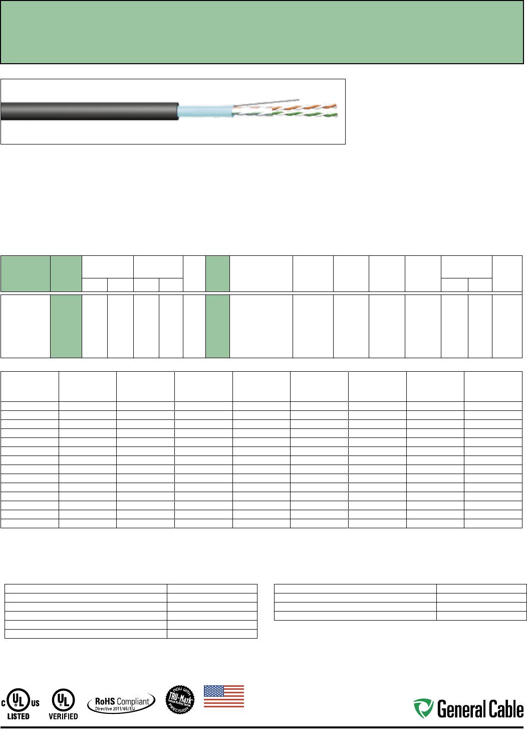
GCR1403 7506
0.230 5.842 23 10 2 24 1: Orange/White,
Orange
2: Green/White,
Green
HDPE 100%
F/UTP
Polyester Oil- and
Sunlight-
Resistant
PVC
0.032 0.813 Red,
Black
Industrial Ethernet Category 5e - 2 Pair F/UTP
Shielded Twisted Pair Cable
Frequency
(MHz)
Insertion Loss
(dB/100 m)
Next
(dB)
PSNext
(dB)
ACR
(dB/100 m)
PSACR
(dB/100 m)
ACRF
(dB/100 m)
PSACRF
(dB/100 m)
Return Loss
(dB)
max. min. min. min. min. min. min. min.
1 2.0 65.3 62.3 63.3 60.3 63.8 60.8 20.0
4 4.1 56.3 53.3 52.2 49.2 51.7 48.7 23.6
10 6.5 50.3 47.3 43.8 40.8 43.8 40.8 26.0
16 8.2 47.3 44.3 39.0 36.1 39.7 36.7 26.0
20 9.3 45.8 42.8 36.5 33.5 37.7 34.7 26.0
25 10.4 44.3 41.3 33.9 30.9 35.8 32.8 25.5
31.25 11.7 42.9 39.9 31.2 28.2 33.9 30.9 25.0
62.5 17.0 38.4 35.4 21.4 18.4 27.8 24.8 23.5
100 22.0 35.3 32.3 13.3 10.3 23.8 20.8 22.5
155 28.1 32.4 29.4 4.4 1.4 20.0 17.0 18.8
200 32.4 30.8 27.8 — — 17.8 14.8 18.0
250 36.9 29.3 26.3 — — 15.8 12.8 17.3
300 41.0 28.1 25.1 — — 14.3 11.3 16.8
350 44.9 27.1 24.1 — — 12.9 9.9 16.3
Values over 200 Mhz are for informational purposes.
ELECTRICAL CHARACTERISTICS
Maximum DC Resistance 8.9 Ohms/100 m @ 20˚ C
Maximum DC Resistance Unbalance, Ind Pair 3%
Maximum Mutual Capacitance 17 pF/ft @ 1 KHz
Maximum Delay Skew 45 ns/100 m
Nominal Velocity of Propagation 70% Speed of Light
Characteristic Impedence (Frequency 1-200 MHz) Ohms: 100±15
MECHANICAL CHARACTERISTICS
Maximum Pulling Force 20 lbs.
Minimum Bend Radius 0.5"
Installation Temperature Rating -20˚C to +75˚C
Operation Temperature Rating -40˚C to +75˚C
Made
in
U.S.A.
12
Ethernet Industrial Automation
Applications:
• IEEE 802.3: 1000 BASE-T, 100 BASE-TX, 10
BASE-T, PoE, PoE+
• CDDI, Token Ring, ATM
• Broadband and Baseband Analog Video
• Voice, T1
• Harsh Industrial Environments
• Noisy (EMI) Environments
• ODVA EtherNet/IP™
Compliances:
• UL Verified to ANSI/TIA 568-C.2 Category 5e
• NEC/CEC Type: UL Listed CMX OUTDOOR - CMR
• NEC/CEC Type CMR (UL 1666)
• SUN RES per UL 444
• UL OIL RES I and II
• RoHS II Compliant (EU DIRECTIVE 2011/65/EU)
• MSHA Signaling Cable P-07-KA140025-MSHA
Features and Benefits:
• Foil shield reduces electromagnetic interference
(EMI) for optimal performance
• Third-party verified for guaranteed performance
• TRU-Mark® print legend contains
footage markings
• Industrial-grade oil- and sunlight-resistant jacket
Print Legend:
**** GENERAL CABLE* GCR1419 INDUSTRIAL F/UTP CAT
5E 4PR/24AWG RISER C(UL)US CMX OUTDOOR - CMR
75C SUN RES VERIFIED (UL) ANSI/TIA-568C.2 CAT-5E---
FT4 OIL RES II P-07-KA140022-MSHA ODVA ETHERNET/
IP (TM) VEN 1293 PAT 5767441 ##-## ######## CAT 5E
CATALOG
NUMBER
SPEC
NUMBER
NOMINAL
O.D.
CABLE WEIGHT
MFT NO.
PAIRS
COND.
AWG
SIZE
PAIR
COLOR
CODE
INSULATION
MATERIAL
SHIELD
COVERAGE RIPCORD
JACKET
MATERIAL
JACKET
THICKNESS JACKET
COLORSINCHES mm LBS kg INCHES mm
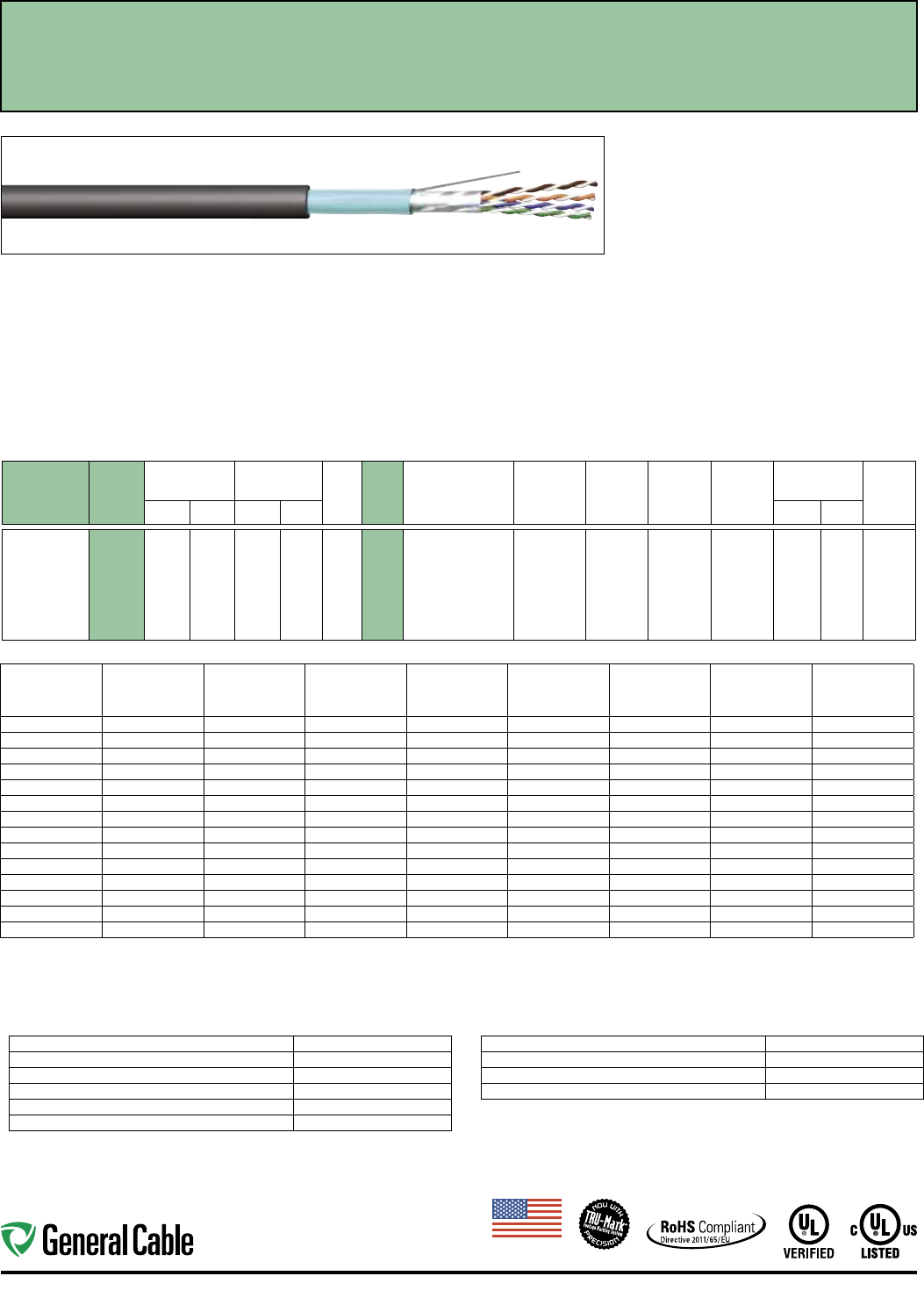
GCR1419 7508
0.270 6.858 34 15 4 24 1: Blue/White, Blue
2: Orange/White,
Orange
3: Green/White,
Green
4: Brown/White,
Brown
HDPE 100%
F/UTP
Polyester Oil- and
Sunlight-
Resistant
PVC
0.032 0.813 Red,
Black
Industrial Ethernet Category 5e - 4 Pair F/UTP
Shielded Twisted Pair Cable
Frequency
(MHz)
Insertion Loss
(dB/100 m)
Next
(dB)
PSNext
(dB)
ACR
(dB/100 m)
PSACR
(dB/100 m)
ACRF
(dB/100 m)
PSACRF
(dB/100 m)
Return Loss
(dB)
max. min. min. min. min. min. min. min.
1 2.0 65.3 62.3 63.3 60.3 63.8 60.8 20.0
4 4.1 56.3 53.3 52.2 49.2 51.7 48.7 23.6
10 6.5 50.3 47.3 43.8 40.8 43.8 40.8 26.0
16 8.2 47.3 44.3 39.0 36.1 39.7 36.7 26.0
20 9.3 45.8 42.8 36.5 33.5 37.7 34.7 26.0
25 10.4 44.3 41.3 33.9 30.9 35.8 32.8 25.5
31.25 11.7 42.9 39.9 31.2 28.2 33.9 30.9 25.0
62.5 17.0 38.4 35.4 21.4 18.4 27.8 24.8 23.5
100 22.0 35.3 32.3 13.3 10.3 23.8 20.8 22.5
155 28.1 32.4 29.4 4.4 1.4 20.0 17.0 18.8
200 32.4 30.8 27.8 — — 17.8 14.8 18.0
250 36.9 29.3 26.3 — — 15.8 12.8 17.3
300 41.0 28.1 25.1 — — 14.3 11.3 16.8
350 44.9 27.1 24.1 — — 12.9 9.9 16.3
Values over 100 Mhz are for informational purposes.
ELECTRICAL CHARACTERISTICS
Maximum DC Resistance 8.9 Ohms/100 m @ 20˚ C
Maximum DC Resistance Unbalance, Ind Pair 3%
Maximum Mutual Capacitance 17 pF/ft @ 1 KHz
Maximum Delay Skew 45 ns/100 m
Nominal Velocity of Propagation 70% Speed of Light
Characteristic Impedence (Frequency 1-200 MHz) Ohms: 100±15
MECHANICAL CHARACTERISTICS
Maximum Pulling Force 25 lbs.
Minimum Bend Radius 1.00"
Installation Temperature Rating -20˚C to +75˚C
Operation Temperature Rating -40˚C to +75˚C
Made
in
U.S.A.
13
Industrial Automation Ethernet
Applications:
• IEEE 802.3: 1000 BASE-T, 100 BASE-TX, 10
BASE-T, PoE, PoE+
• CDDI, Token Ring, ATM
• Broadband and Baseband Analog Video
• Voice, T1
• Harsh Industrial Environments
• Noisy (EMI) Environments
• ODVA EtherNet/IP™
Compliances:
• UL Verified to ANSI/TIA 568-C.2 Category 5e
• NEC/CEC Type: UL Listed CMX OUTDOOR - CMR
• NEC/CEC Type CMR (UL 1666)
• UL AWM Style 21047 (UL: 75°C, 600 V)
• SUN RES per UL 444
• UL OIL RES I and II
• RoHS II Compliant (EU DIRECTIVE 2011/65/EU)
• MSHA Signaling Cable P-07-KA140025-MSHA
Features and Benefits:
• Foil shield reduces electromagnetic interference
(EMI) for optimal performance
• Third-party verified for guaranteed performance
• TRU-Mark® print legend contains footage markings
• Industrial-grade oil- and sunlight-resistant jacket
Print Legend:
**** GENERAL CABLE * GCR1405 INDUSTRIAL F/UTP
CAT 5E 4PR/24AWG RISER C(UL)US CMX OUTDOOR
- CMR 75C SUN RES VERIFIED (UL) ANSI/TIA-568C.2
CAT-5E AWM 21047 75C 600 V---FT4 OIL RES II P-07-
KA140025-MSHA ODVA ETHERNET/IP (TM) VEN 1293
PAT 5767441 ##-## ######## CAT 5E
CATALOG
NUMBER
SPEC
NUMBER
NOMINAL
O.D.
CABLE WEIGHT
MFT NO.
PAIRS
COND.
AWG
SIZE
PAIR
COLOR
CODE
INSULATION
MATERIAL
SHIELD
COVERAGE RIPCORD
JACKET
MATERIAL
JACKET
THICKNESS JACKET
COLORSINCHES mm LBS kg INCHES mm
GCR1405 7501
0.270 6.858 34 15 4 24 1: Blue/White, Blue
2: Orange/White,
Orange
3: Green/White,
Green
4: Brown/White,
Brown
HDPE 100%
F/UTP
Polyester Oil- and
Sunlight-
Resistant
PVC
0.032 0.813 Red,
Black
Industrial Ethernet Category 5e - 4 Pair Enhanced F/UTP
Shielded Twisted Pair Cable
Frequency
(MHz)
Insertion Loss
(dB/100 m)
Next
(dB)
PSNext
(dB)
ACR
(dB/100 m)
PSACR
(dB/100 m)
ACRF
(dB/100 m)
PSACRF
(dB/100 m)
Return Loss
(dB)
max. min. min. min. min. min. min. min.
1 2.0 65.3 62.3 63.3 60.3 63.8 60.8 20.0
4 4.1 56.3 53.3 52.2 49.2 51.7 48.7 23.6
10 6.5 50.3 47.3 43.8 40.8 43.8 40.8 26.0
16 8.2 47.3 44.3 39.0 36.1 39.7 36.7 26.0
20 9.3 45.8 42.8 36.5 33.5 37.7 34.7 26.0
25 10.4 44.3 41.3 33.9 30.9 35.8 32.8 25.5
31.25 11.7 42.9 39.9 31.2 28.2 33.9 30.9 25.0
62.5 17.0 38.4 35.4 21.4 18.4 27.8 24.8 23.5
100 22.0 35.3 32.3 13.3 10.3 23.8 20.8 22.5
155 28.1 32.4 29.4 4.4 1.4 20.0 17.0 18.8
200 32.4 30.8 27.8 — — 17.8 14.8 18.0
250 36.9 29.3 26.3 — — 15.8 12.8 17.3
300 41.0 28.1 25.1 — — 14.3 11.3 16.8
350 44.9 27.1 24.1 — — 12.9 9.9 16.3
Values over 200 Mhz are for informational purposes.
ELECTRICAL CHARACTERISTICS
Maximum DC Resistance 8.9 Ohms/100 m @ 20˚ C
Maximum DC Resistance Unbalance, Ind Pair 3%
Maximum Mutual Capacitance 17 pF/ft @ 1 KHz
Maximum Delay Skew 45 ns/100 m
Nominal Velocity of Propagation 70% Speed of Light
Characteristic Impedence (Frequency 1-200 MHz) Ohms: 100±15
MECHANICAL CHARACTERISTICS
Maximum Pulling Force 25 lbs.
Minimum Bend Radius 1.00"
Installation Temperature Rating -20˚C to +75˚C
Operation Temperature Rating -40˚C to +75˚C
Made
in
U.S.A.
14
Ethernet Industrial Automation
Industrial Ethernet Category 5e - 4 Pair
CCW
®
Applications:
• For high speed data transmission.
Tested to 100 MHz
• CID1 applications
• Recognized for use in Class I and III, Divisions 1
and 2; Class II, Division 2; or Class 1, Zones 1 and 2
hazardous locations per NEC Articles 501, 502, 503
and 505
• Installed indoors or outdoors, in wet or dry locations,
in a raceway, as aerial cable on a messenger, in
cable trays, or for direct burial
Compliances:
• TIA/EIA 568-B.2 Category 5e
• UL Listed, NEC Type ITC-HL, 300 V, CT USE, SUN
RES, DIR BUR, -40˚C
Features and Benefits:
• CCW armor provides an impervious barrier to
moisture, gas and liquids
• Meets cold bend at -55˚C
• Insulation and inner jacket passes ASTM D746-04
brittleness temperature impact test at -73˚C
• Arctic-grade PVC inner sheath and outer jacket
passes ASTM D746-04 brittleness temperature
impact test at -60˚C
CATALOG
NUMBER
NOMINAL
O.D.
CABLE WEIGHT
MFT NO.
PAIRS
COND.
AWG
SIZE
PAIR
COLOR
CODE
INSULATION
MATERIAL
SHIELD
COVERAGE RIPCORD
JACKET
MATERIAL
JACKET
THICKNESS JACKET
COLORSINCHES mm LBS kg INCHES mm
9899.CT02104000
0.930 23.62 382 173 4 21 1: Blue/White,
Blue
2: Orange/White,
Orange
3: Green/White,
Green
4: Brown/White,
Brown
Fluoropolymer Unshielded Polyester Fluoropolymer 0.180 4.57 Light
Blue
ELECTRICAL CHARACTERISTICS
Maximum DC Resistance 9.3 Ohms/100 m @ 20˚ C
Maximum DC Resistance Unbalance, Ind Pair 5%
Nominal Velocity of Propagation 70%
Characteristic Impedence (Frequency 1-350 MHz) Ohms: 100±15
Frequency
(MHz)
Insertion Loss
(dB/100 m)
Next
(dB/100 m)
PSNext
(dB/100 m)
ACRF
(dB/100 m)
PSACRF
(dB/100 m)
Char. Impedance
(Ohms)
Return Loss
(dB)
max. min. min. min. min. (+/-15) min.
1 2.0 66.3 65.3 63.8 60.8 100 20.0
4 4.1 56.3 53.3 51.7 48.7 100 23.0
8 5.8 51.8 48.8 45.7 42.7 100 24.5
10 6.5 50.3 47.3 43.8 40.8 100 25.0
16 8.2 47.3 44.3 39.7 36.7 100 25.0
20 9.3 45.8 42.8 37.7 34.7 100 25.0
25 10.4 44.3 41.3 35.8 32.8 100 24.3
31.25 11.7 42.9 39.9 33.9 30.9 100 23.6
62.5 17.0 38.4 35.4 27.8 24.8 100 21.5
100 22.0 35.3 32.3 23.8 20.8 100 20.1
Made
in
U.S.A.
15
Industrial Automation Ethernet
Applications:
• IEEE 802.3: 1000 BASE-T, 100 BASE-TX, 10
BASE-T, PoE, PoE+
• CDDI, Token Ring, ATM
• Broadband and Baseband Analog Video
• Voice, T1
• Harsh Industrial Environments
• Noisy (EMI) Environments
• ODVA EtherNet/IP™
Compliances:
• UL Verified to ANSI/TIA 568-C.2 Category 5e
• NEC/CEC Type: UL Listed CMX OUTDOOR - CMR
• NEC/CEC Type CMR (UL 1666)
• UL AWM Style 21047 (UL: 75°C, 600 V)
• SUN RES per UL 444
• UL OIL RES I and II
• RoHS II Compliant (EU DIRECTIVE 2011/65/EU)
Features and Benefits:
• Foil shield reduces electromagnetic interference (EMI) for
optimal performance
• Third-party verified for guaranteed performance
• TRU-Mark® print legend contains footage markings
• Industrial-grade oil- and sunlight-resistant jacket
• Additional braid shield for added low frequency EMI protection
Print Legend:
**** GENERAL CABLE * GCR1407 INDUSTRIAL SF/UTP CAT 5E
4PR/24AWG RISER C(UL)US CMX OUTDOOR - CMR 75C SUN RES
VERIFIED (UL) ANSI/TIA-568C.2 CAT-5E AWM 21047 75C 600 V---
FT4 OIL RES II ODVA ETHERNET/IP (TM) VEN 1293 PAT 5767441
##-## ######## CAT 5E*AAAAA:
CATALOG
NUMBER
SPEC
NUMBER
NOMINAL
O.D.
CABLE WEIGHT
MFT NO.
PAIRS
COND.
AWG
SIZE
PAIR
COLOR
CODE
INSULATION
MATERIAL
SHIELD
COVERAGE RIPCORD
JACKET
MATERIAL
JACKET
THICKNESS JACKET
COLORSINCHES mm LBS kg INCHES mm
GCR1407 7502
0.305 7.239 47 21 4 24 1: Blue/White, Blue
2: Orange/White,
Orange
3: Green/White,
Green
4: Brown/White,
Brown
HDPE 100%/80%
SF/UTP
Polyester Oil- and
Sunlight-
Resistant
PVC
0.032 0.813 Red,
Black
Industrial Ethernet Category 5e - 4 Pair SF/UTP
Shielded Twisted Pair Cable
Frequency
(MHz)
Insertion Loss
(dB/100 m)
Next
(dB)
PSNext
(dB)
ACR
(dB/100 m)
PSACR
(dB/100 m)
ACRF
(dB/100 m)
PSACRF
(dB/100 m)
Return Loss
(dB)
max. min. min. min. min. min. min. min.
1 2.0 65.3 62.3 63.3 60.3 63.8 60.8 20.0
4 4.1 56.3 53.3 52.2 49.2 51.7 48.7 23.6
10 6.5 50.3 47.3 43.8 40.8 43.8 40.8 26.0
16 8.2 47.3 44.3 39.0 36.1 39.7 36.7 26.0
20 9.3 45.8 42.8 36.5 33.5 37.7 34.7 26.0
25 10.4 44.3 41.3 33.9 30.9 35.8 32.8 25.5
31.25 11.7 42.9 39.9 31.2 28.2 33.9 30.9 25.0
62.5 17.0 38.4 35.4 21.4 18.4 27.8 24.8 23.5
100 22.0 35.3 32.3 13.3 10.3 23.8 20.8 22.5
155 28.1 32.4 29.4 4.4 1.4 20.0 17.0 18.8
200 32.4 30.8 27.8 — — 17.8 14.8 18.0
250 36.9 29.3 26.3 — — 15.8 12.8 17.3
300 41.0 28.1 25.1 — — 14.3 11.3 16.8
350 44.9 27.1 24.1 — — 12.9 9.9 16.3
Values over 200 Mhz are for informational purposes.
ELECTRICAL CHARACTERISTICS
Maximum DC Resistance 8.9 Ohms/100 m @ 20˚ C
Maximum DC Resistance Unbalance, Ind Pair 3%
Maximum Mutual Capacitance 17 pF/ft @ 1 KHz
Maximum Delay Skew 45 ns/100 m
Nominal Velocity of Propagation 70% Speed of Light
Characteristic Impedence (Frequency 1-200 MHz) Ohms: 100±15
MECHANICAL CHARACTERISTICS
Maximum Pulling Force 40 lbs.
Minimum Bend Radius 1.00"
Installation Temperature Rating -20˚C to +75˚C
Operation Temperature Rating -40˚C to +75˚C
Made
in
U.S.A.
16
Ethernet Industrial Automation
Applications:
• IEEE 802.3: 1000 BASE-T, 100 BASE-TX, 10
BASE-T, PoE, PoE+
• CDDI, Token Ring, ATM
• Broadband and Baseband Analog Video
• Non-armored design is recommended for duct
installation
Compliances:
• ANSI/TIA 568-C.2
• UL 444
• RoHS Compliant Directive 2011/65/EU
• ANSI/TIA 862 (Building Automation)
• ICEA S-90-661
• ISO/IEC 11801 Ed. 2.0 (Class D)
• Telcordia (Bellcore) Specification GR-421-CORE
Water Penetration Requirements
CATALOG
NUMBER
SPEC
NUMBER
NOMINAL
O.D.
CABLE WEIGHT
MFT NO.
PAIRS
COND.
AWG
SIZE
PAIR
COLOR
CODE
INSULATION
MATERIAL
SHIELD
COVERAGE RIPCORD
JACKET
MATERIAL
JACKET
THICKNESS JACKET
COLORSINCHES mm LBS kg INCHES mm
5136100 N/A
0.230 5.842 25 11 4 24 1: Blue/White, Blue
2: Orange/White,
Orange
3: Green/White,
Green
4: Brown/White,
Brown
HDPE Unshielded Polyester UV and
Abrasion
Resistant
Zero-Halogen
Polyethylene
0.032 0.813 Black
Industrial Ethernet Category 5e
Outside Plant Cable
Frequency
(MHz)
Insertion Loss
(dB/100 m)
Next
(dB)
PSNext
(dB)
ACR*
(dB/100 m)
PSACR*
(dB/100 m)
ACRF
(dB/100 m)
PSACRF
(dB/100 m)
Return Loss
(dB)
max. min. min. min. min. min. min. min.
1 2.0 65.3 62.3 63.3 60.3 63.8 60.8 20.0
4 4.1 56.3 53.3 52.2 49.2 51.7 48.8 23.0
10 6.5 50.3 47.3 43.8 40.8 43.8 40.8 25.0
16 8.2 47.2 44.2 39.0 36.0 39.7 36.7 25.0
20 9.3 45.8 42.8 36.5 33.5 37.7 34.8 25.0
25 10.4 44.3 41.3 33.9 30.9 35.8 32.8 24.3
31.25 11.7 42.9 39.9 31.2 28.2 33.9 30.9 23.6
62.5 17.0 38.4 35.4 21.4 18.4 27.8 24.9 21.5
100 22.0 35.3 32.3 13.3 10.3 23.8 20.8 20.1
155 28.1 32.4 29.4 4.4 1.4 20.0 17.0 —
200 32.4 30.8 27.8 — — 17.8 14.8 —
250 36.9 29.3 26.3 — — 15.8 12.8 —
300 41.0 28.1 25.1 — — 14.3 11.3 —
350 44.9 27.1 24.1 — — 12.9 9.9 —
Values above 100 MHz are for informational purposes.
*PSACR & ACR not specified in ANSI/TIA 568-C.2.
ELECTRICAL CHARACTERISTICS
Maximum DC Resistance 9.38 Ohms/100 m @ 20˚ C
Maximum DC Resistance Unbalance, Ind Pair 4%
Maximum Mutual Capacitance 17 pF/ft @ 1 KHz
Maximum Delay Skew 45 ns/100 m
Nominal Velocity of Propagation 69% Speed of Light
Characteristic Impedence (Frequency 1-100 MHz) Ohms: 100±15
MECHANICAL CHARACTERISTICS
Maximum Pulling Force 25 lbs.
Minimum Bend Radius 1.00"
Installation Temperature Rating -30˚C to +60˚C
Operation Temperature Rating -45˚C to +80˚C
Features and Benefits:
• Protects against environmental elements that can
cause electrical performance failures
• TRU-Mark® print legend contains footage markings
from 1000' to 0'
• Prevents moisture migration
• Made in U.S.A.
• Gel-filled construction to prevent moisture
migration in underground and wet applications
Print Legend:
XXXXXX FEET CAT 5e GENERAL CABLE (F) 4PR24AWG
GENSPEED 5000 OUTDOOR - DIR BUR UTP CAT.5e
AAAAA PAT 5767441 MO/YR
Made
in
U.S.A.
17
Industrial Automation Ethernet
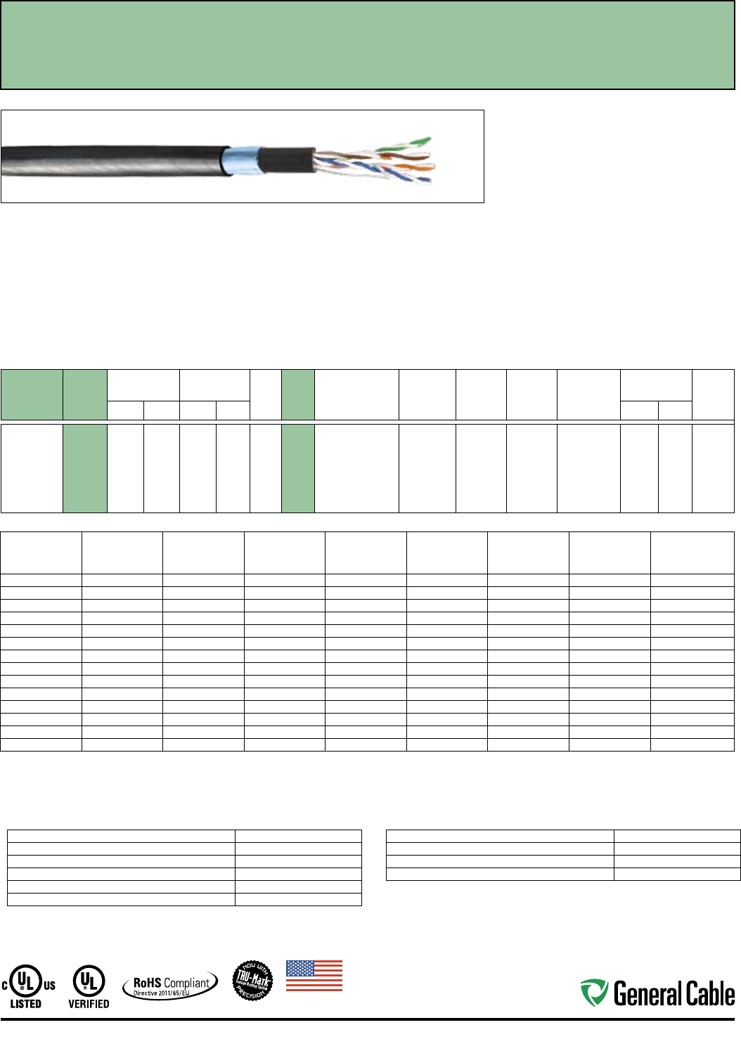
Applications:
• IEEE 802.3: 1000 BASE-T, 100 BASE-TX, 10
BASE-T, PoE, PoE+
• CDDI, Token Ring, ATM
• Broadband and Baseband Analog Video
• Armored: aerial, duct and buried installations
Compliances:
• ANSI/TIA 568-C.2
• UL 444
• RoHS Compliant Directive 2011/65/EU
• ANSI/TIA 862 (Building Automation)
• ICEA S-90-661
• ISO/IEC 11801 Ed. 2.0 (Class D)
• Telcordia (Bellcore) Specification GR-421-CORE
Water Penetration Requirements
CATALOG
NUMBER
SPEC
NUMBER
NOMINAL
O.D.
CABLE WEIGHT
MFT NO.
PAIRS
COND.
AWG
SIZE
PAIR
COLOR
CODE
INSULATION
MATERIAL
SHIELD
COVERAGE RIPCORD
JACKET
MATERIAL
JACKET
THICKNESS JACKET
COLORSINCHES mm LBS kg INCHES mm
5136101 N/A
0.340 8.636 50 23 4 24 1: Blue/White, Blue
2: Orange/White,
Orange
3: Green/White,
Green
4: Brown/White,
Brown
HDPE Aluminum
Armor
Polyester UV Abrasion-
Resistant
Polyethylene
0.032 0.813 Black
Frequency
(MHz)
Insertion Loss
(dB/100 m)
Next
(dB)
PSNext
(dB)
ACR*
(dB/100 m)
PSACR*
(dB/100 m)
ACRF
(dB/100 m)
PSACRF
(dB/100 m)
Return Loss
(dB)
max. min. min. min. min. min. min. min.
1 2.0 65.3 62.3 63.3 60.3 63.8 60.8 20.0
4 4.1 56.3 53.3 52.2 49.2 51.7 48.8 23.0
10 6.5 50.3 47.3 43.8 40.8 43.8 40.8 25.0
16 8.2 47.2 44.2 39.0 36.0 39.7 36.7 25.0
20 9.3 45.8 42.8 36.5 33.5 37.7 34.8 25.0
25 10.4 44.3 41.3 33.9 30.9 35.8 32.8 24.3
31.25 11.7 42.9 39.9 31.2 28.2 33.9 30.9 23.6
62.5 17.0 38.4 35.4 21.4 18.4 27.8 24.9 21.5
100 22.0 35.3 32.3 13.3 10.3 23.8 20.8 20.1
155 28.1 32.4 29.4 4.4 1.4 20.0 17.0 —
200 32.4 30.8 27.8 — — 17.8 14.8 —
250 36.9 29.3 26.3 — — 15.8 12.8 —
300 41.0 28.1 25.1 — — 14.3 11.3 —
350 44.9 27.1 24.1 — — 12.9 9.9 —
Values above 100 MHz are for informational purposes.
*PSACR & ACR not specified in ANSI/TIA 568-C.2.
ELECTRICAL CHARACTERISTICS
Maximum DC Resistance 9.38 Ohms/100 m @ 20˚ C
Maximum DC Resistance Unbalance, Ind Pair 4%
Maximum Mutual Capacitance 17 pF/ft @ 1 KHz
Maximum Delay Skew 45 ns/100 m
Nominal Velocity of Propagation 69% Speed of Light
Characteristic Impedence (Frequency 1-100 MHz) Ohms: 100±15
MECHANICAL CHARACTERISTICS
Maximum Pulling Force 25 lbs.
Minimum Bend Radius 1.00"
Installation Temperature Rating -30˚C to +60˚C
Operation Temperature Rating -45˚C to +80˚C
Features and Benefits:
• Protects against environmental elements that can
cause electrical performance failures
• TRU-Mark® print legend contains footage markings
from 1000' to 0'
• Prevents moisture migration
• Made in U.S.A.
• Gel-filled construction to prevent moisture
migration in underground and wet applications
Print Legend:
XXXXXX FEET CAT 5e GENERAL CABLE (F) 4PR24AWG
GENSPEED 5000 ARMORED OUTDOOR - DIR BUR UTP
CAT.5e AAAAA Pat 5767441 MO/YR
Industrial Ethernet Category 5e - 4 Pair
Outside Plant Armored Cable
Made
in
U.S.A.
18
Ethernet Industrial Automation
CATALOG
NUMBER
SPEC
NUMBER
NOMINAL
O.D.
CABLE WEIGHT
MFT NO.
PAIRS
COND.
AWG
SIZE
PAIR
COLOR
CODE
INSULATION
MATERIAL
SHIELD
COVERAGE RIPCORD
JACKET
MATERIAL
JACKET
THICKNESS JACKET
COLORSINCHES mm LBS kg INCHES mm
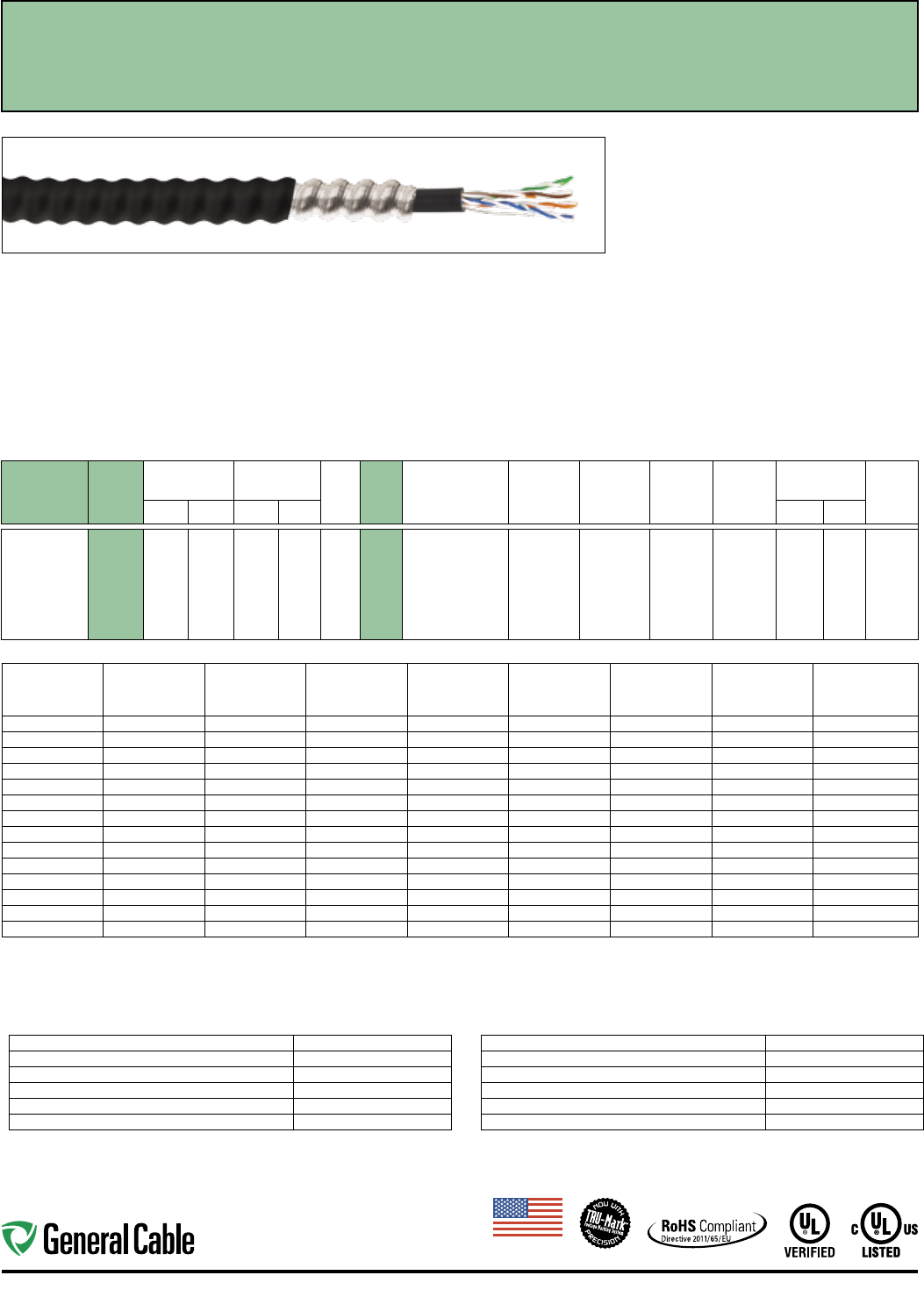
GCR1410 7508
0.270 6.858 34 15 4 24 1: Blue/White, Blue
2: Orange/White,
Orange
3: Green/White,
Green
4: Brown/White,
Brown
HDPE Unshielded Polyester Oil- and
Sunlight-
Resistant
PVC
0.032 0.813 Red,
Black
Frequency
(MHz)
Insertion Loss
(dB/100 m)
Next
(dB)
PSNext
(dB)
ACR*
(dB/100 m)
PSACR*
(dB/100 m)
ACRF
(dB/100 m)
PSACRF
(dB/100 m)
Return Loss
(dB)
max. min. min. min. min. min. min. min.
1 2.0 65.3 62.3 63.3 60.3 63.8 60.8 20.0
4 4.1 56.3 53.3 52.2 49.2 51.7 48.8 23.0
10 6.5 50.3 47.3 43.8 40.8 43.8 40.8 25.0
16 8.2 47.2 44.2 39.0 36.0 39.7 36.7 25.0
20 9.3 45.8 42.8 36.5 33.5 37.7 34.7 25.0
25 10.4 44.3 41.3 33.9 30.9 35.8 32.8 24.3
31.25 11.7 42.9 39.9 31.2 28.2 33.9 30.9 23.6
62.5 17.0 38.4 35.4 21.4 18.4 27.8 24.8 21.5
100 22.0 35.3 32.3 13.3 10.3 23.8 20.8 20.1
155 28.1 32.4 29.4 4.4 1.4 20.0 17.0 —
200 32.4 30.8 27.8 — — 17.8 14.8 —
250 36.9 29.3 26.3 — — 15.8 12.8 —
300 41.0 28.1 25.1 — — 14.3 11.3 —
350 44.9 27.1 24.1 — — 12.9 9.9 —
Values above 100 MHz are for informational purposes.
*PSACR & ACR not specified in ANSI/TIA 568-C.2.
ELECTRICAL CHARACTERISTICS
Maximum DC Resistance 9.38 Ohms/100 m @ 20˚ C
Maximum DC Resistance Unbalance, Ind Pair 3%
Maximum Mutual Capacitance 17 pF/ft @ 1 KHz
Maximum Delay Skew 45 ns/100 m
Nominal Velocity of Propagation 69% Speed of Light
Characteristic Impedence (Frequency 1-100 MHz) Ohms: 100±15
MECHANICAL CHARACTERISTICS
Nominal Cable Diameter 0.340"
Nominal Cable Weight 50 lbs.
Maximum Pulling Force 25 lbs.
Minimum Bend Radius 1.00"
Installation Temperature Rating -30˚C to +60˚C
Operation Temperature Rating -40˚C to +80˚C
Features and Benefits:
• Protects against environmental elements that can
cause electricalperformance failures
• TRU-Mark® print legend contains footage markings
from 1000' to 0'
• Prevents moisture migration
• Made in U.S.A.
Print Legend:
*** GENERAL CABLE F GCR1410 INDUSTRIAL ARMORED
CAT 5E 4PR/24AWG RISER C(UL) US CMX OUTDOOR
- CMR 75C UV RES VERIFIED (UL) ANSI/TIA-568C.2
CAT 5E AWM 21074 75C 600 V---FT4 OIL RES ODVA
ETHERNET/IP™ VEN 1293 PAT 5767441 ######## CAT 5E
Industrial Ethernet Category 5e
Interlocking Armored Cable
Applications:
• IEEE 802.3: 100 BASE-TX, 10 BASE-T, PoE, PoE+
• CDDI, Token Ring, ATM
• Broadband and Baseband Analog Video
• Voice, T1
• Harsh Industrial Environments
• ODVA EtherNet/IP™
Compliances:
• UL Verified to ANSI/TIA 568-C.2 Category 5e
• NEC/CEC Type: UL Listed CMX OUTDOOR - CMR
• NEC/CEC Type CMR (UL 1666)
• UL AWM Style 21047 (UL: 75°C, 600 V)
• UV RES per UL 444
• RoHS II Compliant (EU DIRECTIVE 2011/65/EU)
Made
in
U.S.A.
19
Industrial Automation Ethernet
CATALOG
NUMBER
SPEC
NUMBER
NOMINAL
O.D.
CABLE WEIGHT
MFT NO.
PAIRS
COND.
AWG
SIZE
PAIR
COLOR
CODE
INSULATION
MATERIAL
SHIELD
COVERAGE RIPCORD
JACKET
MATERIAL
JACKET
THICKNESS JACKET
COLORSINCHES mm LBS kg INCHES mm
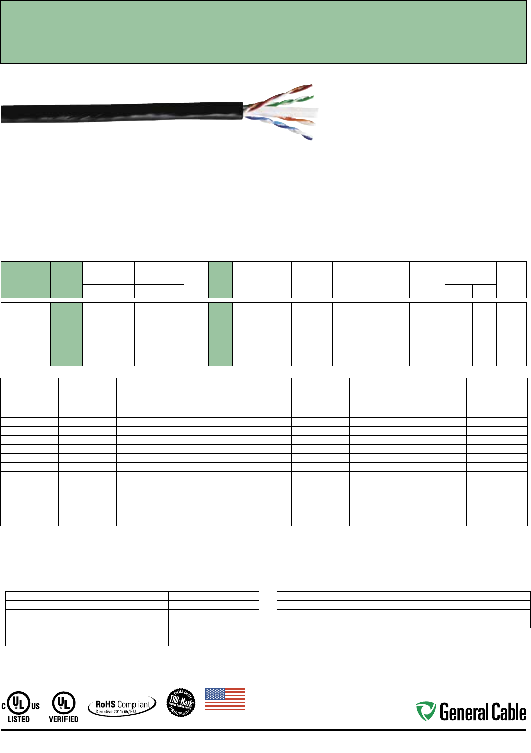
GCR1440 7509
0.270 6.858 38 17 4 23 1: Blue/White, Blue
2: Orange/White,
Orange
3: Green/White,
Green
4: Brown/White,
Brown
HDPE Unshielded Polyester Oil- and
Sunlight-
Resistant
PVC
0.032 0.813 Red,
Black
Industrial Ethernet Category 6 - 4 Pair
Unshielded Twisted Pair Cable
Applications:
• IEEE 802.3: 1000 BASE-T, 100 BASE-TX, 10
BASE-T, PoE, PoE+
• CDDI, Token Ring, ATM
• Broadband and Baseband Analog Video
• Voice, T1
• Harsh Industrial Environments
Compliances:
• UL Verified to ANSI/TIA 568-C.2 Category 6
• NEC/CEC Type: UL Listed CMX OUTDOOR - CMR
• NEC/CEC Type CMR (UL 1666)
• UV RES per UL 444
• RoHS II Compliant (EU DIRECTIVE 2011/65/EU)
Features and Benefits:
• TRU-Mark® print legend
• Third-party verified for guaranteed performance
• Industrial-grade oil- and sunlight-resistant jacket
Print Legend:
**** GENERAL CABLE * GCR1440 INDUSTRIAL CAT 6
4PR/23AWG RISER C(UL)US CMX OUTDOOR - CMR 75C
VERIFIED (UL) ANSI/TIA-568C.2 CAT-6---FT4 OIL RES UV
RES PAT 5767441 ##-## ######## CAT 6
ELECTRICAL CHARACTERISTICS
Maximum DC Resistance 8.9 Ohms/100 m @ 20˚ C
Maximum DC Resistance Unbalance, Ind Pair 3%
Maximum Mutual Capacitance 17 pF/ft @ 1 KHz
Maximum Delay Skew 45 ns/100 m
Nominal Velocity of Propagation 70% Speed of Light
Characteristic Impedence (Frequency 1-350 MHz) Ohms: 100±15
MECHANICAL CHARACTERISTICS
Maximum Pulling Force 41 lbs.
Minimum Bend Radius 1.00"
Installation Temperature Rating -10˚C to +60˚C
Operation Temperature Rating -40˚C to +75˚C
Frequency
(MHz)
Insertion Loss
(dB/100 m)
Next
(dB)
PSNext
(dB)
ACR
(dB/100 m)
PSACR
(dB/100 m)
ACRF
(dB/100 m)
PSACRF
(dB/100 m)
Return Loss
(dB)
max. min. min. min. min. min. min. min.
1 2.0 74.3 72.3 72.3 70.3 67.8 64.8 20.0
4 3.8 65.3 63.3 61.5 59.3 55.7 52.8 23.6
10 6.0 59.3 57.3 53.3 51.3 47.8 44.8 26.0
16 7.6 56.2 54.2 48.7 46.7 43.7 40.7 26.0
20 8.5 54.8 52.8 46.3 44.3 41.7 38.8 26.0
31.25 10.7 51.9 49.9 41.2 39.2 37.9 34.9 26.0
62.5 15.4 47.4 45.4 32.0 29.9 31.8 28.9 25.5
100 19.8 44.3 42.3 24.5 22.5 27.8 24.8 22.5
150 24.7 41.7 39.7 16.9 14.9 24.3 21.3 18.9
200 29.0 39.8 37.8 10.8 8.8 21.8 18.8 18.0
250 32.8 38.3 36.3 5.5 3.5 19.8 16.8 17.3
350 39.8 36.1 34.1 — — 16.9 13.9 16.3
500 48.9 33.8 31.8 — — 13.8 10.8 15.2
Values over 250 Mhz are for informational purposes.
Made
in
U.S.A.
20
Ethernet Industrial Automation
CATALOG
NUMBER
SPEC
NUMBER
NOMINAL
O.D.
CABLE WEIGHT
MFT NO.
PAIRS
COND.
AWG
SIZE
PAIR
COLOR
CODE
INSULATION
MATERIAL
SHIELD
COVERAGE RIPCORD
JACKET
MATERIAL
JACKET
THICKNESS JACKET
COLORSINCHES mm LBS kg INCHES mm
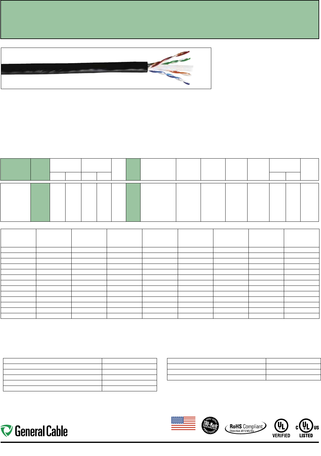
GCR1450 7504
0.270 6.858 38 17 4 23 1: Blue/White, Blue
2: Orange/White,
Orange
3: Green/White,
Green
4: Brown/White,
Brown
HDPE Unshielded Polyester Oil- and
Sunlight-
Resistant
PVC
0.032 0.813 Red,
Black
Industrial Ethernet Category 6 - 4 Pair Enhanced
Unshielded Twisted Pair Cable
Applications:
• IEEE 802.3: 1000 BASE-T, 100 BASE-TX, 10
BASE-T, PoE, PoE+
• CDDI, Token Ring, ATM
• Broadband and Baseband Analog Video
• Voice, T1
• Harsh Industrial Environments
Compliances:
• UL Verified to ANSI/TIA 568-C.2 Category 6
• NEC/CEC Type: UL Listed CMX OUTDOOR - CMR
• NEC/CEC Type CMR (UL 1666)
• UL AWM Style 21047 (UL: 75°C, 600 V)
• UV RES per UL 444
• RoHS II Compliant (EU DIRECTIVE 2011/65/EU)
Features and Benefits:
• TRU-Mark® print legend
• Third-party verified for guaranteed performance
• Industrial-grade oil- and sunlight-resistant jacket
Print Legend:
**** GENERAL CABLE * GCR1450 INDUSTRIAL CAT 6
4PR/23AWG RISER C(UL)US CMX OUTDOOR - CMR
75C VERIFIED (UL) ANSI/TIA-568C.2 CAT-6 AWM 21047
75C 600 V---FT4 OIL RES UV RES PAT 5767441 ##-##
######## CAT 6
ELECTRICAL CHARACTERISTICS
Maximum DC Resistance 8.9 Ohms/100 m @ 20˚ C
Maximum DC Resistance Unbalance, Ind Pair 3%
Maximum Mutual Capacitance 17 pF/ft @ 1 KHz
Maximum Delay Skew 45 ns/100 m
Nominal Velocity of Propagation 70% Speed of Light
Characteristic Impedence (Frequency 1-350 MHz) Ohms: 100±15
MECHANICAL CHARACTERISTICS
Maximum Pulling Force 41 lbs.
Minimum Bend Radius 1.00"
Installation Temperature Rating -20˚C to +75˚C
Operation Temperature Rating -40˚C to +75˚C
Frequency
(MHz)
Insertion Loss
(dB/100 m)
Next
(dB)
PSNext
(dB)
ACR
(dB/100 m)
PSACR
(dB/100 m)
ACRF
(dB/100 m)
PSACRF
(dB/100 m)
Return Loss
(dB)
max. min. min. min. min. min. min. min.
1 2.0 79.3 77.3 77.3 75.3 72.8 69.8 20.0
4 3.8 70.2 68.3 66.5 64.5 60.7 57.7 23.6
10 5.9 64.3 62.3 58.4 56.4 52.8 49.8 26.0
16 7.5 61.3 59.3 53.8 51.7 48.7 45.7 26.0
20 8.4 59.8 57.6 51.4 49.4 46.7 43.7 26.0
31.25 10.6 56.9 54.9 46.3 44.3 42.9 39.9 26.0
62.5 15.3 52.4 50.4 37.1 35.1 36.8 33.8 25.5
100 19.7 49.3 47.3 29.6 27.6 32.8 29.8 22.5
150 24.7 46.7 44.7 22.0 20.0 29.3 26.3 21.6
200 29.0 44.8 42.8 15.8 13.8 26.8 23.8 21.0
250 32.6 43.3 41.3 10.7 8.7 24.8 21.6 20.5
350 39.5 41.2 39.2 1.7 — 21.9 18.9 19.8
500 48.6 38.8 36.6 — — 18.8 15.8 19.0
Values over 350 Mhz are for informational purposes.
Made
in
U.S.A.
21
Industrial Automation Ethernet
Industrial Ethernet Category 6 - 4 Pair F/UTP
Shielded Twisted Pair Cable
Applications:
• IEEE 802.3: 1000 BASE-T, 100 BASE-TX, 10
BASE-T, PoE, PoE+
• CDDI, Token Ring, ATM
• Broadband and Baseband Analog Video
• Voice, T1
• Harsh Industrial Environments
• Noisy (EMI) Environments
Compliances:
• UL Verified to ANSI/TIA 568-C.2 Category 6
• NEC/CEC Type: UL Listed CMX OUTDOOR - CMR
• NEC/CEC Type CMR (UL 1666)
• UL AWM Style 21047 (UL: 75°C, 600 V)
• UV RES per UL 444
• RoHS II Compliant (EU DIRECTIVE 2011/65/EU)
Features and Benefits:
• Foil shield reduces electromagnetic interference
(EMI) for optimal performance
• Third-party verified for guaranteed performance
• TRU-Mark® print legend contains
footage markings from 1000' to 0'
• Industrial-grade oil- and sunlight-resistant jacket
Print Legend:
4 PAIR 23 AWG SCREENED TWISTED PAIR (SCTP) CABLE,
FOR HIGH SPEED DATA TRANSMISSION AND IS TESTED
TO 500 MHZ. THIS CABLE IS CMX OUTDOOR - CMR
RATED AND UL VERIFIED TO CATEGORY 6 ELECTRICALS.
CATALOG
NUMBER
SPEC
NUMBER
NOMINAL
O.D.
CABLE WEIGHT
MFT NO.
PAIRS
COND.
AWG
SIZE
PAIR
COLOR
CODE
INSULATION
MATERIAL
SHIELD
COVERAGE RIPCORD
JACKET
MATERIAL
JACKET
THICKNESS JACKET
COLORSINCHES mm LBS kg INCHES mm
GCR1452 7505
0.385 8.509 46 21 4 23 1: Blue/White, Blue
2: Orange/White,
Orange
3: Green/White,
Green
4: Brown/White,
Brown
HDPE 100% Foil Polyester Oil- and
Sunlight-
Resistant
PVC
0.032 0.813 Red,
Black
ELECTRICAL CHARACTERISTICS
Maximum DC Resistance 9.38 Ohms/100 m @ 20˚ C
Maximum DC Resistance Unbalance, Ind Pair 4%
Maximum Mutual Capacitance 17 pF/ft @ 1 KHz
Maximum Delay Skew 35 ns/100 m
Nominal Velocity of Propagation 70% Speed of Light
Characteristic Impedence (Frequency 1-350 MHz) Ohms: 100±15
MECHANICAL CHARACTERISTICS
Maximum Pulling Force 40 lbs.
Minimum Bend Radius 2.50"
Installation Temperature Rating -20˚C to +75˚C
Operation Temperature Rating -40˚C to +75˚C
Frequency
(MHz)
Insertion Loss
(dB/100 m)
Next
(dB)
PSNext
(dB)
ACR
(dB/100 m)
PSACR
(dB/100 m)
ACRF
(dB/100 m)
PSACRF
(dB/100 m)
Return Loss
(dB)
max. min. min. min. min. min. min. min.
1 2.1 74.3 72.0 72.2 70.2 67.8 64.8 20.0
4 3.8 65.3 63.3 61.5 59.5 55.8 52.8 23.6
10 5.9 59.3 57.3 53.4 51.4 47.8 44.8 26.0
16 7.5 56.2 54.2 48.8 46.8 43.7 40.7 26.0
20 8.4 54.8 52.8 46.4 44.4 41.8 38.8 26.0
31.25 10.5 51.9 49.9 41.4 39.4 37.9 34.9 25.5
62.5 15.0 47.4 45.4 32.4 30.4 31.9 28.9 23.5
100 19.1 44.3 42.3 25.2 23.2 27.8 24.8 22.5
150 23.7 41.7 39.7 18.0 16.0 24.3 21.3 18.9
200 27.6 39.8 37.8 12.2 10.2 21.8 18.8 18.0
250 31.1 38.3 36.3 7.2 5.2 19.8 19.8 17.3
300 34.3 37.1 35.1 2.9 0.9 18.3 18.3 16.8
400 40.1 35.3 33.3 — — 15.8 15.8 15.9
500 45.3 33.8 31.8 — — 13.8 13.8 15.2
Values over 350 Mhz are for informational purposes.
Made
in
U.S.A.
22
Ethernet Industrial Automation
Industrial Ethernet Category 6 - 4 Pair
Outside Plant Cable
Applications
• IEEE 802.3: 1000 BASE-T, 100 BASE-TX, 10
BASE-T, PoE, PoE+
• ANSI/TIA 854: 1000 BASE-TX
• CDDI, Token Ring, ATM
• Digital Video
• Broadband and Baseband Analog Video
• Duct and conduit installations
• Not to be used aerially or direct buried
Compliances:
• ANSI/TIA 568-C.2
• UL 444
• RoHS Compliant Directive 2011/65/EU
• ANSI/TIA 862 (Building Automation)
• ICEA S-116-732
• ICEA S-102-700
• ISO/IEC 11801 Ed. 2.0 (Class E)
• Telcordia (Bellcore) Specification
GR-421-CORE Water Penetration Requirement
Features and Benefits:
• Innovative cross-web design allowing for maximum pair
separation, increasing key electrical performance parameters
• Gel-filled construction to prevent moisture migration in
underground and wet applications
• Wide temperature range for extreme weather environments
• TRU-Mark® print legend contains footage markings from 1000'
to 0'
• Made in U.S.A.
Print Legend:
XXXXXX FEET CAT 6 GENERAL CABLE (F) 4PR23AWG GENSPEED
6000 OUTDOOR - DIR BUR UTP CAT.6 AAAAA PAT 5767441 MO/YR
CATALOG
NUMBER
SPEC
NUMBER
NOMINAL
O.D.
CABLE WEIGHT
MFT NO.
PAIRS
COND.
AWG
SIZE
PAIR
COLOR
CODE
INSULATION
MATERIAL
SHIELD
COVERAGE RIPCORD
JACKET
MATERIAL
JACKET
THICKNESS JACKET
COLORSINCHES mm LBS kg INCHES mm
7136100 N/A
0.250 6.350 32 14.5 4 23 1: Blue/White, Blue
2: Orange/White,
Orange
3: Green/White,
Green
4: Brown/White,
Brown
HDPE Unshielded Polyester UV and
Abrasion
Resistant
Zero-Halogen
Polyethylene
0.032 0.813 Black
ELECTRICAL CHARACTERISTICS
Maximum DC Resistance 9.38 Ohms/100 m @ 20˚ C
Maximum DC Resistance Unbalance, Ind Pair 4%
Maximum Mutual Capacitance 17 pF/ft @ 1 KHz
Maximum Delay Skew 45 ns/100 m
Nominal Velocity of Propagation 69% Speed of Light
Characteristic Impedence (Frequency 1-250 MHz) Ohms: 100±15
Frequency
(MHz)
Insertion Loss
(dB/100 m)
Next
(dB)
PSNext
(dB)
ACR*
(dB/100 m)
PSACR*
(dB/100 m)
ACRF
(dB/100 m)
PSACRF
(dB/100 m)
Return Loss
(dB)
max. min. min. min. min. min. min. min.
1 2.0 74.3 72.3 72.3 70.3 67.8 64.8 20.0
4 3.8 65.3 63.3 61.5 59.3 55.8 52.8 23.0
10 6.0 59.3 57.3 53.3 51.3 47.8 44.8 25.0
16 7.6 56.2 54.2 48.7 46.7 43.7 40.7 25.0
20 8.5 54.8 52.8 46.3 44.3 41.8 38.8 25.0
31.25 10.7 51.9 49.9 41.2 39.2 37.9 34.9 23.6
62.5 15.4 47.4 45.4 32.0 29.9 31.9 28.9 21.5
100 19.8 44.3 42.3 24.5 22.5 27.8 24.8 20.1
200 29.0 39.8 37.8 10.8 8.8 24.3 18.8 18.0
250 32.8 38.3 36.3 5.5 3.5 21.8 16.8 17.3
*PSACR & ACR not specified in ANSI/TIA 568-C.2.
MECHANICAL CHARACTERISTICS
Nominal Cable Diameter 0.250"
Nominal Cable Weight 32 lbs.
Maximum Pulling Force 32 lbs.
Minimum Bend Radius 1.00"
Installation Temperature Rating -30˚C to +60˚C
Operation Temperature Rating -45˚C to +80˚C
23
Industrial Automation Ethernet
FIBER TYPE
NEXTGEN®
BRAND
CORNING®
OPTICAL FIBER DESCRIPTION
Standard Loose
Tube SM
AQ SMF-28®
Ultra
Full spectrum, low water peak singlemode, ITU-T
Recommendation G.657.A1, IEC 60793-2-50 for B1.3
and B6_a1 class fibers, TIA/EIA-492CAAB and
Telcordia GR-20-CORE, Issue 3
Performance Loose
Tube SM
AT SMF-28®
Ultra
Full spectrum, high performance low water peak
singlemode with 0.35/0.25 attenuation, ITU-T
Recommendation G.657.A1, IEC 60793-2-50 for
B1.3 and B6_a1 class fibers, TIA/EIA-492CAAB and
Telcordia GR-20-CORE, Issue 3
Tight Buffer SM AP SMF-28®
Ultra
Full spectrum, low water peak singlemode with 900
µm PVC buffer, ITU-T Recommendation G.657.A1,
IEC 60793-2-50 for B1.3 and B6_a1 class fibers, TIA/
EIA-492CAAB and Telcordia GR-20-CORE, Issue 3
Long-Haul SM AL LEAF®
Fiber
Large Aeff, low water peak, NZ-DSF singlemode,
ITU-T G.655
Ultra-Bendable SM AZ ClearCurve®
ZBL
Full spectrum with best macrobending
performance, ITU-T G.652.D and ITU-T G.657.A
62.5 µm MM CG InfiniCor® 300
Fiber
1 Gb/s _< 300 m at 850 nm, OM1*
1 Gb/s _< 550 m at 1300 nm
62.5 µm MM CL InfiniCor® CL™
1000 Fiber
1 Gb/s _< 500 m at 850 nm, OM1*
1 Gb/s _< 1000 m at 1300 nm
Ultra-bendable 50 µm MM BI ClearCurve®
OM2 Fiber
10 Gb/s _< 150 m at 850 nm, OM2*
1 Gb/s _< 750 m at 850 nm
Ultra-bendable 50 µm MM BE ClearCurve®
OM3 Fiber
10 Gb/s _< 300 m at 850 nm, OM3*
1 Gb/s _< 1000 m at 850 nm
Ultra-bendable 50 µm MM BL ClearCurve®
OM4 Fiber
10 Gb/s _< 550 m at 850 nm, OM4*
1 Gb/s _< 1100 m at 850 nm
Ultra-bendable 50 µm MM BM ClearCurve®
OM4 Fiber
10 Gb/s _< 600 m at 850 nm, OM4+*
1 Gb/s _< 1100 m at 850 nm
* Designation per ISO 11801 Fiber Standards
SMF-28 Ultra is a trademark and Corning, LEAF, InfiniCor and Plus Corning Optical Fiber are registered trademarks of Corning Incorporated, Corning, NY, U.S.A.
Optical Fiber Code Cross-Reference
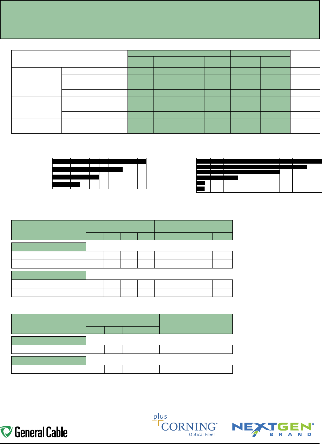
24
Ethernet Industrial Automation
0 50 100 150 200 250 300 500 550 600
Use the code in the “Fiber Type”
column to replace the XX notation
in the catalog number shown on
the catalog page. This identifies the
fiber that will be provided with the
cable choice.
The fibers in all completed cables
are tested 100% at the factory for
attenuation, and each fiber must
meet the minimum requirements
specified by the customer.
MULTIMODE FIBER SELECTION GUIDE
Optical Characteristics:
50/125 PRODUCT FAMILY 62.5/125 PRODUCT FAMILY
UNITS
OM2
Type-BI OM3
Type-BE OM4
Type-BL OM4
Type-BM OM1
Type-CG OM1
Type-CL
Maximum Finished Cable
Attenuation Coefficient
850 nm 3.0 3.0 3.0 3.0 3.5 3.5 dB/km
1300 nm 1.0 1.0 1.0 1.0 1.0 1.0 dB/km
Overfill Launch Bandwidth
850 nm 700 1500 1500 1500 200 200 MHz.km
1300 nm 500 500 500 500 500 500 MHz.km
Laser Bandwidth
850 nm 850 2000 4700 5350* 220 385 MHz.km
Gigabit Ethernet Link
Length (1 Gbps)
1000 BASE-SX (850 nm) 750 1000 1100 1100 300 500 meters
1000 BASE-LX (1300 nm) 550 550 550 550 550 1000 meters
10 Gigabit Ethernet
Length (10 Gbps)
10G BASE-SR (850 nm) 150 300 550 600 33 33 meters
* Using 3.0 dB cable attenuation and 0.7 dB connector allocation
SINGLEMODE FIBER SELECTION GUIDE
FIBER
DESCRIPTION FIBER TYPE
TYPICAL
ATTENUATION (dB/km) GIGABIT ETHERNET
DISTANCE (METERS) 10 GIGABIT ETHERNET
DISTANCE (METERS)
1310 nm 1383 nm 1550 nm 1625 nm 1310 nm 1310 nm 1550 nm
OS2 SINGLEMODE LOOSE TUBE
Premium
AQ 0.40 0.40 0.30 0.35 10,000 5,000 30,000
High Performance
AT 0.35 0.35 0.25 0.30 10,000 5,000 30,000
OS2 SINGLEMODE TIGHT BUFFER
Distribution
AP 0.65 –0.65 –10,000 5,000 30,000
Breakout
AP 1.00 –1.00 –10,000 5,000 30,000
SPECIALTY FIBERS — SINGLEMODE
FIBER
DESCRIPTION FIBER
TYPE
TYPICAL ATTENUATION (dB/km) TYPICAL APPLICATION
1310 nm 1383 nm 1550 nm 1625 nm
Singlemode (NZDS)
Large Effective Area
AL – – 0.30 0.30 DWDM
Singlemode
Bend-Insensitive
AZ 0.40 0.40 0.30 0.30 SMALL BEND RADIUS
1 Gbps Link Lengths @ 850 nm
0 100 200 300 400 500 600 700 800 900 1000
Distance (meters)
OM3/OM4, 50 micron TYPE -
BE, BL, BM
OM2, 50 micron TYPE - BI
OM1, 62.5 micron TYPE - CL
OM1, 62.5 micron TYPE - CG
OM4, 50 micron TYPE - BM
OM4, 50 micron TYPE - BL
OM3, 50 micron TYPE - BE
OM2, 50 micron TYPE - BI
OM1, 62.5 micron TYPE - CL
OM1, 62.5 micron TYPE - CG
Distance (meters)
10 Gbps Link Lengths @ 850 nm
Fiber Specification and Selection
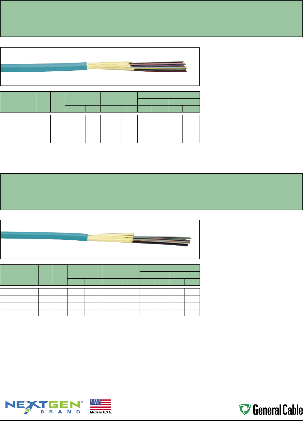
25
Industrial Automation Ethernet
CATALOG
NUMBER
FIBER
COUNT
NO. OF
SUB-
UNITS
NOMINAL CABLE
DIAMETER
NOMINAL CABLE
WEIGHT
MAXIMUM TENSILE LOAD
INSTALLATION IN-SERVICE
IN MM LBS/1000' KG/KM LBS NLBS N
XX0021PNR
2 — 0.19 5 14 20 225 1000 65 290
XX0061PNR
6 — 0.20 5 18 27 225 1000 65 290
XX0121PNR
12 — 0.25 6 24 36 320 1425 112 500
XX0241P1R
24 4 0.34 9 47 70 330 1425 112 500
XX denotes glass type.
NOTE: More fiber counts are available upon request. See Fiber Optic Catalog for complete product information.
*Not for aerial or direct burial applications.
CATALOG
NUMBER
FIBER
COUNT
NO. OF
SUB-
UNITS
NOMINAL CABLE
DIAMETER
NOMINAL CABLE
WEIGHT
MAXIMUM TENSILE LOAD
INSTALLATION IN-SERVICE
IN MM LBS/1000' KG/KM LBS NLBS N
XX0021PNU
2 — 0.17 4 12 17 225 1000 65 290
XX0061PNU
6 — 0.18 5 16 24 225 1000 65 290
XX0121PNU
12 — 0.22 6 23 34 320 1423 112 500
XX0241PNU
24 — 0.32 8 45 67 320 1423 112 500
XX denotes glass type.
NOTE: More fiber counts are available upon request. See Fiber Optic Catalog for complete product information.
*Not for aerial or direct burial applications.
Tight Buffer Distribution Riser Cable
Type OFNR, CSA FT4, Indoor*
Tight Buffer Distribution Plenum Cable
Type OFNP, CSA FT6, Indoor*
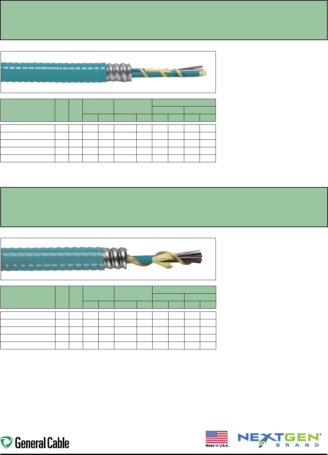
26
Ethernet Industrial Automation
CATALOG
NUMBER
FIBER
COUNT
NO. OF
SUB-
UNITS
NOMINAL CABLE
DIAMETER
NOMINAL CABLE
WEIGHT
MAXIMUM TENSILE LOAD
INSTALLATION IN-SERVICE
IN MM LBS/1000' KG/KM LBS NLBS N
XX0021PNR-ILRA
2 — 0.52 13 85 126 550 2447 165 734
XX0041PNR-ILRA
4 — 0.57 14 95 141 550 2447 165 734
XX0061PNR-ILRA
6 — 0.57 14 98 146 550 2447 165 734
XX0121PNR-ILRA
12 — 0.57 14 104 155 550 2447 165 734
XX0241PNR-ILRA
24 — 0.67 17 144 214 550 2447 165 734
XX denotes glass type.
NOTE: More fiber counts are available upon request. See Fiber Optic Catalog for complete product information.
*Not for aerial or direct burial applications.
CATALOG
NUMBER
FIBER
COUNT
NO. OF
SUB-
UNITS
NOMINAL CABLE
DIAMETER
NOMINAL CABLE
WEIGHT
MAXIMUM TENSILE LOAD
INSTALLATION IN-SERVICE
IN MM LBS/1000' KG/KM LBS NLBS N
XX0021PNU-ILPA
2 — 0.49 12 80 119 550 2447 165 734
XX0041PNU-ILPA
4 — 0.49 12 82 122 550 2447 165 734
XX0061PNU-ILPA
6 — 0.49 12 84 125 550 2447 165 734
XX0121PNU-ILPA
12 — 0.49 12 100 149 550 2447 165 734
XX0241PNU-ILPA
24 — 0.59 15 138 205 550 2447 165 734
XX denotes glass type.
NOTE: More fiber counts are available upon request. See Fiber Optic Catalog for complete product information.
*Not for aerial or direct burial applications.
Tight Buffer Distribution Interlock Armored Riser Cable
Type OFCR, CSA FT4, Indoor*
Tight Buffer Distribution Interlock Armored Plenum Cable
Type OFCP, CSA FT6, Indoor*
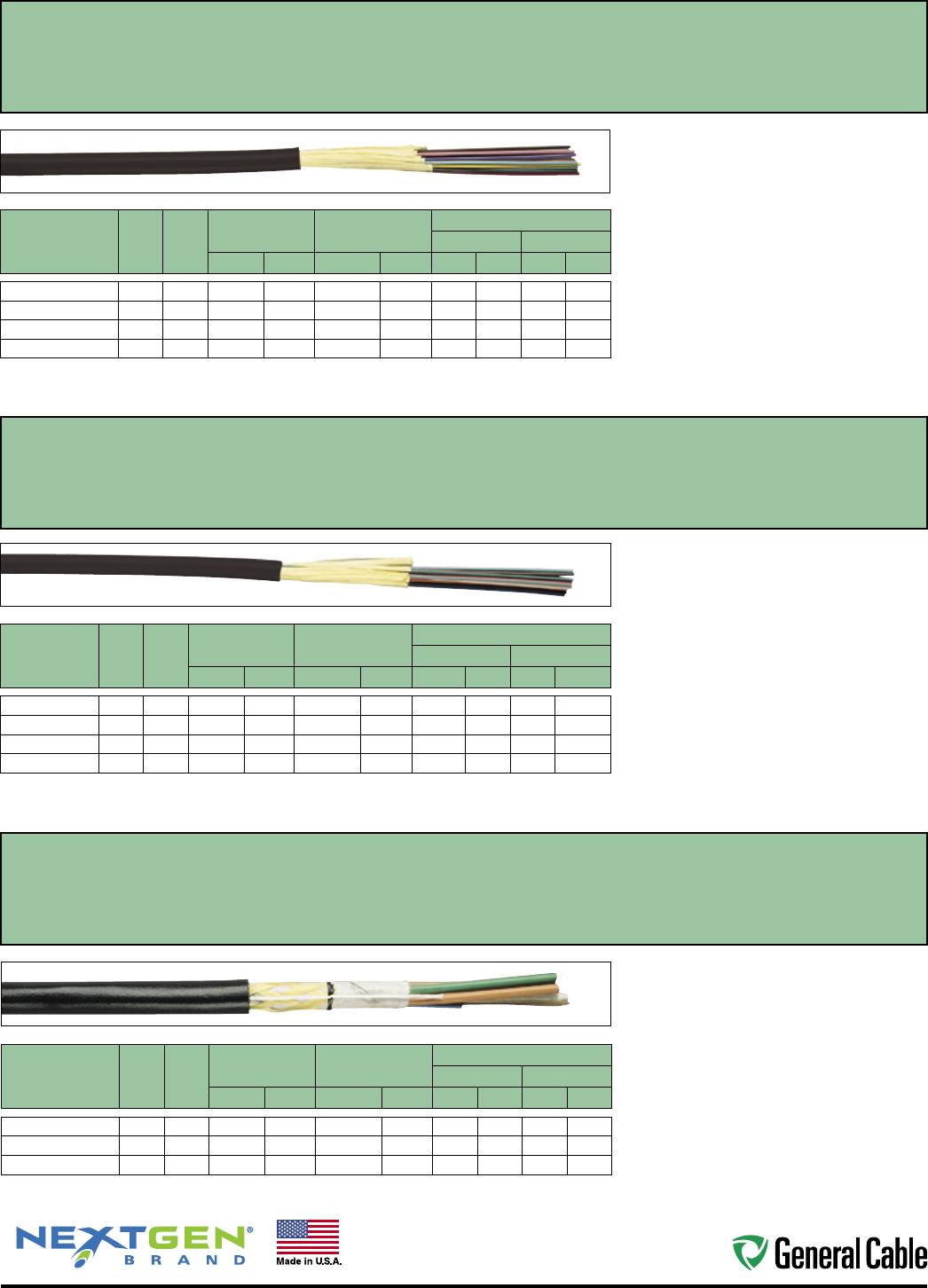
27
Industrial Automation Ethernet
CATALOG
NUMBER
FIBER
COUNT
NO. OF
LOOSE
TUBES
NOMINAL CABLE
DIAMETER
NOMINAL CABLE
WEIGHT
MAXIMUM TENSILE LOAD
INSTALLATION IN-SERVICE
IN MM LBS/1000' KG/KM LBS NLBS N
XX0064M1D-DT
6 1 0.31 8 48 71 300 1334 100 445
XX0124M1D-DT
12 2 0.31 8 47 69 300 1334 100 445
XX0244M1D-DT
24 4 0.31 8 44 65 300 1334 100 445
XX denotes glass type.
NOTE: More fiber counts are available upon request. See Fiber Optic Catalog for complete product information.
* Not for aerial or direct burial applications.
CATALOG
NUMBER
FIBER
COUNT
NO. OF
SUB-
UNITS
NOMINAL CABLE
DIAMETER
NOMINAL CABLE
WEIGHT
MAXIMUM TENSILE LOAD
INSTALLATION IN-SERVICE
IN MM LBS/1000' KG/KM LBS NLBS N
XX0021ANR.BK
2 — 0.19 5 14 20 300 1334 90 400
XX0061ANR.BK
6 — 0.20 6 18 27 320 1423 96 427
XX0121ANR.BK
12 — 0.25 6 24 36 400 1780 120 534
XX0241ANR.BK
24 — 0.34 9 47 70 320 1425 112 500
XX denotes glass type.
NOTE: More fiber counts are available upon request. See Fiber Optic Catalog for complete product information.
*Not for aerial or direct burial applications.
CATALOG
NUMBER
FIBER
COUNT
NO. OF
SUB-
UNITS
NOMINAL CABLE
DIAMETER
NOMINAL CABLE
WEIGHT
MAXIMUM TENSILE LOAD
INSTALLATION IN-SERVICE
IN MM LBS/1000' KG/KM LBS NLBS N
XX0021ANU.BK
2 — 0.17 4 11.7 17.4 300 1334 90 400
XX0061ANU.BK
6 — 0.20 5 16.0 23.8 320 1423 96 427
XX0121ANU.BK
12 — 0.23 6 22.7 33.8 400 1780 120 534
XX0241ANU.BK
24 — 0.32 8 45.0 67.0 320 1423 112 500
XX denotes glass type.
NOTE: More fiber counts are available upon request. See Fiber Optic Catalog for complete product information.
* Not for aerial or direct burial applications.
Tight Buffer Distribution Riser Cable
Type OFNR, CSA FT4, Indoor/Outdoor*
Tight Buffer Distribution Plenum Cable
Dry Water Block, Type OFNP, CSA FT6, Indoor/Outdoor*
Loose Tube Single Jacket Plenum Cable
Type OFNP, CSA FT6, Indoor/Outdoor*
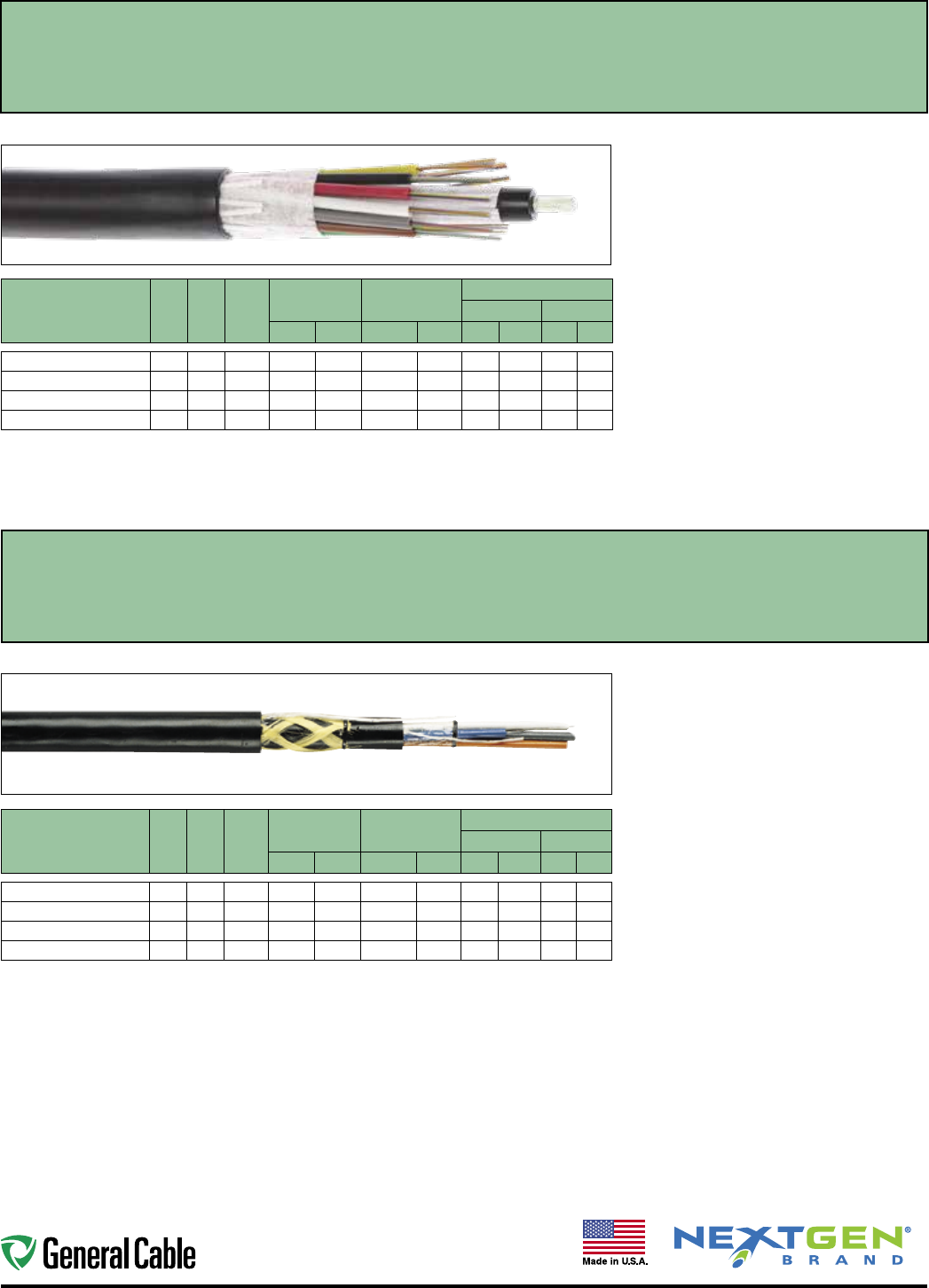
28
Ethernet Industrial Automation
CATALOG
NUMBER
FIBER
COUNT
NO. OF
LOOSE
TUBES
NO. OF
FILLERS
NOMINAL CABLE
DIAMETER
NOMINAL CABLE
WEIGHT
MAXIMUM TENSILE LOAD
INSTALLATION IN-SERVICE
IN MM LBS/1000' KG/KM LBS NLBS N
XX0124M1A-DWB
12 1 4 0.44 11.1 55 82 600 2700 180 800
XX0244M1A-DWB
24 2 3 0.44 11.1 55 82 600 2700 180 800
XX0484M1A-DWB
48 4 1 0.44 11.1 55 82 600 2700 180 800
XX0724M1A-DWB
72 6 0 0.47 12.0 66 98 600 2700 180 800
XX denotes glass type.
NOTE: More fiber counts are available upon request. See Fiber Optic Catalog for complete product information.
* Not for aerial or direct burial applications.
CATALOG
NUMBER
FIBER
COUNT
NO. OF
LOOSE
TUBES
NO. OF
FILLERS
NOMINAL CABLE
DIAMETER
NOMINAL CABLE
WEIGHT
MAXIMUM TENSILE LOAD
INSTALLATION IN-SERVICE
IN mm LBS/1000' kg/km LBS N LBS N
XX0124H1A-DWB
12 1 4 0.51 13.0 78 116 600 2700 180 800
XX0244H1A-DWB
24 2 3 0.51 13.0 78 116 600 2700 180 800
XX0484H1A-DWB
48 4 1 0.51 13.0 78 116 600 2700 180 800
XX0724H1A-DWB
72 6 0 0.54 13.7 90 134 600 2700 180 800
XX denotes glass type.
NOTE: More fiber counts are available upon request. See Fiber Optic Catalog for complete product information.
Loose Tube Single Jacket Cable
Outdoor*
Loose Tube Dual Jacket Cable
Outdoor*
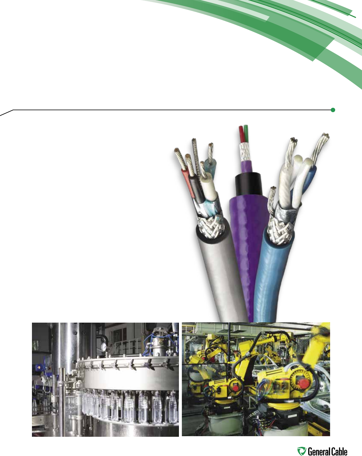
29
Industrial Communication
Protocol Cables
No matter if your design is brand new
or you are repairing an older design,
General Cable has you covered with our
comprehensive list of protocol cables.
Be certain that cabling will not cause
you downtime.
General Cable's list of protocol cables
includes CC-Link®, ControlNet®,
DataHighway®, DeviceNet®, Foundation
Fieldbus, Interbus®-S, LonWorks®, Modbus,
Profibus®, RS-485/HART/Can Open,
Seriplex® and Smart Distribution System.

30
Table of Contents
PROTOCOL
CATALOG NO. DESCRIPTION PAGE
Coax & Twinax GCR1309
RG-6 Quad Shield FR-PVC
32
GCR1309A
RG-6 Quad Shield FR-PVC Aluminum Interlock Armor
32
GCR1309CC
RG-6 Quad Shield FR-PVC With CCW® Armor
32
GCR1309F
RG-6 Quad Shield FR-PVC Flexible
32
GCR1309FC
RG-6 Quad Shield FR-PVC Flexible Tinned Copper
32
GCR1309S
RG-6 Quad Shield FR-PVC Steel Interlock Armor
32
GCR1309P
RG-6 Quad Shield FR-PVC Plenum
32
GCR1300
18 AWG 2 Pair 600 V Twinax
33
GCR1314
20 AWG 1 Pair Twinax
33
GCR1314A
20 AWG 1 Pair Twinax Aluminum Interlock Armor
33
GCR1314D
20 AWG 1 Pair Twinax Outdoor
33
GCR1314F
20 AWG 1 Pair Twinax Flexible
33
GCR1314P
20 AWG 1 Pair Twinax Plenum Outdoor
33
GCR1314S
20 AWG 1 Pair Twinax Steel Interlock Armor
33
GCR1314T
20 AWG 1 Pair Twinax Heavy-Duty
33
GCR1314ZH
20 AWG 1 Pair Twinax Low-Smoke Zero-Halogen
33
GCR1314CC
20 AWG 1 Pair Twinax With CCW® Armor
33
GCR1324
20 AWG 2 Pair Twinax
33
GCR1324A
20 AWG 2 Pair Twinax Armored
33
Multi-Paired
Shielded GCR1302
18 AWG 1 Pair Foil PVC
34
GCR1303
22 AWG 1 Pair Foil PVC
34
GCR1304
22 AWG 1 Pair Foil + Braid PVC
34
GCR1304F
22 AWG 1 Pair Foil + Braid PVC Flexible
34
GCR1315
20 AWG 3 Cond Foil + Braid PVC
34
GCR1316
20 AWG 3 Cond Foil + Braid + 18 AWG 2 Cond
34
GCR1332
16 AWG 1 Pair Foil + 20 AWG 1 Pair PVC
34
GCR1334
22 AWG 1 Pair Foil + 22 AWG 1 Pair Foil PVC
34
9899.PB02201000
22 AWG 1 Pair CCW®
35
9899.FB01801120
18 AWG 1 Pair CCW®
35
9899.FB01802120
18 AWG 2 Pair CCW®
35
9899.FB01804120
18 AWG 4 Pair CCW®
35
9899.FB01601118
16 AWG 1 Pair CCW®
35
9899.FB01602118
16 AWG 2 Pair CCW®
35
9899.FB01604118
16 AWG 4 Pair CCW®
35
GCR1305
15 AWG 1 Pair Foil + 18 AWG 1 Pair Foil + Braid PVC
36
GCR1305F
15 AWG 1 Pair Foil + 18 AWG 1 Pair Foil + Braid PVC Flexible
36
GCR1306
15 AWG 1 Pair Foil + 18 AWG 1 Pair Foil + Braid CPE
36
GCR1307
22 AWG 1 Pair Foil + 24 AWG 1 Pair Foil PVC
36
GCR1307F
22 AWG 1 Pair Foil + 24 AWG 1 Pair Foil PVC Flexible
36
GCR1308
22 AWG 1 Pair Foil + 24 AWG 1 Pair Foil CPE
36
GCR1311
16 AWG 1 Pair Ind Foil + 18 AWG 1 Pair Foil + Braid PVC
36
GCR1312
15 AWG 1 Pair Foil + 18 AWG 1 Pair Foil + Braid PVC
36
GCR1313
18 AWG 1 Pair + 20 AWG 1 Pair PVC
36

31
PROTOCOL
CATALOG NO. DESCRIPTION PAGE
Multi-Paired
Shielded
(Cont'd.)
GCR1317
18 AWG 1 Pair Foil + 20 AWG 1 Pair Foil + Braid PVC
36
C9530ZH
20 AWG 2 Pair Foil + Braid LSZH
36
C8651
22 AWG 1 Pair Foil PVC
37
C8611
22 AWG 1 Pair Foil FEP
37
GCR1330
22 AWG 1 Pair + 18 AWG 1 Pair Foil PVC
37
GCR1330A
22 AWG 1 Pair + 18 AWG 1 Pair Foil PVC Armored
37
GCR1331
22 AWG 1 Pair + 16 AWG 1 Pair Foil PVC
37
GCR1331A
22 AWG 1 Pair + 16 AWG 1 Pair Foil PVC Armored
37
GCR1333
22 AWG 1 Pair + 16 AWG 1 Pair + 12 AWG 1 Pair Foil PVC
37
GCR1333A
22 AWG 1 Pair + 16 AWG 1 Pair + 12 AWG 1 Pair Foil PVC Armored
37
GCR1318
24 AWG 3 Pair + 18 AWG 3 Cond Foil Braid
37
GCR1319
24 AWG 3 Pair Foil TPU
37
GCR1310
22 AWG 1 Pair + 1 Cond Foil + Braid
38
GCR1320
22 AWG 3 Pair Individually Foil Shielded
38
GCR1320A
22 AWG 3 Pair Individually Foil Shielded Armored
38
GCR1320S
22 AWG 3 Pair Individually Foil Shielded Steel Armored
38
GCR1320P
22 AWG 3 Pair Individually Foil Shielded Low-Smoke PVC
38
GCR1320FP
22 AWG 3 Pair Individually Foil Shielded FEP
38
C7112A
22 AWG 1 Pair Copper Braid
39
C7112AF
22 AWG 1 Pair Copper Braid Flex
39
C7114A
22 AWG 2 Pair Copper Braid
39
C7114AF
22 AWG 2 Pair Copper Braid Flex
39
C7116A
22 AWG 3 Pair Copper Braid
39
C7116AF
22 AWG 3 Pair Copper Braid Flex
39
C7118A
22 AWG 4 Pair Copper Braid
39
C7118AF
22 AWG 4 Pair Copper Braid Flex
39
C4841A
24 AWG 1 Pair Foil + Braid
39
C4842A
24 AWG 2 Pair Foil + Braid
39
C4843A
24 AWG 3 Pair Foil + Braid
39
C4844A
24 AWG 4 Pair Foil + Braid
39
C4851A
24 AWG 1 Pair Foil + Braid Plenum
40
C4852A
24 AWG 2 Pair Foil + Braid Plenum
40
GCR1301
18 AWG 2 Pair Foil + Copper Braid PVC
40
C2534A
18 AWG 1 Pair Foil PVC
40
C8123
18 AWG 1 Pair Foil Low-Smoke PVC
40
C8101
18 AWG 1 Pair Foil FEP
40
Multi-Paired
Unshielded C8661
16 AWG 1 Pair Unshielded
41
C8621
16 AWG 1 Pair Unshielded Plenum
41
C8641
22 AWG 1 Pair Unshielded
41
C8601
22 AWG 1 Pair Plenum
41
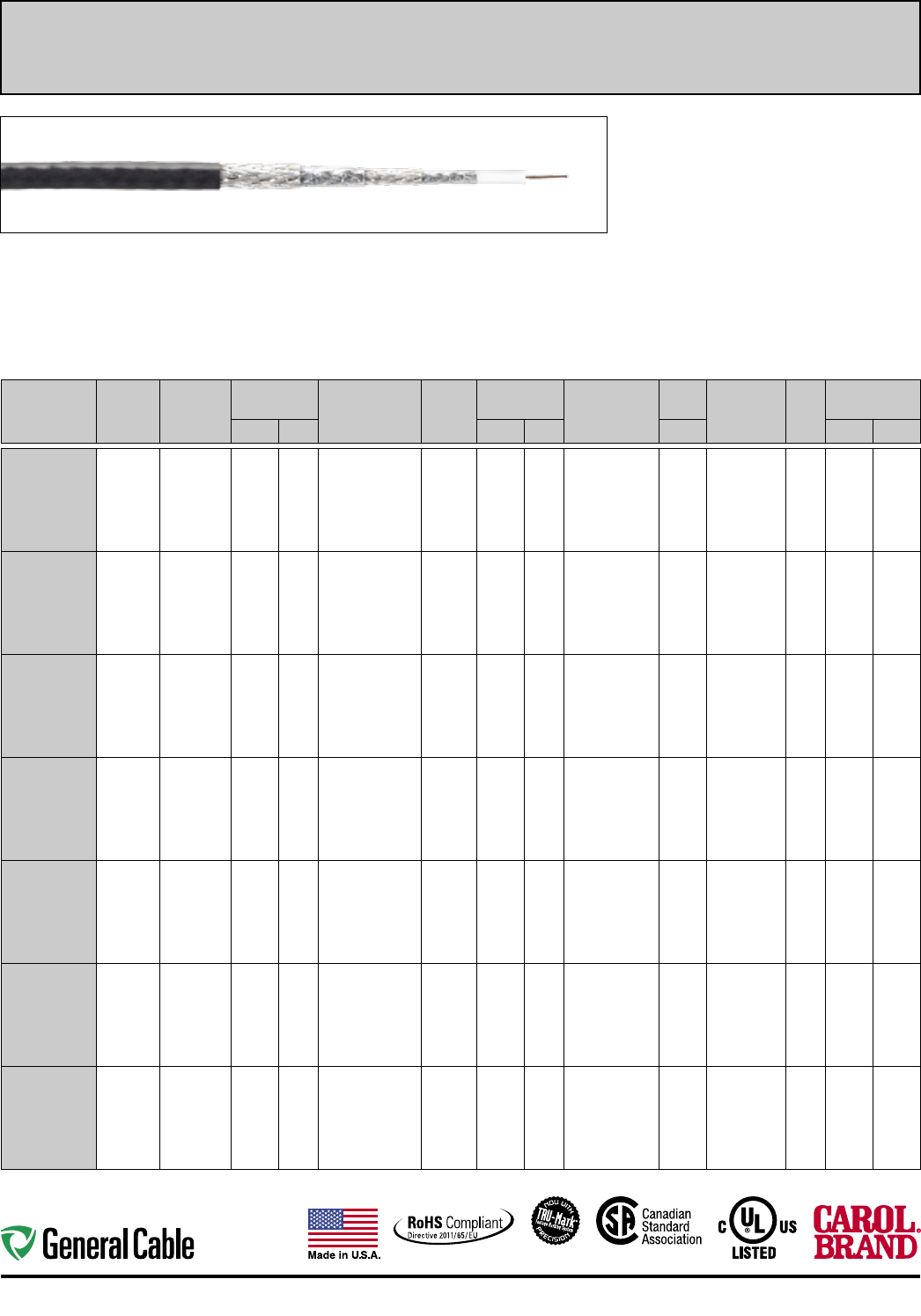
32
Industrial Protocol Communication Industrial Automation
Coax
Product Construction:
Conductors:
• Copper per ASTM B3
• Copper-clad steel per ASTM B869
Insulation:
• Gas Injected Foam Polyethylene
or Gas Injected Foam FEP
Shield:
• Aluminum quad shield or tin copper quad shield
Applications:
• ODVA ControlNet™
• Industrial type applications
• Interlocked armored (steel or aluminum)
• Continuous Corrugated Welded Aluminum Armor
(CCW) for harsh environments
Compliances:
• CL2R, CMR, CMG and CATVR
• CL2P, CMP and CATVP
• RoHS/CE
• UL or ETL
• FT4 or FT6
Packaging:
• 1000' reels
• Multiple colors available
CATALOG
NUMBER
NEC-TYPE
AWG
TYPE DCR
(Nom.)
INSULATION
TYPE
INSULATION
NOMINAL O.D. SHIELD
TYPE DCR
(Nom.)
JACKET
TYPE
COAX
NOMINAL O.D. OVERALL
ARMOR TYPE
NOM.
C A P. VELOCITY OF
PROPAGATION
(NOM.)
NOM.
IMP.
OHMS
NOMINAL
ATTENUATION
INCHES mm INCHES mm pF/FT MHz dB/100'
GCR1309
RG 6/U Type
NEC-CL2R,
CMR, CATVR &
CMG/FT4
-20C to +80C
18
Solid CCS
(28.9 Ohm)
Foam
Polyethylene
0.180 4.57 Quad Shield
100% Foil Bonded,
60% AL-Braid,
100% Foil,
40% AL-Braid
(5.2 Ohm)
PVC 0.298 7.57 N/A 16.20 83% 75 1
10
100
200
500
1000
3000
0.35
0.59
1.97
2.82
4.58
6.59
12.65
GCR1309A
RG 6/U Type
NEC-CL2R,
CMR, CATVR &
CMG/FT4
-20C to +80C
18
Solid CCS
(28.9 Ohm)
Foam
Polyethylene
0.180 4.57 Quad Shield
100% Foil Bonded,
60% AL-Braid,
100% Foil,
40% AL-Braid
(5.2 Ohm)
PVC 0.590 14.99 Aluminum Interlock
Armor/PVC
16.20 83% 75 1
10
100
200
500
1000
3000
0.35
0.59
1.97
2.82
4.58
6.59
12.65
GCR1309CC
RG 6/U Type
NEC-CL2R,
CMR, CATVR &
CMG/FT4
-20C to +80C
18
Solid CCS
(28.9 Ohm)
Foam
Polyethylene
0.180 4.57 Quad Shield
100% Foil Bonded,
60% AL-Braid,
100% Foil,
40% AL-Braid
(5.2 Ohm)
PVC 0.560 14.22 Aluminum CCW®
Armor/PVC
16.20 83% 75 1
10
100
200
500
1000
3000
0.35
0.59
1.97
2.82
4.58
6.59
12.65
GCR1309F
RG 6/U Type
NEC-CL2R,
CMR, CATVR &
CMG/FT4
-20C to +80C
20
105/40 BC
(10.5 Ohm)
Foam
Polyethylene
0.183 4.64 Quad Shield
100% Foil Bonded
60% AL-Braid,
100% Foil,
40% AL-Braid
(5.2 Ohm)
PVC 0.300 7.62 N/A 16.20 83% 75 1
10
100
200
500
1000
3000
0.25
0.81
2.64
3.83
6.30
9.32
17.90
GCR1309FC
RG 6/U Type
NEC-CL2R,
CMR, CATVR &
CMG/FT4
-20C to +80C
20
105/40 BC
(10.5 Ohm)
Foam
Polyethylene
0.183 4.64 Quad Shield
100% Foil Bonded,
60% TC-Braid,
100% Foil,
40% TC-Braid
(2.9 Ohm)
PVC 0.295 7.49 N/A 16.20 83% 75 1
10
100
200
500
1000
3000
0.25
0.81
2.64
3.83
6.30
9.32
17.90
GCR1309S
RG 6/U Type
NEC-CL2R,
CMR, CATVR &
CMG/FT4
-20C to +80C
18
Solid CCS
(28.9 Ohm)
Foam
Polyethylene
0.180 4.57 Quad Shield
100% Foil Bonded,
60% AL-Braid,
100% Foil,
40% AL-Braid
(5.2 Ohm)
PVC 0.590 14.99 Galvanized
Steel Interlock
Armor/PVC
16.20 83% 75 1
10
100
200
500
1000
3000
0.35
0.59
1.97
2.82
4.58
6.59
12.65
GCR1309P
RG 6/U Type
NEC-CL2P, CMP,
CATVP/FT6
-40C to +150C
18
Solid CCS
(28.9 Ohm)
Foam FEP 0.170 4.32 Quad Shield
100% Foil Bonded,
60% AL-Braid,
100% Foil,
40% AL-Braid
(5.2 Ohm)
PVDF 0.274 6.96 N/A 16.20 83% 75 1
10
100
200
500
1000
3000
0.36
0.66
2.10
3.10
5.00
7.30
14.28
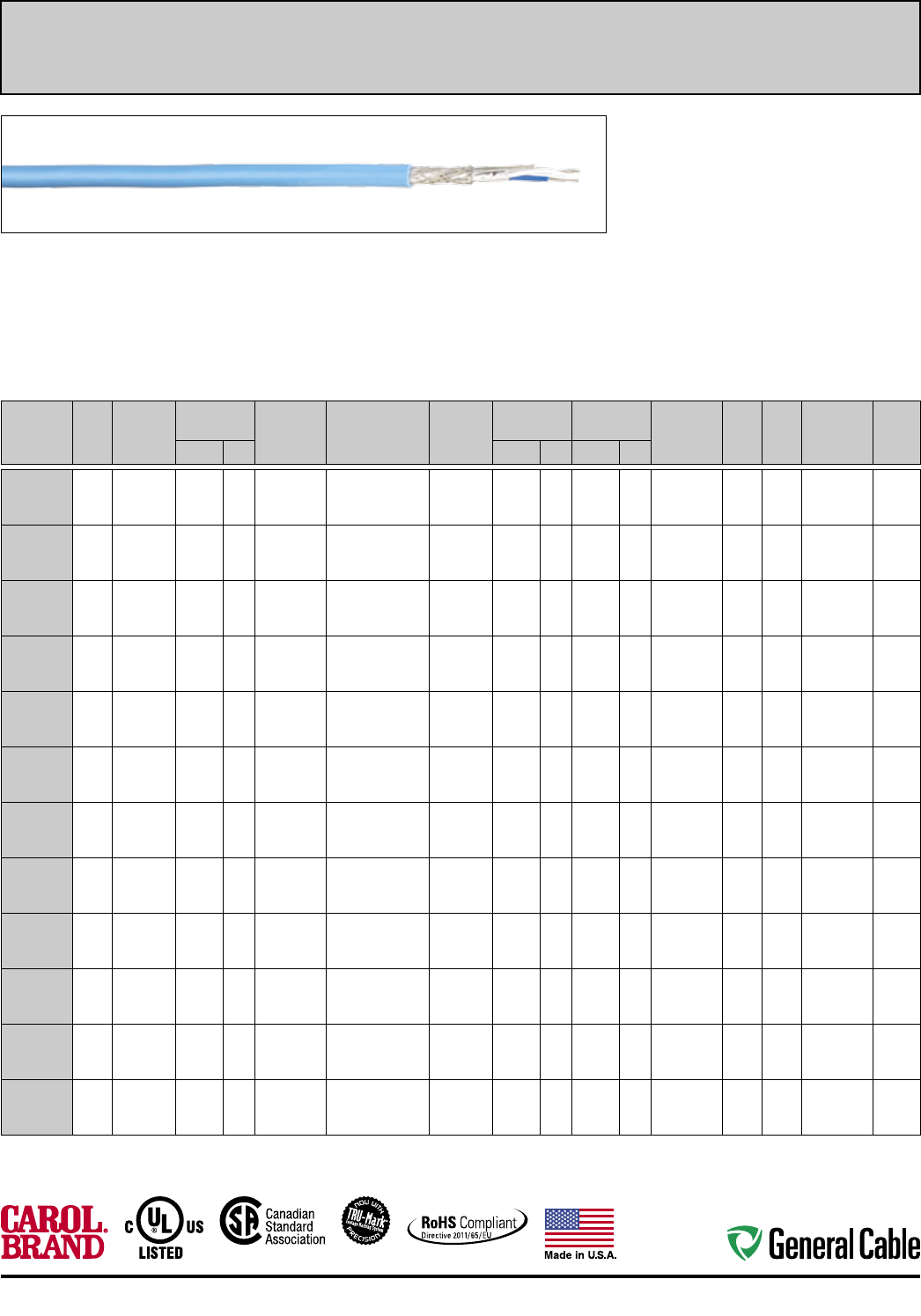
33
Industrial Automation Industrial Protocol Communication
Twinax
Product Construction:
Conductor:
• Fully annealed stranded tinned copper
per ASTM B33
Insulation:
• Premium grade Polyethylene
• Premium grade LSZH
• Premium grade FEP (GCR1314P)
• Premium grade Polyolefin (GCR1300)
Jacket:
• PVC
• FEP (GCR1314P)
• LSZH-Polyolefin (GCR1314ZH)
• Polyethelene (GCR1314D)
Shield:
• Overall foil shield and tinned copper braid
Applications:
• Data Highway and Data Highway Plus (DH+)
applications
• Interlocked armored (steel or aluminum)
• Continuous Corrugated Welded Aluminum Armor
(CCW) for harsh and HL environments
Compliances:
• UL, c(UL)
• See below for individual product compliances
CATALOG
NUMBER
NO.
OF
COND.
AWG TYPE
DCR (NOM)
PER/MFT
INSULATION
NOMINAL O.D. INSULATION
MATERIAL
SHIELD TYPE
DCR (NOM.)
JACKET
TYPE
NOM. JACKET
THICKNESS
CABLE
NOMINAL O.D. OVERALL
ARMOR
TYPE
NOM.
C A P.
pF/FT
NOM.
IMP.
OHMS
NEC
UL C(UL)US
TYPE
COND.
COLOR
CODEINCHES mm INCHES mm INCHES mm
GCR1300
2 18
7/26 TC
(6.9 Ohm)
0.108 2.74 Polyethylene 100% Flex Foil + 60%
Tinned Copper Braid
(3.2 Ohm)
PVC 0.048 1.22 0.336 8.53 N/A 19.50 78.00 TC, PLTC, ITC,
CMG FT4
-40C to +80C
Blue,
White
GCR1314
2 20
7/28 TC
(9.5 Ohm)
0.078 1.98 Polyethylene 100% Flex Foil + 60%
Tinned Copper Braid
(3.9 Ohm)
PVC 0.035 0.89 0.242 6.15 N/A 19.70 78.00 CL2, CM,
AWM 2464
-20C to +80C
Blue,
Natural
GCR1314A
2 20
7/28 TC
(9.5 Ohm)
0.078 1.98 Polyethylene 100% Flex Foil + 60%
Tinned Copper Braid
(3.9 Ohm)
PVC 0.035 0.89 0.558 14.17 Aluminum
Interlock
Armor/PVC
19.70 78.00 CL2, CM,
AWM 2464
-20C to +80C
Blue,
Natural
GCR1314D
(Gel Water Block)
2 20
7/28 TC
(9.5 Ohm)
0.078 1.98 Polyethylene 100% Flex Foil + 60%
Tinned Copper Braid
(3.9 Ohm)
Polyethylene 0.035 0.89 0.242 6.15 N/A 19.70 78.00 -60C to +80C Blue,
Natural
GCR1314F
2 20
41/30 TC
(9.5 Ohm)
0.078 1.98 Polyethylene 100% Flex Foil + 85%
Tinned Copper Braid
(3.0 Ohm)
PVC 0.035 0.89 0.242 6.15 N/A 19.70 78.00 CL2, CM,
AWM 2464
-20C to +80C
Blue,
Natural
GCR1314P
2 20
7/28 TC
(9.5 Ohm)
0.072 1.83 FEP 100% Flex Foil + 76%
Tinned Copper Braid
(3.6 Ohm)
FEP 0.016 0.41 0.203 5.16 N/A 19.70 78.00 CL 2P, CMP
-70C to +200C
Blue,
Natural
GCR1314S
2 20
7/28 TC
(9.5 Ohm)
0.078 1.98 Polyethylene 100% Flex Foil + 60%
Tinned Copper Braid
(3.9 Ohm)
PVC 0.035 0.89 0.558 14.17 Galvanized
Steel Interlock
Armor/PVC
19.70 78.00 CL2, CM,
AWM 2464
-20C to +80C
Blue,
Natural
GCR1314T
2 20
7/28 TC
(9.5 Ohm)
0.078 1.98 Polyethylene 100% Flex Foil + 60%
Tinned Copper Braid
(3.9 Ohm)
PVC 0.100 2.54 0.380 9.65 N/A 19.70 78.00 PLTC-ER, CM,
AWM 2464
-20C to +80C
Blue,
Natural
GCR1314ZH
2 20
7/28 TC
(9.5 Ohm)
0.078 1.98 LSZH 100% Flex Foil + 85%
Tinned Copper Braid
(3.0 Ohm)
LSZH 0.035 0.89 0.242 6.15 N/A 19.70 78.00 CL2, CM
-20C to +80C
Blue,
Natural
GCR1314CC
2 20
7/28 TC
(9.5 Ohm)
0.078 1.98 Polyethylene 100% Flex Foil + 60%
Tinned Copper Braid
(3.9 Ohm)
PVC 0.035 0.89 0.510 12.95 Aluminum
(CCW®)
Armor/PVC
19.70 78.00 CL2, CM,
AWM 2464
-20C to +80C
Blue,
Natural
GCR1324
2 20
7/28 TC
(9.5 Ohm)
0.078 1.98 Polyethylene 100% Flex Foil + 85%
Tinned Copper Braid
(3.9 Ohm)
PVC 0.060 1.52 0.385 9.78 N/A 19.70 78.00 CL2, CM,
AWM 2464
-20C to +80C
Blue,
Natural
GCR1324A
2 20
7/28 TC
(9.5 Ohm)
0.078 1.98 Polyethylene 100% Flex Foil + 85%
Tinned Copper Braid
(3.9 Ohm)
PVC 0.065 1.65 0.750 19.05 Aluminum
Armor/PVC
19.70 78.00 CL2, CM,
AWM 2464
-20C to +80C
Blue,
Natural
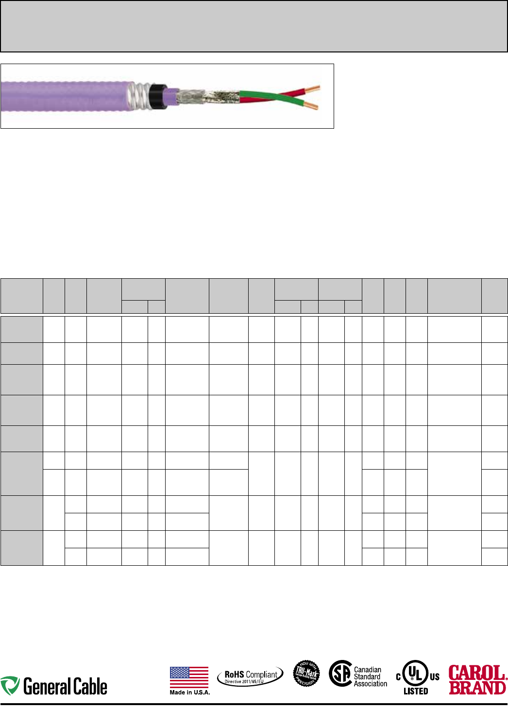
34
Industrial Protocol Communication Industrial Automation
Multi-Paired, Shielded
Product Construction:
Conductor:
• Fully annealed stranded tinned copper
per ASTM B33
• Fully annealed solid bare copper per ASTM B3
Insulation:
• Polyolefin and Foam Injected Polyolefin
• Foam HDPE
• PVC
Jacket:
• PVC
• Fluoropolymer
Shield:
• Flex Foil
• Tinned copper braid
Applications:
• High speed Profibus DP communication for use in
factory automation systems
• CC-Link applications
• SDS applications
• Interlocked armored (steel or aluminum)
• Industrial type applications
• Recognized for use in Class I and III, Divisions 1
and 2; Class II, Division 2; or Class I, Zones 1 and 2
hazardous locations per NEC Articles 501, 502, 503
and 505 (9899.PB02201000 only)
• Recognized for use in Class I, II and III, Divisions
1 and 2; or Class I, Zones 1 and 2 hazardous
locations per NEC Articles 501, 502, 503 and 505
(9899.FB01801120, 9899.FB01802120,
9899.FB01804120, 9899.FB01601118,
9899.FB01602118, 9899.FB01604118 only)
Compliances:
• UL, c(UL)
• See below for individual product compliances
CATALOG
NUMBER
NO.
OF
PAIRS
AWG
SIZE
COND.
STRAND
INSULATION
NOMINAL O.D. INSULATION
MATERIAL
SHIELD
TYPE
JACKET
TYPE
NOM. JACKET
THICKNESS
CABLE
NOMINAL O.D. VEL.
OF
PROP.
NOM.
C A P.
pF/FT
NOM.
IMP.
OHMS
NEC
TYPE
PAIRS
COLOR
CODEINCHES mm INCHES mm INCHES mm
GCR1302
1 18 7/26 TC 0.106 2.69 FR-Polyolefin 100%
Flex Foil
PVC 0.038 0.97 0.290 7.37 65% 24.0 100.0 PLTC-ER, ITC, CM,
CMG c(UL) FT4
-40C to +75C/300 V
Blue,
Orange
GCR1303
1 22 7/30 TC 0.060 1.52 Polyolefin 100%
Flex Foil
PVC 0.035 0.89 0.196 4.98 66% 22.0 100.0 CM, c(UL)
-20C to +75C/300 V
Blue,
Orange
GCR1304
1 22 Solid 0.103 2.62 Foam-Polyolefin 100%
Flex Foil + 65%
Tinned Copper
Braid
PVC 0.038 0.97 0.315 8.00 78% 8.5 150.0 PLTC, CM,
CMG c(UL), FT4,
AWM 20201
-20C to +75C/600 V
Red,
Green
GCR1304F
1 22 19/34 TC 0.110 2.79 Foam-Polyolefin 10 0 % F le x Foi l
+ 65% Tinned
Copper Braid
PVC 0.038 0.97 0.321 8.15 78% 8.5 150.0 PLTC, CM,
CMG c(UL), FT4,
AWM 20201
-20C to +75C / 600V
Red,
Green
GCR1315
3 20 7/28 TC 0.096 2.44 Foam-HDPE 100% Fle x Foi l
+ 78% Tinned
Copper Braid
PVC 0.035 0.89 0.300 7.62 78% 12.5 110.0 CM, c(UL)
-20C to +75C
Blue,
Yellow,
White
GCR1316
2 18
(Power)
7/26 TC 0.078 1.98 PVC N/A PVC 0.053 1.35 0.512 13.00 53% N/A N/A PLTC, CM, c(UL)
-20C to +75C
Black,
White
3 20
(Signal)
7/28 TC 0.096 2.44 Foam-HDPE 100% Fl ex Fo il
+ 78% Tinned
Copper Braid
78% 12.5 110.0 Blue,
Yellow,
White
GCR1332
2 16
(Power)
19/.0117 TC 0.120 3.05 PVC 100% Foil,
over each pair
PVC 0.042 1.07 0.398 10.11 53% N/A N/A CL2, CM, c(UL),
AWM 2464
-20C to +80C/300 V
Black,
Brown
20
(Data)
19/32 TC 0.126 3.20 Foam-Polyolefin 78% 12.0 120.0 Black,
White
GCR1334
2 22
(Power)
19/34 TC 0.063 1.60 PVC 100% Foil,
over each pair
PVC 0.035 0.89 0.290 7.37 53% N/A N/A CL2, CM, c(UL),
AWM 2464
-20C to +80C / 300V
Brown,
Blue
22
(Data)
19/34 TC 0.101 2.57 Foam-Polyolefin 78% 12.0 120.0 Black,
White
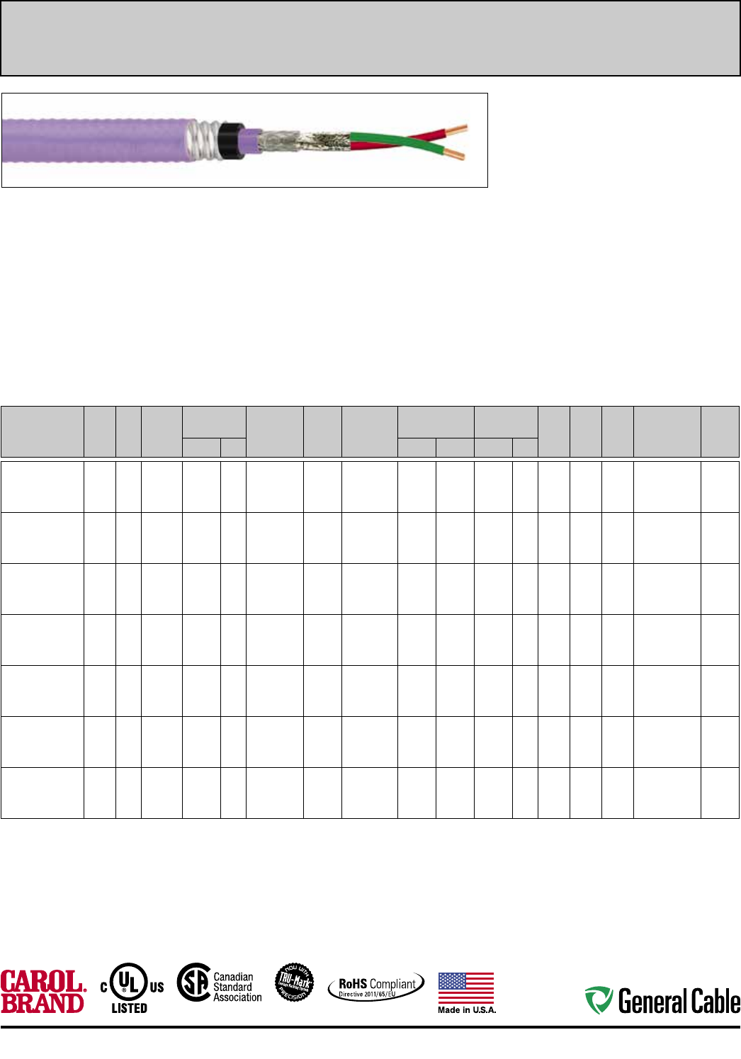
35
Industrial Automation Industrial Protocol Communication
Multi-Paired, Shielded
Product Construction:
Conductor:
• Fully annealed stranded tinned copper
per ASTM B33
• Fully annealed solid bare copper per ASTM B3
Insulation:
• Polyolefin and Foam Injected Polyolefin
• Foam HDPE
• PVC
Jacket:
• PVC
• Fluoropolymer
Shield:
• Flex Foil
• Tinned copper braid
Applications:
• High speed Profibus DP communication for use in
factory automation systems
• CC-Link applications
• SDS applications
• Interlocked armored (steel or aluminum)
• Industrial type applications
• Recognized for use in Class I and III, Divisions 1
and 2; Class II, Division 2; or Class I, Zones 1 and 2
hazardous locations per NEC Articles 501, 502, 503
and 505 (9899.PB02201000 only)
• Recognized for use in Class I, II and III, Divisions
1 and 2; or Class I, Zones 1 and 2 hazardous
locations per NEC Articles 501, 502, 503 and 505
(9899.FB01801120, 9899.FB01802120,
9899.FB01804120, 9899.FB01601118,
9899.FB01602118, 9899.FB01604118 only)
Compliances:
• UL, c(UL)
• See below for individual product compliances
CATALOG
NUMBER
NO.
OF
PAIRS
AWG
SIZE
COND.
STRAND
INSULATION
NOMINAL O.D. INSULATION
MATERIAL
SHIELD
TYPE
JACKET
TYPE
NOM. JACKET
THICKNESS
CABLE
NOMINAL O.D. VEL.
OF
PROP.
NOM.
C A P.
pF/FT
NOM.
IMP.
OHMS
NEC
TYPE
PAIRS
COLOR
CODEINCHES mm INCHES mm INCHES mm
9899.PB02201000
1 22 Solid 0.106 2.69 Fluoropolymer 65%
Tinned
Copper
Braid
Inner:
Fluoropolymer
Outer: PVC
0.038 0.97 0.940 23.88 78% 8.5 100.0 ITC-HL, 300 V,
CT Use, CSA FT4,
IEEE 1202
Red,
Green
9899.FB01801120
1 18 7/26 TC 0.106 2.69 XLPE 100%
Foil, over
ea. pair
Inner: PVC
Outer: PVC
0.040 1.01 0.640 16.13 TBD TBD 100.0 MC-HL, 600 V,
SUN RES,
DIR BUR, -40°C
Blue,
Orange
9899.FB01802120
2 18 7/26 TC 0.480 12.07 XLPE 100%
Overall
Shield
Inner: PVC
Outer: PVC
Inner:
.040
Outer:
.050
Inner:
1.01
Outer:
1.27
0.900 22.73 TBD TBD 100.0 MC-HL, 600 V,
SUN RES,
DIR BUR, -40°C
Blue,
Orange
9899.FB01804120
4 18 7/26 TC 0.570 14.48 XLPE 100%
Overall
Shield
Inner: PVC
Outer: PVC
Inner:
.040
Outer:
.050
Inner:
1.01
Outer:
1.27
0.990 25.02 TBD TBD 100.0 MC-HL, 600 V,
SUN RES,
DIR BUR, -40°C
Blue,
Orange
9899.FB01601118
1 16 7/26 TC 0.290 7.37 XLPE 100%
Overall
Shield
Inner: PVC
Outer: PVC
Inner:
.040
Outer:
.050
Inner:
1.01
Outer:
1.27
0.660 16.76 TBD TBD 100.0 MC-HL, 600 V,
SUN RES,
DIR BUR, -40°C
Blue,
Orange
9899.FB01602118
2 16 7/26 TC 0.520 13.21 XLPE 100%
Overall
Shield
Inner: PVC
Outer: PVC
Inner:
.040
Outer:
.050
Inner:
1.01
Outer:
1.27
0.940 23.88 TBD TBD 100.0 MC-HL, 600 V,
SUN RES,
DIR BUR, -40°C
Blue,
Orange
9899.FB01604118
4 16 7/26 TC 0.620 15.75 XLPE 100%
Overall
Shield
Inner: PVC
Outer: PVC
Inner:
.040
Outer:
.050
Inner:
1.01
Outer:
1.27
1.080 27.31 TBD TBD 100.0 MC-HL, 600 V,
SUN RES,
DIR BUR, -40°C
Blue,
Orange
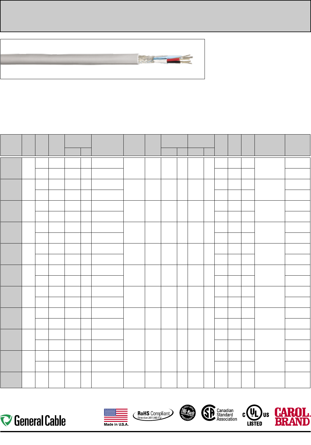
36
Industrial Protocol Communication Industrial Automation
Multi-Paired, Shielded
Product Construction:
Conductor:
• Fully annealed stranded tinned copper
per ASTM B33
Insulation
• Polyolefin and Foam Injected Polyolefin
• PVC/Nylon
• PVC
Jacket
• PVC
• CPE (GCR1308)
• LSZH (C9530ZH)
Shield
• Flex Foil
• Tinned copper braid
Applications:
• ODVA DeviceNetTM applications
• Industrial type applications
• CPE jacket for harsh industrial environments
Compliances:
• UL, c(UL)
• See below for individual product compliances
CATALOG
NUMBER
NO. OF
PAIRS
AWG
SIZE
COND.
STRAND
INSULATION
NOMINAL O.D. INSULATION
MATERIAL SHIELD
JACKET
TYPE
NOM. JACKET
THICKNESS
CABLE
NOMINAL O.D. VEL.
OF
PROP.
NOM.
C A P.
pF/FT
NOM.
IMP.
OHMS
NEC
UL C(UL)US
TYPE
PAIRS
COLOR CODEINCHES mm INCHES mm INCHES mm
GCR1305
2
15
(Power) 19/28 TC 0.107 2.72 PVC 100% Flex
Foil each
pair, o/a 65%
TC Braid
PVC 0.060 1.52 0.475 12.07
53% N/A N/A PLTC, CL2, CM
C(UL), AWM 20201
-20C to +75C/600 V
Black, Red
18
(Data) 19/30 TC 0.155 3.94 Foam-Polyolefin 76% 12.0 120.0 White, Lt. Blue
GCR1305F
2
15
(Power) 65/33 TC 0.110 2.79 PVC 100% Flex
Foil each
pair, o/a 65%
TC Braid
PVC 0.060 1.52 0.480 12.19
53% N/A N/A PLTC, CL2, CM
C(UL) , AWM 20201
-20C to +75C/600 V
Black, Red
18
(Data) 65/36 TC 0.156 3.96 Foam-Polyolefin 76% 12.0 120.0 White, Lt. Blue
GCR1306
2
15
(Power) 19/28 TC 0.107 2.72 PVC 100% Flex
Foil each
pair, o/a 65%
TC Braid
CPE 0.060 1.52 0.475 12.07
53% N/A N/A PLTC, CL2, CM
CMG C(UL)
-40C to +75C/300 V
Black, Red
18
(Data) 19/30 TC 0.155 3.94 Foam-Polyolefin 76% 12.0 120.0 White, Lt. Blue
GCR1307
2
22
(Power) 19/34 TC 0.061 1.55 PVC 100% Flex
Foil each
pair, o/a 65%
TC Braid
PVC 0.035 0.89 0.280 7.11
53% N/A N/A PLTC, CL2, CM
C(UL), AWM 20201
-20C to +75C/600 V
Black, Red
24
(Data) 19/36 TC 0.077 1.96 Foam-Polyolefin 76% 12.0 120.0 White, Lt. Blue
GCR1307F
2
22
(Power) 41/38 TC 0.060 1.52 PVC 100% Flex
Foil each
pair, o/a 65%
TC Braid
PVC 0.035 0.89 0.280 7.11
53% N/A N/A PLTC, CL2, CM
C(UL), AWM 20201
-20C to +75C/600 V
Black, Red
24
(Data) 41/40 TC 0.077 1.96 Foam-Polyolefin 76% 12.0 120.0 White, Lt. Blue
GCR1308
2
22
(Power) 19/34 TC 0.061 1.55 PVC 100% Flex
Foil each
pair, o/a 65%
TC Braid
CPE 0.040 1.02 0.285 7.24
53% N/A N/A CL2, CM
CMG C(UL)
-40C to +75C/300 V
Black, Red
24
(Data) 19/36 TC 0.077 1.96 Foam-Polyolefin 76% 12.0 120.0 White, Lt. Blue
GCR1311
2
16
(Power) 19/29 TC 0.098 2.49 PVC/Nylon 100% Flex
Foil each
pair, o/a 65%
TC Braid
PVC 0.065 1.65 0.525 13.34
55% N/A N/A TC-ER
-40C to +75C/600 V
Black, Red
18
(Data) 19/30 TC 0.178 4.52 Foam FR-Polyolefin 76% 12.0 120.0 White, Lt. Blue
GCR1312
2
15
(Power) 19/28 TC 0.105 2.67 PVC/Nylon 100% Flex
Foil each
pair, o/a 65%
TC Braid
PVC 0.060 1.52 0.460 11.68
55% N/A N/A TC-ER
-40C to +75C/600 V
Black, Red
18
(Data) 19/30 TC 0.139 3.53 Foam-FEP 79% 12.0 120.0 White, Lt. Blue
GCR1313
2
16
(Power) 19/29 TC 0.098 2.49 PVC/Nylon
Unshielded PVC 0.060 1.52 0.430 10.92
55% N/A N/A TC-ER, CSA
AWM I/II A/B FT1
-40C to +75C/600 V
Black, Red
18
(Data) 19/30 TC 0.139 3.53 FR-Polyolefin 78% 14.7 120.0 White, Lt. Blue
GCR1317
2
18
(Power) 19/30 TC 0.081 2.06 PVC 100% Flex
Foil each
pair, o/a 65%
TC Braid
PVC 0.052 1.32 0.385 9.78
55% N/A N/A PLTC, CL2,
CMG C(UL) FT4 ,
AWM 20201
-20C to +75C/600 V
Black, Red
20
(Data) 19/32 TC 0.126 3.20 Foam-Polyolefin 76% 12.0 120.0 White, Lt. Blue
C9530ZH
220
AWG 7/28 TC 0.070 1.78 LSZH
100% Flex
Foil + 85%
TC Braid
LSZH 0.042 1.07 0.35 8.89 66% 22.0 70.0
UL-CL3, PLTC-ER,
CM C(UL)
-40C to +105C
Black, Red
Black, White
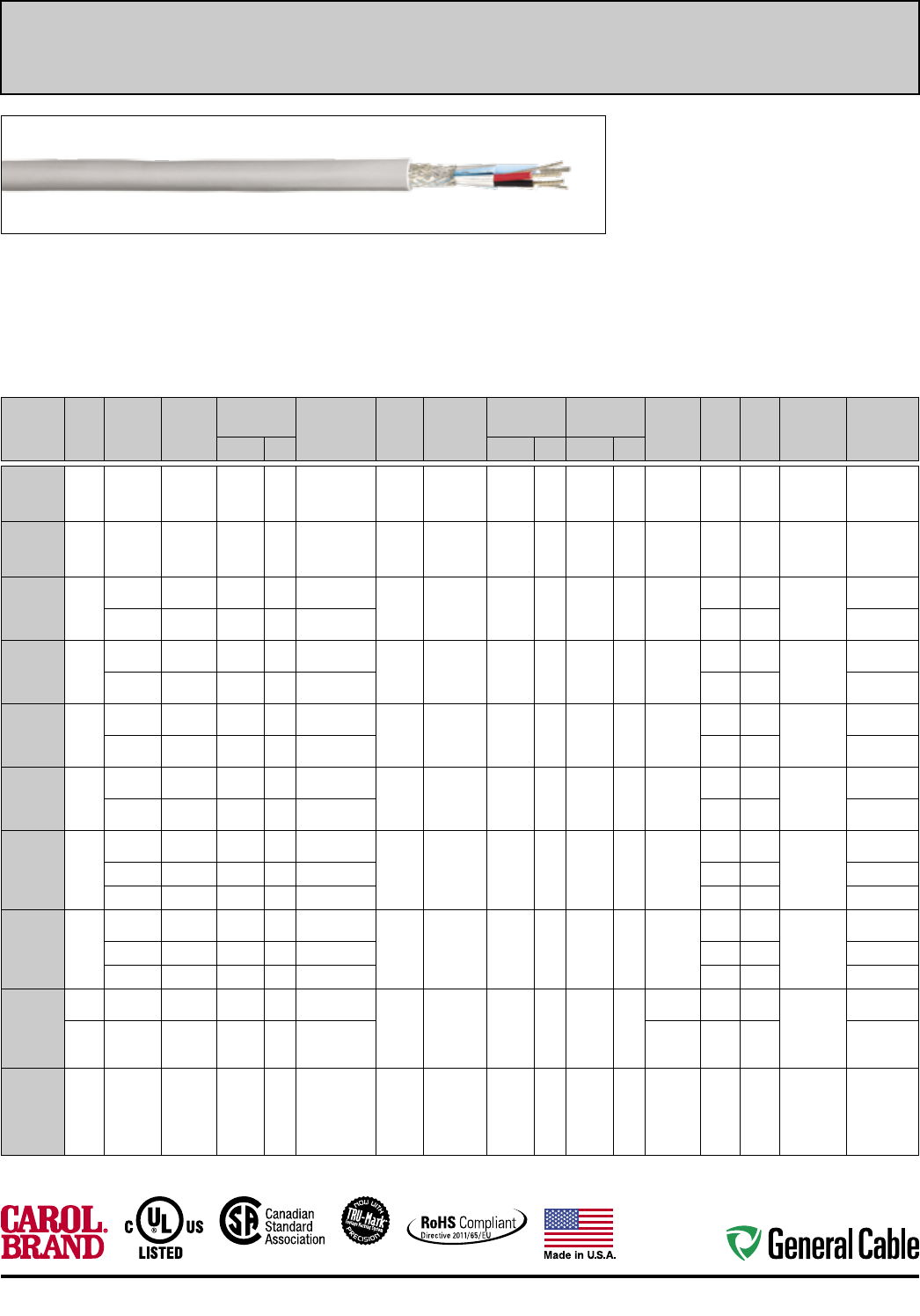
37
Industrial Automation Industrial Protocol Communication
Multi-Paired, Shielded
Product Construction:
Conductor:
• Fully annealed stranded tinned copper
per ASTM B33
Insulation:
• Foam HDPE
• PVC
• HD - Polyetheylene (GCR1319)
• SR-PVC (GCR1318)
Jacket:
• PVC
Shield:
• Overall Flexfoil shield
• Tinned copper braid (GCR1318 & GCR1319)
Applications:
• Seriplex applications
• Interbus-S applications
• Interlocked armored (steel or aluminum)
• Industrial type applications
Compliances:
• UL, c(UL)
• See below for individual product compliances
CATALOG
NUMBER
NO. OF
PAIRS
AWG
SIZE
COND.
STRAND
INSULATION
NOMINAL O.D. INSULATION
MATERIAL
SHIELD
TYPE
JACKET
TYPE
NOM. JACKET
THICKNESS
CABLE
NOMINAL O.D. OVERALL
ARMOR
TYPE
NOM.
C A P.
pF/FT
NOM.
IMP.
OHMS
NEC
UL C(UL)US
TYPE
PAIRS
COLOR
CODEINCHES mm INCHES mm INCHES mm
C8651
1 22 7/.0096 BC 0.059 1.49 Foam-HDPE
100%
Flex Foil
over all
PVC 0.030 0.76 0.195 4.95 N/A 14.5 100.0
CM, CSA,
c(UL), NEC
-20C to +75C
White/Blue,
Blue
C8611
1 22 7/.0096 BC 0.059 1.49 Foam-FEP
100%
Flex Foil
over all
Flexguard 0.015 0.38 0.160 4.06 N/A 14.5 100.0
CMP, CSA,
c(UL)
-10C to +75C
White/Blue,
Blue
GCR1330
2
18 (Power) 16/30 TC 0.096 2.44 Foam-HDPE 100%
Flex Foil
over all
PVC 0.035 0.89 0.308 7.82 N/A
11.5 120.0 CM, CL2,
AWM 20201
-20C to
+75C/600 V
Black, Red
22 (Data) 7/30 TC 0.096 2.44 Foam-HDPE 9.0 150.0 Green, White
GCR1330A
2
18 (Power) 16/30 TC 0.096 2.44 Foam-HDPE 100%
Flex Foil
over all
PVC 0.035 0.89 0.600 15.24
Aluminum
Interlock
Armor/
PVC
11.5 120.0 CM, CL2,
AWM 20201
-20C to
+75C/600 V
Black, Red
22 (Data) 7/30 TC 0.096 2.44 Foam-HDPE 9.0 150.0 Green, White
GCR1331
2
16 (Power) 26/30 TC 0.110 2.79 Foam-HDPE 100%
Flex Foil
over all
PVC 0.045 1.14 0.360 9.14 N/A
16.0 120.0 CM, CL2,
AWM 20201
-20C to
+75C/600 V
Black, Red
22 (Data) 7/30 TC 0.110 2.79 Foam-HDPE 9.0 150.0 Green, White
GCR1331A
2
16 (Power) 26/30 TC 0.110 2.79 Foam-HDPE 100%
Flex Foil
over all
PVC 0.045 1.14 0.690 17.53
Aluminum
Interlock
Armor/
PVC
16.0 120.0 CM, CL2,
AWM 20201
-20C to
+75C/600 V
Black, Red
22 (Data) 7/30 TC 0.110 2.79 Foam-HDPE 9.0 150.0 Green, White
GCR1333
3
16 (Control) 26/30 TC 0.105 2.67 Foam-HDPE 100%
Flex Foil
over all
PVC 0.040 1.02 0.434 11.02 N/A
28.0 N/A CL2,
AWM 20201
-20C to
+75C/600 V
White/Orange,
White/Blue
22 (Data) 7/30 TC 0.110 2.79 Foam-HDPE 16.0 N/A Green, White
12 (Power) 65/30 TC 0.122 3.10 PVC N/A N/A Black, Red
GCR1333A
3
16 (Control) 26/30 TC 0.105 2.67 Foam-HDPE 100%
Flex Foil
over all
PVC 0.040 1.02 0.770 19.56
Aluminum
Interlock
Armor/
PVC
28.0 N/A CL2,
AWM 20201
-20C to
+75C/600 V
White/Orange,
White/Blue
22 (Data) 7/30 TC 0.110 2.79 Foam-HDPE 16.0 N/A Green, White
12 (Power) 65/30 TC 0.122 3.10 PVC N/A N/A Black, Red
GCR1318
3/C 18 18 (Power) 7/26 TC 0.068 1.73 SR-PVC 100%
Flex Foil
+ 90%
Tinned
Copper
Braid
TPU
Polyurethane 0.035 0.89 0.333 8.46
53% N/A N/A AWM 20233
-40C to
+80C/300 V
Blue, Red,
Green/Yellow
3/P 24 24 (Data) 7/32 TC 0.048 1.22 HD-Polyethylene 66% 15.4 100.0
White, Brown,
Pink, Gray,
Yellow, Green
GCR1319
3 24 7/32 TC 0.048 1.22 HD-Polyethylene
100%
Flex Foil
+ 90%
Tinned
Copper
Braid
TPU
Polyurethane 0.035 0.89 0.275 6.99 66% 15.4 100.0
AWM 20233
-40C to
+80C/300 V
White, Brown
Pink, Gray
Yellow, Green
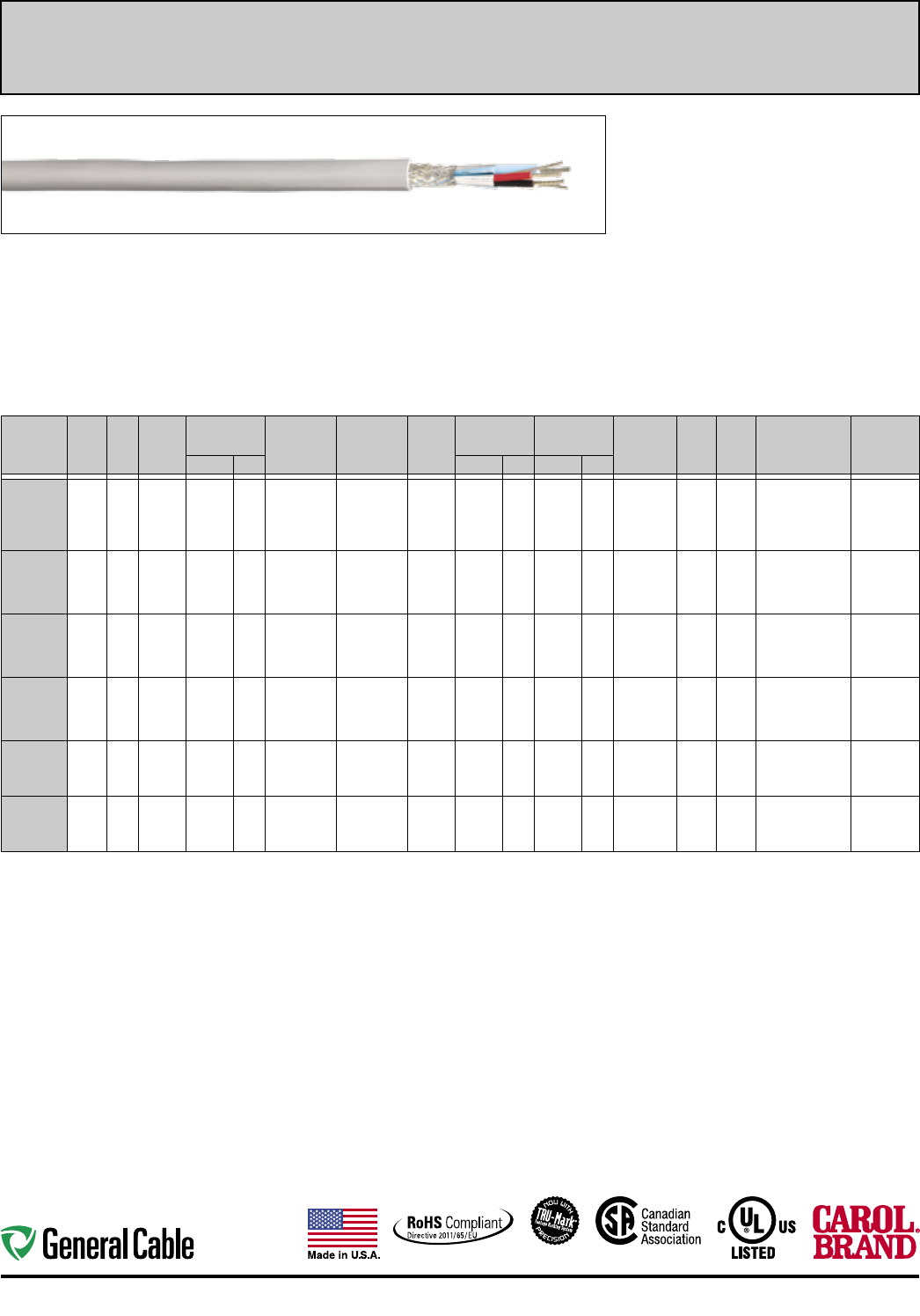
38
Industrial Protocol Communication Industrial Automation
Product Construction:
Conductor:
• Fully annealed stranded tinned copper
per ASTM B33
Insulation:
• Foam-Polyethylene
• Polypropylene
• FEP
• Foam - HDPE
• Polyolefin (GCR1301)
Jacket:
• PVC
• Flexguard
• FEP (C8101)
Shield:
• Flexfoil with tinned copper braid
• Flexfoil
Applications:
• Modbus applications
• HART® applications
• RS-485 applications
• Interlocked armored (steel or aluminum)
• Industrial type applications
Compliances:
• UL, c(UL)
• See below for individual product compliances
Multi-Paired, Shielded/Individually Shielded
INDIVIDUALLY FOIL SHIELDED
CATALOG
NUMBER
NO. OF
PAIRS
AWG
SIZE
COND.
STRAND
INSULATION
NOMINAL O.D. INSULATION
MATERIAL
SHIELD
TYPE
JACKET
TYPE
NOM. JACKET
THICKNESS
CABLE
NOMINAL O.D. OVERALL
ARMOR
TYPE
NOM.
C A P.
pF/FT
NOM.
IMP.
OHMS
NEC
UL C(UL)US
TYPE
PAIRS
COLOR
CODEINCHES mm INCHES mm INCHES mm
GCR1310
1.5 22 7/30 TC 0.090 2.29
Foam-
Polyethylene/
PVC
100% Flex Foil
+ 65% Tinned
Copper Braid
PVC 0.045 1.14 0.285 7.24 N/A 11.0 120.0
PLTC, CM CMG
C ( UL) , FT4
-20C to +75C/300 V
1/P:
White/Orange
Orange/White
1/C:
Blue/White
GCR1320
3 22 7/30 TC 0.052 1.32 Polypropylene 100% Flex Foil
over each pair PVC 0.035 0.89 0.280 7.11 N/A 30.0 50.0 CM, AWM 2919
-20C to +80C/300 V
Black, Red
Black, White
Black, Green
GCR1320A
3 22 7/30 TC 0.052 1.32 Polypropylene 100% Flex Foil
over each pair PVC 0.035 0.89 0.590 14.99
Aluminum
Interlock
Armor/PVC
30.0 50.0 CM, AWM 2919
-20C to +80C/300 V
Black, Red
Black, White
Black, Green
GCR1320S
3 22 7/30 TC 0.052 1.32 Polypropylene 100% Flex Foil
over each pair PVC 0.035 0.89 0.590 14.99
Galvanized
Steel
Interlock
Armor/PVC
30.0 50.0 CM, AWM 2919
-20C to +80C/300 V
Black, Red
Black, White
Black, Green
GCR1320P
3 22 7/30 TC 0.050 1.27 FEP 100% Flex Foil
over each pair
Flex-
Guard 0.015 0.38 0.234 5.94 N/A 30.0 50.0 CMP c(UL)
-10C to +75C/300 V
Black, Red
Black, White
Black, Green
GCR1320FP
3 22 7/30 TC 0.050 1.27 FEP 100% Flex Foil
over each pair FEP 0.015 0.38 0.230 5.84 N/A 30.0 50.0 CMP c(UL)
-70C to +200C/300 V
Black, Red
Black, White
Black, Green
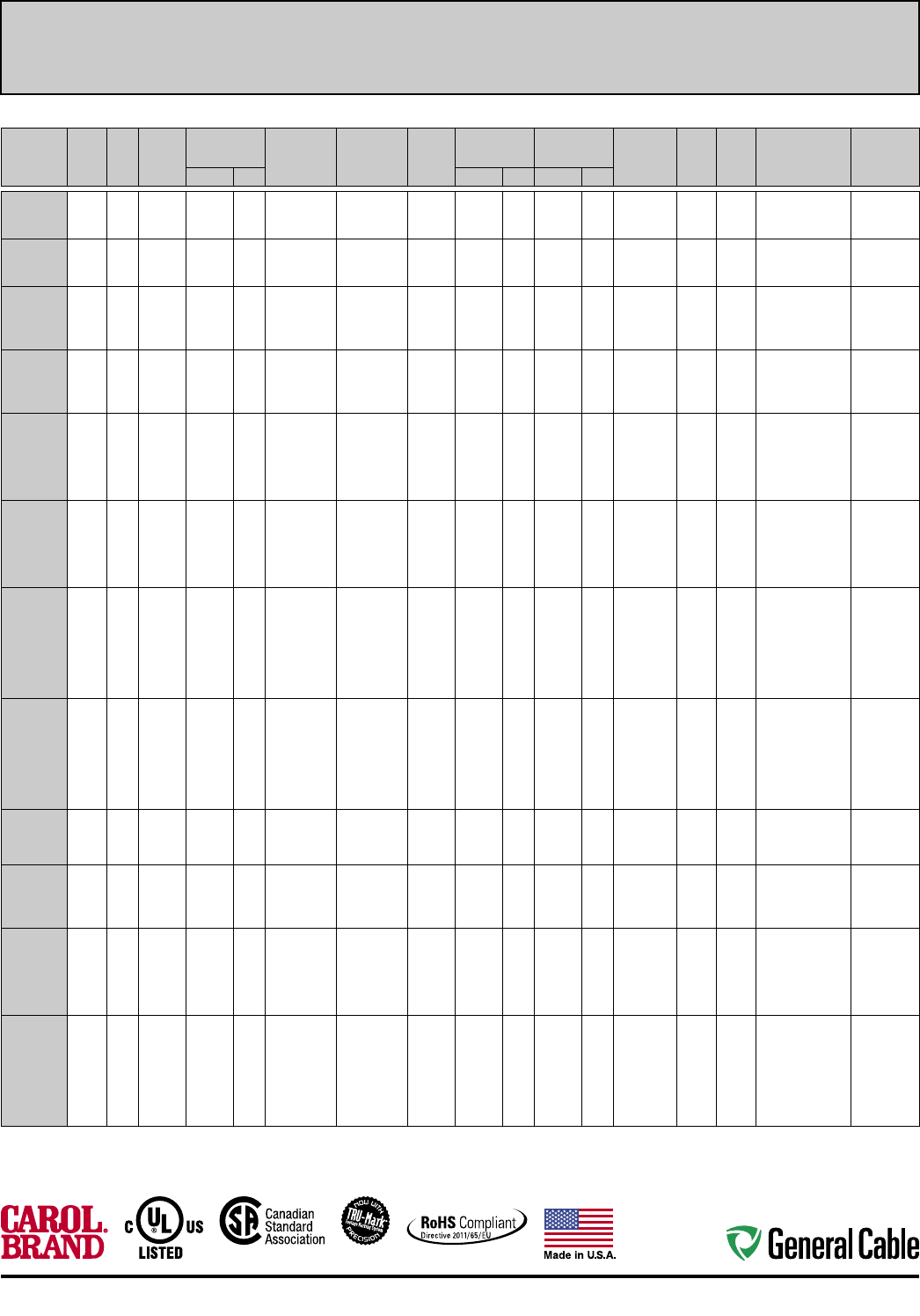
39
Industrial Automation Industrial Protocol Communication
Multi-Paired, Shielded/Individually Shielded
OVERALL FOIL AND BRAID SHIELD
CATALOG
NUMBER
NO. OF
PAIRS
AWG
SIZE
COND.
STRAND
INSULATION
NOMINAL O.D. INSULATION
MATERIAL
SHIELD
TYPE
JACKET
TYPE
NOM. JACKET
THICKNESS
CABLE
NOMINAL O.D. VEL.
OF
PROP.
NOM.
C A P.
pF/FT
NOM.
IMP.
OHMS
NEC
UL C(UL)US
TYPE
PAIRS
COLOR
CODEINCHES mm INCHES mm INCHES mm
C7112A
1 22 7/30 TC 0.078 1.98 Foam-HDPE
100% Flex Foil
+ 65% Tinned
Copper Braid
PVC 0.038 0.97 0.255 6.48 76% 11.0 120.0 PLTC, CM c(UL)
-20C to +75C/300 V
White/Blue,
Blue/White
C7112AF
1 22 26/36 TC 0.078 1.98 Foam-HDPE
100% Flex Foil
+ 65% Tinned
Copper Braid
PVC 0.038 0.97 0.255 6.48 76% 11.0 120.0 PLTC, CM c(UL)
-20C to +75C/300 V
White/Blue,
Blue/White
C7114A
2 22 7/30 TC 0.066 1.68 Foam-HDPE
100% Flex Foil
+ 65% Tinned
Copper Braid
PVC 0.045 1.14 0.330 8.38 76% 11.0 120.0 PLTC, CM c(UL)
-20C to +75C/300 V
White/Blue,
Blue/White,
White/Orange,
Orange/White
C7114AF
2 22 26/36 TC 0.066 1.68 Foam-HDPE
100% Flex Foil
+ 65% Tinned
Copper Braid
PVC 0.045 1.14 0.330 8.38 76% 11.0 120.0 PLTC, CM c(UL)
-20C to +75C/300 V
White/Blue,
Blue/White,
White/Orange,
Orange/White
C7116A
3 22 7/30 TC 0.062 1.57 Foam-HDPE
100% Flex Foil
+ 65% Tinned
Copper Braid
PVC 0.045 1.14 0.335 8.51 76% 11.0 120.0 PLTC, CM c(UL)
-20C to +75C/300 V
White/Blue,
Blue/White,
White/Orange,
Orange/White,
White/Green,
Green/White
C7116AF
3 22 26/36 TC 0.062 1.57 Foam-HDPE
100% Flex Foil
+ 65% Tinned
Copper Braid
PVC 0.045 1.14 0.335 8.51 76% 11.0 120.0 PLTC, CM c(UL)
-20C to +75C/300 V
White/Blue,
Blue/White,
White/Orange,
Orange/White,
White/Green,
Green/White
C7118A
4 22 7/30 TC 0.062 1.57 Foam-HDPE
100% Flex Foil
+ 65% Tinned
Copper Braid
PVC 0.045 1.14 0.365 9.27 76% 11.0 120.0 PLTC, CM c(UL)
-20C to +75C/300 V
White/Blue,
Blue/White,
White/Orange,
Orange/White,
White/Green,
Green/White,
White/Brown,
Brown/White
C7118AF
4 22 26/36 TC 0.062 1.57 Foam-HDPE
100% Flex Foil
+ 65% Tinned
Copper Braid
PVC 0.045 1.14 0.365 9.27 76% 11.0 120.0 PLTC, CM c(UL)
-20C to +75C/300 V
White/Blue,
Blue/White,
White/Orange,
Orange/White,
White/Green,
Green/White,
White/Brown,
Brown/White
C4841A
1 24 7/30 TC 0.072 1.83 Polyethylene
100% Flex Foil
+ 90% Tinned
Copper Braid
PVC 0.035 0.89 0.235 5.97 76% 14.6 120.0
CM, CMH c(UL),
AWM 2919
-20C to +80C/300 V
White/Blue,
Blue/White
C4842A
2 24 7/32 TC 0.072 1.83 Polyethylene
100% Flex Foil
+ 90% Tinned
Copper Braid
PVC 0.035 0.89 0.304 7.72 76% 11.7 120.0
CM, CMH c(UL),
AWM 2919
-20C to +80C/300 V
White/Blue,
Blue/White,
White/Orange,
Orange/White
C4843A
3 24 7/32 TC 0.072 1.83 Polyethylene
100% Flex Foil
+ 90% Tinned
Copper Braid
PVC 0.035 0.89 0.360 9.14 76% 11.9 120.0
CM, CMH c(UL),
AWM 2919
-20C to +80C/300 V
White/Blue,
Blue/White,
White/Orange,
Orange/White,
White/Green,
Green/White
C4844A
4 24 7/32 TC 0.072 1.83 Polyethylene
100% Flex Foil
+ 90% Tinned
Copper Braid
PVC 0.035 0.89 0.390 9.91 76% 11.9 120.0
CM, CMH c(UL),
AWM 2919
-20C to +80C/300 V
White/Blue,
Blue/White,
White/Orange,
Orange/White,
White/Green,
Green/White,
White/Brown,
Brown/White
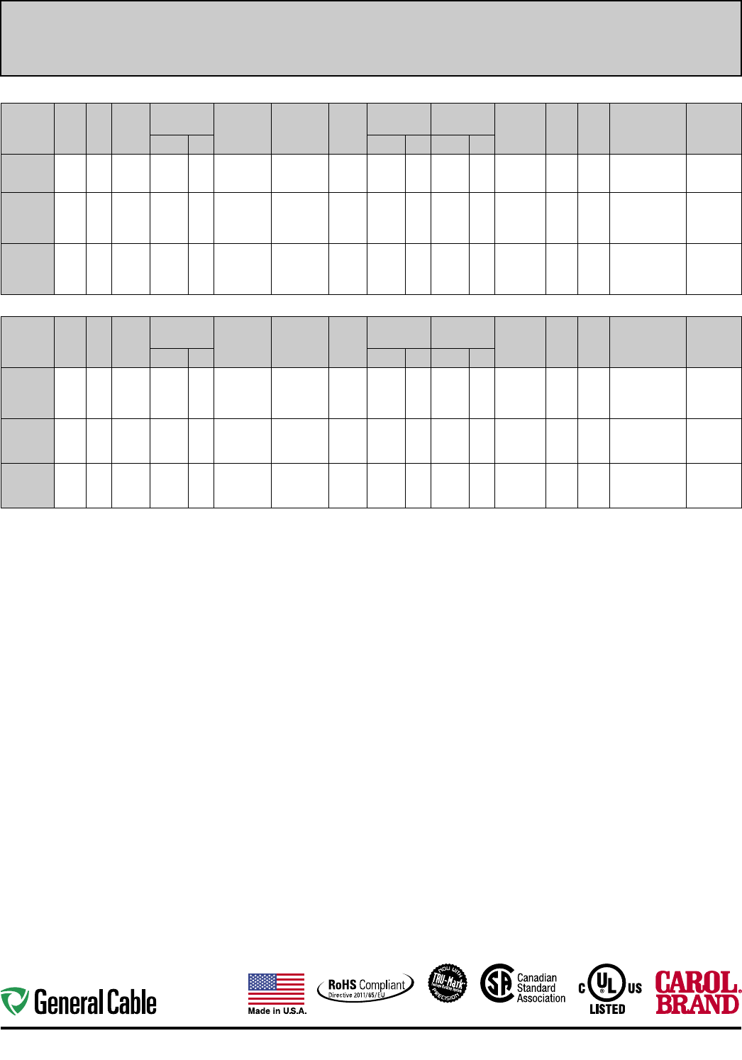
40
Industrial Protocol Communication Industrial Automation
Multi-Paired, Shielded/Individually Shielded
OVERALL FOIL AND BRAID SHIELD (CONT'D.)
CATALOG
NUMBER
NO. OF
PAIRS
AWG
SIZE
COND.
STRAND
INSULATION
NOMINAL O.D. INSULATION
MATERIAL
SHIELD
TYPE
JACKET
TYPE
NOM. JACKET
THICKNESS
CABLE
NOMINAL O.D. VEL.
OF
PROP.
NOM.
C A P.
pF/FT
NOM.
IMP.
OHMS
NEC
UL C(UL)US
TYPE
PAIRS
COLOR
CODEINCHES mm INCHES mm INCHES mm
C4851A
1 24 7/32 TC 0.076 1.93 Foam-FEP
100% Flex Foil
+ 90% Tinned
Copper Braid
Flex-
guard 0.015 0.38 0.210 5.33 78% 12.0 120.0 CMP c(UL)
-10C to +75C/300 V
White/Blue,
Blue/White
C4852A
2 24 7/32 TC 0.062 1.57 Foam-FEP
100% Flex Foil
+ 90% Tinned
Copper Braid
Flex-
guard 0.015 0.38 0.263 6.68 78% 12.0 120.0 CMP c(UL)
-10C to +75C/300 V
White/Blue,
Blue/White,
White/Orange,
Orange/White
GCR1301
2 18 7/26 TC 0.164 4.17 Polyolefin
100% Flex Foil
+ 60% Tinned
Copper Braid
(3.2 Ohm)
PVC 0.055 1.40 0.460 11.68 N/A 12.0 124.0
TC, PLTC, ITC,
CMG, FT4
-40C to +80C
Blue, White
OVERALL FOIL SHIELD
CATALOG
NUMBER
NO. OF
PAIRS
AWG
SIZE
COND.
STRAND
INSULATION
NOMINAL O.D. INSULATION
MATERIAL
SHIELD
TYPE
JACKET
TYPE
NOM. JACKET
THICKNESS
CABLE
NOMINAL O.D. VEL.
OF
PROP.
NOM.
C A P.
pF/FT
NOM.
IMP.
OHMS
NEC
UL C(UL)US
TYPE
PAIRS
COLOR
CODEINCHES mm INCHES mm INCHES mm
C2534A
1 18 16/30
TC 0.078 1.98 Polyethylene 100% Flex
Foil PVC 0.020 0.51 0.205 5.21 66% 25.5 60.0
CM, CMH c(UL),
AWM 2092
-20C to
+80C/300 V
Black,
Natural
C8123
1 18 19/30
TC 0.064 1.63 FEP 100% Flex
Foil
Flex-
guard 0.015 0.38 0.160 4.06 69% 40.0 38.0
CMP c(UL)
-10C to
+75C/300 V
Black, Red
C8101
1 18 19/30
TC 0.064 1.63 FEP 100% Flex
Foil FEP 0.015 0.38 0.160 4.06 69% 40.0 38.0
CMP c(UL)
-70C to
+200C/300 V
Black, Red
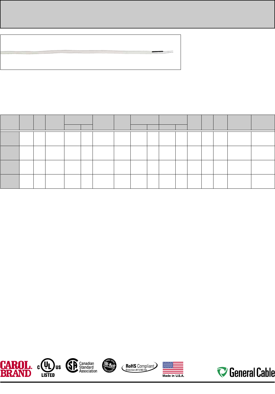
41
Industrial Automation Industrial Protocol Communication
Multi-Paired, Unshielded
Product Construction:
Conductor:
• Fully annealed stranded tinned copper
or bare copper per ASTM B33
Insulation:
• PVC
• HDPE
• Flexguard
Jacket:
• PVC
• Flexguard
Applications:
• LonWorks applications
• Industrial type applications
Compliances:
• UL, c(UL)
• See below for individual product compliances
CATALOG
NUMBER
NO. OF
PAIRS
AWG
SIZE
COND.
STRAND
INSULATION
NOMINAL O.D. INSULATION
MATERIAL
JACKET
TYPE
NOM. JACKET
THICKNESS
CABLE
NOMINAL O.D. VEL.
OF
PROP.
NOM.
C A P.
pF/FT
NOM.
IMP.
OHMS
NEC
UL C(UL)US
TYPE
PAIRS
COLOR CODEINCHES mm INCHES mm INCHES mm
C8661
1 16 19/.0117 TC 0.088 2.23 PVC PVC 0.032 0.81 0.246 6.24 69% 30.0 65.0
CM, CL2,
CSA FT4
(-20C to +75C)
Black, White
C8621
1 16 19/.0117 TC 0.088 2.23 Flexguard Flexguard 0.015 0.38 0.182 4.57 69% 35.0 55.0
CL2P, CMP,
CSA FT6
(-10C to +75C)
Black, White
C8641
1 22 7/.0096 BC 0.049 1.24 HDPE PVC 0.022 0.56 0.145 3.68 69% 17.0 100.0 CM, CSA FT4
(-20C to +75C) White/Blue, Blue
C8601
1 22 7/.0096 BC 0.049 1.24 Flexguard Flexguard 0.015 0.38 0.130 3.30 69% 17.0 100.0 CMP, CSA FT6
(-10C to +75C) White/Blue, Blue
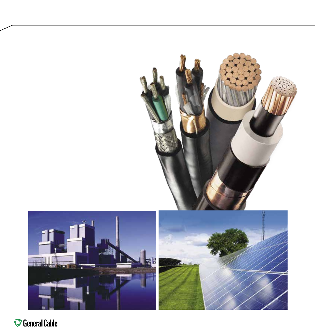
42
Industrial Instrumentation
and Control
Generating power and enhancing
control. General Cable is recognized
worldwide for leadership and breadth
in power, control and instrumentation
cable products. Our solutions span a
very broad range of manufacturing
and industrial distribution applications,
engineered to perform reliably in the
most demanding environments. Our
industry-certified cables for industrial
instrumentation, power and control
serve the full spectrum of customer
requirements. As demand drives
investment in renewable wind, solar
and hydroelectric energy sources,
General Cable is there, a pioneer and
trusted provider.

43
SPEC NO. DESCRIPTION PAGE
Instrumentation 2100 FREP® FR-EPR/CPE, Instrumentation, Shielded 600 V, 44
UL Type TC, Overall Shielded Pairs/Triads
2150 FREP FR-EPR/CPE, Instumentation, Shielded 600 V, 45
UL Type TC, Individual and Overall Shielded Pairs
2200 FREP FR-EPR/CPE, Instrumentation, Shielded 600 V, 46
UL Type TC, Individual and Overall Shielded Triads
2600 GenFree® XLPE/LSZH, Instrumentation, Shielded 600 V, 47
UL Type TC-LS, Overall Shielded Pairs/Triads
2625 GenFree XLPE/LSZH, Instrumentation, Shielded 600 V, 48
UL Type TC-LS, Individual and Overall Shielded Pairs
2650 GenFree XLPE/LSZH, Instrumentation, Shielded 600 V, 49
UL Type TC-LS, Individual and Overall Shielded Triads
Control 4300 FREP FR-EPR/CPE, Control, Unshielded 600 V, 50
UL Type TC-ER - E-2 Color Code
4310 FREP FR-EPR/CPE, Control, Unshielded 600 V, 51
UL Type TC-ER - E-1 Color Code
4325 FREP FR-EPR/CPE, Control, Shielded 600 V, 52
UL Type TC-ER, Overall Shielded - E-2 Color Code
4350 FREP FR-EPR/CPE, Low-Voltage Power, Unshielded 53
600 V, UL Type TC-ER - Method 4 Color Code
4900 GenFree XLPE/LSZH, Control 600 V, UL Type TC-LS-ER - E-2 54
Color Code
4925 GenFree XLPE/LSZH, Control, Shielded 600 V, UL Type 55
TC-LS-ER, Overall Shielded - E-2 Color Code
4950 GenFree XLPE/LSZH, Low-Voltage Power, Unshielded 600 V, 56
UL Type TC-LS-ER - Method 4 Color Code
4775 TC-Flex™ Tray Cable 18 AWG - 16 AWG, UL Type WTTC 1000 V 57
or Type TC-ER 600 V or Type MTW and c(UL) CIC/TC 600 V FT4
or CSA AWM 90°C 1000 V, Flexible, Oil Res I/II, Sunlight- and
Torsion-Resistant, Flame-Retardant, -40°C to +90°C
4780 TC-Flex Tray Cable 14 AWG - 10 AWG, UL Type WTTC 1000 V 58
or Type TC-ER 600 V or Type MTW and c(UL) CIC/TC 600 V FT4
or CSA AWM 90°C 1000 V, Flexible, Oil Res I/II, Sunlight- and
Torsion-Resistant, Flame-Retardant, -40°C to +90°C
4785 TC-Flex Tray Cable 18 AWG - 16 AWG, UL Type WTTC 1000 V 59
or Type TC-ER 600 V or Type MTW and c(UL) CIC/TC 600 V FT4
or CSA AWM 90°C 1000 V, Flexible, Oil Res I/II, Sunlight- and
Flame-Retardant, -40°C to +90°C
4790 TC-Flex Tray Cable 14 AWG - 2 AWG, UL Type WTTC 1000 V 60
or Type TC-ER 600 V or Type MTW and c(UL) CIC/TC 600 V FT4
or CSA AWM 90°C 1000 V, Flexible, Oil Res I/II, Sunlight- and
Flame-Retardant, -40°C to +90°C
Table of Contents
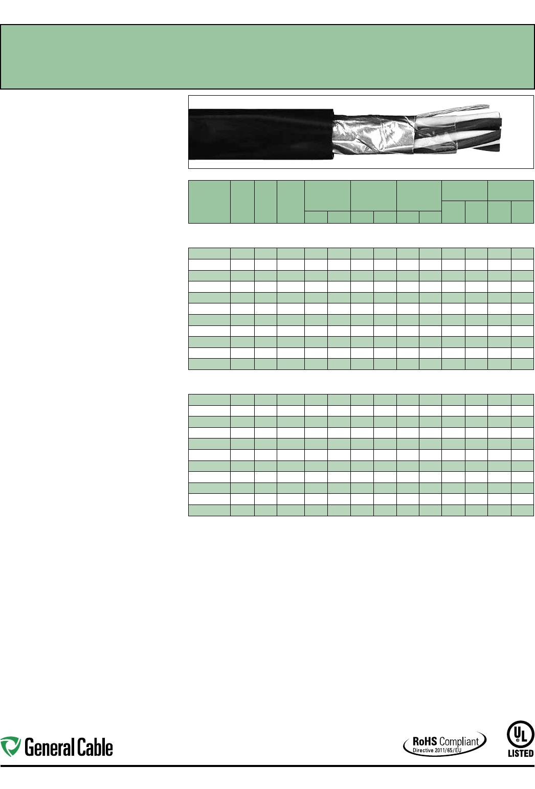
Industrial Automation
44
SPEC 2100
November, 2014
Product Construction:
Conductor:
• 18 AWG and 16 AWG tinned, annealed copper per
ASTM B33
• Class B stranding per ASTM B8
Insulation:
• Flame-Retardant Ethylene Propylene Rubber
(FR-EPR) Type II
• Color-coded per ICEA Method 1: Pairs - black
and white; Triads - black, white and red. One
conductor in each pair or triad is printed alpha-
numerically for easy identification
Shield:
Overall shielded pairs/triads
• Overall shield is Flexfoil® aluminum/polymer in
contact with stranded tinned copper drain wire
Jacket:
• Lead-free, flame-retardant, thermoplastic
Chlorinated Polyethylene (CPE)
Print:
• GENERAL CABLE® (PLANT OF MFG) FREP®
XX/PS/TS XXAWG EPR/CPE SHIELDED
(UL) TYPE TC 90˚C WET OR DRY 600 V DIR
BUR SUN RES DAY/MONTH/YEAR OF MFG
SEQUENTIAL FOOTAGE MARK
Applications:
• In free air, raceways or direct burial
• In wet or dry locations
• Permitted for use in Class I, Division 2 industrial
hazardous locations per NEC
Features:
• Rated at 90˚C wet or dry
• Ripcord applied to all cables with jacket thickness
of 60 mils or less
• Excellent physical, thermal and electrical
properties
• Excellent moisture resistance
• Excellent resistance to compression cuts and heat
deformation
• Excellent flame resistance—burns to an ash; does
not exhibit thermoplastic drip
• Low coefficient of friction for easy pulling
• Sunlight- and weather-resistant
• Excellent low temperature cold bend
characteristics
• Meets cold bend test at -40˚C
Compliances:
Industry Compliances:
• UL 1277 Type TC, UL File # E57179
• UL 1581
• ICEA S-73-532/NEMA WC57
• RoHS Compliant
Flame Test Compliances:
• UL 1581/UL 2556 VW-1
• UL 1685 Vertical Flame Test
• IEEE 383
• IEEE 1202
• CSA FT4
• ICEA T-29-520
Other Compliances:
• EPA 40 CFR, Part 261 for leachable lead
content per TCLP
• OSHA Acceptable
Packaging:
• Material cut to length and shipped on
non-returnable wood reels
FREP
®
FR-EPR/CPE, Instrumentation, Shielded
600 V, UL Type TC, Overall Shielded Pairs/Triads
CATALOG
NUMBER
NO. OF
PAIRS/
TRIADS
COND.
SIZE
(AWG)
COND.
STRAND
MINIMUM AVG.
INSULATION
THICKNESS
MINIMUM AVG.
JACKET
THICKNESS
NOMINAL
CABLE O.D.
COPPER
WEIGHT NET WEIGHT
LBS/
1000 FT kg/km
LBS/
1000 FT kg/kmINCHES mm INCHES mm INCHES mm
OVERALL SHIELDED PAIRS/TRIADS
18 AWG CONDUCTORS
287650* 118 7W 0.025 0.64 0.045 1.14 0.300 7.6 2 13 19 42 63
325250* 1 TRI 18 7W 0.025 0.64 0.045 1.14 0.315 8.00 18 26 53 79
337010* 218 7W 0.025 0.64 0.045 1.14 0.420 10.67 23 34 75 112
337020* 418 7W 0.025 0.64 0.045 1.14 0.490 12.45 44 65 117 174
337030* 818 7W 0.025 0.64 0.060 1.52 0.675 17.15 86 127 224 333
337040* 12 18 7W 0.025 0.64 0.060 1.52 0.775 19.69 127 189 305 454
294580* 16 18 7W 0.025 0.64 0.080 2.03 0.925 23.50 169 251 425 632
337050* 20 18 7W 0.025 0.64 0.080 2.03 1.025 26.04 210 313 510 759
337060* 24 18 7W 0.025 0.64 0.080 2.03 1.10 5 28.07 252 375 604 899
337070* 36 18 7W 0.025 0.64 0.080 2.03 1.360 34.54 377 561 865 1287
337080* 50 18 7W 0.025 0.64 0.080 2.03 1.555 39.50 523 778 114 4 1703
OVERALL SHIELDED PAIRS/TRIADS
16 AWG CONDUCTORS
314960 116 7W 0.025 0.64 0.045 1.14 0.320 8.13 18 28 52 77
279690 1 TRI 16 7W 0.025 0.64 0.045 1.14 0.335 8.51 26 39 66 98
283170* 216 7W 0.025 0.64 0.045 1.14 0.460 11.68 36 54 95 141
283180* 416 7W 0.025 0.64 0.060 1.52 0.560 14.22 69 103 171 254
337090* 816 7W 0.025 0.64 0.060 1.52 0.740 18.80 135 201 294 438
283190* 12 16 7W 0.025 0.64 0.080 2.03 0.900 22.86 202 300 438 652
337100* 16 16 7W 0.025 0.64 0.080 2.03 1.015 25.78 268 399 560 833
337110* 20 16 7W 0.025 0.64 0.080 2.03 1.130 28.70 335 498 680 1012
337120* 24 16 7W 0.025 0.64 0.080 2.03 1.215 30.86 401 597 807 1201
337130* 36 16 7W 0.025 0.64 0.080 2.03 1.505 38.23 601 894 1160 1726
337140* 50 16 7W 0.025 0.64 0.080 2.03 2.095 53.21 834 1241 1702 2533
Dimensions and weights are nominal; subject to industry tolerances.
* Non-stock item; minimum runs apply. Please consult Customer Service for price and delivery.
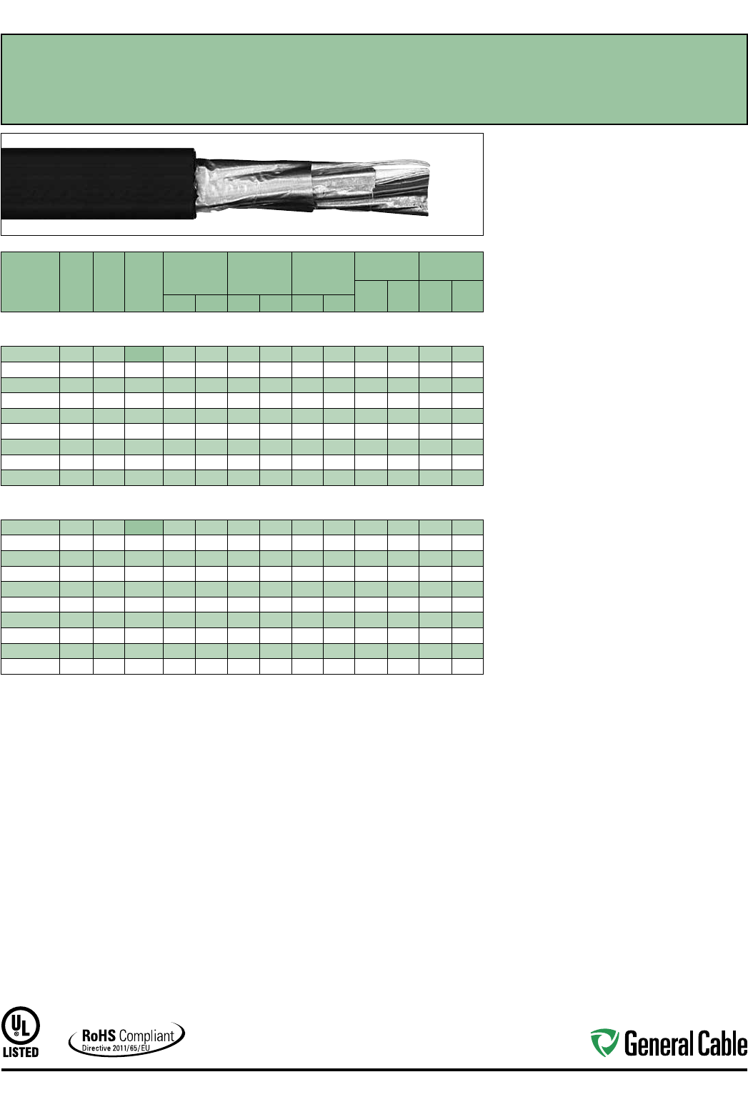
Industrial Automation
45
SPEC 2150
November, 2014
FREP
®
FR-EPR/CPE, Instrumentation, Shielded
600 V, UL Type TC, Individual and Overall Shielded Pairs
CATALOG
NUMBER
NO. OF
PAIRS
COND.
SIZE
(AWG)
COND.
STRAND
MINIMUM AVG.
INSULATION
THICKNESS
MINIMUM AVG.
JACKET
THICKNESS
NOMINAL
CABLE O.D.
COPPER
WEIGHT NET WEIGHT
LBS/
1000 FT kg/km
LBS/
1000 FT kg/kmINCHES mm INCHES mm INCHES mm
INDIVIDUAL AND OVERALL SHIELDED PAIRS
18 AWG CONDUCTORS
279700 218 7W 0.025 0.64 0.045 1.14 0.473 12.01 27 41 83 124
279710 418 7W 0.025 0.64 0.060 1.52 0.586 14.88 53 78 152 226
279720* 818 7W 0.025 0.64 0.060 1.52 0.751 19.08 103 153 259 385
279730* 12 18 7W 0.025 0.64 0.080 2.03 0.948 24.08 153 228 398 592
279740* 16 18 7W 0.025 0.64 0.080 2.03 1.050 26.67 206 307 502 747
319270* 20 18 7W 0.025 0.64 0.080 2.03 1.185 30.10 254 378 623 927
279750* 24 18 7W 0.025 0.64 0.080 2.03 1.220 30.99 311 463 709 1055
337240* 36 18 7W 0.025 0.64 0.080 2.03 1.474 37.44 461 687 1008 1500
337250* 50 18 7W 0.025 0.64 0.110 2.79 1.780 45.21 640 952 1454 2164
INDIVIDUAL AND OVERALL SHIELDED PAIRS
16 AWG CONDUCTORS
280500 216 7W 0.025 0.64 0.045 1.14 0.500 12.70 40 59 103 153
280520 416 7W 0.025 0.64 0.060 1.52 0.650 16.51 77 114 189 281
280530 616 7W 0.025 0.64 0.060 1.52 0.755 19.18 115 171 268 399
280540 816 7W 0.025 0.64 0.060 1.52 0.840 21.34 151 225 330 491
279760 12 16 7W 0.025 0.64 0.080 2.03 1.065 27.05 226 337 506 753
280990* 16 16 7W 0.025 0.64 0.080 2.03 1.185 3 0.10 305 453 643 957
337260* 20 16 7W 0.025 0.64 0.080 2.03 1.320 33.53 380 566 777 1156
279770* 24 16 7W 0.025 0.64 0.080 2.03 1.485 37.72 455 677 932 1387
288260* 36 16 7W 0.025 0.64 0.080 2.03 1.760 44.70 683 1016 1410 2098
288250* 50 16 7W 0.025 0.64 0.110 2.79 2.035 51.69 946 1408 1883 2802
Dimensions and weights are nominal; subject to industry tolerances.
* Non-stock item; minimum runs apply. Please consult Customer Service for price and delivery.
Product Construction:
Conductor:
• 18 AWG and 16 AWG tinned, annealed copper per
ASTM B33
• Class B stranding per ASTM B8
Insulation:
• Flame-Retardant Ethylene Propylene Rubber
(FR-EPR) Type II
• Color-coded per ICEA Method 1: Pairs - black and
white. One conductor in each pair is printed alpha-
numerically for easy identification
Shield:
Individual and overall shielded pairs
• Individual pairs are 100% individually shielded
with Flexfoil® aluminum/polyester in contact with
stranded tinned copper drain wire
• Overall shield is Flexfoil® aluminum/polymer in
contact with stranded tinned copper drain wire
Jacket:
• Lead-free, flame-retardant, thermoplastic
Chlorinated Polyethylene (CPE)
Print:
• GENERAL CABLE® (PLANT OF MFG) FREP®
XX/SPS XXAWG EPR/CPE SHIELDED (UL) TYPE
TC 90˚C WET OR DRY 600 V DIR BUR SUN
RES DAY/MONTH/YEAR OF MFG SEQUENTIAL
FOOTAGE MARK
Applications:
• In free air, raceways or direct burial
• In wet or dry locations
• Permitted for use in Class I, Division 2 industrial
hazardous locations per NEC
Features:
• Rated at 90˚C wet or dry
• Ripcord applied to all cables with jacket thickness
of 60 mils or less
• Excellent physical, thermal and electrical
properties
• Excellent moisture resistance
• Excellent resistance to compression cuts and heat
deformation
• Excellent flame resistance—burns to an ash; does
not exhibit thermoplastic drip
• Low coefficient of friction for easy pulling
• Sunlight- and weather-resistant
• Excellent low temperature cold bend characteristics
• Meets cold bend test at -40˚C
Compliances:
Industry Compliances:
• UL 1277 Type TC, UL File # E57179
• UL 1581
• ICEA S-73-532/NEMA WC57
• RoHS Compliant
Flame Test Compliances:
• UL 1581/UL 2556 VW-1
• UL 1685 Vertical Flame Test
• IEEE 383
• IEEE 1202
• CSA FT4
• ICEA T-29-520
Other Compliances:
• EPA 40 CFR, Part 261 for leachable lead
content per TCLP
• OSHA Acceptable
Packaging:
• Material cut to length and shipped on
non-returnable wood reels
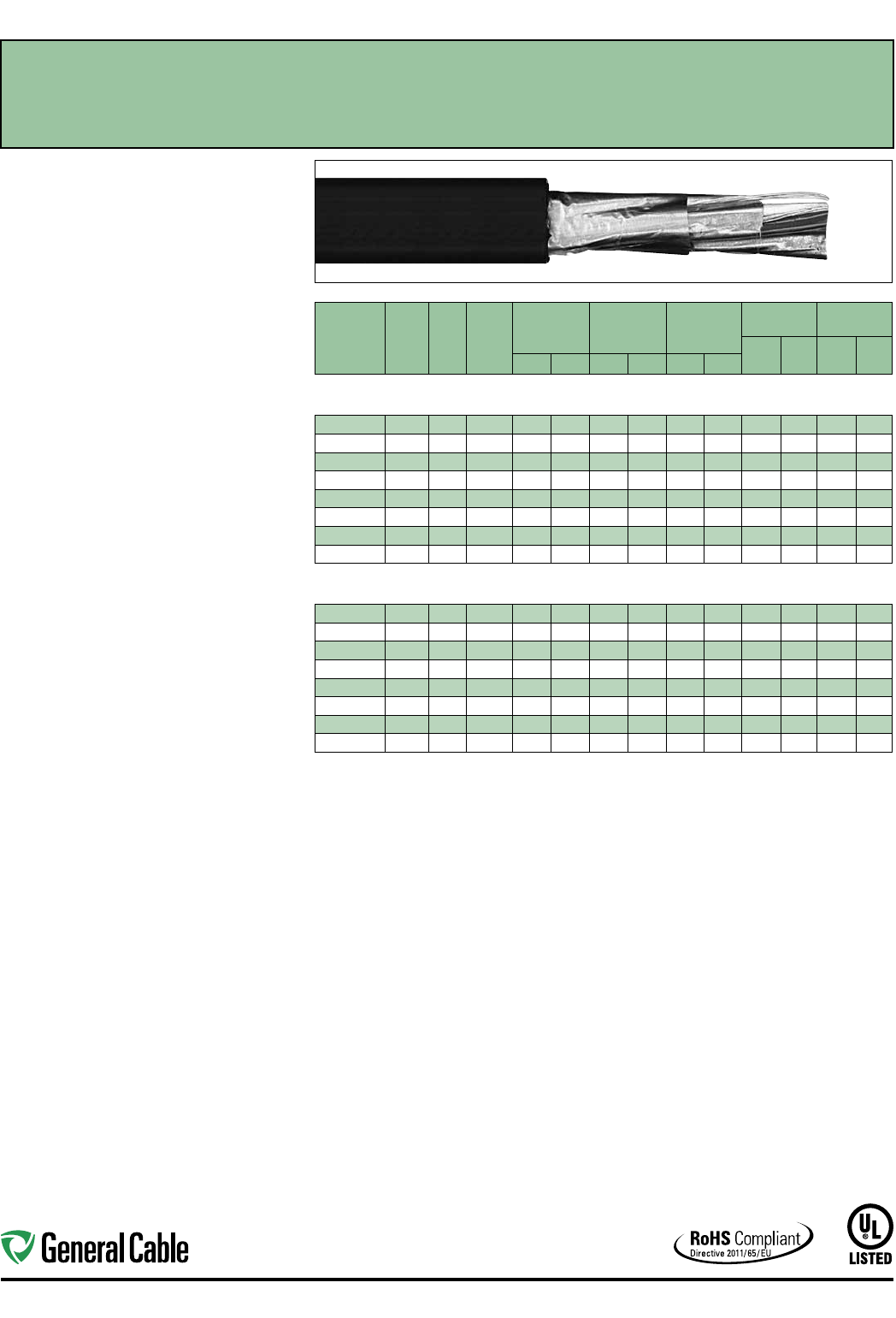
Industrial Automation
46
CATALOG
NUMBER
NO. OF
TRIADS
COND.
SIZE
(AWG)
COND.
STRAND
MINIMUM AVG.
INSULATION
THICKNESS
MINIMUM AVG.
JACKET
THICKNESS
NOMINAL
CABLE O.D.
COPPER
WEIGHT NET WEIGHT
LBS/
1000 FT kg/km
LBS/
1000 FT kg/kmINCHES mm INCHES mm INCHES mm
INDIVIDUAL AND OVERALL SHIELDED TRIADS
18 AWG CONDUCTORS
337150* 2 TRI 18 7W 0.025 0.64 0.060 1.52 0.560 14.22 38 57 127 189
319250* 4 TRI 18 7W 0.025 0.64 0.060 1.52 0.640 16.26 73 109 201 299
319260* 8 TRI 18 7W 0.025 0.64 0.080 2.03 0.825 20.96 144 214 343 510
337160* 12 TRI 18 7W 0.025 0.64 0.080 2.03 1.065 27.0 5 218 324 528 786
294540* 16 TRI 18 7W 0.025 0.64 0.080 2.03 1.180 29.97 290 431 675 1005
337170* 20 TRI 18 7W 0.025 0.64 0.080 2.03 1.310 33.27 361 538 825 1228
337180* 24 TRI 18 7W 0.025 0.64 0.080 2.03 1.500 38.10 433 645 972 1447
337190* 36 TRI 18 7W 0.025 0.64 0.080 2.03 1.740 44.20 649 965 1470 2188
INDIVIDUAL AND OVERALL SHIELDED TRIADS
16 AWG CONDUCTORS
280950* 2 TRI 16 7W 0.025 0.64 0.060 1.52 0.615 15.62 57 84 159 237
280960* 4 TRI 16 7W 0.025 0.64 0.060 1.52 0.705 17.91 108 160 249 371
280970* 8 TRI 16 7W 0.025 0.64 0.080 2.03 0.850 21.59 217 323 472 702
287410* 12 TRI 16 7W 0.025 0.64 0.080 2.03 1.160 29.46 328 487 683 1016
337200* 16 TRI 16 7W 0.025 0.64 0.080 2.03 1.290 32.77 436 649 879 1308
337210* 20 TRI 16 7W 0.025 0.64 0.080 2.03 1.380 35.05 545 811 1058 1575
337220* 24 TRI 16 7W 0.025 0.64 0.080 2.03 1.615 41.02 653 972 1266 1884
337230* 36 TRI 16 7W 0.025 0.64 0.110 2.79 1.920 48.77 979 1457 1918 2854
Dimensions and weights are nominal; subject to industry tolerances.
* Non-stock item; minimum runs apply. Please consult Customer Service for price and delivery.
SPEC 2200
November, 2014
FREP
®
FR-EPR/CPE, Instrumentation, Shielded
600 V, UL Type TC, Individual and Overall Shielded Triads
Product Construction:
Conductor:
• 18 AWG and 16 AWG tinned, annealed copper per
ASTM B33
• Class B stranding per ASTM B8
Insulation:
• Flame-Retardant Ethylene Propylene Rubber
(FR-EPR) Type II
• Color-coded per ICEA Method 1: Triads - black,
white and red. One conductor in each triad is
printed alpha-numerically for easy identification
Shield:
Individual and overall shielded triads
• Individual triads are 100% shielded with Flexfoil®
aluminum/polyester in contact with stranded
tinned copper drain wire
• Overall shield is Flexfoil® aluminum/polymer in
contact with stranded tinned copper drain wire
Jacket:
• Lead-free, flame-retardant, thermoplastic
Chlorinated Polyethylene (CPE)
Print:
• GENERAL CABLE® (PLANT OF MFG) FREP®
XX/STS XXAWG EPR/CPE SHIELDED (UL) TYPE
TC 90˚C WET OR DRY 600 V DIR BUR SUN
RES DAY/MONTH/YEAR OF MFG SEQUENTIAL
FOOTAGE MARK
Applications:
• In free air, raceways or direct burial
• In wet or dry locations
• Permitted for use in Class I, Division 2 industrial
hazardous locations per NEC
Features:
• Rated at 90˚C wet or dry
• Ripcord applied to all cables with jacket thickness
of 60 mils or less
• Excellent physical, thermal and electrical
properties
• Excellent moisture resistance
• Excellent resistance to compression cuts and heat
deformation
• Excellent flame resistance—burns to an ash; does
not exhibit thermoplastic drip
• Low coefficient of friction for easy pulling
• Sunlight- and weather-resistant
• Excellent low temperature cold bend
characteristics
• Meets cold bend test at -40˚C
Compliances:
Industry Compliances:
• UL 1277 Type TC, UL File # E57179
• UL 1581
• ICEA S-73-532/NEMA WC57
• RoHS Compliant
Flame Test Compliances:
• UL 1581/UL 2556 VW-1
• UL 1685 Vertical Flame Test
• IEEE 383
• IEEE 1202
• CSA FT4
• ICEA T-29-520
Other Compliances:
• EPA 40 CFR, Part 261 for leachable lead
content per TCLP
• OSHA Acceptable
Packaging:
• Material cut to length and shipped on
non-returnable wood reels
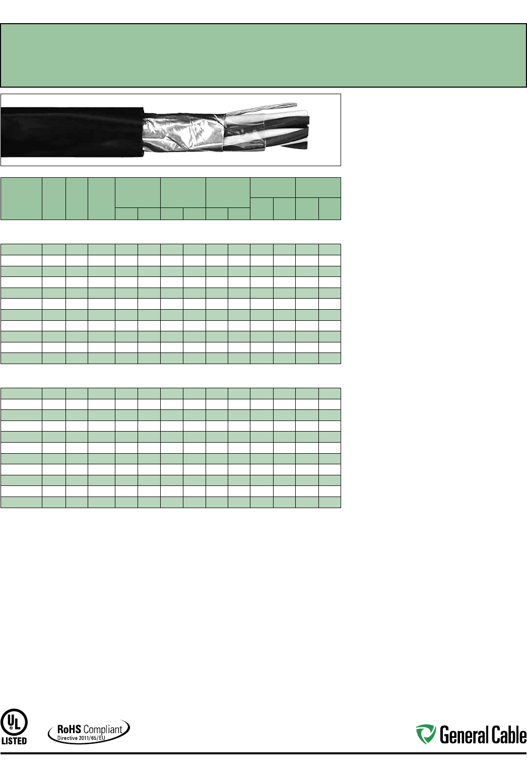
Industrial Automation
47
CATALOG
NUMBER
NO. OF
PAIRS/
TRIADS
COND.
SIZE
(AWG)
COND.
STRAND
MINIMUM AVG.
INSULATION
THICKNESS
MINIMUM AVG.
JACKET
THICKNESS
NOMINAL
CABLE O.D.
COPPER
WEIGHT NET WEIGHT
LBS/
1000 FT kg/km
LBS/
1000 FT kg/kmINCHES mm INCHES mm INCHES mm
OVERALL SHIELDED PAIRS/TRIADS
18 AWG CONDUCTORS
393710* 118 7W 0.030 0.76 0.045 1.14 0.315 8.00 13 19 46 68
393720* 1 TRI 18 7W 0.030 0.76 0.045 1.14 0.340 8.64 18 26 58 86
393730* 218 7W 0.030 0.76 0.045 1.14 0.450 11.43 23 34 88 131
393740* 418 7W 0.030 0.76 0.045 1.14 0.560 14.22 44 65 144 214
393750* 818 7W 0.030 0.76 0.060 1.52 0.750 19.05 86 127 263 391
393760* 12 18 7W 0.030 0.76 0.080 2.03 0.850 21.59 127 189 358 533
393770* 16 18 7W 0.030 0.76 0.080 2.03 1.010 25.65 169 251 461 686
393780* 20 18 7W 0.030 0.76 0.080 2.03 1.085 27.5 6 210 313 600 893
393790* 24 18 7W 0.030 0.76 0.080 2.03 1.210 30.73 252 375 701 1043
393800* 36 18 7W 0.030 0.76 0.080 2.03 1.500 38.10 377 561 1005 1496
393810* 50 18 7W 0.030 0.76 0.080 2.03 2.570 65.28 523 778 1603 2386
OVERALL SHIELDED PAIRS/TRIADS
16 AWG CONDUCTORS
393820* 116 7W 0.030 0.76 0.045 1.14 0.345 8.76 18 28 32 48
393830* 1 TRI 16 7W 0.030 0.76 0.045 1.14 0.360 9.14 26 39 72 107
393840* 216 7W 0.030 0.76 0.045 1.14 0.560 14.22 36 54 121 180
393850* 416 7W 0.030 0.76 0.060 1.52 0.650 16.51 69 103 186 277
393860* 816 7W 0.030 0.76 0.060 1.52 0.810 20.57 135 201 324 482
393870* 12 16 7W 0.030 0.76 0.080 2.03 1.000 25.40 202 300 486 723
393880* 16 16 7W 0.030 0.76 0.080 2.03 1.120 28.45 268 399 616 917
393890* 20 16 7W 0.030 0.76 0.080 2.03 1.170 29.72 335 498 734 1092
393900* 24 16 7W 0.030 0.76 0.080 2.03 1.440 36.58 401 597 894 1330
393910* 36 16 7W 0.030 0.76 0.080 2.03 1.650 41.91 601 894 1254 1866
393920* 50 16 7W 0.030 0.76 0.110 2.79 2.020 51.31 834 1241 1800 2679
Dimensions and weights are nominal; subject to industry tolerances.
* Non-stock item; minimum runs apply. Please consult Customer Service for price and delivery.
SPEC 2600
November, 2014
GenFree
®
XLPE/LSZH, Instrumentation, Shielded
600 V, UL Type TC-LS, Overall Shielded Pairs/Triads
Product Construction:
Conductor:
• 18 AWG and 16 AWG tinned, annealed copper per
ASTM B33
• Class B stranding per ASTM B8
Insulation:
• Lead-free, flame-retardant, low-smoke
Cross-linked Polyethylene (XLPE)
• Color-coded per ICEA Method 1: Pairs - black and
white; Triads - black, white and red. One conductor
in each pair or triad is printed alpha-numerically for
easy identification
Shield:
Overall shielded pairs/triads
• Overall shield is Flexfoil® aluminum/polymer in
contact with stranded tinned copper drain wire
Jacket:
• Lead-free, flame-retardant, sunlight-resistant,
Low-Smoke, Zero-Halogen Polyolefin (LSZH)
Print:
• GENERAL CABLE® (PLANT OF MFG) GENFREE®
XX/PS/TS XXAWG XLPE/LSZH SHIELDED (UL)
TYPE TC-LS 90˚C WET OR DRY 600 V DIR BUR
SUN RES ROHS DAY/MONTH/YEAR OF MFG
SEQUENTIAL FOOTAGE MARK
Applications:
• In free air, raceways, aerial or direct burial
• In wet or dry locations
• Permitted for use in Class I, Division 2 industrial
hazardous locations per NEC
Features:
• Rated at 90˚C wet or dry
• Ripcord applied to all cables with jacket thickness
of 60 mils or less
• Excellent physical and electrical properties
• Excellent moisture resistance
• Excellent resistance to compression and impact
• Chemical-resistant
• Low coefficient of friction for easy pulling
• Sunlight- and weather-resistant
• Meets cold bend test at -30˚C
• Low-Smoke, Zero-Halogen jacket is
environmentally safe
• Low-Smoke, Zero-Halogen jacket reduces the
amount of toxic and corrosive gases emitted
during combustion, providing a safer environment
for personnel and equipment during the hazards
of fire
Compliances:
Industry Compliances:
• UL 1277 Type TC-LS, UL File # E57179
• UL 1581
• ICEA S-73-532/NEMA WC57
• ICEA T-33-655
• RoHS Compliant
Flame Test Compliances:
• UL 1581
• UL 1685 Vertical Flame Test
• IEEE 1202
Other Compliances:
• EPA 40 CFR, Part 261 for leachable lead
content per TCLP
• OSHA Acceptable
Packaging:
• Material cut to length and shipped on
non-returnable wood reels

Industrial Automation
48
CATALOG
NUMBER
NO. OF
PAIRS
COND.
SIZE
(AWG)
COND.
STRAND
MINIMUM AVG.
INSULATION
THICKNESS
MINIMUM AVG.
JACKET
THICKNESS
NOMINAL
CABLE O.D.
COPPER
WEIGHT NET WEIGHT
LBS/
1000 FT kg/km
LBS/
1000 FT kg/kmINCHES mm INCHES mm INCHES mm
INDIVIDUAL AND OVERALL SHIELDED PAIRS
18 AWG CONDUCTORS
393930* 218 7W 0.030 0.76 0.045 1.14 0.510 12.95 27 41 92 137
393940* 418 7W 0.030 0.76 0.060 1.52 0.630 16.00 53 78 167 249
393950* 818 7W 0.030 0.76 0.080 2.03 0.855 21.72 103 153 326 485
393960* 12 18 7W 0.030 0.76 0.080 2.03 1.030 26.16 153 228 441 656
393970* 16 18 7W 0.030 0.76 0.080 2.03 1.140 28.96 206 307 554 824
393980* 20 18 7W 0.030 0.76 0.080 2.03 1.265 32.13 254 378 676 1006
393990* 24 18 7W 0.030 0.76 0.080 2.03 1.450 36.83 311 463 795 1183
394000* 36 18 7W 0.030 0.76 0.010 2.79 1.650 41.91 461 687 1118 1664
394010* 50 18 7W 0.030 0.76 0.010 2.79 2.085 52.96 640 952 1616 2405
INDIVIDUAL AND OVERALL SHIELDED PAIRS
16 AWG CONDUCTORS
394020* 216 7W 0.030 0.76 0.060 1.52 0.585 14.86 40 59 130 193
394030* 416 7W 0.030 0.76 0.060 1.52 0.675
17.15
77 114 204 304
394040* 616 7W 0.030 0.76 0.060 1.52 0.800 20.32 115 171 301 447
394050* 816 7W 0.030 0.76 0.080 2.03 0.915 23.24 151 225 394 586
394060* 12 16 7W 0.030 0.76 0.080 2.03 1.110 28.19 226 337 548 816
394070* 16 16 7W 0.030 0.76 0.080 2.03 1.350 34.29 305 453 713 1061
394080* 20 16 7W 0.030 0.76 0.080 2.03 1.365 34.67 380 566 850 1265
394090* 24 16 7W 0.030 0.76 0.080 2.03 1.570 39.88 455 677 1001 1490
394100* 36 16 7W 0.030 0.76 0.110 2.79 1.980 50.29 683 1016 1548 2304
394110* 50 16 7W 0.030 0.76 0.110 2.79 2.16 5 54.99 946 1408 2020 3006
Dimensions and weights are nominal; subject to industry tolerances.
* Non-stock item; minimum runs apply. Please consult Customer Service for price and delivery.
SPEC 2625
November, 2014
GenFree
®
XLPE/LSZH, Instrumentation, Shielded
600 V, UL Type TC-LS, Individual and Overall Shielded Pairs
Product Construction:
Conductor:
• 18 AWG and 16 AWG tinned, annealed copper per
ASTM B33
• Class B stranding per ASTM B8
Insulation:
• Lead-free, flame-retardant, low-smoke
Cross-linked Polyethylene (XLPE)
• Color-coded per ICEA Method 1: Pairs - black and
white. One conductor in each pair is printed alpha-
numerically for easy identification
Shield:
Individual and overall shielded pairs
• Individual pairs are 100% individually shielded
with Flexfoil® aluminum/polyester in contact with
stranded tinned copper drain wire
• Overall shield is Flexfoil® aluminum/polymer in
contact with stranded tinned copper drain wire
Jacket:
• Lead-free, flame-retardant, sunlight-resistant
Low-Smoke, Zero-Halogen Polyolefin (LSZH)
Print:
• GENERAL CABLE® (PLANT OF MFG) GENFREE®
XX/SPS XXAWG XLPE/LSZH SHIELDED (UL)
TYPE TC-LS 90˚C WET OR DRY 600 V DIR BUR
SUN RES ROHS DAY/MONTH/YEAR OF MFG
SEQUENTIAL FOOTAGE MARK
Applications:
• In free air, raceways, aerial or direct burial
• In wet or dry locations
• Permitted for use in Class I, Division 2 industrial
hazardous locations per NEC
Features:
• Rated at 90˚C wet or dry
• Ripcord applied to all cables with jacket thickness
of 60 mils or less
• Excellent physical and electrical properties
• Excellent moisture resistance
• Excellent resistance to compression and impact
• Chemical-resistant
• Low coefficient of friction for easy pulling
• Sunlight- and weather-resistant
• Meets cold bend test at -30˚C
• Low-Smoke, Zero-Halogen jacket is
environmentally safe
• Low-Smoke, Zero-Halogen jacket reduces the
amount of toxic and corrosive gases emitted
during combustion, providing a safer environment
for personnel and equipment during the hazards
of fire
Compliances:
Industry Compliances:
• UL 1277 Type TC-LS, UL File # E57179
• UL 1581
• ICEA S-73-532/NEMA WC57
• ICEA T-33-655
• RoHS Compliant
Flame Test Compliances:
• UL 1581
• UL 1685 Vertical Flame Test
• IEEE 1202
Other Compliances:
• EPA 40 CFR, Part 261 for leachable lead
content per TCLP
• OSHA Acceptable
Packaging:
• Material cut to length and shipped on
non-returnable wood reels
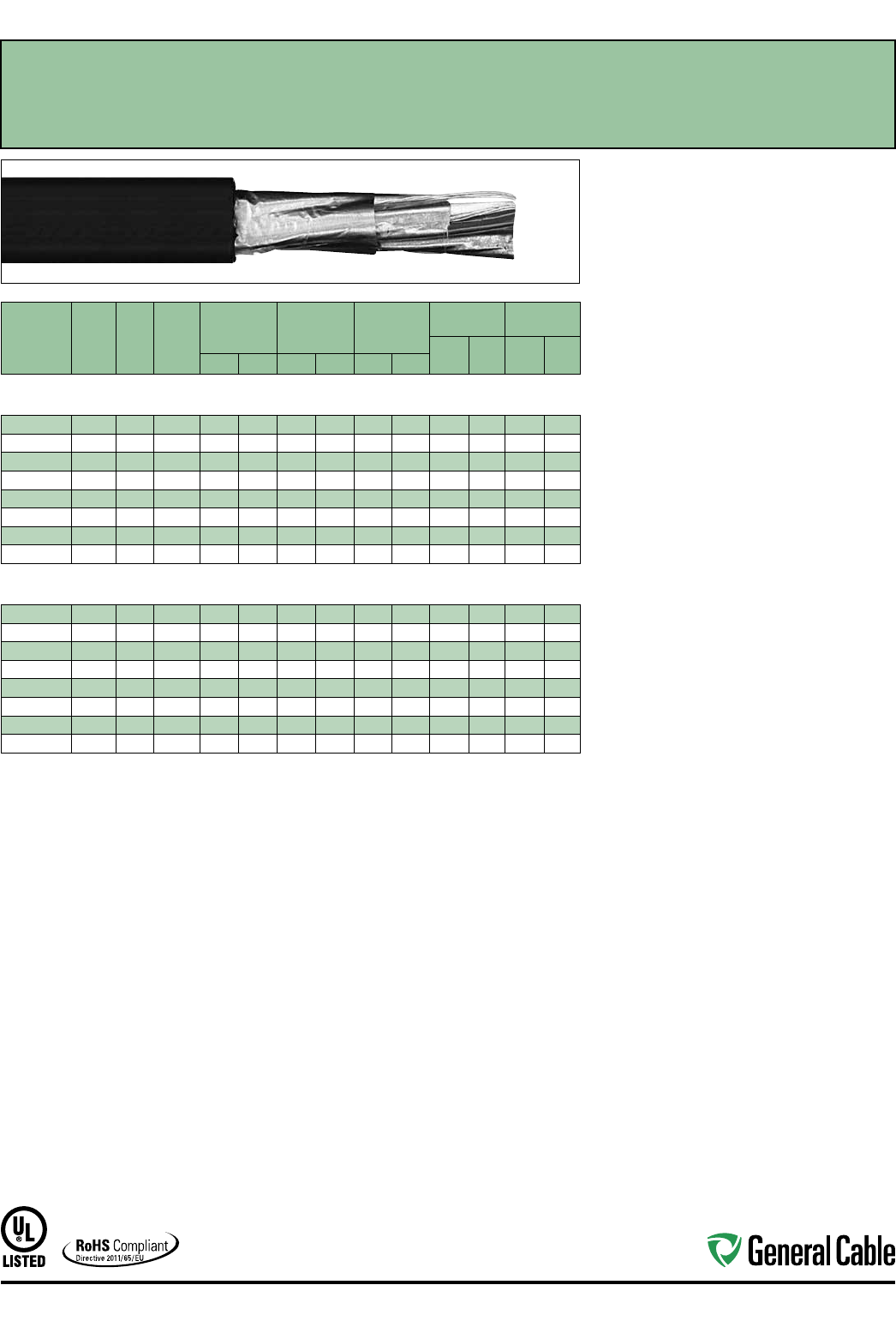
Industrial Automation
49
CATALOG
NUMBER
NO. OF
TRIADS
COND.
SIZE
(AWG)
COND.
STRAND
MINIMUM AVG.
INSULATION
THICKNESS
MINIMUM AVG.
JACKET
THICKNESS
NOMINAL
CABLE O.D.
COPPER
WEIGHT NET WEIGHT
LBS/
1000 FT kg/km
LBS/
1000 FT kg/kmINCHES mm INCHES mm INCHES mm
INDIVIDUAL AND OVERALL SHIELDED TRIADS
18 AWG CONDUCTORS
394120* 2 TRI 18 7W 0.030 0.76 0.060 1.52 0.595 15.11 38 57 150 223
394130* 4 TRI 18 7W 0.030 0.76 0.060 1.52 0.690 17.5 3 74 110 231 344
394140* 8 TRI 18 7W 0.030 0.76 0.080 2.03 0.940 23.88 145 216 435 647
394150* 12 TRI 18 7W 0.030 0.76 0.080 2.03 1.135 28.83 217 323 612 911
394160* 16 TRI 18 7W 0.030 0.76 0.080 2.03 1.265 32.13 289 430 773 1150
394170* 20 TRI 18 7W 0.030 0.76 0.080 2.03 1.405 35.69 361 537 935 1391
394180* 24 TRI 18 7W 0.030 0.76 0.080 2.03 1.565 39.75 432 643 1097 1633
394190* 36 TRI 18 7W 0.030 0.76 0.110 2.79 1.860 47. 24 647 963 1662 2473
INDIVIDUAL AND OVERALL SHIELDED TRIADS
16 AWG CONDUCTORS
394200* 2 TRI 16 7W 0.030 0.76 0.060 1.52 0.640 16.26 57 84 183 272
394210* 4 TRI 16 7W 0.030 0.76 0.060 1.52 0.745 18.92 111 165 494 735
394220* 8 TRI 16 7W 0.030 0.76 0.080 2.03 1.015 25.78 219 326 549 817
394230* 12 TRI 16 7W 0.030 0.76 0.080 2.03 1.230 31.24 328 487 777 1156
394240* 16 TRI 16 7W 0.030 0.76 0.080 2.03 1.370 34.80 437 650 988 1470
394250* 20 TRI 16 7W 0.030 0.76 0.080 2.03 1.525 38.74 545 811 1120 1667
394260* 24 TRI 16 7W 0.030 0.76 0.110 2.79 1.760 44.70 654 973 1530 2277
394270* 36 TRI 16 7W 0.030 0.76 0.110 2.79 2.015 51.18 979 1457 2142 3188
Dimensions and weights are nominal; subject to industry tolerances.
* Non-stock item; minimum runs apply. Please consult Customer Service for price and delivery.
SPEC 2650
November, 2014
GenFree
®
XLPE/LSZH, Instrumentation, Shielded
600 V, UL Type TC-LS, Individual and Overall Shielded Triads
Product Construction:
Conductor:
• 18 AWG and 16 AWG tinned, annealed copper per
ASTM B33
• Class B stranding per ASTM B8
Insulation:
• Lead-free, flame-retardant, low-smoke
Cross-linked Polyethylene (XLPE)
• Color-coded per ICEA Method 1: Triads - black,
white and red. One conductor in each triad is
printed alpha-numerically for easy identification
Shield:
Individual and overall shielded triads
• Individual triads are 100% shielded with Flexfoil®
aluminum/polyester in contact with stranded tinned
copper drain wire
• Overall shield is Flexfoil® aluminum/polymer in
contact with stranded tinned copper drain wire
Jacket:
• Lead-free, flame-retardant, sunlight-resistant
Low-Smoke, Zero-Halogen Polyolefin (LSZH)
Print:
• GENERAL CABLE® (PLANT OF MFG) GENFREE®
XX/STS XXAWG XLPE/LSZH SHIELDED (UL)
TYPE TC-LS 90˚C WET OR DRY 600 V DIR BUR
SUN RES ROHS DAY/MONTH/YEAR OF MFG
SEQUENTIAL FOOTAGE MARK
Applications:
• In free air, raceways, aerial or direct burial
• In wet or dry locations
• Permitted for use in Class I, Division 2 industrial
hazardous locations per NEC
Features:
• Rated at 90˚C wet or dry
• Ripcord applied to all cables with jacket thickness
of 60 mils or less
• Excellent physical and electrical properties
• Excellent moisture resistance
• Excellent resistance to compression and impact
• Chemical-resistant
• Low coefficient of friction for easy pulling
• Sunlight- and weather-resistant
• Meets cold bend test at -30˚C
• Low-Smoke, Zero-Halogen jacket is
environmentally safe
• Low-Smoke, Zero-Halogen jacket reduces the
amount of toxic and corrosive gases emitted during
combustion, providing a safer environment for
personnel and equipment during the hazards of fire
Compliances:
Industry Compliances:
• UL 1277 Type TC-LS, UL File # E57179
• UL 1581
• ICEA S-73-532/NEMA WC57
• ICEA T-33-655
• RoHS Compliant
Flame Test Compliances:
• UL 1581
• UL 1685 Vertical Flame Test
• IEEE 1202
Other Compliances:
• EPA 40 CFR, Part 261 for leachable lead
content per TCLP
• OSHA Acceptable
Packaging:
• Material cut to length and shipped on
non-returnable wood reels
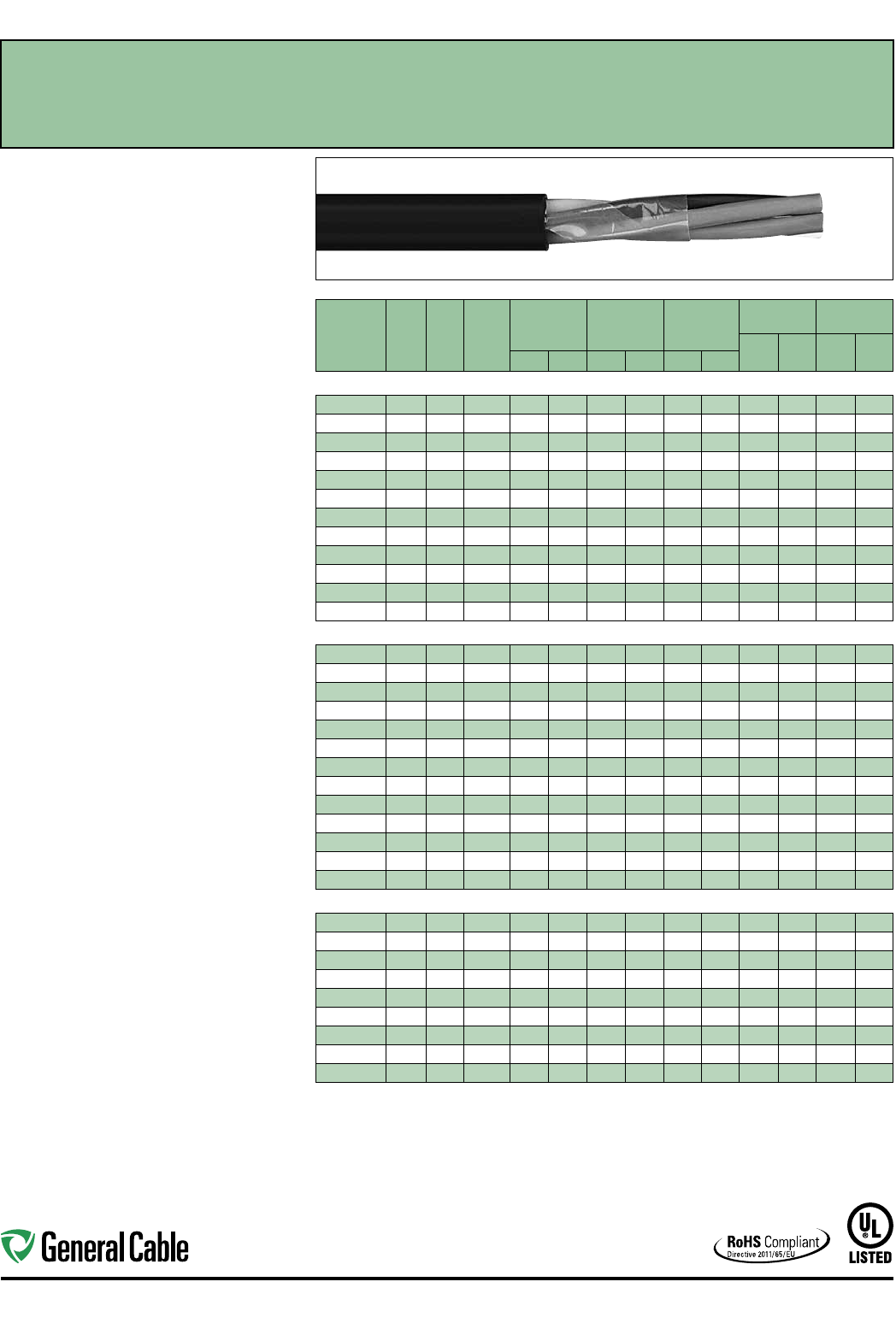
Industrial Automation
50
CATALOG
NUMBER
NO.
OF
COND.
COND.
SIZE
(AWG)
COND.
STRAND
MINIMUM AVG.
INSULATION
THICKNESS
MINIMUM AVG.
JACKET
THICKNESS
NOMINAL
CABLE O.D.
COPPER
WEIGHT NET WEIGHT
LBS/
1000 FT kg/km
LBS/
1000 FT kg/kmINCHES mm INCHES mm INCHES mm
14 AWG CONDUCTORS
279560 2 Flat 14 7W 0.030 0.76 0.045 1.14
.365 x .230
9.30 x 5.80
26 38 61 91
305320* 214 7W 0.030 0.76 0.045 1.14 0.370 9.40 26 39 71 106
280180 314 7W 0.030 0.76 0.045 1.14 0.390 9.91 39 59 92 137
280190 414 7W 0.030 0.76 0.045 1.14 0.425
10.80
53 78 115 171
279870 514 7W 0.030 0.76 0.045 1.14 0.465 11.81 66 98 139 207
280200 714 7W 0.030 0.76 0.045 1.14 0.505 12.83 92 137 173 257
280210 914 7W 0.030 0.76 0.060 1.52 0.620 15.75 118 176 240 357
279880 12 14 7W 0.030 0.76 0.060 1.52 0.700 17.78 158 235 301 448
279580 19 14 7W 0.030 0.76 0.060 1.52 0.815 20.70 250 372 468 696
279590 25 14 7W 0.030 0.76 0.080 2.03 0.935 23.75 323 481 624 929
347080* 30 14 7W 0.030 0.76 0.080 2.03 1.030 26.16 387 576 747 1112
279600 37 14 7W 0.030 0.76 0.080 2.03 1.110 28.19 466 694 875 1302
12 AWG CONDUCTORS
279840 2 Flat 12 7W 0.030 0.76 0.045 1.14
.400 x .245
10.20 x 6.20
40 60 82 122
307690* 212 7W 0.030 0.76 0.045 1.14 0.410 10.41 41 61 94 140
280170
3+ Grnd
12 7W 0.030 0.76 0.045 1.14 0.435 11.05 85 127 148 220
280300 312 7W 0.030 0.76 0.045 1.14 0.435 11.05 64 95 124 185
280310 412 7W 0.030 0.76 0.045 1.14 0.475 12.07 85 127 157 234
280320 512 7W 0.030 0.76 0.045 1.14 0.520 13.21 106 158 191 284
279890 712 7W 0.030 0.76 0.060 1.52 0.595 15.11 149 221 268 399
280330 912 7W 0.030 0.76 0.060 1.52 0.695 17. 6 5 191 285 337 502
280340 12 12 7W 0.030 0.76 0.060 1.52 0.765 19.43 247 368 428 637
279610 19 12 7W 0.030 0.76 0.080 2.03 0.940 23.88 391 582 688 1024
295400* 25 12 7W 0.030 0.76 0.080 2.03 1.095 27. 81 515 767 854 1271
347100* 30 12 7W 0.030 0.76 0.080 2.03 1.150 29.21 618 920 1002 1491
301870 37 12 7W 0.030 0.76 0.080 2.03 1.240 31.50 762 113 4 1240 1845
10 AWG CONDUCTORS
279570 2 Flat 10 7W 0.030 0.76 0.045 1.14
.445 x .270
11.30 x 6.90
64 95 113 168
305340* 210 7W 0.030 0.76 0.045 1.14 0.455 11.56 65 97 128 190
279680
3+ Grnd
10 7W 0.030 0.76 0.045 1.14 0.485 12.32 134 199 225 335
280410 310 7W 0.030 0.76 0.045 1.14 0.485 12.32 100 150 172 256
279900 410 7W 0.030 0.76 0.060 1.52 0.560 14.22 134 199 234 348
279620 510 7W 0.030 0.76 0.060 1.52 0.615 15.62 167 249 284 423
279630 710 7W 0.030 0.76 0.060 1.52 0.670 17.02 234 349 381 567
279640 910 7W 0.030 0.76 0.060 1.52 0.760 19.30 295 440 464 691
279650 12 10 7W 0.030 0.76 0.080 2.03 0.905 22.99 402 598 651 696
Dimensions and weights are nominal; subject to industry tolerances.
* Non-stock item; minimum runs apply. Please consult Customer Service for price and delivery.
¹ Approved as TYPE TC-ER for Exposed Run applications of 3 or more conductors as defined by NEC.
SPEC 4300
November, 2014
FREP
®
FR-EPR/CPE, Control, Unshielded
600 V, UL Type TC-ER
1
—E-2 Color Code
Product Construction:
Conductor:
• 14 AWG thru 10 AWG fully annealed stranded
tinned copper per ASTM B33
• Class B stranding per ASTM B8
Insulation:
• Flame-Retardant Ethylene Propylene Rubber
(FR-EPR) Type II
• Color-coded per ICEA Method 1, Table E-2
(does not include white or green)
Jacket:
• Lead-free, flame-retardant thermoplastic
Chlorinated Polyethylene (CPE)
Print
• GENERAL CABLE® (PLANT OF MFG) FREP®
XX/C XXAWG EPR/CPE (UL) TYPE TC-ER
XHHW-2 CDRS 90°C WET OR DRY 600 V DIR
BUR SUN RES DAY/MONTH/YEAR OF MFG
SEQUENTIAL FOOTAGE MARK
Applications:
• In free air, raceways or direct burial
• In wet or dry locations
• Permitted for Exposed Run (ER) use in
accordance with NEC for 3 or more conductors
• Approved for direct burial
• Class I, Division 2 industrial hazardous locations
per NEC
Features:
• Rated at 90˚C wet or dry
• Ripcord applied to all cables with jacket thickness
of 60 mils or less
• Excellent physical, thermal and electrical
properties
• Sunlight- and weather-resistant
• Excellent moisture resistance
• Excellent resistance to compression cuts and heat
deformation
• Low coefficient of friction for easy pulling
• Excellent flame resistance—burns to ash; does
not exhibit thermoplastic drip
• Excellent low temperature cold bend
characteristics
• Meets cold bend test at -40˚C
• Meets the crush and impact requirements of Type
MC cable for 3 or more conductors
Compliances:
Industry Compliances:
• UL 44 Type XHHW-2
• UL 1277 Type TC-ER for 3 or more conductors,
UL File # E57179
• UL 1581
• ICEA S-73-532/NEMA WC57
Flame Test Compliances:
• UL 1581/UL 2556 VW-1
• UL 1685 Vertical Flame Test
• IEEE 383
• IEEE 1202
• CSA FT4
• ICEA T-29-520
Other Compliances:
• EPA 40 CFR, Part 261 for leachable lead
content per TCLP
• OSHA Acceptable
• RoHS Compliant
Packaging:
• Material cut to length and shipped on
non-returnable wood reels
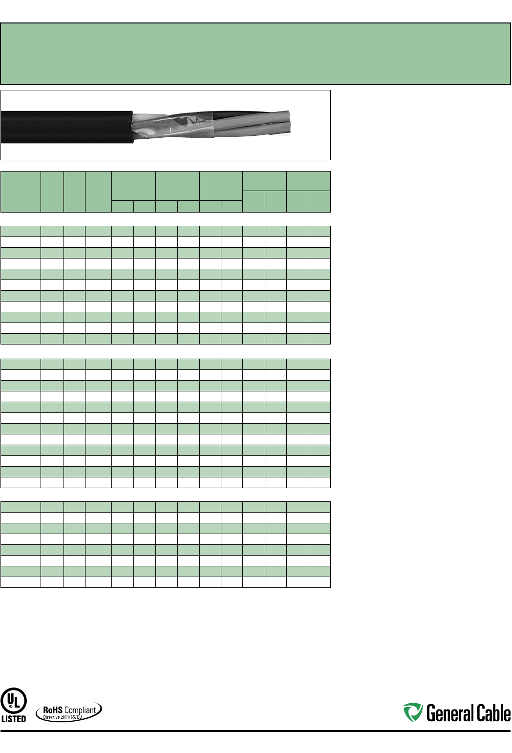
Industrial Automation
51
CATALOG
NUMBER
NO.
OF
COND.
COND.
SIZE
(AWG)
COND.
STRAND
MINIMUM AVG.
INSULATION
THICKNESS
MINIMUM AVG.
JACKET
THICKNESS
NOMINAL
CABLE O.D.
COPPER
WEIGHT NET WEIGHT
LBS/
1000 FT kg/km
LBS/
1000 FT kg/kmINCHES mm INCHES mm INCHES mm
14 AWG CONDUCTORS
280590 2 Flat 14 7W 0.030 0.76 0.045 1.14
.365 x .230
9.30 x 5.80
26 38 61 91
280230 314 7W 0.030 0.76 0.045 1.14 0.390 9.91 39 59 92 137
280240 414 7W 0.030 0.76 0.045 1.14 0.425
10.80
53 78 115 171
280250 514 7W 0.030 0.76 0.045 1.14 0.465 11.81 66 98 139 207
280260 714 7W 0.030 0.76 0.045 1.14 0.505 12.83 92 137 173 257
280270 914 7W 0.030 0.76 0.060 1.52 0.620 15.75 118 176 240 357
280280 12 14 7W 0.030 0.76 0.060 1.52 0.700 17.78 158 235 301 448
280290* 19 14 7W 0.030 0.76 0.060 1.52 0.815 20.70 250 372 468 696
385350* 25 14 7W 0.030 0.76 0.080 2.03 0.935 23.75 323 481 624 929
385360* 30 14 7W 0.030 0.76 0.080 2.03 1.030 26.16 387 576 747 1112
385370* 37 14 7W 0.030 0.76 0.080 2.03 1.110 28.19 466 694 875 1302
12 AWG CONDUCTORS
279850 2 Flat 12 7W 0.030 0.76 0.045 1.14
.400 x .245
10.20 x 6.20
42 63 82 122
280350* 212 7W 0.030 0.76 0.045 1.14 0.410 10.41 42 63 94 140
280360 312 7W 0.030 0.76 0.045 1.14 0.435 11.05 64 95 124 185
279910 412 7W 0.030 0.76 0.045 1.14 0.475 12.07 85 127 157 234
280370 512 7W 0.030 0.76 0.045 1.14 0.520 13.21 106 158 191 284
280380 712 7W 0.030 0.76 0.060 1.52 0.595 15.11 149 221 268 399
280390* 912 7W 0.030 0.76 0.060 1.52 0.695 17.65 191 285 337 502
280400 12 12 7W 0.030 0.76 0.060 1.52 0.765 19.43 247 368 428 637
383930* 19 12 7W 0.030 0.76 0.080 2.03 0.940 23.88 391 582 688 1024
383940* 25 12 7W 0.030 0.76 0.080 2.03 1.095 27.81 515 767 854 1271
383950* 30 12 7W 0.030 0.76 0.080 2.03 1.150 29.21 618 920 1002 1491
330800* 37 12 7W 0.030 0.76 0.080 2.03 1.240 31.50 762 113 4 1240 1845
10 AWG CONDUCTORS
280600* 2 Flat 10 7W 0.030 0.76 0.045 1.14
.445 x .270
11.30 x 6.90
64 95 113 168
280420* 210 7W 0.030 0.76 0.045 1.14 0.455 11.56 65 97 128 190
279920 310 7W 0.030 0.76 0.045 1.14 0.485 12.32 100 150 172 256
279930 410 7W 0.030 0.76 0.060 1.52 0.560 14.22 134 199 234 348
330990* 510 7W 0.030 0.76 0.060 1.52 0.615 15.62 167 249 284 423
280430* 710 7W 0.030 0.76 0.060 1.52 0.670 17.02 234 349 381 567
382880* 910 7W 0.030 0.76 0.060 1.52 0.760 19.30 295 440 464 691
383970* 12 10 7W 0.030 0.76 0.080 2.03 0.950 22.99 402 598 651 969
Dimensions and weights are nominal; subject to industry tolerances.
* Non-stock item; minimum runs apply. Please consult Customer Service for price and delivery.
¹ Approved as TYPE TC-ER for Exposed Run applications of 3 or more conductors as defined by NEC.
SPEC 4310
November, 2014
FREP
®
FR-EPR/CPE, Control, Unshielded
600 V, UL Type TC-ER
1
—E-1 Color Code
Product Construction:
Conductor:
• 14 AWG thru 10 AWG fully annealed stranded
tinned copper per ASTM B33
• Class B stranding per ASTM B8
Insulation:
• Flame-Retardant Ethylene Propylene Rubber
(FR-EPR) Type II
• Color-coded per ICEA Method 1, Table E-1
(includes white or green)
Jacket:
• Lead-free, flame-retardant thermoplastic
Chlorinated Polyethylene (CPE)
Print
• GENERAL CABLE® (PLANT OF MFG) FREP®
XX/C XXAWG EPR/CPE (UL) TYPE TC-ER
XHHW-2 CDRS 90°C WET OR DRY 600 V DIR
BUR SUN RES DAY/MONTH/YEAR OF MFG
SEQUENTIAL FOOTAGE MARK
Applications:
• In free air, raceways or direct burial
• In wet or dry locations
• Permitted for Exposed Run (ER) use in accordance
with NEC for 3 or more conductors
• Approved for direct burial
• Class I, Division 2 industrial hazardous locations
per NEC
Features:
• Rated at 90˚C wet or dry
• Ripcord applied to all cables with jacket thickness
of 60 mils or less
• Excellent physical, thermal and electrical properties
• Sunlight- and weather-resistant
• Excellent moisture resistance
• Excellent resistance to compression cuts and heat
deformation
• Low coefficient of friction for easy pulling
• Excellent flame resistance—burns to ash;
does not exhibit thermoplastic drip
• Excellent low temperature cold bend characteristics
• Meets cold bend test at -40˚C
• Meets the crush and impact requirements of
Type MC cable for 3 or more conductors
Compliances:
Industry Compliances:
• UL 44 Type XHHW-2
• UL 1277 Type TC-ER for 3 or more conductors,
UL File # E57179
• UL 1581
• ICEA S-73-532/NEMA WC57
Flame Test Compliances:
• UL 1581/UL 2556 VW-1
• UL 1685 Vertical Flame Test
• IEEE 383
• IEEE 1202
• CSA FT4
• ICEA T-29-520
Other Compliances:
• EPA 40 CFR, Part 261 for leachable lead
content per TCLP
• OSHA Acceptable
• RoHS Compliant
Packaging:
• Material cut to length and shipped on
non-returnable wood reels
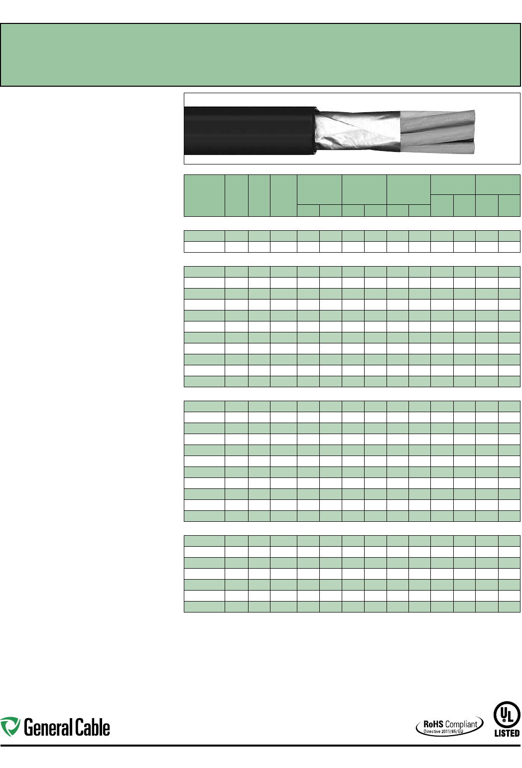
Industrial Automation
52
CATALOG
NUMBER
NO.
OF
COND.
COND.
SIZE
(AWG)
COND.
STRAND
MINIMUM AVG.
INSULATION
THICKNESS
MINIMUM AVG.
JACKET
THICKNESS
NOMINAL
CABLE O.D.
COPPER
WEIGHT NET WEIGHT
LBS/
1000 FT kg/km
LBS/
1000 FT kg/kmINCHES mm INCHES mm INCHES mm
OVERALL SHIELDED 16 AWG CONDUCTORS
280470 216 7W 0.025 0.64 0.045 1.14 0.320
8.13
19 28 52 77
280490 316 7W 0.025 0.64 0.045 1.14 0.335 8.51 27 40 66 98
OVERALL SHIELDED 14 AWG CONDUCTORS
280980* 214 7W 0.030 0.76 0.045 1.14 0.375 9.53 29 43 74 110
354800* 314 7W 0.030 0.76 0.045 1.14 0.395 10.03 42 63 95 141
305330* 414 7W 0.030 0.76 0.045 1.14 0.430 10.92 55 82 118 176
354810* 514 7W 0.030 0.76 0.045 1.14 0.470 11.94 68 101 142 211
354820* 714 7W 0.030 0.76 0.045 1.14 0.510 12.95 94 140 176 262
367120* 914 7W 0.030 0.76 0.060 1.52 0.625 15.88 121 180 243 362
354830* 12 14 7W 0.030 0.76 0.060 1.52 0.705 17.91 160 238 304 452
305360* 19 14 7W 0.030 0.76 0.060 1.52 0.820 20.83 252 375 471 701
367130* 25 14 7W 0.030 0.76 0.080 2.03 0.940 25.53 325 484 627 933
367140* 30 14 7W 0.030 0.76 0.080 2.03 1.035 26.29 389 579 750 1116
367150* 37 14 7W 0.030 0.76 0.080 2.03 1.115 28.32 468 696 878 1307
OVERALL SHIELDED 12 AWG CONDUCTORS
367160* 212 7W 0.030 0.76 0.045 1.14 0.415 10.45 43 64 97 144
367170* 312 7W 0.030 0.76 0.045 1.14 0.440 11.18 66 98 127 189
326650* 412 7W 0.030 0.76 0.045 1.14 0.480 12.19 87 129 160 238
367180* 512 7W 0.030 0.76 0.045 1.14 0.525 13.34 108 162 194 289
326660* 712 7W 0.030 0.76 0.060 1.52 0.600 15.24 151 225 271 403
367190* 912 7W 0.030 0.76 0.060 1.52 0.700 17.78 193 287 340 506
326640* 12 12 7W 0.030 0.76 0.060 1.52 0.770 19.56 249 371 431 641
326670* 19 12 7W 0.030 0.76 0.080 2.03 0.945 24.00 393 585 691 1028
367200* 25 12 7W 0.030 0.76 0.080 2.03 1.100 27.9 4 517 769 857 1275
367210* 30 12 7W 0.030 0.76 0.080 2.03 1.155 29.80 620 923 1005 1496
367220* 37 12 7W 0.030 0.76 0.080 2.03 1.245 31.62 764 1137 1243 1850
OVERALL SHIELDED 10 AWG CONDUCTORS
3119 00* 210 7W 0.030 0.76 0.045 1.14 0.460 11.68 68 101 131 195
367230* 310 7W 0.030 0.76 0.045 1.14 0.490 12.45 103 155 175 260
311910* 410 7W 0.030 0.76 0.060 1.52 0.565 14.35 136 202 237 353
367240* 510 7W 0.030 0.76 0.060 1.52 0.620 15.75 170 253 287 427
367250* 710 7W 0.030 0.76 0.060 1.52 0.675 17.15 237 353 384 571
367260* 910 7W 0.030 0.76 0.060 1.52 0.765 19.43 298 443 467 695
367270* 12 10 7W 0.030 0.76 0.080 2.03 0.910 23.11 404 601 654 973
Dimensions and weights are nominal; subject to industry tolerances.
* Non-stock item; minimum runs apply. Please consult Customer Service for price and delivery.
¹ Approved as TYPE TC-ER for Exposed Run applications of 3 or more conductors as defined by NEC.
SPEC 4325
November, 2014
FREP
®
FR-EPR/CPE, Control, Shielded
600 V, UL Type TC-ER
1
, Overall Shielded—E-2 Color Code
Product Construction:
Conductor:
• 16 AWG thru 10 AWG fully annealed stranded
tinned copper per ASTM B33
• Class B stranding per ASTM B8
Insulation:
• Flame-Retardant Ethylene Propylene Rubber
(FR-EPR) Type II
• Color-coded per ICEA Method 1, Table E-2
(does not include white or green)
Shield:
Overall shielded multi-conductor cable
• Overall shield is Flexfoil® aluminum/polymer in
contact with stranded tinned copper drain wire
Jacket:
• Lead-free, flame-retardant thermoplastic
Chlorinated Polyethylene (CPE)
Print
• GENERAL CABLE® (PLANT OF MFG) SHIELDED
FREP® XX/C XXAWG EPR/CPE (UL) TYPE TC-ER
XHHW-2 CDRS 90˚C WET OR DRY 600 V DIR
BUR SUN RES DAY/MONTH/YEAR OF MFG
SEQUENTIAL FOOTAGE MARK
Applications:
• In free air, raceway and direct burial
• In wet or dry locations
• Permitted for Exposed Run (ER) use in
accordance with NEC for 3 or more conductors
• Approved for direct burial
• Class I, Division 2 industrial hazardous locations
per NEC
Features:
• Rated at 90˚C wet or dry
• Ripcord applied to all cables with jacket thickness
of 60 mils or less
• Excellent physical, thermal and electrical
properties
• Sunlight- and weather-resistant
• Excellent moisture resistance
• Excellent resistance to compression cuts and heat
deformation
• Low coefficient of friction for easy pulling
• Excellent flame resistance—burns to ash;
does not exhibit thermoplastic drip
• Excellent low temperature cold bend
characteristics
• Meets cold bend test at -40˚C
• Meets the crush and impact requirements of
Type MC cable for 3 conductors or more
Compliances:
Industry Compliances:
• UL 44 Type XHHW-2
• UL 1277 Type TC-ER for 3 or more conductors,
UL File # E57179
• UL 1581
• ICEA S-73-532/NEMA WC57
Flame Test Compliances:
• UL 1581/UL 2556 VW-1
• UL 1685 Vertical Flame Test
• IEEE 383
• IEEE 1202
• CSA FT4
• ICEA T-29-520
Other Compliances:
• EPA 40 CFR, Part 261 for leachable lead
content per TCLP
• OSHA Acceptable
• RoHS Compliant
Packaging:
• Material cut to length and shipped on
non-returnable wood reels
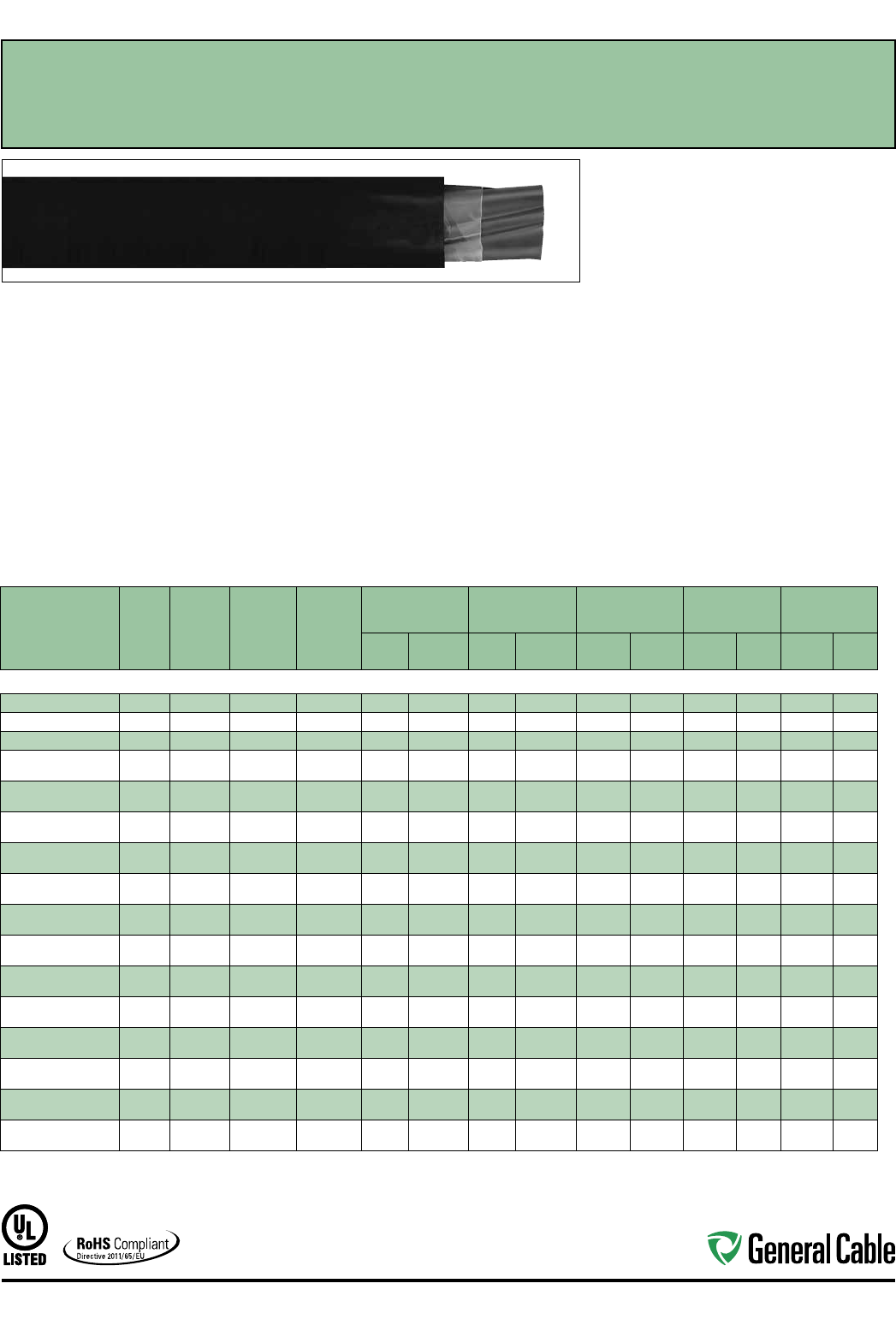
Industrial Automation
53
CATALOG
NUMBER
NO. OF
COND.
COND.
SIZE
(AWG/
kcmil)
COND.
STRAND
GROUND
WIRE SIZE
(AWG)
MINIMUM AVG.
INSULATION
THICKNESS
MINIMUM AVG.
JACKET THICKNESS NOMINAL CABLE O.D.
COPPER
WEIGHT NET WEIGHT
INCHES mm INCHES mm INCHES mm
LBS/
1000 FT kg/km
LBS/
1000 FT kg/km
14 AWG - 750 kcmil CONDUCTORS
383830* 314 7W 14 0.030 0.76 0.045 1.14 0.390 9.91 55 82 118 176
296450* 312 7W 12 0.030 0.76 0.045 1.14 0.435 11.0 5 87 129 160 238
296440* 310 7W 10 0.030 0.76 0.060 1.52 0.485 12.32 136 202 237 353
279660 387W 10 0.045 1.14 0.060 1.52 0.655 16.64 190 283 314 467
279670 487W 10 0.045 1.14 0.060 1.52 0.720 18.29 242 360 393 585
283210 367W 80.045 1.14 0.060 1.52 0.740 18.80 297 442 456 679
300380 467W 80.045 1.14 0.060 1.52 0.790 20.07 384 571 561 835
283200 347W 80.045 1.14 0.060 1.52 0.825 22.35 442 658 642 955
295390 447W 80.045 1.14 0.060 1.52 0.950 24.13 578 861 822 1223
293600 327W 60.045 1.14 0.080 2.03 1.010 25.65 703 1046 979 1457
295890 427W 60.045 1.14 0.080 2.03 1.090 27. 6 9 919 1368 1235 1838
297730* 3119W 60.055 1.40 0.080 2.03 1.120 28.45 872 1298 1021 1594
356740* 4119W 60.055 1.40 0.080 2.03 1.235 31.37 1136 1691 1521 2264
283220 31/0 19W 60.055 1.40 0.080 2.03 1.225 31.12 1069 1591 1439 2142
294530* 41/0 19W 60.055 1.40 0.080 2.03 1.330 33.78 1413 2103 1820 2709
284560 32/0 19W 60.055 1.40 0.080 2.03 1.300 33.02 1340 1994 1720 2560
295360* 42/0 19W 60.055 1.40 0.080 2.03 1.440 36.58 1760 2619 2208 3286
325700* 33/0 19W 40.055 1.40 0.080 2.03 1.420 36.07 1717 2555 2176 3238
365750* 43/0 19W 40.055 1.40 0.080 2.03 1.570 39.88 2245 3341 2788 3405
325110 34/0 19W 40.055 1.40 0.080 2.03 1.540 39.12 2130 3170 2614 3890
346980* 44/0 19W 40.055 1.40 0.110 2.79 1.790 45.47 2796 4161 3495 5201
300780 3250 37W 40.065 1.65 0.110 2.79 1.760 44.70 2494 3712 3184 4738
346990* 4250 37W 40.065 1.65 0.110 2.79 1.915 48.64 3282 4884 4019 5981
325120 3350 37W 30.065 1.65 0.110 2.79 1.960 49.78 3474 5170 4187 6231
347000* 4350 37W 30.065 1.65 0.110 2.79 2.165 5499 4577 6811 5436 8090
298020 3500 37W 20.065 1.65 0.110 2.79 2.245 57.0 2 4934 7343 5847 8702
14407.546500* 4500 37W 20.065 1.65 0.110 2.79 2.475 62.87 6509 9687 7607 11321
14407.247000* 3750 61W 10.080 2.03 0.140 3.56 2.810 71.37 7278 10831 9145 13610
14407.547000* 4750 61W 10.080 2.03 0.140 3.56 3.115 79.12 9712 14453 11805 17569
Dimensions and weights are nominal; subject to industry tolerances.
* Non-stock item; minimum runs apply. Please consult Customer Service for price and delivery.
¹ Approved as TYPE TC-ER for Exposed Run applications of 3 or more conductors as defined by NEC.
SPEC 4350
November, 2014
FREP
®a
FR-EPR/CPE, Low-Voltage Power, Unshielded
600 V, UL Type TC-ER
1
—Method 4 Color Code
Product Construction:
Conductor:
• 14 AWG thru 750 kcmil tinned, annealed
copper per ASTM B33
• Class B stranding per ASTM B8
Insulation:
• Flame-Retardant Ethylene Propylene Rubber
(FR-EPR) Type II
• Color-coded per ICEA Method 4; individual
conductors colored black with conductor number
surface printed in contrasting ink
Ground:
• Uninsulated tinned annealed copper per ASTM B3
• Class B stranding per ASTM B8
Jacket:
• Lead-free, flame-retardant thermoplastic
Chlorinated Polyethylene (CPE)
Print:
• GENERAL CABLE® (PLANT OF MFG) FREP®
XX/C XXAWG WITH GRND EPR/CPE (UL) TYPE
TC-ER XHHW-2 CDRS 90˚C WET OR DRY 600 V
DIR BUR SUN RES DAY/MONTH/YEAR OF MFG
SEQUENTIAL FOOTAGE MARK
Applications:
• In free air, raceways or direct burial
• In wet or dry locations
• Permitted for Exposed Run (ER) use in accordance
with NEC for 3 or more conductors
• Permitted for use in Class I, Division 2 industrial
hazardous locations per NEC
Features:
• Rated at 90˚C wet or dry
• Ripcord applied to all cables with jacket thickness
of 60 mils or less
• Excellent physical, thermal and electrical properties
• Excellent moisture resistance
• Excellent resistance to crush, compression cuts
and heat deformation
Features (cont’d.):
• Excellent low temperature cold bend
characteristics
• Excellent flame resistance—burns to ash; does not
exhibit thermoplastic drip
• Low coefficient of friction for easy pulling
• Sunlight- and weather-resistant
• Meets cold bend test at -40˚C
Compliances:
Industry Compliances:
• UL 44 Type XHHW-2
• UL 1277 Type TC-ER, UL File # E57179
• UL 1581
• ICEA S-95-658/NEMA WC70
Flame Test Compliances:
• UL 1581/UL 2556 VW-1
• UL 1685 Vertical Flame Test
• IEEE 383
• IEEE 1202
• CSA FT4
• ICEA T-29-520
Other Compliances:
• EPA 40 CFR, Part 261 for leachable lead
content per TCLP
• OSHA Acceptable
• RoHS Compliant
Packaging:
• Material cut to length and shipped on
non-returnable wood reels

Industrial Automation
54
CATALOG
NUMBER
NO.
OF
COND.
COND.
SIZE
(AWG)
COND.
STRAND
MINIMUM AVG.
INSULATION
THICKNESS
MINIMUM AVG.
JACKET
THICKNESS
NOMINAL
CABLE O.D.
COPPER
WEIGHT NET WEIGHT
LBS/
1000 FT kg/km
LBS/
1000 FT kg/kmINCHES mm INCHES mm INCHES mm
14 AWG CONDUCTORS
394280* 2 Flat 14 7W 0.030 0.76 0.045 1.14
.365 x .230
9.30 x 5.80
26 38 61 91
394290* 214 7W 0.030 0.76 0.045 1.14 0.370 9.40 26 39 71 106
394300* 314 7W 0.030 0.76 0.045 1.14 0.390 9.91 39 59 92 137
394310* 414 7W 0.030 0.76 0.045 1.14 0.425
10.80
53 78 115 171
394320* 514 7W 0.030 0.76 0.045 1.14 0.465 11. 81 66 98 139 207
394330* 714 7W 0.030 0.76 0.045 1.14 0.505 12.83 92 137 173 257
394340* 914 7W 0.030 0.76 0.060 1.52 0.620 15.75 118 176 240 357
394350* 12 14 7W 0.030 0.76 0.060 1.52 0.700 17.78 158 235 301 448
394360* 19 14 7W 0.030 0.76 0.060 1.52 0.815 20.70 250 372 468 696
394370* 25 14 7W 0.030 0.76 0.080 2.03 0.935 23.75 323 481 624 929
394380* 30 14 7W 0.030 0.76 0.080 2.03 1.030 26.16 387 576 747 1112
394390* 37 14 7W 0.030 0.76 0.080 2.03 1.110 28.19 466 694 875 1302
12 AWG CONDUCTORS
394400* 2 Flat 12 7W 0.030 0.76 0.045 1.14
.400 x .245
10.20 x 6.20
40 60 82 122
394410* 212 7W 0.030 0.76 0.045 1.14 0.410 10.41 41 61 94 140
3944202*
3+ Grnd
12 7W 0.030 0.76 0.045 1.14 0.435 11.05 85 127 148 220
394430* 312 7W 0.030 0.76 0.045 1.14 0.435 11.05 64 95 124 185
394440* 412 7W 0.030 0.76 0.045 1.14 0.475 12.07 85 127 157 234
394450* 512 7W 0.030 0.76 0.045 1.14 0.520 13.21 106 158 191 284
394460* 712 7W 0.030 0.76 0.060 1.52 0.595 15.11 149 221 268 399
394470* 912 7W 0.030 0.76 0.060 1.52 0.695 17.65 191 285 337 502
394480* 12 12 7W 0.030 0.76 0.060 1.52 0.765 19.43 247 368 428 637
394490* 19 12 7W 0.030 0.76 0.080 2.03 0.940 23.88 391 582 688 1024
394500* 25 12 7W 0.030 0.76 0.080 2.03 1.095 27.81 515 767 854 1271
394510* 30 12 7W 0.030 0.76 0.080 2.03 1.150 29.21 618 920 1002 1491
394520* 37 12 7W 0.030 0.76 0.080 2.03 1.240 31.50 762 1134 1240 1845
10 AWG CONDUCTORS
394530* 2 Flat 10 7W 0.030 0.76 0.045 1.14
.445 x .270
11.30 x 6.90
64 95 113 168
394540* 210 7W 0.030 0.76 0.045 1.14 0.455 11.56 65 97 128 190
3945502*
3+ Grnd
10 7W 0.030 0.76 0.045 1.14 0.485 12.32 134 199 225 335
394560* 310 7W 0.030 0.76 0.045 1.14 0.485 12.32 100 150 172 256
394570* 410 7W 0.030 0.76 0.060 1.52 0.560 14.22 134 199 234 348
394580* 510 7W 0.030 0.76 0.060 1.52 0.615 15.62 167 249 284 423
394590* 710 7W 0.030 0.76 0.060 1.52 0.670 17.02 234 349 381 567
394600* 910 7W 0.030 0.76 0.060 1.52 0.760 19.30 295 440 464 691
394610* 12 10 7W 0.030 0.76 0.080 2.03 0.905 22.99 402 598 651 696
Dimensions and weights are nominal; subject to industry tolerances.
* Non-stock item; minimum runs apply. Please consult Customer Service for price and delivery.
¹ Approved as -ER for Exposed Run applications of 3 or more conductors as defined by the NEC.
² This construction does not require an -ER mark.
SPEC 4900
November, 2014
GenFree
®
XLPE/LSZH, Control
600 V, UL Type TC-LS-ER
1
—E-2 Color Code
Product Construction:
Conductor:
• 14 AWG thru 10 AWG stranded tinned copper per
ASTM B33
• Class B stranding per ASTM B8
Insulation:
• Lead-free, flame-retardant, low-smoke
Cross-linked Polyethylene (XLPE)
• Color-coded per ICEA Method 1, Table E-2 (does
not include white or green)
Jacket:
• Lead-free, flame-retardant, sunlight-resistant,
Low-Smoke, Zero-Halogen Polyolefin (LSZH)
Print
• GENERAL CABLE® (PLANT OF MFG) GENFREE®
XX/C XXAWG XLPE/LSZH (UL) TYPE TC-LS-ER
XHHW-2 CDRS 90°C WET OR DRY 600 V DIR
BUR SUN RES ROHS DAY/MONTH/YEAR OF
MFG SEQUENTIAL FOOTAGE MARK
Applications:
• In free air, raceways, aerial or direct burial
• In wet or dry locations
• Permitted for use in Class I, Division 2 industrial
hazardous locations per NEC
• Permitted for Exposed Run (ER) use in
accordance with the NEC for 3 or more
conductors
Features:
• Rated at 90˚C wet or dry
• Ripcord applied to all cables with jacket thickness
of 60 mils or less
• Excellent physical and electrical properties
• Excellent moisture resistance
• Excellent resistance to compression and impact
• Chemical-resistant
• Low coefficient of friction for easy pulling
• Sunlight- and weather-resistant
• Meets cold bend test at -30˚C
• Low-Smoke, Zero-Halogen jacket is
environmentally safe
• Low-Smoke, Zero-Halogen jacket reduces the
amount of toxic and corrosive gases emitted
during combustion, providing a safer environment
for personnel and equipment during the hazards
of fire
• Meets the crush and impact requirements of Type
MC cable for 3 or more conductors
Compliances:
Industry Compliances:
• UL 44 Type XHHW-2
• UL 1277 Type TC-LS-ER, UL File # E57179
• UL 1581
• ICEA S-73-532/NEMA WC57
• ICEA T-33-655
• RoHS Compliant
Flame Test Compliances:
• UL 1581/UL 2556
• UL 1685 Vertical Flame Test
• IEEE 1202
Other Compliances:
• EPA 40 CFR, Part 261 for leachable lead
content per TCLP
• OSHA Acceptable
Packaging:
• Material cut to length and shipped on
non-returnable wood reels
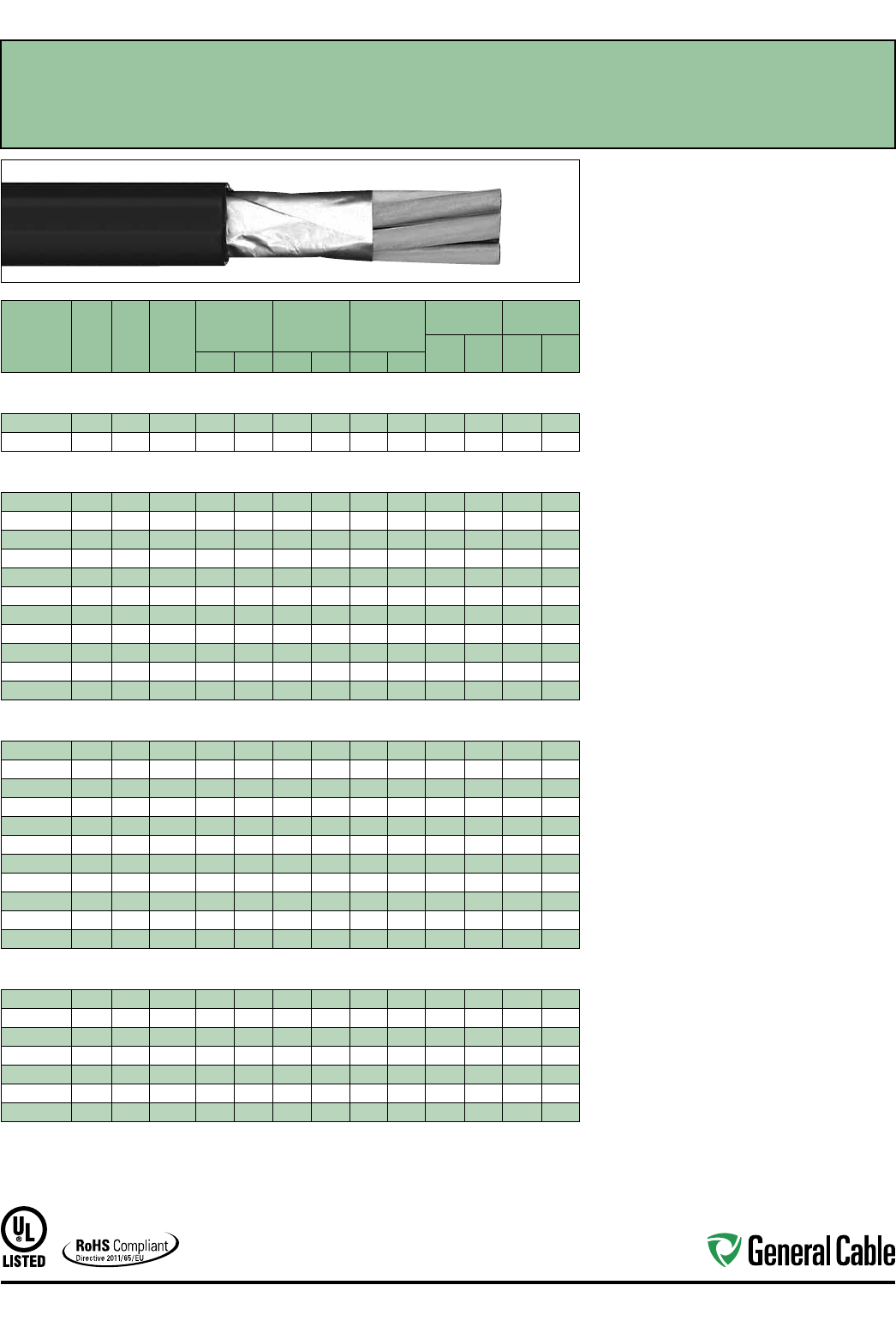
Industrial Automation
55
CATALOG
NUMBER
NO.
OF
COND.
COND.
SIZE
(AWG)
COND.
STRAND
MINIMUM AVG.
INSULATION
THICKNESS
MINIMUM AVG.
JACKET
THICKNESS
NOMINAL
CABLE O.D.
COPPER
WEIGHT NET WEIGHT
LBS/
1000 FT kg/km
LBS/
1000 FT kg/kmINCHES mm INCHES mm INCHES mm
OVERALL SHIELDED MULTI-CONDUCTORS
16 AWG CONDUCTORS
394960* 216 7W 0.025 0.64 0.045 1.14 0.320
8.13
19 28 52 77
394630* 316 7W 0.025 0.64 0.045 1.14 0.335 8.51 27 40 66 98
OVERALL SHIELDED MULTI-CONDUCTORS
14 AWG CONDUCTORS
394640* 214 7W 0.030 0.76 0.045 1.14 0.375 9.53 29 43 74 110
394650* 314 7W 0.030 0.76 0.045 1.14 0.395 10.03 42 63 95 141
394660* 414 7W 0.030 0.76 0.045 1.14 0.430 10.92 55 82 118 176
394670* 514 7W 0.030 0.76 0.045 1.14 0.470 11.9 4 68 101 142 211
394680* 714 7W 0.030 0.76 0.045 1.14 0.510 12.95 94 140 176 262
394690* 914 7W 0.030 0.76 0.060 1.52 0.625 15.88 121 180 243 362
394700* 12 14 7W 0.030 0.76 0.060 1.52 0.705 17. 91 160 238 304 452
394710* 19 14 7W 0.030 0.76 0.060 1.52 0.820 20.83 252 375 471 701
394720* 25 14 7W 0.030 0.76 0.080 2.03 0.940 25.53 325 484 627 933
394730* 30 14 7W 0.030 0.76 0.080 2.03 1.035 26.29 389 579 750 1116
394740* 37 14 7W 0.030 0.76 0.080 2.03 1.115 28.32 468 696 878 1307
OVERALL SHIELDED MULTI-CONDUCTORS
12 AWG CONDUCTORS
394750* 212 7W 0.030 0.76 0.045 1.14 0.415 10.45 43 64 97 144
394760* 312 7W 0.030 0.76 0.045 1.14 0.440 11.18 66 98 127 189
394770* 412 7W 0.030 0.76 0.045 1.14 0.480 12.19 87 129 160 238
394780* 512 7W 0.030 0.76 0.045 1.14 0.525 13.34 108 162 194 289
394790* 712 7W 0.030 0.76 0.060 1.52 0.600 15.24 151 225 271 403
394800* 912 7W 0.030 0.76 0.060 1.52 0.700 17.78 193 287 340 506
394810* 12 12 7W 0.030 0.76 0.060 1.52 0.770 19.56 249 371 431 641
394820* 19 12 7W 0.030 0.76 0.080 2.03 0.945 24.00 393 585 691 1028
394830* 25 12 7W 0.030 0.76 0.080 2.03 1.100 27.9 4 517 769 857 1275
394840* 30 12 7W 0.030 0.76 0.080 2.03 1.155 29.80 620 923 1005 1496
394850* 37 12 7W 0.030 0.76 0.080 2.03 1.245 31.62 764 1137 1243 1850
OVERALL SHIELDED MULTI-CONDUCTORS
10 AWG CONDUCTORS
394860* 210 7W 0.030 0.76 0.045 1.14 0.460 11.68 68 101 131 195
394870* 310 7W 0.030 0.76 0.045 1.14 0.490 12.45 103 155 175 260
394880* 410 7W 0.030 0.76 0.060 1.52 0.565 14.35 136 202 237 353
394890* 510 7W 0.030 0.76 0.060 1.52 0.620 15.75 170 253 287 427
394900* 710 7W 0.030 0.76 0.060 1.52 0.675 17.15 237 353 384 571
394910* 910 7W 0.030 0.76 0.060 1.52 0.765 19.43 298 443 467 695
394920* 12 10 7W 0.030 0.76 0.080 2.03 0.910 23.11 404 601 654 973
Dimensions and weights are nominal; subject to industry tolerances.
* Non-stock item; minimum runs apply. Please consult Customer Service for price and delivery.
¹ Approved as -ER for Exposed Run applications of 3 or more conductors as defined by the NEC.
SPEC 4925
November, 2014
GenFree
®
XLPE/LSZH, Control, Shielded
600 V, UL Type TC-LS-ER
1
, Overall Shielded—E-2 Color Code
Product Construction:
Conductor:
• 16 AWG thru 10 AWG stranded tinned copper per
ASTM B33
• Class B stranding per ASTM B8
Insulation:
• Lead-free, flame-retardant, low-smoke
Cross-linked Polyethylene (XLPE)
• Color-coded per ICEA Method 1, Table E-2
(does not include white or green)
Shield:
Overall shielded multi-conductor cable
• Overall shield is Flexfoil® aluminum/polymer in
contact with stranded tinned copper drain wire
Jacket:
• Lead-free, flame-retardant, sunlight-resistant,
Low-Smoke, Zero-Halogen Polyolefin (LSZH)
Print
• GENERAL CABLE® (PLANT OF MFG) SHIELDED
GENFREE® XX/C XXAWG XLPE/LSZH (UL) TYPE
TC-LS-ER XHHW-2 CDRS 90˚C WET OR DRY 600
V DIR BUR SUN RES ROHS DAY/MONTH/YEAR
OF MFG SEQUENTIAL FOOTAGE MARK
Applications:
• In free air, raceway, aerial and direct burial
• In wet or dry locations
• Permitted for use in Class I, Division 2 industrial
hazardous locations per NEC
• Permitted for Exposed Run (ER) use in
accordance with the NEC for 3 or more
conductors
Features:
• Rated at 90˚C wet or dry
• Ripcord applied to all cables with jacket thickness
of 60 mils or less
• Excellent physical and electrical properties
• Excellent moisture resistance
• Excellent resistance to compression and impact
• Chemical-resistant
• Low coefficient of friction for easy pulling
• Sunlight- and weather-resistant
• Meets cold bend test at -30˚C
• Low-Smoke, Zero-Halogen jacket is
environmentally safe
• Low-Smoke, Zero-Halogen jacket reduces the
amount of toxic and corrosive gases emitted
during combustion, providing a safer environment
for personnel and equipment during the hazards
of fire
• Meets the crush and impact requirements of Type
MC cable for 3 or more conductors
Compliances:
Industry Compliances:
• UL 44 Type XHHW-2
• UL 1277 Type TC-LS-ER, UL File # E57179
• UL 1581/UL 2556
• ICEA S-73-532/NEMA WC57
• ICEA T-33-655
• RoHS Compliant
Flame Test Compliances:
• UL 1581/UL 2556
• UL 1685 Vertical Flame Test
• IEEE 1202
Other Compliances:
• EPA 40 CFR, Part 261 for leachable lead
content per TCLP
• OSHA Acceptable
Packaging:
• Material cut to length and shipped on
non-returnable wood reels
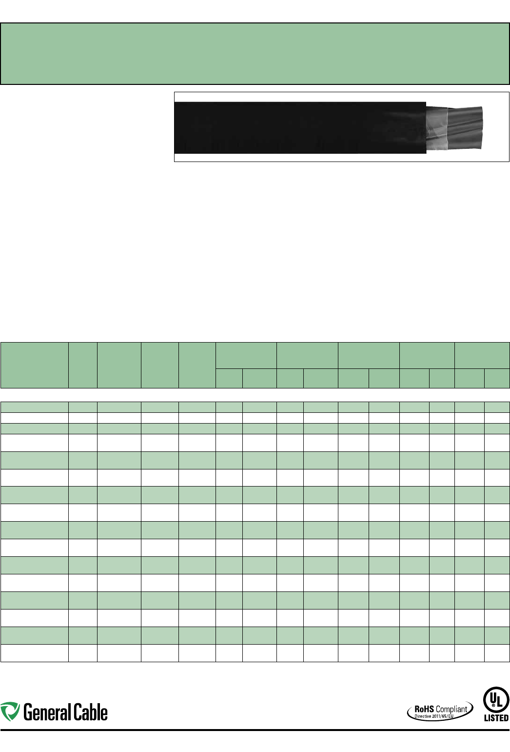
Industrial Automation
56
CATALOG
NUMBER
NO. OF
COND.
COND.
SIZE
(AWG/
kcmil)
COND.
STRAND
GROUND
WIRE SIZE
(AWG)
MINIMUM AVG.
INSULATION
THICKNESS
MINIMUM AVG.
JACKET THICKNESS NOMINAL CABLE O.D.
COPPER
WEIGHT NET WEIGHT
INCHES mm INCHES mm INCHES mm
LBS/
1000 FT kg/km
LBS/
1000 FT kg/km
14 AWG - 750 kcmil CONDUCTORS
394930* 314 7W 14 0.030 0.76 0.045 1.14 0.390 9.91 55 82 118 176
394940* 312 7W 12 0.030 0.76 0.045 1.14 0.435 11.05 87 129 160 238
394950* 310 7W 10 0.030 0.76 0.045 1.14 0.485 12.32 124 184 194 289
14428.030800* 387W 10 0.045 1.14 0.060 1.52 0.655 16.64 190 283 314 467
14428.040800* 487W 10 0.045 1.14 0.060 1.52 0.720 18.29 242 360 393 585
14428.030600* 367W 80.045 1.14 0.060 1.52 0.740 18.80 297 442 456 679
14428.040600* 467W 80.045 1.14 0.060 1.52 0.790 20.07 384 571 561 835
14428.030400* 347W 80.045 1.14 0.080 2.03 0.880 22.35 442 658 642 955
14428.040400* 447W 80.045 1.14 0.080 2.03 0.950 24.13 578 861 822 1223
14428.030200* 327W 60.045 1.14 0.080 2.03 1.010 25.65 703 1046 979 1457
14428.040200* 427W 60.045 1.14 0.080 2.03 1.090 27.69 919 1368 1235 1838
14428.030100* 3119W 60.055 1.40 0.080 2.03 1.120 28.45 872 1298 1021 1594
14428.040100* 4119W 60.055 1.40 0.080 2.03 1.235 31.37 1136 1691 1521 2264
14428.035100* 31/0 19W 60.055 1.40 0.080 2.03 1.225 31.12 1069 1591 1439 2142
14428.045100* 41/0 19W 60.055 1.40 0.080 2.03 1.330 33.78 1413 2103 1820 2709
14428.035200* 32/0 19W 60.055 1.40 0.080 2.03 1.300 33.02 1340 1994 1720 2560
14428.045200* 42/0 19W 60.055 1.40 0.080 2.03 1.440 36.58 1760 2619 2208 3286
14428.035300* 33/0 19W 40.055 1.40 0.080 2.03 1.420 36.07 1717 2555 2176 3238
14428.045300* 43/0 19W 40.055 1.40 0.080 2.03 1.570 39.88 2245 3341 2788 3405
14428.035400* 34/0 19W 40.055 1.40 0.080 2.03 1.540 39.12 2130 3170 2614 3890
14428.045400* 44/0 19W 40.055 1.40 0.110 2.79 1.790 45.47 2796 4161 3495 5201
14428.036000* 3250 37W 40.065 1.65 0.110 2.79 1.760 44.70 2494 3712 3184 4738
14428.046000* 4250 37W 40.065 1.65 0.110 2.79 1.915 48.64 3282 4884 4019 5981
14428.036200* 3350 37W 30.065 1.65 0.110 2.79 1.960 49.78 3474 5170 4187 6231
14428.046200* 4350 37W 30.065 1.65 0.110 2.79 2.165 54.99 4577 6811 5436 8090
14428.036500* 3500 37W 20.065 1.65 0.110 2.79 2.245 57.02 4934 7343 5847 8702
14428.046500* 4500 37W 20.065 1.65 0.110 2.79 2.475 62.87 6509 9687 7607 11321
14428.037000* 3750 61W 10.080 2.03 0.140 3.56 2.810 71.37 7278 10831 9145 13610
14428.047000* 4750 61W 10.080 2.03 0.14 0 3.56 3.115 79.12 9712 14453 11805 17569
Dimensions and weights are nominal; subject to industry tolerances.
* Non-stock item; minimum runs apply. Please consult Customer Service for price and delivery.
SPEC 4950
November, 2014
GenFree
®
XLPE/LSZH, Low-Voltage Power, Unshielded
600 V, UL Type TC-LS-ER—Method 4 Color Code
Product Construction:
Conductor:
• 14 AWG thru 750 kcmil tinned annealed
copper per ASTM B33
• Class B stranding per ASTM B8
Insulation:
• Lead-free, flame-retardant, low-smoke
Cross-linked Polyethylene (XLPE)
• Color-coded per ICEA Method 4; individual
conductors colored black with conductor number
surface printed in contrasting ink
Ground:
• Uninsulated bare annealed copper per ASTM B3
• Class B stranding per ASTM B8
Jacket:
• Lead-free, flame-retardant, sunlight-resistant,
Low-Smoke, Zero-Halogen Polyolefin (LSZH)
Print:
• GENERAL CABLE® (PLANT OF MFG) GENFREE®
XX/C XXAWG XLPE/LSZH (UL) TYPE TC-LS-ER
XHHW-2 CDRS 90˚C WET OR DRY 600 V DIR
BUR SUN RES ROHS DAY/MONTH/YEAR OF
MFG SEQUENTIAL FOOTAGE MARK
Applications:
• In free air, raceways, aerial or direct burial
• In wet or dry locations
• Permitted for use in Class I, Division 2 industrial
hazardous locations per NEC
• Permitted for Exposed Run (ER) use in
accordance with the NEC
Features:
• Rated at 90˚C wet or dry
• Ripcord applied to all cables with jacket thickness
of 60 mils or less
• Excellent physical, thermal and electrical properties
• Excellent moisture resistance
• Excellent resistance to crush, compression and
impact
• Chemical-resistant
• Low coefficient of friction for easy pulling
• Sunlight- and weather-resistant
• Meets cold bend test at -30˚C
• Low-Smoke, Zero-Halogen jacket is
environmentally safe
• Low-Smoke, Zero-Halogen jacket reduces the
amount of toxic and corrosive gases emitted during
combustion, providing a safer environment for
personnel and equipment during the hazards of fire
Compliances:
Industry Compliances:
• UL 44 Type XHHW-2
• UL 1277 Type TC-LS-ER, UL File # E57179
• UL 1581/UL 2556
• ICEA S-95-658/NEMA WC70
• ICEA T-33-655
• RoHS Compliant
Flame Test Compliances:
• UL 1581/UL 2556
• UL 1685 Vertical Flame Test
• IEEE 1202
Other Compliances:
• EPA 40 CFR, Part 261 for leachable lead
content per TCLP
• OSHA Acceptable
Packaging:
• Material cut to length and shipped on
non-returnable wood reels
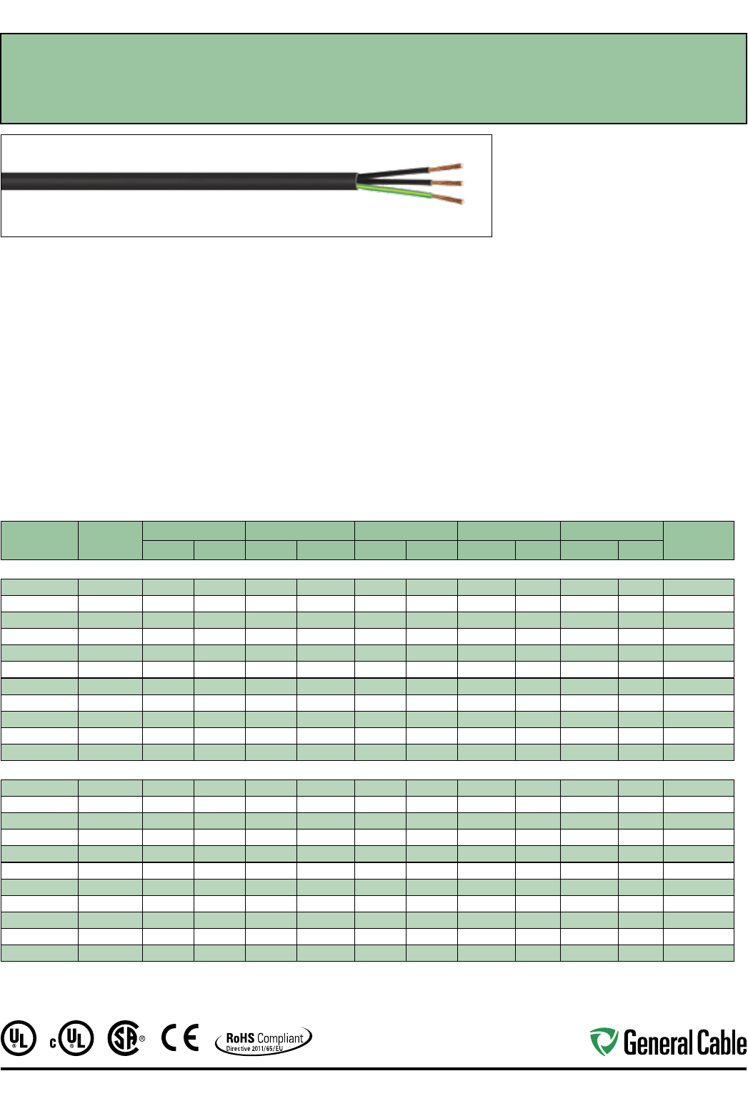
Industrial Automation
57
TC-Flex™ Tray Cable
18 AWG (1,0 mm
²
) — 16 AWG (1,5 mm
²
)
UL Type WTTC 1000 V or Type TC-ER 600 V or Type MTW and c(UL) CIC/TC 600 V FT4 or CSA AWM
90°C 1000 V, Flexible, Oil Res I/II, Sunlight- and Torsion-Resistant, Flame-Retardant, -40˚C to +90˚C
SPEC 4775
November, 2013
Product Construction:
Conductors:
• 18 AWG (1,0 mm²) and 16 AWG (1,5 mm²) fully
annealed flexible stranded bare copper with
Class 5 stranding per EN 60228 (IEC 60228)
Insulation:
• Polyvinyl Chloride (PVC) insulation with Polyamide
(nylon) jacket per UL 83
Conductor Identification:
• Conductors are black with printed numbers and
green/yellow grounding conductor
Cable Assembly:
• Conductors cabled with non-hygroscopic fillers to
make the cable suitably round
Jacket:
• Black, flexible, flame-retardant, sunlight- and oil-
resistant Polyvinyl Chloride (PVC) jacket
Print:
• GENERAL CABLE® TC-FLEX™ XX/C XXAWG
(XXMM2) (UL) TC-ER TYPE TFFN 90˚C DRY
600 V SUN RES DIR BUR OIL RES I/II OR MTW
OR WTTC 1000 V 90˚C DRY c(UL) CIC/TC PVC/N
90˚C FT4 --- CSA AWM I/II A/B 90˚C 1000 V –
ROHS CE – MADE IN USA DAY/MONTH/YEAR OF
MFG SEQUENTIAL FOOTAGE MARKER
Minimum Bending Radius:
• 4x O.D. for fixed installation
• 8x O.D. for flexing applications
Torsion:
• 10,000 cycles at -40°C, +/- 150° twist per meter,
cable weight compensated to 20 meters
Applications:
• In free air, raceways or direct burial
• (UL) WTTC cables for use up to 1000 V in wind
turbine generator applications in accordance with
UL Subject 6140
• (UL) TC-ER cables for use up to 600 V as power
and control cables in accordance with NEC®
Article 336
Applications (cont'd.):
• (UL) MTW cables for machine tool and wire up to
600 V as power and control cables in accordance
with UL 1063
• (CSA) CIC/TC cables for use up to 600 V in cable
trays and other applications when installed in
accordance with the Canadian Electrical Code, Part I
• (CSA) AWM cables for use up to 1000 V as
equipment wiring in accordance with the
Canadian Electrical Code, Part I
Specifications:
Design Adherence:
• UL 66 & UL 83/CSA C22.2 No. 75-08
Thermoplastic Insulated Wires
• UL 1063/MTW Machine Tool Wire
• UL 1277 Power and Control Tray Cables
• UL 2277 Wind Turbine Tray Cables
• CSA C22.2 No. 230-09 Tray Cables
• CSA C22.2 No. 239-09 Control and
Instrumentation Cables
• CSA C22.2 No. 210-11 Appliance Wiring
Material Products
Flame Tests:
• IEEE 1202/CSA FT4
Compliances:
• Type TC-ER 90°C Dry, 75°C Wet, 600 V
• Type MTW
• Type WTTC 90°C, 1000 V
• Type CIC/TC 90°C, 600 V
• Type AWM I/II A/B, 90°C, 1000 V FT4
• RoHS Compliant
CATALOG
NUMBER
NO. OF COND.
INC. GRND.
NOM. INS. THICKNESS NOM. JACKET THICKNESS NOM. CABLE O.D. NOM. COPPER WEIGHT NOM. CABLE WEIGHT 90°C AMP. @
30°C AMBIENT¹INCHES mm INCHES mm INCHES mm LBS/1000 FT kg/km LBS/1000 FT kg/km
18 AWG (1,0 mm²) 19 Strands
4775.03018
3 0.021 0.53 0.048 1.22 0.313 7.9 18 26 50 74 8
4775.04018
4 0.021 0.53 0.048 1.22 0.338 8.6 23 35 61 90 8
4775.05018
5 0.021 0.53 0.048 1.22 0.363 9.2 29 43 72 107 8
4775.07018
7 0.021 0.53 0.048 1.22 0.409 10.4 41 61 93 138 8
4775.09018*
9 0.021 0.53 0.048 1.22 0.448 11.4 53 78 114 169 7
4775.12018
12 0.021 0.53 0.048 1.22 0.497 12.6 70 104 144 214 7
4775.16018
16 0.021 0.53 0.063 1.60 0.578 14.7 94 139 197 294 6
4775.19018
19 0.021 0.53 0.063 1.60 0.623 15.8 111 165 229 340 6
4775.25018*
25 0.021 0.53 0.063 1.60 0.697 17.7 146 217 289 429 6
4775.30018*
30 0.021 0.53 0.063 1.60 0.735 18.7 175 261 336 500 5
4775.37018*
37 0.021 0.53 0.063 1.60 0.789 20.0 216 322 402 598 5
16 AWG (1,5 mm²) 28 Strands
4775.03016
3 0.021 0.53 0.048 1.22 0.339 8.6 26 39 63 93 10
4775.04016
4 0.021 0.53 0.048 1.22 0.367 9.3 35 52 77 115 10
4775.05016
5 0.021 0.53 0.048 1.22 0.396 10.1 44 66 92 137 10
4775.07016
7 0.021 0.53 0.048 1.22 0.448 11.4 62 92 121 179 10
4775.09016*
9 0.021 0.53 0.048 1.22 0.491 12.5 79 118 149 221 9
4775.12016
12 0.021 0.53 0.063 1.60 0.577 14.6 106 157 204 304 9
4775.16016
16 0.021 0.53 0.063 1.60 0.634 16.1 141 210 259 385 7
4775.19016
19 0.021 0.53 0.063 1.60 0.686 17.4 167 249 301 448 7
4775.25016
25 0.021 0.53 0.063 1.60 0.769 19.5 220 328 383 570 7
4775.30016*
30 0.021 0.53 0.063 1.60 0.812 20.6 264 393 448 666 6
4775.37016*
37 0.021 0.53 0.085 2.16 0.917 23.3 326 485 573 853 6
* Non-stock item; minimum runs apply. Please consult Customer Service for price and delivery.
¹ Ampacities provided are for open cable runs, in a raceway, directly buried, or as aerial cable supported on a messenger in accordance with NEC® Articles 336.80 and 392.11,
Table 310.16 and are derated in accordance with NEC® 310.15.B.2.
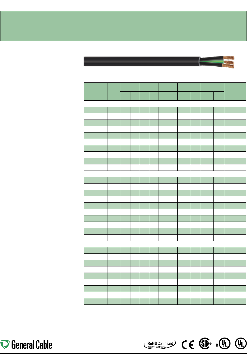
Industrial Automation
58
TC-Flex™ Tray Cable
14 AWG (2,5 mm
²
) – 10 AWG (6,0 mm
²
)
UL Type WTTC 1000 V or Type TC-ER 600 V or Type MTW and c(UL) CIC/TC 600 V FT4 or CSA AWM
90°C 1000 V, Flexible, Oil Res I/II, Sunlight- and Torsion-Resistant, Flame-Retardant, -40˚C to +90˚C
SPEC 4780
November, 2013
CATALOG
NUMBER
NO. OF
COND.
INC.
GRND.
NOM. INS.
THICKNESS
NOM. JACKET
THICKNESS
NOM.
CABLE O.D.
NOM. COPPER
WEIGHT
NOM. CABLE
WEIGHT
90°C
AMP. @ 30°C
AMBIENT¹
INCHES mm INCHES mm INCHES mm
LBS/
1000 FT kg/km
LBS/
1000 FT kg/km
14 AWG (2,50 mm²) 46 Strands
4780.03014
3 0.021 0.53 0.048 1.22 0.375 9.5 43 65 85 126 18
4780.04014
4 0.021 0.53 0.048 1.22 0.408 10.4 58 86 106 158 18
4780.05014
5 0.021 0.53 0.048 1.22 0.442 11.2 72 108 128 190 18
4780.07014
7 0.021 0.53 0.048 1.22 0.502 12.8 101 151 170 253 18
4780.09014*
9 0.021 0.53 0.063 1.60 0.583 14.8 130 194 226 336 16
4780.12014*
12 0.021 0.53 0.063 1.60 0.647 16.4 174 259 289 429 16
4780.19014*
19 0.021 0.53 0.063 1.60 0.774 19.7 275 410 432 642 12
4780.25014*
25 0.021 0.53 0.085 2.16 0.915 23.2 362 539 587 874 12
4780.30014*
30 0.021 0.53 0.085 2.16 0.965 24.5 435 647 686 1,021 10
4780.37014*
37 0.021 0.53 0.085 2.16 1.036 26.3 536 798 826 1,229 10
12 AWG (4,0 mm²) 56 Strands
4780.03012
3 0.021 0.53 0.048 1.22 0.435 11.1 72 108 123 183 25
4780.04012
4 0.021 0.53 0.048 1.22 0.476 12.1 97 144 155 231 25
4780.05012
5 0.021 0.53 0.048 1.22 0.517 13.1 121 180 188 280 25
4780.07012*
7 0.021 0.53 0.063 1.60 0.622 15.8 169 252 269 401 25
4780.09012*
9 0.021 0.53 0.063 1.60 0.684 17.4 217 323 335 498 20
4780.12012*
12 0.021 0.53 0.063 1.60 0.763 19.4 290 431 431 642 20
4780.19012*
19 0.021 0.53 0.085 2.16 0.964 24.5 459 683 689 1,025 17
4780.25012*
25 0.021 0.53 0.095 2.41 1.103 28.0 604 898 901 1,341 17
4780.30012*
30 0.021 0.53 0.095 2.41 1.164 29.6 724 1,078 1,057 1,572 14
4780.37012*
37 0.021 0.53 0.095 2.41 1.252 31.8 893 1,329 1,275 1,897 14
10 AWG (6,0 mm²) 82 Strands
4780.03010
3 0.027 0.69 0.048 1.22 0.491 12.5 109 162 172 256 35
4780.04010
4 0.027 0.69 0.063 1.60 0.567 14.4 146 217 234 348 35
4780.05010
5 0.027 0.69 0.063 1.60 0.618 15.7 182 271 284 422 35
4780.07010*
7 0.027 0.69 0.063 1.60 0.705 17.9 255 379 381 568 35
4780.09010*
9 0.027 0.69 0.063 1.60 0.779 19.8 327 487 477 710 30
4780.12010*
12 0.027 0.69 0.085 2.16 0.915 23.2 437 650 654 973 30
4780.19010*
19 0.027 0.69 0.095 2.41 1.119 28.4 691 1,029 1,007 1,499 25
4780.25010*
25 0.027 0.69 0.095 2.41 1.259 32.0 910 1,354 1,293 1,925 20
4780.30010*
30 0.027 0.69 0.095 2.41 1.331 33.8 1,092 1,625 1,524 2,268 20
* Non-stock item; minimum runs apply. Please consult Customer Service for price and delivery.
¹ Ampacities provided are for open cable runs, in a raceway, directly buried, or as aerial cable supported on a messenger
in accordance with NEC® Articles 336.80 and 392.11, Table 310.16 and are derated in accordance with NEC® 310.15.B.2.
Product Construction:
Conductors:
• 14 AWG (2,5 mm²) thru 10 AWG (6,0 mm²) fully
annealed flexible stranded bare copper with
Class 5 stranding per EN 60228 (IEC 60228)
Insulation:
• Polyvinyl Chloride (PVC) insulation with Polyamide
(nylon) jacket per UL 83
Conductor Identification:
• Conductors are black with printed numbers and
green/yellow grounding conductor
Cable Assembly:
• Conductors cabled with non-hygroscopic fillers
to make the cable suitably round
Jacket:
• Black, flexible, flame-retardant, sunlight- and oil-
resistant Polyvinyl Chloride (PVC) jacket
Print:
• GENERAL CABLE® TC-FLEX™ XX/C XXAWG
(XXMM2) (UL) TC-ER TYPE THHN/THWN 90˚C DRY
75˚C WET 600 V SUN RES DIR BUR OIL RES I/II
OR MTW OR WTTC 1000 V 90˚C DRY c(UL) CIC/TC
PVC/N 90˚C FT4 --- CSA AWM I/II A/B 90˚C 1000 V
– ROHS CE – MADE IN USA DAY/MONTH/YEAR OF
MFG SEQUENTIAL FOOTAGE MARKER
Minimum Bending Radius:
• 4x O.D. for fixed installation
• 8x O.D. for flexing applications
Torsion:
• 10,000 cycles at -40°C, +/- 150° twist per meter,
cable weight compensated to 20 meters
Applications:
• In free air, raceways or direct burial
• (UL) WTTC cables for use up to 1000 V in wind
turbine generator applications in accordance with
UL Subject 6140
• (UL) TC-ER cables for use up to 600 V as power and
control cables in accordance with NEC® Article 336
• (UL) MTW cables for machine tool and wire up to
600 V as power and control cables in accordance
with UL 1063
• (CSA) CIC/TC cables for use up to 600 V in cable
trays and other applications when installed in
accordance with the Canadian Electrical Code,
Part I
• (CSA) AWM cables for use up to 1000 V as
equipment wiring in accordance with the
Canadian Electrical Code, Part I
Specifications:
Design Adherence:
• UL 66 & UL 83/CSA C22.2 No. 75-08
Thermoplastic Insulated Wires
• UL 1063/MTW Machine Tool Wire
• UL 1277 Power and Control Tray Cables
• UL 2277 Wind Turbine Tray Cables
• CSA C22.2 No. 230-09 Tray Cables
• CSA C22.2 No. 239-09 Control
and Instrumentation Cables
• CSA C22.2 No. 210-11 Appliance Wiring
Material Products
Flame Tests:
• IEEE 1202/CSA FT4
Compliances:
• Type TC-ER 90°C Dry, 75°C Wet, 600 V
• Type MTW
• Type WTTC 90°C, 1000 V
• Type CIC/TC 90°C, 600 V
• Type AWM I/II A/B, 90°C, 1000 V FT4
• RoHS Compliant
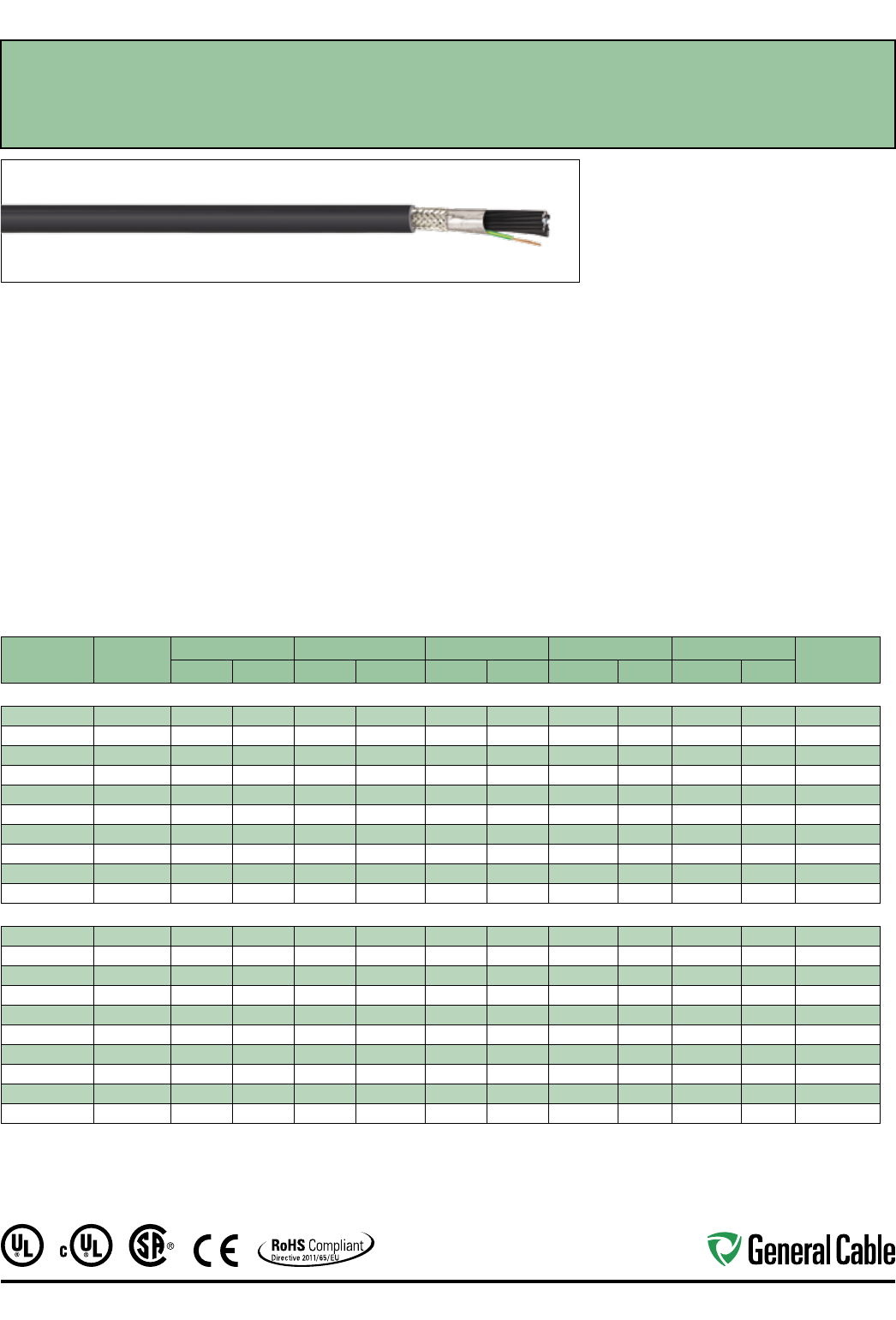
Industrial Automation
59
SPEC 4785
July, 2014
TC-Flex™ Shielded Tray Cable
18 AWG (1,0 mm
²
) — 16 AWG (1,5 mm
²
)
UL Type WTTC 1000 V or Type TC-ER 600 V or Type MTW and c(UL) CIC/TC 600 V FT4 or CSA AWM
90°C 1000 V, Flexible, Oil Res I/II, Sunlight- and Flame-Retardant, -40˚C to +90˚C
Product Construction:
Conductors:
• 18 AWG (1,0 mm²) and 16 AWG (1,5 mm²) fully
annealed flexible stranded bare copper with Class
5 stranding per EN 60228 (IEC 60228)
Insulation:
• Polyvinyl Chloride (PVC) insulation with Polyamide
(nylon) jacket per UL 83
Conductor Identification:
• Conductors are black with printed numbers and
green/yellow grounding conductor
Cable Assembly:
• Conductors cabled with non-hygroscopic fillers
to make cable suitably round
Shield:
• Aluminum/Mylar foil shield providing 100%
coverage combined with a tinned copper braid
with 85% nom. coverage
Jacket:
• Black, flexible, flame-retardant, sunlight- and
oil-resistant Polyvinyl Chloride (PVC) jacket
Print:
• GENERAL CABLE® TC-FLEX™ XX/C XXAWG
(XXMM2) SHIELDED (UL) TC-ER TYPE TFFN 90˚C
DRY 600 V SUN RES DIR BUR OIL RES I/II OR
MTW OR WTTC 1000 V 90˚C DRY c(UL) CIC/TC
PVC/N 90˚C FT4 --- CSA AWM I/II A/B 90˚C
1000 V – ROHS CE – MADE IN USA DAY/MONTH/
YEAR OF MFG SEQUENTIAL FOOTAGE MARKER
Minimum Bending Radius:
• 4x O.D. for fixed installation
• 8x O.D. for flexing applications
Applications:
• In free air, raceways or direct burial
• (UL) WTTC cables for use up to 1000 V in wind
turbine generator applications in accordance with
UL Subject 6140
• (UL) TC-ER cables for use up to 600 V as power and
control cables in accordance with NEC® Article 336
• (UL) MTW cables for machine tool and wire up to
600 V as power and control cables in accordance
with UL 1063
Applications (cont'd.):
• (CSA) CIC/TC cables for use up to 600 V in cable
trays and other applications when installed in
accordance with the Canadian Electrical Code,
Part I
• (CSA) AWM cables for use up to 1000 V as
equipment wiring in accordance with the
Canadian Electrical Code, Part I
Specifications:
Design Adherence:
• UL 66 & UL 83/CSA C22.2 No. 75-08
Thermoplastic Insulated Wires
• UL 1063/MTW Machine Tool Wire
• UL 1277 Power and Control Tray Cables
• UL 2277 Wind Turbine Tray Cables
• CSA C22.2 No. 230-09 Tray Cables
• CSA C22.2 No. 239-09 Control and
Instrumentation Cables
• CSA C22.2 No. 210-11 Appliance Wiring
Material Products
Flame Tests:
• IEEE 1202/CSA FT4
Compliances:
• Type TC-ER 90°C Dry, 75°C Wet, 600 V
• Type MTW
• Type WTTC 90°C, 1000 V
• Type CIC/TC 90°C, 600 V
• Type AWM I/II A/B, 90°C, 1000 V FT4
• RoHS Compliant
CATALOG
NUMBER
NO. OF COND.
INC. GRND.
NOM. INS. THICKNESS NOM. JACKET THICKNESS NOM. CABLE O.D. NOM. COPPER WEIGHT NOM. CABLE WEIGHT 90°C AMP. @
30°C AMBIENT¹INCHES mm INCHES mm INCHES mm LBS/1000 FT kg/km LBS/1000 FT kg/km
18 AWG (1,0 mm²) 19 Strands
4785.03018*
3 0.021 0.53 0.048 1.22 0.334 8.5 30 44 63 93 8
4785.04018
4 0.021 0.53 0.048 1.22 0.359 9.1 41 62 79 118 8
4785.05018*
5 0.021 0.53 0.048 1.22 0.384 9.8 49 72 92 136 8
4785.07018*
7 0.021 0.53 0.048 1.22 0.430 10.9 64 95 116 173 8
4785.09018*
9 0.021 0.53 0.048 1.22 0.469 11.9 79 117 140 208 7
4785.12018*
12 0.021 0.53 0.048 1.22 0.518 13.2 100 149 174 258 7
4785.19018*
19 0.021 0.53 0.063 1.60 0.644 16.4 148 221 266 395 6
4785.25018*
25 0.021 0.53 0.063 1.60 0.718 18.2 189 281 331 492 6
4785.30018*
30 0.021 0.53 0.063 1.60 0.756 19.2 221 329 381 567 5
4785.37018*
37 0.021 0.53 0.063 1.60 0.810 20.6 268 399 453 674 5
16 AWG (1,5 mm²) 28 Strands
4785.03016*
3 0.021 0.53 0.048 1.22 0.360 9.1 44 66 81 121 10
4785.04016
4 0.021 0.53 0.048 1.22 0.388 9.8 56 83 98 146 10
4785.05016*
5 0.021 0.53 0.048 1.22 0.417 10.6 66 99 114 170 10
4785.07016*
7 0.021 0.53 0.048 1.22 0.469 11.9 88 131 147 218 10
4785.09016*
9 0.021 0.53 0.048 1.22 0.512 13.0 109 162 178 265 9
4785.12016*
12 0.021 0.53 0.063 1.60 0.598 15.2 139 207 238 354 9
4785.19016*
19 0.021 0.53 0.063 1.60 0.707 18.0 210 312 343 510 7
4785.25016*
25 0.021 0.53 0.063 1.60 0.790 20.1 269 401 431 641 7
4785.30016*
30 0.021 0.53 0.085 2.16 0.877 22.3 318 473 533 793 6
4785.37016*
37 0.021 0.53 0.085 2.16 0.938 23.8 385 573 632 940 6
* Non-stock item; minimum runs apply. Please consult Customer Service for price and delivery.
¹ Ampacities provided are for open cable runs, in a raceway, directly buried, or as aerial cable supported on a messenger in accordance with NEC® Articles 336.80 and 392.11,
Table 310.16 and are derated in accordance with NEC® 310.15.B.2.
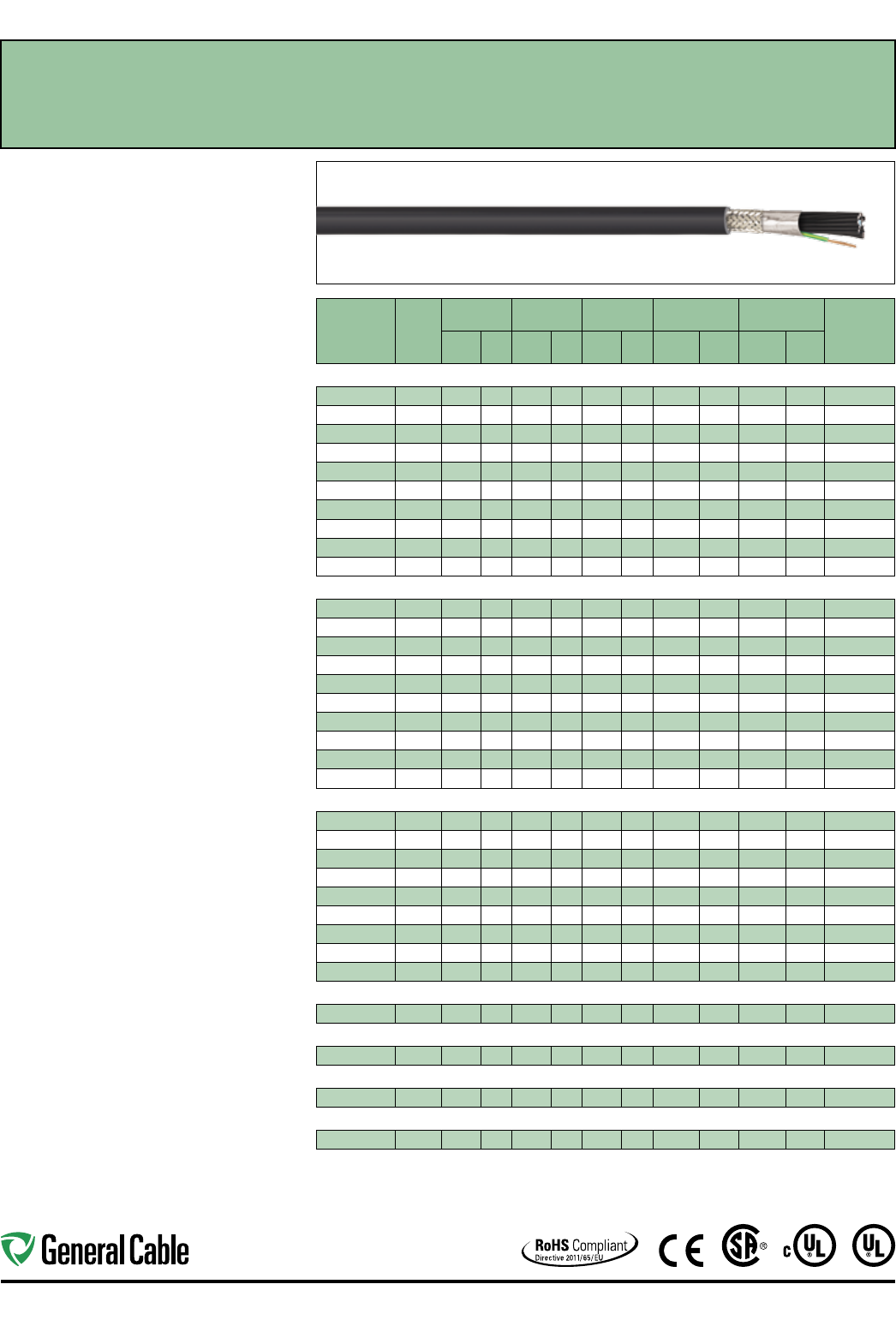
Industrial Automation
60
TC-Flex™ Shielded Tray Cable
14 AWG (2,5 mm
²
) — 2 AWG (35,0 mm
²
)
UL Type WTTC 1000 V or Type TC-ER 600 V or Type MTW and c(UL) CIC/TC 600 V FT4 or CSA AWM
90°C 1000 V, Flexible, Oil Res I/II, Sunlight- and Flame-Retardant, -40˚C to +90˚C
Product Construction:
Conductors:
• 14 AWG (2,5 mm²) thru 2 AWG (35,0 mm²) fully
annealed flexible stranded bare copper with
Class 5 stranding per EN 60228 (IEC 60228)
Insulation:
• Polyvinyl Chloride (PVC) insulation with Polyamide
(nylon) jacket per UL 83
Conductor Identification:
• Conductors are black with printed numbers and
green/yellow grounding conductor
Cable Assembly:
• Conductors cabled with non-hygroscopic fillers
to make the cable suitably round
Shield:
• Aluminum/Mylar foil shield providing 100%
coverage in combination with a tinned copper
braid providing 85% nominal coverage
Jacket:
• Black, flexible, flame-retardant, sunlight- and
oil-resistant Polyvinyl Chloride (PVC) jacket
Print:
• GENERAL CABLE® TC-FLEX™ XX/C XXAWG
(XXMM2) SHIELDED (UL) TC-ER TYPE THHN/THWN
90˚C DRY 75˚C WET 600 V SUN RES DIR BUR OIL
RES I/II OR MTW OR WTTC 1000 V 90˚C DRY c(UL)
CIC/TC PVC/N 90˚C FT4 --- CSA AWM I/II A/B 90˚C
1000 V – ROHS CE – MADE IN USA DAY/MONTH/
YEAR OF MFG SEQUENTIAL FOOTAGE MARKER
Minimum Bending Radius:
• 4x O.D. for fixed installation
• 8x O.D. for flexing applications
Applications:
• In free air, raceways or direct burial
• (UL) WTTC cables for use up to 1000 V in wind
turbine generator applications in accordance with
UL Subject 6140
• (UL) TC-ER cables for use up to 600 V as power and
control cables in accordance with NEC® Article 336
• (UL) MTW cables for machine tool and wire up to
600 V as power and control cables in accordance
with UL 1063
• (CSA) CIC/TC cables for use up to 600 V in cable trays
and other applications when installed in accordance
with the Canadian Electrical Code, Part I
• (CSA) AWM cables for use up to 1000 V as equipment
wiring in accordance with the Canadian Electrical
Code, Part I
Specifications:
Design Adherence:
• UL 66 & UL 83/CSA C22.2 No. 75-08
Thermoplastic Insulated Wires
• UL 1063/MTW Machine Tool Wire
• UL 1277 Power and Control Tray Cables
• UL 2277 Wind Turbine Tray Cables
• CSA C22.2 No. 230-09 Tray Cables
• CSA C22.2 No. 239-09 Control and
Instrumentation Cables
• CSA C22.2 No. 210-11 Appliance Wiring
Material Products
Flame Tests:
• IEEE 1202/CSA FT 4
Compliances:
• Type TC-ER 90°C Dry, 75°C Wet, 600 V
• Type MTW
• Type WTTC 90°C, 1000 V
• Type CIC/TC 90°C, 600 V
• Type AWM I/II A/B, 90°C, 1000 V FT4
• RoHS Compliant
SPEC 4790
July, 2014
CATALOG
NUMBER
NO. OF
COND.
INC.
GRND.
NOM. INS.
THICKNESS
NOM. JACKET
THICKNESS
NOM.
CABLE O.D.
NOM. COPPER
WEIGHT
NOM. CABLE
WEIGHT
90°C
AMP.
@ 30°C
AMBIENT¹
INCHES mm INCHES mm INCHES mm
LBS/
1000 FT kg/km
LBS/
1000 FT kg/km
14 AWG (2,50 mm²) 46 Strands
4790.03014* 3 0.021 0.53 0.048 1.22 0.396 10.1 64 95 106 158 18
4790.04014 4 0.021 0.53 0.048 1.22 0.429 10.9 81 121 118 176 18
4790.05014* 5 0.021 0.53 0.048 1.22 0.463 11.8 98 146 139 206 18
4790.07014* 7 0.021 0.53 0.063 1.60 0.553 14.1 132 196 192 285 18
4790.09014* 9 0.021 0.53 0.063 1.60 0.604 15.3 164 244 230 342 16
4790.12014* 12 0.021 0.53 0.063 1.60 0.668 17.0 214 318 287 427 16
4790.19014* 19 0.021 0.53 0.063 1.60 0.795 20.2 325 483 412 613 12
4790.25014* 25 0.021 0.53 0.085 2.16 0.936 23.8 421 627 555 826 12
4790.30014* 30 0.021 0.53 0.085 2.16 0.986 25.0 498 741 639 951 10
4790.37014* 37 0.021 0.53 0.085 2.16 1.057 26.8 605 901 757 1,127 10
12 AWG (4,0 mm²) 56 Strands
4790.03012* 3 0.021 0.53 0.048 1.22 0.456 11.6 98 146 149 221 25
4790.04012 4 0.021 0.53 0.048 1.22 0.497 12.6 126 187 184 274 25
4790.05012* 5 0.021 0.53 0.063 1.60 0.568 14.4 153 228 235 350 25
4790.07012* 7 0.021 0.53 0.063 1.60 0.643 16.3 208 309 308 458 25
4790.09012* 9 0.021 0.53 0.063 1.60 0.705 17.9 261 388 378 562 20
4790.12012* 12 0.021 0.53 0.063 1.60 0.784 19.9 340 506 480 715 20
4790.19012* 19 0.021 0.53 0.085 2.16 0.985 25.0 525 781 754 1,122 17
4790.25012* 25 0.021 0.53 0.095 2.41 1.124 28.5 680 1,012 976 1,453 17
4790.30012* 30 0.021 0.53 0.095 2.41 1.185 30.1 807 1,201 1,138 1,693 14
4790.37012* 37 0.021 0.53 0.095 2.41 1.273 32.3 986 1,468 1,366 2,033 14
10 AWG (6,0 mm²) 82 Strands
4790.03010* 3 0.027 0.69 0.063 1.60 0.542 13.8 139 208 216 321 35
4790.04010 4 0.027 0.69 0.063 1.60 0.588 14.9 179 267 268 399 35
4790.05010* 5 0.027 0.69 0.063 1.60 0.639 16.2 219 326 321 477 35
4790.07010* 7 0.027 0.69 0.063 1.60 0.726 18.4 299 445 425 633 35
4790.09010* 9 0.027 0.69 0.063 1.60 0.800 20.3 378 562 527 784 30
4790.12010* 12 0.027 0.69 0.085 2.16 0.936 23.8 496 739 713 1,061 30
4790.19010* 19 0.027 0.69 0.095 2.41 1.145 29.1 767 1,142 1,083 1,611 25
4790.25010* 25 0.027 0.69 0.095 2.41 1.285 32.6 999 1,486 1,381 2,055 20
4790.30010* 30 0.027 0.69 0.095 2.41 1.357 34.5 1,189 1,769 1,620 2,410 20
8 AWG (10 mm²) 74 strands
4790.04008 4 0.039 0.99 0.063 1.60 0.735 18.7 280 417 412 613 55
6 AWG (16 mm²) 119 Strands
4790.04006 4 0.039 0.99 0.085 2.16 0.914 23.2 435 647 632 941 75
4 AWG (21 mm²) 413 Strands
4790.04004 4 0.050 1.27 0.095 2.41 1.094 27.8 586 872 867 1,290 90
2 AWG (35 mm²) 665 Strands
4790.04002 4 0.050 1.27 0.110 2.79 1.289 32.7 928 1,381 1,294 1,926 130
* Non-stock item; minimum runs apply. Please consult Customer Service for price and delivery.
¹ Ampacities provided are for open cable runs, in a raceway, directly buried, or as aerial cable supported on a
messenger in accordance with NEC® Articles 336.80 and 392.11, Table 310.16 and are derated in accordance
with NEC® 310.15.B.2.
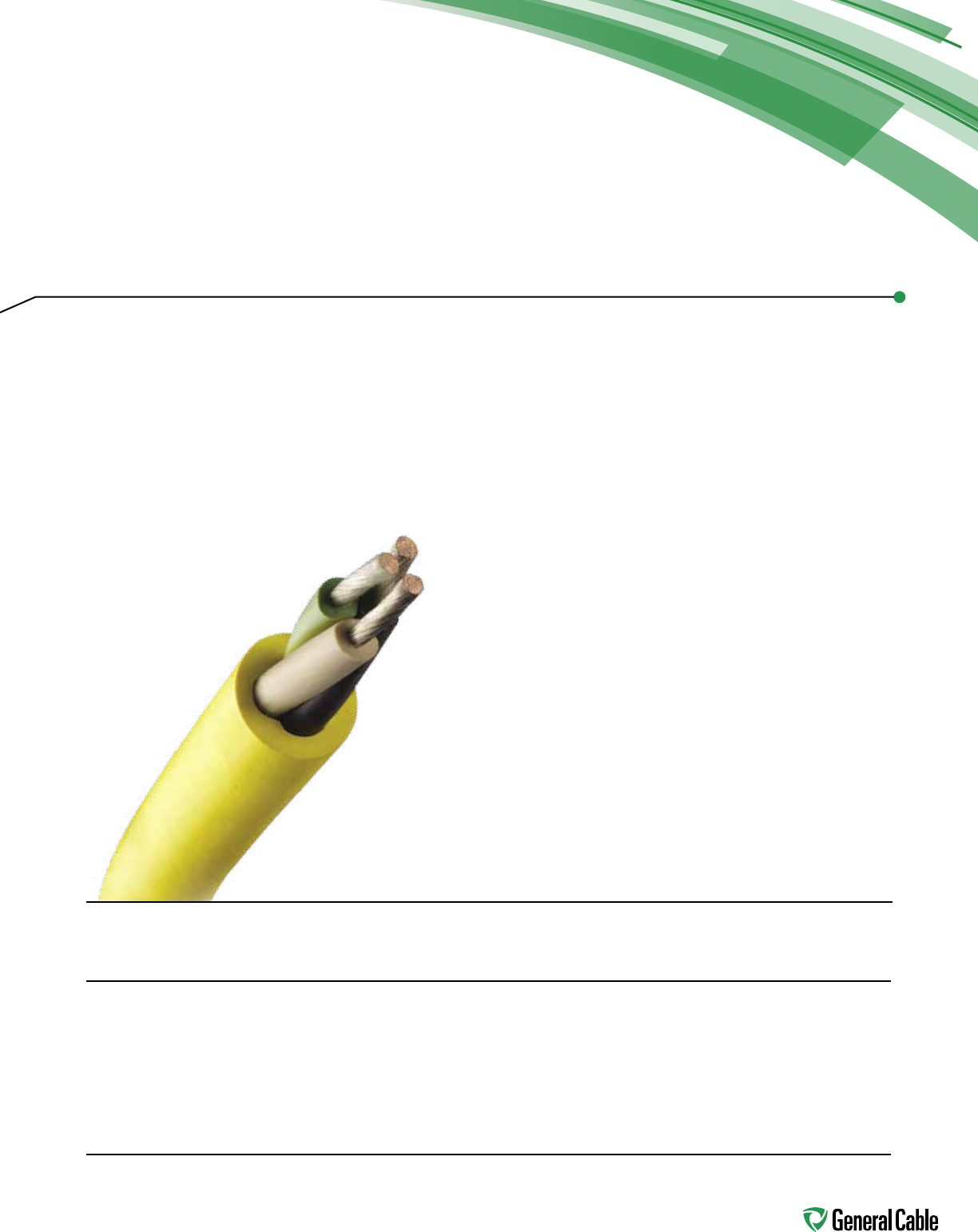
61
Table of Contents
DESCRIPTION PAGE
Super Vu-Tron®Super Vu-Tron Type SO 62
Super Vu-Tron Multi-Conductor Type SOOW 63-64
Super Vu-Tron Single Conductor 65
Super Vu-Tron Multi-Conductor Type W Round 66
Super Vu-Tron Type G and Type G-GC Round 67
Super Vu-Tron Canadian Type G-GC Round 68
Super Vu-Tron III Types SJOOW/SOOW 69
Super Vu-Tron Supreme Types SJOOW/SOOW 70
Super Vu-Tron with GenClean™Super Vu-Tron Supreme Types SJOOW/SOOW with GenClean 71
Portable & Temporary
Power Cord
General Cable's Carol® Brand is the
most recognized name in flexible cords
for temporary power. The extensive line
includes portable cord, portable power
cable and premium-grade cable for
commercial and industrial applications.
Rubber Cord
Thermoset rubber cord products have evolved over
the last 50 years from simple and unsophisticated
to a product line where specialized, technologically
advanced products are in demand for exacting
commercial and industrial applications.
No longer are rubber cord products used only in
applications where flexibility is needed. Today,
typical applications require cord to perform well in
environments of extreme heat and cold as well as on
job sites and factory floors where resistance to oil,
chemicals and abrasion is required.
General Cable's role as the producer of premier
Carol Brand rubber cord products is to ensure that
new product development, product innovation and
quality not only keep pace with industry requirements
but also set the trends.
Our rubber cord products carry a full range of listings
and certifications with Underwriters Laboratories, Inc.
and the Canadian Standard Association. In addition,
many products meet or exceed the requirements of
OSHA, MSHA and other relevant industry standards.
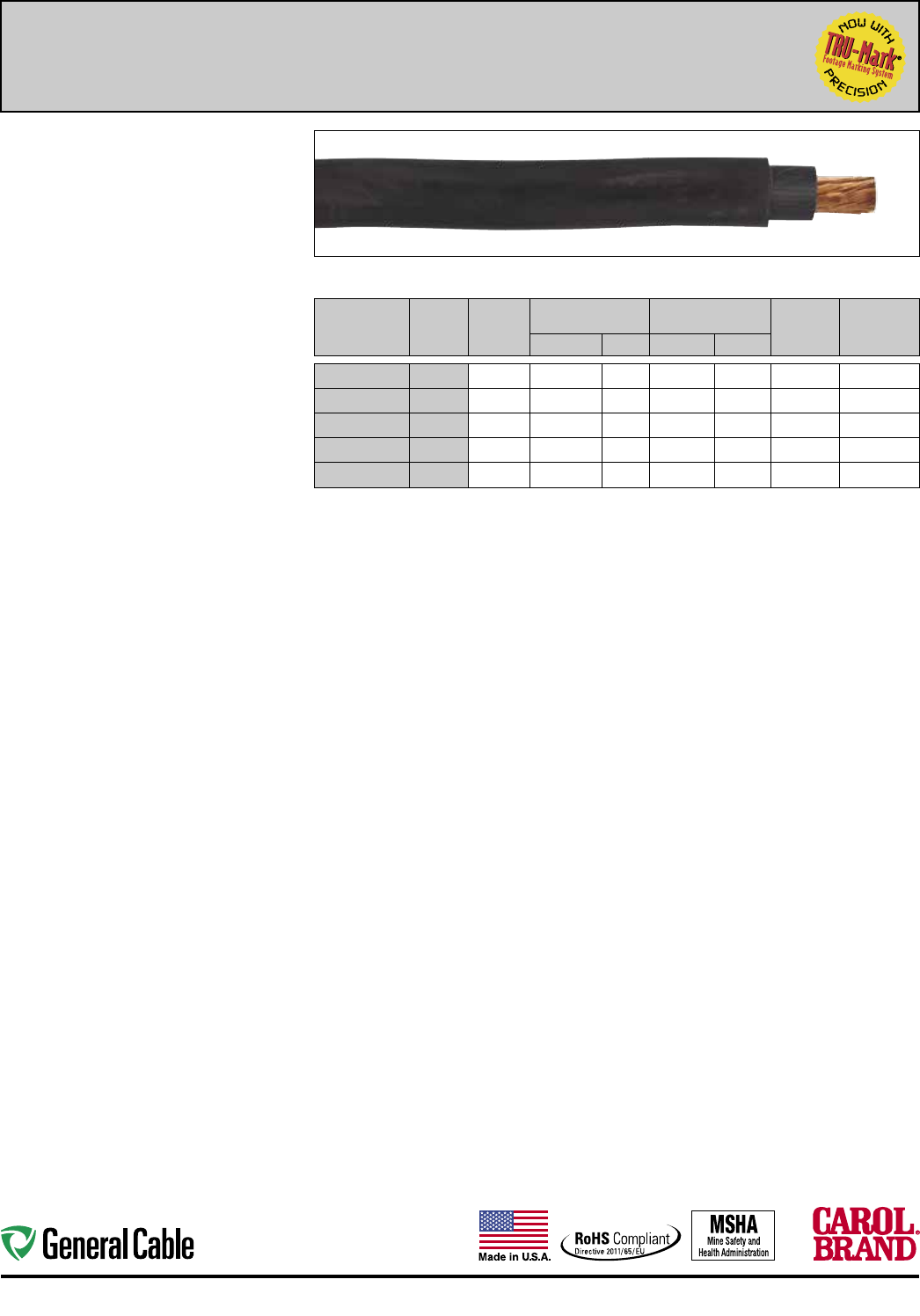
62
Portable & Temporary Power Cord Industrial Automation
Product Construction:
Conductors:
• 18 through 10 AWG stranded bare copper
Insulation:
• Premium-grade 90ºC EPDM
Jacket:
• Super Vu-Tron®, black
• Temperature range: -40ºC to +90ºC
Jacket Marking:
• (SIZE) TYPE SO 600 VOLT CAROL SUPER
VU-TRON® 90°C P-123-MSHA
(1)
(TRU-MARK
SEQUENTIAL FOOTAGE)
Applications:
• Portable tools and equipment
• Portable appliances
• Small motors and associated machinery
• Flexible power leads
Features:
• Excellent resistance to oil and moisture
• Good tensile strength, elongation and aging
characteristics
• High flexibility
• Excellent abrasion resistance
• Ozone-, sunlight (UV)- and weather-resistant
• TRU-Mark® sequential footage marking
Industry Approvals:
• MSHA Approved
(1)
• RoHS Compliant
Packaging:
• Lengths cut to order
TYPE SO, NON-UL – 600 VOLT
CATALOG
NUMBER
AWG
SIZE
COND.
STRAND
NOMINAL INS.
THICKNESS NOMINAL O.D. CURRENT
AMPS†
APPROX.
NET WT.
LBS/M'(S)
INCHES mm INCHES mm
77493* 18 16/30 0.030 0.76 0.180 4.57 10 19
77483* 16 26/30 0.030 0.76 0.200 5.08 13 25
77473* 14 41/30 0.045 1.14 0.240 6.09 18 40
77463* 12 65/30 0.045 1.14 0.265 6.60 25 50
77453*(1) 10 104/30 0.045 1.14 0.305 7.75 30 75
† Ampacities based on NEC Table 400.5(A)(1).
* Non-stock item; minimum quantity purchase required.
(S) Actual shipping weight may vary.
(1) Only 10 AWG construction is MSHA Approved.
Super Vu-Tron
®
Type SO
90ºC, 600 Volt
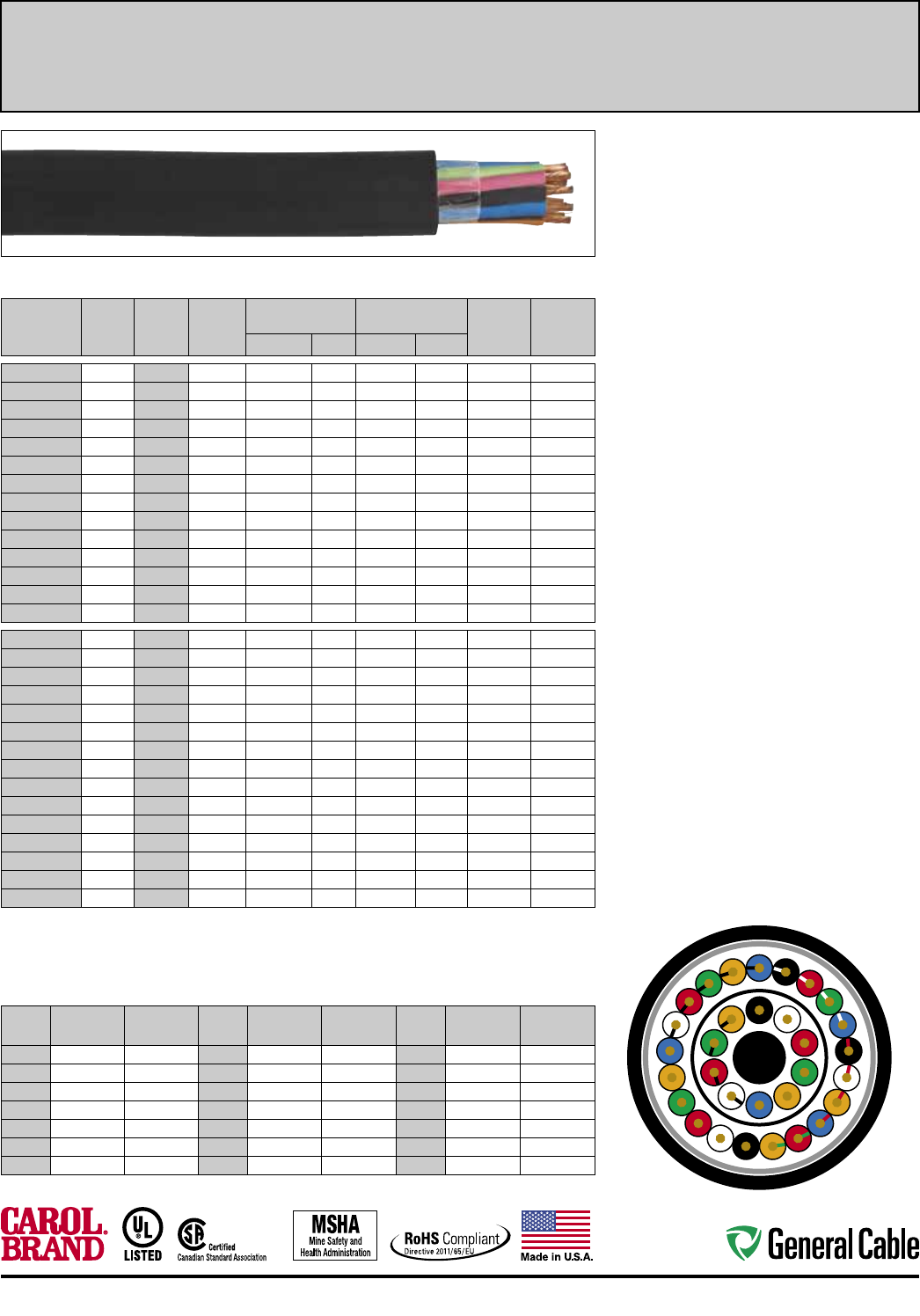
63
Industrial Automation Portable & Temporary Power Cord
Super Vu-Tron
®
Multi-Conductor Type SOOW
90ºC, 600 Volt, UL /CSA Portable Cord
TYPE S00W – 600 VOLT – UL/CSA
CATALOG
NUMBER
NO. OF
COND.
AWG
SIZE
COND.
STRAND
NOMINAL INS.
THICKNESS NOMINAL O.D. CURRENT
AMPS†
APPROX.
NET WT.
LBS/M'(S)
INCHES mm INCHES mm
09805 5 18 16/30 0.030 0.76 0.465 11.81 5.6 131
09806 6 18 16/30 0.030 0.76 0.495 12.57 5.6 142
09807 7 18 16/30 0.030 0.76 0.520 13.21 5.6 161
09808 8 18 16/30 0.030 0.76 0.530 13.46 4.9 173
09810 10 18 16/30 0.030 0.76 0.595 15.11 4.9 221
09812 12 18 16/30 0.030 0.76 0.600 15.24 3.5 235
09814 14 18 16/30 0.030 0.76 0.630 16.00 3.5 262
09816 16 18 16/30 0.030 0.76 0.700 17.78 3.5 306
09818* 18 18 16/30 0.030 0.76 0.760 19.30 3.5 341
09820 20 18 16/30 0.030 0.76 0.795 20.19 3.5 377
09822* 22 18 16/30 0.030 0.76 0.805 20.45 3.1 400
09824 24 18 16/30 0.030 0.76 0.850 21.59 3.1 453
09827* 27 18 16/30 0.030 0.76 0.865 21.97 3.1 475
09830* 30 18 16/30 0.030 0.76 0.915 23.24 3.1 524
09605 5 16 26/30 0.030 0.76 0.495 12.57 8.0 152
09606 6 16 26/30 0.030 0.76 0.520 13.21 8.0 184
09607 7 16 26/30 0.030 0.76 0.540 13.72 8.0 210
09608 8 16 26/30 0.030 0.76 0.575 14.61 7.0 228
09609 9 16 26/30 0.030 0.76 0.600 15.24 7.0 255
09610 10 16 26/30 0.030 0.76 0.620 15.75 5.0 260
09612 12 16 26/30 0.030 0.76 0.660 16.76 5.0 319
09614 14 16 26/30 0.030 0.76 0.730 18.54 5.0 343
09616 16 16 26/30 0.030 0.76 0.740 18.80 5.0 367
09618* 18 16 26/30 0.030 0.76 0.770 19.56 5.0 405
09620 20 16 26/30 0.030 0.76 0.810 20.57 5.0 444
09622* 22 16 26/30 0.030 0.76 0.900 22.86 4.5 510
09624 24 16 26/30 0.030 0.76 0.925 23.50 4.5 547
09626* 26 16 26/30 0.030 0.76 0.965 24.51 4.5 611
09630 30 16 26/30 0.030 0.76 1.010 25.65 4.5 685
†
Values shown are for current-carrying conductors. A grounding conductor, or one which carries only the unbalance current
from other conductors, is NOT counted in determining current carrying capacity. Ampacities based on NEC Table 400.5(A)(1).
* Non-stock item; minimum quantity purchase required.
(S) Actual shipping weight may vary.
Product Construction:
Conductors:
• 18 and 16 AWG fully annealed stranded bare
copper
Insulation:
• Premium-grade, color-coded 90ºC EPDM
• Color code: See chart below
Jacket:
• Super Vu-Tron® 90ºC, black
• Temperature range: -40ºC to +90ºC
Jacket Marking:
• CAROL SUPER VU-TRON® (SIZE) (mm2) 90°C
(UL) WATER RESISTANT SOOW CSA (-40°C)
FT2 P-7K-123033 MSHA 600 VOLT ROHS
MADE IN USA
Applications:
• Control circuits
• Tools
• Heavy industrial, processing and construction
equipment
Features:
• Extra-flexible stranding
• Abrasion-resistant
• Resists oils and solvents
• Flame-resistant
• Ozone-resistant
• 90ºC rated conductors and jacket
• Water-resistant*
• UL Listed and CSA Certified for indoor and
outdoor use
• Ozone-, sunlight (UV)- and weather-resistant
Industry Approvals:
• UL Flexible Cord - UL 62
• CSA Flexible Cord - C22.2-49
• MSHA Approved
• RoHS Compliant
Packaging:
• 5- through 8-conductor available on 250'
(76.2 m), 500' (152.4 m), and 1000' (304.8 m) reels
• 9+ cond. available on long-length reels
• Other put-ups available on special order
* Suitable for immersion in water if properly sealed and
terminated.
COLOR CODE CHART
NO. OF
COND. COLOR TRACER
NO. OF
COND. COLOR TRACER
NO. OF
COND. COLOR TRACER
1
Black —
8
Red Black
15
Blue White
2
White —
9
Green Black
16
Black Red
3
Red —
10
Orange Black
17
White Red
4
Green —
11
Blue Black
18
Orange Red
5
Orange —
12
Black White
19
Blue Red
6
Blue —
13
Red White
20
Red Green
7
White Black
14
Green White
21
Orange Green
Note: Colors repeat after 21 conductors.
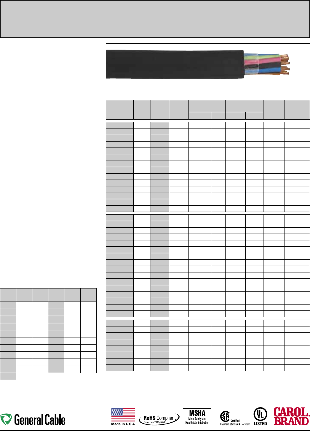
64
Portable & Temporary Power Cord Industrial Automation
Product Construction:
Conductors:
• 14 through 10 AWG fully annealed stranded bare
copper
Insulation:
• Premium-grade, color-coded 90ºC EPDM
• Color code: See chart below
Jacket:
• Super Vu-Tron® 90ºC, black
• Temperature range: -40ºC to +90ºC
Jacket Marking:
• CAROL SUPER VU-TRON® (SIZE) (mm2) 90°C
(UL) WATER RESISTANT SOOW CSA (-40°C)
FT2 P-7K-123033 MSHA 600 VOLT ROHS
MADE IN USA
Applications:
• Control circuits
• Tools
• Heavy industrial, processing and construction
equipment
Features:
• Extra-flexible stranding
• Abrasion-resistant
• Resists oils and solvents
• Flame-resistant
• Ozone-resistant
• 90ºC rated conductors and jacket
• Water-resistant*
• UL Listed and CSA Certified for indoor and
outdoor use
• Ozone-, sunlight (UV)- and weather-resistant
Industry Approvals:
• UL Flexible Cord - UL 62
• CSA Flexible Cord - C22.2-49
• MSHA Approved
• RoHS Compliant
Packaging:
• 5- through 8-conductor available on 250'
(76.2 m), 500' (152.4 m), and 1000' (304.8 m)
reels
• 9+ cond. available on long-length reels
• Other put-ups available on special order
* Suitable for immersion in water if properly sealed and
terminated.
COLOR CODE CHART
NO. OF
COND. COLOR TRACER
NO. OF
COND. COLOR TRACER
1
Black —
12
Black White
2
White —
13
Red White
3
Red —
14
Green White
4
Green —
15
Blue White
5
Orange —
16
Black Red
6
Blue —
17
White Red
7
White Black
18
Orange Red
8
Red Black
19
Blue Red
9
Green Black
20
Red Green
10
Orange Black
21
Orange Green
11
Blue Black
Note: Colors repeat after
21 conductors. Refer to
page 63 for color diagram.
TYPE S00W – 600 VOLT – UL/CSA
CATALOG
NUMBER
NO. OF
COND.
AWG
SIZE
COND.
STRAND
NOMINAL INS.
THICKNESS NOMINAL O.D. CURRENT
AMPS
†
APPROX.
NET WT.
LBS/M'(S)
INCHES mm INCHES mm
09405 5 14 41/30 0.045 1.14 0.645 16.26 12.0 266
09406 6 14 41/30 0.045 1.14 0.710 18.03 12.0 313
09407 7 14 41/30 0.045 1.14 0.755 19.18 12.0 326
09408 8 14 41/30 0.045 1.14 0.810 20.57 10.5 366
09409* 9 14 41/30 0.045 1.14 0.860 21.84 10.5 419
09410 10 14 41/30 0.045 1.14 0.875 22.23 10.5 436
09412 12 14 41/30 0.045 1.14 0.900 22.86 7.5 516
09414 14 14 41/30 0.045 1.14 1.000 25.40 7.5 597
09416 16 14 41/30 0.045 1.14 1.030 26.16 7.5 658
09418* 18 14 41/30 0.045 1.14 1.100 27.94 7.5 720
09420 20 14 41/30 0.045 1.14 1.155 29.34 7.5 799
09424 24 14 41/30 0.045 1.14 1.260 32.00 6.7 998
09428* 28 14 41/30 0.045 1.14 1.330 33.78 6.7 1080
09430* 30 14 41/30 0.045 1.14 1.335 33.97 6.0 1146
09205 5 12 65/30 0.045 1.14 0.715 18.16 16.0 326
09206 6 12 65/30 0.045 1.14 0.740 18.80 16.0 362
09207 7 12 65/30 0.045 1.14 0.790 20.07 16.0 415
09208 8 12 65/30 0.045 1.14 0.825 20.96 14.0 464
09209 9 12 65/30 0.045 1.14 0.900 22.86 14.0 510
09210 10 12 65/30 0.045 1.14 0.95024.13 14.0 602
09212 12 12 65/30 0.045 1.14 1.010 25.65 10.0 662
09214 14 12 65/30 0.045 1.14 1.020 25.91 10.0 724
09216 16 12 65/30 0.045 1.14 1.135 28.83 10.0 869
09218* 18 12 65/30 0.045 1.14 1.175 29.85 10.0 912
09220 20 12 65/30 0.045 1.14 1.175 29.84 10.0 977
09224 24 12 65/30 0.045 1.14 1.360 34.54 9.0 1236
09226 26 12 65/30 0.045 1.14 1.380 35.05 9.0 1309
09227* 27 12 65/30 0.045 1.14 1.390 35.30 9.0 1335
09228* 28 12 65/30 0.045 1.14 1.455 36.95 9.0 1375
09230 30 12 65/30 0.045 1.14 1.455 36.96 9.0 1512
09005 5 10 104/30 0.045 1.14 0.770 19.56 20.0 423
09006 6 10 104/30 0.045 1.14 0.875 22.23 20.0 508
09007 7 10 104/30 0.045 1.14 0.900 22.86 20.0 549
09008* 8 10 104/30 0.045 1.14 0.935 23.75 17.5 625
09010 10 10 104/30 0.045 1.14 1.020 25.91 17.5 755
09012 12 10 104/30 0.045 1.14 1.070 27.18 12.5 867
09016* 16 10 104/30 0.045 1.14 1.230 31.24 12.5 1142
09020* 20 10 104/30 0.045 1.14 1.325 33.66 12.5 1445
† Values shown are for current-carrying conductors. A grounding conductor, or one which carries only the unbalance
current from other conductors, is NOT counted in determining current carrying capacity. Ampacities based on
NEC Table 400.5(A)(1).
* Non-stock item; minimum quantity purchase required.
(S) Actual shipping weight may vary.
Super Vu-Tron
®
Multi-Conductor Type SOOW
90ºC, 600 Volt, UL /CSA Portable Cord
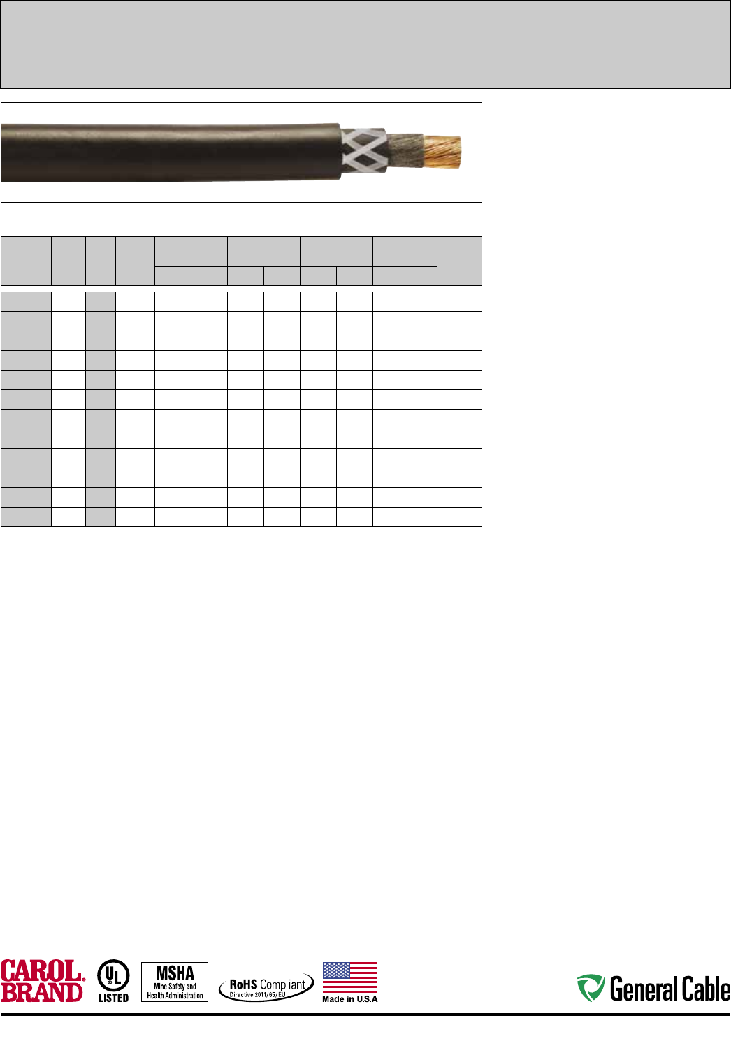
65
Industrial Automation Portable & Temporary Power Cord
Product Construction:
Conductor:
• 8 AWG through 500 kcmil fully annealed stranded
bare copper
Insulation:
• Premium-grade 90ºC EPDM
Jacket:
• Super Vu-Tron® 90ºC, black
• Temperature range: -40ºC to +90ºC
• Voltage rating:
600 volts Type RHH/RHW
2000 volts Type W
• An open polyester braid reinforcement is applied
between the insulation and jacket for mechanical
strength
Jacket Marking:
• 8-1 AWG: CAROL SUPER VU-TRON® TYPE
W PORTABLE POWER CABLE (UL) DRY 90°C
WET 75°C 2000 V SUNLIGHT RESISTANT P-7K-
123049-MSHA (SIZE) TYPE RHH OR RHW (UL)
600 V MADE IN USA
• 1/0-500 kcmil: CAROL SUPER VU-TRON® TYPE
W PORTABLE POWER CABLE (UL) DRY 90°C
WET 75°C 2000 V SUNLIGHT RESISTANT P-7K-
123049-MSHA (SIZE) TYPE RHH OR RHW (UL)
600 V FOR CT USE --- CSA TYPE W (-40°C)
2 KV FT5 MADE IN USA
Applications:
• Portable power systems
• Entertainment industry activities such as theatre,
television, night clubs, motion pictures, mobile
communication vans, spotlights and sound
systems
• Other similar applications that would require
permanent or temporary power
• Permanent wiring of 600 volt power supplies,
hoists, cranes and other applications where
flexible power leads must be installed in conduit
or raceways
Features:
• Water-resistant*
• Sunlight-resistant
• Designed to withstand severe environmental
conditions
• Withstands exposure to oil, acids, alkalies, heat,
flame, moisture and chemicals
• Meets or exceeds flame test requirements of
MSHA and UL
Industry Approvals:
• UL Type W
• UL Type RHH or RHW
• MSHA Approved
• RoHS Compliant
Packaging:
• Lengths cut to order
* Suitable for immersion in water if properly sealed and
terminated.
Super Vu-Tron
®
Single Conductor
90ºC (UL), Type W, 2000 Volt and Type RHH/RHW
600 Volt Portable Power Cable
TYPE W 2000 VOLT (UL) AND TYPE RHH/RHW 600 VOLT (UL)
CATALOG
NUMBER
NO.
OF
COND.
AWG
OR
kcmil
COND.
STRAND
NOMINAL
COND. O.D.
NOMINAL INS.
THICKNESS NOMINAL O.D.
CURRENT
AMPS
APPROX.
NET WT.
LBS/
M
'
(S)
INCHES mm INCHES mm INCHES mm (1) (2)
83008* 1 8 133 0.160 4.06 0.060 1.52 0.470 11.94 55 80 145
83006 1 6 259 0.198 5.03 0.060 1.52 0.545 13.84 75 105 205
83004 1 4 259 0.245 6.22 0.060 1.52 0.595 15.11 95 140 270
83002 1 2 259 0.294 7.47 0.060 1.52 0.670 17.02 130 190 380
83001 1 1 259 0.346 8.79 0.080 2.03 0.730 18.54 150 220 465
83010 1 1/0†259 0.384 9.75 0.080 2.03 0.790 20.07 170 260 550
83020 1 2/0†259 0.441 11. 20 0.080 2.03 0.865 21.97 195 300 675
83030 1 3/0†259 0.482 12.24 0.080 2.03 0.910 23.11 225 350 790
83040 1 4/0†259 0.555 14.10 0.080 2.03 0.960 24.38 260 405 940
83250 1 250†627 0.615 15.62 0.10 5 2.67 1.045 26.54 290 455 1125
83350 1 350†855 0.725 18.42 0.105 2.67 1.145 29.08 350 570 1465
83500 1 500†1235 0.880 22.35 0.105 2.67 1.315 33.40 430 700 2010
* Non-stock item; minimum quantity purchase required.
(1) Ampacities based on 90°C conductor and 30°C ambient temperature based on Table 310-16 in the National
Electrical Code® for RHH/RHW with not more than three current-carrying conductors in raceway, cable or earth.
(2) Ampacities based on 90°C conductor and 30°C ambient temperature based on Table 310-17 and Table 400.5(A)(2)
in the National Electrical Code® for single-conductor cables.
(S) Actual shipping weight may vary.
† Designated for CT use.
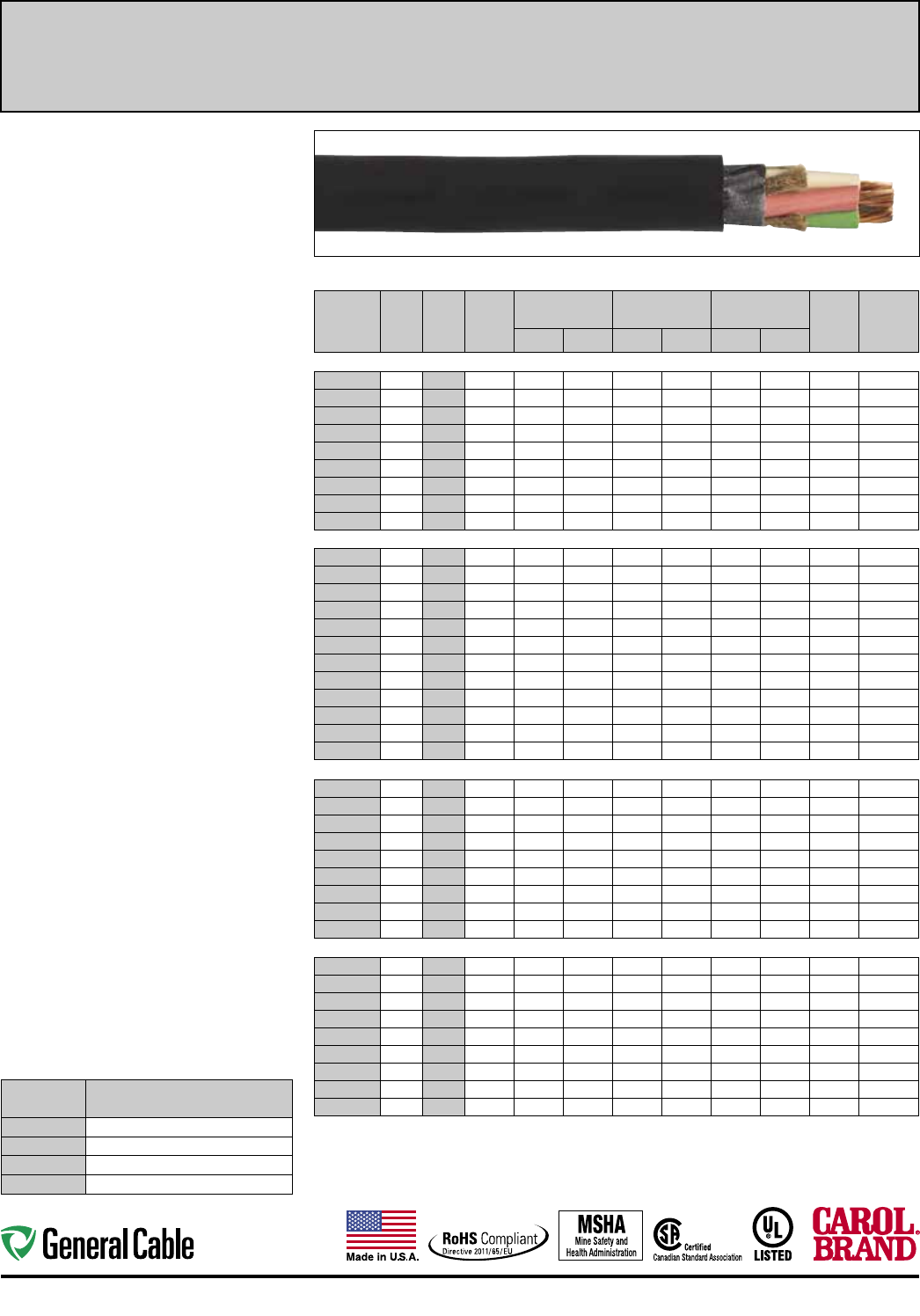
66
Portable & Temporary Power Cord Industrial Automation
CATALOG
NUMBER
NO. OF
COND.
AWG
OR
kcmil
COND.
STRAND
NOMINAL
COND. O.D.
NOMINAL INS.
THICKNESS NOMINAL O.D. CURRENT
AMPS(1)
APPROX.
NET WT.
LBS/M'(S)
INCHES mm INCHES mm INCHES mm
2 CONDUCTOR – TYPE W – 2000 VOLT
81312 2 8 133 0.160 4.06 0.060 1.52 0.770 19.56 74 325
81622 2 6 259 0.198 5.03 0.060 1.52 0.910 23.11 99 470
81642 2 4 259 0.245 6.22 0.060 1.52 1.020 25.91 130 620
81662 2 2 259 0.297 7.54 0.080 2.03 1.210 30.73 174 935
81372* 2 1 259 0.353 8.97 0.080 2.03 1.370 34.80 202 1305
81382* 2 1/0 259 0.385 9.78 0.080 2.03 1.435 36.45 234 1555
81392* 2 2/0 259 0.442 11.23 0.080 2.03 1.555 39.50 271 1860
81402* 2 3/0 259 0.480 12.19 0.080 2.03 1.670 42.42 313 2230
81412* 2 4/0 259 0.555 14.10 0.080 2.03 1.815 46.10 361 2655
3 CONDUCTOR – TYPE W – 2000 VOLT
81313 3 8 133 0.160 4.06 0.060 1.52 0.945 24.00 74 470
81623 3 6 259 0.198 5.03 0.060 1.52 1.020 25.91 99 625
81643 3 4 259 0.245 6.22 0.060 1.52 1.135 28.83 130 810
81663 3 2 259 0.297 7.54 0.080 2.03 1.345 34.16 174 1190
81373* 3 1 259 0.353 8.97 0.080 2.03 1.455 36.96 202 1655
81383 3 1/0 259 0.385 9.78 0.080 2.03 1.585 40.26 234 1965
81393 3 2/0 259 0.442 11.23 0.080 2.03 1.675 42.55 271 2350
81403* 3 3/0 259 0.480 12.19 0.080 2.03 1.815 46.10 313 2890
81413* 3 4/0 259 0.555 14.10 0.080 2.03 1.950 49.53 361 3285
81423* 3 250 627 0.615 15.62 0.095 2.41 2.390 60.71 402 5070
81443* 3 350 855 0.725 18.42 0.095 2.41 2.680 68.07 495 6570
81473* 3 500 1235 0.880 22.35 0.095 2.41 3.030 76.96 613 8700
4 CONDUCTOR – TYPE W – 2000 VOLT
81314 4 8 133 0.160 4.06 0.060 1.52 0.980 24.89 65 615
81624 4 6 259 0.198 5.03 0.060 1.52 1.070 27.18 87 800
81644 4 4 259 0.245 6.22 0.060 1.52 1.210 30.73 114 1040
81664 4 2 259 0.297 7.54 0.080 2.03 1.435 36.45 152 1580
81374 4 1 259 0.353 8.97 0.080 2.03 1.595 40.51 177 2045
81384 4 1/0 259 0.385 9.78 0.080 2.03 1.705 43.31 205 2430
81394 4 2/0 259 0.442 11.23 0.080 2.03 1.845 46.86 237 2950
81404 4 3/0 259 0.480 12.19 0.080 2.03 1.965 49.91 274 3430
81414 4 4/0 259 0.555 14.10 0.080 2.03 2.145 54.48 316 3885
5 CONDUCTOR – TYPE W – 2000 VOLT
81315 5 8 133 0.160 4.06 0.060 1.52 1.030 26.16 52 650
81625 5 6 259 0.198 5.03 0.060 1.52 1.170 29.72 69 915
81645 5 4 259 0.245 6.22 0.060 1.52 1.360 34.54 91 1320
81665 5 2 259 0.297 7.54 0.080 2.03 1.595 40.51 121 1925
81375* 5 1 259 0.353 8.97 0.080 2.03 1.820 46.23 141 2675
81385 5 1/0 259 0.385 9.78 0.080 2.03 1.900 48.26 164 2885
81395* 5 2/0 259 0.442 11.23 0.080 2.03 2.060 52.32 189 3630
81405* 5 3/0 259 0.480 12.19 0.080 2.03 2.260 57.40 219 4900
81415* 5 4/0 259 0.555 14.10 0.080 2.03 2.460 62.48 252 5980
(1) Ampacities based on 90°C conductor and 30°C ambient temperature per Table 400.5(A)(2) of the National Electrical Code®.
* Non-stock item; minimum quantity purchase required.
** Green conductor for grounding only.
(S) Actual shipping weight may vary.
Product Construction:
Conductor:
• 8 AWG through 500 kcmil fully annealed stranded
bare copper
Insulation:
• Premium-grade, color-coded 90ºC EPDM
• Color code: See chart below
Jacket:
• Super Vu-Tron® 90ºC, black
• Temperature range: -40ºC to +90ºC
Jacket Marking:
• SIZES SMALLER THAN 2-1/4" – CAROL SUPER
VU-TRON® (SIZE) TYPE W PORTABLE POWER
CABLE (UL) 2000 V DRY 90°C WET 75°C SUN
RES P-7K-123049-MSHA---CSA TYPE W (-40°C)
2 KV FT5 MADE IN USA
• SIZES 2-1/4" AND LARGER – (SIZE) TYPE W
CAROL SUPER VU-TRON® 90°C DRY AND
WATER RESISTANT 75°C 2000 V SUN RES (UL)
P-7K-123049 MSHA LR27161 MADE IN USA
Applications:
• Industrial and light- to medium-duty mining
applications
• Heavy-duty service as power supply cable
• AC systems (grounded and ungrounded)
• Mobile and portable electrical equipment
• Motor and battery leads
• 2-conductor cables—use on DC or AC single-
phase systems where grounding is not required
• 3-conductor cables—use on AC systems where no
grounding is required or on DC systems with one
conductor for grounding
• 4-conductor cables—use on two- or three-
phase AC systems with one conductor used for
grounding
• 5-conductor cables—use in applications where
separating the system neutral from the frame
ground is required
Features:
• Withstands severe environmental conditions
• Suitable for immersion in water*
• Indent-printed for easy identification
• Withstands exposure to oil, acids, alkalies, heat,
moisture and most chemicals
• Rope lay stranding for maximum flex life
• Excellent impact resistance
• Cable core bound for superior flexibility and
toughness
• Sunlight-resistant
Industry Approvals:
• CSA
• MSHA Approved
• UL Type W
• RoHS Compliant
Packaging:
• Lengths cut to order
* Suitable for immersion in water if properly sealed and terminated.
Super Vu-Tron
®
Multi-Conductor Type W Round
90ºC (UL), Type W, 2000 Volt Portable Power Cable
COLOR CODE CHART
NO. OF
CONDUCTORS COLOR**
2
Black, White
3
Black, White, Green
4
Black, White, Red, Green
5
Black, White, Red, Green, Orange
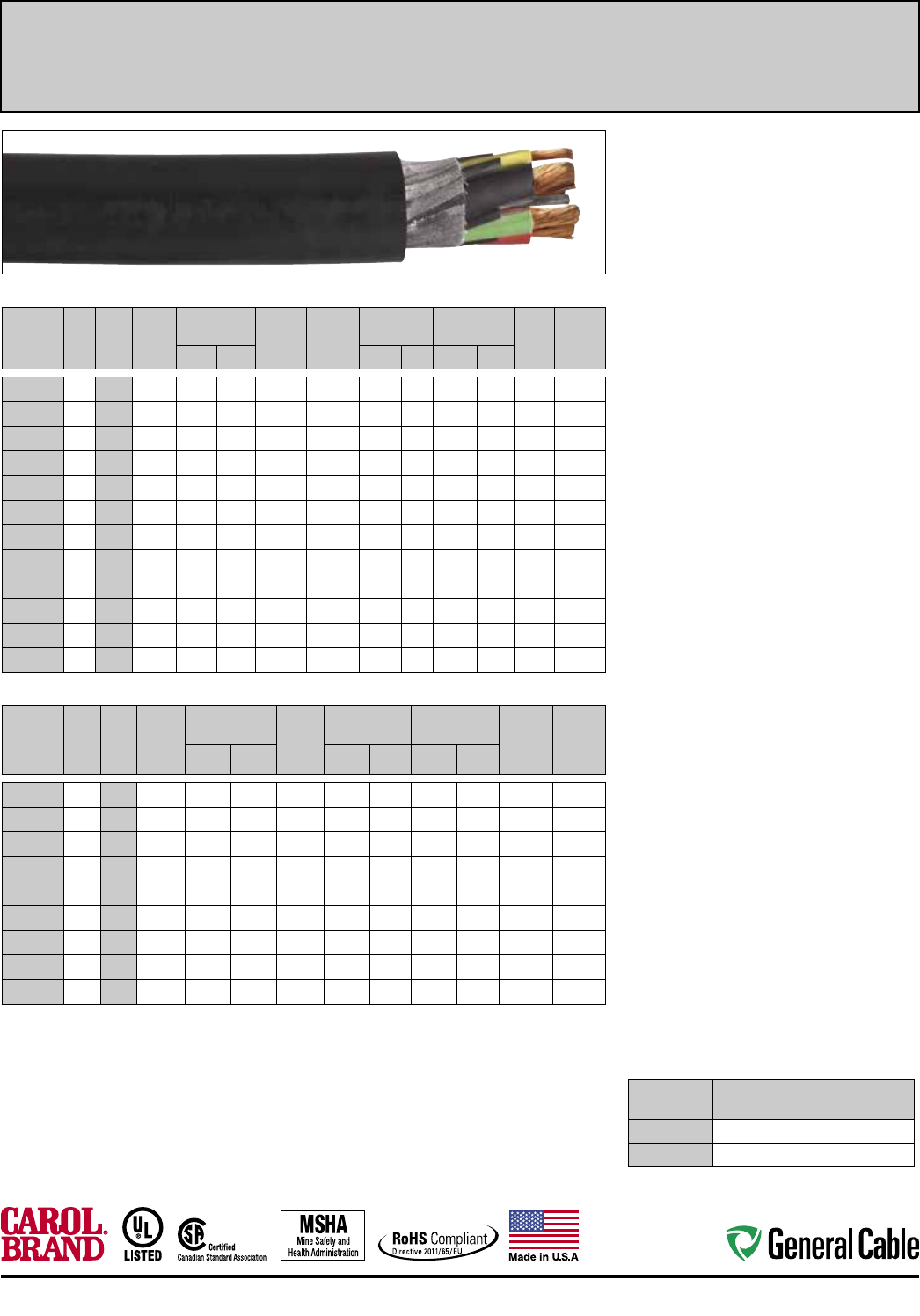
67
Industrial Automation Portable & Temporary Power Cord
Product Construction:
Conductor:
• 8 AWG through 500 kcmil fully annealed stranded
bare copper
Insulation:
• Premium-grade, color-coded 90ºC EPDM
• Color code: See chart below
• Insulated grounds and ground checks
Jacket:
• Super Vu-Tron® 90ºC, black
• Temperature range: -40ºC to +90ºC
Jacket Marking:
• TYPE G-GC (4/0 AND SMALLER) –
CAROL SUPER VU-TRON® SIZE (mm2) TYPE G-GC
PORTABLE POWER CABLE (UL) 2000 V DRY 90°C
WET 75°C SUN RES P-7K-123049-MSHA --- CSA
TYPE G-CG (-40°C) 2 KV FT5 MADE IN USA
• TYPE G-GC (LARGER THAN 4/0) -
(SIZE) TYPE G-GC CAROL SUPER VU-TRON®
90°C DRY AND WATER RESISTANT 75°C 2000 V
SUN RES (UL) P-7K-123049 MSHA LR27161
MADE IN USA
• TYPE G -
CAROL SUPER VU-TRON® SIZE (mm2) TYPE G
PORTABLE POWER CABLE (UL) 600/2000 V DRY
90°C WET 75°C SUN RES P-7K-123049 MHSA ---
CSA TYPE G (-40°C) 2 KV FT5 MADE IN USA
Applications:
• Industrial and light- to medium-duty mining
applications
• Heavy-duty service as power supply cable
• Mobile and portable electrical equipment
• 3- and 4-conductor—use on three-phase AC
systems where grounding is required
Features:
• Excellent impact and abrasion resistance
• Withstands exposure to oil, acids, alkalies, heat,
moisture and most chemicals
• Suitable for immersion in water*
• Indent-printed for easy identification
• Rope lay stranding for maximum flex life
• Cable core bound for superior flexibility and
toughness
• Non-wicking rubber fillers (G-GC)
• Canadian color code available upon request
• Sunlight-resistant
Industry Approvals:
• UL Type G, G-GC
• CSA
• MSHA Approved
• RoHS Compliant
Packaging:
• Lengths cut to order
* Suitable for immersion in water if properly sealed and
terminated.
3 CONDUCTOR – TYPE G-GC – 2000 VOLT
CATALOG
NUMBER
NO.
OF
COND.
AWG
OR
kcmil
COND.
STRAND
NOMINAL
COND. O.D.
YELLOW
GROUND
CHECK
AWG SIZE
GREEN
GROUND
COND.
AWG SIZE
NOMINAL INS.
THICKNESS
NOMINAL
O.D. CURR.
AMPS(1)
APPROX.
NET WT.
LBS/M'(S)
INCHES mm INCHES mm INCHES mm
82313 3 8 133 0.160 4.06 10 2#10 0.060 1.52 0.965 24.51 65 600
82623 3 6 259 0.198 5.03 10 2#10 0.060 1.52 1.02
5 26.04
87 770
82643 3 4 259 0.245 6.22 10 2#8 0.060 1.52 1.13
0
28.
70
114
1015
82663 3 2 259 0.297 7.54
8
2#7 0.080 2.03 1.345
34.16
152 1480
82373 3 1 259 0.353 8.97 8 2#6 0.080 2.03
1.455 36.96
177
1795
82383 3 1/0 259 0.385 9.78 8 2#5 0.080 2.03
1.585 40.26
205 2245
82393 3 2/0 259 0.442 11.23 8 2#4 0.080 2.03
1.675 42.55
237 25
70
82403 3 3/0 259 0.480 12.19 8 2#3 0.080 2.03 1.810 45.97 274 3230
82413 3 4/0 259 0.555 14.10 8 2#2 0.080 2.03
1.950 49.53
316
3700
82423(2)*3 250 627 0.615 15.62 8 2#2 0.095 2.41 2.390 60.71 352
6060
82443(2)*3 350 855 0.725 18.42 8 2#1/0 0.095 2.41 2.680 68.07 433
7400
82473(2)*3 500 1235 0.880 22.35 8 2#2/0 0.095 2.41 3.030 76.96 536
10100
4 CONDUCTOR – TYPE G – 600/2000 VOLT
CATALOG
NUMBER
NO.
OF
COND.
AWG
OR
kcmil
COND.
STRAND
NOMINAL
COND. O.D. GREEN
COND.
AWG
SIZE
NOMINAL INS.
THICKNESS NOMINAL O.D.
CURRENT
AMPS(1)
APPROX.
NET WT.
LBS/M'(S)
INCHES mm INCHES mm INCHES mm
82314
4 8 133 0.160 4.06 4#12 0.060 1.52 1.045 26.54 52 690
82624
4 6 259 0.198 5.03 4#12 0.060 1.52 1.125 28.58 70 880
82644
4 4 259 0.245 6.22 4#10 0.060 1.52 1.225 31.12 91 1160
82664
4 2 259 0.297 7.54 4#9 0.080 2.03 1.435 36.45 122 1720
82374*
4 1 259 0.353 8.97 4#8 0.080 2.03 1.590 40.39 142 2200
82384
4 1/0 259 0.385 9.78 4#7 0.080 2.03 1.730 43.94 164 2705
82394
4 2/0 259 0.442 11.23 4#6 0.080 2.03 1.855 47.12 190 3190
82404
4 3/0 259 0.480 12.19 4#5 0.080 2.03 2.040 51.82 219 4005
82414
4 4/0 259 0.555 14.10 4#4 0.080 2.03 2.145 54.48 253 4560
(1) Ampacities based on 90°C conductor and 30°C ambient temperature per
Table 400.5(A)(2) of the
National Electrical Code®.
(2) UL Listed and c(UL) Certified.
* Non-stock item; minimum quantity purchase required.
(S) Actual shipping weight may vary.
COLOR CODE CHART
NO. OF
CONDUCTORS COLOR
3Black, White, Red
4Black, White, Red, Orange
Super Vu-Tron
®
Type G and Type G-GC Round
90ºC (UL), 2000 Volt Portable Power Cable
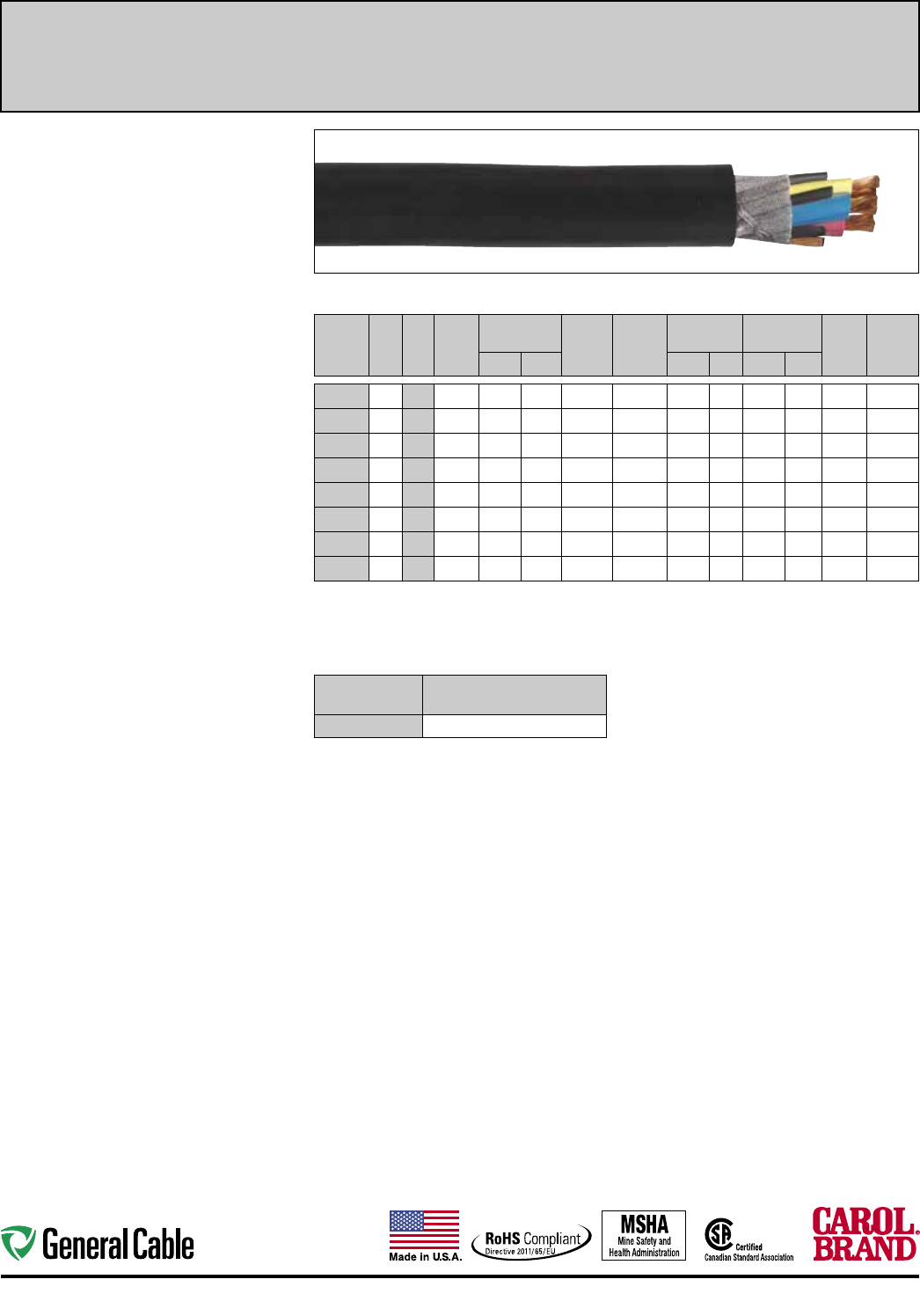
68
Portable & Temporary Power Cord Industrial Automation
Product Construction:
Conductor:
• 6 AWG through 4/0 AWG fully annealed stranded
bare copper
Insulation:
• Premium-grade, color-coded 90ºC EPDM
• Color code: See chart below
• Insulated yellow ground check
Jacket:
• Super Vu-Tron® 90ºC, black
• Temperature range: -40ºC to +90ºC
Jacket Marking:
• CAROL SUPER VU-TRON® SIZE (mm2)
TYPE G-GC 2 KV 90°C (-40°C) FT5 CSA LR92874
P-7K-123049-MSHA MADE IN USA
Applications:
• Industrial and light- to medium-duty mining
applications
• Heavy-duty service as power supply cable
• Mobile and portable electrical equipment
• 3- and 4-conductor—use on three-phase AC
systems where grounding is required
Features:
• Excellent impact and abrasion
resistance
• Withstands exposure to oil,
acids, alkalies, heat, moisture
and most chemicals
• Indent-printed for easy identification
• Rope lay stranding for maximum flex life
• Cable core bound for superior flexibility and
toughness
• Non-wicking rubber fillers (GGC)
• Canadian color code
• Sunlight-resistant
Industry Approvals:
• CSA Flexible Cord - C22.2-96
• MSHA Approved
• RoHS Compliant
Packaging:
• Lengths cut to order
3 CONDUCTOR – TYPE G-GC – 2000 VOLT
CATALOG
NUMBER
NO.
OF
COND.
AWG
SIZE
COND.
STRAND
NOMINAL
COND. O.D.
YELLOW
GROUND
CHECK
AWG SIZE
GROUND
COND.
AWG SIZE
NOMINAL INS.
THICKNESS
NOMINAL
O.D. CURR.
AMPS(1)
APPROX.
NET WT.
LBS/
M'(S)
INCHES mm INCHES mm INCHES mm
83103 3 8 133 0.160 4.06 10 2#10 0.060 1.52 0.945 24.00 65 827
83113 3 6 259 0.198 5.03 10 2#10 0.060 1.52 1.025 26.04 87 770
83123 3 4 259 0.245 6.22 10 2#8 0.060 1.52 1.14 0 28.96 114 1015
83133 3 2 259 0.297 7.54 8 2#6 0.080 2.03 1.345 34.16 152 1480
83143 3 1 259 0.353 8.97 8 2#6 0.080 2.03 1.455 36.96 177 1795
83153 3 1/0 259 0.385 9.78 8 2#4 0.080 2.03 1.585 40.26 205 2245
83163 3 2/0 259 0.442 11.23 8 2#4 0.080 2.03 1.685 42.80 237 2570
83183 3 4/0 259 0.555 14.10 8 2#2 0.080 2.03 1.975 50.17 316 3700
(1) Ampacity rating based on CEC/CSA.
(S) Actual shipping weight may vary.
COLOR CODE CHART
NO. OF
CONDUCTORS COLOR
3Black, Red, Blue
Super Vu-Tron
®
Canadian Type G-GC Round
90ºC, 2000 Volt Portable Power Cable
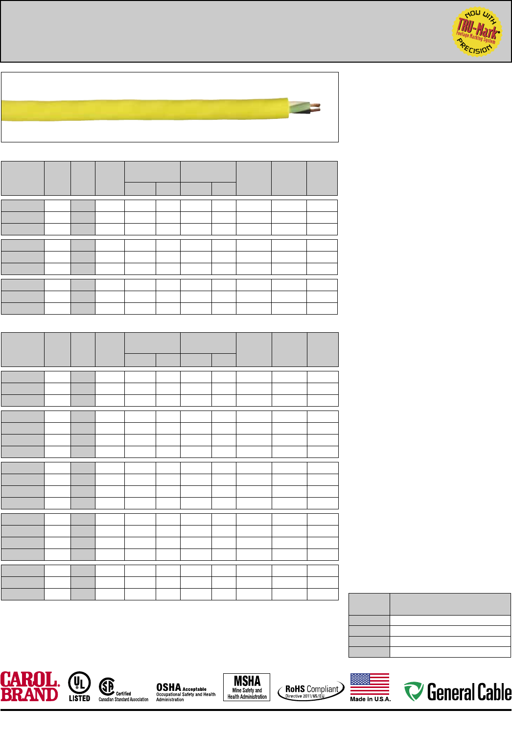
69
Industrial Automation Portable & Temporary Power Cord
TYPE SJOOW – 300 VOLT – UL/CSA
CATALOG
NUMBER
NO. OF
COND.
AWG
SIZE
COND.
STRAND
NOMINAL INS.
THICKNESS NOMINAL O.D. CURRENT
AMPS†
APPROX.
NET WT.
LBS/M1(S)
STD.
CTN.INCHES mm INCHES mm
02001* 2 18 41/34 0.030 0.76 0.310 8.00 10 56 1000'
02002* 3 18 41/34 0.030 0.76 0.320 8.12 10 65 1000'
02003* 4 18 41/34 0.030 0.76 0.345 8.76 7 80 250'
02004* 2 16 65/34 0.030 0.76 0.315 8.00 13 68 1000'
02005* 3 16 65/34 0.030 0.76 0.335 8.51 13 80 250'
02006* 4 16 65/34 0.030 0.76 0.370 9.40 10 95 250'
02007* 2 14 41/30 0.030 0.76 0.370 9.40 18 90 250'
02008* 3 14 41/30 0.030 0.76 0.375 9.52 18 110 250'
02009* 4 14 41/30 0.030 0.76 0.405 10.29 15 130 250'
TYPE SOOW – 600 VOLT – UL/CSA
CATALOG
NUMBER
NO. OF
COND.
AWG
SIZE
COND.
STRAND
NOMINAL INS.
THICKNESS NOMINAL O.D. CURRENT
AMPS†
APPROX.
NET WT.
LBS/M1(S)
STD.
CTN.INCHES mm INCHES mm
02031* 2 18 41/34 0.030 0.76 0.365 9.27 10 75 250'
02032* 3 18 41/34 0.030 0.76 0.375 9.53 10 80 250'
02033* 4 18 41/34 0.030 0.76 0.400 10.16 7 110 250'
02034* 2 16 65/34 0.030 0.76 0.370 9.40 13 75 250'
02035* 3 16 65/34 0.030 0.76 0.395 10.80 13 100 250'
02036* 4 16 65/34 0.030 0.76 0.425 10.80 10 120 250'
02021* 5 16 65/34 0.030 0.76 0.515 13.08 8 150 250'
02037* 2 14 41/30 0.045 1.14 0.510 12.95 18 155 250'
02038* 3 14 41/30 0.045 1.14 0.525 13.34 18 165 250'
02039* 4 14 41/30 0.045 1.14 0.575 14.61 15 215 250'
02022* 5 14 41/30 0.045 1.14 0.675 17.15 12 285 250'
02041* 2 12 65/30 0.045 1.14 0.590 14.99 25 200 250'
02042* 3 12 65/30 0.045 1.14 0.600 15.24 25 250 250'
02043* 4 12 65/30 0.045 1.14 0.650 16.51 20 280 250'
02023* 5 12 65/30 0.045 1.14 0.730 18.54 16 315 250'
02045* 3 10 104/30 0.045 1.14 0.660 16.76 30 320 250'
02046* 4 10 104/30 0.045 1.14 0.710 18.03 25 375 250'
02024* 5 10 104/30 0.045 1.14 0.770 19.56 20 432 250'
* Non-stock item available by special order; minimum quantity purchase required.
† Green conductor for grounding only. Ampacities based on NEC Table 400.5(A)(1).
(S) Actual shipping weight may vary.
COLOR CODE CHART
NO. OF
CONDUCTORS
COLOR
2
Black, White
3
Black, White, Green
4
Black, White, Red, Green
5
Black, White, Red, Green, Orange
Super Vu-Tron
®
III Types SJOOW/SOOW
105ºC, 300 and 600 Volt, UL /CSA Portable Cord
Product Construction:
Conductors:
• 18 through 10 AWG fully annealed stranded bare
copper
Insulation:
• Premium-grade, color-coded, oil-resistant 105ºC
EPDM
• Color code: See chart below
Jacket:
• Super Vu-Tron® III, yellow
• Temperature range:
–50ºC to +105ºC UL/CSA
• Voltage rating:
300 volts Type SJOOW
600 volts Type SOOW
Jacket Marking:
• SUPER VU-TRON® III SJOOW -
CAROL SUPER VU-TRON® III (SIZE) (mm2)
105°C (UL) WATER RESISTANT SJOOW CSA
(-50°C) FT1 --- P-07-KA120015-MSHA 300 VOLT
ROHS MADE IN USA (TRU-MARK SEQUENTIAL
FOOTAGE )
• SUPER VU-TRON® III SOOW -
CAROL SUPER VU-TRON® III (SIZE) (mm2) 105°C
(UL) WATER RESISTANT SOOW CSA (-50°C)
FT1 --- P-07-KA120015-MSHA 600 VOLT ROHS
MADE IN USA (TRU-MARK SEQUENTIAL
FOOTAGE )
Applications:
• Machine tools
• Power tools
• Dockside power applications
• Motor leads
• Portable machinery
• Cranes
• Submersible pumps
Features:
• Excellent flexibility in cold temperatures
• Last longer in flex applications
• Integral Flexfill®
• Ozone-, sunlight (UV)- and weather-resistant
• UL Listed and CSA Certified for indoor and
outdoor use
• Water-resistant*
• Safety-colored
• High heat and flame resistance
• Resistant to oils, acids and chemicals
• Excellent abrasion and cut resistance
• TRU-Mark® sequential footage marking
Industry Approvals:
• UL Flexible Cord - UL 62
• CSA Flexible Cord - C22.2-49
• MSHA Approved
• RoHS Compliant
Packaging:
• 250' (76.2 m), 500' (152.4 m),
1000' (304.8 m)
• Other put-ups available on special order
* Suitable for immersion in water if properly sealed and terminated.
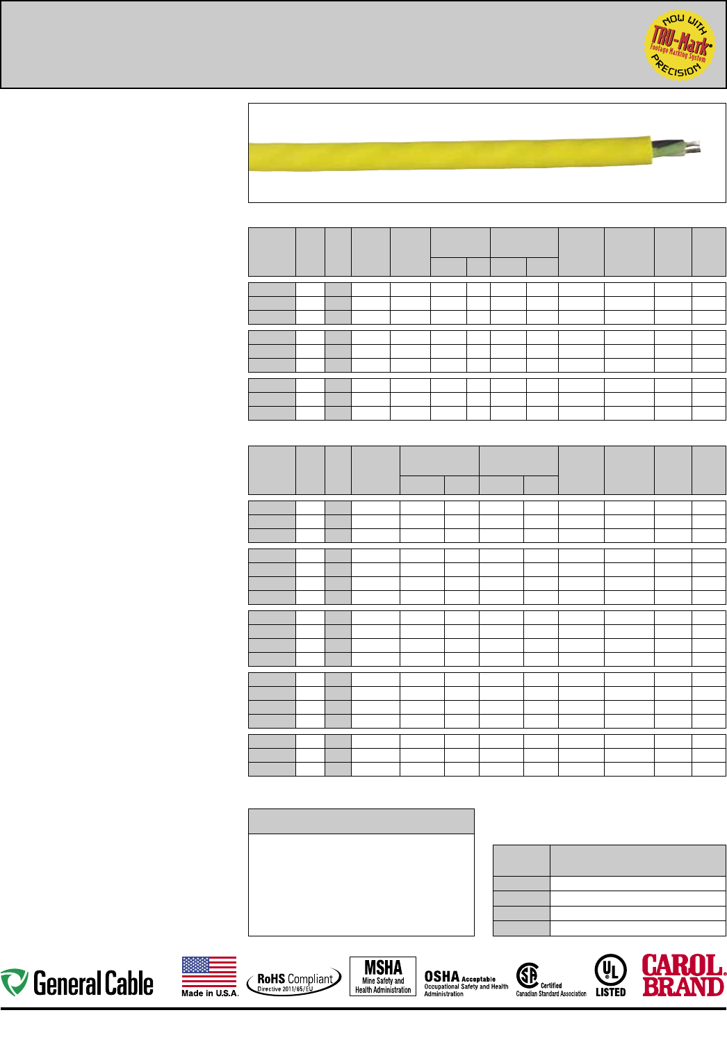
70
Portable & Temporary Power Cord Industrial Automation
Product Construction:
Conductors:
• 18 through 10 AWG fully annealed stranded tinned
copper
Insulation:
• Premium-grade, color-coded, oil-resistant 105ºC
EPDM
• Color code: See chart below
Jacket:
• Super Vu-Tron® Supreme, yellow
• Temperature range:
–50ºC to +105ºC UL/CSA
• Voltage rating:
300 volts Type SJOOW
600 volts Type SOOW
Jacket Marking:
• SUPER VU-TRON® SUPREME SJOOW -
CAROL SUPER VU-TRON® SUPREME (SIZE)
(mm2) 105°C (UL) WATER RESISTANT SJOOW
CSA (-50°C) FT1 --- P-07-KA120015-MSHA
300 VOLT ROHS MADE IN USA (TRU-MARK
SEQUENTIAL FOOTAGE)
• SUPER VU-TRON® SUPREME SOOW -
CAROL SUPER VU-TRON® SUPREME (SIZE)
(mm2) 105°C (UL) WATER RESISTANT SOOW CSA
(-50°C) FT1 --- P-07-KA120015-MSHA 600 VOLT
ROHS MADE IN USA (TRU-MARK SEQUENTIAL
FOOTAGE )
Applications:
• Machine tools
• Power tools
• Dockside power applications
• Motor leads
• Portable machinery
• Cranes
• Submersible pumps
• Where water immersion is required
• Severe environment OEM/MRO applications
Features:
• Excellent flexibility in cold temperatures
• Lasts longer in flex applications (extra-flexible
Class M stranding)
• Integral Flexfill®
• Ozone-, sunlight (UV)- and weather-resistant
• UL Listed and CSA Certified for indoor and
outdoor use
• Water-resistant*
• Safety-colored, with high-visibility yellow jacket
• High heat and flame resistance
• Resistant to sunlight, oils, acids and chemicals
• Excellent abrasion and cut resistance
• TRU-Mark® sequential footage marking
• Tinned copper conductors — corrosion/
oxidation-resistant
Industry Approvals:
• UL Flexible Cord - UL 62
• CSA Flexible Cord - C22.2-49
• MSHA Approved
• OSHA Acceptable
• RoHS Compliant
Packaging:
• 250' (76.2 m), 500' (152.4 m),
1000' (304.8 m)
• Other put-ups available on special order
* Suitable for immersion in water if properly sealed and terminated.
TYPE SJOOW – 300 VOLT – UL/CSA
CATALOG
NUMBER
NO.
OF
COND.
AWG
SIZE
COND.
STRAND
STRAND
O.D.
NOM. INS.
THICKNESS
JACKET
NOMINAL O.D. CURRENT
AMPS†
APPROX.
NET WT.
LBS/M'(S)
COPPER
WT.
LBS/M'
STD.
CTN.INCHES mm INCHES mm
02601 2 18 41/34 .048" 0.030 0.76 0.310 7.87 10 56 10 1000'
02602 3 18 41/34 .048" 0.030 0.76 0.320 8.13 10 66 15 1000'
02603 4 18 41/34 .048" 0.030 0.76 0.345 8.76 7 79 20 250'
02604 2 16 65/34 .057" 0.030 0.76 0.315 8.00 13 62 16 1000'
02605 3 16 65/34 .057" 0.030 0.76 0.335 8.51 13 77 24 250'
02606 4 16 65/34 .057" 0.030 0.76 0.370 9.40 10 98 32 250'
02607 2 14 105/34 .077" 0.030 0.76 0.370 9.40 18 75 24 250'
02608 3 14 105/34 .077" 0.030 0.76 0.375 9.53 18 99 36 250'
02609 4 14 105/34 .077" 0.030 0.76 0.405 10.29 15 122 48 250'
TYPE SOOW – 600 VOLT – UL/CSA
CATALOG
NUMBER
NO.
OF
COND.
AWG
SIZE
COND.
STRAND
NOM. INS.
THICKNESS
JACKET
NOMINAL O.D. CURRENT
AMPS†
APPROX.
NET WT.
LBS/M'(S)
COPPER
WT.
LBS/M'
STD.
CTN.INCHES mm INCHES mm
02631* 2 18 41/34 0.030 0.76 0.365 9.27 10 75 10 250'
02632 3 18 41/34 0.030 0.76 0.375 9.53 10 84 15 250'
02633* 4 18 41/34 0.030 0.76 0.400 10.16 7 110 21 250'
02634 2 16 65/34 0.030 0.76 0.370 9.40 13 80 16 250'
02635 3 16 65/34 0.030 0.76 0.395 10.03 13 96 24 250'
02636 4 16 65/34 0.030 0.76 0.425 10.80 10 118 32 250'
02621 5 16 65/34 0.030 0.76 0.515 13.08 8 166 40 250'
02637* 2 14 105/34 0.045 1.14 0.510 12.95 18 153 24 250'
02638 3 14 105/34 0.045 1.14 0.525 13.34 18 164 36 250'
02639 4 14 105/34 0.045 1.14 0.575 14.61 15 204 48 250'
02622* 5 14 105/34 0.045 1.14 0.675 17.15 12 279 60 250'
02641* 2 12 168/34 0.045 1.14 0.590 14.99 25 198 38 250'
02642 3 12 168/34 0.045 1.14 0.600 15.24 25 224 57 250'
02643 4 12 168/34 0.045 1.14 0.650 16.51 20 270 76 250'
02623* 5 12 168/34 0.045 1.14 0.730 18.54 16 308 96 250'
02645 3 10 259/34 0.045 1.14 0.660 16.76 30 295 99 250'
02646 4 10 259/34 0.045 1.14 0.710 18.03 25 365 132 250'
02624* 5 10 259/34 0.045 1.14 0.770 19.56 20 422 168 250'
* Non-stock item; minimum quantity purchase required.
† Green conductor for grounding only. Ampacities based
on NEC Table 400.5(A)(1).
(S) Actual shipping weight may vary.
TOP PERFORMANCE IN THE TOUGHEST ENVIRONMENTS
Volume change (%) of SUPER VU-TRON® SUPREME after 28 days
at room temperature in the following materials
ACETIC ACID (30%)
AMMONIA HYDROXIDE
ASTM 3 OIL
BEER
BLEACH WATER
BUTYL ALCOHOL
CORN OIL
FORMALDEHYDE
GLYCOL (ANTI-FREEZE)
HYDROCHLORIC ACID (20%)
JP-4
KEROSENE
+19.00
+3.12
+0.26
+4.42
+2.60
-1.82
0.00
+3.38
-2.60
+10.60
+10.90
+10.60
LINSEED OIL
LUBE OIL
MILK
NITRIC ACID (10%)
SAE 30 OIL
SKYDROL 500
SODIUM HYDROXIDE
SULFURIC ACID (10%)
TOLUENE
UNLEADED GAS
WATER
+1.04
-1.82
+4.16
+7.29
-1.30
+17.10
+10.90
+2.34
+30.20
+22.10
+2.86
COLOR CODE CHART
NO. OF
CONDUCTORS
COLOR
2
Black, White
3
Black, White, Green/Yellow
4
Black, White, Red, Green/Yellow
5
Black, White, Red, Green/Yellow, Orange
Super Vu-Tron
®
Supreme Types SJOOW/SOOW
105ºC, 300 and 600 Volt, UL /CSA Portable Cord
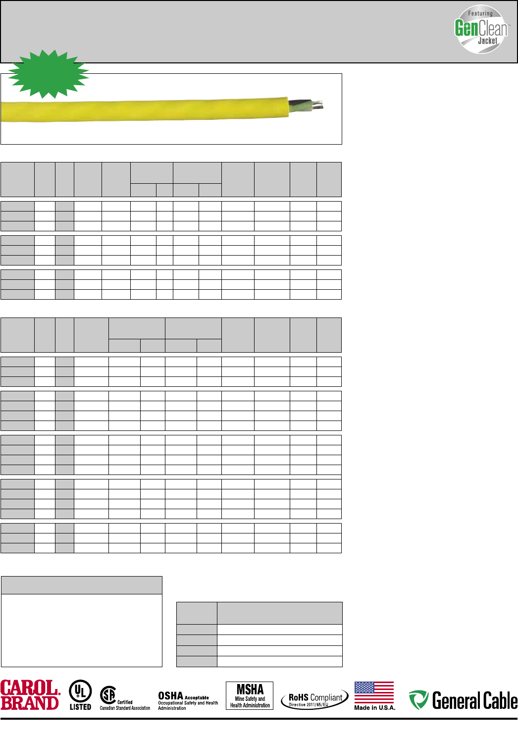
71
Industrial Automation Portable & Temporary Power Cord
TYPE SJOOW – 300 VOLT – UL/CSA
CATALOG
NUMBER
NO.
OF
COND.
AWG
SIZE
COND.
STRAND
STRAND
O.D.
NOM. INS.
THICKNESS
JACKET
NOMINAL O.D. CURRENT
AMPS†
APPROX.
NET WT.
LBS/M'(S)
COPPER
WT.
LBS/M'
STD.
CTN.INCHES mm INCHES mm
GC601
2 18 41/34 .048" 0.030 0.76 0.310 7.87 10 56 10 1000'
GC602
3 18 41/34 .048" 0.030 0.76 0.320 8.13 10 66 15 1000'
GC603
4 18 41/34 .048" 0.030 0.76 0.345 8.76 7 79 21 250'
GC604
2 16 65/34 .057" 0.030 0.76 0.315 8.00 13 62 16 1000'
GC605
3 16 65/34 .057" 0.030 0.76 0.335 8.51 13 77 24 250'
GC606
4 16 65/34 .057" 0.030 0.76 0.370 9.40 10 98 32 250'
GC607
2 14 105/34 .077" 0.030 0.76 0.370 9.40 18 75 24 250'
GC608
3 14 105/34 .077" 0.030 0.76 0.375 9.53 18 99 36 250'
GC609
4 14 105/34 .077" 0.030 0.76 0.405 10.29 15 122 48 250'
TYPE SOOW – 600 VOLT – UL/CSA
CATALOG
NUMBER
NO.
OF
COND.
AWG
SIZE
COND.
STRAND
NOM. INS.
THICKNESS
JACKET
NOMINAL O.D. CURRENT
AMPS†
APPROX.
NET WT.
LBS/M'(S)
COPPER
WT.
LBS/M'
STD.
CTN.INCHES mm INCHES mm
GC631*
2 18 41/34 0.030 0.76 0.365 9.27 10 75 10 250'
GC632
3 18 41/34 0.030 0.76 0.375 9.53 10 84 15 250'
GC633*
4 18 41/34 0.030 0.76 0.400 10.16 7 110 21 250'
GC634
2 16 65/34 0.030 0.76 0.370 9.40 13 80 16 250'
GC635
3 16 65/34 0.030 0.76 0.395 10.03 13 96 24 250'
GC636
4 16 65/34 0.030 0.76 0.425 10.80 10 118 32 250'
GC621
5 16 65/34 0.030 0.76 0.515 13.08 8 166 40 250'
GC637*
2 14 105/34 0.045 1.14 0.510 12.95 18 153 24 250'
GC638
3 14 105/34 0.045 1.14 0.525 13.34 18 164 36 250'
GC639
4 14 105/34 0.045 1.14 0.575 14.61 15 204 48 250'
GC622*
5 14 105/34 0.045 1.14 0.675 17.15 12 279 60 250'
GC641*
2 12 168/34 0.045 1.14 0.590 14.99 25 198 38 250'
GC642
3 12 168/34 0.045 1.14 0.600 15.24 25 224 57 250'
GC643
4 12 168/34 0.045 1.14 0.650 16.51 20 270 76 250'
GC623*
5 12 168/34 0.045 1.14 0.730 18.54 16 308 96 250'
GC645
3 10 259/34 0.045 1.14 0.660 16.76 30 295 99 250'
GC646
4 10 259/34 0.045 1.14 0.710 18.03 25 365 132 250'
GC624*
5 10 259/34 0.045 1.14 0.770 19.56 20 422 168 250'
* Non-stock item; minimum quantity purchase required.
† Green conductor for grounding only. Ampacities based on
NEC Table 400.5(A)(1).
(S) Actual shipping weight may vary.
TOP PERFORMANCE IN THE TOUGHEST ENVIRONMENTS
Volume change (%) of SUPER VU-TRON® SUPREME after 28 days
at room temperature in the following materials
ACETIC ACID (30%)
AMMONIA HYDROXIDE
ASTM 3 OIL
BEER
BLEACH WATER
BUTYL ALCOHOL
CORN OIL
FORMALDEHYDE
GLYCOL (ANTI-FREEZE)
HYDROCHLORIC ACID (20%)
JP-4
KEROSENE
+19.00
+3.12
+0.26
+4.42
+2.60
-1.82
0.00
+3.38
-2.60
+10.60
+10.90
+10.60
LINSEED OIL
LUBE OIL
MILK
NITRIC ACID (10%)
SAE 30 OIL
SKYDROL 500
SODIUM HYDROXIDE
SULFURIC ACID (10%)
TOLUENE
UNLEADED GAS
WATER
+1.04
-1.82
+4.16
+7.29
-1.30
+17.10
+10.90
+2.34
+30.20
+22.10
+2.86
COLOR CODE CHART
NO. OF
CONDUCTORS
COLOR
2
Black, White
3
Black, White, Green/Yellow
4
Black, White, Red, Green/Yellow
5
Black, White, Red, Green/Yellow, Orange
Product Construction:
Conductors:
• 18 through 10 AWG fully annealed stranded
tinned copper
Insulation:
• Premium-grade, color-coded, oil-resistant 105ºC
EPDM
• Color code: See chart below
Jacket:
• Super Vu-Tron® Supreme, yellow, with
GenClean™ technology
• Temperature range:
–50ºC to +105ºC UL/CSA
• Voltage rating:
300 volts Type SJOOW
600 volts Type SOOW
Jacket Marking:
• SUPER VU-TRON® SUPREME SJOOW -
CAROL SUPER VU-TRON® SUPREME FEATURING
GENCLEAN™ JACKET (SIZE) (mm2) 105°C (UL)
WATER RESISTANT SJOOW CSA (-50°C) FT1
--- P-07-KA120015-MSHA 300 VOLT ROHS MADE
IN USA
• SUPER VU-TRON® SUPREME SOOW -
CAROL SUPER VU-TRON® SUPREME FEATURING
GENCLEAN™ JACKET (SIZE) (mm2) 105°C (UL)
WATER RESISTANT SOOW CSA (-50°C) FT1 ---
P-07-KA120015-MSHA 600 VOLT ROHS MADE
IN USA
Target Applications/Markets:
• Food/beverage manufacturing
• Marine manufacturing
• Manufactured structures
• Severe environments
• Dockside power
• Health care
Features:
• Cleanable rubber jacket
• Excellent flexibility in cold temperatures
• Lasts longer in flex applications
(extra-flexible Class M stranding)
• Integral Flexfill®
• Enhanced cleanability
• Reduced scuffing
• Ozone-, sunlight (UV)- and weather-resistant
• UL Listed and CSA Certified for indoor and
outdoor use
• Water-resistant*
• Safety-colored, with high-visibility yellow jacket
• High heat and flame resistance
• Resistant to sunlight, oils, acids and chemicals
• Excellent abrasion and cut resistance
• Tinned copper conductors —
corrosion/oxidation-resistant
Industry Approvals:
• UL Flexible Cord - UL 62
• CSA Flexible Cord - C22.2-49
• MSHA Approved
• OSHA Acceptable
• RoHS Compliant
Packaging:
• 250' (76.2 m), 500' (152.4 m),
1000' (304.8 m)
• Other put-ups available on special order
* Suitable for immersion in water if properly sealed and terminated.
Super Vu-Tron® Supreme Types SJOOW/SOOW with GenClean™
105ºC, 300 and 600 Volt, UL /CSA Portable Cord
ENHANCED
CLEANABILITY
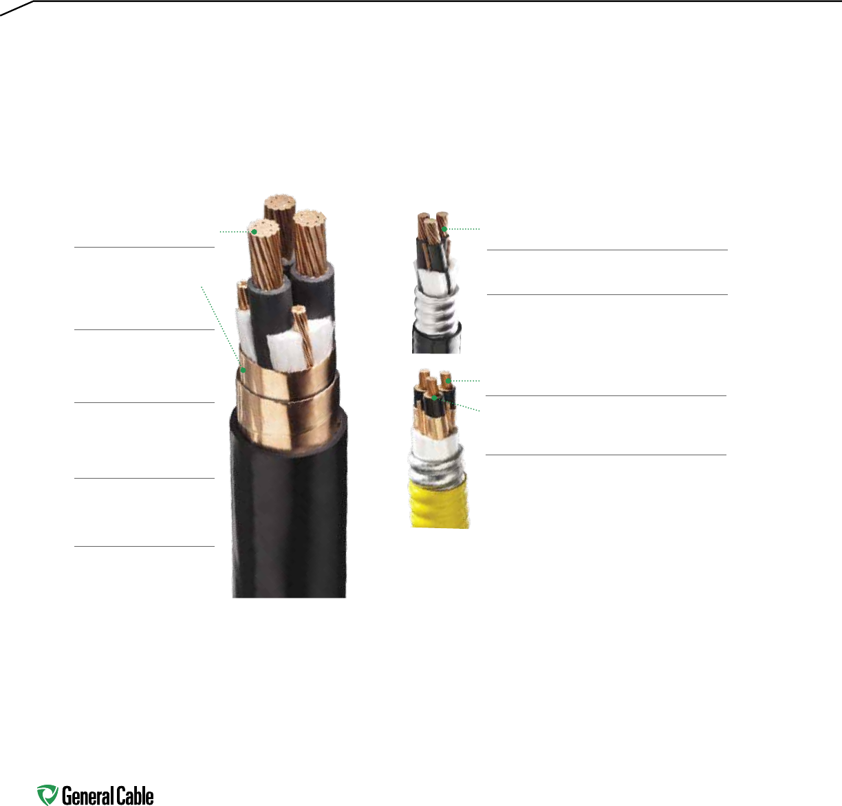
72
Industrial Cable Solutions for
Variable Frequency Drives
Compact or compressed stranding to reduce
conductor size
Compact conductors provide reduced conductor size
XLPE insulation with high impulse voltage
breakdown level resists degradation
Pure EPR insulation system has outstanding
corona resistance and high dielectric strength,
providing electrical stability under stress
Symmetrically placed annealed bare copper
grounding conductors in direct contact with shield
Triple Extrusion applies strand shield, EPR
insulation and insulation shield in one operation,
eliminating exposure to contamination and
providing maximum control and consistency
CVTC® VFD Low-Voltage Power
Type TC-ER
CCW® VFD Low- & Medium-Voltage Power
Type MC-HL
Compressed stranding to
reduce overall cable diameter
Dual copper tape shields
provide maximum shield
coverage required for
Variable Frequency Drive
applications
Symmetrically placed
annealed bare copper
grounding conductors in
direct contact with shield
Designed to reduce the
risk of Electromagnetic
Interference (EMI), which can
lead to malfunction
Meets crush and impact
requirements of Type MC cable
Permitted for use in Class I,
Division 2 industrial hazardous
locations per NEC
Additional Benefits of CCW® VFD Low- & Medium-Voltage
Power Cable
Continuously Corrugated Welded armor:
• Provides impervious barrier to moisture, gas and liquids
• Provides EMI shielding performance
• Factory assembled and tested for use as an economical,
rugged and reliable alternative to cable in conduit
wiring systems
Armored constructions suitable for use in Class I, II, & III,
Divisions 1 and 2; and Class I, Zones 1 and 2 hazardous
locations per NEC Articles 501, 502, 503 and 505
Tough challenges call for innovative solutions, and General Cable is your worldwide source for new products and
a wide range of industry-leading industrial cables. General Cable provides a line of cables for Variable Frequency
Drives (VFD) in both unarmored and armored designs as well as in many power ratings.
The following highlights the features and benefits of specially engineered cable designs for use with AC motors
controlled by pulse-width modulated inverters in VFD applications rated up to 1000 V, 2000 V, 5 kV and 8 kV:

73
VFD Cable Advantages in Industrial Automation Applications
Today’s manufacturing and processing environments
are relying on increased automation to improve
productivity. As a result, there is more focus and
awareness around minimizing downtime and improving
safety. The use of Variable Frequency Drive (VFD) cable
in industrial automation applications provides a reliable
solution to address these issues.
When Are VFD Cables Needed?
Whenever you are installing a VFD system, VFD cables
should be strongly considered for use between the
inverter and the motor. Standard power cable is not
designed to handle the high frequency components of
the drive’s inverter output. Some applicable market
applications are shown in the chart below.
Why Are VFD Cables Needed?
Many problems that are common in VFD systems
can be fixed or their impact lessened by simply using
a properly terminated VFD cable. These problems
include but are not limited to:
• intermittent issues with other factory control or
communication systems
• alarm system malfunctions
• premature motor bearing failure
• premature cable failure
• drive failure and drive problems
• shock hazards (to maintenance and other personnel)
How Does a VFD Cable Address These Issues?
VFD cable features a properly designed overall
electrical shield, symmetrically designed conductors,
and thermoset insulation with a low dielectric constant.
Proper Shielding
VFD cable is designed with an overall electrical
shield in the form of armor, copper tape or a copper
braid. General Cable offers all three designs so you
can choose the construction that best meets your
needs. However, not all shields are created equal. The
shield must be designed to effectively handle the high
frequency components of the inverter waveform and
minimize inductive loading.
This shield, along with proper cable termination, will
minimize electromagnetic radiation broadcast from the
cable. Unshielded cable acts like a broadcast antenna,
radiating these unwanted electrical signals in the
form of noise throughout your plant. This radiation can
cause issues with alarm systems, other control and
communication systems, and other drives. As factories
become more automated, these issues become more
prevalent.
Shielding also minimizes electromagnetic induction
(a signal produced in nearby electrical circuits when
they are exposed to a varying magnetic field). It has
been shown that when unshielded inverter-motor
MARKETS
VFD OFFERING
Unarmored
VFD (CVTC®)Armored
VFD (CCW®) Applications
Marine X Fluid/flow control – process pumps/drilling and pumps
(Note: TYPE P VFD cable for flex applications)
Power & Energy Management X X Process & flow control, cooling towers
Pulp & Paper X X Conveyors, process equipment
Automotive & Tire X X Material handling, process equipment, conveyors
Global Machine & Equip X X Packaging, material handling, equipment, cranes, conveyors
Oil, Gas & Petrochemical X X Fluid/flow control – process pumps and cooling towers, terminals and pipelines
Specialty Chemical X X Fluid/flow control, process pumps, rotary equipment
Water & Waste X X Process/flow control pumps, rotary equipment

74
cables are installed in tray, a potentially lethal current
can be induced in a cable that is locked out from the
electromagnetic induction generated by the other
energized cables in the tray. Many people feel that
human safety alone justifies the utilization of VFD
cables for their motor-inverter connections.
Shielding also has the effect of reducing the risk of
premature motor bearing failure by providing a low
impedance path for common mode current to return to
the inverter frame. Without this low impedance path,
the current can end up flowing through motor bearings,
causing bearing fluting.1
Proper Conductor Design
Common mode (CM) current is a frequent cause of drive
system issues (including false trips). One way to deal
with CM current is to direct it back to the inverter frame
via the shield. Some VFD cables go further and actually
reduce the generation of CM current. A cable designed
with a symmetrical relationship between the phase
conductors and the grounds provides the cancellation
effects that will minimize the CM current in the system.
These designs typically have three phase conductors
with three ground conductors in the interstices of the
phase conductors.
Proper Insulation
Cable insulation also plays a critical role in keeping your
VFD system performing reliably. VFD cables should have
a thermoset, cross-linked insulation which will provide
more protection than less expensive PVC insulation.
General Cable uses thermoset, cross-linked insulations
in all their VFD cable constructions. Using THHN cable
as your inverter motor cable is not recommended.
The PVC insulation on THHN cable possesses two
undesirable characteristics in VFD applications:
(1) It is hydroscopic, meaning it can absorb moisture
from the air, which drops its dielectric withstand to
as low as 55% of its rated voltage.
(2) It can experience cold-flow, causing the insulation
to displace when under pressure, resulting in the
reduction of insulation wall thickness.
Furthermore, THHN cable is rated for 600 volts RMS or
850 volts peak, but reflected waves (standing waves) in
VFD cables can reach 1300 volts in a run as short as 35
feet. The 1300 volts places a lot of stress on a cable that
is rated for 850 volts. When you factor in the decreased
insulation strength due to moisture and the decreased
wall thickness, you may experience problems.
In addition, PVC insulated cables have a high
capacitance associated with them, causing the cable to
leak current through the insulation, resulting in false
trips. The cables also have a higher charging current
associated with them, which requires a drive with more
power (and more cost). In order to minimize these
problems, choose a cable with thermoset insulation that
is rated to handle the peak standing wave voltage.
The Right Cable Solution for VFD Applications
VFD cable offers three key attributes to mitigate the
issues that arise in these applications: shielding, robust
insulation and symmetrical design. VFD cable is a more
expensive alternative to standard power cables, but in
today’s environment with increased automation, more
focus on safety and limited tolerance for downtime, it
proves to be a very wise investment.
1
Bearing fluting is addressed in further detail in the white paper
General Cable VFD Cables, An Overview of Variable Frequency Drive
Cables, November 2013.

75
Table of Contents
VARIABLE FREQUENCY DRIVE
SPEC NO. DESCRIPTION PAGE
CCW®9600 600 V Power, 3/C VFD and 4/C 76-77
UL Type MC-HL, XLPE, 90°C, ABS CWCMC
9605 600 V Power, 3/C VFD and 4/C 78-79
UL Type MC-HL, XLPE, 90°C, ABS CWCMC
9615 2000 V Power, 3/C VFD 80-81
UL Type MC-HL, XLPE, 90°C, ABS CWCMC
9675 1000 V Power, 3/C VFD 82-83
CSA Type RA90, HL, XLPE, 90°C
9700 2.4 kV Power, Nonshielded, 3/C VFD 84-85
UL Type MC-HL or MV-90, EPR, 105°C, ABS CWCMC
9800 5 kV 133%/8 kV 100% Power, Shielded, 3/C VFD 86-87
UL Type MC-HL or MV-105, EPR, 105°C, ABS CWCMC
9805 5 kV 133%/8 kV 100% Power, Shielded, 3/C VFD 88-89
UL Type MC-HL or MV-105, EPR, 105°C, ABS CWCMC
9815 8 kV 133% Power, Shielded, 3/C VFD 90-91
UL Type MC-HL or MV-105, EPR, 105°C, ABS CWCMC
CVTC®4560 XLPE/PVC, Low-Voltage Power, Al/Polyester + TC 92
Braid Shielded, 1000 V, UL Flexible Motor Supply,
600 V, UL Type TC-ER – Method 4 Color Code
w/Green/Yellow Ground
4565 XLPE/PVC, Low-Voltage Power, Al/Polyester/Al 93
TC Braid Shielded, 1000 V, UL Flexible Motor Supply,
600 V, UL Type TC-ER – Method 4 Color Code
w/Green/Yellow Ground and Signal Pair
4570 XLPE/PVC, Low-Voltage Power, Dual Copper Tape 94
Shielded, 1000 V, UL Flexible Motor Supply, 600 V,
UL Type TC-ER – Method 4 Color Code
4575 XLPE/PVC, Low-Voltage Power, Shielded 95
2000 V, UL Type TC-ER—Method 4 Color Code
4580 XLPE/PVC, Low-Voltage Power, Copper Tape Shielded 96
2000 V, UL Type TC-ER—Method 4 Color Code
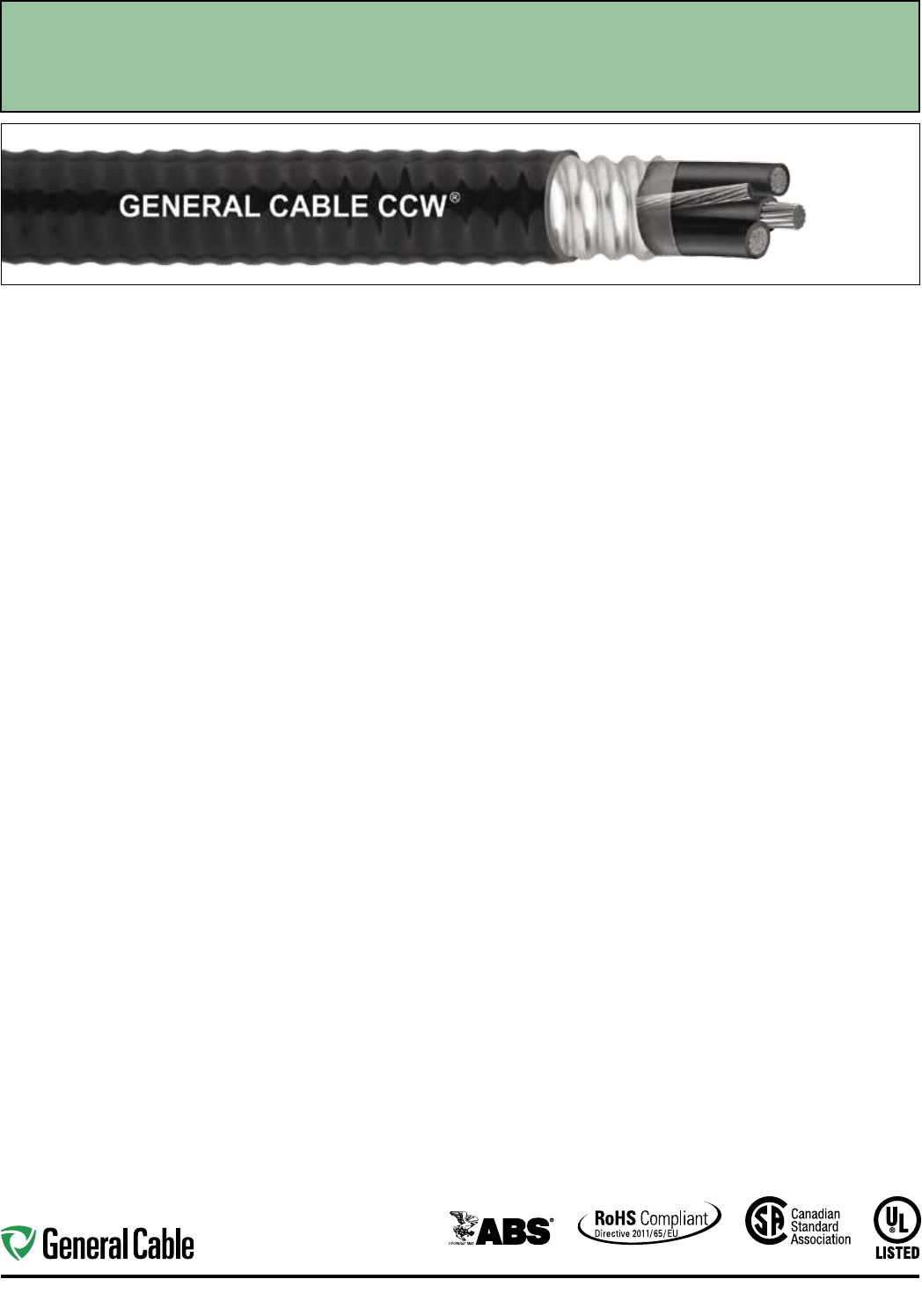
Industrial Automation
76
Applications:
• Variable Frequency Drives: 3-conductor
CCW armored cables with three (3)
symmetrical grounding wires are the
preferred wiring method for use with
AC motors controlled by pulse-width
modulated inverters in VFD applications
• CCW armored cables offer an
economical, rugged and reliable
alternative to labor-intensive cable in
conduit wiring methods
• For use in Class I, II and III, Divisions
1 and 2; and Class I, Zones 1 and 2
hazardous locations per NEC Articles
501, 502, 503 and 505
• For use as services, feeders and
branch circuits for power, lighting,
control, and signal circuits in
accordance with NEC Articles 330
and 725
• Installed indoors or outdoors, wet
or dry locations, directly buried,
embedded in concrete, in a raceway, as
aerial cable on a messenger, in cable
trays, or as exposed runs secured
to supports in accordance with NEC
Article 330
• Recognized for use on fixed or
floating offshore petroleum facilities
as recommended by the American
Petroleum Institute
Features:
• 3-conductor CCW power cables
with three grounding wires are
recommended for use with pulse-width
modulated AC drives
• CCW armor provides an impervious
barrier to moisture, gas and liquids
• CCW armor provides EMI shielding
performance
• Factory assembled and tested cable for
use as an alternative to cable in conduit
wiring systems
Features (cont’d.):
• Meets cold impact at -40°C
• 90˚C continuous operating temperature,
wet or dry
• 130˚C emergency rating
• 250˚C short circuit rating
Specifications:
Design Adherence:
• ICEA S-95-658/WC70 Standard for
Non-Shielded Power Cable, 2 kV
or Less
• UL 44 Rubber Insulated Wires
and Cables
• UL 1569 Metal Clad Cables
• UL 2225 Cables and Cable Fittings for
Use in Hazardous Locations
• UL 1309 Marine Shipboard Cable
• CSA C22.2 No. 123 Metal Sheathed
Cables
• CSA C22.2 No. 174 Cables and Cable
Glands for Use in Hazardous Locations
Flame Tests:
• ICEA T-29-520 (210,000 BTU/hr)
• IEEE 383 (70,000 BTU/hr)
• CSA FT4
• IEEE 1202 (70,000 BTU/hr)
• UL 1581 (70,000 BTU/hr)
• IEC 60332-3 Cat. A
Compliances:
• UL Type MC-HL, XHHW-2, SUN RES,
CT USE, DIR BUR, -40°C, UL File
# E90496
• UL Listed Marine Shipboard, UL File
# E85994
• American Bureau of Shipping (ABS)
Listed for CWCMC
• CSA certified1 Type RA90, XLPE,
HL, SR, FT4, and -40°C, CSA File
# 7319
• RoHS Compliant
1
Standard cables are also marked CSA Type RA90, except
four (4) conductor cables which require a different color
code, which may be special-ordered.
Product Construction:
• Bare annealed copper per ASTM B3
• 10 AWG and smaller are Class B
compressed stranding per ASTM B8
• 8 AWG and larger are compact
stranding per ASTM B496
Insulation:
• Cross-linked Polyethylene (XLPE)
insulation per ICEA S-95-658 and UL
44, Listed XHHW-2
• 6 AWG and smaller are color-coded
per ICEA Method 1, Table E2
• 4 AWG and larger are black with
printed numbers per ICEA Method 4
• Color-coded per CSA C22.2 No. 123
where applicable
Grounding Conductor(s):
• Class B stranded bare annealed
copper per ASTM B3 and B8
• Where specified, single or three
split grounding wires are sized in
accordance with NEC Table 250.122
Cable Assembly:
• Insulated conductors and grounding
wire(s) are cabled together with non-
hygroscopic fillers when required
• A binder tape is applied over the
cabled core
CCW Armor:
• Impervious, continuously welded and
corrugated aluminum alloy sheath per
UL 1569 and UL 2225
• CCW armor conductivity meets the
grounding requirements of NEC
Article 250
Jacket:
• Flame-retardant, moisture- and
sunlight-resistant Polyvinyl Chloride
(PVC), black
• Low temperature performance meets
ASTM D746 brittleness temperature at
or below -40°C
• Meets CSA Low Acid Gas
requirements
SPEC 9600
October, 2014
CCW
®
Armored Power, 3/C VFD and 4/C
UL Type MC-HL, CSA Type HL, XLPE, 600 V, 90°C, Cable Tray Use, Sunlight-Resistant
Direct Burial, UL Marine Shipboard Cable, ABS CWCMC
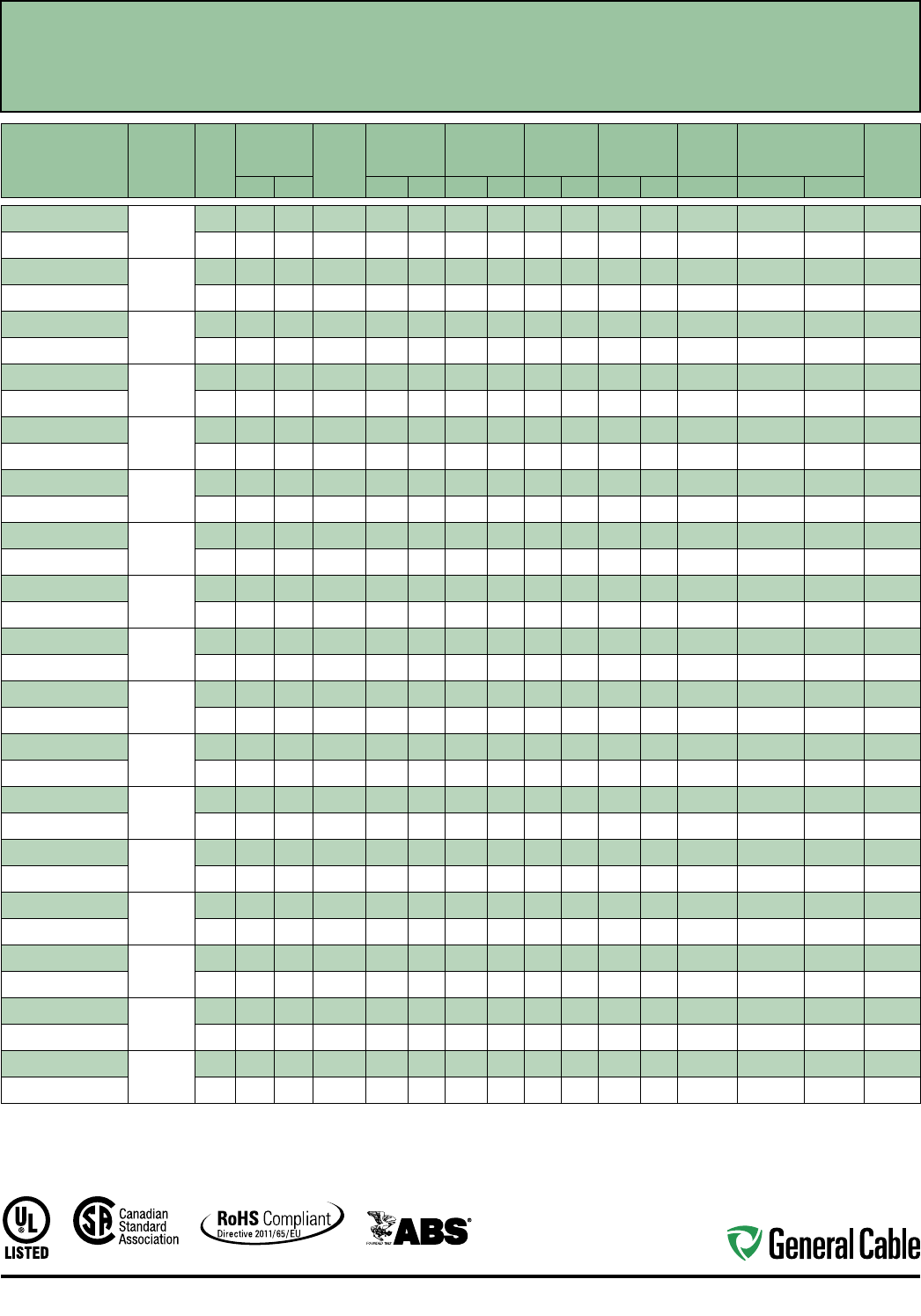
Industrial Automation
77
CCW
®
Armored Power, 3/C VFD and 4/C
UL Type MC-HL, CSA Type HL, XLPE, 600 V, 90°C, Cable Tray Use, Sunlight-Resistant
Direct Burial, UL Marine Shipboard Cable, ABS CWCMC
SPEC 9600
October, 2014
CATALOG
NUMBER
COND.
SIZE
(AWG/kcmil)
NO. OF
COND.
INSULATION
THICKNESS BARE
GROUND
(AWG)
NOMINAL
CORE O.D.
NOMINAL
ARMOR O.D.
JACKET
THICKNESS
NOMINAL
OVERALL O.D.
CROSS-
SECTIONAL
AREA¹
APPROXIMATE
NET WEIGHT
90°C
AMPACITY
@ 30°C
AMBIENT²mils mm INCHES mm INCHES mm mils mm INCHES mm SQ. IN. LBS/1000 FT kg/1000 m
9600.01403318
14 (7/W)
(2.08 mm²)
3 30 0.76 3 x #18 0.33 8.4 0.53 13.5 50 1.27 0.64 16.3 0.33 163 242 15
9600.01404318
4 30 0.76 3 x #18 0.37 9.4 0.58 14.7 50 1.27 0.69 17.5 0.38 226 336 15
9600.01203316
12 (7/W)
(3.31 mm²)
3 30 0.76 3 x #16 0.37 9.4 0.58 14.7 50 1.27 0.69 17.5 0.38 243 362 20
9600.01204316
4 30 0.76 3 x #16 0.45 11.4 0.67 17.0 50 1.27 0.78 19.8 0.48 291 433 20
9600.01003314
10 (7/W)
(5.26 mm²)
3 30 0.76 3 x #14 0.41 10.4 0.62 15.7 50 1.27 0.73 18.5 0.42 305 454 30
9600.01004314
4 30 0.76 3 x #14 0.45 11.4 0.67 17.0 50 1.27 0.78 19.8 0.48 354 527 30
9600.00803314
8 (7/W)
(8.36 mm²)
3 45 1.14 3 x #14 0.50 12.7 0.71 18.0 50 1.27 0.81 20.6 0.52 392 583 55
9600.00804110
4 45 1.14 1 x #10 0.58 14.7 0.80 20.3 50 1.27 0.90 22.9 0.64 473 704 44
9600.00603312
6 (7/W)
(13.3 mm²)
3 45 1.14 3 x #12 0.58 14.7 0.80 20.3 50 1.27 0.90 22.9 0.64 534 795 75
9600.00604108
4 45 1.14 1 x #8 0.66 16.8 0.89 22.6 50 1.27 0.99 25.1 0.78 641 954 60
9600.00403312
4 (7/W)
(21.2 mm²)
3 45 1.14 3 x #12 0.68 17.3 0.89 22.6 50 1.27 0.99 25.1 0.78 716 1,066 95
9600.00404108
4 45 1.14 1 x #8 0.77 19.6 0.97 24.6 50 1.27 1.08 27.4 0.93 860 1,280 76
9600.00203310
2 (7/W)
(33.6 mm²)
3 45 1.14 3 x #10 0.80 20.3 1.02 25.9 50 1.27 1.13 28.7 1.02 1,013 1,507 130
9600.00204106
4 45 1.14 1 x #6 0.92 23.4 1.15 29.2 50 1.27 1.26 32.0 1.26 1,267 1,885 104
9600.00103310
1 (19/W)
(42.4 mm²)
3 55 1.40 3 x #10 0.92 23.4 1.15 29.2 50 1.27 1.26 32.0 1.26 1,119 1,666 150
9600.00104106
4 55 1.40 1 x #6 1.04 26.4 1.29 32.8 50 1.27 1.40 35.6 1.56 1,526 2,272 120
9600.11003310
1/0 (19/W)
(53.5 mm²)
3 55 1.40 3 x #10 1.00 25.4 1.24 31.5 50 1.27 1.34 34.0 1.43 1,496 2,226 170
9600.11004106
4 55 1.40 1 x #6 1.12 28.4 1.37 34.8 50 1.27 1.48 37.6 1.74 1,862 2,771 136
9600.21003310
2/0 (19/W)
(67.4 mm²)
3 55 1.40 3 x #10 1.09 27.7 1.34 34.0 50 1.27 1.44 36.6 1.65 1,801 2,681 195
9600.21004106
4 55 1.40 1 x #6 1.23 31.2 1.51 38.4 60 1.52 1.64 41.7 2.14 2,351 3,498 156
9600.31003308
3/0 (19/W)
(85.0 mm²)
3 55 1.40 3 x #8 1.21 30.7 1.47 37.3 60 1.52 1.58 40.1 1.99 2,262 3,367 225
9600.31004104
4 55 1.40 1 x #4 1.36 34.5 1.65 41.9 60 1.52 1.78 45.2 2.52 2,921 4,346 180
9600.41003308
4/0 (19/W)
(107 mm²)
3 55 1.40 3 x #8 1.33 33.8 1.60 40.6 60 1.52 1.73 43.9 2.38 2,722 4,051 260
9600.41004104
4 55 1.40 1 x #4 1.49 37.8 1.78 45.2 60 1.52 1.91 48.5 2.90 3,491 5,194 208
9600.25003308
250 (37/W)
(127 mm²)
3 65 1.65 3 x #8 1.48 37.6 1.74 44.2 60 1.52 1.87 47.5 — 3,195 4,755 290
9600.25004104
4 65 1.65 1 x #4 1.64 41.7 1.96 49.8 60 1.52 2.09 53.1 — 4,142 6,164 232
9600.35003307
350 (37/W)
(177 mm²)
3 65 1.65 3 x #7 1.66 42.2 1.96 49.8 60 1.52 2.09 53.1 — 4,284 6,376 350
9600.35004103
4 65 1.65 1 x #3 1.89 48.0 2.19 55.6 75 1.91 2.35 59.7 — 5,536 8,238 280
9600.50003306
500 (37/W)
(253 mm²)
3 65 1.65 3 x #6 1.94 49.3 2.28 57.9 75 1.91 2.44 62.0 — 6,035 8,981 430
9600.50004102
4 65 1.65 1 x #2 2.14 54.4 2.49 63.2 75 1.91 2.65 67.3 — 7,704 11,464 344
9600.75003305
750 (61/W)
(380 mm²)
3 80 2.03 3 x #5 2.37 60.2 2.75 69.9 75 1.91 2.92 74.2 — 8,854 13,176 535
9600.75004101
4 80 2.03 1 x #1 2.61 66.3 3.03 77.0 85 2.16 3.21 81.5 — 11,449 17,037 428
9600.100031110
1000 (61/W)
(507 mm²)
3 80 2.03 1 x #1/0 2.67 67.8 3.11 79.0 85 2.16 3.30 83.8 — 11,611 17,280 615
9600.100041110
4 80 2.03 1 x #1/0 3.07 78.0 3.63 92.2 85 2.16 3.81 96.8 — 15,377 22,883 492
Dimensions and weights are nominal; subject to industry tolerances.
¹ Cross-sectional area for cable tray fill is in accordance with NEC Section 392.22.
² Ampacities in accordance with NEC Article 310 and Table 310.15(B)(16).
Note: Three (3) conductors, 6 AWG and smaller are also marked CSA Type RA90. One (1) AWG and larger are also marked CSA Type RA90.
Industrial Automation
78
Product Construction:
Conductor:
• Bare annealed copper per ASTM B3
• 10 AWG and smaller are Class B
compressed stranding per ASTM B8
• 8 AWG and larger are compact
stranding per ASTM B496
Insulation:
• Cross-linked Polyethylene (XLPE)
insulation per ICEA S-95-658 and
UL 44, Listed XHHW-2
• 6 AWG and smaller are color-coded per
ICEA Method 1, Table E2
• 4 AWG and larger are black with printed
numbers per ICEA Method 4
• Color-coded per CSA C22.2 No. 123
where applicable
Grounding Conductor:
• Class B stranded bare annealed copper
per ASTM B3 and B8
• Where specified, single or three
split grounding wires are sized in
accordance with NEC Table 250.122
Cable Assembly:
• Insulated conductors and grounding
wire are cabled together with
non-hydroscopic fillers when required
• A binder tape, when required, is applied
over the cabled core
CCW Armor:
• Impervious, continuously welded and
corrugated aluminum alloy sheath per
UL Standards 1569 and 2225
• CCW armor conductivity meets
the grounding requirements of
NEC Article 250
Jacket:
• Flame-retardant, moisture- and
sunlight-resistant Polyvinyl Chloride
(PVC), black
• Low temperature performance meets
ASTM D746 brittleness temperature at
or below -60°C
Applications:
• Variable Frequency Drives: 3-conductor
CCW armored cables with three (3)
symmetrical grounding wires are the
preferred wiring method for use with
AC motors controlled by pulse-width
modulated inverters in VFD applications
• CCW armored cables offer an
economical, rugged and reliable
alternative to labor-intensive cable in
conduit wiring methods
• For use in Class I, II and III, Divisions
1 and 2; and Class I, Zones 1 and 2
hazardous locations per NEC Articles
501, 502, 503 and 505
• For use as services, feeders and branch
circuits for power, lighting, control, and
signal circuits in accordance with
NEC Articles 330 and 725
• Installed indoors or outdoors, wet
or dry locations, directly buried,
embedded in concrete, in a raceway, as
aerial cable on a messenger, in cable
trays, or as exposed runs secured
to supports in accordance with NEC
Article 330
• Recognized for use on fixed or
floating offshore petroleum facilities
as recommended by the American
Petroleum Institute
Features:
• 3-conductor CCW power cables
with three grounding wires are
recommended for use with pulse-width
modulated AC drives
• CCW armor provides an impervious
barrier to moisture, gas and liquids
• CCW armor provides EMI shielding
performance
• Factory assembled and tested cable for
use as an alternate to cable in conduit
wiring systems
Features (cont’d.):
• Meets cold bend at -55°C
• 90°C continuous operating
temperature, wet or dry
• 130°C emergency rating
• 250°C short circuit rating
Specifications:
Design Adherence:
• ICEA S-95-658/WC70 Standard for
Non-Shielded Power Cable, 2 kV or Less
• UL 44 Rubber Insulated Wires and
Cables
• UL 1569 Metal Clad Cables
• UL 2225 Cables and Cable Fittings for
Use in Hazardous Locations
• UL 1309 Marine Shipboard Cable
• CSA C22.2 No. 123 Metal Sheathed
Cables
• CSA C22.2 No. 174 Cables and Cable
Glands for Use in Hazardous Locations
Flame Tests:
• ICEA T-29-520 (210,000 BTU/hr)
• IEEE 383 (70,000 BTU/hr)
• CSA FT4
• IEEE 1202 (70,000 BTU/hr)
• UL 1581 (70,000 BTU/hr)
• IEC 60332-3 Cat. A
Compliances:
• UL Type MC-HL, XHHW-2, SUN RES,
CT USE, DIR BUR, -40°C, UL File
# E90496
• UL Listed Marine Shipboard, UL File
# E85994
• American Bureau of Shipping (ABS)
Listed for CWCMC
• RoHS Compliant
CCW
®
Armored Power, 3/C VFD and 4/C
UL Type MC-HL, XLPE, 600 V, 90°C, Cable Tray Use, Sunlight-Resistant
Direct Burial, UL Marine Shipboard Cable, ABS CWCMC, Arctic-Grade
SPEC 9605
October, 2014
Industrial Automation
79
CCW
®
Armored Power, 3/C VFD and 4/C
UL Type MC-HL, XLPE, 600 V, 90°C, Cable Tray Use, Sunlight-Resistant
Direct Burial, UL Marine Shipboard Cable, ABS CWCMC, Arctic-Grade
SPEC 9605
October, 2014
CATALOG
NUMBER
COND. SIZE
(AWG/kcmil)
NO. OF
COND.
INSULATION
THICKNESS BARE
GROUND
(AWG)
NOMINAL
CORE O.D.
NOMINAL
ARMOR O.D.
JACKET
THICKNESS
NOMINAL
OVERALL
O.D.
CROSS-
SECTIONAL
AREA1
APPROXIMATE
NET WEIGHT 90°C
AMPACITY
@ 30°C
AMBIENT²mils mm INCHES mm INCHES mm mils mm INCHES mm SQ. IN.
LBS/1000
FT
kg/1000
m
9605.01403318
14 (7/ W)
(2.08 mm²)
330 0.76 3 x #18 0.33 8.4 0.53 13.5 50 1.27 0.64 16.3 0.33 163 242 15
9605.01404216
430 0.76 2 x #16 0.33 8.4 0.51 13.0 50 1.27 0.62 15.7 0.30 221 330 15
9605.01404318
430 0.76 3 x #18 0.37 9.4 0.58 14.7 50 1.27 0.69 17.5 0.38 226 336 15
9605.01203316
12 (7/W)
(3.31 mm²)
330 0.76 3 x #16 0.37 9.4 0.58 14.7 50 1.27 0.69 17.5 0.38 243 362 20
9605.01204316
430 0.76 3 x #16 0.45 11.4 0.67 17.0 50 1.27 0.78 19.8 0.48 291 433 20
9605.01003314
10 (7/W)
(5.26 mm²)
330 0.76 3 x #14 0.41 10.4 0.62 15.7 50 1.27 0.73 18.5 0.42 305 454 30
9605.01004314
430 0.76 3 x #14 0.45 11.4 0.67 17.0 50 1.27 0.78 19.8 0.48 354 527 30
9605.00803314
8 (7/W)
(8.36 mm²)
345 1.14 3 x #14 0.50 12.7 0.71 18.0 50 1.27 0.81 20.6 0.52 392 583 55
9605.00804110
445 1.14 1 x #10 0.58 14.7 0.80 20.3 50 1.27 0.90 22.9 0.64 473 704 44
9605.00804212
445 1.14 2 x #12 0.57 14.5 0.77 19.6 50 1.27 0.88 22.4 0.61 491 731 44
9605.00603312
6 (7/W)
(13.3 mm²)
345 1.14 3 x #12 0.58 14.7 0.80 20.3 50 1.27 0.90 22.9 0.64 534 795 75
9605.00604108
445 1.14 1 x #8 0.66 16.8 0.89 22.6 50 1.27 0.99 25.1 0.78 641 954 60
9605.00604210
445 1.14 2 x #10 0.66 16.8 0.88 22.4 50 1.27 0.99 25.1 0.78 679 1,012 60
9605.00403312
4 (7/W)
(21.2 mm²)
345 1.14 3 x #12 0.68 17.3 0.89 22.6 50 1.27 0.99 25.1 0.78 716 1,066 95
9605.00404108
445 1.14 1 x #8 0.77 19.6 0.97 24.6 50 1.27 1.08 27.4 0.93 860 1,280 76
9605.00404210
445 1.14 2 x #10 0.76 19.3 1.00 25.4 50 1.27 1.11 28.2 0.97 950 1,415 76
9605.00203310
2 (7/W)
(33.6 mm²)
345 1.14 3 x #10 0.80 20.3 1.02 25.9 50 1.27 1.13 28.7 1.02 1,013 1,507 130
9605.00204106
445 1.14 1 x #6 0.92 23.4 1.15 29.2 50 1.27 1.26 32.0 1.26 1,267 1,885 104
9605.00204208
445 1.14 2 x #8 0.89 22.6 1.16 29.5 50 1.27 1.27 32.3 1.27 1,371 2,043 104
9605.00103310
1 (19/W)
(42.4 mm²)
355 1.40 3 x #10 0.92 23.4 1.15 29.2 50 1.27 1.26 32.0 1.26 1,119 1,666 150
9605.00104106
455 1.40 1 x #6 1.04 26.4 1.29 32.8 50 1.27 1.40 35.6 1.56 1,526 2,272 120
9605.11003310
1/0 (19/W)
(53.5 mm²)
355 1.40 3 x #10 1.00 25.4 1.24 31.5 50 1.27 1.34 34.0 1.43 1,496 2,226 170
9605.11004106
455 1.40 1 x #6 1.12 28.4 1.37 34.8 50 1.27 1.48 37.6 1.74 1,862 2,771 136
9605.21003310
2/0 (19/W)
(67.4 mm²)
355 1.40 3 x #10 1.09 27.7 1.34 34.0 50 1.27 1.44 36.6 1.65 1,801 2,681 195
9605.21004106
455 1.40 1 x #6 1.23 31.2 1.51 38.4 60 1.52 1.64 41.7 2.14 2,351 3,498 156
9605.31003308
3/0 (19/W)
(85.0 mm²)
355 1.40 3 x #8 1.21 30.7 1.47 37. 3 60 1.52 1.58 40.1 1.99 2,262 3,367 225
9605.31004104
455 1.40 1 x #4 1.36 34.5 1.65 41.9 60 1.52 1.78 45.2 2.52 2,921 4,346 180
9605.41003308
4/0 (19/W)
(107 mm²)
355 1.40 3 x #8 1.33 33.8 1.60 40.6 60 1.52 1.73 43.9 2.38 2,722 4,051 260
9605.41004104
455 1.40 1 x #4 1.49 37.8 1.78 45.2 60 1.52 1.91 48.5 2.87 3,491 5,194 208
9605.25003308
250 (37/W)
(127 mm²)
365 1.65 3 x #8 1.48 37.6 1.74 44.2 60 1.52 1.87 47.5 2.75 3,19 5 4,755 290
9605.25004104
465 1.65 1 x #4 1.64 41.7 1.96 49.8 60 1.52 2.09 53.1 3.43 4,142 6,164 232
9605.35003307
350 (37/W)
(177 mm² )
365 1.65 3 x #7 1.66 42.2 1.96 49.8 60 1.52 2.09 53.1 3.43 4,284 6,376 350
9605.35003306
365 1.65 3 x #6 1.63 41.4 1.95 49.5 60 1.52 2.09 5 3.1 3.43 4,329 6,443 350
9605.35004103
465 1.65 1 x #3 1.89 48.0 2.19 55.6 75 1.91 2.35 59.7 4.34 5,536 8,238 280
9605.50003306
500 (37/W)
(253 mm²)
365 1.65 3 x #6 1.94 49.3 2.28 57.9 75 1.91 2.44 62.0 4.68 6,035 8,981 430
9605.50004102
465 1.65 1 x #2 2.14 54.4 2.49 63.2 75 1.91 2.65 67. 3 5.52 7,704 11,46 4 344
9605.75003305
750 (61/W)
(380 mm²)
380 2.03 3 x #5 2.37 60.2 2.75 69.9 75 1.91 2.92 74.2 6.70 8,854 13,176 535
9605.75003304
380 2.03 3 x #4 2.32 58.9 2.71 68.8 75 1.91 2.86 72.6 6.42 8,926 13,293 535
9605.75004101
480 2.03 1 x #1 2.61 66.3 3.03 77.0 85 2.16 3.21 81.5 8.09 11,449 17, 0 37 428
9605.10 0031110
1000 (61/W)
(507 mm²)
380 2.03 1 x #1/0 2.67 67. 8 3.11 79.0 85 2.16 3.30 83.8 8.55 11,611 17, 2 8 0 615
9605.10 0041110
480 2.03 1 x #1/0 3.07 78.0 3.63 92.2 85 2.16 3.81 96.8 11.40 15,377 22,883 492
Dimensions and weights are nominal; subject to industry tolerances.
¹ Cross-sectional area for cable tray fill is in accordance with NEC Section 392.22.
² Ampacities in accordance with NEC Article 310 and Table 310.15(B)(16).
Industrial Automation
80
Applications:
• Variable Frequency Drives: 3-conductor
CCW armored cables with three (3)
symmetrical grounding wires is the
preferred wiring method for use with
AC motors controlled by pulse-width
modulated Inverters in VFD applications
• CCW armored cables offer an
economical, rugged and reliable
alternative to labor-intensive cable in
conduit wiring methods
• For use in Class I, II and III, Divisions
1 and 2; and Class I, Zones 1 and 2
hazardous locations per NEC Articles
501, 502 and 503
• For use as services, feeders and
branch circuits for power, lighting,
control, and signal circuits in
accordance with NEC Articles 330
and 725
• Installed indoors or outdoors, wet
or dry locations, directly buried,
embedded in concrete, in a raceway, as
aerial cable on a messenger, in cable
trays, or as exposed runs secured
to supports in accordance with NEC
Article 330
• Recognized for use on fixed or
floating offshore petroleum facilities
as recommended by the American
Petroleum Institute
Features:
• 90°C, 2000 V rated XLPE insulation with
a dielectric constant less than 3.0 to
withstand momentary voltage spikes
common in certain VFD applications
• Three (3) oversized, symmetrical
grounding wires recommended for use
with pulse-width modulated AC drives
• CCW armor provides an impervious
barrier to moisture, gas and liquids
Features (cont’d.):
• CCW armor provides EMI shielding
performance
• Factory assembled and tested cable for
use as an alternative to cable in conduit
wiring systems
• Meets cold impact at -40°C
• 90˚C continuous operating temperature,
wet or dry
• 130˚C emergency rating
• 250˚C short circuit rating
Specifications:
Design Adherence:
• ICEA S-95-658/WC70 Standard
for Non-Shielded Power Cable, 2 kV or
Less
• UL 44 Rubber Insulated Wires and
Cables
• UL 1569 Metal Clad Cables
• UL 2225 Cables and Cable Fittings for
Use in Hazardous Locations
• UL 1309 Marine Shipboard Cable
Flame Tests:
• ICEA T-29-520 (210,000 BTU/hr)
• IEEE 383 (70,000 BTU/hr)
• CSA FT4
• IEEE 1202 (70,000 BTU/hr)
• UL 1581 (70,000 BTU/hr)
• IEC 332-3 Cat. A
Compliances:
• UL Type MC-HL, SUN RES, CT USE,
DIR BUR, -40°C, UL File # E90496
• UL Listed Marine Shipboard, UL File
# E85994
• American Bureau of Shipping (ABS)
Listed for CWCMC
• RoHS Compliant
Product Construction:
Conductor:
• Bare annealed copper per ASTM B3
• 10 AWG and smaller are Class B
compressed stranding per ASTM B8
• 8 AWG and larger are compact
standing per ASTM B496
Insulation:
• Cross-linked Polyethylene (XLPE)
insulation, 2000 V thicknesses per ICEA
S-95-658
• Color-coded black with printed
numbers per ICEA Method 4
Grounding Conductors:
• Class B stranded bare annealed copper
per ASTM B3 and B8
• Three (3) split grounding wires per
specification 9615 exceed the minimum
required in NEC Table 250.122
Cable Assembly:
• Insulated conductors and grounding
wires are cabled together with non-
hygroscopic fillers when required
• A binder tape is applied over the cabled
core
CCW Armor:
• Impervious, continuously welded and
corrugated aluminum alloy sheath per
UL 1569 and UL 2225
• CCW armor conductivity meets the
grounding requirements of NEC
Article 250
Jacket:
• Flame-retardant, moisture- and
sunlight-resistant Polyvinyl Chloride
(PVC) — Black
• Low temperature performance meets
ASTM D746 brittleness temperature at
or below -40°C
SPEC 9615
October, 2014
CCW
®
Armored Power, 3/C VFD
UL Type MC-HL, XLPE, 2000 V, 90°C, Cable Tray Use, Sunlight-Resistant, Direct Burial
UL Marine Shipboard Cable, ABS CWCMC
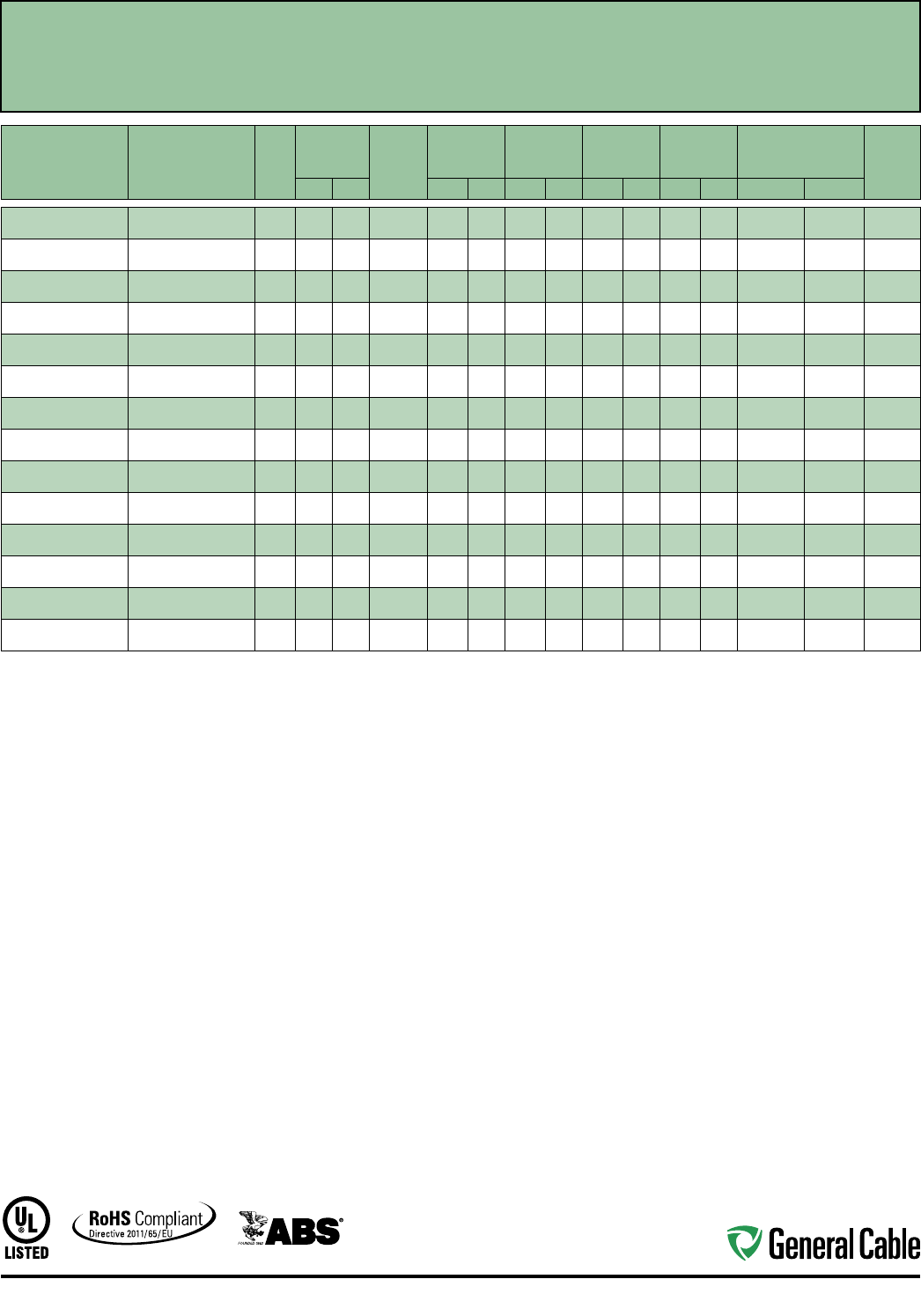
Industrial Automation
81
CCW
®
Armored Power, 3/C VFD
UL Type MC-HL, XLPE, 2000 V, 90°C, Cable Tray Use, Sunlight-Resistant, Direct Burial
UL Marine Shipboard Cable, ABS CWCMC
SPEC 9615
October, 2014
CATALOG
NUMBER
COND.
SIZE
(AWG/kcmil)
NO. OF
COND.
INSULATION
THICKNESS BARE
GROUND
(AWG)
NOMINAL
CORE O.D.
NOMINAL
ARMOR O.D.
JACKET
THICKNESS
NOMINAL
OVERALL O.D.
APPROXIMATE
NET WEIGHT
90°C
AMPACITY
@ 30°C
AMBIENT¹mils mm INCHES mm INCHES mm mils mm INCHES mm LBS/1000 FT kg/1000 m
9615.01403318
14 (7/W) (2.08 mm²)
360 1.52 3 x #18 0.44 11.1 0.62 15.2 50 1.27 0.73 17.9 267 397 15
9615.01203316
12 (7/W) (3.31 mm²)
360 1.52 3 x #16 0.47 11.9 0.66 16.2 50 1.27 0.77 18.9 324 482 20
9615.01003314
10 (7/W) (5.26 mm²)
360 1.52 3 x #14 0.53 13.3 0.73 17. 8 50 1.27 0.84 20.5 400 595 30
9615.00803314
8 (7/W) (8.36 mm²)
370 1.78 3 x #14 0.65 16.5 0.86 21.1 50 1.27 0.97 23.8 524 780 55
9615.00603312
6 (7/W) (13.3 mm²)
370 1.78 3 x #12 0.71 18.0 0.96 23.4 50 1.27 1.07 26 .1 697 1,037 75
9615.00403312
4 (7/W) (21.2 mm²)
370 1.78 3 x #12 0.81 20.6 1.09 26.6 50 1.27 1.23 30.1 1,000 1,488 95
9615.00203310
2 (7/W) (33.6 mm²)
370 1.78 3 x #10 0.94 23.9 1.25 30.6 50 1.27 1.36 33.3 1,285 1,912 130
9615.00103310
1 (19/W) (42.4 mm²)
390 2.29 3 x #10 1.13 28.7 1.48 36.1 50 1.27 1.59 38.8 1,595 2,374 150
9615.11003310
1/0 (19/W) (53.5 mm²)
390 2.29 3 x #10 1.21 30.6 1.55 38.0 60 1.52 1.68 41.2 1,930 2,872 170
9615.21003306
2/0 (19/W) (67.4 mm²)
390 2.29 3 x #6 1.30 32.9 1.68 41.0 60 1.52 1.81 44.2 2,507 3,731 195
9615.41003304
4/0 (19/W) (107 mm²)
390 2.29 3 x #4 1.53 38.7 1.91 46.7 60 1.52 2.04 49.9 3,590 5,342 260
9615.25003304
250 (37/W) (127 mm²)
3105 2.67 3 x #4 1.71 43.4 2.12 51.8 60 1.52 2.25 55.1 4,150 6,176 290
9615.35003302
350 (37/W) (177 mm²)
3105 2.67 3 x #2 1.93 48.9 2.41 58.9 75 1.91 2.57 62.8 5,214 7,75 9 350
9615.50003301
500 (37/W) (253 mm²)
3105 2.67 3 x #1 2.20 55.8 2.68 65.5 75 1.91 2.84 69.5 6,977 10,382 430
Dimensions and weights are nominal; subject to industry tolerances.
¹ Ampacities in accordance with NEC Article 310 and Table 310.15(B)(16).
Industrial Automation
82
Product Construction:
Conductor:
• Bare annealed copper per ASTM B3
• Sizes 10 AWG and smaller are Class B
compressed stranding per ASTM B8
• Sizes 8 AWG and larger are compact
stranding per ASTM B496
Insulation:
• Cross-linked Polyethylene (XLPE)
insulation rated 1000 Volts, RW90 per
CSA C22.2 No. 38
• Sizes 2 AWG and smaller utilize a single
color insulation: black, red and blue
• Sizes 1 AWG and larger utilize black
insulation with printed number/color,
1-black, 2-red, 3-blue
Bonding/Grounding Conductors:
• Class B stranded bare annealed copper
per ASTM B3 and B8
• Three (3) symmetrical grounding wires
are sized in accordance with CEC
Table 16
Cable Assembly:
• Three symmetrical grounding wires
are cabled within the interstices of the
phase conductors
• Non-hygroscopic fillers when required
• A binder tape is applied over the
cabled core
CCW Armor:
• Impervious, continuously welded and
corrugated aluminum alloy sheath per
C22.2 No. 123
Jacket:
• Flame-retardant, moisture- and
sunlight-resistant Polyvinyl Chloride
(PVC), black
• Meets CSA Low Gas Emission
requirements, AG14
Applications:
• Variable Frequency Drives: 3-conductor
CCW armored cables with three (3)
symmetrical grounding wires are the
preferred wiring method for use with
AC motors controlled by pulse-width
modulated inverters in VFD applications
• CCW armored cables offer an
economical, rugged and reliable
alternative to labor-intensive cable in
conduit wiring methods
• For use in industrial and commercial
installations including hazardous
locations in accordance with the CEC
• Can be installed in wet or dry locations,
indoors or outdoors, in cable trays, in a
raceway, or direct buried in accordance
with the CEC
Features:
• 90°C, 1000 V wet or dry XLPE
insulation and three (3) symmetrical
grounding wires, recommended
for use with pulse-width modulated
AC drives
• XLPE insulation has a dielectric
constant less than 3.0 to withstand
momentary voltage spikes common
with VFD applications
Features (cont’d.):
• CCW armor provides an impervious
barrier to moisture, gas and liquids
• CCW armor provides EMI shielding
performance
• Factory assembled and tested cable for
use as an alternative to cable in conduit
wiring systems
• Meets cold impact at -40°C
• 90˚C continuous operating temperature,
wet or dry
• 130˚C emergency rating
• 250˚C short circuit rating
Specifications:
Design Adherence:
• CSA C22.2 No. 38 Thermoset-Insulated
Wires and Cables
• CSA C22.2 No. 123 Metal Sheathed
Cables
• CSA C22.2 No. 174 Cables and Cable
Glands for Use in Hazardous Locations
Flame Tests:
• CSA FT4
• ICEA T-29-520 (210,000 BTU/hr)
• IEEE 383 (70,000 BTU/hr)
• IEEE 1202 (70,000 BTU/hr)
Compliances:
• CSA Certified Type RA90, XLPE,
HL, SR, FT4, AG14 and -40°C,
CSA File # 7319
• RoHS Compliant
SPEC 9675
October, 2014
CCW
®
Armored Power, 1000 V, 3/C VFD
CSA Type RA90, XLPE, 1000 V, 90°C, Cable Tray Use, Sunlight-Resistant
Direct Burial, FT4, -40°C, AG14, HL
Industrial Automation
83
SPEC 9675
October, 2014
CCW
®
Armored Power, 1000 V, 3/C VFD
CSA Type RA90, XLPE, 1000 V, 90°C, Cable Tray Use, Sunlight-Resistant
Direct Burial, FT4, -40°C, AG14, HL
CATALOG
NUMBER
COND.
SIZE
(AWG/kcmil)
NO. OF
COND.
INSULATION
THICKNESS
BARE
GROUND
COND.
(AWG)
NOMINAL
CORE O.D.
NOMINAL
ARMOR O.D.
JACKET
THICKNESS
NOMINAL
OVERALL O.D.
APPROXIMATE NET
WEIGHT MIN. BEND RADIUS ¹
90°C
AMPACITY
@ 30°C
AMBIENT²mils mm INCHES mm INCHES mm mils mm INCHES mm LBS/1000 FT kg/1000 m INCHES mm
9675.01203318 12 (7/W)
(3.31 mm²)
3 45 1.14 3 x #18 0.40 10.2 0.60 15.3 50 1.27 0.70 17.8 249 370 7.0 178 30
9675.01003316 10 (7/W)
(5.26 mm²)
3 45 1.14 3 x #16 0.45 11.5 0.63 16.1 50 1.27 0.73 18.6 299 445 7.3 185 40
9675.00803314 8 (7/W)
(8.36 mm²)
3 45 1.14 3 x #14 0.50 12.7 0.76 19.2 50 1.27 0.86 21.9 417 620 8.6 218 55
9675.00603312 6 (7/W)
(13.3 mm²)
3 60 1.52 3 x #12 0.64 16.3 0.91 23.2 50 1.27 1.02 26.0 601 895 12.2 311 75
9675.00403312 4 (7/W)
(21.2 mm²)
3 60 1.52 3 x #12 0.74 18.7 0.98 24.8 50 1.27 1.08 27.4 763 1,135 12.9 329 95
9675.00203310 2 (7/W)
(33.6 mm²)
3 60 1.52 3 x #10 0.86 21.8 1.18 29.9 50 1.27 1.28 32.5 1,122 1,670 15.4 390 130
9675.00103310 1 (19/W)
(42.4 mm²)
3 80 2.03 3 x #10 1.01 25.7 1.36 34.6 50 1.27 1.46 37.1 1,404 2,090 17.5 445 145
9675.11003310 1/0 (19/W)
(53.5 mm²)
3 80 2.03 3 x #10 1.09 27.8 1.42 36.0 50 1.27 1.52 38.6 1,623 2,415 18.2 462 170
9675.21003310 2/0 (19/W)
(67.4 mm²)
3 80 2.03 3 x #10 1.18 30.0 1.56 39.6 50 1.27 1.66 42.2 2,043 3,040 20.0 506 195
9675.41003308 4/0 (19/W)
(107 mm²)
3 80 2.03 3 x #8 1.40 35.5 1.75 44.4 50 1.27 1.85 47.0 2,950 4,390 22.2 564 260
9675.25003308 250 (37/W)
(127 mm²)
3 90 2.29 3 x #8 1.49 37.8 1.90 48.2 50 1.27 2.01 51.1 3,380 5,030 24.1 612 290
9675.35003308 350 (37/W)
(177 mm²)
3 90 2.29 3 x #8 1.74 44.3 2.22 56.4 50 1.27 2.33 59.2 4,465 6,645 27.9 710 350
9675.50003306 500 (37/W)
(253 mm²)
3 90 2.29 3 x #6 2.00 50.9 2.48 63.0 50 1.27 2.59 65.8 6,152 9,155 31.0 789 430
Dimensions and weights are nominal; subject to industry tolerances.
¹ Minimum bend radius per Canadian Electrical Code, Part I, Section 12-712.
² Ampacity per Table #2, Canadian Electical Code.
Industrial Automation
84
Applications:
• Variable Frequency Drives:
3-conductor CCW armored cables
with three (3) symmetrical grounding
wires are the preferred wiring method
for use with AC motors controlled by
pulse-width modulated inverters in
VFD applications
• CCW armored medium-voltage
power cables offer an economical,
rugged and reliable alternative to
labor-intensive cable in conduit wiring
methods
• For use on feeders and branch circuits
in industrial power distribution systems
per NEC Articles 328 and 330
• For use in Class I, II and III, Divisions
1 and 2; and Class I, Zones 1 and 2
hazardous locations per NEC Articles
501, 502, 503 and 505
• Installed on metal racks, troughs, in
raceways, in cable trays or secured
to supports spaced not more than six
feet apart
• Installed in both exposed and
concealed work, wet or dry locations,
directly buried or embedded in
concrete
• Recognized for use on fixed or
floating offshore petroleum facilities
as recommended by the American
Petroleum Institute
Features:
• CCW armor provides an impervious
barrier to moisture, gas and liquids
and meets the grounding requirements
of UL 1072 and the NEC
• Factory assembled and tested cable
for use as an alternative to cable in
conduit wiring systems
Features (cont’d.):
• General Cable’s EPR insulation system
has outstanding corona resistance and
high dielectric strength, and it provides
electrical stability under stress
• Cable meets cold impact at -40°C
• 90˚C continuous operating temperature,
wet or dry
• 140˚C emergency rating
• 250˚C short circuit rating
Specifications:
Design Adherence:
• ICEA S-96-659/WC71 Standard for
Nonshielded Cables Rated 2001 –
5000 Volts
• UL 1072 Medium-Voltage Power Cables
• UL 1569 Metal Clad Cables
• UL 2225 Cables and Cable Fittings for
Use in Hazardous Locations
• UL 1309 Marine Shipboard Cable
Flame Tests:
• ICEA T-29-520 (210,000 BTU/hr)
• IEEE 383 (70,000 BTU/hr)
• CSA FT4
• IEEE 1202 (70,000 BTU/hr)
• UL 1072
• IEC 60332-3 Category A
Compliances:
• UL Type MV-90 or MC-HL, SUN RES,
CT USE, DIR BUR, -40°C, FT4, UL File
# E90501
• UL Listed Marine Shipboard, UL File #
E85994
• American Bureau of Shipping (ABS)
Listed for CWCMC
Product Construction:
Conductor:
• Bare annealed copper per ASTM B3
• Compact stranding per ASTM B496
Extruded Strand Shield (ESS):
• Extruded thermoset semi-conductor
stress control layer over conductor per
ICEA S-96-659 and UL 1072
Insulation:
• 90 mils Ethylene Propylene Rubber
(EPR) insulation per ICEA S-96-659 and
UL 1072
• Insulation is printed 1-black, 2-red and
3-blue for phase identification
Grounding Conductors:
• Three (3) split Class B stranded bare
annealed copper grounding conductors
• Sized in accordance with UL 1072 and
NEC Table 250.122
Cable Assembly:
• Insulated and grounding conductors are
cabled together with non-hygroscopic
fillers when required
• Binder tape is applied over the cabled
core
CCW Armor:
• Impervious, continuously welded and
corrugated aluminum alloy sheath per
UL 1072 and UL 1569
• CCW armor conductivity meets
the grounding requirements of NEC
Article 250
Jacket:
• Flame-retardant, moisture- and
sunlight-resistant Polyvinyl Chloride
(PVC), yellow
• Low temperature performance meets
ASTM D746 brittleness temperature at
or below -40°C
CCW
®
Armored Power, 2.4 kV, Nonshielded, 3/C VFD
UL Type MC-HL or MV-90, EPR, 105°C, Cable Tray Use, Sunlight-Resistant
Direct Burial, ABS CWCMC
SPEC 9700
July, 2014
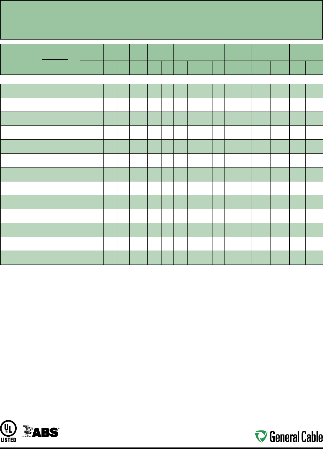
Industrial Automation
85
CCW
®
Armored Power, 2.4 kV, Nonshielded, 3/C VFD
UL Type MC-HL or MV-90, EPR, 105°C, Cable Tray Use, Sunlight-Resistant
Direct Burial, ABS CWCMC
SPEC 9700
July, 2014
CATALOG
NUMBER
COND.
SIZE
NO.
OF
COND.
INSULATION
THICKNESS
NOMINAL O.D.
OVER
INSULATION
BARE
GROUND
NOMINAL
CORE O.D.
NOMINAL
ARMOR O.D.
JACKET
THICKNESS
NOMINAL
OVERALL O.D.
APPROXIMATE
NET WEIGHT AMPACITY
AWG (kcmil) mils mm INCHES mm AWG INCHES mm INCHES mm mils mm INCHES mm
LBS/1000
FT
kg/1000
mIN AIR¹
DIRECT
BURIAL²
3/C WITH GROUND MC-HL OR MV-90, 90 MILS EPR, 2.4 kV, YELLOW JACKET
9700.00803312 8 (7/W)
(8.36 mm²)
3 90 2.3 0.36 9.1 3 x #12 0.77 19.6 0.97 24.6 50 1.27 1.08 27.4 570 848 59 85
9700.00603310 6 (7/W)
(13.3 mm²)
3 90 2.3 0.38 9.6 3 x #10 0.85 21.6 1.06 26.9 50 1.27 1.17 29.7 745 1,109 79 105
9700.00403310 4 (7/W)
(21.2 mm²)
3 90 2.3 0.43 10.8 3 x #10 0.97 24.6 1.19 30.2 50 1.27 1.30 33.0 965 1,436 105 135
9700.00203310 2 (7/W)
(33.6 mm²)
3 90 2.3 0.48 12.1 3 x #10 1.10 27.9 1.34 34.0 50 1.27 1.45 36.8 1,275 1,897 140 180
9700.00103308 1 (19/W)
(42.4 mm²)
3 90 2.3 0.52 13.1 3 x #8 1.16 29.5 1.42 36.1 50 1.27 1.53 38.9 1,525 2,269 160 200
9700.11003308 1/0 (19/W)
(53.5 mm²)
3 90 2.3 0.55 13.9 3 x #8 1.23 31.2 1.51 38.4 60 1.52 1.65 41.9 1,840 2,738 185 230
9700.21003308 2/0 (19/W)
(67.4 mm²)
3 90 2.3 0.59 14.9 3 x #8 1.33 33.8 1.60 40.6 60 1.52 1.73 43.9 2,165 3,222 215 260
9700.41003307 4/0 (19/W)
(107 mm²)
3 90 2.3 0.69 17.4 3 x #7 1.53 38.9 1.83 46.5 60 1.52 1.96 49.8 3,080 4,584 285 335
9700.25003307 250 (37/W)
(127 mm²)
3 90 2.3 0.74 18.7 3 x #7 1.64 41.7 1.96 49.8 60 1.52 2.09 53.1 3,475 5,171 320 365
9700.35003306 350 (37/W)
(177 mm²)
3 90 2.3 0.83 21.0 3 x #6 1.86 47.2 2.19 55.6 60 1.52 2.32 58.9 4,710 7,009 395 440
9700.50003305 500 (37/W)
(253 mm²)
3 90 2.3 0.95 24.0 3 x #5 2.10 53.3 2.45 62.2 75 1.91 2.61 66.3 6,410 9,539 485 530
9700.75003304 750 (61/W)
(380 mm²)
3 90 2.3 1.12 28.3 3 x #4 2.51 63.8 2.93 74.4 75 1.91 3.10 78.7 9,225 13,728 615 650
9700.10003304 1000 (61/W)
(507 mm²)
3 90 2.3 1.27 32.2 3 x #4 2.90 73.7 3.41 86.6 80 2.03 3.59 91.2 12,080 17,977 705 730
Dimensions and weights are nominal, subject to industry tolerances.
¹ In-air ampacities are per NEC Table 310.60(C)(71) for three insulated copper conductors rated 90°C, cabled with an overall covering and isolated in air at 40°C ambient temperature.
² Direct burial ampacities are per NEC Table 310.60(C)(83) for three insulated copper conductors rated 90°C, cabled within an overall covering and directly buried in earth at 20°C ambient
earth temperature.
Industrial Automation
86
Jacket:
• Flame-retardant, moisture- and
sunlight-resistant Polyvinyl Chloride
(PVC), yellow
• Low temperature performance meets
ASTM D746 brittleness temperature at
or below -40°C
Applications:
• Variable Frequency Drives: 3-conductor
CCW armored cables with three (3)
symmetrical grounding wires are the
preferred wiring method for use with
AC motors controlled by pulse-width
modulated inverters in VFD applications
• CCW armored medium-voltage power
cables offer an economical, rugged and
reliable alternative to labor-intensive
cable in conduit wiring methods
• For use on feeders and branch circuits
in industrial power distribution systems
per NEC Articles 328 and 330
• For use in Class I, II and III, Divisions
1 and 2; and Class I, Zones 1 and 2
hazardous locations per NEC Articles
501, 502, 503 and 505
• Installed on metal racks, troughs, in
raceways, in cable trays or secured to
supports spaced not more than six feet
apart
• Installed in both exposed and
concealed work, wet or dry locations,
directly buried or embedded in
concrete
• Recognized for use on fixed or
floating offshore petroleum facilities
as recommended by the American
Petroleum Institute
Features:
• CCW armor provides an impervious
barrier to moisture, gas and liquids and
meets the grounding requirements of
UL 1072 and the NEC
Features (cont’d.):
• Triple Extrusion: The strand shield, EPR
insulation and insulation shield are all
extruded in one operation
• General Cable’s EPR insulation system
has outstanding corona resistance and
high dielectric strength, and it provides
electrical stability under stress
• Cable meets cold impact at -40°C
• 105˚C continuous operating
temperature, wet or dry
• 140˚C emergency rating
• 250˚C short circuit rating
Specifications:
Design Adherence:
• ICEA S-93-639/WC74, 5-46 kV
Shielded Power Cable
• AEIC CS8 Specification for Shielded
Power Cable, 5-46 kV
• UL 1072 Medium-Voltage Power Cables
• UL 1569 Metal Clad Cables
• UL 2225 Cables and Cable Fittings for
Use in Hazardous Locations
• UL 1309 Marine Shipboard Cable
• CSA 68.10
Flame Tests:
• ICEA T-29-520 (210,000 BTU/hr)
• IEEE 383 (70,000 BTU/hr)
• CSA FT4
• IEEE 1202 (70,000 BTU/hr)
• UL 1072
• IEC 60332-3 Category A
Compliances:
• UL Type MV-105 or MC-HL, SUN RES,
CT USE, DIR BUR, -40°C, FT4, UL File
# E90501
• UL Listed Marine Shipboard, UL File #
E85994
• CSA Type HL, SR, FT4, -40°C, CSA File
# 27161
• American Bureau of Shipping (ABS)
Listed for CWCMC
Product Construction:
Conductor:
• Bare annealed copper per ASTM B3
• Compact stranding per ASTM B496
Extruded Strand Shield (ESS):
• Extruded thermoset semi-conductor
stress control layer over the conductor
per ICEA S-93-639 and UL 1072
Insulation:
• 115 mils Ethylene Propylene Rubber
(EPR) insulation per ICEA S-93-639 and
UL 1072
Extruded Insulation Shield (EIS):
• Thermoset semi-conducting polymeric
layer, free stripping from the insulation
per ICEA S-93-639 and UL 1072
Shield:
• 5 mil annealed bare copper tape with
25% overlap
Phase Identification:
• Color-coded polymeric identification
tape laid under the shield — black, red
and blue
Grounding Conductors:
• Three (3) split Class B stranded bare
annealed copper grounding conductors
• Sized in accordance with UL 1072 and
NEC Article 250
Cable Assembly:
• Insulated and grounding conductors are
cabled together with non-hygroscopic
fillers when required
• Binder tape is applied over the cabled
core
CCW Armor:
• Impervious, continuously welded and
corrugated aluminum alloy sheath per
UL 1072 and UL 1569
• CCW armor conductivity meets
the grounding requirements of NEC
Article 250
CCW
®
Armored Power, 5 kV 133%/8 kV 100%, Shielded, 3/C VFD
UL Type MC-HL or MV-105, CSA Type HL, EPR, 105°C, Cable Tray Use, Sunlight-Resistant
Direct Burial, ABS CWCMC
SPEC 9800
October, 2014
Industrial Automation
87
CCW
®
Armored Power, 5 kV 133%/8 kV 100%, Shielded, 3/C VFD
UL Type MC-HL or MV-105, CSA Type HL, EPR, 105°C, Cable Tray Use, Sunlight-Resistant
Direct Burial, ABS CWCMC
SPEC 9800
October, 2014
CATALOG
NUMBER
COND.
SIZE
NO. OF
COND.
INSULATION
THICKNESS
NOMINAL O.D.
OVER
INSULATION
BARE
GROUND
NOMINAL
CORE O.D.
NOMINAL
ARMOR O.D.
JACKET
THICKNESS
NOMINAL
OVERALL O.D.
APPROXIMATE
NET WEIGHT
5 kV³
AMPACITY
AWG (kcmil) mils mm INCHES mm AWG INCHES mm INCHES mm mils mm INCHES mm
LBS/1000
FT
kg/1000
mIN AIR¹
DIRECT
BURIAL²
3/C WITH GROUND MC-HL OR MV-105, 115 MILS EPR, 5 kV 133% AND 8 kV 100% INSULATION LEVEL
9800.00603310 6 (7/W)
(13.3 mm²) 3 115 2.9 0.43 10.9 3 x #10 1.15 29.2 1.37 34.8 50 1.27 1.48 37.6 1,121 1,668 88 115
9800.00403310 4 (7/W)
(21.2 mm²) 3 115 2.9 0.48 12.2 3 x #10 1.24 31.5 1.51 38.4 60 1.52 1.65 41.9 1,418 2,110 115 150
9800.00203310 2 (7/W)
(33.6 mm²) 3 115 2.9 0.53 13.5 3 x #10 1.37 34.8 1.64 41.7 60 1.52 1.78 45.2 1,731 2,576 154 190
9800.00103308 1 (19/W)
(42.4 mm²) 3 115 2.9 0.57 14.5 3 x #8 1.47 37.3 1.69 42.9 60 1.52 1.82 46.2 1,978 2,944 180 215
9800.11003308 1/0 (19/W)
(53.5 mm²) 3 115 2.9 0.60 15.2 3 x #8 1.56 39.6 1.78 45.2 60 1.52 1.91 48.5 2,259 3,362 205 245
9800.21003308 2/0 (19/W)
(67.4 mm²) 3 115 2.9 0.64 16.3 3 x #8 1.61 40.9 1.92 48.8 60 1.52 2.05 52.1 2,626 3,908 240 280
9800.41003307 4/0 (19/W)
(107 mm²) 3 115 2.9 0.74 18.8 3 x #7 1.82 46.2 2.15 54.6 60 1.52 2.28 57.9 3,650 5,432 320 360
9800.25003306 250 (37/W)
(127 mm²) 3 115 2.9 0.80 20.3 3 x #6 2.01 51.1 2.23 56.6 60 1.52 2.36 59.9 4,060 6,042 355 395
9800.35003306 350 (37/W)
(177 mm²) 3 115 2.9 0.89 22.6 3 x #6 2.10 53.3 2.45 62.2 75 1.91 2.61 66.3 5,045 7,508 440 475
9800.50003305 500 (37/W)
(253 mm²) 3 115 2.9 1.01 25.7 3 x #5 2.39 60.7 2.75 69.9 75 1.91 2.92 74.2 7,137 10,621 545 570
9800.75003304 750 (61/W)
(380 mm²) 3 115 2.9 1.19 30.2 3 x #4 3.07 78.0 3.32 84.3 85 2.16 3.50 88.9 10,268 15,280 685 700
9800.10003304 1000 (61/W)
(507 mm²) 3 115 2.9 1.34 34.0 3 x #4 3.43 87.1 3.76 95.5 85 2.16 3.94 100.1 13,051 19,422 790 785
Dimensions and weights are nominal; subject to industry tolerances.
¹ In-air ampacities are per NEC Table 310.60(C)(71) for three insulated copper conductors rated 105°C, cabled with an overall covering and isolated in air at 40°C ambient temperature.
² Direct burial ampacities are per NEC Table 310.60(C)(83) for three insulated copper conductors rated 105°C, cabled within an overall covering and directly buried in earth at 20°C
ambient earth temperature.
³ For 8 kV ampacities, refer to NEC Tables 310.60(C)(71) and 310.60(C)(83) for cables listed 5001-35,000 volts.
Industrial Automation
88
Product Construction:
Conductor:
• Bare annealed copper per ASTM B3
• Compact stranding per ASTM B496
Extruded Strand Shield (ESS):
• Extruded thermoset semi-conductor
stress control layer over the conductor
per ICEA S-93-639 and UL 1072
Insulation:
• 115 mils Ethylene Propylene Rubber
(EPR) insulation per ICEA S-93-639 and
UL 1072
Extruded Insulation Shield (EIS):
• Thermoset semi-conducting polymeric
layer, free stripping from the insulation
per ICEA S-93-639 and UL 1072
Shield:
• 5 mil annealed bare copper tape with
25% overlap
Phase Identification:
• Color-coded polymeric identification
tape laid under the shield – black, red
and blue
Grounding Conductors:
• Three (2) split Class B stranded bare
annealed copper grounding conductors
• Sized in accordance with UL 1072 and
NEC Article 250
Cable Assembly:
• Insulated and grounding conductors are
cabled together with non-hydroscopic
fillers when required
• Binder tape is applied over the
cabled core
CCW Armor:
• Impervious, continuously welded and
corrugated aluminum alloy sheath per
UL Standards 1569 and 2225
• CCW armor conductivity meets the
grounding requirements of NEC
Article 250
Jacket:
• Flame-retardant, moisture- and
sunlight-resistant Polyvinyl Chloride
(PVC), black
• Low temperature performance meets
ASTM D746 brittleness temperature at
or below -60°C
Applications:
• Variable Frequency Drives: 3-conductor
CCW armored cables with three (3)
symmetrical grounding wires are the
preferred wiring method for use with
AC motors controlled by pulse-width
modulated inverters in VFD applications
• CCW armored medium-voltage power
cables offer an economical, rugged and
reliable alternative to labor-intensive cable
in conduit wiring methods
• For use on feeders and branch circuits
for power distribution systems per NEC
Articles 328 and 330
• For use in Class I, II and III, Divisions
1 and 2; and Class I, Zones 1 and 2
hazardous locations per NEC Articles
501, 502, 503 and 505
• Installed on metal racks, troughs, in
raceways, in cable trays or secured to
supports spaced not more than
six feet apart
• Installed in both exposed and
concealed work, wet or dry locations,
directly buried or embedded in
concrete
• Recognized for use on fixed or
floating offshore petroleum facilities
as recommended by the American
Petroleum Institute
Features:
• CCW armor provides an impervious
barrier to moisture, gas and liquids and
meets grounding requirements of UL
1072 and the NEC
Features (cont’d.):
• Triple Extrusion: The strand shield, EPR
insulation and insulation shield are all
extruded in one operation
• General Cable’s EPR insulation system
has outstanding corona resistance and
high dielectric strength, and it provides
electrical stability under stress
• Meets cold bend at -55°C
• 105°C continuous operating
temperature, wet or dry
• 140°C emergency rating
• 250°C short circuit rating
Specifications:
Design Adherence:
• ICEA S-93-639/WC74, 5-46 kV
Shielded Power Cables
• AEIC CS8 Specification for Shielded
Power Cable, 5 – 46 kV
• UL 1072 Medium-Voltage Power Cables
• UL 1569 Metal Clad Cables
• UL 2225 Cables and Cable Fittings for
Use in Hazardous Locations
• UL 1309 Marine Shipboard Cable
• CSA C68.10
Flame Tests:
• ICEA T-29-520 (210,000 BTU/hr)
• IEEE 383 (70,000 BTU/hr)
• CSA FT4
• IEEE 1202 (70,000 BTU/hr)
• UL 1581 (70,000 BTU/hr)
• IEC 60332-3 Cat. A
Compliances:
• UL Type MV-105 or UL Type MC-HL,
SUN RES, CT USE, DIR BUR, -40°C,
FT4, UL File # E90501
• UL Listed Marine Shipboard, UL File
# E85994
• CSA Type HL, SR, FT4, -40˚C,
CSA File # 27161
• American Bureau of Shipping (ABS)
Listed for CWCMC
CCW
®
Armored Power, 5 kV 133%/8 kV 100%, Shielded, 3/C VFD
UL Type MC-HL or MV-105, CSA Type HL, EPR, 105°C, Cable Tray Use
Sunlight-Resistant, Direct Burial, UL Marine Shipboard Cable, ABS CWCMC, Arctic-Grade
SPEC 9805
October, 2014
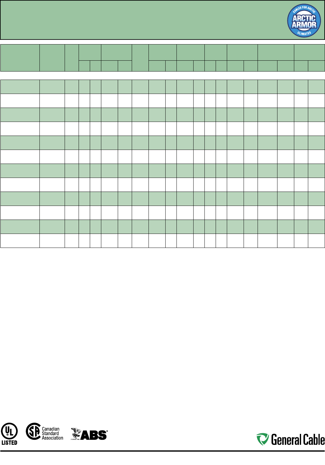
Industrial Automation
89
CCW
®
Armored Power, 5 kV 133%/8 kV 100%, Shielded, 3/C VFD
UL Type MC-HL or MV-105, CSA Type HL, EPR, 105°C, Cable Tray Use
Sunlight-Resistant, Direct Burial, UL Marine Shipboard Cable, ABS CWCMC, Arctic-Grade
SPEC 9805
October, 2014
CATALOG
NUMBER
COND. SIZE
(AWG/kcmil)
NO.
OF
COND.
INSULATION
THICKNESS
NOMINAL
O.D. OVER
INSULATION BARE
GROUND
(AWG)
NOMINAL
CORE O.D.
NOMINAL
ARMOR O.D.
JACKET
THICKNESS
NOMINAL
OVERALL O.D.
APPROXIMATE
NET WEIGHT 5 kV³ AMPACITY
mils mm INCHES mm INCHES mm INCHES mm mils mm INCHES mm
LBS/1000
FT
kg/1000
mIN AIR¹
DIRECT
BURIAL²
3/C WITH GROUND MC-HL OR MV-105, 115 MILS EPR, 5 kV 133% AND 8 kV 100% INSULATION LEVEL
9805.00603310 6 (7/W)
(13.3 mm²) 3115 2.9 0.43 10.9 3 x #10 1.15 29.2 1.37 34.8 50 1.27 1.48 37.6 1,121 1,668 88 115
9805.00403310 4 (7/W)
(21.2 mm²) 3115 2.9 0.48 12.2 3 x #10 1.24 31.5 1.51 38.4 60 1.52 1.65 41.9 1,418 2,110 115 150
9805.00203310 2 (7/W)
(33.6 mm²) 3115 2.9 0.53 13.5 3 x #10 1.37 34.8 1.64 41.7 60 1.52 1.78 45.2 1,731 2,576 154 190
9805.00103308 1 (19/W)
(42.4 mm²) 3115 2.9 0.57 14.5 3 x #8 1.47 37. 3 1.69 42.9 60 1.52 1.82 46.2 1,978 2,944 180 215
9805.11003308 1/0 (19/W)
(53.5 mm²) 3115 2.9 0.60 15.2 3 x #8 1.56 39.6 1.78 45.2 60 1.52 1.91 48.5 2,259 3,362 205 245
9805.21003308 2/0 (19/W)
(67.4 mm²) 3115 2.9 0.64 16.3 3 x #8 1.61 40.9 1.92 48.8 60 1.52 2.05 52.1 2,626 3,908 240 280
9805.41003307 4/0 (19/W)
(107 mm²) 3115 2.9 0.74 18.8 3 x #7 1.82 46.2 2.15 54.6 60 1.52 2.28 57.9 3,650 5,432 320 360
9805.25003306 250 (37/W)
(127 mm²) 3115 2.9 0.80 20.3 3 x #6 2.01 51.1 2.23 56.6 60 1.52 2.36 59.9 4,060 6,042 355 395
9805.35003306 350 (37/W)
(177 mm² ) 3115 2.9 0.89 22.6 3 x #6 2.10 53.3 2.45 62.2 75 1.91 2.61 66.3 5,045 7,50 8 440 475
9805.50003305 500 (37/W)
(253 mm²) 3115 2.9 1.01 25.7 3 x #5 2.39 60.7 2.75 69.9 75 1.91 2.92 74.2 7,137 10,621 545 570
9805.75003304 750 (61/W)
(380 mm²) 3115 2.9 1.19 30.2 3 x #4 3.07 78.0 3.32 84.3 85 2.16 3.50 88.9 10,268 15,280 685 700
9805.10003304 1000 (61/W)
(507 mm²) 3115 2.9 1.34 34.0 3 x #4 3.43 87.1 3.76 95.5 85 2.16 3.94 100.1 13,051 19,422 790 785
Dimensions and weights are nominal; subject to industry tolerances.
¹ In-air ampacities are per NEC Table 310.60(C)(71) for three insulated copper conductors rated 105°C, cabled with an overall covering and isolated in air at 40°C ambient temperature.
² Direct burial ampacities are per NEC Table 310.60(C)(83) for three insulated copper conductors rated 105°C, cabled within an overall covering and directly buried in earth at 20°C
ambient earth temperature.
³ For 8 kV ampacities, refer to NEC Tables 310.60(C)(71) and 310.60(C)(83) for cables listed 5,001-35,000 volts.

Industrial Automation
90
Jacket:
• Flame-retardant, moisture- and
sunlight-resistant Polyvinyl Chloride
(PVC), yellow
• Low temperature performance meets
ASTM D746 brittleness temperature at
or below -40°C
Applications:
• Variable Frequency Drives: 3-conductor
CCW armored cables with three (3)
symmetrical grounding wires are the
preferred wiring method for use with
AC motors controlled by pulse-width
modulated inverters in VFD applications
• CCW armored medium-voltage power
cables offer an economical, rugged and
reliable alternative to labor-intensive
cable in conduit wiring methods
• For use on feeders and branch circuits
in industrial power distribution systems
per NEC Articles 328 and 330
• For use in Class I, II and III, Divisions
1 and 2; and Class I, Zones 1 and 2
hazardous locations per NEC Articles
501, 502, 503 and 505
• Installed on metal racks, troughs, in
raceways, in cable trays or secured to
supports spaced not more than six feet
apart
• Installed in both exposed and
concealed work, wet or dry locations,
directly buried or embedded in
concrete
• Recognized for use on fixed or
floating offshore petroleum facilities
as recommended by the American
Petroleum Institute
Features:
• CCW armor provides an impervious
barrier to moisture, gas and liquids and
meets the grounding requirements of
UL 1072 and the NEC
Features (cont’d.):
• Triple Extrusion: The strand shield, EPR
insulation and insulation shield are all
extruded in one operation
• General Cable’s EPR insulation system
has outstanding corona resistance and
high dielectric strength, and it provides
electrical stability under stress
• Cable meets cold impact at -40°C
• 105˚C continuous operating
temperature, wet or dry
• 140˚C emergency rating
• 250˚C short circuit rating
Specifications:
Design Adherence:
• ICEA S-93-639/WC74, 5-46 kV
Shielded Power Cable
• AEIC CS8 Specification for Shielded
Power Cable, 5-46 kV
• UL 1072 Medium-Voltage Power Cables
• UL 1569 Metal Clad Cables
• UL 2225 Cables and Cable Fittings for
Use in Hazardous Locations
• UL 1309 Marine Shipboard Cable
• CSA 68.10
Flame Tests:
• ICEA T-29-520 (210,000 BTU/hr)
• IEEE 383 (70,000 BTU/hr)
• CSA FT4
• IEEE 1202 (70,000 BTU/hr)
• UL 1072
• IEC 60332-3 Category A
Compliances:
• UL Type MV-105 or MC-HL, SUN RES,
CT USE, DIR BUR, -40°C, FT4, UL File
# E90501
• UL Listed Marine Shipboard, UL File #
E85994
• CSA Type HL, SR, FT4, -40°C, CSA File
# 27161
• American Bureau of Shipping (ABS)
Listed for CWCMC
Product Construction:
Conductor:
• Bare annealed copper per ASTM B3
• Compact stranding per ASTM B496
Extruded Strand Shield (ESS):
• Extruded thermoset semi-conductor
stress control layer over the conductor
per ICEA S-93-639 and UL 1072
Insulation:
• 140 mils Ethylene Propylene Rubber
(EPR) insulation per ICEA S-93-639 and
UL 1072
Extruded Insulation Shield (EIS):
• Thermoset semi-conducting polymeric
layer, free stripping from the insulation
per ICEA S-93-639 and UL 1072
Shield:
• 5 mil annealed bare copper tape with
25% overlap
Phase Identification:
• Color-coded polymeric identification
tape laid under the shield - black, red
and blue
Grounding Conductors:
• Three (3) split Class B stranded bare
annealed copper grounding conductors
• Sized in accordance with UL 1072 and
NEC Article 250
Cable Assembly:
• Insulated and grounding conductors are
cabled together with non-hygroscopic
fillers when required
• Binder tape is applied over the cabled
core
CCW Armor:
• Impervious, continuously welded and
corrugated aluminum alloy sheath per
UL 1072 and UL 1569
• CCW armor conductivity meets the
grounding requirements of the NEC
CCW
®
Armored Power, 8 kV 133%, Shielded, 3/C VFD
UL Type MC-HL or MV-105, CSA Type HL, EPR, 105°C, Cable Tray Use, Sunlight-Resistant
Direct Burial, ABS CWCMC
SPEC 9815
October, 2014
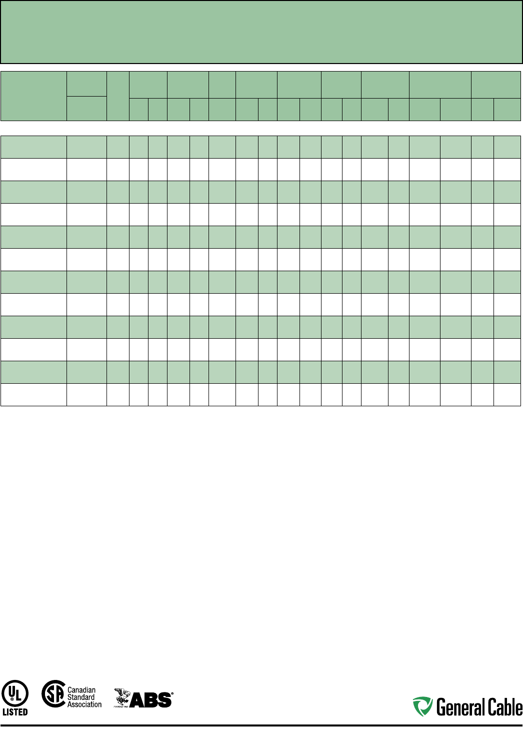
Industrial Automation
91
CCW
®
Armored Power, 8 kV 133%, Shielded, 3/C VFD
UL Type MC-HL or MV-105, CSA Type HL, EPR, 105°C, Cable Tray Use, Sunlight-Resistant
Direct Burial, ABS CWCMC
SPEC 9815
October, 2014
CATALOG
NUMBER
COND.
SIZE
NO. OF
COND.
INSULATION
THICKNESS
NOMINAL O.D.
OVER
INSULATION
BARE
GROUND
NOMINAL
CORE O.D.
NOMINAL
ARMOR O.D.
JACKET
THICKNESS
NOMINAL
OVERALL O.D.
APPROXIMATE
NET WEIGHT AMPACITY
AWG (kcmil) mils mm INCHES mm AWG INCHES mm INCHES mm mils mm INCHES mm
LBS/1000
FT
kg/1000
mIN AIR¹
DIRECT
BURIAL²
3/C WITH GROUND MC-HL OR MV-105, 140 MILS EPR, 8 kV 133% INSULATION LEVEL
9815.00603310 6 (7/W)
(13.3 mm²) 3 140 3.6 0.48 12.2 3 x #10 1.20 30.5 1.60 40.6 60 1.52 1.73 43.9 1,350 2,009 105 120
9815.00403310 4 (7/W)
(21.2 mm²) 3 140 3.6 0.53 13.5 3 x #10 1.29 32.8 1.70 43.2 60 1.52 1.83 46.5 1,600 2,381 135 155
9815.00203310 2 (7/W)
(33.6 mm²) 3 140 3.6 0.58 14.7 3 x #10 1.42 36.1 1.85 47.0 60 1.52 1.98 50.3 2,000 2,976 185 200
9815.00103308 1 (19/W)
(42.4 mm²) 3 140 3.6 0.62 15.7 3 x #8 1.52 38.6 1.93 49.0 60 1.52 2.06 52.3 2,275 3,386 210 225
9815.11003308 1/0 (19/W)
(53.5 mm²) 3 140 3.6 0.65 16.5 3 x #8 1.61 40.9 2.03 51.6 60 1.52 2.16 54.9 2,600 3,869 240 255
9815.21003308 2/0 (19/W)
(67.4 mm²) 3 140 3.6 0.69 17.5 3 x #8 1.66 42.2 2.14 54.4 60 1.52 2.27 57.7 2,950 4,390 275 290
9815.41003307 4/0 (19/W)
(107 mm²) 3 140 3.6 0.79 20.1 3 x #7 1.87 47.5 2.40 61.0 75 1.91 2.56 65.0 4,025 5,990 360 375
9815.25003306 250 (37/W)
(127 mm²) 3 140 3.6 0.85 21.6 3 x #6 2.06 52.3 2.59 65.8 75 1.91 2.75 69.9 4,600 6,846 400 410
9815.35003306 350 (37/W)
(177 mm²) 3 140 3.6 0.94 23.9 3 x #6 2.15 54.6 2.85 72.4 75 1.91 3.01 76.5 5,800 8,631 490 495
9815.50003305 500 (37/W)
(253 mm²) 3 140 3.6 1.06 26.9 3 x #5 2.44 62.0 3.19 81.0 85 2.16 3.37 85.6 7,800 11,608 600 590
9815.75003304 750 (61/W)
(380 mm²) 3 140 3.6 1.26 32.0 3 x #4 3.19 81.0 3.68 93.5 85 2.16 3.86 98.0 10,750 15,998 745 720
9815.10003304 1000 (61/W)
(507 mm²) 3 140 3.6 1.42 36.1 3 x #4 3.48 88.4 3.98 101.1 85 2.16 4.16 105.7 13,550 20,165 860 810
Dimensions and weights are nominal; subject to industry tolerances.
¹ In-air ampacities are per NEC Table 310.60(C)(71) for three insulated copper conductors rated 105°C, cabled with an overall covering and isolated in air at 40°C ambient temperature.
² Direct burial ampacities are per NEC Table 310.60(C)(83) for three insulated copper conductors rated 105°C, cabled within an overall covering and directly buried in earth at 20°C
ambient earth temperature.
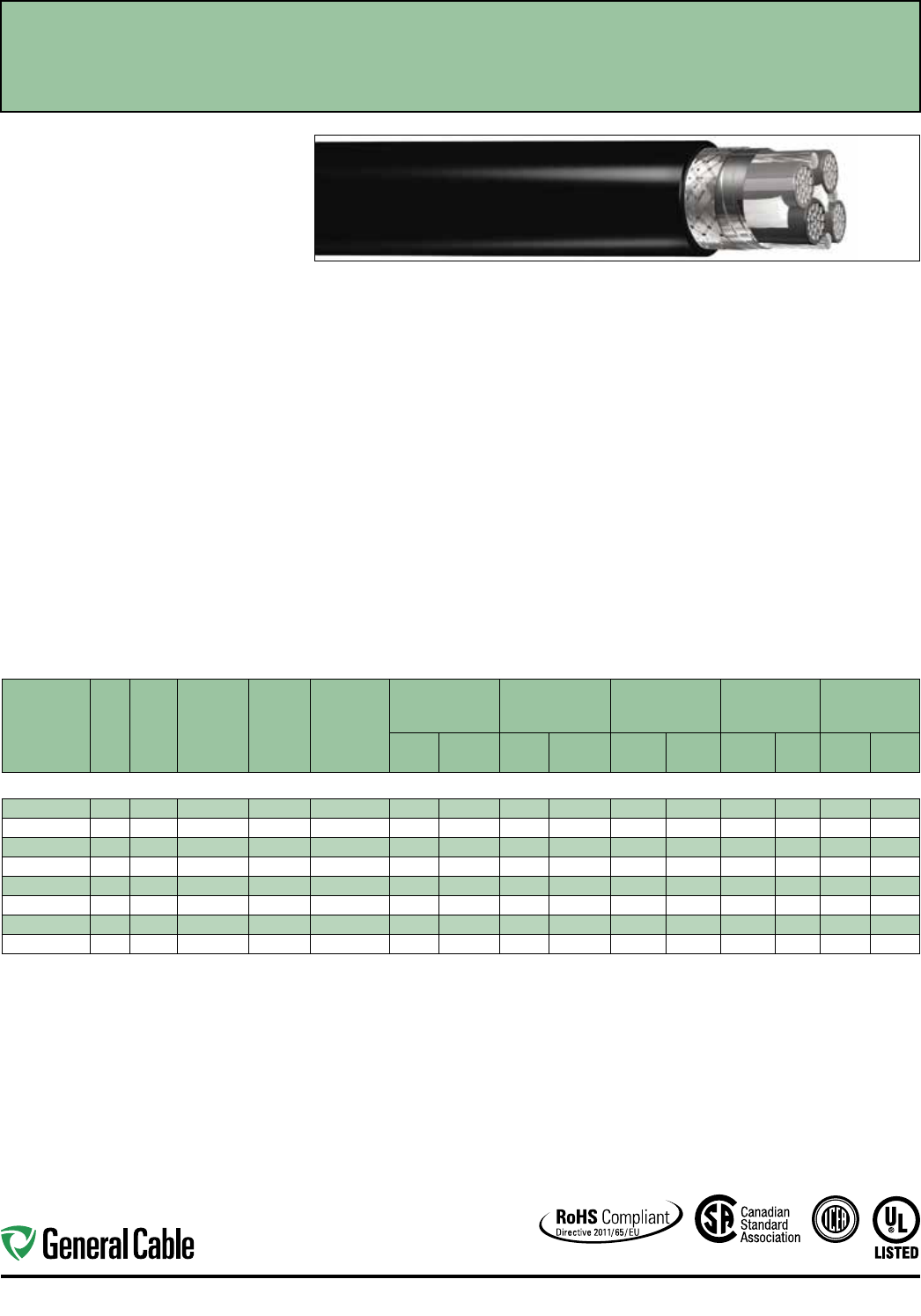
Industrial Automation
92
SPEC 4560
November, 2014
Product Construction:
Conductor:
• 16 AWG thru 10 AWG tinned copper per ASTM
B33. Class K stranding per ASTM B172
• 8 AWG thru 2 AWG tinned copper per ASTM B33.
Class H stranding per ASTM B173
Insulation:
• Flame-retardant Cross-linked Polyethylene (XLPE)
90°C, VW-1
• Color-coded per ICEA Method 4; individual
conductors colored black with conductor number
surface printed in contrasting ink
Ground:
• One full-sized green/yellow insulated ground, same
AWG size as circuit conductors
Metallic Shield:
• Overall aluminum/polyester/aluminum shield with
25% minimum overlap in conjunction with overall
tinned copper braid with 85% coverage and full-
sized tinned copper drain wire(s)
Jacket:
• Lead-free, flame-retardant, sunlight-resistant
Polyvinyl Chloride (PVC), black
Print:
• GENERAL CABLE® (PLANT OF MFG) CVTC®
VFD XX/C XXAWG SHIELDED WITH GRND
XLPE/PVC TYPE RHH OR RHW-2* CDRS 90°C
WET OR DRY 600 V TYPE TC-ER OR 1000 V FLEX
MOTOR SUPPLY OR 1000 V WTTC SUN RES
(UL) DAY/MONTH/YEAR OF MFG SEQUENTIAL
FOOTAGE MARK
*
16 AWG conductors are not listed as RHH or RHW-2
Options:
• Colored jackets available upon request
• 2000 V rated designs
Applications:
• For use with AC motors controlled by pulse-width
modulated inverter in VFD applications rated up to
1000 V
• In free air, raceways or direct burial
• For use in aerial, conduit, open tray and
underground duct/installations
• Permitted for use in Class I, Div. 2 industrial
hazardous locations per NEC
• Permitted for Exposed Run (ER) use in accordance
with NEC
Features:
• Rated at 90°C wet or dry
• Combination foil/braid shield provides maximum
shield coverage required for Variable Frequency
Drive (VFD) applications
• Meets cold bend test at -25°C
• TC-ER listing meets crush and impact requirements
for Type MC cables
• Abrasion- and chemical-resistant
• Stable electrical properties over a broad
temperature range
• UV/sunlight-resistant
Features (cont'd.):
• Flexible strand conductors for all sizes to allow for
ease of installation and long-term performance in
light duty flexing applications
Compliances:
Industry Compliances:
• UL 2277 1000 V Flexible Motor Supply Cable and
1000 V Wind Turbine Tray Cable
• UL 1277 600 V Type TC-ER UL File # E57179
• UL 44 Type RHH or RHW-2 conductors
• ICEA S-95-658/NEMA WC70
Flame Test Compliances:
• UL 1581 VW-1
• IEEE 1202/CSA FT4
• UL 1685
Other Compliances:
• EPA 40 CFR, Part 261 for leachable lead content
per TCLP
• OSHA Acceptable
• RoHS Compliant
Packaging:
• Material cut to length and shipped on
non-returnable wood reels
CVTC
®
VFD - Flexible Motor Supply Cable
XLPE/PVC, Low-Voltage Power, Al/Polyester/AI + TC Braid Shielded, 1000 V UL Flexible
Motor Supply and WTTC, 600 V UL Type TC-ER
—
Method 4 Color Code w/Green/Yellow Ground
CATALOG
NUMBER
NO. OF
COND.
COND.
SIZE
(AWG/
kcmil)
COND.
STRAND
INSULATED
GROUND
WIRE SIZE
(AWG)
DRAIN WIRE
NUMBER X SIZE
(AWG)
NOMINAL
CONDUCTOR
DIAMETER
MINIMUM AVG.
INSULATION
THICKNESS
MINIMUM AVG.
JACKET
THICKNESS
NOMINAL
CABLE O.D. NET WEIGHT
INCHES mm INCHES mm INCHES mm INCHES mm
LBS/
1000 FT kg/km
16 AWG - 2 AWG MULTI-CONDUCTORS
438070 316 26W 16 1 x 16 0.057 1.40 0.045 1.14 0.045 1.14 0.535 13.59 175 260
438080 314 41W 14 1 x 14 0.071 1.80 0.045 1.14 0.060 1.52 0.608 15.44 213 317
438090 312 65W 12 1 x 12 0.088 2.20 0.045 1.14 0.060 1.52 0.653 16.59 285 424
438100 310 105W 10 1 x 10 0.112 2.80 0.045 1.14 0.060 1.52 0.690 17.5 3 362 539
438110 3 8 133W 84 x 14 0.164 4.17 0.060 1.52 0.080 2.03 0.931 23.65 638 949
438120 3 6 133W 64 x 12 0.204 5.18 0.060 1.52 0.080 2.03 1.028 26.11 894 1330
438130 3 4 133W 44 x 10 0.260 6.60 0.060 1.52 0.080 2.03 1.163 29.54 1202 1789
438140 3 2 133W 24 x 8 0.327 8.31 0.060 1.52 0.080 2.03 1.314 33.38 1665 2478
Dimensions and weights are nominal, subject to industry tolerances.
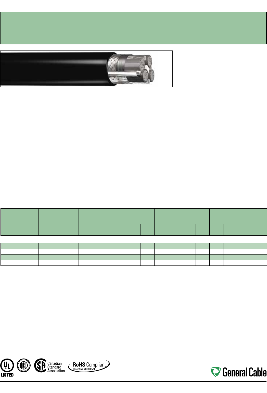
Industrial Automation
93
SPEC 4565
November, 2014
Product Construction:
Conductor:
• 16 AWG to 10 AWG tinned copper per ASTM B33
• Class K stranding per ASTM B172
Insulation:
• Flame-retardant Cross-linked Polyethylene (XLPE)
90°C, VW-1
• Color-coded per ICEA Method 4; individual
conductors colored black with conductor number
surface printed in contrasting ink
Ground:
• One full-sized green/yellow insulated ground, same
AWG size as circuit conductors
Metallic Shield:
• Overall aluminum/polyester/aluminum shield with
25% minimum overlap in conjunction with overall
tinned copper braid with 85% coverage and full-
sized tinned copper drain wire(s)
Signal Pair for Brake:
• One 16 AWG (26 x 30) tinned copper signal pair
with an overall aluminum foil shield and 18 AWG
drain wire
• Black/White color code
Jacket:
• Lead-free, flame-retardant, sunlight-resistant
Polyvinyl Chloride (PVC), black
Print:
• GENERAL CABLE® (PLANT OF MFG) CVTC®
VFD XX/C XXAWG SHIELDED WITH GRND
XLPE/PVC TYPE RHH OR RHW-2* CDRS 90°C
WET OR DRY 600 V TYPE TC-ER OR 1000 V FLEX
MOTOR SUPPLY OR 1000 V WTTC SUN RES
(UL) DAY/MONTH/YEAR OF MFG SEQUENTIAL
FOOTAGE MARK
*
16 AWG conductors are not listed as RHH or RHW-2
Options:
• Colored jackets available upon request
• 2000 V rated designs
Applications:
• For use with AC motors controlled by pulse-width
modulated inverter in VFD applications rated up
to 1000 V
• In free air, raceways or direct burial
• For use in aerial, conduit, open tray and
underground duct/installations
• Permitted for use in Class I, Div. 2 industrial
hazardous locations per NEC
• Permitted for Exposed Run (ER) use in accordance
with NEC
Features:
• Rated at 90°C wet or dry
• Combination foil/braid shield provides maximum
shield coverage required for Variable Frequency
Drive (VFD) applications
• Meets cold bend test at -25°C
• TC-ER listing meets crush and impact requirements
for Type MC cables
• Abrasion- and chemical-resistant
• Stable electrical properties over a broad
temperature range
• UV/sunlight-resistant
• Flexible strand conductors for all sizes to allow for
ease of installation and long-term performance in
light duty flexing applications
Compliances:
Industry Compliances:
• UL 2277 1000 V Flexible Motor Supply Cable and
1000 V Wind Turbine Tray Cable
• UL 1277 600 V Type TC-ER UL File # E57179
• UL 44 Type RHH or RHW-2 conductors
• ICEA S-95-658/NEMA WC70
Flame Test Compliances:
• UL 1581 VW-1
• IEEE 1202/CSA FT4
• UL 1685
Other Compliances:
• EPA 40 CFR, Part 261 for leachable lead content
per TCLP
• OSHA Acceptable
• RoHS Compliant
Packaging:
• Material cut to length and shipped on
non-returnable wood reels
CVTC
®
VFD - Flexible Motor Supply Cable
XLPE/PVC, Low-Voltage Power, Al/Polyester/AI TC Braid Shielded, 1000 V UL Flexible Motor Supply
and WTTC, 600 V UL Type TC-ER
—
Method 4 Color Code w/Green/Yellow Ground and Signal Pair
CATALOG
NUMBER
NO. OF
COND.
COND. SIZE
(AWG/kcmil)
COND.
STRAND
INSULATED
GROUND
WIRE SIZE
(AWG)
DRAIN
WIRE SIZE
(AWG)
SIGNAL
PAIR
(AWG)
NOMINAL
CONDUCTOR
DIAMETER
MINIMUM AVG.
INSULATION
THICKNESS
MINIMUM AVG.
JACKET
THICKNESS
NOMINAL
CABLE O.D. NET WEIGHT
INCHES mm INCHES mm INCHES mm INCHES mm
LBS/
1000 FT kg/km
16 AWG - 10 AWG MULTI-CONDUCTORS
438150* 316 26W 16 16 16 0.057 1.40 0.045 1.14 0.060 1.52 0.750 19.05 324 482
438160* 314 41W 14 14 16 0.071 1.80 0.045 1.14 0.060 1.52 0.823 20.90 340 506
438170* 312 65W 12 12 16 0.088 2.20 0.045 1.14 0.080 2.03 0.909 23.09 438 652
438180* 310 105W 10 10 16 0.112 2.80 0.045 1.14 0.080 2.03 0.997 25.32 563 838
Dimensions and weights are nominal, subject to industry tolerances.
* Non-stock item; minimum runs apply. Please consult customer service for price and delivery.
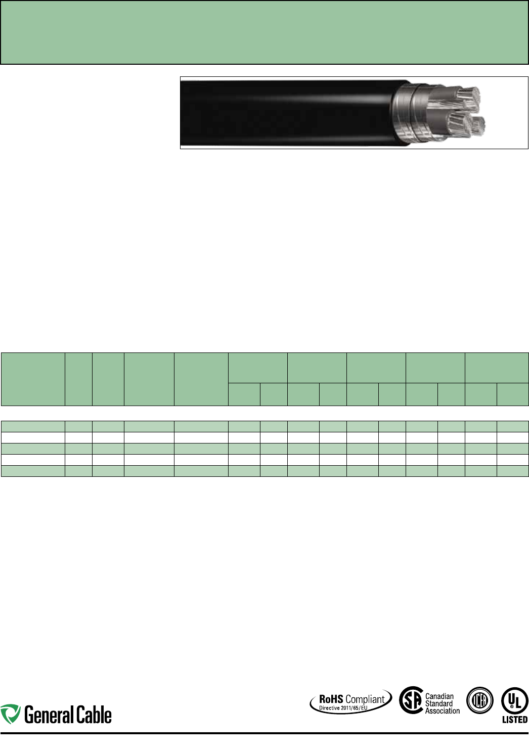
Industrial Automation
94
CATALOG
NUMBER
NO. OF
COND.
COND.
SIZE
(AWG/
kcmil)
COND.
STRAND
GROUND WIRE
SIZE (AWG)
NOMINAL
CONDUCTOR
DIAMETER
MINIMUM AVG.
INSULATION
THICKNESS
MINIMUM AVG.
JACKET
THICKNESS
NOMINAL
CABLE O.D. NET WEIGHT
INCHES mm INCHES mm INCHES mm INCHES mm
LBS/
1000 FT kg/km
1 AWG - 4/0 AWG MULTI-CONDUCTORS
438190* 3 1 224W 3 x 6 0.380 9.65 0.055 1.40 0.080 2.03 1.205 30.61 1610 2396
438200 31/0 273W 3 x 4 0.410 10.41 0.055 1.40 0.080 2.03 1.295 32.89 2020 3006
438210 32/0 323W 3 x 4 0.470 11.90 0.055 1.40 0.080 2.03 1.408 35.76 2325 3460
438220* 33/0 456W 3 x 4 0.549 13.94 0.055 1.40 0.080 2.03 1.524 38.71 2680 3988
438230 34/0 551W 3 x 2 0.593 14.70 0.055 1.40 0.110 2.80 1.682 42.72 3694 5497
Dimensions and weights are nominal, subject to industry tolerances.
* Non-stock item; minimum runs apply. Please consult customer service for price and delivery.
SPEC 4570
November, 2014
Product Construction:
Conductor:
• 1 AWG thru 4/0 AWG tinned copper
• Class I stranding per ASTM B33, B172
Insulation:
• Flame-retardant Cross-linked Polyethylene (XLPE)
90°C, VW-1
• Color-coded per ICEA Method 4; individual
conductors colored black with conductor number
surface printed in contrasting ink
Ground:
• Three symmetrical stranded annealed bare copper
grounds per ASTM B8
Metallic Shield:
• Two spirally applied 2 mil copper tapes providing
100% coverage
Jacket:
• Lead-free, flame-retardant, sunlight-resistant
Polyvinyl Chloride (PVC), black
Print:
• GENERAL CABLE® (PLANT OF MFG) CVTC® VFD
XX/C XXAWG SHIELDED WITH GRND XLPE/PVC
TYPE XHHW-2 CDRS 90°C WET OR DRY 600 V
TYPE TC-ER OR 1000 V FLEX MOTOR SUPPLY OR
1000 V WTTC SUN RES (UL) DAY/MONTH/YEAR
OF MFG SEQUENTIAL FOOTAGE MARK
Options:
• Colored jackets available upon request
Applications:
• For use with AC motors controlled by pulse-width
modulated inverter in VFD applications rated up to
1000 V
• In free air, raceways or direct burial
• For use in aerial, conduit, open tray and
underground duct/installations
• Permitted for use in Class I, Div. 2 industrial
hazardous locations per NEC
• Permitted for Exposed Run (ER) use in accordance
with NEC
Features:
• Rated at 90°C wet or dry
• Dual copper tape shield provides 100% shield
coverage
• Meets cold bend test at -25°C
• TC-ER rating meets crush and impact requirements
for Type MC cables
• Abrasion- and chemical-resistant
• Stable electrical properties over a broad
temperature range
• UV/sunlight-resistant
Features (cont'd.):
• Flexible strand conductors for all sizes to allow for
ease of installation
Compliances:
Industry Compliances:
• UL 2277 1000 V Flexible Motor Supply Cable and
1000 V Wind Turbine Tray Cable
• UL 1277 600 V Type TC-ER UL File # E57179
• UL 44 Type XHHW-2 conductors
• ICEA S-95-658/NEMA WC70
Flame Test Compliances:
• UL 1581 VW-1
• IEEE 1202/CSA FT4
• UL 1685
Other Compliances:
• EPA 40 CFR, Part 261 for leachable lead content
per TCLP
• OSHA Acceptable
• RoHS Compliant
Packaging:
• Material cut to length and shipped on
non-returnable wood reels
CVTC
®
VFD - Flexible Motor Supply Cable
XLPE/PVC, Low-Voltage Power, Dual Copper Tape Shielded, 1000 V UL Flexible Motor Supply
and WTTC, 600 V UL Type TC-ER
—
Method 4 Color Code
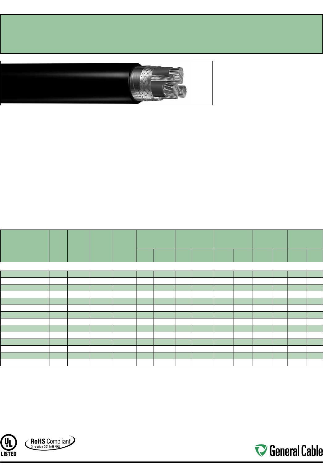
Industrial Automation
95
Product Construction:
Conductor:
• 14 AWG thru 500 kcmil fully annealed tinned
stranded copper
• Class B stranding per ASTM B8
Insulation:
• Flame-retardant Cross-linked Polyethylene
(XLPE)—90°C, VW-1
• Color-coded per ICEA Method 4; individual
conductors colored black with conductor
number surface printed in contrasting ink
Ground:
• 3 symmetrically placed annealed tinned copper
conductors in direct contact with shield
• Class B stranding per ASTM B8
Dual Shield:
• Overall tinned copper braided shield in conjunction
with an aluminum/polymer tape shield
Jacket:
• Lead-free, flame-retardant, sunlight-resistant
Polyvinyl Chloride (PVC)
Print:
• GENERAL CABLE® (PLANT OF MFG) CVTC® VFD
XX/C XXAWG WITH GRND FR-XLP/PVC (UL) TYPE
TC-ER RHH or RHW-2 CDRS 90˚C WET OR DRY
2000 V DIR BUR SUN RES DAY/MONTH/YEAR
SEQUENTIAL FOOTAGE MARK
Applications:
• For use with AC motors controlled by pulse-width
modulated inverter in VFD applications rated up
to 2000 volts. These motor drive systems require
cables that are designed to prevent radio frequency
interference (RFI) which can lead to malfunction
• In raceways, cable trays or direct burial
• In wet or dry locations
• Permitted for use in Class I, Division 2 industrial
hazardous locations per NEC
• Permitted for Exposed Run (ER) use in accordance
with NEC
Features:
• Rated at 90˚C wet or dry
• Dual shield provides maximum shield coverage
required for Variable Frequency Drive (VFD)
applications
• Meets cold bend test at -25°C
• Meets crush and impact requirements to
Type MC cable
• Abrasion- and chemical-resistant
• Excellent electrical properties
• Sunlight- and weather-resistant
Compliances:
Industry Compliances:
• UL 1277 Type TC-ER, UL File # E57179
• UL Type RHH or RHW-2 conductors per UL 44
Flame Test Compliances:
• UL 1581/UL 2556 VW-1
• UL 1685 Vertical Flame Test
• IEEE 383
• IEEE 1202
• ICEA T-29-520 (210,000 BTU/hr)
Other Compliances:
• EPA 40 CFR, Part 261 for leachable lead
content per TCLP
• OSHA Acceptable
• RoHS Compliant
Packaging:
• Material cut to length and shipped on
non-returnable wood reels
SPEC 4575
November, 2014
CVTC
®
VFD
XLPE/PVC, Low-Voltage Power, Shielded
2000 V, UL Type TC-ER
1
—Method 4 Color Code
CATALOG
NUMBER
NO. OF
COND.
COND.
SIZE
(AWG/
kcmil)
COND.
STRAND
GROUND
WIRE SIZE
(AWG)
MINIMUM AVG.
INSULATION
THICKNESS
MINIMUM AVG.
JACKET THICKNESS NOMINAL CABLE O.D.
COPPER
WEIGHT NET WEIGHT
INCHES mm INCHES mm INCHES mm
LBS/
1000 FT kg/km
LBS/
1000 FT kg/km
14 AWG - 500 kcmil MULTI-CONDUCTORS
384730* 314 7W 3 x 18 0.060 1.52 0.060 1.52 0.565 14.35 79 118 190 283
384740* 312 7W 3 x 16 0.060 1.52 0.060 1.52 0.605 15.37 114 170 236 351
384750* 310 7W 3 x 14 0.060 1.52 0.060 1.52 0.665 16.89 172 256 313 466
384760* 387W 3 x 14 0.070 1.78 0.060 1.52 0.785 19.94 234 348 420 625
384770* 367W 3 x 12 0.070 1.78 0.080 2.03 0.910 23.11 354 527 605 900
384780* 347W 3 x 12 0.070 1.78 0.080 2.03 1.010 25.65 507 755 800 1191
384790* 327W 3 x 10 0.070 1.78 0.080 2.03 1.315 28.83 783 1165 1126 1676
384800* 31/0 19W 3 x 6 0.090 2.29 0.080 2.03 1.390 35.31 1251 1861 1832 2726
384810* 32/0 19W 3 x 6 0.090 2.29 0.080 2.03 1.490 37.8 5 1511 2248 2134 3175
384820* 33/0 19W 3 x 5 0.090 2.29 0.080 2.03 1.595 40.51 1897 2823 2553 3799
384830* 34/0 19W 3 x 4 0.090 2.29 0.110 2.79 1.775 45.09 2355 3504 3254 4842
384840* 3250 37W 3 x 4 0.105 2.67 0.110 2.79 1.940 49.28 2719 4046 3726 5544
384850* 3350 37W 3 x 2 0.105 2.67 0.110 2.79 2.160 54.86 3883 5778 5040 7500
384860* 3500 37W 3 x 1 0.105 2.67 0.110 2.79 2.440 61.98 5507 8194 6809 10132
Dimensions and weights are nominal; subject to industry tolerances.
* Non-stock item; minimum runs apply. Please consult Customer Service for price and delivery.
1 Approved as TYPE TC-ER for Exposed Run applications of 3 or more conductors as defined by NEC.
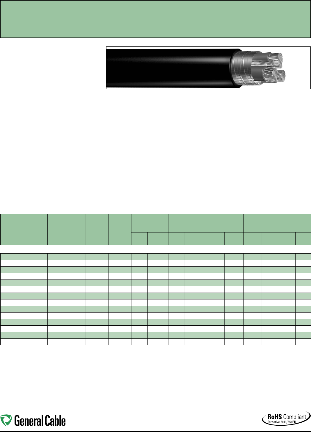
Industrial Automation
96
SPEC 4580
November, 2014
Product Construction:
Conductor:
• 14 AWG thru 500 kcmil fully annealed bare
stranded copper
• Class B stranding per ASTM B8
Insulation:
• Flame-retardant Cross-linked Polyethylene
(XLPE)—90°C, VW-1
• Color-coded per ICEA Method 4; individual
conductors colored black with conductor
number surface printed in contrasting ink
Ground:
• 3 symmetrically placed annealed bare copper
conductors in direct contact with shield
• Class B stranding per ASTM B8
Metallic Shield:
• Overall 5 mil annealed bare copper tape shield
with 50% overlap
Jacket:
• Lead-free, flame-retardant, sunlight-resistant
Polyvinyl Chloride (PVC)
Print:
• GENERAL CABLE® (PLANT OF MFG) CVTC® VFD
XX/C XXAWG WITH GRNDS FR-XLP/PVC (UL)
TYPE TC-ER RHH or RHW-2 CDRS 90˚C WET OR
DRY 2000 V DIR BUR SUN RES DAY/MONTH/
YEAR SEQUENTIAL FOOTAGE MARK
Applications:
• For use with AC motors controlled by pulse-width
modulated inverter in VFD applications rated
up to 2000 volts. These motor drive systems
require cables that are designed to prevent radio
frequency interference (RFI) which can lead to
malfunction
• In raceways, cable trays or direct burial
• In wet or dry locations
• Permitted for use in Class I, Division 2 industrial
hazardous locations per NEC
• Permitted for Exposed Run (ER) use in
accordance with NEC
Features:
• Rated at 90˚C wet or dry
• Overlapped bare copper tape shield provides
necessary shield coverage required for Variable
Frequency Drive (VFD) applications
• Meets cold bend test at -25°C
• Meets crush and impact requirements for
Type MC cable
• Abrasion- and chemical-resistant
• Excellent electrical properties
• Sunlight- and weather-resistant
Compliances:
Industry Compliances:
• UL 1277 Type TC-ER, 2000 V, UL File # E57179
• UL Type RHH or RHW-2 conductors per UL 44
Flame Test Compliances:
• UL 1581/UL 2556 VW-1
• UL 1685 Vertical Flame Test
• IEEE 383
• IEEE 1202
• ICEA T-29-520 (210,000 BTU/hr)
Other Compliances:
• EPA 40 CFR, Part 261 for leachable lead
content per TCLP
• OSHA Acceptable
• RoHS Compliant
Packaging:
• Material cut to length and shipped on
non-returnable wood reels
CVTC
®
VFD
XLPE/PVC, Low-Voltage Power, Copper Tape Shielded
2000 V, UL Type TC-ER
1
—Method 4 Color Code
CATALOG
NUMBER
NO. OF
COND.
COND.
SIZE
(AWG/
kcmil)
COND.
STRAND
GROUND
WIRE SIZE
(AWG)
MINIMUM AVG.
INSULATION
THICKNESS
MINIMUM AVG.
JACKET THICKNESS NOMINAL CABLE O.D.
COPPER
WEIGHT NET WEIGHT
INCHES mm INCHES mm INCHES mm
LBS/
1000 FT kg/km
LBS/
1000 FT kg/km
14 AWG - 500 kcmil MULTI-CONDUCTORS
395070V 314 7W 3 x 18 0.060 1.52 0.060 1.52 0.580 14.73 91 135 212 315
395080V 312 7W 3 x 16 0.060 1.52 0.060 1.52 0.615 15.37 127 189 260 387
395090V 310 7W 3 x 14 0.060 1.52 0.060 1.52 0.670 17.0 2 183 272 329 490
395100V 387W 3 x 14 0.070 1.78 0.060 1.52 0.770 19.56 246 366 441 656
395110V 367W 3 x 12 0.070 1.78 0.080 2.03 0.895 22.73 368 548 618 920
395120V 347W 3 x 12 0.070 1.78 0.080 2.03 0.995 25.27 522 777 830 1235
395130V 327W 3 x 10 0.070 1.78 0.080 2.03 1.125 28.58 801 1192 1152 1714
395140V 31/0 19W 3 x 6 0.090 2.29 0.080 2.03 1.385 35.18 1348 2006 1853 2757
395150V 32/0 19W 3 x 6 0.090 2.29 0.080 2.03 1.480 37.59 1616 2405 2169 3227
395160V* 33/0 19W 3 x 5 0.090 2.29 0.080 2.03 1.590 40.39 2010 2991 2619 3897
395170V 34/0 19W 3 x 4 0.090 2.29 0.110 2.79 1.780 45.21 2517 3745 3241 4823
395180V* 3250 37W 3 x 4 0.105 2.67 0.110 2.79 1.940 49.28 2895 4308 3763 5599
395190V 3350 37W 3 x 2 0.105 2.67 0.110 2.79 2.160 54.86 4089 6084 5109 7602
395200V 3500 37W 3 x 1 0.105 2.67 0.110 2.79 2.455 62.36 5693 8471 6933 10316
Dimensions and weights are nominal; subject to industry tolerances.
* Non-stock item; minimum runs apply. Please consult Customer Service for price and delivery.
1 Approved as TYPE TC-ER for Exposed Run applications of 3 or more conductors as defined by NEC.

98
Technical Information Industrial Automation
Please consult your General Cable representative for additional information (800) 950-3512
Industrial Automation General Cable to Belden
Cross-Reference
General Cable, a leading wire and cable innovator for over 170 years, knows that factory productivity is key to your business
success. Trusting your automation infrastructure puts your mind at ease. General Cable is proud to introduce its new line of
DeviceNet™, ControlNet™ and Industrial Ethernet products. As One Company and one source, General Cable is ready to respond to
your changing requirements and help you achieve continuous productivity savings.
CONTROLNET™ SYSTEM
PART
DESCRIPTION
GENERAL CABLE
CATALOG NUMBER
BELDEN
EQUIVALENT
18 AWG RG-6 ControlNet
Quad Shield
GCR1309 3092A
18 AWG RG-6 ControlNet Quad
Shield Aluminum Braid Flex Shield
GCR1309F 3092F
18 AWG RG-6 ControlNet
Quad Shield Copper Braid
GCR1309FC YR28690
18 AWG RG-6 ControlNet
Quad Shield Plenum
GCR1309P 3093A
18 AWG RG-6 ControlNet
Quad Shield Aluminum Armored
GCR1309A 123092A
18 AWG RG-6 ControlNet
Quad Shield Steel Armor
GCR1309S 133092A
18 AWG RG-6 ControlNet
Quad Shield CCW®
GCR1309CC 183092A
CAN OPEN/HART/RS-485 SYSTEM
PART
DESCRIPTION
GENERAL CABLE
CATALOG NUMBER
BELDEN
EQUIVALENT
24 AWG 1 Pair Tinned Copper
Foil and Braid Shield
C4841A 9841
24 AWG 2 Pair Tinned Copper
Foil and Braid Shield
C4842A 9842
24 AWG 3 Pair Tinned Copper
Foil and Braid Shield
C4843A 9843
24 AWG 4 Pair Tinned Copper
Foil and Braid Shield
C4844A 9844
24 AWG 1 Pair Tinned Copper
Foil and Braid Shield Plenum
C4851A 82841
24 AWG 2 Pair Tinned Copper
Foil and Braid Shield Plenum
C4852A 82842
22 AWG 1 Pair LO-CAP®
Tinned Plated Copper Braid
C7112A 3105A
22 AWG 2 Pair LO-CAP
Tinned Plated Copper Braid
C7114A 3107A
22 AWG 3 Pair LO-CAP
Tinned Plated Copper Braid
C7116A 3108A
22 AWG 4 Pair LO-CAP
Tinned Plated Copper Braid
C7118A 3109A
22 AWG 1 Pair + 1 Conductor LO-CAP
Tinned Copper Braid and Foil Shield
GCR1310 3106A
DATA HIGHWAY & DATA HIGHWAY PLUS SYSTEM
PART
DESCRIPTION
GENERAL CABLE
CATALOG NUMBER
BELDEN
EQUIVALENT
18 AWG 2 Conductor
Dual Shielded Twinaxial
GCR1300 3072F
20 AWG 2 Conductor
Dual Shielded Twinaxial
GCR1314 9463
20 AWG 2 Conductor Dual Shielded
Twinaxial Aluminum Armor
GCR1314A 129463
20 AWG 2 Conductor Dual Shielded
Twinaxial CCW®
GCR1314CC 189463
20 AWG 2 Conductor Dual Shielded
Twinaxial Direct Burial
GCR1314D 9463DB
20 AWG 2 Conductor Dual Shielded
Twinaxial Flexible Jacket
GCR1314F 9463F
20 AWG 2 Conductor Dual Shielded
Twinaxial Plenum
GCR1314P 89463
20 AWG 2 Conductor Dual Shielded
Twinaxial Steel Armor
GCR1314S 139463
20 AWG 2 Conductor Heavy Duty
Tough Shielded Twinaxial
GCR1314T YR28764
20 AWG 2 Conductor Dual
Shielded Low–Smoke Zero-Halogen
GCR1314ZH YR41104
DEVICENET™ SYSTEM
PART
DESCRIPTION
GENERAL CABLE
CATALOG NUMBER
BELDEN
EQUIVALENT
15 AWG 2 Conductor + 18 AWG
2 Conductor Shielded DeviceNet
GCR1305 3082A
15 AWG 2 Conductor + 18 AWG
2 Conductor Shielded Flexible DeviceNet
GCR1305F 3082F
15 AWG 2 Conductor + 18 AWG
2 Conductor Shielded CPE DeviceNet
GCR1306 3083A
22 AWG 2 Conductor + 24 AWG
2 Conductor Shielded DeviceNet
GCR1307 3084A
22 AWG 2 Conductor + 24 AWG
2 Conductor Shielded Flexible DeviceNet
GCR1307F 3084F
22 AWG 2 Conductor + 24 AWG
2 Conductor Shielded CPE DeviceNet
GCR1308 3085A
16 AWG 2 Conductor + 18 AWG
2 Conductor Individually Shielded
DeviceNet
GCR1311 7896A
15 AWG 2 Conductor + 18 AWG
2 Conductor Individually Shielded
DeviceNet
GCR1312 7897A
16 AWG 2 Conductor + 18 AWG
2 Conductor Unshielded DeviceNet
GCR1313 7900A
18 AWG 2 Conductor + 20 AWG
2 Conductor Shielded DeviceNet
GCR1317 7895A
99
Industrial Automation Technical Information
Please consult your General Cable representative for additional information (800) 950-3512
Seriplex® is a registered trademark of Belden CDT Inc.
DeviceNet™ is a trademark of Open DeviceNet™ Vendor Assoc.
ControlNet™ is a trademark of Open DeviceNet™ Vendor Assoc.
Lo-Cap® and CCW® are trademarks of General Cable Technologies Corporation.
This cross-reference guide should be used in conjunction with the product information in our catalog or on our website.
It should be used for suggested alternative items which are functionally equal. Constructional differences are not indicated.
General Cable is not responsible for variances due to competitor and industry constructional changes or agency updates.
Industrial Automation General Cable to Belden
Cross-Reference
CC-LINK SYSTEM
PART DESCRIPTION GENERAL CABLE
CATALOG NUMBER
BELDEN
EQUIVALENT
20 AWG 3 Conductor Dual Shielded
CC-Link
GCR1315 1348A
20 AWG 3 Conductor Shielded + 18 AWG
2 Conductor Composite & CC-Link
GCR1316 1349A
FOUNDATION™ FIELDBUS SYSTEM
PART DESCRIPTION GENERAL CABLE
CATALOG NUMBER
BELDEN
EQUIVALENT
18 AWG 1 Pair Shielded Foundation
Fieldbus or Profibus
GCR1302 3076F
22 AWG 1 Pair Shielded Foundation
Fieldbus
GCR1303 3077F
INTERBUS/LONWORKS®/MODBUS/PROFIBUS OP-FMS-PA
SERIPLEX®/SMART DISTRIBUTED SYSTEM
PART
DESCRIPTION
GENERAL CABLE
CATALOG NUMBER
BELDEN
EQUIVALENT
24 AWG 3 Pair + 18 AWG
3 Conductor Shielded Interbus
GCR1318 3119A
24 AWG 3 Pair Shielded Interbus GCR1319 3120A
22 AWG 3 Pair Individually Shielded
Modbus
GCR1320 8777
22 AWG 3 Pair Individually Shielded
LS PVC Jacket
GCR1320P 82777
22 AWG 3 Pair Individually Shielded
Aluminum Armor Modbus
GCR1320A 128777
22 AWG 3 Pair Flexible Individually
Shielded Plenum Modbus
GCR1320FP 88777
22 AWG 3 Pair Individually Shielded
Steel Armor Modbus
GCR1320S 138777
22 AWG 2 Conductor Shielded
Profibus
GCR1304 3079A
22 AWG 2 Conductor Shielded
Flexible Profibus
GCR1304F 3079E
18 AWG 2 Conductor + 22 AWG
2 Conductor Shielded Seriplex
GCR1330 3124A
18 AWG 2 Conductor + 22 AWG
2 Conductor Shielded Aluminum
Armored Seriplex
GCR1330A 123124A
16 AWG 2 Conductor + 22 AWG
2 Conductor Shielded Seriplex
GCR1331 3125A
16 AWG 2 Conductor + 22 AWG
2 Conductor Shielded Aluminum
Armored Seriplex
GCR1331A 123125A
16 AWG 2 Conductor + 22 AWG
2 Conductor + 12 AWG 2 Conductor
Shielded Seriplex
GCR1333 3126A
16 AWG 2 Conductor + 22 AWG
2 Conductor + 12 AWG 2 Conductor
Shielded Aluminum Armored
Seriplex
GCR1333A 123126A
16 AWG 1 Pair + 20 AWG 1 Pair
Individually Shielded SDS
GCR1332 3086A
22 AWG 2 Pair Individually
Shielded SDS
GCR1334 3087A
INDUSTRIAL ETHERNET SYSTEM
PART
DESCRIPTION
GENERAL CABLE
CATALOG NUMBER
BELDEN
EQUIVALENT
24 AWG 4 Pair Multi-Conductor
Category 5e Industrial Ethernet UTP
Cable Waterblocked
5136100 7934A
24 AWG 4 Pair Multi-Conductor
Category 5e Industrial Ethernet UTP
Cable Waterblocked Armored
5136101
23 AWG 4 Pair Multi-Conductor
Category 6 Industrial Ethernet UTP
Cable Waterblocked
7136100
24 AWG 2 Pair Multi-Conductor
Category 5e Industrial Ethernet UTP
Cable 600 V UL AWM
GCR1402 7932A
24 AWG 2 Pair Multi-Conductor
Category 5e Industrial Ethernet F/UTP
Cable Shielded 600 V UL AWM
GCR1403 7933A
24 AWG 4 Pair Multi-Conductor
Category 5e Industrial Ethernet UTP
Cable 600 V UL AWM
GCR1404*
7918A/7923A
24 AWG 4 Pair Multi-Conductor
Category 5e Industrial Ethernet F/UTP
Cable Shielded, 600 V UL AWM
GCR1405*
7929A/7958A
24 AWG 4 Pair Multi-Conductor
Category 5e Industrial Ethernet
SF/UTP Cable 600 V UL AWM
GCR1407
7921A/7957A
22 AWG 4 Pair Multi-Conductor
Category 5e Industrial Ethernet UTP
Cable PLTC 600 V UL AWM
GCR1408 7922A
24 AWG 4 Pair Multi-Conductor
Category 5e Industrial Ethernet UTP
Cable Armored
GCR1410 121700A
24 AWG 4 Pair Multi-Conductor
Category 5e Industrial Ethernet F/UTP
Cable 600 V UL AWM
GCR1419 7919A
23 AWG 4 Pair Multi-Conductor
Category 6 Industrial Ethernet UTP
Cable 600 V UL AWM
GCR1440 7940A
23 AWG 4 Pair Multi-Conductor
Category 6 Industrial Ethernet UTP
Cable Enhanced 600 V UL AWM
GCR1450 7927A
23 AWG 4 Pair Multi-Conductor
Category 6 Industrial Ethernet F/UTP
Cable Shielded 600 V UL AWM
GCR1452 7953A
* MSHA rating pending approval.

100
Technical Information Industrial Automation
This cross-reference guide should be used in conjunction with the product information in our catalog or on our website.
It should be used for suggested alternative items which are functionally equal. Constructional differences are not indicated.
General Cable is not responsible for variances due to competitor and industry constructional changes or agency updates.
Please consult your General Cable representative for additional information (800) 950-3512
Industrial Communication Protocol Cables
Cross-Reference
CANOpen® Network Cables typically are 2 pairs, either 24 AWG or 22 AWG. The final decision on the wire size, capacitance,
impedance, shielding, and other electrical specifications is a function of the application. General Cable Corporation cannot
specify a specific cable for these applications. General Cable Corporation offers different cable constructions to function in many
CANOpen® applications.
CANOpen® NETWORK CABLES OPTIONS
GCC PART
NUMBER
BELDEN PART
NUMBER CABLE DESCRIPTION
UL/CSA
LISTINGS
PAGE
NUMBER
C4842A 9842 2 pr 24 AWG (7x32) TC, OFS + 90% TC Braid/PVC
Print Legend: CAROL® 24 AWG -- C4842A -- 75C E105765-H CM (UL) C(UL) CMH
OR 80CAWM STYLE 2919 30 V LOW VOLTAGE COMPUTER CABLE -- ROHS/CE --
MADE IN USA (date code - MM/YY) (sequential footage)
CM, CMH c(UL)
AWM 2919
39
C4852A 82842 2 pr 24 AWG (7x32) TC, OFS + 90% TC Braid/LS PVC
Print Legend: CAROL® -- C4852A -- 2/PR 24 AWG SHIELDED LOW CAP RS-485
TYPE CMP (UL) C(UL) 75C E105765-F -- ROHS/CE -- MADE IN USA – MM/YY
AAAAA XXXXXFT
CMP c(UL) 40
C7114A 3107A 2 pr 22 AWG (7x30) TC, OFS + 65% TC Braid/PVC
Print Legend: CAROL® -- C7114A -- 2/PR 22 AWG SHIELDED LOW CAP RS-485 (UL)
PLTC OR CM C(UL) 75C E60233-F -- RoHS/CE -- MADE IN USA – MM/YY AAAAA
XXXXXFT
PLTC, CM c(UL) 39
C7114AF 2 pr 22 AWG (26x36) TC, OFS + 65% TC Braid/PVC
Print Legend: CAROL® -- C7114AF -- 2/PR 22 AWG SHIELDED LOW CAP RS-485
(UL) PLTC OR CM C(UL) 75C E60233-F -- RoHS/CE -- MADE IN USA – MM/YY
AAAAA XXXXXFT
PLTC, CM c(UL) 39
CiA® and CANOpen® are registered Community Trademarks of CAN in Automotive e.V
Guidelines for the environment of automation applications may be classified by ANSI/TIA 1005. Levels (MICE) Mechanical, Ingress, Climatic, Chemical and Electromagnetic.
CC-Link cables are used extensively in industrial environments. The cable application is dependent on where the cables are to be
residing. Factory floor environments can range from general light duty, clean environments to more severe environments that may be
subject to moisture, chemicals, extreme temperature ranges, physical or outdoor environments that could cause premature failure of a
cable that was just designed for indoor enterprise applications.
CC-LINK CABLES
MITSUBISHI
PART NUMBER
GCC PART
NUMBER
BELDEN PART
NUMBER CABLE DESCRIPTION APPLICATIONS
UL/CSA
LISTINGS
PAGE
NUMBER
BA1SJ61-5 GCR1315 1348A 3 Cond. 20 AWG (7x28) BC, OFS + Braid 78% TC/PVC
Print Legend: GENERAL CABLE (F) – GCR1315 -- 3/C 20 AWG
SHIELDED (UL) TYPE CM 75C --- ROHS/CE -- MADE IN USA AAAAA
MO/YR XXXXXXFT
CC-Link Cable Version 1.10, 2.0,
industrial environments, relatively
clean, minimum temperature
changes
CM, c(UL) 34
BA1SJ61-P GCR1316 1349A Data: 3 Cond. 20 AWG (7x28) BC, OFS + Braid 78% TC/PVC Power: 2
Cond. 18 AWG (7x26) BC
Print Legend: GENERAL CABLE (F) – GCR1316 -- 1/PR18 AWG + 1/PR20
SHIELDED (UL) TYPE PLTC OR CM 75C -- ROHS/CE -- MADE IN USA
AAAAA MO/YR XXXXXXFT
CC-Link Cable Version 1.10, 2.0,
industrial environments, relatively
clean, minimum temperature
changes
PLTC, CM
c(UL)
34
CC-Link Cables: reference CC-Link Partner Association
Information contained on these pages is intended for evaluation by technically skilled persons. Any person relying on this document does so at his/her own independent discretion and sole
risk and assumes all risks, liability and obligations whatsoever in connection with such use. General Cable Corporation and its subsidiaries will have no liability with respect thereto, whether
the claim is based in contract, tort or other legal theory. General Cable Corporation and its subsidiaries make no representations or warranties, expressed or implied, with respect to the
accuracy, completeness or reliability of this information.
Guidelines for the environment of automation applications may be classified by ANSI/TIA 1005. Levels (MICE) Mechanical, Ingress, Climatic, Chemical and Electromagnetic.
101
Industrial Automation Technical Information
This cross-reference guide should be used in conjunction with the product information in our catalog or on our website.
It should be used for suggested alternative items which are functionally equal. Constructional differences are not indicated.
General Cable is not responsible for variances due to competitor and industry constructional changes or agency updates.
Please consult your General Cable representative for additional information (800) 950-3512
Industrial Communication Protocol Cables
Cross-Reference
ControlNet™ cables are used extensively in industrial environments. The cable application is dependent on where the cables are to be
residing. Factory floor environments can range from general light duty, clean environments to more severe environments that may be
subject to moisture, chemicals, extreme temperature ranges, physical or outdoor environments that could cause premature failure of a
cable that was just designed for indoor enterprise applications.
ControlNet™ CABLES
GCC PART
NUMBER
BELDEN PART
NUMBER CABLE DESCRIPTION APPLICATIONS
UL/CSA
LISTINGS
PAGE
NUMBER
GCR1309 3092A RG-6/U 18 AWG CCS, Quad Shield OFS(2) 60/40% AL Braid/PVC
Print Legend: GENERAL CABLE (F) – GCR1309 – ODVA ControlNet™ VEN #1293 RG6/U TYPE
75 OHM QUAD SHIELD – 3.0 GHZ – 18 AWG 75C (ETL) CL2R - CATVR OR CMR c(ETL)us
CMG FT4 3084997 – ROHS/CE-- MADE IN USA AAAAA MM/YY XXXXFT
Industrial environments,
relatively clean, mimimum
temperature changes
CL2R, CMR,
CMG, CATVR,
FT4 c(ETL)
32
GCR1309P 3093A RG-6/U 18 AWG CCS, Quad Shield OFS(2) 60/40% AL Braid/PVDF
Print Legend: GENERAL CABLE (F) – GCR1309P -- ODVA ControlNet™ VEN #1293 RG-6/U
TYPE 75 OHM QUAD SHIELD – 3.0 GHZ – 18 AWG 150C (ETL) CL2P - CATVP OR CMP
c(ETL)us FT6 3084997 – ROHS/CE – MADE IN USA AAAAA MM/YY XXXXFT
Plenum rated, FEP/PVDF
construction, suitable for
high and low temperatures
(-40°C+150°C)
CL2P, CMP,
CATVP, FT6
c(ETL)
32
GCR1309F 3092F RG-6/U 20 AWG (105x40) BC, Quad Shield OFS(2) 60/40% AL Braid/PVC
Print Legend: GENERAL CABLE (F) – GCR1309F – ODVA ControlNet™ VEN #1293 RG-6/U
TYPE 75 OHM FLEXIBLE QUAD SHIELD – 3.0 GHZ – 20 AWG 75C (ETL) CL2R - CATVR OR
CMR c(ETL)us CMG FT4 3084997 – ROHS/CE-- MADE IN USA AAAAA MM/YY XXXXFT
High Flex version of GCR1309
(note higher attenuation)
CL2R, CMR,
CMG, CATVR,
FT4 c(ETL)
32
GCR1309FC YR28690* RG-6/U 20 AWG (105x40) BC, Quad Shield OFS(2) 65/60% TC Braid/PVC
Print Legend: GENERAL CABLE (F) – GCR1309FC -- ODVA ControlNet™ VEN #1293 RG-6/U
TYPE FLEXIBLE 75 OHM QUAD SHIELD – 20 AWG 75C (ETL) CL2R - CATVR OR CMR
c(ETL)us CMG FT4 3084997 – ROHS/CE – MADE IN USA AAAA MM/YY XXXXFT
High Flex version of GCR1309
higher braid coverage for
improved noise immunity
(note higher attenuation)
CL2R, CMR,
CMG, CATVR,
FT4 c(ETL)
32
GCR1309A 123092A RG-6/U 18 AWG CCS, Quad Shield OFS(2) 60/40% AL Braid/PVC/AIA/PVC
Print Legend: GENERAL CABLE (F) – GCR1309A -- ODVA ControlNet™ VEN #1293
ALUM-ARMORED RG-6/U TYPE 75 OHM QUAD SHIELD SUN RES DIR BUR – 3.0 GHZ
–18 AWG 75C (ETL) CL2R - CATVR OR CMR c(ETL)us CMG FT4 3084997 – ROHS/CE --
MADE IN USA AAAAA MM/YY XXXXFT
Aluminum Interlock Armor
(AIA), PVC jacket, alterna-
tive to conduit installation,
additional mechanical and
electrical shielding
CL2R, CMR,
CMG, CATVR,
FT4 c(ETL)
32
GCR1309S 133092A* RG-6/U 18 AWG CCS, Quad Shield OFS(2) 60/40% AL Braid/PVC/GSIA/PVC
Print Legend: GENERAL CABLE (F) – GCR1309S – ODVA ControlNet™ VEN #1293 STEEL
ARMORED RG-6/U TYPE 75 OHM QUAD SHIELD SUN RES DIR BUR – 3.0 GHZ –
18 AWG 75C (ETL) CL2R - CATVR OR CMR c(ETL)us CMG FT4 3084997 – ROHS/CE --
MADE IN USA AAAAA MM/YY XXXXFT
Galvanized Steel Interlock
Armor (GSIA), PVC jacket,
alternate to conduit install-
lation, additional mechanical
and crush resistance,
electrical shielding
CL2R, CMR,
CMG, CATVR,
FT4 c(ETL)
32
GCR1309CC 183092A RG-6/U 18 AWG CCS, Quad Shield OFS(2) 60/40% AL Braid/PVC/CCW/PVC
Print Legend: GENERAL CABLE (F) – GCR1309CC -- ODVA ControlNet™ VEN #1293
CCW-ARMORED RG-6/U TYPE 75 OHM QUAD SHIELD SUN RES DIR BUR – 3.0 GHZ
–18 AWG 75C (ETL) CL2R - CATVR OR CMR c(ETL)us CMG FT4 3084997 – ROHS/CE --
MADE IN USA AAAAA MM/YY XXXXFT
Continuously Corrugated
Welded Armor (CCW) provides
mechanical protection, electri-
cal shielding (EMI), impervious
to moisture and dust
CL2R, CMR,
CMG, CATVR,
FT4 c(ETL)
32
ControlNet™ is a trademark of Open DeviceNet Vendor Association, Inc. (ODVA)
* Belden special make-to-order cables.
Guidelines for the environment of automation applications may be classified by ANSI/TIA 1005. Levels (MICE) Mechanical, Ingress, Climatic, Chemical and Electromagnetic.

102
Technical Information Industrial Automation
This cross-reference guide should be used in conjunction with the product information in our catalog or on our website.
It should be used for suggested alternative items which are functionally equal. Constructional differences are not indicated.
General Cable is not responsible for variances due to competitor and industry constructional changes or agency updates.
Please consult your General Cable representative for additional information (800) 950-3512
DeviceNet™ cables are used extensively in industrial environments. The cable application is dependent on where the cables are
to be residing. Factory floor environments can range from general light duty, clean environments to more severe environments
that may be subject to moisture, chemicals, extreme temperature ranges, physical or outdoor environments that could cause
premature failure of a cable that was just designed for indoor enterprise applications.
DeviceNet™ CABLES
ROCKWELL
AUTOMATION
CABLE TYPE
GCC
PART
NUMBER
BELDEN
PART
NUMBER CABLE DESCRIPTION APPLICATIONS
UL/CSA
LISTINGS
PAGE
NUMBER
1485C-P1A GCR1305 3082A Power: 1 pr 15 AWG (19x28) TC OFS, Data: 1 pr 18 AWG (19x30) TC
OFS, + Braid 65% TC/PVC Thick, ODVA Class 2
Print Legend: GENERAL CABLE (F) – GCR1305 – ODVA DEVICENET™
VEN #1293 THICK CABLE -- 1/PR18 AWG + 1/PR16 SHIELDED (UL)
TYPE PLTC OR CM CMG C(UL)US FT4 75C SUN RES OR AWM 20201
600 V -- ROHS/CE -- MADE IN USA AAAAA MO/YR XXXXXXFT
Industrial environ-
ments, relatively clean,
mimimum temperature
changes
CM, c(UL), CL2,
PLTC-ER, AWM
20201 600 V, CSA
AWM I/IIA 80°C,
FT4
36
1485C-F1A GCR1305F 3082F Power: 1 pr 15 AWG (65x33) TC OFS, Data: 1 pr 18 AWG (65x36) TC
OFS, + Braid 65% TC/PVC Thick, ODVA Class 2
Print Legend: GENERAL CABLE (F) – GCR1305F – ODVA DEVICENET™
VEN #1293 FLEXIBLE THICK CABLE --1/PR18 AWG + 1/PR16
SHIELDED (UL) TYPE PLTC OR CM CMG C(UL)US FT4 75C SUN RES
OR AWM 20201 600 V -- ROHS/CE -- MADE IN USA AAAAA MO/YR
XXXXXXFT
High Flex version of
GCR1305
CM, c(UL), CL2,
PLTC-ER, AWM
20201 600 V, CSA
AWM I/IIA 80°C,
FT4
36
1485C-P1A GCR1306 3083A Power: 1 pr 15 AWG (19x28) TC OFS, Data: 1 pr 18 AWG (19x30) TC
OFS, + Braid 65% TC/CPE Thick, ODVA Class 2
Print Legend: GENERAL CABLE (F) – GCR1306 – ODVA DEVICENET™
VEN #1293 THICK CABLE -- 1/PR18 AWG +1/PR16 SHIELDED (UL)
TYPE PLTC-ER OR CL2 OR CMG c(UL)us FT4 75C SUN RES OIL RES
-- ROHS/CE -- MADE IN USA AAAAA MO/YR XXXXXXFT
Same as GCR1305
except CPE jacket
for extremely harsh
industrial enviornments
CM, c(UL), CL2,
PLTC-ER, AWM
20201 600 V, CSA
AWM I/IIA 80°C,
FT4
36
1485C-P1B
(ODVA Type V)
GCR1312 7897A Power: 1 pr 15 AWG (19x28) TC OFS, Data: 1 pr 18 AWG (19x30) TC
OFS, + Braid 65% TC/PVC Thick, ODVA Cable II, Class 1
Print Legend: GENERAL CABLE (F) – GCR1312 – ODVA DEVICENET™
VEN #1293 CABLE-II THICK CABLE 1/PR18 AWG & 1/PR15 AWG
SHIELDED (UL) TYPE TC-ER 75C 600 V SUN RES OIL RES -- ROHS/CE
-- MADE IN USA AAAAA MO/YR XXXXXXFT
Class 1, 600 V rated for
cable tray use and able
to occupy the same
tray or conduit as 600 V
rated cables
TC-ER, CSA AWM
I/II A/B 80°C FT1
36
1485C-P1B
(ODVA Type V)
GCR1311 7896A Power: 1 pr 16 AWG (19x29) TC Ind Shield, Data: 1 pr 18 AWG (19x30)
TC Ind Shield, + Braid 65% TC/PVC Thick, ODVA Cable V, Class 1
Print Legend: GENERAL CABLE (F) – GCR1311 – ODVA DEVICENET™
VEN #1293 CABLE-V THICK CABLE 1/PR18 AWG & 1/PR16 AWG
SHIELDED (UL) TYPE TC-ER 75C 600 V SUN RES OIL RES DIR BUR
-- ROHS/CE -- MADE IN USA AAAAA MO/YR XXXXXXFT
Class 1, 600 V rated for
cable tray use and able
to occupy the same
tray or conduit as 600 V
rated cables
TC-ER, CSA AWM
I/II A/B 80°C FT1
36
2100H-DNRC1
(ODVA Type IV)
GCR1313 7900A Power: 1 pr 18 AWG (19x30) TC, Data: 1 pr 20 AWG (19x32) TC
Unshielded/PVC Thick, ODVA Cable IV, Class 1
Print Legend: GENERAL CABLE (F) – GCR1313 – ODVA DEVICENET™
VEN #1293 CABLE-IV THICK CABLE 1/PR18 AWG & 1/PR16 AWG (UL)
TYPE TC-ER 75C SUN RES OIL RES -- ROHS/CE --MADE IN USA
AAAAA MO/YR XXXXXFT
Drop Cable Class 1,
600 V rated for cable
tray use and able to
occupy the same tray or
conduit as 600 V rated
cables: note unshielded
TC-ER, CSA AWM
I/II A/B 80°C FT1
36
GCR1317 7895A Power: 1 pr 18 AWG (19x30) TC OFS, Data: 1 pr 20 AWG (19x32) TC
OFS, + Braid 65% TC/PVC Thick, ODVA Cable III, Class 2
Print Legend: GENERAL CABLE (F) – GCR1317 – ODVA DEVICENET™
VEN #1293 CABLE-III 1/PR18 AWG + 1/PR 20 AWG SHIELDED (UL)
TYPE PLTC OR CM CMG C(UL) FT4 75C SUN RES OR AWM 20201
600 V -- ROHS/CE -- MADE IN USA AAAAA MO/YR XXXXXFT
Mid Cable III, Class 2
300 V rated, can be
used for trunk or drop
applications
CM, CMG, c(UL),
PLTC-ER, AWM
20201
600 V, FT4
36
DeviceNet™ is a trademark of Open DeviceNet Vendor Association, Inc. (ODVA)
Guidelines for the environment of automation applications may be classified by ANSI/TIA 1005. Levels (MICE) Mechanical, Ingress, Climatic, Chemical and Electromagnetic.
Industrial Communication Protocol Cables
Cross-Reference

103
Industrial Automation Technical Information
This cross-reference guide should be used in conjunction with the product information in our catalog or on our website.
It should be used for suggested alternative items which are functionally equal. Constructional differences are not indicated.
General Cable is not responsible for variances due to competitor and industry constructional changes or agency updates.
Please consult your General Cable representative for additional information (800) 950-3512
DeviceNet™ CABLES
ROCKWELL
AUTOMATION
CABLE TYPE
GCC
PART
NUMBER
BELDEN
PART
NUMBER CABLE DESCRIPTION APPLICATIONS
UL/CSA
LISTINGS
PAGE
NUMBER
1485C-P1CG GCR1307 3084A Power: 1 pr 22 AWG (19x34) TC OFS, Data: 1 pr 24 AWG (19x36) TC
OFS, + Braid 65% TC/PVC, ODVA Class 2 Thin Cable
Print Legend: GENERAL CABLE (F) -- GCR1307 – ODVA CABLE-I
DEVICENET™ VEN #1293 THIN CABLE --1/PR22 AWG + 1/PR24 AWG
SHIELDED (UL) TYPE CL2 OR CM CMG c(UL)us FT4 75C OR AWM
20201 600 V -- CSA AWM I/II A 80C 300 V FT4 – SUN RES ROHS/CE
-- MADE IN USA AAAAA MO/YR XXXXXFT
Thin Cable, Class 2
300 V rated, can be
used for trunk or drop
applications
CL2, CM, CMG,
c(UL), CSA AWM I/II
A/B 80°C FT1
36
1485C-F1G GCR1307F 3084F Power: 1 pr 22 AWG (19x34) TC OFS, Data: 1 pr 24 AWG (19x36) TC
OFS, + Braid 65% TC/PVC, ODVA Class 2 Thin Cable
Print Legend: GENERAL CABLE (F) -- GCR1307F – ODVA CABLE-I
DEVICENET™ VEN #1293 FLEXIBLE THIN CABLE -- 1/PR22 AWG + 1/
PR24 AWG SHIELDED (UL) TYPE CL2 OR CM CMG c(UL)us FT4 75C
OR AWM 20201 600 V -- SUN RES ROHS/CE -- MADE IN USA AAAAA
MO/YR XXXXXFT
High Flex version of
GCR1307
CL2, CM, CMG,
c(UL), CSA AWM I/II
A/B 80°C FT1
36
1485C-P1C GCR1308 3085A Power: 1 pr 22 AWG (19x34) TC OFS, Data: 1 pr 24 AWG (19x36) TC
OFS, + Braid 65% TC/CPE, ODVA Class 2 Thin Cable
Print Legend: GENERAL CABLE (F) -- GCR1308 – ODVA CABLE-1
DEVICENET™ VEN #1293 THIN CABLE -- 1/PR22 AWG + 1/PR24 AWG
SHIELDED (UL) TYPE CL2 OR CM C(UL) 75C SUN RES OIL RES DIR
BUR – ROHS/CE -- MADE IN USA AAAAA MO/YR XXXXXXFT
Same as GCR1307
except CPE jacket
for extremely harsh
industrial enviornments
CL2, CM, CMG,
c(UL), CSA AWM I/II
A/B 80°C FT1
36
DeviceNet™ is a trademark of Open DeviceNet Vendor Association, Inc. (ODVA)
Guidelines for the environment of automation applications may be classified by ANSI/TIA 1005. Levels (MICE) Mechanical, Ingress, Climatic, Chemical and Electromagnetic.
Industrial Communication Protocol Cables
Cross-Reference
104
Technical Information Industrial Automation
This cross-reference guide should be used in conjunction with the product information in our catalog or on our website.
It should be used for suggested alternative items which are functionally equal. Constructional differences are not indicated.
General Cable is not responsible for variances due to competitor and industry constructional changes or agency updates.
Please consult your General Cable representative for additional information (800) 950-3512
Foundation™ Fieldbus cables are used extensively in industrial environments. The cable application is dependent on where the
cables are to be residing. Factory floor environments can range from general light duty, clean environments to more severe
environments that may be subject to moisture, chemicals, extreme temperature ranges, physical or outdoor environments that
could cause premature failure of a cable that was just designed for indoor enterprise applications.
FOUNDATION™ FIELDBUS CABLES
GCC PART
NUMBER
BELDEN PART
NUMBER CABLE DESCRIPTION APPLICATIONS
UL/CSA
LISTINGS
PAGE
NUMBER
GCR1302 3076F 1 pr 18 AWG (7x26) TC OFS, PVC Foundation™ Fieldbus Type A
Print Legend: GENERAL CABLE (F) – GCR1302 -- FIELDBUS 1/PR
18 AWG SHIELDED (UL) TYPE PLTC OR ITC OR CM CMG C(UL)
US FT4 75C -- SUN RES OIL RES --- ROHS/CE – MADE IN USA
AAAAA MO/YR XXXXXXFT
Industrial environments, relatively clean,
mimimum temperature changes, trunk
and/or spur
CM, c(UL),
ITC-ER, CMG
80°C, FT4
34
GCR1303 3077F 1 pr 22 AWG (7x30) TC OFS, PVC Foundation™ Fieldbus Type B
Print Legend: GENERAL CABLE (F) – GCR1303 -- FIELDBUS 1/PR
22 AWG SHIELDED (UL) TYPE CM 75C -- ROHS/CE -- MADE IN
USA -- MM/YY AAAAA XXXXXXFT
Industrial environments, relatively clean,
mimimum temperature changes, spur
connections only
CM, c(UL),
ITC-ER, CMG
80°C, FT4
34
9899.FB01801120 *183076F 1 pr 18 AWG (7x 0.152") TC, XLPE Ins. OFS, PVC/CCW/PVC
Black Jacket, Foundation™ Fieldbus Type A
Print Legend: GENERAL CABLE (WC) CCW ARCTIC ARMOR
FIELDBUS 1 PAIR 18 AWG CU SHIELDED 600 V (UL) TYPE
MC-HL 90C-40C SUN RES OR ABS TYPE CWCMC DAY/MONTH/
YEAR XXXXXFT
Continuously Corrugated Welded Armor
(CCW) provides mechanical protection,
electrical shielding (EMI), impervious to
moisture and dust, trunk and/or spur Arctic
Armor grade +90° -40°C, direct burial
MC-HL 600 V,
Sun Res,
Direct Burial,
CSA FT4,
IEEE 1202
35
9899.FB01802120 - 2 pr 18 AWG (7x0.152") TC, XLPE Ins. IFS +OFS, PVC/CCW/PVC
Black Jacket, Foundation™ Fieldbus Type A
Print Legend: GENERAL CABLE (WC) CCW ARCTIC ARMOR
FIELDBUS 2 PAIR 18 AWG CU SHIELDED 600 V (UL) TYPE
MC-HL 90C-40C SUN RES OR ABS TYPE CWCMC DAY/MONTH/
YEAR XXXXXFT
Continuously Corrugated Welded Armor
(CCW) provides mechanical protection,
electrical shielding (EMI), impervious to
moisture and dust, trunk and/or spur Arctic
Armor grade +90° -40°C, direct burial
MC-HL 600 V,
Sun Res,
Direct Burial,
CSA FT4,
IEEE 1202
35
9899.FB01804120 - 4 pr 18 AWG (7x0.152”) TC, XLPE Ins. IFS +OFS, PVC/CCW/PVC
Black Jacket, Foundation™ Fieldbus Type A
Print Legend: GENERAL CABLE (WC) CCW ARCTIC ARMOR
FIELDBUS 4 PAIR 18 AWG CU SHIELDED 600 V (UL) TYPE
MC-HL 90C-40C SUN RES OR ABS TYPE CWCMC DAY/MONTH/
YEAR XXXXXFT
Continuously Corrugated Welded Armor
(CCW) provides mechanical protection,
electrical shielding (EMI), impervious to
moisture and dust, trunk and/or spur Arctic
Armor grade +90° -40°C, direct burial
MC-HL 600 V,
Sun Res,
Direct Burial,
CSA FT4,
IEEE 1202
35
9899.FB01602118 - 2 pr 16 AWG (7x0.192”) TC, XLPE Ins. IFS +OFS, PVC/CCW/PVC
Black Jacket, Foundation™ Fieldbus Type A
Print Legend: GENERAL CABLE (WC) CCW ARCTIC ARMOR
FIELDBUS 2 PAIR 16 AWG CU SHIELDED 600 V (UL) TYPE
MC-HL 90C-40C SUN RES OR ABS TYPE CWCMC DAY/MONTH/
YEAR XXXXXFT
Continuously Corrugated Welded Armor
(CCW) provides mechanical protection,
electrical shielding (EMI), impervious to
moisture and dust, trunk and/or spur Arctic
Armor grade +90° -40°C, direct burial
MC-HL 600 V,
Sun Res,
Direct Burial,
CSA FT4,
IEEE 1202
35
9899.FB01604118 - 4 pr 16 AWG (7x0.192”) TC, XLPE Ins. IFS +OFS, PVC/CCW/PVC
Black Jacket, Foundation™ Fieldbus Type A
Print Legend: GENERAL CABLE (WC) CCW ARCTIC ARMOR
FIELDBUS 4 PAIR 16 AWG CU SHIELDED 600 V (UL) TYPE
MC-HL 90C-40C SUN RES OR ABS TYPE CWCMC DAY/MONTH/
YEAR XXXXXFT
Continuously Corrugated Welded Armor
(CCW) provides mechanical protection,
electrical shielding (EMI), impervious to
moisture and dust, trunk and/or spur Arctic
Armor grade +90° -40°C, direct burial
MC-HL 600 V,
Sun Res,
Direct Burial,
CSA FT4,
IEEE 1202
35
Foundation™ is a trademark of Fieldbus Foundation *Belden 183076F has an orange jacket color
Guidelines for the environment of automation applications may be classified by ANSI/TIA 1005. Levels (MICE) Mechanical, Ingress, Climatic, Chemical and Electromagnetic.
Industrial Communication Protocol Cables
Cross-Reference

105
Industrial Automation Technical Information
This cross-reference guide should be used in conjunction with the product information in our catalog or on our website.
It should be used for suggested alternative items which are functionally equal. Constructional differences are not indicated.
General Cable is not responsible for variances due to competitor and industry constructional changes or agency updates.
Please consult your General Cable representative for additional information (800) 950-3512
The final decision on the number of pairs, wire size, capacitance, impedance, shielding, and other electrical specifications is
a function of the application. General Cable Corporation cannot specify a specific cable for these applications. General Cable
Corporation offers different cable constructions to function in many HART® applications.
HART® NETWORK CABLES
GCC PART
NUMBER
BELDEN PART
NUMBER CABLE DESCRIPTION
UL/CSA
LISTINGS
PAGE
NUMBER
C4841A 9841 1 pr 24 AWG (7x32) TC, OFS + 90% TC Braid/PVC
Print Legend: CAROL® 24 AWG -- C4841A -- 75C E105765-H CM (UL) C(UL) CMH OR 80CAWM STYLE 2919 30 V LOW
VOLTAGE COMPUTER CABLE -- ROHS/CE -- MADE IN USA (date code - MM/YY) (sequential footage)
CM, CMH
c(UL) AWM
2919
39
C4851A 82841 1 pr 24 AWG (7x32) TC, OFS + 90% TC Braid/LS PVC
Print Legend: CAROL® -- C4851A -- 1/PR 24 AWG SHIELDED LOW CAP RS-485 TYPE CMP (UL) C(UL) 75C E105765-F --
ROHS/CE -- MADE IN USA – MM/YY AAAAA XXXXXFT
CMP c(UL) 40
C4842A 9842 2 pr 24 AWG (7x32) TC, OFS + 90% TC Braid/PVC
Print Legend: CAROL® 24 AWG -- C4842A -- 75C E105765-H CM (UL) C(UL) CMH OR 80CAWM STYLE 2919 30 V LOW
VOLTAGE COMPUTER CABLE -- ROHS/CE -- MADE IN USA (date code - MM/YY) (sequential footage)
CM, CMH
c(UL) AWM
2919
39
C4852A 82842 2 pr 24 AWG (7x32) TC, OFS + 90% TC Braid/LS PVC
Print Legend: CAROL® -- C4852A -- 2/PR 24 AWG SHIELDED LOW CAP RS-485 TYPE CMP (UL) C(UL) 75C E105765-F --
ROHS/CE -- MADE IN USA – MM/YY AAAAA XXXXXFT
CMP c(UL) 40
C4843A 9843 3 pr 24 AWG (7x32) TC, OFS + 90% TC Braid/PVC
Print Legend: CAROL® 24 AWG -- C4843A -- 75C E105765-H CM (UL) C(UL) CMH OR 80C AWM STYLE 2919 30 V LOW
VOLTAGE COMPUTER CABLE -- ROHS/CE -- MADE IN USA (date code - MM/YY) (sequential footage)
CM, CMH
c(UL) AWM
2919
39
C4844A 9844 4 pr 24 AWG (7x32) TC, OFS + 90% TC Braid/PVC
Print Legend: CAROL® 24 AWG -- C4844A -- 75C E105765-H CM (UL) C(UL) CMH OR 80C AWM STYLE 2919 30 V LOW
VOLTAGE COMPUTER CABLE -- ROHS/CE -- MADE IN USA (date code - MM/YY) (sequential footage)
CM, CMH
c(UL) AWM
2919
39
C7112A 3105A 1 pr 22 AWG (7x30) TC, OFS + 65% TC Braid/PVC
Print Legend: CAROL® -- C7112A -- 1/PR 22 AWG SHIELDED LOW CAP RS-485 (UL) PLTC OR CM C(UL) 75C E60233-F --
RoHS/CE -- MADE IN USA – MM/YY AAAAA XXXXXFT
PLTC, CM
c(UL)
39
C7114A 3107A 3 pr 22 AWG (7x30) TC, OFS + 65% TC Braid/PVC
Print Legend: CAROL® -- C7114A -- 2/PR 22 AWG SHIELDED LOW CAP RS-485 (UL) PLTC OR CM C(UL) 75C E60233-F --
RoHS/CE -- MADE IN USA – MM/YY AAAAA XXXXXFT
PLTC, CM
c(UL)
39
C7116A 3108A 3 pr 22 AWG (7x30) TC, OFS + 65% TC Braid/PVC
Print Legend: CAROL® -- C7116A -- 3/PR 22 AWG SHIELDED LOW CAP RS-485 (UL) PLTC OR CM C(UL) 75C E60233-F --
RoHS/CE -- MADE IN USA – MM/YY AAAAA XXXXXFT
PLTC, CM
c(UL)
39
C7116AF 3 pr 22 AWG (26x36) TC, OFS + 65% TC Braid/PVC
Print Legend: CAROL® -- C7116AF -- 3/PR 22 AWG SHIELDED LOW CAP RS-485 (UL) PLTC OR CM C(UL) 75C E60233-F
-- RoHS/CE -- MADE IN USA – MM/YY AAAAA XXXXXFT
PLTC, CM
c(UL)
39
C7118A 3109A 4 pr 22 AWG (7x30) TC, OFS + 65% TC Braid/PVC
Print Legend: CAROL® -- C7118A -- 4/PR 22 AWG SHIELDED LOW CAP RS-485 (UL) PLTC OR CM C(UL) 75C E60233-F --
RoHS/CE -- MADE IN USA – MM/YY AAAAA XXXXXFT
PLTC, CM
c(UL)
39
C7118AF 4 pr 22 AWG (26x36) TC, OFS + 65% TC Braid/PVC
Print Legend: CAROL® -- C7118AF -- 4/PR 22 AWG SHIELDED LOW CAP RS-485 (UL) PLTC OR CM C(UL) 75C E60233-F
-- RoHS/CE -- MADE IN USA – MM/YY AAAAA XXXXXFT
PLTC, CM
c(UL)
39
C2534A 8760 1 pr 18 AWG (16x30) TC, OFS/PVC
Print Legend: CAROL® 18 AWG -- C2534A -- 75C E105765-H CM (UL) C(UL) CMH OR AWM STYLE 2092 --ROHS/CE --
MADE IN USA (date code - MM/YY) (sequential footage)
CM, CMH
c(UL) AWM
2092
40
C8123 82760 1 pr 18 AWG (16x30) TC, OFS/LS PVC
Print Legend: CAROL® 18 AWG -- C2534A -- 75C E105765-H CM (UL) C(UL) CMH OR AWM STYLE 2092 -- ROHS/CE --
MADE IN USA (date code - MM/YY) (sequential footage)
CMP c(UL) 40
C8101 88760 1 pr 18 AWG (16x30) TC, OFS/FEP (high and low temperatures (-70°C+200°C), corrosive environments)
Print Legend: GENERAL CABLE (F) – C8101 - 2C 18 AWG SHIELDED CMP (UL) C(UL) FEP/FEP—GAS AND OIL RESISTANT
--- ROHS AAAAAA*
CMP c(UL) 40
HART® is a registered trademark of the HART Communication Foundation.
Guidelines for the environment of automation applications may be classified by ANSI/TIA 1005. Levels (MICE) Mechanical, Ingress, Climatic, Chemical and Electromagnetic.
Industrial Communication Protocol Cables
Cross-Reference
106
Technical Information Industrial Automation
This cross-reference guide should be used in conjunction with the product information in our catalog or on our website.
It should be used for suggested alternative items which are functionally equal. Constructional differences are not indicated.
General Cable is not responsible for variances due to competitor and industry constructional changes or agency updates.
Interbus cables are used extensively in industrial environments. The cable application is dependent on where the cables are
to be residing. Factory floor environments can range from general light duty, clean environments to more severe environments
that may be subject to moisture, chemicals, extreme temperature ranges, physical or outdoor environments that could cause
premature failure of a cable that was just designed for indoor enterprise applications.
INTERBUS CABLES
PHOENIX
CONTACT PART
NUMBER
GCC
PART
NUMBER
BELDEN
PART
NUMBER CABLE DESCRIPTION APPLICATIONS
UL/CSA
LISTINGS
PAGE
NUMBER
E-T-2723149 GCR1319 3120A Data: 3 pr 24 AWG (7x32) TC OFS + Braid 90% TC/TPU
Print Legend: GENERAL CABLE (F) – GCR1319 – 3/PR 24 AWG
SHIELDED AWM STYLE 20233 80C 300 V -- ROHS/CE --
MADE IN USA AAAAA MO/YR XXXXXFT
Interbus cable, industrial
environments, relatively clean,
minimum temperature changes
AWM 20233
80°C 300 V
37
E-T-2723152 GCR1318 3119A Data: 3 pr 24 AWG (7x32) TC OFS + Braid 90% TC/TPU, Power: 3
Cond. 18 AWG (7x26) TC
Print Legend: GENERAL CABLE (F) – GCR1318 – 3/C 18 AWG + 3/
PR 24 AWG SHIELDED AWM STYLE 20233 80C 300 V -- ROHS/CE --
MADE IN USA AAAAA MO/YR XXXXXFT
Interbus cable, industrial
environments, relatively clean,
minimum temperature changes
AWM 20233
80°C 300 V
37
Interbus System developed by Phoenix Contact.
Guidelines for the environment of automation applications may be classified by ANSI/TIA 1005. Levels (MICE) Mechanical, Ingress, Climatic, Chemical and Electromagnetic.
LonWorks® based communications protocol is one of the most widely deployed technologies worldwide. LonWorks is suited to be
used with different types of cables such as twisted pair cables, power line, RF, fiber optics and industrial Ethernet cables. The cable
application is dependent on where the cables are to be residing. Factory floor environments can range from general light duty, clean
environments to more severe environments that may be subject to moisture, chemicals, extreme temperature ranges, physical or
outdoor environments that could cause premature failure of a cable that was just designed for indoor enterprise applications.
LonWorks® CABLE CONSTRUCTION OPTIONS
GCC PART
NUMBER
BELDEN PART
NUMBER CABLE DESCRIPTION APPLICATIONS
UL/CSA
LISTINGS
PAGE
NUMBER
C8601 1 pr 22 AWG (7x.0096") BC, UTP Level 4
Print Legend: XXXX/XXXX feet ECHELON GUIDELINE COMPLIANT 22 AWG UTP LEVEL-4 TYPE
CMP (UL) c(UL) 75C E105765-F ROHS/CE AAAAA
Industrial environments CMP c(UL) 41
C8611 1 pr 22 AWG (7x.0096") BC, ScTP Level 4
Print Legend: XXXX/XXXX feet ECHELON GUIDELINE COMPLIANT 22 AWG SCREENED STP
LEVEL-4 TYPE CMP (UL) c(UL) 75C E105765-F ROHS/CE AAAAA
Industrial environments CMP c(UL) 37
C8641 1 pr 22 AWG (7x.0096") BC, UTP Level 4
Print Legend: XXXX/XXXX feet ECHELON GUIDELINE COMPLIANT 22 AWG UTP LEVEL-4 TYPE
CM (UL) c(UL) 75C E105765-F ROHS/CE AAAA
Industrial environments CM c(UL) 41
C8651 1 pr 22 AWG (7x.0096") BC, ScTP Level 4
Print Legend: XXXX/XXXX feet ECHELON GUIDELINE COMPLIANT 22 AWG SCREENED STP
LEVEL-4 TYPE CM (UL) c(UL) 75C E105765-F ROHS/CE AAAAA
Industrial environments CM c(UL) 37
C8621 85102 1 pr 16 AWG (19x.0116”) TC Unshielded
Print Legend: XXXX/XXXX feet ECHELON GUIDELINE COMPLIANT 16 AWG (UL) TYPE CL2P OR
CMP (UL) c(UL) 75C E105765-F ROHS/CE AAAAA
Industrial environments CL2P, CMP
c(UL)
41
C8661 8471 1 pr 16 AWG (19x.0116”) TC Unshielded
Print Legend: XXXX/XXXX feet ECHELON GUIDELINE COMPLIANT 16 AWG (UL) TYPE CL2 OR
CM CMG (UL) c(UL) 75C E105765-F ROHS/CE AAAAA
Industrial environments CM c(UL) 41
GCR1404 7918A/7923A 4 UTP 24 AWG SBC, Category 5e
Print Legend: **** GENERAL CABLE * GCR1404 INDUSTRIAL CAT 5E 4PR/24AWG RISER C(UL)US
CMX OUTDOOR - CMR 75C UV RES VERIFIED (UL) ANSI/TIA-568C.2 CAT-5E AWM 21047 75C 600V---
FT4 OIL RES P-07-KA140022-MSHA ODVA ETHERNET/IP™ VEN 1293 PAT 5767441 CAT 5E
Industrial Ethernet
environments
CMR c(UL)
600 V
9
C2104A 8917 1 C 16 AWG (26x30) TC PVC Insulation
Print Legend: CAROL 16 AWG RU AWM 105C VW-1 600 V E18621-8 --- CSA TEW 105C LL69381
--- MADE IN USA
Jumper wire AWM 1015,
CSA TEW
600 V
-
Guidelines for the environment of automation applications may be classified by ANSI/TIA 1005. Levels (MICE) Mechanical, Ingress, Climatic, Chemical and Electromagnetic.
Information contained on these pages is intended for evaluation by technically skilled persons. Any person relying on this document does so at his/her own independent discretion and sole risk and assumes all
risks, liability and obligations whatsoever in connection with such use. General Cable Corporation and its subsidiaries will have no liability with respect thereto, whether the claim is based in contract, tort or other
legal theory. General Cable Corporation and its subsidiaries make no representations or warranties, expressed or implied, with respect to the accuracy, completeness or reliability of this product training manual.
Industrial Communication Protocol Cables
Cross-Reference

107
Industrial Automation Technical Information
This cross-reference guide should be used in conjunction with the product information in our catalog or on our website.
It should be used for suggested alternative items which are functionally equal. Constructional differences are not indicated.
General Cable is not responsible for variances due to competitor and industry constructional changes or agency updates.
Please consult your General Cable representative for additional information (800) 950-3512
Modbus cables are used extensively in industrial environments. The cable application is dependent on where the cables are
to be residing. Factory floor environments can range from general light duty, clean environments to more severe environments
that may be subject to moisture, chemicals, extreme temperature ranges, physical or outdoor environments that could cause
premature failure of a cable that was just designed for indoor enterprise applications.
MODBUS CABLES
GCC PART
NUMBER
BELDEN PART
NUMBER CABLE DESCRIPTION APPLICATIONS
UL/CSA
LISTINGS
PAGE
NUMBER
GCR1320 8777 3pr 22 AWG (7x30) TC, Ind Shield prs./PVC
Print Legend: GENERAL CABLE (F) – GCR1320 – 3/PR 22 AWG
SHIELDED (UL) TYPE CM OR AWM 2919 -- ROHS/CE -- MADE IN
USA AAAAA MO/YR XXXXXFT
RS-232, industrial environments, relatively
clean, minimum temperature changes
CM, c(UL)
AWM 2919
38
GCR1320P 82777 3pr 22 AWG (7x30) TC, Ind Shield prs./LS PVC
Print Legend: GENERAL CABLE (F) – GCR1320P -- 3PR 22 AWG
SHIELDED CMP (UL) c(UL)us 75C – ROHS/CE -- MADE IN USA
AAAAA MO/YR XXXXXFT
Plenum rated, (-10°C+75°C), RS-232, light
industrial environments, relatively clean, mini-
mum temperature changes
CMP c(UL) 38
GCR1320FP 88777 3pr 22 AWG (7x30) TC, Ind Shield prs./FEP
Print Legend: GENERAL CABLE (F) – GCR1320FP -- 3PR 22
AWG SHIELDED CMP (UL) c(UL)us FEP/FEP --- GAS AND OIL
RESISTANCE -- ROHS/CE – MADE IN USA XXXXFT
Plenum rated, FEP/FEP construction, RS-232,
suitable for high and low temperatures
(-70°C+200°C), corrosive environments
CMP c(UL) 38
GCR1320A 128777 3pr 22 AWG (7x30) TC, Ind Shield prs./PVC/AIA/PVC
Print Legend: GENERAL CABLE (F) – GCR1320A – ARMORED 3/
PR 22 AWG SHIELDED (UL) TYPE CM OR AWM 2919 -- ROHS/CE
-- MADE IN USA AAAAA MO/YR XXXXXFT
Aluminum Interlock Armor (AIA), PVC jacket,
RS-232, alternative to conduit installation,
additional mechanical and electrical shielding
CM, c(UL)
AWM 2919
38
C4841A 9841 1 pr 24 AWG (7x32) TC, OFS + 90% TC Braid/PVC
Print Legend: CAROL® 24 AWG -- C4841A -- 75C E105765-H CM
(UL) C(UL) CMH OR 80C AWM STYLE 2919 30 V LOW VOLTAGE
COMPUTER CABLE -- ROHS/CE -- MADE IN USA (date code -
MM/YY) (sequential footage)
RS-485, industrial environments, relatively
clean, minimum temperature changes
CM, CMH
c(UL) AWM
2919
39
C4851A 82841 1 pr 24 AWG (7x32) TC, OFS + 90% TC Braid/LS PVC
Print Legend: CAROL® -- C4851A -- 1/PR 24 AWG SHIELDED LOW
CAP RS-485 TYPE CMP (UL) C(UL) 75C E105765-F -- ROHS/CE --
MADE IN USA – MM/YY AAAAA XXXXXFT
Plenum rated, (-10°C+75°C), RS-485, light
industrial environments, relatively clean,
minimum temperature changes
CMP c(UL) 40
C4842A 9842 2 pr 24 AWG (7x32) TC, OFS + 90% TC Braid/PVC
Print Legend: CAROL® 24 AWG -- C4842A -- 75C E105765-H CM
(UL) C(UL) CMH OR 80C AWM STYLE 2919 30 V LOW VOLTAGE
COMPUTER CABLE -- ROHS/CE -- MADE IN USA (date code - MM/
YY) (sequential footage)
RS-485, industrial environments, relatively
clean, minimum temperature changes
CM, CMH
c(UL) AWM
2919
39
C4852A 82842 2 pr 24 AWG (7x32) TC, OFS + 90% TC Braid/LS PVC
Print Legend: CAROL® -- C4852A -- 2/PR 24 AWG SHIELDED LOW
CAP RS-485 TYPE CMP (UL) C(UL) 75C E105765-F -- ROHS/CE --
MADE IN USA – MM/YY AAAAA XXXXXFT
Plenum rated, (-10°C+75°C), RS-485,
industrial environments, relatively clean,
minimum temperature changes
CMP c(UL) 40
C4843A 9843 3 pr 24 AWG (7x32) TC, OFS + 90% TC Braid/PVC
Print Legend: CAROL® 24 AWG -- C4843A -- 75C E105765-H CM
(UL) C(UL) CMH OR 80C AWM STYLE 2919 30 V LOW VOLTAGE
COMPUTER CABLE -- ROHS/CE -- MADE IN USA (date code -
MM/YY) (sequential footage)
RS-485, industrial environments, relatively
clean, minimum temperature changes
CM, CMH
c(UL) AWM
2919
39
C4844A 9844 4 pr 24 AWG (7x32) TC, OFS + 90% TC Braid/PVC
Print Legend: CAROL® 24 AWG -- C4844A -- 75C E105765-H CM
(UL) C(UL) CMH OR 80C AWM STYLE 2919 30 V LOW VOLTAGE
COMPUTER CABLE -- ROHS/CE -- MADE IN USA (date code - MM/
YY) (sequential footage)
RS-485, industrial environments, relatively
clean, minimum temperature changes
CM, CMH
c(UL) AWM
2919
39
C7112A 3105A 1 pr 22 AWG (7x30) TC, OFS + 65% TC Braid/PVC
Print Legend: CAROL® -- C7112A -- 1/PR 22 AWG SHIELDED LOW
CAP RS-485 (UL) PLTC OR CM C(UL) 75C E60233-F -- RoHS/CE --
MADE IN USA – MM/YY AAAAA XXXXXFT
RS-485, industrial environments, relatively
clean, minimum temperature changes
PLTC, CM
c(UL)
39
* Belden special make-to-order cables.
Guidelines for the environment of automation applications may be classified by ANSI/TIA 1005. Levels (MICE) Mechanical, Ingress, Climatic, Chemical and Electromagnetic.
Industrial Communication Protocol Cables
Cross-Reference
108
Technical Information Industrial Automation
This cross-reference guide should be used in conjunction with the product information in our catalog or on our website.
It should be used for suggested alternative items which are functionally equal. Constructional differences are not indicated.
General Cable is not responsible for variances due to competitor and industry constructional changes or agency updates.
Please consult your General Cable representative for additional information (800) 950-3512
MODBUS CABLES
GCC PART
NUMBER
BELDEN PART
NUMBER CABLE DESCRIPTION APPLICATIONS
UL/CSA
LISTINGS
PAGE
NUMBER
C7112AF 1 pr 22 AWG (26x36) TC, OFS + 65% TC Braid/PVC
Print Legend: CAROL® -- C7112AF -- 1/PR 22 AWG SHIELDED LOW
CAP RS-485 (UL) PLTC OR CM C(UL) 75C E60233-F -- RoHS/CE --
MADE IN USA – MM/YY AAAAA XXXXXFT
High Flex version of C7112A, RS-485,
industrial environments, relatively clean,
minimum temperature changes
PLTC, CM
c(UL)
39
GCR1310 3106A 1.5pr 22 AWG (7x30) TC, OFS + 65% TC Braid/PVC, Sun Res Oil Res
Print Legend: GENERAL CABLE (F) – GCR1310 -- 3/C 22 AWG
RS-485 SHIELDED (UL) TYPE PLTC OR CM C(UL) FT1 SUN RES --
ROHS/CE -- MADE IN USA AAAAA MO/YR XXXXXXFT
RS-485, industrial environments, relatively
clean, minimum temperature changes
CL2, CM,
c(UL), CSA
AWM I/II A
80°C, FT1
38
C7114A 3107A 2 pr 22 AWG (7x30) TC, OFS + 65% TC Braid/PVC
Print Legend: CAROL® -- C7114A -- 2/PR 22 AWG SHIELDED LOW
CAP RS-485 (UL) PLTC OR CM C(UL) 75C E60233-F -- RoHS/CE --
MADE IN USA – MM/YY AAAAA XXXXXFT
RS-485, industrial environments, relatively
clean, minimum temperature changes
PLTC, CM
c(UL)
39
C7114AF 2 pr 22 AWG (26x36) TC, OFS + 65% TC Braid/PVC
Print Legnd: CAROL® -- C7114AF -- 2/PR 22 AWG SHIELDED LOW
CAP RS-485 (UL) PLTC OR CM C(UL) 75C E60233-F -- RoHS/CE --
MADE IN USA – MM/YY AAAAA XXXXXFT
High Flex version of C7114A, RS-485,
industrial environments, relatively clean,
minimum temperature changes
PLTC, CM
c(UL)
39
C7116A 3108A 3 pr 22 AWG (7x30) TC, OFS + 65% TC Braid/PVC
Print Legend: CAROL® -- C7116A -- 3/PR 22 AWG SHIELDED LOW
CAP RS-485 (UL) PLTC OR CM C(UL) 75C E60233-F -- RoHS/CE --
MADE IN USA – MM/YY AAAAA XXXXXFT
RS-485, industrial environments, relatively
clean, minimum temperature changes
PLTC, CM
c(UL)
39
C7116AF 3 pr 22 AWG (26x36) TC, OFS + 65% TC Braid/PVC
Print Legend: CAROL® -- C7116AF -- 3/PR 22 AWG SHIELDED LOW
CAP RS-485 (UL) PLTC OR CM C(UL) 75C E60233-F -- RoHS/CE --
MADE IN USA – MM/YY AAAAA XXXXXFT
High Flex version of C7116A, RS-485,
industrial environments, relatively clean,
minimum temperature changes
PLTC, CM
c(UL)
39
C7118A 3109A 4 pr 22 AWG (7x30) TC, OFS + 65% TC Braid/PVC
Print Legend: CAROL® -- C7118A -- 4/PR 22 AWG SHIELDED LOW
CAP RS-485 (UL) PLTC OR CM C(UL) 75C E60233-F -- RoHS/CE --
MADE IN USA – MM/YY AAAAA XXXXXFT
RS-485, industrial environments, relatively
clean, minimum temperature changes
PLTC, CM
c(UL)
39
C7118AF 4 pr 22 AWG (26x36) TC, OFS + 65% TC Braid/PVC
Print Legend: CAROL® -- C7118AF -- 4/PR 22 AWG SHIELDED LOW
CAP RS-485 (UL) PLTC OR CM C(UL) 75C E60233-F -- RoHS/CE --
MADE IN USA – MM/YY AAAAA XXXXXFT
High Flex version of C7118A, RS-485,
industrial environments, relatively clean,
minimum temperature changes
PLTC, CM
c(UL)
39
GCR1309 3092A RG-6/U 18 AWG CCS, Quad Shield OFS(2) 60/40% AL Braid/PVC
Print Legend: GENERAL CABLE (F) – GCR1309 – ODVA ControlNet™
VEN #1293 RG-6/U TYPE 75 OHM QUAD SHIELD – 3.0 GHZ – 18
AWG 75C (ETL) CL2R - CATVR OR CMR c(ETL)us CMG FT4 3084997
– ROHS/CE-- MADE IN USA AAAAA MM/YY XXXXFT
Remote I/O, industrial environments, relatively
clean, minimum temperature changes
CL2R,
CMR, CMG,
CATVR, FT4
c(ETL)
32
GCR1309P 3093A RG-6/U 18 AWG CCS, Quad Shield OFS(2) 60/40% AL Braid/PVDF
Print Legend: GENERAL CABLE (F) – GCR1309P -- ODVA ControlNet™
VEN #1293 RG-6/U TYPE 75 OHM QUAD SHIELD – 3.0 GHZ –
18 AWG 150C (ETL) CL2P - CATVP OR CMP c(ETL)us FT6 3084997 –
ROHS/CE – MADE IN USA AAAAA MM/YY XXXXFT
Remote I/O, plenum rated, FEP/PVDF
construction, suitable for high and low
temperatures (-40°C+150°C)
CL2P, CMP,
CATVP, FT6,
c(ETL)
32
GCR1309F 3092F RG-6/U 20 AWG (105x40) BC, Quad Shield OFS(2) 60/40% AL Braid/PVC
Print Legend: GENERAL CABLE (F) – GCR1309F – ODVA ControlNet™
VEN #1293 RG-6/U TYPE 75 OHM FLEXIBLE QUAD SHIELD – 3.0
GHZ – 20 AWG 75C (ETL) CL2R - CATVR OR CMR c(ETL)us CMG FT4
3084997 – ROHS/CE-- MADE IN USA AAAAA MM/YY XXXXFT
Remote I/O, High Flex version of GCR 1309
(note higher attenuation)
CL2R, CMR,
CMG, FT4,
CATVR
c(ETL)
32
GCR1309A 123092A RG-6/U 18 AWG CCS, Quad Shield OFS(2) 60/40% AL Braid/PVC/AIA/PVC
Print Legend: GENERAL CABLE (F) – GCR1309A -- ODVA ControlNet™
VEN #1293 ALUM-ARMORED RG-6/U TYPE 75 OHM QUAD SHIELD
SUN RES DIR BUR – 3.0 GHZ –18 AWG 75C (ETL) CL2R - CATVR
OR CMR c(ETL)us CMG FT4 3084997 – ROHS/CE -- MADE IN USA
AAAAA MM/YY XXXXFT
Remote I/O, Aluminum Interlock Armor (AIA),
PVC jacket, alternative to conduit installation,
additional mechanical and electrical shielding
CL2R, CMR,
CMG, FT4,
CATVR
c(ETL)
32
* Belden special make-to-order cables.
Guidelines for the environment of automation applications may be classified by ANSI/TIA 1005. Levels (MICE) Mechanical, Ingress, Climatic, Chemical and Electromagnetic.
Industrial Communication Protocol Cables
Cross-Reference

109
Industrial Automation Technical Information
This cross-reference guide should be used in conjunction with the product information in our catalog or on our website.
It should be used for suggested alternative items which are functionally equal. Constructional differences are not indicated.
General Cable is not responsible for variances due to competitor and industry constructional changes or agency updates.
Profibus DP and Profibus PA cables are used extensively in industrial environments. The cable application is dependent on
where the cables are to be residing. Factory floor environments can range from general light duty, clean environments to more
severe environments that may be subject to moisture, chemicals, extreme temperature ranges, physical or outdoor environments
that could cause premature failure of a cable that was just designed for indoor enterprise applications.
Profibus DP CABLES
GCC PART
NUMBER
BELDEN PART
NUMBER CABLE DESCRIPTION APPLICATIONS
UL/CSA
LISTINGS
PAGE
NUMBER
GCR1304 3079A 1 pr 22 AWG (solid) BC OFS + 65% TC Braid, 150Ω imp. PVC,
Profibus DP Type A
Print Legend: GENERAL CABLE (F) – GCR1304 -- PROFIBUS 1/PR
22 AWG SHIELDED (UL) TYPE PLTC OR CM CMG c(UL)us FT4 75C
-- SUN RES OR AWM 20201 600 V – ROHS/CE – MADE IN USA
AAAA MO/YR XXXXXXFT
Industrial environments, relatively
clean, mimimum temperature
changes, trunk and/or spur
CM, c(UL), PLTC-ER,
CMG 80°C, FT4,
AWM 20201 600 V
34
GCR1304F 3079E 1 pr 22 AWG (19x34) TC OFS + 65% TC Braid, 150Ω imp. PVC,
Profibus DP Type A
Print Legend: GENERAL CABLE (F) – GCR1304F -- PROFIBUS
FLEXIBLE 1/PR 22 AWG SHIELDED (UL) TYPE PLTC OR CM CMG
c(UL)us FT4 75C -- SUN RES OR AWM 20201 600 V – ROHS/CE
-- MADE IN USA AAAAA MO/YR XXXXXXFT
High Flex version of GCR 1304
light industrial environments,
relatively clean, mimimum
temperature changes, spur
connections only
CM, c(UL), PLTC-ER,
CMG 80°C, FT4,
AWM 20201 600 V
34
9899.PB02201000 183079A 1 pr 22 AWG (solid) BC OFS + 65% TC Braid, 150Ω imp.
Fluoropolymer Ins/Fluoropolymer Inner Jacket/CCW/PVC
Outer Jacket Purple Profibus DP Type A
Print Legend: GENERAL CABLE (WC) CCW PROFIBUS 1 PAIR 22
AWG CU FEP INSUL (UL) TYPE ITC-HL -40C DIR BUR SUN RES
105C FT4/IEEE 1202 DAY/MONTH/YEAR XXXXXXFT
Continuously Corrugated Welded
Armor (CCW) provides mechani-
cal protection, electrical shielding
(EMI), impervious to moisture and
dust, trunk and/or spur Arctic Armor
grade +105° -40°C, direct burial
ITC-HL, 300 V, CT use,
CSA FT4, IEEE 1202
35
GCR1302 3076F** 1 pr 18 AWG (7x26) TC OFS, PVC Foundation™ Fieldbus Type A per
ISA/SP 50 for Profibus PA applications
Print Legend: GENERAL CABLE (F) – GCR1302 -- FIELDBUS 1/PR
18 AWG SHIELDED (UL) TYPE PLTC OR ITC OR CM CMG C(UL)
US FT4 75C -- SUN RES OIL RES --- ROHS/CE – MADE IN USA
AAAAA MO/YR XXXXXXFT
Industrial environments, relatively
clean, mimimum temperature
changes, trunk and/or spur
CM, c(UL), ITC-ER,
CMG 80°C, FT4
34
Guidelines for the environment of automation applications may be classified by ANSI/TIA 1005. Levels (MICE) Mechanical, Ingress, Climatic, Chemical and Electromagnetic.
** Note: Profibus PA Type A and Type B cables and Foundation™ Fieldbus Cable Type A and Type B are in accordance to IEC 61158-2. Profibus PA Type A cable and Foundation™ Fieldbus
Type A cables can be used, but note the color code of the conductors are not the same. ISA Standard SP50 requires the color code of the conductors to be orange(+) and blue(-) with an
orange jacket or sheath. The inner conductors color code for Profibus PA are red(+) and green(-1).The electrical specifications are the same in accordance with IEC 61158-2.
MODBUS CABLES
GCC PART
NUMBER
BELDEN PART
NUMBER CABLE DESCRIPTION APPLICATIONS
UL/CSA
LISTINGS
PAGE
NUMBER
GCR1309S 133092A* RG-6/U 18 AWG CCS, Quad Shield OFS(2) 60/40% AL Braid/PVC/
GSIA/PVC
Print Legend: GENERAL CABLE (F) – GCR1309S – ODVA
ControlNet™ VEN #1293 STEEL ARMORED RG-6/U TYPE 75 OHM
QUAD SHIELD SUN RES DIR BUR – 3.0 GHZ –18 AWG 75C (ETL)
CL2R - CATVR OR CMR c(ETL)us CMG FT4 3084997 – ROHS/CE
-- MADE IN USA AAAAA MM/YY XXXXFT
Remote I/O, Galvanized Steel Interlock Armor
(GSIA), PVC jacket, alternate to conduit
installlation, additional mechanical and crush
resistance, electrical shielding
CL2R, CMR,
CMG, CATVR
c(ETL)
32
GCR1309CC 183092A RG-6/U 18 AWG CCS, Quad Shield OFS(2) 60/40% AL Braid/PVC/
CCW/PVC
Print Legend: GENERAL CABLE (F) – GCR1309CC -- ODVA
ControlNet™ VEN #1293 CCW-ARMORED RG-6/U TYPE 75 OHM
QUAD SHIELD SUN RES DIR BUR – 3.0 GHZ –18 AWG 75C (ETL)
CL2R - CATVR OR CMR c(ETL)us CMG FT4 3084997 – ROHS/CE
-- MADE IN USA AAAAA MM/YY XXXXFT
Remote I/O, Continuously Corrugated Welded
Armor (CCW) provides mechanical protection,
electrical shielding (EMI), impervious to
moisture and dust
CL2R, CMR,
CMG, FT4,
CATVR
c(ETL)
32
* Belden special make-to-order cables.
Guidelines for the environment of automation applications may be classified by ANSI/TIA 1005. Levels (MICE) Mechanical, Ingress, Climatic, Chemical and Electromagnetic.
Information contained on these pages is intended for evaluation by technically skilled persons. Any person relying on this document does so at his/her own independent discretion and sole
risk and assumes all risks, liability and obligations whatsoever in connection with such use. General Cable Corporation and its subsidiaries will have no liability with respect thereto, whether
the claim is based in contract, tort or other legal theory. General Cable Corporation and its subsidiaries make no representations or warranties, expressed or implied, with respect to the
accuracy, completeness or reliability of this information.
Industrial Communication Protocol Cables
Cross-Reference

110
Technical Information Industrial Automation
This cross-reference guide should be used in conjunction with the product information in our catalog or on our website.
It should be used for suggested alternative items which are functionally equal. Constructional differences are not indicated.
General Cable is not responsible for variances due to competitor and industry constructional changes or agency updates.
Please consult your General Cable representative for additional information (800) 950-3512
RS-485 cables are used extensively in industrial environments. Typical applications include process automation (chemicals, paper mills),
factory automation, HVAC, security, motion control and motor controls.
RS-485 network cables typically are either 24 AWG or 22 AWG. The final decision on the number of pairs, wire size, capacitance,
impedance, shielding, and other electrical specifications is a function of the application. General Cable Corporation cannot
specify a specific cable for these applications. General Cable Corporation offers different cable constructions to function in many
RS-485 applications.
RS-485 NETWORK CABLES
GCC PART
NUMBER
BELDEN PART
NUMBER CABLE DESCRIPTION
UL/CSA
LISTINGS
PAGE
NUMBER
C4841A 9841 1 pr 24 AWG (7x32) TC, OFS + 90% TC Braid/PVC
Print Legend: CAROL® 24 AWG -- C4841A -- 75C E105765-H CM (UL) C(UL) CMH OR 80C AWM STYLE 2919 30 V
LOW VOLTAGE COMPUTER CABLE -- ROHS/CE -- MADE IN USA (date code - MM/YY) (sequential footage)
CM, CMH c(UL)
AWM 2919
39
C4851A 82841 1 pr 24 AWG (7x32) TC, OFS + 90% TC Braid/LS PVC
Print Legend: CAROL® -- C4851A -- 1/PR 24 AWG SHIELDED LOW CAP RS-485 TYPE CMP (UL) C(UL) 75C
E105765-F -- ROHS/CE -- MADE IN USA – MM/YY AAAAA XXXXXFT
CMP c(UL) 40
C4842A 9842 2 pr 24 AWG (7x32) TC, OFS + 90% TC Braid/PVC
Print Legend: CAROL® 24 AWG -- C4842A -- 75C E105765-H CM (UL) C(UL) CMH OR 80C AWM STYLE 2919 30 V
LOW VOLTAGE COMPUTER CABLE -- ROHS/CE -- MADE IN USA (date code - MM/YY) (sequential footage)
CM, CMH c(UL)
AWM 2919
39
C4852A 82842 2 pr 24 AWG (7x32) TC, OFS + 90% TC Braid/LS PVC
Print Legend: CAROL® -- C4852A -- 2/PR 24 AWG SHIELDED LOW CAP RS-485 TYPE CMP (UL) C(UL) 75C
E105765-F -- ROHS/CE -- MADE IN USA – MM/YY AAAAA XXXXXFT
CMP c(UL) 40
C4843A 9843 3 pr 24 AWG (7x32) TC, OFS + 90% TC Braid/PVC
Print Legend: CAROL® 24 AWG -- C4843A -- 75C E105765-H CM (UL) C(UL) CMH OR 80C AWM STYLE 2919 30 V
LOW VOLTAGE COMPUTER CABLE -- ROHS/CE -- MADE IN USA (date code - MM/YY) (sequential footage)
CM, CMH c(UL)
AWM 2919
39
C4844A 9844 4 pr 24 AWG (7x32) TC, OFS + 90% TC Braid/PVC
Print Legend: CAROL® 24 AWG -- C4844A -- 75C E105765-H CM (UL) C(UL) CMH OR 80C AWM STYLE 2919 30 V
LOW VOLTAGE COMPUTER CABLE -- ROHS/CE -- MADE IN USA (date code - MM/YY) (sequential footage)
CM, CMH c(UL)
AWM 2919
39
C7112A 3105A 1 pr 22 AWG (7x30) TC, OFS + 65% TC Braid/PVC
Print Legend: CAROL® -- C7112A -- 1/PR 22 AWG SHIELDED LOW CAP RS-485 (UL) PLTC OR CM C(UL) 75C
E60233-F -- RoHS/CE -- MADE IN USA – MM/YY AAAAA XXXXXFT
PLTC, CM c(UL) 39
C7112AF 1 pr 22 AWG (26x36) TC, OFS + 65% TC Braid/PVC
Print Legend: CAROL® -- C7112AF -- 1/PR 22 AWG SHIELDED LOW CAP RS-485 (UL) PLTC OR CM C(UL) 75C
E60233-F -- RoHS/CE -- MADE IN USA – MM/YY AAAAA XXXXXFT
PLTC, CM c(UL) 39
GCR1310 3106A 1.5pr 22 AWG (7x30) TC, OFS + 65% TC Braid/PVC, Sun Res Oil Res
Print Legend: GENERAL CABLE (F) – GCR1310 -- 3/C 22 AWG RS-485 SHIELDED (UL) TYPE PLTC OR CM CMG
C(UL)US FT4 75C SUN RES -- ROHS/CE -- MADE IN USA AAAAA MO/YR XXXXXXFT
CL2, CM, c(UL),
CSA AWM I/II A
80°C, FT1
38
C7114A 3107A 2 pr 22 AWG (7x30) TC, OFS + 65% TC Braid/PVC
Print Legend: CAROL® -- C7114A -- 2/PR 22 AWG SHIELDED LOW CAP RS-485 (UL) PLTC OR CM C(UL) 75C
E60233-F -- RoHS/CE -- MADE IN USA – MM/YY AAAAA XXXXXFT
PLTC, CM c(UL) 39
C7114AF 2 pr 22 AWG (26x36) TC, OFS + 65% TC Braid/PVC
Print Legend: CAROL® -- C7114AF -- 2/PR 22 AWG SHIELDED LOW CAP RS-485 (UL) PLTC OR CM C(UL) 75C
E60233-F -- RoHS/CE -- MADE IN USA – MM/YY AAAAA XXXXXFT
PLTC, CM c(UL) 39
C7116A 3108A 3 pr 22 AWG (7x30) TC, OFS + 65% TC Braid/PVC
Print Legend: CAROL® -- C7116A -- 3/PR 22 AWG SHIELDED LOW CAP RS-485 (UL) PLTC OR CM C(UL) 75C
E60233-F -- RoHS/CE -- MADE IN USA – MM/YY AAAAA XXXXXFT
PLTC, CM c(UL) 39
C7116AF 3 pr 22 AWG (26x36) TC, OFS + 65% TC Braid/PVC
Print Legend: CAROL® -- C7116AF -- 3/PR 22 AWG SHIELDED LOW CAP RS-485 (UL) PLTC OR CM C(UL) 75C
E60233-F -- RoHS/CE -- MADE IN USA – MM/YY AAAAA XXXXXFT
PLTC, CM c(UL) 39
Guidelines for the environment of automation applications may be classified by ANSI/TIA 1005. Levels (MICE) Mechanical, Ingress, Climatic, Chemical and Electromagnetic.
Industrial Communication Protocol Cables
Cross-Reference
111
Industrial Automation Technical Information
This cross-reference guide should be used in conjunction with the product information in our catalog or on our website.
It should be used for suggested alternative items which are functionally equal. Constructional differences are not indicated.
General Cable is not responsible for variances due to competitor and industry constructional changes or agency updates.
Please consult your General Cable representative for additional information (800) 950-3512
RS-485 NETWORK CABLES
GCC PART
NUMBER
BELDEN PART
NUMBER CABLE DESCRIPTION
UL/CSA
LISTINGS
PAGE
NUMBER
C7118A 3109A 4 pr 22 AWG (7x30) TC, OFS + 65% TC Braid/PVC
Print Legend: CAROL® -- C7118A -- 4/PR 22 AWG SHIELDED LOW CAP RS-485 (UL) PLTC OR CM C(UL) 75C
E60233-F -- RoHS/CE -- MADE IN USA – MM/YY AAAAA XXXXXFT
PLTC, CM c(UL) 39
C7118AF 4 pr 22 AWG (26x36) TC, OFS + 65% TC Braid/PVC
Print Legend: CAROL® -- C7118AF -- 4/PR 22 AWG SHIELDED LOW CAP RS-485 (UL) PLTC OR CM C(UL) 75C
E60233-F -- RoHS/CE -- MADE IN USA – MM/YY AAAAA XXXXXFT
PLTC, CM c(UL) 39
GCR1301 3704F 1 pr 18 AWG (7x26) TC, OFS + 60% TC Braid/PVC, Sun Res Oil Res, Direct Burial
Print Legend: GENERAL CABLE (F) – GCR1301 -- 1/PR 18 AWG SHIELDED LOW CAP (UL) TYPE TC 600 V 75C DRY
OR PLTC OR ITC OR CMG C(UL)US FT4 -- SUN RES OIL RES DIR BUR --- ROHS/CE -- MADE IN USA AAAAA
MO/YR XXXXXXFT
TC-ER, PLTC,
ITC-ER, CSA
CMG, FT4
40
Guidelines for the environment of automation applications may be classified by ANSI/TIA 1005. Levels (MICE) Mechanical, Ingress, Climatic, Chemical and Electromagnetic.
Smart Distributed Systems (SDS) cables are used extensively in industrial environments. The cable application is dependent on
where the cables are to be residing. Factory floor environments can range from general light duty, clean environments to more
severe environments that may be subject to moisture, chemicals, extreme temperature ranges, physical or outdoor environments
that could cause premature failure of a cable that was just designed for indoor enterprise applications.
SMART DISTRIBUTED SYSTEM (SDS) CABLE
GCC PART
NUMBER
BELDEN PART
NUMBER CABLE DESCRIPTION APPLICATIONS
UL/CSA
LISTINGS
PAGE
NUMBER
GCR1332 3086A Power: 1 pr 16 AWG (19x0.0117") TC, OFS Data: 1 pr 20 AWG (19x32) TC
OFS, Common Drain Wire, 120Ω imp. PVC
Print Legend: GENERAL CABLE (F) – GCR1332 – 1/PR 16 AWG + 1/PR
20 AWG SHIELDED (UL) TYPE CL2 OR AWM 2464 300 V -- ROHS/CE --
MADE IN USA AAAAA MO/YR XXXXXFT
Light industrial environments, relatively
clean, minimum temperature changes,
trunk and/or branch
CL2, AWM 2464
300 V
34
GCR1334 3087A Power: 1 pr 22 AWG (19x34) TC, OFS Data: 1 pr 22 AWG (19x34) TC OFS,
Common Drain Wire, 120Ω imp. PVC
Print Legend: GENERAL CABLE (F) – GCR1334 – SYSTEM (SOS) - 2/PR
22 AWG SHIELDED (UL) TYPE CL2 OR AWM 2464 300 V -- ROHS/CE --
MADE IN USA AAAAA MO/YR XXXXXFT
Light industrial environments, relatively
clean, minimum temperature changes,
branch
CL2, AWM 2464
300 V
34
Guidelines for the environment of automation applications may be classified by ANSI/TIA 1005. Levels (MICE) Mechanical, Ingress, Climatic, Chemical and Electromagnetic.
Information contained on these pages is intended for evaluation by technically skilled persons. Any person relying on this document does so at his/her own independent discretion and sole
risk and assumes all risks, liability and obligations whatsoever in connection with such use. General Cable Corporation and its subsidiaries will have no liability with respect thereto, whether
the claim is based in contract, tort or other legal theory. General Cable Corporation and its subsidiaries make no representations or warranties, expressed or implied, with respect to the
accuracy, completeness or reliability of this information.
Industrial Communication Protocol Cables
Cross-Reference

112
Technical Information Industrial Automation
This cross-reference guide should be used in conjunction with the product information in our catalog or on our website.
It should be used for suggested alternative items which are functionally equal. Constructional differences are not indicated.
General Cable is not responsible for variances due to competitor and industry constructional changes or agency updates.
Please consult your General Cable representative for additional information (800) 950-3512
Seriplex® cables are used extensively in industrial environments. The cable application is dependent on where the cables are
to be residing. Factory floor environments can range from general light duty, clean environments to more severe environments
that may be subject to moisture, chemicals, extreme temperature ranges, physical or outdoor environments that could cause
premature failure of a cable that was just designed for indoor enterprise applications.
SERIPLEX® CABLE CONSTRUCTION OPTIONS
GCC PART
NUMBER
BELDEN PART
NUMBER CABLE DESCRIPTION APPLICATIONS
UL/CSA
LISTINGS
PAGE
NUMBER
GCR1330 3124A Power: 1 pr 18 AWG (16x30) TC, Data: 1 pr 22 AWG (7x30) TC OFS/PVC, SquareD/Seriplex
Print Legend: GENERAL CABLE (F) – GCR1330 -- 2/C 18 AWG + 2/C 22 AWG SHIELDED
(UL) TYPE CL2 OR CM c(UL)us OR AWM 20201 600 V -- ROHS/CE -- MADE IN USA
AAAAA MO/YR XXXXXXFT
Industrial environments,
relatively clean, mimimum
temperature changes
CM, c(UL),
CL2,
AWM 20201
600 V, 80°C
37
GCR1330A 123124A Power: 1 pr 18 AWG (16x30) TC, Data: 1 pr 22 AWG (7x30) TC OFS/PVC/AIA/PVC,
SquareD/Seriplex
Print Legend: GENERAL CABLE (F) – GCR1330A -- ARMORED 2/C 18 AWG + 2/C 22 AWG
SHIELDED (UL) TYPE CL2 OR CM c(UL)us OR AWM 20201 600 V -- ROHS/CE -- MADE IN
USA AAAAA MO/YR XXXXXXFT
Aluminum Interlock Armor
(AIA), PVC jacket, alterna-
tive to conduit installation,
additional mechanical and
electrical shielding
CM, c(UL),
CL2,
AWM 20201
600 V, 80°C
37
GCR1331 3125A Power: 1 pr 16 AWG (26x30) TC, Data: 1 pr 22 AWG (7x30) TC OFS/PVC, SquareD/Seriplex
Print Legend: GENERAL CABLE (F) – GCR1331 -- 2/C 16 AWG + 2/C 22 AWG SHIELDED
(UL) TYPE CL2 OR CM c(UL)us OR AWM 20201 600 V -- ROHS/CE -- MADE IN USA
AAAAA MO/YR XXXXXXFT
Industrial environments,
relatively clean, mimimum
temperature changes
CM, c(UL),
CL2,
AWM 20201
600 V, 80°C
37
GCR1331A 123125A Power: 1 pr 16 AWG (26x30) TC, Data: 1 pr 22 AWG (7x30) TC OFS/PVC/AIA/PVC,
SquareD/Seriplex
Print Legend: GENERAL CABLE (F) – GCR1331A -- ARMORED 2/C 16 AWG + 2/C 22 AWG
SHIELDED (UL) TYPE CL2 OR CM c(UL)us OR AWM 20201 600 V -- ROHS/CE -- MADE IN
USA AAAAA MO/YR XXXXXXFT
Aluminum Interlock Armor
(AIA), PVC jacket, alterna-
tive to conduit installation,
additional mechanical and
electrical shielding
CM, c(UL),
CL2,
AWM 20201
600V, 80°C
37
GCR1333 3126A Power: 1 pr 12 AWG (65x30) TC, Data: 1 pr 22 AWG (7x30) TC, Control: 1 pr 16 AWG
(26x30) OFS/PVC, SquareD/Seriplex
Print Legend: GENERAL CABLE (F) – GCR1333 -- 2/C 16 AWG + 2/C 22 AWG + 2/C 12
AWG SHIELDED (UL) TYPE CL2 OR AWM 20201 600 V -- ROHS/CE -- MADE IN USA
AAAAA MO/YR XXXXXXFT
Industrial environments,
relatively clean, mimimum
temperature changes
CL2,
AWM 20201
600 V, 80°C
37
GCR1333A 123126A Power: 1 pr 12 AWG (65x30) TC, Data: 1 pr 22 AWG (7x30) TC, Control: 1 pr 16 AWG
(26x30) OFS/PVC/AIA/PVC, SquareD/Seriplex
Print Legend: GENERAL CABLE (F) – GCR1333A -- ARMORED 2/C 16 AWG + 2/C 22 AWG
+ 2/C 12 AWG SHIELDED (UL) TYPE CL2 OR AWM 20201 600 V -- ROHS/CE -- MADE IN
USA AAAAA MO/YR XXXXXXFT
Aluminum Interlock Armor
(AIA), PVC jacket, alterna-
tive to conduit installation,
additional mechanical and
electrical shielding
CL2,
AWM 20201
600 V, 80°C
37
Guidelines for the environment of automation applications may be classified by ANSI/TIA 1005. Levels (MICE) Mechanical, Ingress, Climatic, Chemical and Electromagnetic.
Information contained on these pages is intended for evaluation by technically skilled persons. Any person relying on this document does so at his/her own independent discretion and sole
risk and assumes all risks, liability and obligations whatsoever in connection with such use. General Cable Corporation and its subsidiaries will have no liability with respect thereto, whether
the claim is based in contract, tort or other legal theory. General Cable Corporation and its subsidiaries make no representations or warranties, expressed or implied, with respect to the accu-
racy, completeness or reliability of this information.
Industrial Communication Protocol Cables
Cross-Reference
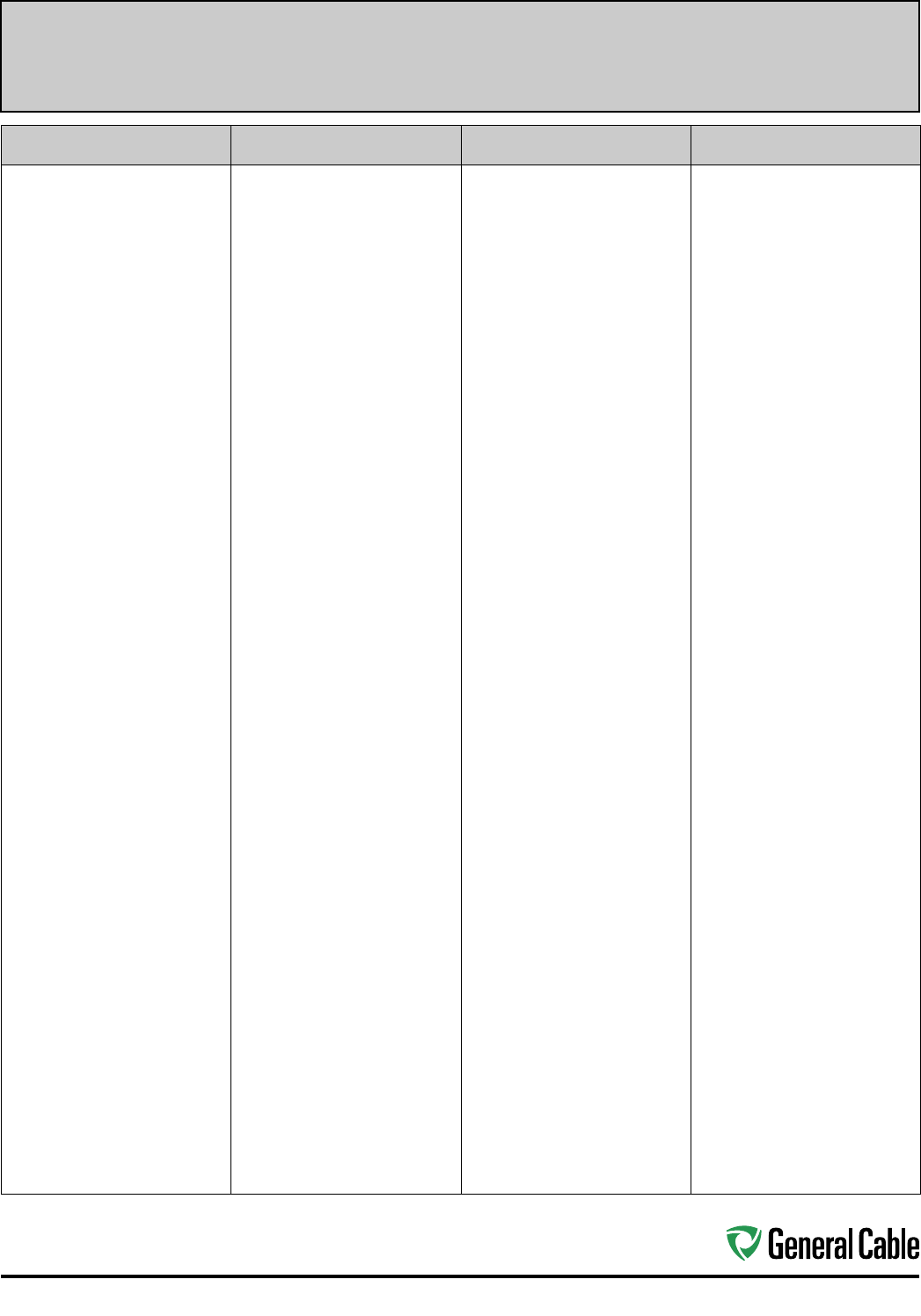
113
Industrial Automation Index and Cross-Reference
Catalog Number Index
CATALOG NUMBER PAGE CATALOG NUMBER PAGE CATALOG NUMBER PAGE CATALOG NUMBER PAGE
02001 ............................69
02002 ............................69
02003 ............................69
02004 ............................69
02005 ............................69
02006 ............................69
02007 ............................69
02008 ............................69
02009 ............................69
02021 ............................69
02022 ............................69
02023 ............................69
02024 ............................69
02031 ............................69
02032 ............................69
02033 ............................69
02034 ............................69
02035 ............................69
02036 ............................69
02037 ............................69
02038 ............................69
02039 ............................69
02041 ............................69
02042 ............................69
02043 ............................69
02045 ............................69
02046 ............................69
02601 ............................70
02602 ............................70
02603 ............................70
02604 ............................70
02605 ............................70
02606 ............................70
02607 ............................70
02608 ............................70
02609 ............................70
02621 ............................70
02622 ............................70
02623 ............................70
02624 ............................70
02631 ............................70
02632 ............................70
02633 ............................70
02634 ............................70
02635 ............................70
02636 ............................70
02637 ............................70
02638 ............................70
02639 ............................70
02641 ............................70
02642 ............................70
02643 ............................70
02645 ............................70
02646 ............................70
4775.03016....................57
4775.03018....................57
4775.04016....................57
4775.04018....................57
4775.05016....................57
4775.05018....................57
4775.07016....................57
4775.07018....................57
4775.09016....................57
4775.09018....................57
4775.12016....................57
4775.12018....................57
4775.16016....................57
4775.16018....................57
4775.19016....................57
4775.19018....................57
4775.25016....................57
4775.25018....................57
4775.30016....................57
4775.30018....................57
4775.37016....................57
4775.37018....................57
4780.03010....................58
4780.03012....................58
4780.03014....................58
4780.04010....................58
4780.04012....................58
4780.04014....................58
4780.05010....................58
4780.05012....................58
4780.05014....................58
4780.07010....................58
4780.07012....................58
4780.07014....................58
4780.09010....................58
4780.09012....................58
4780.09014....................58
4780.12010....................58
4780.12012....................58
4780.12014....................58
4780.19010....................58
4780.19012....................58
4780.19014....................58
4780.25010....................58
4780.25012....................58
4780.25014....................58
4780.30010....................58
4780.30012....................58
4780.30014....................58
4780.37012....................58
4780.37014....................58
4785.03016....................59
4785.03018....................59
4785.04016....................59
4785.04018....................59
4785.05016....................59
4785.05018....................59
4785.07016....................59
4785.07018....................59
4785.09016....................59
4785.09018....................59
4785.12016....................59
4785.12018....................59
4785.19016....................59
4785.19018....................59
4785.25016....................59
4785.25018....................59
4785.30016....................59
4785.30018....................59
4785.37016....................59
4785.37018....................59
4790.03010....................60
4790.03012....................60
4790.03014....................60
4790.04002....................60
4790.04004....................60
4790.04006....................60
4790.04008....................60
4790.04010....................60
4790.04012....................60
4790.04014....................60
4790.05010....................60
4790.05012....................60
4790.05014....................60
4790.07010....................60
4790.07012....................60
4790.07014....................60
4790.09010....................60
4790.09012....................60
4790.09014....................60
4790.12010....................60
4790.12012....................60
4790.12014....................60
4790.19010....................60
4790.19012....................60
4790.19014....................60
4790.25010....................60
4790.25012....................60
4790.25014....................60
4790.30010....................60
4790.30012....................60
4790.30014....................60
4790.37012....................60
4790.37014....................60
09005 ............................64
09006 ............................64
09007 ............................64
09008 ............................64
09010 ............................64
09012 ............................64
09016 ............................64
09020 ............................64
09205 ............................64
09206 ............................64
09207 ............................64
09208 ............................64
09209 ............................64
09210 ............................64
09212 ............................64
09214 ............................64
09216 ............................64
09218 ............................64
09220 ............................64
09224 ............................64
09226 ............................64
09227 ............................64
09228 ............................64
09230 ............................64
09405 ............................64
09406 ............................64
09407 ............................64
09408 ............................64
09409 ............................64
09410 ............................64
09412 ............................64
09414 ............................64
09416 ............................64
09418 ............................64
09420 ............................64
09424 ............................64
09428 ............................64
09430 ............................64
9600.00103310..............77
9600.00104106..............77
9600.00203310..............77
9600.00204106..............77
9600.00403312..............77
9600.00404108..............77
9600.00603312..............77
9600.00604108..............77
9600.00803314..............77
9600.00804110..............77
9600.01003314..............77
9600.01004314..............77

114
Index and Cross-Reference Industrial Automation
CATALOG NUMBER PAGE CATALOG NUMBER PAGE CATALOG NUMBER PAGE CATALOG NUMBER PAGE
Catalog Number Index
9600.01203316..............77
9600.01204316..............77
9600.01403318..............77
9600.01404318..............77
9600.11003310..............77
9600.11004106..............77
9600.21003310..............77
9600.21004106..............77
9600.25003308..............77
9600.25004104..............77
9600.31003308..............77
9600.31004104..............77
9600.35003307..............77
9600.35004103..............77
9600.41003308..............77
9600.41004104..............77
9600.50003306..............77
9600.50004102..............77
9600.75003305..............77
9600.75004101..............77
9600.100031110............77
9600.100041110............77
09605 ............................63
9605.00103310..............79
9605.00104106..............79
9605.00203310..............79
9605.00204106..............79
9605.00204208..............79
9605.00403312..............79
9605.00404108..............79
9605.00404210..............79
9605.00603312..............79
9605.00604108..............79
9605.00604210..............79
9605.00803314..............79
9605.00804110..............79
9605.00804212..............79
9605.01003314..............79
9605.01004314..............79
9605.01203316..............79
9605.01204316..............79
9605.01403318..............79
9605.01404216..............79
9605.01404318..............79
9605.11003310..............79
9605.11004106..............79
9605.21003310..............79
9605.21004106..............79
9605.25003308..............79
9605.25004104..............79
9605.31003308..............79
9605.31004104..............79
9605.35003306..............79
9605.35003307..............79
9605.35004103..............79
9605.41003308..............79
9605.41004104..............79
9605.50003306..............79
9605.50004102..............79
9605.75003304..............79
9605.75003305..............79
9605.75004101..............79
9605.100031110............79
9605.100041110............79
09606 ............................63
09607 ............................63
09608 ............................63
09609 ............................63
09610 ............................63
09612 ............................63
09614 ............................63
9615.00103310..............81
9615.00203310..............81
9615.00403312..............81
9615.00603312..............81
9615.00803314..............81
9615.01003314..............81
9615.01203316..............81
9615.01403318..............81
9615.11003310..............81
9615.21003306..............81
9615.25003304..............81
9615.35003302..............81
9615.41003304..............81
9615.50003301..............81
09616 ............................63
09618 ............................63
09620 ............................63
09622 ............................63
09624 ............................63
09626 ............................63
09630 ............................63
9675.00103310..............83
9675.00203310..............83
9675.00403312..............83
9675.00603312..............83
9675.00803314..............83
9675.01003316..............83
9675.01203318..............83
9675.11003310..............83
9675.21003310..............83
9675.25003308..............83
9675.35003308..............83
9675.41003308..............83
9675.50003306..............83
9700.00103308..............85
9700.00203310..............85
9700.00403310..............85
9700.00603310..............85
9700.00803312..............85
9700.10003304..............85
9700.11003308..............85
9700.21003308..............85
9700.25003307..............85
9700.35003306..............85
9700.41003307..............85
9700.50003305..............85
9700.75003304..............85
9800.00103308..............87
9800.00203310..............87
9800.00403310..............87
9800.00603310..............87
9800.10003304..............87
9800.11003308..............87
9800.21003308..............87
9800.25003306..............87
9800.35003306..............87
9800.41003307..............87
9800.50003305..............87
9800.75003304..............87
09805 ............................63
9805.00103308..............89
9805.00203310..............89
9805.00403310..............89
9805.00603310..............89
9805.10003304..............89
9805.11003308..............89
9805.21003308..............89
9805.25003306..............89
9805.35003306..............89
9805.41003307..............89
9805.50003305..............89
9805.75003304..............89
09806 ............................63
09807 ............................63
09808 ............................63
09810 ............................63
09812 ............................63
09814 ............................63
9815.00103308..............91
9815.00203310..............91
9815.00403310..............91
9815.00603310..............91
9815.10003304..............91
9815.11003308..............91
9815.21003308..............91
9815.25003306..............91
9815.35003306..............91
9815.41003307..............91
9815.50003305..............91
9815.75003304..............91
09816 ............................63
09818 ............................63
09820 ............................63
09822 ............................63
09824 ............................63
09827 ............................63
09830 ............................63
9899.CT02104000 .........14
9899.FB01601118 .........35
9899.FB01602118 .........35
9899.FB01604118 .........35
9899.FB01801120 .........35
9899.FB01802120 .........35
9899.FB01804120 .........35
9899.PB02201000 ......... 35
14407.247000................53
14407.546500................53
14407.547000................53
14428.030100................56
14428.030200................56
14428.030400................56
14428.030600................56
14428.030800................56
14428.035100................56
14428.035200................56
14428.035300................56
14428.035400................56
14428.036000................56
14428.036200................56
14428.036500................56
14428.037000................56
14428.040100................56
14428.040200................56
14428.040400................56
14428.040600................56
14428.040800................56
14428.045100................56
14428.045200................56
14428.045300................56
14428.045400................56
14428.046000................56
14428.046200................56
14428.046500................56
14428.047000................56
77453 ............................62
77463 ............................62
77473 ............................62

115
Industrial Automation Index and Cross-Reference
CATALOG NUMBER PAGE CATALOG NUMBER PAGE CATALOG NUMBER PAGE CATALOG NUMBER PAGE
Catalog Number Index
77483 ............................62
77493 ............................62
81312 ............................66
81313 ............................66
81314 ............................66
81315 ............................66
81372 ............................66
81373 ............................66
81374 ............................66
81375 ............................66
81382 ............................66
81383 ............................66
81384 ............................66
81385 ............................66
81392 ............................66
81393 ............................66
81394 ............................66
81395 ............................66
81402 ............................66
81403 ............................66
81404 ............................66
81405 ............................66
81412 ............................66
81413 ............................66
81414 ............................66
81415 ............................66
81423 ............................66
81443 ............................66
81473 ............................66
81622 ............................66
81623 ............................66
81624 ............................66
81625 ............................66
81642 ............................66
81643 ............................66
81644 ............................66
81645 ............................66
81662 ............................66
81663 ............................66
81664 ............................66
81665 ............................66
82313 ............................67
82314 ............................67
82373 ............................67
82374 ............................67
82383 ............................67
82384 ............................67
82393 ............................67
82394 ............................67
82403 ............................67
82404 ............................67
82413 ............................67
82414 ............................67
82423 ............................67
82443 ............................67
82473 ............................67
82623 ............................67
82624 ............................67
82643 ............................67
82644 ............................67
82663 ............................67
82664 ............................67
83001 ............................65
83002 ............................65
83004 ............................65
83006 ............................65
83008 ............................65
83010 ............................65
83020 ............................65
83030 ............................65
83040 ............................65
83103 ............................68
83113 ............................68
83123 ............................68
83133 ............................68
83143 ............................68
83153 ............................68
83163 ............................68
83183 ............................68
83250 ............................65
83350 ............................65
83500 ............................65
279560...........................50
279570...........................50
279580...........................50
279590...........................50
279600...........................50
279610...........................50
279620...........................50
279630...........................50
279640...........................50
279650...........................50
279660...........................53
279670...........................53
279680...........................50
279690...........................44
279700...........................45
279710...........................45
279720...........................45
279730...........................45
279740...........................45
279750...........................45
279760...........................45
279770...........................45
279840...........................50
279850...........................51
279870...........................50
279880...........................50
279890...........................50
279900...........................50
279910...........................51
279920...........................51
279930...........................51
280170...........................50
280180...........................50
280190...........................50
280200...........................50
280210...........................50
280230...........................51
280240...........................51
280250...........................51
280260...........................51
280270...........................51
280280...........................51
280290...........................51
280300...........................50
280310...........................50
280320...........................50
280330...........................50
280340...........................50
280350...........................51
280360...........................51
280370...........................51
280380...........................51
280390...........................51
280400...........................51
280410...........................50
280420...........................51
280430...........................51
280470...........................52
280490...........................52
280500...........................45
280520...........................45
280530...........................45
280540...........................45
280590...........................51
280600...........................51
280950...........................46
280960...........................46
280970...........................46
280980...........................52
280990...........................45
283170...........................44
283180...........................44
283190...........................44
283200...........................53
283210...........................53
283220...........................53
284560...........................53
287410...........................46
287650...........................44
288250...........................45
288260...........................45
293600...........................53
294530...........................53
294540...........................46
294580...........................44
295360...........................53
295390...........................53
295400...........................50
295890...........................53
296440...........................53
296450...........................53
297730...........................53
298020...........................53
300380...........................53
300780...........................53
301870...........................50
305300...........................52
305320...........................50
305340...........................50
305360...........................52
307690...........................50
311900...........................52
311910...........................52
314960...........................44
319250...........................46
319260...........................46
319270...........................45
325110...........................53
325120...........................53
325250...........................44
325700...........................53
326640...........................52
326650...........................52
326660...........................52
326670...........................52
330800...........................51
330990...........................51
337010...........................44
337020...........................44
337030...........................44
337040...........................44
337050...........................44
337060...........................44
337070...........................44
337080...........................44
337090...........................44

116
Index and Cross-Reference Industrial Automation
CATALOG NUMBER PAGE CATALOG NUMBER PAGE CATALOG NUMBER PAGE CATALOG NUMBER PAGE
Catalog Number Index
337100...........................44
337110...........................44
337120...........................44
337130...........................44
337140...........................44
337150...........................46
337160...........................46
337170...........................46
337180...........................46
337190...........................46
337200...........................46
337210...........................46
337220...........................46
337230...........................46
337240...........................45
337250...........................45
337260...........................45
346980...........................53
346990...........................53
347000...........................53
347080...........................50
347100...........................50
354800...........................52
354810...........................52
354820...........................52
354830...........................52
356740...........................53
365750...........................53
367120...........................52
367130...........................52
367140...........................52
367150...........................52
367160...........................52
367170...........................52
367180...........................52
367190...........................52
367200...........................52
367210...........................52
367220...........................52
367230...........................52
367240...........................52
367250...........................52
367260...........................52
367270...........................52
382880...........................51
383830...........................53
383930...........................51
383940...........................51
383950...........................51
383970...........................51
384730...........................95
384740...........................95
384750...........................95
384760...........................95
384770...........................95
384780...........................95
384790...........................95
384800...........................95
384810...........................95
384820...........................95
384830...........................95
384840...........................95
384850...........................95
384860...........................95
385350...........................51
385360...........................51
385370...........................51
393710...........................47
393720...........................47
393730...........................47
393740...........................47
393750...........................47
393760...........................47
393770...........................47
393780...........................47
393790...........................47
393800...........................47
393810...........................47
393820...........................47
393830...........................47
393840...........................47
393850...........................47
393860...........................47
393870...........................47
393880...........................47
393890...........................47
393900...........................47
393910...........................47
393920...........................47
393930...........................48
393940...........................48
393950...........................48
393960...........................48
393970...........................48
393980...........................48
393990...........................48
394000...........................48
394010...........................48
394020...........................48
394030...........................48
394040...........................48
394050...........................48
394060...........................48
394070...........................48
394080...........................48
394090...........................48
394100...........................48
394110...........................48
394120...........................49
394130...........................49
394140...........................49
394150...........................49
394160...........................49
394170...........................49
394180...........................49
394190...........................49
394200...........................49
394210...........................49
394220...........................49
394230...........................49
394240...........................49
394250...........................49
394260...........................49
394270...........................49
394280...........................54
394290...........................54
394300...........................54
394310...........................54
394320...........................54
394330...........................54
394340...........................54
394350...........................54
394360...........................54
394370...........................54
394380...........................54
394390...........................54
394400...........................54
394410...........................54
394420...........................54
394430...........................54
394440...........................54
394450...........................54
394460...........................54
394470...........................54
394480...........................54
394490...........................54
394500...........................54
394510...........................54
394520...........................54
394530...........................54
394540...........................54
394550...........................54
394560...........................54
394570...........................54
394580...........................54
394590...........................54
394600...........................54
394610...........................54
394630...........................55
394640...........................55
394650...........................55
394660...........................55
394670...........................55
394680...........................55
394690...........................55
394700...........................55
394710...........................55
394720...........................55
394730...........................55
394740...........................55
394750...........................55
394760...........................55
394770...........................55
394780...........................55
394790...........................55
394800...........................55
394810...........................55
394820...........................55
394830...........................55
394840...........................55
394850...........................55
394860...........................55
394870...........................55
394880...........................55
394890...........................55
394900...........................55
394910...........................55
394920...........................55
394930...........................56
394940...........................56
394950...........................56
394960...........................55
395070V ........................96
395080V ........................96
395090V ........................96
395100V ........................96
395110V ........................96
395120V ........................96
395130V ........................96
395140V ........................96
395150V ........................96
395160V ........................96
395170V ........................96
395180V ........................96
395190V ........................96
395200V ........................96
438070...........................92
438080...........................92

117
Industrial Automation Index and Cross-Reference
CATALOG NUMBER PAGE CATALOG NUMBER PAGE CATALOG NUMBER PAGE CATALOG NUMBER PAGE
Catalog Number Index
438090...........................92
438100...........................92
438110...........................92
438120...........................92
438130...........................92
438140...........................92
438150...........................93
438160...........................93
438170...........................93
438180...........................93
438190...........................94
438200...........................94
438210...........................94
438220...........................94
438230...........................94
5136100.........................16
5136101.........................17
7136100.........................22
C2534A ..........................40
C4841A ..........................39
C4842A ..........................39
C4843A ..........................39
C4844A ..........................39
C4851A ..........................40
C4852A ..........................40
C7112A ..........................39
C7112AF ........................39
C7114A ..........................39
C7114AF ........................39
C7116A ..........................39
C7116AF ........................39
C7118A ..........................39
C7118AF ........................39
C8101 ............................40
C8123 ............................40
C8601 ............................41
C8611 ............................37
C8621 ............................41
C8641 ............................41
C8651 ............................37
C8661 ............................41
C9530ZH .......................36
GC601 ...........................71
GC602 ...........................71
GC603 ...........................71
GC604 ...........................71
GC605 ...........................71
GC606 ...........................71
GC607 ...........................71
GC608 ...........................71
GC609 ...........................71
GC621 ...........................71
GC622 ...........................71
GC623 ...........................71
GC624 ...........................71
GC631 ...........................71
GC632 ...........................71
GC633 ...........................71
GC634 ...........................71
GC635 ...........................71
GC636 ...........................71
GC637 ...........................71
GC638 ...........................71
GC639 ...........................71
GC641 ...........................71
GC642 ...........................71
GC643 ...........................71
GC645 ...........................71
GC646 ...........................71
GCR1300 ....................... 33
GCR1301 ....................... 40
GCR1302 ....................... 34
GCR1303 ....................... 34
GCR1304 ....................... 34
GCR1304F ..................... 34
GCR1305 ....................... 36
GCR1305F ..................... 36
GCR1306 ....................... 36
GCR1307 ....................... 36
GCR1307F ..................... 36
GCR1308 ....................... 36
GCR1309 ....................... 32
GCR1309A ....................32
GCR1309CC ..................32
GCR1309F ..................... 32
GCR1309FC ..................32
GCR1309P ....................32
GCR1309S ....................32
GCR1310 ....................... 38
GCR1311 ....................... 36
GCR1312 ....................... 36
GCR1313 ....................... 36
GCR1314 ....................... 33
GCR1314A ....................33
GCR1314CC ..................33
GCR1314D ....................33
GCR1314F ..................... 33
GCR1314P ....................33
GCR1314S ....................33
GCR1314T ..................... 33
GCR1314ZH ..................33
GCR1315 ....................... 34
GCR1316 ....................... 34
GCR1317 ....................... 36
GCR1318 ....................... 37
GCR1319 ....................... 37
GCR1320 ....................... 38
GCR1320A ....................38
GCR1320FP ..................38
GCR1320P ....................38
GCR1320S ....................38
GCR1324 ....................... 33
GCR1324A ....................33
GCR1330 ....................... 37
GCR1330A ....................37
GCR1331 ....................... 37
GCR1331A ....................37
GCR1332 ....................... 34
GCR1333 ....................... 37
GCR1333A ....................37
GCR1334 ....................... 34
GCR1402 ......................... 8
GCR1403 ....................... 11
GCR1404 ......................... 9
GCR1405 ....................... 13
GCR1407 ....................... 15
GCR1408 ....................... 10
GCR1410 ....................... 18
GCR1419 ....................... 12
GCR1440 ....................... 19
GCR1450 ....................... 20
GCR1452 ....................... 21
XX0021ANR.BK .............27
XX0021ANU.BK ............. 27
XX0021PNR ................... 25
XX0021PNR-ILRA .......... 26
XX0021PNU ................... 25
XX0021PNU-ILPA ..........26
XX0041PNR-ILRA .......... 26
XX0041PNU-ILPA ..........26
XX0061ANR.BK .............27
XX0061ANU.BK ............. 27
XX0061PNR ................... 25
XX0061PNR-ILRA .......... 26
XX0061PNU ................... 25
XX0061PNU-ILPA ..........26
XX0064M1D-DT ............27
XX0121ANR.BK .............27
XX0121ANU.BK ............. 27
XX0121PNR ................... 25
XX0121PNR-ILRA .......... 26
XX0121PNU ................... 25
XX0121PNU-ILPA ..........26
XX0124H1A-DWB .........28
XX0124M1A-DWB .........28
XX0124M1D-DT ............27
XX0241ANR.BK .............27
XX0241ANU.BK ............. 27
XX0241P1R ...................25
XX0241PNR-ILRA .......... 26
XX0241PNU ................... 25
XX0241PNU-ILPA ..........26
XX0244H1A-DWB .........28
XX0244M1A-DWB .........28
XX0244M1D-DT ............27
XX0484H1A-DWB .........28
XX0484M1A-DWB .........28
XX0724H1A-DWB .........28
XX0724M1A-DWB .........28

POWERFUL PRESENCE · PRODUCTS
PERFORMANCE · PEOPLE
General Cable has been a wire and cable innovator for over
170 years, always dedicated to connecting and powering people’s
lives. Today, with approximately 14,000 employees and approaching
$6 billion in revenues, we are one of the largest wire and cable
manufacturers in the world.
Our company serves customers through a network of 38
manufacturing facilities in our core markets and has worldwide
sales representation and distribution. We are dedicated to the
production of high-quality aluminum, copper and fiber optic wire
and cable and systems solutions for the energy, construction,
industrial, specialty and communications sectors. With a vast
portfolio of products to meet thousands of diverse application
requirements, we continue to invest in research and development
in order to maintain and extend our technology leadership by
developing new materials, designing new products, and creating
new solutions to meet tomorrow’s market challenges.
In addition to our strong brand recognition and strengths in
technology and manufacturing, General Cable is also competitive
in such areas as distribution and logistics, marketing, sales and
customer service. This combination enables us to better serve our
customers globally and as they expand into new geographic markets.
General Cable offers our customers all the
strengths and value of a large company, but our
people give us the agility and responsiveness of
a small one. We service you globally and locally.
Visit our Website at
www.generalcable.com
One Company
Connecting
The World
General Cable believes corporate social responsibility (CSR) is about creating shared value.
That means keeping a dual focus in our business decisions: what is good for us as a company
and what contributes to the greater good of the communities in which we live and work.
Corporate Social Responsibility
CREATING SHARED VALUE
+1.859.572.8000
info@generalcable.com
Visit www.GeneralCableCSR.com
to learn more.
A commitment to achieving industry-leading standards
and responding proactively to environmental global issues.
SAFETY
Working safer by working together
General Cable has one worldwide safety vision and goal –
ZERO & BEYOND
. We measure safety
performance globally, share best practices and implement sound health and safety management
systems. Many of our facilities worldwide are OHSAS 18001 (safety management system) certified.
All North American facilities have implemented an equivalent health and safety management system.
General Cable was a pioneer in obtaining the OHSAS 18001 Certificate for Occupational Health and
Safety Management Systems in Europe and North Africa.
SUSTAINABILITY
Responsible practices in daily operations
As a global leader in the wire and cable industry, General Cable recognizes its role and responsibility
in promoting sustainability. Our strongest business value is continuous improvement in all areas of
our company. Across our many businesses, the quest to introduce new and better products through
continuous improvement in environmental designs reflects our commitment to achieving industry-leading
standards and responding proactively to global environmental issues. General Cable was the first cable
manufacturer to obtain certification for its environmental management system, in accordance with the
ISO 14001 and EMAS Standards.
CITIZENSHIP
A commitment to being good citizens
Being responsible citizens in our communities is of the utmost importance to us. Unequivocal honesty,
integrity, forthrightness and fair dealing have long been part of General Cable’s core values and are
expected globally in all of our business relationships with our customers, employees, suppliers, neighbors
and competitors. Our company leaders and employees strive to make a difference throughout a host of
volunteer activities and financial support, improving the communities in which we live and work.
INNOVATION
Technologies that power and connect the world
General Cable is delivering innovation that matters. We are focusing on R&D expertise
and investing in developing wire and cable solutions that meet the challenges confronting
our customers and the world. In working together and using all the ingenuity and
creativity we have, we will reach the goal of being the preeminent supplier of
wire and cabling solutions in the industry, with both green constructions
and designs for the ever-growing renewable energy market.

Selecting the proper drive cables for Variable
Frequency Drive (VFD) applications reduces the risk
of electromagnetic interference (EMI), high ground
currents and reflected waves in your cable systems.
General Cable’s line of CVTC® VFD Type TC-ER unarmored and
CCW® VFD Type MC-HL (continuously corrugated welded)
armored cables is specially engineered and designed to handle the
challenges presented in a VFD environment. Delivering reliable
performance for sustained and continuous operations, General
Cable’s VFD cables are used in a wide range of applications.
www.generalcable.com 1.888.593.3355
General Cable has the people,
equipment and experience to
help define the right solution
for your VFD application.
Give us a call!
Drive Cables that Provide Control & Ensure Confidence
General Cable, a leading wire and cable innovator for over 170 years, serves customers
through a network of 38 manufacturing facilities in our core markets and has worldwide
sales representation and distribution. The Company is dedicated to the production of
high-quality aluminum, copper and fiber optic wire and cable and systems solutions for the
energy, construction, industrial, specialty and communications sectors. In addition to our
strong brand recognition and strengths in technology and manufacturing, General Cable is
also competitive in such areas as distribution and logistics, marketing, sales and customer
service. This combination enables General Cable to better serve its customers as they
expand into new geographic markets.
Global Reach
General Cable
4 Tesseneer Drive
Highland Heights, Kentucky 41076-9753
Telephone: 800.950.3512
859.572.8000
Email: info@generalcable.com
www.generalcable.com
©2015. General Cable Technologies Corporation. Highland Heights, KY 41076
All rights reserved. Printed in USA.
Form No. COR-0081-0115
46455
INDUSTRIAL AUTOMATION CABLE SOLUTIONS
