Volume 6 1000509760 Catalog
1000394975-Catalog 1000394975-Catalog 1000394975-Catalog B5 unilog cesco-content
2016-09-04
: Pdf 1000509760-Catalog 1000509760-Catalog B4 unilog
Open the PDF directly: View PDF ![]() .
.
Page Count: 498 [warning: Documents this large are best viewed by clicking the View PDF Link!]
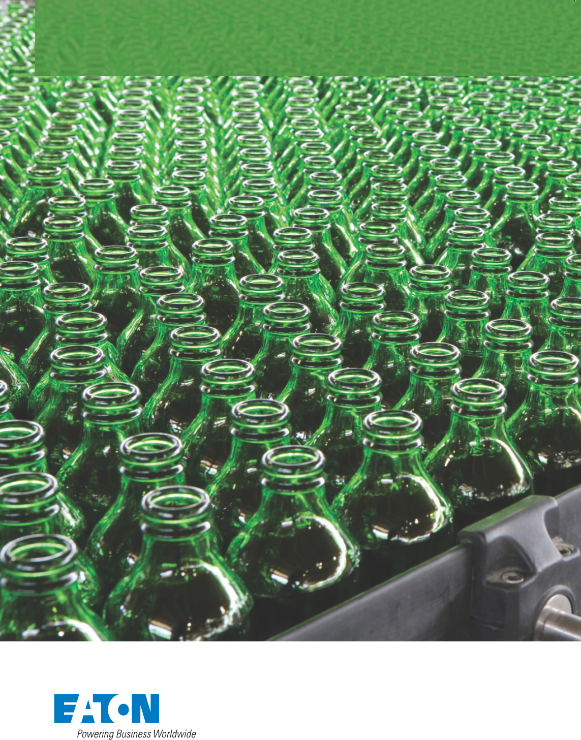
Electrical Sector Solutions
Volume 6:
Solid-State
Motor Control
Volume 1—Residential and Light Commercial
Volume 2—Commercial Distribution
Volume 3—Power Distribution and Control Assemblies
Volume 4—Circuit Protection
Volume 5—Motor Control and Protection
Volume 6—Solid-State Motor Control
Tab 1—Reduced Voltage Motor Starters . . . . . . . . . . . . . . V6-T1-1
Tab 2—Adjustable Frequency Drives . . . . . . . . . . . . . . . . . V6-T2-1
Appendix 1—Eaton Terms & Conditions . . . . . . . . . . . . . . V6-A1-1
Appendix 2—Catalog Parent Number Index . . . . . . . . . . . V6-A2-1
Appendix 3—Alphabetical Product Index . . . . . . . . . . . . . V6-A3-1
Volume 7—Logic Control, Operator Interface
and Connectivity Solutions
1
2
3
4
5
6
7

Copyright
Dimensions, Weights and Ratings
Dimensions, weights and ratings given in this catalog are approximate and should not
be used for construction purposes. Drawings containing exact dimensions are available
upon request. All listed product specications and ratings are subject to change without
notice. Photographs are representative of production units.
Terms and Conditions
All prices and discounts are subject to change without notice. When price changes
occur, they are published in Eaton’s Price and Availability Digest (PAD). All orders
accepted by Eaton’s Electrical Sector are subject to the general terms and conditions
as set forth in Appendix 1—Eaton Terms & Conditions.
Technical and Descriptive Publications
This catalog contains brief technical data for proper selection of products. Further
information is available in the form of technical information publications and illustrated
brochures. If additional product information is required, contact your local Eaton
Products Distributor, call 1-800-525-2000 or visit our website at www.eaton.com.
Compliance with Nuclear Regulation 10 CFR 21
Eaton products are sold as commercial grade products not intended for application in
facilities or activities licensed by the United States Nuclear Regulatory Commission
foratomic purposes, under 10 CFR 21. Further certication will be required for use of
these products in a safety-related application in any nuclear facility licensed by the
U.S. Nuclear Regulatory Commission.
WARNING
The installation and use of Eaton products should be in accordance with the provisions
of the U.S. National Electrical Code® and/or other local codes or industry standards that
are pertinent to the particular end use. Installation or use not in accordance with these
codes and standards could be hazardous to personnel and/or equipment.
Copyright ©2016, Eaton, All Rights Reserved.
These catalog pages do not purport to cover all details or variations in equipment, nor to provide for
every possible contingency to be met in connection with installation, operation or maintenance.
Should further information be desired or should particular problems arise which are not covered
sufciently for the purchaser’s purposes, the matter should be referred to the local Eaton Products
Distributor or Sales Ofce. The contents of this catalog shall not become part of or modify any prior
or existing agreement, commitment or relationship. The sales contract contains the entire
obligation of Eaton’s Electrical Sector. The warranty contained in the contract between the parties
is the sole warranty of Eaton. Any statements contained herein do not create new warranties or
modify the existing warranty.

Volume 6—Solid-State Motor Control CA08100007E—March 2015 www.eaton.com i
Introduction
Eaton is a global leader in power distribution, power quality,
control and automation, and monitoring products.
At Eaton, we believe a reliable, efficient and safe power system is the foundation of every
successful enterprise. Through innovative technologies, cutting-edge products and our highly
skilled services team, we empower businesses around the world to achieve a powerful advantage.
In addition, Eaton is committed to creating and maintaining powerful customer relationships built
on a foundation of excellence. From the products we manufacture to our dedicated customer
service and support, we know what’s important to you.
Solutions
Eaton takes the complexity out of power systems management with a holistic and strategic
approach, leveraging our industry-leading technology, solutions and services. We focus on
the following three areas in all we do:
●Reliability—maintain the
appropriate level of power
continuity without
disruption or unexpected
downtime
●Efficiency—minimize
energy usage, operating
costs, equipment footprint
and environmental impact
●Safety—identify and
mitigate electrical hazards
to protect what you value
most
Using the Eaton Catalog Library
As we grow, it becomes increasingly difficult to include all products in one or two comprehensive
catalogs. Knowing that each user has their specific needs, we have created a library of catalogs for our
products that when complete, will contain 15 volumes. Since the volumes will continuously be a work
in progress and updated, each volume will stand alone. Refer to our volume directory, MZ08100001E,
for a quick glance of where to look for the products you need. The 15 volumes include:
●Volume 1—Residential
and Light Commercial
(CA08100002E)
●Volume 2—Commercial
Distribution (CA08100003E)
●Volume 3—Power
Distribution and Control
Assemblies (CA08100004E)
●Volume 4—Circuit
Protection (CA08100005E)
●Volume 5—Motor Control
and Protection
(CA08100006E)
●Volume 6—Solid-State
Motor Control
(CA08100007E)
●Volume 7—Logic Control,
Operator Interface and
Connectivity Solutions
(CA08100008E)
●Volume 8—Sensing
Solutions (CA08100010E)
●Volume 9—Original
Equipment Manufacturer
(CA08100011E)
●Volume 10—Enclosed
Control (CA08100012E)
●Volume 11—Vehicle and
Commercial Controls
(CA08100013E)
●Volume 12—Aftermarket,
Renewal Parts and Life
Extension Solutions
(CA08100014E)
●Volume 13—Counters,
Timers and Tachometers
(CA08100015E)—Available
in electronic format only
●Volume 14—Fuses
(CA08100016E)—Available
in electronic format only
●Volume 15—Solar Inverters
and Electrical Balance of
System (CA08100018E)
These volumes are not all-inclusive of every product, but they are meant to be an overview
of our product lines. For our full range of product solutions and additional product information,
consult Eaton.com/electrical and other catalogs and product guides in our literature library.
These references include:
●The Consulting Application
Guide (CA08104001E)
●The Eaton Power Quality
Product Guide (COR01FYA)
If you don’t have the volume that contains the product or information that you are looking for,
not to worry. You can access every volume of the catalog library at Eaton.com/electrical in the
Literature Library.
By installing our Automatic Tab Updater (ATU), you can be sure you always have the most recent
version of each volume and tab.

ii Volume 6—Solid-State Motor Control CA08100007E—March 2015 www.eaton.com
Introduction
Icons
Green Leaf
Eaton Green Solutions are products, systems or solutions that represent Eaton
benchmarks for environmental performance. The green leaf symbol is our
promise that the solution has been reviewed and documented as offering
exceptional, industry-leading environmental benefits to customers, consumers
and our communities. Though all of Eaton's products and solutions are
designed to meet or exceed applicable government standards related to
protecting the environment, our products with the Green Leaf designation
further provide “exceptional environmental benefit”.
Learn Online
When you see the Learn Online icon, go to Eaton.com/electrical and search for
the product or training page. There you will find 100-level training courses,
podcasts, webcasts or games and puzzles to learn more.
Drawings Online
When you see the Drawings Online icon, go to Eaton.com/electrical and find the
products page. There you will find a tab that includes helpful product drawings
and illustrations.
Contact Us
If you need additional help, you can find contact information
under the Customer Care heading of Eaton.com/electrical.
V6-T1-1Volume 6—Solid-StateMotor Control CA08100007E—February 2016 www.eaton.com
1
1
1
1
1
1
1
1
1
1
1
1
1
1
1
1
1
1
1
1
1
1
1
1
1
1
1
1
1
1
Reduced Voltage Motor Starters
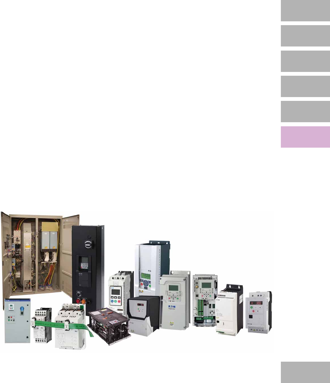
S611 Soft Starters
Soft Start Controllers
S811+ Soft Starters
DS7 Soft Starter Controller
1.1 Solid-State Controllers
Product Overview . . . . . . . . . . . . . . . . . . . . . . . . . . . . . . . . . . . . . . . . V6-T1-2
DS7 Soft Start Controllers . . . . . . . . . . . . . . . . . . . . . . . . . . . . . . . . . . V6-T1-3
Type S701, Soft Start Controllers . . . . . . . . . . . . . . . . . . . . . . . . . . . . . V6-T1-26
Type S701, Soft Start Controllers with Auxiliary Contact . . . . . . . . . . . V6-T1-32
Type S701, Soft Start Controllers with Brake . . . . . . . . . . . . . . . . . . . . V6-T1-35
Type S511, Semiconductor Reversing Contactors . . . . . . . . . . . . . . . . V6-T1-38
1.2 Solid-State Starters
Product Overview . . . . . . . . . . . . . . . . . . . . . . . . . . . . . . . . . . . . . . . . V6-T1-42
Type S611, Soft Starters . . . . . . . . . . . . . . . . . . . . . . . . . . . . . . . . . . . V6-T1-43
Type S801+, Soft Starters . . . . . . . . . . . . . . . . . . . . . . . . . . . . . . . . . . V6-T1-59
Type S811+, Soft Starters with DIM . . . . . . . . . . . . . . . . . . . . . . . . . . V6-T1-75
V6-T1-2 Volume 6—Solid-State Motor Control CA08100007E—February 2016 www.eaton.com
1
1
1
1
1
1
1
1
1
1
1
1
1
1
1
1
1
1
1
1
1
1
1
1
1
1
1
1
1
1
1.1
Reduced Voltage Motor Starters
Solid-State Controllers
Soft Start Controllers
Contents
Description Page
Soft Start Controllers
DS7 Soft Start Controllers . . . . . . . . . . . . . . . . V6-T1-3
Type S701, Soft Start Controllers . . . . . . . . . . . V6-T1-26
Type S701, Soft Start Controllers
with Auxiliary Contact . . . . . . . . . . . . . . . . . . V6-T1-32
Type S701, Soft Start Controllers
with Brake . . . . . . . . . . . . . . . . . . . . . . . . . . . V6-T1-35
Type S511, Semiconductor
Reversing Contactors . . . . . . . . . . . . . . . . . . V6-T1-38
Product Overview
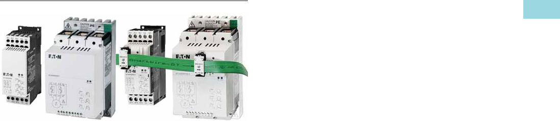
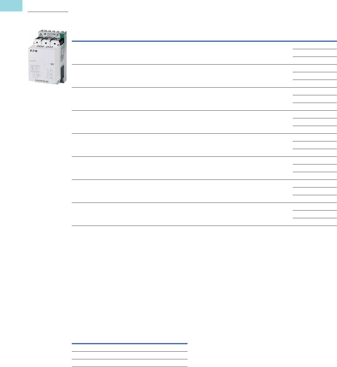
DS7
Eaton’s DS7 line of reduced
voltage solid-state soft start
controllers is very compact,
multi-functional, easy to
install and easy to commission.
Designed to control the
acceleration and deceleration
of three-phase motors with
the ability to adjust initial
torque, ramp up and down
time, the device is available
for current ranges from 4 to
32 A in four frame sizes.
Type S701
The S701 device is a reduced
voltage soft start controller
designed to control
acceleration and deceleration
of three-phase motors. The
S701 provides the user with
the ability to adjust initial
torque, ramp up and down
time, and also select kick
start for high inertial loads.
Type S701 with
Auxiliary Contact
The S701 device is a reduced
voltage soft start controller
designed to control
acceleration and deceleration
of three-phase motors. With
the auxiliary contact, it is
possible to control an external
bypass to reduce heating and
increase acceleration and
deceleration times.
The unit provides the user
with the ability to adjust initial
torque, ramp up and down
time and also select kick start
for high inertia loads.
Type S701 with Brake
The S701 soft start
controller with DC injection
brake is designed to control
acceleration and deceleration
of three-phase motors. Brake
current is adjustable from
0–50 A DC. The ramp-up
feature is adjustable from
0.5–10 seconds. Torque
adjustment is adjustable
with or without break loose
(kick start) function.
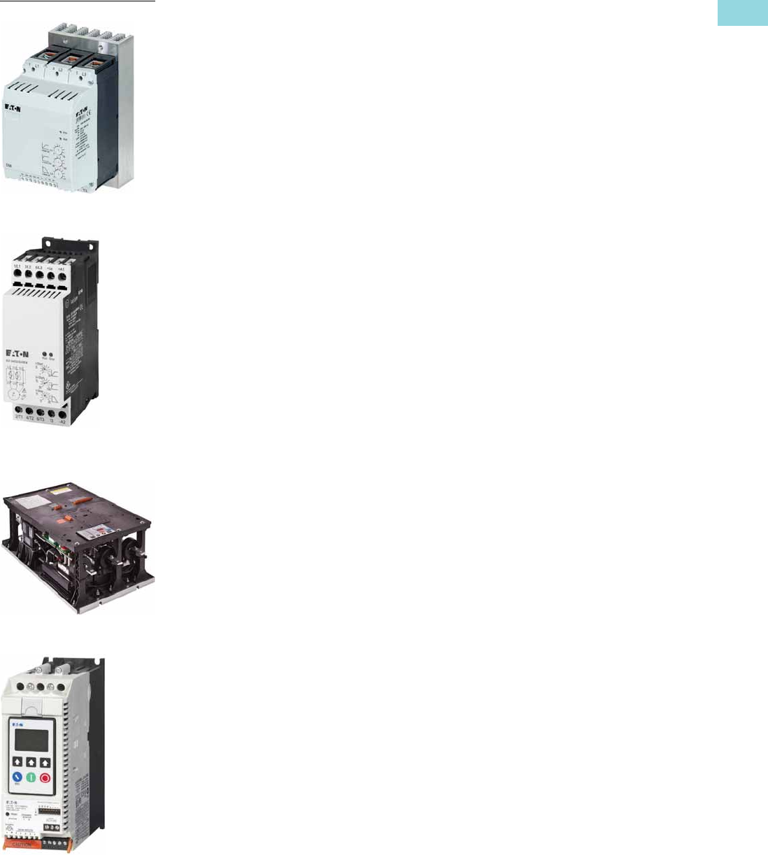
Type S511 Semiconductor
Reversing Contactor
The S511 device is a
semiconductor reversing
contactor designed to switch
three-phase motors forward
and reverse. Unicore
electronics and thermal
design ensures high
switching capacity and
long lifetime.
Volume 6—Solid-State Motor Control CA08100007E—February 2016 www.eaton.com V6-T1-3
1
1
1
1
1
1
1
1
1
1
1
1
1
1
1
1
1
1
1
1
1
1
1
1
1
1
1
1
1
1
1.1
Reduced Voltage Motor Starters
Solid-State Controllers
DS7 Soft Start Controllers
Contents
Description Page
DS7 Soft Start Controllers
Features and Benefits . . . . . . . . . . . . . . . . . . . V6-T1-5
Standards and Certifications . . . . . . . . . . . . . . V6-T1-5
Instructional Leaflets . . . . . . . . . . . . . . . . . . . . V6-T1-5
Catalog Number Selection . . . . . . . . . . . . . . . . V6-T1-6
Product Selection . . . . . . . . . . . . . . . . . . . . . . . V6-T1-7
Accessories . . . . . . . . . . . . . . . . . . . . . . . . . . . V6-T1-15
Technical Data and Specifications . . . . . . . . . . V6-T1-16
Dimensions . . . . . . . . . . . . . . . . . . . . . . . . . . . V6-T1-24
Type S701, Soft Start Controllers . . . . . . . . . . . . . . V6-T1-26
Type S701, Soft Start Controllers with
Auxiliary Contact . . . . . . . . . . . . . . . . . . . . . . . . . V6-T1-32
Type S701, Soft Start Controllers with Brake . . . . V6-T1-35
Type S511, Semiconductor
Reversing Contactors . . . . . . . . . . . . . . . . . . . . . V6-T1-38
DS7 Soft Start Controllers
Product Description
The DS7 is available in
standard and SmartWire-DT®
communications
configurations.
Standard (Non SmartWire-DT)
Eaton’s DS7 line of reduced
voltage solid-state soft start
controllers is very compact,
multi-functional, easy to install
and easy to commission.
Designed to control the
acceleration and deceleration
of three-phase motors, the
device is available for current
ranges from 4 to 200 FLA
in four frame sizes. It is
available with 24 Vdc, 24 Vdc/
24 Vac, or 110/230 Vac
control voltage options. A
low temperature version is
available with 24 Vac/Vdc
control voltage with operation
ambient temperature
minimum of –40 °C.
SmartWire-DT
Our SmartWire-DT interface
completely eliminates the
need for conventional control
wiring. This has several
advantages:
●No incorrect wiring
●Faster wiring
●Cost saving
The interface can be used to
send control commands to
the DS7 SmartWire-DT and
change and diagnose its
parameter configuration;
in addition, the control
electronics can be powered
via the SmartWire-DT cable.
The device is controlled with
one of the selectable profiles:
●A “start/stop” profile
●An 8 bit-wide profile for
the soft starter, which is
provided the same way
for the variable frequency
drive and features more
options
Regardless of the profile
chosen, the DS7 SmartWire-DT’s
parameters can be read and
written to at any time by
using acyclic communications
services.
DS7 SmartWire-DT makes it
possible to read and write to
all device parameters. It is
also possible to overwrite
the potentiometer settings
on the DS7 SmartWire-DT,
which can come in handy,
for instance, when a change
made to the machine needs
to be performed remotely.
The DS7 SmartWire-DT comes
with a detailed diagnostic
system with options that
extend far beyond those of
wired devices. In addition to
having an error log, the DS7
SmartWire-DT can detect and
report nine different device
faults. A warning parameter
reports any present warning
messages. Moreover, the
response to each individual
fault can be customized.
Finally, there are 35 additional
messages for communication
errors. Using the DS7
SmartWire-DT in connection
with the PKE series motor
protective circuit breakers
opens up new functionalities
that were previously thought
impossible to implement with
a low-cost soft starter and
that were reserved to
significantly more
expensive
devices. Combining
a PKE
unit and a DS7 SmartWire-DT
makes it possible to
completely
protect the DS7
SmartWire-DT
device against
overloads. In addition, it
provides a current limiting
function and can report
thermal capacity utilization
levels to higher level
controllers.
V6-T1-4 Volume 6—Solid-State Motor Control CA08100007E—February 2016 www.eaton.com
1
1
1
1
1
1
1
1
1
1
1
1
1
1
1
1
1
1
1
1
1
1
1
1
1
1
1
1
1
1
1.1
Reduced Voltage Motor Starters
Solid-State Controllers
Application Description
With its small size, it can
easily fit in place of existing
soft starters, wye-delta
starters, or across-the-line
NEMA® and IEC starters. This
feature allows easy upgrades
to existing systems. The
product is designed to be
wired in the three-phase line
feeding the three motor input
leads as is done for normal
across-the-line starting. The
starter uses silicon controlled
rectifiers (SCRs) to ramp the
voltage to the motor, providing
smooth acceleration and
deceleration of the load.
After the motor is started,
the internal run bypass relay
closes, resulting in the motor
running directly across-the-
line. Internal run bypass
significantly reduces the
heat generated as compared
to non-bypass starters. The
soft stop option allows for a
ramp stop time that may be
longer than the coast-to-stop
time. An external overload
protection relay or circuit
breaker is needed.
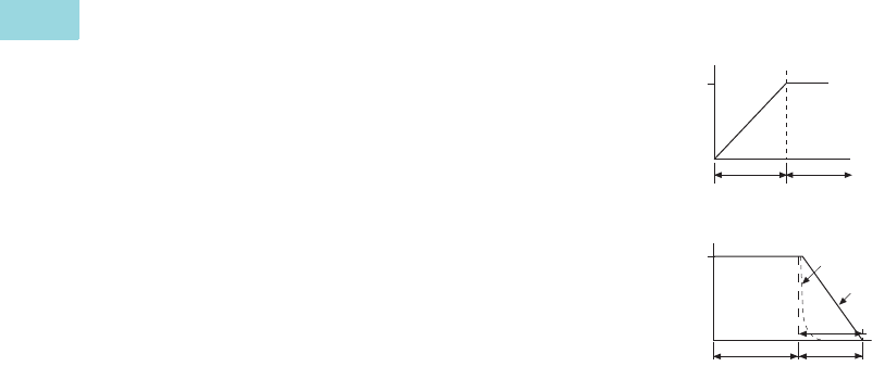
Operation
Voltage Ramp Start
This start method provides a
voltage ramp to the motor,
resulting in a constant torque
increase. This most
commonly used form of soft
start mode allows you to set
the initial voltage value and
the duration of the ramp to
full voltage conditions.
●Adjustable initial voltage
30–92% of full voltage
(120/230 Vac control
voltage)
●Adjustable initial voltage
30–100% of full voltage (24
Vac/Vdc control voltage)
●Adjustable initial voltage
30–92% of full voltage
(24 Vdc control voltage—
SmartWire-DT)
●Adjustable ramp time
1–30 seconds
●Bypass relays close at the
end the ramp time (TOR)
Soft Stop
Allows for a controlled
stopping of load. Used when
a stop-time that is greater
than the coast-to-stop time is
desired. Often used with high
friction loads where a sudden
stop may cause system or
product damage. Setting the
soft stop time to a value of
0 turns off this feature.
●Soft stop time =
0–30 seconds
Start Ramp
Stop Ramp
Auxiliary Contacts
Auxiliary contacts are
provided to indicate soft
start controller status.
Frame Size 1 (4A to 12A)—
One Relay
The auxiliary relay indicates
when the soft starter is at
Top-of-Ramp (TOR).
Frame Size 2, 3 and 4 (16A
to 200A)—Two Relays
One auxiliary relay indicates
when the soft starter is at
Top-of-Ramp (TOR).
One auxiliary relay indicates
that a RUN command is
present, including start ramp,
bypass, and stop ramp times.
Bypass
Speed
Time (Seconds)
Start Run
100%
Speed
Time (Seconds)
Run Soft Stop
100%
1 = Coast to Stop (Speed)
2 = Soft Stop Ramp (Voltage)
3 = Soft Stop Time
1
2
3

Volume 6—Solid-State Motor Control CA08100007E—February 2016 www.eaton.com V6-T1-5
1
1
1
1
1
1
1
1
1
1
1
1
1
1
1
1
1
1
1
1
1
1
1
1
1
1
1
1
1
1
1.1
Reduced Voltage Motor Starters
Solid-State Controllers
Features and Benefits
●Run bypass mode greatly
reduces internal heating
created by the power
dissipation across the
SCRs. The bypass relay
directly connects the
motor to the line and
improves system efficiency
by reducing internal power
losses
●Less heat minimizes
enclosure size and cooling
requirements, and
maximizes the life of all
devices in the enclosure
●LED displays device status
and provides fault
indication
●Variable ramp times and
voltage control (torque
control) settings provide
unlimited starting
configurations, allowing
for maximum application
flexibility
Single-Phase Applications
All DS7 frame sizes can be
configured for single-phase
operation at 200–480 Vac
main voltages in accordance
to the single-phase application
note AP039006EN.
●Soft stop control suits
applications where an
abrupt stop of the load
is not acceptable. Soft
acceleration and
deceleration reduces
wear on belts, gears,
chains, clutches, shafts,
and bearings
●Minimizes the peak inrush
current’s stress on the
power system. Peak
starting torque can be
managed to diminish
mechanical system wear
and damage.
●24 Vac/Vdc control voltage
enhances personnel and
equipment safety.
110/230 Vac control voltage
is also available
●Auxiliary relays indicate
status of the soft start
controllers
●The TOR relay is active
until motor stop
command is received
and/or the soft start
controller detects a
fault condition
●RUN relay is active
during the start ramp,
bypass, and stop ramp
Protective Features
●Mains connection—The
mains connection is
monitored for a phase loss
and/or undervoltage during
ramp up
●Motor connection—The
motor connection is
monitored for an open
condition during the ramp
●SCR faults—SCR
performance is monitored
during the ramp cycle for
proper operation
●Heat sink over/under
temperature—High ambient
temperatures, extended
ramp times, and high duty
cycle conditions may cause
the DS7 to exceed its
thermal rating. When
temperature goes under
–5 °C (–40 °C for low
temperature units), unit
will trip as well. The DS7 is
equipped with sensors that
monitor the temperature of
the device as well. The soft
starter will trip in over/
under temperature
conditions, preventing
device failure
●Warning is indicated for an
over temperature condition
for the next start
●Bypass relay
●The DS7 can detect if
the bypass relay fails to
close after the ramp
start or opens while the
motor is running
●The DS7 will also detect
a condition whereas the
bypass relay is closed
when the RUN
command is given
●The DS7 will trip on a
bypass dropout fault if
either of these
conditions occur
Standards and Certifications
●IEC 60947-4-2
●EN 60947-4-2
●UL® listed
●CSA certified
●CE marked
●C-Tick
Instructional Leaflets
●Instruction Leaflet IL03901001E
V6-T1-6 Volume 6—Solid-State Motor Control CA08100007E—February 2016 www.eaton.com
1
1
1
1
1
1
1
1
1
1
1
1
1
1
1
1
1
1
1
1
1
1
1
1
1
1
1
1
1
1
1.1
Reduced Voltage Motor Starters
Solid-State Controllers
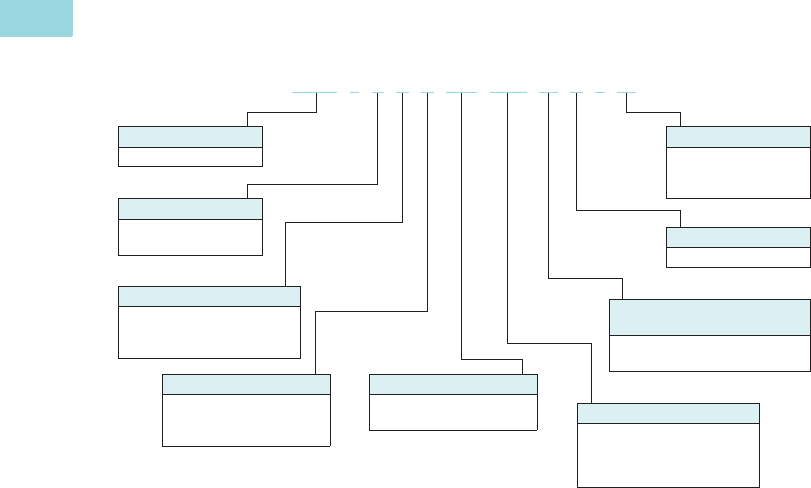
Catalog Number Selection
DS7 Soft Start Controllers
Rated Operational Current
004 =4A
• =
• =
• =
200 = 200A
Number of Phases
3 = Three-phase mains
supply voltage
Device Series
DS7 = Generation 7
Control Voltage Supply
0 = 24 Vac/Vdc
2 = 110/230 Vac
D = 24 Vdc SmartWire-DT
Device Version
SX = Standard soft starters
with internal bypass
DS7 - 3 4 0 SX 004 N 0 - N
Options
N = No option
D = SmartWire-DT
L = Low temperature
Voltage Class
4 = 400 V
(380 V –15% to 480 V
+10%)
Protection Type
0 = IP20
Radio Interference
Suppression Filters
4 = No internal radio interference
suppression filters
Volume 6—Solid-State Motor Control CA08100007E—February 2016 www.eaton.com V6-T1-7
1
1
1
1
1
1
1
1
1
1
1
1
1
1
1
1
1
1
1
1
1
1
1
1
1
1
1
1
1
1
1.1
Reduced Voltage Motor Starters
Solid-State Controllers
Product Selection
DS7 Soft Start Horsepower Ratings
Please refer to Application Note AP039004EN for additional information on proper size selection.
DS7 Soft Start Controllers—Horsepower Ratings—
10 Second Ramp, One Start per Hour, 300% Current Limit at 40 °C 1
Notes
1 Actual motor FLAs vary. Verify these devices cover the motor specific FLA.
2 Selections are based on motor FLA value at 480 V.
3 Not to be used with 230 V.
4 24 Vac/Vdc device.
5 –40 °C rated low temperature version available in 24 Vac/Vdc, change to “N0-L.”
6 110/230 Vac device.
7 24 Vdc for SmartWire-DT device.
Considerations
1. Either XTOB, C306 or C440 series or equivalent overload protection devices may be selected.
2. Contactor is optional for normal applications. It is recommended for mains isolation.
Power Supply
Eaton’s PSG and ELC power supplies are recommended as a compact and low-cost
source for 24 Vdc power. The lightweight, DIN rail mounted devices have a wide input
voltage range, and robust screw terminals make these power supplies easy to install
and use. These power supplies are available in 1A and 2A models.
Power Supply Selection
Rated
Current
(A)
Motor
Power (hp) Maximum
Allowable
Breaker
Size
Maximum
Allowable
Fuse
Size
Recommended
XTOB
Overload
(Direct
Connect) 2
Recommended
XTOE
Overload 2PKE MMP MMP 2
Connection
Kit to MMP Catalog Number200 V 230 V 480 V
3.7 0.75 0.75 2 HFD3015 15A
Class RK5
XTOB004BC1 XTOE005BCS XTPE012BCS XTPR004BC1 XTPAXTPCB DS7-340SX004N0-N 45
DS7-342SX004N0-N 6
DS7-34DSX004N0-D 7
6.9 1.5 2 3 HFD3015 15A
Class RK5
XTOB006BC1 3XTOE020BCS XTPE012BCS XTPR6P3BC1 XTPAXTPCB DS7-340SX007N0-N 45
DS7-342SX007N0-N 6
DS7-34DSX007N0-D 7
7.8 225HFD302020A
Class RK5
XTOB010BC1 XTOE020BCS XTPE012BCS XTPR010BC1 XTPAXTPCB DS7-340SX009N0-N 45
DS7-342SX009N0-N 6
DS7-34DSX009N0-D 7
11 3 3 7.5 HFD3030 20A
Class RK5
XTOB012BC1 XTOE020BCS XTPE032BCS XTPR012BC1 XTPAXTPCB DS7-340SX012N0-N 45
DS7-342SX012N0-N 6
DS7-34DSX012N0-D 7
15.2 3 5 10 HFD3035 25A
Class RK5
XTOB016CC1 XTOE020CCS XTPE032BCS XTPR016BC1 XTPAXTPCC DS7-340SX016N0-N 45
DS7-342SX016N0-N 6
DS7-34DSX016N0-D 7
22 5 7.5 15 HFD3060 40A
Class RK5
XTOB024CC1 XTOE045CCS XTPE032BCS XTPR025BC1 XTPAXTPCC DS7-340SX024N0-N 45
DS7-342SX024N0-N 6
DS7-34DSX024N0-D 7
32 7.5 10 20 HFD3070 50A
Class RK5
XTOB032CC1 XTOE045CCS XTPE032BCS XTPR032BC1 XTPAXTPCC DS7-340SX032N0-N 45
DS7-342SX032N0-N 6
DS7-34DSX032N0-D 7
Description Catalog Number
85–264 V input and 24 Vdc output ELC-PS01
100–240 V input and 24 Vdc output PSG60E
400–500 V input and 24 Vdc output PSG60F24RM
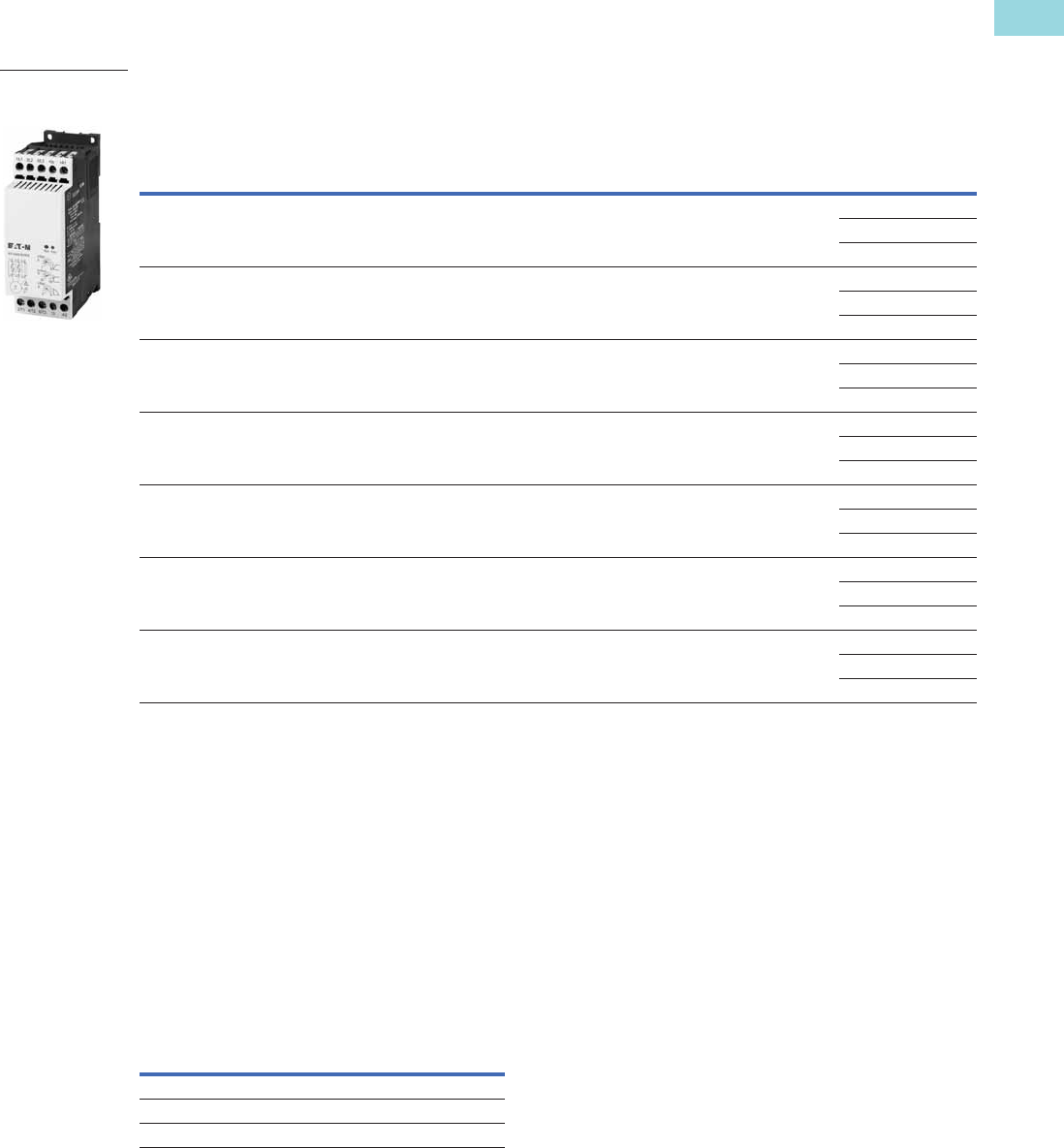
DS7 Soft Start
Controller—
Frames 1 and 2

V6-T1-8 Volume 6—Solid-State Motor Control CA08100007E—February 2016 www.eaton.com
1
1
1
1
1
1
1
1
1
1
1
1
1
1
1
1
1
1
1
1
1
1
1
1
1
1
1
1
1
1
1.1
Reduced Voltage Motor Starters
Solid-State Controllers
Please refer to Application Note AP039004EN for additional information on proper size selection.
DS7 Soft Start Controllers—Horsepower Ratings—
10 Second Ramp, One Start per Hour, 300% Current Limit at 40 °C
Notes
1 Maximum values may be higher than allowed per NEC® 430.52 and UL 508A 31.1.
2 XTOBXDIND Panel Mounting Adapter must be used with this overload.
3 XTOBXTLL line and load lugs must be used with this overload.
4 ZEB-XCT300 current transformer must be used with this overload.
5 24 Vac/Vdc device.
6 –40 °C rated low temperature version available in 24 Vac/Vdc, change to “N0-L.”
7 110/230 Vac device.
8 24 Vdc for SmartWire-DT device.
Considerations
1. Either XTOB, C306 or C440 series or equivalent overload protection devices may be selected.
2. Contactor is optional for normal applications. It is recommended for mains isolation.
Power Supply
Eaton’s PSG and ELC power supplies are recommended as a compact and low-cost
source for 24 Vdc power. The lightweight, DIN rail mounted devices have a wide input
voltage range, and robust screw terminals make these power supplies easy to install
and use. These power supplies are available in 1A and 2A models.
Power Supply Selection
Rated
Current (A)
Motor Power (hp) Maximum
Allowable
Breaker Size 1
Maximum
Allowable
Fuse Size 1
Recommended
XTOB Overload
Recommended
C440 Overload Catalog Number200 V 230 V 460 V
40 10 10 30 HFD3150L 150A Class RK5 XTOB040DC1 2C440A1A045SAX DS7-340SX041N0-N 56
DS7-342SX041N0-N 7
DS7-34DSX041N0-D 8
52 15 20 40 HFD3200L 200A Class RK5 XTOB057DC1 2C440B1A100SAX DS7-340SX055N0-N 56
DS7-342SX055N0-N 7
DS7-34DSX055N0-D 8
65 20 25 50 HJD3250 200A Class RK5 XTOB065DC1 2C440B1A100SAX DS7-340SX070N0-N 56
DS7-342SX070N0-N 7
DS7-34DSX070N0-D 8
77 25 30 60 HKD3300 300A Class RK5 XTOB100GC1S C440B1A100SAX DS7-340SX081N0-N 56
DS7-342SX081N0-N 7
DS7-34DSX081N0-D 8
96 30 30 75 HKD3350 350A Class RK5 XTOB100GC1S C440B1A100SAX DS7-340SX100N0-N 56
DS7-342SX100N0-N 7
DS7-34DSX100N0-D 8
124 40 50 100 HKD3400 500A Class RK5 XTOB125GC1S C440A1A005SAX 4DS7-340SX135N0-N 56
DS7-342SX135N0-N 7
DS7-34DSX135N0-D 8
156 50 60 125 HLD3450 500A Class RK5 XTOB160LC1 3C440A1A005SAX 4DS7-340SX160N0-N 56
DS7-342SX160N0-N 7
DS7-34DSX160N0-D 8
180 60 75 150 HLD3500 500A Class RK5 XTOB220LC1 3C440A1A005SAX 4DS7-340SX200N0-N 56
DS7-342SX200N0-N 7
DS7-34DSX200N0-D 8
Description Catalog Number
85–264 V input and 24 Vdc output ELC-PS01
100–240 V input and 24 Vdc output PSG60E
400–500 V input and 24 Vdc output PSG60F24RM
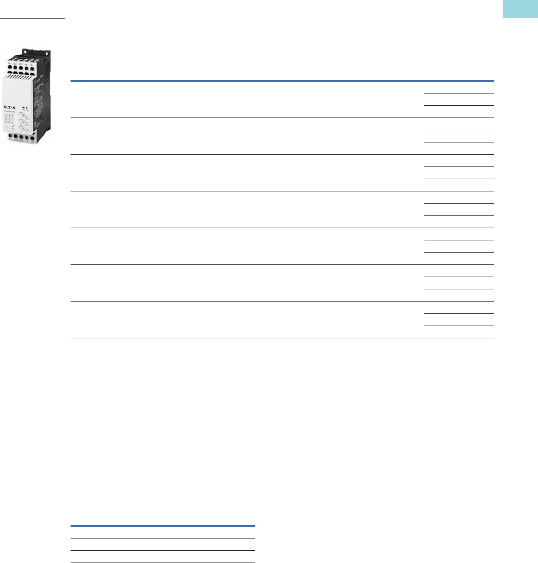
DS7 Soft Start
Controller—
Frames 3 and 4

Volume 6—Solid-State Motor Control CA08100007E—February 2016 www.eaton.com V6-T1-9
1
1
1
1
1
1
1
1
1
1
1
1
1
1
1
1
1
1
1
1
1
1
1
1
1
1
1
1
1
1
1.1
Reduced Voltage Motor Starters
Solid-State Controllers
Please refer to Application Note AP039004EN for additional information on proper size selection.
DS7 Soft Start Controllers—Horsepower Ratings—
10 Second Ramp, One Start per Hour, 400% Current Limit at 40 °C 1
Notes
1 Actual motor FLAs vary. Verify these devices cover the motor specific FLA.
2 Selections are based on motor FLA value at 480 V.
3 Not to be used with 230 V.
4 24 Vac/Vdc device.
5 –40 °C rated low temperature version available in 24 Vac/Vdc, change to “N0-L.”
6 110/230 Vac device.
7 24 Vdc for SmartWire-DT device.
Considerations
1. Either XTOB, C306 or C440 series or equivalent overload protection devices may be selected.
2. Contactor is optional for normal applications. It is recommended for mains isolation.
Power Supply
Eaton’s PSG and ELC power supplies are recommended as a compact and low-cost
source for 24 Vdc power. The lightweight, DIN rail mounted devices have a wide input
voltage range, and robust screw terminals make these power supplies easy to install
and use. These power supplies are available in 1A and 2A models.
Power Supply Selection
Rated
Current
(A)
Motor
Power (hp) Maximum
Allowable
Breaker
Size
Maximum
Allowable
Fuse
Size
Recommended
XTOB
Overload
(Direct
Connect) 2
Recommended
XTOE
Overload 2PKE MMP MMP 2
Connection
Kit to MMP Catalog Number200 V 230 V 480 V
3 0.5 0.5 1.5 HFD3015 15A
Class RK5
XTOB004BC1 XTOE005BCS XTPE012BCS XTPR004BC1 XTPAXTPCB DS7-340SX004N0-N 45
DS7-342SX004N0-N 5
DS7-34DSX004N0-D 6
4.8 113HFD301515A
Class RK5
XTOB006BC1 3XTOE020BCS XTPE012BCS XTPR6P3BC1 XTPAXTPCB DS7-340SX007N0-N 45
DS7-342SX007N0-N 5
DS7-34DSX007N0-D 6
6.9 1.5 2 3 HFD3020 20A
Class RK5
XTOB006BC1 XTOE020BCS XTPE012BCS XTPR6P3BC1 XTPAXTPCB DS7-340SX009N0-N 45
DS7-342SX009N0-N 5
DS7-34DSX009N0-D 6
9 225HFD303020A
Class RK5
XTOB010BC1 XTOE020BCS XTPE032BCS XTPR010BC1 XTPAXTPCB DS7-340SX012N0-N 45
DS7-342SX012N0-N 5
DS7-34DSX012N0-D 6
11 3 3 7.5 HFD3035 25A
Class RK5
XTOB016CC1 XTOE020CCS XTPE032BCS XTPR016BC1 XTPAXTPCC DS7-340SX016N0-N 45
DS7-342SX016N0-N 5
DS7-34DSX016N0-D 6
17.5 5 5 10 HFD3060 40A
Class RK5
XTOB016CC1 XTOE045CCS XTPE032BCS XTPR016BC1 XTPAXTPCC DS7-340SX024N0-N 45
DS7-342SX024N0-N 5
DS7-34DSX024N0-D 6
22 5 7.5 15 HFD3070 50A
Class RK5
XTOB024CC1 XTOE045CCS XTPE032BCS XTPR025BC1 XTPAXTPCC DS7-340SX032N0-N 45
DS7-342SX032N0-N 5
DS7-34DSX032N0-D 6
Description Catalog Number
85–264 V input and 24 Vdc output ELC-PS01
100–240 V input and 24 Vdc output PSG60E
400–500 V input and 24 Vdc output PSG60F24RM
DS7 Soft Start
Controller—
Frames 1 and 2
V6-T1-10 Volume 6—Solid-State Motor Control CA08100007E—February 2016 www.eaton.com
1
1
1
1
1
1
1
1
1
1
1
1
1
1
1
1
1
1
1
1
1
1
1
1
1
1
1
1
1
1
1.1
Reduced Voltage Motor Starters
Solid-State Controllers
Please refer to Application Note AP039004EN for additional information on proper size selection.
DS7 Soft Start Controllers—Horsepower Ratings—
10 Second Ramp, One Start per Hour, 400% Current Limit at 40 °C
Notes
1 Maximum values may be higher than allowed per NEC® 430.52 and UL 508A 31.1.
2 XTOBXDIND Panel Mounting Adapter must be used with this overload.
3 ZEB-XCT300 current transformer must be used with this overload.
4 24 Vac/Vdc device.
5 –40 °C rated low temperature version available in 24 Vac/Vdc, change to “N0-L.”
6 110/230 Vac device.
7 24 Vdc for SmartWire-DT device.
Considerations
1. Either XTOB, C306 or C440 series or equivalent overload protection devices may be selected.
2. Contactor is optional for normal applications. It is recommended for mains isolation.
Power Supply
Eaton’s PSG and ELC power supplies are recommended as a compact and low-cost
source for 24 Vdc power. The lightweight, DIN rail mounted devices have a wide input
voltage range, and robust screw terminals make these power supplies easy to install
and use. These power supplies are available in 1A and 2A models.
Power Supply Selection
Rated
Current (A)
Motor Power (hp) Maximum
Allowable
Breaker Size 1
Maximum
Allowable
Fuse Size 1
Recommended
XTOB Overload
Recommended
C440 Overload Catalog Number200 V 230 V 460 V
27 7.5 10 20 HFD3150L 150A Class RK5 XTOB040DC1 C440A1A045SAX DS7-340SX041N0-N 45
DS7-342SX041N0-N 6
DS7-34DSX041N0-D 7
34 10 10 30 HFD3200L 200A Class RK5 XTOB040DC1 C440A1A045SAX DS7-340SX055N0-N 45
DS7-342SX055N0-N 6
DS7-34DSX055N0-D 7
40 15 15 30 HJD3250 200A Class RK5 XTOB057DC1
2C440A1A045SAX DS7-340SX070N0-N 45
DS7-342SX070N0-N 6
DS7-34DSX070N0-D 7
52 15 20 40 HKD3300 300A Class RK5 XTOB057DC1 2C440B1A100SAX DS7-340SX081N0-N 45
DS7-342SX081N0-N 6
DS7-34DSX081N0-D 7
65 20 25 50 HKD3350 350A Class RK5 XTOB100GC1S C440B1A100SAX DS7-340SX100N0-N 45
DS7-342SX100N0-N 6
DS7-34DSX100N0-D 7
80 30 30 75 HKD3350 500A Class RK5 XTOB100GC1S C440B1A100SAX DS7-340SX135N0-N 45
DS7-342SX135N0-N 6
DS7-34DSX135N0-D 7
96 30 40 75 HLD3450 500A Class RK5 XTOB100GC1S C440B1A100SAX DS7-340SX160N0-N 45
DS7-342SX160N0-N 6
DS7-34DSX160N0-D 7
124 40 50 100 HLD3500 500A Class RK5 XTOB150GC1S C440A1A005SAX 3DS7-340SX200N0-N 45
DS7-342SX200N0-N 6
DS7-34DSX200N0-D 7
Description Catalog Number
85–264 V input and 24 Vdc output ELC-PS01
100–240 V input and 24 Vdc output PSG60E
400–500 V input and 24 Vdc output PSG60F24RM
DS7 Soft Start
Controller—
Frames 3 and 4
Volume 6—Solid-State Motor Control CA08100007E—February 2016 www.eaton.com V6-T1-11
1
1
1
1
1
1
1
1
1
1
1
1
1
1
1
1
1
1
1
1
1
1
1
1
1
1
1
1
1
1
1.1
Reduced Voltage Motor Starters
Solid-State Controllers
DS7 Soft Start kW Ratings
Please refer to Application Note AP039004EN for additional information on proper size selection.
DS7 Soft Start Controllers—kW Ratings According to IEC 60947-4-2—
10 Second Ramp, One Start per Hour, 300% Current Limit at 40 °C 1
Notes
1 Actual motor FLAs vary. Verify these devices cover the motor specific FLA.
2 Selections are based on motor FLA value at 480 V.
3 Not to be used with 230 V.
4 24 Vac/Vdc device.
5 –40 °C rated low temperature version available in 24 Vac/Vdc, change to “N0-L.”
6 110/230 Vac device.
7 24 Vdc for SmartWire-DT device.
Considerations
1. Either XTOB, C306 or C440 series or equivalent overload protection devices may be selected.
2. Contactor is optional for normal applications. It is recommended for mains isolation.
Power Supply
Eaton’s PSG and ELC power supplies are recommended as a compact and low-cost
source for 24 Vdc power. The lightweight, DIN rail mounted devices have a wide input
voltage range, and robust screw terminals make these power supplies easy to install
and use. These power supplies are available in 1A and 2A models.
Power Supply Selection
Rated
Current
(A)
Motor
Power (kW) Maximum
Allowable
Breaker
Size
Maximum
Allowable
Fuse
Size
Recommended
XTOB
Overload
(Direct
Connect) 2
Recommended
XTOE
Overload 2PKE MMP MMP 2
Connection
Kit to MMP Catalog Number230 V 400 V
3.8 0.75 1.5 HFD3015 15A
Class RK5
XTOB004BC1 XTOE005BCS XTPE012BCS XTPR004BC1 XTPAXTPCB DS7-340SX004N0-N 45
DS7-342SX004N0-N 6
DS7-34DSX004N0-D 7
7 1.5 3 HFD3015 15A
Class RK5
XTOB006BC1 3XTOE020BCS XTPE012BCS XTPR6P3BC1 XTPAXTPCB DS7-340SX007N0-N 45
DS7-342SX007N0-N 6
DS7-34DSX007N0-D 7
9 2.2 4 HFD3020 20A
Class RK5
XTOB010BC1 XTOE020BCS XTPE012BCS XTPR010BC1 XTPAXTPCB DS7-340SX009N0-N 45
DS7-342SX009N0-N 6
DS7-34DSX009N0-D 7
12 3 5.5 HFD3030 20A
Class RK5
XTOB012BC1 XTOE020BCS XTPE032BCS XTPR012BC1 XTPAXTPCB DS7-340SX012N0-N 45
DS7-342SX012N0-N 6
DS7-34DSX012N0-D 7
16 4 7.5 HFD3035 25A
Class RK5
XTOB016CC1 XTOE020CCS XTPE032BCS XTPR016BC1 XTPAXTPCC DS7-340SX016N0-N 45
DS7-342SX016N0-N 6
DS7-34DSX016N0-D 7
24 5.5 11 HFD3060 40A
Class RK5
XTOB024CC1 XTOE045CCS XTPE032BCS XTPR025BC1 XTPAXTPCC DS7-340SX024N0-N 45
DS7-342SX024N0-N 6
DS7-34DSX024N0-D 7
32 7.5 15 HFD3070 50A
Class RK5
XTOB032CC1 XTOE045CCS XTPE032BCS XTPR032BC1 XTPAXTPCC DS7-340SX032N0-N 45
DS7-342SX032N0-N 6
DS7-34DSX032N0-D 7
Description Catalog Number
85–264 V input and 24 Vdc output ELC-PS01
100–240 V input and 24 Vdc output PSG60E
400–500 V input and 24 Vdc output PSG60F24RM
DS7 Soft Start
Controller—
Frames 1 and 2

V6-T1-12 Volume 6—Solid-State Motor Control CA08100007E—February 2016 www.eaton.com
1
1
1
1
1
1
1
1
1
1
1
1
1
1
1
1
1
1
1
1
1
1
1
1
1
1
1
1
1
1
1.1
Reduced Voltage Motor Starters
Solid-State Controllers
Please refer to Application Note AP039004EN for additional information on proper size selection.
DS7 Soft Start Controllers—kW Ratings According to IEC 60947-4-2—
10 Second Ramp, One Start per Hour, 300% Current Limit at 40 °C
Notes
1 Maximum values may be higher than allowed per NEC 430.52 and UL 508A 31.1.
2 XTOBXDIND Panel Mounting Adapter must be used with this overload.
3 XTOBXTLL line and load lugs must be used with this overload.
4 ZEB-XCT300 current transformer must be used with this overload.
5 24 Vac/Vdc device.
6 –40 °C rated low temperature version available in 24 Vac/Vdc, change to “N0-L.”
7 110/230 Vac device.
8 24 Vdc for SmartWire-DT device.
Considerations
1. Either XTOB, C306 or C440 series or equivalent overload protection devices may be selected.
2. Contactor is optional for normal applications. It is recommended for mains isolation.
Power Supply
Eaton’s PSG and ELC power supplies are recommended as a compact and low-cost
source for 24 Vdc power. The lightweight, DIN rail mounted devices have a wide input
voltage range, and robust screw terminals make these power supplies easy to install
and use. These power supplies are available in 1A and 2A models.
Power Supply Selection
Rated
Current (A)
Motor Power (kW) Maximum
Allowable
Breaker Size 1
Maximum
Allowable
Fuse Size 1
Recommended
XTOB Overload
Recommended
C440 Overload Catalog Number230 V 400 V
41 11 22 HFD3150L 150A Class RK5 XTOB057DC1 2C440A1A045SAX DS7-340SX041N0-N 56
DS7-342SX041N0-N 7
DS7-34DSX041N0-D 8
55 15 30 HFD3200L 200A Class RK5 XTOB057DC1 2C440B1A100SAX DS7-340SX055N0-N 56
DS7-342SX055N0-N 7
DS7-34DSX055N0-D 8
68 15 37 HJD3250 200A Class RK5 XTOB070GC1 2C440B1A100SAX DS7-340SX070N0-N 56
DS7-342SX070N0-N 7
DS7-34DSX070N0-D 8
81 22 45 HKD3300 300A Class RK5 XTOB100GC1S C440B1A100SAX DS7-340SX081N0-N 56
DS7-342SX081N0-N 7
DS7-34DSX081N0-D 8
99 30 55 HKD3350 350A Class RK5 XTOB100GC1S C440B1A100SAX DS7-340SX100N0-N 56
DS7-342SX100N0-N 7
DS7-34DSX041N0-D 8
134 30 75 HKD3400 500A Class RK5 XTOB150GC1S C440A1A005SAX 4DS7-340SX135N0-N 56
DS7-342SX135N0-N 7
DS7-34DSX135N0-D 8
160 45 90 HLD3450 500A Class RK5 XTOB160LC1 3C440A1A005SAX 4DS7-340SX160N0-N 56
DS7-342SX160N0-N 7
DS7-34DSX160N0-D 8
196 55 110 HLD3500 500A Class RK5 XTOB220LC1 3C440A1A005SAX 4DS7-340SX200N0-N 56
DS7-342SX200N0-N 7
DS7-34DSX200N0-D 8
Description Catalog Number
85–264 V input and 24 Vdc output ELC-PS01
100–240 V input and 24 Vdc output PSG60E
400–500 V input and 24 Vdc output PSG60F24RM
DS7 Soft Start
Controller—
Frames 3 and 4
Volume 6—Solid-State Motor Control CA08100007E—February 2016 www.eaton.com V6-T1-13
1
1
1
1
1
1
1
1
1
1
1
1
1
1
1
1
1
1
1
1
1
1
1
1
1
1
1
1
1
1
1.1
Reduced Voltage Motor Starters
Solid-State Controllers
Please refer to Application Note AP039004EN for additional information on proper size selection.
DS7 Soft Start Controllers—kW Ratings According to IEC 60947-4-2—
10 Second Ramp, One Start per Hour, 400% Current Limit at 40 °C 1
Notes
1 Actual motor FLAs vary. Verify these devices cover the motor specific FLA.
2 Selections are based on motor FLA value at 480 V.
3 Not to be used with 230 V.
4 24 Vac/Vdc device.
5 –40 °C rated low temperature version available in 24 Vac/Vdc, change to “N0-L.”
6 110/230 Vac device.
7 24 Vdc for SmartWire-DT device.
Considerations
1. Either XTOB, C306 or C440 series or equivalent overload protection devices may be selected.
2. Contactor is optional for normal applications. It is recommended for mains isolation.
Power Supply
Eaton’s PSG and ELC power supplies are recommended as a compact and low-cost
source for 24 Vdc power. The lightweight, DIN rail mounted devices have a wide input
voltage range, and robust screw terminals make these power supplies easy to install
and use. These power supplies are available in 1A and 2A models.
Power Supply Selection
Rated
Current
(A)
Motor Power
(kW) Maximum
Allowable
Breaker
Size
Maximum
Allowable
Fuse
Size
Recommended
XTOB
Overload
(Direct
Connect) 2
Recommended
XTOE
Overload 2PKE MMP MMP 2
Connection
Kit to MMP Catalog Number230 V 400 V
2.5 0.33 1 HFD3015 15A
Class RK5
XTOB004BC1 XTOE005BCS XTPE012BCS XTPR004BC1 XTPAXTPCB DS7-340SX004N0-N 45
DS7-342SX004N0-N 6
DS7-34DSX004N0-D 7
3.8 0.75 1.5 HFD3015 15A
Class RK5
XTOB006BC1 3XTOE020BCS XTPE012BCS XTPR6P3BC1 XTPAXTPCB DS7-340SX007N0-N 45
DS7-342SX007N0-N 6
DS7-34DSX007N0-D 7
7 1.5 3 HFD3020 20A
Class RK5
XTOB006BC1 XTOE020BCS XTPE012BCS XTPR6P3BC1 XTPAXTPCB DS7-340SX009N0-N 45
DS7-342SX009N0-N 6
DS7-34DSX009N0-D 7
9 2.2 4 HFD3030 20A
Class RK5
XTOB010BC1 XTOE020BCS XTPE032BCS XTPR010BC1 XTPAXTPCB DS7-340SX012N0-N 45
DS7-342SX012N0-N 6
DS7-34DSX012N0-D 7
12 3 5.5 HFD3035 25A
Class RK5
XTOB016CC1 XTOE020CCS XTPE032BCS XTPR016BC1 XTPAXTPCC DS7-340SX016N0-N 45
DS7-342SX016N0-N 6
DS7-34DSX016N0-D 7
16 4 7.5 HFD3060 40A
Class RK5
XTOB016CC1 XTOE045CCS XTPE032BCS XTPR016BC1 XTPAXTPCC DS7-340SX024N0-N 45
DS7-342SX024N0-N 6
DS7-34DSX016N0-D 7
24 5.5 11 HFD3070 50A
Class RK5
XTOB024CC1 XTOE045CCS XTPE032BCS XTPR025BC1 XTPAXTPCC DS7-340SX032N0-N 45
DS7-342SX032N0-N 6
DS7-34DSX032N0-D 7
Description Catalog Number
85–264 V input and 24 Vdc output ELC-PS01
100–240 V input and 24 Vdc output PSG60E
400–500 V input and 24 Vdc output PSG60F24RM
DS7 Soft Start
Controller—
Frames 1 and 2

V6-T1-14 Volume 6—Solid-State Motor Control CA08100007E—February 2016 www.eaton.com
1
1
1
1
1
1
1
1
1
1
1
1
1
1
1
1
1
1
1
1
1
1
1
1
1
1
1
1
1
1
1.1
Reduced Voltage Motor Starters
Solid-State Controllers
Please refer to Application Note AP039004EN for additional information on proper size selection.
DS7 Soft Start Controllers—kW Ratings According to IEC 60947-4-2—
10 Second Ramp, One Start per Hour, 400% Current Limit at 40 °C
Notes
1 Maximum values may be higher than allowed per NEC 430.52 and UL 508A 31.1.
2 XTOBXDIND Panel Mounting Adapter must be used with this overload.
3 XTOBXTLL line and load lugs must be used with this overload.
4 ZEB-XCT300 current transformer must be used with this overload.
5 24 Vac/Vdc device.
6 –40 °C rated low temperature version available in 24 Vac/Vdc, change to “N0-L.”
7 110/230 Vac device.
8 24 Vdc for SmartWire-DT device.
Considerations
1. Either XTOB, C306 or C440 series or equivalent overload protection devices may be selected.
2. Contactor is optional for normal applications. It is recommended for mains isolation.
Power Supply
Eaton’s PSG and ELC power supplies are recommended as a compact and low-cost
source for 24 Vdc power. The lightweight, DIN rail mounted devices have a wide input
voltage range, and robust screw terminals make these power supplies easy to install
and use. These power supplies are available in 1A and 2A models.
Power Supply Selection
Rated
Current (A)
Motor Power (kW) Maximum
Allowable
Breaker Size 1
Maximum
Allowable
Fuse Size 1
Recommended
XTOB Overload
Recommended
C440 Overload Catalog Number230 V 400 V
28.8 7.5 11 HFD3150L 150A Class RK5 XTOB040DC1 C440A1A045SAX DS7-340SX041N0-N 56
DS7-342SX041N0-N 7
DS7-34DSX041N0-D 8
37.5 11 18.5 HFD3200L 200A Class RK5 XTOB040DC1 C440A1A045SAX DS7-340SX055N0-N 56
DS7-342SX055N0-N 7
DS7-34DSX055N0-D 8
46 11 22 HJD3250 200A Class RK5 XTOB057DC1 2C440B1A100SAX DS7-340SX070N0-N 56
DS7-342SX070N0-N 7
DS7-34DSX070N0-D 8
56 15 30 HKD3300 300A Class RK5 XTOB065DC1 2C440B1A100SAX DS7-340SX081N0-N 56
DS7-342SX081N0-N 7
DS7-34DSX081N0-D 8
68 18.5 37 HKD3350 350A Class RK5 XTOB100GC1S C440B1A100SAX DS7-340SX100N0-N 56
DS7-342SX100N0-N 7
DS7-34DSX100N0-D 8
90 22 45 HKD3350 500A Class RK5 XTOB100GC1S C440B1A100SAX DS7-340SX135N0-N 56
DS7-342SX135N0-N 7
DS7-34DSX135N0-D 8
106 30 55 HLD3450 500A Class RK5 XTOB160LC1 3C440A1A005SAX 4DS7-340SX160N0-N 56
DS7-342SX160N0-N 7
DS7-34DSX160N0-D 8
134 37 75 HLD3500 500A Class RK5 XTOB160LC1 3C440A1A005SAX 4DS7-340SX200N0-N 56
DS7-342SX200N0-N 7
DS7-34DSX200N0-D 8
Description Catalog Number
85–264 V input and 24 Vdc output ELC-PS01
100–240 V input and 24 Vdc output PSG60E
400–500 V input and 24 Vdc output PSG60F24RM
DS7 Soft Start
Controller—
Frames 3 and 4

Volume 6—Solid-State Motor Control CA08100007E—February 2016 www.eaton.com V6-T1-15
1
1
1
1
1
1
1
1
1
1
1
1
1
1
1
1
1
1
1
1
1
1
1
1
1
1
1
1
1
1
1.1
Reduced Voltage Motor Starters
Solid-State Controllers
Accessories
Device Fans
Note
1 NA Certification. Request filed for UL and CSA.
Description For Use With … Std. Pack Catalog Number
Device fan for increasing the load cycle (more
starts per hour higher or longer ramp times
exceeding 10 seconds.
DS7-34…SX004…
DS7-34…SX007…
DS7-34…SX009…
DS7-34…SX012…
DS7-34…SX016…
DS7-34…SX024…
DS7-34…SX032…
1 off DS7-FAN-032 1
DS7-FAN-032

V6-T1-16 Volume 6—Solid-State Motor Control CA08100007E—February 2016 www.eaton.com
1
1
1
1
1
1
1
1
1
1
1
1
1
1
1
1
1
1
1
1
1
1
1
1
1
1
1
1
1
1
1.1
Reduced Voltage Motor Starters
Solid-State Controllers
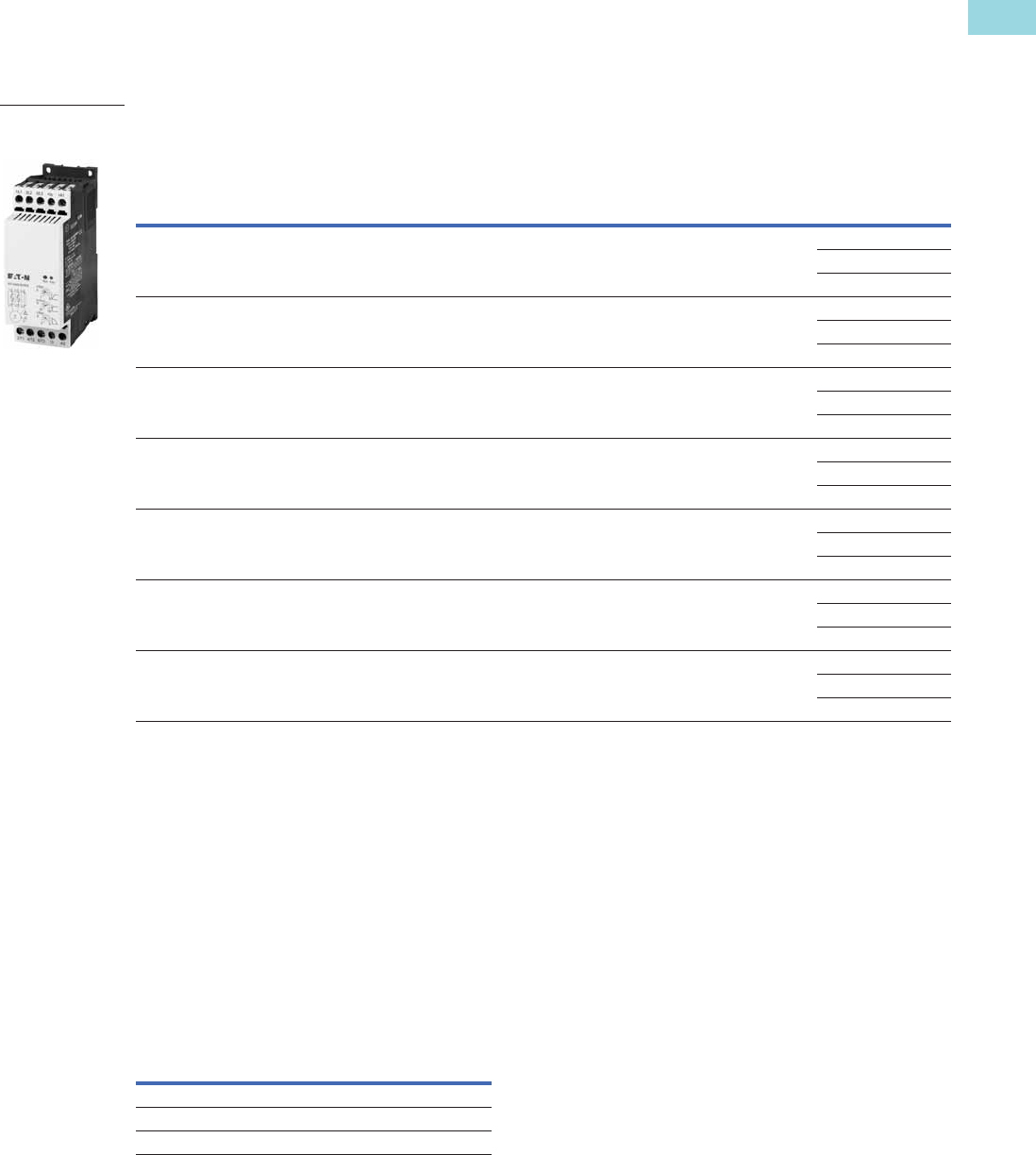
Technical Data and Specifications
DS7 Soft Start Controllers
Rated Control Circuit
Voltage 24 Vac/Vdc
Voltage 110/230 Vac
Voltage 24 Vdc Unit
DS7-340SX004N0-N
DS7-342SX004N0-N
DS7-34DSX004N0-D
DS7-340SX007N0-N
DS7-342SX007N0-N
DS7-34DSX007N0-D
DS7-340SX009N0-N
DS7-342SX009N0-N
DS7-34DSX009N0-D
DS7-340SX012N0-N
DS7-342SX012N0-N
DS7-34DSX012N0-D
General
Standards IEC/EN 60947-4-2; GB14048.6;
UL508; CSA-C22.2 No 0-M91;
CSA-C22.2 No 14-05 CE marking
IEC/EN 60947-4-2; GB14048.6;
UL508; CSA-C22.2 No 0-M91;
CSA-C22.2 No 14-05 CE marking
IEC/EN 60947-4-2; GB14048.6;
UL508; CSA-C22.2 No 0-M91;
CSA-C22.2 No 14-05 CE marking
IEC/EN 60947-4-2; GB14048.6;
UL508; CSA-C22.2 No 0-M91;
CSA-C22.2 No 14-05 CE marking
Certifications/marking UL/CE/CSA/C-Tick UL/CE/CSA/C-Tick UL/CE/CSA/C-Tick UL/CE/CSA/C-Tick
Ambient temperature
(operation)
°C 0 to 40 °C, above 40 °C de-rate
linearly by 1% of rated current
per Celsius to 60 °C
–40 to +40 °C for low
temperature version
0 to 40 °C, above 40 °C de-rate
linearly by 1% of rated current
per Celsius to 60 °C
–40 to +40 °C for low
temperature version
0 to 40 °C, above 40 °C de-rate
linearly by 1% of rated current
per Celsius to 60 °C
–40 to +40 °C for low
temperature version
0 to 40 °C, above 40 °C de-rate
linearly by 1% of rated current
per Celsius to 60 °C
–40 to +40 °C for low
temperature version
Ambient temperature (storage) °C –25 to 55 °C –25 to 55 °C –25 to 55 °C –25 to 55 °C
Altitude 0–1000m, above 1000m de-rate
linearly by 2.5% of rated current
per 100m to a maximum of 2000m
0–1000m, above 1000m de-rate
linearly by 2.5% of rated current
per 100m to a maximum of 2000m
0–1000m, above 1000m de-rate
linearly by 2.5% of rated current
per 100m to a maximum of 2000m
0–1000m, above 1000m de-rate
linearly by 2.5% of rated current
per 100m to a maximum of 2000m
Installation Vertical Vertical Vertical Vertical
Protection class IP20 IP20 IP20 IP20
Protection class applies to the
front and operator control and
display elements. Protection
type from all sides is IP00.
With optional covers from the NZM
range, protection type IP40 from all
sides can be achieved
With optional covers from the NZM
range, protection type IP40 from all
sides can be achieved
With optional covers from the NZM
range, protection type IP40 from all
sides can be achieved
With optional covers from the NZM
range, protection type IP40 from all
sides can be achieved
Busbar tag shroud Back of hand and finger-proof
(from front face)
Back of hand and finger-proof
(from front face)
Back of hand and finger-proof
(from front face)
Back of hand and finger-proof
(from front face)
Overvoltage category/
pollution degree
II/2 II/2 II/2 II/2
Shock resistance 8g/11ms 8g/11ms 8g/11ms 8g/11ms
Vibration resistance according
to EN 60721-3-2
2M2 2M2 2M2 2M2
Mean heat dissipation at
rated duty cycle
W 0.2 0.35 0.35 0.6
Radio interference B B B B
Dimensions (W x H x D)
DS7-340… and DS7-342… in (mm) 1.77 x 5.12 x 3.74 (45 x 130 x 95) 1.77 x 5.12 x 3.74 (45 x 130 x 95) 1.77 x 5.12 x 3.74 (45 x 130 x 95) 1.77 x 5.12 x 3.74 (45 x 130 x 95)
DS7-34D… in (mm) 1.77 x 5.31 x 3.74 (45 x 135 x 95) 1.77 x 5.31 x 3.74 (45 x 135 x 95) 1.77 x 5.31 x 3.74 (45 x 135 x 95) 1.77 x 5.31 x 3.74 (45 x 135 x 95)
Weight
DS7-340… lb (kg) 0.77 (0.35) 0.77 (0.35) 0.77 (0.35) 0.77 (0.35)
DS7-342… lb (kg) 0.88 (0.40) 0.88 (0.40) 0.88 (0.40) 0.88 (0.40)
DS7-34D… lb (kg) 0.90 (0.41) 0.90 (0.41) 0.90 (0.41) 0.90 (0.41)
Main Circuit
Rated operational voltage V 230–460 Vac 230–460 Vac 230–460 Vac 230–460 Vac
Mains frequency Hz 50/60 Hz 50/60 Hz 50/60 Hz 50/60 Hz
Rated operation current AC 53 Ie47912
Motor Power Ratings
200 V hp 0.75 1.5 2 3
230 V hp 0.75 2 2 5
480 Vhp23510
230 V kW 0.75 1.5 2.2 3
400 V kW 1.5 3 4 5.5
Overload cycle according to
EN 60947-4-2
4A: AC53a; 3-5; 75-10 7A: AC53a; 3-5; 75-10 9A: AC53a; 3-5; 75-10 12A: AC53a; 3-5; 75-10

Volume 6—Solid-State Motor Control CA08100007E—February 2016 www.eaton.com V6-T1-17
1
1
1
1
1
1
1
1
1
1
1
1
1
1
1
1
1
1
1
1
1
1
1
1
1
1
1
1
1
1
1.1
Reduced Voltage Motor Starters
Solid-State Controllers
DS7 Soft Start Controllers, continued
Rated Control Circuit
Voltage 24 Vac/Vdc
Voltage 110/230 Vac
Voltage 24 Vdc Unit
DS7-340SX004N0-N
DS7-342SX004N0-N
DS7-34DSX004N0-D
DS7-340SX007N0-N
DS7-342SX007N0-N
DS7-34DSX007N0-D
DS7-340SX009N0-N
DS7-342SX009N0-N
DS7-34DSX009N0-D
DS7-340SX012N0-N
DS7-342SX012N0-N
DS7-34DSX012N0-D
Wire Specifications
Power terminals
Single conductor—solid or stranded AWG 18–10 18–10 18–10 18–10
Terminal torque lb-in 11 11 11 11
Control signals
Single conductor—solid or stranded AWG 18–10 18–10 18–10 18–10
Terminal torque lb-in 11 11 11 11
Power Section
Rated impulse withstand voltage Uimp
1.2/ 50 s
4 kV 4 kV 4 kV 4 kV
Rated insulation voltage 500 500 500 500
Control Commands—Vac/Vdc
Supply voltage control board Us nominal Vac/Vdc 20.4–26.4 20.4–26.4 20.4–26.4 20.4–26.4
Current consumption at 24 Vac/Vdc mA 1.6 1.6 1.6 1.6
Pick-up voltage +17.3–+27 +17.3–+27 +17.3–+27 +17.3–+27
Drop-out voltage +3–0 +3–0 +3–0 +3–0
Relay Outputs
Number of relays 1 (TOR) 1 (TOR) 1 (TOR) 1 (TOR)
Maximum voltage Vac 250 250 250 250
Maximum current A 1A 1A 1A 1A
Soft Start Functions
Ramp times
Start ramp s 1–30 1–30 1–30 1–30
Stop ramp s 0–30 0–30 0–30 0–30
Initial voltage % line voltage
DS7-342… 30–92% 30–92% 30–92% 30–92%
DS7-340… 30–100% 30–100% 30–100% 30–100%
DS7-34D… 30–92% 30–92% 30–92% 30–92%
Control Commands—Vac
Supply voltage control board Us nominal Vac 102–253 102–253 102–253 102–253
Current consumption at 24 Vac/VdcmA4444
Pick-up voltage Vac 102–230 102–230 102–230 102–230
Drop-out voltage Vac 0–28 0–28 0–28 0–28
Relay Outputs
Number of relays 1 (TOR) 1 (TOR) 1 (TOR) 1 (TOR)
Maximum voltage Vac 250 250 250 250
Maximum current A 3A 3A 3A 3A
Soft Start Functions
Ramp times
Start ramp s 1–30 1–30 1–30 1–30
Stop ramp s 0–30 0–30 0–30 0–30
Initial voltage % line voltage 30–92% 30–92% 30–92% 30–92%

V6-T1-18 Volume 6—Solid-State Motor Control CA08100007E—February 2016 www.eaton.com
1
1
1
1
1
1
1
1
1
1
1
1
1
1
1
1
1
1
1
1
1
1
1
1
1
1
1
1
1
1
1.1
Reduced Voltage Motor Starters
Solid-State Controllers
DS7 Soft Start Controllers, continued
Rated Control Circuit
Voltage 24 Vac/Vdc
Voltage 110/230 Vac
Voltage 24 Vdc Unit
DS7-340SX016N0-N
DS7-342SX016N0-N
DS7-34DSX016N0-D
DS7-340SX024N0-N
DS7-342SX024N0-N
DS7-34DSX024N0-D
DS7-340SX032N0-N
DS7-342SX032N0-N
DS7-34DSX032N0-D
General
Standards IEC/EN 60947-4-2; GB14048.6; UL508;
CSA-C22.2 No 0-M91; CSA-C22.2 No 14-05
CE marking
IEC/EN 60947-4-2; GB14048.6; UL508;
CSA-C22.2 No 0-M91; CSA-C22.2 No 14-05
CE marking
IEC/EN 60947-4-2; GB14048.6; UL508;
CSA-C22.2 No 0-M91; CSA-C22.2 No 14-05
CE marking
Certifications/marking UL/CE/CSA/C-Tick UL/CE/CSA/C-Tick UL/CE/CSA/C-Tick
Ambient temperature (operation) °C 0 to 40 °C, above 40 °C de-rate linearly by 1% of
rated current per Celsius to 60 °C
–40 to +40 °C for low temperature version
0 to 40 °C, above 40 °C de-rate linearly by 1% of
rated current per Celsius to 60 °C
–40 to +40 °C for low temperature version
0 to 40 °C, above 40 °C de-rate linearly by 1% of
rated current per Celsius to 60 °C
–40 to +40 °C for low temperature version
Ambient temperature (storage) °C –25 to 55 °C –25 to 55 °C –25 to 55 °C
Altitude 0–1000m, above 1000m de-rate linearly by
2.5% of rated current per 100m to a maximum of
2000m
0–1000m, above 1000m de-rate linearly by
2.5% of rated current per 100m to a maximum of
2000m
0–1000m, above 1000m de-rate linearly by
2.5% of rated current per 100m to a maximum of
2000m
Installation Vertical Vertical Vertical
Protection class IP20 IP20 IP20
Protection class applies to the front
and operator control and display
elements. Protection type from all
sides is IP00.
With optional covers from the NZM range,
protection type IP40 from all sides can be
achieved
With optional covers from the NZM range,
protection type IP40 from all sides can be
achieved
With optional covers from the NZM range,
protection type IP40 from all sides can be
achieved
Busbar tag shroud Back of hand and finger-proof (from front face) Back of hand and finger-proof (from front face) Back of hand and finger-proof (from front face)
Overvoltage category/
pollution degree
II/2 II/2 II/2
Shock resistance 8g/11ms 8g/11ms 8g/11ms
Vibration resistance according to
EN 60721-3-2
2M2 2M2 2M2
Mean heat dissipation at
rated duty cycle
W0.8 1.1 1.5
Radio interference B B B
Dimensions (W x H x D)
DS7-340… and DS7-342… in (mm) 1.77 x 5.91 x 4.65 (45 x 150 x 118) 1.77 x 5.91 x 4.65 (45 x 150 x 118) 1.77 x 5.91 x 4.65 (45 x 150 x 118)
DS7-34D… in (mm) 1.77 x 5.91 x 4.65 (45 x 150 x 118) 1.77 x 5.91 x 4.65 (45 x 150 x 118) 1.77 x 5.91 x 4.65 (45 x 150 x 118)
Weight
DS7-340… lb (kg) 0.88 (0.40) 0.88 (0.40) 0.88 (0.40)
DS7-342… lb (kg) 0.99 (0.45) 0.99 (0.45) 0.99 (0.45)
DS7-34D… lb (kg) 0.90 (0.41) 0.90 (0.41) 0.90 (0.41)
Main Circuit
Rated operational voltage V 230–460 Vac 230–460 Vac 230–460 Vac
Mains frequency Hz 50/60 Hz 50/60 Hz 50/60 Hz
Rated operation current AC 53 Ie16 24 32
Motor Power Ratings
200 V hp 3 5 10
230 V hp 5 7.5 10
480 Vhp101525
230 V kW 4 5.5 7.5
400 V kW 7.5 11 15
Overload cycle according to
EN 60947-4-2
16A: AC53a; 3-5; 75-10 24A: AC53a; 3-5; 75-10 32A: AC53a; 3-5; 75-10

Volume 6—Solid-State Motor Control CA08100007E—February 2016 www.eaton.com V6-T1-19
1
1
1
1
1
1
1
1
1
1
1
1
1
1
1
1
1
1
1
1
1
1
1
1
1
1
1
1
1
1
1.1
Reduced Voltage Motor Starters
Solid-State Controllers
DS7 Soft Start Controllers, continued
Rated Control Circuit
Voltage 24 Vac/Vdc
Voltage 110/230 Vac
Voltage 24 Vdc Unit
DS7-340SX016N0-N
DS7-342SX016N0-N
DS7-34DSX016N0-D
DS7-340SX024N0-N
DS7-342SX024N0-N
DS7-34DSX024N0-D
DS7-340SX032N0-N
DS7-342SX032N0-N
DS7-34DSX032N0-D
Wire Specifications
Power terminals
Single conductor—solid or
stranded
AWG 18–6 18–6 18–6
Terminal torque lb-in 11 11 11
Control Signals
Single conductor—solid or
stranded
AWG 18–10 18–10 18–10
Terminal torque lb-in 11 11 11
Power Section
Rated impulse withstand voltage Uimp
1.2/ 50 s
4 kV 4 kV 4 kV
Rated insulation voltage 500 500 500
Control Commands—Vac/Vdc
Supply voltage control board Us nominal Vac/Vdc 20.4–26.4 20.4–26.4 20.4–26.4
Current consumption at 24 Vac/Vdc mA 1.6 1.6 1.6
Pick-up voltage +17.3–+27 +17.3–+27 +17.3–+27
Drop-out voltage +3–0 +3–0 +3–0
Relay Outputs
Number of relays 2 (TOR, Ready) 2 (TOR, Ready) 2 (TOR, Ready)
Maximum voltage Vac 250 250 250
Maximum current A 1A 1A 1A
Soft Start Functions
Ramp times
Start ramp s 1–30 1–30 1–30
Stop ramp s 0–30 0–30 0–30
Initial voltage % line voltage
DS7-342… 30–92% 30–92% 30–92%
DS7-340… 30–100% 30–100% 30–100%
DS7-34D… 30–92% 30–92% 30–92%
Control Commands—Vac
Supply voltage control board Us nominal Vac 102–253 102–253 102–253
Current consumption at 102–253 Vac mA 4 4 4
Pick-up voltage Vac 102–230 102–230 102–230
Drop-out voltage Vac 0–28 0–28 0–28
Relay Outputs
Number of relays 2 (TOR, Run) 2 (TOR, Run) 2 (TOR, Run)
Maximum voltage Vac 250 250 250
Maximum current A 3A 3A 3A
Soft Start Functions
Ramp times
Start ramp s 1–30 1–30 1–30
Stop ramp s 0–30 0–30 0–30
Initial voltage % line voltage 30–92% 30–92% 30–92%
V6-T1-20 Volume 6—Solid-State Motor Control CA08100007E—February 2016 www.eaton.com
1
1
1
1
1
1
1
1
1
1
1
1
1
1
1
1
1
1
1
1
1
1
1
1
1
1
1
1
1
1
1.1
Reduced Voltage Motor Starters
Solid-State Controllers
DS7 Soft Start Controllers, continued
Rated Control Circuit
Voltage 24 Vac/Vdc
Voltage 110/230 Vac
Voltage 24 Vdc Unit
DS7-340SX041N0-N
DS7-342SX041N0-N
DS7-34DSX041N0-D
DS7-340SX055N0-N
DS7-342SX055N0-N
DS7-34DSX055N0-D
DS7-340SX070N0-N
DS7-342SX070N0-N
DS7-34DSX070N0-D
DS7-340SX081N0-N
DS7-342SX081N0-N
DS7-34DSX081N0-D
General
Standards IEC/EN 60947-4-2; GB14048.6;
UL508; CSA-C22.2 No 0-M91;
CSA-C22.2 No 14-05 CE marking
IEC/EN 60947-4-2; GB14048.6;
UL508; CSA-C22.2 No 0-M91;
CSA-C22.2 No 14-05 CE marking
IEC/EN 60947-4-2; GB14048.6;
UL508; CSA-C22.2 No 0-M91;
CSA-C22.2 No 14-05 CE marking
IEC/EN 60947-4-2; GB14048.6;
UL508; CSA-C22.2 No 0-M91;
CSA-C22.2 No 14-05 CE marking
Certifications/marking UL/CE/CSA/C-Tick UL/CE/CSA/C-Tick UL/CE/CSA/C-Tick UL/CE/CSA/C-Tick
Ambient temperature
(operation)
°C 0 to 40 °C, above 40 °C de-rate
linearly by 1% of rated current
per Celsius to 60 °C
–40 to +40 °C for low
temperature version
0 to 40 °C, above 40 °C de-rate
linearly by 1% of rated current
per Celsius to 60 °C
–40 to +40 °C for low
temperature version
0 to 40 °C, above 40 °C de-rate
linearly by 1% of rated current
per Celsius to 60 °C
–40 to +40 °C for low
temperature version
0 to 40 °C, above 40 °C de-rate
linearly by 1% of rated current
per Celsius to 60 °C
–40 to +40 °C for low
temperature version
Ambient temperature (storage) °C –25 to 55 °C –25 to 55 °C –25 to 55 °C –25 to 55 °C
Altitude 0–1000m, above 1000m de-rate
linearly by 2.5% of rated current
per 100m to a maximum of 2000m
0–1000m, above 1000m de-rate
linearly by 2.5% of rated current
per 100m to a maximum of 2000m
0–1000m, above 1000m de-rate
linearly by 2.5% of rated current
per 100m to a maximum of 2000m
0–1000m, above 1000m de-rate
linearly by 2.5% of rated current
per 100m to a maximum of 2000m
Installation Vertical Vertical Vertical Vertical
Protection class IP20 IP20 IP20 IP20
Protection class applies to the
front and operator control and
display elements. Protection
type from all sides is IP00.
With optional covers from the NZM
range, protection type IP40 from all
sides can be achieved
With optional covers from the NZM
range, protection type IP40 from all
sides can be achieved
With optional covers from the NZM
range, protection type IP40 from all
sides can be achieved
With optional covers from the NZM
range, protection type IP40 from all
sides can be achieved
Busbar tag shroud Back of hand and finger-proof
(from front face)
Back of hand and finger-proof
(from front face)
Back of hand and finger-proof
(from front face)
Back of hand and finger-proof
(from front face)
Overvoltage category/
pollution degree
II/2 II/2 II/2 II/2
Shock resistance 8g/11ms 8g/11ms 8g/11ms 8g/11ms
Vibration resistance according
to EN 60721-3-2
2M2 2M2 2M2 2M2
Mean heat dissipation at
rated duty cycle
W 7 10 13 18
Radio interference B B B B
Dimensions (W x H x D)
DS7-340…, DS7-342…
and DS7-34D…
in (mm) 3.66 x 6.89 x 5.47 (93 x 175 x 139) 3.66 x 6.89 x 5.47 (93 x 175 x 139) 3.66 x 6.89 x 5.47 (93 x 175 x 139) 3.66 x 6.89 x 5.47 (93 x 175 x 139)
Weight
DS7-340…, DS7-342…
and DS7-34D…
lb (kg) 3.97 (1.8) 3.97 (1.8) 3.97 (1.8) 3.97 (1.8)
Main Circuit
Rated operational voltage V 230–460 Vac 230–460 Vac 230–460 Vac 230–460 Vac
Mains frequency Hz 50/60 Hz 50/60 Hz 50/60 Hz 50/60 Hz
Rated operation current AC 53 Ie41 55 70 81
Motor Power Ratings
200 Vhp10152025
230 Vhp10202530
480 Vhp30405060
230 VkW11151522
400 VkW22303745
Overload cycle according to
EN 60947-4-2
41A: AC53a; 3-5; 75-10 55A: AC53a; 3-5; 75-10 70A: AC53a; 3-5; 75-10 81A: AC53a; 3-5; 75-10

Volume 6—Solid-State Motor Control CA08100007E—February 2016 www.eaton.com V6-T1-21
1
1
1
1
1
1
1
1
1
1
1
1
1
1
1
1
1
1
1
1
1
1
1
1
1
1
1
1
1
1
1.1
Reduced Voltage Motor Starters
Solid-State Controllers
DS7 Soft Start Controllers, continued
Rated Control Circuit
Voltage 24 Vac/Vdc
Voltage 110/230 Vac
Voltage 24 Vdc Unit
DS7-340SX041N0-N
DS7-342SX041N0-N
DS7-34DSX041N0-D
DS7-340SX055N0-N
DS7-342SX055N0-N
DS7-34DSX055N0-D
DS7-340SX070N0-N
DS7-342SX070N0-N
DS7-34DSX070N0-D
DS7-340SX081N0-N
DS7-342SX081N0-N
DS7-34DSX081N0-D
Wire Specifications
Power terminals
Single conductor—solid or stranded AWG 12–2/0 12–2/0 12–2/0 12–2/0
Terminal torque lb-in 53–80 53–80 53–80 53–80
Control signals
Single conductor—solid or stranded AWG 18–10 18–10 18–10 18–10
Terminal torque lb-in 11 11 11 11
Power Section
Rated impulse withstand voltage Uimp
1.2/ 50 s
4 kV 4 kV 4 kV 4 kV
Rated insulation voltage 500 500 500 500
Control Commands—24 Vac/Vdc
Supply voltage control board Us nominal Vac/Vdc 20.4–26.4 20.4–26.4 20.4–26.4 20.4–26.4
Current consumption at 24 Vac/Vdc mA 65 65 65 65
Pick-up voltage +17.3–+27 +17.3–+27 +17.3–+27 +17.3–+27
Drop-out voltage +3–0 +3–0 +3–0 +3–0
Relay Outputs
Number of relays 2 (TOR) 2 (TOR) 2 (TOR) 2 (TOR)
Maximum voltage Vac 250 250 250 250
Maximum current A 1A 1A 1A 1A
Soft Start Functions
Ramp times
Start ramp s 1–30 1–30 1–30 1–30
Stop ramp s 0–30 0–30 0–30 0–30
Initial voltage % line voltage
DS7-342… 30–92% 30–92% 30–92% 30–92%
DS7-340… 30–100% 30–100% 30–100% 30–100%
DS7-34D… 30–92% 30–92% 30–92% 30–92%
Control Commands—110–230 Vac
Supply voltage control board Us nominal Vac 102–253 102–253 102–253 102–253
Current consumption at 24 Vac/Vdc mA 14 14 14 14
Pick-up voltage Vac 102–230 102–230 102–230 102–230
Drop-out voltage Vac 0–28 0–28 0–28 0–28
Relay Outputs
Number of relays 2 (TOR) 2 (TOR) 2 (TOR) 2 (TOR)
Maximum voltage Vac 250 250 250 250
Maximum current A 3A 3A 3A 3A
Soft Start Functions
Ramp times
Start ramp s 1–30 1–30 1–30 1–30
Stop ramp s 0–30 0–30 0–30 0–30
Initial voltage % line voltage 30–92% 30–92% 30–92% 30–92%

V6-T1-22 Volume 6—Solid-State Motor Control CA08100007E—February 2016 www.eaton.com
1
1
1
1
1
1
1
1
1
1
1
1
1
1
1
1
1
1
1
1
1
1
1
1
1
1
1
1
1
1
1.1
Reduced Voltage Motor Starters
Solid-State Controllers
DS7 Soft Start Controllers, continued
Rated Control Circuit
Voltage 24 Vac/Vdc
Voltage 110/230 Vac
Voltage 24 Vdc Unit
DS7-340SX100N0-N
DS7-342SX100N0-N
DS7-34DSX100N0-D
DS7-340SX135N0-N
DS7-342SX135N0-N
DS7-34DSX135N0-D
DS7-340SX160N0-N
DS7-342SX160N0-N
DS7-34DSX160N0-D
DS7-340SX200N0-N
DS7-342SX200N0-N
DS7-34DSX200N0-D
General
Standards IEC/EN 60947-4-2; GB14048.6;
UL508; CSA-C22.2 No 0-M91;
CSA-C22.2 No 14-05 CE marking
IEC/EN 60947-4-2; GB14048.6;
UL508; CSA-C22.2 No 0-M91;
CSA-C22.2 No 14-05 CE marking
IEC/EN 60947-4-2; GB14048.6;
UL508; CSA-C22.2 No 0-M91;
CSA-C22.2 No 14-05 CE marking
IEC/EN 60947-4-2; GB14048.6;
UL508; CSA-C22.2 No 0-M91;
CSA-C22.2 No 14-05 CE marking
Certifications/marking UL/CE/CSA/C-Tick UL/CE/CSA/C-Tick UL/CE/CSA/C-Tick UL/CE/CSA/C-Tick
Ambient temperature
(operation)
°C 0 to 40 °C, above 40 °C de-rate
linearly by 1% of rated current
per Celsius to 60 °C
–40 to +40 °C for low
temperature version
0 to 40 °C, above 40 °C de-rate
linearly by 1% of rated current
per Celsius to 60 °C
–40 to +40 °C for low
temperature version
0 to 40 °C, above 40 °C de-rate
linearly by 1% of rated current
per Celsius to 60 °C
–40 to +40 °C for low
temperature version
0 to 40 °C, above 40 °C de-rate
linearly by 1% of rated current
per Celsius to 60 °C
–40 to +40 °C for low
temperature version
Ambient temperature (storage) °C –25 to 55 °C –25 to 55 °C –25 to 55 °C –25 to 55 °C
Altitude 0–1000m, above 1000m de-rate
linearly by 2.5% of rated current
per 100m to a maximum of 2000m
0–1000m, above 1000m de-rate
linearly by 2.5% of rated current
per 100m to a maximum of 2000m
0–1000m, above 1000m de-rate
linearly by 2.5% of rated current
per 100m to a maximum of 2000m
0–1000m, above 1000m de-rate
linearly by 2.5% of rated current
per 100m to a maximum of 2000m
Installation Vertical Vertical Vertical Vertical
Protection class IP20 IP20 IP20 IP20
Protection class applies to the
front and operator control and
display elements. Protection
type from all sides is IP00.
With optional covers from the NZM
range, protection type IP40 from all
sides can be achieved
With optional covers from the NZM
range, protection type IP40 from all
sides can be achieved
With optional covers from the NZM
range, protection type IP40 from all
sides can be achieved
With optional covers from the NZM
range, protection type IP40 from all
sides can be achieved
Busbar tag shroud Back of hand and finger-proof
(from front face)
Back of hand and finger-proof
(from front face)
Back of hand and finger-proof
(from front face)
Back of hand and finger-proof
(from front face)
Overvoltage category/
pollution degree
II/2 II/2 II/2 II/2
Shock resistance 8g/11ms 8g/11ms 8g/11ms 8g/11ms
Vibration resistance according
to EN 60721-3-2
2M2 2M2 2M2 2M2
Mean heat dissipation at
rated duty cycle
W25243042
Radio interference B B B B
Dimensions (W x H x D)
DS7-340…, DS7-342…
and DS7-34D…
in (mm) 3.66 x 6.89 x 5.47 (93 x 175 x 139) 4.25 x 8.46 x 7.01 (108 x 215 x 178) 4.25 x 8.46 x 7.01 (108 x 215 x 178) 4.25 x 8.46 x 7.01 (108 x 215 x 178)
Weight
DS7-340…, DS7-342…
and DS7-34D…
lb (kg) 3.97 (1.8) 8.16 (3.7) 8.16 (3.7) 8.16 (3.7)
Main Circuit
Rated operational voltage V 230–460 Vac 230–460 Vac 230–460 Vac 230–460 Vac
Mains frequency Hz 50/60 Hz 50/60 Hz 50/60 Hz 50/60 Hz
Rated operation current AC 53 Ie100 135 160 200
Motor Power Ratings
200 Vhp30405060
230 Vhp30506075
480 V hp 75 100 125 150
230 VkW30304555
400 VkW557590110
Overload cycle according to
EN 60947-4-2
100A: AC53a; 3-5; 75-10 135A: AC53a; 3-5; 75-10 160A: AC53a; 3-5; 75-10 200A: AC53a; 3-5; 75-10

Volume 6—Solid-State Motor Control CA08100007E—February 2016 www.eaton.com V6-T1-23
1
1
1
1
1
1
1
1
1
1
1
1
1
1
1
1
1
1
1
1
1
1
1
1
1
1
1
1
1
1
1.1
Reduced Voltage Motor Starters
Solid-State Controllers
DS7 Soft Start Controllers, continued
Rated Control Circuit
Voltage 24 Vac/Vdc
Voltage 110/230 Vac
Voltage 24 Vdc Unit
DS7-340SX100N0-N
DS7-342SX100N0-N
DS7-34DSX100N0-D
DS7-340SX135N0-N
DS7-342SX135N0-N
DS7-34DSX135N0-D
DS7-340SX160N0-N
DS7-342SX160N0-N
DS7-34DSX160N0-D
DS7-340SX200N0-N
DS7-342SX200N0-N
DS7-34DSX200N0-D
Wire Specifications
Power terminals
Single conductor—solid or stranded AWG 12–2/0 12–350 kcmil 12–350 kcmil 12–350 kcmil
Terminal torque lb-in 53–80 44–123 44–123 44–123
Control signals
Single conductor—solid or stranded AWG 18–10 18–10 18–10 18–10
Terminal torque lb-in 11 11 11 11
Power Section
Rated impulse withstand voltage Uimp
1.2/ 50 s
4 kV 4 kV 4 kV 4 kV
Rated insulation voltage 500 500 500 500
Control Commands—24 Vac/Vdc
Supply voltage control board Us nominal Vac/Vdc 20.4–26.4 20.4–26.4 20.4–26.4 20.4–26.4
Current consumption at 24 Vac/Vdc mA 65 65 65 65
Pick-up voltage +17.3–+27 +17.3–+27 +17.3–+27 +17.3–+27
Drop-out voltage +3–0 +3–0 +3–0 +3–0
Relay Outputs
Number of relays 2 (TOR) 2 (TOR) 2 (TOR) 2 (TOR)
Maximum voltage Vac 250 250 250 250
Maximum current A 1A 1A 1A 1A
Soft Start Functions
Ramp times
Start ramp s 1–30 1–30 1–30 1–30
Stop ramp s 0–30 0–30 0–30 0–30
Initial voltage % line voltage
DS7-342… 30–92% 30–92% 30–92% 30–92%
DS7-340… 30–100% 30–100% 30–100% 30–100%
DS7-34D… 30–92% 30–92% 30–92% 30–92%
Control Commands—110–230 Vac
Supply voltage control board Us nominal Vac 102–253 102–253 102–253 102–253
Current consumption at 24 Vac/Vdc mA 14 14 14 14
Pick-up voltage Vac 102–230 102–230 102–230 102–230
Drop-out voltage Vac 0–28 0–28 0–28 0–28
Relay Outputs
Number of relays 2 (TOR) 2 (TOR) 2 (TOR) 2 (TOR)
Maximum voltage Vac 250 250 250 250
Maximum current A 3A 3A 3A 3A
Soft Start Functions
Ramp times
Start ramp s 1–30 1–30 1–30 1–30
Stop ramp s 0–30 0–30 0–30 0–30
Initial voltage % line voltage 30–92% 30–92% 30–92% 30–92%
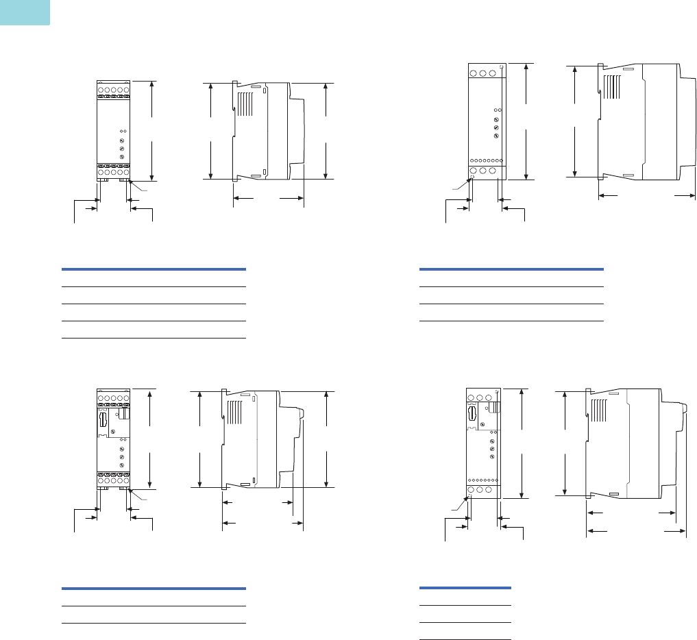
V6-T1-24 Volume 6—Solid-State Motor Control CA08100007E—February 2016 www.eaton.com
1
1
1
1
1
1
1
1
1
1
1
1
1
1
1
1
1
1
1
1
1
1
1
1
1
1
1
1
1
1
1.1
Reduced Voltage Motor Starters
Solid-State Controllers
Dimensions
Approximate Dimensions in Inches (mm)
Frame 1
Frame 1—SmartWire-DT
Frame 2
Frame 2—SmartWire-DT
Catalog Numbers
DS7-340SX004N0-N DS7-342SX004N0-N
DS7-340SX007N0-N DS7-342SX007N0-N
DS7-340SX009N0-N DS7-342SX009N0-N
DS7-340SX012N0-N DS7-342SX012N0-N
Catalog Numbers
DS7-34DSX004N0-D DS7-34DSX009N0-D
DS7-34DSX007N0-D DS7-34DSX012N0-D
4.92
(125.0)
3.74
(95.0)
1.77
(45.0)
4 x M4
4.80
(122.0)
5.12
(130.0)
1.38
(35.0)
4.92
(125.0)
4.05 (103.0)
3.74 (95.0)
1.77
(45.0)
4 x M4
1.38
(35.0)
4.80
(122.0)
5.12
(130.0)
Catalog Numbers
DS7-340SX016N0-N DS7-342SX016N0-N
DS7-340SX024N0-N DS7-342SX024N0-N
DS7-340SX032N0-N DS7-342SX032N0-N
Catalog Numbers
DS7-34DSX016N0-D
DS7-34DSX024N0-D
DS7-34DSX032N0-D
1.77
(45.0)
4 x M4
1.38
(35.0)
5.90
(150.0)
4.65 (118.0)
5.51
(140.0)
4.65 (118.0)
1.77
(45.0)
2 x M4
5.60
(150.0)
1.38
(35.0)
5.51
(140.0)
4.96 (126.0)
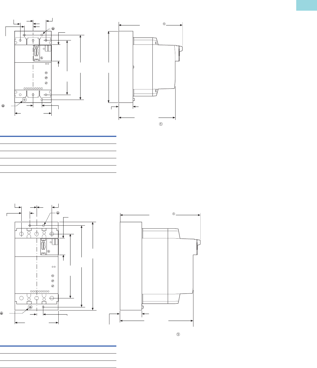
Volume 6—Solid-State Motor Control CA08100007E—February 2016 www.eaton.com V6-T1-25
1
1
1
1
1
1
1
1
1
1
1
1
1
1
1
1
1
1
1
1
1
1
1
1
1
1
1
1
1
1
1.1
Reduced Voltage Motor Starters
Solid-State Controllers
Frame 3—SmartWire-DT and Standard (Non SmartWire-DT)
Frame 4—SmartWire-DT and Standard (Non SmartWire-DT)
Catalog Numbers
DS7-340SX041N0-N DS7-342SX041N0-N DS7-34DSX041N0-D
DS7-340SX055N0-N DS7-342SX055N0-N DS7-34DSX055N0-D
DS7-340SX070N0-N DS7-342SX070N0-N DS7-34DSX070N0-D
DS7-340SX081N0-N DS7-342SX081N0-N DS7-34DSX081N0-D
DS7-340SX100N0-N DS7-342SX100N0-N DS7-34DSX100N0-D
Catalog Numbers
DS7-342SX135N0-N DS7-340SX135N0-N DS7-34DSX135N0-D
DS7-342SX160N0-N DS7-340SX160N0-N DS7-34DSX160N0-D
DS7-342SX200N0-N DS7-340SX200N0-N DS7-34DSX200N0-D
6.14 (156.0)
DS7-…-D
5.47 (139.0)
1.38 (35.0)
6.89
(175.0)
6.34
(161.0)
5.08
(129.0)
1.58
(40.0)
PE
1.18
(30.0)
0.89
(22.5)
1.18
(30.0)
3.66 (93.0) 0.89
(22.5)
PE
PE
PE
8.46
(215.0)
4.25 (108.0)
0.59
(15.0)
7.68 (195.0)
DS7-…-D
7.01 (178.0)
2.07 (52.5)
7.87
(200.0)
6.22
(158.0)
1.58
(40.0)
1.18
(30.0)
0.89
(22.5)
1.18
(30.0)
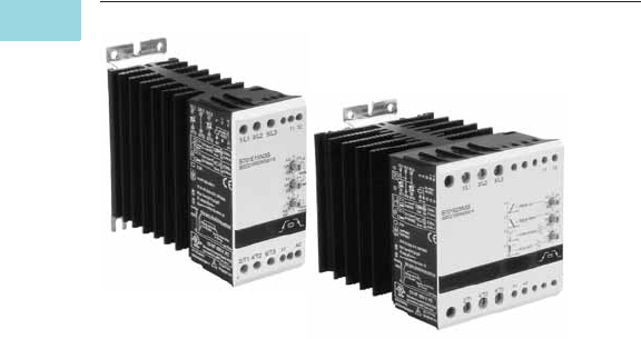
V6-T1-26 Volume 6—Solid-State Motor Control CA08100007E—February 2016 www.eaton.com
1
1
1
1
1
1
1
1
1
1
1
1
1
1
1
1
1
1
1
1
1
1
1
1
1
1
1
1
1
1
1.1
Reduced Voltage Motor Starters
Solid-State Controllers
Type S701, Soft Start Controllers
Contents
Description Page
DS7 Soft Start Controllers . . . . . . . . . . . . . . . . . . . V6-T1-3
Type S701, Soft Start Controllers
Standards and Certifications . . . . . . . . . . . . . . V6-T1-27
Catalog Number Selection . . . . . . . . . . . . . . . . V6-T1-27
Product Selection . . . . . . . . . . . . . . . . . . . . . . . V6-T1-27
Technical Data and Specifications . . . . . . . . . . V6-T1-28
Dimensions . . . . . . . . . . . . . . . . . . . . . . . . . . . V6-T1-31
Type S701, Soft Start Controllers with
Auxiliary Contact . . . . . . . . . . . . . . . . . . . . . . . . . V6-T1-32
Type S701, Soft Start Controllers with Brake . . . . V6-T1-35
Type S511, Semiconductor
Reversing Contactors . . . . . . . . . . . . . . . . . . . . . V6-T1-38
Type S701, Soft Start Controllers
Product Description
The S701 device is a reduced
voltage soft start controller
designed to control
acceleration and deceleration
of three-phase motors. The
S701 provides the user with
the ability to adjust initial
torque, ramp up and down
time, and also select kick
start for high inertial loads.
Application Description
The S701 line of soft start
controllers is specifically
designed to be a low cost
option for soft starting small
(15 hp and down) three-phase
motors. The S701 unit
controls current on two of
three motor phases to control
the torque being applied to the
motor, allowing for smooth
starting of a motor. The S701
is designed to be used with
a manual motor starter or a
full voltage starter. These
devices provide the necessary
overload protection for the
motor and also provide line
isolation for the motor. Short-
circuit protection can be
provided by fuses or circuit
breakers.
Features
●Rated operational voltage
up to 600 Vac
●Control voltage range from
24–480 Vac/Vdc
●Adjustable ramp times
(0.5–10 seconds)
●Adjustable initial torque
control (0–85%)
●Kick start feature
●Soft stop (0.5–10 seconds)
●Unlimited number of
START/STOP operations
per hour
●IP20 finger protection
●Fractional to 15 hp motors
at 480 V (20 hp at 600 V)
Benefits
●Reduced wear on belts,
gears, chains, clutches,
shafts and bearings
●Allows for controlling the
inrush current to the motor
●Reduced water-hammer in
pumping applications
●Less shock to product on
conveyor lines and material
handling gear
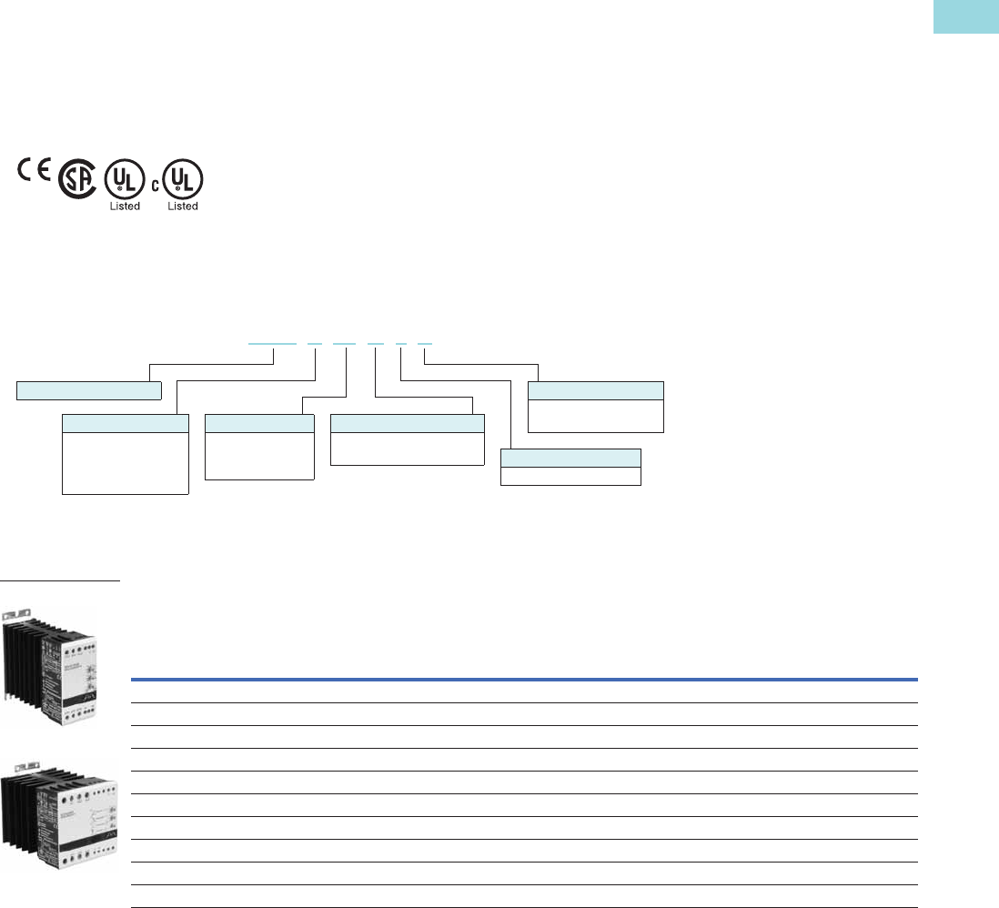
Volume 6—Solid-State Motor Control CA08100007E—February 2016 www.eaton.com V6-T1-27
1
1
1
1
1
1
1
1
1
1
1
1
1
1
1
1
1
1
1
1
1
1
1
1
1
1
1
1
1
1
1.1
Reduced Voltage Motor Starters
Solid-State Controllers
Standards and Certifications
●IEC 947 compliant
●EN 60947-4-2
●CE marked
●CSA certified
●UL listed (E108212)
●cUL listed
Catalog Number Selection
S701 Soft Starters
Product Selection
Soft Start Controllers
Rated
Current
Line
Voltage
Control
Voltage
(Vac/Vdc)
Three-Phase Motor
Catalog
Number
kW Rating (50 Hz) hp Rating (60 Hz)
230 V 380–400 V 440 V
200 V 230 V 460 V 575 V
1.0 SF 1.15 SF 1.0 SF 1.15 SF 1.0 SF 1.15 SF 1.0 SF 1.15 SF
3.5 208–240 24–230 7.5 N/A N/A 1 1 1 1 N/A N/A N/A N/A S701C03N3S
3.5 380–415 24–415 N/A 1.1 N/A N/A N/A N/A N/A 1-1/2 1-1/2 N/A N/A S701D03N3S
3.5 440–480 24–480 N/A N/A 1.5 N/A N/A N/A N/A 2 2 N/A N/A S701E03N3S
3.5 500–600 24–480 N/A N/A N/A N/A N/A N/A N/A N/A N/A 2 2 S701G03N3S
15 208–240 24–230 4 N/A N/A 3 3 3 3 N/A N/A N/A N/A S701C15N3S
15 380–480 24–480 N/A 5.5 7.5 N/A N/A N/A N/A 10 7-1/2 N/A N/A S701E15N3S
15 500–600 24–480 N/A N/A N/A N/A N/A N/A N/A N/A N/A 10 10 S701G15N3S
25 208–240 24–230 7.5 N/A N/A 5 5 7-1/2 5 N/A N/A N/A N/A S701C25N3S
25 380–480 24–480 N/A 11 12.5 N/A N/A N/A N/A 15 15 N/A N/A S701E25N3S
25 500–600 24–480 N/A N/A N/A N/A N/A N/A N/A N/A N/A 20 20 S701G25N3S
Control Options
S = Standard
BP = Auxiliary contact
Number of Poles
3 = (Only three at this time)
Options
N = No special options
B = Braking
Ampere Rating
03 = 3.5A
15 = 15A
25 = 25A
Line Voltage
C = 208–240 Vac
D = 380–415 Vac
E = 380–480 Vac
G = 550–600 Vac
Soft Start Controller
S701 C15 N 3 S
S701E15N3S
S701E25N3S

V6-T1-28 Volume 6—Solid-State Motor Control CA08100007E—February 2016 www.eaton.com
1
1
1
1
1
1
1
1
1
1
1
1
1
1
1
1
1
1
1
1
1
1
1
1
1
1
1
1
1
1
1.1
Reduced Voltage Motor Starters
Solid-State Controllers
Technical Data and Specifications
Soft Starters—S701…03N3S
Description S701C03N3S S701D03N3S S701E03N3S S701G03N3S
Maximum current capacity 3.5 3.5 3.5 3.5
Trip Class
10A 3.5 3.5 3.5 3.5
10 3.5 3.5 3.5 3.5
20 2.8 2.8 2.8 2.8
30 2.1 2.1 2.1 2.1
Electrical Characteristics
Line voltage (Vac) 208–240 380–415 440–480 500–600
Operating frequency (Hz) 50/60 50/60 50/60 50/60
Leakage current 5 mA AC max. 5 mA AC max. 5 mA AC max. 5 mA AC max.
Minimum operational current 50 mA 50 mA 50 mA 50 mA
Control voltage (Vac/Vdc) 24–230 24–415 24–480 24–480
Pickup voltage max. 20.4 Vac/Vdc 20.4 Vac/Vdc 20.4 Vac/Vdc 20.4 Vac/Vdc
Dropout voltage min. 5 Vac/Vdc 5 Vac/Vdc 5 Vac/Vdc 5 Vac/Vdc
Max. control current for no operation 1 mA 1 mA 1 mA 1 mA
Response time max. 70 ms 70 ms 70 ms 70 ms
Control Characteristics
Ramp time (secs) 0.5–10 0.5–10 0.5–10 0.5–10
Ramp settings (% LRT) 85% 85% 85% 85%
Kick start settings (% LRT) 85% 85% 85% 85%
Soft stop (secs) 0.5–10 0.5–10 0.5–10 0.5–10
Environment Characteristics
Temperature–operating (no derating) –30 ° to 40 °C –30 ° to 40 °C –30 ° to 40 °C –30 ° to 40 °C
Current rating 50 °C N/A N/A N/A N/A
Limited duty cycle 50 °C N/A N/A N/A N/A
Current rating 60 °C N/A N/A N/A N/A
Limited duty cycle 60 °C N/A N/A N/A N/A
Temperature–storage –30 ° to 80 °C –30 ° to 80 °C –30 ° to 80 °C –30 ° to 80 °C
Altitude (meters)–no derating 2000 2000 2000 2000
Humidity 95% noncondensing 95% noncondensing 95% noncondensing 95% noncondensing
Operating position (no derating) Vertical ±30 ° Vertical ±30 ° Vertical ±30 ° Vertical ±30 °
Impulse withstand voltage IEC 947-4-1 4000 V 4000 V 4000 V 4000 V
Rated insulation voltage (Ui) 660 V 660 V 660 V 660 V
Installation category III III III III
Vibration IEC 68-2-6 5g 10–150 Hz IEC 68-2-6 5g 10–150 Hz IEC 68-2-6 5g 10–150 Hz IEC 68-2-6 5g 10–150 Hz
Power dissipation for intermittent operation 4 W/A x duty cycle 4 W/A x duty cycle 4 W/A x duty cycle 4 W/A x duty cycle
Power dissipation for continuous operation 4 W/A x duty cycle 4 W/A x duty cycle 4 W/A x duty cycle 4 W/A x duty cycle
Cooling method Natural convection Natural convection Natural convection Natural convection
Degree of protection IP20 IP20 IP20 IP20
Pollution degree3333
Agency approvals UL, cUL, CE UL, cUL, CE UL, cUL, CE UL, cUL, CE

Volume 6—Solid-State Motor Control CA08100007E—February 2016 www.eaton.com V6-T1-29
1
1
1
1
1
1
1
1
1
1
1
1
1
1
1
1
1
1
1
1
1
1
1
1
1
1
1
1
1
1
1.1
Reduced Voltage Motor Starters
Solid-State Controllers
Soft Starters—S701…15N3S
Description S701C15N3S S701E15N3S S701G15N3S
Maximum current capacity 15 15 15
Trip Class
10A 151515
10 15 15 15
20 12 12 12
30 10 10 10
Electrical Characteristics
Line voltage (Vac) 208–240 380–480 500–600
Operating frequency (Hz) 50/60 50/60 50/60
Leakage current 5 mA AC max. 5 mA AC max. 5 mA AC max.
Minimum operational current 50 mA 50 mA 50 mA
Control voltage (Vac/Vdc) 24–230 24–480 24–480
Pickup voltage max. 20.4 Vac/Vdc 20.4 Vac/Vdc 20.4 Vac/Vdc
Dropout voltage min. 5 Vac/Vdc 5 Vac/Vdc 5 Vac/Vdc
Max. control current for no operation 1 mA 1 mA 1 mA
Response time max. 70 ms 70 ms 70 ms
Control Characteristics
Ramp time (secs) 0.5–10 0.5–10 0.5–10
Ramp settings (% LRT) 85% 85% 85%
Kick start settings (% LRT) 85% 85% 85%
Soft stop (secs) 0.5–10 0.5–10 0.5–10
Environment Characteristics
Temperature–operating (no derating) –30 ° to 40 °C –30 ° to 40 °C –30 ° to 40 °C
Current rating 50 °C 12.5A 12.5A 12.5A
Limited duty cycle 50 °C 15A on-time max.
15 min. duty cycle max. 0.8
15A on-time max.
15 min. duty cycle max. 0.8
15A on-time max.
15 min. duty cycle max. 0.8
Current rating 60 °C 10A 10A 10A
Limited duty cycle 60 °C 15A on-time max.
15 min. duty cycle max. 0.65
15A on-time max.
15 min. duty cycle max. 0.65
15A on-time max.
15 min. duty cycle max. 0.65
Temperature–storage –30 ° to 80 °C –30 ° to 80 °C –30 ° to 80 °C
Altitude (meters)–no derating 2000 2000 2000
Humidity 95% noncondensing 95% noncondensing 95% noncondensing
Operating position (no derating) Vertical ±30 ° Vertical ±30 ° Vertical ±30 °
Impulse withstand voltage IEC 947-4-1 4000 V 4000 V 4000 V
Rated insulation voltage (Ui) 660 V 660 V 660 V
Installation category III III III
Vibration IEC 68-2-6 5g 10–150 Hz IEC 68-2-6 5g 10–150 Hz IEC 68-2-6 5g 10–150 Hz
Power dissipation for intermittent operation 2 W/A x duty cycle 2 W/A x duty cycle 2 W/A x duty cycle
Power dissipation for continuous operation 2 W/A 2 W/A 2 W/A
Cooling method Natural convection Natural convection Natural convection
Degree of protection IP20 IP20 IP20
Pollution degree 3 3 3
Agency approvals UL, CSA, CE UL, CSA, CE UL, CSA, CE

V6-T1-30 Volume 6—Solid-State Motor Control CA08100007E—February 2016 www.eaton.com
1
1
1
1
1
1
1
1
1
1
1
1
1
1
1
1
1
1
1
1
1
1
1
1
1
1
1
1
1
1
1.1
Reduced Voltage Motor Starters
Solid-State Controllers
Soft Starters—S701…25N3S
Description S701C25N3S S701E25N3S S701G25N3S
Maximum current capacity 25 25 25
Trip Class
10A 252525
10 25 25 25
20 20 20 20
30 15 15 15
Electrical Characteristics
Line voltage (Vac) 208–240 380–480 500–600
Operating frequency (Hz) 50/60 50/60 50/60
Leakage current 5 mA AC max. 5 mA AC max. 5 mA AC max.
Minimum operational current 50 mA 50 mA 50 mA
Control voltage (Vac/Vdc) 24–230 24–480 24–480
Pickup voltage max. 20.4 Vac/Vdc 20.4 Vac/Vdc 20.4 Vac/Vdc
Dropout voltage min. 5 Vac/Vdc 5 Vac/Vdc 5 Vac/Vdc
Max. control current for no operation 1 mA 1 mA 1 mA
Response time max. 70 ms 70 ms 70 ms
Control Characteristics
Ramp time (secs) 0.5–10 0.5–10 0.5–10
Ramp settings (% LRT) 85% 85% 85%
Kick start settings (% LRT) 85% 85% 85%
Soft stop (secs) 0.5–10 0.5–10 0.5–10
Environment Characteristics
Temperature–operating (no derating) –30 ° to 40 °C –30 ° to 40 °C –30 ° to 40 °C
Current rating 50 °C 20A 20A 20A
Limited duty cycle 50 °C 25A on-time max.
15 min. duty cycle max. 0.8
25A on-time max.
15 min. duty cycle max. 0.8
25A on-time max.
15 min. duty cycle max. 0.8
Current rating 60 °C 17A 17A 17A
Limited duty cycle 60 °C 25A on-time max.
15 min. duty cycle max. 0.65
25A on-time max.
15 min. duty cycle max. 0.65
25A on-time max.
15 min. duty cycle max. 0.65
Temperature–storage –30 ° to 80 °C –30 ° to 80 °C –30 ° to 80 °C
Altitude (meters)–no derating 2000 2000 2000
Humidity 95% noncondensing 95% noncondensing 95% noncondensing
Operating position (no derating) Vertical ±30 ° Vertical ±30 ° Vertical ±30 °
Impulse withstand voltage IEC 947-4-1 4000 V 4000 V 4000 V
Rated insulation voltage (Ui) 660 V 660 V 660 V
Installation category III III III
Vibration IEC 68-2-6 5g 10–150 Hz IEC 68-2-6 5g 10–150 Hz IEC 68-2-6 5g 10–150 Hz
Power dissipation for intermittent operation 2 W/A x duty cycle 2 W/A x duty cycle 2 W/A x duty cycle
Power dissipation for continuous operation 2 W/A 2 W/A 2 W/A
Cooling method Natural convection Natural convection Natural convection
Degree of protection IP20 IP20 IP20
Pollution degree 3 3 3
Agency approvals UL, CSA, CE UL, CSA, CE UL, CSA, CE

Volume 6—Solid-State Motor Control CA08100007E—February 2016 www.eaton.com V6-T1-31
1
1
1
1
1
1
1
1
1
1
1
1
1
1
1
1
1
1
1
1
1
1
1
1
1
1
1
1
1
1
1.1
Reduced Voltage Motor Starters
Solid-State Controllers
Dimensions
Approximate Dimensions in Inches (mm)
Soft Starters—S701…N3S
Catalog Number W H D
Weight
in Lbs (kg)
S701C03N3S 0.89 (22.5) 3.94 (100) 5.01 (127) 0.6 (270)
S701D03N3S 0.89 (22.5) 3.94 (100) 5.01 (127) 0.6 (270)
S701E03N3S 0.89 (22.5) 3.94 (100) 5.01 (127) 0.6 (270)
S701G03N3S 0.89 (22.5) 3.94 (100) 5.01 (127) 0.6 (270)
S701C15N3S 1.77 (45) 3.94 (100) 5.04 (128) 1.52 (690)
S701E15N3S 1.77 (45) 3.94 (100) 5.04 (128) 1.52 (690)
S701G15N3S 1.77 (45) 3.94 (100) 5.04 (128) 1.52 (690)
S701C25N3S 3.54 (90) 3.94 (100) 5.04 (128) 2.53 (1150)
S701E25N3S 3.54 (90) 3.94 (100) 5.04 (128) 2.53 (1150)
S701G25N3S 3.54 (90) 3.94 (100) 5.04 (128. 2.53 (1150)
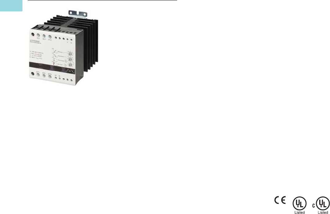
V6-T1-32 Volume 6—Solid-State Motor Control CA08100007E—February 2016 www.eaton.com
1
1
1
1
1
1
1
1
1
1
1
1
1
1
1
1
1
1
1
1
1
1
1
1
1
1
1
1
1
1
1.1
Reduced Voltage Motor Starters
Solid-State Controllers
Type S701, Soft Start Controllers with Auxiliary Contact
Contents
Description Page
DS7 Soft Start Controllers . . . . . . . . . . . . . . . . . . . V6-T1-3
Type S701, Soft Start Controllers . . . . . . . . . . . . . V6-T1-26
Type S701, Soft Start Controllers with
Auxiliary Contact
Product Selection . . . . . . . . . . . . . . . . . . . . . . . V6-T1-33
Technical Data and Specifications . . . . . . . . . . V6-T1-33
Dimensions . . . . . . . . . . . . . . . . . . . . . . . . . . . V6-T1-34
Type S701, Soft Start Controllers with Brake . . . . V6-T1-35
Type S511, Semiconductor
Reversing Contactors . . . . . . . . . . . . . . . . . . . . . V6-T1-38
Type S701, Soft Start Controllers with Auxiliary Contact
Product Description
The S701 device is a reduced
voltage soft start controller
designed to control
acceleration and deceleration
of three-phase motors. With
the auxiliary contact, it is
possible to control an external
bypass to reduce heating and
increase acceleration and
deceleration times.
The unit provides the user
with the ability to adjust initial
torque, ramp up and down
time and also select kick start
for high inertia loads.
Application Description
The S701 line of soft start
controllers is specifically
designed to be a low cost
option for soft starting small
(15 hp and down) three-phase
motors. The auxiliary contact
is designed to work in
conjunction with an across-
the-line contactor. The
purpose of the contactor is
to provide a parallel current
path once the soft starter
has brought the motor up to
speed. Once the soft start
controller reaches end of
ramp, the auxiliary contact will
close and send a signal to
close the bypass contactor,
thus providing a low
impedance path for the
current to the motor. The
S701 unit controls current
on two of three motor phases
to control the torque being
applied to the motor, allowing
for smooth starting of a motor.
The S701 is designed to be
used with a manual motor
protector or a full voltage
starter. These devices provide
the necessary overload
protection for the motor and
also provide line isolation for
the motor. Short-circuit
protection can be provided by
fuses or circuit breakers.
Features
●Rated operational voltage
up to 600 Vac
●Control voltage range
from 24–300 Vac/Vdc
●Adjustable ramp times
(0.5–20 seconds)
●Adjustable initial torque
control (0–85%)
●Kick start feature
(0–85% adjustment)
●Kick start for 200 ms
●Soft stop (0.5–20 seconds)
●IP20 finger protection
●Available up to 30A
(with Bypass installed)
●Auxiliary contact for
up-to-speed indication
Benefits
●Reduced wear on belts,
gears, chains, clutches,
shafts and bearings
●Bypass option allows for
greater current capacity in
the unit
●Bypass option helps to
reduce heat in the
enclosure
●Allows for controlling the
inrush current to the motor
●Reduced water-hammer in
pumping applications
●Less shock to product on
conveyor lines and material
handling gear
Standards and Certifications
●IEC 947 compliant
●EN 60947-4-2
●CE marked
●UL listed (E108212)
●cUL listed
Volume 6—Solid-State Motor Control CA08100007E—February 2016 www.eaton.com V6-T1-33
1
1
1
1
1
1
1
1
1
1
1
1
1
1
1
1
1
1
1
1
1
1
1
1
1
1
1
1
1
1
1.1
Reduced Voltage Motor Starters
Solid-State Controllers
Product Selection
For S701 catalog number selection, see Page V6-T1-27.
Soft Start Controllers with Auxiliary Contact
Technical Data and Specifications
Soft Starters with Auxiliary Contact—S701…25N3BP
Rated
Current
Line
Voltage
Control
Voltage
(Vac/Vdc)
Three-Phase Motor
Catalog
Number
kW Rating (50 Hz) hp Rating
230 V 380–400 V 440 V
200 V 230 V 460 V 575 V
1.0 SF 1.15 SF 1.0 SF 1.15 SF 1.0 SF 1.15 SF 1.0 SF 1.15 SF
Ratings without Bypass
25 208–240 24–230 5.5 N/A N/A 5 5 7-1/2 5 N/A N/A N/A N/A S701C25N3BP
25 380–480 24–480 N/A 12.5 12.5 N/A N/A N/A N/A 15 15 N/A N/A S701E25N3BP
25 500–600 24–480 N/A N/A N/A N/A N/A N/A N/A N/A N/A 20 20 S701G25N3BP
Ratings with Bypass
30 208–240 24–230 7.5 N/A N/A 7-1/2 7-1/2 10 7-1/2 N/A N/A N/A N/A S701C25N3BP
30 380–480 24–480 N/A 15 15 N/A N/A N/A N/A 20 15 N/A N/A S701E25N3BP
30 500–600 24–480 N/A N/A N/A N/A N/A N/A N/A N/A N/A 25 20 S701G25N3BP
Description S701C25N3BP S701E25N3BP S701G25N3BP
Maximum current capacity with bypass (without bypass) 30 (25) 30 (25) 30 (25)
Trip Class
10A 30 (25) 30 (25) 30 (25)
10 30 (25) 30 (25) 30 (25)
20 24 (20) 24 (20) 24 (20)
30 19.5 (15) 19.5 (15) 19.5 (15)
Electrical Characteristics
Line voltage (Vac) 208–240 380–480 500–600
Operating frequency (Hz) 50/60 50/60 50/60
Leakage current 5 mA AC max. 5 mA AC max. 5 mA AC max.
Minimum operational current 50 mA 50 mA 50 mA
Control voltage (Vac/Vdc) 24–230 24–480 24–480
Pickup voltage max. 20.4 Vac/Vdc 20.4 Vac/Vdc 20.4 Vac/Vdc
Dropout voltage min. 5 Vac/Vdc 5 Vac/Vdc 5 Vac/Vdc
Max. control current for no operation 1 mA 1 mA 1 mA
Response time max. 70 ms 70 ms 70 ms
S701
V6-T1-34 Volume 6—Solid-State Motor Control CA08100007E—February 2016 www.eaton.com
1
1
1
1
1
1
1
1
1
1
1
1
1
1
1
1
1
1
1
1
1
1
1
1
1
1
1
1
1
1
1.1
Reduced Voltage Motor Starters
Solid-State Controllers
Soft Starters with Auxiliary Contact—S701…25N3BP, continued
Dimensions
Approximate Dimensions in Inches (mm)
Soft Starters with Auxiliary Contact—S701…25N3BP
Description S701C25N3BP S701E25N3BP S701G25N3BP
Control Characteristics
Ramp time (secs) 0.5–20 0.5–20 0.5–20
Ramp settings (% LRT) 85% 85% 85%
Kick start settings (% LRT) 85% 85% 85%
Soft stop (secs) 0.5–20 0.5–20 0.5–20
Environmental Characteristics
Temperature—operating (no derating) –30 ° to 40 °C –30 ° to 40 °C –30 ° to 40 °C
Current rating 50 °C 20A 20A 20A
Limited duty cycle 50 °C 25A on-time max.
15 min. duty cycle max. 0.8
25A on-time max.
15 min. duty cycle max. 0.8
25A on-time max.
15 min. duty cycle max. 0.8
Current rating 60 °C 17A 17A 17A
Limited duty cycle 60 °C 25A on-time max.
15 min. duty cycle max. 0.65
25A on-time max.
15 min. duty cycle max. 0.65
25A on-time max.
15 min. duty cycle max. 0.65
Temperature—storage –30 ° to 80 °C –30 ° to 80 °C –30 ° to 80 °C
Altitude (meters)—no derating 2000 2000 2000
Humidity 95% noncondensing 95% noncondensing 95% noncondensing
Operating position (no derating) Vertical ±30 ° Vertical ±30 ° Vertical ±30 °
Impulse withstand voltage IEC 947-4-1 4000 V 4000 V 4000 V
Rated insulation voltage (Ui) 660 V 660 V 660 V
Installation category III III III
Vibration IEC 68-2-6 5g 10–150 Hz IEC 68-2-6 5g 10–150 Hz IEC 68-2-6 5g 10–150 Hz
Power dissipation for continuous operation 2 W/A without bypass 2 W/A without bypass 2 W/A without bypass
Power dissipation with semiconductor bypassed 5 W/A max. with bypass 5 W/A max. with bypass 5 W/A max. with bypass
Cooling method Natural convection Natural convection Natural convection
Degree of protection IP20 IP20 IP20
Pollution degree 3 3 3
Agency approvals UL, cUL, CE UL, cUL, CE UL, cUL, CE
Catalog Number W H D
Weight
in Lbs (kg)
S701C25N3BP 3.54 (89.9) 3.94 (100.1) 5.04 (128.0) 2.53 (1150)
S701E25N3BP 3.54 (89.9) 3.94 (100.1) 5.04 (128.0) 2.53 (1150)
S701G25N3BP 3.54 (89.9) 3.94 (100.1) 5.04 (128.0) 2.53 (1150)
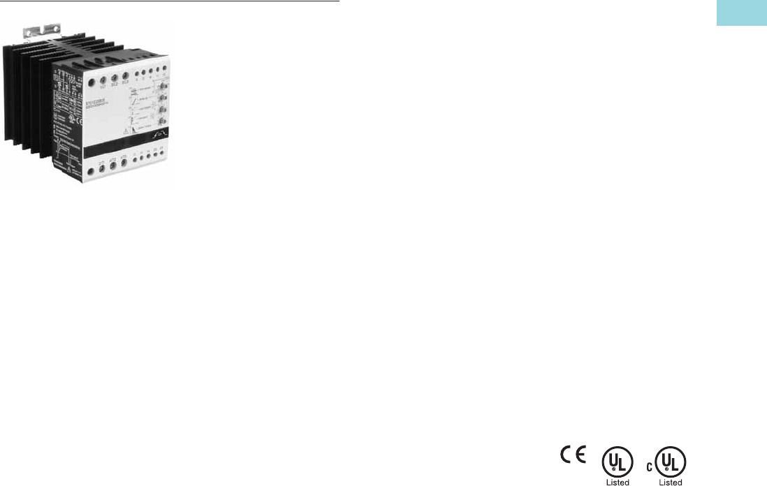
Volume 6—Solid-State Motor Control CA08100007E—February 2016 www.eaton.com V6-T1-35
1
1
1
1
1
1
1
1
1
1
1
1
1
1
1
1
1
1
1
1
1
1
1
1
1
1
1
1
1
1
1.1
Reduced Voltage Motor Starters
Solid-State Controllers
Type S701, Soft Start Controllers with Brake
Contents
Description Page
DS7 Soft Start Controllers . . . . . . . . . . . . . . . . . . . V6-T1-3
Type S701, Soft Start Controllers . . . . . . . . . . . . . . V6-T1-26
Type S701, Soft Start Controllers with
Auxiliary Contact . . . . . . . . . . . . . . . . . . . . . . . . . V6-T1-32
Type S701, Soft Start Controllers with Brake
Product Selection . . . . . . . . . . . . . . . . . . . . . . . V6-T1-36
Technical Data and Specifications . . . . . . . . . . V6-T1-36
Dimensions . . . . . . . . . . . . . . . . . . . . . . . . . . . V6-T1-37
Type S511, Semiconductor
Reversing Contactors . . . . . . . . . . . . . . . . . . . . . V6-T1-38
Type S701, Soft Start Controllers with Brake
Product Description
The S701 soft start
controller with DC injection
brake is designed to control
acceleration and deceleration
of three-phase motors. Brake
current is adjustable from
0–50A DC. The ramp-up
feature is adjustable from
0.5–10 seconds. Torque
adjustment is adjustable
with or without break loose
(kick start) function.
Application Description
The S701 line of soft start
controllers is specifically
designed to be a low cost
option for soft starting small
(15 hp and down) three-phase
motors. The braking option
is a DC injection system,
allowing for fast stopping of a
three-phase motor. The S701
unit controls current on two
of the three phases to control
the torque being applied to
the motor, allowing for
smooth starting of a motor.
The S701 is designed to be
used with a manual motor
starter or a full voltage
starter. These devices
provide the necessary
overload protection for the
motor and also provide line
isolation for the motor.
Short-circuit protection can
be provided by fuses or
circuit breakers.
Features
●Rated operational voltage
up to 480 Vac
●Control voltage range
from 24–300 Vac/Vdc
●Adjustable ramp times
(0.5–20 seconds)
●Adjustable initial torque
control (0–85%)
●Kick start feature
(0–85% adjustment)
●Kick start for 200 ms
●IP20 finger protection
●Braking control adjustable
from 0–50A DC
●Slow speed: 7.5% or 10%
of nominal speed
Benefits
●Reduced wear on bolts,
gears, chains, clutches,
shafts and bearings
●Braking option allows for
quick stopping of loads
●Brake control can help
eliminate expensive
mechanical brakes
●Allows for controlling the
inrush current to the motor
●Reduced water-hammer in
pumping applications
●Less shock to product on
conveyor lines and material
handling gear
Standards and Certifications
●IEC 947 compliant
●EN 60947-4-2
●CE marked
●UL listed (E108212)
●cUL listed
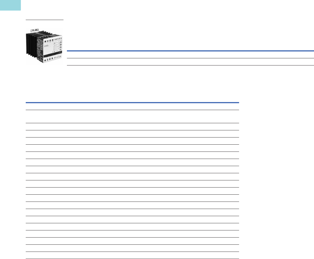
V6-T1-36 Volume 6—Solid-State Motor Control CA08100007E—February 2016 www.eaton.com
1
1
1
1
1
1
1
1
1
1
1
1
1
1
1
1
1
1
1
1
1
1
1
1
1
1
1
1
1
1
1.1
Reduced Voltage Motor Starters
Solid-State Controllers
Product Selection
For S701 catalog number selection, see Page V6-T1-27.
Soft Start Controllers with Brake
Technical Data and Specifications
Soft Starters with Brake—S701…25B3S
Rated
Current
Line
Voltage
Control
Voltage
(Vac/Vdc)
Three-Phase Motor
Catalog
Number
kW Rating (50 Hz) hp Rating
230 V 380–400 V 440 V
200 V 230 V 460 V
1.0 SF 1.15 SF 1.0 SF 1.15 SF 1.0 SF 1.15 SF
25 208–240 24–230 5.5 N/A N/A 5 5 7-1/2 5 N/A N/A S701C25B3S
25 380–480 24–480 N/A 12.5 12.5 N/A N/A N/A N/A 15 15 S701E25B3S
Description S701C25B3S S701E25B3S
Maximum current capacity 25 25
Trip Class
10A 25 25
10 25 25
20 20 20
30 15 15
Electrical Characteristics
Line voltage (Vac) 208–240 380–480
Operating frequency (Hz) 50/60 50/60
Leakage current 5 mA AC max. 5 mA AC max.
Minimum operational current 1A 1A
Control voltage (Vac/Vdc) 24–230 24–480
Pickup voltage max. 20.4 Vac/Vdc 20.4 Vac/Vdc
Dropout voltage min. 5 Vac/Vdc 5 Vac/Vdc
Max. control current for no operation 1 mA 1 mA
Response time max. 100 ms 100 ms
Control Characteristics
Ramp time (secs) 0.5–10 0.5–10
Ramp settings (% LRT) 85% 85%
Kick start settings (% LRT) 85% 85%
Soft stop (secs) 0.5–10 0.5–10
Brake current 0–50 Vdc 0–50 Vdc
S701E25B3S

Volume 6—Solid-State Motor Control CA08100007E—February 2016 www.eaton.com V6-T1-37
1
1
1
1
1
1
1
1
1
1
1
1
1
1
1
1
1
1
1
1
1
1
1
1
1
1
1
1
1
1
1.1
Reduced Voltage Motor Starters
Solid-State Controllers
Soft Starters with Brake—S701…25B3S, continued
Dimensions
Approximate Dimensions in Inches (mm)
Soft Starters with Brake—S701…25B3S
Description S701C25B3S S701E25B3S
Environmental Characteristics
Temperature—operating –30 ° to 40 °C –30 ° to 40 °C
Current rating 50 °C 20A 20A
Limited duty cycle 50 °C 25A on-time max.
15 min. duty cycle max. 0.8
25A on-time max.
15 min. duty cycle max. 0.8
Current rating 60 °C 17A 17A
Limited duty cycle 60 °C 25A on-time max.
15 min. duty cycle max. 0.65
25A on-time max.
15 min. duty cycle max. 0.65
Temperature—storage –30 ° to 80 °C –30 ° to 80 °C
Altitude (meters)—no derating 2000 2000
Humidity 95% noncondensing 95% noncondensing
Operating position Vertical ± 0 ° Vertical ± 0 °
Impulse withstand voltage IEC 947-4-1 4000 V 4000 V
Rated insulation voltage (Ui) 660 V 660 V
Installation category III III
Vibration IEC 68-2-6 5g 10–150 Hz IEC 68-2-6 5g 10–150 Hz
Power dissipation for intermittent operation 2 W/A x duty cycle 2 W/A x duty cycle
Power dissipation for continuous operation 2 W/A 2 W/A
Cooling method Natural convection Natural convection
Degree of protection IP20 IP20
Pollution degree 3 3
Agency approvals UL, cUL, CE UL, cUL, CE
Catalog Number W H D
Weight
in Lbs (kg)
S701C25B3S 3.54 (89.9) 3.94 (100.1) 5.04 (128.0) 2.53 (1150)
S701E25B3S 3.54 (89.9) 3.94 (100.1) 5.04 (128.0) 2.53 (1150)

V6-T1-38 Volume 6—Solid-State Motor Control CA08100007E—February 2016 www.eaton.com
1
1
1
1
1
1
1
1
1
1
1
1
1
1
1
1
1
1
1
1
1
1
1
1
1
1
1
1
1
1
1.1
Reduced Voltage Motor Starters
Solid-State Controllers
Contents
Description Page
DS7 Soft Start Controllers . . . . . . . . . . . . . . . . . . . V6-T1-3
Type S701, Soft Start Controllers . . . . . . . . . . . . . V6-T1-26
Type S701, Soft Start Controllers with
Auxiliary Contact . . . . . . . . . . . . . . . . . . . . . . . . . V6-T1-32
Type S701, Soft Start Controllers with Brake . . . . V6-T1-35
Type S511, Semiconductor
Reversing Contactors
Product Selection . . . . . . . . . . . . . . . . . . . . . . . V6-T1-39
Technical Data and Specifications . . . . . . . . . . V6-T1-39
Dimensions . . . . . . . . . . . . . . . . . . . . . . . . . . . V6-T1-40
Type S511, Semiconductor Reversing Contactors
Product Description
The S511 device is a
semiconductor reversing
contactor designed to switch
three-phase motors forward
and reverse. Unicore
electronics and thermal
design ensures high
switching capacity and
long lifetime.
Application Description
The S511 line of solid-state
reversing contactors is
specifically designed for high
speed operations or when
long contactor life is required.
The reversing contactors are
intended for small motor
applications (5 hp and below).
The S511 unit can be used
in a variety of applications
including fans, pumps,
conveyors, doors, hoists,
cranes, etc. It is designed
to be used with a manual
motor starter or a full voltage
starter. These devices provide
the necessary overload
protection for the motor
and also provide line isolation
for the motor. Short-circuit
protection can be provided by
fuses or circuit breakers.
Features
●Rated operational voltage
up to 480 Vac
●Control voltage ranges
of 5–24 Vdc and
24–240 Vac/Vdc
●Unlimited number of
START/STOP operations
per hour
●IP20 finger protection
●AC-3 current rating of 10A
●AC-4 current rating of 8A
Benefits
●Extremely high switching
rates possible
●Very long life expectancy
and no contacts or
movable parts to replace
●Compact design (45 mm
wide) leads to significant
panel savings
Standards and Certifications
●IEC 947 compliant
●EN 60947-4-2
●CE marked
●CSA certified
●UL listed

Volume 6—Solid-State Motor Control CA08100007E—February 2016 www.eaton.com V6-T1-39
1
1
1
1
1
1
1
1
1
1
1
1
1
1
1
1
1
1
1
1
1
1
1
1
1
1
1
1
1
1
1.1
Reduced Voltage Motor Starters
Solid-State Controllers
Product Selection
Reversing Solid-State Contactors
Technical Data and Specifications
Semiconductor Reversing Contactors—S511E10N3…
Rated
Current
Line
Voltage
Control
Voltage
Three-Phase Motor
Catalog
Number
kW Rating (50 Hz) hp Rating
230 V 380–400 V 440 V
200 V 230 V 460 V
1.0 SF 1.15 SF 1.0 SF 1.15 SF 1.0 SF 1.15 SF
10 208–4805–24 Vdc 2.24 4223255S511E10N3D
10 208–48024–240 Vac/Vdc2.24 4223255S511E10N3S
Description S511E10N3D S511E10N3S
Maximum current capacity 10 10
Trip Class
10A 10 10
10 10 10
20 8 8
30 6.5 6.5
Electrical Characteristics
Line Voltage (Vac) 208–480 208–480
Operating frequency (Hz) 50/60 50/60
Control voltage 5–24 Vdc 24–240 Vac/Vdc
Pickup voltage max. 4.25 Vdc 20.4 Vac/Vdc
Dropout voltage min. 1.5 Vdc 7.2 Vac/Vdc
Max. control voltage 26.4 Vdc 253 Vac/Vdc
Response time max. 1/2 cycle 1 cycle
Interlock time max. 80 ms 150 ms
Control Characteristics
Operation current AC-3 10 10
Operation current AC-4 8 8
Duty cycle Continuous operation Continuous operation
Leakage current 1 mA AC max. 1 mA AC max.
Minimum operation current 10 mA AC 10 mA AC
Environmental Characteristics
Temperature—operating 0 ° to 60 °C 0 ° to 60 °C
Temperature—storage –20 ° to 80 °C –20 ° to 80 °C
Altitude (meters) 2000 2000
Humidity 95% noncondensing 95% noncondensing
Operating position Vertical ±30 ° Vertical ±30 °
Impulse withstand voltage IEC 947-4-1 4000 V 4000 V
Rated insulation voltage (Ui) 660 V 660 V
Installation category III III
Vibration IEC 68-2-6 5g 10–150 Hz IEC 68-2-6 5g 10–150 Hz
Power dissipation for intermittent operation 2.2 W/A x duty cycle 2.2 W/A x duty cycle
Power dissipation for continuous operation 2.2 W/A 2.2 W/A
Cooling method Natural convection Natural convection
Degree of protection IP20 IP20
Pollution degree 3 3
Agency approvals UL, CSA, CE UL, CSA, CE
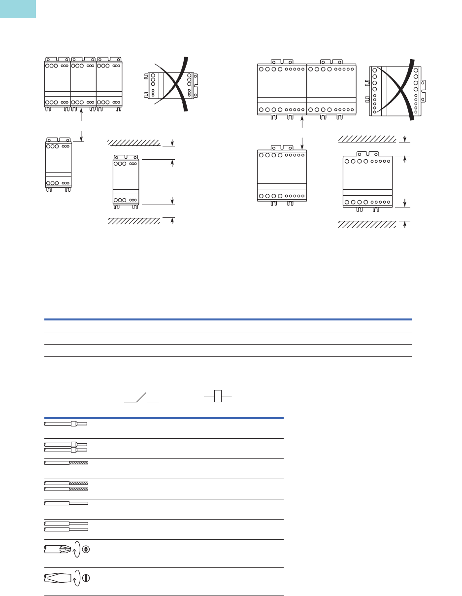
V6-T1-40 Volume 6—Solid-State Motor Control CA08100007E—February 2016 www.eaton.com
1
1
1
1
1
1
1
1
1
1
1
1
1
1
1
1
1
1
1
1
1
1
1
1
1
1
1
1
1
1
1.1
Reduced Voltage Motor Starters
Solid-State Controllers
Mounting Instructions
IMPORTANT: The controller is designed for vertical mounting in free air. If the controller is
mounted horizontally, the load current must be reduced to 50% of rated current.
Recommended Mounting Distances
Dimensions
Approximate Dimensions in Inches (mm)
Semiconductor Reversing Contactors—S511E10N3…
Cable Requirements and Sizing
1.18 (30) min.
1.18 (30) min.
3.15 (80) min.
Requires
50% Rating
Reduction
3.15 (80) min.
1.18 (30) min.
1.18 (30) min.
Requires
50% Rating
Reduction
Catalog Number W H D
Weight
in Lbs (kg)
S511E10N3D 1.77 (45.0) 3.94 (100.1) 5.04 (128.0) 1.52 (690)
S511E10N3S 1.77 (45.0) 3.94 (100.1) 5.04 (128.0) 1.52 (690)
Also refer to dimension drawings on Page V6-T1-41.
75 °C AWG (mm2)AWG (mm
2)
18–12
(0.75–4)
20–16
(0.5–1.5)
2–18
(2 x 1)
2 x 20–18
(2 x 0.5–0.75)
18–10
(0.75–4)
20–16
(0.5–1.5)
2 x 18–14
(2 x 0.75–2.5)
2 x 20–16
(2 x 0.5–1.5)
18–10
(0.75–4)
20–16
(0.5–1.5)
2 x 18–16
(0.75–6)
2 x 20–16
(2 x 0.5–1.5)
Posidrive 1
4.4 in-lb. max.
0.5 Nm max.)
N/A
4 mm
4.4 in-lb max.
(0.5 Nm max.)
3 mm
3.5 in-lb max.
(0.4 Nm max.)
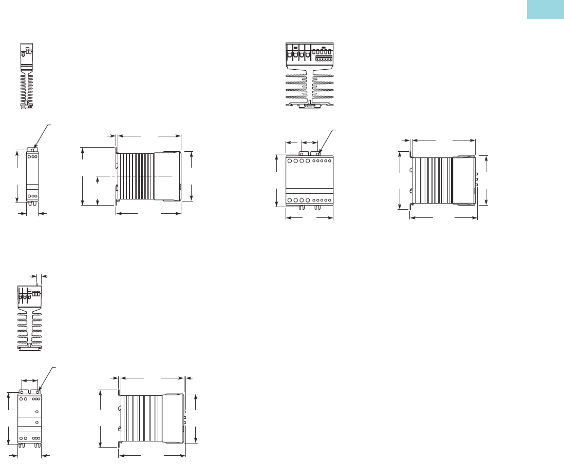
Volume 6—Solid-State Motor Control CA08100007E—February 2016 www.eaton.com V6-T1-41
1
1
1
1
1
1
1
1
1
1
1
1
1
1
1
1
1
1
1
1
1
1
1
1
1
1
1
1
1
1
1.1
Reduced Voltage Motor Starters
Solid-State Controllers
Approximate Dimensions in Inches (mm)
22.5 mm Frame
S511E10N3D, S511E10N3S
45 mm Frame
S511E10N3D, S511E10N3S
90 mm Frame
S511E10N3D, S511E10N3S
4.72
(120)
0.17
(4.3)
3.94
(100)
5.01
(127.3)
4.33
(110)
2.17
(55)
3.70
(94)
0.89
(22.5)
0.10
(4.5)
Dia.
4.72
(120) 0.15
(3.8)
0.17
(4.3)
1.18
(30)
0.10
(4.5)
Dia.
3.94
(100)
5.04
(128.1)
4.33
(110) 3.70
(94)
1.77
(45)
0.33
(8.5)
4.72
(120)
0.17
(4.3)
3.70
(94)
3.94
(100)
4.33
(110)
0.10
(4.5)
Dia.
5.04
(128.0)
3.54
(89.9)
1.18
(30)
1.18
(30)
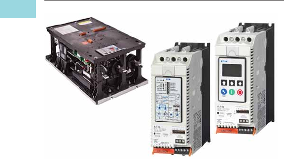
V6-T1-42 Volume 6—Solid-State Motor Control CA08100007E—February 2016 www.eaton.com
1
1
1
1
1
1
1
1
1
1
1
1
1
1
1
1
1
1
1
1
1
1
1
1
1
1
1
1
1
1
1.2
Reduced Voltage Motor Starters
Solid-State Starters
Solid-State Starters
Contents
Description Page
Solid-State Starters
Type S611, Soft Starters . . . . . . . . . . . . . . . . . . V6-T1-43
Type S801+, Soft Starters . . . . . . . . . . . . . . . . V6-T1-59
Type S811+, Soft Starters with DIM . . . . . . . . V6-T1-75
Product Overview
Type S611
The S611 soft starter is a
powerful combination of
performance capability,
application flexibility, and the
industry’s best user interface
experience.
Designed to control
acceleration and deceleration
of three-phase motors, the
line is available for current
ranges from 26A through
414A applications.
The S611 has integrated
bypass and overload
protection. The S611 is
available as a component for
panel mounting or in
enclosed control—NEMA
Type 1, 12, 3R, 4, 4X.
Type S801+
Eaton’s S801+ line of reduced
voltage soft starters is very
compact, multi-functional,
easy to install and easy to
program. Designed to control
acceleration and deceleration
of three-phase motors, the
line is available for current
ranges from 11A to 1000A
applications, and is suitable
for mounting in motor control
centers or in enclosed control
(NEMA Type 1, 4, 4X and 12)
applications.
Type S811+
Eaton’s S811+ offers all
the popular features of the
S801+ and adds enhanced
functionality with the new
DIM (Digital Interface
Module), communications,
metering, monitoring and
diagnostics capabilities.
Eaton’s line of S811+
reduced voltage soft starters
is very compact, multi-
functional, easy to install and
easy to set operating
parameters. Designed to
control the acceleration and
deceleration of three-phase
motors up to 690 V, the line is
available from 11A to 1000A.
The S811+ is designed to
be a complete package,
combining the silicon
controlled rectifiers (SCRs),
bypass contactor and
overload in one, very compact
unit. The S811+ is available
as a component for panel
mounting, in motor control
centers or in enclosed control
(NEMA Type 1, 3R, 4, 4X, 7/9
and 12).
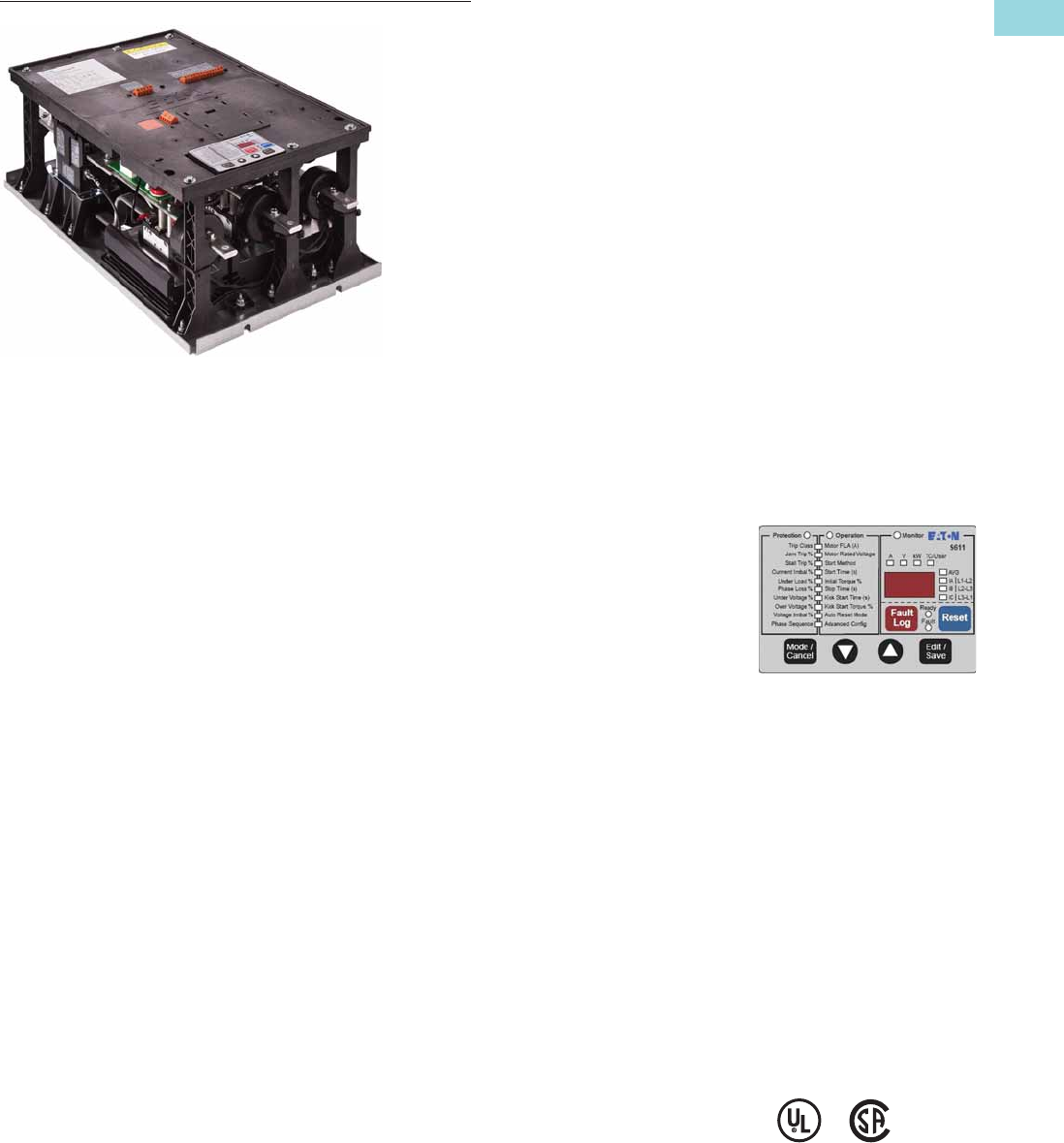
Volume 6—Solid-State Motor Control CA08100007E—February 2016 www.eaton.com V6-T1-43
1
1
1
1
1
1
1
1
1
1
1
1
1
1
1
1
1
1
1
1
1
1
1
1
1
1
1
1
1
1
1.2
Reduced Voltage Motor Starters
Solid-State Starters
Type S611, Soft Starter
Contents
Description Page
Type S611, Soft Starters
Features and Benefits . . . . . . . . . . . . . . . . . . . . V6-T1-44
Operation. . . . . . . . . . . . . . . . . . . . . . . . . . . . . . V6-T1-47
Catalog Number Selection . . . . . . . . . . . . . . . . V6-T1-50
Product Selection . . . . . . . . . . . . . . . . . . . . . . . V6-T1-51
Accessories . . . . . . . . . . . . . . . . . . . . . . . . . . . . V6-T1-52
Replacement Parts . . . . . . . . . . . . . . . . . . . . . . V6-T1-53
Technical Data and Specifications . . . . . . . . . . . V6-T1-54
Dimensions . . . . . . . . . . . . . . . . . . . . . . . . . . . . V6-T1-57
Type S801+, Soft Starters . . . . . . . . . . . . . . . . . . . V6-T1-59
Type S811+, Soft Starters with DIM . . . . . . . . . . . V6-T1-75
Type S611, Soft Starters
Product Description
Eaton revolutionized the
reduced voltage control
marketplace with its
advanced feature set and
user-friendly user interface
module to enhance system
performance and reduce
commissioning times. The
S611 adds enhanced
functionality with network
communications, metering,
monitoring and diagnostics
capabilities.
The Eaton line of S611
reduced voltage soft starters
is multi-functional, easy to
install and easy to program.
Designed to control the
acceleration and deceleration
of three-phase motors up to
600 V, the line is available
from 26 amps through
414 amps.
The S611 is designed to be a
complete package combining
the SCRs, bypass contactor
and overload in one unit.
Application Description
Designed to control the
acceleration and deceleration
of three-phase motors, the
S611 soft starter uses Silicon
Controlled Rectifiers (SCRs)
to control the voltage to soft
start and soft stop the motor.
After the motor is started,
internal run bypass
contactors close, resulting in
the motor running directly
across-the-line. The built-in
solid-state overload protects
the motor from overload
conditions with sophisticated
algorithms that model true
motor heating, resulting in
better motor protection and
fewer nuisance trips.
Advanced protective and
diagnostic features reduce
downtime.
A voltage ramp start or
current limit start is available.
Kick start is available in either
starting mode. The soft stop
option allows for a ramp stop
time that is longer than the
coast to stop time. The pump
control option provides a
smooth transition for starting
and stopping a motor and
eliminating the “water-
hammer” effect that can
damage pipes, valves and
pumps.
The S611 offers an impressive
array of advanced protective
features. Not only are the
protective features selectable,
but many offer variable settings
allowing the user to fine
tune the soft starter to meet
specific system requirements.
The S611 has an easy to use
User Interface Module (UI)
that allows the user to
configure the device and to
read system parameters and
values. The UI includes an
LED display and keypad to
scroll through the various
parameters. The UI allows
the user to modify control
parameters, enable or
disable protections, set
communication variables,
monitor system values such
as line voltages and currents,
and access the fault queue.
User Interface Module (UI)
The UI can be removed from
the S611 and remote
mounted. Kits are available to
door mount the UI, enabling
users to safely configure,
commission, monitor and
troubleshoot the system at
the electrical panel without
opening the enclosure door.
This will help eliminate the
possibility of an arc flash
incident.
Standards and Certifications
●IEC 60947-4-2
●UL listed
●CSA certified (3211 06)

V6-T1-44 Volume 6—Solid-State Motor Control CA08100007E—February 2016 www.eaton.com
1
1
1
1
1
1
1
1
1
1
1
1
1
1
1
1
1
1
1
1
1
1
1
1
1
1
1
1
1
1
1.2
Reduced Voltage Motor Starters
Solid-State Starters
Features and Benefits
●The User Interface Module
(UI) provides an intuitive,
easy-to-use human
interface with powerful
configuration capabilities to
maximize system
performance
●Door or device mounted UI
enables users to safely
configure, commission,
monitor and troubleshoot
the system at the electrical
panel without opening the
enclosure door, eliminating
the possibility of an arc
flash incident
●System operating
parameters can be
monitored enterprise-wide
through a communications
network. Increase uptime
by providing data for
process management and
preventive diagnostics
●Run bypass mode greatly
reduces internal heating
created by the greater
power dissipation in the
SCRs. Bypass contactors
directly connect the motor
to the line and improves
system efficiency by
reducing internal power
losses
●Internal solid-state
overload protection
provides accurate current
measurement and trip
settings. Sophisticated
algorithms solve a series of
differential equations that
model true motor heating
and cooling, resulting in
superior motor overload
protection while
minimizing nuisance trips.
Advanced selectable
protective features
safeguard the motor and
system against a variety of
system faults
●Internal run bypass
contactors and overload
protection eliminate the
need for additional devices,
reducing enclosure sizes
minimizing installation and
wiring time and reducing
overall assembly size and
cost
●Wide range of overload
FLA settings (50–100% of
rated frame current) and a
selectable trip class (5–30)
offers users the flexibility
to fine tune the starter to
match specific application
requirements
●Variable ramp times and
torque control settings
provide unlimited starting
configurations, allowing for
maximum application
flexibility
●Kick-start feature enables
soft starting of high friction
loads
●Soft stop control for
applications where an
abrupt stop of the load is
not acceptable
●Pump control option with
sophisticated pump
algorithms on both starting
and stopping that minimize
the pressure surges that
cause water hammer. The
pump control option will
maximize the life of the
pump and piping systems
while minimizing the
downtime caused by
system failure
●Six SCRs control all three
motor phases, providing
smooth acceleration and
deceleration performance
●Soft acceleration and
deceleration reduces wear
on belts, gears, chains,
clutches, shafts and
bearings
●Reduce the peak inrush
current's stress on the
power system
●Minimize peak starting
torque to diminish
mechanical system wear
and damage
●120 Vac control voltage
enhances ease of
connections
●The S611 lends itself to
serviceability. The printed
circuit boards (PCBs) and
contactors can be replaced
in the field
●The S611 has built-in
communication capabilities
through two communications
ports to connect the soft
starter to a variety of
networks, including
Modbus (resident),
DeviceNet™, PROFIBUS®,
and Ethernet
Protective Features
All protective features can be configured, enabled or disabled with the UI or through the
communications network.
Motor Overload
The S611 includes electronic
overload protection as
standard. The overload meets
applicable requirements for a
motor overload protective
device. The overload protects
the motor from over heat
conditions with the use of
sophisticated algorithms that
model true motor heating,
resulting in superior motor
protection and fewer
nuisance trips.
The S611 calculates a thermal
memory value. A 100% value
represents the maximum
safe temperature of the
motor. When the thermal
memory value reaches 100%,
an overload trip will occur
removing power to the motor.
Upon trip, the S611 stores
the calculated motor heating
value and will not allow a
motor re-start until the motor
has cooled. This feature
ensures the motor will not
be damaged by repeated
overload trip, reset and
re-start cycles.
The thermal memory value
can be monitored through the
UI or the communications
network. The thermal
memory value can be of great
use in determining an
impending overload trip
condition. Alarms can be
implemented in the process
monitoring system warning
of an impending trip before a
trip occurs halting the
process. Costly system
downtime can be avoided.
The trip current is adjusted to
match the specific application
requirements by entering the
motor nameplate full load
current rating and trip class.
The FLA adjustment includes
a 2 to 1 adjustment range.
The overload trip class is
adjustable from class 5
through class 30. The
overload is ambient
temperature compensated -
meaning its trip
characteristics will not vary
with changes in ambient
temperature. The overload
protection can be enabled,
disabled, or disabled on start.
Short Circuit
The use of a short circuit
protective device in
coordination with the S611 is
required in branch motor
circuits by most electrical
codes. Short circuit
coordination ratings with both
fuses and Eaton molded case
circuit breakers are available
providing customers with
design flexibility. The S611
has short circuit coordination
ratings as an open
component, an enclosed
starter, and in a motor control
center. The short circuit
ratings can go up to 100 kA
depending on application
configuration.

Volume 6—Solid-State Motor Control CA08100007E—February 2016 www.eaton.com V6-T1-45
1
1
1
1
1
1
1
1
1
1
1
1
1
1
1
1
1
1
1
1
1
1
1
1
1
1
1
1
1
1
1.2
Reduced Voltage Motor Starters
Solid-State Starters
Jam
Excessive current and torque
up to locked rotor levels can
occur in a jam condition. The
condition can result in stress
and damage to the motor,
load, mechanical system, and
the electrical distribution
system. Jam protection
prevents the stress and
damage from a jam during
normal run. After the motor is
started, a current greater than
300% FLA setting will cause
the starter to trip on a jam
fault.
Stall
Excessive current and torque
up to locked rotor levels can
occur in a stall condition. The
condition can lead to an
overload trip and result in
stress and damage to the
motor, load, mechanical
system, and the electrical
distribution system. Stall
protection prevents stress
and damage to a motor that
has not come up to speed, or
stalled after the soft start
time. The S611 will trip to
protect the system in the
event that the motor did not
get to the rated speed in the
defined soft start period. A
current greater than 200%
FLA at the end of the soft
start period will cause the
starter to trip on a stall fault.
Pole Over Temperature
High ambient temperatures,
extended ramp times and
high duty cycle conditions
may cause the S611 power
pole conductors to reach a
temperature that exceeds
their thermal rating. The S611
is equipped with sensors that
monitor the temperature of
the power poles. Over
temperature protection
occurs if the device's thermal
capacity is exceeded. The
soft starter will trip in over
temperature conditions,
preventing device failure.
The device pole temperature
value can be monitored
through the UI or the
communications network.
This feature can be of use in
determining an impending
over temperature trip
condition. Alarms can be
implemented in the process
monitoring system warning
of an impending trip before a
trip occurs, halting the
process. Costly system
shutdown can be avoided.
Phase Loss
Loss of a phase can cause a
significant increase in the
current drawn in the
remaining two phases. Phase
loss can lead to motor
damage before an eventual
overload trip occurs. Phase
loss is typically an indication
of a failure in the electrical
distribution system. The S611
will detect a phase loss and
trip if any phase current drops
below a preset value. The
phase loss trip level is
adjustable from 0% to 100%
of the average of the other
two phase levels with an
adjustable trip delay of 0.1 to
60 seconds.
Phase Imbalance
Phase current or voltage
imbalance can cause a
significant increase in the
current drawn in the
remaining two phases. Phase
imbalance can lead to motor
damage before an eventual
overload trip. Phase
imbalance is typically an
indication of a failure in the
electrical distribution system
or the motor. The S611 will
detect both current and
voltage phase imbalances
and trip if any phase becomes
imbalanced as compared to
the average of the other two
phases.
The phase current imbalance
trip level is adjustable from
0% to 100% of the average
of the current in the other
two phases with an adjustable
trip delay of 0.1 to 60 seconds.
The phase voltage imbalance
trip level is adjustable from
0% to 100% of the average
of the voltage in the other
two phases with an adjustable
trip delay of 0.1 to 60 seconds.
Reset Mode
The S611 can be set up for
automatic or manual reset on
trip. The manual reset mode
requires the operator to
physically press the RESET
button located on the soft
starter. The overload can be
manually reset through the UI
or through the communications
network.
The automatic reset mode
allows the soft starter to be
automatically reset as soon
as the trip condition is no
longer present. With the
automatic reset mode, after
the fault is no longer present,
the motor will be restarted as
soon as a valid start signal is
present.
Phase Reversal
The S611 can determine if
the proper line phase
sequence is present by
default. The device will trip if
the line phase sequence is
something other than A-B-C.
The S611 can be configured
to operate under reversed
phase conditions (A-C-B).
Shorted SCR Detection
The S611 monitors the
operation of the power poles
and will trip under a shorted
SCR condition.
Open SCR Detection
The S611 monitors the
operation of the power poles
and will trip under an open
SCR condition.
Low Current
Low current conditions can
be a result of a loss of load or
a failure in the mechanical
system. The S611 has low
current protection that will
trip if the average RMS current
falls below a preset value.
The low current protection
can be programmed as a
percent of motor FLA from
0% to 100%.
Low Voltage
Low voltage conditions can
result from disturbances
in the electrical power
distribution system. Low
voltage conditions can cause
a malfunction and damage to
electrical equipment. The
S611 has low voltage
protection that will trip if the
average RMS voltage falls
below a preset value. The low
voltage protection can be
programmed as a percent of
nominal voltage from 1% to
99% with a trip delay of 0.1
to 60 seconds.
High Voltage
High voltage conditions can
result from disturbances in
the electrical power
distribution system. High
voltage conditions can cause
malfunctions or failures of
electrical equipment. The
S611 has high voltage
protection that will trip if the
average RMS voltage is
greater than a preset value.
The high voltage protection
can be programmed as a
percent of nominal voltage
from 101% to 120% with a
trip delay of 0.1 to 60 seconds.

V6-T1-46 Volume 6—Solid-State Motor Control CA08100007E—February 2016 www.eaton.com
1
1
1
1
1
1
1
1
1
1
1
1
1
1
1
1
1
1
1
1
1
1
1
1
1
1
1
1
1
1
1.2
Reduced Voltage Motor Starters
Solid-State Starters
Monitoring Capabilities
The S611 has an impressive
array of system monitoring
capabilities that allow users
to access real time process
and diagnostic data. This data
can be viewed at the device
with the UI or through a
communications network.
Data over a communications
network can provide valuable
insight into the condition
of the equipment and
processes. Maintenance and
production personnel can
monitor critical operational
and maintenance data from
a central control station that
can be located far away
from the production facility.
Process data can be monitored
to determine system anomalies
that may indicate a need for
preventive maintenance or an
Impeding failure.
Adjustments made through
the communications network
can reduce costs by minimizing
the time traveling to the
location where the motor
controls are located. When
faults do occur, real time fault
data can assist maintenance in
troubleshooting and planning
repair resources. Remote
reset signals can be given to
tripped devices without the
need for manual intervention
by maintenance personnel.
Average Line Current
Provides the average of the
three phase RMS line
currents in amps, accurate
to within 2%. Current data
can be used to indicate a
need for maintenance.
Increased currents in a
fixed load application can
indicate a reduction in
system efficiencies and
performance, signifying
system maintenance is due.
Average Pole Current
Provides the average of the
three phase RMS pole
currents in amps, accurate to
within 2%. The pole current
is the current through the soft
starter. The line and pole
current will be identical in
in-line applications, and will
differ in inside-the-delta
applications.
Average Line Current
as a % FLA
Provides the average RMS
line current as a percentage
of the S611 FLA setting.
Three-Phase Line Currents
Provides three RMS phase
line currents in amps,
accurate to within 2%.
Imbalances or changes in
the relative phase current
to one another can indicate
anomalies in the motor or
electrical distribution system.
Three-Phase Pole Currents
Provides three RMS phase
pole currents in amps,
accurate to within 2%. The
pole current is the current
through the soft starter. The
line and pole current will be
identical in in-line applications.
Three-Phase Line Voltages
Provides the individual RMS
three phase line voltages.
Imbalances or changes in the
relative phase voltage to one
another can indicate
anomalies in the motor or
electrical distribution system.
Voltage can be used to
monitor electrical distribution
system performance.
Warnings, alarms and
system actions to low or
high voltage conditions can
be implemented.
Percent Thermal Memory
Provides the real time
calculated thermal memory
value. The S611 calculates
thermal memory value. A
100% value represents the
maximum safe temperature
of the motor. When the
thermal memory value
reaches 100%, an overload
trip will occur, removing
power to the motor.
The thermal memory value
can be of great use in
determining an impending
overload trip Condition.
Alarms can be implemented
in the process monitoring
system warning of an
Impending trip before a trip
occurs, halting the process.
Costly system downtime can
be avoided.
Pole Temperature
Increases in pole temperature
are caused by increases in
ambient temperature, start/
stop times and start duty
cycles. Changes in pole
temperatures represent a
change in system operating
conditions. Identifying
unexpected operating
conditions or changes can
prompt maintenance and aid
in process evaluation
activities.
Power Monitoring
S611 can monitor power and
it can be displayed on the UI.
Start Count
Number of starts are stored
in the device and can be
displayed using field bus.
Diagnostics
Fault Queue
Current fault and a fault
queue containing the last nine
system faults can be read
through the UI or
communications network.
Fault identification can
minimize troubleshooting
time and cost and prevent arc
flash incidents. The fault
queue can be remotely
accessed through a
communications network to
assist in planning
maintenance resources.
30 different faults can be
identified by the S611.
Control Status
The S611 provides data that
represents system conditions
that can be read through the
UI or the communications
network. This data identifies
the status of the system and
the control commands the
system is requesting of the
S611. This can be used for
advanced Troubleshooting
and system integration
activities.
Field Serviceability
In the case of maintenance,
the S611 provides easy
access and replacement of
key components including
control board and internal
bypass contactors—
significantly increasing its
service life. If a component
ever needs to be replaced,
this straightforward operation
can be completed by an end-
user without the need to call
in an outside service
technician or engineer. These
components are stocked and
available for order and quick
fulfillment—ensuring your
operation continues with
minimal downtime.
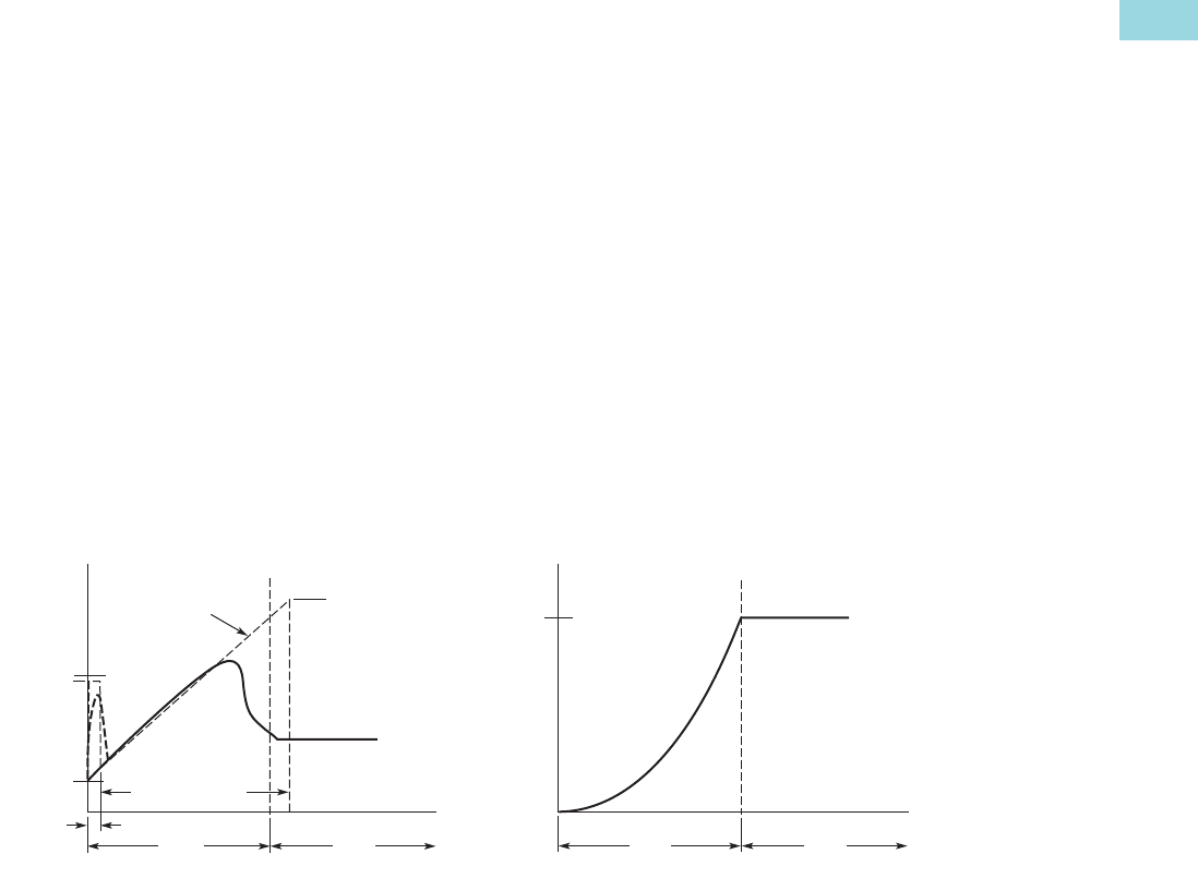
Volume 6—Solid-State Motor Control CA08100007E—February 2016 www.eaton.com V6-T1-47
1
1
1
1
1
1
1
1
1
1
1
1
1
1
1
1
1
1
1
1
1
1
1
1
1
1
1
1
1
1
1.2
Reduced Voltage Motor Starters
Solid-State Starters
Operation
Instructional Leaflets
●Instruction Manual: MN03902011E
●Quick Start Guide: MN03901003E
Starting and Stopping Modes
The S611 has a variety of starting and stopping methods to provide superior performance in the
most demanding applications. The motor can be started in either Voltage Ramp Start or Current
Limit Start mode. Kick Start and Soft Stop are available within both starting modes.
Voltage Ramp Start
Provides a voltage ramp to
the motor resulting in a
constant torque increase. The
most commonly used form of
soft start, this start mode
allows you to set the initial
torque value and the duration
of the ramp to full voltage
conditions. Bypass contactors
close after ramp time.
●Adjustable initial torque
0–85% of locked rotor
torque
●Adjustable start ramp
time 0.5–180 seconds
(can be extended with
factory modification)
Starting Characteristics—Ramp Start
Initial
Torque
Kick
Start
Torq
Kick Start Time
100%
Bypass Bypass
Voltage
Ramp Rated
Voltage
Soft Start Time
tr
Start Run
Torque
Time (Seconds)
100%
Start Run
Speed
Time (Seconds)
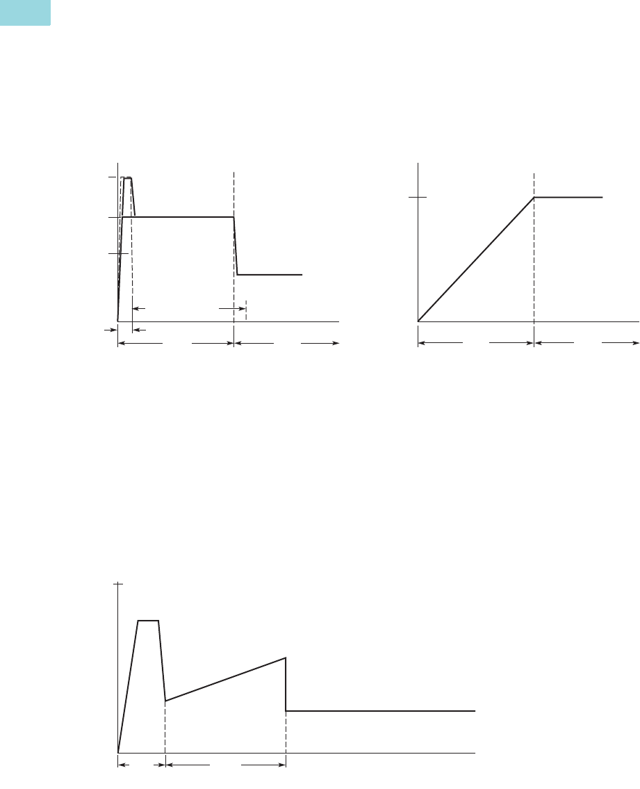
V6-T1-48 Volume 6—Solid-State Motor Control CA08100007E—February 2016 www.eaton.com
1
1
1
1
1
1
1
1
1
1
1
1
1
1
1
1
1
1
1
1
1
1
1
1
1
1
1
1
1
1
1.2
Reduced Voltage Motor Starters
Solid-State Starters
Current Limit Start
Limits the maximum current
available to the motor during
the start phase. This mode of
soft starting is used when it
becomes necessary to limit
the maximum starting current
due to long start times or to
protect the motor. This start
mode allows you to set the
maximum starting current as
a percentage of locked rotor
current and the duration of
the current limit. Bypass
contactors close after current
limit time.
●Maximum current of
0–85% locked rotor current
●Adjustable start ramp time
0.5–180 seconds (can be
extended with factory
modification)
Starting Characteristics—Current Limit Start
Kick Start
Selectable feature in both
Voltage Ramp Start and
Current Limit Start modes.
Provides a current and torque
“kick” for 0 to 2.0 seconds.
This provides greater initial
current to develop additional
torque to breakaway a high
friction load.
●0–85% of locked rotor
torque
●0–2.0 seconds duration
Starting Characteristics—Kick Start
Initial
Torque
Kick
Start
Torq
Kick Start Time
100%
Bypass Bypass
Soft Start Time
Start Run
Current
Time (Seconds) Time (Seconds)
100%
Start Run
Speed
100%
Locked Rotor Torque
Ramp
Time (Seconds)
Kick
Start
Run
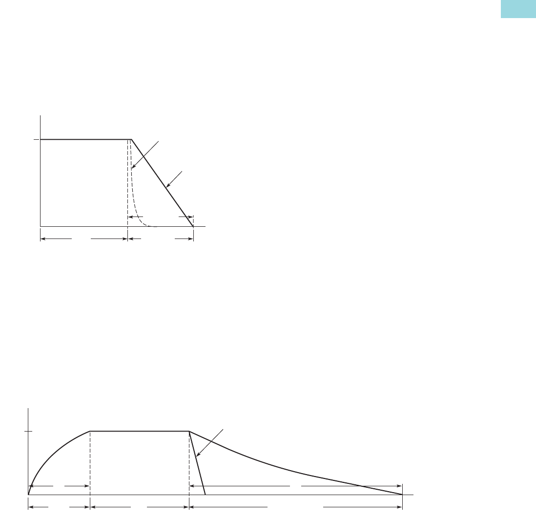
Volume 6—Solid-State Motor Control CA08100007E—February 2016 www.eaton.com V6-T1-49
1
1
1
1
1
1
1
1
1
1
1
1
1
1
1
1
1
1
1
1
1
1
1
1
1
1
1
1
1
1
1.2
Reduced Voltage Motor Starters
Solid-State Starters
Soft Stop
Allows for a controlled
stopping of a load. Used
when a stop-time that is
greater than the coast-to-stop
time is desired. Often used
with high friction loads where
a sudden stop may cause
system or load damage.
●Stop time = 0–60 seconds
Starting Characteristics—Soft Stop
Pump Control Option
This option is intended to
reduce the potential for water
hammer in a centrifugal pump
system by using a starting
and stopping algorithm
developed for pump control.
Upon a start command, the
speed of the motor is
increased, under the control
of the S611 soft starter
microprocessor, to achieve a
gentle start. After the speed
has reached its nominal
value, the bypass contactors
close and the pump operates
as with any other starter.
Upon a stop command, the
bypass contactors are
opened and the motor speed
is decreased in a tapered
manner, to gradually slow the
flow until the motor is
brought to a stop.
Pump Control Option
Soft
Stop Time
100%
Run Soft Stop
Speed
Time (Seconds)
Coast to Stop
(Speed)
Soft Stop Ramp
(Voltage)
100%
tr
potS pmuP tfoStratS
Speed
Time (Seconds)
ts
Run
Coast to Stop
V6-T1-50 Volume 6—Solid-State Motor Control CA08100007E—February 2016 www.eaton.com
1
1
1
1
1
1
1
1
1
1
1
1
1
1
1
1
1
1
1
1
1
1
1
1
1
1
1
1
1
1
1.2
Reduced Voltage Motor Starters
Solid-State Starters
Edge and Level Sensing Control
Edge or Level Sensing is selected with the Start Control parameter in the Advanced Configuration
Menu. Factory default is Level Sensing.
Edge Sensing
Edge sensing requires 120 Vac
power be momentarily
applied to the Start terminal
(with the Permissive terminal
120 Vac) to initiate a start
under all conditions. After a
stop or fault occurs, the
120 Vac must be reapplied to
the start terminal before
another start can occur. This
control configuration should
be used when restarting of
the motor after a fault or stop
must be supervised manually
or as a part of a control
scheme. The cycling of
120 Vac power to the
Permissive terminal before
starting is required regardless
of the position of the auto
reset parameter.
Level Sensing
Level sensing will enable a
motor to restart after a fault is
cleared without cycling 120 V
AC to the Permissive terminal
as long as:
●Permissive terminal is
supplied with 120 Vac
●The auto reset parameter
is set to enabled
●All faults have cleared or
have been reset
This control configuration
should be used where it is
desirable to restart a motor
after a fault without additional
manual or automatic control.
An example of this condition
would be on a remote
pumping station where it is
desirable to automatically
restart a pump after a power
outage without operator
intervention.
Note: If the auto reset feature is
used, CAUTION must be
exercised to assure that any
restart occurs in a safe manner.
Catalog Number Selection
S611 Soft Starters
Ampere Rating
052 = 52A
065 = 65A
077 = 77A
099 = 99A
125 = 125A
156 = 156A
180 = 180A
242 = 242A
302 = 302A
361 = 361A
414 = 414A
S = Standard soft starterS = Soft Starter
611 = Non-combination soft starter Number of Poles
3 = Three-pole device
Options
N = No options
P = Pump control
Frame Size
A = 52–77 Amps
B = 99–125 Amps
C = 156–180 Amps
D = 242 Amps
E = 302–361 Amps
F = 414 Amps
S611 B125 N 3 S
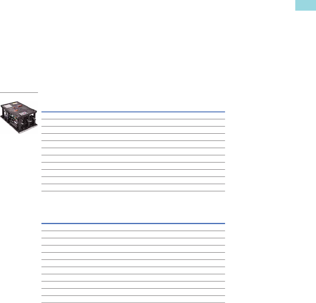
Volume 6—Solid-State Motor Control CA08100007E—February 2016 www.eaton.com V6-T1-51
1
1
1
1
1
1
1
1
1
1
1
1
1
1
1
1
1
1
1
1
1
1
1
1
1
1
1
1
1
1
1.2
Reduced Voltage Motor Starters
Solid-State Starters
Product Selection
Motor applications and
customer needs come in
many different varieties. With
the standard and severe duty
rating tables, we have
attempted to provide
guidelines on what the soft
starter is capable of. If the
application falls under these
categories, you can use these
charts. For other applications,
or when a question arises,
consult with your local Eaton
Representative or call the
Eaton Technical Resource
Center.
Pump Control Option
For pump control option, change the 8th digit in the Catalog Number to P,
as in S611XXXP3S.
Horsepower Ratings
Note: Always refer to motor plate FLA and ensure that the motor plate FLA is equal to or lower than the
maximum current value in the tables.
Standard Duty—300% Current for 15 Seconds, 115% Continuous
Standard Duty Plus—350% FLA for 30 Seconds, 115% Continuous
Rated
Current (Amps)
Horsepower Rating
Catalog Number208V 240 V 480 V 600 V
52 15 15 40 50 S611A052N3S
65 20 20 50 60 S611A065N3S
77 25 25 60 75 S611A077N3S
99 30 30 75 100 S611B099N3S
125 4040100125S611B125N3S
156 5060125150S611C156N3S
180 6060150150S611C180N3S
242 7575200250S611D242N3S
302 100 100 250 300 S611E302N3S
361 125 150 300 350 S611E361N3S
414 150 150 350 450 S611F414N3S
Rated
Current (Amps)
Horsepower Rating
Catalog Number208V 240 V 480 V 600 V
52 15 15 40 50 S611A052N3S
65 20 20 50 60 S611A065N3S
71 20 25 60 75 S611A077N3S
99 30 30 75 100 S611B099N3S
119 4040100125S611B125N3S
156 5060125150S611C156N3S
180 6060150150S611C180N3S
242 7575200250S611D242N3S
302 100 100 250 300 S611E302N3S
361 125 150 300 350 S611E361N3S
407 150 150 350 400 S611F414N3S
S611
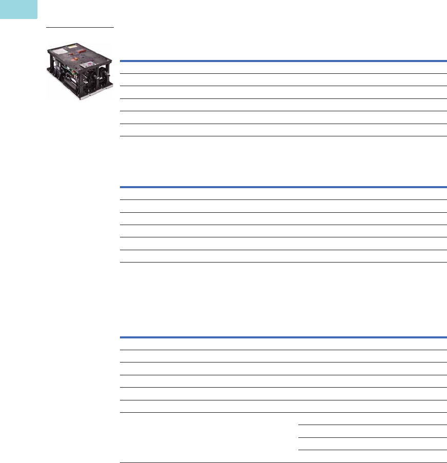
V6-T1-52 Volume 6—Solid-State Motor Control CA08100007E—February 2016 www.eaton.com
1
1
1
1
1
1
1
1
1
1
1
1
1
1
1
1
1
1
1
1
1
1
1
1
1
1
1
1
1
1
1.2
Reduced Voltage Motor Starters
Solid-State Starters
Note: Always refer to motor plate FLA and ensure that the motor plate FLA is equal to or lower than the
maximum current value in the tables.
Heavy Duty—500% FLA for 30 Seconds, 125% Continuous
Severe Duty—600% FLA for 30 Seconds, 125% Continuous
Accessories
Optional Accessory Kits
Rated
Current (Amps)
Horsepower Rating
Catalog Number208V 240 V 480 V 600 V
49 15 15 40 50 S611A052N3S
83 25 30 60 75 S611B099N3S
142 4060125150S611C156N3S
225 7575200200S611D242N3S
256 75 100 200 250 S611E361N3S
285 100 125 250 300 S611F414N3S
Rated
Current (Amps)
Horsepower Rating
Catalog Number208V 240 V 480 V 600 V
41 10 15 30 40 S611A052N3S
69 20 30 60 60 S611B099N3S
117 3050100125S611C180N3S
187 6075150200S611D242N3S
213 7575150200S611E361N3S
238 75 100 200 250 S611F414N3S
Description
S611 Current
Rating
Accessory Kit
Part Number
User interface remote mounting kit —3.28 ft (1 m) 52–414A S611-RMK-100
User interface remote mounting kit—6.56 ft (2 m) 52–414A S611-RMK-200
User interface remote mounting kit—9.84 ft (3 m) 52–414A S611-RMK-300
User interface communication cable—3.28 ft (1 m) 52–414A D77E-QPIP100
User interface communication cable—6.56 ft (2 m) 52–414A D77E-QPIP200
User interface communication cable—9.84 ft (3 m) 52–414A D77E-QPIP300
Lug kit—mechanical 52–77A S611-LUG-M01
99–125A S611-LUG-M02
156–242A S611-LUG-M03
302–414A S611-LUG-M04
S611
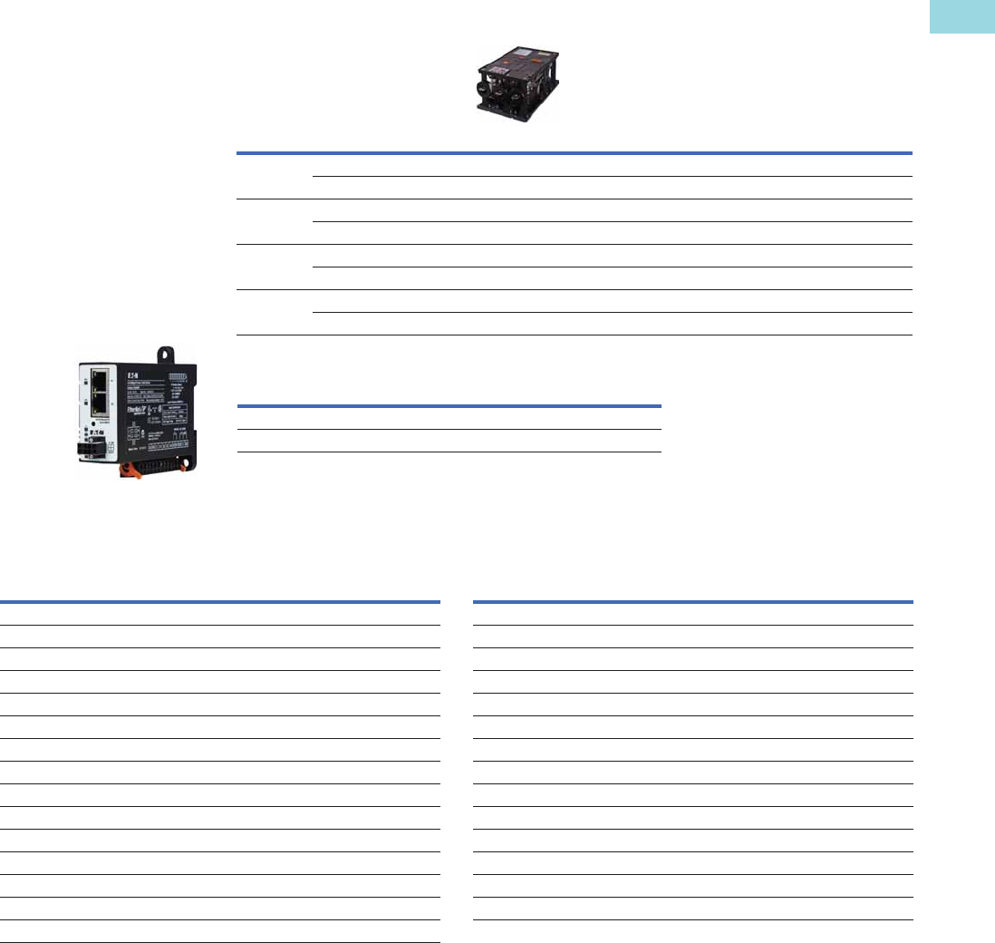
Volume 6—Solid-State Motor Control CA08100007E—February 2016 www.eaton.com V6-T1-53
1
1
1
1
1
1
1
1
1
1
1
1
1
1
1
1
1
1
1
1
1
1
1
1
1
1
1
1
1
1
1.2
Reduced Voltage Motor Starters
Solid-State Starters
C441 Communication Card Options
Designed for use with soft starters …
Note: Refer to Volume 5—Motor Control and Protection, CA08100006E, tab 5.4 for additional details and
BR042002EN brochure for C441 communication module accessories for overload relays and soft starters.
Replacement Parts
S611 Replacement Components
Catalog
Number
Input
Signal Type
General
Purpose I/O 1
Protocol S611 Mounting Options
Modbus RTU C441NS 120 Vac ■ ■ Standalone—DIN rail/panel mount
C441PS 24 Vdc ■ ■ Standalone—DIN rail/panel mount
DeviceNet C441KS 120 Vac ■ ■ Standalone—DIN rail/panel mount
C441LS 24 Vdc ■ ■ Standalone—DIN rail/panel mount
PROFIBUS C441SS 120 Vac ■ ■ Standalone—DIN rail/panel mount
C441QS 24 Vdc ■ ■ Standalone—DIN rail/panel mount
Modbus TCP,
EtherNet/IP
C441U 120 Vac ■ ■ Standalone—DIN rail/panel mount
C441V 24 Vdc ■ ■ Standalone—DIN rail/panel mount
Recommended Power Supply Catalog Number
85–264 Vac single-phase input, 24 Vdc output PSG240E24RM
360–575 Vac three-phase input, 24 Vdc output PSG240F24RM
Description Part Number
User interface S611-KEYPAD Control board assembly—77A pump S611-PCB-077P
User interface communication cable—0.25m (0.82 ft) D77E-QPIP25 Control board assembly—99A pump S611-PCB-099P
Control board assembly—52A standard S611-PCB-052S Control board assembly—125A pump S611-PCB-125P
Control board assembly—65A standard S611-PCB-065S Control board assembly—156A pump S611-PCB-156P
Control board assembly—77A standard S611-PCB-077S Control board assembly—180A pump S611-PCB-180P
Control board assembly—99A standard S611-PCB-099S Control board assembly—242A pump S611-PCB-242P
Control board assembly—125A standard S611-PCB-125S Control board assembly—302A pump S611-PCB-302P
Control board assembly—156A standard S611-PCB-156S Control board assembly—361A pump S611-PCB-361P
Control board assembly—180A standard S611-PCB-180S Control board assembly—414A pump S611-PCB-414P
Control board assembly—242A standard S611-PCB-242S Frame A/B CT S611-CT-AB
Control board assembly—302A standard S611-PCB-302S Frame C/D CT S611-CT-CD
Control board assembly—361A standard S611-PCB-361S Frame E/F CT S611-CT-EF
Control board assembly—414A standard S611-PCB-414S Contactor assembly—52–180A C25DNY172
Control board assembly—52A pump S611-PCB-052P Contactor assembly—242–414A C25DNY173
Control board assembly—65A pump S611-PCB-065P
Communications
The S611 is equipped with
native Modbus RTU
communication capabilities
and may be connected to a
variety of networks, including
DeviceNet, Modbus TCP,
EtherNet/IP and PROFIBUS
using the C441 series
communication modules for
easy integration into any
PLC or DCS system.
The modules come standard
with four inputs and two relay
outputs. C441 communication
modules can also be used
independently for standalone
I/O applications.

V6-T1-54 Volume 6—Solid-State Motor Control CA08100007E—February 2016 www.eaton.com
1
1
1
1
1
1
1
1
1
1
1
1
1
1
1
1
1
1
1
1
1
1
1
1
1
1
1
1
1
1
1.2
Reduced Voltage Motor Starters
Solid-State Starters
Technical Data and Specifications
Soft Starters—S611
Description
S611 Soft Starter (Partial Catalog Number)
S611A052… S611A065… S611A072… S611B099…
Max. current capacity A 52 65 77 99
FLA range A 26–52 32.5–65 38.5–77 48–99
Dimensions
Width inch (mm) 11.58 (294) 11.58 (294) 11.58 (294) 11.58 (294)
Height inch (mm) 19.45 (494) 19.45 (494) 19.45 (494) 19.45 (494)
Depth inch (mm) 7.46 (189) 7.46 (189) 7.46 (189) 7.46 (189)
Weight lb (kg) 24 (11) 24 (11) 24 (11) 24 (11)
General Information
Bypass mechanical lifespan 10M 10M 10M 10M
Insulating voltage V 660 660 660 660
Ramp time range Seconds 0.5–180 0.5–180 0.5–180 0.5–180
Vibration resistance—non-operating g 3g up to 242A units, 2g on
302A to 414A units
3g up to 242A units, 2g on
302A to 414A units
3g up to 242A units, 2g on
302A to 414A units
3g up to 242A units, 2g on
302A to 414A units
Vibration resistance—operatingg1111
Shock resistance g 15g up to 242A units, 5g on
302A to 414A units
15g up to 242A units, 5g on
302A to 414A units
15g up to 242A units, 5g on
302A to 414A units
15g up to 242A units, 5g on
302A to 414A units
Electrical Information
Operating voltage V 130–600 130–600 130–600 130–600
Operating frequency Hertz 47–63 47–63 47–63 47–63
Overload setting (frame) % FLA 50–100 50–100 50–100 50–100
Trip class 5, 10, 20, 30 5, 10, 20, 30 5, 10, 20, 30 5, 10, 20, 30
Cabling Capacity (IEC 947)
Number of conductors 1111
Wire sizes AWG 14–2/0 14–2/0 14–2/0 14–2/0
Type of connectors Lug Lug Lug Lug
Control Wiring
Wire sizes AWG 22–12 22–12 22–12 22–12
Number of conductors 2 (or one 12–14 AWG) 2 (or one 12–14 AWG) 2 (or one 12–14 AWG) 2 (or one 12–14 AWG)
Torque requirements lb-in 3.5 3.5 3.5 3.5
Maximum size AWG12121212
Control Power Requirements
Voltage range (120 V ±10%) V 108–132 108–132 108–132 108–132
Steady state current A 0.375 0.375 0.375 0.375
Inrush current A 0.5 0.5 0.5 0.5
Ripple %1111
Relays (1) Class A and C
Voltage AC—maximum V 120 120 120 120
Voltage DC—maximum V 24 24 24 24
Amps—maximumA3333
Environment
Temperature—operating °C –20° to 50°C –20° to 50°C –20° to 50°C –20° to 50°C
Temperature—storage °C –40° to 85°C –40° to 85°C –40° to 85°C –40° to 85°C
Altitude Meters <2000m, derate 0.5% per
100m >2000m
<2000m, derate 0.5% per
100m >2000m
<2000m, derate 0.5% per
100m >2000m
<2000m, derate 0.5% per
100m >2000m
Humidity % <95% non-condensing <95% non-condensing <95% non-condensing <95% non-condensing
Operating position Vertical, line side up Vertical, line side up Vertical, line side up Vertical, line side up
Pollution degree IEC947-1 3333
Impulse withstand voltage IEC947-4-1 V 6000 6000 6000 6000

Volume 6—Solid-State Motor Control CA08100007E—February 2016 www.eaton.com V6-T1-55
1
1
1
1
1
1
1
1
1
1
1
1
1
1
1
1
1
1
1
1
1
1
1
1
1
1
1
1
1
1
1.2
Reduced Voltage Motor Starters
Solid-State Starters
Soft Starters—S611, continued
Description
S611 Soft Starter (Partial Catalog Number)
S611B125… S611C156… S611C180… S611D242…
Max. current capacity A 125 156 180 242
FLA range A 62.5–125 78–156 90–180 120–242
Dimensions
Width inch (mm) 11.58 (294) 11.58 (294) 11.58 (294) 11.58 (294)
Height inch (mm) 19.45 (494) 20.83 (529) 20.83 (529) 20.83 (529)
Depth inch (mm) 7.46 (189) 8.37 (213) 8.37 (213) 8.37 (213)
Weight lb (kg) 24 (11) 33 (15) 33 (15) 38 (17)
General Information
Bypass mechanical lifespan 10M 10M 10M 10M
Insulating voltage V 660 660 660 660
Ramp time range Seconds 0.5–180 0.5–180 0.5–180 0.5–180
Vibration resistance—non-operating g 3g up to 242A units, 2g on
302A to 414A units
3g up to 242A units, 2g on
302A to 414A units
3g up to 242A units, 2g on
302A to 414A units
3g up to 242A units, 2g on
302A to 414A units
Vibration resistance—operatingg1111
Shock resistance g 15g up to 242A units, 5g on
302A to 414A units
15g up to 242A units, 5g on
302A to 414A units
15g up to 242A units, 5g on
302A to 414A units
15g up to 242A units, 5g on
302A to 414A units
Electrical Information
Operating voltage V 130–600 130–600 130–600 130–600
Operating frequency Hertz 47–63 47–63 47–63 47–63
Overload setting (frame) % FLA 50–100 50–100 50–100 50–100
Trip class 5, 10, 20, 30 5, 10, 20, 30 5, 10, 20, 30 5, 10, 20, 30
Cabling Capacity (IEC 947)
Number of conductors 1111
Wire sizes AWG 2–600 kcmil 2–600 kcmil 2–600 kcmil 2–600 kcmil
Type of connectors Lug Lug Lug Lug
Control Wiring
Wire sizes AWG 22–12 22–12 22–12 22–12
Number of conductors 2 (or one 12–14 AWG) 2 (or one 12–14 AWG) 2 (or one 12–14 AWG) 2 (or one 12–14 AWG)
Torque requirements lb-in 3.5 3.5 3.5 3.5
Maximum size AWG12121212
Control Power Requirements
Voltage range (120 V ±10%) V 108–132 108–132 108–132 108–132
Steady state current A 0.375 0.375 0.375 0.375
Inrush current A 0.5 0.5 0.5 0.5
Ripple %1111
Relays (1) Class A and C
Voltage AC—maximum V 120 120 120 120
Voltage DC—maximum V 24 24 24 24
Amps—maximumA3333
Environment
Temperature—operating °C –20° to 50°C –20° to 50°C –20° to 50°C –20° to 50°C
Temperature—storage °C –40° to 85°C –40° to 85°C –40° to 85°C –40° to 85°C
Altitude Meters <2000m, derate 0.5% per
100m >2000m
<2000m, derate 0.5% per
100m >2000m
<2000m, derate 0.5% per
100m >2000m
<2000m, derate 0.5% per
100m >2000m
Humidity % <95% non-condensing <95% non-condensing <95% non-condensing <95% non-condensing
Operating position Vertical, line side up Vertical, line side up Vertical, line side up Vertical, line side up
Pollution degree IEC947-1 3333
Impulse withstand voltage IEC947-4-1 V 6000 6000 6000 6000

V6-T1-56 Volume 6—Solid-State Motor Control CA08100007E—February 2016 www.eaton.com
1
1
1
1
1
1
1
1
1
1
1
1
1
1
1
1
1
1
1
1
1
1
1
1
1
1
1
1
1
1
1.2
Reduced Voltage Motor Starters
Solid-State Starters
Soft Starters—S611, continued
Description
S611 Soft Starter (Partial Catalog Number)
S611E302… S611E361… S611F414…
Max. current capacity A 302 361 414
FLA range A 151–302 180.5–361 207–414
Dimensions
Width inch (mm) 17.56 (446) 17.56 (446) 17.56 (446)
Height inch (mm) 31.15 (791) 31.15 (791) 31.15 (791)
Depth inch (mm) 9.54 (242) 9.54 (242) 9.54 (242)
Weight lb (kg) 86 (39) 86 (39) 102 (46)
General Information
Bypass mechanical lifespan 10M 10M 10M
Insulating voltage V 660 660 660
Ramp time range Seconds 0.5–180 0.5–180 0.5–180
Vibration resistance—non-operating g 3g up to 242A units, 2g on
302A to 414A units
3g up to 242A units, 2g on
302A to 414A units
3g up to 242A units, 2g on
302A to 414A units
Vibration resistance—operating g 1 1 1
Shock resistance g 15g up to 242A units, 5g on
302A to 414A units
15g up to 242A units, 5g on
302A to 414A units
15g up to 242A units, 5g on
302A to 414A units
Electrical Information
Operating voltage V 130–600 130–600 130–600
Operating frequency Hertz 47–63 47–63 47–63
Overload setting (frame) % FLA 50–100 50–100 50–100
Trip class 5, 10, 20, 30 5, 10, 20, 30 5, 10, 20, 30
Cabling Capacity (IEC 947)
Number of conductors 2 2 2
Wire sizes AWG 2–600 kcmil 2–600 kcmil 2–600 kcmil
Type of connectors Lug Lug Lug
Control Wiring
Wire sizes AWG 22–12 22–12 22–12
Number of conductors 2 (or one 12–14 AWG) 2 (or one 12–14 AWG) 2 (or one 12–14 AWG)
Torque requirements lb-in 3.5 3.5 3.5
Maximum size AWG 12 12 12
Control Power Requirements
Voltage range (120 V ±10%) V 108–132 108–132 108–132
Steady state current A 0.75 0.75 0.75
Inrush currentA111
Ripple %111
Relays (1) Class A and C
Voltage AC—maximum V 120 120 120
Voltage DC—maximum V 24 24 24
Amps—maximum A 3 3 3
Environment
Temperature—operating °C –20° to 50°C –20° to 50°C –20° to 50°C
Temperature—storage °C –40° to 85°C –40° to 85°C –40° to 85°C
Altitude Meters <2000m, derate 0.5% per
100m >2000m
<2000m, derate 0.5% per
100m >2000m
<2000m, derate 0.5% per
100m >2000m
Humidity % <95% non-condensing <95% non-condensing <95% non-condensing
Operating position Vertical, line side up Vertical, line side up Vertical, line side up
Pollution degree IEC947-1 3 3 3
Impulse withstand voltage IEC947-4-1 V 6000 6000 6000
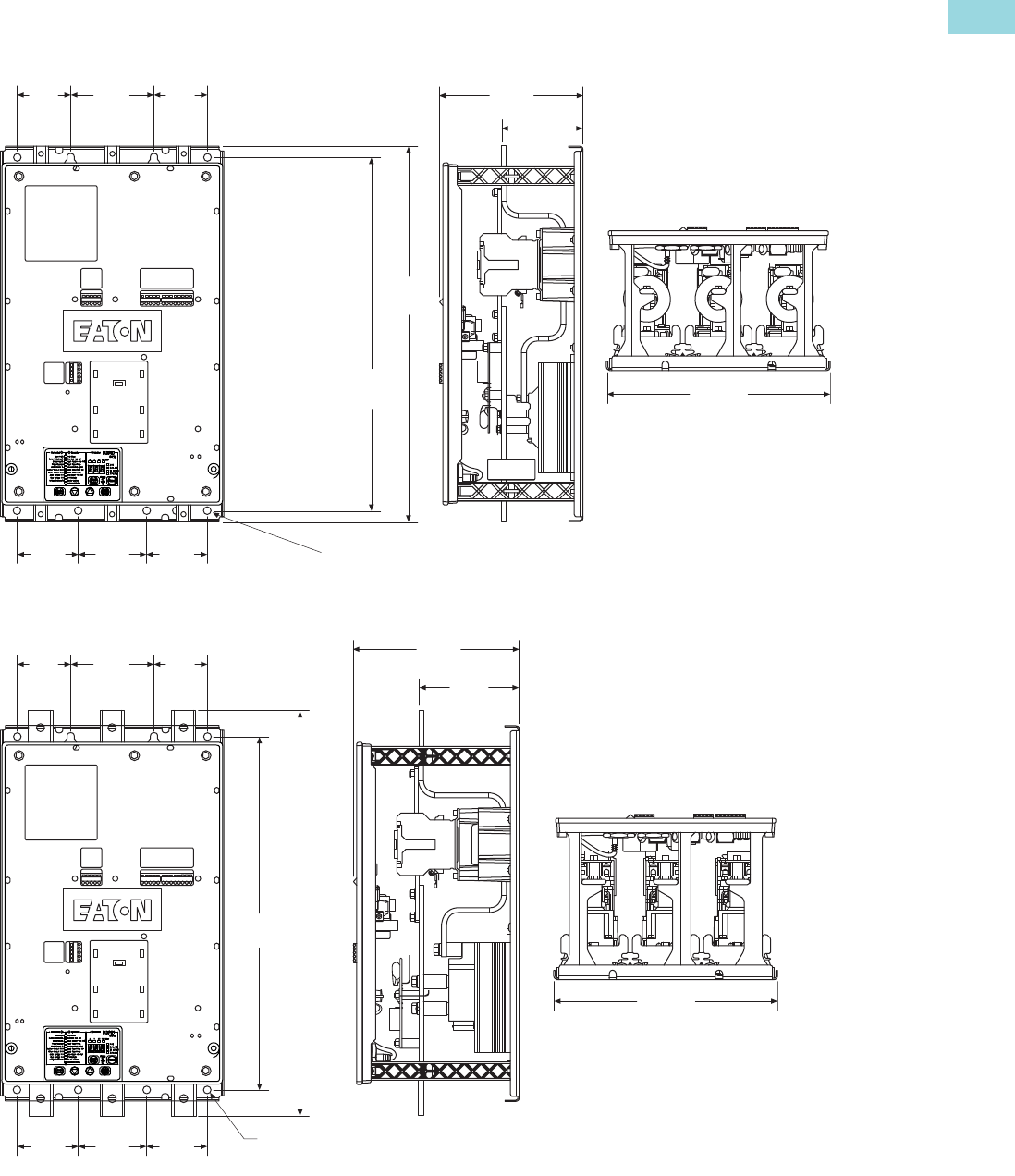
Volume 6—Solid-State Motor Control CA08100007E—February 2016 www.eaton.com V6-T1-57
1
1
1
1
1
1
1
1
1
1
1
1
1
1
1
1
1
1
1
1
1
1
1
1
1
1
1
1
1
1
1.2
Reduced Voltage Motor Starters
Solid-State Starters
Dimensions
Approximate Dimensions in inches (mm)
S611A…, S611B…
S611C…, S611D…
2.76
(70.0)
2.76
(70.0)
7.43
(188.6)
4.21
(107.0)
19.47
(494.5)
18.30
(464.7)
4.33
(110.0)
11.58
(294.2)
3.15
(80.0)
3.15
(80.0)
Ø 0.39 (10.0)
8 Places
3.54
(90.0)
8.57
(217.6)
5.20
(132.0)
2.76
(70.0)
2.76
(70.0)
21.01
(533.6)
18.30
(464.7)
4.33
(110.0)
3.15
(80.0)
3.15
(80.0)
Ø 0.39
(10.0)
8 Places
3.54
(90.0)
11.58
(294.2)
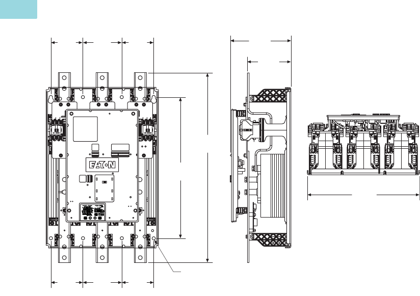
V6-T1-58 Volume 6—Solid-State Motor Control CA08100007E—February 2016 www.eaton.com
1
1
1
1
1
1
1
1
1
1
1
1
1
1
1
1
1
1
1
1
1
1
1
1
1
1
1
1
1
1
1.2
Reduced Voltage Motor Starters
Solid-State Starters
Approximate Dimensions in inches (mm)
S611E…, S611F…
9.50
(241.3)
6.81
(172.9)
5.00
(127.0)
6.10
(155.0)
5.00
(127.0)
29.69
(754.1)
22.13
(562.0)
5.00
(127.0)
6.10
(155.0)
5.00
(127.0)
Ø 0.53
(13.5)
8 Places
17.56
(446.1)
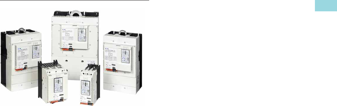
Volume 6—Solid-State Motor Control CA08100007E—February 2016 www.eaton.com V6-T1-59
1
1
1
1
1
1
1
1
1
1
1
1
1
1
1
1
1
1
1
1
1
1
1
1
1
1
1
1
1
1
1.2
Reduced Voltage Motor Starters
Solid-State Starters
Type S801+, Soft Starters
Contents
Description Page
Type S611, Soft Starters . . . . . . . . . . . . . . . . . . . . . V6-T1-43
Type S801+, Soft Starters
Operation. . . . . . . . . . . . . . . . . . . . . . . . . . . . . . V6-T1-60
Features. . . . . . . . . . . . . . . . . . . . . . . . . . . . . . . V6-T1-62
Benefits . . . . . . . . . . . . . . . . . . . . . . . . . . . . . . . V6-T1-62
Standards and Certifications . . . . . . . . . . . . . . . V6-T1-62
User Manuals . . . . . . . . . . . . . . . . . . . . . . . . . . V6-T1-62
Catalog Number Selection . . . . . . . . . . . . . . . . V6-T1-62
Product Selection . . . . . . . . . . . . . . . . . . . . . . . V6-T1-63
Accessories . . . . . . . . . . . . . . . . . . . . . . . . . . . . V6-T1-65
Options . . . . . . . . . . . . . . . . . . . . . . . . . . . . . . . V6-T1-66
Technical Data and Specifications . . . . . . . . . . . V6-T1-67
Wiring Diagram . . . . . . . . . . . . . . . . . . . . . . . . . V6-T1-71
Dimensions . . . . . . . . . . . . . . . . . . . . . . . . . . . . V6-T1-71
Type S811+, Soft Starters with DIM. . . . . . . . . . . . V6-T1-75
Type S801+, Soft Starters
Product Description
Eaton’s S801+ line of
reduced voltage soft starters
is very compact, multi-
functional, easy to install and
easy to program. Designed to
control acceleration and
deceleration of three-phase
motors, the line is available
for current ranges from 11A
all the way through 1000A
applications, and is suitable
for mounting in motor control
centers or in enclosed control
(NEMA 1, 4, 4X and 12)
applications.
Application Description
The S801+ line of soft
starters is designed to be the
smallest, most compact soft
starter in the market today.
With this small size, it can
easily fit in place of existing
soft starter designs, wye-
delta starters or across-the-
line NEMA and IEC starters.
This feature allows easy
retrofits of existing motor
control centers or enclosures,
and saves the expense of
replacing existing structure
or adding a new one to house
a soft starter.
The product is designed
to work with three-phase
motors in a delta (three-lead)
configuration. The S801+
works with all motors from
fractional horsepower up to
motors requiring 1000A of
steady-state current. The
built-in overload (in ranges
from 11–1000A) and run
bypass contactor make
installation and setup quick
and easy. The overload
also offers some advanced
protective functions to give
additional motor protection.
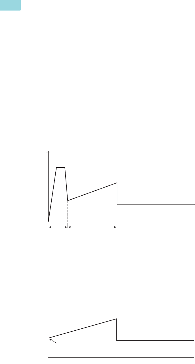
V6-T1-60 Volume 6—Solid-State Motor Control CA08100007E—February 2016 www.eaton.com
1
1
1
1
1
1
1
1
1
1
1
1
1
1
1
1
1
1
1
1
1
1
1
1
1
1
1
1
1
1
1.2
Reduced Voltage Motor Starters
Solid-State Starters
Operation
Overload Functionality
Overtemperature
Protects the device from
overheating. Starter will
shut down at 100°C.
Stall
Selectable protective feature,
unit trips to protect system in
event motor can not get to
rated speed in the defined
ramp period.
Jam
Selectable protective feature,
unit trips to prevent damage
to motor during normal run.
Phase Loss
Selectable protective feature,
trips under voltage loss
condition to any phase.
Phase Reversal
Selectable protective feature,
trips when phase rotation is
something other than A-B-C.
Kick Start
Selectable feature that
provides a current “kick”
of up to 550% of full load
current for 0 to 2.0 seconds.
This provides the additional
torque required at startup to
break free a motor.
Ramp Start
Provides a constant increase
in torque to the motor.
Current Limit Start
Limits the maximum current
available to the motor during
the startup phase.
Soft Stop
Allows for a controlled
stopping of a frictional load.
Shorted SCR Detection
Monitors for shorted SCR
in the power poles.
Starting Characteristics
Kick Start
Provides an initial boost of
current to the motor to help
overcome motor inertia and
begin motor rotation.
●0–85% of locked rotor
torque
●0–2.0 seconds duration
Starting Characteristics—Kick Start
Ramp Start
The most commonly used
form of soft start. This allows
you to set the initial torque
value (of the ramp) and then
raises it to full voltage
conditions.
●Adjustable initial torque =
0–85% of locked
rotor torque
●Adjustable ramp time =
0.5–180 seconds
Starting Characteristics—Ramp Start
100%
Locked Rotor Torque
Ramp
Time (Seconds)
Kick
Start
Run
Run
100%
Locked Rotor Torque
Time (Seconds)
Initial
Torque
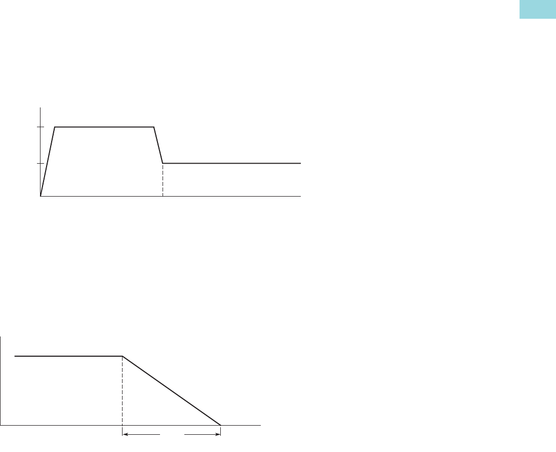
Volume 6—Solid-State Motor Control CA08100007E—February 2016 www.eaton.com V6-T1-61
1
1
1
1
1
1
1
1
1
1
1
1
1
1
1
1
1
1
1
1
1
1
1
1
1
1
1
1
1
1
1.2
Reduced Voltage Motor Starters
Solid-State Starters
Current Limit
This mode of soft starting
is used when it becomes
necessary to limit the
maximum starting current
due to long start times or
to protect the motor.
●Maximum current of
0–85% locked rotor current
●Adjustable ramp time =
0.5–180 seconds
Starting Characteristics—Current Limit
Soft Stop
Used when an extended
coast-to-rest period is
desired. Often used with high
friction loads where a sudden
stop may cause system or
product damage.
●Stop time = 0–60 seconds
Starting Characteristics—Soft Stop
Run
Max.
Allowed
100%
FLA
Current
Time (Seconds)
Ramp
Time (Seconds)
Run
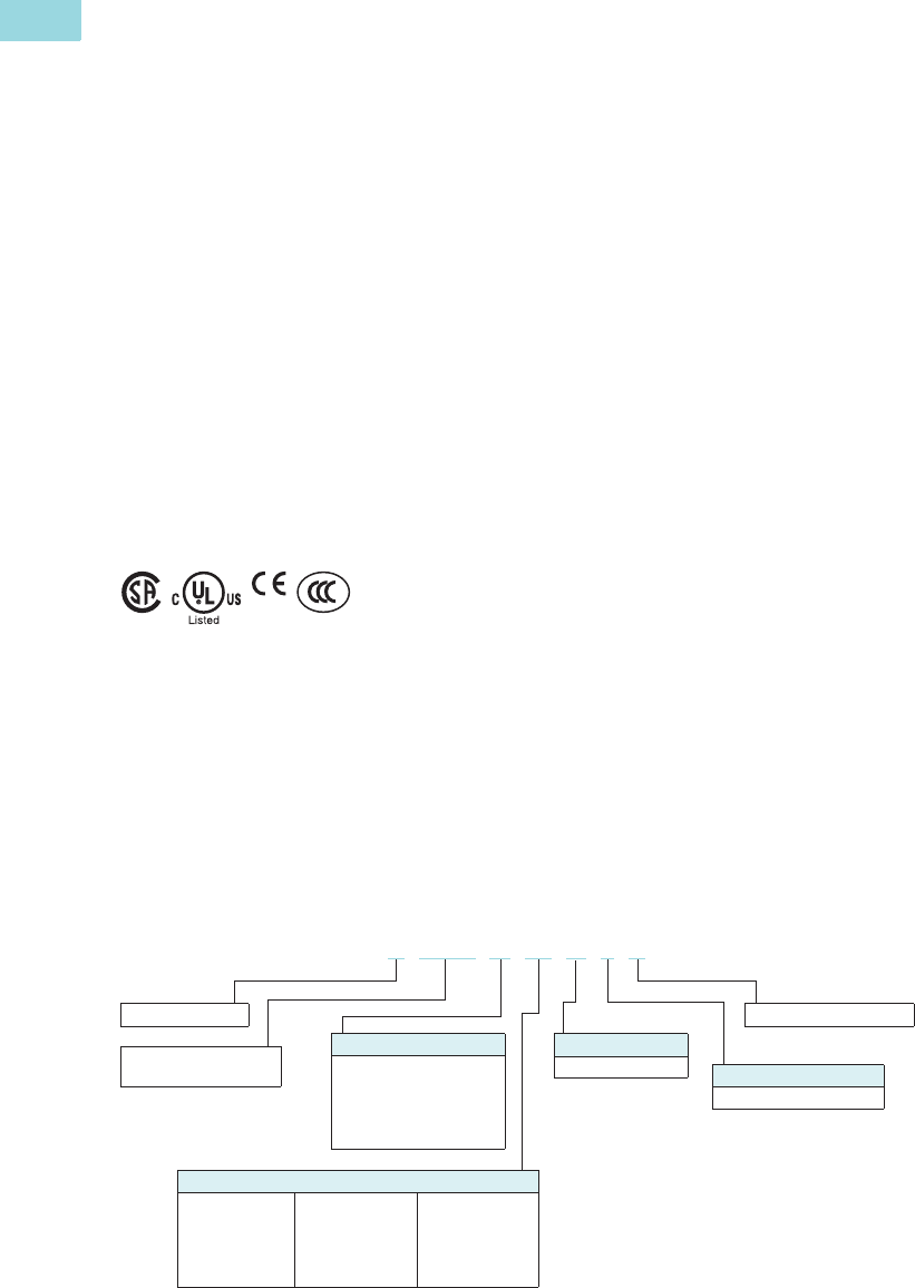
V6-T1-62 Volume 6—Solid-State Motor Control CA08100007E—February 2016 www.eaton.com
1
1
1
1
1
1
1
1
1
1
1
1
1
1
1
1
1
1
1
1
1
1
1
1
1
1
1
1
1
1
1.2
Reduced Voltage Motor Starters
Solid-State Starters
Features
●Built-in overload protection
●Built-in run bypass
contactor
●Adjustable ramp times
●Adjustable torque control
●Adjustable kick start
control
●Programmable overload
settings, 31–100% (3.2:1)
of rated current for the unit
●Physically fits in place of
most NEMA and IEC
starters
●Easy to use control
interface module
●Soft stop control
●Multiple trip class settings
(5, 10, 20 and 30)
●Six SCR control
●Optional CIM door mount
kit for safety
●Optional IP20 protection
Benefits
●Reduced wear on belts,
gears, chains, clutches,
shafts and bearings
●Allows for controlling the
inrush current to the motor
●Reduced inrush current
leads to more stable power
grid and can lower peak
demand charges
●Less shock to product on
conveyor lines and material
handling gear
●24 Vdc control enhances
personnel and equipment
safety
Standards and Certifications
●IEC 947 compliant
●EN 60947-4-2
●CSA certification
●cULus listed
(File No. E202571)
●CE marked
●CSA elevator (2411 01)
User Manuals
A comprehensive user manual
is available and can be
downloaded free of charge
from www.eaton.com by
performing a document search
for MN03900002E.
Catalog Number Selection
S801+ Open Soft Starters 12
Notes
1S801+T…, S801+U… and S801+V… units require lug kits found on Page V6-T1-65.
2All units require a 24 Vdc power supply found on catalog Page V6-T1-65, or equivalent.
3S801+U50N35 unit does not have IEC certification.
S = Soft starter
801+ = Non-combination
soft starter
S801+ N66 N 3 S
Number of Poles
3 = Three-pole device
Options
N = Standard
S = Standard soft starter
Frame Size
N = 65 mm
R = 110 mm
T = 200 mm
U = 200 mm
V = 290 mm
Ampere Rating
37 = 37A
66 = 66A
10 = 105A
13 = 135A
18 = 180A
24 = 240A
30 = 304A
36 = 360A
42 = 420A
50 = 500A 3
65 = 650A
72 = 720A
85 = 850A
10 = 1000A
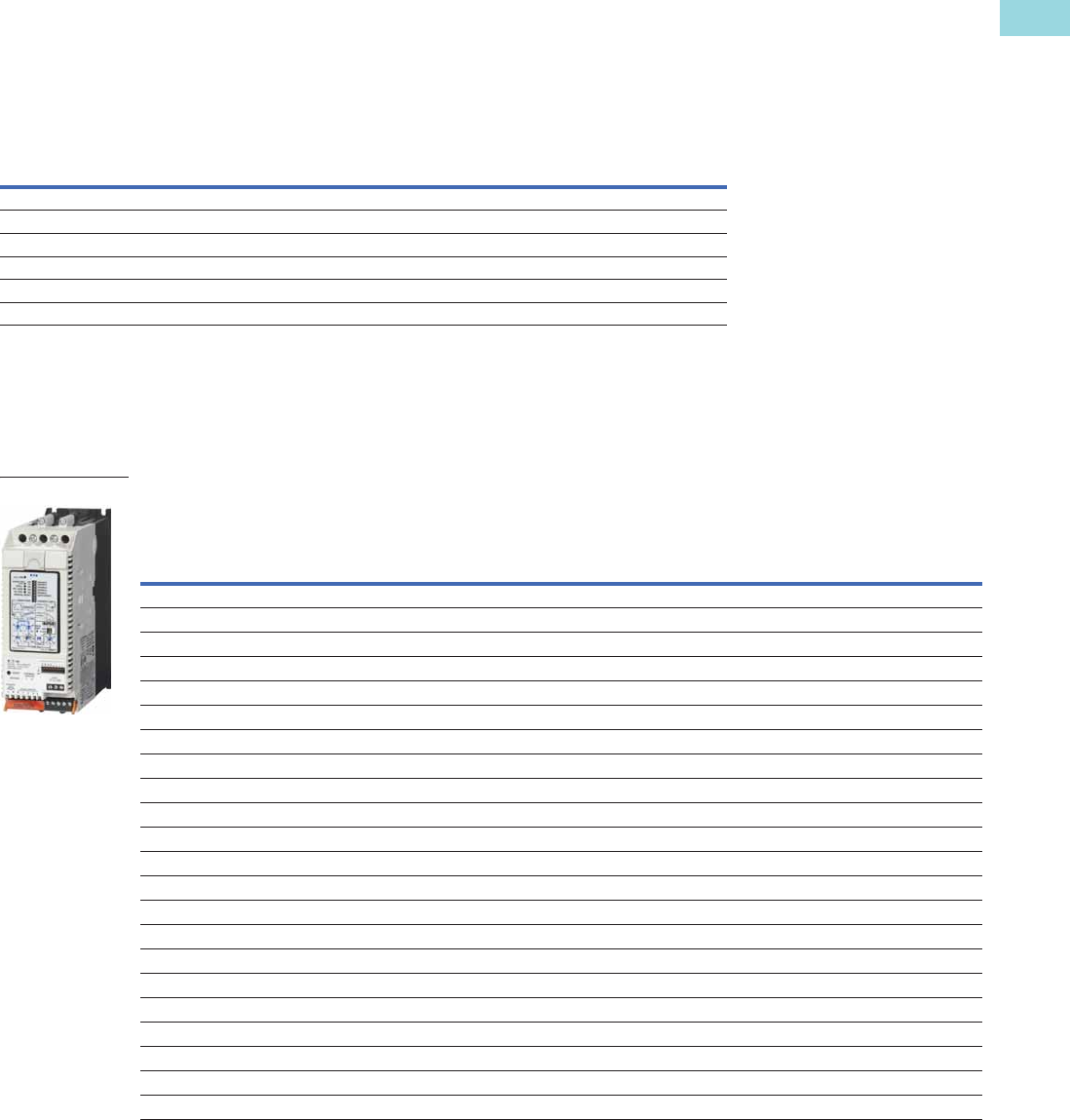
Volume 6—Solid-State Motor Control CA08100007E—February 2016 www.eaton.com V6-T1-63
1
1
1
1
1
1
1
1
1
1
1
1
1
1
1
1
1
1
1
1
1
1
1
1
1
1
1
1
1
1
1.2
Reduced Voltage Motor Starters
Solid-State Starters
Product Selection
Standard Duty Ratings
The table below is the base ratings for the soft starter. The tables included in this catalog are
meant to be a reference table for different applications, but to match a unit to your exact
application, consult with your local Eaton representative or call our Technical Resource Center.
Standard Duty Ratings
Motor applications and
customer needs come in
many different varieties.
With the standard and severe
duty rating tables, we have
attempted to provide
guidelines on what the soft
starter is capable of.
If the application falls under
these categories, you can
use these charts. For other
applications, or when a
question arises, consult
with your local Eaton
representative or call our
Technical Resource Center.
Standard Duty—15 Second Ramp, 300% Current Limit at 40°C, Inline Connection
Note
1 S801+U50N3S does not have IEC certification.
Starting Method
Ramp Current
% of FLA
Ramp Time
Seconds Starts per Hour
Ambient
Temperature
Soft start 300% 30 sec. 3 50°C
Full voltage 500% 10 sec. 3 50°C
Wye-delta 350% 20 sec. 3 50°C
80% RVAT 480% 20 sec. 2 50°C
65% RVAT 390% 20 sec. 3 50°C
50% RVAT 300% 20 sec. 4 50°C
Rated
Current
Three-Phase Motors
Catalog
Number
kW Rating (50 Hz) hp Rating (60 Hz)
230V 380–400V 440V
200V 230V 460V 575–600V
1.0SF 1.15SF 1.0SF 1.15SF 1.0SF 1.15SF 1.0SF 1.15SF
Frame Size N
37 10 18.5 18.5 10 10 10 10 25 20 30 30 S801+N37N3S
66 18.5 30 37 20 15 20 20 50 40 60 50 S801+N66N3S
Frame Size R
105 30 55 59 30254030756010075S801+R10N3S
135 40 63 80 40 30 50 40 100 75 125 100 S801+R13N3S
Frame Size T
180 51 90 110 60 50 60 60 150 125 150 150 S801+T18N3S
240 75 110 147 75 60 75 75 200 150 200 200 S801+T24N3S
304 90 160 185 100 75 100 100 250 200 300 250 S801+T30N3S
Frame Size U
360 110 185 220 125 100 150 125 300 250 350 300 S801+U36N3S
420 129 220 257 150 125 175 150 350 300 450 350 S801+U42N3S
500 150 257 300 150 150 200 150 400 350 500 450 S801+U50N3S 1
Frame Size V
360 110 185 220 125 100 150 125 300 250 350 300 S801+V36N3S
420 129 220 257 150 125 175 150 350 300 450 350 S801+V42N3S
500 150 257 300 150 150 200 150 400 350 500 450 S801+V50N3S
650 200 355 425 250 200 250 200 500 450 600 500 S801+V65N3S
720 220 400 450 — — 300 250 600 500 700 600 S801+V72N3S
850 257 475 500 — — 350 300 700 600 900 700 S801+V85N3S
1000 277 525 550 — — 400 350 800 700 900 800 S801+V10N3S
S801+
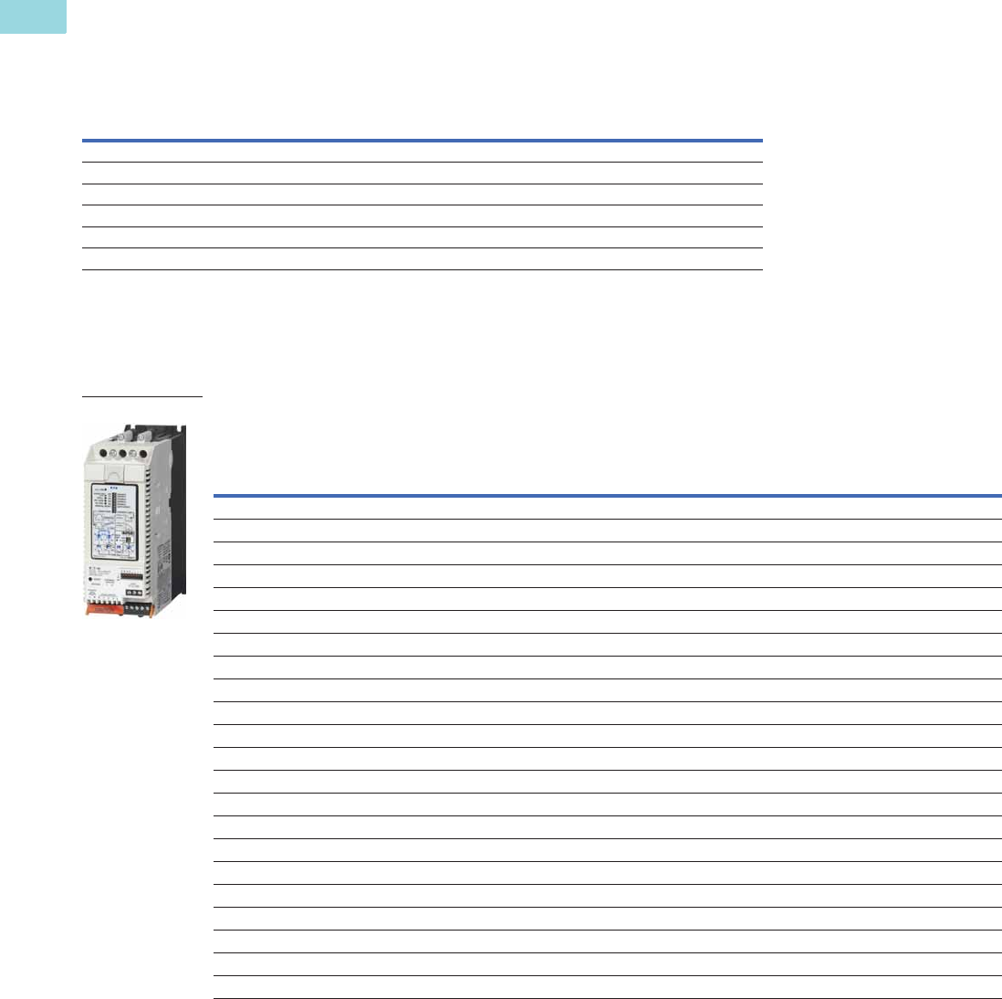
V6-T1-64 Volume 6—Solid-State Motor Control CA08100007E—February 2016 www.eaton.com
1
1
1
1
1
1
1
1
1
1
1
1
1
1
1
1
1
1
1
1
1
1
1
1
1
1
1
1
1
1
1.2
Reduced Voltage Motor Starters
Solid-State Starters
Severe Duty Ratings
The table below is the base ratings for the soft starter. The tables included in this catalog are
meant to be a reference table for different applications, but to match a unit to your exact
application, consult with your local Eaton representative or call our Technical Resource Center.
Severe Duty Ratings
Severe duty ratings are
defined as any combination of
parameters that exceed the
standard duty ratings where
the ramp time is over 30
seconds, and/or the number
of starts per hour exceeds 4,
and/or the current limit set is
over 300%. Example: 35-
second ramp, 5 starts per
hour, 350% current limit at
40°C ambient.
Severe Duty—>30 Second Ramp, >300% Current Limit
Note
1 S801+U50N3S unit does not have IEC certification.
Starting Method
Ramp Current
% of FLA
Ramp Time
Seconds Starts per Hour
Ambient
Temperature
Soft start 450% 30 sec. 4 50°C
Full voltage 500% 10 sec. 10 50°C
Wye-delta 350% 65 sec. 3 50°C
80% RVAT 480% 25 sec. 4 50°C
65% RVAT 390% 40 sec. 4 50°C
50% RVAT 300% 60 sec. 4 50°C
Rated
Current
Three-Phase Motor
Catalog
Number
kW Rating (50 Hz) hp Rating (60 Hz)
230V 380–400V 440V
200V 230V 460V 575V
1.0SF 1.15SF 1.0SF 1.15SF 1.0SF 1.15SF 1.0SF 1.15SF
Frame Size N
22 5.5 10 11 5 5 7-1/2 5 15 10 20 15 S801+N37N3S
42 11 18.522 1010151030254030S801+N66N3S
Frame Size R
65 15 30 33 15 15 20 15 50 40 50 50 S801+R10N3S
80 22 40 45 25 20 30 25 60 50 75 60 S801+R13N3S
Frame Size T
115 335963303040307575100100S801+T18N3S
150 45 80 90 50 40 50 50 100 100 150 125 S801+T24N3S
192 55 100 110 60 50 75 60 150 125 200 150 S801+T30N3S
Frame Size U
240 75 110 147 75 60 75 75 200 150 200 200 S801+U36N3S
305 90 160 185 100 75 100 100 250 200 300 250 S801+U42N3S
365 110 185 220 125 100 150 125 300 250 350 300 S801+U50N3S 1
Frame Size V
240 75 110 147 75 60 75 75 200 150 200 200 S801+V36N3S
305 90 160 185 100 75 100 100 250 200 300 250 S801+V42N3S
365 110 185 220 125 100 150 125 300 250 350 300 S801+V50N3S
420 129 220 257 150 125 150 150 350 300 450 350 S801+V65N3S
480 147 257 295 150 150 200 150 400 350 500 450 S801+V72N3S
525 160 280 335 150 150 200 150 450 350 500 450 S801+V85N3S
600 185 315 375 200 150 250 200 500 450 600 500 S801+V10N3S
S801+
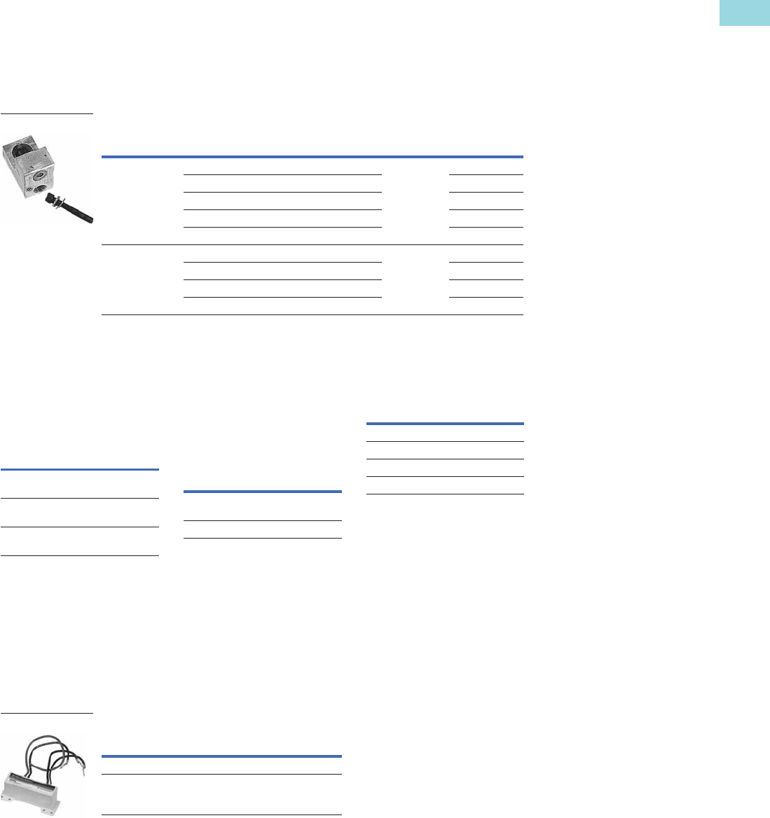
Volume 6—Solid-State Motor Control CA08100007E—February 2016 www.eaton.com V6-T1-65
1
1
1
1
1
1
1
1
1
1
1
1
1
1
1
1
1
1
1
1
1
1
1
1
1
1
1
1
1
1
1.2
Reduced Voltage Motor Starters
Solid-State Starters
Accessories
Lug Kits
S801+T…, S801+U… and
S801+V… soft starters each
have different lug options
based on your wiring needs.
Each lug kit contains three
lugs that can be mounted on
either the load or line side.
Lug Kits
Power Supplies
24 Vdc power supply that can
be used with the S801+ SSRV
or as a stand-alone device.
Power Supplies
Lug Cover Kits
Replacement covers for the
S801+T… and S801+U…
soft starters are available in
case of damage to the
existing covers.
Lug Cover Kits
IP20 Kits
IP20 Kits
Surge Suppressors
The surge suppressor can
mount on either the line or
load side of the soft starter.
It is designed to clip the line
voltage (or load side induced
voltage).
Surge Suppressors
S801+
Catalog Number Description
Kits
Required
Catalog
Number
S801+T…,
S801+U…
2 cable connections, 4 AWG to 1/0 cable 2 EML22
1 cable connection, 4/0 to 500 kcmil cable EML23
2 cable connections, 4/0 to 500 kcmil cable EML24
1 cable connection, 2/0 to 300 kcmil cable EML25
2 cable connections, 2/0 to 300 kcmil cable EML26
S801+V… 2 cable connections, 4/0 to 500 kcmil cable 2 EML28
4 cable connections, 4/0 to 500 kcmil cable EML30
6 cable connections, 4/0 to 500 kcmil cable EML32
4 cable connections, 2/0 to 300 kcmil cable EML33
Lug Kit
Description
Catalog
Number
85–264 Vac input
24 Vdc output
PSG240E
360–575 Vac input
24 Vdc output
PSG240F
600 Vac input
24 Vdc output
PSS55D
Description
Catalog
Number
Lug cover S801+T…,
S801+U…
EML27
Lug cover S801+V… EML34
Description
Catalog
Number
S801+N… SS-IP20-N
S801+R… SS-IP20-R
S801+T… and S801+U… SS-IP20-TU
S801+V… SS-IP20-V
Description
Catalog
Number
600 V MOV for S801+… units EMS39
690 V MOV for S801+… units EMS41
Surge Suppressor

V6-T1-66 Volume 6—Solid-State Motor Control CA08100007E—February 2016 www.eaton.com
1
1
1
1
1
1
1
1
1
1
1
1
1
1
1
1
1
1
1
1
1
1
1
1
1
1
1
1
1
1
1.2
Reduced Voltage Motor Starters
Solid-State Starters
Mounting Plates
The mounting plates are
designed to help make it easy
to install or retrofit the soft
starter into enclosures and
MCCs. The soft starter can
be mounted onto the plate
prior to installation. The
mounting plate is designed
with tear drop mounting
holes for easier installation.
Mounting Plates
Vibration Plates
The vibration plates allow the
soft starter to be applied in
high shock and vibration
applications. The vibration
plate allows vibration up to 5g
and shock in up to 40g. The
soft starter is mounted onto
the vibration plate prior to
installation in the panel.
Vibration Plates
Adapter Plates
The adapter plate allows
customers to retrofit a
S801+V… soft starter with
the S801+U… soft starter.
Adapter Plates
Control Wire Connector
Control Wire Connector
Control Interface Module
The Control Interface
Module (CIM) is available
as a replacement part.
CIM
Options
Cooling Fan Kit
The EMM18 cooling fan kit
mounts on either side of any
frame size S801+ soft starter
to provide additional printed
circuit board cooling in high
ambient operating
temperatures.
Cooling Fan Kit
Description
Catalog
Number
S801+N… EMM13N
S801+R… EMM13R
S801+T… and S801+U… EMM13T
S801+V… EMM13V
Description
Catalog
Number
S801+N… EMM14N
S801+R… EMM14R
S801+T… and S801+U… EMM14T
S801+V… EMM14V
Description
Catalog
Number
Adapter plates EMM13U
Description
Catalog
Number
12-pin, 5 mm pitch connector
for control wiring
EMA75
Description
Catalog
Number
Blank cover (filler) EMA68
CIM for standard unit EMA71
Panel mounting kit
3 ft cable EMA69A
5 ft cable EMA69B
8 ft cable EMA69C
10 ft cable EMA69D
Description
Catalog
Number
Fan kit EMM18

Volume 6—Solid-State Motor Control CA08100007E—February 2016 www.eaton.com V6-T1-67
1
1
1
1
1
1
1
1
1
1
1
1
1
1
1
1
1
1
1
1
1
1
1
1
1
1
1
1
1
1
1.2
Reduced Voltage Motor Starters
Solid-State Starters
Technical Data and Specifications
Soft Starters—S801+
Description
S801+N37N3S S801+N66N3S S801+R10N3S S801+R13N3S
Max. current capacity 37 66 105 135
General Information
Bypass mechanical lifespan 10M 10M 10M 10M
Insulating voltage Ui 660 V 660 V 660 V 660 V
Ramp time range 0.5–180 seconds 0.5–180 seconds 0.5–180 seconds 0.5–180 seconds
Resistance to vibration 3g 3g 3g 3g
Resistance to shock 15g 15g 15g 15g
Electrical Information
Operating voltage 200–600 V 200–600 V 200–600 V 200–600 V
Operating frequency 47–63 Hz 47–63 Hz 47–63 Hz 47–63 Hz
Overload setting 30–100% 30–100% 30–100% 30–100%
Trip class 5, 10, 20 and 30 5, 10, 20 and 30 5, 10, 20 and 30 5, 10, 20 and 30
Cabling Capacity (IEC 947)
Number of conductors 1111
Wire sizes 14–2 14–2 14–4/0 14–4/0
Type of connectors Box lug Box lug Box lug Box lug
Control Wiring (12-Pin)
Wire sizes in AWG 22–14 22–14 22–14 22–14
Number of conductors (stranded) 2 (or one AWG 12) 2 (or one AWG 12) 2 (or one AWG 12) 2 (or one AWG 12)
Torque requirements in lb-in 3.5 3.5 3.5 3.5
Solid, stranded or flexible max. size in mm23.31 3.31 3.31 3.31
Control Power Requirements
Voltage range (24V ±10%) 21.6–26.4 21.6–26.4 21.6–26.4 21.6–26.4
Steady-state current amps 1.0 1.0 1.0 1.0
Inrush current amps 10 10 10 10
Ripple 1% 1% 1% 1%
Relays (1) Class A and C
Voltage AC—maximum 240 240 240 240
Voltage DC—maximum 120 120 120 120
Amps—maximum3333
Environment
Temperature—operating –30° to 50°C (no derating) consult
factory for operation >50°C
–30° to 50°C (no derating) consult
factory for operation >50°C
–30° to 50°C (no derating) consult
factory for operation >50°C
–30° to 50°C (no derating) consult
factory for operation >50°C
Temperature—storage –50° to 70°C –50° to 70°C –50° to 70°C –50° to 70°C
Altitude <2000m—consult factory
for operation >2000m
<2000m—consult factory
for operation >2000m
<2000m—consult factory
for operation >2000m
<2000m—consult factory
for operation >2000m
Humidity <95% noncondensing <95% noncondensing <95% noncondensing <95% noncondensing
Operating position Any Any Any Any
Pollution degree IEC947-13333
Impulse withstand voltage IEC947-4-1 6000 V 6000 V 6000 V 6000 V

V6-T1-68 Volume 6—Solid-State Motor Control CA08100007E—February 2016 www.eaton.com
1
1
1
1
1
1
1
1
1
1
1
1
1
1
1
1
1
1
1
1
1
1
1
1
1
1
1
1
1
1
1.2
Reduced Voltage Motor Starters
Solid-State Starters
Soft Starters—S801+, continued
Notes
1801+U50N3S unit does not have IEC certification.
2UL recognized component.
Description
S801+T18N3S S801+T24N3S S801+T30N3S S801+U36N3S
12
Max. current capacity 180 240 304 360
General Information
Bypass mechanical lifespan 10M 10M 10M 10M
Insulating voltage Ui 660 V 660 V 660 V 660 V
Ramp time range 0.5–180 seconds 0.5–180 seconds 0.5–180 seconds 0.5–180 seconds
Resistance to vibration 3g 3g 3g 3g
Resistance to shock 15g 15g 15g 15g
Electrical Information
Operating voltage 200–600 V 200–600 V 200–600 V 200–600 V
Operating frequency 47–63 Hz 47–63 Hz 47–63 Hz 47–63 Hz
Overload setting 30–100% 30–100% 30–100% 30–100%
Trip class 5, 10, 20 and 30 5, 10, 20 and 30 5, 10, 20 and 30 5, 10, 20 and 30
Cabling Capacity (IEC 947)
Number of conductors 1 or 2 1 or 2 1 or 2 1 or 2
Wire sizes 4 AWG to 500 kcmil 4 AWG to 500 kcmil 4 AWG to 500 kcmil 4 AWG to 500 kcmil
Type of connectors Add-on lug kit Add-on lug kit Add-on lug kit Add-on lug kit
Control Wiring (12-Pin)
Wire sizes in AWG 22–14 22–14 22–14 22–14
Number of conductors (stranded) 2 (or one AWG 12) 2 (or one AWG 12) 2 (or one AWG 12) 2 (or one AWG 12)
Torque requirements in lb-in 3.5 3.5 3.5 3.5
Solid, stranded or flexible max. size in mm23.31 3.31 3.31 3.31
Control Power Requirements
Voltage range (24V ±10%) 21.6–26.4 21.6–26.4 21.6–26.4 21.6–26.4
Steady-state current amps 1.0 1.0 1.0 1.0
Inrush current amps 10 10 10 10
Ripple 1% 1% 1% 1%
Relays (1) Class A and C
Voltage AC—maximum 240 240 240 240
Voltage DC—maximum 120 120 120 120
Amps—maximum3333
Environment
Temperature—operating –30° to 50°C (no derating) consult
factory for operation >50°C
–30° to 50°C (no derating) consult
factory for operation >50°C
–30° to 50°C (no derating) consult
factory for operation >50°C
–30° to 50°C (no derating) consult
factory for operation >50°C
Temperature—storage –50° to 70°C –50° to 70°C –50° to 70°C –50° to 70°C
Altitude <2000m—consult factory
for operation >2000m
<2000m—consult factory
for operation >2000m
<2000m—consult factory
for operation >2000m
<2000m—consult factory
for operation >2000m
Humidity <95% noncondensing <95% noncondensing <95% noncondensing <95% noncondensing
Operating position Any Any Any Any
Pollution degree IEC947-13333
Impulse withstand voltage IEC947-4-1 6000 V 6000 V 6000 V 6000 V

Volume 6—Solid-State Motor Control CA08100007E—February 2016 www.eaton.com V6-T1-69
1
1
1
1
1
1
1
1
1
1
1
1
1
1
1
1
1
1
1
1
1
1
1
1
1
1
1
1
1
1
1.2
Reduced Voltage Motor Starters
Solid-State Starters
Soft Starters—S801+, continued
Note
1801+U50N3S unit does not have IEC certification.
Description
S801+U42N3S S801+U50N3S
1
S801+V36N3S S801+V42N3S
Max. current capacity 420 500 360 420
General Information
Bypass mechanical lifespan 10M 10M 10M 10M
Insulating voltage Ui 660 V 660 V 660 V 660 V
Ramp time range 0.5–180 seconds 0.5–180 seconds 0.5–180 seconds 0.5–180 seconds
Resistance to vibration 3g 3g 3g 3g
Resistance to shock 15g 15g 15g 15g
Electrical Information
Operating voltage 200–600 V 200–600 V 200–600 V 200–600 V
Operating frequency 47–63 Hz 47–63 Hz 47–63 Hz 47–63 Hz
Overload setting 30–100% 30–100% 30–100% 30–100%
Trip class 5, 10, 20 and 30 5, 10, 20 and 30 5, 10, 20 and 30 5, 10, 20 and 30
Cabling Capacity (IEC 947)
Number of conductors 1 or 2 1 or 2 2, 4 or 6 2, 4 or 6
Wire sizes 4 AWG to 500 kcmil 4 AWG to 500 kcmil 2/0 to 500 kcmil 2/0 to 500 kcmil
Type of connectors Add-on lug kit Add-on lug kit Add-on lug kit Add-on lug kit
Control Wiring (12-Pin)
Wire sizes in AWG 22–14 22–14 22–14 22–14
Number of conductors (stranded) 2 (or one AWG 12) 2 (or one AWG 12) 2 (or one AWG 12) 2 (or one AWG 12)
Torque requirements in lb-in 3.5 3.5 3.5 3.5
Solid, stranded or flexible max. size in mm23.31 3.31 3.31 3.31
Control Power Requirements
Voltage range (24V ±10%) 21.6–26.4 21.6–26.4 21.6–26.4 21.6–26.4
Steady-state current amps 1.0 1.0 1.4 1.4
Inrush current amps 10 10 10 10
Ripple 1% 1% 1% 1%
Relays (1) Class A and C
Voltage AC—maximum 240 240 240 240
Voltage DC—maximum 120 120 120 120
Amps—maximum3333
Environment
Temperature—operating –30° to 50°C (no derating) consult
factory for operation >50°C
–30° to 50°C (no derating) consult
factory for operation >50°C
–30° to 50°C (no derating) consult
factory for operation >50°C
–30° to 50°C (no derating) consult
factory for operation >50°C
Temperature—storage –50° to 70°C –50° to 70°C –50° to 70°C –50° to 70°C
Altitude <2000m—consult factory
for operation >2000m
<2000m—consult factory
for operation >2000m
<2000m—consult factory
for operation >2000m
<2000m—consult factory
for operation >2000m
Humidity <95% noncondensing <95% noncondensing <95% noncondensing <95% noncondensing
Operating position Any Any Any Any
Pollution degree IEC947-13333
Impulse withstand voltage IEC947-4-1 6000 V 6000 V 6000 V 6000 V

V6-T1-70 Volume 6—Solid-State Motor Control CA08100007E—February 2016 www.eaton.com
1
1
1
1
1
1
1
1
1
1
1
1
1
1
1
1
1
1
1
1
1
1
1
1
1
1
1
1
1
1
1.2
Reduced Voltage Motor Starters
Solid-State Starters
Soft Starters—S801+, continued
Note
1UL recognized component.
Description
S801+V50N3S S801+V65N3S S801+V72N3S S801+V85N3S S801+V10N3S
2
Max. current capacity 500 650 720 850 1000
Dimensions
Width in inches (mm) 11.03 (280.2) 11.03 (280.2) 11.03 (280.2) 11.03 (280.2) 11.03 (280.2)
Height in inches (mm) 16.57 (420.8) 16.57 (420.8) 16.57 (420.8) 16.57 (420.8) 16.57 (420.8)
Depth in inches (mm) 7.23 (183.7) 7.23 (183.7) 7.23 (183.7) 7.23 (183.7) 7.23 (183.7)
Weight in lbs (kg) 103 (46.8) with lugs
91 (41.4) without lugs
103 (46.8) with lugs
91 (41.4) without lugs
103 (46.8) with lugs
91 (41.4) without lugs
103 (46.8) with lugs
91 (41.4) without lugs
103 (46.8) with lugs
91 (41.4) without lugs
General Information
Bypass mechanical lifespan 10M 10M 10M 10M 10M
Insulating voltage Ui 660 V 660 V 660 V 660 V 660 V
Ramp time range 0.5–180 seconds 0.5–180 seconds 0.5–180 seconds 0.5–180 seconds 0.5–180 seconds
Resistance to vibration3g3g3g3g3g
Resistance to shock 15g 15g 15g 15g 15g
Electrical Information
Operating voltage 200–600 V 200–600 V 200–600 V 200–600 V 200–600 V
Operating frequency 47–63 Hz 47–63 Hz 47–63 Hz 47–63 Hz 47–63 Hz
Overload setting 30–100% 30–100% 30–100% 30–100% 30–100%
Trip class 5, 10, 20 and 30 5, 10, 20 and 30 5, 10, 20 and 30 5, 10, 20 and 30 5, 10, 20 and 30
Cabling Capacity (IEC 947)
Number of conductors 2, 4 or 6 2, 4 or 6 2, 4 or 6 2, 4 or 6 2, 4 or 6
Wire sizes 2/0 to 500 kcmil 2/0 to 500 kcmil 2/0 to 500 kcmil 2/0 to 500 kcmil 2/0 to 500 kcmil
Type of connectors Add-on lug kit Add-on lug kit Add-on lug kit Add-on lug kit Add-on lug kit
Control Wiring (12-Pin)
Wire sizes in AWG 22–14 22–14 22–14 22–14 22–14
Number of conductors (stranded) 2 (or one AWG 12) 2 (or one AWG 12) 2 (or one AWG 12) 2 (or one AWG 12) 2 (or one AWG 12)
Torque requirements in lb-in 3.5 3.5 3.5 3.5 3.5
Solid, stranded or flexible max. size in mm23.31 3.31 3.31 3.31 3.31
Control Power Requirements
Voltage range (24V ±10%) 21.6–26.4 21.6–26.4 21.6–26.4 21.6–26.4 21.6–26.4
Steady-state current amps 1.4 1.4 1.4 1.4 1.4
Inrush current amps 10 10 10 10 10
Ripple 1% 1% 1% 1% 1%
Relays (1) Class A and C
Voltage AC—maximum 240 240 240 240 240
Voltage DC—maximum 120 120 120 120 120
Amps—maximum33333
Environment
Temperature—operating –30° to 50°C (no derating)
consult factory for
operation >50°C
–30° to 50°C (no derating)
consult factory for
operation >50°C
–30° to 50°C (no derating)
consult factory for
operation >50°C
–30° to 50°C (no derating)
consult factory for
operation >50°C
–30° to 50°C (no derating)
consult factory for
operation >50°C
Temperature—storage –50° to 70°C –50° to 70°C –50° to 70°C –50° to 70°C –50° to 70°C
Altitude <2000m—consult factory for
operation >2000m
<2000m—consult factory for
operation >2000m
<2000m—consult factory for
operation >2000m
<2000m—consult factory for
operation >2000m
<2000m—consult factory for
operation >2000m
Humidity <95% noncondensing <95% noncondensing <95% noncondensing <95% noncondensing <95% noncondensing
Operating position Any Any Any Any Any
Pollution degree IEC947-133333
Impulse withstand voltage IEC947-4-1 6000 V 6000 V 6000 V 6000 V 6000 V
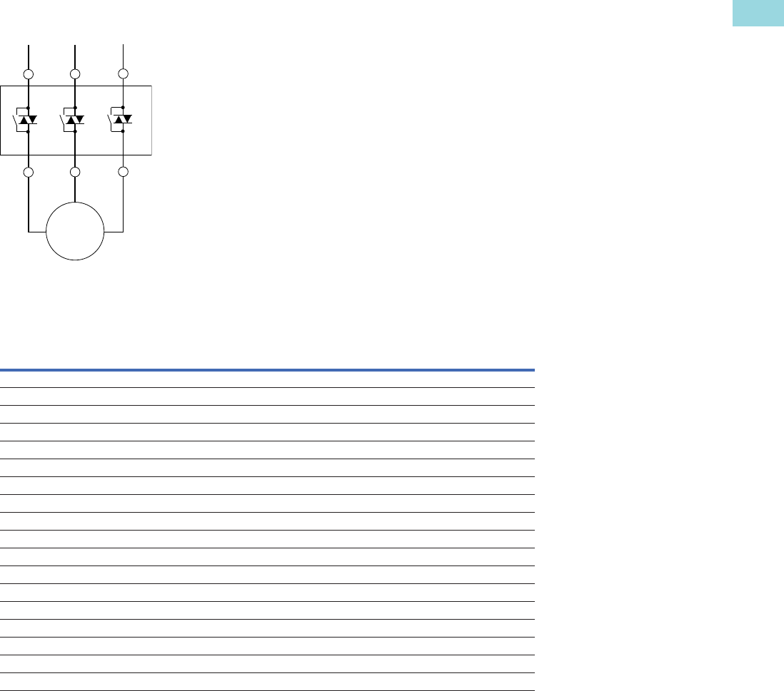
Volume 6—Solid-State Motor Control CA08100007E—February 2016 www.eaton.com V6-T1-71
1
1
1
1
1
1
1
1
1
1
1
1
1
1
1
1
1
1
1
1
1
1
1
1
1
1
1
1
1
1
1.2
Reduced Voltage Motor Starters
Solid-State Starters
Wiring Diagram
Line Connected Soft Starter
Dimensions
Approximate Dimensions in Inches (mm)
Soft Starters—S801+
Catalog
Number W H D
Weight
in Lbs (kg)
S801+
N37N3S
2.66 (67.6) 7.37 (187.2) 6.45 (163.9) 5.8 (2.6)
S801+
N66N3S
2.66 (67.6) 7.37 (187.2) 6.45 (163.9) 5.8 (2.6)
S801+
R10N3S
4.38 (111.3) 7.92 (201.1) 6.64 (168.6) 10.5 (4.8)
S801+
R13N3S
4.38 (111.3) 7.92 (201.1) 6.64 (168.6) 10.5 (4.8)
S801+
T18N3S
7.65 (194.4) 12.71 (322.9) 6.47 (164.4) 48 (21.8) with lugs 41 (18.6) without lugs
S801+
T24N3S
7.65 (194.4) 12.71 (322.9) 6.47 (164.4) 48 (21.8) with lugs 41 (18.6) without lugs
S801+
T30N3S
7.65 (194.4) 12.71 (322.9) 6.47 (164.4) 48 (21.8) with lugs 41 (18.6) without lugs
S801+
U36N3S
7.73 (196.3) 12.72 (323.1) 7.16 (181.8) 48 (21.8) with lugs 41 (18.6) without lugs
S801+
U42N3S
7.73 (196.3) 12.72 (323.1) 7.16 (181.8) 48 (21.8) with lugs 41 (18.6) without lugs
S801+
U50N3S
7.73 (196.3) 12.72 (323.1) 7.16 (181.8) 48 (21.8) with lugs 41 (18.6) without lugs
S801+
V36N3S
11.05 (280.6) 16.57 (420.8) 7.39 (187.8) 103 (46.8) with lugs 91 (41.4) without lugs
S801+
V42N3S
11.05 (280.6) 16.57 (420.8) 7.39 (187.8) 103 (46.8) with lugs 91 (41.4) without lugs
S801+
V50N3S
11.05 (280.6) 16.57 (420.8) 7.39 (187.8) 103 (46.8) with lugs 91 (41.4) without lugs
S801+
V65N3S
11.05 (280.6) 16.57 (420.8) 7.39 (187.8) 103 (46.8) with lugs 91 (41.4) without lugs
S801+
V72N3S
11.05 (280.6) 16.57 (420.8) 7.39 (187.8) 103 (46.8) with lugs 91 (41.4) without lugs
S801+
V85N3S
11.05 (280.6) 16.57 (420.8) 7.39 (187.8) 103 (46.8) with lugs 91 (41.4) without lugs
S801+
V10N3S
11.05 (280.6) 16.57 (420.8) 7.39 (187.8) 103 (46.8) with lugs 91 (41.4) without lugs
Also refer to dimension drawings on Pages V6-T1-72 through V6-T1-74.
1L1 3L2 5L3
2T1 4T2 6T3
3~
M
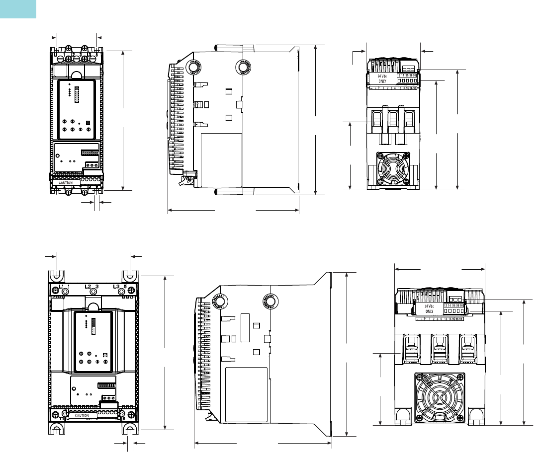
V6-T1-72 Volume 6—Solid-State Motor Control CA08100007E—February 2016 www.eaton.com
1
1
1
1
1
1
1
1
1
1
1
1
1
1
1
1
1
1
1
1
1
1
1
1
1
1
1
1
1
1
1.2
Reduced Voltage Motor Starters
Solid-State Starters
Approximate Dimensions in Inches (mm)
S801+N…
S801+R…
4X Ø
0.22
(5.5)
6.87
(174.5)
1.97 (50.0)
7.37
(187.2)
6.45 (163.9)
5.35
(135.9)
5.89
(149.7)
3.32
(84.4)
2.66
(67.6)
4X Ø
0.27
(6.8)
3.54 (90.0)
7.44
(189.0)
5.54
(140.7)
4.38 (111.3)
6.64 (168.6)
7.92
(201.2)
6.08
(154.5)
3.49
(88.5)

Volume 6—Solid-State Motor Control CA08100007E—February 2016 www.eaton.com V6-T1-73
1
1
1
1
1
1
1
1
1
1
1
1
1
1
1
1
1
1
1
1
1
1
1
1
1
1
1
1
1
1
1.2
Reduced Voltage Motor Starters
Solid-State Starters
Approximate Dimensions in Inches (mm)
S801+T…
S801+U…
11.77
(299.0) 12.71
(322.9)
6.47 (164.4)
7.65 (194.4)
5.40
(137.3)
5.95
(151.1)
5.91 (150.0)
0.28
(7.1)
6X Ø
2.95
(75.0)
11.77
(299.0)
7.16 (181.8)
6X Ø
12.72
(323.1)
6.09
(154.8)
6.64
(168.6)
2.60
(66.0)
0.28
(7.1)
5.20 (132.0)
7.73 (196.3)

V6-T1-74 Volume 6—Solid-State Motor Control CA08100007E—February 2016 www.eaton.com
1
1
1
1
1
1
1
1
1
1
1
1
1
1
1
1
1
1
1
1
1
1
1
1
1
1
1
1
1
1
1.2
Reduced Voltage Motor Starters
Solid-State Starters
Approximate Dimensions in Inches (mm)
S801+V…
4X Ø
0.2650
(6.731)
6.50
(165.1)
7.39
(187.8)
11.05 (280.6)
16.57
(420.8)
2X
15.63
(397.0)
6.79 (172.5) 3.05
(77.5)
9.84 (250.0)
0.236
(6.00)
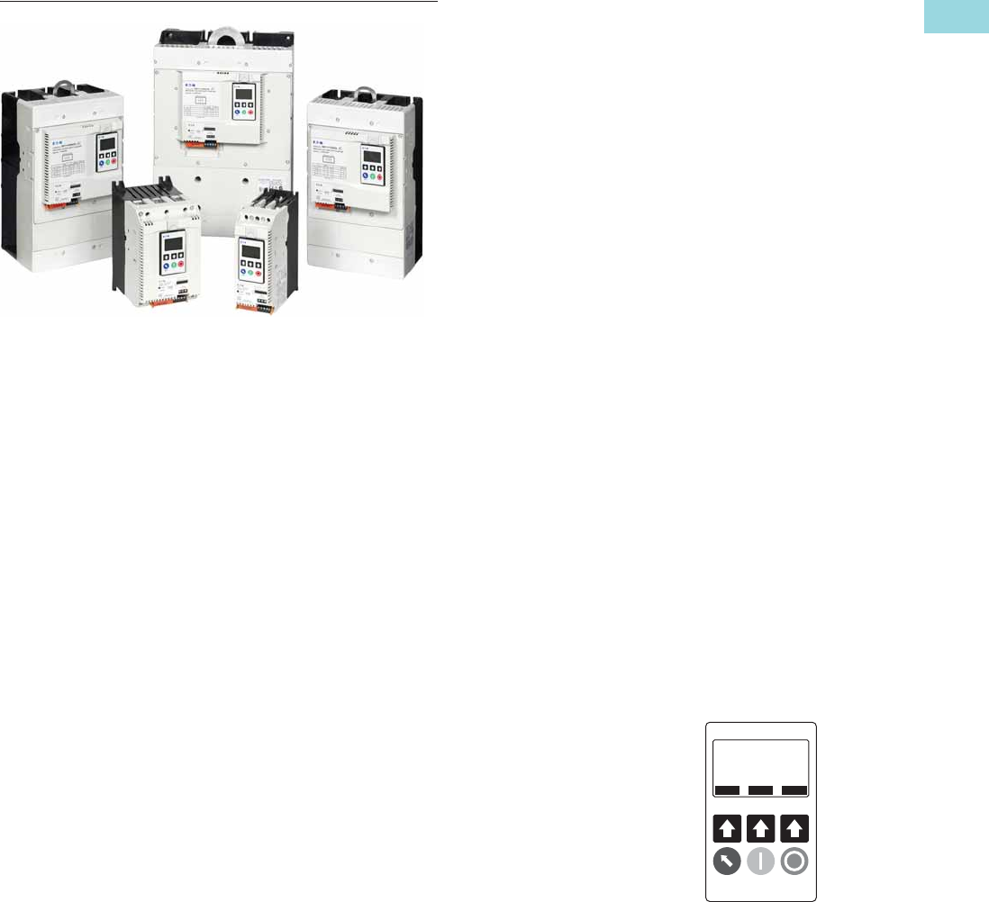
Volume 6—Solid-State Motor Control CA08100007E—February 2016 www.eaton.com V6-T1-75
1
1
1
1
1
1
1
1
1
1
1
1
1
1
1
1
1
1
1
1
1
1
1
1
1
1
1
1
1
1
1.2
Reduced Voltage Motor Starters
Solid-State Starters
Type S811+, Soft Starters with Digital Interface Module (DIM)
Contents
Description Page
Type S611, Soft Starters . . . . . . . . . . . . . . . . . . . . . V6-T1-43
Type S801+, Soft Starters. . . . . . . . . . . . . . . . . . . . V6-T1-59
Type S811+, Soft Starters with DIM
Communications . . . . . . . . . . . . . . . . . . . . . . . V6-T1-76
Operation . . . . . . . . . . . . . . . . . . . . . . . . . . . . . V6-T1-76
Features and Benefits . . . . . . . . . . . . . . . . . . . V6-T1-79
Standards and Certifications . . . . . . . . . . . . . . V6-T1-83
Instructional Leaflets . . . . . . . . . . . . . . . . . . . . V6-T1-83
Catalog Number Selection . . . . . . . . . . . . . . . . V6-T1-83
Product Selection . . . . . . . . . . . . . . . . . . . . . . . V6-T1-84
Accessories . . . . . . . . . . . . . . . . . . . . . . . . . . . V6-T1-88
Options . . . . . . . . . . . . . . . . . . . . . . . . . . . . . . . V6-T1-89
Technical Data and Specifications . . . . . . . . . . V6-T1-90
Wiring Diagrams . . . . . . . . . . . . . . . . . . . . . . . . V6-T1-94
Dimensions . . . . . . . . . . . . . . . . . . . . . . . . . . . V6-T1-95
Type S811+, Soft Starters with DIM
Product Description
Eaton’s S811+ offers all
the popular features of the
S801+ and adds new enhanced
functionality with the new
Digital Interface Module
(DIM), communications,
metering, monitoring and
diagnostics capabilities.
Eaton’s line of S811+
reduced voltage soft starters
is very compact, multi-
functional, easy to install and
easy to set operating
parameters. Designed to
control the acceleration and
deceleration of three-phase
motors up to 690 V, the line is
available from 11A to 1000A.
The S811+ is designed to
be a complete package,
combining the silicon
controlled rectifiers (SCRs),
bypass contactor and
overload in one, very compact
unit. The S811+ is available
as a component for panel
mounting, in motor control
centers or in enclosed control
(NEMA Type 1, 3R, 4, 4X, 7/9
and 12).
Application Description
Designed to control the
acceleration and deceleration
of three-phase motors, the
S811+ soft starter uses SCRs
to control the voltage to soft
start and soft stop the motor.
After the motor is started,
internal run bypass
contactors close, resulting in
the motor running directly
across-the-line. The built-in
solid-state overload protects
the motor from overload
conditions with sophisticated
algorithms that model true
motor heating, resulting in
better motor protection
and fewer nuisance trips.
Advanced protective
and diagnostic features
reduce downtime.
A voltage ramp start or
current limit start is available.
Kick start is available in either
starting mode. The soft stop
option allows for a ramp
stop time that is longer than
the coast to stop time. The
pump control option in the
S811+ Premium provides
a smooth transition for
starting and stopping a
motor and eliminating the
“water-hammer” effect
that can damage pipes,
valves and pumps.
The S811+ offers an
impressive
array of advanced
protective features. Not only
are the
protective features
selectable,
but many offer
variable settings and
adjustable time delays to
ride through system
discrepancies. Protective
features may also be set to
Warning status to avoid
nuisance trips.
The S811+ has an easy to
use Digital Interface Module
(DIM) that allows the user to
configure the device and to
read system parameters and
monitor system values. The
DIM includes an LCD display
and keypad to scroll through
the various menus. The DIM
allows the user to modify
control parameters, enable
or disable protections, set
communication variables,
monitor system parameters
such as line voltages and
currents, and access the
fault queue.
The DIM can be removed
from the S811+ and be
remote mounted. Kits are
available to door mount the
DIM, enabling users to safely
configure, commission,
monitor and troubleshoot
the system at the electrical
panel without opening the
enclosure door. This will help
eliminate the possibility of an
arc flash incident.
Digital Interface
Module (DIM)
ESC
ONLN SS OXFDO1 H STOP
Monitoring
PREV NEXT ENTER
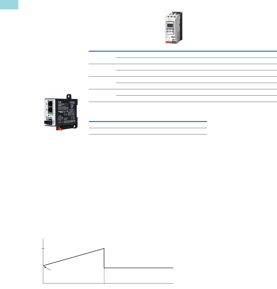
V6-T1-76 Volume 6—Solid-State Motor Control CA08100007E—February 2016 www.eaton.com
1
1
1
1
1
1
1
1
1
1
1
1
1
1
1
1
1
1
1
1
1
1
1
1
1
1
1
1
1
1
1.2
Reduced Voltage Motor Starters
Solid-State Starters
C441 Communication Card Options
Designed for use with soft starters …
Note: Refer to Volume 5—Motor Control and Protection, CA08100006E, tab 5.4 for additional details and
BR042002EN brochure for C441 communication module accessories for overload relays and soft starters.
Operation
Starting and Stopping Modes
The S811+ has a variety of starting and stopping methods to provide superior performance in
the most demanding applications. The motor can be started in either voltage ramp start or
current limit start mode. Kick start and soft stop are available within both starting modes. The
user has the option to configure two independent start ramp profiles to accommodate variations
in starting requirements.
Voltage Ramp Start
Provides a voltage ramp to the
motor resulting in a constant
torque increase. The most
commonly used form of soft
start, this start mode allows
you to set the initial torque
value and the duration of the
ramp to full voltage
conditions. Bypass contactors
close after ramp time.
●Adjustable initial torque
0–85% of locked rotor
torque
●Adjustable ramp time
0.5–180 seconds (0.5–360
seconds with the S811+
Premium)
Starting Characteristics—Ramp Start
Note
1C441 standalone communication modules can be used as general purpose I/O. This allows a customer to monitor the status of any non-communicating
product over the selected protocol by wiring fault or auxiliary contacts from that product to the C441 communication module on-board I/O.
Catalog
Number
Input
Signal Type
General
Purpose I/O 1
Protocol S811+ Mounting Options
Modbus RTU C441NS 120 Vac ■ ■ Standalone—DIN rail/panel mount
C441PS 24 Vdc ■ ■ Standalone—DIN rail/panel mount
DeviceNet C441KS 120 Vac ■ ■ Standalone—DIN rail/panel mount
C441LS 24 Vdc ■ ■ Standalone—DIN rail/panel mount
PROFIBUS C441SS 120 Vac ■ ■ Standalone—DIN rail/panel mount
C441QS 24 Vdc ■ ■ Standalone—DIN rail/panel mount
Modbus TCP,
EtherNet/IP
C441U 120 Vac ■ ■ Standalone—DIN rail/panel mount
C441V 24 Vdc ■ ■ Standalone—DIN rail/panel mount
Recommended Power Supply Catalog Number
85–264 Vac single-phase input, 24 Vdc output PSG240E24RM
360–575 Vac three-phase input, 24 Vdc output PSG240F24RM
Communications
The S811+ is equipped with
native Modbus RTU
communication capabilities
and may be connected to a
variety of networks, including
DeviceNet, Modbus TCP,
EtherNet/IP and PROFIBUS
using the C441 series
communication modules for
easy integration into any
PLC or DCS system.
The modules come standard
with four inputs and two relay
outputs. C441 communication
modules can also be used
independently for standalone
I/O applications.
Run
100%
Locked Rotor Torque
Time (Seconds)
Initial
Torque
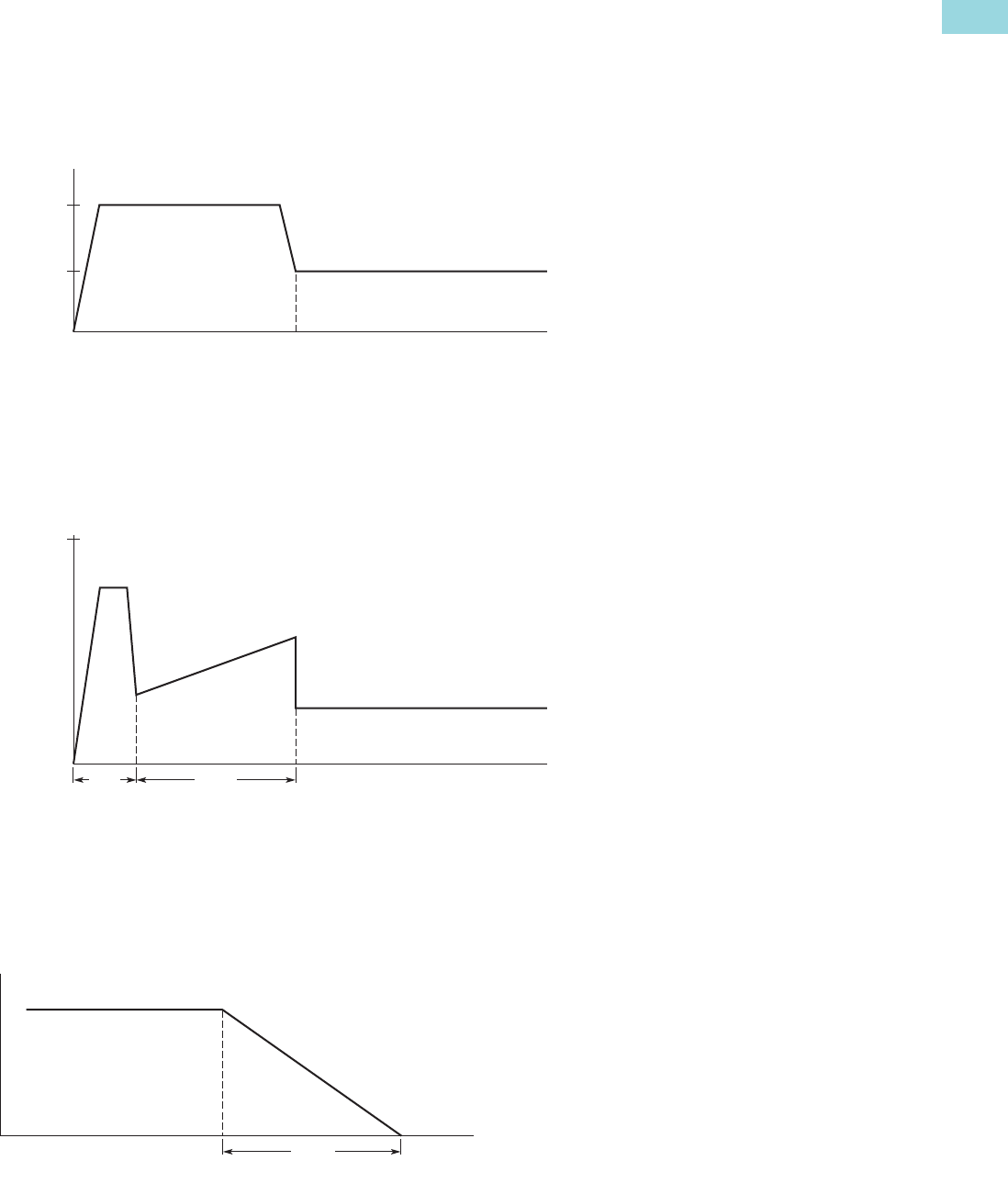
Volume 6—Solid-State Motor Control CA08100007E—February 2016 www.eaton.com V6-T1-77
1
1
1
1
1
1
1
1
1
1
1
1
1
1
1
1
1
1
1
1
1
1
1
1
1
1
1
1
1
1
1.2
Reduced Voltage Motor Starters
Solid-State Starters
Current Limit Start
Limits the maximum current
available to the motor during
the start phase. This mode of
soft starting is used when it
becomes necessary to limit
the maximum starting current
due to long start times or to
protect the motor. This start
mode allows you to set the
maximum starting current as a
percentage of locked rotor
current and the duration of the
current limit. Bypass
contactors close after current
limit time.
●Maximum current of
0–85% locked rotor current
●Adjustable ramp time
0.5–180 seconds (0.5–360
seconds with the S811+
Premium)
Starting Characteristics—Current Limit Start
Kick Start
Selectable feature in both
voltage ramp start and
current limit start modes.
Provides a current and torque
“kick” for 0 to 2.0 seconds.
This provides greater initial
current to develop additional
torque to breakaway a high
friction load.
●0–85% of locked rotor
torque
●0–2.0 seconds duration
Starting Characteristics—Kick Start
Soft Stop
Allows for a controlled
stopping of a load. Used
when a stop-time that is
greater than the coast-to-stop
time is desired. Often used
with high friction loads where
a sudden stop may cause
system or load damage.
●Stop time = 0–60 seconds
Starting Characteristics—Soft Stop
Run
Max.
Allowed
100%
FLA
Current
Time (Seconds)
100%
Locked Rotor Torque
Ramp
Time (Seconds)
Kick
Start
Run
Ramp
Time (Seconds)
Run

V6-T1-78 Volume 6—Solid-State Motor Control CA08100007E—February 2016 www.eaton.com
1
1
1
1
1
1
1
1
1
1
1
1
1
1
1
1
1
1
1
1
1
1
1
1
1
1
1
1
1
1
1.2
Reduced Voltage Motor Starters
Solid-State Starters
Edge and Level Sensing Control
Edge Sensing
Edge sensing requires
+24 Vdc power be
momentarily applied to
Control Terminal Block Pin 1
(with Terminal P at +24 Vdc)
to initiate a start under all
conditions. After a stop or
fault occurs, the +24 Vdc
must be removed, then
reapplied to Terminal Pin 1
before another start can
occur. This control
configuration should be used
when restarting of the motor
after a fault or stop must be
supervised manually or as a
part of a control scheme. The
cycling of +24 Vdc power to
Terminal 1 Pin before starting
is required regardless of the
position of the auto reset
switch on the DIM.
Level Sensing
Level sensing will enable a
motor to restart after a fault
is cleared without cycling
+24 Vdc power to Terminal
Pin 1 as long as:
●Terminal Pin P is supplied
with +24 Vdc (to start
from Control Terminal
Block, Terminal Pin 3
must also be enabled)
●The auto reset switch on
the DIM is set to enabled
●All faults have been reset
This control configuration
should be used where it is
desirable to restart a motor
after a fault without additional
manual or automatic control.
An example of this condition
would be on a remote
pumping station where it is
desirable to automatically
restart a pump after a power
outage without operator
intervention.
Note: If the auto reset feature
is used, CAUTION must be
exercised to ensure that any
restart occurs in a safe manner.

Volume 6—Solid-State Motor Control CA08100007E—February 2016 www.eaton.com V6-T1-79
1
1
1
1
1
1
1
1
1
1
1
1
1
1
1
1
1
1
1
1
1
1
1
1
1
1
1
1
1
1
1.2
Reduced Voltage Motor Starters
Solid-State Starters
Features and Benefits
●Communication
capabilities with various
protocols
●The Digital Interface
Module (DIM) provides an
intuitive, easy-to-use
human interface with
powerful configuration
capabilities to maximize
system performance
●Door or device mounted
DIM enables users to
safely configure,
commission, monitor and
troubleshoot the system at
the electrical panel without
opening the enclo
sure door,
eliminating the possibility
of
an arc flash incident
●System operating
parameters can be
monitored enterprise-wide
through a communications
network. Increase uptime
by providing data for
process management and
preventive diagnostics
●Run internal bypass mode
greatly reduces internal
heating created by the
greater power dissipation
in the SCRs. Bypass
contactor directly connects
the motor to the line and
improves system efficiency
by reducing internal power
losses
●
Internal solid-state overload
protection provides accurate
current measurement and
trip settings. Sophisticated
algorithms solve a series
of differential equations
that model true motor
heating and cooling,
resulting in superior motor
overload protection while
minimizing nuisance trips.
Advanced selectable
protective features
safeguard the motor
and system against a
variety of system faults
●Internal run bypass
contactors and overload
protection eliminate the
need for additional devices,
reducing enclosure sizes,
minimizing installation and
wiring time, and reducing
overall assembly size
and cost
●Wide range of overload
FLA settings (31–100%
of rated current) and a
selectable trip class (5–30)
offers users the flexibility
to fine tune the starter to
match specific application
requirements
●Variable ramp times and
torque control settings
provide unlimited starting
configurations, allowing
for maximum application
flexibility
●Kick-start feature enables
soft starting of high
friction loads
●Soft stop control for
applications where an
abrupt stop of the load
is not acceptable
●The S811+ Premium with
sophisticated pump control
algorithms on both starting
and stopping that minimize
the pressure surges that
cause water hammer. The
pump control feature will
maximize the life of the
pump and piping systems
while minimizing the
downtime caused by
system failure
●Six SCRs control all three
motor phases, providing
smooth acceleration and
deceleration performance
●Soft acceleration and
deceleration reduces
wear on belts, gears,
chains, clutches, shafts and
bearings
●Reduce the peak inrush
current’s stress on the
power system
●Manage peak starting
torque to diminish
mechanical system
wear and damage
●24 Vdc control voltage
enhances personnel
and equipment safety
●Removable, lockable
control terminal block
reduces maintenance
costs. Also provides the
opportunity for OEMs to
reduce assembly and test
costs by utilizing pre-
assembled wire harnesses
Motor Wiring Configuration
User Selectable Inline or
Inside-the-Delta
Mains Motor Wiring
Configuration is
accomplished by simply
selecting the required
configuration from a menu.
This feature allows
adaptability from one
configuration to another
without any additional
programming operations and
reduces inventory levels by
not having to stock both
configurations.
Modbus Native
Communications Protocol
Modbus RTU communications
in now standard on all S811+
units. This allows users to
quickly configure the unit for
network communications
using a common protocol.
Adapters are available for
users who prefer to use
EtherNet/IP or Modbus TCP
protocols.
Programmable Control
Terminal Block
Functionality
Four programmable terminals
on the S811+ enable the user
to expand functionality with
options such as a second
start ramp profile, externally
triggered trip or warning
functions, analog inputs, and
others, in addition to the
normal start, stop, reset, and
so on, functions.
Second Start Ramp Profile
Capability
A second start ramp profile
may be configured for the
soft starter. This profile is
independent of the primary
profile and retains all the
parameter options such as
start time and initial torques.
With a signal at a terminal
programmed for this feature,
the second profile may be
selected by a pushbutton
station or a network.
Alarm-No-Trip Functionality
Some applications require the
ability to effectively disable
most protections with the
intent of enabling the RVSS
unit to control a motor under
the most severe operating
conditions characterized by
current or voltage
imbalances, high or low value
deviations, or other fault
conditions. This function
causes the S811+ to ignore
most fault trip conditions and
continue operation of the
application.
Digital Interface Module
(DIM) Cloning
For OEMs or other users that
desire to load identical
parameter settings into
multiple RVSS units, the DIM
may be used to extract and
duplicate parameter settings
from one RVSS and loaded
into other units, saving time,
effort, and reducing chances
for errors while programming.

V6-T1-80 Volume 6—Solid-State Motor Control CA08100007E—February 2016 www.eaton.com
1
1
1
1
1
1
1
1
1
1
1
1
1
1
1
1
1
1
1
1
1
1
1
1
1
1
1
1
1
1
1.2
Reduced Voltage Motor Starters
Solid-State Starters
Protective Features
All protective features can be configured, enabled or disabled with the DIM or through the
communications network.
Motor Overload
The S811+ includes electronic
overload protection as
standard. The overload meets
applicable requirements for a
motor overload protective
device. The overload protects
the motor from over heat
conditions with the use of
sophisticated algorithms
that model true motor heating,
resulting in superior motor
protection and fewer nuisance
trips.
The S811+ calculates a
thermal memory value based
on the heat energy
introduced into the motor
during the start process. A
100% value represents the
maximum safe internal
temperature of the motor.
When the thermal memory
value reaches 100%, an
overload trip will occur
removing power to the
motor. Upon trip, the S811+
stores the calculated motor
heating value and will not
allow a motor re-start until
the motor has a thermal
memory value of less than
100%. This feature ensures
the motor will not be
damaged by repeated
overload trip, reset and re-
start cycles.
The thermal memory value
can be monitored through the
DIM or the communications
network. The thermal memory
value can be of great use in
determining an impending
overload trip condition.Alarms
can be implemented in the
process monitoring system
warning of an impending trip
before a trip occurs halting
the process. Costly system
downtime can be avoided.
The trip current is adjusted to
match the specific application
requirements by entering the
motor nameplate full load
current rating and trip class.
The FLA parameter is
adjustable from 32% to 100%
of the unit’s rated current.
The overload trip class is
adjustable from class 5
through class 30. The overload
is ambient temperature
compensated—meaning its
trip characteristics will not
vary with changes in ambient
temperature. The overload
protection can be enabled,
disabled, or disabled on start.
Short Circuit
The use of a short-circuit
protective device in
coordination with the S811+
is required in branch motor
circuits by most electrical
codes. Short-circuit
coordination ratings with
both fuses and Eaton molded
case circuit breakers are
available providing customers
with design flexibility.
The S811+ has short-circuit
coordination ratings as
an open component, an
enclosed starter, and in
a motor control center.
External E-Stop
Emergency Stop functionality
may be triggered from an
external source. Removal
of the 24 Vdc signal from
a terminal configured for
E-Stop will initiate an E-Stop
action. The External E-Stop
option is useful in applications
where it is desirable to
accomplish a motor shutdown
in the event that an external
condition(s) exist that will
damage system components
and/or product flows or
operations.
External Trip
External Trip functionality
may be triggered from an
external source. Removal of
the 24 Vdc signal from a
terminal configured for
External Trip will initiate an
External Trip action. The
External Trip option is useful
in applications where it is
desirable to accomplish a
motor stop in the event that
an external condition(s) exist
that will damage system
components and/or product
flows or operations.
Fault Warning Functionality
Selected protection
parameters may be assigned
to provide a Fault Warning
instead of a Fault Trip with
user adjustable set points.
When a Fault Warning
condition is detected, the
fault condition is reported via
the DIM, network
connection, or an auxiliary
relay configured for this
function. The soft starter
remains in operation. At such
time the fault condition no
longer exists, the Fault
Warning message will be
extinguished.
External Warning
The S811+ will accept a
Warning signal from an
external source or device. In a
fashion similar to the Fault
Warning, the fault condition is
reported via the DIM,
network connection, or an
auxiliary relay configured for
this function. The soft starter
remains in operation. At such
time the fault condition no
longer exists, the Fault
Warning message will be
extinguished.
Custom Fault/Warning
Auxiliary Relays
Up to three fault and/or
warning codes may be
selected to operate an
auxiliary relay configured to
operate when any of these
codes are detected. This
option enables the user to
provide external warnings or
fault indications to increase
monitoring effectiveness and
to provide additional system
control.
Motor Power
Motor Power can be not only
be monitored, but trip levels
can be adjusted to provide
indications of system
malfunctions or operating
discrepancies. Both High and
Low Power thresholds can be
set to provide Fault Warning
or Fault Trip functions.
Additionally, fault delays
times may be set to up to
60 seconds.
Analog Input
An input control terminal
may be configured to accept
a 0–20 mA DC signal with
range scaling. This feature
enables the S811+ to
respond to an external device
that may be monitoring a
critical component or process
and provides Fault Trip or
Fault Warning capability to
protect operating systems
and processes.
Start Delay
Three start delay timers are
available to enhance motor
protection or to provide
simple logic functions to
coordinate motor control with
other devices in the system.
The timers will allow delays
from 24 Vdc power up,
receipt of a valid START
command, or a delay in
switch from one start ramp
profile to another.

Volume 6—Solid-State Motor Control CA08100007E—February 2016 www.eaton.com V6-T1-81
1
1
1
1
1
1
1
1
1
1
1
1
1
1
1
1
1
1
1
1
1
1
1
1
1
1
1
1
1
1
1.2
Reduced Voltage Motor Starters
Solid-State Starters
Jam
Excessive current and torque
up to locked rotor levels can
occur in a jam condition. The
condition can result in stress
and damage to the motor, load,
mechanical system, and the
electrical distribution system.
Jam protection prevents the
stress and damage from a
jam during normal run. After
the motor is in bypass, a
current greater than 300%
FLA setting will cause the
starter to trip on a jam fault.
Stall
Excessive current and torque
up to locked rotor levels can
occur in a stall condition. The
condition can lead to an
overload trip and result in
stress and damage to the
motor, load, mechanical
system, and the electrical
distribution system. Stall
protection prevents stress and
damage to a motor that has
not come up to speed during
the soft start time. The S811+
will trip to protect the system
in the event that the motor did
not get to the rated speed in
the defined soft start period. A
current greater than 200% FLA
at the end of the soft start
period will cause the starter to
trip on a stall fault.
Pole Over Temperature
High ambient temperatures,
extended ramp times and
high duty cycle conditions
may cause the S811+ power
pole conductors to reach a
temperature that exceeds
their thermal rating. The
S811+ is equipped with
sensors that monitor the
temperature of the power
poles. Over temperature
protection occurs if the
power pole’s thermal
capacity is exceeded. The
soft starter will trip in over
temperature conditions,
preventing device failure.
Each power pole temperature
value can be monitored
through the DIM or the
communications network.
This feature can be of use in
determining an impending
over temperature trip
condition.
When using a
communications network,
alarms can be implemented
in the process monitoring
system warning of an
impending trip before the trip
occurs, halting the process.
Phase Loss
Loss of a phase can cause
a significant increase in
the current drawn in the
remaining two phases.
Phase loss can lead to motor
damage before an eventual
overload trip occurs. Phase
loss is typically an indication
of a failure in the electrical
distribution system. The
S811+ will detect a phase
loss and trip if any phase
current
drops below a preset value.
The phase loss trip level is
adjustable from 0% to 100%
of the average of the other
two phase levels with an
adjustable trip delay of 0.1
to 60 seconds.
Phase Imbalance
Phase current or voltage
imbalance can cause a
significant increase in
the current drawn in the
remaining two phases.
Phase imbalance can lead
to motor damage before an
eventual overload trip. Phase
imbalance is typically an
indication of a failure in the
electrical distribution system
or the motor. The S811+ will
detect both current and
voltage phase imbalances
and trip if any phase becomes
imbalanced as compared to
the average of the other
two phases.
The phase current imbalance
trip level is adjustable from
0% to 100% of the average
of the current in the other
two phases with an
adjustable trip delay of
0.1 to 60 seconds.
The phase voltage imbalance
trip level is adjustable from
0% to 100% of the average
of the voltage in the other
two phases with an
adjustable trip delay of
0.1 to 60 seconds.
Reset Mode
The S811+ can be set up for
automatic or manual reset
on trip. The manual reset
mode requires the operator to
physically press the
RESET button located on
the soft starter. The trip can
be manually reset through the
DIM or through the
communications network.
The trip can also be
electrically reset by
energizing a 24 Vdc input on
the control terminal block.
The automatic reset mode
allows the soft starter to be
automatically reset as soon
as the trip condition is no
longer present. With the
automatic reset mode, after
the fault is no longer present,
the motor will be restarted
as soon as a valid start signal
is present.
Phase Reversal
The S811+ can determine
if the proper line phase
sequence is present by
default. The device will trip
if the line phase sequence is
something other than A-B-C.
The S811+ can be configured
to operate under reversed
phase conditions (A-C-B).
Shorted SCR Detection
The S811+ monitors the
operation of the power poles
and will trip under a shorted
SCR condition.
Open SCR Detection
The S811+ monitors the
operation of the power poles
and will trip under an open
SCR condition.
Ground Fault Protection
The S811+ Premium and
690 V versions meet the IEC
Ground Fault trip thresholds.
Reference Application Note
AP039007EN for more
information.
Low Current
Low current conditions can
be a result of a loss of load
or a failure in the mechanical
system. The S811+ has low
current protection that will
trip if the average rms current
falls below a preset value.
The low current protection
can be programmed as a
percent of motor FLA from
0% to 100%.
Low Voltage
Low voltage conditions
can result from disturbances
in the electrical power
distribution system. Low
voltage conditions can cause
a malfunction and damage
to electrical equipment.
The S811+ has low voltage
protection that will trip if the
average rms voltage falls
below a preset value. The
low voltage protection can
be programmed as a percent
of nominal voltage from
1% to 99% with a trip delay
of 0.1 to 60 seconds to
accommodate short
temporary voltage drops
during the start process.
High Voltage
High voltage conditions can
result from disturbances in
the electrical power
distribution system. High
voltage conditions can cause
malfunctions or failures of
electrical equipment. The
S811+ has high voltage
protection that will trip if
the average rms voltage is
greater than a preset value.
The high voltage protection
can be programmed as a
percent of nominal voltage
from 101% to 120% with
a trip delay of 0.1 to
60 seconds.

V6-T1-82 Volume 6—Solid-State Motor Control CA08100007E—February 2016 www.eaton.com
1
1
1
1
1
1
1
1
1
1
1
1
1
1
1
1
1
1
1
1
1
1
1
1
1
1
1
1
1
1
1.2
Reduced Voltage Motor Starters
Solid-State Starters
Monitoring Capabilities
The S811+ has an impressive array of system monitoring capabilities that allows users to access real
time process and diagnostic data. This data can be viewed at the device with the DIM or through a
communications network. Data over a communications network can provide valuable insight into the
condition of the equipment and processes. Maintenance and production personnel can monitor critical
operational and maintenance data from a central control station that can be located far away from the
production facility. Process data can be monitored to determine system anomalies that may indicate a
need for preventive maintenance or an impeding failure. Adjustments made through the communications
network can reduce costs by minimizing the time traveling to the location where the motor controls are
located. When faults do occur, real time fault data can assist maintenance in troubleshooting and planning
repair resources. Remote reset signals can be given to tripped devices without the need for manual
intervention by maintenance personnel.
Average Line Current
Provides the average of
the three-phase rms line
currents in amps, accurate to
within 2%. Current data can
be used to indicate a need for
maintenance. Increased
currents in a fixed load
application can indicate a
reduction in system
efficiencies and performance,
signifying system
maintenance is due.
Average Pole Current
Provides the average of
the three-phase rms pole
currents in amps, accurate to
within 2%. The pole current
is the current through the soft
starter. The line and pole
current will be identical in
inline applications, and will
differ in inside-the-delta
applications.
Average Line Current
as a % FLA
Provides the average rms line
current as a percentage of
the S811+ FLA setting.
Three-Phase Line Currents
Provides three rms phase line
currents in amps, accurate to
within 2%. Imbalances or
changes in the relative phase
current to one another can
indicate anomalies in the
motor or electrical distribution
system.
Three-Phase Pole Currents
Provides three rms phase
pole currents in amps,
accurate to within 2%. The
pole current is the current
through the soft starter.
The line and pole current
will be identical in in-line
applications, and will differ in
inside-the-delta applications.
Three-Phase Line Voltages
Provides the individual rms
three-phase line voltages.
Imbalances or changes in
|the relative phase voltage
to one another can indicate
anomalies in the motor or
electrical distribution system.
Voltage can be used to
monitor electrical distribution
system performance.
Warnings, alarms and
system actions to low or
high voltage conditions can
be implemented.
Percent Thermal Memory
Provides the real time
calculated thermal memory
value. The S811+ calculates
thermal memory value. A 100%
value represents the maximum
safe internal temperature of
the motor. When the thermal
memory value reaches
100%, an overload trip will
occur, removing power to the
motor.
The thermal memory value
can be of great use in
determining an impending
overload trip condition. When
using a communications
network, alarms can be
implemented in the process
monitoring system warning
of an impending trip before
the trip occurs, halting the
process. Costly system
downtime can be avoided.
DC Control Voltage
Monitors level of the 24 Vdc
control voltage. Fluctuations
in control voltage can cause
component malfunction and
failure. System control
voltage data can be used to
implement warnings, alarms
and system actions to low or
high voltage conditions.
Pole Temperature
Increases in power pole
temperature are caused by
increases in ambient
temperature, start/stop times
and start duty cycles.
Changes in pole
temperatures represent a
change in system operating
conditions. Identifying
unexpected operating
conditions or changes can
prompt maintenance and
aid in process evaluation
activities.
PCB Device Temperature
An increase in printed circuit
board (PCB) device
temperature is a strong
indication of an increase in
ambient temperature. High
ambient temperature
operation can be identified
with the device temperature
data. Device temperature
increases can be due to
undersized enclosures, failure
of cooling fans or blocked
venting. High operating
temperatures will reduce the
life of all electrical equipment
in the enclosure.
Start Count
Start count data can be used
to monitor system output,
schedule preventative
maintenance, identify system
anomalies and identify
changes in system operation.
Average Line Power
Provides the average of the
three-phase line power in
kilowatts, accurate to 5%.
Power data may be used
to monitor power transmitted
to the load. Increased power
demand may indicate degraded
system components or
connections. Additionally,
such data is useful in
determine power utilization
in branch circuits consisting
of multiple loads.
Power Factor
Provides the three-phase
power factor value, accurate
to 5%. The power factor of
the circuit may be used to
identify circuit conditions that
may need to be corrected
due to low power factor
indications. Low circuit power
factor can indicate improper
or degraded components.
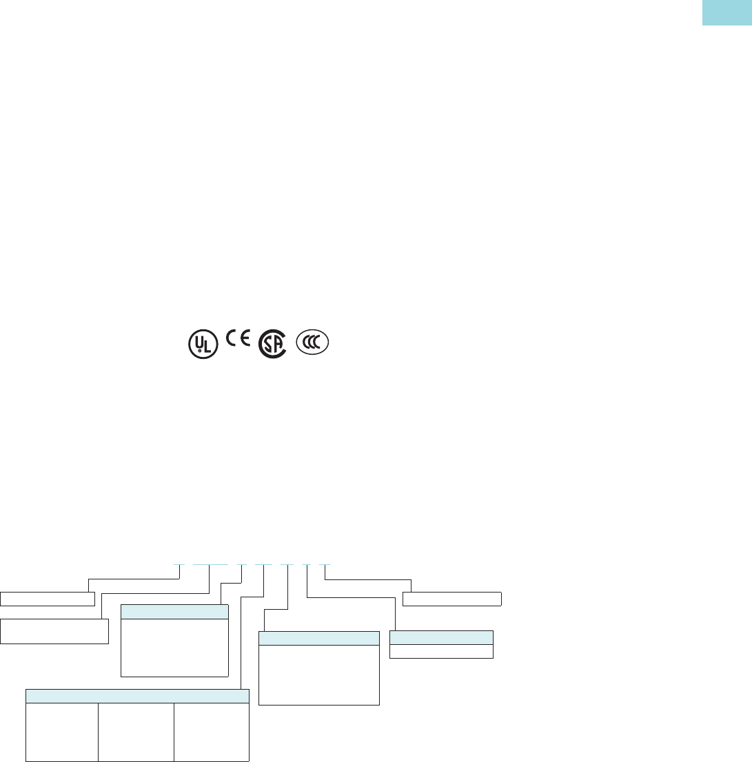
Volume 6—Solid-State Motor Control CA08100007E—February 2016 www.eaton.com V6-T1-83
1
1
1
1
1
1
1
1
1
1
1
1
1
1
1
1
1
1
1
1
1
1
1
1
1
1
1
1
1
1
1.2
Reduced Voltage Motor Starters
Solid-State Starters
Diagnostics
Fault Queue
Current fault and a fault queue
containing the last nine
system faults can be read
through the DIM or
communications network.
Fault identification can
minimize troubleshooting
time and cost, and prevent
arc flash incidents. The fault
queue can be remotely
accessed through a
communications network
to assist in planning
maintenance resources.
Thirty (30) different faults can
be identified by the S811+.
Control Status
The S811+ provides data that
represents system conditions
that can be read through the
DIM or the communications
network. This data identifies
the status of the system and
the control commands the
system is requesting of the
S811+. This can be used for
advanced troubleshooting
and system integration
activities.
Breaker Status
The S811+ has provisions
to read and display circuit
breaker status. Eaton
communicating cover
control or other
communicating protective
device is required to take
advantage of this feature.
Standards and Certifications
●IEC 60947-4-2
●EN 60947-4-2
●UL listed (NMFT-E202571)
S811+N37… through
S811+V85…
●UL recognized (NMFT2)
S811+V10…
●CE marked
●CSA certified (3211 06)
●CSA elevator (2411 01)
Instructional Leaflets
●User manual MN03900001E
●Outline drawings:
●S811+N…: 10-8574
●S811+R…: 10-8575
●S811+T…: 10-8576
●S811+U…: 10-8857
●S811+V…: 10-8577
Catalog Number Selection
S811+ Open Soft Starters 1
Notes
1All units require a 24 Vdc power supply found on catalog Page V6-T1-88, or equivalent.
2S811+T…, S811+U… and S811+V… units require lug kits found on Page V6-T1-88.
3S811+U50… unit does not have IEC certification.
4Level/Edge Sense, Inline or Inside-the-Delta wiring configuration.
5Level/Edge Sense, Inline or Inside-the-Delta wiring configuration, pump control and extended ramp.
6Not available in S811+U….
7Level/Edge Sense, Inline wiring configuration, pump control, extended ramp.
8Ground fault protection included.
S811+ T30 N 3 S
Frame Size 2
N = 65 mm
R = 110 mm
T = 200 mm
U = 200 mm
V = 290 mm
Ampere Rating
37 = 37A
66 = 66A
10 = 105A
13 = 135A
18 = 180A
24 = 240A
30 = 304A
36 = 360A
42 = 420A
50 = 500A 3
65 = 650A
72 = 720A
85 = 850A
10 = 1000A
S = Standard soft starter
Number of Poles
3 = Three-pole device
Options
N = No options 4
P = Premium, 600 V rated 58
V = Premium, 690 V rated
(S811+ frame size
T and V only) 678
S = Soft starter
811+ = Non-combination
soft starter
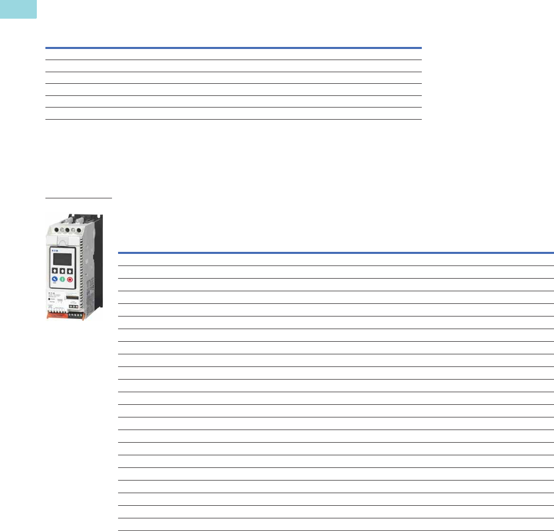
V6-T1-84 Volume 6—Solid-State Motor Control CA08100007E—February 2016 www.eaton.com
1
1
1
1
1
1
1
1
1
1
1
1
1
1
1
1
1
1
1
1
1
1
1
1
1
1
1
1
1
1
1.2
Reduced Voltage Motor Starters
Solid-State Starters
Product Selection
Standard Duty Ratings
Motor applications and
customer needs come in
many different varieties.
With the standard and severe
duty rating tables, we have
attempted to provide
guidelines on what the soft
starter is capable of.
If the application falls under
these categories, you can
use these charts. For other
applications, or when a
question arises, consult
with your local Eaton
representative or call our
Technical Resource Center.
Standard Duty—15 Second Ramp, 300% Current Limit at 40°C, Inline Connection
Notes
1 Replace N3S with P3S for premium/pump option.
2 S811+U5O… rating does not have IEC certification.
Starting Method
Ramp Current
% of FLA
Ramp Time
Seconds Starts per Hour
Ambient
Temperature
Soft start 300% 30 sec. 3 50°C
Full voltage 500% 10 sec. 3 50°C
Wye-delta 350% 20 sec. 3 50°C
80% RVAT 480% 20 sec. 2 50°C
65% RVAT 390% 20 sec. 3 50°C
50% RVAT 300% 20 sec. 4 50°C
Rated
Current
Three-Phase Motors
Catalog
Number 1
kW Rating (50 Hz) hp Rating (60 Hz)
230 V 380–400 V 440 V
200 V 230 V 460 V 575–690 V
1.0SF 1.15SF 1.0SF 1.15SF 1.0SF 1.15SF 1.0SF 1.15SF
Frame Size N
37 10 18.5 18.5 10 10 10 10 25 20 30 30 S811+N37N3S
66 18.5 30 37 20 15 20 20 50 40 60 50 S811+N66N3S
Frame Size R
105 30 55 59 30254030756010075S811+R10N3S
135 40 63 80 4030504010075125100S811+R13N3S
Frame Size T
180 51 90 110 60 50 60 60 150 125 150 150 S811+T18N3S
240 75 11014775607575200150200200S811+T24N3S
304 90 160 185 100 75 100 100 250 200 300 250 S811+T30N3S
Frame Size U
360 110 185 220 125 100 150 125 300 250 350 300 S811+U36N3S
420 129 220 257 150 125 175 150 350 300 450 350 S811+U42N3S
500 150 257 300 150 150 200 150 400 350 500 450 S811+U50N3S 2
Frame Size V
360 110 185 220 125 100 150 125 300 250 350 300 S811+V36N3S
420 129 220 257 150 125 175 150 350 300 450 350 S811+V42N3S
500 150 257 300 150 150 200 150 400 350 500 450 S811+V50N3S
650 200 355 425 250 200 250 200 500 450 600 500 S811+V65N3S
720 220 400 450 — — 300 250 600 500 700 600 S811+V72N3S
850 257 475 500 — — 350 300 700 600 900 700 S811+V85N3S
1000 277 525 550 — — 400 350 800 700 900 800 S811+V10N3S
S811+
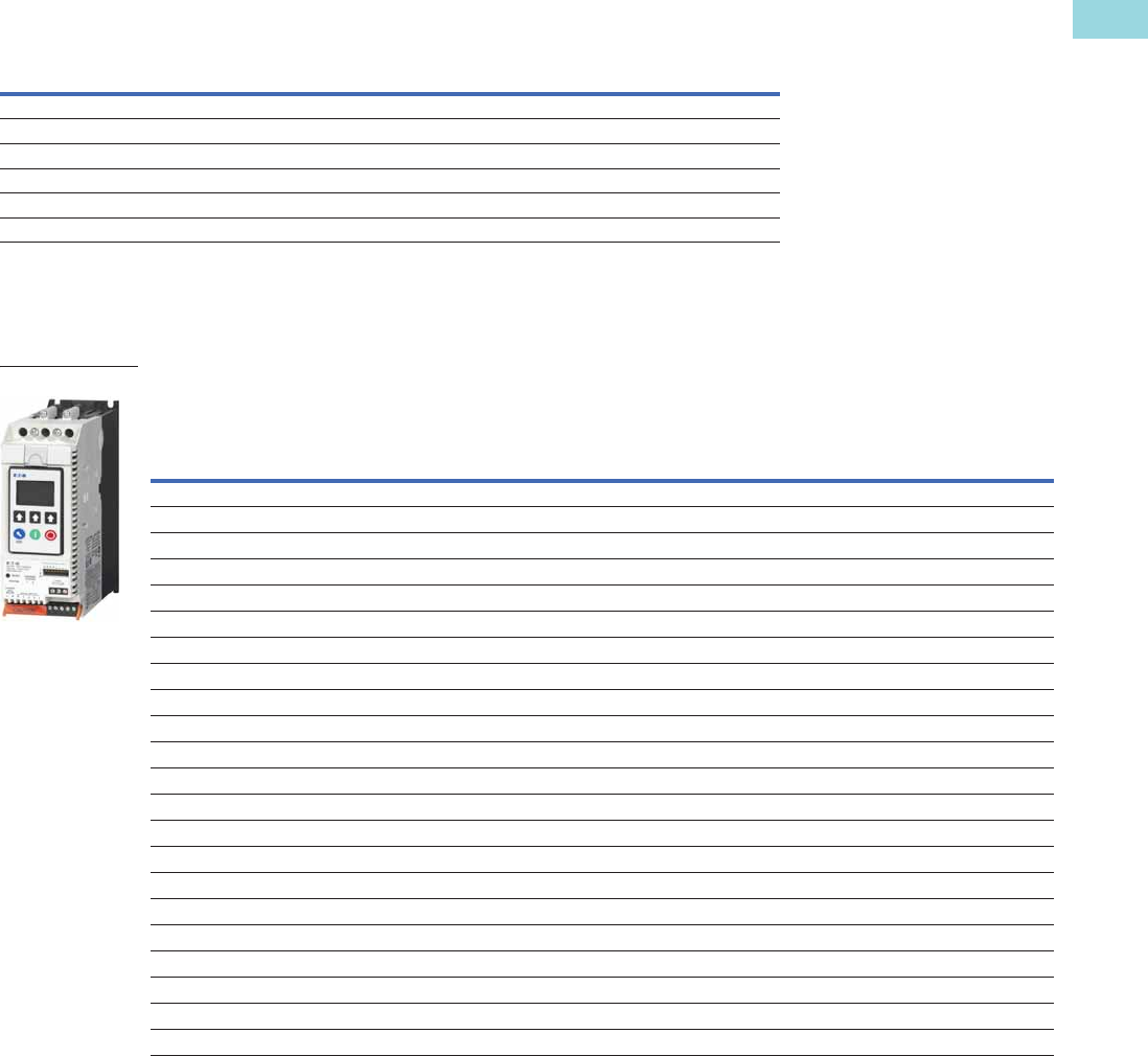
Volume 6—Solid-State Motor Control CA08100007E—February 2016 www.eaton.com V6-T1-85
1
1
1
1
1
1
1
1
1
1
1
1
1
1
1
1
1
1
1
1
1
1
1
1
1
1
1
1
1
1
1.2
Reduced Voltage Motor Starters
Solid-State Starters
Severe Duty
Severe Duty Ratings
Severe duty ratings are
defined as any combination of
parameters that exceed the
standard duty ratings where
the ramp time is over 30
seconds, and/or the number
of starts per hour exceeds 4,
and/or the current limit set is
over 300%. Example: 35-
second ramp, 5 starts per
hour, 350% current limit at
40°C ambient.
Severe Duty—30 Second Ramp and/or 450% Current Limit at 50°C, Inline Connection
Notes
1 Replace N3S with P3S for premium/pump option.
2 S811+U5O… rating does not have IEC certification.
Starting Method
Ramp Current
% of FLA
Ramp Time
Seconds Starts per Hour
Ambient
Temperature
Soft start 450% 30 sec. 4 50°C
Full voltage 500% 10 sec. 10 50°C
Wye-delta 350% 65 sec. 3 50°C
80% RVAT 480% 25 sec. 4 50°C
65% RVAT 390% 40 sec. 4 50°C
50% RVAT 300% 60 sec. 4 50°C
Rated
Current
Three-Phase Motors
Catalog
Number 1
kW Rating (50 Hz) hp Rating (60 Hz)
230 V 380–400 V 440 V
200 V 230 V 460 V 575–690 V
1.0SF 1.15SF 1.0SF 1.15SF 1.0SF 1.15SF 1.0SF 1.15SF
Frame Size N
22 5.510 11 5 5 7-1/25 15102015S811+N37N3S
42 11 18.5 22 10 10 15 10 30 25 40 30 S811+N66N3S
Frame Size R
65 15 30 33 15 15 20 15 50 40 50 50 S811+R10N3S
80 22 40 45 25 20 30 25 60 50 75 60 S811+R13N3S
Frame Size T
115 33 59 63 303040307575100100S811+T18N3S
150 45 80 90 50405050100100150125S811+T24N3S
192 55 100 110 60 50 75 60 150 125 200 150 S811+T30N3S
Frame Size U
240 75 110 147 75 60 75 75 200 150 200 200 S811+U36N3S
305 90 160 185 100 75 100 100 250 200 300 250 S811+U42N3S
365 110 185 220 125 100 150 125 300 250 350 300 S811+U50N3S 2
Frame Size V
240 75 110 147 75 60 75 75 200 150 200 200 S811+V36N3S
305 90 160 185 100 75 100 100 250 200 300 250 S811+V42N3S
365 110 185 220 125 100 150 125 300 250 350 300 S811+V50N3S
420 129 220 257 150 125 150 150 350 300 450 350 S811+V65N3S
480 147 257 295 150 150 200 150 400 350 500 450 S811+V72N3S
525 160 280 335 150 150 200 150 450 350 500 450 S811+V85N3S
575 172 303 370 200 150 250 200 500 450 600 500 S811+V10N3S
S811+
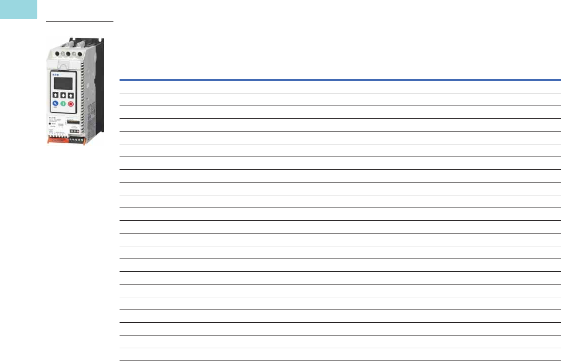
V6-T1-86 Volume 6—Solid-State Motor Control CA08100007E—February 2016 www.eaton.com
1
1
1
1
1
1
1
1
1
1
1
1
1
1
1
1
1
1
1
1
1
1
1
1
1
1
1
1
1
1
1.2
Reduced Voltage Motor Starters
Solid-State Starters
Inside-the-Delta Standard Duty Ratings
Standard Duty—15 Second Ramp, 300% Current Limit at 40°C, Inside-the-Delta Connection
Notes
1 Replace N3S with P3S for premium/pump option.
2 S811+U50… unit does not have IEC certification.
3 15 sec. start, 300% inrush, 40 °C, 1 start every 15 minutes. If these start parameters are exceeded, please refer to S811+V50….
Catalog numbers also represent P3S and V3S units.
Rated
Motor Line
Current
Three-Phase Motor
Catalog
Number 1
kW Rating (50 Hz) hp Rating (60 Hz)
230 V 380–400 V 440 V
200 V230 V460 V575 V
1.0SF 1.15SF 1.0SF 1.15SF 1.0SF 1.15SF 1.0SF 1.15SF
Frame Size N
65 10 18.5 18.5 15 15 15 15 40 30 50 50 S811+N37N3S
114 18.530 37 30253030756010075S811+N66N3S
Frame Size R
182 3055 59 50406050125100150125S811+R10N3S
234 4063 80 60507560150125200150S811+R13N3S
Frame Size T
311 51 90 110 100 75 100 100 250 200 250 250 S811+T18N3S
415 75 110 147 125 100 125 125 300 250 300 300 S811+T24N3S
526 90 160 185 150 125 150 150 400 300 400 400 S811+T30N3S
Frame Size U
623 110 185 220 200 150 250 200 450 400 550 450 S811+U36N3S
727 129 220 257 250 200 300 250 550 450 700 550 S811+U42N3S
865 150 257 300 250 250 300 250 600 550 750 700 S811+U50N3S 23
Frame Size V
623 110 185 220 200 150 250 200 450 400 550 450 S811+V36N3S
727 129 220 257 250 200 300 250 550 450 700 550 S811+V42N3S
865 150 257 300 250 250 300 250 600 550 750 700 S811+V50N3S
1125 200 355 425 400 300 400 300 750 700 900 750 S811+V65N3S
1246 —— — ————————S811+V72N3S
1471 —— — ————————S811+V85N3S
— —— — ————————S811+V10N3S
S811+
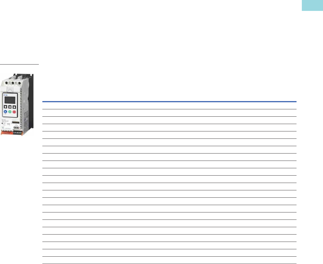
Volume 6—Solid-State Motor Control CA08100007E—February 2016 www.eaton.com V6-T1-87
1
1
1
1
1
1
1
1
1
1
1
1
1
1
1
1
1
1
1
1
1
1
1
1
1
1
1
1
1
1
1.2
Reduced Voltage Motor Starters
Solid-State Starters
Inside-the-Delta Severe Duty Ratings
Severe duty ratings are
defined as any combination of
parameters that exceed the
standard duty ratings where
the ramp time is over 30
seconds, and/or the number
of starts per hour exceeds
4, and/or the current limit set
is over 300%.
Example: 35-second ramp,
5 starts per hour 350%
current limit at 40°C ambient.
Severe Duty—30 Second Ramp and/or 450% Current Limit at 50°C, Inside-the-Delta Connection
Notes
1 Replace N3S with P3S for premium/pump option.
2 S811+U50… unit does not have IEC certification.
Rated
Motor Line
Current
Three-Phase Motor
Catalog
Number 1
kW Rating (50 Hz) hp Rating (60 Hz)
230 V 380–400 V 440 V
200 V230 V460 V575 V
1.0SF 1.15SF 1.0SF 1.15SF 1.0SF 1.15SF 1.0SF 1.15SF
Frame Size N
39 5.5 10 11 7-1/2 7-1/2 10 7-1/2 25 15 30 25 S811+N37N3S
73 11 18.5 22 15 15 25 15 50 40 60 50 S811+N66N3S
Frame Size R
111 1530 33 2525302575607575S811+R10N3S
138 22 40 45 40 30 50 40 100 75 120 100 S811+R13N3S
Frame Size T
199 3359 63 50506050125125150150S811+T18N3S
257 4580 90 75607575150150250200S811+T24N3S
324 55 100 110 100 75 100 100 250 200 300 250 S811+T30N3S
Frame Size U
415 75 110 147 125 100 125 125 300 250 300 300 S811+U36N3S
526 90 160 185 150 120 150 150 400 300 450 400 S811+U42N3S
623 110 185 220 200 150 250 200 450 400 550 450 S811+U50N3S 2
Frame Size V
415 75 110 147 125 100 125 125 300 250 300 300 S811+V36N3S
526 90 160 185 150 120 150 150 400 300 450 400 S811+V42N3S
623 110 185 220 200 150 250 200 450 400 550 450 S811+V50N3S
727 129 220 257 250 200 250 250 550 450 700 550 S811+V65N3S
816 147 257 295 250 250 300 250 600 550 750 700 S811+V72N3S
908 160 280 335 250 250 300 250 700 550 750 700 S811+V85N3S
— —— — ————————S811+V10N3S
S811+
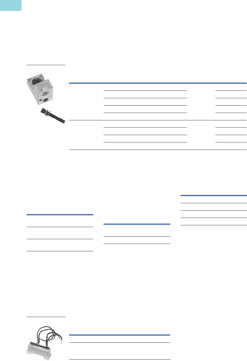
V6-T1-88 Volume 6—Solid-State Motor Control CA08100007E—February 2016 www.eaton.com
1
1
1
1
1
1
1
1
1
1
1
1
1
1
1
1
1
1
1
1
1
1
1
1
1
1
1
1
1
1
1.2
Reduced Voltage Motor Starters
Solid-State Starters
Accessories
Lug Kits
S811+T…, S811U… and
S811+V… soft starters each
have different lug options
based on your wiring needs.
Each lug kit contains three
lugs that can be mounted on
either the load or line side.
Lug Kits
Power Supplies
24 Vdc power supply that can
be used with the S811+ SSRV
or as a stand-alone device.
Power Supplies
Lug Cover Kits
Replacement covers for the
S811+T…, S811+U… and
S811+V… soft starters are
available in case of damage to
the existing covers.
Lug Cover Kits
IP20 Kits
IP20 Kits
Surge Suppressors
The surge suppressor can
mount on either the line or
load side of the soft starter.
It is designed to clip the line
voltage (or load side induced
voltage).
Surge Suppressors
Note
1S811+T… only.
S811+
Catalog Number Description
Kits
Required
Catalog
Number
S811+T…,
S811+U…
2 cable connections, 4 AWG to 1/0 cable 2 EML22
1 cable connection, 4/0 to 500 kcmil cable EML23
2 cable connections, 4/0 to 500 kcmil cable EML24
1 cable connection, 2/0 to 300 kcmil cable EML25
2 cable connections, 2/0 to 300 kcmil cable EML26
S811+V… 2 cable connections, 4/0 to 500 kcmil cable 2 EML28
4 cable connections, 4/0 to 500 kcmil cable EML30
6 cable connections, 4/0 to 500 kcmil cable EML32
4 cable connections, 2/0 to 300 kcmil cable EML33
Lug Kit
Description
Catalog
Number
85–264 Vac input
24 Vdc output
PSG240E
360–575 Vac input
24 Vdc output
PSG240F
600 Vac input
24 Vdc output
PSS55D
Description
Catalog
Number
Lug cover S811+T…,
S811+U…
EML27
Lug cover S811+V… EML34
Description
Catalog
Number
S811+N… SS-IP20-N
S811+R… SS-IP20-R
S811+T… and S811+U… SS-IP20-TU
S811+V… SS-IP20-V
Description
Catalog
Number
600 V MOV for S811+… units EMS39
690 V MOV for S811+… units 1EMS41
Surge Suppressor
Volume 6—Solid-State Motor Control CA08100007E—February 2016 www.eaton.com V6-T1-89
1
1
1
1
1
1
1
1
1
1
1
1
1
1
1
1
1
1
1
1
1
1
1
1
1
1
1
1
1
1
1.2
Reduced Voltage Motor Starters
Solid-State Starters
Mounting Plates
The mounting plates are
designed to help make it easy
to install or retrofit the soft
starter into enclosures and
MCCs. The soft starter can
be mounted onto the plate
prior to installation. The
mounting plate is designed
with tear drop mounting
holes for easier installation.
Mounting Plates
Vibration Plates
The vibration plates allow the
soft starter to be applied in
high shock and vibration
applications. The vibration
plate allows vibration up to 5g
and shock in up to 40g. The
soft starter is mounted onto
the vibration plate prior to
installation in the panel.
Vibration Plates
Adapter Plates
The adapter plate allows
customers to retrofit a
S811+V… soft starter with
the S811+U… soft starter.
Adapter Plates
Control Wire Connector
Control Wire Connector
Digital Interface Module
The Digital Interface
Module (DIM) is available
as a replacement part.
DIM
Options
S811+ Premium
In addition to what is already
there in the S811+ standard,
these devices offer pump
control and extended ramp
functions.
S811+ Premium
S811+ Premium 690 V Option
In addition to what is already
there in S811+ standard, this
product offers 690 V, pump
control and extended ramp
functions.
S811+ Premium 690 V
Option
Cooling Fan Kit
The EMM18 cooling fan kit
mounts on either side of
any frame size S811+ soft
starter to provide additional
printed circuit board cooling in
high ambient operating
temperatures.
Cooling Fan Kit
Note
1S811+U50… unit does not have IEC certification.
Description
Catalog
Number
S811+N… EMM13N
S811+R… EMM13R
S811+T… and S811+U… EMM13T
S811+V… EMM13V
Description
Catalog
Number
S811+N… EMM14N
S811+R… EMM14R
S811+T… and S811+U… EMM14T
S811+V… EMM14V
Description
Catalog
Number
Adapter plates EMM13U
Description
Catalog
Number
12-pin, 5 mm pitch connector
for control wiring
EMA75
Description
Catalog
Number
Blank cover (filler) EMA68
DIM for standard unit EMA91
Panel mounting kit
3 ft cable EMA69A
5 ft cable EMA69B
8 ft cable EMA69C
10 ft cable EMA69D
Current
Range
Catalog
Number
11–37 S811+N37P3S
20–66 S811+N66P3S
32–105 S811+R10P3S
42–135 S811+R13P3S
56–180 S811+T18P3S
75–240 S811+T24P3S
95–304 S811+T30P3S
112–360 S811+U36P3S
131–420 S811+U42P3S
156–500 S811+U50P3S 1
112–360 S811+V36P3S
131–420 S811+V42P3S
156–500 S811+V50P3S
203–650 S811+V65P3S
225–720 S811+V72P3S
265–850 S811+V85P3S
312–1000 S811+V10P3S
Current
Range
Catalog
Number
56–180 S811+T18V3S
75–240 S811+T24V3S
95–304 S811+T30 V3S
112–360 S811+V36V3S
131–420 S811+V42V3S
156–500 S811+V50 V3S
203–650 S811+V65V3S
225–720 S811+V72V3S
265–850 S811+V85V3S
Description
Catalog
Number
Fan kit EMM18
V6-T1-90 Volume 6—Solid-State Motor Control CA08100007E—February 2016 www.eaton.com
1
1
1
1
1
1
1
1
1
1
1
1
1
1
1
1
1
1
1
1
1
1
1
1
1
1
1
1
1
1
1.2
Reduced Voltage Motor Starters
Solid-State Starters
Technical Data and Specifications
Soft Starters—S811+
Description
S811+N37… S811+N66… S811+R10+… S811+R13…
Max. current capacity 37 66 105 135
FLA range 11–37 20–66 32–105 42–135
General Information
Bypass mechanical lifespan 10M 10M 10M 10M
Insulating voltage Ui 660 V 660 V 660 V 660 V
Ramp time range 0.5–180 seconds
(0.5–360 seconds S811+ Premium)
0.5–180 seconds
(0.5–360 seconds S811+ Premium)
0.5–180 seconds
(0.5–360 seconds S811+ Premium)
0.5–180 seconds
(0.5–360 seconds S811+ Premium)
Resistance to vibration 3g 3g 3g 3g
Resistance to shock 15g 15g 15g 15g
Electrical Information
Operating voltage 200–600 V 200–600 V 200–600 V 200–600 V
Operating frequency 47–63 Hz 47–63 Hz 47–63 Hz 47–63 Hz
Overload setting 30–100% 30–100% 30–100% 30–100%
Trip class 5, 10, 20 and 30 5, 10, 20 and 30 5, 10, 20 and 30 5, 10, 20 and 30
Cabling Capacity (IEC 947)
Number of conductors 1111
Wire sizes 14–2 14–2 14–4/0 14–4/0
Type of connectors Box lug Box lug Box lug Box lug
Control Wiring (12-Pin)
Wire sizes in AWG 22–14 22–14 22–14 22–14
Number of conductors (stranded) 2 (or one AWG 12) 2 (or one AWG 12) 2 (or one AWG 12) 2 (or one AWG 12)
Torque requirements in lb-in 3.5 3.5 3.5 3.5
Solid, stranded or flexible max. size in mm23.31 3.31 3.31 3.31
Control Power Requirements
Voltage range (24V ±10%) 21.6–26.4 21.6–26.4 21.6–26.4 21.6–26.4
Steady-state current amps 1.0 1.0 1.0 1.0
Inrush current amps 10 10 10 10
Ripple 1% 1% 1% 1%
Relays (1) Class A and C
Voltage AC—maximum 240 240 240 240
Voltage DC—maximum 120 120 120 120
Amps—maximum3333
Environment
Temperature—operating –30° to 50°C (no derating) consult
factory for operation >50°C
–30° to 50°C (no derating) consult
factory for operation >50°C
–30° to 50°C (no derating) consult
factory for operation >50°C
–30° to 50°C (no derating) consult
factory for operation >50°C
Temperature—storage –50° to 70°C –50° to 70°C –50° to 70°C –50° to 70°C
Altitude <2000m—consult factory
for operation >2000m
<2000m—consult factory
for operation >2000m
<2000m—consult factory
for operation >2000m
<2000m—consult factory
for operation >2000m
Humidity <95% noncondensing <95% noncondensing <95% noncondensing <95% noncondensing
Operating position Any Any Any Any
Pollution degree IEC947-13333
Impulse withstand voltage IEC947-4-1 6000 V 6000 V 6000 V 6000 V

Volume 6—Solid-State Motor Control CA08100007E—February 2016 www.eaton.com V6-T1-91
1
1
1
1
1
1
1
1
1
1
1
1
1
1
1
1
1
1
1
1
1
1
1
1
1
1
1
1
1
1
1.2
Reduced Voltage Motor Starters
Solid-State Starters
Soft Starters—S811+, continued
Description
S811+T18… S811+T24… S811+T30… S811+U36…
Max. current capacity 180 240 304 360
FLA range 56–180 75–240 95–304 112–360
General Information
Bypass mechanical lifespan 10M 10M 10M 10M
Insulating voltage Ui 660 V 660 V 660 V 660 V
Ramp time range 0.5–180 seconds
(0.5–360 seconds S811+ Premium)
0.5–180 seconds
(0.5–360 seconds S811+ Premium)
0.5–180 seconds
(0.5–360 seconds S811+ Premium)
0.5–180 seconds
(0.5–360 seconds S811+ Premium)
Resistance to vibration 3g 3g 3g 3g
Resistance to shock 15g 15g 15g 15g
Electrical Information
Operating voltage 200–600 V 200–600 V 200–600 V 200–600 V
Operating frequency 47–63 Hz 47–63 Hz 47–63 Hz 47–63 Hz
Overload setting 30–100% 30–100% 30–100% 30–100%
Trip class 5, 10, 20 and 30 5, 10, 20 and 30 5, 10, 20 and 30 5, 10, 20 and 30
Cabling Capacity (IEC 947)
Number of conductors 1 or 2 1 or 2 1 or 2 1 or 2
Wire sizes 4 AWG to 500 kcmil 4 AWG to 500 kcmil 4 AWG to 500 kcmil 4 AWG to 500 kcmil
Type of connectors Add-on lug kit Add-on lug kit Add-on lug kit Add-on lug kit
Control Wiring (12-Pin)
Wire sizes in AWG 22–14 22–14 22–14 22–14
Number of conductors (stranded) 2 (or one AWG 12) 2 (or one AWG 12) 2 (or one AWG 12) 2 (or one AWG 12)
Torque requirements in lb-in 3.5 3.5 3.5 3.5
Solid, stranded or flexible max. size in mm23.31 3.31 3.31 3.31
Control Power Requirements
Voltage range (24V ±10%) 21.6–26.4 21.6–26.4 21.6–26.4 21.6–26.4
Steady-state current amps 1.0 1.0 1.0 1.0
Inrush current amps 10 10 10 10
Ripple 1% 1% 1% 1%
Relays (1) Class A and C
Voltage AC—maximum 240 240 240 240
Voltage DC—maximum 120 120 120 120
Amps—maximum3333
Environment
Temperature—operating –30° to 50°C (no derating) consult
factory for operation >50°C
–30° to 50°C (no derating) consult
factory for operation >50°C
–30° to 50°C (no derating) consult
factory for operation >50°C
–30° to 50°C (no derating) consult
factory for operation >50°C
Temperature—storage –50° to 70°C –50° to 70°C –50° to 70°C –50° to 70°C
Altitude <2000m—consult factory
for operation >2000m
<2000m—consult factory
for operation >2000m
<2000m—consult factory
for operation >2000m
<2000m—consult factory
for operation >2000m
Humidity <95% noncondensing <95% noncondensing <95% noncondensing <95% noncondensing
Operating position Any Any Any Any
Pollution degree IEC947-13333
Impulse withstand voltage IEC947-4-1 6000 V 6000 V 6000 V 6000 V

V6-T1-92 Volume 6—Solid-State Motor Control CA08100007E—February 2016 www.eaton.com
1
1
1
1
1
1
1
1
1
1
1
1
1
1
1
1
1
1
1
1
1
1
1
1
1
1
1
1
1
1
1.2
Reduced Voltage Motor Starters
Solid-State Starters
Soft Starters—S811+, continued
Note
1S811+U50… unit does not have IEC certification.
Description
S811+U42… S811+U50…
1
S811+V36… S811+V42…
Max. current capacity 420 500 360 420
FLA range 131–420 156–500 112–360 131–420
General Information
Bypass mechanical lifespan 10M 10M 10M 10M
Insulating voltage Ui 660 V 660 V 660 V 660 V
Ramp time range 0.5–180 seconds
(0.5–360 seconds S811+ Premium)
0.5–180 seconds
(0.5–360 seconds S811+ Premium)
0.5–180 seconds
(0.5–360 seconds S811+ Premium)
0.5–180 seconds
(0.5–360 seconds S811+ Premium)
Resistance to vibration 3g 3g 3g 3g
Resistance to shock 15g 15g 15g 15g
Electrical Information
Operating voltage 200–600 V 200–600 V 200–600 V 200–600 V
Operating frequency 47–63 Hz 47–63 Hz 47–63 Hz 47–63 Hz
Overload setting 30–100% 30–100% 30–100% 30–100%
Trip class 5, 10, 20 and 30 5, 10, 20 and 30 5, 10, 20 and 30 5, 10, 20 and 30
Cabling Capacity (IEC 947)
Number of conductors 1 or 2 1 or 2 2, 4 or 6 2, 4 or 6
Wire sizes 4 AWG to 500 kcmil 4 AWG to 500 kcmil 2/0 to 500 kcmil 2/0 to 500 kcmil
Type of connectors Add-on lug kit Add-on lug kit Add-on lug kit Add-on lug kit
Control Wiring (12-Pin)
Wire sizes in AWG 22–14 22–14 22–14 22–14
Number of conductors (stranded) 2 (or one AWG 12) 2 (or one AWG 12) 2 (or one AWG 12) 2 (or one AWG 12)
Torque requirements in lb-in 3.5 3.5 3.5 3.5
Solid, stranded or flexible max. size in mm23.31 3.31 3.31 3.31
Control Power Requirements
Voltage range (24V ±10%) 21.6–26.4 21.6–26.4 21.6–26.4 21.6–26.4
Steady-state current amps 1.0 1.0 1.4 1.4
Inrush current amps 10 10 10 10
Ripple 1% 1% 1% 1%
Relays (1) Class A and C
Voltage AC—maximum 240 240 240 240
Voltage DC—maximum 120 120 120 120
Amps—maximum3333
Environment
Temperature—operating –30° to 50°C (no derating) consult
factory for operation >50°C
–30° to 50°C (no derating) consult
factory for operation >50°C
–30° to 50°C (no derating) consult
factory for operation >50°C
–30° to 50°C (no derating) consult
factory for operation >50°C
Temperature—storage –50° to 70°C –50° to 70°C –50° to 70°C –50° to 70°C
Altitude <2000m—consult factory
for operation >2000m
<2000m—consult factory
for operation >2000m
<2000m—consult factory
for operation >2000m
<2000m—consult factory
for operation >2000m
Humidity <95% noncondensing <95% noncondensing <95% noncondensing <95% noncondensing
Operating position Any Any Any Any
Pollution degree IEC947-13333
Impulse withstand voltage IEC947-4-1 6000 V 6000 V 6000 V 6000 V

Volume 6—Solid-State Motor Control CA08100007E—February 2016 www.eaton.com V6-T1-93
1
1
1
1
1
1
1
1
1
1
1
1
1
1
1
1
1
1
1
1
1
1
1
1
1
1
1
1
1
1
1.2
Reduced Voltage Motor Starters
Solid-State Starters
Soft Starters—S811+, continued
Note
1UR recognized product.
Description
S811+V50… S811+V65… S811+V72… S811+V85… S811+V10…
1
Max. current capacity 500 650 720 850 1000
FLA range 156–500 203–650 225–720 265–580 320–1000
General Information
Bypass mechanical lifespan 10M 10M 10M 10M 10M
Insulating voltage Ui 660 V 660 V 660 V 660 V 660 V
Ramp time range 0.5–180 seconds (0.5–360
seconds S811+ Premium)
0.5–180 seconds (0.5–360
seconds S811+ Premium)
0.5–180 seconds (0.5–360
seconds S811+ Premium)
0.5–180 seconds (0.5–360
seconds S811+ Premium)
0.5–180 seconds (0.5–360
seconds S811+ Premium)
Resistance to vibration3g3g3g3g3g
Resistance to shock 15g 15g 15g 15g 15g
Electrical Information
Operating voltage 200–600 V 200–600 V 200–600 V 200–600 V 200–600 V
Operating frequency 47–63 Hz 47–63 Hz 47–63 Hz 47–63 Hz 47–63 Hz
Overload setting 30–100% 30–100% 30–100% 30–100% 30–100%
Trip class 5, 10, 20 and 30 5, 10, 20 and 30 5, 10, 20 and 30 5, 10, 20 and 30 5, 10, 20 and 30
Cabling Capacity (IEC 947)
Number of conductors 2, 4 or 6 2, 4 or 6 2, 4 or 6 2, 4 or 6 2, 4 or 6
Wire sizes 2/0 to 500 kcmil 2/0 to 500 kcmil 2/0 to 500 kcmil 2/0 to 500 kcmil 2/0 to 500 kcmil
Type of connectors Add-on lug kit Add-on lug kit Add-on lug kit Add-on lug kit Add-on lug kit
Control Wiring (12-Pin)
Wire sizes in AWG 22–14 22–14 22–14 22–14 22–14
Number of conductors (stranded) 2 (or one AWG 12) 2 (or one AWG 12) 2 (or one AWG 12) 2 (or one AWG 12) 2 (or one AWG 12)
Torque requirements in lb-in 3.5 3.5 3.5 3.5 3.5
Solid, stranded or flexible max. size in mm23.31 3.31 3.31 3.31 3.31
Control Power Requirements
Voltage range (24V ±10%) 21.6–26.4 21.6–26.4 21.6–26.4 21.6–26.4 21.6–26.4
Steady-state current amps 1.4 1.4 1.4 1.4 1.4
Inrush current amps 10 10 10 10 10
Ripple 1% 1% 1% 1% 1%
Relays (1) Class A and C
Voltage AC—maximum 240 240 240 240 240
Voltage DC—maximum 120 120 120 120 120
Amps—maximum33333
Environment
Temperature—operating –30° to 50°C (no derating)
consult factory for
operation >50°C
–30° to 50°C (no derating)
consult factory for
operation >50°C
–30° to 50°C (no derating)
consult factory for
operation >50°C
–30° to 50°C (no derating)
consult factory for
operation >50°C
–30° to 50°C (no derating)
consult factory for
operation >50°C
Temperature—storage –50° to 70°C –50° to 70°C –50° to 70°C –50° to 70°C –50° to 70°C
Altitude <2000m—consult factory
for operation >2000m
<2000m—consult factory
for operation >2000m
<2000m—consult factory
for operation >2000m
<2000m—consult factory
for operation >2000m
<2000m—consult factory
for operation >2000m
Humidity <95% noncondensing <95% noncondensing <95% noncondensing <95% noncondensing <95% noncondensing
Operating position Any Any Any Any Any
Pollution degree IEC947-133333
Impulse withstand voltage IEC947-4-1 6000 V 6000 V 6000 V 6000 V 6000 V
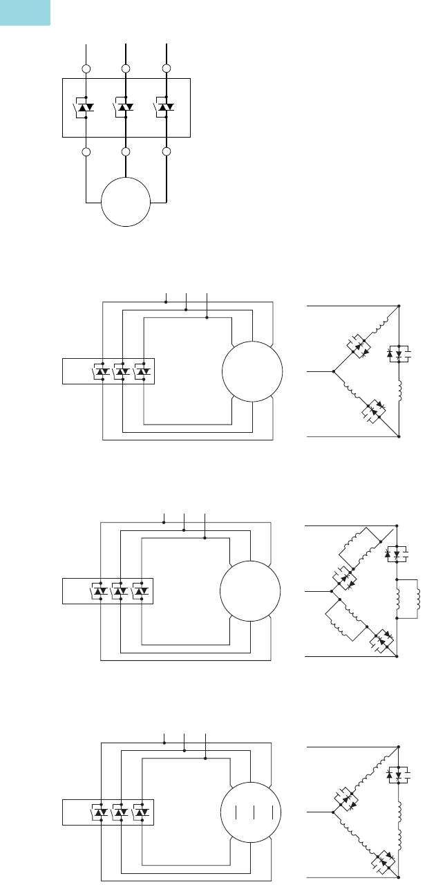
V6-T1-94 Volume 6—Solid-State Motor Control CA08100007E—February 2016 www.eaton.com
1
1
1
1
1
1
1
1
1
1
1
1
1
1
1
1
1
1
1
1
1
1
1
1
1
1
1
1
1
1
1.2
Reduced Voltage Motor Starters
Solid-State Starters
Wiring Diagrams
Line Connected Soft Starter
Inside-the-Delta Connected Soft Starter for a 6-Lead Motor
Inside-the-Delta Connected Soft Starter for a 12-Lead Low Voltage Motor
Inside-the-Delta Connected Soft Starter for a 12-Lead High Voltage Motor
1L1 3L2 5L3
2T1 4T2 6T3
3~
M
L1S L2S
Supply
L3S
L3
1
L1 3
L2 5
L3
T5 T4 T6
T3
T3
T3
T6
T4
T1
T1
T2
T2
T2
T1
2
T1 4
T2 6
T3
T5
L1
L1
Motor
L3
L2
L2
S811+
L1S L2S
Supply
L3S
L3
L1
1
L1 3
L2 5
L3
T11
T5
T11
T10
T4 T12
T6
T3
T9
T3
T5
T3
T6
T10
T7
T4
T1
T1
T12
T9
T2
T8
T2
T2
T1
T7
2
T1 4
T2 6
T3
T8
L1
Motor
L3
L2 L2
12-Lead
Low Voltage
S811+
L1S L2S
Supply 12-Lead
High Voltage
L3S
L3
L1
1
L1 3
L2 5
L3
T11
T11
T10 T12
T3
T3
T3
T6
T10
T7
T4
T1
T1
T12
T9
T2
T2
T2
T1
2
T1 4
T2 6
T3
T8
T5
T5T8
T6
T9
L1
T7
T4
Motor
L3
L2
L2
S811+

Volume 6—Solid-State Motor Control CA08100007E—February 2016 www.eaton.com V6-T1-95
1
1
1
1
1
1
1
1
1
1
1
1
1
1
1
1
1
1
1
1
1
1
1
1
1
1
1
1
1
1
1.2
Reduced Voltage Motor Starters
Solid-State Starters
Dimensions
Approximate Dimensions in Inches (mm)
Soft Starters—S811+
Note
1Dimensions of the frames stay consistent between the N3S, P3S, and V3S options.
Catalog
Number 1WH D
Weight
in Lbs (kg)
S811+
N37N3S
2.66 (67.6) 7.37 (187.2) 6.45 (163.9) 5.8 (2.6)
S811+
N66N3S
2.66 (67.6) 7.37 (187.2) 6.45 (163.9) 5.8 (2.6)
S811+
R10N3S
4.38 (111.3) 7.92 (201.1) 6.64 (168.6) 10.5 (4.8)
S811+
R13N3S
4.38 (111.3) 7.92 (201.1) 6.64 (168.6) 10.5 (4.8)
S811+
T18N3S
7.65 (194.4) 12.71 (322.9) 6.47 (164.4) 48 (21.8) with lugs 41 (18.6) without lugs
S811+
T24N3S
7.65 (194.4) 12.71 (322.9) 6.47 (164.4) 48 (21.8) with lugs 41 (18.6) without lugs
S811+
T30N3S
7.65 (194.4) 12.71 (322.9) 6.47 (164.4) 48 (21.8) with lugs 41 (18.6) without lugs
S811+
U36N3S
7.73 (196.3) 12.72 (323.1) 7.16 (181.8) 48 (21.8) with lugs 41 (18.6) without lugs
S811+
U42N3S
7.73 (196.3) 12.72 (323.1) 7.16 (181.8) 48 (21.8) with lugs 41 (18.6) without lugs
S811+
U50N3S
7.73 (196.3) 12.72 (323.1) 7.16 (181.8) 48 (21.8) with lugs 41 (18.6) without lugs
S811+
V36N3S
11.05 (280.6) 16.57 (420.8) 7.39 (187.8) 103 (46.8) with lugs 91 (41.4) without lugs
S811+
V42N3S
11.05 (280.6) 16.57 (420.8) 7.39 (187.8) 103 (46.8) with lugs 91 (41.4) without lugs
S811+
V50N3S
11.05 (280.6) 16.57 (420.8) 7.39 (187.8) 103 (46.8) with lugs 91 (41.4) without lugs
S811+
V65N3S
11.05 (280.6) 16.57 (420.8) 7.39 (187.8) 103 (46.8) with lugs 91 (41.4) without lugs
S811+
V72N3S
11.05 (280.6) 16.57 (420.8) 7.39 (187.8) 103 (46.8) with lugs 91 (41.4) without lugs
S811+
V85N3S
11.05 (280.6) 16.57 (420.8) 7.39 (187.8) 103 (46.8) with lugs 91 (41.4) without lugs
S811+
V10N3S
11.05 (280.6) 16.57 (420.8) 7.39 (187.8) 103 (46.8) with lugs 91 (41.4) without lugs
Also refer to dimension drawings on Pages V6-T1-96 through V6-T1-98.
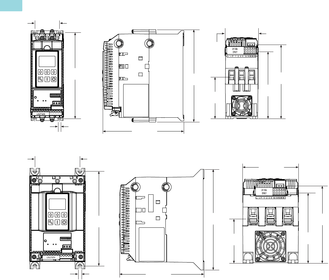
V6-T1-96 Volume 6—Solid-State Motor Control CA08100007E—February 2016 www.eaton.com
1
1
1
1
1
1
1
1
1
1
1
1
1
1
1
1
1
1
1
1
1
1
1
1
1
1
1
1
1
1
1.2
Reduced Voltage Motor Starters
Solid-State Starters
Approximate Dimensions in Inches (mm)
S811+N…
S811+R…
6.87
(174.5)
1.97 (50.0)
4X Ø
0.22
(5.5)
7.37
(187.2)
6.45 (163.9)
5.35
(135.9)
5.89
(149.7)
3.32
(84.4)
2.66
(67.6)
5.54
(140.7)
4.38 (111.3)
3.54 (90.0)
4X Ø
0.27
(6.8) 6.64 (168.6)
7.92
(201.2)
6.08
(154.5)
7.44
(189.0)
3.49
(88.5)
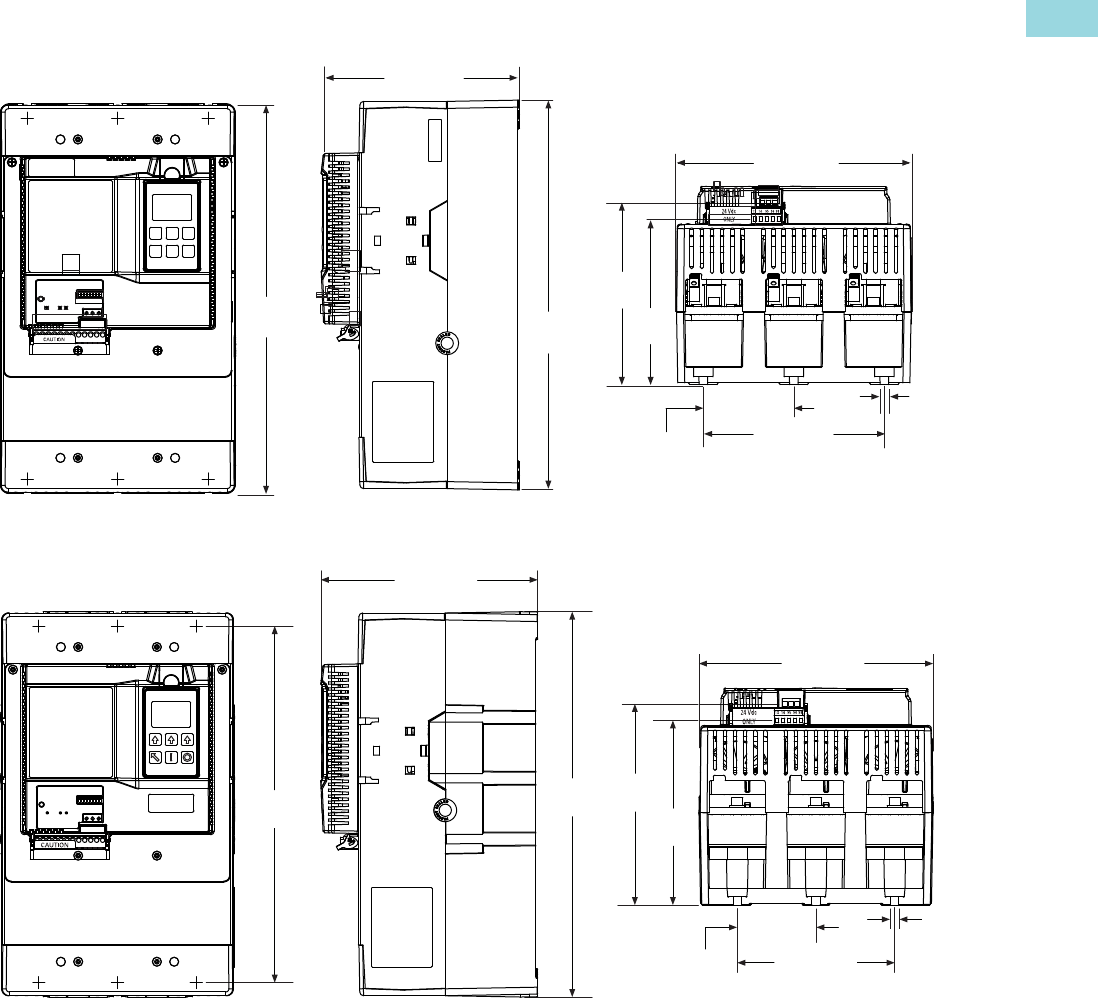
Volume 6—Solid-State Motor Control CA08100007E—February 2016 www.eaton.com V6-T1-97
1
1
1
1
1
1
1
1
1
1
1
1
1
1
1
1
1
1
1
1
1
1
1
1
1
1
1
1
1
1
1.2
Reduced Voltage Motor Starters
Solid-State Starters
Approximate Dimensions in Inches (mm)
S811+T…
S811+U…
11.77
(299.0) 12.71
(322.9)
6.47 (164.4)
7.65 (194.4)
5.40
(137.3)
5.95
(151.1)
5.91 (150.0)
0.28
(7.1)
6X Ø
2.95
(75.0)
7.16 (181.8)
6X Ø
12.72
(323.1)
11.77
(299.0) 6.09
(154.8)
6.64
(168.6)
2.60
(66.0)
0.28
(7.1)
5.20 (132.0)
7.73 (196.3)
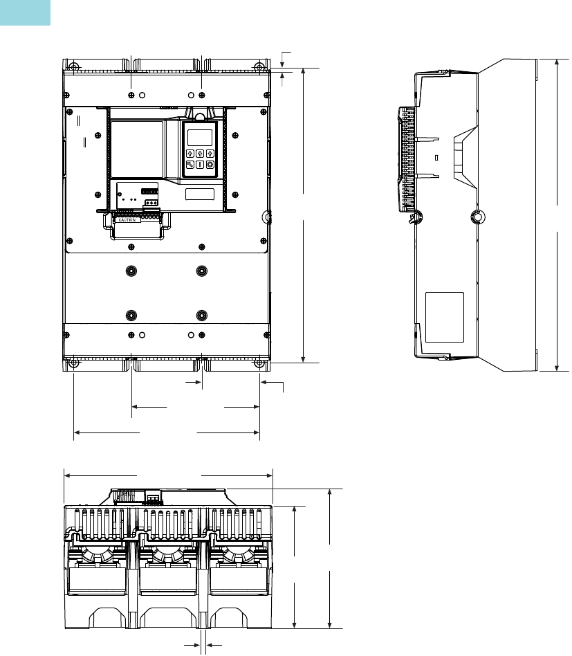
V6-T1-98 Volume 6—Solid-State Motor Control CA08100007E—February 2016 www.eaton.com
1
1
1
1
1
1
1
1
1
1
1
1
1
1
1
1
1
1
1
1
1
1
1
1
1
1
1
1
1
1
1.2
Reduced Voltage Motor Starters
Solid-State Starters
Approximate Dimensions in Inches (mm)
S811+V…
6.79 (172.5)
0.236
(6.00)
3.05
(77.5)
9.84 (250.0)
15.63
(397.0)
4X Ø
0.2650
(6.731)
6.50
(165.1)
7.39
(187.8)
11.05 (280.6)
16.57
(420.8)
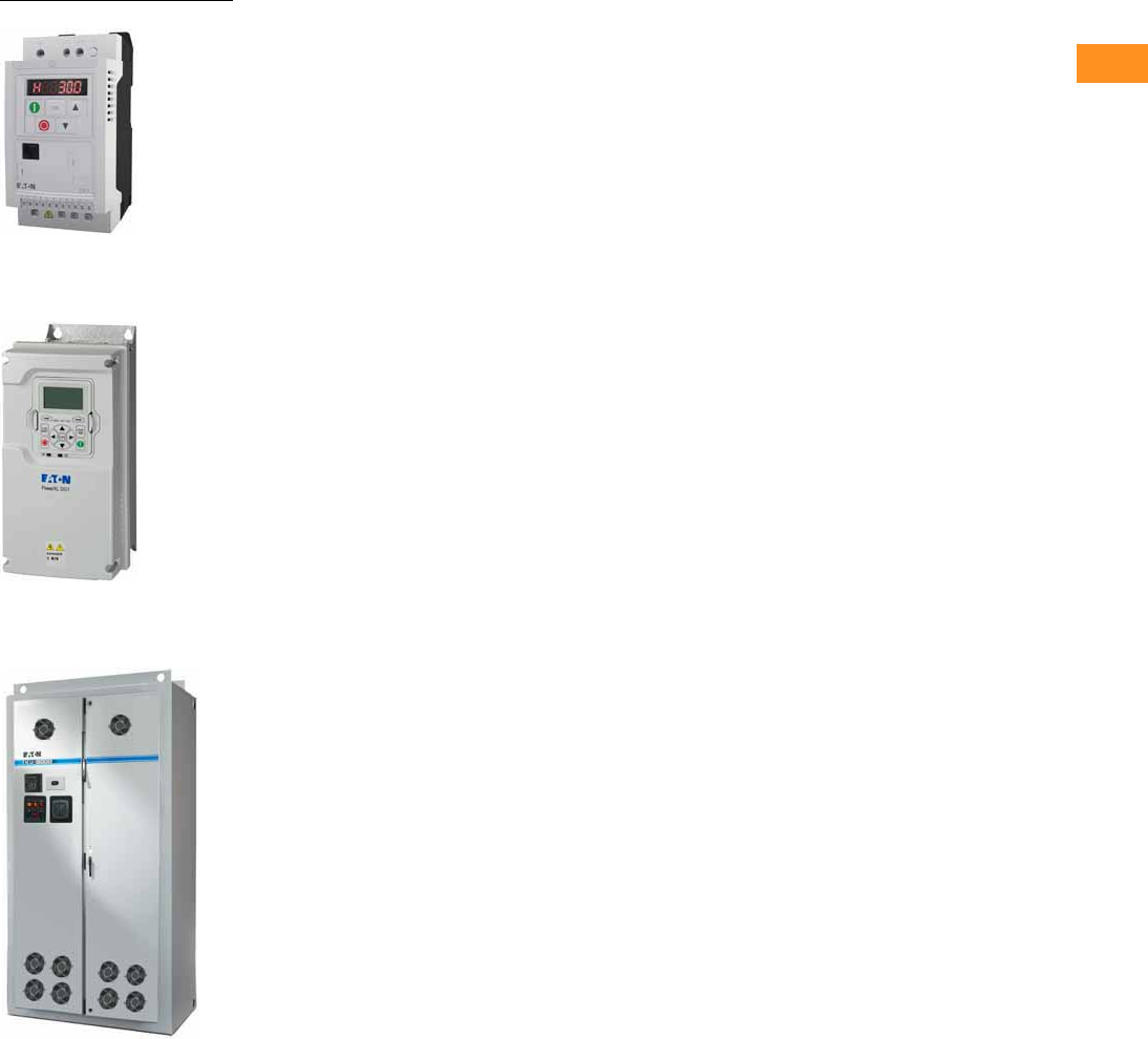
Volume 6—Solid-State Motor Control CA08100007E—February 2016 www.eaton.com V6-T2-1
2
2
2
2
2
2
2
2
2
2
2
2
2
2
2
2
2
2
2
2
2
2
2
2
2
2
2
2
2
2
Adjustable Frequency Drives
PowerXL DC1
PowerXL DG1
Enclosed 18-Pulse Drive
2.1 Product Overview . . . . . . . . . . . . . . . . . . . . . . . . . . . . . . . . . . . . . . . . V6-T2-2
OEM Drives
2.2 PowerXL DE1 Series . . . . . . . . . . . . . . . . . . . . . . . . . . . . . . . . . . . . . . V6-T2-9
2.3 PowerXL DC1 Series Drives . . . . . . . . . . . . . . . . . . . . . . . . . . . . . . . V6-T2-15
2.4 PowerXL DA1 Series Drives . . . . . . . . . . . . . . . . . . . . . . . . . . . . . . . V6-T2-25
2.5 M-Max Series Drives . . . . . . . . . . . . . . . . . . . . . . . . . . . . . . . . . . . . . V6-T2-36
General Purpose Industrial Drives
2.6 PowerXL DG1 Series Drives
DG1 Drives . . . . . . . . . . . . . . . . . . . . . . . . . . . . . . . . . . . . . . . . . . . . . V6-T2-48
DG1 Enclosed Drives . . . . . . . . . . . . . . . . . . . . . . . . . . . . . . . . . . . . . . V6-T2-70
2.7 SVX Drives
SVX Drives . . . . . . . . . . . . . . . . . . . . . . . . . . . . . . . . . . . . . . . . . . . . . . V6-T2-100
SVX Enclosed Drives . . . . . . . . . . . . . . . . . . . . . . . . . . . . . . . . . . . . . . V6-T2-141
General Purpose HVAC Drives
2.8 H-Max Series Drives
H-Max Drives . . . . . . . . . . . . . . . . . . . . . . . . . . . . . . . . . . . . . . . . . . . . V6-T2-179
H-Max IntelliPass and IntelliDisconnect Drives . . . . . . . . . . . . . . . . . . V6-T2-190
Performance Drives
2.9 SPX Drives . . . . . . . . . . . . . . . . . . . . . . . . . . . . . . . . . . . . . . . . . . . . . . V6-T2-213
2.10 Clean Power Drives
Product Overview . . . . . . . . . . . . . . . . . . . . . . . . . . . . . . . . . . . . . . . . V6-T2-256
Enclosed Passive Filtered Drives
EGF Drives . . . . . . . . . . . . . . . . . . . . . . . . . . . . . . . . . . . . . . . . . . . V6-T2-263
CFX Drives . . . . . . . . . . . . . . . . . . . . . . . . . . . . . . . . . . . . . . . . . . . V6-T2-288
HCX Enclosed 12-Pulse Drives . . . . . . . . . . . . . . . . . . . . . . . . . . . . . . V6-T2-319
CPX Enclosed 18-Pulse Drives . . . . . . . . . . . . . . . . . . . . . . . . . . . . . . . V6-T2-323
RGX Enclosed Regenerative Drives . . . . . . . . . . . . . . . . . . . . . . . . . . . V6-T2-348
2.11 LCX Liquid Cooled Drives . . . . . . . . . . . . . . . . . . . . . . . . . . . . . . . . . V6-T2-361
2.12 SPA/SPN/SPI Common DC Bus Drives . . . . . . . . . . . . . . . . . . . . . V6-T2-377
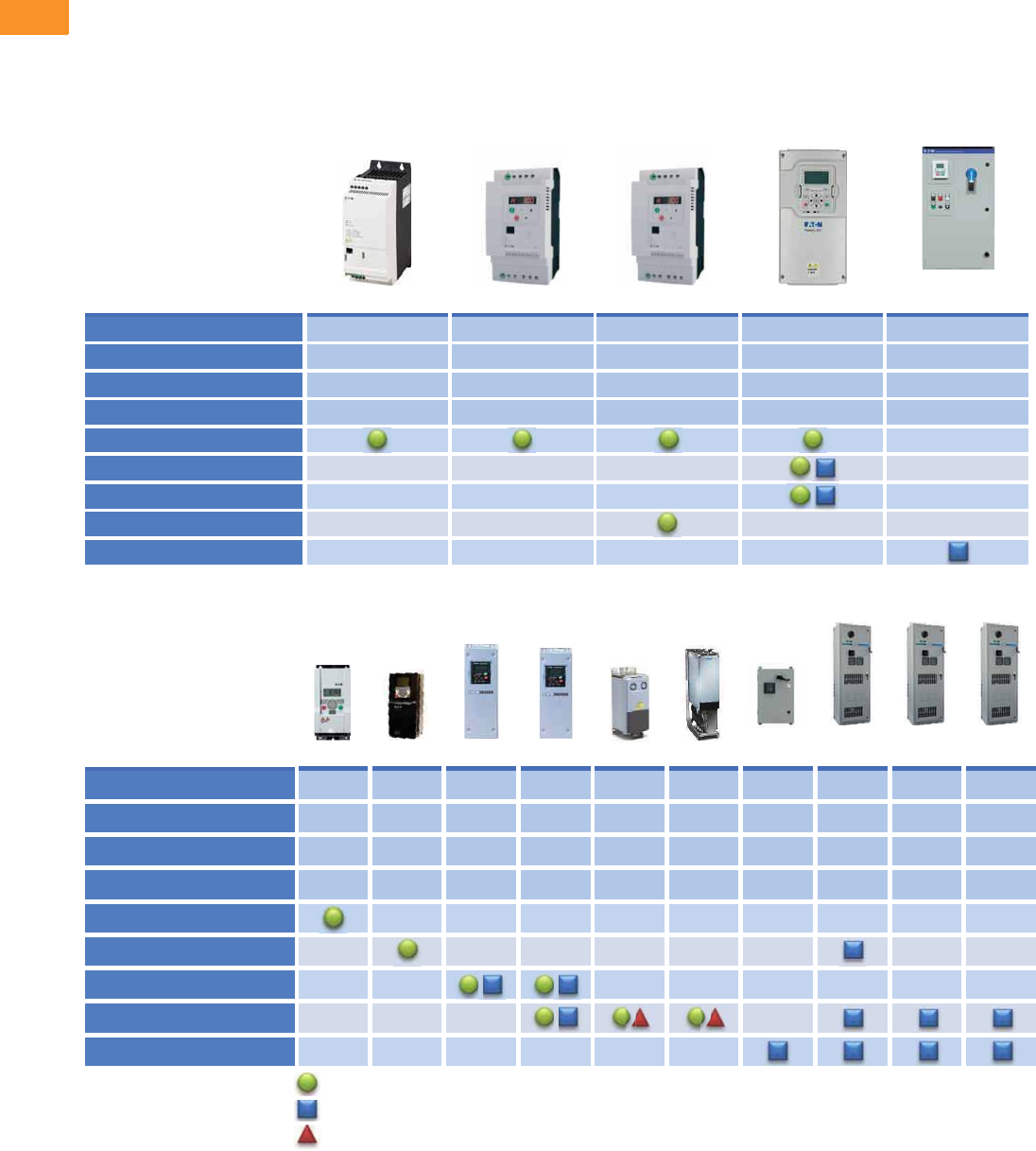
V6-T2-2 Volume 6—Solid-State Motor Control CA08100007E—February 2016 www.eaton.com
2
2
2
2
2
2
2
2
2
2
2
2
2
2
2
2
2
2
2
2
2
2
2
2
2
2
2
2
2
2
2.1
Adjustable Frequency Drives
Product Overview
A Drive For Any Application
Your application might call for
an ultra-compact solution,
clean power or future
configurability.
Whether it is a standard
product from the catalog or a
custom-enclosed variable
frequency drive (VFD)
solution, Eaton delivers.
Eaton drives are designed for
industrial, HVAC, water/
wastewater treatment,
machinery OEM and other
application demands.
Whether designing a new
industrial complex, renovating
an existing structure or
developing a new machine,
Eaton has the right product
for your application.
PowerXL® Family
9000X Family
Application DE1 DC1 DA1 DG1
EGF
(Filtered)
Yes
3
10
—
Yes
15
30
—
Yes
7.5
15
20
Yes
125
250
250
—
125
250
250
Single-phase input
Maximum 230 V hp
Maximum 480 V hp
Maximum 575 V hp
OEM drives
General purpose HVAC drives
General purpose industrial
Performance
Low harmonic
M-Max SVXH-Max SPX
CFX
(Filtered)LCX SPIApplication
HCX
(12-Pulse)
CPX
(18-Pulse)
RGX
(AFE)
Yes
15
25
7.5
—
125
250
—
Yes
125
250
200
Yes
125
2200
2300
—
—
3200
2800
—
—
2400
2200
—
100
400
400
—
60
125
—
—
200
800
800
—
—
900
750
Single-phase input
Maximum 230 V hp
Maximum 480 V hp
Maximum 575 V hp
OEM drives
General purpose HVAC drives
General purpose industrial
Performance
Low harmonic
= Open drive standard
= Enclosed drive standard
= Enclosed—consult Enclosed Drives Plant (Watertown, WI)
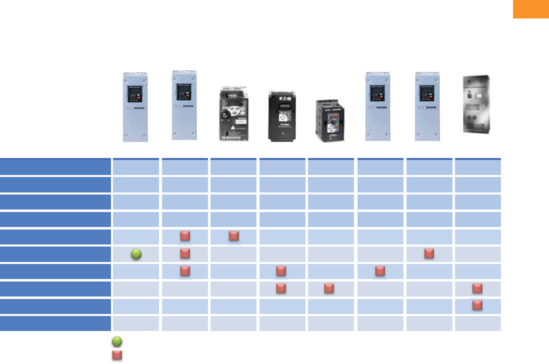
Volume 6—Solid-State Motor Control CA08100007E—February 2016 www.eaton.com V6-T2-3
2
2
2
2
2
2
2
2
2
2
2
2
2
2
2
2
2
2
2
2
2
2
2
2
2
2
2
2
2
2
2.1
Adjustable Frequency Drives
Product Overview
A History of Drives
Throughout the years, Eaton’s drive offering has evolved as technology has changed. Some
drives are no longer available, but are listed below for reference and aid in finding the drive in
our current offering that fits your application. If needed, please contact the Drives Technical
Resource Center (1-877-ETN-CARE, option 2, option 6) for assistance in finding the current
drive to suit your needs.
Legacy Product Offering
= Open drive standard
= Legacy product; no longer available
HVXApplication
Single-phase input
Maximum 230 V hp
Maximum 480 V hp
Maximum 575 V hp
OEM drives
General purpose HVAC drives
General purpose industrial
Performance
Low harmonic
Current product offering
Yes
75
150
—
H-Max
SLX NFX GVX MVX SV HV
CP
(18-Pulse)
—
40
100
100
DG1
Yes
2
—
—
DE1
Yes
50
125
125
DC1 / DG1
Yes
7.5
10
10
DC1 / DA1
Yes
100
1100
800
DG1
Yes
150
1000
700
H-Max
—
—
800
—
CPX
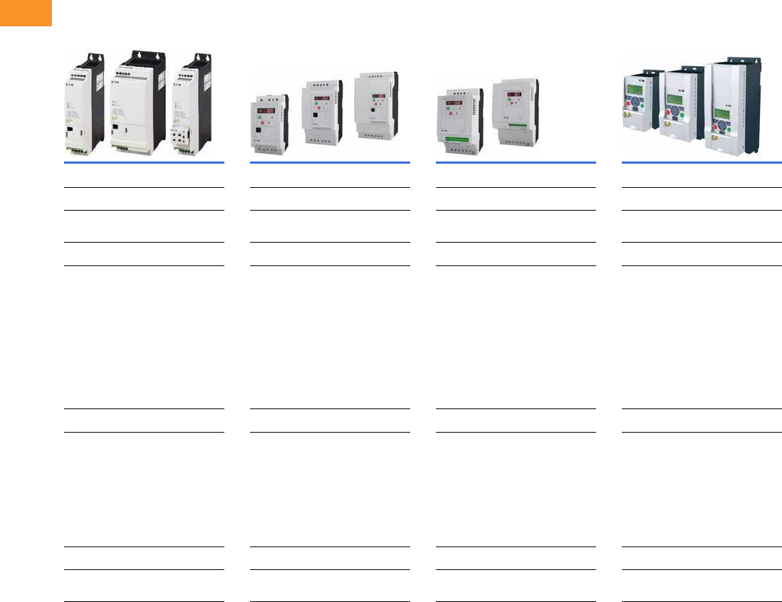
V6-T2-4 Volume 6—Solid-State Motor Control CA08100007E—February 2016 www.eaton.com
2
2
2
2
2
2
2
2
2
2
2
2
2
2
2
2
2
2
2
2
2
2
2
2
2
2
2
2
2
2
2.1
Adjustable Frequency Drives
Product Overview
Product Selection Guide
OEM Drives
PowerXL DE1 Series PowerXL DC1 Series PowerXL DA1 Series M-Max Series
Page V6-T2-9 Page V6-T2-15 Page V6-T2-25 Page V6-T2-36
Applications Applications Applications Applications
Machinery OEM variable speed starter General-purpose microdrive
Machinery OEM drive
High-performance microdrive
Machinery OEM drive
General-purpose microdrive
Description Description Description Description
The DE1 VSS is a variable speed starter
that brings the simplicity of a
electromechanical starter with the
additional functionality of a variable
frequency drive. The DE1 offers simple
installation in a compact, keypad-less
design. With the use of the intuitive plug-in
configuration module or the integration of
SmartWire-DT®, the DE1 is the simplest
solution for variable speed. The VSS is
great for HVAC, material handling and
general MOEM applications.
The DC1 VFD is a compact VFD with only
14 basic parameters, SmartWire-DT®
connectivity and outstanding ease of
mounting and installation. The DC1 is
perfect for quick commissioning and is
ideal for panel builders. This drive
supports single-phase motor applications,
and an IP66 offering provides unique
mounting with integrated disconnect
and cover controls.
The DA1 VFD is the perfect match for
demanding OEM applications. High-
performance processor, safe torque off,
multiple fieldbus protocols including
SmartWire-DT, sensorless vector control
and the possibility to operate permanent
magnet motors are sure to leave a lasting
impression. The DA1 includes an IP66
offering as well.
The M-Max™ VFD is a compact microdrive
with a broad power range, perfectly suited
for machinery applications in many
industries: food and beverage, HVAC,
packaging, pumping, general machine
and more.
Offering/Range Offering/Range Offering/Range Offering/Range
Single-phase to three-phase
230 V to 3 hp
Three-phase to three-phase
230 V to 3 hp
Three-phase to three-phase
480 V to 10 hp
Single-phase to single-phase
115 V to 0.75 hp
230 V to 1.5 hp
Single-phase to three-phase
115 V to 1.5 hp
230 V to 5 hp
Three-phase to three-phase
230 V to 15 hp
480 V to 30 hp
Single-phase to three-phase
230 V to 3 hp
Three-phase to three-phase
230 V to 7.5 hp
480 V to 15 hp
600 V to 20 hp
Single-phase to three-phase
115 V to 1.5 hp
230 V to 3 hp
Three-phase to three-phase
230 V to 15 hp
480 V to 25 hp
575 V to 7.5 hp
Enclosure Enclosure Enclosure Enclosure
Open IP20 Open IP20, IP66 Open IP20, IP66 Open IP20, IP21
Open NEMA 1
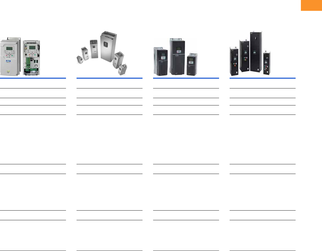
Volume 6—Solid-State Motor Control CA08100007E—February 2016 www.eaton.com V6-T2-5
2
2
2
2
2
2
2
2
2
2
2
2
2
2
2
2
2
2
2
2
2
2
2
2
2
2
2
2
2
2
2.1
Adjustable Frequency Drives
Product Overview
Product Selection Guide
General Purpose Industrial Drives General Purpose HVAC Drives
PowerXL DG1 Series SVX
H-Max Series
H-Max H-Max IntelliPass and
IntelliDisconnect Drives
Page V6-T2-48 Page V6-T2-100 Page V6-T2-179 Page V6-T2-190
Applications Applications Applications Applications
General-purpose drive General-purpose drive General-purpose HVAC drive General-purpose HVAC drive
Description Description Description Description
The DG1 general-purpose drives are part
of the Eaton next-generation PowerXL
series of adjustable frequency drives
specifically engineered for today’s more
demanding commercial and industrial
applications. With an industry-leading
energy-efficiency algorithm, high short-
circuit current rating and robust design,
the DG1 offers customers increased
efficiency, safety and reliability.
The SVX VFD is a general-purpose,
compact, modular solution for variable
speed applications and offers a variety
of features and application capabilities.
With a reliable design, quick startup and
flexibility with options, the SVX provides a
great solution for customer's commercial
and industrial applications.
The H-Max™ VFD is specifically designed
to meet the needs of the HVAC industry
by offering leading HVAC software and
hardware features. With an industry-
leading energy efficiency algorithm, high
short-circuit current rating and robust
design, it offers customers increased
efficiency, safety and reliability.
The H-Max IntelliPass and IntelliDisconnect
use the H-Max drive along with XT series
contactors and optional manual override
switches to provide the ability to bypass
the H-Max drive. The IntelliPass
construction features allow for easy
installation, reliable operation and
serviceability with additional onboard
wire space and removable conduit
plates with knockouts.
Offering/Range Offering/Range Offering/Range Offering/Range
Single-phase to three-phase
230 V to 40 hp
480 V to 60 hp
Three-phase to three-phase
230 V to 125 hp
480 V to 250 hp
575 V to 250 hp
Single-phase to three-phase
230 V to 40 hp
480 V to 60 hp
Three-phase to three-phase
230 V to 125 hp
480 V to 2200 hp
575 V to 2300 hp
Three-phase to three-phase
230 V to 125 hp
480 V to 250 hp
Three-phase to three-phase
208 V to 30 hp
230 V to 30 hp
480 V to 75 hp
Enclosure Enclosure Enclosure Enclosure
Open IP21, IP54
Open NEMA 1, 12
Enclosed NEMA 1, 12, 3R
Consult Eaton for NEMA 4X
Open IP20, IP21, IP54
Open NEMA 1, 12
Enclosed NEMA 1, 12, 3R
AGSVX (agriculture config)
Consult Eaton for NEMA 4X
Open IP21, IP54
Open NEMA 1, 12
Enclosed NEMA 1, 12, 3R
IntelliDisconnect (breaker included)
IntelliPass (bypass included)
Open IP21, IP54
Open NEMA 1, 12
Enclosed NEMA 1, 12, 3R
IntelliDisconnect (breaker included)
IntelliPass (bypass included)
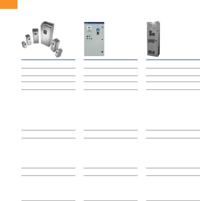
V6-T2-6 Volume 6—Solid-State Motor Control CA08100007E—February 2016 www.eaton.com
2
2
2
2
2
2
2
2
2
2
2
2
2
2
2
2
2
2
2
2
2
2
2
2
2
2
2
2
2
2
2.1
Adjustable Frequency Drives
Product Overview
Product Selection Guide
Performance Drives
SPX
Low Harmonic Drives
Passive Filtered—EGF Passive Filtered—CFX
Page V6-T2-213 Page V6-T2-263 Page V6-T2-288
Applications Applications Applications
High-performance drive Filtered drive Filtered drive
Description Description Description
The SPX VFD is a compact, modular
solution for high-performance variable
speed applications. When high
performance is critical to a customer’s
application, the SPX VFD is the ideal
choice. They are equipped with high
processing power, capable of closed loop
feedback, safe torque off, permanent
magnet motor operation and very precise
motor control.
Eaton’s enclosed passive filtered drives
use tuned passive filters to significantly
reduce line harmonics at the drive input
terminals.
The CFX VFD uses a tuned passive filter
to significantly reduce the line harmonics
generated by a standard 6-pulse drive.
Designed for small to mid-sized drive
applications, the CFX, in conjunction
with the CPX, offers the user a tiered
approach to harmonic mitigation.
Offering/Range Offering/Range Offering/Range
Single-phase to three-phase
230 V to 40 hp
480 V to 60 hp
Three-phase to three-phase
230 V to 125 hp
480 V to 2200 hp
575 V to 2300 hp
208 V: 0.75–100 hp
230 V: 0.75–125 hp
480 V: 1–250 hp
Three-phase to three-phase
230 V to 100 hp
480 V to 400 hp
575 V to 400 hp
Enclosure Enclosure Enclosure
Open IP20, IP21, IP54
Open NEMA 1, 12
Enclosed NEMA 1, 12, 3R
AGSVX (agriculture config)
Consult Eaton for NEMA 4X
Enclosed NEMA 1, 12, 3R
Consult Eaton for NEMA 4X
Enclosed NEMA 1, 12, 3R
Consult Eaton for NEMA 4X
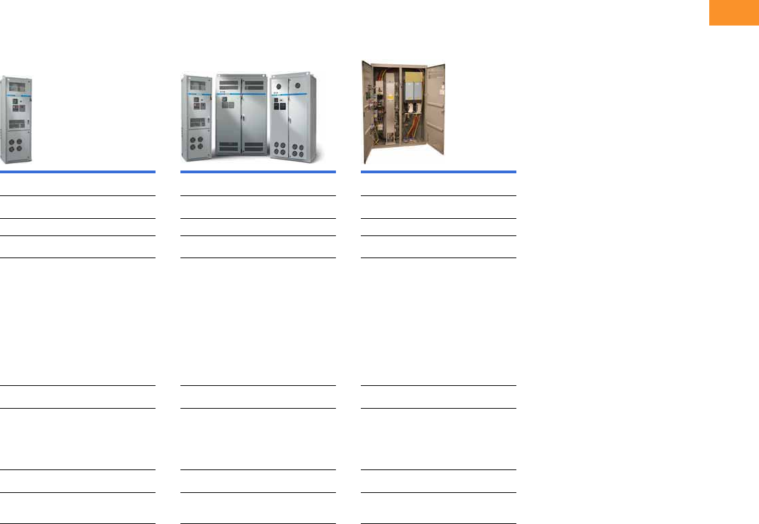
Volume 6—Solid-State Motor Control CA08100007E—February 2016 www.eaton.com V6-T2-7
2
2
2
2
2
2
2
2
2
2
2
2
2
2
2
2
2
2
2
2
2
2
2
2
2
2
2
2
2
2
2.1
Adjustable Frequency Drives
Product Overview
Product Selection Guide
Performance Drives
Low Harmonic Drives
12-Pulse—HCX 18-Pulse—CPX Regenerative—RGX
Page V6-T2-319 Page V6-T2-323 Page V6-T2-348
Applications Applications Applications
12-pulse drive 18-pulse drive Regenerative drive
Description Description Description
The enclosed HCX drive is specifically
tailored for HVAC applications where
clean power is necessary. The enclosed
HCX drive uses Eaton’s SVX drive with a
12-pulse phase shifting transformer to
deliver a substantial reduction in voltage
and current harmonics.
The CPX VFD uses advanced 18-pulse clean
power technology that significantly reduces
line harmonics at the drive input terminals
and is designed to exceed IEEE 519-1992
requirements. Delivering true power factor
and reducing harmonic distortion prevents
upstream transformer overheating and
overloading of breakers and feeders,
enabling the application of variable
frequency drives on generators and other
high-impedance power systems.
The RGX is an enclosed solution to meet
the needs of customer's regenerative
load applications. It combines Eaton’s
comprehensive family of DC common
DC bus drive products together with the
necessary circuit protection and filtering
to give the customer an all-in-one package.
The RGX is available in 480 V and 575 V
configurations in sizes up through 900 hp.
Offering/Range Offering/Range Offering/Range
208 V: 7.5 to 60 hp
230 V: 7.5 to 60 hp
480 V: 25 to 125 hp
Three-phase to three-phase
230 V to 200 hp
480 V to 800 hp
575 V to 800 hp
(Consult Eaton for larger hp)
Three-phase to three-phase
480 V: 900 hp
575 V: 750 hp
Enclosure Enclosure Enclosure
Enclosed NEMA 1, 12 Enclosed NEMA 1, 12, 3R
Consult Eaton for NEMA 4X
Enclosed NEMA 1
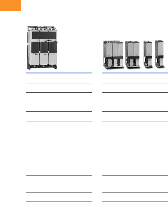
V6-T2-8 Volume 6—Solid-State Motor Control CA08100007E—February 2016 www.eaton.com
2
2
2
2
2
2
2
2
2
2
2
2
2
2
2
2
2
2
2
2
2
2
2
2
2
2
2
2
2
2
2.1
Adjustable Frequency Drives
Product Overview
Product Selection Guide
Performance Drives
Low Harmonic Drives
LCX SPA/SPN/SPI
Page V6-T2-361 Page V6-T2-377
Applications Applications
Liquid cooled drive Common DC bus drive
Active front end drive
Regenerative drive
Description Description
The LCX VFD is well suited for locations
when air-cooling would be difficult or
expensive or when space is at a premium.
These extremely compact drives are
suitable for ships, mines and heavy
industry.
Eaton offers a comprehensive range of
common DC bus VFD products. This
includes a number of front-end units and
inverter units in the entire power range.
Common DC bus drives are used in a
multitude of applications and
combinations. Drives that are braking
can transfer the energy directly to the
drives in a motoring mode.
Offering/Range Offering/Range
Three-phase to three-phase
480 V to 3200 hp
575 V to 2800 hp
Three-phase to three-phase
480 V to 2400 hp
575 V to 2200 hp
Enclosure Enclosure
Open IP00 Open IP00, IP21
Open NEMA 1
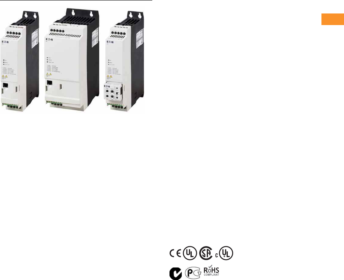
Volume 6—Solid-State Motor Control CA08100007E—February 2016 www.eaton.com V6-T2-9
2
2
2
2
2
2
2
2
2
2
2
2
2
2
2
2
2
2
2
2
2
2
2
2
2
2
2
2
2
2
2.2
Adjustable Frequency Drives
PowerXL DE1 Series
PowerXL DE1 Series
Contents
Description Page
PowerXL DE1 Series
Catalog Number Selection . . . . . . . . . . . . . . . . V6-T2-10
Product Selection . . . . . . . . . . . . . . . . . . . . . . . V6-T2-10
Accessories . . . . . . . . . . . . . . . . . . . . . . . . . . . V6-T2-11
Technical Data and Specifications . . . . . . . . . . V6-T2-12
Dimensions . . . . . . . . . . . . . . . . . . . . . . . . . . . V6-T2-14
Product Description
Eaton’s PowerXL
®
DE1
variable speed starter offers
the advantages of both a
motor starter and a variable
frequency drive in a single
device. The DE1 is a compact
and easy-to-use device with
the ability to change the
speed of the motor with
the simplicity of a contactor
starter. With 14 basic
parameters, SmartWire-DT®
connectivity and an intuitive
configuration module, the
DE1 setup and commissioning
is easy for any panel builder
and MOEM. The DE1 was
designed for customers
who have concerns of the
complexity of a VFD but still
require variable frequency and
advanced motor protection.
Models rated at 480 volts,
three-phase, 50/60 Hz are
available in sizes ranging from
0.5 to 10 hp. Models rated
at 230 volts, single-phase in/
three-phase out, 50/60 Hz
are available in sizes ranging
from 0.33 to 3 hp.
The DE1 VSS is designed
without a keypad to provide
a simplistic, cost effective
solution. Units are shipped
without a keypad. In order to
change parameters, there are
accessories such as the
configuration module that can
change up to 5 parameters or
connectivity products to
connect to the drivesConnect
PC Tool.
Features
●Compact, space-saving
design
●Rugged design rated up
to 60 °C without derating
●DIN rail and screw
mountable
●Narrow footprint for true
side-by-side installation
●Rated for group motor
applications
●Low capacitor design for
low harmonics
●Control terminal blocks
●Three digital inputs
●One digital/analog
(programmable) input
●One relay output
●Contactor style power
wiring
●RS-485/Modbus as
standard
●Efficient, simple design
without a keypad
●Three indicating LEDs
for fault and condition
status
●Reliable design—
150% for 60 s
175% for 2 s
●Smartwire-DT ready for
expanding communication
gateways
Standards and
Certifications
Product
●Complies with EN 61800-3
Safety
●IEC 61800-5-1
●CE
●UL
●CSA/cUL
●cTick
●UKRSekpro
●GOST R
●RoHS compliant
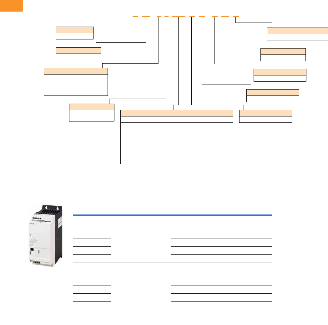
V6-T2-10 Volume 6—Solid-State Motor Control CA08100007E—February 2016 www.eaton.com
2
2
2
2
2
2
2
2
2
2
2
2
2
2
2
2
2
2
2
2
2
2
2
2
2
2
2
2
2
2
2.2
Adjustable Frequency Drives
PowerXL DE1 Series
Catalog Number Selection
DE1 Series Variable Speed Starter
Product Selection
DE1 Series IP20 Enclosure Drives
Notes
1 For all applications, select the unit such that the motor current is less than or equal to the rated continuous output current.
2 These are constant torque/high overload rated drives.
hp 1kW Volts
100% Continuous
Current In (A)
Frame
Size Catalog Number
2
0.33 0.25 200–240 V single-phase in/
230 V three-phase out
1.4 1 DE1-121D4NN-N20N
0.5 0.37 2.3 1 DE1-122D3NN-N20N
0.75 0.55 2.7 1 DE1-122D7NN-N20N
10.75 4.3 1 DE1-124D3NN-N20N
21.5 7 1 DE1-127D0NN-N20N
32.2 9.6 2 DE1-129D6NN-N20N
0.5 0.37 380–480 V three-phase in/
480 V three-phase out
1.3 1 DE1-341D3NN-N20N
10.75 2.1 1 DE1-342D1NN-N20N
21.5 3.6 1 DE1-343D6NN-N20N
32.2 5 2 DE1-345D0NN-N20N
43 6.6 2 DE1-346D6NN-N20N
54 8.5 2 DE1-348D5NN-N20N
7.5 5.5 11.3 2 DE1-34011NN-N20N
10 7.5 16 2 DE1-34016NN-N20N
DE1 -1 24D3 N N -N 20 N
Conformation Coated Option
N= Not conformal coated boards
Device Series
E1 = Economy
Basic Naming
D=Drive
Current Rating
230 V 460 V
1D4 = 1.4 A, 0.33 hp, 0.25 kW
2D3 = 2.3 A, 0.5 hp, 0.37 kW
2D7 = 2.7 A, 0.75 hp, 0.55 kW
4D3 = 4.3 A, 1.0 hp, 0.75 kW
7D0 = 7.0 A, 2.0 hp, 1.5 kW
9D6 = 9.6 A, 3.0 hp, 2.2 kW
1D3 = 1.3 A, 0.5 hp, 0.37 kW
2D1 = 2.1 A, 1.0 hp, 0.75 kW
3D6 = 3.6 A, 2.0 hp, 1.5 kW
5D0 = 5.0 A, 3.0 hp, 2.2 kW
6D6 = 6.6 A, 4.0 hp, 3.0 kW
8D5 = 8.5 A, 5.0 hp, 4.0 kW
011 = 11 A, 7.5 hp, 5.5 kW
016 = 16 A, 10 hp, 7.5 kW
Number of Phases
1= Single-phase main connection/
three-phase motor connection
3= Three-phase main connection/
three-phase motor connection
Input/Output Voltage
2=230 V
4=480 V
Environment Rating
20 = IP20, NEMA 0
Display Option
N=No display
Brake Chopper Option
N= No brake chopper
Filter Option
N= No filter
IP20
Volume 6—Solid-State Motor Control CA08100007E—February 2016 www.eaton.com V6-T2-11
2
2
2
2
2
2
2
2
2
2
2
2
2
2
2
2
2
2
2
2
2
2
2
2
2
2
2
2
2
2
2.2
Adjustable Frequency Drives
PowerXL DE1 Series
Accessories
DE1 Series
PC Communication Kit and Copy/Paste Module
Keypad Options
Extension Cables and Data Cable Splitter
SmartWire Modules
Commoning Links 2
Notes
1Includes 1 m RS-485 data cable.
2Commoning links can be used to connect multiple line side 460 V DE1 units for use in
group motor applications.
3These combinations may result in the total of the individual input currents exceeding the
three-phase commoning link’s and incoming connection block’s ampacity (35 A).
4Required for group motor applications when using the 460 V commoning links.
Description Catalog Number
Bluetooth copy/paste communication stick DX-COM-STICK
USB to RJ45 panel mount kit DX-COM-PCKIT
USB to RJ45 PC Tool cable DX-CBL-PC-3M0
Description Catalog Number
LED remote keypad—7-segment display, IP54 rated DX-KEY-LED 1
Configuration module—plug-in unit, DIP switch and dial control DXE-EXT-SET
Description Catalog Number
RJ45 communication cable w/terminating resistor EASY-NT-R
RS-485 data cable, RJ45, 0.5 m DX-CBL-RJ45-0M5
RS-485 data cable, RJ45, 1.0 m DX-CBL-RJ45-1M0
RS-485 data cable, RJ45, 3.0 m DX-CBL-RJ45-3M0
RS-485 three-way data cable splitter, RJ45 DX-SPL-RJ45-3SL
RS-485 data cable splitter, RJ45, (1 connector to 2 socket) DX-SPL-RJ45-2SL1PL
Description Catalog Number
SmartWire-DT interface for DE1 and DC1 IP20 DX-NET-SWD3
Description Max. Devices Used Catalog Number
460 V, three-phase link 3xFS1 XTCEXCLK3B
2xFS1 + 1xFS2
2xFS2
4xFS1 XTCEXCLK4B
3xFS1 + 1xFS2
1xFS1 + 2xFS2 3
5xFS1 XTCEXCLK5B
4xFS1 + 1xFS2
2xFS1 + 2xFS2 3
3xFS2 3
460 V, incoming terminal — XTCEXITB 4

V6-T2-12 Volume 6—Solid-State Motor Control CA08100007E—February 2016 www.eaton.com
2
2
2
2
2
2
2
2
2
2
2
2
2
2
2
2
2
2
2
2
2
2
2
2
2
2
2
2
2
2
2.2
Adjustable Frequency Drives
PowerXL DE1 Series
Technical Data and Specifications
DE1 Series
Ratings
PowerXL DE1 Basic Controller Standard Ratings
Programmable Parameters
Specifications
PowerXL DE1 Series
Note
1All units do not require derating except for the 10 hp 460 V unit which may require derating
depending on the switching frequency used.
Description Specification
Protections
Overload protection 150% for 60s for every 600 seconds
Overvoltage protection Yes
Undervoltage protection Yes
Ground fault protection Yes
Overtemperature
protection
Yes
Motor overload protection Yes
Motor stall protection Yes
Short-circuit protection 100 kAIC with fuses,
65 kAIC with PKZM,
10 kAIC with FAZ
Description
14 Standard operation parameters
Programmable start function
DC-brake at start and stop
Adjustable switching frequency
Autorestart function after fault
Protections and supervisions
Power section fault indication
External fault
Fieldbus communication
Analog input range selection, signal scaling and filtering
Four preset speed reference
Description Specification
Input Ratings
Input voltage (Vin)±10%
Input frequency (fin) 50/60 Hz (variation up to 48–62 Hz)
Connection to power Maximum of one time every 30 seconds
Output Ratings
Output voltage 0 to Vin
Continuous output
current
Continuous rated current IN at ambient temperature max.
140 °F (60 °C), 150% for 60 seconds, 175% for 2 seconds
Output frequency 0 to 500 Hz
Frequency resolution 0.1 Hz
Initial output current (IH) 175% for 2s for every 20 seconds
Torque depends on motor
Control Characteristics
Operation mode
U/f control, slip compensation
Switching frequency 4 to 32 kHz
Voltage reference 10 Vdc (max. 10 mA)
Field weakening point 0 to 500 Hz
Acceleration time 0.1 to 600 seconds
Deceleration time 0.1 to 600 seconds
Ambient Conditions
Ambient operating
temperature
–10 °C to +50 °C, for 60 °C there is no derating required 1
Storage temperature –40 °C to +70 °C
Relative humidity 0 to 95% RH, noncondensing, non-corrosive, no dripping water
Enclosure class IP20 (FS1–FS3)
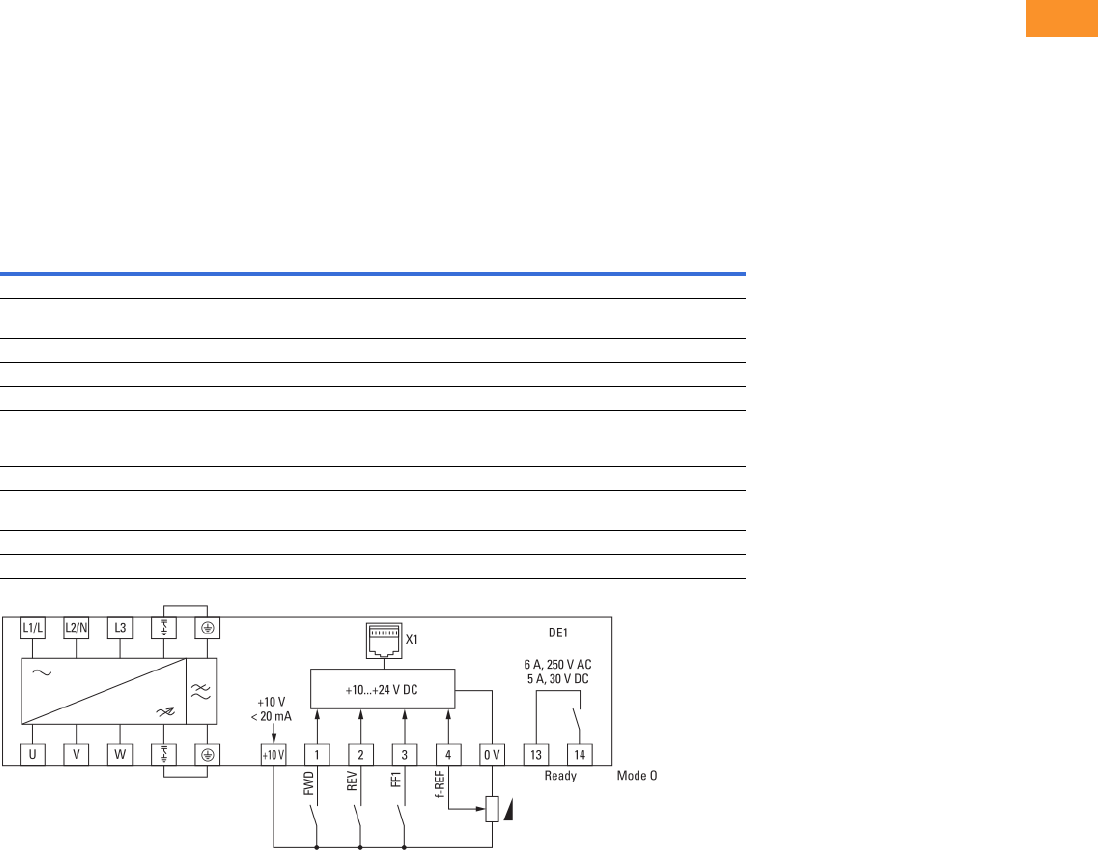
Volume 6—Solid-State Motor Control CA08100007E—February 2016 www.eaton.com V6-T2-13
2
2
2
2
2
2
2
2
2
2
2
2
2
2
2
2
2
2
2
2
2
2
2
2
2
2
2
2
2
2
2.2
Adjustable Frequency Drives
PowerXL DE1 Series
Standards—DE1 Series Variable Speed Starter
I/O Specifications
●Digital inputs DI1–DI4 are
programmable
●Relay output is
programmable
●DI3 and DI4 can be
programmed to be digital,
thermistor or analog
Includes:
●Four inputs (three digital
and one digital/analog)
●Analog input
●4–20 mA
●0–10 V
●One relay output
●RS-485 interface
Reliability
●Pretested components
●Computerized testing
●Robust design rated to
60 °C
DE1 Series I/O Interface
Terminal Signal Factory Preset Description
0 V 0 V Reference potential — 0 V connection
+0 V +24 Vdc Control voltage for DI1-DI4 — Maximum load 100 mA
Reference potential V
1 DI1 Digital Input 1 FWD +10 to 24 V
2 DI2 Digital Input 2 REV +10 to 24 V
3 DI3 Digital Input 3 Fixed frequency FF1 +10 to 24 V
Ther. Thermistor Fixed frequency FF1 External fault: [Need info]
Trip at 3600 Ω
Reset at 1600 Ω
4 DI4 Digital Input 4 Frequency reference value +10 to 24 V
AI1 Analog Input Frequency reference value 0 to 10 V 0/4–20 mA
Can be switched with parameter P16
13 K13 Relay 1, normally open contact Active = RUN Maximum switching load: 250 Vac/6 A or 30 Vdc/5 A
14 K14 Relay 1, normally open contact Active = RUN Maximum switching load: 250 Vac/6 A or 30 Vdc/5 A
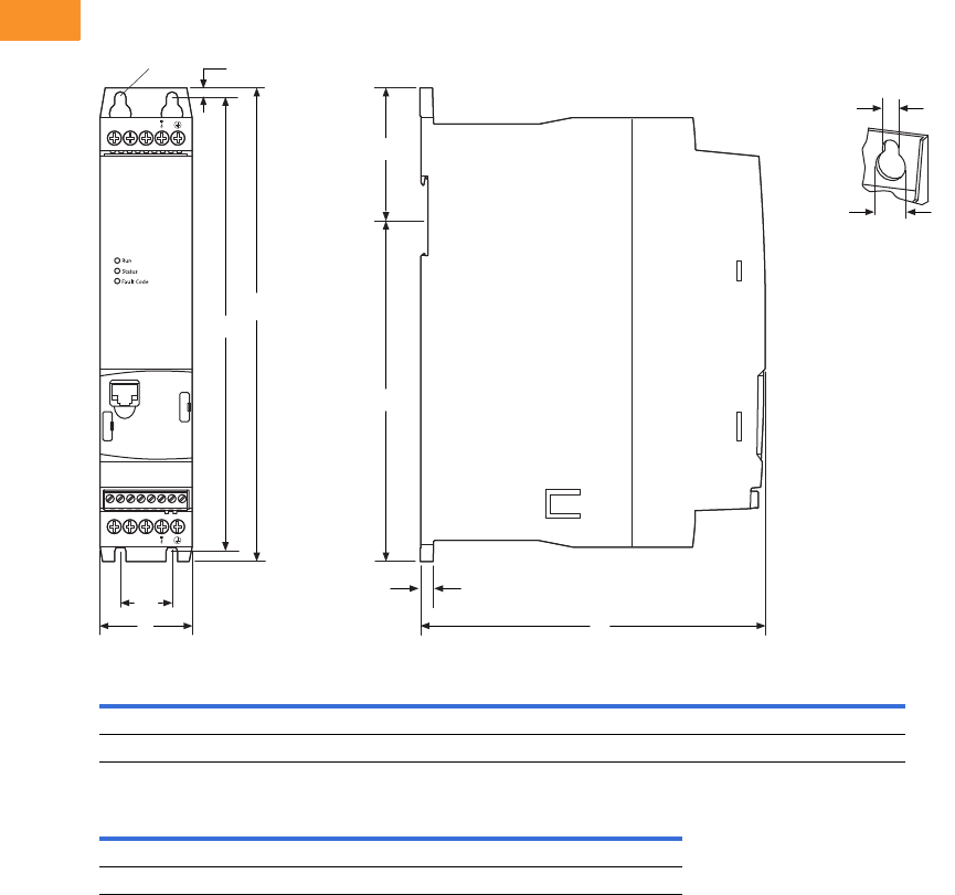
V6-T2-14 Volume 6—Solid-State Motor Control CA08100007E—February 2016 www.eaton.com
2
2
2
2
2
2
2
2
2
2
2
2
2
2
2
2
2
2
2
2
2
2
2
2
2
2
2
2
2
2
2.2
Adjustable Frequency Drives
PowerXL DE1 Series
Dimensions
Approximate Dimensions in Inches (mm)
DE1, Sizes FS1 and FS2, Degree of Protection IP20/NEMA 0
Frame
Size A A1 B B1 B2 B3 B4
FS1 1.77 (45.0) 0.98 (25.0) 9.09 (231.0) 8.66 (220.0) 0.20 (5.1) 2.52 (64.0) 6.54 (166.1)
FS2 3.54 (90.0) 1.97 (50.0) 9.09 (231.0) 8.66 (220.0) 0.20 (5.1) 2.52 (64.0) 6.54 (166.1)
Frame
Size C C1 Ø1Ø2
Weight
lbs (kg)
FS1 6.65 (169.0) 0.26 (6.6) 0.20 (5.1) 0.39 (10.0) 2.29 (1.04)
FS2 6.65 (169.0) 0.26 (6.6) 0.20 (5.1) 0.39 (10.0) 3.70 (1.68)
B
C
Ø2
Ø1
A
A1 C1
B1
B2
0 V +10 V 1 2 3 4 13 14
UVW
B3
B4
Ø
L1/LL2/NL3
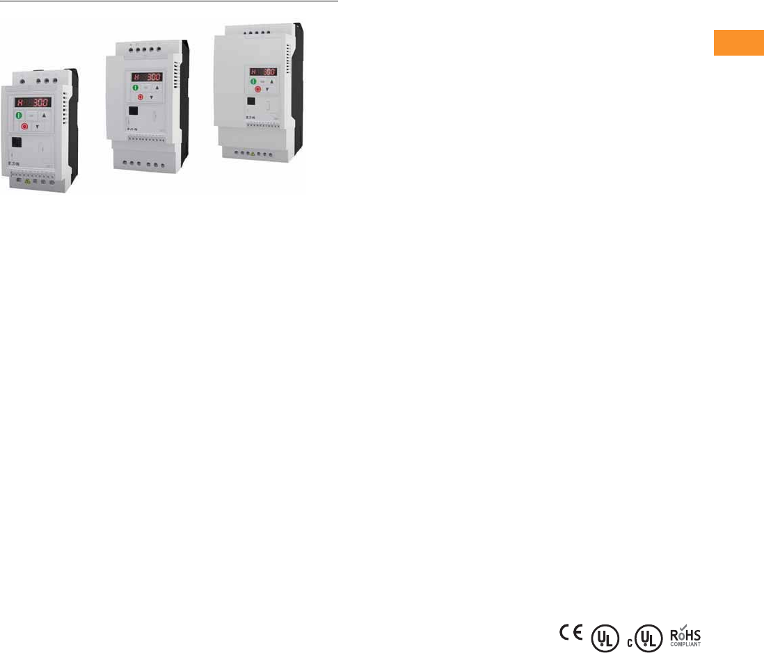
Volume 6—Solid-State Motor Control CA08100007E—February 2016 www.eaton.com V6-T2-15
2
2
2
2
2
2
2
2
2
2
2
2
2
2
2
2
2
2
2
2
2
2
2
2
2
2
2
2
2
2
2.3
Adjustable Frequency Drives
PowerXL DC1 Series Drives
PowerXL DC1 Series Drives
Contents
Description Page
PowerXL DC1 Series Drives
Catalog Number Selection . . . . . . . . . . . . . . . . V6-T2-16
Product Selection . . . . . . . . . . . . . . . . . . . . . . . V6-T2-17
Accessories . . . . . . . . . . . . . . . . . . . . . . . . . . . V6-T2-19
Technical Data and Specifications . . . . . . . . . . V6-T2-21
Dimensions . . . . . . . . . . . . . . . . . . . . . . . . . . . V6-T2-23
Product Description
Eaton’s PowerXL
®
DC1
variable frequency drives are
the next generation of drives
specifically engineered for
today’s machinery
applications.
The DC1 is compact with
only 14 basic parameters,
SmartWire-DT® connectivity,
and outstanding ease of
mounting and installation.
The DC1 is perfect for quick
commissioning and is ideal
for panel builders. This drive
supports single-phase motor
applications, and detachable
terminal blocks make control
wiring much easier.
Models rated at 480 volts,
three-phase, 50/60 Hz are
available in sizes ranging from
1 to 30 hp 2. Models rated at
240 volts, single- or three-
phase, 50/60 Hz are available
in sizes ranging from 0.5
to 15 hp 2. Models rated at
115 volts, single-phase,
50/60 Hz are available in
the 0.5 to 3 hp size range.
Features
●Compact, space-saving
design
●
Rugged and reliable—
175%
for 2 s, 50 °C rated
●DIN rail and screw
mountable (FS1 and FS2)
●Side-by-side installation
●Industry-leading efficiency
delivers energy savings to
the customer
●Optional integrated EMC
filters make the unit
suitable for commercial
and industrial networks
●Brake chopper as standard
in frames 2 and higher
●Temperature-controlled fan
●RS-485/Modbus® and
CANopen™ as standard
●PI controller as standard
●SmartWire capability
●Removable I/O terminal
blocks
●Contactor style power
wiring
●Designed for shaded-pole,
single-phase motors and
permanent split capacitor
single-phase motors
Standards and
Certifications
Product
●Complies with EN61800-3
(2004)
EMC (At Default Settings)
●EMC Category C1, C2
and C3 at default settings
(1 m, 5 m, 25 m)
Safety 1
●61800-5-1
●EN 60529
●CE
●UL
●cUL
●UkrSepro
●c-Tick
●RoHS compliant
Note
1See unit nameplate for more detailed
approvals.
2Available September 2015.
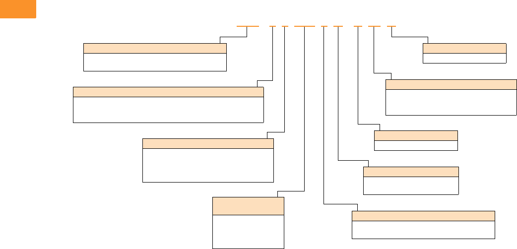
V6-T2-16 Volume 6—Solid-State Motor Control CA08100007E—February 2016 www.eaton.com
2
2
2
2
2
2
2
2
2
2
2
2
2
2
2
2
2
2
2
2
2
2
2
2
2
2
2
2
2
2
2.3
Adjustable Frequency Drives
PowerXL DC1 Series Drives
Catalog Number Selection
DC1 Series Adjustable Frequency AC Drives
DC1 -1 24D1 F N -A 20 N
Rated
Operational Current
Examples—
2D2 = 2.2 A
4D1 = 4.1 A
024 = 24 A
Type
N= Standard basic device
Degree of Protection
20 = IP20/NEMA 0
66 = IP66/NEMA 4/4X
6S = IP66 with disconnect/NEMA 4/4X
Device Series
DC1 = Variable frequency drive, compact, Series 1
(D = Drives, C = Compact, 1 = Series 1)
Connection in Power Section
1= Single-phase mains connection/three-phase motor connection
3= Three-phase mains connection/three-phase motor connection
S= Single-phase mains connection/single-phase motor connection
Mains Voltage Category
1= 110 V (110–115 V ±10%)
2= 230 V (200–240 V ±10%)
4= 480 V (380–480 V ±10%)
D= 110 V input/230 V output (voltage doubler)
Display Unit (Display)
A= LED display
Brake Chopper
N= No internal brake chopper
B= Brake chopper
EMC (Radio Interference Suppression Filter)
N= No internal RFI filter
F= Internal RFI filter
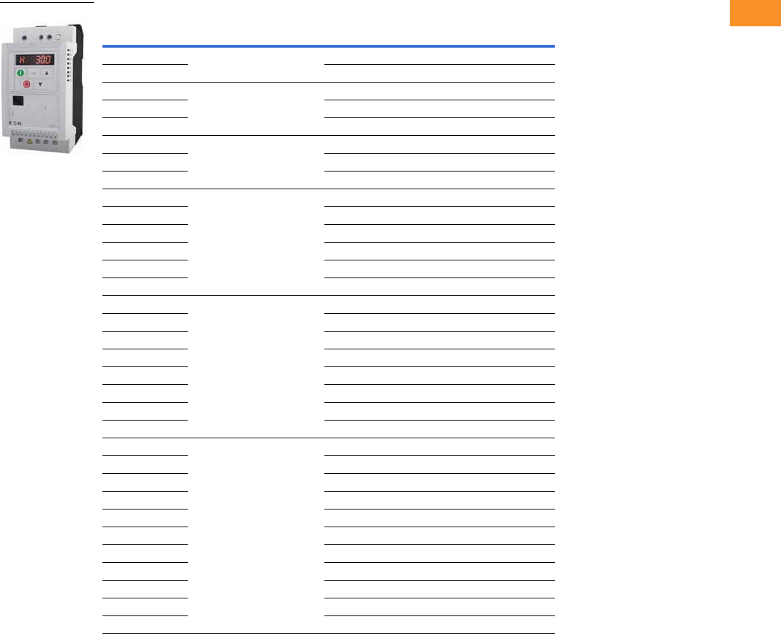
Volume 6—Solid-State Motor Control CA08100007E—February 2016 www.eaton.com V6-T2-17
2
2
2
2
2
2
2
2
2
2
2
2
2
2
2
2
2
2
2
2
2
2
2
2
2
2
2
2
2
2
2.3
Adjustable Frequency Drives
PowerXL DC1 Series Drives
Product Selection
DC1 Series IP20 Enclosure Drives 1
Notes
1 These are constant torque/high overload rated drives.
2 For all applications, select the unit such that the motor current is less than or equal to the rated continuous output current.
3 Brake chopper circuit available as standard in frames 2 and 3.
4 Only for use with shaded pole or split capacitor single-phase motors.
5 RFI version available. Substitute with DC1-*****F*-**** for this option.
6 Frame size 4 available January 2016.
hp 2kW Volts
100% Continuous
Current In (A)
Frame
Size 3Catalog Number
0.5 0.37 115 V single-phase in/ 4
115 V single-phase out
71DC1-S17D0NN-A20N
0.75 0.55 10.5 2 DC1-S1011NB-A20N
0.5 0.37 200–240 V single-phase in/ 4
200–240 V single-phase out
4.3 1 DC1-S24D3NN-A20N 5
10.75 7 1 DC1-S27D0NN-A20N 5
1.5 1.1 10 2 DC1-S2011NB-A20N 5
0.5 0.37 115 V single-phase in/
230 V three-phase out
2.3 1 DC1-1D2D3NN-A20N
10.75 4.3 1 DC1-1D4D3NN-A20N
1.5 1.1 5.8 2 DC1-1D5D8NB-A20N
0.5 0.37 200–240 V single-phase in/
230 V three-phase out
2.3 1 DC1-122D3NN-A20N 5
10.75 4.3 1 DC1-124D3NN-A20N 5
21.5 7 1 DC1-127D0NN-A20N 5
21.5 7 2 DC1-127D0NB-A20N 5
32.2 10.5 2 DC1-12011NB-A20N 5
54 15 3 DC1-12015NB-A20N
0.5 0.37 200–240 V three-phase in/
230 V three-phase out
2.3 1 DC1-322D3NN-A20N
10.75 4.3 1 DC1-324D3NN-A20N
21.5 7 1 DC1-327D0NN-A20N
21.5 7 2 DC1-327D0NB-A20N 5
32.2 10.5 2 DC1-32011NB-A20N 5
54 18 3 DC1-32018NB-A20N 5
10 7.5 30 4 DC1-32030NB-A20N 56
15 11 46 4 DC1-32046NB-A20N 56
1 0.75 380–480 V three-phase in/
480 V three-phase out
2.2 1 DC1-342D2NN-A20N 5
21.5 4.1 1 DC1-344D1NN-A20N 5
21.5 4.1 2 DC1-344D1NB-A20N 5
32.2 5.8 2 DC1-345D8NB-A20N 5
54 9.5 2 DC1-349D5NB-A20N 5
7.5 5.5 14 3 DC1-34014NB-A20N 5
10 7.5 18 3 DC1-34018NB-A20N 5
15 11 24 3 DC1-34024NB-A20N 5
20 15 30 4 DC1-34030NB-A20N 56
25 18.5 39 4 DC1-34039NB-A20N 56
30 22 46 4 DC1-34046NB-A20N 56
IP20
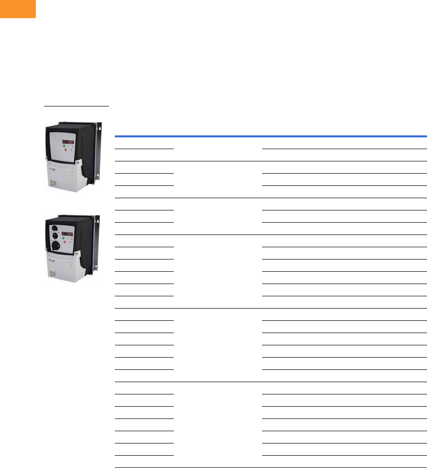
V6-T2-18 Volume 6—Solid-State Motor Control CA08100007E—February 2016 www.eaton.com
2
2
2
2
2
2
2
2
2
2
2
2
2
2
2
2
2
2
2
2
2
2
2
2
2
2
2
2
2
2
2.3
Adjustable Frequency Drives
PowerXL DC1 Series Drives
IP66 NEMA 4/4X Interior
DC1 Drive
The IP66 version of the
DC1 is a unique solution
to allow for mounting the
drive outside of a control
panel or next to a motor
for distributed control.
“-A66N” Option
This version comes with the
keypad that is similar to that
of IP20 version. There are no
additional cover controls to
address security concerns.
“-A6SN” Option
This version has an integrated
potentiometer, a forward/off/
reverse switch and a
disconnect switch with
lock-off capability with the
standard keypad. This
allows for reduced labor and
materials when compared to
a IP20 solution in separate
enclosure.
DC1 Series IP66 Enclosure Drives 1
Notes
1 These are constant torque/high overload rated drives.
2 For all applications, select the unit such that the motor current is less than or equal to the rated continuous output current.
3 Brake chopper circuit available as standard in frames 2 and 3.
4 Non-disconnect version available. Substitute with -A66N.
5 RFI version available. Substitute with DC1-*****F*-**** for this option.
hp 2kW Volts
100% Continuous
Current In (A)
Frame
Size 3Catalog Number
0.5 0.37 115 V single-phase in/
115 V single-phase out
71DC1-S17D0NN-A6SN 4
0.75 0.55 10.5 2 DC1-S1011NB-A6SN 4
0.5 0.37 200–240 V single-phase in/
200–240 V single-phase out
4.3 1 DC1-S24D3NN-A6SN 45
10.75 7 1 DC1-S27D0NN-A6SN 45
1.5 1.1 10 2 DC1-S2011NB-A6SN 45
0.5 0.37 115 V single-phase in/
230 V three-phase out
2.3 1 DC1-1D2D3NN-A6SN 4
10.75 4.3 1 DC1-1D4D3NN-A6SN 4
1.5 1.1 5.8 2 DC1-1D5D8NB-A6SN 4
0.5 0.37 200–240 V single-phase in/
230 V three-phase out
2.3 1 DC1-122D3NN-A6SN 45
10.75 4.3 1 DC1-124D3NN-A6SN 45
21.5 7 1 DC1-127D0NN-A6SN 45
21.5 7 2 DC1-127D0NB-A6SN 45
32.2 10.5 2 DC1-12011NB-A6SN 45
54 15 3 DC1-12015NB-A6SN 4
0.5 0.37 200–240 V three-phase in/
230 V three-phase out
2.3 1 DC1-322D3NN-A6SN 4
10.75 4.3 1 DC1-324D3NN-A6SN 4
21.5 7 1 DC1-327D0NN-A6SN 4
21.5 7 2 DC1-327D0NB-A6SN 45
32.2 10.5 2 DC1-32011NB-A6SN 45
54 18 3 DC1-32018NB-A6SN 45
1 0.75 380–480 V three-phase in/
460 V three-phase out
2.2 1 DC1-342D2NN-A6SN 45
21.5 4.1 1 DC1-344D1NN-A6SN 45
21.5 4.1 2 DC1-344D1NB-A6SN 45
32.2 5.8 2 DC1-345D8NB-A6SN 45
54 9.5 2 DC1-349D5NB-A6SN 45
7.5 5.5 14 3 DC1-34014NB-A6SN 45
10 7.5 18 3 DC1-34018NB-A6SN 45
IP66
IP66S

Volume 6—Solid-State Motor Control CA08100007E—February 2016 www.eaton.com V6-T2-19
2
2
2
2
2
2
2
2
2
2
2
2
2
2
2
2
2
2
2
2
2
2
2
2
2
2
2
2
2
2
2.3
Adjustable Frequency Drives
PowerXL DC1 Series Drives
Accessories
DC1 Series
PC Communication Kit and Copy/Paste Module
Encoder Feedback Plug-In Option Module
and Miscellaneous Cards
Remote Keypad
Brake Resistor (FR2 and FR3)
Extension Cables and Data Cable Splitter
SmartWire Modules
Note
1Includes 1 m RS-485 data cable.
Description Catalog Number
Bluetooth copy/paste communication stick DX-COM-STICK
USB to RJ45 panel mount kit DX-COM-PCKIT
USB to RJ45 PC Tool cable DX-CBL-PC-3MO
Description Catalog Number
Local control/test option card DXC-EXT-LOCSIM
HVACO drive running and tripped relay output card DXC-EXT-2RO1 AO
Dual relay output card DXC-EXT-2RO
110 V logic input card DXC-EXT-IO110
230 V logic input card DXC-EXT-IO230
Description Catalog Number
LED remote keypad—7-segment display, IP54 rated DX-KEY-LED 1
OLED remote keypad—full text display, multi-line text,
multi-language, IP54 hand/auto buttons
DX-KEY-OLED 1
Description Catalog Number
DC1, DA1 internal mount 200 W, 100 R DX-BR3-100
Description Catalog Number
RJ45 communication cable w/terminating resistor EASY-NT-R
RS-485 data cable, RJ45, 0.5 m DX-CBL-RJ45-0M5
RS-485 data cable, RJ45, 1.0 m DX-CBL-RJ45-1M0
RS-485 data cable, RJ45, 3.0 m DX-CBL-RJ45-3M0
RS-485 three-way data cable splitter, RJ45 DX-SPL-RJ45-3SL
RS-485 data cable splitter, RJ45, (1 connector to 2 socket) DX-SPL-RJ45-2SL1PL
Description Catalog Number
SmartWire-DT interface for DC1 IP20 DX-NET-SWD3
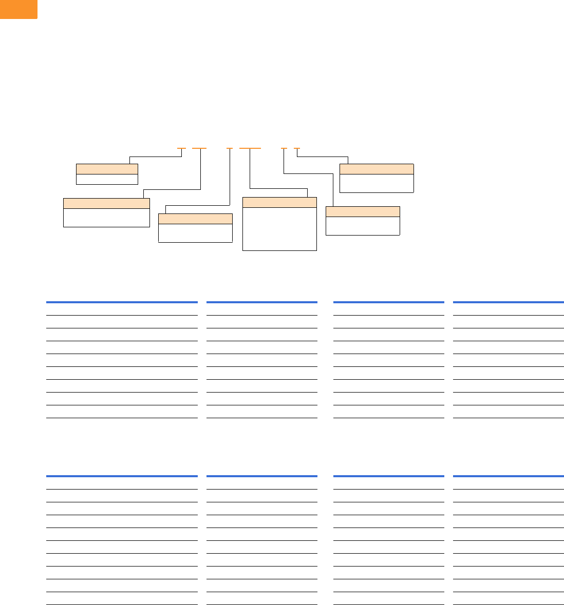
V6-T2-20 Volume 6—Solid-State Motor Control CA08100007E—February 2016 www.eaton.com
2
2
2
2
2
2
2
2
2
2
2
2
2
2
2
2
2
2
2
2
2
2
2
2
2
2
2
2
2
2
2.3
Adjustable Frequency Drives
PowerXL DC1 Series Drives
Line and Load Reactors
A line and load reactor is a
three-phase inductance filter
that can be placed on the line
and load side of the AFD to
help improve the harmonic
performance of the system.
Consult the factory for
additional filtering options and
further technical details.
DR1 Line Reactor
A line reactor helps to provide
a moderate reduction in
current harmonics similar to a
DC choke. It also provides
increased input protection for
AFD and its semiconductors
from line transients helping to
extend the life of the AFD.
DR2 Output Reactor
An output filter is used to
reduce the transient voltage
(dV/dt) at the motor terminals.
The output filter is
recommended for cable
lengths exceeding 100 ft
(30 m) with a drive of 3 hp
and above and for cable
lengths of 33 ft (10 m) with a
drive of 2 hp and below.
Line and Load Reactors—Catalog Number Selection
Line and Load Reactors—230 V
Line and Load Reactors—480 V
Open NEMA 1
Load Reactor Line Reactor Load Reactor Line Reactor
hp (CT) 3% 5% 3% 5% 3% 5% 3% 5%
0.5 DR2-22D0-03 DR2-22D0-05 DR1-22D2-03 DR1-22D2-05 DR2-22D0-13 DR2-22D0-15 DR1-22D2-13 DR1-22D2-15
1 DR2-24D0-03 DR2-28D0-05 DR1-24D2-03 DR1-24D2-05 DR2-24D0-13 DR2-28D0-15 DR1-24D2-13 DR1-24D2-15
1.5 DR2-28D0-03 DR2-28D0-05 DR1-26D0-03 DR1-26D0-05 DR2-28D0-13 DR2-28D0-15 DR1-26D0-13 DR1-26D0-15
2 DR2-28D0-03 DR2-28D0-05 DR1-26D8-03 DR1-26D8-05 DR2-28D0-13 DR2-28D0-15 DR1-26D8-13 DR1-26D8-15
3 DR2-2012-03 DR2-2012-05 DR1-29D6-03 DR1-29D6-05 DR2-2012-13 DR2-2012-15 DR1-29D6-13 DR1-29D6-15
5 DR2-2018-03 DR2-2018-05 DR1-2015-03 DR1-2015-05 DR2-2018-13 DR2-2018-15 DR1-2015-13 DR1-2015-15
7.5 DR2-2025-03 DR2-2025-05 DR1-2022-03 DR1-2022-05 DR2-2025-13 DR2-2025-15 DR1-2022-13 DR1-2022-15
10 DR2-2035-03 DR2-2035-05 DR1-2028-03 DR1-2028-05 DR2-2035-13 DR2-2035-15 DR1-2028-13 DR1-2028-15
15 DR2-2045-03 DR2-2045-05 DR1-2042-03 DR1-2042-05 DR2-2045-13 DR2-2045-15 DR1-2042-13 DR1-2042-15
Open NEMA 1
Load Reactor Line Reactor Load Reactor Line Reactor
hp (CT) 3% 5% 3% 5% 3% 5% 3% 5%
1 DR2-42D0-03 DR2-42D0-05 DR1-42D1-03 DR1-42D1-05 DR2-42D0-13 DR2-42D0-15 DR1-42D1-13 DR1-42D1-15
2 DR2-44D0-03 DR2-44D0-05 DR1-43D4-03 DR1-43D4-05 DR2-44D0-13 DR2-44D0-15 DR1-43D4-13 DR1-43D4-15
3 DR2-48D0-03 DR2-48D0-05 DR1-44D8-03 DR1-44D8-05 DR2-48D0-13 DR2-48D0-15 DR1-44D8-13 DR1-44D8-15
5 DR2-48D0-03 DR2-48D0-05 DR1-47D6-03 DR1-47D6-05 DR2-48D0-13 DR2-48D0-15 DR1-47D6-13 DR1-47D6-15
7.5 DR2-4012-03 DR2-4012-05 DR1-4011-03 DR1-4011-05 DR2-4012-13 DR2-4012-15 DR1-4011-13 DR1-4011-15
10 DR2-4018-03 DR2-4018-05 DR1-4014-03 DR1-4014-05 DR2-4018-13 DR2-4018-15 DR1-4014-13 DR1-4014-15
15 DR2-4025-03 DR2-4025-05 DR1-4021-03 DR1-4021-05 DR2-4025-13 DR2-4025-15 DR1-4021-13 DR1-4021-15
20 DR2-4025-03 DR2-4025-05 DR1-4027-03 DR1-4027-05 DR2-4025-13 DR2-4025-15 DR1-4027-13 DR1-4027-15
25 DR2-4035-03 DR2-4035-05 DR1-4034-03 DR1-4034-05 DR2-4035-13 DR2-4035-15 DR1-4034-13 DR1-4034-15
30 DR2-4045-03 DR2-4045-05 DR1-4040-03 DR1-4040-05 DR2-4045-13 DR2-4045-15 DR1-4040-13 DR1-4040-15
DR1 –22D0 –05
Device Series
R1 = Line side reactor
R2 = Load side reactor
Basic Naming
D= Drive
Input/Output Voltage
2= 230 V
4= 480 V
Environment Rating
0= Open
1= NEMA 1
Impedance
3= 3%
5= 5%
Current Rating
Examples:
2D0 = 2.0 A
4D0 = 4.0 A
8D0 = 8.0 A
012
= 12 A

Volume 6—Solid-State Motor Control CA08100007E—February 2016 www.eaton.com V6-T2-21
2
2
2
2
2
2
2
2
2
2
2
2
2
2
2
2
2
2
2
2
2
2
2
2
2
2
2
2
2
2
2.3
Adjustable Frequency Drives
PowerXL DC1 Series Drives
Technical Data and Specifications
DC1 Series
Ratings
PowerXL DC1 Basic Controller IP20 Standard Ratings
Programmable Parameters
Specifications
PowerXL DC1 Series Drives 1
Notes
1Frame size 4 available January 2016.
2Exception: 115 V single-phase in, 230 V three-phase out.
3Only FS2, FS3 and FS4 drives are equipped with brake chopper circuit.
Description Specification
Protections
Overload protection 150% for 60s for every 600 seconds
Overvoltage protection Yes
Undervoltage protection Yes
Ground fault protection Yes
Overtemperature
protection
Yes
Motor overload protection Yes
Motor stall protection Yes
Short-circuit
withstand rating
100 kAIC with Type 1 fuses
Description
Built-in Help card
14 Standard operation parameters
Reference scaling
Programmable start and stop functions
DC-brake at start and stop
Programmable V/Hz curve
Adjustable switching frequency
Autorestart function after fault
Protections and supervisions
Power section fault indication
External fault
Fieldbus communication
Second deceleration time
Analog input range selection, signal scaling and filtering
PI controller
Skip frequencies
Description Specification
Input Ratings
Input voltage (Vin)±10%
Input frequency (fin) 50/60 Hz (variation up to 48–62 Hz)
Connection to power Maximum of one time every 30 seconds
Output Ratings
Output voltage 0 to Vin 2
Continuous output
current
Continuous rated current IN at ambient temperature max.
122 °F (50 °C), 150% for 60 seconds, 175% for 2 seconds
Output frequency 0 to 500 Hz
Frequency resolution 0.1 Hz
Initial output current (IH) 175% for 2s for every 20 seconds
Torque depends on motor
Control Characteristics
Operation mode
U/f control, slip compensation
Switching frequency 4 to 32 kHz
Voltage reference 10 Vdc (max. 10 mA)
Field weakening point 0 to 500 Hz
Acceleration time 0.1 to 600 seconds
Deceleration time 0.1 to 600 seconds
Brake Resistor (Minimum Values) 3
230 V Series FS2 and FS3 47 ohms
400 V Series FS2 100 ohms, FS3 47 ohms
Ambient Conditions
Ambient operating
temperature
+14 °F (–10 °C), no frost to +122 °F (+50 °C): Rated loadability IN
IP20—NEMA 0
Storage temperature –40 °F (–40 °C) to +140 °F (+60 °C)
Relative humidity 0 to 95% RH, noncondensing, non-corrosive, no dripping water
Enclosure class IP20 (FS1–FS4)
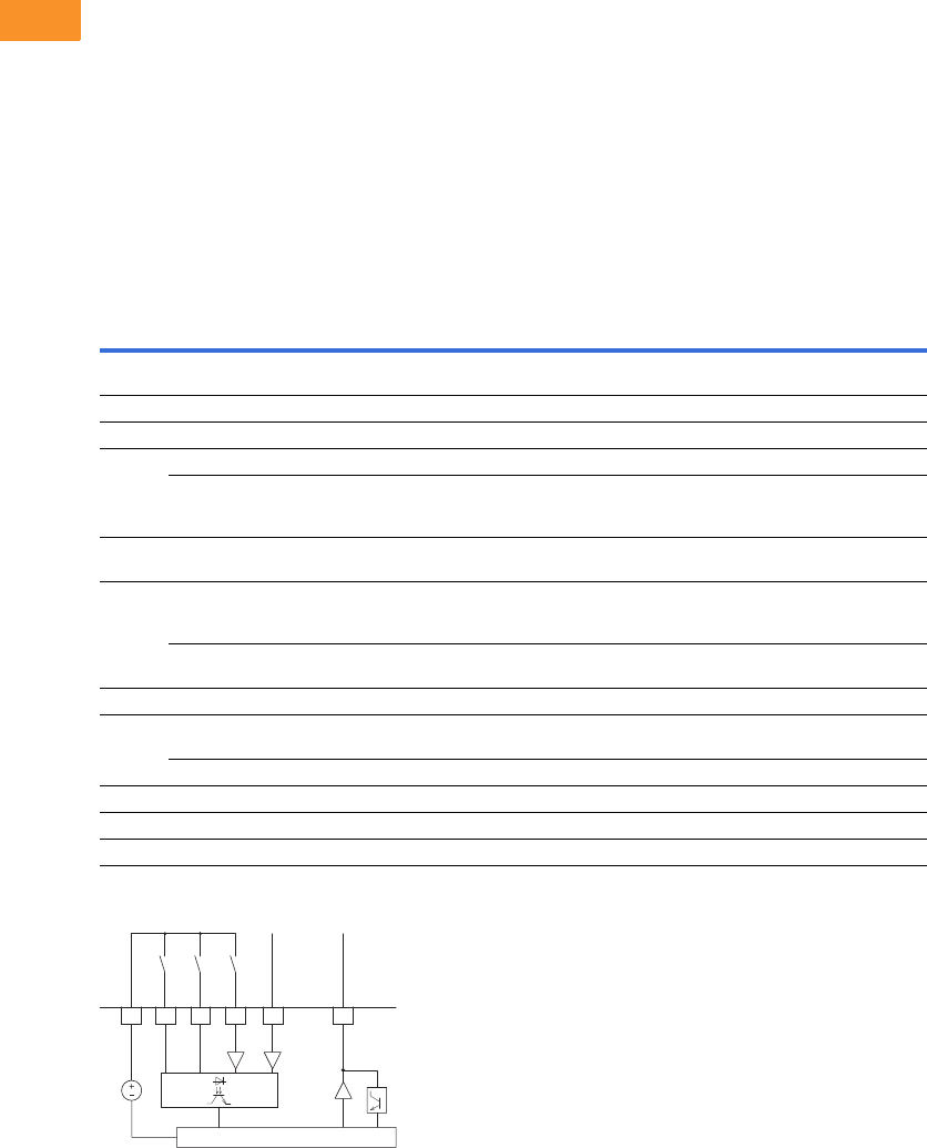
V6-T2-22 Volume 6—Solid-State Motor Control CA08100007E—February 2016 www.eaton.com
2
2
2
2
2
2
2
2
2
2
2
2
2
2
2
2
2
2
2
2
2
2
2
2
2
2
2
2
2
2
2.3
Adjustable Frequency Drives
PowerXL DC1 Series Drives
Standards—DC1 Series
I/O Specifications
●Digital inputs DI1–DI4 are
programmable
●Digital, relay and analog
outputs are programmable
Includes:
●Four inputs (two digital and
two digital/analog)
●Analog inputs
●4–20 mA
●0–10 V
●One output (analog or
digital)
●One relay output
●RS-485 interface
Reliability
●Pretested components
●Computerized testing
●Final test with full load
●Conformal-coated boards
●
Eaton’s Electrical Services &
Systems: national network
of AF drive specialists
DC1 Series I/O Interface
Note
1Programmable function.
Terminal Signal Factory Preset Description
1 +24 Vdc Control voltage for DI1–DI4 — Maximum load 100 mA
Reference potential V
2 DI1 Digital Input 1 Start Enable FWD 8 to +30 V (High, R1 > 6 kΩ)
3 DI2 Digital Input 2 Start Enable REV 8 to +30 V (High, R1 > 6 kΩ)
4 DI3 Digital Input 3 Fixed frequency FF1 Digital: 8–30 V (high)
AI2 Analog Input 2 Fixed frequency FF1 Analog: 0 to +10 V (Ri >72 kΩ)
0/4–20 mA (Rß = 500 Ω)
Can be switched with parameter P16
5 +10 Vdc Reference voltage, Output (+10 V) — Maximum load 10 mA
Reference potential 0 V
6 AI1 Analog Input 1 Frequency reference value 1
(fixed frequency)
Analog: 0 to +10 V (Ri >72 kΩ)
0/4–20 mA (Rß = 500 Ω)
Can be switched with parameter P16
DI4 Digital Input 5 Frequency reference value 1
(fixed frequency)
Digital: 8–30 V (high)
7 0 V Reference potential — 0 V = connection terminal 9
8 AO1 Analog Output 1 Output frequency Analog: 0 to +10 V, maximum 4–20 mA
Can be switched with parameter P-25
DO1 Digital Output 1 Output frequency Digital: 8 to +24 V
9 0 V Reference potential — 0 V connection terminal 7
10 K13 Relay 1, normally open contact Active = RUN Maximum switching load: 250 Vac/6 A or 30 Vdc/5 A
11 K14 Relay 1, normally open contact Active = RUN Maximum switching load: 250 Vac/6 A or 30 Vdc/5 A
2
DI1 FWD
24V
3
DI2 REV
4
DI3
(AI2)
FF1
6
AI1
(DI4)
f-Soll
1
+24V Out
< 100 mA
8
AO
(DO)
f-Out
CPU
0 to +10V/20 mA
0 to +10V/20 mA

Volume 6—Solid-State Motor Control CA08100007E—February 2016 www.eaton.com V6-T2-23
2
2
2
2
2
2
2
2
2
2
2
2
2
2
2
2
2
2
2
2
2
2
2
2
2
2
2
2
2
2
2.3
Adjustable Frequency Drives
PowerXL DC1 Series Drives
Dimensions
Approximate Dimensions in Inches (mm)
DC1, Sizes FS1–FS4, Degree of Protection IP20/NEMA 0
DC1, Sizes FS1–FS3, Degree of Protection IP66/NEMA 4
Note
1Frame size 4 available June 2015.
Frame
Size A A1 B B1 B2 C C1 Ø1Ø2
Weight
lbs (kg)
FS1 3.19 (81.0) 1.97 (50.0) 7.24 (184.0) 6.69 (170.0) 0.28 (7.0) 4.88 (124.0) 0.16 (4.0) 0.24 (6.0) 0.47 (12.0) 2.43 (1.1)
FS2 4.21 (107.0) 2.95 (75.0) 9.09 (231.0) 8.46 (215.0) 0.31 (8.0) 5.98 (152.0) 0.20 (5.0) 0.24 (6.0) 0.47 (12.0) 5.73 (2.6)
FS3 5.16 (131.0) 3.94 (100.0) 10.75 (273.0) 10.04 (255.0) 0.33 (8.5) 6.89 (175.0) 0.20 (5.0) 0.24 (6.0) 0.47 (12.0) 8.82 (4.0)
FS4 16.30 (160.0) — 16.54 (420.0) — — 8.35 (212.0) — — — —
Frame
Size A A1 B B1 B2 C C1 Ø1Ø2
Weight
lbs (kg)
FS1 6.34 (161.0) 5.85 (148.5) 9.13 (232.0) 7.44 (189.0) 0.98 (25.0) 7.24 (184.0) 0.14 (3.5) 0.15 (4.0) 0.31 (8.0) 5.51 (2.5)
FS2 7.40 (188.0) 6.93 (176.0) 10.12 (257.0) 7.87 (200.0) 1.12 (28.5) 7.58 (192.0) 0.14 (3.5) 0.16 (4.2) 0.33 (8.5) 10.36 (4.7)
FS3 8.29 (210.5) 7.78 (197.5) 12.20 (310.0) 9.90 (251.5) 1.31 (33.4) 9.21 (234.0) 0.14 (3.5) 0.16 (4.2) 0.33 (8.5) 17.42 (7.9)
B1
A
B
Ø2
Ø1
Ø
C1
C
A1
B2
B
C
A1
B1
Ø2
Ø1
A
A1 C1
B1
B2
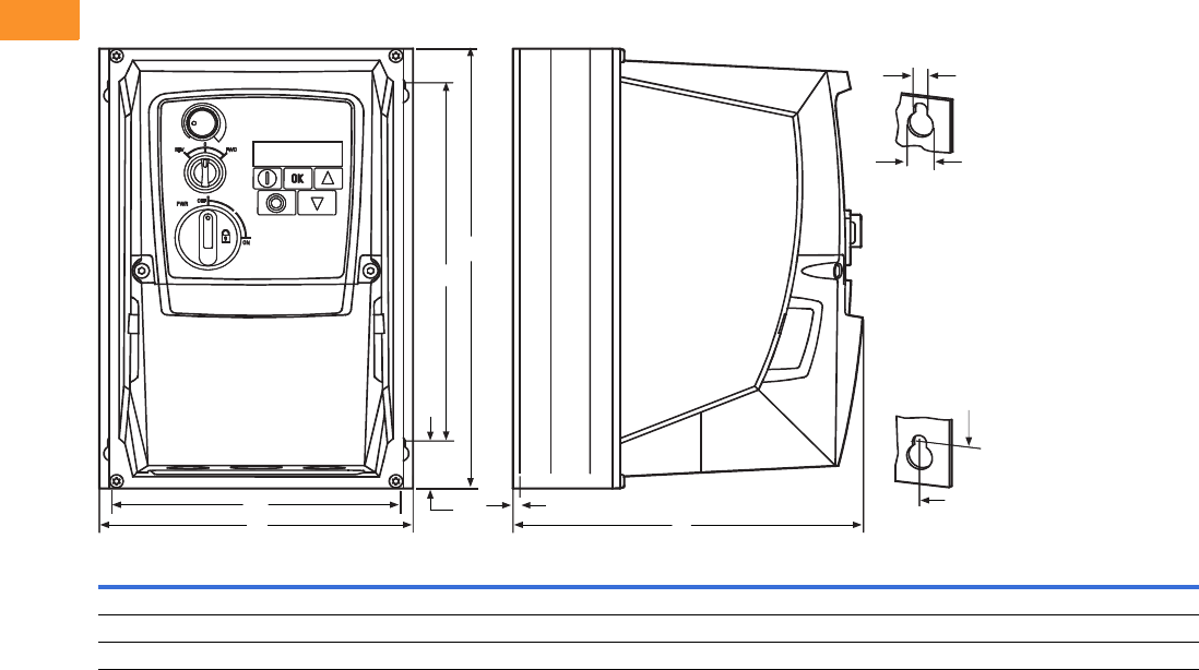
V6-T2-24 Volume 6—Solid-State Motor Control CA08100007E—February 2016 www.eaton.com
2
2
2
2
2
2
2
2
2
2
2
2
2
2
2
2
2
2
2
2
2
2
2
2
2
2
2
2
2
2
2.3
Adjustable Frequency Drives
PowerXL DC1 Series Drives
Approximate Dimensions in Inches (mm)
DC1, Sizes FS1–FS3, Degree of Protection IP66/NEMA 4, with Local Controls
Frame
Size A A1 B B1 B2 C C1 Ø1Ø2
Weight
lbs (kg)
FS1 6.34 (161.0) 5.85 (148.5) 9.13 (232.0) 7.44 (189.0) 0.98 (25.0) 7.24 (184.0) 0.14 (3.5) 0.15 (4.0) 0.31 (8.0) 6.17 (2.8)
FS2 7.40 (188.0) 6.93 (176.0) 10.12 (257.0) 7.87 (200.0) 1.12 (28.5) 7.58 (192.0) 0.14 (3.5) 0.16 (4.2) 0.33 (8.5) 11.02 (5.0)
FS3 8.29 (210.5) 7.78 (197.5) 12.20 (310.0) 9.90 (251.5) 1.31 (33.4) 9.21 (234.0) 0.14 (3.5) 0.16 (4.2) 0.33 (8.5) 18.08 (8.2)
Ø2
A1
C1
A1
A C
B1
B
B1
B2
Ø1
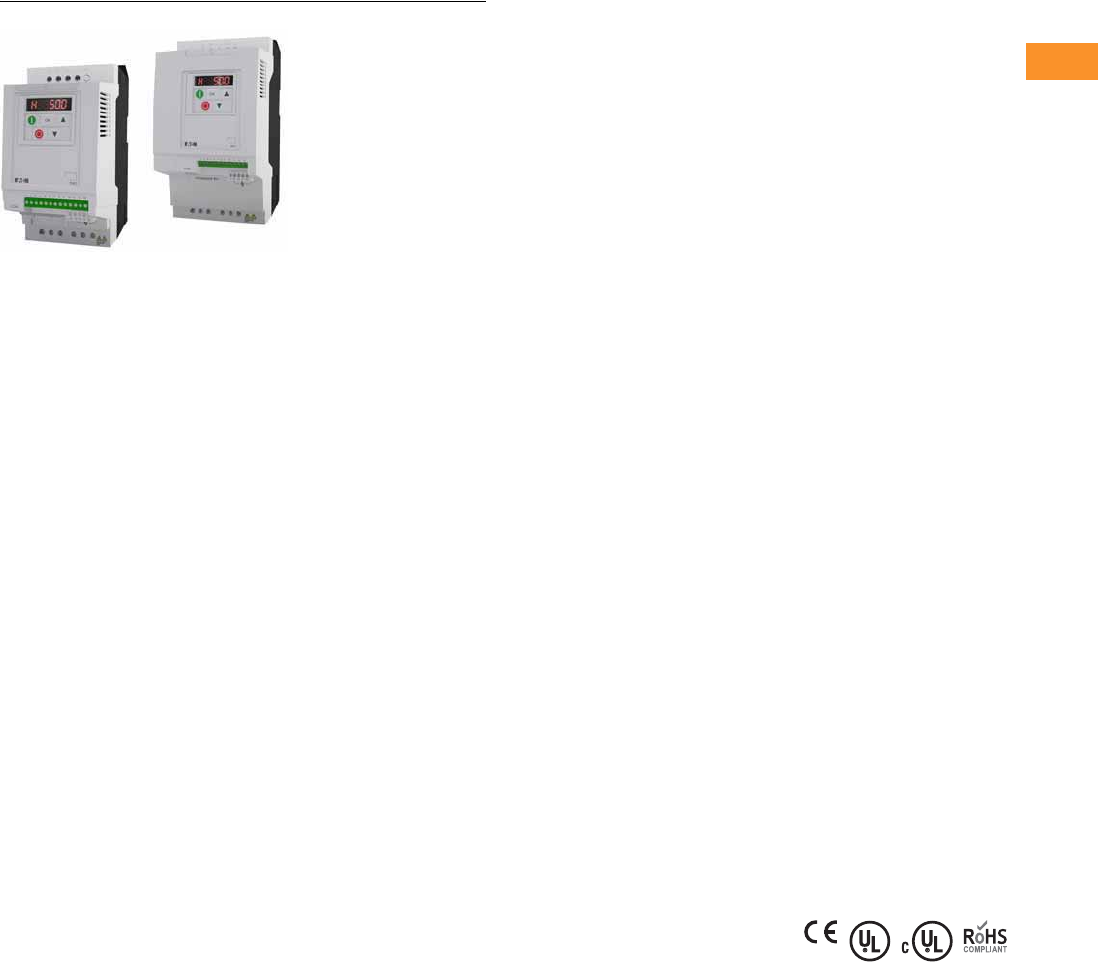
Volume 6—Solid-State Motor Control CA08100007E—February 2016 www.eaton.com V6-T2-25
2
2
2
2
2
2
2
2
2
2
2
2
2
2
2
2
2
2
2
2
2
2
2
2
2
2
2
2
2
2
2.4
Adjustable Frequency Drives
PowerXL DA1 Series Drives
PowerXL DA1 Series Drives
Contents
Description Page
PowerXL DA1 Series Drives
Catalog Number Selection . . . . . . . . . . . . . . . . V6-T2-26
Product Selection . . . . . . . . . . . . . . . . . . . . . . . V6-T2-27
Accessories . . . . . . . . . . . . . . . . . . . . . . . . . . . V6-T2-29
Technical Data and Specifications . . . . . . . . . . V6-T2-32
Dimensions . . . . . . . . . . . . . . . . . . . . . . . . . . . V6-T2-34
Product Description
Eaton’s PowerXL
®
DA1
variable frequency drives are
the next generation of drives
specifically engineered for
today’s machinery
applications.
DA1 is the perfect match for
demanding OEM applications.
High-performance processor,
safe torque off, multiple
fieldbus protocols including
SmartWire-DT, sensorless
vector control and the
possibility
to operate
permanent magnet motors
are sure to leave a lasting
impression.
Models rated at 480 volts,
three-phase, 50/60 Hz are
available in sizes ranging from
1 to 15 hp. Models rated at
240 volts, single- or three-
phase, 50/60 Hz are available
in sizes ranging from 0.5
to 7.5 hp. Models rated at
575 volts, three-phase,
50/60 Hz are available in sizes
ranging from 1 to 20 hp.
Features
●Compact, space-saving
design
●
Rugged and reliable—200%
for 4s 50 °C rated
●DIN rail and screw
mountable (FS1 and FS2)
●Side-by-side installation
●Industry-leading efficiency
delivers energy savings to
the customer
●Integrated EMC filters
make the unit suitable for
commercial and industrial
networks
●Communication cards that
integrate into the drive—
●EtherNet/IP
●DeviceNet
●PROFIBUS-DP
●EtherCAT
●PROFINET
●Modbus TCP
●BACnet
●Brake chopper as standard
●Temperature-controlled fan
●RS-485/Modbus® and
CANopen™ as standard
●PID controller as standard
●SmartWire capability
●Removable I/O terminal
blocks
●Contactor style power
wiring
●200% torque at zero speed
●Designed to run surface
mounted (SPM) and rotor
in-built (IPM) permanent
magnet motors
●PLC programming
●Closed loop
●Conformal coated boards
Standards and
Certifications
Product
●Complies with EN61800-3
(2004)
EMC (At Default Settings)
●EMC Category C1, C2
and C3 at default settings
(1 m, 5 m, 25 m)
Safety 1
●61800-5-1
●EN 60529
●CE
●UL
●cUL
●DNV
●UkrSepro
●c-Tick
●RoHS compliant
Note
1See unit nameplate for more detailed
approvals.
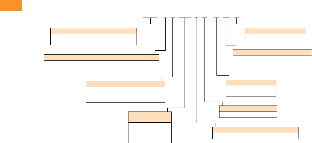
V6-T2-26 Volume 6—Solid-State Motor Control CA08100007E—February 2016 www.eaton.com
2
2
2
2
2
2
2
2
2
2
2
2
2
2
2
2
2
2
2
2
2
2
2
2
2
2
2
2
2
2
2.4
Adjustable Frequency Drives
PowerXL DA1 Series Drives
Catalog Number Selection
DA1 Series Adjustable Frequency AC Drives
DA1 -1 24D1 F B -A 20 C
Rated
Operational Current
Examples—
2D2 = 2.2 A
4D1 = 4.1 A
024 = 24 A
Type
C= Coated printed circuit boards
Degree of Protection
20 = IP20/NEMA 0
66 = IP66/NEMA 4/4X
6S = IP66 with disconnect/NEMA 4/4X
Device Series
DA1 = Variable frequency drive, compact, Series 1
(D = Drives, A = Advanced, 1 = Series 1)
Connection in Power Section
1= Single-phase mains connection/three-phase motor connection
3= Three-phase mains connection/three-phase motor connection
Mains Voltage Category
2= 230 V (200–240 V ±10%)
4= 400 V (380–480 V ±10%)
5= 575 V (500–600 V ±10%)
Display Unit (Display)
A= LED display (IP20 only)
B= OLED display (IP66 only)
Brake Chopper
B= Brake chopper
EMC (Radio Interference Suppression Filter)
F= Internal RFI filter
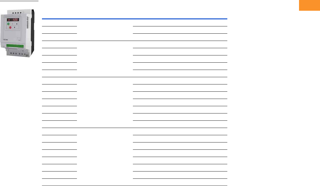
Volume 6—Solid-State Motor Control CA08100007E—February 2016 www.eaton.com V6-T2-27
2
2
2
2
2
2
2
2
2
2
2
2
2
2
2
2
2
2
2
2
2
2
2
2
2
2
2
2
2
2
2.4
Adjustable Frequency Drives
PowerXL DA1 Series Drives
Product Selection
DA1 Series IP20 Enclosure Drives 1
Notes
1 These are constant torque/high overload rated drives.
2 For all applications, select the unit such that the motor current is less than or equal to the rated continuous output current.
3 Brake chopper circuit available as standard in frames 2 and 3.
hp 2kW Volts
100% Continuous
Current In (A)
Frame
Size 3Catalog Number
1 0.75 200–240 V single-phase in/
230 V three-phase out
4.3 2 DA1-124D3FB-A20C
21.5 7 2 DA1-127D0FB-A20C
32.2 10.5 2 DA1-12011FB-A20C
1 0.75 200–240 V three-phase in/
230 V three-phase out
4.3 2 DA1-324D3FB-A20C
21.5 7 2 DA1-327D0FB-A20C
32.2 10.5 2 DA1-32011FB-A20C
54 18 3 DA1-32018FB-A20C
7.5 5.5 24 3 DA1-32024FB-A20C
1 0.75 380–480 V three-phase in/
460 V three-phase out
2.2 2 DA1-342D2FB-A20C
21.5 4.1 2 DA1-344D1FB-A20C
32.2 5.8 2 DA1-345D8FB-A20C
54 9.5 2 DA1-349D5FB-A20C
7.5 5.5 14 3 DA1-34014FB-A20C
10 7.5 18 3 DA1-34018FB-A20C
15 11 24 3 DA1-34024FB-A20C
1 0.75 500–600 V three-phase in/
575 V three-phase out
2.1 2 DA1-352D1NB-A20C
24.5 3.1 2 DA1-353D1NB-A20C
32.2 4.1 2 DA1-354D1NB-A20C
54 6.5 2 DA1-356D5NB-A20C
7.5 5.5 9 2 DA1-359D0NB-A20C
10 7.5 12 3 DA1-35012NB-A20C
15 11 17 3 DA1-35017NB-A20C
20 15 22 3 DA1-35022NB-A20C
IP20
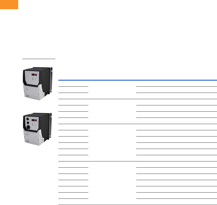
V6-T2-28 Volume 6—Solid-State Motor Control CA08100007E—February 2016 www.eaton.com
2
2
2
2
2
2
2
2
2
2
2
2
2
2
2
2
2
2
2
2
2
2
2
2
2
2
2
2
2
2
2.4
Adjustable Frequency Drives
PowerXL DA1 Series Drives
IP66 NEMA 4/4X Interior
DA1 Drive
The IP66 version of the
DA1 is a unique solution to
allow for mounting the drive
outside of a control panel or
next to a motor for distributed
control.
“-B66C” Option
This version comes with the
OLED keypad. There are no
additional cover controls to
address security concerns.
“-B6SC” Option
This version has an integrated
potentiometer, a forward/off/
reverse switch and a
disconnect switch with lock-
off capability with the
OLED keypad. This allows
for reduced labor and
materials when compared
to a IP20 solution in
separate enclosure.
DA1 Series IP66 Enclosure Drives 1
IP66 NEMA 4/4X Interior DA1 Drive
Notes
1 These are constant torque/high overload rated drives.
2 For all applications, select the unit such that the motor current is less than or equal to the rated continuous output current.
3 Brake chopper circuit available as standard in frames 2 and 3.
4 Non-disconnect version available. Substitute with -B66C.
hp 2kW Volts
100% Continuous
Current In (A)
Frame
Size 3Catalog Number
1 0.75 200–240 V single-phase in/
230 V three-phase out
4.3 2 DA1-124D3FB-B6SC 4
21.5 7 2 DA1-127D0FB-B6SC 4
32.2 10.5 2 DA1-12011FB-B6SC 4
1 0.75 200–240 V three-phase in/
230 V three-phase out
4.3 2 DA1-324D3FB-B6SC 4
21.5 7 2 DA1-327D0FB-B6SC 4
32.2 10.5 2 DA1-32011FB-B6SC 4
54 18 3 DA1-32018FB-B6SC 4
1 0.75 380–480 V three-phase in/
460 V three-phase out
2.2 2 DA1-342D2FB-B6SC 4
21.5 4.1 2 DA1-344D1FB-B6SC 4
32.2 5.8 2 DA1-345D8FB-B6SC 4
54 9.5 2 DA1-349D5FB-B6SC 4
7.5 5.5 14 3 DA1-34014FB-B6SC 4
10 7.5 18 3 DA1-34018FB-B6SC 4
1 0.75 500–600 V three-phase in/
575 V three-phase out
2.1 2 DA1-352D1NB-B6SC
24.5 3.1 2 DA1-353D1NB-B6SC
32.2 4.1 2 DA1-354D1NB-B6SC
54 6.5 2 DA1-356D5NB-B6SC
7.5 5.5 9 2 DA1-359D0NB-B6SC
10 7.5 12 3 DA1-35012NB-B6SC
15 11 17 3 DA1-35017NB-B6SC
IP66
IP66S

Volume 6—Solid-State Motor Control CA08100007E—February 2016 www.eaton.com V6-T2-29
2
2
2
2
2
2
2
2
2
2
2
2
2
2
2
2
2
2
2
2
2
2
2
2
2
2
2
2
2
2
2.4
Adjustable Frequency Drives
PowerXL DA1 Series Drives
Accessories
DA1 Series
PC Communication Kit and Copy/Paste Module
Optional Communication Modules
Encoder Feedback Plug-In Option Module
and Miscellaneous Cards
Remote Keypad
Extension Cables and Data Cable Splitter
SmartWire Modules
Note
1Includes 1 m RS-485 data cable.
Description Catalog Number
Bluetooth copy/paste communication stick DX-COM-STICK
USB to RJ45 panel mount kit DX-COM-PCKIT
USB to RJ45 PC Tool cable DX-CBL-PC-3M0
Description Catalog Number
DeviceNet plug-in interface module DX-NET-DEVICENET
PROFIBUS-DP plug-in interface module DX-NET-PROFIBUS
EtherNet/IP plug-in interface module DX-NET-ETHERNET-2
EtherCAT plug-in interface module DX-NET-ETHERCAT-2
PROFINET plug-in interface module DX-NET-PROFINET-2
Modbus TCP plug-in interface module DX-NET-MODBUSTCP-2
BACnet plug-in interface module DX-NET-BACNETIP-2
Description Catalog Number
Expansion card: 3 relay outputs DXA-EXT-3RO
Encoder feedback plug-in option module DXA-EXT-ENCOD
Expansion card: 3 digital inputs and 1 relay output DXA-EXT-3DI1RO
Description Catalog Number
LED remote keypad—7-segment display, IP54 rated DX-KEY-LED 1
OLED remote keypad—full text display, multi-line text,
multi-language, IP54, hand/auto
DX-KEY-OLED 1
Description Catalog Number
RJ45 communication cable w/terminating resistor EASY-NT-R
RS-485 data cable, RJ45, 0.5 m DX-CBL-RJ45-0M5
RS-485 data cable, RJ45, 1.0 m DX-CBL-RJ45-1M0
RS-485 data cable, RJ45, 3.0 m DX-CBL-RJ45-3M0
RS-485 three-way data cable splitter, RJ45 DX-SPL-RJ45-3SL
RS-485 data cable splitter, RJ45, (1 connector to 2 socket) DX-SPL-RJ45-2SL1PL
Description Catalog Number
SmartWire-DT interface for DA1 IP20 DX-NET-SWD1
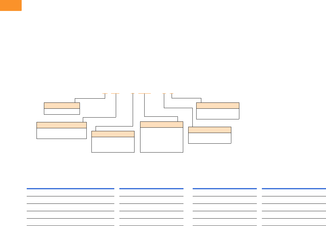
V6-T2-30 Volume 6—Solid-State Motor Control CA08100007E—February 2016 www.eaton.com
2
2
2
2
2
2
2
2
2
2
2
2
2
2
2
2
2
2
2
2
2
2
2
2
2
2
2
2
2
2
2.4
Adjustable Frequency Drives
PowerXL DA1 Series Drives
Line and Load Reactors
A line and load reactor is a
three-phase inductance filter
that can be placed on the line
and load side of the AFD to
help improve the harmonic
performance of the system.
Consult the factory for
additional filtering options and
further technical details.
DR1 Line Reactor
A line reactor helps to provide
a moderate reduction in
current harmonics similar to a
DC choke. It also provides
increased input protection for
AFD and its semiconductors
from line transients helping to
extend the life of the AFD.
DR2 Output Reactor
An output filter is used to
reduce the transient voltage
(dV/dt) at the motor terminals.
The output filter is
recommended for cable
lengths exceeding 100 ft
(30 m) with a drive of 3 hp
and above and for cable
lengths of 33 ft (10 m) with a
drive of 2 hp and below.
Line and Load Reactors—Catalog Number Selection
Line and Load Reactors—230 V
Open NEMA 1
Load Reactor Line Reactor Load Reactor Line Reactor
hp (CT) 3% 5% 3% 5% 3% 5% 3% 5%
1 DR2-24D0-03 DR2-28D0-05 DR1-24D2-03 DR1-24D2-05 DR2-24D0-13 DR2-28D0-15 DR1-24D2-13 DR1-24D2-15
2 DR2-28D0-03 DR2-28D0-05 DR1-26D8-03 DR1-26D8-05 DR2-28D0-13 DR2-28D0-15 DR1-26D8-13 DR1-26D8-15
3 DR2-2012-03 DR2-2012-05 DR1-29D6-03 DR1-29D6-05 DR2-2012-13 DR2-2012-15 DR1-29D6-13 DR1-29D6-15
5 DR2-2018-03 DR2-2018-05 DR1-2015-03 DR1-2015-05 DR2-2018-13 DR2-2018-15 DR1-2015-13 DR1-2015-15
7.5 DR2-2025-03 DR2-2025-05 DR1-2022-03 DR1-2022-05 DR2-2025-13 DR2-2025-15 DR1-2022-13 DR1-2022-15
DR1 –22D0 –05
Device Series
R1 = Line side reactor
R2 = Load side reactor
Basic Naming
D= Drive
Input/Output Voltage
2= 230 V
4= 460 V
5= 575 V
Environment Rating
0= Open
1= NEMA 1
Impedance
3= 3%
5= 5%
Current Rating
Examples:
2D0 = 2.0 A
4D0 = 4.0 A
8D0 = 8.0 A
012
= 12 A

Volume 6—Solid-State Motor Control CA08100007E—February 2016 www.eaton.com V6-T2-31
2
2
2
2
2
2
2
2
2
2
2
2
2
2
2
2
2
2
2
2
2
2
2
2
2
2
2
2
2
2
2.4
Adjustable Frequency Drives
PowerXL DA1 Series Drives
Line and Load Reactors—480 V
Line and Load Reactors—575 V
Open NEMA 1
Load Reactor Line Reactor Load Reactor Line Reactor
hp (CT) 3% 5% 3% 5% 3% 5% 3% 5%
1 DR2-42D0-03 DR2-42D0-05 DR1-42D1-03 DR1-42D1-05 DR2-42D0-13 DR2-42D0-15 DR1-42D1-13 DR1-42D1-15
2 DR2-44D0-03 DR2-44D0-05 DR1-43D4-03 DR1-43D4-05 DR2-44D0-13 DR2-44D0-15 DR1-43D4-13 DR1-43D4-15
3 DR2-48D0-03 DR2-48D0-05 DR1-44D8-03 DR1-44D8-05 DR2-48D0-13 DR2-48D0-15 DR1-44D8-13 DR1-44D8-15
5 DR2-48D0-03 DR2-48D0-05 DR1-47D6-03 DR1-47D6-05 DR2-48D0-13 DR2-48D0-15 DR1-47D6-13 DR1-47D6-15
7.5 DR2-4012-03 DR2-4012-05 DR1-4011-03 DR1-4011-05 DR2-4012-13 DR2-4012-15 DR1-4011-13 DR1-4011-15
10 DR2-4018-03 DR2-4018-05 DR1-4014-03 DR1-4014-05 DR2-4018-13 DR2-4018-15 DR1-4014-13 DR1-4014-15
15 DR2-4025-03 DR2-4025-05 DR1-4021-03 DR1-4021-05 DR2-4025-13 DR2-4025-15 DR1-4021-13 DR1-4021-15
Open NEMA 1
Load Reactor Line Reactor Load Reactor Line Reactor
hp (CT) 3% 5% 3% 5% 3% 5% 3% 5%
1 DR2-52D0-03 DR2-52D0-05 DR1-51D7-03 DR1-51D7-05 DR2-52D0-13 DR2-52D0-15 DR1-51D7-13 DR1-51D7-15
2 DR2-54D0-03 DR2-54D0-05 DR1-52D7-03 DR1-52D7-05 DR2-54D0-13 DR2-54D0-15 DR1-52D7-13 DR1-52D7-15
3 DR2-54D0-03 DR2-54D0-05 DR1-53D9-03 DR1-53D9-05 DR2-54D0-13 DR2-54D0-15 DR1-53D9-13 DR1-53D9-15
5 DR2-58D0-03 DR2-58D0-05 DR1-56D1-03 DR1-56D1-05 DR2-58D0-13 DR2-58D0-15 DR1-56D1-13 DR1-56D1-15
7.5 DR2-58D0-03 DR2-58D0-05 DR1-59D0-03 DR1-59D0-05 DR2-58D0-13 DR2-58D0-15 DR1-59D0-13 DR1-59D0-15
10 DR2-5012-03 DR2-5012-05 DR1-5011-03 DR1-5011-05 DR2-5012-13 DR2-5012-15 DR1-5011-13 DR1-5011-15
15 DR2-5018-03 DR2-5018-05 DR1-5017-03 DR1-5017-05 DR2-5018-13 DR2-5018-15 DR1-5017-13 DR1-5017-15
20 DR2-5025-03 DR2-5025-05 DR1-5022-03 DR1-5022-05 DR2-5025-13 DR2-5025-15 DR1-5022-13 DR1-5022-15

V6-T2-32 Volume 6—Solid-State Motor Control CA08100007E—February 2016 www.eaton.com
2
2
2
2
2
2
2
2
2
2
2
2
2
2
2
2
2
2
2
2
2
2
2
2
2
2
2
2
2
2
2.4
Adjustable Frequency Drives
PowerXL DA1 Series Drives
Technical Data and Specifications
DA1 Series
Ratings
PowerXL DA1 Basic Controller IP20 Standard Ratings
Programmable Parameters
Specifications
PowerXL DA1 Series Drives
Notes
1Exception: 115 V single-phase in, 230 V three-phase out.
2Only FS2 and FS3 drives are equipped with brake chopper circuit.
Description Specification
Protections
Overload protection 150% for 60s for every 600 seconds
Overvoltage protection Yes
Undervoltage protection Yes
Ground fault protection Yes
Overtemperature
protection
Yes
Motor overload protection Yes
Motor stall protection Yes
Short-circuit
withstand rating
100 kAIC with Type 1 fuses
Description
Built-in Help card
14 Standard operation parameters
Reference scaling
Programmable start and stop functions
DC-brake at start and stop
Programmable V/Hz curve
Adjustable switching frequency
Autorestart function after fault
Protections and supervisions
Power section fault indication
External fault
Fieldbus communication
Safe torque off (STO) function
Analog input range selection, signal scaling and filtering
PI controller
Skip frequencies
Description Specification
Input Ratings
Input voltage (Vin)±10%
Input frequency (fin) 50/60 Hz (variation up to 48–62 Hz)
Connection to power Maximum of one time every 30 seconds
Output Ratings
Output voltage 0 to Vin 1
Continuous output
current
Continuous rated current IN at ambient temperature
max. 122 °F (50 °C), 150% for 60 seconds, 200% for 4 seconds
Output frequency 0 to 500 Hz
Frequency resolution 0.1 Hz
Initial output current (IH) 200% for 4s for every 40 seconds
Torque depends on motor
Control Characteristics
Operation mode
U/f control, slip compensation, sensorless vector control (SLV),
vector control with feedback (CLV)
Switching frequency 4 to 32 kHz
Voltage reference 10 Vdc (max. 10 mA)
Field weakening point 0 to 500 Hz
Acceleration time 0.1 to 600 seconds
Deceleration time 0.1 to 600 seconds
Brake Resistor (Minimum Values) 2
230 V Series FS2 and FS3 15 ohms
400 V Series FS2 33 ohms, FS3 22 ohms
Ambient Conditions
Ambient operating
temperature
+14 °F (–10 °C), no frost to +122 °F (+50 °C): Rated loadability IN
IP20—NEMA 0
Storage temperature –40 °F (–40 °C) to +140 °F (+60 °C)
Relative humidity 0 to 95% RH, noncondensing, non-corrosive, no dripping water
Enclosure class IP20 (FS2 and FS3)
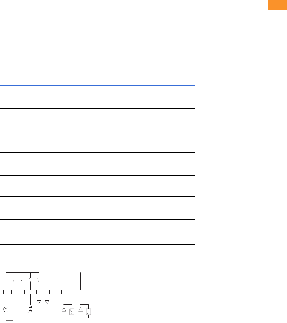
Volume 6—Solid-State Motor Control CA08100007E—February 2016 www.eaton.com V6-T2-33
2
2
2
2
2
2
2
2
2
2
2
2
2
2
2
2
2
2
2
2
2
2
2
2
2
2
2
2
2
2
2.4
Adjustable Frequency Drives
PowerXL DA1 Series Drives
Standards—DA1 Series
I/O Specifications
●Digital inputs DI1–DI5 are
programmable
●Digital, relay and analog
outputs are programmable
Includes:
●Five inputs (three digital
and two digital/analog)
●Analog inputs
●4–20 mA
●0–10 V
●Two outputs (analog or
digital)
●Two relay outputs
●RS-485 interface
Reliability
●Pretested components
●Computerized testing
●Final test with full load
●Conformal-coated boards
●
Eaton’s Electrical Services &
Systems: national network
of AF drive specialists
DA1 Series I/O Interface
Note
1Programmable function.
Terminal Signal Factory Preset Description
1 +24 Vdc Control voltage for DI1–DI5 — Maximum load 100 mA
Reference potential V
2 DI1 Digital Input 1 Start Enable FWD 18 to +30 V (High, R1 > 6 kΩ)
3 DI2 Digital Input 2 Start Enable REV 18 to +30 V (High, R1 > 6 kΩ)
4 DI3 Digital Input 3 Fixed frequency FF1/FF2 18 to +30 V (High, R1 > 6 kΩ)
5 +10 Vdc Reference voltage, Output (+10 V) — Maximum load 10 mA
Reference potential 0 V
6 AI1 Analog Input 1 Frequency reference value 1Analog: 0 to +10 V (Ri >72 kΩ)
0/4–20 mA (Ri = 500 Ω)
Can be switched with parameter P2-30
DI4 Digital Input 5 Frequency reference value 1Digital: 8–30 V (high)
7 0 V Reference potential — 0 V = connection terminal 9
8 AO1 Analog Output 1 Output frequency Analog: 0 to +10 V, maximum 20 mA
Can be switched with parameter P2-11
DO1 Digital Output 1 Output frequency Digital: 8–24 V
9 0 V Reference potential — 0 V connection terminal 7
10 DI4 Digital Input 4 Fixed frequency FF2 1Analog: 0 to +10 V (Ri >72 kΩ)
0/4–20 mA (Ri = 500 Ω)
Can be switched with parameter P2-30
AI2 Analog Input 2 Fixed frequency FF2 1Digital: 8–30 V (high)
11 AO2 Analog output 2 Output current 1Analog: 0 to +10 V, maximum 4–20 mA
Can be switched with parameter P2-11
DO2 Digital output 2 Output current 1Digital: 8–24 V
12 STO+ Safe Torque Off + — Enable = +24 V
13 STO- Safe Torque Off – — Enable = 0 V
14 K11 Relay 1, changeover contact Active = FAULT 1Maximum switching load: 250 Vac/6 A or 30 Vdc/5 A
15 K14 Relay 1, changeover contact (N/O) Active = FAULT 1Maximum switching load: 250 Vac/6 A or 30 Vdc/5 A
16 K12 Relay 1, changeover contact (N/C) Active = FAULT 1Maximum switching load: 250 Vac/6 A or 30 Vdc/5 A
17 K23 Relay 2, N/O contact Active = FAULT 1Maximum switching load: 250 Vac/6 A or 30 Vdc/5 A
18 K24 Relay 2, N/C contact Active = FAULT 1Maximum switching load: 250 Vac/6 A or 30 Vdc/5 A
2
DI1 FWD
+24V
4
DI3 FF1/FF2
3
DI2 REV
10
DI4
(AI2)
FF2
1
+24V Out
< 100 mA
6
AI1
(DI5)
CPU
8
AO1
(DO1)
f-Out
0 to +10V/20 mA
f-Soll
0 to +10V/20 mA
11
AO2
(DO2)
A-Out
0 to +10V/20 mA
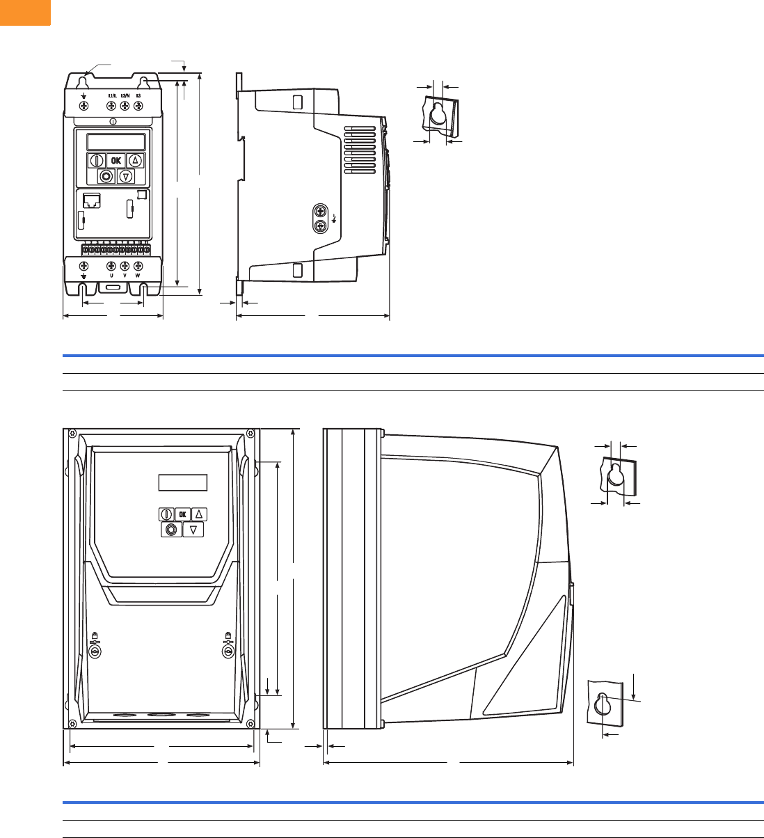
V6-T2-34 Volume 6—Solid-State Motor Control CA08100007E—February 2016 www.eaton.com
2
2
2
2
2
2
2
2
2
2
2
2
2
2
2
2
2
2
2
2
2
2
2
2
2
2
2
2
2
2
2.4
Adjustable Frequency Drives
PowerXL DA1 Series Drives
Dimensions
Approximate Dimensions in Inches (mm)
DA1, Sizes FS2 and FS3, Degree of Protection IP20/NEMA 0
DA1, Sizes FS2 and FS3, Degree of Protection IP66/NEMA 4
Frame
Size A A1 B B1 B2 C C1 Ø1Ø2
Weight
lbs (kg)
FS2 4.21 (107.0) 2.95 (75.0) 9.09 (231.0) 8.46 (215.0) 0.31 (8.0) 7.32 (186.0) 0.20 (5.0) 0.24 (6.0) 0.47 (12.0) 3.97 (1.8)
FS3 5.16 (131.0) 3.94 (100.0) 10.75 (273.0) 10.04 (255.0) 0.33 (8.5) 8.03 (204.0) 0.20 (5.0) 0.24 (6.0) 0.47 (12.0) 7.72 (3.5)
Frame
Size A A1 B B1 B2 C C1 Ø1Ø2
Weight
lbs (kg)
FS2 7.40 (188.0) 6.93 (176.0) 10.12 (257.0) 7.87 (200.0) 0.79 (20.0) 9.42 (239.3) 0.14 (3.5) 0.16 (4.2) 0.33 (8.5) 10.4 (4.5)
FS3 8.29 (211.0) 7.78 (198.0) 12.20 (310.0) 9.90 (252.0) 0.98 (25.0) 10.48 (266.3) 0.14 (3.5) 0.16 (4.2) 0.33 (8.5) 15.9 (7.0)
B1
A
B
Ø2
Ø1
Ø
C1
C
A1
B2
A1
B1
Ø2
Ø1
B
B1
B2
CA
A1 C1
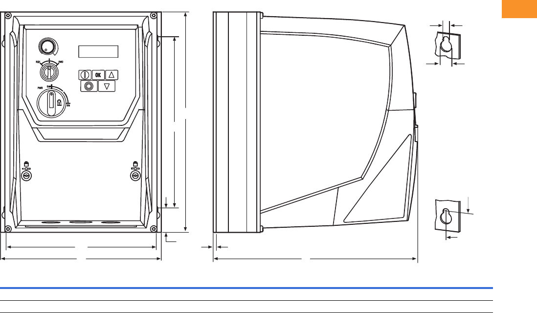
Volume 6—Solid-State Motor Control CA08100007E—February 2016 www.eaton.com V6-T2-35
2
2
2
2
2
2
2
2
2
2
2
2
2
2
2
2
2
2
2
2
2
2
2
2
2
2
2
2
2
2
2.4
Adjustable Frequency Drives
PowerXL DA1 Series Drives
Approximate Dimensions in Inches (mm)
DA1, Sizes FS2 and FS3, Degree of Protection IP66/NEMA 4, with Local Controls
Frame
Size A A1 B B1 B2 C C1 Ø1Ø2
Weight
lbs (kg)
FS2 7.40 (188.0) 6.93 (176.0) 10.12 (257.0) 7.87 (200.0) 0.79 (20.0) 9.42 (239.3) 0.14 (3.5) 0.16 (4.2) 0.33 (8.5) 10.6 (4.8)
FS3 8.29 (211.0) 7.78 (198.0) 12.20 (310.0) 9.90 (252.0) 0.98 (25.0) 10.48 (266.3) 0.14 (3.5) 0.16 (4.2) 0.33 (8.5) 16.1 (7.3)
Ø2
A1
C1A1
A C
B1
B
B1
B2
Ø1
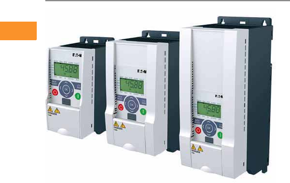
V6-T2-36 Volume 6—Solid-State Motor Control CA08100007E—February 2016 www.eaton.com
2
2
2
2
2
2
2
2
2
2
2
2
2
2
2
2
2
2
2
2
2
2
2
2
2
2
2
2
2
2
2.5
Adjustable Frequency Drives
M-Max Series Drives
M-Max Series Drives for Machinery Applications
Contents
Description Page
M-Max Series Drives
Standards and Certifications . . . . . . . . . . . . . . V6-T2-37
Catalog Number Selection . . . . . . . . . . . . . . . . V6-T2-37
Product Selection . . . . . . . . . . . . . . . . . . . . . . . V6-T2-38
Accessories . . . . . . . . . . . . . . . . . . . . . . . . . . . V6-T2-39
Technical Data and Specifications . . . . . . . . . . V6-T2-42
Dimensions . . . . . . . . . . . . . . . . . . . . . . . . . . . V6-T2-44
Product Description
Eaton’s M-Max™ Series
Sensorless Vector Adjustable
Frequency AC Drives are
the next generation of drives
specifically engineered
for today’s machinery
applications. These micro-
processor-based drives have
standard features that can be
programmed to tailor the
drive’s performance to suit a
wide variety of application
requirements. The M-Max
product line uses a 32-bit
microprocessor and insulated
gate bipolar transistors
(IGBTs) that provide quiet
motor operation, high motor
efficiency, and smooth low-
speed performance. The size
and simplicity of the M-Max
make it ideal for hassle-free
installation. Models rated at
575 volts, three-phase,
50/60 Hz are available in sizes
ranging from 1 to 7-1/2 hp.
Models rated at 480 volts,
three-phase, 50/60 Hz
are available in sizes ranging
from 1/2 to 25 hp. Models
rated at 240 volts, single- or
three-phase, 50/60 Hz are
available in sizes ranging from
1/4 to 15 hp. Models rated
at 115 volts, single-phase,
50/60 Hz are available in the
1/4 to 1-1/2 hp size range.
The standard drive includes a
digital display, and operating
and programming keys on a
visually appealing, efficient
application programming
interface. The display
provides drive monitoring, as
well as adjustment and
diagnostic information. The
keys are used for digital
adjustment and programming
of the drive, as well as for
operator control. Separate
terminal blocks for control
and power wiring are
provided for customer
connections.
Features
●Ease of use—preset
application macros, startup
wizard, diagnostic
capabilities
●Compact, space-saving
design
●Rugged and reliable—
150% torque for one
minute, 50C rated,
conformal coated boards
●DIN rail and screw
mountable
●Side-by-side installation
●Industry leading efficiency
delivers energy savings to
the customer
●Integrated 5% DC choke
(FS4 and FS5)
●Integrated EMC filters
make the unit suitable for
commercial and industrial
networks
●IP21 as standard, option
for NEMA® 1 (FS4 and FS5)
●IP20 as standard, option
for IP21 and NEMA 1
(FS1–FS3)
●Brake chopper as standard
in three-phase, applications
of frames 2 (FS2) and
larger
●Temperature-controlled fan
●RS-485/Modbus® as
standard
●PID controller as standard
●Several fieldbus options
●PROFIBUS
●DeviceNet
●CANopen
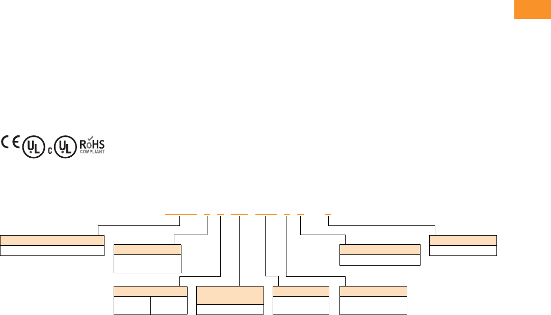
Volume 6—Solid-State Motor Control CA08100007E—February 2016 www.eaton.com V6-T2-37
2
2
2
2
2
2
2
2
2
2
2
2
2
2
2
2
2
2
2
2
2
2
2
2
2
2
2
2
2
2
2.5
Adjustable Frequency Drives
M-Max Series Drives
Standards and Certifications
Product
●Complies with EN61800-3
(2004)
Safety 1
●61800-5-1
●EN60204-1
●CE
●UL
●cUL
●IEC
●RoHS compliant
EMC (At Default Settings)
●EMC Category C2, C3, and
C4 (Level H): With an
internal RFI filter option
Note
1See unit nameplate for more detailed
approvals.
Catalog Number Selection
Software
Designation Series
AA
Description
MMX = Base catalog number
MMX 11AA 1D1 F0–0
Phase
1= Single-phase
3= Three-phase
Voltage
1= 120 V
2= 230 V
4= 480 V
5= 575 V
Output Current
1D6 =1.6 A
010 = 10 A
EMC Filter
F= Filter
N= No filter
Enclosure Class
0 = NEMA 0 or IP20
Option
0 = Full version
V6-T2-38 Volume 6—Solid-State Motor Control CA08100007E—February 2016 www.eaton.com
2
2
2
2
2
2
2
2
2
2
2
2
2
2
2
2
2
2
2
2
2
2
2
2
2
2
2
2
2
2
2.5
Adjustable Frequency Drives
M-Max Series Drives
Product Selection
M-Max Basic Controller
Notes
1 Horsepower ratings are based on the use of a 240 V, 460 V, and 575 V NEMA B, four- or six-pole squirrel cage induction motor and are for reference only.
Units are to be selected such that the motor current is less than or equal to the MMX rated continuous output current.
2 For 208 V, 380 V, or 415 V applications, select the unit such that the motor current is less than or equal to the MMX rated continuous output current.
3 For EMC filtered unit, replace “N0-0” with “F0-0”.
4 EMC filters are not available on MMX11 units.
5 All 575 V units come with EMC filter standard.
hp 1Volts 2
100% Continuous
Current IN (A)
Nominal Input
Current (A)
Frame
Size Catalog Number 3
1/4 100–120 V single-phase in
230 V three-phase out
1.7 9.2 FS2 MMX11AA1D7N0-0 4
1/2 2.4 11.6 MMX11AA2D4N0-0 4
3/4 2.8 12.4 MMX11AA2D8N0-0 4
13.715MMX11AA3D7N0-0 4
1-1/2 4.8 16.5 FS3 MMX11AA4D8N0-0 4
1/4 200–240 V single-phase in
230 V three-phase out
1.7 4.2 FS1 MMX12AA1D7N0-0
1/2 2.4 5.7 MMX12AA2D4N0-0
3/4 2.8 6.6 MMX12AA2D8N0-0
13.78.3FS2MMX12AA3D7N0-0
1-1/2 4.8 11.2 MMX12AA4D8N0-0
2714.1MMX12AA7D0N0-0
3 9.6 15.8 FS3 MMX12AA9D6N0-0
1/4 200–240 V three-phase in
230 V three-phase out
1.7 2.7 FS1 MMX32AA1D7N0-0
1/2 2.4 3.5 MMX32AA2D4N0-0
3/4 2.8 3.8 MMX32AA2D8N0-0
13.74.3FS2MMX32AA3D7N0-0
1-1/2 4.8 6.8 MMX32AA4D8N0-0
278.4MMX32AA7D0N0-0
31113.4FS3MMX32AA011N0-0
5 1717FS4MMX32AA017N0-0
7-1/2 25 25 MMX32AA025N0-0
10 31 31 FS5 MMX32AA031N0-0
15 38 38 MMX32AA038N0-0
1/2 380–480 V three-phase in
460 V three-phase out
1.3 2.2 FS1 MMX34AA1D3N0-0
3/4 1.9 2.8 MMX34AA1D9N0-0
12.43.2MMX34AA2D4N0-0
1-1/2 3.3 4 FS2 MMX34AA3D3N0-0
24.35.6MMX34AA4D3N0-0
35.67.3MMX34AA5D6N0-0
47.69.6FS3MMX34AA7D6N0-0
5911.5MMX34AA9D0N0-0
7-1/2 12 14.9 MMX34AA012N0-0
10 14 18.7 MMX34AA014N0-0
10 16 16 FS4 MMX34AA016N0-0
15 23 23 MMX34AA023N0-0
20 31 31 FS5 MMX34AA031N0-0
25 38 38 MMX34AA038N0-0
1 575 V three-phase in
575 V three-phase out
1.7 2.0 FS3 MMX35AA1D7N0-0 5
22.73.6MMX35AA2D7N0-0 5
33.95.0MMX35AA3D9N0-0 5
56.17.6MMX35AA6D1N0-0 5
7-1/2 9.0 10.4 MMX35AA9D0N0-0 5
M-Max

Volume 6—Solid-State Motor Control CA08100007E—February 2016 www.eaton.com V6-T2-39
2
2
2
2
2
2
2
2
2
2
2
2
2
2
2
2
2
2
2
2
2
2
2
2
2
2
2
2
2
2
2.5
Adjustable Frequency Drives
M-Max Series Drives
Accessories
M-Max Copy/Paste Module
PC Cable
NEMA Type 1 Kits 1
Optional Communication Modules
Network cards require communication adapter.
Remote Keypad 3
There are three components needed for a full remote keypad.
Notes
1NEMA Type 1 kit provides conduit entry plate.
2Requires communication adapter kit.
3All three components are required for remote keypad operation.
Description Catalog Number
Module is plugged onto the front of the drive to provide: upload/download of all parameters, direct
link to a PC via USB interface for parameter assignment via MaxConnect software, and copying of
parameters for a series of devices or when exchanging devices. No PC required
MMX-COM-PC
Description Catalog Number
Remote download USB to RJ-45 cable with software driver disk REM-USB-DOWN
Description Catalog Number
NEMA Type 1 and IP21 kit for frame 1 MMX-IP21-FS1
NEMA Type 1 and IP21 kit for frame 2 MMX-IP21-FS2
NEMA Type 1 and IP21 kit for frame 3 MMX-IP21-FS3
NEMA Type 1 for frame 4 MMX-CKIT-FS4
NEMA Type 1 for frame 5 MMX-CKIT-FS5
Description Catalog Number
Communication adapter kit (FS1–FS3) MMX-NET-XA
Communication adapter kit (FS4 and FS5) MMX-NET-XA-45
PROFIBUS DP network card with serial connection 2XMX-NET-PS-A
PROFIBUS DP network card with Sub-D connection 2XMX-NET-PD-A
DeviceNet network card 2XMX-NET-DN-A
CANopen network card 2XMX-NET-CO-A
Description Catalog Number
Bezel and cable OPTRMT-BP-HMAX 3
Remote copy/paste keypad MMX-REMKEY-TEXT 3
VFD adapter MMX-ADAPTER-RJ45 3
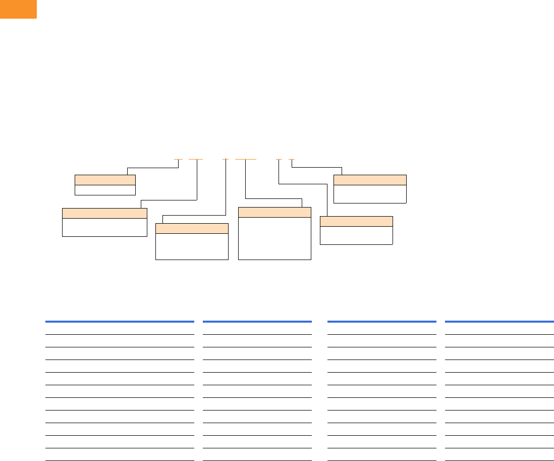
V6-T2-40 Volume 6—Solid-State Motor Control CA08100007E—February 2016 www.eaton.com
2
2
2
2
2
2
2
2
2
2
2
2
2
2
2
2
2
2
2
2
2
2
2
2
2
2
2
2
2
2
2.5
Adjustable Frequency Drives
M-Max Series Drives
Line and Load Reactors
A line and load reactor is a
three-phase inductance filter
that can be placed on the line
and load side of the AFD to
help improve the harmonic
performance of the system.
Consult the factory for
additional filtering options and
further technical details.
DR1 Line Reactor
A line reactor helps to provide
a moderate reduction in
current harmonics similar to a
DC choke. It also provides
increased input protection for
AFD and its semiconductors
from line transients helping to
extend the life of the AFD.
DR2 Output Reactor
An output filter is used to
reduce the transient voltage
(dV/dt) at the motor terminals.
The output filter is
recommended for cable
lengths exceeding 100 ft
(30 m) with a drive of 3 hp
and above and for cable
lengths of 33 ft (10 m) with a
drive of 2 hp and below.
Line and Load Reactors—Catalog Number Selection
Line and Load Reactors—230 V
Open NEMA 1
Load Reactor Line Reactor Load Reactor Line Reactor
hp (CT) 3% 5% 3% 5% 3% 5% 3% 5%
0.33 DR2-22D0-03 DR2-22D0-05 DR1-21D7-03 DR1-21D7-05 DR2-22D0-13 DR2-22D0-15 DR1-21D7-13 DR1-21D7-15
0.5 DR2-22D0-03 DR2-22D0-05 DR1-22D2-03 DR1-22D2-05 DR2-22D0-13 DR2-22D0-15 DR1-22D2-13 DR1-22D2-15
0.75 DR2-24D0-03 DR2-24D0-05 DR1-23D2-03 DR1-23D2-05 DR2-24D0-13 DR2-24D0-15 DR1-23D2-13 DR1-23D2-15
1 DR2-24D0-03 DR2-28D0-05 DR1-24D2-03 DR1-24D2-05 DR2-24D0-13 DR2-28D0-15 DR1-24D2-13 DR1-24D2-15
1.5 DR2-28D0-03 DR2-28D0-05 DR1-26D0-03 DR1-26D0-05 DR2-28D0-13 DR2-28D0-15 DR1-26D0-13 DR1-26D0-15
2 DR2-28D0-03 DR2-28D0-05 DR1-26D8-03 DR1-26D8-05 DR2-28D0-13 DR2-28D0-15 DR1-26D8-13 DR1-26D8-15
3 DR2-2012-03 DR2-2012-05 DR1-29D6-03 DR1-29D6-05 DR2-2012-13 DR2-2012-15 DR1-29D6-13 DR1-29D6-15
5 DR2-2018-03 DR2-2018-05 DR1-2015-03 DR1-2015-05 DR2-2018-13 DR2-2018-15 DR1-2015-13 DR1-2015-15
7.5 DR2-2025-03 DR2-2025-05 DR1-2022-03 DR1-2022-05 DR2-2025-13 DR2-2025-15 DR1-2022-13 DR1-2022-15
10 DR2-2035-03 DR2-2035-05 DR1-2028-03 DR1-2028-05 DR2-2035-13 DR2-2035-15 DR1-2028-13 DR1-2028-15
15 DR2-2045-03 DR2-2045-05 DR1-2042-03 DR1-2042-05 DR2-2045-13 DR2-2045-15 DR1-2042-13 DR1-2042-15
DR1 –22D0 –05
Device Series
R1 = Line side reactor
R2 = Load side reactor
Basic Naming
D= Drive
Input/Output Voltage
2= 230 V
4= 480 V
5= 575 V
Environment Rating
0= Open
1= NEMA 1
Impedance
3= 3%
5= 5%
Current Rating
Examples:
2D0 = 2.0 A
4D0 = 4.0 A
8D0 = 8.0 A
012
= 12 A
Volume 6—Solid-State Motor Control CA08100007E—February 2016 www.eaton.com V6-T2-41
2
2
2
2
2
2
2
2
2
2
2
2
2
2
2
2
2
2
2
2
2
2
2
2
2
2
2
2
2
2
2.5
Adjustable Frequency Drives
M-Max Series Drives
Line and Load Reactors—480 V
Line and Load Reactors—575 V
Open NEMA 1
Load Reactor Line Reactor Load Reactor Line Reactor
hp (CT) 3% 5% 3% 5% 3% 5% 3% 5%
0.5 DR2-41D0-03 DR2-41D0-05 DR1-41D1-03 DR1-41D1-05 DR2-41D0-13 DR2-41D0-15 DR1-41D1-13 DR1-41D1-15
0.75 DR2-42D0-03 DR2-42D0-05 DR1-41D6-03 DR1-41D6-05 DR2-42D0-13 DR2-42D0-15 DR1-41D6-13 DR1-41D6-15
1 DR2-42D0-03 DR2-42D0-05 DR1-42D1-03 DR1-42D1-05 DR2-42D0-13 DR2-42D0-15 DR1-42D1-13 DR1-42D1-15
1.5 DR2-44D0-03 DR2-44D0-05 DR1-43D0-03 DR1-43D0-05 DR2-44D0-13 DR2-44D0-15 DR1-43D0-13 DR1-43D0-15
2 DR2-44D0-03 DR2-44D0-05 DR1-43D4-03 DR1-43D4-05 DR2-44D0-13 DR2-44D0-15 DR1-43D4-13 DR1-43D4-15
3 DR2-48D0-03 DR2-48D0-05 DR1-44D8-03 DR1-44D8-05 DR2-48D0-13 DR2-48D0-15 DR1-44D8-13 DR1-44D8-15
5 DR2-48D0-03 DR2-48D0-05 DR1-47D6-03 DR1-47D6-05 DR2-48D0-13 DR2-48D0-15 DR1-47D6-13 DR1-47D6-15
7.5 DR2-4012-03 DR2-4012-05 DR1-4011-03 DR1-4011-05 DR2-4012-13 DR2-4012-15 DR1-4011-13 DR1-4011-15
10 DR2-4018-03 DR2-4018-05 DR1-4014-03 DR1-4014-05 DR2-4018-13 DR2-4018-15 DR1-4014-13 DR1-4014-15
15 DR2-4025-03 DR2-4025-05 DR1-4021-03 DR1-4021-05 DR2-4025-13 DR2-4025-15 DR1-4021-13 DR1-4021-15
20 DR2-4025-03 DR2-4025-05 DR1-4027-03 DR1-4027-05 DR2-4025-13 DR2-4025-15 DR1-4027-13 DR1-4027-15
25 DR2-4035-03 DR2-4035-05 DR1-4034-03 DR1-4034-05 DR2-4035-13 DR2-4035-15 DR1-4034-13 DR1-4034-15
Open NEMA 1
Load Reactor Line Reactor Load Reactor Line Reactor
hp (CT) 3% 5% 3% 5% 3% 5% 3% 5%
1 DR2-52D0-03 DR2-52D0-05 DR1-51D7-03 DR1-51D7-05 DR2-52D0-13 DR2-52D0-15 DR1-51D7-13 DR1-51D7-15
2 DR2-54D0-03 DR2-54D0-05 DR1-43D4-03 DR1-52D7-05 DR2-54D0-13 DR2-54D0-15 DR1-52D7-13 DR1-52D7-15
3 DR2-54D0-03 DR2-54D0-05 DR1-53D9-03 DR1-53D9-05 DR2-54D0-13 DR2-54D0-15 DR1-53D9-13 DR1-53D9-15
5 DR2-58D0-03 DR2-58D0-05 DR1-56D1-03 DR1-56D1-05 DR2-58D0-13 DR2-58D0-15 DR1-56D1-13 DR1-56D1-15
7.5 DR2-58D0-03 DR2-58D0-05 DR1-59D0-03 DR1-59D0-05 DR2-58D0-13 DR2-58D0-15 DR1-59D0-13 DR1-59D0-15

V6-T2-42 Volume 6—Solid-State Motor Control CA08100007E—February 2016 www.eaton.com
2
2
2
2
2
2
2
2
2
2
2
2
2
2
2
2
2
2
2
2
2
2
2
2
2
2
2
2
2
2
2.5
Adjustable Frequency Drives
M-Max Series Drives
Technical Data and Specifications
Ratings
M-Max Basic Controller IP20 Standard Ratings
Programmable Parameters
Specifications
M-Max Series Drives
Notes
1Exception: 115 V single-phase in, 230 V three-phase out.
2Only three-phase FS2 and FS3 drives are equipped with brake chopper circuit.
Description Specification
Protections
Overcurrent protection Trip limit 4.0 x IH instantaneously
Overvoltage protection 115/230 V series: 437 Vdc; 400 V series: 874 Vdc;
575 V series: 1048 Vdc trip level
Undervoltage protection 115/230 V series: 183 Vdc; 400 V series: 333 Vdc;
575 V series: 460 Vdc trip level
Ground fault protection Ground fault is tested before every start. In case of ground fault in
motor or motor cable, only the frequency converter is protected
Overtemperature
protection
Yes
Motor overload protection Yes
Motor stall protection Yes
Motor underload protection Yes
Short-circuit protection 100 kAIC with fuses
Description
Application macros: basic, pump, fan and high load (hoist)
Programmable start/stop and reverse signal logic (sinking or sourcing)
Reference scaling
Programmable start and stop functions
DC-brake at start and stop
Programmable V/Hz curve
Adjustable switching frequency
Autorestart function after fault
Protections and supervisions (all fully programmable; off, warning, fault)
Current signal input fault
External fault
Fieldbus communication
Eight preset speeds
Analog input range selection, signal scaling and filtering
PID controller
Skip frequencies
Description Specification
Input Ratings
Input voltage (Vin) +10%/–15%
Input frequency (fin) 50/60 Hz (variation up to 45–66 Hz)
Connection to power Once per minute or less (typical operation)
Output Ratings
Output voltage 0 to Vin 1
Continuous output
current
Continuous rated current IN at ambient temperature max.
122 °F (50 °C), overload 1.5 x IN max. 1 min/10 min
Output frequency 0 to 320 Hz
Frequency resolution 0.01 Hz
Initial output current (IH) Current 2 x IN for 2 seconds in every 20-second period
Torque depends on motor
Control Characteristics
Control method
Frequency control (V/Hz) open loop or sensorless vector control
Switching frequency 1.5 to 16 kHz; default 4 kHz
Frequency reference Analog input: resolution 0.1% (10-bit), accuracy ± 1% V/Hz
Panel reference: resolution 0.01 Hz
Field weakening point 30 to 320 Hz
Acceleration time 0 to 3000 sec
Deceleration time 0 to 3000 sec
Braking torque DC brake: 30% x Tn (without brake option)
Brake Resistor (Minimum Values) 2
230 V Series FS2 35 ohms and FS3 26 ohms, FS4 14 ohms, FS5 9 ohms
400 V Series FS2 75 ohms and FS3 54 ohms, FS4 28 ohms, FS5 17 ohms
575 V Series FS3 103 ohms
Ambient Conditions
Ambient operating
temperature
14 °F (–10 °C), no frost to 122 °F (+50 °C): Rated loadability IN
Storage temperature –40 °F (–40 °C) to 158 °F (70 °C)
Relative humidity 0 to 95% RH, noncondensing, non-corrosive, no dripping water
Air quality Chemical vapors: IEC 721-3-3, unit in operation, Class 3C2; Mechanical
particles: IEC 721-3-3, unit in operation, Class 3S2
Altitude 100% load capacity (no derating) up to 3280 ft (1000 m);
1% derating for each 328 ft (100 m) above 3280 ft (1000 m);
max. 6560 ft (2000 m)
Vibration EN 60068-2-6; 3 to 150 Hz, displacement amplitude 1 mm (peak) at 3 to
15.8 Hz, max. acceleration amplitude 1G at 15.8 to 150 Hz
Shock EN 50178, IEC 68-2-27 UPS Drop test (for applicable UPS weights);
storage and shipping: max. 15 g, 11 ms (in package)
Enclosure class IP20 (FS1–FS3)
IP21 (FS4 and FS5)
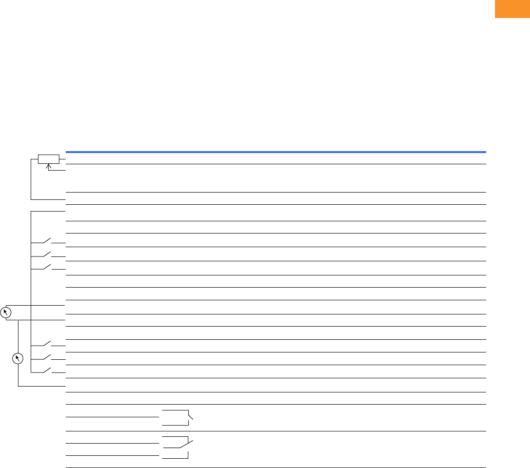
Volume 6—Solid-State Motor Control CA08100007E—February 2016 www.eaton.com V6-T2-43
2
2
2
2
2
2
2
2
2
2
2
2
2
2
2
2
2
2
2
2
2
2
2
2
2
2
2
2
2
2
2.5
Adjustable Frequency Drives
M-Max Series Drives
Standards
I/O Specifications
●Digital inputs DI1–DI6 are
freely programmable. The
user can assign multiple
functions to a single input
●Digital, relay, and analog
outputs are freely
programmable
Includes:
●Six digital inputs
●Two analog inputs
– 4–20 mA
– 0–10 V
●One analog output
●One digital output
●Two relay outputs
●RS-485 interface
Reliability
●Pretested components
●Computerized testing
●Final test with full load
●Conformal-coated boards
●
Eaton’s Electrical Services &
Systems: national network
of AF drive specialists
M-Max I/O Interface
Note
P) Parameter-selectable function.
Terminal Signal Factory Preset Description
1 +10 V Ref. output voltage — Maximum load 10 mA
2 AI1 Analog signal in 1 Freq. reference P) 0–+10 V Ri = 200k ohms [min.]
3 GND I/O signal ground — —
6 24 V 24 V output for DIs — ±20%, max. load 50 mA
7 GND I/O signal ground — —
8 DI1 Digital input 1 Start forward P) 0–+30 V Ri = 12k ohms min.
9 DI2 Digital input 2 Start reverse P) —
10 DI3 Digital input 3 Preset speed P) —
A A RS-485 signal A FB communication —
B B RS-485 signal B FB communication —
4 AI2 Analog signal in 2 PI actual value P) 0[4]–20 mA, Ri = 200k ohms
5 GND I/O signal ground — —
13 GND I/O signal ground — —
14 DI4 Digital input 4 Preset speed B1 P) 0–+30 V Ri = 12k ohms min.
15 DI5 Digital input 5 Fault reset P) 0–+30 V Ri = 12k ohms min.
16 DI6 Digital input 6 Disable PI contr. P) 0–+30 V Ri = 12k ohms min.
18 AO Analog output Output frequency P) 0(2)–10 V, RL = 500 ohms
20 DO Digital signal out Active = READY P) Open collector, max. load 48V/50 mA
22 RO11 Relay out 1 Active = RUN P) Max. switching load: 250 Vac/2 A or 250 Vdc/0.4 A
23 RO12
24 RO21 Relay out 2 Active = FAULT P) Max. switching load: 250 Vac/2 A or 250 Vdc/0.4 A
25 RO22
26 RO23
Analog
OUT
AUTOGEN
Ref
Current
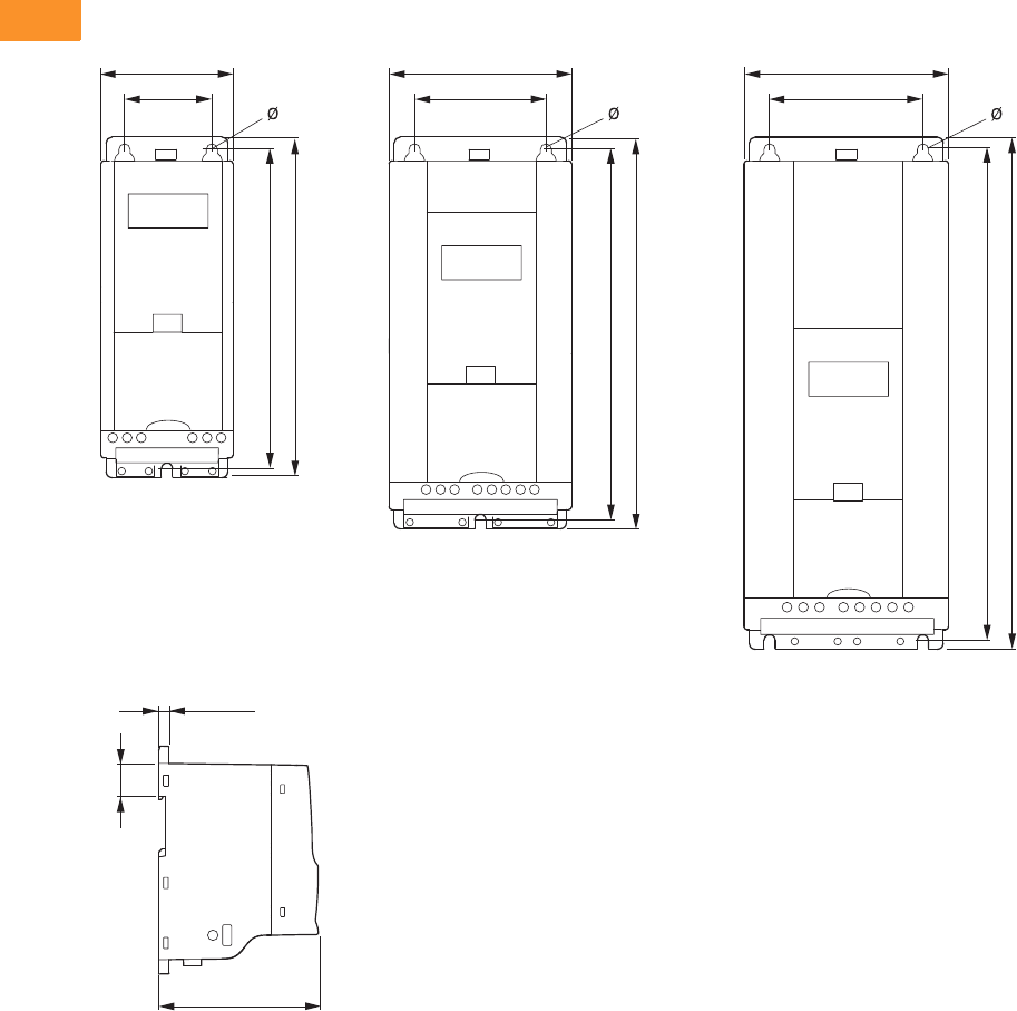
V6-T2-44 Volume 6—Solid-State Motor Control CA08100007E—February 2016 www.eaton.com
2
2
2
2
2
2
2
2
2
2
2
2
2
2
2
2
2
2
2
2
2
2
2
2
2
2
2
2
2
2
2.5
Adjustable Frequency Drives
M-Max Series Drives
Dimensions
Approximate Dimensions in Inches (mm)
Dimensions and Frame Sizes, FS1–FS3 (FS = Frame Size)
b1
b
a1
a
b1
b
a1
a
b1
b
a1
a
b2
c
0.28 in
(7 mm)
FS1
FS2
FS3
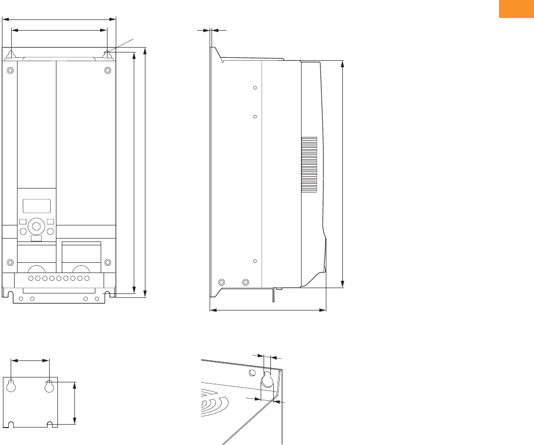
Volume 6—Solid-State Motor Control CA08100007E—February 2016 www.eaton.com V6-T2-45
2
2
2
2
2
2
2
2
2
2
2
2
2
2
2
2
2
2
2
2
2
2
2
2
2
2
2
2
2
2
2.5
Adjustable Frequency Drives
M-Max Series Drives
Approximate Dimensions in Inches (mm)
Dimensions and Frame Sizes, FS4 and FS5 (FS = Frame Size)
b1
a1
b2
c
b1
b
a1
a
Ø
0.28
(7.0)
Ø1
Ø2

V6-T2-46 Volume 6—Solid-State Motor Control CA08100007E—February 2016 www.eaton.com
2
2
2
2
2
2
2
2
2
2
2
2
2
2
2
2
2
2
2
2
2
2
2
2
2
2
2
2
2
2
2.5
Adjustable Frequency Drives
M-Max Series Drives
Dimensions and Frame Sizes
Note
1 in = 25.4 mm, 1 mm = 0.0394 in
Approximate Dimensions in inches (mm) Installation
SizePart Number a a1 b b1 b2 c Ø, Ø1 Ø2
MMX12AA1D7_
MMX12AA2D4_
MMX12AA2D8_
2.60
(66)
1.50
(38)
6.30
(160)
5.79
(147)
1.26
(32)
4.02
(102)
0.18
(4.5)
—FS1
MMX32AA1D7_
MMX32AA2D4_
MMX32AA2D8_
MMX34AA1D3_
MMX34AA1D9_
MMX34AA2D4_
MMX11AA1D7_
MMX11AA2D4_
MMX11AA2D8_
MMX11AA3D7_
3.54
(90)
2.46
(62.5)
7.68
(195)
7.17
(182)
1.26
(32)
4.14
(105)
2.17
(5.5)
—FS2
MMX12AA3D7_
MMX12AA4D8_
MMX12AA7D0_
MMX32AA3D7_
MMX32AA4D8_
MMX32AA7D0_
MMX34AA3D3_
MMX34AA4D3_
MMX34AA5D6_
MMX11AA4D8_ 3.94
(100)
2.95
(75)
9.96
(253)
9.53
(242)
1.34
(34)
4.41
(112)
2.17
(5.5)
—FS3
MMX12AA9D6_
MMX32AA011_
MMX34AA7D6_
MMX34AA9D0_
MMX34AA012_
MMX34AA014_
MMX35AA1D7_
MMX35AA2D7_
MMX35AA3D9_
MMX35AA6D1_
MMX35AA9D0_
MMX32AA012_
MMX32AA017_
MMX32AA025_
6.50
(165.0)
5.51
(140.0)
14.57
(370.0)
13.82
(351.0)
13.27
(337.0)
6.61
(168.0)
0.28
(7.0)
0.55
(14.0)
FS4
MMX34AA016_
MMX34AA023_
MMX32AA031_
MMX32AA038_
6.50
(165.0)
5.51
(140.0)
16.30
(414.0)
15.67
(398.0)
15.08
(383.0)
8.07
(205.0)
0.28
(7.0)
0.55
(14.0)
FS5
MMX34AA031_
MMX34AA038_
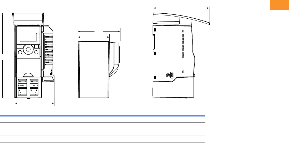
Volume 6—Solid-State Motor Control CA08100007E—February 2016 www.eaton.com V6-T2-47
2
2
2
2
2
2
2
2
2
2
2
2
2
2
2
2
2
2
2
2
2
2
2
2
2
2
2
2
2
2
2.5
Adjustable Frequency Drives
M-Max Series Drives
Approximate Dimensions in Inches (mm)
NEMA 1/IP21 M-Max Drives and Communication Adapter Kit
Frame Type H W1 W2 W3 D
FS1 8.14 (206.7) 3.77 (95.7) 2.99 (75.9) 3.98 (101.2) 5.41 (137.5)
FS2 9.90 (251.5) 4.72 (120.0) 3.97 (100.8) 4.94 (125.5) 5.68 (144.2)
FS3 12.26 (311.5) 5.12 (130.1) 4.36 (110.8) 5.33 (135.3) 6.32 (160.5)
FS4 16.40 (416.6) — 6.50 (165.0) — 6.61 (166.0)
FS5 18.10 (460.1) — 6.50 (165.0) — 8.07 (205.0)
H
W1
W2
D
W3
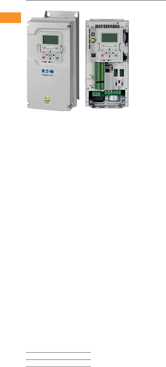
V6-T2-48 Volume 6—Solid-State Motor Control CA08100007E—February 2016 www.eaton.com
2
2
2
2
2
2
2
2
2
2
2
2
2
2
2
2
2
2
2
2
2
2
2
2
2
2
2
2
2
2
2.6
Adjustable Frequency Drives
PowerXL DG1 Series Drives
DG1 General Purpose Drive
Contents
Description Page
PowerXL DG1 Series Drives
Standards and Certifications . . . . . . . . . . . . . . V6-T2-49
Catalog Number Selection . . . . . . . . . . . . . . . . V6-T2-49
Product Selection . . . . . . . . . . . . . . . . . . . . . . . V6-T2-50
Accessories . . . . . . . . . . . . . . . . . . . . . . . . . . . V6-T2-53
Replacement Parts . . . . . . . . . . . . . . . . . . . . . . V6-T2-60
Technical Data and Specifications . . . . . . . . . . V6-T2-63
Dimensions . . . . . . . . . . . . . . . . . . . . . . . . . . . V6-T2-69
PowerXL DG1 Series Enclosed Drives . . . . . . . . . V6-T2-70
PowerXL DG1 Series Drives
Product Description
The DG1 general purpose
drives are part of Eaton’s next
generation PowerXL Series of
adjustable frequency drives
specifically engineered for
today’s more demanding
commercial and industrial
applications. The power unit
makes use of the most
sophisticated semiconductor
technology and a highly
modular construction that can
be flexibly adapted to meet
the customer’s needs.
The control module was
designed to include today’s
standard communication
protocols and I/O while still
having the modularity to add
additional option cards.
Eaton’s patented Active
Energy Control is also a
standard feature on DG1
drives, offering customers
increased efficiency, safety
and reliability.
These drives continue
the tradition of robust
performance and raise
the bar on features and
functionality, ensuring
the best solution at the
right price.
Product Range
Features and Benefits
Hardware
●Brake chopper standard on
Frames 1, 2, 3
●Dual overload ratings
●
110% variable torque (I
L
)
●
150% constant torque (I
H
)
●Type 1/IP21 and Type 12/
IP54 enclosures available
●Integrated common mode
reduction 5% DC link
choke with input surge
protection
●EMI/RFI filters standard on
all drives—meets EMC
Category C2
●Real-time clock—supports
calendaring and PLC
functionality
●Graphic LCD display and
keypad—supports simple
menu navigation as well as
on-screen diagnostics and
troubleshooting
●LOCAL/REMOTE operation
from keypad and two
configurable soft keys
●Conformal coated control
and power boards standard
●Control logic can be
powered from an external
auxiliary control panel—
internal drive functions and
fieldbus if necessary
●Standard I/O:
●8DI, 1DO
●2AI, 2AO
●2FC, 1FA relays
●Standard communications:
●EtherNet/IP,
Modbus TCP
●RS-485: Modbus RTU,
BACnet MS/TP
●Seamless integration into
EtherNet/IP networks
via EIP-Assist I/O
tag-generation tool
●Two expansion slots—
intended to support
additional I/O or
communication protocols
as necessary
●Quick disconnect terminals
for I/O connections—
supports fast easy
installation
●Safe Torque Off (STO) built-
in with functional safety
SIL1 certification
Software
●Active energy control—
minimizes energy losses
in your motor, resulting in
industry-leading energy
efficiency for your
application
●Quick Start Wizard upon
initial power-up supports
fast, easy installation
●Standard applications:
●Standard
●Multi-pump and fan
Control
●Multi-PID
●Multi-purpose
●Copy/paste functionality
on drive keypad—allows
for fast setup of multiple
drives
●Pre-programmed I/O—
supports fast, easy
installation for most
applications
●Dynamic motor
regenerative energy
management
●Advanced PC Tool with
diagnostic capabilities
●Two keypad software keys
for easy menu navigation
and shortcuts
230 V to 125 hp, 312 A, 90 kW
480 V to 250 hp, 310 A, 160 kW
575 V to 250 hp, 250 A, 160 kW
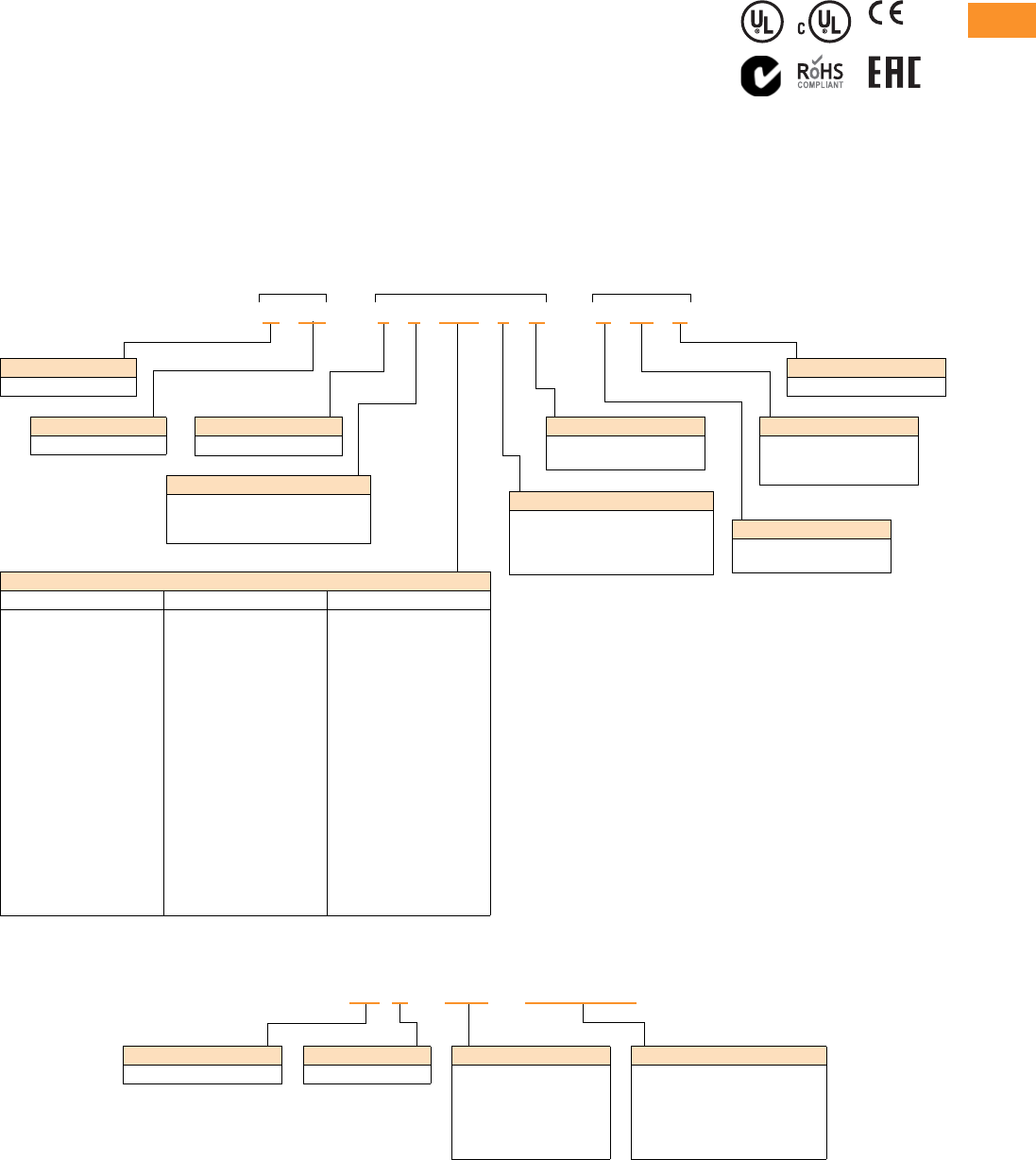
Volume 6—Solid-State Motor Control CA08100007E—February 2016 www.eaton.com V6-T2-49
2
2
2
2
2
2
2
2
2
2
2
2
2
2
2
2
2
2
2
2
2
2
2
2
2
2
2
2
2
2
2.6
Adjustable Frequency Drives
PowerXL DG1 Series Drives
Standards and Certifications
Product
●IEC/EN 61800-5-1
●IEC/EN 61800-5-2
●UL 508C
●IEC 61508
●EN 62061
●EN ISO 13849-1
EMC
●Immunity: IEC/EN 61800-3
●Category C2
Certification
●UL
●cUL
●CE
●C-Tick
●RoHS
●EAC
●Plenum rated
Catalog Number Selection
Catalog Number Selection is for illustrative purposes only and not to be used to create new catalog numbers.
PowerXL Series—DG1 General Purpose Drive
PowerXL Series—DG1 General Purpose Drive Option Boards
Internal Brake Chopper
N = No brake chopper
B = Brake chopper
Series Power Part Options
DG1 –344D3 F B –C21 C
Input/Output Voltage Rating
2 = 230 V (208–240 V, –15%, +10%)
4 = 400 V (380–500 V, –15%, +10%)
5 = 575 V (525–600 V, –15%, +10%)
Basic Naming
D = Drive
Output Current Rating (CT)
208–240 V 380–500 V 525–600 V
3D7 = 3.7 A, 0.55 kW, 0.75 hp
4D8 = 4.8 A, 0.75 kW, 1 hp
6D6 = 6.6 A, 1.1 kW, 1.5 hp
7D8 = 7.8 A, 1.5 kW, 2 hp
011 = 11 A, 2.2 kW, 3 hp
012 = 12.5 A, 3 kW, 5 hp (VT)
017 = 17.5 A, 3.7 kW, 5 hp
025 = 25 A, 5.5 kW, 7.5 hp
031 = 31 A, 7.5 kW, 10 hp
048 = 48 A, 11 kW, 15 hp
061 = 61 A, 15 kW, 20 hp
075 = 75 A, 18.5 kW, 25 hp
088 = 88 A, 22 kW, 30 hp
114 = 114 A, 30 kW, 40 hp
143 = 143 A, 37 kW, 50 hp
170 = 170 A, 45 kW, 60 hp
211 = 211 A, 55 kW, 75 hp
248 = 248 A, 75 kW, 100 hp
2D2 = 2.2 A, 0.75 kW, 1 hp
3D3 = 3.3 A, 1.1 kW, 1.5 hp
4D3 = 4.3 A, 1.5 kW, 2 hp
5D6 = 5.6 A, 2.2 kW, 3 hp
7D6 = 7.6 A, 3 kW, 5 hp
9D0 = 9 A, 4 kW, 7.5 hp (VT)
012 = 12 A, 5.5 kW, 7.5 hp
016 = 16 A, 7.5 kW, 10 hp
023 = 23 A, 11 kW, 15 hp
031 = 31 A, 15 kW, 20 hp
038 = 38 A, 18 kW, 25 hp
046 = 46 A, 22 kW, 30 hp
061 = 61 A, 30 kW, 40 hp
072 = 72 A, 37 kW, 50 hp
087 = 87 A, 45 kW, 60 hp
105 = 105 A, 55 kW, 75 hp
140 = 140 A, 75 kW, 100 hp
170 = 170 A, 90 kW, 125 hp
205 = 205 A, 110 kW, 150 hp
245 = 245 A, 150 kW, 200 hp
3D3 = 3.3 A, 1.5 kW, 2 hp
4D5 = 4.5 A, 2.2 kW, 3 hp
7D5 = 7.5 A, 3.7 kW, 5 hp
010 = 10 A, 5.5 kW, 7.5 hp
013 = 13.5 A, 7.5 kW, 10 hp
018 = 18 A, 11 kW, 15 hp
022 = 22 A, 15 kW, 20 hp
027 = 27 A, 18 kW, 25 hp
034 = 34 A, 22 kW, 30 hp
041 = 41 A, 30 kW, 40 hp
052 = 52 A, 37 kW, 50 hp
062 = 62 A, 45 kW, 60 hp
080 = 80 A, 55 kW, 75 hp
100 = 100 A, 75 kW, 100 hp
125 = 125 A, 90 kW, 125 hp
144 = 144 A, 110 kW, 150 hp
208 = 208 A, 160 kW, 200 hp
Series
G1 = General purpose
Phase Reference
3 = 3~ INPUT/3~ OUTPUT
Internal EMC Filter
D = DC choke only
E = EMC filter only
F = Internal EMC filter and DC choke
N = No EMC filter, no DC choke
Coating of Boards
C = Coated
Enclosure (IP Rating)
00 = IP00
21 = IP21/Type 1
54 = IP54/Type 12
Display Option
C = LCD (graphical)
N = No display
Function
PROFB = PROFIBUS
DEVICENET = DeviceNet
CANOPEN = CANopen
SWD =SmartWire
See Accessories on Page V6-T2-53
for full offering
Series
G = General purpose
Type
NET = Communication card
EXT =I/O card
ACC = Accessory
SPR =Spare part
KEY = Keypad
CBL = Cable
Basic Naming
DX = PowerXL Drive
DX G–NET–PROFIBUS
V6-T2-50 Volume 6—Solid-State Motor Control CA08100007E—February 2016 www.eaton.com
2
2
2
2
2
2
2
2
2
2
2
2
2
2
2
2
2
2
2
2
2
2
2
2
2
2
2
2
2
2
2.6
Adjustable Frequency Drives
PowerXL DG1 Series Drives
Product Selection
DG1 Series Drives—208–240 Volt
Type 1/IP21
Ty p e 1 2 / I P 5 4
Note
1 FR6 available in 2016.
Constant Torque (CT) / High Overload (IH) Variable Torque (VT) / Low Overload (IL)
Frame Size
230 V, 50 Hz
kW Rating
230 V, 60 Hz
hp
Current
A
230 V, 50 Hz
kW Rating
230 V, 60 Hz
hp
Current
A Catalog Number
FR1 0.55 0.75 3.7 0.75 1 4.8 DG1-323D7FB-C21C
0.75 1 4.8 1.1 1.5 6.6 DG1-324D8FB-C21C
1.1 1.5 6.6 1.5 2 7.8 DG1-326D6FB-C21C
1.5 2 7.8 2.2 3 11 DG1-327D8FB-C21C
2.2 3 11 3 — 12.5 DG1-32011FB-C21C
FR2 3 — 12.5 3.7 5 17.5 DG1-32012FB-C21C
3.7 5 17.5 5.5 7.5 25 DG1-32017FB-C21C
5.5 7.5 25 7.5 10 31 DG1-32025FB-C21C
FR3 7.51031 111548 DG1-32031FB-C21C
11 15 48 15 20 61 DG1-32048FB-C21C
FR4 152061 18.52575 DG1-32061FN-C21C
18.5 25 75 22 30 88 DG1-32075FN-C21C
22 30 88 30 40 114 DG1-32088FN-C21C
FR5 30 40 114 37 50 143 DG1-32114FN-C21C
37 50 143 45 60 170 DG1-32143FN-C21C
45 60 170 55 75 211 DG1-32170FN-C21C
FR6 155 75 211 75 100 261 DG1-32211FN-C21C
75 100 248 90 125 312 DG1-32248FN-C21C
Constant Torque (CT) / High Overload (IH) Variable Torque (VT) / Low Overload (IL)
Frame Size
230 V, 50 Hz
kW Rating
230 V, 60 Hz
hp
Current
A
230 V, 50 Hz
kW Rating
230 V, 60 Hz
hp
Current
A Catalog Number
FR1 0.55 0.75 3.7 0.75 1 4.8 DG1-323D7FB-C54C
0.75 1 4.8 1.1 1.5 6.6 DG1-324D8FB-C54C
1.1 1.5 6.6 1.5 2 7.8 DG1-326D6FB-C54C
1.5 2 7.8 2.2 3 11 DG1-327D8FB-C54C
2.2 3 11 3 — 12.5 DG1-32011FB-C54C
FR2 3 — 12.5 3.7 5 17.5 DG1-32012FB-C54C
3.7 5 17.5 5.5 7.5 25 DG1-32017FB-C54C
5.5 7.5 25 7.5 10 31 DG1-32025FB-C54C
FR3 7.51031 111548 DG1-32031FB-C54C
11 15 48 15 20 61 DG1-32048FB-C54C
FR4 152061 18.52575 DG1-32061FN-C54C
18.5 25 75 22 30 88 DG1-32075FN-C54C
22 30 88 30 40 114 DG1-32088FN-C54C
FR5 30 40 114 37 50 143 DG1-32114FN-C54C
37 50 143 45 60 170 DG1-32143FN-C54C
45 60 170 55 75 211 DG1-32170FN-C54C
FR6 155 75 211 75 100 261 DG1-32211FN-C54C
75 100 248 90 125 312 DG1-32248FN-C54C
PowerXL Series—DG1
PowerXL Series—DG1
Volume 6—Solid-State Motor Control CA08100007E—February 2016 www.eaton.com V6-T2-51
2
2
2
2
2
2
2
2
2
2
2
2
2
2
2
2
2
2
2
2
2
2
2
2
2
2
2
2
2
2
2.6
Adjustable Frequency Drives
PowerXL DG1 Series Drives
DG1 Series Drives—380–500 Volt
Type 1/IP21
Ty p e 1 2 / I P 5 4
Note
1 FR6 available in 2016.
Constant Torque (CT) / High Overload (IH) Variable Torque (VT) / Low Overload (IL)
Frame Size
400 V, 50 Hz
kW Rating
460 V, 60 Hz
hp
Current
A
400 V, 50 Hz
kW Rating
460 V, 60 Hz
hp
Current
A Catalog Number
FR1 0.75 1 2.2 1.1 1.5 3.3 DG1-342D2FB-C21C
1.1 1.5 3.3 1.5 2 4.3 DG1-343D3FB-C21C
1.5 2 4.3 2.2 3 5.6 DG1-344D3FB-C21C
2.2 3 5.6 3 5 7.6 DG1-345D6FB-C21C
357.6 4—9 DG1-347D6FB-C21C
4—9 5.57.512 DG1-349D0FB-C21C
FR2 5.5 7.5 12 7.5 10 16 DG1-34012FB-C21C
7.51016 111523 DG1-34016FB-C21C
11 15 23 15 20 31 DG1-34023FB-C21C
FR3 152031 18.52538 DG1-34031FB-C21C
18.5 25 38 22 30 46 DG1-34038FB-C21C
22 30 46 30 40 61 DG1-34046FB-C21C
FR4 304061 375072 DG1-34061FN-C21C
37 50 72 45 60 87 DG1-34072FN-C21C
45 60 87 55 75 105 DG1-34087FN-C21C
FR5 5575105 75100140 DG1-34105FN-C21C
75 100 140 90 125 170 DG1-34140FN-C21C
90 125 170 110 150 205 DG1-34170FN-C21C
FR6 1110 150 205 132 200 261 DG1-34205FN-C21C
150 200 245 160 250 310 DG1-34245FN-C21C
Constant Torque (CT) / High Overload (IH) Variable Torque (VT) / Low Overload (IL)
Frame Size
400 V, 50 Hz
kW Rating
460 V, 60 Hz
hp
Current
A
400 V, 50 Hz
kW Rating
460 V, 60 Hz
hp
Current
A Catalog Number
FR1 0.75 1 2.2 1.1 1.5 3.3 DG1-342D2FB-C54C
1.1 1.5 3.3 1.5 2 4.3 DG1-343D3FB-C54C
1.5 2 4.3 2.2 3 5.6 DG1-344D3FB-C54C
2.2 3 5.6 3 5 7.6 DG1-345D6FB-C54C
357.6 4—9 DG1-347D6FB-C54C
4—9 5.57.512 DG1-349D0FB-C54C
FR2 5.5 7.5 12 7.5 10 16 DG1-34012FB-C54C
7.51016 111523 DG1-34016FB-C54C
11 15 23 15 20 31 DG1-34023FB-C54C
FR3 152031 18.52538 DG1-34031FB-C54C
18.5 25 38 22 30 46 DG1-34038FB-C54C
22 30 46 30 40 61 DG1-34046FB-C54C
FR4 304061 375072 DG1-34061FN-C54C
37 50 72 45 60 87 DG1-34072FN-C54C
45 60 87 55 75 105 DG1-34087FN-C54C
FR5 5575105 75100140 DG1-34105FN-C54C
75 100 140 90 125 170 DG1-34140FN-C54C
90 125 170 110 150 205 DG1-34170FN-C54C
FR6 1110 150 205 132 200 261 DG1-34205FN-C54C
150 200 245 160 250 310 DG1-34245FN-C54C
PowerXL Series—DG1
PowerXL Series—DG1
V6-T2-52 Volume 6—Solid-State Motor Control CA08100007E—February 2016 www.eaton.com
2
2
2
2
2
2
2
2
2
2
2
2
2
2
2
2
2
2
2
2
2
2
2
2
2
2
2
2
2
2
2.6
Adjustable Frequency Drives
PowerXL DG1 Series Drives
DG1 Series Drives—575 Volt 1
Type 1/IP21
Ty p e 1 2 / I P 5 4
Notes
1 575 V available 2016.
2 FR6 available in 2016.
Constant Torque (CT) / High Overload (IH) Variable Torque (VT) / Low Overload (IL)
Frame Size
575 V, 60 Hz
kW Rating
575 V, 60 Hz
hp
Current
A
575 V, 60 Hz
kW Rating
575 V, 60 Hz
hp
Current
A Catalog Number
FR1 1.5 2 3.3 2.2 3 4.5 DG1-353D3FB-C21C
2.2 3 4.5 3.7 5 7.5 DG1-354D5FB-C21C
3.7 5 7.5 5.5 7.5 10 DG1-357D5FB-C21C
FR2 5.5 7.5 10 7.5 10 13.5 DG1-35010FB-C21C
7.51013.5 111518 DG1-35013FB-C21C
11 15 18 15 20 22 DG1-35018FB-C21C
FR3 152022 18.52527 DG1-35022FB-C21C
18.5 25 27 22 30 34 DG1-35027FB-C21C
22 30 34 30 40 41 DG1-35034FB-C21C
FR4 304041 375052 DG1-35041FN-C21C
37 50 52 45 60 62 DG1-35052FN-C21C
45 60 62 55 75 80 DG1-35062FN-C21C
FR5 557580 75100100 DG1-35080FN-C21C
75 100 100 90 125 125 DG1-35100FN-C21C
90 125 125 110 150 144 DG1-35125FN-C21C
FR6 2110 150 144 150 200 208 DG1-35144FN-C21C
150 200 208 187 250 250 DG1-35208FN-C21C
Constant Torque (CT) / High Overload (IH) Variable Torque (VT) / Low Overload (IL)
Frame Size
575 V, 60 Hz
kW Rating
575 V, 60 Hz
hp
Current
A
575 V, 60 Hz
kW Rating
575 V, 60 Hz
hp
Current
A Catalog Number
FR1 1.5 2 3.3 2.2 3 4.5 DG1-353D3FB-C54C
2.2 3 4.5 3.7 5 7.5 DG1-354D5FB-C54C
3.7 5 7.5 5.5 7.5 10 DG1-357D5FB-C54C
FR2 5.5 7.5 10 7.5 10 13.5 DG1-35010FB-C54C
7.51013.5 111518 DG1-35013FB-C54C
11 15 18 15 20 22 DG1-35018FB-C54C
FR3 152022 18.52527 DG1-35022FB-C54C
18.5 25 27 22 30 34 DG1-35027FB-C54C
22 30 34 30 40 41 DG1-35034FB-C54C
FR4 304041 375052 DG1-35041FN-C54C
37 50 52 45 60 62 DG1-35052FN-C54C
45 60 62 55 75 80 DG1-35062FN-C54C
FR5 557580 75100100 DG1-35080FN-C54C
75 100 100 90 125 125 DG1-35100FN-C54C
90 125 125 110 150 144 DG1-35125FN-C54C
FR6 2110 150 144 150 200 208 DG1-35144FN-C54C
150 200 208 187 250 250 DG1-35208FN-C54C
PowerXL Series—DG1
PowerXL Series—DG1

Volume 6—Solid-State Motor Control CA08100007E—February 2016 www.eaton.com V6-T2-53
2
2
2
2
2
2
2
2
2
2
2
2
2
2
2
2
2
2
2
2
2
2
2
2
2
2
2
2
2
2
2.6
Adjustable Frequency Drives
PowerXL DG1 Series Drives
Accessories
The PowerXL Series—DG1 drives can accommodate a wide
selection of expander and adapter option boards to customize
the drive for your application needs. The drive’s control unit is
designed to accept a total of two additional option boards.
The PowerXL Series—DG1 drives come with a factory-installed
standard board configuration including the following:
●Standard I/O:
●8DI, 1DO
●2AI, 2AO
●2FC, 1FA relays
●Standard communications:
●EtherNet/IP, Modbus TCP
●RS-485: Modbus RTU, BACnet MS/TP
PowerXL Series—DG1 I/O Card Kits
PowerXL Series—DG1 Communication Card Kits
PowerXL Series—DG1 Keypad Kits
PowerXL Series—DG1 Conversion and Flange Kits
The Type 12/IP54 option kit is used to convert a Type 1/IP21 to a
Type 12/IP54 drive. The kit includes cover, fan and grommets.
Type 12/IP54 Conversion Kits 2
The flange kit is used when the power section heat sink is
mounted through the back panel of an enclosure. The kit
includes hardware, top flange plate, bottom flange plate and
two side flange plates.
Flange Kits
PowerXL Series—DG1 Demo Units
Demo Units
Notes
1Available January 2016.
2For Frame 3 and above, consult factory.
Description Catalog Number
3 x DI, 3 x DO, 1 x thermistor, 24 Vdc/EXT option card DXG-EXT-3DI3DO1T
1 x AI, 2 x AO (isolated to control board) option card DXG-EXT-1AI2AO
3 x relay dry contact (2NO + 1NO/NC) option card DXG-EXT-3RO
3 x PT100 RTD thermistor input option card DXG-EXT-THER1
6 x DI 240 Vac input option card DXG-EXT-6DI
Description Catalog Number
PROFIBUS-DP communication card DXG-NET-PROFB
CANopen communication card DXG-NET-CANOPEN
DeviceNet communication card DXG-NET-DEVICENET
PROFIBUS DB9 to 5-pin adapter card DXG-NET-PROAD
SmartWire communication card and module DXG-NET-SWD 1
Description Catalog Number
Standard keypad DXG-KEY-LCD
Remote keypad kit (IP 54 rated keypad holder and 3 m cable) DXG-KEY-RMTKIT
1 m remote keypad cable DXG-CBL-1M0
3 m remote keypad cable DXG-CBL-3M0
Remote keypad mounting holder only DXG-KEY-HOLDER
Type 12/IP54 keypad hole plug (maintain rating without keypad) DXG-KEY-N12PLUG
Description Catalog Number
Frame 1 230 V Type 12/IP54 kit DXG-ACC-2FR1N12KIT
Frame 1 480 V Type 12/IP54 kit DXG-ACC-4FR1N12KIT
Frame 2 Type 12/IP54 kit DXG-ACC-FR2N12KIT
Description Catalog Number
Frame 1 flange kit Type 12/IP54 DXG-ACC-FR1N12FK
Frame 2 flange kit Type 12/IP54 DXG-ACC-FR2N12FK
Frame 3 flange kit Type 12/IP54 DXG-ACC-FR3N12FK
Frame 4 flange kit Type 12/IP54 DXG-ACC-FR4N12FK
Frame 5 flange kit Type 12/IP54 DXG-ACC-FR5N12FK
Description Catalog Number
DG1 control module demo stand DG1-DEMO1
DG1 full drive demo case DG1-DEMO2
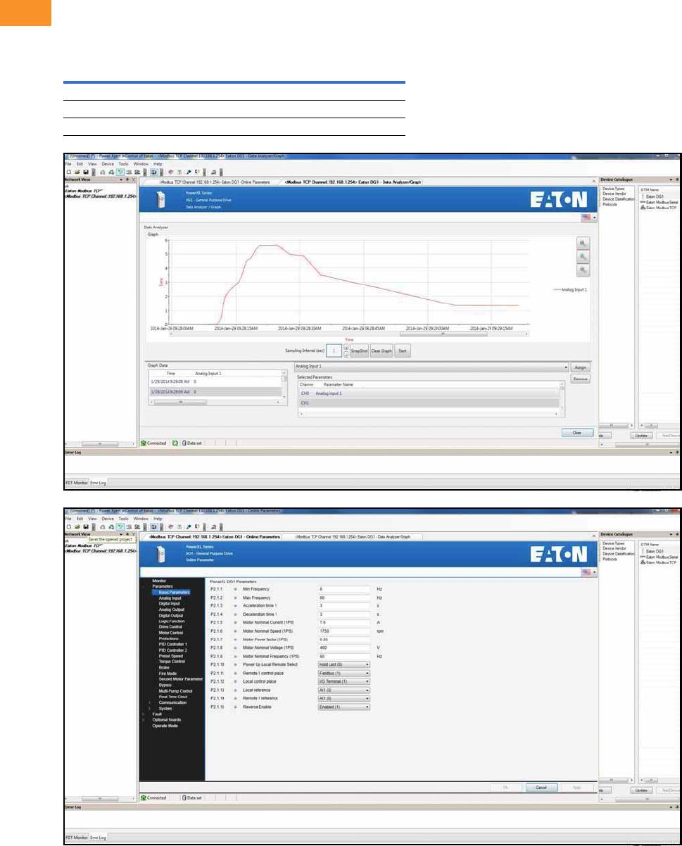
V6-T2-54 Volume 6—Solid-State Motor Control CA08100007E—February 2016 www.eaton.com
2
2
2
2
2
2
2
2
2
2
2
2
2
2
2
2
2
2
2
2
2
2
2
2
2
2
2
2
2
2
2.6
Adjustable Frequency Drives
PowerXL DG1 Series Drives
Power Xpert inControl Software
The PowerXL Series PC Tool is designed for programming, controlling and monitoring of
the DG1 drives. Features include loading parameters that can be saved to a file or printed,
setting references, starting and stopping the motor, monitoring signals in graphical or text
form, and real-time display.
PowerXpert inControl Software
Description Catalog Number
Software kit (software, cable, manual) DXG-ACC-SOFTWARE
Software cable (USB to keypad [RJ45]) DXG-CBL-PCCABLE
Real-time clock battery (approximately 10,000 hours life) DXG-ACC-RTBATT
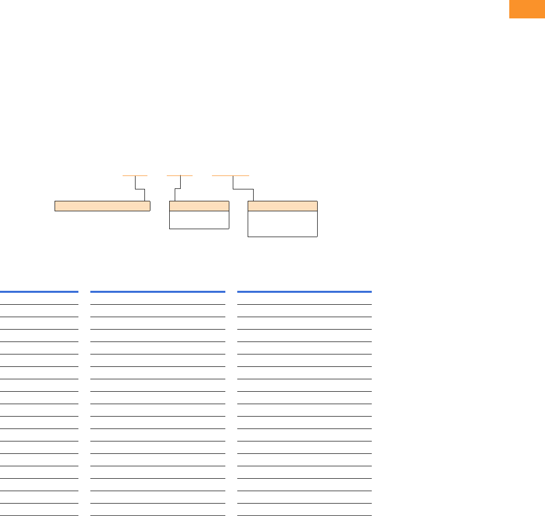
Volume 6—Solid-State Motor Control CA08100007E—February 2016 www.eaton.com V6-T2-55
2
2
2
2
2
2
2
2
2
2
2
2
2
2
2
2
2
2
2
2
2
2
2
2
2
2
2
2
2
2
2.6
Adjustable Frequency Drives
PowerXL DG1 Series Drives
Brake Chopper Options
The brake chopper circuit
option is used for applications
that require dynamic braking.
Dynamic braking resistors are
not included with drive
purchase. Consult the factory
for additional dynamic braking
resistor selections that are
supplied separately. A list of
common resistors are listed
below and are complete
indoor assemblies, include a
pre-wired terminal block and
a thermal switch, and are not
UL Listed.
Duty Cycle
The duty cycle rating is based
on a 60-second period. For
example, the 20% duty cycle
resistor can carry 100%
current for 12 seconds out
of every 60 seconds, while
the 50% duty cycle resistor
can carry 150% current for
30 seconds out of every
60 seconds.
Torque
If the braking torque required
is less than 15%, dynamic
braking is not required
because the regenerated
energy will be dissipated in
the drive and motor losses.
Dynamic Brake Resistor—Catalog Number Selection
230 V Brake Resistors
Drive hp
(CT/IH)
Minimum
Ohms
20% Duty Cycle, 100% Torque 50% Duty Cycle, 150% Torque
Catalog Number Dimensions Catalog Number Dimensions
0.75 15.0 DBR-R100-W0400 12W x 5D x 5H DBR-R100-W0800 12W x 7D x 5H
115.0 DBR-R100-W0400 12W x 5D x 5H DBR-R100-W0800 12W x 7D x 5H
1.5 15.0 DBR-R100-W0400 12W x 5D x 5H DBR-R036-W1200 12W x 10D x 5H
215.0 DBR-R100-W0400 12W x 5D x 5H DBR-R036-W1200 12W x 10D x 5H
315.0 DBR-R036-W0800 12W x 7D x 5H DBR-R036-W2000 12W x 16D x 5H
49.0 DBR-R036-W0800 12W x 7D x 5H DBR-R012-W2400 19W x 10D x 5H
59.0 DBR-R036-W0800 12W x 7D x 5H DBR-R020-W2800 19W x 13D x 5H
7.5 9.0 DBR-R020-W1200 12W x 10D x 5H DBR-R012-W4800 26.5W x 10D x 5H
10 7.0 DBR-R015-W1600 12W x 13D x 5H DBR-R112-W6000 26.5W x 13D x 5H
15 7.0 DBR-R012-W2400 19W x 10D x 5H DBR-R7D8-W9000 28W x 10D x 10H
20 2.0 DBR-R9D3-W3200 19W x 10D x 5H DBR-R3D4-W012K 28W x 10D x 10H
25 2.0 DBR-R5D5-W4000 26.5W x 10D x 5H DBR-R5D1-W015K 28W x 16D x 10H
30 2.0 DBR-R4D8-W4800 26.5W x 10D x 5H DBR-R4D1-W020K 28W x 16D x 10H
40 2.0 DBR-R004-W6000 26.5W x 13D x 5H DBR-R3D4-W025K 30W x 18D x 16H
50 2.0 DBR-R3D1-W7500 26.5W x 16D x 5H DBR-R2D1-W030K 30W x 18D x 24H
60 2.0 DBR-R2D8-W9000 26.5W x 16D x 5H DBR-R002-W036K 30W x 18D x 24H
75 2.0 DBR-R2D6-W012K 28W x 10D x 10H DBR-R002-W045K 30W x 18D x 32H
100 2.0 DBR-R002-W015K 28W x 16D x 10H DBR-R002-W060K 30W x 18D x 48H
DBR – R100 – W0800
Dynamic Brake Resistor Resistance
1D0 =1.0 Ohms
100 =100 Ohms
Rated Watts
0800 = 800 Watts
8000 = 8000 Watts
080K = 80,000 Watts

V6-T2-56 Volume 6—Solid-State Motor Control CA08100007E—February 2016 www.eaton.com
2
2
2
2
2
2
2
2
2
2
2
2
2
2
2
2
2
2
2
2
2
2
2
2
2
2
2
2
2
2
2.6
Adjustable Frequency Drives
PowerXL DG1 Series Drives
480 V Brake Resistors
Drive hp
(CT/IH)
Minimum
Ohms
20% Duty Cycle, 100% Torque 50% Duty Cycle, 150% Torque
Catalog Number Dimensions Catalog Number Dimensions
136.0 DBR-R100-W0400 12W x 5D x 5H DBR-R100-W0800 12W x 7D x 5H
1.5 36.0 DBR-R100-W0400 12W x 5D x 5H DBR-R100-W1200 12W x 10D x 5H
236.0 DBR-R100-W0400 12W x 5D x 5H DBR-R100-W1200 12W x 10D x 5H
336.0 DBR-R100-W0800 12W x 7D x 5H DBR-R100-W2000 12W x 16D x 5H
536.0 DBR-R100-W0800 12W x 7D x 5H DBR-R100-W2800 19W x 13D x 5H
636.0 DBR-R100-W1200 12W x 10D x 5H DBR-R070-W4000 19W x 16D x 5H
7.5 18.0 DBR-R100-W1200 12W x 10D x 5H DBR-R020-W4800 26.5W x 13D x 5H
10 18.0 DBR-R063-W1600 12W x 13D x 5H DBR-R030-W6000 26.5W x 16D x 5H
15 18.0 DBR-R030-W2400 19W x 10D x 5H DBR-R030-W9000 28W x 10D x 10H
20 13.0 DBR-R030-W3200 19W x 13D x 5H DBR-R023-W012K 28W x 13D x 10H
25 13.0 DBR-R030-W4000 19W x 16D x 5H DBR-R013-W015K 28W x 16D x 10H
30 13.0 DBR-R020-W4800 26.5W x 13D x 5H DBR-R014-W020K 30W x 18D x 24H
40 2.0 DBR-R112-W6000 26.5W x 13D x 5H DBR-R007-W025K 30W x 18D x 16H
50 2.0 DBR-R013-W7500 26.5W x 16D x 5H DBR-R8D5-W030K 30W x 18D x 24H
60 2.0 DBR-R010-W9000 28W x 10D x 10H DBR-R7D3-W036K 30W x 18D x 24H
75 2.0 DBR-R009-W012K 28W x 13D x 10H DBR-R002-W045K 30W x 18D x 32H
100 2.0 DBR-R5D1-W015K 28W x 16D x 10H DBR-R004-W060K 30W x 18D x 40H
125 2.0 DBR-R4D1-W020K 28W x 16D x 10H DBR-R004-W070K 30W x 18D x 48H
150 2.0 DBR-R3D4-W025K 30W x 18D x 16H DBR-R3D5-W085K 30W x 18D x 56H
200 2.0 DBR-R3D3-W030K 30W x 18D x 24H DBR-R2D6-W110K 30W x 18D x 64H

Volume 6—Solid-State Motor Control CA08100007E—February 2016 www.eaton.com V6-T2-57
2
2
2
2
2
2
2
2
2
2
2
2
2
2
2
2
2
2
2
2
2
2
2
2
2
2
2
2
2
2
2.6
Adjustable Frequency Drives
PowerXL DG1 Series Drives
575 V Brake Resistors
Note
1Consult factory.
Drive hp
(CT/IH)
Minimum
Ohms
20% Duty Cycle, 100% Torque 50% Duty Cycle, 150% Torque
Catalog Number Dimensions (Inches) Catalog Number Dimensions (Inches)
2100.0DBR-R100-W0400 12W x 5D x 5H DBR-R100-W1200 12W x 10D x 5H
3100.0DBR-R100-W0800 12W x 7D x 5H DBR-R100-W2000 12W x 16D x 5H
4100.0DBR-R100-W0800 12W x 7D x 5H DBR-R100-W2400 19W x 10D x 5H
5100.0DBR-R100-W0800 12W x 7D x 5H DBR-R100-W2800 19W x 13D x 5H
7.5 100.0 DBR-R100-W1200 12W x 10D x 5H DBR-R100-W4800 26.5W x 13D x 5H
10 30.0 DBR-R063-W1600 12W x 13D x 5H DBR-R063-W6000 26.5W x 16D x 5H
15 30.0 DBR-R042-W2400 19W x 10D x 5H DBR-R042-W9000 28W x 10D x 10H
20 30.0 DBR-R030-W3200 19W x 13D x 5H DBR-R030-W012K 28W x 13D x 10H
25 30.0 DBR-R030-W4000 19W x 16D x 5H DBR-R030-W015K 28W x 16D x 10H
30 18.0 DBR-R020-W4800 26.5W x 13D x 5H DBR-R020-W020K 30W x 18D x 16H
40 18.0 DBR-R030-W6000 26.5W x 16D x 5H DBR-R184-W025K 30W x 18D x 16H
50 9.0 DBR-R013-W7500 26.5W x 16D x 5H DBR-R012-W030K 30W x 18D x 24H
60 9.0 DBR-R010-W9000 28W x 10D x 10H DBR-R010-W036K 30W x 18D x 24H
75 9.0 DBR-R009-W012K 28W x 13D x 10H DBR-R009-W045K 30W x 18D x 24H
100 7.0 DBR-R013-W015K 28W x 16D x 10H DBR-R8D4-W060K 30W x 18D x 40H
125 7.0 DBR-R8D2-W020K 30W x 18D x 10H DBR-R007-W070K 30W x 18D x 40H
150 7.0 DBR-R007-W025K 30W x 18D x 16H DBR-R006-W085K 30W x 18D x 56H
200 2.5 DBR-R3D3-W030K 30W x 18D x 24H DBR-R2D6-W110K 30W x 18D x 64H
250 2.5 DBR-R2D5-W036K 30W x 18D x 24H DBR-R003-W140K 30W x 18D x 72H
300 2.5 DBR-R3D3-W045K 30W x 18D x 32H 1—
400 1.7 DBR-R002-W060K 30W x 18D x 48H 1—
450 1.7 DBR-R1D8-W070K 30W x 18D x 48H 1—
500 1.7 DBR-R002-W080K 30W x 18D x 56H 1—
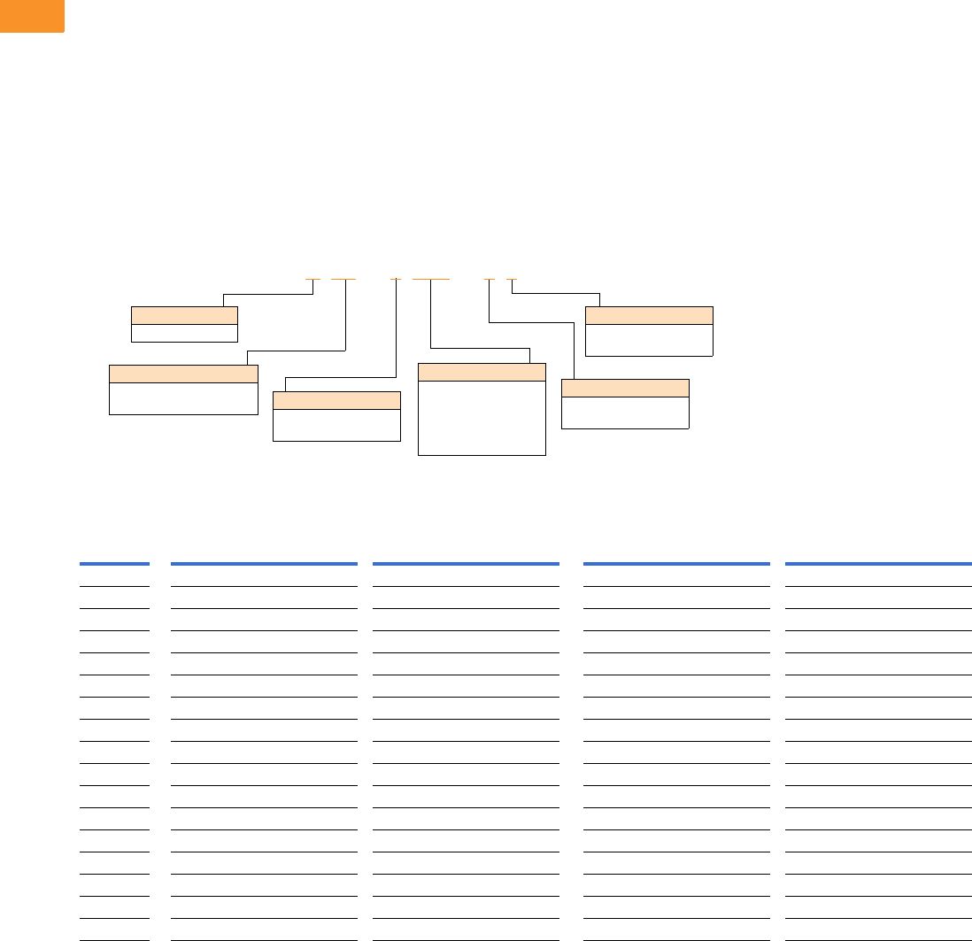
V6-T2-58 Volume 6—Solid-State Motor Control CA08100007E—February 2016 www.eaton.com
2
2
2
2
2
2
2
2
2
2
2
2
2
2
2
2
2
2
2
2
2
2
2
2
2
2
2
2
2
2
2.6
Adjustable Frequency Drives
PowerXL DG1 Series Drives
Line and Load Reactors
A line and load reactor is a
three-phase inductance filter
that can be placed on the line
and load side of the AFD to
help improve the harmonic
performance of the system.
Consult the factory for
additional filtering options and
further technical details.
DR1 Line Reactor
A line reactor helps to provide
a moderate reduction in
current harmonics similar to a
DC choke. It also provides
increased input protection for
AFD and its semiconductors
from line transients helping to
extend the life of the AFD.
DR2 Output Reactor
An output filter is used to
reduce the transient voltage
(dV/dt) at the motor terminals.
The output filter is
recommended for cable
lengths exceeding 100 ft
(30 m) with a drive of 3 hp
and above and for cable
lengths of 33 ft (10 m) with a
drive of 2 hp and below.
Line and Load Reactors—Catalog Number Selection
Line and Load Reactors—230 V
hp (CT)
Open NEMA 1
Line Reactor Load Reactor Line Reactor Load Reactor
3% 5% 3% 5% 3% 5% 3% 5%
0.75 DR1-23D2-03 DR1-23D2-05 DR2-24D0-03 DR2-24D0-05 DR1-23D2-13 DR1-23D2-15 DR2-24D0-13 DR2-24D0-15
1 DR1-24D2-03 DR1-24D2-05 DR2-24D0-03 DR2-28D0-05 DR1-24D2-13 DR1-24D2-15 DR2-24D0-13 DR2-28D0-15
1.5 DR1-26D0-03 DR1-26D0-05 DR2-28D0-03 DR2-28D0-05 DR1-26D0-13 DR1-26D0-15 DR2-28D0-13 DR2-28D0-15
2 DR1-26D8-03 DR1-26D8-05 DR2-28D0-03 DR2-28D0-05 DR1-26D8-13 DR1-26D8-15 DR2-28D0-13 DR2-28D0-15
3 DR1-29D6-03 DR1-29D6-05 DR2-2012-03 DR2-2012-05 DR1-29D6-13 DR1-29D6-15 DR2-2012-13 DR2-2012-15
5 DR1-2015-03 DR1-2015-05 DR2-2018-03 DR2-2018-05 DR1-2015-13 DR1-2015-15 DR2-2018-13 DR2-2018-15
7.5 DR1-2022-03 DR1-2022-05 DR2-2025-03 DR2-2025-05 DR1-2022-13 DR1-2022-15 DR2-2025-13 DR2-2025-15
10 DR1-2028-03 DR1-2028-05 DR2-2035-03 DR2-2035-05 DR1-2028-13 DR1-2028-15 DR2-2035-13 DR2-2035-15
15 DR1-2042-03 DR1-2042-05 DR2-2045-03 DR2-2045-05 DR1-2042-13 DR1-2042-15 DR2-2045-13 DR2-2045-15
20 DR1-2054-03 DR1-2054-05 DR2-2055-03 DR2-2055-05 DR1-2054-13 DR1-2054-15 DR2-2055-13 DR2-2055-15
25 DR1-2068-03 DR1-2068-05 DR2-2080-03 DR2-2080-05 DR1-2068-13 DR1-2068-15 DR2-2080-13 DR2-2080-15
30 DR1-2080-03 DR1-2080-05 DR2-2080-03 DR2-2100-05 DR1-2080-13 DR1-2080-15 DR2-2080-13 DR2-2100-15
40 DR1-2104-03 DR1-2104-05 DR2-2100-03 DR2-2100-05 DR1-2104-13 DR1-2104-15 DR2-2100-13 DR2-2100-15
50 DR1-2130-03 DR1-2130-05 DR2-2130-03 DR2-2130-05 DR1-2130-13 DR1-2130-15 DR2-2130-13 DR2-2130-15
60 DR1-2154-03 DR1-2154-05 DR2-2160-03 DR2-2200-15 DR1-2154-13 DR1-2154-15 DR2-2160-13 DR2-2200-15
75 DR1-2192-03 DR1-2192-05 DR2-2200-13 DR2-2200-15 DR1-2192-13 DR1-2192-15 DR2-2200-13 DR2-2200-15
100 DR1-2248-03 DR1-2248-05 DR2-2225-13 DR2-2225-15 DR1-2248-13 DR1-2248-15 DR2-2225-13 DR2-2225-15
DR1 –22D0 –05
Device Series
R1 = Line side reactor
R2 = Load side reactor
Basic Naming
D= Drive
Input/Output Voltage
2= 230 V
4= 460 V
Environment Rating
0= Open
1= NEMA 1
Impedance
3= 3%
5= 5%
Current Rating
Examples:
2D0 = 2.0 A
4D0 = 4.0 A
8D0 = 8.0 A
012
= 12 A

Volume 6—Solid-State Motor Control CA08100007E—February 2016 www.eaton.com V6-T2-59
2
2
2
2
2
2
2
2
2
2
2
2
2
2
2
2
2
2
2
2
2
2
2
2
2
2
2
2
2
2
2.6
Adjustable Frequency Drives
PowerXL DG1 Series Drives
Line and Load Reactors—480 V
hp (CT)
Open NEMA 1
Line Reactor Load Reactor Line Reactor Load Reactor
3% 5% 3% 5% 3% 5% 3% 5%
1 DR1-42D1-03 DR1-42D1-05 DR2-42D0-05 DR2-42D0-05 DR1-42D1-13 DR1-42D1-15 DR2-42D0-13 DR2-42D0-15
1.5 DR1-43D0-03 DR1-43D0-05 DR2-44D0-05 DR2-44D0-05 DR1-43D0-13 DR1-43D0-15 DR2-44D0-13 DR2-44D0-15
2 DR1-43D4-03 DR1-43D4-05 DR2-44D0-03 DR2-44D0-05 DR1-43D4-13 DR1-43D4-15 DR2-44D0-13 DR2-44D0-15
3 DR1-44D8-03 DR1-44D8-05 DR2-48D0-03 DR2-48D0-05 DR1-44D8-13 DR1-44D8-15 DR2-48D0-13 DR2-48D0-15
5 DR1-47D6-03 DR1-47D6-05 DR2-48D0-03 DR2-48D0-05 DR1-47D6-13 DR1-47D6-15 DR2-48D0-13 DR2-48D0-15
7.5 DR1-4011-03 DR1-4011-05 DR2-4012-03 DR2-4012-05 DR1-4011-13 DR1-4011-15 DR2-4012-13 DR2-4012-15
10 DR1-4014-03 DR1-4014-05 DR2-4018-03 DR2-4018-05 DR1-4014-13 DR1-4014-15 DR2-4018-13 DR2-4018-15
15 DR1-4021-03 DR1-4021-05 DR2-4025-03 DR2-4025-05 DR1-4021-13 DR1-4021-15 DR2-4025-13 DR2-4025-15
20 DR1-4027-03 DR1-4027-05 DR2-4025-03 DR2-4025-05 DR1-4027-13 DR1-4027-15 DR2-4025-13 DR2-4025-15
25 DR1-4034-03 DR1-4034-05 DR2-4035-03 DR2-4035-05 DR1-4034-13 DR1-4034-15 DR2-4035-13 DR2-4035-15
30 DR1-4040-03 DR1-4040-05 DR2-4045-03 DR2-4045-05 DR1-4040-13 DR1-4040-15 DR2-4045-13 DR2-4045-15
40 DR1-4052-03 DR1-4052-05 DR2-4055-03 DR2-4055-05 DR1-4052-13 DR1-4052-15 DR2-4055-13 DR2-4055-15
50 DR1-4065-03 DR1-4065-05 DR2-4080-03 DR2-4080-05 DR1-4065-13 DR1-4065-15 DR2-4080-13 DR2-4080-15
60 DR1-4077-03 DR1-4077-05 DR2-4100-03 DR2-4080-05 DR1-4077-13 DR1-4077-15 DR2-4100-13 DR2-4080-15
75 DR1-4096-03 DR1-4096-05 DR2-4100-03 DR2-4100-05 DR1-4096-13 DR1-4096-15 DR2-4100-13 DR2-4100-15
100 DR1-4124-03 DR1-4124-05 DR2-4130-03 DR2-4130-05 DR1-4124-13 DR1-4124-15 DR2-4130-13 DR2-4130-15
125 DR1-4156-03 DR1-4156-05 DR2-4160-03 DR2-4160-05 DR1-4156-13 DR1-4156-15 DR2-4160-13 DR2-4160-15
150 DR1-4180-03 DR1-4180-05 DR2-4200-13 DR2-4200-15 DR1-4180-13 DR1-4180-15 DR2-4200-13 DR2-4200-15
200 DR1-4240-03 DR1-4240-05 DR2-4250-13 DR2-4250-15 DR1-4240-13 DR1-4240-15 DR2-4250-13 DR2-4250-15

V6-T2-60 Volume 6—Solid-State Motor Control CA08100007E—February 2016 www.eaton.com
2
2
2
2
2
2
2
2
2
2
2
2
2
2
2
2
2
2
2
2
2
2
2
2
2
2
2
2
2
2
2.6
Adjustable Frequency Drives
PowerXL DG1 Series Drives
Replacement Parts
Frame 1
Frame 2
Note
1Factory recommended spare parts.
230 V 480 V 575 V
Description Catalog Number Catalog Number Catalog Number
Standard keypad DXG-KEY-LCD DXG-KEY-LCD DXG-KEY-LCD
Main control board DXG-SPR-CTRLBOARD DXG-SPR-CTRLBOARD DXG-SPR-CTRLBOARD
Control module kit with keypad 1DXG-SPR-CTRLKIT DXG-SPR-CTRLKIT DXG-SPR-CTRLKIT
Control board cover DXG-SPR-BCOVER DXG-SPR-BCOVER DXG-SPR-BCOVER
Type 1/IP21 standard cover DXG-SPR-FR1CVR DXG-SPR-FR1CVR DXG-SPR-FR1CVR
Main fan kit 1DXG-SPR-FR1FAN DXG-SPR-FR1FAN DXG-SPR-FR1FAN
Control fan DXG-SPR-2FR1CF DXG-SPR-4FR1CF DXG-SPR-4FR1CF
Main power board DXG-SPR-2FR1MPB DXG-SPR-4FR1MPB DXG-SPR-4FR1MPB
EMI board DXG-SPR-2FR1EB DXG-SPR-4FR1EB DXG-SPR-4FR1EB
Middle chassis cover DXG-SPR-FR1MCC DXG-SPR-FR1MCC DXG-SPR-FR1MCC
Outer housing DXG-SPR-FR1OH DXG-SPR-FR1OH DXG-SPR-FR1OH
UL conduit plate DXG-SPR-FR1CPUL DXG-SPR-FR1CPUL DXG-SPR-FR1CPUL
IEC conduit plate DXG-SPR-FR1CPIEC DXG-SPR-FR1CPIEC DXG-SPR-FR1CPIEC
230 V 480 V 575 V
Description Catalog Number Catalog Number Catalog Number
Standard keypad DXG-KEY-LCD DXG-KEY-LCD DXG-KEY-LCD
Main control board DXG-SPR-CTRLBOARD DXG-SPR-CTRLBOARD DXG-SPR-CTRLBOARD
Control module kit with keypad 1DXG-SPR-CTRLKIT DXG-SPR-CTRLKIT DXG-SPR-CTRLKIT
Control board cover DXG-SPR-BCOVER DXG-SPR-BCOVER DXG-SPR-BCOVER
Type 1/IP21 standard cover DXG-SPR-FR2CVR DXG-SPR-FR2CVR DXG-SPR-FR2CVR
Main fan kit 1DXG-SPR-FR2FAN DXG-SPR-FR2FAN DXG-SPR-FR2FAN
Control fan DXG-SPR-FR2CF DXG-SPR-FR2CF DXG-SPR-FR2CF
Bus capacitor DXG-SPR-2FR2BC DXG-SPR-4FR24BC DXG-SPR-4FR24BC
Main power board DXG-SPR-2FR2MPB DXG-SPR-4FR2MPB DXG-SPR-4FR2MPB
EMI board DXG-SPR-2FR2EB DXG-SPR-4FR2EB DXG-SPR-4FR2EB
IGBT module DXG-SPR-FR2IGBT DXG-SPR-FR2IGBT DXG-SPR-FR2IGBT
Middle chassis cover DXG-SPR-FR2MCC DXG-SPR-FR2MCC DXG-SPR-FR2MCC
Outer housing DXG-SPR-FR2OH DXG-SPR-FR2OH DXG-SPR-FR2OH
UL conduit plate DXG-SPR-FR2CPUL DXG-SPR-FR2CPUL DXG-SPR-FR2CPUL
IEC conduit plate DXG-SPR-FR2CPIEC DXG-SPR-FR2CPIEC DXG-SPR-FR2CPIEC
Volume 6—Solid-State Motor Control CA08100007E—February 2016 www.eaton.com V6-T2-61
2
2
2
2
2
2
2
2
2
2
2
2
2
2
2
2
2
2
2
2
2
2
2
2
2
2
2
2
2
2
2.6
Adjustable Frequency Drives
PowerXL DG1 Series Drives
Frame 3
Frame 4
Note
1Factory recommended spare parts.
230 V 480 V 575 V
Description Catalog Number Catalog Number Catalog Number
Standard keypad DXG-KEY-LCD DXG-KEY-LCD DXG-KEY-LCD
Main control board DXG-SPR-CTRLBOARD DXG-SPR-CTRLBOARD DXG-SPR-CTRLBOARD
Control module kit with keypad 1DXG-SPR-CTRLKIT DXG-SPR-CTRLKIT DXG-SPR-CTRLKIT
Control board cover DXG-SPR-BCOVER DXG-SPR-BCOVER DXG-SPR-BCOVER
Type 1/IP21 standard cover DXG-SPR-FR3CVR DXG-SPR-FR3CVR DXG-SPR-FR3CVR
Main fan kit 1DXG-SPR-FR3FANKIT DXG-SPR-FR3FANKIT DXG-SPR-FR3FANKIT
Main fan DXG-SPR-FR3FAN DXG-SPR-FR3FAN DXG-SPR-FR3FAN
Control fan DXG-SPR-FR34CF DXG-SPR-FR34CF DXG-SPR-FR34CF
Bus capacitor DXG-SPR-FR3BC DXG-SPR-FR3BC DXG-SPR-FR3BC
Main power board DXG-SPR-2FR3MPB DXG-SPR-4FR3MPB DXG-SPR-4FR3MPB
EMI board DXG-SPR-2FR3EB DXG-SPR-4FR3EB DXG-SPR-4FR3EB
Drive board DXG-SPR-2FR3DB DXG-SPR-4FR3DB DXG-SPR-4FR3DB
Output board DXG-SPR-FR3OB DXG-SPR-FR3OB DXG-SPR-FR3OB
Middle chassis cover DXG-SPR-FR3MCC DXG-SPR-FR3MCC DXG-SPR-FR3MCC
Outer housing DXG-SPR-FR3OH DXG-SPR-FR3OH DXG-SPR-FR3OH
UL conduit plate DXG-SPR-FR3CPUL DXG-SPR-FR3CPUL DXG-SPR-FR3CPUL
IEC conduit plate DXG-SPR-FR3CPIEC DXG-SPR-FR3CPIEC DXG-SPR-FR3CPIEC
230 V 480 V 575 V
Description Catalog Number Catalog Number Catalog Number
Standard keypad DXG-KEY-LCD DXG-KEY-LCD DXG-KEY-LCD
Main control board DXG-SPR-CTRLBOARD DXG-SPR-CTRLBOARD DXG-SPR-CTRLBOARD
Control module kit with keypad 1DXG-SPR-CTRLKIT DXG-SPR-CTRLKIT DXG-SPR-CTRLKIT
Control board cover DXG-SPR-BCOVER DXG-SPR-BCOVER DXG-SPR-BCOVER
Type 1/IP21 standard cover DXG-SPR-FR4CVR DXG-SPR-FR4CVR DXG-SPR-FR4CVR
Main fan kit 1DXG-SPR-FR4FANKIT DXG-SPR-FR4FANKIT DXG-SPR-FR4FANKIT
Main fan DXG-SPR-FR4FAN DXG-SPR-FR4FAN DXG-SPR-FR4FAN
Control fan DXG-SPR-FR34CF DXG-SPR-FR34CF DXG-SPR-FR34CF
Bus capacitor DXG-SPR-2FR4BC DXG-SPR-4FR24BC DXG-SPR-4FR24BC
Main power board DXG-SPR-2FR4MPB DXG-SPR-4FR4MPB DXG-SPR-4FR4MPB
EMI board DXG-SPR-2FR4EB DXG-SPR-4FR4EB DXG-SPR-4FR4EB
Softstart board DXG-SPR-2FR4SB DXG-SPR-4FR4SB DXG-SPR-4FR4SB
IGBT module DXG-SPR-2FR4IGBT DXG-SPR-4FR4IGBT DXG-SPR-4FR4IGBT
Rectifier module DXG-SPR-2FR4RM DXG-SPR-4FR4RM DXG-SPR-4FR4RM
Brake chopper module DXG-SPR-2FR4BCM DXG-SPR-4FR4BCM DXG-SPR-4FR4BCM
Middle chassis cover DXG-SPR-FR4MCC DXG-SPR-FR4MCC DXG-SPR-FR4MCC
Outer housing DXG-SPR-FR4OH DXG-SPR-FR4OH DXG-SPR-FR4OH
UL conduit plate DXG-SPR-FR4CPUL DXG-SPR-FR4CPUL DXG-SPR-FR4CPUL
IEC conduit plate DXG-SPR-FR4CPIEC DXG-SPR-FR4CPIEC DXG-SPR-FR4CPIEC

V6-T2-62 Volume 6—Solid-State Motor Control CA08100007E—February 2016 www.eaton.com
2
2
2
2
2
2
2
2
2
2
2
2
2
2
2
2
2
2
2
2
2
2
2
2
2
2
2
2
2
2
2.6
Adjustable Frequency Drives
PowerXL DG1 Series Drives
Frame 5
Note
1Factory recommended spare parts.
230 V 480 V 575 V
Description Catalog Number Catalog Number Catalog Number
Standard keypad DXG-KEY-LCD DXG-KEY-LCD DXG-KEY-LCD
Main control board DXG-SPR-CTRLBOARD DXG-SPR-CTRLBOARD DXG-SPR-CTRLBOARD
Control module kit with keypad 1DXG-SPR-CTRLKIT DXG-SPR-CTRLKIT DXG-SPR-CTRLKIT
Control board cover DXG-SPR-BCOVER DXG-SPR-BCOVER DXG-SPR-BCOVER
Type 1/IP21 standard cover DXG-SPR-FR5CVR DXG-SPR-FR5CVR DXG-SPR-FR5CVR
Main fan kit 1DXG-SPR-FR5FANKIT DXG-SPR-FR5FANKIT DXG-SPR-FR5FANKIT
Main fan DXG-SPR-FR5FAN DXG-SPR-FR5FAN DXG-SPR-FR5FAN
Control fan DXG-SPR-FR5CF DXG-SPR-FR5CF DXG-SPR-FR5CF
Bus capacitor DXG-SPR-FR5BC DXG-SPR-FR5BC DXG-SPR-FR5BC
Main power board DXG-SPR-2FR5MPB DXG-SPR-4FR5MPB DXG-SPR-4FR5MPB
EMI-1 board DXG-SPR-2FR5E1B DXG-SPR-4FR5E1B DXG-SPR-4FR5E1B
EMI-2 board DXG-SPR-2FR5E2B DXG-SPR-4FR5E2B DXG-SPR-4FR5E2B
EMI-3 board DXG-SPR-FR5E3B DXG-SPR-FR5E3B DXG-SPR-FR5E3B
IGBT module DXG-SPR-FR5IGBT DXG-SPR-FR5IGBT DXG-SPR-FR5IGBT
Rectifier module DXG-SPR-2FR5RM DXG-SPR-4FR5RM DXG-SPR-4FR5RM
Brake chopper module DXG-SPR-2FR5BCM DXG-SPR-4FR5BCM DXG-SPR-4FR5BCM
Middle chassis cover DXG-SPR-FR5MCC DXG-SPR-FR5MCC DXG-SPR-FR5MCC
Outer housing DXG-SPR-FR5OH DXG-SPR-FR5OH DXG-SPR-FR5OH
UL conduit plate DXG-SPR-FR5CPUL DXG-SPR-FR5CPUL DXG-SPR-FR5CPUL
IEC conduit plate DXG-SPR-FR5IECCP DXG-SPR-FR5IECCP DXG-SPR-FR5IECCP
DC terminal kit DXG-SPR-FR5DCKIT DXG-SPR-FR5DCKIT DXG-SPR-FR5DCKIT

Volume 6—Solid-State Motor Control CA08100007E—February 2016 www.eaton.com V6-T2-63
2
2
2
2
2
2
2
2
2
2
2
2
2
2
2
2
2
2
2
2
2
2
2
2
2
2
2
2
2
2
2.6
Adjustable Frequency Drives
PowerXL DG1 Series Drives
Technical Data and Specifications
PowerXL Series—DG1 Technical Data and Specifications
Attribute Description Specification
Input ratings Input voltage Uin 208 V to 240 V, 380 V to 500 V, 525 V to 600 V, –15 to 10%
Input frequency 50 Hz to 60 Hz (variation up to 45 Hz to 66 Hz)
Connection to power Once per minute or less
Starting delay 3 s (FR1 to FR2), 4 s (FR3), 5 s (FR4), 6 s (FR5 and FR6)
Short-circuit withstand rating 100 kAIC (fuses and circuit breakers); 5 kAIC (without fuses or breakers)
Output ratings Output voltage 0 to Uin
Continuous output current IL: ambient temperature maximum 40 °C, up to 60 °C with derating, overload 1.1 x IL (1 min./10 min.)
IH: ambient temperature maximum 50 °C, up to 60 °C with derating, overload 1.5 x IH (1 min./10 min.)
Overload current 150% of drive rating for constant torque, 110% for variable torque
Initial output current 200% (2 s / 20 s)
Output frequency 0–400 Hz (standard)
Frequency resolution 0.01 Hz
Control characteristics Control methods Frequency control
Speed control
Open-loop speed control
Open-loop torque control
Switching frequency 230 V / 480 V range:
FR1–3: 1 kHz to 12 kHz
FR4–6: 1 kHz to 10 kHz
230 V / 480 V defaults:
FR1–3: 4 kHz
FR4–5: 3.6 kHz
FR6: 2 kHz
575 V range:
FR1–6: 1 kHz to 6 kHz
575 V defaults:
FR1–4: 3 kHz
FR5–6: 2 kHz
Automatic switching frequency derating in case of overload.
Frequency reference Analog input: resolution 0.1% (10-bit), accuracy +1%
Analog output: resolution 0.1% (10-bit), accuracy +1%
Panel reference: resolution 0.01 Hz
Field weakening point 20 Hz to 400 Hz
Acceleration time 0.1 s to 3000 s
Deceleration time 0.1 s to 3000 s
Braking torque DC brake: 30% x Motor Rated Torque (Tn) (without brake chopper)
Dynamic braking (with optional brake chopper using an external brake resistor):
100% continuous maximum rating
Ambient conditions Ambient operating temperature –10 °C (no frost) to +50 °C, up to +60 °C with derating (CT)
–10 °C (no frost) to +40 °C, up to +60 °C with derating (VT)
Storage temperature –40 °C to +70 °C
Relative humidity 0–95% RH, noncondensing, non-corrosive
Air quality:
●Chemical vapors
●Mechanical particles
Tested according to IEC 60068-2-60 Test Key:
Flowing mixed gas corrosion test, Method 1 (H2S [hydrogen sulfide] and SO2 [sulfur dioxide])
Designed according to:
IEC 60721-3-3, unit in operation, class 3C2
IEC 60721-3-3, unit in operation, class 3S2
Altitude 100% load capacity (no derating) up to 3280 ft (1000 m); 1% derating for each 328 ft (100 m) above
3280 ft (1000 m); max. 9842 ft (3000 m) (2000 m for corner grounded earth main systems)
For 575 V product, maximum altitude is 6561 ft (2000 m) regardless of main system

V6-T2-64 Volume 6—Solid-State Motor Control CA08100007E—February 2016 www.eaton.com
2
2
2
2
2
2
2
2
2
2
2
2
2
2
2
2
2
2
2
2
2
2
2
2
2
2
2
2
2
2
2.6
Adjustable Frequency Drives
PowerXL DG1 Series Drives
PowerXL Series—DG1 Technical Data and Specifications, continued
Attribute Description Specification
Ambient conditions,
continued
Vibration:
●EN 61800-5-1
●EN 60668-2-6
5–150 Hz
Displacement amplitude: 1 mm (peak) at 5 Hz to 15.8 Hz (FR1–FR6)
Maximum acceleration amplitude: 1g at 15.8 Hz to 150 Hz (FR1–FR6)
Shock:
●ISTA 1 A
●EN 60068-2-27
Storage and shipping: maximum 15 g, 11 ms (in package)
Overvoltage Overvoltage Category III
Pollution degree Pollution Degree 2
Enclosure class IP21/Type 1 standard in entire kW/hp range
IP54/Type 12 option
Note: Keypad or keypad hole plug required to be mounted in drive for IP54/Type 12 rating
Immunity Fulfills EN 61800-3 (2004), first and second environment
MTBF FR1: 165,457 hours
FR2: 134,833 hours
FR3: 102,515 hours
FR4: 121,567 hours
FR5: 108,189 hours
FR6: Available in 2016
Noise FR1: 51.2 dB
FR2: 58.6 dB
FR3: 61.0 dB
FR4: 68.0 dB
FR5: 69.1 dB
FR6: Available in 2016
Standards Safety UL 508C, CSA C22.2 No. 274-13 and EN 61800-5-1
EMC +EMC2: EN 61800-3 (2004), Category C2
The drive can be modified for IT networks and corner grounding TN system
Electrostatic discharge Second environment, IEC 61000-4-2, 4 kV CD or 8 kV AD, Criterion B
Fast transient burst Second environment, IEC 61000-4-4, 2 kV/5 kHz, Criterion B
Dielectrical strength Primary to secondary: 3600 Vac/5100 Vdc
Primary to earth: 2000 Vac/2828 Vdc
Approvals EAC, RCM (C-Tick), RoHS, CE, UL and cUL (see nameplate for more detailed approvals)
Fieldbus connections Onboard: EtherNet/IP, Modbus® TCP, Modbus RTU, BACnet

Volume 6—Solid-State Motor Control CA08100007E—February 2016 www.eaton.com V6-T2-65
2
2
2
2
2
2
2
2
2
2
2
2
2
2
2
2
2
2
2
2
2
2
2
2
2
2
2
2
2
2
2.6
Adjustable Frequency Drives
PowerXL DG1 Series Drives
PowerXL Series—DG1 Technical Data and Specifications, continued
PowerXL Series—DG1 Technical Data and Specifications—Efficiency
230 V
Attribute Description Specification
Safety/protections Overvoltage protection Yes
Overvoltage trip limit 230 V drives: 456 V
480 V drives: 911 V
575 V drives: 1100 V
Undervoltage protection Yes
Undervoltage trip limit 230 V drives: 211 V
480 V drives: 370 V
575 V drives: 550 V
Earth fault protection Yes
Default: 15% motor FLA
Minimum: 0% motor FLA
Maximum: 30% motor FLA
Input phase supervision Yes
Motor phase supervision Yes
Overcurrent protection Yes
Unit overtemperature protection Yes
Motor overload protection Yes
Motor stall protection Yes
Motor underload protection Yes
DC bus overvoltage control Yes
Short-circuit protection of 24 V
reference voltages
Yes
Surge protection Yes (differential mode 2 kV; common mode 4 kV
230 V drives: 275 Vac, 10,000 A
480 V drives: 320 Vac, 8000 A
575 V drives: 385 Vac, 10,000 A
Common coated boards Yes (prevents corrosion)
Efficiency
Frame Size Load Torque VT CT Input THDi
FR1 25% 92.10% 90.90% 42.8%
50% 95.20% 95.20% 35.2%
100% 96.70% 96.20% 29.9%
FR2 25% 90.80% 94.20% 70.0%
50% 96.64% 97.09% 46.6%
100% 97.30% 97.30% 33.3%
FR3 25% 97.23% 97.06% 53.1%
50% 97.37% 97.17% 43.6%
100% 97.00% 97.20% 30.8%
FR4 25% 94.60% 94.30% 39.4%
50% 97.20% 97.10% 32.4%
100% 97.60% 97.60% 25.6%
FR5 25% 94.5 94.30% 30.50%
50% 97.80% 97.60% 30.8%
100% 97.70% 97.80% 25.0%

V6-T2-66 Volume 6—Solid-State Motor Control CA08100007E—February 2016 www.eaton.com
2
2
2
2
2
2
2
2
2
2
2
2
2
2
2
2
2
2
2
2
2
2
2
2
2
2
2
2
2
2
2.6
Adjustable Frequency Drives
PowerXL DG1 Series Drives
480 V
575 V
Efficiency
Frame Size Load Torque VT CT Input THDi
FR1 25% 93.30% 90.70% 54.0%
50% 97.10% 96.98% 46.8%
100% 97.61% 97.67% 35.3%
FR2 25% 95.90% 94.20% 59.8%
50% 97.81% 98.34% 42.7%
100% 98.11% 98.20% 33.8%
FR3 25% 96.40% 95.20% 69.2%
50% 97.87% 97.99% 45.2%
100% 97.79% 98.15% 32.6%
FR4 25% 98.00% 97.80% 56.5%
50% 97.97% 97.89% 39.8%
100% 97.96% 98.17% 31.5%
FR5 25% 97.8 97.60% 50.3%
50% 98.39% 98.10% 37.0%
100% 98.14% 98.19% 29.5%
Efficiency
Frame Size Load Torque VT CT Input THDi
FR1 25% 97.48% 97.25% 62.6%
50% 97.79% 97.66% 45.6%
100% 98.10% 97.60% 36.8%
FR2 25% 98.06% 97.98% 60.6%
50% 98.19% 98.11% 47.2%
100% 98.20% 98.10% 36.7%
FR3 25% 97.98% 97.77% 78.9%
50% 98.32% 98.18% 55.5%
100% 98.10% 98.10% 36.3%
FR4 25% 98.27% 97.96% 66.1%
50% 98.57% 98.44% 41.6%
100% 98.30% 98.30% 31.2%
FR5 25% 98.60% 98.50% 52.80%
50% 98.81% 98.78% 35.9%
100% 98.60% 98.70% 28.4%
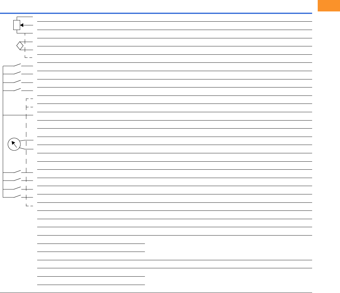
Volume 6—Solid-State Motor Control CA08100007E—February 2016 www.eaton.com V6-T2-67
2
2
2
2
2
2
2
2
2
2
2
2
2
2
2
2
2
2
2
2
2
2
2
2
2
2
2
2
2
2
2.6
Adjustable Frequency Drives
PowerXL DG1 Series Drives
Wiring Diagram
PowerXL Series—DG1 Control Wiring Diagram
Notes
The above wiring demonstrates a SINK configuration. It is important that CMA and CMB are wired to ground (as shown by dashed line).
If a SOURCE configuration is desired, wire 24 V to CMA and CMB and close the inputs to ground.
When using the +10 V for AI1, it is important to wire AI1– to ground (as shown by dashed line).
If using +10 V for AI1 or AI2, terminals 3, 5 and 6 need to be jumpered together.
External Wiring Pin Signal Name Signal Default Setting Description
1 +10 V Ref. Output Voltage — 10 Vdc Supply Source
2 AI1+ Analog Input 1 0–10 V Voltage Speed Reference (Programmable to 4 mA to 20 mA)
3 AI1– Analog Input 1 Ground — Analog Input 1 Common (Ground)
4 AI2+ Analog Input 2 4 mA to 20 mA Current Speed Reference (Programmable to 0–10 V)
5 AI2– Analog Input 2 Ground — Analog Input 2 Common (Ground)
6 GND I/O Signal Ground — I/O Ground for Reference and Control
7 DIN5 Digital Input 5 Preset Speed B0 Sets frequency output to Preset Speed 1
8 DIN6 Digital Input 6 Preset Speed B1 Sets frequency output to Preset Speed 2
9 DIN7 Digital Input 7 — —
10 DIN8 Digital Input 8 Force Remote (TI+) Input takes VFD from Local to Remote
11 CMB DI5 to DI8 Common Grounded Allows source input
12 GND I/O Signal Ground — I/O Ground for Reference and Control
13 24 V +24 Vdc Output — Control voltage output (100 mA max.)
14 DO1 Digital Output 1 Ready Shows the drive is ready to run
15 24 Vo +24 Vdc Output — Control voltage output (100 mA max.)
16 GND I/O Signal Ground — I/O Ground for Reference and Control
17 AO1+ Analog Output 1 Output Frequency Shows Output frequency to motor 0–60 Hz (4 mA to 20 mA)
18 AO2+ Analog Output 2 Motor Current Shows Motor current of motor 0–FLA (4 mA to 20 mA)
19 24 Vi +24 Vdc Input — External control voltage input
20 DIN1 Digital Input 1 Run Forward Input starts drive in forward direction (start enable)
21 DIN2 Digital Input 2 Run Reverse Input starts drive in reverse direction (start enable)
22 DIN3 Digital Input 3 External Fault Input causes drive to fault
23 DIN4 Digital Input 4 Fault Reset Input resets active faults
24 CMA DI1 to DI4 Common Grounded Allows source input
25 A RS-485 Signal A — Fieldbus Communication (Modbus, BACnet)
26 B RS-485 Signal B — Fieldbus Communication (Modbus, BACnet)
27 R3NO Relay 3 Normally Open At Speed Relay output 3 shows VFD is at Ref. Frequency
28 R1NC Relay 1 Normally Closed Run Relay output 1 shows VFD is in a run state
29 R1CM Relay 1 Common
30 R1NO Relay 1 Normally Open
31 R3CM Relay 3 Common At Speed Relay output 3 shows VFD is at Ref. Frequency
32 R2NC Relay 2 Normally Closed Fault Relay output 2 shows VFD is in a fault state
33 R2CM Relay 2 Common
34 R2NO Relay 2 Normally Open
Res
i
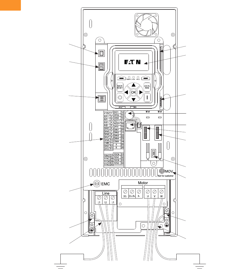
V6-T2-68 Volume 6—Solid-State Motor Control CA08100007E—February 2016 www.eaton.com
2
2
2
2
2
2
2
2
2
2
2
2
2
2
2
2
2
2
2
2
2
2
2
2
2
2
2
2
2
2
2.6
Adjustable Frequency Drives
PowerXL DG1 Series Drives
Control Board Layout
PowerXL Series—DG1 Control Board Layout
DSP Connection
to Power Board
Keypad
MCU Connection
to Power Board
RTC Battery (Standard)
RJ45 EtherNet/IP,
Modbus TCP
Optional Card Slot A
Optional Card Slot B
RS-485 Terminating
Resistor
MOV Screw
Motor Ground
Clamp Location
Grounding
Strap Location
Grounding
Strap Location
Line Ground
Clamp Location
Removable
EMC Screw
Control I/O
Terminals
AI Mode Selection
Safe Torque Off (STO)
Fan Power Wire
Line Side Motor
ON
123
ON
1
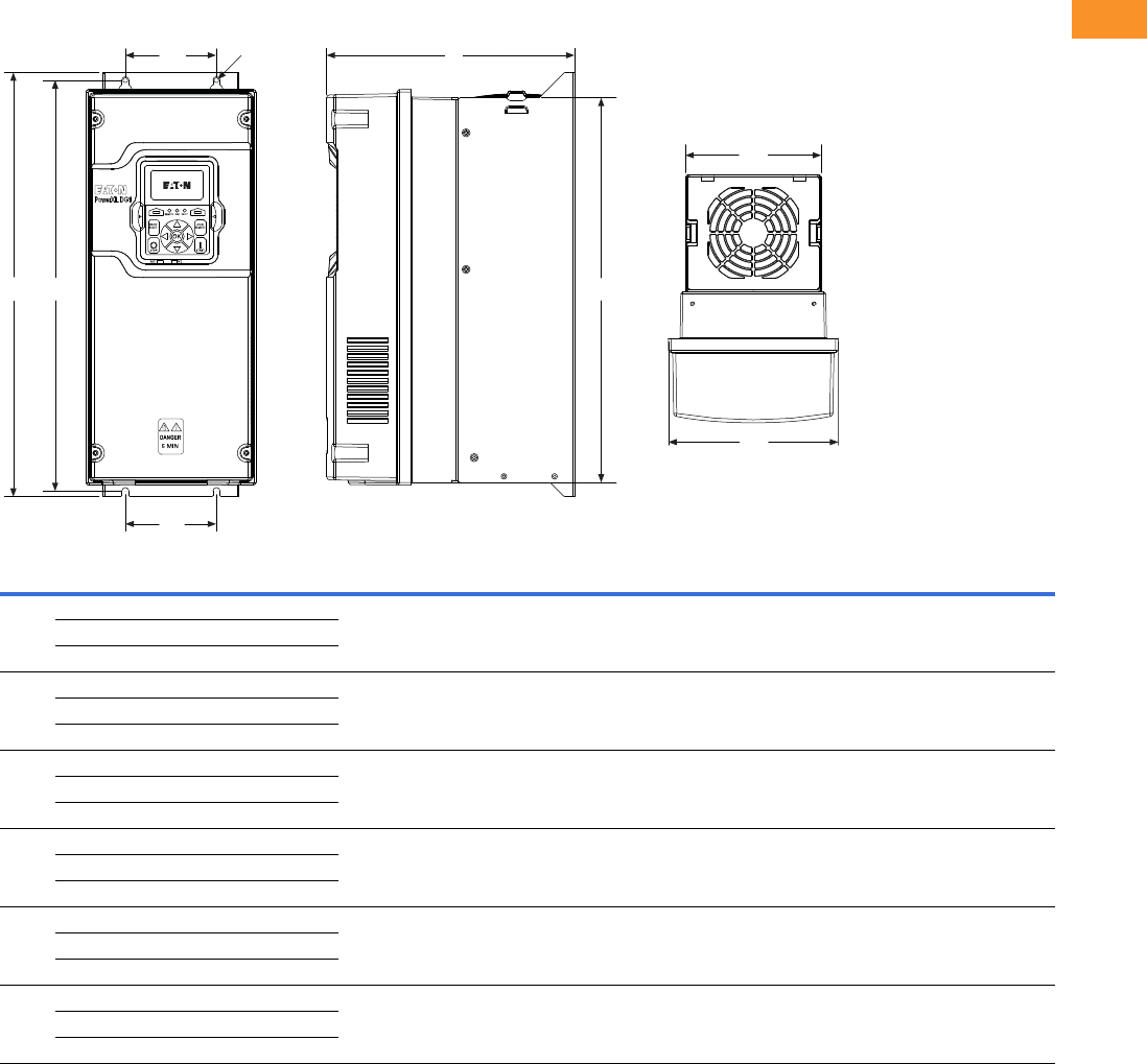
Volume 6—Solid-State Motor Control CA08100007E—February 2016 www.eaton.com V6-T2-69
2
2
2
2
2
2
2
2
2
2
2
2
2
2
2
2
2
2
2
2
2
2
2
2
2
2
2
2
2
2
2.6
Adjustable Frequency Drives
PowerXL DG1 Series Drives
Dimensions
Approximate Dimensions in Inches (mm)
PowerXL Series—DG1 Dimensions
Notes
1575 V available in 2016.
2FR6 available in 2016.
Frame
Size Voltage hp (CT/IH)kW
Amperes
(CT/IH)
Approximate Dimensions in Inches (mm) Weight
Lb (kg)D H1H2H3W1W2W3W4Ø
FR1 230 Vac 0.75–3 0.55–2.2 3.5–11 7.91
(200.9)
12.87
(326.9)
12.28
(311.9)
11.50
(292.1)
6.02
(153.0)
4.80
(121.9)
3.94
(100.1)
3.94
(100.1)
0.28
(7.0)
14.33
(6.5)
480 Vac 1–5 0.75–3.7 2.3–7.6
575 Vac 12–5 1.5–3.7 3.3–7.5
FR2 230 Vac 5–7.5 3–5.5 12.5–25 9.63
(244.7)
16.50
(419.1)
15.98
(405.9)
14.96
(380.0)
6.61
(167.8)
5.28
(134.1)
3.54
(90.0)
3.54
(90.0)
0.28
(7.0)
23.37
(10.6)
480 Vac 7.5–15 5.5–11 12–23
575 Vac 17.5–15 5.5–11 10–18
FR3 230 Vac 10–15 7.5–11 31–48 10.44
(265.1)
21.97
(558.0)
21.46
(545.0)
20.41
(518.5)
8.06
(204.6)
7.24
(183.9)
4.92
(125.0)
4.92
(125.0)
0.35
(9.0)
49.82
(22.6)
480 Vac 20–30 15–22 31–46
575 Vac 120–30 15–22 22–34
FR4 230 Vac 20–30 15–22 61–88 11.57
(294.0)
24.80
(629.9)
24.31
(617.5)
23.27
(591.1)
9.36
(237.7)
9.13
(231.9)
8.07
(205.0)
8.07
(205.0)
0.35
(9.0)
77.60
(35.2)
480 Vac 40–60 30–45 61–87
575 Vac 140–60 30–45 41–62
FR5 230 Vac 40–60 30–45 114–170 13.41
(340.7)
34.98
(888.5)
29.65
(753.1)
27.83
(706.9)
11.34
(288.0)
11.10
(281.9)
8.66
(220.0)
8.66
(220.0)
0.35
(9.0)
154.32
(70.0)
480 Vac 75–125 55–90 105–170
575 Vac 175–125 55–90 80–125
FR6 2230 Vac 75–100 55–75 211–248 14.61
(371.0)
34.04
(864.5)
33.27
(845.0)
40.75
(1035.0)
19.13
(486.0)
18.90
(480.0)
15.75
(400.0)
15.75
(400.0)
0.35
(9.0)
220.5
(100.0)
480 Vac 150–200 110–150 205–261
575 Vac 150–200 110–160 144–208
W3
H2
W4
W1
W2
H1
D
H3
Ø
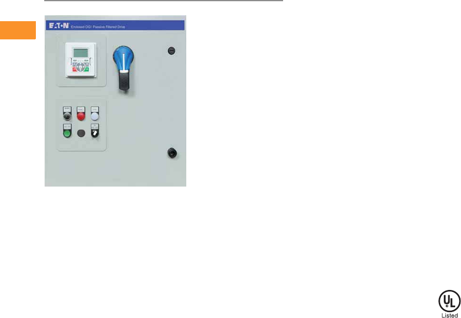
V6-T2-70 Volume 6—Solid-State Motor Control CA08100007E—February 2016 www.eaton.com
2
2
2
2
2
2
2
2
2
2
2
2
2
2
2
2
2
2
2
2
2
2
2
2
2
2
2
2
2
2
2.6
Adjustable Frequency Drives
PowerXL DG1 Series Drives
DG1 General Purpose Enclosed Drive
Contents
Description Page
PowerXL DG1 Series Drives . . . . . . . . . . . . . . . . . V6-T2-48
PowerXL DG1 Series Enclosed Drives
Catalog Number Selection . . . . . . . . . . . . . . . . V6-T2-71
Production Selection . . . . . . . . . . . . . . . . . . . . V6-T2-73
Enclosure Selection . . . . . . . . . . . . . . . . . . . . . V6-T2-77
Accessories . . . . . . . . . . . . . . . . . . . . . . . . . . . V6-T2-78
Options . . . . . . . . . . . . . . . . . . . . . . . . . . . . . . V6-T2-79
Technical Data and Specifications . . . . . . . . . . V6-T2-81
Wiring Diagram . . . . . . . . . . . . . . . . . . . . . . . . V6-T2-84
Dimensions . . . . . . . . . . . . . . . . . . . . . . . . . . . V6-T2-85
PowerXL DG1 Series Enclosed Drives
Product Description
The DG1 Enclosed Drive
family incorporates the latest
Eaton drive technology into
pre-engineered enclosed
solutions covering the
industry’s most common
applications. Using the
benefits of the PowerXL
DG1, the enclosed family
provides enhanced user
safety with the Safe Torque
feature as well as industry-
leading energy efficiency
from the patented Active
Energy Control algorithm.
Eaton further raises the bar
by providing customers with
industry best lead times with
the Rapid Response System.
This system allows
customers to select from
9 million standard
configurations that have been
pre-engineered with each
configuration having a set
lead time. The Rapid
Response System delivers an
improved quotation process
and a faster delivery.
Features and Benefits
●Dual rated for both
constant torque (CT) / high
overload (IH) and variable
torque (VT) / low overload
applications
●Optional Brake Chopper
for external braking
applications
●Available circuit breaker,
motor circuit protector,
fused disconnect, isolation
fusing and surge protection
device options to provide
input power protection
●Optional 3% input and
output reactors provide
a reduction in voltage and
current harmonics on both
line and load side
●Bypass options include a
standard three-contactor
design and a reduced
voltage soft starter design
●Output contactor option
provides a means for
positive disconnection of
the drive output from the
motor terminals
●MotoRX and dV/dt filter
options are used to reduce
transients voltages at the
motor terminals
●Customizable cover control
options
●Padlockable disconnect
●The PowerXL DG1 comes
standard with the following
communication protocols:
●EtherNet/IP
●Modbus/TCP
●Modbus RTU
●BACnet MS/TP
Communication Options
●PROFIBUS-DP
●LonWorks
●CANopen
●DeviceNet
Enclosure Ratings
●NEMA Type 1
●NEMA Type 12
●NEMA Type 3R
Mounting
●Wall mount
●Floor mount: 12-inch legs
●Floor mount: 22-inch legs
Product Range
●208 V: 0.75–100 hp
●230 V: 0.75–125 hp
●480 V: 1–250 hp
●230 V single-phase:
1–60 hp
●480 V single-phase:
1.5–125 hp
Standards and Certifications
●UL 508C tested, listed
and approved
●OSHPD
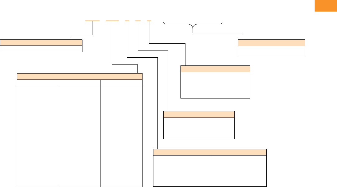
Volume 6—Solid-State Motor Control CA08100007E—February 2016 www.eaton.com V6-T2-71
2
2
2
2
2
2
2
2
2
2
2
2
2
2
2
2
2
2
2
2
2
2
2
2
2
2
2
2
2
2
2.6
Adjustable Frequency Drives
PowerXL DG1 Series Drives
Catalog Number Selection
Catalog Number Selection is for reference only. Not all option combinations may be available.
DG1 Enclosed—Base Catalog Number
Notes
1Brake chopper is a factory-installed option only. Braking resistors sold separately. See DG1 drives starting on Page V6-T2-55 for selection.
2Additional enclosure options including NEMA 4, 4X, 7 and 9 are available. Please contact the factory for configuration and pricing.
3Part number configuration continued on the following page.
EGS 3D5 1 D 1
Product Family
EGS = Enclosed DG1 drives—standard
Output Ampere Rating
208 V 230 V 480 V
3D5 = 3.5 A, 0.75 hp
4D6 = 4.6 A, 1 hp
6D6 = 6.6 A, 1.5 hp
7D5 = 7.5 A, 2 hp
010 = 10.6 A, 3 hp
016 = 16.7 A, 5 hp
024 = 24.2 A, 7.5 hp
030 = 30.8 A, 10 hp
046 = 46.2 A, 15 hp
059 = 59.4 A, 20 hp
074 = 74.8 A, 25 hp
088 = 88 A, 30 hp
114 = 114 A, 40 hp
143 = 143 A, 50 hp
169 = 169 A, 60 hp
211 = 211 A, 75 hp
273 = 273 A, 100 hp
3D2 = 3.2 A, 0.75 hp
4D2 = 4.2 A, 1 hp
6D0 = 6.0 A, 1.5 hp
6D8 = 6.8 A, 2 hp
9D6 = 9.6 A, 3 hp
015 = 15.2, 5 hp
022 = 22 A, 7.5 hp
028 = 28 A, 10 hp
042 = 42 A, 15 hp
054 = 54 A, 20 hp
068 = 68 A, 25 hp
080 = 80 A, 30 hp
104 = 104 A, 40 hp
130 = 130 A, 50 hp
154 = 154 A, 60 hp
192 = 192 A, 75 hp
248 = 248 A, 100 hp
312 = 312 A, 125 hp
2D1 = 2.1 A, 1 hp
3D0 = 3.0 A, 1.5 hp
3D4 = 3.4 A, 2 hp
4D8 = 4.8 A, 3 hp
7D6 = 7.6 A, 5 hp
011 = 11 A, 7.5 hp
014 = 14 A, 10 hp
021 = 21 A, 15 hp
027 = 27 A, 20 hp
034 = 34 A, 25 hp
040 = 40 A, 30 hp
052 = 52 A, 40 hp
065 = 65 A, 50 hp
077 = 77 A, 60 hp
096 = 96 A, 75 hp
124 = 124 A, 100 hp
156 = 156 A, 125 hp
180 = 180 A, 150 hp
240 = 240 A, 200 hp
302 = 302 A, 250 hp
Phasing, Voltage
1 = Input: Three-phase, 208 V
Output: Three-phase
2 = Input: Three-phase, 230 V
Output: Three-phase
4 = Input: Three-phase, 480 V
Output: Three-phase
5 = Input: Three-phase, 575 V
Output: Three-phase
J = Input: Single-phase, 230 V
Output: Three-phase
K = Input: Single-phase, 480 V
Output: Three-phase
Braking Application 1
A = No brake chopper, low overload
B = Brake chopper, low overload
C = No brake chopper, high overload
D = Brake chopper, high overload
Enclosure Rating 2
1 = NEMA Type 1
2 = NEMA Type 12
3 = NEMA Type 3R
6 = NEMA Type 1 Filtered and gasketed
• = Custom option
______
Options 3
See Page V6-T2-72 for catalog number
option selection.
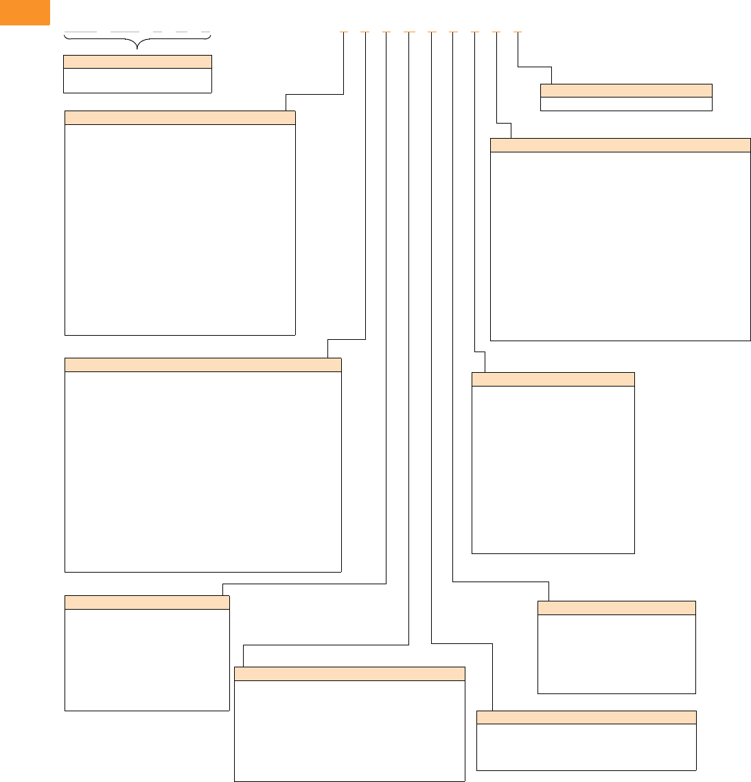
V6-T2-72 Volume 6—Solid-State Motor Control CA08100007E—February 2016 www.eaton.com
2
2
2
2
2
2
2
2
2
2
2
2
2
2
2
2
2
2
2
2
2
2
2
2
2
2
2
2
2
2
2.6
Adjustable Frequency Drives
PowerXL DG1 Series Drives
Catalog Number Selection is for reference only. Not all option combinations may be available.
DG1 Enclosed—Catalog Number Options
EGS 3D5 1 D 1 2 0 0 B 1 0 0 0 0
Power Disconnect Options
0 =None
1 = MCP disconnect 1
2 = Circuit breaker
3 = Circuit breaker/isolation fusing
4 = Circuit breaker/isolation fusing/3% input reactor
5 = Circuit breaker/isolation fusing/SPD
6 = Circuit breaker/isolation fusing/SPD/3% input reactor
7 = Circuit breaker/3% input reactor
8 = Circuit breaker/SPD
9 = Circuit breaker/SPD/3% input reactor
A = Fused disconnect
B = Fused disconnect/SPD
C = Fused disconnect/SPD/3% input reactor
D = Fused disconnect/3% input reactor
E = Isolation fuses
F = Isolation fuses/3% input reactor
G = Isolation fuses/SPD
H = Isolation fuses/SPD/3% input reactor
• = Custom option 2
Base Catalog Number Example
See Page V6-T2-71 for base catalog
number selection.
Bypass Options 3
0 =None
1 = Manual HOA bypass
2 = Manual HOA bypass/isolation fusing
3 = Manual HOA bypass/isolation fusing/3% input reactor
4 = Manual HOA bypass/isolation fusing/SPD
5 = Manual HOA bypass/isolation fusing/SPD/3% input reactor
6 = Manual HOA bypass/3% input reactor
7 = Manual HOA bypass/SPD
8 = Manual HOA bypass/SPD/3% input reactor
H = Manual HOA RVSS bypass
J = Manual HOA RVSS bypass/isolation fusing
K = Manual HOA RVSS bypass/isolation fusing/3% input reactor
L = Manual HOA RVSS bypass/isolation fusing/SPD
M = Manual HOA RVSS bypass/isolation fusing/SPD/3% input reactor
N = Manual HOA RVSS bypass/3% input reactor
P = Manual HOA RVSS bypass/SPD
R = Manual HOA RVSS bypass/SPD/3% input reactor
• = Custom option 2
Output Power Options 4
0 =None
A = Output contactor
B = 3% Output reactor
C = MotoRX filter
D = dV/dt filter
E = 3% Output Reactor/output contactor
F = MotoRX/output contactor
G = dV/dt/output contactor
• = Custom option 2
Option Boards 2
Same options and codes as Option Boards 1
Option Boards 1
0 = No option
1 = 3 x DI, 3 x DO, 1 Thermistor, 24 Vdc/EXT (DG1 only)
2 = 1 x AI, 2 x AO (isolated to control board) (DG1 only)
3 = 3 x relay dry contact (2NO + 1NO/NC) (DG1 only)
4 = 3 x PT100 RTD thermistor input (DG1 only)
5 = 6 DI 240 Vac input (DG1 only)
6 = 6 DI, 1 ext +24 Vdc/EXT +24 Vdc (SVX only)
7 = 1 RO (NC-NO), 1 RO (NO), 1 therm (SVX only)
8 = 1 AI (mA isolated), 2 AO (mA isolated), 1 ext +24 Vdc/EXT +24 Vdc
(SVX only)
9 = 3 RO (NO) (SVX only)
A = 1 ext +24 Vdc/EXT +24 Vdc, 3 Pt100 (SVX only)
B = 1 RO (NO), 5 DI 42–240 Vac input (SVX only)
C = Encoder low volt +5 V / 15 V / 24 V (high-performance drive only)
D = Encoder high volt +15 V / 24 V (high-performance drive only)
E = Double encoder (high-performance drive only)
• = Custom option 2
Communication Options
0 = No option
1 = PROFIBUS-DP
2 = LonWorks (SVX only)
3 = CANopen (slave)
4 = DeviceNet
5 = PROFIBUS-DP (D9 connector)
6 = Modbus (SVX only)
7 = Modbus (D9 connector) (SVX only)
8 = Johnson Controls N2 (SVX only)
9 = Modbus TCP (SVX only)
A = BACnet (SVX only)
B = EtherNet/IP (SVX only)
C = RS-232 with D9 connector (SVX only)
D = SmartWire-DT (DG1 only)
• = Custom option 2
Enclosure Options
0 =None
1 = Floor stand—12 inches
2 = Floor stand—22 inches
A = Space heater
B = Space heater & 12-inch floor stands
C = Space heater & 22-inch floor stands
• = Custom option 2
Light Options 5
0 =None
1 = Non-bypass light kit—Power On, Run, Fault
2 = Bypass light kit—On, VFD Run, Fault, Bypass Run
• = Custom option 2
Notes
1HMCP disconnect option required and only available when bypass is selected.
2More options are available as Engineered to Order through the Bid Manager tool.
3All bypass options include third contactor for drive isolation when in bypass mode.
4Output contactor not available with bypass. Bypass comes standard with output contactor.
5Pilot devices are 22 mm standard. 30 mm options are available as engineered to order through the Bid Manager tool.
Control Options 5
0 =None
1 = Speed pot
2 = Start-stop pushbutton
3 = Start-stop pushbutton with speed pot
A = HOA switch
B = Start-stop pushbutton with speed pot & HOA switch
C = Start-stop pushbutton with HOA switch
D = HOA switch with speed pot
• = Custom option 2
Volume 6—Solid-State Motor Control CA08100007E—February 2016 www.eaton.com V6-T2-73
2
2
2
2
2
2
2
2
2
2
2
2
2
2
2
2
2
2
2
2
2
2
2
2
2
2
2
2
2
2
2.6
Adjustable Frequency Drives
PowerXL DG1 Series Drives
Production Selection
208 V Drives—Constant Torque (CT)/High Overload (IH) Enclosed Drives
208 V Drives—Variable Torque (VT)/Low Overload (IL) Enclosed Drives
Notes
1 Table is for base catalog number reference only. For complete catalog number selection, see Page V6-T2-72.
2 These units are current rated. They do not meet NEC ampere rating at this horsepower.
NEMA Type 1 NEMA Type 12 NEMA Type 3R
hp Current (A)
Drive
Frame Size
Base
Catalog Number 1
Base
Catalog Number 1
Base
Catalog Number 1
0.75 3.5 1 EGS3D51D1 EGS3D51D2 EGS3D51D3
14.61EGS4D61D1 EGS4D61D2 EGS4D61D3
1.5 6.6 1 EGS6D61D1 EGS6D61D2 EGS6D61D3
27.51EGS7D51D1 EGS7D51D2 EGS7D51D3
310.61EGS0101D1 EGS0101D2 EGS0101D3
516.72EGS0161D1 EGS0161D2 EGS0161D3
7.5 24.2 2 EGS0241D1 EGS0241D2 EGS0241D3
10 30.8 3 EGS0301D1 EGS0301D2 EGS0301D3
15 46.2 3 EGS0461D1 EGS0461D2 EGS0461D3
20 59.4 4 EGS0591C1 EGS0591C2 EGS0591C3
25 74.8 4 EGS0741C1 EGS0741C2 EGS0741C3
30 88 4 EGS0881C1 EGS0881C2 EGS0881C3
40 114 5 EGS1141C1 EGS1141C2 EGS1141C3
50 143 5 EGS1431C1 EGS1431C2 EGS1431C3
60 169 5 EGS1691C1 EGS1691C2 EGS1691C3
75 211 6 EGS2111C1 EGS2111C2 EGS2111C3
100 2261 26EGS2611C1 EGS2611C2 EGS2611C3
NEMA Type 1 NEMA Type 12 NEMA Type 3R
hp Current (A)
Drive
Frame Size
Base
Catalog Number 1
Base
Catalog Number 1
Base
Catalog Number 1
14.61EGS4D61B1 EGS4D61B2 EGS4D61B3
1.5 6.6 1 EGS6D61B1 EGS6D61B2 EGS6D61B3
27.51EGS7D51B1 EGS7D51B2 EGS7D51B3
310.61EGS0101B1 EGS0101B2 EGS0101B3
516.72EGS0161B1 EGS0161B2 EGS0161B3
7.5 24.2 2 EGS0241B1 EGS0241B2 EGS0241B3
10 30.8 2 EGS0301B1 EGS0301B2 EGS0301B3
15 46.2 3 EGS0461B1 EGS0461B2 EGS0461B3
20 59.4 3 EGS0591B1 EGS0591B2 EGS0591B3
25 74.8 4 EGS0741A1 EGS0741A2 EGS0741A3
30 88 4 EGS0881A1 EGS0881A2 EGS0881A3
40 114 4 EGS1141A1 EGS1141A2 EGS1141A3
50 143 5 EGS1431A1 EGS1431A2 EGS1431A3
60 169 5 EGS1691A1 EGS1691A2 EGS1691A3
75 211 5 EGS2111A1 EGS2111A2 EGS2111A3
100 273 6 EGS2731A1 EGS2731A2 EGS2731A3
DG1 Enclosed Drive
DG1 Enclosed Drive
V6-T2-74 Volume 6—Solid-State Motor Control CA08100007E—February 2016 www.eaton.com
2
2
2
2
2
2
2
2
2
2
2
2
2
2
2
2
2
2
2
2
2
2
2
2
2
2
2
2
2
2
2.6
Adjustable Frequency Drives
PowerXL DG1 Series Drives
230 V Drives—Constant Torque (CT)/High Overload (IH) Enclosed Drives
230 V Drives—Variable Torque (VT)/Low Overload (IL) Enclosed Drives
Notes
1 Table is for base catalog number reference only. For complete catalog number selection, see Page V6-T2-72.
2 These units are current rated. They do not meet NEC ampere rating at this horsepower.
NEMA Type 1 NEMA Type 12 NEMA Type 3R
hp Current (A)
Drive
Frame Size
Base
Catalog Number 1
Base
Catalog Number 1
Base
Catalog Number 1
0.75 3.2 1 EGS3D22D1 EGS3D22D2 EGS3D22D3
14.21EGS4D22D1 EGS4D22D2 EGS4D22D3
1.5 6 1 EGS6D02D1 EGS6D02D2 EGS6D02D3
26.81EGS6D82D1 EGS6D82D2 EGS6D82D3
39.61EGS9D62D1 EGS9D62D2 EGS9D62D3
515.22EGS0152D1 EGS0152D2 EGS0152D3
7.5 22 2 EGS0222D1 EGS0222D2 EGS0222D3
10 28 3 EGS0282D1 EGS0282D2 EGS0282D3
15 42 3 EGS0422D1 EGS0422D2 EGS0422D3
20 54 4 EGS0542C1 EGS0542C2 EGS0542C3
25 68 4 EGS0682C1 EGS0682C2 EGS0682C3
30 80 4 EGS0802C1 EGS0802C2 EGS0802C3
40 104 5 EGS1042C1 EGS1042C2 EGS1042C3
50 130 5 EGS1302C1 EGS1302C2 EGS1302C3
60 154 5 EGS1542C1 EGS1542C2 EGS1542C3
75 192 6 EGS1922C1 EGS1922C2 EGS1922C3
100 248 6 EGS2482C1 EGS2482C2 EGS2482C3
NEMA Type 1 NEMA Type 12 NEMA Type 3R
hp Current (A)
Drive
Frame Size
Base
Catalog Number 1
Base
Catalog Number 1
Base
Catalog Number 1
14.21EGS4D22B1 EGS4D22B2 EGS4D22B3
1.5 6 1 EGS6D02B1 EGS6D02B2 EGS6D02B3
26.81EGS6D82B1 EGS6D82B2 EGS6D82B3
39.61EGS9D62B1 EGS9D62B2 EGS9D62B3
515.22EGS0152B1 EGS0152B2 EGS0152B3
7.5 22 2 EGS0222B1 EGS0222B2 EGS0222B3
10 28 2 EGS0282B1 EGS0282B2 EGS0282B3
15 42 3 EGS0422B1 EGS0422B2 EGS0422B3
20 54 3 EGS0542B1 EGS0542B2 EGS0542B3
25 68 4 EGS0682A1 EGS0682A2 EGS0682A3
30 80 4 EGS0802A1 EGS0802A2 EGS0802A3
40 104 4 EGS1042A1 EGS1042A2 EGS1042A3
50 130 5 EGS1302A1 EGS1302A2 EGS1302A3
60 154 5 EGS1542A1 EGS1542A2 EGS1542A3
75 192 5 EGS1922A1 EGS1922A2 EGS1922A3
100 248 6 EGS2482A1 EGS2482A2 EGS2482A3
125 312 6 EGS3122A1 EGS3122A2 EGS3122A3
DG1 Enclosed Drive
DG1 Enclosed Drive
Volume 6—Solid-State Motor Control CA08100007E—February 2016 www.eaton.com V6-T2-75
2
2
2
2
2
2
2
2
2
2
2
2
2
2
2
2
2
2
2
2
2
2
2
2
2
2
2
2
2
2
2.6
Adjustable Frequency Drives
PowerXL DG1 Series Drives
480 V Drives—Constant Torque (CT)/High Overload (IH) Enclosed Drives
480 V Drives—Variable Torque (VT)/Low Overload (IL) Enclosed Drives
Note
1 Table is for base catalog number reference only. For complete catalog number selection, see Page V6-T2-72.
NEMA Type 1 NEMA Type 12 NEMA Type 3R
hp Current (A)
Drive
Frame Size
Base
Catalog Number 1
Base
Catalog Number 1
Base
Catalog Number 1
12.11EGS2D14D1 EGS2D14D2 EGS2D14D3
1.5 3 1 EGS3D04D1 EGS3D04D2 EGS3D04D3
23.41EGS3D44D1 EGS3D44D2 EGS3D44D3
34.81EGS4D84D1 EGS4D84D2 EGS4D84D3
57.61EGS7D64D1 EGS7D64D2 EGS7D64D3
7.5 11 2 EGS0114D1 EGS0114D2 EGS0114D3
10 14 2 EGS0144D1 EGS0144D2 EGS0144D3
15 21 2 EGS0214D1 EGS0214D2 EGS0214D3
20 27 3 EGS0274D1 EGS0274D2 EGS0274D3
25 34 3 EGS0344D1 EGS0344D2 EGS0344D3
30 40 3 EGS0404D1 EGS0404D2 EGS0404D3
40 52 4 EGS0524C1 EGS0524C2 EGS0524C3
50 65 4 EGS0654C1 EGS0654C2 EGS0654C3
60 77 4 EGS0774C1 EGS0774C2 EGS0774C3
75 96 5 EGS0964C1 EGS0964C2 EGS0964C3
100 124 5 EGS1244C1 EGS1244C2 EGS1244C3
125 156 5 EGS1564C1 EGS1564C2 EGS1564C3
150 180 6 EGS1804C1 EGS1804C2 EGS1804C3
200 240 6 EGS2404C1 EGS2404C2 EGS2404C3
NEMA Type 1 NEMA Type 12 NEMA Type 3R
hp Current (A)
Drive
Frame Size
Base
Catalog Number 1
Base
Catalog Number 1
Base
Catalog Number 1
1.5 3 1 EGS3D04B1 EGS3D04B2 EGS3D04B3
23.41EGS3D44B1 EGS3D44B2 EGS3D44B3
34.81EGS4D84B1 EGS4D84B2 EGS4D84B3
57.61EGS7D64B1 EGS7D64B2 EGS7D64B3
7.5 11 1 EGS0114B1 EGS0114B2 EGS0114B3
10 14 2 EGS0144B1 EGS0144B2 EGS0144B3
15 21 2 EGS0214B1 EGS0214B2 EGS0214B3
20 27 2 EGS0274B1 EGS0274B2 EGS0274B3
25 34 3 EGS0344B1 EGS0344B2 EGS0344B3
30 40 3 EGS0404B1 EGS0404B2 EGS0404B3
40 52 3 EGS0524B1 EGS0524B2 EGS0524B3
50 65 4 EGS0654A1 EGS0654A2 EGS0654A3
60 77 4 EGS0774A1 EGS0774A2 EGS0774A3
75 96 4 EGS0964A1 EGS0964A2 EGS0964A3
100 124 5 EGS1244A1 EGS1244A2 EGS1244A3
125 156 5 EGS1564A1 EGS1564A2 EGS1564A3
150 180 5 EGS1804A1 EGS1804A2 EGS1804A3
200 240 6 EGS2404A1 EGS2404A2 EGS2404A3
250 302 6 EGS3024A1 EGS3024A2 EGS3024A3
DG1 Enclosed Drive
DG1 Enclosed Drive
V6-T2-76 Volume 6—Solid-State Motor Control CA08100007E—February 2016 www.eaton.com
2
2
2
2
2
2
2
2
2
2
2
2
2
2
2
2
2
2
2
2
2
2
2
2
2
2
2
2
2
2
2.6
Adjustable Frequency Drives
PowerXL DG1 Series Drives
230 V Single-Phase Drives—Variable Torque (VT)/Low Overload (IL) Enclosed Drives
480 V Single-Phase Drives—Variable Torque (VT)/Low Overload (IL) Enclosed Drives
Note
1 Table is for base catalog number reference only. For complete catalog number selection, see Page V6-T2-72.
NEMA Type 1 NEMA Type 12 NEMA Type 3R
hp Current (A)
Drive
Frame Size
Base
Catalog Number 1
Base
Catalog Number 1
Base
Catalog Number 1
14.21EGS4D2JB1 EGS4D2JB2 EGS4D2JB3
1.5 6 1 EGS6D0JB1 EGS6D0JB2 EGS6D0JB3
26.81EGS6D8JB1 EGS6D8JB2 EGS6D8JB3
39.61EGS9D6JB1 EGS9D6JB2 EGS9D6JB3
515.22EGS015JB1 EGS015JB2 EGS015JB3
7.5 22 2 EGS022JB1 EGS022JB2 EGS022JB3
10 28 2 EGS028JB1 EGS028JB2 EGS028JB3
15 42 3 EGS042JB1 EGS042JB2 EGS042JB3
20 54 3 EGS054JB1 EGS054JB2 EGS054JB3
25 68 4 EGS068JA1 EGS068JA2 EGS068JA3
30 80 4 EGS080JA1 EGS080JA2 EGS080JA3
40 104 4 EGS104JA1 EGS104JA2 EGS104JA3
50 130 5 EGS130JA1 EGS130JA2 EGS130JA3
60 154 5 EGS154JA1 EGS154JA2 EGS154JA3
NEMA Type 1 NEMA Type 12 NEMA Type 3R
hp Current (A)
Drive
Frame Size
Base
Catalog Number 1
Base
Catalog Number 1
Base
Catalog Number 1
1.5 3 1 EGS3D0KB1 EGS3D0KB2 EGS3D0KB3
23.41EGS3D4KB1 EGS3D4KB2 EGS3D4KB3
34.81EGS4D8KB1 EGS4D8KB2 EGS4D8KB3
57.61EGS7D6KB1 EGS7D6KB2 EGS7D6KB3
7.5 11 1 EGS011KB1 EGS011KB2 EGS011KB3
10 14 2 EGS014KB1 EGS014KB2 EGS014KB3
15 21 2 EGS021KB1 EGS021KB2 EGS021KB3
20 27 2 EGS027KB1 EGS027KB2 EGS027KB3
25 34 3 EGS034KB1 EGS034KB2 EGS034KB3
30 40 3 EGS040KB1 EGS040KB2 EGS040KB3
40 52 3 EGS052KB1 EGS052KB2 EGS052KB3
50 65 4 EGS065KA1 EGS065KA2 EGS065KA3
60 77 4 EGS077KA1 EGS077KA2 EGS077KA3
75 96 4 EGS096KA1 EGS096KA2 EGS096KA3
100 124 5 EGS124KA1 EGS124KA2 EGS124KA3
125 156 5 EGS156KA1 EGS156KA2 EGS156KA3
DG1 Enclosed Drive
DG1 Enclosed Drive
Volume 6—Solid-State Motor Control CA08100007E—February 2016 www.eaton.com V6-T2-77
2
2
2
2
2
2
2
2
2
2
2
2
2
2
2
2
2
2
2
2
2
2
2
2
2
2
2
2
2
2
2.6
Adjustable Frequency Drives
PowerXL DG1 Series Drives
Enclosure Selection
EGS
Enclosure selection charts are based on physical space limitations only and only to be used as a reference.
For actual enclosure sizing, refer to Bid Manager.
Note: Standard enclosure sizing includes dedicated space for a circuit
breaker or fusible disconnect, CPT, SPD, heater/thermostat, control relay
and terminal blocks.
Standard Enclosure X-Space
Standard Power Options X-Space
Note: Bypass enclosure sizing includes dedicated space for a MCP, CPT,
input contactor, output bypass contactors, overload relay, SPD, heater/
thermostat, control relay and terminal blocks.
Bypass Enclosure X-Space
Bypass Power Options X-Space
Note: Single-phase enclosure sizing includes dedicated space for a
capacitor kit, circuit breaker or fusible disconnect, CPT, SPD, heater/
thermostat, control relay and terminal blocks.
Single-Phase Enclosure X-Space
Single-Phase Power Options X-Space
Enclosure Size Frame 1 Frame 2 Frame 3 Frame 4 Frame 5
AX 222——
BX 4444—
CX 77777
DX 18 18 18 18 18
Power Options Frame 1 Frame 2 Frame 3 Frame 4 Frame 5
Isolation fuses 11111
3% Input reactor 22356
3% Output reactor 11356
MotoRX filter 33335
dV/dt filter 33356
Output contactor 11111
Enclosure Size Frame 1 Frame 2 Frame 3 Frame 4 Frame 5
AX 000——
BX 2220—
CX 55532
DX 16 16 16 14 13
Power Options Frame 1 Frame 2 Frame 3 Frame 4 Frame 5
Isolation fuses 11111
3% Input reactor 22356
RVSS bypass 22234
3% output reactor 11356
MotoRX filter 33335
dV/dt filter 33356
Enclosure Size Frame 1 Frame 2 Frame 3 Frame 4 Frame 5
AX 0 0 ———
BX 2211—
CX 55444
DX 16 16 15 15 15
Power Options Frame 1 Frame 2 Frame 3 Frame 4 Frame 5
Isolation fuses 11111
3% Input reactor 22356
3% Output reactor 11356
MotoRX filter 33335
dV/dt filter 33356
Output contactor 11111

V6-T2-78 Volume 6—Solid-State Motor Control CA08100007E—February 2016 www.eaton.com
2
2
2
2
2
2
2
2
2
2
2
2
2
2
2
2
2
2
2
2
2
2
2
2
2
2
2
2
2
2
2.6
Adjustable Frequency Drives
PowerXL DG1 Series Drives
Accessories
The PowerXL Series—DG1 drives can accommodate a wide
selection of expander and adapter option boards to customize
the drive for your application needs. The drive’s control unit is
designed to accept a total of two additional option boards.
The PowerXL Series—DG1 drives come with a factory-installed
standard board configuration including the following:
●Standard I/O:
●8DI, 1DO
●2AI, 2AO
●2FC, 1FA relays
●Standard communications:
●EtherNet/IP, Modbus TCP
●RS-485: Modbus RTU, BACnet MS/TP
PowerXL Series—DG1 I/O Card Kits
PowerXL Series—DG1 Communication Card Kits
Note
1Available in 2016.
Description Catalog Number
3 x DI, 3 x DO, 1 x thermistor, 24 Vdc/EXT option card DXG-EXT-3DI3DO1T
1 x AI, 2 x AO (isolated to control board) option card DXG-EXT-1AI2AO
3 x relay dry contact (2NO + 1NO/NC) option card DXG-EXT-3RO
3 x PT100 RTD thermistor input option card DXG-EXT-THER1
6 x DI 240 Vac input option card DXG-EXT-6DI
Description Catalog Number
PROFIBUS-DP communication card DXG-NET-PROFB
CANopen communication card DXG-NET-CANOPEN
DeviceNet communication card DXG-NET-DEVICENET
PROFIBUS DB9 to 5-pin adapter card DXG-NET-PROAD
SmartWire communication card and module DXG-NET-SWD 1

Volume 6—Solid-State Motor Control CA08100007E—February 2016 www.eaton.com V6-T2-79
2
2
2
2
2
2
2
2
2
2
2
2
2
2
2
2
2
2
2
2
2
2
2
2
2
2
2
2
2
2
2.6
Adjustable Frequency Drives
PowerXL DG1 Series Drives
Options
Input Power Options
Bypass Options
Output Power Options
Option Description
HMCP Disconnect The HMCP motor protection circuit breaker uses an electronic trip unit to provide typical motor overload relay functionality and short-circuit
protection against potential phase-to-phase or phase-to-ground faults.
Circuit Breaker Utilizes a circuit breaker to provide a means of short-circuit protection for the power cables between it and the drive, and protection from high-
level ground faults on the power cable. Allows a convenient means of disconnecting the drive from the line, and the operating mechanism can
be padlocked in the OFF position. This is factory mounted in the enclosure.
Isolation Fusing Provides high-level fault protection of the drive input power circuit from the load side of the fuses to the input side of the power transistors.
This option consists of three 200 kA fuses that are factory mounted in the enclosure.
3% Input Reactor The input reactor is a three-phase series inductance on the line side of an AFD. It is used to provide a reduction in voltage and current
harmonics. It also provides increased input protection for AFD and its semiconductors from line transients.
SPD Provides a surge protection device (SPD) connected to the line side terminals and is designed to clip line side transients.
Fused Disconnect Utilizes fusing to provide a means of short-circuit protection for the power cables between it and the drive, and protection from high-level
ground faults on the power cable. Allows a convenient means of disconnecting the drive from the line, and the operating mechanism can be
padlocked in the OFF position. This is factory mounted in the enclosure.
Option Description
Manual HOA Bypass Provides a three-position selector switch that allows the user to select either a HAND or AUTO mode of operation. HAND mode is defaulted
keypad operation, and AUTO mode is defaulted to control from an external terminal source. These modes of operation can be configured via
programming to allow for alternate combinations of start and speed sources. Start and speed sources include keypad, I/O and fieldbus.
Manual HOA RVSS Bypass This option adds a reduced voltage soft starter to bypass assembly for soft starting in bypass mode.
Option Description
Output Contactor Provides a means for positive disconnection of the drive output from the motor terminals. The contactor coil is controlled by the drive’s run or
permissive logic. NC and NO auxiliary contacts rated at 10 A, 600 Vac are provided for customer use. This option includes a low VA 115 Vac
fused control power transformer and is factory mounted in the enclosure.
3% Output Reactor The output reactor is a three-phase series inductance on the load side of an AFD. It is used to provide a reduction in voltage and current
harmonics.
MotoRX Filter Used to reduce transient voltage (dV/dt) and peak voltages at the motor terminals. This option is comprised of a 0.5% line reactor, followed by
capacitive filtering and an energy recovery/clamping circuit. Unlike the traditional dV/dt filter, the MotoRx recovers most of the energy from the
voltage peaks, resulting in a lower voltage drop to the motor, therefore conserving power. This option is used when the distance between
a single motor and the drive is 300–600 ft (91–183 m). This option can not be used with the brake chopper circuit. in this case, the traditional
dV/dt filter should be investigated as an alternative.
dV/dt Filter Used to reduce the transient voltage (dV/dt) at the motor terminals. The traditional dV/dt filter is recommended for cable lengths exceeding
100 ft (30 m) with a drive of 3 hp and above, for cable lengths of 33 ft (10 m) with a drive of 2 hp and below, or for a drive rated at 525–690 V.
This option is mounted in the enclosure and may be used in conjunction with a brake chopper circuit. This option is mounted in the enclosure.

V6-T2-80 Volume 6—Solid-State Motor Control CA08100007E—February 2016 www.eaton.com
2
2
2
2
2
2
2
2
2
2
2
2
2
2
2
2
2
2
2
2
2
2
2
2
2
2
2
2
2
2
2.6
Adjustable Frequency Drives
PowerXL DG1 Series Drives
Control Options
Light Options
Enclosure Options
Option Description
Speed Pot Provides the ability to adjust the frequency reference using a door-mounted potentiometer. This option uses the 10 Vdc reference to generate a
0–10 V signal at the analog voltage input signal terminal. When the HOA bypass option is added, the speed is controlled when the HOA switch
is in the HAND position. Without the HOA bypass option, a two-position switch (labeled local/remote) is provided on the keypad to select
speed reference from the speed potentiometer or a remote speed signal.
HOA Switch Provides a three-position selector switch that allows the user to select either a HAND or AUTO mode of operation. HAND mode is defaulted to
keypad operation, and AUTO mode is defaulted to control from an external terminal source. These modes of operation can be configured via
drive programming to allow for alternate combinations of start and speed sources. Start and speed sources include Keypad, I/O and fieldbus.
Start-Stop Pushbutton Provides door-mounted START and STOP pushbuttons for either bypass or non-bypass configurations.
Option Description
Non-Bypass Light Kit—Power On, Run, Fault Provides a white POWER ON light that indicates power to the enclosed cabinet, a green RUN light that indicates the drive is running and a red
FAULT light that indicates a drive fault has occurred.
Bypass Light Kit—On, VFD Run, Fault, Bypass Run Provides a white POWER ON light that indicates power to the enclosed cabinet, a green RUN light that indicates the drive is running, a red
FAULT light that indicates a drive fault has occurred and an amber light that indicates when the motor is running in Bypass mode.
Option Description
Floor Stand 12 in Converts a normally wall-mounted enclosure to a floor-standing enclosure with a height of 12 in (304.8 mm).
Floor Stand 22 in Converts a normally wall-mounted enclosure to a floor-standing enclosure with a height of 22 in (558.8 mm).

Volume 6—Solid-State Motor Control CA08100007E—February 2016 www.eaton.com V6-T2-81
2
2
2
2
2
2
2
2
2
2
2
2
2
2
2
2
2
2
2
2
2
2
2
2
2
2
2
2
2
2
2.6
Adjustable Frequency Drives
PowerXL DG1 Series Drives
Technical Data and Specifications
PowerXL Series—DG1 Technical Data and Specifications
Attribute Description Specification
Input ratings Input voltage Uin 208 V to 240 V, 380 V to 500 V, 525 V to 600 V, –15 to 10%
Input frequency 50 Hz to 60 Hz (variation up to 45 Hz to 66 Hz)
Connection to power Once per minute or less
Starting delay 3 s (FR1 to FR2), 4 s (FR3), 5 s (FR4), 6 s (FR5 and FR6)
Short-circuit withstand rating 100 kAIC (fuses and circuit breakers)
Output ratings Output voltage 0 to Uin
Continuous output current IL: ambient temperature maximum 40 °C, up to 60 °C with derating, overload 1.1 x IL (1 min./10 min.)
IH: ambient temperature maximum 50 °C, up to 60 °C with derating, overload 1.5 x IH (1 min./10 min.)
Overload current 150% respectively 110% (1 min./10 min.)
Initial output current 200% (2 s / 20 s)
Output frequency 0–400 Hz (standard)
Frequency resolution 0.01 Hz
Control characteristics Control methods Frequency control
Speed control
Open-loop speed control
Open-loop torque control
Switching frequency 230 V / 480 V range:
FR1–3: 1 kHz to 12 kHz
FR4–6: 1 kHz to 10 kHz
230 V / 480 V defaults:
FR1–3: 4 kHz
FR4–5: 3.6 kHz
FR6: 2 kHz
575 V range:
FR1–6: 1 kHz to 6 kHz
575 V defaults:
FR1–4: 3 kHz
FR5–6: 2 kHz
Automatic switching frequency derating in case of overload.
Frequency reference Analog input: resolution 0.1% (10-bit), accuracy +1%
Analog output: resolution 0.1% (10-bit), accuracy +1%
Panel reference: resolution 0.01 Hz
Field weakening point 20 Hz to 400 Hz
Acceleration time 0.1 s to 3000 s
Deceleration time 0.1 s to 3000 s
Braking torque DC brake: 30% x Motor Rated Torque (Tn) (without brake chopper)
Dynamic braking (with optional brake chopper using an external brake resistor):
100% continuous maximum rating
Ambient conditions Ambient operating temperature –10 °C (no frost) to +50 °C, up to +60 °C with derating (CT)
–10 °C (no frost) to +40 °C, up to +60 °C with derating (VT)
Storage temperature –40 °C to +70 °C
Relative humidity 0–95% RH, noncondensing, non-corrosive
Air quality:
●Chemical vapors
●Mechanical particles
Tested according to IEC 60068-2-60 Test Key:
Flowing mixed gas corrosion test, Method 1 (H2S [hydrogen sulfide] and SO2 [sulfur dioxide])
Designed according to:
IEC 60721-3-3, unit in operation, class 3C2
IEC 60721-3-3, unit in operation, class 3S2
Altitude 100% load capacity (no derating) up to 3280 ft (1000 m); 1% derating for each 328 ft (100 m) above
3280 ft (1000 m); max. 9842 ft (3000 m) (2000 m for corner grounded earth main systems)
For 575 V product, maximum altitude is 6561 ft (2000 m) regardless of main system

V6-T2-82 Volume 6—Solid-State Motor Control CA08100007E—February 2016 www.eaton.com
2
2
2
2
2
2
2
2
2
2
2
2
2
2
2
2
2
2
2
2
2
2
2
2
2
2
2
2
2
2
2.6
Adjustable Frequency Drives
PowerXL DG1 Series Drives
PowerXL Series—DG1 Technical Data and Specifications, continued
Attribute Description Specification
Ambient conditions,
continued
Vibration:
●EN 61800-5-1
●EN 60668-2-6
5–150 Hz
Displacement amplitude: 1 mm (peak) at 5 Hz to 15.8 Hz (FR1–FR6)
Maximum acceleration amplitude: 1g at 15.8 Hz to 150 Hz (FR1–FR6)
Shock:
●ISTA 1 A
●EN 60068-2-27
Storage and shipping: maximum 15 g, 11 ms (in package)
Overvoltage Overvoltage Category III
Pollution degree Pollution Degree 2
Enclosure class IP21/Type 1 standard in entire kW/hp range
IP54/Type 12 option
Note: Keypad or keypad hole plug required to be mounted in drive for IP54/Type 12 rating
Immunity Fulfills EN 61800-3 (2004), first and second environment
MTBF FR1: 165,457 hours
FR2: 134,833 hours
FR3: 102,515 hours
FR4: 121,567 hours
FR5: 108,189 hours
FR6: Available in 2016
Noise FR1: 51.2 dB
FR2: 58.6 dB
FR3: 61.0 dB
FR4: 68.0 dB
FR5: 69.1 dB
FR6: Available in 2016
Standards Safety UL 508C, CSA C22.2 No. 274-13 and EN 61800-5-1
EMC +EMC2: EN 61800-3 (2004), Category C2
The drive can be modified for IT networks and corner grounding TN system
Electrostatic discharge Second environment, IEC 61000-4-2, 4 kV CD or 8 kV AD, Criterion B
Fast transient burst Second environment, IEC 61000-4-4, 2 kV/5 kHz, Criterion B
Dielectrical strength Primary to secondary: 3600 Vac/5100 Vdc
Primary to earth: 2000 Vac/2828 Vdc
Approvals EAC, RCM (C-Tick), RoHS, CE, UL and cUL (see nameplate for more detailed approvals)
Fieldbus connections Onboard: EtherNet/IP, Modbus® TCP, Modbus RTU, BACnet

Volume 6—Solid-State Motor Control CA08100007E—February 2016 www.eaton.com V6-T2-83
2
2
2
2
2
2
2
2
2
2
2
2
2
2
2
2
2
2
2
2
2
2
2
2
2
2
2
2
2
2
2.6
Adjustable Frequency Drives
PowerXL DG1 Series Drives
PowerXL Series—DG1 Technical Data and Specifications, continued
Attribute Description Specification
Safety/protections Overvoltage protection Yes
Overvoltage trip limit 230 V drives: 456 V
480 V drives: 911 V
575 V drives: 1100 V
Undervoltage protection Yes
Undervoltage trip limit 230 V drives: 211 V
480 V drives: 370 V
575 V drives: 550 V
Earth fault protection Yes
Default: 15% motor FLA
Minimum: 0% motor FLA
Maximum: 30% motor FLA
Input phase supervision Yes
Motor phase supervision Yes
Overcurrent protection Yes
Unit overtemperature protection Yes
Motor overload protection Yes
Motor stall protection Yes
Motor underload protection Yes
DC bus overvoltage control Yes
Short-circuit protection of 24 V
reference voltages
Yes
Surge protection Yes (differential mode 2 kV; common mode 4 kV
230 V drives: 275 Vac, 10,000 A
480 V drives: 320 Vac, 8000 A
575 V drives: 385 Vac, 10,000 A
Common coated boards Yes (prevents corrosion)
Efficiency Drive efficiency ratings 480 V: FR1 = 97.7%
480 V: FR2 = 97.9%
480 V: FR3 = 97.7%
480 V: FR4 = 98.0%
480 V: FR5 = 98.2%
230 V: FR1 = 96.7%
230 V: FR2 = 97.4%
230 V: FR3 = 97.2%
230 V: FR4 = 97.4%
230 V: FR5 = 97.7%
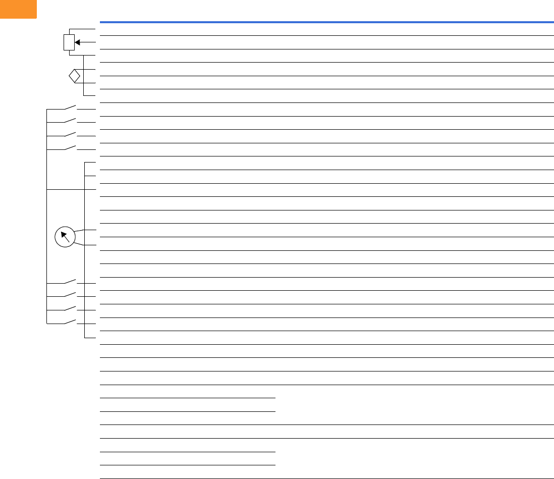
V6-T2-84 Volume 6—Solid-State Motor Control CA08100007E—February 2016 www.eaton.com
2
2
2
2
2
2
2
2
2
2
2
2
2
2
2
2
2
2
2
2
2
2
2
2
2
2
2
2
2
2
2.6
Adjustable Frequency Drives
PowerXL DG1 Series Drives
Wiring Diagram
PowerXL Series—DG1 Control Wiring Diagram
Pin Signal Name Signal Default Setting Description
1 +10 V Ref. Output Voltage — 10 Vdc Supply Source
2 AI1+ Analog Input 1 0–10 V Voltage Speed Reference (Programmable to 4 mA to 20 mA)
3 AI1– Analog Input 1 Ground — Analog Input 1 Common (Ground)
4 AI2+ Analog Input 2 4 mA to 20 mA Current Speed Reference (Programmable to 0–10 V)
5 AI2– Analog Input 2 Ground — Analog Input 2 Common (Ground)
6 GND I/O Signal Ground — I/O Ground for Reference and Control
7 DIN5 Digital Input 5 Preset Speed B0 Sets frequency output to Preset Speed 1
8 DIN6 Digital Input 6 Preset Speed B1 Sets frequency output to Preset Speed 2
9 DIN7 Digital Input 7 Emergency Stop (TI–) Input forces VFD output to shut off
10 DIN8 Digital Input 8 Force Remote (TI+) Input takes VFD from Local to Remote
11 CMB DI5 to DI8 Common Grounded Allows source input
12 GND I/O Signal Ground — I/O Ground for Reference and Control
13 24 V +24 Vdc Output — Control voltage output (100 mA max.)
14 DO1 Digital Output 1 Ready Shows the drive is ready to run
15 24 Vo +24 Vdc Output — Control voltage output (100 mA max.)
16 GND I/O Signal Ground — I/O Ground for Reference and Control
17 AO1+ Analog Output 1 Output Frequency Shows Output frequency to motor 0–60 Hz (4 mA to 20 mA)
18 AO2+ Analog Output 2 Motor Current Shows Motor current of motor 0–FLA (4 mA to 20 mA)
19 24 Vi +24 Vdc Input — External control voltage input
20 DIN1 Digital Input 1 Run Forward Input starts drive in forward direction (start enable)
21 DIN2 Digital Input 2 Run Reverse Input starts drive in reverse direction (start enable)
22 DIN3 Digital Input 3 External Fault Input causes drive to fault
23 DIN4 Digital Input 4 Fault Reset Input resets active faults
24 CMA DI1 to DI4 Common Grounded Allows source input
25 A RS-485 Signal A — Fieldbus Communication (Modbus, BACnet)
26 B RS-485 Signal B — Fieldbus Communication (Modbus, BACnet)
27 R3NO Relay 3 Normally Open At Speed Relay output 3 shows VFD is at Ref. Frequency
28 R1NC Relay 1 Normally Closed Run Relay output 1 shows VFD is in a run state
29 R1CM Relay 1 Common
30 R1NO Relay 1 Normally Open
31 R3CM Relay 3 Common At Speed Relay output 3 shows VFD is at Ref. Frequency
32 R2NC Relay 2 Normally Closed Fault Relay output 2 shows VFD is in a fault state
33 R2CM Relay 2 Common
34 R2NO Relay 2 Normally Open
Res
i
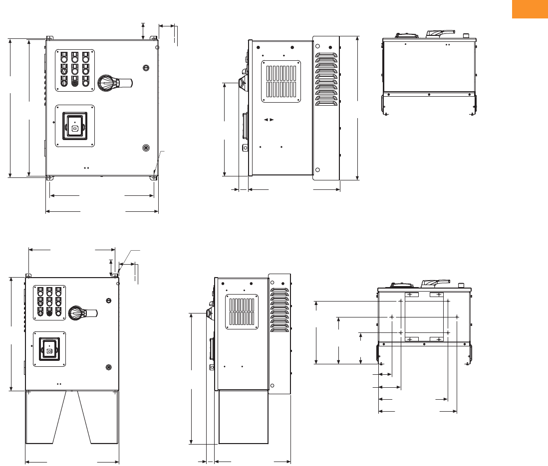
Volume 6—Solid-State Motor Control CA08100007E—February 2016 www.eaton.com V6-T2-85
2
2
2
2
2
2
2
2
2
2
2
2
2
2
2
2
2
2
2
2
2
2
2
2
2
2
2
2
2
2
2.6
Adjustable Frequency Drives
PowerXL DG1 Series Drives
Dimensions
Approximate Dimensions in Inches (mm)
AX Box Type 1
AX Box Type 1—12 Inch Floor Stands
25.80
(655.3)
3.00 (76.2)
Minimum
Air Space
Required
Both Sides
4.00 (101.6) Minimum
Free Air Space Required
25.35
(643.9)
19.30 (490.2)
20.92 (531.4)
17.02 (432.2)
1.76
(44.8)
26.74
(679.2)
17.31
(439.7)
Ø 0.44 (11.2)
Mounting
Holes
(4 Places)
19.30 (490.0)
25.35
(643.9)
20.92 (531.4)
29.12
(739.6)
1.76 (44.8) 17.02 (432.2)
14.06
(357.1)
10.53
(267.5) 7.00
(177.8)
3.00 (76.2)
5.00 (127.0)
15.50 (393.7)
17.50 (444.7)
4.00 (101.6) Minimum
Free Air Space Required
Ø 0.44 (11.2)
Mounting Holes
(2 Places)
3.00 (76.2)
Minimum
Air Space
Required
Both Sides
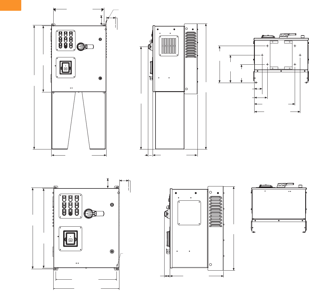
V6-T2-86 Volume 6—Solid-State Motor Control CA08100007E—February 2016 www.eaton.com
2
2
2
2
2
2
2
2
2
2
2
2
2
2
2
2
2
2
2
2
2
2
2
2
2
2
2
2
2
2
2.6
Adjustable Frequency Drives
PowerXL DG1 Series Drives
Approximate Dimensions in Inches (mm)
AX Box Type 1—22 Inch Floor Stands
AX Box Type 12
19.30 (490.2)
25.35
(643.9)
47.37
(1203.2)
20.92 (531.4) 17.02 (432.2)1.76 (44.8)
39.15
(994.4)
47.87
(1215.9)
14.06
(357.1)
10.53
(267.5) 7.00
(177.8)
3.00 (76.2)
5.00 (127.0)
17.50 (444.5)
15.50 (393.7)
4.00 (101.6) Minimum
Free Air Space Required
Ø 0.44 (11.2)
Mounting Holes
(2 Places)
3.00 (76.2)
Minimum
Air Space
Required
Both Sides
Ø 0.44 (11.2)
Mounting
Holes
(4 Places)
3.00 (76.2)
Minimum
Air Space
Required
Both Sides
26.74
(679.2)
4.00 (101.6) Minimum
Free Air Space Required
25.80
(655.3)
25.35
(643.9)
20.92 (531.4)
19.30 (490.2)
1.76
(44.8) 17.02 (432.2)

Volume 6—Solid-State Motor Control CA08100007E—February 2016 www.eaton.com V6-T2-87
2
2
2
2
2
2
2
2
2
2
2
2
2
2
2
2
2
2
2
2
2
2
2
2
2
2
2
2
2
2
2.6
Adjustable Frequency Drives
PowerXL DG1 Series Drives
Approximate Dimensions in Inches (mm)
AX Box Type 12—12 Inch Floor Stands
AX Box Type 12—22 Inch Floor Stands
37.87
(961.9)
4.00 (101.6) Minimum
Free Air Space Required
19.30 (490.2)
25.35
(643.9)
37.37
(949.2)
20.92 (531.4) 17.02 (432.2)
1.76 (44.8)
29.13
(739.9)
14.06
(357.1)
10.53
(267.5) 7.00
(177.8)
3.00 (76.2)
5.00 (127.0)
15.50 (393.7)
17.50 (444.5)
Ø 0.44 (11.2)
Mounting
Holes
(2 Places)
3.00 (76.2)
Minimum
Air Space
Required
Both Sides
14.06
(357.1)
10.53
(267.5) 7.00
(177.8)
3.00 (76.2)
5.00 (127.0)
15.50 (393.7)
17.75 (450.7)
4.00 (101.6) Minimum
Free Air Space Required
19.30 (490.2)
47.37
(1203.2)
25.35
(643.9)
20.92 (531.4) 17.02 (432.2)
1.76 (44.8)
39.15
(994.4)
47.87
(1215.9)
Ø 0.44 (11.2)
Mounting
Holes
(2 Places)
3.00 (76.2)
Minimum
Air Space
Required
Both Sides

V6-T2-88 Volume 6—Solid-State Motor Control CA08100007E—February 2016 www.eaton.com
2
2
2
2
2
2
2
2
2
2
2
2
2
2
2
2
2
2
2
2
2
2
2
2
2
2
2
2
2
2
2.6
Adjustable Frequency Drives
PowerXL DG1 Series Drives
Approximate Dimensions in Inches (mm)
AX Box Type 3R
AX Box Type 3R—12 Inch Floor Stands
20.18 (512.5)
3.00 (76.2)
Minimum
Air Space
Required
Both Sides
33.09
(840.4)
31.76
(806.6)
25.35
(643.9)
19.30 (490.2)
20.92 (531.4)
3.64
(92.5) 17.02 (432.2)
17.28
(438.9)
33.97
(862.8)
Ø 0.44 (11.2)
Mounting
Holes
(4 Places)
20.88 (530.4)
17.88 (454.2)
31.76
(806.8)
25.36
(644.0)
44.66
(1134.3)
20.92 (531.4) 17.02 (432.2)
3.64
(92.5)
29.12
(739.6)
20.18 (512.5)
14.25
(361.8)
10.72
(272.2) 7.19
(182.5)
45.10
(1145.5)
3.20
(81.3)
5.20
(132.1)
15.70 (398.8)
17.70 (449.6)
1.04 [26.4]
Ø 0.44 (11.2)
Mounting
Holes
(2 Places)
3.00 (76.2)
Minimum
Air Space
Required
Both Sides

Volume 6—Solid-State Motor Control CA08100007E—February 2016 www.eaton.com V6-T2-89
2
2
2
2
2
2
2
2
2
2
2
2
2
2
2
2
2
2
2
2
2
2
2
2
2
2
2
2
2
2
2.6
Adjustable Frequency Drives
PowerXL DG1 Series Drives
Approximate Dimensions in Inches (mm)
AX Box Type 3R—22 Inch Floor Stands
BX Box Type 1
20.88 (530.4)
17.88 (454.2)
31.76
(806.8)
25.35
(643.9)
54.66
(1388.3)
20.92 (531.4) 17.02 (432.2)
3.64 (92.5)
3.20 (81.3)
5.20 (132.1)
15.70 (398.8)
17.70 (449.6)
14.25
(361.8) 10.72
(272.2)
7.19
(182.5)
20.18 (512.5)
39.13
(993.9)
Ø 0.44 (11.2)
Mounting
Holes
(2 Places)
3.00 (76.2)
Minimum
Air Space
Required
Both Sides
55.10
(1399.5)
4.00 (101.6)
Minimum
Free Air Space
Required
28.55
(725.1)
36.80
(934.7)
36.35
(923.3)
19.30 (490.2)
20.92 (531.4)
17.01 (432.2)
1.76
(44.8)
37.74
(958.6)
3.00 (76.2)
Minimum
Air Space
Required
Both Sides
Ø 0.44 (11.2)
Mounting
Holes
(4 Places)
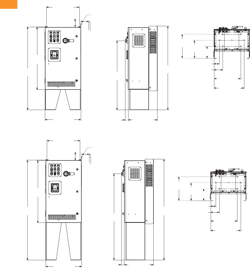
V6-T2-90 Volume 6—Solid-State Motor Control CA08100007E—February 2016 www.eaton.com
2
2
2
2
2
2
2
2
2
2
2
2
2
2
2
2
2
2
2
2
2
2
2
2
2
2
2
2
2
2
2.6
Adjustable Frequency Drives
PowerXL DG1 Series Drives
Approximate Dimensions in Inches (mm)
BX Box Type 1—12 Inch Floor Stands
BX Box Type 1—22 Inch Floor Stands
4.00 (101.6)
Minimum
Free Air Space
Required
14.06
(357.1)
19.30 (490.2)
36.35
(923.3)
48.37
(1228.6)
20.92 (531.4) 17.01 (432.2)
1.76
(44.8)
40.38
(1025.7)
48.87
(1241.3)
15.50 (393.7)
17.50 (444.5)
10.53
(267.5) 7.00
(177.8)
Ø 0.44 (11.2)
Mounting
Holes
(2 Places)
3.00 (76.2)
Minimum
Air Space
Required
Both Sides
3.00 (76.2)
5.00 (127.0)
4.00 (101.6)
Minimum
Free Air Space
Required
14.06
(357.1)
15.50 (393.7)
17.50 (444.5)
10.53
(267.5) 7.00
(177.8)
3.00 (76.2)
5.00 (127.0)
58.87
(1495.3)
19.30 (490.2)
36.35
(923.3)
58.37
(1482.6)
20.92 (531.4) 17.01 (432.2)
1.76
(44.8)
50.38
(1279.7)
Ø 0.44 (11.2)
Mounting
Holes
(2 Places)
3.00 (76.2)
Minimum
Air Space
Required
Both Sides

Volume 6—Solid-State Motor Control CA08100007E—February 2016 www.eaton.com V6-T2-91
2
2
2
2
2
2
2
2
2
2
2
2
2
2
2
2
2
2
2
2
2
2
2
2
2
2
2
2
2
2
2.6
Adjustable Frequency Drives
PowerXL DG1 Series Drives
Approximate Dimensions in Inches (mm)
BX Box Type 12
BX Box Type 12—12 Inch Floor Stands
4.00 (101.6)
Minimum
Free Air Space
Required
28.55
(725.1)
36.80
(934.7)
36.35
(923.3)
19.30 (490.2)
20.92 (531.4)
37.74
(958.6)
Ø 0.44 (11.2)
Mounting
Holes
(2 Places)
3.00 (76.2)
Minimum
Air Space
Required
Both Sides
17.01 (432.2)
1.76
(44.8)
7.00
(177.8)
10.53
(267.5)
14.06
(357.1)
15.50 (393.7)
17.50 (444.5)
3.00 (76.2)
5.00 (127.0)
40.38
(1025.7)
19.30 (490.2)
36.35
(923.3)
48.37
(1228.6)
20.92 (531.4) 17.01 (432.2)
1.76
(44.8)
48.87
(1241.3)
Ø 0.44 (11.2)
Mounting
Holes
(2 Places)
3.00 (76.2)
Minimum
Air Space
Required
Both Sides
4.00 (101.6)
Minimum
Free Air Space
Required

V6-T2-92 Volume 6—Solid-State Motor Control CA08100007E—February 2016 www.eaton.com
2
2
2
2
2
2
2
2
2
2
2
2
2
2
2
2
2
2
2
2
2
2
2
2
2
2
2
2
2
2
2.6
Adjustable Frequency Drives
PowerXL DG1 Series Drives
Approximate Dimensions in Inches (mm)
BX Box Type 12—22 Inch Floor Stands
BX Box Type 3R
7.00
(177.8)
10.53
(267.5)
14.06
(357.1)
15.50 (393.7)
17.50 (444.5)
3.00 (76.2)
5.00 (127.0)
58.87
(1495.3)
19.30 (490.2)
36.35
(923.3)
58.37
(1482.6)
20.92 (531.4) 17.01 (432.2)
1.76
(44.8)
Ø 0.44 (11.2)
Mounting
Holes
(2 Places)
3.00 (76.2)
Minimum
Air Space
Required
Both Sides
4.00 (101.6)
Minimum
Free Air Space
Required
28.56
(725.3)
44.09
(1119.8)
36.35
(923.3)
42.69
(1084.3)
19.30 (490.2)
20.92 (531.4)
37.74
(958.6)
3.00 (76.2)
Minimum
Air Space
Required
Both Sides
Ø 0.44 (11.2)
Mounting
Holes
(4 Places)
17.01 (432.2)
3.51
(89.1)
20.18 (512.5)
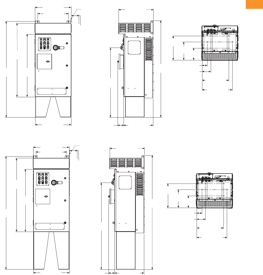
Volume 6—Solid-State Motor Control CA08100007E—February 2016 www.eaton.com V6-T2-93
2
2
2
2
2
2
2
2
2
2
2
2
2
2
2
2
2
2
2
2
2
2
2
2
2
2
2
2
2
2
2.6
Adjustable Frequency Drives
PowerXL DG1 Series Drives
Approximate Dimensions in Inches (mm)
BX Box Type 3R—12 Inch Floor Stands
BX Box Type 3R—22 Inch Floor Stands
17.88 (454.2)
20.88 (530.4)
55.66
(1413.7)
42.77
(1086.4)
36.35
(923.3)
20.92 (531.4) 17.01 (432.2)
3.51
(89.1)
40.40
(1026.3)
56.10
(1424.9)
20.18 (512.5)
7.00
(177.8)
10.53
(267.5)
14.06
(357.1)
Ø 0.44 (11.2)
Mounting
Holes
(2 Places)
3.00 (76.2)
Minimum
Air Space
Required
Both Sides
15.50 (393.7)
17.50 (444.5)
3.00 (76.2)
5.00 (127.0)
7.00
(177.8)
10.53
(267.5)
14.06
(357.1)
15.50 (393.7)
17.50 (444.5)
3.00 (76.2)
5.00 (127.0)
50.38
(1279.7)
20.88 (530.4)
17.88 (454.2)
65.66
(1667.7)
42.77
(1086.4)
36.35
(923.3)
Ø 0.44 (11.2)
Mounting
Holes
(2 Places)
3.00 (76.2)
Minimum
Air Space
Required
Both Sides
20.92 (531.4) 17.01 (432.2)3.57 (90.7)
20.18 (512.5)
55.10
(1429.9)
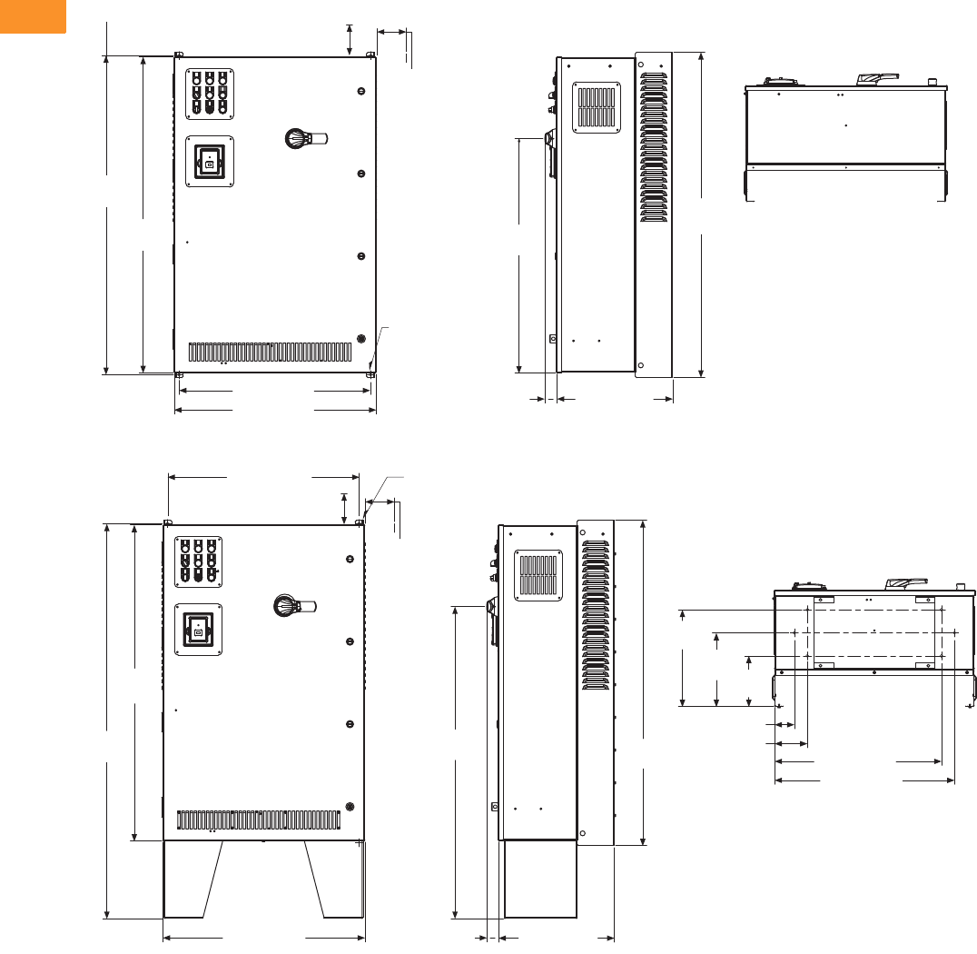
V6-T2-94 Volume 6—Solid-State Motor Control CA08100007E—February 2016 www.eaton.com
2
2
2
2
2
2
2
2
2
2
2
2
2
2
2
2
2
2
2
2
2
2
2
2
2
2
2
2
2
2
2.6
Adjustable Frequency Drives
PowerXL DG1 Series Drives
Approximate Dimensions in Inches (mm)
CX Box Type 1
CX Box Type 1—12 Inch Floor Stands
4.00 (101.6) Minimum
Free Air Space Required
48.80
(1239.5)
48.35
(1228.1)
29.30 (744.2)
30.92 (785.4) 17.76 (451.2)
1.74
(44.2)
49.74
(1263.4)
35.85
(910.6)
3.00 (76.2)
Minimum
Air Space
Required
Both Sides
Ø 0.44 (11.2)
Mounting
Holes
(4 Places)
3.00 (76.2)
5.00 (127.0)
29.30 (744.2)
48.35
(1228.1)
60.37
(1533.4)
30.92 (785.4) 17.76 (451.2)
47.67
(1210.8) 49.74
(1263.4)
14.81
(376.2)
11.28
(286.5) 7.75
(196.9)
27.50 (698.5)
25.50 (647.7)
Ø 0.44 (11.2)
Mounting
Holes
(2 Places)
3.00 (76.2)
Minimum
Air Space
Required
Both Sides
4.00 (101.6) Minimum
Free Air Space Required
1.74
(44.2)
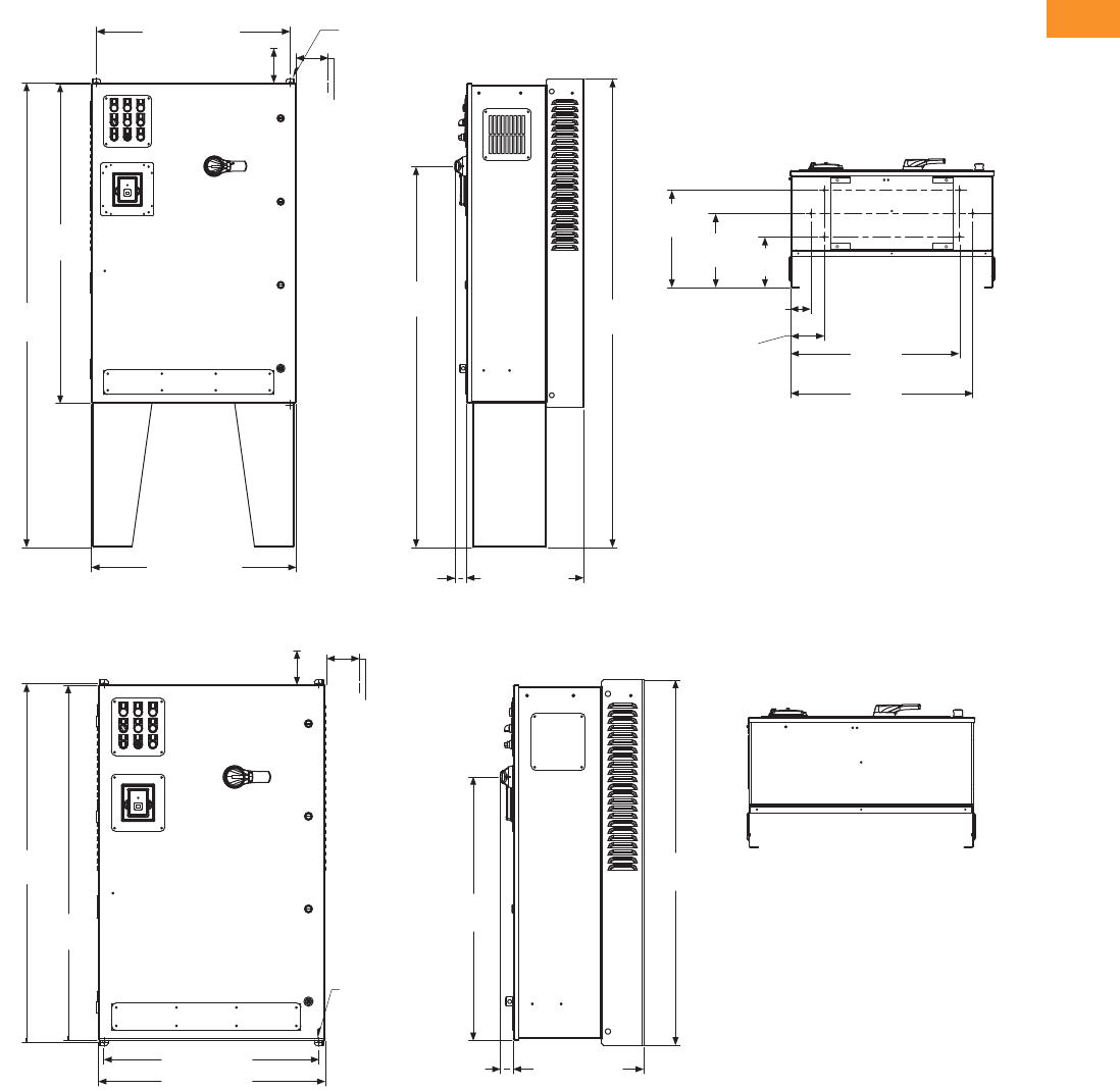
Volume 6—Solid-State Motor Control CA08100007E—February 2016 www.eaton.com V6-T2-95
2
2
2
2
2
2
2
2
2
2
2
2
2
2
2
2
2
2
2
2
2
2
2
2
2
2
2
2
2
2
2.6
Adjustable Frequency Drives
PowerXL DG1 Series Drives
Approximate Dimensions in Inches (mm)
CX Box Type 1—22 Inch Floor Stands
CX Box Type 12
29.30 (744.2)
4.00 (101.6) Minimum
Free Air Space Required
Ø 0.44 (11.2)
Mounting Holes
(2 Places)
3.00 (76.2)
Minimum
Air Space
Required
Both Sides
48.35
(1228.1)
70.37
(1787.4)
30.92 (785.4) 17.76 (451.2)1.74 (44.2)
57.68
(1465.0) 70.87
(1800.1)
14.81
(376.2) 11.28
(286.5) 7.75
(196.9)
25.50
(647.7)
27.50
(698.5)
5.00
(127.0)
3.00
(76.2)
49.74
(1263.4)
48.80
(1239.5)
48.35
(1228.1)
29.30 (744.2)
30.92 (785.4)
1.74
(44.2) 17.76 (451.2)
35.85
(910.6)
3.00 (76.2)
Minimum
Air Space
Required
Both Sides
4.00 (101.6) Minimum
Free Air Space Required
Ø 0.44 (11.2)
Mounting
Holes
(4 Places)
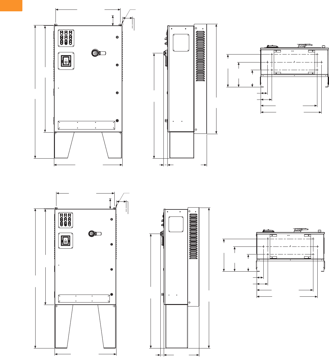
V6-T2-96 Volume 6—Solid-State Motor Control CA08100007E—February 2016 www.eaton.com
2
2
2
2
2
2
2
2
2
2
2
2
2
2
2
2
2
2
2
2
2
2
2
2
2
2
2
2
2
2
2.6
Adjustable Frequency Drives
PowerXL DG1 Series Drives
Approximate Dimensions in Inches (mm)
CX Box Type 12—12 Inch Floor Stands
CX Box Type 12—22 Inch Floor Stands
48.35
(1228.1)
60.37
(1533.4)
30.92 (785.4) 17.76 (451.2)
1.74
(44.2)
47.67
(1210.8) 49.74
(1263.4)
14.81
(376.2)
7.75
(196.9)
11.28
(286.5)
25.50 (647.7)
27.50 (698.5)
3.00 (76.2)
5.00 (127.0)
29.30 (744.2)
4.00 (101.6) Minimum
Free Air Space Required
Ø 0.44 (11.2)
Mounting
Holes
(2 Places)
3.00 (76.2)
Minimum
Air Space
Required
Both Sides
29.30 (744.2)
48.35
(1228.1)
70.37
(1787.4)
30.92 (785.4)
57.68
(1465.0) 70.87
(1800.1)
Ø 0.44 (11.2)
Mounting
Holes
(2 Places)
3.00 (76.2)
Minimum
Air Space
Required
Both Sides
4.00 (101.6) Minimum
Free Air Space Required
14.81
(376.2)
7.75
(196.9)
11.28
(286.5)
25.50 (647.7)
27.50 (698.5)
3.00 (76.2)
5.00 (127.0)
17.76
(451.2)
1.74
(44.2)
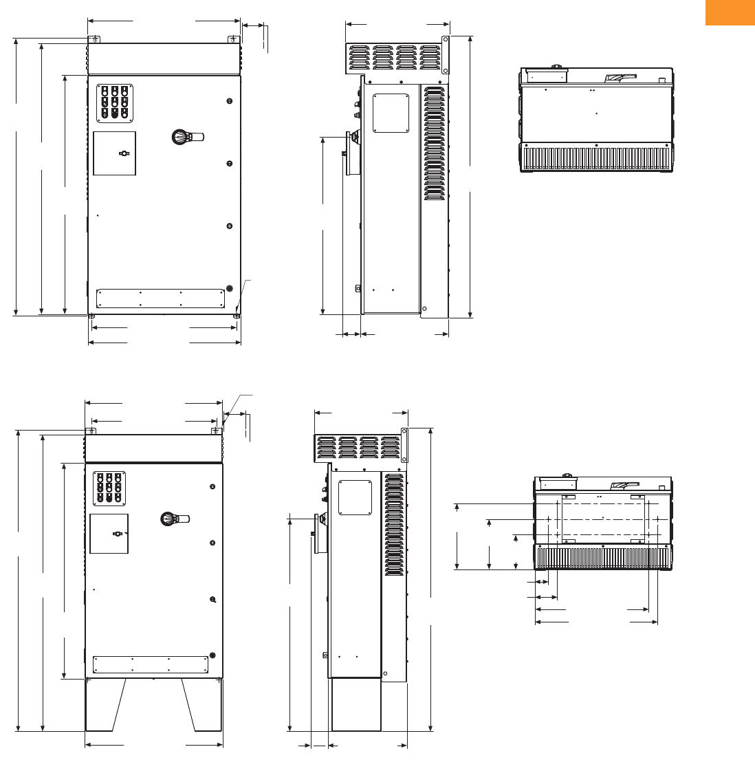
Volume 6—Solid-State Motor Control CA08100007E—February 2016 www.eaton.com V6-T2-97
2
2
2
2
2
2
2
2
2
2
2
2
2
2
2
2
2
2
2
2
2
2
2
2
2
2
2
2
2
2
2.6
Adjustable Frequency Drives
PowerXL DG1 Series Drives
Approximate Dimensions in Inches (mm)
CX Box Type 3R
CX Box Type 3R—12 Inch Floor Stands
30.88 (784.4)
56.08
(1424.5)
54.77
(1391.2)
48.35
(1228.1)
29.30 (744.2)
30.92 (785.4) 17.76 (451.2)
3.72
(94.4)
56.96
(1446.9)
35.85
(910.6)
21.00 (533.3)
3.00 (76.2)
Minimum
Air Space
Required
Both Sides
Ø 0.44 (11.2)
Mounting
Holes
(4 Places)
3.00 (76.2)
30.88 (784.4)
28.10 (713.7)
67.65
(1718.4)
48.35
(1228.1)
66.60
(1691.7)
30.92 (785.4)
21.00 (533.3)
68.09
(1729.6)
47.67
(1210.8)
17.76 (451.2)
3.72
(94.4)
14.81
(376.2) 11.28
(286.5) 7.75
(196.9)
25.50 (647.7)
27.50 (698.5)
5.00 (127.0)
Ø 0.44 (11.2)
Mounting
Holes
(2 Places)
3.00 (76.2)
Minimum
Air Space
Required
Both Sides

V6-T2-98 Volume 6—Solid-State Motor Control CA08100007E—February 2016 www.eaton.com
2
2
2
2
2
2
2
2
2
2
2
2
2
2
2
2
2
2
2
2
2
2
2
2
2
2
2
2
2
2
2.6
Adjustable Frequency Drives
PowerXL DG1 Series Drives
Approximate Dimensions in Inches (mm)
CX Box Type 3R—22 Inch Floor Stands
DX Box Type 1
78.09
(1983.6) 3.00 (76.2)
14.81
(376.2) 11.28
(286.5) 7.75
(196.9)
25.50 (647.7)
27.50 (698.5)
5.00 (127.0)
21.00 (533.3)
57.68
(1465.0)
30.92 (785.4)
77.65
(1972.4)
48.35
(1228.1)
76.60
(1945.7)
30.88 (784.4)
27.88 (708.2)
Ø 0.44 (11.2)
Mounting
Holes
(2 Places)
3.00 (76.2)
Minimum
Air Space
Required
Both Sides
17.76
(451.2)
3.72
(94.4)
1.55
(39.4)
29.30 (744.2)
82.23
(2088.6)
76.35
(1939.3)
30.92 (785.4) 22.48
(571.1)
28.88 (733.6)
82.85
(2104.4)
67.88
(1724.2)
22.56
(573.0) 6.13
(155.6)
8.38 (212.9)
1.62 (41.1)
22.12
(561.8)
Ø 0.44 (11.2)
Mounting
Holes
(2 Places)
3.00 (76.2)
Minimum
Air Space
Required
Both Sides
4.00 (101.6)
Minimum
Free Air Space
Required
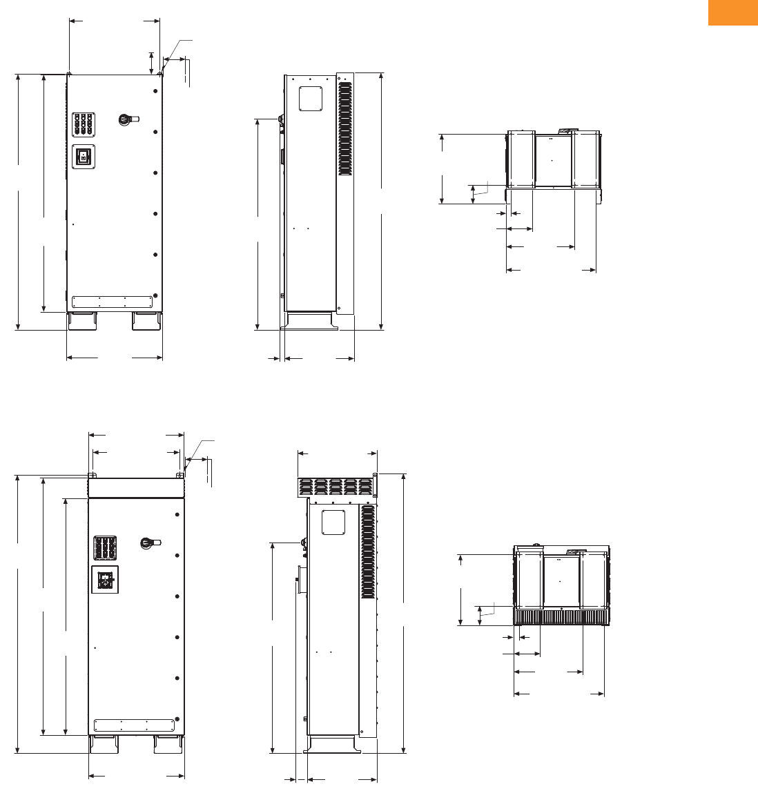
Volume 6—Solid-State Motor Control CA08100007E—February 2016 www.eaton.com V6-T2-99
2
2
2
2
2
2
2
2
2
2
2
2
2
2
2
2
2
2
2
2
2
2
2
2
2
2
2
2
2
2
2.6
Adjustable Frequency Drives
PowerXL DG1 Series Drives
Approximate Dimensions in Inches (mm)
DX Box Type 12
DX Box Type 3R
82.35
(2091.7)
76.35
(1939.3)
30.92
(785.4)
22.48
(571.1)
1.55
(39.4)
82.85
(2104.4)
67.89
(1724.4)
28.88 (733.6)
22.56
(573.0) 6.13
(155.6)
8.38 (212.9)
1.62 (41.1)
22.12
(561.8)
29.30 (744.2)
Ø 0.44 (11.2)
Mounting
Holes
(2 Places)
3.00 (76.2)
Minimum
Air Space
Required
Both Sides
4.00 (101.6)
Minimum
Free Air Space
Required
22.81
(579.2)
29.06 (738.1)
30.88 (784.4)
27.88 (708.2)
89.70
(2278.3)
82.84
(2104.1)
76.35
(1939.3)
30.92 (785.4) 3.64
(92.5)
22.48
(571.1)
67.89
(1724.4)
90.14
(2289.5)
25.51 (647.8)
1.80 (45.7)
8.56 (217.4)
22.30
(566.4)
Ø 0.44 (11.2)
Mounting
Holes
(2 Places)
3.00 (76.2)
Minimum
Air Space
Required
Both Sides
6.31
(160.3)
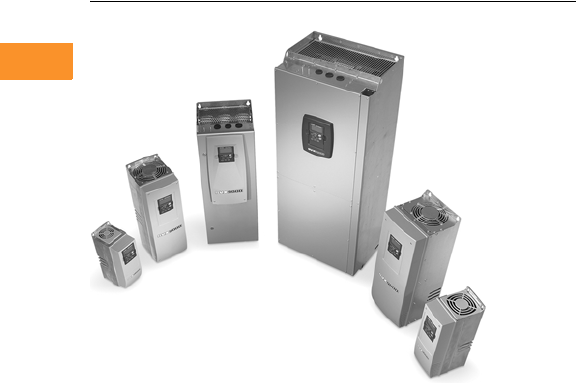
V6-T2-100 Volume 6—Solid-State Motor Control CA08100007E—February 2016 www.eaton.com
2
2
2
2
2
2
2
2
2
2
2
2
2
2
2
2
2
2
2
2
2
2
2
2
2
2
2
2
2
2
2.7
Adjustable Frequency Drives
SVX Drives
SVX Drives
Contents
Description Page
SVX Drives
Standards and Certifications . . . . . . . . . . . . . . V6-T2-101
Catalog Number Selection . . . . . . . . . . . . . . . . V6-T2-101
Product Selection . . . . . . . . . . . . . . . . . . . . . . . V6-T2-102
Accessories . . . . . . . . . . . . . . . . . . . . . . . . . . . V6-T2-106
Options . . . . . . . . . . . . . . . . . . . . . . . . . . . . . . V6-T2-107
Replacement Parts . . . . . . . . . . . . . . . . . . . . . . V6-T2-115
Technical Data and Specifications . . . . . . . . . . V6-T2-124
Dimensions . . . . . . . . . . . . . . . . . . . . . . . . . . . V6-T2-125
SVX Enclosed Drives . . . . . . . . . . . . . . . . . . . . . . . V6-T2-141
SVX Drives
Product Description
SVX Series Adjustable
Frequency Drives from
Eaton’s Electrical Sector are
the next generation of drives
specifically engineered for
today’s commercial and
industrial applications. The
power unit makes use of the
most sophisticated
semiconductor technology
and a highly modular
construction that can be
flexibly adapted to the
customer’s needs.
The input and output
configuration (I/O) is designed
with modularity in mind. The
I/O is compromised of option
cards, each with its own input
and output configuration. The
control module is designed to
accept a total of five of these
cards. The cards contain not
only normal analog and digital
inputs but also fieldbus cards.
These drives continue the
tradition of robust
performance, and raise the
bar on features and
functionality, ensuring the
best solution at the right
price.
Features
●Robust design—proven
500,000 hours MTBF
●Integrated 3% line reactors
standard on drives from
FR4 through FR9
●EMI/RFI Filters H standard
up to 200 hp IH 480 V, 100
hp IH 230 V
●Simplified operating menu
allows for typical
programming changes,
while programming mode
provides control of
everything
●Quick Start Wizard built
into the programming of
the drive ensures a smooth
start-up
●Keypad can display up to
three monitored
parameters simultaneously
●LOCAL/REMOTE operation
from keypad
●Copy/paste function allows
transfer of parameter
settings from one drive to
the next
●Standard NEMA Type 12/
IP54 keypad on all drives
●The SVX can be flexibly
adapted to a variety of
needs using our pre-
installed “Seven in One”
precision application
programs consisting of:
●Basic
●Standard
●Local/remote
●Multi step speed control
●PID control
●Multi-purpose control
●Pump and fan control
with auto change
●Additional I/O and
communication cards
provide plug and play
functionality
●I/O connections with
simple quick connection
terminals
●Hand-held auxiliary 24 V
power supply allows
programming/monitoring
of control module without
applying full power to the
drive
●Control logic can be
powered from an external
auxiliary control panel,
internal drive functions and
fieldbus if necessary
●Brake chopper standard
from: 1–30 hp/380–500 V
3/4–15 hp/208–230 V
●NEMA Type 1/IP21 and
NEMA Type 12/IP54
enclosures available,
Frame Sizes FR4–FR9
●Open chassis FR10 and
greater
●Standard option board
configuration includes an
A9 I/O board and an A2
relay output board installed
in slots A and B
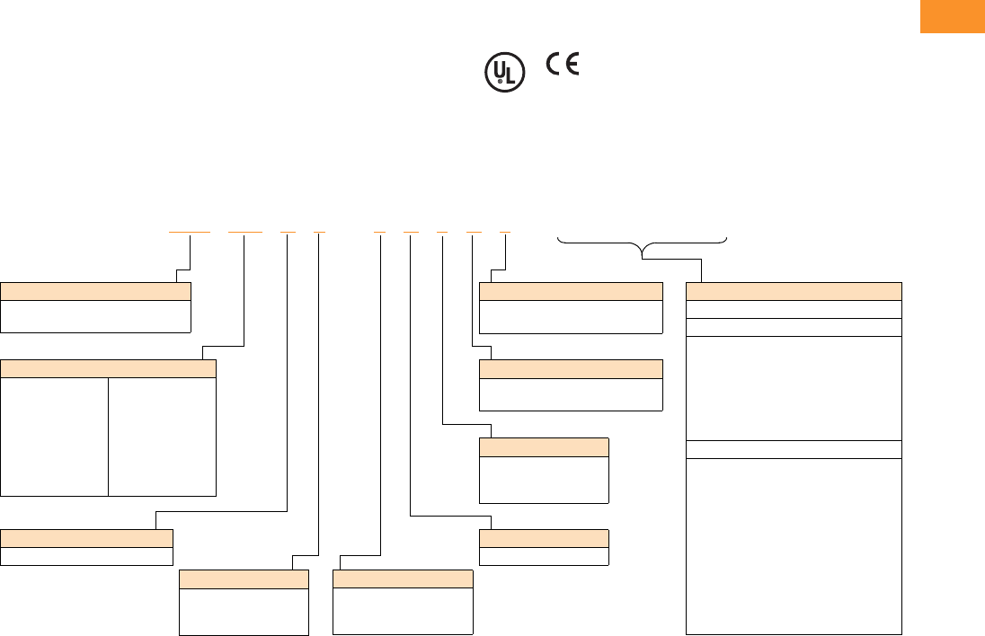
Volume 6—Solid-State Motor Control CA08100007E—February 2016 www.eaton.com V6-T2-101
2
2
2
2
2
2
2
2
2
2
2
2
2
2
2
2
2
2
2
2
2
2
2
2
2
2
2
2
2
2
2.7
Adjustable Frequency Drives
SVX Drives
Standards and Certifications
Product
●IEC 61800-2
EMC (At Default Settings)
●Immunity: Fulfills all EMC
immunity requirements;
Emissions: EN 61800-3,
LEVEL H
Safety
●UL 508C
●CE
Catalog Number Selection
SVX Adjustable Frequency Drives
Notes
1All 230 V drives and 480 V drives up to 200 hp (IH) are only available with input option 1 (EMC Level H). 480 V drives 250 hp (IH) or larger are available
with input option 2 (EMC Level N). 480 V drives are available with input option 4 (EMC Level L). 575 V drives 200 hp (IH) or larger are only available
with input option 2. 575 V drives up to 150 hp (IH) are only available with input option 4 (EMC Level L).
2480 V drives up to 30 hp (IH) are only available with brake chopper option B. 480 V drives 40 hp (IH) or larger come standard with brake chopper option N.
230 V drives up to 15 hp (IH) are only available with brake chopper option B. 230 V drives 20 hp or larger come standard with brake chopper option N.
All 575 V drives come standard without brake chopper option (N). N = No brake chopper.
3480 V drives 250 hp (IH) and larger are available with enclosure style 0 (chassis); 690 V drives 200 hp (IH) and larger are available with
enclosure style 0 (chassis).
4Factory promise delivery. Consult sales office for availability.
SVX 010 A 1 –4A 1 B 1 ______
Options
Options appear in alphabetical order.
Extended I/O Card Options
B1 = 6 DI, 1 ext +24 Vdc/EXT +24 Vdc
B2 = 1 RO (NC-NO), 1 RO (NO), 1 therm
B4 = 1 AI (mA isolated), 2 AO (mA isolated),
1 ext +24 Vdc/EXT + 24 Vdc
B5 = 3 RO (NO)
B8 = 1 ext +24 Vdc/EXT +24 Vdc, 3 Pt100
B9 = 1 RO (NO), 5 DI 42–240 Vac input
Communication Cards
CA = Johnson Controls N2
CI = Modbus TCP
CJ = BACnet
CQ = EtherNet/IP
C2 = Modbus
C3 = PROFIBUS DP
C4 = LonWorks
C5 = PROFIBUS DP (D9 connector)
C6 = CANopen (slave)
C7 = DeviceNet
C8 = Modbus (D9 Type connector)
D3 = RS-232 with D9 connection
Board Modifications
1 = Standard boards
2 = Conformal (varnished) coating 4
Brake Chopper Options 2
N = No brake chopper circuit
B = Internal brake chopper circuit
Input Options 1
1 = Three-phase, EMC H
2 = Three-phase, EMC N
4 = Three-phase, EMC L
Keypad
A = Alphanumeric
AFD Software Series
A = Standard software
Enclosure 3
0 = Chassis
1 = NEMA Type 1/IP21
2 = NEMA Type 12/IP54
Voltage Rating
2 = 230 V (208–240)
4 = 480 V (380–500)
5 = 575 V (525–690)
Product Family
SVX = Open drives
SPX = Open drives FR10 and greater
Horsepower Rating
F07 = 3/4 hp
F15 = 1-1/2 hp
007 = 7-1/2 hp
010 = 10 hp
050 = 50 hp
125 = 125 hp
350 = 350 hp
700 = 700 hp
800 = 800 hp
900 = 900 hp
H10 = 1000 hp
H12 = 1200 hp
H13 = 1350 hp
H15 = 1500 hp
H16 = 1600 hp
H20 = 2000 hp

V6-T2-102 Volume 6—Solid-State Motor Control CA08100007E—February 2016 www.eaton.com
2
2
2
2
2
2
2
2
2
2
2
2
2
2
2
2
2
2
2
2
2
2
2
2
2
2
2
2
2
2
2.7
Adjustable Frequency Drives
SVX Drives
Product Selection
230 V SVX Drives
208–240 V, NEMA Type 1/IP21 Drives
208–240 V, NEMA Type 12/IP54 Drives
Frame
Size hp (IH) Current (IH) hp (IL) Current (IL) Catalog Number
FR4 3/4 3.7 1 4.8 SVXF07A1-2A1B1
1 4.8 1-1/2 6.6 SVX001A1-2A1B1
1-1/2 6.6 2 7.8 SVXF15A1-2A1B1
27.8 311 SVX002A1-2A1B1
311 —12.5 SVX003A1-2A1B1
FR5 — 12.5 5 17.5 SVX004A1-2A1B1
517.5 7-1/225 SVX005A1-2A1B1
7-1/2 25 10 31 SVX007A1-2A1B1
FR61031 1548 SVX010A1-2A1B1
15 48 20 61 SVX015A1-2A1B1
FR72061 2575 SVX020A1-2A1N1
25 75 30 88 SVX025A1-2A1N1
30 88 40 114 SVX030A1-2A1N1
FR8 40 114 50 140 SVX040A1-2A1N1
50 140 60 170 SVX050A1-2A1N1
60 170 75 205 SVX060A1-2A1N1
FR9 75 205 100 261 SVX075A1-2A1N1
100 261 125 300 SVX100A1-2A1N1
Frame
Size hp (IH) Current (IH) hp (IL) Current (IL) Catalog Number
FR4 3/4 3.7 1 4.8 SVXF07A2-2A1B1
1 4.8 1-1/2 6.6 SVX001A2-2A1B1
1-1/2 6.6 2 7.8 SVXF15A2-2A1B1
27.8 311 SVX002A2-2A1B1
311 —12.5 SVX003A2-2A1B1
FR5 — 12.5 5 17.5 SVX004A2-2A1B1
517.5 7-1/225 SVX005A2-2A1B1
7-1/2 25 10 31 SVX007A2-2A1B1
FR61031 1548 SVX010A2-2A1B1
15 48 20 61 SVX015A2-2A1B1
FR72061 2575 SVX020A2-2A1N1
25 75 30 88 SVX025A2-2A1N1
30 88 40 114 SVX030A2-2A1N1
FR8 40 114 50 140 SVX040A2-2A1N1
50 140 60 170 SVX050A2-2A1N1
60 170 75 205 SVX060A2-2A1N1
FR9 75 205 100 261 SVX075A2-2A1N1
100 261 125 300 SVX100A2-2A1N1
SVX Open Drives

Volume 6—Solid-State Motor Control CA08100007E—February 2016 www.eaton.com V6-T2-103
2
2
2
2
2
2
2
2
2
2
2
2
2
2
2
2
2
2
2
2
2
2
2
2
2
2
2
2
2
2
2.7
Adjustable Frequency Drives
SVX Drives
480 V SVX Drives
380–500 V, NEMA Type 1/IP21 Drives
380–500 V, NEMA Type 12/IP54 Drives
Frame
Size hp (IH) Current (IH) hp (IL) Current (IL) Catalog Number
FR4 1 2.2 1-1/2 3.3 SVX001A1-4A1B1
1-1/2 3.3 2 4.3 SVXF15A1-4A1B1
24.3 35.6 SVX002A1-4A1B1
35.6 57.6 SVX003A1-4A1B1
57.6 —9 SVX005A1-4A1B1
—9 7-1/212 SVX006A1-4A1B1
FR5 7-1/2 12 10 16 SVX007A1-4A1B1
10 16 15 23 SVX010A1-4A1B1
15 23 20 31 SVX015A1-4A1B1
FR62031 2538 SVX020A1-4A1B1
25 38 30 46 SVX025A1-4A1B1
30 46 40 61 SVX030A1-4A1B1
FR74061 5072 SVX040A1-4A1N1
50 72 60 87 SVX050A1-4A1N1
60 87 75 105 SVX060A1-4A1N1
FR8 75 105 100 140 SVX075A1-4A1N1
100 140 125 170 SVX100A1-4A1N1
125 170 150 205 SVX125A1-4A1N1
FR9 150 205 200 261 SVX150A1-4A1N1
200 245 250 300 SVX200A1-4A1N1
Frame
Size hp (IH) Current (IH) hp (IL) Current (IL) Catalog Number
FR4 1 2.2 1-1/2 3.3 SVX001A2-4A1B1
1-1/2 3.3 2 4.3 SVXF15A2-4A1B1
24.3 35.6 SVX002A2-4A1B1
35.6 57.6 SVX003A2-4A1B1
57.6 —9 SVX005A2-4A1B1
— 9 7-1/2 12 SVX006A2-4A1B1
FR5 7-1/2 12 10 16 SVX007A2-4A1B1
10 16 15 23 SVX010A2-4A1B1
15 23 20 31 SVX015A2-4A1B1
FR62031 2538 SVX020A2-4A1B1
25 38 30 46 SVX025A2-4A1B1
30 46 40 61 SVX030A2-4A1B1
FR74061 5072 SVX040A2-4A1N1
50 72 60 87 SVX050A2-4A1N1
60 87 75 105 SVX060A2-4A1N1
FR8 75 105 100 140 SVX075A2-4A1N1
100 140 125 170 SVX100A2-4A1N1
125 170 150 205 SVX125A2-4A1N1
FR9 150 205 200 261 SVX150A2-4A1N1
200 245 250 300 SVX200A2-4A1N1
SVX Open Drives
V6-T2-104 Volume 6—Solid-State Motor Control CA08100007E—February 2016 www.eaton.com
2
2
2
2
2
2
2
2
2
2
2
2
2
2
2
2
2
2
2
2
2
2
2
2
2
2
2
2
2
2
2.7
Adjustable Frequency Drives
SVX Drives
380–500 V, Open Chassis Drives
575 V SVX Drives
525–690 V, NEMA Type 1/IP21 Drives
Note
1 FR10–FR14 includes 3% line reactor, but it is not integral to chassis.
Frame
Size hp (IH) Current (IH) hp (IL) Current (IL) Catalog Number
FR10 1250 330 300 385 SPX250A0-4A2N1
300 385 350 460 SPX300A0-4A2N1
350 460 400 520 SPX350A0-4A2N1
FR11 400 520 500 590 SPX400A0-4A2N1
500 590 — 650 SPX500A0-4A2N1
— 650 600 730 SPX550A0-4A2N1
FR12 600 730 — 820 SPX600A0-4A2N1
— 820 700 920 SPX650A0-4A2N1
700 920 800 1030 SPX700A0-4A2N1
FR13 800 1030 900 1150 SPX800A0-4A2N1
900 1150 1000 1300 SPX900A0-4A2N1
1000 1300 1200 1450 SPXH10A0-4A2N1
FR14 1200 1600 1500 1770 SPXH12A0-4A2N1
1600 1940 1800 2150 SPXH16A0-4A2N1
1900 2300 2200 2700 SPXH19A0-4A2N1
Frame
Size hp (IH) Current (IH) hp (IL) Current (IL) Catalog Number
FR6 2 3.3 3 4.5 SVX002A1-5A4N1
34.5 —5.5 SVX003A1-5A4N1
—5.5 5 7.5 SVX004A1-5A4N1
5 7.5 7-1/2 10 SVX005A1-5A4N1
7-1/2 10 10 13.5 SVX007A1-5A4N1
10 13.5 15 18 SVX010A1-5A4N1
15 18 20 22 SVX015A1-5A4N1
20 22 25 27 SVX020A1-5A4N1
25 27 30 34 SVX025A1-5A4N1
FR73034 4041 SVX030A1-5A4N1
40 41 50 52 SVX040A1-5A4N1
FR85052 6062 SVX050A1-5A4N1
60 62 75 80 SVX060A1-5A4N1
75 80 100 100 SVX075A1-5A4N1
FR9 100 100 125 125 SVX100A1-5A4N1
125 125 150 144 SVX125A1-5A4N1
150 144 — 170 SVX150A1-5A4N1
— 170 200 208 SVX175A1-5A4N1
SVX Open Drives
Volume 6—Solid-State Motor Control CA08100007E—February 2016 www.eaton.com V6-T2-105
2
2
2
2
2
2
2
2
2
2
2
2
2
2
2
2
2
2
2
2
2
2
2
2
2
2
2
2
2
2
2.7
Adjustable Frequency Drives
SVX Drives
525–690 V, NEMA Type 12/IP54 Drives
525–690 V, Open Chassis Drives
Frame
Size hp (IH) Current (IH) hp (IL) Current (IL) Catalog Number
FR6 2 3.3 3 4.5 SVX002A2-5A4N1
34.5 —5.5 SVX003A2-5A4N1
—5.5 5 7.5 SVX004A2-5A4N1
5 7.5 7-1/2 10 SVX005A2-5A4N1
7-1/2 10 10 13.5 SVX007A2-5A4N1
10 13.5 15 18 SVX010A2-5A4N1
15 18 20 22 SVX015A2-5A4N1
20 22 25 27 SVX020A2-5A4N1
25 27 30 34 SVX025A2-5A4N1
FR73034 4041 SVX030A2-5A4N1
40 41 50 52 SVX040A2-5A4N1
FR85052 6062 SVX050A2-5A4N1
60 62 75 80 SVX060A2-5A4N1
75 80 100 100 SVX075A2-5A4N1
FR9 100 100 125 125 SVX100A2-5A4N1
125 125 150 144 SVX125A2-5A4N1
150 144 — 170 SVX150A2-5A4N1
— 170 200 208 SVX175A2-5A4N1
Frame
Size hp (IH) Current (IH) hp (IL) Current (IL) Catalog Number
FR10 200 208 250 261 SPX200A0-5A2N1
250 261 300 325 SPX250A0-5A2N1
300 325 400 385 SPX300A0-5A2N1
FR11 400 385 450 460 SPX400A0-5A2N1
450 460 500 502 SPX450A0-5A2N1
500 502 — 590 SPX500A0-5A2N1
FR12 — 590 600 650 SPX550A0-5A2N1
600 650 700 750 SPX600A0-5A2N1
700 750 800 820 SPX700A0-5A2N1
FR13 800 820 900 920 SPX800A0-5A2N1
900 920 1000 1030 SPX900A0-5A2N1
1000 1030 1250 1180 SPXH10A0-5A2N1
FR14 1350 1300 1500 1500 SPXH13A0-5A2N1
1500 1500 2000 1900 SPXH15A0-5A2N1
2000 1900 2300 2250 SPXH20A0-5A2N1
SVX Open Drives

V6-T2-106 Volume 6—Solid-State Motor Control CA08100007E—February 2016 www.eaton.com
2
2
2
2
2
2
2
2
2
2
2
2
2
2
2
2
2
2
2
2
2
2
2
2
2
2
2
2
2
2
2.7
Adjustable Frequency Drives
SVX Drives
Accessories
Demo Drive and Power Supply
Demo Drive and Power Supply
NEMA Type 12/IP54 Conversion Kit
The NEMA Type 12/IP54 kit
option is used to convert a
NEMA Type 1/IP21 to a
NEMA Type 12/IP54 drive.
The NEMA Type 12/IP54
kit consists of a metal
drive shroud, fan kit for
some frames, adaptor plate
and plugs.
NEMA Type 12/IP54 Conversion Kit
Flange Kits
Flange Kit NEMA Type 12/IP54
The flange kit is utilized when the power section is mounted through the back panel of an enclosure.
Includes flange mount brackets and NEMA Type 12/IP54 fan components. Metal shroud not included.
Flange kits for NEMA Type 12/IP54 enclosure drive rating are determined by rating of drive.
NEMA Type 12/IP54 Conversion Kit
Notes
1For installation of an SVX NEMA Type 1/IP21 drive into a NEMA Type 12/IP54 oversized enclosure.
2For NEMA 1 drives, both parts are required.
Description Catalog Number
9000X demo drive 9000XDEMO
Approximate Dimensions in Inches (mm) Approximate
Weight Lb (kg)Frame Size Delivery Code Length Width Height Catalog Number
FR4 W 13 (330) 7 (178) 4 (102) 4 (1.8) OPTN12FR4
FR5 16 (406) 8 (203) 7 (178) 5 (2.3) OPTN12FR5
FR6 21 (533) 10 (254) 5 (127) 7 (3.2) OPTN12FR6
Drive
NEMA Rating
Drive
Frame Size
Parts Needed
N12 Conversion Kit Flange Kit
NEMA 1 FR4 OPTTHRFR4 2OPTTHR4 2
NEMA 1 FR5 OPTTHRFR5 2OPTTHR5 2
NEMA 1 FR6 OPTTHRFR5 2OPTTHR5 2
NEMA 1 FR7 Need to use NEMA 12 drive Need to use NEMA 12 drive
NEMA 1 FR8 Need to use NEMA 12 drive Need to use NEMA 12 drive
NEMA 1 FR9 Need to use NEMA 12 drive Need to use NEMA 12 drive
NEMA 12 FR4 — OPTTHR4
NEMA 12 FR5 — OPTTHR5
NEMA 12 FR6 — OPTTHR5
NEMA 12 FR7 — OPTTHR7
NEMA 12 FR8 — OPTTHR8
NEMA 12 FR9 — OPTTHR9
Volume 6—Solid-State Motor Control CA08100007E—February 2016 www.eaton.com V6-T2-107
2
2
2
2
2
2
2
2
2
2
2
2
2
2
2
2
2
2
2
2
2
2
2
2
2
2
2
2
2
2
2.7
Adjustable Frequency Drives
SVX Drives
Options
SVX Series Option Board Kits
The SVX Series drives can accommodate a wide selection of expander and adapter option boards to
customize the drive for your application needs. The drive’s control unit is designed to accept a total
of five option boards.
The SVX Series factory installed standard board configuration includes an A9 I/O board and an A2 relay
output board, which are installed in slots A and B.
Option Board Kits
Notes
1 AI = Analog Input; AO = Analog Output, DI = Digital Input, DO = Digital Output, RO = Relay Output
2 Option card must be installed in one of the slots listed for that card. Slot indicated in bold is the preferred location.
3 OPTC2 is a multi-protocol option card.
Option Kit Description 1
Allowed Slot
Locations 2
Field
Installed
Factory
Installed SVX Ready Programs
Catalog
Number
Option
Designator Basic
Local/
Remote Standard MSS PID Multi-P. PFC
Standard I/O Cards
6 DI, 1 DO, 2 AI, 1 AO, 1 +10 Vdc ref,
2 ext +24 Vdc/EXT +24 Vdc
AOPTA9 — ■ ■ ■ ■■■ ■
2 RO (NC-NO) B OPTA2 — ■ ■ ■ ■■■ ■
Extended I/O Cards
2 RO, therm B OPTA3 A3 —■ ■ ■■■ ■
Encoder low volt +5 V/15 V/24 V—SPX only C OPTA4 A4 —■ ■ ■■■ ■
Encoder high volt +15 V/24 V—SPX only C OPTA5 A5 —■ ■ ■■■ ■
Double encoder—SPX only C OPTA7 A7 ■ ■ ■ ■■■ ■
6 DI, 1 DO, 2 AI, 1 AO A OPTA8 A8 —■ ■ ■■■ ■
3 DI (encoder 10–24 V), out +15 V/+24 V,
2 DO (pulse+direction)—SPX only
COPTAE AE ■ ■ ■ ■■■ ■
6 DI, 1 ext +24 Vdc/EXT +24 Vdc B, C, D, E OPTB1 B1 —— — ——
■■
1 RO (NC-NO), 1 RO (NO), 1 therm B, C, D, E OPTB2 B2 —— — ——
■■
1 AI (mA isolated), 2 AO (mA isolated),
1 ext +24 Vdc/EXT +24 Vdc
B, C, D, E OPTB4 B4 ■ ■ ■ ■■■ ■
3 RO (NO) B, C, D, E OPTB5 B5 —— — ——
■■
1 ext +24 Vdc/EXT +24 Vdc, 3 Pt100 B, C, D, E OPTB8 B8 — — — ——— —
1 RO (NO), 5 DI 42–240 Vac input B, C, D, E OPTB9 B9 —— — ——
■■
Communication Cards
Modbus 3D, E OPTC2-BP C2 ■ ■ ■ ■■■ ■
Johnson Controls N2 3D, E OPTC2-BP CA — — — ——— —
Modbus TCP D, E OPTCI-BP CI ■ ■ ■ ■■■ ■
BACnet D, E OPTCJ CJ ■ ■ ■ ■■■ ■
EtherNet/IP D, E OPTCQ CQ ■ ■ ■ ■■■ ■
PROFIBUS DP D, E OPTC3 C3 ■ ■ ■ ■■■ ■
LonWorks D, E OPTC4 C4 ■ ■ ■ ■■■ ■
PROFIBUS DP (D9 connector) D, E OPTC5 C5 ■ ■ ■ ■■■ ■
CANopen (slave) D, E OPTC6 C6 ■ ■ ■ ■■■ ■
DeviceNet D, E OPTC7 C7 ■ ■ ■ ■■■ ■
Modbus (D9 type connector) D, E OPTC8 C8 ■ ■ ■ ■■■ ■
Adapter—SPX only D, EOPTD1VD1
■ ■ ■ ■■■ ■
Adapter—SPX only D, EOPTD2VD2
■ ■ ■ ■■■ ■
RS-232 with D9 connection D, E OPTD3 D3 ■ ■ ■ ■■■ ■
Option Boards
ABCDE

V6-T2-108 Volume 6—Solid-State Motor Control CA08100007E—February 2016 www.eaton.com
2
2
2
2
2
2
2
2
2
2
2
2
2
2
2
2
2
2
2
2
2
2
2
2
2
2
2
2
2
2
2.7
Adjustable Frequency Drives
SVX Drives
Modbus RTU Network
Communications
The Modbus Network Card
OPTC2 is used for connecting
the SVX Drive as a slave on a
Modbus network. The
interface is connected by a
9-pin DSUB connector
(female) and the baud rate
ranges from 300 to 19,200
baud. Other communication
parameters include an
address range from 1 to 247;
a parity of None, Odd or
Even; and the stop bit is 1.
PROFIBUS Network
Communications
The PROFIBUS Network Card
OPTC3 is used for connecting
the SVX Drive as a slave on
a PROFIBUS-DP network.
The interface is connected
by a 9-pin DSUB connector
(female). The baud rates
range from 9.6 Kbaud to
12 Mbaud, and the addresses
range from 1 to 127.
LonWorks Network
Communications
The LonWorks Network Card
OPTC4 is used for connecting
the SVX Drive on a LonWorks
network. This interface uses
Standard Network Variable
Types (SNVT) as data types.
The channel connection is
achieved using a FTT-10 A
Free Topology transceiver
via a single twisted transfer
cable. The communication
speed with LonWorks is
78 kBits/s.
CANopen (Slave)
Communications
The CANopen (Slave)
Network Card OPTC6 is used
for connecting the SVX Drive
to a host system. According
to ISO11898 standard cables
to be chosen for CANbus
should have a nominal
impedance of 120 ohms, and
specific line delay of nominal
5 nS/m. 120 ohms line
termination resistors required
for installation.
DeviceNet Network
Communications
The DeviceNet Network Card
OPTC7 is used for connecting
the SVX Drive on a DeviceNet
Network. It includes a
5.08 mm pluggable
connector. Transfer method
is via CAN using a two-wire
twisted shielded cable with
two-wire bus power cable
and drain. The baud rates
used for communication
include 125 Kbaud,
250 Kbaud and 500 Kbaud.
Johnson Controls
Metasys N2 Network
Communications
The OPTC2 fieldbus board
provides communication
between the SVX Drive and a
Johnson Controls Metasys™
N2 network. With this
connection, the drive can be
controlled, monitored and
programmed from the
Metasys system. The N2
fieldbus is available as a
factory installed option and as
a field installable kit.
Modbus/TCP Network
Communications
The Modbus/TCP Network
Card OPTCI is used for
connecting the SVX Drive to
Ethernet networks utilizing
Modbus protocol. It includes
an RJ-45 pluggable connector.
This interface provides a
selection of standard and
custom register values to
communicate drive parameters.
The board supports 10 Mbps
and 100 Mbps communication
speeds. The IP address of the
board is configurable over
Ethernet using a supplied
software tool.
BACnet Network
Communications
The BACnet Network Card
OPTCJ is used for connecting
the SVX Drive to BACnet
networks. It includes a
5.08 mm pluggable connector.
Data transfer is Master-Slave/
Token Passing (MS/TP)
RS-485. This interface uses
a collection of 30 Binary Value
Objects (BVOs) and 35 Analog
Value Objects (AVOs) to
communicate drive parameters.
The card supports 9.6, 19.2
and 38.4 Kbaud communication
speeds and supports network
addresses 1–127.
EtherNet/IP Network
Communications
The EtherNet/IP Network
Card OPTCK is used for
connecting the SVX Drive to
Ethernet/Industrial Protocol
networks. It includes an
RJ-45 pluggable connector.
The interface uses CIP
objects to communicate drive
parameters (CIP is “Common
Industrial Protocol”, the same
protocol used by DeviceNet).
The board supports 10 Mbps
and 100 Mbps communication
speeds. The IP address of the
board is configurable by Static,
BOOTP and DHCP methods.

Volume 6—Solid-State Motor Control CA08100007E—February 2016 www.eaton.com V6-T2-109
2
2
2
2
2
2
2
2
2
2
2
2
2
2
2
2
2
2
2
2
2
2
2
2
2
2
2
2
2
2
2.7
Adjustable Frequency Drives
SVX Drives
Control Panel Options
Factory Options
Miscellaneous Options
Factory Installed Field Installed
Description Option Code
NEMA Type 1/IP21
Catalog Number
Local/Remote Keypad SVX Control Panel—This option is standard on all drives and consists of
an RS-232 connection, backlit alphanumeric LCD display with nine indicators for the RUN status
and two indicators for the control source. The nine pushbuttons on the panel are used for panel
programming and monitoring of all SVX parameters. The panel is detachable and isolated from the
input line potential. Include LOC/REM key to choose control location.
A KEYPAD-LOC/REM
Keypad Remote Mounting Kit—This option is used to remote mount the SVX keypad. The
footprint is compatible to the SV remote mount kit. Includes 10 ft cable, keypad holder and
mounting hardware.
— OPTRMT-KIT-9000X
Description Catalog Number
9000XDrive—A PC-based tool for controlling and monitoring of the SVX. Features include: loading parameters that can be
saved to a file or printed, setting references, starting and stopping the motor, monitoring signals in graphical or text form,
and real-time display. To avoid damage to the drive or computer, SVDrivecable must be used.
9000XDRIVE
SVDrivecable—6 ft (1.8 m) RS-232 cable (22 gauge) with a 7-pin connector on each end. Should be used in conjunction
with the 9000XDrive option to avoid damage to the SVX or computer. The same cable can be used for downloading
specialized applications to the drive.
SVDRIVECABLE
External Dynamic Braking Resistors—Used with the dynamic braking chopper circuit to absorb motor regenerative
energy for stopping the load and to dissipate the energy flowing back into the drive. Resistors are separated into standard
duty and heavy-duty. Standard duty is defined as 20% duty or less with 100% braking torque, while heavy-duty is defined as
50% duty or less with 150% braking torque.
See Page V6-T2-110
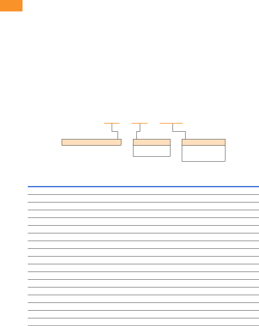
V6-T2-110 Volume 6—Solid-State Motor Control CA08100007E—February 2016 www.eaton.com
2
2
2
2
2
2
2
2
2
2
2
2
2
2
2
2
2
2
2
2
2
2
2
2
2
2
2
2
2
2
2.7
Adjustable Frequency Drives
SVX Drives
Open Drive Options
Brake Chopper Options
The brake chopper circuit
option is used for applications
that require dynamic braking.
Dynamic braking resistors are
not included with drive
purchase. Consult the factory
for additional dynamic braking
resistor selections that are
supplied separately. A list of
common resistors are listed
below and are complete
indoor assemblies, include a
pre-wired terminal block and
a thermal switch, and are not
UL Listed.
Duty Cycle
The duty cycle rating is based
on a 60-second period. For
example, the 20% duty cycle
resistor can carry 100%
current for 12 seconds out
of every 60 seconds, while
the 50% duty cycle resistor
can carry 150% current for
30 seconds out of every
60 seconds.
Torque
If the braking torque required
is less than 15%, dynamic
braking is not required
because the regenerated
energy will be dissipated in
the drive and motor losses.
Dynamic Brake Resistor—Catalog Number Selection
230 V Brake Resistors
Drive hp
(CT/IH)
Minimum
Ohms
20% Duty Cycle, 100% Torque 50% Duty Cycle, 150% Torque
Catalog Number Dimensions (Inches) Catalog Number Dimensions (Inches)
0.75 30.0 DBR-R100-W0400 12W x 5D x 5H DBR-R100-W0800 12W x 7D x 5H
130.0DBR-R100-W0400 12W x 5D x 5H DBR-R100-W0800 12W x 7D x 5H
1.5 30.0 DBR-R100-W0400 12W x 5D x 5H DBR-R036-W1200 12W x 10D x 5H
230.0DBR-R100-W0400 12W x 5D x 5H DBR-R036-W1200 12W x 10D x 5H
330.0DBR-R036-W0800 12W x 7D x 5H DBR-R036-W2000 12W x 16D x 5H
430.0DBR-R036-W0800 12W x 7D x 5H DBR-R030-W2400 19W x 10D x 5H
530.0DBR-R036-W0800 12W x 7D x 5H DBR-R030-W2800 19W x 13D x 5H
7.5 20.0 DBR-R020-W1200 12W x 10D x 5H DBR-R020-W4800 26.5W x 13D x 5H
10 10.0 DBR-R015-W1600 12W x 13D x 5H DBR-R112-W6000 26.5W x 13D x 5H
15 10.0 DBR-R012-W2400 19W x 10D x 5H DBR-R010-W9000 28W x 10D x 10H
20 3.3 DBR-R9D3-W3200 19W x 10D x 5H DBR-R3D4-W012K 28W x 10D x 10H
25 3.3 DBR-R5D5-W4000 26.5W x 10D x 5H DBR-R5D1-W015K 28W x 16D x 10H
30 3.3 DBR-R4D8-W4800 26.5W x 10D x 5H DBR-R4D1-W020K 28W x 16D x 10H
40 1.4 DBR-R004-W6000 26.5W x 13D x 5H DBR-R3D4-W025K 30W x 18D x 16H
50 1.4 DBR-R3D1-W7500 26.5W x 16D x 5H DBR-R2D1-W030K 30W x 18D x 24H
60 1.4 DBR-R2D8-W9000 26.5W x 16D x 5H DBR-R002-W036K 30W x 18D x 24H
75 1.4 DBR-R2D6-W012K 28W x 10D x 10H DBR-R1D5-W045K 30W x 18D x 32H
100 1.4 DBR-R002-W015K 28W x 16D x 10H DBR-R1D4-W060K 30W x 18D x 40H
DBR – R100 – W0800
Dynamic Brake Resistor Resistance
1D0 =1.0 Ohms
100 =100 Ohms
Rated Watts
0800 = 800 Watts
8000 = 8000 Watts
080K = 80,000 Watts

Volume 6—Solid-State Motor Control CA08100007E—February 2016 www.eaton.com V6-T2-111
2
2
2
2
2
2
2
2
2
2
2
2
2
2
2
2
2
2
2
2
2
2
2
2
2
2
2
2
2
2
2.7
Adjustable Frequency Drives
SVX Drives
480 V Brake Resistors
Note
1Consult factory.
Drive hp
(CT/IH)
Minimum
Ohms
20% Duty Cycle, 100% Torque 50% Duty Cycle, 150% Torque
Catalog Number Dimensions (Inches) Catalog Number Dimensions (Inches)
163.0DBR-R100-W0400 12W x 5D x 5H DBR-R100-W0800 12W x 7D x 5H
1.5 63.0 DBR-R100-W0400 12W x 5D x 5H DBR-R100-W1200 12W x 10D x 5H
263.0DBR-R100-W0400 12W x 5D x 5H DBR-R100-W1200 12W x 10D x 5H
363.0DBR-R100-W0800 12W x 7D x 5H DBR-R100-W2000 12W x 16D x 5H
563.0DBR-R100-W0800 12W x 7D x 5H DBR-R100-W2800 19W x 13D x 5H
663.0DBR-R100-W1200 12W x 10D x 5H DBR-R070-W4000 19W x 16D x 5H
7.5 63.0 DBR-R100-W1200 12W x 10D x 5H DBR-R063-W4800 26.5W x 13D x 5H
10 63.0 DBR-R063-W1600 12W x 13D x 5H DBR-R063-W6000 26.5W x 16D x 5H
15 42.0 DBR-R042-W2400 19W x 10D x 5H DBR-R042-W9000 28W x 10D x 10H
20 21.0 DBR-R030-W3200 19W x 13D x 5H DBR-R023-W012K 28W x 13D x 10H
25 21.0 DBR-R030-W4000 19W x 16D x 5H DBR-R021-W015K 28W x 13D x 10H
30 14.0 DBR-R020-W4800 26.5W x 13D x 5H DBR-R014-W020K 30W x 18D x 24H
40 6.5 DBR-R112-W6000 26.5W x 13D x 5H DBR-R007-W025K 30W x 18D x 16H
50 6.5 DBR-R013-W7500 26.5W x 16D x 5H DBR-R8D5-W030K 30W x 18D x 24H
60 6.5 DBR-R010-W9000 28W x 10D x 10H DBR-R7D3-W036K 30W x 18D x 24H
75 3.3 DBR-R009-W012K 28W x 13D x 10H DBR-R3D3-W045K 30W x 18D x 32H
100 3.3 DBR-R5D1-W015K 28W x 16D x 10H DBR-R004-W060K 30W x 18D x 40H
125 3.3 DBR-R4D1-W020K 28W x 16D x 10H DBR-R004-W070K 30W x 18D x 48H
150 3.3 DBR-R3D4-W025K 30W x 18D x 16H DBR-R3D5-W085K 30W x 18D x 56H
200 3.3 DBR-R3D3-W030K 30W x 18D x 24H DBR-R3D3-W110K 30W x 18D x 72H
250 1.4 DBR-R2D5-W036K 30W x 18D x 24H 1—
300 1.4 DBR-R1D5-W045K 30W x 18D x 32H 1—
350 1.4 DBR-R1D4-W060K 30W x 18D x 40H 1—
400 0.9 DBR-R1D4-W060K 30W x 18D x 40H 1—
500 0.9 DBR-R0D9-W080K 30W x 18D x 48H 1—
550 0.9 DBR-R001-W085K 30W x 18D x 56H 1—

V6-T2-112 Volume 6—Solid-State Motor Control CA08100007E—February 2016 www.eaton.com
2
2
2
2
2
2
2
2
2
2
2
2
2
2
2
2
2
2
2
2
2
2
2
2
2
2
2
2
2
2
2.7
Adjustable Frequency Drives
SVX Drives
575 V Brake Resistors
Note
1Consult factory.
Drive hp
(CT/IH)
Minimum
Ohms
20% Duty Cycle, 100% Torque 50% Duty Cycle, 150% Torque
Catalog Number Dimensions (Inches) Catalog Number Dimensions (Inches)
2100.0DBR-R100-W0400 12W x 5D x 5H DBR-R100-W1200 12W x 10D x 5H
3100.0DBR-R100-W0800 12W x 7D x 5H DBR-R100-W2000 12W x 16D x 5H
4100.0DBR-R100-W0800 12W x 7D x 5H DBR-R100-W2400 19W x 10D x 5H
5100.0DBR-R100-W0800 12W x 7D x 5H DBR-R100-W2800 19W x 13D x 5H
7.5 100.0 DBR-R100-W1200 12W x 10D x 5H DBR-R100-W4800 26.5W x 13D x 5H
10 30.0 DBR-R063-W1600 12W x 13D x 5H DBR-R063-W6000 26.5W x 16D x 5H
15 30.0 DBR-R042-W2400 19W x 10D x 5H DBR-R042-W9000 28W x 10D x 10H
20 30.0 DBR-R030-W3200 19W x 13D x 5H DBR-R030-W012K 28W x 13D x 10H
25 30.0 DBR-R030-W4000 19W x 16D x 5H DBR-R030-W015K 28W x 16D x 10H
30 18.0 DBR-R020-W4800 26.5W x 13D x 5H DBR-R020-W020K 30W x 18D x 16H
40 18.0 DBR-R030-W6000 26.5W x 16D x 5H DBR-R184-W025K 30W x 18D x 16H
50 9.0 DBR-R013-W7500 26.5W x 16D x 5H DBR-R012-W030K 30W x 18D x 24H
60 9.0 DBR-R010-W9000 28W x 10D x 10H DBR-R010-W036K 30W x 18D x 24H
75 9.0 DBR-R009-W012K 28W x 13D x 10H DBR-R009-W045K 30W x 18D x 24H
100 7.0 DBR-R013-W015K 28W x 16D x 10H DBR-R8D4-W060K 30W x 18D x 40H
125 7.0 DBR-R8D2-W020K 30W x 18D x 10H DBR-R007-W070K 30W x 18D x 40H
150 7.0 DBR-R007-W025K 30W x 18D x 16H DBR-R006-W085K 30W x 18D x 56H
175 7.0 DBR-R007-W030K 30W x 18D x 24H DBR-R007-W100K 30W x 18D x 72H
200 2.5 DBR-R3D3-W030K 30W x 18D x 24H DBR-R2D6-W110K 30W x 18D x 64H
250 2.5 DBR-R2D5-W036K 30W x 18D x 24H DBR-R003-W140K 30W x 18D x 72H
300 2.5 DBR-R3D3-W045K 30W x 18D x 32H 1—
400 1.7 DBR-R002-W060K 30W x 18D x 48H 1—
450 1.7 DBR-R1D8-W070K 30W x 18D x 48H 1—
500 1.7 DBR-R002-W080K 30W x 18D x 56H 1—
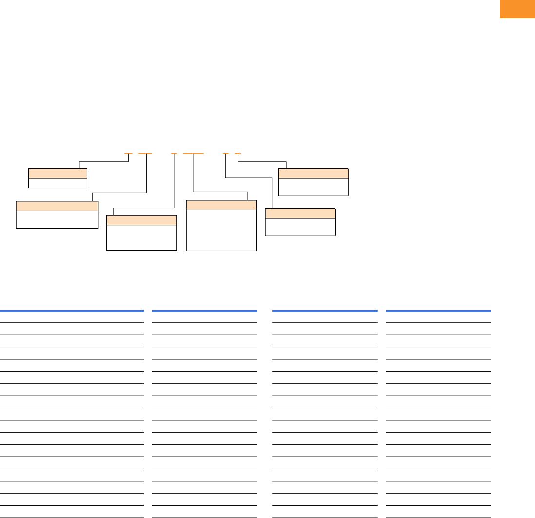
Volume 6—Solid-State Motor Control CA08100007E—February 2016 www.eaton.com V6-T2-113
2
2
2
2
2
2
2
2
2
2
2
2
2
2
2
2
2
2
2
2
2
2
2
2
2
2
2
2
2
2
2.7
Adjustable Frequency Drives
SVX Drives
Line and Load Reactors
A line and load reactor is a
three-phase inductance filter
that can be placed on the line
and load side of the AFD to
help improve the harmonic
performance of the system.
Consult the factory for
additional filtering options and
further technical details.
DR1 Line Reactor
A line reactor helps to provide
a moderate reduction in
current harmonics similar to a
DC choke. It also provides
increased input protection for
AFD and its semiconductors
from line transients helping to
extend the life of the AFD.
DR2 Output Reactor
An output filter is used to
reduce the transient voltage
(dV/dt) at the motor terminals.
The output filter is
recommended for cable
lengths exceeding 100 ft
(30 m) with a drive of 3 hp
and above and for cable
lengths of 33 ft (10 m) with a
drive of 2 hp and below.
Line and Load Reactors—Catalog Number Selection
Line and Load Reactors—230 V
Open NEMA 1
Line Reactor Load Reactor Line Reactor Load Reactor
hp (CT) 3% 5% 3% 5% 3% 5% 3% 5%
0.75 DR1-23D2-03 DR1-23D2-05 DR2-24D0-03 DR2-24D0-05 DR1-23D2-13 DR1-23D2-15 DR2-24D0-13 DR2-24D0-15
1 DR1-24D2-03 DR1-24D2-05 DR2-24D0-03 DR2-28D0-05 DR1-24D2-13 DR1-24D2-15 DR2-24D0-13 DR2-28D0-15
1.5 DR1-26D0-03 DR1-26D0-05 DR2-28D0-03 DR2-28D0-05 DR1-26D0-13 DR1-26D0-15 DR2-28D0-13 DR2-28D0-15
2 DR1-26D8-03 DR1-26D8-05 DR2-28D0-03 DR2-28D0-05 DR1-26D8-13 DR1-26D8-15 DR2-28D0-13 DR2-28D0-15
3 DR1-29D6-03 DR1-29D6-05 DR2-2012-03 DR2-2012-05 DR1-29D6-13 DR1-29D6-15 DR2-2012-13 DR2-2012-15
5 DR1-2015-03 DR1-2015-05 DR2-2018-03 DR2-2018-05 DR1-2015-13 DR1-2015-15 DR2-2018-13 DR2-2018-15
7.5 DR1-2022-03 DR1-2022-05 DR2-2025-03 DR2-2025-05 DR1-2022-13 DR1-2022-15 DR2-2025-13 DR2-2025-15
10 DR1-2028-03 DR1-2028-05 DR2-2035-03 DR2-2035-05 DR1-2028-13 DR1-2028-15 DR2-2035-13 DR2-2035-15
15 DR1-2042-03 DR1-2042-05 DR2-2045-03 DR2-2045-05 DR1-2042-13 DR1-2042-15 DR2-2045-13 DR2-2045-15
20 DR1-2054-03 DR1-2054-05 DR2-2055-03 DR2-2055-05 DR1-2054-13 DR1-2054-15 DR2-2055-13 DR2-2055-15
25 DR1-2068-03 DR1-2068-05 DR2-2080-03 DR2-2080-05 DR1-2068-13 DR1-2068-15 DR2-2080-13 DR2-2080-15
30 DR1-2080-03 DR1-2080-05 DR2-2080-03 DR2-2100-05 DR1-2080-13 DR1-2080-15 DR2-2080-13 DR2-2100-15
40 DR1-2104-03 DR1-2104-05 DR2-2100-03 DR2-2100-05 DR1-2104-13 DR1-2104-15 DR2-2100-13 DR2-2100-15
50 DR1-2130-03 DR1-2130-05 DR2-2130-03 DR2-2130-05 DR1-2130-13 DR1-2130-15 DR2-2130-13 DR2-2130-15
60 DR1-2154-03 DR1-2154-05 DR2-2160-03 DR2-2200-15 DR1-2154-13 DR1-2154-15 DR2-2160-13 DR2-2200-15
75 DR1-2192-03 DR1-2192-05 DR2-2200-13 DR2-2200-15 DR1-2192-13 DR1-2192-15 DR2-2200-13 DR2-2200-15
100 DR1-2248-03 DR1-2248-05 DR2-2225-13 DR2-2225-15 DR1-2248-13 DR1-2248-15 DR2-2225-13 DR2-2225-15
DR1 –22D0 –05
Device Series
R1 = Line side reactor
R2 = Load side reactor
Basic Naming
D= Drive
Input/Output Voltage
2= 240 V
4= 480 V
5= 575 V
Environment Rating
0= Open
1= NEMA 1
Impedance
3= 3%
5= 5%
Current Rating
Examples:
2D0 = 2.0 A
4D0 = 4.0 A
8D0 = 8.0 A
012
= 12 A
V6-T2-114 Volume 6—Solid-State Motor Control CA08100007E—February 2016 www.eaton.com
2
2
2
2
2
2
2
2
2
2
2
2
2
2
2
2
2
2
2
2
2
2
2
2
2
2
2
2
2
2
2.7
Adjustable Frequency Drives
SVX Drives
Line and Load Reactors—480 V
Line and Load Reactors—575 V
Open NEMA 1
Line Reactor Load Reactor Line Reactor Load Reactor
hp (CT) 3% 5% 3% 5% 3% 5% 3% 5%
1 DR1-42D1-03 DR1-42D1-05 DR2-42D0-05 DR2-42D0-05 DR1-42D1-13 DR1-42D1-15 DR2-42D0-13 DR2-42D0-15
1.5 DR1-43D0-03 DR1-43D0-05 DR2-44D0-05 DR2-44D0-05 DR1-43D0-13 DR1-43D0-15 DR2-44D0-13 DR2-44D0-15
2 DR1-43D4-03 DR1-43D4-05 DR2-44D0-03 DR2-44D0-05 DR1-43D4-13 DR1-43D4-15 DR2-44D0-13 DR2-44D0-15
3 DR1-44D8-03 DR1-44D8-05 DR2-48D0-03 DR2-48D0-05 DR1-44D8-13 DR1-44D8-15 DR2-48D0-13 DR2-48D0-15
5 DR1-47D6-03 DR1-47D6-05 DR2-48D0-03 DR2-48D0-05 DR1-47D6-13 DR1-47D6-15 DR2-48D0-13 DR2-48D0-15
7.5 DR1-4011-03 DR1-4011-05 DR2-4012-03 DR2-4012-05 DR1-4011-13 DR1-4011-15 DR2-4012-13 DR2-4012-15
10 DR1-4014-03 DR1-4014-05 DR2-4018-03 DR2-4018-05 DR1-4014-13 DR1-4014-15 DR2-4018-13 DR2-4018-15
15 DR1-4021-03 DR1-4021-05 DR2-4025-03 DR2-4025-05 DR1-4021-13 DR1-4021-15 DR2-4025-13 DR2-4025-15
20 DR1-4027-03 DR1-4027-05 DR2-4025-03 DR2-4025-05 DR1-4027-13 DR1-4027-15 DR2-4025-13 DR2-4025-15
25 DR1-4034-03 DR1-4034-05 DR2-4035-03 DR2-4035-05 DR1-4034-13 DR1-4034-15 DR2-4035-13 DR2-4035-15
30 DR1-4040-03 DR1-4040-05 DR2-4045-03 DR2-4045-05 DR1-4040-13 DR1-4040-15 DR2-4045-13 DR2-4045-15
40 DR1-4052-03 DR1-4052-05 DR2-4055-03 DR2-4055-05 DR1-4052-13 DR1-4052-15 DR2-4055-13 DR2-4055-15
50 DR1-4065-03 DR1-4065-05 DR2-4080-03 DR2-4080-05 DR1-4065-13 DR1-4065-15 DR2-4080-13 DR2-4080-15
60 DR1-4077-03 DR1-4077-05 DR2-4100-03 DR2-4080-05 DR1-4077-13 DR1-4077-15 DR2-4100-13 DR2-4080-15
75 DR1-4096-03 DR1-4096-05 DR2-4100-03 DR2-4100-05 DR1-4096-13 DR1-4096-15 DR2-4100-13 DR2-4100-15
100 DR1-4124-03 DR1-4124-05 DR2-4130-03 DR2-4130-05 DR1-4124-13 DR1-4124-15 DR2-4130-13 DR2-4130-15
125 DR1-4156-03 DR1-4156-05 DR2-4160-03 DR2-4160-05 DR1-4156-13 DR1-4156-15 DR2-4160-13 DR2-4160-15
150 DR1-4180-03 DR1-4180-05 DR2-4200-13 DR2-4200-15 DR1-4180-13 DR1-4180-15 DR2-4200-13 DR2-4200-15
200 DR1-4240-03 DR1-4240-05 DR2-4250-13 DR2-4250-15 DR1-4240-13 DR1-4240-15 DR2-4250-13 DR2-4250-15
250 DR1-4302-03 DR1-4302-05 DR2-4320-13 DR2-4320-15 DR1-4302-13 DR1-4302-15 DR2-4320-13 DR2-4320-15
300 DR1-4361-03 DR1-4361-05 DR2-4400-13 DR2-4400-15 DR1-4361-13 DR1-4361-15 DR2-4400-13 DR2-4400-15
350 DR1-4414-03 DR1-4414-05 DR2-4400-13 DR2-4400-15 DR1-4414-13 DR1-4414-15 DR2-4400-13 DR2-4400-15
400 DR1-4477-03 DR1-4477-05 DR2-4500-03 DR2-4500-05 DR1-4477-13 DR1-4477-15 DR2-4500-13 DR2-4500-15
500 DR1-4590-03 DR1-4590-05 DR2-4600-03 DR2-4600-05 DR1-4590-13 DR1-4590-15 DR2-4600-13 DR2-4600-15
600 DR1-4708-03 DR1-4708-05 DR2-4750-03 DR2-4750-05 DR1-4708-13 DR1-4708-15 DR2-4750-13 DR2-4750-15
Open NEMA 1
Line Reactor Load Reactor Line Reactor Load Reactor
hp (CT) 3% 5% 3% 5% 3% 5% 3% 5%
2 DR1-52D7-03 DR1-52D7-05 DR2-54D0-03 DR2-54D0-05 DR1-52D7-13 DR1-52D7-15 DR2-54D0-13 DR2-54D0-15
3 DR1-53D9-03 DR1-53D9-05 DR2-54D0-03 DR2-54D0-05 DR1-53D9-13 DR1-53D9-15 DR2-54D0-13 DR2-54D0-15
5 DR1-56D1-03 DR1-56D1-05 DR2-58D0-03 DR2-58D0-05 DR1-56D1-13 DR1-56D1-15 DR2-58D0-13 DR2-58D0-15
7.5 DR1-59D0-03 DR1-59D0-05 DR2-58D0-03 DR2-58D0-05 DR1-59D0-13 DR1-59D0-15 DR2-58D0-13 DR2-58D0-15
10 DR1-5011-03 DR1-5011-05 DR2-5012-03 DR2-5012-05 DR1-5011-13 DR1-5011-15 DR2-5012-13 DR2-5012-15
15 DR1-5017-03 DR1-5017-05 DR2-5018-03 DR2-5018-05 DR1-5017-13 DR1-5017-15 DR2-5018-13 DR2-5018-15
20 DR1-5022-03 DR1-5022-05 DR2-5025-03 DR2-5025-05 DR1-5022-13 DR1-5022-15 DR2-5025-13 DR2-5025-15
25 DR1-5027-03 DR1-5027-05 DR2-5025-03 DR2-5025-05 DR1-5027-13 DR1-5027-15 DR2-5025-13 DR2-5025-15
30 DR1-5032-03 DR1-5032-05 DR2-5035-03 DR2-5035-05 DR1-5032-13 DR1-5032-15 DR2-5035-13 DR2-5035-15
40 DR1-5041-03 DR1-5041-05 DR2-5045-03 DR2-5045-05 DR1-5041-13 DR1-5041-15 DR2-5045-13 DR2-5045-15
50 DR1-5052-03 DR1-5052-05 DR2-5055-03 DR2-5055-05 DR1-5052-13 DR1-5052-15 DR2-5055-13 DR2-5055-15
60 DR1-5062-03 DR1-5062-05 DR2-5080-03 DR2-5080-05 DR1-5062-13 DR1-5062-15 DR2-5080-13 DR2-5080-15
75 DR1-5077-03 DR1-5077-05 DR2-5080-03 DR2-5080-05 DR1-5077-13 DR1-5077-15 DR2-5080-13 DR2-5080-15
100 DR1-5100-03 DR1-5100-05 DR2-5100-03 DR2-5100-05 DR1-5100-13 DR1-5100-15 DR2-5100-13 DR2-5100-15
125 DR1-5125-03 DR1-5125-05 DR2-5130-03 DR2-5130-05 DR1-5125-13 DR1-5125-15 DR2-5130-13 DR2-5130-15
150 DR1-5144-03 DR1-5144-05 DR2-5160-03 DR2-5160-05 DR1-5144-13 DR1-5144-15 DR2-5160-13 DR2-5160-15
200 DR1-5192-03 DR1-5192-05 DR2-5200-13 DR2-5200-15 DR1-5192-13 DR1-5192-15 DR2-5200-13 DR2-5200-15
250 DR1-5242-03 DR1-5242-05 DR2-5250-13 DR2-5250-15 DR1-5242-13 DR1-5242-15 DR2-5250-13 DR2-5250-15
300 DR1-5289-03 DR1-5289-05 DR2-5320-13 DR2-5320-15 DR1-5289-13 DR1-5289-15 DR2-5320-13 DR2-5320-15
400 DR1-5382-03 DR1-5382-05 DR2-5400-13 DR2-5400-15 DR1-5382-13 DR1-5382-15 DR2-5400-13 DR2-5400-15
450 DR1-5412-03 DR1-5412-05 DR2-5400-13 DR2-5400-15 DR1-5412-13 DR1-5412-15 DR2-5400-13 DR2-5400-15
500 DR1-5472-03 DR1-5472-05 DR2-5500-03 DR2-5500-05 DR1-5472-13 DR1-5472-15 DR2-5500-13 DR2-5500-15
600 DR1-5576-03 DR1-5576-05 DR2-5600-03 DR2-5600-05 DR1-5576-13 DR1-5576-15 DR2-5600-13 DR2-5600-15

Volume 6—Solid-State Motor Control CA08100007E—February 2016 www.eaton.com V6-T2-115
2
2
2
2
2
2
2
2
2
2
2
2
2
2
2
2
2
2
2
2
2
2
2
2
2
2
2
2
2
2
2.7
Adjustable Frequency Drives
SVX Drives
Replacement Parts
FR4 Spare Parts
FR5 Spare Parts
Notes
1Only for NEMA Type 12/IP54 Type drives.
2Factory recommended spare parts.
3Select one part number based on the amperage rating of the drive. Please contact EatonCare at 877-ETN-CARE for assistance.
Quantity/
Drive
230 V 480 V 575 V
Category Description Catalog Number Catalog Number Catalog Number
Control fan NEMA Type 12 control fan 11PP01086 PP01086 —
Control module 2SVX control module 1 CSBS0000000000 CSBS0000000000 —
Standard slot A I/O card 1 OPTA9 OPTA9 —
Standard slot B I/O card 1 OPTA2 OPTA2 —
Converter Power board 31VB00308-0004-2 VB00208-0003-5 —
1VB00308-0007-2 VB00208-0004-5 —
1VB00308-0008-2 VB00208-0005-5 —
1— VB00208-0007-5 —
1— VB00208-0009-5 —
1— VB00410-0012-5-ARV —
Keypad 2SVX/SPX keypad 1 KEYPAD-LOC/REM KEYPAD-LOC/REM —
Main fan 2DC fan (main) 1 PP01060 PP01060 —
Other Mounting kit, fixing kit 1 FR00040 FR00040 —
Mounting kit, fixing kit, N12 11FR00079 FR00079 —
Control cover, plastic, N1 1 FR00006 FR00006 —
Quantity/
Drive
230 V 480 V 575 V
Category Description Catalog Number Catalog Number Catalog Number
Control fan NEMA Type 12 control fan 11PP01088 PP01088 —
Control module 2SVX control module 1 CSBS0000000000 CSBS0000000000 —
Standard slot A I/O card 1 OPTA9 OPTA9 —
Standard slot B I/O card 1 OPTA2 OPTA2 —
Converter Power board 31VB00313-0017-2 VB00213-0016-5 —
1VB00313-0025-2 VB00213-0022-5 —
1VB00313-0031-2 VB00213-0031-5 —
Keypad 2SVX/SPX keypad 1 KEYPAD-LOC/REM KEYPAD-LOC/REM —
Main fan 2DC fan (main) 1 PP01061 PP01061 —
Other Mounting kit, fixing kit 1 FR00050 FR00050 —
Mounting kit, fixing kit, N12 11FR00081 FR00081 —

V6-T2-116 Volume 6—Solid-State Motor Control CA08100007E—February 2016 www.eaton.com
2
2
2
2
2
2
2
2
2
2
2
2
2
2
2
2
2
2
2
2
2
2
2
2
2
2
2
2
2
2
2.7
Adjustable Frequency Drives
SVX Drives
FR6 Spare Parts
FR7 Spare Parts
Notes
1Only for NEMA Type 12/IP54 Type drives.
2Factory recommended spare parts.
3Select one part number based on the amperage rating of the drive. Please contact EatonCare at 877-ETN-CARE for assistance.
Quantity/
Drive
230 V 480 V 575 V
Category Description Catalog Number Catalog Number Catalog Number
Control fan NEMA Type 12 control fan 11PP01049 PP01049 —
Control module 2SVX control module 1 CSBS0000000000 CSBS0000000000 CSBS0000000000
Standard slot A I/O card 1 OPTA9 OPTA9 OPTA9
Standard slot B I/O card 1 OPTA2 OPTA2 OPTA2
Converter Power board 31VB00316-0048-2 VB00416-0038-5 VB00404-0004-6
1VB00316-0061-2 VB00416-0045-5 VB00404-0005-6
1— VB00416-0061-5 VB00404-0007-6
1— — VB00404-0010-6
1— — VB00404-0013-6
1— — VB00404-0018-6
1— — VB00404-0022-6
1— — VB00404-0027-6
1— — VB00404-0034-6
DC section Bus capacitor 2 — — S00930
Keypad 2SVX/SPX keypad 1 KEYPAD-LOC/REM KEYPAD-LOC/REM KEYPAD-LOC/REM
Main fan 2DC fan (main) 1 PP01062 PP01062 —
Other Mounting kit, fixing kit 1 FR00060 FR00060 FR00060
Mounting kit, fixing kit, N12 11FR00082 FR00082 FR00082
Control cover, plastic, N1 1 FR06011 FR06011 FR06011
Quantity/
Drive
230 V 480 V 575 V
Category Description Catalog Number Catalog Number Catalog Number
Control fan NEMA Type 12 control fan 11PP01049 PP01049 PP01049
Control module 2SVX control module 1 CSBS0000000000 CSBS0000000000 CSBS0000000000
Standard slot A I/O card 1 OPTA9 OPTA9 OPTA9
Standard slot B I/O card 1 OPTA2 OPTA2 OPTA2
Converter Power board 31VB00319-0075-2 VB00619-0072-5 VB00419-0041-6
1VB00319-0088-2 VB00619-0087-5 VB00419-0052-6
1VB00319-0114-2 VB00619-0105-5 —
DC section Bus capacitor 2 — — PP01041
Keypad 2SVX/SPX keypad 1 KEYPAD-LOC/REM KEYPAD-LOC/REM KEYPAD-LOC/REM
Main fan 2DC fan (main) 1 PP01063 PP01063 PP01063
Other Mounting kit, fixing kit 1 FR07071 FR07071 FR07071
Mounting kit, fixing kit, N12 11FR07072 FR07072 FR07072
Control cover, plastic, N1 1 FR07011 FR07011 FR07011

Volume 6—Solid-State Motor Control CA08100007E—February 2016 www.eaton.com V6-T2-117
2
2
2
2
2
2
2
2
2
2
2
2
2
2
2
2
2
2
2
2
2
2
2
2
2
2
2
2
2
2
2.7
Adjustable Frequency Drives
SVX Drives
FR8 Spare Parts
Notes
1Only for NEMA Type 12/IP54 Type drives.
2Factory recommended spare parts.
3Select one part number based on the amperage rating of the drive. Please contact EatonCare at 877-ETN-CARE for assistance.
Quantity/
Drive
230 V 480 V 575 V
Category Description Catalog Number Catalog Number Catalog Number
Control fan NEMA Type 12 control fan 11CP01180 CP01180 CP01180
Control module 2SVX control module 1 CSBS0000000000 CSBS0000000000 CSBS0000000000
Standard slot A I/O card 1 OPTA9 OPTA9 OPTA9
Standard slot B I/O card 1 OPTA2 OPTA2 OPTA2
Converter Power board 31VB00722-0140-2-ANV VB00636-0140-4-ANV VB00422-0062-5-ANV
1VB00722-0170-2-ANV VB00636-0168-4-ANV VB00422-0080-5-ANV
1VB00722-0205-2-ANV VB00636-0205-4-ANV VB00422-0100-5-ANV
IGBT 2 PP01175 PP01175 PP01127
DC section Bus capacitor 4 S00335 S00335 PP01041
Inverter Diode 3 CP01268 CP01268 CP01373
Rectifier board 1 VB00227 VB00227 VB00427
Keypad 2SVX/SPX keypad 1 KEYPAD-LOC/REM KEYPAD-LOC/REM KEYPAD-LOC/REM
Main AC fan Fan AC 1 PP01123 PP01123 PP01123
Fan fuse 2 PP20202 PP20202 PP20202
Starting cap 1 S00734 S00734 S00734
Fan driver board AC 1 VB00599 VB00799 VB00799
Isolation transformer (fan) 1 S0000113 S0000113 S0000113
Main DC fan 2DC fan 1 PP00071 PP00071 PP00071
DC power supply 1 S01016 S01016 S01016
Other Front cover, N12 11FR08079 FR08079 FR08079
Conduit plate, N12 1 FR08082 FR08082 FR08082

V6-T2-118 Volume 6—Solid-State Motor Control CA08100007E—February 2016 www.eaton.com
2
2
2
2
2
2
2
2
2
2
2
2
2
2
2
2
2
2
2
2
2
2
2
2
2
2
2
2
2
2
2.7
Adjustable Frequency Drives
SVX Drives
FR9 Spare Parts
Notes
1Factory recommended spare parts.
2Select one part number based on the amperage rating of the drive. Please contact EatonCare at 877-ETN-CARE for assistance.
Quantity/
Drive
230 V 480 V 575 V
Category Description Catalog Number Catalog Number Catalog Number
Control fan 50 mm fan 1 PP09041 PP09041 PP09041
80 mm fan 1 PP01068 PP01068 PP01068
Control module 1SVX control module 1 CSBS0000000000 CSBS0000000000 CSBS0000000000
Standard slot A I/O card 1 OPTA9 OPTA9 OPTA9
Standard slot B I/O card 1 OPTA2 OPTA2 OPTA2
Converter Power module
21FR09-0261-2-ANV FR09-0261-4-ANV FR09-0125-5-ANV
1FR09-0300-2-ANV FR09-0300-4-ANV FR09-0144-5-ANV
1— — FR09-0170-5-ANV
Driver board 1 S00583 S00583 S00583
Shunt board 26— VB00535 VB00537
6— VB00536 VB00542
6——VB00543
DC section Balancing resistor 3 PP00052 PP00052 PP00052
Bus capacitor 8 S00335 S00335 PP01041
DC busbars DC– 1 FR09043 FR09043 FR09043
DC busbars DC+ 1 FR09044 FR09044 FR09044
DC busbars connection 1 FR09045 FR09045 FR09045
DC busbars +/– insulator 1 FR09046 FR09046 FR09046
DC busbars –/con insulator 1 FR09047 FR09047 FR09047
Inverter Rectifier module 1 FR09826 FR09822 FR09823
Diode 3 CP01268 CP01268 CP01268
Rectifier board 1 — VB00459 VB00460
Keypad 1SVX/SPX keypad 1 KEYPAD-LOC/REM KEYPAD-LOC/REM KEYPAD-LOC/REM
Main AC fan Fan AC 1 PP01080 PP01080 PP01080
Fan fuse 2 PP20202 PP20202 PP20202
Starting cap 1 S00465 S00465 S00465
Fan driver board AC 1 VB00899 VB00399 VB00299
Isolation transformer (fan) 1 PP09056 PP09055 PP09055
Main DC fan 1DC fan 1 PP00072 PP00072 PP00072
DC power supply 1 S01017 S01017 S01017
Other Front cover power 1 FR09012 FR09012 FR09012
Front cover connection 1 FR09013 FR09013 FR09013
Front power conduit 1 FR09014 FR09014 FR09014

Volume 6—Solid-State Motor Control CA08100007E—February 2016 www.eaton.com V6-T2-119
2
2
2
2
2
2
2
2
2
2
2
2
2
2
2
2
2
2
2
2
2
2
2
2
2
2
2
2
2
2
2.7
Adjustable Frequency Drives
SVX Drives
FR10 Spare Parts
Notes
1Factory recommended spare parts.
2Select one part number based on the amperage rating of the drive. Please contact EatonCare at 877-ETN-CARE for assistance.
Quantity/
Drive
230 V 480 V 575 V
Category Description Catalog Number Catalog Number Catalog Number
Control Fiber board 1 — S00451 S00451
ASIC board 1 — S00457 S00457
Control fan ASIC fan 1 — PP01096 PP01096
Control module 1SVX control module 1 — CPBS0000000000 CPBS0000000000
Standard slot A I/O card 1 — OPTA9 OPTA9
Standard slot B I/O card 1 — OPTA2 OPTA2
Converter Power module 21— FR10-0385-4-ANV FR10-0261-5-ANV
1— FR10-0460-4-ANV FR10-0325-5-ANV
1— FR10-0520-4-ANV FR10-0385-5-ANV
1— — FR10-0416-5-ANV
Driver board 1 — S00450 S00450
Driver adapter board 1 — VB00330 VB00330
Shunt board 26— VB00497 VB00510
6— VB00498 VB00511
6— VB00537 VB00545
Covers Top cover 1 — FR10340 FR10340
Side cover 2 — FR10341 FR10341
DC section Balancing resistor 2 — PP13027 PP13028
DC busbars kit (right) 1 — S0000005 S0000005
Bus capacitor 12 — S00335 S00336
Inverter Rectifier module 1 — FR10823 FR10823
Charging resistor 1 — PP00066 PP00066
Diode 3 — PP01177 PP01177
Rectifier board 1 — S00591 S00592
Keypad 1SVX/SPX keypad 1 — KEYPAD-LOC/REM KEYPAD-LOC/REM
Main AC fan Fan assembly (left) 1 — FR10846 FR10846
Fan assembly (right) 1 — FR10847 FR10847
Fan AC 2 — PP01080 PP01080
Fan fuse 4 — PP20202 PP20202
Starting cap 2 — S00528 S00528
Fan driver board AC 2 — VB00299 VB00299
Isolation transformer (left) 1 — FR10844 FR10844
Isolation transformer (right) 1 — FR10845 FR10845
Main DC fan 1DC fan 2 — PP00072 PP00072
DC power supply 2 — S01017 S01017

V6-T2-120 Volume 6—Solid-State Motor Control CA08100007E—February 2016 www.eaton.com
2
2
2
2
2
2
2
2
2
2
2
2
2
2
2
2
2
2
2
2
2
2
2
2
2
2
2
2
2
2
2.7
Adjustable Frequency Drives
SVX Drives
FR11 Spare Parts
Notes
1Factory recommended spare parts.
2Select one part number based on the amperage rating of the drive. Please contact EatonCare at 877-ETN-CARE for assistance.
Quantity/
Drive
230 V 480 V 575 V
Category Description Catalog Number Catalog Number Catalog Number
Control Fiber board 1 — S00451 S00451
ASIC board 1 — S00457 S00457
Control fan ASIC fan 1 — PP01096 PP01096
Control module 1SVX control module 1 — CPBS0000000000 CPBS0000000000
Standard slot A I/O card 1 — OPTA9 OPTA9
Standard slot B I/O card 1 — OPTA2 OPTA2
Converter Power module 21— FR11-0590-4-ANV FR11-0460-5-ANV
1— FR11-0650-4-ANV FR11-0502-5-ANV
1— FR11-0730-4-ANV FR11-0590-5-ANV
Driver board 1 — S00452 S00452
Driver adapter board 1 — VB00330 VB00330
Shunt board 29— VB00513 VB00512
9— VB00514 VB00546
9— VB00538 VB00547
Covers Top cover 1 — FR11345 FR11345
DC section Balancing resistor 3 — PP13027 PP13027
DC busbars kit (right) 3 — S0000005 S0000005
Bus capacitor 18 — S00335 S00335
Inverter Rectifier module 1 — FR10823 FR10823
Diode 3 — PP01177 PP01177
Rectifier board 1 — S00591 S00591
Keypad 1SVX/SPX keypad 1 — KEYPAD-LOC/REM KEYPAD-LOC/REM
Main AC fan Fan assembly (right) 3 — FR10847 FR10847
Fan AC 3 — PP01080 PP01080
Fan fuse 4 — PP20202 PP20202
Starting cap 3 — S00530 S00530
Fan driver board AC 3 — VB00299 VB00299
Isolation transformer (right) 3 — FR10845 FR10845
Main DC fan 1DC fan 2 — PP00072 PP00072
DC power supply 2 — S01017 S01017

Volume 6—Solid-State Motor Control CA08100007E—February 2016 www.eaton.com V6-T2-121
2
2
2
2
2
2
2
2
2
2
2
2
2
2
2
2
2
2
2
2
2
2
2
2
2
2
2
2
2
2
2.7
Adjustable Frequency Drives
SVX Drives
FR12 Spare Parts
Notes
1Factory recommended spare parts.
2Select one part number based on the amperage rating of the drive. Please contact EatonCare at 877-ETN-CARE for assistance.
Quantity/
Drive
230 V 480 V 575 V
Category Description Catalog Number Catalog Number Catalog Number
Control Fiber board 2 — S00451 S00451
ASIC board 2 — S00457 S00457
Star coupler 1 — S00593 S00593
Control fan ASIC fan 2 — PP01096 PP01096
Control module 1SVX control module 1 — CPBS0000000000 CPBS0000000000
Standard slot A I/O card 1 — OPTA9 OPTA9
Standard slot B I/O card 1 — OPTA2 OPTA2
Converter Power module 21— FR12-0820-4-ANV FR12-0650-5-ANV
1— FR12-0920-4-ANV FR12-0750-5-ANV
1— FR12-1030-4-ANV FR12-0820-5-ANV
Driver board 2 — S00450 S00450
Driver adapter board 2 — VB00330 VB00330
Shunt board 12 — VB00498 VB00511
Covers Top cover 2 — FR10340 FR10340
Side cover 4 — FR10341 FR10341
DC section Balancing resistor 4 — PP13027 PP13027
DC busbars kit (right) 2 — S0000005 S0000005
Bus capacitor 24 — S00335 S00336
Inverter Rectifier module 2 — FR10823 FR10823
Diode 3 — PP01177 PP01177
Rectifier board 2 — S00591 S00591
Keypad 1SVX/SPX keypad 1 — KEYPAD-LOC/REM KEYPAD-LOC/REM
Main AC fan Fan assembly (left) 2 — FR10846 FR10846
Fan assembly (right) 2 — FR10847 FR10847
Fan AC 4 — PP01080 PP01080
Fan fuse 8 — PP20202 PP20202
Starting cap 4 — S00528 S00528
Fan driver board AC 4 — VB00299 VB00299
Isolation transformer (left) 2 — FR10844 FR10844
Isolation transformer (right) 2 — FR10845 FR10845
Main DC fan 1DC fan 4 — PP00072 PP00072
DC power supply 4 — S01017 S01017

V6-T2-122 Volume 6—Solid-State Motor Control CA08100007E—February 2016 www.eaton.com
2
2
2
2
2
2
2
2
2
2
2
2
2
2
2
2
2
2
2
2
2
2
2
2
2
2
2
2
2
2
2.7
Adjustable Frequency Drives
SVX Drives
FR13 Spare Parts
Notes
1Factory recommended spare parts.
2Select one part number based on the amperage rating of the drive. Please contact EatonCare at 877-ETN-CARE for assistance.
Quantity/
Drive
230 V 480 V 575 V
Category Description Catalog Number Catalog Number Catalog Number
Control ASIC board 1 — S00457 S00457
ASIC assembly 1 — 60S01030 60S01030
Control fan ASIC fan 1 — PP01096 PP01096
Control module 1SVX control module 1 — CPBS0000000000 CPBS0000000000
Standard slot A I/O card 1 — OPTA9 OPTA9
Standard slot B I/O card 1 — OPTA2 OPTA2
Converter Power module 23— FI13-1150-4-ANV FR13-1030-5-ANV
3— FI13-1300-4-ANV FR13-1180-5-ANV
3— FI13-1450-4-ANV FR13-920-5-ANV
Driver board 3 — S00454 S00454
Driver adapter board 2 — VB00330 VB00330
Shunt board 218 — VB00505 VB00516
18 — VB00514 VB00517
18 — VB00541 VB00547
Covers Top cover 3 — FI10001 FI10001
Side cover 3 — FI10003 FI10003
DC section Balancing resistor 6 — PP13034 PP13034
Bus capacitor 36 — S00335 S00336
DC busbars kit 3 — FI13329 FI13329
Inverter Rectifier module 2 — FR10823 FR10823
Diode 3 — PP01177 PP01177
Rectifier board 2 — S00591 S00591
Keypad 1SVX/SPX keypad 1 — KEYPAD-LOC/REM KEYPAD-LOC/REM
Main AC fan Fan assembly (left) 3 — FI13301 FI13301
Fan AC 3 — PP01080 PP01080
Fan fuse 6 — PP20202 PP20202
Starting cap 3 — S00520 S00520
Fan driver board AC 3 — VB00299 VB00299
Isolation transformer 3 — PP10057 PP10057
Main DC fan 1DC fan 4 — PP00072 PP00072
DC power supply 4 — S01017 S01017

Volume 6—Solid-State Motor Control CA08100007E—February 2016 www.eaton.com V6-T2-123
2
2
2
2
2
2
2
2
2
2
2
2
2
2
2
2
2
2
2
2
2
2
2
2
2
2
2
2
2
2
2.7
Adjustable Frequency Drives
SVX Drives
FR14 Spare Parts
Notes
1Factory recommended spare parts.
2Select one part number based on the amperage rating of the drive. Please contact EatonCare at 877-ETN-CARE for assistance.
Quantity/
Drive
230 V 480 V 575 V
Category Description Catalog Number Catalog Number Catalog Number
Control ASIC board 2 — S00457 S00457
Star coupler 1 — S00593 S00593
ASIC assembly 2 — 60S01030 60S01030
Star coupler kit 1 — FR10860 FR10860
Control fan ASIC fan 2 — PP01096 PP01096
Control module 1SVX control module 1 — CPBS0000000000 CPBS0000000000
Standard slot A I/O card 1 — OPTA9 OPTA9
Standard slot B I/O card 1 — OPTA2 OPTA2
Converter Power module 21— FR14-1770-4-ANV FR14-1500-5-ANV
1— FR14-2150-4-ANV FR14-1900-5-ANV
1— FR14-2700-4-ANV FR14-2250-5-ANV
Driver board 6 — S00454 S00454
Driver adapter board 2 — VB00330 VB00330
Shunt board 236 — VB00541 VB00516
36 ——VB00517
Covers Top cover 6 — FI10001 FI10001
Side cover 6 — FI10003 FI10003
DC section Balancing resistor 6 — PP13034 PP13034
Bus capacitor 72 — S00335 S00336
DC busbars kit 6 — FI13329 FI13329
Inverter Rectifier module 2 — FR10823 FR10823
Diode 3 — PP01177 PP01177
Rectifier board 2 — S00591 S00591
Keypad 1SVX/SPX keypad 1 — KEYPAD-LOC/REM KEYPAD-LOC/REM
Main AC fan Fan assembly (left) 6 — FI13301 FI13301
Fan AC 6 — PP01080 PP01080
Fan fuse 12 — PP20202 PP20202
Starting cap 6 — S00520 S00520
Fan driver board AC 6 — VB00299 VB00299
Isolation transformer 6 — PP10057 PP10057
Main DC fan 1DC fan 6 — PP00072 PP00072
DC power supply 6 — S01017 S01017

V6-T2-124 Volume 6—Solid-State Motor Control CA08100007E—February 2016 www.eaton.com
2
2
2
2
2
2
2
2
2
2
2
2
2
2
2
2
2
2
2
2
2
2
2
2
2
2
2
2
2
2
2.7
Adjustable Frequency Drives
SVX Drives
Technical Data and Specifications
SVX Drives
Standard I/O Specifications
Description Specification
Input Ratings
Input voltage (Vin)+10%/–15%
Input frequency (fin) 50/60 Hz (variation up to 45–66 Hz)
Connection to power Once per minute or less (typical operation)
High withstand rating 100 kAIC
Output Ratings
Output voltage 0 to Vin
Continuous output current IH rated 100% at 122 °F (50 °C), FR9 and below
IL rated 100% at 104 °F (40 °C), FR9 and below
IH/IL 100% at 104 °F (40 °C), FR10 and above
Overload current (IH/IL)150% I
H, 110% IL for 1 min.
Output frequency 0 to 320 Hz
Frequency resolution 0.01 Hz
Initial output current (IH) 250% for 2 seconds
Efficiency >96%
Control Characteristics
Control method Frequency control (V/f)
Open loop: Sensorless vector control
Closed loop: SPX drives only
Switching frequency
Frame 4–6
Frame 7–12
Adjustable with parameter 2.6.9
1–16 kHz; default 10 kHz
1–10 kHz; default 3.6 kHz
Frequency reference Analog input: Resolution 0.1% (10-bit), accuracy ±1% V/Hz
Panel reference: Resolution 0.01 Hz
Field weakening point 30–320 Hz
Acceleration time 0–3000 sec.
Deceleration time 0–3000 sec.
Braking torque DC brake: 30% x Tn (without brake option)
Ambient Conditions
Ambient operating
temperature
14 °F (–10 °C), no frost to 122 °F (50 °C) IH (FR4–FR9)
14 °F (–10 °C), no frost to 104 °F (40 °C) IH (FR10 and up)
14 °F (–10 °C), no frost to 104 °F (40 °C) IL (all frames)
Storage temperature –40° to 158 °F (–40° to 70 °C)
Relative humidity 0 to 95% RH, noncondensing, non-corrosive,
no dripping water
Air quality Chemical vapors: IEC 721-3-3, unit in operation, class 3C2;
Mechanical particles: IEC 721-3-3, unit in operation, class 3S2
Altitude 100% load capacity (no derating) up to 3280 ft (1000 m);
1% derating for each 328 ft (100 m) above 3280 ft (1000 m);
max. 9842 ft (3000 m)
Vibration EN 50178, EN 60068-2-6; 5 to 50 Hz, displacement amplitude
1 mm (peak) at 3 to 15.8 Hz, max. acceleration amplitude
1G at 15.8 to 150 Hz
Shock EN 50178, EN 60068-2-27 UPS Drop test (for applicable UPS
weights) Storage and shipping: max. 15 g, 11 ms (in package)
Enclosure class NEMA 1/IP21 or NEMA 12/IP54, open chassis/IP20
Description Specification
Control Connections
Analog input voltage 0 to 10 V, R = 200 kohms (–10 to 10 V joystick control)
resolution 0.1%; accuracy ±1%
Analog input current 0(4) to 20 mA; Ri—250 ohms differential
Digital inputs (6) Positive or negative logic; 18 to 30 Vdc
Auxiliary voltage +24 V ±15%, max. 250 mA
Output reference voltage +10 V +3%, max. load 10 mA
Analog output 0(4) to 20 mA; RL max. 500 ohms;
resolution 10 bit; accuracy ±2%
Digital outputs Open collector output, 50 mA/48V
Relay outputs Two programmable Form C relay outputs
switching capacity: 24 Vdc/8 A, 250 Vac/8 A, 125 Vdc/0.4 A
Protections
Overcurrent protection Trip limit 4.0 x IH instantaneously
Overvoltage protection Yes
Undervoltage protection Yes
Earth fault protection In case of earth fault in motor or motor cable, only the
frequency converter is protected
Input phase supervision Trips if any of the input phases are missing
Motor phase supervision Trips if any of the output phases are missing
Overtemperature protection Yes
Motor overload protection Yes
Motor stall protection Yes
Motor underload protection Yes
Short-circuit protection Yes (+24 V and +10 V reference voltages)
Description Specification
Six–digital input
programmable
24 V: “0” <10 V, “1” >18V,Ri >5 kohms
Two–analog input
configurable w/jumpers
Voltage: 0–±10 V, Ri >200 kohms
Current: 0 (4)–20 mA, Ri = 250 ohms
Two–digital output
programmable
Form C relays 250 Vac
30 Vdc 2 amp resistive
One–analog output
programmable
configurable w/jumper
0–20 mA, RL max. 500 ohms 10 bits ±2%
One digital output
programmable
Open collector 48 Vdc 50 mA
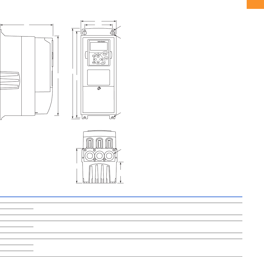
Volume 6—Solid-State Motor Control CA08100007E—February 2016 www.eaton.com V6-T2-125
2
2
2
2
2
2
2
2
2
2
2
2
2
2
2
2
2
2
2
2
2
2
2
2
2
2
2
2
2
2
2.7
Adjustable Frequency Drives
SVX Drives
Dimensions
Approximate Dimensions in Inches (mm)
9000X Open Drives
NEMA Type 1/IP21 and NEMA Type 12/IP54, FR4, FR5 and FR6
Voltage hp (IH) H1 H2 H3 D1 D2 D3 W1 W2 R1 Dia. R2 Dia.
Weight
Lbs (kg)
Knockouts at Inches (mm)
N1 (O.D.)
FR4
230 V 3/4–3 12.9
(327)
12.3
(313)
11.5
(292)
7.5
(190)
3.0
(77)
4.9
(126)
5.0
(128)
3.9
(100)
0.5 (13) 0.3 (7) 11.0 (5) 3 @ 1.1 (28)
480 V 1–5
FR5
230 V 5–7-1/2 16.5
(419)
16.0
(406)
15.3
(389)
8.4
(214)
3.9
(100)
5.8
(148)
5.6
(143)
3.9
(100)
0.5 (13) 0.3 (7) 17.9 (8) 2 @ 1.5 (37)
1 @ 1.1 (28)
480 V 7-1/2–15
FR6
230 V 10–15 22.0
(558)
21.3
(541)
20.4
(519)
9.3
(237)
4.2
(105)
6.5
(165)
7.6
(195)
5.8
(148)
0.6 (15.5) 0.4 (9) 40.8 (19) 3 @ 1.5 (37)
480 V 20–30
575 V 2–25
EATON
D1 W2
W1
R2
R1
R2
H3 H2
H1
D2
D3
Knockouts

V6-T2-126 Volume 6—Solid-State Motor Control CA08100007E—February 2016 www.eaton.com
2
2
2
2
2
2
2
2
2
2
2
2
2
2
2
2
2
2
2
2
2
2
2
2
2
2
2
2
2
2
2.7
Adjustable Frequency Drives
SVX Drives
Approximate Dimensions in Inches (mm)
NEMA Type 1/IP21 and NEMA Type 12/IP54 with Flange Kit, FR4, FR5 and FR6
FR4, FR5 and FR6 with Flange Kit
Flange Opening, FR4 to FR6
W1 W2 H1 H2 H3 H4 H5 D1 D2 Dia. A
FR4
5.0 (128) 4.5 (113) 13.3 (337) 12.8 (325) 12.9 (327) 1.2 (30) 0.9 (22) 7.5 (190) 3.0 (77) 0.3 (7)
FR5
5.6 (143) 4.7 (120) 17.0 (434) 16.5 (420) 16.5 (419) 1.4 (36) 0.7 (18) 8.4 (214) 3.9 (100) 0.3 (7)
FR6
7.7 (195) 6.7 (170) 22.0 (560) 21.6 (549) 22.0 (558) 1.2 (30) 0.8 (20) 9.3 (237) 4.2 (106) 0.3 (7)
W3 W4 W5 H6 H7 H8 H9 Dia. B
FR4
4.8 (123) 4.5 (113) — 12.4 (315) 12.8 (325) — 0.2 (5) 0.3 (7)
FR5
5.3 (135) 4.7 (120) — 16.2 (410) 16.5 (420) — 0.2 (5) 0.3 (7)
FR6
7.3 (185) 6.7 (170) 6.2 (157) 21.2 (539) 21.6 (549) 0.3 (7) 0.2 (5) 0.3 (7)
W2
H1
H2
D2
Flange Opening
FR4 to FR6
H4
H5
H3
W1
Dia. A
D1
W3W4
W5
Dia. B
H7
H6 H9H8
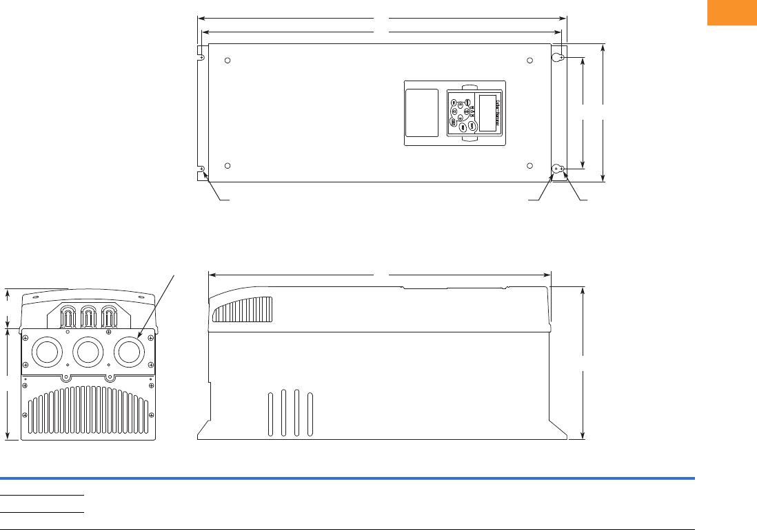
Volume 6—Solid-State Motor Control CA08100007E—February 2016 www.eaton.com V6-T2-127
2
2
2
2
2
2
2
2
2
2
2
2
2
2
2
2
2
2
2
2
2
2
2
2
2
2
2
2
2
2
2.7
Adjustable Frequency Drives
SVX Drives
Approximate Dimensions in Inches (mm)
NEMA Type 1/IP21 and NEMA Type 12/IP54, FR7
Voltage hp (IH) H1 H2 H3 D1 D2 D3 W1 W2 R1 Dia. R2 Dia.
Weight
Lbs (kg)
Knockouts at Inches (mm)
N1 (O.D.)
230 V 20–30 24.8 (630) 24.2 (614) 23.2 (590) 10.1 (257) 3.0 (77) 7.3 (184) 9.3 (237) 7.5 (190) 0.7 (18) 0.4 (9) 77.2 (35) 3 at 1.5 (37)
480 V 40–60
575 V 30–40
W2
H1
D1
D2
Knockouts
R2 R2R1
D3
H2
H3
W1
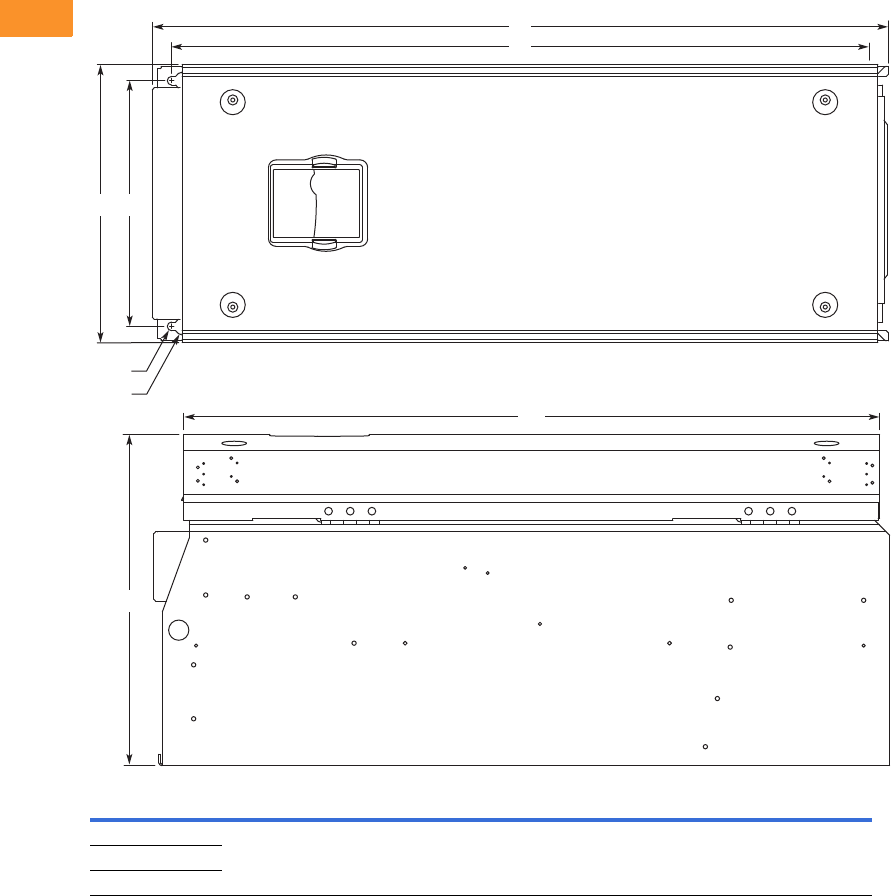
V6-T2-128 Volume 6—Solid-State Motor Control CA08100007E—February 2016 www.eaton.com
2
2
2
2
2
2
2
2
2
2
2
2
2
2
2
2
2
2
2
2
2
2
2
2
2
2
2
2
2
2
2.7
Adjustable Frequency Drives
SVX Drives
Approximate Dimensions in Inches (mm)
NEMA Type 1/IP21 and NEMA Type 12/IP54, FR8
Voltage hp (IH) D1 H1 H2 H3 W1 W2 R1 Dia. R2 Dia.
Weight
Lbs (kg)
230 V 40–60 13.5 (344) 30.1 (764) 28.8 (732) 28.4 (721) 11.5 (291) 10 (255) 0.7 (18) 0.4 (9) 127 (58)
480 V 75–125
575 V 50–75
D1
H2
H1
W2W1
H3
R2
R1
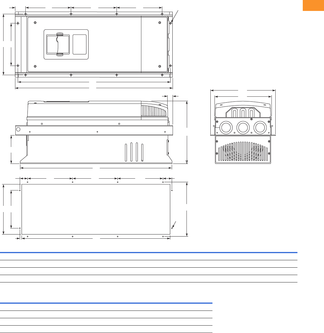
Volume 6—Solid-State Motor Control CA08100007E—February 2016 www.eaton.com V6-T2-129
2
2
2
2
2
2
2
2
2
2
2
2
2
2
2
2
2
2
2
2
2
2
2
2
2
2
2
2
2
2
2.7
Adjustable Frequency Drives
SVX Drives
Approximate Dimensions in Inches (mm)
NEMA Type 1/IP21 and NEMA Type 12/IP54, with Flange Kit, FR7 and FR8
Flange Opening, FR7 and FR8
W1 W2 W3 W4 H1 H2 H3 H4 H5 H6 H7 D1 D2 Dia. A
FR7
9.3 (237) 6.8 (175) 10.6 (270) 10.0 (253) 24.9 (652) 24.8 (632) 24.8 (630) 7.4 (189) 7.4 (189) 0.9 (23) 0.8 (20) 10.1 (257) 4.6 (117) 0.3 (6)
FR8
11.2 (285) — 14.0 (355) 13.0 (330) 32.8 (832) — 29.3 (745) 10.2 (258) 10.4 (265) 1.7 (43) 2.2 (57) 13.5 (344) 4.3 (110) 0.4 (9)
W5 W6 W7 H8 H9 H10 H11 H12 H13 Dia. B
FR7
9.2 (233) 6.9 (175) 10.0 (253) 24.4 (619) 7.4 (189) 7.4 (189) 1.4 (35) 1.3 (32) 1.0 (25) 0.3 (6)
FR8
11.9 (301) — 13.0 (330) 31.9 (810) 10.2 (258) 10.4 (265) — — 1.3 (33) 0.4 (9)
H7
W3
H9
D1
W1
H9H12
H13
H11H10
H1
H2
H5 Dia. A
Dia. B
H4H4H6
W2W4
D2
W6W5 W7
H3
H8
Flange Opening
FR7/FR8
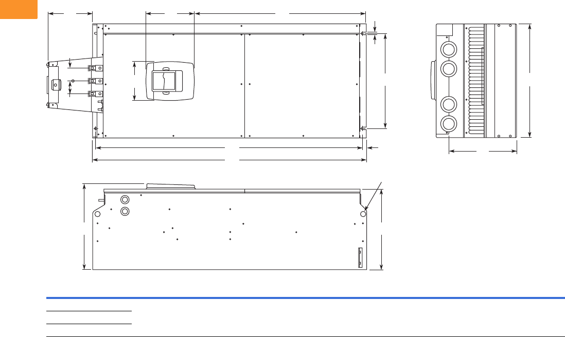
V6-T2-130 Volume 6—Solid-State Motor Control CA08100007E—February 2016 www.eaton.com
2
2
2
2
2
2
2
2
2
2
2
2
2
2
2
2
2
2
2
2
2
2
2
2
2
2
2
2
2
2
2.7
Adjustable Frequency Drives
SVX Drives
Approximate Dimensions in Inches (mm)
NEMA Type 1/IP21 and NEMA Type 12/IP54 FR9
Note
1Brake resistor terminal box (H6) included when brake chopper ordered.
Voltage hp (IH) W1W2W3W4H1 H2 H3 H4
1D1 D2 D3 Dia.
Weight
Lbs (kg)
230 V 75–100 18.9
(480)
15.7
(400)
0.4
(9)
2.1
(54)
45.3
(1150)
44.1
(1120)
0.6
(16)
7.4
(188)
14.2
(361.5)
13.4
(340)
11.2
(285)
0.8
(21)
321.9 (146)
480 V 150–200
575 V 100–175
D2
Dia.
D1
H5
W2
W4
H3H4
H2
H1
H6
W3
W5
PE
B- B+ /R+ R-
W5 W1
D3
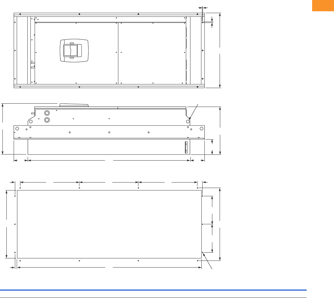
Volume 6—Solid-State Motor Control CA08100007E—February 2016 www.eaton.com V6-T2-131
2
2
2
2
2
2
2
2
2
2
2
2
2
2
2
2
2
2
2
2
2
2
2
2
2
2
2
2
2
2
2.7
Adjustable Frequency Drives
SVX Drives
Approximate Dimensions in Inches (mm)
NEMA Type 1/IP21 and NEMA Type 12/IP54, FR9 with Flange Kit
W1 W2 W3 W4 W5 H1 H2 H3 H4 H5 H6 H7 D1 D2 D3 Dia.
20.9 (530) 20.0 (510) 19.1 (485) 7.9 (200) 0.2 (5.5) 51.7 (1312) 45.3 (1150) 16.5 (420) 3.9 (100) 1.4 (35) 0.4 (9) 0.1 (2) 24.9 (362) 13.4 (340) 4.3 (109) 0.8 (21)
.20 (5)
Dia.
H4
H2
D2
Dia.
D1
D3
H4
W1
H7
W5
W3
W4
H3 H3 H3 H5H5
H6 H1
W4
W2
Flange Opening
FR9
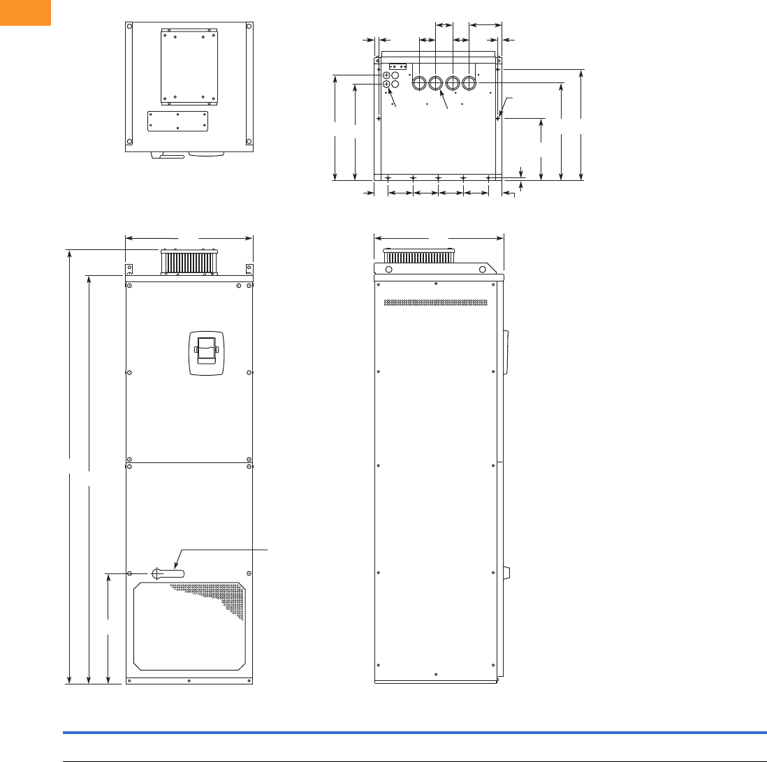
V6-T2-132 Volume 6—Solid-State Motor Control CA08100007E—February 2016 www.eaton.com
2
2
2
2
2
2
2
2
2
2
2
2
2
2
2
2
2
2
2
2
2
2
2
2
2
2
2
2
2
2
2.7
Adjustable Frequency Drives
SVX Drives
Approximate Dimensions in Inches (mm)
NEMA Type 1/IP21 and NEMA Type 12/IP54, FR10 Freestanding
W1 W2 W3 W4 W5 W6 W7 H1 H2 H3 D1 D2 D3 D4 D5 D6 D7 Dia. 1 Dia. 2 Dia. 3
Weight
Lbs (kg)
23.43
(595)
2.46
(62.5)
4.53
(115)
0.79
(20)
5.95
(151)
2.95
(75)
30.11
(79)
79.45
(2018)
74.80
(1900)
20.18
(512.5)
23.70
(602)
17.44
(443)
19.02
(483)
0.47
(12)
11.22
(285)
17.60
(447)
20.08
(510)
0.83
(21)
1.89
(48)
0.43
(11)
857
(389)
Dia. 3
Dia. 2
Dia. 1
W5
W6
W4 W4
D4
D2
W2
W2
D5
D3 D6 D7
W3 W3 W3 W3
H1
H2
H3
W1 D1
Operator
(Shown with
Optional
Disconnect)
W6
W7
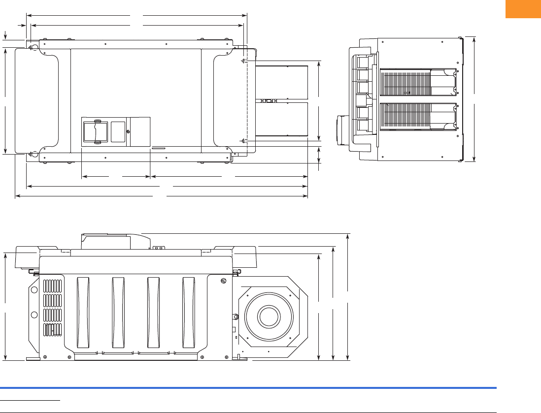
Volume 6—Solid-State Motor Control CA08100007E—February 2016 www.eaton.com V6-T2-133
2
2
2
2
2
2
2
2
2
2
2
2
2
2
2
2
2
2
2
2
2
2
2
2
2
2
2
2
2
2
2.7
Adjustable Frequency Drives
SVX Drives
Approximate Dimensions in Inches (mm)
FR10 Open Chassis 1
Note
19000X FR12 is built of two FR10 modules. Please refer to SPX installation manual for mounting instructions.
Voltage hp (IH)W1W2W3W4W5H1H2H3H4H5H6H7D1D2D3D4
Weight
Lbs (kg)
480 V 250–350 19.7
(500)
16.7
(425)
1.2
(30)
2.6
(67)
12.8
(325)
45.9
(1165)
44.1
(1121)
34.6
(879)
33.5
(850)
0.7
(17)
24.7
(627)
10.8
(275)
19.9
(506)
17.9
(455)
16.7
(423)
16.6
(421)
518
(235)
575 V 200–300
H2
W1
H7 H6
H4H5
H3
H1
W2
W3
W5
W4
D4 D2 D1
D3

V6-T2-134 Volume 6—Solid-State Motor Control CA08100007E—February 2016 www.eaton.com
2
2
2
2
2
2
2
2
2
2
2
2
2
2
2
2
2
2
2
2
2
2
2
2
2
2
2
2
2
2
2.7
Adjustable Frequency Drives
SVX Drives
Approximate Dimensions in Inches (mm)
NEMA Type 1/IP21, FR11 Freestanding Drive
Voltage hp (IH)W1W2W3W4W5W6W7W8H1 H2 H3 D1 D2 D3 D4 D5 Dia. 1Dia. 2Dia. 3
Weight
Lbs (kg)
480 400–550 31.26
(794)
2.40
(61)
6.50
(165)
0.79
(20)
3.43
(87)
2.95
(75)
2.52
(64)
1.18
(30)
79.45
(2018)
74.80
(1900)
20.18
(512.5)
23.70
(602)
11.22
(285)
19.09
(485)
0.47
(12)
17.60
(447)
0.83
(21)
1.89
(48)
0.35 x 0.43
(9 x 11)
526
(239)
H1
H2
W1 D1
H3
D2
D3
Dia. 3
D4
D5
Dia. 1 Dia. 2
W2
W2 W3 W3 W3 W3
W8
W6
W4
W6
W5
W7W7 W6W6W6W6
Operator
(Shown with
Optional
Disconnect)
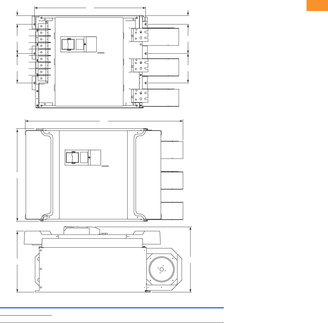
Volume 6—Solid-State Motor Control CA08100007E—February 2016 www.eaton.com V6-T2-135
2
2
2
2
2
2
2
2
2
2
2
2
2
2
2
2
2
2
2
2
2
2
2
2
2
2
2
2
2
2
2.7
Adjustable Frequency Drives
SVX Drives
Approximate Dimensions in Inches (mm)
FR11 Open Chassis
Voltage hp (IH)W1W2W3H1 H2 D1 D2
Weight
Lbs (kg)
480 V 400–550 27.9 (709) 8.86 (225) 2.6 (67) 45.5 (1155) 33.5 (850) 19.8 (503) 18.4 (468) 833 (378)
575 V 400–500
H1
H2
D1
W2
W2
W3
W2
W2
W3
W1
Shown without
terminal cover
D2
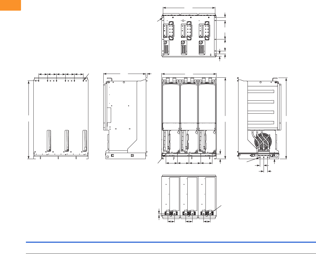
V6-T2-136 Volume 6—Solid-State Motor Control CA08100007E—February 2016 www.eaton.com
2
2
2
2
2
2
2
2
2
2
2
2
2
2
2
2
2
2
2
2
2
2
2
2
2
2
2
2
2
2
2.7
Adjustable Frequency Drives
SVX Drives
Approximate Dimensions in Inches (mm)
FR13, Open Chassis Inverter
Notes
9000X FR14 is built of two FR13 modules. Please refer to SPX installation manual for mounting instructions.
FR13 is built from an inverter module and a converter module. Please refer to SPX installation manual for mounting instructions.
W1 W2 W3 W4 W5 H1 H2 H3 H4 H5 D1 D2 D3 D4 D5 D6 D7 D8
Dia.
1
Dia.
2
Dia.
3
Dia.
4
Weight
Lbs (kg)
27.87
(708)
5.91
(150)
26.65
(677)
4.57
(116)
3.35
(85)
41.54
(1055)
2.46
(62.5)
39.86
(1012.5)
41.34
(1050)
0.79
(20)
21.77
(553)
0.51
(13)
0.63
(16)
1.97
(50)
1.06
(27)
1.57
(40)
5.91
(150)
9.64
(244.8)
0.35x0.59
(9x15)
0.18
(4.6)
0.51
(13)
0.37
(9.5)
683
(310)
W4 W4 W4 W4 W4
H3
Dia. 1 D1 D2 W1
W2W2W2W2
H2
W5 W5 W5
D3
Dia. 3
Dia. 3 D4
D4
H5
H4H1
D5 D6
D7
D8
D6
W3
Dia. 2
Dia. 4

Volume 6—Solid-State Motor Control CA08100007E—February 2016 www.eaton.com V6-T2-137
2
2
2
2
2
2
2
2
2
2
2
2
2
2
2
2
2
2
2
2
2
2
2
2
2
2
2
2
2
2
2.7
Adjustable Frequency Drives
SVX Drives
Approximate Dimensions in Inches (mm)
FR13, Open Chassis Converter
Number of Input Units
W1 W2 W3 W4 W5 H1 H2 H3 H4 H5 D1 D2 D3 D4 D5 D6 D7 D8 D9 Dia. 1 Dia. 2 Dia. 3
Weight
Lbs (kg)
18.74
(476)
5.91
(150)
17.52
(445)
4.57
(116)
3.35
(85)
41.54
(1055)
2.46
(62.5)
39.86
(1012.5)
41.34
(1050)
0.69
(17.5)
14.69
(373)
0.51
(13)
0.73
(18.5)
6.42
(163)
2.56
(65)
1.06
(27)
1.57
(40)
5.91
(150)
5.24
(133)
0.35x0.59
(9x15)
0.51
(13)
0.37
(9.5)
295
(134)
480 V
Catalog Number hp
Input
Modules
690 V
Catalog Number hp
Input
Modules
SPX800A0-4A2N1 800 2 SPX800A0-5A2N1 800 2
SPX900A0-5A2N1 900 2
SPXH10A0-5A2N1 1000 2
H3
H2
H5
H4
Dia. 1 W4 W4 W4
W5
D3 W5
D5
D4 D5
W2
W2
D1 D2
Dia. 2
Dia. 2
H1
W3 Dia. 3
D9
D8
D7
D6
W1
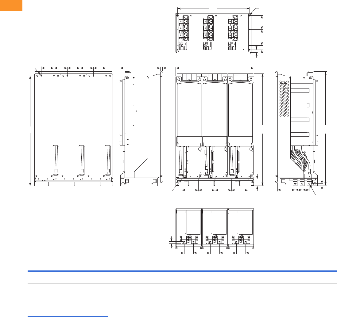
V6-T2-138 Volume 6—Solid-State Motor Control CA08100007E—February 2016 www.eaton.com
2
2
2
2
2
2
2
2
2
2
2
2
2
2
2
2
2
2
2
2
2
2
2
2
2
2
2
2
2
2
2.7
Adjustable Frequency Drives
SVX Drives
Approximate Dimensions in Inches (mm)
FR13, Open Chassis Converter—900/1000 hp 480 V
Number of Input Units
W1 W2 W3 W4 W5 H1 H2 H3 H4 H5 D1 D2 D3 D4 D5 D6 D7 D8 D9
Dia.
1
Dia.
2
Dia.
3
Dia.
4
Weight
Lbs (kg)
27.87
(708)
5.91
(150)
26.65
(677)
4.57
(116)
3.35
(85)
41.54
(1055)
2.46
(62.5)
39.86
(1012.5)
41.34
(1050)
0.69
(17.5)
14.69
(373)
0.51
(13)
0.73
(18.5)
6.42
(163)
2.56
(65)
1.06
(27)
1.57
(40)
5.91
(150)
5.24
(133)
0.35x0.59
(9x15)
0.18
(4.6)
0.51
(13)
0.37
(9.5)
443
(201)
480 V
Catalog Number hp
Input
Modules
SPX900A0-4A2N1 900 3
SPXH10A0-4A2N1 1000 3
H3
H2
H5
Dia. 1 W4 W4 W4 W4 W4
W5
D3 W5 W5
D5
D4 D5
W2
W2
W2 W2
D1 D2
Dia. 2
Dia. 3
H1 H4
W3 Dia. 4
D9
D8
D7
D6
W1
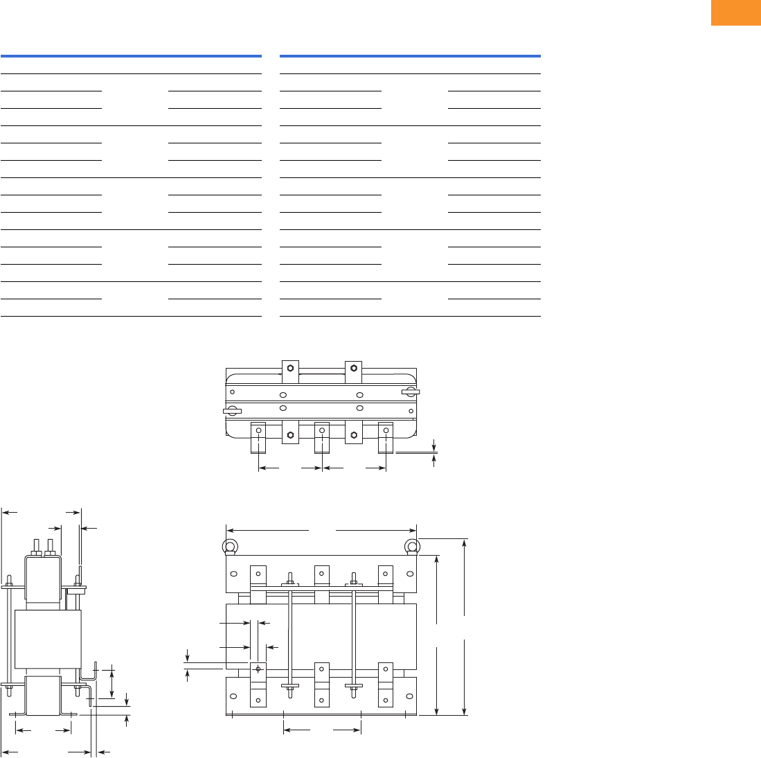
Volume 6—Solid-State Motor Control CA08100007E—February 2016 www.eaton.com V6-T2-139
2
2
2
2
2
2
2
2
2
2
2
2
2
2
2
2
2
2
2
2
2
2
2
2
2
2
2
2
2
2
2.7
Adjustable Frequency Drives
SVX Drives
Approximate Dimensions in Inches (mm)
AC Choke Dimensions
Choke Types
CHK0520
Note
1Chokes are provided with all FR10–FR14 drives.
Catalog Number Frame Size Choke Type 1Catalog Number Frame Size Choke Type 1
Voltage Range 380–500 V Voltage Range 525–690 V
SPX 250 4 FR10 CHK0400 SPX 200 5 FR10 CHK0261
SPX 300 4 CHK0520 SPX 250 5 CHK0400
SPX 350 4 CHK0520 SPX 300 5 CHK0400
SPX 400 4 FR11 2 x CHK0400 SPX 400 5 FR11 CHK0520
SPX 500 4 2 x CHK0400 SPX 450 5 CHK0520
SPX 550 4 2 x CHK0400 SPX 500 5 2 x CHK0400
SPX 600 4 FR12 2 x CHK0520 SPX 550 5 FR12 2 x CHK0400
SPX 650 4 2 x CHK0520 SPX 600 5 2 x CHK0400
SPX 700 4 2 x CHK0520 SPX 700 5 2 x CHK0400
SPX 800 4 FR13 2 x CHK0400 SPX 800 5 FR13 2 x CHK0400
SPX 900 4 3 x CHK0520 SPX 900 5 2 x CHK0400
SPX H10 4 3 x CHK0520 SPX H10 5 2 x CHK0400
SPX H12 4 FR14 4 x CHK0520 SPX H13 5 FR14 4 x CHK0400
SPX H16 4 6 x CHK0400 SPX H15 5 6 x CHK0400
11
33
2
1
3
22
1.58
(40)
7.88
(200)
6.50
(165) 6.50
(165)
19.57
(497)
.79
(20) 15.71
(399)
17.57
(446)
.79
(20)
.24
(6)
3.03
(77)
.83
(21)
.55 (14)9.61 (244)
8.03 (204)
1.69
(43)
5.70
(145)
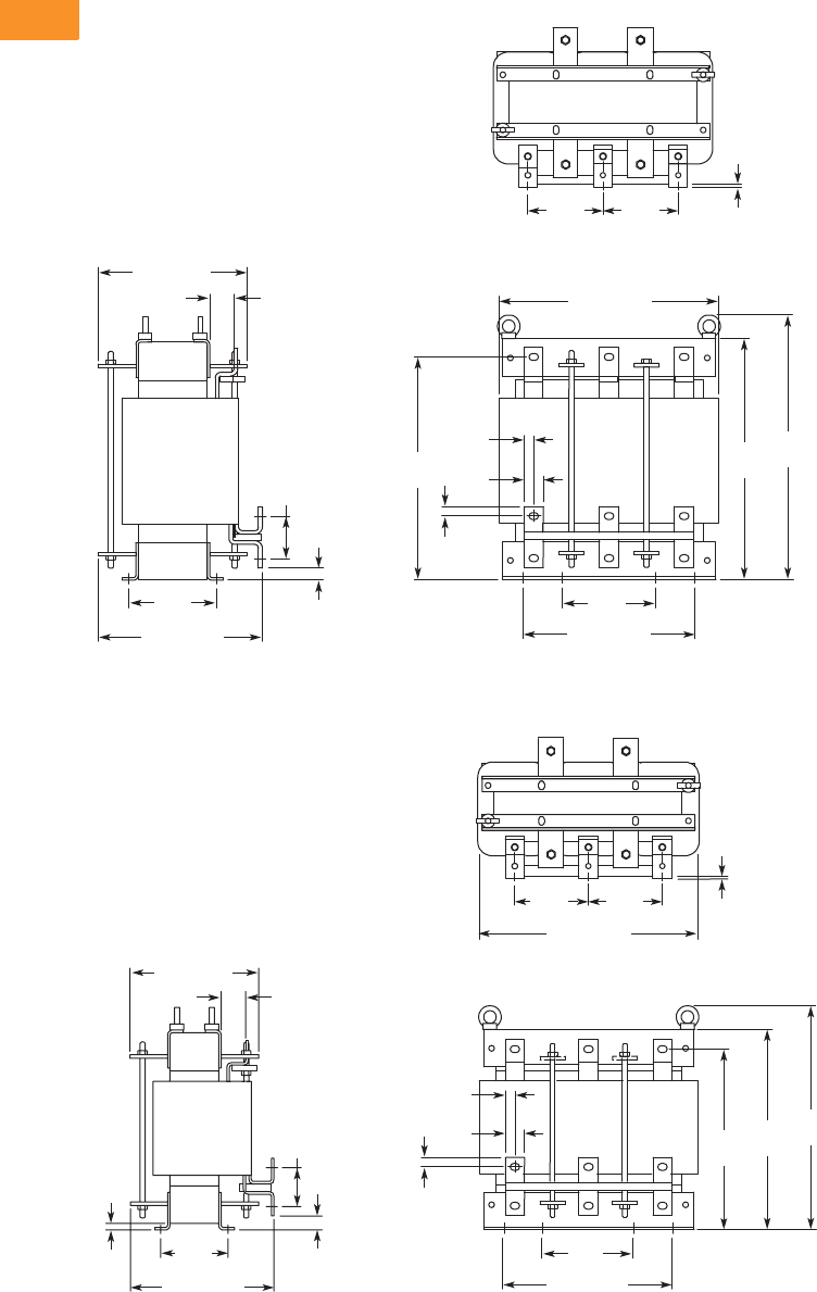
V6-T2-140 Volume 6—Solid-State Motor Control CA08100007E—February 2016 www.eaton.com
2
2
2
2
2
2
2
2
2
2
2
2
2
2
2
2
2
2
2
2
2
2
2
2
2
2
2
2
2
2
2.7
Adjustable Frequency Drives
SVX Drives
Approximate Dimensions in Inches (mm)
CHK0400
CHK0261
111
33
22
3
2
10.30 (262)
9.37 (238)
1.54
(39)
1.18
(30)
5.90
(150)
13.79 (350)
4.72
(120) 4.72
(120)
10.83 (275)
.59
(15)
5.51
(140)
13.94
(354)
15.08
(383)
16.58
(421)
2.64
(67)
.75
(19)
.24
(6)
.59
(15)
13.79 (350)
4.72
(120) 4.72
(120)
.24
(6)
11
33
2
1
3
22
1.18
(30)
5.90
(150)
10.83 (275)
.59
(15)
11.30
(287)
12.56
(319)
14.06
(357)
.59
(15)
.39
(10)
.87
(22)
.75 (19)
Min.
9.06 (230)
8.11 (206)
1.54
(39)
4.25
(108)
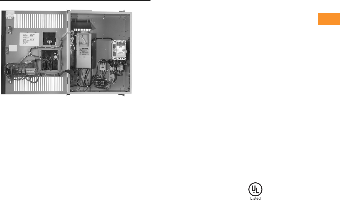
Volume 6—Solid-State Motor Control CA08100007E—February 2016 www.eaton.com V6-T2-141
2
2
2
2
2
2
2
2
2
2
2
2
2
2
2
2
2
2
2
2
2
2
2
2
2
2
2
2
2
2
2.7
Adjustable Frequency Drives
SVX Drives
SVX Enclosed Drives
Contents
Description Page
SVX Drives . . . . . . . . . . . . . . . . . . . . . . . . . . . . . . . V6-T2-100
SVX Enclosed Drives
Catalog Number Selection . . . . . . . . . . . . . . . . V6-T2-142
Product Selection . . . . . . . . . . . . . . . . . . . . . . . V6-T2-144
Enclosure Selection . . . . . . . . . . . . . . . . . . . . . V6-T2-151
Options . . . . . . . . . . . . . . . . . . . . . . . . . . . . . . . V6-T2-153
Technical Data and Specifications . . . . . . . . . . V6-T2-157
Dimensions . . . . . . . . . . . . . . . . . . . . . . . . . . . V6-T2-159
SVX Enclosed Drives
Product Description
Eaton’s line of enclosed
SVX drives combine the
proven performance from
Eaton’s SVX drives with the
enhanced capabilities of
enclosed control. With a
comprehensive list of pre-
engineered options, Eaton’s
SVX enclosed drives
eliminate the lead time
normally associated with
customer specific options.
For those applications with
more unique or complex
requirements, Eaton offers
individually engineered
solutions to meet the
customer’s needs.
Features and Benefits
●Dual rated for both
constant torque (CT) /
high overload (IH) and
variable torque (VT) / low
overload applications
●Optional Brake Chopper
for external braking
applications
●High-performance drive
option uses an Eaton
SPX (IH) drive that allows
for increased functionality
and performance
●Available circuit breaker,
motor circuit protector,
isolation fusing and surge
protection device options
to provide input power
protection
●Optional 3% input and
output reactors provide
a reduction in voltage and
current harmonics on both
line and load side
●Bypass options include a
standard three-contactor
design and a reduced
voltage soft starter design
●Output contactor option
provides a means for
positive disconnection of
the drive output from the
motor terminals
●MotoRX and dV/dt filter
options are used to reduce
transients voltages at the
motor terminals
●Customizable cover control
options
●Padlockable disconnect
Communication Options
●Modbus
●Modbus/TCP
●Johnson Controls N2
●BACnet
●EtherNet/IP
●PROFIBUS-DP
●LonWorks
●CANopen
●DeviceNet
Enclosure Ratings
●NEMA Type 1
●NEMA Type 12
●NEMA Type 3R
Mounting
●Wall mount
●Floor mount: 12-inch legs
●Floor mount: 22-inch legs
Product Range
●208 V: 0.75–100 hp
●230 V: 0.75–125 hp
●480 V: 1–800 hp
●575 V: 2–800 hp
●230 V single-phase:
1–60 hp
●480 V single-phase:
1.5–125 hp
Standards and Certifications
●UL 508C tested, listed
and approved
●OSHPD
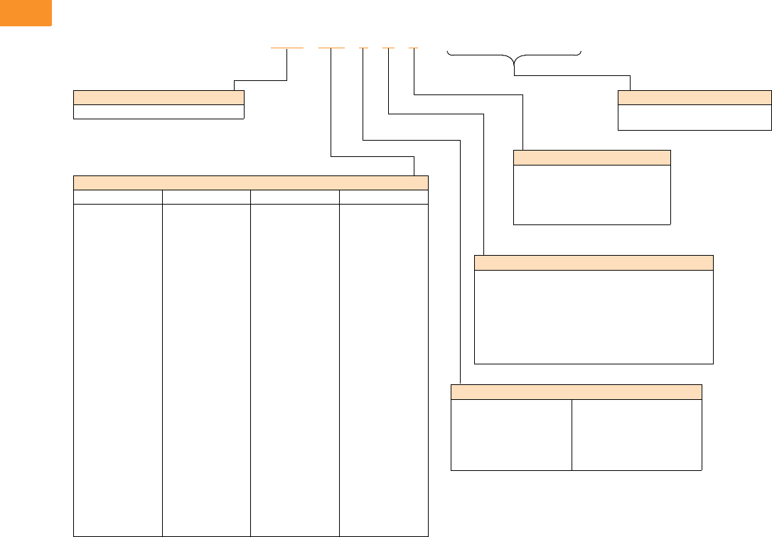
V6-T2-142 Volume 6—Solid-State Motor Control CA08100007E—February 2016 www.eaton.com
2
2
2
2
2
2
2
2
2
2
2
2
2
2
2
2
2
2
2
2
2
2
2
2
2
2
2
2
2
2
2.7
Adjustable Frequency Drives
SVX Drives
Catalog Number Selection
Catalog Number Selection is for reference only. Not all option combinations may be available.
SVX Enclosed—Base Catalog Number
Notes
1Brake chopper is a factory-installed option only. Braking resistors sold separately. See SVX catalog section for selection.
2Additional enclosure options including NEMA 4 and 4X are available. Please contact the factory for configuration and pricing.
3Part number configuration continued on the following page.
SVX F07 1 A 1
Product Family
SVX = Enclosed SVX drives—standard
Output Horsepower Rating
208 V 230 V 480 V 575 V
F07 = 0.75 hp
001 =1 hp
F15 =1.5 hp
002 =2 hp
003 =3 hp
005 =5 hp
007 =7.5 hp
010 =10 hp
015 =15 hp
020 =20 hp
025 =25 hp
030 =30 hp
040 =40 hp
050 =50 hp
060 =60 hp
075 =75 hp
100 =100 hp
F07 = 0.75 hp
001 =1 hp
F15 = 1.5 hp
002 =2 hp
003 =3 hp
005 =5 hp
007 = 7.5 hp
010 =10 hp
015 =15 hp
020 =20 hp
025 =25 hp
030 =30 hp
040 =40 hp
050 =50 hp
060 =60 hp
075 =75 hp
100 =100 hp
125 =125 hp
001 =1 hp
F15 = 1.5 hp
002 =2 hp
003 =3 hp
005 =5 hp
007 = 7.5 hp
010 =10 hp
015 =15 hp
020 =20 hp
025 =25 hp
030 =30 hp
040 =40 hp
050 =50 hp
060 =60 hp
075 =75 hp
100 =100 hp
125 =125 hp
150 =150 hp
200 =200 hp
250 =250 hp
300 =300 hp
350 =350 hp
400 =400 hp
500 =500 hp
550 =550 hp
600 =600 hp
650 =650 hp
700 =700 hp
800 =800 hp
Phasing and Voltage Rating
1 = Input: Three-phase, 208 V
Output: Three-phase
2 = Input: Three-phase, 230 V
Output: Three-phase
4 = Input: Three-phase, 480 V
Output: Three-phase
5 = Input: Three-phase, 575 V
Output: Three-phase
J = Input: Single-phase, 230 V
Output: Three-phase
K = Input: Single-phase, 480 V
Output: Three-phase
Drive Type/Braking/Application 1
A = Standard drive/no brake chopper/low overload
B = Standard drive/brake chopper/low overload
C = Standard drive/no brake chopper/high overload
D = Standard drive/brake chopper/high overload
E = High-performance drive/no brake chopper/low overload
F = High-performance drive/brake chopper/low overload
G = High-performance drive/no brake chopper/high overload
H = High-performance drive/brake chopper/high overload
Enclosure Rating 2
1 = NEMA Type 1
2 = NEMA Type 12
3 = NEMA Type 3R
6 = NEMA Type 1 Filtered and gasketed
• = Custom option
______
Options 3
See Page V6-T2-143 for catalog
number option selection.

Volume 6—Solid-State Motor Control CA08100007E—February 2016 www.eaton.com V6-T2-143
2
2
2
2
2
2
2
2
2
2
2
2
2
2
2
2
2
2
2
2
2
2
2
2
2
2
2
2
2
2
2.7
Adjustable Frequency Drives
SVX Drives
Catalog Number Selection is for reference only. Not all option combinations may be available.
SVX Enclosed—Catalog Number Options
SVX F07 1 A 1
Base Catalog Number Example
See Page V6-T2-142 for base catalog
number selection.
2 0 0 B 1 0 0 0 0
Power Disconnect Options
0 =None
1 = MCP disconnect 1
2 = Circuit breaker
3 = Circuit breaker/isolation fusing
4 = Circuit breaker/isolation fusing/3% input reactor
5 = Circuit breaker/isolation fusing/SPD
6 = Circuit breaker/isolation fusing/SPD/3% input reactor
7 = Circuit breaker/3% input reactor
8 = Circuit breaker/SPD
9 = Circuit breaker/SPD/3% input reactor
A = Fused disconnect
B = Fused disconnect/SPD
C = Fused disconnect/SPD/3% input reactor
D = Fused disconnect/3% input reactor
E = Isolation fuses
F = Isolation fuses/3% input reactor
G = Isolation fuses/SPD
H = Isolation fuses/SPD/3% input reactor
• = Custom option 2
Bypass Options 3
0 =None
1 = Manual HOA bypass
2 = Manual HOA bypass/isolation fusing
3 = Manual HOA bypass/isolation fusing/3% input reactor
4 = Manual HOA bypass/isolation fusing/SPD
5 = Manual HOA bypass/isolation fusing/SPD/3% input reactor
6 = Manual HOA bypass/3% input reactor
7 = Manual HOA bypass/SPD
8 = Manual HOA bypass/SPD/3% input reactor
H = Manual HOA RVSS bypass
J = Manual HOA RVSS bypass/isolation fusing
K = Manual HOA RVSS bypass/isolation fusing/3% input reactor
L = Manual HOA RVSS bypass/isolation fusing/SPD
M = Manual HOA RVSS bypass/isolation fusing/SPD/3% input reactor
N = Manual HOA RVSS bypass/3% input reactor
P = Manual HOA RVSS bypass/SPD
R = Manual HOA RVSS bypass/SPD/3% input reactor
• = Custom option 2
Output Power Options 4
0 =None
A = Output contactor
B = 3% Output reactor
C = MotoRX filter
D = dV/dt filter
E = 3% Output Reactor/output contactor
F = MotoRX/output contactor
G = dV/dt/output contactor
• = Custom option 2
Option Boards 2
Same options and codes as Option Boards 1
Option Boards 1
0 = No option
1 = 3 x DI, 3 x DO, 1 Thermistor, 24 Vdc/EXT (DG1 only)
2 = 1 x AI, 2 x AO (isolated to control board) (DG1 only)
3 = 3 x relay dry contact (2NO + 1NO/NC) (DG1 only)
4 = 3 x PT100 RTD thermistor input (DG1 only)
5 = 6 DI 240 Vac input (DG1 only)
6 = 6 DI, 1 ext +24 Vdc/EXT +24 Vdc (SVX only)
7 = 1 RO (NC-NO), 1 RO (NO), 1 therm (SVX only)
8 = 1 AI (mA isolated), 2 AO (mA isolated), 1 ext +24 Vdc/EXT +24 Vdc
(SVX only)
9 = 3 RO (NO) (SVX only)
A = 1 ext +24 Vdc/EXT +24 Vdc, 3 Pt100 (SVX only)
B = 1 RO (NO), 5 DI 42–240 Vac input (SVX only)
C = Encoder low volt +5 V / 15 V / 24 V (high-performance drive only)
D = Encoder high volt +15 V / 24 V (high-performance drive only)
E = Double encoder (high-performance drive only)
• = Custom option 2
Communication Options
0 = No option
1 = PROFIBUS-DP
2 = LonWorks (SVX only)
3 = CANopen (slave)
4 = DeviceNet
5 = PROFIBUS-DP (D9 connector)
6 = Modbus (SVX only)
7 = Modbus (D9 connector) (SVX only)
8 = Johnson Controls N2 (SVX only)
9 = Modbus TCP (SVX only)
A = BACnet (SVX only)
B = EtherNet/IP (SVX only)
C = RS-232 with D9 connector (SVX only)
D = SmartWire-DT (DG1 only)
• = Custom option 2
Enclosure Options
0 =None
1 = Floor stand—12 inches
2 = Floor stand—22 inches
A = Space heater
B = Space heater & 12-inch floor stands
C = Space heater & 22-inch floor stands
• = Custom option 2
Light Options 5
0 =None
1 = Non-bypass light kit—Power On, Run, Fault
2 = Bypass light kit—On, VFD Run, Fault, Bypass Run
• = Custom option 2
Notes
1HMCP disconnect option required and only available when bypass is selected.
2More options are available as Engineered to Order through the Bid Manager tool.
3All bypass options include third contactor for drive isolation when in bypass mode.
4Output contactor not available with bypass. Bypass comes standard with output contactor.
5Pilot devices are 22 mm standard. 30 mm options are available as engineered to order through the Bid Manager tool.
Control Options 5
0 =None
1 = Speed pot
2 = Start-stop pushbutton
3 = Start-stop pushbutton with speed pot
A = HOA switch
B = Start-stop pushbutton with speed pot & HOA switch
C = Start-stop pushbutton with HOA switch
D = HOA switch with speed pot
• = Custom option 2
V6-T2-144 Volume 6—Solid-State Motor Control CA08100007E—February 2016 www.eaton.com
2
2
2
2
2
2
2
2
2
2
2
2
2
2
2
2
2
2
2
2
2
2
2
2
2
2
2
2
2
2
2.7
Adjustable Frequency Drives
SVX Drives
Product Selection
208 V Drives
208 V Drives—Constant Torque (CT)/High Overload (IH) Enclosed Drives
208 V Drives—Variable Torque (VT)/Low Overload (IL) Enclosed Drives
Notes
1 Table is for base catalog number reference only. For complete catalog number selection, see Page V6-T2-142.
2 These units are current rated. They do not meet NEC ampere rating at this horsepower.
NEMA Type 1 NEMA Type 12 NEMA Type 3R
hp Current (A)
Drive
Frame Size
Base
Catalog Number 1
Base
Catalog Number 1
Base
Catalog Number 1
0.75 3.5 4 SVXF071D1 SVXF071D2 SVXF071D3
14.64SVX0011D1 SVX0011D2 SVX0011D3
1.5 6.6 4 SVXF151D1 SVXF151D2 SVXF151D3
27.54SVX0021D1 SVX0021D2 SVX0021D3
310.64SVX0031D1 SVX0031D2 SVX0031D3
516.75SVX0051D1 SVX0051D2 SVX0051D3
7.5 24.2 5 SVX0071D1 SVX0071D2 SVX0071D3
10 30.8 6 SVX0101D1 SVX0101D2 SVX0101D3
15 46.2 6 SVX0151D1 SVX0151D2 SVX0151D3
20 59.4 7 SVX0201C1 SVX0201C2 SVX0201C3
25 74.8 7 SVX0251C1 SVX0251C2 SVX0251C3
30 88 7 SVX0301C1 SVX0301C2 SVX0301C3
40 114 8 SVX0401C1 SVX0401C2 SVX0401C3
50 143 8 SVX0501C1 SVX0501C2 SVX0501C3
60 169 8 SVX0601C1 SVX0601C2 SVX0601C3
75 211 9 SVX0751C1 SVX0751C2 SVX0751C3
2261 9 SVX1001C1 SVX1001C2 SVX1001C3
NEMA Type 1 NEMA Type 12 NEMA Type 3R
hp Current (A)
Drive
Frame Size
Base
Catalog Number 1
Base
Catalog Number 1
Base
Catalog Number 1
14.64SVX0011B1 SVX0011B2 SVX0011B3
1.5 6.6 4 SVXF151B1 SVXF151B2 SVXF151B3
27.54SVX0021B1 SVX0021B2 SVX0021B3
310.64SVX0031B1 SVX0031B2 SVX0031B3
516.75SVX0051B1 SVX0051B2 SVX0051B3
7.5 24.2 5 SVX0071B1 SVX0071B2 SVX0071B3
10 30.8 5 SVX0101B1 SVX0101B2 SVX0101B3
15 46.2 6 SVX0151B1 SVX0151B2 SVX0151B3
20 59.4 6 SVX0201B1 SVX0201B2 SVX0201B3
25 74.8 7 SVX0251A1 SVX0251A2 SVX0251A3
30 88 7 SVX0301A1 SVX0301A2 SVX0301A3
40 114 7 SVX0401A1 SVX0401A2 SVX0401A3
50 143 8 SVX0501A1 SVX0501A2 SVX0501A3
60 169 8 SVX0601A1 SVX0601A2 SVX0601A3
75 211 9 SVX0751A1 SVX0751A2 SVX0751A3
100 273 9 SVX1001A1 SVX1001A2 SVX1001A3
SVX Enclosed Drives
SVX Enclosed Drives
Volume 6—Solid-State Motor Control CA08100007E—February 2016 www.eaton.com V6-T2-145
2
2
2
2
2
2
2
2
2
2
2
2
2
2
2
2
2
2
2
2
2
2
2
2
2
2
2
2
2
2
2.7
Adjustable Frequency Drives
SVX Drives
230 V Drives
230 V Drives—Constant Torque (CT)/High Overload (IH) Enclosed Drives
230 V Drives—Variable Torque (VT)/Low Overload (IL) Enclosed Drives
Notes
1 Table is for base catalog number reference only. For complete catalog number selection, see Page V6-T2-142.
2 These units are current rated. They do not meet NEC ampere rating at this horsepower.
NEMA Type 1 NEMA Type 12 NEMA Type 3R
hp Current (A)
Drive
Frame Size
Base
Catalog Number 1
Base
Catalog Number 1
Base
Catalog Number 1
0.75 3.2 4 SVXF072D1 SVXF072D2 SVXF072D3
14.24SVX0012D1 SVX0012D2 SVX0012D3
1.5 6 4 SVXF152D1 SVXF152D2 SVXF152D3
26.84SVX0022D1 SVX0022D2 SVX0022D3
39.64SVX0032D1 SVX0032D2 SVX0032D3
515.25SVX0052D1 SVX0052D2 SVX0052D3
7.5 22 5 SVX0072D1 SVX0072D2 SVX0072D3
10 28 6 SVX0102D1 SVX0102D2 SVX0102D3
15 42 6 SVX0152D1 SVX0152D2 SVX0152D3
20 54 7 SVX0202C1 SVX0202C2 SVX0202C3
25 68 7 SVX0252C1 SVX0252C2 SVX0252C3
30 80 7 SVX0302C1 SVX0302C2 SVX0302C3
40 104 8 SVX0402C1 SVX0402C2 SVX0402C3
50 130 8 SVX0502C1 SVX0502C2 SVX0502C3
60 154 8 SVX0602C1 SVX0602C2 SVX0602C3
75 192 9 SVX0752C1 SVX0752C2 SVX0752C3
100 248 9 SVX1002C1 SVX1002C2 SVX1002C3
NEMA Type 1 NEMA Type 12 NEMA Type 3R
hp Current (A)
Drive
Frame Size
Base
Catalog Number 1
Base
Catalog Number 1
Base
Catalog Number 1
14.24SVX0012B1 SVX0012B2 SVX0012B3
1.5 6 4 SVXF152B1 SVXF152B2 SVXF152B3
26.84SVX0022B1 SVX0022B2 SVX0022B3
39.64SVX0032B1 SVX0032B2 SVX0032B3
515.25SVX0052B1 SVX0052B2 SVX0052B3
7.5 22 5 SVX0072B1 SVX0072B2 SVX0072B3
10 28 5 SVX0102B1 SVX0102B2 SVX0102B3
15 42 6 SVX0152B1 SVX0152B2 SVX0152B3
20 54 6 SVX0202B1 SVX0202B2 SVX0202B3
25 68 7 SVX0252A1 SVX0252A2 SVX0252A3
30 80 7 SVX0302A1 SVX0302A2 SVX0302A3
40 104 7 SVX0402A1 SVX0402A2 SVX0402A3
50 130 8 SVX0502A1 SVX0502A2 SVX0502A3
60 154 8 SVX0602A1 SVX0602A2 SVX0602A3
75 192 8 SVX0752A1 SVX0752A2 SVX0752A3
100 248 9 SVX1002A1 SVX1002A2 SVX1002A3
2300 9 SVX1252A1 SVX1252A2 SVX1252A3
SVX Enclosed Drives
SVX Enclosed Drives
V6-T2-146 Volume 6—Solid-State Motor Control CA08100007E—February 2016 www.eaton.com
2
2
2
2
2
2
2
2
2
2
2
2
2
2
2
2
2
2
2
2
2
2
2
2
2
2
2
2
2
2
2.7
Adjustable Frequency Drives
SVX Drives
480 V Drives
480 V Drives—Constant Torque (CT)/High Overload (IH) Enclosed Drives
Notes
1 Table is for base catalog number reference only. For complete catalog number selection, see Page V6-T2-142.
2 Enclosure rating is NEMA Type 1 filtered and gasketed.
NEMA Type 1 NEMA Type 12 NEMA Type 3R
hp Current (A)
Drive
Frame Size
Base
Catalog Number 1
Base
Catalog Number 1
Base
Catalog Number 1
12.14SVX0014D1 SVX0014D2 SVX0014D3
1.5 3 4 SVXF154D1 SVXF154D2 SVXF154D3
23.44SVX0024D1 SVX0024D2 SVX0024D3
34.84SVX0034D1 SVX0034D2 SVX0034D3
57.64SVX0054D1 SVX0054D2 SVX0054D3
7.5 11 5 SVX0074D1 SVX0074D2 SVX0074D3
10 14 5 SVX0104D1 SVX0104D2 SVX0104D3
15 21 5 SVX0154D1 SVX0154D2 SVX0154D3
20 27 6 SVX0204D1 SVX0204D2 SVX0204D3
25 34 6 SVX0254D1 SVX0254D2 SVX0254D3
30 40 6 SVX0304D1 SVX0304D2 SVX0304D3
40 52 7 SVX0404C1 SVX0404C2 SVX0404C3
50 65 7 SVX0504C1 SVX0504C2 SVX0504C3
60 77 7 SVX0604C1 SVX0604C2 SVX0604C3
75 96 8 SVX0754C1 SVX0754C2 SVX0754C3
100 124 8 SVX1004C1 SVX1004C2 SVX1004C3
125 156 8 SVX1254C1 SVX1254C2 SVX1254C3
150 180 9 SVX1504C1 SVX1504C2 SVX1504C3
200 240 9 SVX2004C1 SVX2004C2 SVX2004C3
250 302 10 SVX2504G1 SVX2504G6 2SVX2504G3
300 361 10 SVX3004G1 SVX3004G6 2SVX3004G3
350 414 10 SVX3504G1 SVX3504G6 2SVX3504G3
400 477 11 SVX4004G1 SVX4004G6 2SVX4004G3
500 590 11 SVX5004G1 SVX5004G6 2SVX5004G3
550 650 11 SVX5504G1 SVX5504G6 2SVX5504G3
600 730 12 SVX6004G1 SVX6004G6 2SVX6004G3
650 820 12 SVX6504G1 SVX6504G6 2SVX6504G3
700 920 12 SVX7004G1 SVX7004G6 2SVX7004G3
SVX Enclosed Drives
Volume 6—Solid-State Motor Control CA08100007E—February 2016 www.eaton.com V6-T2-147
2
2
2
2
2
2
2
2
2
2
2
2
2
2
2
2
2
2
2
2
2
2
2
2
2
2
2
2
2
2
2.7
Adjustable Frequency Drives
SVX Drives
480 V Drives, continued
480 V Drives—Variable Torque (VT)/Low Overload (IL) Enclosed Drives
Notes
1 Table is for base catalog number reference only. For complete catalog number selection, see Page V6-T2-142.
2 These units are current rated. They do not meet NEC ampere rating at this horsepower.
3 Enclosure rating is NEMA Type 1 filtered and gasketed.
NEMA Type 1 NEMA Type 12 NEMA Type 3R
hp Current (A)
Drive
Frame Size
Base
Catalog Number 1
Base
Catalog Number 1
Base
Catalog Number 1
1.5 3 4 SVXF154B1 SVXF154B2 SVXF154B3
23.44SVX0024B1 SVX0024B2 SVX0024B3
34.84SVX0034B1 SVX0034B2 SVX0034B3
57.64SVX0054B1 SVX0054B2 SVX0054B3
7.5 11 4 SVX0074B1 SVX0074B2 SVX0074B3
10 14 5 SVX0104B1 SVX0104B2 SVX0104B3
15 21 5 SVX0154B1 SVX0154B2 SVX0154B3
20 27 5 SVX0204B1 SVX0204B2 SVX0204B3
25 34 6 SVX0254B1 SVX0254B2 SVX0254B3
30 40 6 SVX0304B1 SVX0304B2 SVX0304B3
40 52 6 SVX0404B1 SVX0404B2 SVX0404B3
50 65 7 SVX0504A1 SVX0504A2 SVX0504A3
60 77 7 SVX0604A1 SVX0604A2 SVX0604A3
75 96 7 SVX0754A1 SVX0754A2 SVX0754A3
100 124 8 SVX1004A1 SVX1004A2 SVX1004A3
125 156 8 SVX1254A1 SVX1254A2 SVX1254A3
150 180 8 SVX1504A1 SVX1504A2 SVX1504A3
200 240 9 SVX2004A1 SVX2004A2 SVX2004A3
2300 9 SVX2504A1 SVX2504A2 SVX2504A3
300 361 10 SVX3004E1 SVX3004E6 3SVX3004E3
350 414 10 SVX3504E1 SVX3504E6 3SVX3504E3
400 477 10 SVX4004E1 SVX4004E6 3SVX4004E3
500 590 11 SVX5004E1 SVX5004E6 3SVX5004E3
550 650 11 SVX5504E1 SVX5504E6 3SVX5504E3
600 730 11 SVX6004E1 SVX6004E6 3SVX6004E3
650 820 12 SVX6504E1 SVX6504E6 3SVX6504E3
700 920 12 SVX7004E1 SVX7004E6 3SVX7004E3
800 1030 12 SVX8004E1 SVX8004E6 3SVX8004E3
SVX Enclosed Drives
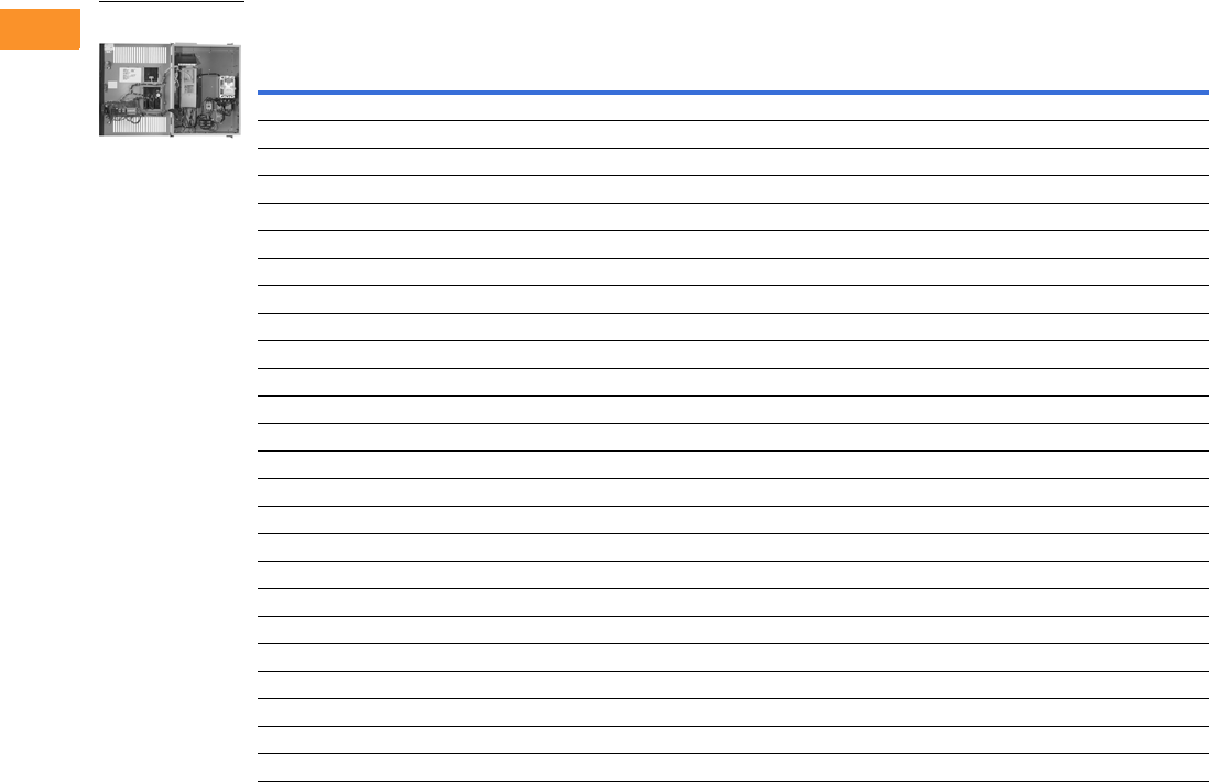
V6-T2-148 Volume 6—Solid-State Motor Control CA08100007E—February 2016 www.eaton.com
2
2
2
2
2
2
2
2
2
2
2
2
2
2
2
2
2
2
2
2
2
2
2
2
2
2
2
2
2
2
2.7
Adjustable Frequency Drives
SVX Drives
575 V Drives
575 V Drives—Variable Torque (VT)/Low Overload (IL) Enclosed Drives
Notes
1 Table is for base catalog number reference only. For complete catalog number selection, see Page V6-T2-142.
2 Enclosure rating is NEMA Type 1 filtered and gasketed.
NEMA Type 1 NEMA Type 12 NEMA Type 3R
hp Current (A)
Drive
Frame Size
Base
Catalog Number 1
Base
Catalog Number 1
Base
Catalog Number 1
33.96SVX0035B1 SVX0035B2 SVX0035B3
56.16SVX0055B1 SVX0055B2 SVX0055B3
7.5 9 6 SVX0075B1 SVX0075B2 SVX0075B3
10 11 6 SVX0105B1 SVX0105B2 SVX0105B3
15 17 6 SVX0155B1 SVX0155B2 SVX0155B3
20 22 6 SVX0205B1 SVX0205B2 SVX0205B3
25 27 6 SVX0255B1 SVX0255B2 SVX0255B3
30 32 6 SVX0305B1 SVX0305B2 SVX0305B3
40 41 7 SVX0405A1 SVX0405A2 SVX0405A3
50 52 7 SVX0505A1 SVX0505A2 SVX0505A3
60 62 8 SVX0605A1 SVX0605A2 SVX0605A3
75 77 8 SVX0755A1 SVX0755A2 SVX0755A3
100 99 8 SVX1005A1 SVX1005A2 SVX1005A3
125 125 9 SVX1255A1 SVX1255A2 SVX1255A3
150 144 9 SVX1505A1 SVX1505A2 SVX1505A3
200 192 9 SVX2005A1 SVX2005A2 SVX2005A3
250 242 10 SVX2505E1 SVX2505E6 2SVX2505E3
300 289 10 SVX3005E1 SVX3005E6 2SVX3005E3
400 382 10 SVX4005E1 SVX4005E6 2SVX4005E3
450 412 11 SVX4505E1 SVX4505E6 2SVX4505E3
500 472 11 SVX5005E1 SVX5005E6 2SVX5005E3
550 590 11 SVX5505E1 SVX5505E6 2SVX5505E3
600 650 12 SVX6005E1 SVX6005E6 2SVX6005E3
700 750 12 SVX7005E1 SVX7005E6 2SVX7005E3
800 820 12 SVX8005E1 SVX8005E6 2SVX8005E3
SVX Enclosed Drives
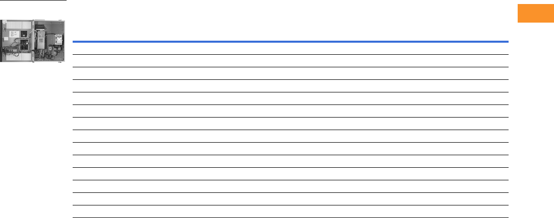
Volume 6—Solid-State Motor Control CA08100007E—February 2016 www.eaton.com V6-T2-149
2
2
2
2
2
2
2
2
2
2
2
2
2
2
2
2
2
2
2
2
2
2
2
2
2
2
2
2
2
2
2.7
Adjustable Frequency Drives
SVX Drives
230 V, Single-Phase Drives
230 V Single-Phase Drives—Variable Torque (VT)/Low Overload (IL) Enclosed Drives
Note
1 Table is for base catalog number reference only. For complete catalog number selection, see Page V6-T2-142.
NEMA Type 1 NEMA Type 12 NEMA Type 3R
hp Current (A)
Drive
Frame Size
Base
Catalog Number 1
Base
Catalog Number 1
Base
Catalog Number 1
14.24SVX001JB1 SVX001JB2 SVX001JB3
1.5 6 4 SVXF15JB1 SVXF15JB2 SVXF15JB3
26.84SVX002JB1 SVX002JB2 SVX002JB3
39.64SVX003JB1 SVX003JB2 SVX003JB3
515.25SVX005JB1 SVX005JB2 SVX005JB3
7.5 22 5 SVX007JB1 SVX007JB2 SVX007JB3
10 28 5 SVX010JB1 SVX010JB2 SVX010JB3
15 42 6 SVX015JB1 SVX015JB2 SVX015JB3
20 54 6 SVX020JB1 SVX020JB2 SVX020JB3
25 68 7 SVX025JA1 SVX025JA2 SVX025JA3
30 80 7 SVX030JA1 SVX030JA2 SVX030JA3
40 104 7 SVX040JA1 SVX040JA2 SVX040JA3
50 130 8 SVX050JA1 SVX050JA2 SVX050JA3
60 154 8 SVX060JA1 SVX060JA2 SVX060JA3
SVX Enclosed Drives
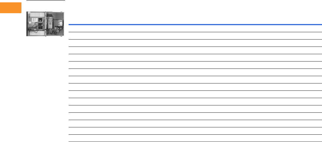
V6-T2-150 Volume 6—Solid-State Motor Control CA08100007E—February 2016 www.eaton.com
2
2
2
2
2
2
2
2
2
2
2
2
2
2
2
2
2
2
2
2
2
2
2
2
2
2
2
2
2
2
2.7
Adjustable Frequency Drives
SVX Drives
480 V, Single-Phase Drives
480 V Single-Phase Drives—Variable Torque (VT)/Low Overload (IL) Enclosed Drives
Note
1 Table is for base catalog number reference only. For complete catalog number selection, see Page V6-T2-142.
NEMA Type 1 NEMA Type 12 NEMA Type 3R
hp Current (A)
Drive
Frame Size
Base
Catalog Number 1
Base
Catalog Number 1
Base
Catalog Number 1
1.5 3 4 SVXF15KB1 SVXF15KB2 SVXF15KB3
23.44SVX002KB1 SVX002KB2 SVX002KB3
34.84SVX003KB1 SVX003KB2 SVX003KB3
57.64SVX005KB1 SVX005KB2 SVX005KB3
7.5 11 4 SVX007KB1 SVX007KB2 SVX007KB3
10 14 5 SVX010KB1 SVX010KB2 SVX010KB3
15 21 5 SVX015KB1 SVX015KB2 SVX015KB3
20 27 5 SVX020KB1 SVX020KB2 SVX020KB3
25 34 6 SVX025KB1 SVX025KB2 SVX025KB3
30 40 6 SVX030KB1 SVX030KB2 SVX030KB3
40 52 6 SVX040KB1 SVX040KB2 SVX040KB3
50 65 7 SVX050KA1 SVX050KA2 SVX050KA3
60 77 7 SVX060KA1 SVX060KA2 SVX060KA3
75 96 7 SVX075KA1 SVX075KA2 SVX075KA3
100 124 8 SVX100KA1 SVX100KA2 SVX100KA3
125 156 8 SVX125KA1 SVX125KA2 SVX125KA3
SVX Enclosed Drives
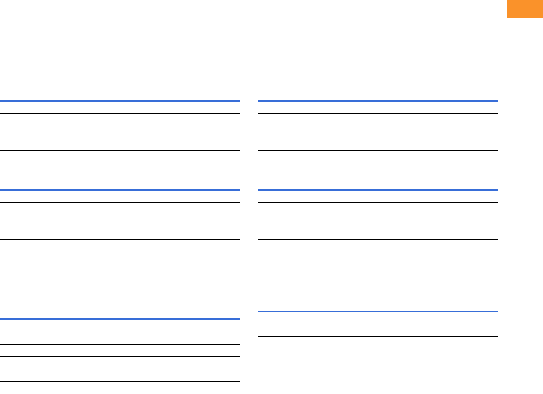
Volume 6—Solid-State Motor Control CA08100007E—February 2016 www.eaton.com V6-T2-151
2
2
2
2
2
2
2
2
2
2
2
2
2
2
2
2
2
2
2
2
2
2
2
2
2
2
2
2
2
2
2.7
Adjustable Frequency Drives
SVX Drives
Enclosure Selection
SVX Drives
Enclosure selection charts are based on physical space limitations only and only to be used as a reference.
For actual enclosure sizing, refer to Bid Manager.
Note: Standard enclosure sizing includes dedicated space for a circuit
breaker or fusible disconnect, CPT, SPD, heater/thermostat, control relay
and terminal blocks.
Standard Enclosure X-Space
Standard Power Options X-Space
Larger Frame Enclosure Sizes
Note: Bypass enclosure sizing includes dedicated space for a MCP, CPT,
input contactor, output bypass contactors, overload relay, SPD, heater/
thermostat, control relay and terminal blocks.
Bypass Enclosure X-Space
Bypass Power Options X-Space
Larger Frame Enclosure Sizes
Note
1Consult factory.
Enclosure Size Frame 4 Frame 5 Frame 6 Frame 7 Frame 8
AX 222——
BX 4444—
CX 77777
DX 18 18 18 18 18
Power Options Frame 4 Frame 5 Frame 6 Frame 7 Frame 8
Isolation fuses 11111
3% Input reactor 22356
3% Output reactor 11356
MotoRX filter 33335
dV/dt filter 33356
Output contactor 11111
Frame Size Type 1 Type 12
Type 1
Filtered and
Gasketed Type 3R
Frame 9 Size 5 Size 5 — Size F
Frame 10 (without power options) Size 6 — Size 6 Size F
Frame 10 (with power options) Size 8 — Size 8 Size F
Frame 11 (without power options) Size 8 — Size 8 Size F
Frame 11 (with power options) Size 9 — Size 9 Size F
Frame 12 1—11
Enclosure Size Frame 4 Frame 5 Frame 6 Frame 7 Frame 8
AX 000——
BX 2220—
CX 55532
DX 16 16 16 14 13
Power Options Frame 4 Frame 5 Frame 6 Frame 7 Frame 8
Isolation fuses 11111
3% Input reactor 22356
RVSS bypass 22234
3% Output reactor 11356
MotoRX filter 33335
dV/dt filter 33356
Frame Size Type 1 Type 12
Type 1 Filtered
and Gasketed Type 3R
Frame 9 Size 5 Size 5 — Size F
Frame 10 Size 8 — Size 8 Size F
Frame 11 Size 9 — Size 9 Size F
Frame 12 1—11
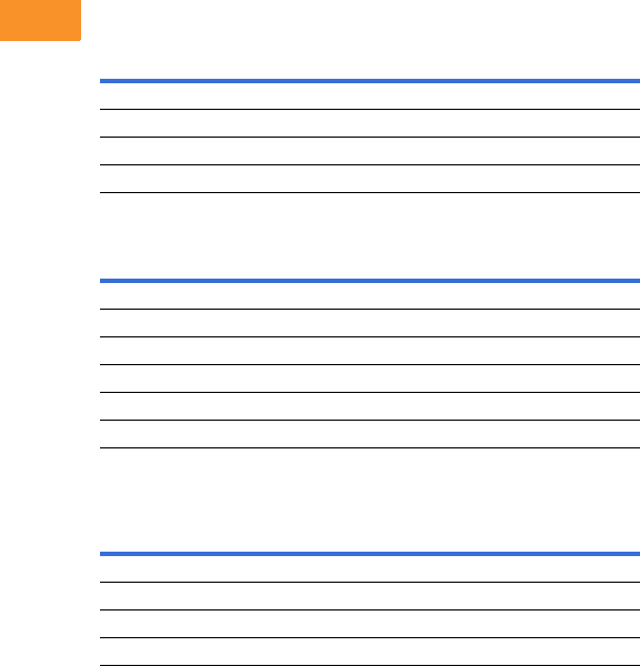
V6-T2-152 Volume 6—Solid-State Motor Control CA08100007E—February 2016 www.eaton.com
2
2
2
2
2
2
2
2
2
2
2
2
2
2
2
2
2
2
2
2
2
2
2
2
2
2
2
2
2
2
2.7
Adjustable Frequency Drives
SVX Drives
Note: Single-phase enclosure sizing includes dedicated space for a
capacitor kit, circuit breaker or fusible disconnect, CPT, SPD, heater/
thermostat, control relay and terminal blocks.
Single-Phase Enclosure X-Space
Single-Phase Power Options X-Space
Larger Frame Enclosure Sizes
Note
1Consult factory.
Enclosure Size Frame 4 Frame 5 Frame 6 Frame 7 Frame 8
AX 0 0 ———
BX 2211—
CX 55444
DX 16 16 15 15 15
Power Options Frame 4 Frame 5 Frame 6 Frame 7 Frame 8
Isolation fuses 11111
3% Input reactor 22356
3% Output reactor 11356
MotoRX filter 33335
dV/dt filter 33356
Output contactor 11111
Frame Size Type 1 Type 12
Type 1A Filtered
and Gasketed Type 3R
Frame 9 Size 5 Size 5 — Size F
Frame 10 Size 8 — Size 8 Size F
Frame 11 Size 9 — Size 9 Size F
Frame 12 1—11

Volume 6—Solid-State Motor Control CA08100007E—February 2016 www.eaton.com V6-T2-153
2
2
2
2
2
2
2
2
2
2
2
2
2
2
2
2
2
2
2
2
2
2
2
2
2
2
2
2
2
2
2.7
Adjustable Frequency Drives
SVX Drives
Options
SVX Series Option Board Kits
The SVX Series drives can accommodate a wide selection of expander and adapter option boards to
customize the drive for your application needs. The drive’s control unit is designed to accept a total
of five option boards.
The SVX Series factory installed standard board configuration includes an A9 I/O board and an A2 relay
output board, which are installed in slots A and B.
Option Board Kits
Notes
1 AI = Analog Input; AO = Analog Output, DI = Digital Input, DO = Digital Output, RO = Relay Output
2 Option card must be installed in one of the slots listed for that card. Slot indicated in bold is the preferred location.
3 OPTC2 is a multi-protocol option card.
Option Kit Description 1
Allowed Slot
Locations 2
Field
Installed
Factory
Installed SVX Ready Programs
Catalog
Number
Option
Designator Basic
Local/
Remote Standard MSS PID Multi-P. PFC
Standard I/O Cards
6 DI, 1 DO, 2 AI, 1 AO, 1 +10 Vdc ref,
2 ext +24 Vdc/EXT +24 Vdc
AOPTA9 — ■ ■ ■ ■■■ ■
2 RO (NC-NO) B OPTA2 — ■ ■ ■ ■■■ ■
Extended I/O Cards
2 RO, therm B OPTA3 A3 —■ ■ ■■■ ■
Encoder low volt +5 V/15 V/24 V—SPX only C OPTA4 A4 —■ ■ ■■■ ■
Encoder high volt +15 V/24 V—SPX only C OPTA5 A5 —■ ■ ■■■ ■
Double encoder—SPX only C OPTA7 A7 ■ ■ ■ ■■■ ■
6 DI, 1 DO, 2 AI, 1 AO A OPTA8 A8 —■ ■ ■■■ ■
3 DI (encoder 10–24 V), out +15 V/+24 V,
2 DO (pulse+direction)—SPX only
COPTAE AE ■ ■ ■ ■■■ ■
6 DI, 1 ext +24 Vdc/EXT +24 Vdc B, C, D, E OPTB1 B1 —— — ——
■■
1 RO (NC-NO), 1 RO (NO), 1 therm B, C, D, E OPTB2 B2 —— — ——
■■
1 AI (mA isolated), 2 AO (mA isolated),
1 ext +24 Vdc/EXT +24 Vdc
B, C, D, E OPTB4 B4 ■ ■ ■ ■■■ ■
3 RO (NO) B, C, D, E OPTB5 B5 —— — ——
■■
1 ext +24 Vdc/EXT +24 Vdc, 3 Pt100 B, C, D, E OPTB8 B8 — — — ——— —
1 RO (NO), 5 DI 42–240 Vac input B, C, D, E OPTB9 B9 —— — ——
■■
Communication Cards
Modbus 3D, E OPTC2 C2 ■ ■ ■ ■■■ ■
Modbus TCP D, E OPTCI CI ■ ■ ■ ■■■ ■
BACnet D, E OPTCJ CJ ■ ■ ■ ■■■ ■
EtherNet/IP D, E OPTCQ CQ ■ ■ ■ ■■■ ■
Johnson Controls N2 3D, E OPTC2 CA — — — ——— —
PROFIBUS DP D, E OPTC3 C3 ■ ■ ■ ■■■ ■
LonWorks D, E OPTC4 C4 ■ ■ ■ ■■■ ■
PROFIBUS DP (D9 connector) D, E OPTC5 C5 ■ ■ ■ ■■■ ■
CANopen (slave) D, E OPTC6 C6 ■ ■ ■ ■■■ ■
DeviceNet D, E OPTC7 C7 ■ ■ ■ ■■■ ■
Modbus (D9 type connector) D, E OPTC8 C8 ■ ■ ■ ■■■ ■
Adapter—SPX only D, E OPTD1 D1 ■ ■ ■ ■■■ ■
Adapter—SPX only D, EOPTD2VD2
■ ■ ■ ■■■ ■
RS-232 with D9 connection D, E OPTD3 D3 ■ ■ ■ ■■■ ■
Option Boards
ABCDE

V6-T2-154 Volume 6—Solid-State Motor Control CA08100007E—February 2016 www.eaton.com
2
2
2
2
2
2
2
2
2
2
2
2
2
2
2
2
2
2
2
2
2
2
2
2
2
2
2
2
2
2
2.7
Adjustable Frequency Drives
SVX Drives
Modbus RTU Network
Communications
The Modbus Network Card
OPTC2 is used for connecting
the SVX Drive as a slave on a
Modbus network. The
interface is connected by a
9-pin DSUB connector
(female) and the baud rate
ranges from 300 to 19,200
baud. Other communication
parameters include an
address range from 1 to 247;
a parity of None, Odd or
Even; and the stop bit is 1.
PROFIBUS Network
Communications
The PROFIBUS Network Card
OPTC3 is used for connecting
the SVX Drive as a slave on
a PROFIBUS-DP network.
The interface is connected
by a 9-pin DSUB connector
(female). The baud rates
range from 9.6 Kbaud to
12 Mbaud, and the addresses
range from 1 to 127.
LonWorks Network
Communications
The LonWorks Network Card
OPTC4 is used for connecting
the SVX Drive on a LonWorks
network. This interface uses
Standard Network Variable
Types (SNVT) as data types.
The channel connection is
achieved using a FTT-10 A
Free Topology transceiver
via a single twisted transfer
cable. The communication
speed with LonWorks is
78 kBits/s.
CANopen (Slave)
Communications
The CANopen (Slave)
Network Card OPTC6 is used
for connecting the SVX Drive
to a host system. According
to ISO11898 standard cables
to be chosen for CANbus
should have a nominal
impedance of 120 ohms, and
specific line delay of nominal
5 nS/m. 120 ohms line
termination resistors required
for installation.
DeviceNet Network
Communications
The DeviceNet Network Card
OPTC7 is used for connecting
the SVX Drive on a DeviceNet
Network. It includes a
5.08 mm pluggable
connector. Transfer method
is via CAN using a two-wire
twisted shielded cable with
two-wire bus power cable
and drain. The baud rates
used for communication
include 125 Kbaud,
250 Kbaud and 500 Kbaud.
Johnson Controls
Metasys N2 Network
Communications
The OPTC2 fieldbus board
provides communication
between the SVX Drive and a
Johnson Controls Metasys™
N2 network. With this
connection, the drive can be
controlled, monitored and
programmed from the
Metasys system. The N2
fieldbus is available as a
factory installed option and as
a field installable kit.
Modbus/TCP Network
Communications
The Modbus/TCP Network
Card OPTCI is used for
connecting the SVX Drive to
Ethernet networks utilizing
Modbus protocol. It includes
an RJ-45 pluggable connector.
This interface provides a
selection of standard and
custom register values to
communicate drive parameters.
The board supports 10 Mbps
and 100 Mbps communication
speeds. The IP address of the
board is configurable over
Ethernet using a supplied
software tool.
BACnet Network
Communications
The BACnet Network Card
OPTCJ is used for connecting
the SVX Drive to BACnet
networks. It includes a
5.08 mm pluggable connector.
Data transfer is Master-Slave/
Token Passing (MS/TP)
RS-485. This interface uses
a collection of 30 Binary Value
Objects (BVOs) and 35 Analog
Value Objects (AVOs) to
communicate drive parameters.
The card supports 9.6, 19.2
and 38.4 Kbaud communication
speeds and supports network
addresses 1–127.
EtherNet/IP Network
Communications
The EtherNet/IP Network
Card OPTCK is used for
connecting the SVX Drive to
Ethernet/Industrial Protocol
networks. It includes an
RJ-45 pluggable connector.
The interface uses CIP
objects to communicate drive
parameters (CIP is “Common
Industrial Protocol”, the same
protocol used by DeviceNet).
The board supports 10 Mbps
and 100 Mbps communication
speeds. The IP address of the
board is configurable by Static,
BOOTP and DHCP methods.

Volume 6—Solid-State Motor Control CA08100007E—February 2016 www.eaton.com V6-T2-155
2
2
2
2
2
2
2
2
2
2
2
2
2
2
2
2
2
2
2
2
2
2
2
2
2
2
2
2
2
2
2.7
Adjustable Frequency Drives
SVX Drives
Input Power Options
Bypass Options
Output Power Options
Control Options
Option Description
HMCP Disconnect The HMCP motor protection circuit breaker uses an electronic trip unit to provide typical motor overload relay functionality and short-circuit
protection against potential phase-to-phase or phase-to-ground faults.
Circuit Breaker Utilizes a circuit breaker to provide a means of short-circuit protection for the power cables between it and the drive, and protection from high-
level ground faults on the power cable. Allows a convenient means of disconnecting the drive from the line, and the operating mechanism can
be padlocked in the OFF position. This is factory mounted in the enclosure.
Isolation Fusing Provides high-level fault protection of the drive input power circuit from the load side of the fuses to the input side of the power transistors.
This option consists of three 200 kA fuses that are factory mounted in the enclosure.
3% Input Reactor The input reactor is a three-phase series inductance on the line side of an AFD. It is used to provide a reduction in voltage and current
harmonics. It also provides increased input protection for AFD and its semiconductors from line transients.
SPD Provides a surge protection device (SPD) connected to the line side terminals and is designed to clip line side transients.
Fused Disconnect Utilizes fusing to provide a means of short-circuit protection for the power cables between it and the drive, and protection from high-level
ground faults on the power cable. Allows a convenient means of disconnecting the drive from the line, and the operating mechanism can be
padlocked in the OFF position. This is factory mounted in the enclosure.
Option Description
Manual HOA Bypass Provides a three-position selector switch that allows the user to select either a HAND or AUTO mode of operation. HAND mode is defaulted
keypad operation, and AUTO mode is defaulted to control from an external terminal source. These modes of operation can be configured via
programming to allow for alternate combinations of start and speed sources. Start and speed sources include keypad, I/O and fieldbus.
Manual HOA RVSS Bypass This option adds a reduced voltage soft starter to bypass assembly for soft starting in bypass mode.
Option Description
Output Contactor Provides a means for positive disconnection of the drive output from the motor terminals. The contactor coil is controlled by the drive’s run or
permissive logic. NC and NO auxiliary contacts rated at 10 A, 600 Vac are provided for customer use. This option includes a low VA 115 Vac
fused control power transformer and is factory mounted in the enclosure.
3% Output Reactor The output reactor is a three-phase series inductance on the load side of an AFD. It is used to provide a reduction in voltage and current
harmonics.
MotoRX Filter Used to reduce transient voltage (dV/dt) and peak voltages at the motor terminals. This option is comprised of a 0.5% line reactor, followed by
capacitive filtering and an energy recovery/clamping circuit. Unlike the traditional dV/dt filter, the MotoRx recovers most of the energy from the
voltage peaks, resulting in a lower voltage drop to the motor, therefore conserving power. This option is used when the distance between
a single motor and the drive is 300–600 ft (91–183 m). This option can not be used with the brake chopper circuit. in this case, the traditional
dV/dt filter should be investigated as an alternative.
dV/dt Filter Used to reduce the transient voltage (dV/dt) at the motor terminals. The traditional dV/dt filter is recommended for cable lengths exceeding
100 ft (30 m) with a drive of 3 hp and above, for cable lengths of 33 ft (10 m) with a drive of 2 hp and below, or for a drive rated at 525–690 V.
This option is mounted in the enclosure and may be used in conjunction with a brake chopper circuit. This option is mounted in the enclosure.
Option Description
Speed Pot Provides the ability to adjust the frequency reference using a door-mounted potentiometer. This option uses the 10 Vdc reference to generate a
0–10 V signal at the analog voltage input signal terminal. When the HOA bypass option is added, the speed is controlled when the HOA switch
is in the HAND position. Without the HOA bypass option, a two-position switch (labeled local/remote) is provided on the keypad to select
speed reference from the speed potentiometer or a remote speed signal.
HOA Switch Provides a three-position selector switch that allows the user to select either a HAND or AUTO mode of operation. HAND mode is defaulted to
keypad operation, and AUTO mode is defaulted to control from an external terminal source. These modes of operation can be configured via
drive programming to allow for alternate combinations of start and speed sources. Start and speed sources include Keypad, I/O and fieldbus.
Start-Stop Pushbutton Provides door-mounted START and STOP pushbuttons for either bypass or non-bypass configurations.

V6-T2-156 Volume 6—Solid-State Motor Control CA08100007E—February 2016 www.eaton.com
2
2
2
2
2
2
2
2
2
2
2
2
2
2
2
2
2
2
2
2
2
2
2
2
2
2
2
2
2
2
2.7
Adjustable Frequency Drives
SVX Drives
Light Options
Enclosure Options
Enclosed Drive Options
Brake Chopper Options
The brake chopper circuit option is used for applications that
require dynamic braking. Dynamic braking resistors are not
included with drive purchase. Consult Page V6-T2-110 for
dynamic braking resistors
which are supplied separately.
Resistors are not UL Listed.
For brake chopper circuit selection and adder—NEMA
Type 1/IP21, NEMA Type 12/IP54, consult the factory
Option Description
Non-Bypass Light Kit—Power On, Run, Fault Provides a white POWER ON light that indicates power to the enclosed cabinet, a green RUN light that indicates the drive is running and a red
FAULT light that indicates a drive fault has occurred.
Bypass Light Kit—On, VFD Run, Fault, Bypass Run Provides a white POWER ON light that indicates power to the enclosed cabinet, a green RUN light that indicates the drive is running, a red
FAULT light that indicates a drive fault has occurred and an amber light that indicates when the motor is running in Bypass mode.
Option Description
Floor Stand 12 in Converts a normally wall-mounted enclosure to a floor-standing enclosure with a height of 12 in (304.8 mm).
Floor Stand 22 in Converts a normally wall-mounted enclosure to a floor-standing enclosure with a height of 22 in (558.8 mm).
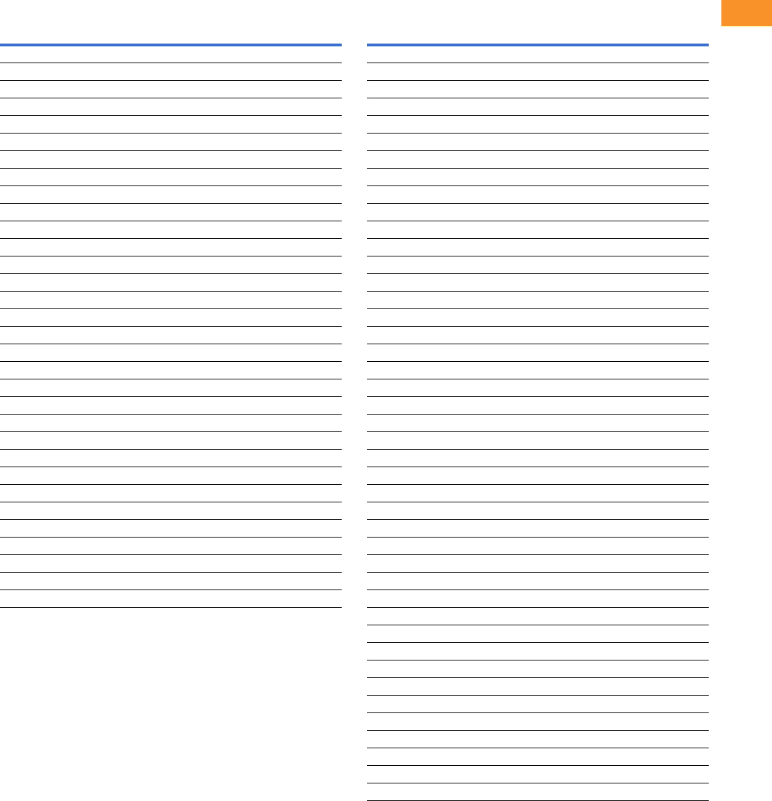
Volume 6—Solid-State Motor Control CA08100007E—February 2016 www.eaton.com V6-T2-157
2
2
2
2
2
2
2
2
2
2
2
2
2
2
2
2
2
2
2
2
2
2
2
2
2
2
2
2
2
2
2.7
Adjustable Frequency Drives
SVX Drives
Technical Data and Specifications
SVX Enclosed Drives
Description
NEMA Type 1/IP21 or NEMA Type 12/IP54
Specification
Primary Design Features
45–66 Hz input frequency Standard
Output: AC volts maximum Input voltage base
Output frequency range 0–320 Hz
Initial output current (IH) 250% for 2 seconds
Overload (1 minute [IH/IL]) 150%/110%
Enclosure space heater Optional
Oversize enclosure Standard
Output contactor Optional
Bypass motor starter Optional
Listings UL, cUL
Protection Features
Incoming line fuses Optional
AC input circuit disconnect Optional
Line reactors (3%) Standard
Phase rotation insensitive Standard
EMI filter Standard
Input phase loss protection Standard
Input overvoltage protection Standard
Line surge protection Optional
Output short-circuit protection Standard
Output ground fault protection Standard
Output phase protection Standard
Overtemperature protection Standard
DC overvoltage protection Standard
Drive overload protection Standard
Motor overload protection Standard
Programmer software Optional
Local/remote keypad Standard
Keypad lockout Standard
Fault alarm output Standard
Built-in diagnostics Standard
Description
NEMA Type 1/IP21 or NEMA Type 12/IP54
Specification
Input/Output Interface Features
Setup adjustment provisions
Remote keypad/display Standard
Personal computer Standard
Operator control provisions
Drive mounted keypad/display Standard
Remote keypad/display Standard
Conventional control elements Standard
Serial communications Optional
115 Vac control circuit Optional
Speed setting inputs
Keypad Standard
0–10 Vdc potentiometer/voltage signal Standard
4–20 mA Isolated Configurable
4–20 mA Differential Configurable
Analog outputs
Speed/frequency Standard
Torque/load/current Programmable
Motor voltage Programmable
Kilowatts Programmable
0–10 Vdc signals Configurable w/jumpers
4–20 mA DC signals Standard
Isolated signals Optional
Discrete outputs
Fault alarm Standard
Drive running Standard
Drive at set speed Programmable
Optional parameters 14
Dry contacts 1 (2 relays Form C)
Open collector outputs 1
Additional discrete outputs Optional
Communications
RS-232 Standard
RS-422/485 Optional
DeviceNet™ Optional
Modbus RTU Optional
CANopen (slave) Optional
PROFIBUS-DP Optional
Lonworks® Optional
Johnson Controls Metasys™ N2 Optional
EtherNet/IP Optional
Modbus TCP Optional
BACnet Optional

V6-T2-158 Volume 6—Solid-State Motor Control CA08100007E—February 2016 www.eaton.com
2
2
2
2
2
2
2
2
2
2
2
2
2
2
2
2
2
2
2
2
2
2
2
2
2
2
2
2
2
2
2.7
Adjustable Frequency Drives
SVX Drives
SVX Enclosed Drives, continued Standard I/O Specifications
I/O Specifications for Control/Communication Options
Note
1Some horsepower units include dynamic braking chopper as standard—refer to individual
drive sections.
Description
NEMA Type 1/IP21 or NEMA Type 12/IP54
Specification
Performance Features
Sensorless vector control Standard
Volts/hertz control Standard
IR and slip compensation Standard
Electronic reversing Standard
Dynamic braking Optional 1
DC braking Standard
PID setpoint controller Programmable
Critical speed lockout Standard
Current (torque) limit Standard
Adjustable acceleration/deceleration Standard
Linear or S curve accel/decel Standard
Jog at preset speed Standard
Thread/preset speeds 7 Standard, 15 Optional
Automatic restart Selectable
Coasting motor start Standard
Coast or ramp stop selection Standard
Elapsed time meter Optional
Carrier frequency adjustment 1–16 kHz
Standard Conditions for Application and Service
Operating ambient temperature IL: 0 to 40 °C; IH: 0 to 50 °C
Storage temperature –40 to 60 °C
Humidity (maximum), non-condensing 95%
Altitude (maximum without derate) 3300 ft (1000 m)
Line voltage variation +10/–15%
Line frequency variation 45–66 Hz
Efficiency >96%
Power factor (displacement) >0.94
Description Specification
Six–digital input
programmable
24 V: “0” <10 V, “1” >18V,Ri >5 kohms
Two–analog input
configurable w/jumpers
Voltage: 0–±10 V, Ri >200 kohms
Current: 0 (4)–20 mA, Ri = 250 ohms
Two–digital output
programmable
Form C relays 250 Vac
30 Vdc 2 amp resistive
One–analog output
programmable
configurable w/jumper
0–20 mA, RL max. 500 ohms 10 bits ±2%
One digital output
programmable
Open collector 48 Vdc 50 mA
Description Specification
Analog voltage, input 0–±10 V, Ri >200 kohms
Analog current, input 0 (4)–20 mA, Ri = 250 ohms
Digital input 24 V: “0” <10 V, “1” >18V, Ri >5 kohms
Auxiliary voltage 24 V (±20%), max. 50 mA
Reference voltage 10 V ±3%, max. 10 mA
Analog current, output 0 (4)–20 mA, RL = 500 kohms resolution 10 bit,
accuracy <±2%
Analog voltage, output 0 (2)–10 V, RL >1 kohms, resolution 10 bit,
accuracy <±2%
Relay output
Maximum switching voltage 300 Vdc, 250 Vac
Maximum switching load 8 A/24 Vdc, 0.4 A/300 Vdc, 2 kVA/250 Vac
Maximum continuous load 2 A rms
Thermistor input Rtrip = 4.7 kohms
Encoder input 24 V: “0” <10 V, “1” >18V, Ri = 2.2 kohms
5 V: “0” <2V, “1” >3V, Ri = 330 ohms

Volume 6—Solid-State Motor Control CA08100007E—February 2016 www.eaton.com V6-T2-159
2
2
2
2
2
2
2
2
2
2
2
2
2
2
2
2
2
2
2
2
2
2
2
2
2
2
2
2
2
2
2.7
Adjustable Frequency Drives
SVX Drives
Dimensions
Approximate Dimensions in Inches (mm)
AX Box Type 1
AX Box Type 1—12 Inch Floor Stands
25.80
(655.3)
3.00 (76.2)
Minimum
Air Space
Required
Both Sides
4.00 (101.6) Minimum
Free Air Space Required
25.35
(643.9)
19.30 (490.2)
20.92 (531.4)
17.02 (432.2)
1.76
(44.8)
26.74
(679.2)
17.31
(439.7)
Ø 0.44 (11.2)
Mounting
Holes
(4 Places)
19.30 (490.0)
25.35
(643.9)
20.92 (531.4)
29.12
(739.6)
1.76 (44.8) 17.02 (432.2)
14.06
(357.1)
10.53
(267.5) 7.00
(177.8)
3.00 (76.2)
5.00 (127.0)
15.50 (393.7)
17.50 (444.7)
4.00 (101.6) Minimum
Free Air Space Required
Ø 0.44 (11.2)
Mounting Holes
(2 Places)
3.00 (76.2)
Minimum
Air Space
Required
Both Sides

V6-T2-160 Volume 6—Solid-State Motor Control CA08100007E—February 2016 www.eaton.com
2
2
2
2
2
2
2
2
2
2
2
2
2
2
2
2
2
2
2
2
2
2
2
2
2
2
2
2
2
2
2.7
Adjustable Frequency Drives
SVX Drives
Approximate Dimensions in Inches (mm)
AX Box Type 1—22 Inch Floor Stands
AX Box Type 12
19.30 (490.2)
25.35
(643.9)
47.37
(1203.2)
20.92 (531.4) 17.02 (432.2)1.76 (44.8)
39.15
(994.4)
47.87
(1215.9)
14.06
(357.1)
10.53
(267.5) 7.00
(177.8)
3.00 (76.2)
5.00 (127.0)
17.50 (444.5)
15.50 (393.7)
4.00 (101.6) Minimum
Free Air Space Required
Ø 0.44 (11.2)
Mounting Holes
(2 Places)
3.00 (76.2)
Minimum
Air Space
Required
Both Sides
Ø 0.44 (11.2)
Mounting
Holes
(4 Places)
3.00 (76.2)
Minimum
Air Space
Required
Both Sides
26.74
(679.2)
4.00 (101.6) Minimum
Free Air Space Required
25.80
(655.3)
25.35
(643.9)
20.92 (531.4)
19.30 (490.2)
1.76
(44.8) 17.02 (432.2)
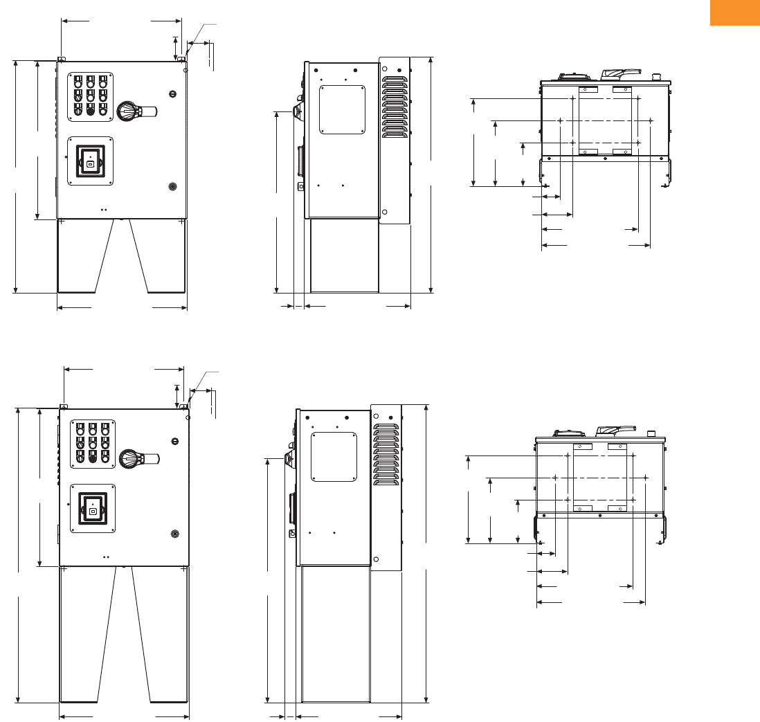
Volume 6—Solid-State Motor Control CA08100007E—February 2016 www.eaton.com V6-T2-161
2
2
2
2
2
2
2
2
2
2
2
2
2
2
2
2
2
2
2
2
2
2
2
2
2
2
2
2
2
2
2.7
Adjustable Frequency Drives
SVX Drives
Approximate Dimensions in Inches (mm)
AX Box Type 12—12 Inch Floor Stands
AX Box Type 12—22 Inch Floor Stands
37.87
(961.9)
4.00 (101.6) Minimum
Free Air Space Required
19.30 (490.2)
25.35
(643.9)
37.37
(949.2)
20.92 (531.4) 17.02 (432.2)
1.76 (44.8)
29.13
(739.9)
14.06
(357.1)
10.53
(267.5) 7.00
(177.8)
3.00 (76.2)
5.00 (127.0)
15.50 (393.7)
17.50 (444.5)
Ø 0.44 (11.2)
Mounting
Holes
(2 Places)
3.00 (76.2)
Minimum
Air Space
Required
Both Sides
14.06
(357.1)
10.53
(267.5) 7.00
(177.8)
3.00 (76.2)
5.00 (127.0)
15.50 (393.7)
17.75 (450.7)
4.00 (101.6) Minimum
Free Air Space Required
19.30 (490.2)
47.37
(1203.2)
25.35
(643.9)
20.92 (531.4) 17.02 (432.2)
1.76 (44.8)
39.15
(994.4)
47.87
(1215.9)
Ø 0.44 (11.2)
Mounting
Holes
(2 Places)
3.00 (76.2)
Minimum
Air Space
Required
Both Sides
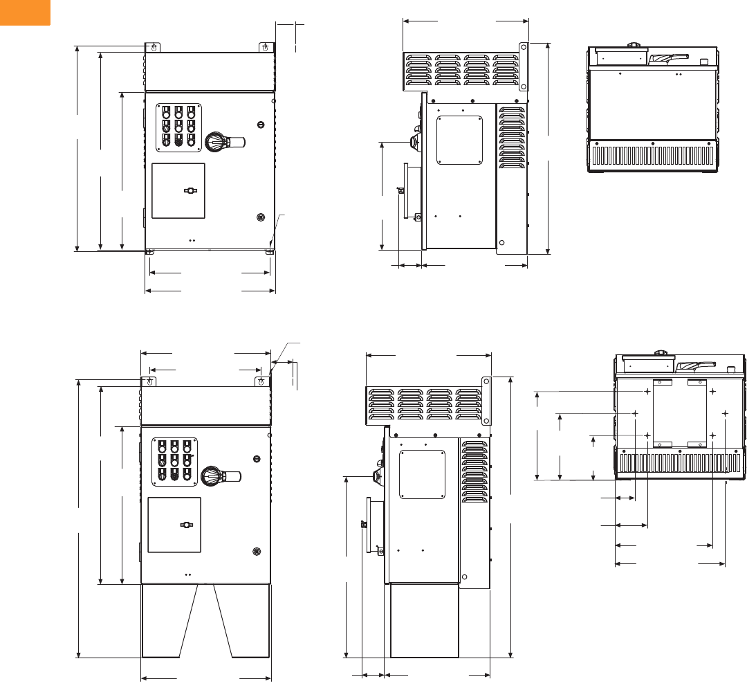
V6-T2-162 Volume 6—Solid-State Motor Control CA08100007E—February 2016 www.eaton.com
2
2
2
2
2
2
2
2
2
2
2
2
2
2
2
2
2
2
2
2
2
2
2
2
2
2
2
2
2
2
2.7
Adjustable Frequency Drives
SVX Drives
Approximate Dimensions in Inches (mm)
AX Box Type 3R
AX Box Type 3R—12 Inch Floor Stands
20.18 (512.5)
3.00 (76.2)
Minimum
Air Space
Required
Both Sides
33.09
(840.4)
31.76
(806.6)
25.35
(643.9)
19.30 (490.2)
20.92 (531.4)
3.64
(92.5) 17.02 (432.2)
17.28
(438.9)
33.97
(862.8)
Ø 0.44 (11.2)
Mounting
Holes
(4 Places)
20.88 (530.4)
17.88 (454.2)
31.76
(806.8)
25.36
(644.0)
44.66
(1134.3)
20.92 (531.4) 17.02 (432.2)
3.64
(92.5)
29.12
(739.6)
20.18 (512.5)
14.25
(361.8)
10.72
(272.2) 7.19
(182.5)
45.10
(1145.5)
3.20
(81.3)
5.20
(132.1)
15.70 (398.8)
17.70 (449.6)
1.04 [26.4]
Ø 0.44 (11.2)
Mounting
Holes
(2 Places)
3.00 (76.2)
Minimum
Air Space
Required
Both Sides
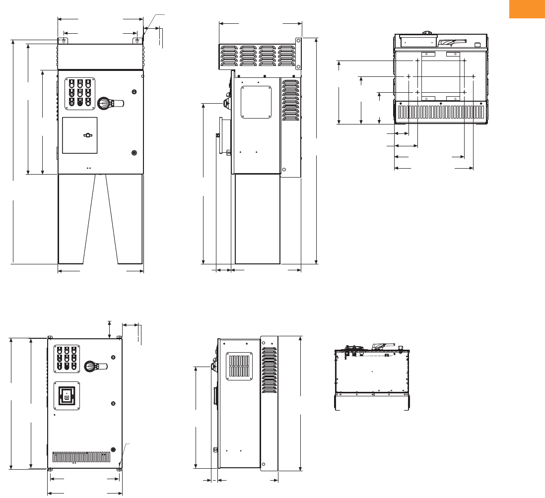
Volume 6—Solid-State Motor Control CA08100007E—February 2016 www.eaton.com V6-T2-163
2
2
2
2
2
2
2
2
2
2
2
2
2
2
2
2
2
2
2
2
2
2
2
2
2
2
2
2
2
2
2.7
Adjustable Frequency Drives
SVX Drives
Approximate Dimensions in Inches (mm)
AX Box Type 3R—22 Inch Floor Stands
BX Box Type 1
20.88 (530.4)
17.88 (454.2)
31.76
(806.8)
25.35
(643.9)
54.66
(1388.3)
20.92 (531.4) 17.02 (432.2)
3.64 (92.5)
3.20 (81.3)
5.20 (132.1)
15.70 (398.8)
17.70 (449.6)
14.25
(361.8) 10.72
(272.2)
7.19
(182.5)
20.18 (512.5)
39.13
(993.9)
Ø 0.44 (11.2)
Mounting
Holes
(2 Places)
3.00 (76.2)
Minimum
Air Space
Required
Both Sides
55.10
(1399.5)
4.00 (101.6)
Minimum
Free Air Space
Required
28.55
(725.1)
36.80
(934.7)
36.35
(923.3)
19.30 (490.2)
20.92 (531.4)
17.01 (432.2)
1.76
(44.8)
37.74
(958.6)
3.00 (76.2)
Minimum
Air Space
Required
Both Sides
Ø 0.44 (11.2)
Mounting
Holes
(4 Places)

V6-T2-164 Volume 6—Solid-State Motor Control CA08100007E—February 2016 www.eaton.com
2
2
2
2
2
2
2
2
2
2
2
2
2
2
2
2
2
2
2
2
2
2
2
2
2
2
2
2
2
2
2.7
Adjustable Frequency Drives
SVX Drives
Approximate Dimensions in Inches (mm)
BX Box Type 1—12 Inch Floor Stands
BX Box Type 1—22 Inch Floor Stands
4.00 (101.6)
Minimum
Free Air Space
Required
14.06
(357.1)
19.30 (490.2)
36.35
(923.3)
48.37
(1228.6)
20.92 (531.4) 17.01 (432.2)
1.76
(44.8)
40.38
(1025.7)
48.87
(1241.3)
15.50 (393.7)
17.50 (444.5)
10.53
(267.5) 7.00
(177.8)
Ø 0.44 (11.2)
Mounting
Holes
(2 Places)
3.00 (76.2)
Minimum
Air Space
Required
Both Sides
3.00 (76.2)
5.00 (127.0)
4.00 (101.6)
Minimum
Free Air Space
Required
14.06
(357.1)
15.50 (393.7)
17.50 (444.5)
10.53
(267.5) 7.00
(177.8)
3.00 (76.2)
5.00 (127.0)
58.87
(1495.3)
19.30 (490.2)
36.35
(923.3)
58.37
(1482.6)
20.92 (531.4) 17.01 (432.2)
1.76
(44.8)
50.38
(1279.7)
Ø 0.44 (11.2)
Mounting
Holes
(2 Places)
3.00 (76.2)
Minimum
Air Space
Required
Both Sides
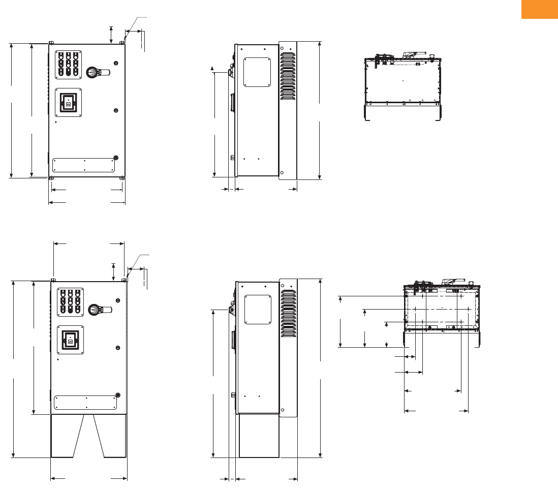
Volume 6—Solid-State Motor Control CA08100007E—February 2016 www.eaton.com V6-T2-165
2
2
2
2
2
2
2
2
2
2
2
2
2
2
2
2
2
2
2
2
2
2
2
2
2
2
2
2
2
2
2.7
Adjustable Frequency Drives
SVX Drives
Approximate Dimensions in Inches (mm)
BX Box Type 12
BX Box Type 12—12 Inch Floor Stands
4.00 (101.6)
Minimum
Free Air Space
Required
28.55
(725.1)
36.80
(934.7)
36.35
(923.3)
19.30 (490.2)
20.92 (531.4)
37.74
(958.6)
Ø 0.44 (11.2)
Mounting
Holes
(2 Places)
3.00 (76.2)
Minimum
Air Space
Required
Both Sides
17.01 (432.2)
1.76
(44.8)
7.00
(177.8)
10.53
(267.5)
14.06
(357.1)
15.50 (393.7)
17.50 (444.5)
3.00 (76.2)
5.00 (127.0)
40.38
(1025.7)
19.30 (490.2)
36.35
(923.3)
48.37
(1228.6)
20.92 (531.4) 17.01 (432.2)
1.76
(44.8)
48.87
(1241.3)
Ø 0.44 (11.2)
Mounting
Holes
(2 Places)
3.00 (76.2)
Minimum
Air Space
Required
Both Sides
4.00 (101.6)
Minimum
Free Air Space
Required
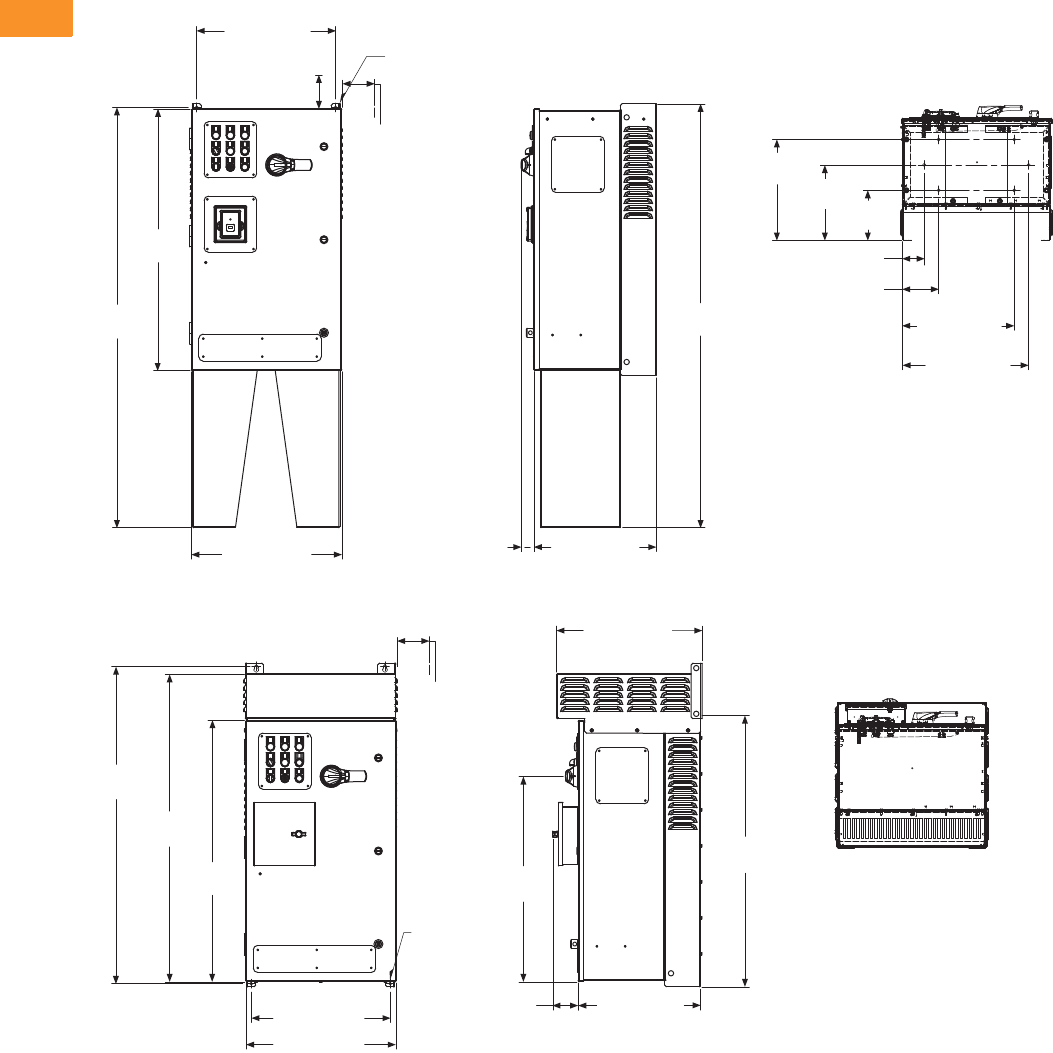
V6-T2-166 Volume 6—Solid-State Motor Control CA08100007E—February 2016 www.eaton.com
2
2
2
2
2
2
2
2
2
2
2
2
2
2
2
2
2
2
2
2
2
2
2
2
2
2
2
2
2
2
2.7
Adjustable Frequency Drives
SVX Drives
Approximate Dimensions in Inches (mm)
BX Box Type 12—22 Inch Floor Stands
BX Box Type 3R
7.00
(177.8)
10.53
(267.5)
14.06
(357.1)
15.50 (393.7)
17.50 (444.5)
3.00 (76.2)
5.00 (127.0)
58.87
(1495.3)
19.30 (490.2)
36.35
(923.3)
58.37
(1482.6)
20.92 (531.4) 17.01 (432.2)
1.76
(44.8)
Ø 0.44 (11.2)
Mounting
Holes
(2 Places)
3.00 (76.2)
Minimum
Air Space
Required
Both Sides
4.00 (101.6)
Minimum
Free Air Space
Required
28.56
(725.3)
44.09
(1119.8)
36.35
(923.3)
42.69
(1084.3)
19.30 (490.2)
20.92 (531.4)
37.74
(958.6)
3.00 (76.2)
Minimum
Air Space
Required
Both Sides
Ø 0.44 (11.2)
Mounting
Holes
(4 Places)
17.01 (432.2)
3.51
(89.1)
20.18 (512.5)

Volume 6—Solid-State Motor Control CA08100007E—February 2016 www.eaton.com V6-T2-167
2
2
2
2
2
2
2
2
2
2
2
2
2
2
2
2
2
2
2
2
2
2
2
2
2
2
2
2
2
2
2.7
Adjustable Frequency Drives
SVX Drives
Approximate Dimensions in Inches (mm)
BX Box Type 3R—12 Inch Floor Stands
BX Box Type 3R—22 Inch Floor Stands
17.88 (454.2)
20.88 (530.4)
55.66
(1413.7)
42.77
(1086.4)
36.35
(923.3)
20.92 (531.4) 17.01 (432.2)
3.51
(89.1)
40.40
(1026.3)
56.10
(1424.9)
20.18 (512.5)
7.00
(177.8)
10.53
(267.5)
14.06
(357.1)
Ø 0.44 (11.2)
Mounting
Holes
(2 Places)
3.00 (76.2)
Minimum
Air Space
Required
Both Sides
15.50 (393.7)
17.50 (444.5)
3.00 (76.2)
5.00 (127.0)
7.00
(177.8)
10.53
(267.5)
14.06
(357.1)
15.50 (393.7)
17.50 (444.5)
3.00 (76.2)
5.00 (127.0)
50.38
(1279.7)
20.88 (530.4)
17.88 (454.2)
65.66
(1667.7)
42.77
(1086.4)
36.35
(923.3)
Ø 0.44 (11.2)
Mounting
Holes
(2 Places)
3.00 (76.2)
Minimum
Air Space
Required
Both Sides
20.92 (531.4) 17.01 (432.2)3.57 (90.7)
20.18 (512.5)
55.10
(1429.9)

V6-T2-168 Volume 6—Solid-State Motor Control CA08100007E—February 2016 www.eaton.com
2
2
2
2
2
2
2
2
2
2
2
2
2
2
2
2
2
2
2
2
2
2
2
2
2
2
2
2
2
2
2.7
Adjustable Frequency Drives
SVX Drives
Approximate Dimensions in Inches (mm)
CX Box Type 1
CX Box Type 1—12 Inch Floor Stands
4.00 (101.6) Minimum
Free Air Space Required
48.80
(1239.5)
48.35
(1228.1)
29.30 (744.2)
30.92 (785.4) 17.76 (451.2)
1.74
(44.2)
49.74
(1263.4)
35.85
(910.6)
3.00 (76.2)
Minimum
Air Space
Required
Both Sides
Ø 0.44 (11.2)
Mounting
Holes
(4 Places)
3.00 (76.2)
5.00 (127.0)
29.30 (744.2)
48.35
(1228.1)
60.37
(1533.4)
30.92 (785.4) 17.76 (451.2)
47.67
(1210.8) 49.74
(1263.4)
14.81
(376.2)
11.28
(286.5) 7.75
(196.9)
27.50 (698.5)
25.50 (647.7)
Ø 0.44 (11.2)
Mounting
Holes
(2 Places)
3.00 (76.2)
Minimum
Air Space
Required
Both Sides
4.00 (101.6) Minimum
Free Air Space Required
1.74
(44.2)

Volume 6—Solid-State Motor Control CA08100007E—February 2016 www.eaton.com V6-T2-169
2
2
2
2
2
2
2
2
2
2
2
2
2
2
2
2
2
2
2
2
2
2
2
2
2
2
2
2
2
2
2.7
Adjustable Frequency Drives
SVX Drives
Approximate Dimensions in Inches (mm)
CX Box Type 1—22 Inch Floor Stands
CX Box Type 12
29.30 (744.2)
4.00 (101.6) Minimum
Free Air Space Required
Ø 0.44 (11.2)
Mounting Holes
(2 Places)
3.00 (76.2)
Minimum
Air Space
Required
Both Sides
48.35
(1228.1)
70.37
(1787.4)
30.92 (785.4) 17.76 (451.2)1.74 (44.2)
57.68
(1465.0) 70.87
(1800.1)
14.81
(376.2) 11.28
(286.5) 7.75
(196.9)
25.50
(647.7)
27.50
(698.5)
5.00
(127.0)
3.00
(76.2)
49.74
(1263.4)
48.80
(1239.5)
48.35
(1228.1)
29.30 (744.2)
30.92 (785.4)
1.74
(44.2) 17.76 (451.2)
35.85
(910.6)
3.00 (76.2)
Minimum
Air Space
Required
Both Sides
4.00 (101.6) Minimum
Free Air Space Required
Ø 0.44 (11.2)
Mounting
Holes
(4 Places)

V6-T2-170 Volume 6—Solid-State Motor Control CA08100007E—February 2016 www.eaton.com
2
2
2
2
2
2
2
2
2
2
2
2
2
2
2
2
2
2
2
2
2
2
2
2
2
2
2
2
2
2
2.7
Adjustable Frequency Drives
SVX Drives
Approximate Dimensions in Inches (mm)
CX Box Type 12—12 Inch Floor Stands
CX Box Type 12—22 Inch Floor Stands
48.35
(1228.1)
60.37
(1533.4)
30.92 (785.4) 17.76 (451.2)
1.74
(44.2)
47.67
(1210.8) 49.74
(1263.4)
14.81
(376.2)
7.75
(196.9)
11.28
(286.5)
25.50 (647.7)
27.50 (698.5)
3.00 (76.2)
5.00 (127.0)
29.30 (744.2)
4.00 (101.6) Minimum
Free Air Space Required
Ø 0.44 (11.2)
Mounting
Holes
(2 Places)
3.00 (76.2)
Minimum
Air Space
Required
Both Sides
29.30 (744.2)
48.35
(1228.1)
70.37
(1787.4)
30.92 (785.4)
57.68
(1465.0) 70.87
(1800.1)
Ø 0.44 (11.2)
Mounting
Holes
(2 Places)
3.00 (76.2)
Minimum
Air Space
Required
Both Sides
4.00 (101.6) Minimum
Free Air Space Required
14.81
(376.2)
7.75
(196.9)
11.28
(286.5)
25.50 (647.7)
27.50 (698.5)
3.00 (76.2)
5.00 (127.0)
17.76
(451.2)
1.74
(44.2)

Volume 6—Solid-State Motor Control CA08100007E—February 2016 www.eaton.com V6-T2-171
2
2
2
2
2
2
2
2
2
2
2
2
2
2
2
2
2
2
2
2
2
2
2
2
2
2
2
2
2
2
2.7
Adjustable Frequency Drives
SVX Drives
Approximate Dimensions in Inches (mm)
CX Box Type 3R
CX Box Type 3R—12 Inch Floor Stands
30.88 (784.4)
56.08
(1424.5)
54.77
(1391.2)
48.35
(1228.1)
29.30 (744.2)
30.92 (785.4) 17.76 (451.2)
3.72
(94.4)
56.96
(1446.9)
35.85
(910.6)
21.00 (533.3)
3.00 (76.2)
Minimum
Air Space
Required
Both Sides
Ø 0.44 (11.2)
Mounting
Holes
(4 Places)
3.00 (76.2)
30.88 (784.4)
28.10 (713.7)
67.65
(1718.4)
48.35
(1228.1)
66.60
(1691.7)
30.92 (785.4)
21.00 (533.3)
68.09
(1729.6)
47.67
(1210.8)
17.76 (451.2)
3.72
(94.4)
14.81
(376.2) 11.28
(286.5) 7.75
(196.9)
25.50 (647.7)
27.50 (698.5)
5.00 (127.0)
Ø 0.44 (11.2)
Mounting
Holes
(2 Places)
3.00 (76.2)
Minimum
Air Space
Required
Both Sides
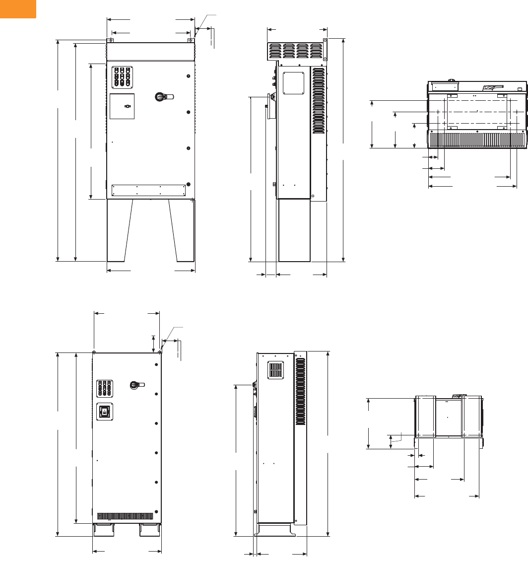
V6-T2-172 Volume 6—Solid-State Motor Control CA08100007E—February 2016 www.eaton.com
2
2
2
2
2
2
2
2
2
2
2
2
2
2
2
2
2
2
2
2
2
2
2
2
2
2
2
2
2
2
2.7
Adjustable Frequency Drives
SVX Drives
Approximate Dimensions in Inches (mm)
CX Box Type 3R—22 Inch Floor Stands
DX Box Type 1
78.09
(1983.6) 3.00 (76.2)
14.81
(376.2) 11.28
(286.5) 7.75
(196.9)
25.50 (647.7)
27.50 (698.5)
5.00 (127.0)
21.00 (533.3)
57.68
(1465.0)
30.92 (785.4)
77.65
(1972.4)
48.35
(1228.1)
76.60
(1945.7)
30.88 (784.4)
27.88 (708.2)
Ø 0.44 (11.2)
Mounting
Holes
(2 Places)
3.00 (76.2)
Minimum
Air Space
Required
Both Sides
17.76
(451.2)
3.72
(94.4)
1.55
(39.4)
29.30 (744.2)
82.23
(2088.6)
76.35
(1939.3)
30.92 (785.4) 22.48
(571.1)
28.88 (733.6)
82.85
(2104.4)
67.88
(1724.2)
22.56
(573.0) 6.13
(155.6)
8.38 (212.9)
1.62 (41.1)
22.12
(561.8)
Ø 0.44 (11.2)
Mounting
Holes
(2 Places)
3.00 (76.2)
Minimum
Air Space
Required
Both Sides
4.00 (101.6)
Minimum
Free Air Space
Required

Volume 6—Solid-State Motor Control CA08100007E—February 2016 www.eaton.com V6-T2-173
2
2
2
2
2
2
2
2
2
2
2
2
2
2
2
2
2
2
2
2
2
2
2
2
2
2
2
2
2
2
2.7
Adjustable Frequency Drives
SVX Drives
Approximate Dimensions in Inches (mm)
DX Box Type 12
DX Box Type 3R
82.35
(2091.7)
76.35
(1939.3)
30.92
(785.4)
22.48
(571.1)
1.55
(39.4)
82.85
(2104.4)
67.89
(1724.4)
28.88 (733.6)
22.56
(573.0) 6.13
(155.6)
8.38 (212.9)
1.62 (41.1)
22.12
(561.8)
29.30 (744.2)
Ø 0.44 (11.2)
Mounting
Holes
(2 Places)
3.00 (76.2)
Minimum
Air Space
Required
Both Sides
4.00 (101.6)
Minimum
Free Air Space
Required
22.81
(579.2)
29.06 (738.1)
30.88 (784.4)
27.88 (708.2)
89.70
(2278.3)
82.84
(2104.1)
76.35
(1939.3)
30.92 (785.4) 3.64
(92.5)
22.48
(571.1)
67.89
(1724.4)
90.14
(2289.5)
25.51 (647.8)
1.80 (45.7)
8.56 (217.4)
22.30
(566.4)
Ø 0.44 (11.2)
Mounting
Holes
(2 Places)
3.00 (76.2)
Minimum
Air Space
Required
Both Sides
6.31
(160.3)
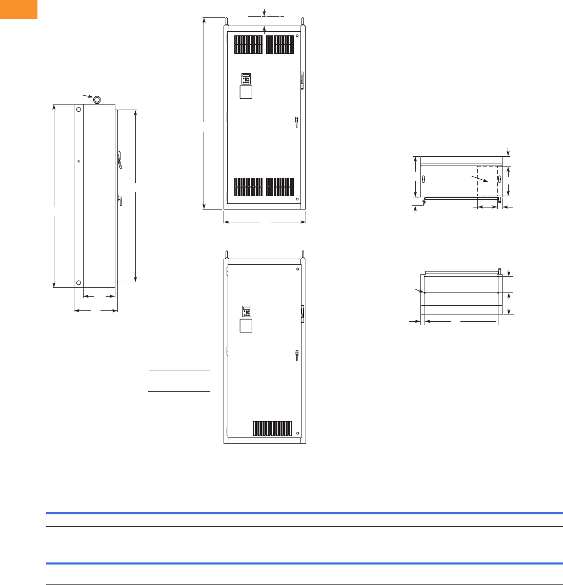
V6-T2-174 Volume 6—Solid-State Motor Control CA08100007E—February 2016 www.eaton.com
2
2
2
2
2
2
2
2
2
2
2
2
2
2
2
2
2
2
2
2
2
2
2
2
2
2
2
2
2
2
2.7
Adjustable Frequency Drives
SVX Drives
Approximate Dimensions in Inches (mm)
Size 5
For reference only, dimensions are subject to change.
Wide High Deep Mounting Door Height Min. Air Space
ABCDD1EE1FGG1H JK
40.0 (1016) 90.0 (2286) 21.3 (541) 36.0 (914) 2.0 (51) — — 8.0 (203) 10.8 (273) — 84.4 (2143) 4.0 (102) —
Max. Approx.
Shipping Weight
Lbs (kg)
Cable Entry Door Clearance
L M N P R S T U V W RR SS TT UU VV
15.0
(381)
10.0
(254)
4.8
(122)
2.0
(51)
—36.3
(921)
20.0
(508)
——— 94.0
(2387)
15.5
(394)
— — — 1275 (579)
M
Lifting Eyes
(2 Places)
B
H
C
SS
Side View
RR
J
A
Front View
NEMA Type 1/IP21
Front View
NEMA Type 12/IP54
S
T
0.56 (14.2) Dia.
Mounting
Holes
(4 Places)
D1 D
G
F
N
L
For Cable
Entry
P
Top View
Bottom View
IL hp
75
100
200
250
208/230V
480V
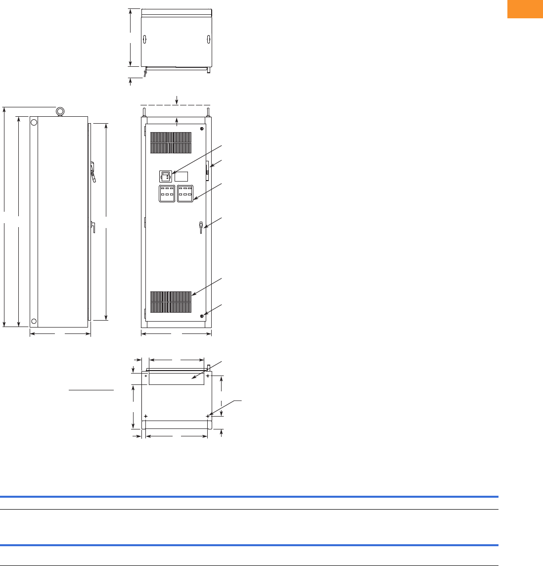
Volume 6—Solid-State Motor Control CA08100007E—February 2016 www.eaton.com V6-T2-175
2
2
2
2
2
2
2
2
2
2
2
2
2
2
2
2
2
2
2
2
2
2
2
2
2
2
2
2
2
2
2.7
Adjustable Frequency Drives
SVX Drives
Approximate Dimensions in Inches (mm)
Size 6
For reference only, dimensions are subject to change. See Page V6-T2-146, notes 3 and 5 for enclosure and option selection.
Wide High Deep Mounting Door Height Min. Air Space
ABCDD1EE1FGG1H JK
30.0 (762) 90.0 (2286) 26.0 (660) 26.5 (673) 1.8 (46) — — 17.3 (438) 5.5 (140) — 84.4 (2143) 4.0 (102) —
Max. Approx.
Shipping Weight
Lbs (kg)
Cable Entry Door Clearance
L M N P R S T U V W RR SS TT UU VV
23.5
(597)
3.3
(84)
4.5
(114)
19.3
(490)
—26.2
(667)
24.8
(629)
———93.9
(2386)
————1500 (681)
Keypad
Operator Elements When Specied,
Mounted on These Panels
Ventilating Slots
Key-Locking Handle
Quarter Turn Latch
(2 Places)
Flanged Disconnect Supplied
with Circuit Breaker When Specied
A
C
Side View
Bottom View
S
J
H
B
T
Top View
Door Clearance
RR
L
DD1
G
F
N
P
For Cable Entry
M
0.56 (14.2) Dia.
Mounting Hole –
(4 Places)
Front View
IL hp
300
350
400
480V
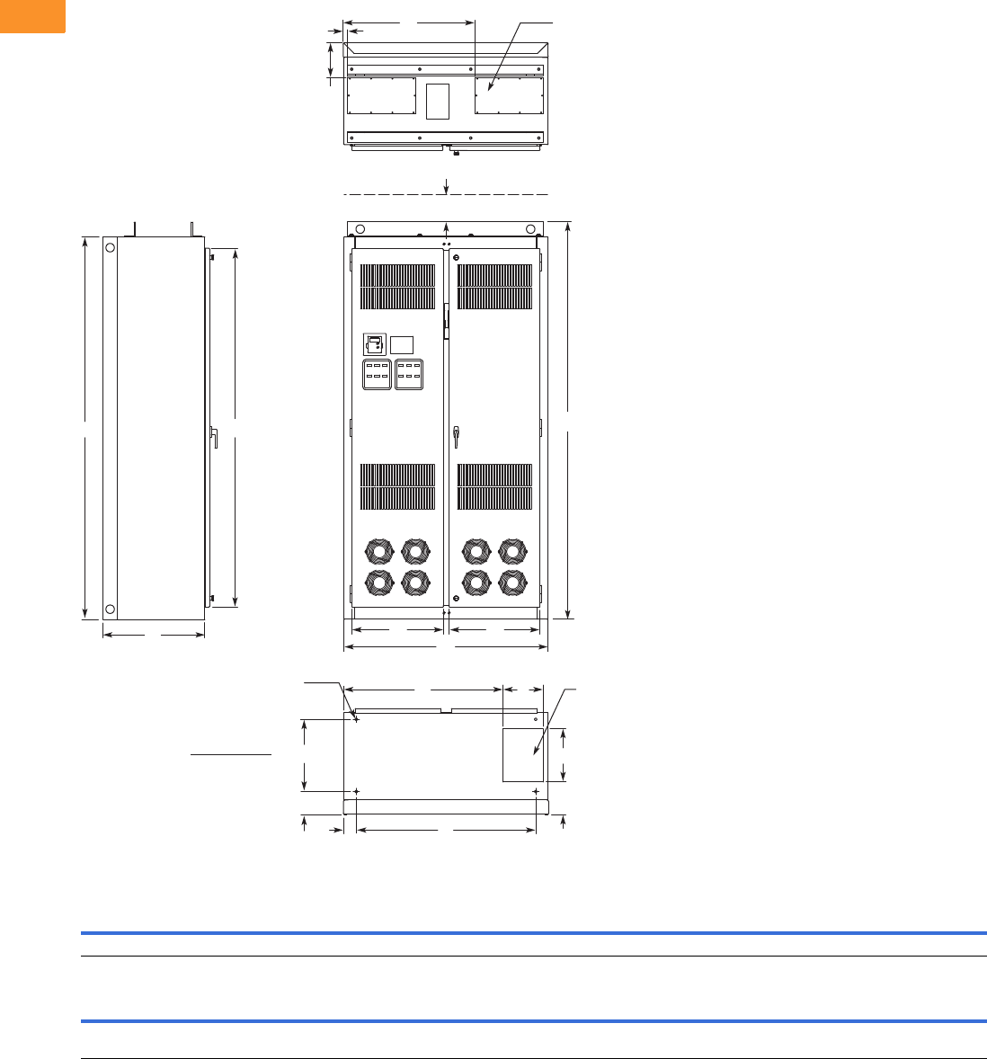
V6-T2-176 Volume 6—Solid-State Motor Control CA08100007E—February 2016 www.eaton.com
2
2
2
2
2
2
2
2
2
2
2
2
2
2
2
2
2
2
2
2
2
2
2
2
2
2
2
2
2
2
2.7
Adjustable Frequency Drives
SVX Drives
Approximate Dimensions in Inches (mm)
Size 8
For reference only, dimensions are subject to change. See Page V6-T2-146, notes 3 and 5 for enclosure and option selection.
Wide High Deep Mounting Door Height Min. Air Space
ABCDD1EE1FGG1H JK
48.0 (1219)90.0 (2286)24.0 (610)42.2 (1072)3.0 (77)———5.5 (139)—84.4 (2143) 4.0 (102) —
Max. Approx.
Shipping Weight
Lbs (kg)
Cable Entry
LMNPRSTUVWRRSSTTUUVV
9.5
(241)
37.5
(952)
12.5
(318)
7.7
(196)
8.3
(210)
1.3
(32)
31.0
(787)
21.5
(545)
21.3
(541)
—93.5
(2375)
————2000 (908)
T
S
LM
0.56 (14.2) Dia.
Mounting Hole –
(4 Places)
R
RR
H
B
UV
CA
For Top Cable Entry –
(2 Places)
Bottom View
Top View
Front View
Side View
For Bottom
Cable Entry
N
P
F
G
J
D
D1
IL hp
300
350
400
480V
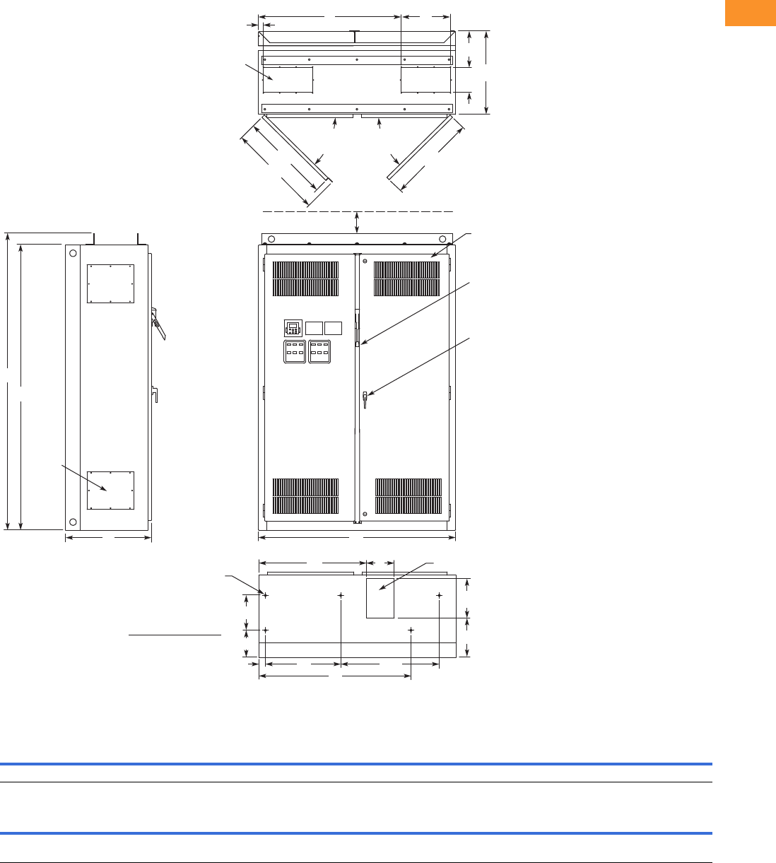
Volume 6—Solid-State Motor Control CA08100007E—February 2016 www.eaton.com V6-T2-177
2
2
2
2
2
2
2
2
2
2
2
2
2
2
2
2
2
2
2
2
2
2
2
2
2
2
2
2
2
2
2.7
Adjustable Frequency Drives
SVX Drives
Approximate Dimensions in Inches (mm)
Size 9
For reference only, dimensions are subject to change. See Page V6-T2-146, notes 3 and 5 for enclosure and option selection.
Wide High Deep Mounting Door Height Min. Air Space
ABCDD1EE1FGG1H JK
60.0 (1524) 90.0 (2286) 260.1 (664) 22.9 (582) 2.0 (51) 30.0 (762) 44.3 (1125) 10.6 (270) 10.6 (270) 8.2 (208) — 4.0 (102) —
Max. Approx.
Shipping Weight
Lbs (kg)
Cable Entry
LMNPRSTUVWRRSSTTUUVV
8.5
(216)
32.7
(831)
12.0
(305)
11.9
(303)
9.8
(249)
1.5
(38)
43.5
(1105)
15.0
(381)
7.5
(191)
25.0
(635)
93.5
(2375)
27.4
(696)
290.1
(738)
270.1
(687)
— 2500 (1135)
R
W
V
UU
J
SS
TT
Top View
STU
B
RR
AC Front View
Bottom View
Side View
Access in Top –
(2 Places)
Bottom Access
0.56 (14.2) Dia.
Mounting Hole –
(5 Places)
90° Max.
Door
Opening
P
N
D1 D
G1
G
D2
ML
E
Key-Locking Handle
Access
Plate –
4 Places
90° Max.
Door
Opening
Drive Circuit Breaker
IL hp
500
550
600
IH hp
400
500
550
480V
Openings Filtered for
NEMA Type 12/IP54 Design
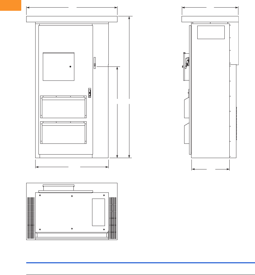
V6-T2-178 Volume 6—Solid-State Motor Control CA08100007E—February 2016 www.eaton.com
2
2
2
2
2
2
2
2
2
2
2
2
2
2
2
2
2
2
2
2
2
2
2
2
2
2
2
2
2
2
2.7
Adjustable Frequency Drives
SVX Drives
Approximate Dimensions in Inches (mm)
Enclosure Size F
HH1WW1DD1
Approximate
Weight
Lbs (kg)
Approximate
Shipping Weight
Lbs (kg)
93.58
(2376.9)
69.51
(1765.60)
60.00
(1524.0)
48.00
(1219.2)
37.50
(952.5)
26.00
(660.4)
1700 (771) 1850 (839)
D
D1
HH1
W
W1
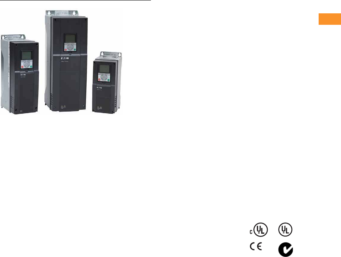
Volume 6—Solid-State Motor Control CA08100007E—February 2016 www.eaton.com V6-T2-179
2
2
2
2
2
2
2
2
2
2
2
2
2
2
2
2
2
2
2
2
2
2
2
2
2
2
2
2
2
2
2.8
Adjustable Frequency Drives
H-Max Series Drives
H-Max Drives
Contents
Description Page
H-Max Drives
Catalog Number Selection . . . . . . . . . . . . . . . . V6-T2-180
Product Selection . . . . . . . . . . . . . . . . . . . . . . . V6-T2-181
Accessories . . . . . . . . . . . . . . . . . . . . . . . . . . . V6-T2-184
Replacement Parts . . . . . . . . . . . . . . . . . . . . . . V6-T2-184
Technical Data and Specifications . . . . . . . . . . V6-T2-187
Wiring Diagram . . . . . . . . . . . . . . . . . . . . . . . . V6-T2-188
Dimensions . . . . . . . . . . . . . . . . . . . . . . . . . . . V6-T2-189
H-Max IntelliPass and IntelliDisconnect Drives . . . V6-T2-190
H-Max Drives
Product Description
Eaton’s H-Max Series VFD
has software and hardware
designed specifically for the
HVAC, pump industry. The
ultra-efficient DC capacitor
and power structure allows
the drive to consume less
energy, lowering greenhouse
gases.
The I/O configuration is
designed
with wiring
ergonomics in mind by
including removable terminal
blocks. The main, easily
removable, control board
used for all drive frames with
six digital IN,
two analog IN,
one analog OUT, three relay
OUT
accepts two additional
I/O or communication board.
In addition, the control board
has built-in RS-485 and
Ethernet communication.
These drives continue
the tradition of robust
performance, and raise
the bar on features and
functionality, ensuring
the best solution at the
right price.
In addition to the Active
Energy Control Algorithm to
maximize motor efficiency,
the drive boasts an ultra-
efficient DC capacitor and
power structure to allow less
energy consumption,
lowering greenhouse gases.
Features and Benefits
Hardware
●Thin metal capacitor
design—ultra-efficient
drive operation and
extended self life (up to
five years without
reforming)
●Integrated 5% DC link
choke with Input surge
protection—protects
against voltage spikes and
provides a clean wave form
to the motor
●EMI/RFI filters standard on
all drives—meets EMC
Category 2 for commercial
applications
●Real-time clock—supports
calendaring and PLC
functionality
●Graphic LCD display and
keypad—supports simple
menu navigation as well as
on-screen diagnostics and
troubleshooting
●HAND-OFF-AUTO and
drive-bypass selector on
keypad—simplifies control
●Standard I/O: 6DI, 2AI,
1AO, 2 Form C RO (NO/
NC), 1 Form A RO (NO)—
supports requirements for
most installations
●Onboard RS 485: Modbus,
N2, BACnet—meets needs
of most communication
requirements
●Onboard Ethernet: BACnet/
IP, Modbus/TCP—meets
needs of most
communication
requirements
●Two expansion slots—
intended to support
additional I/O or
communication protocols
as necessary
●Quick disconnect terminals
for I/O connections—
supports fast easy
installation
Software
●Active energy control—
minimizes energy losses in
your motor resulting in
industry leading energy
efficiency for your
application
●Quick Start Wizard upon
initial power up—supports
fast easy installation
●Copy/paste functionality on
drive keypad—allows for
fast setup of multiple
drives
●Pre-programmed I/O—
supports fast easy
installation for most
applications
Standards and Certifications
Product
●IEC 61800-5-1
●CE
●UL508C
●cUL
●C-Tick Mark
●OSHPD Seismic Certified
●Plenum Rated
V6-T2-180 Volume 6—Solid-State Motor Control CA08100007E—February 2016 www.eaton.com
2
2
2
2
2
2
2
2
2
2
2
2
2
2
2
2
2
2
2
2
2
2
2
2
2
2
2
2
2
2
2.8
Adjustable Frequency Drives
H-Max Series Drives
Catalog Number Selection
H-Max Series Drives
Notes
All boards are varnished (conformed coated). Corrosion resistant.
Battery included in all drives for real-time clock.
Keypad kit includes HOA bypass.
Keypad kit includes HOA, back reset for Europe application.
EMI/RFI filters included.
DC link choke included.
HMX 3 4 A G 3D4 2 1 -N
Software Series
A–Z
Keypad
G = Graphical panel
Voltage
2 = 200–240 V
4 = 380–480 V
Phase
3 = Three-phase
Product
HMX = HVAC drive
Enclosure
1 = Open NEMA Type 1 IP21
2 = Open NEMA Type 12 IP54
Input Options Frame and
Voltage Specific
2 =EMC C2
Braking/Application
N = No brake chopper (low overload)
Amperes
200–240 Volts 380–480 Volts
3D7 = 3.7 A–0.75 hp, 0.55 kW
4D8 = 4.8 A–1 hp, 0.75 kW
6D6 = 6.6 A–1.5 hp, 1.1 kW
8D0 = 8 A–2 hp, 1.5 kW
011 = 11 A–3 hp, 2.2 kW
012 = 12 A–4 hp, 3 kW
018 = 18 A–5 hp, 4 kW
024 = 24 A–7.5 hp, 5.5 kW
031 = 31 A–10 hp, 7.5 kW
048 = 48 A–15 hp, 11 kW
062 = 62 A–20 hp, 15 kW
075 = 75 A–25 hp, 18.5 kW
088 = 88 A–30 hp, 22 kW
105 = 105 A–40 hp, 30 kW
140 = 140 A–50 hp, 37 kW
170 = 170 A–60 hp, 45 kW
205 = 205 A–75 hp, 55 kW
261 = 261 A–100 hp, 75 kW
310 = 310 A–125 hp, 90 kW
3D4 = 3.4 A–1.5 hp, 1.1 kW
4D8 = 4.8–2 hp, 1.5 kW
5D6 = 5.6 A–3 hp, 2.2 kW
8D0 = 8 A–4 hp, 3 kW
9D6 = 9.6 A–5 hp, 4 kW
012 = 12 A–7.5 hp, 5.5 kW
016 = 16 A–10 hp, 7.5 kW
023 = 23 A–15 hp, 11 kW
031 = 31 A–20 hp, 15 kW
038 = 38 A–25 hp, 18.5 kW
046 = 46 A–30 hp, 22 kW
061 = 61 A–40 hp, 30 kW
072 = 72 A–50 hp, 37 kW
087 = 87 A–60 hp, 45 kW
105 = 105 A–75 hp, 55 kW
140 = 140 A–100 hp, 75 kW
170 = 170 A–125 hp, 90 kW
205 = 205 A–150 hp, 110 kW
261 = 261 A–200 hp, 132 kW
310 = 310 A–250 hp, 160 kW
Volume 6—Solid-State Motor Control CA08100007E—February 2016 www.eaton.com V6-T2-181
2
2
2
2
2
2
2
2
2
2
2
2
2
2
2
2
2
2
2
2
2
2
2
2
2
2
2
2
2
2
2.8
Adjustable Frequency Drives
H-Max Series Drives
Product Selection
H-Max Series Drives—230 Vac
NEMA Type 1/IP21
NEMA Type 12/IP54
Note
1 For sizing reference.
FS
Frame
Size
Drive Output Current Assigned Motor Ratings
230 Vac
NEC Amps 1
Catalog
Number
Low Overload Full
Load Amps at 40 °C Horsepower
Drive kW
230 Vac/50 Hz
Low Overload Full
Load Amps at 50 °C
4 3.7 0.75 0.55 3.2 2.6 HMX32AG3D721-N
4.8 1 0.75 4.2 3.7 HMX32AG4D821-N
6.6 1.5 1.1 6.6 4.8 HMX32AG6D621-N
8 2 1.5 6.8 6.6 HMX32AG8D021-N
11 3 2.2 9.6 8 HMX32AG01121-N
12.5 4 3 N/A 11 HMX32AG01221-N
5 18 5 4 15.2 12.5 HMX32AG01821-N
24 7.5 5.5 22 18 HMX32AG02421-N
31 10 7.5 28 24 HMX32AG03121-N
6 48 15 11 42 31 HMX32AG04821-N
62 20 15 54 48 HMX32AG06221-N
775 25 18.5 68 62 HMX32AG07521-N
88 30 22 80 75 HMX32AG08821-N
105 40 30 104 88 HMX32AG10521-N
8 140 50 37 130 105 HMX32AG14021-N
170 60 45 154 140 HMX32AG17021-N
205 75 55 192 170 HMX32AG20521-N
9 261 100 75 248 205 HMX32AG26121-N
310 125 90 N/A 261 HMX32AG31021-N
FS
Frame
Size
Drive Output Current Assigned Motor Ratings
230 Vac
NEC Amps 1
Catalog
Number
Low Overload Full
Load Amps at 40 °C Horsepower
Drive kW
230 Vac/50 Hz
Low Overload Full
Load Amps at 50 °C
4 3.7 0.75 0.55 3.2 2.6 HMX32AG3D722-N
4.8 1 0.75 4.2 3.7 HMX32AG4D822-N
6.6 1.5 1.1 6.6 4.8 HMX32AG6D622-N
8 2 1.5 6.8 6.6 HMX32AG8D022-N
11 3 2.2 9.6 8 HMX32AG01122-N
12.5 4 3 N/A 11 HMX32AG01222-N
5 18 5 4 15.2 12 HMX32AG01822-N
24 7.5 5.5 22 18 HMX32AG02422-N
31 10 7.5 28 24 HMX32AG03122-N
6 48 15 11 42 31 HMX32AG04822-N
62 20 15 54 48 HMX32AG06222-N
775 25 18.5 68 62 HMX32AG07522-N
88 30 22 80 75 HMX32AG08822-N
105 40 30 104 88 HMX32AG10522-N
8 140 50 37 130 105 HMX32AG14022-N
170 60 45 154 140 HMX32AG17022-N
205 75 55 192 170 HMX32AG20522-N
9 261 100 75 248 205 HMX32AG26122-N
310 125 90 N/A 261 HMX32AG31022-N
NEMA Type 1
NEMA Type 12
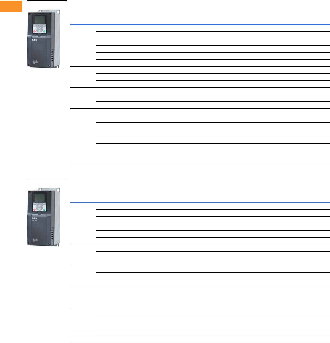
V6-T2-182 Volume 6—Solid-State Motor Control CA08100007E—February 2016 www.eaton.com
2
2
2
2
2
2
2
2
2
2
2
2
2
2
2
2
2
2
2
2
2
2
2
2
2
2
2
2
2
2
2.8
Adjustable Frequency Drives
H-Max Series Drives
H-Max Series Drives—480 Vac
NEMA Type 1/IP21
NEMA Type 12/IP54
Note
1 For sizing reference.
FS
Frame
Size
Drive Output Current Assigned Motor Ratings
480 Vac
NEC Amps 1
Catalog
Number
Low Overload Full
Load Amps at 40 °C Horsepower
Drive kW
400 Vac/50 Hz
Low Overload Full
Load Amps at 50 °C
4 3.4 1.5 1.1 2.1 2.6 HMX34AG3D421-N
4.8 2 1.5 3.4 3.4 HMX34AG4D821-N
5.6 3 2.2 5.6 4.8 HMX34AG5D621-N
8.0 4 3.0 N/A 5.6 HMX34AG8D021-N
9.6 5 4 7.6 8 HMX34AG9D621-N
12 7.5 5.5 11 9.6 HMX34AG01221-N
5 16 10 7.5 14 12 HMX34AG01621-N
23 15 11 21 16 HMX34AG02321-N
31 20 15 27 23 HMX34AG03121-N
6 38 25 18.5 34 31 HMX34AG03821-N
46 30 22 40 38 HMX34AG04621-N
61 40 30 52 46 HMX34AG06121-N
7 72 50 37 65 61 HMX34AG07221-N
87 60 45 77 72 HMX34AG08721-N
105 75 55 96 87 HMX34AG10521-N
8 140 100 75 124 105 HMX34AG14021-N
170 125 90 156 140 HMX34AG17021-N
205 150 110 180 170 HMX34AG20521-N
9 261 200 132 240 205 HMX34AG26121-N
310 250 160 302 261 HMX34AG31021-N
FS
Frame
Size
Drive Output Current Assigned Motor Ratings
480 Vac
NEC Amps 1
Catalog
Number
Low Overload Full
Load Amps at 40 °C Horsepower
Drive kW
400 Vac/50 Hz
Low Overload Full
Load Amps at 50 °C
4 3.4 1.5 1.1 2.1 2.6 HMX34AG3D422-N
4.8 2 1.5 3.4 3.4 HMX34AG4D822-N
5.6 3 2.2 5.6 4.8 HMX34AG5D622-N
8.0 4 3.0 N/A 5.6 HMX34AG8D022-N
9.6 5 4 7.6 8 HMX34AG9D622-N
12 7.5 5.5 11 9.6 HMX34AG01222-N
5 16 10 7.5 14 12 HMX34AG01622-N
23 15 11 21 16 HMX34AG02322-N
31 20 15 27 23 HMX34AG03122-N
6 38 25 18.5 34 31 HMX34AG03822-N
46 30 22 40 38 HMX34AG04622-N
61 40 30 52 46 HMX34AG06122-N
7 72 50 37 65 61 HMX34AG07222-N
87 60 45 77 72 HMX34AG08722-N
105 75 55 96 87 HMX34AG10522-N
8 140 100 75 124 105 HMX34AG14022-N
170 125 90 156 140 HMX34AG17022-N
205 150 110 180 170 HMX34AG20522-N
9 261 200 132 240 205 HMX34AG26122-N
310 250 160 302 261 HMX34AG31022-N
NEMA Type 1
NEMA Type 12

Volume 6—Solid-State Motor Control CA08100007E—February 2016 www.eaton.com V6-T2-183
2
2
2
2
2
2
2
2
2
2
2
2
2
2
2
2
2
2
2
2
2
2
2
2
2
2
2
2
2
2
2.8
Adjustable Frequency Drives
H-Max Series Drives
Onboard Network Communications
Johnson Controls
Metasys N2
H-Max Series provides
communication between the
drive and a Johnson Controls
Metasys™ N2 network. With
this connection, the drive can
be controlled, monitored and
programmed from the
Metasys system. N2 can be
selected and programmed by
the drive keypad.
BACnet
H-Max Series provides
communication to BACnet
networks. Data transfer is
master-slave/token passing
(MS/TP) RS-485.
BACnet/IP
100Base-T interface.
Modbus TCP
Ethernet based protocol.
Modbus RTU
H-Max Series provides
communication to Modbus
RTU RS-485 as a slave on a
Modbus network. Other
communication parameters
include an address range
from 1–247; a parity of
None, Odd or Even; and the
stop bit is 1.
H-Max Series Option Board Kits Available for Slot B
The factory issued relay
option board can be replaced
with the following option
boards to customize the drive
for your application needs.
The standard board provides
2 Form C RO (NO/NC) and
1 Form A RO (NO).
Option Boards Mounted in Slot B
H-Max Series Option Board Kits Available for Slots D and E
The H-Max Series drives can
accommodate a wide
selection of expander and
adapter option boards to
customize the drive for your
application needs. The drive’s
control unit is designed to
accept a total of two option
boards.
The H-Max Series factory-
installed standard board
configuration includes an
I/O board and a relay
output board.
Option Boards Mounted in Slots D and E
NEMA Type 1 to NEMA Type 12/IP54 Conversion Kit
The NEMA Type 12/IP54
option kit is used to convert a
NEMA Type 1 to a NEMA
Type 12 drive.
Kit consists of a drive cover,
fan kit and plugs.
NEMA Type 12/IP54 Cover
Option Kit Description
Option Kit
Catalog Number
I/O expander card, 2 RO and thermistor input Relay Board 2
Option Kit Description
Option Kit
Catalog Number
6 x DI /DO, each digital input can be individually programmed as digital output XMX-IO-B1-A
1RO Form C (NO/NC), 1RO Form A (NO), 1 thermistor XMX-IO-B2-A
1 x AI, 2 x AO (isolated) XMX-IO-B4-A
3 x RO Form A (NO) XMX-IO-B5-A
1RO Form A (NO), 5DI 42–240 Vac input XMX-IO-B9-A
1 x AO, 1 x DO, 1 x RO XMX-IO-BF-A
LonWorks®XMX-COM-C4-A
Option Kit Description
Option Kit
Catalog Number
FS4-branded N12/IP54 cover with gasket, plastic plug, fans, Eaton logos FS4-N12KIT
FS5-branded N12/IP54 cover with gasket, plastic plug, fans, Eaton logos FS5-N12KIT
FS6-branded N12/IP54 cover with gasket, plastic plug, fans, Eaton logos FS6-N12KIT

V6-T2-184 Volume 6—Solid-State Motor Control CA08100007E—February 2016 www.eaton.com
2
2
2
2
2
2
2
2
2
2
2
2
2
2
2
2
2
2
2
2
2
2
2
2
2
2
2
2
2
2
2.8
Adjustable Frequency Drives
H-Max Series Drives
Accessories
Flange Kits
The flange kit is used when the power section heat sink is
mounted through the back panel of an enclosure.
Flange Kit NEMA Type 12/IP54
Includes flange, mounting brackets, NEMA Type 12 fan
components, air shroud screws and plugs.
Frames FS4–FS7 12
Keypad Accessories
Remote Mounting Keypad Kit
Frames FS4–FS9
Drive Demo
H-Max Series Drive Demo
Demos and Power Supply
Notes
1For installation of a NEMA Type 1 drive into a NEMA Type 12 oversized enclosure.
2Frame size 8 and 9 must be ordered from the factory as a flange mount unit.
Replacement Parts
Control Board/Keypad
PC Cable
Replacement Relay Board in Slot B
Main Fan
Internal Fan
Description
Catalog
Number
NEMA Type 12/IP54
FS4 N12/IP54 flange kit
(mounting N1 drive into N12 enclosure)
FS4-Flange-N12KIT
FS5 N12/IP54 flange kit
(mounting N1 drive into N12 enclosure)
FS5-Flange-N12KIT
FS6 N12/IP54 flange kit
(mounting N1 drive into N12 enclosure)
FS6-Flange-N12KIT
FS7 N12/IP54 flange kit
(mounting N1 drive into N12 enclosure)
FS7-Flange-N12KIT
Description
Catalog
Number
Remote mounting keypad kit—bezel and cable OPTRMT-BP-HMAX
Description
Catalog
Number
H-Max Series bypass demo H-MAX-BYPASS-DEMO
Hand-held 24 V auxiliary power supply—used to supply power
to the control module in order to perform keypad programming
before the drive is connected to line voltage
9000XAUX24 V
Description
Current Catalog
Number
H-Max series graphic bypass, HOA KeypadbypassHOA
H-Max series graphic back, HOA KeypadbackHOA
H-Max control board replacement HMX-SPR-CTRLBOARD
Description
Catalog
Number
Remote download USB to RJ-45 cable with
software driver disk
REM-USB-Down
Description
Catalog
Number
Replacement relay board
qty 2 Form C relay, qty 1 Form A relay
Relay board 1
Description
Catalog
Number
FS4 main fan FS4-Main Fan
FS5 main fan FS5-Main Fan
FS6 main fan FS6-Main Fan
FS7 main fan FS7-Main Fan
FS8 main fan FS8-Main Fan
FS9 main fan FS9-Main Fan
Description
Catalog
Number
FS4 internal fan (IP54/NEMA 12) FS4-Internal Fan
FS5 internal fan (IP54/NEMA 12) FS5-Internal Fan
FS6 internal fan (IP54/NEMA 12) FS6-Internal Fan
FS7 internal fan (IP54/NEMA 12) FS7-Internal Fan
FS8 internal fan (IP54/NEMA 12) FS8-Internal Fan
FS9 internal fan (IP54/NEMA 12) FS9-Internal Fan
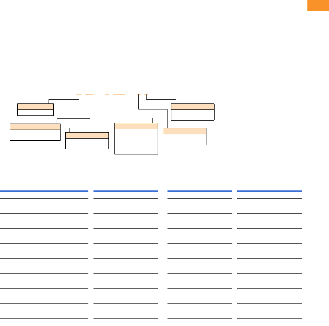
Volume 6—Solid-State Motor Control CA08100007E—February 2016 www.eaton.com V6-T2-185
2
2
2
2
2
2
2
2
2
2
2
2
2
2
2
2
2
2
2
2
2
2
2
2
2
2
2
2
2
2
2.8
Adjustable Frequency Drives
H-Max Series Drives
Line and Load Reactors
A line and load reactor is a
three-phase inductance filter
that can be placed on the line
and load side of the AFD to
help improve the harmonic
performance of the system.
Consult the factory for
additional filtering options and
further technical details.
DR1 Line Reactor
A line reactor helps to provide
a moderate reduction in
current harmonics similar to a
DC choke. It also provides
increased input protection for
AFD and its semiconductors
from line transients helping to
extend the life of the AFD.
DR2 Output Reactor
An output filter is used to
reduce the transient voltage
(dV/dt) at the motor terminals.
The output filter is
recommended for cable
lengths exceeding 100 ft
(30 m) with a drive of 3 hp
and above and for cable
lengths of 33 ft (10 m) with a
drive of 2 hp and below.
Line and Load Reactors—Catalog Number Selection
Line and Load Reactors—240 V
Open NEMA 1
Load Reactor Line Reactor Load Reactor Line Reactor
hp (CT) 3% 5% 3% 5% 3% 5% 3% 5%
0.75 DR2-24D0-03 DR2-24D0-05 DR1-23D2-03 DR1-23D2-05 DR2-24D0-13 DR2-24D0-15 DR1-23D2-13 DR1-23D2-15
1 DR2-24D0-03 DR2-28D0-05 DR1-24D2-03 DR1-24D2-05 DR2-24D0-13 DR2-28D0-15 DR1-24D2-13 DR1-24D2-15
1.5 DR2-28D0-03 DR2-28D0-05 DR1-26D0-03 DR1-26D0-05 DR2-28D0-13 DR2-28D0-15 DR1-26D0-13 DR1-26D0-15
2 DR2-28D0-03 DR2-28D0-05 DR1-26D8-03 DR1-26D8-05 DR2-28D0-13 DR2-28D0-15 DR1-26D8-13 DR1-26D8-15
3 DR2-2012-03 DR2-2012-05 DR1-29D6-03 DR1-29D6-05 DR2-2012-13 DR2-2012-15 DR1-29D6-13 DR1-29D6-15
5 DR2-2018-03 DR2-2018-05 DR1-2015-03 DR1-2015-05 DR2-2018-13 DR2-2018-15 DR1-2015-13 DR1-2015-15
7.5 DR2-2025-03 DR2-2025-05 DR1-2022-03 DR1-2022-05 DR2-2025-13 DR2-2025-15 DR1-2022-13 DR1-2022-15
10 DR2-2035-03 DR2-2035-05 DR1-2028-03 DR1-2028-05 DR2-2035-13 DR2-2035-15 DR1-2028-13 DR1-2028-15
15 DR2-2045-03 DR2-2045-05 DR1-2042-03 DR1-2042-05 DR2-2045-13 DR2-2045-15 DR1-2042-13 DR1-2042-15
20 DR2-2055-03 DR2-2055-05 DR1-2054-03 DR1-2054-05 DR2-2055-13 DR2-2055-15 DR1-2054-13 DR1-2054-15
25 DR2-2080-03 DR2-2080-05 DR1-2068-03 DR1-2068-05 DR2-2080-13 DR2-2080-15 DR1-2068-13 DR1-2068-15
30 DR2-2080-03 DR2-2100-05 DR1-2080-03 DR1-2080-05 DR2-2080-13 DR2-2100-15 DR1-2080-13 DR1-2080-15
40 DR2-2100-03 DR2-2100-05 DR1-2104-03 DR1-2104-05 DR2-2100-13 DR2-2100-15 DR1-2104-13 DR1-2104-15
50 DR2-2130-03 DR2-2130-05 DR1-2130-03 DR1-2130-05 DR2-2130-13 DR2-2130-15 DR1-2130-13 DR1-2130-15
60 DR2-2160-03 DR2-2200-15 DR1-2154-03 DR1-2154-05 DR2-2160-13 DR2-2200-15 DR1-2154-13 DR1-2154-15
75 DR2-2200-13 DR2-2200-15 DR1-2192-03 DR1-2192-05 DR2-2200-13 DR2-2200-15 DR1-2192-13 DR1-2192-15
100 DR2-2225-13 DR2-2225-15 DR1-2248-03 DR1-2248-05 DR2-2225-13 DR2-2225-15 DR1-2248-13 DR1-2248-15
125 DR2-2320-13 DR2-2320-15 DR1-2312-03 DR1-2312-05 DR2-2320-13 DR2-2320-15 DR1-2312-13 DR1-2312-15
DR1 –22D0 –05
Device Series
R1 = Line side reactor
R2 = Load side reactor
Basic Naming
D= Drive
Input/Output Voltage
2= 240 V
4= 480 V
Environment Rating
0= Open
1= NEMA 1
Impedance
3= 3%
5= 5%
Current Rating
Examples:
2D0 = 2.0 A
4D0 = 4.0 A
8D0 = 8.0 A
012
= 12 A

V6-T2-186 Volume 6—Solid-State Motor Control CA08100007E—February 2016 www.eaton.com
2
2
2
2
2
2
2
2
2
2
2
2
2
2
2
2
2
2
2
2
2
2
2
2
2
2
2
2
2
2
2.8
Adjustable Frequency Drives
H-Max Series Drives
Line and Load Reactors—480 V
Open NEMA 1
Load Reactor Line Reactor Load Reactor Line Reactor
hp (CT) 3% 5% 3% 5% 3% 5% 3% 5%
1.5 DR2-44D0-05 DR2-44D0-05 DR1-43D0-03 DR1-43D0-05 DR2-44D0-13 DR2-44D0-15 DR1-43D0-13 DR1-43D0-15
2 DR2-44D0-03 DR2-44D0-05 DR1-43D4-03 DR1-43D4-05 DR2-44D0-13 DR2-44D0-15 DR1-43D4-13 DR1-43D4-15
3 DR2-48D0-03 DR2-48D0-05 DR1-44D8-03 DR1-44D8-05 DR2-48D0-13 DR2-48D0-15 DR1-44D8-13 DR1-44D8-15
5 DR2-48D0-03 DR2-48D0-05 DR1-47D6-03 DR1-47D6-05 DR2-48D0-13 DR2-48D0-15 DR1-47D6-13 DR1-47D6-15
7.5 DR2-4012-03 DR2-4012-05 DR1-4011-03 DR1-4011-05 DR2-4012-13 DR2-4012-15 DR1-4011-13 DR1-4011-15
10 DR2-4018-03 DR2-4018-05 DR1-4014-03 DR1-4014-05 DR2-4018-13 DR2-4018-15 DR1-4014-13 DR1-4014-15
15 DR2-4025-03 DR2-4025-05 DR1-4021-03 DR1-4021-05 DR2-4025-13 DR2-4025-15 DR1-4021-13 DR1-4021-15
20 DR2-4025-03 DR2-4025-05 DR1-4027-03 DR1-4027-05 DR2-4025-13 DR2-4025-15 DR1-4027-13 DR1-4027-15
25 DR2-4035-03 DR2-4035-05 DR1-4034-03 DR1-4034-05 DR2-4035-13 DR2-4035-15 DR1-4034-13 DR1-4034-15
30 DR2-4045-03 DR2-4045-05 DR1-4040-03 DR1-4040-05 DR2-4045-13 DR2-4045-15 DR1-4040-13 DR1-4040-15
40 DR2-4055-03 DR2-4055-05 DR1-4052-03 DR1-4052-05 DR2-4055-13 DR2-4055-15 DR1-4052-13 DR1-4052-15
50 DR2-4080-03 DR2-4080-05 DR1-4065-03 DR1-4065-05 DR2-4080-13 DR2-4080-15 DR1-4065-13 DR1-4065-15
60 DR2-4100-03 DR2-4080-05 DR1-4077-03 DR1-4077-05 DR2-4100-13 DR2-4080-15 DR1-4077-13 DR1-4077-15
75 DR2-4100-03 DR2-4100-05 DR1-4096-03 DR1-4096-05 DR2-4100-13 DR2-4100-15 DR1-4096-13 DR1-4096-15
100 DR2-4130-03 DR2-4130-05 DR1-4124-03 DR1-4124-05 DR2-4130-13 DR2-4130-15 DR1-4124-13 DR1-4124-15
125 DR2-4160-03 DR2-4160-05 DR1-4156-03 DR1-4156-05 DR2-4160-13 DR2-4160-15 DR1-4156-13 DR1-4156-15
150 DR2-4200-13 DR2-4200-15 DR1-4180-03 DR1-4180-05 DR2-4200-13 DR2-4200-15 DR1-4180-13 DR1-4180-15
200 DR2-4250-13 DR2-4250-15 DR1-4240-03 DR1-4240-05 DR2-4250-13 DR2-4250-15 DR1-4240-13 DR1-4240-15

Volume 6—Solid-State Motor Control CA08100007E—February 2016 www.eaton.com V6-T2-187
2
2
2
2
2
2
2
2
2
2
2
2
2
2
2
2
2
2
2
2
2
2
2
2
2
2
2
2
2
2
2.8
Adjustable Frequency Drives
H-Max Series Drives
Technical Data and Specifications
H-Max Series Drives
Description Specification
Input Ratings
Input voltage (Vin) 200–240 Vac, 380–480 Vac, –10%/+10%
Input frequency (fin) 50/60 Hz (variation up to 47–66 Hz)
Connection to power Once per minute or less (typical operation)
Short-circuit withstand
rating
100 kAIC
Output Ratings
Output voltage 0 to Vin/Uin line voltage in
Continuous output current Ambient temperature max. 104 °F (40 °C)
IL overload 1.1 x IL (1 min./10 min.)
Overload current 110% (1 min./10 min.)
Initial output current 150% for two seconds
Output frequency 0 to 320 Hz
Frequency resolution 0.01 Hz
Control Characteristics
Control method Frequency control (V/f) open loop sensorless vector control
Switching frequency 1–310 amps
FS4–9: default 6 kHz
Frequency reference Analog input: Resolution 0.1% (10-bit), accuracy ±1%
Panel reference: Resolution 0.01 Hz
Field weakening point 8 to 320 Hz
Acceleration time 0.1 to 3000 seconds
Deceleration time 0.1 to 3000 seconds
Braking torque DC brake: 30% x Tn
Ambient Conditions
Ambient operating
temperature
FS4–FS9: 14 °F (–10 °C), no frost to 104 °F (40 °C)
(Drive can operate at 122 °F (50 °C), see Pages V6-T2-181 and
V6-T2-182)
Storage temperature –40° to 158 °F (–40° to 70 °C)
Relative humidity 0 to 95% RH, noncondensing, non-corrosive, no dripping water
Air quality Chemical vapors: IEC 60721-3-3, unit in operation, Class 3C2;
Mechanical particles: IEC 60721-3-3, unit in operation, Class 3S2
Altitude 100% load capacity (no derating) up to 3280 ft (1000 m);
1% derating for each 328 ft (100 m) above 3280 ft (1000 m);
max. 9842 ft (3000 m); 380–480 V
Vibration FS4–FS9: EN 61800-5-1, EN 60068-2-6; 5 to 150 Hz,
displacement amplitude 1 mm (peak) at 5 to 15.8 Hz,
max. acceleration amplitude 1G at 15.8 to 150 Hz
Shock EN 61800-5-1, EN 60068-2-27 UPS Drop test (for applicable UPS
weights) Storage and shipping: max. 15 g, 11 ms (in package)
Enclosure class NEMA Type 1/IP21 or NEMA Type 12/IP54
(keypad required for IP54/Type 12)
Standards
EMC Immunity: Fulfills all EMC immunity requirements;
Emissions: EN 61800-3, LEVEL H (EMC C2)
Emissions EMC level dependent—
+EMC 2: EN61800-3 (2004) Category C2
Delivered with Class C2 EMC filtering as default.
Efficiency 97.5% at 480 V
96.6% at 208/230 V
Description Specification
Control Connections
Analog input voltage 0 to 10 V, R = 200 kohms differential
Resolution 0.1%; Accuracy ±1%
DIP switch selection (voltage/current)
Analog input current 0(4) to 20 mA; Ri –250 ohms differential
Digital inputs (6) Positive or negative logic; 18 to 30 Vdc
Auxiliary voltage +24 V ±10%, max. 250 mA
Output reference voltage +10 V +3%, max. load 10 mA
Analog output 0–10 V, 0(4) to 20 mA; RL max. 500 ohms;
Resolution 10 bit; Accuracy ±2%
DIP switch selection (voltage/current)
Relay outputs 3 programmable, 2 Form C, 1 Form A relay outputs
Switching capacity: 24 Vdc/8 A, 250 Vac/8 A, 125 Vdc/0.4 A
Hard wire jumper Between terminal 6 and 10 factory default
DIP switch setting default RS-485 = off
A01 = current
A12 = current
A11 = voltage
Protections
Overcurrent protection Yes
Overvoltage protection Yes
DC bus regulation anti-trip Yes (accelerates or decelerates the load)
Undervoltage protection Yes
Earth fault protection Yes (in case of earth fault in motor or motor cable,
only the frequency converter is protected)
Input phase supervision Yes (trips if any of the input phases are missing)
Motor phase supervision Yes (trips if any of the output phases are missing)
Overtemperature protection Yes
Motor overload protection Yes
Motor stall protection Yes
Motor underload protection Yes
Short-circuit protection Yes
Surge protection Yes (varistor input)
Conformed coated
(varnished) boards
Yes (prevents corrosion)
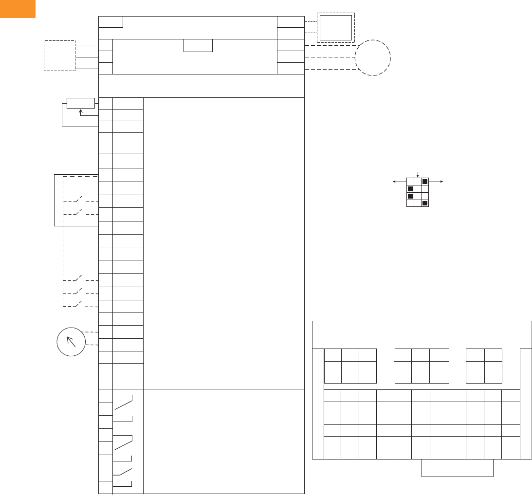
V6-T2-188 Volume 6—Solid-State Motor Control CA08100007E—February 2016 www.eaton.com
2
2
2
2
2
2
2
2
2
2
2
2
2
2
2
2
2
2
2
2
2
2
2
2
2
2
2
2
2
2
2.8
Adjustable Frequency Drives
H-Max Series Drives
Wiring Diagram
Control Input/Output, PID Application
Standards
●Digital inputs D1–D6, relay
out, analog in/out are freely
programmed
●The user can assign a
single input to multiple
functions
Includes
●Six digital input
●Two analog input
●One analog output
●Three relay output
●RS-485
●Ethernet (BACnet and
Modbus)
Reliability
●Pretested components
●Conformal coated
(varnished) boards
●40 °C rated
●110% overload for one
minute
●Eaton Electrical Services &
Systems national network
of AF drive specialists
Slot A
1
2
3
4
5
6
7
8
9
10
11
12
13
14
15
16
17
18
19
A
+10V
AI–1+
Vin
AI–2+
AI–2–
24Vout
GND
DIN1
DIN2
DIN3
24Vout
GND
DIN4
DIN5
DIN6
AO–1+
AO–1–
DATA-
Reference Output
Analog Input Voltage (Range 0–10 Vdc)
(can be programmed to current 4–20 mA)
Analog Output Common (Ground)
Analog Input Common
PI Setpoint or Feedback
Control Voltage Output (0.1A max.)
I/O Ground
START/STOP (Contact closed = start)
External Fault (Closed = fault)
Run Interlock Permissive IP Interlock
(Closed = OK)
DIN1–DIN6 Common
Control Voltage Output (0.1A max.)
I/O Ground
Fire Mode (Contact closed = re mode)
Force Bypass (Contact closed = bypass)
DIN1–DIN6 Common
Output Frequency (0–20 mA)
Analog Output Common (Ground)
RS-485 DATA-
Speed Select 0–100% (Preset speed)
U (T1)
V (T2)
W (T3)
R+
R-
L1
L2
L3
Three-Phase Input
Input
(Single-Phase not available)
Three-Phase
Output
DB
Chopper
Optional
Resistor
Terminal Factory Default Signal
Resistor
Analog Input Current (Range 4–20 mA)
(can be programmed to voltage 0–10 Vdc)
PI Setpoint or Feedback
BDATA+
RO1 Bypass Run
RO2 Drive Run
RO3 Fault
24 Vdc/8A
250 Vac/8A
125 Vdc/0.4A
Relay Board 1
Default Signal
21
22
23
24
25
26
32
33
Slot B
Analog
RS-485 DATA+
Factory
Jumper
COM
CMB
30
24 Vdcin
Auxiliary Input Voltage
123456 78 91011
12 13 14 15 16 17 18 19 30 A B
RS-485
Data–
RS-485
Data+
24 Vdc
in
AO1–AO1+COM
DI1–6
DI6DI5DI4GND24 Vdc
out
DI2DI1GND24 Vdc
out
AI2–AI2+AI1–AI1++10
Vdc
COM
DI1–6
DI3
21
RO1
22 23 24 25 26 32 33
NC
RO1
COM
RO1
NO
RO2
NC
RO2
COM
RO2
NO
RO3
COM
RO3
NO
Slot D __________________
Slot E __________________
Terminal Block Layout
Factory Jumper
External Interlock
Circuit
Breaker
Optional
Motor
RJ-45 BACnet/IP Ethernet Industrial Protocol
Modbus/TCP Transmission Control Protocol (Ethernet Based)
5% DC Link
Reactor
Programmable BACnet,
Modbus, N2
ON
CURRENT
CURRENT
CURRENT
RS485
AO1
AI2
AI1
OFF
VOLTAGE
VOLTAGE
VOLTAGE
Test
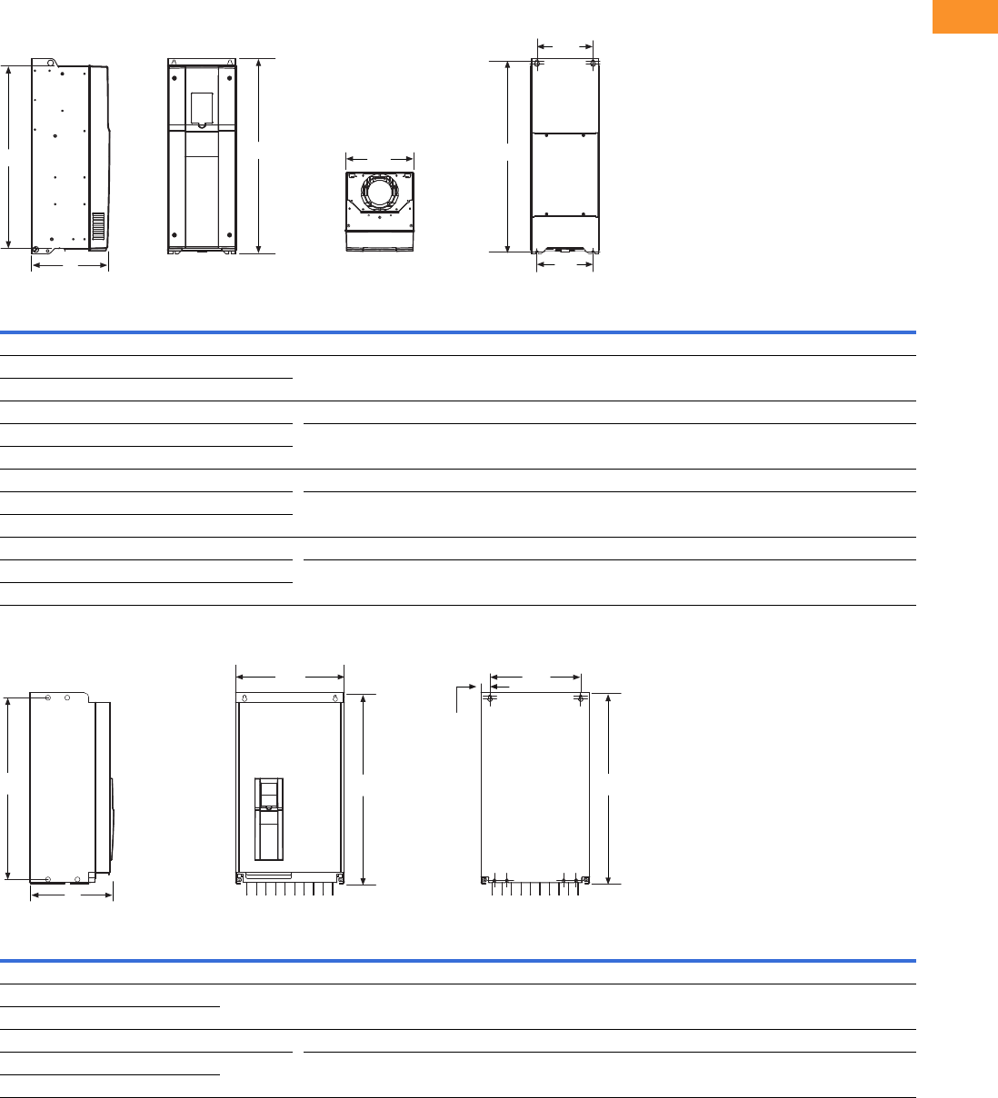
Volume 6—Solid-State Motor Control CA08100007E—February 2016 www.eaton.com V6-T2-189
2
2
2
2
2
2
2
2
2
2
2
2
2
2
2
2
2
2
2
2
2
2
2
2
2
2
2
2
2
2
2.8
Adjustable Frequency Drives
H-Max Series Drives
Dimensions
Approximate Dimensions in Inches (mm)
H-Max Series Frames FS4–FS7
H-Max Series Frames FS8 and FS9
Note: For flange dimension, please reference User Manual.
Voltage hp kW Amps D H1
Hole
Center-to-Center
H2 H3 W1 W2 W3
Weight in
Lbs (kg)
FS4
230 Vac 0.75–4 0.55–3.0 3.7–12.5 7.77
(197.3)
12.89
(327.5)
12.32
(313.0)
11.22
(285.0)
5.04
(128.0)
3.94
(100.0)
3.94
(100.0)
13.2
(6)
480 Vac 1.5–7.5 1.1–5.5 3.4–12
FS5
230 Vac 5–10 4–7.5 18–31 8.73
(221.6)
16.50
(419.0)
15.98
(406.0)
15.04
(382.0)
5.67
(144.0)
4.53
(115.0)
3.94
(100.0)
22.0
(10)
480 Vac 10–20 7.5–15 16–31
FS6
230 Vac 15–20 11–15 48–62 9.29
(236.0)
21.93
(557.0)
21.28
(540.5)
20.24
(514.0)
7.68
(195.0)
5.83
(148.0)
5.83
(148.0)
44.1
(20)
480 Vac 25–40 18.5–30 38–61
FS7
230 Vac 25–30 18.5–30 75–105 10.49
(266.5)
25.98
(660.0)
25.39
(645.0)
24.29
(617.0)
9.06
(230.0)
7.48
(190.0)
7.48
(190.0)
82.6
(37.5)
480 Vac 50–75 37–55 72–105
Voltage hp kW Amps D H1
Hole
Center-to-Center
H2 H3 W1 W2 W3
Weight in
Lbs (kg)
FS8
230 Vac 50–75 37–55 140–205 13.76
(349.6)
38.02
(965.7)
37.26
(946.4)
37.26
(946.4)
11.42
(290.1)
9.29
(236.0)
1.42
(36.0)
154.3
(70)
480 Vac 100–150 75–110
FS9
230 Vac 100–120 75–90 261–310 14.63
(371.6)
33.09
(890.4)
31.89
(810.0)
31.89
(810.0)
18.90
(480.0)
15.75
(400.0)
1.57
(40.0)
238.1
(108)
480 Vac 200–250 132–160
W1
H3 H1 H2
W2
W3
D
H3 H1
W1 W2
W3
H2
D
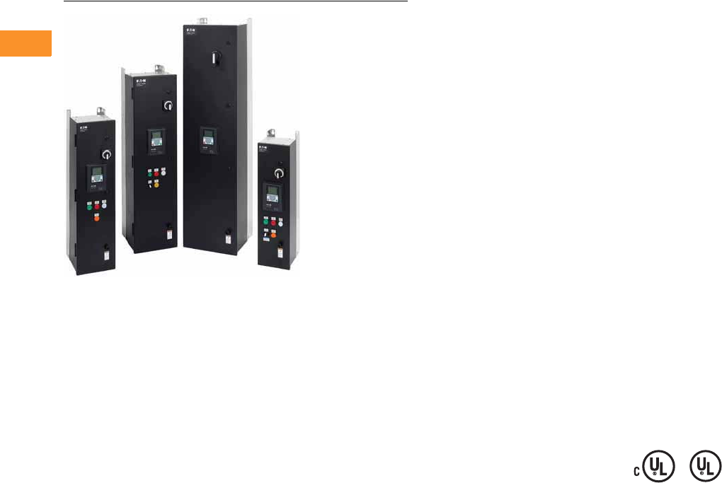
V6-T2-190 Volume 6—Solid-State Motor Control CA08100007E—February 2016 www.eaton.com
2
2
2
2
2
2
2
2
2
2
2
2
2
2
2
2
2
2
2
2
2
2
2
2
2
2
2
2
2
2
2.8
Adjustable Frequency Drives
H-Max Series Drives
H-Max IntelliPass and IntelliDisconnect Drives
Contents
Description Page
H-Max Drives . . . . . . . . . . . . . . . . . . . . . . . . . . . . V6-T2-179
H-Max IntelliPass and IntelliDisconnect Drives
Catalog Number Selection . . . . . . . . . . . . . . . . V6-T2-191
Product Selection . . . . . . . . . . . . . . . . . . . . . . . V6-T2-192
Technical Data and Specifications . . . . . . . . . . V6-T2-203
Wiring Diagrams . . . . . . . . . . . . . . . . . . . . . . . V6-T2-204
Dimensions . . . . . . . . . . . . . . . . . . . . . . . . . . . V6-T2-206
H-Max IntelliPass and IntelliDisconnect Drives
Product Description
The IntelliPass electronic
bypass is a two or optional
three contactor design using a
24 Vdc XT Series contactor
with an optional manual
override switch that allows
the unit to run in bypass
without the H-Max Series
drive.
The IntelliPass software
parameters utilize engineering
units common to the HVAC
industry. Onboard startup
wizard guarantees flawless
commissioning with plug-
and-play screen entry.
Available in NEMA/UL Type 1,
Type 12 and Type 3R with
optional pre-engineered
operator devices to meet
all customized specification
requirements.
The IntelliPass construction
features allow for easy
installation, reliable operation
and serviceability with
additional onboard wire space,
and removable conduit plates
with knockouts.
Features and Benefits
Industry-leading energy
saving solution—uses the
Eaton H-Max drive with
Active Energy Control
algorithm.
Built to be as tough as the
application—Eaton’s robust
design boasts an industrial
grade enclosure and industry
proven components.
●Industrial Power Supply
●XT Contactors
●22 mm Pilot Devices
Designed with Our Customers
in Mind
●Removable top and bottom
entry panels
●Door-mounted graphic
display and keypad
●Easily accessible
connection terminals with
removable I/O terminal
connections
Engineered Product Solution
●The Eaton H-Max
IntelliPass and
IntelliDisconnect products
are available with a variety
of factory tested and
certified options meeting
or exceeding UL508C
requirements
Standards and Certifications
Product
●IEC 61800-5-1
●UL508C
●cUL
●OSHPD Seismic Certified
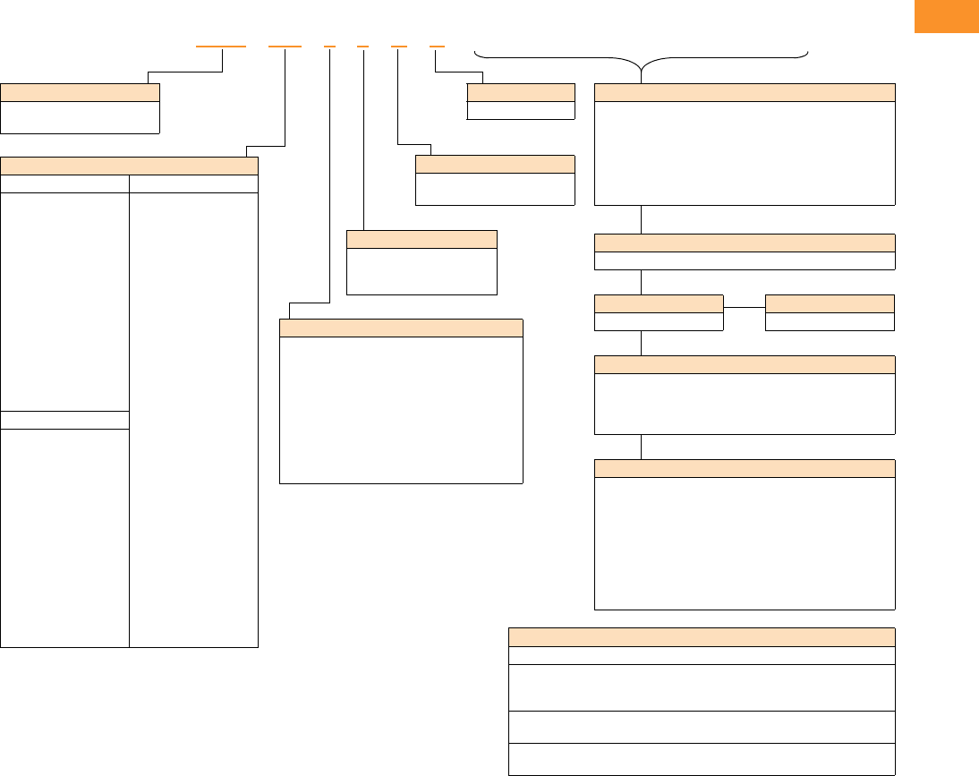
Volume 6—Solid-State Motor Control CA08100007E—February 2016 www.eaton.com V6-T2-191
2
2
2
2
2
2
2
2
2
2
2
2
2
2
2
2
2
2
2
2
2
2
2
2
2
2
2
2
2
2
2.8
Adjustable Frequency Drives
H-Max Series Drives
Catalog Number Selection
H-Max Series IntelliPass and IntelliDisconnect Drives
Notes
IntelliPass—two contactor electronic bypass standard.
All boards are varnished. Corrosion resistant.
Battery included in all drives for real-time clock. Three year lifetime.
Keypad kit includes HOA bypass.
EMI/RFI filters included.
DC link choke included.
NEC Ampere Ratings
208 Volts 480 Volts
4D6 = 4.6 A–1 hp
7D5 = 7.5 A–2 hp
011 = 11 A–3 hp
017 = 17 A–5 hp
025 = 25 A–7.5 hp
031 = 31 A–10 hp
047 = 47 A–15 hp
060 = 60 A–20 hp
075 = 75 A–25 hp
088 = 88 A–30 hp
114 = 114 A–40 hp
143 = 143 A–50 hp
169 = 169 A–60 hp
211 = 211 A–75 hp
273 = 273 A–100 hp
2D1 = 2.1 A–1 hp
3D4 = 3.4 A–2 hp
5D6 = 5.6 A–3 hp
7D6 = 7.6 A–5 hp
011 = 11 A–7.5 hp
014 = 14 A–10 hp
021 = 21 A–15 hp
027 = 27 A–20 hp
034 = 34 A–25 hp
040 = 40 A–30 hp
052 = 52 A–40 hp
065 = 65 A–50 hp
077 = 77 A–60 hp
096 = 96 A–75 hp
124 = 124 A–100 hp
156 = 156 A–125 hp
186 = 186 A–150 hp
240 = 240 A–200 hp
302 = 302 A–250 hp
230 Volts
4D2 = 4.2 A–1 hp
6D8 = 6.8 A–2 hp
9D6 = 9.6 A–3 hp
016 = 16 A–5 hp
022 = 22 A–7.5 hp
028 = 28 A–10 hp
042 = 42 A–15 hp
054 = 54 A–20 hp
068 = 68 A–25 hp
080 = 80 A–30 hp
104 = 104 A–40 hp
130 = 130 A–50 hp
154 = 154 A–60 hp
192 = 192 A–75 hp
248 = 248 A–100 hp
Enclosure Style
3= IntelliPass NEMA Type 1
4= IntelliPass NEMA Type 12
5= IntelliPass NEMA Type 3R
6= IntelliPass oversized NEMA Type 1
7= IntelliPass oversized NEMA Type 12
A= IntelliDisconnect NEMA Type 1
B= IntelliDisconnect NEMA Type 12
C= IntelliDisconnect NEMA Type 3R
D= IntelliDisconnect oversized NEMA Type 1
E= IntelliDisconnect oversized NEMA Type 12
Braking/Application
N= No brake chopper
(low overload)
HMX 011 3 4 N A __________
Product
HMX = HVAC drive (VT)
(low overload)
Voltage
1= 208V
2= 230 V
4= 480 V
Software Series
A–Z
Keypad Options
None available
Build options alphabetically and numerically.
EMC Upgrade Option
EMC C2 Standard
IntelliDisconnect Options
L3 = Pilot lights (Power ON, RUN, Fault)
P3 = Fused drive isolation
PE = Output contactor
SA = Space heater w/transformer (Type 3R only)
Optional Communications in Slot D and E
C4 =LonWorks
IntelliPass Bypass Options
L4 = Pilot lights (Power ON, RUN, Fault, Bypass)
P3 = Fused drive isolation (can not be used with IS, P6 or M1)
P6 = Third contactor drive isolation
(cannot be used with P3, IS or MI)
M1 = Manual bypass, includes isolation contactor and pilot
lights (not available with P3, L4, P6 or IS)
SA = Space heater w/transformer (Type 3R only)
K9 = Auxiliary contacts
IS = Isolation switch (cannot be used with P3, P6 or M1)
Standard Onboard Communications
RS-485 Communications
BACnet MS/TP = Master slave/token protocol (Universal BACnet) RS-485
Modbus RTU RS-485, ASCII or RTU, remote terminal unit 32 nodes
N2 = Johnson Controls Metasys N2 network
Onboard Ethernet-Based Communications
(port left side of keypad)
BACnet/IP Ethernet industrial protocol
Modbus/TCP Transmission control protocol (Ethernet-based)
Extended I/O Options in Slot D and E
B1 = 6 x DI /DO, Each digital input can be individually
programmed as digital output
B2 = 1RO (NC/NO), 1RO (NO), 1 Thermistor
B4 = 1 x AI, 2 x AO (isolated)
B5 =3 x RO
B9 = 1RO (NO), 5 DI 42–240 Vac input
BF = Expander IO, 1 AO, 1 DO, 1 RO
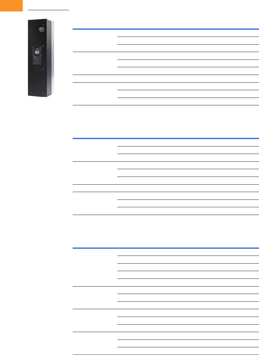
V6-T2-192 Volume 6—Solid-State Motor Control CA08100007E—February 2016 www.eaton.com
2
2
2
2
2
2
2
2
2
2
2
2
2
2
2
2
2
2
2
2
2
2
2
2
2
2
2
2
2
2
2.8
Adjustable Frequency Drives
H-Max Series Drives
Product Selection
H-Max Series IntelliPass NEMA Type 1—Two Contactor Bypass Standard
208 Vac
230 Vac
480 Vac
Notes
For Wiring Diagrams, see Page V6-T2-205.
For NEMA 12 or 3R enclosures, see Catalog Number Selection on Page V6-T2-191.
Call Technical Support for NEMA 3R specifics. Enclosure size and weight differ from NEMA 1 and 12 products.
FS
Frame Size Horsepower
Drive Rated
NEC Amps Catalog Number
414.6HMX4D631NA
27.5HMX7D531NA
311HMX01131NA
5517HMX01731NA
7.5 25 HMX02531NA
10 31 HMX03131NA
61547HMX04731NA
72060HMX06031NA
25 75 HMX07531NA
30 88 HMX08831NA
FS
Frame Size Horsepower
Drive Rated
NEC Amps Catalog Number
414.2HMX4D232NA
26.8HMX6D832NA
39.6HMX9D632NA
5516HMX01632NA
7.5 22 HMX02232NA
10 28 HMX02832NA
61542HMX04232NA
72054HMX05432NA
25 68 HMX06832NA
30 80 HMX08032NA
FS
Frame Size Horsepower
Drive Rated
NEC Amps Catalog Number
412.1HMX2D134NA
23.4HMX3D434NA
35.6HMX5D634NA
57.6HMX7D634NA
7.5 11 HMX01134NA
51014HMX01434NA
15 21 HMX02134NA
20 27 HMX02734NA
62534HMX03434NA
30 40 HMX04034NA
40 52 HMX05234NA
75065HMX06534NA
60 77 HMX07734NA
75 96 HMX09634NA
HMX_

Volume 6—Solid-State Motor Control CA08100007E—February 2016 www.eaton.com V6-T2-193
2
2
2
2
2
2
2
2
2
2
2
2
2
2
2
2
2
2
2
2
2
2
2
2
2
2
2
2
2
2
2.8
Adjustable Frequency Drives
H-Max Series Drives
H-Max Series IntelliPass NEMA Type 12—Two Contactor Bypass Standard
208 Vac
230 Vac
Notes
For Wiring Diagrams, see Page V6-T2-205.
For NEMA 12 or 3R enclosures, see Catalog Number Selection on Page V6-T2-191.
Call Technical Support for NEMA 3R specifics. Enclosure size and weight differ from NEMA 1 and 12 products.
FS
Frame Size Horsepower
Drive Rated
NEC Amps Catalog Number
414.6HMX4D641NA
27.5HMX7D541NA
311HMX01141NA
5517HMX01741NA
7.5 25 HMX02541NA
10 31 HMX03141NA
61547HMX04741NA
72060HMX06041NA
25 75 HMX07541NA
30 88 HMX08841NA
840114HMX11471NA
50 143 HMX14371NA
60 169 HMX16971NA
975211HMX21171NA
100 273 HMX27371NA
FS
Frame Size Horsepower
Drive Rated
NEC Amps Catalog Number
414.2HMX4D242NA
26.8HMX6D842NA
39.6HMX9D642NA
5516HMX01642NA
7.5 22 HMX02242NA
10 28 HMX02842NA
61542HMX04242NA
72054HMX05442NA
25 68 HMX06842NA
30 80 HMX08042NA
840104HMX10472NA
50 130 HMX13072NA
60 154 HMX15472NA
75 192 HMX19272NA
9100248HMX24872NA
HMX_
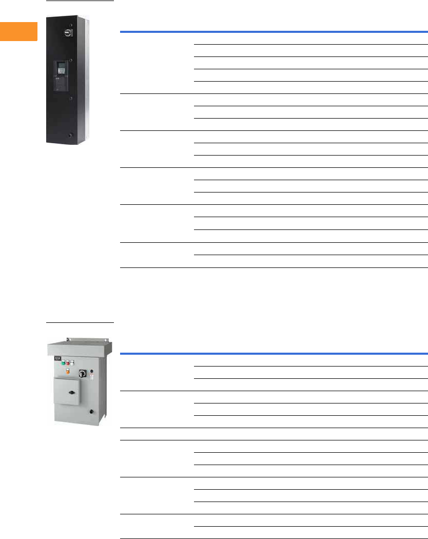
V6-T2-194 Volume 6—Solid-State Motor Control CA08100007E—February 2016 www.eaton.com
2
2
2
2
2
2
2
2
2
2
2
2
2
2
2
2
2
2
2
2
2
2
2
2
2
2
2
2
2
2
2.8
Adjustable Frequency Drives
H-Max Series Drives
480 Vac
H-Max Series IntelliPass NEMA Type 3R—Two Contactor Bypass Standard
208 Vac
Notes
For Wiring Diagrams, see Page V6-T2-205.
For NEMA 12 or 3R enclosures, see Catalog Number Selection on Page V6-T2-191.
Call Technical Support for NEMA 3R specifics. Enclosure size and weight differ from NEMA 1 and 12 products.
FS
Frame Size Horsepower
Drive Rated
NEC Amps Catalog Number
412.1HMX2D144NA
23.4HMX3D444NA
35.6HMX5D644NA
57.6HMX7D644NA
7.5 11 HMX01144NA
51014HMX01444NA
15 21 HMX02144NA
20 27 HMX02744NA
62534HMX03444NA
30 40 HMX04044NA
40 52 HMX05244NA
75065HMX06544NA
60 77 HMX07744NA
75 96 HMX09644NA
8100124HMX12744NA
125 156 HMX15674NA
150 180 HMX18074NA
9200240HMX24074NA
250 302 HMX30274NA
FS
Frame Size Horsepower
Drive Rated
NEC Amps Catalog Number
414.6HMX4D651NA
27.5HMX7D551NA
311HMX01151NA
5517HMX01751NA
7.5 25 HMX02551NA
10 31 HMX03151NA
61547HMX04751NA
72060HMX06051NA
25 75 HMX07551NA
30 88 HMX08851NA
840114HMX11451NA
50 143 HMX14351NA
60 169 HMX16951NA
975211HMX21151NA
100 273 HMA27351NA
HMX_
HMX_
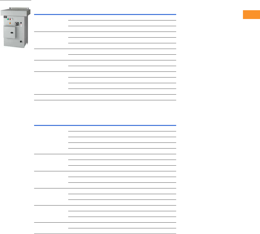
Volume 6—Solid-State Motor Control CA08100007E—February 2016 www.eaton.com V6-T2-195
2
2
2
2
2
2
2
2
2
2
2
2
2
2
2
2
2
2
2
2
2
2
2
2
2
2
2
2
2
2
2.8
Adjustable Frequency Drives
H-Max Series Drives
230 Vac
480 Vac
Notes
For Wiring Diagrams, see Page V6-T2-205.
For NEMA 12 or 3R enclosures, see Catalog Number Selection on Page V6-T2-191.
Call Technical Support for NEMA 3R specifics. Enclosure size and weight differ from NEMA 1 and 12 products.
FS
Frame Size Horsepower
Drive Rated
NEC Amps Catalog Number
414.2HMX4D252NA
26.8HMX6D852NA
39.6HMX9D652NA
5516HMX01652NA
7.5 22 HMX02252NA
10 28 HMX02852NA
61542HMX04252NA
20 54 HMX05452NA
72568HMX06852NA
30 80 HMX08052NA
840104HMX10452NA
50 130 HMX13052NA
60 154 HMX15452NA
75 192 HMX19252NA
9100248HMX24852NA
FS
Frame Size Horsepower
Drive Rated
NEC Amps Catalog Number
412.1HMX2D154NA
23.4HMX3D454NA
35.6HMX5D654NA
57.6HMX7D654NA
7.5 11 HMX01154NA
51014HMX01454NA
15 21 HMX02154NA
20 27 HMX02754NA
62534HMX03454NA
30 40 HMX04054NA
40 52 HMX05254NA
75065HMX06554NA
60 77 HMX07754NA
75 96 HMX09654NA
8100124HMX12544NA
125 156 HMX15654NA
150 180 HMX18054NA
9200240HMX24054NA
250 302 HMX30254NA
HMX_
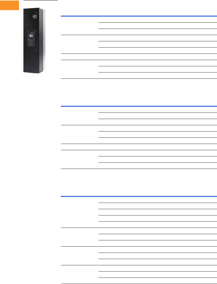
V6-T2-196 Volume 6—Solid-State Motor Control CA08100007E—February 2016 www.eaton.com
2
2
2
2
2
2
2
2
2
2
2
2
2
2
2
2
2
2
2
2
2
2
2
2
2
2
2
2
2
2
2.8
Adjustable Frequency Drives
H-Max Series Drives
H-Max Series IntelliDisconnect NEMA Type 1—Main Disconnect Standard
208 Vac
230 Vac
480 Vac
Notes
For Wiring Diagrams, see Page V6-T2-205.
For NEMA 12 or 3R enclosures, see Catalog Number Selection on Page V6-T2-191.
Call Technical Support for NEMA 3R specifics. Enclosure size and weight differ from NEMA 1 and 12 products.
FS
Frame Size Horsepower
Drive Rated
NEC Amps Catalog Number
414.6HMX4D6A1NA
27.5HMX7D5A1NA
311HMX011A1NA
5517HMX017A1NA
7.5 25 HMX025A1NA
10 31 HMX031A1NA
61547HMX047A1NA
72060HMX060A1NA
25 75 HMX075A1NA
30 88 HMX088A1NA
FS
Frame Size Horsepower
Drive Rated
NEC Amps Catalog Number
414.2HMX4D2A2NA
26.8HMX6D8A2NA
39.6HMX9D6A2NA
5516HMX016A2NA
7.5 22 HMX022A2NA
10 28 HMX028A2NA
61542HMX042A2NA
72054HMX054A2NA
25 68 HMX068A2NA
30 80 HMX080A2NA
FS
Frame Size Horsepower
Drive Rated
NEC Amps Catalog Number
412.1HMX2D1A4NA
23.4HMX3D4A4NA
35.6HMX5D6A4NA
57.6HMX7D6A4NA
7.5 11 HMX011A4NA
51014HMX014A4NA
15 21 HMX021A4NA
20 27 HMX027A4NA
62534HMX034A4NA
30 40 HMX040A4NA
40 52 HMX052A4NA
75065HMX065A4NA
60 77 HMX077A4NA
75 96 HMX096A4NA
HMX_
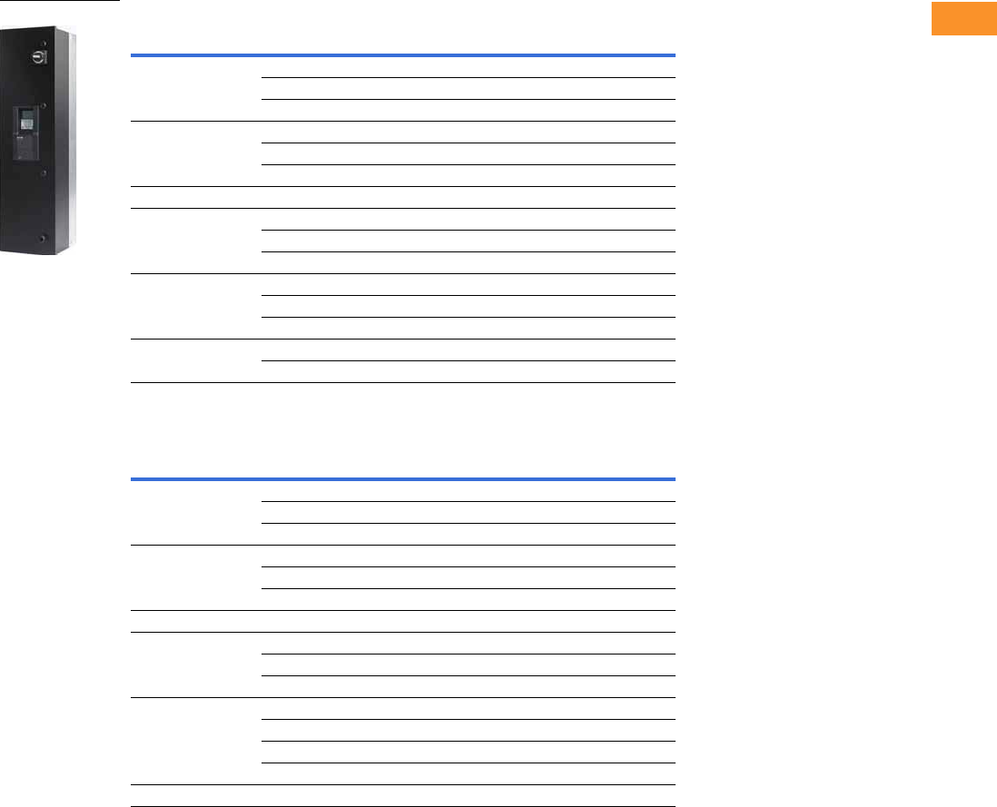
Volume 6—Solid-State Motor Control CA08100007E—February 2016 www.eaton.com V6-T2-197
2
2
2
2
2
2
2
2
2
2
2
2
2
2
2
2
2
2
2
2
2
2
2
2
2
2
2
2
2
2
2.8
Adjustable Frequency Drives
H-Max Series Drives
H-Max Series IntelliDisconnect NEMA Type 12—Main Disconnect Standard
208 Vac
230 Vac
Notes
For Wiring Diagrams, see Page V6-T2-205.
For NEMA 12 or 3R enclosures, see Catalog Number Selection on Page V6-T2-191.
Call Technical Support for NEMA 3R specifics. Enclosure size and weight differ from NEMA 1 and 12 products.
FS
Frame Size Horsepower
Drive Rated
NEC Amps Catalog Number
414.6HMX4D6B1NA
27.5HMX7D5B1NA
311HMX011B1NA
5517HMX017B1NA
7.5 25 HMX025B1NA
10 31 HMX031B1NA
61547HMX047B1NA
72060HMX060B1NA
25 75 HMX075B1NA
30 88 HMX088B1NA
840114HMX114E1NA
50 143 HMX143E1NA
60 169 HMX169E1NA
975211HMX211E1NA
100 273 HMA273E1NA
FS
Frame Size Horsepower
Drive Rated
NEC Amps Catalog Number
414.2HMX4D2B2NA
26.8HMX6D8B2NA
39.6HMX9D6B2NA
5516HMX016B2NA
7.5 22 HMX022B2NA
10 28 HMX028B2NA
61542HMX042B2NA
72054HMX054B2NA
25 68 HMX068B2NA
30 80 HMX080B2NA
840104HMX104E2NA
50 130 HMX130E2NA
60 154 HMX154E2NA
75 192 HMX192E2NA
9100248HMX248E2NA
HMX_
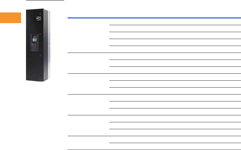
V6-T2-198 Volume 6—Solid-State Motor Control CA08100007E—February 2016 www.eaton.com
2
2
2
2
2
2
2
2
2
2
2
2
2
2
2
2
2
2
2
2
2
2
2
2
2
2
2
2
2
2
2.8
Adjustable Frequency Drives
H-Max Series Drives
480 Vac
Notes
For Wiring Diagrams, see Page V6-T2-205.
For NEMA 12 or 3R enclosures, see Catalog Number Selection on Page V6-T2-191.
Call Technical Support for NEMA 3R specifics. Enclosure size and weight differ from NEMA 1 and 12 products.
FS
Frame Size Horsepower
Drive Rated
NEC Amps Catalog Number
412.1HMX2D1B4NA
23.4HMX3D4B4NA
35.6HMX5D6B4NA
57.6HMX7D6B4NA
7.5 11 HMX011B4NA
51014HMX014B4NA
15 21 HMX021B4NA
20 27 HMX027B4NA
62534HMX034B4NA
30 40 HMX040B4NA
40 52 HMX052B4NA
75065HMX065B4NA
60 77 HMX077B4NA
75 96 HMX096B4NA
8100124HMX12E44NA
125 156 HMX156E4NA
150 180 HMX180E4NA
9200240HMX240E4NA
250 302 HMX302E4NA
HMX_
Volume 6—Solid-State Motor Control CA08100007E—February 2016 www.eaton.com V6-T2-199
2
2
2
2
2
2
2
2
2
2
2
2
2
2
2
2
2
2
2
2
2
2
2
2
2
2
2
2
2
2
2.8
Adjustable Frequency Drives
H-Max Series Drives
H-Max Series IntelliDisconnect NEMA Type 3R—Main Disconnect Standard
208 Vac
230 Vac
Notes
For Wiring Diagrams, see Page V6-T2-205.
For NEMA 12 or 3R enclosures, see Catalog Number Selection on Page V6-T2-191.
Call Technical Support for NEMA 3R specifics. Enclosure size and weight differ from NEMA 1 and 12 products.
FS
Frame Size Horsepower
Drive Rated
NEC Amps Catalog Number
414.6HMX4D6C1NA
27.5HMX7D5C1NA
311HMX011C1NA
5517HMX017C1NA
7.5 25 HMX025C1NA
10 31 HMX031C1NA
61547HMX047C1NA
20 60 HMX060C1NA
72575HMX075C1NA
30 88 HMX088C1NA
840114HMX114C1NA
50 143 HMX143C1NA
60 169 HMX169C1NA
975211HMX211C1NA
100 273 HMA273C1NA
FS
Frame Size Horsepower
Drive Rated
NEC Amps Catalog Number
414.2HMX4D2C2NA
26.8HMX6D8C2NA
39.6HMX9D6C2NA
5516HMX016C2NA
7.5 22 HMX022C2NA
10 28 HMX028C2NA
61542HMX042C2NA
20 54 HMX054C2NA
72568HMX068C2NA
30 80 HMX080C2NA
840104HMX104C2NA
50 130 HMX130C2NA
60 154 HMX154C2NA
75 192 HMX192C2NA
9100248HMX248C2NA
HMX_
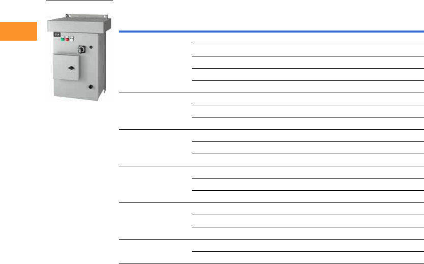
V6-T2-200 Volume 6—Solid-State Motor Control CA08100007E—February 2016 www.eaton.com
2
2
2
2
2
2
2
2
2
2
2
2
2
2
2
2
2
2
2
2
2
2
2
2
2
2
2
2
2
2
2.8
Adjustable Frequency Drives
H-Max Series Drives
480 Vac
Notes
For Wiring Diagrams, see Page V6-T2-205.
For NEMA 12 or 3R enclosures, see Catalog Number Selection on Page V6-T2-191.
Call Technical Support for NEMA 3R specifics. Enclosure size and weight differ from NEMA 1 and 12 products.
FS
Frame Size Horsepower
Drive Rated
NEC Amps Catalog Number
412.1HMX2D1C4NA
23.4HMX3D4C4NA
35.6HMX5D6C4NA
57.6HMX7D6C4NA
7.5 11 HMX011C4NA
51014HMX014C4NA
15 21 HMX021C4NA
20 27 HMX027C4NA
62534HMX034C4NA
30 40 HMX040C4NA
40 52 HMX052C4NA
75065HMX065C4NA
60 77 HMX077C4NA
75 96 HMX096C4NA
8100124HMX12C44NA
125 156 HMX156C4NA
150 180 HMX180C4NA
9200240HMX240C4NA
250 302 HMX302C4NA
HMX_

Volume 6—Solid-State Motor Control CA08100007E—February 2016 www.eaton.com V6-T2-201
2
2
2
2
2
2
2
2
2
2
2
2
2
2
2
2
2
2
2
2
2
2
2
2
2
2
2
2
2
2
2.8
Adjustable Frequency Drives
H-Max Series Drives
Onboard Network Communications
Johnson Controls
Metasys N2
H-Max Series provides
communication between the
drive and a Johnson Controls
Metasys™ N2 network. With
this connection, the drive can
be controlled, monitored and
programmed from the
Metasys system. N2 can be
selected and programmed by
the drive keypad.
BACnet
H-Max Series provides
communication to BACnet
networks. Data transfer is
master-slave/token passing
(MS/TP) RS-485.
BACnet/IP
100Base-T interface.
Modbus TCP
Ethernet based protocol.
Modbus RTU
H-Max Series provides
communication to Modbus
RTU RS-485 as a slave on a
Modbus network. Other
communication parameters
include an address range
from 1 to 247; a parity of
None, Odd or Even; and the
stop bit is 1.
.
H-Max Series Option Board Kits Available for Slots D and E
The H-Max Series drives can
accommodate a wide
selection of expander and
adapter option boards to
customize the drive for your
application needs. The drive’s
control unit is designed to
accept a total of two option
boards.
The H-Max Series factory-
installed standard board
configuration includes an
I/O board and a relay
output board.
Option Boards Mounted in Slots D and E
Option Kit Description
Option Kit
Catalog Number
6 x DI /DO, each digital input can be individually programmed as digital output XMX-IO-B1-A
1RO Form C (NO/NC), 1RO Form A (NO), 1 thermistor XMX-IO-B2-A
1 x AI, 2 x AO (isolated) XMX-IO-B4-A
3 x RO Form A (NO) XMX-IO-B5-A
1RO Form A (NO), 5DI 42–240 Vac input XMX-IO-B9-A
LonWorks XMX-COM-C4-A
1 x AO, 1 x DO, 1 x RO XMX-IO-BF-A

V6-T2-202 Volume 6—Solid-State Motor Control CA08100007E—February 2016 www.eaton.com
2
2
2
2
2
2
2
2
2
2
2
2
2
2
2
2
2
2
2
2
2
2
2
2
2
2
2
2
2
2
2.8
Adjustable Frequency Drives
H-Max Series Drives
Extended I/O Options in Slot D and E
Optional Communications in Slot D and E
IntelliDisconnect Options
IntelliPass Bypass Options
Standard Onboard Communications
Description
Suffix
Number
6 x DI /DO, Each digital input can be individually
programmed as digital output
B1
1RO (NC/NO), 1RO (NO), 1 Thermistor B2
1 x AI, 2 x AO (isolated) B4
3 x RO B5
1RO (NO), 5 DI 42–240 Vac input B9
Expander IO, 1 AO, 1 DO, 1 RO BF
Description
Suffix
Number
LonWorks C4
Description
Suffix
Number
Pilot lights (Power ON, RUN, Fault) L3
Fused drive isolation (cannot be used with PE) P3
Output contactor (cannot be used with P3) PE
Space heater w/transformer (Type 3R only) SA
Description
Suffix
Number
Pilot lights (Power ON, RUN, Fault) L4
Fused drive isolation (can not be used with P6) P3
Third contactor drive isolation (cannot be used with P3 or IS) P6
Manual bypass switch located on front door M1
Space heater w/transformer (Type 3R only) SA
Auxiliary contacts K9
Isolation switch IS
Description
Suffix
Number
RS-485 Communications
BACnet MS/TP = Master slave/token protocol (Universal BACnet) RS-485 BACnet
Modbus RTU RS-485, ASCII or RTU, remote terminal unit 32 nodes Modbus
Johnson Controls Metasys N2 network N2
Onboard Ethernet-Based Communications
(port left side of keypad)
BACnet/IP Ethernet industrial protocol BACnet
Modbus/TCP Transmission control protocol (Ethernet-based) Modbus

Volume 6—Solid-State Motor Control CA08100007E—February 2016 www.eaton.com V6-T2-203
2
2
2
2
2
2
2
2
2
2
2
2
2
2
2
2
2
2
2
2
2
2
2
2
2
2
2
2
2
2
2.8
Adjustable Frequency Drives
H-Max Series Drives
Technical Data and Specifications
Primary Design Features
H-Max Series Drives
Description IntelliPass IntelliDisconnect Description IntelliPass IntelliDisconnect
CB MMP Standard Standard Isolation switch Optional N/A
2 contactor bypass Standard N/A Top entry (power) Standard Standard
Electrical interlock Standard N/A Bottom entry (power) Standard Standard
Third contactor (isolation) Optional N/A Output contactor Standard Optional
Description Specification
Input Ratings
Input voltage (Vin) 208, 230, 480 Vac, –10%/+10%
Input frequency (fin) 50/60 Hz (variation up to 47–66 Hz)
Connection to power Once per minute or less (typical operation)
Short-circuit withstand
rating
65 kAIC combination
Output Ratings
Output voltage 0 to Vin/Uin line voltage in
Continuous output current Ambient temperature max. 104 °F (40 °C)
IL overload 1.1 x IL (1 min./10 min.)
Overload current 110% (1 min./10 min.)
Initial output current 150% for two seconds
Output frequency 0 to 320 Hz
Frequency resolution 0.01 Hz
Control Characteristics
Control method Frequency control (V/f) open loop sensorless vector control
Switching frequency 1–310 amps; adjustable with parameter 2.6.9
FS4–FS7: default 6 kHz
Frequency reference Analog input: Resolution 0.1% (10-bit), accuracy ±1%
Panel reference: Resolution 0.01 Hz
Field weakening point 8 to 320 Hz
Acceleration time 0.1 to 3000 seconds
Deceleration time 0.1 to 3000 seconds
Braking torque DC brake: 30% x Tn
Ambient Conditions
Ambient operating
temperature
FS4–FS7: 14 °F (–10 °C), no frost to 104 °F (40 °C)
(Drive can operate at 122 °F (50 °C)
Storage temperature –40° to 158 °F (–40° to 70 °C)
Relative humidity 0 to 95% RH, noncondensing, non-corrosive, no dripping water
Air quality Chemical vapors: IEC 60721-3-3, unit in operation, Class 3C2;
Mechanical particles: IEC 60721-3-3, unit in operation, Class 3S2
Altitude 100% load capacity (no derating) up to 3280 ft (1000 m);
1% derating for each 328 ft (100 m) above 3280 ft (1000 m);
max. 9842 ft (3000 m); 380–480 V
Vibration FS4–FS7: IEC 60068-2-6, 10–150 Hz
Displacement amplitude = 1 mm peak-to-peak from 10–15.8 Hz
Max. acceleration amplitude = 1G peak from 15.8–150 Hz
Shock FS4–FS7: IEC 60068-2-27, 15G peak acceleration at 11 ms
duration, 1/2-sine. ISTA 1 A Certified
Enclosure class NEMA Type 1/IP21 or NEMA Type 12/IP54
(keypad required for IP54/Type 12)
Description Specification
Standards
EMC Immunity: Fulfills all EMC immunity requirements;
Emissions: EN 61800-3, LEVEL H (EMC C2)
Emissions EMC level dependent—
+EMC 2: EN61800-3 (2004) Category C2
Delivered with Class C2 EMC filtering as default.
Control Connections
Analog input voltage 0 to 10 V, R = 200 kohms differential
Resolution 0.1%; Accuracy ±1%
DIP switch selection (voltage/current)
Analog input current 0(4) to 20 mA; Ri –250 ohms differential
Digital inputs (6) Positive or negative logic; 18 to 30 Vdc
Auxiliary voltage +24 V ±10%, max. 250 mA
Output reference voltage +10 V +3%, max. load 10 mA
Analog output 0–10 V, 0(4) to 20 mA; RL max. 500 ohms;
Resolution 10 bit; Accuracy ±2%;
DIP switch selection (voltage/current)
Relay outputs 3 programmable, 2 Form C, 1 Form A relay outputs
Switching capacity: 24 Vdc/8 A, 250 Vac/8 A, 125 Vdc/0.4 A
Hard wire jumper Between terminal 6 and 10 factory default
DIP switch setting default RS-485 = off
A01 = current
A12 = current
A11 = voltage
Protections
Overcurrent protection Yes
Overvoltage protection Yes
DC bus regulation anti-trip Yes (accelerates or decelerates the load)
Undervoltage protection Yes
Earth fault protection Yes (in case of earth fault in motor or motor cable,
only the frequency converter is protected)
Input phase supervision Yes (trips if any of the input phases are missing)
Motor phase supervision Yes (trips if any of the output phases are missing)
Overtemperature protection Yes
Motor overload protection Yes
Motor stall protection Yes
Motor underload protection Yes
Short-circuit protection Yes
Surge protection Yes (varistor input)
Conformed coated
(varnished) board
Yes (prevents corrosion)
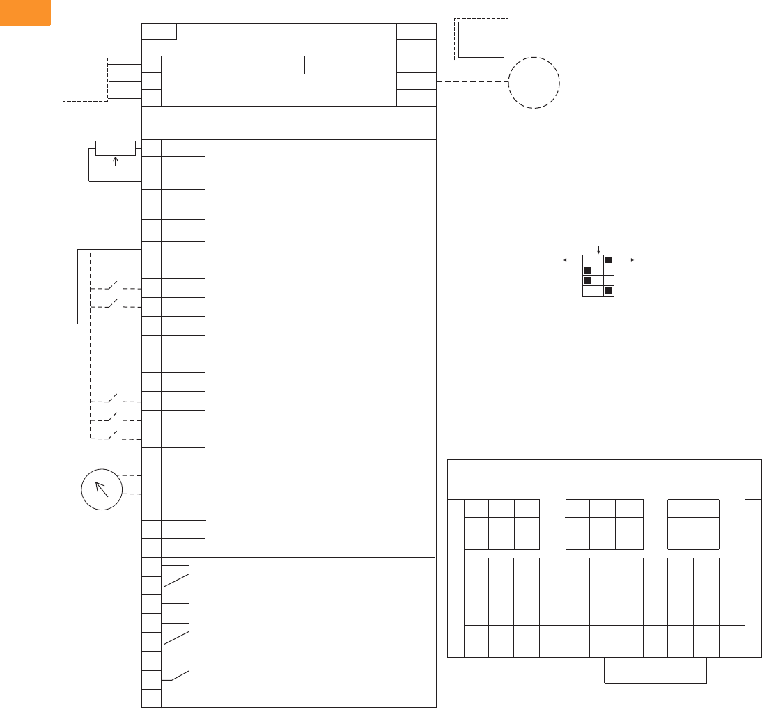
V6-T2-204 Volume 6—Solid-State Motor Control CA08100007E—February 2016 www.eaton.com
2
2
2
2
2
2
2
2
2
2
2
2
2
2
2
2
2
2
2
2
2
2
2
2
2
2
2
2
2
2
2.8
Adjustable Frequency Drives
H-Max Series Drives
Wiring Diagrams
Control Input/Output, PID Application
Standards
●Digital inputs D1–D6, relay
out, analog in/out are freely
programmed
●The user can assign a
single input to multiple
functions
Includes
●Six digital input
●Two analog input
●One analog output
●
Three relay outputs (2 relays
are factory wired for bypass
operation in IntelliPass
configurations)
●RS-485
●Ethernet
Reliability
●Pretested components
●Conformal coated
(varnished) boards
●40 °C rated
●110% overload for one
minute
●Eaton Electrical Services &
Systems national network
of AF drive specialists
Slot A
1
2
3
4
5
6
7
8
9
10
11
12
13
14
15
16
17
18
19
A
+10V
AI–1+
V
in
AI–2+
AI–2–
24V
out
GND
DIN1
DIN2
DIN3
24V
out
GND
DIN4
DIN5
DIN6
AO–1+
AO–1–
DATA-
Reference Output
Analog Input Voltage (Range 0–10 Vdc)
(can be programmed to current 4–20 mA)
Analog Output Common (Ground)
Analog Input Common
PI Setpoint or Feedback
Control Voltage Output (0.1A max.)
I/O Ground
START/STOP (Contact closed = start)
External Fault (Closed = fault)
Run Interlock Permissive IP Interlock
(Closed = OK)
DIN1–DIN6 Common
Control Voltage Output (0.1A max.)
I/O Ground
Fire Mode (Contact closed = re mode)
Force Bypass (Contact closed = bypass)
DIN1–DIN6 Common
Output Frequency (0–20 mA)
Analog Output Common (Ground)
RS-485 DATA-
Speed Select 0–100% (Preset speed)
U (T1)
V (T2)
W (T3)
R+
R-
L1
L2
L3
Three-Phase Input
Input
(Single-Phase not available)
Three-Phase
Output
DB
Chopper
Optional
Resistor
Terminal Factory Default Signal
Resistor
Analog Input Current (Range 4–20 mA)
(can be programmed to voltage 0–10 Vdc)
PI Setpoint or Feedback
BDATA+
RO1 Bypass Run
RO2 Drive Run
RO3 Fault
24 Vdc/8A
250 Vac/8A
125 Vdc/0.4A
Relay Board 1
Default Signal
21
22
23
24
25
26
32
33
Slot B
Analog
RS-485 DATA+
Factory
Jumper
COM
CMB
30
24 Vdc
in
Auxiliary Input Voltage
123456 78 91011
12 13 14 15 16 17 18 19 30 A B
RS-485
Data–
RS-485
Data+
24 Vdc
in
AO1–AO1+COM
DI1–6
DI6DI5DI4GND24 Vdc
out
DI2DI1GND24 Vdc
out
AI2–AI2+AI1–AI1++10
Vdc
COM
DI1–6
DI3
21
RO1
22 23 24 25 26 32 33
NC
RO1
COM
RO1
NO
RO2
NC
RO2
COM
RO2
NO
RO3
COM
RO3
NO
Slot D __________________
Slot E __________________
Terminal Block Layout
Factory Jumper
External Interlock
Circuit
Breaker
Optional
Motor
RJ-45 BACnet/IP Ethernet Industrial Protocol
Modbus/TCP Transmission Control Protocol (Ethernet Based)
5% DC Link
Reactor
Programmable BACnet,
Modbus, N2
ON
CURRENT
CURRENT
CURRENT
RS485
AO1
AI2
AI1
OFF
VOLTAGE
VOLTAGE
VOLTAGE
Test
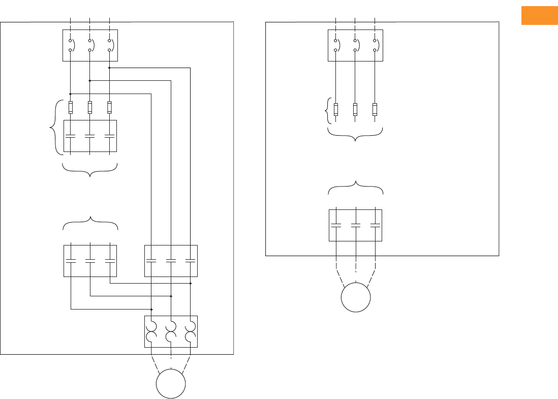
Volume 6—Solid-State Motor Control CA08100007E—February 2016 www.eaton.com V6-T2-205
2
2
2
2
2
2
2
2
2
2
2
2
2
2
2
2
2
2
2
2
2
2
2
2
2
2
2
2
2
2
2.8
Adjustable Frequency Drives
H-Max Series Drives
H-Max Series IntelliPass H-Max Series IntelliDisconnect Power Wiring
Bypass
Incoming Power
L1 L2 L3
Circuit
Breaker
L1
To Drive Input
To Drive Output
U(T1)
L2 L3
Output
Contactor
V(T2)W(T3)
Motor
Bypass
Contactor
Overload
Relay
U(T1)
V(T2)
W(T3)
Optional Fuse
or
Drive Input
Contactor
Incoming Power
L1 L2 L3
Circuit
Breaker
Optional Fuse
To Drive Input
To Drive Output
Motor
U(T1)
V(T2)
W(T3)
U(T1)
Optional
Output
Contactor
V(T2)W(T3)
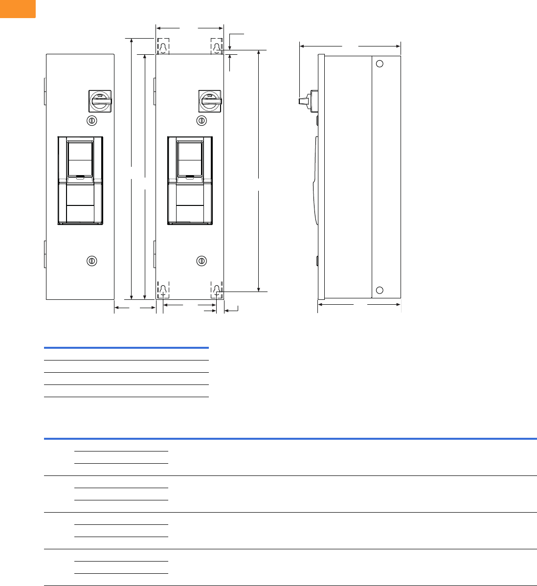
V6-T2-206 Volume 6—Solid-State Motor Control CA08100007E—February 2016 www.eaton.com
2
2
2
2
2
2
2
2
2
2
2
2
2
2
2
2
2
2
2
2
2
2
2
2
2
2
2
2
2
2
2.8
Adjustable Frequency Drives
H-Max Series Drives
Dimensions
Approximate Dimensions in Inches (mm)
H-Max Series IntelliPass and IntelliDisconnect Drives
Distance to mount multiple drives.
Consult factory or use manual for final dimensions.
Note: C distance is spacing required to mount multiple drives.
Top Bottom
FR4 4.00 (101.6) 2.00 (50.8)
FR5 4.75 (120.7) 2.50 (63.5)
FR6 6.50 (165.1) 3.25 (82.6)
FR7 10.00 (254.0) 4.00 (101.6)
Frame
Size Voltage Horsepower (IL) H1 H2 H3 H4 C W1 W2 W3 D1 D2
Weight in
Lbs (kg)
FS4 208 1–3 30.00
(762.0)
29.41
(747.1)
0.25
(6.35)
31.00
(787.4)
3.00
(76.2)
7.88
(200.2)
6.25
(158.8)
0.75
(19.1)
12.49
(317.2)
10.36
(263.1)
45 (20.41)
230 1–3
480 1–7.5
FS5 208 5–10 37.00
(939.8)
36.72
(932.7)
0.25
(6.35)
38.31
(973.0)
3.00
(76.2)
9.60
(243.8)
7.97
(202.4)
0.75
(19.1)
15.35
(390.0)
13.22
(335.8)
57.5 (26.10)
230 5–10
480 10–20
FS6 208 15–20 45.45
(1154.4)
44.81
(1138.2)
0.25
(6.35)
46.4
(1178.6)
4.00
(101.6)
11.44
(290.6)
9.75
(247.6)
0.75
(19.1)
15.80
(401.3)
13.67
(347.2)
98.0 (44.45)
230 15–20
480 25–40
FS7 208 25–30 58.51
(1486.2)
57.87
(1470.0)
0.25
(6.35)
59.46
(1510.3)
5.00
(127.0)
14.52
(368.8)
12.83
(325.9)
0.75
(19.1)
15.68
(398.3)
13.72
(348.5)
165.0 (74.84)
230 25–30
480 50–75
C
H1
W2 W3
H2
W1 H3
D1
D2
H4
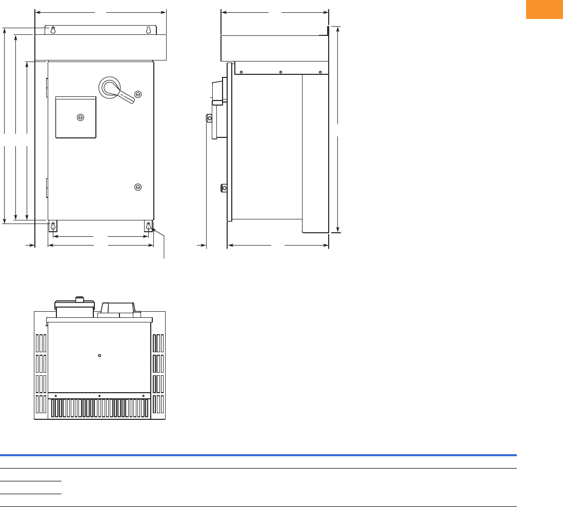
Volume 6—Solid-State Motor Control CA08100007E—February 2016 www.eaton.com V6-T2-207
2
2
2
2
2
2
2
2
2
2
2
2
2
2
2
2
2
2
2
2
2
2
2
2
2
2
2
2
2
2
2.8
Adjustable Frequency Drives
H-Max Series Drives
Approximate Dimensions in Inches (mm)
Enclosure Box A NEMA Type 3R
Voltage
AC
hp
(IL) H H1 H2 H3 W W1 W2 W3 D D1 D2
Approx.
Weight
Lbs (kg)
Approx.
Shipping Weight
Lbs (kg)
Three-Phase
208 V 1–10 33.00
(838.2)
31.36
(796.5)
29.67
(753.6)
25.35
(643.9)
21.05
(534.7)
16.92
(429.8)
15.30
(388.6)
2.07
(52.6)
17.24
(437.9)
16.26
(413.0)
3.31
(84.1)
170 (77) 215 (98)
230 V 1–10
480 V 1–20
H3H2H1
H
W2
W1 D2
W
3 D1
DW
0.44 (11.2)
Mounting
Holes
(4 Places)
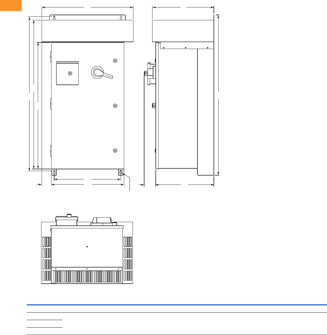
V6-T2-208 Volume 6—Solid-State Motor Control CA08100007E—February 2016 www.eaton.com
2
2
2
2
2
2
2
2
2
2
2
2
2
2
2
2
2
2
2
2
2
2
2
2
2
2
2
2
2
2
2.8
Adjustable Frequency Drives
H-Max Series Drives
Approximate Dimensions in Inches (mm)
Enclosure Box B NEMA Type 3R
Voltage
AC
hp
(IL) H H1 H2 H3 W W1 W2 W3 D D1 D2
Approx.
Weight
Lbs (kg)
Approx.
Shipping Weight
Lbs (kg)
Three-Phase
208 V 15 46.09
(1170.7)
44.45
(1129.0)
42.77
(1086.4)
36.35
(923.3)
26.31
(668.3)
20.92
(531.4)
19.30
(490.2)
2.69
(68.3)
17.74
(450.6)
16.76
(425.7)
3.31
(84.1)
235 (107) 290 (132)
230 V 15
480 V 25–40
H3
H2
H1 H
W2
W1 D2
W
3D1
DW
0.44 (11.2)
Mounting
Holes
(4 Places)
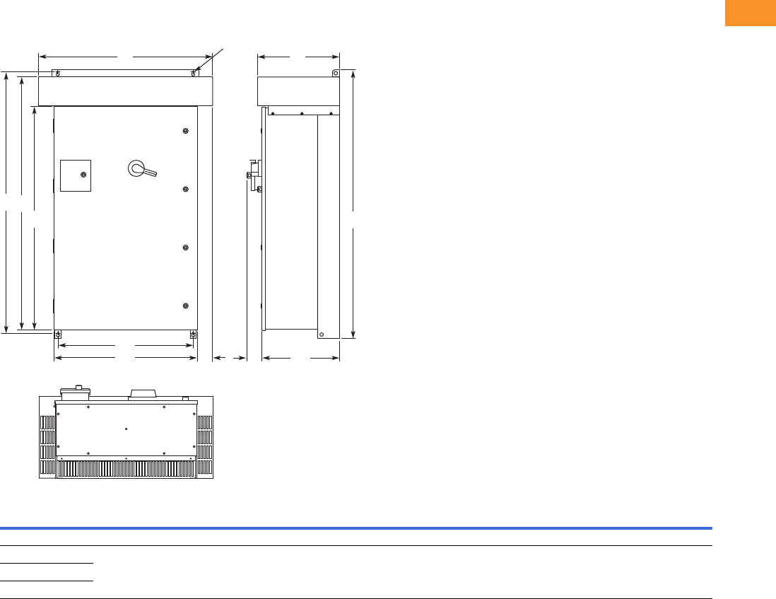
Volume 6—Solid-State Motor Control CA08100007E—February 2016 www.eaton.com V6-T2-209
2
2
2
2
2
2
2
2
2
2
2
2
2
2
2
2
2
2
2
2
2
2
2
2
2
2
2
2
2
2
2.8
Adjustable Frequency Drives
H-Max Series Drives
Approximate Dimensions in Inches (mm)
Enclosure Box C NEMA Type 3R
Note
1Consult factory.
Voltage
AC
hp
(IL) H H1 H2 H3 W W1 W2 W3 D D1 D2
Approx.
Weight
Lbs (kg)
Three-Phase
208 20–30 58.09
(1475.5)
56.45
(1433.8)
54.77
(1391.2)
48.35
(1228.1)
37.73
(958.3)
30.92
(785.4)
29.30
(744.2)
3.34
(84.8)
17.74
(450.6)
16.77
(426.0)
3.31
(84.1)
1
230 20–30
480 50–75
0.44 (11.2)
Mounting Holes
(4 Places)
H3 H
H2
H1
W2
W1 W3 D2 D1
WD
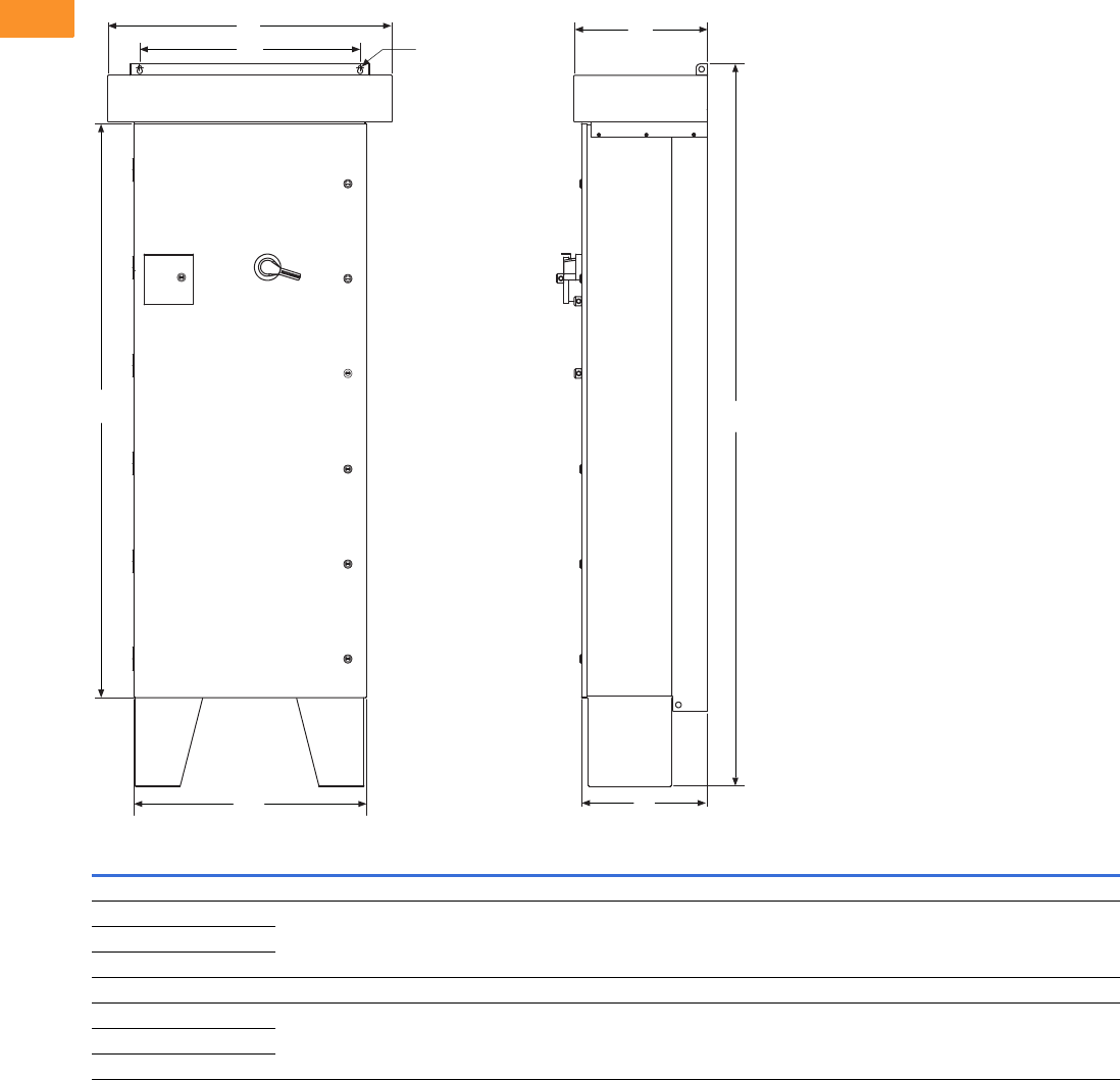
V6-T2-210 Volume 6—Solid-State Motor Control CA08100007E—February 2016 www.eaton.com
2
2
2
2
2
2
2
2
2
2
2
2
2
2
2
2
2
2
2
2
2
2
2
2
2
2
2
2
2
2
2.8
Adjustable Frequency Drives
H-Max Series Drives
Approximate Dimensions in Inches (mm)
Enclosure Box D
Voltage
AC
hp
(IL) H H1 W W1 W2 D D1
Approx. Weight
Lbs (kg)
NEMA Type 12
208 40–60 80.00
(2032.0)
76.27
(1937.3)
31.00
(787.4)
29.30
(744.2)
30.92
(785.4)
16.76
(425.7)
16.76
(425.7)
850
(386)
230 40–75
480 100–250
NEMA Type 3R
208 40–60 96.00
(2438.4)
76.27
(1937.3)
37.73
(958.3)
29.30
(744.2)
30.92
(785.4)
17.74
(450.6)
16.76
(425.7)
900
(409)
230 40–75
480 100–250
H
WØ0.44 (11.2)
Mounting Holes
(2 Places)
W1
D
D1
W2
H1
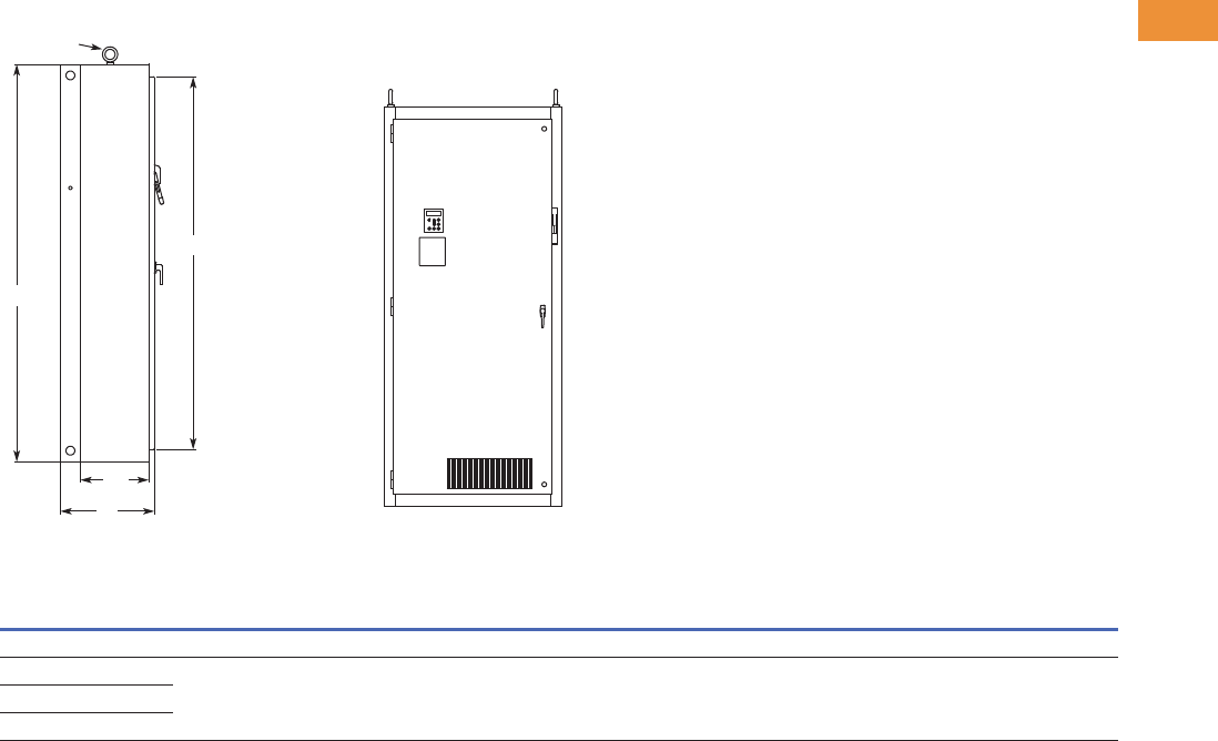
Volume 6—Solid-State Motor Control CA08100007E—February 2016 www.eaton.com V6-T2-211
2
2
2
2
2
2
2
2
2
2
2
2
2
2
2
2
2
2
2
2
2
2
2
2
2
2
2
2
2
2
2.8
Adjustable Frequency Drives
H-Max Series Drives
Approximate Dimensions in Inches (mm)
Enclosure Box 5
Voltage
AC
hp
(IL) Wide A High B Deep C SS Mounting D D1 F G
Door
Height (H)
Approx.Weight
Lbs (kg)
Three-phase
208 75–100 40.00
(1016.0)
90.00
(2286.0)
21.30
(541.0)
15.50
(394.0)
36.00
(914.4)
2.00
(50.8)
8.00
(203.2)
10.80
(274.3)
84.40
(2143.8)
1275
(578)
230 100
480 200–250
Lifting Eyes
(2 Places)
B
H
C
SS
Side View
Front View
NEMA Type 12/IP54
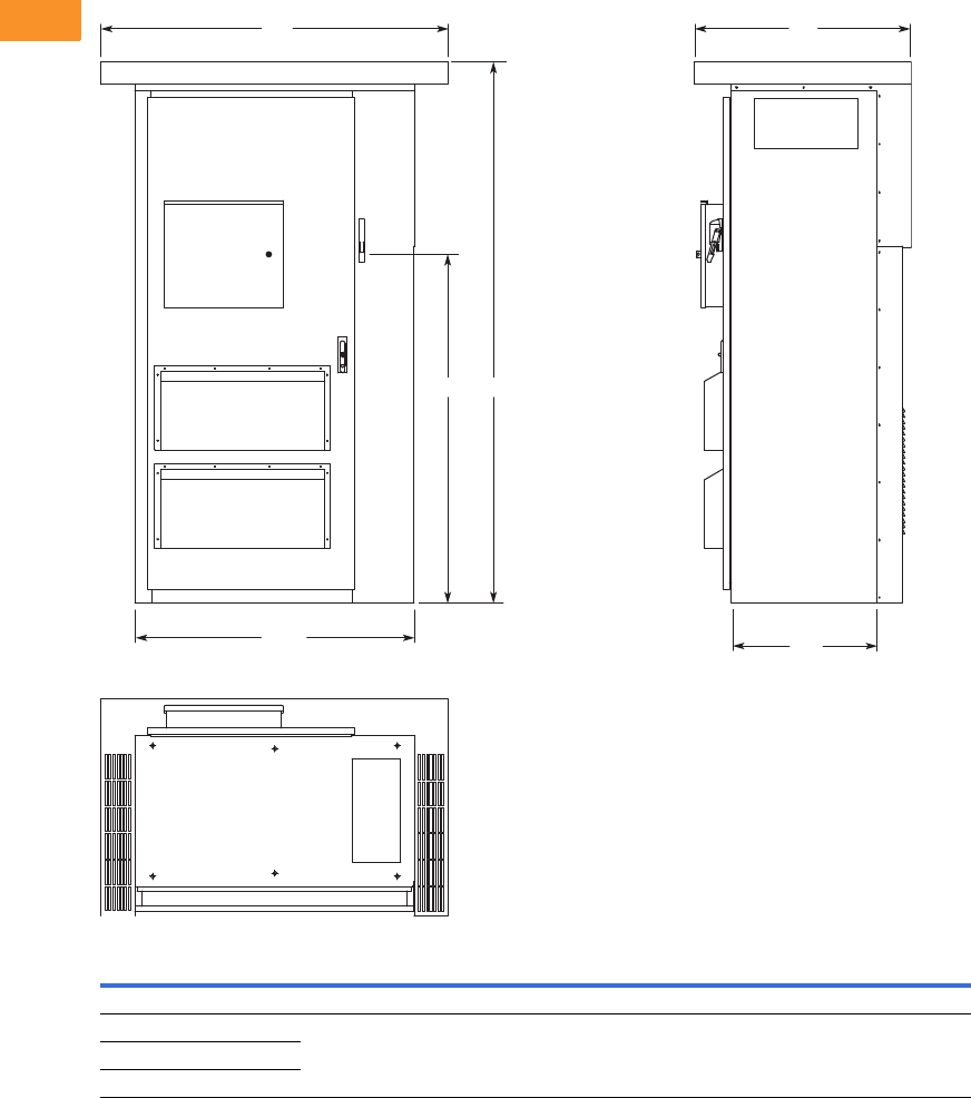
V6-T2-212 Volume 6—Solid-State Motor Control CA08100007E—February 2016 www.eaton.com
2
2
2
2
2
2
2
2
2
2
2
2
2
2
2
2
2
2
2
2
2
2
2
2
2
2
2
2
2
2
2.8
Adjustable Frequency Drives
H-Max Series Drives
Approximate Dimensions in Inches (mm)
Enclosure Box F
Voltage
AC
hp
(IL) H H1 W W1 D D1
Approx. Weight
Lbs (kg)
Three-Phase
208 75–100 93.58
(2377.0)
69.51
(1765.5)
60.00
(1524.0)
48.00
(1219.2)
37.50
(952.5)
26.00
(660.4)
1700
(772)
230 100
480 200–250
D
D1
1HH
W
W1
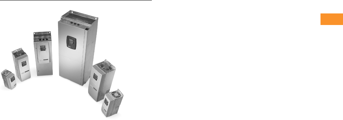
Volume 6—Solid-State Motor Control CA08100007E—February 2016 www.eaton.com V6-T2-213
2
2
2
2
2
2
2
2
2
2
2
2
2
2
2
2
2
2
2
2
2
2
2
2
2
2
2
2
2
2
2.9
Adjustable Frequency Drives
SPX Drives
SPX Drives
Contents
Description Page
SPX Drives
Features and Benefits . . . . . . . . . . . . . . . . . . . V6-T2-214
Standards and Certifications . . . . . . . . . . . . . . V6-T2-214
Catalog Number Selection . . . . . . . . . . . . . . . . V6-T2-215
Product Selection . . . . . . . . . . . . . . . . . . . . . . . V6-T2-216
Accessories . . . . . . . . . . . . . . . . . . . . . . . . . . . V6-T2-221
Options . . . . . . . . . . . . . . . . . . . . . . . . . . . . . . . V6-T2-222
Replacement Parts . . . . . . . . . . . . . . . . . . . . . . V6-T2-229
Technical Data and Specifications . . . . . . . . . . V6-T2-238
Dimensions . . . . . . . . . . . . . . . . . . . . . . . . . . . V6-T2-239
Product Description
The SPX Series Adjustable
Frequency Drives from
Eaton’s Electrical Sector are
specifically designed for high
performance applications.
Equipped with high
processing power, the SPX
can use information from an
encoder or a resolver in order
to provide very precise motor
control. Sensorless vector
and simple frequency control
are also supported. Typical
applications requiring high
performance are: master-
slave drives, positioning
applications, winder tension
control and synchronization.
The core of the SPX
is a fast microprocessor,
providing high dynamic
performance for applications
where good motor handling
and reliability are required.
It can be used both in open
loop applications as well
as in applications requiring
encoder feedback.
The SPX supports fast drive-
to-drive communication. It
also offers an integrated data
logger functionality for
analysis of dynamic events
without the need of additional
hardware. Simultaneous fast
monitoring of several drives
can be done by using the
9000Xdrive tool and CAN
communication. In
applications where reliability
and quality are essential for
high-performance, the SPX is
the logical choice.
The Eaton family of drives
includes DA1, DC1, H-Max,
M-Max, SVX and SPX. 9000X
Series drive ratings are rated
for either high overload (IH) or
low overload (IL). IL indicates
110% overload capacity for
1 minute out of 10 minutes.
IH indicates 150% overload
capacity for 1 minute out of
10 minutes.

V6-T2-214 Volume 6—Solid-State Motor Control CA08100007E—February 2016 www.eaton.com
2
2
2
2
2
2
2
2
2
2
2
2
2
2
2
2
2
2
2
2
2
2
2
2
2
2
2
2
2
2
2.9
Adjustable Frequency Drives
SPX Drives
Features and Benefits
●Speed error <0.01%,
depending on the encoder
●Incremental or absolute
encoder support
●Encoder voltages of 5 V
(RS-422), 15 V or 24 V,
depending on the option
card
●Full torque control at all
speeds, including zero
●Torque accuracy <2%;
<5% down to zero speed
●Starting torque >200%,
depending on motor and
drive sizing
●Integrated datalogger for
system analysis
●Fast multiple drive
monitoring with PC
●Full capability for master/
slave configurations
●High-speed bus (12 Mbit/s)
for fast inter-drive
communication
●High-speed applications
(up to 7200 Hz) possible
with special software
●Robust design—proven
500,000 hours MTBF
●Integrated 3% line reactors
standard on drives from
FR4 through FR9
●Line reactor is included but
is separated from chassis
●EMI/RFI Filters H standard
up to 200 hp IH 480 V,
100 hp IH 230 V
●Simplified operating menu
allows for typical
programming changes,
while programming mode
provides control of
everything
●Quick Start Wizard built
into the programming of
the drive ensures a smooth
start-up
●Keypad can display up to
three monitored
parameters simultaneously
●LOCAL/REMOTE operation
from keypad
●Copy/paste function allows
transfer of parameter
settings from one drive to
the next
●Standard NEMA Type 12/
IP54 keypad on all drives
●Hand-held auxiliary 240
power supply allows
programming/monitoring
of control module without
applying full power to the
drive
●The SPX can be flexibly
adapted to a variety of
needs using our pre-
installed “Seven in One”
precision application
programs consisting of:
●Basic
●Standard
●Local/remote
●Multi-step speed control
●PID control
●Multi-purpose control
●Pump and fan control
with auto change
●Additional I/O and
communication cards
provide plug and play
functionality
●I/O connections with
simple quick connection
terminals
●Control logic can be
powered from an external
auxiliary control panel,
internal drive functions and
fieldbus if necessary
●Brake chopper standard
from: 1–30 hp/380–500 V
3/4–15 hp/208–230 V
●NEMA Type 1/IP21
enclosures available Frame
Sizes FR4–FR11, NEMA
Type 12/IP54 enclosures
available Frame Sizes FR4–
FR10 (FR10 and FR11
freestanding drives)
●Open chassis FR10 and
greater
●Standard option board
configuration includes an
A9 I/O board and an A2
relay output board installed
in slots A and B
Standards and Certifications
Product
●IEC 61800-2
Safety
●UL 508C
EMC (at default settings)
●Immunity: Fulfills all EMC
immunity requirements;
Emissions: EN 61800-3,
LEVEL H
●UL Listed
●CE
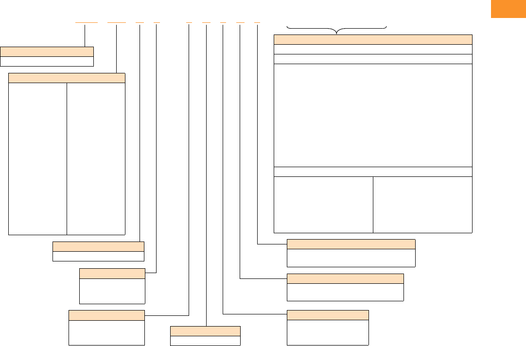
Volume 6—Solid-State Motor Control CA08100007E—February 2016 www.eaton.com V6-T2-215
2
2
2
2
2
2
2
2
2
2
2
2
2
2
2
2
2
2
2
2
2
2
2
2
2
2
2
2
2
2
2.9
Adjustable Frequency Drives
SPX Drives
Catalog Number Selection
SPX Adjustable Frequency Drives
Notes
1All 230 V drives and 480 V drives up to 200 hp (
I
H
) are only available with input option 1 (EMC level H). 480 V drives 250 hp (
I
H
) or larger are
available with input option 2 (EMC level N). 575 V drives 200 hp (
I
H
) or larger are available with input option 2. 575 V drives up to 150 hp (
I
H
)
are available with input option 4 (EMC level L). 480 V and 690 V freestanding drives are available with input option 4 (EMC level L).
2480 V drives up to 30 hp (
I
H
) are only available with brake chopper option B. 480 V drives 40 hp (
I
H
) or larger come standard with brake
chopper option N. 230 V drives up to 15 hp (
I
H
) are only available with brake chopper option B. 230 V drives 20 hp and larger come standard
with brake chopper option N. All 575 V drives come standard without brake chopper option (N). N = No brake chopper.
3480 V drives 250–350 hp (
I
H
) and 690 V drives 200–300 hp (
I
H
) are available with enclosure style 0 (chassis). 480 V and 690 V FR10
freestanding drives are available with 1 (NEMA Type 1/IP21) or 2 (NEMA Type 12/IP54). FR11 freestanding drives are only available with
enclosure style 1 (NEMA Type 1/IP21).
4Factory promise delivery. Consult sales office for availability.
Keypad
A = Alphanumeric
Board Modifications
1 = Standard boards
2 = Conformal (varnished) coating 4
Brake Chopper Options 2
N = No brake chopper circuit
B = Internal brake chopper circuit
Input Options 1
1 = Three-phase, EMC H
2 = Three-phase, EMC N
4 = Three-phase, EMC L
Options
Options appear in alphabetical order.
Extended I/O Card Options
A3 = 2 RO, Therm
A4 = Encoder low volt +5 V/15 V24 V
A5 = Encoder high volt +15 V/24 V
A7 = Double Encoder
A8 = 6 DI, 1 DO, 2 AI, 1 AO
AE = 3 DI (Encoder 10–24 V), Out +15 V/+24 V 2 DO (pulse + direction)
B1 = 6 DI, 1 ext +24 Vdc/EXT +24 Vdc
B2 = 1 RO (NC-NO), 1 RO (NO), 1 therm
B4 = 1 AI (mA isolated), 2 AO (mA isolated), 1 ext +24 Vdc/EXT + 24 Vdc
B5 = 3 RO (NO)
B8 = 1 ext +24 Vdc/EXT +24 Vdc, 3 Pt100
B9 = 1 RO (NO), 5 DI 42–240 Vac input
BB = SPI, absolute encoder
Communication Cards
CA = Johnson Controls N2
CI = Modbus TCP
CJ = BACnet
CQ = EtherNet/IP
C2 = Modbus
C3 = PROFIBUS DP
C4 = LonWorks
C5 = PROFIBUS DP (D9 connector)
C6 = CANopen (slave)
C7 = DeviceNet
C8 = Modbus (D9 type connector)
D1 = Adapter—SPX only
D2 = Adapter—SPX only
D3 = RS-232 with D9 connection
Product Family
SPX = Open drives
Horsepower Rating
F07 =3/4
001 =1
F15 =1-1/2
002 =2
003 =3
004 =5 (I
L)
005 =5
006 = 7-1/2 (IL)
007 =7-1/2
010 =10
015 =15
020 =20
025 =25
030 =30
040 =40
050 =50
060 =60
075 =75
100 =100
125 =125
150 =150
250 =250
300 =300
350 =350
400 =400
500 =500
550 =550
600 =600
650 =650
700 =700
800 =800
900 =900
H10 = 1000
H12 = 1200
H13 = 1350
H15 = 1500
H16 = 1600
H20 = 2000
AFD Software Series
A = Standard software
Enclosure 3
0 = Chassis
1 = NEMA Type 1/IP21
2 = NEMA Type 12/IP54
Voltage Rating
2 = 230 V (208–240)
4 = 480 V (380–500)
5 = 575 V (525–690)
SPX 010 A 1 –4A 1 B 1 ______
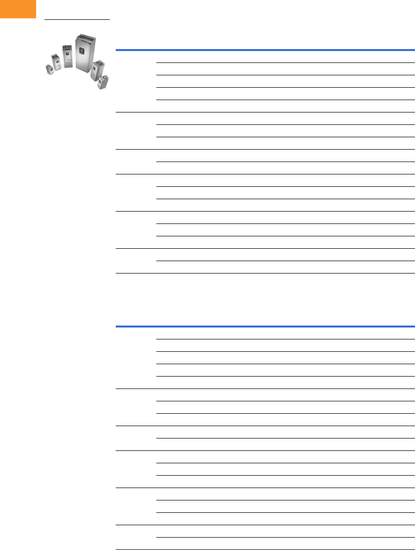
V6-T2-216 Volume 6—Solid-State Motor Control CA08100007E—February 2016 www.eaton.com
2
2
2
2
2
2
2
2
2
2
2
2
2
2
2
2
2
2
2
2
2
2
2
2
2
2
2
2
2
2
2.9
Adjustable Frequency Drives
SPX Drives
Product Selection
230 V Drives
208–240 V, NEMA Type 1/IP21 Drives
208–240 V, NEMA Type 12/IP54 Drives
Frame
Size hp (IH) Current (IH) hp (IL) Current (IL) Catalog Number
FR4 3/4 3.7 1 4.8 SPXF07A1-2A1B1
1 4.8 1-1/2 6.6 SPX001A1-2A1B1
1-1/2 6.6 2 7.8 SPXF15A1-2A1B1
27.8 311 SPX002A1-2A1B1
311 —12.5 SPX003A1-2A1B1
FR5 — 12.5 5 17.5 SPX004A1-2A1B1
517.5 7-1/225 SPX005A1-2A1B1
7-1/2 25 10 31 SPX007A1-2A1B1
FR61031 1548 SPX010A1-2A1B1
15 48 20 61 SPX015A1-2A1B1
FR72061 2575 SPX020A1-2A1N1
25 75 30 88 SPX025A1-2A1N1
30 88 40 114 SPX030A1-2A1N1
FR8 40 114 50 140 SPX040A1-2A1N1
50 140 60 170 SPX050A1-2A1N1
60 170 75 205 SPX060A1-2A1N1
FR9 75 205 100 261 SPX075A1-2A1N1
100 261 — — SPX100A1-2A1N1
Frame
Size hp (IH) Current (IH) hp (IL) Current (IL) Catalog Number
FR4 3/4 3.7 1 4.8 SPXF07A2-2A1B1
1 4.8 1-1/2 6.6 SPX001A2-2A1B1
1-1/2 6.6 2 7.8 SPXF15A2-2A1B1
27.8 311 SPX002A2-2A1B1
311 —12.5 SPX003A2-2A1B1
FR5 — 12.5 5 17.5 SPX004A2-2A1B1
517.5 7-1/225 SPX005A2-2A1B1
7-1/2 25 10 31 SPX007A2-2A1B1
FR61031 1548 SPX010A2-2A1B1
15 48 20 61 SPX015A2-2A1B1
FR72061 2575 SPX020A2-2A1N1
25 75 30 88 SPX025A2-2A1N1
30 88 40 114 SPX030A2-2A1N1
FR8 40 114 50 140 SPX040A2-2A1N1
50 140 60 170 SPX050A2-2A1N1
60 170 75 205 SPX060A2-2A1N1
FR9 75 205 100 261 SPX075A2-2A1N1
100 261 — — SPX100A2-2A1N1
SPX Open Drives
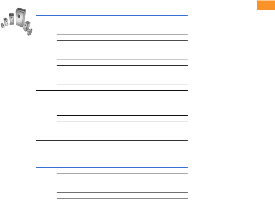
Volume 6—Solid-State Motor Control CA08100007E—February 2016 www.eaton.com V6-T2-217
2
2
2
2
2
2
2
2
2
2
2
2
2
2
2
2
2
2
2
2
2
2
2
2
2
2
2
2
2
2
2.9
Adjustable Frequency Drives
SPX Drives
480 V Drives
380–500 V, NEMA Type 1/IP21 Drives
380–500 V, NEMA Type 1/IP21 Freestanding Drives
Note
Integrated fuses as standard. Limited option selection available; 115 V transformer (KB), light kit (L1), HOA (K4),
speed potentiometer w/HOA (K2), Disconnect switch (P2). See Freestanding Option selection on Page V6-T2-228.
Frame
Size hp (IH) Current (IH) hp (IL) Current (IL) Catalog Number
FR4 1 2.2 1-1/2 3.3 SPX001A1-4A1B1
1-1/2 3.3 2 4.3 SPXF15A1-4A1B1
24.3 35.6 SPX002A1-4A1B1
35.6 57.6 SPX003A1-4A1B1
5 7.6 — 9 SPX005A1-4A1B1
— 9 7-1/2 12 SPX006A1-4A1B1
FR5 7-1/2 12 10 16 SPX007A1-4A1B1
10 16 15 23 SPX010A1-4A1B1
15 23 20 31 SPX015A1-4A1B1
FR62031 2538 SPX020A1-4A1B1
25 38 30 46 SPX025A1-4A1B1
30 46 40 61 SPX030A1-4A1B1
FR74061 5072 SPX040A1-4A1N1
50 72 60 87 SPX050A1-4A1N1
60 87 75 105 SPX060A1-4A1N1
FR8 75 105 100 140 SPX075A1-4A1N1
100 140 125 170 SPX100A1-4A1N1
125 170 150 205 SPX125A1-4A1N1
FR9 150 205 200 261 SPX150A1-4A1N1
200 245 250 300 SPX200A1-4A1N1
Frame
Size hp (IH) Current (IH) hp (IL) Current (IL) Catalog Number
FR10 250 330 300 385 SPX250A1-4A4N1
300 385 350 460 SPX300A1-4A4N1
350 460 400 520 SPX350A1-4A4N1
FR11 400 520 500 590 SPX400A1-4A4N1
500 590 550 650 SPX500A1-4A4N1
550 650 600 730 SPX550A1-4A4N1
SPX Open Drives
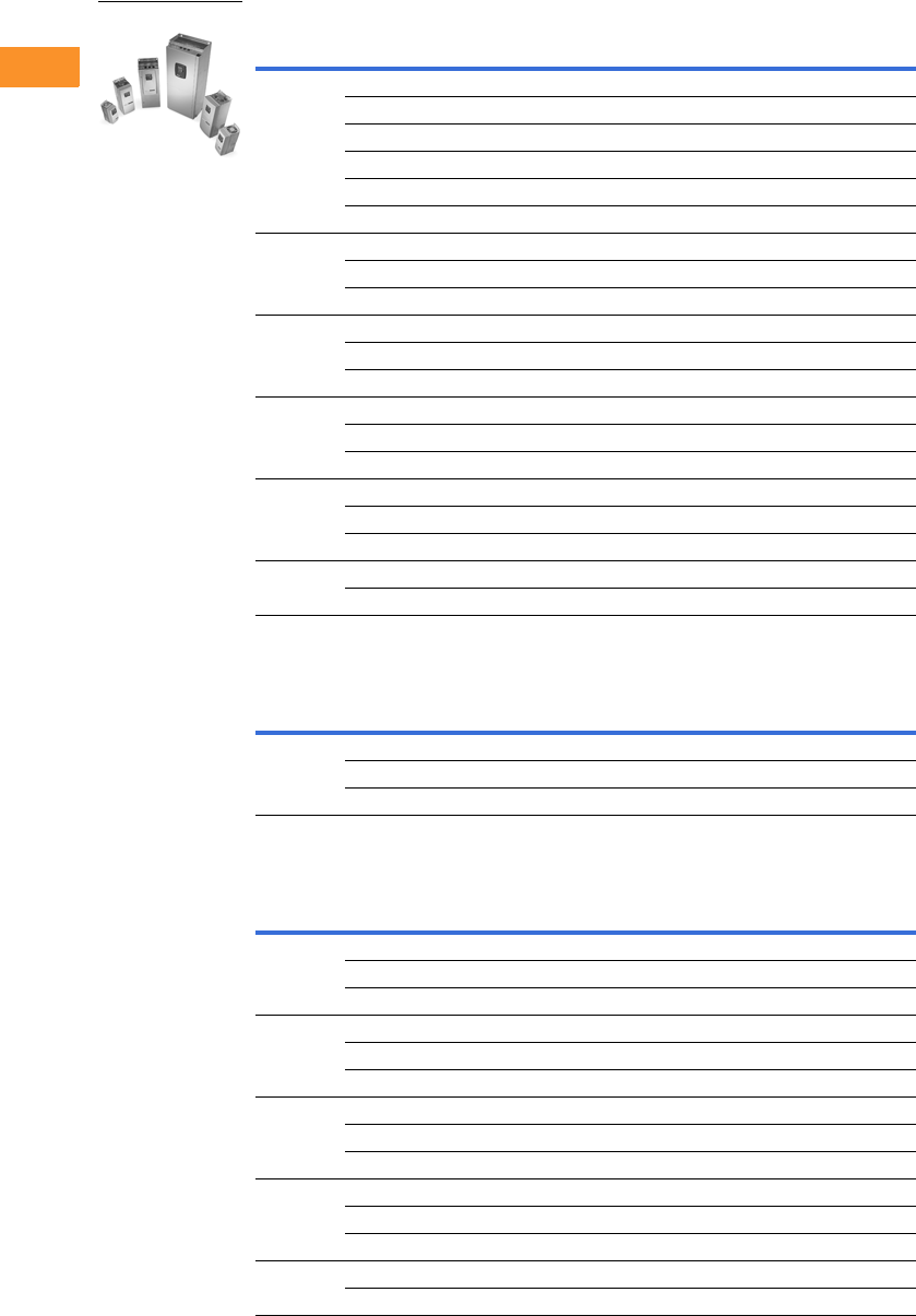
V6-T2-218 Volume 6—Solid-State Motor Control CA08100007E—February 2016 www.eaton.com
2
2
2
2
2
2
2
2
2
2
2
2
2
2
2
2
2
2
2
2
2
2
2
2
2
2
2
2
2
2
2.9
Adjustable Frequency Drives
SPX Drives
380–500 V, NEMA Type 12/IP54 Drives
380–500 V, NEMA Type 12/IP54 Freestanding Drives
380–500 V, Open Chassis Drives
Notes
Integrated fuses as standard. Limited option selection available; 115 V transformer (KB), light kit (L1), HOA (K4),
speed potentiometer w/HOA (K2), disconnect switch (P2). See Freestanding Option selection on Page V6-T2-228.
1 FR10–FR14 includes 3% line reactor, but it is not integral to chassis.
Frame
Size hp (IH) Current (IH) hp (IL) Current (IL) Catalog Number
FR4 1 2.2 1-1/2 3.3 SPX001A2-4A1B1
1-1/2 3.3 2 4.3 SPXF15A2-4A1B1
24.3 35.6 SPX002A2-4A1B1
35.6 57.6 SPX003A2-4A1B1
5 7.6 — 9 SPX005A2-4A1B1
— 9 7-1/2 12 SPX006A2-4A1B1
FR5 7-1/2 12 10 16 SPX007A2-4A1B1
10 16 15 23 SPX010A2-4A1B1
15 23 20 31 SPX015A2-4A1B1
FR62031 2538 SPX020A2-4A1B1
25 38 30 46 SPX025A2-4A1B1
30 46 40 61 SPX030A2-4A1B1
FR74061 5072 SPX040A2-4A1N1
50 72 60 87 SPX050A2-4A1N1
60 87 75 105 SPX060A2-4A1N1
FR8 75 105 100 140 SPX075A2-4A2N1
100 140 125 170 SPX100A2-4A1N1
125 170 150 205 SPX125A2-4A1N1
FR9 150 205 200 261 SPX150A2-4A1N1
200 245 250 300 SPX200A2-4A1N1
Frame
Size hp (IH) Current (IH) hp (IL) Current (IL) Catalog Number
FR10 250 330 300 385 SPX250A2-4A4N1
300 385 350 460 SPX300A2-4A4N1
350 460 400 520 SPX350A2-4A4N1
Frame
Size hp (IH) Current (IH) hp (IL) Current (IL) Catalog Number
FR10 250 330 300 385 SPX250A0-4A2N1
300 385 — 460 SPX300A0-4A2N1
350 460 400 520 SPX350A0-4A2N1
FR11 400 520 500 590 SPX400A0-4A2N1
500 590 — 650 SPX500A0-4A2N1
— 650 600 730 SPX550A0-4A2N1
FR12 600 730 — 820 SPX600A0-4A2N1
— 820 700 920 SPX650A0-4A2N1
700 920 800 1030 SPX700A0-4A2N1
FR13 800 1030 900 1150 SPX800A0-4A2N1
900 1150 1000 1300 SPX900A0-4A2N1
1000 1300 1200 1450 SPXH10A0-4A2N1
FR14 1200 1600 1500 1770 SPXH12A0-4A2N1
1600 1940 1800 2150 SPXH16A0-4A2N1
SPX Open Drives
Volume 6—Solid-State Motor Control CA08100007E—February 2016 www.eaton.com V6-T2-219
2
2
2
2
2
2
2
2
2
2
2
2
2
2
2
2
2
2
2
2
2
2
2
2
2
2
2
2
2
2
2.9
Adjustable Frequency Drives
SPX Drives
575 V Drives
525–690 V, NEMA Type 1/IP21 Drives
525–690 V, NEMA Type 1/IP21 Freestanding Drives
Note
Integrated fuses as standard. Limited option selection available; 115 V transformer (KB), light kit (L1), HOA (K4),
speed potentiometer w/HOA (K2), disconnect switch (P2). See Freestanding Option selection on Page V6-T2-228.
Frame
Size hp (IH) Current (IH) hp (IL) Current (IL) Catalog Number
FR6 2 3.3 3 4.5 SPX002A1-5A4N1
34.5 —5.5 SPX003A1-5A4N1
—5.5 5 7.5 SPX004A1-5A4N1
5 7.5 7-1/2 10 SPX005A1-5A4N1
7-1/2 10 10 13.5 SPX007A1-5A4N1
10 13.5 15 18 SPX010A1-5A4N1
15 18 20 22 SPX015A1-5A4N1
20 22 25 27 SPX020A1-5A4N1
25 27 30 34 SPX025A1-5A4N1
FR73034 4041 SPX030A1-5A4N1
40 41 50 52 SPX040A1-5A4N1
FR85052 6062 SPX050A1-5A4N1
60 62 75 80 SPX060A1-5A4N1
75 80 100 100 SPX075A1-5A4N1
FR9 100 100 125 125 SPX100A1-5A4N1
125 125 150 144 SPX125A1-5A4N1
150 144 — 170 SPX150A1-5A4N1
— 170 200 208 SPX175A1-5A4N1
Frame
Size hp (IH) Current (IH) hp (IL) Current (IL) Catalog Number
FR10 200 208 250 261 SPX200A1-5A4N1
250 261 300 325 SPX250A1-5A4N1
300 325 400 385 SPX300A1-5A4N1
FR11 400 385 450 460 SPX400A1-5A4N1
450 460 500 502 SPX450A1-5A4N1
500 502 550 590 SPX500A1-5A4N1
SPX Open Drives
V6-T2-220 Volume 6—Solid-State Motor Control CA08100007E—February 2016 www.eaton.com
2
2
2
2
2
2
2
2
2
2
2
2
2
2
2
2
2
2
2
2
2
2
2
2
2
2
2
2
2
2
2.9
Adjustable Frequency Drives
SPX Drives
525–690 V, NEMA Type 12/IP54 Drives
525–690 V, NEMA Type 12/IP54 Freestanding Drives
525–690 V, Open Chassis Drives
Notes
Integrated fuses as standard. Limited option selection available; 115 V transformer (KB), light kit (L1), HOA (K4),
speed potentiometer w/HOA (K2), disconnect switch (P2). See Freestanding Option selection on Page V6-T2-228.
1 FR10–FR14 includes 3% line reactor, but it is not integral to chassis.
Frame
Size hp (IH) Current (IH) hp (IL) Current (IL) Catalog Number
FR6 2 3.3 3 4.5 SPX002A2-5A4N1
34.5 —5.5 SPX003A2-5A4N1
—5.5 5 7.5 SPX004A2-5A4N1
5 7.5 7-1/2 10 SPX005A2-5A4N1
7-1/2 10 10 13.5 SPX007A2-5A4N1
10 13.5 15 18 SPX010A2-5A4N1
15 18 20 22 SPX015A2-5A4N1
20 22 25 27 SPX020A2-5A4N1
25 27 30 34 SPX025A2-5A4N1
FR73034 4041 SPX030A2-5A4N1
40 41 50 52 SPX040A2-5A4N1
FR85052 6062 SPX050A2-5A4N1
60 62 75 80 SPX060A2-5A4N1
75 80 100 100 SPX075A2-5A4N1
FR9 100 100 125 125 SPX100A2-5A4N1
125 125 150 144 SPX125A2-5A4N1
150 144 — 170 SPX150A2-5A4N1
— 170 200 208 SPX175A2-5A4N1
Frame
Size hp (IH) Current (IH) hp (IL) Current (IL) Catalog Number
FR10 200 208 250 261 SPX200A2-5A4N1
250 261 300 325 SPX250A2-5A4N1
300 325 400 385 SPX300A2-5A4N1
Frame
Size hp (IH) Current (IH) hp (IL) Current (IL) Catalog Number
FR10 200 208 250 261 SPX200A0-5A2N1
250 261 300 325 SPX250A0-5A2N1
300 325 400 385 SPX300A0-5A2N1
FR11 400 385 450 460 SPX400A0-5A2N1
450 460 500 502 SPX450A0-5A2N1
500 502 — 590 SPX500A0-5A2N1
FR12 — 590 600 650 SPX550A0-5A2N1
600 650 700 750 SPX600A0-5A2N1
700 750 800 820 SPX700A0-5A2N1
FR13 800 820 900 920 SPX800A0-5A2N1
900 920 1000 1030 SPX900A0-5A2N1
1000 1030 1250 1180 SPXH10A0-5A2N1
FR14 1350 1300 1500 1500 SPXH13A0-5A2N1
1500 1500 2000 1900 SPXH15A0-5A2N1
2000 1900 2300 2250 SPXH20A0-5A2N1
SPX Open Drives
Volume 6—Solid-State Motor Control CA08100007E—February 2016 www.eaton.com V6-T2-221
2
2
2
2
2
2
2
2
2
2
2
2
2
2
2
2
2
2
2
2
2
2
2
2
2
2
2
2
2
2
2.9
Adjustable Frequency Drives
SPX Drives
Accessories
Demo Drive and Power Supply
Demo Drive and Power Supply
NEMA Type 12/IP54 Conversion Kit
The NEMA Type 12/IP54 kit
option is used to convert a
NEMA Type 1/IP21 to a
NEMA Type 12/IP54 drive.
The NEMA Type 12/IP54
kit consists of a metal
drive shroud, fan kit for
some frames, adaptor plate
and plugs.
NEMA Type 12/IP54 Conversion Kit
Flange Kits
Flange Kit NEMA Type 12/IP54
The flange kit is utilized when the power section is mounted through the back panel of an enclosure.
Includes flange mount brackets and NEMA Type 12/IP54 fan components. Metal shroud not included.
Flange kits for NEMA Type 12/IP54 enclosure drive rating are determined by rating of drive.
NEMA Type 12/IP54 Conversion Kit
Notes
1For installation of an SVX NEMA Type 1/IP21 drive into a NEMA Type 12/IP54 oversized enclosure.
2For NEMA 1 drives, both parts are required.
Description Catalog Number
9000X demo drive 9000XDEMO
Approximate Dimensions in Inches (mm) Approximate
Weight Lb (kg)Frame Size Delivery Code Length Width Height Catalog Number
FR4 W 13 (330) 7 (178) 4 (102) 4 (1.8) OPTN12FR4
FR5 16 (406) 8 (203) 7 (178) 5 (2.3) OPTN12FR5
FR6 21 (533) 10 (254) 5 (127) 7 (3.2) OPTN12FR6
Drive
NEMA Rating
Drive
Frame Size
Parts Needed
N12 Conversion Kit Flange Kit
NEMA 1 FR4 OPTTHRFR4 2OPTTHR4 2
NEMA 1 FR5 OPTTHRFR5 2OPTTHR5 2
NEMA 1 FR6 OPTTHRFR5 2OPTTHR5 2
NEMA 1 FR7 Need to use NEMA 12 drive Need to use NEMA 12 drive
NEMA 1 FR8 Need to use NEMA 12 drive Need to use NEMA 12 drive
NEMA 1 FR9 Need to use NEMA 12 drive Need to use NEMA 12 drive
NEMA 12 FR4 — OPTTHR4
NEMA 12 FR5 — OPTTHR5
NEMA 12 FR6 — OPTTHR5
NEMA 12 FR7 — OPTTHR7
NEMA 12 FR8 — OPTTHR8
NEMA 12 FR9 — OPTTHR9
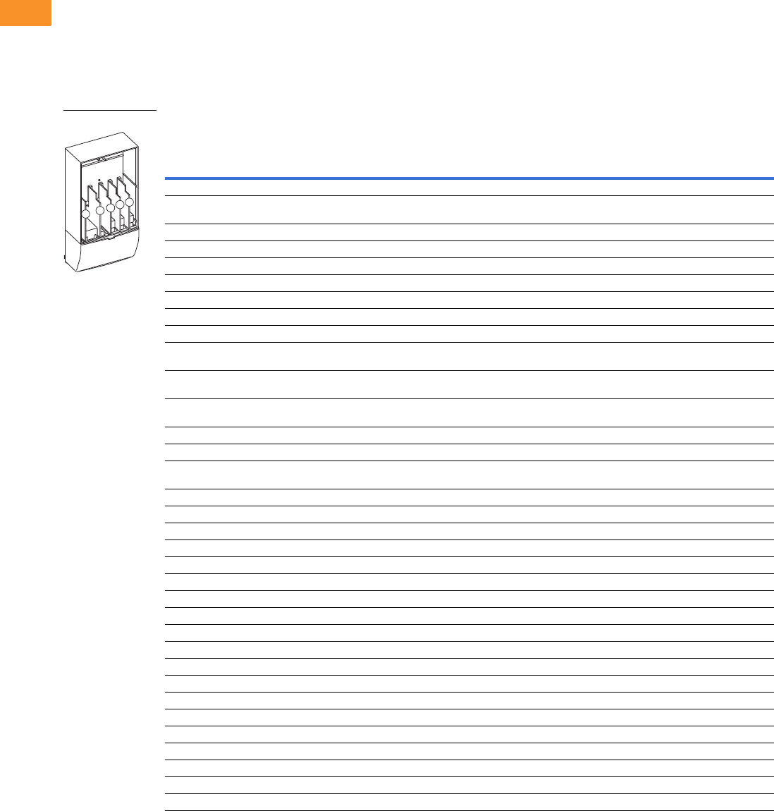
V6-T2-222 Volume 6—Solid-State Motor Control CA08100007E—February 2016 www.eaton.com
2
2
2
2
2
2
2
2
2
2
2
2
2
2
2
2
2
2
2
2
2
2
2
2
2
2
2
2
2
2
2.9
Adjustable Frequency Drives
SPX Drives
Options
9000X Series Option Board Kits
The 9000X Series drives can accommodate a wide selection of expander and adapter option boards
to customize the drive for your application needs. The drive’s control unit is designed to accept a
total of five option boards.
The 9000X Series factory installed standard board configuration includes an A9 I/O board and an A2
relay output board, which are installed in slots A and B.
Option Board Kits
Notes
1 AI = Analog Input; AO = Analog Output, DI = Digital Input, DO = Digital Output, RO = Relay Output
2 Option card must be installed in one of the slots listed for that card. Slot indicated in bold is the preferred location.
3 OPTC2 is a multi-protocol option card.
Option Kit Description 1
Allowed Slot
Locations 2
Field
Installed
Factory
Installed SVX Ready Programs
Catalog
Number
Option
Designator Basic
Local/
Remote Standard MSS PID Multi-P. PFC
Standard I/O Cards
6 DI, 1 DO, 2 AI, 1 AO, 1 +10 Vdc ref,
2 ext +24 Vdc/EXT +24 Vdc
AOPTA9 — ■ ■ ■ ■■■ ■
2 RO (NC-NO) B OPTA2 — ■ ■ ■ ■■■ ■
Extended I/O Cards
2 RO, therm B OPTA3 A3 —■ ■ ■■■ ■
Encoder low volt +5 V/15 V/24 V C OPTA4 A4 —■ ■ ■■■ ■
Encoder high volt +15 V/24 V C OPTA5 A5 —■ ■ ■■■ ■
Double encoder—SPX only C OPTA7 A7 ■ ■ ■ ■■■ ■
6 DI, 1 DO, 2 AI, 1 AO A OPTA8 A8 —■ ■ ■■■ ■
6 DI, 1 DO, 2 AI, 1 AO, 1 +10 Vdc ref,
2 ext +24 Vdc/EXT +24 Vdc
AOPTA1 — ■ ■ ■ ■■■ ■
3 DI (encoder 10–24 V), out +15 V/+24 V,
2 DO (pulse+direction)—SPX only
COPTAE AE ■ ■ ■ ■■■ ■
6 DI, 1 DO, 2 AI, 1 AO, 1 +10 Vdc ref,
2 ext +24 Vdc/EXT +24 Vdc
AOPTAFA1 — ■ ■ ■ ■■■ ■
6 DI, 1 ext +24 Vdc/EXT +24 Vdc B, C, D, E OPTB1 B1 —— — ——
■■
1 RO (NC-NO), 1 RO (NO), 1 therm B, C, D, E OPTB2 B2 —— — ——
■■
1 AI (mA isolated), 2 AO (mA isolated),
1 ext +24 Vdc/EXT +24 Vdc
B, C, D, E OPTB4 B4 —■ ■ ■■■ ■
3 RO (NO) B, C, D, E OPTB5 B5 —— — ——
■■
1 ext +24 Vdc/EXT +24 Vdc, 3 Pt100 B, C, D, E OPTB8 B8 — — — ——— —
1 RO (NO), 5 DI 42–240 Vac input B, C, D, E OPTB9 B9 —— — ——
■■
SPI, absolute encoder C OPTBB BB — — — ——— —
Communication Cards
Modbus 3D, E OPTC2-BP C2 ■ ■ ■ ■■■ ■
Johnson Controls N2 3D, E OPTC2-BP CA — — — ——— —
Modbus TCP D, E OPTCI-BP CI ■ ■ ■ ■■■ ■
BACnet D, E OPTCJ C4 ■ ■ ■ ■■■ ■
EtherNet/IP D, E OPTCQ CQ ■ ■ ■ ■■■ ■
PROFIBUS DP D, E OPTC3 C3 ■ ■ ■ ■■■ ■
LonWorks D, E OPTC4 C4 ■ ■ ■ ■■■ ■
PROFIBUS DP (D9 connector) D, E OPTC5 C5 ■ ■ ■ ■■■ ■
CANopen (slave) D, E OPTC6 C6 ■ ■ ■ ■■■ ■
DeviceNet D, E OPTC7 C7 ■ ■ ■ ■■■ ■
Modbus (D9 type connector) D, E OPTC8 C8 ■ ■ ■ ■■■ ■
Adapter—SPX only D, EOPTD1VD1
■ ■ ■ ■■■ ■
Adapter—SPX only D, EOPTD2VD2
■ ■ ■ ■■■ ■
RS-232 with D9 connection D, E OPTD3 D3 ■ ■ ■ ■■■ ■
Option Boards
ABCDE

Volume 6—Solid-State Motor Control CA08100007E—February 2016 www.eaton.com V6-T2-223
2
2
2
2
2
2
2
2
2
2
2
2
2
2
2
2
2
2
2
2
2
2
2
2
2
2
2
2
2
2
2.9
Adjustable Frequency Drives
SPX Drives
Modbus RTU Network
Communications
The Modbus Network Card
OPTC2 is used for connecting
the SVX Drive as a slave on a
Modbus network. The
interface is connected by a
9-pin DSUB connector
(female) and the baud rate
ranges from 300 to 19,200
baud. Other communication
parameters include an
address range from 1 to 247;
a parity of None, Odd or
Even; and the stop bit is 1.
PROFIBUS Network
Communications
The PROFIBUS Network Card
OPTC3 is used for connecting
the SVX Drive as a slave on
a PROFIBUS-DP network.
The interface is connected
by a 9-pin DSUB connector
(female). The baud rates
range from 9.6 Kbaud to
12 Mbaud, and the addresses
range from 1 to 127.
LonWorks Network
Communications
The LonWorks Network Card
OPTC4 is used for connecting
the SVX Drive on a LonWorks
network. This interface uses
Standard Network Variable
Types (SNVT) as data types.
The channel connection is
achieved using a FTT-10 A
Free Topology transceiver
via a single twisted transfer
cable. The communication
speed with LonWorks is
78 kBits/s.
CANopen (Slave)
Communications
The CANopen (Slave)
Network Card OPTC6 is used
for connecting the SVX Drive
to a host system. According
to ISO11898 standard cables
to be chosen for CANbus
should have a nominal
impedance of 120 ohms, and
specific line delay of nominal
5 nS/m. 120 ohms line
termination resistors required
for installation.
DeviceNet Network
Communications
The DeviceNet Network Card
OPTC7 is used for connecting
the SVX Drive on a DeviceNet
Network. It includes a
5.08 mm pluggable
connector. Transfer method
is via CAN using a two-wire
twisted shielded cable with
two-wire bus power cable
and drain. The baud rates
used for communication
include 125 Kbaud,
250 Kbaud and 500 Kbaud.
Johnson Controls
Metasys N2 Network
Communications
The OPTC2 fieldbus board
provides communication
between the SVX Drive and a
Johnson Controls Metasys™
N2 network. With this
connection, the drive can be
controlled, monitored and
programmed from the
Metasys system. The N2
fieldbus is available as a
factory installed option and as
a field installable kit.
Modbus/TCP Network
Communications
The Modbus/TCP Network
Card OPTCI is used for
connecting the SVX Drive to
Ethernet networks utilizing
Modbus protocol. It includes
an RJ-45 pluggable connector.
This interface provides a
selection of standard and
custom register values to
communicate drive parameters.
The board supports 10 Mbps
and 100 Mbps communication
speeds. The IP address of the
board is configurable over
Ethernet using a supplied
software tool.
BACnet Network
Communications
The BACnet Network Card
OPTCJ is used for connecting
the SVX Drive to BACnet
networks. It includes a
5.08 mm pluggable connector.
Data transfer is Master-Slave/
Token Passing (MS/TP)
RS-485. This interface uses
a collection of 30 Binary Value
Objects (BVOs) and 35 Analog
Value Objects (AVOs) to
communicate drive parameters.
The card supports 9.6, 19.2
and 38.4 Kbaud communication
speeds and supports network
addresses 1–127.
EtherNet/IP Network
Communications
The EtherNet/IP Network
Card OPTCK is used for
connecting the SVX Drive to
Ethernet/Industrial Protocol
networks. It includes an
RJ-45 pluggable connector.
The interface uses CIP
objects to communicate drive
parameters (CIP is “Common
Industrial Protocol”, the same
protocol used by DeviceNet).
The board supports 10 Mbps
and 100 Mbps communication
speeds. The IP address of the
board is configurable by Static,
BOOTP and DHCP methods.

V6-T2-224 Volume 6—Solid-State Motor Control CA08100007E—February 2016 www.eaton.com
2
2
2
2
2
2
2
2
2
2
2
2
2
2
2
2
2
2
2
2
2
2
2
2
2
2
2
2
2
2
2.9
Adjustable Frequency Drives
SPX Drives
Control Panel Options
Factory Options
Miscellaneous Options
Factory Installed Field Installed
Description Option Code
NEMA Type 1/IP21
Catalog Number
Local/Remote Keypad SVX Control Panel—This option is standard on all drives and consists of
an RS-232 connection, backlit alphanumeric LCD display with nine indicators for the RUN status
and two indicators for the control source. The nine pushbuttons on the panel are used for panel
programming and monitoring of all SVX parameters. The panel is detachable and isolated from the
input line potential. Include LOC/REM key to choose control location.
A KEYPAD-LOC/REM
Keypad Remote Mounting Kit—This option is used to remote mount the SVX keypad. The
footprint is compatible to the SV9000 remote mount kit. Includes 10 ft cable, keypad holder and
mounting hardware.
— OPTRMT-KIT-9000X
Keypad Blank—9000X Series select keypad for use with special and custom applications. — KEYPAD-BLANK
Description Catalog Number
9000XDrive—A PC-based tool for controlling and monitoring of the SVX. Features include: loading parameters that can be
saved to a file or printed, setting references, starting and stopping the motor, monitoring signals in graphical or text form,
and real-time display. To avoid damage to the drive or computer, SVDrivecable must be used.
9000XDRIVE
SVDrivecable—6 ft (1.8 m) RS-232 cable (22 gauge) with a 7-pin connector on each end. Should be used in conjunction
with the 9000XDrive option to avoid damage to the SVX or computer. The same cable can be used for downloading
specialized applications to the drive.
SVDRIVECABLE
External Dynamic Braking Resistors—Used with the dynamic braking chopper circuit to absorb motor regenerative
energy for stopping the load and to dissipate the energy flowing back into the drive. Resistors are separated into standard
duty and heavy-duty. Standard duty is defined as 20% duty or less with 100% braking torque, while heavy-duty is defined as
50% duty or less with 150% braking torque.
See Page V6-T2-225
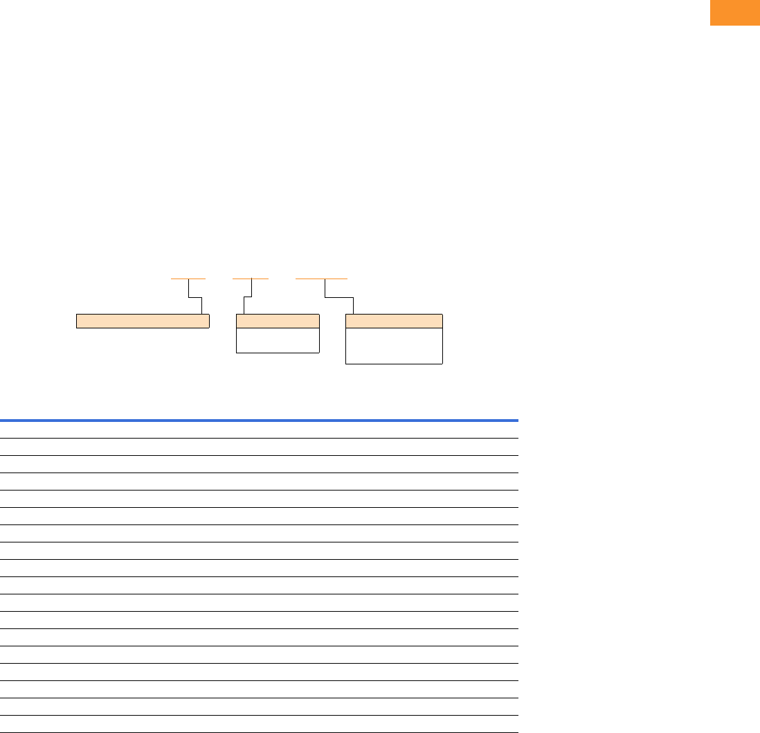
Volume 6—Solid-State Motor Control CA08100007E—February 2016 www.eaton.com V6-T2-225
2
2
2
2
2
2
2
2
2
2
2
2
2
2
2
2
2
2
2
2
2
2
2
2
2
2
2
2
2
2
2.9
Adjustable Frequency Drives
SPX Drives
SPX Drive Options
Brake Chopper Options
The brake chopper circuit
option is used for applications
that require dynamic braking.
Dynamic braking resistors are
not included with drive
purchase. Consult the factory
for additional dynamic braking
resistor selections that are
supplied separately. A list of
common resistors are listed
below and are complete
indoor assemblies, include a
pre-wired terminal block and
a thermal switch, and are not
UL Listed.
Duty Cycle
The duty cycle rating is based
on a 60-second period. For
example, the 20% duty cycle
resistor can carry 100%
current for 12 seconds out
of every 60 seconds, while
the 50% duty cycle resistor
can carry 150% current for
30 seconds out of every
60 seconds.
Torque
If the braking torque required
is less than 15%, dynamic
braking is not required
because the regenerated
energy will be dissipated in
the drive and motor losses.
Dynamic Brake Resistor—Catalog Number Selection
230 V Brake Resistors
Drive hp
(CT/IH)
Minimum
Ohms
20% Duty Cycle, 100% Torque 50% Duty Cycle, 150% Torque
Catalog Number Dimensions (Inches) Catalog Number Dimensions (Inches)
0.75 30.0 DBR-R100-W0400 12W x 5D x 5H DBR-R100-W0800 12W x 7D x 5H
130.0DBR-R100-W0400 12W x 5D x 5H DBR-R100-W0800 12W x 7D x 5H
1.5 30.0 DBR-R100-W0400 12W x 5D x 5H DBR-R036-W1200 12W x 10D x 5H
230.0DBR-R100-W0400 12W x 5D x 5H DBR-R036-W1200 12W x 10D x 5H
330.0DBR-R036-W0800 12W x 7D x 5H DBR-R036-W2000 12W x 16D x 5H
430.0DBR-R036-W0800 12W x 7D x 5H DBR-R030-W2400 19W x 10D x 5H
530.0DBR-R036-W0800 12W x 7D x 5H DBR-R030-W2800 19W x 13D x 5H
7.5 20.0 DBR-R020-W1200 12W x 10D x 5H DBR-R020-W4800 26.5W x 13D x 5H
10 10.0 DBR-R015-W1600 12W x 13D x 5H DBR-R112-W6000 26.5W x 13D x 5H
15 10.0 DBR-R012-W2400 19W x 10D x 5H DBR-R010-W9000 28W x 10D x 10H
20 3.3 DBR-R9D3-W3200 19W x 10D x 5H DBR-R3D4-W012K 28W x 10D x 10H
25 3.3 DBR-R5D5-W4000 26.5W x 10D x 5H DBR-R5D1-W015K 28W x 16D x 10H
30 3.3 DBR-R4D8-W4800 26.5W x 10D x 5H DBR-R4D1-W020K 28W x 16D x 10H
40 1.4 DBR-R004-W6000 26.5W x 13D x 5H DBR-R3D4-W025K 30W x 18D x 16H
50 1.4 DBR-R3D1-W7500 26.5W x 16D x 5H DBR-R2D1-W030K 30W x 18D x 24H
60 1.4 DBR-R2D8-W9000 26.5W x 16D x 5H DBR-R002-W036K 30W x 18D x 24H
75 1.4 DBR-R2D6-W012K 28W x 10D x 10H DBR-R1D5-W045K 30W x 18D x 32H
100 1.4 DBR-R002-W015K 28W x 16D x 10H DBR-R1D4-W060K 30W x 18D x 40H
DBR – R100 – W0800
Dynamic Brake Resistor Resistance
1D0 =1.0 Ohms
100 =100 Ohms
Rated Watts
0800 = 800 Watts
8000 = 8000 Watts
080K = 80,000 Watts

V6-T2-226 Volume 6—Solid-State Motor Control CA08100007E—February 2016 www.eaton.com
2
2
2
2
2
2
2
2
2
2
2
2
2
2
2
2
2
2
2
2
2
2
2
2
2
2
2
2
2
2
2.9
Adjustable Frequency Drives
SPX Drives
480 V Brake Resistors
Note
1Consult factory.
Drive hp
(CT/IH)
Minimum
Ohms
20% Duty Cycle, 100% Torque 50% Duty Cycle, 150% Torque
Catalog Number Dimensions (Inches) Catalog Number Dimensions (Inches)
163.0DBR-R100-W0400 12W x 5D x 5H DBR-R100-W0800 12W x 7D x 5H
1.5 63.0 DBR-R100-W0400 12W x 5D x 5H DBR-R100-W1200 12W x 10D x 5H
263.0DBR-R100-W0400 12W x 5D x 5H DBR-R100-W1200 12W x 10D x 5H
363.0DBR-R100-W0800 12W x 7D x 5H DBR-R100-W2000 12W x 16D x 5H
563.0DBR-R100-W0800 12W x 7D x 5H DBR-R100-W2800 19W x 13D x 5H
663.0DBR-R100-W1200 12W x 10D x 5H DBR-R070-W4000 19W x 16D x 5H
7.5 63.0 DBR-R100-W1200 12W x 10D x 5H DBR-R063-W4800 26.5W x 13D x 5H
10 63.0 DBR-R063-W1600 12W x 13D x 5H DBR-R063-W6000 26.5W x 16D x 5H
15 42.0 DBR-R042-W2400 19W x 10D x 5H DBR-R042-W9000 28W x 10D x 10H
20 21.0 DBR-R030-W3200 19W x 13D x 5H DBR-R023-W012K 28W x 13D x 10H
25 21.0 DBR-R030-W4000 19W x 16D x 5H DBR-R021-W015K 28W x 13D x 10H
30 14.0 DBR-R020-W4800 26.5W x 13D x 5H DBR-R014-W020K 30W x 18D x 24H
40 6.5 DBR-R112-W6000 26.5W x 13D x 5H DBR-R007-W025K 30W x 18D x 16H
50 6.5 DBR-R013-W7500 26.5W x 16D x 5H DBR-R8D5-W030K 30W x 18D x 24H
60 6.5 DBR-R010-W9000 28W x 10D x 10H DBR-R7D3-W036K 30W x 18D x 24H
75 3.3 DBR-R009-W012K 28W x 13D x 10H DBR-R3D3-W045K 30W x 18D x 32H
100 3.3 DBR-R5D1-W015K 28W x 16D x 10H DBR-R004-W060K 30W x 18D x 40H
125 3.3 DBR-R4D1-W020K 28W x 16D x 10H DBR-R004-W070K 30W x 18D x 48H
150 3.3 DBR-R3D4-W025K 30W x 18D x 16H DBR-R3D5-W085K 30W x 18D x 56H
200 3.3 DBR-R3D3-W030K 30W x 18D x 24H DBR-R3D3-W110K 30W x 18D x 72H
250 1.4 DBR-R2D5-W036K 30W x 18D x 24H 1—
300 1.4 DBR-R1D5-W045K 30W x 18D x 32H 1—
350 1.4 DBR-R1D4-W060K 30W x 18D x 40H 1—
400 0.9 DBR-R1D4-W060K 30W x 18D x 40H 1—
500 0.9 DBR-R0D9-W080K 30W x 18D x 48H 1—
550 0.9 DBR-R001-W085K 30W x 18D x 56H 1—

Volume 6—Solid-State Motor Control CA08100007E—February 2016 www.eaton.com V6-T2-227
2
2
2
2
2
2
2
2
2
2
2
2
2
2
2
2
2
2
2
2
2
2
2
2
2
2
2
2
2
2
2.9
Adjustable Frequency Drives
SPX Drives
575 V Brake Resistors
Note
1Consult factory.
Drive hp
(CT/IH)
Minimum
Ohms
20% Duty Cycle, 100% Torque 50% Duty Cycle, 150% Torque
Catalog Number Dimensions (Inches) Catalog Number Dimensions (Inches)
2100.0DBR-R100-W0400 12W x 5D x 5H DBR-R100-W1200 12W x 10D x 5H
3100.0DBR-R100-W0800 12W x 7D x 5H DBR-R100-W2000 12W x 16D x 5H
4100.0DBR-R100-W0800 12W x 7D x 5H DBR-R100-W2400 19W x 10D x 5H
5100.0DBR-R100-W0800 12W x 7D x 5H DBR-R100-W2800 19W x 13D x 5H
7.5 100.0 DBR-R100-W1200 12W x 10D x 5H DBR-R100-W4800 26.5W x 13D x 5H
10 30.0 DBR-R063-W1600 12W x 13D x 5H DBR-R063-W6000 26.5W x 16D x 5H
15 30.0 DBR-R042-W2400 19W x 10D x 5H DBR-R042-W9000 28W x 10D x 10H
20 30.0 DBR-R030-W3200 19W x 13D x 5H DBR-R030-W012K 28W x 13D x 10H
25 30.0 DBR-R030-W4000 19W x 16D x 5H DBR-R030-W015K 28W x 16D x 10H
30 18.0 DBR-R020-W4800 26.5W x 13D x 5H DBR-R020-W020K 30W x 18D x 16H
40 18.0 DBR-R030-W6000 26.5W x 16D x 5H DBR-R184-W025K 30W x 18D x 16H
50 9.0 DBR-R013-W7500 26.5W x 16D x 5H DBR-R012-W030K 30W x 18D x 24H
60 9.0 DBR-R010-W9000 28W x 10D x 10H DBR-R010-W036K 30W x 18D x 24H
75 9.0 DBR-R009-W012K 28W x 13D x 10H DBR-R009-W045K 30W x 18D x 24H
100 7.0 DBR-R013-W015K 28W x 16D x 10H DBR-R8D4-W060K 30W x 18D x 40H
125 7.0 DBR-R8D2-W020K 30W x 18D x 10H DBR-R007-W070K 30W x 18D x 40H
150 7.0 DBR-R007-W025K 30W x 18D x 16H DBR-R006-W085K 30W x 18D x 56H
175 7.0 DBR-R007-W030K 30W x 18D x 24H DBR-R007-W100K 30W x 18D x 72H
200 2.5 DBR-R3D3-W030K 30W x 18D x 24H DBR-R2D6-W110K 30W x 18D x 64H
250 2.5 DBR-R2D5-W036K 30W x 18D x 24H DBR-R003-W140K 30W x 18D x 72H
300 2.5 DBR-R3D3-W045K 30W x 18D x 32H 1—
400 1.7 DBR-R002-W060K 30W x 18D x 48H 1—
450 1.7 DBR-R1D8-W070K 30W x 18D x 48H 1—
500 1.7 DBR-R002-W080K 30W x 18D x 56H 1—
V6-T2-228 Volume 6—Solid-State Motor Control CA08100007E—February 2016 www.eaton.com
2
2
2
2
2
2
2
2
2
2
2
2
2
2
2
2
2
2
2
2
2
2
2
2
2
2
2
2
2
2
2.9
Adjustable Frequency Drives
SPX Drives
Control/Communication Options
Available Control/Communications Options
SPX Freestanding Options
480 V and 690 V Control Options, 200–550 hp 1
480 V and 690 V Light Options, 200–550 hp 1
Input Options, 200–550 hp 1
Notes
1Consult factory for adder information.
2Applicable with FR10 and FR11 freestanding designs only.
Option Description Option Type
K2 Door-Mounted Speed Potentiometer with HOA Selector Switch—Provides the SPX with the ability to start/stop and adjust the speed reference from door-
mounted control devices or remotely from customer supplied inputs. In HAND position, the drive will start and the speed is controlled by the door-mounted speed
potentiometer. The drive will be disabled in the OFF position. When AUTO is selected, the drive run and speed control commands are via user-supplied dry contact and
4–20 mA signal.
Control
K4 HAND/OFF/AUTO Switch for Non-Bypass Configurations—Provides a three-position selector switch that allows the user to select either a HAND or AUTO
mode of operation. HAND mode is defaulted to keypad operation, and AUTO mode is defaulted to control from an external terminal source. These modes of operation
can be configured via programming to allow for alternate combinations of start and speed sources. Start and speed sources include keypad, I/O and fieldbus.
Control
KB 115 V Control Transformer, 550 VA—Provides a fused control power transformer with additional 550 VA at 115 V for customer use. Control
L1 Power On and Fault Pilot Lights—Provide a white power on light that indicates power to the enclosed cabinet and a red fault light that indicates a drive fault
has occurred.
Light
P2 Disconnect Switch—Disconnect switch option is applicable only with NEMA Type 1/IP21 and NEMA Type 12/IP54 Freestanding drives. Allows a convenient
means of disconnecting the SPX from the line, and the operating mechanism can be padlocked in the OFF position. This is factory-mounted in the enclosure.
Input
Description
Catalog Number
Suffix
Door-mounted speed potentiometer with HOA selector switch K2
HAND/OFF/AUTO switch (22 mm) K4
115 volt control transformer 550 VA KB
Description
Catalog Number
Suffix
Power on/fault pilot lights L1
Description
Catalog Number
Suffix
Disconnect switch P2 2
Volume 6—Solid-State Motor Control CA08100007E—February 2016 www.eaton.com V6-T2-229
2
2
2
2
2
2
2
2
2
2
2
2
2
2
2
2
2
2
2
2
2
2
2
2
2
2
2
2
2
2
2.9
Adjustable Frequency Drives
SPX Drives
Replacement Parts
FR4 Spare Parts
FR5 Spare Parts
Notes
1Only for NEMA Type 12/IP54 Type drives.
2Factory recommended spare parts.
3Select one part number based on the amperage rating of the drive. Please contact EatonCare at 877-ETN-CARE for assistance.
Quantity/
Drive
230 V 480 V 575 V
Category Description Catalog Number Catalog Number Catalog Number
Control fan NEMA Type 12 control fan 11PP01086 PP01086 —
Control module 2SPX control module 1 CPBS0000000000 CPBS0000000000 —
Standard slot A I/O card 1 OPTA9 OPTA9 —
Standard slot B I/O card 1 OPTA2 OPTA2 —
Converter Power board 31VB00308-0004-2 VB00208-0003-5 —
1VB00308-0007-2 VB00208-0004-5 —
1VB00308-0008-2 VB00208-0005-5 —
1— VB00208-0007-5 —
1— VB00208-0009-5 —
1— VB00410-0012-5-ARV —
Keypad 2SVX/SPX keypad 1 KEYPAD-LOC/REM KEYPAD-LOC/REM —
Main fan 2DC fan (main) 1 PP01060 PP01060 —
Other Mounting kit, fixing kit 1 FR00040 FR00040 —
Mounting kit, fixing kit, N12 11FR00079 FR00079 —
Control cover, plastic, N1 1 FR00006 FR00006 —
Quantity/
Drive
230 V 480 V 575 V
Category Description Catalog Number Catalog Number Catalog Number
Control fan NEMA Type 12 control fan 11PP01088 PP01088 —
Control module 2SPX control module 1 CPBS0000000000 CPBS0000000000 —
Standard slot A I/O card 1 OPTA9 OPTA9 —
Standard slot B I/O card 1 OPTA2 OPTA2 —
Converter Power board 31VB00313-0017-2 VB00213-0016-5 —
1VB00313-0025-2 VB00213-0022-5 —
1VB00313-0031-2 VB00213-0031-5 —
Keypad 2SVX/SPX keypad 1 KEYPAD-LOC/REM KEYPAD-LOC/REM —
Main fan 2DC fan (main) 1 PP01061 PP01061 —
Other Mounting kit, fixing kit 1 FR00050 FR00050 —
Mounting kit, fixing kit, N12 11FR00081 FR00081 —
Control cover, plastic, N1 1 FR05011 FR05011 —

V6-T2-230 Volume 6—Solid-State Motor Control CA08100007E—February 2016 www.eaton.com
2
2
2
2
2
2
2
2
2
2
2
2
2
2
2
2
2
2
2
2
2
2
2
2
2
2
2
2
2
2
2.9
Adjustable Frequency Drives
SPX Drives
FR6 Spare Parts
FR7 Spare Parts
Notes
1Only for NEMA Type 12/IP54 Type drives.
2Factory recommended spare parts.
3Select one part number based on the amperage rating of the drive. Please contact EatonCare at 877-ETN-CARE for assistance.
Quantity/
Drive
230 V 480 V 575 V
Category Description Catalog Number Catalog Number Catalog Number
Control fan NEMA Type 12 control fan 11PP01049 PP01049 —
Control module 2SPX control module 1 CPBS0000000000 CPBS0000000000 CPBS0000000000
Standard slot A I/O card 1 OPTA9 OPTA9 OPTA9
Standard slot B I/O card 1 OPTA2 OPTA2 OPTA2
Converter Power board 31VB00316-0048-2 VB00416-0038-5 VB00404-0004-6
1VB00316-0061-2 VB00416-0045-5 VB00404-0005-6
1— VB00416-0061-5 VB00404-0007-6
1— — VB00404-0010-6
1— — VB00404-0013-6
1— — VB00404-0018-6
1— — VB00404-0022-6
1— — VB00404-0027-6
1— — VB00404-0034-6
DC section Bus capacitor 2 — — S00930
Keypad 2SVX/SPX keypad 1 KEYPAD-LOC/REM KEYPAD-LOC/REM KEYPAD-LOC/REM
Main fan 2DC fan (main) 1 PP01062 PP01062 —
Other Mounting kit, fixing kit 1 FR00060 FR00060 FR00060
Mounting kit, fixing kit, N12 11FR00082 FR00082 FR00082
Control cover, plastic, N1 1 FR06011 FR06011 FR06011
Quantity/
Drive
230 V 480 V 575 V
Category Description Catalog Number Catalog Number Catalog Number
Control fan NEMA Type 12 control fan 11PP01049 PP01049 PP01049
Control module 2SPX control module 1 CPBS0000000000 CPBS0000000000 CPBS0000000000
Standard slot A I/O card 1 OPTA9 OPTA9 OPTA9
Standard slot B I/O card 1 OPTA2 OPTA2 OPTA2
Converter Power board 31VB00319-0075-2 VB00619-0072-5 VB00419-0041-6
1VB00319-0088-2 VB00619-0087-5 VB00419-0052-6
1VB00319-0114-2 VB00619-0105-5 —
DC section Bus capacitor 2 — — PP01041
Keypad 2SVX/SPX keypad 1 KEYPAD-LOC/REM KEYPAD-LOC/REM KEYPAD-LOC/REM
Main fan 2DC fan (main) 1 PP01063 PP01063 PP01063
Other Mounting kit, fixing kit 1 FR07071 FR07071 FR07071
Mounting kit, fixing kit, N12 11FR07072 FR07072 FR07072
Control cover, plastic, N1 1 FR07011 FR07011 FR07011

Volume 6—Solid-State Motor Control CA08100007E—February 2016 www.eaton.com V6-T2-231
2
2
2
2
2
2
2
2
2
2
2
2
2
2
2
2
2
2
2
2
2
2
2
2
2
2
2
2
2
2
2.9
Adjustable Frequency Drives
SPX Drives
FR8 Spare Parts
Notes
1Only for NEMA Type 12/IP54 Type drives.
2Factory recommended spare parts.
3Select one part number based on the amperage rating of the drive. Please contact EatonCare at 877-ETN-CARE for assistance.
Quantity/
Drive
230 V 480 V 575 V
Category Description Catalog Number Catalog Number Catalog Number
Control fan NEMA Type 12 control fan 11CP01180 CP01180 CP01180
Control module 2SPX control module 1 CPBS0000000000 CPBS0000000000 CPBS0000000000
Standard slot A I/O card 1 OPTA9 OPTA9 OPTA9
Standard slot B I/O card 1 OPTA2 OPTA2 OPTA2
Converter Power board 31VB00722-0140-2-ANV VB00636-0140-4-ANV VB00422-0062-5-ANV
1VB00722-0170-2-ANV VB00636-0168-4-ANV VB00422-0080-5-ANV
1VB00722-0205-2-ANV VB00636-0205-4-ANV VB00422-0100-5-ANV
IGBT 2 PP01175 PP01175 PP01127
DC section Bus capacitor 4 S00335 S00335 PP01041
Inverter Diode 3 CP01268 CP01268 CP01373
Rectifier board 1 VB00227 VB00227 VB00427
Keypad 2SVX/SPX keypad 1 KEYPAD-LOC/REM KEYPAD-LOC/REM KEYPAD-LOC/REM
Main AC fan Fan AC 1 PP01123 PP01123 PP01123
Fan fuse 2 PP20202 PP20202 PP20202
Starting cap 1 S00734 S00734 S00734
Fan driver board AC 1 VB00599 VB00799 VB00799
Isolation transformer (fan) 1 S0000113 S0000113 S0000113
Main DC fan 2DC fan 1 PP00071 PP00071 PP00071
DC power supply 1 S01016 S01016 S01016
Other Front cover, N12 11FR08079 FR08079 FR08079
Conduit plate, N12 1 FR08082 FR08082 FR08082
Front cover, N1 1 FR08106 FR08106 FR08106

V6-T2-232 Volume 6—Solid-State Motor Control CA08100007E—February 2016 www.eaton.com
2
2
2
2
2
2
2
2
2
2
2
2
2
2
2
2
2
2
2
2
2
2
2
2
2
2
2
2
2
2
2.9
Adjustable Frequency Drives
SPX Drives
FR9 Spare Parts
Notes
1Factory recommended spare parts.
2Select one part number based on the amperage rating of the drive. Please contact EatonCare at 877-ETN-CARE for assistance.
Quantity/
Drive
230 V 480 V 575 V
Category Description Catalog Number Catalog Number Catalog Number
Control fan 50 mm fan 1 PP09041 PP09041 PP09041
80 mm fan 1 PP01068 PP01068 PP01068
Control module 1SPX control module 1 CPBS0000000000 CPBS0000000000 CPBS0000000000
Standard slot A I/O card 1 OPTA9 OPTA9 OPTA9
Standard slot B I/O card 1 OPTA2 OPTA2 OPTA2
Converter Power module
21FR09-0261-2-ANV FR09-0261-4-ANV FR09-0125-5-ANV
1FR09-0300-2-ANV FR09-0300-4-ANV FR09-0144-5-ANV
1— — FR09-0170-5-ANV
Driver board 1 S00583 S00583 S00583
Shunt board 26— VB00535 VB00537
6— VB00536 VB00542
6——VB00543
DC section Balancing resistor 3 PP00052 PP00052 PP00052
Bus capacitor 8 S00335 S00335 PP01041
DC busbars DC– 1 FR09043 FR09043 FR09043
DC busbars DC+ 1 FR09044 FR09044 FR09044
DC busbars connection 1 FR09045 FR09045 FR09045
DC busbars +/– insulator 1 FR09046 FR09046 FR09046
DC busbars –/con insulator 1 FR09047 FR09047 FR09047
Inverter Rectifier module 1 FR09826 FR09822 FR09823
Diode 3 CP01268 CP01268 CP01268
Rectifier board 1 — VB00459 VB00460
Keypad 1SVX/SPX keypad 1 KEYPAD-LOC/REM KEYPAD-LOC/REM KEYPAD-LOC/REM
Main AC fan Fan AC 1 PP01080 PP01080 PP01080
Fan fuse 2 PP20202 PP20202 PP20202
Starting cap 1 S00465 S00465 S00465
Fan driver board AC 1 VB00899 VB00399 VB00299
Isolation transformer (fan) 1 PP09056 PP09055 PP09055
Main DC fan 1DC fan 1 PP00072 PP00072 PP00072
DC power supply 1 S01017 S01017 S01017
Other Front cover power 1 FR09012 FR09012 FR09012
Front cover connection 1 FR09013 FR09013 FR09013
Front power conduit 1 FR09014 FR09014 FR09014

Volume 6—Solid-State Motor Control CA08100007E—February 2016 www.eaton.com V6-T2-233
2
2
2
2
2
2
2
2
2
2
2
2
2
2
2
2
2
2
2
2
2
2
2
2
2
2
2
2
2
2
2.9
Adjustable Frequency Drives
SPX Drives
FR10 Spare Parts
Notes
1Factory recommended spare parts.
2Select one part number based on the amperage rating of the drive. Please contact EatonCare at 877-ETN-CARE for assistance.
Quantity/
Drive
230 V 480 V 575 V
Category Description Catalog Number Catalog Number Catalog Number
Control Fiber board 1 — S00451 S00451
ASIC board 1 — S00457 S00457
Control fan ASIC fan 1 — PP01096 PP01096
Control module 1SPX control module 1 — CPBS0000000000 CPBS0000000000
Standard slot A I/O card 1 — OPTA9 OPTA9
Standard slot B I/O card 1 — OPTA2 OPTA2
Converter Power module 21— FR10-0385-4-ANV FR10-0261-5-ANV
1— FR10-0460-4-ANV FR10-0325-5-ANV
1— FR10-0520-4-ANV FR10-0385-5-ANV
1— — FR10-0416-5-ANV
Driver board 1 — S00450 S00450
Driver adapter board 1 — VB00330 VB00330
Shunt board 26— VB00497 VB00510
6— VB00498 VB00511
6— VB00537 VB00545
Covers Top cover 1 — FR10340 FR10340
Side cover 2 — FR10341 FR10341
DC section Balancing resistor 2 — PP13027 PP13028
DC busbars kit (right) 1 — S0000005 S0000005
Bus capacitor 12 — S00335 S00336
Inverter Rectifier module 1 — FR10823 FR10823
Charging resistor 1 — PP00066 PP00066
Diode 3 — PP01177 PP01177
Rectifier board 1 — S00591 S00592
Keypad 1SVX/SPX keypad 1 — KEYPAD-LOC/REM KEYPAD-LOC/REM
Main AC fan Fan assembly (left) 1 — FR10846 FR10846
Fan assembly (right) 1 — FR10847 FR10847
Fan AC 2 — PP01080 PP01080
Fan fuse 4 — PP20202 PP20202
Starting cap 2 — S00528 S00528
Fan driver board AC 2 — VB00299 VB00299
Isolation transformer (left) 1 — FR10844 FR10844
Isolation transformer (right) 1 — FR10845 FR10845
Main DC fan 1DC fan 2 — PP00072 PP00072
DC power supply 2 — S01017 S01017

V6-T2-234 Volume 6—Solid-State Motor Control CA08100007E—February 2016 www.eaton.com
2
2
2
2
2
2
2
2
2
2
2
2
2
2
2
2
2
2
2
2
2
2
2
2
2
2
2
2
2
2
2.9
Adjustable Frequency Drives
SPX Drives
FR11 Spare Parts
Notes
1Factory recommended spare parts.
2Select one part number based on the amperage rating of the drive. Please contact EatonCare at 877-ETN-CARE for assistance.
Quantity/
Drive
230 V 480 V 575 V
Category Description Catalog Number Catalog Number Catalog Number
Control Fiber board 1 — S00451 S00451
ASIC board 1 — S00457 S00457
Control fan ASIC fan 1 — PP01096 PP01096
Control module 1SPX control module 1 — CPBS0000000000 CPBS0000000000
Standard slot A I/O card 1 — OPTA9 OPTA9
Standard slot B I/O card 1 — OPTA2 OPTA2
Converter Power module 21— FR11-0590-4-ANV FR11-0460-5-ANV
1— FR11-0650-4-ANV FR11-0502-5-ANV
1— FR11-0730-4-ANV FR11-0590-5-ANV
Driver board 1 — S00452 S00452
Driver adapter board 1 — VB00330 VB00330
Shunt board 29— VB00513 VB00512
9— VB00514 VB00546
9— VB00538 VB00547
Covers Top cover 1 — FR11345 FR11345
DC section Balancing resistor 3 — PP13027 PP13027
DC busbars kit (right) 3 — S0000005 S0000005
Bus capacitor 18 — S00335 S00335
Inverter Rectifier module 1 — FR10823 FR10823
Diode 3 — PP01177 PP01177
Rectifier board 1 — S00591 S00591
Keypad 1SVX/SPX keypad 1 — KEYPAD-LOC/REM KEYPAD-LOC/REM
Main AC fan Fan assembly (right) 3 — FR10847 FR10847
Fan AC 3 — PP01080 PP01080
Fan fuse 4 — PP20202 PP20202
Starting cap 3 — S00530 S00530
Fan driver board AC 3 — VB00299 VB00299
Isolation transformer (right) 3 — FR10845 FR10845
Main DC fan 1DC fan 2 — PP00072 PP00072
DC power supply 2 — S01017 S01017

Volume 6—Solid-State Motor Control CA08100007E—February 2016 www.eaton.com V6-T2-235
2
2
2
2
2
2
2
2
2
2
2
2
2
2
2
2
2
2
2
2
2
2
2
2
2
2
2
2
2
2
2.9
Adjustable Frequency Drives
SPX Drives
FR12 Spare Parts
Notes
1Factory recommended spare parts.
2Select one part number based on the amperage rating of the drive. Please contact EatonCare at 877-ETN-CARE for assistance.
Quantity/
Drive
230 V 480 V 575 V
Category Description Catalog Number Catalog Number Catalog Number
Control Fiber board 2 — S00451 S00451
ASIC board 2 — S00457 S00457
Star coupler 1 — S00593 S00593
Control fan ASIC fan 2 — PP01096 PP01096
Control module 1SPX control module 1 — CPBS0000000000 CPBS0000000000
Standard slot A I/O card 1 — OPTA9 OPTA9
Standard slot B I/O card 1 — OPTA2 OPTA2
Converter Power module 21— FR12-0820-4-ANV FR12-0650-5-ANV
1— FR12-0920-4-ANV FR12-0750-5-ANV
1— FR12-1030-4-ANV FR12-0820-5-ANV
Driver board 2 — S00450 S00450
Driver adapter board 2 — VB00330 VB00330
Shunt board 12 — VB00498 VB00511
Covers Top cover 2 — FR10340 FR10340
Side cover 4 — FR10341 FR10341
DC section Balancing resistor 4 — PP13027 PP13027
DC busbars kit (right) 2 — S0000005 S0000005
Bus capacitor 24 — S00335 S00336
Inverter Rectifier module 2 — FR10823 FR10823
Diode 3 — PP01177 PP01177
Rectifier board 2 — S00591 S00591
Keypad 1SVX/SPX keypad 1 — KEYPAD-LOC/REM KEYPAD-LOC/REM
Main AC fan Fan assembly (left) 2 — FR10846 FR10846
Fan assembly (right) 2 — FR10847 FR10847
Fan AC 4 — PP01080 PP01080
Fan fuse 8 — PP20202 PP20202
Starting cap 4 — S00528 S00528
Fan driver board AC 4 — VB00299 VB00299
Isolation transformer (left) 2 — FR10844 FR10844
Isolation transformer (right) 2 — FR10845 FR10845
Main DC fan 1DC fan 4 — PP00072 PP00072
DC power supply 4 — S01017 S01017

V6-T2-236 Volume 6—Solid-State Motor Control CA08100007E—February 2016 www.eaton.com
2
2
2
2
2
2
2
2
2
2
2
2
2
2
2
2
2
2
2
2
2
2
2
2
2
2
2
2
2
2
2.9
Adjustable Frequency Drives
SPX Drives
FR13 Spare Parts
Notes
1Factory recommended spare parts.
2Select one part number based on the amperage rating of the drive. Please contact EatonCare at 877-ETN-CARE for assistance.
Quantity/
Drive
230 V 480 V 575 V
Category Description Catalog Number Catalog Number Catalog Number
Control ASIC board 1 — S00457 S00457
ASIC assembly 1 — 60S01030 60S01030
Control fan ASIC fan 1 — PP01096 PP01096
Control module 1SPX control module 1 — CPBS0000000000 CPBS0000000000
Standard slot A I/O card 1 — OPTA9 OPTA9
Standard slot B I/O card 1 — OPTA2 OPTA2
Converter Power module 23— FI13-1150-4-ANV FR13-1030-5-ANV
3— FI13-1300-4-ANV FR13-1180-5-ANV
3— FI13-1450-4-ANV FR13-920-5-ANV
Driver board 3 — S00454 S00454
Driver adapter board 2 — VB00330 VB00330
Shunt board 218 — VB00505 VB00516
18 — VB00514 VB00517
18 — VB00541 VB00547
Covers Top cover 3 — FI10001 FI10001
Side cover 3 — FI10003 FI10003
DC section Balancing resistor 6 — PP13034 PP13034
Bus capacitor 36 — S00335 S00336
DC busbars kit 3 — FI13329 FI13329
Inverter Rectifier module 2 — FR10823 FR10823
Diode 3 — PP01177 PP01177
Rectifier board 2 — S00591 S00591
Keypad 1SVX/SPX keypad 1 — KEYPAD-LOC/REM KEYPAD-LOC/REM
Main AC fan Fan assembly (left) 3 — FI13301 FI13301
Fan AC 3 — PP01080 PP01080
Fan fuse 6 — PP20202 PP20202
Starting cap 3 — S00520 S00520
Fan driver board AC 3 — VB00299 VB00299
Isolation transformer 3 — PP10057 PP10057
Main DC fan 1DC fan 4 — PP00072 PP00072
DC power supply 4 — S01017 S01017

Volume 6—Solid-State Motor Control CA08100007E—February 2016 www.eaton.com V6-T2-237
2
2
2
2
2
2
2
2
2
2
2
2
2
2
2
2
2
2
2
2
2
2
2
2
2
2
2
2
2
2
2.9
Adjustable Frequency Drives
SPX Drives
FR14 Spare Parts
Notes
1Factory recommended spare parts.
2Select one part number based on the amperage rating of the drive. Please contact EatonCare at 877-ETN-CARE for assistance.
Quantity/
Drive
230 V 480 V 575 V
Category Description Catalog Number Catalog Number Catalog Number
Control ASIC board 2 — S00457 S00457
Star coupler 1 — S00593 S00593
ASIC assembly 2 — 60S01030 60S01030
Star coupler kit 1 — FR10860 FR10860
Control fan ASIC fan 2 — PP01096 PP01096
Control module 1SPX control module 1 — CPBS0000000000 CPBS0000000000
Standard slot A I/O card 1 — OPTA9 OPTA9
Standard slot B I/O card 1 — OPTA2 OPTA2
Converter Power module 21— FR14-1770-4-ANV FR14-1500-5-ANV
1— FR14-2150-4-ANV FR14-1900-5-ANV
1— FR14-2700-4-ANV FR14-2250-5-ANV
Driver board 6 — S00454 S00454
Driver adapter board 2 — VB00330 VB00330
Shunt board 236 — VB00541 VB00516
36 ——VB00517
Covers Top cover 6 — FI10001 FI10001
Side cover 6 — FI10003 FI10003
DC section Balancing resistor 6 — PP13034 PP13034
Bus capacitor 72 — S00335 S00336
DC busbars kit 6 — FI13329 FI13329
Inverter Rectifier module 2 — FR10823 FR10823
Diode 3 — PP01177 PP01177
Rectifier board 2 — S00591 S00591
Keypad 1SVX/SPX keypad 1 — KEYPAD-LOC/REM KEYPAD-LOC/REM
Main AC fan Fan assembly (left) 6 — FI13301 FI13301
Fan AC 6 — PP01080 PP01080
Fan fuse 12 — PP20202 PP20202
Starting cap 6 — S00520 S00520
Fan driver board AC 6 — VB00299 VB00299
Isolation transformer 6 — PP10057 PP10057
Main DC fan 1DC fan 6 — PP00072 PP00072
DC power supply 6 — S01017 S01017

V6-T2-238 Volume 6—Solid-State Motor Control CA08100007E—February 2016 www.eaton.com
2
2
2
2
2
2
2
2
2
2
2
2
2
2
2
2
2
2
2
2
2
2
2
2
2
2
2
2
2
2
2.9
Adjustable Frequency Drives
SPX Drives
Technical Data and Specifications
SPX Drives
Description Specification
Input Ratings
Input voltage (Vin)+10%/–15%
Input frequency (fin) 50/60 Hz (variation up to 45–66 Hz)
Connection to power Once per minute or less (typical operation)
High withstand rating 100 kAIC
Output Ratings
Output voltage 0 to Vin
Continuous output current IH rated 100% at 122 °F (50 °C), FR9 and below
IL rated 100% at 104 °F (40 °C), FR9 and below
IH/IL 100% at 104 °F (40 °C), FR10 and above
Overload current (
I
H
/
I
L
)150%
I
H
, 110%
I
L
for 1 min.
Output frequency 0 to 320 Hz
Frequency resolution 0.01 Hz
Initial output current (
I
H
) 250% for 2 seconds
Efficiency >96%
Control Characteristics
Control method Frequency control (V/f) Open loop: sensorless vector control
Closed loop: frequency control
Closed loop: vector control
Switching frequency Adjustable with parameter 2.6.9
Frame 4–6 1 to 16 kHz; default 10 kHz
Frame 7–12 1 to 10 kHz; default 3.6 kHz
Frequency reference Analog input: Resolution 0.1% (10-bit), accuracy ±1% V/Hz
Panel reference: Resolution 0.01 Hz
Field weakening point 30 to 320 Hz
Acceleration time 0 to 3000 sec.
Deceleration time 0 to 3000 sec.
Braking torque DC brake: 30% x Tn (without brake option)
Ambient Conditions
Ambient operating
temperature
14 °F (–10 °C), no frost to 122 °F (50 °C)
I
H
(FR4–FR9)
14 °F (–10 °C), no frost to 104 °F (40 °C)
I
L
(FR10 and up)
14 °F (–10 °C), no frost to 104 °F (40 °C)
I
L
(all frames)
Storage temperature –40° to 158 °F (–40° to 70 °C)
Relative humidity 0 to 95% RH, noncondensing, non-corrosive,
no dripping water
Air quality Chemical vapors: IEC 721-3-3, unit in operation, class 3C2;
Mechanical particles: IEC 721-3-3, unit in operation, class 3S2
Altitude 100% load capacity (no derating) up to 3280 ft (1000 m);
1% derating for each 328 ft (100 m) above 3280 ft (1000 m);
max. 9842 ft (3000 m)
Vibration EN 50178, EN 60068-2-6; 5 to 50 Hz, displacement amplitude
1 mm (peak) at 3 to 15.8 Hz, max. acceleration amplitude
1G at 15.8 to 150 Hz
Shock EN 50178, EN 60068-2-27 UPS Drop test (for applicable UPS
weights) Storage and shipping: max. 15 g, 11 ms (in package)
Enclosure class NEMA 1/IP21 or NEMA 12/IP54, open chassis/IP20
Description Specification
Control Connections
Analog input voltage 0 to 10 V, R = 200 kohms (–10 to 10 V joystick control)
resolution 0.1%; accuracy ±1%
Analog input current 0(4) to 20 mA; Ri—250 ohms differential
Digital inputs (6) Positive or negative logic; 18 to 30 Vdc
Auxiliary voltage +24 V ±15%, max. 250 mA
Output reference voltage +10 V +3%, max. load 10 mA
Analog output 0(4) to 20 mA; RL max. 500 ohms;
resolution 10 bit; Accuracy ±2%
Digital outputs Open collector output, 50 mA/48V
Relay outputs 2 programmable Form C relay outputs
switching capacity: 24 Vdc/8 A, 250 Vac/8 A, 125 Vdc/0.4 A
Protections
Overcurrent protection Trip limit 4.0 x IH instantaneously
Overvoltage protection Yes
Undervoltage protection Yes
Earth fault protection In case of earth fault in motor or motor cable, only the
frequency converter is protected
Input phase supervision Trips if any of the input phases are missing
Motor phase supervision Trips if any of the output phases are missing
Overtemperature protection Yes
Motor overload protection Yes
Motor stall protection Yes
Motor underload protection Yes
Short-circuit protection Yes (+24 V and +10 V reference voltages)
High Performance Features
Speed error <0.01%, depending on the encoder
Encoder support Incremental or absolute
Encoder voltages 5 V (RS-422), 15 V or 24 V, depending on the option card
Torque control Full torque control at all speeds, including zero
Torque accuracy <2%; <5% down to zero speed
Starting torque >200%, depending on motor and drive sizing
Master/slave configurations Full capability
System analysis Integrated data logger
PC communication Fast multiple drive monitoring with PC
Inter-drive communication High-speed bus (12 Mbits/s)
High-speed applications Up to 7200 Hz (special software required)

Volume 6—Solid-State Motor Control CA08100007E—February 2016 www.eaton.com V6-T2-239
2
2
2
2
2
2
2
2
2
2
2
2
2
2
2
2
2
2
2
2
2
2
2
2
2
2
2
2
2
2
2.9
Adjustable Frequency Drives
SPX Drives
Dimensions
Approximate Dimensions in Inches (mm)
9000X Drives
NEMA Type 1/IP21 and NEMA Type 12/IP54, FR4, FR5 and FR6
Voltage hp (IH) H1 H2 H3 D1 D2 D3 W1 W2 R1 Dia. R2 Dia.
Weight
Lbs (kg)
Knockouts at Inches (mm)
N1 (O.D.)
FR4
230 V 3/4–3 12.9
(327)
12.3
(313)
11.5
(292)
7.5
(190)
3.0
(77)
5.0
(126)
5.04
(128)
3.9
(100)
0.5
(13)
0.3
(7)
11.0 (5) 3 at 10.1 (28)
480 V 1–5
FR5
230 V 5–7-1/2 16.5
(419)
16.0
(406)
15.3
(389)
8.4
(214)
3.9
(100)
5.8
(148)
5.7
(144)
3.9
(100)
0.5
(13)
0.3
(7)
17.9 (8) 2 at 1.5 (37)
1 at 10.1 (28)
480 V 7-1/2–15
FR6
230 V 10–15 22.0
(558)
21.3
(541)
20.4
(519)
9.3
(237)
4.2
(105)
6.5
(165)
7.7
(195)
5.8
(148)
0.6
(15.5)
0.4
(9)
40.8 (19) 3 at 1.5 (37)
480 V 20–30
575 V 2–25
EATON
D1 W2
W1
R2
R1
R2
H3 H2
H1
D2
D3
Knockouts
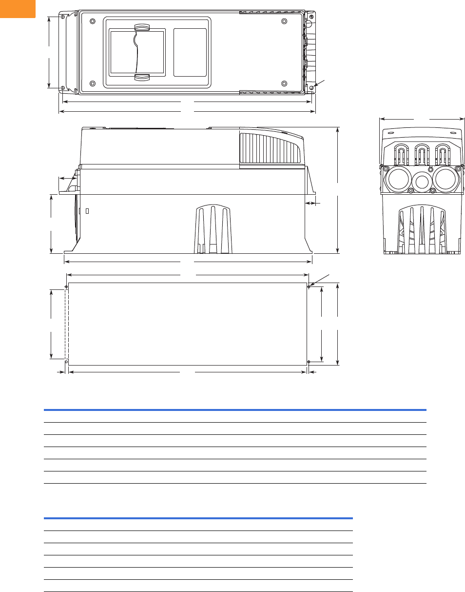
V6-T2-240 Volume 6—Solid-State Motor Control CA08100007E—February 2016 www.eaton.com
2
2
2
2
2
2
2
2
2
2
2
2
2
2
2
2
2
2
2
2
2
2
2
2
2
2
2
2
2
2
2.9
Adjustable Frequency Drives
SPX Drives
Approximate Dimensions in Inches (mm)
NEMA Type 1/IP21 and NEMA Type 12/IP54 with Flange Kit, FR4, FR5 and FR6
FR4, FR5 and FR6 with Flange Kit
Flange Opening, FR4 to FR6
W1 W2 H1 H2 H3 H4 H5 D1 D2 Dia. A
FR4
5.0 (128) 4.5 (113) 13.3 (337) 12.8 (325) 12.9 (327) 1.2 (30) 0.9 (22) 7.5 (190) 3.0 (77) 0.3 (7)
FR5
5.6 (143) 4.7 (120) 17.0 (434) 16.5 (420) 16.5 (419) 1.4 (36) 0.7 (18) 8.4 (214) 3.9 (100) 0.3 (7)
FR6
7.7 (195) 6.7 (170) 22.0 (560) 21.6 (549) 22.0 (558) 1.2 (30) 0.8 (20) 9.3 (237) 4.2 (106) 0.3 (7)
W3 W4 W5 H6 H7 H8 H9 Dia. B
FR4
4.8 (123) 4.5 (113) — 12.4 (315) 12.8 (325) — 0.2 (5) 0.3 (7)
FR5
5.3 (135) 4.7 (120) — 16.2 (410) 16.5 (420) — 0.2 (5) 0.3 (7)
FR6
7.3 (185) 6.7 (170) 6.2 (157) 21.2 (539) 21.6 (549) 0.3 (7) 0.2 (5) 0.3 (7)
W2
H1
H2
D2
Flange Opening
FR4 to FR6
H4
H5
H3
W1
Dia. A
D1
W3W4
W5
Dia. B
H7
H6 H9H8

Volume 6—Solid-State Motor Control CA08100007E—February 2016 www.eaton.com V6-T2-241
2
2
2
2
2
2
2
2
2
2
2
2
2
2
2
2
2
2
2
2
2
2
2
2
2
2
2
2
2
2
2.9
Adjustable Frequency Drives
SPX Drives
Approximate Dimensions in Inches (mm)
NEMA Type 1/IP21 and NEMA Type 12/IP54, FR7
Voltage hp (IH) H1 H2 H3 D1 D2 D3 W1 W2 R1 Dia. R2 Dia.
Weight
Lbs (kg)
Knockouts at Inches (mm)
N1 (O.D.)
230 V 20–30 24.8 (630) 24.2 (614) 23.2 (590) 10.1 (257) 3.0 (77) 7.3 (184) 9.3 (237) 7.5 (190) 0.7 (18) 0.4 (9) 77.2 (35) 3 at 1.5 (37)
480 V 40–60
575 V 30–40
W2
H1
D1
D2
Knockouts
R2 R2R1
D3
H2
H3
W1

V6-T2-242 Volume 6—Solid-State Motor Control CA08100007E—February 2016 www.eaton.com
2
2
2
2
2
2
2
2
2
2
2
2
2
2
2
2
2
2
2
2
2
2
2
2
2
2
2
2
2
2
2.9
Adjustable Frequency Drives
SPX Drives
Approximate Dimensions in Inches (mm)
NEMA Type 1/IP21 and NEMA Type 12/IP54, FR8
Voltage hp (IH) D1 H1 H2 H3 W1 W2 R1 Dia. R2 Dia.
Weight
Lbs (kg)
230 V 40–60 13.5 (344) 300.1 (764) 28.8 (732) 28.4 (721) 11.5 (291) 10 (255) 0.7 (18) 0.4 (9) 127 (58)
480 V 75–125
575 V 50–75
D1
H2
H1
W2W1
H3
R2
R1

Volume 6—Solid-State Motor Control CA08100007E—February 2016 www.eaton.com V6-T2-243
2
2
2
2
2
2
2
2
2
2
2
2
2
2
2
2
2
2
2
2
2
2
2
2
2
2
2
2
2
2
2.9
Adjustable Frequency Drives
SPX Drives
Approximate Dimensions in Inches (mm)
NEMA Type 1/IP21 and NEMA Type 12/IP54, with Flange Kit, FR7 and FR8
Flange Opening, FR7 and FR8
W1 W2 W3 W4 H1 H2 H3 H4 H5 H6 H7 D1 D2 Dia. A
FR7
9.3 (237) 6.8 (175) 10.6 (270) 10.0 (253) 25.6 (652) 24.9 (632) 24.8 (630) 7.4 (189) 7.4 (189) 0.9 (23) 0.8 (20) 10.1 (257) 4.6 (117) 0.3 (6)
FR8
11.2 (285) — 14.0 (355) 13.0 (330) 32.8 (832) — 29.3 (745) 10.2 (258) 10.4 (265) 1.7 (43) 2.2 (57) 13.5 (344) 4.3 (110) 0.4 (9)
W5 W6 W7 H8 H9 H10 H11 H12 H13 Dia. B
FR7
9.2 (233) 6.9 (175) 10.0 (253) 24.4 (619) 7.4 (189) 7.4 (189) 1.4 (35) 1.3 (32) 1.0 (25) 0.3 (6)
FR8
11.9 (301) — 13.0 (330) 31.9 (810) 10.2 (258) 10.4 (265) — — 1.3 (33) 0.4 (9)
H7
W3
H9
D1
W1
H9H12
H13
H11H10
H1
H2
H5 Dia. A
Dia. B
H4H4H6
W2W4
D2
W6W5 W7
H3
H8
Flange Opening
FR7/FR8

V6-T2-244 Volume 6—Solid-State Motor Control CA08100007E—February 2016 www.eaton.com
2
2
2
2
2
2
2
2
2
2
2
2
2
2
2
2
2
2
2
2
2
2
2
2
2
2
2
2
2
2
2.9
Adjustable Frequency Drives
SPX Drives
Approximate Dimensions in Inches (mm)
NEMA Type 1/IP21 and NEMA Type 12/IP54, FR9
Note
1Brake resistor terminal box (H6) included when brake chopper ordered.
Voltage hp (IH) W1W2W3W4H1 H2 H3 H4
1D1 D2 D3 Dia.
Weight
Lbs (kg)
230 V 75–100 18.9
(480)
15.7
(400)
0.4
(9)
2.1
(54)
45.3
(1150)
44.1
(1120)
0.6
(16)
7.4
(188)
14.2
(361.5)
13.4
(340)
11.2
(285)
0.8
(21)
321.9 (146)
480 V 150–200
575 V 100–175
D2
Dia.
D1
H5
W2
W4
H3H4
H2
H1
H6
W3
W5
PE
B- B+ /R+ R-
W5 W1
D3

Volume 6—Solid-State Motor Control CA08100007E—February 2016 www.eaton.com V6-T2-245
2
2
2
2
2
2
2
2
2
2
2
2
2
2
2
2
2
2
2
2
2
2
2
2
2
2
2
2
2
2
2.9
Adjustable Frequency Drives
SPX Drives
Approximate Dimensions in Inches (mm)
NEMA Type 1/IP21 and NEMA Type 12/IP54, FR9 with Flange Kit
W1 W2 W3 W4 W5 H1 H2 H3 H4 H5 H6 H7 D1 D2 D3 Dia.
20.9 (530) 20.0 (510) 19.1 (485) 7.9 (200) 0.2 (5.5) 51.7 (1312) 45.3 (1150) 16.5 (420) 3.9 (100) 1.4 (35) 0.4 (9) 0.1 (2) 24.9 (362) 13.4 (340) 4.3 (109) 0.8 (21)
.20 (5)
Dia.
H4
H2
D2
Dia.
D1
D3
H4
W1
H7
W5
W3
W4
H3 H3 H3 H5H5
H6 H1
W4
W2
Flange Opening
FR9
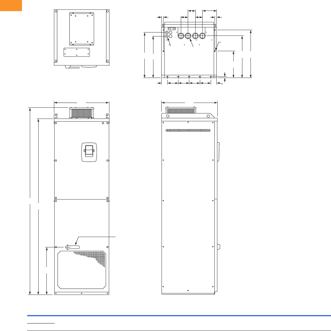
V6-T2-246 Volume 6—Solid-State Motor Control CA08100007E—February 2016 www.eaton.com
2
2
2
2
2
2
2
2
2
2
2
2
2
2
2
2
2
2
2
2
2
2
2
2
2
2
2
2
2
2
2.9
Adjustable Frequency Drives
SPX Drives
Approximate Dimensions in Inches (mm)
NEMA Type 1/IP21 and NEMA Type 12/IP54, FR10 Freestanding
Volts
hp
(IH) W1W2W3W4W5W6W7H1H2H3D1D2D3D4D5D6D7Dia. 1Dia. 2Dia. 3
Weight
Lbs (kg)
480 V 250–350 23.43
(595)
2.46
(62.5)
4.53
(115)
0.79
(20)
5.95
(151)
2.95
(75)
30.11
(79)
79.45
(2018)
74.80
(1900)
20.18
(512.5)
23.70
(602)
17.44
(443)
19.02
(483)
0.47
(12)
11.22
(285)
17.60
(447)
20.08
(510)
0.83
(21)
1.89
(48)
0.43
(11)
875 (389)
690 V 200–300
Dia. 3
Dia. 2
Dia. 1
W5
W6
W4 W4
D4
D2
W2
W2
D5
D3 D6 D7
W3 W3 W3 W3
H1
H2
H3
W1 D1
Operator
(Shown with
Optional
Disconnect)
W6
W7

Volume 6—Solid-State Motor Control CA08100007E—February 2016 www.eaton.com V6-T2-247
2
2
2
2
2
2
2
2
2
2
2
2
2
2
2
2
2
2
2
2
2
2
2
2
2
2
2
2
2
2
2.9
Adjustable Frequency Drives
SPX Drives
Approximate Dimensions in Inches (mm)
FR10 Open Chassis 1
Note
1SPXX FR12 is built of two FR10 modules. Please refer to SPX installation manual for mounting instructions.
Voltage hp (IH)W1W2W3W4W5H1H2H3H4H5H6H7D1D2D3D4
Weight
Lbs (kg)
480 V 250–350 19.7
(500)
16.7
(425)
1.2
(30)
2.6
(67)
12.8
(325)
45.9
(1165)
44.1
(1121)
34.6
(879)
33.5
(850)
0.7
(17)
24.7
(627)
10.8
(275)
19.9
(506)
17.9
(455)
16.7
(423)
16.6
(421)
518
(235)
575 V 200–300
H2
W1
H7 H6
H4H5
H3
H1
W2
W3
W5
W4
D4 D2 D1
D3
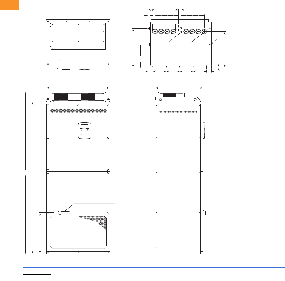
V6-T2-248 Volume 6—Solid-State Motor Control CA08100007E—February 2016 www.eaton.com
2
2
2
2
2
2
2
2
2
2
2
2
2
2
2
2
2
2
2
2
2
2
2
2
2
2
2
2
2
2
2.9
Adjustable Frequency Drives
SPX Drives
Approximate Dimensions in Inches (mm)
NEMA Type 1/IP21, FR11 Freestanding Drive
Voltage
hp
(IH) W1W2W3W4W5W6W7W8H1 H2 H3 D1 D2 D3 D4 D5 Dia. 1Dia. 2Dia. 3
Weight
Lbs (kg)
480 V 400–550 31.26
(794)
2.40
(61)
6.50
(165)
0.79
(20)
3.43
(87)
2.95
(75)
2.52
(64)
1.18
(30)
79.45
(2018)
74.80
(1900)
20.18
(512.5)
23.70
(602)
11.22
(285)
19.09
(485)
0.47
(12)
17.60
(447)
0.83
(21)
1.89
(48)
0.35 x 0.43
(9 x 11)
526
(239)
690 V 400–500
H1
H2
W1 D1
H3
D2
D3
Dia. 3
D4
D5
Dia. 1 Dia. 2
W2
W2 W3 W3 W3 W3
W8
W6
W4
W6
W5
W7W7 W6W6W6W6
Operator
(Shown with
Optional
Disconnect)

Volume 6—Solid-State Motor Control CA08100007E—February 2016 www.eaton.com V6-T2-249
2
2
2
2
2
2
2
2
2
2
2
2
2
2
2
2
2
2
2
2
2
2
2
2
2
2
2
2
2
2
2.9
Adjustable Frequency Drives
SPX Drives
Approximate Dimensions in Inches (mm)
FR11 Open Chassis
Voltage hp (IH)W1W2W3H1 H2 D1 D2
Weight
Lbs (kg)
480 V 400–550 27.9 (709) 8.6 (225) 2.6 (67) 45.5 (1155) 33.5 (850) 19.8 (503) 18.4 (468) 833 (378)
575 V 400–500
H1
H2
D1
W2
W2
W3
W2
W2
W3
W1
Shown without
terminal cover
D2

V6-T2-250 Volume 6—Solid-State Motor Control CA08100007E—February 2016 www.eaton.com
2
2
2
2
2
2
2
2
2
2
2
2
2
2
2
2
2
2
2
2
2
2
2
2
2
2
2
2
2
2
2.9
Adjustable Frequency Drives
SPX Drives
Approximate Dimensions in Inches (mm)
FR13, Open Chassis Inverter
Notes
9000X FR14 is built of two FR13 modules. Please refer to SPX installation manual for mounting instructions.
FR13 is built from an inverter module and a converter module. Please refer to SPX installation manual for mounting instructions.
W1 W2 W3 W4 W5 H1 H2 H3 H4 H5 D1 D2 D3 D4 D5 D6 D7 D8
Dia.
1
Dia.
2
Dia.
3
Dia.
4
Weight
Lbs (kg)
27.87
(708)
5.91
(150)
26.65
(677)
4.57
(116)
3.35
(85)
41.54
(1055)
2.46
(62.5)
39.86
(1012.5)
41.34
(1050)
0.79
(20)
21.77
(553)
0.51
(13)
0.63
(16)
1.97
(50)
1.06
(27)
1.57
(40)
5.91
(150)
9.64
(244.8)
0.35x0.59
(9x15)
0.18
(4.6)
0.51
(13)
0.37
(9.5)
683 (310)
W4 W4 W4 W4 W4
H3
Dia. 1 D1 D2 W1
W2W2W2W2
H2
W5 W5 W5
D3
Dia. 3
Dia. 3 D4
D4
H5
H4H1
D5 D6
D7
D8
D6
W3
Dia. 2
Dia. 4
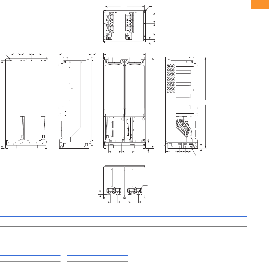
Volume 6—Solid-State Motor Control CA08100007E—February 2016 www.eaton.com V6-T2-251
2
2
2
2
2
2
2
2
2
2
2
2
2
2
2
2
2
2
2
2
2
2
2
2
2
2
2
2
2
2
2.9
Adjustable Frequency Drives
SPX Drives
Approximate Dimensions in Inches (mm)
FR13, Open Chassis Converter
Number of Input Units
W1 W2 W3 W4 W5 H1 H2 H3 H4 H5 D1 D2 D3 D4 D5 D6 D7 D8 D9 Dia. 1 Dia. 2 Dia. 3
Weight
Lbs (kg)
18.74
(476)
5.91
(150)
17.52
(445)
4.57
(116)
3.35
(85)
41.54
(1055)
2.46
(62.5)
39.86
(1012.5)
41.34
(1050)
0.69
(17.5)
14.69
(373)
0.51
(13)
0.73
(18.5)
6.42
(163)
2.56
(65)
1.06
(27)
1.57
(40)
5.91
(150)
5.24
(133)
0.35x0.59
(9x15)
0.51
(13)
0.37
(9.5)
295 (134)
480 V
Catalog Number hp
Input
Modules
690 V
Catalog Number hp
Input
Modules
SPX800 A0-4 A2N1 800 2 SPX800 A0-5 A2N1 800 2
SPX900 A0-5 A2N1 900 2
SPXH10 A0-5 A2N1 1000 2
H3
H2
H5
H4
Dia. 1 W4 W4 W4
W5
D3 W5
D5
D4 D5
W2
W2
D1 D2
Dia. 2
Dia. 2
H1
W3 Dia. 3
D9
D8
D7
D6
W1

V6-T2-252 Volume 6—Solid-State Motor Control CA08100007E—February 2016 www.eaton.com
2
2
2
2
2
2
2
2
2
2
2
2
2
2
2
2
2
2
2
2
2
2
2
2
2
2
2
2
2
2
2.9
Adjustable Frequency Drives
SPX Drives
Approximate Dimensions in Inches (mm)
FR13, Open Chassis Converter—900/1000 hp 480 V
Number of Input Units
W1 W2 W3 W4 W5 H1 H2 H3 H4 H5 D1 D2 D3 D4 D5 D6 D7 D8 D9
Dia.
1
Dia.
2
Dia.
3
Dia.
4
Weight
Lbs (kg)
27.87
(708)
5.91
(150)
26.65
(677)
4.57
(116)
3.35
(85)
41.54
(1055)
2.46
(62.5)
39.86
(1012.5)
41.34
(1050)
0.69
(17.5)
14.69
(373)
0.51
(13)
0.73
(18.5)
6.42
(163)
2.56
(65)
1.06
(27)
1.57
(40)
5.91
(150)
5.24
(133)
0.35x0.59
(9x15)
0.18
(4.6)
0.51
(13)
0.37
(9.5)
443 (201)
480 V
Catalog Number hp
Input
Modules
SPX900 A0-4 A2N1 900 3
SPXH10 A0-4 A2N1 1000 3
H3
H2
H5
Dia. 1 W4 W4 W4 W4 W4
W5
D3 W5 W5
D5
D4 D5
W2
W2
W2 W2
D1 D2
Dia. 2
Dia. 3
H1 H4
W3 Dia. 4
D9
D8
D7
D6
W1

Volume 6—Solid-State Motor Control CA08100007E—February 2016 www.eaton.com V6-T2-253
2
2
2
2
2
2
2
2
2
2
2
2
2
2
2
2
2
2
2
2
2
2
2
2
2
2
2
2
2
2
2.9
Adjustable Frequency Drives
SPX Drives
Approximate Dimensions in Inches (mm)
AC Choke Dimensions
Choke Types
CHK0520
Note
1Chokes are provided with all FR10–FR14 drives.
Catalog Number Frame Size Choke Type 1Catalog Number Frame Size Choke Type 1
Voltage Range 380–500 V Voltage Range 525–690 V
SPX 250 4 FR10 CHK0400 SPX 200 5 FR10 CHK0261
SPX 300 4 CHK0520 SPX 250 5 CHK0400
SPX 350 4 CHK0520 SPX 300 5 CHK0400
SPX 400 4 FR11 2 x CHK0400 SPX 400 5 FR11 CHK0520
SPX 500 4 2 x CHK0400 SPX 450 5 CHK0520
SPX 550 4 2 x CHK0400 SPX 500 5 2 x CHK0400
SPX 600 4 FR12 2 x CHK0520 SPX 550 5 FR12 2 x CHK0400
SPX 650 4 2 x CHK0520 SPX 600 5 2 x CHK0400
SPX 700 4 2 x CHK0520 SPX 700 5 2 x CHK0400
SPX 800 4 FR13 2 x CHK0400 SPX 800 5 FR13 2 x CHK0400
SPX 900 4 3 x CHK0520 SPX 900 5 2 x CHK0400
SPX H10 4 3 x CHK0520 SPX H10 5 2 x CHK0400
SPX H12 4 FR14 4 x CHK0520 SPX H13 5 FR14 4 x CHK0400
SPX H16 4 6 x CHK0400 SPX H15 5 6 x CHK0400
11
33
2
1
3
22
1.58
(40)
7.88
(200)
6.50
(165) 6.50
(165)
19.57
(497)
.79
(20) 15.71
(399)
17.57
(446)
.79
(20)
.24
(6)
3.03
(77)
.83
(21)
.55 (14)9.61 (244)
8.03 (204)
1.69
(43)
5.70
(145)

V6-T2-254 Volume 6—Solid-State Motor Control CA08100007E—February 2016 www.eaton.com
2
2
2
2
2
2
2
2
2
2
2
2
2
2
2
2
2
2
2
2
2
2
2
2
2
2
2
2
2
2
2.9
Adjustable Frequency Drives
SPX Drives
Approximate Dimensions in Inches (mm)
CHK0400
CHK0261
111
33
22
3
2
10.30 (262)
9.37 (238)
1.54
(39)
1.18
(30)
5.90
(150)
13.79 (350)
4.72
(120) 4.72
(120)
10.83 (275)
.59
(15)
5.51
(140)
13.94
(354)
15.08
(383)
16.58
(421)
2.64
(67)
.75
(19)
.24
(6)
.59
(15)
13.79 (350)
4.72
(120) 4.72
(120)
.24
(6)
11
33
2
1
3
22
1.18
(30)
5.90
(150)
10.83 (275)
.59
(15)
11.30
(287)
12.56
(319)
14.06
(357)
.59
(15)
.39
(10)
.87
(22)
.75 (19)
Min.
9.06 (230)
8.11 (206)
1.54
(39)
4.25
(108)
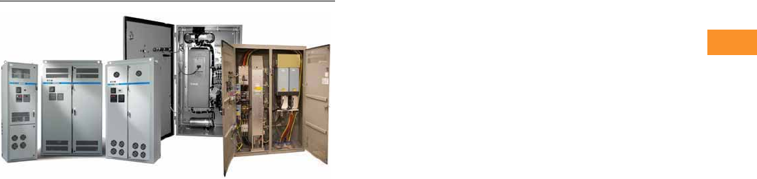
Volume 6—Solid-State Motor Control CA08100007E—February 2016 www.eaton.com V6-T2-255
2
2
2
2
2
2
2
2
2
2
2
2
2
2
2
2
2
2
2
2
2
2
2
2
2
2
2
2
2
2
2.10
Adjustable Frequency Drives
Clean Power Drives
Clean Power Drives
Contents
Description Page
Clean Power Drives Overview . . . . . . . . . . . . . . . . V6-T2-256
Enclosed Passive Filtered Drives
EGF Enclosed Drives . . . . . . . . . . . . . . . . . . . . V6-T2-263
CFX Enclosed Drives . . . . . . . . . . . . . . . . . . . . V6-T2-288
HCX Enclosed 12-Pulse Drives . . . . . . . . . . . . . . . V6-T2-319
CPX Enclosed 18-Pulse Drives . . . . . . . . . . . . . . . V6-T2-323
RGX Enclosed Regenerative Drives . . . . . . . . . . . V6-T2-348
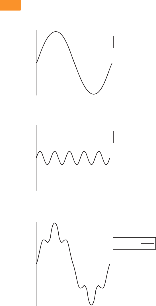
V6-T2-256 Volume 6—Solid-State Motor Control CA08100007E—February 2016 www.eaton.com
2
2
2
2
2
2
2
2
2
2
2
2
2
2
2
2
2
2
2
2
2
2
2
2
2
2
2
2
2
2
2.10
Adjustable Frequency Drives
Clean Power Drives
Clean Power Drives Overview
What Are Harmonics?
Take a perfect wave with a fundamental frequency of 60 Hz,
which is close to what is supplied by the power company.
Perfect Wave
Add a second wave that is five times the fundamental frequency—
300 Hz (typical of frequency added to the line by a fluorescent light).
Second Wave
Combine the two waves. The result is a 60 Hz supply rich in
fifth harmonics.
Resulting Supply
f(x) = sin(x)
Volts
(v)
Time
(t)
f(x) = sin(5x)
5
Volts
(v)
Time
(t)
f(x) = sin(x) +
Volts
(v)
Time
(t)
sin(5x)
5
What Causes Harmonics?
Harmonics are the result of
nonlinear loads that convert
AC line voltage to DC.
Examples of equipment that
are non-linear loads are listed
below:
●AC variable frequency
drives
●DC drives
●Fluorescence lighting,
computers, UPS systems
●Industrial washing
machines, punch presses,
welders, etc.
How Can Harmonics Due to
VFDs Be Diminished?
By applying drives from the
Eaton Clean Power drives
family: EGF and CFX passive
filtered drives, HCX 12-pulse
drives, EGP and CPX 18-pulse
drives, and RGX regenerative
drives.
What Are Linear Loads?
Linear loads are primarily
devices that run across the
line and do not add
harmonics. Motors are prime
examples. The downside to
having large motor linear
loads is that they draw more
energy than a VFD, because
of their inability to control
motor speed. In most
applications there is a turn
down valve used with the
motor which will reduce the
flow of the material, without
significantly reducing the load
to the motor. While this
provides some measure of
speed control, it is extremely
inefficient.
Why Be Concerned
About Harmonics?
1. Installation and utility
costs increase.
Harmonics cause
damage to transformers
and lower efficiencies
due to the voltage drop.
These losses can
become significant (from
16.6–21.6%) which can
have a dramatic effect on
the HVAC systems that
are controlling the
temperatures of the
building where the
transformer and drive
equipment reside.
2. Downtime and loss of
productivity. Telephones
and data transmissions
links may not be
guaranteed to work on
the same power grids
polluted with harmonics.
3. Downtime and
nuisance trips of drives
and other equipment.
Emergency generators
have up to three times
the impedance that is
found in a conventional
utility source. Thus the
harmonic voltage can be
up to three times as
large, causing risk of
operation problems.
4. Larger motors must be
used. Motors running
across the line that are
connected on polluted
power distribution grids
can overheat or operate
at lower efficiency due to
harmonics.
5. Higher installation
costs. Transformers and
power equipment must
be oversized to
accommodate the loss of
efficiencies. This is due
to the harmonic currents
circulating through the
distribution without
performing useful work.
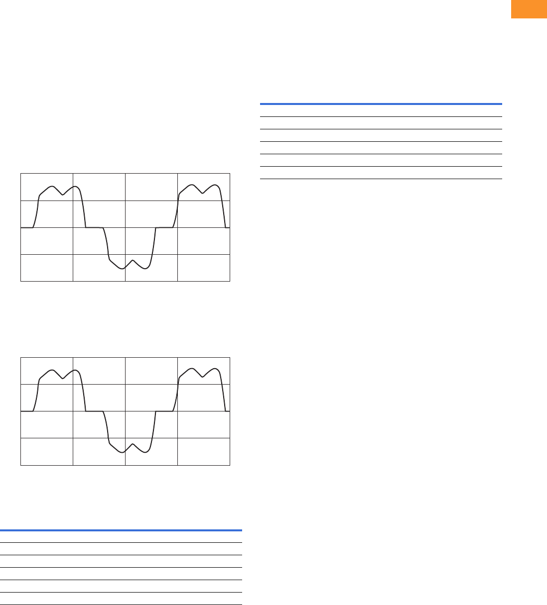
Volume 6—Solid-State Motor Control CA08100007E—February 2016 www.eaton.com V6-T2-257
2
2
2
2
2
2
2
2
2
2
2
2
2
2
2
2
2
2
2
2
2
2
2
2
2
2
2
2
2
2
2.10
Adjustable Frequency Drives
Clean Power Drives
How Does a VFD Convert Three-Phase AC to a
Variable Output Voltage and Frequency?
The six-pulse VFD: The
majority of all conventional
drives that are built consist of
a six-pulse configuration. The
figure below
represents a six-
diode rectifier design that
converts three-phase utility
power to DC. The inverter
section uses IGBTs to convert
DC power to a simulated AC
sine wave that can vary in
frequency from 0–400 Hz.
The six-pulse VFD drive
creates harmonic current
distortion. The harmonic
current that is created is
energy that can not be used
by customers and causes
external heat and losses to all
components including other
drives that are on the same
power distribution. The figure
is a 100 hp drive with 45 A of
damaging harmonic current.
100 hp Six-Diode Rectifier Design
100 hp Six-Pulse Nonproductive Harmonic Current
Six-Pulse Nonproductive Harmonic Current
Six-Pulse Circuit
Current harmonics
I1 = 100% I11 = 6.10% I19 = 1.77%
I5 = 22.5% I13 = 4.06% I23 = 1.12%
I7 = 9.38% I17 = 2.26% I25 = 0.86%
Power = 100 hp
Harmonic current = 45 amps
1000
Current
Amps
500
0
–500
–1000
0.100 0.10625 0.1125
Time in Seconds
0.11875 0.125
1000
Current
Amps
500
0
–500
–1000
0.100 0.10625 0.1125
Time in Seconds
0.11875 0.125
Guidelines of Meeting IEEE Std. 519-2014
Harmonic Distortion Limits
The IEEE 519-2014
Specification is a standard
that provides guidelines for
commercial and industrial
users that are implementing
medium and low voltage
equipment.
Current Distortion Limits for Systems Rated
120 V through 69 kV
Notes
1Even harmonics are limited to 25% of the odd harmonic limits shown in table above.
2Current distortions that result in a DC offset, e.g., half-wave converters, are not allowed.
3All power generation equipment is limited to these values of current distortion, regardless
of actual Isc
/IL.
where
Isc = maximum short-circuit current at PCC.
IL
= maximum demand load current (fundamental frequency component)
at the PCC under normal load operating conditions.
Maximum Harmonic Current Distortion in percent of IL
Individual Harmonic Order (Odd Harmonics) 12
Isc/IL3 ≤ h < 11 11 ≤ h < 17 17 ≤ h < 23 23 ≤ h < 35 35 ≤ h ≤ 50 TDD
<20 34.0 2.0 1.5 0.6 0.3 5.0
20 <50 7.0 3.5 2.5 1.0 0.5 8.0
50 <100 10.0 4.5 4.0 1.5 0.7 12.0
100 <1000 12.0 5.5 5.0 2.0 1.0 15.0
>1000 15.0 7.0 6.0 2.5 1.4 20.0
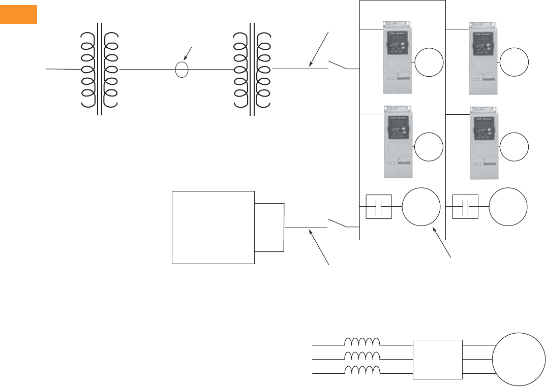
V6-T2-258 Volume 6—Solid-State Motor Control CA08100007E—February 2016 www.eaton.com
2
2
2
2
2
2
2
2
2
2
2
2
2
2
2
2
2
2
2
2
2
2
2
2
2
2
2
2
2
2
2.10
Adjustable Frequency Drives
Clean Power Drives
One-Line Diagram for Harmonic Analysis
Terms
●PCC (Point of Common
Coupling) is defined as the
electrical connecting point
between the utility and
multiple customers per the
specifications in IEEE 519
●POA (Point of Analysis)
is defined as where the
harmonic calculations
are taken
An oscilloscope can make
all measurements at the
PCC or POA to do an on-site
harmonic evaluation.
Harmonic Reduction
Methods to Meet IEEE 519
1. Line Reactor
A line reactor is a three-phase
series inductance on the line
side of an AFD. If a line
reactor is applied on all
AFDs, it is possible to meet
IEEE guidelines where
10–25% of system loads
are AFDs, depending on the
stiffness of the line and the
value of line reactance. Line
reactors are available in
various values of percent
impedance, most typically
1–1.5%, 3% and 5%.
Note: The SVX/SPX drives come
standard with a nominal 3% input
impedance.
____Volts ____Volts
____Volts
____kVA
____Isc
____Impedance
PCC
Utility Side
Utility Side
Transformer
____Volts ____Volts
____Volts
____kVA
____Isc
____Impedance
Customer
Transformer
Customer
Generator
____Volts
____kVA
____Isc
____Impedance
Source A
Source B
Generator
Set
AC
Motor
AC
Motor
AC
Motor
Total Linear Motor Loads
Total Non-Linear Drive Loads
____AMPS
____AMPS
AC
Motor
AC
Motor
AC
Motor
The best way to estimate AFD harmonic contribution to an electrical system is to perform a harmonic analysis based on known system
characteristics. The one line in this figure would provide the data to complete the calculations.
Line Reactor
Advantages
●Low cost
●Can provide moderate
reduction in voltage and
current harmonics
●Available in various values
of percent impedance
●Provides increased input
protection for AFD and its
semiconductors from line
transients
Disadvantages
●May not reduce harmonic
levels to below IEEE 519-
2014 guidelines
●Voltage drop due to IR loss
AFD Motor
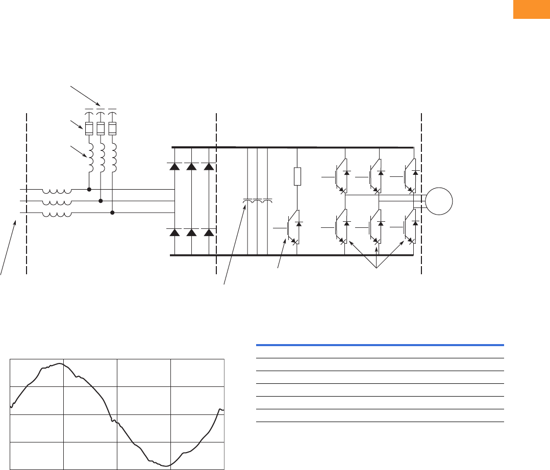
Volume 6—Solid-State Motor Control CA08100007E—February 2016 www.eaton.com V6-T2-259
2
2
2
2
2
2
2
2
2
2
2
2
2
2
2
2
2
2
2
2
2
2
2
2
2
2
2
2
2
2
2.10
Adjustable Frequency Drives
Clean Power Drives
2. Passive Filters
Tuned harmonic filters
involve the series connection
of an inductor with the shunt
connection of an inductor and
capacitor to form a low
impedance path to ground for
a specific range of
frequencies. This path
presents an alternative to the
flow of harmonic currents
back into the utility source.
Enclosed Drive with Integrated Passive Filter
100 hp Enclosed 480 V Drive with Integrated Passive Filter
Three-Phase
Input
AC Input
Reactor
L1A
L2A
L3A
1
2
3
Output Transistors
IGBT Section
Dynamic Braking
Transistor
6-Pulse Diode
Bridge Rectier
Converter Section
Shunt
Fusing
Tuned
Shunt
Reactor
Tuned
Harmonic
Capacitor
Inverter Section
(–) DC
(+) DC
Bus
Capacitors
AC
Motor
200
Current
Amps
100
0
–100
–200
Time
100 hp Enclosed 480 V Drive with Integrated Passive Filter
Advantages
●Low cost for smaller
horsepower applications
●More effective harmonic
attenuation than 12-pulse
drives
●Provides increased input
protection for AFD from
line transients
Disadvantages
●Capacitors age over time,
unlike magnetics
●Not as effective as
18-pulse drives
●Challenging to retrofit with
bypass applications
Passive Filter
Current harmonics
I1 = 100% I11 = 0.24% I19 = 0.50%
I5 = 3.76% I13 = 1.1% I23 = 0.55%
I7 = 1.65% I17 = 0.80% I25 = 0.80%
Power = 100 hp
Hc = 8.6 Amps
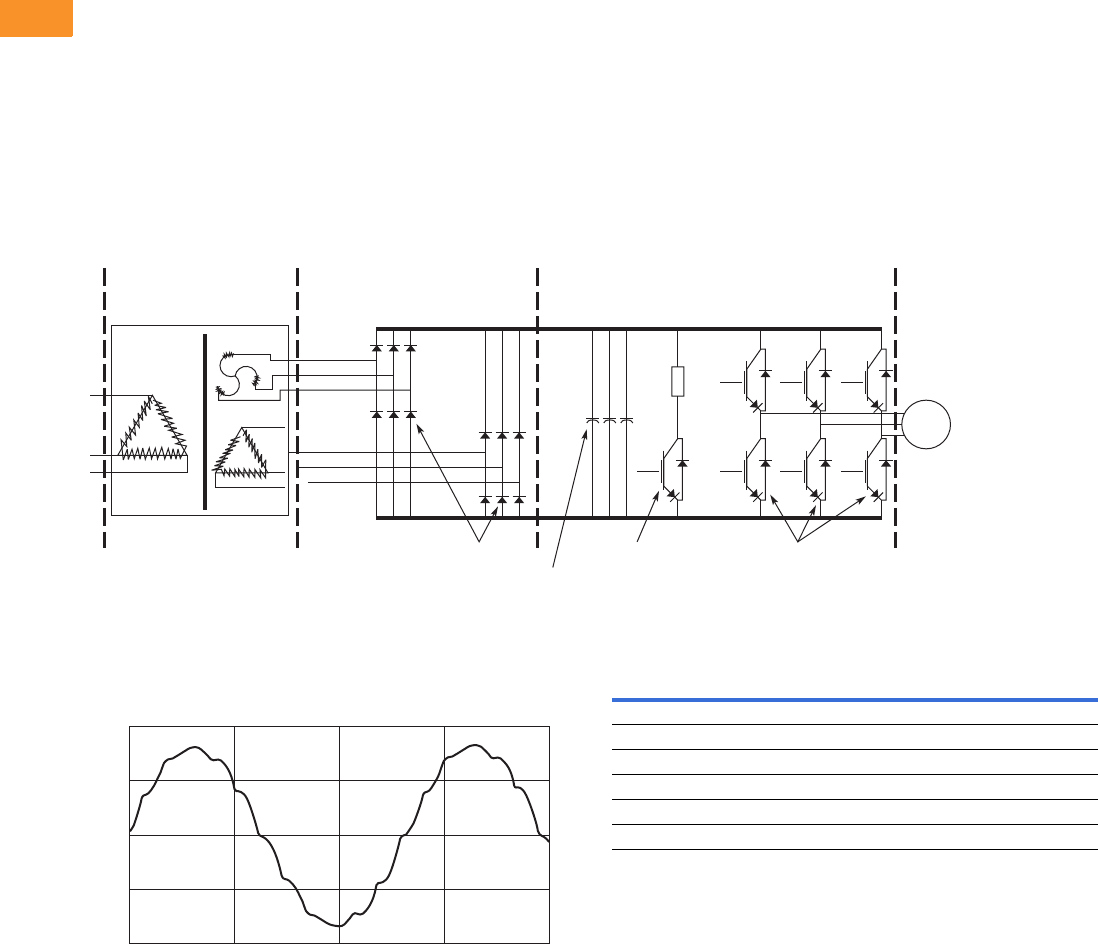
V6-T2-260 Volume 6—Solid-State Motor Control CA08100007E—February 2016 www.eaton.com
2
2
2
2
2
2
2
2
2
2
2
2
2
2
2
2
2
2
2
2
2
2
2
2
2
2
2
2
2
2
2.10
Adjustable Frequency Drives
Clean Power Drives
3. 12-Pulse Converters
A 12-pulse converter
incorporates two separate
AFD input semiconductor
bridges, which are fed from
30º phase shifted power
sources with identical
impedance. The sources may
be two isolation
transformers, where one is a
delta/wye design (which
provides the phase shift) and
the second a delta/delta
design (which does not phase
shift). The 12-pulse
arrangement allows the
harmonics from the first
converter to cancel the
harmonics of the second. Up
to approximately 85%
reduction of harmonic current
and voltage distortion may be
achieved (over standard
Basic 12-Pulse Rectifier with “Phase Shifting” Transformer
100 hp 480 V Drive with 12-Pulse Rectifier
12-Pulse Diode
Bridge Rectier
Converter Section
Inverter Section
(+) DC
L1A
L2A
L3A
L1B
L2B
L3B
(-) DC
Dynamic Braking
Transistor
Output Transistors
IGBT Section
AC
Motor
12-Pulse Diode
Bridge Rectier
Converter Section
12-Pulse
Phase-Shifting
Transformer
Bus
Capacitors
200
Current
Amps
100
0
–100
–200
Time
six-pulse converter). This
permits a facility to use a
larger percentage of AFD
loads under IEEE 519-2014
guidelines than allowable
using line reactors or DC
chokes. A harmonic analysis
is required to guarantee
compliance with guidelines.
100 hp 480 V Drive with 12-Pulse Rectifier
Advantages
●Reasonable cost, although
significantly more than
reactors or chokes
●Substantial reduction (up to
approx. 85%) in voltage
and current harmonics
●Provides increased input
protection for AFD and its
semiconductors from line
transients
Disadvantages
●Impedance matching of
phase shifted sources is
critical to performance
●Transformers often require
separate mounting or
larger AFD enclosures
●May not reduce
distribution harmonic levels
to below IEEE 519-2014
guidelines
●Cannot retrofit for most
AFDs
12-Pulse Circuit
Current harmonics
I1 = 100% I11 = 4.19% I19 = 0.06%
I5 = 1.25% I13 = 2.95% I23 = 0.87%
I7 = 0.48% I17 = 0.21% I25 = 0.73%
Power = 100 hp
Hc = 20 Amps
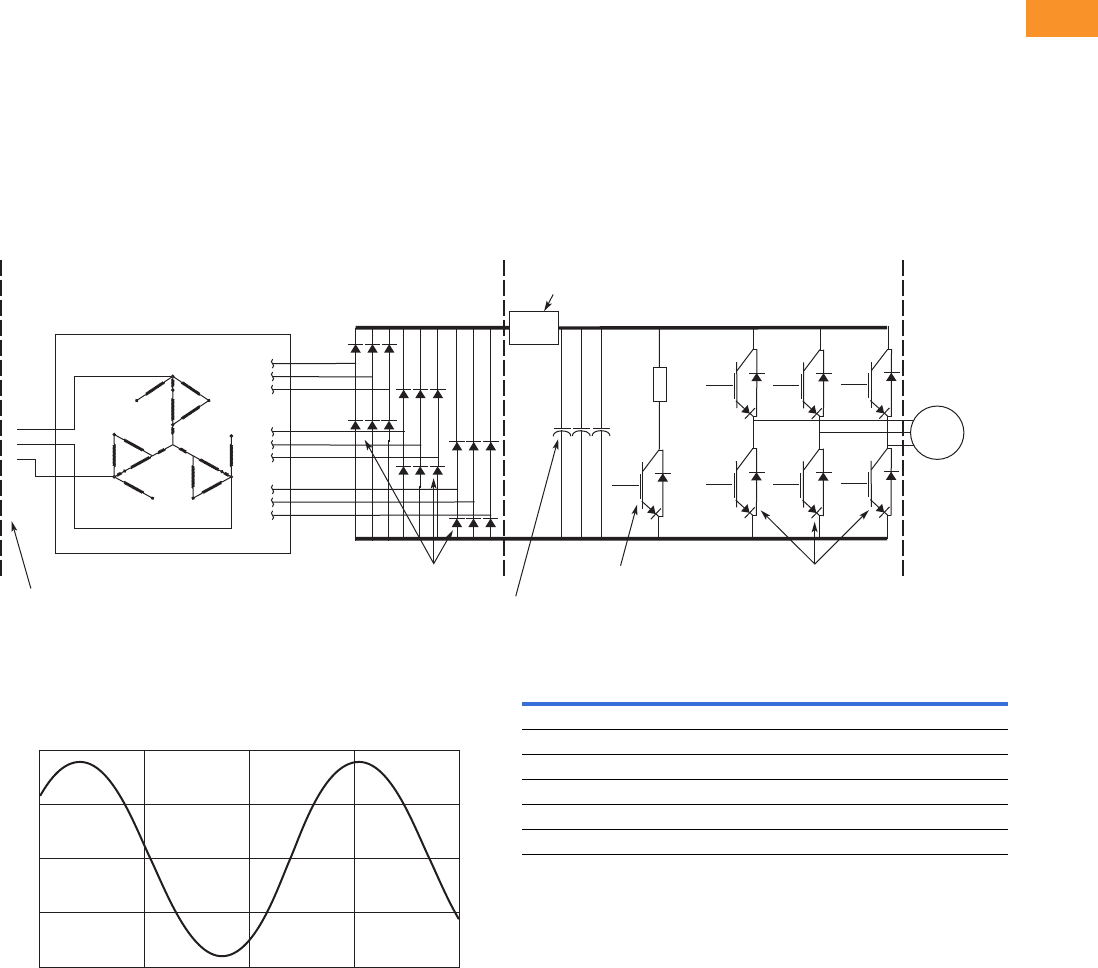
Volume 6—Solid-State Motor Control CA08100007E—February 2016 www.eaton.com V6-T2-261
2
2
2
2
2
2
2
2
2
2
2
2
2
2
2
2
2
2
2
2
2
2
2
2
2
2
2
2
2
2
2.10
Adjustable Frequency Drives
Clean Power Drives
4. 18-Pulse Converters
When the total load is
comprised of non-linear load
such as drives, and the ratio
is lsc/IL, the greatest
harmonic mitigation is
required. Under these
conditions, the currents
drawn from the supply need
to be sinusoidal and “clean”
such that system
interference and additional
losses are negligible. Eaton’s
enclosed 18-pulse drive uses
a phase-shifting auto-
transformer with delta-
connected winding that
carries only the ampere-turns
caused by the difference in
load currents. This results in
nine separate phases. In this
type of configuration, the
Basic 18-Pulse Rectifier with Phase-Shifting Auto-Transformer
100 hp 480 V Drive with 18-Pulse Rectifiers
1
12
23
34
4
5
5
6
67
7
8
8
9
9
A
C
N
Output Transistors
IGBT Section
Dynamic Braking
Transistor
Pre-charge
Circuit
18-Pulse SCR
Bridge Rectier
Converter Section
18-Pulse
Phase-Shifting
Auto-Transformer
Inverter Section
(–) DC
(+) DC
Diode Rectiers
Bus
Capacitors
3-Phase
AC Input
1
2
3
AC
Motor
200
Current
Amps
100
0
–100
–200
Time
total kVA rating of the
transformer magnetic system
was only 48% that of the
motor load. A traditional
isolated transformer system,
with multipulse windings,
would require the full kVA
rating to be supported, which
is more common in an MV
step-down transformer.
The integrated 18-pulse drive,
with near sine wave input
current and low harmonics
will meet the requirements of
IEEE 519-2014 under all
practical operating conditions.
The comparisons with six-
pulse passive filter and 12-
pulse systems are shown on
Pages V6-T2-257, V6-T2-259
and below.
100 hp 480 V Drive with 18-Pulse Rectifiers
Advantages
●Effectively guarantees
compliance with IEEE 519-
2014
●Provides increased input
protection for AFD and its
semiconductors from line
transients
●Up to 4 times the harmonic
reduction of 12-pulse
methods
●Smaller transformer than
isolation transformer used
in 12-pulse converter
●Minimizes ripple current in
capacitors, doubling
expected capacitor life
Disadvantages
●Not as cost effective as
some other methods at
small (<50) horsepower
18-Pulse Clean Power
Current harmonics
I1 = 100% I11 = 0.24% I19 = 1.00%
I5 = 0.16% I13 = 0.10% I23 = 0.01%
I7 = 0.03% I17 = 0.86% I25 = 0.01%
Power = 100 hp
Hc = 5.9 Amps
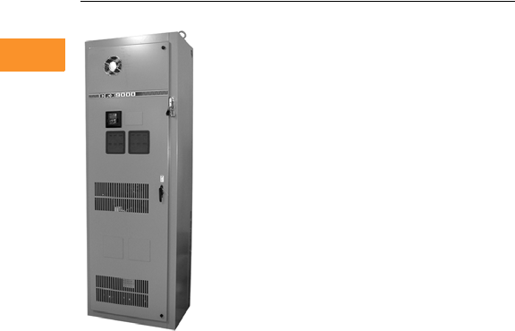
V6-T2-262 Volume 6—Solid-State Motor Control CA08100007E—February 2016 www.eaton.com
2
2
2
2
2
2
2
2
2
2
2
2
2
2
2
2
2
2
2
2
2
2
2
2
2
2
2
2
2
2
2.10
Adjustable Frequency Drives
Clean Power Drives
Enclosed Passive Filtered Drives
Contents
Description Page
Clean Power Drives Overview . . . . . . . . . . . . . . . V6-T2-256
Enclosed Passive Filtered Drives
EGX Enclosed Drives . . . . . . . . . . . . . . . . . . . . V6-T2-263
CFX Enclosed Drives . . . . . . . . . . . . . . . . . . . . V6-T2-288
Enclosed 12-Pulse Drives . . . . . . . . . . . . . . . . . . . V6-T2-319
Enclosed 18-Pulse Drives . . . . . . . . . . . . . . . . . . . V6-T2-323
Enclosed Regenerative Drives . . . . . . . . . . . . . . . V6-T2-348
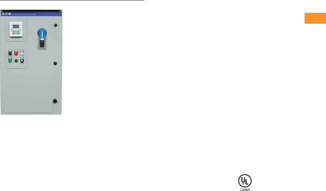
Volume 6—Solid-State Motor Control CA08100007E—February 2016 www.eaton.com V6-T2-263
2
2
2
2
2
2
2
2
2
2
2
2
2
2
2
2
2
2
2
2
2
2
2
2
2
2
2
2
2
2
2.10
Adjustable Frequency Drives
Clean Power Drives
EGF Enclosed Drives
Contents
Description Page
Clean Power Drives Overview . . . . . . . . . . . . . . . . V6-T2-256
Enclosed Passive Filtered Drives
EGF Enclosed Drives
Product Identification . . . . . . . . . . . . . . . . . V6-T2-289
Catalog Number Selection . . . . . . . . . . . . . V6-T2-264
Production Selection . . . . . . . . . . . . . . . . . . V6-T2-266
Enclosure Selection . . . . . . . . . . . . . . . . . . . V6-T2-269
Options . . . . . . . . . . . . . . . . . . . . . . . . . . . . V6-T2-271
Technical Data and Specifications . . . . . . . . V6-T2-273
Wiring Diagram . . . . . . . . . . . . . . . . . . . . . . V6-T2-276
Dimensions . . . . . . . . . . . . . . . . . . . . . . . . . V6-T2-277
CFX Enclosed Drives . . . . . . . . . . . . . . . . . . . . V6-T2-288
Enclosed 12-Pulse Drives . . . . . . . . . . . . . . . . . . . V6-T2-319
Enclosed 18-Pulse Drives . . . . . . . . . . . . . . . . . . . V6-T2-323
Enclosed Regenerative Drives . . . . . . . . . . . . . . . . V6-T2-348
EGF Enclosed Drives
Product Description
Eaton’s Enclosed EGF Drives
combine harmonic distortion
reduction and true power
factor performance with the
latest in Eaton adjustable
frequency drive technology to
deliver an industry-leading
solution. This pre-engineered
passive filtered solution
prevents transformer
overheating and overloading
of breakers and feeders,
which enables the application
of adjustable frequency
drives on generators and
other high impedance power
systems.
Features and Benefits
●Tuned passive filter
●Delivers 5–8% THD
●Generator compatible
●Uses the same DG1, SVX
or SPX drive that is stocked
in the warehouse
●Simple to retrofit
●Provides a low-impedance
path to ground for the
harmonic frequencies
●Meets IEEE 519-2014
●Excellent cost for
performance
●Small footprint, compact
enclosure design
●Insensitive to voltage
imbalance
●Customizable cover control
options
●Padlockable disconnect
●The PowerXL DG1 comes
standard with the following
communication protocols:
●EtherNet/IP
●Modbus/TCP
●Modbus RTU
●BACnet MS/TP
Communication Options
●PROFIBUS-DP
●LonWorks
●CANopen
●DeviceNet
Enclosure Ratings
●NEMA Type 1
●NEMA Type 12
●NEMA Type 3R
Mounting
●Wall mount
●Floor mount: 12-inch legs
●Floor mount: 22-inch legs
Product Range
●208 V: 0.75–100 hp
●230 V: 0.75–125 hp
●480 V: 1–250 hp
Standards and Certifications
●UL 508C tested, listed
and approved
●OSHPD
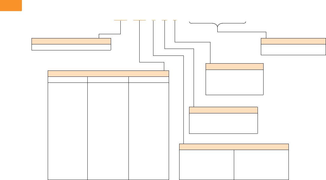
V6-T2-264 Volume 6—Solid-State Motor Control CA08100007E—February 2016 www.eaton.com
2
2
2
2
2
2
2
2
2
2
2
2
2
2
2
2
2
2
2
2
2
2
2
2
2
2
2
2
2
2
2.10
Adjustable Frequency Drives
Clean Power Drives
Catalog Number Selection
Catalog Number Selection is for reference only. Not all option combinations may be available.
EGF Enclosed—Base Catalog Number
Notes
1Brake chopper is a factory-installed option only. Braking resistors sold separately. See DG1 drives starting on Page V6-T2-55 for selection.
2Additional enclosure options including NEMA 4 and 4X are available. Please contact the factory for configuration and pricing.
3Part number configuration continued on the following page.
EGF 3D5 1 D 1
Product Family
EGF = Enclosed DG1 drives—passive filtered
Output Ampere Rating
208 V 230 V 480 V
3D5 = 3.5 A, 0.75 hp
4D6 = 4.6 A, 1 hp
6D6 = 6.6 A, 1.5 hp
7D5 = 7.5 A, 2 hp
010 = 10.6 A, 3 hp
016 = 16.7 A, 5 hp
024 = 24.2 A, 7.5 hp
030 = 30.8 A, 10 hp
046 = 46.2 A, 15 hp
059 = 59.4 A, 20 hp
074 = 74.8 A, 25 hp
088 = 88 A, 30 hp
114 = 114 A, 40 hp
143 = 143 A, 50 hp
169 = 169 A, 60 hp
211 = 211 A, 75 hp
273 = 273 A, 100 hp
3D2 = 3.2 A, 0.75 hp
4D2 = 4.2 A, 1 hp
6D0 = 6.0 A, 1.5 hp
6D8 = 6.8 A, 2 hp
9D6 = 9.6 A, 3 hp
015 = 15.2, 5 hp
022 = 22 A, 7.5 hp
028 = 28 A, 10 hp
042 = 42 A, 15 hp
054 = 54 A, 20 hp
068 = 68 A, 25 hp
080 = 80 A, 30 hp
104 = 104 A, 40 hp
130 = 130 A, 50 hp
154 = 154 A, 60 hp
192 = 192 A, 75 hp
248 = 248 A, 100 hp
312 = 312 A, 125 hp
2D1 = 2.1 A, 1 hp
3D0 = 3.0 A, 1.5 hp
3D4 = 3.4 A, 2 hp
4D8 = 4.8 A, 3 hp
7D6 = 7.6 A, 5 hp
011 = 11 A, 7.5 hp
014 = 14 A, 10 hp
021 = 21 A, 15 hp
027 = 27 A, 20 hp
034 = 34 A, 25 hp
040 = 40 A, 30 hp
052 = 52 A, 40 hp
065 = 65 A, 50 hp
077 = 77 A, 60 hp
096 = 96 A, 75 hp
124 = 124 A, 100 hp
156 = 156 A, 125 hp
180 = 180 A, 150 hp
240 = 240 A, 200 hp
302 = 302 A, 250 hp
Phasing and Voltage
1 = Input: Three-phase, 208 V
Output: Three-phase
2 = Input: Three-phase, 230 V
Output: Three-phase
4 = Input: Three-phase, 480 V
Output: Three-phase
5 = Input: Three-phase, 575 V
Output: Three-phase
J = Input: Single-phase, 230 V
Output: Three-phase
K = Input: Single-phase, 480 V
Output: Three-phase
Braking/Application 1
A = No brake chopper, low overload
B = Brake chopper, low overload
C = No brake chopper, high overload
D = Brake chopper, high overload
Enclosure Rating 2
1 = NEMA Type 1
2 = NEMA Type 12
3 = NEMA Type 3R
6 = NEMA Type 1 Filtered
• = Custom option
______
Options 3
See Page V6-T2-265 for catalog
number option selection.
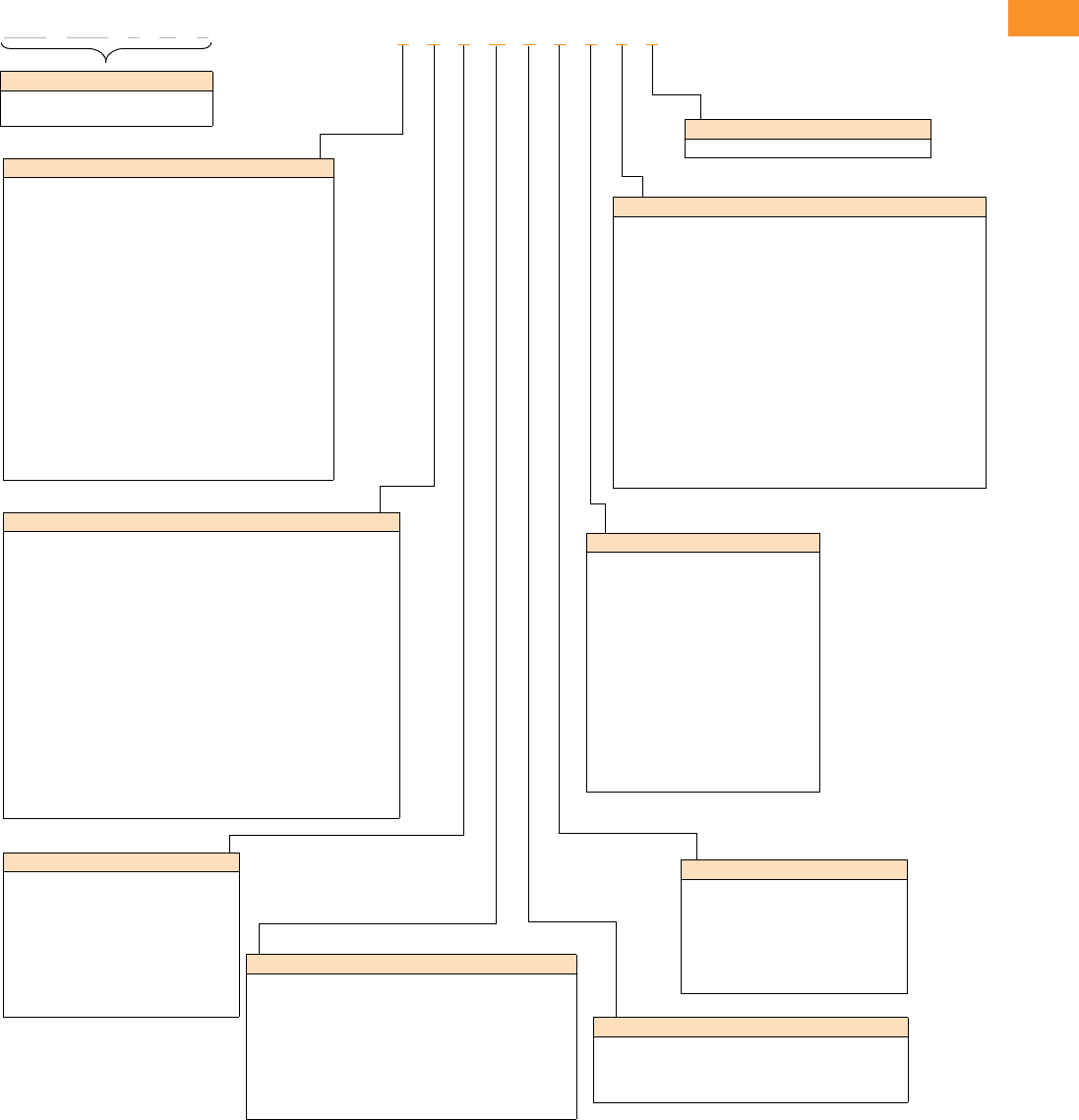
Volume 6—Solid-State Motor Control CA08100007E—February 2016 www.eaton.com V6-T2-265
2
2
2
2
2
2
2
2
2
2
2
2
2
2
2
2
2
2
2
2
2
2
2
2
2
2
2
2
2
2
2.10
Adjustable Frequency Drives
Clean Power Drives
Catalog Number Selection is for reference only. Not all option combinations may be available.
EGF Enclosed—Catalog Number Options
EGF 3D5 1 D 1
Base Catalog Number Example
See Page V6-T2-264 for base catalog
number selection.
2 0 0 B 1 0 0 0 0
Power Disconnect Options
0 =None
1 = MCP disconnect 1
2 = Circuit breaker
3 = Circuit breaker/isolation fusing
4 = Circuit breaker/isolation fusing/3% input reactor
5 = Circuit breaker/isolation fusing/SPD
6 = Circuit breaker/isolation fusing/SPD/3% input reactor
7 = Circuit breaker/3% input reactor
8 = Circuit breaker/SPD
9 = Circuit breaker/SPD/3% input reactor
A = Fused disconnect
B = Fused disconnect/SPD
C = Fused disconnect/SPD/3% input reactor
D = Fused disconnect/3% input reactor
E = Isolation fuses
F = Isolation fuses/3% input reactor
G = Isolation fuses/SPD
H = Isolation fuses/SPD/3% input reactor
• = Custom option 2
Bypass Options 3
0 =None
1 = Manual HOA bypass
2 = Manual HOA bypass/isolation fusing
3 = Manual HOA bypass/isolation fusing/3% input reactor
4 = Manual HOA bypass/isolation fusing/SPD
5 = Manual HOA bypass/isolation fusing/SPD/3% input reactor
6 = Manual HOA bypass/3% input reactor
7 = Manual HOA bypass/SPD
8 = Manual HOA bypass/SPD/3% input reactor
H = Manual HOA RVSS bypass
J = Manual HOA RVSS bypass/isolation fusing
K = Manual HOA RVSS bypass/isolation fusing/3% input reactor
L = Manual HOA RVSS bypass/isolation fusing/SPD
M = Manual HOA RVSS bypass/isolation fusing/SPD/3% input reactor
N = Manual HOA RVSS bypass/3% input reactor
P = Manual HOA RVSS bypass/SPD
R = Manual HOA RVSS bypass/SPD/3% input reactor
• = Custom option 2
Output Power Options 4
0 =None
A = Output contactor
B = 3% Output reactor
C = MotoRX filter
D = dV/dt filter
E = 3% Output Reactor/output contactor
F = MotoRX/output contactor
G = dV/dt/output contactor
• = Custom option 2
Option Boards 2
Same options and codes as Option Boards 1
Option Boards 1
0 = No option
1 = 3 x DI, 3 x DO, 1 Thermistor, 24 Vdc/EXT (DG1 only)
2 = 1 x AI, 2 x AO (isolated to control board) (DG1 only)
3 = 3 x relay dry contact (2NO + 1NO/NC) (DG1 only)
4 = 3 x PT100 RTD thermistor input (DG1 only)
5 = 6 DI 240 Vac input (DG1 only)
6 = 6 DI, 1 ext +24 Vdc/EXT +24 Vdc (SVX only)
7 = 1 RO (NC-NO), 1 RO (NO), 1 therm (SVX only)
8 = 1 AI (mA isolated), 2 AO (mA isolated), 1 ext +24 Vdc/EXT +24 Vdc
(SVX only)
9 = 3 RO (NO) (SVX only)
A = 1 ext +24 Vdc/EXT +24 Vdc, 3 Pt100 (SVX only)
B = 1 RO (NO), 5 DI 42–240 Vac input (SVX only)
C = Encoder low volt +5 V / 15 V / 24 V (high-performance drive only)
D = Encoder high volt +15 V / 24 V (high-performance drive only)
E = Double encoder (high-performance drive only)
• = Custom option 2
Communication Options
0 = No option
1 = PROFIBUS-DP
2 = LonWorks (SVX only)
3 = CANopen (slave)
4 = DeviceNet
5 = PROFIBUS-DP (D9 connector)
6 = Modbus (SVX only)
7 = Modbus (D9 connector) (SVX only)
8 = Johnson Controls N2 (SVX only)
9 = Modbus TCP (SVX only)
A = BACnet (SVX only)
B = EtherNet/IP (SVX only)
C = RS-232 with D9 connector (SVX only)
D = SmartWire-DT (DG1 only)
• = Custom option 2
Enclosure Options
0 =None
1 = Floor stand—12 inches
2 = Floor stand—22 inches
A = Space heater
B = Space heater & 12-inch floor stands
C = Space heater & 22-inch floor stands
• = Custom option 2
Light Options 5
0 =None
1 = Non-bypass light kit—Power On, Run, Fault
2 = Bypass light kit—On, VFD Run, Fault, Bypass Run
• = Custom option 2
Notes
1HMCP disconnect option required and only available when bypass is selected.
2More options are available as Engineered to Order through the Bid Manager tool.
3All bypass options include third contactor for drive isolation when in bypass mode.
4Output contactor not available with bypass. Bypass comes standard with output contactor.
5Pilot devices are 22 mm standard. 30 mm options are available as engineered to order through the Bid Manager tool.
Control Options 5
0 =None
1 = Speed pot
2 = Start-stop pushbutton
3 = Start-stop pushbutton with speed pot
A = HOA switch
B = Start-stop pushbutton with speed pot & HOA switch
C = Start-stop pushbutton with HOA switch
D = HOA switch with speed pot
• = Custom option 2
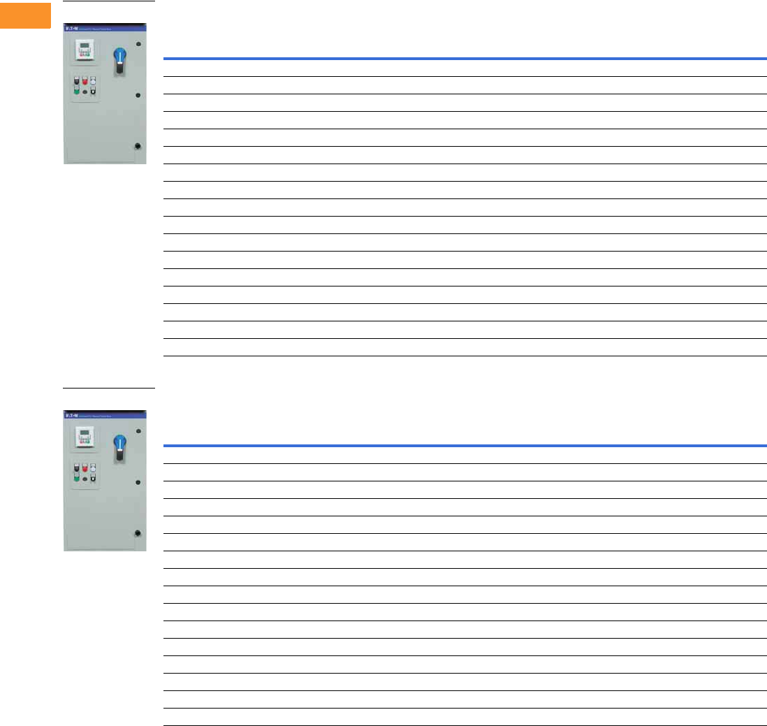
V6-T2-266 Volume 6—Solid-State Motor Control CA08100007E—February 2016 www.eaton.com
2
2
2
2
2
2
2
2
2
2
2
2
2
2
2
2
2
2
2
2
2
2
2
2
2
2
2
2
2
2
2.10
Adjustable Frequency Drives
Clean Power Drives
Production Selection
208 V Drives—Constant Torque (CT)/High Overload (IH) Enclosed Drives
208 V Drives—Variable Torque (VT)/Low Overload (IL) Enclosed Drives
Notes
1 Table is for base catalog number reference only. For complete catalog number selection, see Page V6-T2-264.
2 These units are current rated. They do not meet NEC ampere rating at this horsepower.
NEMA Type 1 NEMA Type 12 NEMA Type 3R
hp Current (A)
Drive
Frame Size
Base
Catalog Number 1
Base
Catalog Number 1
Base
Catalog Number 1
0.75 3.5 1 EGF3D51D1 EGF3D51D2 EGF3D51D3
14.61EGF4D61D1 EGF4D61D2 EGF4D61D3
1.5 6.6 1 EGF6D61D1 EGF6D61D2 EGF6D61D3
27.51EGF7D51D1 EGF7D51D2 EGF7D51D3
310.61EGF0101D1 EGF0101D2 EGF0101D3
516.72EGF0161D1 EGF0161D2 EGF0161D3
7.5 24.2 2 EGF0241D1 EGF0241D2 EGF0241D3
10 30.8 3 EGF0301D1 EGF0301D2 EGF0301D3
15 46.2 3 EGF0461D1 EGF0461D2 EGF0461D3
20 59.4 4 EGF0591C1 EGF0591C2 EGF0591C3
25 74.8 4 EGF0741C1 EGF0741C2 EGF0741C3
30 88 4 EGF0881C1 EGF0881C2 EGF0881C3
40 114 5 EGF1141C1 EGF1141C2 EGF1141C3
50 143 5 EGF1431C1 EGF1431C2 EGF1431C3
60 169 5 EGF1691C1 EGF1691C2 EGF1691C3
75 211 6 EGF2111C1 EGF2111C2 EGF2111C3
100 2261 26EGF2611C1 EGF2611C2 EGF2611C3
NEMA Type 1 NEMA Type 12 NEMA Type 3R
hp Current (A)
Drive
Frame Size
Base
Catalog Number 1
Base
Catalog Number 1
Base
Catalog Number 1
14.61EGF4D61B1 EGF4D61B2 EGF4D61B3
1.5 6.6 1 EGF6D61B1 EGF6D61B2 EGF6D61B3
27.51EGF7D51B1 EGF7D51B2 EGF7D51B3
310.61EGF0101B1 EGF0101B2 EGF0101B3
516.72EGF0161B1 EGF0161B2 EGF0161B3
7.5 24.2 2 EGF0241B1 EGF0241B2 EGF0241B3
10 30.8 2 EGF0301B1 EGF0301B2 EGF0301B3
15 46.2 3 EGF0461B1 EGF0461B2 EGF0461B3
20 59.4 3 EGF0591B1 EGF0591B2 EGF0591B3
25 74.8 4 EGF0741A1 EGF0741A2 EGF0741A3
30 88 4 EGF0881A1 EGF0881A2 EGF0881A3
40 114 4 EGF1141A1 EGF1141A2 EGF1141A3
50 143 5 EGF1431A1 EGF1431A2 EGF1431A3
60 169 5 EGF1691A1 EGF1691A2 EGF1691A3
75 211 5 EGF2111A1 EGF2111A2 EGF2111A3
100 273 6 EGF2731A1 EGF2731A2 EGF2731A3
EGF Enclosed Drive
EGF Enclosed Drive
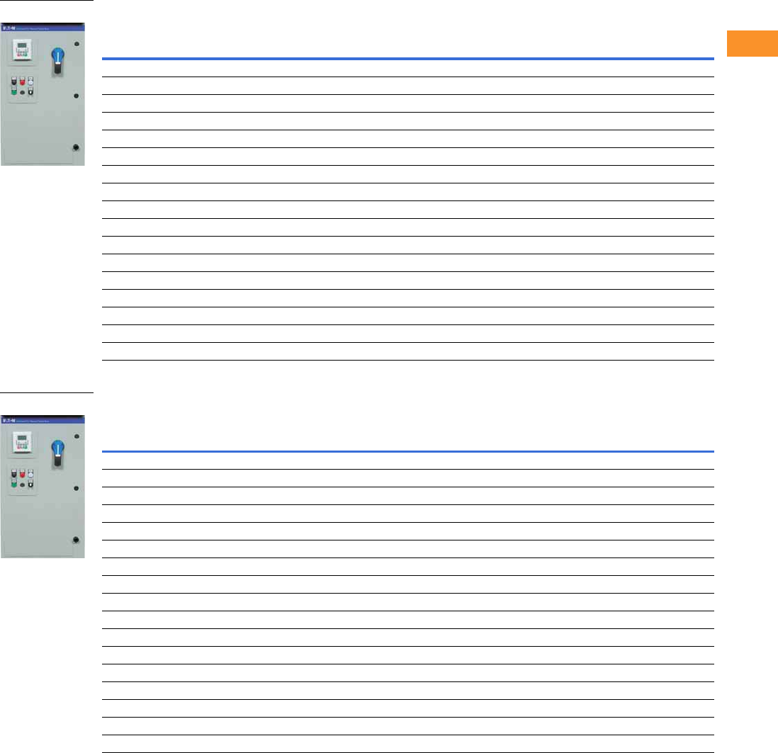
Volume 6—Solid-State Motor Control CA08100007E—February 2016 www.eaton.com V6-T2-267
2
2
2
2
2
2
2
2
2
2
2
2
2
2
2
2
2
2
2
2
2
2
2
2
2
2
2
2
2
2
2.10
Adjustable Frequency Drives
Clean Power Drives
230 V Drives—Constant Torque (CT)/High Overload (IH) Enclosed Drives
230 V Drives—Variable Torque (VT)/Low Overload (IL) Enclosed Drives
Note
1 Table is for base catalog number reference only. For complete catalog number selection, see Page V6-T2-264.
NEMA Type 1 NEMA Type 12 NEMA Type 3R
hp Current (A)
Drive
Frame Size
Base
Catalog Number 1
Base
Catalog Number 1
Base
Catalog Number 1
0.75 3.2 1 EGF3D22D1 EGF3D22D2 EGF3D22D3
14.21EGF4D22D1 EGF4D22D2 EGF4D22D3
1.5 6 1 EGF6D02D1 EGF6D02D2 EGF6D02D3
26.81EGF6D82D1 EGF6D82D2 EGF6D82D3
39.61EGF9D62D1 EGF9D62D2 EGF9D62D3
515.22EGF0152D1 EGF0152D2 EGF0152D3
7.5 22 2 EGF0222D1 EGF0222D2 EGF0222D3
10 28 3 EGF0282D1 EGF0282D2 EGF0282D3
15 42 3 EGF0422D1 EGF0422D2 EGF0422D3
20 54 4 EGF0542C1 EGF0542C2 EGF0542C3
25 68 4 EGF0682C1 EGF0682C2 EGF0682C3
30 80 4 EGF0802C1 EGF0802C2 EGF0802C3
40 104 5 EGF1042C1 EGF1042C2 EGF1042C3
50 130 5 EGF1302C1 EGF1302C2 EGF1302C3
60 154 5 EGF1542C1 EGF1542C2 EGF1542C3
75 192 6 EGF1922C1 EGF1922C2 EGF1922C3
100 248 6 EGF2482C1 EGF2482C2 EGF2482C3
NEMA Type 1 NEMA Type 12 NEMA Type 3R
hp Current (A)
Drive
Frame Size
Base
Catalog Number 1
Base
Catalog Number 1
Base
Catalog Number 1
14.21EGF4D22B1 EGF4D22B2 EGF4D22B3
1.5 6 1 EGF6D02B1 EGF6D02B2 EGF6D02B3
26.81EGF6D82B1 EGF6D82B2 EGF6D82B3
39.61EGF9D62B1 EGF9D62B2 EGF9D62B3
515.22EGF0152B1 EGF0152B2 EGF0152B3
7.5 22 2 EGF0222B1 EGF0222B2 EGF0222B3
10 28 2 EGF0282B1 EGF0282B2 EGF0282B3
15 42 3 EGF0422B1 EGF0422B2 EGF0422B3
20 54 3 EGF0542B1 EGF0542B2 EGF0542B3
25 68 4 EGF0682A1 EGF0682A2 EGF0682A3
30 80 4 EGF0802A1 EGF0802A2 EGF0802A3
40 104 4 EGF1042A1 EGF1042A2 EGF1042A3
50 130 5 EGF1302A1 EGF1302A2 EGF1302A3
60 154 5 EGF1542A1 EGF1542A2 EGF1542A3
75 192 5 EGF1922A1 EGF1922A2 EGF1922A3
100 248 6 EGF2482A1 EGF2482A2 EGF2482A3
125 312 6 EGF3122A1 EGF3122A2 EGF3122A3
EGF Enclosed Drive
EGF Enclosed Drive
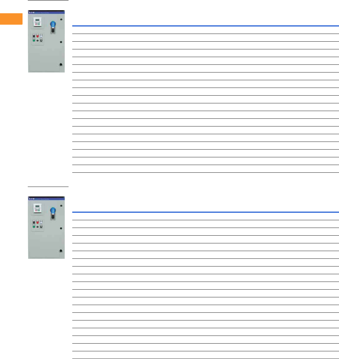
V6-T2-268 Volume 6—Solid-State Motor Control CA08100007E—February 2016 www.eaton.com
2
2
2
2
2
2
2
2
2
2
2
2
2
2
2
2
2
2
2
2
2
2
2
2
2
2
2
2
2
2
2.10
Adjustable Frequency Drives
Clean Power Drives
480 V Drives—Constant Torque (CT)/High Overload (IH) Enclosed Drives
480 V Drives—Variable Torque (VT)/Low Overload (IL) Enclosed Drives
Note
1 Table is for base catalog number reference only. For complete catalog number selection, see Page V6-T2-264.
NEMA Type 1 NEMA Type 12 NEMA Type 3R
hp Current (A)
Drive
Frame Size
Base
Catalog Number 1
Base
Catalog Number 1
Base
Catalog Number 1
12.11EGF2D14D1 EGF2D14D2 EGF2D14D3
1.5 3 1 EGF3D04D1 EGF3D04D2 EGF3D04D3
23.41EGF3D44D1 EGF3D44D2 EGF3D44D3
34.81EGF4D84D1 EGF4D84D2 EGF4D84D3
57.61EGF7D64D1 EGF7D64D2 EGF7D64D3
7.5 11 2 EGF0114D1 EGF0114D2 EGF0114D3
10 14 2 EGF0144D1 EGF0144D2 EGF0144D3
15 21 2 EGF0214D1 EGF0214D2 EGF0214D3
20 27 3 EGF0274D1 EGF0274D2 EGF0274D3
25 34 3 EGF0344D1 EGF0344D2 EGF0344D3
30 40 3 EGF0404D1 EGF0404D2 EGF0404D3
40 52 4 EGF0524C1 EGF0524C2 EGF0524C3
50 65 4 EGF0654C1 EGF0654C2 EGF0654C3
60 77 4 EGF0774C1 EGF0774C2 EGF0774C3
75 96 5 EGF0964C1 EGF0964C2 EGF0964C3
100 124 5 EGF1244C1 EGF1244C2 EGF1244C3
125 156 5 EGF1564C1 EGF1564C2 EGF1564C3
150 180 6 EGF1804C1 EGF1804C2 EGF1804C3
200 240 6 EGF2404C1 EGF2404C2 EGF2404C3
NEMA Type 1 NEMA Type 12 NEMA Type 3R
hp Current (A)
Drive
Frame Size
Base
Catalog Number 1
Base
Catalog Number 1
Base
Catalog Number 1
1.5 3 1 EGF3D04B1 EGF3D04B2 EGF3D04B3
23.41EGF3D44B1 EGF3D44B2 EGF3D44B3
34.81EGF4D84B1 EGF4D84B2 EGF4D84B3
57.61EGF7D64B1 EGF7D64B2 EGF7D64B3
7.5 11 1 EGF0114B1 EGF0114B2 EGF0114B3
10 14 2 EGF0144B1 EGF0144B2 EGF0144B3
15 21 2 EGF0214B1 EGF0214B2 EGF0214B3
20 27 2 EGF0274B1 EGF0274B2 EGF0274B3
25 34 3 EGF0344B1 EGF0344B2 EGF0344B3
30 40 3 EGF0404B1 EGF0404B2 EGF0404B3
40 52 3 EGF0524B1 EGF0524B2 EGF0524B3
50 65 4 EGF0654A1 EGF0654A2 EGF0654A3
60 77 4 EGF0774A1 EGF0774A2 EGF0774A3
75 96 4 EGF0964A1 EGF0964A2 EGF0964A3
100 124 5 EGF1244A1 EGF1244A2 EGF1244A3
125 156 5 EGF1564A1 EGF1564A2 EGF1564A3
150 180 5 EGF1804A1 EGF1804A2 EGF1804A3
200 240 6 EGF2404A1 EGF2404A2 EGF2404A3
250 302 6 EGF3024A1 EGF3024A2 EGF3024A3
EGF Enclosed Drive
EGF Enclosed Drive

Volume 6—Solid-State Motor Control CA08100007E—February 2016 www.eaton.com V6-T2-269
2
2
2
2
2
2
2
2
2
2
2
2
2
2
2
2
2
2
2
2
2
2
2
2
2
2
2
2
2
2
2.10
Adjustable Frequency Drives
Clean Power Drives
Enclosure Selection
EGF Enclosed Drives
Enclosure selection charts are based on physical space limitations only and only to be used as a reference.
For actual enclosure sizing, refer to Bid Manager.
Note: Filtered enclosure sizing includes dedicated space for passive filter,
input fuses, circuit breaker or fusible disconnect, CPT, SPD, heater/
thermostat, control relay and terminal blocks.
Filtered Enclosure X-Space
Filtered Power Options X-Space
Note: Filtered bypass enclosure sizing includes dedicated space for a
passive filter, input fuses, MCP, CPT, input contactor, output bypass
contactors, overload relay, SPD, heater/thermostat, control relay and
terminal blocks.
Filtered Bypass Enclosure X-Space
Filtered Bypass Power Options X-Space
Enclosure Size Frame 1 Frame 2 Frame 3 Frame 4 Frame 5
AX —————
BX 0 0 ———
CX 3322—
DX 14 14 13 13 10
Power Options Frame 1 Frame 2 Frame 3 Frame 4 Frame 5
3% Output reactor 11356
MotoRX filter 33335
dV/dt filter 33356
Output contactor 11111
Enclosure Size Frame 1 Frame 2 Frame 3 Frame 4 Frame 5
AX —————
BX —————
CX 210——
DX 13 12 11 10 6
Power Options Frame 1 Frame 2 Frame 3 Frame 4 Frame 5
RVSS Bypass 11356
3% Output reactor 22234
MotoRX filter 33335
dV/dt filter 33356

V6-T2-270 Volume 6—Solid-State Motor Control CA08100007E—February 2016 www.eaton.com
2
2
2
2
2
2
2
2
2
2
2
2
2
2
2
2
2
2
2
2
2
2
2
2
2
2
2
2
2
2
2.10
Adjustable Frequency Drives
Clean Power Drives
Accessories
The PowerXL Series—DG1 drives can accommodate a wide
selection of expander and adapter option boards to customize
the drive for your application needs. The drive’s control unit is
designed to accept a total of two additional option boards.
The PowerXL Series—DG1 drives come with a factory-installed
standard board configuration including the following:
●Standard I/O:
●8DI, 1DO
●2AI, 2AO
●2FC, 1FA relays
●Standard communications:
●EtherNet/IP, Modbus TCP
●RS-485: Modbus RTU, BACnet MS/TP
PowerXL Series—DG1 I/O Card Kits
PowerXL Series—DG1 Communication Card Kits
Note
1Available January 2016.
Description Catalog Number
3 x DI, 3 x DO, 1 x thermistor, 24 Vdc/EXT option card DXG-EXT-3DI3DO1T
1 x AI, 2 x AO (isolated to control board) option card DXG-EXT-1AI2AO
3 x relay dry contact (2NO + 1NO/NC) option card DXG-EXT-3RO
3 x PT100 RTD thermistor input option card DXG-EXT-THER1
6 x DI 240 Vac input option card DXG-EXT-6DI
Description Catalog Number
PROFIBUS-DP communication card DXG-NET-PROFB
CANopen communication card DXG-NET-CANOPEN
DeviceNet communication card DXG-NET-DEVICENET
PROFIBUS DB9 to 5-pin adapter card DXG-NET-PROAD
SmartWire communication card and module DXG-NET-SWD 1

Volume 6—Solid-State Motor Control CA08100007E—February 2016 www.eaton.com V6-T2-271
2
2
2
2
2
2
2
2
2
2
2
2
2
2
2
2
2
2
2
2
2
2
2
2
2
2
2
2
2
2
2.10
Adjustable Frequency Drives
Clean Power Drives
Options
Input Power Options
Bypass Options
Output Power Options
Option Description
HMCP Disconnect The HMCP motor protection circuit breaker uses an electronic trip unit to provide typical motor overload relay functionality and short-circuit
protection against potential phase-to-phase or phase-to-ground faults.
Circuit Breaker Utilizes a circuit breaker to provide a means of short-circuit protection for the power cables between it and the drive, and protection from high-
level ground faults on the power cable. Allows a convenient means of disconnecting the drive from the line, and the operating mechanism can
be padlocked in the OFF position. This is factory mounted in the enclosure.
Isolation Fusing Provides high-level fault protection of the drive input power circuit from the load side of the fuses to the input side of the power transistors.
This option consists of three 200 kA fuses that are factory mounted in the enclosure.
3% Input Reactor The input reactor is a three-phase series inductance on the line side of an AFD. It is used to provide a reduction in voltage and current
harmonics. It also provides increased input protection for AFD and its semiconductors from line transients.
SPD Provides a surge protection device (SPD) connected to the line side terminals and is designed to clip line side transients.
Fused Disconnect Utilizes fusing to provide a means of short-circuit protection for the power cables between it and the drive, and protection from high-level
ground faults on the power cable. Allows a convenient means of disconnecting the drive from the line, and the operating mechanism can be
padlocked in the OFF position. This is factory mounted in the enclosure.
Option Description
Manual HOA Bypass Provides a three-position selector switch that allows the user to select either a HAND or AUTO mode of operation. HAND mode is defaulted
keypad operation, and AUTO mode is defaulted to control from an external terminal source. These modes of operation can be configured via
programming to allow for alternate combinations of start and speed sources. Start and speed sources include keypad, I/O and fieldbus.
Manual HOA RVSS Bypass This option adds a reduced voltage soft starter to bypass assembly for soft starting in bypass mode.
Option Description
Output Contactor Provides a means for positive disconnection of the drive output from the motor terminals. The contactor coil is controlled by the drive’s run or
permissive logic. NC and NO auxiliary contacts rated at 10 A, 600 Vac are provided for customer use. This option includes a low VA 115 Vac
fused control power transformer and is factory mounted in the enclosure.
3% Output Reactor The output reactor is a three-phase series inductance on the load side of an AFD. It is used to provide a reduction in voltage and current
harmonics.
MotoRX Filter Used to reduce transient voltage () and peak voltages at the motor terminals. This option is comprised of a 0.5% line reactor, followed by
capacitive filtering and an energy recovery/clamping circuit. Unlike the traditional filter, the MotoRx recovers most of the energy from the
voltage peaks, resulting in a lower voltage drop to the motor, therefore conserving power. This option is used when the distance between
a single motor and the drive is 300–600 ft (91–183 m). This option can not be used with the brake chopper circuit. in this case, the traditional
filter should be investigated as an alternative.
dV/dt Filter Used to reduce the transient voltage () at the motor terminals. The traditional filter is recommended for cable lengths exceeding 100 ft (30 m)
with a drive of 3 hp and above, for cable lengths of 33 ft (10 m) with a drive of 2 hp and below, or for a drive rated at 525–690 V. This option is
mounted in the enclosure and may be used in conjunction with a brake chopper circuit. This option is mounted in the enclosure.

V6-T2-272 Volume 6—Solid-State Motor Control CA08100007E—February 2016 www.eaton.com
2
2
2
2
2
2
2
2
2
2
2
2
2
2
2
2
2
2
2
2
2
2
2
2
2
2
2
2
2
2
2.10
Adjustable Frequency Drives
Clean Power Drives
Control Options
Light Options
Enclosure Options
Option Description
Speed Pot Provides the ability to adjust the frequency reference using a door-mounted potentiometer. This option uses the 10 Vdc reference to generate a
0–10 V signal at the analog voltage input signal terminal. When the HOA bypass option is added, the speed is controlled when the HOA switch
is in the HAND position. Without the HOA bypass option, a two-position switch (labeled local/remote) is provided on the keypad to select
speed reference from the speed potentiometer or a remote speed signal.
HOA Switch Provides a three-position selector switch that allows the user to select either a HAND or AUTO mode of operation. HAND mode is defaulted to
keypad operation, and AUTO mode is defaulted to control from an external terminal source. These modes of operation can be configured via
drive programming to allow for alternate combinations of start and speed sources. Start and speed sources include Keypad, I/O and fieldbus.
Start-Stop Pushbutton Provides door-mounted START and STOP pushbuttons for either bypass or non-bypass configurations.
Option Description
Non-Bypass Light Kit—Power On, Run, Fault Provides a white POWER ON light that indicates power to the enclosed cabinet, a green RUN light that indicates the drive is running and a red
FAULT light that indicates a drive fault has occurred.
Bypass Light Kit—On, VFD Run, Fault, Bypass Run Provides a white POWER ON light that indicates power to the enclosed cabinet, a green RUN light that indicates the drive is running, a red
FAULT light that indicates a drive fault has occurred and an amber light that indicates when the motor is running in Bypass mode.
Option Description
Floor Stand 12 in Converts a normally wall-mounted enclosure to a floor-standing enclosure with a height of 12 in (304.8 mm).
Floor Stand 22 in Converts a normally wall-mounted enclosure to a floor-standing enclosure with a height of 22 in (558.8 mm).

Volume 6—Solid-State Motor Control CA08100007E—February 2016 www.eaton.com V6-T2-273
2
2
2
2
2
2
2
2
2
2
2
2
2
2
2
2
2
2
2
2
2
2
2
2
2
2
2
2
2
2
2.10
Adjustable Frequency Drives
Clean Power Drives
Technical Data and Specifications
PowerXL Series—DG1 Technical Data and Specifications
Attribute Description Specification
Input ratings Input voltage Uin 208 V to 240 V, 380 V to 500 V, 525 V to 600 V, –15 to 10%
Input frequency 50 Hz to 60 Hz (variation up to 45 Hz to 66 Hz)
Connection to power Once per minute or less
Starting delay 3 s (FR1 to FR2), 4 s (FR3), 5 s (FR4), 6 s (FR5 and FR6)
Short-circuit withstand rating 100 kAIC (fuses and circuit breakers)
Output ratings Output voltage 0 to Uin
Continuous output current IL: ambient temperature maximum 40 °C, up to 60 °C with derating, overload 1.1 x IL (1 min./10 min.)
IH: ambient temperature maximum 50 °C, up to 60 °C with derating, overload 1.5 x IH (1 min./10 min.)
Overload current 150% respectively 110% (1 min./10 min.)
Initial output current 200% (2 s / 20 s)
Output frequency 0–400 Hz (standard)
Frequency resolution 0.01 Hz
Control characteristics Control methods Frequency control
Speed control
Open-loop speed control
Open-loop torque control
Switching frequency 230 V / 480 V range:
FR1–3: 1 kHz to 12 kHz
FR4–6: 1 kHz to 10 kHz
230 V / 480 V defaults:
FR1–3: 4 kHz
FR4–5: 3.6 kHz
FR6: 2 kHz
575 V range:
FR1–6: 1 kHz to 6 kHz
575 V defaults:
FR1–4: 3 kHz
FR5–6: 2 kHz
Automatic switching frequency derating in case of overload.
Frequency reference Analog input: resolution 0.1% (10-bit), accuracy +1%
Analog output: resolution 0.1% (10-bit), accuracy +1%
Panel reference: resolution 0.01 Hz
Field weakening point 20 Hz to 400 Hz
Acceleration time 0.1 s to 3000 s
Deceleration time 0.1 s to 3000 s
Braking torque DC brake: 30% x Motor Rated Torque (Tn) (without brake chopper)
Dynamic braking (with optional brake chopper using an external brake resistor):
100% continuous maximum rating
Ambient conditions Ambient operating temperature –10 °C (no frost) to +50 °C, up to +60 °C with derating (CT)
–10 °C (no frost) to +40 °C, up to +60 °C with derating (VT)
Storage temperature –40 °C to +70 °C
Relative humidity 0–95% RH, noncondensing, non-corrosive
Air quality:
●Chemical vapors
●Mechanical particles
Tested according to IEC 60068-2-60 Test Key:
Flowing mixed gas corrosion test, Method 1 (H2S [hydrogen sulfide] and SO2 [sulfur dioxide])
Designed according to:
IEC 60721-3-3, unit in operation, class 3C2
IEC 60721-3-3, unit in operation, class 3S2
Altitude 100% load capacity (no derating) up to 3280 ft (1000 m); 1% derating for each 328 ft (100 m) above
3280 ft (1000 m); max. 9842 ft (3000 m) (2000 m for corner grounded earth main systems)
For 575 V product, maximum altitude is 6561 ft (2000 m) regardless of main system

V6-T2-274 Volume 6—Solid-State Motor Control CA08100007E—February 2016 www.eaton.com
2
2
2
2
2
2
2
2
2
2
2
2
2
2
2
2
2
2
2
2
2
2
2
2
2
2
2
2
2
2
2.10
Adjustable Frequency Drives
Clean Power Drives
PowerXL Series—DG1 Technical Data and Specifications, continued
Attribute Description Specification
Ambient conditions,
continued
Vibration:
●EN 61800-5-1
●EN 60668-2-6
5–150 Hz
Displacement amplitude: 1 mm (peak) at 5 Hz to 15.8 Hz (FR1–FR6)
Maximum acceleration amplitude: 1g at 15.8 Hz to 150 Hz (FR1–FR6)
Shock:
●ISTA 1 A
●EN 60068-2-27
Storage and shipping: maximum 15 g, 11 ms (in package)
Overvoltage Overvoltage Category III
Pollution degree Pollution Degree 2
Enclosure class IP21/Type 1 standard in entire kW/hp range
IP54/Type 12 option
Note: Keypad or keypad hole plug required to be mounted in drive for IP54/Type 12 rating
Immunity Fulfills EN 61800-3 (2004), first and second environment
MTBF FR1: 165,457 hours
FR2: 134,833 hours
FR3: 102,515 hours
FR4: 121,567 hours
FR5: 108,189 hours
FR6: Available in 2016
Noise FR1: 51.2 dB
FR2: 58.6 dB
FR3: 61.0 dB
FR4: 68.0 dB
FR5: 69.1 dB
FR6: Available in 2016
Standards Safety UL 508C, CSA C22.2 No. 274-13 and EN 61800-5-1
EMC +EMC2: EN 61800-3 (2004), Category C2
The drive can be modified for IT networks and corner grounding TN system
Electrostatic discharge Second environment, IEC 61000-4-2, 4 kV CD or 8 kV AD, Criterion B
Fast transient burst Second environment, IEC 61000-4-4, 2 kV/5 kHz, Criterion B
Dielectrical strength Primary to secondary: 3600 Vac/5100 Vdc
Primary to earth: 2000 Vac/2828 Vdc
Approvals EAC, RCM (C-Tick), RoHS, CE, UL and cUL (see nameplate for more detailed approvals)
Fieldbus connections Onboard: EtherNet/IP, Modbus® TCP, Modbus RTU, BACnet

Volume 6—Solid-State Motor Control CA08100007E—February 2016 www.eaton.com V6-T2-275
2
2
2
2
2
2
2
2
2
2
2
2
2
2
2
2
2
2
2
2
2
2
2
2
2
2
2
2
2
2
2.10
Adjustable Frequency Drives
Clean Power Drives
PowerXL Series—DG1 Technical Data and Specifications, continued
Attribute Description Specification
Safety/protections Overvoltage protection Yes
Overvoltage trip limit 230 V drives: 456 V
480 V drives: 911 V
575 V drives: 1100 V
Undervoltage protection Yes
Undervoltage trip limit 230 V drives: 211 V
480 V drives: 370 V
575 V drives: 550 V
Earth fault protection Yes
Default: 15% motor FLA
Minimum: 0% motor FLA
Maximum: 30% motor FLA
Input phase supervision Yes
Motor phase supervision Yes
Overcurrent protection Yes
Unit overtemperature protection Yes
Motor overload protection Yes
Motor stall protection Yes
Motor underload protection Yes
DC bus overvoltage control Yes
Short-circuit protection of 24 V
reference voltages
Yes
Surge protection Yes (differential mode 2 kV; common mode 4 kV
230 V drives: 275 Vac, 10,000 A
480 V drives: 320 Vac, 8000 A
575 V drives: 385 Vac, 10,000 A
Common coated boards Yes (prevents corrosion)
Efficiency Drive efficiency ratings 480 V: FR1 = 97.7%
480 V: FR2 = 97.9%
480 V: FR3 = 97.7%
480 V: FR4 = 98.0%
480 V: FR5 = 98.2%
230 V: FR1 = 96.7%
230 V: FR2 = 97.4%
230 V: FR3 = 97.2%
230 V: FR4 = 97.4%
230 V: FR5 = 97.7%

V6-T2-276 Volume 6—Solid-State Motor Control CA08100007E—February 2016 www.eaton.com
2
2
2
2
2
2
2
2
2
2
2
2
2
2
2
2
2
2
2
2
2
2
2
2
2
2
2
2
2
2
2.10
Adjustable Frequency Drives
Clean Power Drives
Wiring Diagram
PowerXL Series—DG1 Control Wiring Diagram
Pin Signal Name Signal Default Setting Description
1 +10 V Ref. Output Voltage — 10 Vdc Supply Source
2 AI1+ Analog Input 1 0–10 V Voltage Speed Reference (Programmable to 4 mA to 20 mA)
3 AI1– Analog Input 1 Ground — Analog Input 1 Common (Ground)
4 AI2+ Analog Input 2 4 mA to 20 mA Current Speed Reference (Programmable to 0–10 V)
5 AI2– Analog Input 2 Ground — Analog Input 2 Common (Ground)
6 GND I/O Signal Ground — I/O Ground for Reference and Control
7 DIN5 Digital Input 5 Preset Speed B0 Sets frequency output to Preset Speed 1
8 DIN6 Digital Input 6 Preset Speed B1 Sets frequency output to Preset Speed 2
9 DIN7 Digital Input 7 Emergency Stop (TI–) Input forces VFD output to shut off
10 DIN8 Digital Input 8 Force Remote (TI+) Input takes VFD from Local to Remote
11 CMB DI5 to DI8 Common Grounded Allows source input
12 GND I/O Signal Ground — I/O Ground for Reference and Control
13 24 V +24 Vdc Output — Control voltage output (100 mA max.)
14 DO1 Digital Output 1 Ready Shows the drive is ready to run
15 24 Vo +24 Vdc Output — Control voltage output (100 mA max.)
16 GND I/O Signal Ground — I/O Ground for Reference and Control
17 AO1+ Analog Output 1 Output Frequency Shows Output frequency to motor 0–60 Hz (4 mA to 20 mA)
18 AO2+ Analog Output 2 Motor Current Shows Motor current of motor 0–FLA (4 mA to 20 mA)
19 24 Vi +24 Vdc Input — External control voltage input
20 DIN1 Digital Input 1 Run Forward Input starts drive in forward direction (start enable)
21 DIN2 Digital Input 2 Run Reverse Input starts drive in reverse direction (start enable)
22 DIN3 Digital Input 3 External Fault Input causes drive to fault
23 DIN4 Digital Input 4 Fault Reset Input resets active faults
24 CMA DI1 to DI4 Common Grounded Allows source input
25 A RS-485 Signal A — Fieldbus Communication (Modbus, BACnet)
26 B RS-485 Signal B — Fieldbus Communication (Modbus, BACnet)
27 R3NO Relay 3 Normally Open At Speed Relay output 3 shows VFD is at Ref. Frequency
28 R1NC Relay 1 Normally Closed Run Relay output 1 shows VFD is in a run state
29 R1CM Relay 1 Common
30 R1NO Relay 1 Normally Open
31 R3CM Relay 3 Common At Speed Relay output 3 shows VFD is at Ref. Frequency
32 R2NC Relay 2 Normally Closed Fault Relay output 2 shows VFD is in a fault state
33 R2CM Relay 2 Common
34 R2NO Relay 2 Normally Open
Res
i

Volume 6—Solid-State Motor Control CA08100007E—February 2016 www.eaton.com V6-T2-277
2
2
2
2
2
2
2
2
2
2
2
2
2
2
2
2
2
2
2
2
2
2
2
2
2
2
2
2
2
2
2.10
Adjustable Frequency Drives
Clean Power Drives
Dimensions
Approximate Dimensions in Inches (mm)
BX Box Type 1
BX Box Type 1—12 Inch Floor Stands
4.00 (101.6)
Minimum
Free Air Space
Required
28.55
(725.1)
36.80
(934.7)
36.35
(923.3)
19.30 (490.2)
20.92 (531.4)
17.01 (432.2)
1.76
(44.8)
37.74
(958.6)
3.00 (76.2)
Minimum
Air Space
Required
Both Sides
Ø 0.44 (11.2)
Mounting
Holes
(4 Places)
4.00 (101.6)
Minimum
Free Air Space
Required
14.06
(357.1)
19.30 (490.2)
36.35
(923.3)
48.37
(1228.6)
20.92 (531.4) 17.01 (432.2)
1.76
(44.8)
40.38
(1025.7)
48.87
(1241.3)
15.50 (393.7)
17.50 (444.5)
10.53
(267.5) 7.00
(177.8)
Ø 0.44 (11.2)
Mounting
Holes
(2 Places)
3.00 (76.2)
Minimum
Air Space
Required
Both Sides
3.00 (76.2)
5.00 (127.0)

V6-T2-278 Volume 6—Solid-State Motor Control CA08100007E—February 2016 www.eaton.com
2
2
2
2
2
2
2
2
2
2
2
2
2
2
2
2
2
2
2
2
2
2
2
2
2
2
2
2
2
2
2.10
Adjustable Frequency Drives
Clean Power Drives
Approximate Dimensions in Inches (mm)
BX Box Type 1—22 Inch Floor Stands
BX Box Type 12
4.00 (101.6)
Minimum
Free Air Space
Required
14.06
(357.1)
15.50 (393.7)
17.50 (444.5)
10.53
(267.5) 7.00
(177.8)
3.00 (76.2)
5.00 (127.0)
58.87
(1495.3)
19.30 (490.2)
36.35
(923.3)
58.37
(1482.6)
20.92 (531.4) 17.01 (432.2)
1.76
(44.8)
50.38
(1279.7)
Ø 0.44 (11.2)
Mounting
Holes
(2 Places)
3.00 (76.2)
Minimum
Air Space
Required
Both Sides
4.00 (101.6)
Minimum
Free Air Space
Required
28.55
(725.1)
36.80
(934.7)
36.35
(923.3)
19.30 (490.2)
20.92 (531.4)
37.74
(958.6)
Ø 0.44 (11.2)
Mounting
Holes
(2 Places)
3.00 (76.2)
Minimum
Air Space
Required
Both Sides
17.01 (432.2)
1.76
(44.8)

Volume 6—Solid-State Motor Control CA08100007E—February 2016 www.eaton.com V6-T2-279
2
2
2
2
2
2
2
2
2
2
2
2
2
2
2
2
2
2
2
2
2
2
2
2
2
2
2
2
2
2
2.10
Adjustable Frequency Drives
Clean Power Drives
Approximate Dimensions in Inches (mm)
BX Box Type 12—12 Inch Floor Stands
BX Box Type 12—22 Inch Floor Stands
7.00
(177.8)
10.53
(267.5)
14.06
(357.1)
15.50 (393.7)
17.50 (444.5)
3.00 (76.2)
5.00 (127.0)
40.38
(1025.7)
19.30 (490.2)
36.35
(923.3)
48.37
(1228.6)
20.92 (531.4) 17.01 (432.2)
1.76
(44.8)
48.87
(1241.3)
Ø 0.44 (11.2)
Mounting
Holes
(2 Places)
3.00 (76.2)
Minimum
Air Space
Required
Both Sides
4.00 (101.6)
Minimum
Free Air Space
Required
7.00
(177.8)
10.53
(267.5)
14.06
(357.1)
15.50 (393.7)
17.50 (444.5)
3.00 (76.2)
5.00 (127.0)
58.87
(1495.3)
19.30 (490.2)
36.35
(923.3)
58.37
(1482.6)
20.92 (531.4) 17.01 (432.2)
1.76
(44.8)
Ø 0.44 (11.2)
Mounting
Holes
(2 Places)
3.00 (76.2)
Minimum
Air Space
Required
Both Sides
4.00 (101.6)
Minimum
Free Air Space
Required
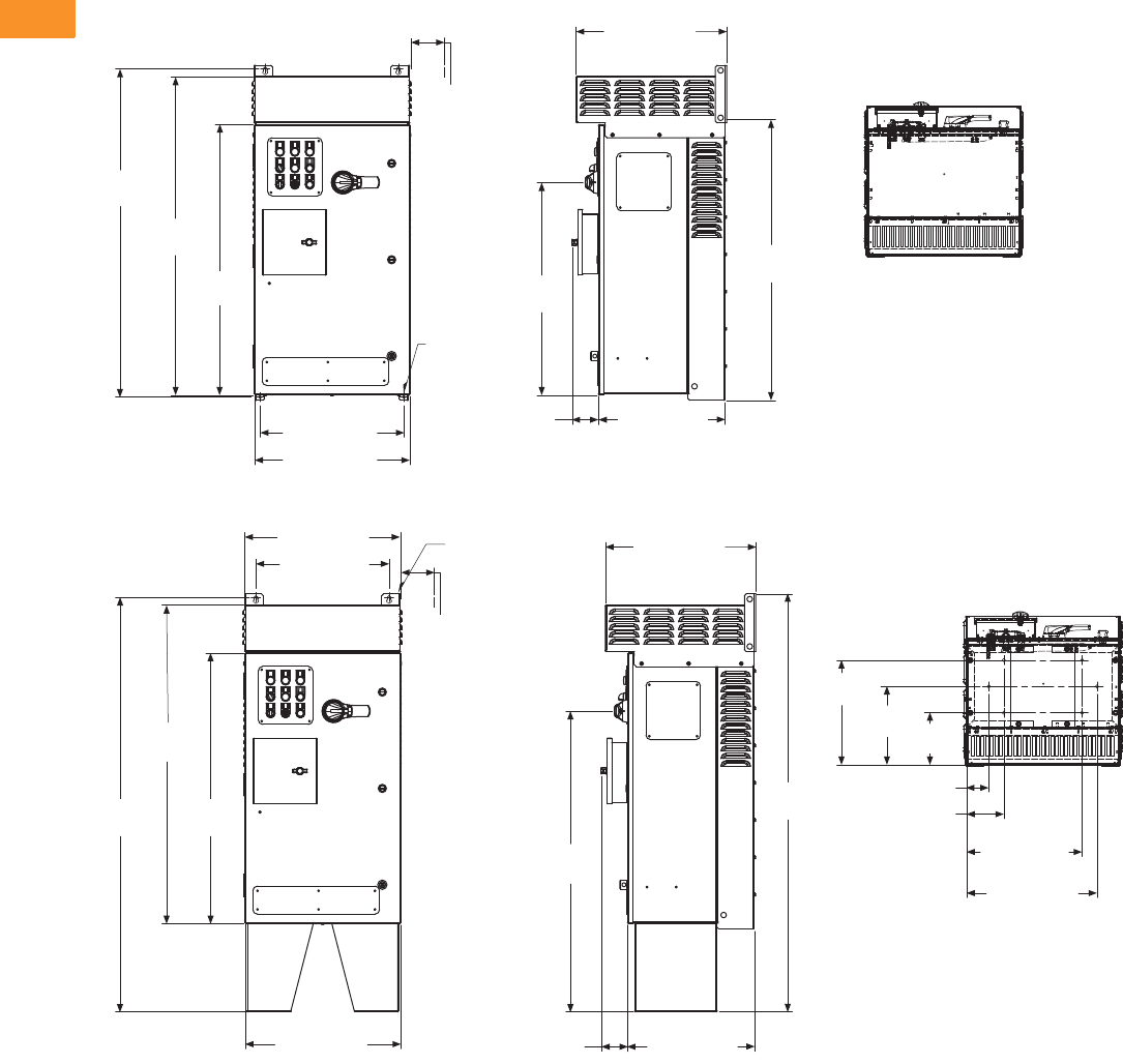
V6-T2-280 Volume 6—Solid-State Motor Control CA08100007E—February 2016 www.eaton.com
2
2
2
2
2
2
2
2
2
2
2
2
2
2
2
2
2
2
2
2
2
2
2
2
2
2
2
2
2
2
2.10
Adjustable Frequency Drives
Clean Power Drives
Approximate Dimensions in Inches (mm)
BX Box Type 3R
BX Box Type 3R—12 Inch Floor Stands
28.56
(725.3)
44.09
(1119.8)
36.35
(923.3)
42.69
(1084.3)
19.30 (490.2)
20.92 (531.4)
37.74
(958.6)
3.00 (76.2)
Minimum
Air Space
Required
Both Sides
Ø 0.44 (11.2)
Mounting
Holes
(4 Places)
17.01 (432.2)
3.51
(89.1)
20.18 (512.5)
17.88 (454.2)
20.88 (530.4)
55.66
(1413.7)
42.77
(1086.4)
36.35
(923.3)
20.92 (531.4) 17.01 (432.2)
3.51
(89.1)
40.40
(1026.3)
56.10
(1424.9)
20.18 (512.5)
7.00
(177.8)
10.53
(267.5)
14.06
(357.1)
Ø 0.44 (11.2)
Mounting
Holes
(2 Places)
3.00 (76.2)
Minimum
Air Space
Required
Both Sides
15.50 (393.7)
17.50 (444.5)
3.00 (76.2)
5.00 (127.0)
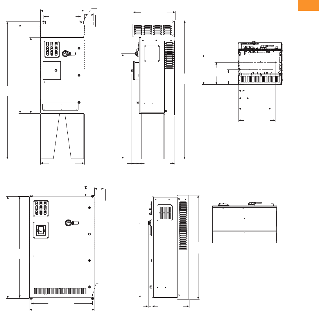
Volume 6—Solid-State Motor Control CA08100007E—February 2016 www.eaton.com V6-T2-281
2
2
2
2
2
2
2
2
2
2
2
2
2
2
2
2
2
2
2
2
2
2
2
2
2
2
2
2
2
2
2.10
Adjustable Frequency Drives
Clean Power Drives
Approximate Dimensions in Inches (mm)
BX Box Type 3R—22 Inch Floor Stands
CX Box Type 1
7.00
(177.8)
10.53
(267.5)
14.06
(357.1)
15.50 (393.7)
17.50 (444.5)
3.00 (76.2)
5.00 (127.0)
50.38
(1279.7)
20.88 (530.4)
17.88 (454.2)
65.66
(1667.7)
42.77
(1086.4)
36.35
(923.3)
Ø 0.44 (11.2)
Mounting
Holes
(2 Places)
3.00 (76.2)
Minimum
Air Space
Required
Both Sides
20.92 (531.4) 17.01 (432.2)3.57 (90.7)
20.18 (512.5)
55.10
(1429.9)
4.00 (101.6) Minimum
Free Air Space Required
48.80
(1239.5)
48.35
(1228.1)
29.30 (744.2)
30.92 (785.4) 17.76 (451.2)
1.74
(44.2)
49.74
(1263.4)
35.85
(910.6)
3.00 (76.2)
Minimum
Air Space
Required
Both Sides
Ø 0.44 (11.2)
Mounting
Holes
(4 Places)

V6-T2-282 Volume 6—Solid-State Motor Control CA08100007E—February 2016 www.eaton.com
2
2
2
2
2
2
2
2
2
2
2
2
2
2
2
2
2
2
2
2
2
2
2
2
2
2
2
2
2
2
2.10
Adjustable Frequency Drives
Clean Power Drives
Approximate Dimensions in Inches (mm)
CX Box Type 1—12 Inch Floor Stands
CX Box Type 1—22 Inch Floor Stands
3.00 (76.2)
5.00 (127.0)
29.30 (744.2)
48.35
(1228.1)
60.37
(1533.4)
30.92 (785.4) 17.76 (451.2)
47.67
(1210.8) 49.74
(1263.4)
14.81
(376.2)
11.28
(286.5) 7.75
(196.9)
27.50 (698.5)
25.50 (647.7)
Ø 0.44 (11.2)
Mounting
Holes
(2 Places)
3.00 (76.2)
Minimum
Air Space
Required
Both Sides
4.00 (101.6) Minimum
Free Air Space Required
1.74
(44.2)
29.30 (744.2)
4.00 (101.6) Minimum
Free Air Space Required
Ø 0.44 (11.2)
Mounting Holes
(2 Places)
3.00 (76.2)
Minimum
Air Space
Required
Both Sides
48.35
(1228.1)
70.37
(1787.4)
30.92 (785.4) 17.76 (451.2)1.74 (44.2)
57.68
(1465.0) 70.87
(1800.1)
14.81
(376.2) 11.28
(286.5) 7.75
(196.9)
25.50
(647.7)
27.50
(698.5)
5.00
(127.0)
3.00
(76.2)

Volume 6—Solid-State Motor Control CA08100007E—February 2016 www.eaton.com V6-T2-283
2
2
2
2
2
2
2
2
2
2
2
2
2
2
2
2
2
2
2
2
2
2
2
2
2
2
2
2
2
2
2.10
Adjustable Frequency Drives
Clean Power Drives
Approximate Dimensions in Inches (mm)
CX Box Type 12
CX Box Type 12—12 Inch Floor Stands
49.74
(1263.4)
48.80
(1239.5)
48.35
(1228.1)
29.30 (744.2)
30.92 (785.4)
1.74
(44.2) 17.76 (451.2)
35.85
(910.6)
3.00 (76.2)
Minimum
Air Space
Required
Both Sides
4.00 (101.6) Minimum
Free Air Space Required
Ø 0.44 (11.2)
Mounting
Holes
(4 Places)
48.35
(1228.1)
60.37
(1533.4)
30.92 (785.4) 17.76 (451.2)
1.74
(44.2)
47.67
(1210.8) 49.74
(1263.4)
14.81
(376.2)
7.75
(196.9)
11.28
(286.5)
25.50 (647.7)
27.50 (698.5)
3.00 (76.2)
5.00 (127.0)
29.30 (744.2)
4.00 (101.6) Minimum
Free Air Space Required
Ø 0.44 (11.2)
Mounting
Holes
(2 Places)
3.00 (76.2)
Minimum
Air Space
Required
Both Sides
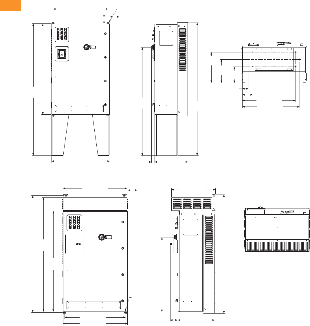
V6-T2-284 Volume 6—Solid-State Motor Control CA08100007E—February 2016 www.eaton.com
2
2
2
2
2
2
2
2
2
2
2
2
2
2
2
2
2
2
2
2
2
2
2
2
2
2
2
2
2
2
2.10
Adjustable Frequency Drives
Clean Power Drives
Approximate Dimensions in Inches (mm)
CX Box Type 12—22 Inch Floor Stands
CX Box Type 3R
29.30 (744.2)
48.35
(1228.1)
70.37
(1787.4)
30.92 (785.4)
57.68
(1465.0) 70.87
(1800.1)
Ø 0.44 (11.2)
Mounting
Holes
(2 Places)
3.00 (76.2)
Minimum
Air Space
Required
Both Sides
4.00 (101.6) Minimum
Free Air Space Required
14.81
(376.2)
7.75
(196.9)
11.28
(286.5)
25.50 (647.7)
27.50 (698.5)
3.00 (76.2)
5.00 (127.0)
17.76
(451.2)
1.74
(44.2)
30.88 (784.4)
56.08
(1424.5)
54.77
(1391.2)
48.35
(1228.1)
29.30 (744.2)
30.92 (785.4) 17.76 (451.2)
3.72
(94.4)
56.96
(1446.9)
35.85
(910.6)
21.00 (533.3)
3.00 (76.2)
Minimum
Air Space
Required
Both Sides
Ø 0.44 (11.2)
Mounting
Holes
(4 Places)

Volume 6—Solid-State Motor Control CA08100007E—February 2016 www.eaton.com V6-T2-285
2
2
2
2
2
2
2
2
2
2
2
2
2
2
2
2
2
2
2
2
2
2
2
2
2
2
2
2
2
2
2.10
Adjustable Frequency Drives
Clean Power Drives
Approximate Dimensions in Inches (mm)
CX Box Type 3R—12 Inch Floor Stands
CX Box Type 3R—22 Inch Floor Stands
3.00 (76.2)
30.88 (784.4)
28.10 (713.7)
67.65
(1718.4)
48.35
(1228.1)
66.60
(1691.7)
30.92 (785.4)
21.00 (533.3)
68.09
(1729.6)
47.67
(1210.8)
17.76 (451.2)
3.72
(94.4)
14.81
(376.2) 11.28
(286.5) 7.75
(196.9)
25.50 (647.7)
27.50 (698.5)
5.00 (127.0)
Ø 0.44 (11.2)
Mounting
Holes
(2 Places)
3.00 (76.2)
Minimum
Air Space
Required
Both Sides
78.09
(1983.6) 3.00 (76.2)
14.81
(376.2) 11.28
(286.5) 7.75
(196.9)
25.50 (647.7)
27.50 (698.5)
5.00 (127.0)
21.00 (533.3)
57.68
(1465.0)
30.92 (785.4)
77.65
(1972.4)
48.35
(1228.1)
76.60
(1945.7)
30.88 (784.4)
27.88 (708.2)
Ø 0.44 (11.2)
Mounting
Holes
(2 Places)
3.00 (76.2)
Minimum
Air Space
Required
Both Sides
17.76
(451.2)
3.72
(94.4)
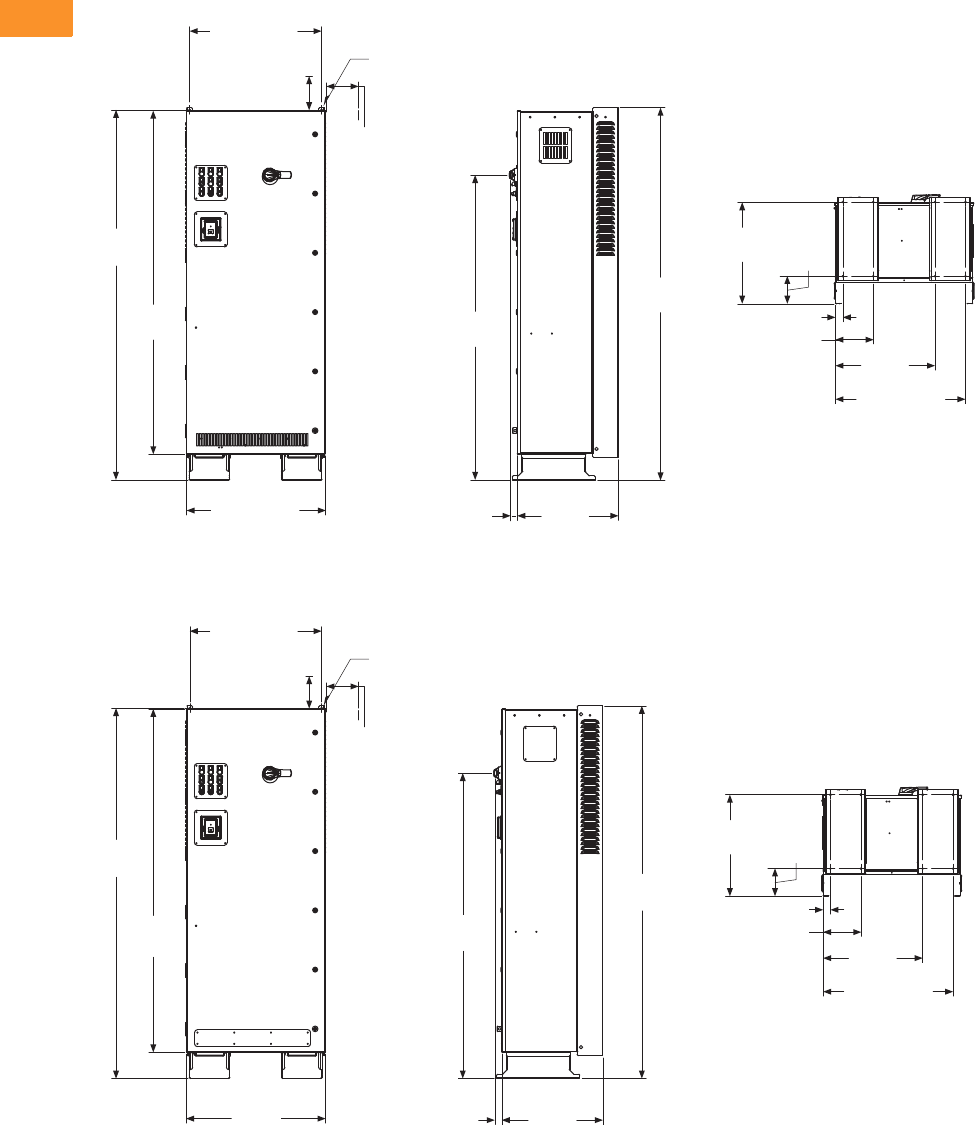
V6-T2-286 Volume 6—Solid-State Motor Control CA08100007E—February 2016 www.eaton.com
2
2
2
2
2
2
2
2
2
2
2
2
2
2
2
2
2
2
2
2
2
2
2
2
2
2
2
2
2
2
2.10
Adjustable Frequency Drives
Clean Power Drives
Approximate Dimensions in Inches (mm)
DX Box Type 1
DX Box Type 12
1.55
(39.4)
29.30 (744.2)
82.23
(2088.6)
76.35
(1939.3)
30.92 (785.4) 22.48
(571.1)
28.88 (733.6)
82.85
(2104.4)
67.88
(1724.2)
22.56
(573.0) 6.13
(155.6)
8.38 (212.9)
1.62 (41.1)
22.12
(561.8)
Ø 0.44 (11.2)
Mounting
Holes
(2 Places)
3.00 (76.2)
Minimum
Air Space
Required
Both Sides
4.00 (101.6)
Minimum
Free Air Space
Required
82.35
(2091.7)
76.35
(1939.3)
30.92
(785.4)
22.48
(571.1)
1.55
(39.4)
82.85
(2104.4)
67.89
(1724.4)
28.88 (733.6)
22.56
(573.0) 6.13
(155.6)
8.38 (212.9)
1.62 (41.1)
22.12
(561.8)
29.30 (744.2)
Ø 0.44 (11.2)
Mounting
Holes
(2 Places)
3.00 (76.2)
Minimum
Air Space
Required
Both Sides
4.00 (101.6)
Minimum
Free Air Space
Required

Volume 6—Solid-State Motor Control CA08100007E—February 2016 www.eaton.com V6-T2-287
2
2
2
2
2
2
2
2
2
2
2
2
2
2
2
2
2
2
2
2
2
2
2
2
2
2
2
2
2
2
2.10
Adjustable Frequency Drives
Clean Power Drives
Approximate Dimensions in Inches (mm)
DX Box Type 3R
22.81
(579.2)
29.06 (738.1)
30.88 (784.4)
27.88 (708.2)
89.70
(2278.3)
82.84
(2104.1)
76.35
(1939.3)
30.92 (785.4) 3.64
(92.5)
22.48
(571.1)
67.89
(1724.4)
90.14
(2289.5)
25.51 (647.8)
1.80 (45.7)
8.56 (217.4)
22.30
(566.4)
Ø 0.44 (11.2)
Mounting
Holes
(2 Places)
3.00 (76.2)
Minimum
Air Space
Required
Both Sides
6.31
(160.3)
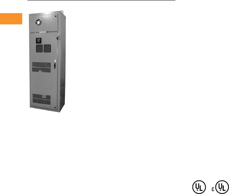
V6-T2-288 Volume 6—Solid-State Motor Control CA08100007E—February 2016 www.eaton.com
2
2
2
2
2
2
2
2
2
2
2
2
2
2
2
2
2
2
2
2
2
2
2
2
2
2
2
2
2
2
2.10
Adjustable Frequency Drives
Clean Power Drives
CFX Enclosed Drives
Contents
Description Page
Clean Power Drives Overview . . . . . . . . . . . . . . . V6-T2-256
Enclosed Passive Filtered Drives
EGF Enclosed Drives . . . . . . . . . . . . . . . . . . . . V6-T2-263
CFX Enclosed Drives
Product Identification . . . . . . . . . . . . . . . . . V6-T2-289
Catalog Number Selection . . . . . . . . . . . . . V6-T2-290
Product Selection . . . . . . . . . . . . . . . . . . . . V6-T2-292
Enclosure Selection . . . . . . . . . . . . . . . . . . V6-T2-299
Options . . . . . . . . . . . . . . . . . . . . . . . . . . . . V6-T2-300
Technical Data and Specifications . . . . . . . . V6-T2-302
Wiring Diagram . . . . . . . . . . . . . . . . . . . . . . V6-T2-304
Dimensions . . . . . . . . . . . . . . . . . . . . . . . . . V6-T2-305
Enclosed 12-Pulse Drives . . . . . . . . . . . . . . . . . . . V6-T2-319
Enclosed 18-Pulse Drives . . . . . . . . . . . . . . . . . . . V6-T2-323
Enclosed Regenerative Drives . . . . . . . . . . . . . . . V6-T2-348
CFX Enclosed Drives
Product Description
The enclosed passive filtered
drive also delivers True
Power Factor—in addition to
reducing harmonic distortion,
the enclosed passive filtered
drive prevents transformer
overheating and overloading
of breakers and feeders,
which enables the application
of adjustable frequency
drives on generators and
other high impedance power
systems.
Features and Benefits
The CFX passive filtered drive
features include (at 480 V):
●UL Type 1, UL Type 12, UL
Type 3R
and NEMA 12 with
gaskets and filters
●Input voltage: 480 V, 230 V,
575 V
●Complete range of control,
network and power options
●Horsepower range:
●480 V, 7-1/2–400 hp IL
●230 V, 7-1/2–100 hp IL;
consult factory for
details
●575 V, 15–400 hp IL;
consult factory for
details
●Single enclosure for both
drive and filter reduces
field wiring and enables
convenient bypass
installation
●Packaged solution ensures
optimal coordination of
drive and filter
Standards and Certifications
●UL
●cUL
●508C
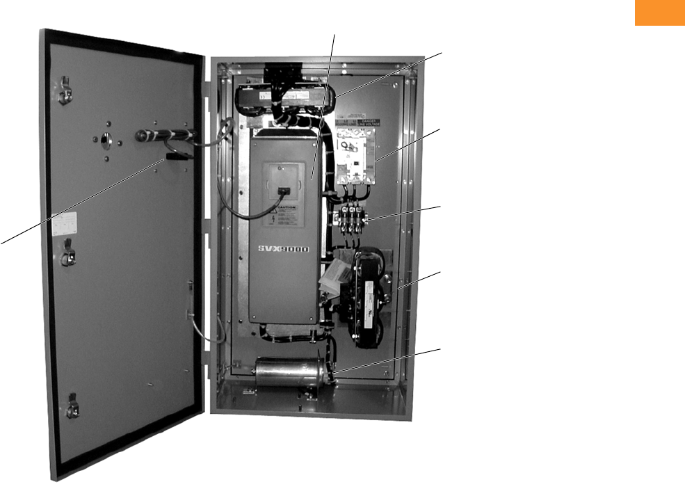
Volume 6—Solid-State Motor Control CA08100007E—February 2016 www.eaton.com V6-T2-289
2
2
2
2
2
2
2
2
2
2
2
2
2
2
2
2
2
2
2
2
2
2
2
2
2
2
2
2
2
2
2.10
Adjustable Frequency Drives
Clean Power Drives
Product Identification
Enclosed Passive Filtered Drive—UL Type 12, 40 hp
Input Reactor
Optional Breaker
Disconnect (P1)
Shunt Fusing
Tuned Shunt
Reactor
SVX Drive
Tuned Har monic
Capacitor
Door Mounted
Keypad

V6-T2-290 Volume 6—Solid-State Motor Control CA08100007E—February 2016 www.eaton.com
2
2
2
2
2
2
2
2
2
2
2
2
2
2
2
2
2
2
2
2
2
2
2
2
2
2
2
2
2
2
2.10
Adjustable Frequency Drives
Clean Power Drives
Catalog Number Selection
Catalog Number Selection is for reference only. Not all option combinations may be available.
CFX Enclosed—Base Catalog Number
Notes
1Single-phase voltage refers to the supply voltage. Output voltage will be three-phase and equal to the magnitude of the input voltage.
2Brake chopper is a factory-installed option only. Braking resistors sold separately. See SVX catalog section for selection.
3Additional enclosure options including NEMA 4 and 4X are available. Please contact the factory for configuration and pricing.
4Part number configuration continued on the following page.
CFX F07 1 A 1
Product Family
CFX = Enclosed CFX passive filtered drives
Output Horsepower Rating
208 V 230 V 480 V 575 V
F07 = 0.75 hp
001 =1 hp
F15 =1.5 hp
002 =2 hp
003 =3 hp
005 =5 hp
007 =7.5 hp
010 =10 hp
015 =15 hp
020 =20 hp
025 =25 hp
030 =30 hp
040 =40 hp
050 =50 hp
060 =60 hp
075 =75 hp
100 =100 hp
F07 = 0.75 hp
001 =1 hp
F15 = 1.5 hp
002 =2 hp
003 =3 hp
005 =5 hp
007 = 7.5 hp
010 =10 hp
015 =15 hp
020 =20 hp
025 =25 hp
030 =30 hp
040 =40 hp
050 =50 hp
060 =60 hp
075 =75 hp
100 =100 hp
125 =125 hp
001 =1 hp
F15 = 1.5 hp
002 =2 hp
003 =3 hp
005 =5 hp
007 = 7.5 hp
010 =10 hp
015 =15 hp
020 =20 hp
025 =25 hp
030 =30 hp
040 =40 hp
050 =50 hp
060 =60 hp
075 =75 hp
100 =100 hp
125 =125 hp
150 =150 hp
200 =200 hp
250 =250 hp
300 =300 hp
350 =350 hp
400 =400 hp
500 =500 hp
550 =550 hp
600 =600 hp
650 =650 hp
700 =700 hp
800 =800 hp
002 =2 hp
003 =3 hp
005 =5 hp
007 = 7.5 hp
010 =10 hp
015 =15 hp
020 =20 hp
025 =25 hp
030 =30 hp
040 =40 hp
050 =50 hp
060 =60 hp
075 =75 hp
100 =100 hp
125 =125 hp
150 =150 hp
200 =200 hp
250 =250 hp
300 =300 hp
350 =350 hp
400 =400 hp
500 =500 hp
550 =550 hp
600 =600 hp
650 =650 hp
700 =700 hp
800 =800 hp
Phasing and Voltage Rating 1
1 = Input: Three-phase, 208 V
Output: Three-phase
2 = Input: Three-phase, 230 V
Output: Three-phase
4 = Input: Three-phase, 480 V
Output: Three-phase
5 = Input: Three-phase, 575 V
Output: Three-phase
J = Input: Single-phase, 230 V
Output: Three-phase
K = Input: Single-phase, 480 V
Output: Three-phase
Drive Type/Braking/Application 2
A = Standard drive/no brake chopper/low overload
B = Standard drive/brake chopper/low overload
C = Standard drive/no brake chopper/high overload
D = Standard drive/brake chopper/high overload
E = High-performance drive/no brake chopper/low overload
F = High-performance drive/brake chopper/low overload
G = High-performance drive/no brake chopper/high overload
H = High-performance drive/brake chopper/high overload
Enclosure Rating 3
1 = NEMA Type 1
2 = NEMA Type 12
3 = NEMA Type 3R
6 = NEMA Type 1 Filtered and gasketed
• = Custom option
______
Options 4
See Page V6-T2-291 for catalog
number option selection.
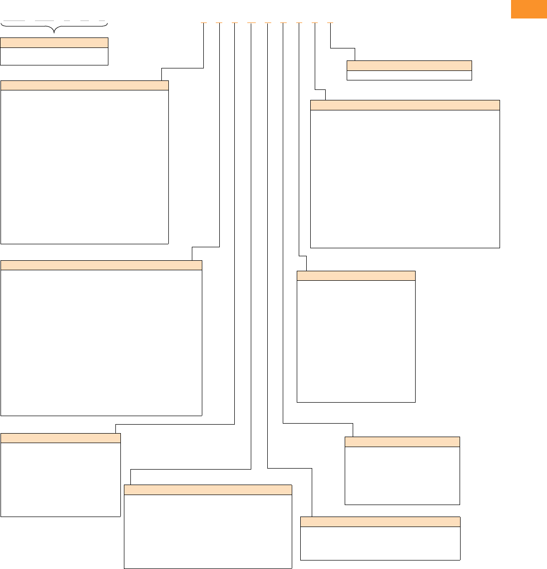
Volume 6—Solid-State Motor Control CA08100007E—February 2016 www.eaton.com V6-T2-291
2
2
2
2
2
2
2
2
2
2
2
2
2
2
2
2
2
2
2
2
2
2
2
2
2
2
2
2
2
2
2.10
Adjustable Frequency Drives
Clean Power Drives
Catalog Number Selection is for reference only. Not all option combinations may be available.
CFX Enclosed—Catalog Number Options
CFX F07 1 A 1
Base Catalog Number Example
See Page V6-T2-290 for base catalog
number selection.
2 0 0 B 1 0 0 0 0
Power Disconnect Options
0 =None
1 = MCP disconnect 1
2 = Circuit breaker
3 = Circuit breaker/isolation fusing
4 = Circuit breaker/isolation fusing/3% input reactor
5 = Circuit breaker/isolation fusing/SPD
6 = Circuit breaker/isolation fusing/SPD/3% input reactor
7 = Circuit breaker/3% input reactor
8 = Circuit breaker/SPD
9 = Circuit breaker/SPD/3% input reactor
A = Fused disconnect
B = Fused disconnect/SPD
C = Fused disconnect/SPD/3% input reactor
D = Fused disconnect/3% input reactor
E = Isolation fuses
F = Isolation fuses/3% input reactor
G = Isolation fuses/SPD
H = Isolation fuses/SPD/3% input reactor
• = Custom option 2
Bypass Options 3
0 =None
1 = Manual HOA bypass
2 = Manual HOA bypass/isolation fusing
3 = Manual HOA bypass/isolation fusing/3% input reactor
4 = Manual HOA bypass/isolation fusing/SPD
5 = Manual HOA bypass/isolation fusing/SPD/3% input reactor
6 = Manual HOA bypass/3% input reactor
7 = Manual HOA bypass/SPD
8 = Manual HOA bypass/SPD/3% input reactor
H = Manual HOA RVSS bypass
J = Manual HOA RVSS bypass/isolation fusing
K = Manual HOA RVSS bypass/isolation fusing/3% input reactor
L = Manual HOA RVSS bypass/isolation fusing/SPD
M = Manual HOA RVSS bypass/isolation fusing/SPD/3% input reactor
N = Manual HOA RVSS bypass/3% input reactor
P = Manual HOA RVSS bypass/SPD
R = Manual HOA RVSS bypass/SPD/3% input reactor
• = Custom option 2
Output Power Options 4
0 =None
A = Output contactor
B = 3% Output reactor
C = MotoRX filter
D = dV/dt filter
E = 3% Output Reactor/output contactor
F = MotoRX/output contactor
G = dV/dt/output contactor
• = Custom option 2
Option Boards 2
Same options and codes as Option Boards 1
Option Boards 1
0 = No option
1 = 3 x DI, 3 x DO, 1 Thermistor, 24 Vdc/EXT (DG1 only)
2 = 1 x AI, 2 x AO (isolated to control board) (DG1 only)
3 = 3 x relay dry contact (2NO + 1NO/NC) (DG1 only)
4 = 3 x PT100 RTD thermistor input (DG1 only)
5 = 6 DI 240 Vac input (DG1 only)
6 = 6 DI, 1 ext +24 Vdc/EXT +24 Vdc (SVX only)
7 = 1 RO (NC-NO), 1 RO (NO), 1 therm (SVX only)
8 = 1 AI (mA isolated), 2 AO (mA isolated), 1 ext +24 Vdc/EXT +24 Vdc
(SVX only)
9 = 3 RO (NO) (SVX only)
A = 1 ext +24 Vdc/EXT +24 Vdc, 3 Pt100 (SVX only)
B = 1 RO (NO), 5 DI 42–240 Vac input (SVX only)
C = Encoder low volt +5 V / 15 V / 24 V (high-performance drive only)
D = Encoder high volt +15 V / 24 V (high-performance drive only)
E = Double encoder (high-performance drive only)
• = Custom option 2
Communication Options
0 = No option
1 = PROFIBUS-DP
2 = LonWorks (SVX only)
3 = CANopen (slave)
4 = DeviceNet
5 = PROFIBUS-DP (D9 connector)
6 = Modbus (SVX only)
7 = Modbus (D9 connector) (SVX only)
8 = Johnson Controls N2 (SVX only)
9 = Modbus TCP (SVX only)
A = BACnet (SVX only)
B = EtherNet/IP (SVX only)
C = RS-232 with D9 connector (SVX only)
D = SmartWire-DT (DG1 only)
• = Custom option 2
Enclosure Options
0 =None
1 = Floor stand—12 inches
2 = Floor stand—22 inches
A = Space heater
B = Space heater & 12-inch floor stands
C = Space heater & 22-inch floor stands
• = Custom option 2
Light Options 5
0 =None
1 = Non-bypass light kit—Power On, Run, Fault
2 = Bypass light kit—On, VFD Run, Fault, Bypass Run
• = Custom option 2
Notes
1HMCP disconnect option required and only available when bypass is selected.
2More options are available as Engineered to Order through the Bid Manager tool.
3All bypass options include third contactor for drive isolation when in bypass mode.
4Output contactor not available with bypass. Bypass comes standard with output contactor.
5Pilot devices are 22 mm standard. 30 mm options are available as engineered to order through the Bid Manager tool.
Control Options 5
0 =None
1 = Speed pot
2 = Start-stop pushbutton
3 = Start-stop pushbutton with speed pot
A = HOA switch
B = Start-stop pushbutton with speed pot & HOA switch
C = Start-stop pushbutton with HOA switch
D = HOA switch with speed pot
• = Custom option 2
V6-T2-292 Volume 6—Solid-State Motor Control CA08100007E—February 2016 www.eaton.com
2
2
2
2
2
2
2
2
2
2
2
2
2
2
2
2
2
2
2
2
2
2
2
2
2
2
2
2
2
2
2.10
Adjustable Frequency Drives
Clean Power Drives
Product Selection
208 V Drives
208 V Drives—Constant Torque (CT)/High Overload (IH) Enclosed Drives
208 V Drives—Variable Torque (VT)/Low Overload (IL) Enclosed Drives
Notes
1 Table is for base catalog number reference only. For complete catalog number selection, see Page V6-T2-290.
2 These units are current rated. They do not meet NEC ampere rating at this horsepower.
NEMA Type 1 NEMA Type 12 NEMA Type 3R
hp Current (A)
Drive
Frame Size
Base
Catalog Number 1
Base
Catalog Number 1
Base
Catalog Number 1
0.75 3.5 4 CFXF071D1 CFXF071D2 CFXF071D3
14.64CFX0011D1 CFX0011D2 CFX0011D3
1.5 6.6 4 CFXF151D1 CFXF151D2 CFXF151D3
27.54CFX0021D1 CFX0021D2 CFX0021D3
310.64CFX0031D1 CFX0031D2 CFX0031D3
516.75CFX0051D1 CFX0051D2 CFX0051D3
7.5 24.2 5 CFX0071D1 CFX0071D2 CFX0071D3
10 30.8 6 CFX0101D1 CFX0101D2 CFX0101D3
15 46.2 6 CFX0151D1 CFX0151D2 CFX0151D3
20 59.4 7 CFX0201C1 CFX0201C2 CFX0201C3
25 74.8 7 CFX0251C1 CFX0251C2 CFX0251C3
30 88 7 CFX0301C1 CFX0301C2 CFX0301C3
40 114 8 CFX0401C1 CFX0401C2 CFX0401C3
50 143 8 CFX0501C1 CFX0501C2 CFX0501C3
60 169 8 CFX0601C1 CFX0601C2 CFX0601C3
75 211 9 CFX0751C1 CFX0751C2 CFX0751C3
100 2261 29CFX1001C1 CFX1001C2 CFX1001C3
NEMA Type 1 NEMA Type 12 NEMA Type 3R
hp Current (A)
Drive
Frame Size
Base
Catalog Number 1
Base
Catalog Number 1
Base
Catalog Number 1
14.64CFX0011B1 CFX0011B2 CFX0011B3
1.5 6.6 4 CFXF151B1 CFXF151B2 CFXF151B3
27.54CFX0021B1 CFX0021B2 CFX0021B3
310.64CFX0031B1 CFX0031B2 CFX0031B3
516.75CFX0051B1 CFX0051B2 CFX0051B3
7.5 24.2 5 CFX0071B1 CFX0071B2 CFX0071B3
10 30.8 5 CFX0101B1 CFX0101B2 CFX0101B3
15 46.2 6 CFX0151B1 CFX0151B2 CFX0151B3
20 59.4 6 CFX0201B1 CFX0201B2 CFX0201B3
25 74.8 7 CFX0251A1 CFX0251A2 CFX0251A3
30 88 7 CFX0301A1 CFX0301A2 CFX0301A3
40 114 7 CFX0401A1 CFX0401A2 CFX0401A3
50 143 8 CFX0501A1 CFX0501A2 CFX0501A3
60 169 8 CFX0601A1 CFX0601A2 CFX0601A3
75 211 9 CFX0751A1 CFX0751A2 CFX0751A3
100 273 9 CFX1001A1 CFX1001A2 CFX1001A3
CFX Enclosed Drives
CFX Enclosed Drives
Volume 6—Solid-State Motor Control CA08100007E—February 2016 www.eaton.com V6-T2-293
2
2
2
2
2
2
2
2
2
2
2
2
2
2
2
2
2
2
2
2
2
2
2
2
2
2
2
2
2
2
2.10
Adjustable Frequency Drives
Clean Power Drives
230 V Drives
230 V Drives—Constant Torque (CT)/High Overload (IH) Enclosed Drives
230 V Drives—Variable Torque (VT)/Low Overload (IL) Enclosed Drives
Notes
1 Table is for base catalog number reference only. For complete catalog number selection, see Page V6-T2-290.
2 These units are current rated. They do not meet NEC ampere rating at this horsepower.
NEMA Type 1 NEMA Type 12 NEMA Type 3R
hp Current (A)
Drive
Frame Size
Base
Catalog Number 1
Base
Catalog Number 1
Base
Catalog Number 1
0.75 3.2 4 CFXF072D1 CFXF072D2 CFXF072D3
14.24CFX0012D1 CFX0012D2 CFX0012D3
1.5 6 4 CFXF152D1 CFXF152D2 CFXF152D3
26.84CFX0022D1 CFX0022D2 CFX0022D3
39.64CFX0032D1 CFX0032D2 CFX0032D3
515.25CFX0052D1 CFX0052D2 CFX0052D3
7.5 22 5 CFX0072D1 CFX0072D2 CFX0072D3
10 28 6 CFX0102D1 CFX0102D2 CFX0102D3
15 42 6 CFX0152D1 CFX0152D2 CFX0152D3
20 54 7 CFX0202C1 CFX0202C2 CFX0202C3
25 68 7 CFX0252C1 CFX0252C2 CFX0252C3
30 80 7 CFX0302C1 CFX0302C2 CFX0302C3
40 104 8 CFX0402C1 CFX0402C2 CFX0402C3
50 130 8 CFX0502C1 CFX0502C2 CFX0502C3
60 154 8 CFX0602C1 CFX0602C2 CFX0602C3
75 192 9 CFX0752C1 CFX0752C2 CFX0752C3
100 248 9 CFX1002C1 CFX1002C2 CFX1002C3
NEMA Type 1 NEMA Type 12 NEMA Type 3R
hp Current (A)
Drive
Frame Size
Base
Catalog Number 1
Base
Catalog Number 1
Base
Catalog Number 1
14.24CFX0012B1 CFX0012B2 CFX0012B3
1.5 6 4 CFXF152B1 CFXF152B2 CFXF152B3
26.84CFX0022B1 CFX0022B2 CFX0022B3
39.64CFX0032B1 CFX0032B2 CFX0032B3
515.25CFX0052B1 CFX0052B2 CFX0052B3
7.5 22 5 CFX0072B1 CFX0072B2 CFX0072B3
10 28 5 CFX0102B1 CFX0102B2 CFX0102B3
15 42 6 CFX0152B1 CFX0152B2 CFX0152B3
20 54 6 CFX0202B1 CFX0202B2 CFX0202B3
25 68 7 CFX0252A1 CFX0252A2 CFX0252A3
30 80 7 CFX0302A1 CFX0302A2 CFX0302A3
40 104 7 CFX0402A1 CFX0402A2 CFX0402A3
50 130 8 CFX0502A1 CFX0502A2 CFX0502A3
60 154 8 CFX0602A1 CFX0602A2 CFX0602A3
75 192 8 CFX0752A1 CFX0752A2 CFX0752A3
100 248 9 CFX1002A1 CFX1002A2 CFX1002A3
125 2300 29CFX1252A1 CFX1252A2 CFX1252A3
CFX Enclosed Drives
CFX Enclosed Drives
V6-T2-294 Volume 6—Solid-State Motor Control CA08100007E—February 2016 www.eaton.com
2
2
2
2
2
2
2
2
2
2
2
2
2
2
2
2
2
2
2
2
2
2
2
2
2
2
2
2
2
2
2.10
Adjustable Frequency Drives
Clean Power Drives
480 V Drives
480 V Drives—Constant Torque (CT)/High Overload (IH) Enclosed Drives
Note
1 Table is for base catalog number reference only. For complete catalog number selection, see Page V6-T2-290.
NEMA Type 1 NEMA Type 12 NEMA Type 3R
hp Current (A)
Drive
Frame Size
Base
Catalog Number 1
Base
Catalog Number 1
Base
Catalog Number 1
12.14CFX0014D1 CFX0014D2 CFX0014D3
1.5 3 4 CFXF154D1 CFXF154D2 CFXF154D3
23.44CFX0024D1 CFX0024D2 CFX0024D3
34.84CFX0034D1 CFX0034D2 CFX0034D3
57.64CFX0054D1 CFX0054D2 CFX0054D3
7.5 11 5 CFX0074D1 CFX0074D2 CFX0074D3
10 14 5 CFX0104D1 CFX0104D2 CFX0104D3
15 21 5 CFX0154D1 CFX0154D2 CFX0154D3
20 27 6 CFX0204D1 CFX0204D2 CFX0204D3
25 34 6 CFX0254D1 CFX0254D2 CFX0254D3
30 40 6 CFX0304D1 CFX0304D2 CFX0304D3
40 52 7 CFX0404C1 CFX0404C2 CFX0404C3
50 65 7 CFX0504C1 CFX0504C2 CFX0504C3
60 77 7 CFX0604C1 CFX0604C2 CFX0604C3
75 96 8 CFX0754C1 CFX0754C2 CFX0754C3
100 124 8 CFX1004C1 CFX1004C2 CFX1004C3
125 156 8 CFX1254C1 CFX1254C2 CFX1254C3
150 180 9 CFX1504C1 CFX1504C2 CFX1504C3
200 240 9 CFX2004C1 CFX2004C2 CFX2004C3
250 302 10 CFX2504G1 CFX2504G2 CFX2504G3
300 361 10 CFX3004G1 CFX3004G2 CFX3004G3
350 414 10 CFX3504G1 CFX3504G2 CFX3504G3
CFX Enclosed Drives
Volume 6—Solid-State Motor Control CA08100007E—February 2016 www.eaton.com V6-T2-295
2
2
2
2
2
2
2
2
2
2
2
2
2
2
2
2
2
2
2
2
2
2
2
2
2
2
2
2
2
2
2.10
Adjustable Frequency Drives
Clean Power Drives
480 V Drives, continued
480 V Drives—Variable Torque (VT)/Low Overload (IL) Enclosed Drives
Note
1 Table is for base catalog number reference only. For complete catalog number selection, see Page V6-T2-290.
NEMA Type 1 NEMA Type 12 NEMA Type 3R
hp Current (A)
Drive
Frame Size
Base
Catalog Number 1
Base
Catalog Number 1
Base
Catalog Number 1
1.5 3 4 CFXF154B1 CFXF154B2 CFXF154B3
23.44CFX0024B1 CFX0024B2 CFX0024B3
34.84CFX0034B1 CFX0034B2 CFX0034B3
57.64CFX0054B1 CFX0054B2 CFX0054B3
7.5 11 4 CFX0074B1 CFX0074B2 CFX0074B3
10 14 5 CFX0104B1 CFX0104B2 CFX0104B3
15 21 5 CFX0154B1 CFX0154B2 CFX0154B3
20 27 5 CFX0204B1 CFX0204B2 CFX0204B3
25 34 6 CFX0254B1 CFX0254B2 CFX0254B3
30 40 6 CFX0304B1 CFX0304B2 CFX0304B3
40 52 6 CFX0404B1 CFX0404B2 CFX0404B3
50 65 7 CFX0504A1 CFX0504A2 CFX0504A3
60 77 7 CFX0604A1 CFX0604A2 CFX0604A3
75 96 7 CFX0754A1 CFX0754A2 CFX0754A3
100 124 8 CFX1004A1 CFX1004A2 CFX1004A3
125 156 8 CFX1254A1 CFX1254A2 CFX1254A3
150 180 8 CFX1504A1 CFX1504A2 CFX1504A3
200 240 9 CFX2004A1 CFX2004A2 CFX2004A3
250 302 10 CFX2504E1 CFX2504E2 CFX2504E3
300 361 10 CFX3004E1 CFX3004E2 CFX3004E3
350 414 10 CFX3504E1 CFX3504E2 CFX3504E3
400 477 10 CFX4004E1 CFX4004E2 CFX4004E3
CFX Enclosed Drives
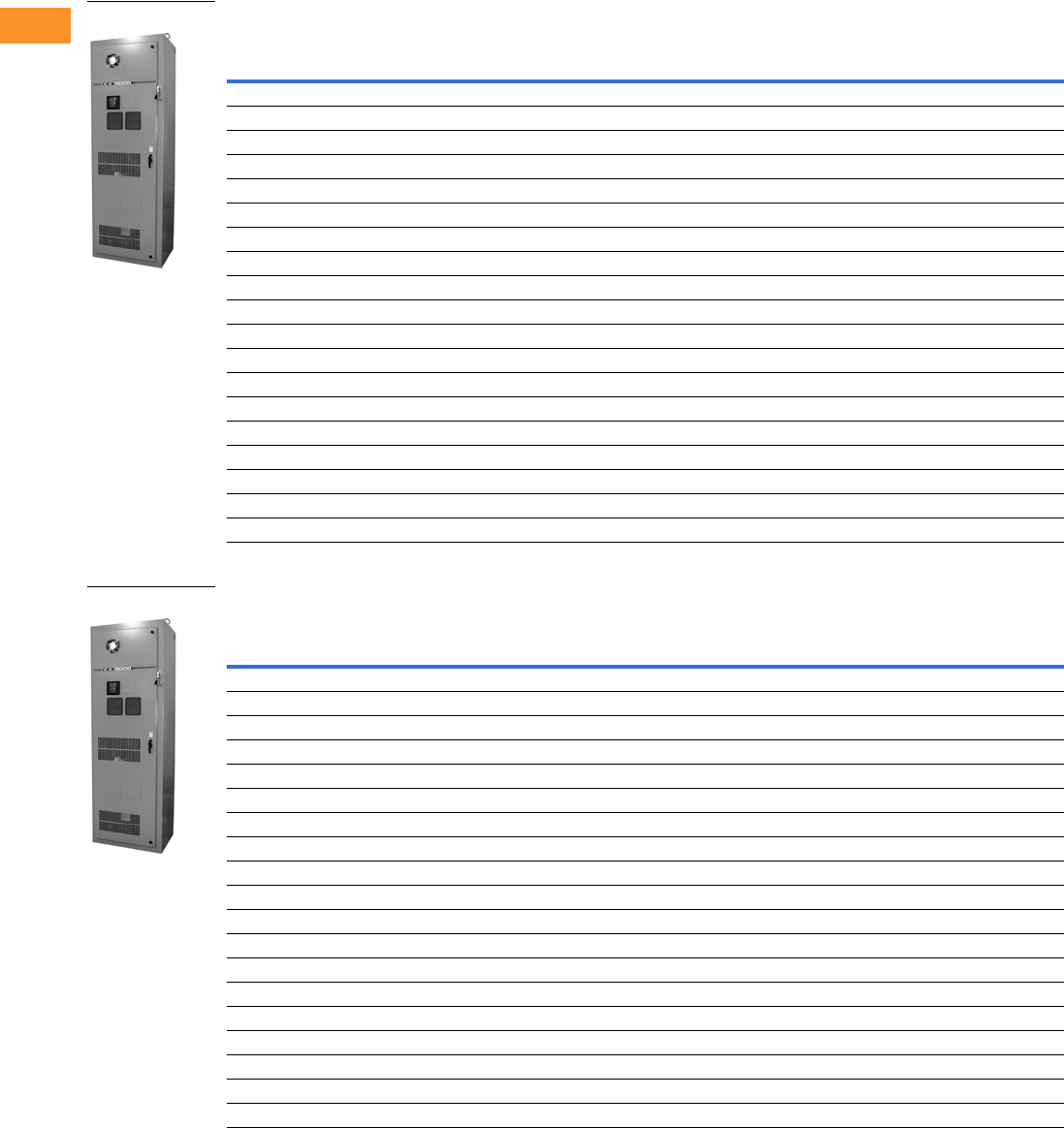
V6-T2-296 Volume 6—Solid-State Motor Control CA08100007E—February 2016 www.eaton.com
2
2
2
2
2
2
2
2
2
2
2
2
2
2
2
2
2
2
2
2
2
2
2
2
2
2
2
2
2
2
2.10
Adjustable Frequency Drives
Clean Power Drives
575 V Drives
575 V Drives—Constant Torque (CT)/High Overload (IH) Enclosed Drives
575 V Drives—Variable Torque (VT)/Low Overload (IL) Enclosed Drives
Note
1 Table is for base catalog number reference only. For complete catalog number selection, see Page V6-T2-290.
NEMA Type 1 NEMA Type 12 NEMA Type 3R
hp Current (A)
Drive
Frame Size
Base
Catalog Number 1
Base
Catalog Number 1
Base
Catalog Number 1
22.76CFX0025D1 CFX0025D2 CFX0025D3
33.96CFX0035D1 CFX0035D2 CFX0035D3
56.16CFX0055D1 CFX0055D2 CFX0055D3
7.5 9 6 CFX0075D1 CFX0075D2 CFX0075D3
10 11 6 CFX0105D1 CFX0105D2 CFX0105D3
15 17 6 CFX0155D1 CFX0155D2 CFX0155D3
20 22 6 CFX0205D1 CFX0205D2 CFX0205D3
25 27 6 CFX0255D1 CFX0255D2 CFX0255D3
30 32 7 CFX0305C1 CFX0305C2 CFX0305C3
40 41 7 CFX0405C1 CFX0405C2 CFX0405C3
50 52 8 CFX0505C1 CFX0505C2 CFX0505C3
60 62 8 CFX0605C1 CFX0605C2 CFX0605C3
75 77 8 CFX0755C1 CFX0755C2 CFX0755C3
100 99 9 CFX1005C1 CFX1005C2 CFX1005C3
125 125 9 CFX1255C1 CFX1255C2 CFX1255C3
150 144 9 CFX1505C1 CFX1505C2 CFX1505C3
200 192 10 CFX2005G1 CFX2005G2 CFX2005G3
250 242 10 CFX2505G1 CFX2505G2 CFX2505G3
300 289 10 CFX3005G1 CFX3005G2 CFX3005G3
NEMA Type 1 NEMA Type 12 NEMA Type 3R
hp Current (A)
Drive
Frame Size
Base
Catalog Number 1
Base
Catalog Number 1
Base
Catalog Number 1
33.96CFX0035B1 CFX0035B2 CFX0035B3
56.16CFX0055B1 CFX0055B2 CFX0055B3
7.5 9 6 CFX0075B1 CFX0075B2 CFX0075B3
10 11 6 CFX0105B1 CFX0105B2 CFX0105B3
15 17 6 CFX0155B1 CFX0155B2 CFX0155B3
20 22 6 CFX0205B1 CFX0205B2 CFX0205B3
25 27 6 CFX0255B1 CFX0255B2 CFX0255B3
30 32 6 CFX0305B1 CFX0305B2 CFX0305B3
40 41 7 CFX0405A1 CFX0405A2 CFX0405A3
50 52 7 CFX0505A1 CFX0505A2 CFX0505A3
60 62 8 CFX0605A1 CFX0605A2 CFX0605A3
75 77 8 CFX0755A1 CFX0755A2 CFX0755A3
100 99 8 CFX1005A1 CFX1005A2 CFX1005A3
125 125 9 CFX1255A1 CFX1255A2 CFX1255A3
150 144 9 CFX1505A1 CFX1505A2 CFX1505A3
200 192 9 CFX2005A1 CFX2005A2 CFX2005A3
250 242 10 CFX2505E1 CFX2505E2 CFX2505E3
300 289 10 CFX3005E1 CFX3005E2 CFX3005E3
400 382 10 CFX4005E1 CFX4005E2 CFX4005E3
CFX Enclosed Drives
CFX Enclosed Drives
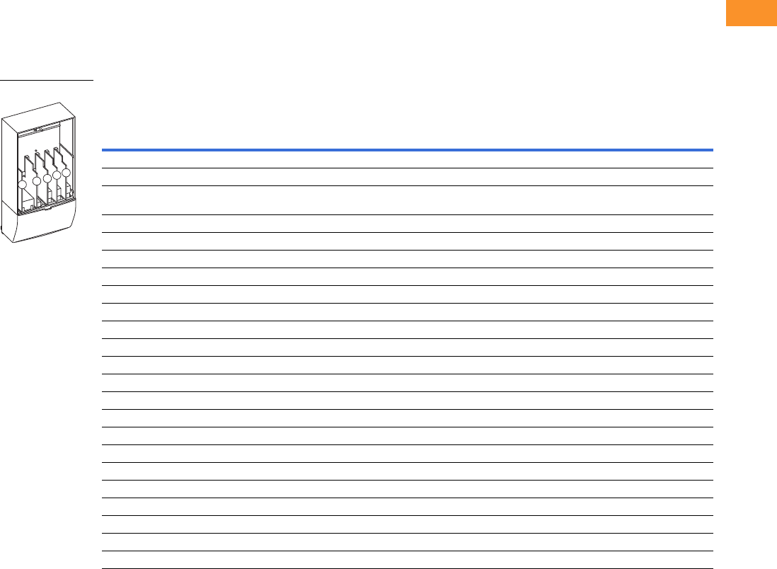
Volume 6—Solid-State Motor Control CA08100007E—February 2016 www.eaton.com V6-T2-297
2
2
2
2
2
2
2
2
2
2
2
2
2
2
2
2
2
2
2
2
2
2
2
2
2
2
2
2
2
2
2.10
Adjustable Frequency Drives
Clean Power Drives
Enclosed Passive Filtered Drive Option Board Kits
The enclosed passive filtered drive series can accommodate a wide selection of expander and
adapter option boards to customize the drive for your application needs. The drive’s control unit is
designed to accept a total of five option boards.
The enclosed passive filtered drive series factory-installed standard board configuration includes an A9
I/O board and an A2 relay output board, which are installed in slots A and B.
Option Board Kits
Notes
1 AI = Analog Input; AO = Analog Output, DI = Digital Input, DO = Digital Output, RO = Relay Output
2 Option card must be installed in one of the slots listed for that card. Slot indicated in bold is the preferred location.
3 OPTC2 is a multi-protocol option card.
Option Kit Description 1
Allowed Slot
Locations 2
Field
Installed
Factory
Installed SVX Ready Programs
Catalog
Number
Option
Designator Basic
Local/
Remote Standard MSS PID Multi-P. PFC
Standard I/O Cards
2 RO (NC/NO) B OPTA2 — ■ ■ ■ ■■■ ■
6 DI, 1 DO, 2 AI, 1 AO, 1 +10 Vdc ref,
2 ext +24 Vdc/ext +24 Vdc
AOPTA9 — ■ ■ ■ ■■■ ■
Extended I/O Cards
6 DI B, C, D, E OPTB1 B1 —— — ——
■■
1 RO (NC/NO), 1 RO (NO), 1 therm B, C, D, E OPTB2 B2 —— — ——
■■
1 AI (mA isolated), 2 AO (mA isolated) B, C, D, E OPTB4 B4 ■ ■ ■ ■■■ ■
3 RO (NO) B, C, D, E OPTB5 B5 —— — ——
■■
3 Pt100 RTD board B, C, D, E OPTB8 B8 —— — ——
■—
1 RO (NO), 5 DI 42–240 Vac input B, C, D, E OPTB9 B9 —— — ——
■■
Communication Cards 3
Modbus D, E OPTC2 C2 ■ ■ ■ ■■■ ■
Modbus TCP D, E OPTCI CI ■ ■ ■ ■■■ ■
BACnet D, E OPTCJ CJ ■ ■ ■ ■■■ ■
EtherNet/IP D, E OPTCQ CQ ■ ■ ■ ■■■ ■
Johnson Controls N2 D, E OPTC2 CA ■ ■ ■ ■■■ ■
PROFIBUS DP D, E OPTC3 C3 ■ ■ ■ ■■■ ■
LonWorks D, E OPTC4 C4 ■ ■ ■ ■■■ ■
PROFIBUS DP (D9 connector) D, E OPTC5 C5 ■ ■ ■ ■■■ ■
CANopen (slave) D, E OPTC6 C6 ■ ■ ■ ■■■ ■
DeviceNet D, E OPTC7 C7 ■ ■ ■ ■■■ ■
Modbus (D9 type connector) D, E OPTC8 C8 ■ ■ ■ ■■■ ■
RS-232 with D9 connection D, E OPTD3 D3 ■ ■ ■ ■■■ ■
Option Boards
ABCDE

V6-T2-298 Volume 6—Solid-State Motor Control CA08100007E—February 2016 www.eaton.com
2
2
2
2
2
2
2
2
2
2
2
2
2
2
2
2
2
2
2
2
2
2
2
2
2
2
2
2
2
2
2.10
Adjustable Frequency Drives
Clean Power Drives
Modbus RTU Network
Communications
The Modbus Network Card
OPTC2 is used for connecting
the SVX Drive as a slave
on a Modbus network. The
interface is connected by
a 9-pin DSUB connector
(female) and the baud rate
ranges from 300 to 19,200
baud. Other communication
parameters include an
address range from 1 to 247;
a parity of None, Odd or
Even; and the stop bit is 1.
PROFIBUS Network
Communications
The PROFIBUS Network Card
OPTC3 is used for connecting
the SVX Drive as a slave
on a PROFIBUS-DP network.
The interface is connected
by a 9-pin DSUB connector
(female). The baud rates
range from 9.6 Kbaud to
12 Mbaud, and
the addresses
range from 1 to 127.
LonWorks Network
Communications
The LonWorks Network Card
OPTC4 is used for connecting
the SVX Drive on a LonWorks
network. This interface uses
Standard Network Variable
Types (SNVT) as data types.
The channel connection is
achieved using a FTT-10 A
Free Topology transceiver
via a single twisted transfer
cable. The communication
speed with LonWorks is
78 kBits/s.
CANopen (Slave)
Communications
The CANopen (Slave)
Network Card OPTC6 is used
for connecting the SVX Drive
to a host system. According
to ISO11898 standard cables
to be chosen for CANbus
should have a nominal
impedance of 120 ohms,
and specific line delay of
nominal 5 as/m. 120 ohm
line termination resistors
required for installation.
DeviceNet Network
Communications
The DeviceNet Network Card
OPTC7 is used for connecting
the SVX Drive on a DeviceNet
Network. It includes a
5.08 mm pluggable
connector. Transfer method
is via CAN using a two-wire
twisted shielded cable with
two-wire bus power cable
and drain. The baud rates
used for communication
include 125 Kbaud,
250 Kbaud and 500 Kbaud.
Johnson Controls Metasys N2
Network Communications
The OPTC2 fieldbus board
provides communication
between the SVX Drive
and a Johnson Controls
Metasys™ N2 network.
With this connection, the
drive can be controlled,
monitored and programmed
from the Metasys system.
The N2 fieldbus is available as
a factory-installed option and
as a field-installable kit.
Modbus/TCP Network
Communications
The Modbus/TCP Network
Card OPTCI is used for
connecting the SVX Drive
to Ethernet networks using
Modbus protocol. It includes
an RJ-45 pluggable
connector. This interface
provides a selection of
standard and custom register
values to communicate drive
parameters. The board
supports 10 Mbps and
100 Mbps communication
speeds. The IP address of
the board is configurable over
Ethernet using a supplied
software tool.
BACnet Network
Communications
The BACnet Network Card
OPTCJ is used for connecting
the SVX Drive to BACnet
networks. It includes a 5.08
mm pluggable connector.
Data transfer is Master-Slave/
Token Passing (MS/TP)
RS-485. This interface uses
a collection of 30 Binary
Value Objects (BVOs) and
35 Analog Value Objects
(AVOs) to communicate
drive parameters. The card
supports 9.6, 19.2 and 38.4
Kbaud communication
speeds and supports network
addresses 1 to 127.
EtherNet/IP Network
Communications
The EtherNet/IP Network
Card OPTCK is used for
connecting the SVX Drive
to Ethernet/Industrial Protocol
networks. It includes an
RJ-45 pluggable connector.
The interface uses CIP
objects to communicate
drive parameters (CIP is
“Common Industrial
Protocol,” the same protocol
used by DeviceNet). The
board supports 10 Mbps and
100 Mbps communication
speeds. The IP address of
the board is configurable
by Static, BOOTP and
DHCP methods.

Volume 6—Solid-State Motor Control CA08100007E—February 2016 www.eaton.com V6-T2-299
2
2
2
2
2
2
2
2
2
2
2
2
2
2
2
2
2
2
2
2
2
2
2
2
2
2
2
2
2
2
2.10
Adjustable Frequency Drives
Clean Power Drives
Enclosure Selection
CFX Drives
Enclosure selection charts are based on physical space limitations only and only to be used as a reference.
For actual enclosure sizing, refer to Bid Manager.
Note: Filtered enclosure sizing includes dedicated space for passive filter,
input fuses, circuit breaker or fusible disconnect, CPT, SPD, heater/
thermostat, control relay and terminal blocks.
Filtered Enclosure X-Space
Filtered Power Options X-Space
Larger Frame Enclosure Sizes
Note: Filtered bypass enclosure sizing includes dedicated space for a
passive filter, input fuses, MCP, CPT, input contactor, output bypass
contactors, overload relay, SPD, heater/thermostat, control relay and
terminal blocks.
Filtered Bypass Enclosure X-Space
Filtered Bypass Power Options X-Space
Larger Frame Enclosure Sizes
Note
1Consult factory.
Enclosure Size Frame 4 Frame 5 Frame 6 Frame 7 Frame 8
AX —————
BX 0 0 ———
CX 3322—
DX 14 14 13 13 10
Power Options Frame 4 Frame 5 Frame 6 Frame 7 Frame 8
3% Output reactor 11356
MotoRX filter 33335
dV/dt filter 33356
Output contactor 11111
Frame Size Type 1 Type 12
Type 1 Filtered
and Gasketed Type 3R
Frame 9 Size 8 — Size 8 Size F
Frame 10 Size 9Size 9— 1
Enclosure Size Frame 4 Frame 5 Frame 6 Frame 7 Frame 8
AX —————
BX —————
CX 210——
DX 13 12 11 10 6
Power Options Frame 4 Frame 5 Frame 6 Frame 7 Frame 8
RVSS Bypass 11356
3% Output reactor 22234
MotoRX filter 33335
dV/dt filter 33356
Frame Size Type 1 Type 12
Type 1 Filtered
and Gasketed Type 3R
Frame 9 Size 8 — Size 8 Size F
Frame 10 Size 9Size 9— 1

V6-T2-300 Volume 6—Solid-State Motor Control CA08100007E—February 2016 www.eaton.com
2
2
2
2
2
2
2
2
2
2
2
2
2
2
2
2
2
2
2
2
2
2
2
2
2
2
2
2
2
2
2.10
Adjustable Frequency Drives
Clean Power Drives
Options
Input Power Options
Bypass Options
Output Power Options
Option Description
HMCP Disconnect The HMCP motor protection circuit breaker uses an electronic trip unit to provide typical motor overload relay functionality and short-circuit
protection against potential phase-to-phase or phase-to-ground faults.
Circuit Breaker Utilizes a circuit breaker to provide a means of short-circuit protection for the power cables between it and the drive, and protection from high-
level ground faults on the power cable. Allows a convenient means of disconnecting the drive from the line, and the operating mechanism can
be padlocked in the OFF position. This is factory mounted in the enclosure.
Isolation Fusing Provides high-level fault protection of the drive input power circuit from the load side of the fuses to the input side of the power transistors.
This option consists of three 200 kA fuses that are factory mounted in the enclosure.
3% Input Reactor The input reactor is a three-phase series inductance on the line side of an AFD. It is used to provide a reduction in voltage and current
harmonics. It also provides increased input protection for AFD and its semiconductors from line transients.
SPD Provides a surge protection device (SPD) connected to the line side terminals and is designed to clip line side transients.
Fused Disconnect Utilizes fusing to provide a means of short-circuit protection for the power cables between it and the drive, and protection from high-level
ground faults on the power cable. Allows a convenient means of disconnecting the drive from the line, and the operating mechanism can be
padlocked in the OFF position. This is factory mounted in the enclosure.
Option Description
Manual HOA Bypass Provides a three-position selector switch that allows the user to select either a HAND or AUTO mode of operation. HAND mode is defaulted
keypad operation, and AUTO mode is defaulted to control from an external terminal source. These modes of operation can be configured via
programming to allow for alternate combinations of start and speed sources. Start and speed sources include keypad, I/O and fieldbus.
Manual HOA RVSS Bypass This option adds a reduced voltage soft starter to bypass assembly for soft starting in bypass mode.
Option Description
Output Contactor Provides a means for positive disconnection of the drive output from the motor terminals. The contactor coil is controlled by the drive’s run or
permissive logic. NC and NO auxiliary contacts rated at 10 A, 600 Vac are provided for customer use. This option includes a low VA 115 Vac
fused control power transformer and is factory mounted in the enclosure.
3% Output Reactor The output reactor is a three-phase series inductance on the load side of an AFD. It is used to provide a reduction in voltage and current
harmonics.
MotoRX Filter Used to reduce transient voltage (dV/dt) and peak voltages at the motor terminals. This option is comprised of a 0.5% line reactor, followed by
capacitive filtering and an energy recovery/clamping circuit. Unlike the traditional dV/dt filter, the MotoRx recovers most of the energy from the
voltage peaks, resulting in a lower voltage drop to the motor, therefore conserving power. This option is used when the distance between
a single motor and the drive is 300–600 ft (91–183 m). This option can not be used with the brake chopper circuit. in this case, the traditional
dV/dt filter should be investigated as an alternative.
dV/dt Filter Used to reduce the transient voltage (dV/dt) at the motor terminals. The traditional dV/dt filter is recommended for cable lengths exceeding
100 ft (30 m) with a drive of 3 hp and above, for cable lengths of 33 ft (10 m) with a drive of 2 hp and below, or for a drive rated at 525–690 V.
This option is mounted in the enclosure and may be used in conjunction with a brake chopper circuit. This option is mounted in the enclosure.

Volume 6—Solid-State Motor Control CA08100007E—February 2016 www.eaton.com V6-T2-301
2
2
2
2
2
2
2
2
2
2
2
2
2
2
2
2
2
2
2
2
2
2
2
2
2
2
2
2
2
2
2.10
Adjustable Frequency Drives
Clean Power Drives
Control Options
Light Options
Enclosure Options
Option Description
Speed Pot Provides the ability to adjust the frequency reference using a door-mounted potentiometer. This option uses the 10 Vdc reference to generate a
0–10 V signal at the analog voltage input signal terminal. When the HOA bypass option is added, the speed is controlled when the HOA switch
is in the HAND position. Without the HOA bypass option, a two-position switch (labeled local/remote) is provided on the keypad to select
speed reference from the speed potentiometer or a remote speed signal.
HOA Switch Provides a three-position selector switch that allows the user to select either a HAND or AUTO mode of operation. HAND mode is defaulted to
keypad operation, and AUTO mode is defaulted to control from an external terminal source. These modes of operation can be configured via
drive programming to allow for alternate combinations of start and speed sources. Start and speed sources include Keypad, I/O and fieldbus.
Start-Stop Pushbutton Provides door-mounted START and STOP pushbuttons for either bypass or non-bypass configurations.
Option Description
Non-Bypass Light Kit—Power On, Run, Fault Provides a white POWER ON light that indicates power to the enclosed cabinet, a green RUN light that indicates the drive is running and a red
FAULT light that indicates a drive fault has occurred.
Bypass Light Kit—On, VFD Run, Fault, Bypass Run Provides a white POWER ON light that indicates power to the enclosed cabinet, a green RUN light that indicates the drive is running, a red
FAULT light that indicates a drive fault has occurred and an amber light that indicates when the motor is running in Bypass mode.
Option Description
Floor Stand 12 in Converts a normally wall-mounted enclosure to a floor-standing enclosure with a height of 12 in (304.8 mm).
Floor Stand 22 in Converts a normally wall-mounted enclosure to a floor-standing enclosure with a height of 22 in (558.8 mm).

V6-T2-302 Volume 6—Solid-State Motor Control CA08100007E—February 2016 www.eaton.com
2
2
2
2
2
2
2
2
2
2
2
2
2
2
2
2
2
2
2
2
2
2
2
2
2
2
2
2
2
2
2.10
Adjustable Frequency Drives
Clean Power Drives
Technical Data and Specifications
Enclosed Passive Filtered Drives
Note
1The EMI filter is optional in FR10.
Description Specification
Primary Design Features
45–66 Hz input frequency Standard
Output: AC volts maximum Input Voltage Base
Output frequency range 0–320 Hz
Initial output current (IH) 250% for 2 seconds
Overload (1 minute [IH/IL]) 150%/110%
Enclosure space heater Optional
Oversize enclosure Standard
Output contactor Optional
Bypass motor starter Optional
Listings UL, cUL, 508C
Protection Features
Incoming line fuses Optional
AC input circuit disconnect Optional
Phase rotation insensitive Standard
EMI filter Standard—FR6 thru FR9 1
Input phase loss protection Standard
Input overvoltage protection Standard
Line surge protection Standard
Output short-circuit protection Standard
Output ground fault protection Standard
Output phase protection Standard
Overtemperature protection Standard
DC overvoltage protection Standard
Drive overload protection Standard
Motor overload protection Standard
Programmer software Optional
Local/remote keypad Standard
Keypad lockout Standard
Fault alarm output Standard
Built-in diagnostics Standard
Surge protective device Optional
Description Specification
Input/Output Interface Features
Setup adjustment provisions
Remote keypad/display Standard
Personal computer Standard
Operator control provisions
Drive mounted keypad/display Standard
Remote keypad/display Standard
Conventional control elements Standard
Serial communications Optional
115 Vac control circuit Optional
Speed setting inputs
Keypad Standard
0–10 Vdc potentiometer/voltage signal Standard
4–20 mA isolated Configurable
4–20 mA differential Configurable
3–15 psig Optional
Analog outputs
Speed/frequency Standard
Torque/load/current Programmable
Motor voltage Programmable
Kilowatts Programmable
0–10 Vdc signals Configurable w/jumpers
4–20 mA DC signals Standard
Isolated signals Optional
Discrete outputs
Fault alarm Standard
Drive running Standard
Drive at set speed Programmable
Optional parameters 14
Dry contacts 2 relays Form C
Open collector outputs 1
Additional discrete outputs Optional
Communications
RS-232 Standard
RS-422/485 Optional
DeviceNet™ Optional
Modbus RTU Optional
CANopen (slave) Optional
PROFIBUS-DP Optional
Lonworks®Optional
Johnson Controls Metasys™ N2 Optional
EtherNet/IP/Modbus TCP Optional
BACnet Optional

Volume 6—Solid-State Motor Control CA08100007E—February 2016 www.eaton.com V6-T2-303
2
2
2
2
2
2
2
2
2
2
2
2
2
2
2
2
2
2
2
2
2
2
2
2
2
2
2
2
2
2
2.10
Adjustable Frequency Drives
Clean Power Drives
Enclosed Passive Filtered Drives, continued Standard I/O Specifications
I/O Specifications for Control/Communication Options
Notes
1Units FR10 rated 40 °C.
2For applications above 3 A consult instruction manual.
Description Specification
Performance Features
Sensorless vector control Standard
Volts/hertz control Standard
IR and slip compensation Standard
Electronic reversing Standard
Dynamic braking Optional
DC braking Standard
PID setpoint controller Programmable
Critical speed lockout Standard
Current (torque) limit Standard
Adjustable acceleration/deceleration Standard
Linear or S curve accel/decel Standard
Jog at preset speed Standard
Thread/preset speeds 7
Automatic restart Selectable
Coasting motor start Standard
Coast or ramp stop selection Standard
Elapsed time meter Optional
Standard Conditions for Application and Service
Maximum operating ambient temperature 0 to 40 °C, contact factory for 50 °C 1
Storage temperature –40 to 60 °C
Humidity (maximum), non-condensing 95%
Altitude 100% load capacity (no derating) up to
3280 ft (1000 m);
1% derating for each 328 ft (100 m) above
3280 ft (1000 m); max. 9842 ft (3000 m)
Line voltage variation +10/–15%
Line frequency variation 45–66 Hz
Efficiency >96%
Power factor (displacement) 0.99
Description Specification
Six–digital input programmable 24 V: “0” <10 V, “1” >18V,Ri >5 kohms
Two–analog input configurable w/
jumpers
Voltage: 0–±10 V, Ri >200 kohms
Current: 0 (4)–20 mA, Ri = 250 kohms
Two–digital output programmable Form C relays 250 Vac or 30 Vdc 2 Amp resistive
One–digital output programmable Open collector 48 Vdc 50 mA
One–analog output programmable
configurable w/jumper
0–20 mA, RL max. 500 ohms 10 bits ±2%
Description Specification
Analog voltage, input 0–±10 V, Ri >200 kilohms
Analog current, input 0 (4)–20 mA, Ri = 250 ohms
Digital input 24 V: “0” <10 V, “1” >18V, Ri >5 kilohms
Auxiliary voltage 24 V (±20%), max. 50 mA
Reference voltage 10 V ±3%, max. 10 mA
Analog current, output 0 (4)–20 mA, RL = 500 kilohms, resolution
10 bit, accuracy <±2%
Analog voltage, output 0 (2)–10 V, RL >1 kohm, resolution
10 bit, accuracy <±2%
Relay output max. switching voltage 300 Vdc, 250 Vac
Relay output max. switching load 3 A/24 Vdc, 300 Vdc, 250 Vac 2
Relay output max. continuous load 2 A rms
Thermistor input Rtrip = 4.7 kohms
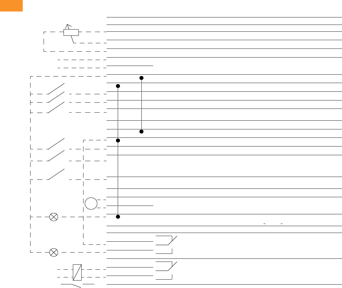
V6-T2-304 Volume 6—Solid-State Motor Control CA08100007E—February 2016 www.eaton.com
2
2
2
2
2
2
2
2
2
2
2
2
2
2
2
2
2
2
2
2
2
2
2
2
2
2
2
2
2
2
2.10
Adjustable Frequency Drives
Clean Power Drives
Wiring Diagram
Control Input/Output
Basic Application Default I/O Configuration
Terminal Signal Description
OPTA9
1 +10 Vref Reference output Voltage for potentiometer, etc.
2 AI1+ Analog input, voltage range 0–10 Vdc Voltage input frequency reference
3 AI1– I/O Ground Ground for reference and controls
4 AI2+ Analog input, current range 0–20 mA Current input frequency reference
5AI2–
6 +24 V Control voltage output Voltage for switches, etc. max 0.1 A
7 GND I/O ground Ground for reference and controls
8 DIN1 Start forward Contact closed = start forward
9 DIN2 Start reverse Contact closed = start reverse
10 DIN3 External fault input (programmable) Contact open = no fault
Contact closed = fault
11 CMA Common for DIN 1–DIN 3 Connect to GND or +24 V
12 +24 V Control voltage output Voltage for switches (see terminal 6)
13 GND I/O ground Ground for reference and controls
14 DIN4 Multi-step speed select 1 DIN4 DIN5 Frequency Ref.
15 DIN5 Multi-step speed select 2 Open
Closed
Open
Closed
Open
Open
Closed
Closed
Ref.Vin
Multi-step ref.1
Multi-step ref.2
RefMax
16 DIN6 Fault reset Contact open = no action
Contact closed = fault reset
17 CMB Common for DIN4–DIN6 Connect to GND or +24 V
18 AO1+ Output frequency
Analog output
Programmable
Range 0–20 mA, RL max. 500 ohms
19 AO1–
20 DO1 Digital output
READY
Programmable
Open collector, I <50 mA, V <48 Vdc
OPTA2
21 RO1 Relay output 1
RUN
22 RO1
23 RO1
24 RO2 Relay output 2
FAULT
25 RO2
26 RO2
Remote reference
0(4)–20 mA
mA
READY
RUN
Reference potentiometer
1–10 kohms
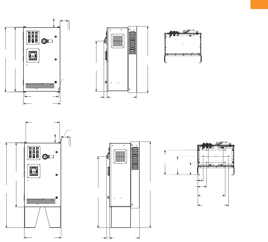
Volume 6—Solid-State Motor Control CA08100007E—February 2016 www.eaton.com V6-T2-305
2
2
2
2
2
2
2
2
2
2
2
2
2
2
2
2
2
2
2
2
2
2
2
2
2
2
2
2
2
2
2.10
Adjustable Frequency Drives
Clean Power Drives
Dimensions
Approximate Dimensions in Inches (mm)
BX Box Type 1
BX Box Type 1—12 Inch Floor Stands
4.00 (101.6)
Minimum
Free Air Space
Required
28.55
(725.1)
36.80
(934.7)
36.35
(923.3)
19.30 (490.2)
20.92 (531.4)
17.01 (432.2)
1.76
(44.8)
37.74
(958.6)
3.00 (76.2)
Minimum
Air Space
Required
Both Sides
Ø 0.44 (11.2)
Mounting
Holes
(4 Places)
4.00 (101.6)
Minimum
Free Air Space
Required
14.06
(357.1)
19.30 (490.2)
36.35
(923.3)
48.37
(1228.6)
20.92 (531.4) 17.01 (432.2)
1.76
(44.8)
40.38
(1025.7)
48.87
(1241.3)
15.50 (393.7)
17.50 (444.5)
10.53
(267.5) 7.00
(177.8)
Ø 0.44 (11.2)
Mounting
Holes
(2 Places)
3.00 (76.2)
Minimum
Air Space
Required
Both Sides
3.00 (76.2)
5.00 (127.0)
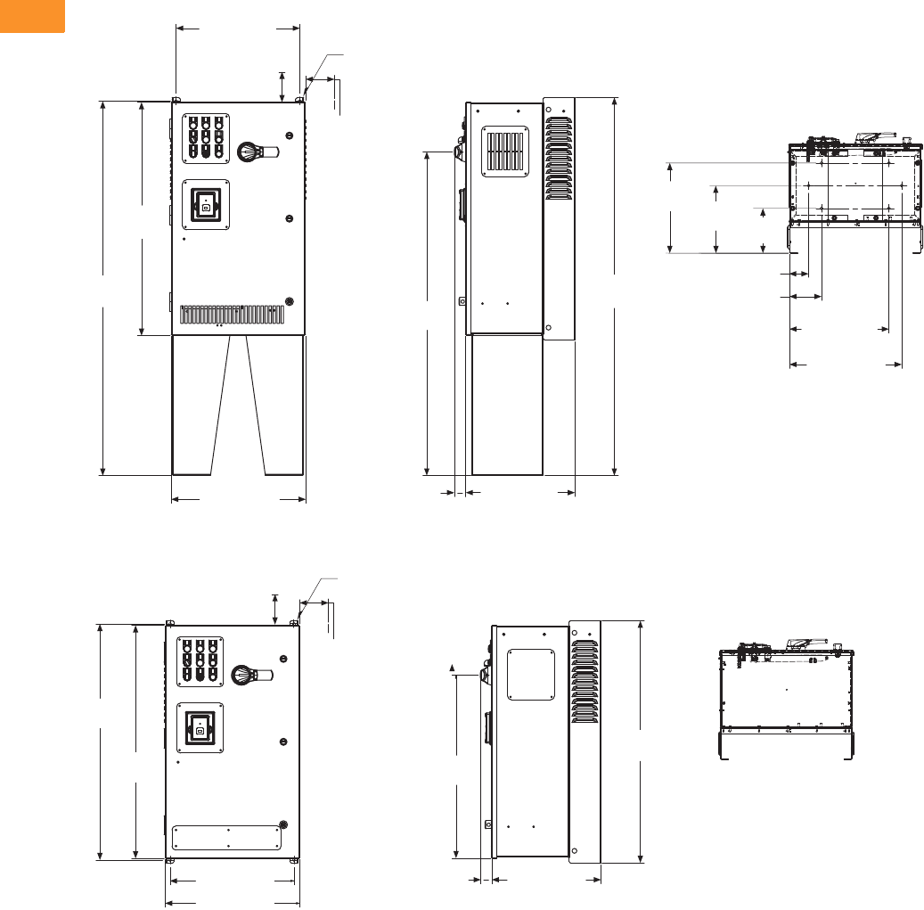
V6-T2-306 Volume 6—Solid-State Motor Control CA08100007E—February 2016 www.eaton.com
2
2
2
2
2
2
2
2
2
2
2
2
2
2
2
2
2
2
2
2
2
2
2
2
2
2
2
2
2
2
2.10
Adjustable Frequency Drives
Clean Power Drives
Approximate Dimensions in Inches (mm)
BX Box Type 1—22 Inch Floor Stands
BX Box Type 12
4.00 (101.6)
Minimum
Free Air Space
Required
14.06
(357.1)
15.50 (393.7)
17.50 (444.5)
10.53
(267.5) 7.00
(177.8)
3.00 (76.2)
5.00 (127.0)
58.87
(1495.3)
19.30 (490.2)
36.35
(923.3)
58.37
(1482.6)
20.92 (531.4) 17.01 (432.2)
1.76
(44.8)
50.38
(1279.7)
Ø 0.44 (11.2)
Mounting
Holes
(2 Places)
3.00 (76.2)
Minimum
Air Space
Required
Both Sides
4.00 (101.6)
Minimum
Free Air Space
Required
28.55
(725.1)
36.80
(934.7)
36.35
(923.3)
19.30 (490.2)
20.92 (531.4)
37.74
(958.6)
Ø 0.44 (11.2)
Mounting
Holes
(2 Places)
3.00 (76.2)
Minimum
Air Space
Required
Both Sides
17.01 (432.2)
1.76
(44.8)
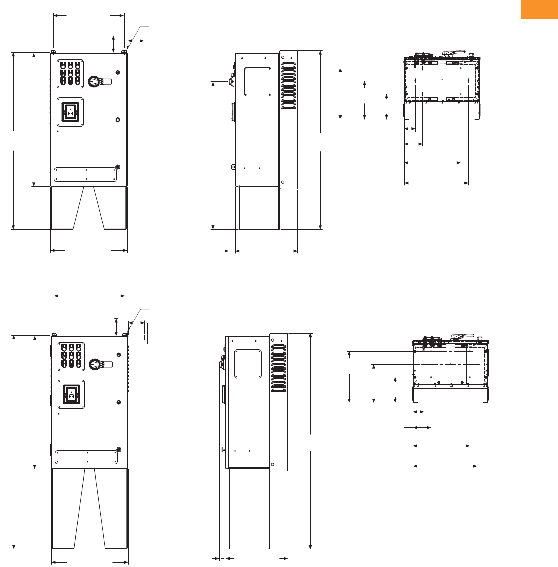
Volume 6—Solid-State Motor Control CA08100007E—February 2016 www.eaton.com V6-T2-307
2
2
2
2
2
2
2
2
2
2
2
2
2
2
2
2
2
2
2
2
2
2
2
2
2
2
2
2
2
2
2.10
Adjustable Frequency Drives
Clean Power Drives
Approximate Dimensions in Inches (mm)
BX Box Type 12—12 Inch Floor Stands
BX Box Type 12—22 Inch Floor Stands
7.00
(177.8)
10.53
(267.5)
14.06
(357.1)
15.50 (393.7)
17.50 (444.5)
3.00 (76.2)
5.00 (127.0)
40.38
(1025.7)
19.30 (490.2)
36.35
(923.3)
48.37
(1228.6)
20.92 (531.4) 17.01 (432.2)
1.76
(44.8)
48.87
(1241.3)
Ø 0.44 (11.2)
Mounting
Holes
(2 Places)
3.00 (76.2)
Minimum
Air Space
Required
Both Sides
4.00 (101.6)
Minimum
Free Air Space
Required
7.00
(177.8)
10.53
(267.5)
14.06
(357.1)
15.50 (393.7)
17.50 (444.5)
3.00 (76.2)
5.00 (127.0)
58.87
(1495.3)
19.30 (490.2)
36.35
(923.3)
58.37
(1482.6)
20.92 (531.4) 17.01 (432.2)
1.76
(44.8)
Ø 0.44 (11.2)
Mounting
Holes
(2 Places)
3.00 (76.2)
Minimum
Air Space
Required
Both Sides
4.00 (101.6)
Minimum
Free Air Space
Required
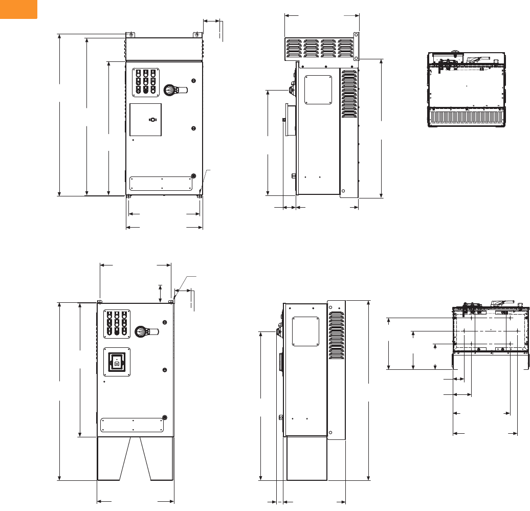
V6-T2-308 Volume 6—Solid-State Motor Control CA08100007E—February 2016 www.eaton.com
2
2
2
2
2
2
2
2
2
2
2
2
2
2
2
2
2
2
2
2
2
2
2
2
2
2
2
2
2
2
2.10
Adjustable Frequency Drives
Clean Power Drives
Approximate Dimensions in Inches (mm)
BX Box Type 3R
BX Box Type 3R—12 Inch Floor Stands
28.56
(725.3)
44.09
(1119.8)
36.35
(923.3)
42.69
(1084.3)
19.30 (490.2)
20.92 (531.4)
37.74
(958.6)
3.00 (76.2)
Minimum
Air Space
Required
Both Sides
Ø 0.44 (11.2)
Mounting
Holes
(4 Places)
17.01 (432.2)
3.51
(89.1)
20.18 (512.5)
7.00
(177.8)
10.53
(267.5)
14.06
(357.1)
15.50 (393.7)
17.50 (444.5)
3.00 (76.2)
5.00 (127.0)
40.38
(1025.7)
19.30 (490.2)
36.35
(923.3)
48.37
(1228.6)
20.92 (531.4) 17.01 (432.2)
1.76
(44.8)
48.87
(1241.3)
Ø 0.44 (11.2)
Mounting
Holes
(2 Places)
3.00 (76.2)
Minimum
Air Space
Required
Both Sides
4.00 (101.6)
Minimum
Free Air Space
Required

Volume 6—Solid-State Motor Control CA08100007E—February 2016 www.eaton.com V6-T2-309
2
2
2
2
2
2
2
2
2
2
2
2
2
2
2
2
2
2
2
2
2
2
2
2
2
2
2
2
2
2
2.10
Adjustable Frequency Drives
Clean Power Drives
Approximate Dimensions in Inches (mm)
BX Box Type 3R—22 Inch Floor Stands
CX Box Type 1
7.00
(177.8)
10.53
(267.5)
14.06
(357.1)
15.50 (393.7)
17.50 (444.5)
3.00 (76.2)
5.00 (127.0)
50.38
(1279.7)
20.88 (530.4)
17.88 (454.2)
65.66
(1667.7)
42.77
(1086.4)
36.35
(923.3)
Ø 0.44 (11.2)
Mounting
Holes
(2 Places)
3.00 (76.2)
Minimum
Air Space
Required
Both Sides
20.92 (531.4) 17.01 (432.2)3.57 (90.7)
20.18 (512.5)
55.10
(1429.9)
4.00 (101.6) Minimum
Free Air Space Required
48.80
(1239.5)
48.35
(1228.1)
29.30 (744.2)
30.92 (785.4) 17.76 (451.2)
1.74
(44.2)
49.74
(1263.4)
35.85
(910.6)
3.00 (76.2)
Minimum
Air Space
Required
Both Sides
Ø 0.44 (11.2)
Mounting
Holes
(4 Places)
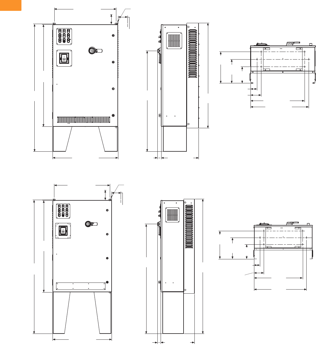
V6-T2-310 Volume 6—Solid-State Motor Control CA08100007E—February 2016 www.eaton.com
2
2
2
2
2
2
2
2
2
2
2
2
2
2
2
2
2
2
2
2
2
2
2
2
2
2
2
2
2
2
2.10
Adjustable Frequency Drives
Clean Power Drives
Approximate Dimensions in Inches (mm)
CX Box Type 1—12 Inch Floor Stands
CX Box Type 1—22 Inch Floor Stands
3.00 (76.2)
5.00 (127.0)
29.30 (744.2)
48.35
(1228.1)
60.37
(1533.4)
30.92 (785.4) 17.76 (451.2)
47.67
(1210.8) 49.74
(1263.4)
14.81
(376.2)
11.28
(286.5) 7.75
(196.9)
27.50 (698.5)
25.50 (647.7)
Ø 0.44 (11.2)
Mounting
Holes
(2 Places)
3.00 (76.2)
Minimum
Air Space
Required
Both Sides
4.00 (101.6) Minimum
Free Air Space Required
1.74
(44.2)
29.30 (744.2)
4.00 (101.6) Minimum
Free Air Space Required
Ø 0.44 (11.2)
Mounting Holes
(2 Places)
3.00 (76.2)
Minimum
Air Space
Required
Both Sides
48.35
(1228.1)
70.37
(1787.4)
30.92 (785.4) 17.76 (451.2)1.74 (44.2)
57.68
(1465.0) 70.87
(1800.1)
14.81
(376.2) 11.28
(286.5) 7.75
(196.9)
25.50
(647.7)
27.50
(698.5)
5.00
(127.0)
3.00
(76.2)
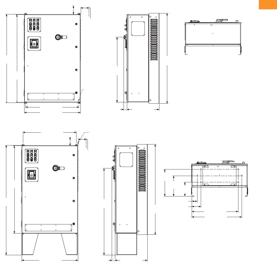
Volume 6—Solid-State Motor Control CA08100007E—February 2016 www.eaton.com V6-T2-311
2
2
2
2
2
2
2
2
2
2
2
2
2
2
2
2
2
2
2
2
2
2
2
2
2
2
2
2
2
2
2.10
Adjustable Frequency Drives
Clean Power Drives
Approximate Dimensions in Inches (mm)
CX Box Type 12
CX Box Type 12—12 Inch Floor Stands
49.74
(1263.4)
48.80
(1239.5)
48.35
(1228.1)
29.30 (744.2)
30.92 (785.4)
1.74
(44.2) 17.76 (451.2)
35.85
(910.6)
3.00 (76.2)
Minimum
Air Space
Required
Both Sides
4.00 (101.6) Minimum
Free Air Space Required
Ø 0.44 (11.2)
Mounting
Holes
(4 Places)
48.35
(1228.1)
60.37
(1533.4)
30.92 (785.4) 17.76 (451.2)
1.74
(44.2)
47.67
(1210.8) 49.74
(1263.4)
14.81
(376.2)
7.75
(196.9)
11.28
(286.5)
25.50 (647.7)
27.50 (698.5)
3.00 (76.2)
5.00 (127.0)
29.30 (744.2)
4.00 (101.6) Minimum
Free Air Space Required
Ø 0.44 (11.2)
Mounting
Holes
(2 Places)
3.00 (76.2)
Minimum
Air Space
Required
Both Sides

V6-T2-312 Volume 6—Solid-State Motor Control CA08100007E—February 2016 www.eaton.com
2
2
2
2
2
2
2
2
2
2
2
2
2
2
2
2
2
2
2
2
2
2
2
2
2
2
2
2
2
2
2.10
Adjustable Frequency Drives
Clean Power Drives
Approximate Dimensions in Inches (mm)
CX Box Type 12—22 Inch Floor Stands
CX Box Type 3R
29.30 (744.2)
48.35
(1228.1)
70.37
(1787.4)
30.92 (785.4)
57.68
(1465.0) 70.87
(1800.1)
Ø 0.44 (11.2)
Mounting
Holes
(2 Places)
3.00 (76.2)
Minimum
Air Space
Required
Both Sides
4.00 (101.6) Minimum
Free Air Space Required
14.81
(376.2)
7.75
(196.9)
11.28
(286.5)
25.50 (647.7)
27.50 (698.5)
3.00 (76.2)
5.00 (127.0)
17.76
(451.2)
1.74
(44.2)
30.88 (784.4)
56.08
(1424.5)
54.77
(1391.2)
48.35
(1228.1)
29.30 (744.2)
30.92 (785.4) 17.76 (451.2)
3.72
(94.4)
56.96
(1446.9)
35.85
(910.6)
21.00 (533.3)
3.00 (76.2)
Minimum
Air Space
Required
Both Sides
Ø 0.44 (11.2)
Mounting
Holes
(4 Places)
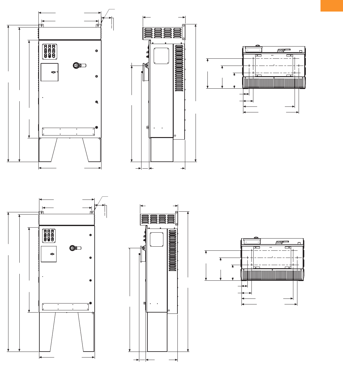
Volume 6—Solid-State Motor Control CA08100007E—February 2016 www.eaton.com V6-T2-313
2
2
2
2
2
2
2
2
2
2
2
2
2
2
2
2
2
2
2
2
2
2
2
2
2
2
2
2
2
2
2.10
Adjustable Frequency Drives
Clean Power Drives
Approximate Dimensions in Inches (mm)
CX Box Type 3R—12 Inch Floor Stands
CX Box Type 3R—22 Inch Floor Stands
3.00 (76.2)
30.88 (784.4)
28.10 (713.7)
67.65
(1718.4)
48.35
(1228.1)
66.60
(1691.7)
30.92 (785.4)
21.00 (533.3)
68.09
(1729.6)
47.67
(1210.8)
17.76 (451.2)
3.72
(94.4)
14.81
(376.2) 11.28
(286.5) 7.75
(196.9)
25.50 (647.7)
27.50 (698.5)
5.00 (127.0)
Ø 0.44 (11.2)
Mounting
Holes
(2 Places)
3.00 (76.2)
Minimum
Air Space
Required
Both Sides
78.09
(1983.6) 3.00 (76.2)
14.81
(376.2) 11.28
(286.5) 7.75
(196.9)
25.50 (647.7)
27.50 (698.5)
5.00 (127.0)
21.00 (533.3)
57.68
(1465.0)
30.92 (785.4)
77.65
(1972.4)
48.35
(1228.1)
76.60
(1945.7)
30.88 (784.4)
27.88 (708.2)
Ø 0.44 (11.2)
Mounting
Holes
(2 Places)
3.00 (76.2)
Minimum
Air Space
Required
Both Sides
17.76
(451.2)
3.72
(94.4)

V6-T2-314 Volume 6—Solid-State Motor Control CA08100007E—February 2016 www.eaton.com
2
2
2
2
2
2
2
2
2
2
2
2
2
2
2
2
2
2
2
2
2
2
2
2
2
2
2
2
2
2
2.10
Adjustable Frequency Drives
Clean Power Drives
Approximate Dimensions in Inches (mm)
DX Box Type 1
DX Box Type 12
1.55
(39.4)
29.30 (744.2)
82.23
(2088.6)
76.35
(1939.3)
30.92 (785.4) 22.48
(571.1)
28.88 (733.6)
82.85
(2104.4)
67.88
(1724.2)
22.56
(573.0) 6.13
(155.6)
8.38 (212.9)
1.62 (41.1)
22.12
(561.8)
Ø 0.44 (11.2)
Mounting
Holes
(2 Places)
3.00 (76.2)
Minimum
Air Space
Required
Both Sides
4.00 (101.6)
Minimum
Free Air Space
Required
82.35
(2091.7)
76.35
(1939.3)
30.92
(785.4)
22.48
(571.1)
1.55
(39.4)
82.85
(2104.4)
67.89
(1724.4)
28.88 (733.6)
22.56
(573.0) 6.13
(155.6)
8.38 (212.9)
1.62 (41.1)
22.12
(561.8)
29.30 (744.2)
Ø 0.44 (11.2)
Mounting
Holes
(2 Places)
3.00 (76.2)
Minimum
Air Space
Required
Both Sides
4.00 (101.6)
Minimum
Free Air Space
Required
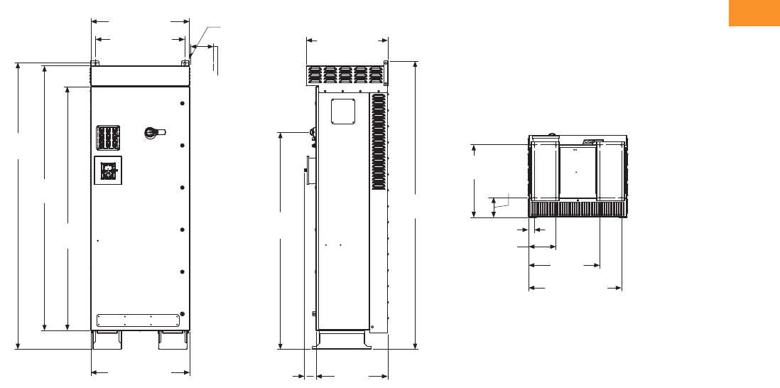
Volume 6—Solid-State Motor Control CA08100007E—February 2016 www.eaton.com V6-T2-315
2
2
2
2
2
2
2
2
2
2
2
2
2
2
2
2
2
2
2
2
2
2
2
2
2
2
2
2
2
2
2.10
Adjustable Frequency Drives
Clean Power Drives
Approximate Dimensions in Inches (mm)
DX Box Type 3R
22.81
(579.2)
29.06 (738.1)
30.88 (784.4)
27.88 (708.2)
89.70
(2278.3)
82.84
(2104.1)
76.35
(1939.3)
30.92 (785.4) 3.64
(92.5)
22.48
(571.1)
67.89
(1724.4)
90.14
(2289.5)
25.51 (647.8)
1.80 (45.7)
8.56 (217.4)
22.30
(566.4)
Ø 0.44 (11.2)
Mounting
Holes
(2 Places)
3.00 (76.2)
Minimum
Air Space
Required
Both Sides
6.31
(160.3)
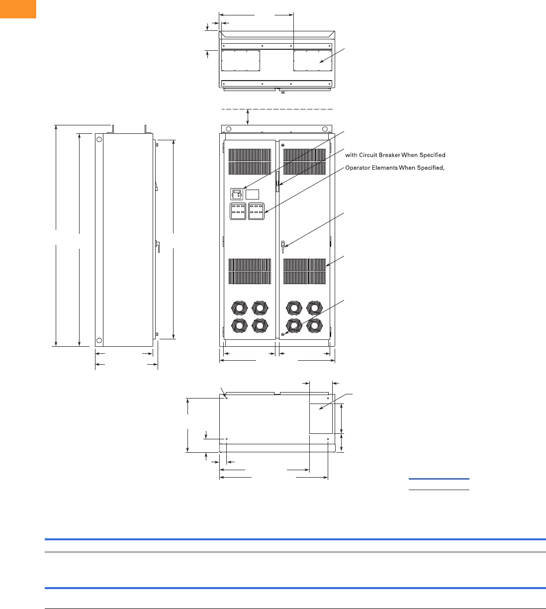
V6-T2-316 Volume 6—Solid-State Motor Control CA08100007E—February 2016 www.eaton.com
2
2
2
2
2
2
2
2
2
2
2
2
2
2
2
2
2
2
2
2
2
2
2
2
2
2
2
2
2
2
2.10
Adjustable Frequency Drives
Clean Power Drives
Approximate Dimensions in Inches (mm)
Size 8
For reference only, dimensions are subject to change. See Page V6-T2-294, notes 3 and 5 for enclosure and option selection.
Wide High Deep Mounting Door Height Min. Air Space
ABCDD1EE1FGG1H JK
48.0 (1219)90.0 (2286)24.0 (610)42.2 (1072)3.0 (77)———5.5 (139)—84.4 (2143) 4.0 (102) —
Max. Approx.
Shipping Weight
Lbs (kg)
Cable Entry
LMNPRSTUVWRRSSTTUUVV
9.5
(241)
37.5
(952)
12.5
(318)
7.7
(196)
8.3
(210)
1.3
(32)
31.0
(787)
21.5
(545)
21.3
(541)
—93.5
(2375)
————2000 (908)
Construction: UL Type 1 Oversize
Finish: Enclosure – ANSI 61 Gray (Light)
24.00 (609.6)
25.14 (639)
Side View 9.50
(241.3)
22.47
(570.74)
5.48
(139.19)
7.73
(196.34)
12.50
(317.5)
45.22 (1148.59)
37.47 (951.74)
3.01 (76.45)
8.25
(209.6)
1.25
(31.8)
31.00
(787.4)
21.45 (544.8) 21.31 (541.3)
48.00 (1219.2)
Front View
Top View
90.00
(2286.0)
93.50
(2374.9) 84.37
(2143.0)
Opening for Top Cable Entry
(2 Places)
Keypad
Mounted on These Panels
Intake Ventilating Slots
(Filtered on NEMA 12)
Door Handle
(key-lock optional)
Quarter Turn Latch
(2 Places)
Bottom View
.56 (14.2) Dia.
Mounting Holes
(4 Places) Opening for
Bottom Cable Entry
Flanged Disconnect Supplied
4.00 (101.6) Minimum
Free Air Space Required
Approximate
Shipping Weight
Lbs (kg)
1400 (636)
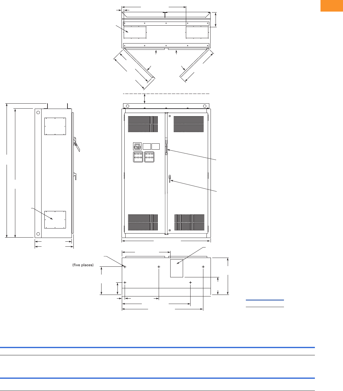
Volume 6—Solid-State Motor Control CA08100007E—February 2016 www.eaton.com V6-T2-317
2
2
2
2
2
2
2
2
2
2
2
2
2
2
2
2
2
2
2
2
2
2
2
2
2
2
2
2
2
2
2.10
Adjustable Frequency Drives
Clean Power Drives
Approximate Dimensions in Inches (mm)
Size 9
For reference only, dimensions are subject to change. See Page V6-T2-294, notes 3 and 5 for enclosure and option selection.
Wide High Deep Mounting Door Height Min. Air Space
ABCDD1EE1FGG1H JK
60.0 (1524) 90.0 (2286) 260.1 (664) 22.9 (582) 2.0 (51) 30.0 (762) 44.3 (1125) 10.6 (270) 10.6 (270) 8.2 (208) — 4.0 (102) —
Max. Approx.
Shipping Weight
Lbs (kg)
Cable Entry
LMNPRSTUVWRRSSTTUUVV
8.5
(216)
32.7
(831)
12.0
(305)
11.9
(303)
9.8
(249)
1.5
(38)
43.5
(1105)
15.0
(381)
7.5
(191)
25.0
(635)
93.5
(2375)
27.4
(696)
290.1
(738)
270.1
(687)
— 2500 (1135)
24.00 (609.6)
25.14 (638.6)
8.75
(222.3)
Top View
1.50 (38.1) 43.50 (1104.9)
90.00
(2286.0)
93.50
(2374.9)
4.00 (101.6) Minimum
Free Air Space Required
60.00 (1524.0)
Front View
Bottom View
Side View
7.46 x 15.00
(189.5 x 381.0)
Access in Top
(two places)
8.50 x 12.00 (215.9 x 304.8)
Bottom Access
ø0.56 (ø14.2) Dia.
Mounting Hole
27.06
(687.3)
27.36
(694.9)
90 Max.
Door
Opening
29.05
(737.9)
11.93
(303.0)
25.00
(635.0)
18.84
(478.5)
8.20
(208.3)
2.00 (50.8) 22.90 (581.7)
32.72 (831.1)
46.30 (1176.0)
54.90 (1394.5)
Door Handle
(key-lock optional)
Access
Plate
(4 places)
90 Max.
Door
Opening
Finish: Enclosure—ANSI 61 Gray (light)
Material: Enclosure and Backplate—
12 ga. = 0.1046 Cold Rolled Steel
Drive
Circuit Breaker
Approximate
Shipping Weight
Lbs (kg)
1800 (817)

V6-T2-318 Volume 6—Solid-State Motor Control CA08100007E—February 2016 www.eaton.com
2
2
2
2
2
2
2
2
2
2
2
2
2
2
2
2
2
2
2
2
2
2
2
2
2
2
2
2
2
2
2.10
Adjustable Frequency Drives
Clean Power Drives
Approximate Dimensions in Inches (mm)
Enclosure Size F
HH1WW1DD1
Approximate
Weight
Lbs (kg)
Approximate
Shipping Weight
Lbs (kg)
93.58
(2376.9)
69.51
(1765.60)
60.00
(1524.0)
48.00
(1219.2)
37.50
(952.5)
26.00
(660.4)
1700 (771) 1850 (839)
D
D1
HH1
W
W1
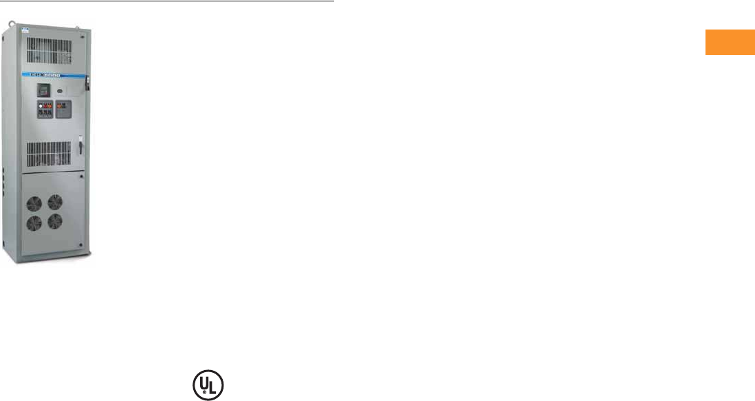
Volume 6—Solid-State Motor Control CA08100007E—February 2016 www.eaton.com V6-T2-319
2
2
2
2
2
2
2
2
2
2
2
2
2
2
2
2
2
2
2
2
2
2
2
2
2
2
2
2
2
2
2.10
Adjustable Frequency Drives
Clean Power Drives
Enclosed 12-Pulse Drives
Contents
Description Page
Clean Power Drives Overview . . . . . . . . . . . . . . . . V6-T2-256
Enclosed Passive Filtered Drives
EGF Enclosed Drives . . . . . . . . . . . . . . . . . . . . V6-T2-263
CFX Enclosed Drives . . . . . . . . . . . . . . . . . . . . V6-T2-288
Enclosed 12-Pulse Drives
Catalog Number Selection . . . . . . . . . . . . . . . . V6-T2-320
Product Selection . . . . . . . . . . . . . . . . . . . . . . . V6-T2-321
Dimensions . . . . . . . . . . . . . . . . . . . . . . . . . . . V6-T2-322
Enclosed 18-Pulse Drives . . . . . . . . . . . . . . . . . . . V6-T2-323
Enclosed Regenerative Drives . . . . . . . . . . . . . . . . V6-T2-348
HCX Enclosed 12-Pulse Drives
Product Description
The Enclosed HCX Drives is
specifically tailored for HVAC
applications where clean
power is necessary. The
Enclosed HCX Drive uses
Eaton’s SVX drive with a
12-pulse phase shifting
transformer to deliver a
substantial reduction in
voltage and current
harmonics.
Standards and Certifications
●UL 508C
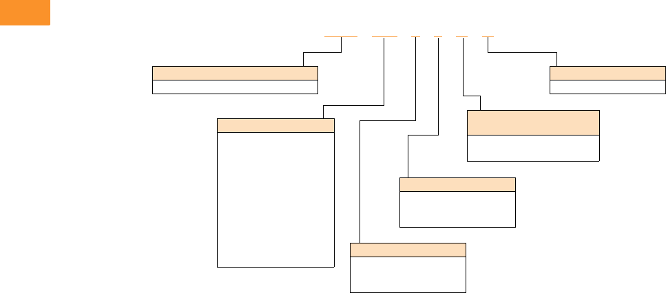
V6-T2-320 Volume 6—Solid-State Motor Control CA08100007E—February 2016 www.eaton.com
2
2
2
2
2
2
2
2
2
2
2
2
2
2
2
2
2
2
2
2
2
2
2
2
2
2
2
2
2
2
2.10
Adjustable Frequency Drives
Clean Power Drives
Catalog Number Selection
HCX Enclosed 12-Pulse Drives
HCX 007 1 2 B A
Product Family
HCX = Enclosed 12-pulse drive
Horsepower Rating
007 = 7.5 hp
010 = 10 hp
015 = 15 hp
020 = 20 hp
025 = 25 hp
030 = 30 hp
040 = 40 hp
050 = 50 hp
060 = 60 hp
075 = 75 hp
100 = 100 hp
125 = 125 hp
Enclosure Rating
1 = Type 1
2 = Type 12
6 = Type 1 filtered
Application—
Torque/Braking
A = IL/No brake chopper
B = IL/Internal brake chopper
Voltage Rating
1 = 208 V
2 = 230 V
4 = 480 V
Enclosure Style
A = Enclosed drive
Volume 6—Solid-State Motor Control CA08100007E—February 2016 www.eaton.com V6-T2-321
2
2
2
2
2
2
2
2
2
2
2
2
2
2
2
2
2
2
2
2
2
2
2
2
2
2
2
2
2
2
2.10
Adjustable Frequency Drives
Clean Power Drives
Product Selection
208 V Drives
208 V Drives—Variable Torque (VT)/Low Overload (IL) Enclosed Drives
230 V Drives
230 V Drives—Variable Torque (VT)/Low Overload (IL) Enclosed Drives
480 V Drives
480 V Drives—Variable Torque (VT)/Low Overload (IL) Enclosed Drives
Note
1 Table is for base catalog number reference only. For complete catalog number selection, see Page V6-T2-320.
NEMA Type 1 NEMA Type 12 NEMA Type 1 Filtered
hp Current (A)
Drive
Frame Size
Base
Catalog Number 1
Base
Catalog Number 1
Base
Catalog Number 1
7.5 24.2 5 HCX00711BA — HCX00761BA
10 30.8 5 HCX01011BA — HCX01061BA
15 46.2 6 HCX01511BA — HCX01561BA
20 59.4 6 HCX02011BA — HCX02061BA
25 74.8 7 HCX02511AA HCX02521AA HCX02561AA
30 88 7 HCX03011AA HCX03021AA HCX03061AA
40 114 7 HCX04011AA HCX04021AA HCX04061AA
50 143 8 HCX05011AA HCX05021AA HCX05061AA
60 169 8 HCX06011AA HCX06021AA HCX06061AA
NEMA Type 1 NEMA Type 12 NEMA Type 1 Filtered
hp Current (A)
Drive
Frame Size
Base
Catalog Number 1
Base
Catalog Number 1
Base
Catalog Number 1
7.5 22 5 HCX00712BA — HCX00762BA
10 28 5 HCX01012BA — HCX01062BA
15 42 6 HCX01512BA — HCX01562BA
20 54 6 HCX02012BA — HCX02062BA
25 68 7 HCX02512AA HCX02522AA HCX02562AA
30 80 7 HCX03012AA HCX03022AA HCX03062AA
40 104 7 HCX04012AA HCX04022AA HCX04062AA
50 130 8 HCX05012AA HCX05022AA HCX05062AA
60 154 8 HCX06012AA HCX06022AA HCX06062AA
NEMA Type 1 NEMA Type 12 NEMA Type 1 Filtered
hp Current (A)
Drive
Frame Size
Base
Catalog Number 1
Base
Catalog Number 1
Base
Catalog Number 1
25 34 6 HCX02514BA HCX02524BA HCX02564BA
30 40 6 HCX03014BA HCX03024BA HCX03064BA
40 52 6 HCX04014BA HCX04024BA HCX04064BA
50 65 7 HCX05014AA HCX05024AA HCX05064AA
60 77 7 HCX06014AA HCX06024AA HCX06064AA
75 96 7 HCX07514AA HCX07524AA HCX07564AA
100 124 8 HCX10014AA HCX10024AA HCX10064AA
125 156 8 HCX12514AA HCX12524AA HCX12564AA
HCX Enclosed Drives
HCX Enclosed Drives
HCX Enclosed Drives
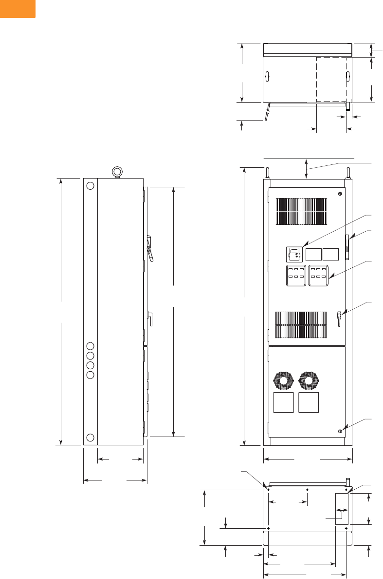
V6-T2-322 Volume 6—Solid-State Motor Control CA08100007E—February 2016 www.eaton.com
2
2
2
2
2
2
2
2
2
2
2
2
2
2
2
2
2
2
2
2
2
2
2
2
2
2
2
2
2
2
2.10
Adjustable Frequency Drives
Clean Power Drives
Dimensions
Approximate Dimensions in Inches (mm)
Enclosure Size 7
25–150 hp IL and 25–125 hp IH 480 V—25–100 hp IL and 25–75 hp IH 575 V
Side View
26.25
(666.8)
ø0.56 (ø14.2) Dia.
Mounting Holes
(ve places)
90.00
(2286.0)
84.37
(2143.0)
15.50
(393.7)
21.50
(546.1)
93.92
(2385.6)
30.00
(762.0)
4.00 (101.6) Minimum
Free Air Space Required
Keypad
Flanged Disconnect Supplied
With Circuit Breaker
When Specied
Operator Elements
When Specied, Mounted
On These Panels
Door Handle
(key-lock optional)
Quarter Turn Latch
(three places)
Bottom View
18.75
(476.3)
Opening For Bottom
Cable Entry
7. 0 0
(177.8)
5.75
(146.1)
14.90
(378.5)
1.75
(44.5) 24.45
(621.0) 28.05
(712.5)
10.50
(266.7)
4.25
(107.9)
Top View
Exhaust Air
For
Cable
Entry
Hinged
Side Door
Clearance at 90º
20.00
(508.0)
4.79
(121.7)
15.00
(381.0)
2.00
(50.8)
10.00
(254.0)
Finish: Enclosure—ANSI 61 Gray (light)
Material: Enclosure and Backplate—
12 ga. = 0.1046 Cold Rolled Steel
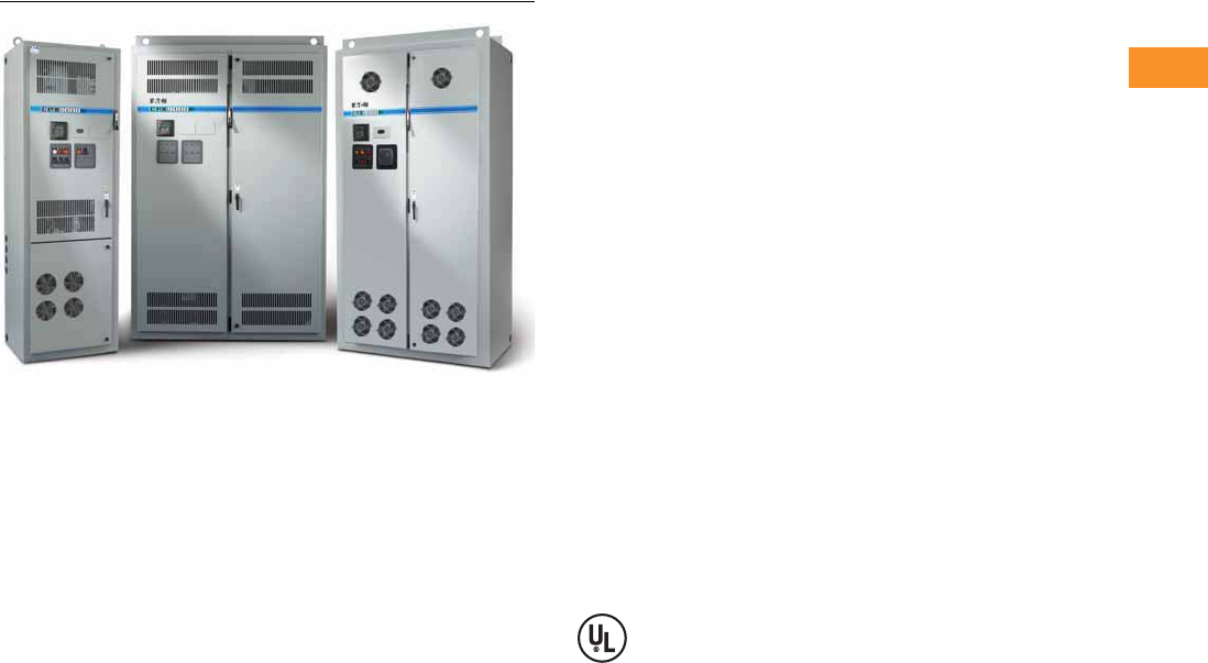
Volume 6—Solid-State Motor Control CA08100007E—February 2016 www.eaton.com V6-T2-323
2
2
2
2
2
2
2
2
2
2
2
2
2
2
2
2
2
2
2
2
2
2
2
2
2
2
2
2
2
2
2.10
Adjustable Frequency Drives
Clean Power Drives
Enclosed 18-Pulse Drives
Contents
Description Page
Enclosed Passive Filtered Drives . . . . . . . . . . . . . . V6-T2-262
Enclosed 18-Pulse Drives
Catalog Number Selection . . . . . . . . . . . . . . . . V6-T2-325
Product Selection . . . . . . . . . . . . . . . . . . . . . . . V6-T2-326
Options . . . . . . . . . . . . . . . . . . . . . . . . . . . . . . . V6-T2-334
Technical Data and Specifications . . . . . . . . . . V6-T2-340
Wiring Diagrams . . . . . . . . . . . . . . . . . . . . . . . . V6-T2-342
Dimensions . . . . . . . . . . . . . . . . . . . . . . . . . . . V6-T2-343
CPX Enclosed 18-Pulse Drives
Product Description
Eaton’s enclosed 18-pulse
drives use advanced
18-pulse technology that
significantly reduces line
harmonics at the drive input
terminals, resulting in one of
the purest sinusoidal
waveforms available.
The enclosed 18-pulse drive
also delivers True Power
Factor—in addition to
reducing harmonic distortion,
the enclosed 18-pulse drive
prevents upstream
transformer overheating and
overloading of breakers and
feeders, enabling the
application of adjustable
frequency drives on
generators and other high
impedance power systems.
Features and Benefits
Enclosed 18-pulse drive
features include:
●Space optimized enclosure
●Simple layout for power
options
●Type 1, NEMA 12 with
gaskets and filters,
Type 3R
●Input voltage: 480 V, 208 V,
575 V
●Complete range of control,
network and power options
●Horsepower range:
●480 V, 25–800 hp (consult
factory for larger sizes)
●208/230 V, 25–200 hp
●575 V, 25–800 hp (consult
factory for larger sizes)
●Over 15 years of 18-pulse
clean power experience
●65 kAIC Standard at 480 V
and 208 V
●100 kAIC optional
Standards and Certifications
UL 508C tested, listed and
approved.
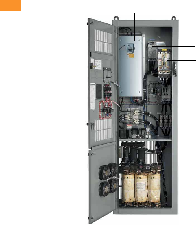
V6-T2-324 Volume 6—Solid-State Motor Control CA08100007E—February 2016 www.eaton.com
2
2
2
2
2
2
2
2
2
2
2
2
2
2
2
2
2
2
2
2
2
2
2
2
2
2
2
2
2
2
2.10
Adjustable Frequency Drives
Clean Power Drives
Product Identification
Type 1, 25–150 hp (30 x 90 x 21.50)
SVX Drive
Door Mounted Keypad
18-Pulse Auto-Transformer
Motor Circuit Protector
(standard with bypass options)
Pre-Charge Input Contactor
18-Pulse Diode Rectifier Input Line Fuses
Input Choke
Bypass Starter Assembly
(option)
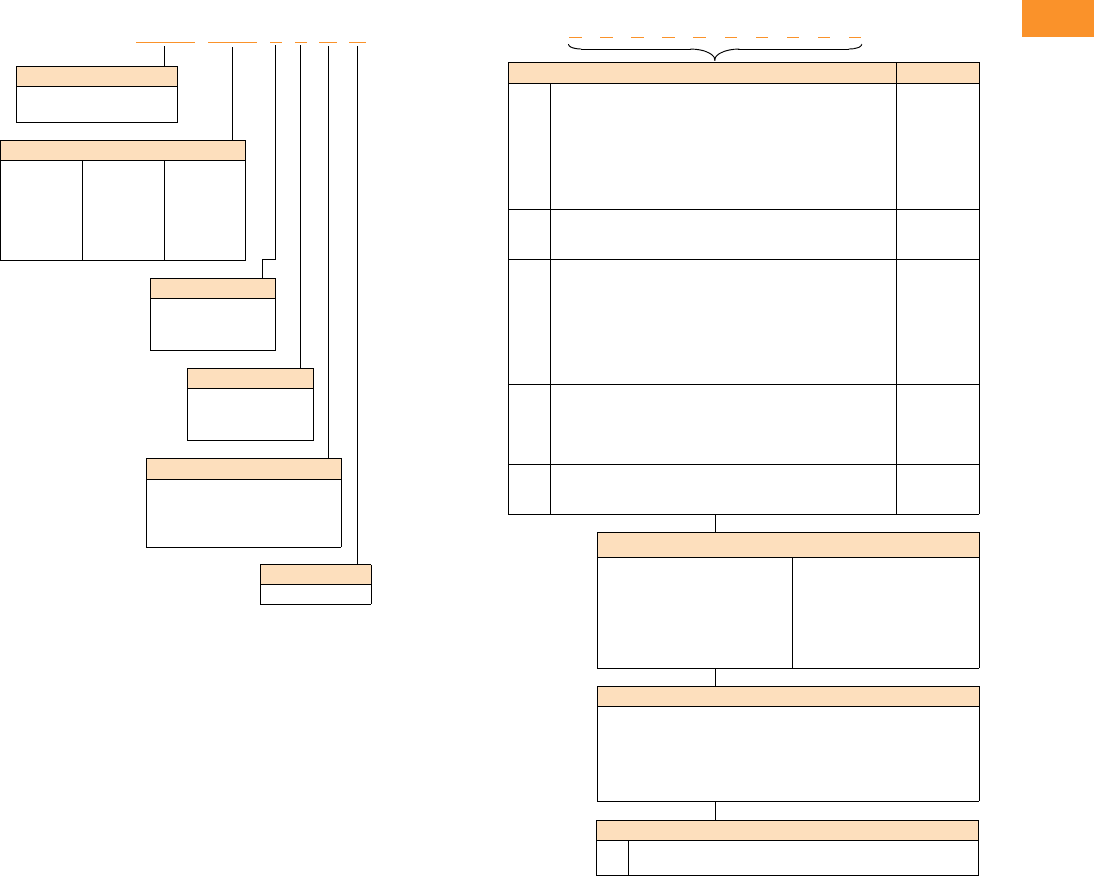
Volume 6—Solid-State Motor Control CA08100007E—February 2016 www.eaton.com V6-T2-325
2
2
2
2
2
2
2
2
2
2
2
2
2
2
2
2
2
2
2
2
2
2
2
2
2
2
2
2
2
2
2.10
Adjustable Frequency Drives
Clean Power Drives
Catalog Number Selection
Enclosed 18-Pulse Drive
Notes
1Brake chopper is standard in drives up to 30 hp IH or 40 hp IL at 480 V. It is optional in larger drives.
2Local/remote keypad is included as the standard control panel.
3Some options are voltage and/or horsepower specific. Consult your Eaton representative for details.
4See Pages V6-T2-336 and V6-T2-337 for complete descriptions.
5Includes local/remote speed reference switch.
6See Pages V6-T2-334 and V6-T2-335 for complete descriptions.
7Consult Eaton for availability.
C P X 1 0 0 1 4 A A
Voltage Rating
2 = 230 V (208–240 V)
4 = 480 V
5 = 575 V (575–600 V)
Product Family
CPX = Clean power 18-pulse
enclosed drives
Horsepower Rating
025 = 25 hp
030 = 30 hp
040 = 40 hp
050 = 50 hp
060 = 60 hp
075 = 75 hp
100 = 100 hp
125 = 125 hp
150 = 150 hp
200 = 200 hp
250 = 250 hp
300 = 300 hp
350 = 350 hp
400 = 400 hp
500 = 500 hp
600 = 600 hp
700 = 700 hp
800 = 800 hp
Enclosure Rating
1 = Type 1
3 = Type 3R
6 = Type 12 filtered
Application—Torque/Braking 1
A = IL/no brake chopper
B = IL/internal brake chopper
D = IH/no brake chopper
E = IH/internal brake chopper
Enclosed Style
A = Enclosed drive
Engineered Options
HT
VB
High temperature rating for 50 °C (FR10 and above) 7
Varnished boards
Communication Options 6
C2 = Modbus®
C3 = PROFIBUS® DP
C4 = LonWorks®
C5 = PROFIBUS DP (D9 connector)
C6 = CANopen (slave)
C7 = DeviceNet™
C8 = Modbus (D9 Type connector)
CA = Johnson Controls N2
CI = Modbus TCP
CJ = BACnet
CQ = EtherNet/IP
D3 = RS-232 with D9 connection
Control Options
B1 = 6 DI, 1 ext +24 Vdc/ext +24 Vdc
B2 = 1 RO (NC/NO), 1 RO (NO), 1 therm
B4 = 1 AI (mA isolated), 2 AO (mA isolated), 1 ext +24 Vdc/EXT +24 Vdc
B5 = 3 RO (NO)
B8 = 1 ext +24 Vdc/ext +24 Vdc, 3 Pt100
B9 = 1 RO (NO), 5 DI 42–240 Vac input
Enclosed Options 234 Type
K1
K2
K3
K4
K5
K6
KF
KO
Door-mounted speed potentiometer 5
Door-mounted speed potentiometer with HOA selector switch 5
3–15 psig follower
HAND/OFF/AUTO switch 0.87-inch (22 mm)
MANUAL/AUTO reference switch 0.87-inch (22 mm)
START/STOP pushbuttons 0.87-inch (22 mm)
Bypass test switch for RA and RB
Standard elapsed time meter
Control
Control
Control
Control
Control
Control
Addl. bypass
Control
L1
L2
LE
Power, RUN and fault pilot lights
Bypass pilot lights for RA, RB, bypass options
Red RUN light
Light
Addl. bypass
Light
P1
P8
PE
PF
PG
PH
PI
PN
Input disconnect
Surge protective device
Output contactor
Output filter
MotoRx (up to 600 ft [182.9 m]) 1000 V/μS dV/dt filter
Single overload relay
Dual overload relays
Dual overloads for bypass
Input
Input
Output
Output
Output
Output
Output
Addl. bypass
RA
RB
RC
RD
RG
Manual HOA bypass controller
Manual IOB bypass controller
Auto transfer HOA bypass controller
Auto transfer IOB bypass controller
Reduced voltage starter for bypass
Bypass
Bypass
Bypass
Bypass
Bypass
S7
S8
S9
10.00-inch (254.0 mm) expansion
20.00-inch (508.0 mm) expansion
Space heater
Enclosure
Enclosure
Enclosure
Build options alphabetically and numerically.
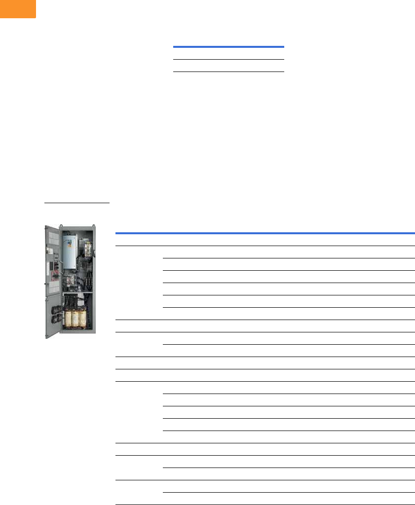
V6-T2-326 Volume 6—Solid-State Motor Control CA08100007E—February 2016 www.eaton.com
2
2
2
2
2
2
2
2
2
2
2
2
2
2
2
2
2
2
2
2
2
2
2
2
2
2
2
2
2
2
2.10
Adjustable Frequency Drives
Clean Power Drives
Product Selection
When Ordering
●Select a base catalog
number that meets the
application requirements—
nominal horsepower,
voltage and enclosure
rating. (The enclosed
drive’s continuous output
amp rating should be equal
to or greater than the
motor’s full load amp
rating.) The base-enclosed
package includes a
standard drive, door-
mounted alphanumeric
panel and enclosure.
Ambient Temperature
Ratings
●If dynamic brake chopper
or control/communication
option is desired, change
the appropriate code in the
base catalog number.
●All of the programming is
exactly the same as the
standard SVX drive.
●Select enclosed options.
Add the codes as suffixes
to the base catalog number
in alphabetical and numeric
order.
208/230 V Drives
Enclosed 18-Pulse Base Drive Type 1
Notes
1 See enclosure dimensions beginning on Page V6-T2-343.
2 hp ratings are provided as a guideline. Drives should be sized per motor nameplate FLA.
3 The 18-pulse clean power assembly includes a standard drive, door-mounted local/remote keypad and enclosure.
Frame
Size IHIL
FR4–FR9 50 °C 50 °C
FR10 and above 40 °C 40 °C
Enclosure
Size 1hp 2
Current
(A)
Chassis
Frame
Base Catalog
Number 3
Low Overload Drive
72575 FR7 CPX02512AA
30 88 FR7 CPX03012AA
40 114 FR7 CPX04012AA
50 140 FR8 CPX05012AA
60 170 FR8 CPX06012AA
75 205 FR8 CPX07512AA
8100300 FR9 CPX10012AA
9 125 340 FR8T CPX12512AA
150 410 FR8T CPX15012AA
10 200 522 FR9T CPX20012AA
High Overload Drive
72575 FR7 CPX02512DA
30 88 FR7 CPX03012DA
40 114 FR8 CPX04012DA
50 140 FR8 CPX05012DA
60 170 FR8 CPX06012DA
875205 FR9 CPX07512DA
9 100 300 FR8T CPX10012DA
125 340 FR8T CPX12512DA
10 150 410 FR9T CPX15012DA
200 522 FR9T CPX20012DA
Enclosed 18-Pulse
Drive
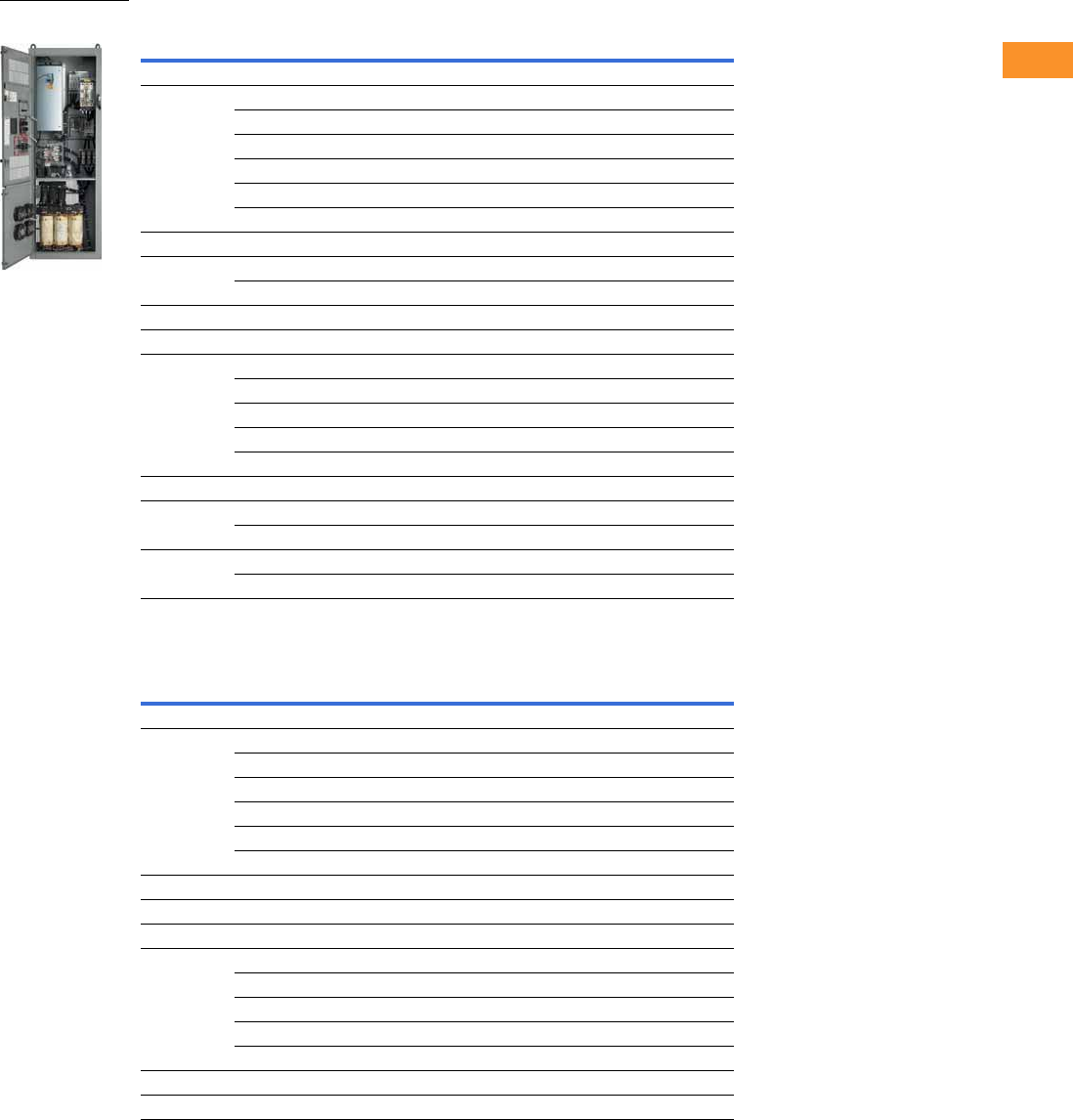
Volume 6—Solid-State Motor Control CA08100007E—February 2016 www.eaton.com V6-T2-327
2
2
2
2
2
2
2
2
2
2
2
2
2
2
2
2
2
2
2
2
2
2
2
2
2
2
2
2
2
2
2.10
Adjustable Frequency Drives
Clean Power Drives
Enclosed 18-Pulse Base Drive NEMA 12 Filtered
Enclosed 18-Pulse Base Drive Type 3R 4
Notes
1 See enclosure dimensions beginning on Page V6-T2-343.
2 hp ratings are provided as a guideline. Drives should be sized per motor nameplate FLA.
3 The 18-pulse clean power assembly includes a standard drive, door-mounted local/remote keypad and enclosure.
4 All Type 3R drives use the Size F enclosure.
Enclosure
Size 1hp 2
Current
(A)
Chassis
Frame
Base Catalog
Number 3
Low Overload Drive
72575 FR7 CPX02562AA
30 88 FR7 CPX03062AA
40 114 FR7 CPX04062AA
50 140 FR8 CPX05062AA
60 170 FR8 CPX06062AA
75 205 FR8 CPX07562AA
8100300 FR9 CPX10062AA
9 125 340 FR8T CPX12562AA
150 410 FR8T CPX15052AA
10 200 522 FR9T CPX20062AA
High Overload Drive
72575 FR7 CPX02562DA
30 88 FR7 CPX03062DA
40 114 FR8 CPX04062DA
50 140 FR8 CPX05062DA
60 170 FR8 CPX06062DA
875205 FR9 CPX07562DA
9 100 300 FR8T CPX10062DA
125 340 FR8T CPX12562DA
10 150 410 FR9T CPX15062DA
200 522 FR9T CPX20062DA
Enclosure
Size 1hp 2
Current
(A)
Chassis
Frame
Base Catalog
Number 3
Low Overload Drive
72575 FR7 CPX02532AA
30 88 FR7 CPX03032AA
40 114 FR7 CPX04032AA
50 140 FR8 CPX05032AA
60 170 FR8 CPX06032AA
75 205 FR8 CPX07532AA
8100300 FR9 CPX10032AA
9 125 340 FR8T CPX12532AA
High Overload Drive
72575 FR7 CPX02532DA
30 88 FR7 CPX03032DA
40 114 FR8 CPX04032DA
50 140 FR8 CPX05032DA
60 170 FR8 CPX06032DA
875205 FR9 CPX07532DA
9 100 300 FR8T CPX10032DA
Enclosed 18-Pulse
Drive
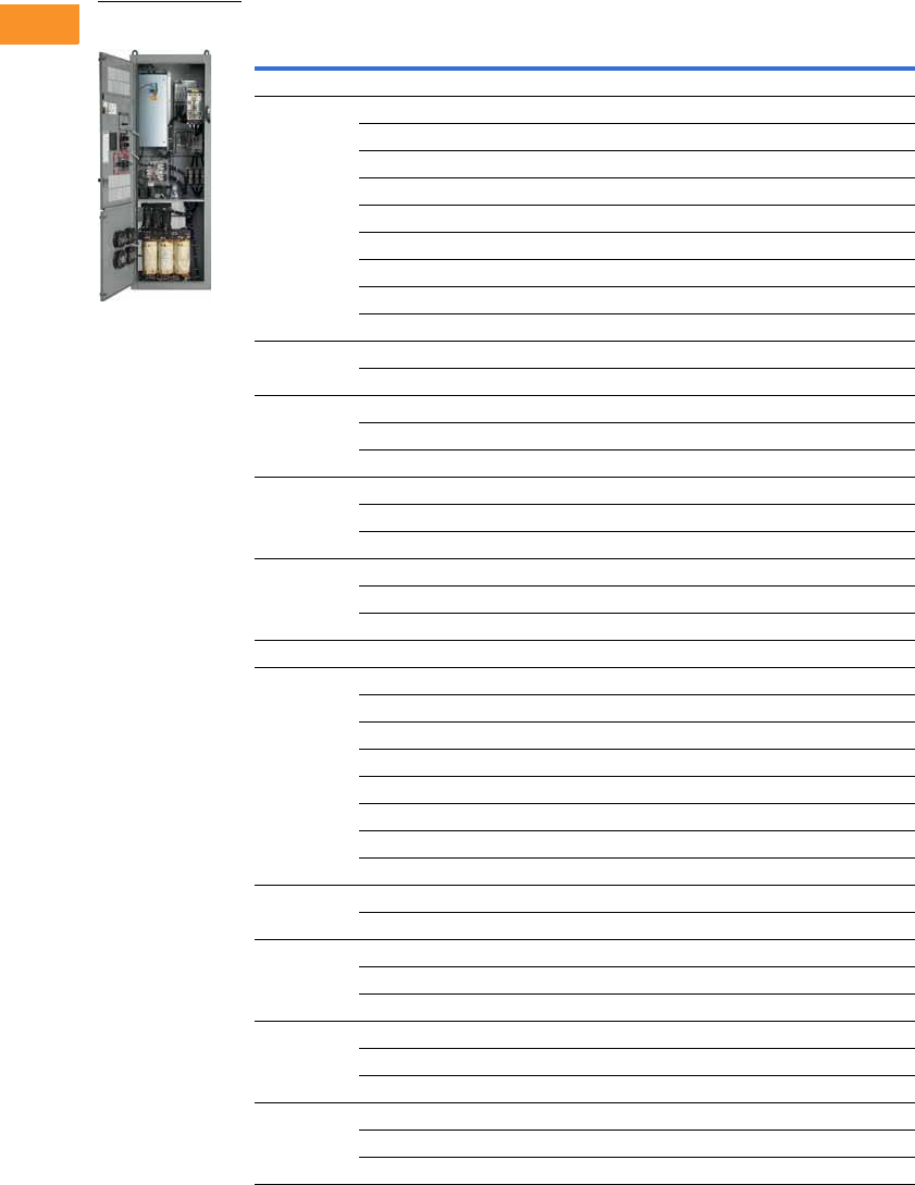
V6-T2-328 Volume 6—Solid-State Motor Control CA08100007E—February 2016 www.eaton.com
2
2
2
2
2
2
2
2
2
2
2
2
2
2
2
2
2
2
2
2
2
2
2
2
2
2
2
2
2
2
2.10
Adjustable Frequency Drives
Clean Power Drives
480 V Drives
Enclosed 18-Pulse Base Drive Type 1
Notes
1 See enclosure dimensions beginning on Page V6-T2-343.
2 hp ratings are provided as a guideline. Drives should be sized per motor nameplate FLA.
3 The 18-pulse clean power assembly includes a standard drive, door-mounted local/remote keypad and enclosure.
Enclosure
Size 1hp 2
Current
(A)
Chassis
Frame
Base Catalog
Number 3
Low Overload Drive
72538 FR6 CPX02514BA
30 46 FR6 CPX03014BA
40 61 FR6 CPX04014BA
50 72 FR7 CPX05014AA
60 87 FR7 CPX06014AA
75 105 FR7 CPX07514AA
100 140 FR8 CPX10014AA
125 170 FR8 CPX12514AA
150 205 FR8 CPX15014AA
8200261 FR9 CPX20014AA
250 300 FR9 CPX25014AA
9 300 385 FR10 CPX30014AA
350 460 FR10 CPX35014AA
400 520 FR10 CPX40014AA
10 500 590 FR11 CPX50014AA
550 650 FR11 CPX55014AA
600 730 FR11 CPX60014AA
11 650 820 FR11 CPX65014AA
700 920 FR12 CPX70014AA
800 1030 FR12 CPX80014AA
High Overload Drive
72538 FR6 CPX02514EA
30 46 FR6 CPX03014EA
40 61 FR7 CPX04014DA
50 72 FR7 CPX05014DA
60 87 FR7 CPX06014DA
75 105 FR8 CPX07514DA
100 140 FR8 CPX10014DA
125 170 FR8 CPX12514DA
8150205 FR9 CPX15014DA
200 245 FR9 CPX20014DA
9 250 300 FR10 CPX25014DA
300 385 FR10 CPX30014DA
350 460 FR10 CPX35014DA
10 400 520 FR11 CPX40014DA
500 590 FR11 CPX50014DA
550 650 FR11 CPX55014DA
11 600 720 FR12 CPX60014DA
650 820 FR12 CPX65014DA
700 840 FR12 CPX70014DA
Enclosed 18-Pulse
Drive
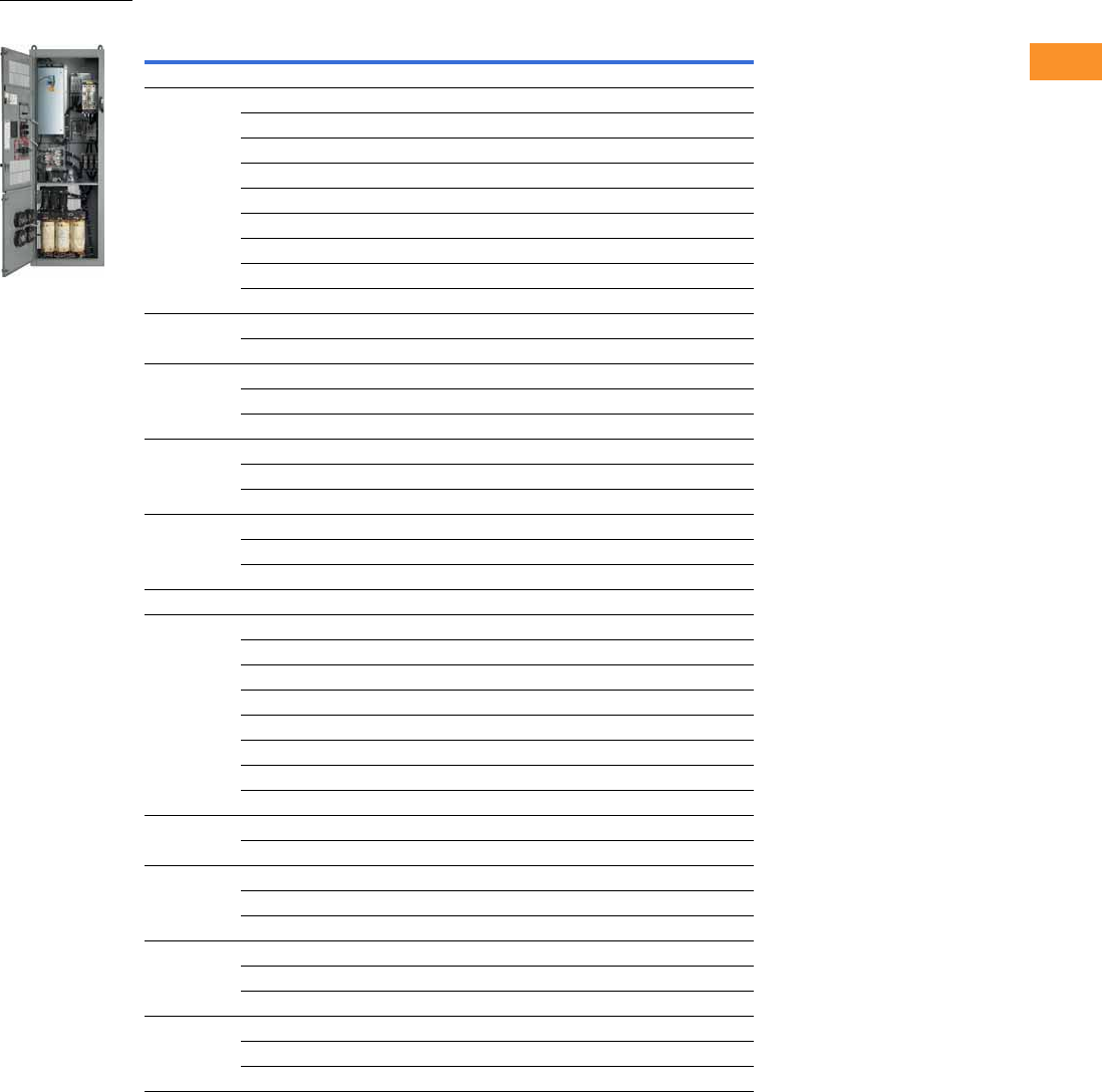
Volume 6—Solid-State Motor Control CA08100007E—February 2016 www.eaton.com V6-T2-329
2
2
2
2
2
2
2
2
2
2
2
2
2
2
2
2
2
2
2
2
2
2
2
2
2
2
2
2
2
2
2.10
Adjustable Frequency Drives
Clean Power Drives
Enclosed 18-Pulse Base Drive NEMA 12 Filtered
Notes
1 See enclosure dimensions beginning on Page V6-T2-343.
2 hp ratings are provided as a guideline. Drives should be sized per motor nameplate FLA.
3 The 18-pulse clean power assembly includes a standard drive, door-mounted local/remote keypad and enclosure.
Enclosure
Size 1hp 2
Current
(A)
Chassis
Frame
Base Catalog
Number 3
Low Overload Drive
72538 FR6 CPX02564BA
30 46 FR6 CPX03064BA
40 61 FR6 CPX04064BA
50 72 FR7 CPX05064AA
60 87 FR7 CPX06064AA
75 105 FR7 CPX07564AA
100 140 FR8 CPX10064AA
125 170 FR8 CPX12564AA
150 205 FR8 CPX15064AA
8200261 FR9 CPX20064AA
250 300 FR9 CPX25064AA
9 300 385 FR10 CPX30064AA
350 460 FR10 CPX35064AA
400 520 FR10 CPX40064AA
10 500 590 FR11 CPX50064AA
550 650 FR11 CPX55064AA
600 730 FR11 CPX60064AA
11 650 820 FR11 CPX65064AA
700 920 FR12 CPX70064AA
800 1030 FR12 CPX80064AA
High Overload Drive
72538 FR6 CPX02564EA
30 46 FR6 CPX03064EA
40 61 FR7 CPX04064DA
50 72 FR7 CPX05064DA
60 87 FR7 CPX06064DA
75 105 FR8 CPX07564DA
100 140 FR8 CPX10064DA
125 170 FR8 CPX12564DA
8150205 FR9 CPX15064DA
200 245 FR9 CPX20064DA
9 250 300 FR10 CPX25064DA
300 385 FR10 CPX30064DA
350 460 FR10 CPX35014DA
10 400 520 FR11 CPX40064DA
500 590 FR11 CPX50064DA
550 650 FR11 CPX55064DA
11 600 720 FR12 CPX60064DA
650 820 FR12 CPX65064DA
700 840 FR12 CPX70064DA
Enclosed 18-Pulse
Drive
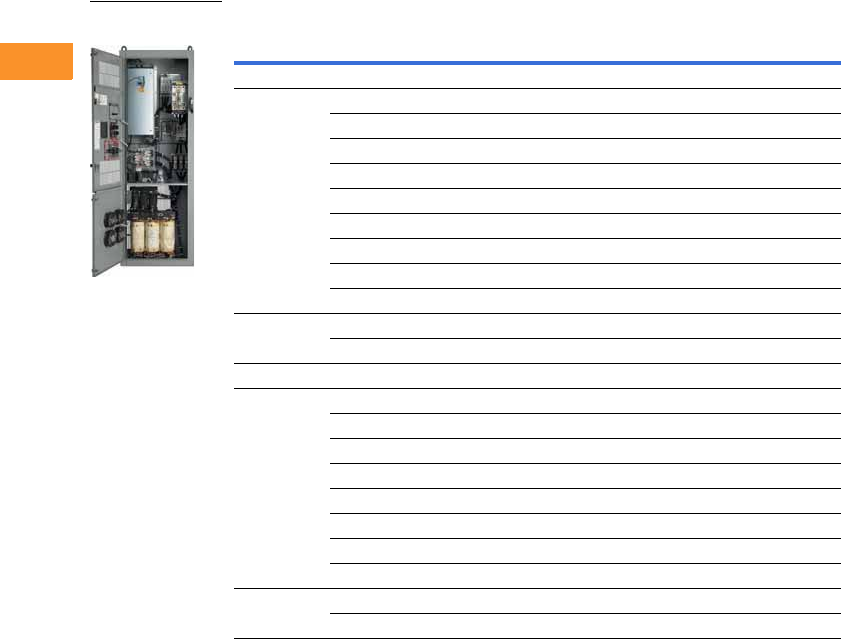
V6-T2-330 Volume 6—Solid-State Motor Control CA08100007E—February 2016 www.eaton.com
2
2
2
2
2
2
2
2
2
2
2
2
2
2
2
2
2
2
2
2
2
2
2
2
2
2
2
2
2
2
2.10
Adjustable Frequency Drives
Clean Power Drives
Enclosed 18-Pulse Base Drive Type 3R 1
Notes
1 All Type 3R drives use the Size F enclosure.
2 See enclosure dimensions beginning on Page V6-T2-343.
3 hp ratings are provided as a guideline. Drives should be sized per motor nameplate FLA.
4 The 18-pulse clean power assembly includes a standard drive, door-mounted local/remote keypad and enclosure.
Enclosure
Size 2hp 3
Current
(A)
Chassis
Frame
Base Catalog
Number 4
Low Overload Drive
72538 FR6 CPX02534AA
30 46 FR6 CPX03034AA
40 61 FR6 CPX04034AA
50 72 FR7 CPX05034AA
60 87 FR7 CPX06034AA
75 105 FR7 CPX07534AA
100 140 FR8 CPX10034AA
125 170 FR8 CPX12534AA
150 205 FR8 CPX15034AA
8200261 FR9 CPX20034AA
250 300 FR9 CPX25034AA
High Overload Drive
72538 FR6 CPX02534DA
30 46 FR6 CPX03034DA
40 61 FR7 CPX04034DA
50 72 FR7 CPX05034DA
60 87 FR7 CPX06034DA
75 105 FR8 CPX07534DA
100 140 FR8 CPX10034DA
125 170 FR8 CPX12534DA
8150205 FR9 CPX15034DA
200 245 FR9 CPX20034DA
Enclosed 18-Pulse
Drive
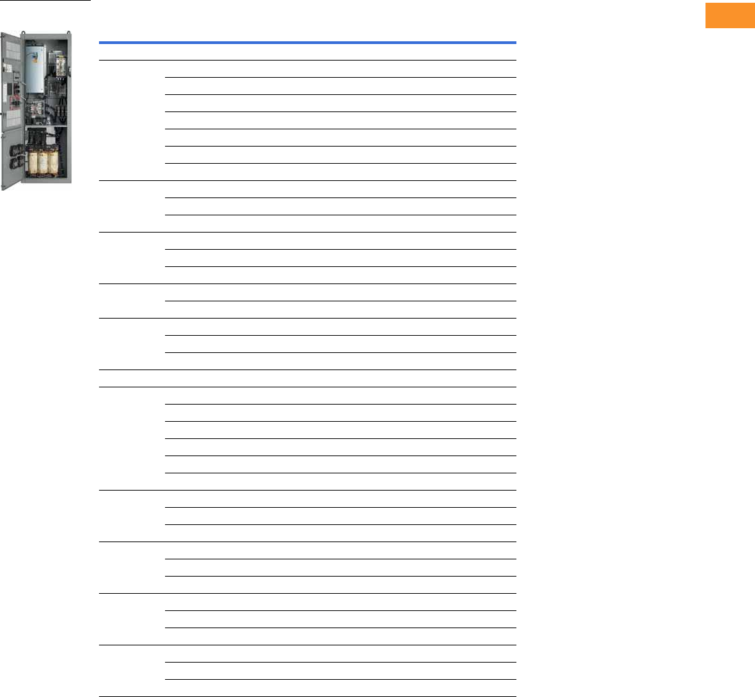
Volume 6—Solid-State Motor Control CA08100007E—February 2016 www.eaton.com V6-T2-331
2
2
2
2
2
2
2
2
2
2
2
2
2
2
2
2
2
2
2
2
2
2
2
2
2
2
2
2
2
2
2.10
Adjustable Frequency Drives
Clean Power Drives
575 V Drives
Enclosed 18-Pulse Base Drive Type 1
Notes
1 See enclosure dimensions beginning on Page V6-T2-343.
2 hp ratings are provided as a guideline. Drives should be sized per motor nameplate FLA.
3 The 18-pulse clean power assembly includes a standard drive, door-mounted local/remote keypad and enclosure.
Enclosure
Size 1hp 2
Current
(A)
Chassis
Frame
Base Catalog
Number 3
Low Overload Drive
72527 FR6 CPX02515AA
30 34 FR6 CPX03015AA
40 41 FR7 CPX04015AA
50 52 FR7 CPX05015AA
60 62 FR8 CPX06015AA
75 80 FR8 CPX07515AA
100 100 FR8 CPX10015AA
8125125 FR9 CPX12515AA
150 144 FR9 CPX15015AA
200 208 FR9 CPX20015AA
9 250 261 FR10 CPX25015AA
300 325 FR10 CPX30015AA
400 385 FR10 CPX40015AA
10 500 502 FR11 CPX50015AA
600 590 FR11 CPX60015AA
11 650 650 FR12 CPX65015AA
700 750 FR12 CPX70015AA
800 820 FR12 CPX80015AA
High Overload Drive
72527 FR6 CPX02515DA
30 34 FR7 CPX03015DA
40 41 FR7 CPX04015DA
50 52 FR8 CPX05015DA
60 62 FR8 CPX06015DA
75 80 FR8 CPX07515DA
8100100 FR9 CPX10015DA
125 125 FR9 CPX12515DA
150 144 FR9 CPX15015DA
9 200 208 FR10 CPX20015DA
250 261 FR10 CPX25015DA
300 325 FR10 CPX30015DA
10 400 385 FR11 CPX40015DA
450 460 FR11 CPX45015DA
500 502 FR11 CPX50015DA
11 600 590 FR12 CPX60015DA
650 650 FR12 CPX65015DA
700 750 FR12 CPX70015DA
Enclosed 18-Pulse
Drive
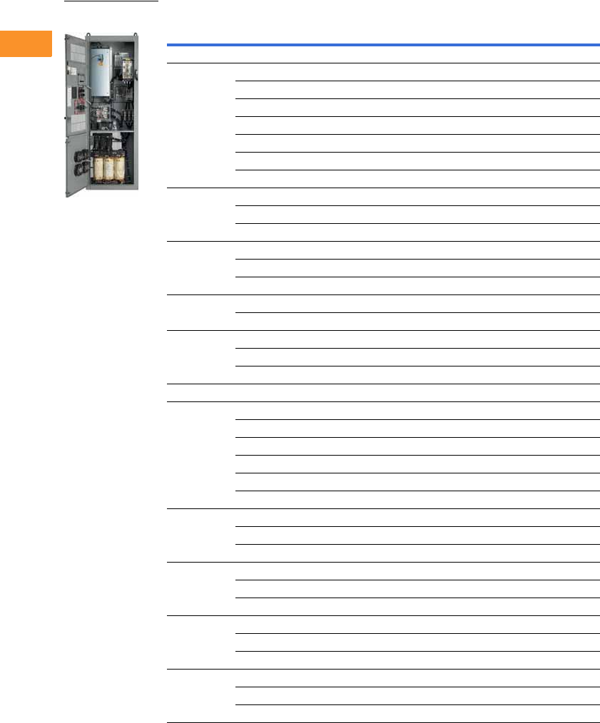
V6-T2-332 Volume 6—Solid-State Motor Control CA08100007E—February 2016 www.eaton.com
2
2
2
2
2
2
2
2
2
2
2
2
2
2
2
2
2
2
2
2
2
2
2
2
2
2
2
2
2
2
2.10
Adjustable Frequency Drives
Clean Power Drives
Enclosed 18-Pulse Base Drive NEMA 12 Filtered
Notes
1 See enclosure dimensions beginning on Page V6-T2-343.
2 hp ratings are provided as a guideline. Drives should be sized per motor nameplate FLA.
3 The 18-pulse clean power assembly includes a standard drive, door-mounted local/remote keypad and enclosure.
Enclosure
Size 1hp 2
Current
(A)
Chassis
Frame
Base Catalog
Number 3
Low Overload Drive
72527 FR6 CPX02565AA
30 34 FR6 CPX03065AA
40 41 FR7 CPX04065AA
50 52 FR7 CPX05065AA
60 62 FR8 CPX06065AA
75 80 FR8 CPX07565AA
100 100 FR8 CPX10065AA
8125125 FR9 CPX12565AA
150 144 FR9 CPX15065AA
200 208 FR9 CPX20065AA
9 250 261 FR10 CPX25065AA
300 325 FR10 CPX30065AA
400 385 FR10 CPX40065AA
10 500 502 FR11 CPX50065AA
600 590 FR11 CPX60065AA
11 650 650 FR12 CPX65065AA
700 750 FR12 CPX70065AA
800 820 FR12 CPX80065AA
High Overload Drive
72527 FR6 CPX02565DA
30 34 FR7 CPX03065DA
40 41 FR7 CPX04065DA
50 52 FR8 CPX05065DA
60 62 FR8 CPX06065DA
75 80 FR8 CPX07565DA
8100100 FR9 CPX10065DA
125 125 FR9 CPX12565DA
150 144 FR9 CPX15065DA
9 200 208 FR10 CPX20065DA
250 261 FR10 CPX25065DA
300 325 FR10 CPX30065DA
10 400 385 FR11 CPX40065DA
450 460 FR11 CPX45065DA
500 502 FR11 CPX50065DA
11 600 590 FR12 CPX60065DA
650 650 FR12 CPX65065DA
700 750 FR12 CPX70065DA
Enclosed 18-Pulse
Drive
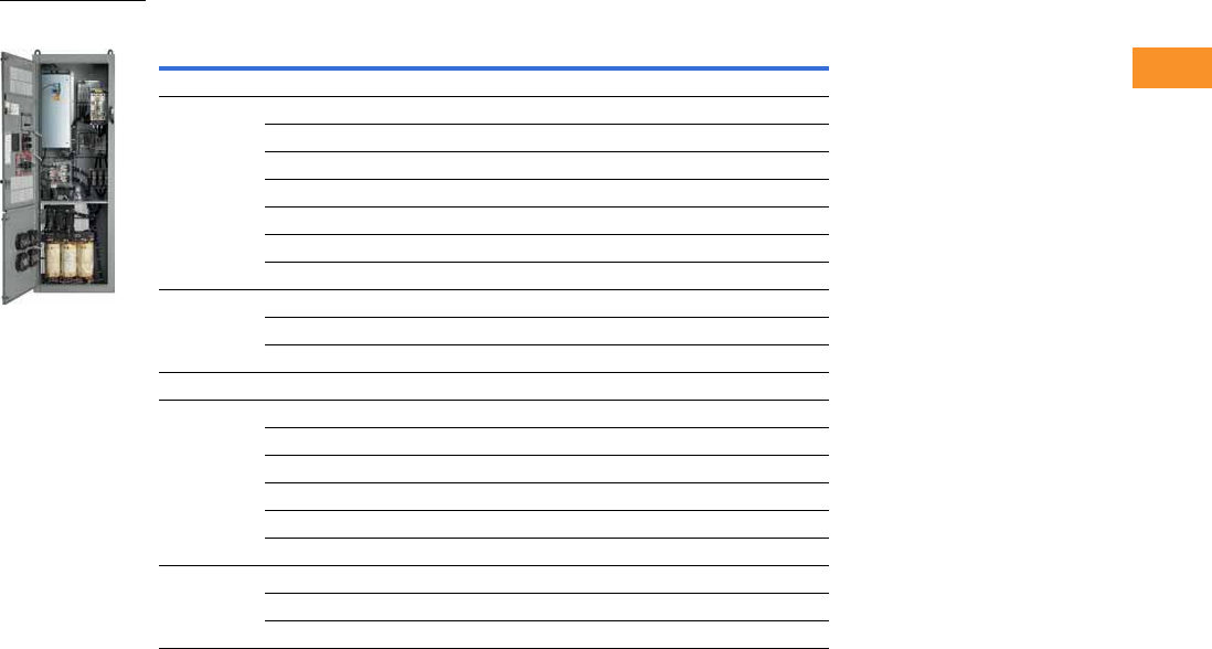
Volume 6—Solid-State Motor Control CA08100007E—February 2016 www.eaton.com V6-T2-333
2
2
2
2
2
2
2
2
2
2
2
2
2
2
2
2
2
2
2
2
2
2
2
2
2
2
2
2
2
2
2.10
Adjustable Frequency Drives
Clean Power Drives
Enclosed 18-Pulse Base Drive Type 3R 1
Notes
1 All Type 3R drives use the Size F enclosure.
2 See enclosure dimensions beginning on Page V6-T2-343.
3 hp ratings are provided as a guideline. Drives should be sized per motor nameplate FLA.
4 The 18-pulse clean power assembly includes a standard drive, door-mounted local/remote keypad and enclosure.
Enclosure
Size 2hp 3
Current
(A)
Chassis
Frame
Base Catalog
Number 4
Low Overload Drive
72527 FR6 CPX02535AA
30 34 FR6 CPX03035AA
40 41 FR7 CPX04035AA
50 52 FR7 CPX05035AA
60 62 FR8 CPX06035AA
75 80 FR8 CPX07535AA
100 100 FR8 CPX10035AA
8125125 FR9 CPX12535AA
150 144 FR9 CPX15035AA
200 208 FR9 CPX20035AA
High Overload Drive
72527 FR6 CPX02535DA
30 34 FR7 CPX03035DA
40 41 FR7 CPX04035DA
50 52 FR8 CPX05035DA
60 62 FR8 CPX06035DA
75 80 FR8 CPX07535DA
8100100 FR9 CPX10035DA
125 125 FR9 CPX12535DA
150 144 FR9 CPX15035DA
Enclosed 18-Pulse
Drive
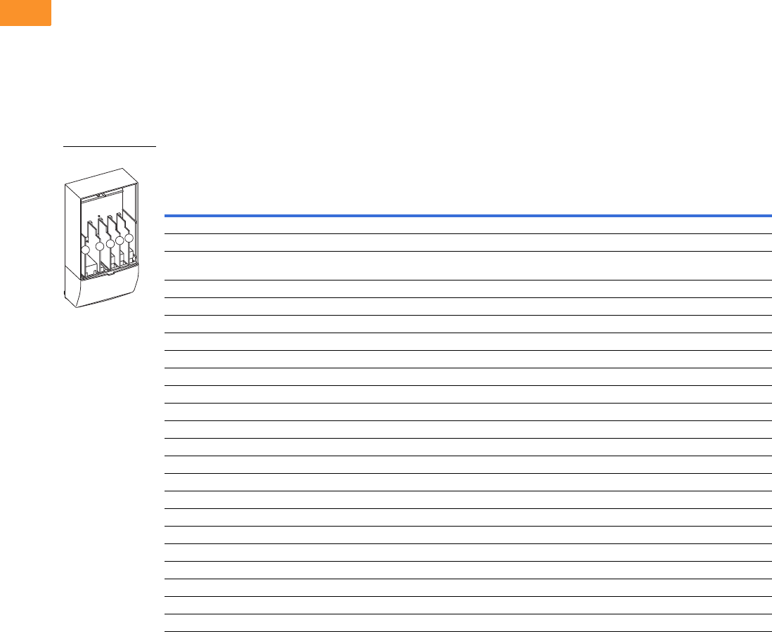
V6-T2-334 Volume 6—Solid-State Motor Control CA08100007E—February 2016 www.eaton.com
2
2
2
2
2
2
2
2
2
2
2
2
2
2
2
2
2
2
2
2
2
2
2
2
2
2
2
2
2
2
2.10
Adjustable Frequency Drives
Clean Power Drives
Options
Enclosed 18-Pulse Drive Option Board Kits
The enclosed 18-pulse drives can accommodate a wide selection of expander and adapter option
boards to customize the drive for your application needs. The drive’s control unit is designed to accept
a total of five option boards (see figure below).
The enclosed 18-pulse drives factory-installed standard board configuration includes an A9 I/O board
and an A2 relay output board, which are installed in slots A and B.
SVX Series Option Board Kits
Option Board Kits
Notes
1 AI = Analog Input; AO = Analog Output, DI = Digital Input, DO = Digital Output, RO = Relay Output
2 Option card must be installed in one of the slots listed for that card. Slot indicated in bold is the preferred location.
3 OPTC2 is a multi-protocol option card.
Option Kit Description 1
Allowed Slot
Locations 2
Field
Installed
Factory
Installed SVX Ready Programs
Catalog
Number
Option
Designator Basic
Local/
Remote Standard MSS PID Multi-P. PFC
Standard I/O Cards
2 RO (NC/NO) B OPTA2 — ■ ■ ■ ■■■ ■
6 DI, 1 DO, 2 AI, 1 AO, 1 +10 Vdc ref,
2 ext +24 Vdc/ext +24 Vdc
AOPTA9 — ■ ■ ■ ■■■ ■
Extended I/O Cards
6 DI B, C, D, E OPTB1 B1 —— — ——
■■
1 RO (NC/NO), 1 RO (NO), 1 therm B, C, D, E OPTB2 B2 —— — ——
■■
1 AI (mA isolated), 2 AO (mA isolated) B, C, D, E OPTB4 B4 ■ ■ ■ ■■■ ■
3 RO (NO) B, C, D, E OPTB5 B5 —— — ——
■■
3 Pt100 RTD board B, C, D, E OPTB8 B8 —— — ——
■—
1 RO (NO), 5 DI 42–240 Vac input B, C, D, E OPTB9 B9 —— — ——
■■
Communication Cards 3
Modbus D, E OPTC2 C2 ■ ■ ■ ■■■ ■
Modbus TCP D, E OPTCI CI ■ ■ ■ ■■■ ■
BACnet D, E OPTCJ CJ ■ ■ ■ ■■■ ■
EtherNet/IP D, E OPTCQ CQ ■ ■ ■ ■■■ ■
Johnson Controls N2 D, E OPTC2 CA ■ ■ ■ ■■■ ■
PROFIBUS DP D, E OPTC3 C3 ■ ■ ■ ■■■ ■
LonWorks D, E OPTC4 C4 ■ ■ ■ ■■■ ■
PROFIBUS DP (D9 connector) D, E OPTC5 C5 ■ ■ ■ ■■■ ■
CANopen (slave) D, E OPTC6 C6 ■ ■ ■ ■■■ ■
DeviceNet D, E OPTC7 C7 ■ ■ ■ ■■■ ■
Modbus (D9 type connector) D, E OPTC8 C8 ■ ■ ■ ■■■ ■
RS-232 with D9 connection D, E OPTD3 D3 ■ ■ ■ ■■■ ■
Option Boards
ABCDE

Volume 6—Solid-State Motor Control CA08100007E—February 2016 www.eaton.com V6-T2-335
2
2
2
2
2
2
2
2
2
2
2
2
2
2
2
2
2
2
2
2
2
2
2
2
2
2
2
2
2
2
2.10
Adjustable Frequency Drives
Clean Power Drives
Modbus RTU Network
Communications
The Modbus Network Card
OPTC2 is used for connecting
the SVX Drive as a slave
on a Modbus network. The
interface is connected by
a 9-pin DSUB connector
(female) and the baud rate
ranges from 300 to 19,200
baud. Other communication
parameters include an
address range from 1 to 247;
a parity of None, Odd or
Even; and the stop bit is 1.
PROFIBUS Network
Communications
The PROFIBUS Network Card
OPTC3 is used for connecting
the SVX Drive as a slave
on a PROFIBUS-DP network.
The interface is connected
by a 9-pin DSUB connector
(female). The baud rates
range from 9.6 Kbaud to
12 Mbaud, and
the addresses
range from 1 to 127.
LonWorks Network
Communications
The LonWorks Network Card
OPTC4 is used for connecting
the SVX Drive on a LonWorks
network. This interface uses
Standard Network Variable
Types (SNVT) as data types.
The channel connection is
achieved using a FTT-10 A
Free Topology transceiver
via a single twisted transfer
cable. The communication
speed with LonWorks is
78 kBits/s.
CANopen (Slave)
Communications
The CANopen (Slave)
Network Card OPTC6 is used
for connecting the SVX Drive
to a host system. According
to ISO11898 standard cables
to be chosen for CANbus
should have a nominal
impedance of 120 ohms,
and specific line delay of
nominal 5 nS/m. 120 ohm
line termination resistors
required for installation.
DeviceNet Network
Communications
The DeviceNet Network Card
OPTC7 is used for connecting
the SVX Drive on a DeviceNet
Network. It includes a 5.08
mm pluggable connector.
Transfer method is via CAN
using a two-wire twisted
shielded cable with two-wire
bus power cable and drain.
The baud rates used for
communication include
125 Kbaud, 250 Kbaud and
500 Kbaud.
Johnson Controls Metasys N2
Network Communications
The OPTC2 fieldbus board
provides communication
between the SVX Drive
and a Johnson Controls
Metasys™ N2 network.
With this connection, the
drive can be controlled,
monitored and programmed
from the Metasys system.
The N2 fieldbus is available as
a factory-installed option and
as a field-installable kit.
Modbus/TCP Network
Communications
The Modbus/TCP Network
Card OPTCI is used for
connecting the SVX Drive to
Ethernet networks using
Modbus protocol. It includes
an RJ-45 pluggable
connector. This interface
provides a selection of
standard and custom register
values to communicate drive
parameters. The board
supports 10 Mbps and
100 Mbps communication
speeds. The IP address of
the board is configurable over
Ethernet using a supplied
software tool.
BACnet Network
Communications
The BACnet Network Card
OPTCJ is used for connecting
the SVX Drive to BACnet
networks. It includes a 5.08
mm pluggable connector.
Data transfer is Master-Slave/
Token Passing (MS/TP)
RS-485. This interface uses
a collection of 30 Binary
Value Objects (BVOs) and
35 Analog Value Objects
(AVOs) to communicate
drive parameters. The card
supports 9.6, 19.2 and 38.4
Kbaud communication
speeds and supports network
addresses 1 to 127.
EtherNet/IP Network
Communications
The EtherNet/IP Network
Card OPTCK is used for
connecting the SVX Drive
to Ethernet/Industrial Protocol
networks. It includes an
RJ-45 pluggable connector.
The interface uses CIP
objects to communicate
drive parameters (CIP is
“Common Industrial
Protocol,” the same protocol
used by DeviceNet). The
board supports 10 Mbps and
100 Mbps communication
speeds. The IP address of
the board is configurable
by Static, BOOTP and
DHCP methods.

V6-T2-336 Volume 6—Solid-State Motor Control CA08100007E—February 2016 www.eaton.com
2
2
2
2
2
2
2
2
2
2
2
2
2
2
2
2
2
2
2
2
2
2
2
2
2
2
2
2
2
2
2.10
Adjustable Frequency Drives
Clean Power Drives
Control/Communication Option Descriptions
For availability, see Product Selection for base drive voltage required.
Available Control/Communications Options
Option Description
Option
Type
K1 Door-Mounted Speed Potentiometer—Provides the enclosed 18-pulse drive with the ability to adjust the frequency reference using a door-mounted potentiometer.
This option uses the 10 Vdc reference to generate a 0–10 V signal at the analog voltage input signal terminal. When the HOA bypass option is added, the speed is
controlled when the HOA switch is in the HAND position. Without the HOA bypass option, a two-position switch (labeled local/remote) is provided on the keypad to select
speed reference from the speed potentiometer or a remote speed signal.
Control
K2 Door-Mounted Speed Potentiometer with HOA Selector Switch—Provides the enclosed 18-pulse drive with the ability to start/stop and adjust the speed
reference from door-mounted control devices or remotely from customer-supplied inputs. In HAND position, the drive will start and the speed is controlled by the door-
mounted speed potentiometer. The drive will be disabled in the OFF position. When AUTO is selected, the drive run and speed control commands are via user-supplied dry
contact and 4–20 mA signal.
Control
K3 3–15 psig Follower—Provides a pneumatic transducer that converts a 3–15 psig pneumatic signal to either 0–8 Vdc or a 1–9 Vdc signal interface with the enclosed
18-pulse drive. The circuit board is mounted on the inside of the front enclosure panel and connects to the user’s pneumatic control system via 6 ft (1.8 m) of flexible
tubing and a 1/4 inch (6.4 mm) brass tube union.
Control
K4 HAND/OFF/AUTO Switch for Non-Bypass Configurations—Provides a three-position selector switch that allows the user to select either a HAND or AUTO mode
of operation. HAND mode is defaulted to keypad operation, and AUTO mode is defaulted to control from an external terminal source. These modes of operation can be
configured via drive programming to allow for alternate combinations of start and speed sources. Start and speed sources include Keypad, I/O and fieldbus.
Control
K5 MANUAL/AUTO Speed Reference Switch—Provides door-mounted selector switch for MANUAL/AUTO speed reference. Control
K6 START/STOP Pushbuttons—Provide door-mounted START and STOP pushbuttons for either bypass or non-bypass configurations. Control
KF Bypass Test Switch for RB and RA—Allows the user to energize the AF drive for testing while operating the motor on the bypass controller. The Test Switch is
mounted on the inside of the enclosure door.
Addl. bypass
KO Standard Elapsed Time Meter—Provides a door-mounted elapsed run-time meter. Control
L1 Power On and Fault Power Lights—Provide a white Power On light that indicates power to the enclosed cabinet and a red fault light that indicates a drive fault
has occurred.
Light
L2 Bypass Pilot Lights for RB, RA Bypass Options—A green light indicates when the motor is running in Inverter mode and an amber light indicates when the motor is
running in Bypass mode. The lights are mounted on the enclosure door, above the switches.
Addl. bypass
LE Red Run Pilot Light 0.87-Inch (22 mm)—Provides a red Run pilot light that indicates the drive is running. Light
P1 Input Circuit Breaker—High interrupting circuit breaker that provides a means of short-circuit protection for the power cables between it and the enclosed 18-pulse
drive, and protection from high-level ground faults on the power cable. Allows a convenient means of disconnecting the enclosed 18-pulse drive from the line, and the operating
mechanism can be padlocked in the OFF position. This is factory mounted in the enclosure. Standard rating is 65 kAIC at 208/480 V. 100 kAIC is available as an option.
Input
PE Output Contactor—Provides a means for positive disconnection of the drive output from the motor terminals. The contactor coil is controlled by the drive’s run or
permissive logic. NC and NO auxiliary contacts rated at 10 A, 600 Vac are provided for customer use. Bypass options RB and RA include an output contactor as standard.
This option includes a low VA 115 Vac fused control power transformer and is factory mounted in the enclosure.
Output
PF Output Filter—Used to reduce the transient voltage (dV/dt) at the motor terminals. The output filter is recommended for cable lengths exceeding 100 ft (30.5 m) with a
drive of 3 hp and above, for cable lengths of 33 ft (10.1 m) with a drive of 2 hp and below, or for a drive rated at 525–690 V. This option is mounted in the enclosure.
Output
PG MotoRx (300–600 Ft) 1000 V/μS dV/dt Filter—Used to reduce transient voltage (dV/dt) and peak voltages at the motor terminals. This option is comprised of a 0.5% line
reactor, followed by capacitive filtering and an energy recovery/clamping circuit. Unlike the output filter (see option PF), the MotoRx recovers most of the energy from the voltage
peaks, resulting in a lower voltage drop to the motor, and therefore conserving power. This option is used when the distance between a single motor and the drive is 300–
600 ft (91.4–182.9 m).
Output
PH Single Overload Relay—Uses a bimetallic overload relay to provide additional overload current protection to the motor on configurations without bypass options.
It is included with the bypass configurations for overload current protection in the bypass mode. The overload relay is mounted within the enclosure, and is manually
resettable. Heater pack included.
Output
PI Dual Overload Relays—This option is recommended when a single drive is operating two motors and overload current protection is needed for each of the motors.
The standard configuration includes two bimetallic overload relays, each sized to protect a motor with 50% of the drive hp rating. For example, a 100 hp drive would
include two overload relays sized to protect two 50 hp motors. The relays are mounted within the enclosure, and are manually resettable. Heater packs not included.
Output
PN Dual Overloads for Bypass—This option is recommended when a single drive is operating two motors in the Bypass mode and overload current protection is needed
for each of the motors. The standard configuration includes two bimetallic overload relays, each sized to protect a motor with 50% of the drive hp rating. For example,
a 100 hp drive would include two overload relays sized to protect two 50 hp motors. The relays are mounted within the enclosure, and are manually resettable.
Addl. bypass
Volume 6—Solid-State Motor Control CA08100007E—February 2016 www.eaton.com V6-T2-337
2
2
2
2
2
2
2
2
2
2
2
2
2
2
2
2
2
2
2
2
2
2
2
2
2
2
2
2
2
2
2.10
Adjustable Frequency Drives
Clean Power Drives
For availability, see Product Selection for base drive voltage required.
Available Control/Communications Options, continued
Dissipated Watt Losses
Conformal (Varnished) Coating 1
Notes
1See catalog number description to order.
2Contact factory for 208 V and 575 V applications.
3Contact factory.
480 V Input Disconnect Selection 2
Option Description
Option
Type
RA Manual HOA Bypass Controller—The manual HAND/OFF/AUTO (HOA)—three-contactor—bypass option provides a means of bypassing the enclosed 18-pulse drive,
allowing the AC motor to be operated at full speed directly from the AC supply line. This option consists of an input HMCP, a fused control power transformer, and a
full voltage bypass starter with a door-mounted HOA selector switch and an INVERTER/BYPASS switch. The HOA switch provides the ability to start and stop the drive
in the inverter mode. IEC type input, bypass and input contactors are provided. The contactors are mechanically and electrically interlocked (see wiring diagram on
Page V6-T2-342).
Bypass
RB Manual IOB Bypass Controller—The manual INVERTER/OFF/BYPASS (IOB)—three-contactor—bypass option provides a means of bypassing the enclosed 18-pulse
drive, allowing the AC motor to be operated at full speed directly from the AC supply line. This option consists of an input HMCP, a fused control power transformer, and
a full voltage bypass starter with a door-mounted IOB selector switch. IEC type input, bypass and input contactors are provided. The contactors are mechanically and
electrically interlocked (see wiring diagram on Page V6-T2-342).
Bypass
RC Auto Transfer HOA Bypass Controller —The manual HAND/OFF/AUTO (HOA)—three-contactor—bypass option provides a means of bypassing the enclosed
18-pulse drive, allowing the AC motor to be operated at full speed directly from the AC supply line. The circuitry provides an automatic transfer of the load to “across the
line” operation after a drive trip. This option consists of an input HMCP, a fused control power transformer, and a full voltage bypass starter with a door-mounted HOA
selector switch and an INVERTER/BYPASS switch. The HOA switch provides the ability to start and stop the drive in either mode. IEC type input, bypass and input
contactors are provided. The contactors are mechanically and electrically interlocked (see wiring diagram on Page V6-T2-342). Door-mounted pilot lights are provided
that indicate bypass or inverter operation. A green light indicates when the motor is running in inverter mode and an amber light indicates when the motor is running in
bypass mode.
WARNING: The motor may restart when the overcurrent relay is reset when operating in bypass, unless the IOB selector switch is turned to the OFF position.
Bypass
RD Auto Transfer IOB Bypass Controller—The auto INVERTER/OFF/BYPASS (IOB)—three-contactor—bypass option provides a means of bypassing the enclosed
18-pulse drive, allowing the AC motor to be operated at full speed directly from the AC supply line. The circuitry provides an automatic transfer of the load to “across the
line” operation after a drive trip. This option consists of an input HMCP, a fused control power transformer, and a full voltage bypass starter with a door-mounted IOB
selector switch. IEC type input, bypass and input contactors are provided. The contactors are mechanically and electrically interlocked (see wiring diagram on Page
V6-T2-342). Door-mounted pilot lights are provided that indicate bypass or inverter operation. A green light indicates when the motor is running in inverter mode and an
amber light indicates when the motor is running in bypass mode.
WARNING: The motor may restart when the overcurrent relay is reset when operating in bypass, unless the IOB selector switch is turned to the OFF position.
Bypass
RG Reduced Voltage Starter for Bypass—Used in conjunction with bypass option RA, RB, RC or RD. This option adds reduced voltage soft starter to bypass assembly for
soft starting in bypass mode.
Bypass
S7 10.00-Inch (254.0 mm) Expansion—Expansion cabinet allows for special components, customer-supplied components or oversized cables.
NOTE: Enclosure expansion rated Type 1 only.
Enclosure
S8 20.00-Inch (508.0 mm) Expansion—Expansion cabinet allows for special components, customer-supplied components or oversized cables.
NOTE: Enclosure expansion rated Type 1 only.
Enclosure
S9 Space Heater—Prevents condensation from forming in the enclosure when the drive is inactive or in storage. Includes a thermostat for variable temperature control.
The heater requires a customer-supplied 115 V remote supply source.
Enclosure
Horsepower 40 50 60 75 100 125 150 200 250 300 350 400 450 500 600 700 800
Watts 1844 2170 2540 3040 4011 4940 5730 8020 9383 11600 13600 15700 16250 17976 20393 27200 31400
Chassis
Frame
Delivery
Code
Chassis
Frame
Delivery
Code
FR6 FP FR9 FP
FR7 FP FR10 FP
FR8 FP FR11 FP
— — FR12 FP
Horsepower
P1 Input
Breaker
Bypass Motor Circuit Protector
(RA, RB, RC, RD)
25 HFD3050 HMCP050K2C
30 HFD3060 HMCP100R3C
40 HFD3080 HMCP100R3C
50 HFD3100 HMCP100R3C
60 HFD3100 HMCP150T4C
75 HFD3125 HMCP150T4C
100 HFD3150 HMCP150U4C
125 HFD3200 HMCP250W5C
150 HFD3225 HMCP250W5C
200 HKD3300 HMCP400X5C
250 HKD3400 HMCP400X5C
300–400 HLD3600 HMCP600L6W
500–600 HND3800 HMCP800X7W
650–800 HND312 3
V6-T2-338 Volume 6—Solid-State Motor Control CA08100007E—February 2016 www.eaton.com
2
2
2
2
2
2
2
2
2
2
2
2
2
2
2
2
2
2
2
2
2
2
2
2
2
2
2
2
2
2
2.10
Adjustable Frequency Drives
Clean Power Drives
Enclosed Drive Options
Light Options
Control Options
Bypass Control Options
Meter Options
Enclosure Options
Note
1Requires customer-supplied 115 Vac supply.
Description
Catalog
Number Suffix
Power on, run, fault LED lights (22 mm) L1
Power on, fault LED lights (22 mm) L3
Green LED run light (22 mm) LA
Green LED stop light (22 mm) LD
Red LED run light (22 mm) LE
Red LED stop light (22 mm) LF
Red LED fault light (22 mm) LG
Power on white LED light (22 mm) LJ
Miscellaneous LED light (22 mm) LU
Description
Catalog
Number Suffix
Door-mounted speed potentiometer K1
Door-mounted speed potentiometer with HOA selector switch K2
3–15 psig follower K3
HOA selector switch K4
MANUAL/AUTO reference switch K5
START-STOP pushbuttons K6
Type D2 control relay SD
On-delay relay SE
Off-delay relay SF
Additional terminal blocks per 4 points SD
Description
Catalog
Number Suffix
Bypass test switch used with RA and RB KF
Inverter/bypass pilot lights L2
Description
Catalog
Number Suffix
Standard elapsed time meter KO
Frequency meter KS
MP-3000 relay with URTD KV
MP-3000 relay with URTD and CTs KU
Enclosure
Size
Catalog
Number Suffix
10.00 Inch (254.0 mm) Expansion
7S7
8S7
9S7
10 S7
11 S7
20.00 Inch (508.0 mm) Expansion
7S8
8S8
9S8
10 S8
11 S8
Space Heater 1
7S9
8S9
9S9
10 S9
11 S9
Plastic Nameplate
7SN
8SN
9SN
10 SN
11 SN

Volume 6—Solid-State Motor Control CA08100007E—February 2016 www.eaton.com V6-T2-339
2
2
2
2
2
2
2
2
2
2
2
2
2
2
2
2
2
2
2
2
2
2
2
2
2
2
2
2
2
2
2.10
Adjustable Frequency Drives
Clean Power Drives
208 and 230 V Power Options, 25–200 hp
480 and 575 V Power Options, 25–800 hp
208 and 230 V Bypass Options, 25–200 hp
480 and 575 V Bypass Options, 25–800 hp
Description
Catalog
Number Suffix
Input breaker P1
Output contactor PE
Single overload relay PH
Dual overload relays PI
MOV P7
50 kA surge protective device P8
100 kA surge protective device P9
Description
Catalog
Number Suffix
Input breaker P1
Output contactor PE
Output filter PF
MotoRx (300–600 Ft) dV/dt filter PG
Single overload relay PH
Dual overload relays PI
Input MOV P7
50 kA surge protective device P8
100 kA surge protective device P8
Description
Catalog
Number Suffix
Manual HOA bypass controller RA
IOB bypass controller RB
Auto transfer HOA bypass controller RC
Auto transfer IOB bypass controller RD
Reduced voltage starter for bypass RG
Dual overloads for bypass PN
Description
Catalog
Number Suffix
Manual HOA bypass controller RA
IOB bypass controller RB
Auto transfer HOA bypass controller RC
Auto transfer IOB bypass controller RD
Reduced voltage starter for bypass RG
Dual overloads for bypass PN
V6-T2-340 Volume 6—Solid-State Motor Control CA08100007E—February 2016 www.eaton.com
2
2
2
2
2
2
2
2
2
2
2
2
2
2
2
2
2
2
2
2
2
2
2
2
2
2
2
2
2
2
2.10
Adjustable Frequency Drives
Clean Power Drives
Technical Data and Specifications
Enclosed 18-Pulse Drives
Note
1The EMI filter is optional in FR10 and larger.
Description Specification
Primary Design Features
45–66 Hz input frequency Standard
Output: AC volts maximum Input voltage base
Output frequency range 0–320 Hz
Initial output current (IH) 250% for 2 seconds
Overload (1 minute [IH/IL]) 150%/110%
Enclosure space heater Optional
Oversize enclosure Standard
Output contactor Optional
Bypass motor starter Optional
Listings UL, cUL, 508C
Protection Features
Incoming line fuses Standard 200 kAIC rating
AC input circuit disconnect Optional
Phase rotation insensitive Standard
EMI filter Standard FR6 thru FR9 1
Input phase loss protection Standard
Input overvoltage protection Standard
Line surge protection Standard
Output short-circuit protection Standard
Output ground fault protection Standard
Output phase protection Standard
Overtemperature protection Standard
DC overvoltage protection Standard
Drive overload protection Standard
Motor overload protection Standard
Programmer software Optional
Local/remote keypad Standard
Keypad lockout Standard
Fault alarm output Standard
Built-in diagnostics Standard
Surge protective device Optional
Description Specification
Input/Output Interface Features
Setup adjustment provisions
Remote keypad/display Standard
Personal computer Standard
Operator control provisions
Drive mounted keypad/display Standard
Remote keypad/display Standard
Conventional control elements Standard
Serial communications Optional
115 Vac control circuit Optional
Speed setting inputs
Keypad Standard
0–10 Vdc potentiometer/voltage signal Standard
4–20 mA isolated Configurable
4–20 mA differential Configurable
3–15 psig Optional
Analog outputs
Speed/frequency Standard
Torque/load/current Programmable
Motor voltage Programmable
Kilowatts Programmable
0–10 Vdc signals Configurable w/jumpers
4–20 mA DC signals Standard
Isolated signals Standard
Discrete outputs
Fault alarm Standard
Drive running Standard
Drive at set speed Programmable
Optional parameters 14
Dry contacts
2 Form C contacts available
Additional discrete outputs Optional
Communications
RS-232 Standard
RS-422/485 Optional
DeviceNet™ Optional
Modbus RTU Optional
CANopen (slave) Optional
PROFIBUS-DP Optional
LonWorks Optional
Johnson Controls Metasys N2 Optional
EtherNet/IP/Modbus TCP Optional
BACnet Optional

Volume 6—Solid-State Motor Control CA08100007E—February 2016 www.eaton.com V6-T2-341
2
2
2
2
2
2
2
2
2
2
2
2
2
2
2
2
2
2
2
2
2
2
2
2
2
2
2
2
2
2
2.10
Adjustable Frequency Drives
Clean Power Drives
Enclosed 18-Pulse Drives Standard I/O Specifications
I/O Specifications for Control/Communication Options
Note
1For applications above 3 A consult instruction manual.
Description Specification
Performance Features
Sensorless vector control Standard
Volts/hertz control Standard
IR and slip compensation Standard
Electronic reversing Standard
Dynamic braking Optional
DC braking Standard
PID set point controller Programmable
Critical speed lockout Standard
Current (torque) limit Standard
Adjustable acceleration/deceleration Standard
Linear or S curve accel/decel Standard
Jog at preset speed Standard
Thread/preset speeds 7
Automatic restart Selectable
Coasting motor start Standard
Coast or ramp stop selection Standard
Elapsed time meter Optional
Carrier frequency adjustment 1–16 kHz
Standard Conditions for Application and Service
Maximum operating ambient temperature 0–50 °C up to FR9
0–40 °C FR10 and larger, consult factory for 50 °C
rating above FR9
Storage temperature –40 to 60 °C
Humidity (maximum), noncondensing 95%
Altitude (maximum without derate) 3300 ft (1000 m)
Line voltage variation +10/–15%
Line frequency variation 45–66 Hz
Efficiency >95%
Power factor (displacement) 0.99+
Power factor (apparent) 0.99
Description Specification
Six–digital input programmable 24 V: “0” <10 V, “1” >18V,Ri >5 kohms
Two–analog input configurable
w/jumpers
Voltage: 0–±10 V, Ri >200 kohms
Current: 0 (4)–20 mA, Ri = 250 ohms
Two–digital output programmable Form C relays 250 Vac
30 Vdc 2 amp resistive
One–analog output programmable
configurable w/jumper
0–20 mA, RL max. 500 ohms 10 bits ±2%
Description Specification
Analog voltage, input 0–±10 V, Ri >200 kilohms
Analog current, input 0 (4)–20 mA, Ri = 250 ohms
Digital input 24 V: “0” <10 V, “1” >18V, Ri >5 kilohms
Auxiliary voltage 24 V (±20%), max. 50 mA
Reference voltage 10 V ±3%, max. 10 mA
Analog current, output 0 (4)–20 mA, RL = 500 kilohms, resolution
10 bit, accuracy <±2%
Analog voltage, output 0 (2)–10 V, RL >1 kilohm, resolution
10 bit, accuracy <±2%
Relay output max. switching voltage 300 Vdc, 250 Vac
Relay output max. switching load 3 A/24 Vdc, 300 Vdc, 250 Vac 1
Relay output max. continuous load 2 A rms
Thermistor input Rtrip = 4.7 kohms
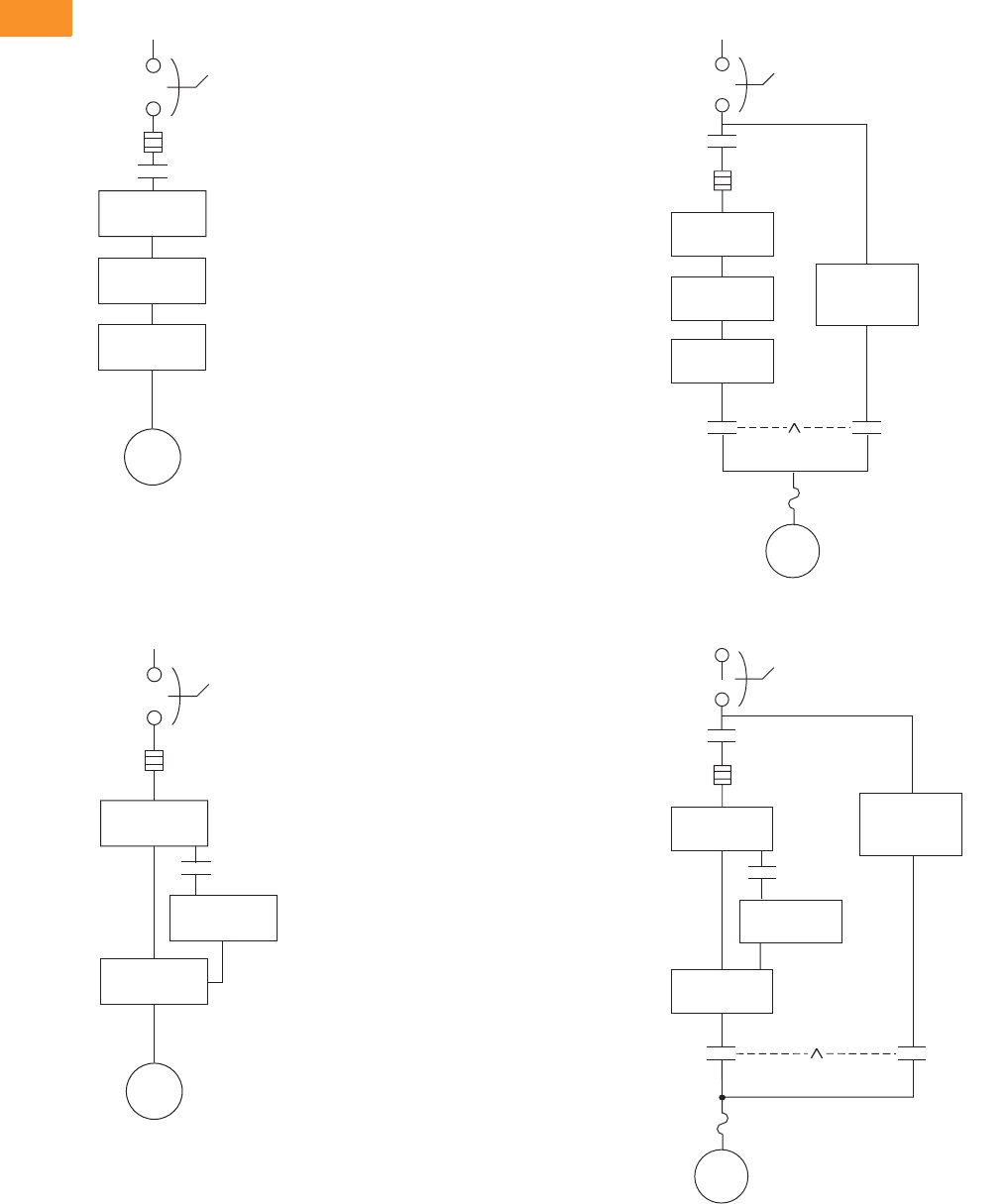
V6-T2-342 Volume 6—Solid-State Motor Control CA08100007E—February 2016 www.eaton.com
2
2
2
2
2
2
2
2
2
2
2
2
2
2
2
2
2
2
2
2
2
2
2
2
2
2
2
2
2
2
2.10
Adjustable Frequency Drives
Clean Power Drives
Wiring Diagrams
Power Diagram Up to FR9
Power Diagram FR10 and Larger
Power Diagram Up to FR9 with Bypass
Power Diagram FR10 and Larger with Bypass
18-Pulse
Transformer
18-Pulse
Diode Bridge
SVX
Drive
Circuit
Breaker
Motor
Input
Fusing
IInverter Input
Contactor
18-Pulse
Transformer
6-Pulse
Diode Bridge
SVX
12-Pulse Drive
Circuit
Breaker
Motor
Input
Fusing
Pre-charge
Complete
Contactor
18-Pulse
Transformer
Optional
Reduced
Voltage Starter
18-Pulse
Diode Bridge
SVX
Drive
HMCP
Output
Contactor
Mechanical
Interlock
Motor
M
Inverter Input
Contactor I
Bypass
Contactor
L
(IT.)
Input
Fusing
Overload
18-Pulse
Transformer
Optional
Reduced
Voltage Starter
SVX
12-Pulse Drive
HMCP
Output
Contactor
Mechanical
Interlock
Motor
M
Inverter Input
Contactor I
Bypass
Contactor
L
Input
Fusing
Overload
6-Pulse
Diode Bridge
Pre-charge
Complete
Contactor
(IT.)
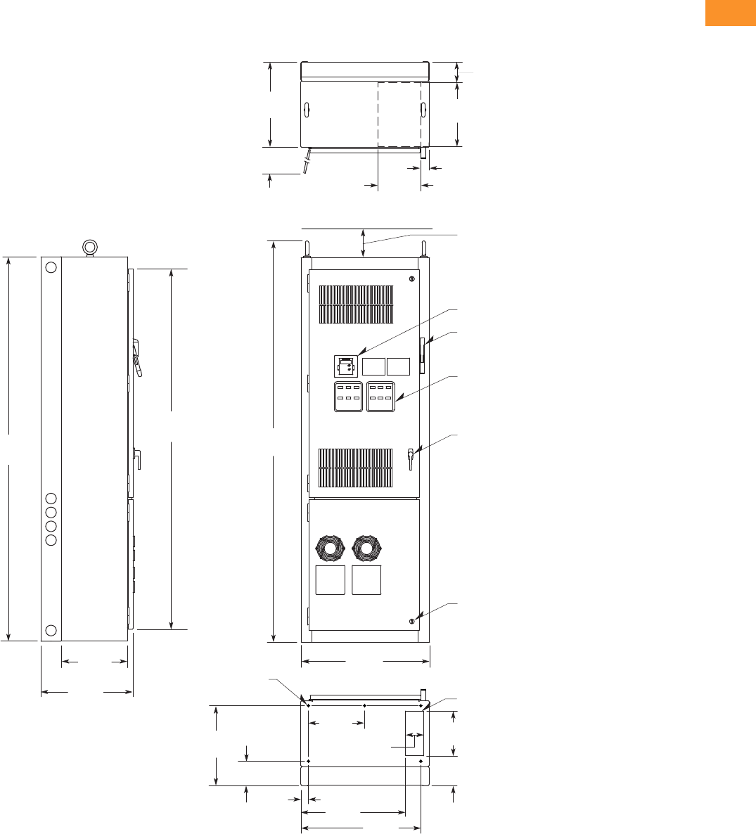
Volume 6—Solid-State Motor Control CA08100007E—February 2016 www.eaton.com V6-T2-343
2
2
2
2
2
2
2
2
2
2
2
2
2
2
2
2
2
2
2
2
2
2
2
2
2
2
2
2
2
2
2.10
Adjustable Frequency Drives
Clean Power Drives
Dimensions
Approximate Dimensions in Inches (mm)
Enclosure Size 7
25–150 hp IL and 25–125 hp IH 480 V—25–100 hp IL and 25–75 hp IH 575 V
Side View
26.25
(666.8)
ø0.56 (ø14.2) Dia.
Mounting Holes
(ve places)
90.00
(2286.0)
84.37
(2143.0)
15.50
(393.7)
21.50
(546.1)
93.92
(2385.6)
30.00
(762.0)
4.00 (101.6) Minimum
Free Air Space Required
Keypad
Flanged Disconnect Supplied
With Circuit Breaker
When Specied
Operator Elements
When Specied, Mounted
On These Panels
Door Handle
(key-lock optional)
Quarter Turn Latch
(three places)
Bottom View
18.75
(476.3)
Opening For Bottom
Cable Entry
7. 0 0
(177.8)
5.75
(146.1)
14.90
(378.5)
1.75
(44.5) 24.45
(621.0) 28.05
(712.5)
10.50
(266.7)
4.25
(107.9)
Top View
Exhaust Air
For
Cable
Entry
Hinged
Side Door
Clearance at 90º
20.00
(508.0)
4.79
(121.7)
15.00
(381.0)
2.00
(50.8)
10.00
(254.0)
Finish: Enclosure—ANSI 61 Gray (light)
Material: Enclosure and Backplate—
12 ga. = 0.1046 Cold Rolled Steel
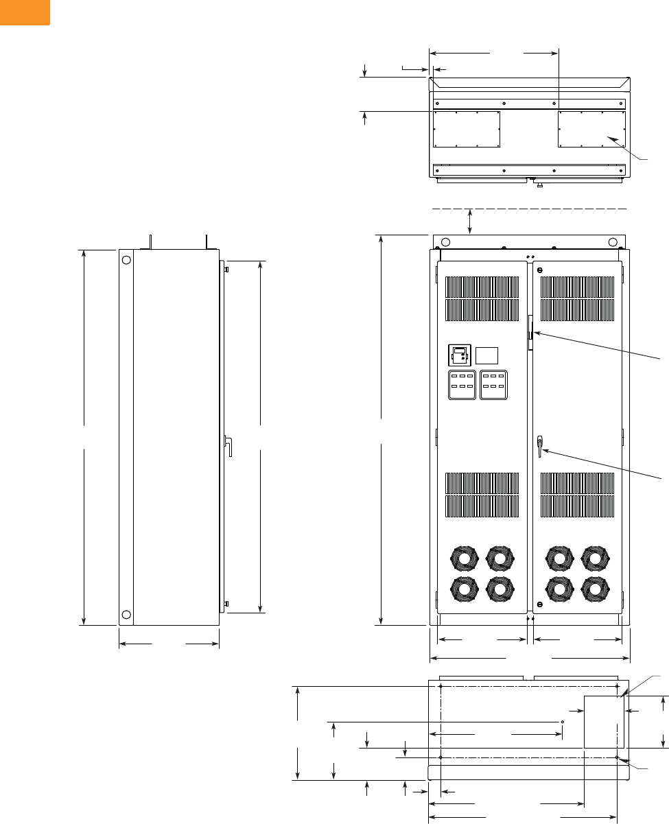
V6-T2-344 Volume 6—Solid-State Motor Control CA08100007E—February 2016 www.eaton.com
2
2
2
2
2
2
2
2
2
2
2
2
2
2
2
2
2
2
2
2
2
2
2
2
2
2
2
2
2
2
2.10
Adjustable Frequency Drives
Clean Power Drives
Approximate Dimensions in Inches (mm)
Enclosure Size 8
200–250 hp IL and 150–200 hp IH 480 V—125–200 hp IL and 100–150 hp IH 575 V
Bottom View
For Bottom
Cable Entry
ø0.56
(ø14.2)
(ve places)
90.00
(2286.0)
84.37
(2143.0)
24.00
(609.6)
31.00
(787.4)
1.25
(31.8)
8.25
(209.6)
For Top
Cable Entry
(two places)
Top View
Side View
93.50
(2374.9)
3.01 (76.5)
32.20
(817.9)
37.47 (951.7)
45.22 (1148.6)
22.47
(570.7) 13.97
(354.8) 7.73
(196.3) 5.48
(139.2)
9.50
(241.3) 12.50
(317.5)
21.45
(544.8) 48.00
(1219.2)
21.31
(541.3)
Finish: Enclosure—ANSI 61 Gray (light)
Material: Enclosure and Backplate—
12 ga. = 0.1046 Cold Rolled Steel
4.00 (101.6) Minimum
Free Air Space Required
Door Handle
(key-lock optional)
Drive
Circuit Breaker
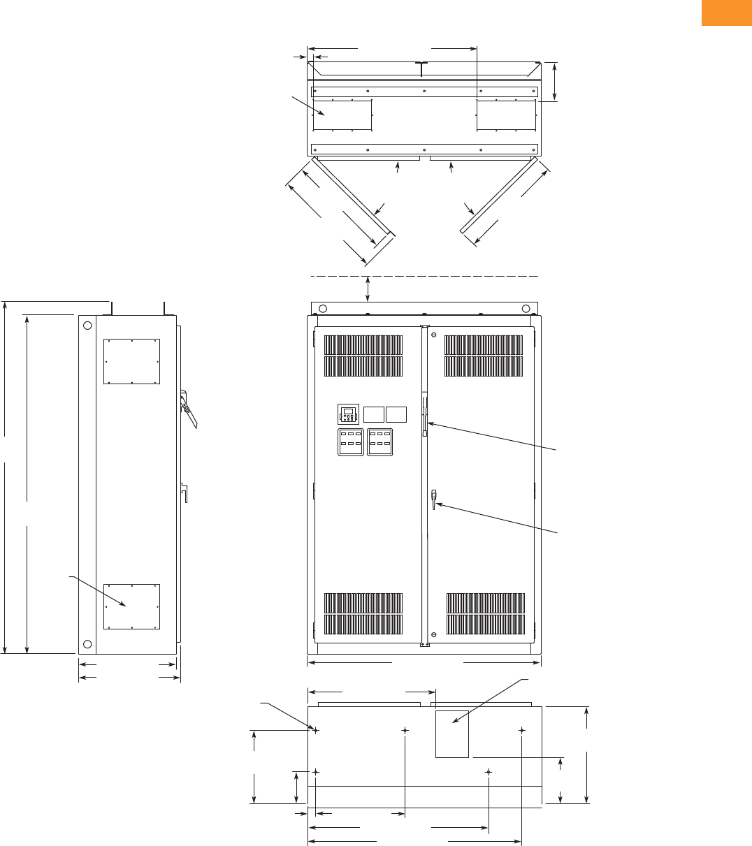
Volume 6—Solid-State Motor Control CA08100007E—February 2016 www.eaton.com V6-T2-345
2
2
2
2
2
2
2
2
2
2
2
2
2
2
2
2
2
2
2
2
2
2
2
2
2
2
2
2
2
2
2.10
Adjustable Frequency Drives
Clean Power Drives
Approximate Dimensions in Inches (mm)
Enclosure Size 9
300–400 hp IL and 250–350 hp IH 480 V—250–400 hp IL and 200–300 hp IH 575 V
24.00 (609.6)
25.14 (638.6)
8.75
(222.3)
Top View
1.50 (38.1) 43.50 (1104.9)
90.00
(2286.0)
93.50
(2374.9)
4.00 (101.6) Minimum
Free Air Space Required
60.00 (1524.0)
Front View
Bottom View
Side View
7.46 x 15.00
(189.5 x 381.0)
Access in Top
(two places)
8.50 x 12.00 (215.9 x 304.8)
Bottom Access
ø0.56 (ø14.2) Dia.
Mounting Hole
(ve places)
27.06
(687.3)
27.36
(694.9)
90 Max.
Door
Opening
29.05
(737.9)
11.93
(303.0)
25.00
(635.0)
18.84
(478.5)
8.20
(208.3)
2.00 (50.8) 22.90 (581.7)
32.72 (831.1)
46.30 (1176.0)
54.90 (1394.5)
Door Handle
(key-lock optional)
Access
Plate
(4 places)
90 Max.
Door
Opening
Finish: Enclosure—ANSI 61 Gray (light)
Material: Enclosure and Backplate—
12 ga. = 0.1046 Cold Rolled Steel
Drive
Circuit Breaker
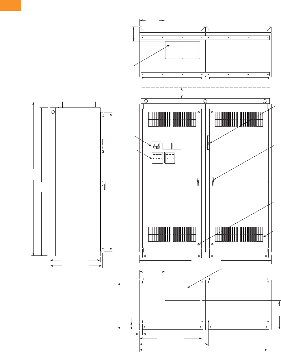
V6-T2-346 Volume 6—Solid-State Motor Control CA08100007E—February 2016 www.eaton.com
2
2
2
2
2
2
2
2
2
2
2
2
2
2
2
2
2
2
2
2
2
2
2
2
2
2
2
2
2
2
2.10
Adjustable Frequency Drives
Clean Power Drives
Approximate Dimensions in Inches (mm)
Enclosure Size 10
500–600 hp IL and 400–500 hp IH 480 V—500–600 hp IL and 400–500 hp IH 575 V
30.50 (774.7)
31.75 (806.5)
9.03
(229.4)
Top View
15.63
(397.0)
90.00
(2286.0)
84.37
(2143.0)
93.50
(2374.9)
4.00 (101.6) Minimum
Free Air Space Required
35.75 (908.1) 35.75 (908.1)
80.00 (2032.0)
Front View
Side View
21.00 x 10.00
(533.4 x 254.0)
Access in Top
21.00 x 10.00 (533.4 x 254.0)
Bottom Access
17.79
(451.9)
29.04
(737.6)
4.87
(123.7)
2.00 (50.8)
15.64
(397.3)
38.00 (965.2)
42.02 (1067.3)
Bottom View
78.02 (1981.7)
Finish: Enclosure – ANSI 61 Gray (light)
Material: Enclosure and Backplate—
12 ga. = 0.1046 Cold Rolled Steel
Operator
Elements
When
Specied,
Mounted
on These
Panels
Keypad
Door Handle
(key-lock optional)
Intake Ventilating
Slots (ltered on
Type 12)
Quarter-Turn
Latch (four places)
Flanged
Disconnect
Supplied with
Circuit Breaker
When Specied
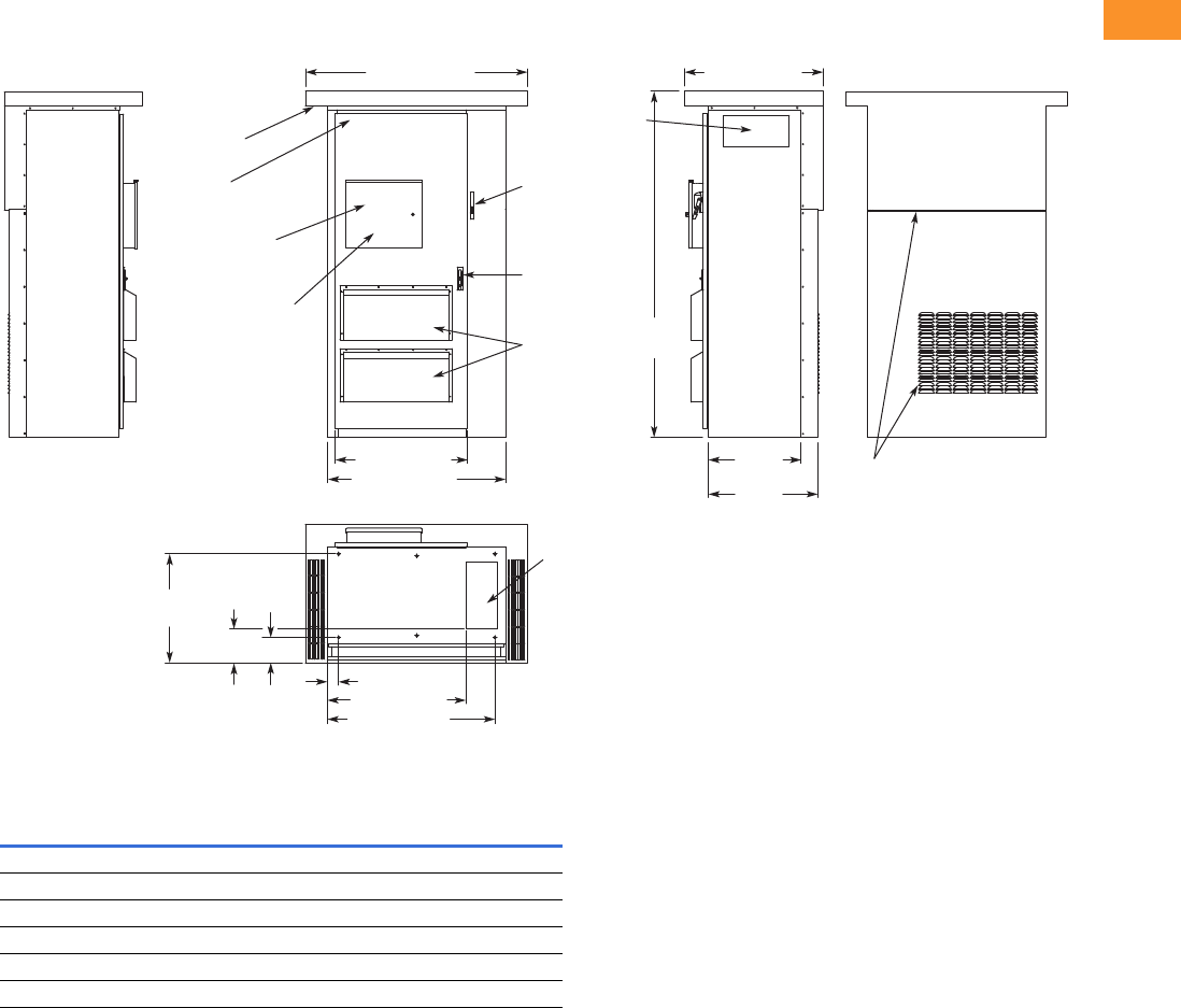
Volume 6—Solid-State Motor Control CA08100007E—February 2016 www.eaton.com V6-T2-347
2
2
2
2
2
2
2
2
2
2
2
2
2
2
2
2
2
2
2
2
2
2
2
2
2
2
2
2
2
2
2.10
Adjustable Frequency Drives
Clean Power Drives
Approximate Dimensions in Inches (mm)
Enclosure Size F Type 3R Drives
25–250 hp IL and 25–200 hp IH 480 V—25–200 hp IL and 25–150 hp IH 575 V Type 3R Drives
Enclosed 18-Pulse Drive Enclosure Dimensions
Notes
1Enclosure sizes accommodate drive and options, including bypass and disconnect.
For other power options, consult your Eaton representative.
2Consult factory. Limited power options available.
3Enclosure size 11 consists of two of the enclosure size 9.
4All Type 3R drives use the Size F enclosure.
Enclosure
Size 1Width Height Depth
Approx. Shipping
Weight in Lbs (kg)
7 30.00 (762.0) 90.00 (2286.0) 21.50 (546.1) 1000 (454)
8 48.00 (1219.2) 90.00 (2286.0) 26.14 (664.0) 1400 (636)
9 60.00 (1524.0) 90.00 (2286.0) 25.74 (653.8) 1800 (817)
10 80.00 (2032.0) 90.00 (2286.0) 31.75 (806.5) 2100 (953)
11 23 120.00 (3048.0) 90.00 (2286.0) 25.74 (653.8) 2500 (1,135)
F 460.00 (1524.0) 93.50 (2374.9) 37.50 (952.5) 2500 (1,135)
37.50 (952.5)
60.00 (1524.0)
35.75 (908.0)
48.00 (1219.2)
Operator Elements
When Specied,
Mounted Inside
Locking Enclosure Door
Keypad Located
Inside Locking
Enclosure Door
Enclosure
Door Stop
Exhaust Air
Venting Slots
Filtered
Intake Air
Ventilating
Slots
Key Locking
Three-Position
Latch
Flanged
Disconnect
Supplied with
Circuit Breaker
When Specied
93.50
(2374.9)
18.00 x 8.50
(457.2 x 215.9)
Side Access
25.84
(656.2)
29.58
(751.2)
Exhaust Air
Venting Slots
9.08
(230.5)
29.32
(744.7)
6.82
(173.3)
3.11 (78.9)
18.00 x 8.50
(457.2 x 215.9)
Bottom Access
37.43 (950.7)
45.32 (1151.1)
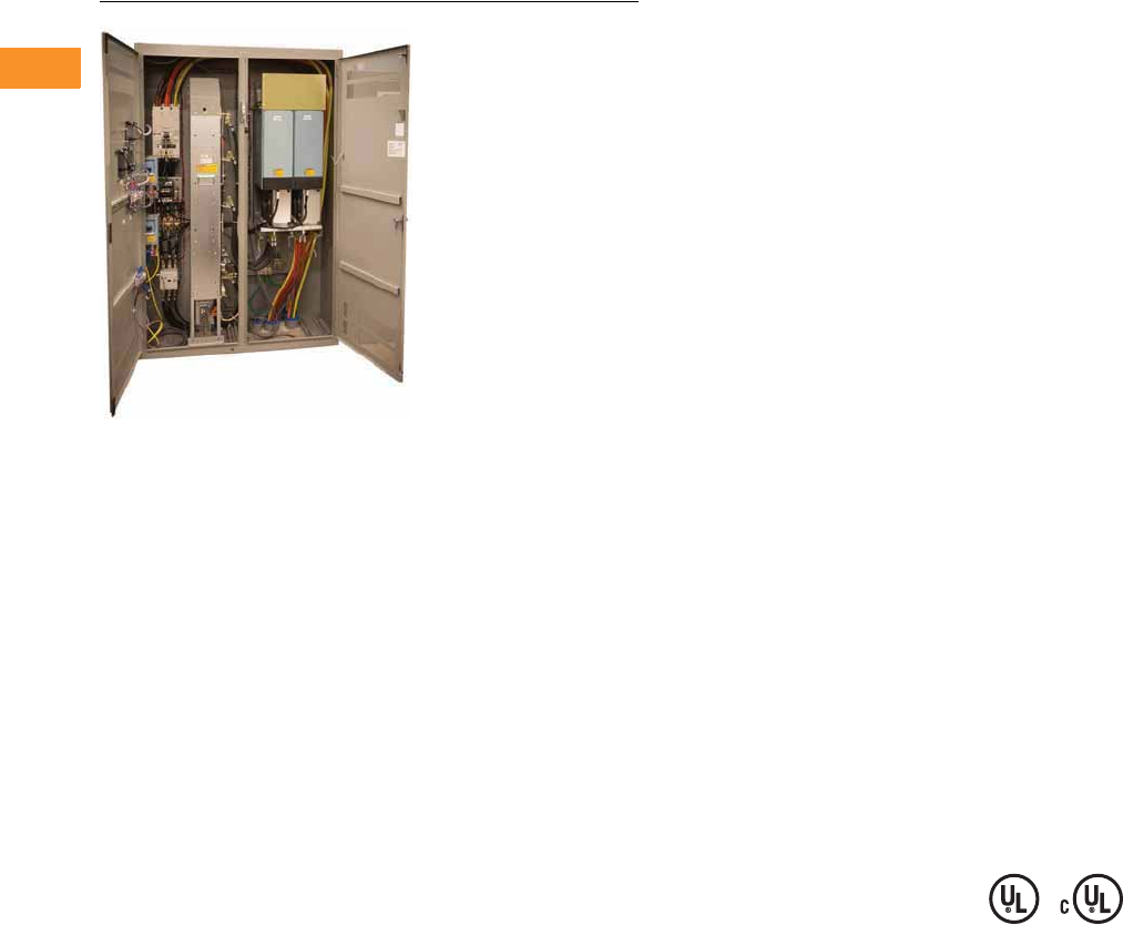
V6-T2-348 Volume 6—Solid-State Motor Control CA08100007E—February 2016 www.eaton.com
2
2
2
2
2
2
2
2
2
2
2
2
2
2
2
2
2
2
2
2
2
2
2
2
2
2
2
2
2
2
2.10
Adjustable Frequency Drives
Clean Power Drives
Enclosed Regenerative Drives
Contents
Description Page
Enclosed Passive Filtered Drives . . . . . . . . . . . . . V6-T2-262
CPX Enclosed 18-Pulse Drives . . . . . . . . . . . . . . . V6-T2-323
RGX Enclosed Regenerative Drives
Catalog Number Selection . . . . . . . . . . . . . . . . V6-T2-350
Product Selection . . . . . . . . . . . . . . . . . . . . . . . V6-T2-351
Options . . . . . . . . . . . . . . . . . . . . . . . . . . . . . . V6-T2-353
Technical Data and Specifications . . . . . . . . . . V6-T2-354
Dimensions . . . . . . . . . . . . . . . . . . . . . . . . . . . V6-T2-355
RGX Enclosed Regenerative Drives
Product Description
The RGX is an enclosed
solution to meet the needs of
customer's regenerative load
applications. It combines
Eaton’s comprehensive
family of DC common DC bus
drive products together with
the necessary circuit
protection and filtering to give
the customer an all-in-one
package. The RGX is available
in 480 V and 575 V
configurations in sizes up
through 900 hp.
Base Assembly Components
LCL Filter
An LCL filter is applied on
the line side of the of the
front end unit and integrated
into the enclosed solution.
This unit corrects the
voltage wave form to
return clean power back
to the power system.
Front-End Unit
The RGX uses the SPA drive
module, which is an active
bi-directional converter. This
converter allows power to
flow from the main voltage to
the DC bus and back from the
DC bus to the main voltage.
Inverter Unit
The RGX uses an SPI drive
module, which is a DC-fed
power inverter for the supply
and control of AC motors.
This inverter is specifically
designed to also allow
power to flow back to the
DC bus in a regenerative
load application.
Harmonic Distortion
Harmonics are distorted
electrical waveforms that
produce inefficiencies, which
could negatively affect your
system. These inefficiencies
can cause increased electrical
usage, power quality
problems, increased machine
wear and utility penalties.
The RGX takes control of
high harmonics and reduces
distortion to below the
IEEE 519 recommendations.
This minimal harmonic
output allows the RGX drive
to increase user energy
efficiency, extend system
life and reduce maintenance
costs.
Regeneration
The active front end module
gives the system power
regeneration capabilities.
Through the use of IGBT
bridge components, power
flows bi-directionally through
the drive unit and can be
converted back to an AC
voltage. Additionally, the LCL
filter corrects distorted
voltage wave form on the
output, thus producing clean
power with low harmonics
suitable to be returned to
utility line. With power
regeneration, the system
does not need large resistor
banks for ridding excess
energy. Eliminating resistors
increases energy savings
while simplifying design.
Energy Savings
The RGX provides exceptional
energy savings through the
use of regenerative braking.
Regenerative braking uses
the electric motor as a
generator when slowing, and
in turn, power is regenerated.
Recovered, clean power can
then be returned to the line or
utility for other uses.
Comparatively, regenerative
braking reduces energy
consumption greatly over
traditional mechanical and
resistive braking because
power is returned to the
line rather than released
as heat.
Application Description
The RGX Series encompasses
a wide range of application
solutions, including belt
conveyor, ball mill, extruder,
centrifugal pump, center
driver winder and a variety
of test stands.
Standards and Certifications
●UL
●cUL
●EN 61800-5-1 (2003)
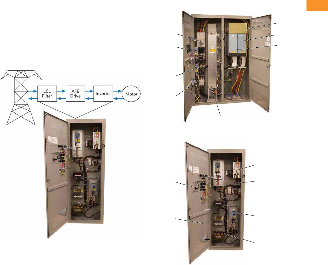
Volume 6—Solid-State Motor Control CA08100007E—February 2016 www.eaton.com V6-T2-349
2
2
2
2
2
2
2
2
2
2
2
2
2
2
2
2
2
2
2
2
2
2
2
2
2
2
2
2
2
2
2.10
Adjustable Frequency Drives
Clean Power Drives
Product Identification 1
Power Flow Diagram and Components
●Power flows from the utility through the LCL filter, active-front
end IGBT bridge and component inverter to the motor
●IGBT bridge components allow bi-directional current
conversion and flow for power regeneration needs
●
The active rectifier draws linear current off of the line, reducing
peak currents on the input and reducing THDI to 2–3%
●During regeneration, the LCL filter corrects the voltage wave
form to return clean power back to the utility
Power Flow Diagram and Components
RGX Size 9 Enclosure 2
RGX Size 3 Enclosure 3
Notes
1Product identification section serves as example products and does not encompass full
RGX product range.
2Size 9 enclosure example is used as a solution for the RGX product range of 100–250 hp.
3Size 3 enclosure example is used as a solution for a 30 hp RGX product.
Circuit
Breaker
Door-
Mounted
Keypad
Input Line
Fuses
Input
Contactor
Common
DC Bus
Inverter
Unit
Front End
Unit
LCL Filter
Circuit
Breaker
Door-
Mounted
Keypad
Input Line
Fuses
Auto
Transformer
Front End
Unit
LCL Filter
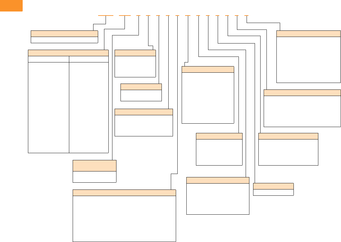
V6-T2-350 Volume 6—Solid-State Motor Control CA08100007E—February 2016 www.eaton.com
2
2
2
2
2
2
2
2
2
2
2
2
2
2
2
2
2
2
2
2
2
2
2
2
2
2
2
2
2
2
2.10
Adjustable Frequency Drives
Clean Power Drives
Catalog Number Selection
Enclosed Regenerative Drives 1
Notes
1Catalog number selection is for illustration purpose only and not to be used to create new catalog numbers.
2HMCP disconnect is standard when bypass is selected.
Product Family
RGX = Enclosed regenerative drives
Output
480 V 575 V
052 = 52 A – 40 hp
065 = 65 A – 50 hp
077 = 77 A – 60 hp
096 = 96 A – 75 hp
124 = 124 A – 100 hp
156 = 156 A – 125 hp
180 = 180 A – 150 hp
240 = 240 A – 200 hp
302 = 302 A – 250 hp
361 = 361 A – 300 hp
414 = 414 A – 350 hp
477 = 477 A – 400 hp
590 = 590 A – 500 hp
650 = 650 A – 600 hp
730 = 730 A – 650 hp
820 = 820 A – 750 hp
920 = 920 A – 800 hp
H10 = 1030 A – 900 hp
032 = 32 A – 30 hp
041 = 41 A – 40 hp
052 = 52 A – 50 hp
062 = 62 A – 60 hp
077 = 77 A – 75 hp
099 = 99 A – 100 hp
125 = 125 A – 125 hp
144 = 144 A – 150 hp
192 = 192 A – 200 hp
242 = 242 A – 250 hp
289 = 289 A – 300 hp
336 = 336 A – 350 hp
382 = 382 A – 400 hp
412 = 412 A – 450 hp
472 = 472 A – 500 hp
590 = 590 A – 600 hp
650 = 650 A – 650 hp
750 = 750 A – 750 hp
Input Phasing/
Voltage
4 = Three-phase, 480 V
5 = Three-phase, 575 V
Brake/Overload
E = No brake chopper /
low overload
G = No brake chopper /
high overload
Enclosure
1 = Type 1
6 = Type 1 filtered
Power Disconnect Options
0 = None
1 = HMCP disconnect 2
2 = Circuit breaker
8 = Circuit breaker/SPD
Bypass Options
0 = None
1 = Manual HOA bypass
2 = Manual HOA bypass/isolation fusing
4 = Manual HOA bypass/isolation fusing/SPD
7 = Manual HOA bypass/SPD
H = Manual HOA RVSS bypass
J = Manual HOA RVSS bypass/isolation fusing
L = Manual HOA RVSS bypass/isolation fusing/SPD
P = Manual HOA RVSS bypass/SPD
Control Options
0 =None
2 = Start-stop pushbutton
A = HOA switch (6)
C = Start-stop pushbutton
with HOA switch (6)
Output Power Options
0 =None
A = Output contactor
B = 3% output reactor
C = MotoRX
D = Traditional dV/dt filter
E = 3% output reactor /
output contactor
F = MotoRX/output contactor
G = Traditional dV/dt /
output contactor
Light Options
0 = None
1 = Non-bypass—22 mm power on,
run, fault indicator lights
2 = Bypass—22 mm power on,
VFD run, fault, bypass run
indicator lights
Enclosure Options
0 = None
Option Boards 2
0 = No option
1 =
3 x DI, 3 x DO, 1 thermistor,
24 Vdc/EXT
2 = 1 x AI, 2 x AO
(isolated to control board)
3 = 3 x relay dry contact
(2NO + 1NO/NC)
4 = 3 x PT100 RTD thermistor input
5 = 6 DI 240 Vac input
Option Boards 1
0 = No option
1 = 3 x DI, 3 x DO, 1 thermistor, 24 Vdc/EXT
2 = 1 x AI, 2 x AO (isolated to control board)
3 = 3 x relay dry contact (2NO + 1NO/NC)
4 = 3 x PT100 RTD thermistor input
5 = 6 DI 240 Vac input
Com Options
0 = No option
1 = PROFIBUS-DP
2 =LonWorks
3 = CANopen (slave)
4 = DeviceNet
RGX 052 4 E 1 1 1 A 0 0 0 1 1 1
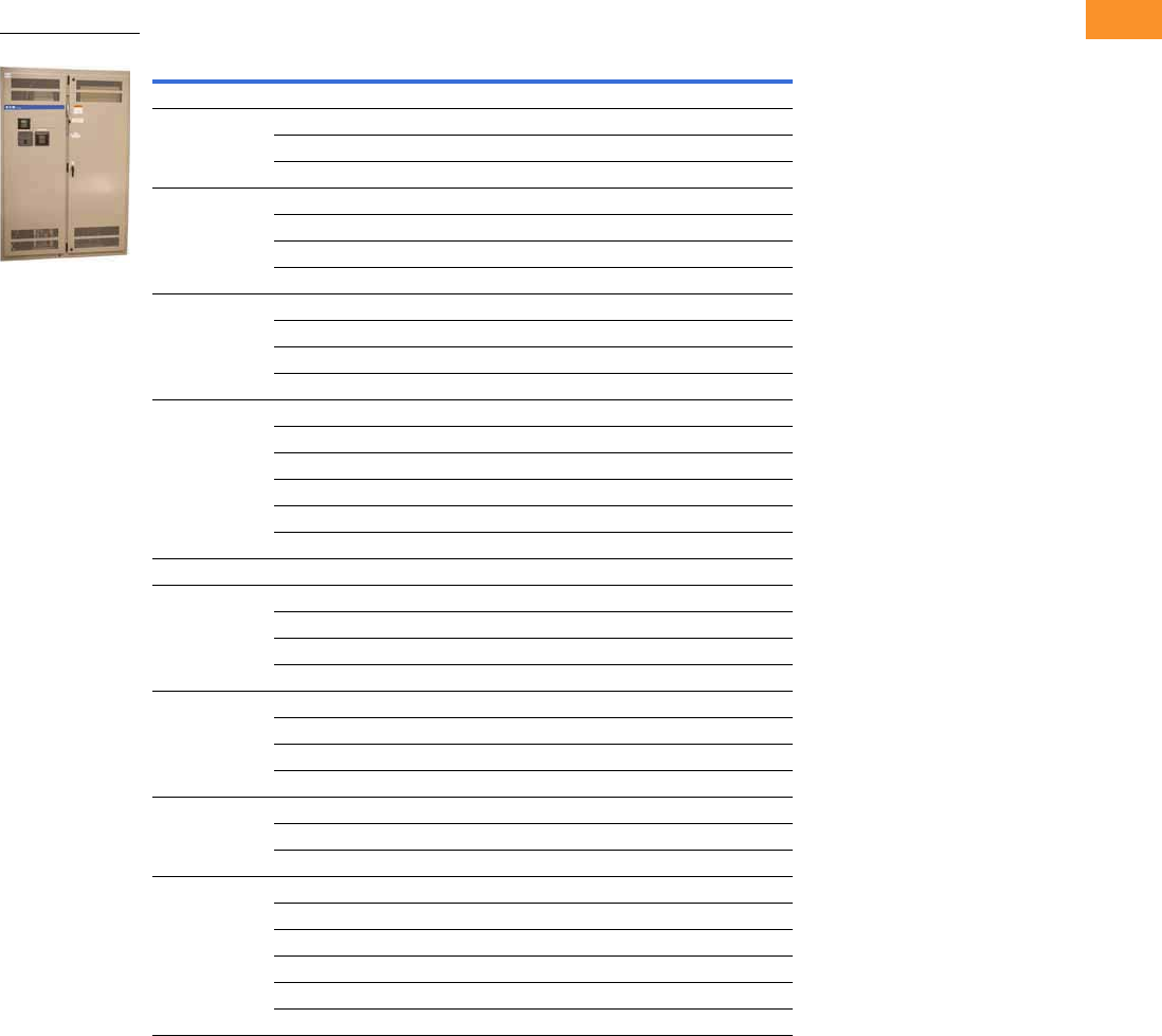
Volume 6—Solid-State Motor Control CA08100007E—February 2016 www.eaton.com V6-T2-351
2
2
2
2
2
2
2
2
2
2
2
2
2
2
2
2
2
2
2
2
2
2
2
2
2
2
2
2
2
2
2.10
Adjustable Frequency Drives
Clean Power Drives
Product Selection
480 V Drives
RGX 480 V—NEMA Type 1/IP21
Note
1 “_” denotes that catalog numbers are incomplete, base catalog numbers.
Enclosure Size hp Current (A) Frame Size Catalog Number 1
Low Overload Drive and Enclosure (VT)
7 50657 RGX0654E1_
60 77 7 RGX0774E1_
75 96 7 RGX0964E1_
51001248RGX1244E1_
125 156 9 RGX1564E1_
150 180 9 RGX1804E1_
200 240 9 RGX2404E1_
82503029RGX3024E1_
300 361 10 RGX3614E1_
350 414 10 RGX4144E1_
400 477 10 RGX4774E1_
Consult factory 500 590 12 RGX5904E1_
600 650 12 RGX6504E1_
650 730 12 RGX7304E1_
750 820 12 RGX8204E1_
800 920 12 RGX9204E1_
900 1030 12 RGX10304E1_
High Overload Drive and Enclosure (CT)
740
52 7 RGX0524G1_
50 65 7 RGX0654G1_
60 77 7 RGX0774G1_
75 96 8 RGX0964G1_
51001249RGX1244G1_
125 156 9 RGX1564G1_
150 180 9 RGX1804G1_
200 240 9 RGX2404G1_
825030010RGX3004G1_
300 361 10 RGX3614G1_
350 414 10 RGX4144G1_
Consult factory 450 515 12 RGX5154G1_
500 590 12 RGX5904G1_
600 650 12 RGX6504G1_
650 730 12 RGX7304G1_
750 820 12 RGX8204G1_
800 920 12 RGX9204G1_
RGX Drive
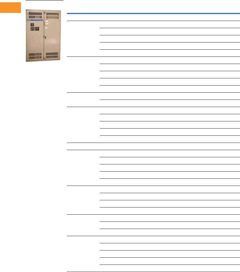
V6-T2-352 Volume 6—Solid-State Motor Control CA08100007E—February 2016 www.eaton.com
2
2
2
2
2
2
2
2
2
2
2
2
2
2
2
2
2
2
2
2
2
2
2
2
2
2
2
2
2
2
2.10
Adjustable Frequency Drives
Clean Power Drives
575 V Drives
RGX 575 V—NEMA Type 1/IP21
Note
1 “_” denotes that catalog numbers are incomplete, base catalog numbers.
Enclosure Size hp Current (A) Frame Size Catalog Number 1
Low Overload Drive and Enclosure (VT)
740
41 7 RGX0415E1_
50 52 7 RGX0525E1_
50 62 8 RGX0625E1_
75 77 8 RGX0775E1_
100 99 8 RGX0995E1_
5125
125 9 RGX1255E1_
150 144 9 RGX1445E1_
150 192 9 RGX1925E1_
200 242 9 RGX2425E1_
250 289 10 RGX2895E1_
8300
336 10 RGX3365E1_
400 382 10 RGX3825E1_
Consult factory 450 412 12 RGX4125E1_
500 472 12 RGX4725E1_
600 590 12 RGX5905E1_
650 650 12 RGX6505E1_
750 750 12 RGX7505E1_
High Overload Drive and Enclosure (CT)
7300327RGX0325G1_
40 041 7 RGX0415G1_
50 052 8 RGX0525G1_
60 062 8 RGX0625G1_
75 077 8 RGX0775G1_
51000999RGX0995G1_
125 125 9 RGX1255G1_
150 144 9 RGX1445G1_
150 170 9 RGX1705G1_
820019210RGX1925G1_
250 242 10 RGX2425G1_
300 289 10 RGX2895G1_
Consult factory 400 382 12 RGX3825G1_
450 412 12 RGX4125G1_
500 472 12 RGX4725G1_
600 590 12 RGX5905G1_
650 650 12 RGX6505G1_
RGX Drive
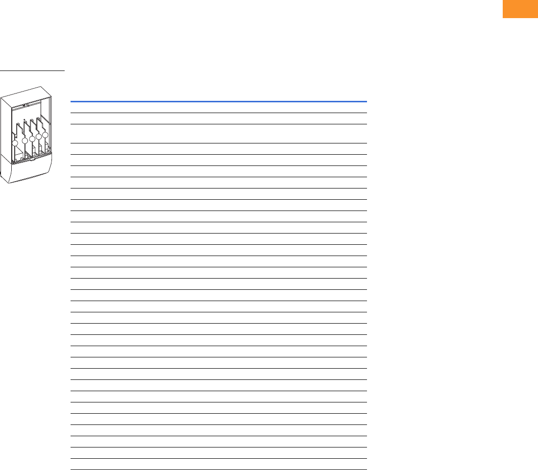
Volume 6—Solid-State Motor Control CA08100007E—February 2016 www.eaton.com V6-T2-353
2
2
2
2
2
2
2
2
2
2
2
2
2
2
2
2
2
2
2
2
2
2
2
2
2
2
2
2
2
2
2.10
Adjustable Frequency Drives
Clean Power Drives
Options
RGX Series Option Board Kits
The RGX Series drives can accommodate a wide selection of expander and adapter option boards
to customize the drive for your application needs. The drive’s control unit is designed to accept a
total of five option boards.
The RGX Series factory installed standard board configuration includes an A9 I/O board and an
A2 relay output board, which are installed in slots A and B.
Option Board Kits
Notes
1 AI = Analog Input; AO = Analog Output, DI = Digital Input, DO = Digital Output, RO = Relay Output
2 Option card must be installed in one of the slots listed for that card. Slot indicated in bold is the preferred location.
3 OPTC2 is a multi-protocol option card.
Option Kit Description 1
Allowed Slot
Locations 2
Field Installed
Catalog Number
Standard I/O Cards
2 RO (NC-NO) B OPTA2
6 DI, 1 DO, 2 AI, 1AO, 1 +10 Vdc ref,
2 ext +24 Vdc/EXT +24 Vdc
AOPTA9
Extended I/O Cards
2 RO, therm B OPTA3
Encoder low volt +5 V/15 V 24 V C OPTA4
Encoder high volt +15 V/24 V C OPTA5
Double encoder C OPTA7
6 DI, 1 DO, 2 AI, 1 AO A OPTA8
3 DI (encoder 10–24 V), out +15 V/+24 V, 2 DO (pulse+direction) C OPTAE
6 DI, 1 ext +24 Vdc/EXT +24 Vdc B, C, D, E OPTB1
1 RO (NC-NO), 1 RO (NO), 1 therm B, C, D, E OPTB2
1 AI (mA isolated), 2 AO (mA isolated), 1 ext +24 Vdc/EXT +24 Vdc B, C, D, E OPTB4
3 RO (NO) B, C, D, E OPTB5
1 ext +24 Vdc/EXT +24 Vdc, 3 Pt100 B, C, D, E OPTB8
1 RO (NO), 5 DI 42–240 Vac input B, C, D, E OPTB9
SPI, absolute encoder C OPTBB
Communication Cards 3
Modbus D, E OPTC2
Johnson Controls N2 D, E OPTC2
Modbus TCP D, E OPTCI
BACnet D, E OPTCJ
EtherNet/IP D, E OPTCQ
PROFIBUS-DP D, E OPTC3
LonWorks D, E OPTC4
PROFIBUS-DP (D9 connector) D, E OPTC5
CANopen (slave) D, E OPTC6
DeviceNet D, E OPTC7
Modbus (D9 type connector) D, E OPTC8
Adapter D, EOPTD1
Adapter D, EOPTD2V
RS-232 with D9 connection D, EOPTD3
ABCDE
Option Boards

V6-T2-354 Volume 6—Solid-State Motor Control CA08100007E—February 2016 www.eaton.com
2
2
2
2
2
2
2
2
2
2
2
2
2
2
2
2
2
2
2
2
2
2
2
2
2
2
2
2
2
2
2.10
Adjustable Frequency Drives
Clean Power Drives
Technical Data and Specifications
Enclosed Regenerative Drives
Description Specification
Supply Connection
Input voltage Uin (AC) front end modules 380–500 Vac/525–690 Vac –10% to +10%
Input voltage Uin (DC) inverter 465–800 Vdc/640–1100 Vdc –0% to 0%, the waviness of the inverter supply voltage,
formed in rectification of the electric network’s alternating voltage in basic frequency,
must be less than 50 V peak-to-peak
Output voltage Uout (AC) inverter 3 ~ 0–Uin/1.4
Output voltage Uout (DC) active front end module 1.35 x Uin (factory default)
Output voltage Uout (DC) non-regenerative front end module 1.35 x Uin
Ambient Conditions
Ambient operating temperature 14 (no frost) to +122 °F (–10 °C to +50 °C): IH
14 (no frost) to +104 °F (–10 °C to +40 °C): IL
Storage temperature –40 °F to +158 °F (–40 °C to +70 °C)
Relative humidity 0 to 95% RH, non-condensing, non-corrosive, no dripping water
Air quality
Chemical vapors IEC 721-3-3, unit in operation, class 3C2
Mechanical particles IEC 721-3-3, unit in operation, class 3S2
Altitude 100% load capacity (no derating) up to 1000 m
1% derating for each 100 m above 1000 m; max. 3000 m
Vibration 5–150 Hz
EN50178/EN60068-2-6 Displacement amplitude 0.25 mm (peak) at 3–15.8 Hz
Max. acceleration amplitude 1 G at 15.8–150 Hz
Shock
EN50178, EN60068-2-27
UPS Drop Test (for applicable UPS weights)
Storage and shipping: max. 15 G, 11 ms (in package)
Cooling capacity required Approximately 2%
Cooling air required FR4 41 cfm, FR6 250 cfm, FR7 250 cfm, FR8 383 cfm
FI9 677 cfm, FI10 824 cfm, FI12 1648 cfm, FI13 2472 cfm
Unit enclosure class FR4–FR7 NEMA Type 1/IP21; FR8, FI9–FI14 chassis (IP00)
EMC (at fault settings)
Immunity Fulfill all EMC immunity requirements
Safety
Approvals UL, cUL, EN 61800-5-1 (2003), see unit nameplate for more detailed approvals
Control Connections
Analog input voltage 0–10 V, Ri = 200 kohms, (–10 V to +10 V joystick control)
Resolution 0.1%, accuracy ±1%
Analog input current 0(4)–20 mA, Ri = 250 ohms differential
Digital inputs 6, positive or negative logic; 18–30 Vdc
Auxiliary voltage +24 V, ±15%, max. 250 mA
Output reference voltage +10 V, +3%, max. load 10 mA
Analog output 0(4)–20 mA; RL max. 500 ohms; resolution 10 bits
Accuracy ±2%
Digital outputs Open collector output, 50 mA/48 V
Relay outputs 2 programmable change-over relay outputs
Switching capacity: 24 Vdc/8 A, 250 Vac/8 A, 125 Vdc/0.4 A
Min. switching load: 5 V/10 mA
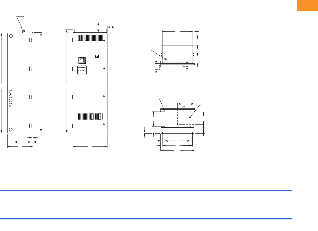
Volume 6—Solid-State Motor Control CA08100007E—February 2016 www.eaton.com V6-T2-355
2
2
2
2
2
2
2
2
2
2
2
2
2
2
2
2
2
2
2
2
2
2
2
2
2
2
2
2
2
2
2.10
Adjustable Frequency Drives
Clean Power Drives
Dimensions
Approximate Dimensions in Inches (mm)
Enclosure Size 3
For reference only, dimensions are subject to change.
Wide High Deep Mounting Door Height Min. Air Space
ABCDD1EE1FGG1H JK
26.4 (671) 77.0 (1956) 19.4 (493) 19.5 (495) 3.3 (83) 23.0 (584) 1.5 (38) 11.7 (298) 5.5 (140) 0.9 (24) 76.4 (1939) 4.0 (102) 3.0 (76)
Max. Approx.
Shipping Weight
Lbs (kg)
Cable Entry Door Clearance CB Handle
L M N P R S T U V W RR SS TT UU VV
5.3
(133)
23.4
(594)
10.0
(254)
1.3
(32)
12.9
(328)
26.4
(669)
1.5
(38)
8.0
(203)
4.8
(121)
6.8
(173)
79.5
(2018)
13.40
(340)
0.8
(19)
1.3
(32)
26.0
(660)
690 (313)
0.44 (11.2)
Mounting Holes
6 Places
D
D1
E1 E
VV
R
MP
0.50 (12.7)
Lifting Eyes
2 Places
H
C A
UU
SS TT
B
S
F
G
G1
V
U
L
T
Top View
Bottom View
N
W
JK
RR
NEMA Type 1/IP21
For Cable
Entry
For Cable
Entry
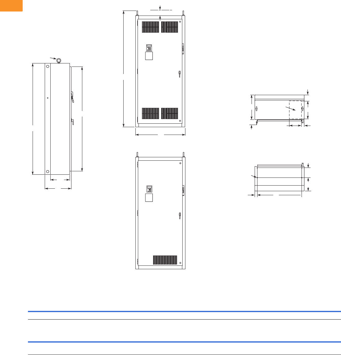
V6-T2-356 Volume 6—Solid-State Motor Control CA08100007E—February 2016 www.eaton.com
2
2
2
2
2
2
2
2
2
2
2
2
2
2
2
2
2
2
2
2
2
2
2
2
2
2
2
2
2
2
2.10
Adjustable Frequency Drives
Clean Power Drives
Approximate Dimensions in Inches (mm)
Enclosure Size 5
For reference only, dimensions are subject to change.
Wide High Deep Mounting Door Height Min. Air Space
ABCDD1EE1FGG1H JK
40.0 (1016) 90.0 (2286) 21.3 (541) 36.0 (914) 2.0 (51) — — 8.0 (203) 10.8 (273) — 84.4 (2143) 4.0 (102) —
Max. Approx.
Shipping Weight
Lbs (kg)
Cable Entry Door Clearance
L M N P R S T U V W RR SS TT UU VV
15.0
(381)
10.0
(254)
4.8
(122)
2.0
(51)
—36.3
(921)
20.0
(508)
——— 94.0
(2387)
15.5
(394)
— — — 1275 (579)
M
Lifting Eyes
(2 Places)
B
H
C
SS
Side View
RR
J
A
Front View
NEMA Type 1/IP21
Front View
NEMA Type 12/IP54
S
T
0.56 (14.2) Dia.
Mounting
Holes
(4 Places)
D1 D
G
F
N
L
For Cable
Entry
P
Top View
Bottom View
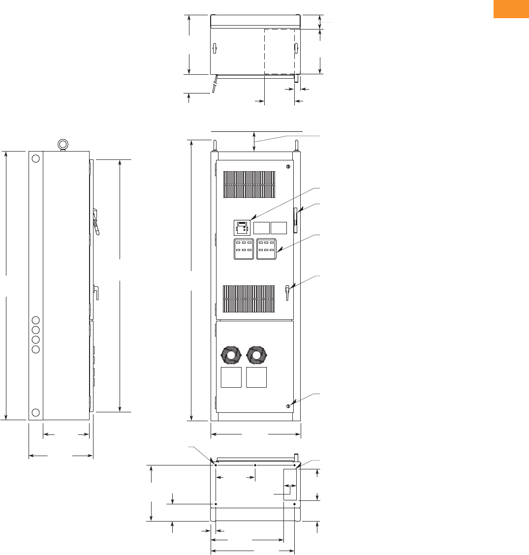
Volume 6—Solid-State Motor Control CA08100007E—February 2016 www.eaton.com V6-T2-357
2
2
2
2
2
2
2
2
2
2
2
2
2
2
2
2
2
2
2
2
2
2
2
2
2
2
2
2
2
2
2.10
Adjustable Frequency Drives
Clean Power Drives
Approximate Dimensions in Inches (mm)
Enclosure Size 7
Side View
26.25
(666.8)
ø0.56 (ø14.2) Dia.
Mounting Holes
(ve places)
90.00
(2286.0)
84.37
(2143.0)
15.50
(393.7)
21.50
(546.1)
93.92
(2385.6)
30.00
(762.0)
4.00 (101.6) Minimum
Free Air Space Required
Keypad
Flanged Disconnect Supplied
With Circuit Breaker
When Specied
Operator Elements
When Specied, Mounted
On These Panels
Door Handle
(key-lock optional)
Quarter Turn Latch
(three places)
Bottom View
18.75
(476.3)
Opening For Bottom
Cable Entry
7. 0 0
(177.8)
5.75
(146.1)
14.90
(378.5)
1.75
(44.5) 24.45
(621.0) 28.05
(712.5)
10.50
(266.7)
4.25
(107.9)
Top View
Exhaust Air
For
Cable
Entry
Hinged
Side Door
Clearance at 90º
20.00
(508.0)
4.79
(121.7)
15.00
(381.0)
2.00
(50.8)
10.00
(254.0)
Finish: Enclosure—ANSI 61 Gray (light)
Material: Enclosure and Backplate—
12 ga. = 0.1046 Cold Rolled Steel
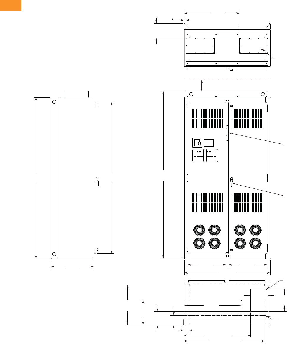
V6-T2-358 Volume 6—Solid-State Motor Control CA08100007E—February 2016 www.eaton.com
2
2
2
2
2
2
2
2
2
2
2
2
2
2
2
2
2
2
2
2
2
2
2
2
2
2
2
2
2
2
2.10
Adjustable Frequency Drives
Clean Power Drives
Approximate Dimensions in Inches (mm)
Enclosure Size 8
Bottom View
For Bottom
Cable Entry
ø0.56
(ø14.2)
(ve places)
90.00
(2286.0)
84.37
(2143.0)
24.00
(609.6)
31.00
(787.4)
1.25
(31.8)
8.25
(209.6)
For Top
Cable Entry
(two places)
Top View
Side View
93.50
(2374.9)
3.01 (76.5)
32.20
(817.9)
37.47 (951.7)
45.22 (1148.6)
22.47
(570.7) 13.97
(354.8) 7.73
(196.3) 5.48
(139.2)
9.50
(241.3) 12.50
(317.5)
21.45
(544.8) 48.00
(1219.2)
21.31
(541.3)
Finish: Enclosure—ANSI 61 Gray (light)
Material: Enclosure and Backplate—
12 ga. = 0.1046 Cold Rolled Steel
4.00 (101.6) Minimum
Free Air Space Required
Door Handle
(key-lock optional)
Drive
Circuit Breaker
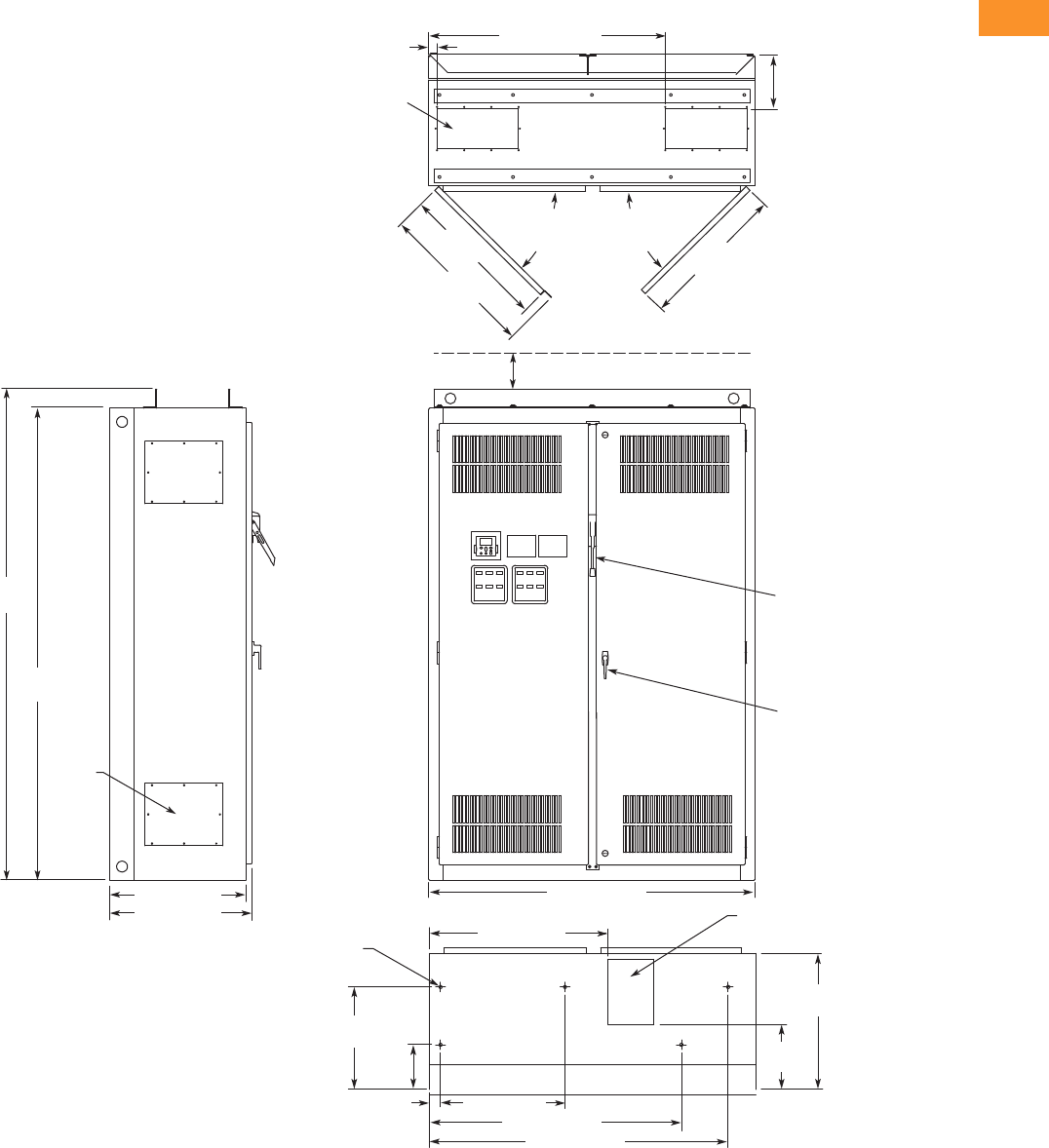
Volume 6—Solid-State Motor Control CA08100007E—February 2016 www.eaton.com V6-T2-359
2
2
2
2
2
2
2
2
2
2
2
2
2
2
2
2
2
2
2
2
2
2
2
2
2
2
2
2
2
2
2.10
Adjustable Frequency Drives
Clean Power Drives
Approximate Dimensions in Inches (mm)
Enclosure Size 9
24.00 (609.6)
25.14 (638.6)
8.75
(222.3)
Top View
1.50 (38.1) 43.50 (1104.9)
90.00
(2286.0)
93.50
(2374.9)
4.00 (101.6) Minimum
Free Air Space Required
60.00 (1524.0)
Front View
Bottom View
Side View
7.46 x 15.00
(189.5 x 381.0)
Access in Top
(two places)
8.50 x 12.00 (215.9 x 304.8)
Bottom Access
ø0.56 (ø14.2) Dia.
Mounting Hole
(ve places)
27.06
(687.3)
27.36
(694.9)
90 Max.
Door
Opening
29.05
(737.9)
11.93
(303.0)
25.00
(635.0)
18.84
(478.5)
8.20
(208.3)
2.00 (50.8) 22.90 (581.7)
32.72 (831.1)
46.30 (1176.0)
54.90 (1394.5)
Door Handle
(key-lock optional)
Access
Plate
(4 places)
90 Max.
Door
Opening
Finish: Enclosure—ANSI 61 Gray (light)
Material: Enclosure and Backplate—
12 ga. = 0.1046 Cold Rolled Steel
Drive
Circuit Breaker
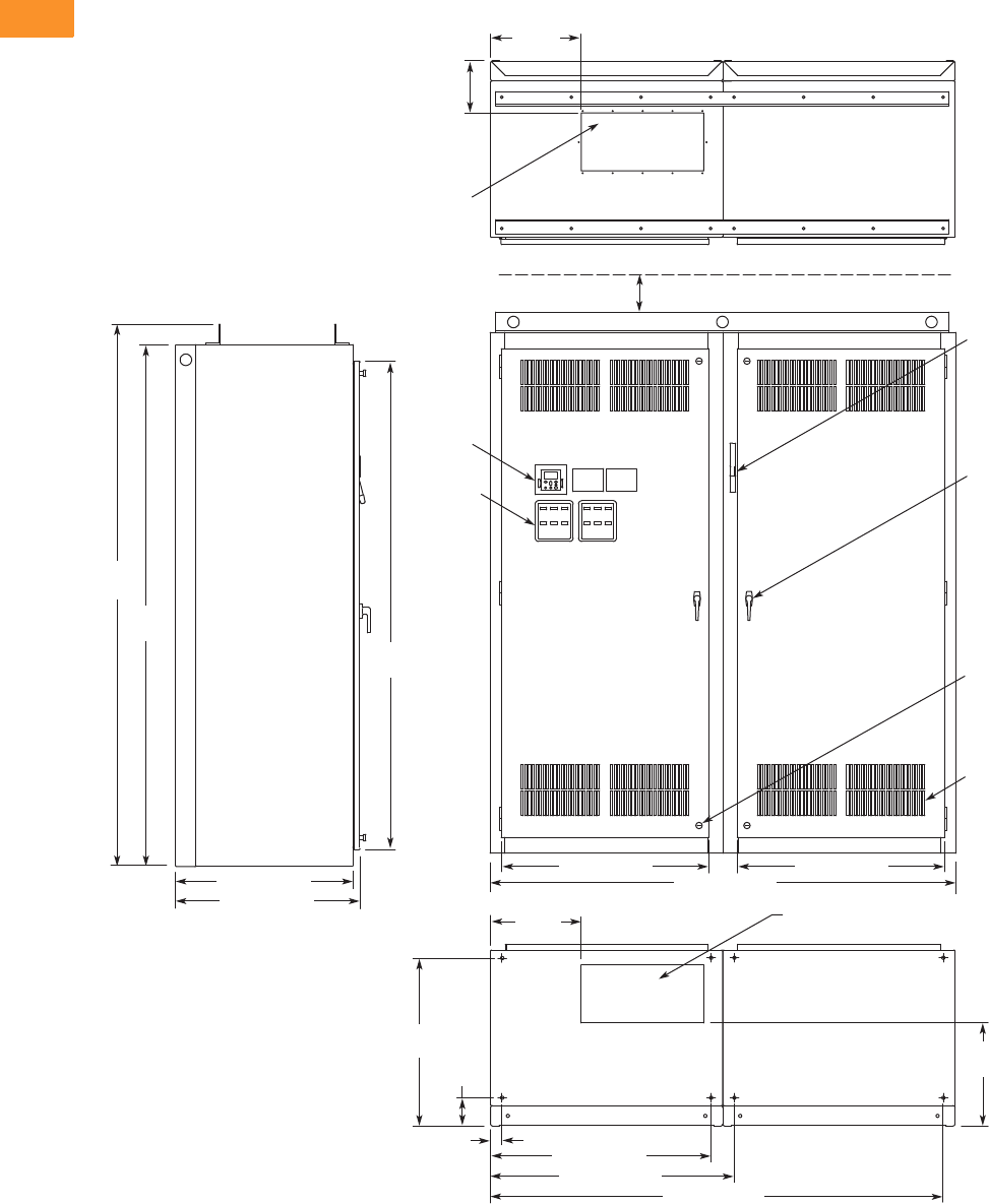
V6-T2-360 Volume 6—Solid-State Motor Control CA08100007E—February 2016 www.eaton.com
2
2
2
2
2
2
2
2
2
2
2
2
2
2
2
2
2
2
2
2
2
2
2
2
2
2
2
2
2
2
2.10
Adjustable Frequency Drives
Clean Power Drives
Approximate Dimensions in Inches (mm)
Enclosure Size 10
30.50 (774.7)
31.75 (806.5)
9.03
(229.4)
Top View
15.63
(397.0)
90.00
(2286.0)
84.37
(2143.0)
93.50
(2374.9)
4.00 (101.6) Minimum
Free Air Space Required
35.75 (908.1) 35.75 (908.1)
80.00 (2032.0)
Front View
Side View
21.00 x 10.00
(533.4 x 254.0)
Access in Top
21.00 x 10.00 (533.4 x 254.0)
Bottom Access
17.79
(451.9)
29.04
(737.6)
4.87
(123.7)
2.00 (50.8)
15.64
(397.3)
38.00 (965.2)
42.02 (1067.3)
Bottom View
78.02 (1981.7)
Finish: Enclosure – ANSI 61 Gray (light)
Material: Enclosure and Backplate—
12 ga. = 0.1046 Cold Rolled Steel
Operator
Elements
When
Specied,
Mounted
on These
Panels
Keypad
Door Handle
(key-lock optional)
Intake Ventilating
Slots (ltered on
Type 12)
Quarter-Turn
Latch (four places)
Flanged
Disconnect
Supplied with
Circuit Breaker
When Specied
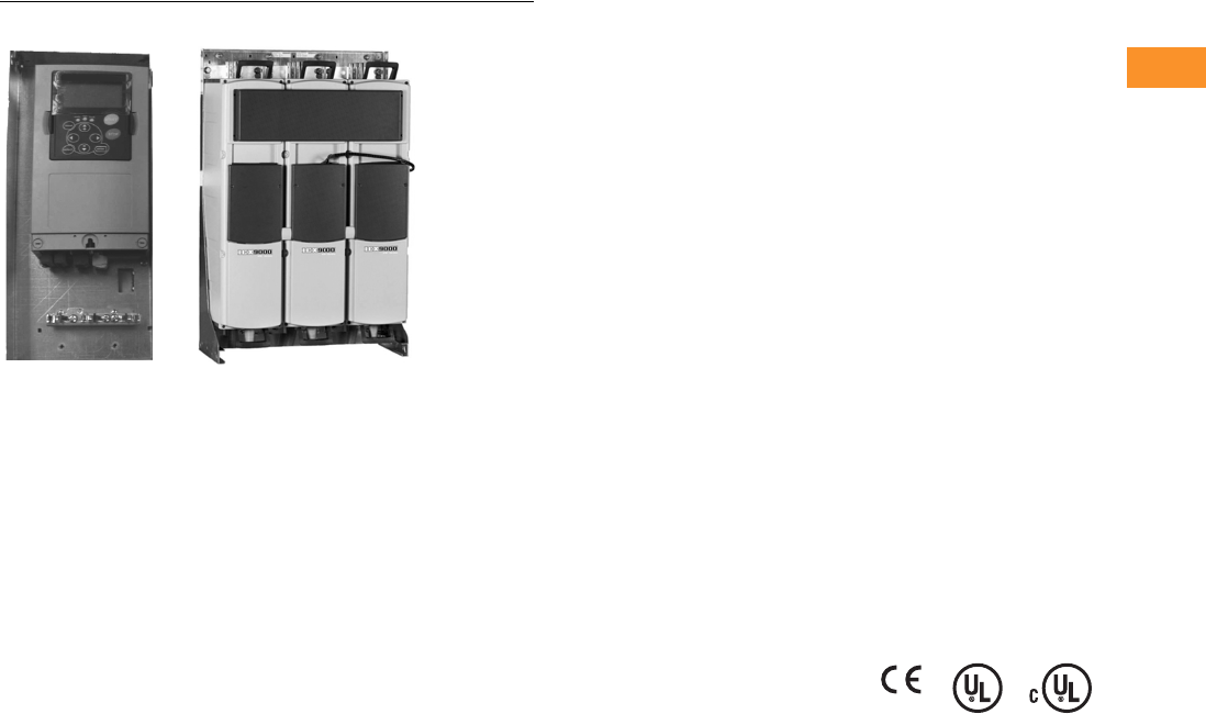
Volume 6—Solid-State Motor Control CA08100007E—February 2016 www.eaton.com V6-T2-361
2
2
2
2
2
2
2
2
2
2
2
2
2
2
2
2
2
2
2
2
2
2
2
2
2
2
2
2
2
2
2.11
Adjustable Frequency Drives
LCX Liquid Cooled Drives
LCX Liquid Cooled Adjustable Frequency Drives
Contents
Description Page
LCX Drives
Catalog Number Selection . . . . . . . . . . . . . . . . V6-T2-362
Product Selection . . . . . . . . . . . . . . . . . . . . . . . V6-T2-363
Options . . . . . . . . . . . . . . . . . . . . . . . . . . . . . . . V6-T2-366
Technical Data and Specifications . . . . . . . . . . V6-T2-367
Wiring Diagrams . . . . . . . . . . . . . . . . . . . . . . . . V6-T2-368
Dimensions . . . . . . . . . . . . . . . . . . . . . . . . . . . V6-T2-370
Product Description
The LCX Liquid Cooled Drive
family continues Eaton’s
tradition of providing state-of-
the-industry products, by
taking advantage of liquid
cooling technology in lieu of
air-cooling techniques.
The LCX drives are liquid-
cooled products that utilize
potable water or a water-
glycol mixture as a cooling
medium.
Features and Benefits
●Compact size and low
heat transfer rates allow
enclosure size to be greatly
reduced, which is especially
beneficial in UL Type 4X
applications
●Design is modular, with
control and power modules
independent of each other.
Connection between
power and control modules
can be direct or extended
via a fiber optic cable
●Same reliable control
module and operating
system as the SPX
air-cooled drives
●CE mark ensures
compliance with the
Electromagnetic
Compatibility Directive
(EMC) and the Low Voltage
Directive (LVD)
●Reliable drive with over
500,000 hours MTBF
based on MIL 217
●Currently supports
DeviceNet, PROFIBUS-DP,
Modbus RTU and Modbus
TCP communication
protocols
●Separately mounted line
reactor included with AC
fed models
Standards and
Certifications
●UL
●cUL
●CE
●IEC
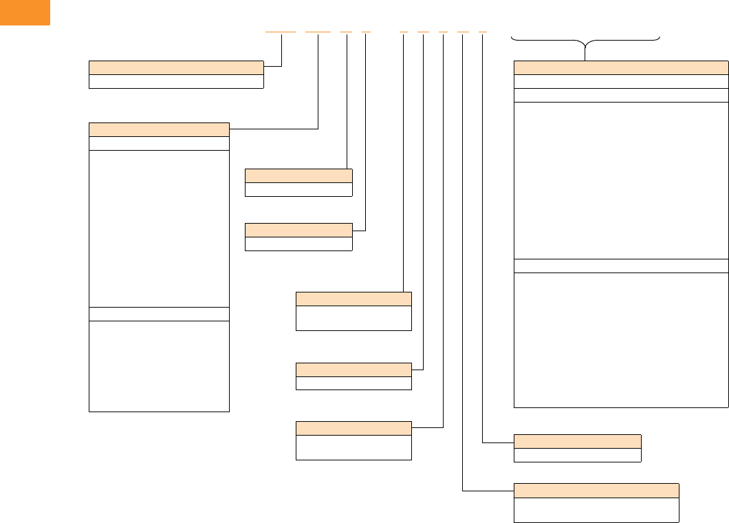
V6-T2-362 Volume 6—Solid-State Motor Control CA08100007E—February 2016 www.eaton.com
2
2
2
2
2
2
2
2
2
2
2
2
2
2
2
2
2
2
2
2
2
2
2
2
2
2
2
2
2
2
2.11
Adjustable Frequency Drives
LCX Liquid Cooled Drives
Catalog Number Selection
LCX Liquid Cooled Adjustable Frequency Drives
Note
1Brake chopper is only available in 480 V CH3 drives.
LCX 016 A 0 –4A 3 B 2 __ __ __
Keypad
A = Alphanumeric
Software Series
A = Standard
Brake Chopper Options 1
N = No brake chopper circuit
B = Internal brake chopper
Input Options
3 = Three-phase, EMC T
7 = DC Input
Enclosure Rating
0 = Open chassis
Product Family
LCX = High performance, liquid-cooled drive
Board Modifications
2 = Varnished boards
Voltage Rating
4 = 380–500 V
5 = 520–690 V
Options
List options in alphabetical order.
Extended I/O Card Options
A3 = 2 RO, therm
A4 = Encoder low volt +5 V/15 V/24 V
A5 = Encoder high volt +15 V/24 V
A7 = Dual encoder +15 V/24 V
A8 = 6 DI, 1 DO, 2 AI, 1 AO
AE = Encoder with 2 DOs
B1 = 6 DI, 1 ext +24 Vdc/EXT +24 Vdc
B2 = 1 RO (NC-NO), 1 RO (NO), 1 therm
B4 = 1 AI (mA isolated), 2 AO (mA isolated),
1 ext +24 Vdc/EXT + 24 Vdc
B5 = 3 RO (NO)
B8 = 1 ext +24 Vdc/EXT +24 Vdc, 3 Pt100
B9 = 1 RO (NO), 5 DI 42–240 Vac input
BB = SPI, absolute encoder
Communication Cards
CA = Johnson Controls N2
CI = Modbus TCP
C2 = Modbus
C3 = PROFIBUS DP
C4 = LonWorks
C5 = PROFIBUS DP (D9 Connector)
C6 = CANopen (Slave)
C7 = DeviceNet
C8 = Modbus (D9 Type Connector)
D1 = Adapter
D2 = Adapter
D3 = RS-232 with D9 Connection
Current Rating
480 V
016 = 16 A
022 = 22 A
031 = 31 A
038 = 38 A
045 = 45 A
061 = 61 A
072 = 72 A
087 = 87 A
105 = 105 A
140 = 140 A
168 = 168 A
205 = 205 A
261 = 261 A
300 = 300 A
385 = 385 A
460 = 460 A
520 = 520 A
590 = 590 A
650 = 650 A
730 = 730 A
820 = 820 A
920 = 920 A
H10 = 1030 A
H11 = 1150 A
H13 = 1370 A
H16 = 1640 A
H20 = 2060 A
H23 = 2300 A
690 V
170 = 170 A
208 = 208 A
261 = 261 A
325 = 325 A
385 = 385 A
416 = 416 A
460 = 460 A
502 = 502 A
590 = 590 A
650 = 650 A
750 = 750 A
820 = 820 A
H10 = 1030 A
H11 = 1180 A
H13 = 1300 A
H15 = 1500 A
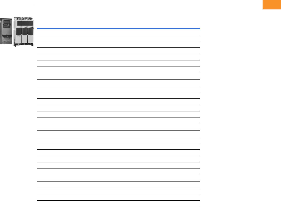
Volume 6—Solid-State Motor Control CA08100007E—February 2016 www.eaton.com V6-T2-363
2
2
2
2
2
2
2
2
2
2
2
2
2
2
2
2
2
2
2
2
2
2
2
2
2
2
2
2
2
2
2.11
Adjustable Frequency Drives
LCX Liquid Cooled Drives
Product Selection
380–500 Vac Liquid Cooled Drives
Motor Output
Current
Thermal, Ith (A) IL (A) IH (A) kW Chassis Catalog Number
16 15 11 7.5 CH3 LCX016A0-4A3N2
22 20 15 11 CH3 LCX022A0-4A3N2
31 28 21 15 CH3 LCX031A0-4A3N2
38 35 25 18.5 CH3 LCX038A0-4A3N2
45 41 30 22 CH3 LCX045A0-4A3N2
61 55 41 30 CH3 LCX061A0-4A3N2
72 65 48 37 CH4 LCX072A0-4A3N2
87 79 58 45 CH4 LCX087A0-4A3N2
105 957055CH4LCX105A0-4A3N2
140 127 93 75 CH4 LCX140A0-4A3N2
168 153 112 90 CH5 LCX168A0-4A3N2
205 186 137 110 CH5 LCX205A0-4A3N2
261 237 174 132 CH5 LCX261A0-4A3N2
300 273 200 160 CH61 LCX300A0-4A3N2
385 350 257 200 CH61 LCX385A0-4A3N2
460 418 307 250 CH72 LCX460A0-4A3N2
520 473 347 250 CH72 LCX520A0-4A3N2
590 536 393 315 CH72 LCX590A0-4A3N2
650 591 433 355 CH72 LCX650A0-4A3N2
730 664 487 400 CH72 LCX730A0-4A3N2
820 745 547 450 CH63 LCX820A0-4A3N2
920 836 613 500 CH63 LCX920A0-4A3N2
1030 936 687 560 CH63 LCXH10A0-4A3N2
1150 1045 766 600 CH63 LCXH11A0-4A3N2
1370 1245 913 700 CH74 LCXH13A0-4A3N2
1640 1491 1093 900 CH74 LCXH16A0-4A3N2
2060 1873 1373 1100 CH74 LCXH20A0-4A3N2
2300 2091 1533 1200 CH74 LCXH23A0-4A3N2
LCX Liquid Cooled
Drives
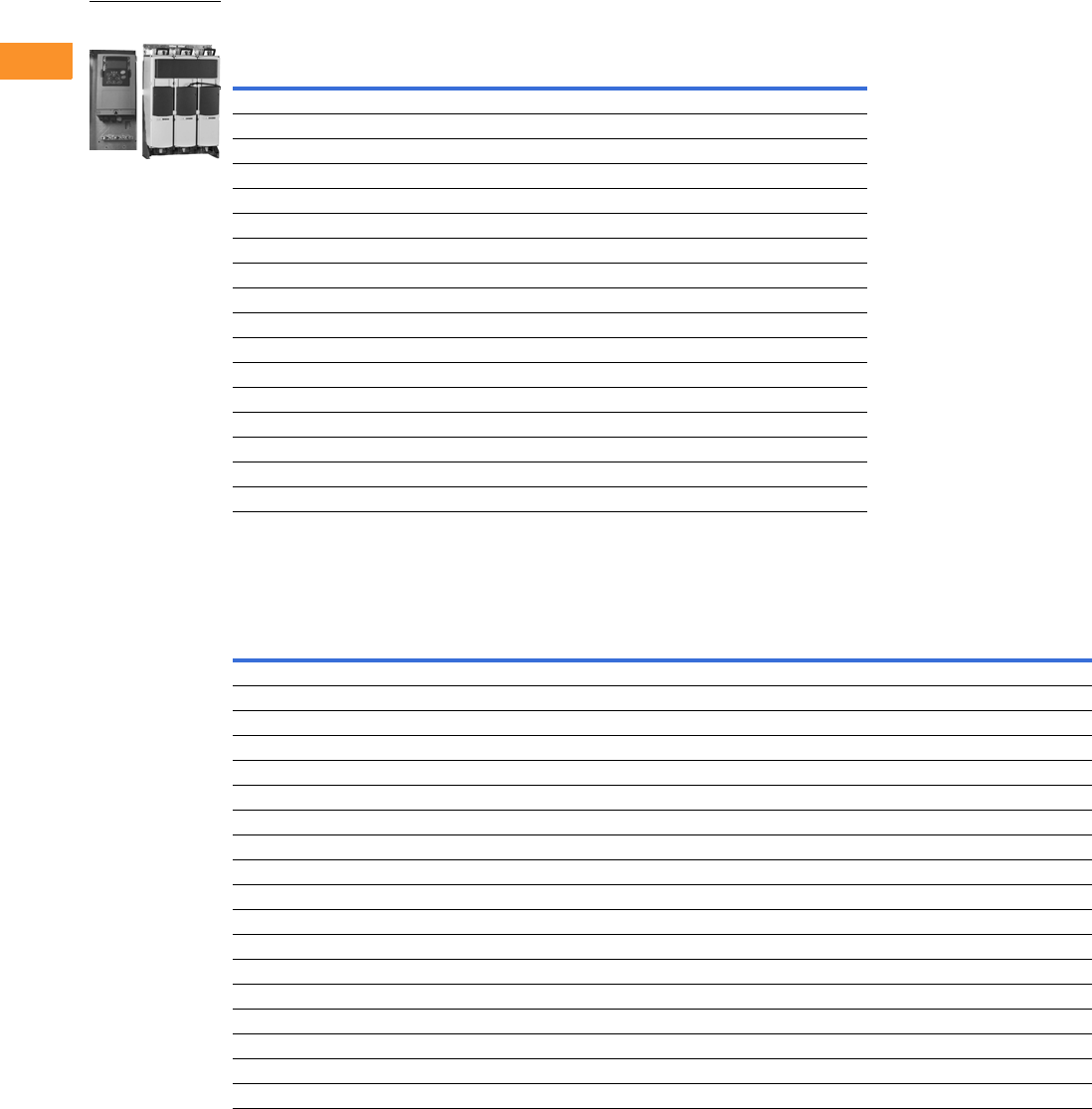
V6-T2-364 Volume 6—Solid-State Motor Control CA08100007E—February 2016 www.eaton.com
2
2
2
2
2
2
2
2
2
2
2
2
2
2
2
2
2
2
2
2
2
2
2
2
2
2
2
2
2
2
2.11
Adjustable Frequency Drives
LCX Liquid Cooled Drives
525–690 Vac Liquid Cooled Drives
540–675 Vdc Liquid Cooled Inverter Units
Motor Output
Current
Thermal, Ith (A) IL (A) IH (A) kW Chassis Catalog Number
170 155 113 110 CH61 LCX170A0-5A3N2
208 189 139 132 CH61 LCX208A0-5A3N2
261 237 174 160 CH72 LCX261A0-5A3N2
325 295 217 200 CH72 LCX325A0-5A3N2
385 350 257 250 CH72 LCX385A0-5A3N2
416 378 277 250 CH72 LCX416A0-5A3N2
460 418 307 300 CH72 LCX460A0-5A3N2
502 456 335 355 CH72 LCX502A0-5A3N2
590 536 393 400 CH63 LCX590A0-5A3N2
650 591 433 450 CH63 LCX650A0-5A3N2
750 682 500 500 CH63 LCX750A0-5A3N2
820 745 547 560 CH74 LCX820A0-5A3N2
920 836 613 650 CH74 LCX920A0-5A3N2
1030 936 687 700 CH74 LCXH10A0-5A3N2
1180 1073 787 800 CH74 LCXH11A0-5A3N2
1300 1182 867 900 CH74 LCXH13A0-5A3N2
1500 1364 1000 1000 CH74 LCXH15A0-5A3N2
Drive Output
Power Loss
c/a/T
(kW)
Current Motor Output Power
Thermal
Ith (A)
Rated Cont.
IL (A)
Rated Cont.
IH (A)
Optimum Motor
at Ith 400 V (kW)
Optimum Motor
at Ith 500 V (kW) Chassis Catalog Number
16 15 11 7.5 11 0.4/0.2/0.6 CH3 LCX016A0-4A7B2
22 20 15 11 15 0.5/0.2/0.7 CH3 LCX022A0-4A7B2
31 28 21 15 18.5 0.7/0.2/0.9 CH3 LCX031A0-4A7B2
38 35 25 18.5 22 0.8/0.2/1.0 CH3 LCX038A0-4A7B2
45 41 30 22 30 1.0/0.3/1.3 CH3 LCX045A0-4A7B2
61 55 41 30 37 1.3/0.3/1.5 CH3 LCX061A0-4A7B2
72 65 48 37 45 1.2/0.3/1.5 CH4 LCX072A0-4A7N2
87 79 58 45 55 1.5/0.3/1.8 CH4 LCX087A0-4A7N2
105 95 70 55 75 1.8/0.3/2.1 CH4 LCX105A0-4A7N2
140 127 93 75 90 2.3/0.3/2.6 CH4 LCX140A0-4A7N2
168 153 112 90 110 2.5/0.3/2.8 CH5 LCX168A0-4A7N2
205 186 137 110 132 3.0/0.4/3.4 CH5 LCX205A0-4A7N2
261 237 174 132 160 4.0/0.4/4.4 CH5 LCX261A0-4A7N2
300 273 200 160 200 4.5/0.4/4.9 CH61 LCX300A0-4A7N2
385 350 257 200 250 5.5/0.5/6.0 CH61 LCX385A0-4A7N2
460 418 307 250 315 5.5/0.5/6.0 CH62 LCX460A0-4A7N2
520 473 347 250 355 6.5/0.5/7.0 CH62 LCX520A0-4A7N2
590 536 393 315 400 7.5/0.6/8.1 CH62 LCX590A0-4A7N2
LCX Liquid Cooled
Drives
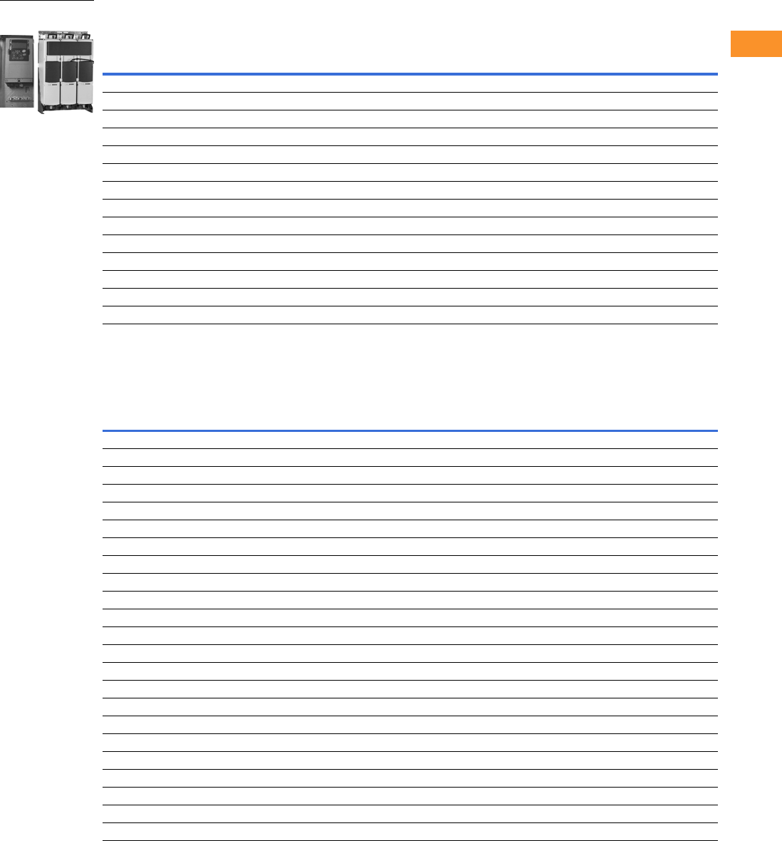
Volume 6—Solid-State Motor Control CA08100007E—February 2016 www.eaton.com V6-T2-365
2
2
2
2
2
2
2
2
2
2
2
2
2
2
2
2
2
2
2
2
2
2
2
2
2
2
2
2
2
2
2.11
Adjustable Frequency Drives
LCX Liquid Cooled Drives
540–675 Vdc Liquid Cooled Inverter Units, continued
710–930 Vdc Liquid Cooled Inverter Unit
Drive Output
Power Loss
c/a/T
(kW)
Current Motor Output Power
Thermal
Ith (A)
Rated Cont.
IL (A)
Rated Cont.
IH (A)
Optimum Motor
at Ith 400 V (kW)
Optimum Motor
at Ith 500 V (kW) Chassis Catalog Number
650 591 433 355 450 8.5/0.6/9.1 CH62 LCX650A0-4A7N2
730 664 487 400 500 10.0/0.7/10.7 CH62 LCX730A0-4A7N2
820 745 547 450 560 12.5/0.8/13.3 CH63 LCX820A0-4A7N2
920 836 613 500 600 14.4/0.9/15.3 CH63 LCX920A0-4A7N2
1030 936 687 560 700 16.5/1.0/17.5 CH63 LCXH10A0-4A7N2
1150 1045 766 600 750 18.4/10.1/19.5 CH63 LCXH11A0-4A7N2
1370 1245 913 700 900 15.5/1.0/16.5 CH64 LCXH13A0-4A7N2
1640 1491 1093 900 1100 19.5/1.2/20.7 CH64 LCXH16A0-4A7N2
2060 1873 1373 1100 1400 26.5/1.5/28.0 CH64 LCXH20A0-4A7N2
2300 2091 1533 1250 1500 29.6/1.7/31.3 CH64 LCXH23A0-4A7N2
2470 2245 1647 1300 1600 36.0/2.0/38.0 2*CH64 LCXH24A0-4A7N2
2950 2681 1967 1550 1950 39.0/2.4/41.4 2*CH64 LCXH29A0-4A7N2
3710 3372 2473 1950 2450 48.0/2.7/50.7 2*CH64 LCXH37A0-4A7N2
4140 3763 2760 2150 2700 53.0/3.0/66.0 2*CH64 LCXH41A0-4A7N2
Drive Output
Power Loss
c/a/T
(kW)
Current Motor Output Power
Thermal
Ith (A)
Rated Cont.
IL (A)
Rated Cont.
IH (A)
Optimum Motor
at Ith 400 V (kW)
Optimum Motor
at Ith 500 V (kW) Chassis Catalog Number
170 155 113 110 160 4.5/0.2/4.7 CH61 LCX170A0-5A7N2
208 189 139 132 200 5.5/0.3/5.8 CH61 LCX208A0-5A7N2
261 237 174 160 250 5.5/0.3/5.8 CH61 LCX261A0-5A7N2
325 295 217 200 300 6.5/0.3/6.8 CH62 LCX325A0-5A7N2
385 350 257 250 355 7.5/0.4/7.9 CH62 LCX385A0-5A7N2
416 378 277 250 355 8.0/0.4/8.4 CH62 LCX416A0-5A7N2
460 418 307 300 400 8.5/0.4/8.9 CH62 LCX460A0-5A7N2
502 456 335 355 450 10.0/0.5/10.5 CH62 LCX502A0-5A7N2
590 536 393 400 560 10.0/0.5/10.5 CH63 LCX590A0-5A7N2
650 591 433 450 600 13.5/0.7/14.2 CH63 LCX650A0-5A7N2
750 682 500 500 700 16.0/0.8/16.8 CH63 LCX750A0-5A7N2
820 745 547 560 800 16.0/0.8/16.8 CH64 LCX820A0-5A7N2
920 836 613 650 850 18.0/0.9/18.9 CH64 LCX920A0-5A7N2
1030 936 687 700 1000 19.0/1.0/20.0 CH64 LCXH10A0-5A7N2
1180 1073 787 800 1100 21.0/10.1/20.1 CH64 LCXH11A0-5A7N2
1300 1182 867 900 1200 27.0/1.4/28.4 CH64 LCXH13A0-5A7N2
1500 1364 1000 1050 1400 32.0/1.6/33.6 CH64 LCXH15A0-5A7N2
1700 1545 1133 1150 1550 N/A CH64 LCXH17A0-5A7N2
1850 1682 1233 1250 1650 34.2/1.8/36.0 2*CH64 LCXH18A0-5A7N2
2120 1927 1413 1450 1900 37.8/2.0/39.8 2*CH64 LCXH21A0-5A7N2
2340 2127 1560 1600 2100 48.6/2.5/51.1 2*CH64 LCXH23A0-5A7N2
2700 2455 1800 1850 2450 57.6/3.0/60.6 2*CH64 LCXH27A0-5A7N2
3100 2818 2066 2150 2800 N/A 2*CH64 LCXH31A0-5A7N2
LCX Liquid Cooled
Drives
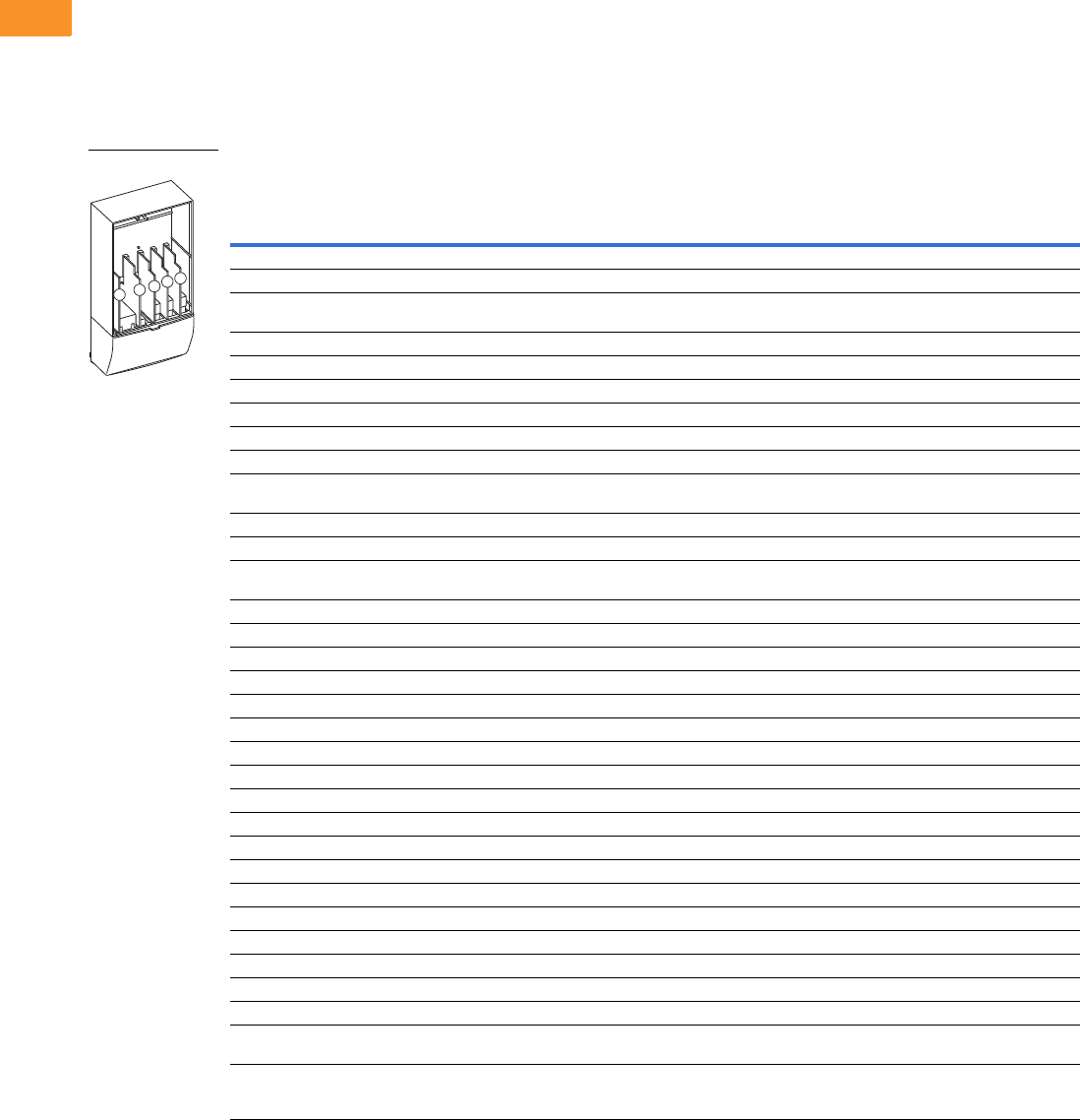
V6-T2-366 Volume 6—Solid-State Motor Control CA08100007E—February 2016 www.eaton.com
2
2
2
2
2
2
2
2
2
2
2
2
2
2
2
2
2
2
2
2
2
2
2
2
2
2
2
2
2
2
2.11
Adjustable Frequency Drives
LCX Liquid Cooled Drives
Options
9000X Series Option Board Kits
The 9000X Series drives can accommodate a wide selection of expander and adapter option boards to
customize the drive for your application needs. The drive’s control unit is designed to accept a total of
five option boards.
The 9000X Series factory installed standard board configuration includes an A9 I/O board and an A2
relay output board, which are installed in slots A and B.
Option Board Kits
Notes
1 AI = Analog Input; AO = Analog Output, DI = Digital Input, DO = Digital Output, RO = Relay Output
2 Option card must be installed in one of the slots listed for that card. Slot indicated in bold is the preferred location.
3 OPTC2 is a multi-protocol option card.
Option Kit Description 1
Allowed Slot
Locations 2
Field
Installed
Factory
Installed SVX Ready Programs
Catalog
Number
Option
Designator Basic
Local/
Remote Standard MSS PID Multi-P. PFC
Standard I/O Cards
2 RO (NC-NO) B OPTA2 — ■ ■ ■ ■■■ ■
6 DI, 1 DO, 2 AI, 1 AO, 1 +10 Vdc ref,
2 ext +24 Vdc/EXT +24 Vdc
AOPTA9 — ■ ■ ■ ■■■ ■
Extended I/O Cards
2 RO, therm B OPTA3 A3 —■ ■ ■■■ ■
Encoder low Volt +5 V/15 V/24 V C OPTA4 A4 —■ ■ ■■■ ■
Encoder high Volt +15 V/24 V C OPTA5 A5 —■ ■ ■■■ ■
Dual encoder +15 V/24 V C OPTA7 A7 —■ ■ ■■■ ■
6 DI, 1 DO, 2 AI, 1 AO A OPTA8 A8 —■ ■ ■■■ ■
3 DI (encoder 10–24 V), out +15 V/+24 V,
2 DO (pulse+direction)—SPX only
COPTAE AE ■ ■ ■ ■■■ ■
6 DI, 1 ext +24 Vdc/EXT +24 Vdc B, C, D, E OPTB1 B1 —— — ——
■■
1 RO (NC-NO), 1 RO (NO), 1 therm B, C, D, E OPTB2 B2 —— — ——
■■
1 AI (mA isolated), 2 AO (mA isolated),
1 ext +24 Vdc/EXT +24 Vdc
B, C, D, E OPTB4 B4 —■ ■ ■■■ ■
3 RO (NO) B, C, D, E OPTB5 B5 —— — ——
■■
1 ext +24 Vdc/EXT +24 Vdc, 3 Pt100 B, C, D, E OPTB8 B8 — — — ——— —
1 RO (NO), 5 DI 42–240 Vac input B, C, D, E OPTB9 B9 —— — ——
■■
SPI, absolute encoder C OPTBB BB — — — ——— —
Communication Cards 3
Modbus D, E OPTC2 C2 ■ ■ ■ ■■■ ■
Johnson Controls N2 D, E OPTC2 CA — — — ——— —
PROFIBUS DP D, E OPTC3 C3 ■ ■ ■ ■■■ ■
LonWorks D, E OPTC4 C4 ■ ■ ■ ■■■ ■
PROFIBUS DP (D9 connector) D, E OPTC5 C5 ■ ■ ■ ■■■ ■
CANopen (slave) D, E OPTC6 C6 ■ ■ ■ ■■■ ■
DeviceNet D, E OPTC7 C7 ■ ■ ■ ■■■ ■
Modbus (D9 Type connector) D, E OPTC8 C8 ■ ■ ■ ■■■ ■
Modbus TCP D, E OPTCI CI ■ ■ ■ ■■■ ■
Adapter—SPX only D, E OPTD1 D1 ■ ■ ■ ■■■ ■
Adapter—SPX only D, EOPTD2VD2
■ ■ ■ ■■■ ■
RS-232 with D9 connection D, E OPTD3 D3 ■ ■ ■ ■■■ ■
Keypad
9000X Series standard keypad — KEYPAD-
STD
—— — — ——— ■
9000X Series remote mount keypad unit
(keypad not included, includes 10 ft cable,
keypad holder, mounting hardware)
—OPTRMT-
KIT-9000X
—— — — ——— —
Option Boards
ABCDE

Volume 6—Solid-State Motor Control CA08100007E—February 2016 www.eaton.com V6-T2-367
2
2
2
2
2
2
2
2
2
2
2
2
2
2
2
2
2
2
2
2
2
2
2
2
2
2
2
2
2
2
2.11
Adjustable Frequency Drives
LCX Liquid Cooled Drives
Technical Data and Specifications
LCX Products
Note
1Derating required if higher switching frequency than the default is used.
Description Specification
General Specifications
Line voltage 400 to 500 Vac; 525 to 690 Vac; (–10% to 10%)
465 to 800 Vdc; 640 to 1100 Vdc; (–0 to 0%)
Frequency 50/60 Hz
Line voltage variation –10% to 10%
Input frequency variation 45–66 Hz
Continuous output current Rated current at incoming cooling liquid
temperature of 30 °C
Output frequency 0–320 Hz
Drive efficiency >95%
Power factor (displacement) 0.96
Liquid coolant pressure 87 psi (6 bar) maximum
Liquid coolant flow rate 1.3 to 7.9 gal./min. (5 to 30 liter/min.)
minimum depending on drive size
Liquid coolant fittings Standard quick connect, NPT
Operating ambient temperature –10/50 °C
Storage temperature –40/70 °C
Humidity 95% maximum (non-condensing)
Altitude 3300 ft (1000 m) maximum without derating
Enclosure IP00
Warranty Standard terms, 3 years with certified start-up
Mains Connection
Input voltage (Vin) 400–500 Vac; 525–690 Vac; (–10%–10%)
465–800 Vdc; 640–1100 Vdc; (–0–0%)
Input frequency (fin) 45–66 Hz
Connection to mains Once per minute or less (normal case)
Motor Connection
Output voltage 0–Vin
Continuous output current Rated current at nominal inflow cooling water
temperature of 30 °C; Overload 2 sec./20 sec.
Starting current Rated current at 2 sec./20 sec. if output frequency
<30 Hz and temperature of heatsink <149 °F (65 °C)
Output frequency 0–320 Hz (standard); 7200 Hz (special software)
Frequency resolution Application dependent
Control Characteristics
Control method Frequency control (V/f)
Open loop: Sensorless vector control
Closed loop: Frequency control
Closed loop: Vector control
Switching frequency Adjustable with parameter 2.6.9
480 V 1Up to and including 61-Amp size:
1–16 kHz (factory default, 10 kHz)
From 72-Amp size:
1–12 kHz (factory default, 3.6 kHz)
575 V 11–6 kHz (factory default, 1.5 kHz)
Frequency reference Analog input: resolution 0.1% (10 bits); accuracy ±1%
Panel reference: resolution 0.01 Hz
Field weakening point 30–320 Hz
Acceleration time 0.1–3000 seconds
Deceleration time 0.1–3000 seconds
Braking torque DC brake: 30% x Tn (without brake option)
Description Specification
Ambient Conditions
Ambient operating temperature 14 °F (–10 °C), no frost to 122 °F (50 °C) at Ith
122 to 158 °F (50 to 70 °C), derating required
Storage temperature –40 °F to 158 °F (–40 to 70 °C)
No liquid in heatsink under 32 °F (0 °C)
Relative humidity 5–96% RH, noncondensing, no dripping water
Air quality Chemical vapors:
IEC 721-3-3, unit in operation, class 3C2
Mechanical particles:
IEC 721-3-3, unit in operation, class 3S2 (no conductive
dust allowed); No corrosive gases
Altitude Up to 1,000 m: 100% load capacity (no derating)
Above 1,000 m: Derating of 1% per each 100 m required
Vibration EN 50178, EN 60068-2-6; 5–150 Hz
Displacement amplitude: 0.25 mm (peak) at 3–31 Hz
Max. acceleration amplitude: 1G at 31–150 Hz
Shock EN 50178, EN 60068-2-27, UPS drop test
(for applicable UPS weights)
Storage and shipping: Max. 15 g, 11 ms (in package)
Enclosure class IP00 open frame standard in entire kW/hp range
EMC
Immunity Fulfils all EMC immunity requirements
Emissions EMC level N; EMC level T for IT networks
Safety
Approvals EN 50178, EN 60204-1, CE, UL, CUL, FI,
GOST R, IEC 61800-5
(See unit nameplate for more detailed approvals.)
Control Connections
Analog input voltage 0 to +10 V, Ri = 200 kohm (–10 V to +10 V joystick control)
Resolution 0.1%; accuracy ±1%
Analog input current 0(4)–20 mA, Ri = 250 ohm differential
Digital inputs 6 positive or negative logic; 18–24 Vdc
Auxiliary voltage +24 V, ±15%, max. 250 mA
Output reference voltage +10 V, +3%, max. load 10 mA
Analog output 0(4)–20 mA, RL max. 500 ohm
Resolution 10 bits; accuracy ±2%
Digital outputs Open collector output, 50 mA/48V
Relay outputs Two programmable change-over relay outputs
Switching capacity: 24 Vdc/8 A, 250 Vac/8 A,
125 Vdc/0.4 A
Min. switching load: 5 V/10 mA
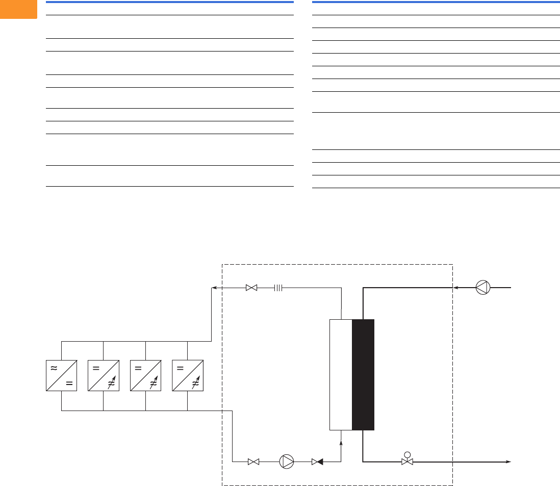
V6-T2-368 Volume 6—Solid-State Motor Control CA08100007E—February 2016 www.eaton.com
2
2
2
2
2
2
2
2
2
2
2
2
2
2
2
2
2
2
2
2
2
2
2
2
2
2
2
2
2
2
2.11
Adjustable Frequency Drives
LCX Liquid Cooled Drives
LCX Products, continued
Wiring Diagrams
Cooling System Diagrams
Example of a Typical Cooling System
Description Specification
Protections
Overvoltage protection
480 V 911 V
575 V 1200 V
Undervoltage protection
480 V 333 V
575 V 461 V
Ground fault protection In case of ground fault in motor or motor cable,
only the drive is protected
Mains supervision Trips if any of the input phases are missing (drives only)
Motor phase supervision Trips if any of the output phases are missing
Unit overtemperature protection
Alarm limit 149 °F (65 °C) for heatsink, 158 °F (70 °C) for circuit
boards
Trip limit 158 °F (70 °C) for heatsink, 185 °F (85 °C) for circuit
boards
Description Specification
Protections, continued
Overcurrent protection Yes
Motor overload protection Yes
Motor stall protection Yes
Motor underload protection Yes
Short-circuit protection Yes (+24 V and +10 V reference voltages)
Liquid Cooling
Allowed cooling agents Drinking water
Water-glycol mixture
Temperature of cooling agent 32 to 86 °F (0 to 30 °C) at Ith for input;
86 to 149 °F (30 to 65 °C)
Max. temperature rise during circulation: 9 °F (5 °C), no
condensation allowed
System max. working pressure 87 psi (6 bar)
System max. peak pressure 580 psi (40 bar)
Pressure loss (at nominal flow) Varies according to size
Heat
Exchanger
18.0C30.0C
26.1C35.4C
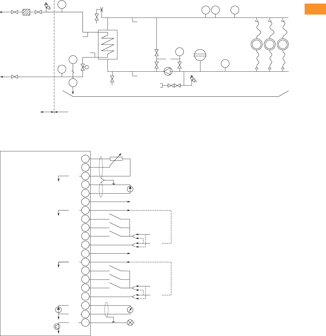
Volume 6—Solid-State Motor Control CA08100007E—February 2016 www.eaton.com V6-T2-369
2
2
2
2
2
2
2
2
2
2
2
2
2
2
2
2
2
2
2
2
2
2
2
2
2
2
2
2
2
2
2.11
Adjustable Frequency Drives
LCX Liquid Cooled Drives
Example PI-Diagram of a Typical Cooling System and Connections
I/O Board Diagrams
A9 Option Board Control Wiring
Cooling Water Inlet
Cooling Water Outlet
Customer Delivery
Frequency
Converters
9
8
7
6
5
4
3
1
+10 Vref
AI1+
GND
AI2+
Reference
(voltage)
Control Voltage Output
Reference
(current)
AI2-
24Vout
DIN1
AO1+
DO1
Dotted lines indicate the connections for inverted signals
DIN3
DIN2
CMA
10
11
24V
GND
+ V<+48V
0 (4)/20mA
RL<500W
I<50mA
Basic I/O Board A9
2
GND
AO1-
12
24Vout
15
14
13
DIN4
DIN6
DIN5
CMB
16
17
24V
GND
18
19
20
GND
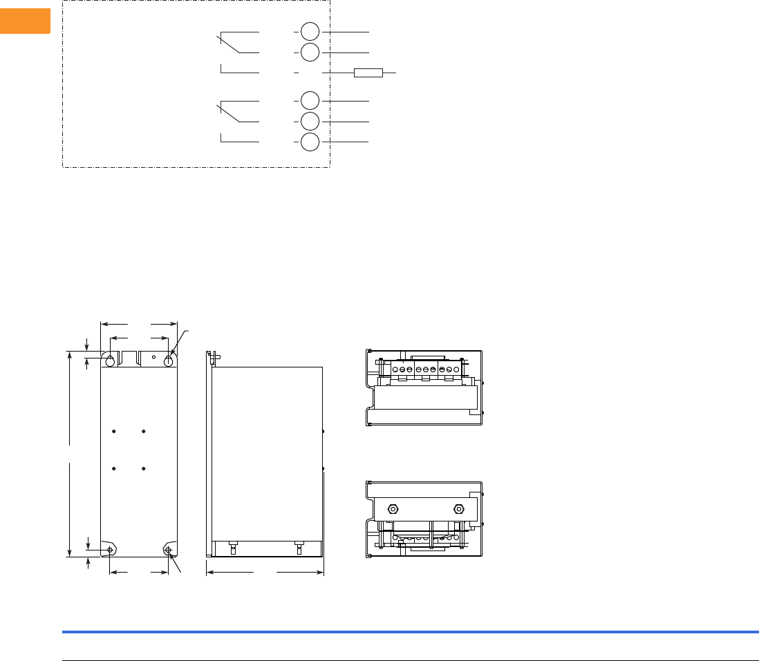
V6-T2-370 Volume 6—Solid-State Motor Control CA08100007E—February 2016 www.eaton.com
2
2
2
2
2
2
2
2
2
2
2
2
2
2
2
2
2
2
2
2
2
2
2
2
2
2
2
2
2
2
2.11
Adjustable Frequency Drives
LCX Liquid Cooled Drives
A2 Option Board Wiring
Dimensions
Approximate Dimensions in Inches (mm)
LCX Drives
Chassis Size, CH3
Voltage Amps H1 H2 H3 D1 W1 W2 W3 R1 Dia. R2 Dia.
Weight
Lbs (kg)
380–500 Vac 16–61 16.97
(431.0)
0.53
(13.5)
0.59
(15.0)
9.69
(246.0)
6.30
(160.0)
4.80
(122.0)
4.80
(122.0)
0.39
(10.0)
0.35
(9.0)
66 (30)
RO1/1
RO1/2
RO1/3 RL
Switching:
<8 A / 24 Vdc
<0.4 A / 125 Vdc
<8 A / 250 Vac
Continuous
<2 Arms
AC / DC
Basic Relay Board A2
21
22
23
RO2/1
RO2/2
RO2/3
24
25
26
W3 D1
Front Side
Bottom
To p
R1
W2
W1
H2 R2
H3
H1
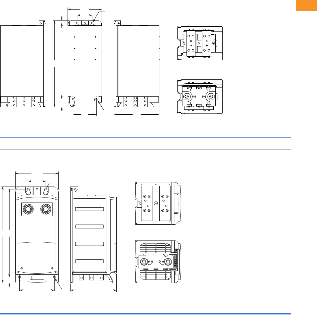
Volume 6—Solid-State Motor Control CA08100007E—February 2016 www.eaton.com V6-T2-371
2
2
2
2
2
2
2
2
2
2
2
2
2
2
2
2
2
2
2
2
2
2
2
2
2
2
2
2
2
2
2.11
Adjustable Frequency Drives
LCX Liquid Cooled Drives
Approximate Dimensions in Inches (mm)
Chassis Size, CH4
Chassis Size, CH5
Voltage Amps H1 H2 H3 D1 W1 W2 W3 R1 Dia. R2 Dia.
Weight
Lbs (kg)
380–500 Vac 72–140 19.41
(493.0)
0.49
(12.5)
1.77
(45.0)
10.14
(257.5)
7.60
(193.0)
3.35
(85.0)
5.24
(133.0)
0.39
(10.0)
— 77 (35)
Voltage Amps H1 H2 H3 D1 W1 W2 W3 R1 Dia. R2 Dia.
Weight
Lbs (kg)
380–500 Vac 168–261 21.77
(553.0)
1.30
(33.0)
19.88
(505.0)
10.39
(264.0)
9.69
(246)
3.94
(100.0)
7.87
(200.0)
0.51
(13.0)
— 88 (40)
W1
W2
W3 D1
FrontRight Side Left Side
H1
H2
H3
R1
R1
Bottom
To p
W3 D1
W1
Front Side
H2
W2 R1
H3H1
R1 Bottom
To p
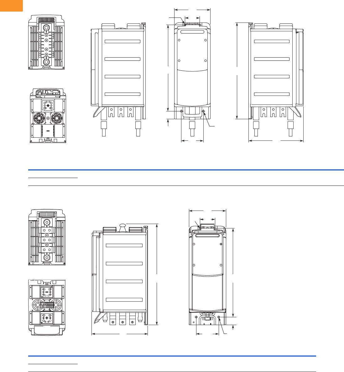
V6-T2-372 Volume 6—Solid-State Motor Control CA08100007E—February 2016 www.eaton.com
2
2
2
2
2
2
2
2
2
2
2
2
2
2
2
2
2
2
2
2
2
2
2
2
2
2
2
2
2
2
2.11
Adjustable Frequency Drives
LCX Liquid Cooled Drives
Approximate Dimensions in Inches (mm)
Chassis Size, CH61
Liquid-Cooled Inverter—Chassis Size, CH62
Voltage Amps H1 H2 H3 D1 W1 W2 W3 R1 Dia. R2 Dia.
Weight
Lbs (kg)
380–500 Vac 300–385 25.91
(658.0)
2.09
(53.0)
23.23
(590.0)
14.69
(373.0)
9.69
(246.0)
3.94
(100.0)
5.91
(150.0)
0.55
(14.0)
0.51
(13.0)
121 (55)
525–690 Vac 170–208
Voltage Amps H1 H2 H3 D1 W1 W2 W3 R1 Dia. R2 Dia.
540–675 Vdc 460–730 26.50
(673)
2.0
(53)
23.23
(590)
14.69
(373)
9.69
(246)
3.94
(100)
5.91
(150)
0.55
(14)
0.51
(13)
710–930 Vdc 325–502
D1W3
Left SideFrontRight Side
Bottom
Top
W2
W1
R2
H2
H3 H1
R1
H1
H2
H3
R1
R2 W2
W3
W1
D1
FrontSideBottom
Top
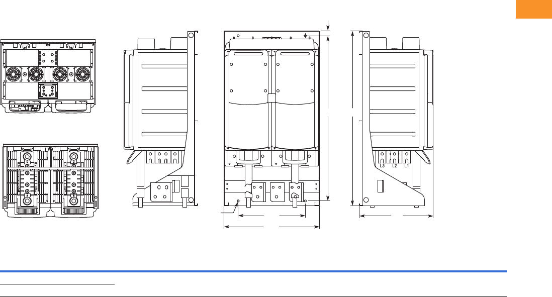
Volume 6—Solid-State Motor Control CA08100007E—February 2016 www.eaton.com V6-T2-373
2
2
2
2
2
2
2
2
2
2
2
2
2
2
2
2
2
2
2
2
2
2
2
2
2
2
2
2
2
2
2.11
Adjustable Frequency Drives
LCX Liquid Cooled Drives
Approximate Dimensions in Inches (mm)
Chassis Size, CH63
Voltage Amps H1 H2 H3 D1 W1 W2 R1 Dia.
Weight
Lbs (kg)
380–500 Vac 820–1030 36.36
(923.5)
0.91
(23.0)
34.39
(873.5)
15.35
(390.0)
19.88
(505.0)
13.98
(355.0)
0.43
(11.0)
264 (120)
525–690 Vac 590–750
H3
H2
W2
R1 D1
W1
Left SideRight Side Front
Bottom
Top
H1
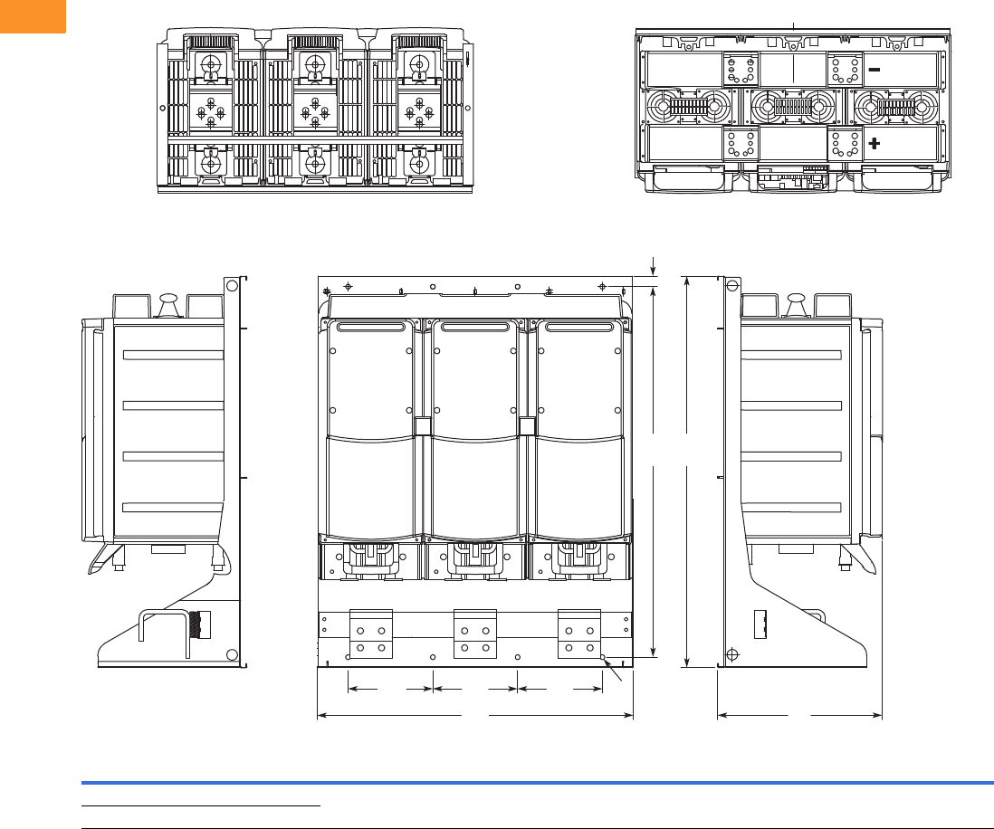
V6-T2-374 Volume 6—Solid-State Motor Control CA08100007E—February 2016 www.eaton.com
2
2
2
2
2
2
2
2
2
2
2
2
2
2
2
2
2
2
2
2
2
2
2
2
2
2
2
2
2
2
2.11
Adjustable Frequency Drives
LCX Liquid Cooled Drives
Approximate Dimensions in Inches (mm)
Liquid-Cooled Inverter with Mounting Bracket, Chassis Size CH64, IP90
Voltage Amps H1H2H3D1W1W2R1 Dia.
540–675 Vdc 1370–4140 36.38
(924)
1.03
(26)
34.37
(873)
15.35
(390)
29.37
(746)
7.87
(200)
0.43
(11)
710–930 Vdc 820–3100
Bottom
H1H3
H2
W1
W2 W2 W2
D1
FrontRight Side Left Side
R1
Top
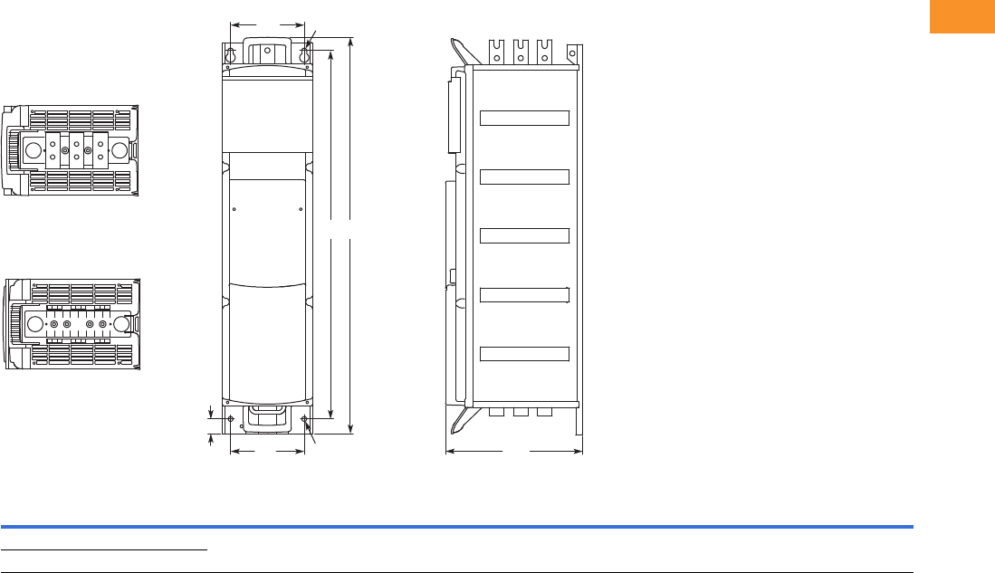
Volume 6—Solid-State Motor Control CA08100007E—February 2016 www.eaton.com V6-T2-375
2
2
2
2
2
2
2
2
2
2
2
2
2
2
2
2
2
2
2
2
2
2
2
2
2
2
2
2
2
2
2.11
Adjustable Frequency Drives
LCX Liquid Cooled Drives
Approximate Dimensions in Inches (mm)
Chassis Size, CH72
Voltage Amps H1 H2 H3 D1 W1 R1 Dia. R2 Dia.
Weight
Lbs (kg)
380–500 Vac 460–730 42.38
(1076.5)
1.57
(40.0)
39.37
(1000.0)
14.65
(372.0)
7.87
(200.0)
0.55
(14.0)
0.51
(13.0)
198 (90)
525–690 Vac 261–502
W1 R1
H1H3
H2 R2W1 D1
Front Side
Bottom
Top
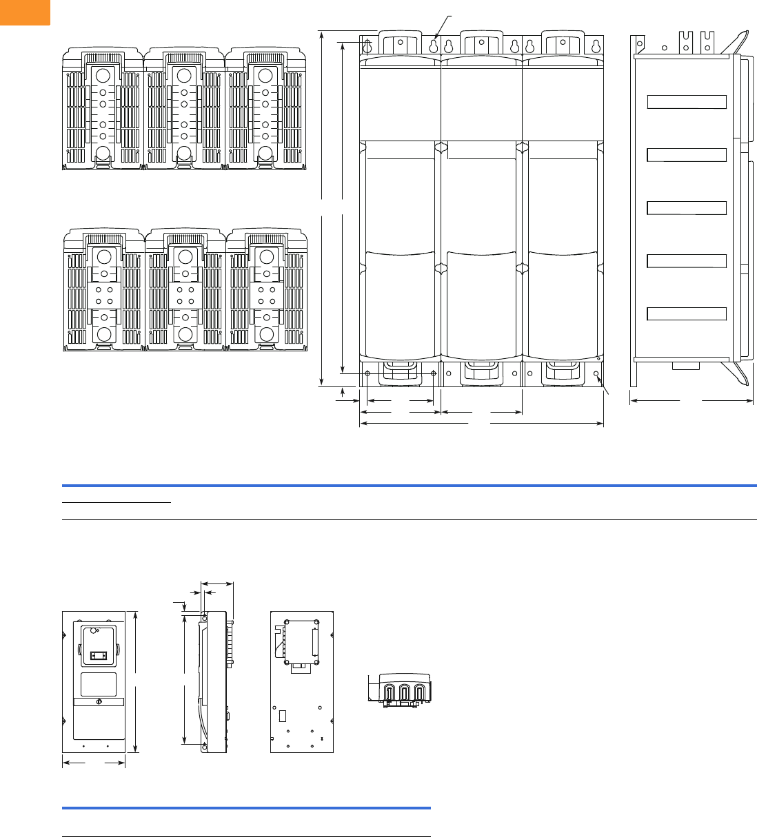
V6-T2-376 Volume 6—Solid-State Motor Control CA08100007E—February 2016 www.eaton.com
2
2
2
2
2
2
2
2
2
2
2
2
2
2
2
2
2
2
2
2
2
2
2
2
2
2
2
2
2
2
2.11
Adjustable Frequency Drives
LCX Liquid Cooled Drives
Approximate Dimensions in Inches (mm)
Chassis Size, CH74
Control Unit
Voltage Amps H1 H2 H3 D1 W1 W2 W3 W4 R1 Dia. R2 Dia.
Weight
Lbs (kg)
380–500 Vac 1370–2300 42.38
(1076.5)
1.57
(40.0)
39.37
(1000.0)
14.65
(372.0)
29.06
(738.0)
0.91
(23.0)
7.87
(200.0)
9.69
(246)
0.51
(13.0)
0.55
(14.0)
617 (280)
525–690 Vac 820–1500
H1 H2 H3 D1 D2 W1
12.93
(328.5)
0.33
(8.5)
11.81
(300.0)
2.95
(75.0)
0.33
(8.5)
5.75
(146.0)
W3
W4 W4
W2
W1
D1
ediStnorF
Bottom
Top
R1
R2
H2
H1 H3
D1
D2
H2
H3H1
W1
Side BackFront
Bottom
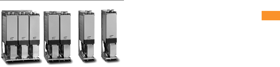
Volume 6—Solid-State Motor Control CA08100007E—February 2016 www.eaton.com V6-T2-377
2
2
2
2
2
2
2
2
2
2
2
2
2
2
2
2
2
2
2
2
2
2
2
2
2
2
2
2
2
2
2.12
Adjustable Frequency Drives
SPA/SPN/SPI Common DC Bus Drives
SPA/SPN/SPI Common DC Bus Drive Products
Contents
Description Page
SPA/SPN/SPI Common DC Bus Drives
Application Description . . . . . . . . . . . . . . . . . . . V6-T2-378
Product Comparison . . . . . . . . . . . . . . . . . . . . . V6-T2-378
Features . . . . . . . . . . . . . . . . . . . . . . . . . . . . . . V6-T2-379
Standards and Certifications . . . . . . . . . . . . . . V6-T2-379
Catalog Number Selection . . . . . . . . . . . . . . . . V6-T2-379
Product Selection . . . . . . . . . . . . . . . . . . . . . . . V6-T2-381
Options . . . . . . . . . . . . . . . . . . . . . . . . . . . . . . . V6-T2-383
Technical Data and Specifications . . . . . . . . . . V6-T2-384
Wiring Diagrams . . . . . . . . . . . . . . . . . . . . . . . . V6-T2-386
Dimensions . . . . . . . . . . . . . . . . . . . . . . . . . . . V6-T2-387
Product Description
Eaton offers a comprehensive
range of common DC bus
drive products. The product
family covers a number of
front-end units and inverter
units in the entire power
range from 1-1/2 to 2000
horsepower at 460 V and 690
V. The drive components are
built on the SPX technology.
Front-End Units
The front-end units convert a
mains AC voltage and current
into a DC voltage and current.
The power is transferred from
the mains to a common DC
bus (and, in certain cases,
vice versa).
The SPA (active front-end)
unit is a bidirectional
(regenerative) power
converter for the front end
of a common DC bus drive
line up. An external LCL filter
is used at the input. This unit
is suitable in applications
where low mains harmonics
are required.
The SPN (non-regenerative
front-end) unit is a uni-
directional (motoring) power
converter for the front-end
of a common DC bus drive
line-up. The device operates
as a diode bridge using diode/
thyristor components. A
dedicated external choke is
used at the input. The unit
has the capacity to charge a
common DC bus. This unit is
suitable as a rectifying device
when a “normal” level of
harmonics is accepted and
no regeneration to the mains
is required.
Inverter Unit
The SPI Inverter Unit is a
bidirectional DC-fed power
inverter for the supply and
control of AC motors. The
inverter is supplied from a
common DC bus drive line-
up. A charging circuit is
needed in case a connection
to a live DC bus is required.
The DC side charging circuit
is integrated up to 75 kW
(FR4–FR8) and external
for higher power ratings
(FI9–FI14).
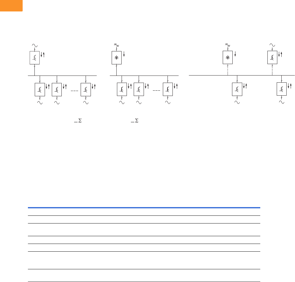
V6-T2-378 Volume 6—Solid-State Motor Control CA08100007E—February 2016 www.eaton.com
2
2
2
2
2
2
2
2
2
2
2
2
2
2
2
2
2
2
2
2
2
2
2
2
2
2
2
2
2
2
2.12
Adjustable Frequency Drives
SPA/SPN/SPI Common DC Bus Drives
Application Description
The common DC bus product portfolio fulfills all solution demands with a flexible architecture.
Front end units are selected according to the level of harmonics and power requirements. Typical
drive system configurations are illustrated the following figures.
SPA + Inverters SPN + Inverters Combination Configuration
●Low harmonics, -Pmains
+Pmains/Pmains < PINU
●Suitable for almost every
application
●Low total mains power,
Pmains < PINU
●Suitable e.g. for small
processing line with
un- and recoiler, em-stop
coasting
Common DC bus
components are used in a
multitude of combinations.
Drives which are braking can
transfer the energy directly to
the drives in motoring mode.
Product Comparison
Advantages over Conventional Front Ends
Eaton Front Ends vs. Conventional
Note
1Conventional regenerative front end (a.k.a. “anti-parallel thyristor bridge”) is not available from Eaton.
2
3
Inverter
2
3
Inverter
2
3
Inverter
Non-regenerative
Front End
(SPN)
3
2
3
2
2
3
Inverter
2
3
Inverter
2
3
Inverter
Active
Front End
(SPA)
2
3
Inverter
Common DC Bus 2
3
Inverter
3
2
3
2
Non-regenerative
Front End
(SPN) Alternative
Active
Front End
(SPA) Alternative
~
~
Non-Regenerative
Front End
Active
Front End
Conventional
Regenerative Front End 1
Input device Choke (L) Filter (LCL) Choke or auto-transformer (L)
Bridge type Diode/thyristor bridge IGBT bridge, two-level type Anti-parallel connected thyristor bridge
Type of operation Controlled half-bridge High frequency modulation
(1.5 to 3.6 kHz)
Firing angle controlled
Direction of power Motoring Motoring and regenerating Motoring and regenerating
Charging Constant current External required Usually internal
DC voltage Nominal (approx. 1.35
alternative UN)
Stable at +10% of nominal
(approx. 110% of 1.35
alternative UN)
Lowered DC voltage for commutation margin
(e.g. 17% fi approx. 83% of 1.35 alternative UN) or
autotransformer on regenerative bridge
THD Similar to six-pulse bridge
normal <40%
Very low Similar to six-pulse bridge or worse
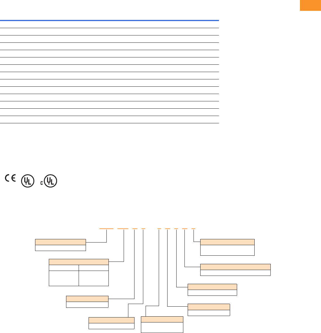
Volume 6—Solid-State Motor Control CA08100007E—February 2016 www.eaton.com V6-T2-379
2
2
2
2
2
2
2
2
2
2
2
2
2
2
2
2
2
2
2
2
2
2
2
2
2
2
2
2
2
2
2.12
Adjustable Frequency Drives
SPA/SPN/SPI Common DC Bus Drives
Features
Standard Features
Standards and Certifications
●CE
●UL
●cUL
●EN 61800-5-1 (2003)
Catalog Number Selection
Active Front End
SPI SPA SPN
Feature FR4, 6, 7 FR8 FI9–FI14 FI9–FI14 FI9
IP00 — ■■■■
IP21 ■————
Air cooling ■■■■■
Standard board ■■■■
Varnished board —————
Alphanumeric keypad ■■■■—
EMC class T (EN 61800-3 for IT networks) ■■■■■
Safety CE/UL ■■■■■
Input choke ————■
LCL filter ———■—
No integrated charging — — ■■—
Integrated charging (DC side) ■■——■
Diode/thyristor rectifier ————■
IGBT ■■■■—
SPA 205 A 0 –4A 3 N 1
Keypad
A = Alphanumeric
Software Series
A = Standard
Brake Chopper Options
N = No brake chopper circuit
EMC Level
3 = IT network
Enclosure Rating
0 = Chassis
Product Family
SPA = Active Front End
Board Modifications
1 = Standard boards
2 = Varnished boards
Voltage Rating
4 = 480 V
5 = 575 V
Current Rating
480 V 575 V
205 = 205 A
385 = 385 A
H10 = 1150 A
125 = 125 A
325 = 325 A
920 = 920 A
V6-T2-380 Volume 6—Solid-State Motor Control CA08100007E—February 2016 www.eaton.com
2
2
2
2
2
2
2
2
2
2
2
2
2
2
2
2
2
2
2
2
2
2
2
2
2
2
2
2
2
2
2.12
Adjustable Frequency Drives
SPA/SPN/SPI Common DC Bus Drives
Non-Regenerative Front End
SPI Inverter Unit
SPN 510 A 0 –4A 3 N 1
Keypad
A = Alphanumeric
Software Series
A = Standard
Brake Chopper Options
N = No brake chopper circuit
EMC Level
3 = IT network
Enclosure Rating
0 = Chassis
Product Family
SPN = Non-regenerative
SPN = front end
Board Modifications
1 = Standard boards
2 = Varnished boards
Current Rating
480 V/575 V
510 = 510 A
Voltage Rating
4 = 480 V
5 = 575 V
SPI 016 A 1 –4A 3 N 1
Keypad
A = Alphanumeric
Software Series
A = Standard
Brake Chopper Options
N = No brake chopper circuit
EMC Level
3 = IT network
Enclosure Rating
1 = NEMA Type 1/IP21
0 = Chassis
Product Family
SPI = Inverter unit
Board Modifications
1 = Standard boards
2 = Varnished boards
Voltage Rating
4 = 480 V
5 = 575 V
Current Rating
480 V (FR4–FR8) 575 V (FR6–FR8)
003 = 3.3 A
007 = 7.6 A
009 = 9 A
012 = 12 A
016 = 16 A
023 = 23 A
031 = 31 A
038 = 38 A
061 = 61 A
071 = 72 A
087 = 87 A
105 = 105 A
003 = 3.2 A
004 = 4.5 A
005 = 5.5 A
007 = 7.5 A
010 = 10 A
013 = 13.5 A
018 = 18 A
022 = 22 A
027 = 27 A
034 = 34 A
041 = 41 A
052 = 52 A
062 = 62 A
080 = 80 A
480 V (FI9–FI13) 575 V (FI9–FI14)
140 = 140 A
170 = 170 A
205 = 205 A
245 = 245 A
300 = 300 A
385 = 385 A
460 = 460 A
520 = 520 A
590 = 590 A
650 = 650 A
730 = 730 A
820 = 820 A
920 = 920 A
H10 = 1030 A
H11 = 1150 A
H13 = 1300 A
H16 = 1600 A
H19 = 1940 A
H23 = 2300 A
100 = 100 A
125 = 125 A
144 = 144 A
170 = 170 A
208 = 207 A
261 = 261 A
325 = 325 A
385 = 385 A
460 = 460 A
502 = 502 A
590 = 590 A
650 = 650 A
820 = 820 A
920 = 920 A
H10 = 1030 A
H13 = 1300 A
H15 = 1500 A
H19 = 1900 A
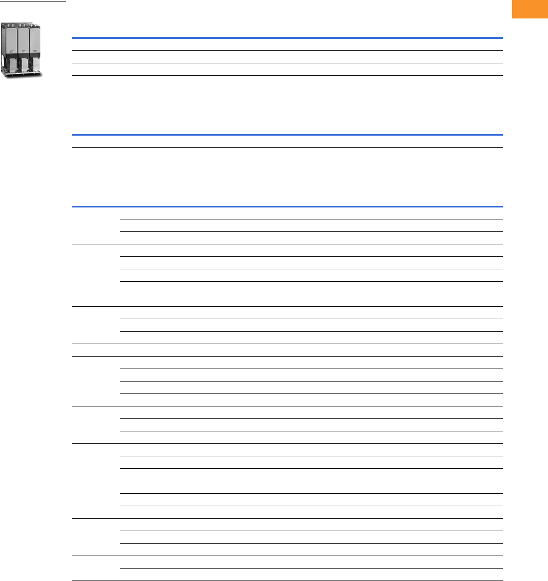
Volume 6—Solid-State Motor Control CA08100007E—February 2016 www.eaton.com V6-T2-381
2
2
2
2
2
2
2
2
2
2
2
2
2
2
2
2
2
2
2
2
2
2
2
2
2
2
2
2
2
2
2.12
Adjustable Frequency Drives
SPA/SPN/SPI Common DC Bus Drives
Product Selection
SPA Active Front End 480 V
SPN Non-Regenerative Front End 480 V
SPI Inverter Unit 480 V
Note
For filter and line reactor information, see Page [NEED REF] CONTENT WAS DELETED.
Low Overload (AC Current) High Overload (AC Current) Imax
Frame IL-cont (A) I1 min (A) IH-cont (A) I1 min (A) I2s (A) Catalog Number
FI9 261 287 205 308 349 SPA205A0-4A3N1
FI10 460 506 385 578 693 SPA385A0-4A3N1
FI13 1300 1430 1150 1725 2070 SPAH11A0-4A3N1
Low Overload (AC Current) High Overload (AC Current) Imax
Frame IL-cont (A) I1 min (A) IH-cont (A) I1 min (A) I2s (A) Catalog Number
FI9 520 572 460 690 828 SPN460A0-4A3N1
Low Overload (AC Current) High Overload (AC Current) Imax
Frame IL-cont (A) I1 min (A) IH-cont (A) I1 min (A) I2s (A) Catalog Number
FR4 4.3 4.7 3.3 5 6.2 SPI003A1-4A3N1
99.9 7.611.4 14 SPI007A1-4A3N1
12 13.2 9 13.5 18 SPI009A1-4A3N1
FR61617.6 1218 24 SPI012A1-4A3N1
23 25.3 16 24 32 SPI016A1-4A3N1
31 34 23 35 46 SPI023A1-4A3N1
38 42 31 47 62 SPI031A1-4A3N1
46 51 38 57 76 SPI038A1-4A3N1
FR77279 6192 122 SPI061A1-4A3N1
87 96 72 108 144 SPI072A1-4A3N1
105 116 87 131 174 SPI087A1-4A3N1
FR8 140 154 105 158 210 SPI105A0-4A3N1
FI9 170 187 140 210 280 SPI140A0-4A3N1
205 226 170 255 336 SPI170A0-4A3N1
261 287 205 308 349 SPI205A0-4A3N1
300 330 245 379 444 SPI245A0-4A3N1
FI10 385 424 300 450 540 SPI300A0-4A3N1
460 506 385 578 693 SPI385A0-4A3N1
520 572 460 690 828 SPI460A0-4A3N1
FI12 590 649 520 780 936 SPI520A0-4A3N1
650 715 590 885 1062 SPI590A0-4A3N1
730 803 650 975 1170 SPI650A0-4A3N1
820 902 730 1095 1314 SPI730A0-4A3N1
920 1012 820 1230 1476 SPI820A0-4A3N1
1030 1133 920 1380 1656 SPI920A0-4A3N1
FI13 1150 1265 1030 1545 1854 SPIH10A0-4A3N1
1300 1430 1150 1720 2070 SPIH11A0-4A3N1
1450 1595 1300 1950 2340 SPIH13A0-4A3N1
FI14 1770 1947 1600 2400 2880 SPIH16A0-4A3N1
2150 2365 1940 2910 3492 SPIH19A0-4A3N1
Common DC Bus Drive
Products
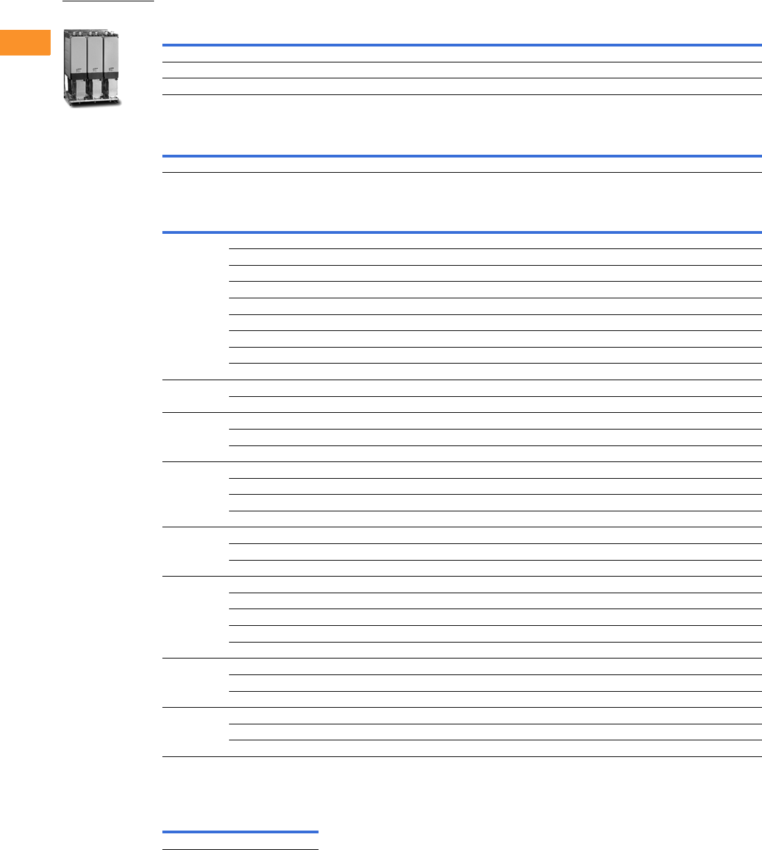
V6-T2-382 Volume 6—Solid-State Motor Control CA08100007E—February 2016 www.eaton.com
2
2
2
2
2
2
2
2
2
2
2
2
2
2
2
2
2
2
2
2
2
2
2
2
2
2
2
2
2
2
2.12
Adjustable Frequency Drives
SPA/SPN/SPI Common DC Bus Drives
SPA Active Front End 575 V
SPN Non-Regenerative Front End 575 V
SPI Inverter Unit 575 V
Line Reactor
Line Reactor for Non-Regenerative Front End (480/575 VV)
Low Overload (AC Current) High Overload (AC Current) Imax
Frame IL-cont (A) I1 min (A) IH-cont (A) I1 min (A) I2s (A) Catalog Number
FI9 144 158 125 188 213 SPA125A0-5A3N1
FI10 385 424 325 488 585 SPA325A0-5A3N1
FI13 1030 1133 920 1380 1656 SPA920A0-5A3N1
Low Overload (AC Current) High Overload (AC Current) Imax
Frame IL-cont (A) I1 min (A) IH-cont (A) I1 min (A) I2s (A) Catalog Number
FI9 600 660 510 732 888 SPN510A0-5A3N1
Low Overload (AC Current) High Overload (AC Current) Imax
Frame IL-cont (A) I1 min (A) IH-cont (A) I1 min (A) I2s (A) Catalog Number
FR6 4.5 5 3.2 5 6.4 SPI003A1-5A3N1
5.5 6 4.5 7 9 SPI004A1-5A3N1
7.5 8 5.5 8 11 SPI005A1-5A3N1
10 11 7.5 11 15 SPI007A1-5A3N1
13.5 15 10 15 20 SPI010A1-5A3N1
18 20 13.5 20 27 SPI013A1-5A3N1
22 24 18 27 36 SPI018A1-5A3N1
27 30 22 33 44 SPI022A1-5A3N1
34 37 27 41 54 SPI027A1-5A3N1
FR74145 3451 68 SPI034A1-5A3N1
52 57 41 62 82 SPI041A1-5A3N1
FR86268 5278 104 SPI052A0-5A3N1
80 88 62 93 124 SPI062A0-5A3N1
100 110 80 120 160 SPI080A0-5A3N1
FI9 125 138 100 150 200 SPI100A0-5A3N1
144 158 125 188 213 SPI125A0-5A3N1
170 187 144 216 245 SPI144A0-5A3N1
208 229 170 255 289 SPI170A0-5A3N1
FI10 261 287 208 312 375 SPI208A0-5A3N1
325 358 261 392 470 SPI261A0-5A3N1
385 424 325 488 585 SPI325A0-5A3N1
FI12 460 506 385 578 693 SPI385A0-5A3N1
502 552 460 690 828 SPI460A0-5A3N1
590 649 502 753 904 SPI502A0-5A3N1
650 715 590 885 1062 SPI590A0-5A3N1
750 825 650 975 1170 SPI650A0-5A3N1
FI13 920 1012 820 1230 1476 SPI820A0-5A3N1
1030 1133 920 1380 1656 SPI920A0-5A3N1
1180 1298 1030 1464 1755 SPIH10A0-5A3N1
FI14 1500 1650 1300 1950 2340 SPIH13A0-5A3N1
1900 2090 1500 2250 2700 SPIH15A0-5A3N1
2250 2475 1900 2782 3335 SPIH19A0-5A3N1
Amps
Watts
Losses
Catalog
Number
600 493 CHK600
Common DC Bus Drive
Products
Volume 6—Solid-State Motor Control CA08100007E—February 2016 www.eaton.com V6-T2-383
2
2
2
2
2
2
2
2
2
2
2
2
2
2
2
2
2
2
2
2
2
2
2
2
2
2
2
2
2
2
2.12
Adjustable Frequency Drives
SPA/SPN/SPI Common DC Bus Drives
Options
SVX Series Option Board Kits
The SVX Series drives can accommodate a wide selection of expander and adapter option boards to
customize the drive for your application needs. The drive’s control unit is designed to accept a total of
five option boards.
The SVX Series factory installed standard board configuration includes an A9 I/O board and an A2 relay
output board, which are installed in slots A and B.
Option Board Kits
Notes
1 AI = Analog Input; AO = Analog Output, DI = Digital Input, DO = Digital Output, RO = Relay Output
2 Option card must be installed in one of the slots listed for that card. Slot indicated in bold is the preferred location.
3 OPTC2 is a multi-protocol option card.
Option Kit Description 1
Allowed Slot
Locations 2
Field
Installed
Factory
Installed SVX Ready Programs
Catalog
Number
Option
Designator Basic
Local/
Remote Standard MSS PID Multi-P. PFC
Standard I/O Cards
2 RO (NC-NO) B OPTA2 — ■ ■ ■ ■■■ ■
6 DI, 1 DO, 2 AI, 1 AO, 1 +10 Vdc ref,
2 ext +24 Vdc/EXT +24 Vdc
AOPTA9 — ■ ■ ■ ■■■ ■
Extended I/O Cards
2 RO, therm B OPTA3 A3 —■ ■ ■■■ ■
Encoder low volt +5 V/15 V24 V C OPTA4 A4 —■ ■ ■■■ ■
Encoder high volt +15 V/24 V C OPTA5 A5 —■ ■ ■■■ ■
Double encoder C OPTA7 A7 ■ ■ ■ ■■■ ■
6 DI, 1 DO, 2 AI, 1 AO A OPTA8 A8 —■ ■ ■■■ ■
3 DI (encoder 10–24 V), out +15 V/+24 V,
2 DO (pulse+direction)
COPTAE AE ■ ■ ■ ■■■ ■
6 DI, 1 ext +24 Vdc/EXT +24 Vdc B, C, D, E OPTB1 B1 —— — ——
■■
1 RO (NC-NO), 1 RO (NO), 1 therm B, C, D, E OPTB2 B2 —— — ——
■■
1 AI (mA isolated), 2 AO (mA isolated),
1 ext +24 Vdc/EXT +24 Vdc
B, C, D, E OPTB4 B4 —■ ■ ■■■ ■
3 RO (NO) B, C, D, E OPTB5 B5 —— — ——
■■
1 ext +24 Vdc/EXT +24 Vdc, 3 Pt100 B, C, D, E OPTB8 B8 — — — ——— —
1 RO (NO), 5 DI 42–240 Vac input B, C, D, E OPTB9 B9 —— — ——
■■
SPI, absolute encoder C OPTBB BB — — — ——— —
Communication Cards 3
Modbus D, E OPTC2 C2 ■ ■ ■ ■■■ ■
Johnson Controls N2 D, E OPTC2 CA — — — ——— —
Modbus TCP D, E OPTCI CI ■ ■ ■ ■■■ ■
BACnet D, E OPTCJ CJ ■ ■ ■ ■■■ ■
EtherNet/IP D, E OPTCQ CQ ■ ■ ■ ■■■ ■
PROFIBUS DP D, E OPTC3 C3 ■ ■ ■ ■■■ ■
LonWorks D, E OPTC4 C4 ■ ■ ■ ■■■ ■
PROFIBUS DP (D9 connector) D, E OPTC5 C5 ■ ■ ■ ■■■ ■
CANopen (slave) D, E OPTC6 C6 ■ ■ ■ ■■■ ■
DeviceNet D, E OPTC7 C7 ■ ■ ■ ■■■ ■
Modbus (D9 type connector) D, E OPTC8 C8 ■ ■ ■ ■■■ ■
Adapter D, E OPTD1 D1 ■ ■ ■ ■■■ ■
Adapter D, EOPTD2VD2
■ ■ ■ ■■■ ■
RS-232 with D9 connection D, E OPTD3 D3 ■ ■ ■ ■■■ ■
Keypad
9000X Series local/remote keypad
(replacement keypad)
—KEYPAD-
LOC/REM
—— — — ——— ■
9000X Series remote mount keypad unit
(keypad not included, includes 10 ft cable,
keypad holder, mounting hardware)
—OPTRMT-
KIT-9000X
—— — — ——— —
9000X Series RS-232 cable, 13 ft — PP00104 — — — — ——— —
Option Boards
ABCDE

V6-T2-384 Volume 6—Solid-State Motor Control CA08100007E—February 2016 www.eaton.com
2
2
2
2
2
2
2
2
2
2
2
2
2
2
2
2
2
2
2
2
2
2
2
2
2
2
2
2
2
2
2.12
Adjustable Frequency Drives
SPA/SPN/SPI Common DC Bus Drives
Technical Data and Specifications
SPA/SPN/SPI
Description Specification
Supply Connection
Input voltage Uin (AC) front end modules 380–500 Vac/525–690 Vac –10% to 10%
Input voltage Uin (DC) inverter 465–800 Vdc/640–1100 Vdc –0% to 0%, the waviness of the inverter supply voltage,
formed in rectification of the electric network’s alternating voltage in basic frequency,
must be less than 50 V peak-to-peak
Output voltage Uout (AC) inverter 3 ~ 0–Uin/1.4
Output voltage Uout (DC) active front end module 10.10 x 1.35 x Uin (factory default)
Output voltage Uout (DC) non-regenerative front end module 1.35 x Uin
Ambient Conditions
Ambient operating temperature 14 (no frost) to 122 °F (–10 to 50 °C): IH
14 (no frost) to 104 °F (–10 to 40 °C): IL
Storage temperature –40 to 158 °F (–40 to 70 °C)
Relative humidity 0 to 95% RH, non-condensing, non-corrosive, no dripping water
Air quality
Chemical vapors IEC 721-3-3, unit in operation, class 3C2
Mechanical particles IEC 721-3-3, unit in operation, class 3S2
Altitude 100% load capacity (no derating) up to 1000 m
1% derating for each 100 m above 1000 m; max. 3000 m
Vibration 5–150 Hz
EN50178/EN60068-2-6 Displacement amplitude 0.25 mm (peak) at 3–15.8 Hz
Max acceleration amplitude 1G at 15.8–150 Hz
Shock
EN50178, EN60068-2-27
UPS Drop Test (for applicable UPS weights)
Storage and shipping: max 15 g, 11 ms (in package)
Cooling capacity required Approximately 2%
Cooling air required FR4 41 cfm, FR6 250 cfm, FR7 250 cfm, FR8 383 cfm
FI9 677 cfm, FI10 824 cfm, FI12 1648 cfm, FI13 2472 cfm
Unit enclosure class FR4–FR7 NEMA Type 1/IP21; FR8, FI9–FI14 chassis (IP00)
EMC (at fault settings)
Immunity Fulfill all EMC immunity requirements
Safety
Approvals CE, UL, cUL, EN 61800-5-1 (2003), see unit nameplate for more detailed approvals
Control Connections
Analog input voltage 0–10 V, Ri = 200 kohms, (–10 V to 10 V joystick control)
Resolution 0.1%, accuracy ±1%
Analog input current 0(4)–20 mA, Ri = 250 ohms differential
Digital inputs 6, positive or negative logic; 18–30 Vdc
Auxiliary voltage +24 V, ±15%, max. 250 mA
Output reference voltage +10 V, +3%, max. load 10 mA
Analog output 0(4)–20 mA; RL max. 500 ohms; resolution 10 bits
Accuracy ±2%
Digital outputs Open collector output, 50 mA/48V
Relay outputs 2 programmable change-over relay outputs
Switching capacity: 24 Vdc/8 A, 250 Vac/8 A, 125 Vdc/0.4 A
Min. switching load: 5 V/10 mA

Volume 6—Solid-State Motor Control CA08100007E—February 2016 www.eaton.com V6-T2-385
2
2
2
2
2
2
2
2
2
2
2
2
2
2
2
2
2
2
2
2
2
2
2
2
2
2
2
2
2
2
2.12
Adjustable Frequency Drives
SPA/SPN/SPI Common DC Bus Drives
SPA/SPN/SPI, continued
Input Fuses
SHT fuses can be assembled into same-size DIN fuse base.
SPA/SPN/SPI
Description Specification
Protections
Overvoltage protection 480 V/911 Vdc, 575 V/1200 Vdc
Undervoltage protection 480 V/333 Vdc, 575 V/460 Vdc
Ground fault protection In case of ground fault in motor or motor cable, only the inverter is protected
Motor phase supervision Trips if any of the output phases is missing
Overcurrent protection Yes
Unit overtemperature protection Yes
Motor overload protection Yes
Motor stall protection Yes
Motor underload protection Yes
Short-circuit protection of 24 V and 10 V reference voltages Yes
Module
Component Frame Bussmann Fuse Type (aR) Size UN (V) IN (A) Qty.
Inverter Units
SPI003A1-4 FR4 170M1560 0 690 20 2
SPI007A1-4 FR4 170M1562 0 690 63 2
SPI009A1-4 FR4 170M1562 0 690 63 2
SPI012A1-4 FR6 170M1565 0 690 63 2
SPI016A1-4 FR6 170M1565 0 690 63 2
SPI023A1-4 FR6 170M1565 0 690 63 2
SPI031A1-4 FR6 170M1567 0 690 100 2
SPI038A1-4 FR6 170M1567 0 690 100 2
SPI061A1-4 FR7 170M1570 0 690 200 2
SPI072A1-4 FR7 170M1570 0 690 200 2
SPI087A1-4 FR7 170M1571 0 690 250 2
SPI105A0-4 FR8 170M3819 DIN1 690 400 2
SPI140A0-4 FR8 170M3819 DIN1 690 400 2
SPI170A0-4 FR8 170M3819 DIN1 690 400 2
SPI205A0-4 FI9 170M6812 DIN3 690 800 2
SPI245A0-4 FI9 170M6812 DIN3 690 800 2
SPI300A0-4 FI10 170M8547 3SHT 690 1250 2
SPI385A0-4 FI10 170M8547 3SHT 690 1250 2
SPI460A0-4 FI10 170M8547 3SHT 690 1250 2
SPI520A0-4 FI12 170M8547 3SHT 690 1250 2 x 2
SPI590A0-4 FI12 170M8547 3SHT 690 1250 2 x 2
SPI650A0-4 FI12 170M8547 3SHT 690 1250 2 x 2
SPI730A0-4 FI12 170M8547 3SHT 690 1250 2 x 2
SPI820A0-4 FI12 170M8547 3SHT 690 1250 2 x 2
SPI920A0-4 FI12 170M8547 3SHT 690 1250 2 x 2
SPIH10A0-4 FI13 170M8547 3SHT 690 1250 6
SPIH11A0-4 FI13 170M8547 3SHT 690 1250 6
SPIH13A0-4 FI13 170M8547 3SHT 690 1250 6
SPIH16A0-4 FI14 170M8547 3SHT 690 1250 2 x 6
SPIH19A0-4 FI14 170M8547 3SHT 690 1250 2 x 6
SPIH23A0-4 FI14 170M8547 3SHT 690 1250 2 x 6
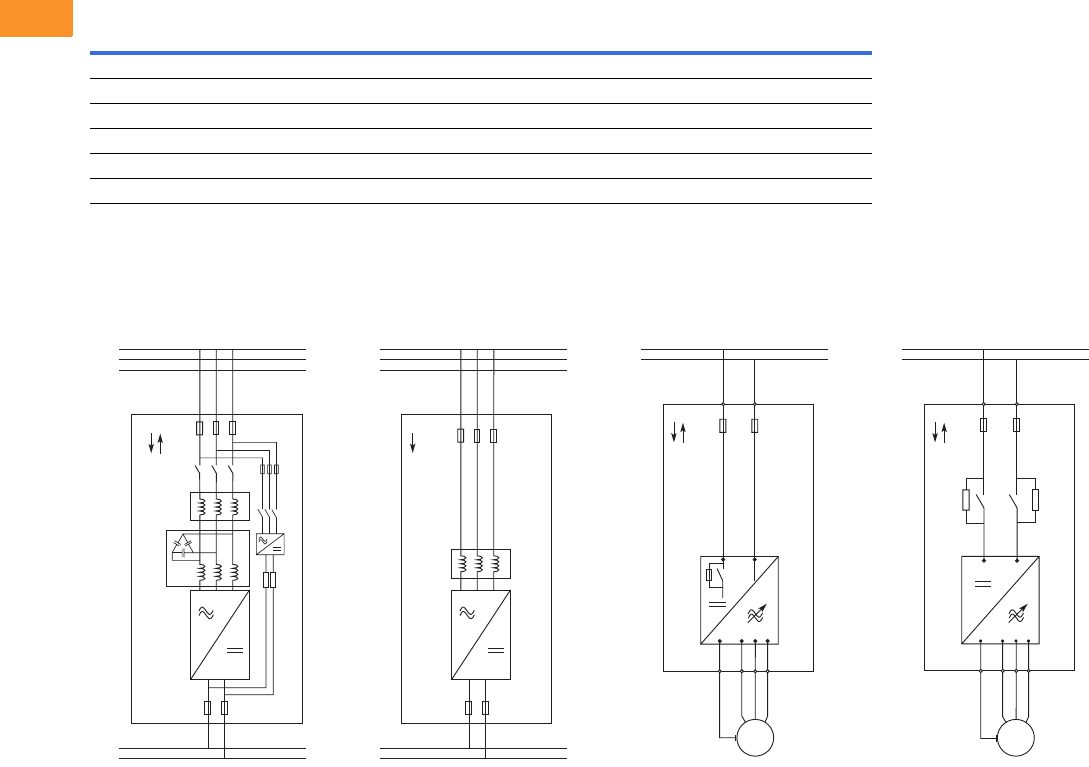
V6-T2-386 Volume 6—Solid-State Motor Control CA08100007E—February 2016 www.eaton.com
2
2
2
2
2
2
2
2
2
2
2
2
2
2
2
2
2
2
2
2
2
2
2
2
2
2
2
2
2
2
2.12
Adjustable Frequency Drives
SPA/SPN/SPI Common DC Bus Drives
SHT fuses can be assembled into same-size DIN fuse base.
SPA/SPN/SPI, continued
Wiring Diagrams
SPA—
Active Front End
SPN—Non-Regenerative
Front End
SPI—Inverter Unit
(FR4–FR8)
SPI—Inverter Unit
(FI9–FI14)
Module
Component Frame Bussmann Fuse Type (aR) Size UN (V) IN (A) Qty.
Active Front Ends
SPA205 A0-4 FI9 170 m6202 3SHT 1250 500 3
SPA385 A0-4 FI10 170 m6277 3SHT 1250 1000 3
SPAH10 A0-4 FI13 170 m6277 3SHT 1250 1000 3 x 3
Non-Regenerative Front Ends
SPN468 A0-4 FI9 170 m8547 3SHT 690 1250 3
-K4 -F4
-K5
-V4
-R4
425 – 600 Vdc
L2
L1
L3
DC+
DC-
-F1
-U1
-F2
380 – 500 Vac
AFE
-L1.1
-L1.2
425 – 800 Vdc
L2
L1
L3
DC+
DC-
-F1
-U1
-F2
380 – 500 Vac
NFE
-L1
DC+ DC-
VW
PE U
425 – 800 Vdc
DC+
DC-
M
INU -F1
VWU
PE
DC+
425 – 800 Vdc
DC+
DC-
DC-
INU -F1
M

Volume 6—Solid-State Motor Control CA08100007E—February 2016 www.eaton.com V6-T2-387
2
2
2
2
2
2
2
2
2
2
2
2
2
2
2
2
2
2
2
2
2
2
2
2
2
2
2
2
2
2
2.12
Adjustable Frequency Drives
SPA/SPN/SPI Common DC Bus Drives
Dimensions
Approximate Dimensions in Inches (mm)
SPA/SPN/SPI
Frame Height Width Depth
Weight
Lbs (kg)
Active Front Ends
FI9 40.6 (1030) 9.4 (239) 14.6 (372) 148 (67)
FI10 40.6 (1032) 9.4 (239) 21.7 (552) 220 (100)
FI12 40.6 (1032) 2 x 9.4 (2 x 239) 21.7 (552) 441 (200)
FI13 40.6 (1032) 27.9 (708) 21.8 (553) 674 (306)
FI14 40.6 (1032) 2 x 27.9 (2 x 708) 21.8 (553) 1348 (612)
Non-Regenerative Front Ends
FI9 40.6 (1030) 9.4 (239) 14.6 (372) 148 (67)
Inverter Units
FR4 11.5 (292) 5.0 (128) 7.5 (190) 11 (5)
FR6 20.4 (519) 7.7 (195) 9.3 (237) 35 (16)
FR7 23.3 (591) 9.3 (237) 10.1 (257) 64 (29)
FR8 29.8 (758) 11.4 (289) 13.5 (344) 106 (48)
FI9 40.6 (1030) 9.4 (239) 14.6 (372) 148 (67)
FI10 40.6 (1032) 9.4 (239) 21.7 (552) 220 (100)
FI12 40.6 (1032) 2 x 9.4 (2 x 239) 21.7 (552) 441 (200)
FI13 40.6 (1032) 27.9 (708) 21.8 (553) 674 (306)
FI14 40.6 (1032) 2 x 27.9 (2 x 708) 21.8 (553) 1348 (612)
Volume 6—Solid-State Motor Control CA08100007E—March 2015 www.eaton.com V6-A1-1
Appendix 1—Eaton Terms & Conditions
Effective Date: November 1, 2008
Eaton Terms & Conditions
Contents
Description Page
Terms and Conditions of Sale. . . . . . . . . . . . . . . . . V6-A1-1
Terms of Payment . . . . . . . . . . . . . . . . . . . . . . . . . V6-A1-2
Freight . . . . . . . . . . . . . . . . . . . . . . . . . . . . . . . . . . V6-A1-3
Warranty . . . . . . . . . . . . . . . . . . . . . . . . . . . . . . . . . V6-A1-3
Selling Policy (Supersedes Selling Policy 25-000, dated February 20, 2006)
Terms and Conditions of Sale
The Terms and Conditions of
Sale set forth herein, and any
supplements which may be
attached hereto, constitute
the full and final expression
of the contract for the sale
of products or services
(hereinafter referred to as
Product(s) or Services by
Eaton Corporation
(hereinafter referred to as
Seller) to the Buyer, and
supersedes all prior
quotations, purchase orders,
correspondence or
communications whether
written or oral between the
Seller and the Buyer.
Notwithstanding any contrary
language in the Buyer’s
purchase order,
correspondence or other
form of acknowledgment,
Buyer shall be bound by
these Terms and Conditions
of Sale when it sends a
purchase order or otherwise
indicates acceptance of this
contract, or when it accepts
delivery from Seller of the
Products or Services.
THE CONTRACT FOR SALE
OF THE PRODUCTS OR
SERVICES IS EXPRESSLY
LIMITED TO THE TERMS
AND CONDITIONS OF SALE
STATED HEREIN. ANY
ADDITIONAL OR DIFFERENT
TERMS PROPOSED BY
BUYER ARE REJECTED
UNLESS EXPRESSLY
AGREED TO IN WRITING BY
SELLER. No contract shall
exist except as herein
provided.
Complete Agreement
No amendment or
modification hereto nor any
statement, representation or
warranty not contained herein
shall be binding on the Seller
unless made in writing by an
authorized representative of
the Seller. Prior dealings,
usage of the trade or a course
of performance shall not be
relevant to determine the
meaning of this contract even
though the accepting or
acquiescing party had
knowledge of the nature
of the performance and
opportunity for objection.
Quotations
Written quotations are valid
for 30 days from its date
unless otherwise stated in
the quotation or terminated
sooner by notice.
Verbal quotations, unless
accepted, expire the same
day they are made.
A complete signed order
must be received by Seller
within 20 calendar days of
notification of award,
otherwise the price and
shipment will be subject to
re-negotiation.
Termination and Cancellation
Any order may be terminated
by the Buyer only by written
notice and upon payment
of reasonable termination
charges, including all costs
plus profit.
Seller shall have the right to
cancel any order at any time
by written notice if Buyer
breaches any of the terms
hereof, becomes the subject
of any proceeding under state
or federal law for the relief
of debtors, or otherwise
becomes insolvent or
bankrupt, generally does not
pay its debts as they become
due or makes an assignment
for the benefit of creditors.
V6-A1-2 Volume 6—Solid-State Motor Control CA08100007E—March 2015 www.eaton.com
Appendix 1—Eaton Terms & Conditions
Effective Date: November 1, 2008
Prices
All prices are subject to
change without notice. In the
event of a price change, the
effective date of the change
will be the date of the new
price or discount sheet, letter
or telegram. All quotations
made or orders accepted
after the effective date will be
on the new basis. For existing
orders, the price of the
unshipped portion of an order
will be the price in effect at
time of shipment.
Price Policy—Products and
Services
When prices are quoted as
firm for quoted shipment, they
are firm provided the following
conditions are met:
1. The order is released
with complete
engineering details.
2. Shipment of Products are
made, and Services
purchased are provided
within the quoted
lead time.
3. When drawings for
approval are required
for any Products, the
drawings applicable to
those Products must be
returned within 30*
calendar days from the
date of the original
mailing of the drawings
by Seller. The return
drawings must be
released for manufacture
and shipment and must
be marked “APPROVED”
or “APPROVED AS
NOTED.” Drawing
re-submittals which are
required for any other
reason than to correct
Seller errors will not
extend the 30-day period.
* 60 days for orders
through contractors
to allow time for their
review and approval
before and after
transmitting them
to their customers.
If the Buyer initiates or in
any way causes delays
in shipment, provision of
Services or return of approval
drawings beyond the periods
stated above, the price of the
Products or Services will be
increased 1% per month
or fraction thereof up to a
maximum of 18 months from
the date of the Buyer’s order.
For delays resulting in
shipment or provision of
Services beyond 18 months
from the date of the Buyer’s
order, the price must be
renegotiated.
Price Policy—BLS
Refer to Price Policy 25-050.
Minimum Billing
Orders less than $1,000 will
be assessed a shipping and
handling charge of 5% of the
price of the order, with a
minimum charge of $25.00
unless noted differently on
Product discount sheets.
Taxes
The price does not include
any taxes. Buyer shall be
responsible for the payment
of all taxes applicable to, or
arising from the transaction,
the Products, its sale, value,
or use, or any Services
performed in connection
therewith regardless of
the person or entity
actually taxed.
Terms of Payment
Products
Acceptance of all orders is
subject to the Buyer meeting
Seller’s credit requirements.
Terms of payment are subject
to change for failure to meet
such requirements. Seller
reserves the right at any time
to demand full or partial
payment before proceeding
with a contract of sale as a
result of changes in the
financial condition of the
Buyer. Terms of Payment are
either Net 30 days from the
date of invoice of each
shipment or carry a cash
discount based on Product
type. Specific payment terms
for Products are outlined in
the applicable Product
discount schedules.
Services
Terms of payment are net
within 30 days from date of
invoice for orders amounting
to less than $50,000.00.
Terms of payment for orders
exceeding $50,000.00 shall
be made according to the
following:
1. Twenty percent (20%) of
order value with the
purchase order payable
30 days from date of
invoice.
2. Eighty percent (80%) of
order value in equal
monthly payments over
the performance period
payable 30 days from
date of invoice.
Except for work performed (i)
under a firm fixed price basis
or (ii) pursuant to terms of a
previously priced existing
contract between Seller and
Buyer, invoices for work
performed by Seller shall
have added and noted on
each invoice a charge of 3%
(over and above the price of
the work) which is related
to Seller compliance with
present and proposed
environmental, health, and
safety regulations associated
with prescribed requirements
covering hazardous materials
management and employee
training, communications,
personal protective
equipment, documentation
and record keeping
associated therewith.
Adequate Assurances
If, in the judgment of Seller,
the financial condition of the
Buyer, at any time during the
period of the contract, does
not justify the terms of
payment specified, Seller
may require full or partial
payment in advance.
Delayed Payment
If payments are not made in
accordance with these terms,
a service charge will, without
prejudice to the right of Seller
to immediate payment, be
added in an amount equal to
the lower of 1.5% per month
or fraction thereof or the
highest legal rate on the
unpaid balance.
Volume 6—Solid-State Motor Control CA08100007E—March 2015 www.eaton.com V6-A1-3
Appendix 1—Eaton Terms & Conditions
Effective Date: November 1, 2008
Freight
Freight policy will be listed on
the Product discount sheets,
or at option of Seller one of
the following freight terms
will be quoted.
F.O.B.—P/S—Frt./Ppd. and
Invoiced
Products are sold F.O.B. point
of shipment freight prepaid
and invoiced to the Buyer.
F.O.B.—P/S—Frt./Ppd.
and Allowed
Products sold are delivered
F.O.B. point of shipment,
freight prepaid and included
in the price.
F.O.B. Destination—Frt./Ppd.
and Allowed
At Buyer’s option, Seller will
deliver the Products F.O.B.
destination freight prepaid
and 2% will be added to the
net price.
The term “freight prepaid”
means that freight charges
will be prepaid to the
accessible common carrier
delivery point nearest the
destination for shipments
within the United States and
Puerto Rico unless noted
differently on the Product
discount sheets. For any
other destination contact
Seller’s representative.
Shipment and Routing
Seller shall select the point of
origin of shipment, the
method of transportation, the
type of carrier equipment and
the routing of the shipment.
If the Buyer specifies a
special method of
transportation, type of carrier
equipment, routing, or
delivery requirement, Buyer
shall pay all special freight
and handling charges.
When freight is included in
the price, no allowance will
be made in lieu of
transportation if the Buyer
accepts shipment at factory,
warehouse, or freight station
or otherwise supplies its own
transportation.
Risk of Loss
Risk of loss or damage to the
Products shall pass to Buyer
at the F.O.B. point.
Concealed Damage
Except in the event of F.O.B.
destination shipments, Seller
will not participate in any
settlement of claims for
concealed damage.
When shipment has been
made on an F.O.B. destination
basis, the Buyer must unpack
immediately and, if damage is
discovered must:
1. Not move the Products
from the point of
examination.
2. Retain shipping container
and packing material.
3. Notify the carrier in
writing of any apparent
damage.
4. Notify Seller
representative within
72 hours of delivery.
5. Send Seller a copy of
the carrier’s inspection
report.
Witness Tests/Customer
Inspection
Standard factory tests may be
witnessed by the Buyer
at Seller’s factory for an
additional charge calculated
at the rate of $2,500 per day
(not to exceed eight (8) hours)
per Product type. Buyer may
final inspect Products at the
Seller’s factory for $500 per
day per Product type.
Witness tests will add one (1)
week to the scheduled
shipping date. Seller will
notify Buyer fourteen (14)
calendar days prior to
scheduled witness testing
or inspection. In the event
Buyer is unable to attend, the
Parties shall mutually agree
on a rescheduled date.
However, Seller reserves
the right to deem the witness
tests waived with the right to
ship and invoice Products.
Held Orders
For any order held, delayed
or rescheduled at the request
of the Buyer, Seller may, at
its sole option (1) require
payment to be based on any
reasonable basis, including
but not limited to the contract
price, and any additional
expenses, or cost resulting
from such a delay; (2) store
Products at the sole cost and
risk of loss of the Buyer; and/
or (3) charge to the Buyer
those prices under the
applicable price policy.
Payment for such price,
expenses and costs, in any
such event, shall be due by
Buyer within thirty (30) days
from date of Seller’s invoice.
Any order so held delayed or
rescheduled beyond six (6)
months will be treated as a
Buyer termination.
Drawing Approval
Seller will design the
Products in line with, in
Seller’s judgment, good
commercial practice. If at
drawing approval Buyer
makes changes outside of
the design as covered in their
specifications, Seller will then
be paid reasonable charges
and allowed a commensurate
delay in shipping date based
on the changes made.
Drawing Re-Submittal
When Seller agrees to do so
in its quotation, Seller shall
provide Buyer with the first
set of factory customer
approval drawing(s) at Seller’s
expense. The customer
approval drawing(s) will be
delivered at the quoted
delivery date. If Buyer
requests drawing changes
or additions after the initial
factory customer approval
drawing(s) have been
submitted by Seller, the
Seller, at its option, may
assess Buyer drawing
charges. Factory customer
approval drawing changes
required due to
misinterpretation by Seller
will be at Seller’s expense.
Approval drawings generated
by Bid Manager are excluded
from this provision.
Warranty
Warranty for Products
Seller warrants that the
Products manufactured by
it will conform to Seller’s
applicable specifications and
be free from failure due to
defects in workmanship and
material for one (1) year from
the date of installation of
the Product or eighteen (18)
months from the date of
shipment of the Product,
whichever occurs first.
In the event any Product fails
to comply with the foregoing
warranty Seller will, at its
option, either (a) repair or
replace the defective
Product, or defective part or
component thereof, F.O.B.
Seller’s facility freight
prepaid, or (b) credit Buyer
for the purchase price of the
Product. All warranty claims
shall be made in writing.
Seller requires all non-
conforming Products be
returned at Seller’s expense
for evaluation unless
specifically stated otherwise
in writing by Seller.
This warranty does not
cover failure or damage
due to storage, installation,
operation or maintenance not
in conformance with Seller’s
recommendations and
industry standard practice
or due to accident, misuse,
abuse or negligence. This
warranty does not cover
reimbursement for labor,
gaining access, removal,
installation, temporary power
or any other expenses, which
may be incurred in connection
with repair or replacement.
This warranty does not
apply to equipment not
manufactured by Seller.
Seller limits itself to
extending the same warranty
it receives from the supplier.
V6-A1-4 Volume 6—Solid-State Motor Control CA08100007E—March 2015 www.eaton.com
Appendix 1—Eaton Terms & Conditions
Effective Date: November 1, 2008
Extended Warranty for Products
If requested by the Buyer and
specifically accepted in
writing by Seller, the
foregoing standard warranty
for Products will be extended
from the date of shipment for
the period and price indicated
below:
●24 months—2% of
Contract Price
●30 months—3% of
Contract Price
●36 months—4% of
Contract Price
Special Warranty (In and Out)
for Products
If requested by the Buyer
and specifically accepted in
writing by Seller, Seller will,
during the warranty period
for Products, at an additional
cost of 2% of the contract
price, be responsible for the
direct cost of:
1. Removing the Product
from the installed
location.
2. Transportation to the
repair facility and return
to the site.
3. Reinstallation on site.
The total liability of Seller for
this Special Warranty for
Products is limited to 50%
of the contract price of the
particular Product being
repaired and excludes
expenses for removing
adjacent apparatus, walls,
piping, structures, temporary
service, etc.
Warranty for Services
Seller warrants that the
Services performed by it
hereunder will be performed
in accordance with generally
accepted professional
standards.
The Services, which do not
so conform, shall be
corrected by Seller upon
notification in writing by the
Buyer within one (1) year
after completion of the
Services.
Unless otherwise agreed to in
writing by Seller, Seller
assumes no responsibility
with respect to the suitability
of the Buyer’s, or its
customer’s, equipment or
with respect to any latent
defects in equipment not
supplied by Seller. This
warranty does not cover
damage to Buyer’s, or its
customer’s, equipment,
components or parts
resulting in whole or in part
from improper maintenance
or operation or from their
deteriorated condition. Buyer
will, at its cost, provide Seller
with unobstructed access
to the defective Services,
as well as adequate free
working space in the
immediate vicinity of the
defective Services and such
facilities and systems,
including, without limitation,
docks, cranes and utility
disconnects and connects,
as may be necessary in order
that Seller may perform its
warranty obligations. The
conducting of any tests shall
be mutually agreed upon and
Seller shall be notified of, and
may be present at, all tests
that may be made.
Warranty for Power Systems
Studies
Seller warrants that any
power systems studies
performed by it will conform
to generally accepted
professional standards. Any
portion of the study, which
does not so conform, shall
be corrected by Seller upon
notification in writing by the
Buyer within six (6) months
after completion of the study.
All warranty work shall be
performed in a single shift
straight time basis Monday
through Friday. In the event
that the study requires
correction of warranty items
on an overtime schedule,
the premium portion of such
overtime shall be for the
Buyer’s account.
Limitation on Warranties for
Products, Services and Power
Systems Studies
THE FOREGOING
WARRANTIES ARE
EXCLUSIVE EXCEPT FOR
WARRANTY OF TITLE.
SELLER DISCLAIMS ALL
OTHER WARRANTIES
INCLUDING ANY IMPLIED
WARRANTIES OF
MERCHANTABILITY
AND FITNESS FOR A
PARTICULAR PURPOSE.
CORRECTION OF NON-
CONFORMITIES IN THE
MANNER AND FOR THE
PERIOD OF TIME PROVIDED
ABOVE SHALL CONSTITUTE
SELLER’S SOLE LIABILITY
AND BUYER’S EXCLUSIVE
REMEDY FOR FAILURE OF
SELLER TO MEET ITS
WARRANTY OBLIGATIONS,
WHETHER CLAIMS OF
THE BUYER ARE BASED
IN CONTRACT, IN TORT
(INCLUDING NEGLIGENCE
OR STRICT LIABILITY), OR
OTHERWISE.
Asbestos
Federal Law requires that
building or facility owners
identify the presence,
location and quantity of
asbestos containing material
(hereinafter “ACM”) at work
sites. Seller is not licensed to
abate ACM. Accordingly, for
any contract which includes
the provision of Services,
prior to (i) commencement of
work at any site under a
specific Purchase Order, (ii) a
change in the work scope of
any Purchase Order, the
Buyer will certify that the
work area associated with the
Seller’s scope of work
includes the handling of Class
II ACM, including but not
limited to generator wedges
and high temperature gaskets
which include asbestos
materials. The Buyer shall, at
its expense, conduct
abatement should the
removal, handling,
modification or reinstallation,
or some or all of them, of said
Class II ACM be likely to
generate airborne asbestos
fibers; and should such
abatement affect the cost
of or time of performance
of the work then Seller shall
be entitled to an equitable
adjustment in the schedule,
price and other pertinent
affected provisions of
the contract.
Compliance with Nuclear
Regulation
Seller’s Products are sold as
commercial grade Products
not intended for application in
facilities or activities licensed
by the United States Nuclear
Regulatory Commission for
atomic purposes. Further
certification will be required
for use of the Products in any
safety-related application in
any nuclear facility licensed
by the U.S. Nuclear
Regulatory Commission.
Volume 6—Solid-State Motor Control CA08100007E—March 2015 www.eaton.com V6-A1-5
Appendix 1—Eaton Terms & Conditions
Effective Date: November 1, 2008
Returning Products
Authorization and shipping
instructions for the return
of any Products must be
obtained from Seller before
returning the Products.
When return is occasioned
due to Seller error, full credit
including all transportation
charges will be allowed.
Product Notices
Buyer shall provide the user
(including its employees) of
the Products with all Seller
supplied Product notices,
warnings, instructions,
recommendations, and
similar materials.
Force Majeure
Seller shall not be liable for
failure to perform or delay
in performance due to fire,
flood, strike or other labor
difficulty, act of God, act of
any governmental authority or
of the Buyer, riot, embargo,
fuel or energy shortage, car
shortage, wrecks or delays in
transportation, or due to any
other cause beyond Seller’s
reasonable control. In the
event of delay in performance
due to any such cause, the
date of delivery or time for
completion will be extended
by a period of time reasonably
necessary
to overcome the
effect of such delay.
Liquidated Damages
Contracts which include
liquidated damage clauses for
failure to meet shipping or job
completion promises are not
acceptable or binding on
Seller, unless such clauses
are specifically accepted in
writing by an authorized
representative of the Seller at
its headquarters office.
Patent Infringement
Seller will defend or, at its
option, settle any suit or
proceeding brought against
Buyer, or Buyer’s customers,
to the extent it is based upon
a claim that any Product or
part thereof, manufactured by
Seller or its subsidiaries and
furnished hereunder,
infringes any United States
patent, other than a claim of
infringement based upon use
of a Product or part thereof in
a process, provided Seller is
notified in reasonable time
and given authority,
information and assistance
(at Seller’s expense) for the
defense of same. Seller shall
pay all legal and court costs
and expenses and court-
assessed damages awarded
therein against Buyer
resulting from or incident to
such suit or proceeding. In
addition to the foregoing, if at
any time Seller determines
there is a substantial question
of infringement of any United
States patent, and the use of
such Product is or may be
enjoined, Seller may, at its
option and expense: either (a)
procure for Buyer the right to
continue using and selling the
Product; (b) replace the
Product with non-infringing
apparatus; (c) modify the
Product so it becomes non-
infringing; or (d) as a last
resort, remove the Product
and refund the purchase
price, equitably adjusted for
use and obsolescence. In no
case does Seller agree to pay
any recovery based upon its
Buyer’s savings or profit
through use of Seller’s
Products whether the use be
special or ordinary. The
foregoing states the entire
liability of Seller for patent
infringement.
The preceding paragraph
does not apply to any claim of
infringement based upon: (a)
any modification made to a
Product other than by Seller;
(b) any design and/or
specifications of Buyer to
which a Product was
manufactured; or (c) the use
or combination of Product
with other products where
the Product does not itself
infringe. As to the above-
identified claim situations
where the preceding
paragraph does not apply,
Buyer shall defend and hold
Seller harmless in the same
manner and to the extent as
Seller’s obligations described
in the preceding paragraph.
Buyer shall be responsible for
obtaining (at Buyer’s
expense) all license rights
required for Seller to be able
to use software products in
the possession of Buyer
where such use is required in
order to perform any Service
for Buyer.
With respect to a Product or
part thereof not manufactured
by Seller or its subsidiaries,
Seller will attempt to obtain
for Buyer, from the supplier(s),
the patent indemnification
protection normally provided
by the supplier(s) to
customers.
Compliance with OSHA
Seller offers no warranty and
makes no representation that
its Products comply with the
provisions or standards of the
Occupational Safety and
Health Act of 1970, or any
regulation issued thereunder.
In no event shall Seller be
liable for any loss, damage,
fines, penalty or expenses
arising under said Act.
Limitation of Liability
THE REMEDIES OF THE
BUYER SET FORTH IN THIS
CONTRACT ARE EXCLUSIVE
AND ARE ITS SOLE
REMEDIES FOR ANY
FAILURE OF SELLER
TO COMPLY WITH ITS
OBLIGATIONS HEREUNDER.
NOTWITHSTANDING
ANY PROVISION IN THIS
CONTRACT TO THE
CONTRARY, IN NO EVENT
SHALL SELLER BE LIABLE
IN CONTRACT, IN TORT
(INCLUDING NEGLIGENCE
OR STRICT LIABILITY) OR
OTHERWISE FOR DAMAGE
TO PROPERTY OR
EQUIPMENT OTHER THAN
PRODUCTS SOLD
HEREUNDER, LOSS OF
PROFITS OR REVENUE,
LOSS OF USE OF
PRODUCTS, COST OF
CAPITAL, CLAIMS OF
CUSTOMERS OF THE
BUYER OR ANY SPECIAL,
INDIRECT, INCIDENTAL OR
CONSEQUENTIAL
DAMAGES WHATSOEVER,
REGARDLESS OF WHETHER
SUCH POTENTIAL
DAMAGES ARE
FORESEEABLE OR IF
SELLER HAS BEEN ADVISED
OF THE POSSIBILITY OF
SUCH DAMAGES.
THE TOTAL CUMULATIVE
LIABILITY OF SELLER
ARISING FROM OR
RELATED TO THIS
CONTRACT WHETHER
THE CLAIMS ARE BASED
IN CONTRACT, IN TORT
(INCLUDING NEGLIGENCE
OR STRICT LIABILITY) OR
OTHERWISE, SHALL NOT
EXCEED THE PRICE OF THE
PRODUCT OR SERVICES
ON WHICH SUCH LIABILITY
IS BASED.
Volume 6—Solid-State Motor Control CA08100007E—February 2016 www.eaton.com V6-A2-1
Appendix 2—Catalog Parent Number Index
C
CFX . . . . . . . . . . . V6-T2-292–V6-T2-296
CHK . . . . . . . . . . . V6-T2-382
CPX . . . . . . . . . . . V6-T2-326–V6-T2-333
C25D . . . . . . . . . . V6-T1-53
C440 . . . . . . . . . . V6-T1-52
C441 . . . . . . . . . . V6-T1-52, V6-T1-76
D
DA1 . . . . . . . . . . . V6-T2-27
DBR-R . . . . . . . . . V6-T2-110, V6-T2-225
DC1 . . . . . . . . . . . V6-T2-17
DG1 . . . . . . . . . . . V6-T2-50, V6-T2-51
DS7 . . . . . . . . . . . V6-T1-7–V6-T1-14
DXG. . . . . . . . . . . V6-T2-60, V6-T2-61, V6-T2-270
D77E . . . . . . . . . . V6-T1-52, V6-T1-53
E
EGF . . . . . . . . . . . V6-T2-266–V6-T2-268
EGS . . . . . . . . . . . V6-T2-73–V6-T2-76
EMA . . . . . . . . . . V6-T1-66, V6-T1-89
EML. . . . . . . . . . . V6-T1-65, V6-T1-88
EMM . . . . . . . . . . V6-T1-66, V6-T1-89
EMS . . . . . . . . . . V6-T1-65, V6-T1-88
H
HCX . . . . . . . . . . . V6-T2-321
HMX . . . . . . . . . . V6-T2-181, V6-T2-182, V6-T2-192–V6-T2-200
K
KEYPAD . . . . . . . V6-T2-109, V6-T2-224, V6-T2-366, V6-T2-383
L
LCX . . . . . . . . . . . V6-T2-363–V6-T2-365
M
MMX . . . . . . . . . . V6-T2-38, V6-T2-39
O
OPTA . . . . . . . . . V6-T2-107, V6-T2-153, V6-T2-222, V6-T2-297,
V6-T2-334, V6-T2-353, V6-T2-366, V6-T2-383
OPTB . . . . . . . . . V6-T2-107, V6-T2-153, V6-T2-222, V6-T2-297,
V6-T2-334, V6-T2-353, V6-T2-366, V6-T2-383
OPTC . . . . . . . . . V6-T2-107, V6-T2-153, V6-T2-222, V6-T2-297,
V6-T2-334, V6-T2-353, V6-T2-366, V6-T2-383
OPTD . . . . . . . . . V6-T2-107, V6-T2-153, V6-T2-222, V6-T2-297,
V6-T2-334, V6-T2-353, V6-T2-366, V6-T2-383
OPTN . . . . . . . . . V6-T2-106, V6-T2-221
OPTR . . . . . . . . . V6-T2-109, V6-T2-224, V6-T2-366, V6-T2-383
P
PP00 . . . . . . . . . V6-T2-383
PSG . . . . . . . . . . V6-T1-65, V6-T1-76, V6-T1-88
R
RGX . . . . . . . . . . V6-T2-351, V6-T2-352
S
SPA . . . . . . . . . . V6-T2-381, V6-T2-382
SPI . . . . . . . . . . . V6-T2-381, V6-T2-382
SPN . . . . . . . . . . V6-T2-381, V6-T2-382
SPX . . . . . . . . . . V6-T2-104, V6-T2-105, V6-T2-216–V6-T2-220
SS-IP . . . . . . . . . V6-T1-65, V6-T1-88
SVDRIVE . . . . . . V6-T2-109, V6-T2-224
SVX . . . . . . . . . . V6-T2-102–V6-T2-105
S511. . . . . . . . . . V6-T1-39
S611. . . . . . . . . . V6-T1-51–V6-T1-53
S701. . . . . . . . . . V6-T1-27, V6-T1-33, V6-T1-36
S801+ . . . . . . . . V6-T1-63, V6-T1-64
S811+ . . . . . . . . V6-T1-84–V6-T1-87, V6-T1-89
X
XMX . . . . . . . . . . V6-T2-183, V6-T2-201
Numerics
9000X. . . . . . . . . V6-T2-106, V6-T2-109, V6-T2-184, V6-T2-221,
V6-T2-224
Volume 6—Solid-State Motor Control CA08100007E—February 2016 www.eaton.com V6-A3-1
Appendix 3—Alphabetical Product Index
A
Accessories
Adjustable Frequency Drives
Clean Power Drives . . . . . . . . . . . . . . . . . . . . . . . . V6-T2-270
H-Max Series . . . . . . . . . . . . . . . . . . . . . . . . . . . . . V6-T2-184
M-Max Series AC . . . . . . . . . . . . . . . . . . . . . . . . . . . V6-T2-39
PowerXL DC1, DA1 Series. . . . . . . . . . . . V6-T2-19, V6-T2-29
PowerXL DG1. . . . . . . . . . . . . . . . . . . . . . . . . . . . . . V6-T2-53
PowerXL DG1, Enclosed . . . . . . . . . . . . . . . . . . . . . V6-T2-78
SPX9000. . . . . . . . . . . . . . . . . . . . . . . . . . . . . . . . . V6-T2-221
SVX9000. . . . . . . . . . . . . . . . . . . . . . . . . . . . . . . . . V6-T2-106
DS7 Solid-State Controllers. . . . . . . . . . . . . . . . . . . . . V6-T1-15
Type S801+, Soft Starters. . . . . . . . . . . . . . . . . . . . . . V6-T1-65
Type S811+, Soft Starters. . . . . . . . . . . . . . . . . . . . . . V6-T1-88
Adjustable Frequency Drives
H-Max Series . . . . . . . . . . . . . . . . . . . . . V6-T2-179–V6-T2-206
IntelliDisconnect. . . . . . . . . . . . . . . . . . . . . . . . . . . V6-T2-190
IntelliPass . . . . . . . . . . . . . . . . . . . . . . . . . . . . . . . . V6-T2-190
H-Max Series (Open). . . . . . . . . . . . . . . . . . . . . . . . . V6-T2-179
LCX9000 . . . . . . . . . . . . . . . . . . . . . . . . . V6-T2-361–V6-T2-376
Low Harmonic Drives . . . . . . . . . . . . . . . V6-T2-255–V6-T2-347
M-Max Series AC . . . . . . . . . . . . . . . . . . . . V6-T2-36–V6-T2-44
PowerXL DA1 Series . . . . . . . . . . . . . . . . . . . . . . . . . V6-T2-25
PowerXL DC1 Series . . . . . . . . . . . . . . . . . . . . . . . . . V6-T2-15
PowerXL DE1 Series. . . . . . . . . . . . . . . . . . . . . . . . . . . V6-T2-9
PowerXL DG1 . . . . . . . . . . . . . . . . . . . . . . . . . . . . . . . V6-T2-48
SPA9000/SPN9000/SPI9000
Drive Products . . . . . . . . . . . . . . . . . . . V6-T2-377–V6-T2-387
SPX9000 . . . . . . . . . . . . . . . . . . . . . . . . . V6-T2-213–V6-T2-254
SVX9000 . . . . . . . . . . . . . . . . . . . . . . . . . . . . . . . . . . V6-T2-100
SVX9000 Enclosed . . . . . . . . . . . . . . . . . . . . . . . . . . V6-T2-141
SVX9000 Product Overview . . . . . . . . . . . . . . . . . . . V6-T2-100
Auxiliary Contacts
Type S701, Soft Start Controllers . . . . . . . . . . . . . . . . V6-T1-32
C
Communication Modules
BACnet
Enclosed 18-Pulse Drives. . . . . . . . . . . . . . . . . . . . V6-T2-335
Enclosed Passive Filtered Drives . . . . . . . . . . . . . . V6-T2-298
CANopen (Slave)
Enclosed 18-Pulse Drives. . . . . . . . . . . . . . . . . . . . V6-T2-335
Enclosed Passive Filtered Drives . . . . . . . . . . . . . . V6-T2-298
DeviceNet
Enclosed 18-Pulse Drives. . . . . . . . . . . . . . . . . . . . V6-T2-335
Enclosed Passive Filtered Drives . . . . . . . . . . . . . . V6-T2-298
Ethernet/IP
Enclosed 18-Pulse Drives. . . . . . . . . . . . . . . . . . . . V6-T2-335
Enclosed Passive Filtered Drives . . . . . . . . . . . . . . V6-T2-298
Johnson Controls Metasys N2
Enclosed 18-Pulse Drives. . . . . . . . . . . . . . . . . . . . V6-T2-335
Enclosed Passive Filtered Drives . . . . . . . . . . . . . . V6-T2-298
Communication Modules, continued
LonWorks
Enclosed 18-Pulse Drives . . . . . . . . . . . . . . . . . . . . V6-T2-335
Enclosed Passive Filtered Drives . . . . . . . . . . . . . . V6-T2-298
Modbus
Enclosed 18-Pulse Drives . . . . . . . . . . . . . . . . . . . . V6-T2-335
Enclosed Passive Filtered Drives . . . . . . . . . . . . . . V6-T2-298
Modbus/TCP
Enclosed 18-Pulse Drives . . . . . . . . . . . . . . . . . . . . V6-T2-335
Enclosed Passive Filtered Drives . . . . . . . . . . . . . . V6-T2-298
PROFIBUS
Enclosed 18-Pulse Drives . . . . . . . . . . . . . . . . . . . . V6-T2-335
Enclosed Passive Filtered Drives . . . . . . . . . . . . . . V6-T2-298
Communications
H-Max Series Drives (IntelliDisconnect)
Onboard Network . . . . . . . . . . . . . . . . . . . . . . . . . . V6-T2-201
H-Max Series Drives (IntelliPass)
Onboard Network . . . . . . . . . . . . . . . . . . . . . . . . . . V6-T2-201
H-Max Series Drives (Open)
Onboard Network . . . . . . . . . . . . . . . . . . . . . . . . . . V6-T2-183
Contactors
Semiconductor Reversing, Type S511 . . . . . . . . . . . . V6-T1-38
E
Eaton Terms & Conditions
Freight . . . . . . . . . . . . . . . . . . . . . . . . . . . . . . . . . . . . . . V6-A1-3
Limitation of Liability . . . . . . . . . . . . . . . . . . . . . . . . . . . V6-A1-5
Terms and Conditions of Sale . . . . . . . . . . . . . . . . . . . . V6-A1-1
Terms of Payment . . . . . . . . . . . . . . . . . . . . . . . . . . . . . V6-A1-2
Warranty . . . . . . . . . . . . . . . . . . . . . . . . . . . . . . . . . . . . V6-A1-3
K
Kits
Enclosed 18-Pulse Drive Option Boards . . . . . . . . . . V6-T2-334
Enclosed Passive Filtered Drives
Option Boards. . . . . . . . . . . . . . . . . . . . . . . . . . . . . V6-T2-297
H-Max Series Drives (IntelliPass)
Option Boards. . . . . . . . . . . . . . . . . . . . . . . . . . . . . V6-T2-201
H-Max Series Drives (Open)
Flange . . . . . . . . . . . . . . . . . . . . . . . . . . . . . . . . . . . V6-T2-184
Option Boards. . . . . . . . . . . . . . . . . . . . . . . . . . . . . V6-T2-183
SPX9000 Drives
9000X Series Option Boards. . . . . . . . . . . . . . . . . . V6-T2-222
SVX9000 Drives Option Boards. . . . . . . . . . . . . . . . . V6-T2-107
SVX9000 Open Drives
9000X Series Option Boards. . . . . . . . . . . . . . . . . . V6-T2-153
Type S801+, Soft Starters . . . . . . . . . . . . . . . . . . . . . . V6-T1-65
Type S811+, Soft Starters . . . . . . . . . . . . . . . . . . . . . . V6-T1-88
V6-A3-2 Volume 6—Solid-State Motor Control CA08100007E—February 2016 www.eaton.com
Appendix 3—Alphabetical Product Index
O
Options
Enclosed 18-Pulse Drive . . . . . . . . . . . . . . . . . . . . . . V6-T2-338
Enclosed 18-Pulse Drives Option Board Kits . . . . . . V6-T2-334
Enclosed Passive Filtered Drives
Option Board Kits . . . . . . . . . . . . . . . . . . . . . . . . . . V6-T2-297
H-Max Series Drives (IntelliDisconnect)
Option Board Kits . . . . . . . . . . . . . . . . . . . . . . . . . . V6-T2-201
H-Max Series Drives (Open)
Option Board Kits . . . . . . . . . . . . . . . . . . . . . . . . . . V6-T2-183
LCX9000 Series Drives
9000X Series Option Board Kits . . . . . . . . . . . . . . . V6-T2-366
SPA9000/SPN9000/SPI9000 Drive Products
9000X Series Option Board Kits . . . . . . . . . . . . . . . V6-T2-383
SPX9000 Drives . . . . . . . . . . . . . . . . . . . . . . . . . . . . V6-T2-222
SVX9000 Drives . . . . . . . . . . . . . . . . . . . V6-T2-107, V6-T2-153
Type S801+, Soft Starters. . . . . . . . . . . . . . . . . . . . . . V6-T1-66
Type S811+, Soft Starters. . . . . . . . . . . . . . . . . . . . . . V6-T1-89
P
PowerXpert inControl Software . . . . . . . . . . . . . . . . . . . . . V6-T2-54
R
Reduced Voltage Motor Starters
DS7 . . . . . . . . . . . . . . . . . . . . . . . . . . . . . . . . . . . . . . . . V6-T1-3
Solid-State . . . . . . . . . . . . . . . . . . . . . . . . . . . . . . . . . . V6-T1-42
Solid-State Controllers. . . . . . . . . . . . . . . . . . . . . . . . . . V6-T1-2
Type S511 . . . . . . . . . . . . . . . . . . . . . . . . . . . . . . . . . . V6-T1-38
Type S611 . . . . . . . . . . . . . . . . . . . . . . . . . . . . . . . . . . V6-T1-43
Type S701 . . . . . . . . . . . . . . . . . . . . . . . . . . . . . . . . . . V6-T1-26
Type S701 with Auxiliary Contact . . . . . . . . . . . . . . . . V6-T1-32
Type S701 with Brake . . . . . . . . . . . . . . . . . . . . . . . . . V6-T1-35
Type S801+. . . . . . . . . . . . . . . . . . . . . . . . . . . . . . . . . V6-T1-59
Type S811+. . . . . . . . . . . . . . . . . . . . . . . . . . . . . . . . . V6-T1-75
Replacement Parts
Adjustable Frequency Drives
H-Max Series (Open) . . . . . . . . . . . . . . . . . . . . . . . V6-T2-184
PowerXl DG1 . . . . . . . . . . . . . . . . . . . . . . . . . . . . . . V6-T2-60
SPX9000. . . . . . . . . . . . . . . . . . . . . . . . . . . . . . . . . V6-T2-229
SVX9000. . . . . . . . . . . . . . . . . . . . . . . . . . . . . . . . . V6-T2-115
S
Semiconductor Reversing Contactors
Type S511 . . . . . . . . . . . . . . . . . . . . . . . . . . . . . . . . . . V6-T1-38
Soft Start Controllers
DS7 . . . . . . . . . . . . . . . . . . . . . . . . . . . . . . . . . . . . . . . . V6-T1-3
Type S701 . . . . . . . . . . . . . . . . . . . . . . . . . . . . . . . . . . V6-T1-26
Type S701 with Auxiliary Contact . . . . . . . . . . . . . . . . V6-T1-32
Type S701 with Brake . . . . . . . . . . . . . . . . . . . . . . . . . V6-T1-35
Soft Starters
Type S611 . . . . . . . . . . . . . . . . . . . . . . . . . . . . . . . . . . V6-T1-43
Heavy Duty . . . . . . . . . . . . . . . . . . . . . . . . . . . . . . . . V6-T1-52
Severe Duty . . . . . . . . . . . . . . . . . . . . . . . . . . . . . . . V6-T1-52
Standard Duty . . . . . . . . . . . . . . . . . . . . . . . . . . . . . . V6-T1-51
Type S801+ . . . . . . . . . . . . . . . . . . . . . . . . . . . . . . . . . V6-T1-59
Severe Duty . . . . . . . . . . . . . . . . . . . . . . . . . . . . . . . V6-T1-64
Standard Duty . . . . . . . . . . . . . . . . . . . . . . . . . . . . . . V6-T1-63
Type S811+ . . . . . . . . . . . . . . . . . . . . . . . . . . . . . . . . . V6-T1-75
Inside-the-Delta Severe Duty . . . . . . . . . . . . . . . . . . V6-T1-87
Inside-the-Delta Standard Duty . . . . . . . . . . . . . . . . . V6-T1-86
Severe Duty . . . . . . . . . . . . . . . . . . . . . . . . . . . . . . . V6-T1-85
Standard Duty . . . . . . . . . . . . . . . . . . . . . . . . . . . . . . V6-T1-84
Starters
Reduced Voltage Motor
DS7 . . . . . . . . . . . . . . . . . . . . . . . . . . . . . . . . . . . . . . . V6-T1-3
Solid-State. . . . . . . . . . . . . . . . . . . . . . . . . . . . . . . . . V6-T1-42
Solid-State Controllers . . . . . . . . . . . . . . . . . . . . . . . . V6-T1-2
Type S511 . . . . . . . . . . . . . . . . . . . . . . . . . . . . . . . . . V6-T1-38
Type S611 . . . . . . . . . . . . . . . . . . . . . . . . . . . . . . . . . V6-T1-43
Type S701 . . . . . . . . . . . . . . . . . . . . . . . . . . . . . . . . . V6-T1-26
Type S701 with Auxiliary Contact . . . . . . . . . . . . . . . V6-T1-32
Type S701 with Brake. . . . . . . . . . . . . . . . . . . . . . . . V6-T1-35
Type S801+. . . . . . . . . . . . . . . . . . . . . . . . . . . . . . . . V6-T1-59
Type S811+. . . . . . . . . . . . . . . . . . . . . . . . . . . . . . . . V6-T1-75
