TB04800003E 1000515956 Catalog
1000422818-Catalog 1000422818-Catalog 1000422818-Catalog B5 unilog cesco-content
2016-09-04
: Pdf 1000515956-Catalog 1000515956-Catalog B4 unilog
Open the PDF directly: View PDF ![]() .
.
Page Count: 40
CA08104001E For more information, visit: www.eaton.com/consultants
June 2016
Contents
Surge Protection (SPD) & Power Conditioning Products
34.0-1
Sheet 34
22
23
24
25
26
27
28
29
30
31
32
33
34
35
36
37
38
39
40
41
42
4 3
001
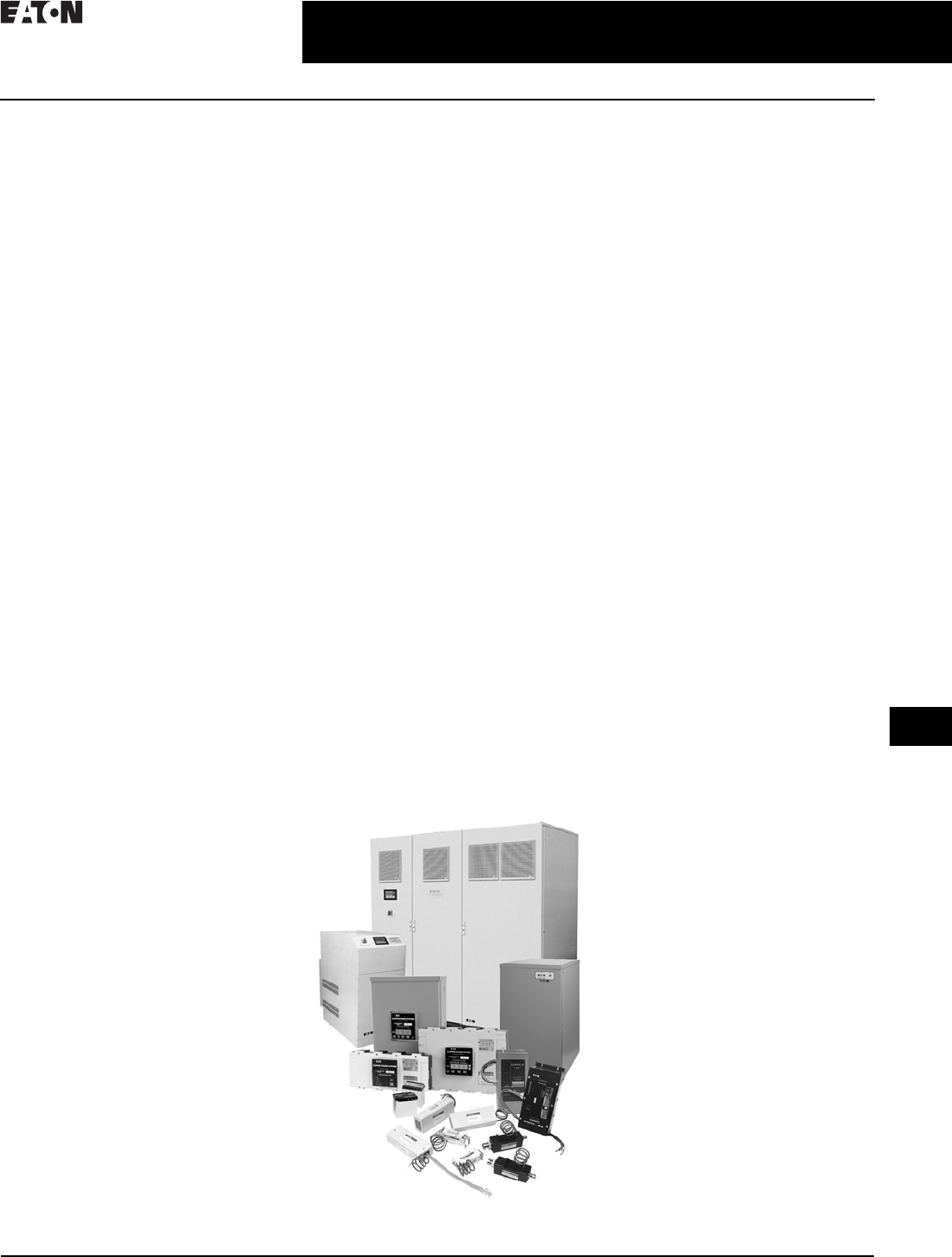
Surge Protection (SPD) &
Power Conditioning Products
Surge Protection (SPD) & Power Conditioning Products
Surge Protection Products—SPD
Facility-Wide Protection . . . . . . . . . . . . . . . . . . . . . . . . . . . . . . . . . . . . . . . . 34.1-1
Integrated Surge Protection . . . . . . . . . . . . . . . . . . . . . . . . . . . . . . . . . . . . 34.1-3
Integrated Panelboard SPD . . . . . . . . . . . . . . . . . . . . . . . . . . . . . . . . . . . . . 34.1-4
SPD Series Sidemount Units. . . . . . . . . . . . . . . . . . . . . . . . . . . . . . . . . . . . 34.1-6
SPD MAX Series Surge Protection . . . . . . . . . . . . . . . . . . . . . . . . . . . . . . . 34.1-16
Sidemount Surge Protective Device for Commercial
and Light Industrial Applications . . . . . . . . . . . . . . . . . . . . . . . . . . . . . . . 34.1-20
CVX050/100. . . . . . . . . . . . . . . . . . . . . . . . . . . . . . . . . . . . . . . . . . . . . . . . . . 34.1-22
Eaton SP1 . . . . . . . . . . . . . . . . . . . . . . . . . . . . . . . . . . . . . . . . . . . . . . . . . . . 34.1-25
Eaton SP2 . . . . . . . . . . . . . . . . . . . . . . . . . . . . . . . . . . . . . . . . . . . . . . . . . . . 34.1-27
AEGIS Powerline Filters . . . . . . . . . . . . . . . . . . . . . . . . . . . . . . . . . . . . . . . . 34.1-29
Power Conditioning Products
Sag Ride Through (SRT2) . . . . . . . . . . . . . . . . . . . . . . . . . . . . . . . . . . . . . . 34.1-34
Electronic Voltage Regulator (EVR). . . . . . . . . . . . . . . . . . . . . . . . . . . . . . . 34.1-37
Specifications
See Eaton’s Product Specification Guide, available on CD or on the Web.
CSI Format: . . . . . . . . . . . . . . . . . . . . . . . 1995 2010
SPD Series Integrated . . . . . . . . . . . . Section 16671A Section 26 43 13
SPD Series Side Mount . . . . . . . . . . . . Section 16671B Section 26 43 16
Power Protection & Conditioning Products Family

34.0-2
For more information, visit: www.eaton.com/consultants CA08104001E
June 2016
Surge Protection (SPD) & Power Conditioning Products
Sheet 34
22
23
24
25
26
27
28
29
30
31
32
33
34
35
36
37
38
39
40
41
42
4 3
002
This page intentionally left blank.
CA08104001E For more information, visit: www.eaton.com/consultants
34.1-1
June 2016
Surge Protection (SPD) & Power Conditioning Products
Sheet 34
22
23
24
25
26
27
28
29
30
31
32
33
34
35
36
37
38
39
40
41
42
4 3
Surge Protection Products—SPD
Facility-Wide Protection—SPD Series
003
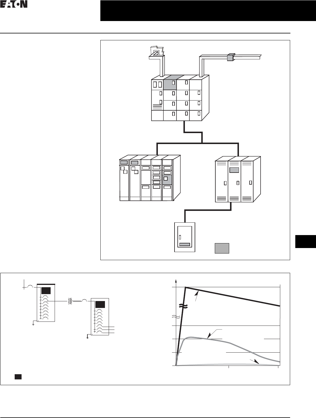
Facility-Wide Protection
A Facility-Wide Protection
Approach Should be Employed
to Address Power Quality Issues
Why Coordinated (Cascaded)
Facility-Wide Protection?
As recommended in the IEEE® Emerald
Book, a cascaded or staged protection
approach should be employed to
reduce external/internal impulse wave-
forms to harmless levels. An SPD filter
should be installed at the main service
entrance and key distribution or branch
panelboards to eliminate ringing and
impulse disturbances, as well as high
frequency EMI/RFI noise.
All SPD Series units are coordinated to
work on a “system basis.” SPD Series
units installed at each level in the
system work together to isolate and
remove external/internal generated
disturbances, creating superior
facility-wide performance and
reliability. Integrated SPD units are
available in switchboards, switchgear,
panelboards, MCCs, automatic
transfer switches and retrofit.
Benefits of SPD Series
Facility-Wide Protection
■High amplitude lightning impulses
reduced to negligible levels
■The electrical distribution’s noise
attenuation is significantly enhanced
The coordinated design ensures
effective current sharing between
main and branch SPD devices.
SPD
480V SPD
120/208V
Stage 1 Protection
(Service Entrance)
SPD250 Recommended Stage 2 Protection
(Branch Entrance)
SPD200 Recommended
System Test Parameters:
IEEE C62.41 and C62.45 test procedures using C-High impulse 480V
main entrance panels; 100 ft (30m) of three-phase wire; 480/208V
distribution transformer; and 120/208V branch
SPD Series Unit
Computer
Sensitive
Loads
0
25μS 50μSS
400
800
5000
10,000
Let-Through Voltage (V)
Time (Microseconds)
High Energy Transient
Disturbance Input at Main Panel
—IEEE Category C-High Impulse
(Combination) Waveform, 10,000V, 10,000A
Best Achievable Performance
with Single SPD at 480V
Main Panel (Stage 1)
Two Stage use of SPDs
(Cascade Approach) Achieves Best
Possible Surge Protection (Stage 2)
Figure 34.1-2. IEEE Emerald Book Recommends a Cascaded (or Two-Stage) Approach
Figure 34.1-1. Cascaded Performance
Incoming LV
Substation
Service Entrance
Switchgear or
Switchgear SPD250
SPD Bus Plug SPD120
LV Busway
Switchboard
SPD120
Motor Control Center SPD120
Panelboard SPD100
SPD Series Unit
34.1-2
For more information, visit: www.eaton.com/consultants CA08104001E
June 2016
Surge Protection (SPD) & Power Conditioning Products
Sheet 34
22
23
24
25
26
27
28
29
30
31
32
33
34
35
36
37
38
39
40
41
42
4 3
Surge Protection Products—SPD
Facility-Wide Protection—SPD Series
004
System Application
The SPD applications covered under
this section include distribution and
branch panel locations, busway, motor
control centers (MCC), switchgear
and switchboard assemblies. All
SPDs shall be tested and demonstrate
suitability for application within
ANSI/IEEE C62.41 Category C, B
and A environments.
Surge Current Capacity
The minimum surge current capacity
that the device is capable of withstand-
ing shall be as shown in Table 34.1-1.
SPD Type
All SPDs installed on the line side
of the service entrance disconnect
shall be Type 1 SPDs. All SPDs
installed on the load side of the
service entrance disconnect shall
be Type 1 or Type 2 SPDs.
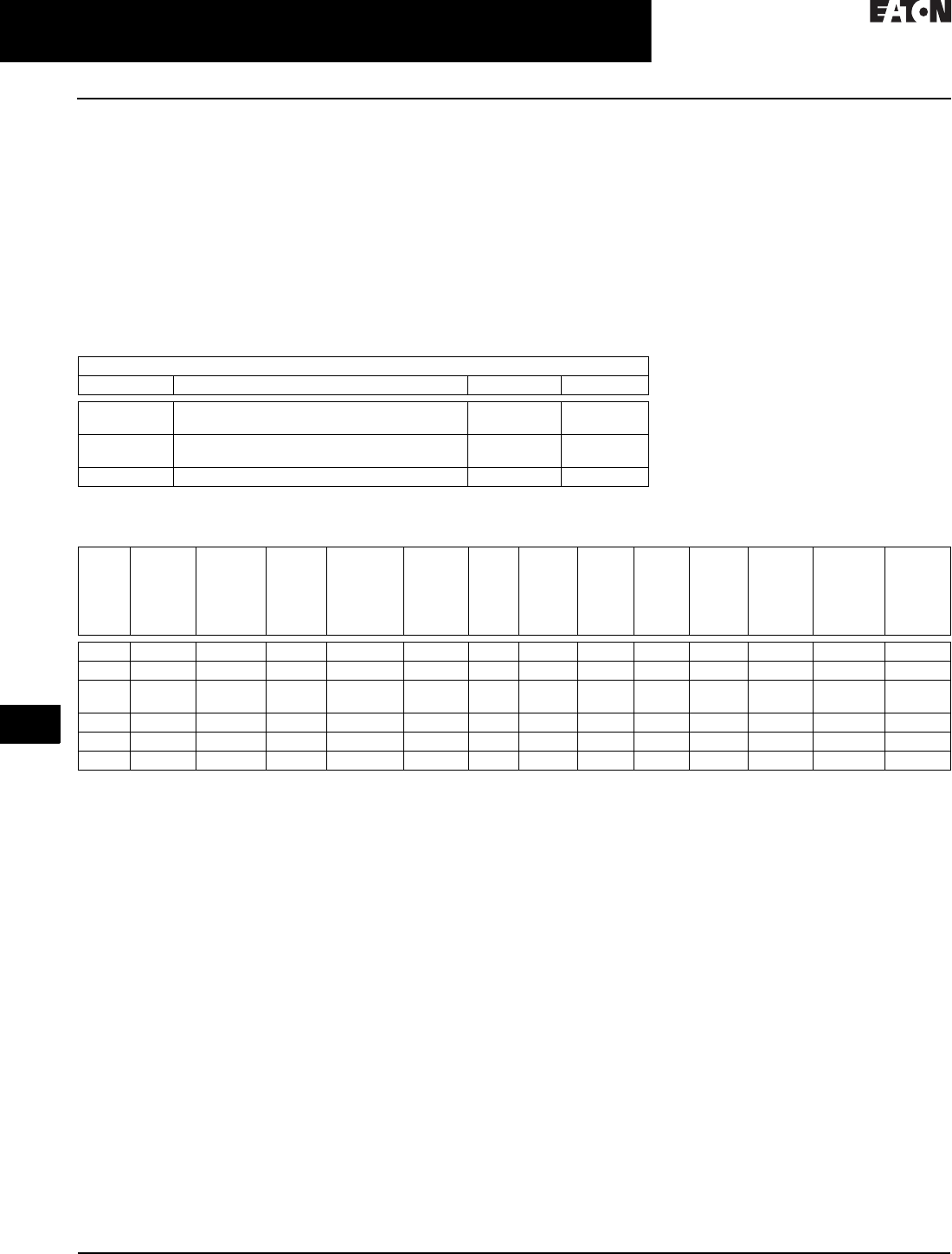
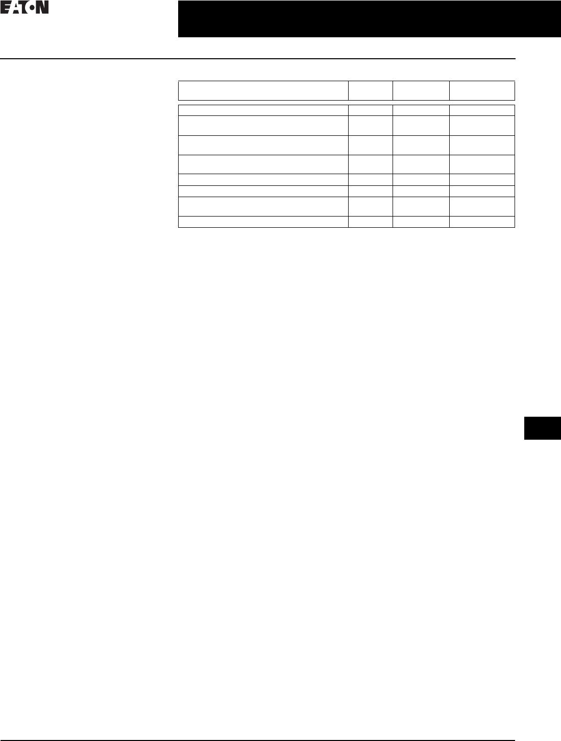
Table 34.1-1. Surge Current Capacity
Features
Table 34.1-2. Eaton Surge Protection Model Features
1100 kA units only.
2208Y, 240S, 240D, 400Y and 480Y units rated 10 kA In.
3480L, 600D, and 600Y units rated 10 kA In.
4600Y and 600D units rated 10 kA In.
55 kA SCCR for 400D and 480D.
6With on-line product registration.
Minimum Surge Current Capacity Based on ANSI/IEEE C62.41 Location Category
Category Application Per Phase Per Mode
C Service entrance locations (switchboards,
switchgear, MCC, main entrance)
250 kA 125 kA
B High exposure roof top locations
(distribution panelboards)
160 kA 80 kA
A Branch locations (panelboards, MCCs, busway) 120 kA 60 kA
Produc
t
Series
L to N
Protectio
n
Mode
L to G
and N to G
Protection
Modes
Per
Phase kA
Range
EMI/RFI
Filtering
Attenuation
Nominal
Discharge
Current
(In)
Short-
Circuit
Curren
t
Rating
(SCCR)
Alarm
Contact
s
(Option)
Audible
Alarm
(Option
)
Surge
Counter
(Option
)
Warrant
y
(Years)
Enclosure
Options
(NEMA
Ty p e s )
Disconnec
t
(Option)
Integrate
d
Mounting
(Option)
SPD Yes Yes 50–400 50 dB 20 kA 200 kA Yes Yes Yes 15 61, 4 & 4X Yes Yes
SPM Yes Yes 100–800 50 dB 20 kA 200 kA Yes Yes Yes 20 64 & 4X Yes No
SPV Yes Yes 50–200 40 dB 20 kA 242 kA
5
Yes Yes No 10 1 & 3R No No
CVX Yes Yes 150–100 No 20 kA 3100 kA No No No 5 4X No No
SP1 Yes No 50 only No 20 kA 4200 kA No No No 2 4 No No
SP2 Yes No 45 only No 10 kA 200 kA No No No 2 4X No No
CA08104001E For more information, visit: www.eaton.com/consultants
34.1-3
June 2016
Surge Protection (SPD) & Power Conditioning Products
Sheet 34
22
23
24
25
26
27
28
29
30
31
32
33
34
35
36
37
38
39
40
41
42
4 3
Surge Protection Products—SPD
SPD Series
005
Integrated Surge Protection
Eaton was the first to introduce the
“Direct-On™ bus bar” connect SPD
that provides customers with the lowest
system let-through voltage at the bus
bar when compared to traditional
cable connected surge protectors.
By using a direct bus bar connection,
the SPD Series achieves the industry’s
lowest let-through voltage—effectively
suppressing both high and low energy
transient events providing protection
for all connected electronic loads. This
design provides superior suppression
ratings and eliminates poor performance
that results from cable connections
and/or long lead lengths.
Other Products
Other surge suppressor manufacturers’
measurements are made at the SPD
module or the suppressor’s terminals,
not at the electrical distribution equip-
ment’s bus bar. The distance between
module or suppressor terminals and
the distribution equipment bus bar
is often 14.00 inches (355.6 mm) or
more. The impedance associated
with cabling required to connect the
surge suppressor to the electrical
distribution equipment (also referred
to as lead length) significantly effects
the overall performance of the surge
suppressor and results in an increase
in let-through voltage.
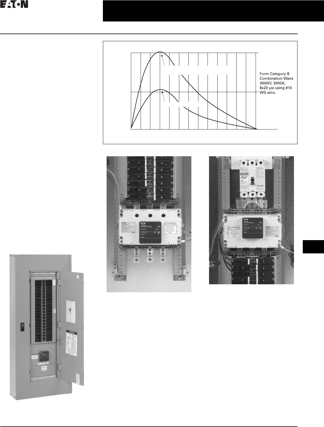
SPD Series Unit Integrated Within
an Eaton Pow-R-Line 1a Panelboard
Figure 34.1-3. 120V/208Y Panelboard—Integrated SPD vs. Cable Connected
In this installation, the SPD Series is
mounted directly to the panelboard’s bus
bars. This type of installation will provide
the best possible surge protection by
minimizing the connected lead length.
The SPD Series is also available as an
integrated unit interfaced via a circuit
breaker resident in the electrical assembly.
This installation keeps connected lead
lengths short while providing a means of
disconnecting power to the unit quickly
and easily.
208Y/120V Panelboard
05 10
700–800V
Time (microseconds)
Let-Through Voltage at Bus Bar
•Based on IEEE
C62.41 (2002)
Combination Wave
Integrated SPD System
Cable Connected SPD
(14-Inch Cable Lead Length to Bus Bar)
500–600V
34.1-4
For more information, visit: www.eaton.com/consultants CA08104001E
June 2016
Surge Protection (SPD) & Power Conditioning Products
Sheet 34
22
23
24
25
26
27
28
29
30
31
32
33
34
35
36
37
38
39
40
41
42
4 3
Surge Protection Products—SPD
Let-Through Voltage Consideration
006
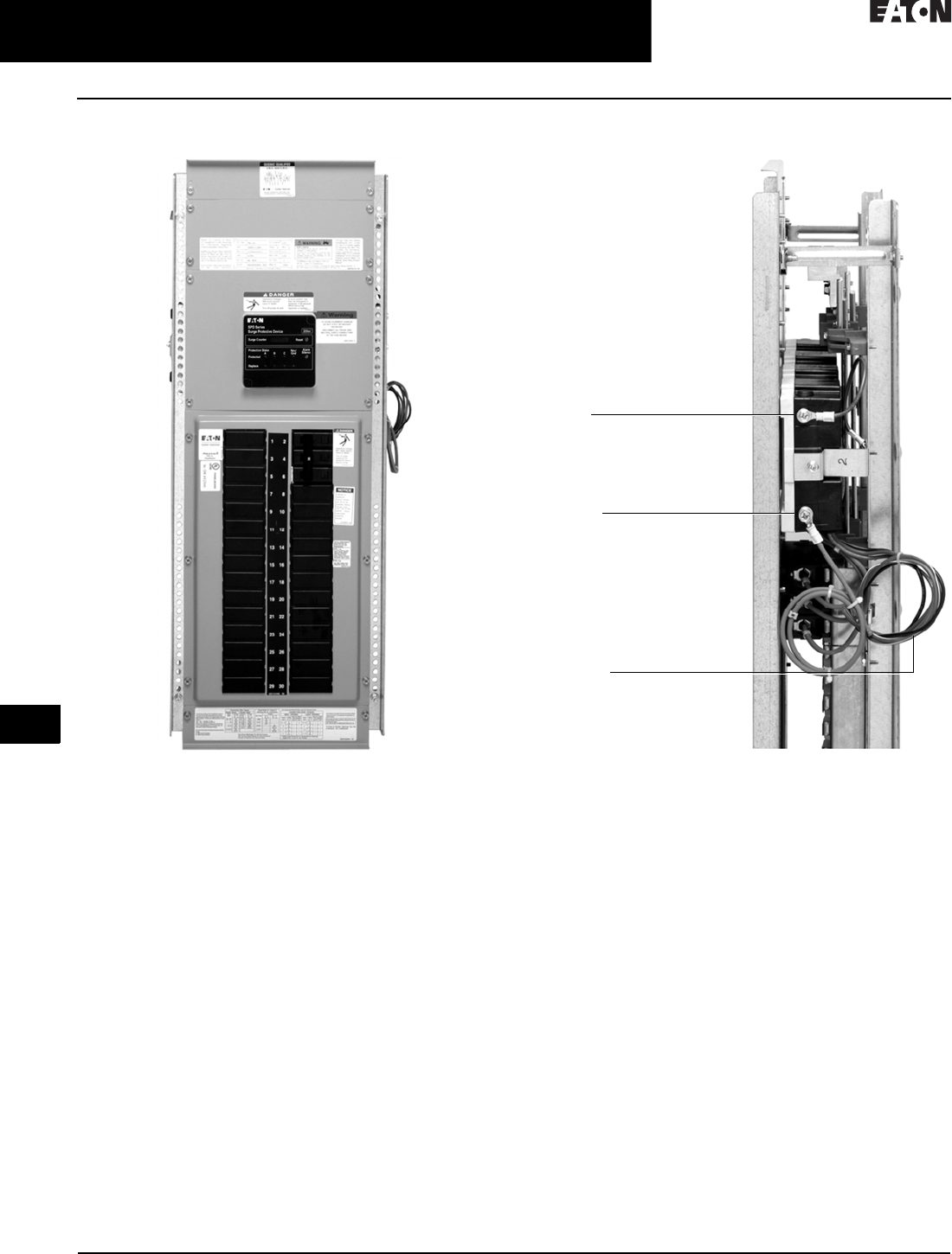
Integrated Panelboard SPD
Integrated SPD Series Unit in PRL1a Panel
(Shown with Option SPD Integral Disconnect)
Integral Disconnect Option—For PRL1a, 2a, 3a, and
3E panelboards.
For applications where load interruptions are intolerable,
an internal dedicated SPD circuit breaker disconnect option
is available. SPD is cable connected via a three-pole 30 A
circuit breaker. (Breaker rating and type dependent on
panel type.)
Note: The addition of the SPD circuit breaker adds 100 V to the
published SPD let-through voltage ratings. See Page 34.1-5.
Direct Bus Mounted SPD Series Unit in a PRL1a Panel
Another distinct advantage that Eaton integrated SPDs offer
is the availability of neutral and ground connections on both
sides of the unit. This enables both the neutral and ground
wires to be kept as short as possible. Only one neutral and
ground connection is required, with the connection point
chosen for each being the one that is in closest proximity
to the neutral and ground bars.
In a sidemount installation, either the neutral or ground
wire connection will be very long, decreasing the installed
performance of the unit. When a sidemount SPD is installed,
its wires enter on one side of the panel. If that point of entry
is closest to the panel’s ground bar, the ground wire is short
and the neutral wire must stretch to the opposite side of the
panel where the neutral bar is located. If the SPD’s wires
enter on the side of the panel where the neutral bar is
located, the neutral wire is kept short but the ground wire
will be much longer.
The presence of neutral and ground connections on both
sides of an integrated unit keeps both leads as short as
possible, increasing the installed performance of the unit.
SPD
Ground
Connection
Form C
Contacts
Wiring
SPD
Neutral
Connection
(Connected
and Trimmed
by Installer)
CA08104001E For more information, visit: www.eaton.com/consultants
34.1-5
June 2016
Surge Protection (SPD) & Power Conditioning Products
Sheet 34
22
23
24
25
26
27
28
29
30
31
32
33
34
35
36
37
38
39
40
41
42
4 3
Surge Protection Products—SPD
Facility-Wide Protection—SPD Series
007
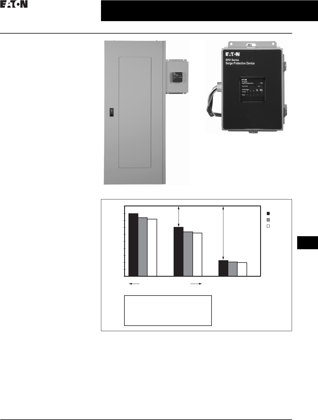
Retrofit Installation
Recommendations to Reduce
Let-Through Voltage
When installing a surge suppressor
in a retrofit environment, it is impor-
tant to mount the suppressor as close
to the electrical equipment as possible,
keep the wiring (lead length) between
the electrical equipment and the
suppressor as short as possible
(less than 14.00 inches (355.6 mm) is
recommended), and twist/wire tie the
conductors to reduce inductive effects.
As shown in Figure 34.1-4 below,
installation lead length reduces the
performance of any surge suppressor.
For each inch of wiring (installation
lead length), add 15 V to 25 V to the
surge suppressor’s published let-
through value (e.g., suppressor let-
through at 400 V and installation of
3 ft (0.9 m) of cable = 1000 V installed
rating).
The SPD uses 10 AWG wire for
connecting to the distribution system.
The wires require protection by using
a 30 A circuit breaker that ensures
protection against fault current and fire.
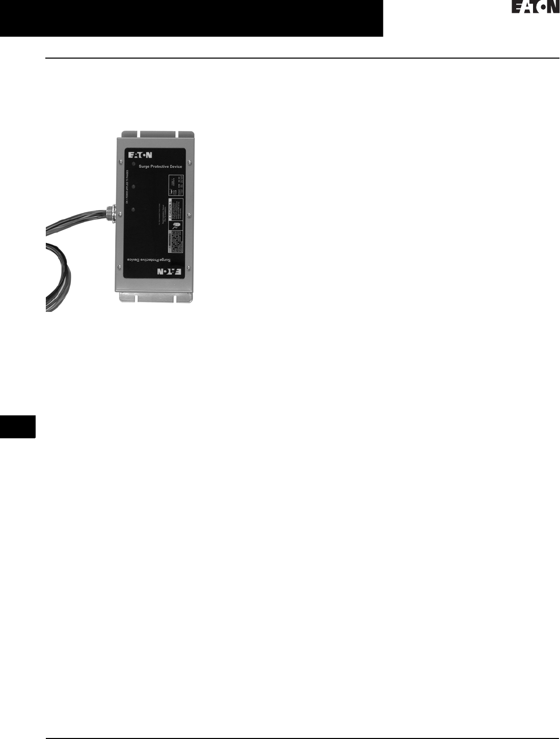
Sidemount Installation Recommendations
SPD Series Sidemount Unit
Figure 34.1-4. Let-Through Graph
Wire Size
14 AWG
10 AWG
4 AWG
3 ft (0.9m) Lead Length 1 ft (0.3m) Lead Length
Twisted Wires
Installation Criteria Order of Importance:
1) Lead Length—75% reduction
2) Twisting Wires—23% reduction
3) Larger Wire—minimal reduction
Additional Let-Through Voltage
(Additional to device “Let Through”)
1000
900
800
700
600
500
400
300
200
100
0
209V (23%)
673V (75%)
Twisted WiresLoose Wiring
34.1-6
For more information, visit: www.eaton.com/consultants CA08104001E
June 2016
Surge Protection (SPD) & Power Conditioning Products
Sheet 34
22
23
24
25
26
27
28
29
30
31
32
33
34
35
36
37
38
39
40
41
42
4 3
Surge Protection Products—SPD
SPD Series
008
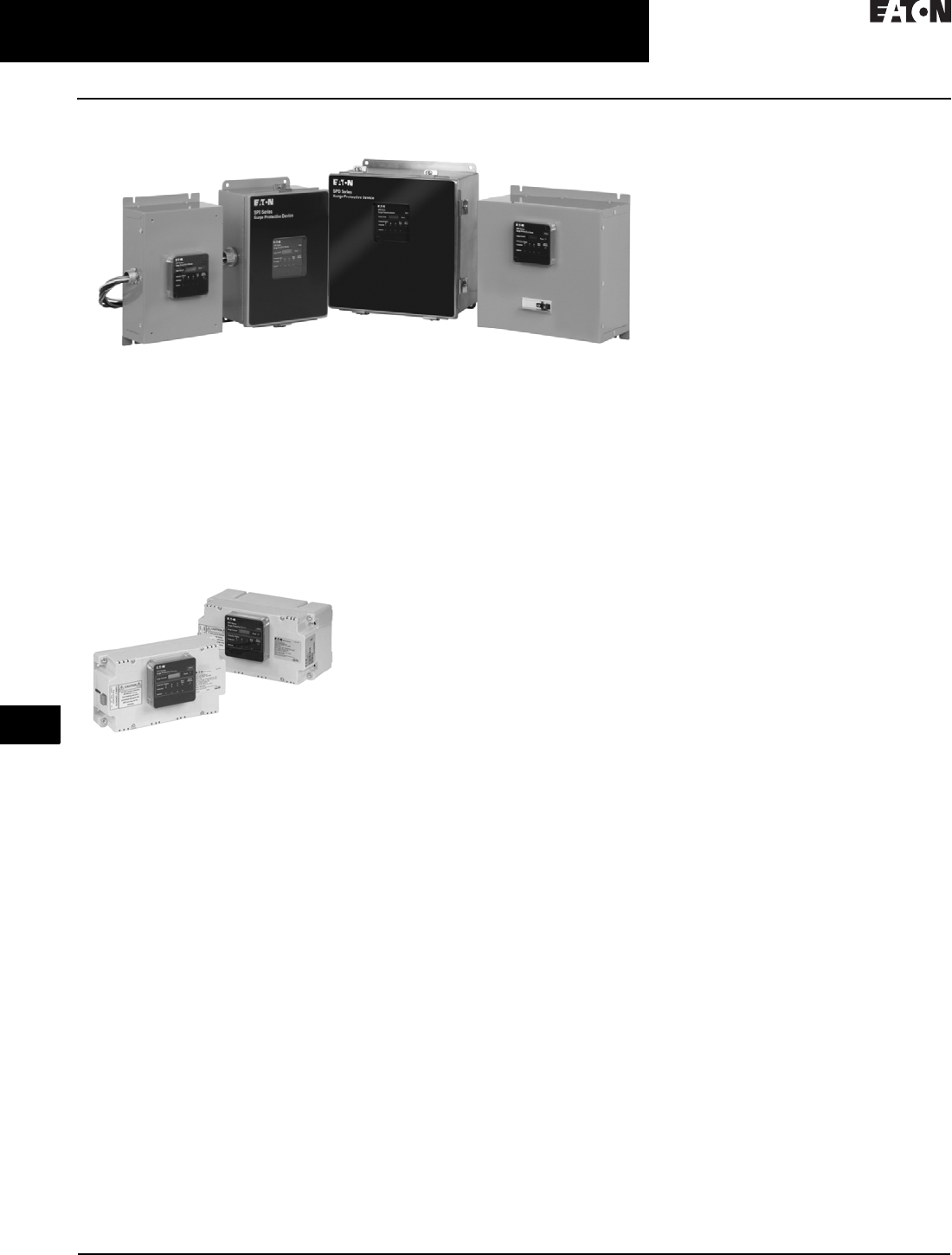
SPD Series Sidemount Units
SPD Series Sidemount Units
General Description
Eaton’s SPD Series surge protective
devices are the latest and most
advanced UL® 1449 4th Edition
certified surge protectors. Units
are available integrated within Eaton
electrical assemblies, including panel-
boards, switchboards, motor control
centers, switchgear, automatic transfer
switches and bus plugs.
SPD Series Integrated Units
A complete offering of sidemount
units designed for mounting external
to electrical distribution equipment
is also available. Application of SPD
Series units throughout a facility will
ensure that equipment is protected
with the safest and most reliable surge
protective devices available. SPD
Series units are available in all
common voltages and configurations
and also in a variety of surge current
capacity ratings from 50 through
400 kA. Three feature package options
are also available to choose from,
ensuring the proper unit is available
for a variety of applications.
Features, Benefits
and Functions
■Uses thermally protected metal
oxide varistor (MOV) technology
■Three feature package options
■True protection status indicators
report the status of the protection
elements, not the status of the
applied power
■Available integrated within the
following Eaton electrical assem-
blies: panelboards, switchboards,
motor control centers, switchgear,
automatic transfer switches and
bus plugs
■10-year warranty
(15-year with registration)
Safety Features
■All units use thermally protected
metal oxide varistor technology
(MOV) as their core surge suppres-
sion component. Usage of this
technology ensures safe operation
when the unit is subjected to
abnormal conditions such as
temporary overvoltage or high
fault current conditions. Under such
conditions, the thermally protected
MOVs are removed from the circuit
quickly and safely before a poten-
tially unsafe condition can occur
■SPD Series units contain no replace-
able parts such as surge modules,
fuses, or surge counter memory
backup batteries. This prevents
potential arc flash and shock
hazards, as the units require no
periodic service or user intervention
after installation
■Integrated versions of the unit
are factory installed and sidemount
versions are factory sealed. These
important safety measures further
enhance user safety
Three Feature Package
Options Available
The SPD Series provides users with
the option of selecting between
three feature packages. These feature
packages are the basic, standard
and standard with surge counter.
The proper feature package can be
selected based on the requirements
of the application or specification.
A side by side comparison of the
individual features found in each
package is below.
Basic Feature Package
The basic feature package is perfect
for applications where basic, cost-
effective, safe and reliable surge
protection is required, but budgets
don’t allow for extra, additional features.
Rather than sacrifice performance or
safety due to cost, SPD Series units
with the basic feature package provide
you with high-performing surge
protection without sacrificing safety
or reliability. The basic feature package
provides the same level of surge
protection and safety provided by
the standard and standard with surge
counter feature packages minus some
of the features found in them. The
package contains dual-colored protection
status LEDs that report the true status
of the protection in each phase/mode.
All four-wire plus ground units also
contain an additional set of dual-
colored protection status LEDs that
report the status of the protection in
the neutral/ground mode.
Standard Feature Package
The standard feature package includes
all of the features found in the basic
feature package, plus an audible alarm
with silence button, EMI/RFI filtering,
and a Form C relay contact that can
be used for remote annunciation of
the SPD’s status. The audible alarm
activates and the Form C relay contact
changes state when any loss of protec-
tion is detected or a fault condition
exists with the unit. Should such a
condition occur, the audible alarm
can be silenced by pressing the silence
button. The EMI/RFI filter provides up
to 50 dB of noise attenuation over the
range of 10 kHz through 100 MHz.
CA08104001E For more information, visit: www.eaton.com/consultants
34.1-7
June 2016
Surge Protection (SPD) & Power Conditioning Products
Sheet 34
22
23
24
25
26
27
28
29
30
31
32
33
34
35
36
37
38
39
40
41
42
4 3
Surge Protection Products—SPD
SPD Series
009
Standard with Surge Counter
Feature Package
The standard with surge counter
feature package includes all of the
features found in the standard feature
package plus a six-digit surge counter
with a reset button. The surge counter
indicates the ongoing count of the
number of surges the unit has been
exposed to and stores them in
nonvolatile memory. Should power
to the SPD Series unit be completely
interrupted, the surge counter will
recall and display the surge count prior
to the interruption when power
is restored. Unlike many surge
protectors, the SPD Series’ surge
counter memory feature does not
require a backup battery that would
require periodic replacement in order
to achieve its memory functionality.
Table 34.1-3. Side-By-Side Comparison of the SPD Series’ Available Feature Packages
Standards and Certifications
■Integrated versions of the unit are
UL 1449 4th Edition recognized
components for the United
States and Canada, covered
by Underwriters Laboratories
certification and follow-up service
■Sidemount versions are UL 1449 4th
Edition listed devices and are also
CSA® approved
Technical Data
and Specifications
■20 kA nominal discharge current
(In) rating (maximum rating
assigned by UL)
■50 through 400 kA surge current
capacity ratings
■200 kA short-circuit current
rating (SCCR)
Feature Package
Comparison
Basic Standard Standard with
Surge Counter
UL 1449 4th Edition Type ■■ ■
Surge protection using thermally protected
MOV technology
■■ ■
Dual-colored protection status indicators
for each phase
■■ ■
Dual-colored protection status indicators
for the N–G protection mode
—■■
Audible alarm with silence button —■■
Form C relay contact —■■
EMI/RFI filtering, providing up to 50 dB of noise
attenuation from 10 kHz to 100 MHz
—■■
Surge counter with reset button —— ■
34.1-8
For more information, visit: www.eaton.com/consultants CA08104001E
June 2016
Surge Protection (SPD) & Power Conditioning Products
Sheet 34
22
23
24
25
26
27
28
29
30
31
32
33
34
35
36
37
38
39
40
41
42
4 3
Surge Protection Products—SPD
SPD Series
010
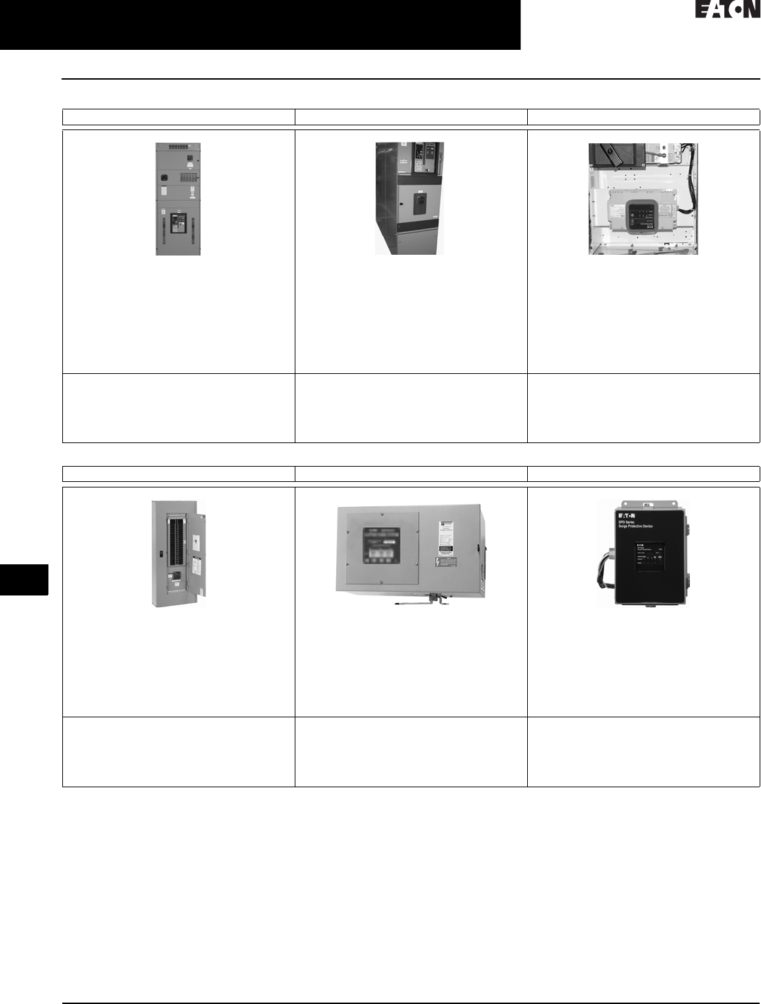
Table 34.1-4. Integrated Product Applications
Note: The SPD Surge components can be integrated into safety switches, automatic transfer switches (ATS) and other assemblies.
Contact your local Eaton sales office.
Switchboard Switchgear Motor Control Centers
Features:
■The SPD can be integrated into any
switchboard
■Specifiers have the flexibility to install the
SPD in any location within the switchboard
■Disconnect switch is a standard feature
■Unique design minimizes installation
impedance
Features:
■Available on all switchgear designs
■Disconnect switch is a standard feature
■Unique design minimizes installation
impedance
■SPD250 ideal for critical industrial
switchgear applications
Features:
■Ideal protection for PLCs, sensors, drives,
electronic starters, or other digital equipment
■SPD is designed to fit in Freedom 2100 in a
standard (3X) size 18-inch (457.2 mm)
compartment
■May be used in new/aftermarket applications
■Ideal for water treatment, petrochemical and
other industrial applications
Safety Standards:
■UL 891 (Switchboard)
■UL 1449 4th Edition (Surge Suppressor)
■UL 1283 5th Edition (EMI/RFI Filter)
■CSA C22.2 Certified (Suppressor)
Safety Standards:
■UL 1558 (Switchgear)
■UL 1449 4th Edition (Surge Suppressor)
■UL 1283 5th Edition (EMI/RFI Filter)
■CSA C22.2 Certified (Suppressor)
Safety Standards:
■UL 845 (MCC)
■UL 1449 4th Edition (Surge Suppressor)
■UL 1283 5th Edition (EMI/RFI Filter)
■CSA C22.2 Certified (Suppressor)
Panelboards Busway Retrofit
Features:
■The SPD is used extensively on branch
panelboards for computer rooms, laboratories,
schools, hospitals and industrial applications
■200% rated neutral is provided for non-linear
loads
■Cost-effective branch protection (assumes
main panel protection employed)
Features:
■Ideal for busway fed distribution systems
■Easy to install SPD units fit in standard bus
plug assembly
■Isolates critical busway sections from nearby
disturbance producing loads
■Designed for new and existing facilities
■Integral disconnect
Features:
■SPD units can be externally mounted to
existing distribution equipment
■Standard NEMA 1, 4 or 4X enclosures
■Requires field installation
■SPD Retrofit 50–400 kA/phase units
■SPV 50–200 kA/phase units
Safety Standards:
■UL 67 (Panelboards)
■UL 1449 4th Edition (Surge Suppressor)
■UL 1283 5th Edition (EMI/RFI Filter)
■CSA C22.2 Certified (Suppressor)
Safety Standards:
■UL 857 (Busway)
■UL 1449 4th Edition (Surge Suppressor)
■UL 1283 5th Edition (EMI/RFI Filter)
■CSA C22.2 Certified (Suppressor)
Safety Standards:
■UL 1449 4th Edition (Surge Suppressor)
■UL 1283 5th Edition (EMI/RFI Filter)
■CSA C22.2 Certified (Suppressor)

CA08104001E For more information, visit: www.eaton.com/consultants
34.1-9
June 2016
Surge Protection (SPD) & Power Conditioning Products
Sheet 34
22
23
24
25
26
27
28
29
30
31
32
33
34
35
36
37
38
39
40
41
42
4 3
Surge Protection Products—SPD
SPD Series
011
Catalog Numbering System
Table 34.1-5. SPD Series Units Mounted Internal to Electrical Distribution Equipment (Integrated Units)
1Please consult the factory for 240 high-leg delta (4W+G) applications with high leg on ‘C’ phase.
2Units used in PRL1a, 2a, 3a and 3E panelboard applications are available in 50–200 kA ratings only. Use the ‘C’ option for PRL1a, 2a, 3a and 3E
panelboard applications when unit is connected through a circuit breaker.
Example: SPD250480D2J = SPD Series, 250 kA per phase, 480D voltage, standard feature package, motor control center application.
Table 34.1-6. SPD Series Units for Mounting External to Electrical Distribution Equipment (Sidemount Units)
3Please consult the factory for 240 high-leg delta (4W+G) applications with high leg on ‘C’ phase.
4NEMA 1 flushmount units are available in 50–200 kA ratings only.
Example: SPD250480D2K = SPD Series, 250 kA per phase, 480D voltage, standard feature package, housed in NEMA 1 enclosure.
SPD 250 480D 2 J
Series
SPD = Surge protective
device
kA Rating
050 = 50 kA per phase
080 = 80 kA per phase
100 = 100 kA per phase
120 = 120 kA per phase
160 = 160 kA per phase
200 = 200 kA per phase
250 = 250 kA per phase
300 = 300 kA per phase
400 = 400 kA per phase
Voltage Code
240S = 120/240 single split-phase
208Y = 120/208 wye (4W+G)
220Y = 127/220 wye (4W+G)
400Y = 230/400 wye (4W+G)
480Y = 277/480 wye (4W+G)
600Y = 347/600 wye (4W+G)
240D = 240 delta (3W+G)
480D = 480 delta (3W+G)
600D = 600 delta (4W+G)
240H = 240 high-leg delta (4W+G)
on ‘B’ phase 1
Application—Integrated Units 2
A = Panelboards (PRL1a, 2a, 3a, 3E),
direct bus mounted
B = Switchgear (includes remote display)
C = Panelboards (PRL1a, 2a, 3a, 3E, 4),
switchboards, busway
J = Motor control centers
Feature Package
1 = Basic
2 = Standard
3 = Standard + surge counter
Series
SPD = Surge protective
device
kA Rating
050 = 50 kA per phase
080 = 80 kA per phase
100 = 100 kA per phase
120 = 120 kA per phase
160 = 160 kA per phase
200 = 200 kA per phase
250 = 250 kA per phase
300 = 300 kA per phase
400 = 400 kA per phase
Voltage Code
240S = 120/240 single split-phase
208Y = 120/208 wye (4W+G)
220Y = 127/220 wye (4W+G)
400Y = 230/400 wye (4W+G)
480Y = 277/480 wye (4W+G)
600Y = 347/600 wye (4W+G)
240D = 240 delta (3W+G)
480D = 480 delta (3W+G)
600D = 600 delta (4W+G)
240H = 240 high-leg delta (4W+G)
on ‘B’ phase 3
Application—Sidemount Units
K = NEMA 1 enclosure
L = NEMA 1 flushmount enclosure 4
M = NEMA 1 enclosure with internal
disconnect
N = NEMA 4 enclosure
O= NEMA 4 enclosure with internal
disconnect
P= NEMA 4X enclosure (stainless steel)
Q= NEMA 4X enclosure with internal
disconnect (stainless steel)
Feature Package
1 = Basic
2 = Standard
3 = Standard + surge counter
SPD 250 480D 2 K
34.1-10
For more information, visit: www.eaton.com/consultants CA08104001E
June 2016
Surge Protection (SPD) & Power Conditioning Products
Sheet 34
22
23
24
25
26
27
28
29
30
31
32
33
34
35
36
37
38
39
40
41
42
4 3
Surge Protection Products—SPD
SPD Series
012
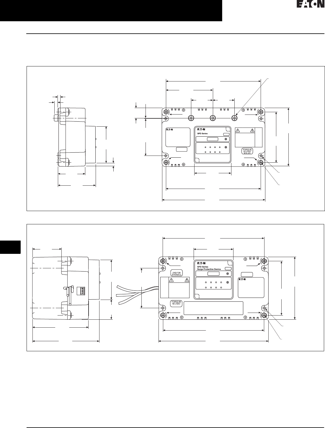
Dimensions in Inches (mm)
Standard Dimensions —Integrated Units
Figure 34.1-5. 50–200 kA Integrated Units
Figure 34.1-6. 250–400 kA Integrated Units
Weights
■50–200 kA units approximately 3.5 lb (1.6 kg)
■250–400 kA units approximately 7.0 lb (3.2 kg)
0.19
(4.8) 4x Mounting
Bus 0.34
(8.6)
3.42
(86.9)
2.52
(64.0)
3.45
(87.6)
0.95
(24.1)
Mounting
8.80
(223.5)
4.40
(111.8)
0.04
(1.0)
5.40
(137.2)
4.66
(118.4)
0.22
(5.6) 4x Mounting
4x #10–32 x 0.38 DP
Brass Terminals
3.42
(86.9)
Terminals
8.74
(222.0)
9.50
(241.3)
0.26
(6.6)
0.22
(5.6) 3x Bus Mounting
Mounting
3.42
(86.9)
2.02
(51.2)
2.02
(51.2)
FORM “C” CONTACTS
CAUTION
SURGE GROUND
NEUTRAL
SURGE
GROUND
NEUTRAL
NEUTRAL
NEUTRAL
SURGE
GROUND
SURGE
GROUND
5.78
(146.8)
4.85
(123.2)
1.71
(43.4)
3.42
(86.9)
4x Mounting
2.52
(64.0)
9.50
(241.3)
Terminals
8.74
(222.0)
Mounting
8.80
(223.5)
3.42
(86.9)
5.40
(137.2)
4.66
(118.4)
0.22
(5.6) 4x Mounting
4x #10–32 x 0.38
DP Brass Terminals
Mounting
3.42
(86.9)
FORM “C” CONTACTS
CAUTION
SURGE GROUND
NEUTRAL
SURGE
GROUND
NEUTRAL
NEUTRAL
NEUTRAL
36 IN. LBS.
36 IN. LBS.
SURGE
GROUND
SURGE
GROUND
CA08104001E For more information, visit: www.eaton.com/consultants
34.1-11
June 2016
Surge Protection (SPD) & Power Conditioning Products
Sheet 34
22
23
24
25
26
27
28
29
30
31
32
33
34
35
36
37
38
39
40
41
42
4 3
Surge Protection Products—SPD
SPD Series
013
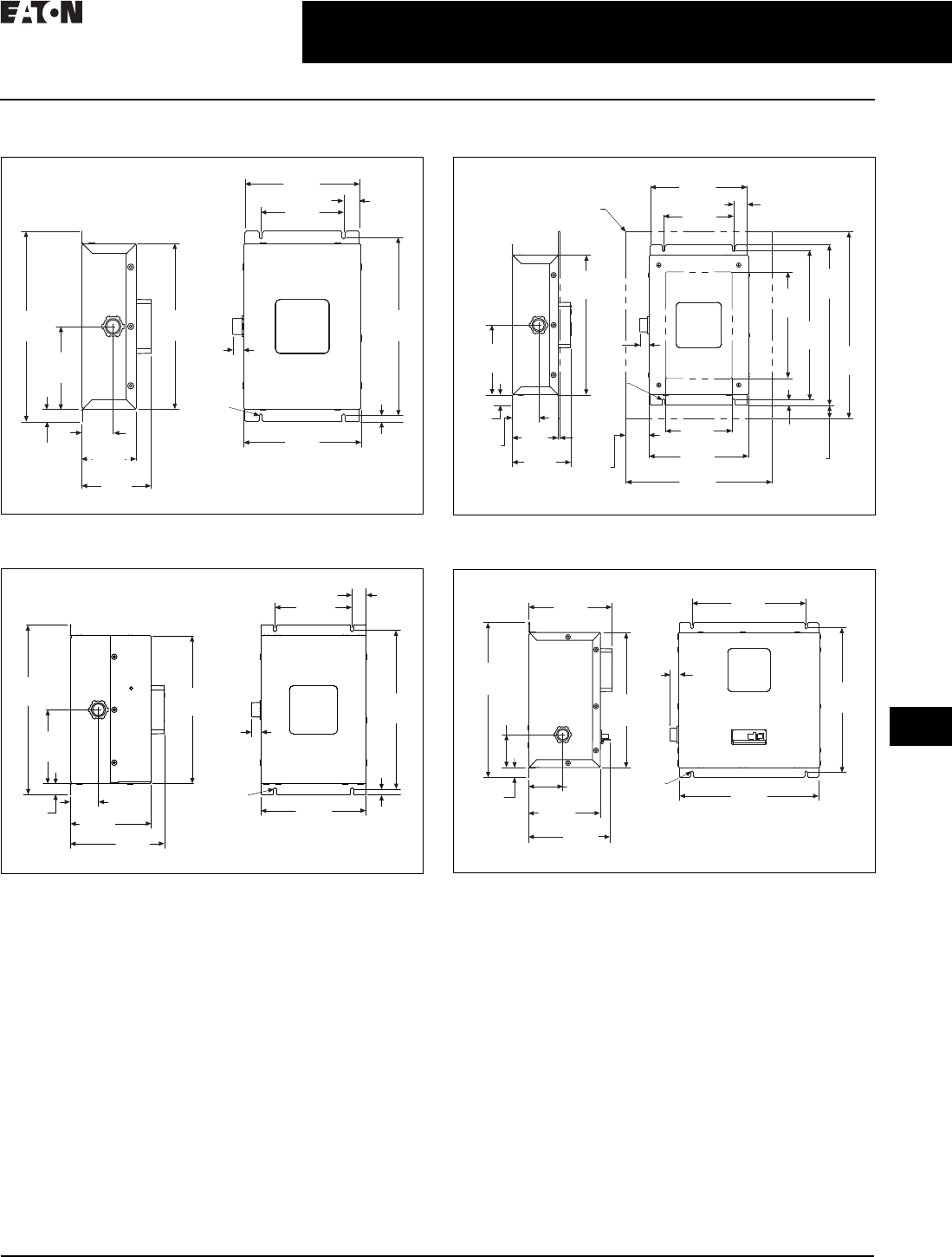
Standard Dimensions—Sidemount Units
Figure 34.1-7. 50–200 kA Units in a NEMA 1 Rated Enclosure,
Weight = 6.8 lb
Figure 34.1-8. 250–400 kA Units in a NEMA 1 Rated Enclosure,
Weight = 13.5 lb
Figure 34.1-9. 50–200 kA Units in a NEMA 1 Rated Flushmount
Enclosure, Weight = 6.8 lb
Figure 34.1-10. 50–400 kA Units in a NEMA 1 Rated Enclosure with
Internal Disconnect, Weight = 14.7 lb
12.05
(306.1)
5.24
(133.1)
0.78
(19.8)
2.00
(50.8)
3.48
(88.4)
4.41
(112.0)
Ø0.20
(Ø5.1)
10.48
(266.2)
0.68
(17.3)
7.28
(184.9)
5.27
(133.9)
1.00
(25.4)
11.25
(285.8)
7.47
(189.7) 0.40
(10.2)
12.05
(306.1)
5.24
(133.1)
0.78
(19.8)
2.00
(50.8)
5.76
(146.3) 6.69
(169.9)
0.40
(10.2)
7.47
(189.7)
Ø0.20
(Ø5.1)
10.48
(266.2)
0.67
(17.0)
5.47
(138.9)
1.00
(25.4)
11.25
(285.8)
Flushmount Panel
(4) #8–32 Flat Hd Screws
5.24
(133.1)
0.78
(19.8)
2.00
(50.8)
3.48
(88.4)
4.41
(112.0)
0.11
(2.8)
10.48
(266.2)
0.68
(17.3)
Ø0.20
(Ø5.1)
1.76
(44.7)
5.00
(127.0)
7.47
(189.7)
11.00
(279.4)
0.40
(10.2)
0.98
(24.9)
8.00
(203.2)
11.25
(285.8)
12.05
(306.1)
14.00
(355.6)
1.00
(25.4)
7.28
(184.9)
5.27
(133.9)
6.69
(169.9)
12.30
(312.4)
2.61
(66.3)
0.78
(19.8)
2.75
(69.9)
5.76
(146.3)
6.55
(166.4)
10.73
(272.5)
0.66
(16.8)
Ø0.20
(Ø5.1) 11.14
(283.0)
11.50
(292.1)
9.14
(232.2)

34.1-12
For more information, visit: www.eaton.com/consultants CA08104001E
June 2016
Surge Protection (SPD) & Power Conditioning Products
Sheet 34
22
23
24
25
26
27
28
29
30
31
32
33
34
35
36
37
38
39
40
41
42
4 3
Surge Protection Products—SPD
SPD Series
014
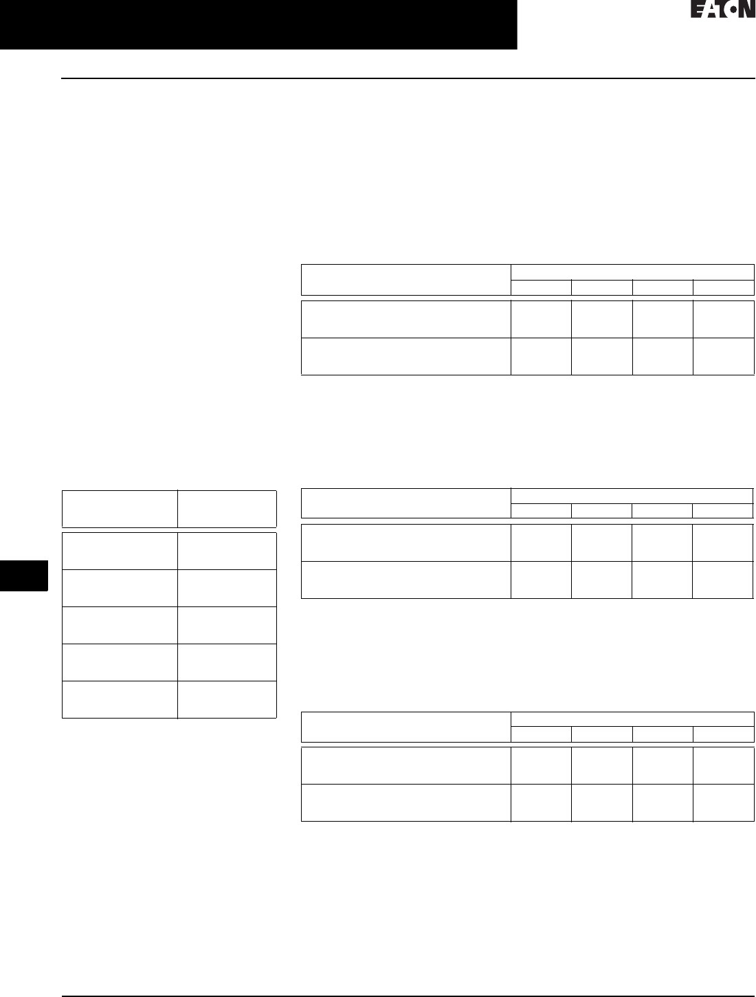
Standard Dimensions—Sidemount Units
Figure 34.1-11. 50–200 kA Units in a NEMA 4 or 4X Rated Enclosure,
Weight = 14.6 lb
Figure 34.1-12. 250–400 kA Units in a NEMA 4 or 4X Rated Enclosure,
Weight = 14.6 lb
Figure 34.1-13. 50–400 kA Units in a NEMA 4 or 4X Rated Enclosure with
Internal Disconnect, Weight = 27.5 lb
12.50
(317.5)
10.98
(278.9)
5.49
(139.4)
0.76
(19.3)
2.60
(66.0)
5.39
(136.9)
11.28
(286.5)
11.75
(298.5)
0.65
(16.5)
6.00
(152.4)
8.65
(219.7)
Ø0.33
(Ø8.4)
SPD Series
Surge Protective Device
SPD Series
Surge Protective Device
12.50
(317.5)
10.98
(278.9)
5.49
(139.4)
0.76
(19.3)
4.10
(104.1) 7.68
(195.1)
11.28
(286.5)
11.75
(298.5)
6.00
(152.4)
0.65
(16.5)
8.65
(219.7)
Ø0.33
(8.4)
SPD Series
Surge Protective Device
SPD Series
Surge Protective Device
13.50
(342.9)
11.98
(304.3)
3.12
(79.2)
0.76
(19.3)
3.36
(85.3)
7.68
(195.1)
12.28
(311.9)
12.75
(323.9)
0.65
(16.5)
10.18
(258.6) 12.47
(316.7)
Ø0.33
(Ø8.4)
SPD Series
Surge Protective Device
SPD Series
Surge Protective Device

CA08104001E For more information, visit: www.eaton.com/consultants
34.1-13
June 2016
Surge Protection (SPD) & Power Conditioning Products
Sheet 34
22
23
24
25
26
27
28
29
30
31
32
33
34
35
36
37
38
39
40
41
42
4 3
Surge Protection Products—SPD
SPD Series
015
Technical Data
Table 34.1-7. SPD Series Specifications
Description Specification
Surge capacity ratings available 50, 80, 100, 120, 160, 200, 250, 300, 400 kA per phase
Nominal discharge current (In) 20 kA (maximum rating assigned by UL)
Short-circuit current rating (SCCR) 200 kA
SPD type Basic feature package = Type 1 (can also be used in Type 2 applications)
Standard and standard with surge counter feature packages = Type 2
Single split-phase voltages available 120/240
Three-phase wye system voltages available 120/208, 127/220, 230/400, 277/480, 347/600
Three-phase delta system voltages available 240, 480, 600
Input power frequency 50/60 Hz
Power consumption (basic units):
208Y, 220Y, 240S, 240D and 240H voltage codes
400Y, 480Y and 480D voltage codes
600Y and 600D voltage codes
0.5 W
1.1 W
1.3 W
Power consumption (standard and standard with surge counter units):
208Y, 220Y, 240S, 240D and 240H voltage codes
400Y, 480Y and 480D basic voltage codes
600Y and 600D voltage codes
0.6 W
1.7 W
2.1 W
Protection modes Single split-phase
Three-phase wye
Three-phase delta
Three-phase high-leg delta
L-N, L-G, N-G, L-L
L-N, L-G, N-G, L-L
L- G , L- L
L-N, L-G, N-G, L-L
Maximum continuous operating voltage (MCOV):
240S, 208Y, 220Y and 240H MCOV
400Y and 480Y MCOV
600Y MCOV
240D MCOV
480D MCOV
600D MCOV
150 L-N, 150 L-G, 150 N-G, 300 L-L
320 L-N, 320 L-G, 320 N-G, 640 L-L
420 L-N, 420 L-G, 420 N-G, 840 L-L
320 L-G, 320 L-L
640 L-G, 640 L-L
840 L-G, 840 L-L
Ports 1
Operating temperature –40 °F through 122 °F (–40 °C through 50 °C)
Operating humidity 5% through 95%, noncondensing
Operating altitude Up to 16,000 ft (5000 m)
Seismic withstand capability Meets or exceeds the requirements specified in IBC 2006 and CBC 2007
Form C relay contact ratings 150 Vdc or 125 Vac, 1A maximum
Form C relay contact logic Power ON, normal state—NO contact = open, NC contact = closed
Power OFF or fault state—NO contact = closed, NC contact = open
EMI/RFI filtering attenuation Up to 50 dB from 10 kHz to 100 MHz
34.1-14
For more information, visit: www.eaton.com/consultants CA08104001E
June 2016
Surge Protection (SPD) & Power Conditioning Products
Sheet 34
22
23
24
25
26
27
28
29
30
31
32
33
34
35
36
37
38
39
40
41
42
4 3
Surge Protection Products—SPD
SPD Series
016
Voltage Protection
Rating (VPR)
The measured limiting voltage test in
UL 1449 4th Edition uses a 6 kV/3 kA
combination wave surge to determine
the voltage protection rating (VPR)
of the SPD. This test is similar to the
suppressed voltage rating (SVR) as
performed in UL 1449 2nd Edition. The
key difference between the tests in the
2nd Edition and the 4th Edition is that
the magnitude of the current used for
the test is six times greater in the 4th
Edition versus the 2nd Edition. This
much higher current level will mean
that the measured limiting voltage will
likely be significantly higher for the
higher current level. For example, the
VPR for an SPD will likely be much
higher than the SVR of an identical
SPD. With higher current levels come
higher limiting voltages. Please note
that VPR ratings fall into predefined
voltage categories as outlined in the
UL 1449 4th Edition. The standard
VPR voltages are shown in the
following table.
Table 34.1-8. Voltage Protection Ratings
Therefore, if an SPD is tested with a
6 kV/3 kA combination wave surge and
the let-through voltage is measured
to be 610 V, the SPD is given a VPR of
700 V. The SPD is given the same
700 V VPR if the same test results in a
let-through voltage measurement of
698 V. Additionally, if the let-through
voltage is measured to be 2005 V, the
SPD is given a VPR of 2500 V.
Measured
Limiting Voltage
Minimum Voltage
Protection Rating
(VPR)
330 V or Less
331 V to 400 V
401 V to 500 V
330
400
500
501 V to 600 V
601 V to 700 V
701 V to 800 V
600
700
800
801 V to 900 V
901 V to 1000 V
1001 V to 1200 V
900
1000
1200
1201 V to 1500 V
1501 V to 1800 V
1801 V to 2000 V
1500
1800
2000
2001 V to 2500 V
2501 V to 3000 V
3001 V to 4000 V
2500
3000
4000
It is important that users are familiar
with the difference in testing methods
and the subsequent effect on the value
of the VPR. Without considering or
understanding the differences in the
level of currents used in the test, one
might assume that a UL 1449 4th Edition
device with a VPR of 700 V has a higher
limiting voltage than a UL 1449 2nd
Edition device with an SVR of 400 V.
Such a conclusion would be inaccurate.
The higher VPR rating of 700 V is likely
caused by the higher level of surge
current during the measured limiting
voltage test. In order to make an
accurate assessment of devices, the
VPR rating of one device must be
compared with the VPR rating of
another device. Comparing a VPR
rating to an SVR rating yields no useful
or conclusive information.
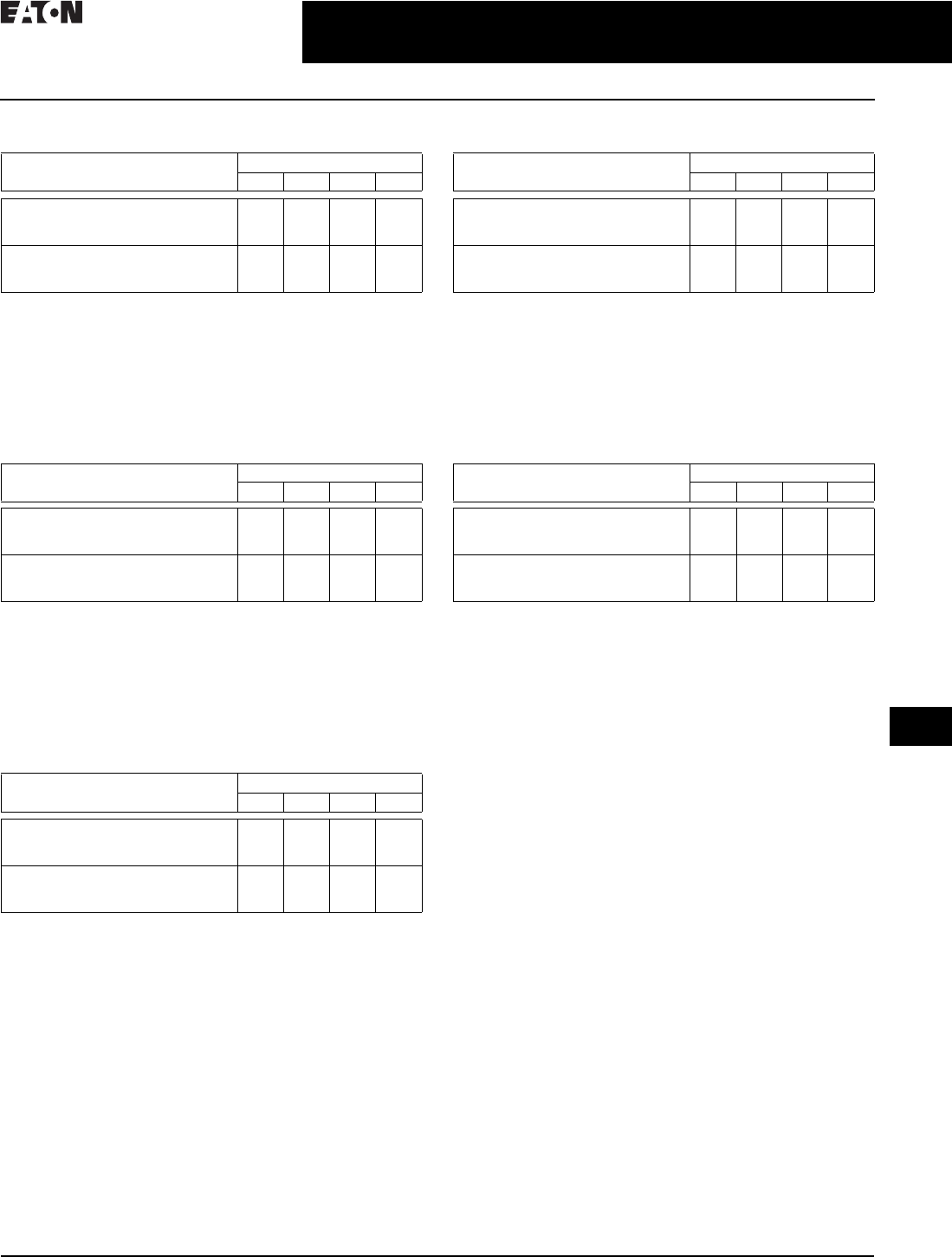
Table 34.1-9. VPR Ratings for 80–400 kA Units Rated 120/240 V Single Split-Phase 1
1Highest VPR shown for each model and mode. Specific units may have lower VPR ratings based
upon options used. Refer to specific VPR ratings shown in TD01005006E for integrated SPDs and
TD01005025E for sidemount SPDs.
2Direct bus connected not available above 200 kA.
Note: VPR ratings of 50 kA units and ratings of each specific configuration can be found in
TD01005006E for integrated SPDs and TD01005025E for sidemount SPDs.
Table 34.1-10. VPR Ratings for 80–400 kA Units Rated 120/208 V Wye (4W + G)
and 127/220V Wye (4W +G) 3
3Highest VPR shown for each model and mode. Specific units may have lower VPR ratings based
upon options used. Refer to specific VPR ratings shown in TD01005006E for integrated SPDs and
TD01005025E for sidemount SPDs.
4Direct bus connected not available above 200 kA.
Note: VPR ratings of 50 kA units and ratings of each specific configuration can be found in
TD01005006E for integrated SPDs and TD01005025E for sidemount SPDs.
Table 34.1-11. VPR Ratings for 80–400 kA Units Rated 230/400 V Wye (4W + G)
and 277/480 V Wye (4W +G) 5
5Highest VPR shown for each model and mode. Specific units may have lower VPR ratings based
upon options used. Refer to specific VPR ratings shown in TD01005006E for integrated SPDs and
TD01005025E for sidemount SPDs.
6Direct bus connected not available above 200 kA.
Note: VPR ratings of 50 kA units and ratings of each specific configuration can be found in
TD01005006E for integrated SPDs and TD01005025E for sidemount SPDs.
Type (All Voltage Code 240S) Protection Mode
L-N L-G N-G L-L
Integrated direct bus connected 2
Integrated circuit breaker connected
Sidemount NEMA 1
500
700
700
600
700
800
500
700
700
900
1000
1200
Sidemount NEMA 1 with breaker
Sidemount NEMA 4/4X
Sidemount NEMA 4/4X with breaker
800
900
900
900
900
900
700
700
700
1500
1200
1500
Type (All Voltage Code 208Y and 220Y) Protection Mode
L-N L-G N-G L-L
Integrated direct bus connected 4
Integrated circuit breaker connected
Sidemount NEMA 1
500
700
700
600
700
800
500
700
700
900
1000
1200
Sidemount NEMA 1 with breaker
Sidemount NEMA 4/4X
Sidemount NEMA 4/4X with breaker
800
900
900
1200
900
900
700
700
700
1500
1500
1500
Type (All Voltage Code 400Y and 480Y) Protection Mode
L-N L-G N-G L-L
Integrated direct bus connected 6
Integrated circuit breaker connected
Sidemount NEMA 1
1000
1200
1200
1200
1200
1200
1000
1200
1200
1800
1800
2500
Sidemount NEMA 1 with breaker
Sidemount NEMA 4/4X
Sidemount NEMA 4/4X with breaker
1500
1200
1200
1500
1200
1500
1200
1200
1200
2500
2500
2500
CA08104001E For more information, visit: www.eaton.com/consultants
34.1-15
June 2016
Surge Protection (SPD) & Power Conditioning Products
Sheet 34
22
23
24
25
26
27
28
29
30
31
32
33
34
35
36
37
38
39
40
41
42
4 3
Surge Protection Products—SPD
SPD Series
017
Table 34.1-12. VPR Ratings for 80–400 kA Units Rated 347/600 V
Wye (4W + G) 1
1Highest VPR shown for each model and mode. Specific units may have
lower VPR ratings based upon options used. Refer to specific VPR
ratings shown in TD01005006E for integrated SPDs and TD01005025E
for sidemount SPDs.
2Direct bus connected not available above 200 kA.
Note: VPR ratings of 50 kA units and ratings of each specific
configuration can be found in TD01005006E for integrated SPDs
and TD01005025E for sidemount SPDs.
Table 34.1-13. VPR Ratings for 80–400 kA Units Rated 240 V
Delta (3W +G) 3
3Highest VPR shown for each model and mode. Specific units may have
lower VPR ratings based upon options used. Refer to specific VPR
ratings shown in TD01005006E for integrated SPDs and TD01005025E
for sidemount SPDs.
4Direct bus connected not available above 200 kA.
Note: VPR ratings of 50 kA units and ratings of each specific
configuration can be found in TD01005006E for integrated SPDs
and TD01005025E for sidemount SPDs.
Table 34.1-14. VPR Ratings for 80–400 kA Units Rated 480 V
Delta (3W +G) 5
5Highest VPR shown for each model and mode. Specific units may have
lower VPR ratings based upon options used. Refer to specific VPR
ratings shown in TD01005006E for integrated SPDs and TD01005025E
for sidemount SPDs.
6Direct bus connected not available above 200 kA.
Note: VPR ratings of 50 kA units and ratings of each specific
configuration can be found in TD01005006E for integrated SPDs
and TD01005025E for sidemount SPDs.
Table 34.1-15. VPR Ratings for 80–400 kA Units Rated 600 V
Delta (3W +G) 7
7Highest VPR shown for each model and mode. Specific units may have
lower VPR ratings based upon options used. Refer to specific VPR
ratings shown in TD01005006E for integrated SPDs and TD01005025E
for sidemount SPDs.
8Direct bus connected not available above 200 kA.
Note: VPR ratings of 50 kA units and ratings of each specific
configuration can be found in TD01005006E for integrated SPDs
and TD01005025E for sidemount SPDs.
Table 34.1-16. VPR Ratings for 80–400 kA Units Rated 240 V High-Leg
Delta (4W +G) 9
9Highest VPR shown for each model and mode. Specific units may have
lower VPR ratings based upon options used. Refer to specific VPR
ratings shown in TD01005006E for integrated SPDs and TD01005025E
for sidemount SPDs.
jDirect bus connected not available above 200 kA.
Note: VPR ratings of 50 kA units and ratings of each specific
configuration can be found in TD01005006E for integrated SPDs
and TD01005025E for sidemount SPDs.
Type (All Voltage Code 600Y) Protection Mode
L-N L-G N-G L-L
Integrated direct bus connected 2
Integrated circuit breaker connected
Sidemount NEMA 1
1200
1500
1500
1500
1500
1500
1500
1500
1500
2500
2500
2500
Sidemount NEMA 1 with breaker
Sidemount NEMA 4/4X
Sidemount NEMA 4/4X with breaker
1500
1500
1500
1500
1500
1500
1500
1500
1500
2500
2500
2500
Type (All Voltage Code 240D) Protection Mode
L-N L-G N-G L-L
Integrated direct bus connected 4
Integrated circuit breaker connected
Sidemount NEMA 1
N/A
N/A
N/A
1000
1200
1000
N/A
N/A
N/A
900
1200
1000
Sidemount NEMA 1 with breaker
Sidemount NEMA 4/4X
Sidemount NEMA 4/4X with breaker
N/A
N/A
N/A
1000
1000
1000
N/A
N/A
N/A
1000
1000
1000
Type (All Voltage Code 480D) Protection Mode
L-N L-G N-G L-L
Integrated direct bus connected 6
Integrated circuit breaker connected
Sidemount NEMA 1
N/A
N/A
N/A
1800
2000
2500
N/A
N/A
N/A
1800
2000
2500
Sidemount NEMA 1 with breaker
Sidemount NEMA 4/4X
Sidemount NEMA 4/4X with breaker
N/A
N/A
N/A
2500
2500
2500
N/A
N/A
N/A
2500
2500
2500
Type (All Voltage Code 600D) Protection Mode
L-N L-G N - G L-L
Integrated direct bus connected 8
Integrated circuit breaker connected
Sidemount NEMA 1
N/A
N/A
N/A
2500
2500
3000
N/A
N/A
N/A
2500
2500
2500
Sidemount NEMA 1 with breaker
Sidemount NEMA 4/4X
Sidemount NEMA 4/4X with breaker
N/A
N/A
N/A
3000
3000
2500
N/A
N/A
N/A
2500
2500
2500
Type (All Voltage Code 240H) Protection Mode
L-N L-G N-G L-L
Integrated direct bus connected j
Integrated circuit breaker connected
Sidemount NEMA 1
500
700
700
600
700
800
500
700
700
900
1000
1200
Sidemount NEMA 1 with breaker
Sidemount NEMA 4/4X
Sidemount NEMA 4/4X with breaker
800
900
900
900
900
900
700
700
700
1500
1500
1500
34.1-16
For more information, visit: www.eaton.com/consultants CA08104001E
June 2016
Surge Protection (SPD) & Power Conditioning Products
Sheet 34
22
23
24
25
26
27
28
29
30
31
32
33
34
35
36
37
38
39
40
41
42
4 3
Surge Protection Products—SPD
SPD MAX Series
018
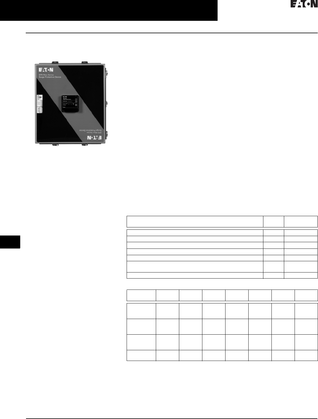
SPD MAX Series
Surge Protection
SPV MAX Series
General Description
Eaton’s SPD MAX Series side-mounted
surge protective devices are the latest
and most advanced UL 1449 4th
Edition certified surge protectors.
Applying SPD MAX Series units at main
service entrances and critical loads
will ensure that equipment is protected
with the safest and most reliable surge
protective devices (SPDs) available.
Units are available in all common
voltages and configurations, and also
in a variety of surge current capacity
ratings from 100 kA through 800 kA.
Additionally, you may choose from two
feature package options.
Application Description
The breadth of the SPD MAX Series’
features, options, and configurations
ensures that the correct unit is available
for all electrical applications, including
service entrances, main switchgear,
motor control centers, distribution
switchboards, panelboards, and point-
of-use applications.
Standards and Certifications
■UL 1449 4th Edition
■UL 1283 5th Edition
■
Canadian Standards Association (CSA)
■Built in an ISO® 9001 facility
■Designed and tested in
accordance with:
❑IEEE C62.41.1
❑IEEE C62.41.2
❑IEEE C62.43-2005
❑IEEE C62.45-2002
❑IEEE C62.48-2005
❑IEEE C62.62-2010
Features, Benefits
and Functions
■Uses thermally protected metal
oxide varistor (MOV) technology
■Lockout and tagout provisions
■Safety barriers
■20 kA nominal discharge current (In)
rating (maximum rating assigned
by UL)
■100 kA through 800 kA surge current
capacity ratings
■Installation flexibility, #10 to 1/0 wire
may be used
■Two feature package options
■200 kA short-circuit current rating
(SCCR) (maximum rating assigned
by UL)
■Field serviceable
■15-year warranty standard,
additional 5 years with product
registration
Feature Package Options
The SPD MAX Series provides users
with the option of selecting between
two feature packages: basic and
standard with surge counter. The
proper feature package can be
selected based on the application’s
requirements or specifications.
See Table 34.1-17.
Enclosure Options,
Dimensions and Weights
There are two enclosure options for
the SPD MAX Series, painted steel
NEMA 4 or stainless steel NEMA 4X.
The maximum weight of the SPD MAX
Series is 52 lb.
Performance Data
Table 34.1-18 contains representative
voltage protection rating (VPR) data for
all SPD MAX Series voltage ratings,
but the VPR varies based on the
feature package, kA rating, number
of modules, and enclosure option.
The UL website contains the actual
VPR for every possible configuration.
Table 34.1-17. Feature Package Comparison
Table 34.1-18. ANSI/UL 1449 4th Edition Voltage Protection Ratings
Feature Package Comparison Basic Standard with
Surge Counter
Surge protection using thermally protected MOV technology ■■
Dual-colored protection status indicators for each phase ■■
Dual-colored protection status indicators for the N–G protection mode ■■
Audible alarm with silence button — ■
Form C relay contact — ■
EMI/RFI filtering that provides up to 50 dB of noise attenuation
from 10 kHz to 100 MHz
—■
Surge counter with reset button — ■
Nominal
Vol ta ge
L–G
VPR
L–L
VPR
L–N
VPR
N–G
VPR
H–G
VPR
H–L
VPR
H–N
VPR
208Y
220Y
230L
800
800
1500
1200
1200
—
900
900
1500
900
900
1200
—
—
—
—
—
—
—
—
—
240D
240H
240S
1200
800
800
1200
1200
1200
—
900
900
—
900
900
—
1500
—
—
2000
—
—
1500
—
400Y
480D
480Y
1500
1500
1500
2000
2000
2000
1500
—
1500
1200
—
1200
—
—
—
—
—
—
—
—
—
600D
600Y
1500
1500
2500
2500
—
1800
—
1500
—
—
—
—
—
—
CA08104001E For more information, visit: www.eaton.com/consultants
34.1-17
June 2016
Surge Protection (SPD) & Power Conditioning Products
Sheet 34
22
23
24
25
26
27
28
29
30
31
32
33
34
35
36
37
38
39
40
41
42
4 3
Surge Protection Products—SPD
SPD MAX Series
019
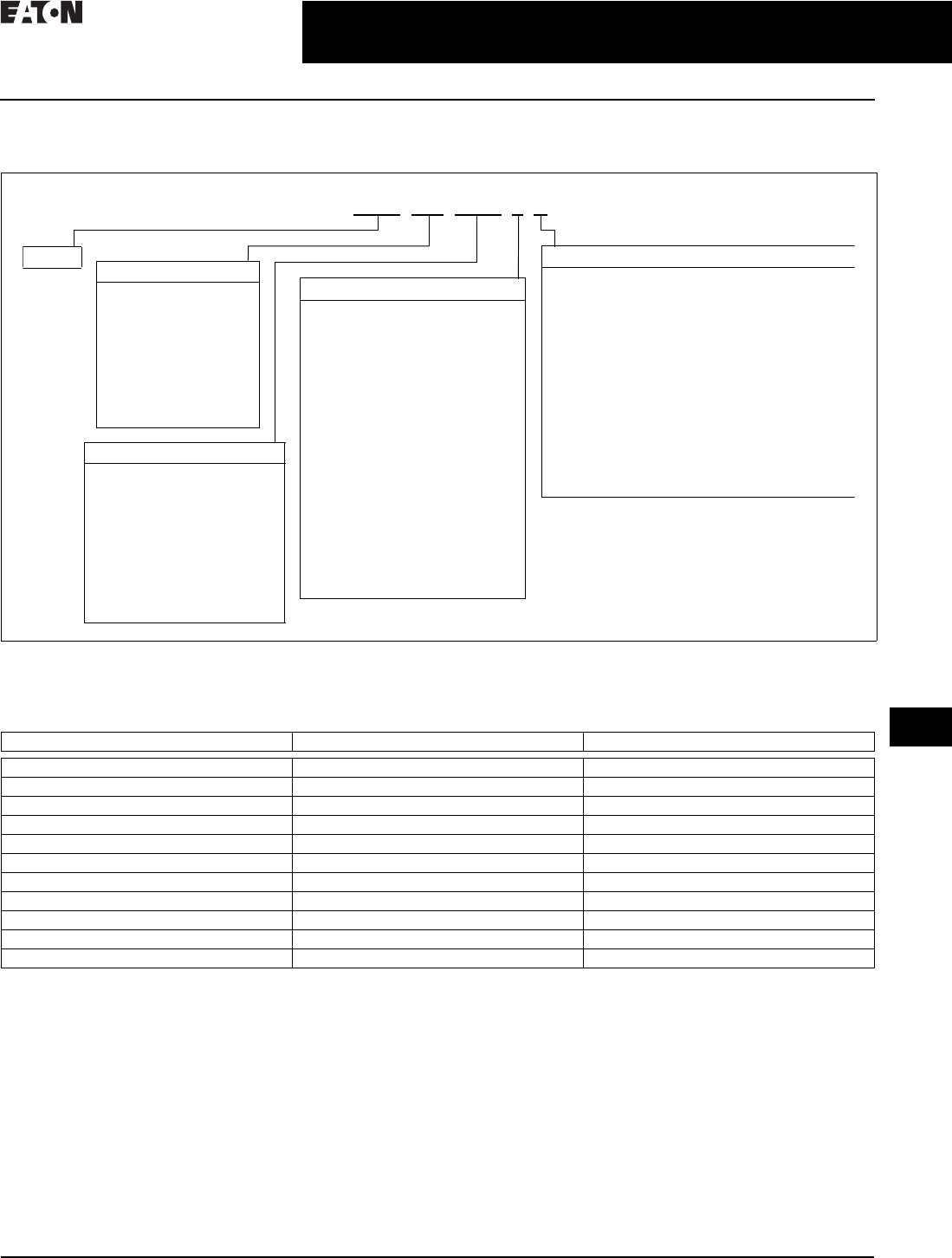
Catalog Numbering System
Table 34.1-19. SPD MAX Series Catalog Numbering System
1Please consult the factory for 240 delta high leg (4W+G) applications with high leg on C phase.
Example: SPD250480D3R = SPD MAX Series, 250 kA per phase, 480 D voltage, standard with counter features package,
NEMA 4 enclosure with internal circuit breaker.
Table 34.1-20. Valid Module and Enclosure Configurations per kA
kA per Phase Number of Surge Modules Available Enclosure Options
100 kA Single module only R, T, V, X enclosures
120 kA Single module only R, T, V, X enclosures
160 kA Single module only R, T, V, X enclosures
200 kA Single or dual module All enclosures
250 kA Single module only R, T, V, X enclosures
300 kA Single module only R, T, V, X enclosures
320 kA Dual module only S, U, W, Y enclosures
400 kA Single or dual module All enclosures
500 kA Dual module only S, U, W, Y enclosures
600 kA Dual module only S, U, W, Y enclosures
800 kA Dual module only S, U, W, Y enclosures
SPM 250 480D 3 R
SPM Application Suffix
R= 1 module, NEMA 4 enclosure with internal
circuit breaker
S= 2 module, NEMA 4 enclosure with internal
circuit breaker
T= 1 module, NEMA 4 enclosure with internal
terminal block
U= 2 module, NEMA 4 enclosure with internal
terminal block
V=1 module, NEMA 4X enclosure with internal
circuit breaker
W= 2 module, NEMA 4X enclosure with internal
circuit breaker
X= 1 module, NEMA 4X enclosure with internal
terminal block
Y= 2 module, NEMA 4X enclosure with internal
terminal block
kA Rating Options
100 = 100 kA per phase
120 = 120 kA per phase
160 = 160 kA per phase
200 = 200 kA per phase
250 = 250 kA per phase
300 = 300 kA per phase
320 = 320 kA per phase
400 = 400 kA per phase
600 = 600 kA per phase
800 = 800 kA per phase
Voltage Code Options
240S = 120/240 split-phase
208Y = 120/208 wye (4W + G)
220Y = 127/220 wye (4W + G)
400Y = 230/400 wye (4W + G)
600Y = 347/600 wye (4W + G)
240D = 240 delta (3W + G)
480D = 480 delta (3W + G)
600D = 600 delta (3W + G)
240H = 240 delta high leg
(4W + G) on B phase
230L = 230 single-phase
Feature Package Options 1
1=Basic
Dual-colored LED per phase to
indicate protection status.
Dual-colored LED to indicate
protection status of the
N–G mode on units with a
neutral wire.
3= Standard with surge counter.
Dual-colored LED per phase to
indicate protection status.
Dual-colored LED to indicate
protection status of the
N–G mode on units with a
neutral wire.
Audible alarm with silence button.
Form C relay contact.
EMI/RFI filtering that provides up
to 50 dB of noise attenuation from
10 kHz to 100 MHz.
Surge counter with alarm silence
(reset) button.
34.1-18
For more information, visit: www.eaton.com/consultants CA08104001E
June 2016
Surge Protection (SPD) & Power Conditioning Products
Sheet 34
22
23
24
25
26
27
28
29
30
31
32
33
34
35
36
37
38
39
40
41
42
4 3
Surge Protection Products—SPD
SPD MAX Series
020
Technical Data and Specifications
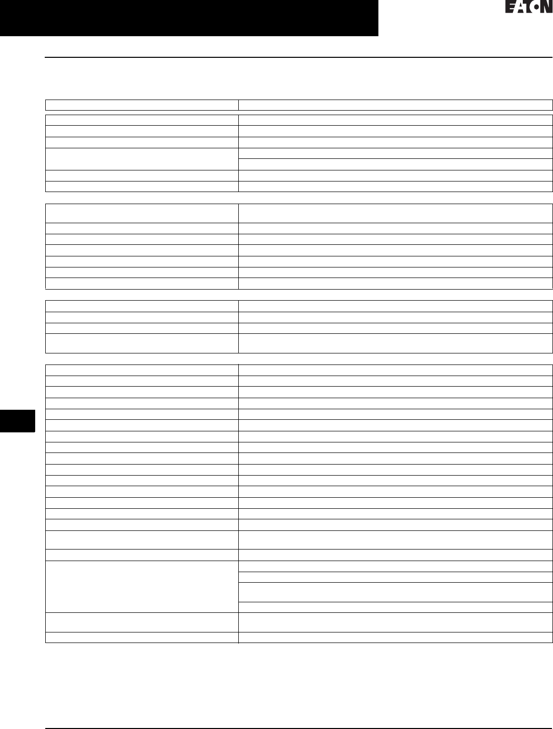
Table 34.1-21. SPD MAX Series Specifications
Description Specification
Surge current capacity per phase 100 kA, 120 kA, 160 kA, 200 kA, 250 kA, 300 kA, 320 kA, 400 kA, 600 kA, 800 kA ratings available
Nominal discharge current (In) 20 kA
Short-circuit current rating (SCCR) 200 kA
SPD type Basic feature package = Type 1 (can also be used in Type 2 applications)
Standard with surge counter feature package = Type 2
Enclosure types NEMA 4, NEMA 4X enclosure
Circuit breaker—30 A Eaton catalog number: FDC3030L
Circuit Breaker Load and Line
Terminal torque specifications #10 AWG 35 lb-in; #8 AWG 40 lb-in; #6–#4 AWG 45 lb-in; #3–1/0 AWG 50 lb-in
(SPD maximum wire range #10–1/0 AWG)
Standard split phase voltages available 120/240
Single-phase 230
Three-phase wye system voltages available 120/208, 127/220, 230/400, 277/480, 347/600
Three-phase delta system voltages 240, 480, 600
Three-phase high leg delta system voltages 120/240 high leg phase wire will be identified with a tag from the factory
Input power frequency 50/60 Hz
Power Consumption (Standard with Surge Counter Units)
208 Y, 220 Y, 230 L, 240 S, 240 D, and 240 H voltage codes 0.6 W
400 Y, 480 Y, and 480 D basic voltage codes 1.7 W
600 Y and 600 D voltage codes 2.1 W
Protection modes Single split phase L–N, L–G, N–G, L–L, single-phase L–N, L–G, N–G, three-phase delta L–G, L–L,
three-phase wye L–N, L–G, N–G, L–L, three-phase high leg delta L–N, L–G, N–G, L–L
Maximum Continuous Operating Voltage (MCOV)
230 V single-phase 320 V L–N, 320 V L–G, 320 V N–G
127 V/220 V wye, 120 V/240 V single split phase 150 V L–N, 150 V L–G, 150 V N–G, 300 V L–L
120 V/240 V hi leg 150 V L–N, 150 V L–G, 150 V N–G, 300 V L–L, 320 V H–N, 320 V H–G, 470 V H–L
230 V/400 V wye, 277 V/480 V wye 320 V L–N, 320 V L–G, 320 V N–G, 640 V L–L
347 V/600 V wye 420 V L–N, 420 V L–G, 420 V N–G, 840 V L–L
240 V delta 300 V L–G, 300 V L–L
480 V delta 640 V L–G, 640 V L–L
600 V delta 840 V L–G, 840 V L–L
Ports 1 or 2
Operating temperature and humidity –20 °C through +50 °C (–4 °F through +122 °F), 5% through 95%, noncondensing
Storage temperature –20 °C through +50 °C (–4 °F through +122 °F)
Operating altitude Up to 16,000 ft (5000 m)
Weight Not to exceed 52 lb
Form C relay contact ratings Maximum 0.46 A, 150 Vac, 1 A, 30 Vdc
Form C terminal block ratings Rated 300 V, 16 A, 30–12 AWG solid or stranded wire. Torque range 5–7 lb-in
Form C relay contact logic Power on, normal state—NO contact = OPEN, NC contact = CLOSED
Power off, fault state—NO contact = CLOSED, NC contact = OPEN
EMI/RFI filtering attenuation (standard with surge counter) Up to 50 dB from 10 kHz to 100 MHz
Standards / agency certifications UL 1449 4th Edition—standard for surge protective devices
UL 1283 5th Edition—standard for EMI filters (Type 2 SPDs only)
CSA Electrical Notice No. 516 Edition 1—surge/transient voltage suppressor
(excludes 230 L voltage code)
CSA 22.2 NO. 8-M1986 Edition 4—EMI filters
Warranty 15 years from the date of delivery to the purchaser, 20 years if the product is properly
registered at www.eaton.com
RoHS compliant Yes

CA08104001E For more information, visit: www.eaton.com/consultants
34.1-19
June 2016
Surge Protection (SPD) & Power Conditioning Products
Sheet 34
22
23
24
25
26
27
28
29
30
31
32
33
34
35
36
37
38
39
40
41
42
4 3
Surge Protection Products—SPD
SPD MAX Series
021
Dimensions
Figure 34.1-14. SPD MAX Dimension in Inches (mm)
Optional Entry
2½ NPT Maximum
1Ø AWG Maximum
¾ NPT Maximum
Form C Entry
1.63
(41.28)
2.33
(59.14)
1.13
(28.58)
6.58
(167.09)
12.00
(304.8)
Mounting Dimension
16.75
(425.45)
Mounting
Dimension
(4X) Ø0.31
(Ø7.87)
1/4–20 Mounting
Hardware
14.91
(378.8)
17.50
(444.50)
1.13
(28.58) 6.58
(167.09)
8.32
(211.25)
9.30
(236.30)
2.33
(59.14)
0.50
(12.70)
1.63
(41.28)
13.00
(330.20)
14.00
(355.60)
2½ NPT Maximum
Optimal Entry
1Ø Maximum
¾ NPT Maximum
Form C Entry
2½ NPT Maximum
Optimal Entry
1Ø Maximum
17.50
(444.50)
16.00
(406.40)
8.00
(203.20)
2.33
(59.14)
Scale 1000
34.1-20
For more information, visit: www.eaton.com/consultants CA08104001E
June 2016
Surge Protection (SPD) & Power Conditioning Products
Sheet 34
22
23
24
25
26
27
28
29
30
31
32
33
34
35
36
37
38
39
40
41
42
4 3
Surge Protection Products—SPD
SPV Series
022
Sidemount Surge Protective
Device for Commercial and
Light Industrial Applications
SPV
General Description
Eaton’s SPV is a commercial grade
and light industrial Surge Protection
Device (SPD) that combines surge
suppression components and EMI/RFI
filtering to provide effective protection
for sensitive electronic loads. Surges
(also known as transients) due to
lightning, utility grid switching,
switching of external/internal inductive
or capacitive loads and other sources
travel on power line conductors
throughout the electrical distribution
system that cause system operating
problems and equipment downtime.
Six different surge current per phase
rated units are available in order to
meet a variety of applications.
Features, Benefits
and Functions
Service Ratings
■120/240 V single split-phase (3W+G)
■Three-phase wye (4W+G)
120/208 V, 230/400 V, 277/480 V
■Three-phase delta (3W+G)
240 V, 480 V
Surge Current Per Phase
■SurgePlane™ technology to ensure
reliability and performance by using
a low impedance copper platform
■Compact design to enable
close mounting to electrical
distribution equipment
■Parallel hybrid filter technology
■Individually fused surge
suppression components
■Status indicator lights to monitor
supply power, surge suppression
component status and fusing
■Can be remotely monitored using
Form C contacts
■Audible alarm
■Ideal for OEM panel applications
■Proven track record in international
applications
■UL 1449 4th Edition
EMI/RFI Filter
■The UL 1283 5th Edition filter
protects against ringing transients
and EMI/RFI noise disturbances.
The tuned suppression filter
achieves 0–40 dB attenuation at
100 kHz (IEEE Category B Ringwave)
Monitoring and Diagnostics
■Status indicator lights to monitor
supply power, surge suppression
component status and fusing
■Individually fused surge suppression
components
■Can be remotely monitored using
Form C contacts c/w Audible Alarm
Enclosure
■NEMA 1 rated indoor enclosure
is standard
■Optional NEMA 3R enclosure

CA08104001E For more information, visit: www.eaton.com/consultants
34.1-21
June 2016
Surge Protection (SPD) & Power Conditioning Products
Sheet 34
22
23
24
25
26
27
28
29
30
31
32
33
34
35
36
37
38
39
40
41
42
4 3
Surge Protection Products—SPD
SPV Series
023
Catalog Numbering System
Table 34.1-22. SPV Series Catalog Numbering System
Table 34.1-23. Voltage Code
1Use these codes to complete the model number.
2Valid for 220/380 and 240/415 per IEC standards.
Note: Contact factory for single-pole (two-wire plus ground) or for other configurations.
Not suitable for resistive or underground wire systems. Refer to the Eaton SPD for
these applications.
Technical Data and
Specifications
■Temperature: –40 °C to +60 °C
■Altitude: <13,000 ft (3962 m)
■Dimensions in inches (mm):
5.00 x 11.55 x 2.50
(127.0 x 293.4 x 63.5)
■Weight in lb (kg): 3.5 (1.6)
Nominal
Vol ta ges 1
Voltage Code
120/208
240 V
230/400
400 V 2
277/480
480 V
120/240 single split-phase (3W plus G)
Three-phase wye (4W plus G)
Three-phase delta (3W plus G)
240S
208Y
240D
—
400Y
—
—
480Y
480D
SPV 200 480D 2 K
SPV Enclosure Suffix
K=NEMA 1
R=NEMA 3R
Feature Package
2=Basic—
Audible alarm
Form C relay
contact
kA Rating
50 = 50 kA per phase
80 = 80 kA per phase
100 = 100 kA per phase
120 = 120 kA per phase
160 = 160 kA per phase
200 = 200 kA per phase
Voltage Code
240S = 120/240 split-phase
208Y = 120/208 wye (4W + G)
220Y = 127/220 wye (4W + G)
400Y = 230/400 wye (4W + G)
480Y = 277/480 wye (4W + G)
240D = 240 delta (3W + G)
480D = 480 delta (3W + G)
230L = 230 single-phase
Dimensions
Figure 34.1-15 shows dimensions
for standard SPV suppressor.
Contact factory for dimensions
using flushmount or 3R enclosures.
Figure 34.1-15. SPV NEMA 1
2.50
(63.5)
2.50
(63.5)
.40
(10.2)
10.75
(273.1)
10.00
(254.0)
11.55
(293.4)
1.25
(31.8)
R .10
(2.5)
4 PLS.
5.00
(127.0)
34.1-22
For more information, visit: www.eaton.com/consultants CA08104001E
June 2016
Surge Protection (SPD) & Power Conditioning Products
Sheet 34
22
23
24
25
26
27
28
29
30
31
32
33
34
35
36
37
38
39
40
41
42
4 3
Surge Protection Products—SPD
CVX Surge Protective Device
024
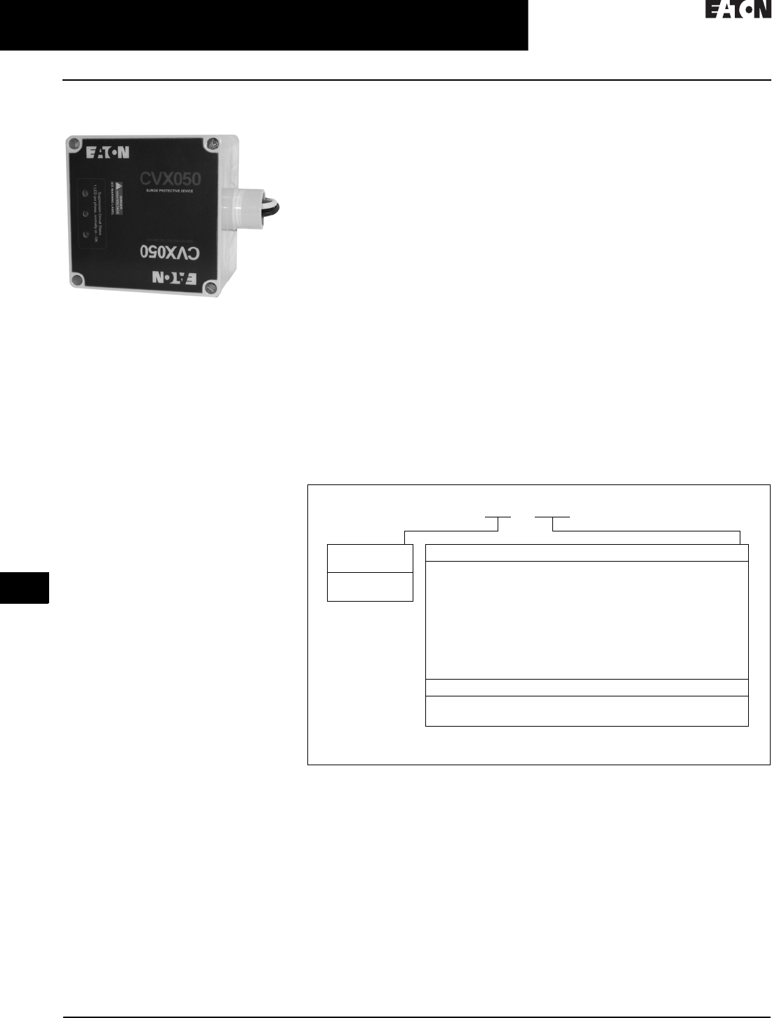
CVX050/100
CVX050/100A
General Description
With over two decades of experience
in the surge suppression industry and
extensive R&D initiatives, Eaton is
considered a world leader in surge
protective device (SPD) manufacturing.
All of Eaton’s products are manufac-
tured in an ISO 9001:2000 and ISO
14001 certified facility.
Eaton’s CVX050/100 models are
rugged, cost-effective, high-quality
SPDs that feature thermally protected
MOVs that eliminate the failure
characteristics of standard Metal-
Oxide-Varistors. The TPMOV is a
fail-safe device that monitors the status
of the metal-oxide disk and connects
itself from the power system when
the disk is approaching breakdown.
The CVX050/100 is easy to install
adjacent or even internal to electrical
equipment. When installing an SPD in
a retrofit environment, it is important
to mount the device as close to the
electrical equipment as possible. Keep
the wiring (lead length) between the
electrical equipment and SPD as short
as possible, and twist or wire tie the
conductors together to reduce the
wire’s impedance factor.
Application Description
Eaton’s CVX050 and CVX100 SPDs
protect electronic equipment from
damaging transients. These units
are suitable for medium and low
exposure level applications that
require cost-effective, high quality
system protection including:
■Residential/small business
■Light industrial
■Light commercial
■Branch panel protection
Features, Benefits
and Functions
■Advanced surge path technology
for high fault current capacity, low
impedance, high frequency design
■Rugged NEMA 4X (IP65) enclosure
■Large diameter, thermally protected
metal oxide varistors provide long
life and fail-safe operation
■LED monitoring of each phase
■Wide range of voltage applications
from 100 to 480 Vac, and 48 and
125 Vdc
■5-year free replacement warranty
Optional Features
■External mounting feet
(catalog number MNTGFTX)
■Flush mounting plate
(catalog number
FLUSHMNTPLATE12)
Standards and Certifications
■UL 1449 4th Edition for surge
protective devices
■CE marked
■Vibration tested IEC 60255-21-1 and -2
Note: CE, CSA and UL on AC unit only.
Catalog Number Selection
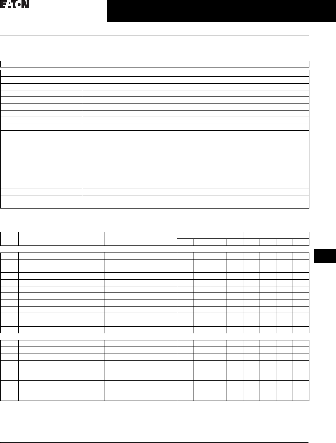
Table 34.1-24. CVX050/100
1DC models only available in 50 kA.
Per Phase Peak
Surge Current
050 = 50 kA
100 = 100 kA 1
Configuration and Voltage Ranges (Vac)
230L = Single-phase–200, 208, 220, 230, 240, 277
480L = Split-phase–380, 400, 440, 460, 480
240S = Split-phase–100/200, 110/220, 120/240
240H = Three-phase high leg delta–120/240
208Y = Three-phase wye (star)–100/174, 110/190, 120/208, 127/220
480Y = Three-phase wye (star)–220/380, 230/400, 240/415, 277/480
600Y = Three-phase wye (star)–305/525, 347/600
240D = Three-phase delta–200, 208, 220, 230, 240
480D = Three-phase delta–380, 400, 415, 440, 480
600D = Three-phase delta–525, 600 Vac (600D available in 50 kA only)
Configuration and Voltage Ranges (Vdc)
048DC = Direct Current 48 Vdc 1
125DC = Direct Current 125 Vdc 1
CVX 050 - 230L
CA08104001E For more information, visit: www.eaton.com/consultants
34.1-23
June 2016
Surge Protection (SPD) & Power Conditioning Products
Sheet 34
22
23
24
25
26
27
28
29
30
31
32
33
34
35
36
37
38
39
40
41
42
4 3
Surge Protection Products—SPD
CVX Surge Protective Device
025
Technical Data and Specifications
Table 34.1-25. CVX050/100 Model Specifications
1480L, 600D and 600Y units rated 10 kA In.
2DC models only available in 50 kA.
Table 34.1-26. CVX050/100 Voltage Ratings
3UL 1449 4th Edition VPR (voltage protection rating) test environment: all tests performed with 6-inch lead length, positive polarity.
4DC units available in 50 kA only. Voltages shown are the maximum suggested operating voltages and are not UL certified.
Description Specification
Peak kA per phase 50, 100
Peak kA per mode 50
Nominal discharge current 20 kA 1
Short-circuit current rating 100 kA
Single-phase voltages 200, 208, 220, 230, 240, 277, 380, 400, 440, 460, 480
Split-phase voltages 100/200, 110/220/ 120/240
High leg delta voltages 240
Wye system voltages 100/175, 110/190, 120/208, 127/220, 220/380, 230/400, 240/415, 277/480, 305/525, 347/600
Delta system voltages 200, 208, 220, 230, 240, 380, 400, 415, 440, 480, 525, 600
Direct current voltage 248 Vdc, 125 Vdc
Input power frequency 47–420 Hz (50/60 Hz typical)
Protection modes Single-phase: L-N, N-G, L-G
Split-phase: L-N, N-G, L-G, L-L
High leg delta: L-N, N-G, L-G, L-L, H-N, H-G, H-L
Wye: L-N, N-G, L-G, L-L
Delta: L-G, L-L
Direct current (DC): L-L, L-G b
Number of ports 1
Specific energy 100 kJ/Ohm
Weight (approximate) 2.0 lb (1.0 kg)
Operating temperature –13 °F (–25 °C) to +140 °F (+60 °C)
Vibration tested IEC 60255-21-1 and IEC 60255-21-2
Model System
Configuration
Nominal
System Voltage
MCOV UL 1449-4 VPR 3
L- L L- N L- G N - G L- L L- N L- G N - G
CVX050
230L Single-phase two-wire + ground 200, 208, 220, 230, 240, 277 — 320 640 320 — 1200 1200 1200
480L Single-phase two-wire + ground 380, 400, 440, 460, 480 — 550 1100 550 — 1800 4000 1800
240S Split-phase three-wire + ground 100/200, 110/220, 120/240 300 150 300 150 1200 700 1200 800
208Y Three-phase wye (star) four-wire + ground 100/175, 110/190, 120/208, 127/220 300 150 300 150 1200 700 1200 800
480Y Three-phase wye (star) four-wire + ground 220/380, 230/400, 240/415, 277/480 640 320 640 320 2500 1200 2000 1200
600Y Three-phase wye (star) four-wire + ground 305/525, 347/600 840 420 840 420 2500 1500 2500 1500
240D Three-phase delta three-wire + ground 200, 208, 220, 230, 240 640 — 320 — 2000 — 1200 —
240H Three-phase high leg delta 240 300 150 150 640 1500 700 1200 700
480D Three-phase delta three-wire + ground 380, 400, 415, 440, 480 1100 — 550 — 3000 — 1800 —
600D Three-phase delta three-wire + ground 525, 600 1100 — 700 — 3000 — 2500 —
048DC Direct current 48 Vdc 4130— 65— ————
125DC Direct current 125 Vdc 4288 — 144 — — — — —
CVX100
230L Single-phase two-wire + ground 200, 208, 220, 230, 240, 277 — 320 320 320 — 1200 1200 1200
480L Single-phase two-wire + ground 380, 400, 440, 460, 480 — 550 550 550 — 1800 1800 1800
240S Split-phase three-wire + ground 100/200, 110/220, 120/240 300 150 150 150 1200 700 800 700
208Y Three-phase wye (star) four-wire + ground 100/175, 110/190, 120/208, 127/220 300 150 150 150 1000 600 700 700
480Y Three-phase wye (star) four-wire + ground 220/380, 230/400, 240/415, 277/480 640 320 320 320 1800 1200 1200 1200
600Y Three-phase wye (star) four-wire + ground 305/525, 347/600 840 420 420 420 2500 1500 1500 1500
240D Three-phase delta three-wire + ground 200, 208, 220, 230, 240 640 — 320 — 1800 — 1200 —
240H Three-phase high leg delta 240 300 150 150 150 1200 700 700 700
480D Three-phase delta three-wire + ground 380, 400, 415, 440, 480 1100 — 550 — 3000 — 1800 —
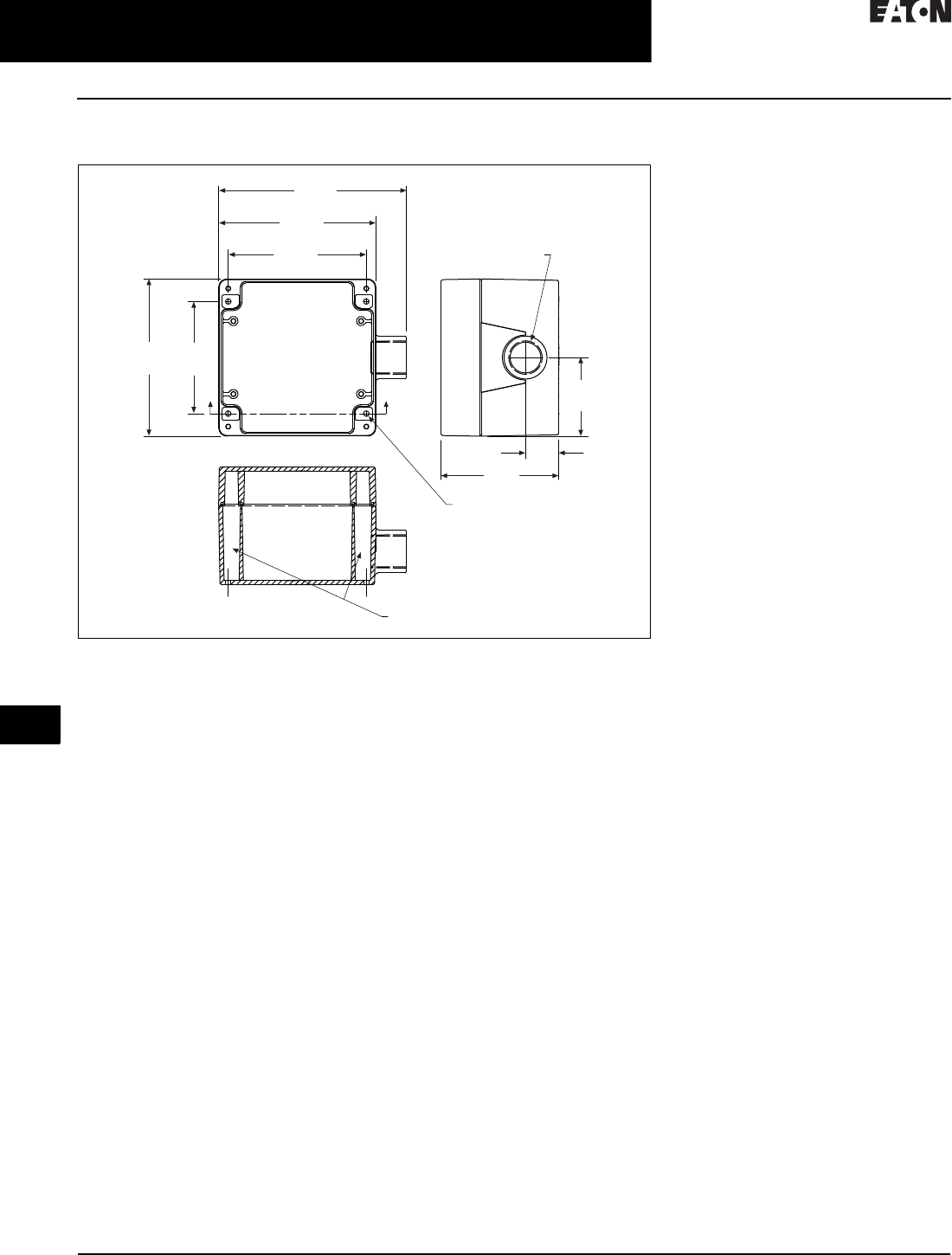
34.1-24
For more information, visit: www.eaton.com/consultants CA08104001E
June 2016
Surge Protection (SPD) & Power Conditioning Products
Sheet 34
22
23
24
25
26
27
28
29
30
31
32
33
34
35
36
37
38
39
40
41
42
4 3
Surge Protection Products—SPD
CVX Surge Protective Device
026
Dimensions
Figure 34.1-16. CVX050/100 Standard Dimensions—Approximate Dimensions in Inches (mm)
A
A
Mounting Hole Shafts
5.67
(144.0)
4.75
(120.6)
2.37
(60.2)
1.0 0
(25.4)
3.55
(90.2)
3.39
(86.1)
4.75
(120.6)
4.17
(106.0)
Conduit Fitting
0.75 (19.0) Internal
Taper Pipe Threads
0.17 (4.3)
(4) Mounting Holes
Under Lid
Lid Removed
Section A-A
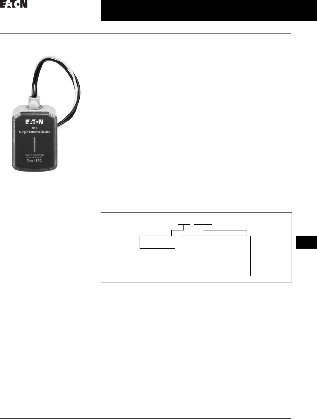
CA08104001E For more information, visit: www.eaton.com/consultants
34.1-25
June 2016
Surge Protection (SPD) & Power Conditioning Products
Sheet 34
22
23
24
25
26
27
28
29
30
31
32
33
34
35
36
37
38
39
40
41
42
4 3
Surge Protection Products—SPD
Eaton SP1
027
Eaton SP1
Eaton SP1
General Description
Eaton‘s SP1 is a UL 1449 4th Edition-
listed surge protective device that
provides reliable, cost-effective surge
protection. This Type 1 SPD is capable
of being installed on either the line
or load side of the service entrance
disconnect and can be used as a
replacement for devices formerly
known as secondary surge arresters
or lightning arresters, which could
not be manufactured after UL 1449
3rd Edition went into effect on
September 29, 2009. The unit is
available in many common voltages
and configurations. Multiple mount-
ing options coupled with a compact
footprint enables installation of the
SP1 in a wide range of applications,
including panelboards, loadcenters,
pump panels, control cabinets,
and other electrical assemblies
and applications.
Installation and Operation
Installation and operation of the SP1 is
simple. The unit comes pre-wired with
24.00 inches (609.6 mm) of 10-gauge
wire and is mounted via the 0.50-inch
(12.7 mm) nipple that is molded into its
enclosure. Wall or DIN rail mounting
can also be accomplished with the
addition of an optional kit. When
powered, the unit‘s light-emitting diode
(LED) indicator reports the status of the
protection elements and is active when
all of them are intact and providing
protection. Any loss of protection is
signaled when the LED extinguishes.
Features
■Type 1 SPD capable of installation
on either the line or load side of
the service entrance disconnect
■20 kA nominal discharge current
rating (In) on most models
■50 kA per phase surge
current capacity
■Compact footprint—
4.80 inches (121.9 mm) L x
2.90 inches (73.7 mm) W x
2.50 inches (63.5 mm) D
■Pre-wired with 24.00 inches
(609.6 mm) of 10-gauge wire
■0.50-inch (12.7 mm) nipple molded
into enclosure enables quick and
easy mounting
■Optional kit enables wall or
DIN rail mounting
■Two-year warranty
Standards and Certifications
■UL 1449 4th Edition-listed device
Catalog Number Selection
Table 34.1-27. SP1 Catalog Numbering System
Note: SP1MNTGKIT = optional wall or DIN rail mounting kit (order separately—
not included with SP1 unit).
Series
SP1
Voltage Codes
240S = 120/240 V single split-phase
208Y = 120/208 wye
480Y = 277/480 wye
600Y = 347/600Y wye
240D = 240 delta
480D = 480 delta
600D = 600 delta
SP1 XXXX
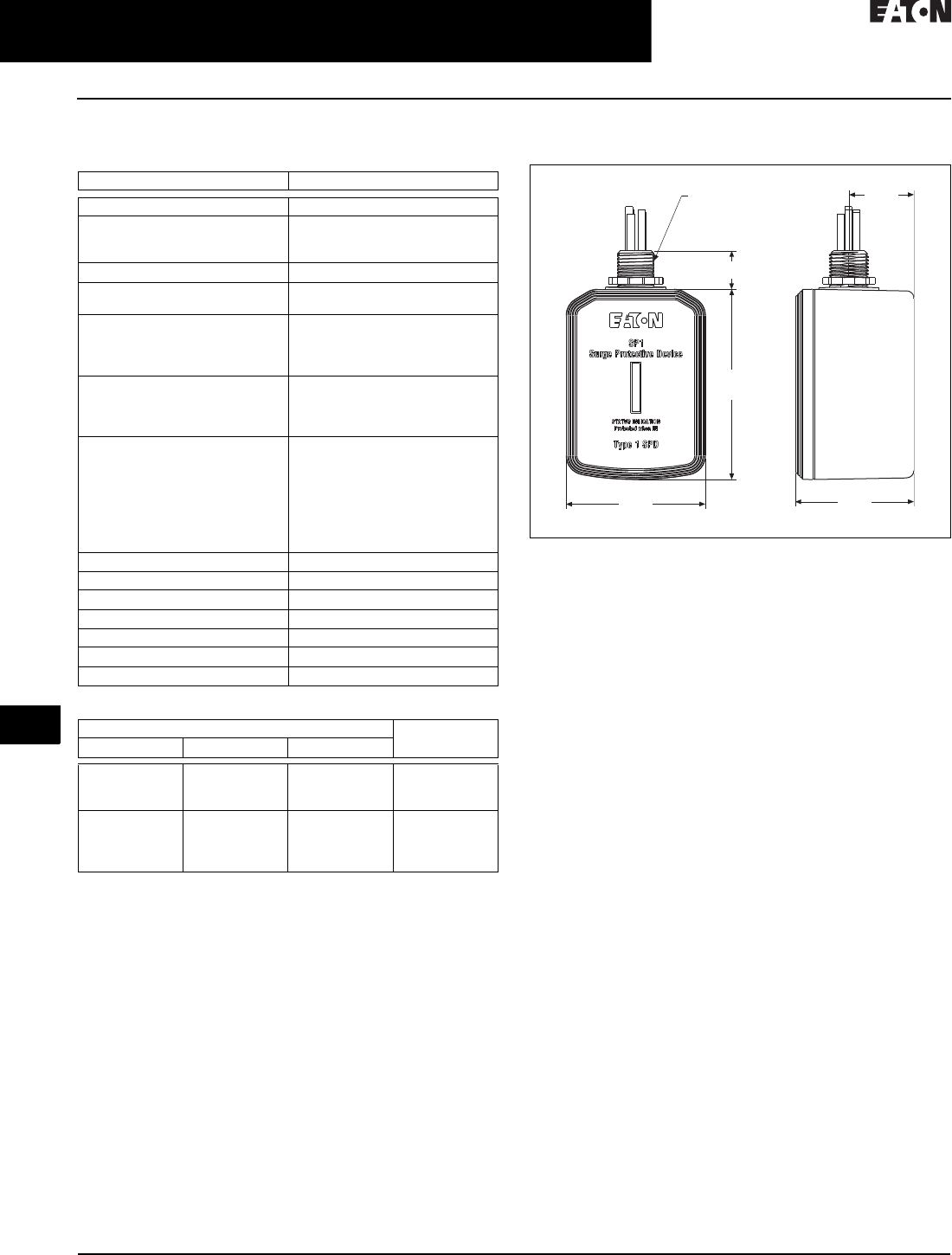
34.1-26
For more information, visit: www.eaton.com/consultants CA08104001E
June 2016
Surge Protection (SPD) & Power Conditioning Products
Sheet 34
22
23
24
25
26
27
28
29
30
31
32
33
34
35
36
37
38
39
40
41
42
4 3
Surge Protection Products—SPD
Eaton SP1
028
Technical Data and Specifications
Table 34.1-28. Specifications
Table 34.1-29. ANSI/UL 1449 4th Edition Voltage Protection Ratings
Technical Support Information
If you have any questions or need additional information,
please contact the Eaton Technical Resource Center at
800-809-2772, option 4, option 2. You may also submit
inquiries via e-mail: spd@eaton.com.
Dimensions in Inches (mm)
Figure 34.1-17. SP1 Dimensions
Description Rating
Surge current capacity per phase 50 kA
Nominal discharge current (In) 20 kA for SP1-240S, 208Y, 480Y,
240D and 480D
10 kA for SP1-600Y and 600D
Short-circuit current rating (SCCR) 200 kA
SPD type Type 1 (can also be used in
Type 2 applications)
System voltages available (Vac)
Single split-phase
Three-phase wye
Three-phase delta
120/240
120/208, 277/480, 347/600
240, 480, 600
Protection modes
Single split-phase and three-phase
wye
Three-phase delta
L- N , L- L
L- G , L- L
Maximum continuous operating
voltage (MCOV)
SP1-240S and SP1-208Y
SP1-480Y
SP1-600Y
SP1-240D
SP1-480D
SP1-600D
150 L-N, 300 L-L
320 L-N, 640 L-G
420 L-N, 840 L-G
300 L-G, 300 L-L
640 L-G, 640 L-L
840 L-G, 840 L-L
Input power frequency 50/60 Hz
Enclosure rating NEMA 4
Operating temperature –20 °C to 50 °C (–4 °F to 122 °F)
Operating humidity 5–95%, noncondensing
Operating altitude Up to 16,000 ft (5000 m)
Agency certification and approvals UL 1449 4th Edition listed device
Warranty 2 years
Protection Mode Catalog
Number
L- N L- G L- L
600
600
1200
N/A
N/A
N/A
1000
1000
2000
SP1-240S
SP1-208Y
SP1-480Y
1500
N/A
N/A
N/A
N/A
1000
2000
2500
2500
1000
2000
2500
SP1-600Y
SP1-240D
SP1-480D
SP1-600D
0.50 (12.7)
Straight Pipe Thread
1.35
(34.3)
0.79 (20.1)
3.95
(100.3)
2.89
(73.4)
2.46
(62.5)
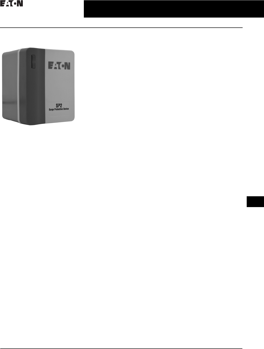
CA08104001E For more information, visit: www.eaton.com/consultants
34.1-27
June 2016
Surge Protection (SPD) & Power Conditioning Products
Sheet 34
22
23
24
25
26
27
28
29
30
31
32
33
34
35
36
37
38
39
40
41
42
4 3
Surge Protection Products—SPD
Eaton SP2
029
SP2 Surge Protective Device
Surge Protection for Light Commercial
and UL 508A Panel Applications
General Description
The SP2 provides basic surge
protection for light commercial
electrical systems and OEM equipment
requirements. The SP2 is available in
the most popular voltage and system
configurations and delivers superior
surge protection using MOV thermal
disconnect technology that eliminates
the need for additional overcurrent
protection.
Studies have shown that failure to
protect sensitive electronic loads
costs American manufacturing and
commercial and service industries
more than $39 billion per year in
lost time and revenue. Preventing
these losses is a major cost-saving
opportunity. The SP2 can be used to
protect downstream points in the
electrical distribution system along
with machinery control panels to keep
your facility and processes running.
Application Description
By providing surge protection, the SP2
can suppress the transients that are
prevalent throughout the power
distribution system to support reliable
operations in applications including:
■HVAC systems
■Control panels
■Automation cabinets
■Pumping systems
■Lighting systems
■Commercial facilities
■Food processing
■Warehouses
■Retail facilities
■Manufacturing operations
Standards and Certifications
■UL 1449 4th Edition Type 1 SPD
File No. E109835, cULus
■Built in an ISO 9001 facility
■Flammability rating UL 94VO
■Designed and tested in accordance
with:
❑IEEE C62.41.1
❑IEEE C62.41.2
❑IEEE C62.43-2005
❑IEEE C62.45-2002
❑IEEE C62.48-2005
❑IEEE C62.62-2010
Features, Benefits
and Functions
■Type 1 UL 1449 4th Edition listed
SP2s are easily selected and
installed on the loadside or lineside
of the service entrance overcurrent
protective device
■Thermal disconnect technology
eliminates the need for additional
overcurrent protection
■Compact UV-resistant NEMA 4X
enclosure for indoor or outdoor
applications
■LED status indicators provide surge
protection status at a glance—green
when good, red to replace
■Voltage-specific models protect
electrical systems and equipment,
improving performance by more
than 110% over “one-size-fits-all”
economy surge arresters
■Compact enclosure takes up less
space and can be installed in tight
spaces
■Can be used on single-phase, split-
phase, wye, delta, and high-leg delta
systems
■All SP2 devices are individually
marked with a serial number for
easy tracking and identification
■Two-year warranty
■Compact design allows for easy
installation on an electrical panel
or meter socket, or integrated into
control cabinets
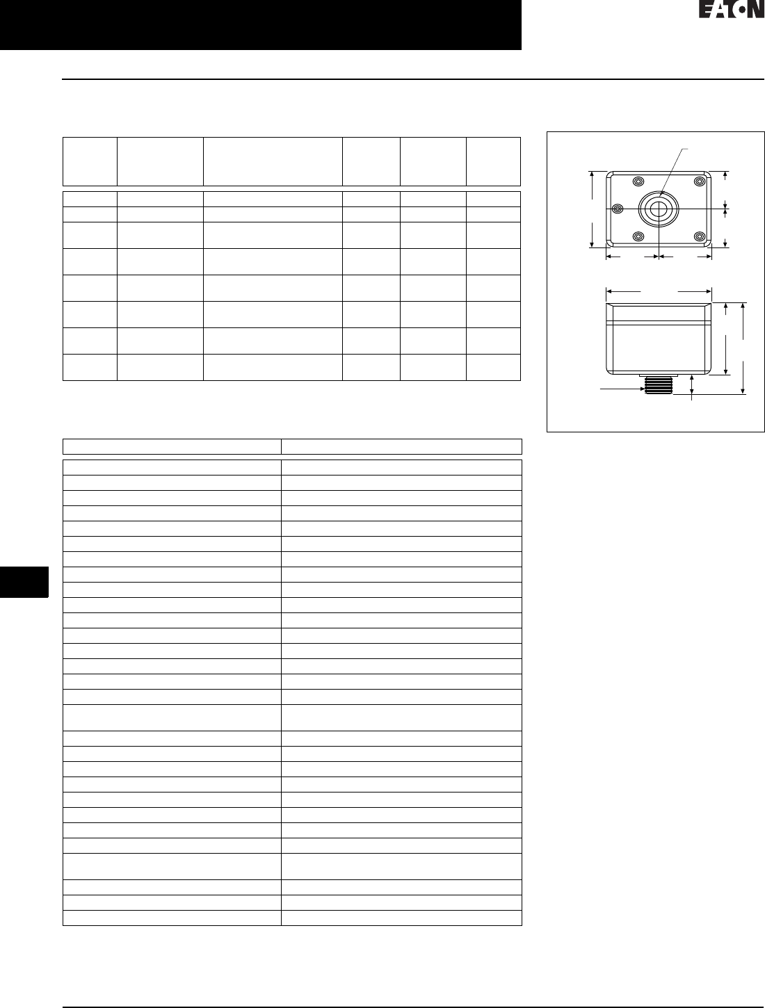
34.1-28
For more information, visit: www.eaton.com/consultants CA08104001E
June 2016
Surge Protection (SPD) & Power Conditioning Products
Sheet 34
22
23
24
25
26
27
28
29
30
31
32
33
34
35
36
37
38
39
40
41
42
4 3
Surge Protection Products—SPD
Eaton SP2
030
Product Selection
Table 34.1-30. SP2 Product Selection
Technical Data and Specifications
Table 34.1-31. SP2 Specifications
Nominal
System
Vol ta ge
Maximum
Continuous
Operating AC
Voltage (MCOV)
System
Ty p e
Voltage
Protection
Ratings
(VPR)
Connection
Points
Catalog
Number
120 150 Single-phase, two-wire 700 L–N 2 SP2-120
240 320 Single-phase, two-wire 1200 L–N 2 SP2-240
120/240 150 Split-phase, three-wire 700 L–N,
1200 L–L
3SP2-240S
240 320 Three-phase delta,
three-wire + ground
1200 L–G,
2500 L–L
4SP2-240D
480 550 Three-phase delta,
three-wire + ground
1800 L–G,
3000 L–L
4SP2-480D
120/208 150 Three-phase wye,
three-wire + ground
700 L–G,
1200 L–L
4SP2-208Y
277/480 320 Three-phase wye,
three-wire + ground
1200 L–G,
2500 L–L
4SP2-480Y
34/600 420 Three-phase wye,
three-wire + ground
1500 L–G,
2500 L–L
4SP2-600Y
Description Specification
Markets Light commercial and UL 508A panels
Product warranty 2 years
System types Single, split, delta, and wye
Nominal system voltage 120, 208, 240, 480, 600 Vac
Installation Two-, three-, four-wire
Maximum continuous operating AC voltage Matched to nominal voltage
MCOV 150–550 Vac (see table above)
L–N protection Yes (single-phase units)
L–L protection Yes
L–G protection Yes (three-phase units)
Protection Surges and transients
SCCR 200 kA
Nominal discharge current (8 x 20 µs) In 10 kA
Maximum discharge current (8 x 20 µs) Imax 45 kA per phase
Response time tA <25 ns
Voltage protection ratings (VPRs) See table above
Overcurrent device (if required by local code) Circuit breaker or fuse sized to protect wires per
local codes
Frequency 50/60 Hz
Operating status / fault indication One bi-color LED—green (good) / red (replace)
Conductor gauge/length 10 AWG stranded copper / 18 inches
Mounting Chase nipple (¾” NPS)
Enclosure rating NEMA 4X—UL 94-5VA
Degree of protection (installed state) IP20 (finger-safe)
Install location Indoor/outdoor
Circuit location Lineside/loadside
Standards / agency information UL 1449 4th Edition Type 1 Listed SPD—cULus,
RoHS compliant
Operating temperature –40 °C to +65 °C
Maximum operating altitude 12,000 ft
Weight 17 oz (476 g)
Dimensions in Inches (mm)
Figure 34.1-18. SP2 Enclosure
3.38
(85.9)
1.69
(42.9)
1.69
(42.9)
3.19
(81.0)
4.06
(103.1)
0.87
(22.1)
4.13
(104.9)
2.06
(52.3)
2.06
(52.3)
1.06 (26.9)
Diameter
¾" NPS
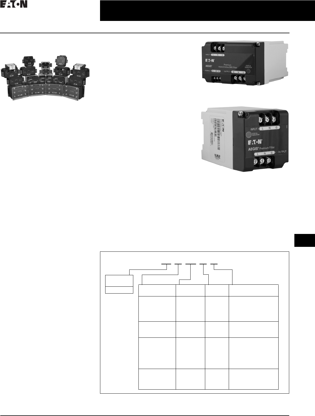
CA08104001E For more information, visit: www.eaton.com/consultants
34.1-29
June 2016
Surge Protection (SPD) & Power Conditioning Products
Sheet 34
22
23
24
25
26
27
28
29
30
31
32
33
34
35
36
37
38
39
40
41
42
4 3
Surge Protection Products—SPD
AEGIS—Series Protective Device
031
AEGIS Powerline Filters
AEGIS Solutions
General Description
Eaton AEGIS™ Series line filters
and surge protectors are specifically
designed to protect sensitive electronics
from hazards that exist within a facility.
The AEGIS Series hybrid filter reacts
instantly to changes in voltage regard-
less of phase angle or polarity. In
comparison to other line filters, this
technology provides a higher level
of suppression, reliability and
life expectancy.
Application Description
By providing surge protection and line
filtering, AEGIS devices can suppress
the noise and transients prevalent
throughout the power distribution
system to support reliable operations
in applications including:
■Instrumentation
■Water treatment facilities
■Pulp and paper operations
■Refrigeration and heating plants
■Petrochemical and refinery
■Food processing
■Textiles
■Automotive assembly
■Manufacturing operations
No matter where transients originate,
the application of AEGIS Series
devices will help protect sensitive
electronic equipment including:
■Programmable logic controllers
(PLCs)
■Scanning devices
■Automatic teller machines (ATMs)
■Cash registers
■Alarm systems
■Microprocessor-controlled
■OEM products
■Robotics
■CAD/CAM systems
■Control equipment
■Medical electronics and devices
AEGIS Series devices are available
in a variety of common voltages
and configurations.
Why Should Sensitive Electronic
Loads be Protected?
PLC manufacturers and service
technicians recommend the use
of surge suppressors and filters to
prevent downtime and equipment
damage due to surges and electrical
line noise. One study shows failure to
protect sensitive electronic loads costs
American manufacturing, commercial
and service industries over $39 billion
per year in lost time and revenue.
Preventing these losses is a major
cost-saving opportunity.
Features, Benefits
and Functions
AEGIS powerline filters protect
against the full spectrum of transient
disturbances.
AEGIS filters the entire sine wave and
is effective against both frequently
occurring low-energy and occasional
high-energy transients. High-energy
transients can create immediate
damage, while low-energy transients
cause microprocessor failure
over time.
The AEGIS PH Series Protects Critical
Loads up to 20 A
The AEGIS PV Series Protects Critical
Loads up to 5 A
Catalog Numbering System
Table 34.1-32. AEGIS Series Catalog Numbering System
1Not available for 10 A, 230 V or 240 V versions.
2Only available for 10 A, 120 V or 240 V CF
version.
3Only available for 10 A, 120 V CF version.
4Only available for 30 A and 60 A CF version.
AG
Protection/
Filtering
Voltage Amperage Options
PH = Premium
protection
with hybrid
filtering
120 = 120 Vac
240 = 240 Vac
03 = 3 A
05 = 5 A
10 = 10 A
15 = 15 A
20 = 20 A
PV = Premium
protection
with filtering
120 = 120 Vac
240 = 240 Vac
01 = 1 A
03 = 3 A
05 = 5 A
CF = Critical
protection
with filtering
120 = 120 Vac
230 = 230 Vac
240 = 240 Vac
024 = 24 Vdc
048 = 48 Vdc
10 = 10 A
15 = 15 A
30 = 30 A
60 = 60 A
DIN = DIN mount 1
DIN2= DIN2 mount 2
CP = Compact 3
RJ = Telcom protection
and Form C
status contacts 4
CN = Critical
protection
without
filtering
120 = 120 Vac
230 = 230 Vac
024 = 24 Vdc
048 = 48 Vdc
30 = 30 A
Product
Family/OEM
AG
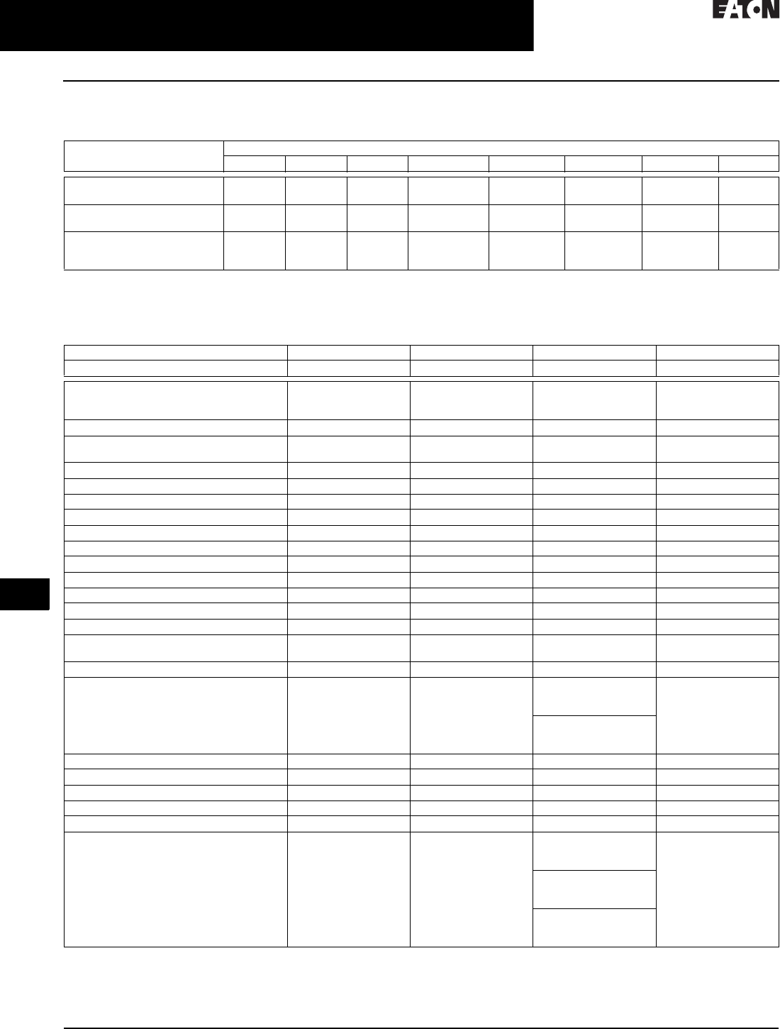
34.1-30
For more information, visit: www.eaton.com/consultants CA08104001E
June 2016
Surge Protection (SPD) & Power Conditioning Products
Sheet 34
22
23
24
25
26
27
28
29
30
31
32
33
34
35
36
37
38
39
40
41
42
4 3
Surge Protection Products—SPD
AEGIS—Series Protective Device
032
Product Selection
Table 34.1-33. Let-Through Voltages Based on IEEE Std. C62.62-2010 Testing Waveforms 1
1All tests conducted on 120 Vac units.
Technical Data and Specifications
Table 34.1-34. AEGIS Specifications
2Optional on 10 A and 30 A models only.
3120 Vac models only.
4Ratings shown for 120 Vac models, other
voltages listed in Technical Data.
5Optional on 30 A and 60 A models only.
6With product registration.
7External circuit breaker sold separately.
Test
Impulse
AEGIS Series
AGPH120xx AGPV120xx AGCF12010 AGCF12010-DIN AGCF12010-CP AGCF12030xxx AGCF12060xxx AGCn12030
IEEE Category A
100 kHz ring wave 6000 V, 200 A
25 V 30 V 150 V 300 V 300 V 150 V 90 V 400 V
IEEE Category B
100 kHz ring wave 6000 V, 500 A
35 V 40 V 330 V 400 V 400 V 330 V 230 V 500 V
IEEE Category B
combination wave 6000 V, 3000 A
(UL 1449-4 VPR)
360 V 370 V 470 V 480 V 460 V 460 V 450 V 460 V
AEGIS Series 234
Rating PH PV CF CN
Application Single-phase, two-
or three-wire
grounded systems
Single-phase, two-
or three-wire
grounded systems
Single-phase, two-
or three-wire
grounded systems
Single-phase, two-
or three-wire
grounded systems
Input voltage—AC 100–127 Vac, 200–240 Vac 100–127 Vac, 200–240 Vac 100–127 Vac, 200–240 Vac 100–127 Vac, 200–240 Vac
Input voltage—DC N/A N/A 5–38 Vdc, 24–65 Vdc,
48–149 Vdc, 150–300 Vdc
5–38 Vdc, 24–65 Vdc,
48–149 Vdc, 150–300 Vdc
Amperage 3, 5, 10, 15, and 20 A 1, 3, and 5 A 10, 30, and 60 A 30 A
DIN mounting Yes Yes Yes 5No
Frequency 50/60 Hz 50/60 Hz 50/60 Hz 50/60 Hz
Protection modes L–N, L–G and N–G L–N, L–G and N–G L–N, L–G and N–G L–N, L–G and N–G
MCOV 150 V and 275 V 150 V and 275 V 150 V and 275 V 150 V and 275 V
Noise attenuation (normal mode) 74 dB at 100 kHz 56 dB at 100 kHz 48 dB at 100 kHz N/A
Filter bandwidth 10 kHz to 100 MHz 10 kHz to 100 MHz 10 kHz to 100 MHz N/A
Peak surge current per phase / per mode 60 kA / 30 kA 40 kA / 20 kA Up to 80 kA / 40 kA Up to 80 kA / 40 kA
UL nominal discharge current (In) 5 kA 5 kA 5 kA 5 kA
UL voltage protection rating (VPR) L–G / L–N 4330/400 330/400 500/500 500/500
Short-circuit current rating (SCCR) 5 kA 5 kA 10 kA 10 kA
Operating temperature –40 °F to +122 °F
(–40 °C to +50 °C)
–40° F to +122 °F
(–40 °C to +50 °C)
–40 °F to +140 °F
(–40 °C to +60 °C)
–40 °F to +140 °F
(–40 °C to +60 °C)
Response time <1 nanosecond <1 nanosecond <1 nanosecond <1 nanosecond
Agency approvals UL 1449 4th Edition,
UL 1283 5th Edition
and CSA
UL 1449 4th Edition,
UL 1283 5th Edition
and CSA
AGCFxxxxx UL 1449
4th Edition, UL 1283
5th Edition
AGCNxxx30 UL 1449,
UL 1283 5th Edition,
EMI filter
AGCFxxx10-DIN2
UL 1449 4th Edition,
IEC 61000-4.5
UL 1449 Type Type 2 Type 2 Type 2 Type 2
Warranty 615 years 15 years 10 years 10 years
Status indicator LED LED LED LED
Form C contacts Yes No Yes 5No
Communication line protection (UL 497A) No No Optional No
External circuit breaker 7Eaton P/N: WMZT1C25
or equiv. 25 A circuit
breaker
Eaton P/N: WMZT1C07
or equiv. 7 A circuit
breaker
10 A—Eaton P/N:
WMXT1C15 or equiv.
15 A circuit breaker
Eaton P/N: WMZT1C40
or equiv. 40 A circuit
breaker
30 A—Eaton P/N:
WMZT1C40 or equiv.
40 A circuit breaker
60 A—Eaton P/N:
EGC3100FFG or equiv.
100 A circuit breaker
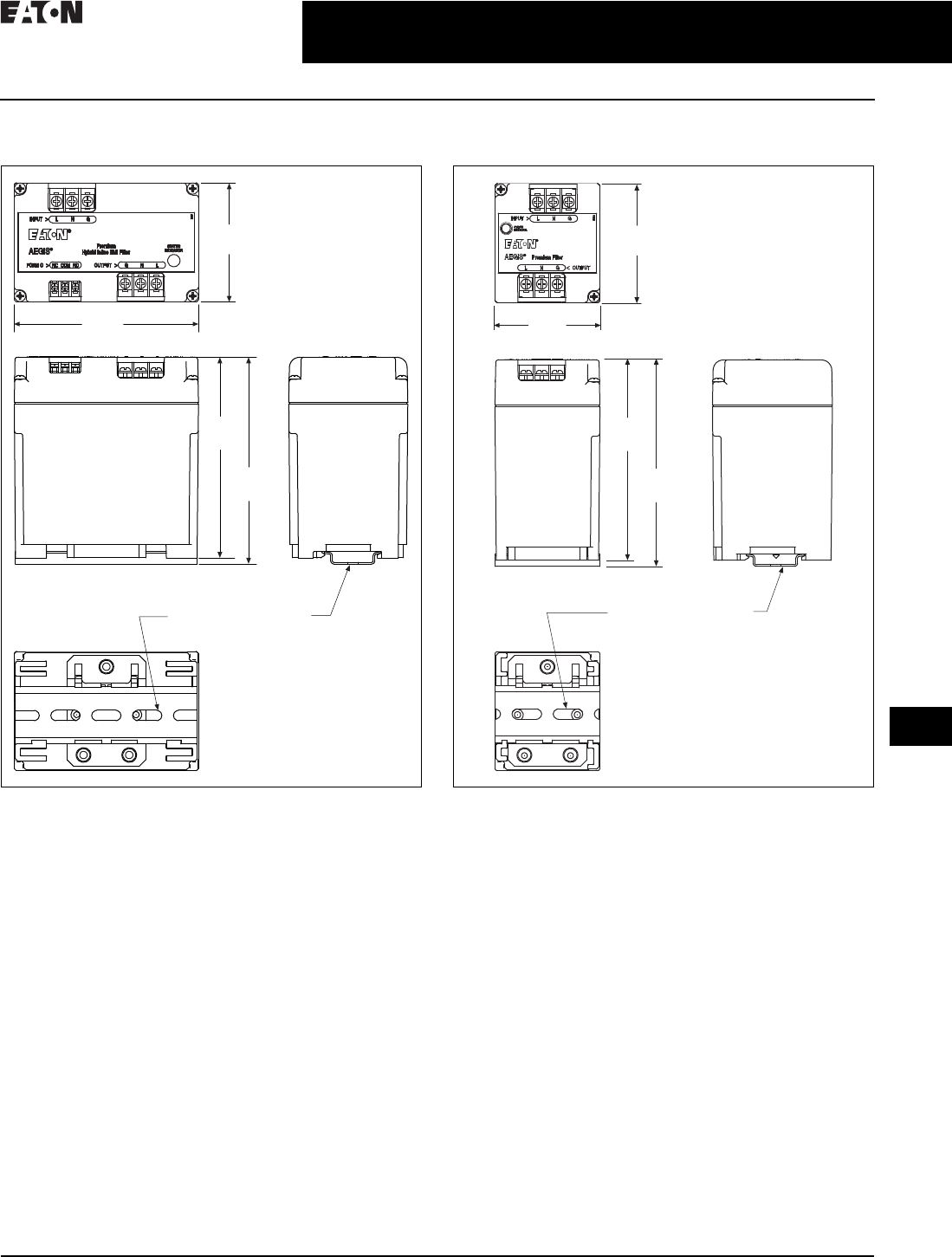
CA08104001E For more information, visit: www.eaton.com/consultants
34.1-31
June 2016
Surge Protection (SPD) & Power Conditioning Products
Sheet 34
22
23
24
25
26
27
28
29
30
31
32
33
34
35
36
37
38
39
40
41
42
4 3
Surge Protection Products—SPD
AEGIS—Series Protective Device
033
Dimensions in Inches (mm)
Figure 34.1-19. AGPHxxxxx Dimensions Figure 34.1-20. AGPVxxxxx Dimensions
2.87
(72.9)
4.44
(112.8)
4.83
(122.8)
4.98
(126.5)
DIN Rail to be Mounted
with Screws Provided
Using Slots as Template
2.87
(72.9)
2.51
(63.8)
4.83
(122.8)
4.98
(126.5)
DIN Rail to be Mounted
with Screws Provided
Using Slots as Template
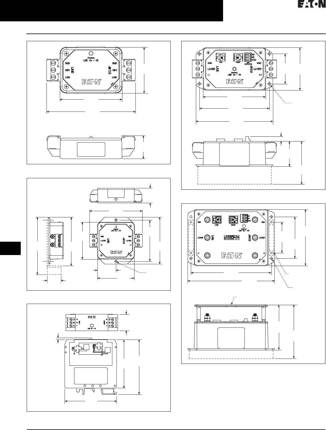
34.1-32
For more information, visit: www.eaton.com/consultants CA08104001E
June 2016
Surge Protection (SPD) & Power Conditioning Products
Sheet 34
22
23
24
25
26
27
28
29
30
31
32
33
34
35
36
37
38
39
40
41
42
4 3
Surge Protection Products—SPD
AEGIS—Series Protective Device
034
Figure 34.1-21. AGCF12010-CP Dimensions
Figure 34.1-22. AGCFxxx10 Dimensions
Figure 34.1-23. AGCFxxx10-DIN Dimensions
Figure 34.1-24. AGCFxxx30xxx Dimensions
Figure 34.1-25. AGCFxxx60xxx Dimensions
2.47
(52.7)
1.25
(31.8)
3.34
(85.0)
4.77
(121.1)
1.68
(42.6)
3.36
(85.2)
5.21
(132.3)
4.78
(121.4)
3.75
(95.3)
4.25
(108.0)
1.36
(34.5)
Optional DIN Rail
Mounting Kit
(#420-9000) Ø 0.19
(Ø 4.8)
4.41
(112.0)
3.36
(85.2)
1.25
(31.8)
3.12
(79.4)
2.92
(74.2)
3.30
(83.8)
0.98
(24.8)
0.10
(2.5)
1.88
(47.8)
5.25
(133.4)
5.78
(146.7)
3.23
(82.0)
4.69
(119.2)
2.25
(57.2) 3.20
(81.2)
0.35
(8.9)
Optional DIN Rail
Mounting Kit
(#420-9100)
(4X) Ø 0.19
(Ø 4.8)
6.75
(171.5) 7.29
(185.0)
2.59
(65.7) 3.50
(88.9)
Optional DIN Rail Mounting Kit (#420-9000)
(4X) Ø 0.19
(Ø 4.8)
Non DIN Mtg.
DIN Mounting
Each Side (4X)
Clear Protective Cover
4.72
(119.9)
3.79
(96.1)
4.50
(114.3)

CA08104001E For more information, visit: www.eaton.com/consultants
34.1-33
June 2016
Surge Protection (SPD) & Power Conditioning Products
Sheet 34
22
23
24
25
26
27
28
29
30
31
32
33
34
35
36
37
38
39
40
41
42
4 3
Surge Protection Products—SPD
AEGIS—Series Protective Device
035
Figure 34.1-26. AGCNxxx30 Dimensions
3.20
(81.2)
1.88
(47.8)
4.69
(119.2)
(4X) Ø 0.1
(Ø 4.8)
2.25
(57.2)
3.23
(82.0)
5.25
(133.4)
5.78
(146.7)
Optional DIN Rail
Mounting Kit
(#420-9100)
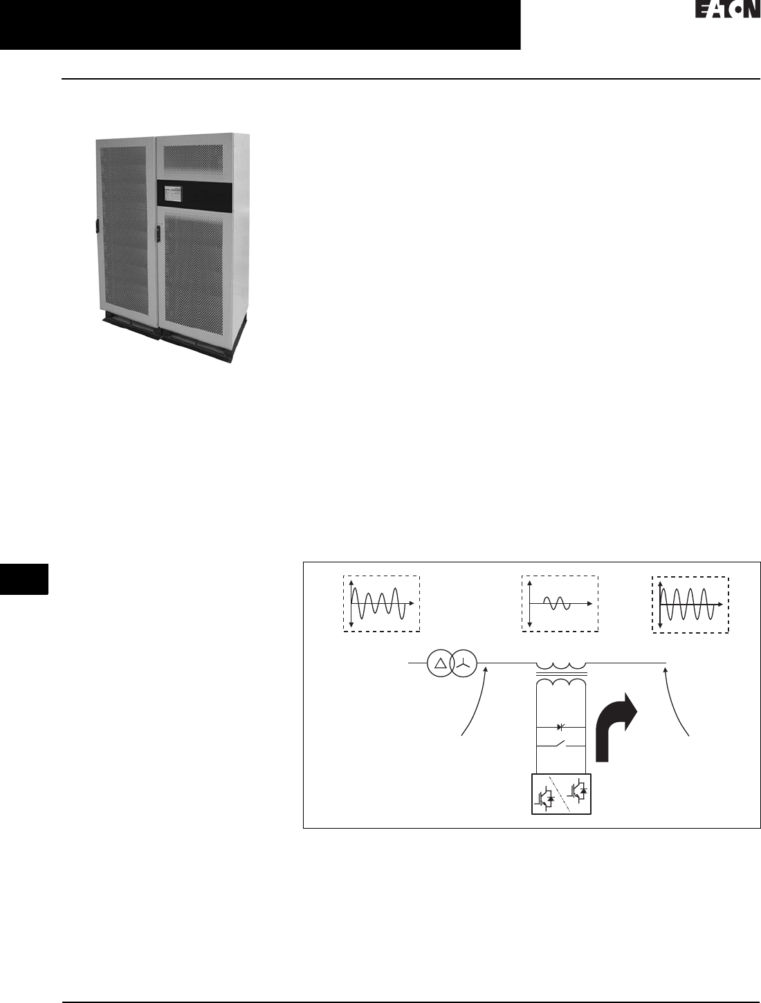
34.1-34
For more information, visit: www.eaton.com/consultants CA08104001E
June 2016
Surge Protection (SPD) & Power Conditioning Products
Sheet 34
22
23
24
25
26
27
28
29
30
31
32
33
34
35
36
37
38
39
40
41
42
4 3
Power Conditioning Products
SRT2
036
Sag Ride Through (SRT2)
Sag Ride Through (SRT2)
General Description
The SRT2 is the latest revision of
Eaton’s sag ride-through products. The
operation of the system is designed
specifically to meet the demanding
requirements of industrial load
protection where the following
eatures are particularly important:
■Extremely high electrical efficiency,
meaning much lower ongoing cost
of ownership than traditional UPS
solutions and much less needed
heat dissipation from the room in
which the SRT2 is located
■High reliability due to the three
levels of redundancy offered in the
SRT2 design
■High levels of fault clearing capacity
(typically 20 times current short
term) to allow for the discrimination
of protection systems
■Ability to cope with industrial loads,
such as motor drives, which are high
in harmonic draw and also loads
that may regenerate power
Application Description
Industries and Applications
Affected by Sags
Key industries:
■Semiconductor manufacturers
■Communications
■Steel mills
■Petroleum and chemical processing
■Healthcare
■Paper mills
■Automotives
■Textile
■Printing
■Plastics
Equipment or processes:
■Manufacturing process controllers
■Variable speed drives
■Robotics
■Motor conductor
■Telephone systems
■HID lighting
■HVAC controls
■Medical equipment
■Computers
Features and Benefits
Continuous Sag Regulation
The SRT2 is an active voltage
conditioner. This means it will
constantly respond to voltage sags
and swells in the ±10% range with a
regulated output in the ±1% range.
The SRT2 can be applied to the main
service entrance, at branch locations
or in front of critical loads. Eaton’s
SRT2 provides an outstanding return
on investment. It delivers operational
productivity that is just not possible
with traditional tap switching or
ferroresonant technologies.
The SRT2 consists of a voltage source
inverter, a bypass circuit and an injec-
tion transformer connected in series
between the incoming utility supply
and the load (Figure 34.1-27).
Sag Correction Using the Sag Ride-Through
The SRT2 power conditioner prevents
expensive electrical downtime. It is a
state-of-the-art solution to today’s
power conditioning challenges.
Standards and Certifications
The SRT2 meets the stringent require-
ments of the SEMI-F47 standard, a key
requirement for sag correction in the
semiconductor industry.
Figure 34.1-27. Block Diagram of the SRT2 Active Voltage Conditioner
Three-Phase Utility
Supply
Three-Phase Load
Voltage
Voltage Source
Inverter
Injection
Transformer
Bypass
Circuit
Secondary
Primary
Distribution
Transformer
SRT2 Input
Three-Phase Compensating
Voltage
SRT2 Output
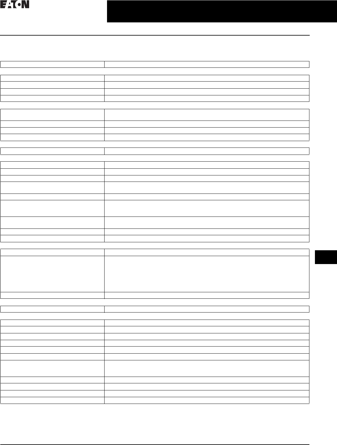
CA08104001E For more information, visit: www.eaton.com/consultants
34.1-35
June 2016
Surge Protection (SPD) & Power Conditioning Products
Sheet 34
22
23
24
25
26
27
28
29
30
31
32
33
34
35
36
37
38
39
40
41
42
4 3
Power Conditioning Products
SRT2
037
Technical Data and Specifications
Table 34.1-35. SRT2 Specifications
1480 V is standard. If additional voltage is needed, consult factory.
Description Specifications
Load Capacity
Capacity (kVA) 150–1800 kVA (consult factory for custom design; up to 36 kVA available)
Displacement power factor of connected load 0 lagging to 0.9 leading
Crest factor for rated kVA 3 at 100% of rated load
Overload capacity (>90% supply voltage) 150%, 30 seconds, once per 500 s
Input Supply
Nominal supply voltage (according to model) 480 V
Voltages up to 36 kV available as custom applications 1
Power system type Three-phase, center ground referenced
Supply voltage category Level III transient voltage capability
Fault capacity Refer to model tables
Operating Voltage Range for Regulation
Supply voltage for regulation 90–110% of nominal input voltage unit rating
Output Supply
Nominal voltage (V) Set to match nominal supply voltage
Three-phase V regulation range ±10% continuous
Three-phase V regulation accuracy ±1%
Three-phase balanced sag/swell correction ability:
40% model +40% / –10% at least 30 s at full load
Sag correction accuracy (within specified range) ±2.5%
Sag correction response:
Initial
Complete
<250 µs
<0.25 cycle
Single-phase sag correction ability:
40% model (15% retained voltage / 85% sag) 90% nominal
Equivalent series impedance (operating) <4% typical
Efficiency of system 0.98 to 0.99 (refer to model tables)
Bypass
Capacity 100% model rating (kVA)
Maximum overload capacity (in bypass):
For 10 minutes
For 1 minute
For 1 second
For 200 milliseconds
Transfer time:
Inverter to bypass
125%
150%
500%
2000%
<0.5 ms
Equivalent series impedance (in bypass) Equivalent series impedance (in bypass)
Interface
Access protocol Access protocol
Environmental
Enclosure rating NEMA® 1, IP20
Pollution degree rating 2
Minimum operating temperature 0 ºC
Maximum operating temperature 40 ºC
Temperature derating Above 40 ºC derate at 2% per ºC to a maximum of 50 ºC
Capacity elevation derating –2% every 100 m above 1000 m
Cooling:
Inverter
Trans form er
Forced ventilation
Fan assisted ventilation
Humidity <95%, noncondensing
EMC emissions CISPR 22 level G
Noise 65 dBA
Warranty 1 year
34.1-36
For more information, visit: www.eaton.com/consultants CA08104001E
June 2016
Surge Protection (SPD) & Power Conditioning Products
Sheet 34
22
23
24
25
26
27
28
29
30
31
32
33
34
35
36
37
38
39
40
41
42
4 3
Power Conditioning Products
SRT2
038
Table 34.1-36. System capacities
1For 50 Hz international applications, consult factory.
2Eaton external three-breaker maintenance bypass is recommended. If a bypass is not used, a terminal cabinet may be required. Contact factory.
3TC in the model number denotes terminal cabinet, which is not required for units of 900 kVA and larger.
4480 V is standard. If additional voltage is needed, consult factory.
Wiring Diagram
Figure 34.1-28. SRT2 With External Maintenance Bypass Block Diagram
Note: A terminal cabinet may be needed if a bypass cabinet is not used. SRT2 units 900 kVA
and larger do not require a terminal cabinet; however, an external three-breaker mechanical
bypass with integrated surge protection is recommended.
Catalog
Number 123
Load
Capacity
at Nominal
Voltage
480 V (kVA) 4
Te r m i n a l
Cabinet
Fault
Capacity
(kVA)
System
Efficiency
(%)
System
Dissipation
(Worst Case)
(kW)
Airflow
(m3/min)
Cabinet Dimensions
H x W x D in Inches (mm)
SRT20150480AA
SRT20150480AA-TC
SRT20225480AA
SRT20225480AA-TC
150
150
225
225
No
Yes
No
Yes
40
40
40
40
97.5
97.5
97.7
97.7
3.8
3.8
5.2
5.2
18
18
18
18
85.00 x 32.00 x 32.00 (2159.0 x 812.8 x 812.8)
85.00 x 32.00 x 32.00 (2159.0 x 812.8 x 812.8)
85.00 x 32.00 x 32.00 (2159.0 x 812.8 x 812.8)
85.00 x 32.00 x 32.00 (2159.0 x 812.8 x 812.8)
SRT20300480AA
SRT20300480AA-TC
SRT20450480AA
SRT20450480AA-TC
300
300
450
450
No
Yes
No
Yes
40
40
40
40
98.0
98.0
98.2
98.2
6.1
6.1
8.0
8.0
18
18
36
36
85.00 x 40.00 x 32.00 (2159.0 x 1016 x 812.8)
85.00 x 40.00 x 32.00 (2159.0 x 1016 x 812.8)
85.00 x 40.00 x 32.00 (2159.0 x 1016 x 812.8)
85.00 x 40.00 x 32.00 (2159.0 x 1016 x 812.8)
SRT20600480AA
SRT20600480AA-TC
SRT20750480AA
SRT20750480AA-TC
600
600
750
750
No
Yes
No
Yes
40
40
40
40
98.4
98.4
98.4
98.4
9.8
9.8
12.2
12.2
36
36
54
54
85.00 x 40.00 x 32.00 (2159.0 x 1016 x 812.8)
85.00 x 40.00 x 32.00 (2159.0 x 1016 x 812.8)
85.00 x 96.00 x 48.00 (2159.0 x 2438.4 x 1219.2)
85.00 x 96.00 x 48.00 (2159.0 x 2438.4 x 1219.2)
SRT20900480AA
SRT21200480AA
SRT21500480AA
SRT21800480AA
900
1200
1500
1800
No
No
No
No
40
40
50
50
98.5
98.5
98.7
98.8
13.2
18.1
20.2
22.1
54
72
90
108
85.00 x 96.00 x 48.00 (2159.0 x 2438.4 x 1219.2)
85.00 x 126.00 x 96.00 (2159.0 x 3200.4 x 2438.4)
85.00 x 126.00 x 96.00 (2159.0 x 3200.4 x 2438.4)
85.00 x 126.00 x 96.00 (2159.0 x 3200.4 x 2438.4)
AC
Supply Load
S3
S1
SRT2
S2
SPD
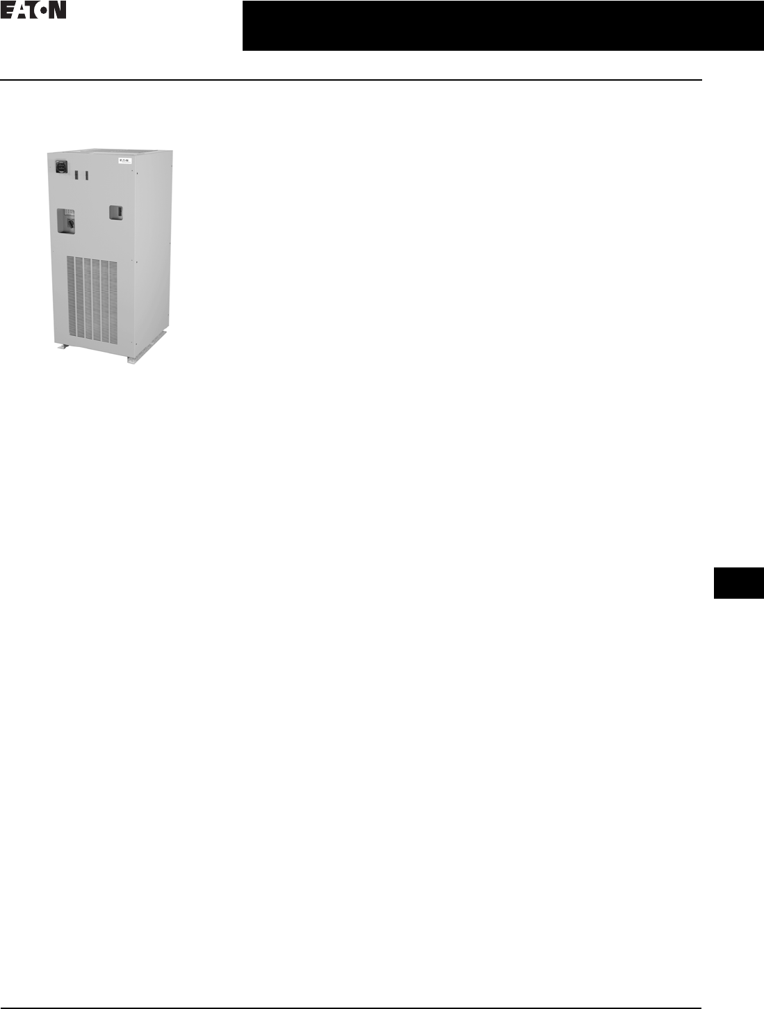
CA08104001E For more information, visit: www.eaton.com/consultants
34.1-37
June 2016
Surge Protection (SPD) & Power Conditioning Products
Sheet 34
22
23
24
25
26
27
28
29
30
31
32
33
34
35
36
37
38
39
40
41
42
4 3
Power Conditioning Products
Electronic Voltage Regulator
039
Electronic Voltage
Regulator (EVR)
Electronic Voltage Regulator (EVR)
Tap Changer
General Description
Eaton’s Electronic Voltage Regulator
(EVR) is the ideal solution for keeping
your facility and equipment up and
running during brownouts, under-
voltage conditions and other power
problems. The EVR can significantly
reduce the costs of equipment damage
and downtime when these situations
occur. The state-of-the-art design
provides rapid response time,
high efficiency, high inrush current
capability, and operating advantages
exclusive to Eaton.
The EVR maintains a tightly regulated
output voltage by automatically
activating the appropriate transformer
tap through a silicone controlled
rectifier (SCR). Tap changer response
time is initiated at one cycle, ensuring
rapid and precise regulation. Switching
at zero current enables noise reduction
during tap transitions.
Brownouts
In the United States, most facilities
have sufficient voltage regulation.
However, in some U.S. locations and
many developing countries, regulation
problems occur because of overstressed
utility distribution systems.
In some cases, due to the excessive
demand on the utility system, voltage
may be below 10% of nominal (–10%)
during the day. This condition is called
a voltage regulation or brownout.
Customers may notice dim lights and
reduced power. During the evening,
voltage may rise above 10% of nominal
(+10%) because large facilities and
loads are shut down. This shutdown
reduces the power demand on the grid
and results in a voltage increase.
The IEEE defines voltage regulation as
overvoltage or undervoltage. Voltage
regulation events last from a few
minutes to many hours with voltage
varying by ±20%. Long-term regulation
problems differ from short duration
sags and dips, which are much deeper
voltage drops.
The Solution
Prior to installing an expensive solution,
Eaton encourages customers to monitor
incoming voltage to determine if voltage
regulation is a problem. The local
utility may also be able to provide
information on voltage expected at
the facility.
Using a meter, it can quickly be
determined if a voltage regulation
problem or brownout condition exists.
The appropriate solution would be
an EVR. EVRs can be installed at the
service entrance, branch panel or at
critical loads.
Eaton’s EVR is a solid-state tap changing
power conditioner designed to protect
against brownouts and long duration
voltage regulation problems.
Features and Benefits
■Coordinated with standard
thermal-magnetic breakers to
allow motor starts
■Optional 50 kA and 100 kA per phase
surge protection
■Input frequency range operation
from 57–63 Hz
■Not affected by load power factor.
Can operate effectively in low-load
applications due to “unique leakage
reactance” technology
■Fail-safe bypass circuit, isolation
transformer and overtemperature
protection
■Less than 1% THD
■Optional Standard and Premium
metering to monitor voltage, current,
frequency, power, energy, PF with
minimum and maximum, and
communication capabilities
■Integral manual rotary maintenance
bypass switch standard on 50 to
500 kVA units and optional on
smaller units
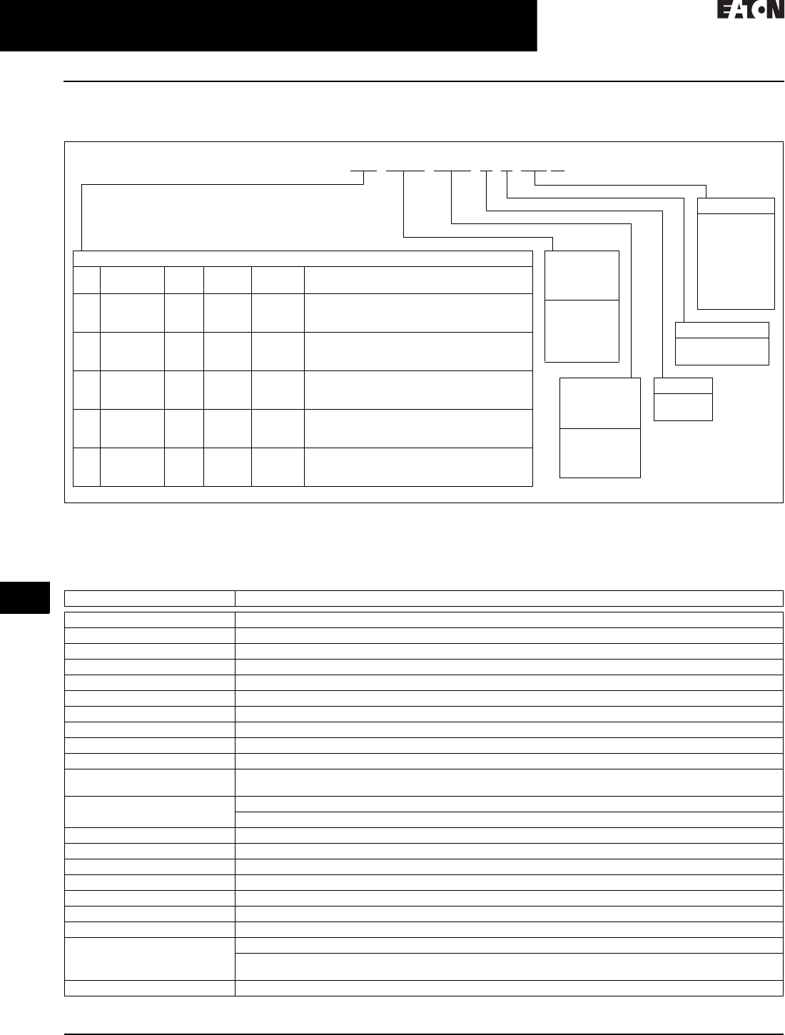
34.1-38
For more information, visit: www.eaton.com/consultants CA08104001E
June 2016
Surge Protection (SPD) & Power Conditioning Products
Sheet 34
22
23
24
25
26
27
28
29
30
31
32
33
34
35
36
37
38
39
40
41
42
4 3
Power Conditioning Products
Electronic Voltage Regulator
040
Catalog Number Selection
Table 34.1-37. EVR Catalog Numbering System
1Bypass is standard on 50 kVA and larger units and an option on 45 kVA and smaller units. The “B” is not included in the part number for units 50 kVA
and larger.
Technical Data and Specifications
Table 34.1-38. EVR Specification (10 to 500 kVA)
Feature Description
Technology Electronic tap changer
Input voltages 208–600 V, three-phase (three-wire)
Input voltage range +10% to –23% of nominal rated input
Output voltage ±3% of nominal
Response time 1/2 cycle
Frequency 60 Hz, ±3%
Efficiency 97% typical
Line regulation Output is ±3% of nominal for input variations of +10% to –23% of nominal
Load regulation Output is maintained within 3% of nominal from no load to full load
Correction time Output will be corrected to within ±3% of nominal in 1.5 cycles or less
Harmonic distortion Less than 1.0% added to the output waveform under any dynamic linear loading conditions presented
to the line regulator
Noise attenuation Common-mode—146 dB
Normal-mode—3 dB down at 1000 Hz, 40 dB/decade to below 50 dB with resistive load
Turn-on characteristics When energized, voltage overshoot will be less than 5% of nominal for 1 cycle or less
Overload rating 1000% for 1 cycle and 200% for 10 seconds
Ambient rating 14 °F to +104 °F (–10 °C to +40 °C)
Monitoring Three green LEDs (phase power on indication), one red LED (alert indication)
Surge protection (optional) CVX 50 kA SPD device 50 kVA and below, CVX 100 kA SPD device 75 kVA and above
Input breaker MCCB rated 125% of full rated current
Bypass switch Normal and bypass selector
Metering (optional) Standard metering (IQ 130)—voltage and current with minimum and maximum
Premium metering (IQ 150)—voltage, current, frequency, power, energy, PF, with minimum and maximum,
communications capabilities
Warranty 1-year parts
Surge Protection
X = No
S = Yes
Nominal
Input Voltage
(Delta Input:
L, L, L, G)
208D = 208
240D = 240
400D = 400
480D = 480
600D = 600
Frequency
A = 60 Hz
B = 50 Hz
kVA Ratings and Dimensions
kVA Weight
Lbs (kg)
BTUs/
hr
Bypass Metering Cabinet Size
Dimensions H x W x D in Inches (mm)
010
010
015
440 (200)
520 (236)
465 (211)
1,025
1,205
1,540
Optional
Optional
Optional
No
Yes
No
30.20 x 22.20 x 29.00 (767.1 x 563.9 x 736.6)
44.20 x 22.20 x 29.00 (1122.7 x 563.9 x 736.6)
30.20 x 22.20 x 29.00 (767.1 x 563.9 x 736.6)
015
025
030
700 (318)
700 (318)
720 (327)
1,540
2,560
3,090
Optional
Optional
Optional
Yes
Yes
Yes
44.20 x 22.20 x 29.00 (1122.7 x 563.9 x 736.6)
44.20 x 22.20 x 29.00 (1122.7 x 563.9 x 736.6)
44.20 x 22.20 x 29.00 (1122.7 x 563.9 x 736.6)
045
050
075
950 (431)
1,176 (534)
1,575 (715)
4,600
7,332
9,514
Optional
Yes
Yes
Yes
Yes
Yes
44.30 x 45.90 x 29.00 (1125.2 x 1165.9 x 736.6)
66.00 x 29.00 x 35.50 (1676.4 x 736.6 x 901.7)
76.00 x 34.40 x 35.50 (1930.4 x 873.8 x 901.7)
100
125
150
2,014 (914)
2,137 (970)
2,240 (1017)
11,833
14,748
17,698
Yes
Yes
Yes
Yes
Yes
Yes
76.00 x 34.40 x 35.50 (1930.4 x 873.8 x 901.7)
76.00 x 34.40 x 35.50 (1930.4 x 873.8 x 901.7)
76.00 x 34.40 x 35.50 (1930.4 x 873.8 x 901.7)
225
300
500
3,300 (1498)
4,000 (1816)
5,500 (2497)
23,000
30,750
51,250
Yes
Yes
Yes
Yes
Yes
Yes
77.40 x 56.00 x 41.50 (1966.0 x 1422.4 x 1054.1)
77.40 x 56.00 x 41.50 (1966.0 x 1422.4 x 1054.1)
77.00 x 72.40 x 48.40 (1955.8 x 1839.0 x 1229.4)
Options
B= Bypass
switch 1
M1 = Standard
metering
(IQ 130)
M2 = Premium
metering
(IQ 150)
Nominal
Output Voltage
(Wye Output:
L, L, L, N, G)
208Y = 120/208
400Y = 230/400
480Y = 277/480
600Y = 347/600
EVR 025 208D 400Y B S M1
