Volume 7 Ibook
101031-Attachment 101031-Attachment 101031-Attachment 786680 Batch8 unilog cesco-content
101031-Attachment 101031-Attachment 101031-Attachment 782116 Batch8 unilog cesco-content
100104-Attachment 100104-Attachment 100104-Attachment 782114 Batch10 unilog cesco-content
100104-Attachment 100104-Attachment 100104-Attachment 782116 Batch10 unilog cesco-content
100104-Attachment 100104-Attachment 100104-Attachment 786680 Batch10 unilog cesco-content
2014-10-17
: Pdf 100104-Attachment 100104-Attachment Batch10 unilog
Open the PDF directly: View PDF ![]() .
.
Page Count: 1004 [warning: Documents this large are best viewed by clicking the View PDF Link!]

Electrical Sector Solutions
Volume 7:
Logic Control,
Operator Interface
and Connectivity
Solutions
1
2
3
4
5
6
7
Volume 1—Residential and Light Commercial
Volume 2—Commercial Distribution
Volume 3—Power Distribution and Control Assemblies
Volume 4—Circuit Protection
Volume 5—Motor Control and Protection
Volume 6—Solid-State Motor Control
Volume 7—Logic Control, Operator Interface
and Connectivity Solutions
Tab 1—Pushbuttons and Indicating Lights . . . . . . . . . . . . . V7-T1-1
Tab 2—Stacklights . . . . . . . . . . . . . . . . . . . . . . . . . . . . . . . . . V7-T2-1
Tab 3—Control Relays and Timers . . . . . . . . . . . . . . . . . . . . V7-T3-1
Tab 4—PLC, I/O and Communications Products . . . . . . . . V7-T4-1
Tab 5—Operator Interface Products . . . . . . . . . . . . . . . . . . . V7-T5-1
Tab 6—Power Supplies . . . . . . . . . . . . . . . . . . . . . . . . . . . . . V7-T6-1
Tab 7—Industrial Control Transformers . . . . . . . . . . . . . . . . V7-T7-1
Tab 8—Terminal Blocks, Fuse Blocks
and Fuse Holders . . . . . . . . . . . . . . . . . . . . . . . . . . V7-T8-1
Tab 9—Connectivity Solutions . . . . . . . . . . . . . . . . . . . . . . . V7-T9-1
Appendix 1—Eaton Terms & Conditions . . . . . . . . . . . . . . . V7-A1-1
Appendix 2—Catalog Parent Number Index . . . . . . . . . . . . V7-A2-1
Appendix 3—Alphabetical Product Index . . . . . . . . . . . . . . V7-A3-1

Copyright
Dimensions, Weights and Ratings
Dimensions, weights and ratings given in this catalog are approximate and should not
be used for construction purposes. Drawings containing exact dimensions are available
upon request. All listed product specifications and ratings are subject to change without
notice. Photographs are representative of production units.
Terms and Conditions
All prices and discounts are subject to change without notice. When price changes
occur, they are published in Eaton’s Price and Availability Digest (PAD). All orders
accepted by Eaton’s Electrical Sector are subject to the general terms and conditions
as set forth in Appendix 1—Eaton Terms & Conditions.
Technical and Descriptive Publications
This catalog contains brief technical data for proper selection of products. Further
information is available in the form of technical information publications and illustrated
brochures. If additional product information is required, contact your local Eaton
Products Distributor, call 1-800-525-2000 or visit our website at www.eaton.com.
Compliance with Nuclear Regulation 10 CFR 21
Eaton products are sold as commercial grade products not intended for application in
facilities or activities licensed by the United States Nuclear Regulatory Commission
for atomic purposes, under 10 CFR 21. Further certification will be required for use of
these products in a safety-related application in any nuclear facility licensed by the
U.S. Nuclear Regulatory Commission.
WARNING
The installation and use of Eaton products should be in accordance with the provisions
of the U.S. National Electrical Code® and/or other local codes or industry standards that
are pertinent to the particular end use. Installation or use not in accordance with these
codes and standards could be hazardous to personnel and/or equipment.
Copyright ©2014 Eaton, All Rights Reserved.
These catalog pages do not purport to cover all details or variations in equipment, nor to provide for
every possible contingency to be met in connection with installation, operation or maintenance.
Should further information be desired or should particular problems arise which are not covered
sufficiently for the purchaser’s purposes, the matter should be referred to the local Eaton Products
Distributor or Sales Office. The contents of this catalog shall not become part of or modify any prior
or existing agreement, commitment or relationship. The sales contract contains the entire
obligation of Eaton’s Electrical Sector. The warranty contained in the contract between the parties
is the sole warranty of Eaton. Any statements contained herein do not create new warranties or
modify the existing warranty.

Volume 7—Logic Control, Operator Interface and Connectivity Solutions CA08100008E—May 2014 www.eaton.com i
Introduction
Eaton is a global leader in power distribution, power quality,
control and automation, and monitoring products.
At Eaton, we believe a reliable, efficient and safe power system is the foundation of every
successful enterprise. Through innovative technologies, cutting-edge products and our highly
skilled services team, we empower businesses around the world to achieve a powerful advantage.
In addition, Eaton is committed to creating and maintaining powerful customer relationships built
on a foundation of excellence. From the products we manufacture to our dedicated customer
service and support, we know what’s important to you.
Solutions
Eaton takes the complexity out of power systems management with a holistic and strategic
approach, leveraging our industry-leading technology, solutions and services. We focus on
the following three areas in all we do:
●Reliability—maintain the
appropriate level of power
continuity without
disruption or unexpected
downtime
●Efficiency—minimize
energy usage, operating
costs, equipment footprint
and environmental impact
●Safety—identify and
mitigate electrical hazards
to protect what you value
most
Using the Eaton Catalog Library
As we grow, it becomes increasingly difficult to include all products in one or two comprehensive
catalogs. Knowing that each user has their specific needs, we have created a library of catalogs for our
products that when complete, will contain 15 volumes. Since the volumes will continuously be a work
in progress and updated, each volume will stand alone. Refer to our volume directory, MZ08100001E,
for a quick glance of where to look for the products you need. The 15 volumes include:
●Volume 1—Residential
and Light Commercial
(CA08100002E)
●Volume 2—Commercial
Distribution (CA08100003E)
●Volume 3—Power
Distribution and Control
Assemblies (CA08100004E)
●Volume 4—Circuit
Protection (CA08100005E)
●Volume 5—Motor Control
and Protection
(CA08100006E)
●Volume 6—Solid-State
Motor Control
(CA08100007E)
●Volume 7—Logic Control,
Operator Interface and
Connectivity Solutions
(CA08100008E)
●Volume 8—Sensing
Solutions (CA08100010E)
●Volume 9—Original
Equipment Manufacturer
(CA08100011E)
●Volume 10—Enclosed
Control (CA08100012E)
●Volume 11—Vehicle and
Commercial Controls
(CA08100013E)
●Volume 12—Aftermarket,
Renewal Parts and Life
Extension Solutions
(CA08100014E)
●Volume 13—Counters,
Timers and Tachometers
(CA08100015E)—Available
in electronic format only
●Volume 14—Fuses
(CA08100016E)—Available
in electronic format only
●Volume 15—Solar Inverters
and Electrical Balance of
System (CA08100018E)
These volumes are not all-inclusive of every product, but they are meant to be an overview
of our product lines. For our full range of product solutions and additional product information,
consult Eaton.com/electrical and other catalogs and product guides in our literature library.
These references include:
●The Consulting Application
Guide (CA08104001E)
●The Eaton Power Quality
Product Guide (COR01FYA)
If you don’t have the volume that contains the product or information that you are looking for,
not to worry. You can access every volume of the catalog library at Eaton.com/electrical in the
Literature Library.
By installing our Automatic Tab Updater (ATU), you can be sure you always have the most recent
version of each volume and tab.

ii Volume 7—Logic Control, Operator Interface and Connectivity Solutions CA08100008E—May 2014 www.eaton.com
Introduction
Icons
Green Leaf
Eaton Green Solutions are products, systems or solutions that represent Eaton
benchmarks for environmental performance. The green leaf symbol is our
promise that the solution has been reviewed and documented as offering
exceptional, industry-leading environmental benefits to customers, consumers
and our communities. Though all of Eaton's products and solutions are
designed to meet or exceed applicable government standards related to
protecting the environment, our products with the Green Leaf designation
further provide “exceptional environmental benefit”.
Learn Online
When you see the Learn Online icon, go to Eaton.com/electrical and search for
the product or training page. There you will find 100-level training courses,
podcasts, webcasts or games and puzzles to learn more.
Drawings Online
When you see the Drawings Online icon, go to Eaton.com/electrical and find the
products page. There you will find a tab that includes helpful product drawings
and illustrations.
Contact Us
If you need additional help, you can find contact information
under the Customer Care heading of Eaton.com/electrical.
1
1
1
1
1
1
1
1
1
1
1
1
1
1
1
1
1
1
1
1
1
1
1
1
1
1
1
1
1
1
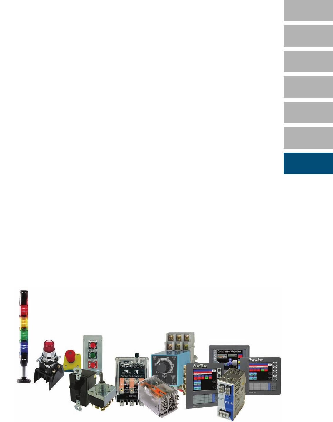
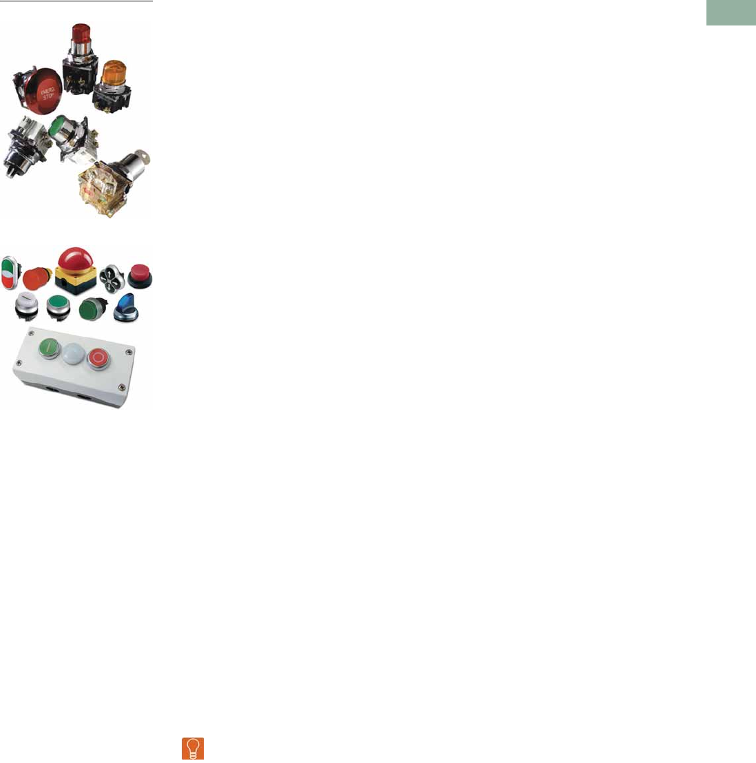
Pushbuttons and Indicating Lights
10250T Pushbuttons
M22 Modular Pushbuttons
1.1 Toggle Switches—E10
Product Description . . . . . . . . . . . . . . . . . . . . . . . . . . . . . . . . . . . . . . . V7-T1-2
Product Selection . . . . . . . . . . . . . . . . . . . . . . . . . . . . . . . . . . . . . . . . . V7-T1-4
1.2 Environmentally Sealed Toggle Switches—E10E
Product Description . . . . . . . . . . . . . . . . . . . . . . . . . . . . . . . . . . . . . . . V7-T1-8
Product Selection . . . . . . . . . . . . . . . . . . . . . . . . . . . . . . . . . . . . . . . . . V7-T1-9
1.3 Pushbutton Control Stations—Assembled
Product Description . . . . . . . . . . . . . . . . . . . . . . . . . . . . . . . . . . . . . . . V7-T1-14
Product Selection . . . . . . . . . . . . . . . . . . . . . . . . . . . . . . . . . . . . . . . . . V7-T1-16
1.4 16.2 mm Pushbuttons—RMQ-16
Product Selection Guide . . . . . . . . . . . . . . . . . . . . . . . . . . . . . . . . . . . V7-T1-31
Product Selection . . . . . . . . . . . . . . . . . . . . . . . . . . . . . . . . . . . . . . . . . V7-T1-32
1.5 22.5 mm Modular Pushbuttons—M22
Product Selection Guide . . . . . . . . . . . . . . . . . . . . . . . . . . . . . . . . . . . V7-T1-48
Product Selection . . . . . . . . . . . . . . . . . . . . . . . . . . . . . . . . . . . . . . . . . V7-T1-53
1.6 22.5 mm Compact Pushbuttons—C22
Product Selection Guide . . . . . . . . . . . . . . . . . . . . . . . . . . . . . . . . . . . V7-T1-139
Product Selection . . . . . . . . . . . . . . . . . . . . . . . . . . . . . . . . . . . . . . . . . V7-T1-141
1.7 30.5 mm Square Multifunction Watertight/Oiltight—E30
Product Description . . . . . . . . . . . . . . . . . . . . . . . . . . . . . . . . . . . . . . . V7-T1-164
Product Selection . . . . . . . . . . . . . . . . . . . . . . . . . . . . . . . . . . . . . . . . . V7-T1-166
1.8 30.5 mm Heavy-Duty Watertight/Oiltight—10250T
Product Description . . . . . . . . . . . . . . . . . . . . . . . . . . . . . . . . . . . . . . . V7-T1-182
Product Selection . . . . . . . . . . . . . . . . . . . . . . . . . . . . . . . . . . . . . . . . . V7-T1-186
1.9 30.5 mm Corrosion Resistant Watertight/Oiltight—E34
Product Description . . . . . . . . . . . . . . . . . . . . . . . . . . . . . . . . . . . . . . . V7-T1-254
Product Selection . . . . . . . . . . . . . . . . . . . . . . . . . . . . . . . . . . . . . . . . . V7-T1-260
1.10 30.5 mm Watertight/Oiltight—HT800
Product Description . . . . . . . . . . . . . . . . . . . . . . . . . . . . . . . . . . . . . . . V7-T1-296
Product Selection . . . . . . . . . . . . . . . . . . . . . . . . . . . . . . . . . . . . . . . . . V7-T1-298
1.11 30.5 mm Class I Division 2 Hazardous Locations—10250T/E34
Product Description . . . . . . . . . . . . . . . . . . . . . . . . . . . . . . . . . . . . . . . V7-T1-321
Product Selection . . . . . . . . . . . . . . . . . . . . . . . . . . . . . . . . . . . . . . . . . V7-T1-324
Learn
Online
Volume 7—Logic Control, Operator Interface and Connectivity Solutions CA08100008E—March 2014 www.eaton.com V7-T1-1
V7-T1-2 Volume 7—Logic Control, Operator Interface and Connectivity Solutions CA08100008E—March 2014 www.eaton.com
1
1
1
1
1
1
1
1
1
1
1
1
1
1
1
1
1
1
1
1
1
1
1
1
1
1
1
1
1
1
1.1
Pushbuttons and Indicating Lights
Tog g l e S w i t c h e s — E10
Toggle Switches—E10
Contents
Description Page
Toggle Switches—E10
Standards and Certifications . . . . . . . . . . . . . . V7-T1-3
Catalog Number Selection . . . . . . . . . . . . . . . . V7-T1-3
Product Selection
Toggle Switches . . . . . . . . . . . . . . . . . . . . . V7-T1-4
Hesitation Switches . . . . . . . . . . . . . . . . . . V7-T1-5
Pushbuttons . . . . . . . . . . . . . . . . . . . . . . . . V7-T1-5
Accessories . . . . . . . . . . . . . . . . . . . . . . . . . . . V7-T1-5
Technical Data and Specifications . . . . . . . . . . V7-T1-6
Circuit Diagrams . . . . . . . . . . . . . . . . . . . . . . . . V7-T1-6
Dimensions . . . . . . . . . . . . . . . . . . . . . . . . . . . V7-T1-7
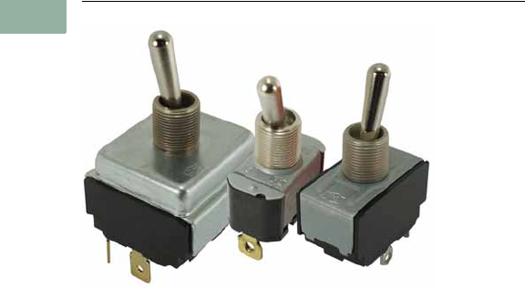
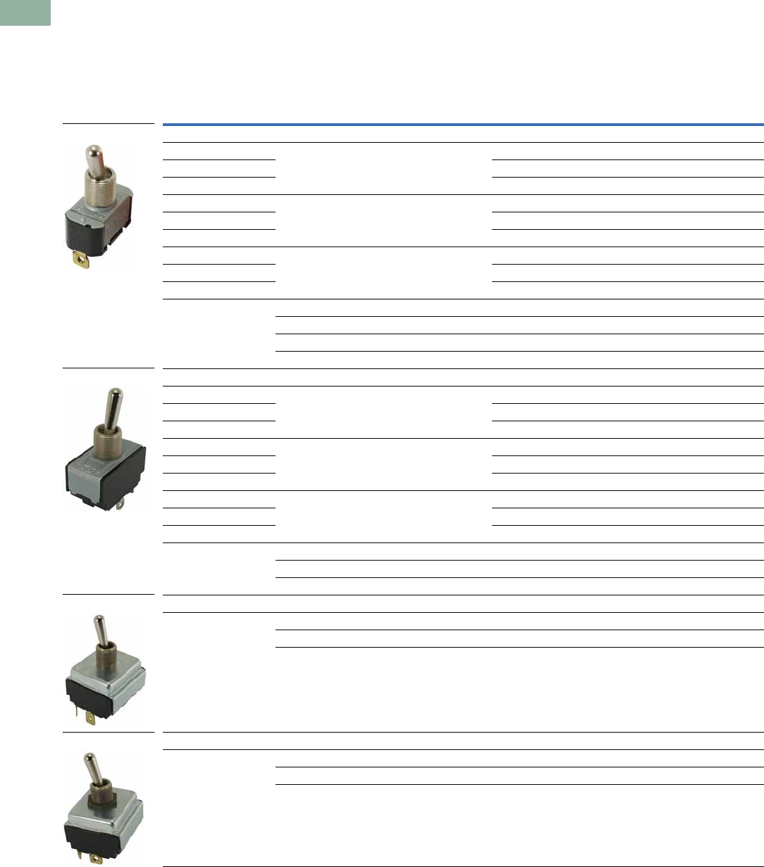
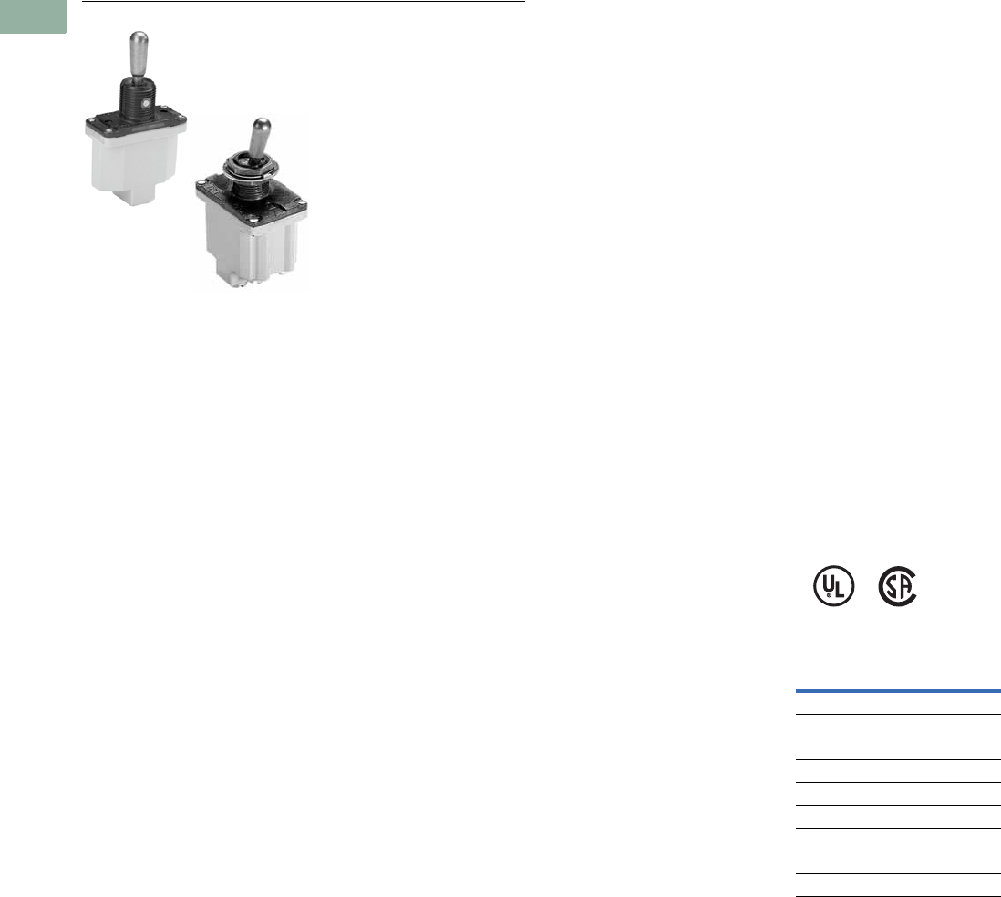
Product Description
The E10 switches from
Eaton’s Electrical Sector are
intended for general purpose
light industrial use. Designed
for retrofit and OEM
applications.
Features
General Purpose Toggles
●Various circuit functions
include maintained and
momentary
●Poles include from single-
pole single-throw to four-
pole double-throw
●Spade, screw, and solder
terminations available
●Numerous ratings
●Short 11/32 in and tall
15/32 in bat lever available
●Standard 15/32–32 thd.
●Hardware furnished
assembled
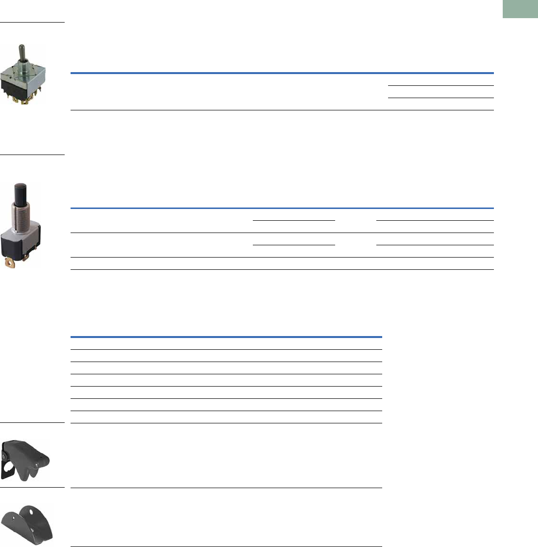
Heavy-Duty Hesitation
Switches
●One-hole panel mount
●Three position switch
offers unique positive
center stop feature to
assure lever cannot be
thrown from one side
through the center OFF
position without stopping
●Design feature is a major
acceptance for motor
reversing and speed
control applications
●Prevents motor damage
resulting from high
current generation by
counter EMF of the
armature at the time of
reversing
●Known as anti-plugging,
hesitation, positive stop
or positive off switch
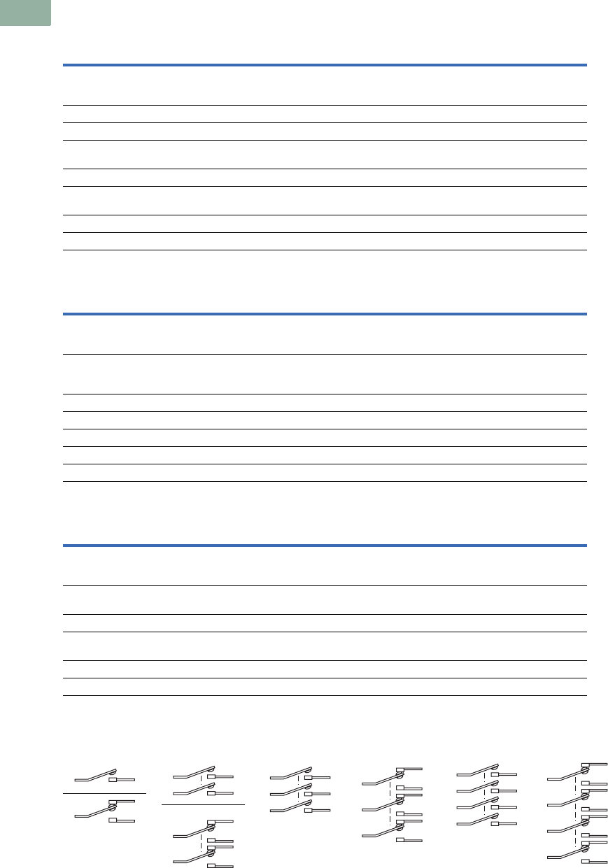
Non-Illuminated AC Rated
Pushbuttons
●One-hole panel mount
●Medium-duty
●Spade and screw
terminations available
●Various bushing lengths
and button extensions
●Numerous ampere ratings
with horsepower ratings
Volume 7—Logic Control, Operator Interface and Connectivity Solutions CA08100008E—March 2014 www.eaton.com V7-T1-3
1
1
1
1
1
1
1
1
1
1
1
1
1
1
1
1
1
1
1
1
1
1
1
1
1
1
1
1
1
1
1.1
Pushbuttons and Indicating Lights
To g g l e Sw i t c h e s — E10
Standards and Certifications
●UL Recognized
●CSA—File No. LR40068
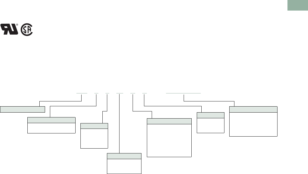
Catalog Number Selection
Catalog Number Selection is for illustrative purposes only and not to be used to create new catalog numbers.
Toggle Switches—E10 Series
Not to be used for ordering purposes
E10 T 1 06 A S =E10T106AS
Poles
1 = Single-pole
2 = Two-pole
3 = Three-pole
4 = Four-pole
Ratings—125V
06 = 6 Amperes
15 = 15 Amperes
20 = 20 Amperes
Function
A = ON—None—OFF
B = OFF—None—(ON)
D = ON—OFF—ON
E = ON—None—ON
F = ON—OFF—(ON)
G = (ON)—OFF—(ON)
H = ON—None—(ON)
Termination
S= Screw
L= Solder lug
P= Spade
Series
Lever Length
T= 0.563 in (14.3 mm) lever
E= 0.688 in (17.5 mm) lever
Complete Cat. No.
0.563 in (14.3 mm)
Single-pole
6 Amperes
ON—None—OFF
Screw terminal
V7-T1-4 Volume 7—Logic Control, Operator Interface and Connectivity Solutions CA08100008E—March 2014 www.eaton.com
1
1
1
1
1
1
1
1
1
1
1
1
1
1
1
1
1
1
1
1
1
1
1
1
1
1
1
1
1
1
1.1
Pushbuttons and Indicating Lights
Tog g l e S w i t c h e s — E10
Product Selection
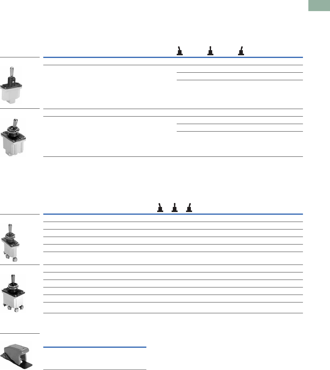
Toggle Switches
E10 Series—AC Rated—Minimum Order Quantity 10 Pieces
Note
1 See Circuit Diagrams on Page V7-T1-6.
Nominal AC Ratings Poles
and
Throw 1
Function—Circuit with Lever In
Screw Terminal
Catalog Number
0.250 in (6.4 mm)
Spade Terminal
Catalog Number
Solder Lug
Catalog Number
UP
Position
CENTER
Position
DOWN
Position—
Keyway
Amperes
125V 250V
hp
50V
Single-Pole
6 3 — 1 P.S.T. ON None OFF E10T106AS E10T106AP E10T106AL
15 10 3/4 E10T115AS E10T115AP E10T115AL
20 10 3/4 E10E120AS E10E120AP E10E120AL
6 3 — 1 P.D.T. ON OFF ON E10T106DS E10T106DP —
15 10 3/4 E10T115DS E10T115DP E10T115DL
20 10 3/4 E10E120DS — —
6 3 — 1 P.D.T. ON None ON E10T106ES — —
15 10 3/4 E10T115ES E10T115EP E10T115EL
20 10 3/4 E10E120ES — —
— 10 1/2 1 P.S.T. OFF None (ON) E10T115BS E10T115BP —
1 P.D.T. ON OFF (ON) E10T115FS E10T115FP —
1 P.D.T. ON None (ON) E10T115HS E10T115HP —
1 P.D.T. (ON) OFF (ON) E10T115GS E10T115GP —
Tw o - Po l e
6 3 — 2 P.S.T. ON None OFF E10T206AS E10T206AP —
15 10 3/4 E10T215AS E10T215AP E10T215AL
20 10 3/4 E10E220AS E10E220AP E10E220AL
6 3 — 2. P.D.T. ON OFF ON E10T206DS E10T206DP —
15 10 3/4 E10T215DS E10T215DP E10T215DL
20 10 3/4 E10E220DS E10E220DP —
6 3 — 2 P.D.T. ON None ON E10T206ES — —
15 10 3/4 E10T215ES E10T215EP E10T215EL
20 10 3/4 E10E220ES — —
15 10 1/2 2 P.S.T. OFF None (ON) E10T215BS — —
2 P.D.T. ON None (ON) E10T215HS E10T215HP —
2 P.D.T. (ON) OFF (ON) E10T215GS E10T215GP —
Three-Pole
15 10 3/4 3 P.S.T. ON None OFF E10E315AS E10E315AP —
3 P.D.T. ON OFF ON E10E315DS E10E315DP E10E315DL
3 P.D.T. ON None ON E10E315ES E10E315EP E10E315EL
Four-Pole
15 10 3/4 4 P.S.T. ON None OFF E10E415AS — E10E415AL
4 P.D.T. ON OFF ON E10E415DS — E10E415DL
4 P.D.T. ON None ON E10E415ES — E10E415EL
Two-Pole
Single-Pole
Three-Pole
Four-Pole
Volume 7—Logic Control, Operator Interface and Connectivity Solutions CA08100008E—March 2014 www.eaton.com V7-T1-5
1
1
1
1
1
1
1
1
1
1
1
1
1
1
1
1
1
1
1
1
1
1
1
1
1
1
1
1
1
1
1.1
Pushbuttons and Indicating Lights
To g g l e Sw i t c h e s — E10
Hesitation Switches
E10 Series—Special Purpose—Minimum Order Quantity 10 Pieces
Pushbuttons
E10 Series—Minimum Order Quantity 10 Pieces
Accessories
Toggle Switches Accessories—Minimum Order Quantity 100 Pieces
Notes
Interlock mechanism prevents operation of lever through the center position until pressure is momentarily relieved.
Designed for control and protection of reversing motors.
1 See Circuit Diagrams on Page V7-T1-6.
2 Rated 1/4 hp at 125V, 1/2 hp at 250V.
Nominal Ratings
Operation
Function—Circuit with Lever In…
Poles
and
Throw 1
Screw Terminal
Catalog Number
Amperes hp
UP
Position
CENTER
Position
DOWN
Position—
Keyway
28
Vdc
125
Vac
250
Vac
250
Vac
15 15 10 3/4 Maintained ON OFF ON 2 P.D.T. E10E215SS
3 P.D.T. E10E315SS
4 P.D.T. E10E415SS
Nominal Ratings
Poles
and
Throw 1 Contacts
Bushing
Length
in (mm)
Dim. “A”
Button
Extension
in (mm)
Dim. “B”
Typical
Maximum
Operating
Force
Screw Terminal
Catalog Number
Spade Terminal
0.250 in (6.4 mm)
Catalog Number
Amperes hp
125 Vac 250 Vac 125–
250VNO NC NO NC
6 — 3 — — 1 P.S.T. NO 0.69 (17.5) 0.53 (13.5) 0.9 lbs E10P106RS E10P106RP
0.34 (8.6) 0.25 (6.4) E10P106JS —
15 — 10 — 1/3 1 P.S.T. NO 0.69 (17.5) 0.53 (13.5) 0.9 lbs E10P115RS E10P115RP
0.34 (8.6) 0.25 (6.4) E10P115JS —
15 10 10 5 1/4 21 P.D.T. NO, NC 0.69 (17.5) 0.53 (13.5) 1.0 lbs E10P115LS —
Description Material/Notes Catalog Number
Hexagon locknut Zinc-chromate treated steel E10TA101
Knurled face nut Zinc-chromate treated steel E10TA102
Internal tooth lockwasher Cadmium plated steel E10TA103
Terminal screws #6-32 x 3/16 in binding head E10TA201
Spade terminal adapter—0.250 in (6.4 mm) Assembles to screw terminals E10TA202
ON-OFF indicating plate—vertical orientation Burnished nickel finish steel E10TA301
OFF-ON indicating plate—horizontal orientation Burnished nickel finish steel E10TA302
Flip-up guard for toggle switches E10TA104
Fixed shroud for toggle switches E10TA105
Heavy-Duty Hesitation
Switch
One-Hole Mounted
Medium-Duty, Mom.
Contact
E10TA104
E10TA105
V7-T1-6 Volume 7—Logic Control, Operator Interface and Connectivity Solutions CA08100008E—March 2014 www.eaton.com
1
1
1
1
1
1
1
1
1
1
1
1
1
1
1
1
1
1
1
1
1
1
1
1
1
1
1
1
1
1
1.1
Pushbuttons and Indicating Lights
Tog g l e S w i t c h e s — E10
Technical Data and Specifications
Toggle Switches
Hesitation Switches
Pushbutton Actuators
Circuit Diagrams
Description Specification
AC ratings 6–20A, 125 Vac
3–10A, 250 Vac
Max. 3/4 hp at 250 Vac
DC ratings 6–20A, 28 Vdc
Electrical life 6,000 cycles make/break at switch ampere rating
Operation Slow make/slow break mechanism with butt action for AC and low voltage DC applications
Maintained and momentary contacts
Poles/throws 1 through 4, single and double throw
Mounting One hole with threaded 0.468 in-32 bushing and 0.068 x 0.035 in (1.7 x 0.9 mm) deep keyway
that serves as anti-rotational feature
Lever lengths 0.563 in (14.3 mm) or 0.688 in (17.5 mm), bright nickel plated
Terminals Screw, 0.250 in (6.4 mm) spade and solder lug
Description Specification
Operation Slow make/slow break mechanism with butt action for AC and low voltage DC applications; maintained contacts; ideal
for reversing motor applications; interlock mechanism prevents operation of lever through center position until manual
pressure is momentarily relieved
AC ratings 15A, 125 Vac
10A, 250 Vac
Max. 3/4 hp at 250 Vac
DC ratings 15A, 28 Vdc
Poles/throws 2, 3 and 4, double throw only
Mounting Single-pole with threaded 0.468 in-32 bushing and 0.068 x 0.049 in (1.7 x 1.2 mm) deep keyway
Lever length 0.687 in (17.4 mm), stainless steel
Terminals Screw
Description Specification
AC ratings 6–15A, 125 Vac (NO)
3–10A, 250 Vac (NO)
Max. 1/3 hp at 125/250 Vac
Operation Slow make/slow break mechanism
Normally open contacts
Poles/throws Single, single and double throw
Mounting One hole with 0.468 in-32 threaded bushing and 0.068 x 0.035 in (1.7 x 0.9 mm) deep keyway
Two bushing heights: 11/16 in (17.5 mm) and 11/32 in (8.7 mm)
Button extensions 17/32 in (13.5 mm) and 1/4 in (6.4 mm), bright nickel plated
Terminals Screw
SPST DPST
SPDT
DPDT
4PST3PDT 4PDT3PST
Volume 7—Logic Control, Operator Interface and Connectivity Solutions CA08100008E—March 2014 www.eaton.com V7-T1-7
1
1
1
1
1
1
1
1
1
1
1
1
1
1
1
1
1
1
1
1
1
1
1
1
1
1
1
1
1
1
1.1
Pushbuttons and Indicating Lights
To g g l e Sw i t c h e s — E10
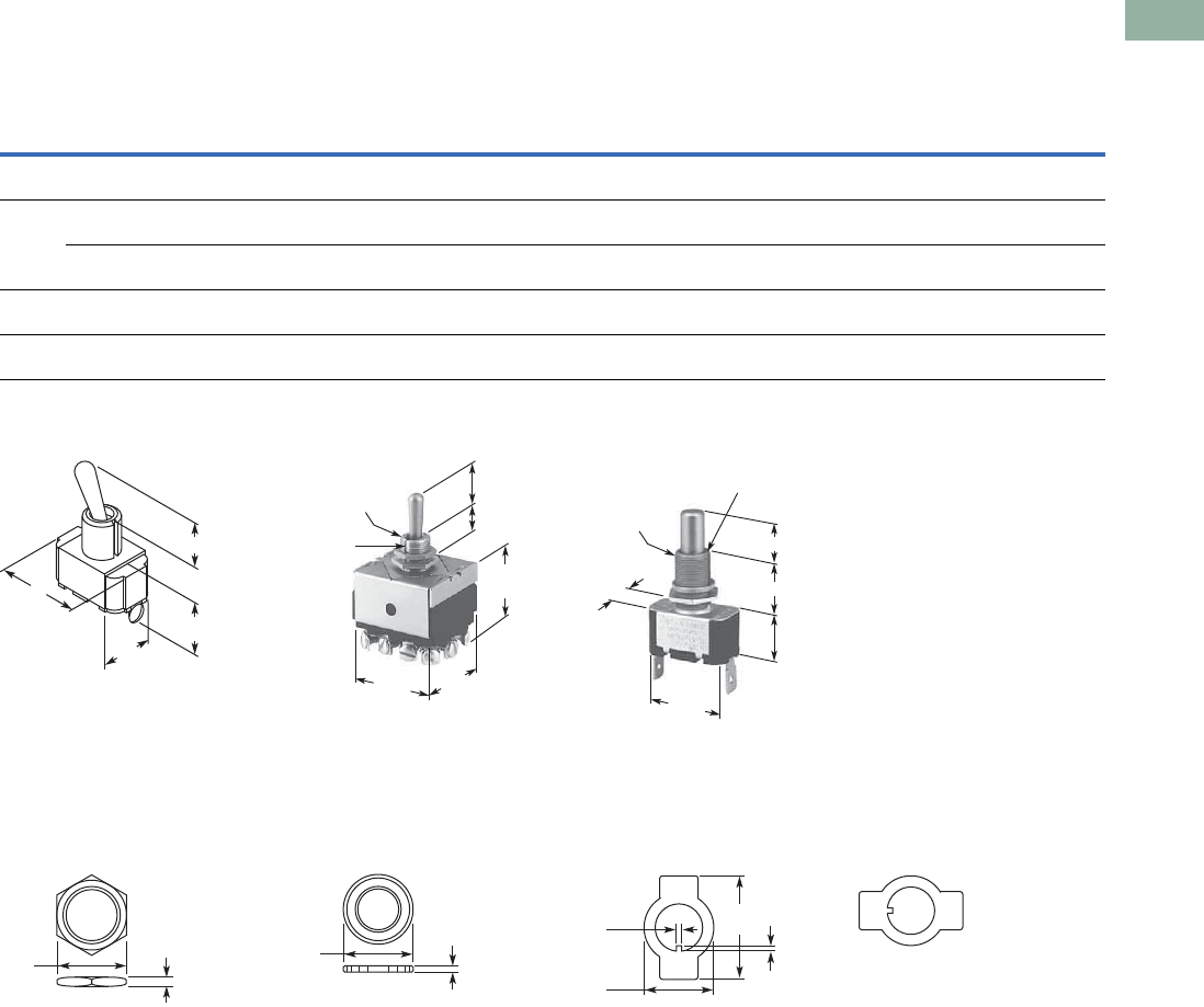
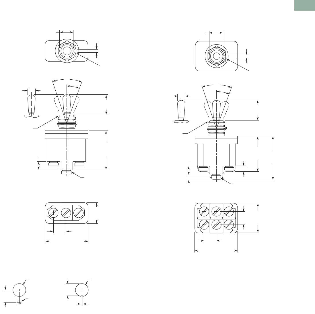
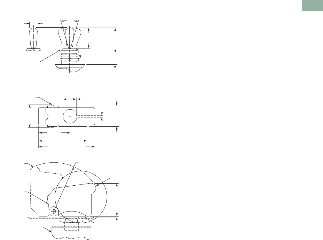
Dimensions
Approximate Dimensions in Inches (mm)
Toggle Switch Dimensions
Toggle Switch Hesitation Switch Pushbutton Actuator
Accessories
E10TA101
Hexagon Locknut
E10TA102
Knurled Face Nut
E10TA301
ON-OFF Indicating Plate—
Vertical Orientation
E10TA302
ON-OFF Indicating Plate—
Horizontal Orientation
Note
1Spade terminal adapters are used on 6 ampere and momentary screw terminal switches, adding 0.42 in (10.7 mm) to dimension C.
No. of
Poles Operation
Bushing
Length
A
Lever
Length
B
Screw Terminals Spade Terminals Solder Lug
CDEC
1DECDE
1 Momentary
and maintained
0.47
(11.9)
0.56
(14.2)
1.00
(25.4)
1.17
(29.7)
0.63
(16.0)
1.13
(28.7)
1.13
(28.7)
0.63
(16.0)
1.00
(25.4)
1.13
(28.7)
0.63
(16.0)
2 Maintained 0.47
(11.9)
0.56
(14.2)
1.06
(26.9)
1.31
(33.3)
0.75
(19.1)
1.19
(30.2)
1.31
(33.3)
0.75
(19.1)
1.06
(26.9)
1.31
(33.3)
0.75
(19.1)
Momentary 0.47
(11.9)
0.56
(14.2)
1.25
(31.8)
1.31
(33.3)
0.75
(19.1)
1.31
(33.3)
1.31
(33.3)
0.75
(19.1)
1.25
(31.8)
1.31
(33.3)
0.75
(19.1)
3 Maintained 0.47
(11.9)
0.69
(17.5)
1.27
(32.3)
1.34
(34.0)
1.44
(36.6)
1.37
(34.8)
1.34
(34.0)
1.44
(36.6)
1.23
(31.2)
1.34
(34.0)
1.44
(36.6)
4 Maintained 0.47
(11.9)
0.69
(17.5)
1.20
(30.5)
1.30
(33.0)
1.40
(35.6)
1.30
(33.0)
1.34
(34.0)
1.40
(35.6)
1.23
(31.2)
1.34
(34.0)
1.44
(36.6)
D
E
C
A
B
1.47
(37.3)
0.47-32
Thread
0.07 (1.8) x
0.05 (1.3)
Keyway
1.34
(34)
1.25
(31.8)
0.47
(11.9)
0.69
(17.5)
1.13
(28.7)
0.47-32
Thread
0.04 (1) x 0.07 (1.8)
Keyway
1.13
(28.7)
A
B
0.63
(16)
0.63
(16)
0.08
(2)
0.63
(16)
0.07
(1.8)
0.63
(16)
0.06
(1.5)
0.03
(.8)
1.0
(25.4)
ON
OFF
O
N
O
F
F
V7-T1-8 Volume 7—Logic Control, Operator Interface and Connectivity Solutions CA08100008E—March 2014 www.eaton.com
1
1
1
1
1
1
1
1
1
1
1
1
1
1
1
1
1
1
1
1
1
1
1
1
1
1
1
1
1
1
1.2
Pushbuttons and Indicating Lights
Environmentally Sealed Toggle Switches—E10E
Toggle Switches—E10E
Contents
Description Page
Environmentally Sealed Toggle Switches—E10E
Product Selection
Molded-In Screw Terminal . . . . . . . . . . . . . V7-T1-9
Econoswitch . . . . . . . . . . . . . . . . . . . . . . . . V7-T1-9
Switch Guard . . . . . . . . . . . . . . . . . . . . . . . . V7-T1-9
Technical Data and Specifications . . . . . . . . . . V7-T1-10
Dimensions . . . . . . . . . . . . . . . . . . . . . . . . . . . V7-T1-11
Product Description
Designed for general purpose
and OEM applications, this
line of toggle switches
provides a high IP68 rating for
demanding environments.
Features
Molded-In Screw Terminal
●Completely sealed against
dust, moisture and other
contaminants
●One-hole mounted bushing
for easy installation
●Multi-circuits offered
●Two- and three-position
with maintained and
momentary action
●Molded-in terminal inserts
and terminals numbers
●Single- and two-pole
circuitry
Econoswitch
●Environmentally sealed
●Single- and two-pole
circuitry
●One-hole mounting for
easy installation
●Multi-circuits
●Two- and three-position
with maintained and
momentary action
●Three types of termination
offered as standard
Switch Guard
●For use with two-position
switch
●Cover closure transfers
switch toggle lever to OFF
position
●One-hole mounted
mounting style
●Cover is molded out of red
thermoset molding
material
●Guard cover is spring-
loaded to either close or
lock in open position
●Prevents accidental
operation at switches
Options
Note: Contact your local Eaton
Sales Representative for more
information.
●Non-UL Recognized
devices
●Alternate toggle levers
●Locking toggle levers
●Rocker buttons
●Special mounting hardware
●Mounting hardware
furnished assembled
●Terminal screws furnished
assembled
●Special circuits
●Panel seal, part number
32-341
●Spade terminal adapters
available
Standards and
Certifications
●UL—File number E15346;
Guide card number is
WOYR2
●CSA—LR40068, class
number 6241
UL and CSA Nominal
Ratings
Catalog Number 125 Vac 250 Vac
Amperes
E10E118xx 18 9
E10E218xx 18 9
Single-Phase hp
E10E118xx 1/4 1/2
E10E218xx 1/2 1
Three-Phase hp
E10E118xx ——
E10E218xx ——
Volume 7—Logic Control, Operator Interface and Connectivity Solutions CA08100008E—March 2014 www.eaton.com V7-T1-9
1
1
1
1
1
1
1
1
1
1
1
1
1
1
1
1
1
1
1
1
1
1
1
1
1
1
1
1
1
1
1.2
Pushbuttons and Indicating Lights
Environmentally Sealed Toggle Switches—E10E
Product Selection
Molded-In Screw Terminal
E10E Series—Molded-In Screw Terminal
Econoswitch
E10E Series—Econoswitch
Switch Guard
E10E Series—Switch Guard
Note
1 Momentary contact.
Circuit with Lever Position
Catalog Number
Up Center
Down
(Keyway)
Nominal AC Ratings
Amperes Single-Phase hp Three-Phase hp
125V 250V 125V 250V 125/250V
Single-Pole
18 9 1/4 1/2 — ON OFF ON E10E118DM
ON NONE OFF E10E118AM
ON NONE ON E10E118EM
Tw o - Po l e
18 9 1/2 1 — ON OFF ON E10E218DM
ON NONE OFF E10E218AM
ON NONE ON E10E218EM
Type of
Operation
Circuit with Lever Position
Screw Terminal
Catalog Number
Solder Lug
Terminal
Catalog Number
Spade Terminal
Catalog Number
Current Ratings—Amperes
Up Center
Down
(Keyway)
28 Vdc 115 Vac, 60 or 400 Hz
Lamp
Load
Resistive
Load
Inductive
Load
Lamp
Load
Resistive
Load
Inductive
Load
Single-Pole
Maintained 5 20 15 3 15 10 ON OFF ON E10E118DS E10E118DL E10E118DP
Maintained 5 20 15 3 15 10 ON NONE OFF E10E118AS E10E118AL E10E118AP
Maintained 5 20 15 3 15 10 ON NONE ON E10E118ES E10E118EL E10E118EP
Momentary 4 15 10 2 15 7 ON 1OFF ON 1E10E118GS E10E118GL E10E118GP
Momentary 4 15 10 2 15 7 OFF NONE ON 1E10E118BS E10E118BL E10E118BP
Tw o - Po l e
Maintained 7 20 15 4 15 15 ON OFF ON E10E218DS E10E218DL E10E218DP
Maintained 7 20 15 4 15 15 ON NONE OFF E10E218AS E10E218AL E10E218AP
Maintained 7 20 15 4 15 15 ON NONE ON E10E218ES E10E218EL E10E218EP
Momentary 5 18 10 2 11 8 ON 1OFF ON 1E10E218GS E10E218GL E10E218GP
Momentary 5 18 10 2 11 8 OFF NONE ON 1E10E218BS E10E218BL E10E218BP
Catalog Number
Switch Guard E10TA104
Single-Pole
Two-Pole
Single-Pole
Two-Pole
Switch Guard

V7-T1-10 Volume 7—Logic Control, Operator Interface and Connectivity Solutions CA08100008E—March 2014 www.eaton.com
1
1
1
1
1
1
1
1
1
1
1
1
1
1
1
1
1
1
1
1
1
1
1
1
1
1
1
1
1
1
1.2
Pushbuttons and Indicating Lights
Environmentally Sealed Toggle Switches—E10E
Technical Data and Specifications
E10E Series—Molded-In Screw Terminal
E10E Series—Econoswitch
Description Specification
Watertight seal Per MIL-STD-108E and designed to meet IP68
Thermoset molding materials Meet flame retardant requirements
Temperature range –50° to 150°F (–46° to 66°C)
Life 20,000 operations at rated load; 40,000 operations mechanical life;
6,000 operations at hp ratings per UL and CSA requirements
Bushings 15/32 in-32 thread
Description Specification
Watertight seal Per MIL-STD-108E and designed to meet IP68
Type of terminal Screws—6-32 UNC-22A
Solder lug—0.125 in (3.17 mm) dia. hole
Spade—0.250 in (6.35 mm) x 0.032 in (0.81 mm) thick
Life 50,000 operations at rated load; 100,000 operations mechanical life
Temperature range –50° to 150°F (–46° to 66°C)
Volume 7—Logic Control, Operator Interface and Connectivity Solutions CA08100008E—March 2014 www.eaton.com V7-T1-11
1
1
1
1
1
1
1
1
1
1
1
1
1
1
1
1
1
1
1
1
1
1
1
1
1
1
1
1
1
1
1.2
Pushbuttons and Indicating Lights
Environmentally Sealed Toggle Switches—E10E
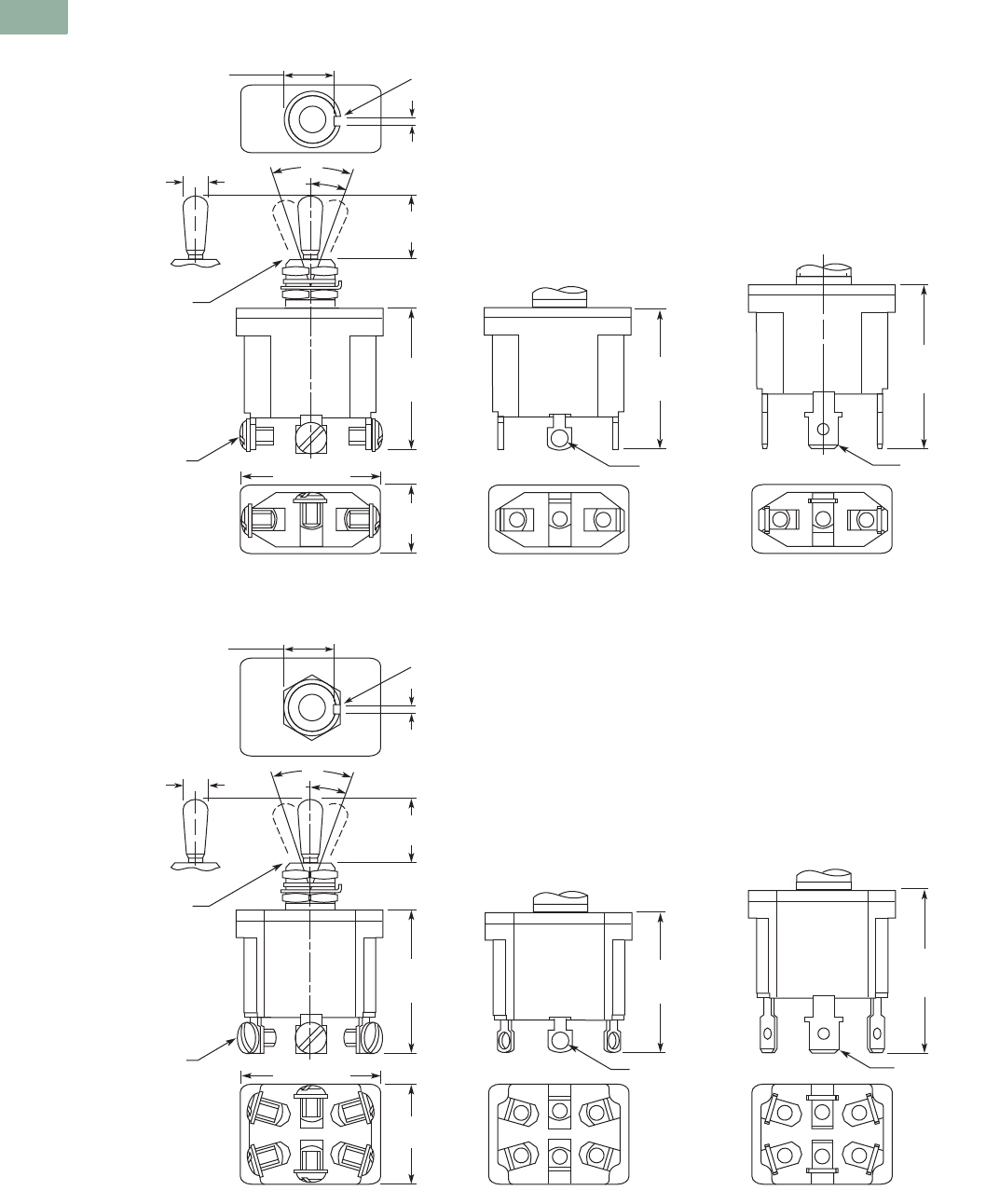
Dimensions
Approximate Dimensions in Inches (mm)
Single-Pole Molded-In Screw Terminal E10E Series
Toggle Switch Panel Cutout
Two-Pole Molded-In Screw Terminal E10E Series
0.432
(10.97) 0.076
(1.93)
Keyway
1.18
(29.9)
Max.
0.250
(6.35)
#6-32 Terminal Screw
with Internal Tooth
Lockwasher (SEMS)
0.635
(16.13)
Max.
0.380
(9.65)
Typ.
1.270 (32.26) Max.
15/32-32 UN-2A
Thread to Within
0.060 (1.52)
of Shoulder
123
16.5°
33°
0.240 (6.10)
Dia.
0.690
(17.53)
0.470
(11.94)
15/32 Dia. Bushing
0.375
(9.52) 0.130
(3.30) 0.062
(1.57)
0.480 (12.19)
Dia. Hole
Locking Ring Keyway
0.445
(11.30)
0.480 (12.19)
Dia. Hole
0.690
(17.53)
0.470
(11.94)
1.10 0
(27.94)
Max.
0.130
(3.30)
0.250
(6.35)
0.130
(3.30)
0.380
(9.65)
0.910
(23.11)
Max.
1.370
(34.80)
Max.
0.076
(1.93)
Keyway
#6-32 Terminal Screw
with Internal Tooth
Lockwasher (SEMS)
15/32-32 UN-2A
Thread to Within
0.060 (1.52)
of Shoulder
123
456
0.432
(10.97)
16.5°
33°
0.240 (6.10)
Dia.
0.380
(9.65)
Typ.
1.340 (34.04) Max.
V7-T1-12 Volume 7—Logic Control, Operator Interface and Connectivity Solutions CA08100008E—March 2014 www.eaton.com
1
1
1
1
1
1
1
1
1
1
1
1
1
1
1
1
1
1
1
1
1
1
1
1
1
1
1
1
1
1
1.2
Pushbuttons and Indicating Lights
Environmentally Sealed Toggle Switches—E10E
Approximate Dimensions in Inches (mm)
Single-Pole Econoswitch E10E Series
Two-Pole Econoswitch E10E Series
#6-32 UNC-2A
Terminal Screw,
SEMS 0.125 (3.17)
Dia. Hole
0.250 x 0.032
(6.35) x (0.81)
Thick
15/32-32 UN-2A
Thread to Within
0.060 (1.52)
of Shoulder
0.240 (6.10)
Dia.
0.432
(10.97)
0.076
(1.93)
Keyway
2
132
132
13
Screw Terminal Solder Lug Spade Terminal
0.690
(17.53)
0.470
(11.94)
1.30
(33.0)
Max.
1.28
(32.5)
Max.
1.51
(38.4)
Max.
0.594
(15.09)
1.25 (31.75)
33°
16.5°
0.432
(10.97)
0.076
(1.93)
Keyway
33°
0.125 (3.17)
Dia. Hole
0.250 x 0.032
(6.35) x (0.81)
Thick
1.55
(39.4)
Max.
Screw Terminal Solder Lug Spade Terminal
0.89
(22.6)
1.32 (33.5)
#6-32 UNC-2A
Terminal Screw,
SEMS
15/32-32 UN-2A
Thread to Within
0.060 (1.52)
of Shoulder
0.240 (6.10)
Dia. 16.5°
0.690
(17.53)
0.468
(11.89)
1.34
(34.1)
Max.
1.32
(33.5)
Max.
Volume 7—Logic Control, Operator Interface and Connectivity Solutions CA08100008E—March 2014 www.eaton.com V7-T1-13
1
1
1
1
1
1
1
1
1
1
1
1
1
1
1
1
1
1
1
1
1
1
1
1
1
1
1
1
1
1
1.2
Pushbuttons and Indicating Lights
Environmentally Sealed Toggle Switches—E10E
Approximate Dimensions in Inches (mm)
Switch Guard
15/32-32 UN-2A
Thread to Within
0.060 (1.52)
of Shoulder
Rivet
Switch
(Ref.)
Red-Molded
Plastic
Closed
Steel
Open
0.240 (6.10)
Dia.
33°
0.840
(21.34)
0.468
(11.89)
0.688
(17.48)
Max.
0.062
(1.57)
0.031
(0.79)
1.062
(26.97)
1.547 (39.29)
Rad.
0.475
(12.07)
Dia.
0.688
(17.48)
1.093
(27.76)
Max.
0.032
(0.81)
1.635 (41.53) Max.
1.830 (46.48) Max.
0.750
(19.05)
Max.
V7-T1-14 Volume 7—Logic Control, Operator Interface and Connectivity Solutions CA08100008E—March 2014 www.eaton.com
1
1
1
1
1
1
1
1
1
1
1
1
1
1
1
1
1
1
1
1
1
1
1
1
1
1
1
1
1
1
1.3
Pushbuttons and Indicating Lights
Pushbutton Control Stations—Assembled
Pushbutton Control Stations
Contents
Description Page
Pushbutton Control Stations—Assembled
Features . . . . . . . . . . . . . . . . . . . . . . . . . . . . . . V7-T1-15
Product Selection
M22 Assembled Control Stations . . . . . . . . V7-T1-16
Commercial Control Stations . . . . . . . . . . . V7-T1-17
General Purpose Control Stations . . . . . . . . V7-T1-18
Special Purpose Control Stations . . . . . . . . V7-T1-19
10250H Series Heavy-Duty
Control Stations . . . . . . . . . . . . . . . . . . . . V7-T1-20
10250T Series Heavy-Duty 30.5 mm
Control Stations . . . . . . . . . . . . . . . . . . . . V7-T1-21
Class I Division 2 10250T Series Heavy-Duty
30.5 mm Control Stations . . . . . . . . . . . . V7-T1-22
Class I Division 2 E34 Series Corrosion
Resistant 30.5 mm Control Stations . . . . V7-T1-23
Accessories . . . . . . . . . . . . . . . . . . . . . . . . . . . V7-T1-23
Custom Assembled Stations
Specification Form . . . . . . . . . . . . . . . . . . . . . V7-T1-24
Renewal Parts . . . . . . . . . . . . . . . . . . . . . . . . . V7-T1-26
Technical Data and Specifications . . . . . . . . . . V7-T1-28
Dimensions. . . . . . . . . . . . . . . . . . . . . . . . . . . . V7-T1-28
Product Description
M22 Assembled Control
Stations
●M22 series operators
●Available in horizontal and
vertical configurations
●Impact resistant
polycarbonate enclosures
●Optional yellow covers
●Base mounting contact
blocks and light units for
quick wiring and vibration
resistance
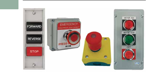
Commercial Control Stations
●10250T series operators
●Full front label
●Specific function labels on
front of enclosure
General Purpose Control
Stations
●Construction grade
●General purpose wall
mount
●Popular with contractors
●UL (NEMA) Type 1
Special Purpose Control
Stations
●Standard grade
●Polyester enclosure
●UL (NEMA) Type 3, 3R, 4,
4X, 13
10250H Series Heavy-Duty
Control Stations
●10250H Series operators
●Dark brown polyester
enclosure
●Protective rubber gaskets
provide NEMA 3S rating on
pushbuttons
●Top and bottom 3/4 in NPT
conduit entrances
●Includes alternate legend
plates and spare mounting
screws
10250T Series Heavy-Duty
30.5 mm Control Stations
●10250T Series operators
●ASA 61 gray die-cast zinc
enclosures
●Surface or flush mounting
●Single 3/4 in NPT conduit
entrance on one and two
element stations
●Single 1 in NPT conduit
entrance on three element
stations
Class I Division 2 10250T
Series Heavy-Duty 30.5 mm
Control Stations
●10250T Series operators
●Factory sealed contact
blocks
●Die-cast, polyester or
stainless steel enclosures
●Approved for NEC Class I
Division 2, Groups B, C and
D or Class I Zone 2 Group
IIB plus Hydrogen type
hazardous locations
Class I Division 2 E34 Series
Corrosion Resistant 30.5 mm
Control Stations
●E34 Series operators
●Factory sealed contact
blocks
●Die-cast, polyester or
stainless steel enclosures
●Approved for NEC Class I
Division 2 Groups B, C and
D or Class I Zone 2 Group
IIB plus Hydrogen type
hazardous locations

Volume 7—Logic Control, Operator Interface and Connectivity Solutions CA08100008E—March 2014 www.eaton.com V7-T1-15
1
1
1
1
1
1
1
1
1
1
1
1
1
1
1
1
1
1
1
1
1
1
1
1
1
1
1
1
1
1
1.3
Pushbuttons and Indicating Lights
Pushbutton Control Stations—Assembled
Features
M22 Assembled Control
Stations
●IP66, UL (NEMA) Type 4X,
13
●Impact resistant
polycarbonate enclosures
●Optional yellow cover
●25% smaller depth than
most competitor
enclosures
●Base mounting contact
blocks and light units for
faster wiring and vibration
resistance
Commercial Control Stations
●ASA 61 gray die-cast zinc
enclosures
●Pre-assembled and labeled
for functions such as “Fuel
Shut-Off”
●Great for commercial
applications
General Purpose Control
Stations
●Construction grade
●General purpose wall
mount
●Popular with contractors
●UL (NEMA) Type 1
Special Purpose Control
Stations
●Standard grade
●Polyester enclosure
●UL (NEMA) Type 3, 3R, 4,
4X, 13
10250H Series Heavy-Duty
Control Stations
●Industrial grade
●Extra heavy-duty
●Polyester enclosure
●Booted buttons
●Outdoor installation
●UL (NEMA) Type 3, 3R, 3S,
4, 4X, 12, 13
10250T Series Heavy-Duty
30.5 mm Control Stations
●30.5 mm operators
●Industrial grade
●Zinc die cast enclosure
●Popular with industrial end
users
●UL (NEMA) Type 4, 4X, 12,
13
Class I Division 2 Control
Stations
●Available with 10250T or
E34 30.5 mm operators
●Zinc die cast, polyester or
stainless steel enclosures
●Factory-sealed contact
blocks
●Popular with industrial end
users
●UL (NEMA) Type 4, 4X, 12,
13
●NEC Class I Division 2
Groups B, C and D
V7-T1-16 Volume 7—Logic Control, Operator Interface and Connectivity Solutions CA08100008E—March 2014 www.eaton.com
1
1
1
1
1
1
1
1
1
1
1
1
1
1
1
1
1
1
1
1
1
1
1
1
1
1
1
1
1
1
1.3
Pushbuttons and Indicating Lights
Pushbutton Control Stations—Assembled
Product Selection
M22 Assembled Control Stations
One Element Control Stations
Two Element Control Stations
Three Element Control Stations
Notes
For assembled control stations not found in this selection, please contact the Eaton Technical Resource Center
at 1-877-ETN CARE (386-2273) or TRC@eaton.com.
1
Contact block configuration.
Orientation Description Color 1Inscription
Enclosure
Cover Color Catalog Number
Horizontal 40 mm mushroom head push-pull emergency stop operator Red NC — Yellow M22-C1-M1H
Horizontal 40 mm illuminated mushroom head push-pull emergency stop
operator, 85–264 Vac
Red NO-NC — Yellow M22-C1-M2H
Horizontal 40 mm mushroom head twist-to-release emergency stop operator Red NC — Yellow M22-C1-M3H
Horizontal 40 mm mushroom head key-release emergency stop operator Red NC — Yellow M22-C1-M4H
Horizontal Flush pushbutton Green NO Gray M22-C1-M5H
Horizontal Flush pushbutton Green NO START Gray M22-C1-M6H
Horizontal Extended pushbutton Red NC Gray M22-C1-M7H
Horizontal Extended pushbutton Red NC STOP Gray M22-C1-M8H
Horizontal Key-operated selector switch, two-position maintained — NO OFF-ON Gray M22-C1-M9H
Horizontal Knob type selector switch, three-position maintained — 2NO HAND 0 AUTO Gray M22-C1-M10H
Horizontal Double pushbutton Green NO START Gray M22-C1-M11H
Red NC STOP
Orientation
Element 1
Description Color 1Inscription
Element 2
Description Color 1Inscription
Enclosure
Cover Color Catalog Number
Horizontal Extended pushbutton Red NC Flush pushbutton Green NO Gray M22-C2-M1H
Vertical Flush pushbutton Green NO START Extended pushbutton Red NC STOP Gray M22-C2-M2V
Vertical Flush pushbutton Black NO FORWARD Flush pushbutton Black NO REVERSE Gray M22-C2-M3V
Orientation
Element 1
Description Color 1Inscription
Element 2
Description Color 1Inscription
Element 3
Description Color 1Inscription
Enclosure
Cover Color Catalog Number
Horizontal Extended
pushbutton
Red NC Indicating
light
White 85–264
Vac
—Flush
pushbutton
Green NO Gray M22-C3-M1H
Vertical Indicating
light
White 85–264
Vac
—Flush
pushbutton
Green NO START Extended
pushbutton
Red NC STOP Gray M22-C3-M2V
Horizontal Flush
pushbutton
Green NO Extended
pushbutton
Red NC Flush
pushbutton
Green NO Gray M22-C3-M3H
Vertical Flush
pushbutton
Black NO OPEN Extended
pushbutton
Red NC STOP Flush
pushbutton
Black NO CLOSE Gray M22-C3-M4V
Vertical Flush
pushbutton
Black NO FORWARD Flush
pushbutton
Red NC STOP Flush
pushbutton
Black NO REVERSE Gray M22-C3-M5V
Vertical Flush
pushbutton
Black NO UP Flush
pushbutton
Red NC STOP Flush
pushbutton
Black NO DOWN Gray M22-C3-M6V
Volume 7—Logic Control, Operator Interface and Connectivity Solutions CA08100008E—March 2014 www.eaton.com V7-T1-17
1
1
1
1
1
1
1
1
1
1
1
1
1
1
1
1
1
1
1
1
1
1
1
1
1
1
1
1
1
1
1.3
Pushbuttons and Indicating Lights
Pushbutton Control Stations—Assembled
Commercial Control Stations
Key Specifications
●30.5 mm (10250T series)
operators
●ASA 61 gray die-cast zinc
enclosures
●Industrial grade
●UL® Type 4, 4X, 12, 13
●Single 3/4 in NPT conduit
entrance
●Dimensions—in (mm)
●Enclosure:
3.88 W x 4.00 H x 3.00 D
(98.6 x 101.6 x 76.3)
●Operator:
1.63 D (to enclosure) x
1.50 diameter
(41.4 x 38.1)
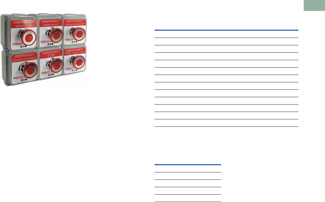
What is included?
Eaton’s pre-assembled,
enclosed emergency stop
pushbutton stations include
an operator, an enclosure,
contact blocks and a variety
of unique labels. Each label
has white lettering on a red
background indicating the
function and red lettering on a
white background indicating
the operator type.
Available Catalog Numbers
Additional Contact Blocks
(Sold Separately)
Note
1Includes 1NO-1NC contact block.
Catalog
Number 1Operator
Enclosure
Color Label
10250T5B62-S101 Push-Pull Gray EMERGENCY STOP
10250T5B62-S102 Push-Pull Gray EMERGENCY SHUT-OFF
10250T5B62-S103 Push-Pull Gray EMERGENCY GENERATOR STOP
10250T5B62-S104 Push-Pull Gray EMERGENCY HVAC SHUT-DOWN
10250T5B62-S105 Push-Pull Gray EMERGENCY ELECTRICAL DISCONNECT
10250T5B62-S106 Push-Pull Gray EMERGENCY BOILER SHUT-DOWN
10250T5B62-S107 Push-Pull Gray EMERGENCY CHILLER STOP
10250T5B62-S108 Push-Pull Gray EMERGENCY FUEL SHUT-OFF
10250T5B62-S109 Push-Pull Gray EMERGENCY REFRIGERATION STOP
10250T5B62-S110 Push-Pull Gray EMERGENCY POWER OFF
10250T5B62-S111 Push-Pull Gray EMERGENCY GAS SHUT-OFF
10250T5B62-S112 Push-Pull Gray EMERGENCY VENTILATION SHUT-DOWN
10250T5B62-S113 Push-Pull Gray GENERATOR
Catalog Number
Circuit
Configuration
10250T51 1NC
10250T53 1NO
10250T1 NO-NC
10250T3 2NC
10250T2 2NO
V7-T1-18 Volume 7—Logic Control, Operator Interface and Connectivity Solutions CA08100008E—March 2014 www.eaton.com
1
1
1
1
1
1
1
1
1
1
1
1
1
1
1
1
1
1
1
1
1
1
1
1
1
1
1
1
1
1
1.3
Pushbuttons and Indicating Lights
Pushbutton Control Stations—Assembled
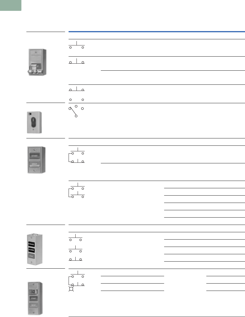
General Purpose Control Stations
Type N Control Stations—UL (NEMA) Type 1
Note
1 Round button.
Contact
Symbol Button Type/Color Legends Catalog Number
One Element Enclosure Type
Flush/green START 10250H5100
Flush/red STOP 10250H5101
Extended/red STOP 10250H5104
Palm operated/black None 10250H89 1
Three-position selector
switch/black knob
RUN/OFF/AUTO 10250H289 1
Two Element Enclosure Type
Flush/red START/STOP 10250H5200
Flush/green
extended/red
START/STOP 10250H5207
Flush/black (all) RAISE/LOWER 10250H5201
FOR/REV 10250H5202
OPEN/CLOSE 10250H5203
UP/DOWN 10250H5204
HIGH/LOW 10250H5205
FAST/SLOW 10250H5208
Three Element Enclosure Type
Flush/black (all) FOR/REV/STOP 10250H5300
UP/DOWN/STOP 10250H5301
RAISE/LOWER/STOP 10250H5302
OPEN/CLOSE/STOP 10250H5303
FAST/SLOW/STOP 10250H5304
110/220V neon indicating light START/STOP
Clear—flush/green; flush/red 10250H5310
Red—flush/green; flush/red 10250ED853
Amber—flush/green; flush/red 10250ED853-2
Selector Switch
Two Button Station
Three Button Station
Three Button Station
with Indicating Light
Single Button Station
with Padlock
Attachment Accessory
Volume 7—Logic Control, Operator Interface and Connectivity Solutions CA08100008E—March 2014 www.eaton.com V7-T1-19
1
1
1
1
1
1
1
1
1
1
1
1
1
1
1
1
1
1
1
1
1
1
1
1
1
1
1
1
1
1
1.3
Pushbuttons and Indicating Lights
Pushbutton Control Stations—Assembled
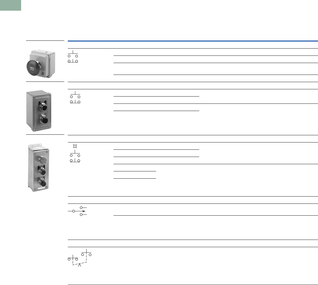
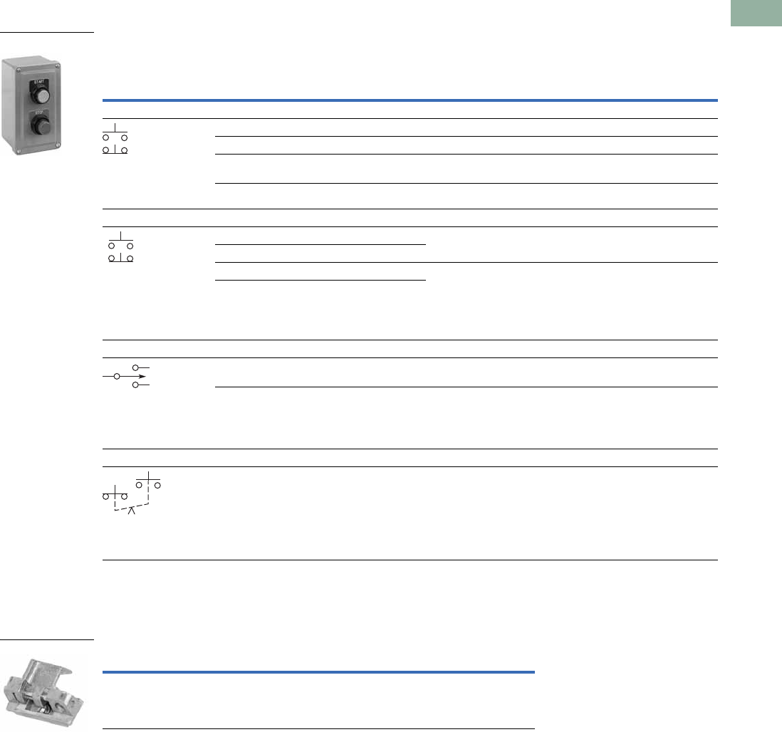
Type N Control Stations—Open Type Construction (No Cover)
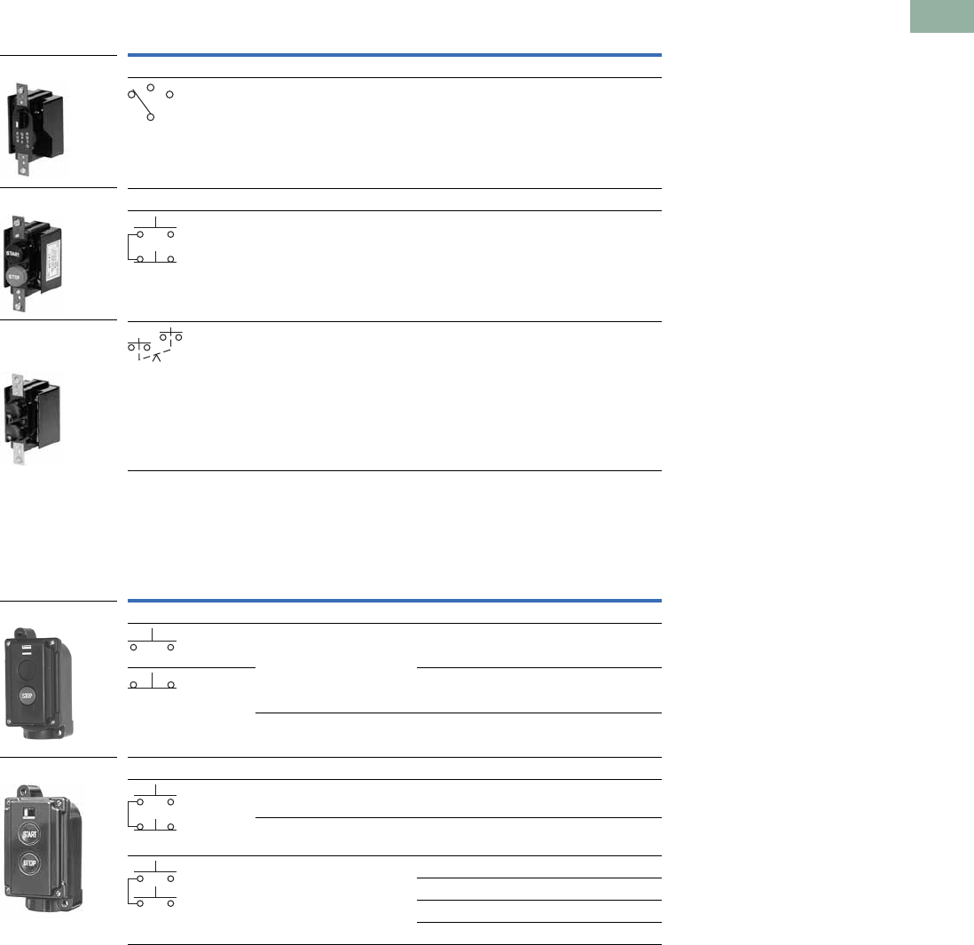
Special Purpose Control Stations
Special Purpose Control Stations—UL (NEMA) Type 3, 3R, 4, 4X, 13
Note
1 No legend on buttons. Specify any standard legend.
Contact
Symbol Button Type/Color Legends Catalog Number
One Element Enclosure Type
Three-position selector
switch/black knob
RUN/OFF/AUTO 10250H2538
Two Element Enclosure Type
Flush/green START/STOP 10250H2747
Flush/black (all)
mech. interlocked
None 110250H2544
Contact
Symbol Feature Legends Catalog Number
One Element Pushbutton Type
Flush START 10250H2738
STOP 10250H658
With lock hasp STOP 10250H665
Two Element Pushbutton Type
Flush START/STOP 10250H364
With lock hasp START/STOP 10250H671
Buttons interlocked FAST/SLOW 10250ED664
FOR/REV 10250H2740
UP/DOWN 10250H2741
OPEN/CLOSE 10250H2742
Mechanically
Interlocked
Pushbuttons
Two Button Station
Selector Switch
10250H_
10250H_
V7-T1-20 Volume 7—Logic Control, Operator Interface and Connectivity Solutions CA08100008E—March 2014 www.eaton.com
1
1
1
1
1
1
1
1
1
1
1
1
1
1
1
1
1
1
1
1
1
1
1
1
1
1
1
1
1
1
1.3
Pushbuttons and Indicating Lights
Pushbutton Control Stations—Assembled
10250H Series Heavy-Duty Control Stations
Type H Control Stations—UL (NEMA) Type 3, 3S, 4, 4X, 12, 13
Element Type Feature Circuit
Assembled
Legend
Plate
Unassembled
Alternate
Legend Plate Catalog Number
One Element
Pushbuttons Without padlock hasp 1NO-1NC JOG START 10250H1881
STOP
RUN
With padlock hasp 1NC STOP — 10250H4239
Knob selector
switch
Two-position 1NO-1NC OFF/ON — 10250H4526
Three-position 1NO-1NC MAN/OFF/AUTO — 10250H4527
Two Element
Pushbuttons Standard 1NO-2NC START/STOP — 10250H1884
2NO-2NC RAISE/LOWER FORWARD 10250H1885
REVERSE
OPEN
CLOSE
Standard and
standard with
padlock hasp
1NO-2NC START/STOP — 10250H4240
Three Element
Pushbuttons Standard 2NO-3NC FOR/REV/STOP START OPEN 10250H1890
Two standard and
standard with
padlock hasp
JOG CLOSE 10250H4241
RAISE FAST
LOWER SLOW
Indicating
light and
pushbuttons
120V Light-red lens
and two plain
1NO-2NC MOTOR
RUNNING
START/STOP
—10250H1913
10250H_
10250H_
10250H_
Volume 7—Logic Control, Operator Interface and Connectivity Solutions CA08100008E—March 2014 www.eaton.com V7-T1-21
1
1
1
1
1
1
1
1
1
1
1
1
1
1
1
1
1
1
1
1
1
1
1
1
1
1
1
1
1
1
1.3
Pushbuttons and Indicating Lights
Pushbutton Control Stations—Assembled
10250T Series Heavy-Duty 30.5 mm Control Stations
Complete Assembled Stations—UL (NEMA) Type 4, 4X, 12, 13
Break Glass Kit
Notes
1 Stop buttons are red—all others are black.
2 NEMA 4–13, if properly mounted on a flat surface. Consists of front plate, legend, operator and contact blocks.
3 Break glass stations will not function with Normally Open contact blocks.
4 Lock is 10250TA2.
5 Uses deep cover instead of shallow cover. Switch component is 10250TA67—mechanically interlocked operators.
6 Shown assembled to contact block (contact block supplied separately).
Element Type 1Features
Contact
Block(s) Legend
Surface Mounting
Catalog Number
Flush Mounting 2
Catalog Number
Break Glass Station
Break glass station 3Gray enclosure NC (logic level) EMERG. OFF 10250TGS —
Red enclosure 10250TGR —
One Element
Pushbutton Standard NO-NC START 10250T3516 10250T3573
NC STOP 10250T3518 10250T3575
NO-NC None 10250T3540 10250T3597
Mushroom head NO-NC START 10250T3517 10250T3574
NC STOP 10250T3519 10250T3576
With lock hasp 4NC STOP 10250T3520 10250T3577
Selector switch Two-position
black knob
NO-NC OFF/ON 10250T3523 10250T3580
Three-position
black knob
2NO MAN/OFF/AUTO 10250T3524 10250T3581
Push-pull
three-position
Momentary
red button
2NC START/STOP 10250T3545 10250T3602
Two Element
Pushbuttons Standard 1NO-2NC START/STOP 10250T3525 10250T3582
2NO-2NC RAISE/LOWER 10250T3672 10250T3673
2NO-2NC None 10250T3541 10250T3598
With lock hasp 4 1NO-2NC START/STOP 10250T3542 10250T3599
Standard and mushroom head 1NO-2NC START/STOP 10250T3526 10250T3583
Standard with
maintained contact 5
NO-NC START/STOP 10250T3528 10250T3585
Plus NC
Three Element
Pushbuttons Standard 2NO-3NC FOR, REV, STOP 10250T3532 10250T3589
2NO-3NC UP, DOWN, STOP 10250T3615 —
2NO-3NC OPEN, CLOSE, STOP 10250T3614 —
2NO-3NC None, None, STOP 10250T3543 10250T3600
Two standard and with lock hasp 2NO-3NC None, None, STOP 10250T3544 10250T3601
Indicating light
(transformer type)
and pushbuttons
Red lens — 120V 1NO-2NC MOTOR RUN,
START/STOP
10250T3536 10250T3593
Red lens — 240V 10250T3537 10250T3594
Red lens — 480V 10250T3538 10250T3595
Red lens — 600V 10250T3539 10250T3596
Description Catalog Number
Operator with hammer and five glass discs 10250TBG
Glass discs only (5) 10250TGL
Break Glass Station
One Element
Two Element
Three Element
Break Glass
Operator 6
V7-T1-22 Volume 7—Logic Control, Operator Interface and Connectivity Solutions CA08100008E—March 2014 www.eaton.com
1
1
1
1
1
1
1
1
1
1
1
1
1
1
1
1
1
1
1
1
1
1
1
1
1
1
1
1
1
1
1.3
Pushbuttons and Indicating Lights
Pushbutton Control Stations—Assembled
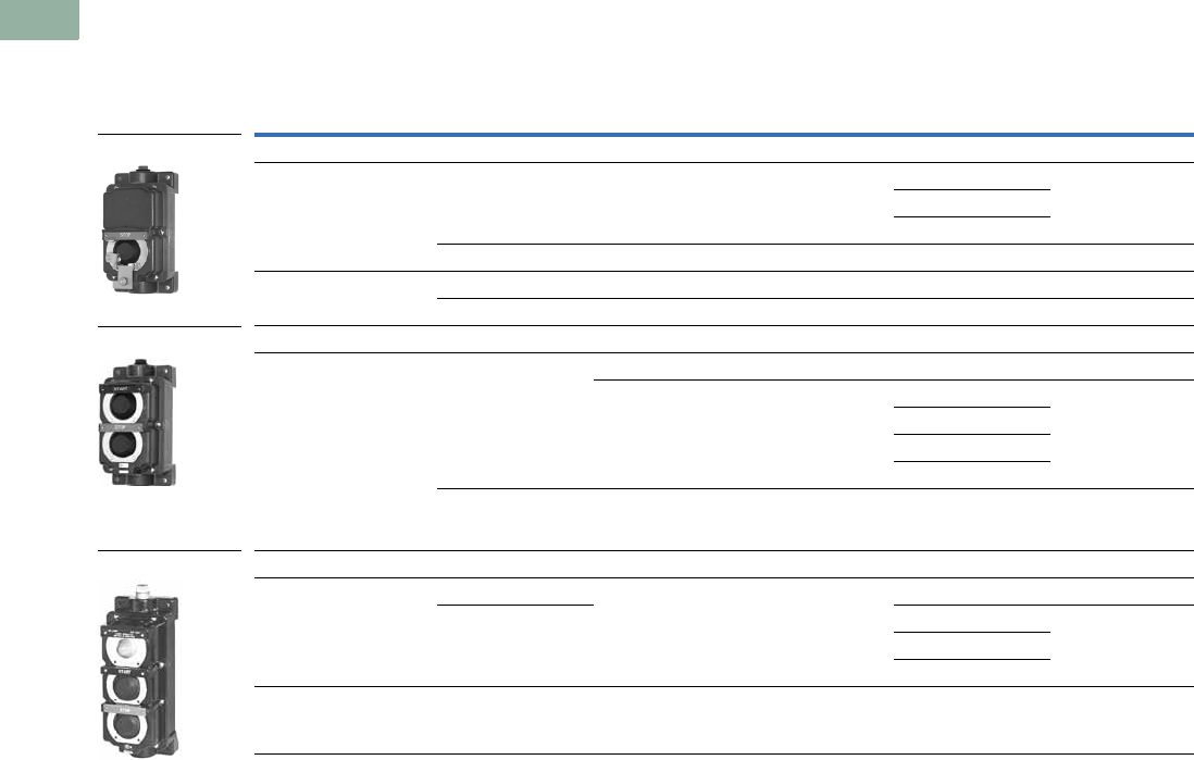
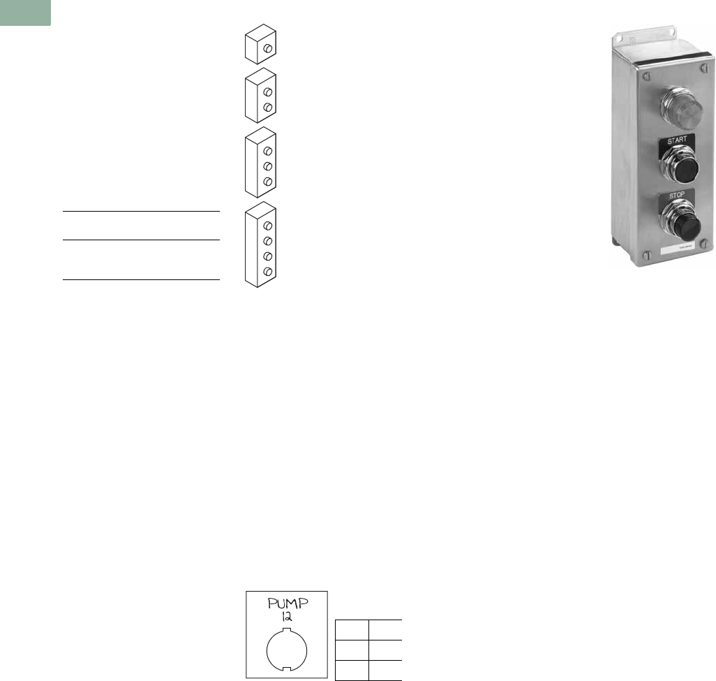
Class I Division 2 10250T Series Heavy-Duty 30.5 mm Control Stations
Complete Assembled Stations—
UL (NEMA) Type 4, 4X, 12, 13; NEC Class I Division 2, Groups B, C and D
Contact
Symbol
Button
Type/Color
Legend
Marking
Die Cast
Enclosure
Catalog Number
Polyester Molded
Enclosure
Catalog Number
Stainless Steel
Enclosure
Catalog Number
Single Pushbutton
Flush/green START 10250T7003 10250T7003P 10250T7003S
Extended/red STOP 10250T7005 10250T7005P 10250T7005S
Alum. jumbo
mushroom/red
EMER. STOP
(engraved button)
10250T7007 10250T7007P 10250T7007S
Flush/black No legend 10250T7009 10250T7009P 10250T7009S
Two Pushbuttons
Flush/green START 10250T7023 10250T7023P 10250T7023S
Extended/red STOP
Flush/black No legend 10250T7025 10250T7025P 10250T7025S
Flush/black No legend
Single Pilot Light—Two Pushbuttons
120 Vac red No legend 10250T7033 10250T7033P 10250T7033S
Flush/green START
Extended/red STOP
120 Vac red No legend 10250T7035 10250T7035P 10250T7035S
Flush/black
Flush/black
Three-Position Selector Switch
Maintained
knob/black
HAND/OFF/AUTO 10250T7011 10250T7011P 10250T7011S
Maintained
knob/black
No legend 10250T7013 10250T7013P 10250T7013S
Single Pushbutton Maintained
Push-pull
with jumbo
mushroom/red
EMER. STOP
(engraved button)
10250T7019 10250T7019P 10250T7019S
10250T7007
10250T7023P
10250T7033S
1NO
1NC
Each Button
1NC
1NO
Each Button
1NC
1NO
2NC
2NO
Pull
O
X
Push
X
O
1NO
1NC
Volume 7—Logic Control, Operator Interface and Connectivity Solutions CA08100008E—March 2014 www.eaton.com V7-T1-23
1
1
1
1
1
1
1
1
1
1
1
1
1
1
1
1
1
1
1
1
1
1
1
1
1
1
1
1
1
1
1.3
Pushbuttons and Indicating Lights
Pushbutton Control Stations—Assembled
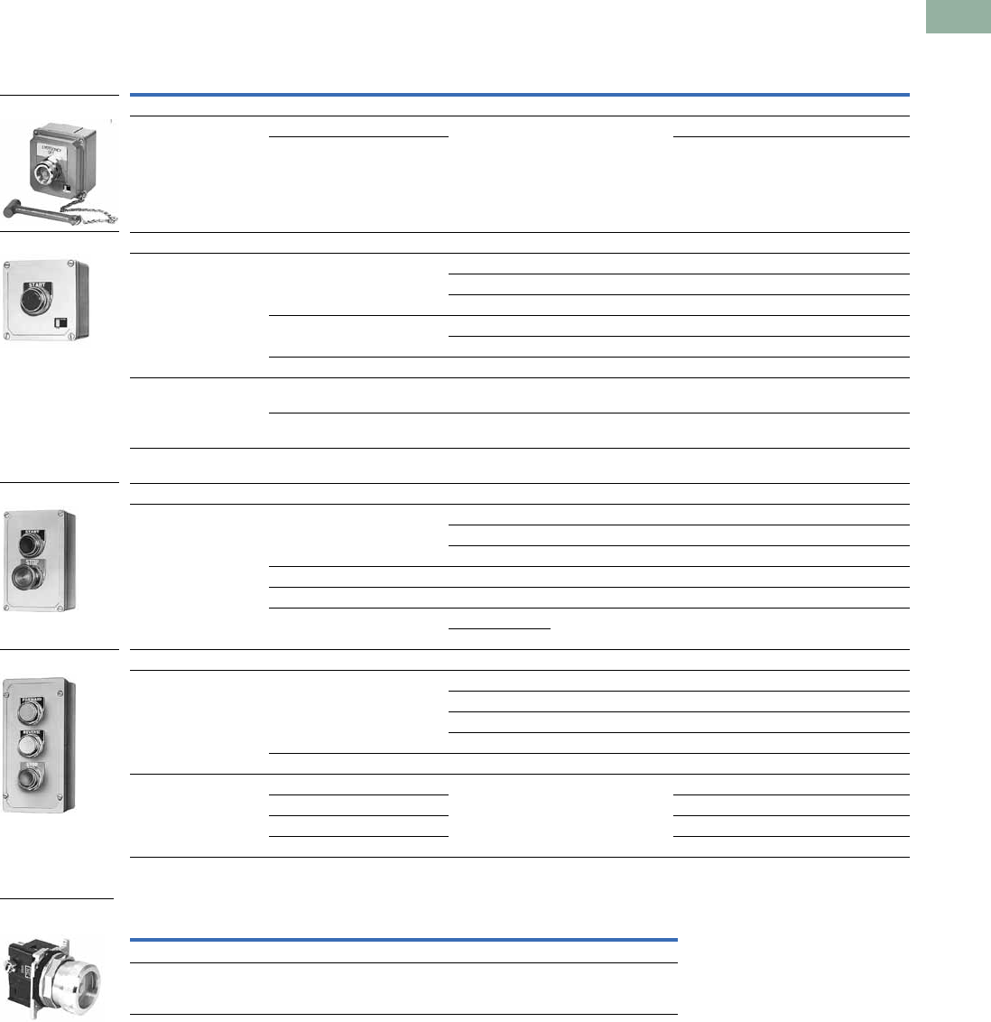
Class I Division 2 E34 Series Corrosion Resistant 30.5 mm Control Stations
Complete Assembled Stations—
UL (NEMA) Type 4, 4X, 12, 13; NEC Class I Division 2, Groups B, C and D
Accessories
Type N Control Stations
Note
Use NEMA 4X 10250T operators where exposed to ultraviolet light, see Page V7-T1-22.
Contact
Symbol
Button
Type/Color
Legend
Marking
Die Cast
Enclosure
Catalog Number
Polyester Molded
Enclosure
Catalog Number
Stainless Steel
Enclosure
Catalog Number
Single Pushbutton
Flush/green START E34EX7003 E34EX7003P E34EX7003S
Extended/red STOP E34EX7005 E34EX7005P E34EX7005S
Alum. jumbo
mushroom/red
EMER. STOP
(engraved button)
E34EX7007 E34EX7007P E34EX7007S
Flush/black No legend E34EX7009 E34EX7009P E34EX7009S
Two Pushbuttons
Flush/green START E34EX7023 E34EX7023P E34EX7023S
Extended/red STOP
Flush/black No legend E34EX7025 E34EX7025P E34EX7025S
Flush/black No legend
Three-Position Selector Switch
Maintained
knob/black
HAND/OFF/AUTO E34EX7011 E34EX7011P E34EX7011S
Maintained
knob/black
No legend E34EX7013 E34EX7013P E34EX7013S
Single Pushbutton Maintained
Push-pull with jumbo
mushroom/red
EMER. STOP
(engraved button)
E34EX7019 E34EX7019P E34EX7019S
Description Catalog Number
Padlock attachment—For field assembly on square button type
(except extended button types)
10250H5110
E34EX_
1NO
1NC
Each Button
1NC
1NO
2NC
2NO
Pull
O
X
Push
X
O
1NO
1NC
Padlock Attachment
V7-T1-24 Volume 7—Logic Control, Operator Interface and Connectivity Solutions CA08100008E—March 2014 www.eaton.com
1
1
1
1
1
1
1
1
1
1
1
1
1
1
1
1
1
1
1
1
1
1
1
1
1
1
1
1
1
1
1.3
Pushbuttons and Indicating Lights
Pushbutton Control Stations—Assembled
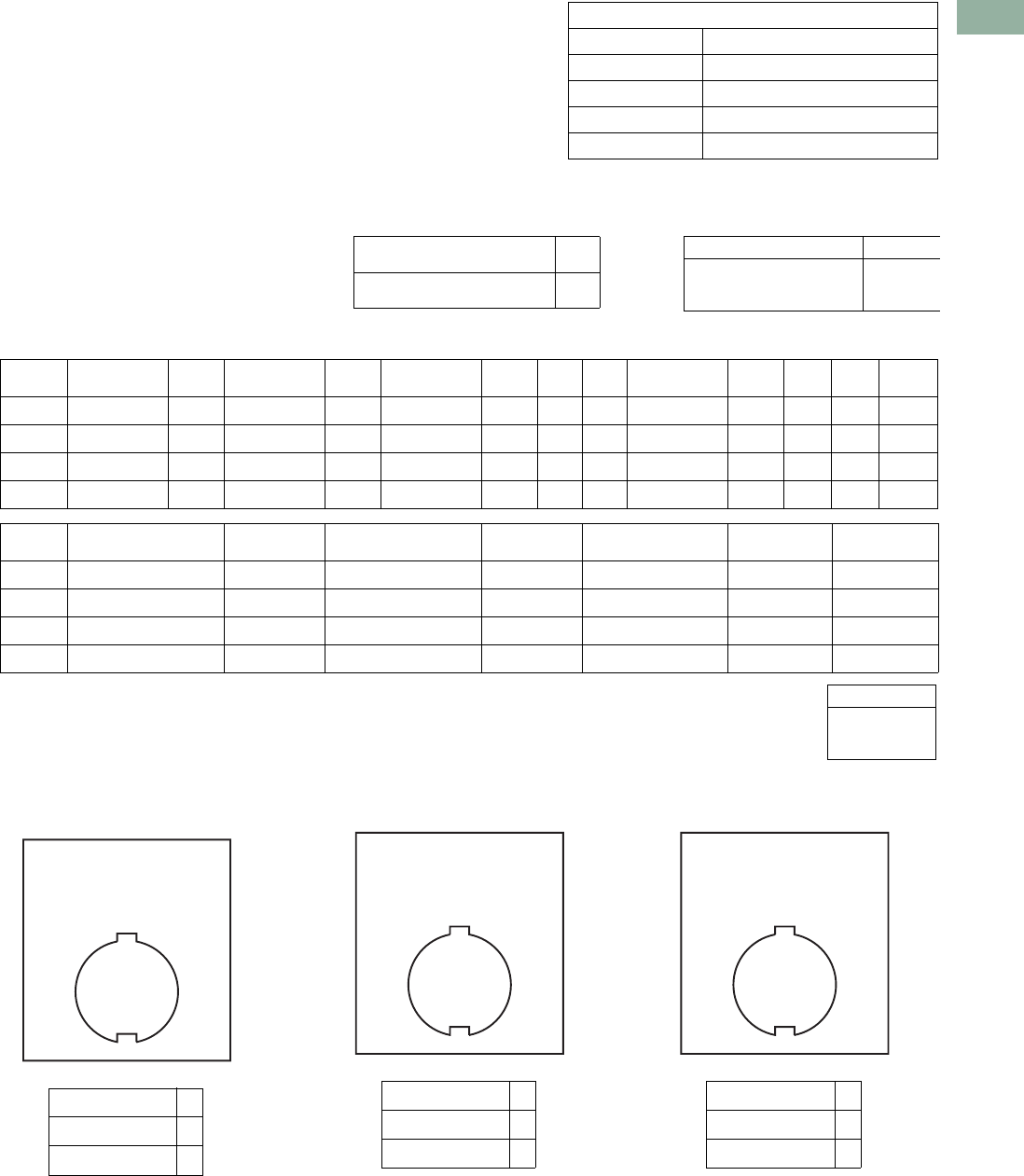
Custom Assembled Stations Specification Form
Ordering Instructions
Step 1
Copy this ordering guide from
catalog.
Step 2
Specify 10250T or E34
pushbutton lines in the
corresponding box on the
following page.
Step 3
Check back of panel
dimensions—specify single
or double depth enclosure in
the corresponding box on the
following page.
Step 4
Specify enclosure catalog
number and price in the
corresponding box on the
following page. Enclosures
can be found on Pages
V7-T1-116, V7-T1-233
and V7-T1-283. For pricing,
reference the most recent
PAD or VISTA-line.
Step 5
Specify catalog numbers for
desired operator, legend
plate, light unit, accessory
and contact block(s) for each
location in the enclosure in
the corresponding box on the
following page. (See position
locations on this page.)
Position Locations
Step 6
For non-standard legends,
specify legend desired, letter
size and location on the
layout sketches on the
following page. For
limitations see Page
V7-T1-232. For pricing,
use the blank legend catalog
number and “STAMP” Suffix
(Ex.: 10250TS36STAMP) and
reference the most recent
PAD or VISTA-line.
Example: 10250TS36
Special
Legend
for Position #_______
Step 7
Fax Sheet 2 of this form to
Eaton’s TRC, Technical
Resource Center, at 828-651-
0549 to the attention of—
Custom Stations Order or
email to TRC@eaton.com.
Within a few days you will
receive a confirmation fax
with the custom station part
number and price.
Step 8
Place your order over the
VISTA System.
For Selector and Roto-Push
Operators
10250T or E34
For single contact blocks or
1NO-1NC contact blocks, the
mounting position of contacts
must be specified. For
example: If a 1NO-1NC
contact block is required,
specify if NO is to be
mounted in Top A position or
Bottom B position.
10250T Pages
V7-T1-182 to V7-T1-253
E34 Pages
V7-T1-254 to V7-T1-295
10250T and
E34
Class I Div. 2
Pages
V7-T1-321 to V7-T1-361
Position 1
Position 2
Position 3
Position 1
Position 2
Position 1
Position 2
Position 3
Position 4
Position 1
LETTER
SIZE
3/32 in
1/8 in ✔
3/16 in
Volume 7—Logic Control, Operator Interface and Connectivity Solutions CA08100008E—March 2014 www.eaton.com V7-T1-25
1
1
1
1
1
1
1
1
1
1
1
1
1
1
1
1
1
1
1
1
1
1
1
1
1
1
1
1
1
1
1.3
Pushbuttons and Indicating Lights
Pushbutton Control Stations—Assembled
for Assembled Stations
FACTORY USE ONLY
Part Number
Product Code
Suffix
Date
Engineer
Step 3) ✔
Single Depth Enclosure
Double Depth Enclosure
Step 4)
Enclosure Catalog Number Price
Step 2)
10250T ❏ STD ❏ Class I Division 2
E34 ❏ STD ❏ Class I Division 2
Step 5)
Position Operator
Price
U.S. $ Light Unit
Price
U.S. $
Contact
Block
Price
U.S. $ A/L B/R
Contact
Block
Price
U.S. $ A/L B/R
Total
Price
1
2
3
4
Total:
Step 6) Non-standard Legends
Special Legend for Position #_______ Special Legend for Position #_______ Special Legend for Position #_______
LETTER SIZE ✔
3/32 inch (2.4 mm)
1/8 inch (3.2 mm)
3/16 inch (4.8 mm)
Position Legend Plate
Price
U.S. $ Lens or Caps
Price
U.S. $ Accessory
Price
U.S. $
Total
Price
1
2
3
4
To — Eaton’s TRC, Custom Station Order
(828) 651-0549 FAX, or email to TRC@eaton.com
From — Customer Name ___________________________________________
Customer Contact __________________________________________
Phone Number_____________________________________________
Fax Number _______________________________________________
Email Address _____________________________________________
10% Adder
LETTER SIZE ✔
3/32 inch (2.4 mm)
1/8 inch (3.2 mm)
3/16 inch (4.8 mm)
LETTER SIZE ✔
3/32 inch (2.4 mm)
1/8 inch (3.2 mm)
3/16 inch (4.8 mm)
V7-T1-26 Volume 7—Logic Control, Operator Interface and Connectivity Solutions CA08100008E—March 2014 www.eaton.com
1
1
1
1
1
1
1
1
1
1
1
1
1
1
1
1
1
1
1
1
1
1
1
1
1
1
1
1
1
1
1.3
Pushbuttons and Indicating Lights
Pushbutton Control Stations—Assembled
Renewal Parts
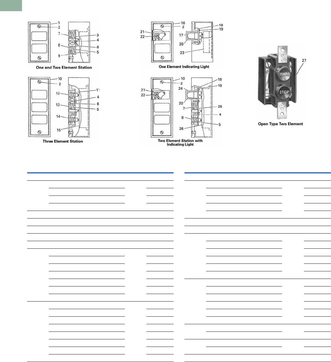
Ty p e N R e n e w a l P a r t s
Assembled Stations—Type N
Item
No. Description
No.
Req. Part Number
Type N—Square Buttons
1 Cover 1
Two element 49-3524
One element—top button 49-3524-2
One element—bottom button 49-3524-3
2 Cover screw 2 11-2168
3 Pushbutton support bracket 1 79-6649
4 Pushbutton support bracket screw 1 11-2090
5 Pushbutton spring 2 69-2571
6 Disc (when used—two element assembly) 2 16-1960
7 Pushbutton—top position 1
START/green 53-1169-3
RAISE/black 53-1169-66
FORWARD/black 53-1169-7
OPEN/black 53-1169-9
UP/blank 53-1169-11
Blank/green 53-1169
8 Pushbutton—bottom position 1
STOP/red 53-1202-2
Extended STOP/red 53-1202-5
REVERSE/black 53-1169-8
CLOSE/black 53-1169-10
DOWN/black 53-1169-12
LOWER/black 53-1169-6
Blank/red 53-1202
Item
No. Description
No.
Req. Part Number
Type N—Square Buttons, continued
9 Pushbutton element 1
1NO-1NC 86-2588
2NO 86-2588-2
1NO 86-2588-3
1NC 86-2588-4
10 Cover 1 49-3464
11 Pushbutton support bracket 1 79-6650
12 Pushbutton—top position 1
FORWARD/black 53-1170-7
UP/black 53-1170-4
RAISE/black 53-1170-5
OPEN/black 53-1170-9
FAST/black 53-1170-6
13 Pushbutton middle position 1
REVERSE/black 53-1169-15
DOWN/black 53-1169-18
LOWER/black 53-1169-16
CLOSE/black 53-1169-17
SLOW/black 53-1169-13
14 Pushbutton—bottom position 1
STOP/red 53-1201-2
15 Pushbutton element 1
2NO-3NC 86-2593
16 Cover 1 49-3524-4
Volume 7—Logic Control, Operator Interface and Connectivity Solutions CA08100008E—March 2014 www.eaton.com V7-T1-27
1
1
1
1
1
1
1
1
1
1
1
1
1
1
1
1
1
1
1
1
1
1
1
1
1
1
1
1
1
1
1.3
Pushbuttons and Indicating Lights
Pushbutton Control Stations—Assembled
Assembled Stations—Type N, continued
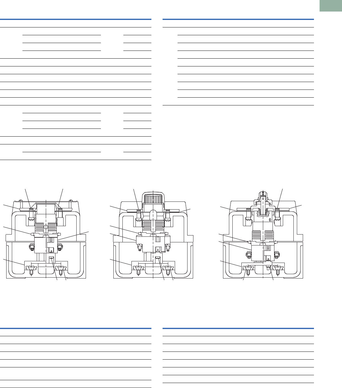
Ty p e H R e n e w a l P a r t s
Assembled Stations—Type H
Item
No. Description
No.
Req. Part Number
Type N—Square Buttons, continued
17 Lens 1
Clear 28-494
Red 28-887-2
Amber 28-887-3
18 Shield 1 73-1337
19 Shield screws 4 11-2012
20 Lamp (neon NE48) 1 28-494
21 Lamp receptacle 1 28-902
22 Lamp receptacle screw 1 911-330F1
23 Pilot light terminal base 1 86-2586
24 Lens 1
Clear 28-887
Red 28-887-2
Amber 28-887-3
25 Pushbutton support bracket 1 79-6650-2
26 Pushbutton element 1
1NO-1NC 86-2594
Item
No. Description
No.
Req. Part Number
Type N—Round Buttons
Similar
to 27
Pushbutton assembly and element for:
10250H289 1 10250H2538
10250H364 1 86-353
10250H685 1 86-353-8
10250H665 1 86-353-8
10250H671 1 86-353
10250H2738 1 86-353-3
10250H2740 1 86-356
10250H2741 1 86-356
10250H2742 1 86-356
1
Pushbutton Indicating Light
2
3
5
4
6
3
4
5
9
78
12
7
12 1
Selector Switch
2
11
10
10
5
4
7
Item
No. Description
No.
Req. Part Number
Type H—Assembled Stations
1Screw 2 11-4654
2Screw 2 11-5719
3Base 1 17-16560
4 Contact blocks See Page V7-T1-235
5 10250T operator See Pages V7-T1-188
to V7-T1-225
6 Mounting plate 1 17-19524
Item
No. Description
No.
Req. Part Number
Type H—Assembled Stations
7Screw 4 11-953
8 Diaphragm 1 32-253-2
9 Mounting plate 1 17-19522
10 Gasket 1 32-254
11 Base 1 17-16561
12 Mounting plate 1 17-19523
V7-T1-28 Volume 7—Logic Control, Operator Interface and Connectivity Solutions CA08100008E—March 2014 www.eaton.com
1
1
1
1
1
1
1
1
1
1
1
1
1
1
1
1
1
1
1
1
1
1
1
1
1
1
1
1
1
1
1.3
Pushbuttons and Indicating Lights
Pushbutton Control Stations—Assembled
Technical Data and Specifications
Ratings
Maximum Ampere Ratings for Type N Control Stations
Maximum Ampere Ratings for Type H Control Stations
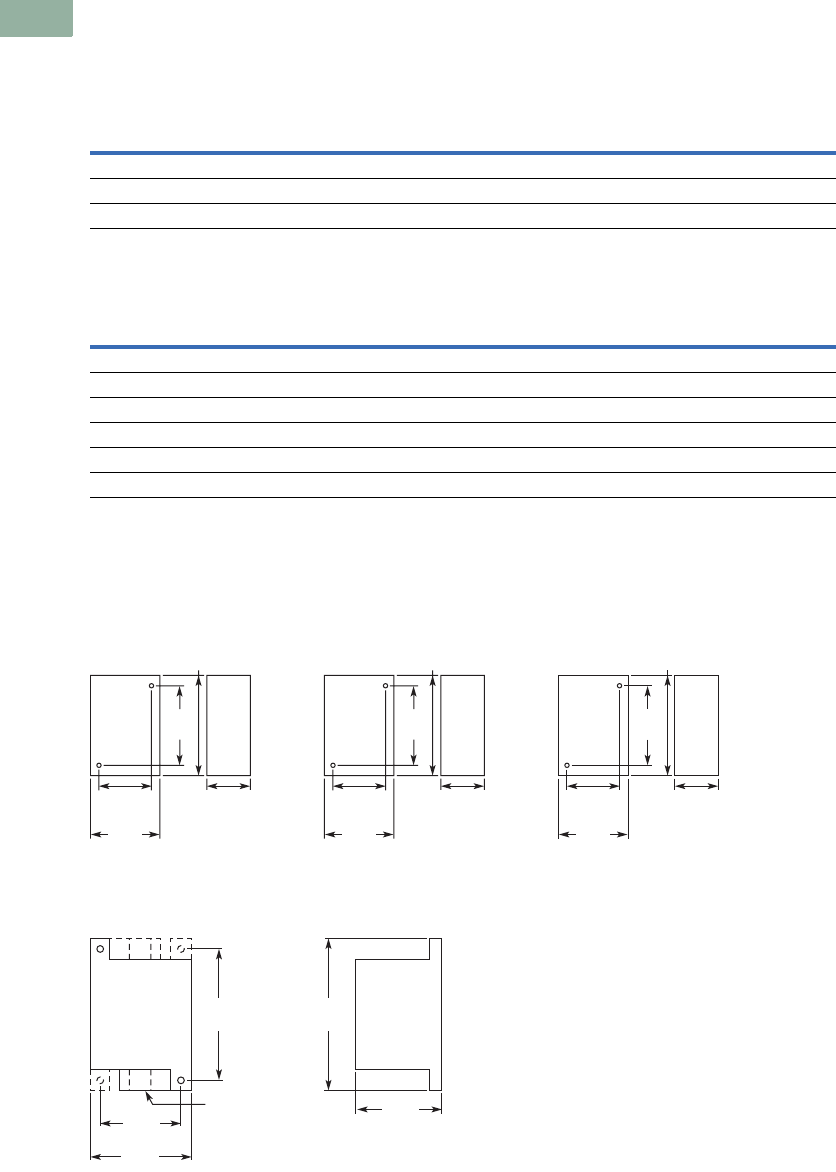
Dimensions
Approximate Dimensions in Inches (mm)
Type N Control Stations
Special Purpose Control Stations
Note
12.38 (60.5) for neon indicating light.
Volts AC Volts DC
Description 110 220 440 550 120 240 600
Make and emergency interrupt capacity 30 15 7.5 6 1.0 0.5 0.1
Normal load break 3 1.5 0.75 0.6 1.0 0.5 0.1
Continuous current 10 10 10 10 10 10 10
Description
Volts AC 50/60 Hz Volts DC
120 240 480 600 125 250
Make and emergency interrupt capacity 60 30 15 12 1.1 0.55
Normal load break 6 3 1.5 1.2 1.1 0.55
Continuous amperes 10 10 10 10 10 10
Voltamperes —
Make and emergency interrupt capacity 7200 7200 7200 7200 138 138
Normal load break 720 720 720 720 138 138
3.25
(82.6)
4.00
(101.6)
2.25
(57.2)
a
1.50
(38.1)
2.25
(57.2)
3.25
(82.6)
4.00
(101.6)
2.25
(57.2)
a
1.50
(38.1)
2.25
(57.2)
Single Button Station
5.00
(127.0)
6.00
(152.4)
2.25
(57.2)
a
1.50
(38.1)
2.25
(57.2)
Two Button Station Three Button Station
3.13
(79.5)
0.75 (19.1)
Pipe Tap
2.25
(57.2)
3.38
(85.9)
6.25
(158.8)
5.50
(139.7)
Ship Wt.
2.5 Lb (1.1 kg)
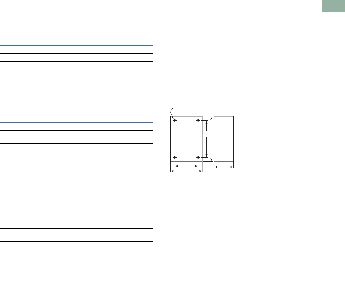
Volume 7—Logic Control, Operator Interface and Connectivity Solutions CA08100008E—March 2014 www.eaton.com V7-T1-29
1
1
1
1
1
1
1
1
1
1
1
1
1
1
1
1
1
1
1
1
1
1
1
1
1
1
1
1
1
1
1.3
Pushbuttons and Indicating Lights
Pushbutton Control Stations—Assembled
Approximate Dimensions in Inches (mm)
Type H Control Stations
NEMA Type 3, 3R, 3S, 4, 4X, 13
10250T and E34
Approximate Enclosure Dimensions
Note
1No conduit entrance holes provided. Drill as required.
No. of
Elements
Dimensions
Wide High Deep
1 and 2 4.50 (114.3) 8.25 (209.6) 4.50 (114.3)
3 4.50 (114.3) 10.75 (273.1) 4.25 (108.0)
Number
of
Elements
Surface Mounting
Conduit
Entrance
Dimensions in In (mm)
Wide
A
High
B
Deep
C
Mounting
DE
Cast
13.88
(98.6)
4.00
(101.6)
3.00
(76.3)
2.69
(68.3)
3.25
(82.6)
3/4
23.88
(98.6)
5.88
(149.4)
3.00
(76.3)
2.69
(68.3)
5.13
(130.3)
3/4
33.88
(98.6)
7.75
(196.9)
3.00
(76.3)
2.69
(68.3)
7.00
(177.8)
1
433.88
(98.6)
9.63
(244.6)
3.00
(76.3)
2.69
(68.3)
8.88
(225.6)
1
Polyester
13.81
(96.8)
6.63
(168.4)
3.38
(85.9)
2.94
(74.7)
4.88
(124.0)
1
23.81
(96.8)
6.63
(168.4)
3.38
(85.9)
2.94
(74.7)
4.88
(124.0)
1
33.81
(96.8)
8.88
(225.6)
3.38
(85.9)
2.94
(74.7)
7.13
(181.1)
1
43.81
(96.8)
6.63
(168.4)
3.38
(85.9)
2.94
(74.7)
4.88
(124.0)
1
Stainless Steel
13.00
(76.2)
3.50
(88.9)
3.00
(76.2)
1.50
(38.1)
4.25
(108.0)
1
23.50
(88.9)
6.75
(171.5)
3.00
(76.2)
1.50
(38.1)
7.50
(190.5)
1
33.50
(88.9)
9.00
(228.6)
3.00
(76.2)
1.50
(38.1)
9.00
(228.6)
1
43.50
(88.9)
11.25
(285.8)
3.00
(76.2)
1.50
(38.1)
12.00
(304.8)
1
A
Surface
DC
B
E
4 Mtg. Holes — 10-32 Screw Size for
1 – 4 Element Die Cast/
Stainless Steel Enclosure
7/32 Screw Size for
Polyester
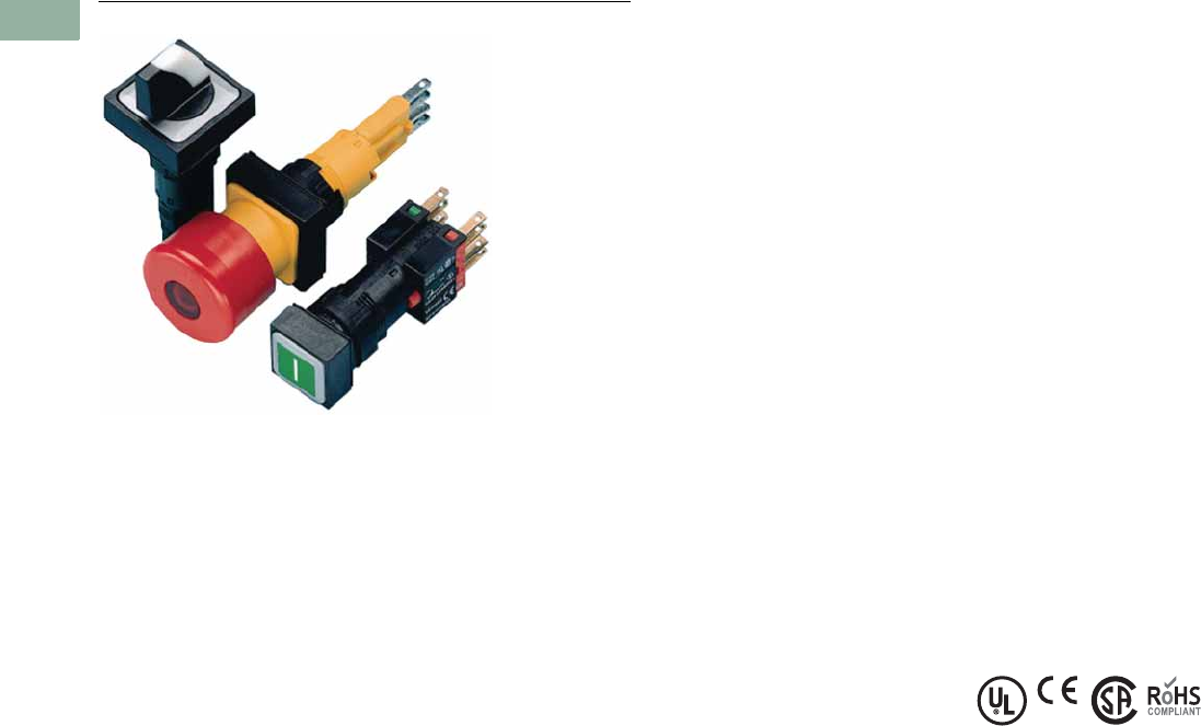
V7-T1-30 Volume 7—Logic Control, Operator Interface and Connectivity Solutions CA08100008E—March 2014 www.eaton.com
1
1
1
1
1
1
1
1
1
1
1
1
1
1
1
1
1
1
1
1
1
1
1
1
1
1
1
1
1
1
1.4
Pushbuttons and Indicating Lights
16.2 mm Pushbuttons—RMQ-16
16.2 mm Pushbuttons—RMQ-16
Contents
Description Page
16.2 mm Pushbuttons—RMQ-16
Product Selection Guide . . . . . . . . . . . . . . . . . V7-T1-31
Pushbuttons—Non-Illuminated and
Illuminated . . . . . . . . . . . . . . . . . . . . . . . . . . . V7-T1-32
Indicating Lights . . . . . . . . . . . . . . . . . . . . . . . . V7-T1-34
Emergency Stops . . . . . . . . . . . . . . . . . . . . . . . V7-T1-35
Selector Switches—Non-Illuminated,
Illuminated and Keyed . . . . . . . . . . . . . . . . . . V7-T1-36
Accessories . . . . . . . . . . . . . . . . . . . . . . . . . . . V7-T1-40
Technical Data and Specifications . . . . . . . . . . V7-T1-43
Dimensions . . . . . . . . . . . . . . . . . . . . . . . . . . . V7-T1-45
Product Overview
Product Description
The RMQ-16 pushbutton
line offers a wide array of
functional and attractively
designed illuminated and
non-illuminated pushbuttons,
selector switches, emergency
stops and indicating lights.
The illuminated line is offered
with either incandescent or
LED. RMQ-16 devices are
designed with two front-of-
panel operator sizes. The
18 x 18 mm or 25 x 25 mm
square operators can help
the user achieve over three
times the information density
compared with 22 mm ranges.
Features
●Wide product breadth:
RMQ-16 offers illuminated
and non-illuminated
pushbuttons, keyed,
non-keyed, and illuminated
selector switches,
emergency stops, and a
large variety of accessories
●Custom laser etching:
Hundreds of standard
markings available in
addition to infinite possible
custom images with laser
etching
●High durability:
Pushbuttons and selector
switches rated for 3 million
mechanical operations
●High information density:
Square operators (18 mm
or 25 mm) allow for side-
by-side mounting and
achieve over three times
the information density of
typical 22 mm installations
●Laser etched operators
●Heavy-duty construction
with IP65 on front of panel
operators
●LED or incandescent
illumination available
●Front-of-panel operators
available in either
18 x 18 mm or 25 x 25 mm
sizes
●Safety rated emergency
stops (IEC 60947-5,
positively driven contacts)
●Mounting diameter
16.2 mm to EN 50007
Standards and Certifications
●UL Listed
●CSA Certified
●IEC/EN 60947-5 VDE-0660
●IP65
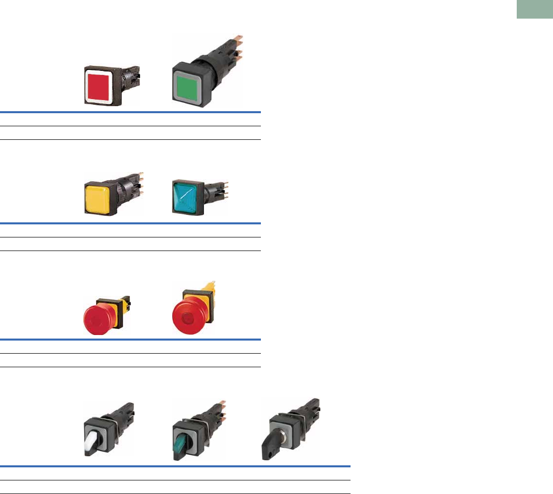
Volume 7—Logic Control, Operator Interface and Connectivity Solutions CA08100008E—March 2014 www.eaton.com V7-T1-31
1
1
1
1
1
1
1
1
1
1
1
1
1
1
1
1
1
1
1
1
1
1
1
1
1
1
1
1
1
1
1.4
Pushbuttons and Indicating Lights
16.2 mm Pushbuttons—RMQ-16
Product Selection Guide
Pushbuttons
Indicating Lights
Emergency Stops
Selector Switches
Description Non-Illuminated Illuminated
Product Selection Page V7-T1-32 Page V7-T1-33
Description Flush Extended
Product Selection Page V7-T1-34 Page V7-T1-34
Description Non-Illuminated Illuminated
Product Selection Page V7-T1-35 Page V7-T1-35
Description Non-Illuminated Illuminated Keyed
Product Selection Page V7-T1-36 Page V7-T1-37 Page V7-T1-38
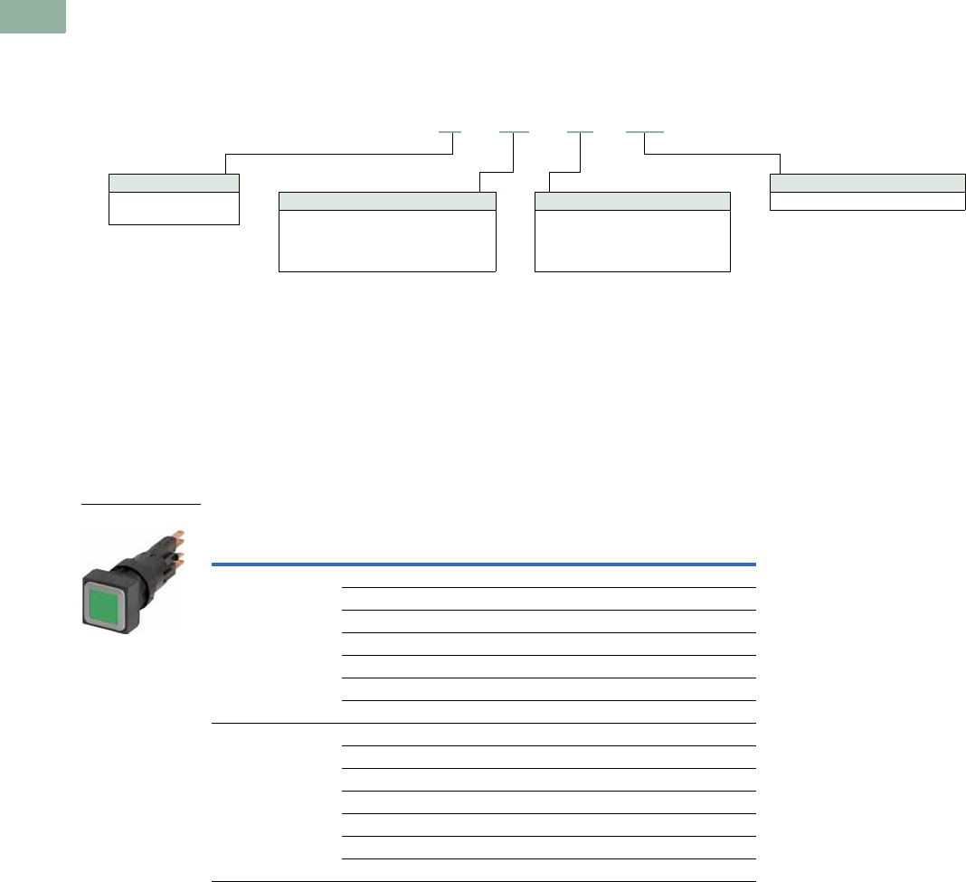
V7-T1-32 Volume 7—Logic Control, Operator Interface and Connectivity Solutions CA08100008E—March 2014 www.eaton.com
1
1
1
1
1
1
1
1
1
1
1
1
1
1
1
1
1
1
1
1
1
1
1
1
1
1
1
1
1
1
1.4
Pushbuttons and Indicating Lights
16.2 mm Pushbuttons—RMQ-16
Pushbuttons—Non-Illuminated and Illuminated
Catalog Number Selection
Catalog Number Selection is for illustrative purposes only and not to be used to create new catalog numbers.
Pushbuttons—Non-Illuminated and Illuminated
Product Selection
Non-Illuminated Pushbuttons
●Momentary or maintained
●Customizable laser etched pushbutton operators
●18 mm or 25 mm square operator
●3 million mechanical operations
●IEC/EN 60947-5
●IP65
Non-Illuminated Pushbuttons
Note
1 To order separate button plates, see Page V7-T1-42.
Type
Button
Color
Catalog Number
18 x 18 mm 25 x 25 mm
Momentary Green Q18D-GN Q25D-GN
Red Q18D-RT Q25D-RT
Black Q18D-SW Q25D-SW
White Q18D-WS Q25D-WS
Blue Q18D-BL Q25D-BL
Yellow Q18D-GE Q25D-GE
Without Q18D-X 1Q25D-X 1
Maintained Green Q18DR-GN Q25DR-GN
Red Q18DR-RT Q25DR-RT
Black Q18DR-SW Q25DR-SW
White Q18DR-WS Q25DR-WS
Blue Q18DR-BL Q25DR-BL
Yellow Q18DR-GE Q25DR-GE
Without Q18DR-X 1Q25DR-X 1
Face Plate
18 = 18 x 18 mm
25 = 25 x 25 mm
Q18–DR–BL/WB
Button Plate
GN =Green
RT =Red
SW = Black
WS =White
BL = Blue
GE = Yellow
X = Without
Operator Type
D = Non-illuminated momentary
DR = Non-illuminated maintained
LT = Illuminated momentary
LTR = Illuminated maintained
Bulb
WB = With incandescent bulb 24V
Q18-D-GN
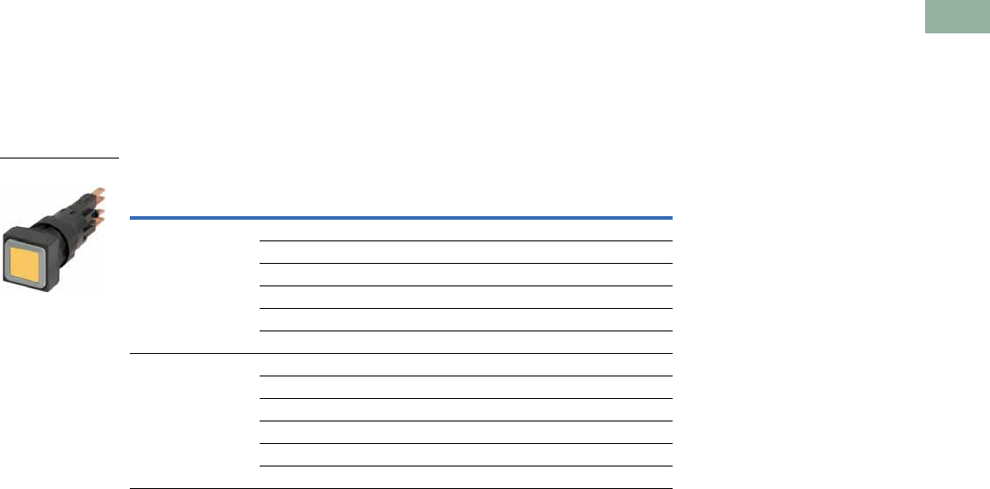
Volume 7—Logic Control, Operator Interface and Connectivity Solutions CA08100008E—March 2014 www.eaton.com V7-T1-33
1
1
1
1
1
1
1
1
1
1
1
1
1
1
1
1
1
1
1
1
1
1
1
1
1
1
1
1
1
1
1.4
Pushbuttons and Indicating Lights
16.2 mm Pushbuttons—RMQ-16
Illuminated Pushbuttons
●Momentary or maintained
●LED or incandescent
●18 mm or 25 mm square operator
●3 million mechanical operations
●IEC/EN 60947-5
●IP65
Illuminated Pushbuttons Without Bulb 1
Notes
1 To order with incandescent 24V bulb, insert a /WB at the end of the catalog number. Example, Q18LT-GN/WB.
2 For a complete selection of incandescent 24V bulbs and LEDs, see Page V7-T1-40.
Type
Button
Color
Catalog Number 2
18 x 18 mm 25 x 25 mm
Momentary Green Q18LT-GN Q25LT-GN
Red Q18LT-RT Q25LT-RT
Black Q18LT-SW Q25LT-SW
White Q18LT-WS Q25LT-WS
Blue Q18LT-BL Q25LT-BL
Yellow Q18LT-GE Q25LT-GE
Maintained Green Q18LTR-GN Q25LTR-GN
Red Q18LTR-RT Q25LTR-RT
Black Q18LTR-SW Q25LTR-SW
White Q18LTR-WS Q25LTR-WS
Blue Q18LTR-BL Q25LTR-BL
Yellow Q18LTR-GE Q25LTR-GE
Q18-LT-GE
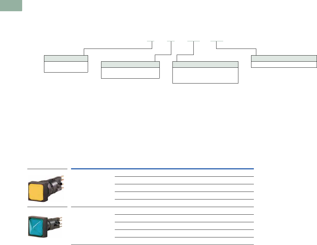
V7-T1-34 Volume 7—Logic Control, Operator Interface and Connectivity Solutions CA08100008E—March 2014 www.eaton.com
1
1
1
1
1
1
1
1
1
1
1
1
1
1
1
1
1
1
1
1
1
1
1
1
1
1
1
1
1
1
1.4
Pushbuttons and Indicating Lights
16.2 mm Pushbuttons—RMQ-16
Indicating Lights
Catalog Number Selection
Catalog Number Selection is for illustrative purposes only and not to be used to create new catalog numbers.
Indicating Lights—Flush and Extended
Product Selection
Indicating Lights
●LED or incandescent
●Flush and extended lenses
●18 mm or 25 mm square operator
●3 million mechanical operations
●IEC/EN 60947-5
●IP65
Indicating Lights Without Bulb 1
Notes
1 To order with incandescent 24V bulb, insert a /WB at the end of the catalog number. Example, Q18-LF-GN/WB.
2 For a complete selection of incandescent 24V bulbs and LEDs, see Page V7-T1-40.
Face Plate
18 = 18 x 18 mm
25 = 25 x 25 mm
Q18–LF–WS/WB
Button Plate
GN = Green
RT =Red
WS =White
BL =Blue
GE = Yellow
Bezel
LF = Flush indicator light
LH = Extended indicator light
Bulb
WB = With incandescent bulb 24V
Type
Button
Color
Catalog Number 2
18 x 18 mm 25 x 25 mm
Flush Green Q18LF-GN Q25LF-GN
Red Q18LF-RT Q25LF-RT
White Q18LF-WS Q25LF-WS
Blue Q18LF-BL Q25LF-BL
Yellow Q18LF-GE Q25LF-GE
Extended. Green Q18LH-GN Q25LH-GN
Red Q18LH-RT Q25LH-RT
White Q18LH-WS Q25LH-WS
Blue Q18LH-BL Q25LH-BL
Yellow Q18LH-GE Q25LH-GE
Q18-LF-GE
Q18-LH-BL
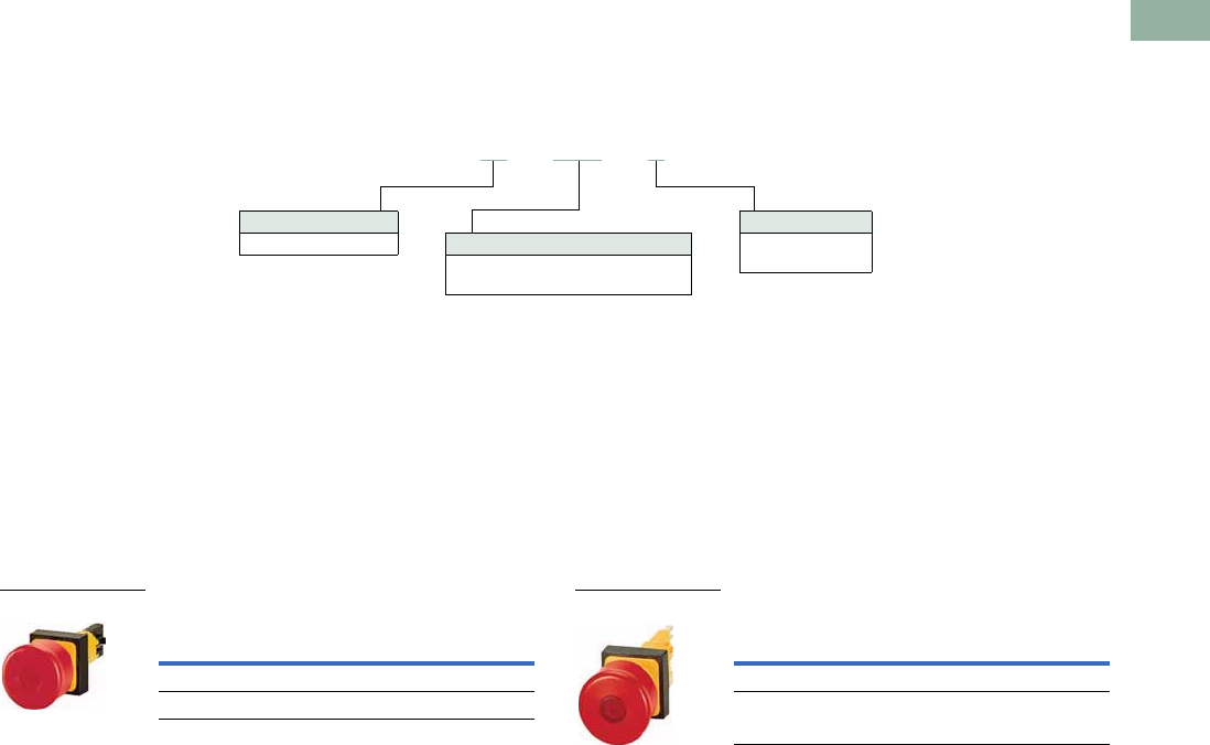
Volume 7—Logic Control, Operator Interface and Connectivity Solutions CA08100008E—March 2014 www.eaton.com V7-T1-35
1
1
1
1
1
1
1
1
1
1
1
1
1
1
1
1
1
1
1
1
1
1
1
1
1
1
1
1
1
1
1.4
Pushbuttons and Indicating Lights
16.2 mm Pushbuttons—RMQ-16
Emergency Stops
Catalog Number Selection
Catalog Number Selection is for illustrative purposes only and not to be used to create new catalog numbers.
Emergency Stops—Non-Illuminated and Illuminated
Product Selection
Emergency Stops
●Push/pull operation
●Illuminated or non-illuminated
●Emergency stop (red) or Machine stop (black) available
●Suitable for use in safety applications
●IEC/EN 60947-5
●IP65
Emergency Stops—Non-Illuminated Emergency Stops—Illuminated 1
Note
1Includes built-in multiple LED 24 Vdc.
Face Plate
25 = 25 x 25 mm
Q25–LPV–S
Operator Type
PV =Emergency stop
LPV = Emergency stop (illuminated)
Color
Blank =Red
S =Black
Button
Color
Catalog Number
25 x 25 mm
Red Q25PV
Black Q25PV-S
Q25PV
Button
Color
Catalog Number
25 x 25 mm
Red Q25LPV
Black Q25LPV-S
Q25LPV
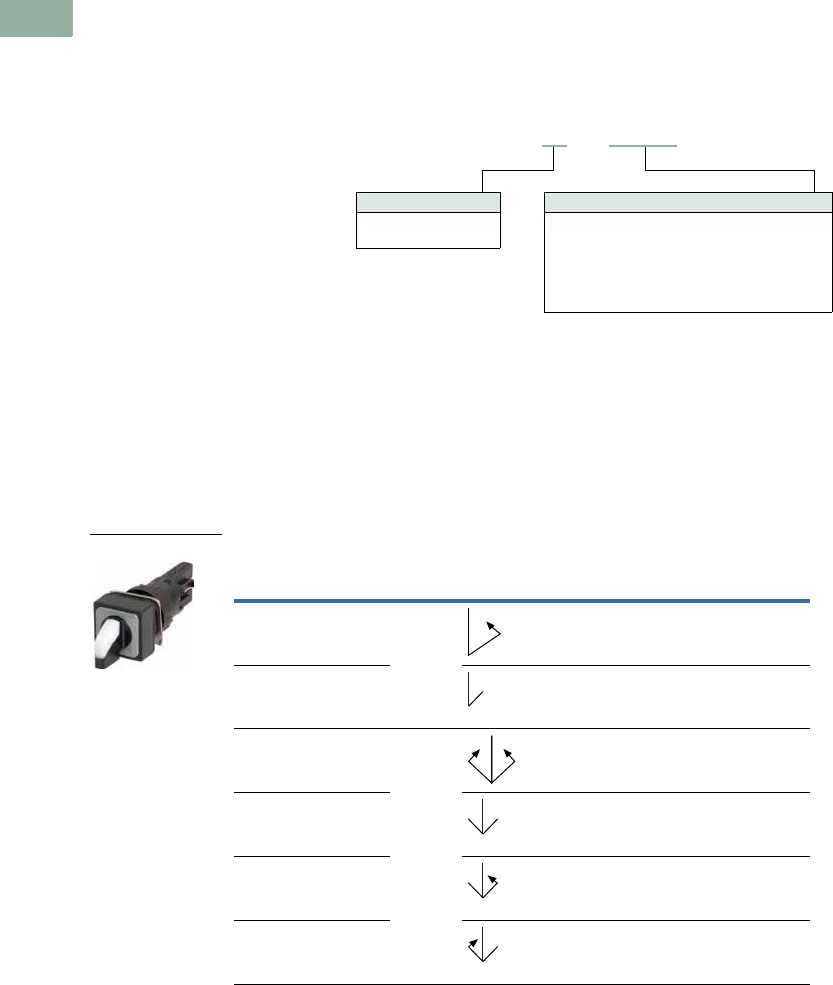
V7-T1-36 Volume 7—Logic Control, Operator Interface and Connectivity Solutions CA08100008E—March 2014 www.eaton.com
1
1
1
1
1
1
1
1
1
1
1
1
1
1
1
1
1
1
1
1
1
1
1
1
1
1
1
1
1
1
1.4
Pushbuttons and Indicating Lights
16.2 mm Pushbuttons—RMQ-16
Selector Switches—Non-Illuminated, Illuminated and Keyed
Catalog Number Selection
Catalog Number Selection is for illustrative purposes only and not to be used to create new catalog numbers.
Selector Switches—Non-Illuminated
Product Selection
Non-Illuminated Selector Switches
●Momentary or maintained
●18 mm or 25 mm square operator
●VS Anti-rotation feature
●3 million mechanical operations
●IP65
Selector Switches—Non-Illuminated
Function Position
Switch
Position
Catalog Number
18 x 18 mm 25 x 25 mm
Momentary 2 Q18WK1 Q25WK1
Maintained Q18WK1R Q25WK1R
Momentary 3 Q18WK3 Q25WK3
Maintained Q18WK3R Q25WK3R
Maintained/momentary Q18WK3R1 Q25WK3R1
Momentary/maintained Q18WK3R2 Q25WK3R2
Face Plate
18 = 18 x 18 mm
25 = 25 x 25 mm
Q18–WK1R
Selector Positions
WK1 = Two positions momentary
WK3 = Three positions momentary
WK1R = Two positions maintained
WK3R = Three positions maintained
WK3R1 = Three positions maintained/momentary
WK3R2 = Three positions momentary/maintained
Q18WK1
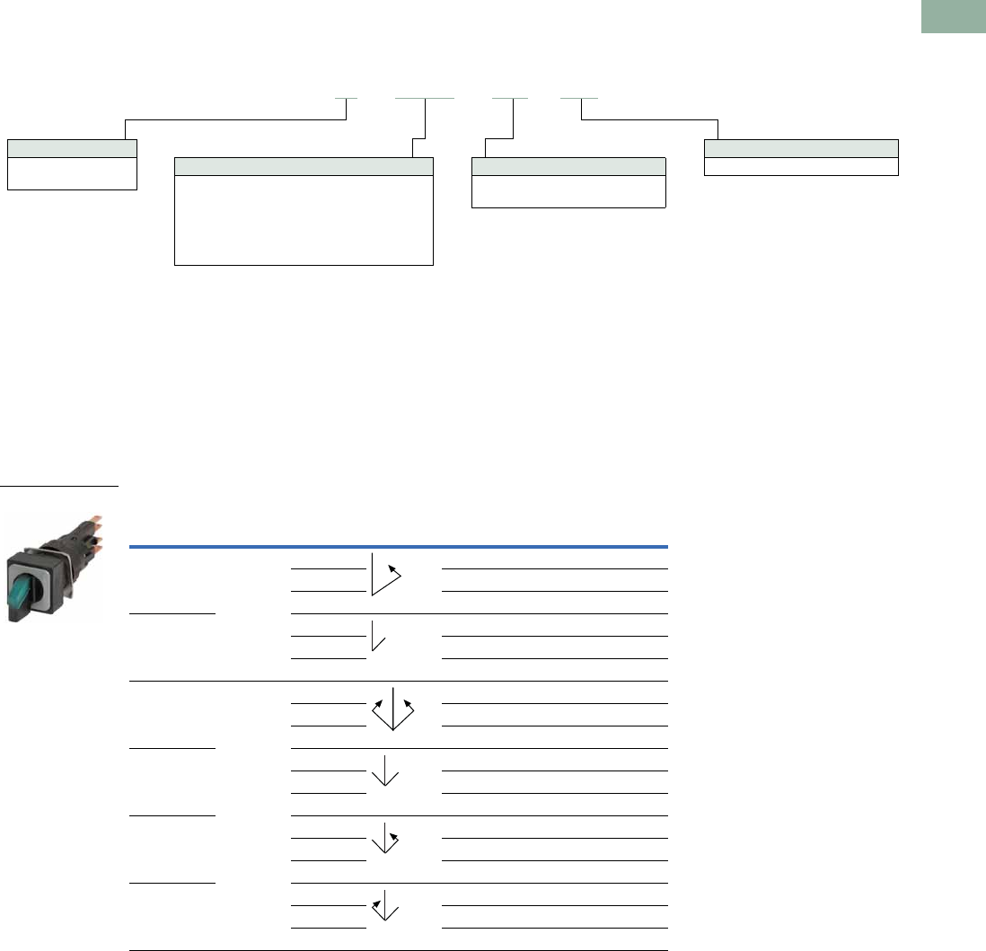
Volume 7—Logic Control, Operator Interface and Connectivity Solutions CA08100008E—March 2014 www.eaton.com V7-T1-37
1
1
1
1
1
1
1
1
1
1
1
1
1
1
1
1
1
1
1
1
1
1
1
1
1
1
1
1
1
1
1.4
Pushbuttons and Indicating Lights
16.2 mm Pushbuttons—RMQ-16
Catalog Number Selection
Catalog Number Selection is for illustrative purposes only and not to be used to create new catalog numbers.
Selector Switches—Illuminated
Product Selection
Illuminated Selector Switches
●LED or incandescent
●Momentary or maintained
●18 mm or 25 mm square operator
●VS Anti-rotation feature
●3 million mechanical operations
●IP65
Selector Switches—Illuminated without Bulb 1
Notes
1 To order with incandescent 24V bulb, insert a /WB at the end of the catalog number. Example, Q18LWK1-GN/WB.
2 For a complete selection of incandescent 24V bulbs and LEDs, see Page V7-T1-40.
Function Position
Button
Color
Switch
Position
Catalog Number 2
18 x 18 mm 25 x 25 mm
Momentary 2 Green Q18LWK1-GN Q25LWK1-GN
Red Q18LWK1-RT Q25LWK1-RT
White Q18LWK1-WS Q25LWK1-WS
Maintained Green Q18LWK1R-GN Q25LWK1R-GN
Red Q18LWK1R-RT Q25LWK1R-RT
White Q18LWK1R-WS Q25LWK1R-WS
Momentary 3 Green Q18LWK3-GN Q25LWK3-GN
Red Q18LWK3-RT Q25LWK3-RT
White Q18LWK3-WS Q25LWK3-WS
Maintained Green Q18LWK3R-GN Q25LWK3R-GN
Red Q18LWK3R-RT Q25LWK3R-RT
White Q18LWK3R-WS Q25LWK3R-WS
Maintained/
momentary
Green Q18LWK3R1-GN Q25LWK3R1-GN
Red Q18LWK3R1-RT Q25LWK3R1-RT
White Q18LWK3R1-WS Q25LWK3R1-WS
Momentary/
maintained
Green Q18LWK3R2-GN Q25LWK3R2-GN
Red Q18LWK3R2-RT Q25LWK3R2-RT
White Q18LWK3R2-WS Q25LWK3R2-WS
Face Plate
18 = 18 x 18 mm
25 = 25 x 25 mm
Q18–LWK1–WS/WB
Button Plate
GN =Green
RT =Red
WS =White
Bulb
WB = With incandescent bulb 24V
Switch Positions
LWK1 = Two positions momentary
LWK3 = Three positions momentary
LWK1R = Two positions maintained
LWK3R = Three positions maintained
LWK3R1 = Three positions maintained/momentary
LWK3R2 = Three positions momentary/maintained
Q18LWK1-GN
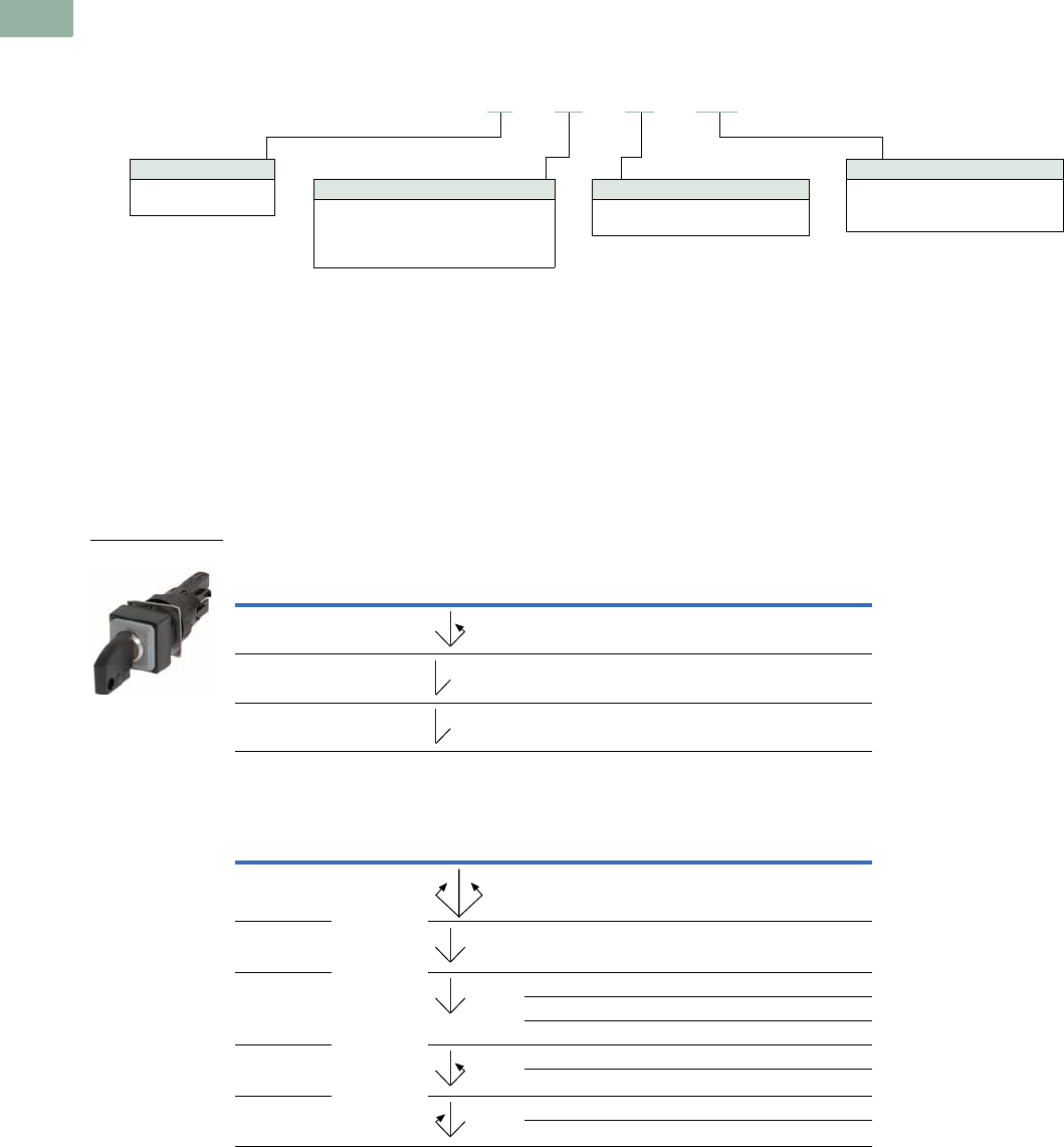
V7-T1-38 Volume 7—Logic Control, Operator Interface and Connectivity Solutions CA08100008E—March 2014 www.eaton.com
1
1
1
1
1
1
1
1
1
1
1
1
1
1
1
1
1
1
1
1
1
1
1
1
1
1
1
1
1
1
1.4
Pushbuttons and Indicating Lights
16.2 mm Pushbuttons—RMQ-16
Catalog Number Selection
Catalog Number Selection is for illustrative purposes only and not to be used to create new catalog numbers.
Keyed Selector Switches—Two- and Three-Position
Product Selection
Keyed Selector Switches
●5 color options
●Momentary or maintained
●18 mm or 25 mm square operator
●VS Anti-rotation feature
●3 million mechanical operations
●IP65
Keyed Selector Switches—Two-Position
Keyed Selector Switches—Three-Position
Note
1 I = Key is removed at the left.
O = Key is removed at the center.
II = Key is removed at the right.
Function
Button
Color
Switch
Position
Key Removal
Position 1
Catalog Number
18 x 18 mm 25 x 25 mm
Momentary Black O Q18S1 Q25S1
Maintained Black O Q18S1R Q25S1R
Maintained Black O Q18S1R-A1 Q25S1R-A1
Function
Button
Color
Switch
Position
Key Removal
Position 1
Catalog Number
18 x 18 mm 25 x 25 mm
Momentary Black O Q18S3 Q25S3
Maintained O, II Q18S3R Q25S3R
Maintained O Q18S3R-A1 Q25S3R-A1
I, O Q18S3R-A2 Q25S3R-A2
O, II Q18S3R-A3 Q25S3R-A3
Maintained/
momentary
I, O Q18S3R-A4 Q25S3R-A4
OQ18S3R-A5 Q25S3R-A5
Momentary/
maintained
O, II Q18S3R-A6 Q25S3R-A6
OQ18S3R-A7 Q25S3R-A7
Face Plate
18 = 18 x 18 mm
25 = 25 x 25 mm
Q18–S1–A1–WS
Color
GN =Green
RT =Red
SW =Black
WS =White
BL = Blue
Switch Positions
S1 = Two positions momentary
S1R = Two positions maintained
S3 = Three positions momentary
S3R = Three positions maintained
Key Code
A1–A7 = Switch and key removal
positions (detailed below)
Q18S1
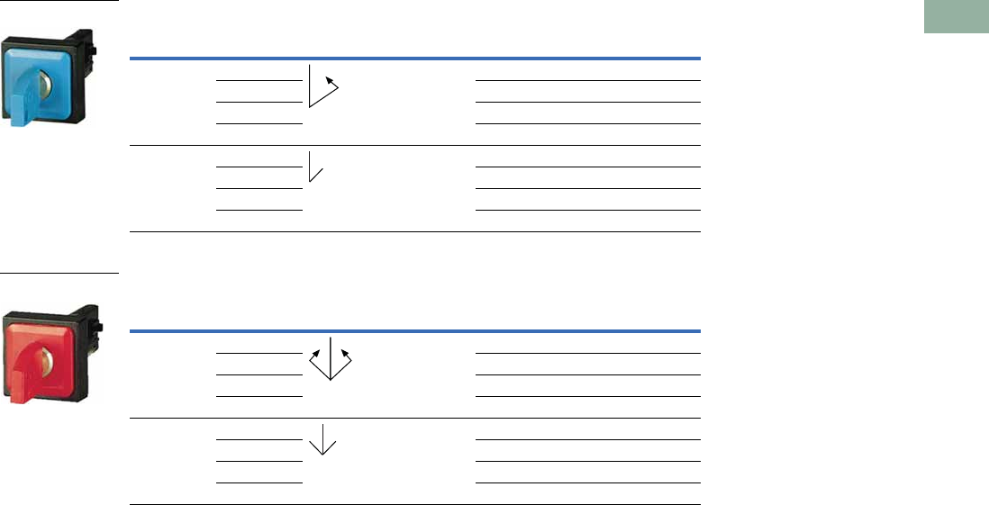
Volume 7—Logic Control, Operator Interface and Connectivity Solutions CA08100008E—March 2014 www.eaton.com V7-T1-39
1
1
1
1
1
1
1
1
1
1
1
1
1
1
1
1
1
1
1
1
1
1
1
1
1
1
1
1
1
1
1.4
Pushbuttons and Indicating Lights
16.2 mm Pushbuttons—RMQ-16
Keyed Selector Switches, Multicolor—Two-Position
Keyed Selector Switches, Multicolor—Three-Position
Note
1 I = Key is removed at the left.
O = Key is removed at the center.
II = Key is removed at the right.
Function
Button
Color
Switch
Position
Key Removal
Position 1
Catalog Number
18 x 18 mm 25 x 25 mm
Momentary Green 0 Q18S1-GN Q25S1-GN
Red Q18S1-RT Q25S1-RT
White Q18S1-WS Q25S1-WS
Blue Q18S1-BL Q25S1-BL
Maintained Green 0 Q18S1R-GN Q25S1R-GN
Red Q18S1R-RT Q25S1R-RT
White Q18S1R-WS Q25S1R-WS
Blue Q18S1R-BL Q25S1R-BL
Function
Button
Color
Switch
Position
Key Removal
Position 1
Catalog Number
18 x 18 mm 25 x 25 mm
Momentary Green 0 Q18S3-GN Q25S3-GN
Red Q18S3-RT Q25S3-RT
White Q18S3-WS Q25S3-WS
Blue Q18S3-BL Q25S3-BL
Maintained Green 0, II Q18S3R-GN Q25S3R-GN
Red Q18S3R-RT Q25S3R-RT
White Q18S3R-WS Q25S3R-WS
Blue Q18S3R-BL Q25S3R-BL
Q18S1-BL
Q18S3-RT
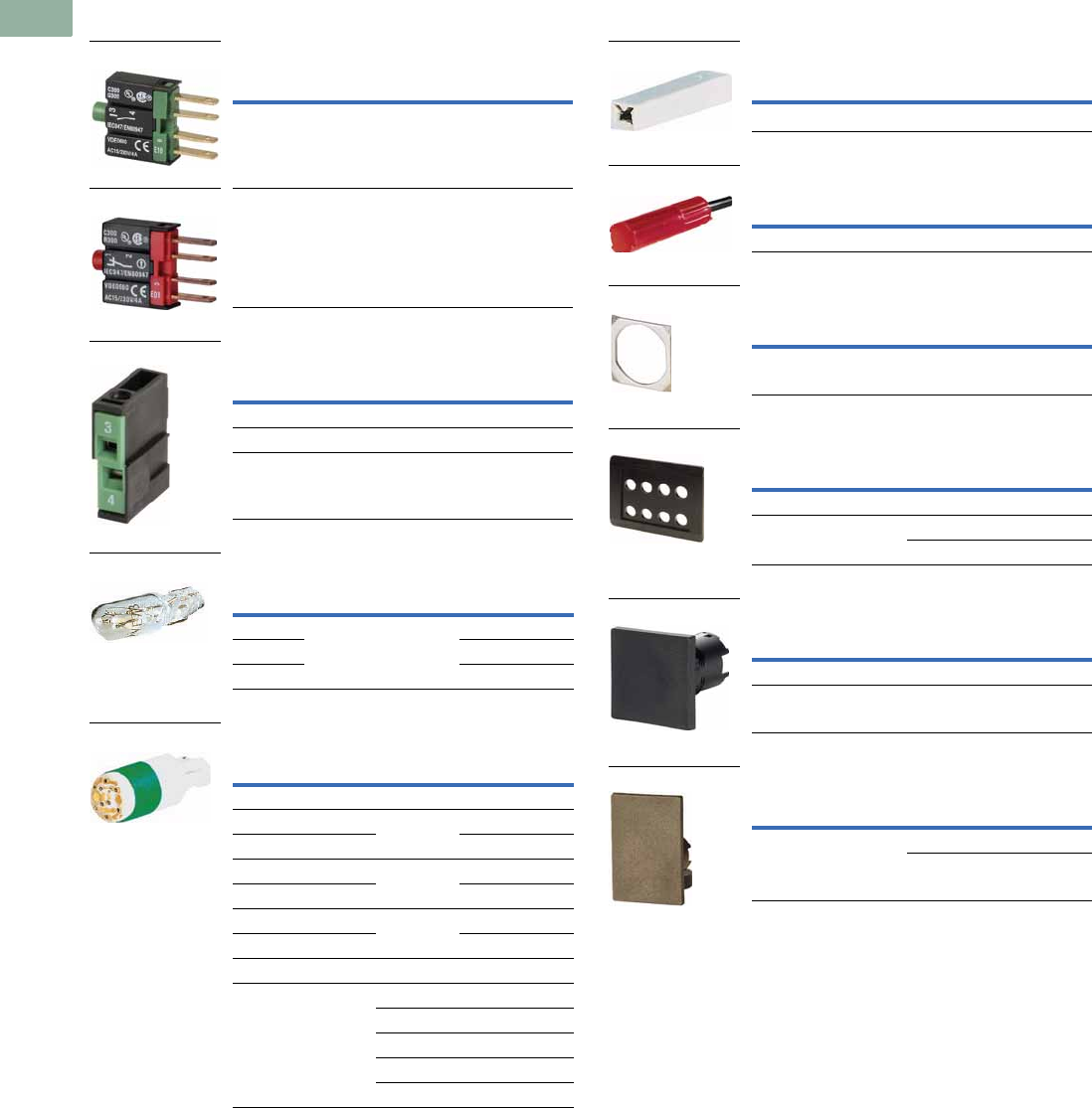
V7-T1-40 Volume 7—Logic Control, Operator Interface and Connectivity Solutions CA08100008E—March 2014 www.eaton.com
1
1
1
1
1
1
1
1
1
1
1
1
1
1
1
1
1
1
1
1
1
1
1
1
1
1
1
1
1
1
1.4
Pushbuttons and Indicating Lights
16.2 mm Pushbuttons—RMQ-16
Accessories
Contact Elements
Screw Adapter
Incandescent 24V Bulbs
LEDs (AC/DC)
Insulated Ferrule
Combination Box Spanner
Anti-Rotation Tab
Housing
Blanking Plug
Cover Plate
Note
1Positive pole to X1. Integral suppressor circuit up to 1000V.
Feature
Catalog
Number
Normally open (N/O) E10
Normally closed (N/C) E01
Feature
Catalog
Number
Normally open (N/O) SRA10
Normally closed (N/C) SRA01
Lamp sockets SRAL
Voltage Current Color
Catalog
Number
6V 1W White WBGL6
12V WBGL12
24–28V WBGL24
Voltage Current Color
Catalog
Number
Multiple Chip LED
6V 45 mA Green WBLED-GN6
12V 24 mA WBLED-GN12
6V 45 mA Red WBLED-RT6
12V 24 mA WBLED-RT12
6V 45 mA Yellow WBGLED-GE6
12V 24 mA WBGLED-GE12
Single Chip LED 1
18–30V 7–12.5 mA Green LEDWB-G
Red LEDWB-R
White LEDWB-W
Blue LEDWB-B
Yellow LEDWB-Y
E10
E01
SRA10
WBGL6
WBLED-GN6
Description
Catalog
Number
Insulated ferrule ISH2,8
Description
Catalog
Number
Mounting ring tool 16-MS
Description
Catalog
Number
Guard ring VS
Description Color
Catalog
Number
Surface mount enclosure White I8
Flush mount panel White E8
Black E8-SW
Size
Catalog
Number
18 x 18 mm Q18BS
25 x 25 mm Q25BS
Size Color
Catalog
Number
25 x 38 mm Black Q25AS
Gray Q25AGR
ISH2,8
R16-MS
VS
E8-SW
Q18BS
Q25AGR
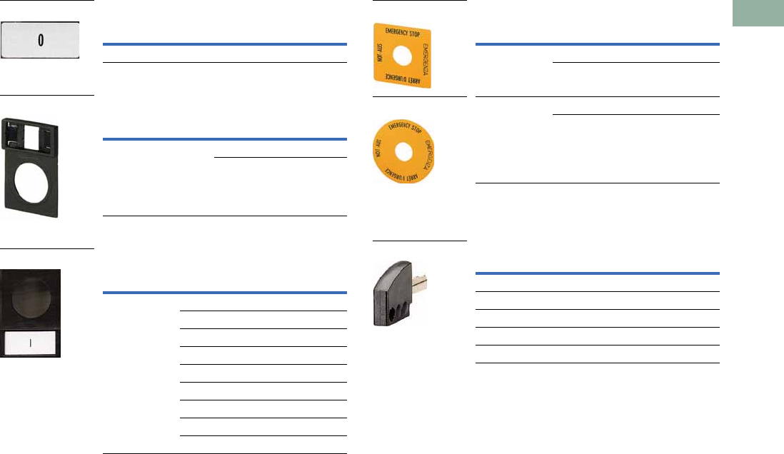
Volume 7—Logic Control, Operator Interface and Connectivity Solutions CA08100008E—March 2014 www.eaton.com V7-T1-41
1
1
1
1
1
1
1
1
1
1
1
1
1
1
1
1
1
1
1
1
1
1
1
1
1
1
1
1
1
1
1.4
Pushbuttons and Indicating Lights
16.2 mm Pushbuttons—RMQ-16
Insert Plate
Legend Plate
Legend Plate—Complete
Emergency Stop Labels
Extra Keys
Codes for Extra Keys
Size
Catalog
Number
10 x 22 mm BLANK 02SQ25
Size Color
Catalog
Number
25 x 38 mm Black Q25TS-X
Gray Q25TGR-X
Size Etching
Catalog
Number
25 x 38 START Q25TS-111
STOP Q25TS-110
FAULT Q25TS-250
HAND 0 AUTO Q25TS-197
MAN 0 AUTO Q25TS-397
0Q25TS-10
IQ25TS-11
0I Q25TS-90
I0II Q25TS-93
02SQ25
Q25TS-X
Q25TS_
Type Feature
Catalog
Number
Square 4 Languages SQT11
Blank SQT-GE
Circle 4 Languages SRT11
Blank SRT-GE
Color Catalog Number
Green ES16-GN
Red ES16-RT
Black ES16
White ES16-WS
Blue ES16-BL
SQT11
SRT11
ES16
V7-T1-42 Volume 7—Logic Control, Operator Interface and Connectivity Solutions CA08100008E—March 2014 www.eaton.com
1
1
1
1
1
1
1
1
1
1
1
1
1
1
1
1
1
1
1
1
1
1
1
1
1
1
1
1
1
1
1.4
Pushbuttons and Indicating Lights
16.2 mm Pushbuttons—RMQ-16
Button Plates
Instructions for Ordering Laser Inscriptions
1. Identify part number to be inscribed.
2. Pick symbol from library and identify suffix code associated with the symbol.
3. Order part number already listed in the catalog with -ETCH suffix.
4. When placing an order by fax or Vistaline on the web, reference order item number and indicate appropriate
symbol code or desired text.
Example
To order a 25 mm green flush button plate with the inscription AUTO HAND:
Order Catalog Number 03TQ25-ETCH.
AUTO HAND inscription is found on Page V7-T1-133 in the M22 Symbols Library, suffix code is X91.
In the order notes, reference item number and suffix X91.
Note: For a complete list of available symbols, see Pages V7-T1-130 to V7-T1-136, M22 Symbols Library.
Type Color Etching
Catalog
Number Type Color Etching
Catalog
Number
18 x 18 mm Black — 01TQ18 25 x 25 mm Black — 01TQ25
CUSTOM 01TQ18-ETCH CUSTOM 01TQ25-ETCH
21TQ18 21TQ25
19TQ18 19TQ25
White — 02TQ18 “STOP” 112TQ25
CUSTOM 02TQ18-ETCH “ON” 221TQ25
20TQ18 White — 02TQ25
Green — 03TQ18 CUSTOM 02TQ25-ETCH
CUSTOM 03TQ18-ETCH 20TQ25
11TQ18 Green — 03TQ25
Red — 04TQ18 CUSTOM 03TQ25-ETCH
CUSTOM 04TQ18-ETCH “START” 111TQ25
10TQ18 11TQ25
Yellow — 05TQ18 Red — 04TQ25
CUSTOM 05TQ18-ETCH CUSTOM 04TQ25-ETCH
Blue — 06TQ18 “STOP” 110TQ25
CUSTOM 06TQ18-ETCH 10TQ25
“OFF” 217TQ25
Yellow — 05TQ25
CUSTOM 05TQ25-ETCH
Blue — 06TQ25
CUSTOM 06TQ25-ETCH
Button Plates

Volume 7—Logic Control, Operator Interface and Connectivity Solutions CA08100008E—March 2014 www.eaton.com V7-T1-43
1
1
1
1
1
1
1
1
1
1
1
1
1
1
1
1
1
1
1
1
1
1
1
1
1
1
1
1
1
1
1.4
Pushbuttons and Indicating Lights
16.2 mm Pushbuttons—RMQ-16
Technical Data and Specifications
RMQ-16
Specification Illuminated Pushbutton
Operators (Maintained)
Illuminated Selector
SwitchesDescription Unit Contact Elements Indicating Lights
General Technical Data
Standards UL, CSA, IEC/EN 60 947, VDE 0660, CE
Lifespan, mechanical (operations) x 105100 30 (3) 3 —
Maximum operating frequency Ops/h 3600 3600 (1800) 1800 —
Operating force N 3 4 — —
Operating torque Nm — 0.2 —
Degree of protection to IEC/EN 60 529 IP20 with ISH2,8 IP65 IP65 IP65
Climatic proofing Damp heat, constant, to IEC 60 068-2-3/Damp heat, cyclical, to IEC 60 068-2-30
Ambient temperature
Open °C –25 to 60 –25 to 60 –25 to 60 –25 to 60
Enclosed °C –25 to 40 –25 to 40 –25 to 40 –25 to 40
Mounting position As required As required As required As required
Mechanical shock resistance to IEC 60 068-2-27
(half-sinusoidal shock, duration 11 ms)
g40404040
Terminal capacity (min./max.) mm20.5/1.0 0.5/1.0 0.5/1.0 0.5/1.0
Blade terminal 2.8 mm x 0.8 mm to DIN 46 244
Ferrule 2.8 mm x 0.8 mm to DIN 46 247 and IEC 60 760
Dimensions See Page V7-T1-45 See Page V7-T1-45 See Page V7-T1-45 See Page V7-T1-45
Contacts
Rated impulse withstand voltage Uimp V 4000 800 800 800
Rated insulation voltage UiV 250 250 250 250
Overvoltage category/pollution degree III/3 III/3 III/3 III/3
Rated operational voltage Ue (max.) V 250 24 24 24
Rated operational current Ie (max.) A 4 — — —
Control circuit reliability at
24 Vdc/5 mA (Fault probability Hr) <10–7, <1 fault in 107 operations
5 Vdc/1 mA (Fault probability Hr) <5 x 10⁻⁶, < fault in 5 x 10⁶ operations
Use of insulated ferrule ISH 2.8
From Ue >24 Vac/dc recommended >24 Vac/dc recommended >24 Vac/dc recommended >24 Vac/dc recommended
From Ue >50 Vac or 120 Vdc is mandatory, even on unused blade terminals
Maximum short-circuit protective device
Fuseless Type FAZ-B6 — — —
Fuse A gG/gL 10 — — —
Switching Capacity
Rated operational current Ie
AC-15
24V A 4 — — —
48V A 4 — — —
110V A 4 — — —
230V A 4 — — —
DC-13
24V A 3 — — —
42V A 1.0 — — —
60V A 0.8 — — —
110V A 0.5 — — —
220V A 0.2 — — —
UL/CSA Data UL listed File No. E 29 184, Guide No. NKCR/CSA certified File No. 46 552 Class No. 321103
Blade terminal 0.110 x 0.032 in 0.110 x 0.032 in 0.110 x 0.032 in 0.110 x 0.032 in
Fast-on connector 0.110 x 0.032 in AMP #60 197-1, 62 050-1 or equivalent
Rated voltage maximum AC Vac 300 24 24 24
Contact rating code AC E10/E01 C300/Q300 — — —
Thermal continuous test current A 2.5 — — —
Rated voltage maximum DC Vdc 300 — — —
Contact rating code DC E10/E01 C300/R300 — — —
Thermal continuous test current A 2.5 — — —
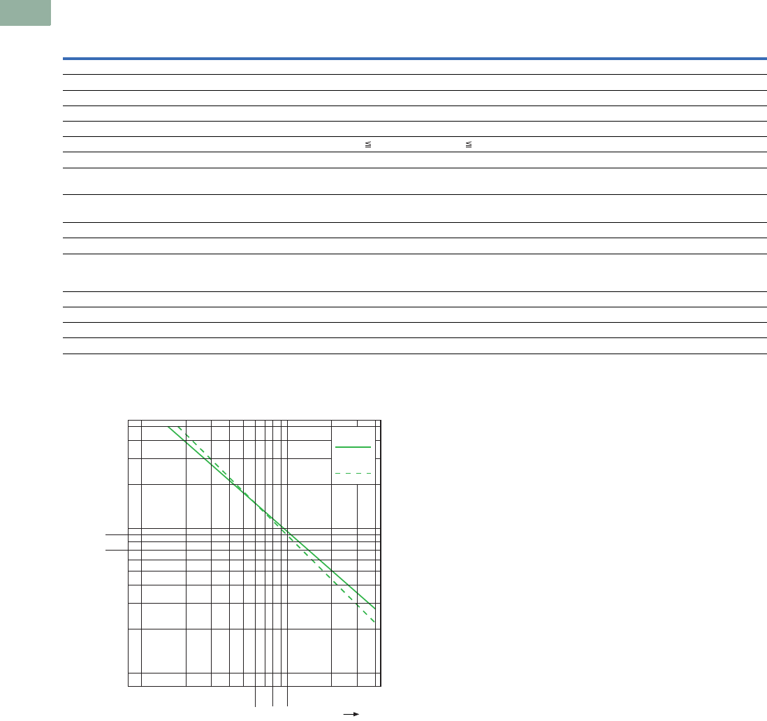
V7-T1-44 Volume 7—Logic Control, Operator Interface and Connectivity Solutions CA08100008E—March 2014 www.eaton.com
1
1
1
1
1
1
1
1
1
1
1
1
1
1
1
1
1
1
1
1
1
1
1
1
1
1
1
1
1
1
1.4
Pushbuttons and Indicating Lights
16.2 mm Pushbuttons—RMQ-16
RMQ-16, continued
Lifespan, Electrical AC-15 to IEC/EN 60 947-5-1 at 230V
Note
1See illuminated selector switches on Page V7-T1-37 for contact values.
Specification Emergency Stop
Operators
(Illuminated) 1
Description Unit
Pushbutton Operators
(Maintained) Selector Switches
Key-Released
Operators
Emergency Stop
Operators
General Technical Data
Standards UL, CSA, IEC/EN 60 947, VDE 0660, CE
Lifespan, mechanical (operations) x 10530 (3) 3 3 0.5 0.5
Maximum operating frequency Ops/h 3600 (1800) 1800 1800 600 600
Operating force N 4 — — 25 25
Operating torque Nm — 0.2 0.4 — —
Degree of protection to IEC/EN 60 529 IP65 IP65 IP65 IP65 IP65
Climatic proofing Damp heat, constant, to IEC 60 068-2-3
Damp heat, cyclical, to IEC 60 068-2-30
Ambient temperature
Open °C –25 to 60 –25 to 60 –25 to 60 –25 to 60 –25 to 60
Enclosed °C –25 to 40 –25 to 40 –25 to 40 –25 to 40 –25 to 40
Mounting position As required As required As required As required As required
Mechanical shock resistance to
IEC 60 068-2-27 (half-sinusoidal shock,
duration 11 ms)
g4040404040
Terminal capacity (min./max.) mm2————0.5/1.0
Blade terminal ————2.8 x 0.8 mm
Ferrule ————2.8 x 0.8 mm
Dimensions See Page V7-T1-45 See Page V7-T1-45 See Page V7-T1-45 See Page V7-T1-45 See Page V7-T1-45
0.1
E10
E01
0.2 0.3 0.4 0.5
0.6 0.8 1.0
3.00.7 4.02.00.9
l[A]
e
0.1
0.2
0.3
0.4
0.5
0.6
0.8
1.0
2.0
3.0
4.0
5.0
0.7
0.9
x 10 6
Operations
l= Rated operational current
e
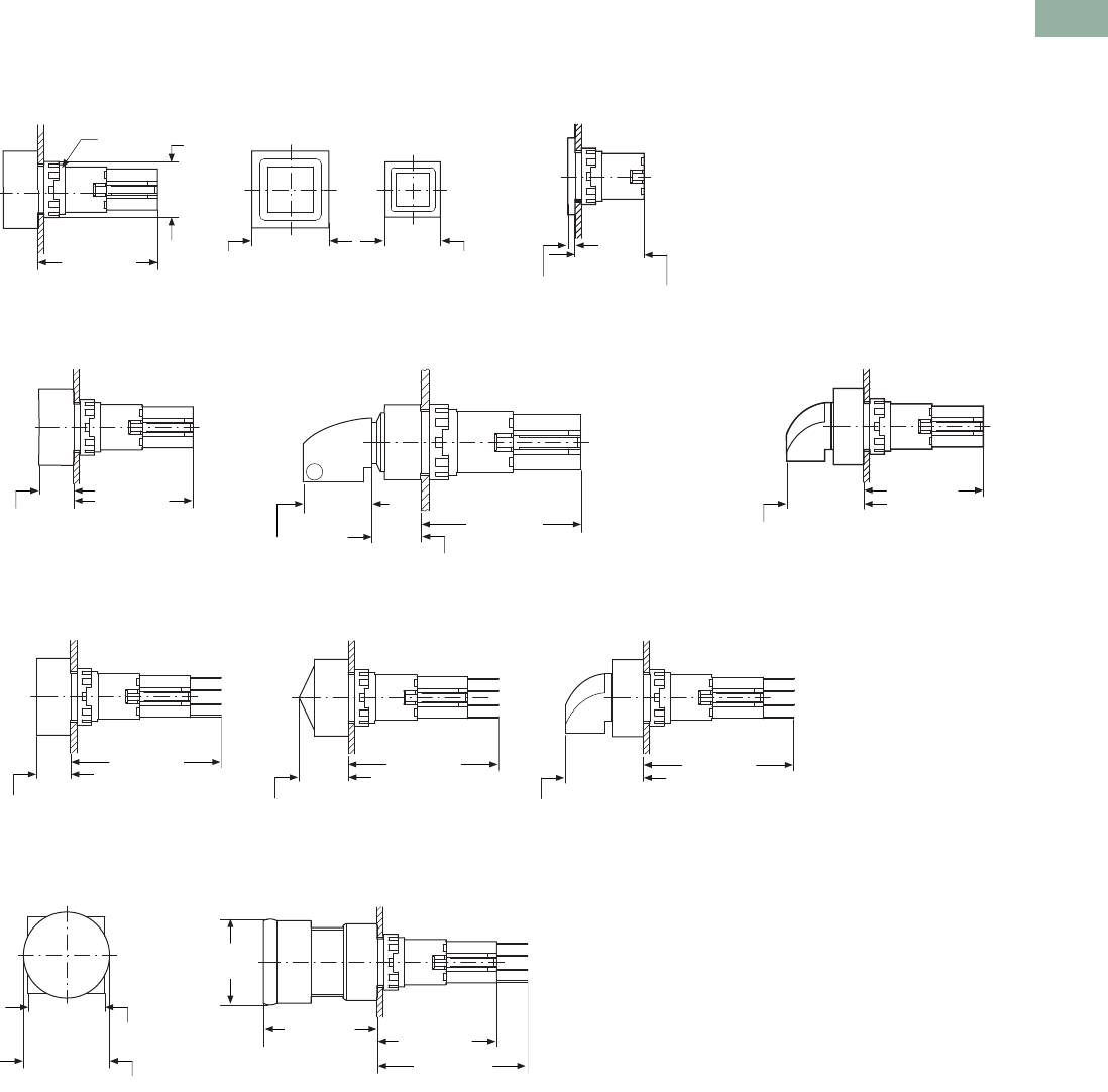
Volume 7—Logic Control, Operator Interface and Connectivity Solutions CA08100008E—March 2014 www.eaton.com V7-T1-45
1
1
1
1
1
1
1
1
1
1
1
1
1
1
1
1
1
1
1
1
1
1
1
1
1
1
1
1
1
1
1.4
Pushbuttons and Indicating Lights
16.2 mm Pushbuttons—RMQ-16
Dimensions
Approximate Dimensions in mm [in]
Actuating and Indicator Elements
Square Style Q…BS
Q…D-_, Q…DR-_ Q…S_ Q…WK_
Q…LT-_, Q…LTR-_, Q…LF-_ Q…LH-_ Q…LWK_
Q25PV_, Q25LPV_
M16 x 1 18.0
[0.71]
39.0 [1.54] Ø25.0 [0.98] Ø18.0 [0.71]
24.0 [0.94]
4.0 [0.16]
39.0 [1.54]
11.0 [0.43]
39.0 [1.54]
17.0
[0.67] 13.0 [0.51]
39.0 [1.54]
26.0 [1.02]
11.0
[0.43]
49.0 [1.93]
16.0
[0.63]
49.0 [1.93]
26.0
[1.02]
49.0 [1.93]
28.0 [1.10]
Ø 25.0
[0.98]
Ø 28.0
[1.10]
37.0 [1.46] 39.0 [1.54]
49.0 [1.93]
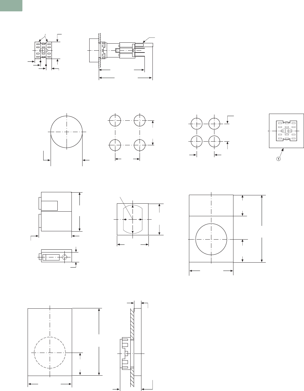
V7-T1-46 Volume 7—Logic Control, Operator Interface and Connectivity Solutions CA08100008E—March 2014 www.eaton.com
1
1
1
1
1
1
1
1
1
1
1
1
1
1
1
1
1
1
1
1
1
1
1
1
1
1
1
1
1
1
1.4
Pushbuttons and Indicating Lights
16.2 mm Pushbuttons—RMQ-16
Approximate Dimensions in mm [in]
Front Fixing
Q18, Q25, E89, SRA, VS, M16
Drilling Dimensions
Drilling
Grid Dimension to
IEC/EN 60947
Q25
Minimum Grid Spacing
Dimension
Q18
Mounting Distance
Mounting
RMQ Screw Adapter Anti-Rotation Feature RMQ-16 Label Mount
SRA_ VS Q25TS-_
Blanking Plates
Q25AS
58.0 [2.28]
49.0 [1.93]
ISH 2.8
[0.11]
E01, E10
6.0
[0.24]
18.0
[0.71]
16.2 [0.64]
+ 0.2
0
25.0
[0.98]
25.0
[0.98]
18.0
[0.71]
18.0 [0.71]
22.0
[0.87]
5.6 [0.22]
18.5 [0.73]
17.8
[0.70]
14.9 [0.59]
17.8
[0.70]
38.0
[1.50]
25.0 [0.98]
12.0
[0.47]
13.0
[0.51]
25.0 [0.98]
13.0
[0.51]
4.0
[0.16]
12.0
[0.47]
38.0
[1.50]
Note
1Exposed conductive part (metal).
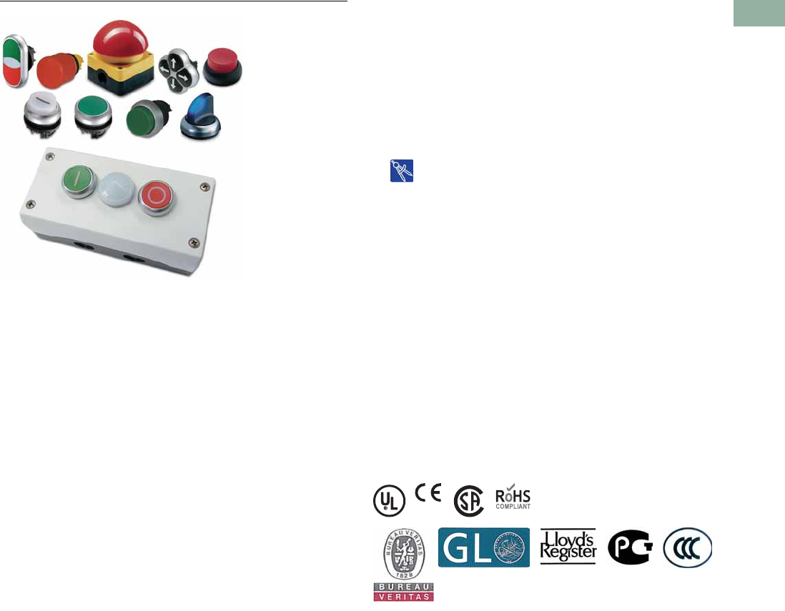
Volume 7—Logic Control, Operator Interface and Connectivity Solutions CA08100008E—March 2014 www.eaton.com V7-T1-47
1
1
1
1
1
1
1
1
1
1
1
1
1
1
1
1
1
1
1
1
1
1
1
1
1
1
1
1
1
1
1.5
Pushbuttons and Indicating Lights
22.5 mm Modular Pushbuttons—M22
22.5 mm Modular Pushbuttons—M22
Contents
Description Page
22.5 mm Modular Pushbuttons—M22
Product Selection Guide . . . . . . . . . . . . . . . . . . V7-T1-48
Accessories . . . . . . . . . . . . . . . . . . . . . . . . . . . V 7-T 1-111
Coding Adapter Guide . . . . . . . . . . . . . . . . . . . V7-T1-118
Technical Data and Specifications . . . . . . . . . . V7-T1-119
Dimensions . . . . . . . . . . . . . . . . . . . . . . . . . . . V7-T1-123
Symbols Library. . . . . . . . . . . . . . . . . . . . . . . . . V7-T1-129
Drawings
Online
Product Description
Eaton’s M22 industrial heavy-
duty pushbutton line offers a
wide array of functional,
attractive and ergonomically
designed illuminated and non-
illuminated pushbuttons,
selector switches, push-pulls,
alternate action and twist-to-
release operators. The
complete illuminated line is
only offered in LED light units
to ensure high-quality
brightness and up to 100,000
hours of LED illumination.
M22 operators are available
with either a silver or black
nylon colored or chrome
metal bezel. The space-
saving modular construction
of the M22 line makes on-
the-job assembly fast and
simplifies the stocking of
both components and
complete devices.
NEW
Eaton has expanded M22
pilot devices with a metal
bezel option. The new M22M
pushbutton is an elegant
chrome metal bezel that is
attractive, durable and rugged
for heavy-duty environments.
M22M devices are configurable
and complement components
within the M22 line.
Highly Modular and
Versatile Line
●Field convertible functions
(pushbuttons and selector
switches), maintained to
momentary
●Customizable laser
engraving capabilities
LED Indicators
●100,000 hours of life
in high-vibration
environments
●Lenses specifically
designed for LED
illumination
Rugged Design
●Most pushbutton operators
and contact blocks exceed
5 million mechanical
operations
●All components have IP66
rating, and some carry
IP67 and IP69K for
washdown environment;
see Page V7-T1-119 for
further technical data
Innovative Technologies
●ASi communicating
devices
●Palm switches
Standards and Certifications
All operators and components
are IEC/EN 60947 VDE 0660.
All operators carry an IP66
rating with some rated for
washdown environment with
IP67 and IP69K.
All pushbuttons, emergency-
stops, indicating lights,
potentiometers and selector
switches carry NEMA 4X, 13.
Marine classification
societies: Bureau Veritas
(BV), Germanischer Lloyd
(GL), and Lloyd’s Register of
Shipping (LR) approved.
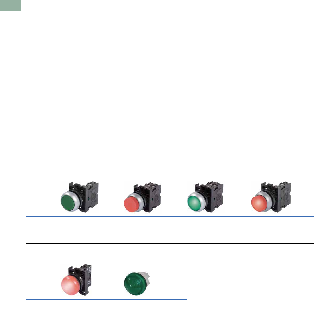
V7-T1-48 Volume 7—Logic Control, Operator Interface and Connectivity Solutions CA08100008E—March 2014 www.eaton.com
1
1
1
1
1
1
1
1
1
1
1
1
1
1
1
1
1
1
1
1
1
1
1
1
1
1
1
1
1
1
1.5
Pushbuttons and Indicating Lights
22.5 mm Modular Pushbuttons—M22
Features
●Field convertible
pushbuttons and
mushroom operators from
maintained to momentary
status
●Field convertible selector
switches from momentary
to maintained operation
and vice versa
●LED offering only for all
illuminated operators
●Laser engraved
pushbuttons, lenses and
enclosures
●Heavy-duty construction
with a minimum of IP66
and UL NEMA® type 4X /
13 on front of panel
operators. Many operators
even carry IP67 and IP69K,
for the toughest
applications
●Silver, black or chrome
metal bezel now available
●Snap-lock contact blocks
and light units for front or
base mounting
●Notched hole mounting
with anti-rotation tab and
central nut mounting on
each operator
●Over 5 million mechanical
operations and 1.6 million
electrical (reference
specification sheet)
●Direct opening action
normally closed contacts
●Unique and innovative
offerings, such as four-way
pushbuttons and USB/
RJ45 bulkhead interfaces
●Screw or spring-cage
terminals
Benefits
●Modular construction
makes assembly fast and
simplifies stocking of
components and complete
devices
●Field convertibility of
operator status for
pushbuttons and selector
switches helps distributors
and customers reduce
inventory and increase
functionality
●LED offering only for
improved brightness
quality and up to 100,000
hours of operation
●Plastic construction is
corrosion resistant.
Operators are designed
for rugged environments,
ideal for washdown
applications (reference
each operator’s IP ratings
and IEC/EN 60529 for ingress
protection definition)
●Anti-rotation tab saves
installation time and
prevents operator rotation
●High mechanical and
electrical life allows for use
in tough and challenging
applications
●Laser inscription
capabilities allow for high-
quality, wear-resistant
markings
●All normally closed (NC)
contacts are direct opening
action, i.e., NC contacts
are physically forced open
by direct linkage with the
pushbutton operator
in the unlikely event of
contact weld
●Some M22 operators are
capable of communication
via ASi protocol
●M22 offers USB and RJ45
connections
Product Selection Guide
Pushbuttons
Indicating Lights
Description Non-illuminated, flush Non-illuminated, extended Illuminated, flush Illuminated, extended
Operator Momentary Maintained Momentary Maintained Momentary Maintained Momentary Maintained
Product Selection
Pages V7-T1-53 to
V7-T1-55
Pages V7-T1-56,
V7-T1-57
Pages V7-T1-58,
V7-T1-59
Pages V7-T1-60,
V7-T1-61
Pages V7-T1-63 to
V7-T1-65
Pages V7-T1-66,
V7-T1-67
Pages V7-T1-68,
V7-T1-69
Pages V7-T1-70,
V7-T1-71
Description Flat Conical
Product Selection
Pages V7-T1-72,
V7-T1-73
Pages V7-T1-72,
V7-T1-73
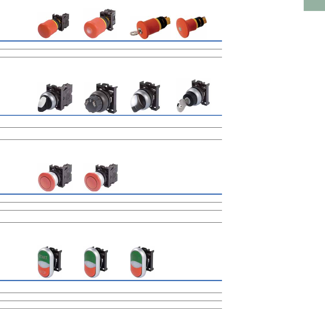
Volume 7—Logic Control, Operator Interface and Connectivity Solutions CA08100008E—March 2014 www.eaton.com V7-T1-49
1
1
1
1
1
1
1
1
1
1
1
1
1
1
1
1
1
1
1
1
1
1
1
1
1
1
1
1
1
1
1.5
Pushbuttons and Indicating Lights
22.5 mm Modular Pushbuttons—M22
Emergency Stops
Selector Switches
Mushroom Head Pushbuttons
Double Pushbuttons
Description Non-illuminated Illuminated Key release Mechanical indication
Product Selection Page V7-T1-75 Page V7-T1-75 Page V7-T1-76 Page V7-T1-76
Description Non-illuminated
knob type
Non-illuminated
rotary type
Illuminated Key-operated
Product Selection
Pages V7-T1-80,
V7-T1-81
Pages V7-T1-82,
V7-T1-83
Pages V7-T1-85
to V7-T1-87
Pages V7-T1-88
to V7-T1-91
Description Non-illuminated Non-illuminated
Operator Momentary Maintained
Product Selection
Pages V7-T1-94,
V7-T1-95
Pages V7-T1-96,
V7-T1-97
Description Extended pushbuttons
and center light
Flush top and center
light, extended bottom
Flush pushbuttons and
center light
Operator Momentary Momentary —
Product Selection Page V7-T1-99 Page V7-T1-100 Page V7-T1-100
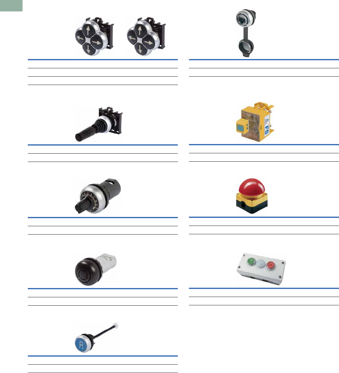
V7-T1-50 Volume 7—Logic Control, Operator Interface and Connectivity Solutions CA08100008E—March 2014 www.eaton.com
1
1
1
1
1
1
1
1
1
1
1
1
1
1
1
1
1
1
1
1
1
1
1
1
1
1
1
1
1
1
1.5
Pushbuttons and Indicating Lights
22.5 mm Modular Pushbuttons—M22
Four-Way Pushbuttons
Joysticks
Potentiometers
Acoustic Devices
Through-the-Door Operators
Bulkhead Interfaces
ASi Adapter Modules
Palm Switches
Assembled Control Stations
Description Non-interlocked Interlocked
Operator Momentary Maintained
Product Selection Page V7-T1-103 Page V7-T1-103
Description Joysticks
Product Selection Page V7-T1-104
Description Potentiometers
Product Selection Page V7-T1-106
Description Acoustic devices
Product Selection Page V7-T1-106
Description Through-the-door operators
Product Selection Page V7-T1-107
Description Bulkhead interfaces
Product Selection Page V7-T1-107
Description ASi adapter modules
Product Selection Page V7-T1-108
Description Palm switches
Product Selection Page V7-T1-109
Description Assembled control stations
Product Selection Page V7-T1-16
Volume 7—Logic Control, Operator Interface and Connectivity Solutions CA08100008E—March 2014 www.eaton.com V7-T1-51
1
1
1
1
1
1
1
1
1
1
1
1
1
1
1
1
1
1
1
1
1
1
1
1
1
1
1
1
1
1
1.5
Pushbuttons and Indicating Lights
22.5 mm Modular Pushbuttons—M22
Point-of-Purchase Units
Note
1 All NC contact blocks are positively driven contact.
Color Type
Contact
Configuration 1Catalog Number
Black Flush momentary NO/NC M22-D-S-K11-P
Red Extended momentary NO/NC M22-DH-R-K11-P
Green Flush momentary NO/NC M22-D-G-K11-P
Red Ext. illuminated (12–30V) momentary NO/NC M22-DLH-R-K11-R-P
Red Ext. illuminated (85–264V) momentary NO/NC M22-DLH-R-K11-230R-P
White Flush illuminated (12–30V) maintained NO/NC M22-DRL-W-K11-W-P
White Flush illuminated (85–264V) maintained NO/NC M22-DRL-W-K11-230W-P
Red Indicating light (12–30V) — M22-L-R-R-P
Green Indicating light (12–30V) — M22-L-G-G-P
Red Indicting light (85–264V) — M22-L-R-230R-P
Green Indicating light (85–264 Vac) — M22-L-G-230G-P
Red Twist-to-release E-stop 1NO/2NC M22-PVT-K12-P
Red Illuminated (12–30V) push-pull E-stop 1NO/2NC M22-PVL-K12-R-P
Red Illuminated (85–264V) push-pull E-stop 1NO/2NC M22-PVL-K12-230R-P
— Two-position maintained V selector switch NO/NC M22-WKV-K11-P
— Three-position momentary selector switch NO/NC M22-WK3-K22-P
M22-_
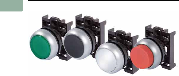
V7-T1-52 Volume 7—Logic Control, Operator Interface and Connectivity Solutions CA08100008E—March 2014 www.eaton.com
1
1
1
1
1
1
1
1
1
1
1
1
1
1
1
1
1
1
1
1
1
1
1
1
1
1
1
1
1
1
1.5
Pushbuttons and Indicating Lights
22.5 mm Modular Pushbuttons—M22
Pushbuttons—Non-Illuminated and Illuminated
Contents
Description Page
Pushbuttons—Non-Illuminated and Illuminated
Non-Illuminated, Flush, Momentary . . . . . . . . V7-T1-53
Non-Illuminated, Flush, Maintained . . . . . . . . . V7-T1-56
Non-Illuminated, Extended, Momentary . . . . . V7-T1-58
Non-Illuminated, Extended, Maintained . . . . . . V7-T1-60
Illuminated, Flush, Momentary . . . . . . . . . . . . V7-T1-63
Illuminated, Flush, Maintained . . . . . . . . . . . . . V7-T1-66
Illuminated, Extended, Momentary . . . . . . . . . V7-T1-68
Illuminated, Extended, Maintained . . . . . . . . . V7-T1-70
Pushbuttons—Non-Illuminated and Illuminated
Product Description
Eaton’s M22 pushbutton
line is a complete, modular
and versatile offering. From
field-convertible maintained
operators to customizable
laser engraved buttons, the
M22 pushbutton line provides
endless opportunity for
flexibility and reduced
inventory. Each operator
type provides options for
ordering as complete or
component parts allowing
for a perfect fit for each
application. All of this
flexibility comes in a very
rugged design.
Features
●Field convertible from
maintained to momentary
(available on maintained
pushbuttons only)
●Customizable laser
engraving on all buttons
●LED offering only for
improved brightness
quality and up to 100,000
hours of operation
●More than five million
mechanical operations on
momentary and 1 million
on maintained pushbuttons
●Modular construction
makes assembly fast and
simplifies stocking of
components and complete
devices
●Capable of communicating
via ASi protocol with ASi
adapter modules
Protection Type
●IP67, IP69K
●NEMA 4X, 13
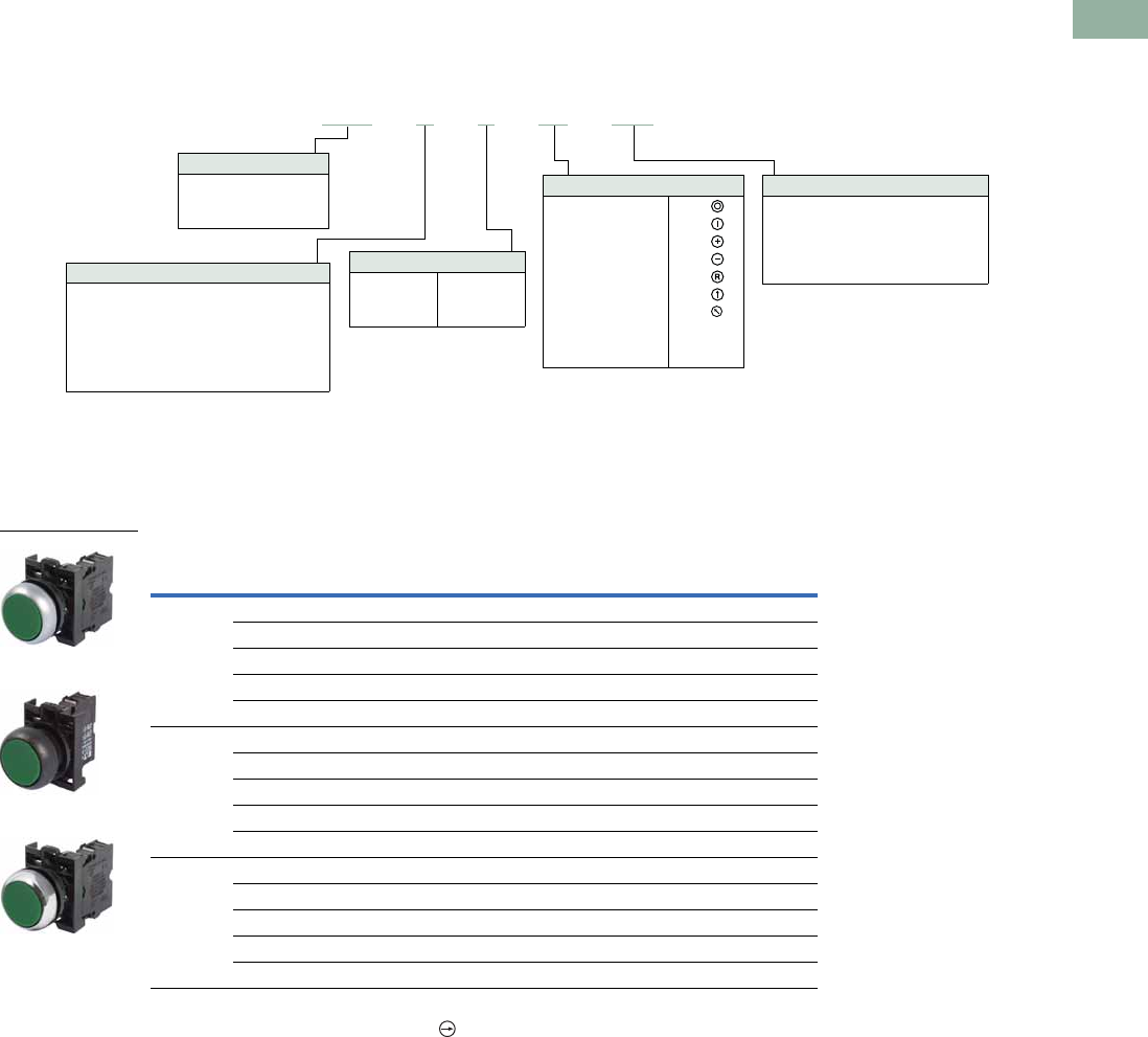
Volume 7—Logic Control, Operator Interface and Connectivity Solutions CA08100008E—March 2014 www.eaton.com V7-T1-53
1
1
1
1
1
1
1
1
1
1
1
1
1
1
1
1
1
1
1
1
1
1
1
1
1
1
1
1
1
1
1.5
Pushbuttons and Indicating Lights
22.5 mm Modular Pushbuttons—M22
Catalog Number Selection
Catalog Number Selection is for illustrative purposes only and not to be used to create new catalog numbers.
Non-Illuminated Pushbuttons
Product Selection
Non-Illuminated Pushbuttons, Flush, Momentary
Complete Devices
Note
1 All NC contact blocks are positively driven contact.
Button
Color
Contact Block
Configuration 1
Silver Bezel
Catalog Number
Black Bezel
Catalog Number
Metal Bezel
Catalog Number
Black NO M22-D-S-K10 M22S-D-S-K10 M22M-D-S-K10
NC M22-D-S-K01 M22S-D-S-K01 M22M-D-S-K01
2NO M22-D-S-K20 M22S-D-S-K20 M22M-D-S-K20
2NC M22-D-S-K02 M22S-D-S-K02 M22M-D-S-K02
1NO-1NC M22-D-S-K11 M22S-D-S-K11 M22M-D-S-K11
Red NO M22-D-R-K10 M22S-D-R-K10 M22M-D-R-K10
NC M22-D-R-K01 M22S-D-R-K01 M22M-D-R-K01
2NO M22-D-R-K20 M22S-D-R-K20 M22M-D-R-K20
2NC M22-D-R-K02 M22S-D-R-K02 M22M-D-R-K02
1NO-1NC M22-D-R-K11 M22S-D-R-K11 M22M-D-R-K11
Green NO M22-D-G-K10 M22S-D-G-K10 M22M-D-G-K10
NC M22-D-G-K01 M22S-D-G-K01 M22M-D-G-K01
2NO M22-D-G-K20 M22S-D-G-K20 M22M-D-G-K20
2NC M22-D-G-K02 M22S-D-G-K02 M22M-D-G-K02
1NO-1NC M22-D-G-K11 M22S-D-G-K11 M22M-D-G-K11
Bezel
M22 = Silver
M22S =Black
M22M = Metal
M22 –D–S–X0–K10
1Silver bezel only.
Operator Type
D = Flush momentary
DH = Extended momentary
DG = Flush with guard 1
DR = Flush maintained
DGH = Extended momentary with guard 1
DRH = Extended maintained
Button Plate Color
G = Green
Y = Yellow
B =Blue
S =Black
R =Red
W =White
Inscription
GB0 =STOP
GB1 =START
GB2 =CLOSE
GB3 =UP
GB4 = DOWN
GB5 =OFF
GB6 =ON
GB14 = RESET
GB15 =FORWARD
GB16 = REVERSE
X0 =
X1 =
X4 =
X5 =
X6 =
X7 =
X8 =
Contact Blocks
K10 =1NO
K01 =1NC
K20 =2NO
K02 =2NC
K11 = 1NO-1NC
K30 =3NO
K03 =3NC
K21 = 2NO-1NC
K12 = 1NO-2NC
M22-D-G-K10
M22S-D-G-K10
M22M-D-G-K10
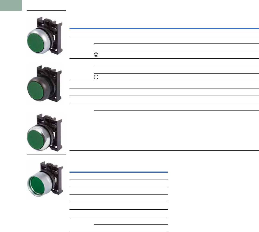
V7-T1-54 Volume 7—Logic Control, Operator Interface and Connectivity Solutions CA08100008E—March 2014 www.eaton.com
1
1
1
1
1
1
1
1
1
1
1
1
1
1
1
1
1
1
1
1
1
1
1
1
1
1
1
1
1
1
1.5
Pushbuttons and Indicating Lights
22.5 mm Modular Pushbuttons—M22
Non-Illuminated Pushbuttons, Flush, Momentary
Operators Only 1
Silver Guarded
Notes
1 Includes contact block mounting adapter.
2 Buttonless operator comes with three color buttons (black, red, green).
3 Buttonless operator comes with all six color buttons (black, white, red, green, yellow, blue).
Button
Color Inscription
Silver Bezel
Catalog Number
Black Bezel
Catalog Number
Metal Bezel
Catalog Number
Black — M22-D-S M22S-D-S M22M-D-S
Red — M22-D-R M22S-D-R M22M-D-R
STOP M22-D-R-GB0 M22S-D-R-GB0 —
M22-D-R-X0 M22S-D-R-X0 M22M-D-R-X0
Green — M22-D-G M22S-D-G M22M-D-G
START M22-D-G-GB1 M22S-D-G-GB1 M22M-D-G-GB1
M22-D-G-X1 M22S-D-G-X1 M22M-D-G-X1
White — M22-D-W M22S-D-W M22M-D-W
Blue — M22-D-B M22S-D-B M22M-D-B
Yellow — M22-D-Y M22S-D-Y M22M-D-Y
—— M22-D-X-SRG 2M22S-D-X-SRG 2M22M-D-X-SRG 2
—M22-D-X-SWRGYB 3M22S-D-X-SWRGYB 3M22M-D-X-SWRGYB 3
Button
Color Inscription
Silver Bezel
Catalog Number
Black — M22-DG-S
Red — M22-DG-R
Green — M22-DG-G
White — M22-DG-W
Blue — M22-DG-B
Yellow — M22-DG-Y
—— M22-DG-X-SRG 2
—M22-DG-X-SWRGYB 3
M22-D-G
M22S-D-G
M22M-D-G
M22-DG-G
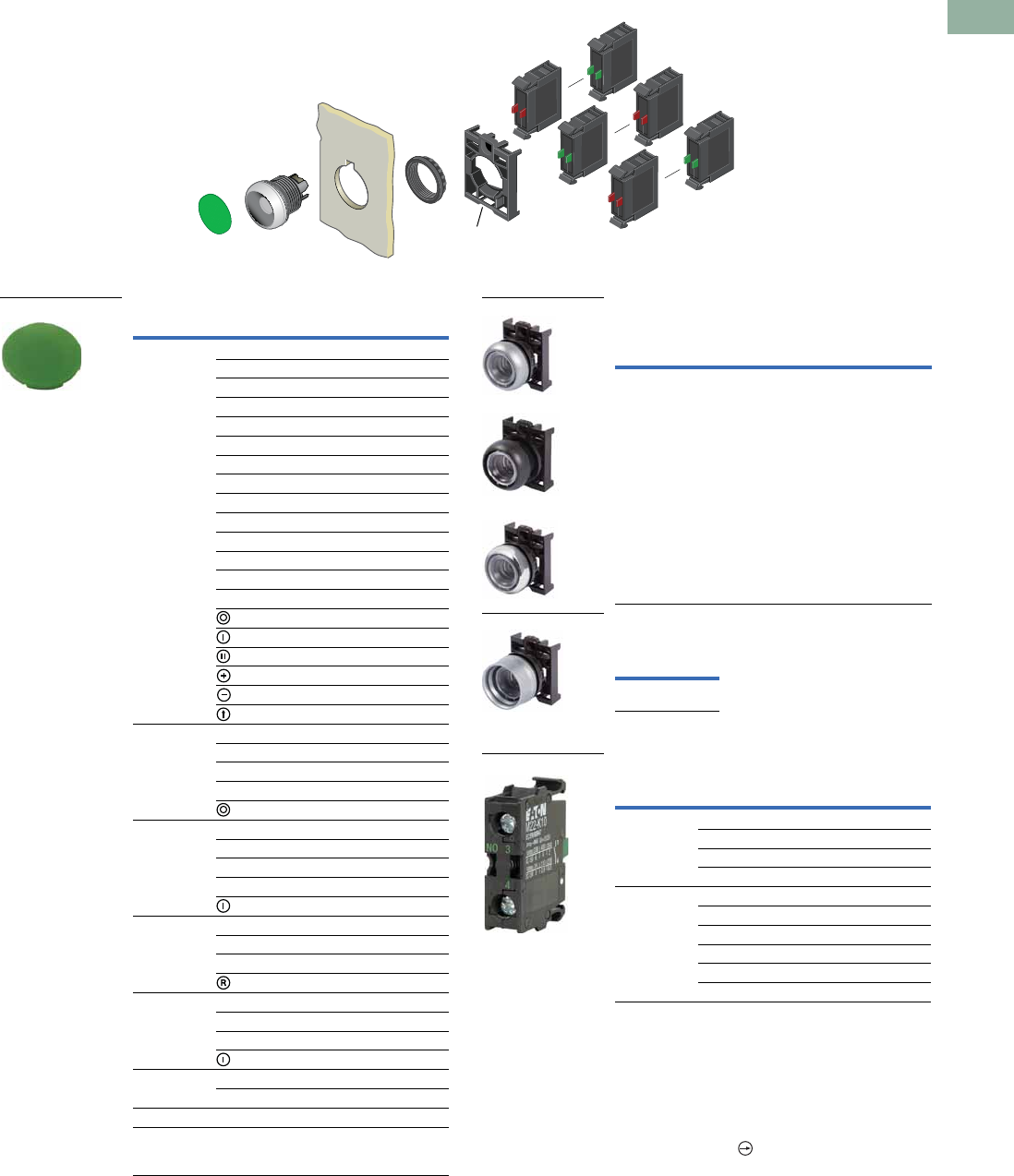
Volume 7—Logic Control, Operator Interface and Connectivity Solutions CA08100008E—March 2014 www.eaton.com V7-T1-55
1
1
1
1
1
1
1
1
1
1
1
1
1
1
1
1
1
1
1
1
1
1
1
1
1
1
1
1
1
1
1.5
Pushbuttons and Indicating Lights
22.5 mm Modular Pushbuttons—M22
Non-Illuminated Pushbuttons, Flush, Momentary
Components
Button Plates 1Buttonless Operator
Silver Guarded
Contact Blocks 1
Notes
1For complete listing of available button plates and contact blocks, see Accessories,
Pages V7-T1-111 to V7-T1-116.
2Minimum order quantity of (10).
3When ordering, specify inscription per catalog number suffix from the Symbols
Library (see Pages V7-T1-129 to V7-T1-136) into the Order Notes.
For example, M22-XD-S-ETCH; Order Notes: Mark with symbol X91, Line item #_.
4Includes contact block mounting adapter.
5All NC contact blocks are positively driven contact.
max. 5mm
thickness
Note: Included
with operator.
Color Inscription Catalog Number
Black — M22-XD-S 2
Custom M22-XD-S-ETCH 3
STOP M22-XD-S-GB0
START M22-XD-S-GB1
CLOSE M22-XD-S-GB2
UP M22-XD-S-GB3
DOWN M22-XD-S-GB4
OFF M22-XD-S-GB5
ON M22-XD-S-GB6
TEST M22-XD-S-GB9
FORWARD M22-XD-S-GB15
REVERSE M22-XD-S-GB16
RAISE M22-XD-S-GB17
LOWER M22-XD-S-GB18
M22-XD-S-X0
M22-XD-S-X1
M22-XD-S-X2
M22-XD-S-X4
M22-XD-S-X5
M22-XD-S-X7
Red — M22-XD-R 2
Custom M22-XD-R-ETCH 3
STOP M22-XD-R-GB0
OFF M22-XD-R-GB5
M22-XD-R-X0
Green — M22-XD-G 2
Custom M22-XD-G-ETCH 3
START M22-XD-G-GB1
ON M22-XD-G-GB6
M22-XD-G-X1
Blue — M22-XD-B 2
Custom M22-XD-B-ETCH 3
RESET M22-XD-B-GB14
M22-XD-B-X6
White — M22-XD-W 2
Custom M22-XD-W-ETCH 3
START M22-XD-W-GB1
M22-XD-W-X1
Yellow — M22-XD-Y 2
Custom M22-XD-Y-ETCH 3
Black, red, green — M22-XD-SRG
Black, white,
red, green,
yellow, blue
—M22-XD-SWRGYB
M22-XD-G
Silver Bezel
Catalog
Number 4
Black Bezel
Catalog
Number 4
Metal Bezel
Catalog
Number 4
M22-D-X M22S-D-X M22M-D-X
Silver Bezel
Catalog
Number 4
M22-DG-X
Terminal
Type
Contact
Configuration 5Catalog Number
Screw NO M22-K10
NO, early-make M22-K10P
NC M22-K01
NC, late-break M22-K01D
Spring-cage NO M22-CK10
NC M22-CK01
NC, late-break M22-CK01D
2NO M22-CK20
2NC M22-CK02
NO-NC M22-CK11
M22-D-X
M22S-D-X
M22M-D-X
M22-DG-X
M22-K10
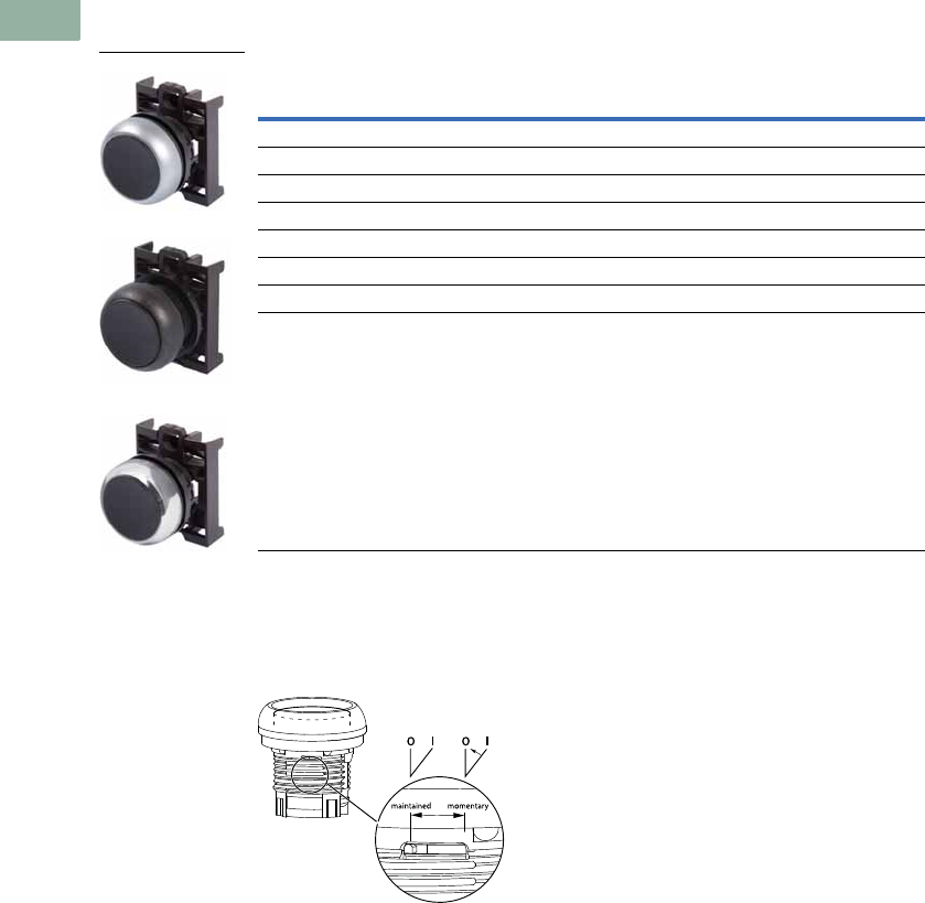
V7-T1-56 Volume 7—Logic Control, Operator Interface and Connectivity Solutions CA08100008E—March 2014 www.eaton.com
1
1
1
1
1
1
1
1
1
1
1
1
1
1
1
1
1
1
1
1
1
1
1
1
1
1
1
1
1
1
1.5
Pushbuttons and Indicating Lights
22.5 mm Modular Pushbuttons—M22
Non-Illuminated Pushbuttons, Flush, Maintained 1
Operators Only 2
Notes
1 Maintained pushbuttons can be converted in the field to momentary operation by switching the locking ring,
which is accessible through the side of the operator body.
2 Includes contact block mounting adapter.
3 Buttonless operator comes with three color buttons (black, red, green).
4 Buttonless operator comes with all six color buttons (black, white, red, green, yellow, blue).
Note: This pilot device features a selectable function switch that enables the device
to be set to either maintained or momentary operation.
Button Color
Silver Bezel
Catalog Number
Black Bezel
Catalog Number
Metal Bezel
Catalog Number
Black M22-DR-S M22S-DR-S M22M-DR-S
Red M22-DR-R M22S-DR-R M22M-DR-R
Green M22-DR-G M22S-DR-G M22M-DR-G
White M22-DR-W M22S-DR-W M22M-DR-W
Blue M22-DR-B M22S-DR-B M22M-DR-B
Yellow M22-DR-Y M22S-DR-Y M22M-DR-Y
3M22-DR-X-SRG M22S-DR-X-SRG M22M-DR-X-SRG
4M22-DR-X-SWRGYB M22S-DR-X-SWRGYB M22M-DR-X-SWRGYB
M22-DR-S
M22S-DR-S
M22M-DR-S
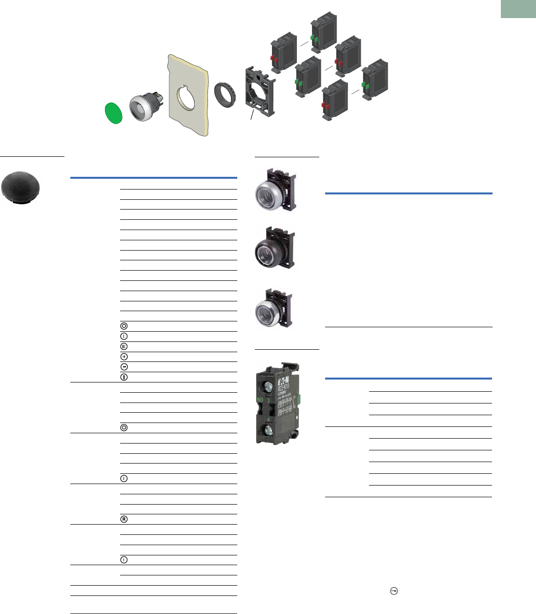
Volume 7—Logic Control, Operator Interface and Connectivity Solutions CA08100008E—March 2014 www.eaton.com V7-T1-57
1
1
1
1
1
1
1
1
1
1
1
1
1
1
1
1
1
1
1
1
1
1
1
1
1
1
1
1
1
1
1.5
Pushbuttons and Indicating Lights
22.5 mm Modular Pushbuttons—M22
Non-Illuminated Pushbuttons, Flush, Maintained 1
Components
Button Plates 2Buttonless Operator
Contact Blocks 2
Notes
1Maintained pushbuttons can be converted in the field to momentary operation by switching
the locking ring, which is accessible through the side of the operator body.
2For complete listing of available button plates and contact blocks, see Accessories,
Pages V7-T1-111 to V7-T1-116.
3Minimum order quantity of (10).
4When ordering, specify inscription per catalog number suffix from the Symbols
Library (see Pages V7-T1-129 to V7-T1-136) into the Order Notes.
For example, M22-XD-S-ETCH; Order Notes: Mark with symbol X91, Line item #_.
5Includes contact block mounting adapter.
6All NC contact blocks are positively driven contact.
max. 5mm
thickness
Note: Included
with operator.
Color Inscription Catalog Number
Black — M22-XD-S 3
Custom M22-XD-S-ETCH 4
STOP M22-XD-S-GB0
START M22-XD-S-GB1
CLOSE M22-XD-S-GB2
UP M22-XD-S-GB3
DOWN M22-XD-S-GB4
OFF M22-XD-S-GB5
ON M22-XD-S-GB6
TEST M22-XD-S-GB9
FORWARD M22-XD-S-GB15
REVERSE M22-XD-S-GB16
RAISE M22-XD-S-GB17
LOWER M22-XD-S-GB18
M22-XD-S-X0
M22-XD-S-X1
M22-XD-S-X2
M22-XD-S-X4
M22-XD-S-X5
M22-XD-S-X7
Red — M22-XD-R 3
Custom M22-XD-R-ETCH 4
STOP M22-XD-R-GB0
OFF M22-XD-R-GB5
M22-XD-R-X0
Green — M22-XD-G 3
Custom M22-XD-G-ETCH 4
START M22-XD-G-GB1
ON M22-XD-G-GB6
M22-XD-G-X1
Blue — M22-XD-B 3
Custom M22-XD-B-ETCH 4
RESET M22-XD-B-GB14
M22-XD-B-X6
White — M22-XD-W 3
Custom M22-XD-W-ETCH 4
START M22-XD-W-GB1
M22-XD-W-X1
Yellow — M22-XD-Y 3
Custom M22-XD-Y-ETCH 4
Black, red, green — M22-XD-SRG
Black, white, red,
green, yellow, blue
—M22-XD-SWRGYB
M22-XD-S
Silver Bezel
Catalog
Number 5
Black Bezel
Catalog
Number 5
Metal Bezel
Catalog
Number 5
M22-DR-X M22S-DR-X M22M-DR-X
Terminal
Type
Contact
Configuration 6Catalog Number
Screw NO M22-K10
NO, early-make M22-K10P
NC M22-K01
NC, late-break M22-K01D
Spring-cage NO M22-CK10
NC M22-CK01
NC, late-break M22-CK01D
2NO M22-CK20
2NC M22-CK02
NO-NC M22-CK11
M22-DR-X
M22S-DR-X
M22M-DR-X
M22-K10
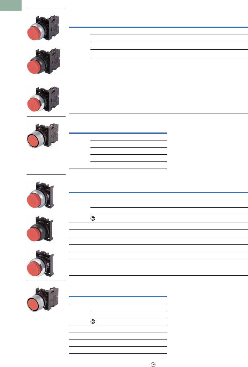
V7-T1-58 Volume 7—Logic Control, Operator Interface and Connectivity Solutions CA08100008E—March 2014 www.eaton.com
1
1
1
1
1
1
1
1
1
1
1
1
1
1
1
1
1
1
1
1
1
1
1
1
1
1
1
1
1
1
1.5
Pushbuttons and Indicating Lights
22.5 mm Modular Pushbuttons—M22
Non-Illuminated Pushbuttons, Extended, Momentary
Complete Devices
Silver Guarded
Operators Only 2
Silver Guarded
Notes
1 All NC contact blocks are positively driven contact.
2 Includes contact block mounting adapter.
3 Buttonless operator comes with three color buttons (black, red, green).
4 Buttonless operator comes with all six color buttons (black, white, red, green, yellow, blue).
Button
Color
Contact Block
Configuration 1
Silver Bezel
Catalog Number
Black Bezel
Catalog Number
Metal Bezel
Catalog Number
Red NO M22-DH-R-K10 M22S-DH-R-K10 M22M-DH-R-K10
NC M22-DH-R-K01 M22S-DH-R-K01 M22M-DH-R-K01
2NO M22-DH-R-K20 M22S-DH-R-K20 M22M-DH-R-K20
2NC M22-DH-R-K02 M22S-DH-R-K02 M22M-DH-R-K02
1NO-1NC M22-DH-R-K11 M22S-DH-R-K11 M22M-DH-R-K11
Button
Color
Contact Block
Configuration 1
Silver Bezel
Catalog Number
Red NO M22-DGH-R-K10
NC M22-DGH-R-K01
2NO M22-DGH-R-K20
2NC M22-DGH-R-K02
1NO-1NC M22-DGH-R-K11
Button
Color Inscription
Silver Bezel
Catalog Number
Black Bezel
Catalog Number
Metal Bezel
Catalog Number
Black — M22-DH-S M22S-DH-S M22M-DH-S
Red — M22-DH-R M22S-DH-R M22M-DH-R
STOP M22-DH-R-GB0 M22S-DH-R-GB0 M22M-DH-R-GB0
M22-DH-R-X0 M22S-DH-R-X0 M22M-DH-R-X0
Green — M22-DH-G M22S-DH-G M22M-DH-G
White — M22-DH-W M22S-DH-W M22M-DH-W
Blue — M22-DH-B M22S-DH-B M22M-DH-B
Yellow — M22-DH-Y M22S-DH-Y M22M-DH-Y
3—M22-DH-X-SRG M22S-DH-X-SRG M22M-DH-X-SRG
4—M22-DH-X-SWRGYB M22S-DH-X-SWRGYB M22M-DH-X-SWRGYB
Button
Color Inscription
Silver Bezel
Catalog Number
Black — M22-DGH-S
Red — M22-DGH-R
STOP M22-DGH-R-GB0
M22-DGH-R-X0
Green — M22-DGH-G
White — M22-DGH-W
Blue — M22-DGH-B
Yellow — M22-DGH-Y
M22-DH-R-K10
M22S-DH-R-K10
M22M-DH-R-K10
M22-DGH-R-K10
M22-DH-R
M22S-DH-R
M22M-DH-R
M22-DGH-R-K10
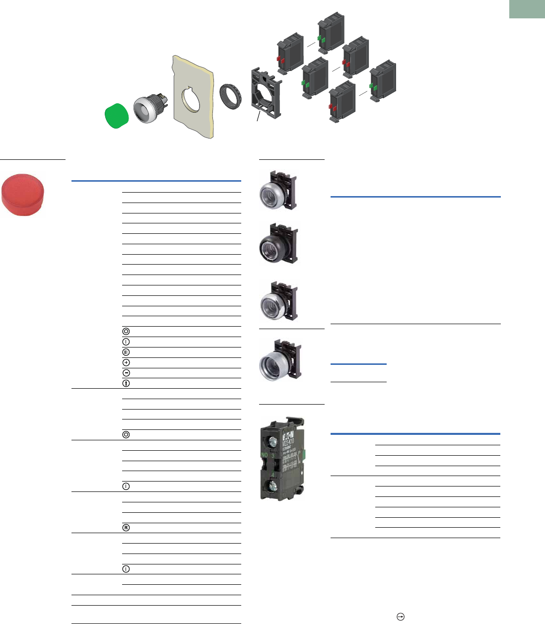
Volume 7—Logic Control, Operator Interface and Connectivity Solutions CA08100008E—March 2014 www.eaton.com V7-T1-59
1
1
1
1
1
1
1
1
1
1
1
1
1
1
1
1
1
1
1
1
1
1
1
1
1
1
1
1
1
1
1.5
Pushbuttons and Indicating Lights
22.5 mm Modular Pushbuttons—M22
Non-Illuminated Pushbuttons, Extended, Momentary
Components
Button Plates 1Buttonless Operator
Silver Guarded
Contact Blocks 1
Notes
1For complete listing of available button plates and contact blocks, see Accessories,
Pages V7-T1-111 to V7-T1-116.
2Minimum order quantity of (10).
3When ordering, specify inscription per catalog number suffix from the Symbols
Library (see Pages V7-T1-129 to V7-T1-136) into the Order Notes.
For example, M22-XDH-S-ETCH; Order Notes: Mark with symbol X91, Line item #_.
4Includes contact block mounting adapter.
5All NC contact blocks are positively driven contact.
max. 5mm
thickness
Note: Included
with operator.
Color Inscription Catalog Number
Black — M22-XDH-S 2
Custom M22-XDH-S-ETCH 3
STOP M22-XDH-S-GB0
START M22-XDH-S-GB1
CLOSE M22-XDH-S-GB2
UP M22-XDH-S-GB3
DOWN M22-XDH-S-GB4
OFF M22-XDH-S-GB5
ON M22-XDH-S-GB6
TEST M22-XDH-S-GB9
FORWARD M22-XDH-S-GB15
REVERSE M22-XDH-S-GB16
RAISE M22-XDH-S-GB17
LOWER M22-XDH-S-GB18
M22-XDH-S-X0
M22-XDH-S-X1
M22-XDH-S-X2
M22-XDH-S-X4
M22-XDH-S-X5
M22-XDH-S-X7
Red — M22-XDH-R 2
Custom M22-XDH-R-ETCH 3
STOP M22-XDH-R-GB0
OFF M22-XDH-R-GB5
M22-XDH-R-X0
Green — M22-XDH-G 2
Custom M22-XDH-G-ETCH 3
START M22-XDH-G-GB1
ON M22-XDH-G-GB6
M22-XDH-G-X1
Blue — M22-XDH-B 2
Custom M22-XDH-B-ETCH 3
RESET M22-XDH-B-GB14
M22-XDH-B-X6
White — M22-XDH-W 2
Custom M22-XDH-W-ETCH 3
START M22-XDH-W-GB1
M22-XDH-W-X1
Yellow — M22-XDH-Y 2
Custom M22-XDH-Y-ETCH 3
Black, red, green — M22-XDH-SRG
Black, white, red,
green, yellow, blue
—M22-XDH-SWRGYB
M22-XDH-R
Silver Bezel
Catalog
Number 4
Black Bezel
Catalog
Number 4
Metal Bezel
Catalog
Number 4
M22-D-X M22S-D-X M22M-D-X
Silver Bezel
Catalog
Number 4
M22-DG-X
Terminal
Type
Contact
Configuration 5Catalog Number
Screw NO M22-K10
NO, early-make M22-K10P
NC M22-K01
NC, late-break M22-K01D
Spring-cage NO M22-CK10
NC M22-CK01
NC, late-break M22-CK01D
2NO M22-CK20
2NC M22-CK02
NO-NC M22-CK11
M22-D-X
M22S-D-X
M22M-D-X
M22-DG-X
M22-K10
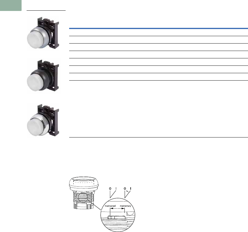
V7-T1-60 Volume 7—Logic Control, Operator Interface and Connectivity Solutions CA08100008E—March 2014 www.eaton.com
1
1
1
1
1
1
1
1
1
1
1
1
1
1
1
1
1
1
1
1
1
1
1
1
1
1
1
1
1
1
1.5
Pushbuttons and Indicating Lights
22.5 mm Modular Pushbuttons—M22
Non-Illuminated Pushbuttons, Extended, Maintained 1
Operators Only 2
Notes
1 Maintained pushbuttons can be converted in the field to momentary operation by switching the locking ring,
which is accessible through the side of the operator body.
2 Includes contact block mounting adapter.
3 Buttonless operator comes with three color buttons (black, red, green).
4 Buttonless operator comes with all six color buttons (black, white, red, green, yellow, blue).
Note: This pilot device features a selectable function switch that enables the device
to be set to either maintained or momentary operation.
Button Color
Silver Bezel
Catalog Number
Black Bezel
Catalog Number
Metal Bezel
Catalog Number
Black M22-DRH-S M22S-DRH-S M22M-DRH-S
Red M22-DRH-R M22S-DRH-R M22M-DRH-R
Green M22-DRH-G M22S-DRH-G M22M-DRH-G
White M22-DRH-W M22S-DRH-W M22M-DRH-W
Blue M22-DRH-B M22S-DRH-B M22M-DRH-B
Yellow M22-DRH-Y M22S-DRH-Y M22M-DRH-Y
3M22-DRH-X-SRG M22S-DRH-X-SRG M22M-DRH-X-SRG
4M22-DRH-X-SWRGYB M22S-DRH-X-SWRGYB M22M-DRH-X-SWRGYB
M22-DRH-W
M22S-DRH-W
M22M-DRH-W
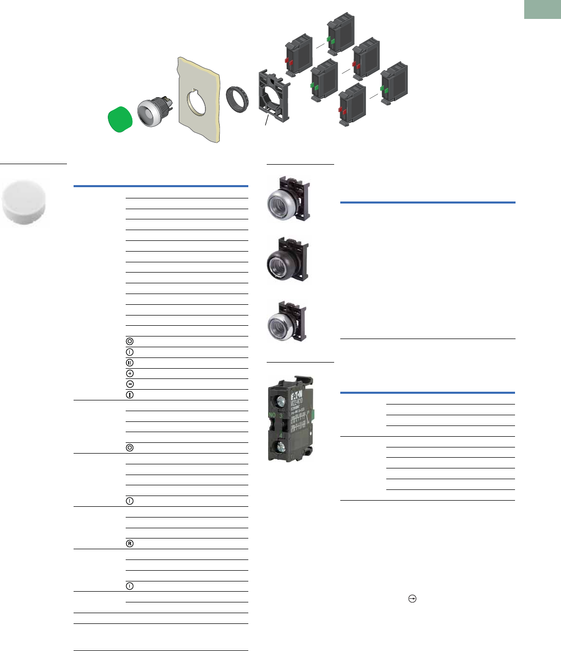
Volume 7—Logic Control, Operator Interface and Connectivity Solutions CA08100008E—March 2014 www.eaton.com V7-T1-61
1
1
1
1
1
1
1
1
1
1
1
1
1
1
1
1
1
1
1
1
1
1
1
1
1
1
1
1
1
1
1.5
Pushbuttons and Indicating Lights
22.5 mm Modular Pushbuttons—M22
Non-Illuminated Pushbuttons, Extended, Maintained 1
Components
Button Plates 2Buttonless Operator
Contact Blocks 2
Notes
1Maintained pushbuttons can be converted in the field to momentary operation by
switching the locking ring, which is accessible through the side of the operator body.
2For complete listing of available button plates and contact blocks, see Accessories,
Pages V7-T1-111 to V7-T1-116.
3Minimum order quantity of (10).
4When ordering, specify inscription per catalog number suffix from the Symbols
Library (see Pages V7-T1-129 to V7-T1-136) into the Order Notes.
For example, M22-XDH-S-ETCH; Order Notes: Mark with symbol X91, Line item #_.
5Includes contact block mounting adapter.
6All NC contact blocks are positively driven contact.
max. 5mm
thickness
Note: Included
with operator.
Color Inscription Catalog Number
Black — M22-XDH-S 3
Custom M22-XDH-S-ETCH 4
STOP M22-XDH-S-GB0
START M22-XDH-S-GB1
CLOSE M22-XDH-S-GB2
UP M22-XDH-S-GB3
DOWN M22-XDH-S-GB4
OFF M22-XDH-S-GB5
ON M22-XDH-S-GB6
TEST M22-XDH-S-GB9
FORWARD M22-XDH-S-GB15
REVERSE M22-XDH-S-GB16
RAISE M22-XDH-S-GB17
LOWER M22-XDH-S-GB18
M22-XDH-S-X0
M22-XDH-S-X1
M22-XDH-S-X2
M22-XDH-S-X4
M22-XDH-S-X5
M22-XDH-S-X7
Red — M22-XDH-R 3
Custom M22-XDH-R-ETCH 4
STOP M22-XDH-R-GB0
OFF M22-XDH-R-GB5
M22-XDH-R-X0
Green — M22-XDH-G 3
Custom M22-XDH-G-ETCH 4
START M22-XDH-G-GB1
ON M22-XDH-G-GB6
M22-XDH-G-X1
Blue — M22-XDH-B 3
Custom M22-XDH-B-ETCH 4
RESET M22-XDH-B-GB14
M22-XDH-B-X6
White — M22-XDH-W 3
Custom M22-XDH-W-ETCH 4
START M22-XDH-W-GB1
M22-XDH-W-X1
Yellow — M22-XDH-Y 3
Custom M22-XDH-Y-ETCH 4
Black, red, green — M22-XDH-SRG
Black, white,
red, green, yellow,
blue
—M22-XDH-SWRGYB
M22-XDH-W
Silver Bezel
Catalog
Number 5
Black Bezel
Catalog
Number 5
Metal Bezel
Catalog
Number 5
M22-DR-X M22S-DR-X M22M-DR-X
Terminal
Type
Contact
Configuration 6Catalog Number
Screw NO M22-K10
NO, early-make M22-K10P
NC M22-K01
NC, late-break M22-K01D
Spring-cage NO M22-CK10
NC M22-CK01
NC, late-break M22-CK01D
2NO M22-CK20
2NC M22-CK02
NO-NC M22-CK11
M22-DR-X
M22S-DR-X
M22M-DR-X
M22-K10
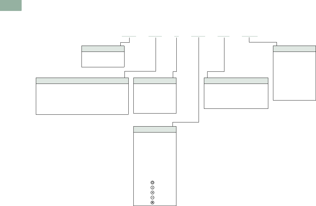
V7-T1-62 Volume 7—Logic Control, Operator Interface and Connectivity Solutions CA08100008E—March 2014 www.eaton.com
1
1
1
1
1
1
1
1
1
1
1
1
1
1
1
1
1
1
1
1
1
1
1
1
1
1
1
1
1
1
1.5
Pushbuttons and Indicating Lights
22.5 mm Modular Pushbuttons—M22
Catalog Number Selection
Catalog Number Selection is for illustrative purposes only and not to be used to create new catalog numbers.
Illuminated Pushbuttons
Bezel
M22 = Silver
M22S =Black
M22M = Metal
1Silver bezel only.
Operator Type
DL = Illuminated flush momentary
DLH = Illuminated extended momentary
DGL = Illuminated flush momentary with guard 1
DRL = Illuminated flush maintained
DGLH = Illuminated extended momentary with guard 1
DRLH = Illuminated extended maintained
Light Units
12–30 Vac/Vdc
W =White
R =Red
G = Green
B =Blue
85–264 Vac
230W =White
230R =Red
230G = Green
230B =Blue
Inscription
GB0 =STOP
GB1 =START
GB2 =CLOSE
GB3 =UP
GB4 = DOWN
GB5 =OFF
GB6 =ON
GB14 = RESET
GB15 =FORWARD
GB16 = REVERSE
X0 =
X1 =
X4 =
X5 =
X6 =
Contact Blocks
K10 =1NO
K01 =1NC
K20 =2NO
K02 =2NC
K11 = 1NO-1NC
K30 =3NO
K03 =3NC
K21 = 2NO-1NC
K12 = 1NO-2NC
Lens Color
W =White
R =Red
G = Green
Y = Yellow
B =Blue
A =Amber
M22 –DRL–R–GB0–K10–230R
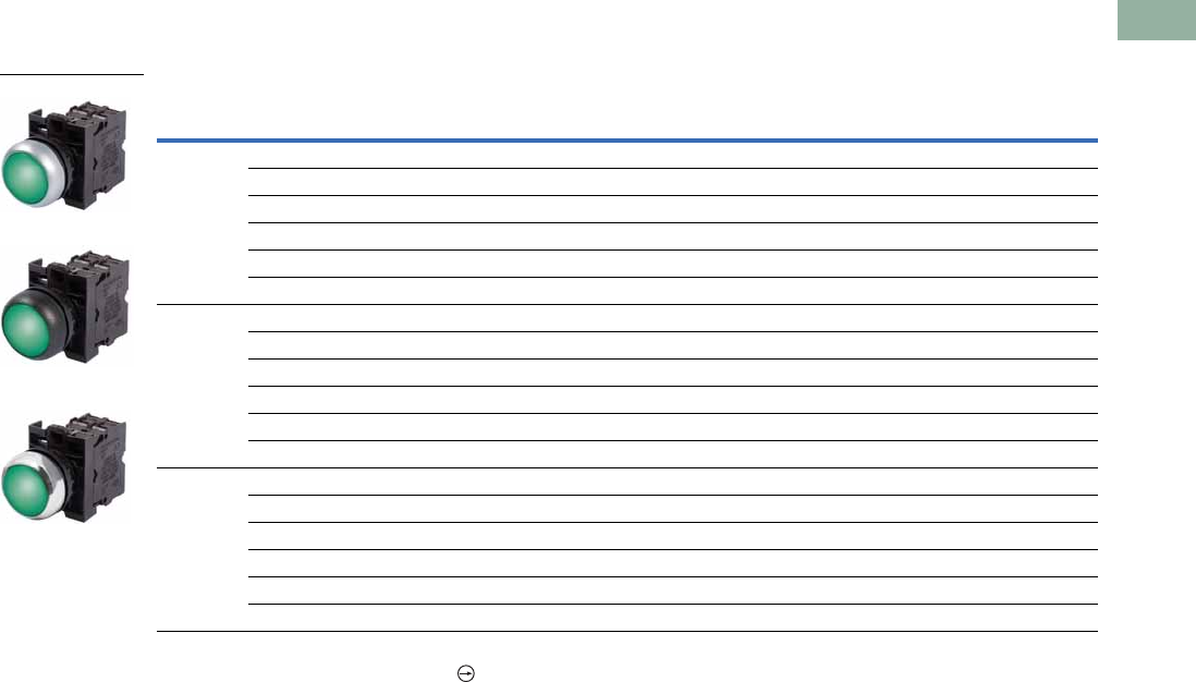
Volume 7—Logic Control, Operator Interface and Connectivity Solutions CA08100008E—March 2014 www.eaton.com V7-T1-63
1
1
1
1
1
1
1
1
1
1
1
1
1
1
1
1
1
1
1
1
1
1
1
1
1
1
1
1
1
1
1.5
Pushbuttons and Indicating Lights
22.5 mm Modular Pushbuttons—M22
Product Selection
Illuminated Pushbuttons, Flush, Momentary
Complete Devices
Note
1 All NC contact blocks are positively driven contact.
Button
Color
Contact Block
Configuration 1Light Unit Voltage
Silver Bezel
Catalog Number
Black Bezel
Catalog Number
Metal Bezel
Catalog Number
Red NC 12–30 Vac/Vdc M22-DL-R-K01-R M22S-DL-R-K01-R M22M-DL-R-K01-R
NC 85–264 Vac M22-DL-R-K01-230R M22S-DL-R-K01-230R M22M-DL-R-K01-230R
2NC 12–30 Vac/Vdc M22-DL-R-K02-R M22S-DL-R-K02-R M22M-DL-R-K02-R
2NC 85–264 Vac M22-DL-R-K02-230R M22S-DL-R-K02-230R M22M-DL-R-K02-230R
1NO/1NC 12–30 Vac/Vdc M22-DL-R-K11-R M22S-DL-R-K11-R M22M-DL-R-K11-R
1NO/1NC 85–264 Vac M22-DL-R-K11-230R M22S-DL-R-K11-230R M22M-DL-R-K11-230R
Green NO 12–30 Vac/Vdc M22-DL-G-K10-G M22S-DL-G-K10-G M22M-DL-G-K10-G
NO 85–264 Vac M22-DL-G-K10-230G M22S-DL-G-K10-230G M22M-DL-G-K10-230G
2NO 12–30 Vac/Vdc M22-DL-G-K20-G M22S-DL-G-K20-G M22M-DL-G-K20-G
2NO 85–264 Vac M22-DL-G-K20-230G M22S-DL-G-K20-230G M22M-DL-G-K20-230G
1NO/1NC 12–30 Vac/Vdc M22-DL-G-K11-G M22S-DL-G-K11-G M22M-DL-G-K11-G
1NO/1NC 85–264 Vac M22-DL-G-K11-230G M22S-DL-G-K11-230G M22M-DL-G-K11-230G
White NO 12–30 Vac/Vdc M22-DL-W-K10-W M22S-DL-W-K10-W —
NO 85–264 Vac M22-DL-W-K10-230W M22S-DL-W-K10-230W M22M-DL-W-K10-230W
2NO 12–30 Vac/Vdc M22-DL-W-K20-W M22S-DL-W-K20-W —
2NO 85–264 Vac M22-DL-W-K20-230W M22S-DL-W-K20-230W M22M-DL-W-K20-230W
1NO/1NC 12–30 Vac/Vdc M22-DL-W-K11-W M22S-DL-W-K11-W —
1NO/1NC 85–264 Vac M22-DL-W-K11-230W M22S-DL-W-K11-230W M22M-DL-W-K11-230W
M22-DL-G-K01-G
M22S-DL-G-K01-G
M22M-DL-G-K01-G
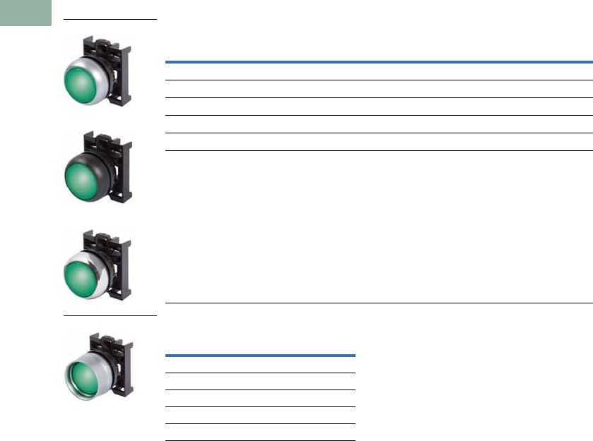
V7-T1-64 Volume 7—Logic Control, Operator Interface and Connectivity Solutions CA08100008E—March 2014 www.eaton.com
1
1
1
1
1
1
1
1
1
1
1
1
1
1
1
1
1
1
1
1
1
1
1
1
1
1
1
1
1
1
1.5
Pushbuttons and Indicating Lights
22.5 mm Modular Pushbuttons—M22
Illuminated Pushbuttons, Flush, Momentary
Operators Only 1
Silver Guarded
Note
1 Includes contact block mounting adapter.
Button Color
Silver Bezel
Catalog Number
Black Bezel
Catalog Number
Metal Bezel
Catalog Number
Red M22-DL-R M22S-DL-R M22M-DL-R
Green M22-DL-G M22S-DL-G M22M-DL-G
White M22-DL-W M22S-DL-W M22M-DL-W
Blue M22-DL-B M22S-DL-B M22M-DL-B
Yellow M22-DL-Y M22S-DL-Y M22M-DL-Y
Amber M22-DL-A M22S-DL-A M22M-DL-A
Button Color
Silver Bezel
Catalog Number
Red M22-DGL-R
Green M22-DGL-G
White M22-DGL-W
Blue M22-DGL-B
Yellow M22-DGL-Y
M22-DL-G
M22S-DL-G
M22M-DL-G
M22-DGL-G
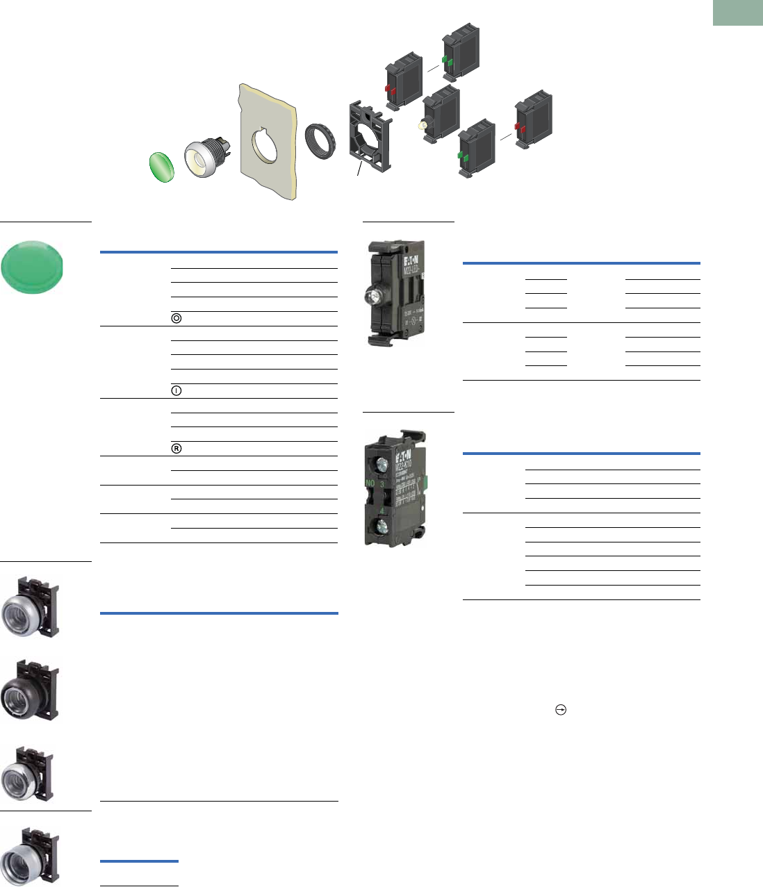
Volume 7—Logic Control, Operator Interface and Connectivity Solutions CA08100008E—March 2014 www.eaton.com V7-T1-65
1
1
1
1
1
1
1
1
1
1
1
1
1
1
1
1
1
1
1
1
1
1
1
1
1
1
1
1
1
1
1.5
Pushbuttons and Indicating Lights
22.5 mm Modular Pushbuttons—M22
Illuminated Pushbuttons, Flush, Momentary
Components
Button Lenses 1
Buttonless Operator
Silver Guarded
Light Units 1
Contact Blocks 1
Notes
1For complete listing of available button lenses, light units and contact blocks, see
Accessories, Pages V7-T1-111 to V7-T1-116.
2Minimum order quantity of (10).
3When ordering, specify inscription per catalog number suffix from the Symbols
Library (see Pages V7-T1-129 to V7-T1-136) into the Order Notes.
For example, M22-XDL-R-ETCH; Order Notes: Mark with symbol X91, Line item #_.
4Includes contact block mounting adapter.
5All NC contact blocks are positively driven contact.
max. 5mm
thickness
Note: Included
with operator.
Color Inscription Catalog Number
Red — M22-XDL-R 2
Custom M22-XDL-R-ETCH 3
STOP M22-XDL-R-GB0
OFF M22-XDL-R-GB5
M22-XDL-R-X0
Green — M22-XDL-G 2
Custom M22-XDL-G-ETCH 3
START M22-XDL-G-GB1
ON M22-XDL-G-GB6
M22-XDL-G-X1
Blue — M22-XDL-B 2
Custom M22-XDL-B-ETCH 3
RESET M22-XDL-B-GB14
M22-XDL-B-X6
White — M22-XDL-W 2
Custom M22-XDL-W-ETCH 3
Yellow — M22-XDL-Y 2
Custom M22-XDL-Y-ETCH 3
Amber — M22-XDL-A
Custom M22-XDL-A-ETCH
Silver Bezel
Catalog
Number 4
Black Bezel
Catalog
Number 4
Metal Bezel
Catalog
Number 4
M22-DL-X M22S-DL-X M22M-DL-X
Silver Bezel
Catalog
Number 4
M22-DGL-X
M22-XDL-G
M22-DL-X
M22S-DL-X
M22M-DL-X
M22-DGL-X
Terminal
Type
LED
Color
Light Unit
Voltage Catalog Number
Screw White 12–30
Vac/Vdc
M22-LED-W
Red M22-LED-R
Green M22-LED-G
Blue M22-LED-B
Screw White 85–264
Vac
M22-LED230-W
Red M22-LED230-R
Green M22-LED230-G
Blue M22-LED230-B
Terminal
Type
Contact
Configuration 5Catalog Number
Screw NO M22-K10
NO, early-make M22-K10P
NC M22-K01
NC, late-break M22-K01D
Spring-cage NO M22-CK10
NC M22-CK01
NC, late-break M22-CK01D
2NO M22-CK20
2NC M22-CK02
NO-NC M22-CK11
M22-LED-W
M22-K10
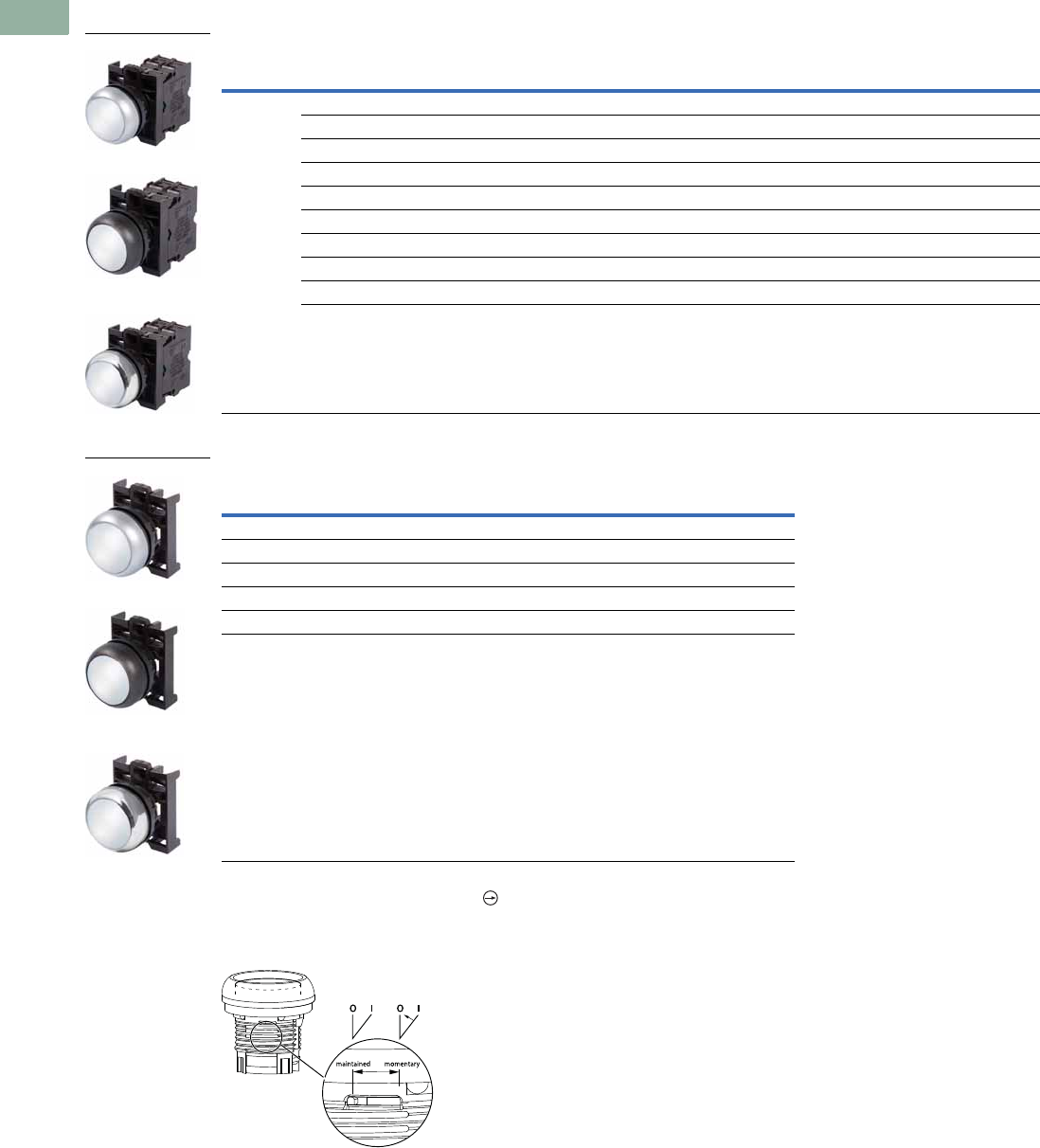
V7-T1-66 Volume 7—Logic Control, Operator Interface and Connectivity Solutions CA08100008E—March 2014 www.eaton.com
1
1
1
1
1
1
1
1
1
1
1
1
1
1
1
1
1
1
1
1
1
1
1
1
1
1
1
1
1
1
1.5
Pushbuttons and Indicating Lights
22.5 mm Modular Pushbuttons—M22
Illuminated Pushbuttons, Flush, Maintained 2
Complete Devices
Operators Only 3
Notes
1 All NC contact blocks are positively driven contact.
2 Maintained pushbuttons can be converted in the field to momentary operation by switching the locking ring,
which is accessible through the side of the operator body.
3 Includes contact block mounting adapter.
Note: This pilot device features a selectable function switch that enables the device
to be set to either maintained or momentary operation.
Button
Color
Contact Block
Configuration 1Light Unit Voltage
Silver Bezel
Catalog Number
Black Bezel
Catalog Number
Metal Bezel
Catalog Number
White NO 12–30 Vac/Vdc M22-DRL-W-K10-W M22S-DRL-W-K10-W M22M-DRL-W-K10-W
NO 85–264 Vac M22-DRL-W-K10-230W M22S-DRL-W-K10-230W M22M-DRL-W-K10-230W
NC 12–30 Vac/Vdc M22-DRL-W-K01-W M22S-DRL-W-K01-W M22M-DRL-W-K01-W
NC 85–264 Vac M22-DRL-W-K01-230W M22S-DRL-W-K01-230W M22M-DRL-W-K01-230W
2NO 12–30 Vac/Vdc M22-DRL-W-K20-W M22S-DRL-W-K20-W M22M-DRL-W-K20-W
2NO 85–264 Vac M22-DRL-W-K20-230W M22S-DRL-W-K20-230W M22M-DRL-W-K20-230W
2NC 12–30 Vac/Vdc M22-DRL-W-K02-W M22S-DRL-W-K02-W M22M-DRL-W-K02-W
2NC 85–264 Vac M22-DRL-W-K02-230W M22S-DRL-W-K02-230W M22M-DRL-W-K02-230W
1NO/1NC 12–30 Vac/Vdc M22-DRL-W-K11-W M22S-DRL-W-K11-W M22M-DRL-W-K11-W
1NO/1NC 85–264 Vac M22-DRL-W-K11-230W M22S-DRL-W-K11-230W M22M-DRL-W-K11-230W
Button Color
Silver Bezel
Catalog Number
Black Bezel
Catalog Number
Metal Bezel
Catalog Number
Red M22-DRL-R M22S-DRL-R M22M-DRL-R
Green M22-DRL-G M22S-DRL-G M22M-DRL-G
White M22-DRL-W M22S-DRL-W M22M-DRL-W
Blue M22-DRL-B M22S-DRL-B M22M-DRL-B
Yellow M22-DRL-Y M22S-DRL-Y M22M-DRL-Y
Amber M22-DRL-A M22S-DRL-A M22M-DRL-A
M22-DRL-W-K10-W
M22S-DRL-W-K10-W
M22M-DRL-W-K10-W
M22-DRL-W
M22S-DRL-W
M22M-DRL-W
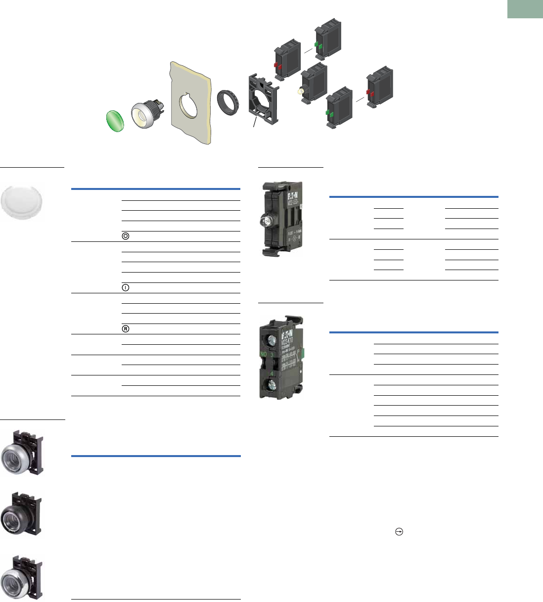
Volume 7—Logic Control, Operator Interface and Connectivity Solutions CA08100008E—March 2014 www.eaton.com V7-T1-67
1
1
1
1
1
1
1
1
1
1
1
1
1
1
1
1
1
1
1
1
1
1
1
1
1
1
1
1
1
1
1.5
Pushbuttons and Indicating Lights
22.5 mm Modular Pushbuttons—M22
Illuminated Pushbuttons, Flush, Maintained 1
Components
Button Lenses 2
Buttonless Operator
Light Units 2
Contact Blocks 2
Notes
1Maintained pushbuttons can be converted in the field to momentary operation by
switching the locking ring, which is accessible through the side of the operator body.
2For complete listing of available button lenses, light units and contact blocks, see
Accessories, Pages V7-T1-111 to V7-T1-116.
3Minimum order quantity of (10).
4When ordering, specify inscription per catalog number suffix from the Symbols
Library (see Pages V7-T1-129 to V7-T1-136) into the Order Notes.
For example, M22-XDL-R-ETCH; Order Notes: Mark with symbol X91, Line item #_.
5Includes contact block mounting adapter.
6All NC contact blocks are positively driven contact.
max. 5mm
thickness
Note: Included
with operator.
Color Inscription Catalog Number
Red — M22-XDL-R 3
Custom M22-XDL-R-ETCH 4
STOP M22-XDL-R-GB0
OFF M22-XDL-R-GB5
M22-XDL-R-X0
Green — M22-XDL-G 3
Custom M22-XDL-G-ETCH 4
START M22-XDL-G-GB1
ON M22-XDL-G-GB6
M22-XDL-G-X1
Blue — M22-XDL-B 3
Custom M22-XDL-B-ETCH 4
RESET M22-XDL-B-GB14
M22-XDL-B-X6
White — M22-XDL-W 3
Custom M22-XDL-W-ETCH 4
Yellow — M22-XDL-Y 3
Custom M22-XDL-Y-ETCH 4
Amber — M22-XDL-A
Custom M22-XDL-A-ETCH
Silver Bezel
Catalog
Number 5
Black Bezel
Catalog
Number 5
Metal Bezel
Catalog
Number 5
M22-DRL-X M22S-DRL-X M22M-DRL-X
M22-XDL-W
M22-DRL-X
M22S-DRL-X
M22M-DRL-X
Terminal
Type
LED
Color
Light Unit
Voltage Catalog Number
Screw White 12–30
Vac/Vdc
M22-LED-W
Red M22-LED-R
Green M22-LED-G
Blue M22-LED-B
Screw White 85–264
Vac
M22-LED230-W
Red M22-LED230-R
Green M22-LED230-G
Blue M22-LED230-B
Terminal
Type
Contact
Configuration 6Catalog Number
Screw NO M22-K10
NO, early-make M22-K10P
NC M22-K01
NC, late-break M22-K01D
Spring-cage NO M22-CK10
NC M22-CK01
NC, late-break M22-CK01D
2NO M22-CK20
2NC M22-CK02
NO-NC M22-CK11
M22-LED-W
M22-K10
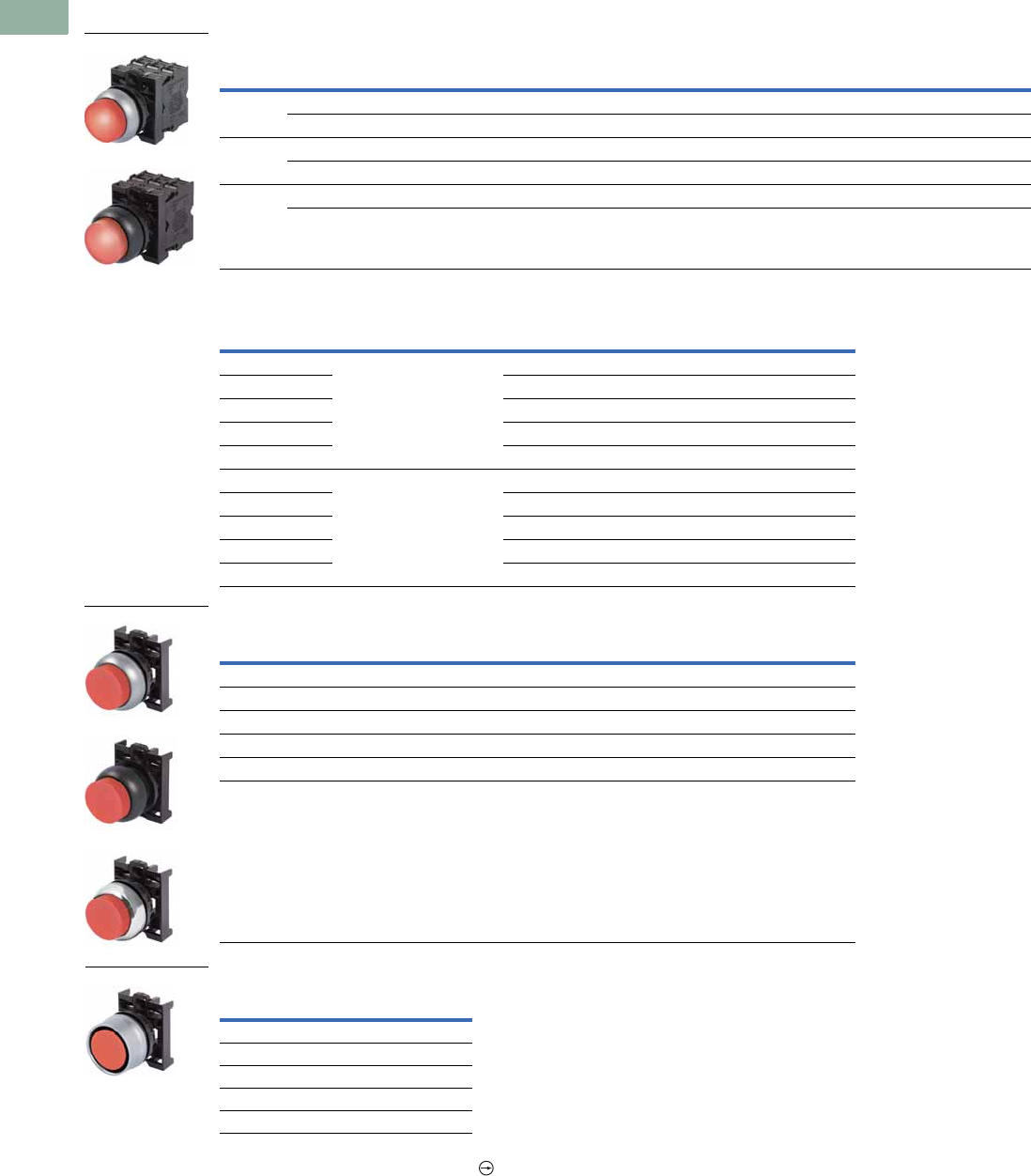
V7-T1-68 Volume 7—Logic Control, Operator Interface and Connectivity Solutions CA08100008E—March 2014 www.eaton.com
1
1
1
1
1
1
1
1
1
1
1
1
1
1
1
1
1
1
1
1
1
1
1
1
1
1
1
1
1
1
1.5
Pushbuttons and Indicating Lights
22.5 mm Modular Pushbuttons—M22
Illuminated Pushbuttons, Extended, Momentary
Complete Devices
Complete Press-to-Test Units
Operators Only 2
Silver Guarded
Notes
1 All NC contact blocks are positively driven contact.
2 Includes contact block mounting adapter.
Button
Color
Contact Block
Configuration 1
Light Unit
Voltage
Silver Bezel
Catalog Number
Black Bezel
Catalog Number
Metal Bezel
Catalog Number
Red 1NO/1NC 12–30 Vac/Vdc M22-DLH-R-K11-R M22S-DLH-R-K11-R M22M-DLH-R-K11-R
1NO/1NC 85–264 Vac M22-DLH-R-K11-230R M22S-DLH-R-K11-230R M22M-DLH-R-K11-230R
Green 2NO 12–30 Vac/Vdc M22-DLH-G-K20-G M22S-DLH-G-K20-G M22M-DLH-G-K20-G
2NO 85–264 Vac M22-DLH-G-K20-230G M22S-DLH-G-K20-230G M22M-DLH-G-K20-230G
White 2NO 12–30 Vac/Vdc M22-DLH-W-K20-W M22S-DLH-W-K20-W M22M-DLH-W-K20-W
2NO 85–264 Vac M22-DLH-W-K20-230W M22S-DLH-W-K20-230W M22M-DLH-W-K20-230W
Button Color Light Unit Voltage
Silver Bezel
Catalog Number
Black Bezel
Catalog Number
Red 12–30 Vac/Vdc M22-T-R-R M22S-T-R-R
Blue M22-T-B-B M22S-T-B-B
Yellow M22-T-Y-W M22S-T-Y-W
Green M22-T-G-G M22S-T-G-G
White M22-T-W-W M22S-T-W-W
Red 85–264 Vac M22-T-R-230R M22S-T-R-230R
Blue M22-T-R-230B M22S-T-B-230B
Yellow M22-T-Y-230W M22S-T-Y-230W
Green M22-T-G-230G M22S-T-G-230G
White M22-T-W-230W M22S-T-W-230W
Button Color
Silver Bezel
Catalog Number
Black Bezel
Catalog Number
Metal Bezel
Catalog Number
Red M22-DLH-R M22S-DLH-R M22M-DLH-R
Green M22-DLH-G M22S-DLH-G M22M-DLH-G
White M22-DLH-W M22S-DLH-W M22M-DLH-W
Blue M22-DLH-B M22S-DLH-B M22M-DLH-B
Yellow M22-DLH-Y M22S-DLH-Y M22M-DLH-Y
Amber M22-DLH-A M22S-DLH-A M22M-DLH-A
Button Color
Silver Bezel
Catalog Number
Red M22-DGLH-R
Green M22-DGLH-G
White M22-DGLH-W
Blue M22-DGLH-B
Yellow M22-DGLH-Y
M22-DLH-R-K11-R
M22S-DLH-R-K11-R
M22-DLH-R
M22S-DLH-R
M22M-DLH-R
M22-DGLH-R
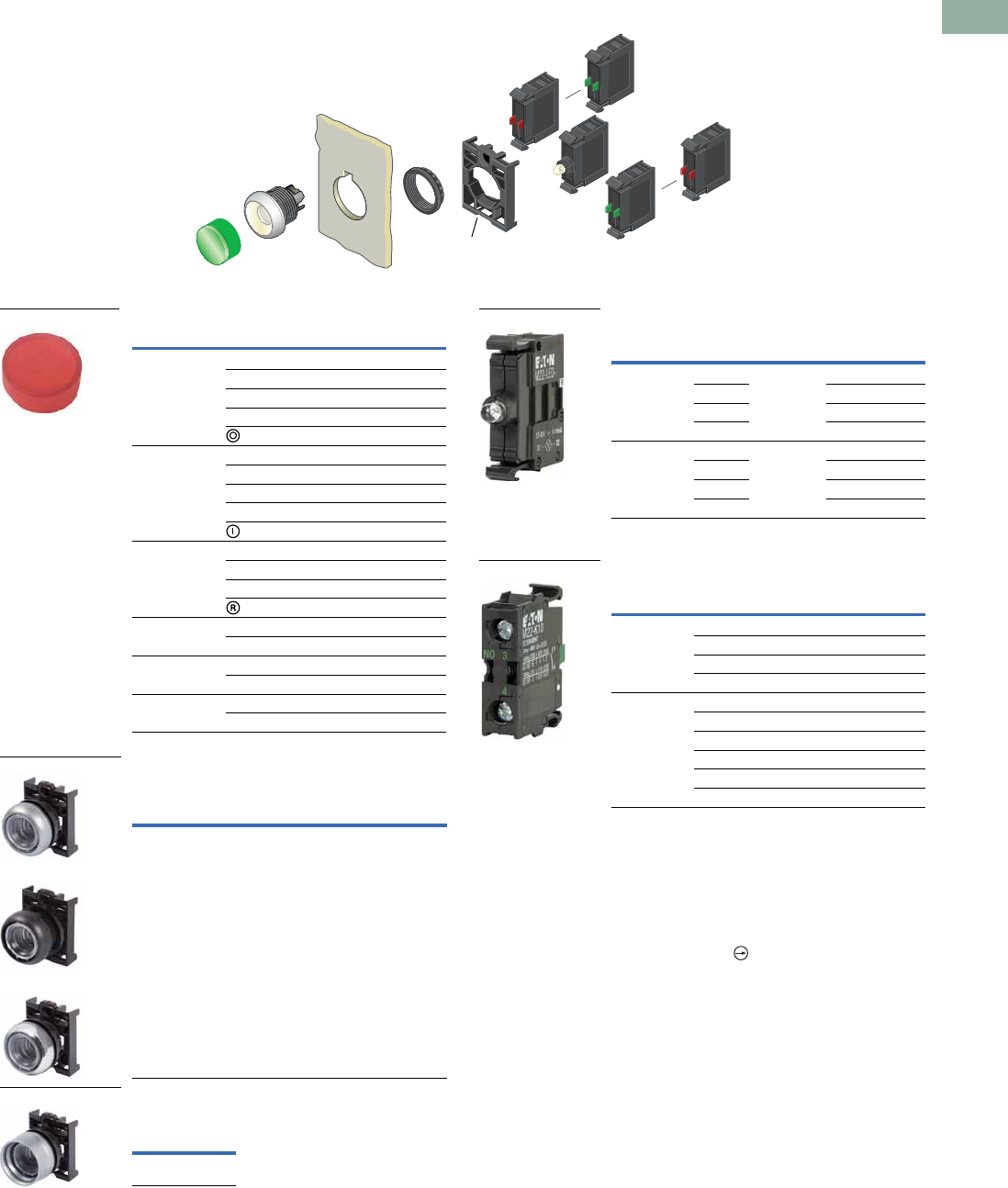
Volume 7—Logic Control, Operator Interface and Connectivity Solutions CA08100008E—March 2014 www.eaton.com V7-T1-69
1
1
1
1
1
1
1
1
1
1
1
1
1
1
1
1
1
1
1
1
1
1
1
1
1
1
1
1
1
1
1.5
Pushbuttons and Indicating Lights
22.5 mm Modular Pushbuttons—M22
Illuminated Pushbuttons, Extended, Momentary
Components
Button Lenses 1
Buttonless Operator
Silver Guarded
Light Units 1
Contact Blocks 1
Notes
1For complete listing of available button lenses, light units and contact blocks, see
Accessories, Pages V7-T1-111 to V7-T1-116.
2Minimum order quantity of (10).
3When ordering, specify inscription per catalog number suffix from the Symbols
Library (see Pages V7-T1-129 to V7-T1-136) into the Order Notes.
For example, M22-XDH-S-ETCH; Order Notes: Mark with symbol X91, Line item #_.
4Includes contact block mounting adapter.
5All NC contact blocks are positively driven contact.
max. 5mm
thickness
Note: Included
with operator.
Color Inscription Catalog Number
Red — M22-XDLH-R 2
Custom M22-XDLH-R-ETCH 3
STOP M22-XDLH-R-GB0
OFF M22-XDLH-R-GB5
M22-XDLH-R-X0
Green — M22-XDLH-G 2
Custom M22-XDLH-G-ETCH 3
START M22-XDLH-G-GB1
ON M22-XDLH-G-GB6
M22-XDLH-G-X1
Blue — M22-XDLH-B 2
Custom M22-XDLH-B-ETCH 3
RESET M22-XDLH-B-GB14
M22-XDLH-B-X6
White — M22-XDLH-W 2
Custom M22-XDLH-W-ETCH 3
Yellow — M22-XDLH-Y 2
Custom M22-XDLH-Y-ETCH 3
Amber — M22-XDLH-A
Custom M22-XDLH-A-ETCH
Silver Bezel
Catalog
Number 4
Black Bezel
Catalog
Number 4
Metal Bezel
Catalog
Number 4
M22-DL-X M22S-DL-X M22M-DL-X
Silver Bezel
Catalog
Number 4
M22-DGL-X
M22-XDH-R
M22-DL-X
M22S-DL-X
M22M-DL-X
M22-DGL-X
Terminal
Type
LED
Color
Light Unit
Voltage Catalog Number
Screw White 12–30
Vac/Vdc
M22-LED-W
Red M22-LED-R
Green M22-LED-G
Blue M22-LED-B
Screw White 85–264
Vac
M22-LED230-W
Red M22-LED230-R
Green M22-LED230-G
Blue M22-LED230-B
Terminal
Type
Contact
Configuration 5Catalog Number
Screw NO M22-K10
NO, early-make M22-K10P
NC M22-K01
NC, late-break M22-K01D
Spring-cage NO M22-CK10
NC M22-CK01
NC, late-break M22-CK01D
2NO M22-CK20
2NC M22-CK02
NO-NC M22-CK11
M22-LED-W
M22-K10
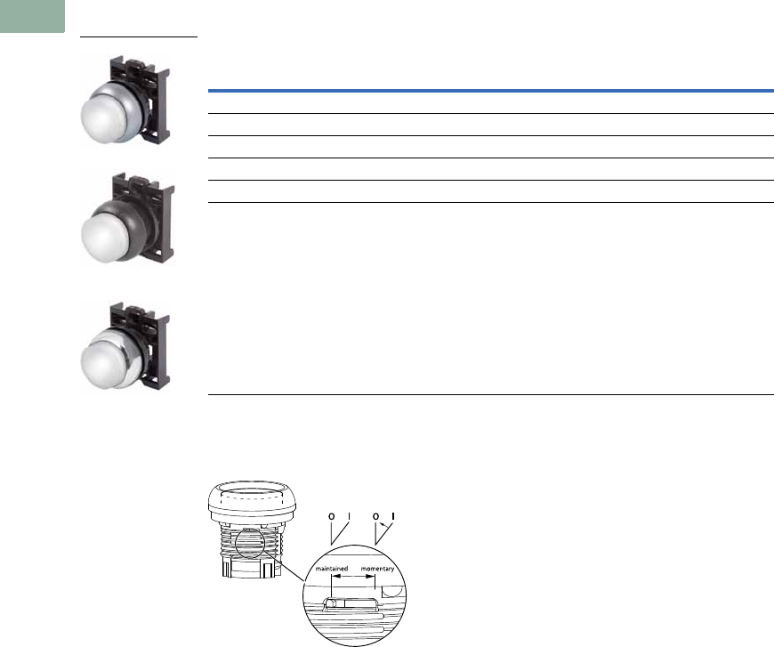
V7-T1-70 Volume 7—Logic Control, Operator Interface and Connectivity Solutions CA08100008E—March 2014 www.eaton.com
1
1
1
1
1
1
1
1
1
1
1
1
1
1
1
1
1
1
1
1
1
1
1
1
1
1
1
1
1
1
1.5
Pushbuttons and Indicating Lights
22.5 mm Modular Pushbuttons—M22
Illuminated Pushbuttons, Extended, Maintained 1
Operators Only 2
Notes
1 Maintained pushbuttons can be converted in the field to momentary operation by switching the locking ring,
which is accessible through the side of the operator body.
2 Includes contact block mounting adapter.
Note: This pilot device features a selectable function switch that enables the device
to be set to either maintained or momentary operation.
Button Color
Silver Bezel
Catalog Number
Black Bezel
Catalog Number
Metal Bezel
Catalog Number
Red M22-DRLH-R M22S-DRLH-R M22M-DRLH-R
Green M22-DRLH-G M22S-DRLH-G M22M-DRLH-G
White M22-DRLH-W M22S-DRLH-W M22M-DRLH-W
Blue M22-DRLH-B M22S-DRLH-B M22M-DRLH-B
Yellow M22-DRLH-Y M22S-DRLH-Y M22M-DRLH-Y
Amber M22-DRLH-A M22S-DRLH-A M22M-DRLH-A
M22-DRLH-W
M22S-DRLH-W
M22M-DRLH-W
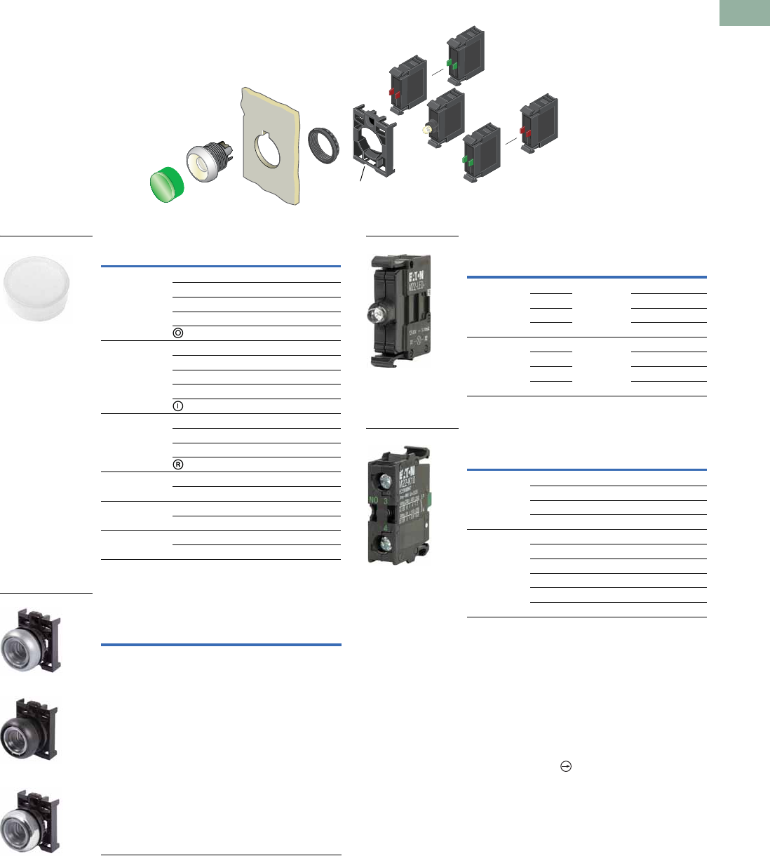
Volume 7—Logic Control, Operator Interface and Connectivity Solutions CA08100008E—March 2014 www.eaton.com V7-T1-71
1
1
1
1
1
1
1
1
1
1
1
1
1
1
1
1
1
1
1
1
1
1
1
1
1
1
1
1
1
1
1.5
Pushbuttons and Indicating Lights
22.5 mm Modular Pushbuttons—M22
Illuminated Pushbuttons, Extended, Maintained 1
Components
Button Lenses 2
Buttonless Operator
Light Units 2
Contact Blocks 2
Notes
1Maintained pushbuttons can be converted in the field to momentary operation by
switching the locking ring, which is accessible through the side of the operator body.
2For complete listing of available button lenses, light units and contact blocks, see
Accessories, Pages V7-T1-111 to V7-T1-116.
3Minimum order quantity of (10).
4When ordering, specify inscription per catalog number suffix from the Symbols
Library (see Pages V7-T1-129 to V7-T1-136) into the Order Notes.
For example, M22-XDLH-S-ETCH; Order Notes: Mark with symbol X91, Line item #_.
5Includes contact block mounting adapter.
6All NC contact blocks are positively driven contact.
max. 5mm
thickness
Note: Included
with operator.
Color Inscription Catalog Number
Red — M22-XDLH-R 3
Custom M22-XDLH-R-ETCH 4
STOP M22-XDLH-R-GB0
OFF M22-XDLH-R-GB5
M22-XDLH-R-X0
Green — M22-XDLH-G 3
Custom M22-XDLH-G-ETCH 4
START M22-XDLH-G-GB1
ON M22-XDLH-G-GB6
M22-XDLH-G-X1
Blue — M22-XDLH-B 3
Custom M22-XDLH-B-ETCH 4
RESET M22-XDLH-B-GB14
M22-XDLH-B-X6
White — M22-XDLH-W 3
Custom M22-XDLH-W-ETCH 4
Yellow — M22-XDLH-Y 3
Custom M22-XDLH-Y-ETCH 4
Amber — M22-XDLH-A
Custom M22-XDLH-A-ETCH
Silver Bezel
Catalog
Number 5
Black Bezel
Catalog
Number 5
Metal Bezel
Catalog
Number 5
M22-DRL-X M22S-DRL-X M22M-DRL-X
M22-XDLH-W
M22-DRL-X
M22S-DRL-X
M22M-DRL-X
Terminal
Type
LED
Color
Light Unit
Voltage Catalog Number
Screw White 12–30
Vac/Vdc
M22-LED-W
Red M22-LED-R
Green M22-LED-G
Blue M22-LED-B
Screw White 85–264
Vac
M22-LED230-W
Red M22-LED230-R
Green M22-LED230-G
Blue M22-LED230-B
Terminal
Type
Contact
Configuration 6Catalog Number
Screw NO M22-K10
NO, early-make M22-K10P
NC M22-K01
NC, late-break M22-K01D
Spring-cage NO M22-CK10
NC M22-CK01
NC, late-break M22-CK01D
2NO M22-CK20
2NC M22-CK02
NO-NC M22-CK11
M22-LED-W
M22-K10
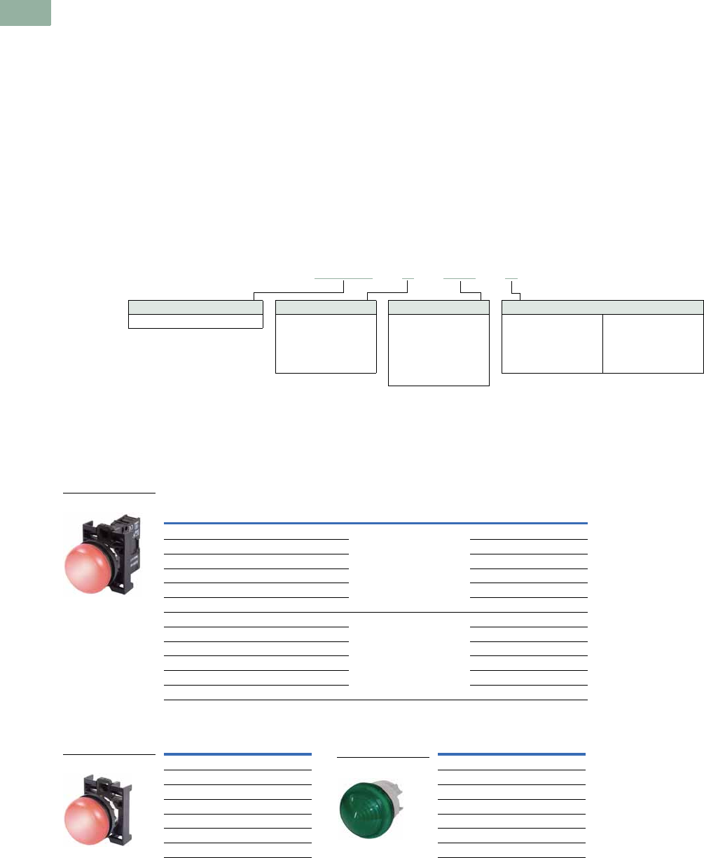
V7-T1-72 Volume 7—Logic Control, Operator Interface and Connectivity Solutions CA08100008E—March 2014 www.eaton.com
1
1
1
1
1
1
1
1
1
1
1
1
1
1
1
1
1
1
1
1
1
1
1
1
1
1
1
1
1
1
1.5
Pushbuttons and Indicating Lights
22.5 mm Modular Pushbuttons—M22
Indicating Lights
Product Description
Eaton’s M22 indicating lights
use the combination of a
durable, bright LED unit and
modern lenses designed
specifically for this type of
LED to create a bright and
visible indicating light.
As with the pushbuttons, the
indicating light lenses can be
laser engraved. Indicating
lights can be ordered as
complete devices, including
lens and LED unit, or as
modular components.
Features
●Customizable laser
engraving on all lenses
●LED offering only for
improved brightness
quality and up to 100,000
hours of operation
●Lenses designed
specifically for LED
illumination
●Modular construction
makes assembly fast and
simplifies stocking of
components and complete
devices
●Capable of communicating
via ASi protocol with ASi
adapter modules
Protection Type
●IP67, IP69K
●NEMA 4X, 13
Catalog Number Selection
Catalog Number Selection is for illustrative purposes only and not to be used to create new catalog numbers.
Indicating Lights
Product Selection
Indicating Lights, Flush
Complete Devices
Operators Only 1
Note
1 Includes contact block mounting adapter.
Lens Color Light Color Light Unit Voltage Catalog Number
White White 12–30 Vac/Vdc M22-L-W-W
Red Red M22-L-R-R
Green Green M22-L-G-G
Yellow White M22-L-Y-W
Blue Blue M22-L-B-B
Amber White M22-L-A-W
White White 85–264 Vac M22-L-W-230W
Red Red M22-L-R-230R
Green Green M22-L-G-230G
Yellow White M22-L-Y-230W
Blue Blue M22-L-B-230B
Amber White M22-L-A-230W
Lens Color Catalog Number Lens Color Catalog Number
Flat Conical
White M22-L-W White M22-LH-W
Red M22-L-R Red M22-LH-R
Green M22-L-G Green M22-LH-G
Yellow M22-L-Y Yellow M22-LH-Y
Blue M22-L-B Blue M22-LH-B
Amber M22-L-A Amber M22-LH-A
Note: Light unit should match color of lens.
Use white light unit with yellow lens.
Lens Color
W =White
R =Red
G = Green
Y = Yellow
B =Blue
M22 - L –B–GB8–B
Operator Type
M22-L = Flush indicating light
1When ordering, specify inscription per catalog number suffix from the Symbols Library
(see Pages V7-T1-129 to V7-T1-136) into the Order Notes.
For example, M22-L-B-ETCH; Order Notes: Mark with symbol X91, Line item #_.
Plate Inscription
ETCH =Custom
1
GB5 =OFF
GB6 =ON
GB8 = FAULT
GB15 =FORWARD
GB16 = REVERSE
Light Units
12–30 Vac/Vdc
W =White
R =Red
G =Green
B =Blue
85–264 Vac
230W =White
230R =Red
230G =Green
230B =Blue
M22-L-R-R
M22-L-R
M22-LH-R
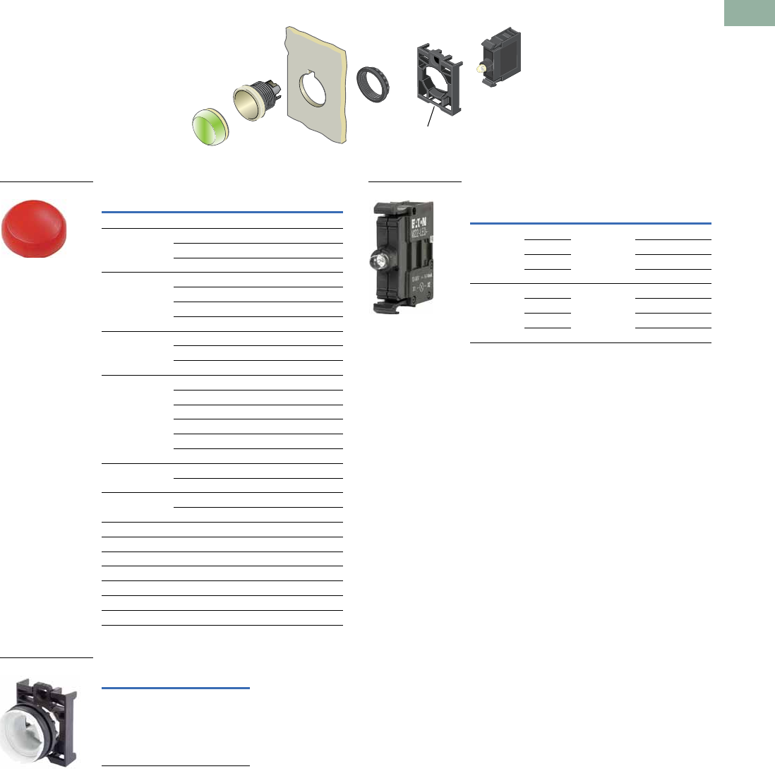
Volume 7—Logic Control, Operator Interface and Connectivity Solutions CA08100008E—March 2014 www.eaton.com V7-T1-73
1
1
1
1
1
1
1
1
1
1
1
1
1
1
1
1
1
1
1
1
1
1
1
1
1
1
1
1
1
1
1.5
Pushbuttons and Indicating Lights
22.5 mm Modular Pushbuttons—M22
Indicating Lights, Flush
Components
Lenses 1
Lensless Indicating Light
Light Units 14
Notes
1For complete listing of available lenses and light units, see Accessories,
Pages V7-T1-111 to V7-T1-116.
2Minimum order quantity of (10).
3When ordering, specify inscription per catalog number suffix from the Symbols
Library (see Pages V7-T1-129 to V7-T1-136) into the Order Notes.
For example, M22-XL-R-ETCH; Order Notes: Mark with symbol X91, Line item #_.
4Select the same color LED element as lens color; for yellow and amber lenses,
choose a white LED.
max. 5mm
thickness
Note: Included
with operator.
Color Inscription Catalog Number
Flat
Red — M22-XL-R 2
Custom M22-XL-R-ETCH 3
OFF M22-XL-R-GB5
Green — M22-XL-G 2
Custom M22-XL-G-ETCH 3
ON M22-XL-G-GB6
REVERSE M22-XL-G-GB16
Blue — M22-XL-B 2
Custom M22-XL-B-ETCH 3
FAULT M22-XL-B-GB8
White — M22-XL-W 2
Custom M22-XL-W-ETCH 3
OFF M22-XL-W-GB5
ON M22-XL-W-GB6
FAULT M22-XL-W-GB8
FORWARD M22-XL-W-GB15
Yellow — M22-XL-Y 2
Custom M22-XL-Y-ETCH 3
Amber — M22-XL-A 2
Custom M22-XL-A-ETCH 3
Conical
Red — M22-XLH-R
Green — M22-XLH-G
Blue — M22-XLH-B
White — M22-XLH-W
Yellow — M22-XLH-Y
Amber — M22-XLH-A
Catalog Number
M22-L-X
M22-XL-R
M22-L-X
Terminal
Type
LED
Color
Light Unit
Voltage Catalog Number
Screw White 12–30
Vac/Vdc
M22-LED-W
Red M22-LED-R
Green M22-LED-G
Blue M22-LED-B
Screw White 85–264
Vac
M22-LED230-W
Red M22-LED230-R
Green M22-LED230-G
Blue M22-LED230-B
M22-LED-W
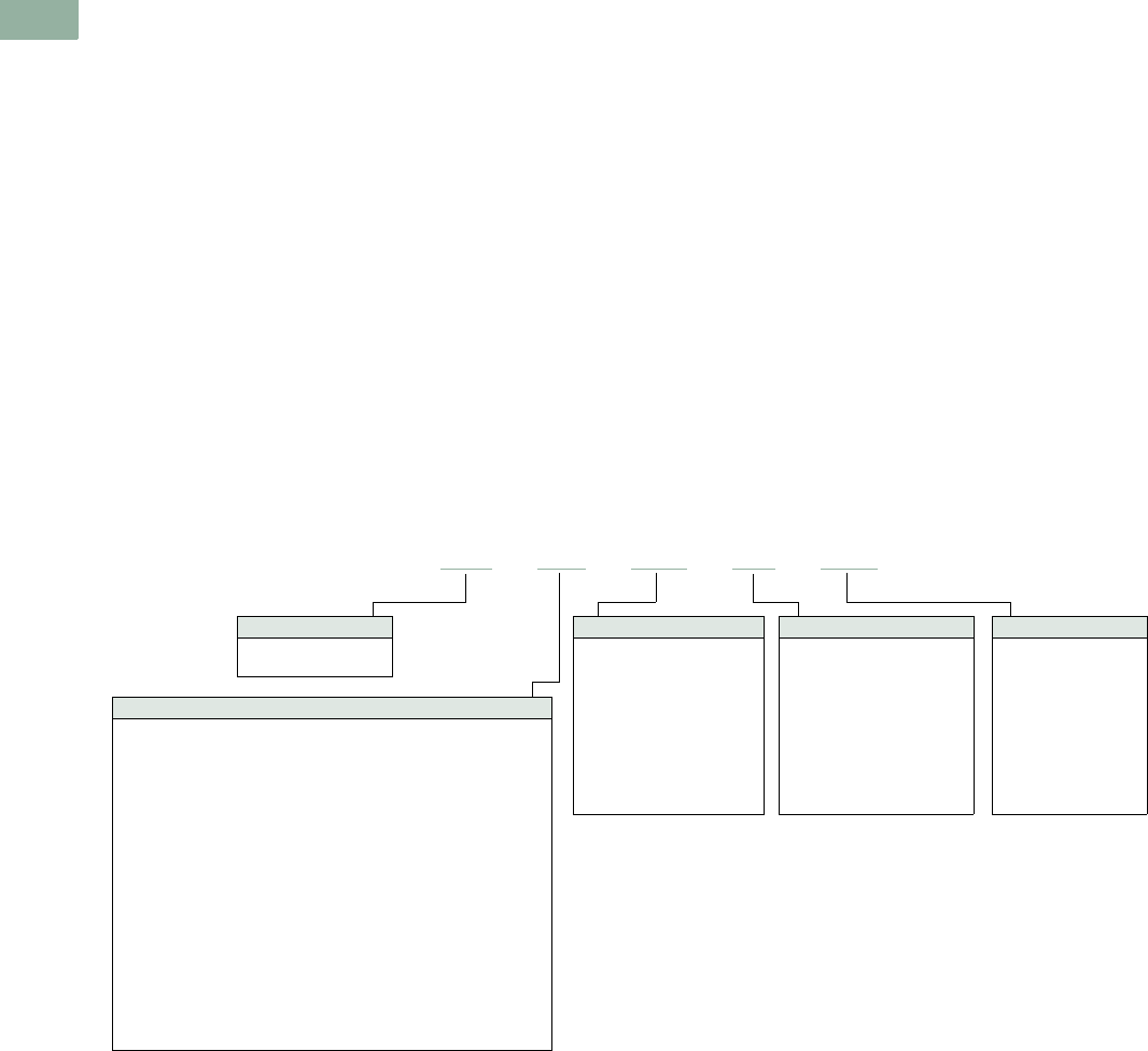
V7-T1-74 Volume 7—Logic Control, Operator Interface and Connectivity Solutions CA08100008E—March 2014 www.eaton.com
1
1
1
1
1
1
1
1
1
1
1
1
1
1
1
1
1
1
1
1
1
1
1
1
1
1
1
1
1
1
1.5
Pushbuttons and Indicating Lights
22.5 mm Modular Pushbuttons—M22
Emergency Stops
Product Description
Eaton’s M22 emergency
stops are a durable and
reliable solution to a variety
of e-stop applications. With
standard push-pull, as well
as twist-to-release and key-
release, illuminated options
and red or black operators,
the M22 e-stop is a robust
solution. As with all
operators, they can be
ordered as a ready to install
complete device or as
modular components for
the perfect fit.
Features
●Push-pull and twist to
release options available as
well as illuminated and
keyed release
●LED offering only for
improved brightness
quality and up to 100,000
hours of operation
●More than 100,000
mechanical operations
●Capable of communicating
via ASi protocol with ASi
adapter modules
●Suitable for use in safety
applications up to
Category-4 or Sil-3
Protection Type
●IP67, IP69K
(IP66 key-release)
●NEMA 4X, 13
Catalog Number Selection
Catalog Number Selection is for illustrative purposes only and not to be used to create new catalog numbers.
Emergency Stops
M22 –PVT–MS2–K10–230R
Operator Color
M22 =Silver
M22S =Black
Contact Blocks
K10 =NO
K10P = NO, early-make
K01 =NC
K01D = NC, late-break
CK10 =NO
CK01 =NC
CK01D = NC, late-break
Ck20 =2NO
CK02 =2NC
CK11 =NO-NC
Key Release Code
Blank =MS1
MS2 =MS2
MS3 =MS3
MS4 =MS4
MS5 =MS5
MS6 =MS6
MS7 =MS7
MS8 =MS8
RS = Ronis
(45 and 60 mm only)
Light Units
12–30 Vac/Vdc
W =White
R =Red
G =Green
B =Blue
85–264 Vac
230W =White
230R =Red
230G =Green
230B =Blue
Operator Type
PV = Non-illuminated push-pull emergency stop
PV45P = Non-illuminated 45 mm emergency stop
PV60P = Non-illuminated 60 mm emergency stop
PV45P-MPI = Non-illuminated mechanical indication, 45 mm
PV60P-MPI = Non-illuminated mechanical indication, 60 mm
PVT = Non-illuminated twist-to-release emergency stop
PVT45P = Non-illuminated twist-to-release 45 mm emergency stop
PVT60P = Non-illuminated twist-to-release 60 mm emergency stop
PVT45P-MPI = Non-illuminated twist-to-release with mechanical
indication, 45 mm
PVT60P-MPI = Non-illuminated twist-to-release with mechanical
indication, 60 mm
PVS = Non-illuminated keyed release (red operator only)
PVS45P = Non-illuminated keyed release 45 mm (red only)
PVS60P = Non-illuminated keyed release 60 mm (red only)
PVL = Illuminated push-pull emergency stop
PVLT = Illuminated twist-to-release emergency stop
PVLT45P = Illuminated twist-to-release 45 mm emergency stop
PVLT60P = Illuminated twist-to-release 60 mm emergency stop
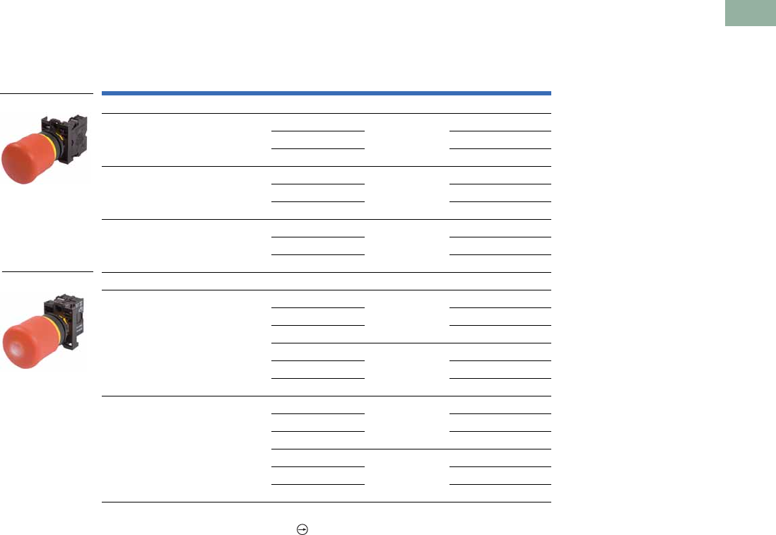
Volume 7—Logic Control, Operator Interface and Connectivity Solutions CA08100008E—March 2014 www.eaton.com V7-T1-75
1
1
1
1
1
1
1
1
1
1
1
1
1
1
1
1
1
1
1
1
1
1
1
1
1
1
1
1
1
1
1.5
Pushbuttons and Indicating Lights
22.5 mm Modular Pushbuttons—M22
Product Selection
Non-Illuminated and Illuminated Emergency Stops
Complete Devices
Note
1 All NC contact blocks are positively driven contact.
Type
Button
Color
LED
Color
Contact Block
Configuration 1
Light Unit
Voltage Catalog Number
Non-Illuminated
Push-pull Red — NC — M22-PV-K01
2NC M22-PV-K02
1NO-2NC M22-PV-K12
Twist-to-release Red — NC — M22-PVT-K01
2NC M22-PVT-K02
1NO-2NC M22-PVT-K12
Key release Red — NC — M22-PVS-K01
2NC M22-PVS-K02
1NO-2NC M22-PVS-K12
Illuminated
Push-pull Red Red NC 12–30 Vac/Vdc M22-PVL-K01-R
2NC M22-PVL-K02-R
1NO-2NC M22-PVL-K12-R
NC 85–264 Vac M22-PVL-K01-230R
2NC M22-PVL-K02-230R
1NO-2NC M22-PVL-K12-230R
Twist-to-release Red Red NC 12–30 Vac/Vdc M22-PVLT-K01-R
2NC M22-PVLT-K02-R
1NO-2NC M22-PVLT-K12-R
NC 85–264 Vac M22-PVLT-K01-230R
2NC M22-PVLT-K02-230R
1NO-2NC M22-PVLT-K12-230R
M22-PV-K01
M22-PVL-K01-R
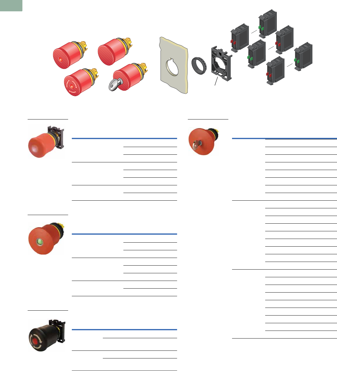
V7-T1-76 Volume 7—Logic Control, Operator Interface and Connectivity Solutions CA08100008E—March 2014 www.eaton.com
1
1
1
1
1
1
1
1
1
1
1
1
1
1
1
1
1
1
1
1
1
1
1
1
1
1
1
1
1
1
1.5
Pushbuttons and Indicating Lights
22.5 mm Modular Pushbuttons—M22
Non-Illuminated and Illuminated Emergency Stops
Components
Push-Pull Emergency Stops
Twist-to-Release Emergency Stops
Machine Stop Operators (Black) 1
Key Release Emergency Stops 2
Notes
1Includes contact block mounting adapter.
2Key included. For identical locks and keys, use the same key code. One key is included with
actuator; additional keys are available as accessories.
3Includes Key Code MS1.
max. 5mm
thickness
Note: Included
with operator.
Illumination/Indication
Actuator
Size
Catalog
Number
None 35 mm M22-PV
45 mm M22-PV45P
60 mm M22-PV60P
LED illumination 35 mm M22-PVL
45 mm M22-PVL45P
60 mm M22-PVL60P
Mechanical indication 45 mm M22-PV45P-MPI
60 mm M22-PV60P-MPI
Illumination/Indication
Actuator
Size
Catalog
Number
None 35 mm M22-PVT
45 mm M22-PVT45P
60 mm M22-PVT60P
LED illumination 35 mm M22-PVLT
45 mm M22-PVLT45P
60 mm M22-PVLT60P
Mechanical indication 45 mm M22-PVT45P-MPI
60 mm M22-PVT60P-MPI
Illumination Type
Actuator
Size
Catalog
Number
Non-illuminated Push-pull 35 mm M22S-PV
Twist-to-
release
35 mm M22S-PVT
LED illumination Push-pull 35 mm M22S-PVL
Twist-to-
release
35 mm M22S-PVLT
M22-PVL
M22-PVT45P-MPI
M22S-PVLT
Actuator
Size
Key
Code
Catalog
Number
35 mm MS1 M22-PVS 3
MS2 M22-PVS-MS2
MS3 M22-PVS-MS3
MS4 M22-PVS-MS4
MS5 M22-PVS-MS5
MS6 M22-PVS-MS6
MS7 M22-PVS-MS7
MS8 M22-PVS-MS8
45 mm MS1 M22-PVS45P
MS2 M22-PVS45P-MS2
MS3 M22-PVS45P-MS3
MS4 M22-PVS45P-MS4
MS5 M22-PVS45P-MS5
MS6 M22-PVS45P-MS6
MS7 M22-PVS45P-MS7
MS8 M22-PVS45P-MS8
Ronis M22-PVS45P-RS
60 mm MS1 M22-PVS60P
MS2 M22-PVS60P-MS2
MS3 M22-PVS60P-MS3
MS4 M22-PVS60P-MS4
MS5 M22-PVS60P-MS5
MS6 M22-PVS60P-MS6
MS7 M22-PVS60P-MS7
MS8 M22-PVS60P-MS8
Ronis M22-PVS60P-RS
M22-PVS60P-MS1
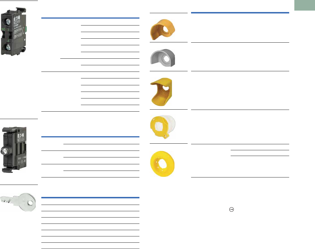
Volume 7—Logic Control, Operator Interface and Connectivity Solutions CA08100008E—March 2014 www.eaton.com V7-T1-77
1
1
1
1
1
1
1
1
1
1
1
1
1
1
1
1
1
1
1
1
1
1
1
1
1
1
1
1
1
1
1.5
Pushbuttons and Indicating Lights
22.5 mm Modular Pushbuttons—M22
Contact Blocks 1
Light Units 1
Extra Keys 4
Accessories
Notes
1For complete listing of available contact blocks, see Accessories,
Pages V7-T1-111 to V7-T1-116.
2Self-monitoring contact blocks (SMCB type) cannot be used with illuminated emergency
stops.
3All NC contact blocks are positively driven contact.
4For use with key release operators only. One key included with operator.
Terminal
Type
Mounting
Location 2
Contact
Configuration 3Catalog Number
Screw Front NO M22-K10
NO, early-make M22-K10P
NC M22-K01
NC, late-break M22-K01D
SMCB, NC M22-K01SMC10
SMCB, 2NC M22-K02SMC10
Base SMCB, NC M22-KC01SMC10
SMCB, 2NC M22-KC02SMC10
Spring-
cage
Front NO M22-CK10
NC M22-CK01
NC, late-break M22-CK01D
2NO M22-CK20
2NC M22-CK02
NO-NC M22-CK11
Terminal
Type
LED
Color
Light Unit
Voltage Catalog Number
Screw White 12–30 Vac/Vdc M22-LED-W
Red 12–30 Vac/Vdc M22-LED-R
Screw White 85–264 Vac M22-LED230-W
Red 85–264 Vac M22-LED230-R
Screw White 207–264 Vac M22-LED230H-W
Red 207–264 Vac M22-LED230H-R
For Key Code Catalog Number
MS1 M22-ES-MS1
MS2 M22-ES-MS2
MS3 M22-ES-MS3
MS4 M22-ES-MS4
MS5 M22-ES-MS5
MS6 M22-ES-MS6
MS7 M22-ES-MS7
MS8 M22-ES-MS8
M22-K10
M22-LED-W
M22-ES-MS1
Description Voltage Catalog Number
Yellow guard ring — M22-XGPV
Gray guard ring — M22G-XGPV
Rectangular guard — M22-MGTA
Sealing shroud — M22-PL-PV
Illuminated ring 24 Vac/Vdc M22-XPV60-Y-24
120 Vac M22-XPV60-Y-120
230 Vac M22-XPV60-Y-230
M22-XGPV
M22G-XGPV
M22-PL-PV
M22-MGTA
M22-XPV60-Y-120
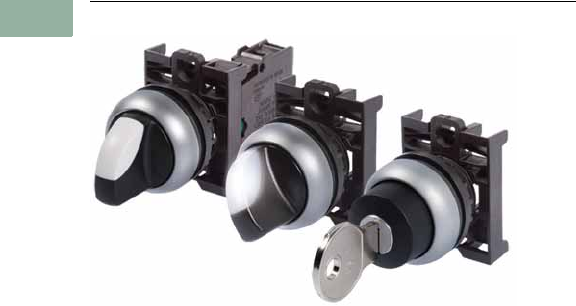
V7-T1-78 Volume 7—Logic Control, Operator Interface and Connectivity Solutions CA08100008E—March 2014 www.eaton.com
1
1
1
1
1
1
1
1
1
1
1
1
1
1
1
1
1
1
1
1
1
1
1
1
1
1
1
1
1
1
1.5
Pushbuttons and Indicating Lights
22.5 mm Modular Pushbuttons—M22
Selector Switches
Contents
Description Page
Selector Switches
Non-Illuminated Switches . . . . . . . . . . . . . . . . . V7-T1-79
Illuminated Switches . . . . . . . . . . . . . . . . . . . . V7-T1-84
Key Operated . . . . . . . . . . . . . . . . . . . . . . . . . . V7-T1-88
Selector Switches
Product Description
Eaton’s M22 selector switch
line offers an almost endless
variety of options in
maintained/momentary, key-
removal and illuminated
devices. The coding adapters
used for maintained/
momentary and key removal
positions make the M22
stand out from competitive
devices. By simply adding or
removing a coding adapter
from inside the operator,
the end-user can change
the function of the button.
Operator options include
standard knob, rotary head,
illuminated and keyed
versions. As with all
operators, they can be
ordered as a ready to install
complete device or as
modular components to
meet application specific
requirements.
Features
●Adding or removing coding
adapters allows for field
convertibility of
maintained/momentary
and key removal positions
●LED offering only for
improved brightness
quality and up to 100,000
hours of operation
●More than 100,000
mechanical operations
●Coding adapter options
make assembly fast and
simplify stocking of
different configurations of
selector switches
●Capable of communicating
via ASi protocol with ASi
adapter modules
Protection Type
●IP66
●NEMA 4X, 13
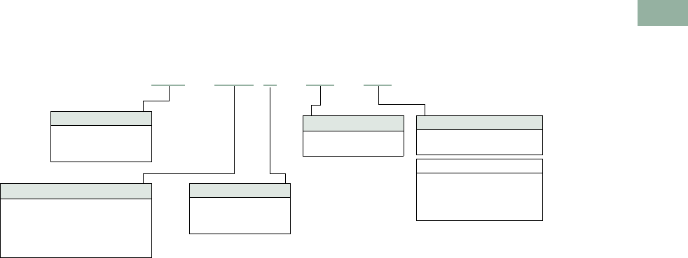
Volume 7—Logic Control, Operator Interface and Connectivity Solutions CA08100008E—March 2014 www.eaton.com V7-T1-79
1
1
1
1
1
1
1
1
1
1
1
1
1
1
1
1
1
1
1
1
1
1
1
1
1
1
1
1
1
1
1.5
Pushbuttons and Indicating Lights
22.5 mm Modular Pushbuttons—M22
Catalog Number Selection
Catalog Number Selection is for illustrative purposes only and not to be used to create new catalog numbers.
Non-Illuminated Selector Switches
Contact Blocks
K10 =NO
K10P = NO, early-make
Options
K11 = NO-NC
K22 = 2NO-2NC
K20 = 2NO
K02 = 2NC
2Rotary type only.
Inscription 2
X91 = AUTO-HAND
X92 = II-I
Bezel
M22 =Silver
M22S =Black
M22M = Metal
1All momentary selector switches can
be converted in the field to maintained
operation with the removal of a color-
coded adapter.
Handle Type 1
W = Momentary rotary
WK = Momentary knob
WKV = Maintained V-position knob
WR = Maintained rotary
WRK = Maintained knob
Number of Positions
Blank = Two-position
3 = Three-position
4 = Four-position
M22 –WRK –X91–K10
–
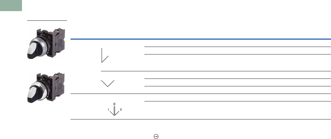
V7-T1-80 Volume 7—Logic Control, Operator Interface and Connectivity Solutions CA08100008E—March 2014 www.eaton.com
1
1
1
1
1
1
1
1
1
1
1
1
1
1
1
1
1
1
1
1
1
1
1
1
1
1
1
1
1
1
1.5
Pushbuttons and Indicating Lights
22.5 mm Modular Pushbuttons—M22
Product Selection
Non-Illuminated Selector Switches
Complete Devices, Knob Type 1
Notes
1 Includes contact block mounting adapter.
2 All NC contact blocks are positively driven contact.
Type Switching Position
Contact Block
Configuration 2
Silver Bezel
Catalog Number
Black Bezel
Catalog Number
Metal Bezel
Catalog Number
Two-position Maintained NO M22-WRK-K10 M22S-WRK-K10 M22M-WRK-K10
1NO-1NC M22-WRK-K11 M22S-WRK-K11 M22M-WRK-K11
2NO-2NC M22-WRK-K22 M22S-WRK-K22 M22M-WRK-K22
Maintained V NO M22-WKV-K10 M22S-WKV-K10 M22M-WKV-K10
1NO-1NC M22-WKV-K11 M22S-WKV-K11 M22M-WKV-K11
2NO-2NC M22-WKV-K22 M22S-WKV-K22 M22M-WKV-K22
Three-position Maintained 2NO M22-WRK3-K20 M22S-WRK3-K20 M22M-WRK3-K20
2NO-2NC M22-WRK3-K22 M22S-WRK3-K22 M22M-WRK3-K22
M22-WKV-K10
M22M-WKV-K10
40°
60°
60° 60°
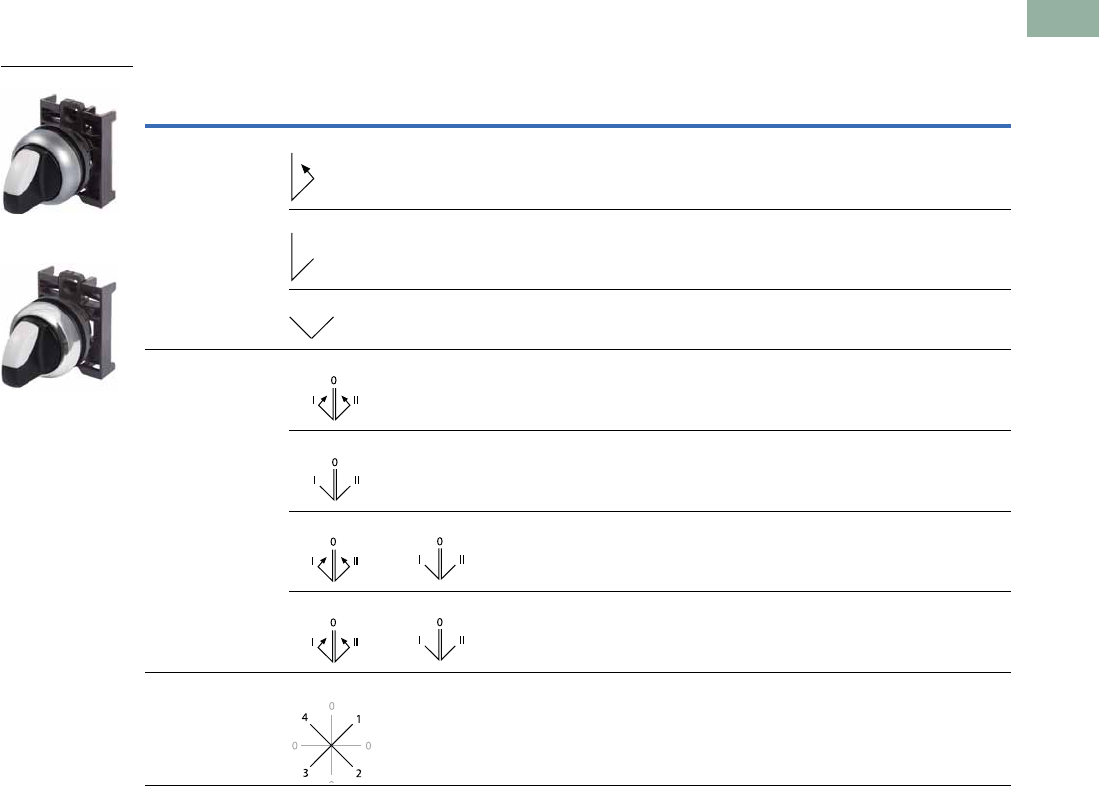
Volume 7—Logic Control, Operator Interface and Connectivity Solutions CA08100008E—March 2014 www.eaton.com V7-T1-81
1
1
1
1
1
1
1
1
1
1
1
1
1
1
1
1
1
1
1
1
1
1
1
1
1
1
1
1
1
1
1.5
Pushbuttons and Indicating Lights
22.5 mm Modular Pushbuttons—M22
Non-Illuminated Selector Switches
Components
Operators Only, Knob Type 1
Notes
1 Includes contact block mounting adapter.
2 Momentary selector switches can be converted in the field to maintained operation with the removal of a color
coded adapter. See Page V7-T1-118.
Type Switching Position
Silver Bezel
Catalog Number
Black Bezel
Catalog Number
Metal Bezel
Catalog Number
Two-position Momentary 2 M22-WK M22S-WK M22M-WK
Maintained M22-WRK M22S-WRK M22M-WRK
Maintained V M22-WKV M22S-WKV M22M-WKV
Three-position Momentary 2 M22-WK3 M22S-WK3 M22M-WK3
Maintained M22-WRK3 M22S-WRK3 M22M-WRK3
Maintained, return from left M22-WRK3-2 M22S-WRK3-2 M22M-WRK3-2
Maintained, return from right M22-WRK3-1 M22S-WRK3-1 M22M-WRK3-1
Four-position Maintained M22-WRK4 M22S-WRK4 M22M-WRK4
M22-WK
M22M-WK
40°
40°
60°
40° 40°
60°60°
40° 40° 60°60°
40° 40° 60°60°
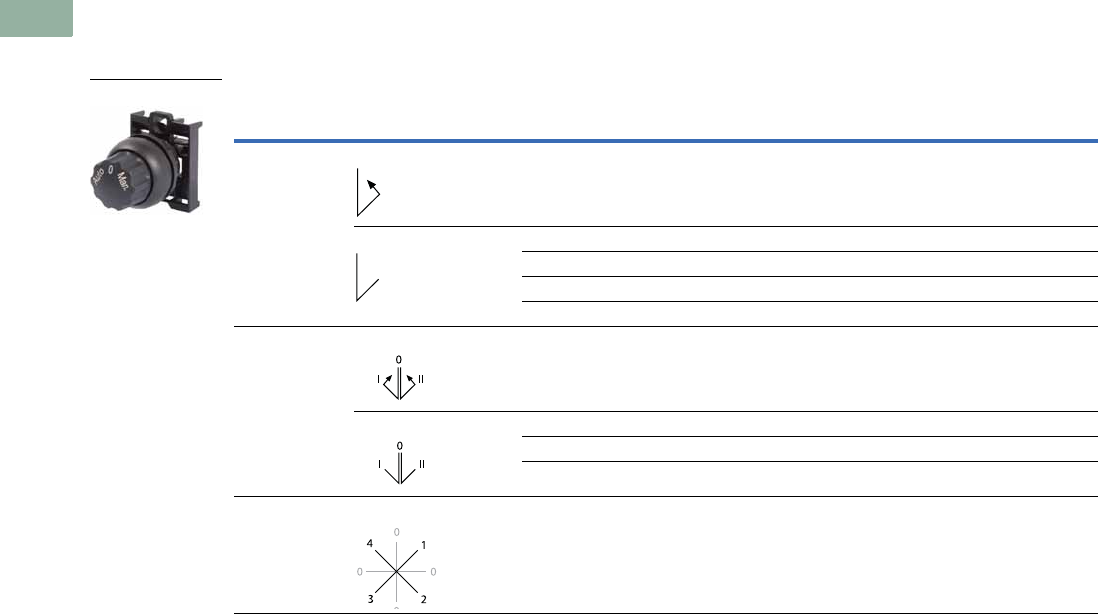
V7-T1-82 Volume 7—Logic Control, Operator Interface and Connectivity Solutions CA08100008E—March 2014 www.eaton.com
1
1
1
1
1
1
1
1
1
1
1
1
1
1
1
1
1
1
1
1
1
1
1
1
1
1
1
1
1
1
1.5
Pushbuttons and Indicating Lights
22.5 mm Modular Pushbuttons—M22
Non-Illuminated Selector Switches
Components
Operators Only, Rotary Type 1
Notes
1 Includes contact block mounting adapter.
2 Momentary selector switches can be converted in the field to maintained operation with the removal of a color
coded adapter. See Page V7-T1-118.
3 When ordering, specify inscription per catalog number suffix from the Symbols Library
(see
Pages
V7-T1-129
to
V7-T1-136
)
into the Order Notes. For example, M22-WR3-ETCH; Order Notes: Mark with symbol X88, Line item #_.
Type Switching Position Inscription
Silver Bezel
Catalog Number
Black Bezel
Catalog Number
Metal Bezel
Catalog Number
Two-position Momentary 2I-O M22-W M22S-W M22M-W
Maintained I-O M22-WR M22S-WR M22M-WR
Custom M22-WR-ETCH 3M22S-WR-ETCH 3M22M-WR-ETCH 3
AUTO-HAND M22-WR-X91 M22S-WR-X91 M22M-WR-X91
II-I M22-WR-X92 M22S-WR-X92 M22M-WR-X92
Three-position Momentary 2I-O-II M22-W3 M22S-W3 M22M-W3
Maintained I-O-II M22-WR3 M22S-WR3 M22M-WR3
Custom M22-WR3-ETCH 3M22S-WR3-ETCH 3M22M-WR3-ETCH 3
AUTO-O-MAN M22-WR3-X94 M22S-WR3-X94 M22M-WR3-X94
Four-position Maintained 0-1-0-2-0-3-0-4 M22-WR4 M22S-WR4 M22M-WR4
M22S-WR3-X94
40°
40°
40° 40°
60°60°
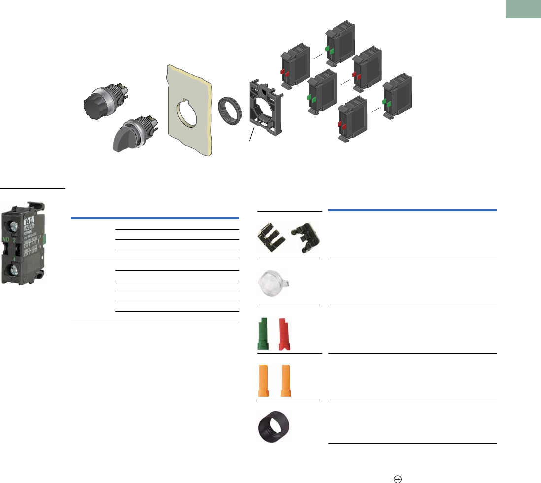
Volume 7—Logic Control, Operator Interface and Connectivity Solutions CA08100008E—March 2014 www.eaton.com V7-T1-83
1
1
1
1
1
1
1
1
1
1
1
1
1
1
1
1
1
1
1
1
1
1
1
1
1
1
1
1
1
1
1.5
Pushbuttons and Indicating Lights
22.5 mm Modular Pushbuttons—M22
Non-Illuminated Selector Switches
Components
Contact Blocks 1Accessories
Notes
1For complete listing of available contact blocks, see Accessories,
Pages V7-T1-111 to V7-T1-116.
2All NC contact blocks are positively driven contact.
3Plunger needed to actuate center-mounted contact blocks. Used for non-illuminated
three-position selector switches only.
4Enables a keyed selector switch to be set to user-selected key withdraw position.
max. 5mm
thickness
Note: Included
with operator.
Terminal
Type
Contact
Configuration 2Catalog Number
Screw NO M22-K10
NO, early-make M22-K10P
NC M22-K01
NC, late-break M22-K01D
Spring-cage NO M22-CK10
NC M22-CK01
NC, late-break M22-CK01D
2NO M22-CK20
2NC M22-CK02
NO-NC M22-CK11
M22-K10
Description Catalog Number
Plunger bridge 3M22-XW
Key cover M22-XWS
Key withdraw adapter 4M22-XC-R
Coding adapter M22-XC-Y
Guard ring M22-XGWK
M22-XC-Y
M22-XWS
M22-XC-R
M22-XW
M22-XGWK
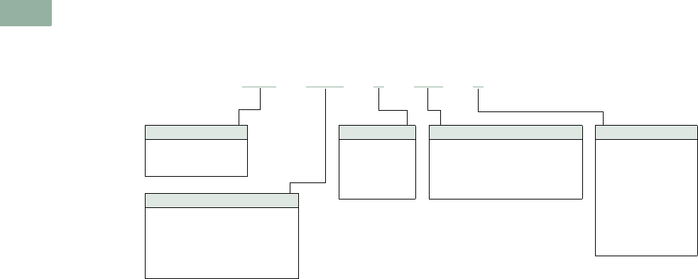
V7-T1-84 Volume 7—Logic Control, Operator Interface and Connectivity Solutions CA08100008E—March 2014 www.eaton.com
1
1
1
1
1
1
1
1
1
1
1
1
1
1
1
1
1
1
1
1
1
1
1
1
1
1
1
1
1
1
1.5
Pushbuttons and Indicating Lights
22.5 mm Modular Pushbuttons—M22
Catalog Number Selection
Catalog Number Selection is for illustrative purposes only and not to be used to create new catalog numbers.
Illuminated Selector Switches
Handle Type
WLK = Illuminated knob type
momentary, two-position
WLKV = Illuminated Knob type
momentary, V-position
WLK3 = Illuminated knob type
momentary, three-position
M22 –WLK–R–K10–R
Light Units
12–30 Vac/Vdc
W =White
R =Red
G =Green
B =Blue
85–264 Vac
230W =White
230R =Red
230G =Green
230B =Blue
Contact Blocks
K10 =1NO
K01 =1NC
K20 =2NO
K02 =2NC
K11 = 1NO-1NC
K30 =3NO
K03 =3NC
K21 = 2NO-1NC
K12 = 1NO-2NC
Handle Color
W =White
R =Red
G = Green
Y = Yellow
B =Blue
Bezel
M22 =Silver
M22S =Black
M22M = Metal
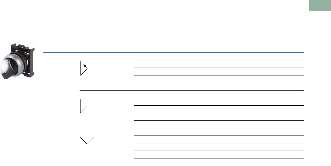
Volume 7—Logic Control, Operator Interface and Connectivity Solutions CA08100008E—March 2014 www.eaton.com V7-T1-85
1
1
1
1
1
1
1
1
1
1
1
1
1
1
1
1
1
1
1
1
1
1
1
1
1
1
1
1
1
1
1.5
Pushbuttons and Indicating Lights
22.5 mm Modular Pushbuttons—M22
Product Selection
Illuminated Selector Switches
Components
Operators Only, Knob Type 1
Notes
1 Includes contact block mounting adapter.
2 Momentary selector switches can be converted in the field to maintained operation with the removal of a color coded
adapter. See Page V7-T1-118.
Type Switching Position Button Color
Silver Bezel
Catalog Number
Black Bezel
Catalog Number
Metal Bezel
Catalog Number
Two-position Momentary 2 White M22-WLK-W M22S-WLK-W M22M-WLK-W
Red M22-WLK-R M22S-WLK-R M22M-WLK-R
Green M22-WLK-G M22S-WLK-G M22M-WLK-G
Yellow M22-WLK-Y M22S-WLK-Y M22M-WLK-Y
Blue M22-WLK-B M22S-WLK-B M22M-WLK-B
Maintained White M22-WRLK-W M22S-WRLK-W M22M-WRLK-W
Red M22-WRLK-R M22S-WRLK-R M22M-WRLK-R
Green M22-WRLK-G M22S-WRLK-G M22M-WRLK-G
Yellow M22-WRLK-Y M22S-WRLK-Y M22M-WRLK-Y
Blue M22-WRLK-B M22S-WRLK-B M22M-WRLK-B
Maintained V White M22-WLKV-W M22S-WLKV-W M22M-WLKV-W
Red M22-WLKV-R M22S-WLKV-R M22M-WLKV-R
Green M22-WLKV-G M22S-WLKV-G M22M-WLKV-G
Yellow M22-WLKV-Y M22S-WLKV-Y M22M-WLKV-Y
Blue M22-WLKV-B M22S-WLKV-B M22M-WLKV-B
M22-WLK-W
40°
40°
60°
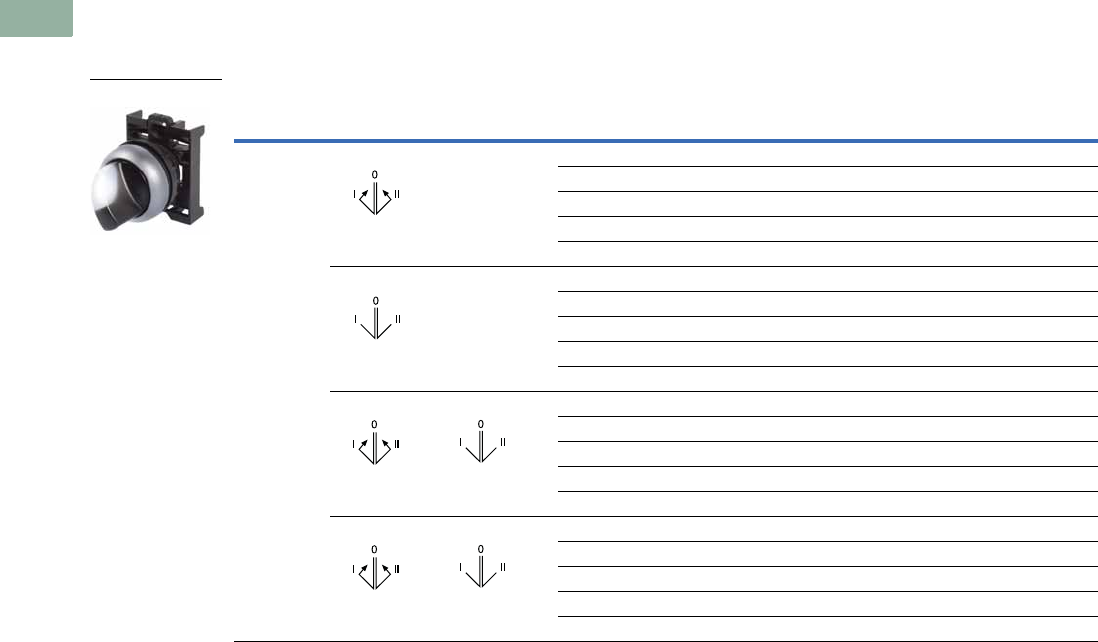
V7-T1-86 Volume 7—Logic Control, Operator Interface and Connectivity Solutions CA08100008E—March 2014 www.eaton.com
1
1
1
1
1
1
1
1
1
1
1
1
1
1
1
1
1
1
1
1
1
1
1
1
1
1
1
1
1
1
1.5
Pushbuttons and Indicating Lights
22.5 mm Modular Pushbuttons—M22
Illuminated Selector Switches
Components
Operators Only, Knob Type 1
Notes
1 Includes contact block mounting adapter.
2 Momentary selector switches can be converted in the field to maintained operation with the removal of a color coded
adapter. See Page V7-T1-118.
Type Switching Position Button Color
Silver Bezel
Catalog Number
Black Bezel
Catalog Number
Metal Bezel
Catalog Number
Three-position Momentary 2 White M22-WLK3-W M22S-WLK3-W M22M-WLK3-W
Red M22-WLK3-R M22S-WLK3-R M22M-WLK3-R
Green M22-WLK3-G M22S-WLK3-G M22M-WLK3-G
Yellow M22-WLK3-Y M22S-WLK3-Y M22M-WLK3-Y
Blue M22-WLK3-B M22S-WLK3-B M22M-WLK3-B
Maintained White M22-WRLK3-W M22S-WRLK3-W M22M-WRLK3-W
Red M22-WRLK3-R M22S-WRLK3-R M22M-WRLK3-R
Green M22-WRLK3-G M22S-WRLK3-G M22M-WRLK3-G
Yellow M22-WRLK3-Y M22S-WRLK3-Y M22M-WRLK3-Y
Blue M22-WRLK3-B M22S-WRLK3-B M22M-WRLK3-B
Maintained, return from right White M22-WRLK3-1-W M22S-WRLK3-1-W M22M-WRLK3-1-W
Red M22-WRLK3-1-R M22S-WRLK3-1-R M22M-WRLK3-1-R
Green M22-WRLK3-1-G M22S-WRLK3-1-G M22M-WRLK3-1-G
Yellow M22-WRLK3-1-Y M22S-WRLK3-1-Y M22M-WRLK3-1-Y
Blue M22-WRLK3-1-B M22S-WRLK3-1-B M22M-WRLK3-1-B
Maintained, return from left White M22-WRLK3-2-W M22S-WRLK3-2-W M22M-WRLK3-2-W
Red M22-WRLK3-2-R M22S-WRLK3-2-R M22M-WRLK3-2-R
Green M22-WRLK3-2-G M22S-WRLK3-2-G M22M-WRLK3-2-G
Yellow M22-WRLK3-2-Y M22S-WRLK3-2-Y M22M-WRLK3-2-Y
Blue M22-WRLK3-2-B M22S-WRLK3-2-B M22M-WRLK3-2-B
M22-WLK3-W
40° 40°
60°60°
40° 40° 60°60°
40° 40° 60°60°
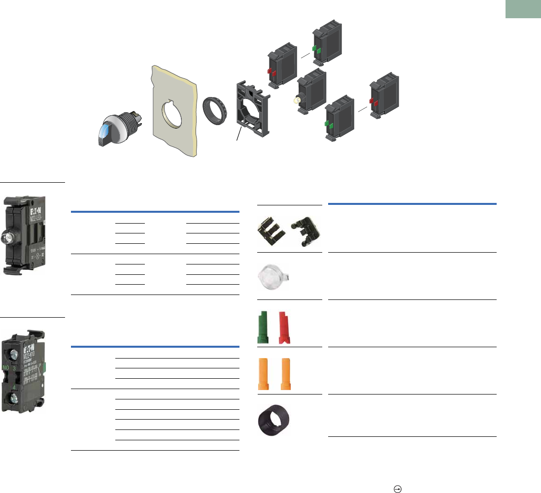
Volume 7—Logic Control, Operator Interface and Connectivity Solutions CA08100008E—March 2014 www.eaton.com V7-T1-87
1
1
1
1
1
1
1
1
1
1
1
1
1
1
1
1
1
1
1
1
1
1
1
1
1
1
1
1
1
1
1.5
Pushbuttons and Indicating Lights
22.5 mm Modular Pushbuttons—M22
Illuminated Selector Switches
Light Units 15
Contact Blocks 1
Accessories
Notes
1For complete listing of available light units and contact blocks, see Accessories,
Pages V7-T1-111 to V7-T1-116.
2Plunger needed to actuate center-mounted contact blocks. Used for non-illuminated
three-position selector switches only.
3All NC contact blocks are positively driven contact.
4Enables a keyed selector switch to be set to user-selected key withdraw position.
5Select the same color LED element as lens color; for yellow lens, choose a white LED.
max. 5mm
thickness
Note: Included
with operator.
Terminal
Type
LED
Color
Light Unit
Voltage Catalog Number
Screw White 12–30
Vac/Vdc
M22-LED-W
Red M22-LED-R
Green M22-LED-G
Blue M22-LED-B
Screw White 85–264
Vac
M22-LED230-W
Red M22-LED230-R
Green M22-LED230-G
Blue M22-LED230-B
Terminal
Type
Contact
Configuration 3Catalog Number
Screw NO M22-K10
NO, early-make M22-K10P
NC M22-K01
NC, late-break M22-K01D
Spring-cage NO M22-CK10
NC M22-CK01
NC, late-break M22-CK01D
2NO M22-CK20
2NC M22-CK02
NO-NC M22-CK11
M22-LED-W
M22-K10
Description Catalog Number
Plunger bridge 2M22-XW
Key cover M22-XWS
Key withdraw adapter 4M22-XC-R
Coding adapter M22-XC-Y
Guard ring M22-XGWK
M22-XC-Y
M22-XWS
M22-XC-R
M22-XW
M22-XGWK
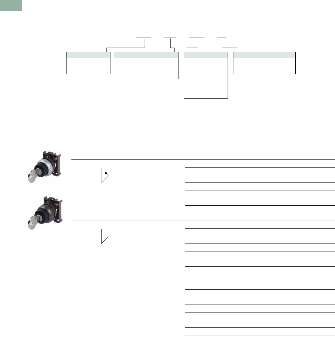
V7-T1-88 Volume 7—Logic Control, Operator Interface and Connectivity Solutions CA08100008E—March 2014 www.eaton.com
1
1
1
1
1
1
1
1
1
1
1
1
1
1
1
1
1
1
1
1
1
1
1
1
1
1
1
1
1
1
1.5
Pushbuttons and Indicating Lights
22.5 mm Modular Pushbuttons—M22
Catalog Number Selection
Catalog Number Selection is for illustrative purposes only and not to be used to create new catalog numbers.
Key-Operated Selector Switches
Product Selection
Key-Operated Selector Switches 12
Components
Operators Only 3
Notes
1 Includes one key.
2 Key removal positions can be modified in the field using coding adapters; see chart on Page V7-T1-118.
3 Includes contact block mounting adapter.
4 Momentary selector switches can be converted in the field to maintained operation with the removal of a color coded adapter. See Page V7-T1-118.
Bezel
M22 = Silver
M22S =Black
M22M = Metal
M22 –WS–MS2–A1
Key Code
Blank =MS1
MS2 =MS2
MS3 =MS3
MS4 =MS4
MS5 =MS5
MS6 =MS6
MS7 =MS7
MS8 =MS8
Handle Type
WS = Two-position, momentary
WS3 = Three-position, momentary
WRS = Two-position, maintained
WRS3 = Three-position, maintained
Key Removal Position
Refer to coding adapter assembly
and functional test guide on Page
V7-T1-118.
Type Switching Position Key Removal Position Key Code
Silver Bezel
Catalog Number
Black Bezel
Catalog Number
Metal Bezel
Catalog Number
Two-position Momentary 4 Return from right, key
removable left
MS1 M22-WS M22S-WS M22M-WS
MS2 M22-WS-MS2 M22S-WS-MS2 M22M-WS-MS2
MS3 M22-WS-MS3 M22S-WS-MS3 M22M-WS-MS3
MS4 M22-WS-MS4 M22S-WS-MS4 M22M-WS-MS4
MS5 M22-WS-MS5 M22S-WS-MS5 M22M-WS-MS5
MS6 M22-WS-MS6 M22S-WS-MS6 M22M-WS-MS6
MS7 M22-WS-MS7 M22S-WS-MS7 M22M-WS-MS7
MS8 M22-WS-MS8 M22S-WS-MS8 M22M-WS-MS8
Two-position Maintained Key removable left MS1 M22-WRS-A1 M22S-WRS-A1 M22M-WRS-A1
MS2 M22-WRS-MS2-A1 M22S-WRS-MS2-A1 M22M-WRS-MS2-A1
MS3 M22-WRS-MS3-A1 M22S-WRS-MS3-A1 M22M-WRS-MS3-A1
MS4 M22-WRS-MS4-A1 M22S-WRS-MS4-A1 M22M-WRS-MS4-A1
MS5 M22-WRS-MS5-A1 M22S-WRS-MS5-A1 M22M-WRS-MS5-A1
MS6 M22-WRS-MS6-A1 M22S-WRS-MS6-A1 M22M-WRS-MS6-A1
MS7 M22-WRS-MS7-A1 M22S-WRS-MS7-A1 M22M-WRS-MS7-A1
MS8 M22-WRS-MS8-A1 M22S-WRS-MS8-A1 M22M-WRS-MS8-A1
Key removable left/right MS1 M22-WRS M22S-WRS M22M-WRS
MS2 M22-WRS-MS2 M22S-WRS-MS2 M22M-WRS-MS2
MS3 M22-WRS-MS3 M22S-WRS-MS3 M22M-WRS-MS3
MS4 M22-WRS-MS4 M22S-WRS-MS4 M22M-WRS-MS4
MS5 M22-WRS-MS5 M22S-WRS-MS5 M22M-WRS-MS5
MS6 M22-WRS-MS6 M22S-WRS-MS6 M22M-WRS-MS6
MS7 M22-WRS-MS7 M22S-WRS-MS7 M22M-WRS-MS7
MS8 M22-WRS-MS8 M22S-WRS-MS8 M22M-WRS-MS8
M22-WS
M22S-WRS
40°
40°
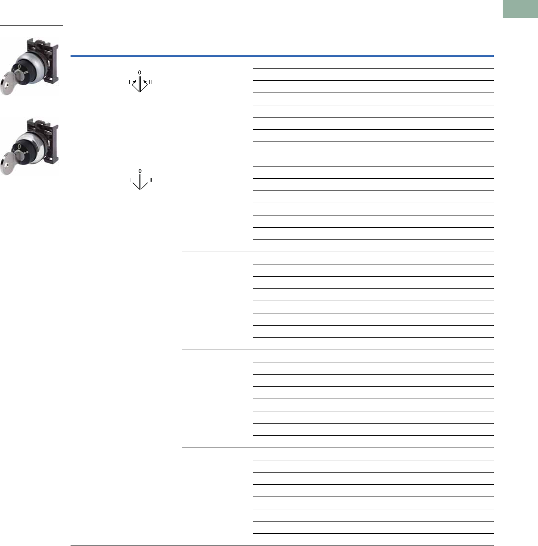
Volume 7—Logic Control, Operator Interface and Connectivity Solutions CA08100008E—March 2014 www.eaton.com V7-T1-89
1
1
1
1
1
1
1
1
1
1
1
1
1
1
1
1
1
1
1
1
1
1
1
1
1
1
1
1
1
1
1.5
Pushbuttons and Indicating Lights
22.5 mm Modular Pushbuttons—M22
Key-Operated Selector Switches 12
Components
Operators Only, continued 3
Notes
1 Includes one key.
2 Key removal positions can be modified in the field using coding adapters; see chart on Page V7-T1-118.
3 Includes contact block mounting adapter.
4 Momentary selector switches can be converted in the field to maintained operation with the removal of a color coded adapter. See Page V7-T1-118.
Type Switching Position Key Removal Position Key Code
Silver Bezel
Catalog Number
Black Bezel
Catalog Number
Metal Bezel
Catalog Number
Three-position Momentary 4 Return from left/right,
key removable center
MS1 M22-WS3 M22S-WS3 M22M-WS3
MS2 M22-WS3-MS2 M22S-WS3-MS2 M22M-WS3-MS2
MS3 M22-WS3-MS3 M22S-WS3-MS3 M22M-WS3-MS3
MS4 M22-WS3-MS4 M22S-WS3-MS4 M22M-WS3-MS4
MS5 M22-WS3-MS5 M22S-WS3-MS5 M22M-WS3-MS5
MS6 M22-WS3-MS6 M22S-WS3-MS6 M22M-WS3-MS6
MS7 M22-WS3-MS7 M22S-WS3-MS7 M22M-WS3-MS7
MS8 M22-WS3-MS8 M22S-WS3-MS8 M22M-WS3-MS8
Three-position Maintained Key removable
left/center/right
MS1 M22-WRS3-A1 M22S-WRS3-A1 M22M-WRS3-A1
MS2 M22-WRS3-MS2-A1 M22S-WRS3-MS2-A1 M22M-WRS3-MS2-A1
MS3 M22-WRS3-MS3-A1 M22S-WRS3-MS3-A1 M22M-WRS3-MS3-A1
MS4 M22-WRS3-MS4-A1 M22S-WRS3-MS4-A1 M22M-WRS3-MS4-A1
MS5 M22-WRS3-MS5-A1 M22S-WRS3-MS5-A1 M22M-WRS3-MS5-A1
MS6 M22-WRS3-MS6-A1 M22S-WRS3-MS6-A1 M22M-WRS3-MS6-A1
MS7 M22-WRS3-MS7-A1 M22S-WRS3-MS7-A1 M22M-WRS3-MS7-A1
MS8 M22-WRS3-MS8-A1 M22S-WRS3-MS8-A1 M22M-WRS3-MS8-A1
Key removable
center/left
MS1 M22-WRS3-A2 M22S-WRS3-A2 M22M-WRS3-A2
MS2 M22-WRS3-MS2-A2 M22S-WRS3-MS2-A2 M22M-WRS3-MS2-A2
MS3 M22-WRS3-MS3-A2 M22S-WRS3-MS3-A2 M22M-WRS3-MS3-A2
MS4 M22-WRS3-MS4-A2 M22S-WRS3-MS4-A2 M22M-WRS3-MS4-A2
MS5 M22-WRS3-MS5-A2 M22S-WRS3-MS5-A2 M22M-WRS3-MS5-A2
MS6 M22-WRS3-MS6-A2 M22S-WRS3-MS6-A2 M22M-WRS3-MS6-A2
MS7 M22-WRS3-MS7-A2 M22S-WRS3-MS7-A2 M22M-WRS3-MS7-A2
MS8 M22-WRS3-MS8-A2 M22S-WRS3-MS8-A2 M22M-WRS3-MS8-A2
Key removable
center/right
MS1 M22-WRS3-A3 M22S-WRS3-A3 M22M-WRS3-A3
MS2 M22-WRS3-MS2-A3 M22S-WRS3-MS2-A3 M22M-WRS3-MS2-A3
MS3 M22-WRS3-MS3-A3 M22S-WRS3-MS3-A3 M22M-WRS3-MS3-A3
MS4 M22-WRS3-MS4-A3 M22S-WRS3-MS4-A3 M22M-WRS3-MS4-A3
MS5 M22-WRS3-MS5-A3 M22S-WRS3-MS5-A3 M22M-WRS3-MS5-A3
MS6 M22-WRS3-MS6-A3 M22S-WRS3-MS6-A3 M22M-WRS3-MS6-A3
MS7 M22-WRS3-MS7-A3 M22S-WRS3-MS7-A3 M22M-WRS3-MS7-A3
MS8 M22-WRS3-MS8-A3 M22S-WRS3-MS8-A3 M22M-WRS3-MS8-A3
Key removable
left/right
MS1 M22-WRS3 M22S-WRS3 M22M-WRS3
MS2 M22-WRS3-MS2 M22S-WRS3-MS2 M22M-WRS3-MS2
MS3 M22-WRS3-MS3 M22S-WRS3-MS3 M22M-WRS3-MS3
MS4 M22-WRS3-MS4 M22S-WRS3-MS4 M22M-WRS3-MS4
MS5 M22-WRS3-MS5 M22S-WRS3-MS5 M22M-WRS3-MS5
MS6 M22-WRS3-MS6 M22S-WRS3-MS6 M22M-WRS3-MS6
MS7 M22-WRS3-MS7 M22S-WRS3-MS7 M22M-WRS3-MS7
MS8 M22-WRS3-MS8 M22S-WRS3-MS8 M22M-WRS3-MS8
M22-WS3-X93
M22M-WS3-X93
40° 40°
60°60°
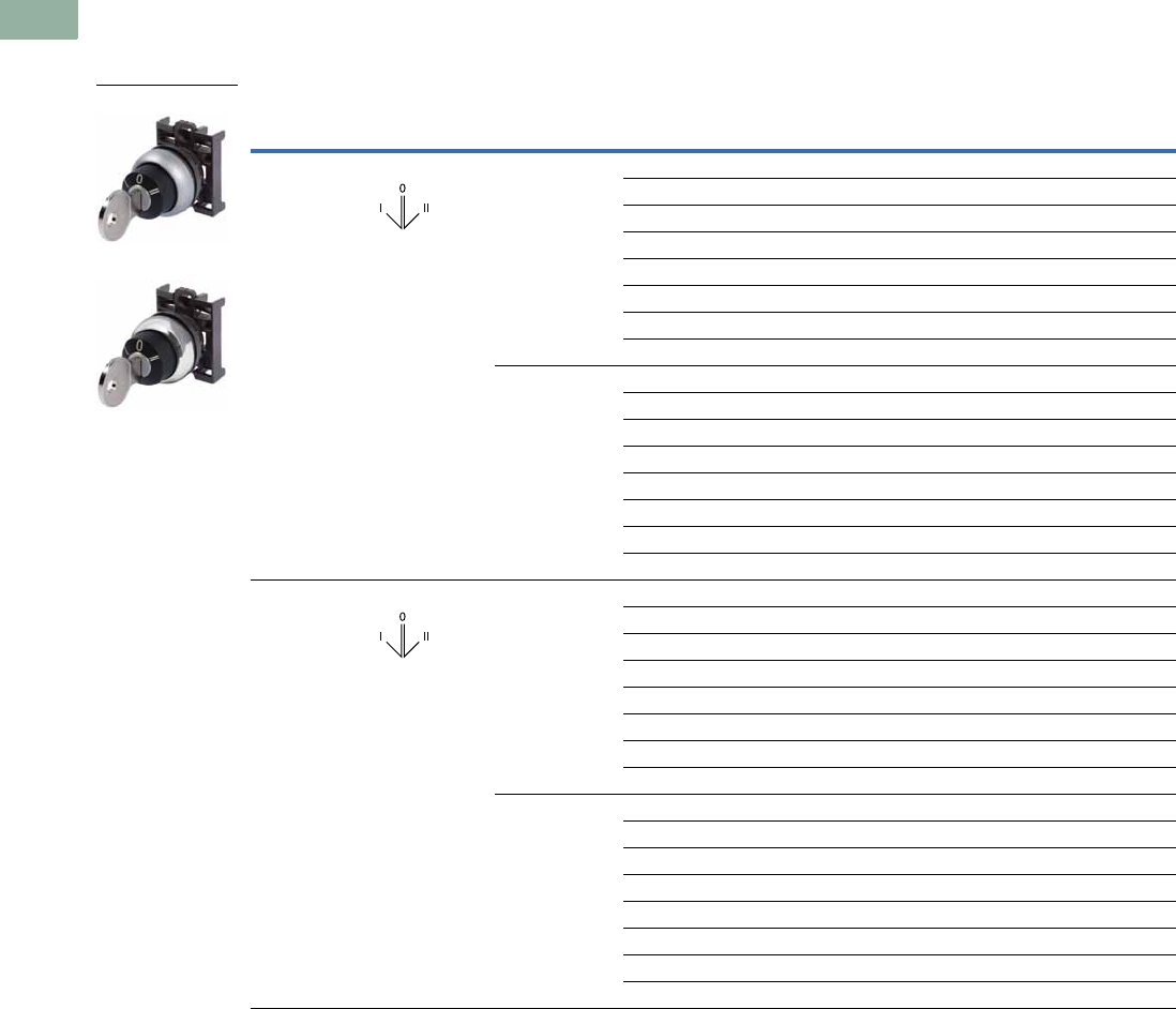
V7-T1-90 Volume 7—Logic Control, Operator Interface and Connectivity Solutions CA08100008E—March 2014 www.eaton.com
1
1
1
1
1
1
1
1
1
1
1
1
1
1
1
1
1
1
1
1
1
1
1
1
1
1
1
1
1
1
1.5
Pushbuttons and Indicating Lights
22.5 mm Modular Pushbuttons—M22
Key-Operated Selector Switches 12
Components
Operators Only, continued 3
Notes
1 Includes one key.
2 Key removal positions can be modified in the field using coding adapters; see chart on Page V7-T1-118.
3 Includes contact block mounting adapter.
Type Switching Position
Key Removal
Position Key Code
Silver Bezel
Catalog Number
Black Bezel
Catalog Number
Metal Bezel
Catalog Number
Three-position Maintained Return from left,
key removable center
MS1 M22-WRS3-A7 M22S-WRS3-A7 M22M-WRS3-A7
MS2 M22-WRS3-MS2-A7 M22S-WRS3-MS2-A7 M22M-WRS3-MS2-A7
MS3 M22-WRS3-MS3-A7 M22S-WRS3-MS3-A7 M22M-WRS3-MS3-A7
MS4 M22-WRS3-MS4-A7 M22S-WRS3-MS4-A7 M22M-WRS3-MS4-A7
MS5 M22-WRS3-MS5-A7 M22S-WRS3-MS5-A7 M22M-WRS3-MS5-A7
MS6 M22-WRS3-MS6-A7 M22S-WRS3-MS6-A7 M22M-WRS3-MS6-A7
MS7 M22-WRS3-MS7-A7 M22S-WRS3-MS7-A7 M22M-WRS3-MS7-A7
MS8 M22-WRS3-MS8-A7 M22S-WRS3-MS8-A7 M22M-WRS3-MS8-A7
Return from left,
key removable
center/right
MS1 M22-WRS3-A6 M22S-WRS3-A6 M22M-WRS3-A6
MS2 M22-WRS3-MS2-A6 M22S-WRS3-MS2-A6 M22M-WRS3-MS2-A6
MS3 M22-WRS3-MS3-A6 M22S-WRS3-MS3-A6 M22M-WRS3-MS3-A6
MS4 M22-WRS3-MS4-A6 M22S-WRS3-MS4-A6 M22M-WRS3-MS4-A6
MS5 M22-WRS3-MS5-A6 M22S-WRS3-MS5-A6 M22M-WRS3-MS5-A6
MS6 M22-WRS3-MS6-A6 M22S-WRS3-MS6-A6 M22M-WRS3-MS6-A6
MS7 M22-WRS3-MS7-A6 M22S-WRS3-MS7-A6 M22M-WRS3-MS7-A6
MS8 M22-WRS3-MS8-A6 M22S-WRS3-MS8-A6 M22M-WRS3-MS8-A6
Three-position Maintained Return from right,
key removable left/
center
MS1 M22-WRS3-A4 M22S-WRS3-A4 M22M-WRS3-A4
MS2 M22-WRS3-MS2-A4 M22S-WRS3-MS2-A4 M22M-WRS3-MS2-A4
MS3 M22-WRS3-MS3-A4 M22S-WRS3-MS3-A4 M22M-WRS3-MS3-A4
MS4 M22-WRS3-MS4-A4 M22S-WRS3-MS4-A4 M22M-WRS3-MS4-A4
MS5 M22-WRS3-MS5-A4 M22S-WRS3-MS5-A4 M22M-WRS3-MS5-A4
MS6 M22-WRS3-MS6-A4 M22S-WRS3-MS6-A4 M22M-WRS3-MS6-A4
MS7 M22-WRS3-MS7-A4 M22S-WRS3-MS7-A4 M22M-WRS3-MS7-A4
MS8 M22-WRS3-MS8-A4 M22S-WRS3-MS8-A4 M22M-WRS3-MS8-A4
Return from right,
key removable center
MS1 M22-WRS3-A5 M22S-WRS3-A5 M22M-WRS3-A5
MS2 M22-WRS3-MS2-A5 M22S-WRS3-MS2-A5 M22M-WRS3-MS2-A5
MS3 M22-WRS3-MS3-A5 M22S-WRS3-MS3-A5 M22M-WRS3-MS3-A5
MS4 M22-WRS3-MS4-A5 M22S-WRS3-MS4-A5 M22M-WRS3-MS4-A5
MS5 M22-WRS3-MS5-A5 M22S-WRS3-MS5-A5 M22M-WRS3-MS5-A5
MS6 M22-WRS3-MS6-A5 M22S-WRS3-MS6-A5 M22M-WRS3-MS6-A5
MS7 M22-WRS3-MS7-A5 M22S-WRS3-MS7-A5 M22M-WRS3-MS7-A5
MS8 M22-WRS3-MS8-A5 M22S-WRS3-MS8-A5 M22M-WRS3-MS8-A5
M22-WS3-X93
M22M-WS3-X93
60°60°
60°60°
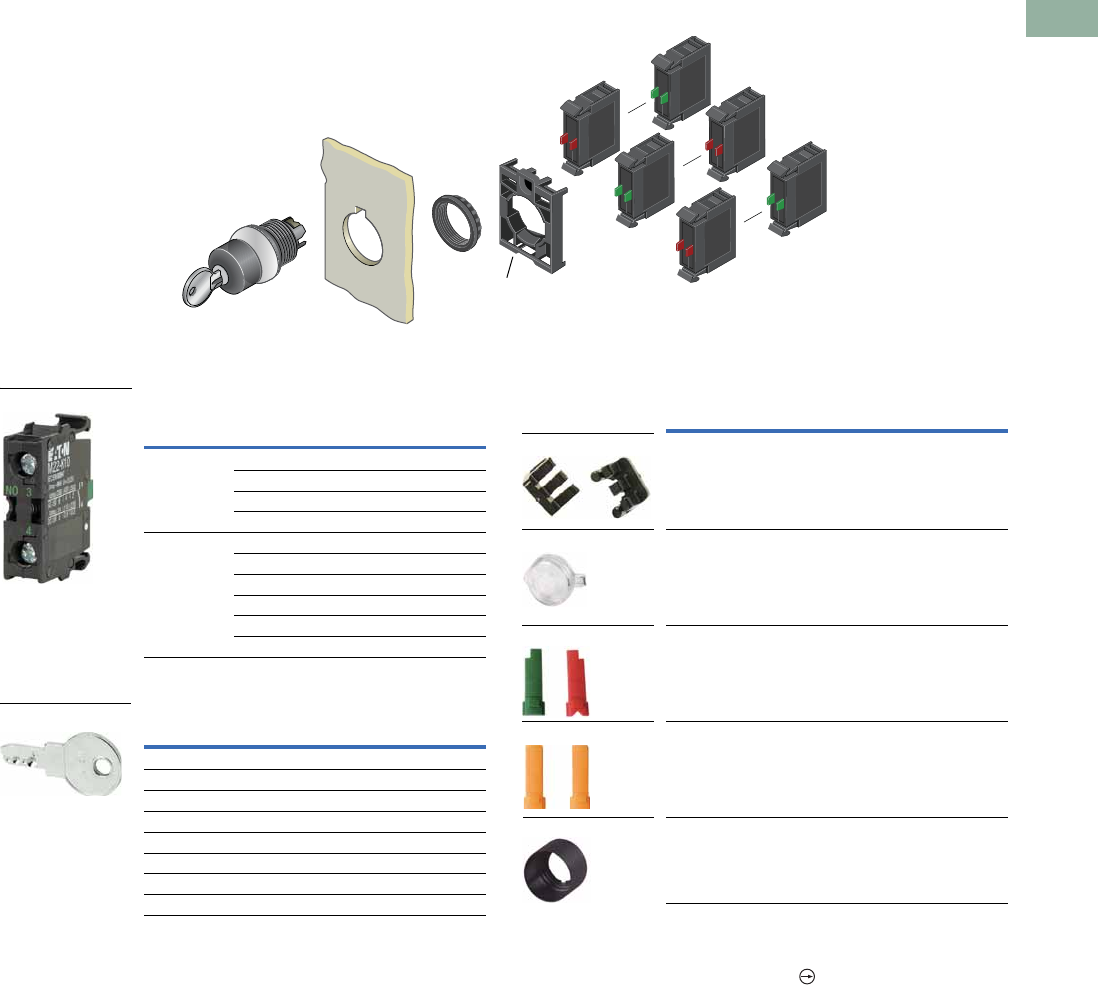
Volume 7—Logic Control, Operator Interface and Connectivity Solutions CA08100008E—March 2014 www.eaton.com V7-T1-91
1
1
1
1
1
1
1
1
1
1
1
1
1
1
1
1
1
1
1
1
1
1
1
1
1
1
1
1
1
1
1.5
Pushbuttons and Indicating Lights
22.5 mm Modular Pushbuttons—M22
Key-Operated Selector Switches
Components
Contact Blocks 1
Extra Keys
Accessories
Notes
1For complete listing of available contact blocks, see Accessories,
Pages V7-T1-111 to V7-T1-116.
2All NC contact blocks are positively driven contact.
3Plunger needed to actuate center-mounted contact blocks. Used for non-illuminated
three-position selector switches only.
4Enables a keyed selector switch to be set to user-selected key withdraw position.
max. 5mm
thickness
Note: Included
with operator.
Terminal
Type
Contact
Configuration 2Catalog Number
Screw NO M22-K10
NO, early-make M22-K10P
NC M22-K01
NC, late-break M22-K01D
Spring-cage NO M22-CK10
NC M22-CK01
NC, late-break M22-CK01D
2NO M22-CK20
2NC M22-CK02
NO-NC M22-CK11
Key Code Catalog Number
MS1 M22-ES-MS1
MS2 M22-ES-MS2
MS3 M22-ES-MS3
MS4 M22-ES-MS4
MS5 M22-ES-MS5
MS6 M22-ES-MS6
MS7 M22-ES-MS7
MS8 M22-ES-MS8
M22-K10
M22-ES-MS1
Description Catalog Number
Plunger bridge 3M22-XW
Key cover M22-XWS
Key withdraw adapter 4M22-XC-R
Coding adapter M22-XC-Y
Guard ring M22-XGWK
M22-XC-Y
M22-XWS
M22-XC-R
M22-XW
M22-XGWK

V7-T1-92 Volume 7—Logic Control, Operator Interface and Connectivity Solutions CA08100008E—March 2014 www.eaton.com
1
1
1
1
1
1
1
1
1
1
1
1
1
1
1
1
1
1
1
1
1
1
1
1
1
1
1
1
1
1
1.5
Pushbuttons and Indicating Lights
22.5 mm Modular Pushbuttons—M22
Mushroom Head Pushbuttons
Product Description
Eaton’s M22 mushroom head
operators are a durable and
unique way to include
standard pushbutton
functionality. Like the
standard pushbutton line,
the maintained pushbuttons
are field convertible to
momentary. They also offer
laser engraving and a robust
five million mechanical
operations on the standard
momentary operator. As with
all operators, they can be
ordered as a ready to install
complete device or as
modular components.
Features
●Field convertible from
maintained to momentary
(available on maintained
pushbuttons only)
●Customizable laser
engraving on all buttons
●More than five million
mechanical operations on
momentary and one million
on maintained pushbuttons
●Modular construction
makes assembly fast and
simplifies stocking of
components and complete
devices
●Capable of communicating
via ASi protocol with ASi
adapter modules
Protection Type
●IP67, IP69K
●NEMA 4X, 13
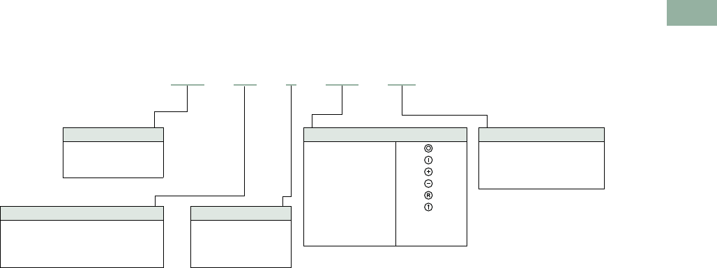
Volume 7—Logic Control, Operator Interface and Connectivity Solutions CA08100008E—March 2014 www.eaton.com V7-T1-93
1
1
1
1
1
1
1
1
1
1
1
1
1
1
1
1
1
1
1
1
1
1
1
1
1
1
1
1
1
1
1.5
Pushbuttons and Indicating Lights
22.5 mm Modular Pushbuttons—M22
Catalog Number Selection
Catalog Number Selection is for illustrative purposes only and not to be used to create new catalog numbers.
Mushroom Head Pushbuttons
Bezel
M22 = Silver
M22S =Black
M22M =Metal
Operator Type
DP = Non-illuminated momentary
mushroom head pushbutton
DRP = Non-illuminated maintained
mushroom head pushbutton
Operator Color
R =Red
S =Black
G = Green
Y = Yellow 1When ordering, specify inscription per
catalog number suffix from the Symbols
Library (see Pages
V7-T1-129 to
V7-T1-136) into the Order Notes.
For example, M22-DP-R-ETCH;
Order Notes: Mark with symbol X91,
Line item #_.
Plate Inscription
ETCH =Custom
1
GB0 =STOP
GB1 =START
GB3 =UP
GB4 = DOWN
GB5 =OFF
GB6 =ON
GB15 =FORWARD
GB16 = REVERSE
X0 =
X1 =
X4 =
X5 =
X6 =
X7 =
M22 –DP–R–GB4–K01
Contact Blocks
K01 =NC
K10 =NO
K11 =NO-NC
K12 = 1NO-2NC
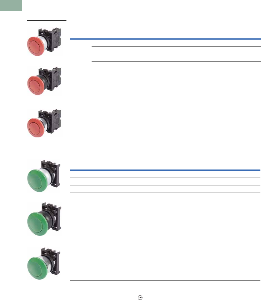
V7-T1-94 Volume 7—Logic Control, Operator Interface and Connectivity Solutions CA08100008E—March 2014 www.eaton.com
1
1
1
1
1
1
1
1
1
1
1
1
1
1
1
1
1
1
1
1
1
1
1
1
1
1
1
1
1
1
1.5
Pushbuttons and Indicating Lights
22.5 mm Modular Pushbuttons—M22
Product Selection
Mushroom Head Pushbuttons, Momentary 1
Complete Devices
Operators Only 2
Notes
1 35 mm diameter mushroom head button.
2 Includes contact block mounting adapter.
Button
Color
Contact Block
Configuration 2
Silver Bezel
Catalog Number
Black Bezel
Catalog Number
Metal Bezel
Catalog Number
Red NC M22-DP-R-K01 M22S-DP-R-K01 M22M-DP-R-K01
2NC M22-DP-R-K02 M22S-DP-R-K02 M22M-DP-R-K02
1NO-2NC M22-DP-R-K12 M22S-DP-R-K12 M22M-DP-R-K12
1NO-1NC M22-DP-R-K11 M22S-DP-R-K11 M22M-DP-R-K11
Button Color
Silver Bezel
Catalog Number
Black Bezel
Catalog Number
Metal Bezel
Catalog Number
Black M22-DP-S M22S-DP-S M22M-DP-S
Red M22-DP-R M22S-DP-R M22M-DP-R
Green M22-DP-G M22S-DP-G M22M-DP-G
Yellow M22-DP-Y M22S-DP-Y M22M-DP-Y
M22-DP-R-K01
M22S-DP-R-K01
M22M-DP-R-K01
M22-DP-G
M22S-DP-G
M22M-DP-G
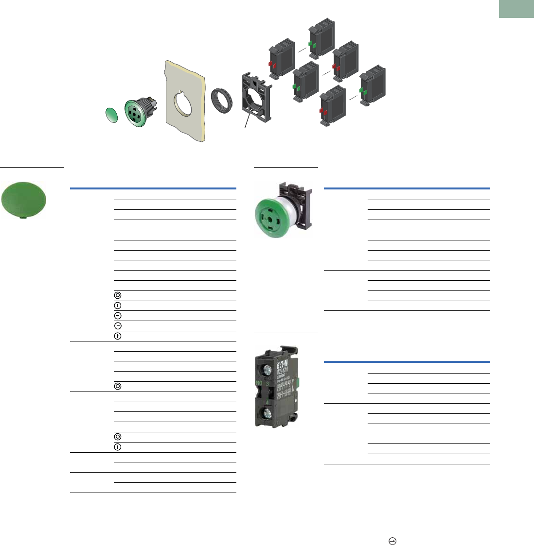
Volume 7—Logic Control, Operator Interface and Connectivity Solutions CA08100008E—March 2014 www.eaton.com V7-T1-95
1
1
1
1
1
1
1
1
1
1
1
1
1
1
1
1
1
1
1
1
1
1
1
1
1
1
1
1
1
1
1.5
Pushbuttons and Indicating Lights
22.5 mm Modular Pushbuttons—M22
Non-Illuminated Mushroom Head Pushbuttons, Momentary 1
Components
Mushroom Head Plates Insertless Mushroom Head Operators
Contact Blocks 4
Notes
135 mm diameter mushroom head button.
2Minimum order quantity of (10).
3When ordering, specify inscription per catalog number suffix from the Symbols
Library (see Pages V7-T1-129 to V7-T1-136) into the Order Notes.
For example, M22-XDP-S-ETCH; Order Notes: Mark with symbol X91, Line item #_.
4For complete listing of available contact blocks, see Accessories,
Pages V7-T1-111 to V7-T1-116.
5All NC contact blocks are positively driven contact.
Note: Included
with operator.
Color Inscription Catalog Number
Black -— M22-XDP-S 2
Custom M22-XDP-S-ETCH 3
STOP M22-XDP-S-GB0
START M22-XDP-S-GB1
FORWARD M22-XDP-S-GB15
REVERSE M22-XDP-S-GB16
UP M22-XDP-S-GB3
DOWN M22-XDP-S-GB4
OFF M22-XDP-S-GB5
ON M22-XDP-S-GB6
M22-XDP-S-X0
M22-XDP-S-X1
M22-XDP-S-X4
M22-XDP-S-X5
M22-XDP-S-X7
Red — M22-XDP-R 2
Custom M22-XDP-R-ETCH 3
STOP M22-XDP-R-GB0
OFF M22-XDP-R-GB5
M22-XDP-R-X0
Green — M22-XDP-G 2
Custom M22-XDP-G-ETCH 3
START M22-XDP-G-GB1
ON M22-XDP-G-GB6
M22-XDP-G-X0
M22-XDP-G-X1
White — M22-XDP-W 2
Custom M22-XDP-W-ETCH 3
Yellow — M22-XDP-Y 2
Custom M22-XDP-Y-ETCH 3
M22-XDP-G
Bezel Color Catalog Number
Silver Black M22-DP-S-X
Red M22-DP-R-X
Green M22-DP-G-X
Yellow M22-DP-Y-X
Black Black M22S-DP-S-X
Red M22S-DP-R-X
Green M22S-DP-G-X
Yellow M22S-DP-Y-X
Metal Black M22M-DP-S-X
Red M22M-DP-R-X
Green M22M-DP-G-X
Yellow M22M-DP-Y-X
Terminal
Type
Contact
Configuration 5Catalog Number
Screw NO M22-K10
NO, early-make M22-K10P
NC M22-K01
NC, late-break M22-K01D
Spring-cage NO M22-CK10
NC M22-CK01
NC, late-break M22-CK01D
2NO M22-CK20
2NC M22-CK02
NO-NC M22-CK11
M22-DP-G-X
M22-K10
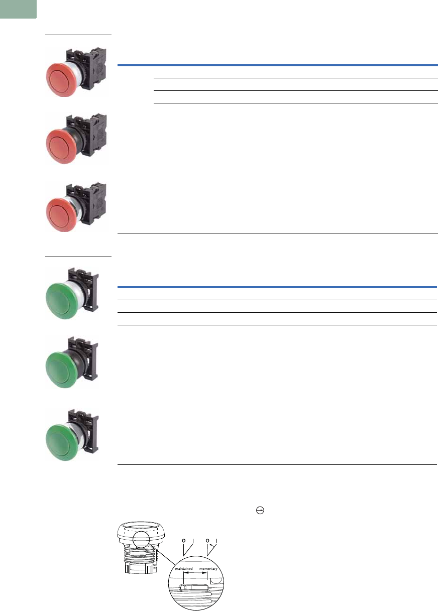
V7-T1-96 Volume 7—Logic Control, Operator Interface and Connectivity Solutions CA08100008E—March 2014 www.eaton.com
1
1
1
1
1
1
1
1
1
1
1
1
1
1
1
1
1
1
1
1
1
1
1
1
1
1
1
1
1
1
1.5
Pushbuttons and Indicating Lights
22.5 mm Modular Pushbuttons—M22
Product Selection
Non-Illuminated Mushroom Head Pushbuttons, Maintained 12
Complete Devices
Operators Only
Notes
1 35 mm diameter mushroom head button.
2 Maintained pushbuttons can be converted in the field to momentary operation by switching the locking ring,
which is accessible through the side of the operator body.
3 All NC contact blocks are positively driven contact.
Note: This pilot device features a selectable function switch that enables the device
to be set to either maintained or momentary operation.
Button
Color
Contact Block
Configuration 2
Silver Bezel
Catalog Number
Black Bezel
Catalog Number
Metal Bezel
Catalog Number
Red NC M22-DRP-R-K01 M22S-DRP-R-K01 M22M-DRP-R-K01
2NC M22-DRP-R-K02 M22S-DRP-R-K02 M22M-DRP-R-K02
1NO-2NC M22-DRP-R-K12 M22S-DRP-R-K12 M22M-DRP-R-K12
1NO-1NC M22-DRP-R-K11 M22S-DRP-R-K11 M22M-DRP-R-K11
Button Color
Silver Bezel
Catalog Number
Black Bezel
Catalog Number
Metal Bezel
Catalog Number
Black M22-DRP-S M22S-DRP-S M22M-DRP-S
Red M22-DRP-R M22S-DRP-R M22M-DRP-R
Green M22-DRP-G M22S-DRP-G M22M-DRP-G
Yellow M22-DRP-Y M22S-DRP-Y M22M-DRP-Y
M22-DRP-R-K01
M22S-DRP-R-K01
M22M-DRP-R-K01
M22-DRP-G
M22S-DRP-G
M22M-DRP-G
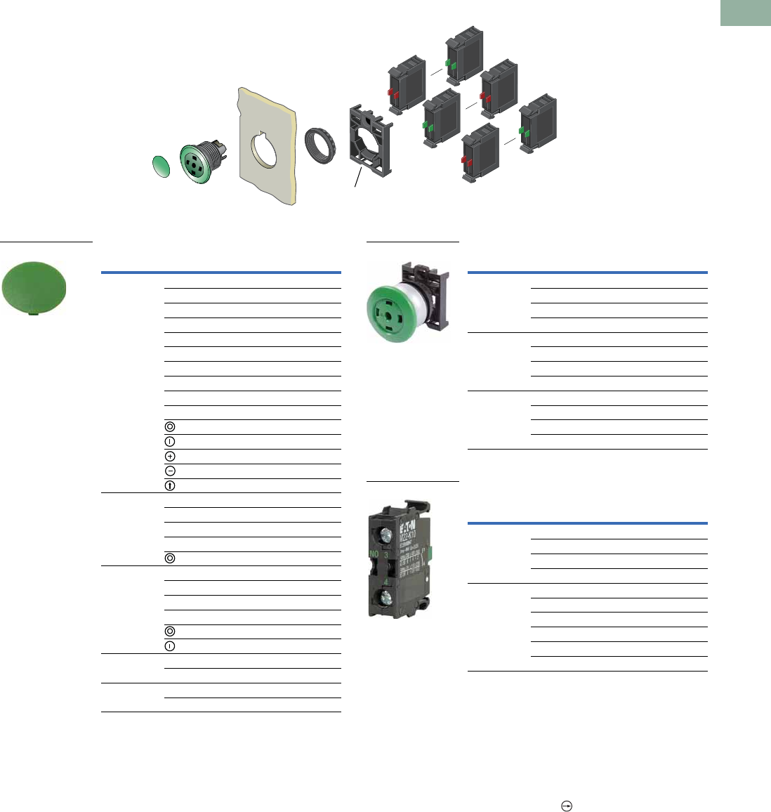
Volume 7—Logic Control, Operator Interface and Connectivity Solutions CA08100008E—March 2014 www.eaton.com V7-T1-97
1
1
1
1
1
1
1
1
1
1
1
1
1
1
1
1
1
1
1
1
1
1
1
1
1
1
1
1
1
1
1.5
Pushbuttons and Indicating Lights
22.5 mm Modular Pushbuttons—M22
Non-Illuminated Mushroom Head Pushbuttons, Maintained 12
Components
Mushroom Head Plates 5Insertless Mushroom Head Operators
Contact Blocks 5
Notes
135 mm diameter mushroom head button.
2Maintained pushbuttons can be converted in the field to momentary operation by
switching the locking ring, which is accessible through the side of the operator body.
3Minimum order quantity of (10).
4When ordering, specify inscription per catalog number suffix from the Symbols
Library (see Pages V7-T1-129 to V7-T1-136) into the Order Notes.
For example, M22-XDP-S-ETCH; Order Notes: Mark with symbol X91, Line item #_.
5For complete listing of available button plates and contact blocks, see Accessories,
Pages V7-T1-111 to V7-T1-116.
6All NC contact blocks are positively driven contact.
Note: Included
with operator.
Color Inscription Catalog Number
Black — M22-XDP-S 3
Custom M22-XDP-S-ETCH 4
STOP M22-XDP-S-GB0
START M22-XDP-S-GB1
FORWARD M22-XDP-S-GB15
REVERSE M22-XDP-S-GB16
UP M22-XDP-S-GB3
DOWN M22-XDP-S-GB4
OFF M22-XDP-S-GB5
ON M22-XDP-S-GB6
M22-XDP-S-X0
M22-XDP-S-X1
M22-XDP-S-X4
M22-XDP-S-X5
M22-XDP-S-X7
Red — M22-XDP-R 3
Custom M22-XDP-R-ETCH 4
STOP M22-XDP-R-GB0
OFF M22-XDP-R-GB5
M22-XDP-R-X0
Green — M22-XDP-G 3
Custom M22-XDP-G-ETCH 4
START M22-XDP-G-GB1
ON M22-XDP-G-GB6
M22-XDP-G-X0
M22-XDP-G-X1
White — M22-XDP-W 3
Custom M22-XDP-W-ETCH 4
Yellow — M22-XDP-Y 3
Custom M22-XDP-Y-ETCH 4
M22-XDP-G
Bezel Color Catalog Number
Silver Black M22-DRP-S-X
Red M22-DRP-R-X
Green M22-DRP-G-X
Yellow M22-DRP-Y-X
Black Black M22S-DRP-S-X
Red M22S-DRP-R-X
Green M22S-DRP-G-X
Yellow M22S-DRP-Y-X
Metal Black M22M-DRP-S-X
Red M22M-DRP-R-X
Green M22M-DRP-G-X
Yellow M22M-DRP-Y-X
Terminal
Type
Contact
Configuration 6Catalog Number
Screw NO M22-K10
NO, early-make M22-K10P
NC M22-K01
NC, late-break M22-K01D
Spring-cage NO M22-CK10
NC M22-CK01
NC, late-break M22-CK01D
2NO M22-CK20
2NC M22-CK02
NO-NC M22-CK11
M22-DRP-G-X
M22-K10
V7-T1-98 Volume 7—Logic Control, Operator Interface and Connectivity Solutions CA08100008E—March 2014 www.eaton.com
1
1
1
1
1
1
1
1
1
1
1
1
1
1
1
1
1
1
1
1
1
1
1
1
1
1
1
1
1
1
1.5
Pushbuttons and Indicating Lights
22.5 mm Modular Pushbuttons—M22
Double Pushbuttons
Product Description
Eaton’s M22 double
pushbutton line is perfect for
applications such as motor
and pump starting, as well as
anytime space is limited. In
addition to the two buttons
that fit in one 22 mm hole is
the integrated white
indicating light between
them. These three operators
allow for multiple functions to
occur in a single space.
Green/red, black/white and
black/black color options
along with laser engraving
allow for further custom
applications.
Features
●Flush and extended, as
well as color options allow
for the perfect combination
button
●Integrated indicating light
adds even more
functionality in one
standard 22 mm hole
●Customizable laser
engraving on all buttons
●LED offering only for
improved brightness
quality and up to 100,000
hours of operation
●More than 200,000
mechanical operations
●Capable of communicating
via ASi protocol with ASi
adapter modules
Protection Type
●IP66
●NEMA 4X, 13
Catalog Number Selection
Catalog Number Selection is for illustrative purposes only and not to be used to create new catalog numbers.
Double Pushbuttons
Bezel
M22 = Silver
M22S =Black
M22 –DDL–GR–GB5–K10–G
Operator Type
DDL = Extended buttons and light
DDLF = Flush buttons and light
DDLM = Extended bottom button
Light Units
12–30 Vac/Vdc
W =White
R =Red
G =Green
B =Blue
85–264 Vac
230W =White
230R =Red
230G =Green
230B =Blue
Inscription
GB0 =STOP
GB1 =START
GB3 =UP
GB4 = DOWN
GB5 =OFF
GB6 =ON
GB14 = RESET
GB15 =FORWARD
GB16 = REVERSE
X0 =
X1 =
X5 =
X5 =
X6 =
X7 =
X5 =
Contact Blocks
K10 =1NO
K01 =1NC
K20 =2NO
K02 =2NC
K11 = 1NO-1NC
K30 =3NO
K03 =3NC
K21 = 2NO-1NC
K12 = 1NO-2NC
Button Plate Color
Top Bottom
GR =
WS =
S =
Green
White
Black
Red
Black
Black
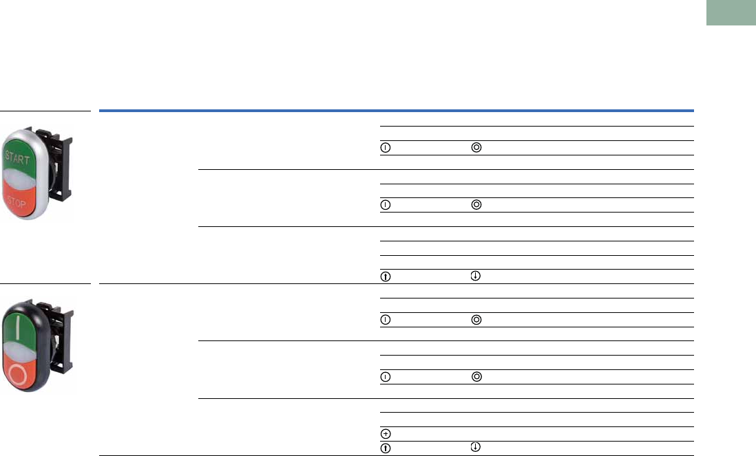
Volume 7—Logic Control, Operator Interface and Connectivity Solutions CA08100008E—March 2014 www.eaton.com V7-T1-99
1
1
1
1
1
1
1
1
1
1
1
1
1
1
1
1
1
1
1
1
1
1
1
1
1
1
1
1
1
1
1.5
Pushbuttons and Indicating Lights
22.5 mm Modular Pushbuttons—M22
Product Selection
Components
Double Pushbuttons, Extended Pushbuttons and Center Light, Momentary
Operators Only 1
Notes
1 Includes contact block mounting adapter.
2 When ordering, specify inscription per catalog number suffix from the Symbols Library
(see
Pages
V7-T1-129 to V7-T1-136
)
into the Order Notes.
For example, M22-DDL-S-ETCH; Order Notes: Mark with symbol X91, Line item #_.
Color Inscription
Catalog NumberBezel Top Bottom Top Bottom
Silver Green Red — — M22-DDL-GR
Custom Custom M22-DDL-GR-ETCH 2
M22-DDL-GR-X1-X0
START STOP M22-DDL-GR-GB1-GB0
White Black — — M22-DDL-WS
Custom Custom M22-DDL-WS-ETCH 2
M22-DDL-WS-X1-X0
START STOP M22-DDL-WS-GB1-GB0
Black Black — — M22-DDL-S
Custom Custom M22-DDL-S-ETCH 2
——M22-DDL-S-X4-X5
M22-DDL-S-X7-X7
Black Green Red — — M22S-DDL-GR
Custom Custom M22S-DDL-GR-ETCH 2
M22S-DDL-GR-X1-X0
START STOP M22S-DDL-GR-GB1-GB0
White Black — — M22S-DDL-WS
Custom Custom M22S-DDL-WS-ETCH 2
M22S-DDL-WS-X1-X0
START STOP M22S-DDL-WS-GB1-GB0
Black Black — — M22S-DDL-S
Custom Custom M22S-DDL-S-ETCH 2
—M22S-DDL-S-X4-X5
M22S-DDL-S-X7-X7
M22-DDL-GR-GB1-GB0
M22S-DDL-GR-X1-X0
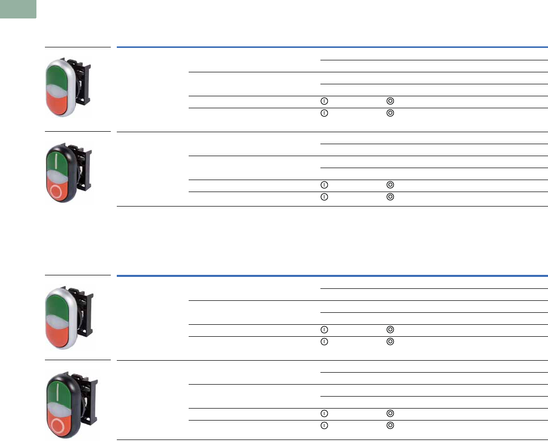
V7-T1-100 Volume 7—Logic Control, Operator Interface and Connectivity Solutions CA08100008E—March 2014 www.eaton.com
1
1
1
1
1
1
1
1
1
1
1
1
1
1
1
1
1
1
1
1
1
1
1
1
1
1
1
1
1
1
1.5
Pushbuttons and Indicating Lights
22.5 mm Modular Pushbuttons—M22
Double Pushbuttons, Flush Top Pushbuttons and Center Light, Momentary
Operators Only 1
Double Pushbuttons, Flush Top Pushbutton and Center Light, Extended Bottom Pushbutton, Momentary
Operators Only 1
Notes
1 Includes contact block mounting adapter.
2 When ordering, specify inscription per catalog number suffix from the Symbols Library
(see
Pages
V7-T1-129 to V7-T1-136
)
into the Order Notes.
For example, M22-DDLM-GR-ETCH; Order Notes: Mark with symbol X91, Line item #_.
Color Inscription
Catalog NumberBezel Top Bottom Top Bottom
Silver Green Red — — M22-DDLF-GR
Custom Custom M22-DDLF-GR-ETCH 2
White Black — — M22-DDLF-WS
Custom Custom M22-DDLF-WS-ETCH 2
Green Red M22-DDLF-GR-X1-X0
White Black M22-DDLF-WS-X1-X0
Black Green Red — — M22S-DDLF-GR
Custom Custom M22S-DDLF-GR-ETCH 2
White Black — — M22S-DDLF-WS
Custom Custom M22S-DDLF-WS-ETCH 2
Green Red M22S-DDLF-GR-X1-X0
White Black M22S-DDLF-WS-X1-X0
Color Inscription
Catalog NumberBezel Top Bottom Top Bottom
Silver Green Red — — M22-DDLM-GR
Custom Custom M22-DDLM-GR-ETCH 2
White Black — — M22-DDLM-WS
Custom Custom M22-DDLM-WS-ETCH 2
Green Red M22-DDLM-GR-X1-X0
White Black M22-DDLM-WS-X1-X0
Black Green Red — — M22S-DDLM-GR
Custom Custom M22S-DDLM-GR-ETCH 2
White Black — — M22S-DDLM-WS
Custom Custom M22S-DDLM-WS-ETCH 2
Green Red M22S-DDLM-GR-X1-X0
White Black M22S-DDLM-WS-X1-X0
M22-DDLF-GR
M22S-DDLF-GR-X1-X0
M22-DDLM-GR
M22-DDLM-GR-X1-X0
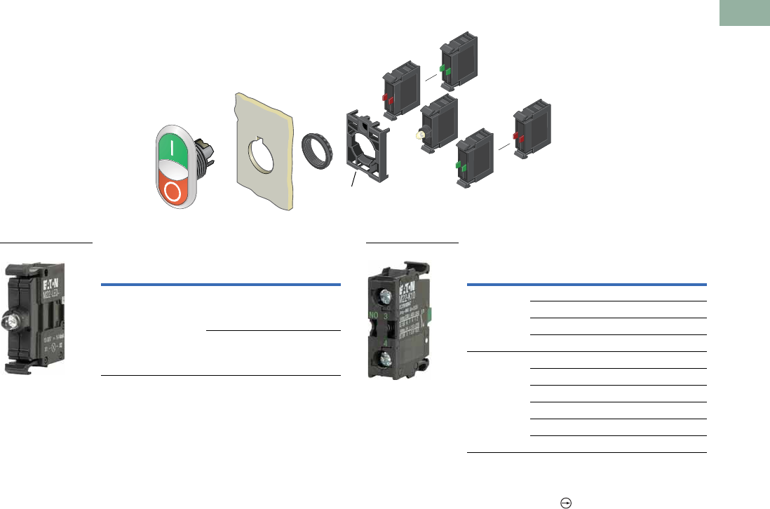
Volume 7—Logic Control, Operator Interface and Connectivity Solutions CA08100008E—March 2014 www.eaton.com V7-T1-101
1
1
1
1
1
1
1
1
1
1
1
1
1
1
1
1
1
1
1
1
1
1
1
1
1
1
1
1
1
1
1.5
Pushbuttons and Indicating Lights
22.5 mm Modular Pushbuttons—M22
Double Pushbuttons
Light Units 1 Contact Blocks
1
Notes
1For complete listing of available light units and contact blocks, see Accessories,
Pages V7-T1-111 to V7-T1-116.
2All NC contact blocks are positively driven contact.
max. 5mm
thickness
Note: Included
with operator.
Terminal
Type
LED
Color
Light Unit
Voltage Catalog Number
Screw White 12–30
Vac/Vdc
M22-LED-W
85–264
Vac
M22-LED230-W
M22-LED-W
Terminal
Type
Contact
Configuration 2Catalog Number
Screw NO M22-K10
NO, early-make M22-K10P
NC M22-K01
NC, late-break M22-K01D
Spring-cage NO M22-CK10
NC M22-CK01
NC, late-break M22-CK01D
2NO M22-CK20
2NC M22-CK02
NO-NC M22-CK11
M22-K10
V7-T1-102 Volume 7—Logic Control, Operator Interface and Connectivity Solutions CA08100008E—March 2014 www.eaton.com
1
1
1
1
1
1
1
1
1
1
1
1
1
1
1
1
1
1
1
1
1
1
1
1
1
1
1
1
1
1
1.5
Pushbuttons and Indicating Lights
22.5 mm Modular Pushbuttons—M22
Four-Way Pushbuttons
Product Description
Eaton’s M22 four-way push-
button is a truly unique
offering. A four-way
pushbutton offers four
different buttons mounted
in a single 22 mm hole. This
is ideal not only for an
application with limited
space, but also directional
applications (when ordered
with the four arrow engraving
option). Another unique
option is the interlocked
version, which prevents two
opposite buttons from being
actuated at the same time.
Features
●Four buttons in one
operator allows for
increased functionality in
limited space
●Optional interlocking
option, which prevents two
buttons from being
actuated at the same time
●Customizable laser
engraving on all buttons for
directional or other
applications
●Capable of communicating
via ASi protocol with ASi
adapter modules
Protection Type
●IP66
Catalog Number Selection
Catalog Number Selection is for illustrative purposes only and not to be used to create new catalog numbers.
Four-Way Pushbuttons
Bezel
M22 =Silver
M22S =Black
M22 –D4–S–X7–K01
Operator Type
D4 = Four-way pushbutton,
momentary, non-interlocked
DI4 = Four-way pushbutton,
momentary, interlocked
1When ordering, specify
inscription per catalog
number suffix from the Symbols
Library (see Pages V7-T1-129
to V7-T1-136) into the Order
Notes.
For example, M22-D4-S-ETCH;
Order Notes: Mark with symbol
X91, Line item #_.
Inscription
ETCH =Custom
1
X7 =
Contact Blocks
K10 =1NO
K01 =1NC
K20 =2NO
K02 =2NC
K11 = 1NO-1NC
K30 =3NO
K03 =3NC
K21 =2NO-1NC
K12 =1NO-2NC
Button Color
S =Black
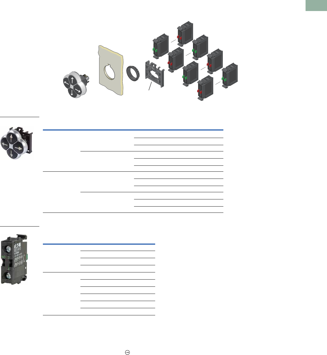
Volume 7—Logic Control, Operator Interface and Connectivity Solutions CA08100008E—March 2014 www.eaton.com V7-T1-103
1
1
1
1
1
1
1
1
1
1
1
1
1
1
1
1
1
1
1
1
1
1
1
1
1
1
1
1
1
1
1.5
Pushbuttons and Indicating Lights
22.5 mm Modular Pushbuttons—M22
Product Selection
Four-Way Pushbuttons, Momentary
Components
Operators Only 1
Contact Blocks 2
Notes
1 Includes contact block mounting adapter.
2 For complete listing of available contact blocks, see Accessories, Pages V7-T1-111 to V7-T1-116.
3 When ordering, specify inscription per catalog number suffix from the Symbols Library
(see
Pages
V7-T1-129 to V7-T1-136
)
into the Order Notes.
For example, M22-D4-S-ETCH; Order Notes: Mark with symbol X91, Line item #_.
4 All NC contact blocks are positively driven contact.
Type Bezel Color Inscription Catalog Number
Non-interlocked Silver Black — M22-D4-S
Custom M22-D4-S-ETCH 3
Directional arrows M22-D4-S-X7
Black Black — M22S-D4-S
Custom M22S-D4-S-ETCH 3
Directional arrows M22S-D4-S-X7
Interlocked Silver Black — M22-DI4-S
Custom M22-DI4-S-ETCH 3
Directional arrows M22-DI4-S-X7
Black Black — M22S-DI4-S
Custom M22S-DI4-S-ETCH 3
Directional arrows M22S-DI4-S-X7
Terminal
Type
Contact
Configuration 4Catalog Number
Screw NO M22-K10
NO, early-make M22-K10P
NC M22-K01
NC, late-break M22-K01D
Spring-cage NO M22-CK10
NC M22-CK01
NC, late-break M22-CK01D
2NO M22-CK20
2NC M22-CK02
NO-NC M22-CK11
max. 5mm
thickness
Note: Included
with operator.
M22-D4-S-X7
M22-K10

V7-T1-104 Volume 7—Logic Control, Operator Interface and Connectivity Solutions CA08100008E—March 2014 www.eaton.com
1
1
1
1
1
1
1
1
1
1
1
1
1
1
1
1
1
1
1
1
1
1
1
1
1
1
1
1
1
1
1.5
Pushbuttons and Indicating Lights
22.5 mm Modular Pushbuttons—M22
Joysticks
Product Description
Eaton’s M22 joystick line
comes in a wide variety of
options. From vertical and
horizontal two-position
switches to the maintained
four-position, these operators
fit a variety of applications. An
additional option, two switch
points, allows for eight
isolated circuits to be
actuated individually on a
single operator.
Features
●Available in four-position
and two-position
●Two switch point option
allows for two contacts in
each direction (up to eight
total contacts in one
operator)
●Capable of communicating
via ASi protocol with ASi
adapter modules
Protection Type
●IP66
Product Selection
Joysticks
Components
Operators 1
Note
1 Includes contact block mounting adapter.
Number of Directions
Switching
Position
Silver Bezel
Catalog Number
Black Bezel
Catalog Number
Metal Bezel
Catalog Number
Two-position horizontal Momentary M22-WJ2H M22S-WJ2H M22M-WJ2H
Two switch points M22-WJ2H-2P M22S-WJ2H-2P M22M-WJ2H-2P
Two-position horizontal Maintained M22-WRJ2H M22S-WRJ2H M22M-WRJ2H
Two-position vertical Momentary M22-WJ2V M22S-WJ2V M22M-WJ2V
Two switch points M22-WJ2V-2P M22S-WJ2V-2P M22M-WJ2V-2P
Two-position vertical Maintained M22-WRJ2V M22S-WRJ2V M22M-WRJ2V
Four-position Momentary M22-WJ4 M22S-WJ4 M22M-WJ4
Two switch points M22-WJ4-2P M22S-WJ4-2P M22M-WJ4-2P
Four-position Maintained M22-WRJ4 M22S-WRJ4 M22M-WRJ4
M22-WJ2H
M22M-WJ2H
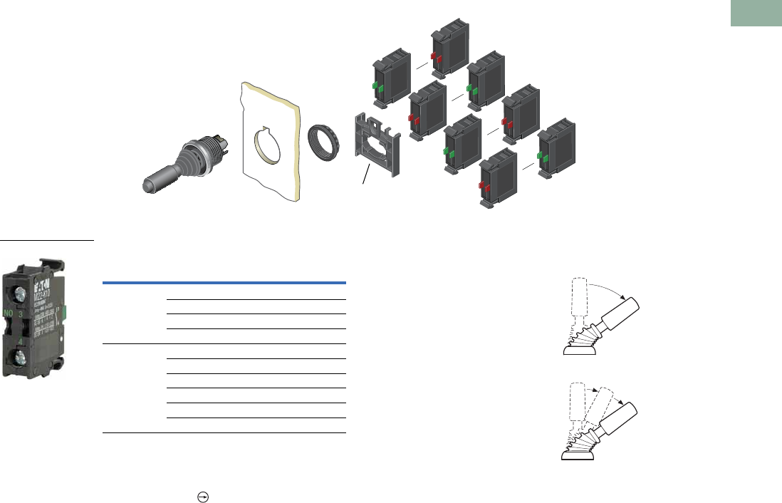
Volume 7—Logic Control, Operator Interface and Connectivity Solutions CA08100008E—March 2014 www.eaton.com V7-T1-105
1
1
1
1
1
1
1
1
1
1
1
1
1
1
1
1
1
1
1
1
1
1
1
1
1
1
1
1
1
1
1.5
Pushbuttons and Indicating Lights
22.5 mm Modular Pushbuttons—M22
Joysticks
Contact Blocks 12
Notes
1Includes contact block mounting adapter.
2For complete listing of available contact blocks, see Accessories,
Pages V7-T1-111 to V7-T1-116.
3All NC contact blocks are positively driven contact.
Joystick with Double Contact
The joystick allows the control
of up to four directions of
movement on machines.
Different variants of the
joystick have two/four-
positions and other variants
have two settings for each
position. This allows, for
example, two-speed settings
for each direction. For this
application, a standard
normally open contact and an
early-make contact are fitted
in series. Momentary contact
and latching contact versions
are available.
max. 5mm
thickness
Note: Included
with operator.
Terminal
Type
Contact
Configuration 3Catalog Number
Screw NO M22-K10
NO, early-make M22-K10P
NC M22-K01
NC, late-break M22-K01D
Spring-cage NO M22-CK10
NC M22-CK01
NC, late-break M22-CK01D
2NO M22-CK20
2NC M22-CK02
NO-NC M22-CK11
M22-K10
0
1
01
2
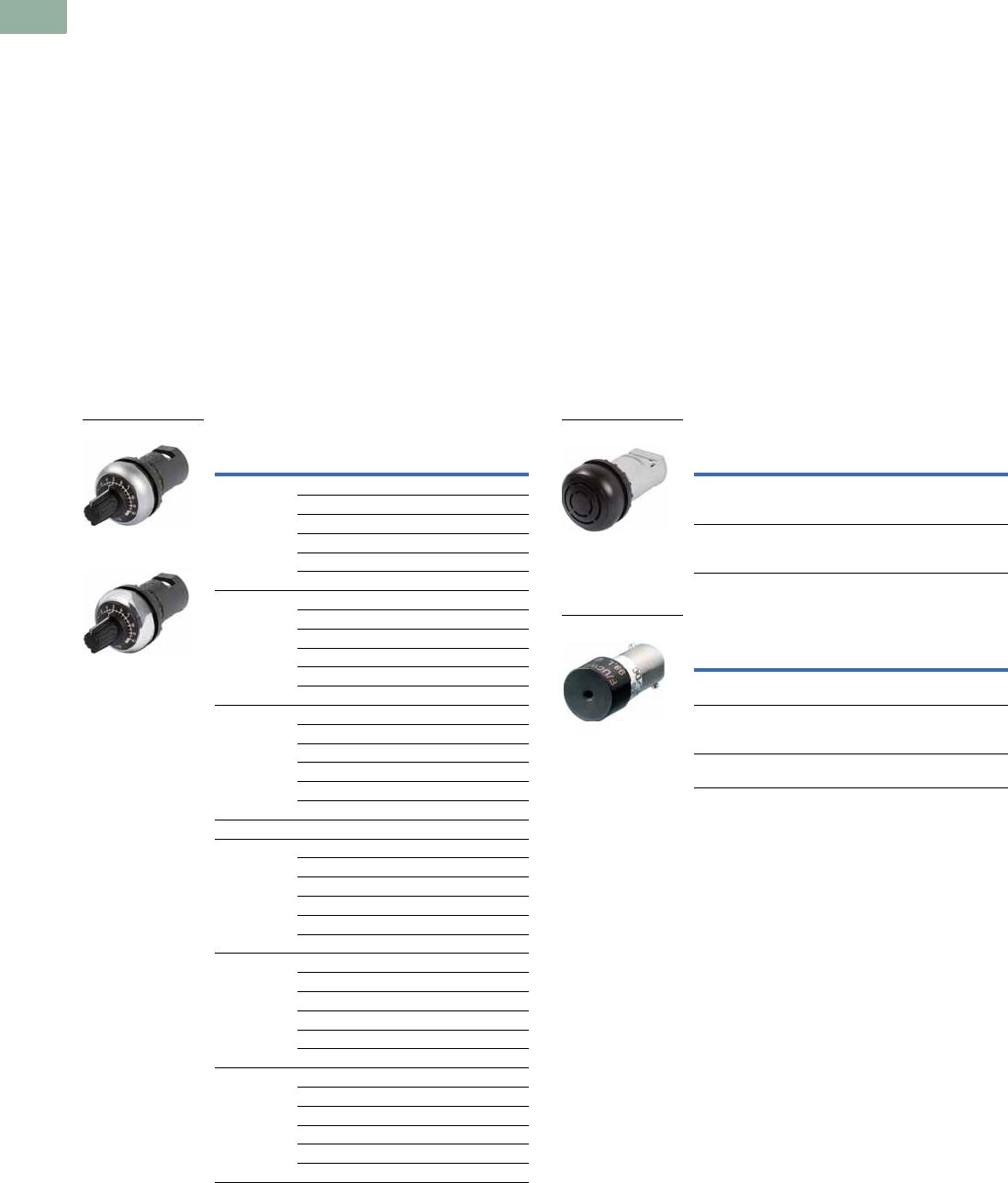
V7-T1-106 Volume 7—Logic Control, Operator Interface and Connectivity Solutions CA08100008E—March 2014 www.eaton.com
1
1
1
1
1
1
1
1
1
1
1
1
1
1
1
1
1
1
1
1
1
1
1
1
1
1
1
1
1
1
1.5
Pushbuttons and Indicating Lights
22.5 mm Modular Pushbuttons—M22
Potentiometers
Product Description
Eaton’s M22 potentiometers allow for a ready to use operator in
a conveniently sized package. M22 potentiometers include the
resistive element, instead of just a knob, and a built in legend
surrounding the knob. The slim design, with integrated contacts
and the range of resistances available, allows for a quick install.
Features
●Scale markings on the knob allows the operator to be used
without an additional legend plate
●Oversized knob option available
●Slim design allows for space saving and simple wiring and
installation
Protection Type
●IP66
●NEMA 4X, 13
Product Selection
Potentiometers
Complete Devices
Acoustic Devices
Product Description
Eaton’s M22 acoustic devices are a simple and aesthetic way to
add a buzzer or indicator to any application. Fitting in the same
22 mm hole, these devices can be ordered in continuous or
pulsed tone and with or without the IP40 enclosure.
Features
●Continuous or pulsed tone available
●83 dB / 10 cm decibel rating
●Slim design allows for space saving and simple wiring and
installation
Protection Type
●IP40
●NEMA 12
Product Selection
Acoustic Devices
Complete Devices
Buzzers
Bezel
Resistance
Rk Catalog Number
Silver 1 M22-R1K
4.7 M22-R4K7
10 M22-R10K
47 M22-R47K
100 M22-R100K
470 M22-R470K
Black 1 M22S-R1K
4.7 M22S-R4K7
10 M22S-R10K
47 M22S-R47K
100 M22S-R100K
470 M22S-R470K
Metal 1 M22M-R1K
4.7 M22M-R4K7
10 M22M-R10K
47 M22M-R47K
100 M22M-R100K
470 M22M-R470K
Oversized Knob
Silver 1 M22-R1K-RH
4.7 M22-R4K7-RH
10 M22-R10K-RH
47 M22-R47K-RH
100 M22-R100K-RH
470 M22-R470K-RH
Black 1 M22S-R1K-RH
4.7 M22S-R4K7-RH
10 M22S-R10K-RH
47 M22S-R47K-RH
100 M22S-R100K-RH
470 M22S-R470K-RH
Metal 1 M22M-R1K-RH
4.7 M22M-R4K7-RH
10 M22M-R10K-RH
47 M22M-R47K-RH
100 M22M-R100K-RH
470 M22M-R470K-RH
M22-R10K
M22M-R10K
Description
Decibel
Rating Catalog Number
Indicator with buzzer,
black continuous tone,
18–30 Vac/Vdc
83 dB/
10 cm
M22-AMC-XAM
Indicator with buzzer,
black pulsed tone,
18–30 Vac/Vdc
83 dB/
10 cm
M22-AMC-XAMP
Description
Decibel
Rating Catalog Number
Indicator without
buzzer, black
83 dB/
10 cm
M22-AMC
Buzzer only,
continuous tone,
18–30 Vac/Vdc
83 dB/
10 cm
M22-XAM
Buzzer only, pulsed
tone, 18–30 Vac/Vdc
83 dB/
10 cm
M22-XAMP
M22-AMC-XAM
M22-XAM
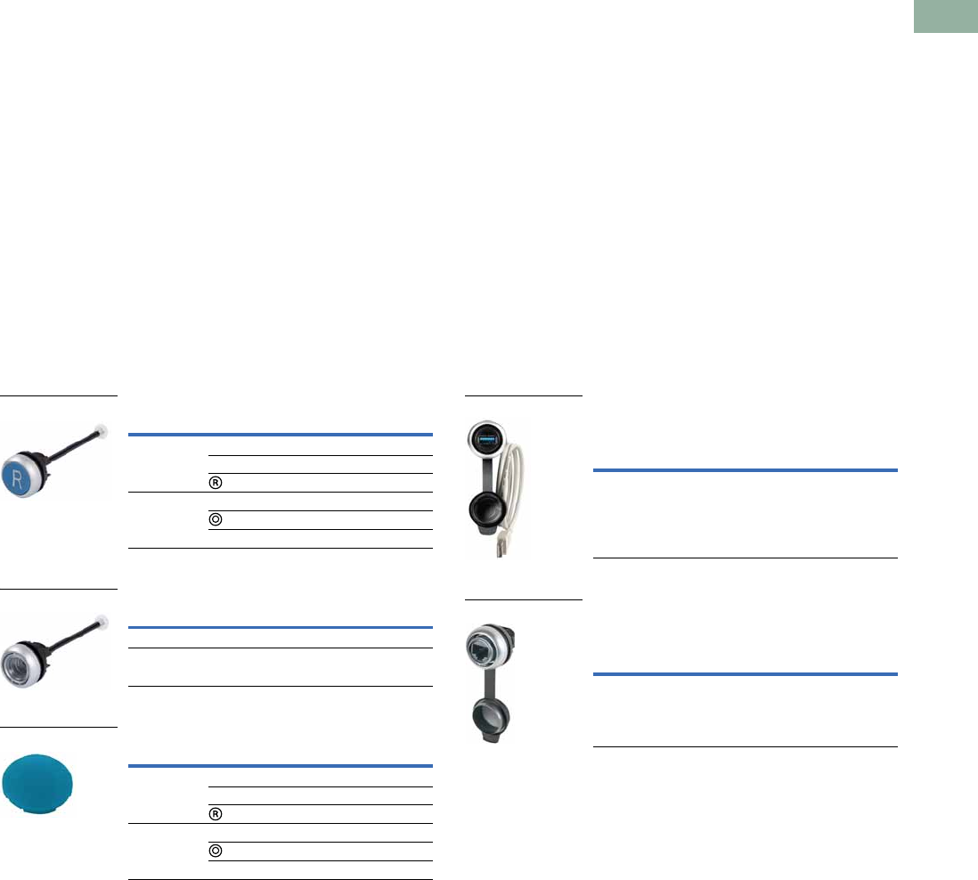
Volume 7—Logic Control, Operator Interface and Connectivity Solutions CA08100008E—March 2014 www.eaton.com V7-T1-107
1
1
1
1
1
1
1
1
1
1
1
1
1
1
1
1
1
1
1
1
1
1
1
1
1
1
1
1
1
1
1.5
Pushbuttons and Indicating Lights
22.5 mm Modular Pushbuttons—M22
Through-the-Door Operators
Product Description
Eaton’s M22 through-the-door operators use the same familiar
flush pushbutton look with the addition of a cut-to-length rod
that allows for a simple reset operator.
Features
●Customizable laser engraving on all buttons
●More than five million mechanical operations
●Pushrod can be cut to length
Protection Type
●IP67, IP69K
●NEMA 4X, 13
Product Selection
Through-the-Door Operators 1
Complete Devices
Buttonless Operator
Button Plates 2
Bulkhead Interfaces
Product Description
Eaton’s M22 bulkhead interfaces are another unique offering in
the M22 line. This device allows for a secure connection to any
USB or RJ45 connected device within an enclosure or panel.
With an IP65 rating when closed, these devices are not only
convenient, but robust and reliable.
Features
●Convenient and safe way to make a data connection to inside
of the panel without opening the panel door
Protection Type
●IP65 when closed, IP20 when connected
Product Selection
Bulkhead Interfaces
USB Socket 45
Used for USB connection plug IP65 when
closed, IP20 when connected.
RJ45 Socket 6
Used for RJ45 Ethernet connection IP65
when closed, IP20 when connected.
Notes
1The pushrod is 3.24 in long and can be cut to length.
2Any combination of plate color and inscription is available.
3Minimum order quantity of (10).
4USB interface is complete with 2-ft-long USB cable.
5USB interface is UL Listed, CSA approved and USB 3.0.
6RJ45 interface is an eight-wire connector.
Color Inscription Catalog Number
Blue — M22-DZ-B
RESET M22-DZ-B-GB14
M22-DZ-B-X6
Red — M22-DZ-R
M22-DZ-R-X0
STOP M22-DZ-R-GB0
Bezel Catalog Number
Silver M22-DZ-X
Metal M22M-DZ-X
Color Inscription Catalog Number
Blue — M22-XD-B 3
RESET M22-XD-B-GB14
M22-XD-B-X6
Red — M22-XD-R 3
M22-XD-R-X0
STOP M22-XD-R-GB0
M22-DZ-B-X6
M22-DZ-X
M22-XD-B
Bezel Catalog Number
Silver M22-USB-SA
Bezel Catalog Number
Silver M22-RJ45-SA
M22-USB-SA
M22-RJ45-SA

V7-T1-108 Volume 7—Logic Control, Operator Interface and Connectivity Solutions CA08100008E—March 2014 www.eaton.com
1
1
1
1
1
1
1
1
1
1
1
1
1
1
1
1
1
1
1
1
1
1
1
1
1
1
1
1
1
1
1.5
Pushbuttons and Indicating Lights
22.5 mm Modular Pushbuttons—M22
ASi Adapter Modules
Product Description
Eaton’s M22 ASi adapter modules add functionality to every
operator in the M22 line. These devices can be connected to any
operator that uses contact blocks or LED units. The simple snap-
on design allows for a quick integration of an entire application of
operators to a communicating network.
Features
●Allows compatible operators to communicate on an ASi
network
●Not only can the status of a contact block be read, but LEDs
can be illuminated by an ASi adapter
●ASi adapters simply clip on to the back of the contact blocks
and LEDs
●Insulation displacement connectors allow for installation of
adapters without any tools
●Two integrated LEDs indicate status of communications
Protection Type
●IP20
Product Selection
ASi Adapter Modules
Complete Devices
Description Catalog Number
ASi adapter module M22-ASI
ASi adapter module for
base mounting
M22-ASI-C
ASi adapter module for
E-stop
M22-ASI-S
ASi adapter module for
E-stop base mounting
M22-ASI-CS
M22-ASI
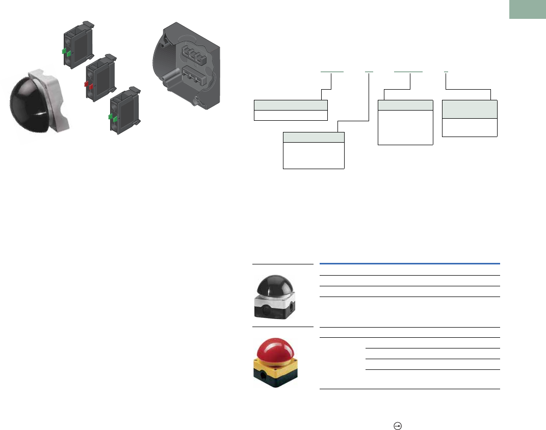
Volume 7—Logic Control, Operator Interface and Connectivity Solutions CA08100008E—March 2014 www.eaton.com V7-T1-109
1
1
1
1
1
1
1
1
1
1
1
1
1
1
1
1
1
1
1
1
1
1
1
1
1
1
1
1
1
1
1.5
Pushbuttons and Indicating Lights
22.5 mm Modular Pushbuttons—M22
Palm Switches
Product Description
Eaton’s M22 palm switches are an oversized button that mount
directly to an enclosure base. This allows for a standalone button
that can be mounted anywhere. The enclosure uses base-
mounted contact blocks, which allows for quick wiring and
mounting. The palm switches come in momentary or maintained
versions. As with other M22 operators, the palm switches are
available as complete devices, including the enclosure and
contact blocks or as modular components.
Features
●Oversized operator in black, red and yellow color options
●Button integrated directly into an enclosure
●Base mounting contact blocks allow for simple wiring and
installation
●More than one million mechanical operations on momentary
and 100,000 on maintained operators
Protection Type
●IP67, IP69K
●NEMA 4X, 13
Catalog Number Selection
Catalog Number Selection is for illustrative purposes only and
not to be used to create new catalog numbers.
Palm Switches, Type 4X/13 Enclosure
Product Selection
Complete Devices
Operator, Base and Contact Blocks 1
Notes
1For complete listing of available contact blocks, see Accessories,
Pages V7-T1-111 to V7-T1-116.
2All NC contact blocks are positively driven contact.
Button
Color
Contact Block
Configuration 2Catalog Number
Momentary
Black 1NO-1NC FAK-S-KC11-I
Red 1NO-1NC FAK-R-KC11-I
Yellow 1NO-1NC FAK-Y-KC11-I
Maintained
Red NC FAK-R-V-KC01-IY
2NC FAK-R-V-KC02-IY
1NO-2NC FAK-R-V-KC12-IY
1NO-1NC FAK-R-V-KC11-IY
Operator Type
FAK = Palm switch
Contact Blocks
KC10 =NO
KC01 =NC
CKC10 =NO
CKC01 =NC
Operator Color
S =Black
R =Red
Y = Yellow
Enclosure
Top Color
I =Gray
IY = Yellow
FAK –S–KC10–I
FAK-S-KC11-I
FAK-R-V-KC01-IY
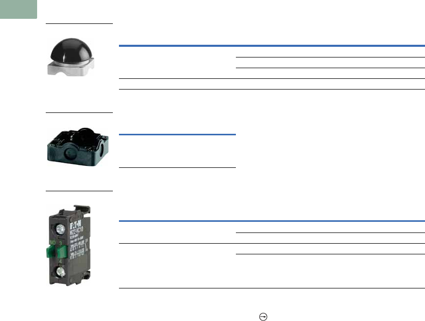
V7-T1-110 Volume 7—Logic Control, Operator Interface and Connectivity Solutions CA08100008E—March 2014 www.eaton.com
1
1
1
1
1
1
1
1
1
1
1
1
1
1
1
1
1
1
1
1
1
1
1
1
1
1
1
1
1
1
1.5
Pushbuttons and Indicating Lights
22.5 mm Modular Pushbuttons—M22
Components
Operators Only
Palm Switch Enclosure Base
Contact Blocks 1
Notes
1 For complete listing of available contact blocks, see Accessories, Pages V7-T1-111 to V7-T1-116.
2 All NC contact blocks are positively driven contact.
Type Button Color Catalog Number
Momentary Black FAK-S
Red FAK-R
Yellow FAK-Y
Maintained Red FAK-R-V-Y
Catalog Number
FAK-IU
Terminal
Type
Contact
Configuration 2Catalog Number
Screw NO M22-KC10
NC M22-KC01
Spring-cage NO M22-CKC10
NC M22-CKC01
FAK-S
FAK-IU
M22-KC10
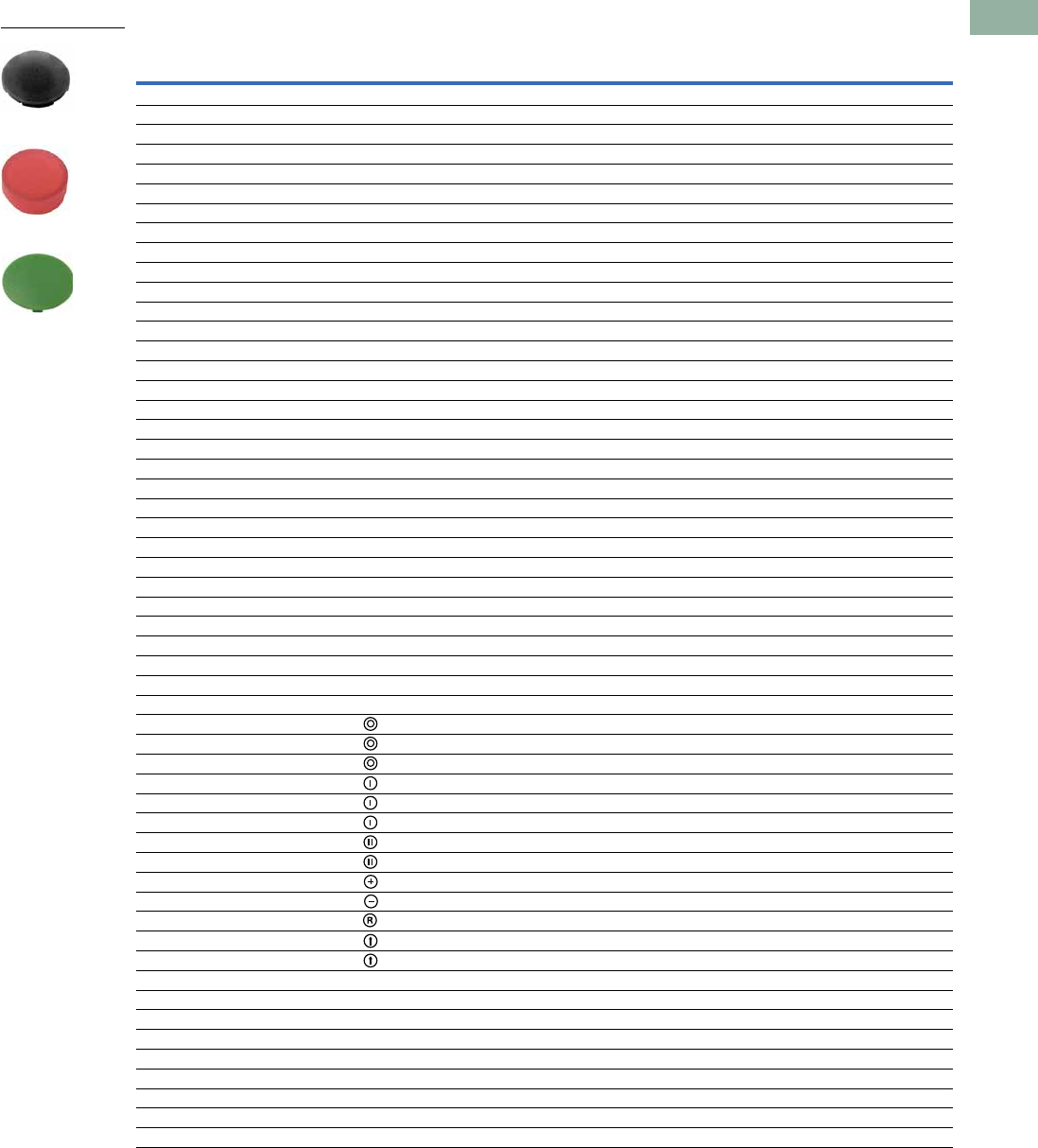
Volume 7—Logic Control, Operator Interface and Connectivity Solutions CA08100008E—March 2014 www.eaton.com V7-T1-111
1
1
1
1
1
1
1
1
1
1
1
1
1
1
1
1
1
1
1
1
1
1
1
1
1
1
1
1
1
1
1.5
Pushbuttons and Indicating Lights
22.5 mm Modular Pushbuttons—M22
Accessories
Button Plates
Note
1 Refer to the Symbols Library,
(see
Pages
V7-T1-129 to V7-T1-136
)
, for symbol image.
Color Inscription
Catalog Number
Flush Pushbutton
Catalog Number
Extended Pushbutton
Catalog Number
Mushroom Head Button
Black — M22-XD-S M22-XDH-S M22-XDP-S
White — M22-XD-W M22-XDH-W M22-XDP-W
Red — M22-XD-R M22-XDH-R M22-XDP-R
Green — M22-XD-G M22-XDH-G M22-XDP-G
Yellow — M22-XD-Y M22-XDH-Y M22-XDP-Y
Blue — M22-XD-B M22-XDH-B —
Black, white, red, green, yellow, blue — M22-XD-SWRGYB M22-XDH-SWRGYB —
Black, red, green — M22-XD-SRG M22-XDH-SRG —
Black Custom M22-XD-S-ETCH M22-XDH-S-ETCH M22-XDP-S-ETCH
White Custom M22-XD-W-ETCH M22-XDH-W-ETCH M22-XDP-W-ETCH
Red Custom M22-XD-R-ETCH M22-XDH-R-ETCH M22-XDP-R-ETCH
Green Custom M22-XD-G-ETCH M22-XDH-G-ETCH M22-XDP-G-ETCH
Yellow Custom M22-XD-Y-ETCH M22-XDH-Y-ETCH M22-XDP-Y-ETCH
Blue Custom M22-XD-B-ETCH M22-XDH-B-ETCH —
Black STOP M22-XD-S-GB0 M22-XDH-S-GB0 M22-XDP-S-GB0
Red STOP M22-XD-R-GB0 M22-XDH-R-GB0 M22-XDP-R-GB0
Black START M22-XD-S-GB1 M22-XDH-S-GB1 M22-XDP-S-GB1
White START M22-XD-W-GB1 M22-XDH-W-GB1 —
Green START M22-XD-G-GB1 M22-XDH-G-GB1 M22-XDP-G-GB1
Black CLOSE M22-XD-S-GB2 M22-XDH-S-GB2 —
Black UP M22-XD-S-GB3 M22-XDH-S-GB3 M22-XDP-S-GB3
Black DOWN M22-XD-S-GB4 M22-XDH-S-GB4 M22-XDP-S-GB4
Black OFF M22-XD-S-GB5 M22-XDH-S-GB5 M22-XDP-S-GB5
Red OFF M22-XD-R-GB5 M22-XDH-R-GB5 M22-XDP-R-GB5
Black ON M22-XD-S-GB6 M22-XDH-S-GB6 M22-XDP-S-GB6
Green ON M22-XD-G-GB6 M22-XDH-G-GB6 M22-XDP-G-GB6
Black TEST M22-XD-S-GB9 M22-XDH-S-GB9 —
Blue RESET M22-XD-B-GB14 M22-XDH-B-GB14 —
Black FORWARD M22-XD-S-GB15 M22-XDH-S-GB15 M22-XDP-S-GB15
Black REVERSE M22-XD-S-GB16 M22-XDH-S-GB16 M22-XDP-S-GB16
Black RAISE M22-XD-S-GB17 M22-XDH-S-GB17 —
Black LOWER M22-XD-S-GB18 M22-XDH-S-GB18 —
Black M22-XD-S-X0 M22-XDH-S-X0 M22-XDP-S-X0
Red M22-XD-R-X0 M22-XDH-R-X0 M22-XDP-R-X0
Green — — M22-XDP-G-X0
Black M22-XD-S-X1 M22-XDH-S-X1 M22-XDP-S-X1
White M22-XD-W-X1 M22-XDH-W-X1 —
Green M22-XD-G-X1 M22-XDH-G-X1 M22-XDP-G-X1
Black M22-XD-S-X2 M22-XDH-S-X2 —
Green M22-XD-G-X2 M22-XDH-G-X2 —
Black M22-XD-S-X4 M22-XDH-S-X4 M22-XDP-S-X4
Black M22-XD-S-X5 M22-XDH-S-X5 M22-XDP-S-X5
Blue M22-XD-B-X6 M22-XDH-B-X6 —
Black M22-XD-S-X7 M22-XDH-S-X7 M22-XDP-S-X7
Black M22-XD-S-X8 M22-XDH-S-X8 —
Black See 1 below M22-XD-S-X9 M22-XDH-S-X9 —
Black See 1 below M22-XD-S-X10 M22-XDH-S-X10 —
Black See 1 below M22-XD-S-X11 M22-XDH-S-X11 —
Black See 1 below M22-XD-S-X12 M22-XDH-S-X12 —
Black See 1 below M22-XD-S-X13 M22-XDH-S-X13 —
Black See 1 below M22-XD-S-X14 M22-XDH-S-X14 —
Black See 1 below M22-XD-S-X15 M22-XDH-S-X15 —
Black See 1 below M22-XD-S-X16 M22-XDH-S-X16 —
Black See 1 below M22-XD-S-X17 M22-XDH-S-X17 —
M22-XDH-R
M22-XDP-G
M22-XD-S
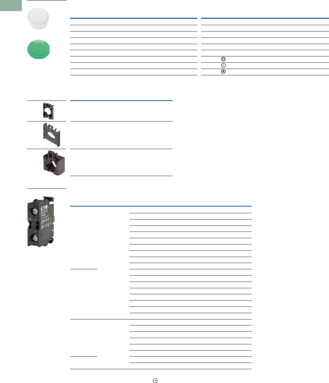
V7-T1-112 Volume 7—Logic Control, Operator Interface and Connectivity Solutions CA08100008E—March 2014 www.eaton.com
1
1
1
1
1
1
1
1
1
1
1
1
1
1
1
1
1
1
1
1
1
1
1
1
1
1
1
1
1
1
1.5
Pushbuttons and Indicating Lights
22.5 mm Modular Pushbuttons—M22
Button Lenses
Mounting Adapters
Contact Blocks
Notes
1 All NC contact blocks are positively driven contact.
2 Not stackable.
Color Inscription
Catalog Number
Flush
Catalog Number
Extended Color Inscription
Catalog Number
Flush
Catalog Number
Extended
White — M22-XDL-W M22-XDLH-W Blue Custom M22-XDL-B-ETCH M22-XDLH-B-ETCH
Red — M22-XDL-R M22-XDLH-R Red STOP M22-XDL-R-GB0 M22-XDLH-R-GB0
Green — M22-XDL-G M22-XDLH-G Green START M22-XDL-G-GB1 M22-XDLH-G-GB1
Yellow — M22-XDL-Y M22-XDLH-Y Red OFF M22-XDL-R-GB5 M22-XDLH-R-GB5
Blue — M22-XDL-B M22-XDLH-B Green ON M22-XDL-G-GB6 M22-XDLH-G-GB6
White Custom M22-XDL-W-ETCH M22-XDLH-W-ETCH Blue RESET M22-XDL-B-GB14 M22-XDLH-B-GB14
Red Custom M22-XDL-R-ETCH M22-XDLH-R-ETCH Red M22-XDL-R-X0 M22-XDLH-R-X0
Green Custom M22-XDL-G-ETCH M22-XDLH-G-ETCH Green M22-XDL-G-X1 M22-XDLH-G-X1
Yellow Custom M22-XDL-Y-ETCH M22-XDLH-Y-ETCH Blue M22-XDL-B-X6 M22-XDLH-B-X6
Description Catalog Number
Contact block mounting adapter M22-A
Contact block mounting adapter,
four-position (for use with
four-way pushbuttons, joysticks
and four-position selector switches
only).
M22-A4
Allows mounting of M22 pushbuttons
to LS-Titan limit switch bodies
(for the full LS-Titan catalog section,
see PG08301004E).
M22-LS
Mounting
Location Terminal Type
Contact
Configuration 1
Package
Qty. Catalog Number
Front Screw NO 1 M22-K10
NO 25 M22-K10-B25
NO 100 M22-K10-B100
NO, early-make 1 M22-K10P
NC 1 M22-K01
NC 25 M22-K01-B25
NC 100 M22-K01-B100
NC, late-break 1 M22-K01D
SMCB, NC 1 M22-K01SMC10
SMCB, 2NC 1 M22-K02SMC10
Base NO 1 M22-KC10
NO 25 M22-KC10-B25
NO 100 M22-KC10-B100
NC 1 M22-KC01
NC 25 M22-KC01-B25
NC 100 M22-KC01-B100
SMCB, NC 1 M22-KC01SMC10
SMCB, 2NC 1 M22-KC02SMC10
Front Spring-cage NO 1 M22-CK10
NC 1 M22-CK01
NC, late-break 1 M22-CK01D
2NO 21M22-CK20
2NC 21M22-CK02
NO-NC 21M22-CK11
Base NO 1 M22-CKC10
NC 1 M22-CKC01
M22-XDLH-W
M22-XDL-G
M22-A
M22-A4
M22-LS
M22-K10
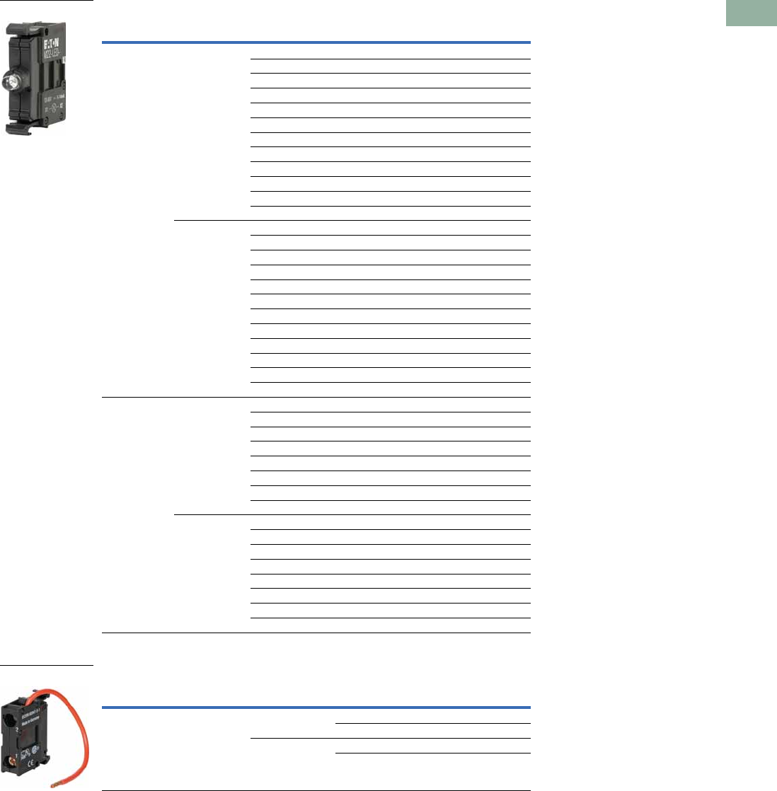
Volume 7—Logic Control, Operator Interface and Connectivity Solutions CA08100008E—March 2014 www.eaton.com V7-T1-113
1
1
1
1
1
1
1
1
1
1
1
1
1
1
1
1
1
1
1
1
1
1
1
1
1
1
1
1
1
1
1.5
Pushbuttons and Indicating Lights
22.5 mm Modular Pushbuttons—M22
Light Units
LED Resistor and Test Elements
Notes
1 Resistor units to be used with 12–30V light units.
2 Refer to IL04716002E for use of resistor elements in series for higher DC voltage.
Terminal Type
Mounting
Location LED Color Light Unit Voltage Catalog Number
Screw Front White 12–30 Vac/Vdc M22-LED-W
Red M22-LED-R
Green M22-LED-G
Blue M22-LED-B
White 85–264 Vac M22-LED230-W
Red M22-LED230-R
Green M22-LED230-G
Blue M22-LED230-B
White 207–264 Vac M22-LED230H-W
Red M22-LED230H-R
Green M22-LED230H-G
Blue M22-LED230H-B
Base White 12–30 Vac/Vdc M22-LEDC-W
Red M22-LEDC-R
Green M22-LEDC-G
Blue M22-LEDC-B
White 85–264 Vac M22-LEDC230-W
Red M22-LEDC230-R
Green M22-LEDC230-G
Blue M22-LEDC230-B
White 207–264 Vac M22-LEDC230H-W
Red M22-LEDC230H-R
Green M22-LEDC230H-G
Blue M22-LEDC230H-B
Spring-cage Front White 12–30 Vac/Vdc M22-CLED-W
Red M22-CLED-R
Green M22-CLED-G
Blue M22-CLED-B
White 85–264 Vac M22-CLED230-W
Red M22-CLED230-R
Green M22-CLED230-G
Blue M22-CLED230-B
Base White 12–30 Vac/Vdc M22-CLEDC-W
Red M22-CLEDC-R
Green M22-CLEDC-G
Blue M22-CLEDC-B
White 85–264 Vac M22-CLEDC230-W
Red M22-CLEDC230-R
Green M22-CLEDC230-G
Blue M22-CLEDC230-B
Terminal Type
Mounting
Location
Element
Type Voltage Catalog Number
Screw Front Resistor 12 42–60 Vac/Vdc M22-XLED60
220 Vdc M22-XLED220
Test 12–240 Vac/Vdc M22-XLED-T
85–264 Vac M22-XLED230-T
M22-LED-W
M22-XLED60
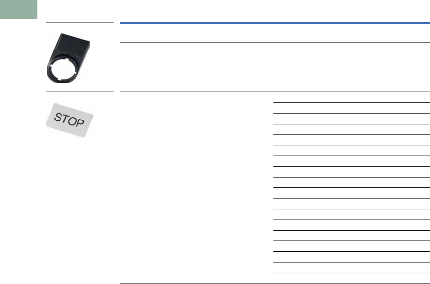
V7-T1-114 Volume 7—Logic Control, Operator Interface and Connectivity Solutions CA08100008E—March 2014 www.eaton.com
1
1
1
1
1
1
1
1
1
1
1
1
1
1
1
1
1
1
1
1
1
1
1
1
1
1
1
1
1
1
1.5
Pushbuttons and Indicating Lights
22.5 mm Modular Pushbuttons—M22
Legend Plate Holders and Inserts, Pushbuttons and Double Pushbuttons 2
Notes
1 When ordering, specify inscription per catalog number suffix from the Symbols Library
(see
Pages
V7-T1-129 to V7-T1-136
)
into the Order Notes.
For example, M22-XD-S-ETCH; Order Notes: Mark with symbol X91, Line item #_.
2 Legend plates are IP66 and NEMA 4X/13.
Example
To order a legend plate for a pushbutton with non-standard markings (FORWARD):
1. Select legend plate holder—M22S-ST-X.
2. Select legend plate insert—M22-XST-ETCH.
3. Select FORWARD from the Symbols Library, Pages V7-T1-129 to V7-T1-136, identified by GB15 suffix.
4. Indicate on the order form in the order notes—suffix GB15, line item # ___ .
Description Inscription Catalog Number
Legend plate holder, without legend plate insert,
for pushbuttons
—M22S-ST-X
Legend plate holder, without legend plate insert,
for double pushbuttons
—M22S-STDD-X
Legend plate insert — M22-XST
Custom M22-XST-ETCH 1
STOP M22-XST-GB0
START M22-XST-GB1
OFF M22-XST-GB5
ON M22-XST-GB6
RUN M22-XST-GB7
FAULT M22-XST-GB8
OFF ON M22-XST-GB10
MAN. AUTO M22-XST-GB11
MAN. O AUTO M22-XST-GB12
HAND AUTO M22-XST-D11
HAND O AUTO M22-XST-D12
1M22-XST-X52
2M22-XST-X53
O I M22-XST-X88
O - I M22-XST-X89
I O II M22-XST-X93
M22S-ST-X
M22-XST-GB0
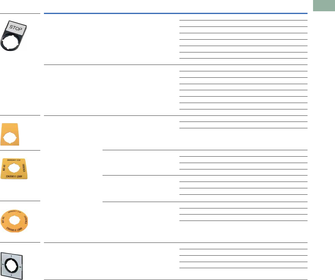
Volume 7—Logic Control, Operator Interface and Connectivity Solutions CA08100008E—March 2014 www.eaton.com V7-T1-115
1
1
1
1
1
1
1
1
1
1
1
1
1
1
1
1
1
1
1
1
1
1
1
1
1
1
1
1
1
1
1.5
Pushbuttons and Indicating Lights
22.5 mm Modular Pushbuttons—M22
Legend Plates, Complete 2
Notes
1 When ordering, specify inscription per catalog number suffix from the Symbols Library
(see
Pages
V7-T1-129 to V7-T1-136
)
into the Order Notes.
For example, M22-XD-S-ETCH; Order Notes: Mark with symbol X91, Line item #_.
2 Legend plates are IP66 and NEMA 4X/13.
Description Inscription Catalog Number
For use with pushbuttons
and indicating lights
Legend plate holder with insert STOP M22S-ST-GB0
START M22S-ST-GB1
OFF M22S-ST-GB5
ON M22S-ST-GB6
RUN M22S-ST-GB7
FAULT M22S-ST-GB8
1M22S-ST-X52
2M22S-ST-X53
Selector switches — OFF ON M22S-ST-GB10
MAN. AUTO M22S-ST-GB11
MAN. O AUTO M22S-ST-GB12
HAND AUTO M22S-ST-D11
HAND O AUTO M22S-ST-D12
O I M22S-ST-X88
O - I M22S-ST-X89
I O II M22S-ST-X93
Emergency-stop operators Rectangular yellow legend plate — M22-XZK
Custom M22-XZK-ETCH 1
EMERGENCY-STOP M22-XZK-GB99
Square yellow legend plate — M22-XYK
—M22-XYK-ETCH 1
EMERGENCY-STOP four-language M22-XYK1
EMERGENCY-STOP (top and bottom) M22-XYK5
Round yellow legend plate, 90 mm — M22-XAK
Custom M22-XAK-ETCH 1
EMERGENCY-STOP four-language M22-XAK1
EMERGENCY-STOP (top and bottom) M22-XAK5
Round yellow legend plate, 60 mm — M22-XBK
Custom M22-XBK-ETCH 1
EMERGENCY-STOP four-language M22-XBK1
EMERGENCY-STOP (top and bottom) M22-XBK5
Four-way pushbutton,
joystick and four-position
selector switches
Silver square legend plate — M22-XCK
Custom M22-XCK-ETCH 1
Four directional arrows M22-XCK1
0-1-0-2-0-3-0-4 M22-XCK2
Two directional arrows M22-XCK3
M22S-ST-GB0
M22-XZK
M22-XBK1
M22-XCK1
M22-XYK
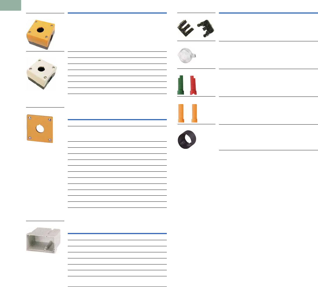
V7-T1-116 Volume 7—Logic Control, Operator Interface and Connectivity Solutions CA08100008E—March 2014 www.eaton.com
1
1
1
1
1
1
1
1
1
1
1
1
1
1
1
1
1
1
1
1
1
1
1
1
1
1
1
1
1
1
1.5
Pushbuttons and Indicating Lights
22.5 mm Modular Pushbuttons—M22
Surface Mounting Enclosures 1
Flush Mounting Plates, Aluminum
Shrouds, Plastic
Selector Switch Accessories
Notes
1Requires use of base mounted contact blocks.
2Plunger needed to actuate center-mounted contact blocks. Used for non-illuminated
three-position selector switches only.
3Enables a keyed selector switch to be set to user-selected key withdraw position.
Description Catalog Number
Yellow top, black base for
emergency-stop operators
M22-IY1-PG
One-element enclosure M22-I1-PG
Two-element enclosure M22-I2-PG
Three-element enclosure M22-I3-PG
Four-element enclosure M22-I4-PG
Six-element enclosure M22-I6-PG
M20 connecting screw M22-XI
M20 cord grip V-M20
Finish Rating Catalog Number
One Hole
Yellow paint for
emergency-stop
operators
—M22-EY1
Gray anodized IP65 M22-E1
Tw o H o l e s
Gray anodized IP65 M22-E2
Three Holes
Gray anodized IP65 M22-E3
Four Holes
Gray anodized IP65 M22-E4
Five Holes
Gray anodized IP65 M22-E5
Six Holes
Anodized IP40 M22-E6
Description Rating Catalog Number
One-element IP55 M22-H1
Two-element IP55 M22-H2
Three-element IP55 M22-H3
Four-element IP40 M22-H4
Five-element IP40 M22-H5
Six-element IP40 M22-H6
Mounting plate — M22-XE5
Plaster keys for
flush mounting
—M22-UPE
M22-IY1-PG
M22-IY-PG
M22-EY1
M22-H1
Description Catalog Number
Plunger bridge 2M22-XW
Key cover M22-XWS
Key withdraw adapter 3M22-XC-R
Coding adapter M22-XC-Y
Guard ring M22-XGWK
M22-XC-Y
M22-XWS
M22-XC-R
M22-XW
M22-XGWK
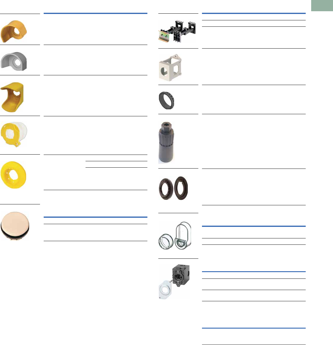
Volume 7—Logic Control, Operator Interface and Connectivity Solutions CA08100008E—March 2014 www.eaton.com V7-T1-117
1
1
1
1
1
1
1
1
1
1
1
1
1
1
1
1
1
1
1
1
1
1
1
1
1
1
1
1
1
1
1.5
Pushbuttons and Indicating Lights
22.5 mm Modular Pushbuttons—M22
Emergency Stop Operator Accessories
Blanking Plugs
Mounting Accessories
Protective Diaphragm
Dust Covers
Kits
Description Voltage Catalog Number
Yellow guard ring — M22-XGPV
Gray guard ring — M22G-XGPV
Rectangular guard — M22-MGTA
Sealing shroud — M22-PL-PV
Illuminated ring 24 Vac/Vdc M22-XPV60-Y-24
120 Vac M22-XPV60-Y-120
230 Vac M22-XPV60-Y-230
Color Catalog Number
Gray M22-B
Black M22S-B
M22-XGPV
M22G-XGPV
M22-PL-PV
M22-XPV60-Y-120
M22-MGTA
M22-B
Description Catalog Number
Telescopic clip with top-hat rail M22-TC
Telescopic clip M22-TA
Telescopic clip extension M22-TCV
DIN rail mounting adapter M22-IVS
Mounting ring M22-GR
Mounting ring tool M22-MS
Adapter ring set for
30 mm holes
M22S-R30
For Use with … Catalog Number
Flush pushbuttons and
indicating lights
M22-T-D
Double pushbuttons M22-T-DD
Description Catalog Number
Contact block dust cover M22-XKDP
Operator dust cover,
max three contact blocks
M22-ADC
Operator dust cover,
max four contact blocks
M22-ADC4
Description Catalog Number
Includes one each: M22-XW,
M22-XC-R, M22-XC-Y, M22S-B,
M22-A, M22-XD-SWRGYB
M22-KT1
M22-TC and M22-TA
M22-IVS
M22-GR
M22-MS
M22S-R30
M22-T-D and
M22-T-DD
M22-ADC4
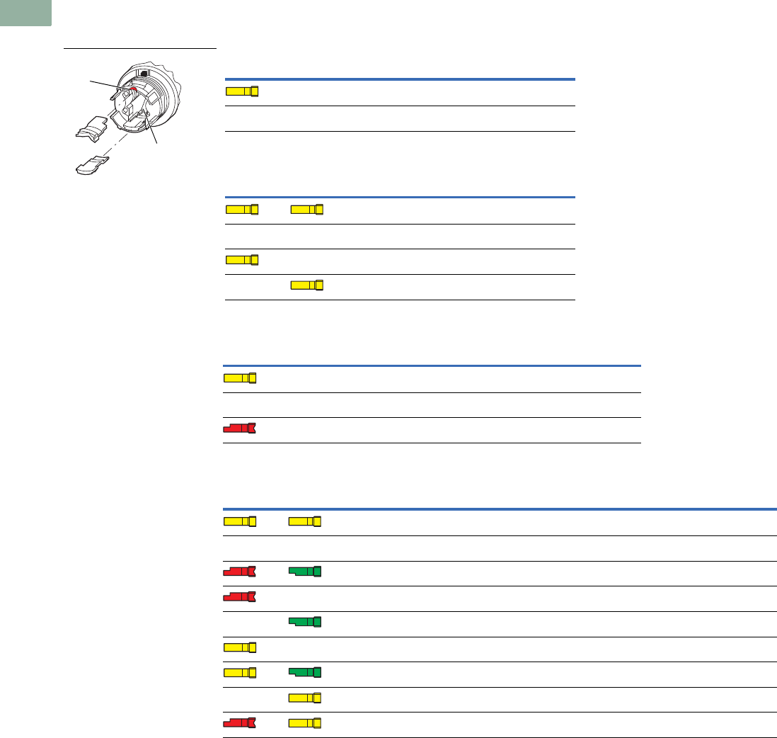
V7-T1-118 Volume 7—Logic Control, Operator Interface and Connectivity Solutions CA08100008E—March 2014 www.eaton.com
1
1
1
1
1
1
1
1
1
1
1
1
1
1
1
1
1
1
1
1
1
1
1
1
1
1
1
1
1
1
1.5
Pushbuttons and Indicating Lights
22.5 mm Modular Pushbuttons—M22
Coding Adapter Guide
Selector Switches
Two-Position Selector Switch
Three-Position Selector Switch
Two-Position Key-Operated Selector Switch
Three-Position Key-Operated Selector Switch
Top (B) Bottom (A) Catalog Number Function
M22(S)-W(L)(K) Momentary
M22(S)-WR(L)(K) Maintained
Top (B) Bottom (A) Catalog Number
Function
Left Right
M22(S)-W(L)(K)3 Momentary Momentary
M22(S)-WR(L)(K)3 Maintained Maintained
M22(S)-WR(L)(K)3-1 Maintained Momentary
M22(S)-WR(L)(K)3-2 Momentary Maintained
Top (B) Bottom (A) Catalog Number
Center
Key Withdraw
Right
Function Key Withdraw
M22(S)-WS Yes Momentary No
M22(S)-WRS Yes Maintained Yes
M22(S)-WRS-A1 Yes Maintained No
Top (B) Bottom (A) Catalog Number
Left
Function Key Withdraw
Center
Key Withdraw
Right
Function Key Withdraw
M22(S)-WS3 Momentary No Yes Momentary No
M22(S)-WRS3 Maintained Yes Yes Maintained Yes
M22(S)-WRS3-A1 Maintained No Yes Maintained No
M22(S)-WRS3-A2 Maintained Yes Yes Maintained No
M22(S)-WRS3-A3 Maintained No Yes Maintained Yes
M22(S)-WRS3-A4 Maintained Yes Yes Momentary No
M22(S)-WRS3-A5 Maintained No Yes Momentary No
M22(S)-WRS3-A6 Momentary No Yes Maintained Yes
M22(S)-WRS3-A7 Momentary No Yes Maintained No
Top ( B)
Bottom (A)

Volume 7—Logic Control, Operator Interface and Connectivity Solutions CA08100008E—March 2014 www.eaton.com V7-T1-119
1
1
1
1
1
1
1
1
1
1
1
1
1
1
1
1
1
1
1
1
1
1
1
1
1
1
1
1
1
1
1.5
Pushbuttons and Indicating Lights
22.5 mm Modular Pushbuttons—M22
Technical Data and Specifications
Pushbuttons, Indicating Lights, Selector Switches and Emergency-Stop Operators
Description
Momentary
Pushbuttons
Maintained
Pushbuttons
Indicating Lights,
Buzzers and
Potentiometers
Emergency-Stop
Operators
Selector
Switches
Key-Operated
Operators
Double
Pushbuttons
General
Standards IEC/EN 60947
VDE 0660
UL #E29184
IEC/EN 60947
VDE 0660
UL #E29184
IEC/EN 60947
VDE 0660
UL #E29184
IEC/EN 60947
VDE 0660
UL #340491
IEC/EN 60947
VDE 0660
UL #E29184
IEC/EN 60947
VDE 0660
UL #E29184
IEC/EN 60947
VDE 0660
UL #E29184
Lifespan, mechanical Operations x 106>5 >1 — >0.1 >0.1 >0.1 >0.2
Operating frequency Operations/h >3600 >1800 — >600 >2000 >100 >3600
Actuating force n >5>5— >50 – — >5
Operating torque
(screw terminals)
Nm——— —>0.3 >0.5 —
Protection Type
IP IP67, IP69K IP67, IP69K Indicating lights: IP67, 69K
Buzzers: IP40
Potentiometers: IP66
IP67, IP69K IP66 IP66 IP66
UL type 4X, 13 4X, 13 Indicating lights: 4X/13
Buzzers: 12
Potentiometers: 4X/13
4X, 13 4X, 13 4X, 13 4X, 13
Climatic proofing Damp heat, constant, according to IEC 60068-2-78
Damp heat, cyclical to IEC 60068-2-30
Ambient temperature,
operating
°F
(°C)
–13 to 158
(–25 to 70)
–13 to 158
(–25 to 70)
–13 to 158
(–25 to 70)
–13 to 158
(–25 to 70)
–13 to 158
(–25 to 70)
–13 to 158
(–25 to 70)
–13 to 158
(–25 to 70)
Mounting position As required As required As required As required As required As required As required
Mechanical shock
resistance to
IEC 60068-2-27
shock duration 11 ms,
half-sinusoidal
g >30 >30 >30 >50 >30 >30 >30
Terminal Capacities
Solid AWG——20-16 ————
mm2— 0.5–1.5 — —
Stranded AWG——20-16 ————
mm2— 0.5–1.5 — —
Contacts
Rated impulse withstand
voltage
Uimp Vac——4000 ————
Rated insulation voltage UiV ——2500 ————
Overvoltage category/
pollution degree
— — III/3 ————

V7-T1-120 Volume 7—Logic Control, Operator Interface and Connectivity Solutions CA08100008E—March 2014 www.eaton.com
1
1
1
1
1
1
1
1
1
1
1
1
1
1
1
1
1
1
1
1
1
1
1
1
1
1
1
1
1
1
1.5
Pushbuttons and Indicating Lights
22.5 mm Modular Pushbuttons—M22
Contact Blocks and Light Units
Description
Contact
Blocks
LED
Light Units
General
Standards IEC/EN 60947
VDE 0660
UL #E29184
IEC/EN 60947
VDE 0660
UL #E29184
Lifespan, mechanical Operations x 106>5 —
Operating frequency Operations/h >3600 —
Actuating force n >5—
Operating torque (screw terminals) Nm <0.8 —
Protection Type
IP IP20 IP20
UL type — —
Climatic proofing Damp heat, constant, according to IEC 60068-2-78
Damp heat, cyclical to IEC 60068-2-30
Ambient temperature, operating °F (°C) –13 to 158 (–25 to 70) –13 to 158 (–25 to 70)
Mounting position As required As required
Mechanical shock resistance to
IEC 60068-2-27 shock duration
11 ms, half-sinusoidal
g>30 >30
Terminal Capacities
Solid AWG 18–14 18–14
mm20.75–2.5 0.75–2.5
Stranded AWG 20–14 20–14
mm20.5–2.5 0.5–2.5
Contacts
Rated impulse withstand voltage Uimp Vac 6000 6000
Rated insulation voltage UiV 500 500
Overvoltage category/
pollution degree
III/3 III/3
NEMA contact ratings A600, Q300 —
Current draw — 5–15 mA
Control Circuit Reliability
at 24 Vdc/5 mA HFFault probability <10-7, <1 fault in 107operations —
at 5 Vdc/1 mA HFFault probability <5 x 10⁻⁶, <1 fault in 5 x 10⁶ operations —
Max. Short-Circuit Protective Device
Fuse gG/gL A 10 —
Switching Capacity
Rated Operational Current
AC-15
115V IeA6 —
230V IeA6 —
400V IeA4 —
500V IeA2 —
DC-13
24V IeA3 —
42V IeA1.7 —
60V IeA1.2 —
110V IeA0.6 —
220V IeA0.3 —
Lifespan, Electrical
AC-15
230V/0.5A Operations x 1061.6 —
230V/1.0A Operations x 1061—
230V/3.0A Operations x 1060.7 —
DV-13
12V/2.8A Operations x 1061.2 —
Contact Element Note: >200 Vac/60 Hz: –25/55°C

Volume 7—Logic Control, Operator Interface and Connectivity Solutions CA08100008E—March 2014 www.eaton.com V7-T1-121
1
1
1
1
1
1
1
1
1
1
1
1
1
1
1
1
1
1
1
1
1
1
1
1
1
1
1
1
1
1
1.5
Pushbuttons and Indicating Lights
22.5 mm Modular Pushbuttons—M22
Palm Switches
ASi Adapter Modules
Description Momentary Maintained FAK-R-V-KC11-I
General
Standards IEC/EN 60947
VDE 0660
IEC/EN 60947
VDE 0660
IEC/EN 60947
VDE 0660
Lifespan, mechanical Operations x 106>1 >0.1 >0.1
Operating frequency Operations/h >3600 >600 >600
Actuating force n 20–40 40–60 15–25
Operating torque Nm — — —
Degree of protection, IEC/EN 60529 IP IP67, IP69K IP67, IP69K IP65
UL Type 4X, 13 4X, 13 4X, 13
Climatic proofing Damp heat, constant, to IEC 60068-2-78
Damp heat, cyclic, to IEC 60068-2-30
Ambient temperature, operating °F (°C) –73 to 104 (–25 to 40) –73 to 104 (–25 to 40) –73 to 104 (–25 to 40)
Mounting position As required
Mechanical shock resistance to
IEC 60068-2-27
shock duration 11 ms, half-sinusoidal
g >15 >15 >15
Description M22-ASI M22-ASI-C
General
Standards IEC/EN 60947,
DIN EN 50295
IEC/EN 60947,
DIN EN 50295
Radio interference suppression EN 55011,
EN 55022
EN 55011,
EN 55022
Limit value class — —
Protection type IP20 IP00
Climatic proofing Damp heat, constant, to IEC 60068-2-78, cyclical, to IEC 60068-2-30
Ambient temperature, operating °F (°C) –13 to 131 (–25 to 55) –13 to 131 (–25 to 55)
Shock resistance shock duration 11 ms g >30 >30
Vibration to IEC 60068-2-27
(amplitude 1 mm)
Hz — —
Dimensions mm — —
Weight kg — —
Mounting Front mounting Front mounting
Mounting position As required As required
Power Supply
Rated voltage to AS-interface
specification
Vdc 26.5–31.6 26.5–31.6
Connection technique Yellow plug-in terminal as insulation
piercing terminal
Two cables onboard
Power supply Completely from the AS-interface cable
Addressing Via connection to AS-interface cable
Total power consumption of
the AS-interface
mA >40 >40
AS-interface — —
Rated operational current at full load mA — —
Rated operational current when idle
(no I, O set)
mA — —
Status LEDs POWER AS-interface cable:
green LED on the rear side of the element
ERROR AS-interface, AS-interface master
failure: red LED on the rear side of the element
POWER AS-interface cable:
green LED on the board
ERROR AS-interface, AS-interface master
failure: red LED on the board

V7-T1-122 Volume 7—Logic Control, Operator Interface and Connectivity Solutions CA08100008E—March 2014 www.eaton.com
1
1
1
1
1
1
1
1
1
1
1
1
1
1
1
1
1
1
1
1
1
1
1
1
1
1
1
1
1
1
1.5
Pushbuttons and Indicating Lights
22.5 mm Modular Pushbuttons—M22
ASi-S Adapter Modules
Description M22-ASI-S M22-ASI-CS
Inputs
Inputs, protected against
short-circuit
Number Two (normally 22V/5 mA) Two (normally 22V/5 mA)
Voltage range Vdc — —
Rated current per input mA — —
High signal level V — —
Low signal mA — —
Length of connecting cables cm — —
Outputs
Outputs, protected against
short-circuit
Number One (normally 19V/8 mA) One (normally 19V/8 mA)
Voltage range Vdc — —
Max. Current Carrying Capacity
All outputs — —
S three external outputs — —
Length of connecting cables cm — —
Profile S-3.A.E S-3.A.E
Specification 2.1 2.1
Addresses Number 62 62
Emergency-Stop Circuits
Connection of the AS-interface line Yellow plug terminal with insulation
piercing
Two cables on the circuit board
Power supply Complete from AS-interface,
cable 26.5–31.6 Vdc
Complete from AS-interface,
cable 26.5–31.6 Vdc
Fixing Front mounted Base mounted
Addressing Via AS-interface cable Via AS-interface cable
Max. total current A 45 mA 45 mA
Ambient temperature, operating °F (°C) –13 to 131 (–25 to 55) –13 to 131 (–25 to 55)
Shock resistance 30g/11 ms as per IEC 60068-2-27 30g/11 ms as per IEC 60068-2-27
Protection type IP20 IP00
Climatic proofing Damp heat, constant, to IEC 60068-2-78,
cyclical, to IEC 60068-2-30
Damp heat, constant, to IEC 60068-2-78,
cyclical, to IEC 60068-2-30
Mounting position As required As required
Standards EN 50178
EN 50 295
EN 50178
EN 50 295
Inputs Two-channel input (22V/5 mA)
(moduled by code sequence)
(two break contact sets M22-K01)
Two-channel input (22V/5 mA)
(moduled by code sequence)
(two break contact sets M22-K01)
Outputs One output, typically 19V/8 mA,
short-circuit proof
One output, typically 19V/8 mA,
short-circuit proof
Status Displays
Power, AS-interface cable Green LED on the back Green LED on the back
AS-interface error,
AS-interface master failure
Red LED on the back Red LED on the back
Profile S-7.B.E S-7.B.E
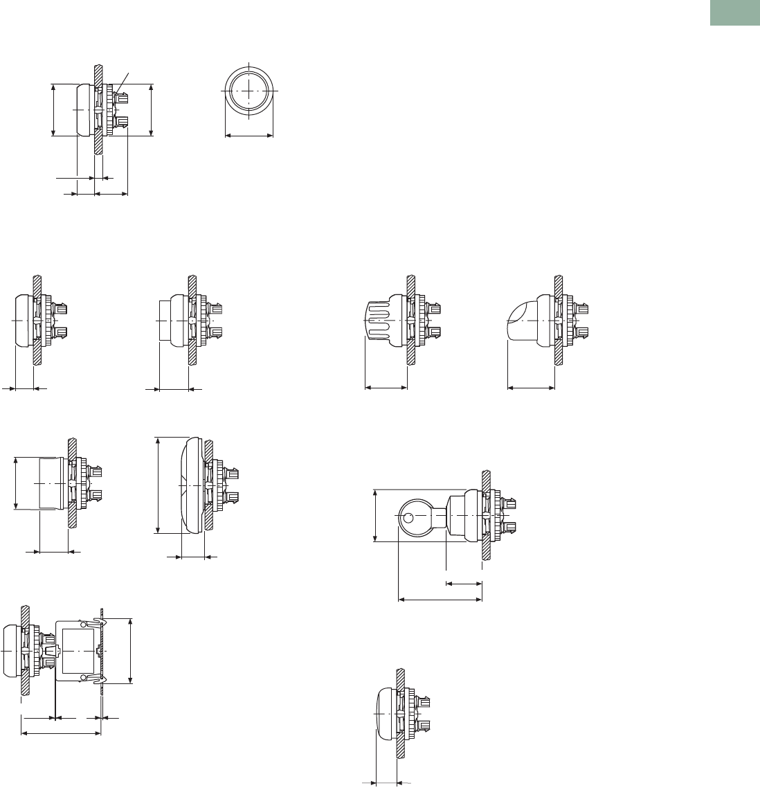
Volume 7—Logic Control, Operator Interface and Connectivity Solutions CA08100008E—March 2014 www.eaton.com V7-T1-123
1
1
1
1
1
1
1
1
1
1
1
1
1
1
1
1
1
1
1
1
1
1
1
1
1
1
1
1
1
1
1.5
Pushbuttons and Indicating Lights
22.5 mm Modular Pushbuttons—M22
Dimensions
Approximate Dimensions in Inches (mm)
Operators and Indicating Lights
Pushbuttons Selector Switches Operators
Key-Operated Selector Switches
Indicating Light
0.75 (19)
M22 x 0.06 (1.5)
0.39 (10)
Ø 1.17 (29.7)
Ø 1.16 (29.5)
0.04 (1)–0.24 (6)
1.17 (29.7)
0.39 (10)
0.65 (16.4)
M22…-D-_ M22…-DH-_
M22-DG(L)-_ M22…-DD-_
Ø1.17 (29.7)
0.65 (16.5)
0.52 (13.2)
2.15 (54.7)
M22-D, Base Mounted
>0.01 (0.3)
1.78 (45.3)
0.04 (1)
1.47 (37.2)
0.93 (23.7) 1.06 (26.9)
M22…-W-_ M22…-WL-_
1.88 (47.75)
Ø1.17 (29.7)
0.81 (20.6)
M22…-W(R)S-_
0.45 (11.5)
M22-L_
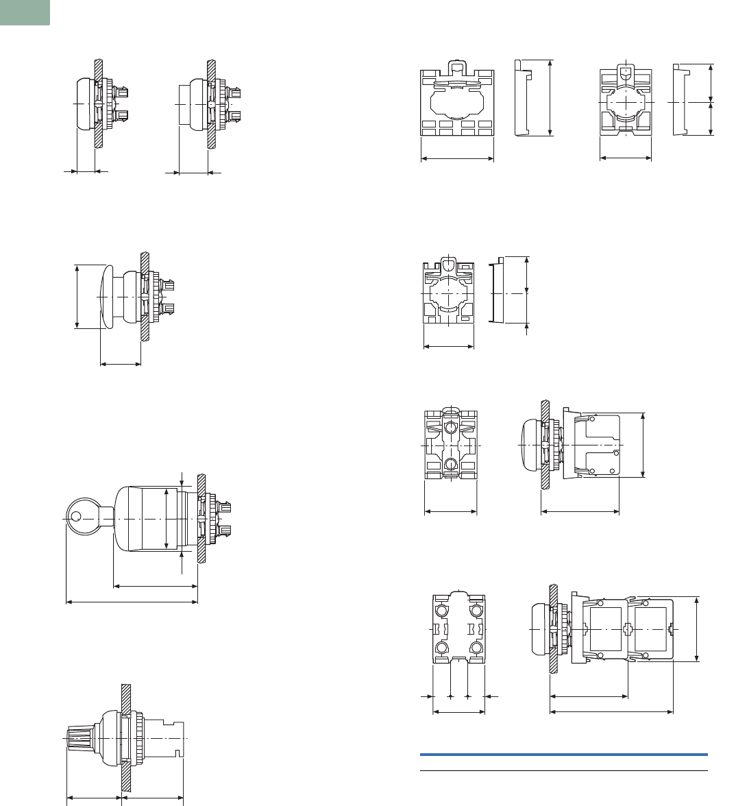
V7-T1-124 Volume 7—Logic Control, Operator Interface and Connectivity Solutions CA08100008E—March 2014 www.eaton.com
1
1
1
1
1
1
1
1
1
1
1
1
1
1
1
1
1
1
1
1
1
1
1
1
1
1
1
1
1
1
1.5
Pushbuttons and Indicating Lights
22.5 mm Modular Pushbuttons—M22
Approximate Dimensions in Inches (mm)
Illuminated Pushbuttons
Mushroom Head Pushbutton
Emergency-Stop Operators
Potentiometer
Contact Block Mounting Adapter
Front Mounted Centering Adapter
Front Mounted Indicating Light
Pushbutton, Complete Devices
0.39 (10)
0.65 (16.4)
M22…-DL-_ M22…-DLH_
M22…-DP-_
Ø1.44 (36.5)
0.93 (23.6)
2.96 (75.1)
1.89 (47.9)
1.5 (38)
1.38 (35)
M22-PV_
M22S-PV_
M22-PVL_
M22-PVS_
1.15 (29.2) 1.3 (32.9)
M22(S)-R_
1.73 (44)
1.77 (45)
1.18 (30)
0.76 (19.3)
0.85 (21.5)
M22-A_ M22S-A…
1.18 (30) 0.7 (17.8)
0.84 (21.4)
M22-ZA
1.18 (30) 1.77 (45)
1.46 (37)
0.39 (10)
0.39 (10)
0.39 (10)
1.18 (30)
2.8 (71)
1.77 (45)
A
1 x M22-K_ 2 x M22-K_ 1 x M22-CK_ 2 x M22-CK_
A1.46 (37.2) 1.46 (37.2) 1.54 (39.0) 1.54 (39.0)
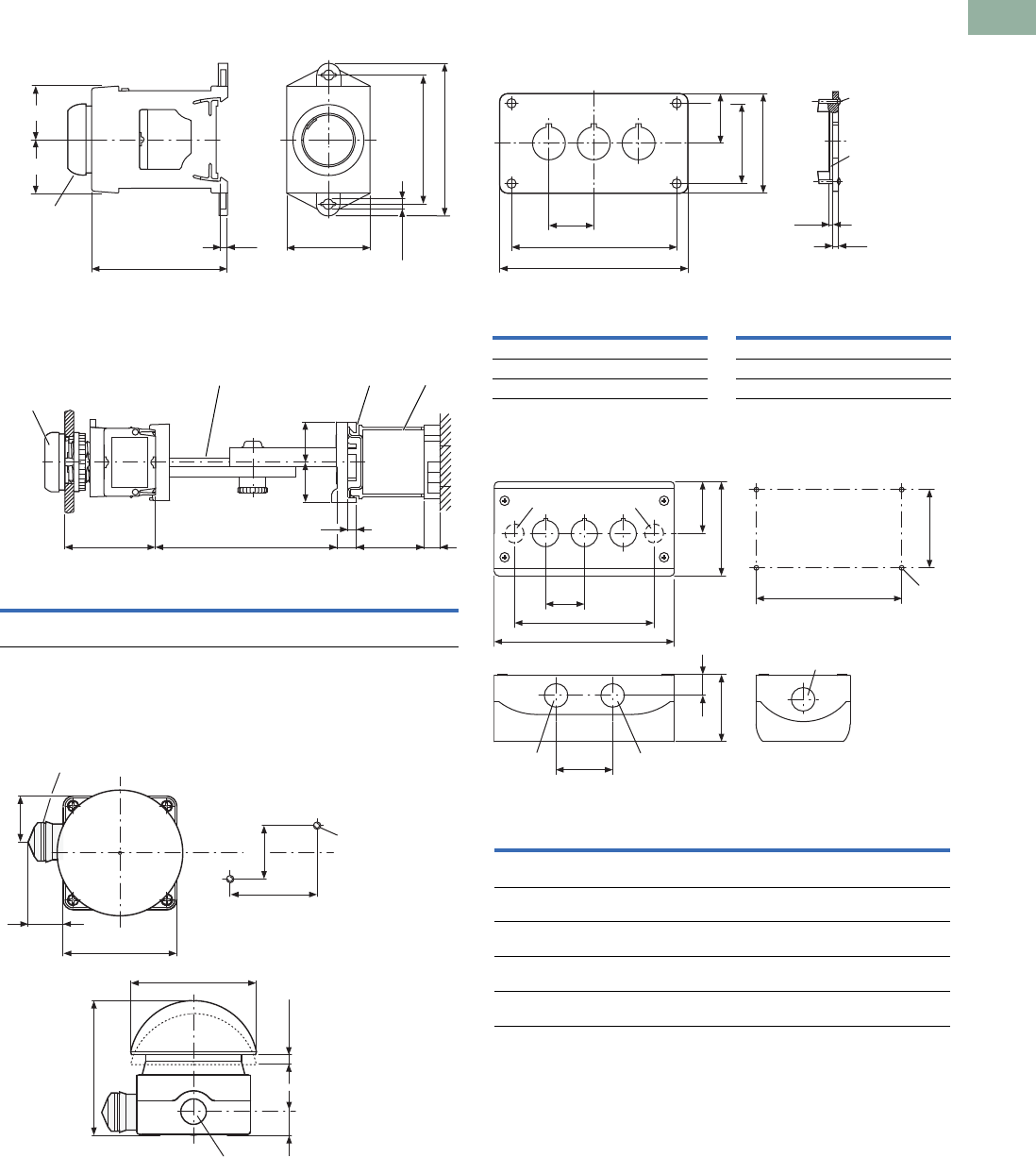
Volume 7—Logic Control, Operator Interface and Connectivity Solutions CA08100008E—March 2014 www.eaton.com V7-T1-125
1
1
1
1
1
1
1
1
1
1
1
1
1
1
1
1
1
1
1
1
1
1
1
1
1
1
1
1
1
1
1.5
Pushbuttons and Indicating Lights
22.5 mm Modular Pushbuttons—M22
Approximate Dimensions in Inches (mm)
DIN-Rail Mounting Adapter
Pushbuttons and Indicating Lights with M22-TC Telescopic
Clip and M22-TVC Extension
Palm Switches
Front Mounted Mounting Plate
Base Mounted Surface Mounting Enclosure
0.88 (22.4)
2.23 (56.7) 0.12 (3.1)
1.39 (35.2)
0.18 (4.5 (M4))
2.15 (54.5)
2.54 (64.5)
M22-D...
M22-L...
M22-W...
M22-P...
0.88 (22.4)
AB
F
G
E
C
D
H
1Top-hat rail to IEC/EN 60715.
AB CDE FGH
1.77
(45)
2.36–3.94
(60–100)
0.79
(20)
0.79
(20)
0.18
(4.5)
0.39
(10)
154
(39)
0.39
(10)
M22-D_
M22-L_
M22-W_
M22-P_
M22-TC M22-TCV
1
L-...
1.36 (34.5)
1.42 (36)
M5 x 20
2.56 (65)
1.57 (40)
0.71 (18)
3.98 (101)
Ø94
0.26 (6.5) – 0.3 (7.5)
3.35 (85)
FAK_
13 x M20 lateral, 1 x M16 in bottom.
1
1.42 (36)
0.12 (3)
0.1 (2.5)
4 x M4 x 16
2.2 (56)
e
a1
1.3 (33)
2.83 (72)
M22-E_
Catalog
Number a1 e
Catalog
Number a1 e
M22-E(Y) 12.83 (72) 2.21 (56) M22-E4 6.73 (171) 6.10 (155)
M22-E2 4.13 (105) 3.50 (89) M22-E5 8.03 (204) 7.40 (188)
M22-E3 5.43 (138) 4.80 (122) M22-E6 9.33 (237) 8.70 (221)
1
3.15 (80)
1.73 (44)
M20
a
b
1.3 (33)
1.89 (48)
2.2 (56)
M20/M25
eM4
2.62 (66.5)
0.7 (17.8)
M20 M20
M20
M22-I_
Catalog
Number
Mounting
LocationsabeCable Entries
M22-I(Y)1 12.83
(72.0)
1.68
(42.6)
2.30
(58.5)
2 x M16 3 x M20 2 x M25
M22-I2 24.72
(120.0)
3.37
(85.6)
4.19
(106.5)
2 x M20 3 x M20 2 x M25
M22-I3 36.02
(153.0)
4.67
(118.6)
5.49
(139.5)
2 x M20 2 x M25 4 x M20
M22-I4 47.32
(186.0)
5.97
(151.6)
6.79
(172.5)
2 x M20 2 x M25 4 x M20
M22-I6 69.92
(252.0)
8.57
(217.6)
9.39
(238.5)
2 x M20 2 x M25 4 x M20
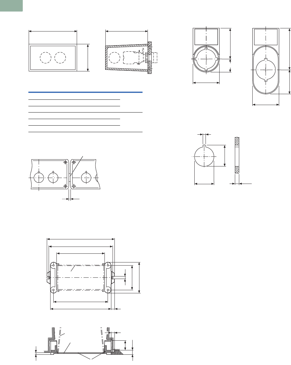
V7-T1-126 Volume 7—Logic Control, Operator Interface and Connectivity Solutions CA08100008E—March 2014 www.eaton.com
1
1
1
1
1
1
1
1
1
1
1
1
1
1
1
1
1
1
1
1
1
1
1
1
1
1
1
1
1
1
1.5
Pushbuttons and Indicating Lights
22.5 mm Modular Pushbuttons—M22
Approximate Dimensions in Inches (mm)
Covers
Connecting Screw
Shroud with Plaster Keys
Legend Plates
Mounting Hole with Lug Slot
USB Socket
a2
M20 M20 M20
2.32 (59)
3.74 (95)
M22-H_
Catalog
Number a2 Cable Entry Style
M22-H1 1.65 (42) 3 x M20 One-piece
M22-H2 2.95 (75) 4 x M20
M22-H3 4.25 (108) 4 x M20
M22-H4 5.55 (141) 4 x M20 Split
M22-H5 6.85 (174) 5 x M20
M22-HE6 8.15 (207) 6 x M20
0.04 (1)
M22-XI
1Gasket.
1
a2 +1.65 (42)
a2 +1.26 (32)
0.16 (4)
2.2 (56)
2.76 (70)
a2
M22-H...
M22-H...
M22-UPE
0.31 (8)
0.31 (8)
1.02 (26)
e
e + 0.51 (13)
0.35 (9)
0.35 (9)
M22-UPE
2Box for closing off when plastering.
3Plaster thickness less than 8 mm.
4Plaster thickness more than 8 mm.
1
23
1.18 (30)
0.59 (15)
1.38 (35)
1.18 (30)
1.08 (27.5) 1.85 (47)
M22S-ST-_ M22S-STDD-X
0.13 (3.2)
0.88 (22.3)
0.95 (24.1)
0.04 (1)–0.24 (6)
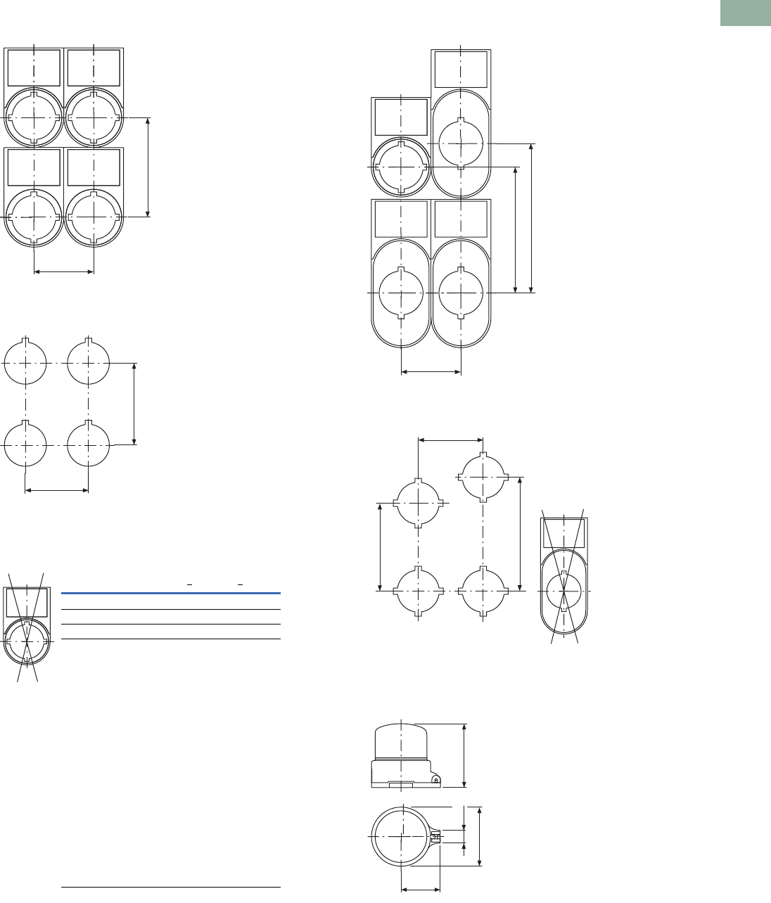
Volume 7—Logic Control, Operator Interface and Connectivity Solutions CA08100008E—March 2014 www.eaton.com V7-T1-127
1
1
1
1
1
1
1
1
1
1
1
1
1
1
1
1
1
1
1
1
1
1
1
1
1
1
1
1
1
1
1.5
Pushbuttons and Indicating Lights
22.5 mm Modular Pushbuttons—M22
Approximate Dimensions in Inches (mm)
Grid Dimension to IEC/EN 60947
Grid Dimension for Various Combinations
Pushbutton Diaphragm
Grid Dimension for M22-DD_
Grid Dimension for M22-DDL_
Emergency Stop Sealing Cover
1.18 (30)
1.97 (50)
A
B
Pushbutton diaphragm cannot be combined with label mount.
Catalog Number A >B >
M22(S)-_(IEC/EN 60947) 1.18 (30.0) 1.97 (50.0)
RMQ-Titan min. 1.18 (30.0) 1.58 (40.0)
M22-D_ + M22-T-D 1.30 (33.0) 1.58 (40.0)
M22-D(R)P_ 1.50 (38.0) 1.58 (40.0)
M22-PV_ 1.50 (38.0) 1.58 (40.0)
M22-PV(L) + M22-PL-PV 1.89 (48.0) 2.20 (56.0)
M22-PV(L)(S_) + M22-D_ 1.30 (33.0) 1.58 (40.0)
M22-DDL_ 1.18 (30.0) 2.17 (55.0)
M22-DDL_ + M22-T-DD 1.30 (33.0) 2.28 (58.0)
M22-ST_ 1.18 (30.0) 1.97 (50.0)
M22-STDD_ 1.18 (30.0) 2.95 (75.0)
M22-CK_ 1.18 (30.0) 1.77 (45.0)
M22-CLED_ 1.18 (30.0) 1.77 (45.0)
M22-XAK_ 3.54 (90.0) 3.54 (90.0)
M22-XZK_ 1.30 (33.0) 2.04 (52.0)
M22-XBK_ 2.36 (60.0) 2.36 (60.0)
M22-XYK_ 1.97 (50.0) 1.97 (50.0)
M22-D4 2.17 (55.0) 2.17 (55.0)
M22-WR…4 1.97 (50.0) 1.97 (50.0)
M22-W…J4 1.97 (50.0) 1.97 (50.0)
1.18 (30)
2.95 (75)
2.48 (63)
b 1.73 (44)
b 2.28 (58)
a 1.18 (30)
Pushbutton
Diaphragm
M22-T-DD 1
1Pushbutton diaphragm cannot be combined with label mount.
1.26 (32)
1.89 (48)
0.41 (10.4) 2.03 (51.6)
M22-PL-PV
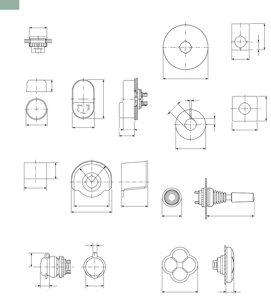
V7-T1-128 Volume 7—Logic Control, Operator Interface and Connectivity Solutions CA08100008E—March 2014 www.eaton.com
1
1
1
1
1
1
1
1
1
1
1
1
1
1
1
1
1
1
1
1
1
1
1
1
1
1
1
1
1
1
1.5
Pushbuttons and Indicating Lights
22.5 mm Modular Pushbuttons—M22
Approximate Dimensions in Inches (mm)
Blanking Plugs
Pushbutton Diaphragm
Guard Ring
Key Cover
Emergency Stop Legend Plate
Joystick
Four-Way Pushbutton
1.16 (29.5)
M22…B-_
1.3 (33)
0.67 (17)
1.3 (33)
0.67 (17)
0.91 (23)
2.28 (58)
M22-T-D M22-T-D
Ø 1.42 (36)
0.98 (25)
3.07 (78)
2.68 (68)
R35 R41
1.97 (50)
M22-XGWK M22-XGPV
0.47 (12)
0.2 (5)
Ø 0.98 (25)
0.79 (20)
M22-XWS
3.54 (90)
d= 0.03 (0.8)
1.3 (33)
0.65 (16.5)
1.97 (50)
M22-XAK_ M22-X(Y)ZK_
0.13 (3.2)
0.49 (12.5)
Ø 2.36 (60)
Ø 0.89 (22.5)
1.97 (50)
1.97 (50)
M22-XBK-_ M22-XYK-_
1.18 (30)
2.95 (75)
M22…W…J_
2.17 (55)
0.45 (11.5)
M22…-D…4-_

Volume 7—Logic Control, Operator Interface and Connectivity Solutions CA08100008E—March 2014 www.eaton.com V7-T1-129
1
1
1
1
1
1
1
1
1
1
1
1
1
1
1
1
1
1
1
1
1
1
1
1
1
1
1
1
1
1
1.5
Pushbuttons and Indicating Lights
22.5 mm Modular Pushbuttons—M22
Symbols Library
Instructions for Ordering Laser Inscriptions
1. Identify part number to be inscribed.
2. Pick symbol from library and identify suffix code associated with the symbol.
3. Order part number already listed in the catalog with -ETCH suffix.
4. When placing an order by fax or Vistaline on the Web, reference order item number and
indicate appropriate suffix code.
Example
To order a green flush button plate with the inscription AUTO HAND:
Order Catalog Number: M22-XD-G-ETCH (see Page V7-T1-55).
AUTO HAND inscription is found on Page V7-T1-133 in the Symbols Library, suffix code is X91.
In the order notes, reference item number and suffix X91.
Letter height 3 mm: max. three lines, max. 12 characters per line.
Letter height 5 mm: max. two lines, max. eight characters per line.
Note: For symbols or text not found in the Symbols Library, please contact the
Eaton Technical Resource Center at 1-877-ETN CARE (386-2273) or TRC@eaton.com.
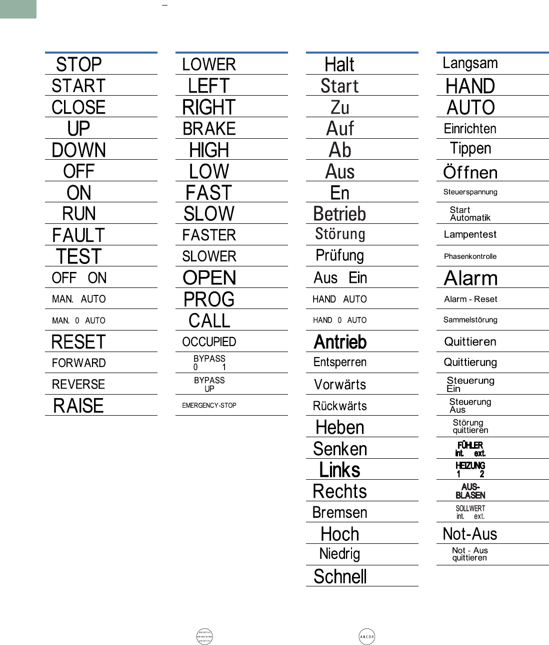
V7-T1-130 Volume 7—Logic Control, Operator Interface and Connectivity Solutions CA08100008E—March 2014 www.eaton.com
1
1
1
1
1
1
1
1
1
1
1
1
1
1
1
1
1
1
1
1
1
1
1
1
1
1
1
1
1
1
1.5
Pushbuttons and Indicating Lights
22.5 mm Modular Pushbuttons—M22
Letter Height Specifications: < five characters; letter height = 0.197 in (5 mm). > five characters; letter height = 0.118 in (3 mm).
Text—English
Text—German
Inscription
Catalog
Number Suffix
GB0
GB1
GB2
GB3
GB4
GB5
GB6
GB7
GB8
GB9
GB10
GB11
GB12
GB14
GB15
GB16
GB17
Text Size: 3 mm—Max. eight characters in first line;
10 characters in second line; eight characters in third line.
Text Size: 5 mm—Max. five characters per line.
Inscription
Catalog
Number Suffix
GB18
GB19
GB20
GB21
GB22
GB23
GB24
GB25
GB26
GB27
GB32
GB62
GB63
GB64
GB65
GB66
GB99
Inscription
Catalog
Number Suffix
D0
D1
D2
D3
D4
D5
D6
D7
D8
D9
D10
D11
D12
D13
D14
D15
D16
D17
D18
D19
D20
D21
D22
D23
D24
Inscription
Catalog
Number Suffix
D25
D28
D29
D30
D31
D32
D33
D34
D35
D36
D37
D38
D39
D40
D41
D42
D43
D44
D72
D73
D74
D75
D99
D100
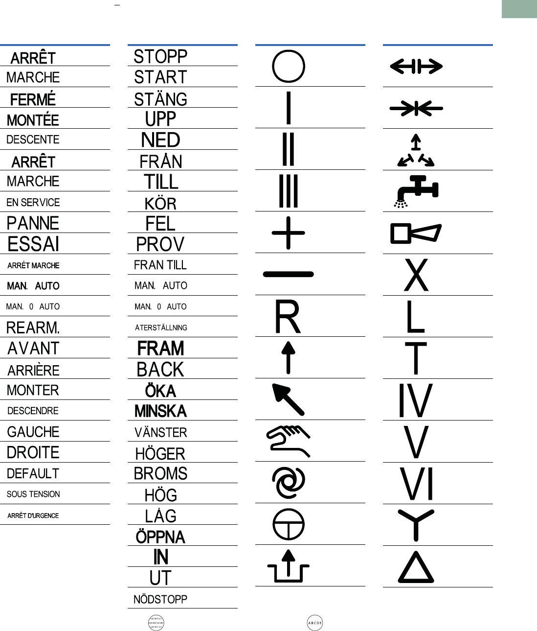
Volume 7—Logic Control, Operator Interface and Connectivity Solutions CA08100008E—March 2014 www.eaton.com V7-T1-131
1
1
1
1
1
1
1
1
1
1
1
1
1
1
1
1
1
1
1
1
1
1
1
1
1
1
1
1
1
1
1.5
Pushbuttons and Indicating Lights
22.5 mm Modular Pushbuttons—M22
Letter Height Specifications: < five characters; letter height = 0.197 in (5 mm). > five characters; letter height = 0.118 in (3 mm).
Text—French
Text—Swedish
Symbols
Inscription
Catalog
Number Suffix
F0
F1
F2
F3
F4
F5
F6
F7
F8
F9
F10
F11
F12
F14
F15
F16
F17
F18
F19
F20
F67
F68
F99
Text Size: 3 mm—Max. eight characters in first line;
10 characters in second line; eight characters in third line.
Text Size: 5 mm—Max. five characters per line.
Inscription
Catalog
Number Suffix
S0
S1
S2
S3
S4
S5
S6
S7
S8
S9
S10
S11
S12
S14
S15
S16
S17
S18
S19
S20
S21
S22
S23
S32
S45
S46
S99
Inscription
Catalog
Number Suffix
X0
X1
X2
X3
X4
X5
X6
X7
X8
X9
X10
X11
X12
Inscription
Catalog
Number Suffix
X13
X14
X15
X16
X17
X18
X19
X20
X21
X22
X23
X24
X25
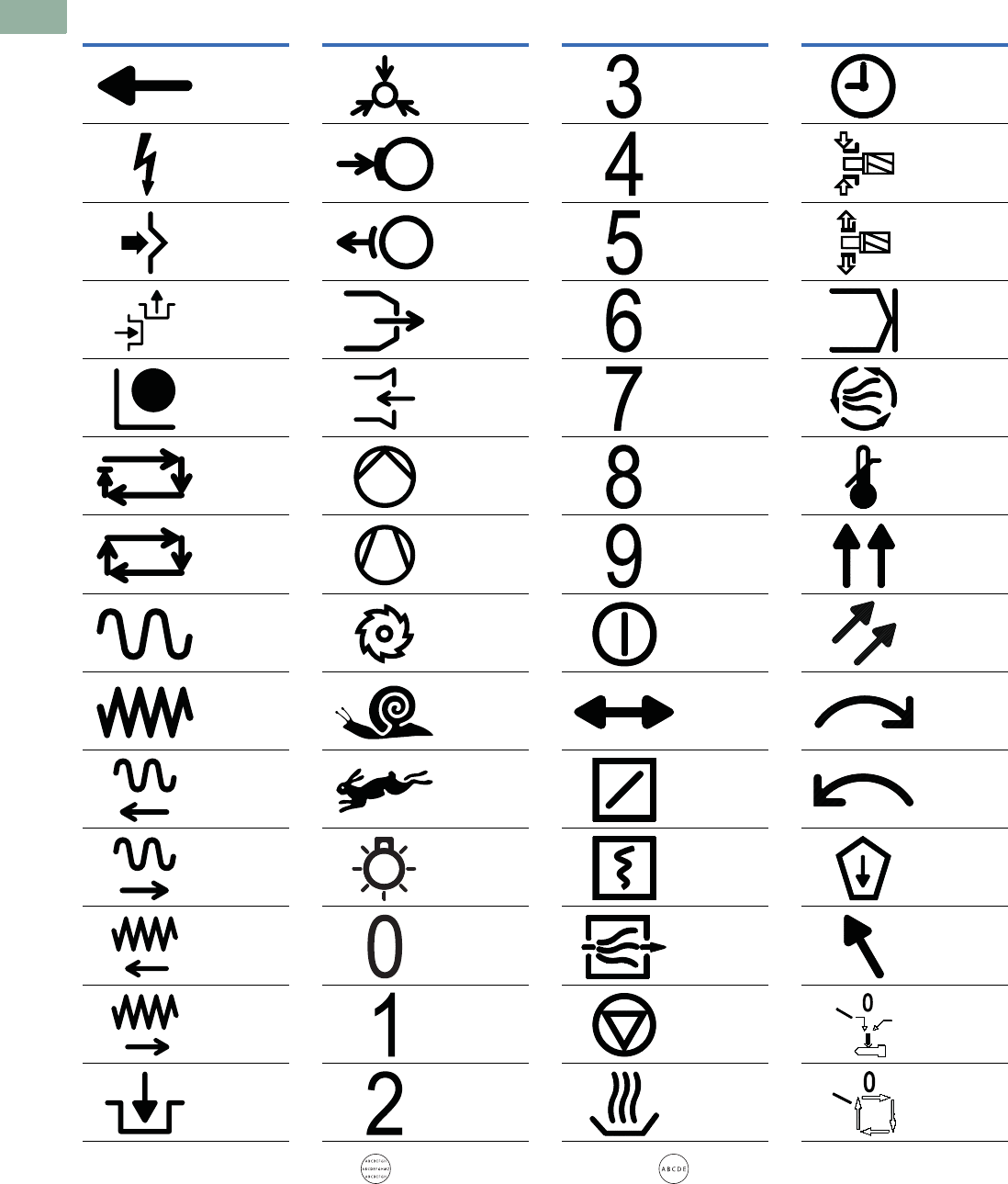
V7-T1-132 Volume 7—Logic Control, Operator Interface and Connectivity Solutions CA08100008E—March 2014 www.eaton.com
1
1
1
1
1
1
1
1
1
1
1
1
1
1
1
1
1
1
1
1
1
1
1
1
1
1
1
1
1
1
1.5
Pushbuttons and Indicating Lights
22.5 mm Modular Pushbuttons—M22
Inscription
Catalog
Number Suffix
X26
X27
X28
X29
X30
X31
X32
X33
X34
X35
X36
X37
X38
X39
Text Size: 3 mm—Max. eight characters in first line;
10 characters in second line; eight characters in third line.
Text Size: 5 mm—Max. five characters per line.
Inscription
Catalog
Number Suffix
X40
X41
X42
X43
X44
X45
X46
X47
X48
X49
X50
X51
X52
X53
Inscription
Catalog
Number Suffix
X54
X55
X56
X57
X58
X59
X60
X61
X62
X63
X64
X65
X66
X67
Inscription
Catalog
Number Suffix
X68
X69
X70
X71
X72
X73
X74
X75
X76
X77
X78
X79
X80
X81
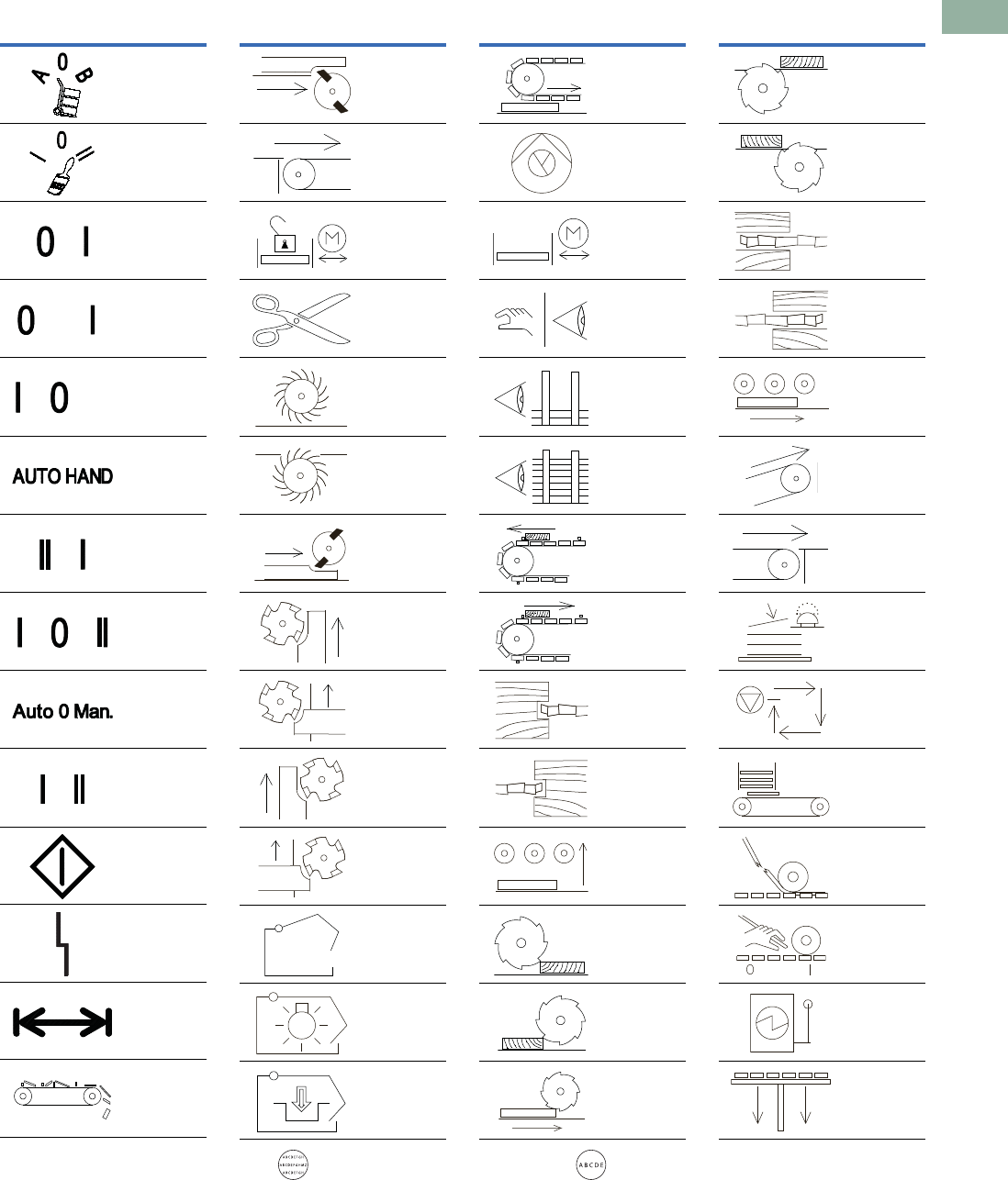
Volume 7—Logic Control, Operator Interface and Connectivity Solutions CA08100008E—March 2014 www.eaton.com V7-T1-133
1
1
1
1
1
1
1
1
1
1
1
1
1
1
1
1
1
1
1
1
1
1
1
1
1
1
1
1
1
1
1.5
Pushbuttons and Indicating Lights
22.5 mm Modular Pushbuttons—M22
Inscription
Catalog
Number Suffix
X82
X83
X88
X89
X90
X91
X92
X93
X94
X95
X100
X101
X102
X103
Text Size: 3 mm—Max. eight characters in first line;
10 characters in second line; eight characters in third line.
Text Size: 5 mm—Max. five characters per line.
Inscription
Catalog
Number Suffix
X104
X105
X106
X107
X108
X109
X110
X111
X112
X113
X114
X115
X116
X117
Inscription
Catalog
Number Suffix
X118
X119
X120
X121
X122
X123
X124
X125
X126
X127
X128
X129
X130
X131
Inscription
Catalog
Number Suffix
X132
X133
X134
X135
X136
X137
X138
X139
X140
X141
X142
X143
X144
X145
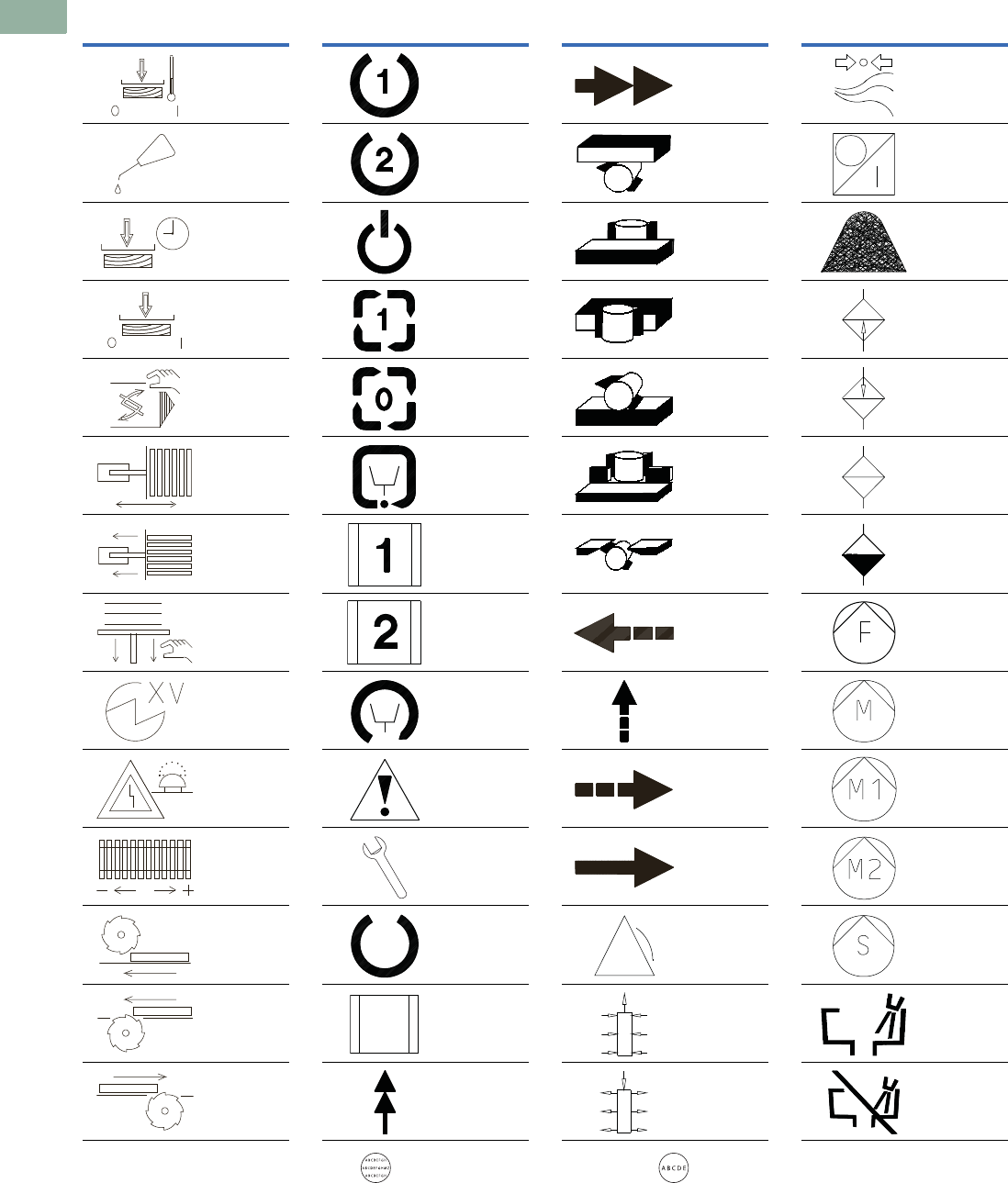
V7-T1-134 Volume 7—Logic Control, Operator Interface and Connectivity Solutions CA08100008E—March 2014 www.eaton.com
1
1
1
1
1
1
1
1
1
1
1
1
1
1
1
1
1
1
1
1
1
1
1
1
1
1
1
1
1
1
1.5
Pushbuttons and Indicating Lights
22.5 mm Modular Pushbuttons—M22
Inscription
Catalog
Number Suffix
X146
X147
X148
X149
X150
X151
X152
X153
X154
X155
X156
X157
X158
X159
Text Size: 3 mm—Max. eight characters in first line;
10 characters in second line; eight characters in third line.
Text Size: 5 mm—Max. five characters per line.
Inscription
Catalog
Number Suffix
X160
X161
X162
X163
X164
X165
X166
X167
X168
X169
X170
X171
X172
X173
Inscription
Catalog
Number Suffix
X174
X175
X176
X177
X178
X179
X180
X181
X182
X183
X184
X185
X186
X187
Inscription
Catalog
Number Suffix
X188
X189
X190
X191
X192
X193
X194
X195
X196
X197
X198
X199
X200
X201
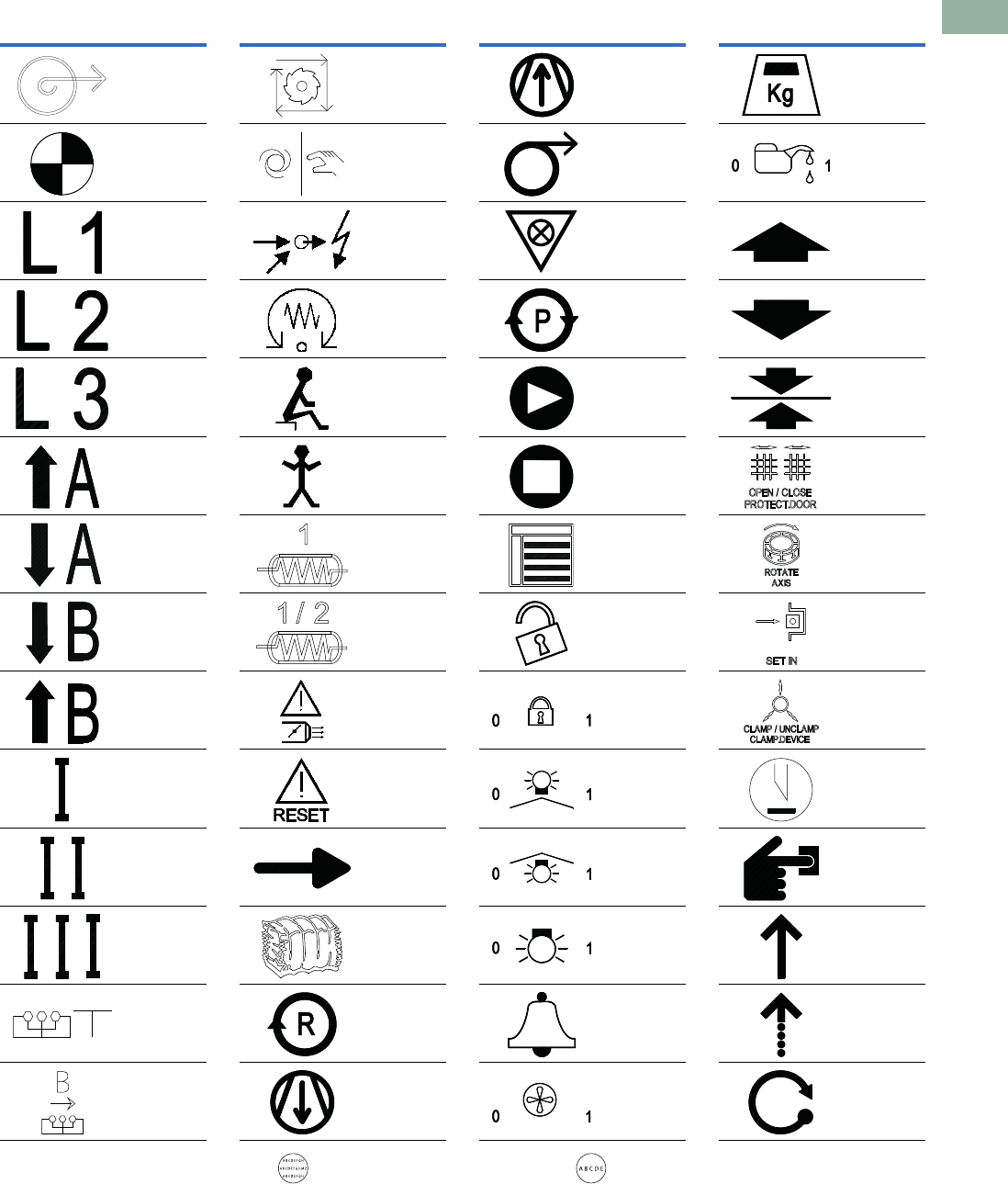
Volume 7—Logic Control, Operator Interface and Connectivity Solutions CA08100008E—March 2014 www.eaton.com V7-T1-135
1
1
1
1
1
1
1
1
1
1
1
1
1
1
1
1
1
1
1
1
1
1
1
1
1
1
1
1
1
1
1.5
Pushbuttons and Indicating Lights
22.5 mm Modular Pushbuttons—M22
Inscription
Catalog
Number Suffix
X202
X203
X204
X205
X206
X207
X208
X209
X210
X211
X212
X213
X214
X215
Text Size: 3 mm—Max. eight characters in first line;
10 characters in second line; eight characters in third line.
Text Size: 5 mm—Max. five characters per line.
Inscription
Catalog
Number Suffix
X216
X217
X218
X219
X220
X221
X222
X223
X224
X225
X226
X227
X228
X229
Inscription
Catalog
Number Suffix
X230
X231
X232
X233
X234
X235
X236
X237
X238
X239
X240
X241
X242
X243
Inscription
Catalog
Number Suffix
X244
X245
X246
X247
X248
X249
X250
X251
X252
X253
X254
X255
X256
X257
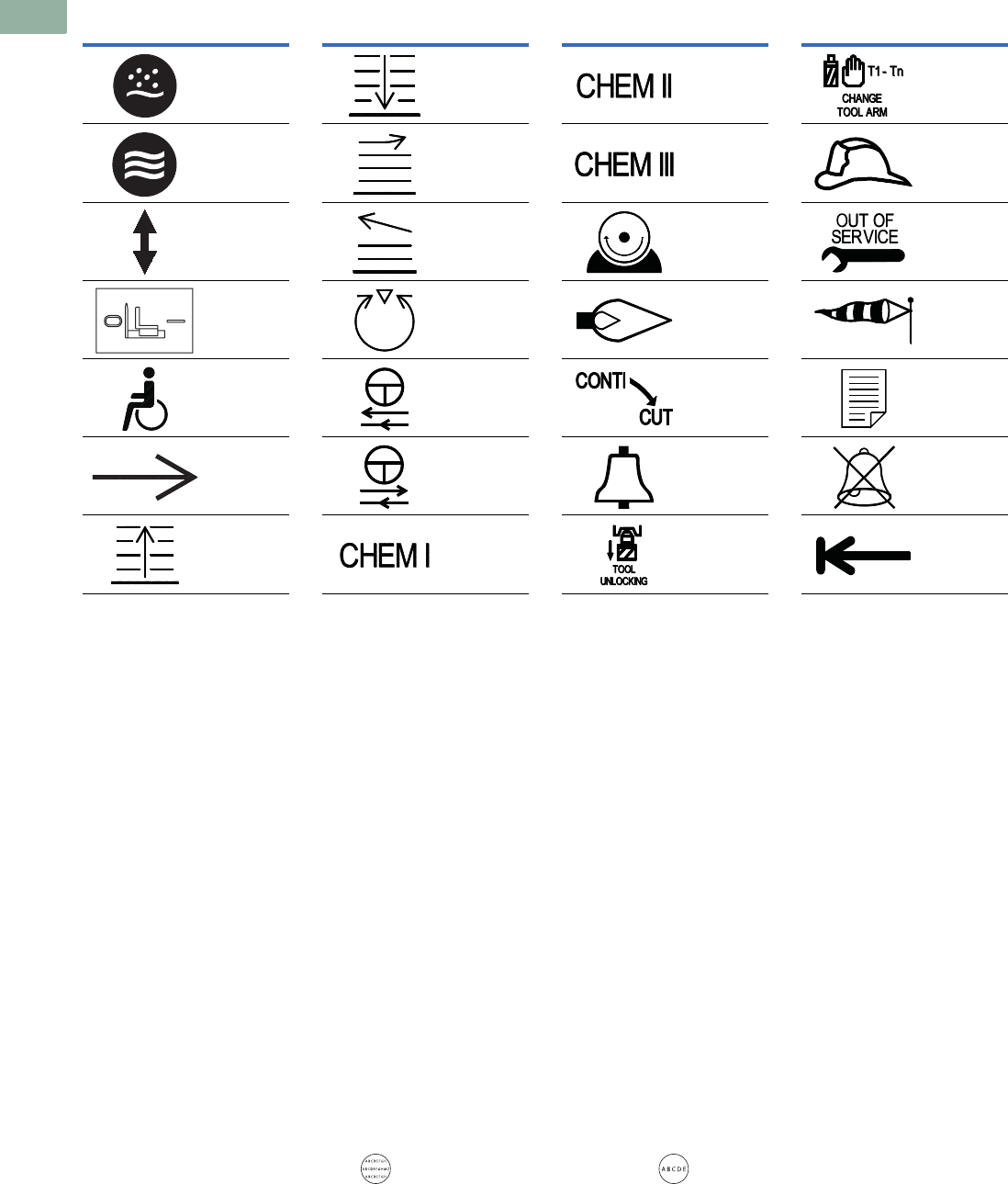
V7-T1-136 Volume 7—Logic Control, Operator Interface and Connectivity Solutions CA08100008E—March 2014 www.eaton.com
1
1
1
1
1
1
1
1
1
1
1
1
1
1
1
1
1
1
1
1
1
1
1
1
1
1
1
1
1
1
1.5
Pushbuttons and Indicating Lights
22.5 mm Modular Pushbuttons—M22
Inscription
Catalog
Number Suffix
X258
X259
X260
X261
X262
X263
X264
Text Size: 3 mm—Max. eight characters in first line;
10 characters in second line; eight characters in third line.
Text Size: 5 mm—Max. five characters per line.
Inscription
Catalog
Number Suffix
X265
X266
X267
X268
X269
X270
X271
Inscription
Catalog
Number Suffix
X272
X273
X274
X275
X276
X277
X278
Inscription
Catalog
Number Suffix
X279
X280
X281
X282
X283
X284
X285
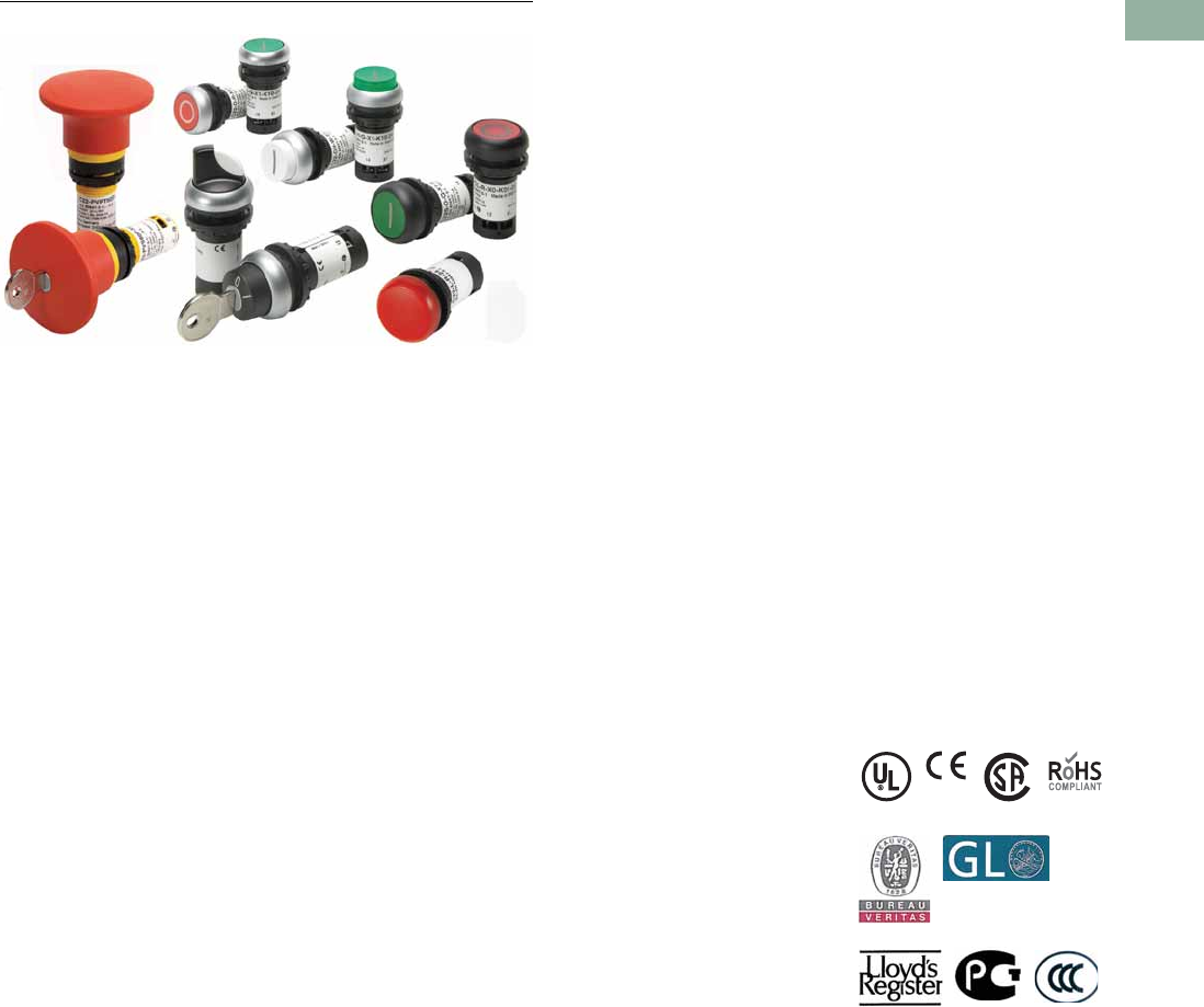
Volume 7—Logic Control, Operator Interface and Connectivity Solutions CA08100008E—March 2014 www.eaton.com V7-T1-137
1
1
1
1
1
1
1
1
1
1
1
1
1
1
1
1
1
1
1
1
1
1
1
1
1
1
1
1
1
1
1.6
Pushbuttons and Indicating Lights
22.5 mm Compact Pushbuttons—C22
22.5 mm Compact Pushbuttons—C22
Contents
Description Page
22.5 mm Compact Pushbuttons—C22
Product Selection Guide . . . . . . . . . . . . . . . . . . V7-T1-139
Pushbuttons—Non-Illuminated and
Illuminated . . . . . . . . . . . . . . . . . . . . . . . . . . . V7-T1-140
Indicating Lights . . . . . . . . . . . . . . . . . . . . . . . . V7-T1-149
Emergency Stops . . . . . . . . . . . . . . . . . . . . . . . V7-T1-151
Selector Switches . . . . . . . . . . . . . . . . . . . . . . . V7-T1-154
Technical Data and Specifications . . . . . . . . . . V7-T1-159
Dimensions . . . . . . . . . . . . . . . . . . . . . . . . . . . V7-T1-161
Product Overview
Product Description
Eaton’s C22 compact
pushbutton line offers an
industry leading array of
functional, attractive, and
ergonomically designed
“all-in-one” illuminated and
non-illuminated pushbuttons,
selector switches, emergency
stops and indicating lights.
The complete illuminated line
is only offered in LED light
units to ensure high-quality
brightness and up to 100,000
hours of LED illumination.
C22 operators are available
with either a silver or black
bezel and share the exact
same front of the panel
look and feel as Eaton’s
M22 line. The C22’s compact,
“all-in-one” design with the
contact block(s) and
operators integral provides
the user with a simple solution.
Wide Product Breadth
●In addition to the standard
compact offering of
indicating lights and
pushbuttons, Eaton’s
C22 offers keyed and
non-keyed operators
and emergency stops
●Hundreds of styles with
standard laser etch
markings with the ability
to use custom M22 laser
etched buttons in
conjunction with C22
buttonless operators
LED Indicators
●100,000 hours of life
in high-vibration
environments
●Lenses specifically
designed for LED
illumination
Rugged Design
●Pushbuttons (momentary)
rated for 5 million
mechanical operations
and selector switches
(non-keyed) rated for
1 million mechanical
operations
●All components have IP65
rating, and some carry
IP67 and IP69K for wash-
down environment
Standards and Certifications
All operators are IEC/EN
60947 VDE 0660, UL Listed,
and CSA Certified.
All operators carry an IP65,
IP66, IP67 or IP69K rating.
All products carry ratings of
NEMA 1, 3R, 4X, 12 and 13

V7-T1-138 Volume 7—Logic Control, Operator Interface and Connectivity Solutions CA08100008E—March 2014 www.eaton.com
1
1
1
1
1
1
1
1
1
1
1
1
1
1
1
1
1
1
1
1
1
1
1
1
1
1
1
1
1
1
1.6
Pushbuttons and Indicating Lights
22.5 mm Compact Pushbuttons—C22
Features
●Field convertible
maintained pushbuttons
from maintained to
momentary
●Field convertible selector
switches from momentary
to maintained operation
and vice versa
●LED offering only for all
illuminated operators
●Laser engraved
pushbuttons and lenses
●Heavy-duty construction
with a minimum of IP65
and UL NEMA® Type 4X/13
on front of panel operators.
Many operators even carry
IP67 and IP69K, for the
toughest applications
●Silver or black colored
nylon bezels
●Notched hole mounting
with anti-rotation tab and
central nut mounting on
each operator
●Pushbuttons (momentary)
rated for 5 million
mechanical operations
and selector switches
(non-keyed) rated for
1 million mechanical
operations
●Unique compact offerings,
including keyed and non-
keyed operators and
emergency stops
Benefits
●Compact, “all-in-one”
operator and contact block
design simplifies product
selection, inventory, and
installation
●Field convertibility of
pushbuttons and selector
switches helps distributors
and customers reduce
inventory and increase
functionality
●LED offering only for
improved brightness
quality and up to 100,000
hours of operation
●Plastic construction is
corrosion resistant
●Operators are designed
for rugged environments,
ideal for wash-down
applications (reference
each operator’s IP ratings
for ingress protection
definition)
●Anti-rotation tab saves
installation time and
prevents operator rotation
●High mechanical and
electrical life allows for
use in tough and
challenging applications
●Laser inscription
capabilities allow for high
quality, wear-resistant
markings
●By having a compact
design emergency stop, the
C22 design eliminates the
need for self-monitoring
contact blocks
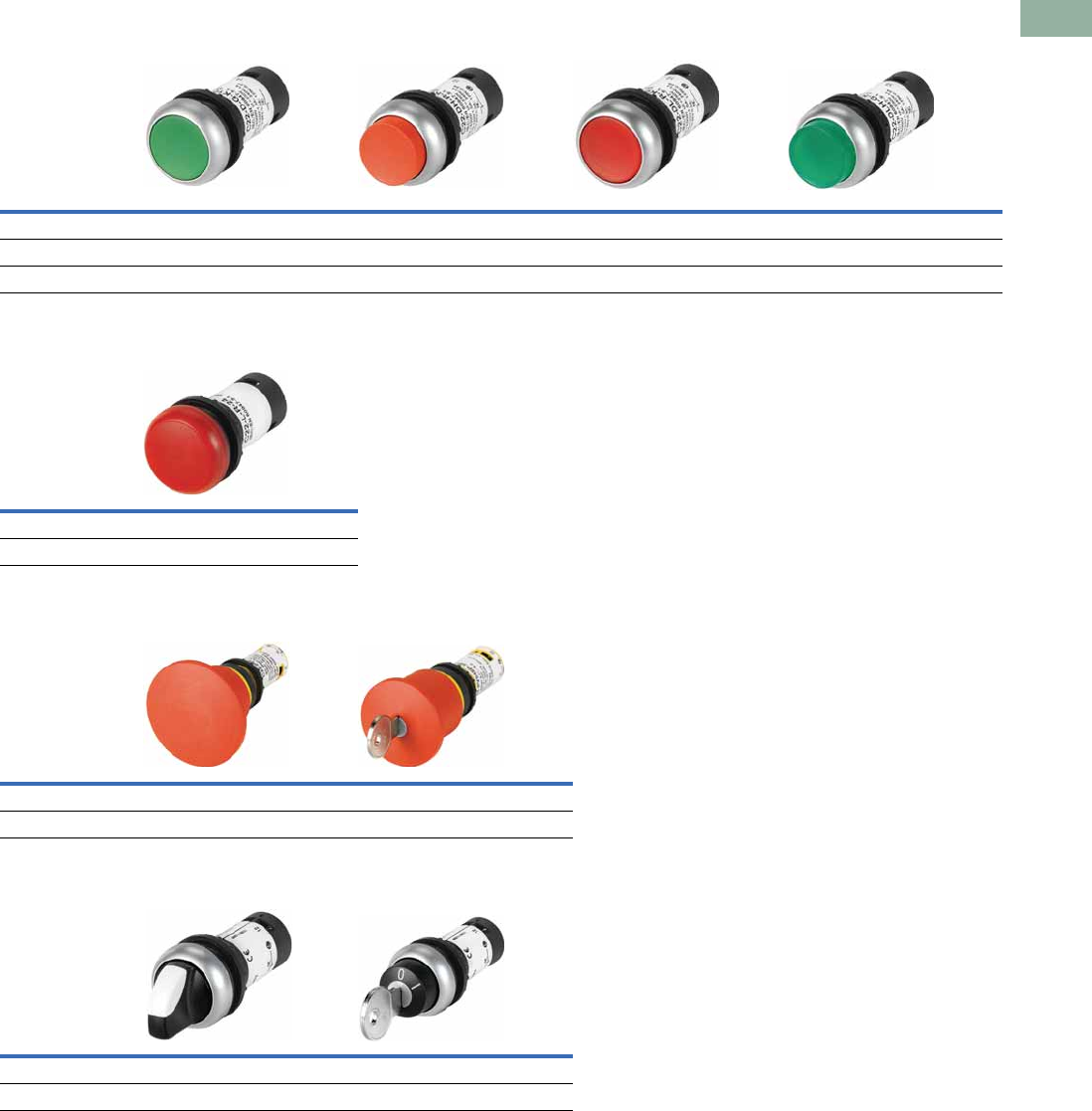
Volume 7—Logic Control, Operator Interface and Connectivity Solutions CA08100008E—March 2014 www.eaton.com V7-T1-139
1
1
1
1
1
1
1
1
1
1
1
1
1
1
1
1
1
1
1
1
1
1
1
1
1
1
1
1
1
1
1.6
Pushbuttons and Indicating Lights
22.5 mm Compact Pushbuttons—C22
Product Selection Guide
Pushbuttons
Indicating Lights
Emergency Stops
Selector Switches
Description Non-illuminated, flush Non-illuminated, extended Illuminated, flush Illuminated, extended
Operator Momentary Maintained Momentary Maintained Momentary Maintained Momentary Maintained
Product Selection Page V7-T1-141 Page V7-T1-142 Page V7-T1-143 Page V7-T1-144 Page V7-T1-145 Page V7-T1-146 Page V7-T1-147 Page V7-T1-148
Description Indicating lights
Product Selection Page V7-T1-150
Description Twist release Keyed-release
Product Selection Page V7-T1-152 Page V7-T1-152
Description Non-illuminated, knob type Key-operated
Product Selection Page V7-T1-155 Page V7-T1-156
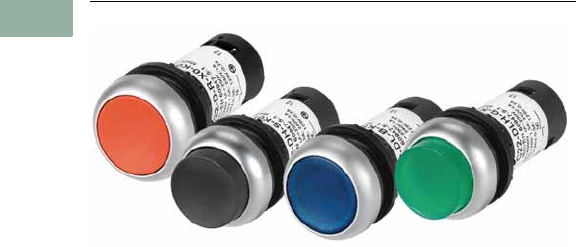
V7-T1-140 Volume 7—Logic Control, Operator Interface and Connectivity Solutions CA08100008E—March 2014 www.eaton.com
1
1
1
1
1
1
1
1
1
1
1
1
1
1
1
1
1
1
1
1
1
1
1
1
1
1
1
1
1
1
1.6
Pushbuttons and Indicating Lights
22.5 mm Compact Pushbuttons—C22
Pushbuttons—Non-Illuminated and Illuminated
Contents
Description Page
Pushbuttons—Non-Illuminated and Illuminated
Non-Illuminated, Flush, Momentary . . . . . . . . V7-T1-141
Non-Illuminated, Flush, Maintained . . . . . . . . . V7-T1-142
Non-Illuminated, Extended, Momentary . . . . . V7-T1-143
Non-Illuminated, Extended, Maintained . . . . . . V7-T1-144
Illuminated, Flush, Momentary . . . . . . . . . . . . V7-T1-145
Illuminated, Flush, Maintained . . . . . . . . . . . . . V7-T1-146
Illuminated, Extended, Momentary . . . . . . . . . V7-T1-147
Illuminated, Extended, Maintained . . . . . . . . . V7-T1-148
Indicating Lights . . . . . . . . . . . . . . . . . . . . . . . . . . V7-T1-149
Emergency Stops . . . . . . . . . . . . . . . . . . . . . . . . . V7-T1-151
Selector Switches . . . . . . . . . . . . . . . . . . . . . . . . . V7-T1-154
Technical Data and Specifications . . . . . . . . . . . . . V7-T1-159
Dimensions . . . . . . . . . . . . . . . . . . . . . . . . . . . . . . V7-T1-161
Pushbuttons—Non-Illuminated and Illuminated
Product Description
Eaton’s C22 Compact
Pushbuttons are a complete
line of monoblock type
pushbuttons with the contact
blocks, mounting adapter,
and operator all-in-one. The
C22 pushbuttons offer the
same look and feel as their
modular counterpart, the
M22. They also carry many of
the same rugged ratings and
options, such as laser
etching, field convertibility,
and LED technology.
Note: For additional accessories,
please see Pages V7-T1-111 to
V7-T1-117, 22.5 mm Modular
Pushbuttons—M22 Accessories.
Features
●Field convertible
maintained pushbuttons
from maintained to
momentary
●LED offering only for
improved brightness
quality and up to 100,000
hours of operation
●Laser engraved
pushbuttons and lenses
●Pushbuttons (momentary)
rated for 5 million
mechanical operations
Protection Type
●IP67/IP69K
●NEMA 4X, 13
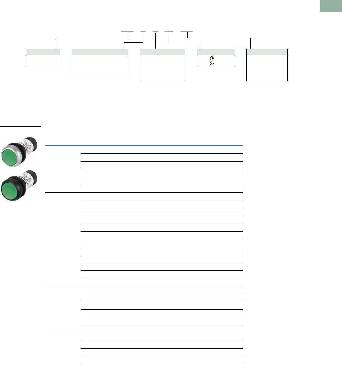
Volume 7—Logic Control, Operator Interface and Connectivity Solutions CA08100008E—March 2014 www.eaton.com V7-T1-141
1
1
1
1
1
1
1
1
1
1
1
1
1
1
1
1
1
1
1
1
1
1
1
1
1
1
1
1
1
1
1.6
Pushbuttons and Indicating Lights
22.5 mm Compact Pushbuttons—C22
Catalog Number Selection
Catalog Number Selection is for illustrative purposes only and not to be used to create new catalog numbers.
Non-Illuminated Pushbuttons
Product Selection
Non-Illuminated, Flush, Momentary
Non-Illuminated Pushbuttons, Flush, Momentary
Button
Color
Button
Etching
Contact Block
Configuration
Silver Bezel
Catalog Number
Black Bezel
Catalog Number
Green — 1NO C22-D-G-K10 C22S-D-G-K10
—2NOC22-D-G-K20 C22S-D-G-K20
— 1NO/1NC C22-D-G-K11 C22S-D-G-K11
X1 1NO C22-D-G-X1-K10 C22S-D-G-X1-K10
X1 2NO C22-D-G-X1-K20 C22S-D-G-X1-K20
X1 1NO/1NC C22-D-G-X1-K11 C22S-D-G-X1-K11
Red — 1NC C22-D-R-K01 C22S-D-R-K01
—2NCC22-D-R-K02 C22S-D-R-K02
— 1NO/1NC C22-D-R-K11 C22S-D-R-K11
X0 1NC C22-D-R-X0-K01 C22S-D-R-X0-K01
X0 2NC C22-D-R-X0-K02 C22S-D-R-X0-K02
X0 1NO/1NC C22-D-R-X0-K11 C22S-D-R-X0-K11
Black — 1NC C22-D-S-K01 C22S-D-S-K01
—2NCC22-D-S-K02 C22S-D-S-K02
— 1NO/1NC C22-D-S-K11 C22S-D-S-K11
X0 1NC C22-D-S-X0-K01 C22S-D-S-X0-K01
X0 2NC C22-D-S-X0-K02 C22S-D-S-X0-K02
X0 1NO/1NC C22-D-S-X0-K11 C22S-D-S-X0-K11
White — 1NO C22-D-W-K10 C22S-D-W-K10
—2NOC22-D-W-K20 C22S-D-W-K20
— 1NO/1NC C22-D-W-K11 C22S-D-W-K11
X1 1NO C22-D-W-X1-K10 C22S-D-W-X1-K10
X1 2NO C22-D-W-X1-K20 C22S-D-W-X1-K20
X1 1NO/1NC C22-D-W-X1-K11 C22S-D-W-X1-K11
Buttonless — 1NO C22-D-X-K10 C22S-D-X-K10
—2NOC22-D-X-K20 C22S-D-X-K20
—1NCC22-D-X-K01 C22S-D-X-K01
—2NCC22-D-X-K02 C22S-D-X-K02
— 1NO/1NC C22-D-X-K11 C22S-D-X-K11
C22 -D-G-X1-K10
Bezel
C22 = Silver
C22S =Black
Operator Type
D = Flush, momentary
DR = Flush, maintained
DH = Extended, momentary
DRH = Extended, maintained
Button Plate Color
G =Green
R =Red
S =Black
W =White
X = Buttonless
Button Etching
X0 =
X1 =
Contact Blocks
K10 =1NO
K20 =2NO
K01 =1NC
K02 =2NC
K11 =1NO/1NC
C22(S)-D-_
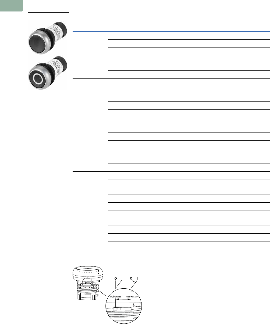
V7-T1-142 Volume 7—Logic Control, Operator Interface and Connectivity Solutions CA08100008E—March 2014 www.eaton.com
1
1
1
1
1
1
1
1
1
1
1
1
1
1
1
1
1
1
1
1
1
1
1
1
1
1
1
1
1
1
1.6
Pushbuttons and Indicating Lights
22.5 mm Compact Pushbuttons—C22
Non-Illuminated, Flush, Maintained
Non-Illuminated Pushbuttons, Flush, Maintained
Note: Maintained pushbuttons can be converted in the field to momentary operation by
switching the locking ring, which is accessible through the side of the operator body.
Button
Color
Button
Etching
Contact Block
Configuration
Silver Bezel
Catalog Number
Black Bezel
Catalog Number
Green — 1NO C22-DR-G-K10 C22S-DR-G-K10
—2NOC22-DR-G-K20 C22S-DR-G-K20
— 1NO/1NC C22-DR-G-K11 C22S-DR-G-K11
X1 1NO C22-DR-G-X1-K10 C22S-DR-G-X1-K10
X1 2NO C22-DR-G-X1-K20 C22S-DR-G-X1-K20
X1 1NO/1NC C22-DR-G-X1-K11 C22S-DR-G-X1-K11
Red — 1NC C22-DR-R-K01 C22S-DR-R-K01
—2NCC22-DR-R-K02 C22S-DR-R-K02
— 1NO/1NC C22-DR-R-K11 C22S-DR-R-K11
X0 1NC C22-DR-R-X0-K01 C22S-DR-R-X0-K01
X0 2NC C22-DR-R-X0-K02 C22S-DR-R-X0-K02
X0 1NO/1NC C22-DR-R-X0-K11 C22S-DR-R-X0-K11
Black — 1NC C22-DR-S-K01 C22S-DR-S-K01
—2NCC22-DR-S-K02 C22S-DR-S-K02
— 1NO/1NC C22-DR-S-K11 C22S-DR-S-K11
X0 1NC C22-DR-S-X0-K01 C22S-DR-S-X0-K01
X0 2NC C22-DR-S-X0-K02 C22S-DR-S-X0-K02
X0 1NO/1NC C22-DR-S-X0-K11 C22S-DR-S-X0-K11
White — 1NO C22-DR-W-K10 C22S-DR-W-K10
—2NOC22-DR-W-K20 C22S-DR-W-K20
— 1NO/1NC C22-DR-W-K11 C22S-DR-W-K11
X1 1NO C22-DR-W-X1-K10 C22S-DR-W-X1-K10
X1 2NO C22-DR-W-X1-K20 C22S-DR-W-X1-K20
X1 1NO/1NC C22-DR-W-X1-K11 C22S-DR-W-X1-K11
Buttonless — 1NO C22-DR-X-K10 C22S-DR-X-K10
—2NOC22-DR-X-K20 C22S-DR-X-K20
—1NCC22-DR-X-K01 C22S-DR-X-K01
—2NCC22-DR-X-K02 C22S-DR-X-K02
— 1NO/1NC C22-DR-X-K11 C22S-DR-X-K11
C22(S)-DR-_
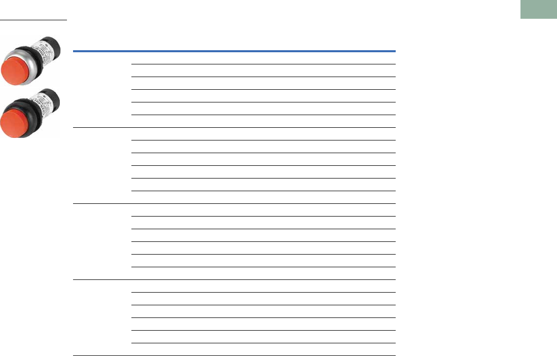
Volume 7—Logic Control, Operator Interface and Connectivity Solutions CA08100008E—March 2014 www.eaton.com V7-T1-143
1
1
1
1
1
1
1
1
1
1
1
1
1
1
1
1
1
1
1
1
1
1
1
1
1
1
1
1
1
1
1.6
Pushbuttons and Indicating Lights
22.5 mm Compact Pushbuttons—C22
Non-Illuminated, Extended, Momentary
Non-Illuminated Pushbuttons, Extended, Momentary
Button
Color
Button
Etching
Contact Block
Configuration
Silver Bezel
Catalog Number
Black Bezel
Catalog Number
Green — 1NO C22-DH-G-K10 C22S-DH-G-K10
—2NOC22-DH-G-K20 C22S-DH-G-K20
— 1NO/1NC C22-DH-G-K11 C22S-DH-G-K11
X1 1NO C22-DH-G-X1-K10 C22S-DH-G-X1-K10
X1 2NO C22-DH-G-X1-K20 C22S-DH-G-X1-K20
X1 1NO/1NC C22-DH-G-X1-K11 C22S-DH-G-X1-K11
Red — 1NC C22-DH-R-K01 C22S-DH-R-K01
—2NCC22-DH-R-K02 C22S-DH-R-K02
— 1NO/1NC C22-DH-R-K11 C22S-DH-R-K11
X0 1NC C22-DH-R-X0-K01 C22S-DH-R-X0-K01
X0 2NC C22-DH-R-X0-K02 C22S-DH-R-X0-K02
X0 1NO/1NC C22-DH-R-X0-K11 C22S-DH-R-X0-K11
Black — 1NC C22-DH-S-K01 C22S-DH-S-K01
—2NCC22-DH-S-K02 C22S-DH-S-K02
— 1NO/1NC C22-DH-S-K11 C22S-DH-S-K11
X0 1NC C22-DH-S-X0-K01 C22S-DH-S-X0-K01
X0 2NC C22-DH-S-X0-K02 C22S-DH-S-X0-K02
X0 1NO/1NC C22-DH-S-X0-K11 C22S-DH-S-X0-K11
White — 1NO C22-DH-W-K10 C22S-DH-W-K10
—2NOC22-DH-W-K20 C22S-DH-W-K20
— 1NO/1NC C22-DH-W-K11 C22S-DH-W-K11
X1 1NO C22-DH-W-X1-K10 C22S-DH-W-X1-K10
X1 2NO C22-DH-W-X1-K20 C22S-DH-W-X1-K20
X1 1NO/1NC C22-DH-W-X1-K11 C22S-DH-W-X1-K11
C22(S)-DH-_
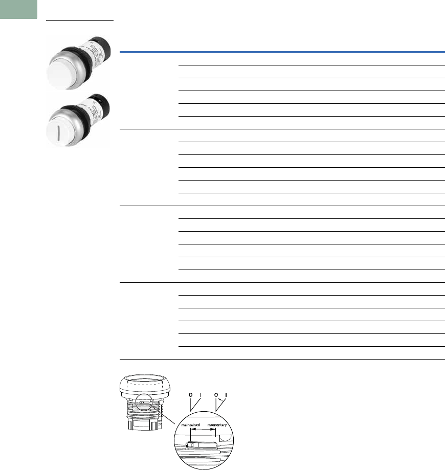
V7-T1-144 Volume 7—Logic Control, Operator Interface and Connectivity Solutions CA08100008E—March 2014 www.eaton.com
1
1
1
1
1
1
1
1
1
1
1
1
1
1
1
1
1
1
1
1
1
1
1
1
1
1
1
1
1
1
1.6
Pushbuttons and Indicating Lights
22.5 mm Compact Pushbuttons—C22
Non-Illuminated, Extended, Maintained
Non-Illuminated Pushbuttons, Extended, Maintained
Note: Maintained pushbuttons can be converted in the field to momentary operation by
switching the locking ring, which is accessible through the side of the operator body.
Button
Color
Button
Etching
Contact Block
Configuration
Silver Bezel
Catalog Number
Black Bezel
Catalog Number
Green — 1NO C22-DRH-G-K10 C22S-DRH-G-K10
—2NOC22-DRH-G-K20 C22S-DRH-G-K20
— 1NO/1NC C22-DRH-G-K11 C22S-DRH-G-K11
X1 1NO C22-DRH-G-X1-K10 C22S-DRH-G-X1-K10
X1 2NO C22-DRH-G-X1-K20 C22S-DRH-G-X1-K20
X1 1NO/1NC C22-DRH-G-X1-K11 C22S-DRH-G-X1-K11
Red — 1NC C22-DRH-R-K01 C22S-DRH-R-K01
—2NCC22-DRH-R-K02 C22S-DRH-R-K02
— 1NO/1NC C22-DRH-R-K11 C22S-DRH-R-K11
X0 1NC C22-DRH-R-X0-K01 C22S-DRH-R-X0-K01
X0 2NC C22-DRH-R-X0-K02 C22S-DRH-R-X0-K02
X0 1NO/1NC C22-DRH-R-X0-K11 C22S-DRH-R-X0-K11
Black — 1NC C22-DRH-S-K01 C22S-DRH-S-K01
—2NCC22-DRH-S-K02 C22S-DRH-S-K02
— 1NO/1NC C22-DRH-S-K11 C22S-DRH-S-K11
X0 1NC C22-DRH-S-X0-K01 C22S-DRH-S-X0-K01
X0 2NC C22-DRH-S-X0-K02 C22S-DRH-S-X0-K02
X0 1NO/1NC C22-DRH-S-X0-K11 C22S-DRH-S-X0-K11
White — 1NO C22-DRH-W-K10 C22S-DRH-W-K10
—2NOC22-DRH-W-K20 C22S-DRH-W-K20
— 1NO/1NC C22-DRH-W-K11 C22S-DRH-W-K11
X1 1NO C22-DRH-W-X1-K10 C22S-DRH-W-X1-K10
X1 2NO C22-DRH-W-X1-K20 C22S-DRH-W-X1-K20
X1 1NO/1NC C22-DRH-W-X1-K11 C22S-DRH-W-X1-K11
C22(S)-DRH-_
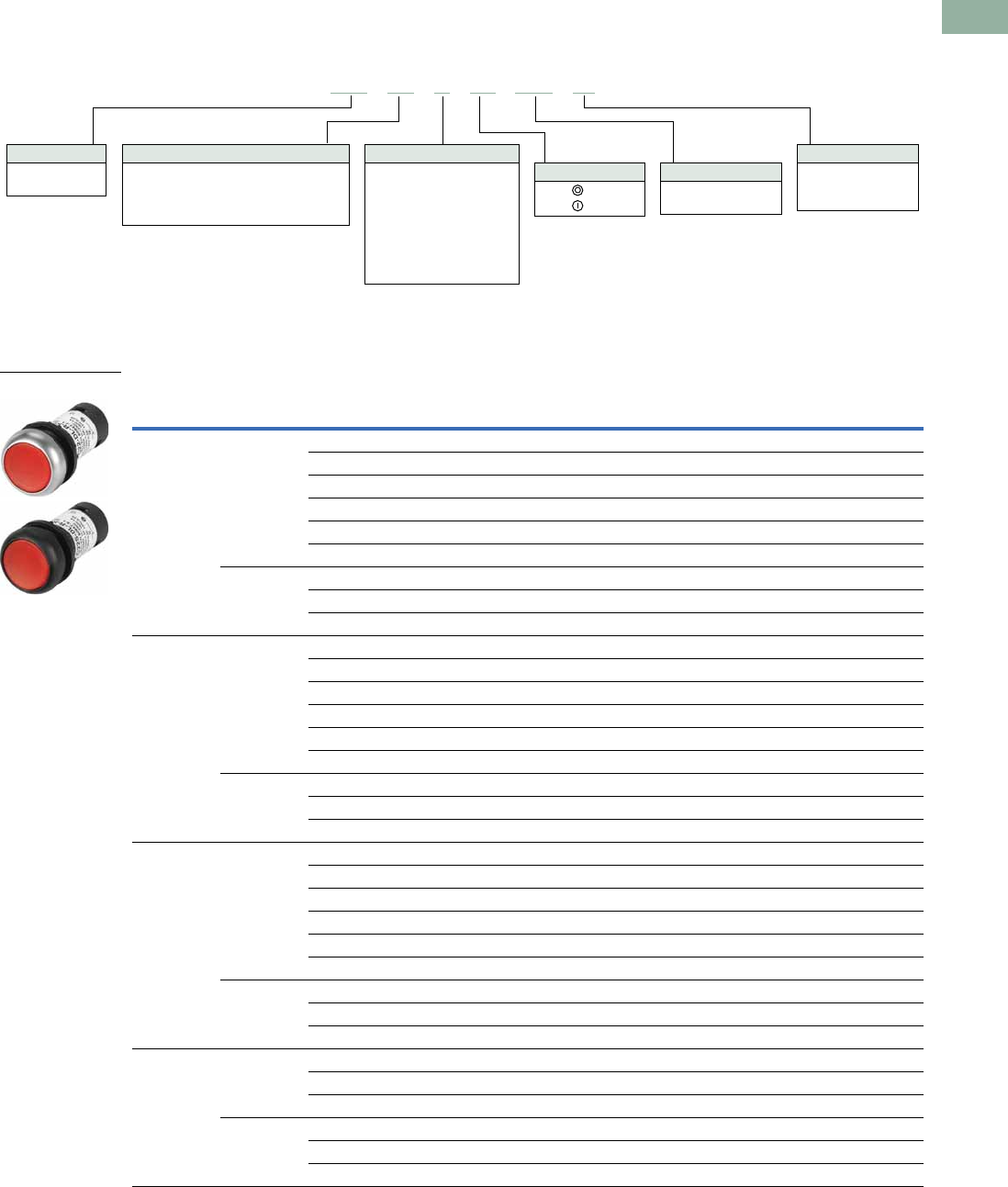
Volume 7—Logic Control, Operator Interface and Connectivity Solutions CA08100008E—March 2014 www.eaton.com V7-T1-145
1
1
1
1
1
1
1
1
1
1
1
1
1
1
1
1
1
1
1
1
1
1
1
1
1
1
1
1
1
1
1.6
Pushbuttons and Indicating Lights
22.5 mm Compact Pushbuttons—C22
Catalog Number Selection
Catalog Number Selection is for illustrative purposes only and not to be used to create new catalog numbers.
Illuminated Pushbuttons
Product Selection
Illuminated, Flush, Momentary
Illuminated Pushbuttons, Flush, Momentary
LED Color
Button
Color Voltage
Button
Etching
Contact Block
Configuration
Silver Bezel
Catalog Number
Black Bezel
Catalog Number
Green Green 24 Vac/Vdc — 1NO C22-DL-G-K10-24 C22S-DL-G-K10-24
120 Vac — 1NO C22-DL-G-K10-120 C22S-DL-G-K10-120
230 Vac — 1NO C22-DL-G-K10-230 C22S-DL-G-K10-230
24 Vac/Vdc X1 1NO C22-DL-G-X1-K10-24 C22S-DL-G-X1-K10-24
120 Vac X1 1NO C22-DL-G-X1-K10-120 C22S-DL-G-X1-K10-120
230 Vac X1 1NO C22-DL-G-X1-K10-230 C22S-DL-G-X1-K10-230
Buttonless 24 Vac/Vdc — 1NO C22-DL-XG-K10-24 C22S-DL-XG-K10-24
120 Vac — 1NO C22-DL-XG-K10-120 C22S-DL-XG-K10-120
230 Vac — 1NO C22-DL-XG-K10-230 C22S-DL-XG-K10-230
Red Red 24 Vac/Vdc — 1NC C22-DL-R-K01-24 C22S-DL-R-K01-24
120 Vac — 1NC C22-DL-R-K01-120 C22S-DL-R-K01-120
230 Vac — 1NC C22-DL-R-K01-230 C22S-DL-R-K01-230
24 Vac/Vdc X0 1NC C22-DL-R-X0-K01-24 C22S-DL-R-X0-K01-24
120 Vac X0 1NC C22-DL-R-X0-K01-120 C22S-DL-R-X0-K01-120
230 Vac X0 1NC C22-DL-R-X0-K01-230 C22S-DL-R-X0-K01-230
Buttonless 24 Vac/Vdc — 1NC C22-DL-XR-K01-24 C22S-DL-XR-K01-24
120 Vac — 1NC C22-DL-XR-K01-120 C22S-DL-XR-K01-120
230 Vac — 1NC C22-DL-XR-K01-230 C22S-DL-XR-K01-230
White White 24 Vac/Vdc — 1NO C22-DL-W-K10-24 C22S-DL-W-K10-24
120 Vac — 1NO C22-DL-W-K10-120 C22S-DL-W-K10-120
230 Vac — 1NO C22-DL-W-K10-230 C22S-DL-W-K10-230
24 Vac/Vdc X1 1NO C22-DL-W-X1-K10-24 C22S-DL-W-X1-K10-24
120 Vac X1 1NO C22-DL-W-X1-K10-120 C22S-DL-W-X1-K10-120
230 Vac X1 1NO C22-DL-W-X1-K10-230 C22S-DL-W-X1-K10-230
Buttonless 24 Vac/Vdc — 1NO C22-DL-XW-K10-24 C22S-DL-XW-K10-24
120 Vac — 1NO C22-DL-XW-K10-120 C22S-DL-XW-K10-120
230 Vac — 1NO C22-DL-XW-K10-230 C22S-DL-XW-K10-230
Blue Blue 24 Vac/Vdc — 1NO C22-DL-B-K10-24 C22S-DL-B-K10-24
120 Vac — 1NO C22-DL-B-K10-120 C22S-DL-B-K10-120
230 Vac — 1NO C22-DL-B-K10-230 C22S-DL-B-K10-230
Buttonless 24 Vac/Vdc — 1NO C22-DL-XB-K10-24 C22S-DL-XB-K10-24
120 Vac — 1NO C22-DL-XB-K10-120 C22S-DL-XB-K10-120
230 Vac — 1NO C22-DL-XB-K10-230 C22S-DL-XB-K10-230
C22 -DL-G-X1-K10-24
Bezel
C22 = Silver
C22S =Black
Operator Type
DL = Illuminated, flush, momentary
DRL = Illuminated, flush, maintained
DLH = Illuminated, extended, momentary
DRLH = Illuminated, extended, maintained
Lens Etching
X0 =
X1 =
Contact Blocks
K10 =1NO
K01 =1NC
LED Voltage
24 = 24 Vac/Vdc
120 = 120 Vac
230 = 230 Vac
LED/Lens Color
G = Green
R =Red
W =White
B = Blue
XG = Green without lens
XR = Red without lens
XW = White without lens
XB = Blue without lens
C22(S)-DL-_
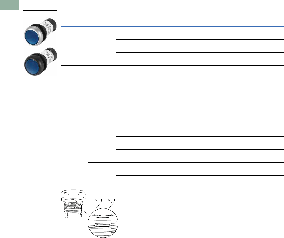
V7-T1-146 Volume 7—Logic Control, Operator Interface and Connectivity Solutions CA08100008E—March 2014 www.eaton.com
1
1
1
1
1
1
1
1
1
1
1
1
1
1
1
1
1
1
1
1
1
1
1
1
1
1
1
1
1
1
1.6
Pushbuttons and Indicating Lights
22.5 mm Compact Pushbuttons—C22
Illuminated, Flush, Maintained
Illuminated Pushbuttons, Flush, Maintained
Note: Maintained pushbuttons can be converted in the field to momentary operation by
switching the locking ring, which is accessible through the side of the operator body.
LED Color
Button
Color Voltage
Contact Block
Configuration
Silver Bezel
Catalog Number
Black Bezel
Catalog Number
Green Green 24 Vac/Vdc 1NO C22-DRL-G-K10-24 C22S-DRL-G-K10-24
120 Vac 1NO C22-DRL-G-K10-120 C22S-DRL-G-K10-120
230 Vac 1NO C22-DRL-G-K10-230 C22S-DRL-G-K10-230
Buttonless 24 Vac/Vdc 1NO C22-DRL-XG-K10-24 C22S-DRL-XG-K10-24
120 Vac 1NO C22-DRL-XG-K10-120 C22S-DRL-XG-K10-120
230 Vac 1NO C22-DRL-XG-K10-230 C22S-DRL-XG-K10-230
Red Red 24 Vac/Vdc 1NC C22-DRL-R-K01-24 C22S-DRL-R-K01-24
120 Vac 1NC C22-DRL-R-K01-120 C22S-DRL-R-K01-120
230 Vac 1NC C22-DRL-R-K01-230 C22S-DRL-R-K01-230
Buttonless 24 Vac/Vdc 1NC C22-DRL-XR-K01-24 C22S-DRL-XR-K01-24
120 Vac 1NC C22-DRL-XR-K01-120 C22S-DRL-XR-K01-120
230 Vac 1NC C22-DRL-XR-K01-230 C22S-DRL-XR-K01-230
White White 24 Vac/Vdc 1NO C22-DRL-W-K10-24 C22S-DRL-W-K10-24
120 Vac 1NO C22-DRL-W-K10-120 C22S-DRL-W-K10-120
230 Vac 1NO C22-DRL-W-K10-230 C22S-DRL-W-K10-230
Buttonless 24 Vac/Vdc 1NO C22-DRL-XW-K10-24 C22S-DRL-XW-K10-24
120 Vac 1NO C22-DRL-XW-K10-120 C22S-DRL-XW-K10-120
230 Vac 1NO C22-DRL-XW-K10-230 C22S-DRL-XW-K10-230
Blue Blue 24 Vac/Vdc 1NO C22-DRL-B-K10-24 C22S-DRL-B-K10-24
120 Vac 1NO C22-DRL-B-K10-120 C22S-DRL-B-K10-120
230 Vac 1NO C22-DRL-B-K10-230 C22S-DRL-B-K10-230
Buttonless 24 Vac/Vdc 1NO C22-DRL-XB-K10-24 C22S-DRL-XB-K10-24
120 Vac 1NO C22-DRL-XB-K10-120 C22S-DRL-XB-K10-120
230 Vac 1NO C22-DRL-XB-K10-230 C22S-DRL-XB-K10-230
C22(S)-DRL-_
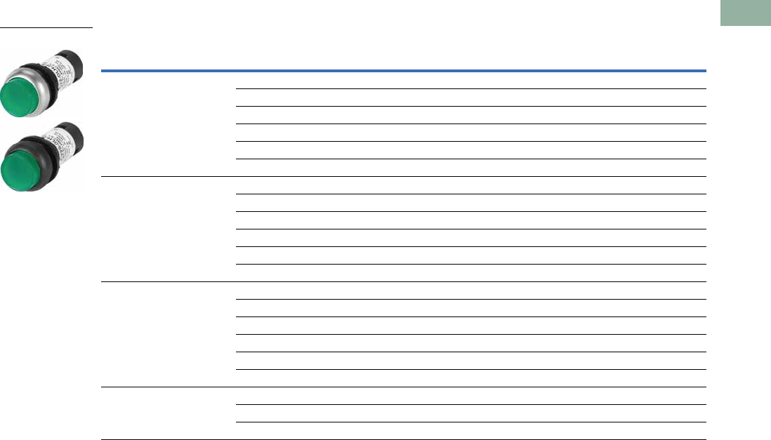
Volume 7—Logic Control, Operator Interface and Connectivity Solutions CA08100008E—March 2014 www.eaton.com V7-T1-147
1
1
1
1
1
1
1
1
1
1
1
1
1
1
1
1
1
1
1
1
1
1
1
1
1
1
1
1
1
1
1.6
Pushbuttons and Indicating Lights
22.5 mm Compact Pushbuttons—C22
Illuminated, Extended, Momentary
Illuminated Pushbuttons, Extended, Momentary
LED Color
Button
Color Voltage
Button
Etching
Contact Block
Configuration
Silver Bezel
Catalog Number
Black Bezel
Catalog Number
Green Green 24 Vac/Vdc — 1NO C22-DLH-G-K10-24 C22S-DLH-G-K10-24
120 Vac — 1NO C22-DLH-G-K10-120 C22S-DLH-G-K10-120
230 Vac — 1NO C22-DLH-G-K10-230 C22S-DLH-G-K10-230
24 Vac/Vdc X1 1NO C22-DLH-G-X1-K10-24 C22S-DLH-G-X1-K10-24
120 Vac X1 1NO C22-DLH-G-X1-K10-120 C22S-DLH-G-X1-K10-12
230 Vac X1 1NO C22-DLH-G-X1-K10-230 C22S-DLH-G-X1-K10-23
Red Red 24 Vac/Vdc — 1NC C22-DLH-R-K01-24 C22S-DLH-R-K01-24
120 Vac — 1NC C22-DLH-R-K01-120 C22S-DLH-R-K01-120
230 Vac — 1NC C22-DLH-R-K01-230 C22S-DLH-R-K01-230
24 Vac/Vdc X0 1NC C22-DLH-R-X0-K01-24 C22S-DLH-R-X0-K01-24
120 Vac X0 1NC C22-DLH-R-X0-K01-120 C22S-DLH-R-X0-K01-12
230 Vac X0 1NC C22-DLH-R-X0-K01-230 C22S-DLH-R-X0-K01-23
White White 24 Vac/Vdc — 1NO C22-DLH-W-K10-24 C22S-DLH-W-K10-24
120 Vac — 1NO C22-DLH-W-K10-120 C22S-DLH-W-K10-120
230 Vac — 1NO C22-DLH-W-K10-230 C22S-DLH-W-K10-230
24 Vac/Vdc X1 1NO C22-DLH-W-X1-K10-24 C22S-DLH-W-X1-K10-24
120 Vac X1 1NO C22-DLH-W-X1-K10-120 C22S-DLH-W-X1-K10-12
230 Vac X1 1NO C22-DLH-W-X1-K10-230 C22S-DLH-W-X1-K10-23
Blue Blue 24 Vac/Vdc — 1NO C22-DLH-B-K10-24 C22S-DLH-B-K10-24
120 Vac — 1NO C22-DLH-B-K10-120 C22S-DLH-B-K10-120
230 Vac — 1NO C22-DLH-B-K10-230 C22S-DLH-B-K10-230
C22(S)-DLH-_
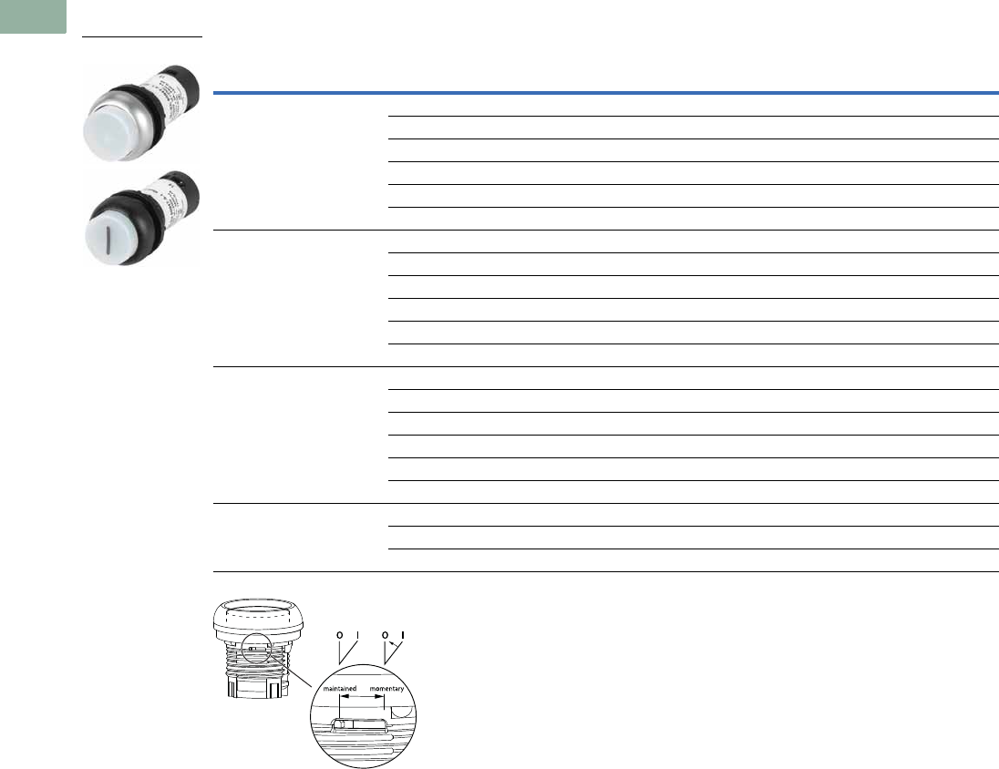
V7-T1-148 Volume 7—Logic Control, Operator Interface and Connectivity Solutions CA08100008E—March 2014 www.eaton.com
1
1
1
1
1
1
1
1
1
1
1
1
1
1
1
1
1
1
1
1
1
1
1
1
1
1
1
1
1
1
1.6
Pushbuttons and Indicating Lights
22.5 mm Compact Pushbuttons—C22
Illuminated, Extended, Maintained
Illuminated Pushbuttons, Flush Extended, Maintained
Note: Maintained pushbuttons can be converted in the field to momentary operation by
switching the locking ring, which is accessible through the side of the operator body.
LED Color
Button
Color Voltage
Button
Etching
Contact Block
Configuration
Silver Bezel
Catalog Number
Black Bezel
Catalog Number
Green Green 24 Vac/Vdc — 1NO C22-DRLH-G-K10-24 C22S-DRLH-G-K10-24
120 Vac — 1NO C22-DRLH-G-K10-120 C22S-DRLH-G-K10-120
230 Vac — 1NO C22-DRLH-G-K10-230 C22S-DRLH-G-K10-230
24 Vac/Vdc X1 1NO C22-DRLH-G-X1-K10-24 C22S-DRLH-G-X1-K10-24
120 Vac X1 1NO C22-DRLH-G-X1-K10-120 C22S-DRLH-G-X1-K10-120
230 Vac X1 1NO C22-DRLH-G-X1-K10-230 C22S-DRLH-G-X1-K10-230
Red Red 24 Vac/Vdc — 1NC C22-DRLH-R-K01-24 C22S-DRLH-R-K01-24
120 Vac — 1NC C22-DRLH-R-K01-120 C22S-DRLH-R-K01-120
230 Vac — 1NC C22-DRLH-R-K01-230 C22S-DRLH-R-K01-230
24 Vac/Vdc X0 1NC C22-DRLH-R-X0-K01-24 C22S-DRLH-R-X0-K01-24
120 Vac X0 1NC C22-DRLH-R-X0-K01-120 C22S-DRLH-R-X0-K01-120
230 Vac X0 1NC C22-DRLH-R-X0-K01-230 C22S-DRLH-R-X0-K01-230
White White 24 Vac/Vdc — 1NO C22-DRLH-W-K10-24 C22S-DRLH-W-K10-24
120 Vac — 1NO C22-DRLH-W-K10-120 C22S-DRLH-W-K10-120
230 Vac — 1NO C22-DRLH-W-K10-230 C22S-DRLH-W-K10-230
24 Vac/Vdc X1 1NO C22-DRLH-W-X1-K10-24 C22S-DRLH-W-X1-K10-24
120 Vac X1 1NO C22-DRLH-W-X1-K10-120 C22S-DRLH-W-X1-K10-120
230 Vac X1 1NO C22-DRLH-W-X1-K10-230 C22S-DRLH-W-X1-K10-230
Blue Blue 24 Vac/Vdc — 1NO C22-DRLH-B-K10-24 C22S-DRLH-B-K10-24
120 Vac — 1NO C22-DRLH-B-K10-120 C22S-DRLH-B-K10-120
230 Vac — 1NO C22-DRLH-B-K10-230 C22S-DRLH-B-K10-230
C22(S)-DRLH-_

Volume 7—Logic Control, Operator Interface and Connectivity Solutions CA08100008E—March 2014 www.eaton.com V7-T1-149
1
1
1
1
1
1
1
1
1
1
1
1
1
1
1
1
1
1
1
1
1
1
1
1
1
1
1
1
1
1
1.6
Pushbuttons and Indicating Lights
22.5 mm Compact Pushbuttons—C22
Indicating Lights
Contents
Description Page
Pushbuttons—Non-Illuminated and
Illuminated . . . . . . . . . . . . . . . . . . . . . . . . . . . . . V7-T1-140
Indicating Lights
Catalog Number Selection . . . . . . . . . . . . . . . . V7-T1-150
Product Selection . . . . . . . . . . . . . . . . . . . . . . . V7-T1-150
Emergency Stops . . . . . . . . . . . . . . . . . . . . . . . . . V7-T1-151
Selector Switches . . . . . . . . . . . . . . . . . . . . . . . . . V7-T1-154
Technical Data and Specifications . . . . . . . . . . . . . V7-T1-159
Dimensions . . . . . . . . . . . . . . . . . . . . . . . . . . . . . . V7-T1-161
Indicating Lights
Product Description
C22 indicating lights use a
combination of a durable,
bright LED unit and modern
lenses designed specifically
for this type of LED to create
a bright and visible indicating
light. As with the
pushbuttons, the indicating
light lenses can be laser
etched, simply order without
lens and order M22/C22
custom etched lenses
to attach.
Note: For additional accessories,
please see Pages V7-T1-111 to
V7-T1-117, 22.5 mm Modular
Pushbuttons—M22 Accessories.
Features
●LED offering only for
improved brightness
quality and up to 100,000
hours of operation
●Lenses specifically
designed for LED
illumination
●Lenses capable of being
laser etched for custom
solutions that last
Protection Type
●IP67/IP69K
●NEMA 4X, 13
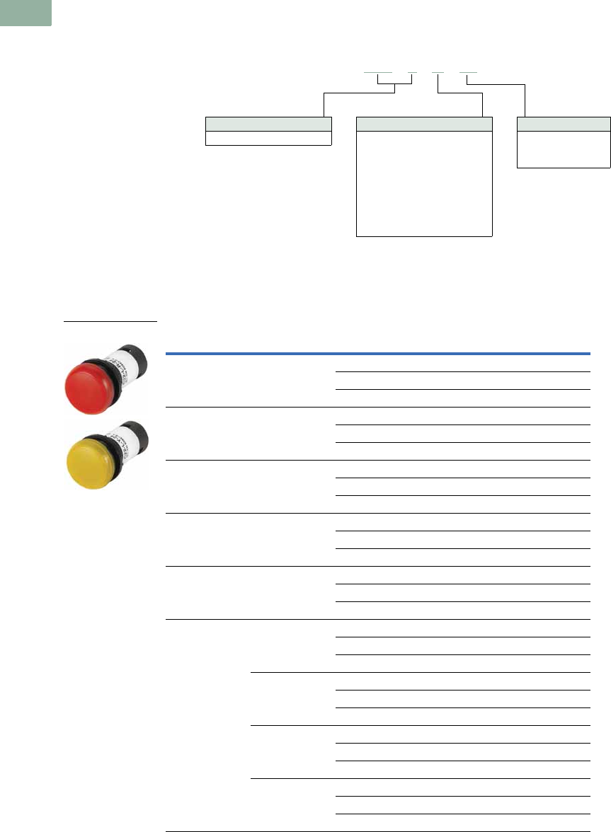
V7-T1-150 Volume 7—Logic Control, Operator Interface and Connectivity Solutions CA08100008E—March 2014 www.eaton.com
1
1
1
1
1
1
1
1
1
1
1
1
1
1
1
1
1
1
1
1
1
1
1
1
1
1
1
1
1
1
1.6
Pushbuttons and Indicating Lights
22.5 mm Compact Pushbuttons—C22
Catalog Number Selection
Catalog Number Selection is for illustrative purposes only and not to be used to create new catalog numbers.
Indicating Lights
Product Selection
Indicating Lights
Indicating Lights
Note
1 Use white LED for both white and yellow lenses.
Lens Color LED Color Voltage Catalog Number
Green Green 24 Vac/Vdc C22-L-G-24
120 Vac C22-L-G-120
230 Vac C22-L-G-230
Red Red 24 Vac/Vdc C22-L-R-24
120 Vac C22-L-R-120
230 Vac C22-L-R-230
White White 24 Vac/Vdc C22-L-W-24
120 Vac C22-L-W-120
230 Vac C22-L-W-230
Yellow White 24 Vac/Vdc C22-L-Y-24
120 Vac C22-L-Y-120
230 Vac C22-L-Y-230
Blue Blue 24 Vac/Vdc C22-L-B-24
120 Vac C22-L-B-120
230 Vac C22-L-B-230
Without Lens Green 24 Vac/Vdc C22-L-XG-24
120 Vac C22-L-XG-120
230 Vac C22-L-XG-230
Red 24 Vac/Vdc C22-L-XR-24
120 Vac C22-L-XR-120
230 Vac C22-L-XR-230
White 24 Vac/Vdc C22-L-XW-24
120 Vac C22-L-XW-120
230 Vac C22-L-XW-230
Blue 24 Vac/Vdc C22-L-XB-24
120 Vac C22-L-XB-120
230 Vac C22-L-XB-230
C22 -L-G-24
Bezel
C22-L = Flush indicating light
LED Voltage
24 = 24 Vac/Vdc
120 = 120 Vac
230 = 230 Vac
LED/Lens Color
G =Green
R =Red
W =White
Y = Yellow
B = Blue
XG = Green without lens
XR = Red without lens
XW = White without lens 1
XB = Blue without lens
C22-L-_

Volume 7—Logic Control, Operator Interface and Connectivity Solutions CA08100008E—March 2014 www.eaton.com V7-T1-151
1
1
1
1
1
1
1
1
1
1
1
1
1
1
1
1
1
1
1
1
1
1
1
1
1
1
1
1
1
1
1.6
Pushbuttons and Indicating Lights
22.5 mm Compact Pushbuttons—C22
Emergency Stops
Contents
Description Page
Pushbuttons—Non-Illuminated and
Illuminated . . . . . . . . . . . . . . . . . . . . . . . . . . . . . V7-T1-140
Indicating Lights . . . . . . . . . . . . . . . . . . . . . . . . . . V7-T1-149
Emergency Stops
Non-Illuminated, Twist-Release . . . . . . . . . . . . V7-T1-152
Non-Illuminated, Keyed-Release . . . . . . . . . . . . V7-T1-152
Selector Switches . . . . . . . . . . . . . . . . . . . . . . . . . V7-T1-154
Technical Data and Specifications . . . . . . . . . . . . . V7-T1-159
Dimensions . . . . . . . . . . . . . . . . . . . . . . . . . . . . . . V7-T1-161
Emergency Stops
Product Description
C22 emergency stops are a
durable and reliable solution
to a variety of e-stop
applications. This compact
e-stop, available as twist-to-
release and keyed-release,
is a simple product that
eliminates the need for self-
monitoring contact blocks,
all while still meeting almost
all of the industry safety
standards.
Note: For additional accessories,
please see Pages V7-T1-111 to
V7-T1-117, 22.5 mm Modular
Pushbuttons—M22 Accessories.
Features
●Available in both twist-
release and keyed-release
with either 45 mm or
60 mm operators
Protection Type
●Twist-Release
●IP67/IP69K
●Keyed-Release
●IP66
●NEMA 4X, 13
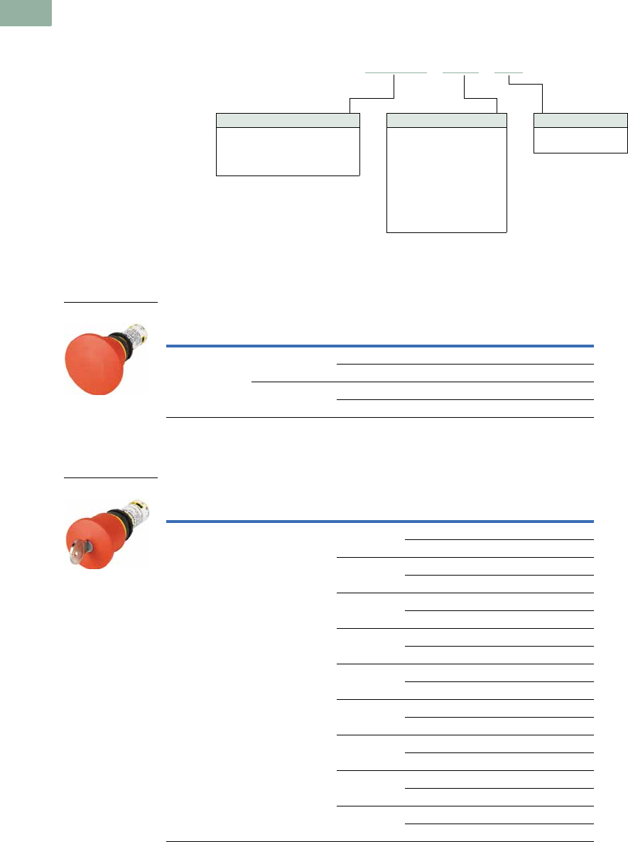
V7-T1-152 Volume 7—Logic Control, Operator Interface and Connectivity Solutions CA08100008E—March 2014 www.eaton.com
1
1
1
1
1
1
1
1
1
1
1
1
1
1
1
1
1
1
1
1
1
1
1
1
1
1
1
1
1
1
1.6
Pushbuttons and Indicating Lights
22.5 mm Compact Pushbuttons—C22
Catalog Number Selection
Catalog Number Selection is for illustrative purposes only and not to be used to create new catalog numbers.
Emergency Stops
Product Selection
Non-Illuminated, Twist-Release
Non-Illuminated Emergency Stops, Twist-Release
Non-Illuminated, Keyed-Release
Non-Illuminated Emergency Stops, Keyed-Release
Release Method Operator Size
Contact Block
Configuration Catalog Number
Twist-release 45 mm 2NC C22-PVT45P-K02
1NO/1NC C22-PVT45P-K11
60 mm 2NC C22-PVT60P-K02
1NO/1NC C22-PVT60P-K11
Release Method Operator Size Key Code
Contact Block
Configuration Catalog Number
Keyed-release 45 mm MS1 2NC C22-PVS45P-MS1-K02
1NO/1NC C22-PVS45P-MS1-K11
MS2 2NC C22-PVS45P-MS2-K02
1NO/1NC C22-PVS45P-MS2-K11
MS3 2NC C22-PVS45P-MS3-K02
1NO/1NC C22-PVS45P-MS3-K11
MS4 2NC C22-PVS45P-MS4-K02
1NO/1NC C22-PVS45P-MS4-K11
MS5 2NC C22-PVS45P-MS5-K02
1NO/1NC C22-PVS45P-MS5-K11
MS6 2NC C22-PVS45P-MS6-K02
1NO/1NC C22-PVS45P-MS6-K11
MS7 2NC C22-PVS45P-MS7-K02
1NO/1NC C22-PVS45P-MS7-K11
MS8 2NC C22-PVS45P-MS8-K02
1NO/1NC C22-PVS45P-MS8-K11
Ronis 2NC C22-PVS45P-RS-K02
1NO/1NC C22-PVS45P-RS-K11
C22 - PVS45P -MS1-K01
Operator Type
PVT45P = Twist-release, 45 mm
PVT60P = Twist-release, 60 mm
PVS45P = Key-release, 45 mm
PVS60P = Key-release, 60 mm
Key Code
MS1 =MS1
MS2 =MS2
MS3 =MS3
MS4 =MS4
MS5 =MS5
MS6 =MS6
MS7 =MS7
MS8 =MS8
RS = Ronis-445
Contact Blocks
K02 =2NC
K11 = 1NO/1NC
C22-PVT_
C22-PVS_
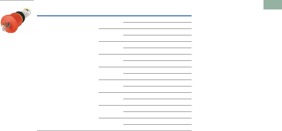
Volume 7—Logic Control, Operator Interface and Connectivity Solutions CA08100008E—March 2014 www.eaton.com V7-T1-153
1
1
1
1
1
1
1
1
1
1
1
1
1
1
1
1
1
1
1
1
1
1
1
1
1
1
1
1
1
1
1.6
Pushbuttons and Indicating Lights
22.5 mm Compact Pushbuttons—C22
Non-Illuminated Emergency Stops, Keyed-Release, continued
Release Method Operator Size Key Code
Contact Block
Configuration Catalog Number
Keyed-release 60 mm MS1 2NC C22-PVS60P-MS1-K02
1NO/1NC C22-PVS60P-MS1-K11
MS2 2NC C22-PVS60P-MS2-K02
1NO/1NC C22-PVS60P-MS2-K11
MS3 2NC C22-PVS60P-MS3-K02
1NO/1NC C22-PVS60P-MS3-K11
MS4 2NC C22-PVS60P-MS4-K02
1NO/1NC C22-PVS60P-MS4-K11
MS5 2NC C22-PVS60P-MS5-K02
1NO/1NC C22-PVS60P-MS5-K11
MS6 2NC C22-PVS60P-MS6-K02
1NO/1NC C22-PVS60P-MS6-K11
MS7 2NC C22-PVS60P-MS7-K02
1NO/1NC C22-PVS60P-MS7-K11
MS8 2NC C22-PVS60P-MS8-K02
1NO/1NC C22-PVS60P-MS8-K11
Ronis 2NC C22-PVS60P-RS-K02
1NO/1NC C22-PVS60P-RS-K11
C22-PVS_
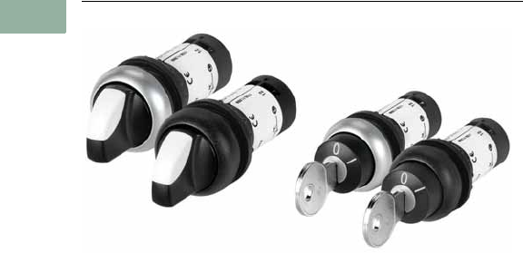
V7-T1-154 Volume 7—Logic Control, Operator Interface and Connectivity Solutions CA08100008E—March 2014 www.eaton.com
1
1
1
1
1
1
1
1
1
1
1
1
1
1
1
1
1
1
1
1
1
1
1
1
1
1
1
1
1
1
1.6
Pushbuttons and Indicating Lights
22.5 mm Compact Pushbuttons—C22
Selector Switches
Contents
Description Page
Pushbuttons—Non-Illuminated and
Illuminated . . . . . . . . . . . . . . . . . . . . . . . . . . . . . V7-T1-140
Indicating Lights . . . . . . . . . . . . . . . . . . . . . . . . . . V7-T1-149
Emergency Stops . . . . . . . . . . . . . . . . . . . . . . . . . V7-T1-151
Selector Switches
Non-Illuminated, Knob Type . . . . . . . . . . . . . . . V7-T1-155
Non-Illuminated, Key Operated . . . . . . . . . . . . V7-T1-156
Technical Data and Specifications . . . . . . . . . . . . . V7-T1-159
Dimensions . . . . . . . . . . . . . . . . . . . . . . . . . . . . . . V7-T1-161
Selector Switches
Product Description
With over 20 variations of
operation and 8 varieties of
key codes, the C22 line offers
a very complete line of
selector switches.
Note: For additional accessories,
please see Pages V7-T1-111 to
V7-T1-117, 22.5 mm Modular
Pushbuttons—M22 Accessories.
Features
●Selector switch (non-
keyed) rated for 1 million
mechanical operations
●Momentary selector
switches are field
convertible from
momentary to maintained
Protection Type
●IP65
●NEMA 4X, 13
Volume 7—Logic Control, Operator Interface and Connectivity Solutions CA08100008E—March 2014 www.eaton.com V7-T1-155
1
1
1
1
1
1
1
1
1
1
1
1
1
1
1
1
1
1
1
1
1
1
1
1
1
1
1
1
1
1
1.6
Pushbuttons and Indicating Lights
22.5 mm Compact Pushbuttons—C22
Catalog Number Selection
Catalog Number Selection is for illustrative purposes only and not to be used to create new catalog numbers.
Selector Switches—Non-Keyed
Product Selection
Non-Illuminated, Knob Type
Non-Illuminated Selector Switches, Knob Type
Note: Momentary selector switches can be field converted to maintained.
Type
Switching
Position
Contact Block
Configuration
Silver Bezel
Catalog Number
Black Bezel
Catalog Number
Two-position Momentary 1NO C22-WK-K10 C22S-WK-K10
2NO C22-WK-K20 C22S-WK-K20
1NC C22-WK-K01 C22S-WK-K01
2NC C22-WK-K02 C22S-WK-K02
1NO/1NC C22-WK-K11 C22S-WK-K11
Momentary 1NO C22-WKV-K10 C22S-WKV-K10
2NO C22-WKV-K20 C22S-WKV-K20
1NC C22-WKV-K01 C22S-WKV-K01
2NC C22-WKV-K02 C22S-WKV-K02
1NO/1NC C22-WKV-K11 C22S-WKV-K11
Maintained 1NO C22-WRK-K10 C22S-WRK-K10
2NO C22-WRK-K20 C22S-WRK-K20
1NC C22-WRK-K01 C22S-WRK-K01
2NC C22-WRK-K02 C22S-WRK-K02
1NO/1NC C22-WRK-K11 C22S-WRK-K11
Maintained 1NO C22-WRKV-K10 C22S-WRKV-K10
2NO C22-WRKV-K20 C22S-WRKV-K20
1NC C22-WRKV-K01 C22S-WRKV-K01
2NC C22-WRKV-K02 C22S-WRKV-K02
1NO/1NC C22-WRKV-K11 C22S-WRKV-K11
Three-position Momentary 2NO C22-WK3-K20 C22S-WK3-K20
2NC C22-WK3-K02 C22S-WK3-K02
1NO/1NC C22-WK3-K11 C22S-WK3-K11
Maintained 2NO C22-WRK3-K20 C22S-WRK3-K20
2NC C22-WRK3-K02 C22S-WRK3-K02
1NO/1NC C22-WRK3-K11 C22S-WRK3-K11
C22 -WK-K10
Bezel
C22 = Silver
C22S =Black
Operator Type
WK = 2-position, momentary
WKV = 2-position, momentary, “V” position
WRK = 2-position, maintained
WRKV = 2-position, maintained, “V” position
WK3 = 3-position, momentary
WRK3 = 3-position, maintained
Contact Blocks
K10 =1NO
K20 =2NO
K01 =1NC
K02 =2NC
K11 =1NO/1NC
C22(S)-WK-_/
C22(S)-WRK_
40°
60°
40°
60°
40°
40°
60°
60°
V7-T1-156 Volume 7—Logic Control, Operator Interface and Connectivity Solutions CA08100008E—March 2014 www.eaton.com
1
1
1
1
1
1
1
1
1
1
1
1
1
1
1
1
1
1
1
1
1
1
1
1
1
1
1
1
1
1
1.6
Pushbuttons and Indicating Lights
22.5 mm Compact Pushbuttons—C22
Catalog Number Selection
Catalog Number Selection is for illustrative purposes only and not to be used to create new catalog numbers.
Selector Switches—Keyed
Non-Illuminated, Key Operated
Non-Illuminated Selector Switches, Key Operated
Note: Momentary selector switches can be field converted to maintained.
Position Type Key Code
Contact Block
Configuration
Silver Bezel
Catalog Number
Black Bezel
Catalog Number
Two-position Momentary
key removal left
MS1 1NO C22-WS-MS1-K10 C22S-WS-MS1-K10
2NO C22-WS-MS1-K20 C22S-WS-MS1-K20
1NC C22-WS-MS1-K01 C22S-WS-MS1-K01
2NC C22-WS-MS1-K02 C22S-WS-MS1-K02
1NO/1NC C22-WS-MS1-K11 C22S-WS-MS1-K11
MS2 1NO C22-WS-MS2-K10 C22S-WS-MS2-K10
2NO C22-WS-MS2-K20 C22S-WS-MS2-K20
1NC C22-WS-MS2-K01 C22S-WS-MS2-K01
2NC C22-WS-MS2-K02 C22S-WS-MS2-K02
1NO/1NC C22-WS-MS2-K11 C22S-WS-MS2-K11
MS3 1NO C22-WS-MS3-K10 C22S-WS-MS3-K10
2NO C22-WS-MS3-K20 C22S-WS-MS3-K20
1NC C22-WS-MS3-K01 C22S-WS-MS3-K01
2NC C22-WS-MS3-K02 C22S-WS-MS3-K02
1NO/1NC C22-WS-MS3-K11 C22S-WS-MS3-K11
MS4 1NO C22-WS-MS4-K10 C22S-WS-MS4-K10
2NO C22-WS-MS4-K20 C22S-WS-MS4-K20
1NC C22-WS-MS4-K01 C22S-WS-MS4-K01
2NC C22-WS-MS4-K02 C22S-WS-MS4-K02
1NO/1NC C22-WS-MS4-K11 C22S-WS-MS4-K11
MS5 1NO C22-WS-MS5-K10 C22S-WS-MS5-K10
2NO C22-WS-MS5-K20 C22S-WS-MS5-K20
1NC C22-WS-MS5-K01 C22S-WS-MS5-K01
2NC C22-WS-MS5-K02 C22S-WS-MS5-K02
1NO/1NC C22-WS-MS5-K11 C22S-WS-MS5-K11
C22 -WS-MS1-A1-K10
Bezel
C22 = Silver
C22S =Black
Operator Type
WS = 2-position, momentary
WRS = 2-position, maintained
WRS-…-A1 = 2-position, maintained,
key removal left
WS3 = 3-position, momentary
WRS3 = 3-position, maintained
Contact Blocks
K10 =1NO
K20 =2NO
K01 =1NC
K02 =2NC
K11 = 1NO/1NC
Key Code
MS1 =MS1
MS2 =MS2
MS3 =MS3
MS4 =MS4
MS5 =MS5
MS6 =MS6
MS7 =MS7
MS8 =MS8
1
1
C22(S)-WS-MS_
40°
Volume 7—Logic Control, Operator Interface and Connectivity Solutions CA08100008E—March 2014 www.eaton.com V7-T1-157
1
1
1
1
1
1
1
1
1
1
1
1
1
1
1
1
1
1
1
1
1
1
1
1
1
1
1
1
1
1
1.6
Pushbuttons and Indicating Lights
22.5 mm Compact Pushbuttons—C22
Non-Illuminated Selector Switches, Key Operated, continued
Note: Momentary selector switches can be field converted to maintained.
Position Type Key Code
Contact Block
Configuration
Silver Bezel
Catalog Number
Black Bezel
Catalog Number
Two-position,
continued
Momentary
key removal left
MS6 1NO C22-WS-MS6-K10 C22S-WS-MS6-K10
2NO C22-WS-MS6-K20 C22S-WS-MS6-K20
1NC C22-WS-MS6-K01 C22S-WS-MS6-K01
2NC C22-WS-MS6-K02 C22S-WS-MS6-K02
1NO/1NC C22-WS-MS6-K11 C22S-WS-MS6-K11
MS7 1NO C22-WS-MS7-K10 C22S-WS-MS7-K10
2NO C22-WS-MS7-K20 C22S-WS-MS7-K20
1NC C22-WS-MS7-K01 C22S-WS-MS7-K01
2NC C22-WS-MS7-K02 C22S-WS-MS7-K02
1NO/1NC C22-WS-MS7-K11 C22S-WS-MS7-K11
MS8 1NO C22-WS-MS8-K10 C22S-WS-MS8-K10
2NO C22-WS-MS8-K20 C22S-WS-MS8-K20
1NC C22-WS-MS8-K01 C22S-WS-MS8-K01
2NC C22-WS-MS8-K02 C22S-WS-MS8-K02
1NO/1NC C22-WS-MS8-K11 C22S-WS-MS8-K11
Two-position Maintained
key removal left/right
MS1 1NO C22-WRS-MS1-K10 C22S-WRS-MS1-K10
2NO C22-WRS-MS1-K20 C22S-WRS-MS1-K20
1NC C22-WRS-MS1-K01 C22S-WRS-MS1-K01
2NC C22-WRS-MS1-K02 C22S-WRS-MS1-K02
1NO/1NC C22-WRS-MS1-K11 C22S-WRS-MS1-K11
MS2 1NO C22-WRS-MS2-K10 C22S-WRS-MS2-K10
2NO C22-WRS-MS2-K20 C22S-WRS-MS2-K20
1NC C22-WRS-MS2-K01 C22S-WRS-MS2-K01
2NC C22-WRS-MS2-K02 C22S-WRS-MS2-K02
1NO/1NC C22-WRS-MS2-K11 C22S-WRS-MS2-K11
MS3 1NO C22-WRS-MS3-K10 C22S-WRS-MS3-K10
2NO C22-WRS-MS3-K20 C22S-WRS-MS3-K20
1NC C22-WRS-MS3-K01 C22S-WRS-MS3-K01
2NC C22-WRS-MS3-K02 C22S-WRS-MS3-K02
1NO/1NC C22-WRS-MS3-K11 C22S-WRS-MS3-K11
C22(S)-WRS-MS_
40°
40°
V7-T1-158 Volume 7—Logic Control, Operator Interface and Connectivity Solutions CA08100008E—March 2014 www.eaton.com
1
1
1
1
1
1
1
1
1
1
1
1
1
1
1
1
1
1
1
1
1
1
1
1
1
1
1
1
1
1
1.6
Pushbuttons and Indicating Lights
22.5 mm Compact Pushbuttons—C22
Non-Illuminated Selector Switches, Key Operated, continued
Note: Momentary selector switches can be field converted to maintained.
Position Type Key Code
Contact Block
Configuration
Silver Bezel
Catalog Number
Black Bezel
Catalog Number
Two-position,
continued
Maintained
key removal left/right
MS4 1NO C22-WRS-MS4-K10 C22S-WRS-MS4-K10
2NO C22-WRS-MS4-K20 C22S-WRS-MS4-K20
1NC C22-WRS-MS4-K01 C22S-WRS-MS4-K01
2NC C22-WRS-MS4-K02 C22S-WRS-MS4-K02
1NO/1NC C22-WRS-MS4-K11 C22S-WRS-MS4-K11
MS5 1NO C22-WRS-MS5-K10 C22S-WRS-MS5-K10
2NO C22-WRS-MS5-K20 C22S-WRS-MS5-K20
1NC C22-WRS-MS5-K01 C22S-WRS-MS5-K01
2NC C22-WRS-MS5-K02 C22S-WRS-MS5-K02
1NO/1NC C22-WRS-MS5-K11 C22S-WRS-MS5-K11
MS6 1NO C22-WRS-MS6-K10 C22S-WRS-MS6-K10
2NO C22-WRS-MS6-K20 C22S-WRS-MS6-K20
1NC C22-WRS-MS6-K01 C22S-WRS-MS6-K01
2NC C22-WRS-MS6-K02 C22S-WRS-MS6-K02
1NO/1NC C22-WRS-MS6-K11 C22S-WRS-MS6-K11
MS7 1NO C22-WRS-MS7-K10 C22S-WRS-MS7-K10
2NO C22-WRS-MS7-K20 C22S-WRS-MS7-K20
1NC C22-WRS-MS7-K01 C22S-WRS-MS7-K01
2NC C22-WRS-MS7-K02 C22S-WRS-MS7-K02
1NO/1NC C22-WRS-MS7-K11 C22S-WRS-MS7-K11
MS8 1NO C22-WRS-MS7-K10 C22S-WRS-MS7-K10
2NO C22-WRS-MS7-K20 C22S-WRS-MS7-K20
1NC C22-WRS-MS7-K01 C22S-WRS-MS7-K01
2NC C22-WRS-MS7-K02 C22S-WRS-MS7-K02
1NO/1NC C22-WRS-MS7-K11 C22S-WRS-MS7-K11
Two-position Maintained
key removal left
MS1 1NO C22-WRS-MS1-A1-K10 C22S-WRS-MS1-A1-K10
2NO C22-WRS-MS1-A1-K20 C22S-WRS-MS1-A1-K20
1NC C22-WRS-MS1-A1-K01 C22S-WRS-MS1-A1-K01
2NC C22-WRS-MS1-A1-K02 C22S-WRS-MS1-A1-K02
1NO/1NC C22-WRS-MS1-A1-K11 C22S-WRS-MS1-A1-K11
Three Position Momentary
Key Removal Center
MS1 2NO C22-WS3-MS1-K20 C22S-WS3-MS1-K20
2NC C22-WS3-MS1-K02 C22S-WS3-MS1-K02
1NO/1NC C22-WS3-MS1-K11 C22S-WS3-MS1-K11
Maintained
Key Removal Left/Right
MS1 2NO C22-WRS3-MS1-K20 C22S-WRS3-MS1-K20
2NC C22-WRS3-MS1-K02 C22S-WRS3-MS1-K02
1NO/1NC C22-WRS3-MS1-K11 C22S-WRS3-MS1-K11
C22(S)-WRS…-MS1_
40°
40°
40°
40°
60°60°

Volume 7—Logic Control, Operator Interface and Connectivity Solutions CA08100008E—March 2014 www.eaton.com V7-T1-159
1
1
1
1
1
1
1
1
1
1
1
1
1
1
1
1
1
1
1
1
1
1
1
1
1
1
1
1
1
1
1.6
Pushbuttons and Indicating Lights
22.5 mm Compact Pushbuttons—C22
Technical Data and Specifications
22.5 mm Compact Pushbuttons—C22
Pushbutton Actuators
Illuminated Pushbuttons C22 Indicator
Lights C22
Selector Switch
Actuators C22
Key-Operated
Buttons C22
Emergency Stop/
Emergency Switching
OFF Pushbuttons C22Description Unit Momentary Maintained
General
Standards IEC/EN 60947 VDE 0660
Lifespan, mechanical Operations x 10651— 1 0.1 0.05
Operating frequency Operations/h >3600 >3600 — >2000 >100 >300
Actuating force N >5>5———>50
Operating torque Nm — — — >0.3 >0.5 —
Terminal screw tightening torque Nm 0.8 0.8 0.8 0.8 0.8 0.8
Threaded ring tightening torque Nm222222
Protection type IP67, IP69K IP67, IP69K IP67, IP69K IP65 IP66 IP67, IP69K
Climatic proofing Damp heat, constant, to IEC 60068-2-78
Damp heat, cyclic, to IEC 60068-2-30
Ambient temperature
Open °C –25° to 70° –25° to 70° –25° to 70° –25° to 70° –25° to 70° –25° to 70°
Storage °C –30° to 80° –30° to 80° –30° to 80° –30° to 80° –30° to 80° –30° to 80°
Mounting position As required As required As required As required As required As required
Mechanical shock resistance to
IEC 60068-2-27 Shock duration
11 ms, half-sinusoidal
g303030303030
Terminal capacities
Solid mm22 x 0.5–1.5 2 x 0.5–1.5 2 x 0.5–1.5 2 x 0.5–1.5 2 x 0.5–1.5 2 x 0.5–1.5
Flexible with ferrule mm22 x 0.5–1.5 2 x 0.5–1.5 2 x 0.5–1.5 2 x 0.5–1.5 2 x 0.5–1.5 2 x 0.5–1.5
Contacts
Rated impulse withstand voltage Uimp Vac 4000 4000 4000 4000 4000 4000
Rated insulation voltage UiV 250 250 250 250 250 250
Overvoltage category/pollution
degree
III/3 III/3 III/3 III/3 III/3 III/3
Control circuit reliability
at 5 Vdc/1 mA HFFault
probability
Values follow Values follow — Values follow Values follow Values follow
at 17 Vdc/7 mA HFFault
probability
N/O contact: statistically determined
1 failure per 17 x 106 operations
N/C contact: statistically determined
1 failure per 0.9 x 10⁶ operations
— N/O contact: statistically determined 1 failure per
17 x 106 operations
N/C contact: statistically determined 1 failure per
0.9 x 10⁶ operations
at 24 Vdc/5 mA HFFault
probability
Values follow Values follow — Values follow Values follow Values follow
Max. short-circuit protective device
Fuse gG/gL A 10 10 — 10 10 10
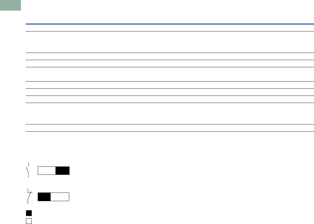
V7-T1-160 Volume 7—Logic Control, Operator Interface and Connectivity Solutions CA08100008E—March 2014 www.eaton.com
1
1
1
1
1
1
1
1
1
1
1
1
1
1
1
1
1
1
1
1
1
1
1
1
1
1
1
1
1
1
1.6
Pushbuttons and Indicating Lights
22.5 mm Compact Pushbuttons—C22
22.5 mm Compact Pushbuttons—C22, continued
Contact Travel
Contact Travel Diagram
Push-button Actuators
Illuminated Pushbuttons C22 Indicator
Lights C22
Selector Switch
Actuators C22
Key-Operated
Buttons C22
Emergency Stop/
Emergency Switching
OFF Pushbuttons C22Description Unit Momentary Maintained
Switching Capacity
Rated operational current
AC-15
24V IeA44—444
110V IeA22—222
230V IeA 1.5 1.5 — 1.5 1.5 1.5
DC-13
24V IeA33—333
60V IeA11—111
110V IeA 0.6 0.6 — 0.6 0.6 0.6
220V IeA 0.3 0.3 — 0.3 0.3 0.3
Lifespan, electrical
AC-15
230V/0.5A Operations x 1060.4 0.4 — 0.4 0.4 0.4
230V/1.0A x 1060.6 0.6 — 0.6 0.6 0.6
0
0
3.15 5.5
5.52.2
3
4
2
1
Contact closed
Contact open
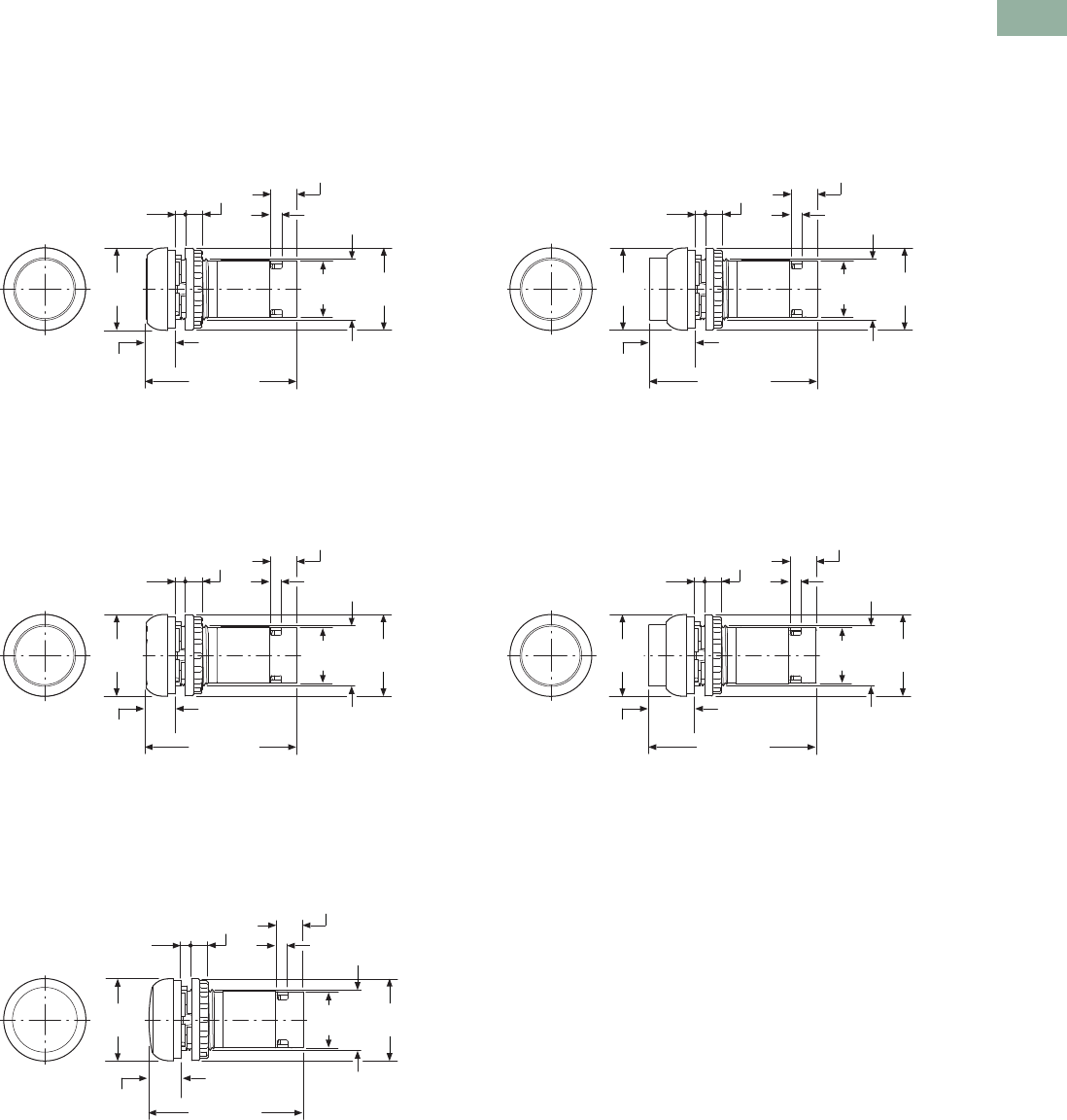
Volume 7—Logic Control, Operator Interface and Connectivity Solutions CA08100008E—March 2014 www.eaton.com V7-T1-161
1
1
1
1
1
1
1
1
1
1
1
1
1
1
1
1
1
1
1
1
1
1
1
1
1
1
1
1
1
1
1.6
Pushbuttons and Indicating Lights
22.5 mm Compact Pushbuttons—C22
Dimensions
Approximate Dimensions in mm [in]
Illuminated Pushbuttons
Flat
C22(S)-DRL_/C22(S)-DL_
Extended
C22(S)-DRLH_/C22(S)-DLH_
Pushbutton Actuators
Flat
C22(S)-DR_/C22(S)-D_
Extended
C22(S)-DRH_/C22(S)-DH_
Indicating Lights
Flat
C22-L_
Ø29.7
[1.17]
M22 x 1.5
54.6 [2.15]
1.0–6.0
[0.04–0.24]
6.0
[0.24]
4.0
[0.16]
Ø29.5
[1.16]
9.6
[0.38]
20.2
[0.80]
10.4
[0.41]
Ø29.7
[1.17]
M22 x 1.5
60.9 [2.40]
1.0–6.0
[0.04–0.24]
6.0
[0.24]
4.0
[0.16]
Ø29.5
[1.16]
9.6
[0.38]
20.2
[0.80]
16.7
[0.66]
Ø29.7
[1.17]
M22 x 1.5
54.6 [2.15]
1.0–6.0
[0.04–0.24]
6.0
[0.24]
4.0
[0.16]
Ø29.5
[1.16]
9.6
[0.38]
20.2
[0.80]
10.4
[0.41]
Ø29.7
[1.17]
M22 x 1.5
60.9 [2.40]
1.0–6.0
[0.04–0.24]
6.0
[0.24]
4.0
[0.16]
Ø29.5
[1.16]
9.6
[0.38]
20.2
[0.80]
16.7
[0.66]
Ø29.7
[1.17]
M22 x 1.5
55.9 [2.20]
1.0–6.0
[0.04–0.24]
6.0
[0.24]
4.0
[0.16]
Ø29.5
[1.16]
9.6
[0.38]
Ø20.2
[0.80]
11.7
[0.46]
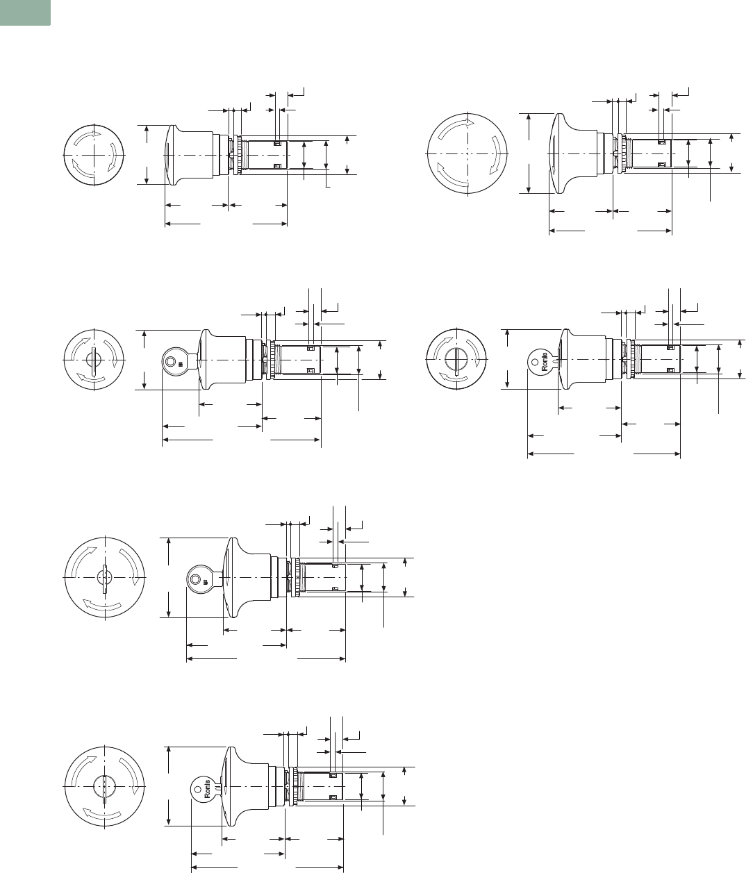
V7-T1-162 Volume 7—Logic Control, Operator Interface and Connectivity Solutions CA08100008E—March 2014 www.eaton.com
1
1
1
1
1
1
1
1
1
1
1
1
1
1
1
1
1
1
1
1
1
1
1
1
1
1
1
1
1
1
1.6
Pushbuttons and Indicating Lights
22.5 mm Compact Pushbuttons—C22
Approximate Dimensions in mm [in]
Emergency Stop/Emergency Switching OFF Pushbuttons
C22-PVT45P_
C22-PVT45P-MS_
C22-PVT60P_
C22-PVT45P-RS_
C22-PVT60P-MS_
C22-PVT60P-MS_
Ø45.0
[1.77]
93.0 [3.66]
1.0–6.0
[0.04–0.24]
6.0
[0.24]
4.0
[0.16]
9.3
[0.37]
M22 x 1.5
Ø29.5
[1.16]
Ø20.4
[0.80]
48.0
[1.89]
45.0
[1.77]
M22 x 1.5
1.0–6.0
[0.04–0.24]
6.0
[0.24]
4.0
[0.16]
Ø29.5
[1.16]
9.3
[0.37]
Ø20.4
[0.80]
Ø45.0
[1.17]
120.0 [4.72]
75.0 [2.95]
48.0
[1.89] 45.0
[1.77]
Ø60.0
[2.36]
92.0 [3.62]
1.0–6.0
[0.04–0.24]
6.0
[0.24]
4.0
[0.16]
9.3
[0.37]
M22 x 1.5
Ø29.5
[1.16]
Ø20.4
[0.80]
48.0
[1.89]
45.0
[1.77]
M22 x 1.5
1.0–6.0
[0.04–0.24]
6.0
[0.24]
4.0
[0.16]
Ø29.5
[1.16]
9.3
[0.37]
Ø20.4
[0.80]
Ø45.0
[1.77]
116.0 [4.57]
71.0 [2.80]
48.0
[1.89] 45.0
[1.77]
M22 x 1.5
1.0–6.0
[0.04–0.24]
6.0
[0.24]
4.0
[0.16]
Ø29.5
[1.16]
9.3
[0.37]
Ø20.4
[0.80]
Ø60.0
[2.36]
120.0 [4.72]
75.0 [2.95]
48.0
[1.89]
45.0
[1.77]
M22 x 1.5
1.0–6.0
[0.04–0.24]
6.0
[0.24]
4.0
[0.16]
Ø29.5
[1.16]
9.3
[0.37]
Ø20.4
[0.80]
Ø60.0
[2.36]
116.0 [4.57]
71.0 [2.80]
48.0
[1.89]
45.0
[1.77]
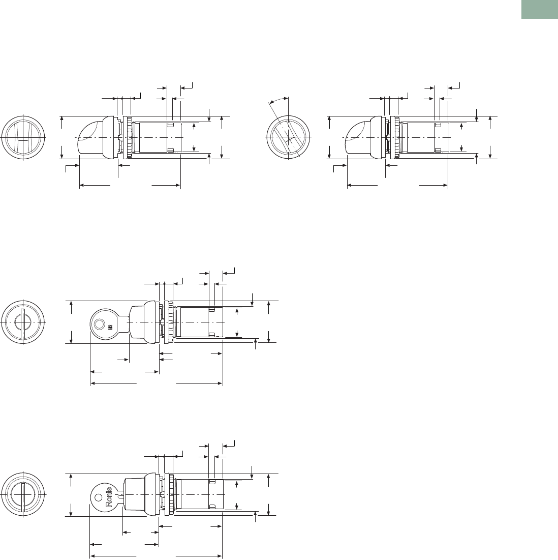
Volume 7—Logic Control, Operator Interface and Connectivity Solutions CA08100008E—March 2014 www.eaton.com V7-T1-163
1
1
1
1
1
1
1
1
1
1
1
1
1
1
1
1
1
1
1
1
1
1
1
1
1
1
1
1
1
1
1.6
Pushbuttons and Indicating Lights
22.5 mm Compact Pushbuttons—C22
Approximate Dimensions in mm [in]
Selector Switch Actuators
C22(S)-W(R)K_
Selector Switch Actuators/V Position
C22(S)-W(R)KV_
Key Operated Actuators
C22(S)-WS(3)-MS_/C22(S)-WRS(3)-MS_
C22(S)-WS(3)-RS_/C22(S)-WRS(3)-RS_
Ø29.7
[1.17]
M22 x 1.5
72.0 [2.83]
1.0–6.0
[0.04–0.24]
6.0
[0.24]
4.0
[0.16]
Ø29.5
[1.16]
9.6
[0.38]
20.2
[0.80]
27.8
[1.09]
Ø29.7
[1.17]
M22 x 1.5
72.0 [2.83]
1.0–6.0
[0.04–0.24]
6.0
[0.24]
4.0
[0.16]
Ø29.5
[1.16]
9.6
[0.38]
20.2
[0.80]
27.8
[1.09]
30°
M22 x 1.5
1.0–6.0
[0.04–0.24]
6.0
[0.24]
4.0
[0.16]
Ø29.5
[1.16]
9.6
[0.38]
20.2
[0.80]
Ø29.7
[1.17]
92.1 [3.63]
20.8
[0.82]
47.9 [1.89]
44.2 [1.74]
M22 x 1.5
1.0–6.0
[0.04–0.24]
6.0
[0.24]
4.0
[0.16]
Ø29.5
[1.16]
9.6
[0.38]
20.2
[0.80]
Ø29.7
[1.17]
92.1 [3.63]
24.9
[0.98]
47.9 [1.89]
44.2 [1.74]
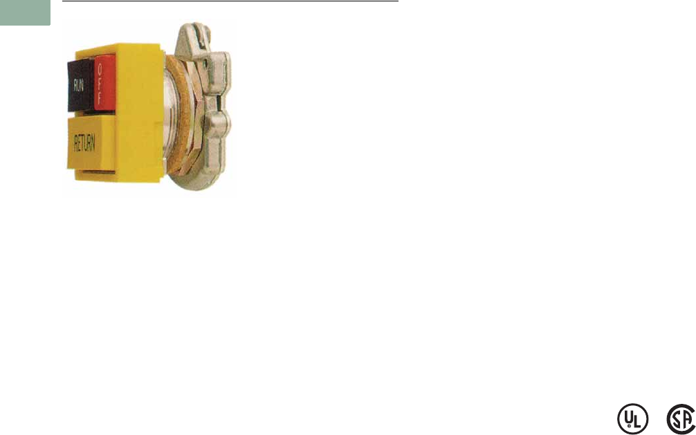
V7-T1-164 Volume 7—Logic Control, Operator Interface and Connectivity Solutions CA08100008E—March 2014 www.eaton.com
1
1
1
1
1
1
1
1
1
1
1
1
1
1
1
1
1
1
1
1
1
1
1
1
1
1
1
1
1
1
1.7
Pushbuttons and Indicating Lights
30.5 mm Square Multifunction Watertight/Oiltight—E30
30.5 mm Square Multifunction Watertight/Oiltight—E30
Contents
Description Page
30.5 mm Square Multifunction
Watertight/Oiltight—E30
Product Identification . . . . . . . . . . . . . . . . . . . . V7-T1-165
Product Selection
Operators . . . . . . . . . . . . . . . . . . . . . . . . . . V7-T1-166
Operator Components . . . . . . . . . . . . . . . . V7-T1-169
Accessories . . . . . . . . . . . . . . . . . . . . . . . . . . . V7-T1-175
Options . . . . . . . . . . . . . . . . . . . . . . . . . . . . . . V7-T1-176
Replacement Parts . . . . . . . . . . . . . . . . . . . . . . V7-T1-179
Technical Data and Specifications . . . . . . . . . . V7-T1-180
Dimensions . . . . . . . . . . . . . . . . . . . . . . . . . . . V7-T1-181
Product Description
The E30 industrial pushbutton
and indicating light line from
Eaton’s Electrical Sector
features a wide selection of
square, multifunction
operators which conveniently
mount in a standard 30.5 mm
(1-13/64 in) diameter panel
hole. Up to six input and
indicating functions can be
grouped into a single
operating head, saving
valuable panel space.
Attractive square operator
styling, coupled with custom
legending of colored buttons
and lenses and many special
function accessories, makes
E30 components ideally
suited for use on control
consoles and for a variety of
industrial OEM applications.
Features
Type E30 control units consist
of a basic operator with one
or more buttons and lenses
and contact block selection
dependent on the specific
operator configuration.
●Pushbutton operators will
accommodate up to four
single depth stackable
contact blocks behind each
operating button, up to
eight circuits maximum.
●Indicating lights are
supplied complete with
either a transformer light
unit up to 600 Vac supply
line voltage or full voltage
light unit up to 120 Vac/Vdc
supply line voltage.
●Combination pushbutton
with indicating light
operators are supplied
complete with a
transformer or full voltage
unit. Contact blocks must
be ordered separately, up to
four circuits maximum.
Die Cast Construction
Each operator has high
pressure type seals to
prevent the passage of oil
and other contaminants
through the operator into the
contact structure or panel
interior. Each operator uses a
Buna N cork gasket between
the mounting flange on the
operator and the panel to
maintain oiltightness.
Standards and
Certifications
●UL Listed—File No.
E131568
●CSA Certified—File No.
LR68551
Ingress Protection
●Single and dual indicating
lights
●UL (NEMA) Type 1, 2, 3,
3R, 3S, 4, 4X, 12, 13
●All other operators
●UL (NEMA) Type 3, 3R,
4, 4X, 12, 13
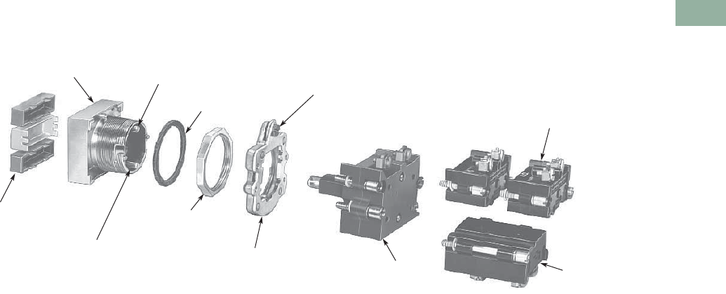
Volume 7—Logic Control, Operator Interface and Connectivity Solutions CA08100008E—March 2014 www.eaton.com V7-T1-165
1
1
1
1
1
1
1
1
1
1
1
1
1
1
1
1
1
1
1
1
1
1
1
1
1
1
1
1
1
1
1.7
Pushbuttons and Indicating Lights
30.5 mm Square Multifunction Watertight/Oiltight—E30
Product Identification
30.5 mm Square Multifunction Watertight/Oiltight
Two C irc u it
Contact Block
Transformer or
Full Voltage Light
Element—Supplied
with Operator
Locking Ring—Supplied with
Operator—Serves as Mount
for Light Element and
Contact Blocks
Retaining Nut
Secures Operator
to Panel
Lower Contact
Block Operating
Plunger
Buttons and Lenses Supplied
Blank or with Custom
Legend(s)
(see Pages V7-T1-169 to
V7-T1-173)
Multifunction Operator
(see Pages V7-T1-166 to V7-T1-168) Upper Contact Block
Operating Plunger
Gasket
Quarter Turn Screw—
Mounts Locking Ring to Operator
Single Circuit
Contact Block
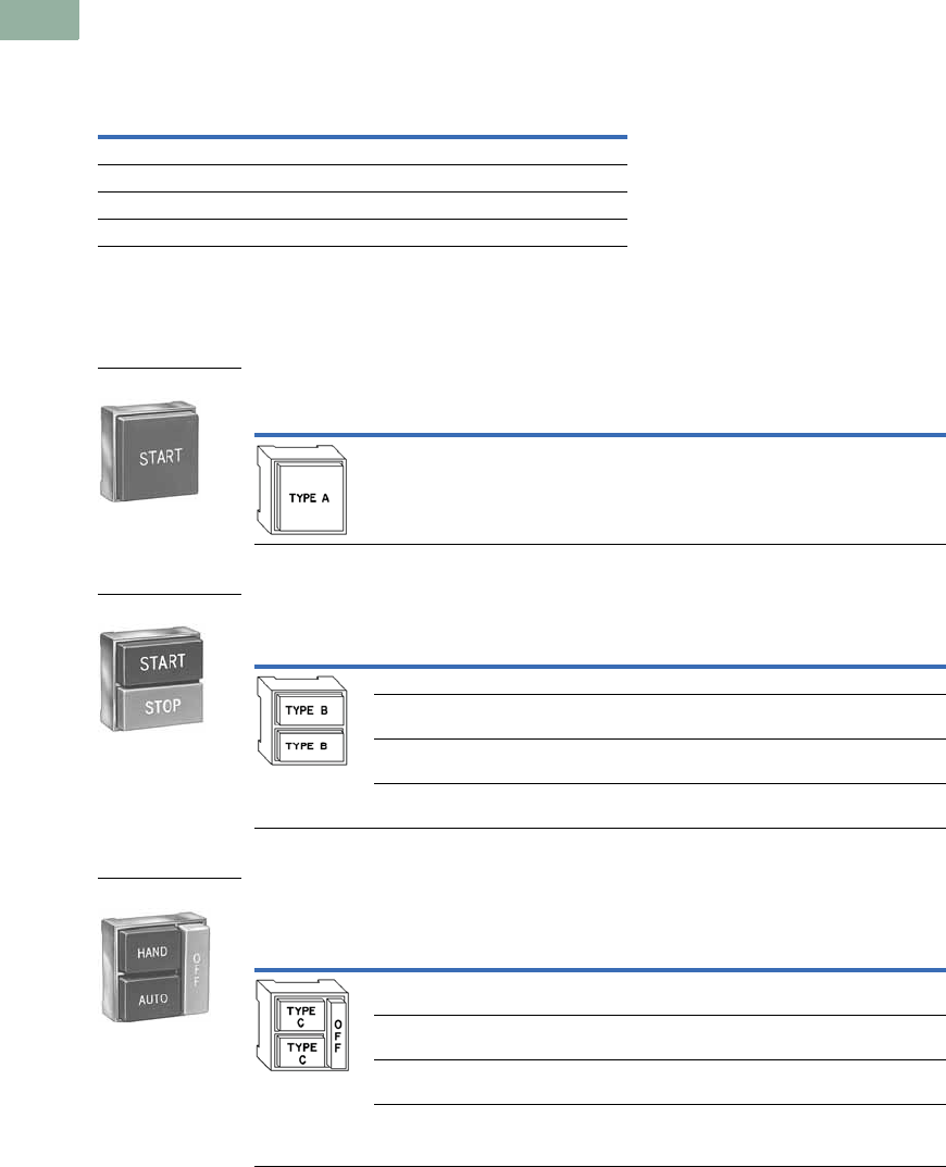
V7-T1-166 Volume 7—Logic Control, Operator Interface and Connectivity Solutions CA08100008E—March 2014 www.eaton.com
1
1
1
1
1
1
1
1
1
1
1
1
1
1
1
1
1
1
1
1
1
1
1
1
1
1
1
1
1
1
1.7
Pushbuttons and Indicating Lights
30.5 mm Square Multifunction Watertight/Oiltight—E30
Product Selection
Operators
When Ordering a Complete E30 Control Unit Specify
Square Multifunction Operators
UL (NEMA) Type 3, 3R, 4, 4X, 12, 13
Single Button Operator/without Button (Order Button Separately)
Two Button Operator/without Buttons (Order Buttons Separately)
Two Button Operator with Long (OFF) Release Bar—Includes OFF Bar/Button
(Order Other Buttons Separately)
Notes
1 Order from table on Page V7-T1-169.
2 Limited to two single circuit, one double circuit 600V or two 120V (E30KLA9) contact blocks behind each button.
3 Buttons are interlocked so that one of the two is maintained at all times.
Depressing the other button releases the maintained button and maintains the depressed button.
4 Operators are supplied as standard with red extended bar(s) marked “OFF” as shown in sketch.
For other colors or markings, contact your nearest Eaton Distributor or call our Customer Service Center 1-800-356-1243.
For replacement of standard red release bar, order E30KR100.
5 Order from table on Page V7-T1-170.
6 Limited to two single circuit, one double circuit 600V or two 120V (E30KLA9) contact blocks behind each button.
Catalog Number of … Ordering Example (E30AB)
Operator E30KB130 “START”
Button(s) E30KB231 “STOP”
Contact block(s) E30KLA1 1NO
Accessories (if required) E30KLA2 1NC
Button Type
Required 1Operation Special Features Catalog Number
Momentary — E30AA
Button Types
Required 1
Operation
Special Features Catalog NumberTop Button Bottom Button
Momentary Momentary — E30AB
Momentary Momentary With mechanical
interlock
E30AC
Maintained
(all contacts)
Release
(all contacts)
—E30AD 2
Maintained
(all contacts)
Release
(all contacts)
With mechanical
interlock
E30AP 23
Button Types
Required 45
Operation
Special Features Catalog NumberTop Button Bottom Button
Maintained Maintained — E30AF
Maintained Maintained With mechanical
interlock
E30AG
Maintained Momentary With mechanical
interlock
E30AH
Maintained
(all contacts)
Maintained
(bottom contacts only)
Top button operates
both top and
bottom contacts
E30AK 6
Shown with
Extended Button
Single Button Operator
Two Button Operator
Shown with
Extended Buttons
Two Button Operator
Shown with Long
Release Bar
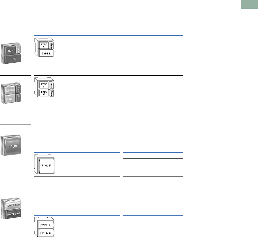
Volume 7—Logic Control, Operator Interface and Connectivity Solutions CA08100008E—March 2014 www.eaton.com V7-T1-167
1
1
1
1
1
1
1
1
1
1
1
1
1
1
1
1
1
1
1
1
1
1
1
1
1
1
1
1
1
1
1.7
Pushbuttons and Indicating Lights
30.5 mm Square Multifunction Watertight/Oiltight—E30
Square Multifunction Operators and Indicating Lights
UL (NEMA) Type 3, 3R, 4, 4X, 12, 13
Two Button Operator with (OFF) Release—Includes OFF Bar/Button(s)
(Order Other Buttons Separately)
Single Indicating Light Unit/without Lens (Order Lens Separately)
Dual Indicating Light Unit/without Lenses (Order Lenses Separately)
Notes
1 Order from table on Page V7-T1-170.
2 Operators are supplied as standard with red extended release bar(s) marked “OFF” as shown in sketch. For other colors or
markings, contact your nearest Eaton Distributor or call our Customer Service Center 1-800-356-1243. For replacement of
standard red release bar, order E30KR101.
3 Order from table on Page V7-T1-171.
4 Light units will also accept LED lamps. For LED part numbers, see table on Page V7-T1-179.
5 Order from table on Page V7-T1-172.
Button Types
Required 12
Operation
Special Features Catalog NumberTop Button Bottom Button
Maintained Momentary Release bar for
top button
E30AL
Maintained Maintained Individual release
bars for each button
E30AN
Maintained
with interlock
Maintained
with interlock
Individual release
bars for each button
E30AM
Lens Type
Required 3
Type of Light Element
Transformer
(60/50 Hertz AC)
Full Voltage
(60/50 Hertz AC or DC)
Voltage
Lamp
Number 4Catalog Number Voltage
Lamp
Number 4Catalog Number
120 6PSB E30BA 24 24PSB E30BJ
120 120PSB E30BM
Lens Types
Required 5
Type of Light Element
Transformer
(60/50 Hertz AC)
Full Voltage
(60/50 Hertz AC or DC)
Voltage
Lamp
Number 4Catalog Number Voltage
Lamp
Number 4Catalog Number
120 6PSB E30CA 24 24PSB E30CJ
120 120PSB E30CM
Shown with Release
Bar for Top Button
Two Button Operator
Shown with Release
Bars for Each Button
Two Button Operator
Shown with Lens
Single Indicating
Light Unit
Shown with Lens
Dual Indicating
Light Unit
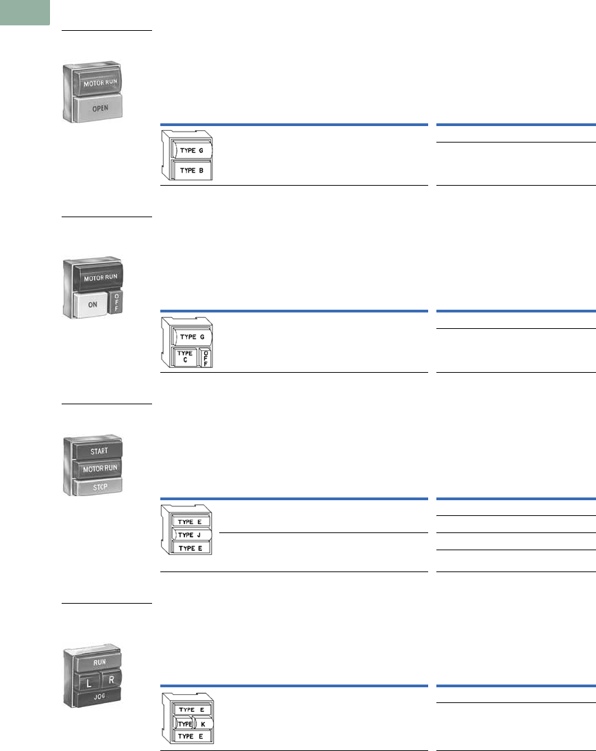
V7-T1-168 Volume 7—Logic Control, Operator Interface and Connectivity Solutions CA08100008E—March 2014 www.eaton.com
1
1
1
1
1
1
1
1
1
1
1
1
1
1
1
1
1
1
1
1
1
1
1
1
1
1
1
1
1
1
1.7
Pushbuttons and Indicating Lights
30.5 mm Square Multifunction Watertight/Oiltight—E30
UL (NEMA) Type 3, 3R, 4, 4X, 12, 13
Single Button Operator with Indicating Light/without Button or Lens
(Order Button and Lens Separately)
Single Button Operator with (OFF) Release Bar and Indicating Light—
Includes OFF Bar/Button (Order Other Button and Lens Separately)
Two Button Operator with Indicating Light/without Buttons or Lens
(Order Buttons and Lens Separately)
Two Button Operator with Dual Indicating Lights/without Buttons and Lens
Notes
1 Order from tables on Pages V7-T1-169 to V7-T1-173.
2 Light units will also accept LED lamps. For LED part numbers, see table on Page V7-T1-179.
3 Operators are supplied as standard with red extended release bar(s) marked “OFF” as shown in sketch. For other colors or
markings, contact your nearest Eaton Distributor or call our Customer Service Center 1-800-356-1243. For replacement of
standard red release bar, order E30KR101.
4 Order from tables on Pages V7-T1-171 and V7-T1-172.
Button and
Lens Types
Required 1
Operation
(Bottom
Button)
Type of Light Element
Transformer
(60/50 Hertz AC)
Full Voltage
(60/50 Hertz AC or DC)
Voltage
Lamp
Number 2Catalog Number Voltage
Lamp
Number 2Catalog Number
Momentary 120 6PSB E30DA 24 24PSB E30DX3
120 120PSB E30DF
Button and
Lens Types
Required 1
Operation
(Bottom
Button)
Type of Light Element
Transformer
(60/50 Hertz AC)
Full Voltage
(60/50 Hertz AC or DC)
Voltage
Lamp
Number 3Catalog Number Voltage
Lamp
Number 2Catalog Number
Maintained 120 6PSB E30DG 24 24PSB E30DX13
120 120PSB E30DM
Button and
Lens Types
Required 4
Button
Operation
Type of Light Element
Transformer
(60/50 Hertz AC)
Full Voltage
(60/50 Hertz AC or DC)
Voltage
Lamp
Number 2Catalog Number Voltage
Lamp
Number 2Catalog Number
Momentary 120 6PSB E30EA 24 24PSB E30EX3
120 120PSB E30EF
Momentary
with
interlock
120 6PSB E30EG 24 24PSB E30EX13
120 120PSB E30EM
Button and
Lens Types
Required 1
Button
Operation
Type of Light Element
Transformer
(60/50 Hertz AC)
Full Voltage
(60/50 Hertz AC or DC)
Voltage
Lamp
Number 2Catalog Number Voltage
Lamp
Number 2Catalog Number
Momentary 120 6PSB E30JA 24 24PSB E30JX3
120 120PSB E30JF
Shown with Button
and Lens
Single Button Operator
and Indicating Light
Shown with Button
and Lens
Single Button Operator
with Release Bar and
Indicating Light
Shown with Button
and Lens
Two Button Operator
with Indicating Light
Shown with Button
and Lens
Two Button Operator
with Dual Indicating
Lights
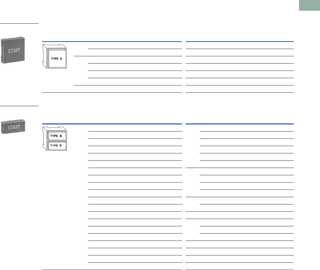
Volume 7—Logic Control, Operator Interface and Connectivity Solutions CA08100008E—March 2014 www.eaton.com V7-T1-169
1
1
1
1
1
1
1
1
1
1
1
1
1
1
1
1
1
1
1
1
1
1
1
1
1
1
1
1
1
1
1.7
Pushbuttons and Indicating Lights
30.5 mm Square Multifunction Watertight/Oiltight—E30
Operator Components
Operating Buttons Only
Type A Buttons with Standard Markings 1
Type B Buttons with Standard Markings 2
Notes
1 Use with operator E30AA, legend characters 3/16 in (4.8 mm) high.
2 Use with operators E30AB thru AE, AL and DA thru DF, legend characters 3/16 in (4.8 mm) high.
Button
Application Color Marking
Extended Button
Catalog Number
Short Button
Catalog Number Color Marking
Extended Button
Catalog Number
Short Button
Catalog Number
Black Blank E30KA100 E30KA150 Green START E30KA330 E30KA380
START — E30KA180 Yellow Blank E30KA400 E30KA450
Red Blank E30KA200 E30KA250 White Blank E30KA500 E30KA550
EMERG. STOP E30KA204 — Gray Blank E30KA600 E30KA650
OFF E30KA218 E30KA268 Brown Blank E30KA700 E30KA750
STOP E30KA231 E30KA281 Orange Blank E30KA800 E30KA950
Green Blank E30KA300 E30KA350 Blue Blank E30KA900 E30KA950
Button
Application Color Marking
Extended Button
Catalog Number
Short Button
Catalog Number Color Marking
Extended Button
Catalog Number
Short Button
Catalog Number
Black Blank E30KB100 E30KB150 Black REVERSE E30KB125 E30KB175
AUTO E30KB101 E30KB151 RUN E30KB126 E30KB176
CLOSE E30KB102 E30KB152 SLOW E30KB128 E30KB178
DOWN E30KB103 E30KB153 START E30KB130 E30KB180
FAST E30KB105 E30KB155 TEST E30KB132 E30KB182
FORWARD E30KB107 E30KB157 UP E30KB134 E30KB184
HIGH E30KB109 E30KB159 Red Blank E30KB200 E30KB250
IN E30KB110 E30KB160 EMERG. STOP E30KB204 —
INCH E30KB111 E30KB161 OFF E30KB218 E30KB268
JOG E30KB112 E30KB162 STOP E30KB231 E30KB281
JOG FOR. E30KB113 E30KB163 Green Blank E30KB300 E30KB350
JOG REV. E30KB114 E30KB164 START E30KB330 E30KB380
LOW E30KB115 E30KB165 Yellow Blank E30KB400 E30KB450
LOWER E30KB116 E30KB166 White Blank E30KB500 E30KB550
MAN E30KB117 E30KB167 AUTO E30KB501 —
ON E30KB119 E30KB169 HAND E30KB508 —
OPEN E30KB120 E30KB170 Gray Blank E30KB600 E30KB650
OUT E30KB121 E30KB171 Brown Blank E30KB700 E30KB750
RAISE E30KB122 E30KB172 Orange Blank E30KB800 E30KB850
RESET E30KB124 E30KB174 Blue Blank E30KB900 E30KB950
Type A Extended
Button
Type B Extended
Button
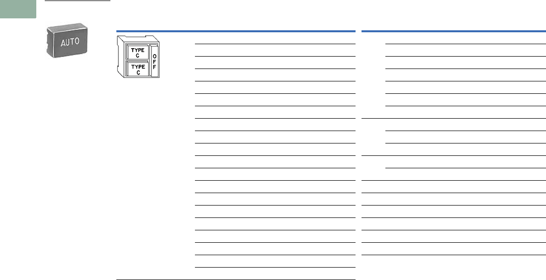
V7-T1-170 Volume 7—Logic Control, Operator Interface and Connectivity Solutions CA08100008E—March 2014 www.eaton.com
1
1
1
1
1
1
1
1
1
1
1
1
1
1
1
1
1
1
1
1
1
1
1
1
1
1
1
1
1
1
1.7
Pushbuttons and Indicating Lights
30.5 mm Square Multifunction Watertight/Oiltight—E30
Type C Buttons with Standard Markings 1
Note
1 Use with operators E30AF thru AK, AL thru AM and DG thru DM, legend characters 1/8 in (3.2 mm) high.
Button
Application Color Marking
Extended Button
Catalog Number
Short Button
Catalog Number Color Marking
Extended Button
Catalog Number
Short Button
Catalog Number
Black Blank E30KC100 E30KC150 Black RESET E30KC124 E30KC174
AUTO E30KC101 E30KC151 REVERSE E30KC125 E30KC175
CLOSE E30KC102 E30KC152 RUN E30KC126 E30KC176
DOWN E30KC103 E30KC153 SLOW E30KC128 E30KC178
FAST E30KC105 E30KC155 START E30KC130 E30KC180
FORWARD E30KC107 E30KC157 TEST E30KC132 E30KC182
HAND E30KC108 E30KC158 UP E30KC134 E30KC184
HIGH E30KC109 E30KC159 Red Blank E30KC200 E30KC250
IN E30KC110 E30KC160 OFF E30KC218 —
INCH E30KC111 E30KC161 STOP E30KC231 E30KC281
JOG E30KC112 E30KC162 Green Blank E30KC300 E30KC350
JOG FOR. E30KC113 E30KC163 START E30KC330 E30KC380
JOG REV. E30KC114 E30KC164 Yellow Blank E30KC400 E30KC450
LOW E30KC115 E30KC165 White Blank E30KC500 E30KC550
LOWER E30KC116 E30KC166 Gray Blank E30KC600 E30KC650
MAN E30KC117 E30KC167 Brown Blank E30KC700 E30KC750
ON E30KC119 E30KC169 Orange Blank E30KC800 E30KC850
OPEN E30KC120 E30KC170 Blue Blank E30KC900 E30KC950
OUT E30KC121 E30KC171
RAISE E30KC122 E30KC172
Type C Extended
Button
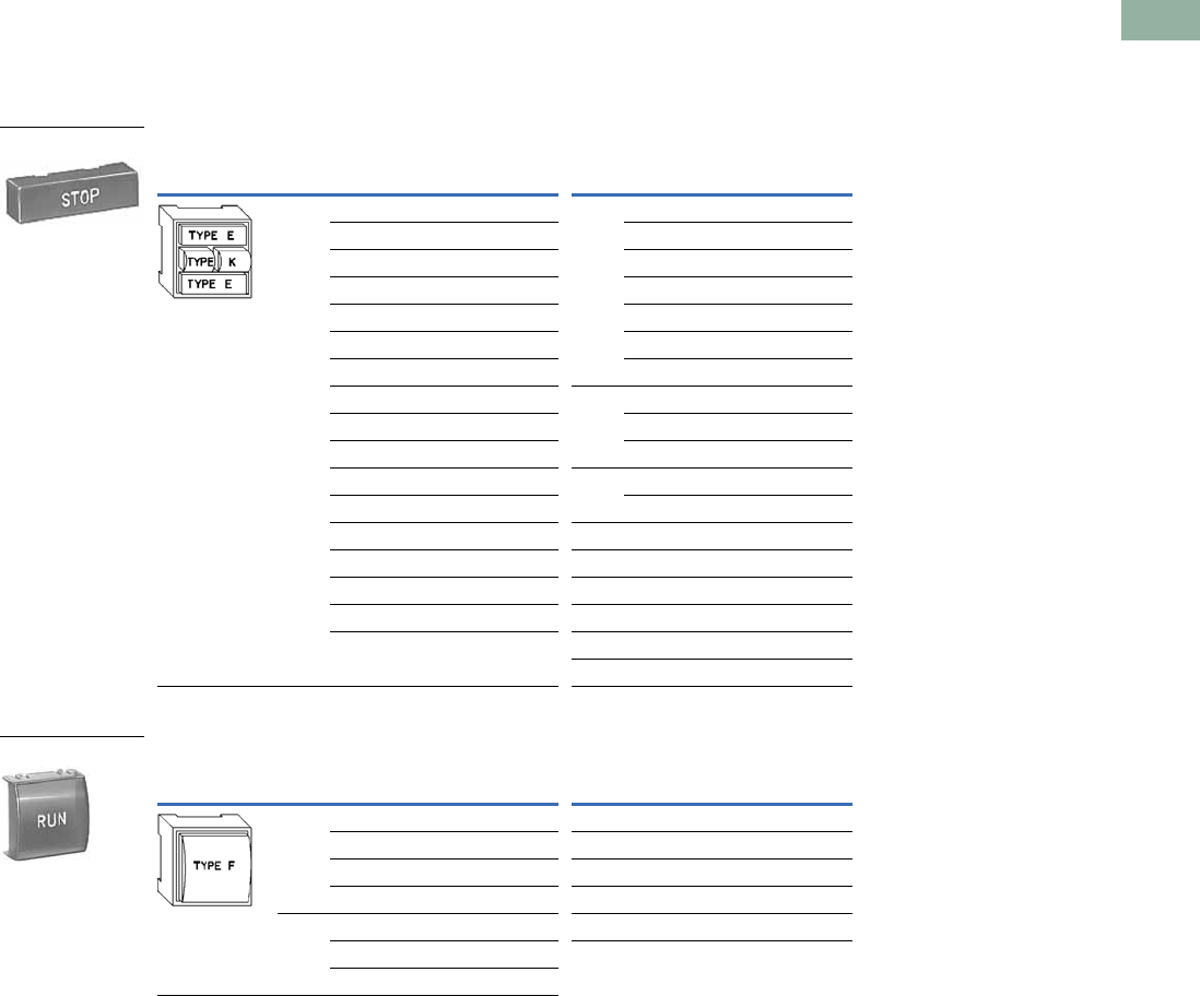
Volume 7—Logic Control, Operator Interface and Connectivity Solutions CA08100008E—March 2014 www.eaton.com V7-T1-171
1
1
1
1
1
1
1
1
1
1
1
1
1
1
1
1
1
1
1
1
1
1
1
1
1
1
1
1
1
1
1.7
Pushbuttons and Indicating Lights
30.5 mm Square Multifunction Watertight/Oiltight—E30
Operating Buttons and Lens Only
Standard Color Buttons and Lens Marking 1
Black lettering on — White, Amber, Yellow and Clear.
White lettering on — Green, Red, Blue, Brown, Black, Orange and Gray.
Type E Buttons with Standard Markings 2
Type F Lenses with Standard Markings 3
Notes
1 For lenses with special markings or with standard markings but in a different color, refer to instructions on
Pages V7-T1-176 to V7-T1-178.
2 Use with operators E30EA thru EM, FA thru FM and JA thru JM, legend characters 1/8 in (3.2 mm) high.
3 Use with operators E30BA thru BY, legend characters 3/16 in (4.8 mm) high.
Button
Application Color Marking
Extended Button
Catalog Number Color Marking
Extended Button
Catalog Number
Black Blank E30KE100 Black RESET E30KE124
CLOSE E30KE102 REVERSE E30KE125
DOWN E30KE103 RUN E30KE126
FAST E30KE105 SLOW E30KE128
FORWARD E30KE107 START E30KE130
HIGH E30KE109 TEST E30KE132
IN E30KE110 UP E30KE134
INCH E30KE111 Red Blank E30KE200
JOG E30KE112 OFF E30KE218
JOG FOR. E30KE113 STOP E30KE231
JOG REV. E30KE114 Green Blank E30KE300
LOW E30KE115 START E30KE330
LOWER E30KE116 Yellow Blank E30KE400
ON E30KE119 White Blank E30KE500
OPEN E30KE120 Gray Blank E30KE600
OUT E30KE121 Brown Blank E30KE700
PHASE E30KE122 Orange Blank E30KE800
Blue Blank E30KE900
Button
Application Color Marking Catalog Number Color Marking Catalog Number
Red Blank E30KF10 Green OFF E30KF22
MOTOR RUN E30KF11 Amber Blank E30KF30
ON E30KF12 Blue Blank E30KF40
POWER ON E30KF13 Clear Blank E30KF50
Green Blank E30KF20 White Blank E30KF60
MOTOR STOP E30KF21
MOTOR RUN E30KF23
Type E Button
Type F Lens
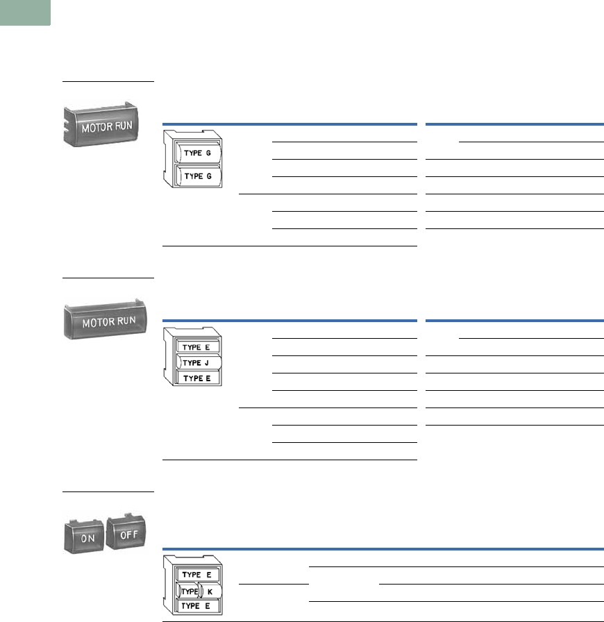
V7-T1-172 Volume 7—Logic Control, Operator Interface and Connectivity Solutions CA08100008E—March 2014 www.eaton.com
1
1
1
1
1
1
1
1
1
1
1
1
1
1
1
1
1
1
1
1
1
1
1
1
1
1
1
1
1
1
1.7
Pushbuttons and Indicating Lights
30.5 mm Square Multifunction Watertight/Oiltight—E30
Operating Lens Only
Standard Color Buttons and Lens Marking 1
Black lettering on — White, Amber, Yellow and Clear.
White lettering on — Green, Red, Blue, Brown, Black, Orange and Gray.
Type G Lenses with Standard Markings 2
Type J Lenses with Standard Markings 3
Type K Lenses with Standard Markings (Sold in Pairs Only) 4
Notes
1 For lenses with special markings or with standard markings but in a different color, refer to instructions on
Pages V7-T1-176 to V7-T1-178.
2 Use with operators E30CA thru CM and DA thru DM, legend characters 3/16 in (4.8 mm) high except MOTOR RUN,
POWER ON and MOTOR STOP are 1/8 in (3.2 mm) high.
3 Use with operators E30EA thru EM, FA thru FM and GA thru GM, legend characters 1/8 in (3.2 mm) high.
4 Use with operators E30JA thru JW, legend characters 1/8 in (3.2 mm) high
Lens
Application Color Marking Catalog Number Color Marking Catalog Number
Red Blank E30KG10 Green OFF E30KG22
MOTOR RUN E30KG11 READY E30KG23
ON E30KG12 Amber Blank E30KG30
POWER ON E30KG13 Blue Blank E30KG40
Green Blank E30KG20 Clear Blank E30KG50
MOTOR RUN E30KG24 White Blank E30KG60
MOTOR STOP E30KG21
Lens
Application Color Marking Catalog Number Color Marking Catalog Number
Red Blank E30KJ10 Green OFF E30KJ22
MOTOR RUN E30KJ11 ON E30KJ24
ON E30KJ12 Amber Blank E30KJ30
POWER ON E30KJ13 Blue Blank E30KJ40
MOTOR STOP E30KJ14 Clear Blank E30KJ50
Green Blank E30KJ20 White Blank E30KJ60
MOTOR STOP E30KJ21
MOTOR RUN E30KJ23
Lens
Application
Color Marking
Catalog Number
Left Hand
Lens
Right Hand
Lens
Left Hand
Lens
Right Hand
Lens
Red Red ON ON E30KK12
Green ON OFF E30KK13
Green OFF OFF E30KK22
Red OFF ON E30KK23
Type G Lens
Type J Lens
Type K Lenses
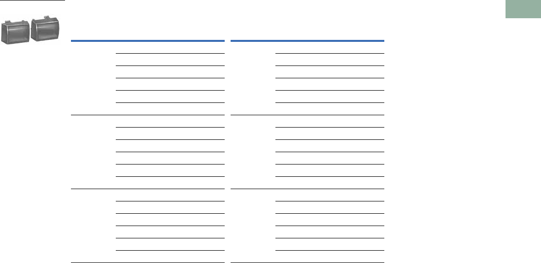
Volume 7—Logic Control, Operator Interface and Connectivity Solutions CA08100008E—March 2014 www.eaton.com V7-T1-173
1
1
1
1
1
1
1
1
1
1
1
1
1
1
1
1
1
1
1
1
1
1
1
1
1
1
1
1
1
1
1.7
Pushbuttons and Indicating Lights
30.5 mm Square Multifunction Watertight/Oiltight—E30
Type K Lenses—Blank (Sold in Pairs Only)
Color Color
Left Hand
Lens
Right Hand
Lens Catalog Number
Left Hand
Lens
Right Hand
Lens Catalog Number
Red Red E30KK10 Blue Red E30KK41
Green E30KK11 Green E30KK42
Amber E30KK17 Amber E30KK43
Blue E30KK14 Blue E30KK40
Clear E30KK15 Clear E30KK45
White E30KK16 White E30KK46
Green Red E30KK21 Clear Red E30KK51
Green E30KK20 Green E30KK52
Amber E30KK27 Amber E30KK53
Blue E30KK24 Blue E30KK54
Clear E30KK25 Clear E30KK50
White E30KK26 White E30KK56
Amber Red E30KK31 White Red E30KK61
Green E30KK32 Green E30KK62
Amber E30KK30 Amber E30KK63
Blue E30KK34 Blue E30KK64
Clear E30KK35 Clear E30KK65
White E30KK36 White E30KK60
Type K Lenses
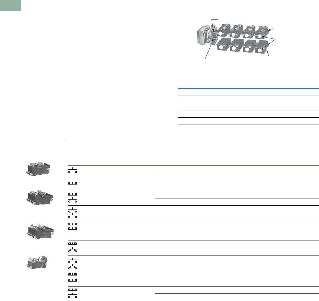
V7-T1-174 Volume 7—Logic Control, Operator Interface and Connectivity Solutions CA08100008E—March 2014 www.eaton.com
1
1
1
1
1
1
1
1
1
1
1
1
1
1
1
1
1
1
1
1
1
1
1
1
1
1
1
1
1
1
1.7
Pushbuttons and Indicating Lights
30.5 mm Square Multifunction Watertight/Oiltight—E30
Contact Blocks
Standard Contact Blocks—Molded, phenolic construction.
Enclosed silver contacts with reliability “nibs” that improve the
reliability of switching performance under dry circuit, corrosive
atmosphere and fine dust conditions. For more extreme
conditions, the logic level contact blocks described below are
recommended.
Logic Level Contact Blocks—Feature palladium contacts.
Palladium, which is more inert than gold, is well suited for
voltages and currents approaching zero. When mounted in an
enclosure rated for highly corrosive environments, logic level
contact blocks can be used where exposure to chemicals may
cause failure to other types of materials.
Mounting Limitations
See the contact block mounting limitations for Type E30
pushbutton and combination pushbutton and light operators on
this page. Mounting positions 1 thru 8 indicate single depth
contact blocks. Each of these positions can represent either a
single circuit 600 volt block or a two-circuit 120 volt block. The
two-circuit 600 volt block requires two of the numbered
positions shown.
Mounting Positions
Contact Block Selection
Notes
1 Except operator E30AD, AJ or AK which will accommodate contact blocks 1, 2, 5 and 6 only. (See Mounting Positions above.)
2 Individually boxed contact blocks master packed 10 per carton.
3 Supplied with non-stacking screws. Limited to 2 contact blocks mounted in positions 1 and 5.
4 Do not use with maintained operators.
5 Contacts must be same polarity.
Catalog Number
of Operator
Contact Blocks Can Be Mounted in
Positions Listed Below
Upper Stack Lower Stack
E30AA thru E30AM 11-2-3-4 5-6-7-8
E30BA thru E30CM None None
E30DA thru E30DM None 5-6-7-8
E30EA thru E30GM 2-3-4 6-7-8
E30JA thru E30JM 3-4 7-8
Contact Block
Mounting
Positions
Upper Contact
Block Stack
Upper Contact Block Stack Operating Plunger
Lower Contact Block Stack
Operating Plunger
Lower Contact
Block Stack
1
5678
234
Circuit
Pressure Terminals Quick Connect Terminals 3
Standard Logic Level Standard
Catalog Number Catalog Number Catalog Number
1NO 600 Vac, 250 Vdc—Single Circuit
E30KLA1 E30KLAE1 E30KLB1
1NC E30KLA2 E30KLAE2 E30KLB2
1NO-1NC 600 Vac, 250 Vdc—Two Circuit
E30KLA3 E30KLAE3 E30KLB3
2NO E30KLA4 E30KLAE4 E30KLB4
2NC E30KLA5 E30KLAE5 E30KLB5
Special Contact Operation
1NO-1NC
Overlapping
E30KLA6 4— E30KLB6 4
2NO
(One early closing)
E30KLA7 4— E30KLB7 4
2NC
(One late opening)
E30KLA8 — E30KLB8
1NO-1NC 120 Vac Only—Two Circuit
E30KLA9 5— E30KLB9 5
Single Circuit,
Screw Terminals
Two Circuit,
Screw Terminals
Two Circuit, Quick
Connect Terminals
120 Vac Only—
Two Circuit
Contact Block Type 2
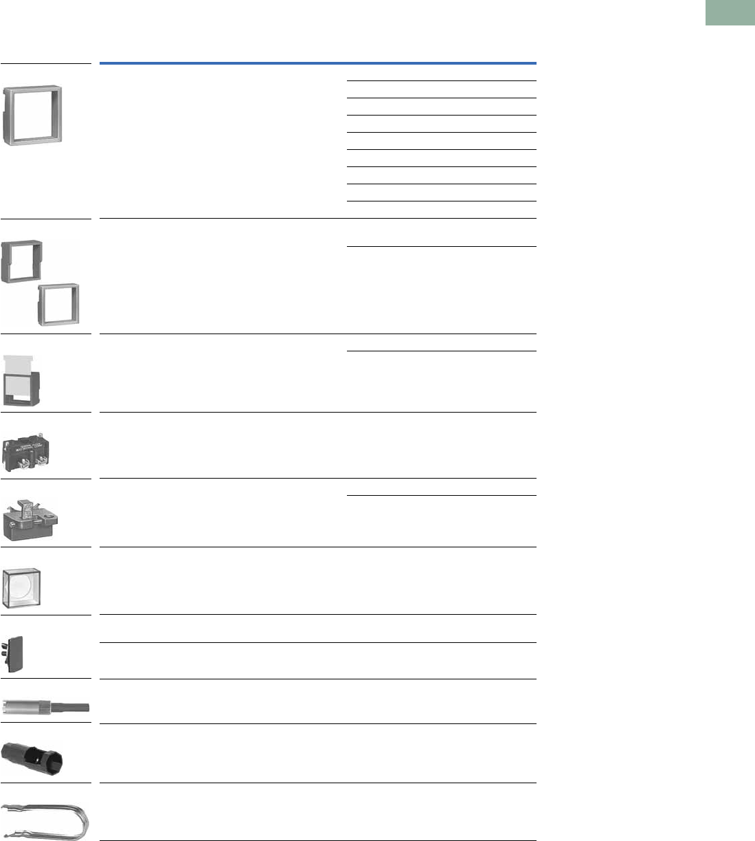
Volume 7—Logic Control, Operator Interface and Connectivity Solutions CA08100008E—March 2014 www.eaton.com V7-T1-175
1
1
1
1
1
1
1
1
1
1
1
1
1
1
1
1
1
1
1
1
1
1
1
1
1
1
1
1
1
1
1.7
Pushbuttons and Indicating Lights
30.5 mm Square Multifunction Watertight/Oiltight—E30
Accessories
Accessories
Note
1 Color coordinating collars, padlock attachments or legend plates cannot be used with operators equipped with a
transparent boot.
Description Color/Type Catalog Number
Collar—Snap on mounting for assembly in the field. Permits
color coding of operator heads. Size: 1-19/32 x 1-19/32 x 9/16 in.
Black E30KR1
Red E30KR2
Green E30KR3
Yellow E30KR4
White E30KR5
Gray E30KR6
Orange E30KR8
Blue E30KR9
Brown E30KR10
Shroud—Similar to collar above except for extension above
the face of button to prevent accidental actuation of button.
Half shroud with an extension on only half the collar may be positioned
to protect top or bottom button.
Full shroud
(gray)
E30KT6
Half shroud
(gray)
E30KT7
Guard—Two collars deep, removable slide prevents accidental
operation. White slide can be marked with grease pencil.
Red with white slide E30KR31
Red with clear slide E30KR32
Terminal Block—2 terminals, each will accommodate 2-wire
terminations.
E30KR30
Padlock Attachment for locking single button and bottom button
of multi-function operators in the depressed position. Locks NC
contacts open or early closing NO contacts closed. Cannot be used
in conjunction with collar, shroud or boot.
Short button E30KT1
Extended button E30KT2
Transparent Boot—Guards against ingress of foreign material
and freezing rain. Note: If this boot is used in conjunction with
operator types AD or AE, an extended type button must be used
in the top position and a short button in the lower position.
E30KT3 1
Square Hole Plug—
Gray enameled E30KT4
Stainless steel E30KT5
Lamp and Lens Removal Tool—Will not fit Cat. No. E30B light units
listed on Page V7-T1-167.
E30KV1
Octagonal Wrench for mounting operators to panel. E22CW
Button and Lens Removal Tool E30KV2
E30KR_
Full
Shroud
Half
Shroud
E30KT_
E30KR3_
E30KR30
E30KT_
E30KT3
E30KT_
E30KV1
E22CW
E30KV2
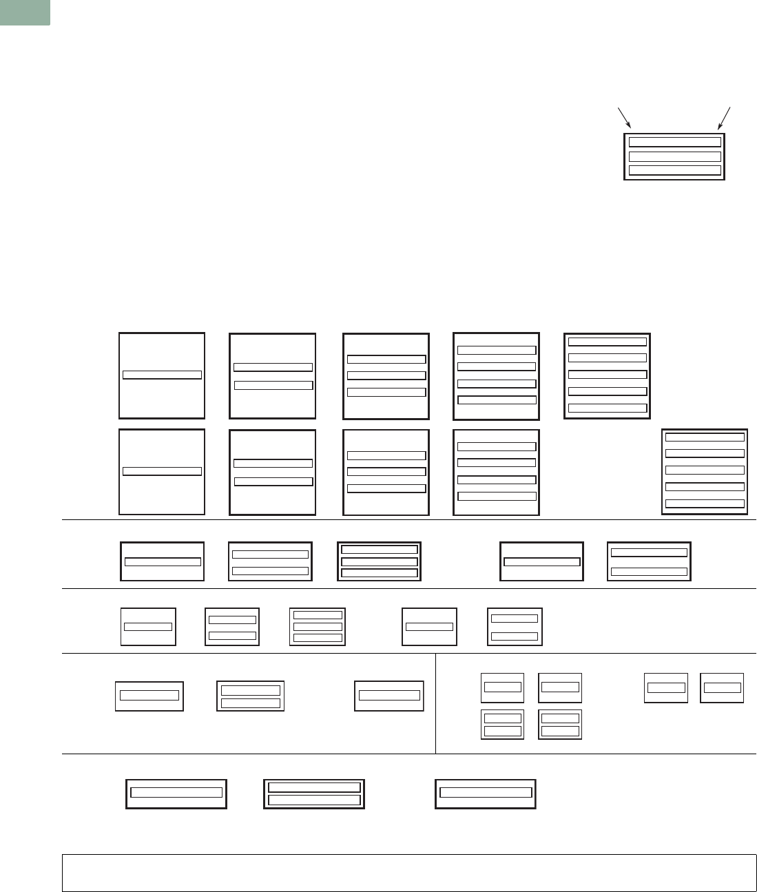
V7-T1-176 Volume 7—Logic Control, Operator Interface and Connectivity Solutions CA08100008E—March 2014 www.eaton.com
1
1
1
1
1
1
1
1
1
1
1
1
1
1
1
1
1
1
1
1
1
1
1
1
1
1
1
1
1
1
1.7
Pushbuttons and Indicating Lights
30.5 mm Square Multifunction Watertight/Oiltight—E30
Options
Markings and Legend Plates
Buttons or Lenses with Non-
Standard Horizontal Markings
Markings not listed as
Standard Markings below are
considered non-standard. If
more than one marking is
required on a button or lens,
order non-standard markings.
Ordering Instructions
●Specify catalog number of
blank button or lens of
desired color, plus suffix
“STAMP” for non-standard
or “STD” for standard
markings in order notes.
See Pages V7-T1-169 to
V7-T1-173.
●Specify size, legend desired
and location in order notes
by alphas as shown in
example.
●Do not exceed maximum
number of legend
characters per line.
Ordering Example
Green Type B button to be
marked with non-standard
legend “ALL
ELEVATORS DOWN.”
Catalog No.: E30KB300STAMP
Letter Size: 1/8 in
Pos. A—ALL
Pos. C—ELEVATORS
Pos. F—DOWN
How to Use the Legend
Location Figure
Legend Locations
Standard Markings
Buttons Lenses
Line Position
7
9
A
C
E
7
8
8
8
No. of Characters per Line
AUTO
CLOSE
DOWN
EMERG. STOP
FAST
FORWARD
HAND
HIGH
IN
INCH
JOG
JOG FOR.
JOG REV.
LOW
LOWER
MAN.
OFF
ON
OPEN
OUT
RAISE
RESET
REVERSE
RUN
SLOW
START
STOP
TEST
UP
MOTOR RUN
MOTOR STOP
POWER ON
READY
7
7
A
C
8
8
99
BB
88
5
56
A
CB
6
B
4
4
A
C
4
B
4
E
4
4
D
F
4
E
4
B
545
5
66
BAB
D
CC
ED
45
6
C
978
9
99
BAB
D
CC
FD
78
888
8
88
88
9
C
8
9
9
9
99
9
9
9
9
D
A
B
E
G
D
E
J
G
K
N
G
K
J
M
9
9
9
9
9
9
8
8
8
88
8
8
8
8
8
8
8
8
8
8
9
9
99
9
9
9
B
B
D
F
E
H
F
K
J
K
9
9
9
8
8
88
8
8
8
8
8
8
A
C
L
F
J
8
8
8
8
8
1/8 in
(3 mm)
High
Char.
Type A buttons and Type F lenses
Type B buttons and Type G lenses
1/8 in
(3 mm)
High
Char.
Type C buttons
1/8 in
(3 mm)
High
Char.
Type D buttons
1/8 in
(3 mm)
High
Char.
Type K buttons
Type E buttons and Type J lenses
1/8 in
(3 mm)
High
Char.
1/8 in
(3 mm)
High
Char.
3/16 in
(5 mm)
High
Char.
Type F lens only
3/16 in
(5 mm)
High
Char.
3/16 in
(5 mm)
High
Char.
3/16 in
(5 mm)
High
Char.
3/16 in
(5 mm)
High
Char.
3/16 in
(5 mm)
High
Char.
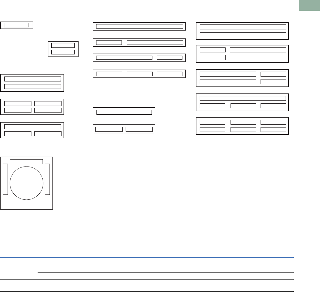
Volume 7—Logic Control, Operator Interface and Connectivity Solutions CA08100008E—March 2014 www.eaton.com V7-T1-177
1
1
1
1
1
1
1
1
1
1
1
1
1
1
1
1
1
1
1
1
1
1
1
1
1
1
1
1
1
1
1.7
Pushbuttons and Indicating Lights
30.5 mm Square Multifunction Watertight/Oiltight—E30
Legend Arrangements and Legend Locations
Legend Plates E30KN76 or KN76B
Maximum Number and Size of Permissible Legend Characters of Custom Stamped Legend Plates
Legend plates
E30KM1 or KM11
Legend plates
E30KM4 or KM14
Legend plates
E30KM2 or KM12
Legend plates
E30KM5 or KM15
Legend plates
E30KM3 or KM13
Legend plates
E30KM6 or KM16
H
G
KB
JA
DM
CL
BFM
G
B
A
F
E
M
L
H
B
M
M
K
D
BF
E
F
F
A
B
B
D
C
C
D
BF
A
B
B
Type
No.of
Lines
Size and Maximum Number of Characters Per Line
One Span Two Span Three Span
3/32 in
(2.5 mm)
1/8 in
(3 mm)
3/16 in
(5 mm)
3/32 in
(2.5 mm)
1/8 in
(3 mm)
3/16 in
(5 mm)
3/32 in
(2.5 mm)
1/8 in
(3 mm)
3/16 in
(5 mm)
Standard 1 13 10 10 30 22 22 47 34 34
Large 1 13 10 10 30 23 23 47 36 36
2 13 101030 232347 3636
Characters available for non-standard markings
3/32 in (2.5 mm)—1/8 in (3 mm)—3/16 in (5 mm)
A B C D E F G H I J K L M N O P Q R S T U V W X Y Z . / — , 1 2 3 4 5 6 7 8 9 0
Legend plates
E30KN76 or KN76B
1/8 in character
size only with a maximum
of six characters.
LINE B
L
I
N
E
A
L
I
N
E
C
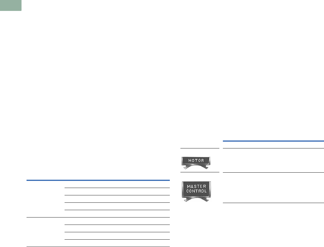
V7-T1-178 Volume 7—Logic Control, Operator Interface and Connectivity Solutions CA08100008E—March 2014 www.eaton.com
1
1
1
1
1
1
1
1
1
1
1
1
1
1
1
1
1
1
1
1
1
1
1
1
1
1
1
1
1
1
1.7
Pushbuttons and Indicating Lights
30.5 mm Square Multifunction Watertight/Oiltight—E30
Buttons or Lenses with Non-Standard Vertical Markings
Ordering Instructions
●Specify catalog number
of blank button or lens of
desired color, selected
from listings on Pages
V7-T1-169 to V7-T1-173.
●Specify size, legend
desired, location and state
“vertically marked” in
order notes.
Note: Specify either 1/8 or 3/16 in
(3.2 or 4.8 mm) character height.
Do not exceed maximum number
of characters as outlined in table
below.
Ordering Example:
Green Type K button to be
marked with “RUN” “ON.”
Catalog No.: E30KK20STAMP
Letter Size: 3/16 in (4.8 mm)
Vertically Marked
Pos. B—RUN
Pos. E—ON
Legend Plates
Legend plates for Type E30
compact pushbutton and
indicating light operators
hook directly onto the
operator and are clamped in
place when the operator
locking nut behind the panel
is secured.
Two and three span plates
are designed for use where
two or more operators are
mounted adjacent to each
other on minimum
horizontal mounting
centers. These legend plates
mount in the same manner as
single span units.
Maximum Number of Characters
Description Type
Maximum Number of Characters
1/8 in (3.2 mm) 3/16 in (4.8 mm)
Buttons A 7 5
B7 5
C4 3
D5 3
E7 5
Lenses F 7 5
G7 5
J7 5
K3 2
When Ordering Legend Plates
with Markings
●Catalog number of blank
legend plate
●Insert the following in
order notes:
●Legends required
●Size of characters—
3/32, 1/8, 3/16 in (2.4,
3.2, 4.8 mm)
●Positions of legends on
one line standard and
two line large legend
plates by alphas as
shown in sketches on
following page.
Ordering Example:
Three span legend plate to be
marked “MASTER
CONTROL”, “STATION A”
and “STATION B.”
Catalog No.: E30KM3STAMP
Letter Size: 1/8 in (3.2 mm)
Pos. C—MASTER CONTROL
Pos. B—STATION A
Pos. F—STATION B
Blank Legend Plates and Legend Plates
with Markings
Type
One Span
Catalog Number
Black
Standard E30KM1
Large E30KM4
Standard— One Span
Large—One Span

Volume 7—Logic Control, Operator Interface and Connectivity Solutions CA08100008E—March 2014 www.eaton.com V7-T1-179
1
1
1
1
1
1
1
1
1
1
1
1
1
1
1
1
1
1
1
1
1
1
1
1
1
1
1
1
1
1
1.7
Pushbuttons and Indicating Lights
30.5 mm Square Multifunction Watertight/Oiltight—E30
Replacement Parts
Replacement Light Units for E30 Components
Replacement Lamps for E30 Illuminated Operators
Replacement Lamps—Incandescent and LED
Note
1E30 blue LED bulbs may not provide sufficient intensity for some applications.
Voltage
AC and DC
Part Numbers—Receptacles without Lamps
Single
Indicating Light
Dual
Indicating Light
Single Light
Single Pushbutton
Single Light
Dual Pushbutton
Dual Light
Dual Pushbutton
Full Voltage Type
6V 57-2579-3A 57-2568A 57-2568A 57-2579-3A 57-2567
12V 57-2579-3A 57-2568A 57-2568A 57-2579-3A 57-2567
18/24V 57-2579-3A 57-2568A 57-2568A 57-2579-3A 57-2567
28V 57-2579-3A 57-2568A 57-2568A 57-2579-3A 57-2567
32V 57-2579-3A 57-2568-2A 57-2568-2A — 57-2567
48V 57-2579-3A 57-2568A 57-2568A 57-2579-3A 57-2567
120V 57-2579-3A 57-2568A 57-2568A 57-2579-3A 57-2567
Transformer Type
120V 42-2672A 42-2663A 42-2663A 42-2671A 42-2664A
208V 42-2672-2A 42-2663-2A 42-2663-2A 42-2671-2A 42-2664-2A
240V 42-2672-3A 42-2663-3A 42-2663-3A 42-2671-3A 42-2664-3A
380V 42-2672-4A 42-2663-4A 42-2663-4A 42-2671-4A 42-2664-4A
480V 42-2672-5A 42-2663-5A 42-2663-5A 42-2671-5A 42-2664-5A
600V 42-2672-6A 42-2663-6A 42-2663-6A 42-2671-6A 42-2664-6A
Description and Part Numbers—Related Parts
Inner lens 28-1008 28-1010 28-1010 28-1010 28-1010
Retaining nut 15-1885 15-1885 15-1885 15-1885 15-1885
Gasket 16-2092 16-2092 16-2092 16-2092 16-2092
Locking ring 52-1116 52-1116 52-1116 52-1116 52-1116
Mfg. Lamp Type Voltage Base Style Application Part Number
6PSB 6V T2 slide E30 transformer and full voltage 28-1022
12PSB 12V T2 slide E30 full voltage 28-1025
24PSB 24V T2 slide E30 full voltage 28-1026
28PSB 28V T2 slide E30 full voltage 28-1027
48PSB 48V T2 slide E30 full voltage 28-1028
60PSB 60V T2 slide E30 full voltage 28-1598
120PSB 120V T2 slide E30 full voltage 28-1029
#259 6.3V T3-1/4 wedge E30 single transformer 28-949
Lamp
Voltage
Incandescent Lamps LED Lamps
Manufacturer’s
Part Number
Base
Style
Eaton’s
Part Number
Eaton’s Part Number
Red Green Yellow Blue 1
6 6PSB T2 slide 28-1022 35-1523 35-1523-2 35-1523-3 35-1523-17
12 12PSB T2 slide 28-1025 35-1523-11 35-1523-12 35-1523-13 35-1523-18
24 24PSB T2 slide 28-1026 35-1523-4 35-1523-5 35-1523-6 35-1523-19
28 28PSB T2 slide 28-1027 35-1523-4 35-1523-5 35-1523-6 35-1523-19
48 48PSB T2 slide 28-1028 35-1523-14 35-1523-15 35-1523-16 35-1523-20
120 120PSB T2 slide 28-1029 35-1523-7 35-1523-8 35-1523-9 35-1523-21
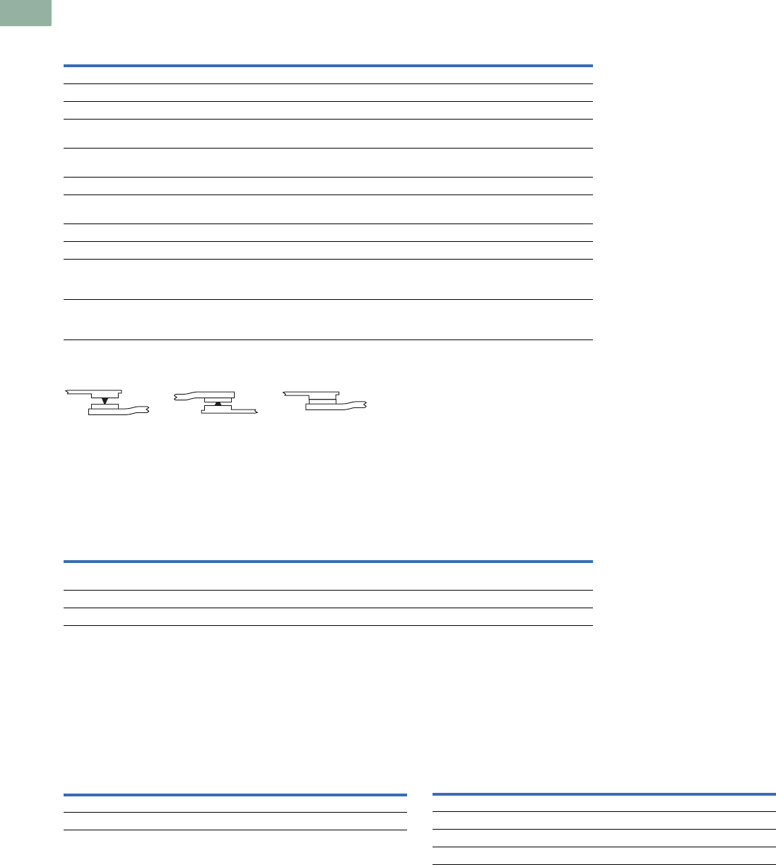
V7-T1-180 Volume 7—Logic Control, Operator Interface and Connectivity Solutions CA08100008E—March 2014 www.eaton.com
1
1
1
1
1
1
1
1
1
1
1
1
1
1
1
1
1
1
1
1
1
1
1
1
1
1
1
1
1
1
1.7
Pushbuttons and Indicating Lights
30.5 mm Square Multifunction Watertight/Oiltight—E30
Technical Data and Specifications
Operator Specifications
Reliability Nibs
Electrical Ratings
Contact Blocks
●UL A600/P300 nominal connect 10A
●1NO, 1NC, 2NO, 2NC, 1NO-1NC, early make, late break and
overlapping configurations
●Mechanical positive drive operation on NC contacts
●Palladium alloy contact for logic level or highly corrosive
environments
Maximum Ratings for Logic Level and
Hostile Atmosphere Application Light Unit
Note
1Logic level contact blocks are UL A600/P500 rated per table above.
Description Specification
Climate Conditions
Operating –20° to 150°F (–29° to 65°C)
Te rm i n a l s
Light units Terminals are saddle clamp type for 2 stranded or solid wires up to 12 AWG (4.0 mm2)
Torque—7 lb-in (0.8 Nm)
Contact block Terminals are saddle clamp type for 2 stranded or solid wires up to 12 AWG (4.0 mm2)
Torque—7 lb-in (0.8 Nm)
Materials
Operator Zinc base die casting with a copper-nickel-chrome plated finish
Withstands the 200 hr. salt spray test in accordance with MIL Spec. QQ-M-151A and NEMA 4X testing.
Internal parts Including shafts, washers and springs, are made of stainless steel
Buttons and lenses Colorfast, wear resistant, molded acetal resin
Contact blocks Made of molded, heat resistant, mineral filled phenolic
Contact block plungers are molded of nylon filled phenolic
Contacts are silver
Reliability nibs These nibs combine a scrubbing action with high pressure density when the contacts are closed
They push through particles and films found on contact surfaces in industrial environments
Reliability nibs self-adjust to the application—dry circuit, normal or heavy-duty
Meet or Exceed NEMA Contact Rating Designation A600 and P300
Vac A600 Vdc P300
Description 120V 240V 480V 600V 24/28V 125V 250V
Make and emergency
interrupting capacity (Amps)
60 30 15 12 5.73 1.1 0.55
Normal load break (Amps) 6 3 1.5 1.2 5.73 1.1 0.55
Continuous current (Amps) 10 10 10 10 5 5 5
Heavy-Duty
Dry Circuit
Medium Duty
Description Specification
Maximum amperes 0.5A 1
Maximum volts 120 Vac/Vdc
Description Specification
Bulbs—Average Life
Transformer type 20,000 hrs.
Resistor/direct voltage type 2,500 hrs. min. at rated voltage
LED 60,000 to 100,000 hrs.
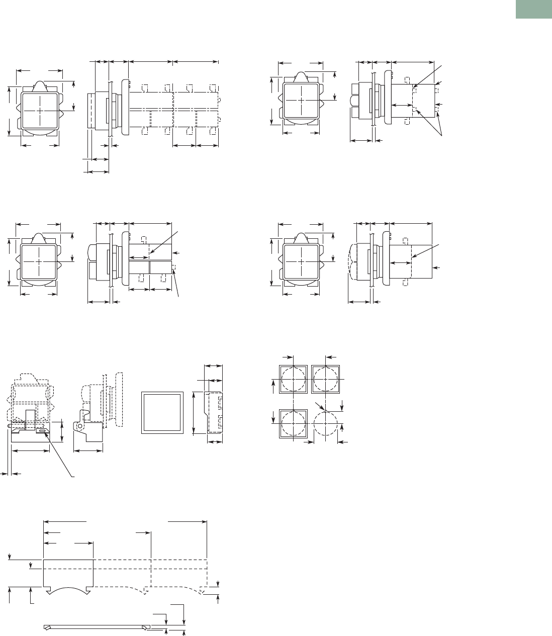
Volume 7—Logic Control, Operator Interface and Connectivity Solutions CA08100008E—March 2014 www.eaton.com V7-T1-181
1
1
1
1
1
1
1
1
1
1
1
1
1
1
1
1
1
1
1
1
1
1
1
1
1
1
1
1
1
1
1.7
Pushbuttons and Indicating Lights
30.5 mm Square Multifunction Watertight/Oiltight—E30
Dimensions
Approximate Dimensions in Inches (mm)
Pushbutton Operators
Combination Pushbutton and Indicating Light Operators
Padlocking Attachment and Half Shroud E30KT7
Legend Plates
Combination Pushbutton and Indicating Light Operators
Indicating Light Operators
Drilling Dimensions—Minimum Spacing 12
Notes
1Dimensions shown allow adequate space for the addition of one or two high legend plates
and color coordinating collars.
2Locating nib hole or notch is 0.136 in (3.5 mm) drill. Alternate to drilling mounting holes use
Greenlee Tool Co. punch (No. 730-S) to punch the hole and (No. 730-K) to punch the notch.
1.75
(44.5)
0.53
(13.5)
0.81
(20.6) 1.72
(43.7) 1.72
(43.7)
1.47
(37.3)
Square 0.88
(22.4) 0.88
(22.4)
1.13
(28.7)
1.88
(47.8)
Panel
0.06 (1.5) Min.
0.25 (6.4) Max.
0.78 (19.8) Ext. Button
0.63 (16)
Std.
Button 1 Circ.
Cont. Blocks
2 Circ.
Cont. Blocks
Plunger
Extends to
0.25 (6.4)
0.88
(22.4)
0.88 (22.4) 0.88 (22.4)
Full Voltage
Types DF,
DM and DX
Plunger Extends
to 0.25 (6.4) on
Contact Blocks
Transformer
Types DA – DL
1.75
(44.5)
0.53
(13.5)
0.84
(21.3)
0.81
(20.6) 1.72
(43.7)
1.47
(37.3)
Square
1.13
(28.7)
1.88
(47.8)
Panel
0.06 (1.5) Min.
0.25 (6.4) Max.
0.69
(17.5)
1.13
(28.7)
0.31 (7.9)
Dia. Hole
0.5 (12.7)
0.56
(14.2)
1.59
(40.4)
0.75
(19.1)
1.44
(36.6)
0.11 (2.8)
Max.
1.44
(36.6)
0.02
(0.5)
0.78
(19.8) 0.39
(9.9)
Standard
3.06 (77.7) Two Span
0.05 (1.3)
0.08 (1.9)
One Span
4.69 (119.1) Three Span
Large
0.88
(22.4)
Operator
Types E30JA–
E30JW
Operator
Types E30EA–
E30GM
Plungers
Extended
to 0.25 (6.4)
Transformer
or Full Voltage
Light Element
1.75
(44.5)
0.53
(13.5)
0.84
(21.3)
0.81
(20.6) 1.72
(43.7)
1.47
(37.3)
Square
1.13
(28.7)
1.88
(47.8)
Panel
0.06 (1.5) Min.
0.25 (6.4) Max.
1.75
(44.5)
0.53
(13.5)
0.84
(21.3)
0.81
(20.6) 1.72
(43.7)
1.47
(37.3)
Square
1.13
(28.7)
1.88
(47.8)
0.88
(22.4)
Panel
0.06 (1.5) Min.
0.25 (6.4) Max.
Operator
Types E30BA–
E30BM
Operator
Types E30CA–
E30CM
1.63 a
(41.3)
2.25 a
(57) 0.6
(15)
Drill .14
(3.5)
ø 1.20 (30.5)
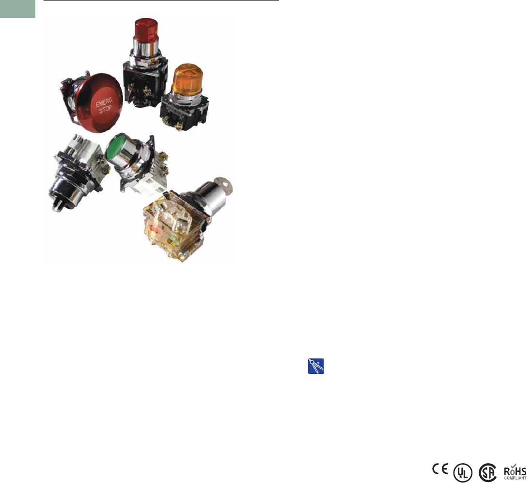
V7-T1-182 Volume 7—Logic Control, Operator Interface and Connectivity Solutions CA08100008E—March 2014 www.eaton.com
1
1
1
1
1
1
1
1
1
1
1
1
1
1
1
1
1
1
1
1
1
1
1
1
1
1
1
1
1
1
1.8
Pushbuttons and Indicating Lights
30.5 mm Heavy-Duty Watertight/Oiltight—10250T
30.5 mm Heavy-Duty Watertight/Oiltight—10250T
Contents
Description Page
30.5 mm Heavy-Duty Watertight/Oiltight—10250T
Product Overview . . . . . . . . . . . . . . . . . . . . . . V7-T1-183
Product Identification . . . . . . . . . . . . . . . . . . . . V7-T1-183
Catalog Number Selection . . . . . . . . . . . . . . . . V7-T1-184
Product Selection
Point-of-Purchase Packaging . . . . . . . . . . . . V7-T1-186
Non-Illuminated Momentary
Pushbutton Units . . . . . . . . . . . . . . . . . . . V7-T1-187
Pushbuttons . . . . . . . . . . . . . . . . . . . . . . . . V7-T1-188
Illuminated Momentary Pushbutton Units . V7-T1-192
Indicating Light Units . . . . . . . . . . . . . . . . . V7-T1-193
Illuminated Pushbuttons and
Indicating Lights . . . . . . . . . . . . . . . . . . . . V7-T1-194
Push-Pull Emergency Stop . . . . . . . . . . . . . V7-T1-196
Illuminated Push-Pull Units . . . . . . . . . . . . . V7-T1-199
Potentiometers . . . . . . . . . . . . . . . . . . . . . . V7-T1-202
Push-Pull Operators . . . . . . . . . . . . . . . . . . V7-T1-203
Selector Switch Units . . . . . . . . . . . . . . . . . V7-T1-207
Selector Switch Selection . . . . . . . . . . . . . . V7-T1-208
Selector Switch Operators . . . . . . . . . . . . . V7-T1-211
Illuminated Selector Switch Operators . . . . V7-T1-214
Joystick Units . . . . . . . . . . . . . . . . . . . . . . . V7-T1-215
Joysticks . . . . . . . . . . . . . . . . . . . . . . . . . . . V7-T1-216
Roto-Push Units . . . . . . . . . . . . . . . . . . . . . V7-T1-219
Roto-Push Operators . . . . . . . . . . . . . . . . . V7-T1-220
Accessories . . . . . . . . . . . . . . . . . . . . . . . . . . . V7-T1-225
Options . . . . . . . . . . . . . . . . . . . . . . . . . . . . . . V7-T1-230
Replacement Parts . . . . . . . . . . . . . . . . . . . . . . V7-T1-239
Technical Data and Specifications . . . . . . . . . . V7-T1-241
Dimensions . . . . . . . . . . . . . . . . . . . . . . . . . . . V7-T1-244
Drawings
Online
Product Description
The 30.5 mm pushbutton line
features a zinc die cast
construction with chrome-
plated housing and mounting
nut. The same durable
construction is also available
with the corrosive resistant
E34 line of pushbuttons.
See E34 section on Pages
V7-T1-254 to V7-T1-288.
Features
●Heavy-duty zinc die cast
construction
●Enclosed silver contacts
with reliability nibs
●Diaphragm seals with
drainage holes
●Grounding nibs on the
operator casing
Benefits
●Reliability nibs improve
contact reliability even
under dry circuit and fine
dust conditions
●Drainage holes prevent
buildup of liquid inside the
operator which can prevent
operation in freezing
environments
●Grounding nibs bit through
paint and other coatings to
provide secure ground
Application Description
Contact Operation
Slow make and break. All
normally closed contacts
have positive opening
operation, i.e., normally closed
contacts are forced open in
the event of contact weld or
spring breakage.
Standards and
Certifications
●CE EN 60947-5-1 and
60947-5-5
●UL 508—File No. 131568
●CSA C22.2 No. 14—File
No. LR68551
Ingress Protection
When mounted in similarly
rated enclosure—
●Standard indicating lights
●UL (NEMA) Type 1, 2, 3,
3R, 3S, 4, 4X, 12, 13
●IEC IP65
●Most other operators
●UL (NEMA) Type 1, 2, 3,
3R, 4, 4X, 12, 13
●IEC IP65
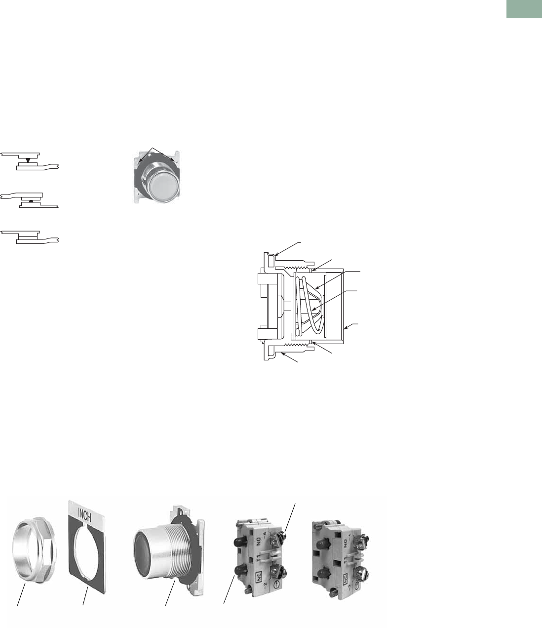
Volume 7—Logic Control, Operator Interface and Connectivity Solutions CA08100008E—March 2014 www.eaton.com V7-T1-183
1
1
1
1
1
1
1
1
1
1
1
1
1
1
1
1
1
1
1
1
1
1
1
1
1
1
1
1
1
1
1.8
Pushbuttons and Indicating Lights
30.5 mm Heavy-Duty Watertight/Oiltight—10250T
Product Overview
Reliability Nibs
Eaton’s contact blocks
feature enclosed silver
contacts with pointed
“reliability nibs” for reliable
performance from logic level
up to 600V. To ensure reliable
switching, nibs bite through
oxide which can form on silver
contacts, eliminating the
need for expensive logic level
blocks for most applications.
Reliability Nibs
Reliability nibs improve
performance in dry circuit,
corrosive, fine dust and other
contaminated atmospheres.
Under normal environmental
conditions, the minimum
operational voltage is 5V and
the minimum operational
current is 1 mA, AC/DC. For
operation under a wider range
of environmental conditions,
logic level contact blocks with
inert palladium tipped
contacts are recommended.
Grounding Nibs
10250T line operators have
“grounding nibs”—four
metal points on the operator
casting designed to bite
through most paints and
other coatings on metal
panels to enhance the ground
connection when the operator
is securely tightened.
Grounding Nibs
Product Identification
30.5 mm Heavy-Duty Watertight/Oiltight—10250T Series
Dry Circuit
Medium Duty
Heavy-Duty
Grounding
Nibs
Mounting Nut Legend Plate Operator
Terminal Clamps
Shipped Ready to Wire
Stackable Contact
Blocks up to 12 Circuits
per Operator
Color Coded Plungers
Red = NC Green = NO
Diaphragm Seal with
Drainage Holes
Liquid Drainage
Eaton’s pushbutton operators
offer front of panel drainage
via holes in the operator
bushing. Hidden from view by
the mounting nut, these
holes prevent buildup of liquid
inside the operator, which
can prevent operation in
freezing environments.
The holes also provide a route
for escaping liquid in high
pressure washdowns,
effectively relieving pressure
from the internal diaphragm
seal, ensuring reliable sealing
in applications even beyond
NEMA 4.
Diaphragm Seal
Foam Neoprene
Panel Sealing Gasket
Drainage Hole
Drainage Hole
Flexible
Diaphragm
Stainless
Steel
Operating
Spring
Mounting Nut
Colorfast
Molded
Button
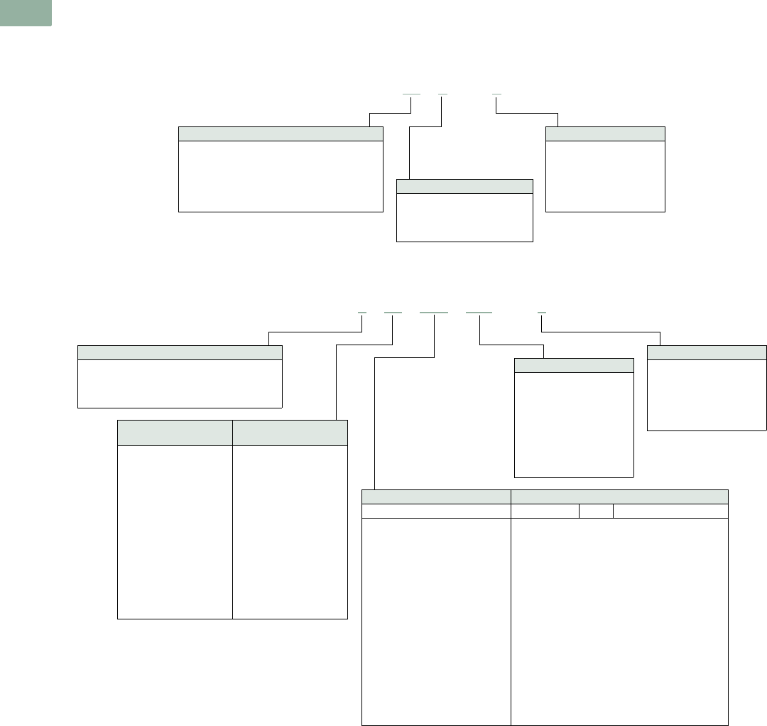
V7-T1-184 Volume 7—Logic Control, Operator Interface and Connectivity Solutions CA08100008E—March 2014 www.eaton.com
1
1
1
1
1
1
1
1
1
1
1
1
1
1
1
1
1
1
1
1
1
1
1
1
1
1
1
1
1
1
1.8
Pushbuttons and Indicating Lights
30.5 mm Heavy-Duty Watertight/Oiltight—10250T
Catalog Number Selection
Catalog Number Selection is for illustrative purposes only and not to be used to create new catalog numbers.
Non-Illuminated Pushbuttons
Illuminated and Non-Illuminated Push-Pulls
Note
1Add X at end of catalog number to receive parts assembled from factory.
10250T 10 1–1 1
Operator
10 = Flush
11 = Extended
12 = 40 mm mushroom
17 = 65 mm mushroom
50 = 1/2 shroud vertical mount
51 = 1/2 shroud horizontal mount
Circuit
Blank = Operator only
1= 1NO-1NC
2 = 2NO
3 = 2NC
51 = 1NC
53 = 1NO
Button Color
1 = Black
2 = Red
3 = Green
4 = Yellow
5 = Gray
6 = White
8 = Blue
9 = Orange
10250T 5 63 C47 –1 1
Circuit
Blank = Operator only
1 = 1NO-1NC
2 =2NO
3 =2NC
51 =1NC
53 =1NO
Incandescent
Light Unit
LED
Light Unit
Blank = Non-illuminated
89 = 24V/XFR
63 = 120V/XFR
64 = 208V/XFR
65 = 240V/XFR
82 = 277V/XFR
66 = 380V/XFR
67 = 480V/XFR
68 = 600V/XFR
69 = 6V/FV
70 = 12V/FV
79 = 24V/FV
83 = 32V/FV
80 = 120V/RES
81 = 240V/RES
Blank = Non-illuminated
89L = 24V/XFR
63L = 120V/XFR
64L = 208V/XFR
65L = 240V/XFR
82L = 277V/XFR
66L = 380V/XFR
67L = 480V/XFR
68L = 600V/XFR
97L = Full voltage
Non-Illuminated Illuminated
Button Incandescent LED Lens Type
B60 = Black 40 mm
B62 = Red 40 mm
B63 = Red 40 mm—“E” STOP
B61 = Green 40 mm
B64 = Blue 40 mm
J60 = Black 65 mm
J62 = Red 65 mm
J63 = Red 65 mm—“E” STOP
J61 = Green 65 mm
J64 = Yellow 65 mm
C47 =
C53 =
C48 =
C49 =
C50 =
C51 =
C52 =
C57 =
C63 =
C58 =
C59 =
C64 =
C60 =
C61 =
C62 =
C65 =
C66 =
C67 =
RD =
ED =
GD =
LD =
AD =
WD =
— =
RS =
ES =
GS =
LS =
AS =
YS =
WS =
— =
RH =
GH =
AH =
Red 40 mm
Red 40 mm—“E” STOP
Green 40 mm
Blue 40 mm
Amber 40 mm
White 40 mm
Clear 40 mm
Red side light
Red side light—“E” STOP
Green side light
Blue side light
Amber side light
Yellow side light
White side light
Clear side light
Red heavy-duty
Green heavy-duty
Amber heavy-duty
LED Voltage
Blank = Non-illuminated
Blank = Incandescent
06 = 6 Vac/Vdc
12 = 12 Vac/Vdc
24 = 24 Vac/Vdc
48 = 48 Vac/Vdc
60 = 60 Vac/Vdc
2A = 120 Vac
2D = 120 Vdc
Operator
5 = Two-position maintained
4 = Three-position mom push-mom pull
9 = Three-position mt push-mom pull
10 = Three-position mom push-mom pull
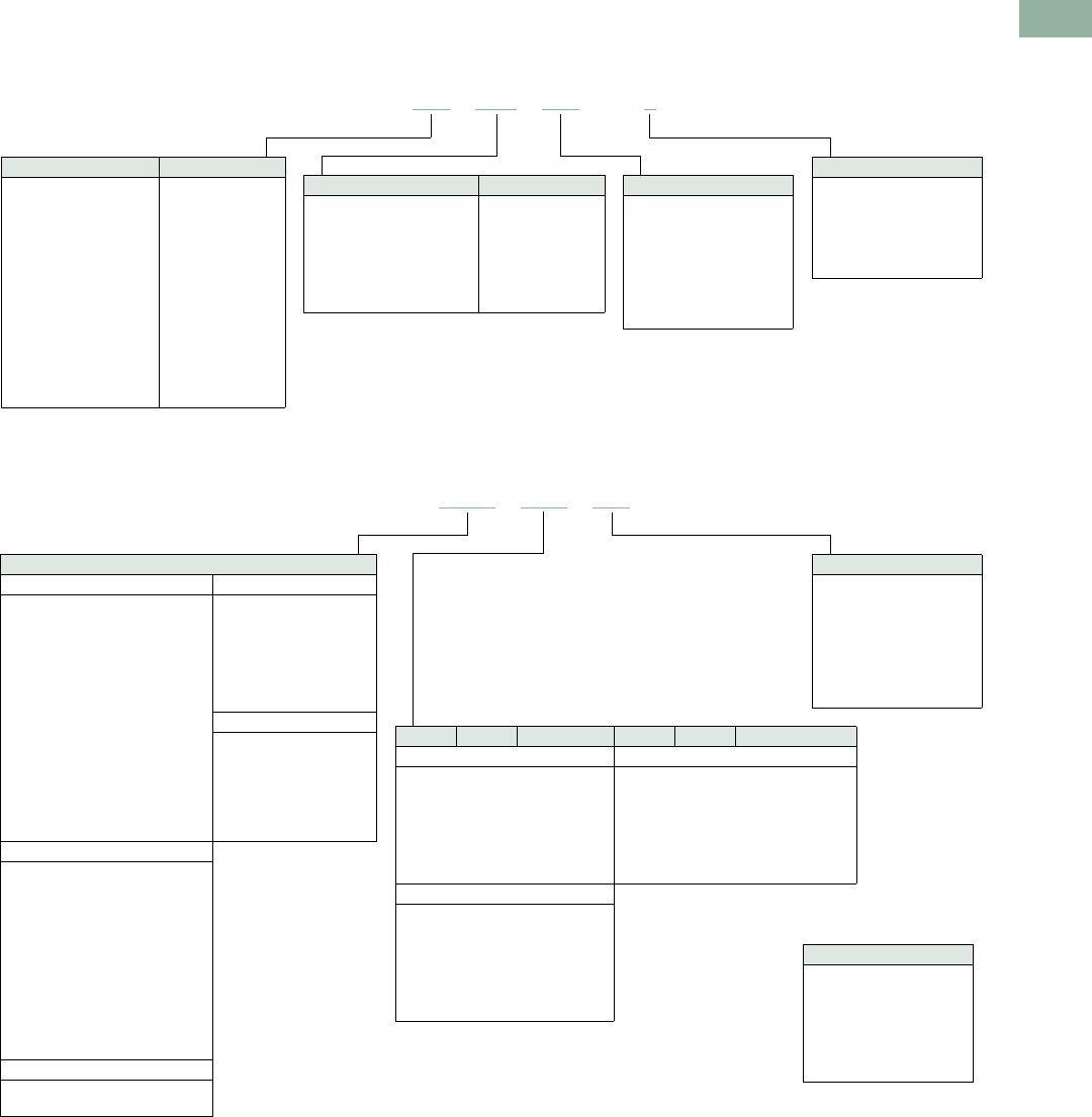
Volume 7—Logic Control, Operator Interface and Connectivity Solutions CA08100008E—March 2014 www.eaton.com V7-T1-185
1
1
1
1
1
1
1
1
1
1
1
1
1
1
1
1
1
1
1
1
1
1
1
1
1
1
1
1
1
1
1.8
Pushbuttons and Indicating Lights
30.5 mm Heavy-Duty Watertight/Oiltight—10250T
Catalog Number Selection is for illustrative purposes only and not to be used to create new catalog numbers.
Illuminated Pushbuttons
Standard Indicating Lights, PresTest and Master Test
Note
1Add X at end of catalog number to receive parts assembled from factory.
10250T 416 C21 –1 1
Circuit
Blank = Operator only
1 = 1NO-1NC
2 =2NO
3 =2NC
51 =1NC
53 =1NO
Incandescent Lens Color LED Lens Color
C21 = Red
C22 = Green
C23 = Yellow
C26 = White
C24 = Blue
C43 = Amber
C25 = Clear
RD =Red
GD = Green
YD = Yellow
WD =White
LD = Blue
AD =Amber
LED Voltage
Blank = Incandescent
06 = 6 Vac/Vdc
12 = 12 Vac/Vdc
24 = 24 Vac/Vdc
48 = 48 Vac/Vdc
60 = 60 Vac/Vdc
2A = 120 Vac
2D = 120 Vdc
Incandescent Light Unit LED Light Unit
416 = 24V/XFR
411 = 120V/XFR
412 = 240V/XFR
419 = 277V/XFR
413 = 380V/XFR
414 = 480V/XFR
415 = 600V/XFR
473 = 6V/FV
474 = 12V/FV
476 = 24V/FV
477 = 32V/FV
478 = 48V/FV
471 = 120V/RES
472 = 240V/RES
397L = Full voltage
416L = 24V/XFR
411L = 120V/XFR
412L = 240V/XFR
419L = 277V/XFR
413L = 380V/XFR
414L = 480V/XFR
415L = 600V/XFR
LED Voltage
Blank = Incandescent
06 = 6 Vac/Vdc
12 = 12 Vac/Vdc
24 = 24 Vac/Vdc
48 = 48 Vac/Vdc
60 = 60 Vac/Vdc
2A = 120 Vac
2D = 120 Vdc
Plastic Glass Lens Color Plastic Glass Lens Color
Standard/Master—Incandescent Standard/Master/PresTest—LED
C1N =
C2N =
C3N =
C6N =
C4N =
C19N =
C5N =
C7N =
C8N =
— =
C12N =
C10N =
C9N =
C11N =
Red
Green
Yellow
White
Blue
Amber
Clear
RP =
GP =
YP =
WP =
LP =
AP =
RG =
GG =
— =
WG =
LG =
AG =
Red
Green
Yellow
White
Blue
Amber
PresTest—Incandescent
C21 =
C22 =
C23 =
C26 =
C24 =
C43 =
C25 =
C13N =
C14N =
— =
C18N =
C16N =
C15N =
C17N =
Red
Green
Yellow
White
Blue
Amber
Clear
Light Unit Type
Standard—Incandescent Standard—LED
181N =
182N =
198N =
183N =
184N =
185N =
203N =
204N =
206N =
207N =
208N =
201N =
202N =
226N =
227N =
120V/XFR
240V/XFR
277V/XFR
380V/XFR
480V/XFR
600V/XFR
6V/FV
12V/FV
24V/FV
32V/FV
48V/FV
120V/RES
240V/RES
120V/neon
240V/neon
181L =
182L =
198L =
183L =
184L =
185L =
197L =
120V/XFR
240V/XFR
277V/XFR
380V/XFR
480V/XFR
600V/XFR
Full voltage
PresTest—LED
221L =
222L =
223L =
224L =
225L =
297L =
120V/XFR
240V/XFR
380V/XFR
480V/XFR
600V/XFR
Full voltage
PresTest—Incandescent
221N =
222N =
223N =
224N =
225N =
232N =
233N =
235N =
238N =
239N =
231N =
240N =
120V/XFR
240V/XFR
380V/XFR
480V/XFR
600V/XFR
6V/FV
12V/FV
24V/FV
32V/FV
48V/FV
120V/RES
240V/RES
Master Test—Incandescent
187N =
189N =
120V/XFR
240 Vac—SS
10250T 203N C1N 1
LED Voltage
Blank = Incandescent
06 = 6 Vac/Vdc
12 = 12 Vac/Vdc
24 = 24 Vac/Vdc
48 = 48 Vac/Vdc
60 = 60 Vac/Vdc
2A = 120 Vac
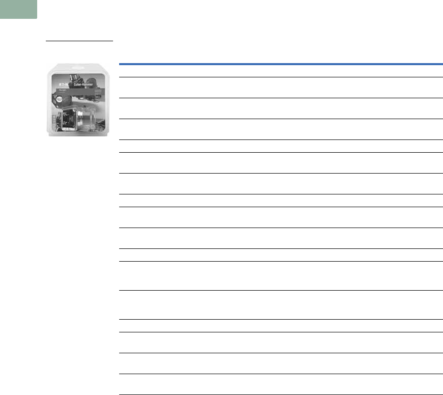
V7-T1-186 Volume 7—Logic Control, Operator Interface and Connectivity Solutions CA08100008E—March 2014 www.eaton.com
1
1
1
1
1
1
1
1
1
1
1
1
1
1
1
1
1
1
1
1
1
1
1
1
1
1
1
1
1
1
1.8
Pushbuttons and Indicating Lights
30.5 mm Heavy-Duty Watertight/Oiltight—10250T
Product Selection
Point-of-Purchase Packaging
10250T Point-of-Purchase Packaged Pilot Devices
Product Description Catalog Number
Emergency Stop Operators
Red non-illuminated
push-pull
1NO-1NC contact block. Also includes two square engraved
legend plates: EMERG. STOP and STOP.
10250T5B62-1-POP
Red mushroom
pushbutton
1NO-1NC contact block. Also includes two square engraved
legend plates: EMERG. STOP and STOP.
10250T32R-POP
Red jumbo
mushroom pushbutton
Engraved EMERG. STOP with 1NO-1NC contact block. 10250T33-POP
Momentary Pushbuttons
Black flush
pushbutton
1NO-1NC contact block. Also includes two square engraved
legend plates: START and JOG.
10250T30B-POP
Red extended
pushbutton
1NO-1NC contact block. Also includes one square engraved
legend plate: STOP.
10250T31R-POP
Indicating Lights
Red indicating light Full voltage 24 Vac/Vdc with two extra lenses: Green and amber.
Also includes two square engraved legend plates: RUN and JOG.
10250T206NC1N-POP
Red indicating light Resistor 120 Vac/Vdc with two extra lenses: Green and Amber.
Also includes one square engraved legend plate: RUN and JOG.
10250T34R-POP
Illuminated Pushbuttons
Red illuminating
pushbutton
Full voltage 24 Vac/Vdc with 1NO-1NC contact block and two
extra lenses: Green and amber. Also includes one square
engraved legend plate: POWER ON.
10250T476C21-1-POP
Red illuminating
pushbutton
Resistor 120 Vac/Vdc with 1NO-1NC contact block and two
extra lenses: Green and amber. Also includes one square
engraved legend plate: POWER ON.
10250T411C21-1-POP
Selector Switches
Black knob two-position
selector switch
1NO-1NC contact block. Also includes three square engraved
legend plates: OFF/ON, HAND/AUTO and RUN/JOG.
10250T20KB-POP
Black knob three-position
selector switch
2NO-2NC contact blocks. Also includes 1 square engraved
legend plate: HAND/OFF/AUTO.
10250T22KB-POP
Black knob three-position
selector switch
1NO-1NC contact block. Also includes legend plate:
HAND/OFF/AUTO
10250T21KB-POP
Point-of-Purchase
Packaged Pilot Device
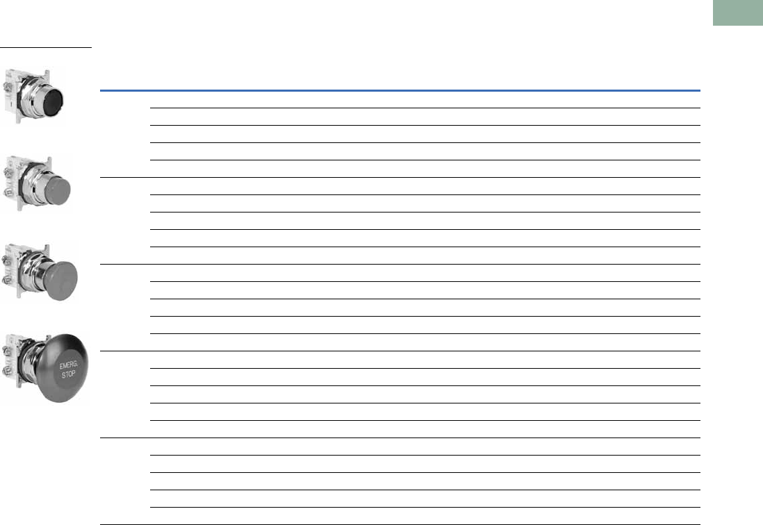
Volume 7—Logic Control, Operator Interface and Connectivity Solutions CA08100008E—March 2014 www.eaton.com V7-T1-187
1
1
1
1
1
1
1
1
1
1
1
1
1
1
1
1
1
1
1
1
1
1
1
1
1
1
1
1
1
1
1.8
Pushbuttons and Indicating Lights
30.5 mm Heavy-Duty Watertight/Oiltight—10250T
Non-Illuminated Momentary Pushbutton Units
UL (NEMA) Type 3, 3R, 4, 4X, 12, 13
Pushbutton Units—Flush, Extended, Mushroom Head or Jumbo Mushroom Head Operators
Note
1 Anodized aluminum head is not suitable for use in ultraviolet light applications.
Contact
Type Button Color
Flush Button
Catalog Number
Extended Button
Catalog Number
Mushroom Button
Catalog Number
Jumbo Mushroom 1
Catalog Number
1NO Black 10250T23B 10250T25B 10250T26B 10250T27B
Red 10250T23R 10250T112-53 10250T122-53 10250T172-53
Green 10250T23G 10250T25G 10250T26G 10250T27G
Yellow 10250T23Y 10250T25Y 10250T26Y 10250T27Y
Red—Engraved EMERG. STOP — — — 10250T17213-53
1NC Black 10250T101-51 10250T111-51 10250T121-51 10250T171-51
Red 10250T102-51 10250T25R 10250T26R 10250T27R
Green 10250T103-51 10250T113-51 10250T123-51 10250T173-51
Yellow 10250T104-51 10250T120-51 10250T124-51 10250T174-51
Red—Engraved EMERG. STOP — — — 10250T29
1NO-1NC Black 10250T30B 10250T31B 10250T32B 10250T33B
Red 10250T30R 10250T31R 10250T32R 10250T33R
Green 10250T30G 10250T31G 10250T32G 10250T33G
Yellow 10250T30Y 10250T31Y 10250T32Y 10250T33Y
Red—Engraved EMERG. STOP — — — 10250T33
2NO Black 10250T101-2 10250T111-2 10250T121-2 10250T171-2
Red 10250T102-2 10250T112-2 10250T122-2 10250T172-2
Green 10250T103-2 10250T113-2 10250T123-2 10250T173-2
Yellow 10250T104-2 10250T120-2 10250T124-2 10250T174-2
Red—Engraved EMERG. STOP — — — 10250T17213-2
2NC Black 10250T101-3 10250T111-3 10250T121-3 10250T171-3
Red 10250T102-3 10250T112-3 10250T122-3 10250T172-3
Green 10250T103-3 10250T113-3 10250T123-3 10250T173-3
Yellow 10250T104-3 10250T120-3 10250T124-3 10250T174-3
Red—Engraved EMERG. STOP — — — 10250T17213-3
Flush Button
Extended Button
Mushroom Button
Jumbo Mushroom
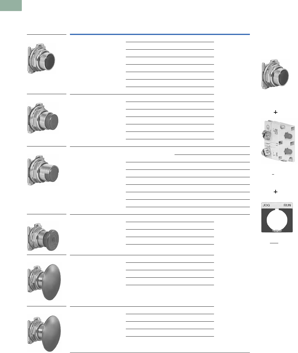
V7-T1-188 Volume 7—Logic Control, Operator Interface and Connectivity Solutions CA08100008E—March 2014 www.eaton.com
1
1
1
1
1
1
1
1
1
1
1
1
1
1
1
1
1
1
1
1
1
1
1
1
1
1
1
1
1
1
1.8
Pushbuttons and Indicating Lights
30.5 mm Heavy-Duty Watertight/Oiltight—10250T
Pushbuttons
UL (NEMA) Type 3, 3R, 4, 4X, 12, 13
Momentary Pushbutton Operators, Non-illuminated
Notes
1 To order operator with factory assembled extended retaining nut, 10250TA12, for thick panel applications,
add suffix letter E to listed catalog number. Example: 10250T101E.
2 Anodized aluminum head is not suitable for use in ultraviolet light applications.
3 Operating force—Standard = 2.4 lb; low force = 1.6 lb.
Button Color Catalog Number Note: To order complete assembled unit
using one composite catalog number,
add contact block and legend plate suffix
to the end of operator catalog number.
Example: 10250T101-1TS33
Flush button 1Black 10250T101
Red 10250T102
Green 10250T103
Yellow 10250T104
Gray 10250T105
White 10250T106
Blue 10250T108
Orange 10250T109
Extended button Black 10250T111
Red 10250T112
Green 10250T113
Yellow 10250T120
White 10250T116
Blue 10250T118
Orange 10250T119
Half shrouded button Vertical Horizontal
Black 10250T501 10250T511
Red 10250T502 10250T512
Green 10250T503 10250T513
Yellow 10250T504 10250T514
Gray 10250T505 10250T515
White 10250T506 10250T516
Blue 10250T508 10250T518
Orange 10250T509 10250T519
Mushroom button Black 10250T121
Red 10250T122
Green 10250T123
Yellow 10250T124
Blue 10250T129
Jumbo mushroom button 2Black 10250T171
Red 10250T172
Red (EMERG. STOP) 10250T17213
Green 10250T173
Yellow 10250T174
Low operating force—
jumbo mushroom 23
Black 10250ED1164-2
Red 10250ED1164-3
Green 10250ED1164-4
Yellow 10250ED1164-5
Clear 10250ED1164
10250T10_
10250T11_
10250T5_
10250T17_
10250T12_
10250ED1164_
Operator
10250T101
Contact Block
10250T1
Legend Plate
10250TS33
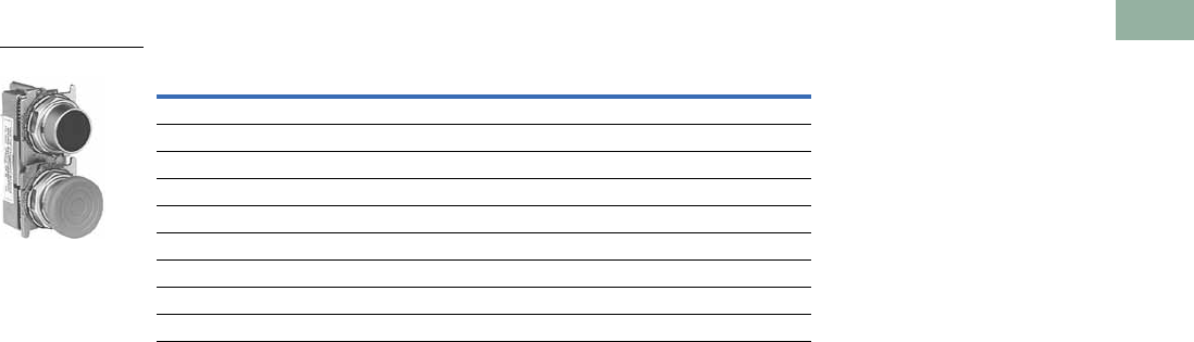
Volume 7—Logic Control, Operator Interface and Connectivity Solutions CA08100008E—March 2014 www.eaton.com V7-T1-189
1
1
1
1
1
1
1
1
1
1
1
1
1
1
1
1
1
1
1
1
1
1
1
1
1
1
1
1
1
1
1.8
Pushbuttons and Indicating Lights
30.5 mm Heavy-Duty Watertight/Oiltight—10250T
UL (NEMA) Type 3, 3R, 4, 4X, 12, 13
Mechanically Interlocked Pushbutton Operators
Note
1 NC contacts must be mounted behind lock-down mushroom head operator to ensure lockout.
Description Catalog Number
Black flush and green flush 10250TA66
Black flush and long red 10250TA67
Black flush and red mushroom head 10250TA68
Black flush and lock-down red mushroom head 10250TA69 1
Black flush and red jumbo mushroom head 10250TA76
Green flush and long red 10250TA72
Black long and long red 10250TA73
Green flush and red mushroom head 10250TA77
Green flush and black flush 10250TA75
10250TA_
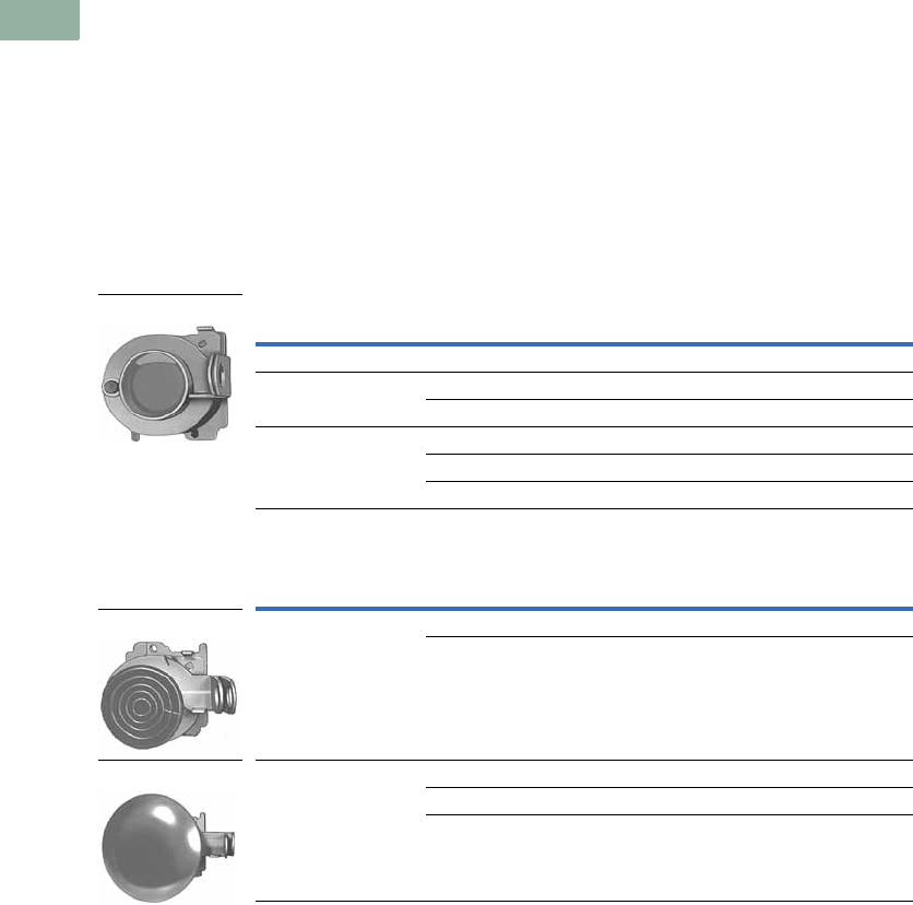
V7-T1-190 Volume 7—Logic Control, Operator Interface and Connectivity Solutions CA08100008E—March 2014 www.eaton.com
1
1
1
1
1
1
1
1
1
1
1
1
1
1
1
1
1
1
1
1
1
1
1
1
1
1
1
1
1
1
1.8
Pushbuttons and Indicating Lights
30.5 mm Heavy-Duty Watertight/Oiltight—10250T
Lockout Pushbutton Operators with Padlock Attachments
UL (NEMA) Type 3, 3R, 4, 4X, 12, 13
The following pushbutton and
mushroom operators include
an integral padlock
attachment for applications
requiring lockout/tagout of
specific machine functions.
They are available in styles
which allow locking of a
button in the down position
(stopped position) or locking a
button in the up position (to
prevent starting). Select the
“Hand” latch type which
functions as a momentary
pushbutton until the operator
presses the button and
moves the padlock
attachment into position for
locking, or choose the
“Spring Loaded” latch type
where the padlock
attachment springs into place
when the button is pressed.
Units accept a customer
supplied 1/4 in padlock.
Padlockable in the Down Position 1
Padlockable in the Up Position 1
Notes
Hand attachment must be manually moved into place for locking. Spring loaded: when operator is pressed—
attachment springs into place. Must be moved manually to release button.
1 Operators can be latched down without a padlock. Padlock not included.
2 Jumbo mushroom heads are not recommended for use in applications where exposure to ultraviolet light exists.
Operator Type Color Latch Type Catalog Number
Flush head Red Hand 10250TA16
Mushroom head Red Hand 10250TA42
Red Spring loaded 10250TA45
Jumbo head 2Red Hand 10250TA52
Red Spring loaded 10250TA55
Red (EMERG. STOP) Spring loaded 10250ED952
Operator Type Color Latch Type Catalog Number
Mushroom head Black Hand 10250TA41
Green Hand 10250TA43
Jumbo mushroom
head 2
Black Hand 10250TA51
Green Hand 10250TA53
Yellow Hand 10250TA54
10250TA16
10250TA4_
10250TA5_
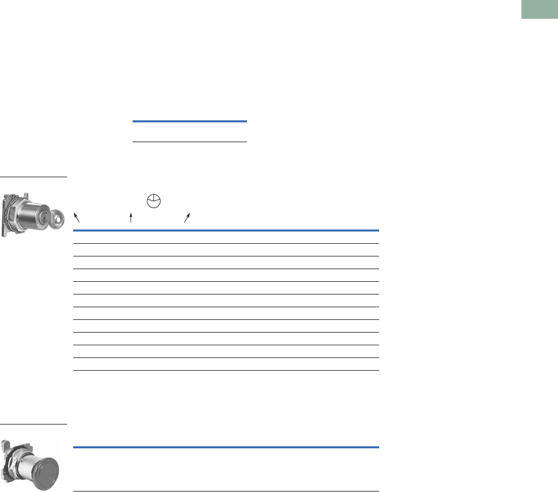
Volume 7—Logic Control, Operator Interface and Connectivity Solutions CA08100008E—March 2014 www.eaton.com V7-T1-191
1
1
1
1
1
1
1
1
1
1
1
1
1
1
1
1
1
1
1
1
1
1
1
1
1
1
1
1
1
1
1.8
Pushbuttons and Indicating Lights
30.5 mm Heavy-Duty Watertight/Oiltight—10250T
Key Pushbutton Operator
UL (NEMA) Type 3, 3R, 4, 4X, 12, 13
These devices incorporate an
integral locking mechanism
which enables locking units in
various positions (Locked
Down), locking units to
prevent operation (Locked
Up) or setting unit to lock
when the button is pressed
(Push to Lock), requiring the
key to be inserted to return to
normal operation. With the
key in the center position,
these operators function as a
normal momentary
pushbutton (Free).
Replacement Keys or Dissimilar Locks for Key Operators Below
Listed operators have
identical locks and keys
(Key Code H661) Catalog
Number 10250ED824. For
dissimilar lock and key
combinations, see listing on
Page V7-T1-212.
Replacement Keys
Key Pushbutton Operator
Latch-In, Twist-to-Release Operator
UL (NEMA) Type 3, 3R, 4, 4X, 12, 13
Operator Only with Button
Note
1 Horizontal mounting available on request.
Description Catalog Number
Replacement keys
(code H661)
10250ED824
Key Position and
Pushbutton Operations
Key Removal
Positions
Vertical Mounting 1
Catalog Number
Three-Position
Lock up Free Lock down All 10250T430
Lock up Free Lock down L and R 10250T431
Lock up Free Lock down C and R 10250T432
Two-Position
Lock up Free — L and C 10250T433
Lock up Free — L 10250T434
— Free Lock down C and R 10250T435
— Free Lock down R 10250T436
— Free Push to lock C and R 10250T437
— Free Push to lock R 10250T438
Description Catalog Number
Latch-in, twist-to-release operator with red mushroom head button 10250ED1043-4
10250T43_
L
C
R
10250ED1043-4
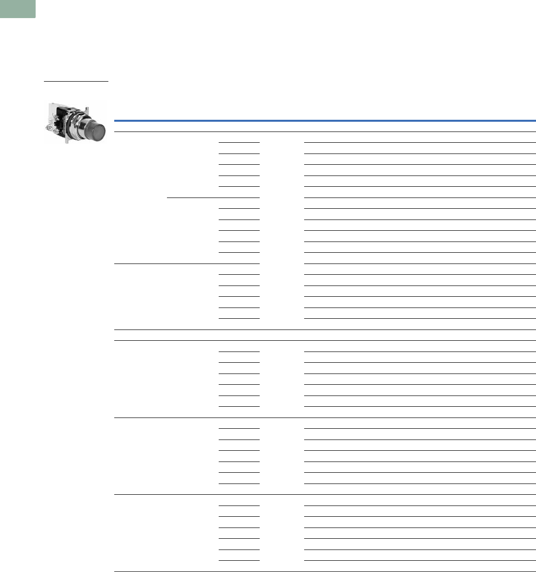
V7-T1-192 Volume 7—Logic Control, Operator Interface and Connectivity Solutions CA08100008E—March 2014 www.eaton.com
1
1
1
1
1
1
1
1
1
1
1
1
1
1
1
1
1
1
1
1
1
1
1
1
1
1
1
1
1
1
1.8
Pushbuttons and Indicating Lights
30.5 mm Heavy-Duty Watertight/Oiltight—10250T
Illuminated Momentary Pushbutton Units
UL (NEMA) Type 3, 3R, 4, 4X, 12, 13
●LED or incandescent
●Full voltage, resistor or transformer type
●Plastic lenses
Illuminated Pushbutton Units
Note
1 For flashing module catalog number 10250TFL1, add suffix code FM to listed catalog number. Example: 10250T75RFM.
Type Voltage Color
LED/Lamp
Number
Illuminated Pushbutton
1NO 1NO-1NC 1NC
Catalog Number Catalog Number Catalog Number
LED Lamp
Full voltage 24 Vac/Vdc Red Bayonet
base
10250T397LRD24-53 10250T397LRD24-1 10250T397LRD24-51
Green 10250T397LGD24-53 10250T397LGD24-1 10250T397LGD24-51
Amber 10250T397LAD24-53 10250T397LAD24-1 10250T397LAD24-51
Yellow 10250T397LYD24-53 10250T397LYD24-1 10250T397LYD24-51
Blue 10250T397LLD24-53 10250T397LLD24-1 10250T397LLD24-51
White 10250T397LWD24-53 10250T397LWD24-1 10250T397LWD24-51
120 Vac/Vdc Red 10250T397LRD2A-53 10250T397LRD2A-1 10250T397LRD2A-51
Green 10250T397LGD2A-53 10250T397LGD2A-1 10250T397LGD2A-51
Amber 10250T397LAD2A-53 10250T397LAD2A-1 10250T397LAD2A-51
Yellow 10250T397LYD2A-53 10250T397LYD2A-2 10250T397LYD2A-51
Blue 10250T397LLD2A-53 10250T397LLD2A-1 10250T397LLD2A-51
White 10250T397LWD2A-53 10250T397LWD2A-1 10250T397LWD2A-51
Transformer 120 Vac Red 10250T411LRD06-53 10250T411LRD06-1 10250T411LRD06-51
Green 10250T411LGD06-53 10250T411LGD06-1 10250T411LGD06-51
Amber 10250T411LAD06-53 10250T411LAD06-1 10250T411LAD06-51
Yellow 10250T411LYD06-53 10250T411LYD06-1 10250T411LYD06-51
Blue 10250T411LLD06-53 10250T411LLD06-1 10250T411LLD06-51
White 10250T411LWD06-53 10250T411LWD06-1 10250T411LWD06-51
Incandescent Lamp
Full voltage 24 Vac/Vdc Red #757 10250T476C21-53 10250T476C21-1 10250T476C21-51
Green 10250T476C22-53 10250T476C22-1 10250T476C22-51
Amber 10250T476C43-53 10250T476C43-1 10250T476C43-51
Yellow 10250T476C23-53 10250T476C23-1 10250T476C23-51
Blue 10250T476C24-53 10250T476C24-1 10250T476C24-51
Clear 10250T476C25-53 10250T476C25-1 10250T476C25-51
White 10250T476C26-53 10250T476C26-1 10250T476C26-51
Resistor 120 Vac/Vdc Red 120MB 10250T471C21-53 10250T471C21-1 10250T471C21-51
Green 10250T471C22-53 10250T471C22-1 10250T471C22-51
Amber 10250T471C43-53 10250T471C43-1 10250T471C43-51
Yellow 10250T471C23-53 10250T471C23-1 10250T471C23-51
Blue 10250T471C24-53 10250T471C24-1 10250T471C24-51
Clear 10250T471C25-53 10250T471C25-1 10250T471C25-51
White 10250T471C26-53 10250T471C26-1 10250T471C26-51
Transformer 120 Vac Red #755 10250T75R 110250T76R 110250T77R 1
Green 10250T75G 110250T76G 110250T77G 1
Amber 10250T75A 110250T76A 110250T77A 1
Yellow 10250T75Y 110250T76Y 110250T77Y 1
Blue 10250T75B 110250T76B 110250T77B 1
Clear 10250T75C 110250T76C 110250T77C 1
White 10250T75W 110250T76W 110250T77W 1
24V Full Voltage
Illuminated Pushbutton
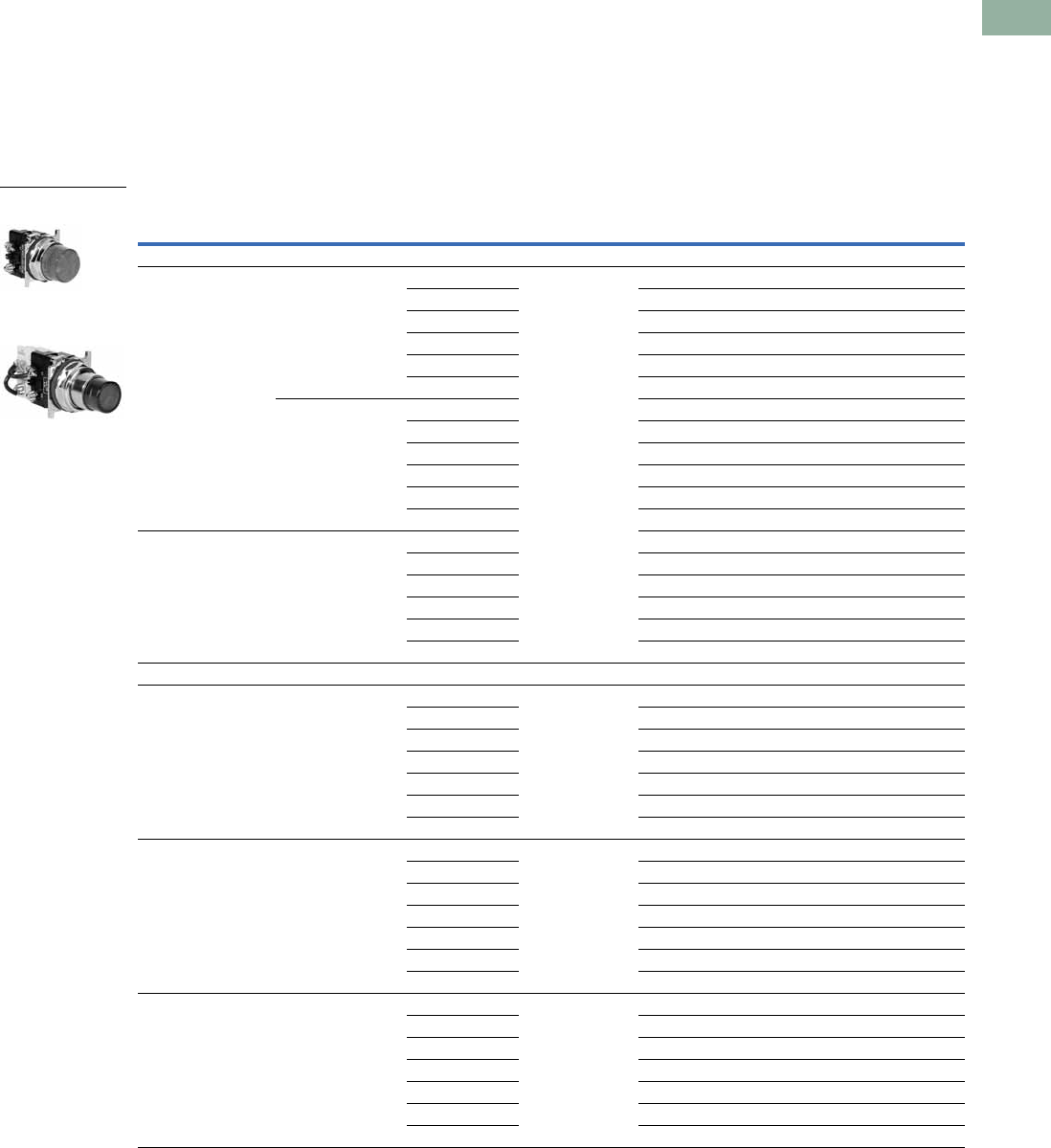
Volume 7—Logic Control, Operator Interface and Connectivity Solutions CA08100008E—March 2014 www.eaton.com V7-T1-193
1
1
1
1
1
1
1
1
1
1
1
1
1
1
1
1
1
1
1
1
1
1
1
1
1
1
1
1
1
1
1.8
Pushbuttons and Indicating Lights
30.5 mm Heavy-Duty Watertight/Oiltight—10250T
Indicating Light Units 1
UL (NEMA) Type 3, 3R, 4, 4X, 12, 13
●LED or incandescent
●Full voltage, resistor or
transformer type
●Standard and PresTest
types
●Plastic lenses
PresTest—This device
incorporates a press-to-test
feature whereby depressing
the lens disconnects the light
from the source being
monitored and connects
the lamp to a continuously
energized circuit for
immediate detection of
faulty lamps.
Indicating Light Units
Notes
1 Standard indicating lights are rated UL (NEMA) 3S as well.
2 For flashing lamp add letter F to listed catalog number. Example: 10250T34RF.
Type Voltage Color
LED/Lamp
Number
Indicating Light
Catalog Number
PresTest
Catalog Number
LED Lamp
Full voltage 24 Vac/Vdc Red Bayonet
base
10250T197LRP24 10250T297LRP24
Green 10250T197LGP24 10250T297LGP24
Amber 10250T197LAP24 10250T297LAP24
Yellow 10250T197LYP24 10250T297LYP24
Blue 10250T197LLP24 10250T297LLP24
White 10250T197LWP24 10250T297LWP24
120 Vac Red 10250T197LRP2A 10250T297LRP2A
Green 10250T197LGP2A 10250T297LGP2A
Amber 10250T197LAP2A 10250T297LAP2A
Yellow 10250T197LYP2A 10250T297LYP2A
Blue 10250T197LLP2A 10250T297LLP2A
White 10250T197LWP2A 10250T297LWP2A
Transformer 120 Vac Red 10250T181LRP06 10250T221LRP06
Green 10250T181LGP06 10250T221LGP06
Amber 10250T181LAP06 10250T221LAP06
Yellow 10250T181LYP06 10250T221LYP06
Blue 10250T181LLP06 10250T221LLP06
White 10250T181LWP06 10250T221LWP06
Incandescent Lamp
Full voltage 24 Vac/Vdc Red #757 10250T206NC1N 10250T235NC21
Green 10250T206NC2N 10250T235NC22
Amber 10250T206NC19N 10250T235NC43
Yellow 10250T206NC3N 10250T235NC23
Blue 10250T206NC4N 10250T235NC24
Clear 10250T206NC5N 10250T235NC25
White 10250T206NC6N 10250T235NC26
Resistor 120 Vac/Vdc Red 120MB 10250T201NC1N 10250T231NC21
Green 10250T201NC2N 10250T231NC22
Amber 10250T201NC19N 10250T231NC43
Yellow 10250T201NC3N 10250T231NC23
Blue 10250T201NC4N 10250T231NC24
Clear 10250T201NC5N 10250T231NC25
White 10250T201NC6N 10250T231NC26
Transformer 2120 Vac Red #755 10250T34R 10250T74NR
Green 10250T34G 10250T74NG
Amber 10250T34A 10250T74NA
Yellow 10250T34Y 10250T74NY
Blue 10250T34B 10250T74NB
Clear 10250T34C 10250T74NC
White 10250T34W 10250T74NW
24V Full Voltage
Illuminated Light
120 Vac Transformer
PresTest

V7-T1-194 Volume 7—Logic Control, Operator Interface and Connectivity Solutions CA08100008E—March 2014 www.eaton.com
1
1
1
1
1
1
1
1
1
1
1
1
1
1
1
1
1
1
1
1
1
1
1
1
1
1
1
1
1
1
1.8
Pushbuttons and Indicating Lights
30.5 mm Heavy-Duty Watertight/Oiltight—10250T
Illuminated Pushbuttons and Indicating Lights
●LED or incandescent
●Full voltage, resistor or transformer type
Operators without Lens
Notes
1 These units do not include lamps. Order LED separately to match lens color. See Page V7-T1-239 for LED Selection and Page V7-T1-185 for Catalog Numbering
System.
2 Resistor units are not available for use with LEDs, choose either transformer or full voltage LED style.
3 For flashing lamp, add letter F to listed catalog number. Example: 10250T181NF.
4 Resistant to shock and vibration. For best illumination use amber, yellow or clear lens.
Type Voltage
LED/Lamp
Number
Illuminated
Pushbutton
Catalog Number
Indicating Light
Catalog Number
PresTest
Catalog Number
Master Test
Catalog Number
Incandescent Unit
Full voltage AC/DC 6 #755 10250T473 10250T203N 10250T232N —
12 #756 10250T474 10250T204N 10250T233N —
24 #757 10250T476 10250T206N 10250T235N —
32 #1828 10250T477 10250T207N 10250T238N —
48 #1835 10250T478 10250T208N 10250T239N —
Resistor AC/DC 2120 120MB 10250T471 10250T201N 10250T231N —
240 120MB 10250T472 10250T202N 10250T240N —
Transformer AC only 324 #755 10250T416 — — —
120 10250T411 10250T181N 10250T221N —
240 10250T422 10250T182N 10250T222N —
277 10250T419 10250T198N — —
380 10250T413 10250T183N 10250T223N —
480 10250T414 10250T184N 10250T224N —
600 10250T415 10250T185N 10250T225N —
Neon AC/DC 4 120 NE51H-R22 — 10250T226N — —
240 NE51H-R68 — 10250T227N — —
Solid-state 50/60 Hz only 120 120MB — — — 10250T189N
LED (LEDs not included) 1
Full voltage — Bayonet
base
10250T397L 10250T197L 10250T297L —
Transformer AC only 24 10250T416L — — —
120 10250T411L 10250T181L 10250T221L —
240 10250T412L 10250T182L 10250T222L —
277 10250T419L 10250T198L — —
380 10250T413L 10250T183L 10250T223L —
480 10250T414L 10250T184L 10250T224L —
600 10250T415L 10250T185L 10250T225L —
Illuminated Pushbutton
Indicating Light
PresTest
Master Test
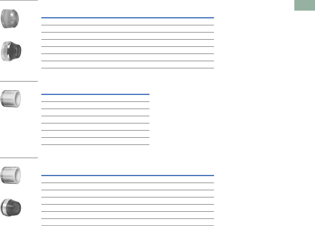
Volume 7—Logic Control, Operator Interface and Connectivity Solutions CA08100008E—March 2014 www.eaton.com V7-T1-195
1
1
1
1
1
1
1
1
1
1
1
1
1
1
1
1
1
1
1
1
1
1
1
1
1
1
1
1
1
1
1.8
Pushbuttons and Indicating Lights
30.5 mm Heavy-Duty Watertight/Oiltight—10250T
Indicating and Master Test Lenses
Illuminated Pushbutton Lenses
PresTest Lenses
Color
Plastic
Catalog Number
Glass
Catalog Number
Red 10250TC1N 10250TC7N
Green 10250TC2N 10250TC8N
Amber 10250TC19N 10250TC9N
Yellow 10250TC3N —
Blue 10250TC4N 10250TC10N
Clear 10250TC5N 10250TC11N
White 10250TC6N 10250TC12N
Color Catalog Number
Red 10250TC21
Green 10250TC22
Yellow 10250TC23
Amber 10250TC43
Blue 10250TC24
Clear 10250TC25
White 10250TC26
Color
Plastic
Catalog Number
Glass
Catalog Number
Red 10250TC21 10250TC13N
Green 10250TC22 10250TC14N
Amber 10250TC43 10250TC15N
Yellow 10250TC23 —
Blue 10250TC24 10250TC16N
Clear 10250TC25 10250TC17N
White 10250TC26 10250TC18N
Plastic
Glass
10250TC2_
Plastic
Glass
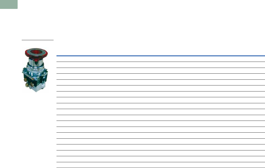
V7-T1-196 Volume 7—Logic Control, Operator Interface and Connectivity Solutions CA08100008E—March 2014 www.eaton.com
1
1
1
1
1
1
1
1
1
1
1
1
1
1
1
1
1
1
1
1
1
1
1
1
1
1
1
1
1
1
1.8
Pushbuttons and Indicating Lights
30.5 mm Heavy-Duty Watertight/Oiltight—10250T
Push-Pull Emergency Stops (Compliant with IEC 60947-5-5)
UL (NEMA) Type 3, 3R, 4, 4X, 12, 13
●Two- and three-position
●Non-illuminated
●LONC contact block
Two-Position Push-Pull Units
Note
1 X = closed circuit, O = open circuit.
Operator Position 1
Button Type/Color Lamp Type Voltage Catalog NumberPull Push
X O 40 mm red—illuminated Incandescent Transformer 120 Vac/Vdc 10250T563C47-71X
X O 40 mm red—illuminated EMERG. STOP Incandescent Transformer 120 Vac/Vdc 10250T563C53-71X
X O 40 mm red—illuminated EMERG. STOP LED Transformer 120 Vac/Vdc 10250T563LED06-71X
X O 40 mm red—illuminated Incandescent Full voltage 24 Vdc 10250T579C47-71X
X O 40 mm red—illuminated EMERG. STOP Incandescent Full voltage 24 Vdc 10250T579C53-71X
X O 40 mm red—illuminated Incandescent Resistor 120 Vac/Vdc 10250T580C47-71X
X O 40 mm red—illuminated EMERG. STOP Incandescent Resistor 120 Vac/Vdc 10250T580C53-71X
X O 40 mm red—illuminated Incandescent Transformer 24 Vac 10250T589C47-71X
X O 40 mm red—illuminated EMERG. STOP Incandescent Transformer 24 Vac 10250T589C53-71X
X O 40 mm red—illuminated EMERG. STOP LED Transformer 24 Vac 10250T589LED06-71X
X O 40 mm red—illuminated LED Transformer 24 Vac 10250T589LRD06-71X
X O 40 mm red—illuminated EMERG. STOP LED Full voltage 24 Vdc 10250T597LED24-71X
X O 40 mm red—illuminated EMERG. STOP LED Full voltage 120 Vac/Vdc 10250T597LED2A-71X
X O 40 mm red—illuminated LED Full voltage 24 Vdc 10250T597LRD24-71X
X O 40 mm red—illuminated LED Full voltage 120 Vac/Vdc 10250T597LRD2A-71X
XO40 mm red ———10250T5B62-71X
X O 40 mm red—EMERG. STOP — — — 10250T5B63-71X
XO65 mm red ———10250T5J62-71X
X O 65 mm red—EMERG. STOP — — — 10250T5J63-71X
10250T579C47-71X
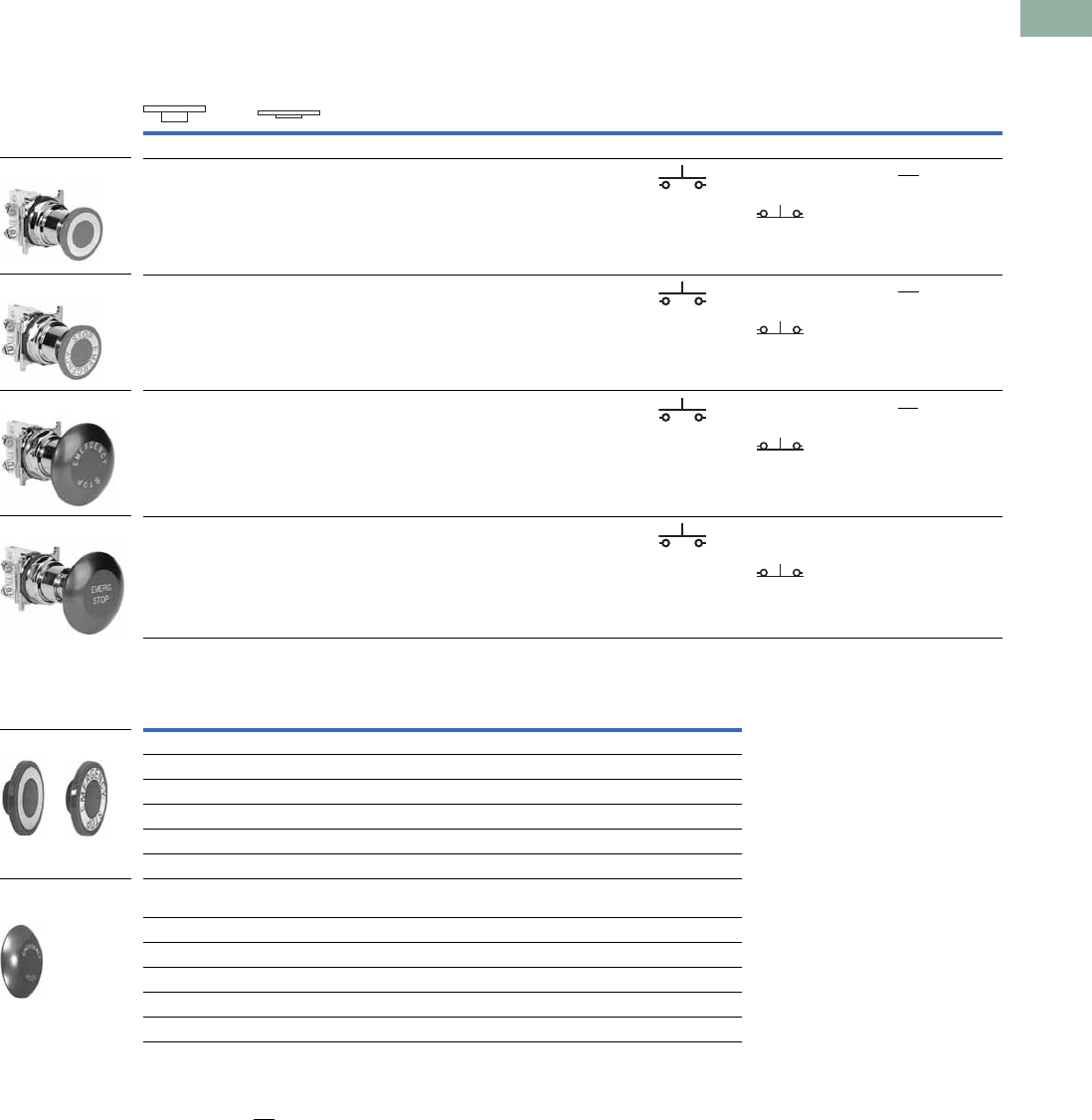
Volume 7—Logic Control, Operator Interface and Connectivity Solutions CA08100008E—March 2014 www.eaton.com V7-T1-197
1
1
1
1
1
1
1
1
1
1
1
1
1
1
1
1
1
1
1
1
1
1
1
1
1
1
1
1
1
1
1.8
Pushbuttons and Indicating Lights
30.5 mm Heavy-Duty Watertight/Oiltight—10250T
UL (NEMA) Type 3, 3R, 4, 4X, 12, 13
Two-Position Push-Pull Units
Button and Color Selection
Notes
1 X = closed circuit, O = open circuit.
2 To order different type or color buttons, substitute the underlined characters with appropriate suffix code from the table.
Example: 10250T5B64-1X.
3 Anodized aluminum head is not suitable for use in ultraviolet light applications.
Operator Position 1
Button Type/Color 2Contact
Type Catalog Number 2
Pull Push Mounting Location
AB
Two-Position Maintained Push, Maintained Pull
O
X
X
O
40 mm/red 1NO 10250T5B62-1X
1NC
O
X
X
O
40 mm engraved
EMERG. STOP/red
1NO 10250T5B63-1X
1NC
O
X
X
O
65 mm aluminum engraved
EMERG. STOP/red
1NO 10250T5J63-1X
1NC
O
X
X
O
65 mm aluminum engraved
EMERG. STOP/red
1NO 10250ED1080-2
Special security
jumbo mushroom head
1NC
Color Suffix Code Catalog Number
Standard—40 mm
Red B62 10250TB62
Red (EMERG. STOP) B63 10250TB63
Green B61 10250TB61
Black B60 10250TB60
Blue B64 10250TB64
Jumbo Mushroom Head 3
(Anodized) Aluminum—65 mm
Red J62 10250TJ62
Red (EMERG. STOP) J63 10250TJ63
Green J61 10250TJ61
Black J60 10250TJ60
Yellow J64 10250TJ64
10250T5B63-1X
10250T5J63-1X
10250T5B62-1X
10250ED1080-2
Standard
Jumbo Mushroom
Head
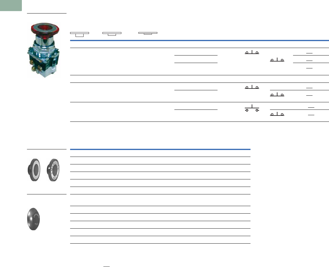
V7-T1-198 Volume 7—Logic Control, Operator Interface and Connectivity Solutions CA08100008E—March 2014 www.eaton.com
1
1
1
1
1
1
1
1
1
1
1
1
1
1
1
1
1
1
1
1
1
1
1
1
1
1
1
1
1
1
1.8
Pushbuttons and Indicating Lights
30.5 mm Heavy-Duty Watertight/Oiltight—10250T
UL (NEMA) Type 3, 3R, 4, 4X, 12, 13
Three-Position Push-Pull Units
Button and Color Selection
Notes
1 X = closed circuit, O = open circuit.
2 To order different type or color buttons, substitute the underlined characters with appropriate suffix code from the table.
Example: 10250T5B64-1X.
3 Anodized aluminum head is not suitable for use in ultraviolet light applications.
Operator Position 1
Button Type/Color 2
Contact
Type Catalog Number 2
Pull Intermediate Push Mounting Location
AB
Maintained Push, Momentary Pull
X
X
O
X
O
O
40 mm/black 1NC 10250T9B60-3X
1NC40 mm/red 10250T9B62-3X
40 mm engraved
EMERG. STOP/red
10250T9B63-3X
Momentary Push, Momentary Pull
X
X
O
X
O
O
40 mm/black 1NC 10250T4B60-3X
1NC40 mm/red 10250T4B62-3X
O
X
O
O
X
O
40 mm/black 1NO 10250T10B60-1X
1NC40 mm/red 10250T10B62-1X
Color Suffix Code Catalog Number
Standard—40 mm
Red B62 10250TB62
Red (EMERG. STOP) B63 10250TB63
Green B61 10250TB61
Black B60 10250TB60
Blue B64 10250TB64
Jumbo Mushroom Head 3
(Anodized) Aluminum—65 mm
Red J62 10250TJ62
Red (EMERG. STOP) J63 10250TJ63
Green J61 10250TJ61
Black J60 10250TJ60
Yellow J64 10250TJ64
10250T_
Standard
Jumbo Mushroom
Head
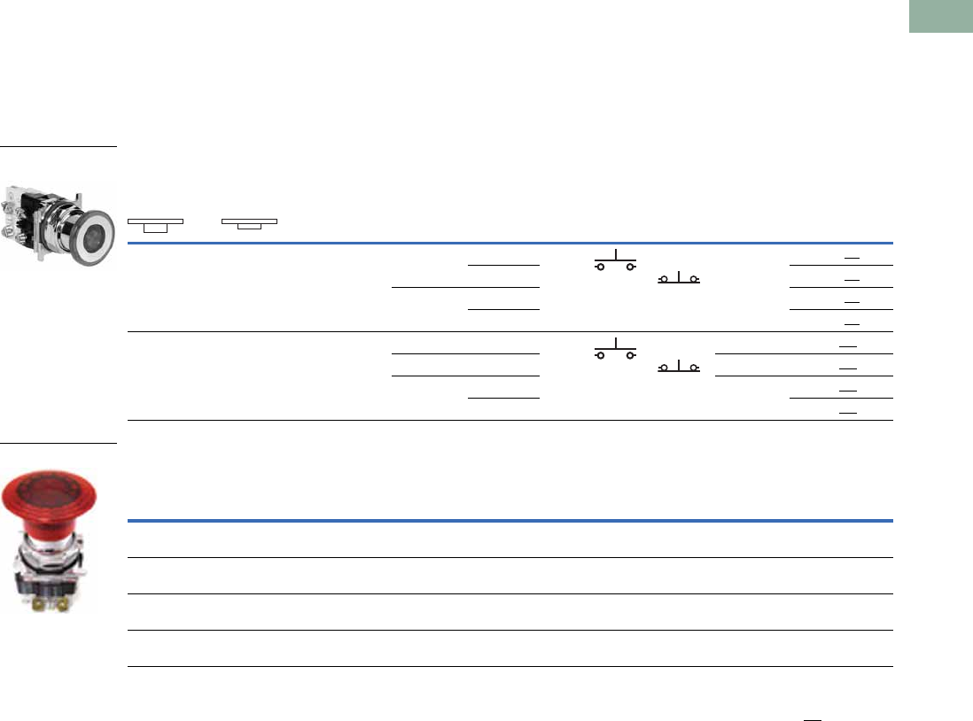
Volume 7—Logic Control, Operator Interface and Connectivity Solutions CA08100008E—March 2014 www.eaton.com V7-T1-199
1
1
1
1
1
1
1
1
1
1
1
1
1
1
1
1
1
1
1
1
1
1
1
1
1
1
1
1
1
1
1.8
Pushbuttons and Indicating Lights
30.5 mm Heavy-Duty Watertight/Oiltight—10250T
Illuminated Push-Pull Units
UL (NEMA) Type 3, 3R, 4, 4X, 12, 13
●LED or incandescent
●Full voltage, resistor or transformer type
●Two-position maintained
Two-Position Illuminated Maintained Push, Maintained Pull
Jumbo Lens Illuminated E-Stops
Notes
1 X = closed circuit, O = open circuit.
2 To order different type or color lens, substitute the underlined characters with appropriate suffix code from table on next page. Example: 10250T579C63-1X.
For LEDs with different voltages see ordering example on Page V7-T1-205.
Operator Position 1
Lamp Type Voltage
Contact
Type
LED/Lamp
Number
Red Standard
Push-Pull
Catalog Number 2
Maintained—
Pull
Maintained—
Push Mounting Location
AB
O
X
X
O
LED Full Voltage 24 Vac/Vdc 1NO Bayonet
base
10250T597LRD24-1X
1NC120 Vac/Vdc 10250T597LRD2A-1X
Transformer 24 Vac 10250T589LRD06-1X
120 Vac 10250T563LRD06-1X
O
X
X
O
Incandescent Full voltage 24 Vac/Vdc 1NO #757 10250T579C47-1X
1NCResistor 120 Vac/Vdc 120MB 10250T580C47-1X
Transformer 24 Vac #755 10250T589C47-1X
120 Vac 10250T563C47-1X
Lamp Button Type/Color Type Voltage
Contact
Type Catalog Number
LED Two-position illuminated maintained push/pull—
50 mm jumbo lens/red
Full voltage 24 Vac/Vdc 1NO
1NC
10250ED1375
LED Three-position illuminated momentary push/pull—
50 mm jumbo lens/red
Full voltage 24 Vac/Vdc 1NC
1NC
10250ED1376
LED Three-position illuminated momentary push/pull—
50 mm jumbo lens/red
Full voltage 24 Vac/Vdc 1NO
1NC
10250ED1377
LED Three-position illuminated maintained push/momentary pull—
50 mm lens/red
Full voltage 1NO
1NC
10250ED1378
Two-Position Push-
Pull Operator
10250ED137_
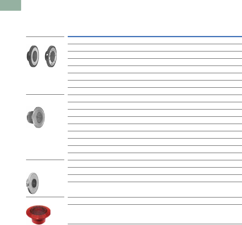
V7-T1-200 Volume 7—Logic Control, Operator Interface and Connectivity Solutions CA08100008E—March 2014 www.eaton.com
1
1
1
1
1
1
1
1
1
1
1
1
1
1
1
1
1
1
1
1
1
1
1
1
1
1
1
1
1
1
1.8
Pushbuttons and Indicating Lights
30.5 mm Heavy-Duty Watertight/Oiltight—10250T
UL (NEMA) Type 3, 3R, 4, 4X, 12, 13
Lens and Color Selection
Note
1 Clear anodized aluminum and colored lens.
Color
Incandescent
Suffix Code
LED
Suffix Code Catalog Number
Standard—40 mm
Red C47 RD 10250TC47
Red (EMERG. STOP) C53 ED 10250TC53
Green C48 GD 10250TC48
Blue C49 LD 10250TC49
Amber C50 AD 10250TC50
White C51 WD 10250TC51
Clear C52 CD 10250TC52
Side-Lighted Aluminum—40 mm 1
Red C57 RS 10250TC57
Red (EMERG. STOP) C63 ES 10250TC63
Green C58 GS 10250TC58
Blue C59 LS 10250TC59
Amber C64 AS 10250TC64
Yellow C60 YS 10250TC60
White C61 WS 10250TC61
Clear C62 CS 10250TC62
Aluminum Transparent Center—40 mm 1
Red C65 RH 10250TC65
Green C66 GH 10250TC66
Amber C67 AH 10250TC67
Jumbo Lens—50 mm
Red — — 10250TC77
Standard
Side-Lighted
Aluminum
Aluminum Transparent
Center
Jumbo Lens
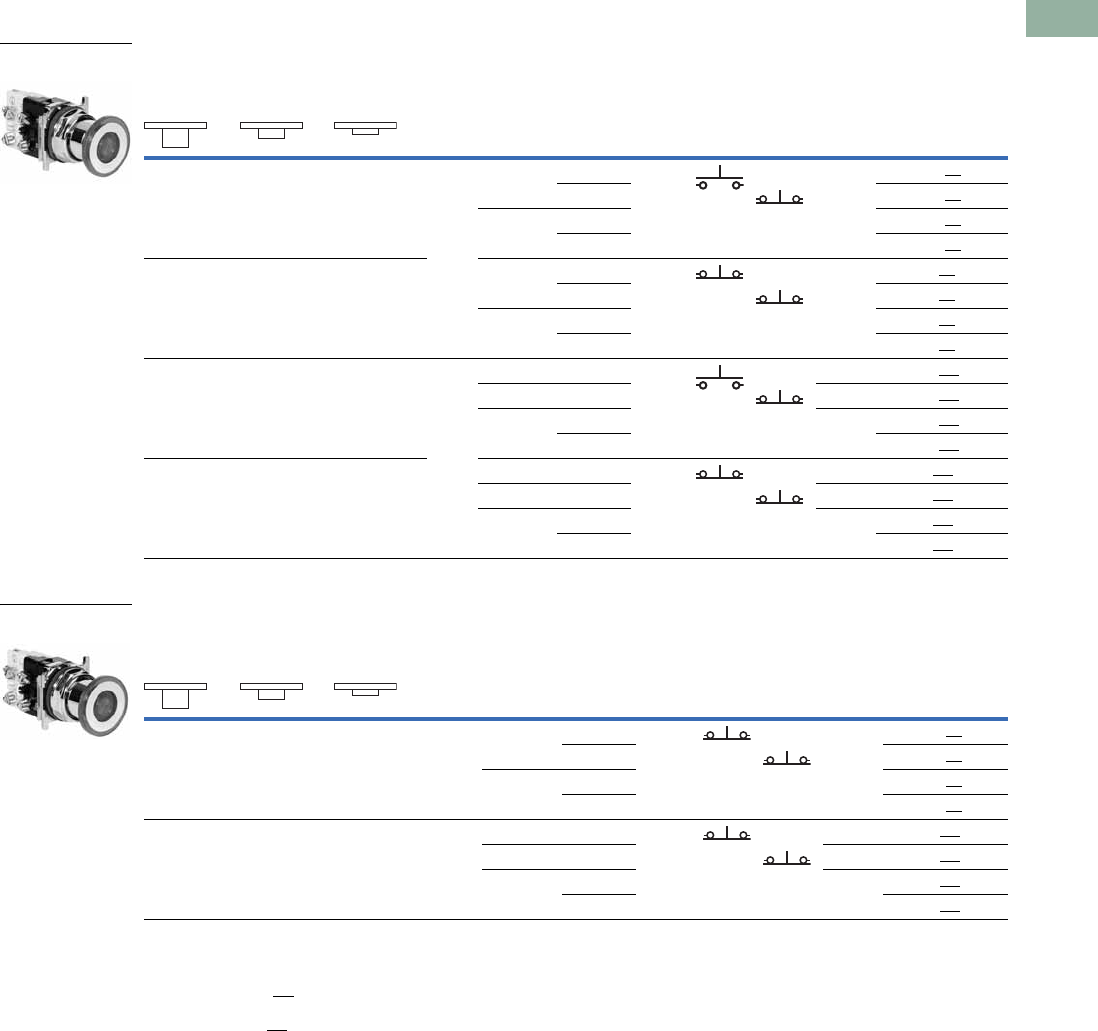
Volume 7—Logic Control, Operator Interface and Connectivity Solutions CA08100008E—March 2014 www.eaton.com V7-T1-201
1
1
1
1
1
1
1
1
1
1
1
1
1
1
1
1
1
1
1
1
1
1
1
1
1
1
1
1
1
1
1.8
Pushbuttons and Indicating Lights
30.5 mm Heavy-Duty Watertight/Oiltight—10250T
UL (NEMA) Type 3, 3R, 4, 4X, 12, 13
Three-Position Illuminated Momentary Push, Momentary Pull
Three-Position Illuminated Maintained Push, Momentary Pull
Notes
1 X = closed circuit, O = open circuit.
2 To order different type or color lens, substitute the underlined characters with appropriate suffix code from table on Page V7-T1-200.
Example: 10250T1079C53-1X. For LEDs with different voltages see ordering example on Page V7-T1-205.
3 To order different type or color lens, substitute the underlined characters with appropriate suffix code from table on Page V7-T1-200.
Example: 10250T979C53X. For LEDs with different voltages see ordering example on Page V7-T1-205.
Operator Position 1
Lamp Type Voltage
Contact
Type
LED/
Lamp
Number
Red Standard
Push-Pull
Catalog Number 3
Momentary—
Pull
Maintained—
Intermediate
Momentary—
Push Mounting Location
AB
O
X
O
O
X
O
LED Full voltage 24 Vac/Vdc 1NO Bayonet
base
10250T1097LRD24-1X
1NC120 Vac 10250T1097LRD2A-1X
Transformer 24 Vac 10250T1089LRD06-1X
120 Vac 10250T1063LRD06-1X
X
X
O
X
O
O
Full voltage 24 Vac/Vdc 1NC Bayonet
base
10250T497LRD24-3X
1NC120 Vac 10250T497LRD2A-3X
Transformer 24 Vac 10250T489LRD06-3X
120 Vac 10250T463LRD06-3X
O
X
O
O
X
O
Incan-
descent
Full voltage 24 Vac/Vdc 1NO #757 10250T1079C47-1X
1NCResistor 120 Vac 120MB 10250T1080C47-1X
Transformer 24 Vac #755 10250T1089C47-1X
120 Vac 10250T1063C47-1X
X
X
O
X
O
O
Full voltage 24 Vac/Vdc 1NC #757 10250T479C47-3X
1NCResistor 120 Vac 120MB 10250T480C47-3X
Transformer 24 Vac #755 10250T489C47-3X
120 Vac 10250T463C47-3X
Operator Position 1
Lamp Type Voltage
Contact
Type
LED/
Lamp
Number
Red Standard
Push-Pull
Catalog Number 2
Momentary—
Pull
Maintained—
Intermediate
Momentary—
Push Mounting Location
AB
X
X
O
X
O
O
LED Full voltage 24 Vac/Vdc 1NC Bayonet
base
10250T997LRD24-3X
1NC120 Vac 10250T997LRD2A-3X
Transformer 24 Vac 10250T989LRD06-3X
120 Vac 10250T963LRD06-3X
X
X
O
X
O
O
Incan-
descent
Full voltage 24 Vac/Vdc 1NC #757 10250T979C47-3X
1NCResistor 120 Vac 120MB 10250T980C47-3X
Transformer 24 Vac #755 10250T989C47-3X
120 Vac 10250T963C47-3X
Three-Position Push-
Pull Operator
Three-Position Push-
Pull Operator
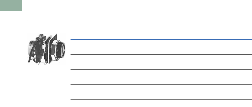
V7-T1-202 Volume 7—Logic Control, Operator Interface and Connectivity Solutions CA08100008E—March 2014 www.eaton.com
1
1
1
1
1
1
1
1
1
1
1
1
1
1
1
1
1
1
1
1
1
1
1
1
1
1
1
1
1
1
1.8
Pushbuttons and Indicating Lights
30.5 mm Heavy-Duty Watertight/Oiltight—10250T
Potentiometers
UL (NEMA) Type 3, 3R, 4, 12, 13
Potentiometer with Knob and Standard Dial Plate—Linear Type ±10%
Notes
1 Shown with standard aluminum dial plate.
2 Large dial plate with space for legend is available at no charge. To order, add suffix 36 to catalog number.
Example: 10250T33136. To order separately, see footnote 3 below.
3 Large dial plate has space at top for 15 letters. 3/32 in high. For custom stamped legend plates,
order legend plate as separate item 10250TR30 and specify stamping.
4 For use with commercially purchased potentiometers having shaft dimensions per dimension drawing
on Page V7-T1-249.
Potentiometer
Ohms Catalog Number
2 Watt (60V Max.) Single Potentiometer with Standard Aluminum Dial Plate 23
1000 10250T331
2500 10250T332
5000 10250T338
10000 10250T333
25000 10250T334
50000 10250T335
Operator only 410250T330
Alternative—black plastic large legend with standard markings E34LP99
Vertical or Horizontal 1
One-Hole Mounting
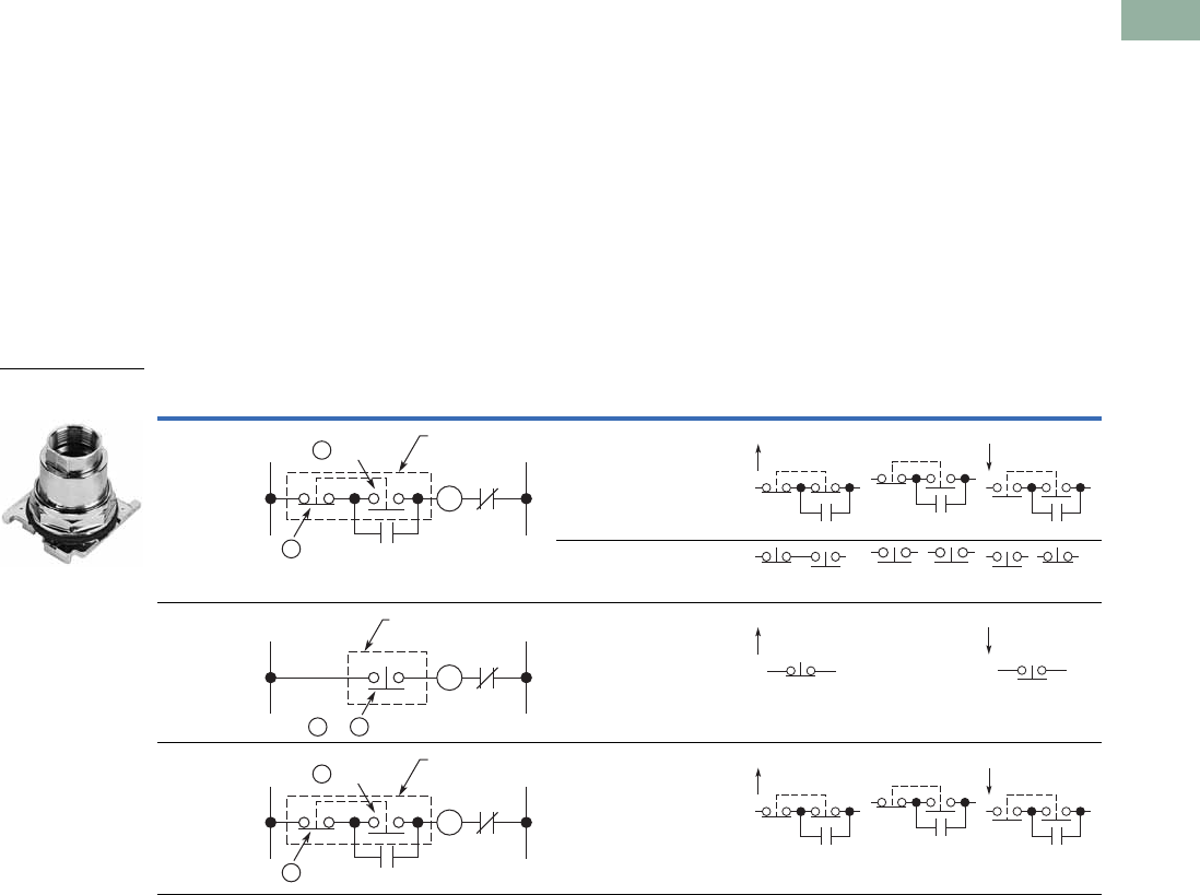
Volume 7—Logic Control, Operator Interface and Connectivity Solutions CA08100008E—March 2014 www.eaton.com V7-T1-203
1
1
1
1
1
1
1
1
1
1
1
1
1
1
1
1
1
1
1
1
1
1
1
1
1
1
1
1
1
1
1.8
Pushbuttons and Indicating Lights
30.5 mm Heavy-Duty Watertight/Oiltight—10250T
Push-Pull Operators
An illuminated push-pull
pushbutton unit, arranged for
one-hole mounting, can
replace two pushbuttons and
a pilot light or the non-
illuminated form can replace
two pushbuttons. These units
are available in three basic
types:
●Maintained—(Two-
position). Maintains in the
pulled or pushed position
until manually actuated to
the opposite mode.
●Momentary—(Three-
position). Spring returns to
an intermediate position
when pulled or pushed and
released.
●Momentary Pull,
Maintained Push—(Three-
position). Spring returns to
intermediate position
when pulled. Maintains in
pushed position until
manually returned to
intermediate (ready to
reset) position. Maintained
stop holds circuit open and
will prevent other series
connected operators from
starting the system.
The operators, buttons,
contact blocks, etc., are
offered as building block
components that can be
intermixed to satisfy many
requirements. This minimizes
the need for a varied and
costly inventory.
Typical Applications
Notes
A and B circuits shown in the application illustrations are defined in the “Application Guide” on the following page.
1 Shown without button on lens.
Control Line—Diagram Operator Circuits Operator Mode
Three-wire
three-position
momentary
Momentary
push and pull
10250T4
2NC
contact block
10250T3
START (mom.) Normal pos.
(maint.)
STOP (mom.)
Momentary
push and pull
10250T10
1NO-1NC
contact block
10250T1
Two-wire
two-position
maintained
Maintained
push and pull
10250T5
1NC
contact block
10250T51
START (maint.) No
intermediate
position
STOP (maint.)
Three-wire
momentary pull
maintained push
Maintained
push and
momentary
pull
10250T9
2NC
contact block
10250T3
START (mom.) Normal pos.
(maint.)
STOP (maint.)
Two-Position
Maintained Push-Pull 1
M
L2L1
OL
M
B Circuit
ACircuit Push-Pull
Operator
M
L2L1
OL
B Circuitor
A
Push-Pull
Operator
M
L2L1
OL
M
B Circuit
ACircuit Push-Pull
Operator
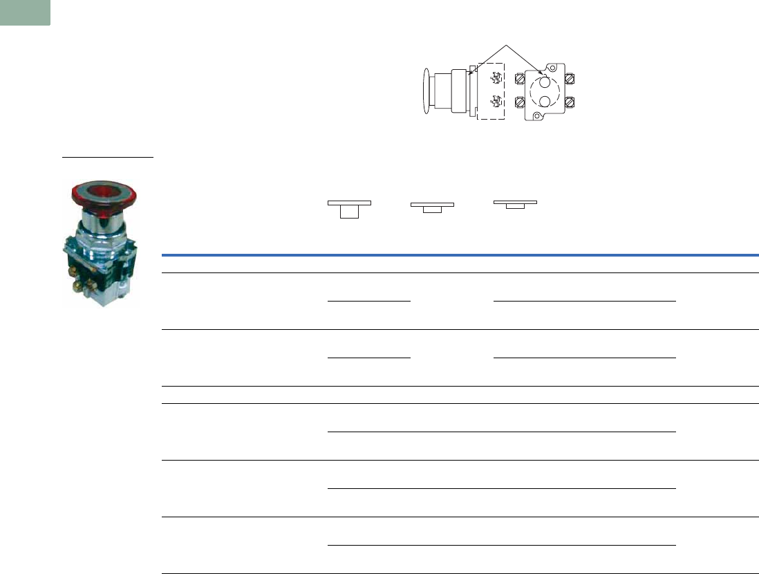
V7-T1-204 Volume 7—Logic Control, Operator Interface and Connectivity Solutions CA08100008E—March 2014 www.eaton.com
1
1
1
1
1
1
1
1
1
1
1
1
1
1
1
1
1
1
1
1
1
1
1
1
1
1
1
1
1
1
1.8
Pushbuttons and Indicating Lights
30.5 mm Heavy-Duty Watertight/Oiltight—10250T
Application Guide
To assist in the selection of
contact blocks, the sketch to
the right shows pictorially by
symbols A and B locations of
contact circuits after
assembly of contact blocks
and adapter to the operator.
The table below shows the
effect of the push and pull
operations on either NO or
NC contacts. (X = contact
closed, O = contact open).
Contact Circuit Locations
Push-Pull Operator Components
Note
1 Maximum of two blocks, four circuits. Special function contact blocks shown on Page V7-T1-235 CANNOT be used with three-position push-pull operators 10250T4,
10250T9 or 10250T10.
Locating Nib
A
B
Type of Operator
Operator Position and Circuit Arrangement
Contact Block 1Catalog Number
Out—Pull Intermediate In—Push
Contact Block Mounting Location
ABABAB
Two-Position Operator without Lens
Maintained push-pull O
Xor O
X
No intermediate
position
X
Oor X
O
1NO
1NC
10250T5
O
X
O
X
X
O
X
O
2NO
2NC
Maintained push-pull with
anti-theft jumbo mushroom
O
Xor O
X
No intermediate
position
X
Oor X
O
1NO
1NC
10250ED1080
O
X
O
X
X
O
X
O
2NO
2NC
Three-Position Operator without Lens
Momentary push-pull O
Xor O
X
O
Oor O
X
X
Oor O
O
1NO
1NC
10250T4 1
O
X
O
X
O
O
O
X
X
O
O
O
2NO
2NC
Maintained push-momentary pull O
Xor O
X
O
Oor O
X
X
Oor O
O
1NO
1NC
10250T9 1
O
X
O
X
O
O
O
X
X
O
O
O
2NO
2NC
Momentary push-pull O
Xor O
X
O
Oor O
O
X
Oor X
O
1NO
1NC
10250T10 1
O
X
O
X
O
O
O
O
X
O
X
O
2NO
2ND
10250T579C47-71X
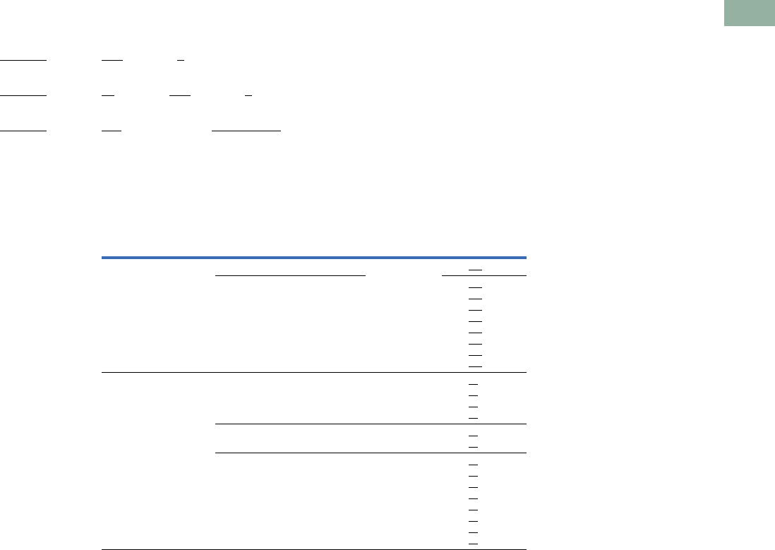
Volume 7—Logic Control, Operator Interface and Connectivity Solutions CA08100008E—March 2014 www.eaton.com V7-T1-205
1
1
1
1
1
1
1
1
1
1
1
1
1
1
1
1
1
1
1
1
1
1
1
1
1
1
1
1
1
1
1.8
Pushbuttons and Indicating Lights
30.5 mm Heavy-Duty Watertight/Oiltight—10250T
Push-Pull Light Units, Lenses and Buttons
Ordering Example with One Composite Number
Non-illuminated:
10250T5 + 10250TB62 + 10250T1 = 10250T5B62-1X
Incandescent:
10250T5 + 10250T79 + 10250TC47 + 10250T1 = 10250T579C47-1X
LED:
10250T5 + 10250T97L + 10250TC47 + Voltage code + 10250T1 = 10250T597LRD24-1X
06—6 Vac/Vdc
12—12 Vac/Vdc
24—24 Vac/Vdc
48—48 Vac/Vdc
60—60 Vac/Vdc
2A—120 Vac
2D—120 Vdc
Light Units for Illuminated Push-Pull Devices
Note
1 These units do not include lamps. Order LED separately to match lens color, see Page V7-T1-239.
Light Unit
Type Type Voltage
LED/Lamp
Number Catalog Number
LED
(LEDs not included) 1Full voltage — Bayonet
base
10250T97L
Transformer
AC only
50/60 Hz
24
120
208
240
277
380
480
600
10250T89L
10250T63L
10250T64L
10250T65L
10250T82L
10250T66L
10250T67L
10250T68L
Incandescent Full voltage
AC or DC
6
12
24/28
32
10250T69
10250T70
10250T79
10250T83
Resistor
AC or DC
120
240
120MB 10250T80
10250T81
Transformer
AC only
50/60 Hz
24
120
208
240
277
380
480
600
#755 10250T89
10250T63
10250T64
10250T65
10250T82
10250T66
10250T67
10250T68
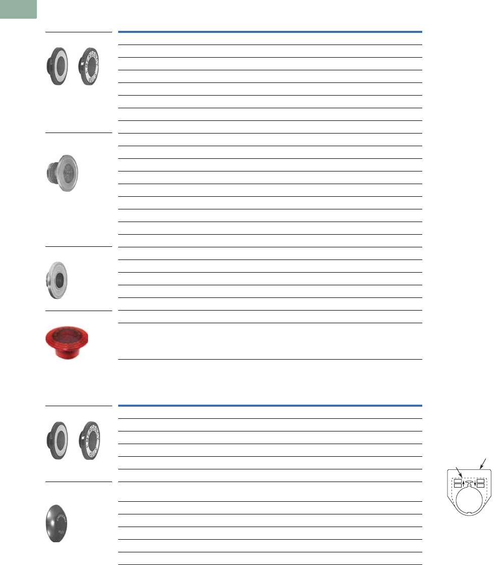
V7-T1-206 Volume 7—Logic Control, Operator Interface and Connectivity Solutions CA08100008E—March 2014 www.eaton.com
1
1
1
1
1
1
1
1
1
1
1
1
1
1
1
1
1
1
1
1
1
1
1
1
1
1
1
1
1
1
1.8
Pushbuttons and Indicating Lights
30.5 mm Heavy-Duty Watertight/Oiltight—10250T
Alternate Lenses for Illuminated Push-Pull Devices
Buttons for Non-Illuminated Push-Pull Devices
Notes
1 Suffix codes should only be used for assembling composite catalog numbers. To order lens above, order by catalog number.
2 Anodized aluminum head is not suitable for use in ultraviolet light applications.
Lens Color
Incandescent
Suffix Code
LED
Suffix Code 1Catalog Number
Standard
Red C47 RD 10250TC47
Red (EMERG. STOP) C53 ED 10250TC53
Green C48 GD 10250TC48
Blue C49 LD 10250TC49
Amber C50 AD 10250TC50
White C51 WD 10250TC51
Clear C52 CD 10250TC52
Side-Lighted Anodized Aluminum Ring
Red C57 RS 10250TC57
Red (EMERG. STOP) C63 ES 10250TC63
Green C58 GS 10250TC58
Blue C59 LS 10250TC59
Amber C64 AS 10250TC64
Yellow C60 YS 10250TC60
White C61 WS 10250TC61
Clear C62 CS 10250TC62
Heavy-Duty Aluminum with Transparent Center
Red C65 RH 10250TC65
Green C66 GH 10250TC66
Amber C67 AH 10250TC67
White C68 — 10250TC68
Jumbo Lens—50 mm
Red — — 10250TC77
Color Suffix Code Catalog Number Legend Plates
For a complete listing
of available legend plates
see Pages V7-T1-230 to
V7-T1-232.
Standard
Red B62 10250TB62
Red (EMERG. STOP) B63 10250TB63
Green B61 10250TB61
Black B60 10250TB60
Blue B64 10250TB64
Jumbo Mushroom Head 2
(Anodized) Aluminum
Red J62 10250TJ62
Red (EMERG. STOP) J63 10250TJ63
Green J61 10250TJ61
Black J60 10250TJ60
Yellow J64 10250TJ64
Standard
Side-Lighted Anodized
Aluminum Ring
Heavy-Duty Aluminum
Jumbo Lens
Standard
Jumbo Mushroom
Head
Standard
Jumbo
P
S
R
T
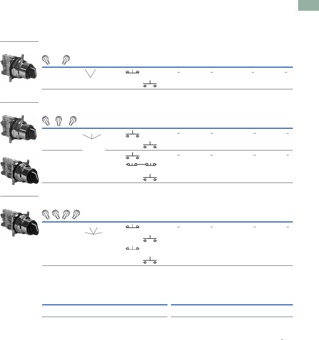
Volume 7—Logic Control, Operator Interface and Connectivity Solutions CA08100008E—March 2014 www.eaton.com V7-T1-207
1
1
1
1
1
1
1
1
1
1
1
1
1
1
1
1
1
1
1
1
1
1
1
1
1
1
1
1
1
1
1.8
Pushbuttons and Indicating Lights
30.5 mm Heavy-Duty Watertight/Oiltight—10250T
Selector Switch Units
UL (NEMA) Type 3, 3R, 4, 4X, 12, 13
●Two-, three- and four-position maintained
●Non-illuminated and illuminated
Two-Position Selector Switch
Three-Position Selector Switch
Four-Position Selector Switch
Color Selection
Notes
1 X = closed circuit, O = open circuit.
2 M = Maintained.
3 To order different type or color selector switch, substitute the underlined character with appropriate suffix code from the Color Selection table. Example: 10250T20KG.
Operator Position 1
Operator
Action 2
Contact
Type
Non-Illuminated Illuminated—120V Transformer
Mounting Location Black Knob
Catalog Number 3
Black Lever
Catalog Number 3
Red Knob
Catalog Number 3
Red Lever
Catalog Number 3
AB
XO 1NC 10250T20KB 10250T20LB 10250ED1117-KR 10250ED1117-LR
OX 1NO
Operator Position 1
Operator
Action 2
Contact
Type
Non-Illuminated Illuminated—120V Transformer
Mounting Location Black Knob
Catalog Number 3
Black Lever
Catalog Number 3
Red Knob
Catalog Number 3
Red Lever
Catalog Number 3
AB
XOO 1NO 10250T21KB 10250T21LB 10250ED1117-2KR 10250ED1117-2LR
OOX 1NO
XOO 1NO 10250T22KB 10250T22LB 10250ED1117-3KR 10250ED1117-3LR
O X O 2NC (Series)
OOX 1NO
Operator Position 1
Operator
Action 2
Contact
Type
Non-Illuminated Illuminated—120V Transformer
Mounting Location Black Knob
Catalog Number 3
Black Lever
Catalog Number 3
Red Knob
Catalog Number 3
Red Lever
Catalog Number 3
AB
XOOO 1NC 10250T46KB 10250T46LB 10250ED1117-4KR 10250ED1117-4LR
OXOO 1NO
OOXO 1NO
OOOX 1NC
Illuminated Non-Illuminated
Color
Code
Letter Color
Code
Letter Color
Code
Letter Color
Code
Letter Color
Code
Letter Color
Code
Letter
Red
Green
R
G
White
Blue
W
B
Amber
Clear
A
C
Black
Red
B
R
Green
White
G
W
Blue
Orange
L
O
Two-Position
Maintained Switch
MM
Three-Position
Maintained Switch
Three-Position
Maintained Switch
MM
M
Three-Position
Maintained Switch
MM
MM
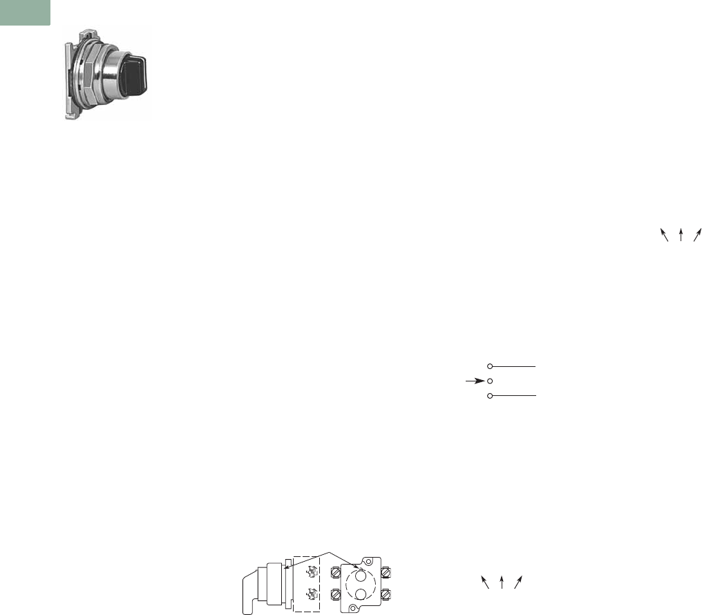
V7-T1-208 Volume 7—Logic Control, Operator Interface and Connectivity Solutions CA08100008E—March 2014 www.eaton.com
1
1
1
1
1
1
1
1
1
1
1
1
1
1
1
1
1
1
1
1
1
1
1
1
1
1
1
1
1
1
1.8
Pushbuttons and Indicating Lights
30.5 mm Heavy-Duty Watertight/Oiltight—10250T
Selector Switch Selection
Cam and Contact Block Selection
Selector switches in their
varied forms (two-position,
three-position and four-
position) are a big factor
contributing to the great
flexibility of control that a well
rounded line of “pushbuttons”
can achieve. Because of their
flexibility, they tend to cause
difficulty with product
selection and application.
The following systematic
approach should simplify
that task.
Cam and contact block
selection is better understood
if you:
●Work with each incoming
and outgoing wire/circuit
separately.
●Recognize the terms NO
and NC only identify the
type of contact by its mode
before mounting to the
operator. The “X-O” table
(Page V7-T1-210) shows
how that contact will act
after assembly to the
operator with the selected
cam shape. X = closed
circuit, O = open circuit.
●Up to six NO or NC
contacts may be mounted
behind each plunger
location for a total of
twelve contacts. Single
circuit contact blocks have
only one plunger with the
other side of the block
“open.” Therefore, single
circuit contact blocks
transmit motion to blocks
behind them only for the
position containing the
circuit.
●Each cam has two
separate lobes, each of
which operates one of the
two contact block plungers
independently of each
other. Those are identified
as position A (locating nib
side) and position B
(opposite of locating nib).
The position designations
give direction in selecting
and mounting of the
contact blocks.
Contact Circuit Locations
Locating Nib
A
B
Systematic Approach
Application: HAND-OFF-
AUTO selector switch. In this
circuit, one incoming line is
distributed to two other
outgoing circuits by the
switch. The two circuits can
be looked at individually.
Step 1: Elementary
Diagram.
Construct on paper, or in your
mind, a simple elementary
diagram of the switching
scheme as follows:
Step 2: “X-O” Pattern.
From the elementary
diagram, you can construct an
“X-O” diagram which
describes when the contacts
are to be closed (X) or open
(O) in the various positions of
the switch. The “X-O” for the
HAND circuit looks like this:
In this circuit, you want a
contact closed on the left
(HAND) but open in the
center and right.
For the AUTO circuit, the
“X-O” diagram would look like
this:
Putting them together, the
complete “X-O” diagram is:
Once the “X-O” diagram has
been generated the next step
is to select the cam and
contact block, or blocks,
needed to perform the
desired “X-O” functions.
The selection tables on the
following pages list the
various types (shapes) of
cams by number to choose
from and the type of contact
and position to achieve the
function outlined in your
“X-O” diagram.
OFF
HAND Outgoing
Circuit
AUTO
Outgoing
Circuit
Incoming
Line
HAND OFF AUTO
XOO
HAND OFF AUTO
OOX
X O O
O O X
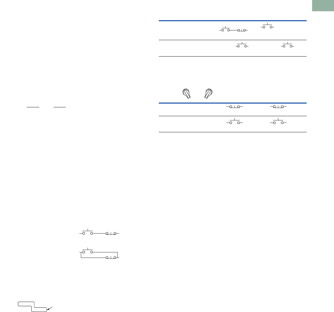
Volume 7—Logic Control, Operator Interface and Connectivity Solutions CA08100008E—March 2014 www.eaton.com V7-T1-209
1
1
1
1
1
1
1
1
1
1
1
1
1
1
1
1
1
1
1
1
1
1
1
1
1
1
1
1
1
1
1.8
Pushbuttons and Indicating Lights
30.5 mm Heavy-Duty Watertight/Oiltight—10250T
Step 3: Cam Selection.
The cam you select
determines the operation of
all contact blocks mounted to
the operator. It is selected on
the basis that it provides the
simplest circuitry for the
desired “X-O” diagram. The
selection tables show all the
“X-O” combinations. For the
purpose of this example, the
applicable portion of those
tables is shown on this page.
Now to make the cam
selection, make a simple
worksheet such as:
It becomes immediately
obvious that cam 3 is the
better choice for two
reasons, (1) the series
combination can be avoided
making it simpler to wire, (2)
only two contacts are
required, which is less
expensive than the three
contacts required by cam 2.
Step 4: Contact Block
Selection.
Having selected the cam,
contact block selection is
simply a matter of gathering
the A position and B position
circuits into pairs which make
up the most convenient contact
block arrangement. If there is
an imbalance in the number of
circuits under A or B, then
single circuit blocks must be
selected for these leftover
circuits.
Back to the worksheet,
having selected cam 3 do
this:
Step 5: Selector Switch
Operator.
Lastly, you have to choose
from the many types of
operators—knob and lever
in various colors or keyed.
Also what combinations of
maintained and spring
return functions are
required. Selection of these
operators can be found on
Page V7-T1-212. For the
example in step 4 you may
want a three-position
maintained black knob,
cam 3—Catalog Number
10250T1323.
The Complete Switch:
10250T1323 with one
10250T2 or, for one
composite catalog number,
10250T21KB found on
Page V7-T1-207.
Diagrams
Circuits shown illustrate
connections to obtain a
selector switch circuit
combination and are shown
with their appropriate line
diagrams. Field wiring of
jumper connections required
as shown.
X = Closed circuit
O = Open circuit
Wiring of Jumper
Connections
Four-position selector
switches are limited to four
contact blocks.
Contact Blocks
For selection and number
of available contact blocks
per operator, see Pages
V7-T1-235 to V7-T1-238.
Cam 2 Cam 3
X O O
O O X
(A)NO-(B)NC
(B)NO
(A)NO
(B)NO
X O X
O O X
ANO
BNO 10250T2
Parallel Connection
Series Connection
Example Selection Table
Two-Position Selector Switch Contact Block Selection
Note
1Wired in series.
No. “X-O” Pattern
Cam Code #2 Cam Code #3
Top A Bottom B Top A Bottom B
1XOO
NO NC NO
—
4 OOX—
NO
—
NO
No.
Desired Circuit and
Operator Position
Contact Blocks Required to
Accomplish Circuit Function
Top Plunger A Bottom Plunger B
1XO
NC or NC
2OX
NO
or
NO
a
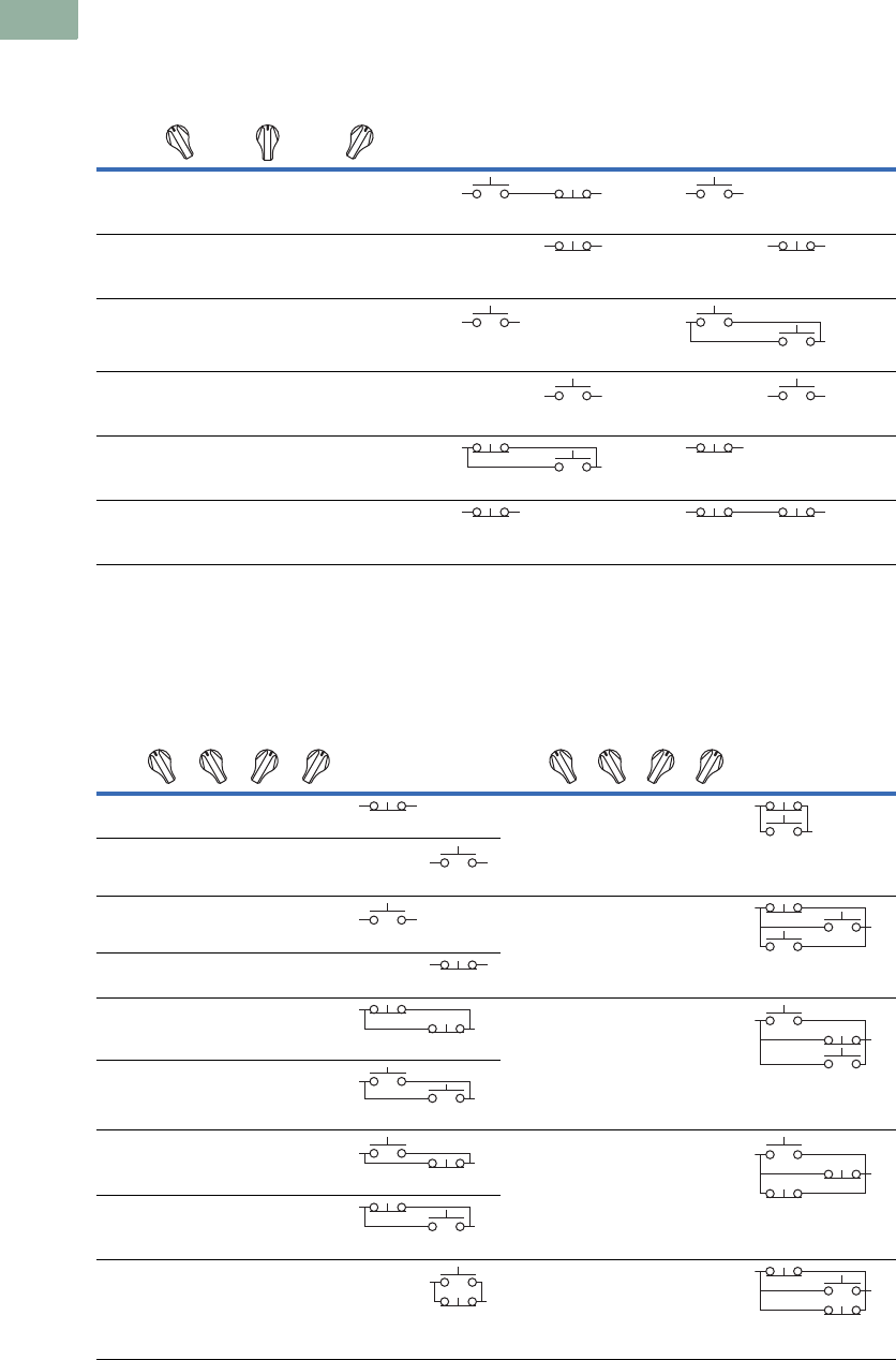
V7-T1-210 Volume 7—Logic Control, Operator Interface and Connectivity Solutions CA08100008E—March 2014 www.eaton.com
1
1
1
1
1
1
1
1
1
1
1
1
1
1
1
1
1
1
1
1
1
1
1
1
1
1
1
1
1
1
1.8
Pushbuttons and Indicating Lights
30.5 mm Heavy-Duty Watertight/Oiltight—10250T
Three-Position Switch—Cam and Contact Block Selection
Four-Position Switch—Contact Block Selection
No.
Desired Circuit and
Operator Position
Contact Blocks Required to Accomplish Circuit Function
(Jumpers must be installed where indicated)
Operator with Cam Code #2 Operator with Cam Code #3
Mounting Location Mounting Location
Top
Plunger
A
Bottom
Plunger
B
Top
Plunger
A
Bottom
Plunger
B
1X O O
NO NC NO
2XXO
NC NC
3X O X
NO
NO NO
4OOX
NO NO
5O X X
NC NO
NC
6O X O
NC NC NC
No.
Contact Blocks
Required to
Accomplish Circuit
Function
No.
Contact Blocks
Required to
Accomplish Circuit
Function
Desired Circuit and
Operator Position
Mounting Location Desired Circuit and
Operator Position
Mounting Location
Top
Plunger
A
Bottom
Plunger
B
Top
Plunger
A
Bottom
Plunger
B
1XOOO
NC
10XOXO
NC
NO
2OXOO
NO
3OOXO
NO
11XXXO
NC
NO NO
4OOOX
NC
5XOOX
NC NC
12OXXX
NO NC
NO
6OXXO
NO NO
7OOXX
NO NC
13XOXX
NO
NC NC
8XXOO
NC NO
9OXOX
NO
NC
14XXOX
NC NO
NC
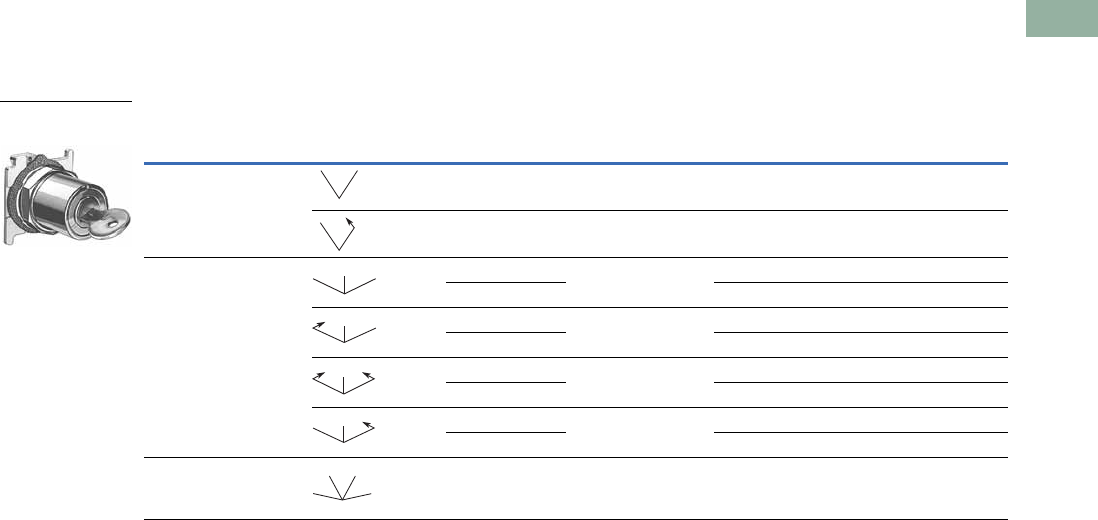
Volume 7—Logic Control, Operator Interface and Connectivity Solutions CA08100008E—March 2014 www.eaton.com V7-T1-211
1
1
1
1
1
1
1
1
1
1
1
1
1
1
1
1
1
1
1
1
1
1
1
1
1
1
1
1
1
1
1.8
Pushbuttons and Indicating Lights
30.5 mm Heavy-Duty Watertight/Oiltight—10250T
Selector Switch Operators
Key Operators
UL (NEMA) Type 3, 3R, 4, 4X, 12, 13
Key Operators with Cam
Notes
1 Horizontal mount, key removal #1 keyed selector switch, cam 1 shown.
2 M = Maintained. S = Spring return in direction of arrow (R).
3 For selection of the proper cam and contact block to obtain the proper circuit sequence, see selection instructions and tables on
Pages V7-T1-208, V7-T1-209 and V7-T1-210.
4 Choose key removal position required for application from table on Page V7-T1-212. Add key removal code no. to listed catalog number.
Example: 10250T15112.
Positions Operator Action 2Cam Code 3
Optional Key
Removal Positions 4
Vertical Mounting
Catalog Number
Horizontal Mounting
Catalog Number
Two-position—60° throw 1 1, 2, 3 10250T1511_ 10250T1611_
12 10250T1571_ 10250T1581_
Three-position—60° throw 2 1–7 10250T1522_ 10250T1622_
310250T1523_ 10250T1623_
21, 4, 5 10250T1532_ 10250T1632_
310250T1533_ 10250T1633_
24 10250T1542_ 10250T1642_
310250T1543_ 10250T1643_
22, 4, 6 10250T1652_ 10250T1662_
310250T1653_ 10250T1663_
Four-position—40° throw 7 7 10250T1677_ 10250T1687_
Two-Position
Maintained 1
MM
MS
MM
M
MS
M
SS
M
MS
M
MM
MM
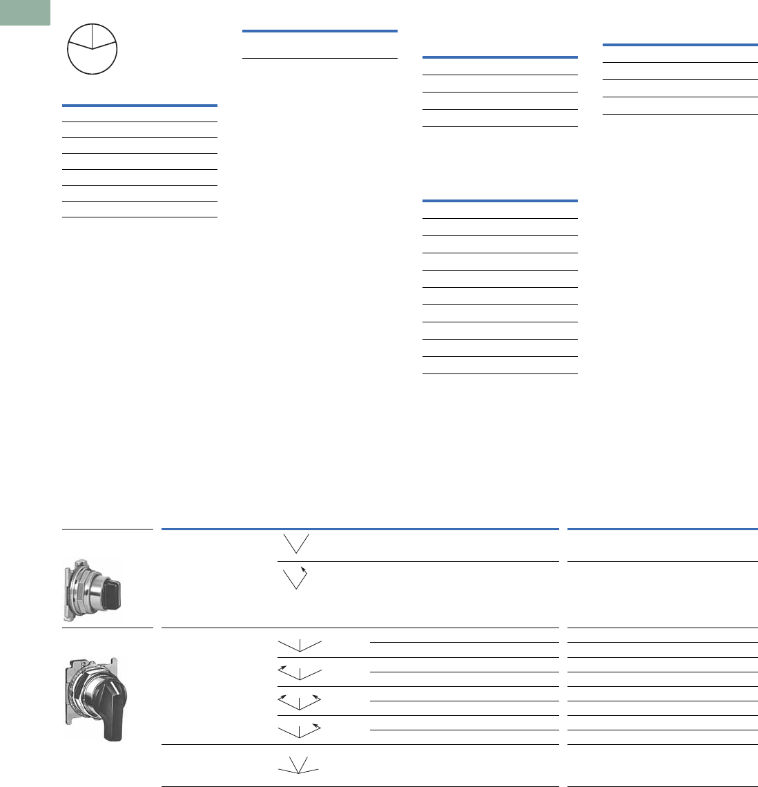
V7-T1-212 Volume 7—Logic Control, Operator Interface and Connectivity Solutions CA08100008E—March 2014 www.eaton.com
1
1
1
1
1
1
1
1
1
1
1
1
1
1
1
1
1
1
1
1
1
1
1
1
1
1
1
1
1
1
1.8
Pushbuttons and Indicating Lights
30.5 mm Heavy-Duty Watertight/Oiltight—10250T
Key Removal Positions
Note: Key removal in “spring
return from” positions not
recommended.
Replacement Keys or Dissimilar
Locks for Key Operators
Operators listed on Page
V7-T1-212 have identical
locks and keys (Key Code
H661) Catalog Number
10250ED824. For dissimilar
lock and key combinations,
see listing on this page.
Replacement Key
Selector Switch Operators with
Dissimilar Locks and Keys
(UL [NEMA] 4, 4X and 13)
The locks in all key operators
listed on Pages V7-T1-191,
V7-T1-212 and V7-T1-349 are
identical and use key code
number H661. Two keys are
supplied with every lock. For
additional code number H661
keys, order Catalog Number
10250ED824. For others,
order 10250ED1130 and
designate lock number.
When dissimilar locks for
each operator or each group
of operators are required,
select from the lock and key
combination listed below.
When Ordering Operator
Only or a complete control
unit with a substitute lock,
order from table below and
add “except Lock and Key
Code No. …”
“H” Series Locks without
Master Key—with Key Slot
Cover
“M” Series Locks with
Master Key—with Key Slot
Cover
Master Keys for Above
Locks
Selector Switch Operators with Caps
UL (NEMA) Type 3, 3R, 4, 4X, 12, 13
Selector Switch Operators with Caps
Notes
1 Black knob selector switch, cam 1 shown.
2 M = Maintained. S = Spring return in direction of arrow (R).
3 Field convertible to horizontal mounting or order operator only and separate operator cap.
4 For selection of the proper cam and contact block to obtain the proper circuit sequence, see selection instructions and
tables on Pages V7-T1-208, V7-T1-209 and V7-T1-210.
5 Black lever selector switch, cam 3 shown.
Code
Suffix
Key Removal
Position
1Right only
2Left only
3Right and left
4Center only
5Right and center
6Left and center
7All positions
L
C
R
Description Catalog Number
Replacement keys
(code H661)
10250ED824 Lock and Key Code Numbers
H501 H635 H663
H620 H639 H675
H621 H643 H683
H634 H654 H688
Lock and Key Code Numbers
MD1 MD14 ME8 MJ6
MD2 MD15 ME11 MJ10
MD3 MD16 ME16 MJ11
MD4 MD19 ME17 MJ13
MD5 MD20 ME18 MJ15
MD7 ME2 ME19 MJ16
MD9 ME3 MJ1 MD17
MD10 ME5 MJ3
MD11 ME6 MJ4
MD13 ME7 MJ5
Application Catalog Number
For code:
MD1–MD20 10250ED825-3
ME2–ME18 10250ED825-4
MJ1–MJ16 10250ED825-5
Positions Operator Action 2
Black Knob Selector Switch—
Vertical Mounting 3
Black Lever Selector Switch—
Vertical Mounting 3
Cam Code 4Catalog Number Cam Code 4Catalog Number
Two-position—60° throw 1 10250T1311 110250T3011
110250T1371 110250T3071
Three-position—60° throw 2 10250T1322 210250T3022
310250T1323 310250T3023
210250T1332 210250T3032
310250T1333 310250T3033
210250T1342 210250T304
310250T1343 310250T3043
210250T1352 210250T3052
310250T1353 310250T3053
Four-position—40° throw 7 10250T1367 710250T3067
Two-Position
Maintained 1
Three-Position
Maintained 5
MM
MS
MM
M
MS
M
SS
M
MS
M
MM
MM
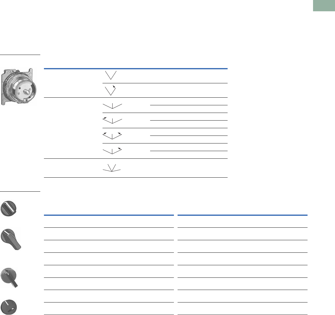
Volume 7—Logic Control, Operator Interface and Connectivity Solutions CA08100008E—March 2014 www.eaton.com V7-T1-213
1
1
1
1
1
1
1
1
1
1
1
1
1
1
1
1
1
1
1
1
1
1
1
1
1
1
1
1
1
1
1.8
Pushbuttons and Indicating Lights
30.5 mm Heavy-Duty Watertight/Oiltight—10250T
Selector Switch Operators without Caps
Operators can be ordered
with caps assembled to
them by adding the code
number from the table on
this page to the end of
catalog number below.
Example: 10250T4011KB
Selector Switch Operators without Caps
Operating Caps
Notes
1 M = Maintained. S = Spring return in direction of arrow (R).
2 For selection of the proper cam and contact block to obtain the proper circuit sequence, see selection instructions and
tables on Pages V7-T1-208, V7-T1-209 and V7-T1-210.
3 Designed for added ingress protection. For use in maintained operators only.
Positions Operator Action 1Cam Code 2Catalog Number
Two-position—60° throw 1 10250T4011
110250T4081
Three-position—60° throw 2 10250T4022
310250T4023
210250T4032
310250T4033
210250T4042
310250T4043
210250T4052
310250T4053
Four-position—40° throw 7 10250T4067
Color
Knob
Catalog and
Code Number
Lever
Catalog and
Code Number Color
Lever 3
Catalog and
Code Number
Coin Slot
Catalog and
Code Number
Black 10250TKB 10250TLB Black 10250TSB 10250TCB
Red 10250TKR 10250TLR Red 10250TSR 10250TCR
Green 10250TKG 10250TLG Green 10250TSG 10250TCG
Yellow 10250TKY 10250TLY Yellow 10250TSY 10250TCY
White 10250TKW 10250TLW White 10250TSW 10250TCW
Gray 10250TKA 10250TLA Gray 10250TSA 10250TCA
Blue 10250TKL 10250TLL Blue 10250TSL 10250TCL
Orange 10250TKD 10250TLO Orange 10250TSO 10250TCO
Two-Position Selector
Switch Maintained
MM
MS
MM
M
MS
M
SS
M
MS
M
MM
MM
Knob
Lever
Lever for Use with
Maintained Operators
Coin Slot
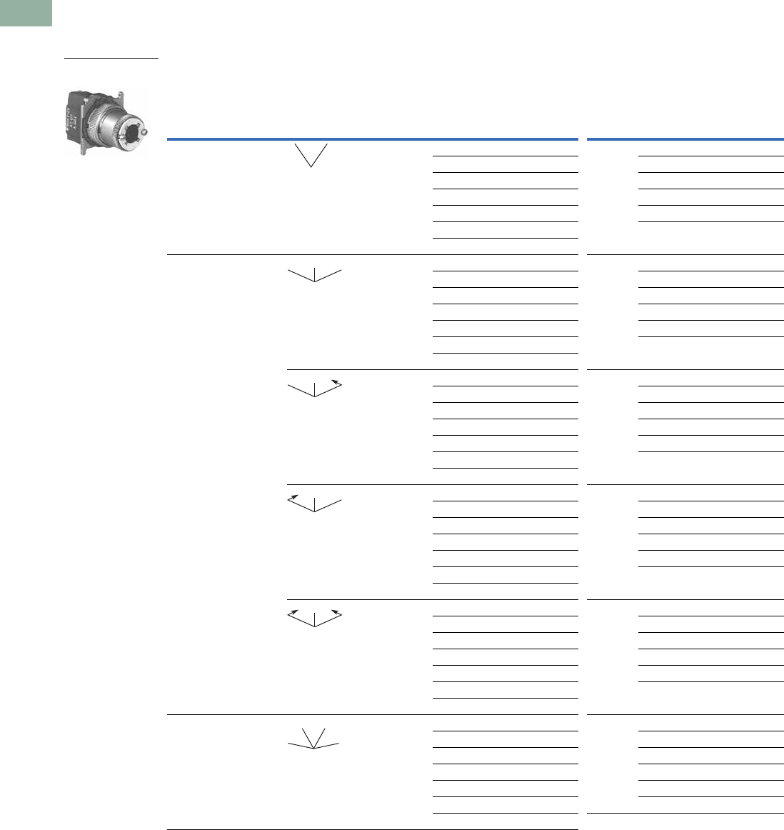
V7-T1-214 Volume 7—Logic Control, Operator Interface and Connectivity Solutions CA08100008E—March 2014 www.eaton.com
1
1
1
1
1
1
1
1
1
1
1
1
1
1
1
1
1
1
1
1
1
1
1
1
1
1
1
1
1
1
1.8
Pushbuttons and Indicating Lights
30.5 mm Heavy-Duty Watertight/Oiltight—10250T
Illuminated Selector Switch Operators
Illuminated Selector Switches without Caps
Operator without Knob or Lever
Notes
1 M = Maintained. S = Spring return in direction of arrow (R).
2 For selection of the proper cam and contact block, to obtain the proper circuit sequence, see selection tables on Pages V7-T1-208, V7-T1-209 and V7-T1-210.
3 Operator includes lens gasket and lens attachment screws.
4 Full voltage light units can be used at other than listed voltages by changing lamp. Replacement lamps are listed on Page V7-T1-239.
5 Resistor type. May generate excess heat if used in high density.
Positions Operator Action 1
Transformer Type—50/60 Hz
6 Volt #755 Lamp
Full Voltage Type—AC or DC 4
Lamps: 6V—#755, 12V—#756, 24V—#757,
48V—#1835, 120/240V—120MB
Cam
Code 2Voltage
Code Number and
Catalog Number 3
Cam
Code 2Voltage
Code Number and
Catalog Number 3
Two-position—60° throw 1 24 10250T5961 1610250T6201
120 10250T5971 12 10250T6211
208 10250T6511 24 10250T6221
240 10250T5981 48 10250T6231
380 10250T5991 120 10250T6361
480 10250T6001 240 510250T6371
600 10250T6011
Three-position—60° throw + 2 or 3 24 10250T602_ + 2 or 3 6 10250T624_
120 10250T603_ 12 10250T625_
208 10250T652_ 24 10250T626_
240 10250T604_ 48 10250T627_
380 10250T605_ 120 10250T638_
480 10250T606_ 240 510250T639_
600 10250T607_
+ 2 or 3 24 10250T654_ + 2 or 3 6 10250T612_
120 10250T620_ 12 10250T632_
208 10250T655_ 24 10250T642_
240 10250T656_ 48 10250T672_
380 10250T657_ 120 10250T622_
480 10250T658_ 240 10250T682_
600 10250T659_
+ 2 or 3 24 10250T660_ + 2 or 3 6 10250T613_
120 10250T621_ 12 10250T633_
208 10250T661_ 24 10250T643_
240 10250T662_ 48 10250T673_
380 10250T663_ 120 10250T623_
480 10250T664_ 240 10250T683_
600 10250T665_
+ 2 or 3 24 10250T614_ + 2 or 3 6 10250T628_
120 10250T615_ 12 10250T629_
208 10250T653_ 24 10250T630_
240 10250T616_ 48 10250T631_
380 10250T617_ 120 10250T640_
480 10250T618_ 240 510250T641_
600 10250T619_
Four-position—40° throw 7 24 10250T6087 7610250T6327
120 10250T6097 12 10250T6337
208 10250T6547 24 10250T6347
240 10250T6107 48 10250T6357
380 10250T6117 120 10250T6427
480 10250T6127 240 510250T6437
600 10250T6137
Two-Position Selector
Switch Maintained
MM
MM
M
MS
M
MS
M
SS
M
MM
MM
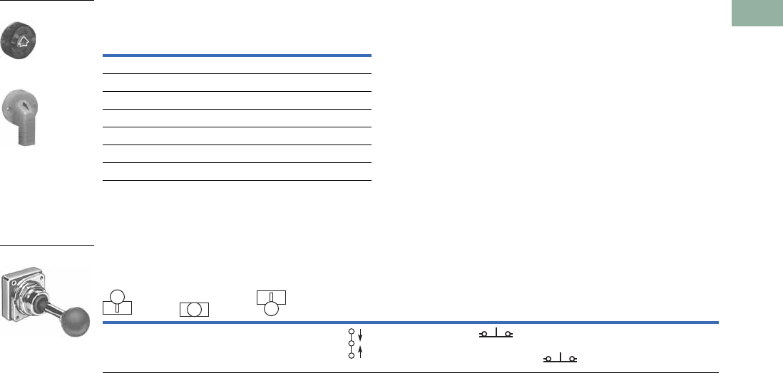
Volume 7—Logic Control, Operator Interface and Connectivity Solutions CA08100008E—March 2014 www.eaton.com V7-T1-215
1
1
1
1
1
1
1
1
1
1
1
1
1
1
1
1
1
1
1
1
1
1
1
1
1
1
1
1
1
1
1.8
Pushbuttons and Indicating Lights
30.5 mm Heavy-Duty Watertight/Oiltight—10250T
Illuminated Knobs and Levers
Joystick Units
Joystick Units—UL (NEMA) Type 3, 3R, 4, 4X, 12, 13
Notes
1 Amber, clear and white lenses have a black arrow (pointer), red, green and blue lenses have a white arrow (pointer).
2 X = closed circuit, O = open circuit.
3 M = Maintained. S = Spring return in direction of arrow (R).
4 Field convertible momentary to maintained or vice versa.
Color 1
Knob
Code Number and
Catalog Number
Lever
Code Number and
Catalog Number
Red 10250TER 10250TFR
Green 10250TEG 10250TFG
Yellow 10250TEA 10250TFA
Blue 10250TEL 10250TFL
Clear 10250TEC 10250TFC
White 10250TEW 10250TFW
Amber 10250TEM 10250TFM
Operator Position 2
Operator
Action 3
Contact
Type
Two-Position
Assembled Unit
Catalog Number 4
Up
Center
Down
Mounting Location
AB
XOO 1NC 10250T452-3X
OOX 1NC
Knob
Lever
Two-Position Joystick
M
S
S
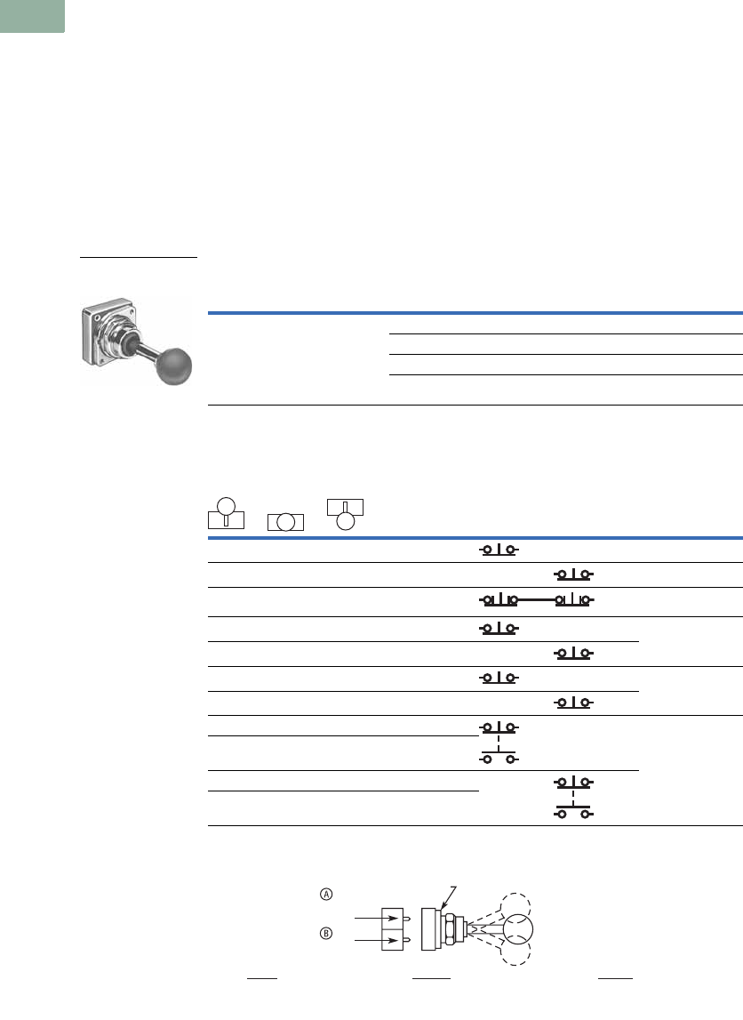
V7-T1-216 Volume 7—Logic Control, Operator Interface and Connectivity Solutions CA08100008E—March 2014 www.eaton.com
1
1
1
1
1
1
1
1
1
1
1
1
1
1
1
1
1
1
1
1
1
1
1
1
1
1
1
1
1
1
1.8
Pushbuttons and Indicating Lights
30.5 mm Heavy-Duty Watertight/Oiltight—10250T
Joysticks
Two-Position Joystick Operators
The device mounts in the
standard 30.5 mm mounting
hole. Allow sufficient panel
space for lever movement.
The maximum travel of the
knob operator (full up to full
down) is 2.2 in (24°)
momentary, 2.5 in (30°)
maintained, but ample space
for lever operation must be
allowed. These operators are
field convertible from
momentary to maintained
operation or vice versa.
The use of NC contacts is
preferred because they
provide positive drive contact
opening and a direct
relationship between lever
movement and affected
terminal, i.e., up movement
affects the top terminals.
Application Caution
Joystick operators are not
recommended on certain DC
applications above 24 Vdc
which may involve lightly
engaging the contacts
(teasing) to achieve speed
control, positioning, jogging,
etc. Excessive arcing and
deterioration of the contacts
will occur.
Two-Position Joystick Operators—UL (NEMA) Type 3, 3R, 4, 4X, 12, 13
Contact Block Operation and Selection
A and B Mounting Location
Notes
1 Field convertible momentary to maintained or vice versa. To expedite shipment of maintained types,
order momentary operator 10250T452 which is a stocked device.
2 Bolded circuit corresponds to “X-O” circuit selection. X = closed circuit, O = open circuit.
3 See above for “A” and “B” mounting location.
4 NO = normally open, NC = normally closed, LONC = late opening normally closed.
5 Four circuits in single block depth—rated 300V max.
Contact Block Limitations
Two-Position Operator Only—AC Applications Only
Description 1Catalog Number
Momentary Mode
4NC contact blocks max.
3NO contact blocks max.
Maintained Mode
2 contact blocks max.
Momentary up and down 10250T452
Maintained up—momentary down 10250T4521
Maintained down—momentary up 10250T4522
Maintained up and down 10250T4525
Handle Position 2
Contact Block
Type 4Catalog Number
Up
Center
Down
Mounting Location 23
Top A Bottom B
XOO1NC 10250T51
OOX1NC 10250T51
OXO2LONC (Series) 10250T45
XOO1NC 10250T3
OOX1NC
X X O 1LONC 10250T45
OXX1LONC
XOO1NC 10250T44 5
OOX1NO
OOX1NC
XOO1NO
Two-Position Joystick
Operator
Up
Center
Down
Locating Nib
Top
Contacts
Bottom
Contacts
Center
All NC and NO Contacts
Are Open (1/2 Way),
Late Opening NC Is Closed
Down
NC Contact at Bottom
Is Closed, NO at
Top Is Closed
Up
NC Contact at Top
Is Closed, NO at
Bottom Is Closed
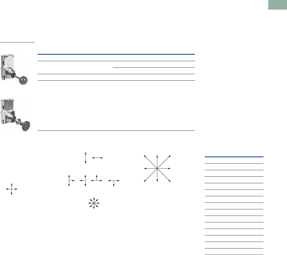
Volume 7—Logic Control, Operator Interface and Connectivity Solutions CA08100008E—March 2014 www.eaton.com V7-T1-217
1
1
1
1
1
1
1
1
1
1
1
1
1
1
1
1
1
1
1
1
1
1
1
1
1
1
1
1
1
1
1.8
Pushbuttons and Indicating Lights
30.5 mm Heavy-Duty Watertight/Oiltight—10250T
Four-Position Joystick Operators
The joystick operated control
unit is intended for AC
application only. For other
use, see Application
Caution on preceding page.
The panel area required for
the four-position operator is
equivalent to two standard
pushbutton operators.
The latch holds the lever in
the center position. The
trigger latch must be released
before lever can moved into
any position.
Four-Position Joystick Operators—UL (NEMA) Type 3, 3R, 4, 4X, 12, 13
Field Conversion—Gate
The factory assembled four-
position operator is
assembled with a gate
arranged for four handle
positions.
Handle Positions
Three additional gates,
supplied with every operator,
allow on the job conversion to
three- or eight-position
operation as illustrated.
Two-, Three- or Eight-
Position Operation
The eight-position gate
controls the four functions
shown as “Up,” “Down,”
“Left” and “Right.” The
remaining four diagonal
positions each actuate two
adjacent functions; for
example, “Left Down”
actuates both “Left” and
“Down.” The operator may
be arranged for spring return
of handle to center position,
or maintained in up to eight
positions (see description of
maintained position operator).
Adjacent Functions
Maintained Position
For maintained position (non-
spring return), locate required
maintained position or
positions of operating lever
and add appropriate suffix
number to the catalog
number selected from the
table above.
Maintained Positions
On an eight-position gate,
when an adjacent vertical and
horizontal position are both
maintained, the included
diagonal position is also
maintained.
Note
1Momentary operators—spring return to center. For maintained operators add suffix code from table on this page.
Example: 10250T45110. Operator without latch, maintained in left and right positions.
Contact Block Limitations Description 1Catalog Number
Operator Only—AC Application Only
Four contact blocks max.—two in each position Four-position—without latch 10250T451_
Four-position—with latch 10250T461_
Hole Plug
Four contact blocks max.—two in each position To plug unused hole 10250TA7
Four-Position Joystick
Operator
Four-Position Joystick
Operator with Latch
Four-Position
Gate
or
Two-Position
Gate
Eight-Position
Gate
Three-Position
Gate
or or or
Up
Right
Up
Left
Up
Down Right
Down
RightLeft
Left
Down
Maintained Positions Suffix
NumberUp Down Left Right
X— —— 1
—— — — 2
—X — — 3
—— X — 4
—— — — 5
X— X — 6
X— —X 7
—X X — 8
—X — X 9
—— X X 10
XX X — 11
XX —X 12
X— X X 13
—X X X 14
XX X X 15
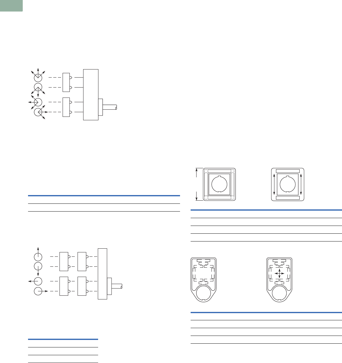
V7-T1-218 Volume 7—Logic Control, Operator Interface and Connectivity Solutions CA08100008E—March 2014 www.eaton.com
1
1
1
1
1
1
1
1
1
1
1
1
1
1
1
1
1
1
1
1
1
1
1
1
1
1
1
1
1
1
1.8
Pushbuttons and Indicating Lights
30.5 mm Heavy-Duty Watertight/Oiltight—10250T
Contact Block Operation
Contact blocks mount directly to the back of the operator. For
reliable operation, the maximum number of contact blocks that
should be installed behind each operator lever is two (four total).
The figure below identifies the circuits activated by each of the
eight possible lever positions. Contact block plungers 1, 2, 3, 4
are depressed (change state) when handle is in the position
indicated by arrows below.
Circuit Activation
Note: Joystick in its resting state, center position, does not activate
contact block plungers.
Ordering Example:
Suppose you are looking for a four-position momentary joystick
without a latch and the following circuit arrangements.
X = Closed Circuit, O = Open Circuit.
Example Circuit Arrangements
The contact blocks and their mounting locations would be as
follows:
Example Contact Blocks and Locations
A complete bill of material for this example would include:
Example Order
Blank Legend Plates for Joystick Operators
When ordering engraved legend plates, order by catalog number
and insert the following into order notes:
●Legend required
●Size of characters: 3/16,
1/8, 3/32 in (4.8, 3.2, 2.4 mm)
●Location by letter (A–N)
Locations K and M can accommodate up to two lines
horizontally; L and N up to two lines vertically.
Maximum number of characters:
●Horizontal
3/16 in—13, 1/8 in—14, 3/32 in—19
●Vertical
3/16 in—10, 1/8 in—13, 3/32 in—14
Ordering Example:
Two-position legend plate to be marked “UP” “DOWN.”
Catalog No. 10250TJ2S4STAMP
Letter Size: 3/16 in (4.8 mm)
Pos. K—UP
Pos. M—DOWN
Two-Position
Four-Position
Circuit Up Down Left Right
1st X X X X
2nd X O O X
Qty. Catalog Number
110250T451
210250T2
210250T1
1
2
3
4
NO
2nd
Circuit 1st
Circuit
10250T1 10250T2
NC
NC
NO
10250T1 10250T2
NO
NO
NO
NO
Catalog Number Catalog Number
Blank Plate
10250TJS3 10250TJS4
Engraved Plate
10250TJS3STAMP 10250TJS4STAMP
Catalog Number Catalog Number
Blank Plate
10250TJS1 10250TJS2
Engraved Plate
10250TJS1STAMP 10250TJS2STAMP
K
M
2.19
(55.6)
Sq.
NL
K
M
A
B
J
D
F
E
C
HG
A
B
J
D
F
E
C
HG
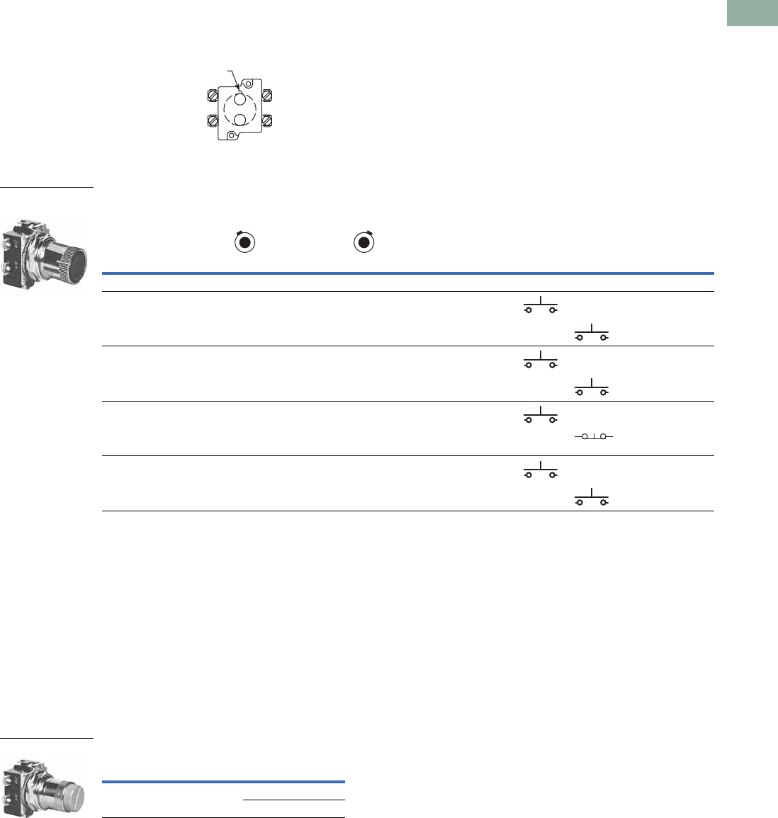
Volume 7—Logic Control, Operator Interface and Connectivity Solutions CA08100008E—March 2014 www.eaton.com V7-T1-219
1
1
1
1
1
1
1
1
1
1
1
1
1
1
1
1
1
1
1
1
1
1
1
1
1
1
1
1
1
1
1.8
Pushbuttons and Indicating Lights
30.5 mm Heavy-Duty Watertight/Oiltight—10250T
Roto-Push Units
Two-Position Momentary
Complete assembled two-
position Roto-Push® Units are
listed below. These operators
have black flush buttons and
are arranged for vertical
mounting. Order legend
plates separately.
Mounting Location
Roto-Push Units—UL (NEMA) Type 3, 3R, 4, 4X, 12, 13
Two-Position Latched
The two-position Roto-Push
Latch Unit is fully assembled
and only requires a legend
plate for a great variety of
applications. When the
selector collar is in the
extreme left position, the
button is in the free or normal
position and can be operated
as a standard pushbutton.
Rotating the collar to the
extreme right position
automatically depresses and
latches the button in the
depressed position. The
white filled groove in the
button indicates the selector
collar position. The selector
collar has spring return to the
left position except when in
the extreme right latched
position.
Rotates to a Latch-Out Mode
Notes
1X = closed circuit, O = open circuit.
2Roto-Push assembled with contact blocks.
Locating
Nib
A
B
Typical Applications
(Most Common Examples)
Operator Position 1
Contact
Type Catalog Number 2
Collar Left Collar Right
Mounting Location
Normal Depressed Normal Depressed A B
Two-Position
FORWARD/REVERSE;
HIGH/LOW; OPEN/CLOSE;
UP/DOWN; etc.
O
O
O
X
O
O
X
O
1NO 10250T2411-2
1NO
JOG/RUN; MAN./AUTO;
etc.
O
O
X
O
O
X
X
X
1NO 10250T24111-2
1NO
RUN/JOG; START/JOG;
etc.
O
X
X
X
O
O
X
O
1NO 10250T24111-1
1NC
SAFE/RUN; etc. O
O
O
O
O
X
X
X
1NO 10250T2415-2
1NO
Roto-Push—Black
Flush Button
Color and Type
of Button
Contact
Block
Vertical Mounting
Catalog Number
Red long 1NC
2NC
10250T72
10250T73
Red Long
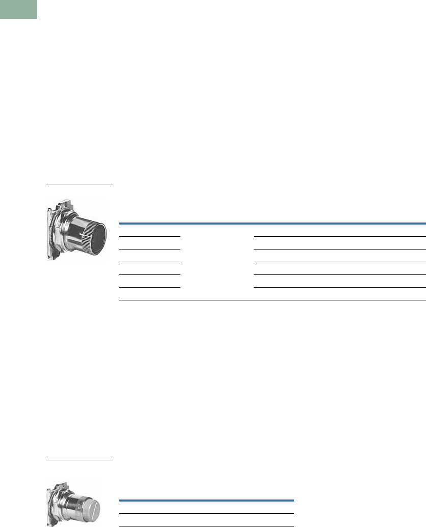
V7-T1-220 Volume 7—Logic Control, Operator Interface and Connectivity Solutions CA08100008E—March 2014 www.eaton.com
1
1
1
1
1
1
1
1
1
1
1
1
1
1
1
1
1
1
1
1
1
1
1
1
1
1
1
1
1
1
1.8
Pushbuttons and Indicating Lights
30.5 mm Heavy-Duty Watertight/Oiltight—10250T
Roto-Push Operators
Roto-Push Components
A Roto-Push control unit
combines the function of a
pushbutton and a selector
switch. The contacts are
operated by the combined
action of rotating the outer
collar and pushing a button
contained in the collar.
In selecting the cam and
contact blocks for the listed
function, the analysis involves
considering the function with
the collar rotated to the given
position with the button free
(designated as “N”) and then
in that same position with
the button depressed
(designated “D”). This is done
for each rotational position of
the collar.
When Ordering Specify
●Catalog number of
operator with cam code
suffix from tables below
and on following pages,
Example: 10250T2411.
●Catalog number(s) for
contact blocks and legend
plates if required.
●To select the cam and
contact blocks needed for
two-position and three-
position switches, use the
tables on following pages.
Operator and Cam
Two-Position Roto-Push Operator—Rotates to a Latch-Out Mode
Special Rotor Latch
This differs from the other
Roto-Push operators in that
as the collar is rotated to the
right it depresses the button
and releases the button when
rotated left. But the button in
the released position can be
momentarily pushed
independent of the collar or
its position. As the button is
depressed by rotating the
collar, the button also rotates
and indicates its mode by a
white line on the button face.
This button can be used as an
emergency stop or latched
stop.
Special Rotor Latch—
UL (NEMA) Type 3, 3R, 4, 4X, 12, 13
Note
1Not to be used for emergency stop application.
Color and
Type of
Button
Cam Code No.
Select from Tables
Vertical Mounting
Catalog and
Code Number
Horizontal Mounting
Catalog and
Code Number
Black flush + 1 to 18 10250T241_ 10250T251_
Red flush 110250T242_ 10250T252_
Green flush 10250T243_ 10250T253_
Black long 10250T261_ 10250T271_
Red long 110250T262_ 10250T272_
Green long 10250T263_ 10250T273_
Operator and Cam
Color and Type
of Button
Vertical Mounting
Catalog Number
Red long 10250T3213
Black long 10250T3214
Special Roto Latch—
Red Long Button
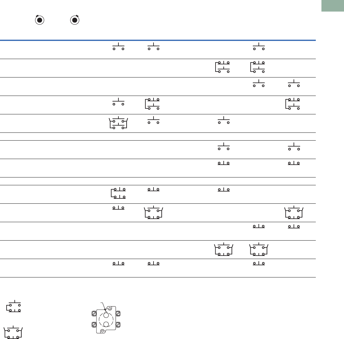
Volume 7—Logic Control, Operator Interface and Connectivity Solutions CA08100008E—March 2014 www.eaton.com V7-T1-221
1
1
1
1
1
1
1
1
1
1
1
1
1
1
1
1
1
1
1
1
1
1
1
1
1
1
1
1
1
1
1.8
Pushbuttons and Indicating Lights
30.5 mm Heavy-Duty Watertight/Oiltight—10250T
Cam and Contact Block Selection for Two-Position Roto-Push
Series and Parallel
Connections
The connections are not
made at the factory. They are
illustrated in the selection
table as requirements, but
must be made on the job.
Circuit Location
Letters “A” and “B”
represent the locations which
the two circuits of a contact
block will occupy in relation
to the locating nib of the
operator.
Note
1N = Button in free or normal position. D = Button depressed.
Combination
Number
Collar Position
Cam Code 1 Cam Code 2 Cam Code 3 Cam Code 4 Cam Code 5 Cam Code 6
Circuit Sequence 1
NDND
1 OOOX — — —
2 OOXO— — — —
3 OOXX— — — —
4OXOO ———
5OXOX — ——
6 OXXO——————
7 OXXX— — A or B NO —
8 XOOO— — A or B NC —
9 XOOX——————
10 X O X O — — —
11 X O X X — — —
12 XXOO— — — —
13 XXOO— — — —
14 XXXO — — —
ANOANO
ANO
BNO
ANC
BNO
ANC
BNO
ANO
BNO
BNO
ANC
BNO
ANC
BNO
ANO
BNO ANO
BNO
BNO
BNC
BNC
BNC
ANC
BNC ANC
BNC
BNC
ANO
BNC
ANO
BNC
ANC
BNC
ANO
BNC
ANO
ANC
ANC
ANC
Series Connection
Parallel Connection
BNC
ANO
BNC
ANO
Locating
Nib
A
B
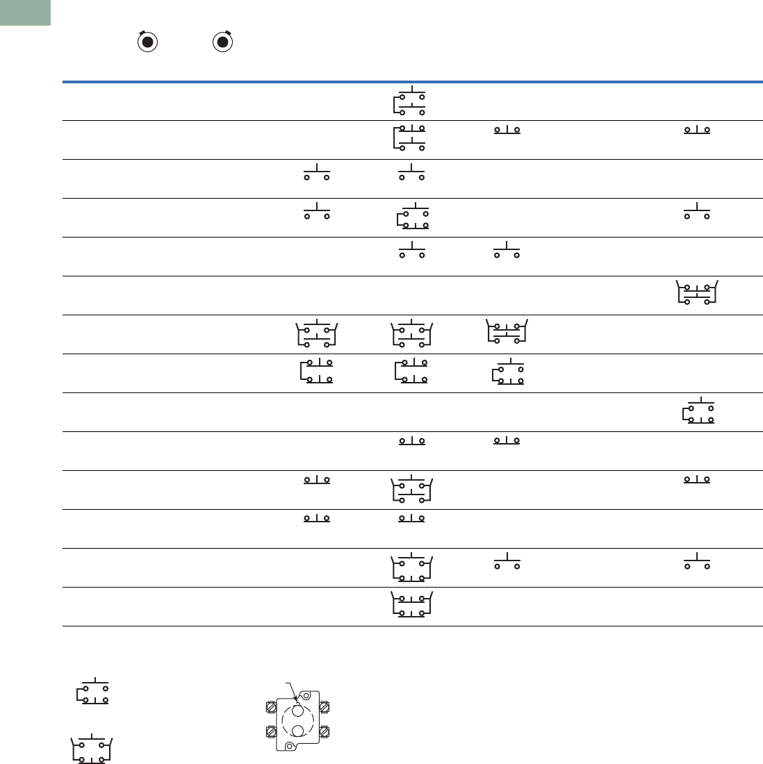
V7-T1-222 Volume 7—Logic Control, Operator Interface and Connectivity Solutions CA08100008E—March 2014 www.eaton.com
1
1
1
1
1
1
1
1
1
1
1
1
1
1
1
1
1
1
1
1
1
1
1
1
1
1
1
1
1
1
1.8
Pushbuttons and Indicating Lights
30.5 mm Heavy-Duty Watertight/Oiltight—10250T
Cam and Contact Block Selection for Two-Position Roto-Push, continued
Series and Parallel
Connections
The connections are not
made at the factory. They are
illustrated in the selection
table as requirements, but
must be made on the job.
Circuit Location
Letters “A” and “B”
represent the locations which
the two circuits of a contact
block will occupy in relation
to the locating nib of the
operator.
Note
1N = Button in free or normal position. D = Button depressed.
Combination
Number
Collar Position
Cam Code 10 Cam Code 11 Cam Code 12 Cam Code 13 Cam Code 14
Circuit Sequence 1
NDND
15 OOOX— — — —
16 OOXO— A or B NC
17 OOXX — — —
18 OXOO — —
19 OXOX— — —
20OXXO————
21 OXXX ——
22 XOOO ——
23XOOX————
24 XOXO— — —
25 XOXX — —
26 XXOO — — —
27 X X O O — A or B NO
28 XXXO— — — —
BNO
ANO
BNO
ANC
ANC ANC
BNO
BNO
ANO
BNC
ANO
BNO
ANO
BNO
BNO
ANC
BNO
ANO
BNO
ANO
BNO
ANC
BNC
ANC
BNC
ANC
BNC
ANO
BNC
ANO
ANCBNC
ANC
BNO
ANO
BNC
BNC
BNC
BNC
ANO
ANO
ANO
BNC
ANC
Series Connection
Parallel Connection
BNC
ANO
BNC
ANO
Locating
Nib
A
B
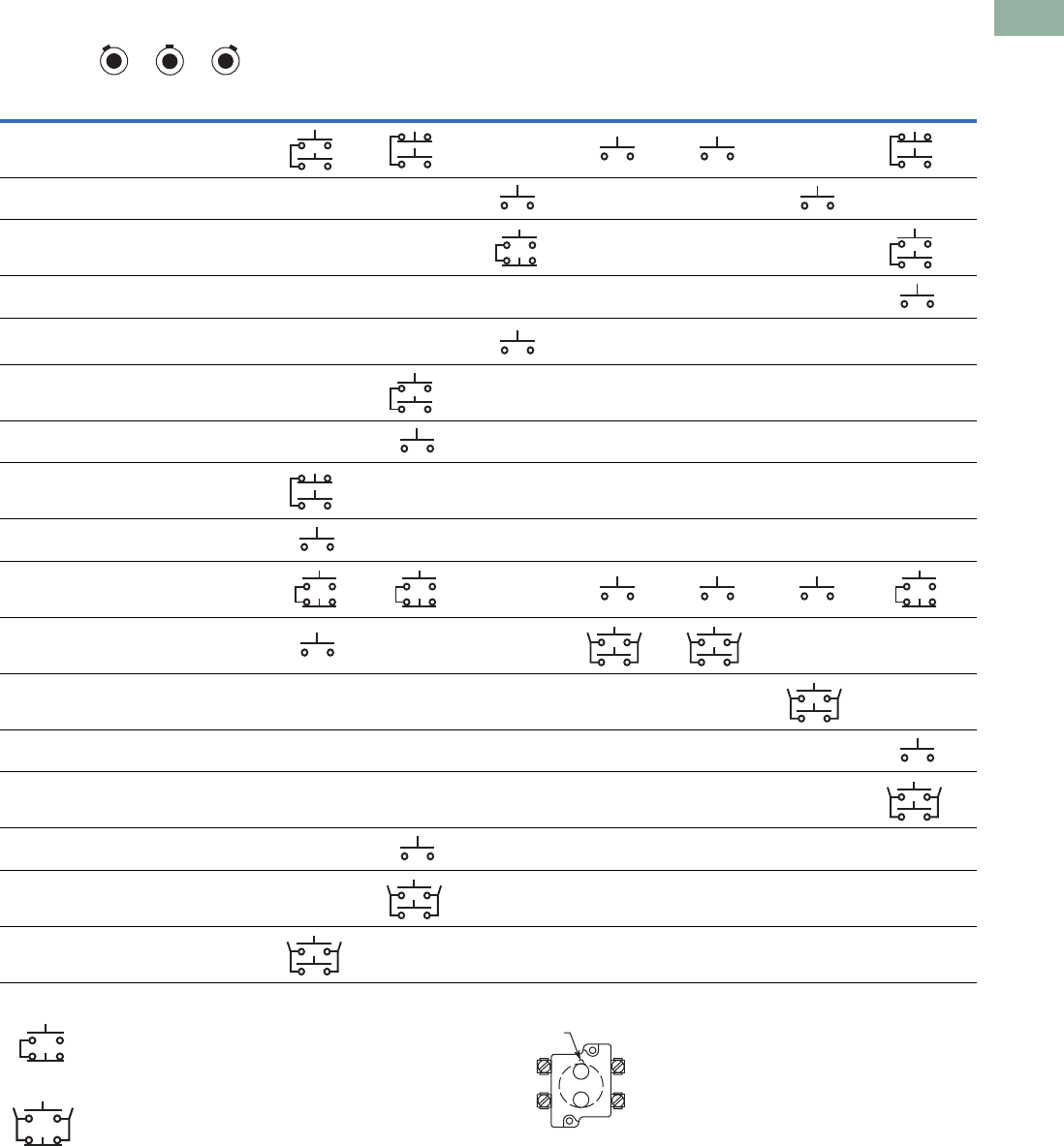
Volume 7—Logic Control, Operator Interface and Connectivity Solutions CA08100008E—March 2014 www.eaton.com V7-T1-223
1
1
1
1
1
1
1
1
1
1
1
1
1
1
1
1
1
1
1
1
1
1
1
1
1
1
1
1
1
1
1.8
Pushbuttons and Indicating Lights
30.5 mm Heavy-Duty Watertight/Oiltight—10250T
Cam and Contact Block Selection for Three-Position Roto-Push
Series and Parallel Connections
The connections are not made at the factory.
They are illustrated in the selection table as
requirements, but must be made on the job.
Circuit Location
Letters “A” and “B” represent the locations
which the two circuits of a contact block will
occupy in relation to the locating nib of the
operator.
Notes
1N = Button in free or normal position. D = Button depressed.
2Limited to 4 contact blocks. See Note on Page V7-T1-236.
Combination
Number
Collar Position
Cam Code 7 Cam Code 8 Cam Code 9 Cam Code 15 2Cam Code 16 Cam Code 17 Cam Code 18
Circuit Sequence 1
NDNDND
1 OOOOOX — —
2 OOOOXX — — — — —
3 OOOXOO — — — — —
4 OOOXOX ——————
5 OOOXXX—— ————
6 OOXXOO— —————
7 OOXXOX— —————
8 OOXXXO ——————
9 OOXXXX ——————
10 OXOOOO —
11 OXOOOX — — — —
12OXOOXX————— —
13OXOXOO——————
14OXOXOX——————
15 OXXXOO — —————
16 OXXXOX — —————
17 OXXXXX ——————
BNO
ANO
BNO
ANC
BNO
2
BNO
BNO
ANC
BNO
ANO
BNC
ANO
BNO
ANO
BNO
ANO
2
BNO
ANO
BNO
BNO
ANC
BNO
BNC
ANO
BNC
ANO
ANO
2
ANO
BNO
BNC
ANO
ANO
BNO
ANO
BNO
ANO
BNO
ANO
ANO
BNO
ANO
ANO
BNO
ANO
BNO
ANO
Series Connection
Parallel Connection
BNC
ANO
BNC
ANO
Locating
Nib
A
B
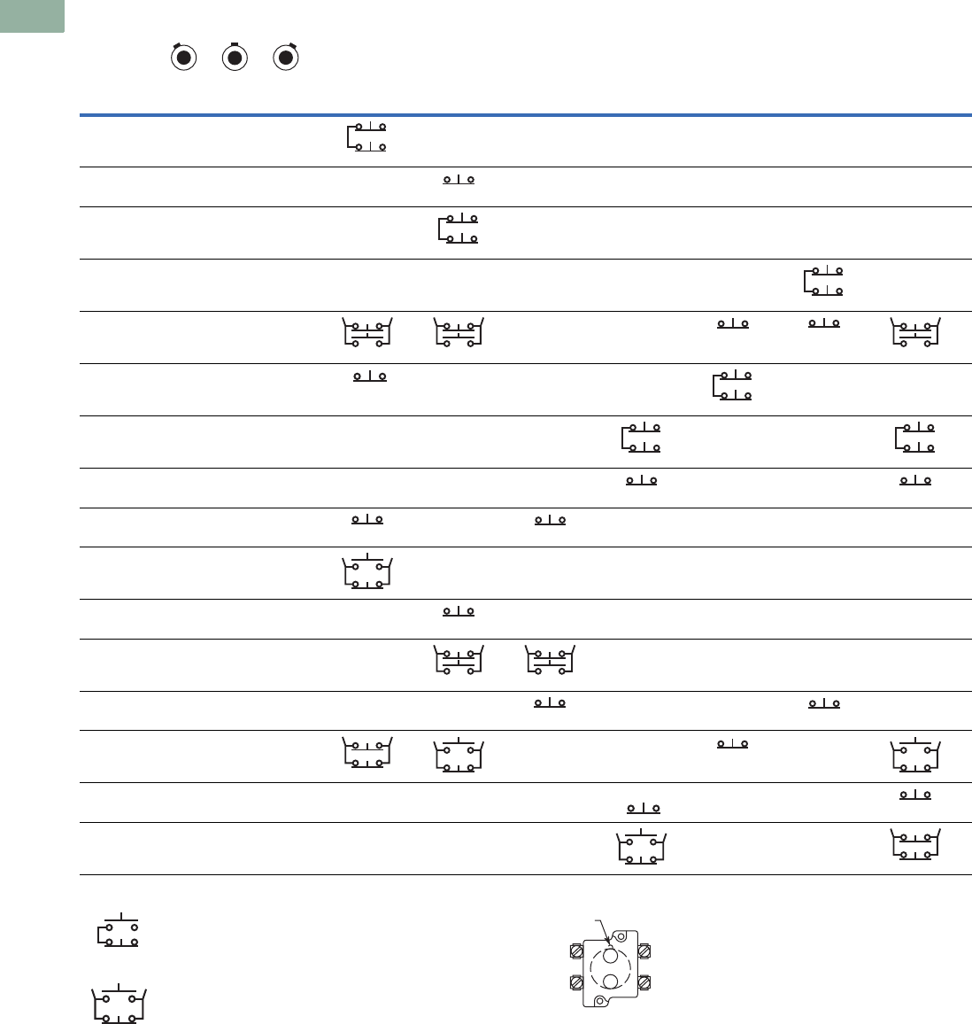
V7-T1-224 Volume 7—Logic Control, Operator Interface and Connectivity Solutions CA08100008E—March 2014 www.eaton.com
1
1
1
1
1
1
1
1
1
1
1
1
1
1
1
1
1
1
1
1
1
1
1
1
1
1
1
1
1
1
1.8
Pushbuttons and Indicating Lights
30.5 mm Heavy-Duty Watertight/Oiltight—10250T
Cam and Contact Block Selection for Three-Position Roto-Push, continued
Series and Parallel Connections
The connections are not made at the factory.
They are illustrated in the selection table as
requirements, but must be made on the job.
Circuit Location
Letters “A” and “B” represent the locations
which the two circuits of a contact block will
occupy in relation to the locating nib of the
operator.
Notes
1N = Button in free or normal position. D = Button depressed.
2Limited to 4 contact blocks. See Note on Page V7-T1-236.
Combination
Number
Collar Position
Cam Code 7 Cam Code 8 2Cam Code 9 Cam Code 15 Cam Code 16 Cam Code 17 Cam Code 18
Circuit Sequence 1
NDNDND
18 XOOOOO ——————
19 XOOOXX — —————
20 XOOOXO — —————
21 XOXXOO————— —
22 XOXXXX — —
23 XOXXXO — — — — —
24 XOXOXO — — — — —
25 XOXOXX — — — — —
26 XXOOOO — ————
27 XXOOOX ——————
28 XXOOXO— —————
29 XXOOXX— ————
30 XXXXOO — — — — —
31 XXXXXO — — —
32 XXXOXO — — — — —
33 XXXOXX — — — — —
BNC
ANC
ANC
BNC
ANC
BNC
ANC
BNO
ANC
BNO
ANC
ANCBNC
BNO
ANC
ANC
BNC
ANC
BNC
ANC
BNC
ANC
2
ANC ANC
BNC
2
ANC
BNC
ANO
BNC
BNO
ANC
BNO
ANC
BNC ANC
BNC
ANC
BNC
ANO
BNC
BNC
ANO
2
BNC
BNC
BNC
ANO
BNC
ANC
Series Connection
Parallel Connection
BNC
ANO
BNC
ANO
Locating
Nib
A
B
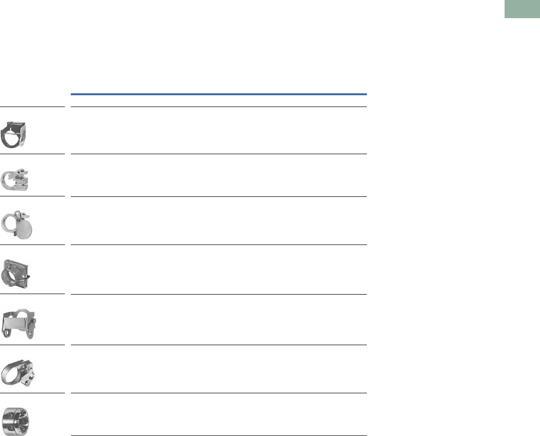
Volume 7—Logic Control, Operator Interface and Connectivity Solutions CA08100008E—March 2014 www.eaton.com V7-T1-225
1
1
1
1
1
1
1
1
1
1
1
1
1
1
1
1
1
1
1
1
1
1
1
1
1
1
1
1
1
1
1.8
Pushbuttons and Indicating Lights
30.5 mm Heavy-Duty Watertight/Oiltight—10250T
Accessories
Padlocks not included with
padlocking attachments. For
operators with built-in
padlock attachment, see
Page V7-T1-190.
Accessories
Description Catalog Number
Padlock Attachments
Padlocking Attachment for Flush Pushbutton Operators
Permits locking NC contacts in open position with 1/4 in padlock.
Will not lock NO contact.
10250TA2
Padlocking Attachment for Use with Extended Pushbutton
Permits locking NC contacts in open position with 1/4 in padlock.
10250TA26
Padlocking Cover Guard
Cover locked over flush button makes it unaccessible or on extended button
locks NC contacts open. Takes 1/4 in shank size padlock.
10250TA36
Padlock Hasp or Flip-Up Guard
When used with a 1/4 in padlock, makes flush and long button and knob selector
switch unaccessible, but not locked down. Without the padlock, it is a flip-up guard.
Padlock hasp can be removed before assembly.
10250TA38
Padlocking Attachment for Use with Flexible Weather Resistant Boot
Used on long button operators. Stainless steel. Use only for locking NC contacts open.
10250TA63
Padlock Attachment
For use with illuminated pushbuttons and maintained push-pull operators having
standard button or lens only. Use 1/4 in padlock. Locks in down position only.
10250TA64
Padlocking Attachment for Non-Illuminated Knob Selector Switches
Provision for up to 5, 1/4 in padlocks.
10250TA11
10250TA2
10250TA26
10250TA36
10250TA38
10250TA63
10250TA64
10250TA11
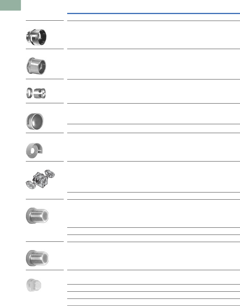
V7-T1-226 Volume 7—Logic Control, Operator Interface and Connectivity Solutions CA08100008E—March 2014 www.eaton.com
1
1
1
1
1
1
1
1
1
1
1
1
1
1
1
1
1
1
1
1
1
1
1
1
1
1
1
1
1
1
1.8
Pushbuttons and Indicating Lights
30.5 mm Heavy-Duty Watertight/Oiltight—10250T
Accessories, continued
Notes
1 Should not be used on flush button for STOP function.
2 Not suitable for single contact block depth cast enclosure. Cover is too thick.
Description Catalog Number
Shrouds and Guards
Shroud for Mushroom Head Operator
Prevents accidental operation. (Not for push-pull operators.)
10250TA6
Extended Retaining Nut
Replaces standard nut and provides guard for flush head pushbutton operators.
10250TA12
Guard for Illuminated Pushbutton 10250TA15
Shroud
For jumbo mushroom head operator.
Gray 10250TA56
Yellow 10250TA56Y
Half Shroud—Yellow
For jumbo mushroom head operator.
10250ED1241
Fingerproof Shroud—10 per package
Fits new style contact blocks and light units.
10250TA101
Boots
Flexible Weather Resistant Boot
For use with button operators (extended buttons preferred).
Temperature to –25°F (–32°C).
(See Page V7-T1-229 for 10250TA96 Tightening Tool.)
Black 10250TA3
Red 10250TA4 1
Green 10250TA10
Transparent Boot
For regular illuminated pushbutton operators and PresTest—
Temperature to –38°F (–39°C). 2
10250TA25
Boot for Flush Pushbutton
Clear 10250TA46
Black 10250TA47
Red 10250TA48
Green 10250TA49
10250TA6
10250TA12
10250TA15
10250TA56_
10250ED1241
10250TA101
10250TA_
10250TA25
10250TA4_
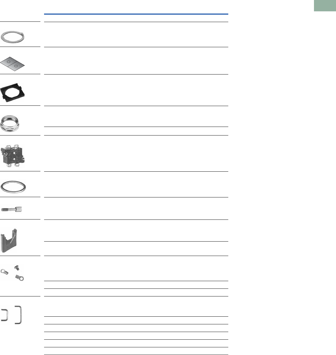
Volume 7—Logic Control, Operator Interface and Connectivity Solutions CA08100008E—March 2014 www.eaton.com V7-T1-227
1
1
1
1
1
1
1
1
1
1
1
1
1
1
1
1
1
1
1
1
1
1
1
1
1
1
1
1
1
1
1.8
Pushbuttons and Indicating Lights
30.5 mm Heavy-Duty Watertight/Oiltight—10250T
Accessories, continued
Notes
1 Component only. Not to be used for custom built (factory assembled) stations.
2 Not suitable for single contact block depth cast enclosure. Cover is too thick.
Description Catalog Number
Hardware and Kits
Thrust Washers—
To meet Ford Motor Co. mounting specifications.
10250TK3
Contact Block Tape Seal—
Seals plunger openings on last contact block. Order in multiples of 10 pieces.
10250TK5
Selector Switch Operator Gasket—
Seals out dust from getting in-between the cam and contact block plungers.
Supplied as standard with all selector switches.
56-9337
Special Retaining Nut—
To accommodate thick panel:
Indicating lights 10250TA30
PresTest, pushbuttons and selector switches 10250TA31
Terminal Block—
Two terminals, each will accommodate two wire terminations.
10250TA62
Spacer Ring—
Used when legend plate is not required.
10250TA8
Stacking Screw—
Replaces transformer mounting screws on indicating light so terminal block
10250TA62 can be mounted to light to support and connect a series resistor.
This screw also fits all contact blocks. Order in multiples of 10.
10250TA79
Base Mounting Spacers 1—
Equivalent to contact block in depth
(one block deep).
10250TA22
Complete with screws, washers, etc.
(two block deep).
10250TA23
Grounding Kits—
Kits consist of a ring connector and a #6 screw for mounting connector to rear
of contact block mounting screw.
All components except standard indicating lights and PresTest indicating lights. 10250TKG1
Standard indicating lights 10250TKG2 2
PresTest indicating lights 10250TKG3 2
Contact Block Terminal Jumpers—
Available in multiples of 100 only.
Terminal to terminal—within block (short)
100 per pkg. 10250TA70
1000 per pkg. 10250TA70-2
Terminal to terminal—block to block (long)
100 per pkg. 10250TA71
1000 per pkg. 10250TA71-2
10250TA79
10250TK3
10250TK5
56-9337
10250TA3_
10250TA62
10250TA8
10250TA2_
10250TKG_
10250TA7_
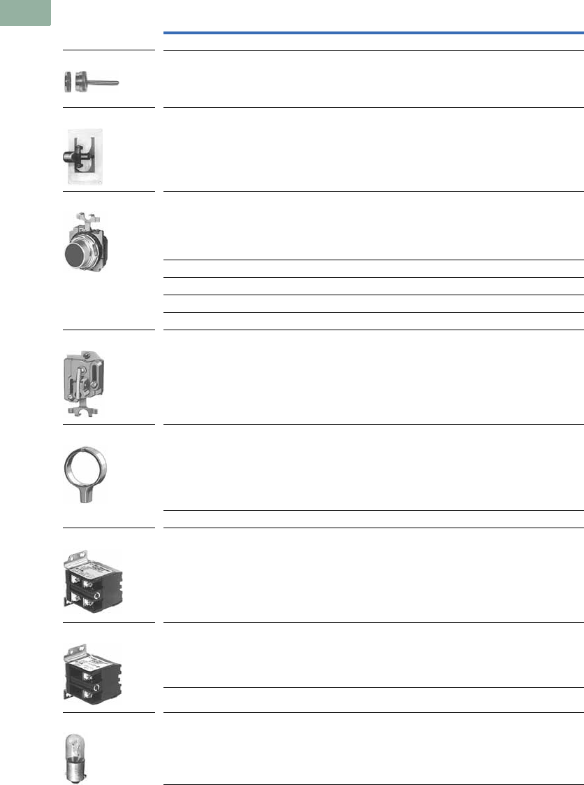
V7-T1-228 Volume 7—Logic Control, Operator Interface and Connectivity Solutions CA08100008E—March 2014 www.eaton.com
1
1
1
1
1
1
1
1
1
1
1
1
1
1
1
1
1
1
1
1
1
1
1
1
1
1
1
1
1
1
1.8
Pushbuttons and Indicating Lights
30.5 mm Heavy-Duty Watertight/Oiltight—10250T
Accessories, continued
Note
1 Not suitable for single contact block depth cast enclosure. Cover is too thick.
Description Catalog Number
Special Operators and Attachments
Wobble Stick
Complete with retaining nut—fits standard button.
10250TA5
Lever Operator
For use with two vertically mounted flush pushbuttons.
10250TA14
Maintained Contact Attachment Release Button Assembly 1
Mechanically interlocks with another pushbutton and contact block (not included).
Provides mode indication. Minimum hole centers 1.62 in (41.1 mm), maximum
2.313 in (58.8 mm).
Black 10250TA17
Red 10250TA18
Green 10250TA19
Yellow 10250TA20
Same with Long Button—Black 10250TA39
Maintained Contact Attachment 1
Mechanically interlocks two buttons and provides position indication for one.
Use with two pushbutton operators and one or more contact blocks.
10250TA1
Roto-Push Lever Operator—
Used to provide lever operation for Roto-Push operators.
10250TA13
Special Light Modules
Master Test (Dual Input) Module—
Internal Form C relay suitable for either AC or DC applications. Total electrical isolation
between monitored and test circuit. Fits all illuminated 10250T, E22, E30 and E34 devices.
48 Vdc 10250TMT8
Flasher Module—
Changes any AC illuminated device to a controlled flashing light.
Fits 10250T, E30 and E34 devices.
24V 10250TFL2
120V 10250TFL1
Flashing Incandescent Lamp—
For use with 120V transformer type or 6V full voltage type indicating lights including
PresTest and most E29 devices.
10250ED986-4
10250TA5
10250TA14
10250TA_
10250TA1
10250TA13
10250TA79
10250TFL_
10250ED986-4
Volume 7—Logic Control, Operator Interface and Connectivity Solutions CA08100008E—March 2014 www.eaton.com V7-T1-229
1
1
1
1
1
1
1
1
1
1
1
1
1
1
1
1
1
1
1
1
1
1
1
1
1
1
1
1
1
1
1.8
Pushbuttons and Indicating Lights
30.5 mm Heavy-Duty Watertight/Oiltight—10250T
Accessories, continued
Description Catalog Number
Hole Plugs
Plug—
For unused holes—steel, painted gray (stainless steel, use E30KT5, see Page V7-T1-175)
10250TA7
Tools
Octagonal 10250T (notched to fit over selector switch lever), E29 and E30 10250TA95
E22, E30, E34 and octagonal 10250T (will not fit over selector switch levers) E22CW
Tool for Tightening Boots—
Used to install boot Catalog Numbers 10250TA3, A4, A10 and A25.
10250TA96
10250T, E34 Allen Wrench—
Used for removal of jumbo mushroom head.
10250TA102
Lamp Removal Tools—
For transformer type illuminated pushbuttons, push-pull and selector switches.
Fits #12 lamp.
10250TA74
For full voltage and resistor type illuminated pushbuttons, push-pull and
selector switches and E30.
E30KV1
Standard indicating lights. Fits #44, #755, #6S6 and #10S6. E29KLT
10250TA7
10250TA95
E22CW
10250TA96
10250TA102
10250TA74
E30KV1
E29KLT
V7-T1-230 Volume 7—Logic Control, Operator Interface and Connectivity Solutions CA08100008E—March 2014 www.eaton.com
1
1
1
1
1
1
1
1
1
1
1
1
1
1
1
1
1
1
1
1
1
1
1
1
1
1
1
1
1
1
1.8
Pushbuttons and Indicating Lights
30.5 mm Heavy-Duty Watertight/Oiltight—10250T
Options
Legend Plates
Legend Plates with Standard Markings
The legend plates listed
below are sized for all
standard commercial
enclosures and Eaton’s cast
enclosures. For vertical
spacing less than 1.75 in,
replace the S in the catalog
number with MS, or the M
with P (except push-pull). No
change in price. The smaller
size legend plates, “MS” or
“P” size, have limited space
for legend.
For Pushbutton Operators and Indicating Lights—Standard
Blank Plastic Legend Plates—Square
Notes
1 Square legend plates have a satin aluminum field. Color is on lower portion.
2 Cannot be used on cast enclosures except for top row. Suitable for most sheet metal enclosures.
3 If legend plate is to be engraved, specify field color required.
Legend
Color of
Field
Square 1
Catalog Number
1/2 Round
Catalog Number Legend
Color of
Field
Square 1
Catalog Number
1/2 Round
Catalog Number
Blank—see table on Page V7-T1-232.
Letters on Legend Plates Below are 3/16 in High
CLAMP Black 10250TS90 10250TM90 OFF Red 10250TS24 10250TM24
CLOSE 10250TS73 10250TM11 ON Black 10250TS25 10250TM25
DOWN 10250TS74 10250TM12 OPEN 10250TS26 10250TM26
EMERG. STOP Red 10250TS13 10250TM13 OUT 10250TS27 10250TM27
FAST Black 10250TS75 10250TM14 POWER ON 10250TS80 10250TM80
FASTER 10250TS87 10250TM87 RAISE 10250TS28 10250TM28
FEEDER ON 10250TS94 10250TM94 READY 10250TS86 10250TM86
FEEDER OFF 10250TS95 10250TM95 RESET 10250TS29 10250TM29
FORWARD 10250TS15 10250TM15 REVERSE 10250TS30 10250TM30
HIGH 10250TS16 10250TM16 RUN 10250TS31 10250TM31
IN 10250TS17 10250TM17 SAFE 10250TS85 10250TM85
INCH 10250TS18 10250TM18 SLOW 10250TS32 10250TM32
JOG 10250TS19 10250TM19 SLOWER 10250TS88 10250TM88
JOG FOR. 10250TS20 10250TM20 START 10250TS33 10250TM33
JOG REV. 10250TS21 10250TM21 STOP Red 10250TS34 10250TM34
LOW 10250TS22 10250TM22 TEST Black 10250TS83 10250TM83
LOWER 10250TS23 10250TM23 TRANSFER 10250TS93 10250TM93
LUBE-FAIL 10250TS92 10250TM92 TRIP 10250TS84 10250TM84
MOTOR RUN 10250TS81 10250TM81 UNCLAMP 10250TS91 10250TM91
MOTOR STOP 10250TS82 10250TM82 UP 10250TS35 10250TM35
Color Standard
Catalog Number
Jumbo 2
Catalog Number
Extra Large
Catalog NumberLettering Field
Black White or silver 310250TSP76 10250TLP76 10250TEP76
White Red or black 310250TSP77 10250TLP77 10250TEP77
Square Legend Plate
1/2 Round Legend Plate
Volume 7—Logic Control, Operator Interface and Connectivity Solutions CA08100008E—March 2014 www.eaton.com V7-T1-231
1
1
1
1
1
1
1
1
1
1
1
1
1
1
1
1
1
1
1
1
1
1
1
1
1
1
1
1
1
1
1.8
Pushbuttons and Indicating Lights
30.5 mm Heavy-Duty Watertight/Oiltight—10250T
For Selector Switch and Roto-Push Operators—Standard Size
45 mm and 70 mm Plastic—Round
For Push-Pull Units 3
Notes
1 Square legend plates have a satin aluminum field. Color is on lower portion.
2 If legend plate is to be engraved, specify field color required.
3 All push-pull legend plates include the symbols in the center of the plate.
Legend
Color of
Field
Square 1
Catalog Number
1/2 Round
Catalog Number Legend
Color of
Field
Square 1
Catalog Number
1/2 Round
Catalog Number
Blank—see table on Page V7-T1-232.
2-Position—5/32 in High Lettering 3-Position—1/8 in High Lettering
FOR. REV. Black 10250TS38 10250TM38 AUTO OFF HAND Black 10250TS49 10250TM49
HAND AUTO 10250TS39 10250TM39 FOR. OFF REV. 10250TS50 10250TM50
HIGH LOW 10250TS40 10250TM40 FOR. SAFE REV. 10250TS69 10250TM69
JOG RUN 10250TS41 10250TM41 HAND OFF AUTO 10250TS51 10250TM51
MAN. AUTO 10250TS67 10250TM67 MAN. OFF AUTO 10250TS68 10250TM68
OFF ON 10250TS42 10250TM42 OPEN OFF CLOSE 10250TS53 10250TM53
OPEN CLOSE 10250TS43 10250TM43 RUN SAFE JOG 10250TS70 10250TM70
RUN JOG 10250TS44 10250TM44 UP OFF DOWN 10250TS54 10250TM54
SAFE RUN 10250TS45 10250TM45 ON STOP SAFE Red 10250TS71 10250TM71
START JOG 10250TS46 10250TM46
START STOP 10250TS47 10250TM47
UP DOWN 10250TS48 10250TM48
Color
Lettering Field Catalog Number
45 mm
Blank Yellow or red 210250TRP78
70 mm
Blank Yellow or red 210250TRP76
Red EMERG. STOP Yellow 10250TRP79
Legend
Color of
Field
Square 1
Catalog Number
1/2 Round
Catalog Number
Standard Size—Letters on Legend Plates Below are 3/32 in High
PULL START/PUSH STOP Green/red 10250TPP2 10250TR2
PUSH ON/PULL OFF Black 10250TPP5 10250TR5
PULL OPEN/PUSH CLOSE Black 10250TPP8 10250TR8
PULL UP/PUSH DOWN Black 10250TPP11 10250TR11
Jumbo Size—Letters on Legend Plates Below are 1/8 in High
PULL START/PUSH STOP Green/red 10250TPP3 10250TR3
PULL ON/PUSH OFF Black 10250TPP6 10250TR6
PULL OPEN/PUSH CLOSE Black 10250TPP9 10250TR9
PULL UP/PUSH DOWN Black 10250TPP12 10250TR12
Square Legend Plate
1/2 Round Legend Plate
70 mm Round—Plastic
Legend Plate
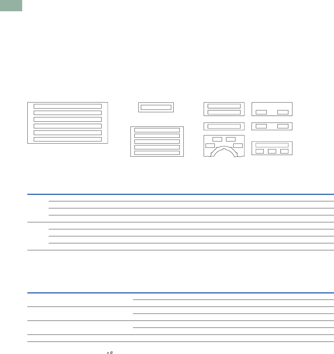
V7-T1-232 Volume 7—Logic Control, Operator Interface and Connectivity Solutions CA08100008E—March 2014 www.eaton.com
1
1
1
1
1
1
1
1
1
1
1
1
1
1
1
1
1
1
1
1
1
1
1
1
1
1
1
1
1
1
1.8
Pushbuttons and Indicating Lights
30.5 mm Heavy-Duty Watertight/Oiltight—10250T
Legend Plates with Non-Standard Markings
When Ordering Specify
●Catalog number of blank
plate phase plus Suffix
“STAMP.”
●Insert the following into
Order Notes: legend, letter
size and locations (letters
A–W)—combine letters for
definitive locations as
shown.
Ordering Example:
Catalog No.:
10250TS36STAMP
Letter Size: 3/32 in (2.4 mm)
Pos. A—POWER HOUSE
Pos. B—START PUMP 1
Legend Characters
Available
A B C D E F G H I J K L M N O
P Q R S T U V W X Y Z / - . , 1
2 3 4 5 6 7 8 9 0
Legend characters on black
and red plates are white—
on satin aluminum plates,
characters are black.
Blackening Kit
Solution blackens aluminum
exposed by engraving
process. Must be applied
immediately after engraving.
0.3 oz. bottle—sufficient for
approximately 1100 legend
plates.
Catalog Number: 10250TBK
Legend Positions
Blank and Custom Engraved Legend Plates
Maximum Characters per Legend Plate and Approximate Dimensions
Notes
1All push-pull legend plates include the symbols in the center of the plate.
2Cannot be used on cast enclosures except for top row. Suitable for most sheet metal enclosures.
3When used to meet Ford Motor Co. specifications, specify engraved legend. Cannot be used on standard cast or sheet metal enclosures.
4Slightly larger than standard size for legends requiring more space—fits cast enclosures.
5Square legend plates have a satin aluminum field. Color is on lower portion.
6Recommended only when mounting on minimum centers (less than 1-3/4 in [44.5 mm] vertical centers).
7Can be used on top row only of any enclosure.
Style Color
Small
Catalog Number
Standard
Catalog Number
Jumbo 2
Catalog Number
Extra Large 3
Catalog Number
Four-Position Selector Switch Push-Pull with Symbols 1
Custom 4
Catalog Number
Standard
Catalog Number
Standard
Catalog Number
Jumbo 2
Catalog Number
Square 5Black 10250TMS36 10250TS36 10250TL36 — 10250TS76 10250TS72 10250TPP17 10250TPP18
Red 10250TMS3710250TS3710250TL37—————
Green/red ——————10250TPP20 10250TPP21
Satin alum. ———10250TNP99 ————
1/2 Round Black 10250TP36 10250TM36 10250TJ36 — — 10250TM72 10250TR17 10250TR18
Red 10250TP3710250TM3710250TJ37—————
Green/red ——————10250TR20 10250TR21
Satin alum. —10250TM8910250TJ89—————
Top
(Aluminum
and Plastic) Style
Character Size
Approximate Dimensions
in Inches (mm)
3/32 in High 1/8 in High 3/16 in High
Number
of Lines
Number of
Characters
Number
of Lines
Number of
Characters
Number
of Lines
Number of
CharactersWidth Height
Small 61.59 (40.4) 1.59 (40.4) Square 1 17 — — — —
1/2 Round 1 15 1 12 1 9
Standard and
custom
1.75 (44.5) 1.75 (44.5) Square 2 18 2 13 1 9
1/2 Round 2 15 2 12 1 9
Jumbo 72.19 (55.6) 2.19 (55.6) Square 5 23 3 18 2 12
1/2 Round 5 19 4 15 2 11
Extra large 32.44 (62.0) 2.44 (62.0) Square 6 25 3 18 3 12
L
K
D
C
B
A
Extra Large Size
Cat. No. 10250TNP99
Jumbo Size
10250TL or TJ Series
Small Size
10250TMS or TP Series
A
A
C
K
D
B
Standard Size
10250TS or TM Series
AB
B
A
GF
AE
GH
A
I
AF
D4
C4B4
A4

Volume 7—Logic Control, Operator Interface and Connectivity Solutions CA08100008E—March 2014 www.eaton.com V7-T1-233
1
1
1
1
1
1
1
1
1
1
1
1
1
1
1
1
1
1
1
1
1
1
1
1
1
1
1
1
1
1
1.8
Pushbuttons and Indicating Lights
30.5 mm Heavy-Duty Watertight/Oiltight—10250T
Enclosures
Die Cast, Polyester and Stainless Steel Enclosures
Enclosures (Case and Cover)—Surface Mounting 1
Mounting Instructions
Two-position joystick must be
used with two contact block
deep enclosures (maximum
number of contact blocks = 1).
Four-position joysticks cannot
be used within these
enclosures.
One and Two Contact Block
Depth Enclosures Enclosure Layouts
Notes
1For spacing increments, see Page V7-T1-234.
2All die cast enclosures can be converted to base mounting of contact blocks, with spacers 10250TA22 or 10250TA23.
See listing on Page V7-T1-227.
3When used with E30 pushbuttons, only the one element enclosure can be used.
4When used with resistor light units, only the 2 contact block depth enclosure can be used.
514 gauge, type 304.
Number of
Elements
One Contact Block Depth
Catalog Number
Two Contact Block Depth
Catalog Number
Die Cast Enclosure—In-Line 234 NEMA 4, 4X, 12, 13
110250TN1 10250TN11
210250TN2 10250TN12
310250TN3 10250TN13
4— 10250TN14
Polyester4—In-Line NEMA 3, 4X, 12
1— E34N51
2— E34N52
3— E34N53
4— E34N54
Stainless Steel 45—In-Line NEMA 4, 4X, 12
1— 10250TN33
2— 10250TN34
3— 10250TN35
4— 10250TN36
Dimensions, see Page V7-T1-246.
Die Cast Enclosure
Polyester Enclosure
Stainless Steel
Enclosure
One Contact
Block Depth
Enclosure
Two Contact
Block Depth
Enclosure
111
Top – For Vertical Mounting
Top – For Horizontal
Mounting
1
222
33
4

V7-T1-234 Volume 7—Logic Control, Operator Interface and Connectivity Solutions CA08100008E—March 2014 www.eaton.com
1
1
1
1
1
1
1
1
1
1
1
1
1
1
1
1
1
1
1
1
1
1
1
1
1
1
1
1
1
1
1.8
Pushbuttons and Indicating Lights
30.5 mm Heavy-Duty Watertight/Oiltight—10250T
Die Cast and Stainless Steel—Flush Mount, Covers Only
Covers Only—Flush Mounting
Spacing Increments
Approximate Dimensions in Inches (mm)
Spacing Increments for
Enclosures Enclosure Layouts
Note
1Not oiltight. NEMA 1 applications only.
Number of
Elements Catalog Number Catalog Number
Flush Die Cast Covers
In-Line Deep
Cover
In-Line Flat
Cover
110250TF11 10250TF1
210250TF12 10250TF2
310250TF13 10250TF3
410250TF14 10250TF4
In-Line Stainless Steel Flush Plates 1
With Pullbox Without Pullbox
110250TS10 10250TS1
210250TS11 10250TS2
310250TS12 10250TS3
410250TS14 10250TS4
Dimensions, see Page V7-T1-247.
Type F G H
Die cast 2.44 (62.0) 2.5 (63.5) 1.88 (47.8)
Polyester 1.88 (47.8) Min. 2.13 (54.1) 2.25 (57.2)
Stainless steel 1.69 (42.9) Min. 1.73 (43.9) 2.25 (57.2)
Flush Mounting Covers
F
G
H
111
Top – For Vertical Mounting
Top – For Horizontal
Mounting
1
222
33
4

Volume 7—Logic Control, Operator Interface and Connectivity Solutions CA08100008E—March 2014 www.eaton.com V7-T1-235
1
1
1
1
1
1
1
1
1
1
1
1
1
1
1
1
1
1
1
1
1
1
1
1
1
1
1
1
1
1
1.8
Pushbuttons and Indicating Lights
30.5 mm Heavy-Duty Watertight/Oiltight—10250T
Contact Blocks
Standard Contact Blocks
●UL A600/P600 rated
●Color-coded plungers—red/
green for NC/NO circuits
●Silver contact tips with
“reliability nibs”
●Gray (opaque) or amber
(translucent) housings
●Pressure plate or spade
terminals
●Fingerproof shrouds (for
pressure terminals only)
Logic Level Contact Blocks
●UL A600/P600 rated
●Color-coded plungers
●Inert palladium knife-blade
contacts
●Gray (opaque) housings
●Pressure plate or spade
terminals
Special Function Contact Blocks
●UL A600/P600 rated
●Color-coded plungers
●Silver contact tips with
“reliability nibs”
●Gray (opaque) housings
●Pressure plate terminals
only
Special Purpose Contact Block
●Maximum 300V rated
●Black plungers
●Silver contact tips with
“reliability nibs”
●Black (opaque) housings
●Pressure plate terminals
only
●Fingerproof shrouds not
available
Reliability Nibs
Reliability nibs are the
hallmark of Eaton’s contact
blocks. A pointed silver nib on
the contact tip ensures
reliable switching from logic
level (5V) up to 600V
applications. Therefore
standard contact blocks can
be used for most logic level
applications where the
contacts are not exposed to
any harsh environmental
conditions.
Palladium Contacts
Palladium, which is more
inert than gold, is well suited
for voltages and currents
approaching zero and is
recommended for applications
where environmental
conditions are a factor.
Maximum Contact Block
Mounting per Operator Type
Operator
Max.
Stack
Pushbuttons 6
Push-pull operators 2
Roto-push operators 4
Two- or three-position
selector switches
6
Four-position selector
switches
4
Joysticks 4

V7-T1-236 Volume 7—Logic Control, Operator Interface and Connectivity Solutions CA08100008E—March 2014 www.eaton.com
1
1
1
1
1
1
1
1
1
1
1
1
1
1
1
1
1
1
1
1
1
1
1
1
1
1
1
1
1
1
1.8
Pushbuttons and Indicating Lights
30.5 mm Heavy-Duty Watertight/Oiltight—10250T
Contact Blocks
Notes
1 All 10250T contact blocks shown are suitable for use on standard 10250T and E34 operators. These contact blocks are not suitable for Class I Division 2
type 10250T or E34 devices.
2 Contact blocks with spade terminals are limited to a maximum of one contact block per operator and minimum spacing between devices is 2.5 in (63.5 mm).
Not suitable for use in 10250T or E34 enclosures. Also available in amber housing. Not available with fingerproof shrouds.
3 Special function contact blocks are not suitable for use with roto-push operators, three-position push-pull operators, or four-position selector switches.
4 ECNO contact blocks are not suitable for use with two-position joysticks or when operators are used with padlock attachments.
5 Special purpose 10250T44 contact blocks are not suitable on selector switches or roto-push operators. Okay to use with three-position push-pull operators only
on low voltage (30V or less) circuits. Fingerproof shrouds not available.
Symbol Circuit Description 1
Standard Logic Level
Pressure Terminal
Catalog Number
Spade Terminal 2
Catalog Number
Pressure Terminal
Catalog Number
Spade Terminal 2
Catalog Number
1NC Stack up to six blocks (six circuits)
unless otherwise noted.
10250T51 10250T59 10250T51E 10250T59E
1NO Stack up to six blocks six circuits)
unless otherwise noted.
10250T53 10250T60 10250T53E 10250T60E
NO-NC Stack up to six blocks (12 circuits)
unless otherwise noted.
10250T1 10250T40 10250T1E 10250T40E
2NC Stack up to six blocks (12 circuits)
unless otherwise noted.
10250T3 10250T42 10250T3E 10250T42E
2NO Stack up to six blocks (12 circuits)
unless otherwise noted.
10250T2 10250T41 10250T2E 10250T41E
Special Function Blocks 3
LONC Late opening NC. Stack up to six
blocks (six circuits) unless
otherwise noted.
10250T71 3— 10250T71E 3—
ECNO-
NC
Early closing NO and standard NC.
Stack up to six blocks unless
otherwise noted.
10250T47 34 — 10250T47E 3—
ECNO-
NO
Early closing NO and standard NO.
Stack up to four blocks unless
otherwise noted.
10250T57 34 — 10250T57E 3—
2LONC Two late opening NC contacts.
Stack up to six blocks unless
otherwise noted.
10250T45 3— 10250T45E 3—
LONC-
ECNO
Overlapping contacts. Stack up to
four blocks unless otherwise noted.
10250T55 34 — 10250T55E 3—
Special Purpose Blocks 5
2NO-
2NC
Four circuits in single block depth.
Rated 300V max. Stack up to four
blocks unless otherwise noted.
10250T44 5—
10250T1
Blank
No
Plunger
Blank
No
Plunger
Blank
No
Plunger
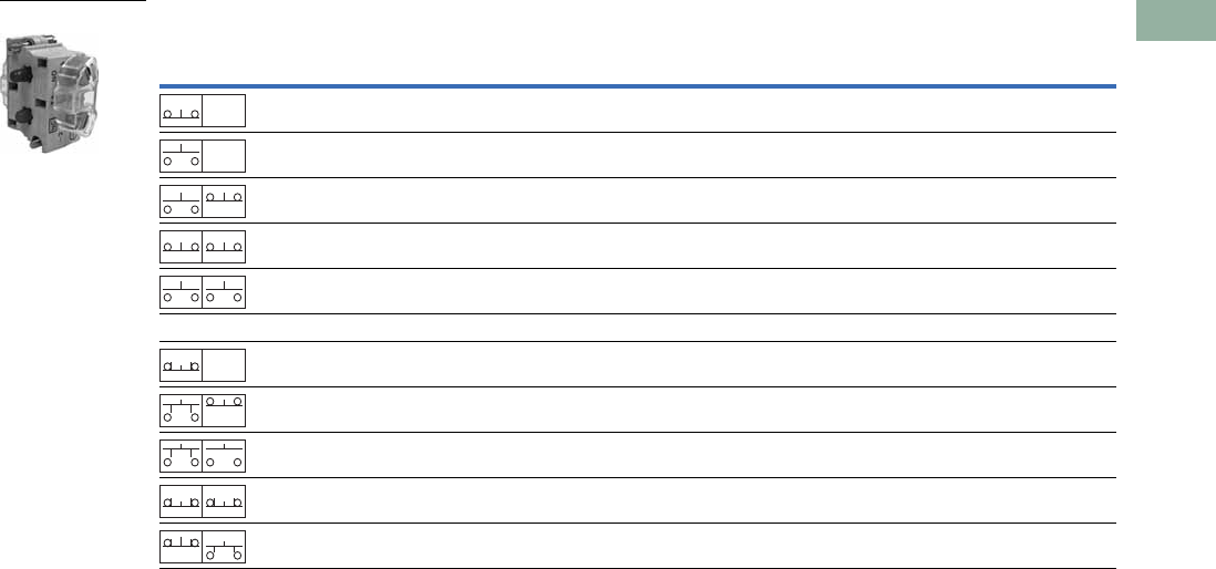
Volume 7—Logic Control, Operator Interface and Connectivity Solutions CA08100008E—March 2014 www.eaton.com V7-T1-237
1
1
1
1
1
1
1
1
1
1
1
1
1
1
1
1
1
1
1
1
1
1
1
1
1
1
1
1
1
1
1.8
Pushbuttons and Indicating Lights
30.5 mm Heavy-Duty Watertight/Oiltight—10250T
Contact Blocks with Fingerproof Shrouds
Notes
1 All 10250T contact blocks shown are suitable for use on standard 10250T and E34 operators. These contact blocks are not suitable for Class I Division 2
type 10250T or E34 devices.
2 To order contact blocks with translucent amber housing, change suffix P to CP in catalog number e.g. 10250T51CP.
3 ECNO contact blocks are not suitable for use with two-position joysticks or when operators are used with padlock attachments.
4 Special function contact blocks are not suitable for use with roto-push operators, three-position push-pull operators, or four-position selector switches.
Symbol Circuit Description 1
Standard
Pressure Terminal 2
Catalog Number
Logic Level
Pressure Terminal 2
Catalog Number
1NC Stack up to six blocks (six circuits) unless otherwise noted. 10250T51P 10250T51EP
1NO Stack up to six blocks (six circuits) unless otherwise noted. 10250T53P 10250T53EP
NO-NC Stack up to six blocks (12 circuits) unless otherwise noted. 10250T1P 10250T1EP
2NC Stack up to six blocks (12 circuits) unless otherwise noted. 10250T3P 10250T3EP
2NO Stack up to six blocks (12 circuits) unless otherwise noted. 10250T2P 10250T2EP
Special Function Blocks 3
LONC Late opening NC. Stack up to six blocks (six circuits) unless
otherwise noted.
10250T71P 410250T71EP 4
ECNO-NC Early closing NO and standard NC. Stack up to six blocks
unless otherwise noted.
10250T47P 34 10250T47EP 4
ECNO-NO Early closing NO and standard NO. Stack up to four blocks
unless otherwise noted.
10250T57P 34 10250T57EP 4
2LONC Two late opening NC contacts. Stack up to six blocks unless
otherwise noted.
10250T45P 410250T45EP 4
LONC-ECNO Overlapping contacts. Stack up to four blocks unless
otherwise noted.
10250T55P 34 10250T55EP 4
10250T1CP
Blank
No
Plunger
Blank
No
Plunger
Blank
No
Plunger
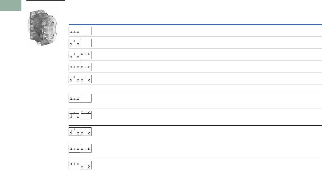
V7-T1-238 Volume 7—Logic Control, Operator Interface and Connectivity Solutions CA08100008E—March 2014 www.eaton.com
1
1
1
1
1
1
1
1
1
1
1
1
1
1
1
1
1
1
1
1
1
1
1
1
1
1
1
1
1
1
1.8
Pushbuttons and Indicating Lights
30.5 mm Heavy-Duty Watertight/Oiltight—10250T
Amber Contact Blocks
Notes
1 All 10250T contact blocks shown are suitable for use on standard 10250T and E34 operators. These contact blocks are not suitable for Class I Division 2
type 10250T or E34 devices.
2 To order amber contact blocks with fingerproof shrouds, change suffix to CP in the catalog number e.g. 10250T51CP. Not available with spade terminals.
3 Contact blocks with spade terminals are limited to a maximum of one contact block per operator and minimum spacing between devices is 2.5 in (63.5 mm).
Not suitable for use in 10250T or E34 enclosures. Also available in amber housing. Not available with fingerproof shrouds.
4 Special function contact blocks are not suitable for use with roto-push operators, three-position push-pull operators, or four-position selector switches.
5 ECNO contact blocks are not suitable for use with two-position joysticks or when operators are used with padlock attachments.
Symbol Circuit Description 1
Standard Logic Level
Pressure Terminal 2
Catalog Number
Spade Terminal 3
Catalog Number
Pressure Terminal 2
Catalog Number
Spade Terminal 3
Catalog Number
1NC Stack up to six blocks (six circuits)
unless otherwise noted.
10250T51C 10250T59C 10250T51EC 10250T59EC
1NO Stack up to six blocks (six circuits)
unless otherwise noted.
10250T53C 10250T60C 10250T53EC 10250T60EC
NO-NC Stack up to six blocks (12 circuits)
unless otherwise noted.
10250T1C 10250T40C 10250T1EC 10250T40EC
2NC Stack up to six blocks (12 circuits)
unless otherwise noted.
10250T3C 10250T42C 10250T3EC 10250T42EC
2NO Stack up to six blocks (12 circuits)
unless otherwise noted.
10250T2C 10250T41C 10250T2EC 10250T41EC
Special Function Blocks 3
LONC Late opening NC. Stack up to six
blocks (six circuits) unless otherwise
noted.
10250T71C 4— 10250T71EC 4—
ECNO-
NC
Early closing NO and standard NC.
Stack up to six blocks unless
otherwise noted.
10250T47C 45 — 10250T47EC 4—
ECNO-
NO
Early closing NO and standard NO.
Stack up to four blocks unless
otherwise noted.
10250T57C 45 — 10250T57EC 4—
2LONC Two late opening NC contacts.
Stack up to six blocks unless
otherwise noted.
10250T45C 4— 10250T45EC 4—
LONC-
ECNO
Overlapping contacts. Stack up to
four blocks unless otherwise noted.
10250T55C 45 — 10250T55EC 4—
10250T1C
Blank
No
Plunger
Blank
No
Plunger
Blank
No
Plunger
Volume 7—Logic Control, Operator Interface and Connectivity Solutions CA08100008E—March 2014 www.eaton.com V7-T1-239
1
1
1
1
1
1
1
1
1
1
1
1
1
1
1
1
1
1
1
1
1
1
1
1
1
1
1
1
1
1
1.8
Pushbuttons and Indicating Lights
30.5 mm Heavy-Duty Watertight/Oiltight—10250T
Replacement Parts
Replacement Lamps—For 10250T Illuminated Operators
Replacement LED Lamps—For 10250T, E34 and E22 Units
Mfg. Lamp Type Voltage Base Style Application Part Number
120MB 120V T 3-1/4 bayonet 10250T resistor indicating light 28-3044
#267 6.3V T 3-1/4 bayonet 10250T flasher 10250ED986-4
#755 6.3V T 3-1/4 bayonet 10250T transformer, PresTest and full voltage 28-2202
#756 12V T 3-1/4 bayonet 10250T full voltage 28-5184
#757 24V T 3-1/4 bayonet 10250T full voltage 28-5185
#1828 32V T 3-1/4 bayonet 10250T full voltage 28-5186
#1835 55V T 3-1/4 bayonet 10250T resistor 28-5187
NE48 120V T 4-1/2 bayonet 10250T neon 28-494
NE51H-R22 120V T 3-1/4 bayonet 10250T neon 28-3754
NE51H-R68 240V T 3-1/4 bayonet 10250T neon 28-3755
Voltage Color
Continuous Flashing
AC/DC
Catalog Number
AC
Catalog Number
DC
Catalog Number
6–12V Red E22LED612RN E22LED006RAF E22LED006RDF
Orange E22LED612ON E22LED006OAF E22LED006ODF
Yellow E22LED612YN E22LED006YAF E22LED006YDF
Green E22LED612GN E22LED006GAF E22LED006GDF
Blue E22LED612BN E22LED006BAF E22LED006BDF
White E22LED612WN E22LED006WAF E22LED006WDF
24V Red E22LED024RN E22LED024RAF E22LED024RDF
Orange E22LED024ON E22LED024OAF E22LED024ODF
Yellow E22LED024YN E22LED024YAF E22LED024YDF
Green E22LED024GN E22LED024GAF E22LED024GDF
Blue E22LED024BN E22LED024BAF E22LED024BDF
White E22LED024WN E22LED024WAF E22LED024WDF
48V Red E22LED048RN E22LED048RAF E22LED048RDF
Orange E22LED048ON E22LED048OAF E22LED048ODF
Yellow E22LED048YN E22LED048YAF E22LED048YDF
Green E22LED048GN E22LED048GAF E22LED048GDF
Blue E22LED048BN E22LED048BAF E22LED048BDF
White E22LED048WN E22LED048WAF E22LED048WDF
60V Red E22LED060RN E22LED060RAF E22LED060RDF
Orange E22LED060ON E22LED060OAF E22LED060ODF
Yellow E22LED060YN E22LED060YAF E22LED060YDF
Green E22LED060GN E22LED060GAF E22LED060GDF
Blue E22LED060BN E22LED060BAF E22LED060BDF
White E22LED060WN E22LED060WAF E22LED060WDF
120V Red E22LED120RN E22LED120RAF E22LED120RDF
Orange E22LED120ON E22LED120OAF E22LED120ODF
Yellow E22LED120YN E22LED120YAF E22LED120YDF
Green E22LED120GN E22LED120GAF E22LED120GDF
Blue E22LED120BN E22LED120BAF E22LED120BDF
White E22LED120WN E22LED120WAF E22LED120WDF
Standard LED Lamp
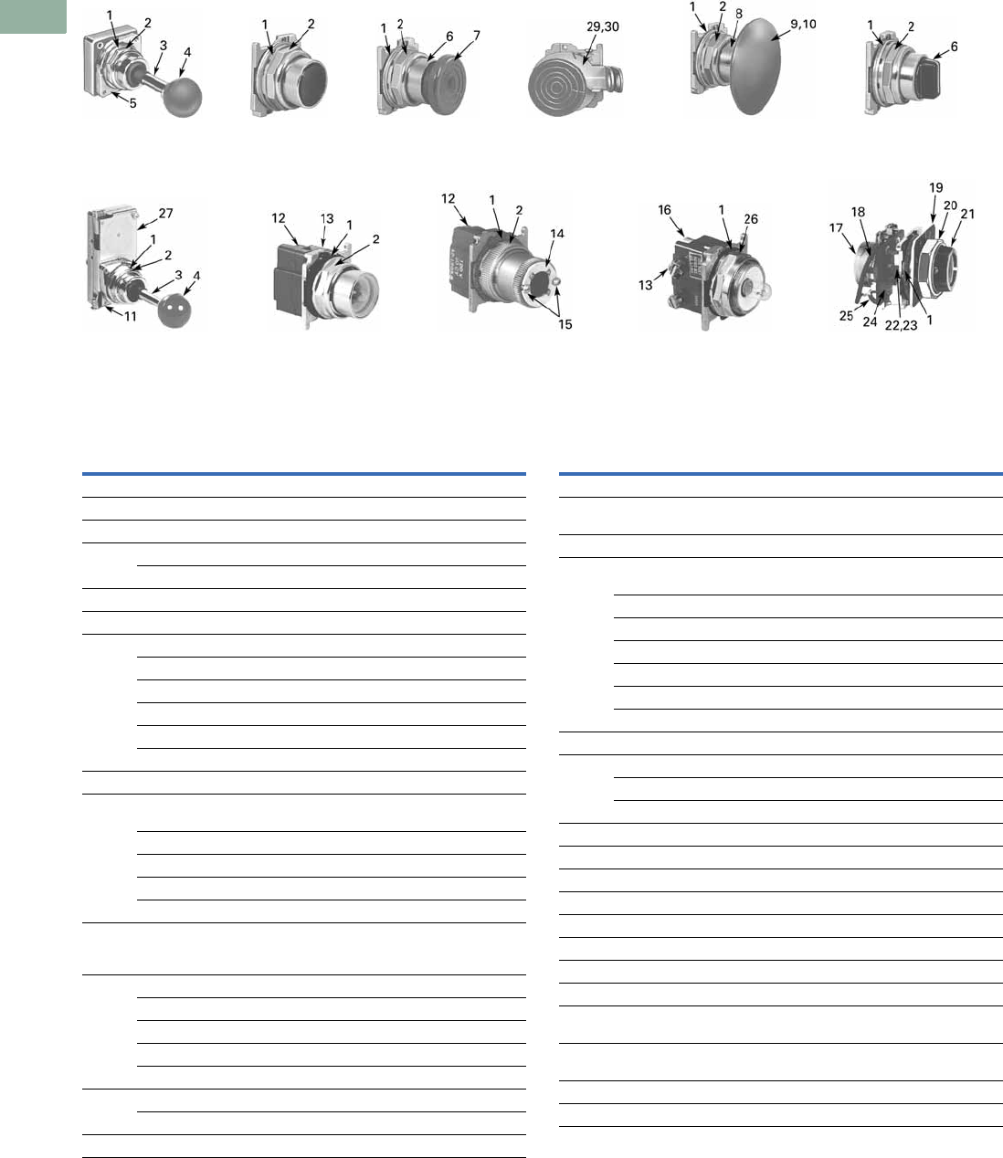
V7-T1-240 Volume 7—Logic Control, Operator Interface and Connectivity Solutions CA08100008E—March 2014 www.eaton.com
1
1
1
1
1
1
1
1
1
1
1
1
1
1
1
1
1
1
1
1
1
1
1
1
1
1
1
1
1
1
1.8
Pushbuttons and Indicating Lights
30.5 mm Heavy-Duty Watertight/Oiltight—10250T
10250T Style Operator Replacement Parts
Two-Position
Joystick Operator
Flush Head
Pushbutton
Operator
Mushroom Head
Pushbutton
Operator
Four-Position Joystick
Operator (without Latch)
Illuminated
Pushbutton Operator
Full Voltage, Resistor
and Transformer Type
Illuminated Selector Switch
Transformer Type
Indicating Light
Mushroom Head
Operator with
Padlock Attachment
Jumbo Mushroom
Head Operator
Knob-Operated
Selector Switch
Operator
Potentiometers
Item
No. Description
No.
Req. Part Number
1Gasket 116-1548
2 Mounting nut 1 15-1530
3 Handle 1 24-5045
4Knob 153-3157
Knob (not shown) for joystick operator with latch 1 53-3159
5 Common gate (supplied with operator) 2 16-3400
6 Set screw (#6-32 x 0.250 in long hollow hex) 2 11-2014
7 Mushroom head button (includes [2] Item 6) 1 As Req. Below
Black — 53-1317
Red — 53-1317-2
Yellow — 53-1317-3
Green — 53-1317-4
Blue — 53-1317-22
8 Set screw (#10-32 x 0.250 in long hollow hex) 2 11-544
9 Jumbo mushroom head button
(aluminum—includes [2] Item 8)
1As Req. Below
Red — 53-1317-9
Black — 53-1317-10
Yellow — 53-1317-11
Green — 53-1317-12
10 Jumbo mushroom head button
(aluminum—red EMERG. STOP)
does not include Item 8
153-1349-18
11 Position gate:
Two-position 1 54-7278
Three-position 1 54-7173
Four-position 1 54-12278
Eight-position 1 54-12279
12 Mounting screw (#6-32 x 0.710 in long) 2 10250TA79
Washer 2 16-2038
13 Terminal screw and lug (captive) Req. 80-5502KIT
Item
No. Description
No.
Req. Part Number
14 Gasket (supplied with basic unit) 1 32-803
15 Round head screw (#4-40 x 0.344 in long)
(supplied with basic unit)
211-4553
16 Mounting screw 2 11-1632
17 Simple potentiometer
(does not include items 18, 28 or 29)
1As Req. Below
1,000 ohms — 41-782-2
2,500 ohms — 41-782-3
5,000 ohms — 41-782-10
10,000 ohms — 41-782-4
25,000 ohms — 41-782-5
50,000 ohms — 41-782-6
18 Connector (includes screw and lug) 2 25-1851
19 Indicating plate 1 As Req. Above
Standard size (without legend) — 30-4460
Large size (specify legend) — 10250TR30
20 Retaining nut 1 15-1547
21 Knob 1 53-1314
Socket set screw (#6-32 x 0.250 in long) 2 11-2014
22 Coupling 1 29-3749-2
23 Set screw (#6-32 x 0.188 in long) 1 11-1199
24 Spacer 2 56-1066-18
25 Connector (includes screw and lug) 1 25-1851-2
26 Mounting nut 1 15-1938
27 Four-position joystick operating mechanism
(complete)
124-6565
28 Four-position joystick operating mechanism
(not shown) (with latch) complete
124-6565-2
29 Spring loaded latch 1 52-1214-2
30 Hand operated latch 1 52-913-3

Volume 7—Logic Control, Operator Interface and Connectivity Solutions CA08100008E—March 2014 www.eaton.com V7-T1-241
1
1
1
1
1
1
1
1
1
1
1
1
1
1
1
1
1
1
1
1
1
1
1
1
1
1
1
1
1
1
1.8
Pushbuttons and Indicating Lights
30.5 mm Heavy-Duty Watertight/Oiltight—10250T
Technical Data and Specifications
Mechanical Ratings
General Specifications
Description Specification
Frequency of Operation
All pushbuttons 6000 operations/hr.
Key and lever selection switches 3000 operations/hr.
Auto-latch devices 1200 operations/hr.
Life
Pushbuttons 10 x 106 operations
Contact blocks 10 x 106 operations
PresTest units 10 x 106 operations
Lever and key selector switches 0.25 x 10⁶ operations
Twist to release pushbuttons 0.3 x 10⁶ operations
Shock Resistance
Duration 20 ms >5g
Description Specification
Climate Conditions
Operating temperature 1° to 150°F (–17° to 66°C)
Storage temperature –40° to 176°F (–40° to 80°C)
Altitude 6,562 ft (2,000m)
Humidity Max. 95% RH at 60°C
Te rm i n a l s
Marking NC-NO on the contact block to meet the NEMA requirements. Dual marking system 1–2
for normally closed, 3–4 for normally open to meet BS5472 (Cenelec EN50 005).
Clamps Terminals are saddle clamp type for 1 x 22 AWG (0.34 mm2) to 2 x 14 AWG (2.5 mm2)
conductors
Torque 7 lb-in (0.8 Nm)
Degree of protection against direct electrical contact IP2X with fingerproof shroud
Light Units
Transformers Will withstand short-circuit for 1 hour per IEC 60997-5-1
Bulbs—average life:
Transformer type 20,000 hrs.
Resistor/direct voltage type 2500 hrs. minimum at rated voltage
LED 60,000 to 100,000 hrs.

V7-T1-242 Volume 7—Logic Control, Operator Interface and Connectivity Solutions CA08100008E—March 2014 www.eaton.com
1
1
1
1
1
1
1
1
1
1
1
1
1
1
1
1
1
1
1
1
1
1
1
1
1
1
1
1
1
1
1.8
Pushbuttons and Indicating Lights
30.5 mm Heavy-Duty Watertight/Oiltight—10250T
Electrical Ratings
Electrical Ratings—Contact Block
Description Specification
Insulation Ui = 660 Vac or Vdc
Thermal Ith = 10A
Short Circuit Coordination to IEC/EN 60947-5-1
Rated conditional short circuit current 1 kA
Fuse type GE power controls TIA 10, red spot type gG, 10A, 660 Vac, 460 Vdc, BS88-2,
IEC 60269-2-1
UL rating A600, P600
AC load life duty cycle 1200 operations/hour
10A 110V pf 0.4—1 x 10⁶ operations
5A 250V pf 0.4—1 x 10⁶ operations
2A 600V pf 0.4—1 x 10⁶ operations
Switching capacity
AC 15 rated make/break (11 x le at 1.1 x Ue)
6A 120V pf 0.3
4A 240V pf 0.3
2A 660V pf 0.3
DC13 rated make/break (1.1 x le at 1.1 x Ue)
1.0A 125V L/R >0.95 at 300 ms
0.55A 250V L/R >0.95 at 300 ms
0.1A 660V L/R >0.95 at 300 ms
10A 110V pure resistive
Maximum ratings for logic level and
hostile atmosphere application
Maximum amperes 0.5A
Maximum volts 120 Vac/Vdc
Description
50 Vac or 60 Hz Vdc
120 240 480 600 24/28 125 250
Meet or Exceed NEMA Rating Designations A600, A300 and B300 for AC and P600 for DC
Make and emerg. interrupting capacity (amp) 60 30 15 12 5.7 1.1 0.55
Normal load break (amp) 6 3 1.5 1.2 5.7 1.1 0.55
Thermal current (amp) 101010105.05.05.0
Voltamperes:
Make and emerg. interrupting capacity 7200 7200 7200 7200 138 138 138
Normal load break 720 720 720 720 138 138 138
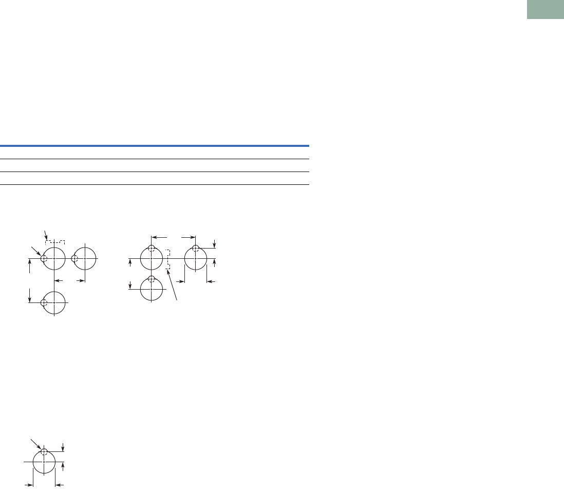
Volume 7—Logic Control, Operator Interface and Connectivity Solutions CA08100008E—March 2014 www.eaton.com V7-T1-243
1
1
1
1
1
1
1
1
1
1
1
1
1
1
1
1
1
1
1
1
1
1
1
1
1
1
1
1
1
1
1.8
Pushbuttons and Indicating Lights
30.5 mm Heavy-Duty Watertight/Oiltight—10250T
Mounting Options
Panel Thickness
●Minimum: 0.06 in (1.6 mm)
●Maximum: 0.25 in (8 mm) including legend plate
●Maximum can be increased to 0.375 in (15.9 mm) using optional retaining nut
●Indicating light: 10250TA30
●Pushbutton/selector switch: 10250TA31
Mounting Matrix
Mounting Options in Inches (mm)
Horizontal mounting means terminals are located top and bottom of contact block.
Vertical mounting means terminals are left and right of contact block.
This allows close spacing of adjacent operators with easy access to terminals.
Locating nib hole or notch is 0.14 in (3.6 mm) #29 drill.
Drilling Dimensions in Inches (mm)
Legend
Plate
Dimensions in Inches (mm)
ABCD
Small 1.63 (41.3) 2.25 (57.2) 2.25 (57.2) 1.63 (41.3)
Medium 1.75 (44.5) 2.25 (57.2) 2.25 (57.2) 1.75 (44.5)
Large 2.25 (57.2) 2.25 (57.2) 2.25 (57.2) 2.25 (57.2)
B
Min.
C
Min.
0.6
(15.2)
A
Min. 1.22
(31)
D
Min.
Horizontal Mounting Vertical Mounting
0.14 (3.6)
Dia.
Terminals on Top
Terminals at Side
0.6
(15.2)
1.20
(30.5)
0.14 (3.6)
Dia.
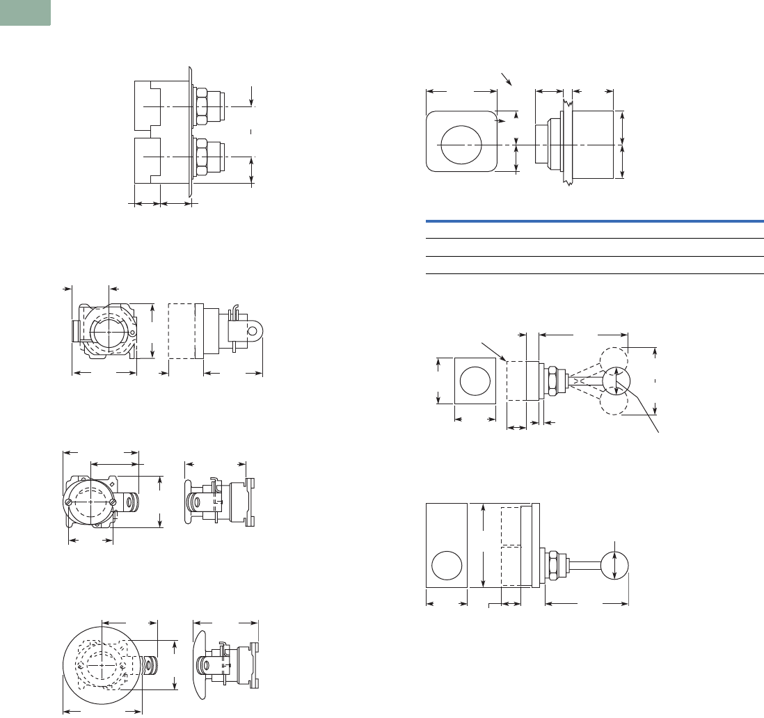
V7-T1-244 Volume 7—Logic Control, Operator Interface and Connectivity Solutions CA08100008E—March 2014 www.eaton.com
1
1
1
1
1
1
1
1
1
1
1
1
1
1
1
1
1
1
1
1
1
1
1
1
1
1
1
1
1
1
1.8
Pushbuttons and Indicating Lights
30.5 mm Heavy-Duty Watertight/Oiltight—10250T
Dimensions
Approximate Dimensions in Inches (mm)
Mechanically Interlocked Pushbutton Operators
Lockout Pushbutton Operator Padlockable
in the Down Position
Lockout Pushbutton Operator Padlockable
in the Up Position—Mushroom Head
Lockout Pushbutton Operator Padlockable
in the Up Position—Jumbo Mushroom Head
Potentiometer
Two-Position Joystick Operator
Four-Position Joystick Operator
0.89
(22.6)
Adjustable
0.88 (22.4)
for Each
Additional
Contact Block 1.07
(27.2)
1.62 (41.1)
Min.
2.5 (63.5)
Max.
2.03
(51.6)
2.0
(50.8)
1.09
(27.7)
1.13
(28.7)
1.78
(45.2)
1.5
(38.1)
1.63
(41.4)
2.5 (63.5)
2.0 (50.8)
1.75
(44.5)
2.5 (63.5)
2.31
(58.7)
2.38
(60.5)
1.75
(44.5)
Potentiometer A B C
2 watt single 1.31 (33.3) 0.94 (23.9) 0.94 (23.9)
25 watt—up to 25 mohms 2.38 (60.5) 1.19 (30.2) 0.81 (20.6)
50 mohms 2.56 (65.0) 1.69 (42.9) 1.25 (31.8)
1.88
(47.8)
1.31
(33.3)
1.09
(27.7) 1.0
(25.4)
0.75
(19.1)
0.94
(23.9)
0.94
(23.9)
0.94
(23.9)
Std. Dial Plate
Large Dial Plate
2.06
(52.3) 2.5 (63.5)
main.
2.2 (55.9)
mom.
2.13
(54.1)
1.25
(31.8)
3.88
(98.6)
0.89
(22.6)
0.88 (22.4)
per Block
0.06 (1.5) to
0.26 (6.6)
Panel Thickness
Contact
Block
4.0
(101.6)
1.88
(47.8) 3.75
(95.3)
1.25
(31.8)
1.19
(30.2)
0.88 (22.4)
Per Unit
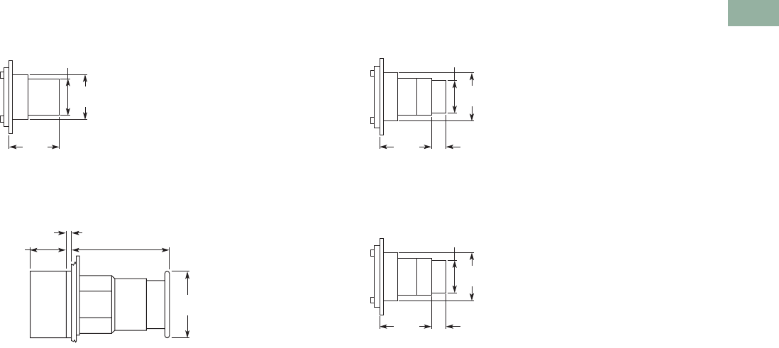
Volume 7—Logic Control, Operator Interface and Connectivity Solutions CA08100008E—March 2014 www.eaton.com V7-T1-245
1
1
1
1
1
1
1
1
1
1
1
1
1
1
1
1
1
1
1
1
1
1
1
1
1
1
1
1
1
1
1.8
Pushbuttons and Indicating Lights
30.5 mm Heavy-Duty Watertight/Oiltight—10250T
Approximate Dimensions in Inches (mm)
Key Operated Pushbutton Operator
Latch-In, Twist-to-Release Operator
Only with Button
Operator and Cam
Special Rotor Latch
1.38
(35.1)
1.13
(28.7)
1.5
(38.1)
1.5
(38.1)
0.86
(21.8)
0.24 (6) 1.55 (39.3)
Spring Return
2.37 (60.3)
Auto-Latch
1.38
(35.1)
1.13
(28.7)
1.53
(38.9)
0.38 (9.7)
Long
Button
Only
1.38
(35.1)
1.13
(28.7)
1.53
(38.9)
0.38 (9.7)
Long
Button
Only
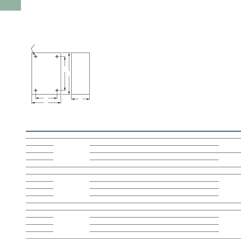
V7-T1-246 Volume 7—Logic Control, Operator Interface and Connectivity Solutions CA08100008E—March 2014 www.eaton.com
1
1
1
1
1
1
1
1
1
1
1
1
1
1
1
1
1
1
1
1
1
1
1
1
1
1
1
1
1
1
1.8
Pushbuttons and Indicating Lights
30.5 mm Heavy-Duty Watertight/Oiltight—10250T
Approximate Dimensions in Inches (mm)
Surface Mounting
Die Cast, Polyester and Stainless Steel Enclosures
Notes
1Depth given is for two contact block deep stations. One contact block deep stations subtract 3/4 in (19.1 mm).
2No conduit entrance holes provided. Drill as required.
A
Surface
DC
B
E
4 Mtg. Holes — 10-32 Screw Size for
1 – 4 Element Die Cast/
Stainless Steel Enclosure
7/32 Screw Size for
Polyester
Number of
Elements
Element
Arrangement
Wide
A
High
B
Deep
C
Mounting Conduit
EntranceDE
Die Cast
1 In-line 3.88 (98.6) 4.00 (101.6) 3.00 (76.3) 12.69 (68.3) 3.25 (82.6) 3/4
2 3.88 (98.6) 5.88 (149.4) 3.00 (76.3) 12.69 (68.3) 5.13 (130.3)
3 3.88 (98.6) 7.75 (196.9) 3.00 (76.3) 12.69 (68.3) 7.00 (177.8) 1
4 3.88 (98.6) 9.63 (244.6) 3.00 (76.3) 12.69 (68.3) 8.88 (225.6)
Polyester
1 In-line 3.81 (96.8) 6.63 (168.4) 3.38 (85.9) 2.94 (74.7) 4.88 (124.0) 2
2 3.81 (96.8) 6.63 (168.4) 3.38 (85.9) 2.94 (74.7) 4.88 (124.0)
3 3.81 (96.8) 8.88 (225.6) 3.38 (85.9) 2.94 (74.7) 7.13 (181.1)
4 3.81 (96.8) 11.13 (282.7) 3.38 (85.9) 2.94 (74.7) 9.38 (238.3)
Stainless Steel
1 In-line 3.00 (76.2) 3.50 (88.9) 3.00 (76.2) 1.50 (38.1) 4.25 (108.0) 2
2 3.50 (88.9) 6.75 (171.5) 3.00 (76.2) 1.50 (38.1) 7.50 (190.5)
3 3.50 (88.9) 9.00 (228.6) 3.00 (76.2) 1.50 (38.1) 9.00 (228.6)
4 3.50 (88.9) 11.25 (285.8) 3.00 (76.2) 1.50 (38.1) 12.00 (304.8)
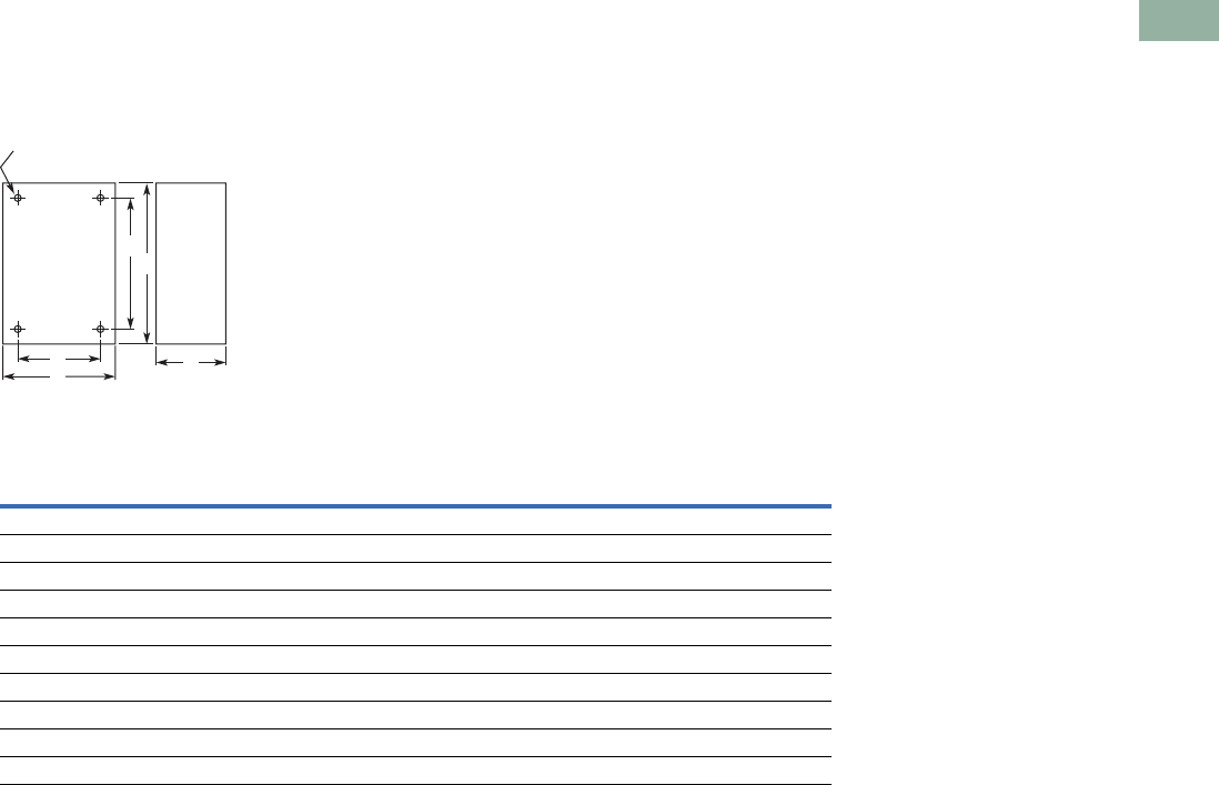
Volume 7—Logic Control, Operator Interface and Connectivity Solutions CA08100008E—March 2014 www.eaton.com V7-T1-247
1
1
1
1
1
1
1
1
1
1
1
1
1
1
1
1
1
1
1
1
1
1
1
1
1
1
1
1
1
1
1.8
Pushbuttons and Indicating Lights
30.5 mm Heavy-Duty Watertight/Oiltight—10250T
Approximate Dimensions in Inches (mm)
Flush Mounting
Die Case and Stainless Steel Covers Only
Notes
1Depth given includes pull box.
2Depth given is for flat cover. Deep cover is 3/4 in (19.1 mm) deeper.
A
Surface or Pendant
DC
B
E
4 Mtg. Holes - 10-32 Screw Size
for 1-11 Element Encl, 1/4-20
Screw Size for 12 Element
and Larger
Number of
Elements
Wide
A
High
B
Deep
C
Mounting
DE
Die Cast
1 3.88 (98.6) 4.00 (101.6) 0.25 (6.4) 23.50 (88.9) 3.63 (92.2)
2 3.88 (98.6) 5.88 (149.4) 0.25 (6.4) 23.50 (88.9) 5.50 (139.7)
3 3.88 (98.6) 7.75 (196.9) 0.25 (6.4) 23.50 (88.9) 6.00 (152.4)
4 3.88 (98.6) 9.63 (244.6) 0.25 (6.4) 23.50 (88.9) 9.25 (235.0)
Stainless Steel
1 5.00 (127.0) 5.00 (127.0) 2.50 (63.5) 23.25 (82.6) 1.88 (47.8)
2 5.00 (127.0) 6.88 (174.8) 2.50 (63.5) 23.25 (82.6) 3.63 (92.2)
3 5.00 (127.0) 8.63 (219.2) 2.50 (63.5) 23.25 (82.6) 5.50 (139.7)
4 5.00 (127.0) 10.50 (266.7) 2.50 (63.5) 23.25 (82.6) 7.25 (184.2)
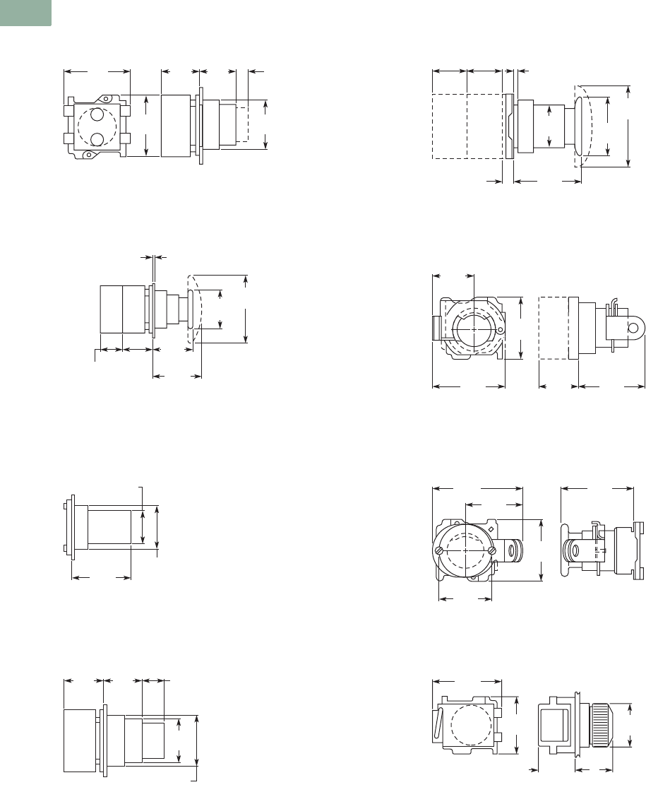
V7-T1-248 Volume 7—Logic Control, Operator Interface and Connectivity Solutions CA08100008E—March 2014 www.eaton.com
1
1
1
1
1
1
1
1
1
1
1
1
1
1
1
1
1
1
1
1
1
1
1
1
1
1
1
1
1
1
1.8
Pushbuttons and Indicating Lights
30.5 mm Heavy-Duty Watertight/Oiltight—10250T
Approximate Dimensions in Inches (mm)
Flush and Long Pushbutton Half Shroud
Mushroom and Jumbo Head Pushbutton
Pushbutton with Cylinder Lock
Illuminated Pushbutton
Push-Pull Switch
Flush Pushbutton Operator with
Padlock Attachment
Mushroom Head Pushbutton Operator
with Padlock Attachment
Indicating Light—Transformer Type
1.81
(46) 1.09
(27.7)
1.06
(26.9)
0.38
(9.7)
1.38
(35.1)
1.78
(45.2)
Long
Button
Only
Half Shroud Is Same as Long Pushbutton with
Lower Half of Guard Ring Cut Back
1.13
(28.7)
0.88 (22.4)
for Each
Additional
Contact Block
1.75
(44.5)
1.63
(41.4)
1.5
(38.1)
2.5
(63.5)
0.06 (1.5) to 0.25 (6.4)
Panel Thickness
1.91
(48.5)
1.13
(28.7)
1.38
(35.1)
1.09
(27.7)
1.09
(27.7)
0.69
(17.5)
1.13
(28.7)
1.38
(35.1)
2.63
(66.8)
1.65
(41.9)
1.78
(45.2)
0.25
(6.4)
0.06 (1.5) to 0.25 (6.4)
Panel Thickness
0.88
(22.4)
0.88
(22.4)
1.13
(28.7)
2.03
(51.6)
2.0
(50.8)
1.09
(27.7)
1.13
(28.7)
1.78
(45.2)
1.5
(38.1)
1.63
(41.4)
2.5
(63.5)
2.0
(50.8)
1.75
(44.5)
1.8
(45.7)
A
1.78
(45.2)
1.1
(27.9)
1.38
(35.1)
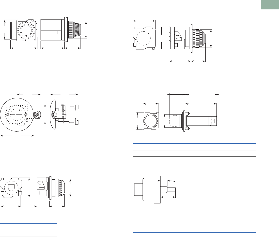
Volume 7—Logic Control, Operator Interface and Connectivity Solutions CA08100008E—March 2014 www.eaton.com V7-T1-249
1
1
1
1
1
1
1
1
1
1
1
1
1
1
1
1
1
1
1
1
1
1
1
1
1
1
1
1
1
1
1.8
Pushbuttons and Indicating Lights
30.5 mm Heavy-Duty Watertight/Oiltight—10250T
Approximate Dimensions in Inches (mm)
PresTest Indicating Light—Transformer Type
Jumbo Mushroom Head Pushbutton Operator
with Padlock Attachment
Indicating Light—Resistor and Neon Type
PresTest Indicating Light—Resistor Type
Master Test Indicating Light
Potentiometer Shaft
Lens A
Plastic 1.38 (35.1)
Glass 1.56 (39.6)
2.19
(55.6)
1.94
(49.3)
1.56
(39.6)
1.38
(35.1)
1.78
(45.2)
2.5
(63.5)
2.31
(58.7)
2.38
(60.5)
1.75
(44.5)
1.81
(46) A
1.1
(27.9)
1.78
(45.2)
1.38
(35.1)
Description B C
Relay type 4.38 (111.2) 4.28 (108.7)
Solid-state type 2.94 (74.7) 2.88 (73.2)
Operator
Catalog Number A B
10250T330 0.38 (9.7) dia. x
0.38 (9.7) long
0.25 (6.4) dia. x
0.63 (16) long
1.88
(47.8)
1.88
(47.8)
1.56
(39.6)
1.78
(45.2)
1.38
(35.1)
1.63
(41.4)
B
Spade Terminal
A
Screw Terminal
1.78
(45.2)
1.38
(35.1)
Plastic 1.38 (35.1)
Glass 1.59 (40.4)
Shaft Dimensions of Potentiometer
That C-H Operator Will Accept
A
B
Shaft
Threaded
Bushing
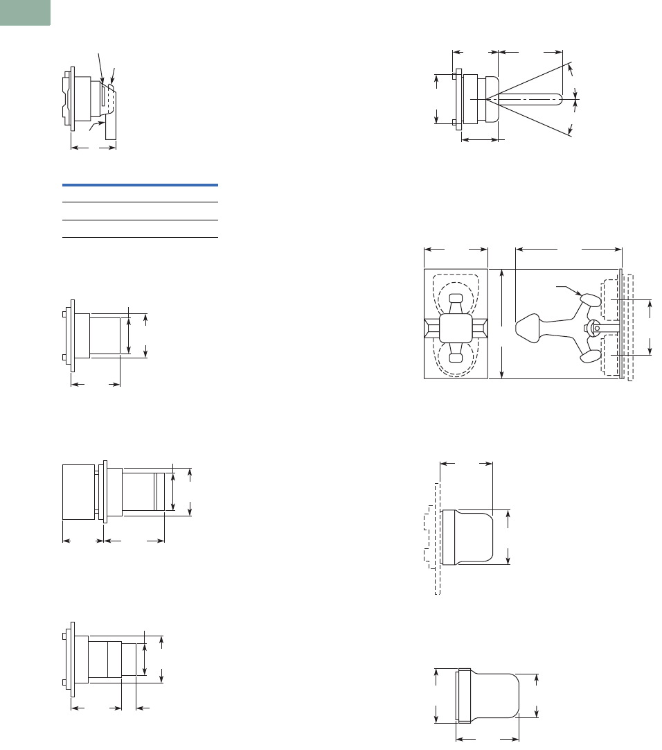
V7-T1-250 Volume 7—Logic Control, Operator Interface and Connectivity Solutions CA08100008E—March 2014 www.eaton.com
1
1
1
1
1
1
1
1
1
1
1
1
1
1
1
1
1
1
1
1
1
1
1
1
1
1
1
1
1
1
1.8
Pushbuttons and Indicating Lights
30.5 mm Heavy-Duty Watertight/Oiltight—10250T
Approximate Dimensions in Inches (mm)
Coin Operated Selector Switch
Key Operated Selector Switch
Illuminated Selector Switch
Roto-Push
Wobble Stick Catalog No. 10250TA5
Lever Operator—For Use with Two
Vertically Mounted Flush Pushbuttons
Catalog No. 10250TA14
Flexible Boot—For Protecting
Flush or Long Pushbutton
Catalog No. 10250TA3 Typical
Transparent Flexible Boot—
For Illuminated Pushbutton
Catalog No. 10250TA25
Operator Dim. A
Knob 1.38 (35.1)
Lever 1.50 (38.1)
Coin slot 1.38 (35.1)
A
Lever
Knob
Coin Slot
1.38
(35.1)
1.13
(28.7)
1.75
(44.5)
1.38
(35.1)
1.13
(28.7)
1.09
(27.7) 1.96
(49.8)
1.38
(35.1)
1.13
(28.7)
1.53
(38.9)
0.38 (9.7)
Long
Button
Only
1.38
(35.1)
1.44
(36.6)
1.22
(31)
2.44
(62)
21°
21°
1.88
(47.8)
3.75
(95.3)
2.19
(55.6) 3.59
(91.2)
Cam
1.59
(40.4)
1.47
(37.3)
1.33
(33.8)
1.59
(40.4)
1.88
(47.8)
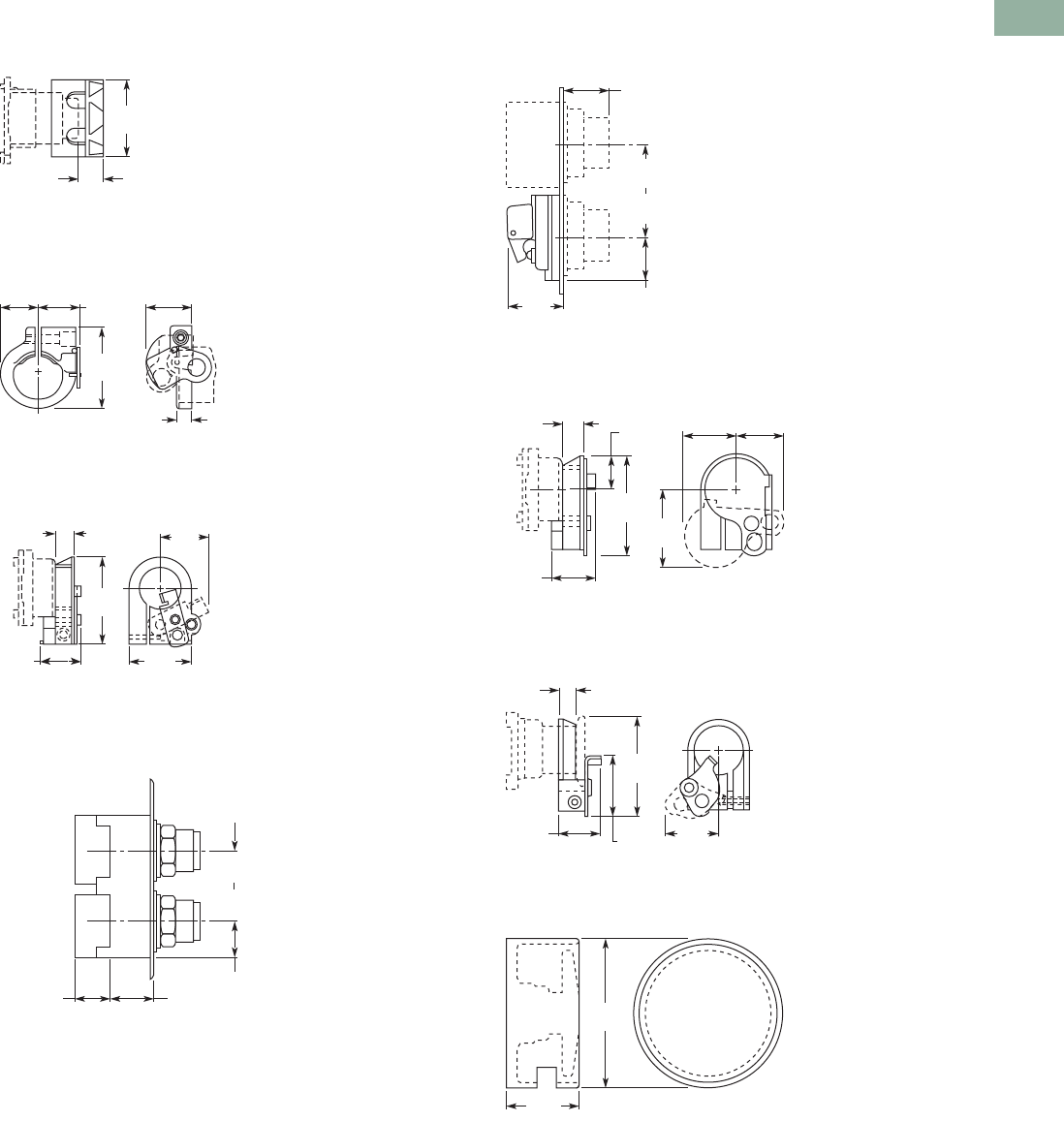
Volume 7—Logic Control, Operator Interface and Connectivity Solutions CA08100008E—March 2014 www.eaton.com V7-T1-251
1
1
1
1
1
1
1
1
1
1
1
1
1
1
1
1
1
1
1
1
1
1
1
1
1
1
1
1
1
1
1.8
Pushbuttons and Indicating Lights
30.5 mm Heavy-Duty Watertight/Oiltight—10250T
Approximate Dimensions in Inches (mm)
Padlock Attachment—For Knob Selector Switch
Catalog No. 10250TA11
Padlock Attachment—For Flush Pushbutton
Catalog No. 10250TA2
Padlock Attachment—For Extended Pushbutton
Catalog No. 10250TA26
Maintained Pushbutton
Catalog No. 10250TA66 Typical
Maintained Contact Attachment
Catalog No. 10250TA17 Typical
Padlock Cover Guard for Flush Pushbutton
Catalog No. 10250TA36
Padlock Attachment for Maintained Push-Pull Operator
Catalog No. 10250TA64
Protecting Shroud for Jumbo Mushroom Head Button
Catalog No. 10250TA56
1.63
(41.4)
0.44
(11.2)
0.75
(19.1) 0.84
(21.3)
0.94
(23.9)
1.63
(41.4)
0.25
(6.4)
2.06
(52.3)
0.38
(9.7)
0.84
(21.3) 1.5
(38.1)
1.06
(26.9)
0.89
(22.6)
Adjustable
0.88
(22.4)
for Each
Additional
Contact
Block
1.07
(27.2)
1.62 (41.1)
Min.
2.5 (63.5)
Max.
0.97
(24.6)
0.91
(23.1)
1.63 (41.4)
Min.
2.31 (58.7)
Max.
1.13
(28.7)
0.38
(9.7)
1.16
(29.5) 1.0
(25.4)
1.91
(48.5)
2.19
(55.6)
0.75
(19.1)
0.91
(23.1)
2.19
(55.6)
1.47
(37.3)
1.25
(31.8)
0.38
(9.7)
0.94
(23.9)
1.65
(41.9)
3.25
(82.6)
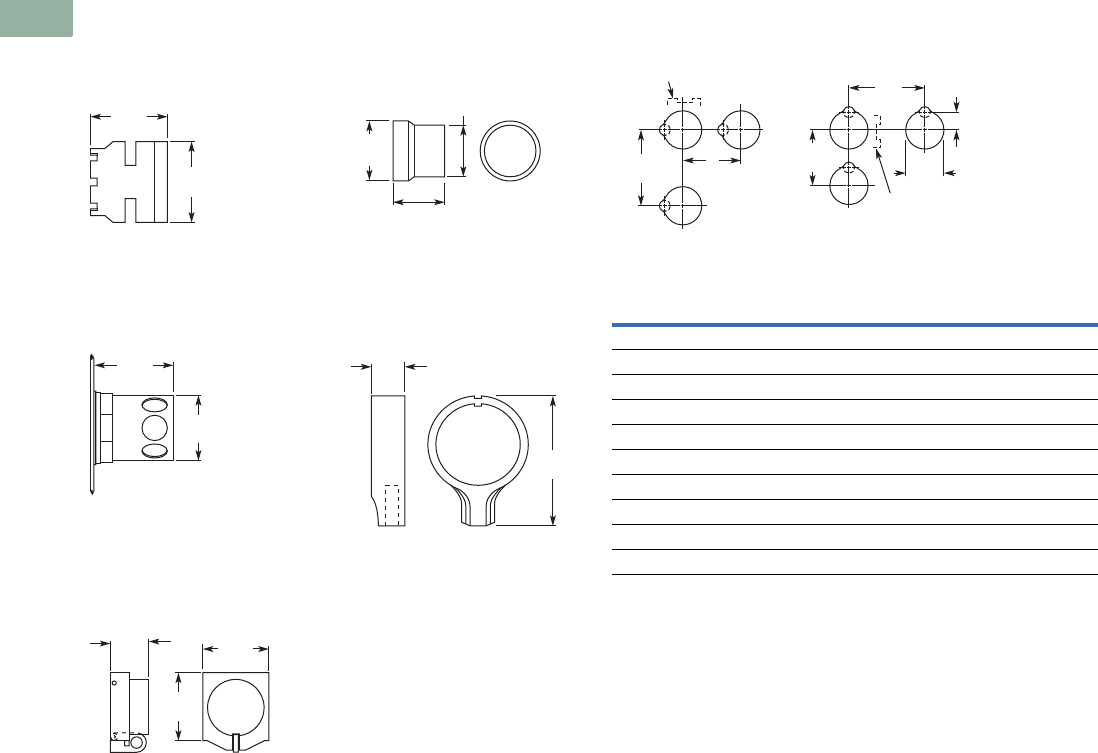
V7-T1-252 Volume 7—Logic Control, Operator Interface and Connectivity Solutions CA08100008E—March 2014 www.eaton.com
1
1
1
1
1
1
1
1
1
1
1
1
1
1
1
1
1
1
1
1
1
1
1
1
1
1
1
1
1
1
1.8
Pushbuttons and Indicating Lights
30.5 mm Heavy-Duty Watertight/Oiltight—10250T
Approximate Dimensions in Inches (mm)
Protecting Shroud for
Mushroom Head Button
Catalog No. 10250TA6
Protecting Shroud for
Illuminated Pushbutton
Catalog No. 10250TA15
Padlock Hasp or
Flip-Up Guard
Catalog No. 10250TA38
Extended Retaining Nut
Catalog No. 10250TA12
Lever for
Roto-Push Operator
Catalog No. 10250TA13
1.53
(38.9)
1.69
(42.9)
1.75
(44.5)
1.50
(38.1)
0.84
(21.3) 1.50
(38.1)
1.75
(44.5)
1.38
(35.1)
1.31
(33.3)
1.25
(31.8)
0.44
(11.2)
1.81
(46)
Panel Drilling and Minimum Spacing
Notes
Locating nib hole or notch is 1.36–1.4 in (34.5–35.6 mm) #29 drill.
1If jumbo plates are to be placed one above the other vertically, add 0.13 (3.3) to minimum
dimensions listed.
Legend
Plate
A
Min.
B
Min.
1 or 2 Circuit Contact Blocks
Small or none 1.63 (41.4) 2.25 (57.2)
Standard 1.75 (44.5) 2.25 (57.2)
Jumbo 12.25 (57.2) 2.25 (57.2)
Extra large 2.50 (63.5) 2.60 (66.0)
4 Circuit Contact Block 10250T44
Small or none 1.88 (47.8) 2.25 (57.2)
Standard 1.88 (47.8) 2.25 (57.2)
Jumbo 12.25 (57.2) 2.25 (57.2)
Extra large 2.50 (63.5) 2.60 (66.0)
B
Min.
A
Min.
0.6
(15.2)
A
Min. 1.22
(31)
B
Min.
Horizontal Rows Vertical Rows
Terminals on Top
Terminals at
Side
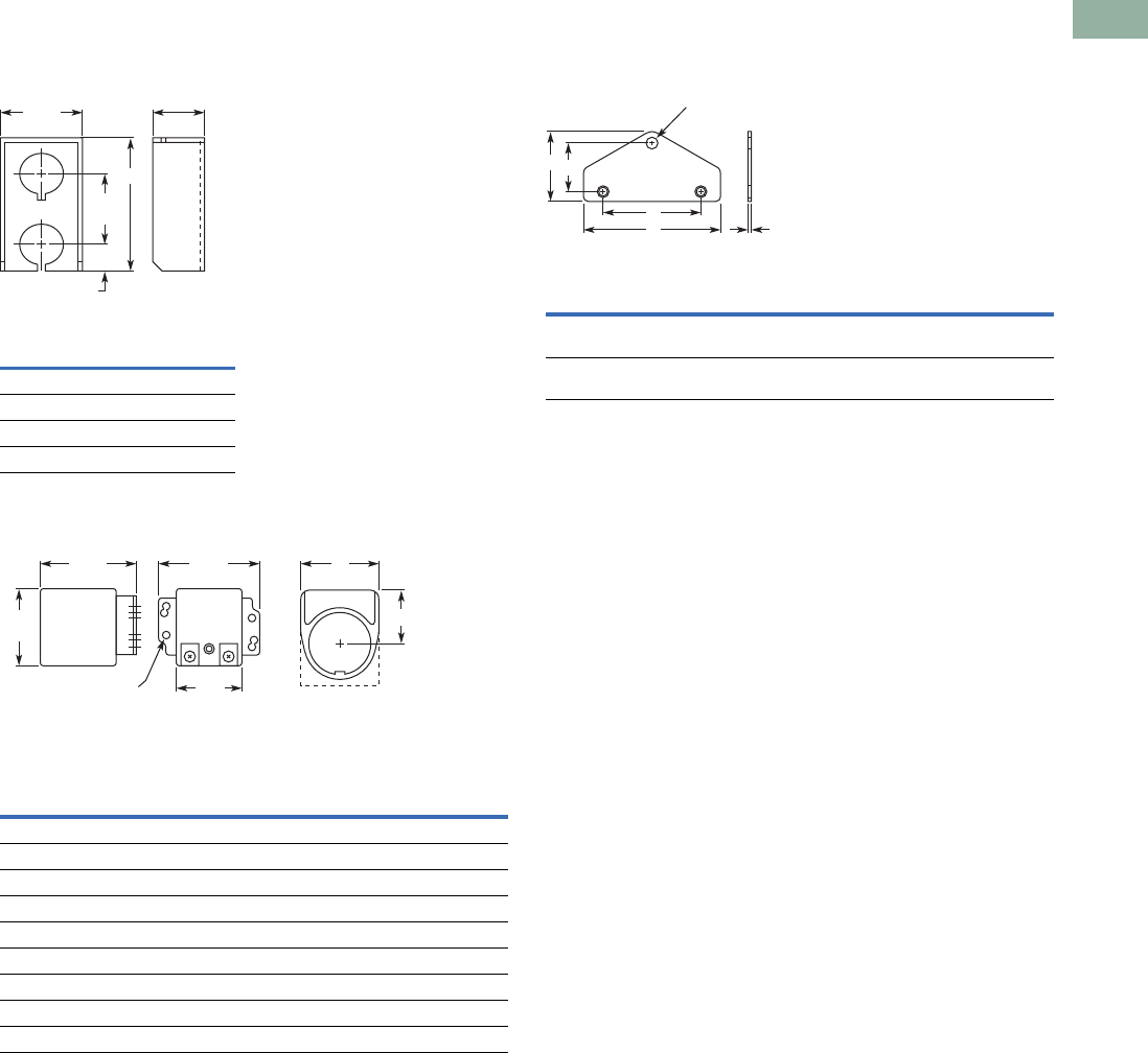
Volume 7—Logic Control, Operator Interface and Connectivity Solutions CA08100008E—March 2014 www.eaton.com V7-T1-253
1
1
1
1
1
1
1
1
1
1
1
1
1
1
1
1
1
1
1
1
1
1
1
1
1
1
1
1
1
1
1.8
Pushbuttons and Indicating Lights
30.5 mm Heavy-Duty Watertight/Oiltight—10250T
Approximate Dimensions in Inches (mm)
Multiple Button Guard
Master Test Module, Flasher Module and Legend Plate
Notes
Locating nib hole or notch is 1.36–1.4 in (34.5–35.6 mm) #29 drill.
1For plastic legend plate, Dimension B is 1.12 (28.4).
Chain Hook Bracket
Number of
Elements A
2 4.0 (101.6)
3 5.88 (149.4)
4 7.88 (200.2)
7 13.38 (339.9)
Legend
Plate AB
1/2 Round Legend Plates
Small 1.56 (39.6) 0.91 (23.1)
Standard 1.59 (40.4) 1.07 (27.2)
Jumbo 2.06 (52.3) 1.53 (38.9)
Square Legend Plates
Small 1.59 (40.4) sq. 0.90 (22.9)
Standard 1.75 (44.5) sq. 1.06 (26.9) 1
Jumbo 2.19 (55.6) sq. 1.50 (38.1)
Extra large 2.44 (62.0) sq. 1.63 (41.4)
2.16
(54.9)
1.31
(33.3)
1.88
(47.8)
0.75
(19.1)
A
1.63
(41.4)
1.14
(29)
6 Mounting Holes
1.78
(45.2) A
1.31
(33.3)
Master Test Module,
Flasher Module
Legend Plate
B
Enclosure Size
(No. of Elements)
Wide
A
High
B
Deep
C
Mounting
DE
2, 3 and 4 3.75
(95.3)
1.94
(49.3)
0.13
(3.3)
2.69
(68.3)
1.38
(35.1)
6 and 7 4.0
(101.6)
2.19
(55.6)
0.13
(3.3)
2.88
(73.2)
1.63
(41.4)
A C
D
BE
0.38 (9.7)
Dia. Hole
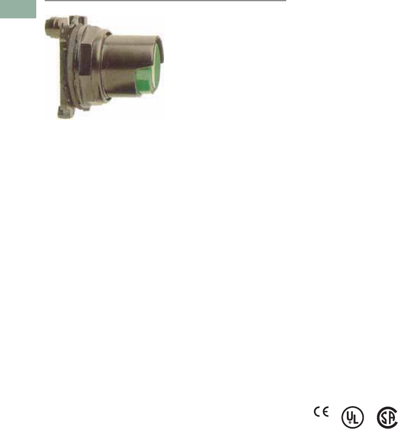
V7-T1-254 Volume 7—Logic Control, Operator Interface and Connectivity Solutions CA08100008E—March 2014 www.eaton.com
1
1
1
1
1
1
1
1
1
1
1
1
1
1
1
1
1
1
1
1
1
1
1
1
1
1
1
1
1
1
1.9
Pushbuttons and Indicating Lights
30.5 mm Corrosion Resistant Watertight/Oiltight—E34
30.5 mm Corrosion Resistant Watertight/Oiltight—E34
Contents
Description Page
30.5 mm Corrosion Resistant Watertight/Oiltight—E34
Product Overview . . . . . . . . . . . . . . . . . . . . . . V7-T1-255
Product Identification . . . . . . . . . . . . . . . . . . . . V7-T1-256
Catalog Number Selection . . . . . . . . . . . . . . . . V7-T1-257
Ordering Complete Devices . . . . . . . . . . . . . . . V7-T1-259
Product Selection
Non-Illuminated Momentary
Pushbutton Units . . . . . . . . . . . . . . . . . . . V7-T1-260
Plastic Lens Indicating Light Units . . . . . . . V7-T1-260
Pushbuttons . . . . . . . . . . . . . . . . . . . . . . . . V7-T1-261
Illuminated Pushbuttons and
Indicating Lights . . . . . . . . . . . . . . . . . . . . V7-T1-262
Push-Pull Units . . . . . . . . . . . . . . . . . . . . . . V7-T1-264
Illuminated Push-Pull Units . . . . . . . . . . . . . V7-T1-265
Potentiometers . . . . . . . . . . . . . . . . . . . . . . V7-T1-267
Push-Pull Operators . . . . . . . . . . . . . . . . . . V7-T1-268
Selector Switch Units . . . . . . . . . . . . . . . . . V7-T1-272
Selector Switch Selection . . . . . . . . . . . . . . V7-T1-273
Selector Switch Operators . . . . . . . . . . . . . V7-T1-276
Key Operators . . . . . . . . . . . . . . . . . . . . . . . V7-T1-276
Illuminated Selector Switch Operators . . . . V7-T1-278
Accessories . . . . . . . . . . . . . . . . . . . . . . . . . . . V7-T1-279
Options . . . . . . . . . . . . . . . . . . . . . . . . . . . . . . V7-T1-281
Replacement Parts . . . . . . . . . . . . . . . . . . . . . . V7-T1-287
Technical Data and Specifications . . . . . . . . . . V7-T1-289
Dimensions . . . . . . . . . . . . . . . . . . . . . . . . . . . V7-T1-292
Product Description
Eaton’s E34 Series 30.5 mm
pushbutton line features the
same rugged die cast
construction of our 10250T
line with an additional
two-layer 100% solid
thermosetting cathodic epoxy
coating. This coating provides
a flat black smooth,
consistent, corrosion
resistant surface that has
passed a demanding 600
hour salt spray test. (The
industry standard for this 4X
test requires only 200 hours.)
Features
●Epoxy-coated metal
operators
●Corrosion resistant
●Integral ground screw
terminal on operators
●FDA approved for sanitary
chemical resistance
requirements
Standards and
Certifications
●CE EN60947-5-1 and
60947-5-5
●UL 508—File No. E131568
●CSA C22.2 No. 14—File No.
LR68551
●FDA 3-A Sanitary
Standards
Ingress Protection
When mounted in similarly
rated enclosure—
●Standard indicating lights
●UL (NEMA) Type 1, 2, 3,
3R, 3S, 4, 4X, 12, 13
●IEC IP65
●All other operators
●UL (NEMA) Type 1, 2, 3,
3R, 4, 4X, 12, 13
●IEC IP65
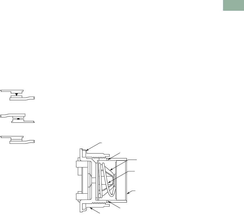
Volume 7—Logic Control, Operator Interface and Connectivity Solutions CA08100008E—March 2014 www.eaton.com V7-T1-255
1
1
1
1
1
1
1
1
1
1
1
1
1
1
1
1
1
1
1
1
1
1
1
1
1
1
1
1
1
1
1.9
Pushbuttons and Indicating Lights
30.5 mm Corrosion Resistant Watertight/Oiltight—E34
Product Overview
Ultraviolet Light
E34 cathodic coating is not
recommended for use in
applications where exposure
to ultraviolet light exists—use
NEMA 4X 10250T operators.
Reliability Nibs
Eaton’s contact blocks
feature enclosed silver
contacts with pointed
“reliability nibs” for reliable
performance from logic level
up to 600V. To ensure reliable
switching, nibs bite through
oxide which can form on silver
contacts, eliminating the
need for expensive logic level
blocks for most applications.
Reliability Nibs
Dry Circuit
Medium Duty
Heavy-Duty
Diaphragm Seal with
Drainage Holes
Liquid Drainage
Eaton’s pushbutton operators
offer front of panel drainage
via holes in the operator
bushing. Hidden from view by
the mounting nut, these
holes prevent buildup of liquid
inside the operator, which
can prevent operation in
freezing environments. The
holes also provide a route for
escaping liquid in high
pressure washdowns,
effectively relieving pressure
from the internal diaphragm
seal, ensuring reliable sealing
in applications even beyond
NEMA 4.
Diaphragm Seal
Foam Neoprene
Panel Sealing Gasket
Drainage Hole
Drainage Hole
Flexible
Diaphragm
Stainless
Steel
Operating
Spring
Mounting Nut
Colorfast
Molded
Button
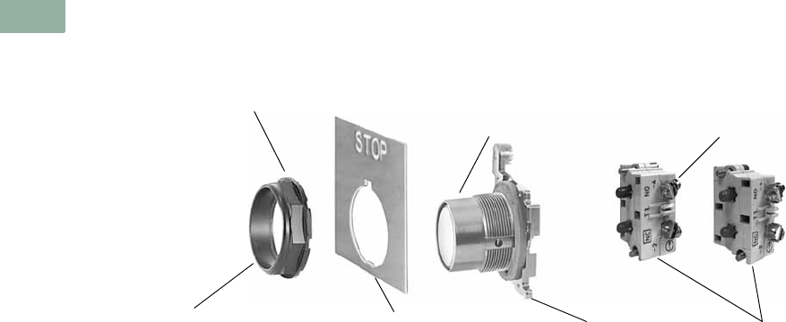
V7-T1-256 Volume 7—Logic Control, Operator Interface and Connectivity Solutions CA08100008E—March 2014 www.eaton.com
1
1
1
1
1
1
1
1
1
1
1
1
1
1
1
1
1
1
1
1
1
1
1
1
1
1
1
1
1
1
1.9
Pushbuttons and Indicating Lights
30.5 mm Corrosion Resistant Watertight/Oiltight—E34
Product Identification
30.5 mm Corrosion Resistant Watertight/Oiltight—E34 Series
Octagonal Mounting Nut Self-Adjusts to
Panel Thickness—Eliminates Spacer Washers
and Set Screws
Internal Sealing Diaphragm
for Excellent Sealing
Terminal Clamps Shipped
Open Ready to Wire
Three Styles of Legend Plates
in Four Sizes Wide Variety of Operator
Types and Colors
Die Cast Construction with Thick,
Tough Corrosion Resistant Coating Stackable Contact Blocks up
to 12 Circuits per Operator
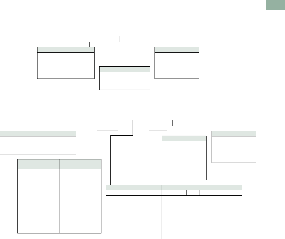
Volume 7—Logic Control, Operator Interface and Connectivity Solutions CA08100008E—March 2014 www.eaton.com V7-T1-257
1
1
1
1
1
1
1
1
1
1
1
1
1
1
1
1
1
1
1
1
1
1
1
1
1
1
1
1
1
1
1.9
Pushbuttons and Indicating Lights
30.5 mm Corrosion Resistant Watertight/Oiltight—E34
Catalog Number Selection
Catalog Number Selection is for illustrative purposes only and not to be used to create new catalog numbers.
Non-Illuminated Pushbuttons
Illuminated and Non-Illuminated Push-Pulls
Note
1Add X at end of catalog number to receive parts assembled from factory.
E34 PB 1–1 1
Operator
PB =Flush
EB = Extended
LB = 40 mm mushroom
JB = 65 mm mushroom
EVB = 1/2 shroud vertical mount
EHB = 1/2 shroud horizontal mount
Circuit
Blank = Operator only
1 = 1NO-1NC
2 =2NO
3 =2NC
51 =1NC
53 =1NO
Button Color
1 = Black
2 = Red
3 = Green
4 = Yellow
7 = Gray
5 = White
6 = Blue
8 = Orange
E34 GDB 63 M2 –1 1
Circuit
Blank = Operator only
1 = 1NO-1NC
2 =2NO
3 =2NC
51 =1NC
53 =1NO
Incandescent
Light Unit
LED
Light Unit
Blank = Non-illuminated
89 = 24V/XFR
63 = 120V/XFR
64 = 208V/XFR
65 = 240V/XFR
82 = 277V/XFR
66 = 380V/XFR
67 = 480V/XFR
68 = 600V/XFR
69 =6V/FV
70 = 12V/FV
79 = 24V/FV
83 = 32V/FV
80 = 120V/RES
81 = 240V/RES
Blank = Non-illuminated
89L =24V/XFR
63L = 120V/XFR
64L = 208V/XFR
65L = 240V/XFR
82L = 277V/XFR
66L = 380V/XFR
67L = 480V/XFR
68L = 600V/XFR
97L = Full voltage
Non-Illuminated Illuminated
Button Incandescent LED Lens Type
C1 = Black 40 mm
C2 = Red 40 mm
C2N8 = Red 40 mm—“E” STOP
C3 = Green 40 mm
C6 = Blue 40 mm
— = Black 65 mm
J2 = Red 65 mm
J2N8 = Red 65 mm—“E” STOP
— = Green 65 mm
— = Yellow 65 mm
M2 =
M2N8 =
M3 =
M6 =
M9 =
M5 =
M0 =
RD =
ED =
GD =
LD =
AD =
WD =
— =
Red 40 mm
Red 40 mm—“E” STOP
Green 40 mm
Blue 40 mm
Amber 40 mm
White 40 mm
Clear 40 mm
LED Voltage
Blank = Non-illuminated
Blank = Incandescent
06 = 6 Vac/Vdc
12 = 12 Vac/Vdc
24 = 24 Vac/Vdc
48 = 48 Vac/Vdc
60 = 60 Vac/Vdc
2A = 120 Vac
2D = 120 Vdc
Operator
GDB = Two-position maintained
GEB = Three-position mom push-mom pull
GFB = Three-position mt push-mom pull
GHB = Three-position mom push-mom pull
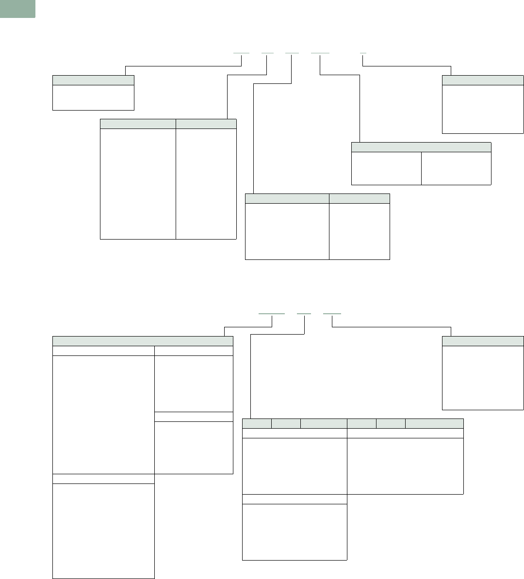
V7-T1-258 Volume 7—Logic Control, Operator Interface and Connectivity Solutions CA08100008E—March 2014 www.eaton.com
1
1
1
1
1
1
1
1
1
1
1
1
1
1
1
1
1
1
1
1
1
1
1
1
1
1
1
1
1
1
1.9
Pushbuttons and Indicating Lights
30.5 mm Corrosion Resistant Watertight/Oiltight—E34
Catalog Number Selection is for illustrative purposes only and not to be used to create new catalog numbers.
Illuminated Pushbuttons
Standard Indicating Lights, PresTest and Master Test
Note
1Add X at end of catalog number to receive parts assembled from factory.
Circuit
Blank = Operator only
1 = 1NO-1NC
2 =2NO
3 =2NC
51 =1NC
53 =1NO
Light Unit Type
XB = Transformer
CB = Full voltage
SB =Resistor
Incandescent Light Unit LED Light Unit
024 = 24V/XFR
120 = 120V/XFR
240 = 240V/XFR
277 = 277V/XFR
380 = 380V/XFR
480 = 480V/XFR
600 = 600V/XFR
06 =6V/FV
12 = 12V/FV
24 = 24V/FV
32 = 32V/FV
48 = 48V/FV
120 = 120V/RES
240 = 240V/RES
024L =24V/XFR
120L = 120V/XFR
240L = 240V/XFR
277L = 277V/XFR
380L = 380V/XFR
480L = 480V/XFR
600L = 600V/XFR
397L = Full voltage
LED Voltage
Blank = Incandescent
06 = 6 Vac/Vdc
12 = 12 Vac/Vdc
24 = 24 Vac/Vdc
48 = 48 Vac/Vdc
60 = 60 Vac/Vdc
2A = 120 Vac
2D = 120 Vdc
Incandescent Lens Color LED Lens Color
V2 =Red
V3 =Green
V4 = Yellow
V5 =White
V6 =Blue
V9 =Amber
V0 = Clear
RD =Red
GD =Green
YD = Yellow
WD =White
LD = Blue
AD =Amber
E34 XB 24 V2 –1 1
LED Voltage
Blank = Incandescent
06 = 6 Vac/Vdc
12 = 12 Vac/Vdc
24 = 24 Vac/Vdc
48 = 48 Vac/Vdc
60 = 60 Vac/Vdc
2A = 120 Vac
2D = 120 Vdc
Plastic Glass Lens Color Plastic Glass Lens Color
Standard/Master—Incandescent Standard/Master/PresTest—LED
H2 =
H3 =
H4 =
H5 =
H6 =
H9 =
H0 =
G2 =
G3 =
G4 =
G5 =
G6 =
G9 =
G0 =
Red
Green
Yellow
White
Blue
Amber
Clear
RP =
GP =
YP =
WP =
LP =
AP =
RG =
GG =
YG =
WG =
LG =
AG =
Red
Green
Yellow
White
Blue
Amber
PresTest—Incandescent
V2 =
V3 =
V4 =
V5 =
V6 =
V9 =
V0 =
P2 =
P3 =
P4 =
P5 =
P6 =
P9 =
P0 =
Red
Green
Yellow
White
Blue
Amber
Clear
Light Unit Type
Standard—Incandescent Standard—LED
TB120 =
TB240 =
TB277 =
TB380 =
TB480 =
TB600 =
FB06 =
FB12 =
FB24 =
FB32 =
FB48 =
RB120 =
RB240 =
NB120 =
NB240 =
120V/XFR
240V/XFR
277V/XFR
380V/XFR
480V/XFR
600V/XFR
6V/FV
12V/FV
24V/FV
32V/FV
48V/FV
120V/RES
240V/RES
120V/neon
240V/neon
TB120L =
TB240L =
TB277L =
TB380L =
TB480L =
TB600L =
FB197L =
120V/XFR
240V/XFR
277V/XFR
380V/XFR
480V/XFR
600V/XFR
Full voltage
PresTest—LED
TPB120L =
TPB240L =
TPB380L =
TPB480L =
TPB600L =
FPB297L =
120V/XFR
240V/XFR
380V/XFR
480V/XFR
600V/XFR
Full voltage
PresTest—Incandescent
TPB120 =
TPB240 =
TPB380 =
TPB480 =
TPB600 =
FPB06 =
FPB12 =
FPB24 =
FPB32 =
FPB48 =
RPB120 =
RPB240 =
120V/XFR
240V/XFR
380V/XFR
480V/XFR
600V/XFR
6V/FV
12V/FV
24V/FV
32V/FV
48V/FV
120V/RES
240V/RES
E34 FB06 H2 1

Volume 7—Logic Control, Operator Interface and Connectivity Solutions CA08100008E—March 2014 www.eaton.com V7-T1-259
1
1
1
1
1
1
1
1
1
1
1
1
1
1
1
1
1
1
1
1
1
1
1
1
1
1
1
1
1
1
1.9
Pushbuttons and Indicating Lights
30.5 mm Corrosion Resistant Watertight/Oiltight—E34
Catalog Number Selection is for illustrative purposes only and not to be used to create new catalog numbers.
Ordering Complete Devices
Complete E34 pushbuttons,
indicating lights and/or
selector switch operators
including contact block(s) and
legend plate can be ordered
using a single composite
catalog number. The
individually packaged
components will be shipped
unassembled in a single
overpack carton marked with
the composite catalog
number.
Ordering Example
Illuminated Pushbutton
Device—Catalog Number
E34XB120V2-153SP90
For a complete Catalog
Number breakdown, see
Pages V7-T1-257 to
V7-T1-258.
For Complete E34 Device Ordering
Operator Legend Plate
E34;SP90
Insert Hyphen Before
Contact Block(s)
Lens
E34V2 Contact Blocks
10250T1 and 10250T53
E34XB120 V2 –153 SP90
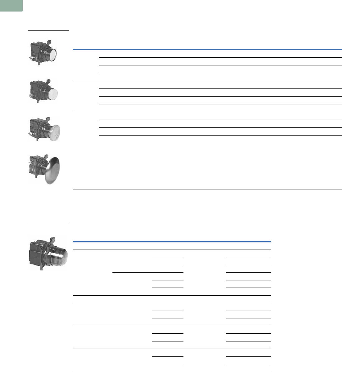
V7-T1-260 Volume 7—Logic Control, Operator Interface and Connectivity Solutions CA08100008E—March 2014 www.eaton.com
1
1
1
1
1
1
1
1
1
1
1
1
1
1
1
1
1
1
1
1
1
1
1
1
1
1
1
1
1
1
1.9
Pushbuttons and Indicating Lights
30.5 mm Corrosion Resistant Watertight/Oiltight—E34
Product Selection
Non-Illuminated Momentary Pushbutton Units
UL (NEMA) Type 3, 3R, 4, 4X, 12, 13
Pushbutton Units
Plastic Lens Indicating Light Units
UL (NEMA) Type 3, 3R, 4, 4X, 12, 13
Indicating Light Units
Notes
Use NEMA 4X 10250T operators where exposed to ultraviolet light, see Pages V7-T1-182 to V7-T1-253.
1 Anodized aluminum head—may not be suitable for some corrosive environments.
Contact
Type Button Color
Flush Button
Catalog Number
Extended Button
Catalog Number
Mushroom Button
Catalog Number
Jumbo Mushroom 1
Catalog Number
1NO Black E34PB1-53X E34EB1-53X E34LB1-53X E34JB1-53X
Red E34PB2-53X E34EB2-53X E34LB2-53X E34JB2-53X
Green E34PB3-53X E34EB3-53X E34LB3-53X E34JB3-53X
Red—Engraved EMERG. STOP — — — E34JB2N8-53X
1NC Black E34PB1-51X E34EB1-51X E34LB1-51X E34JB1-51X
Red E34PB2-51X E34EB2-51X E34LB2-51X E34JB2-51X
Green E34PB3-51X E34EB3-51X E34LB3-51X E34JB3-51X
Red—Engraved EMERG. STOP — — — E34JB2N8-51X
1NO-1NC Black E34PB1-1X E34EB1-1X E34LB1-1X E34JB1-1X
Red E34PB2-1X E34EB2-1X E34LB2-1X E34JB2-1X
Green E34PB3-1X E34EB3-1X E34LB3-1X E34JB3-1X
Red—Engraved EMERG. STOP ———E34JB2N8-1X
Type Voltage Color
LED/Lamp
Number
Indicating Light 1
Catalog Number
LED Lamp
Full voltage 24 Vac/Vdc Red Bayonet base E34FB197LRP24
Green E34FB197LGP24
Amber E34FB197LAP24
120 Vac Red E34FB197LRP2A
Green E34FB197LGP2A
Amber E34FB197LAP2A
Incandescent Lamp
Full voltage 24 Vac/Vdc Red #757 E34FB24H2X
Green E34FB24H3X
Amber E34FB24H9X
Resistor 120 Vac/Vdc Red 120MB E34RB120H2X
Green E34RB120H3X
Amber E34RB120H9X
Transformer 120 Vac
50/60 Hz
Red #755 E34TB120H2X
Green E34TB120H3X
Amber E34TB120H9X
Flush Button
Extended Button
Mushroom Button
Jumbo Mushroom
24V Full Voltage
Indicating Light
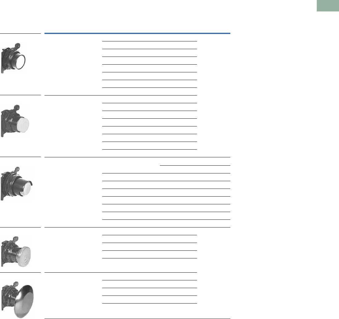
Volume 7—Logic Control, Operator Interface and Connectivity Solutions CA08100008E—March 2014 www.eaton.com V7-T1-261
1
1
1
1
1
1
1
1
1
1
1
1
1
1
1
1
1
1
1
1
1
1
1
1
1
1
1
1
1
1
1.9
Pushbuttons and Indicating Lights
30.5 mm Corrosion Resistant Watertight/Oiltight—E34
Pushbuttons
UL (NEMA) Type 3, 3R, 4, 4X, 12, 13
Momentary Pushbutton Operators, Non-Illuminated
Notes
Use NEMA 4X 10250T operators where exposed to ultraviolet light, see Pages V7-T1-182 to V7-T1-253.
1 Anodized aluminum head—may not be suitable for some corrosive environments.
Button Color Catalog Number
Flush button Black E34PB1
Red E34PB2
Green E34PB3
Yellow E34PB4
White E34PB5
Blue E34PB6
Gray E34PB7
Orange E34PB8
Extended button Black E34EB1
Red E34EB2
Green E34EB3
Yellow E34EB4
White E34EB5
Blue E34EB6
Gray E34EB7
Orange E34EB8
Half shrouded button Vertical Horizontal
Black E34EVB1 E34EHB1
Red E34EVB2 E34EHB2
Green E34EVB3 E34EHB3
Yellow E34EVB4 E34EHB4
White E34EVB5 E34EHB5
Blue E34EVB6 E34EHB6
Gray E34EVB7 E34EHB7
Orange E34EVB8 E34EHB8
Mushroom button Black E34LB1
Red E34LB2
Green E34LB3
Yellow E34LB4
Blue E34LB6
Anodized aluminum jumbo
mushroom button 1
Black E34JB1
Red E34JB2
Red (Engraved EMERG. STOP) E34JB2N8
Green E34JB3
Yellow E34JB4
E34PB_
E34EB_
E34EHB_
E34LB_
E34JB_
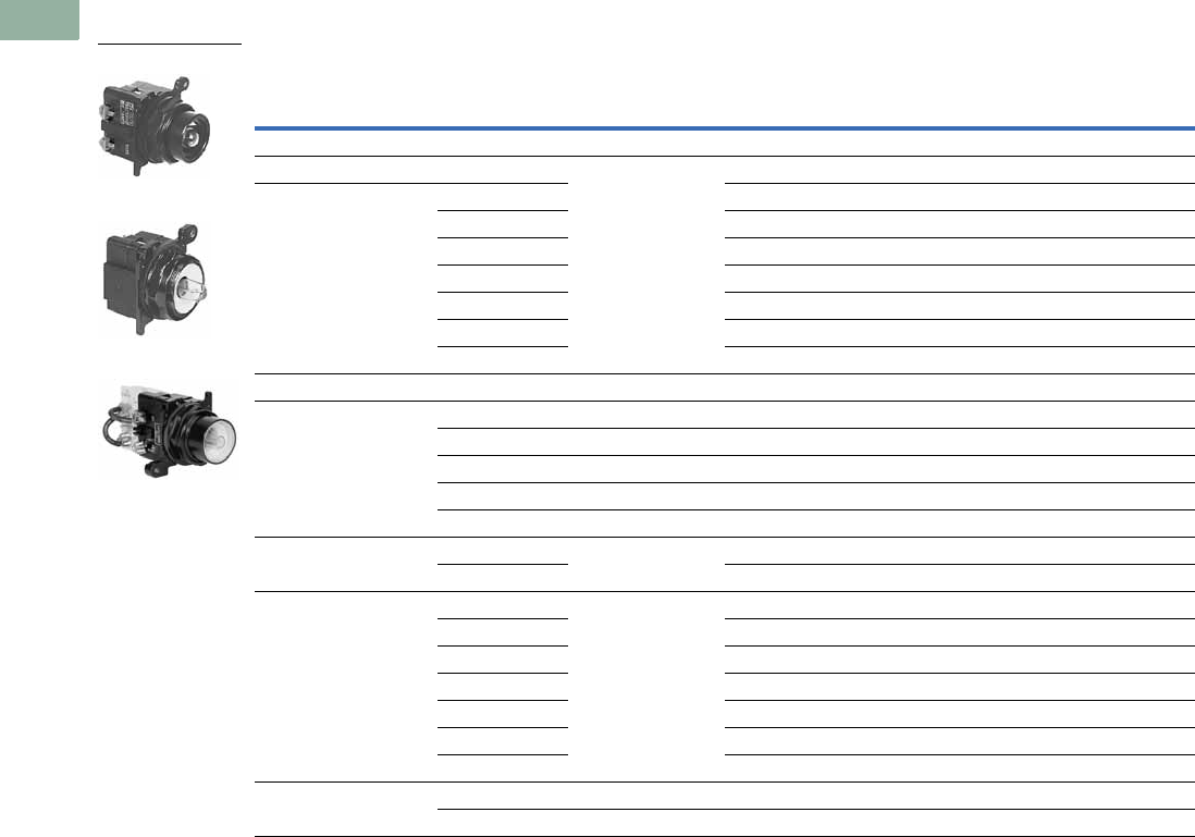
V7-T1-262 Volume 7—Logic Control, Operator Interface and Connectivity Solutions CA08100008E—March 2014 www.eaton.com
1
1
1
1
1
1
1
1
1
1
1
1
1
1
1
1
1
1
1
1
1
1
1
1
1
1
1
1
1
1
1.9
Pushbuttons and Indicating Lights
30.5 mm Corrosion Resistant Watertight/Oiltight—E34
Illuminated Pushbuttons and Indicating Lights
Operators without Lens
Notes
Use NEMA 4X 10250T operators where exposed to ultraviolet light, see Pages V7-T1-182 to V7-T1-253.
1 These units do not include lamps. Order LED separately to match lens color, see Page V7-T1-239 for LED Selection and Pages V7-T1-257 to V7-T1-258 for Catalog
Numbering Selection.
2 Resistor units are not available for use with LEDs, choose either transformer or full voltage LED style.
Type Voltage Lamp Number
Illuminated
Pushbutton
Catalog Number
Indicating
Light
Catalog Number
PresTest
Catalog Number
LED Lamp (LEDs not included) 1
Full voltage — Bayonet
base
E34CB497L E34FB197L E34FPB297L
Transformer AC only 24 E34XB024L — —
120 E34XB120L E34TB120L E34TPB120L
240 E34XB240L E34TB240L E34TPB240L
277 E34XB277L E34TB277L —
380 E34XB380L E34TB380L E34TPB380L
480 E34XB480L E34TB480L E34TPB480L
600 E34XB600L E34TB600L E34TPB600L
Incandescent Lamp
Full voltage AC/DC 6 #755 E34CB06 E34FB06 E34FPB06
12 #756 E34CB12 E34FB12 E34FPB12
24 #757 E34CB24 E34FB24 E34FPB24
32 #1828 E34CB32 E34FB32 E34FPB32
48 #1835 E34CB48 E34FB48 E34FPB48
Resistor AC/DC 2120 120MB E34SB120 E34RB120 E34RPB120
240 E34SB240 E34RB240 E34RPB240
Transformer AC only 24 #755 E34XB024 — —
120 E34XB120 E34TB120 E34TPB120
240 E34XB240 E34TB240 E34TPB240
277 E34XB277 E34TB277 —
380 E34XB380 E34TB380 E34TPB380
480 E34XB480 E34TB480 E34TPB480
600 E34XB600 E34TB600 E34TPB600
Neon AC/DC 120 NE51H-R-22 — E34NB120 —
240 NE51H-4-68 — E34NB240 —
Illuminated Pushbutton
Indicating Light
PresTest
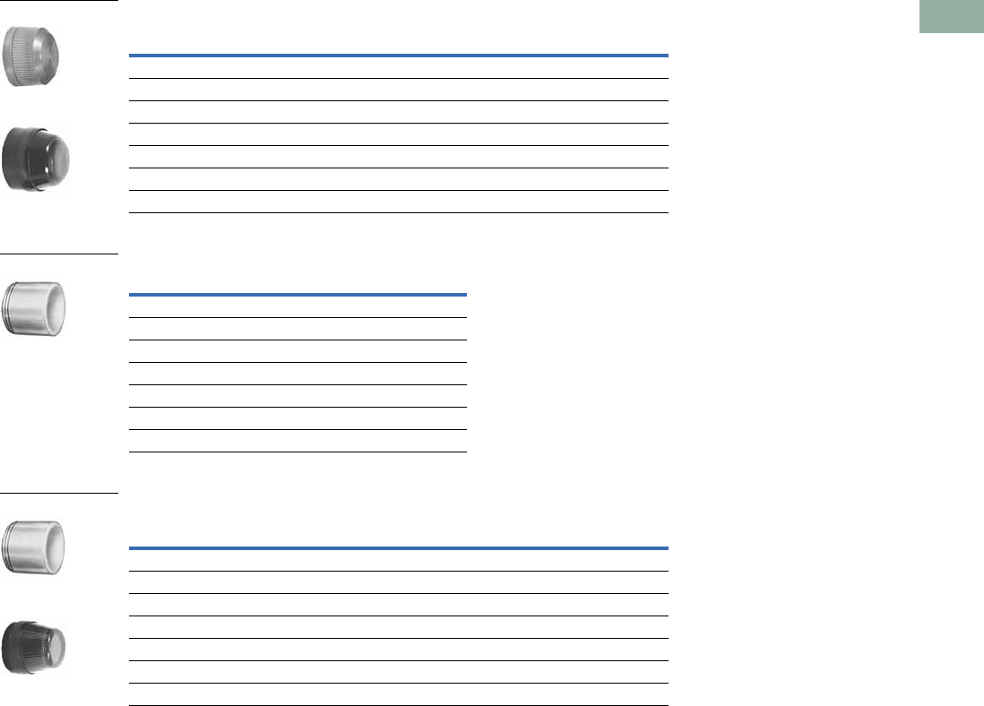
Volume 7—Logic Control, Operator Interface and Connectivity Solutions CA08100008E—March 2014 www.eaton.com V7-T1-263
1
1
1
1
1
1
1
1
1
1
1
1
1
1
1
1
1
1
1
1
1
1
1
1
1
1
1
1
1
1
1.9
Pushbuttons and Indicating Lights
30.5 mm Corrosion Resistant Watertight/Oiltight—E34
Indicating Light Lens
Illuminated Pushbutton Lens
PresTest Lens
Note
1 Glass lens has black anodized aluminum bezel.
Color
Plastic
Catalog Number
Glass 1
Catalog Number
Red E34H2 E34G2
Green E34H3 E34G3
Yellow E34H4 E34G4
White E34H5 E34G5
Blue E34H6 E34G6
Ambler E34H9 E34G9
Clear E34H0 E34G0
Color Catalog Number
Red E34V2
Green E34V3
Yellow E34V4
White E34V5
Blue E34V6
Ambler E34V9
Clear E34V0
Color
Plastic
Catalog Number
Glass 1
Catalog Number
Red E34V2 E34P2
Green E34V3 E34P3
Yellow E34V4 E34P4
White E34V5 E34P5
Blue E34V6 E34P6
Ambler E34V9 E34P9
Clear E34V0 E34P0
Plastic
Glass
E34V_
Plastic
Glass
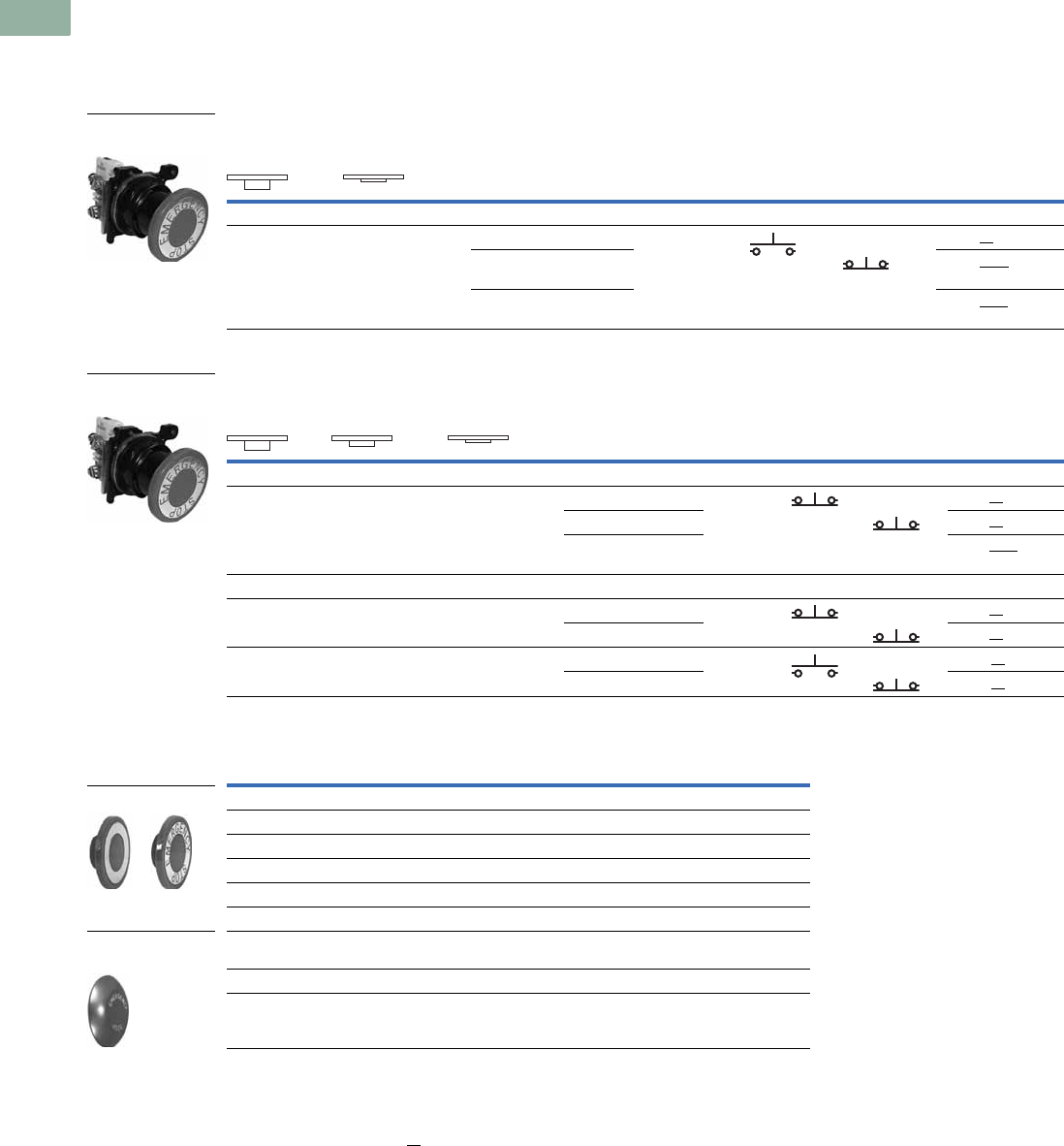
V7-T1-264 Volume 7—Logic Control, Operator Interface and Connectivity Solutions CA08100008E—March 2014 www.eaton.com
1
1
1
1
1
1
1
1
1
1
1
1
1
1
1
1
1
1
1
1
1
1
1
1
1
1
1
1
1
1
1.9
Pushbuttons and Indicating Lights
30.5 mm Corrosion Resistant Watertight/Oiltight—E34
Push-Pull Units
UL (NEMA) Type 3, 3R, 4, 4X, 12, 13
●Two- and three-position
●Non-illuminated
Two-Position Push-Pull Units, Non-Illuminated
Three-Position Push-Pull Units, Non-Illuminated
Button and Color Selection
Notes
Use NEMA 4X 10250T operators where exposed to ultraviolet light, see Pages V7-T1-182 to V7-T1-253.
1 X = closed circuit, O = open circuit.
2 To order different type or color buttons, substitute the underlined characters with appropriate suffix code
from the table. Example: E34GDBC6-1X.
3 Anodized aluminum may not be suitable for use on some corrosive applications.
Operator Position 1
Button Type/Color 2
Contact
Type Catalog Number
Pull Push Mounting Location
AB
Maintained Push, Maintained Pull
O
X
X
O
40 mm/red 1NO E34GDBC2-1X
40 mm engraved
EMERG. STOP/red
1NC E34GDBC2N8-1X
65 mm aluminum engraved
EMERG. STOP/red
E34GDBJ2N8-1X
Operator Position 1
Button Type/Color 2
Contact
Type Catalog Number
Pull Intermediate Push Mounting Location
AB
Maintained Push, Momentary Pull
X
X
O
X
O
O
40 mm/black 1NC E34GFBC1-3X
40 mm/red 1NC E34GFBC2-3X
40 mm engraved
EMERG. STOP/red
E34GFBC2N8-3X
Momentary Push, Momentary Pull
X
X
O
X
O
O
40 mm/black 1NC E34GEBC1-3X
40 mm/red 1NC E34GEBC2-3X
O
X
O
O
X
O
40 mm/black 1NO E34GHBC1-1X
40 mm/red 1NC E34GHBC2-1X
Color Suffix Code Catalog Number
Standard—40 mm
Black C1 E34C1
Red C2 E34C2
Red (EMERG. STOP) C2N8 E34C2N8
Green C3 E34C3
Blue C6 E34C6
Jumbo Mushroom Head 3
(Anodized) Aluminum—65 mm
Red J2 E34J2
Red (EMERG. STOP) J2N8 E34J2N8
Two-Position
Push-Pull Unit
Three-Position
Push-Pull Unit
Standard
Jumbo Mushroom
Head
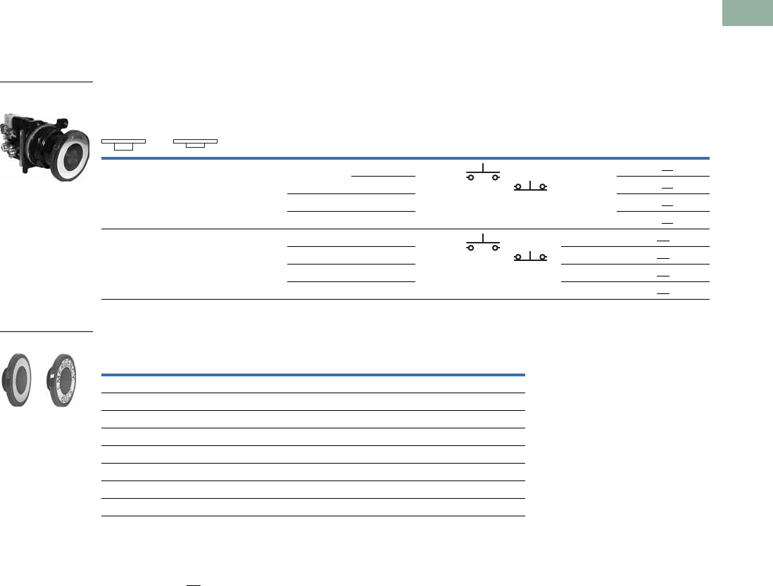
Volume 7—Logic Control, Operator Interface and Connectivity Solutions CA08100008E—March 2014 www.eaton.com V7-T1-265
1
1
1
1
1
1
1
1
1
1
1
1
1
1
1
1
1
1
1
1
1
1
1
1
1
1
1
1
1
1
1.9
Pushbuttons and Indicating Lights
30.5 mm Corrosion Resistant Watertight/Oiltight—E34
Illuminated Push-Pull Units
UL (NEMA) Type 3, 3R, 4, 4X, 12, 13
●Two-position maintained
●Illuminated
Two-Position Illuminated Maintained Push, Maintained Pull
Lens and Color Selection
Notes
Use NEMA 4X 10250T operators where exposed to ultraviolet light, see Pages V7-T1-182 to V7-T1-253.
1 X = closed circuit, O = open circuit.
2 To order different type or color lens, substitute the underlined characters with appropriate suffix code from Lens and Color Selection table above.
Example: E34GDB79M3 -1X. For LEDs with different voltages see ordering example on Page V7-T1-271.
Operator Position 1
Lamp Type Voltage
Contact
Type
LED/Lamp
Number
Red Standard
Push-Pull
Catalog Number 2
Maintained—
Pull
Maintained—
Intermediate Mounting Location
AB
O
X
X
O
LED Full voltage 24 Vac/Vdc 1NO Bayonet
base
E34GDB97LRD24-1X
120 Vac/Vdc 1NC E34GDB97LRD2A-1X
Transformer 24 Vac E34GDB89LRD06-1X
120 Vac E34GDB63LRD06-1X
O
X
X
O
Incan-
descent
Full voltage 24 Vac/Vdc 1NO #757 E34GDB79M2-1X
Resistor 120 Vac/Vdc 1NC 120MB E34GDB80M2-1X
Transformer 24 Vac #755 E34GDB89M2-1X
120 Vac E34GDB63M2-1X
Color
Incandescent
Suffix Code
LED
Suffix Code Catalog Number
Standard
Red M2 RD E34M2
Red (EMER. STOP) M2N8 ED E34M2N8
Green M3 GD E34M3
Blue M6 LD E34M6
Amber M9 AD E34M9
White M5 WD E34M5
Clear M0 CD E34M0
Illuminated Push-Pull
Unit
Standard
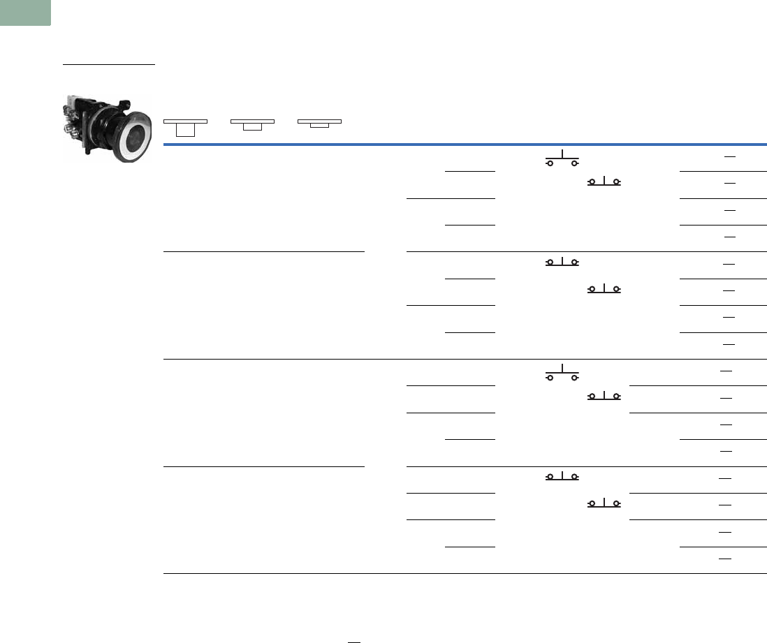
V7-T1-266 Volume 7—Logic Control, Operator Interface and Connectivity Solutions CA08100008E—March 2014 www.eaton.com
1
1
1
1
1
1
1
1
1
1
1
1
1
1
1
1
1
1
1
1
1
1
1
1
1
1
1
1
1
1
1.9
Pushbuttons and Indicating Lights
30.5 mm Corrosion Resistant Watertight/Oiltight—E34
UL (NEMA) Type 3, 3R, 4, 4X, 12, 13
●Three-position maintained
●Illuminated
Three-Position Illuminated Momentary Push, Momentary Pull
Notes
Use NEMA 4X 10250T operators where exposed to ultraviolet light, see Pages V7-T1-182 to V7-T1-253.
1 X = closed circuit, O = open circuit.
2 To order different type or color lens, substitute the underlined characters with appropriate suffix code from Lens and Color Selection table on the
bottom of Page V7-T1-265. Example: E34GEB79M3-3X. For LEDs with different voltages see ordering example on Page V7-T1-271.
Operator Position 1
Lamp Type Voltage
Contact
Type
LED/Lamp
Number
Red Standard
Push-Pull
Catalog Number 2
Momentary—
Pull
Maintained—
Intermediate
Momentary—
Push Mounting Location
AB
O
X
O
O
X
O
LED Full
voltage
24 Vac/Vdc 1NO Bayonet
base
E34GHB97LRD24-1X
120 Vac 1NC E34GHB97LRD2A-1X
Trans-
former
24 Vac E34GHB89LRD06-1X
120 Vac E34GHB63LRD06-1X
X
X
O
X
O
O
Full
voltage
24 Vac/Vdc 1NC Bayonet
base
E34GEB97LRD24-3X
120 Vac 1NC E34GEB97LRD2A-3X
Trans-
former
24 Vac E34GEB89LRD06-3X
120 Vac E34GEB63LRD06-3X
O
X
O
O
X
O
Incan-
descent
Full
voltage
24 Vac/Vdc 1NO #757 E34GHB79M2-1X
Resistor 120 Vac 1NC 120MB E34GHB80M2-1X
Trans-
former
24 Vac #755 E34GHB89M2-1X
120 Vac E34GHB63M2-1X
X
X
O
X
O
O
Full
voltage
24 Vac/Vdc 1NC #757 E34GEB79M2-3X
Resistor 120 Vac 1NC 120MB E34GEB80M2-3X
Trans-
former
24 Vac #755 E34GEB89M2-3X
120 Vac E34GEB63M2-3X
Illuminated Push-Pull
Unit

Volume 7—Logic Control, Operator Interface and Connectivity Solutions CA08100008E—March 2014 www.eaton.com V7-T1-267
1
1
1
1
1
1
1
1
1
1
1
1
1
1
1
1
1
1
1
1
1
1
1
1
1
1
1
1
1
1
1.9
Pushbuttons and Indicating Lights
30.5 mm Corrosion Resistant Watertight/Oiltight—E34
UL (NEMA) Type 3, 3R, 4, 4X, 12, 13
●Three-position—maintained push, momentary pull
●Illuminated
Three-Position Illuminated Maintained Push, Momentary Pull
Potentiometers
UL (NEMA) Type 3, 3R, 4, 4X, 12, 13
Potentiometer with Knob and Standard Dial Plate—Linear Type ±10%
Notes
Use NEMA 4X 10250T operators where exposed to ultraviolet light, see Pages V7-T1-182 to V7-T1-253.
1 X = closed circuit, O = open circuit.
2 To order different type or color lens, substitute the underlined characters with appropriate suffix code from table
on the bottom of Page V7-T1-265.
Example: E34GFB79M3-3X. For LEDs with different voltages see ordering example on Page V7-T1-271.
3 Shown with standard aluminum dial plate.
4 Large dial plate with space for legend is available at no charge. To order, add suffix 36 to catalog number.
Example: E34PDB1F136. To order separately, see footnote 5 below.
5 Large dial plate has space at top for 15 letters. 3/32 in high. For custom stamped legend plates, order legend plate
as separate item 10250TR30 and specify stamping.
6 For use with commercially purchased potentiometers having shaft dimensions per dimension drawing on Page V7-T1-244.
Operator Position 1
Lamp Type Voltage
Contact
Type
LED/Lamp
Number
Red Standard
Push-Pull
Catalog Number 2
Momentary—
Pull
Maintained—
Intermediate
Maintained—
Push Mounting Location
AB
X
X
O
X
O
O
LED Full
voltage
24 Vac/Vdc 1NC Bayonet
base
E34GFB97LRD24-3X
120 Vac 1NC E34GFB97LRD2A-3X
Trans-
former
24 Vac E34GFB89LRD06-3X
120 Vac E34GFB63LRD06-3X
X
X
O
X
O
O
Incan-
descent
Full
voltage
24 Vac/Vdc 1NC #757 E34GFB79M2-3X
Resistor 120 Vac 1NC 120MB E34GFB80M2-3X
Trans-
former
24 Vac #755 E34GFB89M2-3X
120 Vac E34GFB63M2-3X
Potentiometer
Ohms Catalog Number
2 Watt (60V Max.) Single Potentiometer with Standard Aluminum Dial Plate 45
1000 E34PDB1F1
2500 E34PDB1F2
5000 E34PDB1F5
10000 E34PDB1F10
25000 E34PDB1F25
50000 E34PDB1F50
Operator only 6E34PDB1A0
Alternative—black plastic large legend with standard markings E34LP99
Dimensions, see Page V7-T1-292.
Illuminated Push-Pull
Unit
Vertical or Horizontal
One-Hole Mounting 3
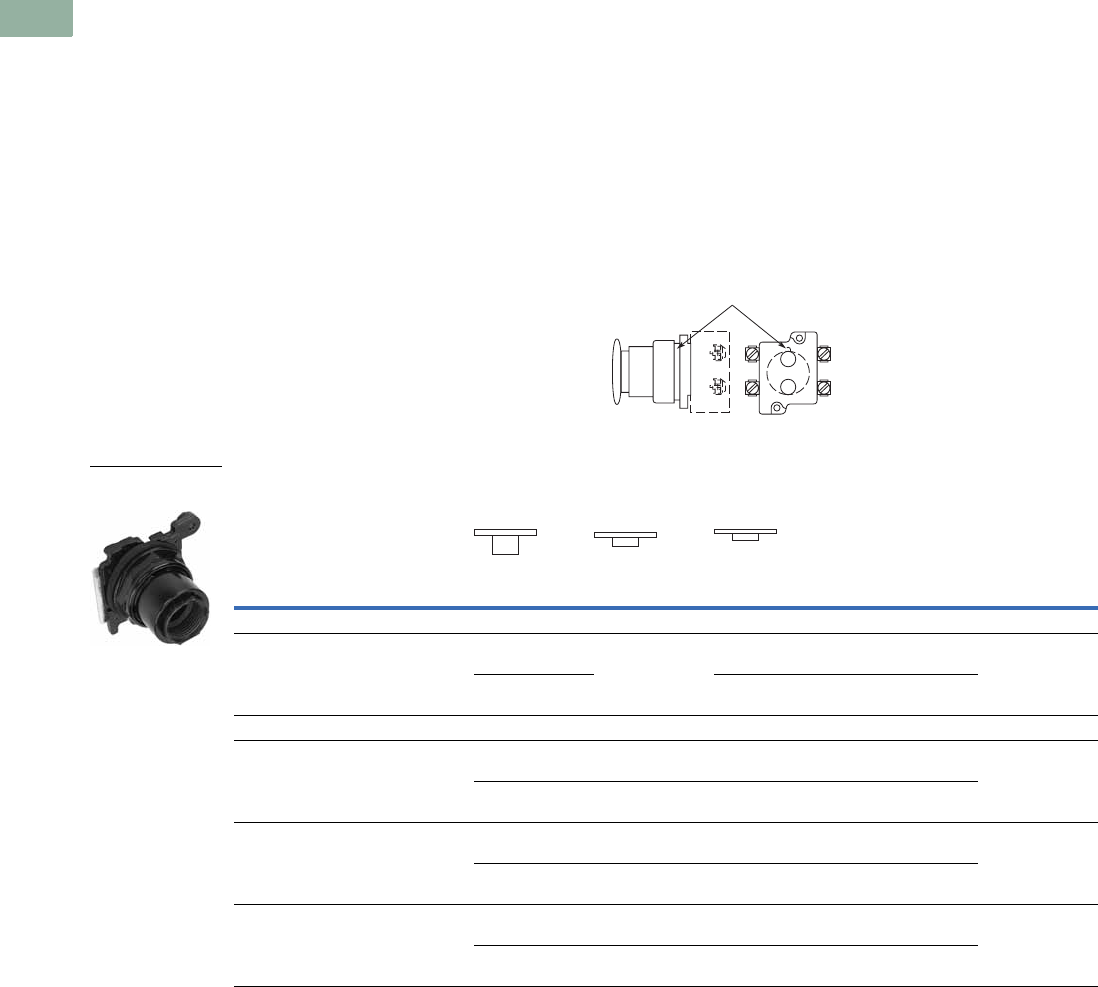
V7-T1-268 Volume 7—Logic Control, Operator Interface and Connectivity Solutions CA08100008E—March 2014 www.eaton.com
1
1
1
1
1
1
1
1
1
1
1
1
1
1
1
1
1
1
1
1
1
1
1
1
1
1
1
1
1
1
1.9
Pushbuttons and Indicating Lights
30.5 mm Corrosion Resistant Watertight/Oiltight—E34
Push-Pull Operators
An illuminated push-pull
pushbutton unit, arranged for
one-hole mounting, can
replace two pushbuttons and
a pilot light or the non-
illuminated form can replace
two pushbuttons. These units
are available in three basic
types:
●Maintained—(Two-
position). Maintains in the
pulled or pushed position
until manually actuated to
the opposite mode.
●Momentary—(Three-
position). Spring returns to
an intermediate position
when pulled or pushed and
released.
●Momentary Pull,
Maintained Push—(Three-
position). Spring returns to
intermediate position when
pulled. Maintains in pushed
position until manually
returned to intermediate
(ready to reset) position.
Maintained stop holds
circuit open and will
prevent other series
connected operators from
starting the system.
The operators, buttons,
contact blocks, etc., are
offered as building block
components that can be
intermixed to satisfy many
requirements. This minimizes
the need for a varied and
costly inventory.
Application Guide
To assist in the selection of
contact blocks, the sketch
below shows pictorially by
symbols A and B locations of
contact circuits after
assembly of contact blocks
and adapter to the operator.
The table below shows the
effect of the push and pull
operations on either NO or
NC contacts. (X = contact
closed, O = contact open).
Contact Circuit Locations
Push-Pull Operator Components
Notes
Use NEMA 4X 10250T operators where exposed to ultraviolet light, see Pages V7-T1-182 to V7-T1-253.
See Typical Applications on Page V7-T1-203.
1 Shown without button on lens.
2 Maximum of two blocks, four circuits. Special function contact blocks shown on Page V7-T1-286 CANNOT be used with
three-position push-pull operators E34GEB, E34GFB or E34GHB.
Locating Nib
A
B
Type of Operator
Operator Position and Circuit Arrangement
Contact Block 2Catalog Number
Out—Pull Intermediate In—Push
Contact Block Mounting Location
ABABAB
Two-Position Operator without Lens
Maintained push-pull O
Xor O
X
No intermediate
position
X
Oor X
O
1NO
1NC
E34GDB
O
X
O
X
X
O
X
O
2NO
2NC
Three-Position Operator without Lens
Momentary push-pull O
Xor O
X
O
Oor O
X
X
Oor O
O
1NO
1NC
E34GEB 2
O
X
O
X
O
O
O
X
X
O
O
O
2NO
2NC
Maintained push-momentary pull O
Xor O
X
O
Oor O
X
X
Oor O
O
1NO
1NC
E34GFB 2
O
X
O
X
O
O
O
X
X
O
O
O
2NO
2NC
Momentary push-pull O
Xor O
X
O
Oor O
O
X
Oor X
O
1NO
1NC
E34GHB 2
O
X
O
X
O
O
O
O
X
O
X
O
2NO
2NC
Two-Position Maint.
Push-Pull 1
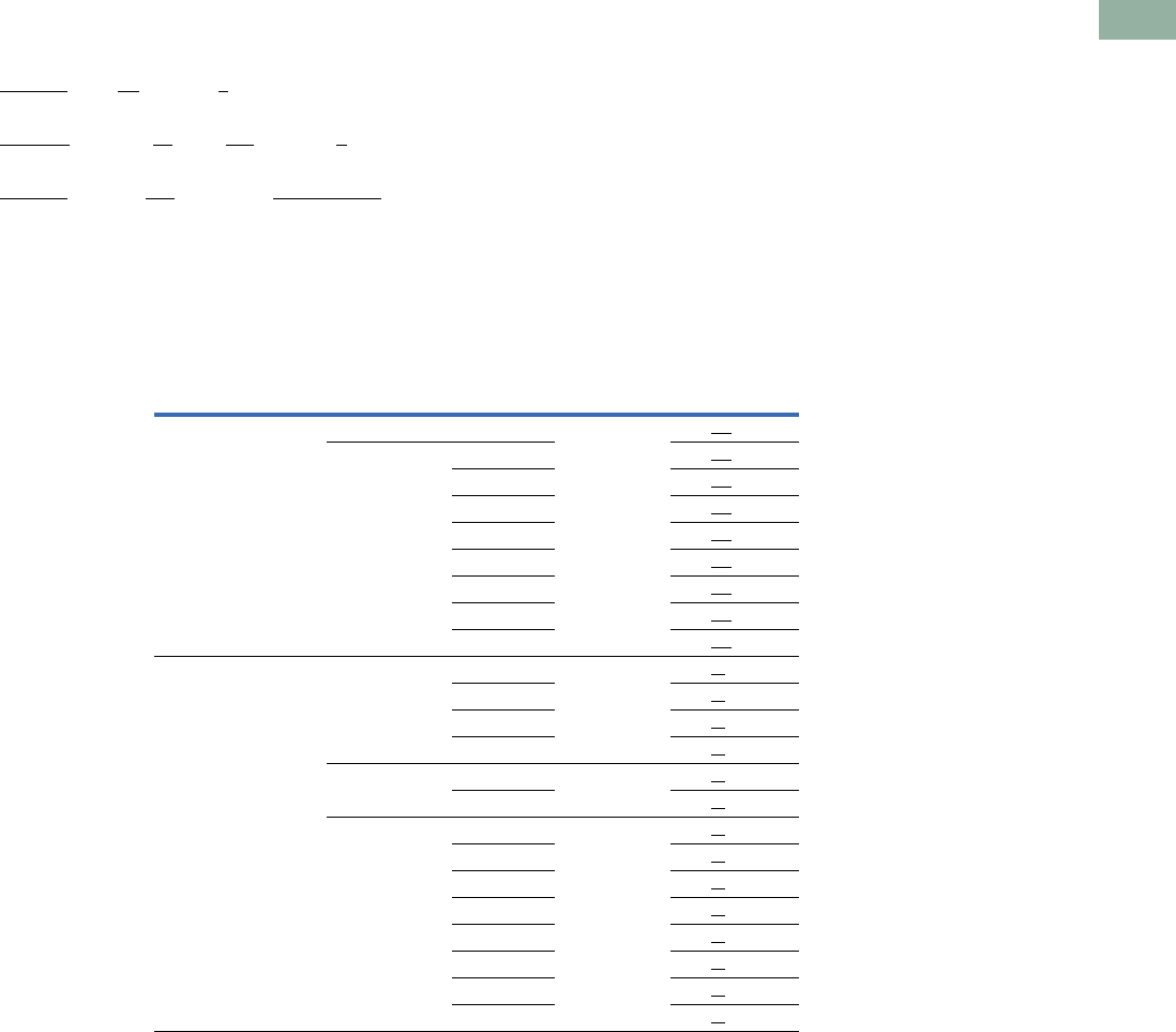
Volume 7—Logic Control, Operator Interface and Connectivity Solutions CA08100008E—March 2014 www.eaton.com V7-T1-269
1
1
1
1
1
1
1
1
1
1
1
1
1
1
1
1
1
1
1
1
1
1
1
1
1
1
1
1
1
1
1.9
Pushbuttons and Indicating Lights
30.5 mm Corrosion Resistant Watertight/Oiltight—E34
Push-Pull Light Units, Lenses and Buttons
Ordering Example with One Composite Number
Non-illuminated:
E34GDB + E34C2 + 10250T1 = E34GDBC2-1X
Incandescent:
E34GDB + 10250T79 + E34M2 + 10250T1 = E34GDB79M2-1X
LED:
E34GDB + 10250T97L + E34M2 + Voltage Code + 10250T1 = E34GDB97LRD24-1X
06—6 Vac/Vdc
12—12 Vac/Vdc
24—24 Vac/Vdc
48—48 Vac/Vdc
60—60 Vac/Vdc
2A—120 Vac
2D—120 Vdc
Light Units for Illuminated Push-Pull Devices
Notes
Use NEMA 4X 10250T operators where exposed to ultraviolet light, see Pages V7-T1-182 to V7-T1-253.
1 These units do not include lamps. Order LED separately to match lens color from chart on Page V7-T1-271.
Light Unit
Type Type Voltage
LED/Lamp
Number Catalog Number
LED
(LEDs not included) 1
Full voltage — Bayonet
base
10250T97L
Transformer
AC only
50/60 Hz
24 10250T89L
120 10250T63L
208 10250T64L
240 10250T65L
277 10250T82L
380 10250T66L
480 10250T67L
600 10250T68L
Incandescent Full voltage
AC or DC
6#755
#756
#757
#1828
10250T69
12 10250T70
24/28 10250T79
32 10250T83
Resistor
AC or DC
120 120MB 10250T80
240 10250T81
Transformer
AC only
50/60 Hz
24 #755 10250T89
120 10250T63
208 10250T64
240 10250T65
277 10250T82
380 10250T66
480 10250T67
600 10250T68

V7-T1-270 Volume 7—Logic Control, Operator Interface and Connectivity Solutions CA08100008E—March 2014 www.eaton.com
1
1
1
1
1
1
1
1
1
1
1
1
1
1
1
1
1
1
1
1
1
1
1
1
1
1
1
1
1
1
1.9
Pushbuttons and Indicating Lights
30.5 mm Corrosion Resistant Watertight/Oiltight—E34
Buttons for Non-Illuminated Push-Pull Devices
Alternate Lenses for Illuminated Push-Pull Devices
Notes
Use NEMA 4X 10250T operators where exposed to ultraviolet light, see Pages V7-T1-182 to V7-T1-253.
1 Anodized aluminum may not be suitable for use on some corrosive applications.
2 Suffix codes should only be used for assembling composite catalog numbers. To order lens, order by catalog number.
Color
Incandescent
Suffix Code Catalog Number
Standard Button
Black C1 E34C1
Red C2 E34C2
Red (EMERG. STOP) C2N8 E34C2N8
Green C3 E34C3
Blue C6 E34C6
Jumbo Mushroom Head
Red 1J2 E34J2
Red (EMERG. STOP) J2N8 E34J2N8
Color
Incandescent
Suffix Code
LED
Suffix Code 2Catalog Number
Red M2 RD E34M2
Red (EMERG. STOP) M2N8 ED E34M2N8
Green M3 GD E34M3
Blue M6 LD E34M6
Amber M9 AD E34M9
White M5 WD E34M5
Clear M0 — E34M0
Standard
Jumbo Mushroom
Head
E34M_

Volume 7—Logic Control, Operator Interface and Connectivity Solutions CA08100008E—March 2014 www.eaton.com V7-T1-271
1
1
1
1
1
1
1
1
1
1
1
1
1
1
1
1
1
1
1
1
1
1
1
1
1
1
1
1
1
1
1.9
Pushbuttons and Indicating Lights
30.5 mm Corrosion Resistant Watertight/Oiltight—E34
LED Selection
Voltage Color Catalog Number Voltage Color Catalog Number
6 Vac/Vdc
suitable for
use with
transformers
Red E22LED006RN 60 Vac/Vdc Red E22LED060RN
Orange E22LED006ON Orange E22LED060ON
Yellow E22LED006YN Yellow E22LED060YN
Green E22LED006GN Green E22LED060GN
Blue E22LED006BN Blue E22LED060BN
White E22LED006WN White E22LED060WN
12 Vac/Vdc Red E22LED012RN 120 Vac Red E22LED120RA
Orange E22LED012ON Orange E22LED120OA
Yellow E22LED012YN Yellow E22LED120YA
Green E22LED012GN Green E22LED120GA
Blue E22LED012BN Blue E22LED120BA
White E22LED012WN White E22LED120WA
24 Vac/Vdc Red E22LED024RN 120 Vdc Red E22LED120RD
Orange E22LED024ON Orange E22LED120OD
Yellow E22LED024YN Yellow E22LED120YD
Green E22LED024GN Green E22LED120GD
Blue E22LED024BN Blue E22LED120BD
White E22LED024WN White E22LED120WD
48 Vac/Vdc Red E22LED048RN
Orange E22LED048ON
Yellow E22LED048YN
Green E22LED048GN
Blue E22LED048BN
White E22LED048WN
Standard LED Lamp
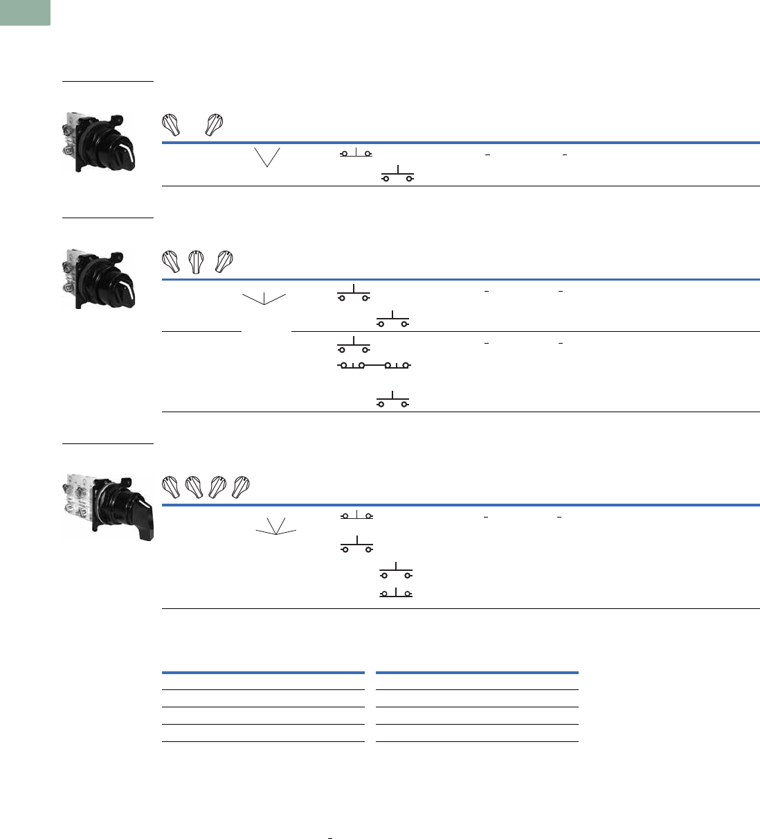
V7-T1-272 Volume 7—Logic Control, Operator Interface and Connectivity Solutions CA08100008E—March 2014 www.eaton.com
1
1
1
1
1
1
1
1
1
1
1
1
1
1
1
1
1
1
1
1
1
1
1
1
1
1
1
1
1
1
1.9
Pushbuttons and Indicating Lights
30.5 mm Corrosion Resistant Watertight/Oiltight—E34
Selector Switch Units
UL (NEMA) Type 3, 3R, 4, 4X, 12, 13
●Two-, three- and four-position—maintained
●Non-illuminated and illuminated
Two-Position Selector Switch
Three-Position Selector Switch
Four-Position Selector Switch
Color Selection, Non-Illuminated
Notes
For Light Unit Voltage Suffix and Knobs, Levers tables, see Page V7-T1-278.
Use NEMA 4X 10250T operators where exposed to ultraviolet light, see Pages V7-T1-182 to V7-T1-253.
1 X = closed circuit, O = open circuit.
2 M = Maintained.
3 To order different type or color selector switch, substitute the underlined character with appropriate suffix code from
the Color Selection table. Example: E34VFBK2-X1.
Operator Position 1
Operator
Action 2
Contact
Type
Cam
Code
Non-Illuminated Illuminated—120V Transformer
Mounting Location Black Knob
Catalog Number 3
Black Lever
Catalog Number 3
Red Knob
Catalog Number 3
Red Lever
Catalog Number 3
AB
X
O
O
X
1NC 1 E34VFBK1-1X E34VFBL1-1X E34VFB120ER-1X E34VFB120FR-1X
1NO
Operator Position 1
Operator
Action 2
Contact
Type
Cam
Code
Non-Illuminated Illuminated—120V Transformer
Mounting Location Black Knob
Catalog Number 3
Black Lever
Catalog Number 3
Red Knob
Catalog Number 3
Red Lever
Catalog Number 3
AB
X
O
O
O
O
X
1NO 3 E34VHBK1-2X E34VHBL1-2X E34VHB120TER-2X E34VHB120TFR-2X
1NO
X
O
O
O
X
O
O
O
X
1NO 3 E34VHBK1-23X E34VHBL1-23X E34VHB120TER-23X E34VHB120TFR-23X
2NC
(Series)
1NO
Operator Position 1
Operator
Action 2
Contact
Type
Cam
Code
Non-Illuminated Illuminated—120V Transformer
Mounting Location Black Knob
Catalog Number 3
Black Lever
Catalog Number 3
Red Knob
Catalog Number 3
Red Lever
Catalog Number 3
AB
X
O
O
O
O
X
O
O
O
O
X
O
O
O
O
X
1NC 7 E34VTBK1-23X E34VTBL1-23X E34VRB120TER-23X E34VRB120TFR-23X
1NO
1NO
1NC
Color Code Letter Color Code Letter
Black 1White 5
Red 2Blue 6
Green 3Gray 7
Yellow 4Orange 8
Two-Position Maint.
Switch Knob
MM
Three-Position Maint.
Switch Knob
MM
M
Four-Position Maint.
Switch Lever
MM
MM
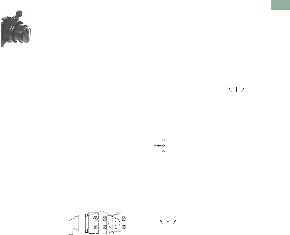
Volume 7—Logic Control, Operator Interface and Connectivity Solutions CA08100008E—March 2014 www.eaton.com V7-T1-273
1
1
1
1
1
1
1
1
1
1
1
1
1
1
1
1
1
1
1
1
1
1
1
1
1
1
1
1
1
1
1.9
Pushbuttons and Indicating Lights
30.5 mm Corrosion Resistant Watertight/Oiltight—E34
Selector Switch Selection
Cam and Contact Block Selection
Selector switches in their
varied forms (two-position,
three-position and four-
position) are a big factor
contributing to the great
flexibility of control that a well
rounded line of “pushbuttons”
can achieve. Because of their
flexibility, they tend to cause
difficulty with product
selection and application.
The following systematic
approach should simplify
that task.
Cam and contact block
selection is better understood
if you:
●Work with each incoming
and outgoing wire/circuit
separately.
●Recognize the terms NO
and NC only identify the
type of contact by its mode
before mounting to the
operator. The “X-O” chart
(Page V7-T1-275) shows
how that contact will act
after assembly to the
operator with the selected
cam shape. X = closed
circuit, O = open circuit.
●Up to six NO or NC
contacts may be mounted
behind each plunger
location for a total of
twelve contacts. Single
circuit contact blocks have
only one plunger with the
other side of the block
“open.” Therefore, single
circuit contact blocks
transmit motion to blocks
behind them only for the
position containing the
circuit.
●Each cam has two
separate lobes, each of
which operates one of the
two contact block plungers
independently of each
other. Those are identified
as position A (locating nib
side) and position B
(opposite of locating nib).
The position designations
give direction in selecting
and mounting of the
contact blocks.
Contact Circuit Locations
Locating Nib
A
B
Systematic Approach
Application: HAND-OFF-
AUTO selector switch. In this
circuit, one incoming line is
distributed to two other
outgoing circuits by the
switch. The two circuits can
be looked at individually.
Step 1: Elementary
Diagram.
Construct on paper, or in your
mind, a simple elementary
diagram of the switching
scheme as follows:
Step 2: “X-O” Pattern.
From the elementary
diagram, you can construct an
“X-O” diagram which
describes when the contacts
are to be closed (X) or open
(O) in the various positions of
the switch. The “X-O” for the
HAND circuit looks like this:
In this circuit, you want a
contact closed on the left
(HAND) but open in the
center and right.
For the AUTO circuit, the
“X-O” diagram would look like
this:
Putting them together, the
complete “X-O” diagram is:
Once the “X-O” diagram has
been generated, the next
step is to select the cam
and contact block, or blocks,
needed to perform the
desired “X-O” functions.
The selection tables on the
following pages list the
various types (shapes) of
cams by number to choose
from and the type of contact
and position to achieve the
function outlined in your
“X-O” diagram.
OFF
HAND Outgoing
Circuit
AUTO
Outgoing
Circuit
Incoming
Line
HAND OFF AUTO
XOO
HAND OFF AUTO
OOX
X O O
O O X
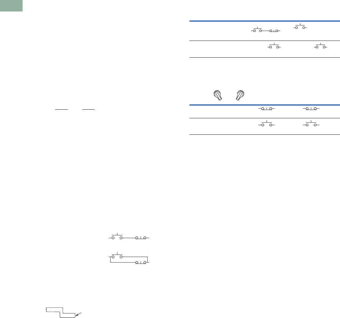
V7-T1-274 Volume 7—Logic Control, Operator Interface and Connectivity Solutions CA08100008E—March 2014 www.eaton.com
1
1
1
1
1
1
1
1
1
1
1
1
1
1
1
1
1
1
1
1
1
1
1
1
1
1
1
1
1
1
1.9
Pushbuttons and Indicating Lights
30.5 mm Corrosion Resistant Watertight/Oiltight—E34
Step 3: Cam Selection.
The cam you select
determines the operation of
all contact blocks mounted to
the operator. It is selected on
the basis that it provides the
simplest circuitry for the
desired “X-O” diagram. The
selection tables show all the
“X-O” combinations. For the
purpose of this example, the
applicable portion of those
tables is shown on this page.
Now to make the cam
selection, make a simple
worksheet such as:
It becomes immediately
obvious that cam 3 is the
better choice for two
reasons, (1) the series
combination can be avoided
making it simpler to wire,
(2) only two contacts are
required, which is less
expensive than the three
contacts required by cam 2.
Step 4: Contact Block
Selection.
Having selected the cam,
contact block selection is
simply a matter of gathering
the A position and B position
circuits into pairs which make
up the most convenient contact
block arrangement. If there is
an imbalance in the number of
circuits under A or B, then
single circuit blocks must be
selected for these leftover
circuits.
Back to the worksheet,
having selected cam 3 do
this:
Step 5: Selector Switch
Operator.
Lastly, you have to choose
from the many types of
operators—knob and lever
in various colors or keyed.
Also what combinations
of maintained and spring
return functions are
required. Selection of these
operators can be found on
Page V7-T1-276. For the
example in step 4, you
may want a three-position
maintained black knob,
cam 3—Catalog Number
E34VHBK1.
The Complete Switch:
E34VHBK1 with one
10250T2 or, for one
composite catalog number,
E34VHBK1-Y1 found on
Page V7-T1-273.
Diagrams
Circuits shown illustrate
connections to obtain a
selector switch circuit
combination and are shown
with their appropriate line
diagrams. Field wiring of
jumper connections required
as shown.
X = Closed circuit
O = Open circuit
Wiring of Jumper
Connections
Four-position selector
switches are limited to four
contact blocks.
Contact Blocks
For selection and number
of available contact blocks
per operator, see Page
V7-T1-285.
Cam 2 Cam 3
X O O
O O X
(A)NO-(B)NC
(B)NO
(A)NO
(B)NO
X O X
O O X
ANO
BNO 10250T2
Parallel Connection
Series Connection
Example Selection Table
Two-Position Selector Switch Contact Block Selection
Note
1Wired in series.
No. “X-O” Pattern
Cam Code #2 Cam Code #3
Top A Bottom B Top A Bottom B
1XOO
NO NC NO
—
4 OOX—
NO
—
NO
No.
Desired Circuit and
Operator Position
Contact Blocks Required to
Accomplish Circuit Function
Top Plunger A Bottom Plunger B
1XO
NC or NC
2OX
NO
or
NO
a
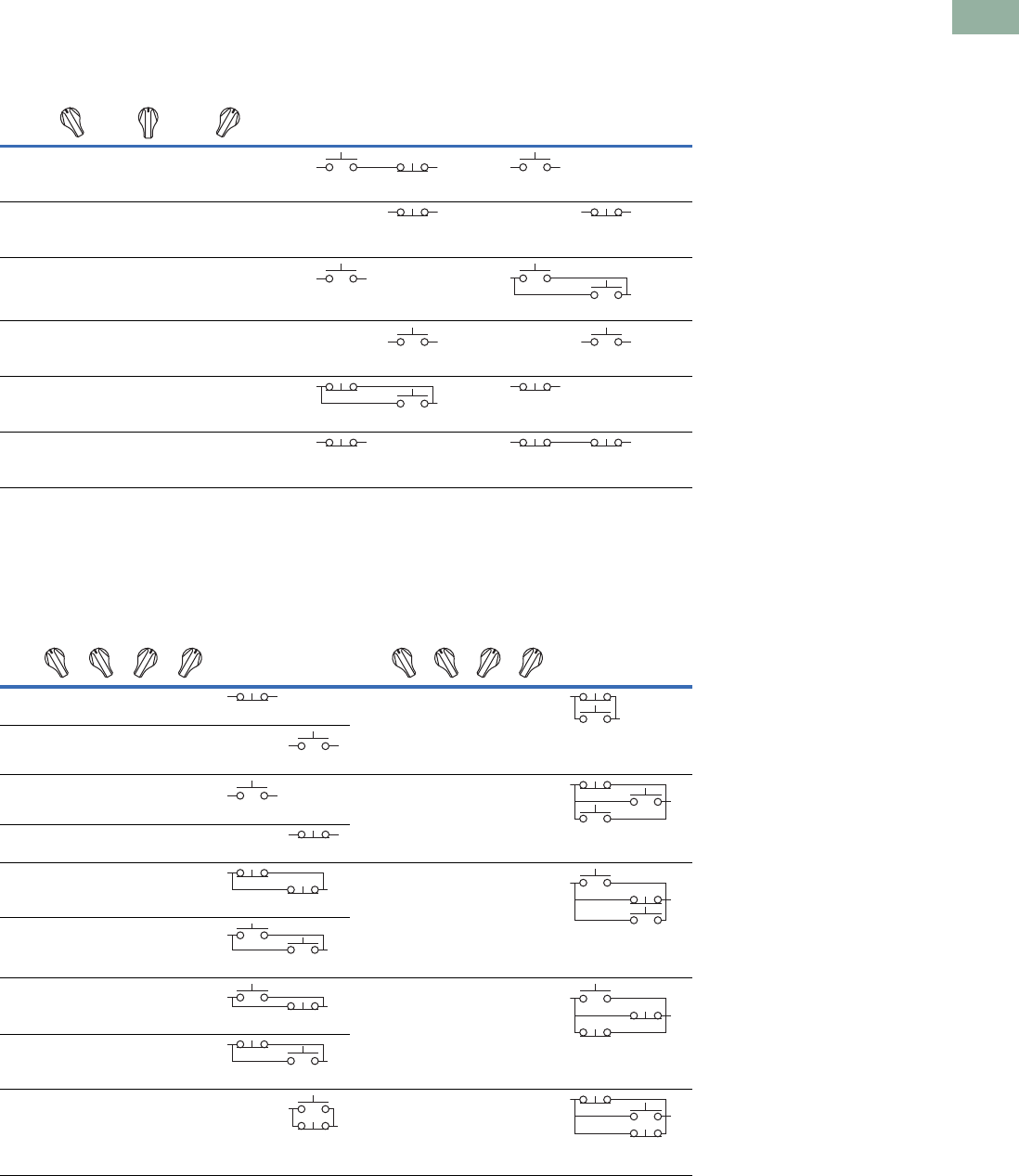
Volume 7—Logic Control, Operator Interface and Connectivity Solutions CA08100008E—March 2014 www.eaton.com V7-T1-275
1
1
1
1
1
1
1
1
1
1
1
1
1
1
1
1
1
1
1
1
1
1
1
1
1
1
1
1
1
1
1.9
Pushbuttons and Indicating Lights
30.5 mm Corrosion Resistant Watertight/Oiltight—E34
Three-Position Switch—Cam and Contact Block Selection
Four-Position Switch—Contact Block Selection
No.
Desired Circuit and
Operator Position
Contact Blocks Required to Accomplish Circuit Function
(Jumpers must be installed where indicated)
Operator with Cam Code #2 Operator with Cam Code #3
Mounting Location Mounting Location
Top
Plunger
A
Bottom
Plunger
B
Top
Plunger
A
Bottom
Plunger
B
1X O O
NO NC NO
2XXO
NC NC
3X O X
NO
NO NO
4OOX
NO NO
5O X X
NC NO
NC
6O X O
NC NC NC
No.
Contact Blocks
Required to
Accomplish Circuit
Function
No.
Contact Blocks
Required to
Accomplish Circuit
Function
Desired Circuit and
Operator Position
Mounting Location Desired Circuit and
Operator Position
Mounting Location
Top
Plunger
A
Bottom
Plunger
B
Top
Plunger
A
Bottom
Plunger
B
1XOOO
NC
10XOXO
NC
NO
2OXOO
NO
3OOXO
NO
11XXXO
NC
NO NO
4OOOX
NC
5XOOX
NC NC
12OXXX
NO NC
NO
6OXXO
NO NO
7OOXX
NO NC
13XOXX
NO
NC NC
8XXOO
NC NO
9OXOX
NO
NC
14XXOX
NC NO
NC
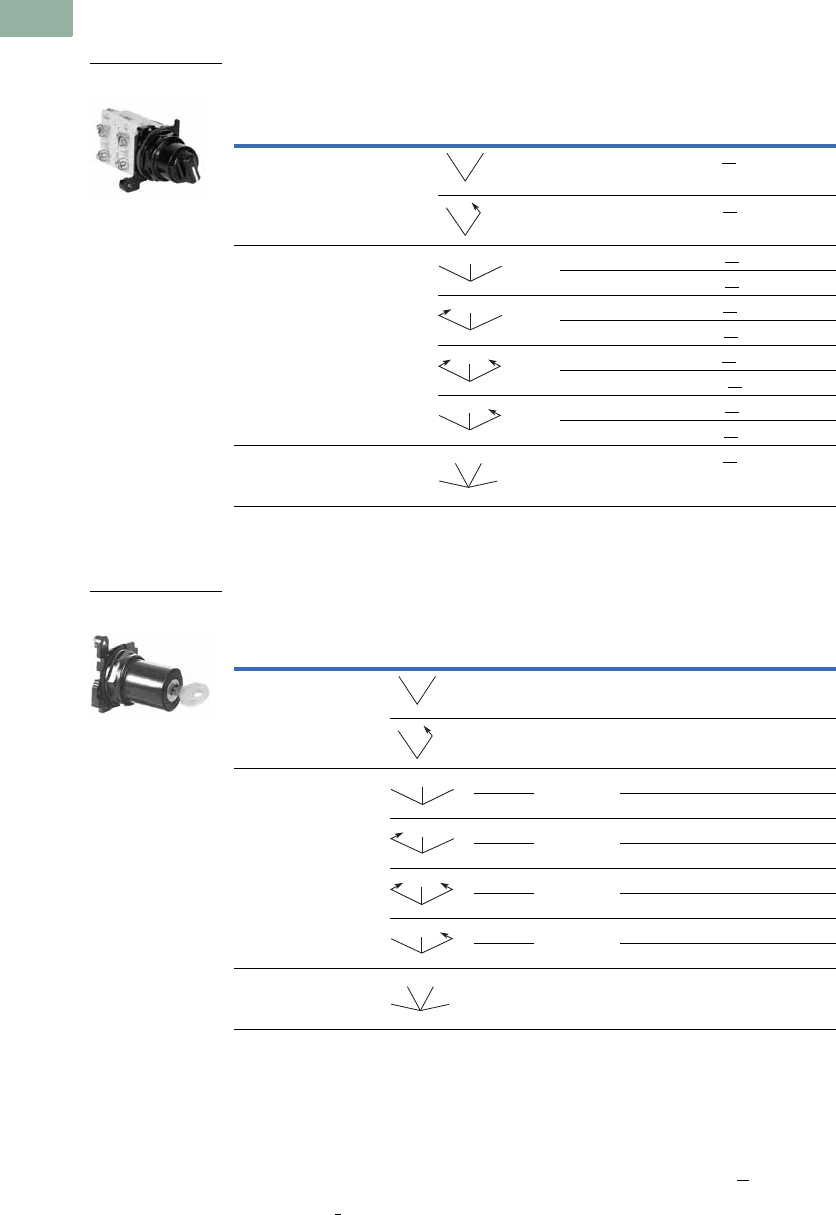
V7-T1-276 Volume 7—Logic Control, Operator Interface and Connectivity Solutions CA08100008E—March 2014 www.eaton.com
1
1
1
1
1
1
1
1
1
1
1
1
1
1
1
1
1
1
1
1
1
1
1
1
1
1
1
1
1
1
1.9
Pushbuttons and Indicating Lights
30.5 mm Corrosion Resistant Watertight/Oiltight—E34
Selector Switch Operators
UL (NEMA) Type 3, 3R, 4, 4X, 12, 13
Operators with Knob Assembled
Key Operators
Key Operators with Cam and Cap
Notes
Use NEMA 4X 10250T operators where exposed to ultraviolet light, see Pages V7-T1-182 to V7-T1-253.
1 M = Maintained. S = Spring return in direction of arrow (R).
2 Field convertible to horizontal mounting.
3 For selection of the proper cam and contact block to obtain the proper circuit sequence, see selection instructions and
tables on Pages V7-T1-273 to V7-T1-275.
4 For other colors of either the knob or lever, replace the underlined characters of the catalog number with the
appropriate suffix code from Alternate Knob and Lever table on Page V7-T1-277. Example: E34VFBL2.
5 Choose key removal position required for application from table on Page V7-T1-277. Add key removal code number to listed catalog number.
Example: E34KFB2.
Positions
Operator
Action 1
Black Knob Selector Switch—
Vertical Mounting 2
Cam Code 3Catalog Number 4
Two-position—60° throw 1 E34VFBK1
1E34VEBK1
Three-position—60° throw 2 E34VGBK1
3E34VHBK1
2E34VJBK1
3E34VKBK1
2E34VLBK1
3E34VMBK1
2E34VNBK1
3E34VPBK1
Four-position—40° throw 7 E34VTBK1
Positions
Operator
Action 1
Cam
Code 3
Key
Removal
Positions 5
Vertical
Mounting
Catalog Number
Horiz.
Mounting
Catalog Number
Two-position—60° throw 1 1, 2, 3 E34KFB_ E34KFHB_
12 E34KEB_ E34KEHB_
Three-position—60° throw 2 1–7 E34KGB_ E34KGHB_
3E34KHB_ E34KHHB_
21, 4, 5 E34KJB_ E34KJHB_
3E34KKB_ E34KKHB_
24 E34KLB_ E34KLHB_
3E34KMB_ E34KMHB_
22, 4, 6 E34KNB_ E34KNHB_
3E34KPB_ E34KPHB_
Four-position—40° throw 7 7 E34KTB_ E34KTHB_
Two-Position Knob
Selector Switch
MM
MS
MM
M
MS
M
SS
M
MS
M
MM
MM
Three-Position Keyed
Selector Switch
MM
MS
MM
M
MS
M
SS
M
MS
M
MM
MM
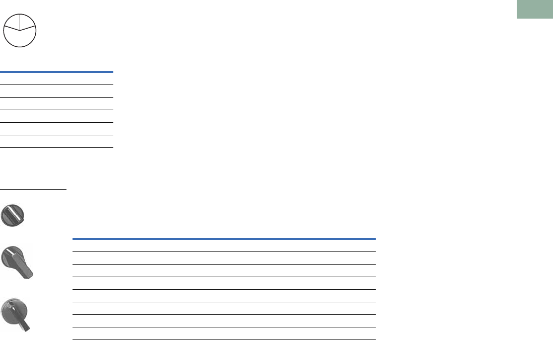
Volume 7—Logic Control, Operator Interface and Connectivity Solutions CA08100008E—March 2014 www.eaton.com V7-T1-277
1
1
1
1
1
1
1
1
1
1
1
1
1
1
1
1
1
1
1
1
1
1
1
1
1
1
1
1
1
1
1.9
Pushbuttons and Indicating Lights
30.5 mm Corrosion Resistant Watertight/Oiltight—E34
Key Removal Positions 1 Dissimilar Locks and Keys
Listed operators have
identical locks and keys (Key
Code H661), Catalog Number
10250ED824. For dissimilar
lock and key combinations,
see Page V7-T1-212.
Alternate Knobs and Levers for Operators 2
Notes
1 Key removal in “spring return from” positions not recommended.
2 See operators on Page V7-T1-276.
3 For use on maintained operators only.
Code
Suffix
Key Removal
Position
1Right only
2Left only
3Right and left
4Center only
6Left and center
7All positions
L
C
R
Color
Knob Lever
Lever Designed for
Added Ingress Protection 3
Suffix
Code Catalog Number
Suffix
Code Catalog Number
Suffix
Code Catalog Number
Black K1 E34K1 L1 E34L1 A1 E34A1
Red K2 E34K2 L2 E34L2 A2 E34A2
Green K3 E34K3 L3 E34L3 A3 E34A3
Yellow K4 E34K4 L4 E34L4 A4 E34A4
White K5 E34K5 L5 E34L5 A5 E34A5
Blue K6 E34K6 L6 E34L6 A6 E34A6
Gray K7 E34K7 L7 E34L7 A7 E34A7
Orange K8 E34K8 L8 E34L8 A8 E34A8
E34K_
E34L_
E34A_
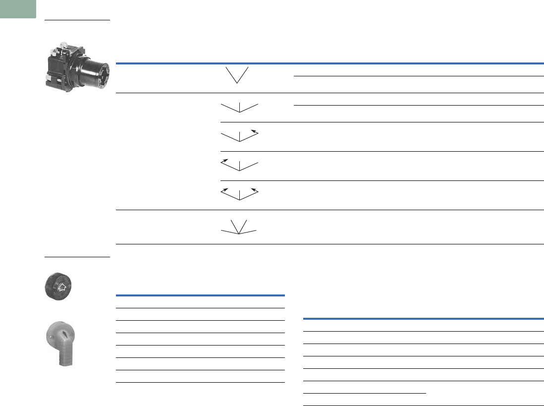
V7-T1-278 Volume 7—Logic Control, Operator Interface and Connectivity Solutions CA08100008E—March 2014 www.eaton.com
1
1
1
1
1
1
1
1
1
1
1
1
1
1
1
1
1
1
1
1
1
1
1
1
1
1
1
1
1
1
1.9
Pushbuttons and Indicating Lights
30.5 mm Corrosion Resistant Watertight/Oiltight—E34
Illuminated Selector Switch Operators
Operator without Knob or Lever
Knobs and Levers Light Unit Voltage Suffix
Add to operator Catalog Number listed in table above.
Notes
Use NEMA 4X 10250T operators where exposed to ultraviolet light, see Pages V7-T1-182 to V7-T1-253.
1 Full voltage light units can be used at other than listed voltages by changing lamp. Replacement lamps are listed on Page V7-T1-239.
2 120MB lamps are used on both 120V and 240V operators.
3 Operator includes lens gasket and lens attachment screws.
4 Add suffix code for light unit voltage to listed catalog number from Light Unit Voltage Suffix table above.
Example: For 24V transformer type light unit, order E34VFB024.
5 For selection of the proper cam and contact block required to obtain a specific circuit sequence, see selection tables on Pages V7-T1-273 to V7-T1-275.
6 120 and 240V transformer only.
7 120 full voltage only.
8 Resistor type. May generate excess heat if used in high density.
9 Amber, clear and white lenses have a black arrow (R). Red, green and blue lenses have a white arrow (R).
Positions Operator Action
Transformer Type—50/60 Hz Full Voltage Type—AC or DC 1
6V #755 Lamp Lamps—#755, #757, #1835, 120MB 2
Catalog Number 34 Catalog Number 4
Two-position—60° throw Cam Code 1 5Cam Code 1 5
E34VFB_ E34SFB_
Three-position—60° throw Cam Code 2 5Cam Code 3 5Cam Code 2 5Cam Code 3 5
E34VGB_ E34VHB_ E34SGB_ E34SHB_
E34VNB_ 6E34VPB_ 6E34SNB_ 7E34SPB_ 7
E34VJB_ 6E34VKB_ 6E34SJB_ 7E34SKB_ 7
E34VLB_ E34VMB_ E34SLB_ E34SMB_
Four-position—40° throw E34VRB_ — E34SRB_ —
120 Vac Transformer
Selector Switch, Cam 1
MM
MM
M
MS
M
MS
M
SS
M
MM
MM
Color 9
Knob
Catalog Number
and Code Number
Lever
Catalog Number
and Code Number
Red 10250TER 10250TFR
Green 10250TEG 10250TFG
Yellow 10250TEA 10250TFA
Blue 10250TEL 10250TFL
Clear 10250TEC 10250TFC
White 10250TEW 10250TFW
Amber 10250TEM 10250TFM
Knob
Lever
Type of Light Unit
Transformer Type
50/60 Hz
Full Voltage Type
AC or DC 1
Voltage Suffix Code Voltage Suffix Code
24 024 606
120 120 12 12
208 208 24 24
240 240 48 48
380 380 120 120
480 480 240 8240
600 600
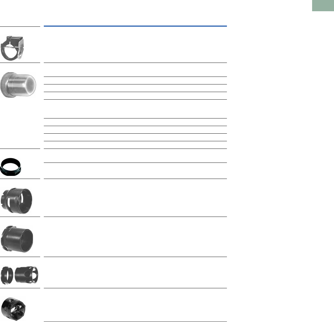
Volume 7—Logic Control, Operator Interface and Connectivity Solutions CA08100008E—March 2014 www.eaton.com V7-T1-279
1
1
1
1
1
1
1
1
1
1
1
1
1
1
1
1
1
1
1
1
1
1
1
1
1
1
1
1
1
1
1.9
Pushbuttons and Indicating Lights
30.5 mm Corrosion Resistant Watertight/Oiltight—E34
Accessories
Accessories
Notes
1 Should not be used on flush button for STOP function.
2 Not suitable for single contact block depth cast enclosure. Cover is too thick.
Description Catalog Number
Padlocking Attachment for Flush Pushbutton Operators.
Permits locking NC contacts in open position with 1/4 in padlock.
Will not lock NO contact.
E34TA2
Flexible Weather Resistant Boot for use with flush pushbutton operators.
Clear 10250TA46
Black 10250TA47
Red 10250TA48
Green 10250TA49
Flexible Weather Resistant Boot for use with button operators (extended
buttons preferred).
Black 10250TA3
Red 10250TA4 1
Green 10250TA10
Clear 10250TA85
Transparent Boot for regular, illuminated pushbutton operators and PresTest. 10250TA25 2
Special Retaining Nut—to accommodate thick panel.
Indicating light E34TA30
PresTest, pushbuttons and selector switches E34TA31
Shroud for Mushroom Head Operator—prevents accidental operation.
(Not for push-pull operators.)
E34TA6
Extended Retaining Nut—replaces standard nut and provides guard for
flush type pushbutton operators.
E34TA12
Guard for illuminated pushbutton E34TA15
Padlocking Attachment for non-illuminated knob selector switches—
accommodates up to five, 1/4 in padlocks.
E34TA11
E34TA2
10250TA_
E34TA3_
E34TA6
E34TA12
E34TA15
E34TA11
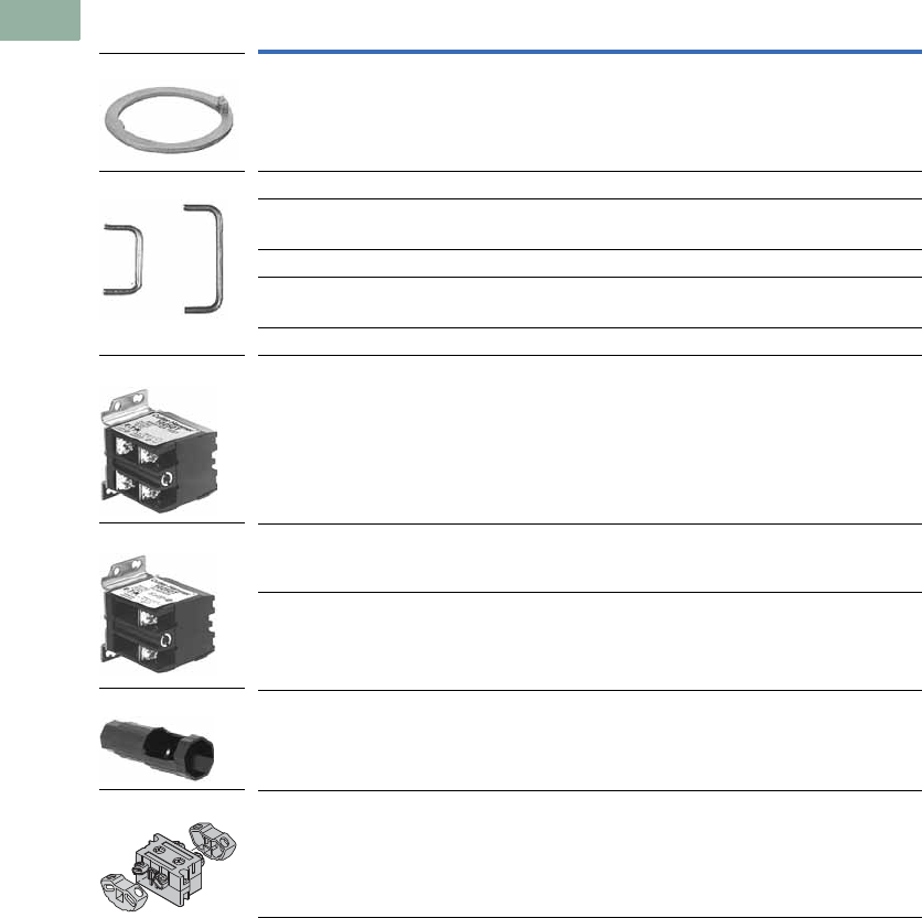
V7-T1-280 Volume 7—Logic Control, Operator Interface and Connectivity Solutions CA08100008E—March 2014 www.eaton.com
1
1
1
1
1
1
1
1
1
1
1
1
1
1
1
1
1
1
1
1
1
1
1
1
1
1
1
1
1
1
1.9
Pushbuttons and Indicating Lights
30.5 mm Corrosion Resistant Watertight/Oiltight—E34
Accessories, continued
Description Catalog Number
Thrust Washer—To meet Ford Motor Company mounting specifications. E34TK3
Contact Block Terminal Jumps—Available in multiples of 100 only.
Terminal to terminal—within block (short):
100 per package 10250TA70
1000 per package 10250TA70-2
Terminal to terminal—block to block (long):
100 per package 10250TA71
1000 per package 10250TA71-2
Master Test (Dual Input) Module—Internal Form C relay suitable for either
AC or DC applications. Total electrical isolation between monitored and test circuit.
Fits all illuminated 10250T, E22, E30 and E34 devices.
48 Vdc 10250TMT8
Flasher Module—Internal Form C relay suitable for AC applications.
One unit required for each operator in master test circuit.
24 Vac 10250TFL2
120 Vac 10250TFL1
Panel Mounting Nut Wrench—E22, E30, E34 and octagonal 10250T. E22CW
Fingerproof Shroud—10 per package
Fits new style contact blocks and light units.
10250TA101
E34TK3
10250TA7_
10250TMT8
10250TFL_
E22CW
10250TA101
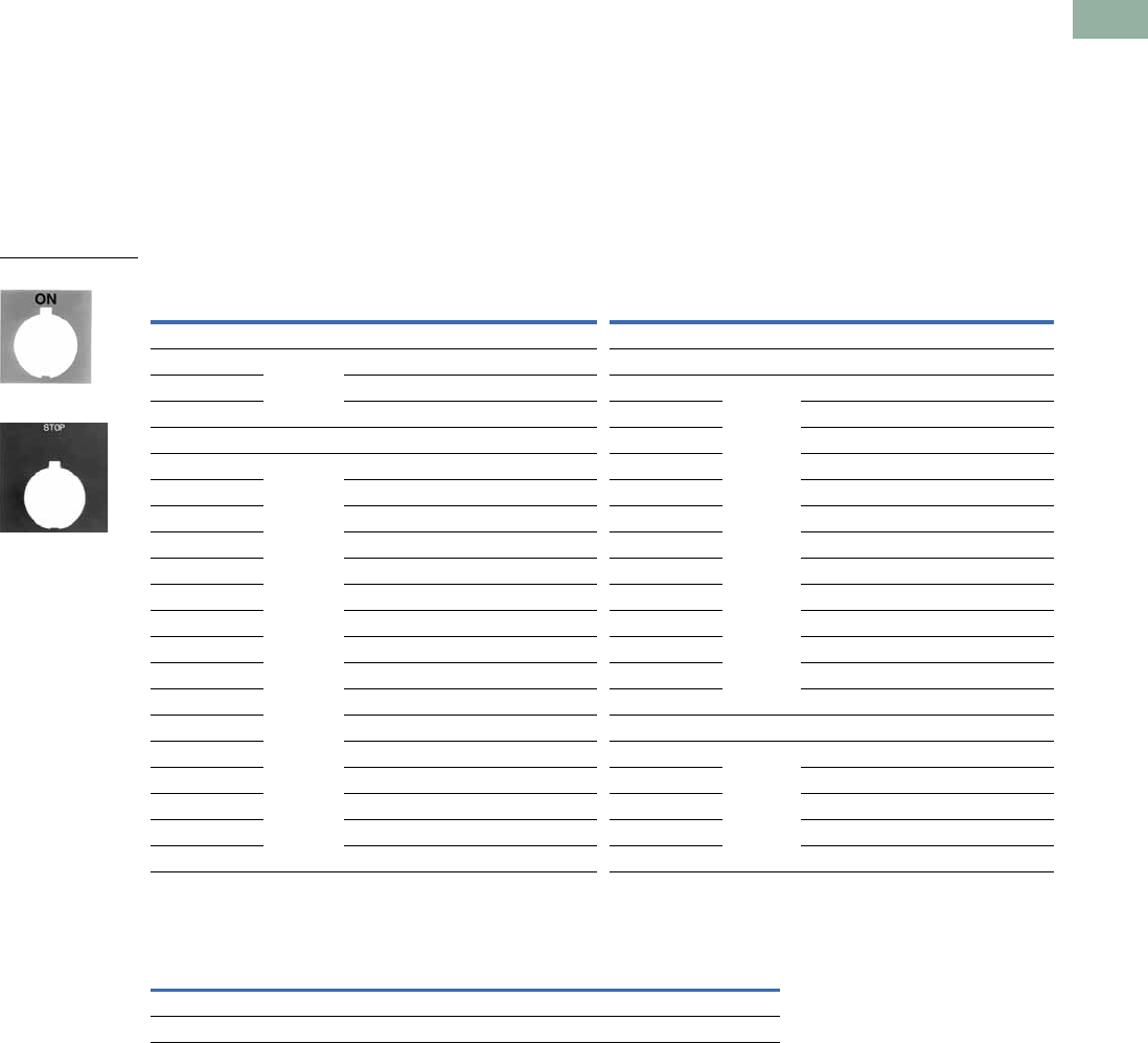
Volume 7—Logic Control, Operator Interface and Connectivity Solutions CA08100008E—March 2014 www.eaton.com V7-T1-281
1
1
1
1
1
1
1
1
1
1
1
1
1
1
1
1
1
1
1
1
1
1
1
1
1
1
1
1
1
1
1.9
Pushbuttons and Indicating Lights
30.5 mm Corrosion Resistant Watertight/Oiltight—E34
Options
Legend Plates 1
Field Color
Legend plates can be
supplied printed on black, red,
silver or white field. To order
legend printed on a color
other than indicated—add
suffix code to the end of the
catalog number as follows:
“R” for Red field;
“W” for White field; or
“S” for Silver field.
Example: E34SP26R—
Standard plate with red field
marked OPEN.
For Pushbutton Operators and Indicating Lights
Blank Plastic Legend Plates—Square 3
Notes
1 For dimensions, see Page V7-T1-258.
2 3/32 in high lettering.
3 Legend plates with non-standard markings or aluminum legend plates see 10250T listing on Page V7-T1-232.
Legend
Color of
Field
Standard 2
Catalog Number
Jumbo
Catalog Number Legend
Color of
Field
Standard 2
Catalog Number
Jumbo
Catalog Number
Letters on Legend Plates Below are 3/16 in High
CLAMP Black E34SP90 E34LP90 OFF Red E34SP24 E34LP24
CLOSE E34SP73 E34LP73 ON Black E34SP25 E34LP25
DOWN E34SP74 E34LP74 OPEN E34SP26 E34LP26
EMERG. STOP Red E34SP13 E34LP13 OUT E34SP27 E34LP27
FAST Black E34SP75 E34LP75 POWER ON E34SP80 E34LP80
FASTER E34SP87 E34LP87 RAISE E34SP28 E34LP28
FEEDER ON E34SP94 E34LP94 READY E34SP86 E34LP86
FEEDER OFF E34SP95 E34LP95 RESET E34SP29 E34LP29
FORWARD E34SP15 E34LP15 REVERSE E34SP30 E34LP30
HIGH E34SP16 E34LP16 RUN E34SP31 E34LP31
IN E34SP17 E34LP17 SAFE E34SP85 E34LP85
INCH E34SP18 E34LP18 SLOW E34SP32 E34LP32
JOG E34SP19 E34LP19 SLOWER E34SP88 E34LP88
JOG FOR. E34SP20 E34LP20 START E34SP33 E34LP33
JOG REV. E34SP21 E34LP21 STOP Red E34SP34 E34LP34
LOW E34SP22 E34LP22 TEST Black E34SP83 E34LP83
LOWER E34SP23 E34LP23 TRANSFER E34SP93 E34LP93
LUBE-FAIL E34SP92 E34LP92 TRIP E34SP84 E34LP84
MOTOR RUN E34SP81 E34LP81 UNCLAMP E34SP91 E34LP91
MOTOR STOP E34SP82 E34LP82 UP E34SP35 E34LP35
Color Field Standard
Catalog Number
Jumbo
Catalog Number
Extra Large
Catalog NumberLettering Side 1 Side 2
Black White Silver 10250TSP76 10250TLP76 10250TEP76
White Red Black 10250TSP77 10250TLP77 10250TEP77
Standard
Jumbo
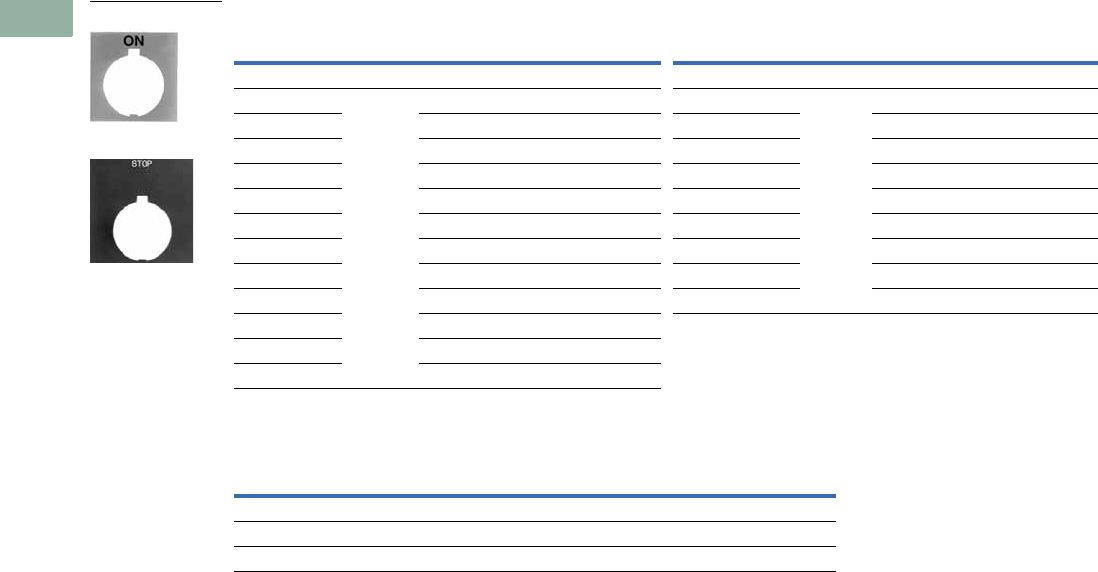
V7-T1-282 Volume 7—Logic Control, Operator Interface and Connectivity Solutions CA08100008E—March 2014 www.eaton.com
1
1
1
1
1
1
1
1
1
1
1
1
1
1
1
1
1
1
1
1
1
1
1
1
1
1
1
1
1
1
1.9
Pushbuttons and Indicating Lights
30.5 mm Corrosion Resistant Watertight/Oiltight—E34
For Selector Switch Operators
For Push-Pull Units
Notes
1 3/32 in (2.4 mm) high lettering.
2 1/8 in (3.2 mm) high lettering.
Legend
Color of
Field
Standard
Catalog Number
Jumbo
Catalog Number Legend
Color of
Field
Standard
Catalog Number
Jumbo
Catalog Number
Two-Position—3/16 in High Lettering Three-Position—3/16 in High Lettering
FOR. REV. Black E34SP38 E34LP38 AUTO OFF HAND Black E34SP49 E34LP49
HAND AUTO E34SP39 E34LP39 FOR. OFF REV. E34SP50 E34LP50
HIGH LOW E34SP40 E34LP40 FOR. SAFE REV. E34SP69 E34LP69
JOG RUN E34SP41 E34LP41 HAND OFF AUTO E34SP51 E34LP51
MAN. AUTO E34SP67 E34LP67 MAN. OFF AUTO E34SP68 E34LP68
OFF ON E34SP42 E34LP42 OPEN OFF CLOSE E34SP53 E34LP53
OPEN CLOSE E34SP43 E34LP43 RUN SAFE JOG E34SP70 E34LP70
RUN JOG E34SP44 E34LP44 UP OFF DOWN E34SP54 E34LP54
SAFE RUN E34SP45 E34LP45 ON STOP SAFE E34SP71 E34LP71
START JOG E34SP46 E34LP46
START STOP E34SP47 E34LP47
UP DOWN E34SP48 E34LP48
Legend
Color of
Field
Standard 1
Catalog Number
Jumbo 2
Catalog Number
PULL ON/PUSH OFF Black E34PP5 E34R5
PULL OPEN/PUSH CLOSE Black E34PP8 E34R8
PULL UP/PUSH DOWN Black E34PP11 E34R11
Standard
Jumbo
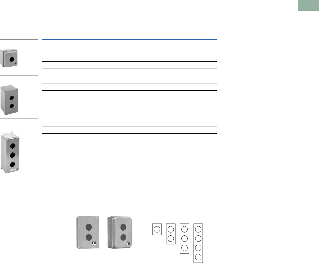
Volume 7—Logic Control, Operator Interface and Connectivity Solutions CA08100008E—March 2014 www.eaton.com V7-T1-283
1
1
1
1
1
1
1
1
1
1
1
1
1
1
1
1
1
1
1
1
1
1
1
1
1
1
1
1
1
1
1.9
Pushbuttons and Indicating Lights
30.5 mm Corrosion Resistant Watertight/Oiltight—E34
Enclosures
Die Cast, Polyester and Stainless Steel Enclosures
Enclosures (Case and Cover)—Surface Mounting 1
Mounting Instructions
These E34 Die Cast
Enclosures feature a
corrosion resistant coating
identical to finish on the E34
operators except gray in
color. Not for use in
ultraviolet light applications.
One and Two Contact Block
Depth Enclosures Enclosure Layouts
Notes
1For spacing increments, see Page V7-T1-284.
2All die cast enclosures can be converted to base mounting of contact blocks with spacers 10250TA22 or 10250TA23.
See listing on Page V7-T1-227.
3When used with E30 pushbuttons, only the one element enclosure can be used.
414 gauge, type 304.
Number of
Elements
One Contact Block Depth
Catalog Number
Two Contact Block Depth
Catalog Number
Die Cast Enclosure—In-Line 23 NEMA 4, 4X, 12, 13
1E34N1 E34N11
2E34N2 E34N12
3E34N3 E34N13
4— E34N14
Polyester—In-Line NEMA 3, 4X, 12
1— E34N51
2— E34N52
3— E34N53
4— E34N54
Stainless Steel 4—In-Line NEMA 4, 4X, 12
1— 10250TN33
2— 10250TN34
3— 10250TN35
4— 10250TN36
Dimensions, see Page V7-T1-292.
Die Cast Enclosure
Polyester Enclosure
Stainless Steel
Enclosure
One Contact
Block Depth
Enclosure
Two Contact
Block Depth
Enclosure
111
Top – For Vertical Mounting
Top – For Horizontal
Mounting
1
222
33
4
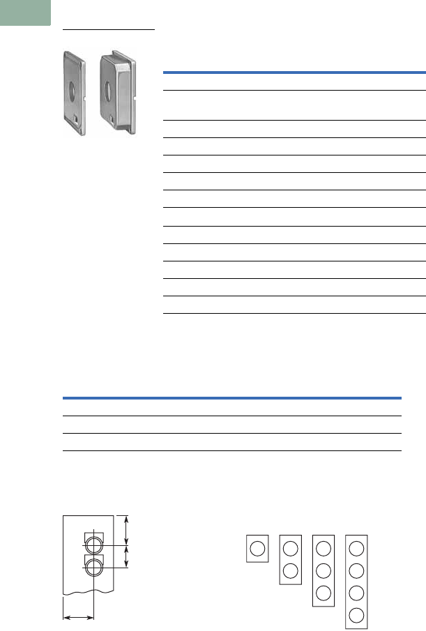
V7-T1-284 Volume 7—Logic Control, Operator Interface and Connectivity Solutions CA08100008E—March 2014 www.eaton.com
1
1
1
1
1
1
1
1
1
1
1
1
1
1
1
1
1
1
1
1
1
1
1
1
1
1
1
1
1
1
1.9
Pushbuttons and Indicating Lights
30.5 mm Corrosion Resistant Watertight/Oiltight—E34
Die Cast and Stainless Steel—Flush Mount, Covers Only 1
Covers Only—Flush Mounting
Spacing Increments
Approximate Dimensions in Inches (mm)
Spacing Increments for
Enclosures Enclosure Layouts
Notes
1These E34 die cast covers feature a corrosion resistant coating identical to the finish on the E34 operators except gray in color.
2Not oiltight. NEMA 1 applications only.
Number of
Elements Catalog Number Catalog Number
Flush Die Cast Covers
In-Line Deep
Cover
In-Line Flat
Cover
1E34F11 E34F1
2E34F12 E34F2
3E34F13 E34F3
4E34F14 E34F4
In-Line Stainless Steel Flush Plates 2
With Pullbox Without Pullbox
110250TS10 10250TS1
210250TS11 10250TS2
310250TS12 10250TS3
410250TS14 10250TS4
Dimensions, see Page V7-T1-293.
Type F G H
Die cast 2.44 (62.0) 2.5 (63.5) 1.88 (47.8)
Polyester 1.88 (47.8) Min. 2.13 (54.1) 2.25 (57.2)
Stainless steel 1.69 (42.9) Min. 1.73 (43.9) 2.25 (57.2)
Flush Mounting Covers
F
G
H
111
Top – For Vertical Mounting
Top – For Horizontal
Mounting
1
222
33
4

Volume 7—Logic Control, Operator Interface and Connectivity Solutions CA08100008E—March 2014 www.eaton.com V7-T1-285
1
1
1
1
1
1
1
1
1
1
1
1
1
1
1
1
1
1
1
1
1
1
1
1
1
1
1
1
1
1
1.9
Pushbuttons and Indicating Lights
30.5 mm Corrosion Resistant Watertight/Oiltight—E34
Contact Blocks
Standard Contact Blocks
●UL A600/P600 rated
●Color-coded plungers—red/
green for NC/NO circuits
●Silver contact tips with
“reliability nibs”
●Black (opaque) or amber
(translucent) housings
●Pressure plate or spade
terminals
●Fingerproof shrouds (for
pressure terminals only)
Logic Level Contact Blocks
●UL A600/P600 rated
●Black plungers
●Inert palladium knife-blade
contacts
●Black (opaque) housings
●Pressure plate or spade
terminals
●Fingerproof shrouds not
available
Special Function Contact Blocks
●UL A600/P600 rated
●Black plungers
●Silver contact tips with
“reliability nibs”
●Black (opaque) housings
●Pressure plate terminals
only
●Fingerproof shrouds not
available
Special Purpose Contact Block
●Maximum 300V rated
●Black plungers
●Silver contact tips with
“reliability nibs”
●Black (opaque) housings
●Pressure plate terminals
only
●Fingerproof shrouds not
available
Reliability Nibs
Reliability nibs are the
hallmark of Eaton’s contact
blocks. A pointed silver nib on
the contact tip ensures
reliable switching from logic
level (5V) up to 600V
applications. Therefore
standard contact blocks can
be used for most logic level
applications where the
contacts are not exposed to
any harsh environmental
conditions.
Palladium Contacts
Palladium, which is more
inert than gold, is well suited
for voltages and currents
approaching zero and is
recommended for
applications where
environmental conditions are
a factor.
Maximum Contact Block
Mounting per Operator Type
Operator
Max.
Stack
Pushbuttons 6
Push-pull operators 2
Roto-push operators 4
Two- or three-position
selector switches
6
Four-position selector
switches
4
Joysticks 4
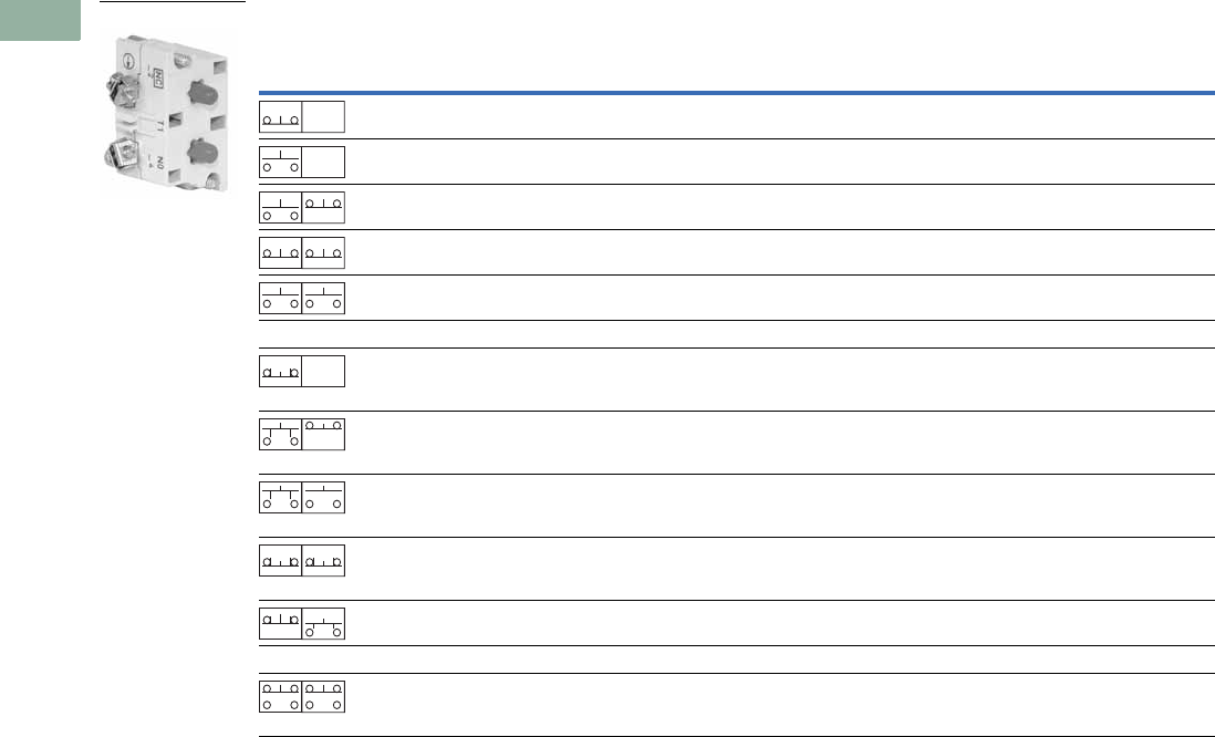
V7-T1-286 Volume 7—Logic Control, Operator Interface and Connectivity Solutions CA08100008E—March 2014 www.eaton.com
1
1
1
1
1
1
1
1
1
1
1
1
1
1
1
1
1
1
1
1
1
1
1
1
1
1
1
1
1
1
1.9
Pushbuttons and Indicating Lights
30.5 mm Corrosion Resistant Watertight/Oiltight—E34
Contact Blocks
Notes
1 All 10250T contact blocks shown are suitable for use on standard 10250T and E34 operators. These contact blocks are not suitable for Class I Division 2
type 10250T or E34 devices.
2 Contact blocks with spade terminals are limited to a maximum of one contact block per operator and minimum spacing between devices is 2.5 in (63.5 mm).
Not suitable for use in 10250T or E34 enclosures. Also available in amber housing. Not available with fingerproof shrouds.
3 Special function contact blocks are not suitable for use with roto-push operators, three-position push-pull operators, or four-position selector switches.
4 ECNO contact blocks are not suitable for use with two-position joysticks or when operators are used with padlock attachments.
5 Special purpose 10250T44 contact blocks are not suitable on selector switches or roto-push operators. Okay to use with three-position push-pull operators only
on low voltage (30V or less) circuits.
Symbol Circuit Description 1
Standard Logic Level
Pressure Terminal
Catalog Number
Spade Terminal 2
Catalog Number
Pressure Terminal
Catalog Number
Spade Terminal 2
Catalog Number
1NC Stack up to six blocks (six circuits)
unless otherwise noted.
10250T51 10250T59 10250T51E 10250T59E
1NO Stack up to six blocks six circuits)
unless otherwise noted.
10250T53 10250T60 10250T53E 10250T60E
NO-NC Stack up to six blocks (12 circuits)
unless otherwise noted.
10250T1 10250T40 10250T1E 10250T40E
2NC Stack up to six blocks (12 circuits)
unless otherwise noted.
10250T3 10250T42 10250T3E 10250T42E
2NO Stack up to six blocks (12 circuits)
unless otherwise noted.
10250T2 10250T41 10250T2E 10250T41E
Special Function Blocks 3
LONC Late opening NC. Stack up to six
blocks (six circuits) unless
otherwise noted.
10250T71 3— 10250T71E 3—
ECNO-
NC
Early closing NO and standard NC.
Stack up to six blocks unless
otherwise noted.
10250T47 34 — 10250T47E 3—
ECNO-
NO
Early closing NO and standard NO.
Stack up to four blocks unless
otherwise noted.
10250T57 34 — 10250T57E 3—
2LONC Two late opening NC contacts.
Stack up to six blocks unless
otherwise noted.
10250T45 3— 10250T45E 3—
LONC-
ECNO
Overlapping contacts. Stack up to
four blocks unless otherwise noted.
10250T55 34 — 10250T55E 3—
Special Purpose Blocks 5
2NO-
2NC
Four circuits in single block depth.
Rated 300V max. Stack up to four
blocks unless otherwise noted.
10250T44 5—
10250T1
Blank
No
Plunger
Blank
No
Plunger
Blank
No
Plunger
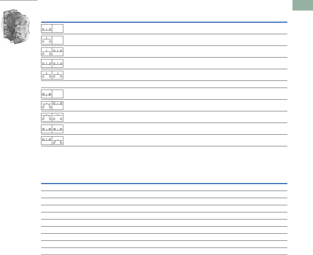
Volume 7—Logic Control, Operator Interface and Connectivity Solutions CA08100008E—March 2014 www.eaton.com V7-T1-287
1
1
1
1
1
1
1
1
1
1
1
1
1
1
1
1
1
1
1
1
1
1
1
1
1
1
1
1
1
1
1.9
Pushbuttons and Indicating Lights
30.5 mm Corrosion Resistant Watertight/Oiltight—E34
Contact Blocks with Fingerproof Shrouds
Replacement Parts
Replacement Lamps—For E34 Illuminated Operators
Notes
1 All 10250T contact blocks shown are suitable for use on standard 10250T and E34 operators. These contact blocks are not suitable for Class I Division 2
type 10250T or E34 devices.
2 To order contact blocks with translucent amber housing, change suffix P to CP in catalog number, e.g., 10250T51CP.
3 ECNO contact blocks are not suitable for use with two-position joysticks or when operators are used with padlock attachments.
4 Special function contact blocks are not suitable for use with roto-push operators, three-position push-pull operators, or four-position selector switches.
Symbol Circuit Description 1
Standard
Pressure Terminal 2
Catalog Number
Logic Level
Pressure Terminal 2
Catalog Number
1NC Stack up to six blocks (six circuits) unless otherwise noted. 10250T51P 10250T51EP
1NO Stack up to six blocks (six circuits) unless otherwise noted. 10250T53P 10250T53EP
NO-NC Stack up to six blocks (12 circuits) unless otherwise noted. 10250T1P 10250T1EP
2NC Stack up to six blocks (12 circuits) unless otherwise noted. 10250T3P 10250T3EP
2NO Stack up to six blocks (12 circuits) unless otherwise noted. 10250T2P 10250T2EP
Special Function Blocks 3
LONC Late opening NC. Stack up to six blocks (six circuits) unless
otherwise noted.
10250T71P 410250T71EP 4
ECNO-NC Early closing NO and standard NC. Stack up to six blocks
unless otherwise noted.
10250T47P 34 10250T47EP 4
ECNO-NO Early closing NO and standard NO. Stack up to four blocks
unless otherwise noted.
10250T57P 34 10250T57EP 4
2LONC Two late opening NC contacts. Stack up to six blocks unless
otherwise noted.
10250T45P 410250T45EP 4
LONC-ECNO Overlapping contacts. Stack up to four blocks unless
otherwise noted.
10250T55P 34 10250T55EP 4
Mfg. Lamp Type Voltage Base Style Application Part Number
120MB 120V T 3-1/4 bayonet 10250T resistor indicating light 28-3044
#267 6.3V T 3-1/4 bayonet 10250T flasher 10250ED986-4
#755 6.3V T 3-1/4 bayonet 10250T transformer, PresTest and full voltage 28-2202
#756 12V T 3-1/4 bayonet 10250T full voltage 28-5184
#757 24V T 3-1/4 bayonet 10250T full voltage 28-5185
#1828 32V T 3-1/4 bayonet 10250T full voltage 28-5186
#1835 55V T 3-1/4 bayonet 10250T resistor 28-5187
NE48 120V T 4-1/2 bayonet 10250T neon 28-494
NE51H-R22 120V T 3-1/4 bayonet 10250T neon 28-3754
NE51H-R68 240V T 3-1/4 bayonet 10250T neon 28-3755
10250T1CP
Blank
No
Plunger
Blank
No
Plunger
Blank
No
Plunger
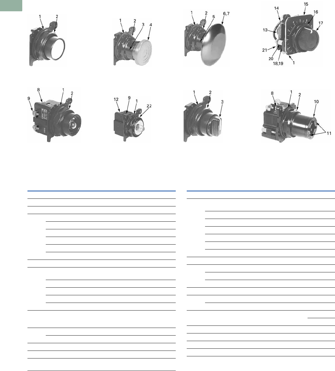
V7-T1-288 Volume 7—Logic Control, Operator Interface and Connectivity Solutions CA08100008E—March 2014 www.eaton.com
1
1
1
1
1
1
1
1
1
1
1
1
1
1
1
1
1
1
1
1
1
1
1
1
1
1
1
1
1
1
1.9
Pushbuttons and Indicating Lights
30.5 mm Corrosion Resistant Watertight/Oiltight—E34
E34 Style Operator Replacement Parts
Flush Head
Pushbutton Operator
Mushroom Head
Pushbutton Operator
Jumbo Mushroom
Head Operator
Illuminated
Pushbutton Operator
Transformer Type
Indicating Light
Knob-Operated
Selector Switch
Operator
Full Voltage, Resistor
and Transformer Type
Illuminated Selector Switch
Potentiometers
Item
No. Description
No.
Req.
Part
Number
1Gasket 116-1548
2 Mounting nut 1 15-1530-4
3 Set screw (#6-32 x 0.250 in long hollow hex) 2 11-2014
4 Mushroom head button (includes [2] item 5) 1 As Req. Below
Black — 53-1317
Red — 53-1317-2
Yellow — 53-1317-3
Green — 53-1317-4
Blue — 53-1317-22
5 Set screw (#10-32 x 0.250 in long hollow hex) 2 11-544
6 Jumbo mushroom head button
(aluminum—includes [2] item 5)
1As Req. Below
Red — 53-1317-9
Black — 53-1317-10
Yellow — 53-1317-11
Green — 53-1317-12
7 Jumbo mushroom head button
(aluminum—red EMERG. STOP)
does not include item 5
153-1349-18
8 Mounting screw (#6-32 x 0.710 in long) 2 10250TA79
Washer 2 16-2038
9 Terminal screw and lug (captive) Req. 80-5502
10 Gasket (supplied with basic unit) 1 32-803
11 Round head screw (#4-40 x 0.344 in long)
(supplied with basic unit)
211-4553
Item
No. Description
No.
Req.
Part
Number
12 Mounting screw 2 11-1632
13 Simple potentiometer
(does not include items 18, 28 or 29)
1As Req. Below
1,000 ohms — 41-782-2
2,500 ohms — 41-782-3
5,000 ohms — 41-782-10
10,000 ohms — 41-782-4
25,000 ohms — 41-782-5
50,000 ohms — 41-782-6
14 Connector (includes screw and lug) 2 25-1851
15 Indicating plate 1 As Req. Above
Standard size (without legend) — 30-4460
Large size (specify legend) — 10250TR30
16 Retaining nut 1 15-1547-3
17 Knob 1 53-1314
Socket set screw (#6-32 x 0.250 in long) 1 11-2014
18 Coupling 1 11-2014
29-3749-2
19 Set screw (#6-32 x 0.188 in long) 1 11-1199
20 Spacer 2 56-1066-18
21 Connector (includes screw and lug) 1 25-1851-2
22 Mounting nut 1 15-1938-2

Volume 7—Logic Control, Operator Interface and Connectivity Solutions CA08100008E—March 2014 www.eaton.com V7-T1-289
1
1
1
1
1
1
1
1
1
1
1
1
1
1
1
1
1
1
1
1
1
1
1
1
1
1
1
1
1
1
1.9
Pushbuttons and Indicating Lights
30.5 mm Corrosion Resistant Watertight/Oiltight—E34
Technical Data and Specifications
Mechanical Ratings
General Specifications
Description Specification
Frequency of Operation
All pushbuttons 6000 operations/hr.
Key and lever selector switches 3000 operations/hr.
Auto-latch devices 1200 operations/hr.
Life
Pushbuttons 10 x 106 operations
Contact blocks 10 x 106 operations
PresTest units 10 x 106 operations
Lever and key selector switches 0.25 x 10⁶ operations
Twist to release pushbuttons 0.3 x 10⁶ operations
Shock Resistance
Duration 210 ms >5g
Description Specification
Climate Conditions
Operating temperature 1° to 150°F (–17° to 66°C)
Storage temperature –40° to 176°F (–40° to 80°C)
Altitude 6,562 ft (2,000m)
Humidity Max. 95% RH at 60°C
Te rm i n a l s
Marking NC-NO on the contact block to meet the NEMA requirements. Dual marking system 1–2
for normally closed, 3–4 for normally open to meet BS5472 (Cenelec EN50 005).
Clamps Terminals are saddle clamp type for 1 x 22 AWG (0.34 mm2) to 2 x 14 AWG (2.5 mm2)
conductors
Torque 7 lb-in (0.8 Nm)
Degree of protection against direct electrical contact IP2X with fingerproof shroud
Light Units
Transformers Will withstand short-circuit for 1 hour per IEC 60947-5-1
Bulbs—average life:
Transformer type 20,000 hrs.
Resistor/direct voltage type 2500 hrs. minimum at rated V
LED 60,000 to 100,000 hrs.

V7-T1-290 Volume 7—Logic Control, Operator Interface and Connectivity Solutions CA08100008E—March 2014 www.eaton.com
1
1
1
1
1
1
1
1
1
1
1
1
1
1
1
1
1
1
1
1
1
1
1
1
1
1
1
1
1
1
1.9
Pushbuttons and Indicating Lights
30.5 mm Corrosion Resistant Watertight/Oiltight—E34
Electrical Ratings
Electrical Ratings—Contact Block
Description Specification
Insulation Ui = 660 Vac or Vdc
Thermal Ith = 10A
Short Circuit Coordination to IEC/EN 60947-5-1
Rated conditional short circuit current 1 kA
Fuse type GE power controls TIA 10, red spot type gG, 10A, 660 Vac, 460 Vdc, BS88-2,
IEC 60269-2-1
UL rating A600, P600
AC load life duty cycle 1200 operations/hour
10A 110V pf 0.4—1 x 10⁶ operations
5A 250V pf 0.4—1 x 10⁶ operations
2A 600V pf 0.4—1 x 10⁶ operations
Switching capacity
AC 15 rated make/break (11 x le at 1.1 x Ue)
6A 120V pf 0.3
4A 240V pf 0.3
2A 660V pf 0.3
DC13 rated make/break (1.1 x le at 1.1 x Ue)
1.0A 125V L/R >0.95 at 300 ms
0.55A 250V L/R >0.95 at 300 ms
0.1A 660V L/R >0.95 at 300 ms
10A 110V pure resistive
Maximum ratings for logic level and
hostile atmosphere application
Maximum amperes 0.5A
Maximum volts 120 Vac/Vdc
Low voltage switching Conical shaped points or “reliability nibs” improve performance in dry circuit,
corrosive, fine dust and other contaminated atmospheres. Under normal
environmental conditions, the minimum operational voltage is 5V and the minimum
operational current is 1 mA, Vac/Vdc.
Contact operation Slow make and break. All normally closed contacts have positive opening operation,
i.e., normally closed contacts are forced open in the event of contact weld or spring
breakage.
Meet or Exceed NEMA Rating Designations A600, A300 and B300 for AC and P600 for DC
Description
50 Vac or 60 H Vdc
120 240 480 600 24/28 125 250
Meet or Exceed NEMA Rating Designations A600, A300 and B300 for AC and P600 for DC
Make and emerg. interrupting capacity (amp) 60 30 15 12 5.7 1.1 0.55
Normal load break (amp) 6 3 1.5 1.2 5.7 1.1 0.55
Thermal current (amp) 101010105.05.05.0
Voltamperes:
Make and emerg. interrupting capacity 7200 7200 7200 7200 138 138 138
Normal load break 720 720 720 720 138 138 138

Volume 7—Logic Control, Operator Interface and Connectivity Solutions CA08100008E—March 2014 www.eaton.com V7-T1-291
1
1
1
1
1
1
1
1
1
1
1
1
1
1
1
1
1
1
1
1
1
1
1
1
1
1
1
1
1
1
1.9
Pushbuttons and Indicating Lights
30.5 mm Corrosion Resistant Watertight/Oiltight—E34
Mounting Options
Panel Thickness
●Minimum: 0.06 in (1.6 mm)
●Maximum: 0.25 in (8 mm) including legend plate
●Maximum can be increased to 0.375 in (15.9 mm) using optional retaining nut
●Indicating light: 10250TA30
●Pushbutton/selector switch: 10250TA31
Mounting Matrix
Mounting Options in Inches (mm)
Horizontal mounting means terminals are located top and bottom of contact block.
Vertical mounting means terminals are left and right of contact block.
This allows close spacing of adjacent operators with easy access to terminals.
Locating nib hole or notch is 0.14 in (3.6 mm) #29 drill.
Drilling Dimensions in Inches (mm)
Legend
Plate
Dimensions in Inches (mm)
ABCD
Small 1.63 (41.3) 2.25 (57.2) 2.25 (57.2) 1.63 (41.3)
Medium 1.75 (44.5) 2.25 (57.2) 2.25 (57.2) 1.75 (44.5)
Large 2.25 (57.2) 2.25 (57.2) 2.25 (57.2) 2.25 (57.2)
B
Min.
C
Min.
0.6
(15.2)
A
Min. 1.22
(31)
D
Min.
Horizontal Mounting Vertical Mounting
0.14 (3.6)
Dia.
Terminals on Top
Terminals at Side
0.6
(15.2)
1.20
(30.5)
0.14 (3.6)
Dia.
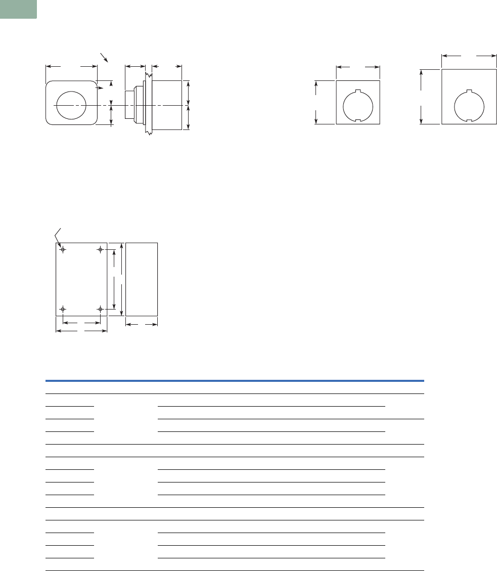
V7-T1-292 Volume 7—Logic Control, Operator Interface and Connectivity Solutions CA08100008E—March 2014 www.eaton.com
1
1
1
1
1
1
1
1
1
1
1
1
1
1
1
1
1
1
1
1
1
1
1
1
1
1
1
1
1
1
1.9
Pushbuttons and Indicating Lights
30.5 mm Corrosion Resistant Watertight/Oiltight—E34
Dimensions
Approximate Dimensions in Inches (mm)
Potentiometer Legend Plates
Surface Mounting
Die Cast, Polyester and Stainless Steel Enclosures
Notes
1Depth given is for two contact block deep stations. One contact block deep stations subtract 3/4 in (19.1 mm).
2No conduit entrance holes provided. Drill as required.
1.88
(47.8)
1.31
(33.3)
1.09
(27.7) 1.0
(25.4)
0.75
(19.1)
0.94
(23.9)
0.94
(23.9)
0.94
(23.9)
Std. Dial Plate
Large Dial Plate
2.19
(55.6)
Jumbo
2.19
(55.6)
1.77
(45)
Standard
1.77
(45)
A
Surface
DC
B
E
4 Mtg. Holes — 10-32 Screw Size for
1 – 4 Element Die Cast/
Stainless Steel Enclosure
7/32 Screw Size for
Polyester
Number of
Elements
Element
Arrangement
Wide
A
High
B
Deep
C
Mounting Conduit
EntranceDE
Die Cast
1 In-line 3.88 (98.6) 4.00 (101.6) 3.00 (76.3) 12.69 (68.3) 3.25 (82.6) 3/4
2 3.88 (98.6) 5.88 (149.4) 3.00 (76.3) 12.69 (68.3) 5.13 (130.3)
3 3.88 (98.6) 7.75 (196.9) 3.00 (76.3) 12.69 (68.3) 7.00 (177.8) 1
4 3.88 (98.6) 9.63 (244.6) 3.00 (76.3) 12.69 (68.3) 8.88 (225.6)
Polyester
1 In-line 3.81 (96.8) 6.63 (168.4) 3.38 (85.9) 2.94 (74.7) 4.88 (124.0) 2
2 3.81 (96.8) 6.63 (168.4) 3.38 (85.9) 2.94 (74.7) 4.88 (124.0)
3 3.81 (96.8) 8.88 (225.6) 3.38 (85.9) 2.94 (74.7) 7.13 (181.1)
4 3.81 (96.8) 11.13 (282.7) 3.38 (85.9) 2.94 (74.7) 9.38 (238.3)
Stainless Steel
1 In-line 3.00 (76.2) 3.50 (88.9) 3.00 (76.2) 1.50 (38.1) 4.25 (108.0) 2
2 3.50 (88.9) 6.75 (171.5) 3.00 (76.2) 1.50 (38.1) 7.50 (190.5)
3 3.50 (88.9) 9.00 (228.6) 3.00 (76.2) 1.50 (38.1) 9.00 (228.6)
4 3.50 (88.9) 11.25 (285.8) 3.00 (76.2) 1.50 (38.1) 12.00 (304.8)

Volume 7—Logic Control, Operator Interface and Connectivity Solutions CA08100008E—March 2014 www.eaton.com V7-T1-293
1
1
1
1
1
1
1
1
1
1
1
1
1
1
1
1
1
1
1
1
1
1
1
1
1
1
1
1
1
1
1.9
Pushbuttons and Indicating Lights
30.5 mm Corrosion Resistant Watertight/Oiltight—E34
Approximate Dimensions in Inches (mm)
Flush Mounting
Die Case and Stainless Steel Covers Only
Notes
1Depth given is for flat cover. Deep cover is 3/4 in (19.1 mm) deeper.
2Depth given includes pull box.
A
Surface or Pendant
DC
B
E
4 Mtg. Holes - 10-32 Screw Size
for 1-11 Element Encl, 1/4-20
Screw Size for 12 Element
and Larger
Number of
Elements
Wide
A
High
B
Deep
C
Mounting
DE
Die Cast
1 3.88 (98.6) 4.00 (101.6) 0.25 (6.4) 13.50 (88.9) 3.63 (92.2)
2 3.88 (98.6) 5.88 (149.4) 0.25 (6.4) 13.50 (88.9) 5.50 (139.7)
3 3.88 (98.6) 7.75 (196.9) 0.25 (6.4) 13.50 (88.9) 6.00 (152.4)
4 3.88 (98.6) 9.63 (244.6) 0.25 (6.4) 13.50 (88.9) 9.25 (235.0)
Stainless Steel
1 5.00 (127.0) 5.00 (127.0) 2.50 (63.5) 23.25 (82.6) 1.88 (47.8)
2 5.00 (127.0) 6.88 (174.8) 2.50 (63.5) 23.25 (82.6) 3.63 (92.2)
3 5.00 (127.0) 8.63 (219.2) 2.50 (63.5) 23.25 (82.6) 5.50 (139.7)
4 5.00 (127.0) 10.50 (266.7) 2.50 (63.5) 23.25 (82.6) 7.25 (184.2)
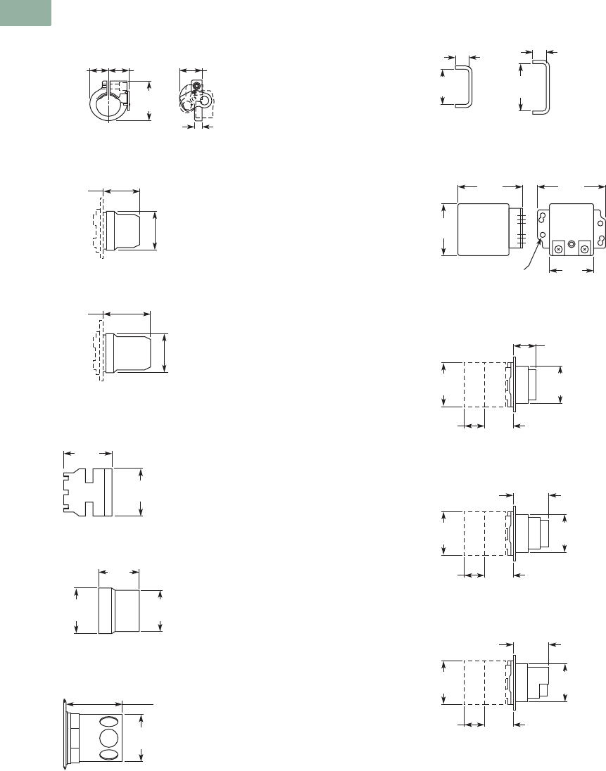
V7-T1-294 Volume 7—Logic Control, Operator Interface and Connectivity Solutions CA08100008E—March 2014 www.eaton.com
1
1
1
1
1
1
1
1
1
1
1
1
1
1
1
1
1
1
1
1
1
1
1
1
1
1
1
1
1
1
1.9
Pushbuttons and Indicating Lights
30.5 mm Corrosion Resistant Watertight/Oiltight—E34
Approximate Dimensions in Inches (mm)
Padlocking Attachment for Flush
Pushbutton Operators
Flexible Weather Resistant Boot
Transparent Boot
Shroud for Mushroom
Head Operator
Extended Retaining Nut
Guard for Illuminated
Pushbutton
Contact Block Terminal Jumps
Master Test Module and
Flasher Module
Flush Pushbutton
Extended Pushbutton
Half Shroud Pushbutton
0.75
(19.1)
0.84
(21.3) 0.94
(23.9)
1.63
(41.4)
0.25
(6.4)
1.47
(37.3)
1.59
(40.4)
1.92
(48.8)
1.59
(40.4)
1.53
(38.9)
1.50
(38.1)
1.25
(31.8)
1.31
(33.3)
1.38
(35.1)
1.63
(41.4)
1.50
(38.1)
0.25
(6.4)
0.25
(6.4)
0.86
(21.8)
0.45
(11.4)
1.63
(41.4)
1.14
(29)
6 Mounting Holes
1.78
(45.2)
1.31
(33.3)
0.88
(22.4) 1.09
(27.7)
1.06
(26.9)
1.78
(45.2) 1.38
(35.1)
Contact
Blk.
Each Addl.
Contact Blk.
0.88
(22.4) 1.09
(27.7)
1.44
(36.6)
1.78
(45.2) 1.38
(35.1)
Contact
Blk.
Each Addl.
Contact Blk.
0.88
(22.4) 1.09
(27.7)
1.44
(36.6)
1.78
(45.2) 1.38
(35.1)
Contact
Blk.
Each Addl.
Contact Blk.
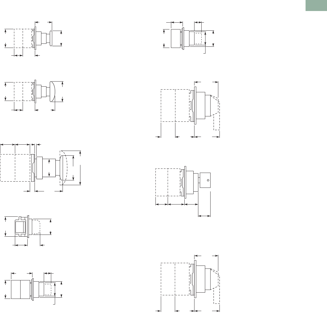
Volume 7—Logic Control, Operator Interface and Connectivity Solutions CA08100008E—March 2014 www.eaton.com V7-T1-295
1
1
1
1
1
1
1
1
1
1
1
1
1
1
1
1
1
1
1
1
1
1
1
1
1
1
1
1
1
1
1.9
Pushbuttons and Indicating Lights
30.5 mm Corrosion Resistant Watertight/Oiltight—E34
Approximate Dimensions in Inches (mm)
Mushroom Pushbutton
Jumbo Mushroom Pushbutton
Push-Pull Switch
Indicating Light
PresTest Indicating Light
Illuminated Pushbutton
Selector Switch
Key Selector Switch
Illuminated Selector Switch
0.88
(22.4) 1.09
(27.7)
1.63
(41.4)
1.78
(45.2)
1.50
(38.1)
Contact
Blk.
Each Addl.
Contact Blk.
0.88
(22.4) 1.09
(27.7)
1.75
(44.5)
1.78
(45.2)
2.50
(63.5)
Contact
Blk.
Each Addl.
Contact Blk.
2.63
(66.8)
1.65
(41.9)
1.78
(45.2)
0.25
(6.4)
0.06 (1.5) to 0.25 (6.4)
Panel Thickness
0.88
(22.4)
0.88
(22.4)
1.13
(28.7)
Light
Unit
Contact
Block
1.38
(35.1)
1.1
(27.9)
1.78
(45.2) 1.38
(35.1)
1.9
(48.3) 1.09
(27.7) 0.69
(17.5)
1.78
(45.2) 1.38
(35.1)
1.13
(28.7)
Contact
Blk.
Each Addl.
Contact Blk.
1.09
(27.7)
1.09
(27.7) 0.69
(17.5)
1.78
(45.2) 1.38
(35.1)
1.13
(28.7)
Light
Unit
1.58
(40.1)
Knob
1.58
(40.1)
Lever
1.09
(27.7)
0.88
(22.4)
Contact
Block
Each Additional
Contact Block
1.5
(38.1)
1.58 (40.1)
to Remove
Key
1.09
(27.7)
0.88
(22.4)
Contact
Block
Each Addl.
Contact Blk.
1.58
(40.1)
Knob
1.58
(40.1)
Lever
1.09
(27.7)
0.88
(22.4)
Light
Unit
Each Additional
Contact Block
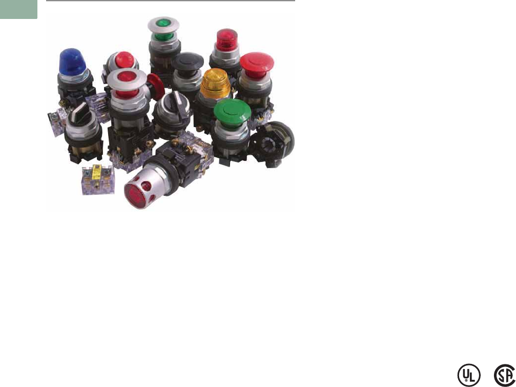
V7-T1-296 Volume 7—Logic Control, Operator Interface and Connectivity Solutions CA08100008E—March 2014 www.eaton.com
1
1
1
1
1
1
1
1
1
1
1
1
1
1
1
1
1
1
1
1
1
1
1
1
1
1
1
1
1
1
1.10
Pushbuttons and Indicating Lights
30.5 mm Watertight/Oiltight—HT800
30.5 mm Watertight/Oiltight—HT800
Contents
Description Page
30.5 mm Watertight/Oiltight—HT800
Catalog Number Selection . . . . . . . . . . . . . . . . V7-T1-297
Product Selection
Momentary Pushbutton Units,
Non-Illuminated . . . . . . . . . . . . . . . . . . . . V7-T1-298
Illuminated Pushbutton Units . . . . . . . . . . . V7-T1-300
Guarded Illuminated Pushbutton
Units . . . . . . . . . . . . . . . . . . . . . . . . . . . . . V7-T1-302
Indicating Light Units . . . . . . . . . . . . . . . . . V7-T1-304
Push-Pull Units . . . . . . . . . . . . . . . . . . . . . . V7-T1-306
Illuminated Push-Pull Units . . . . . . . . . . . . . V7-T1-307
Selector Switch Units . . . . . . . . . . . . . . . . . V7-T1-308
Selector Switch Contact Block
Selection . . . . . . . . . . . . . . . . . . . . . . . . . . V7-T1-310
Accessories . . . . . . . . . . . . . . . . . . . . . . . . . . . V7-T1-311
Options . . . . . . . . . . . . . . . . . . . . . . . . . . . . . . V7-T1-312
Replacement Parts . . . . . . . . . . . . . . . . . . . . . . V7-T1-315
Technical Data and Specifications . . . . . . . . . . V7-T1-316
Dimensions . . . . . . . . . . . . . . . . . . . . . . . . . . . V7-T1-317
Product Description
The HT800 Series from
Eaton’s Electrical Sector is a
family of 30.5 mm pushbutton
devices which includes
momentary, illuminated
and mushroom head
pushbuttons, selector
switches, indicating lights
and push-pull switches. The
HT800 devices have a familiar
appearance found in most
industrial applications and are
suitable for replacement of
several other manufacturers’
30.5 mm pushbutton devices.
Features
●Anodized aluminum
mounting rings
●Watertight double V-gasket
seals
●Extended height bulbs
●Transparent housing
contact blocks
●Color-coded contact blocks
●Gold-plated contacts (on
low voltage contact block)
●Reliability ridge on movable
contact
●Stackable screw-mounted
contact blocks
●Contact blocks can be
mounted in left/right or top/
bottom positions
●Standard NC contact
opens before NO contact
closes (break before make
operation)
●Bright and long lasting LED
indicating lights in six
colors
●Field convertible maintained
selector switches—from
two- to three-position and
vice versa
●Field selectable knob/lever
mounting positions—at any
22.5° increment
Benefits
●Corrosion resistant NEMA
4X finish
●Watertight and oiltight
NEMA 4, 13 ingress
protection
●Increased side illumination
of indicating lights and
illuminated pushbuttons
●Easy visual inspection of
contact conditions
●Easily identifiable NO
(white) or NC (black)
contact blocks
●Gold-plated contacts
suitable for logic level
circuits
●Reliability ridge penetrates
contamination buildup on
stationary contacts
●Left/right or top/bottom
mounted contact blocks
allow correct positioning in
retrofit applications
●All-purpose selector
switches are convertible
and can rotate in 22.5°
increments to suit panel
layouts
Standards and
Certifications
●UL508 per File No.
E131568
●CSA C22.2 No. 14 per File
No. LR68551
Ingress Protection
●UL (NEMA) Type 1, 2, 3,
3R, 4, 4X, 12 and 13 when
mounted in similarly rated
enclosures
Volume 7—Logic Control, Operator Interface and Connectivity Solutions CA08100008E—March 2014 www.eaton.com V7-T1-297
1
1
1
1
1
1
1
1
1
1
1
1
1
1
1
1
1
1
1
1
1
1
1
1
1
1
1
1
1
1
1.10
Pushbuttons and Indicating Lights
30.5 mm Watertight/Oiltight—HT800
Catalog Number Selection
Catalog Number Selection is for illustrative purposes only and not to be used to create new catalog numbers.
HT800 Pushbuttons, Push-Pulls and Indicating Lights
HT800 Selector Switch
Notes
1Maximum of four contact blocks per side or a total of eight contact blocks recommended.
2Maximum of two contact blocks per side or a total of four contacts blocks recommended.
Style
Pushbuttons
AA = Flush
AB = Extended
AE = Mushroom head
Illuminated Pushbuttons
GB = Illuminated PB
Push-Pull Operators
CB = Two-position, maintained
Indicating Lights
HF = Full voltage/resistor type
HB = Transformer type
Push-to-Test Operators
GT = All types
Light Unit Type/Voltage
F3 = 24V FV, LED
F7 = 120V FV, LED
L1 = 120V transformer, LED
T1 = 120V transformer, incandescent
V3 = 24V FV, incandescent
V7 = 120V res., incandescent
Button Color
G = Green
H = Black
R = Red
Lens Color
A = Amber/Orange
B = Blue
C = Clear
G = Green
R = Red
W = White
Y = Yellow
Contact Block Location
(viewed from rear) 1
Left Side Right Side
A = NO
A2 = 2NO
B1 = NC
B2 = 2NC
C = NOEM
C2 = 2 NOEM
D1 = NCLB
D2 = 2NCLB
E1 = NOEM-NCLB
F1 = NO and NC
F4 = 1NO-1NC
A5 = NO
A6 = 2NO
B = NC
B6 = 2NC
C5 = NOEM
C6 = 2 NOEM
D = NCLB
D6 = 2NCLB
E5 = NOEM-NCLB
Q1 = NO and NC
HT8 GB RAB T1
Operator
JA = Two-pos., knob, maint.
JB = Three-pos., knob, maint.
JC = Four-pos., knob, maint.
JD = Two-pos., lever, maint.
JE = Three-pos., lever, maint.
JF = Four-pos., lever, maint.
JK = Two-pos., knob, spr. rtn., left
JL = Two-pos., lever, spr. rtn., left
JN = Two-pos., knob, spr. rtn., right
JP = Two-pos., lever, spr. rtn., right
JR = Three-pos., knob, spr. rtn., left
JS = Three-pos., lever, spr. rtn., left
JU = Three-pos., knob, spr. rtn., right
JV = Three-pos., lever, spr. rtn., right
JX = Three-pos., knob, spr. rtn., both
JY = Three-pos., lever, spr. rtn., both
LN = Four-pos., knob, spr. rtn., pos 1 to 2
LP = Four-pos., lever, spr. rtn., pos 1 to 2
LR = Four-pos., knob, spr. rtn., pos 4 to 3
LS = Four-pos., lever, spr. rtn., pos 4 to 3
Switch Color
H = Black Cam Location/Type
1D = For all three-pos.
3A = For all two-pos.
8E = For all four-pos.
Contact Block Location
(viewed from rear) 2
Left Side Right Side
A = NO
A2 = 2NO
B1 = NC
B2 = 2NC
C = NOEM
C2 = 2 NOEM
D1 = NCLB
D2 = 2NCLB
E1 = NOEM-NCLB
F1 = NO and NC
F4 = 1NO-1NC
A5 = NO
A6 = 2NO
B = NC
B6 = 2NC
C5 = NOEM
C6 = 2 NOEM
D = NCLB
D6 = 2NCLB
E5 = NOEM-NCLB
Q1 = NO and NC
HT8 JA H3A F1Q1
V7-T1-298 Volume 7—Logic Control, Operator Interface and Connectivity Solutions CA08100008E—March 2014 www.eaton.com
1
1
1
1
1
1
1
1
1
1
1
1
1
1
1
1
1
1
1
1
1
1
1
1
1
1
1
1
1
1
1.10
Pushbuttons and Indicating Lights
30.5 mm Watertight/Oiltight—HT800
Product Selection
Momentary Pushbutton Units, Non-Illuminated
UL (NEMA) Type 3, 3R, 4, 4X, 12 and 13
●Flush, extended or 40 mm mushroom head operators
HT800 Pushbuttons—Point-of-Purchase Units
Description Catalog Number
Two-position maintained selector switch 1NO/1NC contact block, three square legend
plates: OFF ON, MAN. AUTO, UP DOWN
HT8JAH3AAB-POP
Three-position maintained selector switch, black knob, 1NO/1NC contact block,
three square legend plates: HAND OFF AUTO, FOR. OFF REV., OPEN OFF CLOSE
HT8JBH1DAB-POP
Three-position selector switch, spring return from left and right, black knob,
1NO/1NC contact block, three square legend plates: UP OFF DOWN, FOR OFF REV.,
OPEN OFF CLOSE
HT8JXH1DAB-POP
Red push-pull emergency stop, 1NO/1NC contact block, three square legend plates:
STOP, EMERG. STOP, OFF
HT8CBRAB-POP
Illuminated push-pull maintained red pushbutton, 120V full voltage low profile LED,
three square legend plates: STOP, EMERG. STOP, OFF
HT8FBRABFL7-POP
Illuminated push-pull maintained red pushbutton, 24V full voltage low profile LED,
three square legend plates: STOP, EMERG. STOP, OFF
HT8FBRABFL3-POP
Green flush pushbutton, 1NO/1NC contact block, three square legend plates:
START, ON, RUN
HT8AAGAB-POP
Black flush pushbutton, 1NO/1NC contact block, three square legend plates:
RESET, JOG, OPEN
HT8AAHAB-POP
Red flush pushbutton, 1NO/1NC contact block, three square legend plates:
STOP, CLOSE, OFF
HT8AARAB-POP
Red extended pushbutton, 1NO/1NC contact block, three square legend plates:
STOP, CLOSE, OFF
HT8ABRAB-POP
Black extended pushbutton, 1NO/1NC contact block, three square legend plates:
RESET, JOG, OPEN
HT8ABHAB-POP
Illuminated green pushbutton, 120V full voltage incandescent, 1NO/1NC contact block,
three square legend plates: START, ON, RUN
HT8GBGABV7-POP
Illuminated green pushbutton, 24V full voltage incandescent, 1NO/1NC contact block,
three square legend plates: START, ON, RUN
HT8GBGABV3-POP
HT800 Pushbuttons
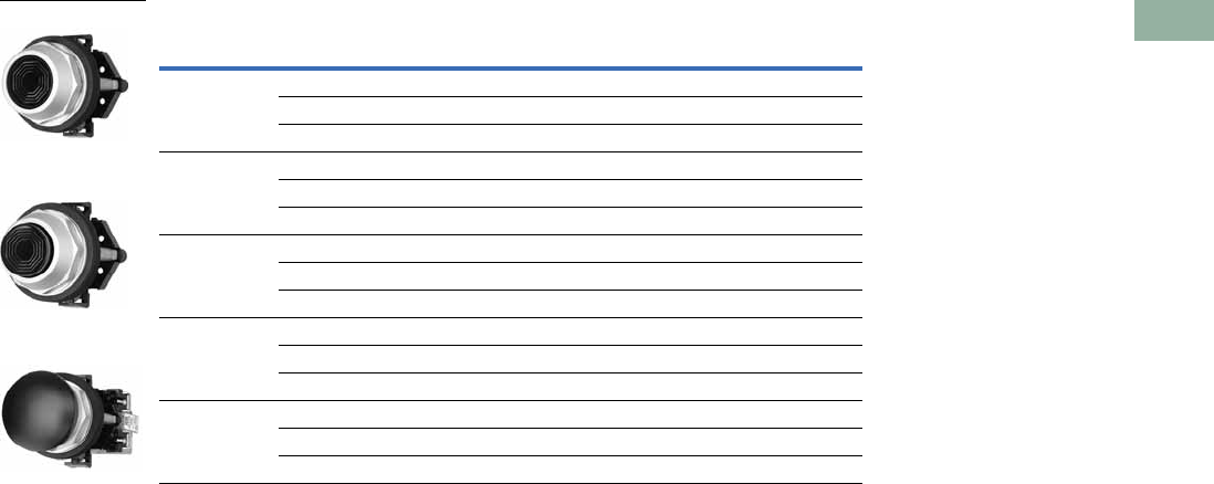
Volume 7—Logic Control, Operator Interface and Connectivity Solutions CA08100008E—March 2014 www.eaton.com V7-T1-299
1
1
1
1
1
1
1
1
1
1
1
1
1
1
1
1
1
1
1
1
1
1
1
1
1
1
1
1
1
1
1.10
Pushbuttons and Indicating Lights
30.5 mm Watertight/Oiltight—HT800
Momentary Contact Pushbutton Units, Non-Illuminated
Contact Type Button Color
Flush Head
Catalog Number
Extended Head
Catalog Number
Mushroom Head (40 mm)
Catalog Number
No contact Black HT8AAH HT8ABH HT8AEH
Red HT8AAR HT8ABR HT8AER
Green HT8AAG HT8ABG HT8AEG
1NO Black HT8AAHA HT8ABHA HT8AEHA
Red HT8AARA HT8ABRA HT8AERA
Green HT8AAGA HT8ABGA HT8AEGA
1NC Black HT8AAHB HT8ABHB HT8AEHB
Red HT8AARB HT8ABRB HT8AERB
Green HT8AAGB HT8ABGB HT8AEGB
1NO-1NC Black HT8AAHAB HT8ABHAB HT8AEHAB
Red HT8AARAB HT8ABRAB HT8AERAB
Green HT8AAGAB HT8ABGAB HT8AEGAB
2NO-2NC Black HT8AAHF1Q1 HT8ABHF1Q1 HT8AEHF1Q1
Red HT8AARF1Q1 HT8ABRF1Q1 HT8AERF1Q1
Green HT8AAGF1Q1 HT8ABGF1Q1 HT8AEGF1Q1
Flush Head Operator
Extended Head
Operator
40 mm Mushroom
Head Operator

V7-T1-300 Volume 7—Logic Control, Operator Interface and Connectivity Solutions CA08100008E—March 2014 www.eaton.com
1
1
1
1
1
1
1
1
1
1
1
1
1
1
1
1
1
1
1
1
1
1
1
1
1
1
1
1
1
1
1.10
Pushbuttons and Indicating Lights
30.5 mm Watertight/Oiltight—HT800
Illuminated Pushbutton Units
UL (NEMA) Type 3, 3R, 4, 4X, 12 and 13
●Incandescent or LED
●Full voltage or transformer type
●24V and 120V
Illuminated Pushbuttons
Note
1 Light unit base operator without lens or bulb.
Type Volts Lens Color
Operator Only
Catalog Number
1NO
Catalog Number
1NC
Catalog Number
1NO-1NC
Catalog Number
2NO-2NC
Catalog Number
Incandescent Lamp
Full voltage 120 Vac/Vdc No lens 1HT8GBFV————
Red HT8GBRV7 HT8GBRAV7 HT8GBRBV7 HT8GBRABV7 HT8GBRF1Q1V7
Green HT8GBGV7 HT8GBGAV7 HT8GBGBV7 HT8GBGABV7 HT8GBGF1Q1V7
Amber HT8GBAV7 HT8GBAAV7 HT8GBABV7 HT8GBAABV7 HT8GBAF1Q1V7
Clear HT8GBCV7 HT8GBCAV7 HT8GBCBV7 HT8GBCABV7 HT8GBCF1Q1V7
White HT8GBWV7 HT8GBWAV7 HT8GBWBV7 HT8GBWABV7 HT8GBWF1Q1V7
Yellow HT8GBYV7 HT8GBYAV7 HT8GBYBV7 HT8GBYABV7 HT8GBYF1Q1V7
Blue HT8GBBV7 HT8GBBAV7 HT8GBBBV7 HT8GBBABV7 HT8GBBF1Q1V7
24 Vac/Vdc No lens 1HT8GBFV————
Red HT8GBRV3 HT8GBRAV3 HT8GBRBV3 HT8GBRABV3 HT8GBRF1Q1V3
Green HT8GBGV3 HT8GBGAV3 HT8GBGBV3 HT8GBGABV3 HT8GBGF1Q1V3
Amber HT8GBAV3 HT8GBAAV3 HT8GBABV3 HT8GBAABV3 HT8GBAF1Q1V3
Clear HT8GBCV3 HT8GBCAV3 HT8GBCBV3 HT8GBCABV3 HT8GBCF1Q1V3
White HT8GBWV3 HT8GBWAV3 HT8GBWBV3 HT8GBWABV3 HT8GBWF1Q1V3
Yellow HT8GBYV3 HT8GBYAV3 HT8GBYBV3 HT8GBYABV3 HT8GBYF1Q1V3
Blue HT8GBBV3 HT8GBBAV3 HT8GBBBV3 HT8GBBABV3 HT8GBBF1Q1V3
Transformer 120 Vac No lens 1HT8GBT1————
Red HT8GBRT1 HT8GBRAT1 HT8GBRBT1 HT8GBRABT1 HT8GBRF1Q1T1
Green HT8GBGT1 HT8GBGAT1 HT8GBGBT1 HT8GBGABT1 HT8GBGF1Q1T1
Amber HT8GBAT1 HT8GBAAT1 HT8GBABT1 HT8GBAABT1 HT8GBAF1Q1T1
Clear HT8GBCT1 HT8GBCAT1 HT8GBCBT1 HT8GBCABT1 HT8GBCF1Q1T1
White HT8GBWT1 HT8GBWAT1 HT8GBWBT1 HT8GBWABT1 HT8GBWF1Q1T1
Yellow HT8GBYT1 HT8GBYAT1 HT8GBYBT1 HT8GBYABT1 HT8GBYF1Q1T1
Blue HT8GBBT1 HT8GBBAT1 HT8GBBBT1 HT8GBBABT1 HT8GBBF1Q1T1
Illuminated Pushbutton
Operator

Volume 7—Logic Control, Operator Interface and Connectivity Solutions CA08100008E—March 2014 www.eaton.com V7-T1-301
1
1
1
1
1
1
1
1
1
1
1
1
1
1
1
1
1
1
1
1
1
1
1
1
1
1
1
1
1
1
1.10
Pushbuttons and Indicating Lights
30.5 mm Watertight/Oiltight—HT800
UL (NEMA) Type 3, 3R, 4, 4X, 12 and 13
Illuminated Pushbuttons, continued
Note
1 Light unit base operator without lens or bulb.
Type Volts Lens Color
Operator Only
Catalog Number
1NO
Catalog Number
1NC
Catalog Number
1NO-1NC
Catalog Number
2NO-2NC
Catalog Number
LED
Full voltage 120 Vac/Vdc No lens 1HT8GBFV————
Red HT8GBRF7 HT8GBRAF7 HT8GBRBF7 HT8GBRABF7 HT8GBRF1Q1F7
Green HT8GBGF7 HT8GBGAF7 HT8GBGBF7 HT8GBGABF7 HT8GBGF1Q1F7
Amber HT8GBAF7 HT8GBAAF7 HT8GBABF7 HT8GBAABF7 HT8GBAF1Q1F7
Clear HT8GBCF7 HT8GBCAF7 HT8GBCBF7 HT8GBCABF7 HT8GBCF1Q1F7
White HT8GBWF7 HT8GBWAF7 HT8GBWBF7 HT8GBWABF7 HT8GBWF1Q1F7
Yellow HT8GBYF7 HT8GBYAF7 HT8GBYBF7 HT8GBYABF7 HT8GBYF1Q1F7
Blue HT8GBBF7 HT8GBBAF7 HT8GBBBF7 HT8GBBABF7 HT8GBBF1Q1F7
24 Vac/Vdc No lens 1HT8GBFV————
Red HT8GBRF3 HT8GBRAF3 HT8GBRBF3 HT8GBRABF3 HT8GBRF1Q1F3
Green HT8GBGF3 HT8GBGAF3 HT8GBGBF3 HT8GBGABF3 HT8GBGF1Q1F3
Amber HT8GBAF3 HT8GBAAF3 HT8GBABF3 HT8GBAABF3 HT8GBAF1Q1F3
Clear HT8GBCF3 HT8GBCAF3 HT8GBCBF3 HT8GBCABF3 HT8GBCF1Q1F3
White HT8GBWF3 HT8GBWAF3 HT8GBWBF3 HT8GBWABF3 HT8GBWF1Q1F3
Yellow HT8GBYF3 HT8GBYAF3 HT8GBYBF3 HT8GBYABF3 HT8GBYF1Q1F3
Blue HT8GBBF3 HT8GBBAF3 HT8GBBBF3 HT8GBBABF3 HT8GBBF1Q1F3
Transformer 120 Vac No lens 1HT8GBT1————
Red HT8GBRL1 HT8GBRAL1 HT8GBRBL1 HT8GBRABL1 HT8GBRF1Q1L1
Green HT8GBGL1 HT8GBGAL1 HT8GBGBL1 HT8GBGABL1 HT8GBGF1Q1L1
Amber HT8GBAL1 HT8GBAAL1 HT8GBABL1 HT8GBAABL1 HT8GBAF1Q1L1
Clear HT8GBCL1 HT8GBCAL1 HT8GBCBL1 HT8GBCABL1 HT8GBCF1Q1L1
White HT8GBWL1 HT8GBWAL1 HT8GBWBL1 HT8GBWABL1 HT8GBWF1Q1L1
Yellow HT8GBYL1 HT8GBYAL1 HT8GBYBL1 HT8GBYABL1 HT8GBYF1Q1L1
Blue HT8GBBL1 HT8GBBAL1 HT8GBBBL1 HT8GBBABL1 HT8GBBF1Q1L1
Illuminated Pushbutton
Operator

V7-T1-302 Volume 7—Logic Control, Operator Interface and Connectivity Solutions CA08100008E—March 2014 www.eaton.com
1
1
1
1
1
1
1
1
1
1
1
1
1
1
1
1
1
1
1
1
1
1
1
1
1
1
1
1
1
1
1.10
Pushbuttons and Indicating Lights
30.5 mm Watertight/Oiltight—HT800
Guarded Illuminated Pushbutton Units
UL (NEMA) Type 3, 3R, 4, 4X, 12 and 13
●Incandescent or LED
●Full voltage or transformer type
●24V and 120V
Guarded Illuminated Pushbuttons
Note
1 Light unit base operator without lens or bulb.
Type Volts Lens Color
Operator Only
Catalog Number
1NO
Catalog Number
1NC
Catalog Number
1NO-1NC
Catalog Number
2NO-2NC
Catalog Number
Incandescent Lamp
Full voltage 120 Vac/Vdc No lens 1HT8GDFV————
Red HT8GDRV7 HT8GDRAV7 HT8GDRBV7 HT8GDRABV7 HT8GDRF1Q1V7
Green HT8GDGV7 HT8GDGAV7 HT8GDGBV7 HT8GDGABV7 HT8GDGF1Q1V7
Amber HT8GDAV7 HT8GDAAV7 HT8GDABV7 HT8GDAABV7 HT8GDAF1Q1V7
Clear HT8GDCV7 HT8GDVAV7 HT8GDCBV7 HT8GDCABV7 HT8GDCF1Q1V7
White HT8GDWV7 HT8GDWAV7 HT8GDWBV7 HT8GDWABV7 HT8GDWF1Q1V7
Yellow HT8GDYV7 HT8GDYAV7 HT8GDYBV7 HT8GDYABV7 HT8GDYF1Q1V7
Blue HT8GDBV7 HT8GDBAV7 HT8GDBBV7 HT8GDBABV7 HT8GDBF1Q1V7
24 Vac/Vdc No lens 1HT8GDFV————
Red HT8GDRV3 HT8GDRAV3 HT8GDRBV3 HT8GDRABV3 HT8GDRF1Q1V3
Green HT8GDGV3 HT8GDGAV3 HT8GDGBV3 HT8GDGABV3 HT8GDGF1Q1V3
Amber HT8GDAV3 HT8GDAAV3 HT8GDABV3 HT8GDAABV3 HT8GDAF1Q1V3
Clear HT8GDCV3 HT8GDVAV3 HT8GDCBV3 HT8GDCABV3 HT8GDCF1Q1V3
White HT8GDWV3 HT8GDWAV3 HT8GDWBV3 HT8GDWABV3 HT8GDWF1Q1V3
Yellow HT8GDYV3 HT8GDYAV3 HT8GDYBV3 HT8GDYABV3 HT8GDYF1Q1V3
Blue HT8GDBV3 HT8GDBAV3 HT8GDBBV3 HT8GDBABV3 HT8GDBF1Q1V3
Transformer 120 Vac No lens 1HT8GDT1————
Red HT8GDRT1 HT8GDRAT1 HT8GDRBT1 HT8GDRABT1 HT8GDRF1Q1T1
Green HT8GDGT1 HT8GDGAT1 HT8GDGBT1 HT8GDGABT1 HT8GDGF1Q1T1
Amber HT8GDAT1 HT8GDAAT1 HT8GDABT1 HT8GDAABT1 HT8GDAF1Q1T1
Clear HT8GDCT1 HT8GDCAT1 HT8GDCBT1 HT8GDCABT1 HT8GDCF1Q1T1
White HT8GDWT1 HT8GDWAT1 HT8GDWBT1 HT8GDWABT1 HT8GDWF1Q1T1
Yellow HT8GDYT1 HT8GDYAT1 HT8GDYBT1 HT8GDYABT1 HT8GDYF1Q1T1
Blue HT8GDBT1 HT8GDBAT1 HT8GDBBT1 HT8GDBABT1 HT8GDBF1Q1T1
Guarded Illuminated
Pushbutton Operator
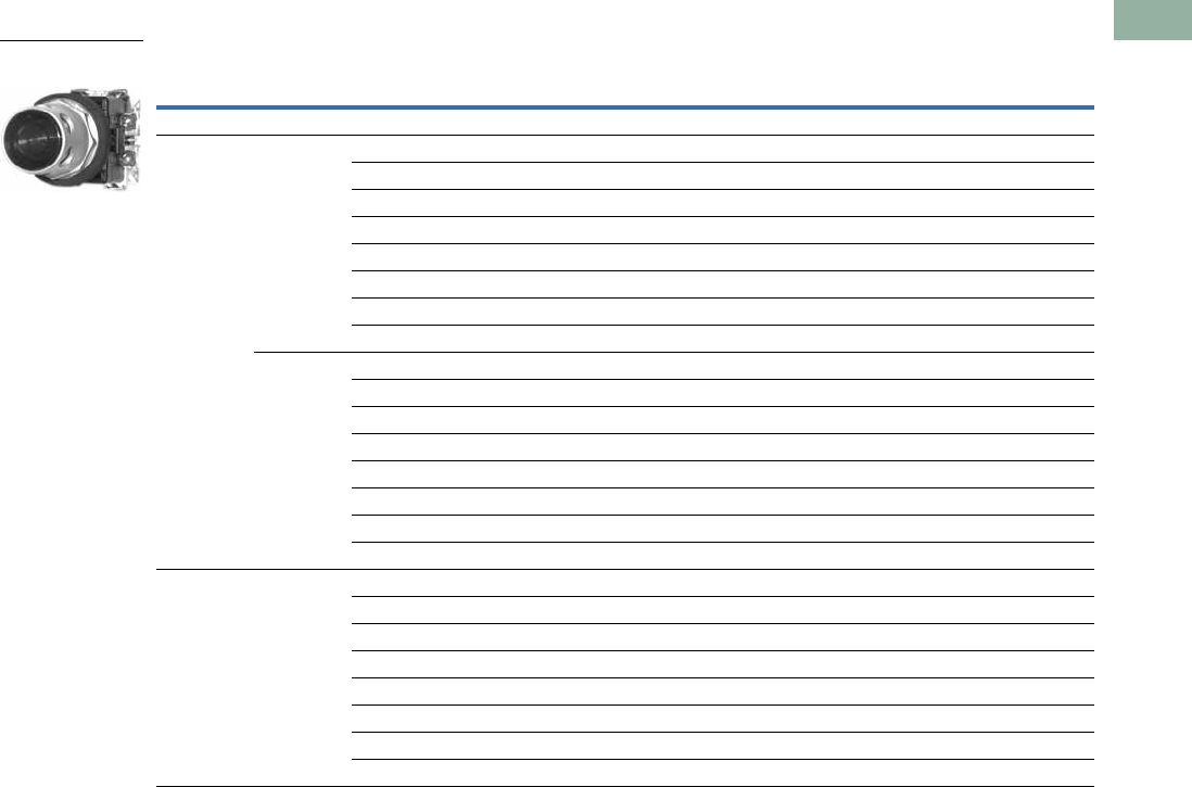
Volume 7—Logic Control, Operator Interface and Connectivity Solutions CA08100008E—March 2014 www.eaton.com V7-T1-303
1
1
1
1
1
1
1
1
1
1
1
1
1
1
1
1
1
1
1
1
1
1
1
1
1
1
1
1
1
1
1.10
Pushbuttons and Indicating Lights
30.5 mm Watertight/Oiltight—HT800
UL (NEMA) Type 3, 3R, 4, 4X, 12 and 13
Guarded Illuminated Pushbuttons, continued
Note
1 Light unit base operator without lens or bulb.
Type Volts Lens Color
Operator Only
Catalog Number
1NO
Catalog Number
1NC
Catalog Number
1NO-1NC
Catalog Number
2NO-2NC
Catalog Number
LED
Full voltage 120 Vac/Vdc No lens 1HT8GDFV————
Red HT8GDRF7 HT8GDRAF7 HT8GDRBF7 HT8GDRABF7 HT8GDRF1Q1F7
Green HT8GDGF7 HT8GDGAF7 HT8GDGBF7 HT8GDGABF7 HT8GDGF1Q1F7
Amber HT8GDAF7 HT8GDAAF7 HT8GDABF7 HT8GDAABF7 HT8GDAF1Q1F7
Clear HT8GDCF7 HT8GDCAF7 HT8GDCBF7 HT8GDCABF7 HT8GDCF1Q1F7
White HT8GDWF7 HT8GDWAF7 HT8GDWBF7 HT8GDWABF7 HT8GDWF1Q1F7
Yellow HT8GDYF7 HT8GDYAF7 HT8GDYBF7 HT8GDYABF7 HT8GDYF1Q1F7
Blue HT8GDBF7 HT8GDBAF7 HT8GDBBF7 HT8GDBABF7 HT8GDBF1Q1F7
24 Vac/Vdc No lens 1HT8GDFV————
Red HT8GDRF3 HT8GDRAF3 HT8GDRBF3 HT8GDRABF3 HT8GDRF1Q1F3
Green HT8GDGF3 HT8GDGAF3 HT8GDGBF3 HT8GDGABF3 HT8GDGF1Q1F3
Amber HT8GDAF3 HT8GDAAF3 HT8GDABF3 HT8GDAABF3 HT8GDAF1Q1F3
Clear HT8GDCF3 HT8GDCAF3 HT8GDCBF3 HT8GDCABF3 HT8GDCF1Q1F3
White HT8GDWF3 HT8GDWAF3 HT8GDWBF3 HT8GDWABF3 HT8GDWF1Q1F3
Yellow HT8GDYF3 HT8GDYAF3 HT8GDYBF3 HT8GDYABF3 HT8GDYF1Q1F3
Blue HT8GDBF3 HT8GDBAF3 HT8GDBBF3 HT8GDBABF3 HT8GDBF1Q1F3
Transformer 120 Vac No lens 1HT8GDT1————
Red HT8GDRL1 HT8GDRAL1 HT8GDRBL1 HT8GDRABL1 HT8GDRF1Q1L1
Green HT8GDGL1 HT8GDGAL1 HT8GDGBL1 HT8GDGABL1 HT8GDGF1Q1L1
Amber HT8GDAL1 HT8GDAAL1 HT8GDABL1 HT8GDAABL1 HT8GDAF1Q1L1
Clear HT8GDCL1 HT8GDCAL1 HT8GDCBL1 HT8GDCABL1 HT8GDCF1Q1L1
White HT8GDWL1 HT8GDWAL1 HT8GDWBL1 HT8GDWABL1 HT8GDWF1Q1L1
Yellow HT8GDYL1 HT8GDYAL1 HT8GDYBL1 HT8GDYABL1 HT8GDYF1Q1L1
Blue HT8GDBL1 HT8GDBAL1 HT8GDBBL1 HT8GDBABL1 HT8GDBF1Q1L1
Guarded Illuminated
Pushbutton Operator
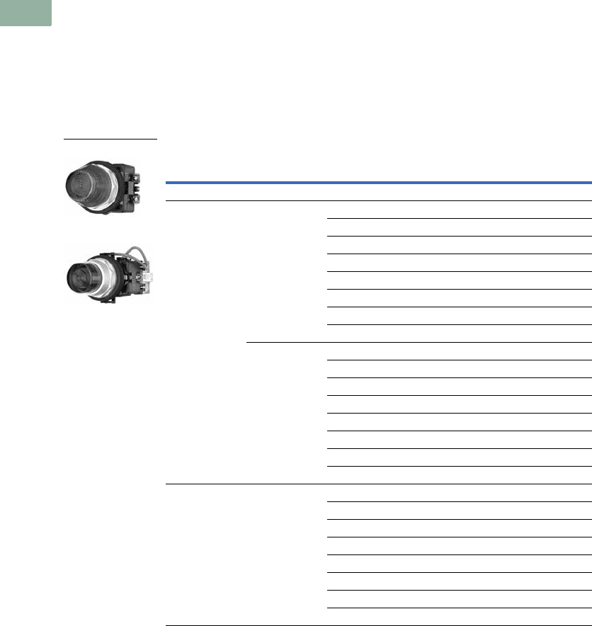
V7-T1-304 Volume 7—Logic Control, Operator Interface and Connectivity Solutions CA08100008E—March 2014 www.eaton.com
1
1
1
1
1
1
1
1
1
1
1
1
1
1
1
1
1
1
1
1
1
1
1
1
1
1
1
1
1
1
1.10
Pushbuttons and Indicating Lights
30.5 mm Watertight/Oiltight—HT800
Indicating Light Units
UL (NEMA) Type 3, 3R, 4, 4X, 12 and 13
●Incandescent or LED
●Full voltage or transformer
type
●Standard and PresTest
types
●24V and 120V
PresTest—This device
incorporates a press-to-test
feature whereby depressing
the lens disconnects
the light from the source
being monitored
and connects the lamp to a
continuously energized
circuit for immediate
detection of faulty lamps.
Indicating Light Units
Note
1 Light unit base operator without lens or bulb.
Type Volts Lens Color
Indicating Light
Catalog Number
PresTest
Catalog Number
Incandescent
Full voltage 120 Vac/Vdc No lens 1HT8HFFV HT8GTFV
Red HT8HFRV7 HT8GTRV7
Green HT8HFGV7 HT8GTGV7
Amber HT8HFAV7 HT8GTAV7
Clear HT8HFCV7 HT8GTCV7
White HT8HFWV7 HT8GTWV7
Yellow HT8HFYV7 HT8GTYV7
Blue HT8HFBV7 HT8GTBV7
24 Vac/Vdc No lens 1HT8HFFV HT8GTFV
Red HT8HFRV3 HT8GTRV3
Green HT8HFGV3 HT8GTGV3
Amber HT8HFAV3 HT8GTAV3
Clear HT8HFCV3 HT8GTCV3
White HT8HFWV3 HT8GTWV3
Yellow HT8HFYV3 HT8GTYV3
Blue HT8HFBV3 HT8GTBV3
Transformer 120 Vac
50/60 Hz
No lens 1HT8HBT1 HT8GTT1
Red HT8HBRT1 HT8GTRT1
Green HT8HBGT1 HT8GTGT1
Amber HT8HBAT1 HT8GTAT1
Clear HT8HBCT1 HT8GTCT1
White HT8HBWT1 HT8GTWT1
Yellow HT8HBYT1 HT8GTYT1
Blue HT8HBBT1 HT8GTBT1
Indicating Light Unit
PresTest Light Unit
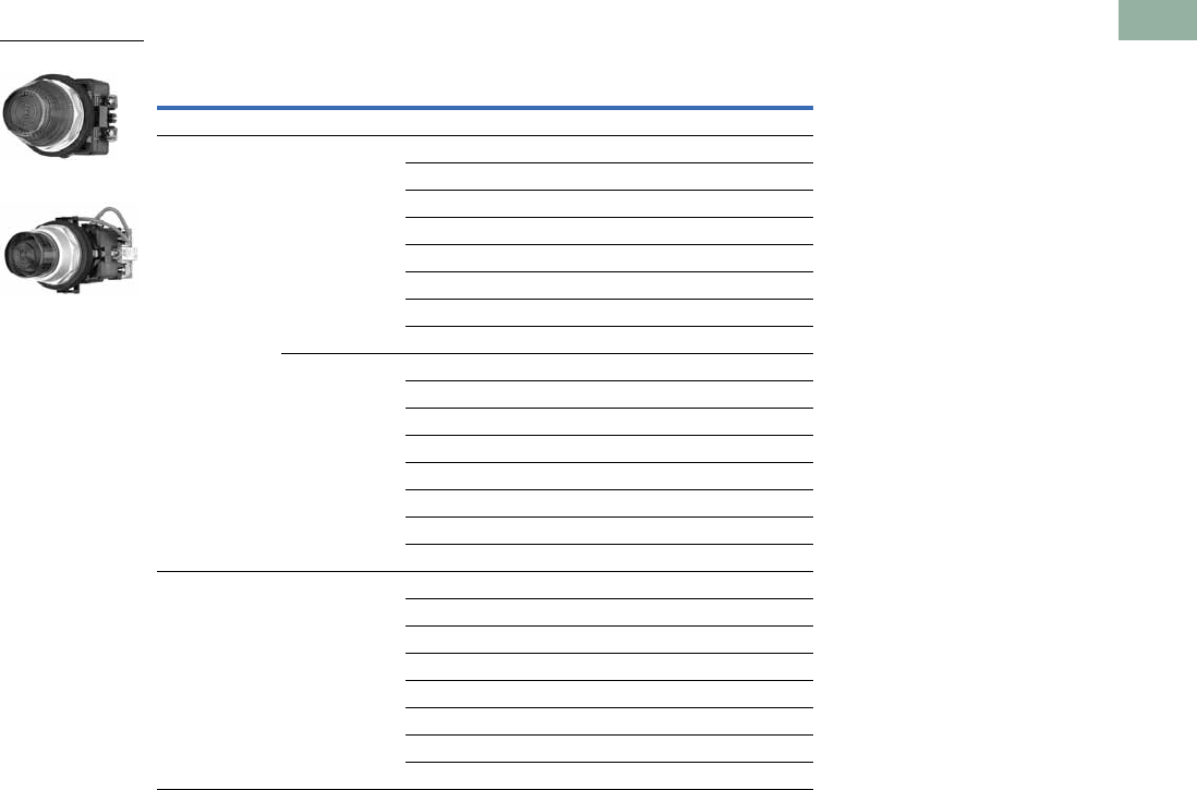
Volume 7—Logic Control, Operator Interface and Connectivity Solutions CA08100008E—March 2014 www.eaton.com V7-T1-305
1
1
1
1
1
1
1
1
1
1
1
1
1
1
1
1
1
1
1
1
1
1
1
1
1
1
1
1
1
1
1.10
Pushbuttons and Indicating Lights
30.5 mm Watertight/Oiltight—HT800
UL (NEMA) Type 3, 3R, 4, 4X, 12 and 13
Indicating Light Units, continued
Note
1 Light unit base operator without lens or bulb.
Type Volts Lens Color
Indicating Light
Catalog Number
PresTest
Catalog Number
LED
Full voltage 120 Vac/Vdc No lens 1HT8HFFV HT8GTFV
Red HT8HFRF7 HT8GTRF7
Green HT8HFGF7 HT8GTGF7
Amber HT8HFAF7 HT8GTAF7
Clear HT8HFCF7 HT8GTCF7
White HT8HFWF7 HT8GTWF7
Yellow HT8HFYF7 HT8GTYF7
Blue HT8HFBF7 HT8GTBF7
24 Vac/Vdc No lens 1HT8HFFV HT8GTFV
Red HT8HFRF3 HT8GTRF3
Green HT8HFGF3 HT8GTGF3
Amber HT8HFAF3 HT8GTAF3
Clear HT8HFCF3 HT8GTCF3
White HT8HFWF3 HT8GTWF3
Yellow HT8HFYF3 HT8GTYF3
Blue HT8HFBF3 HT8GTBF3
Transformer 120 Vac
50/60 Hz
No lens 1HT8HBT1 HT8GTT1
Red HT8HBRL1 HT8GTRL1
Green HT8HBGL1 HT8GTGL1
Amber HT8HBAL1 HT8GTAL1
Clear HT8HBCL1 HT8GTCL1
White HT8HBWL1 HT8GTWL1
Yellow HT8HBYL1 HT8GTYL1
Blue HT8HBBL1 HT8GTBL1
Indicating Light Unit
PresTest Light Unit
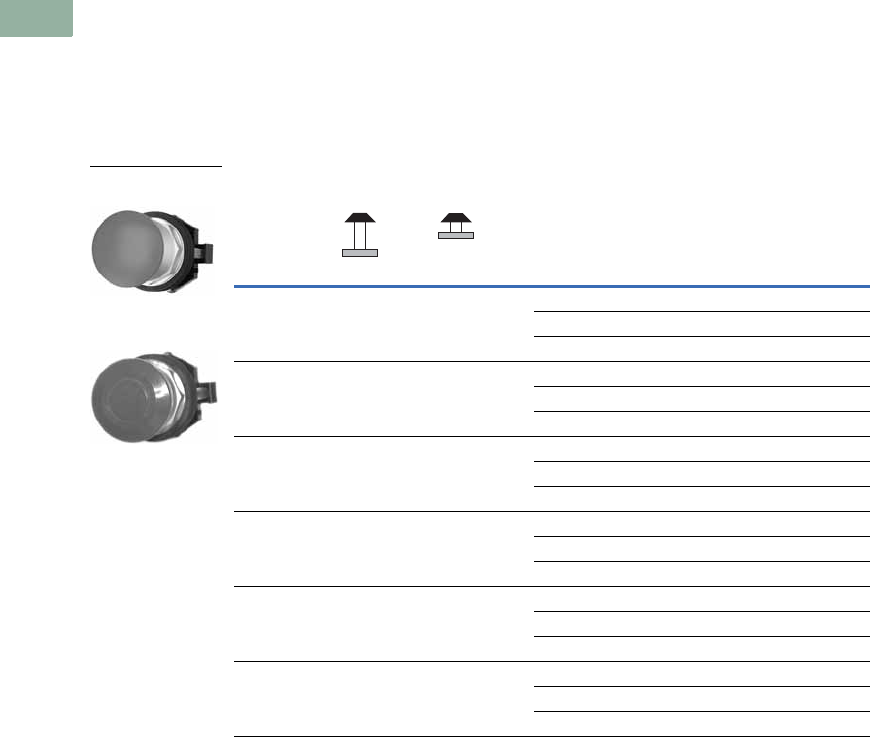
V7-T1-306 Volume 7—Logic Control, Operator Interface and Connectivity Solutions CA08100008E—March 2014 www.eaton.com
1
1
1
1
1
1
1
1
1
1
1
1
1
1
1
1
1
1
1
1
1
1
1
1
1
1
1
1
1
1
1.10
Pushbuttons and Indicating Lights
30.5 mm Watertight/Oiltight—HT800
Push-Pull Units
UL (NEMA) Type 3, 3R, 4, 4X, 12 and 13
●40 mm mushroom head
●Two-position maintained
●Non-illuminated
Two-Position Push-Pull, Maintained, Non-Illuminated
Note
1 NCLB = normally closed late break.
Contact Type
Operator Position—Maintained
Button
Color
Round Head
Mushroom Head
Button
Flat Head
Mushroom Head
Button
Out In Catalog Number Catalog Number
No contact — — Black HT8CBH HT8DBH
Red HT8CBR HT8DBR
Green HT8CBG HT8DBG
NO O X Black HT8CBHA HT8DBHA
Red HT8CBRA HT8DBRA
Green HT8CBGA HT8DBGA
NC X O Black HT8CBHB HT8DBHB
Red HT8CBRB HT8DBRB
Green HT8CBGB HT8DBGB
NO-NC O
X
X
O
Black HT8CBHAB HT8DBHAB
Red HT8CBRAB HT8DBRAB
Green HT8CBGAB HT8DBGAB
NCLB 1
NC
X
X
O
O
Black HT8CBHD1B HT8DBHD1B
Red HT8CBRD1B HT8DBRD1B
Green HT8CBGD1B HT8DBGD1B
NCLB 1
NCLB 1
X
X
O
O
Black HT8CBHD1D HT8DBHD1D
Red HT8CBRD1D HT8DBRD1D
Green HT8CBGD1D HT8DBGD1D
Round Head Two-
Position Push-Pull Unit
Flat Head Two-Position
Push-Pull Unit

Volume 7—Logic Control, Operator Interface and Connectivity Solutions CA08100008E—March 2014 www.eaton.com V7-T1-307
1
1
1
1
1
1
1
1
1
1
1
1
1
1
1
1
1
1
1
1
1
1
1
1
1
1
1
1
1
1
1.10
Pushbuttons and Indicating Lights
30.5 mm Watertight/Oiltight—HT800
Illuminated Push-Pull Units
UL (NEMA) Type 3, 3R, 4, 4X, 12 and 13
●Incandescent or LED
●Full voltage or transformer type
●24V and 120V
Illuminated Push-Pull Units
Note: Complete illuminated push-pull switches will not fit in a standard 3 in deep enclosure.
Illuminated Push-Pull Units with Low Profile Light Units
Type Volts
Lens
Color
Operator Only
Catalog Number
1NO
Catalog Number
1NC
Catalog Number
1NO-1NC
Catalog Number
2NCLB
Catalog Number
Incandescent Lamp
Full voltage 120 Vac/Vdc Red HT8FBRV7 HT8FBRAV7 HT8FBRBV7 HT8FBRABV7 HT8FBRD1DV7
Green HT8FBGV7 HT8FBGAV7 HT8FBGBV7 HT8FBGABV7 HT8FBGD1DV7
24 Vac/Vdc Red HT8FBRV3 HT8FBRAV3 HT8FBRBV3 HT8FBRABV3 HT8FBRD1DV3
Green HT8FBGV3 HT8FBGAV3 HT8FBGBV3 HT8FBGABV3 HT8FBGD1DV3
Transformer 120 Vac Red HT8FBRT1 HT8FBRAT1 HT8FBRBT1 HT8FBRABT1 HT8FBRD1DT1
Green HT8FBGT1 HT8FBGAT1 HT8FBGBT1 HT8FBGABT1 HT8FBGD1DT1
LED Lamp
Full voltage 120 Vac/Vdc Red HT8FBRF7 HT8FBRAF7 HT8FBRBF7 HT8FBRABF7 HT8FBRD1DF7
Green HT8FBGF7 HT8FBGAF7 HT8FBGBF7 HT8FBGABF7 HT8FBGD1DF7
24 Vac/Vdc Red HT8FBRF3 HT8FBRAF3 HT8FBRBF3 HT8FBRABF3 HT8FBRD1DF3
Green HT8FBGF3 HT8FBGAF3 HT8FBGBF3 HT8FBGABF3 HT8FBGD1DF3
Transformer 120 Vac Red HT8FBRL1 HT8FBRAL1 HT8FBRBL1 HT8FBRABL1 HT8FBRD1DL1
Green HT8FBGL1 HT8FBGAL1 HT8FBGBL1 HT8FBGABL1 HT8FBGD1DL1
Type Voltage Color Fingersafe
Operator Only
Catalog Number
1NO
Catalog Number
1NC
Catalog Number
1NO-1NC
Catalog Number
2NCLB
Catalog Number
1NO-1NCLB
Catalog Number
LED Lamp
Full
voltage
120
Vac/Vdc
Red Yes HT8FBRFL7P HT8FBRAFL7P HT8FBRBFL7P HT8FBRABFL7P HT8FBRD1DFL7P HT8FBRD1BFL7P
Red No HT8FBRFL7 HT8FBRAFL7 HT8FBRBFL7 HT8FBRABFL7 HT8FBRD1DFL7 HT8FBRD1BFL7
24
Vac/Vdc
Red Yes HT8FBRFL3P HT8FBRAFL3P HT8FBRBFL3P HT8FBRABFL3P HT8FBRD1DFL3P HT8FBRD1BFL3P
Red No HT8FBRFL3 HT8FBRAFL3 HT8FBRBFL3 HT8FBRABFL3 HT8FBRD1DFL3 HT8FBRD1BFL3
Incandescent
Full
voltage
120
Vac/Vdc
Red Yes HT8FBRVL7P HT8FBRAVL7P HT8FBRBVL7P HT8FBRABVL7P HT8FBRD1DVL7P HT8FBRD1BVL7P
Red No HT8FBRVL7 HT8FBRAVL7 HT8FBRBVL7 HT8FBRABVL7 HT8FBRD1DVL7 HT8FBRD1BVL7
24
Vac/Vdc
Red Yes HT8FBRVL3P HT8FBRAVL3P HT8FBRBVL3P HT8FBRABVL3P HT8FBRD1DVL3P HT8FBRD1BVL3P
Red No HT8FBRVL3 HT8FBRAVL3 HT8FBRBVL3 HT8FBRABVL3 HT8FBRD1DVL3 HT8FBRD1BVL3
Illuminated
Push-Pull Unit
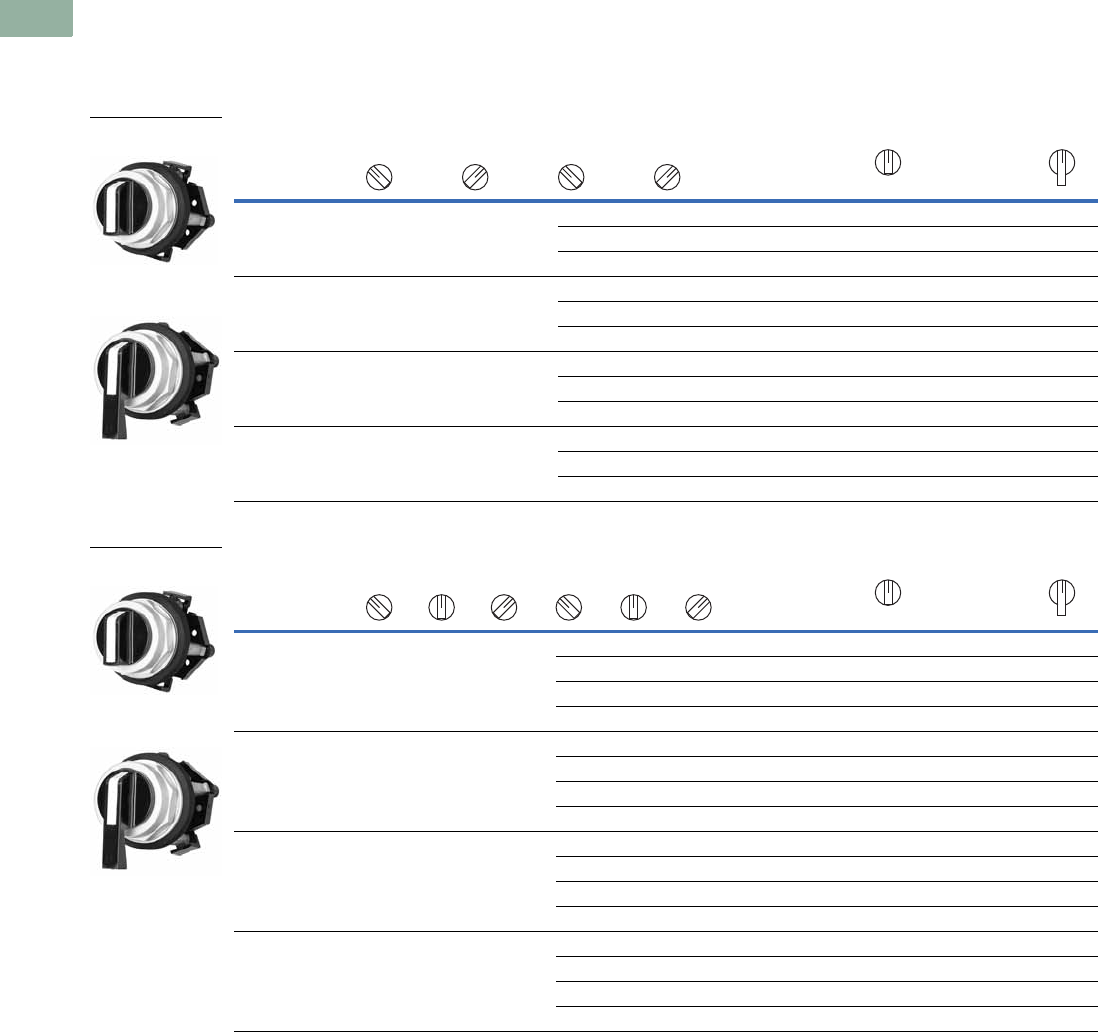
V7-T1-308 Volume 7—Logic Control, Operator Interface and Connectivity Solutions CA08100008E—March 2014 www.eaton.com
1
1
1
1
1
1
1
1
1
1
1
1
1
1
1
1
1
1
1
1
1
1
1
1
1
1
1
1
1
1
1.10
Pushbuttons and Indicating Lights
30.5 mm Watertight/Oiltight—HT800
Selector Switch Units
UL (NEMA) Type 3, 3R, 4, 4X, 12 and 13
●Two-, three- and four-position
●Non-illuminated
Two-Position Selector Switch Units, Non-Illuminated
Three-Position Selector Switch Units, Non-Illuminated
Notes
1 X = closed circuit, O = open circuit.
2 M = Maintained, S = Momentary.
3 For OXO, NC contacts must be wired in series—see Three-Position Selector Switch table on Page V7-T1-310.
Contact
Type
Operator Position 1Operating Mode 2Standard
Black Knob
Catalog Number
Standard
Black Lever
Catalog Number
No contacts — — M M HT8JAH3A HT8JDH3A
SM
HT8JKH3A HT8JLH3A
MS HT8JNH3A HT8JPH3A
1NO O X M M HT8JAH3AA5 HT8JDH3AA5
SM
HT8JKH3AA5 HT8JLH3AA5
MS HT8JNH3AA5 HT8JPH3AA5
2NO X
O
O
X
MMHT8JAH3AAA5 HT8JDH3AAA5
SM
HT8JKH3AAA5 HT8JLH3AAA5
MS HT8JNH3AAA5 HT8JPH3AAA5
2NO-2NC X
O
O
X
O
X
X
O
MMHT8JAH3AF1Q1 HT8JDH3AF1Q1
SM
HT8JKH3AF1Q1 HT8JLH3AF1Q1
MS HT8JNH3AF1Q1 HT8JPH3AF1Q1
Contact
Type
Operator Position 1Operating Mode 2Standard
Black Knob
Catalog Number
Standard
Black Lever
Catalog Number
No contacts — — — M M M HT8JBH1D HT8JEH1D
SMM
HT8JRH1D HT8JSH1D
MMS HT8JUH1D HT8JVH1D
SMSHT8JXH1D HT8JYH1D
2NO X
O
O
O
O
X
MMMHT8JBH1DAA5 HT8JEH1DAA5
SMM
HT8JRH1DAA5 HT8JSH1DAA5
MMS HT8JUH1DAA5 HT8JVH1DAA5
SMSHT8JXH1DAA5 HT8JYH1DAA5
2NO-2NC 3X
O
O
O
X
O
O
O
X
MMMHT8JBH1DF1Q1 HT8JEH1DF1Q1
SMM
HT8JRH1DF1Q1 HT8JSH1DF1Q1
MMS HT8JUH1DF1Q1 HT8JVH1DF1Q1
SMSHT8JXH1DF1Q1 HT8JYH1DF1Q1
2NO-2NC X
O
O
X
O
X
O
X
O
X
X
O
MMMHT8JBH1DF1Q1 HT8JEH1DF1Q1
SMM
HT8JRH1DF1Q1 HT8JSH1DF1Q1
MMS HT8JUH1DF1Q1 HT8JVH1DF1Q1
SMSHT8JXH1DF1Q1 HT8JYH1DF1Q1
Standard Knob
Operator
Standard Lever
Operator
Standard Knob
Operator
Standard Lever
Operator
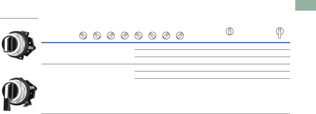
Volume 7—Logic Control, Operator Interface and Connectivity Solutions CA08100008E—March 2014 www.eaton.com V7-T1-309
1
1
1
1
1
1
1
1
1
1
1
1
1
1
1
1
1
1
1
1
1
1
1
1
1
1
1
1
1
1
1.10
Pushbuttons and Indicating Lights
30.5 mm Watertight/Oiltight—HT800
UL (NEMA) Type 3, 3R, 4, 4X, 12 and 13
Four-Position Selector Switch Units, Non-Illuminated
Notes
1 X = closed circuit, O = open circuit.
2 M = Maintained, S = Momentary.
Contact
Type
Operator Position 1Operating Mode 2Standard
Black Knob
Catalog Number
Standard
Black Lever
Catalog Number
No contacts ————MMMMHT8JCH8E HT8JFH8E
S MMMHT8LNH8E HT8LPH8E
MMMS HT8LRH8E HT8LSH8E
2NO-2NC X
O
O
O
O
X
O
O
O
O
X
O
O
O
O
X
MMMMHT8JCH8EF1Q1 HT8JFH8EF1Q1
S MMMHT8LNH8EF1Q1 HT8LPH8EF1Q1
MMMS HT8LRH8EF1Q1 HT8LSH8EF1Q1
Standard Knob
Operator
Standard Lever
Operator
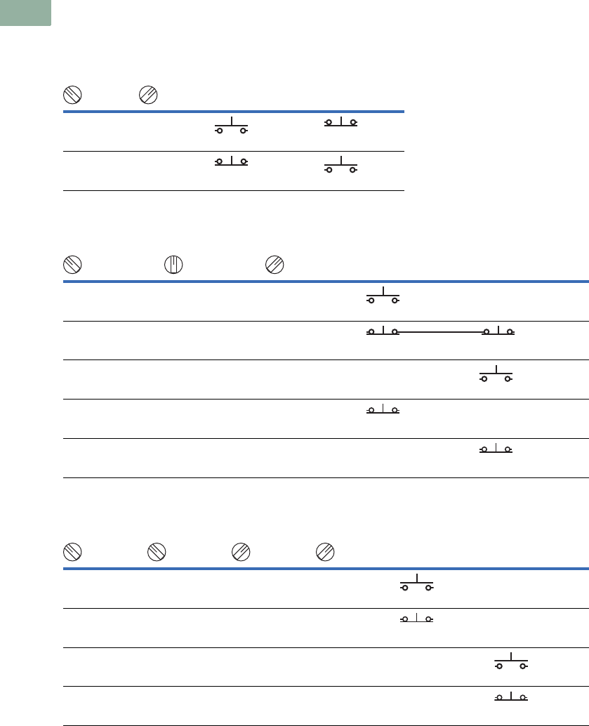
V7-T1-310 Volume 7—Logic Control, Operator Interface and Connectivity Solutions CA08100008E—March 2014 www.eaton.com
1
1
1
1
1
1
1
1
1
1
1
1
1
1
1
1
1
1
1
1
1
1
1
1
1
1
1
1
1
1
1.10
Pushbuttons and Indicating Lights
30.5 mm Watertight/Oiltight—HT800
Selector Switch Contact Block Selection
For Two-, Three- and Four-Position Selector Switches
Two-Position Selector Switch (Cam Code 3A)
Three-Position Selector Switch (Cam Code 1D)
Four-Position Selector Switch (Cam Code 8E)
Operator Position
Left Right
XO
NO
or
NC
OX
NC
or
NO
Operator Position
Left Right
XOO
NO
—
OXO
NC NC
OOX—
NO
OXX
NC
—
XXO—
NC
Operator Position
Left Right
XOOO
NO
—
OXOO
NC
—
OOXO—
NO
OOOX—
NC
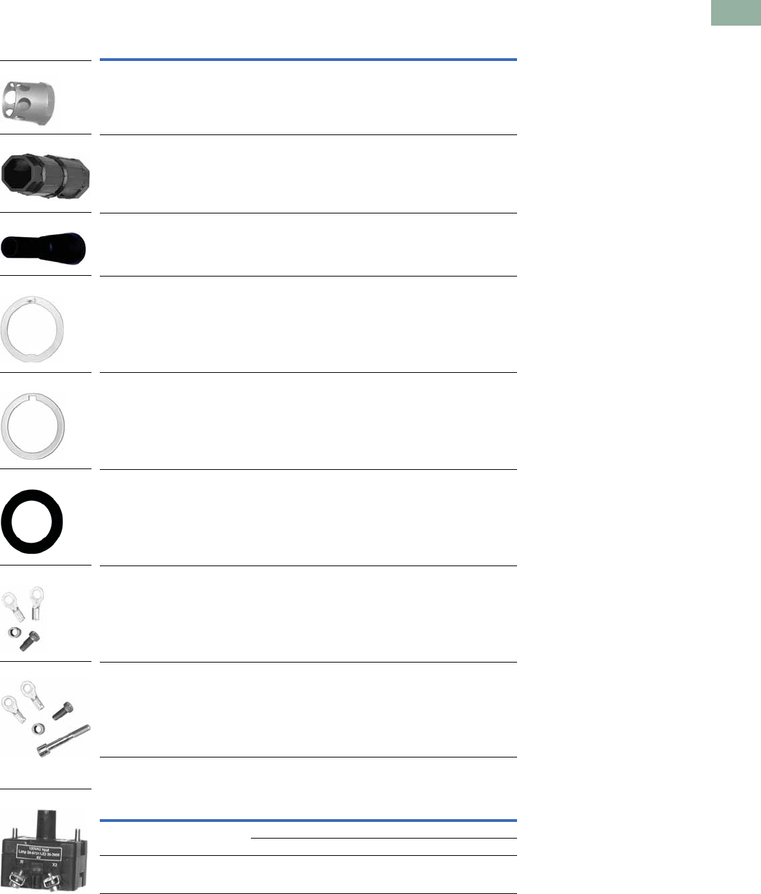
Volume 7—Logic Control, Operator Interface and Connectivity Solutions CA08100008E—March 2014 www.eaton.com V7-T1-311
1
1
1
1
1
1
1
1
1
1
1
1
1
1
1
1
1
1
1
1
1
1
1
1
1
1
1
1
1
1
1.10
Pushbuttons and Indicating Lights
30.5 mm Watertight/Oiltight—HT800
Accessories
HT800 Accessories
Light Units
Description Catalog Number
Illuminated Pushbutton Guard HT8A15
Wrench Tool HT8WRENCH
Lamp/Bulb Removal Tool HT8LAMPTOOL
Thrust Washer (Anti-rotation)
(Included with every operator)
HT8X1
Trim Ring
(Included with every operator)
HT8X2
Sealing/Spacer Washer
(Five included with every operator)
HT8X3
Grounding Kit for Pushbuttons and Selector Switches
(Included with every operator)
HT8GR1
Grounding Kit for Indicating Lights
(Included with indicating lights)
HT8GR2
Type Voltage Catalog Number
Full voltage 24 Vac/Vdc HT8F3V3
120 Vac/Vdc HT8F7V8
Transformer 120 Vac HT8L1T1
HT8A15
HT8WRENCH
HT8LAMPTOOL
HT8X3
HT8GR2
HT8GR1
HT8X2
HT8X1
Light Unit
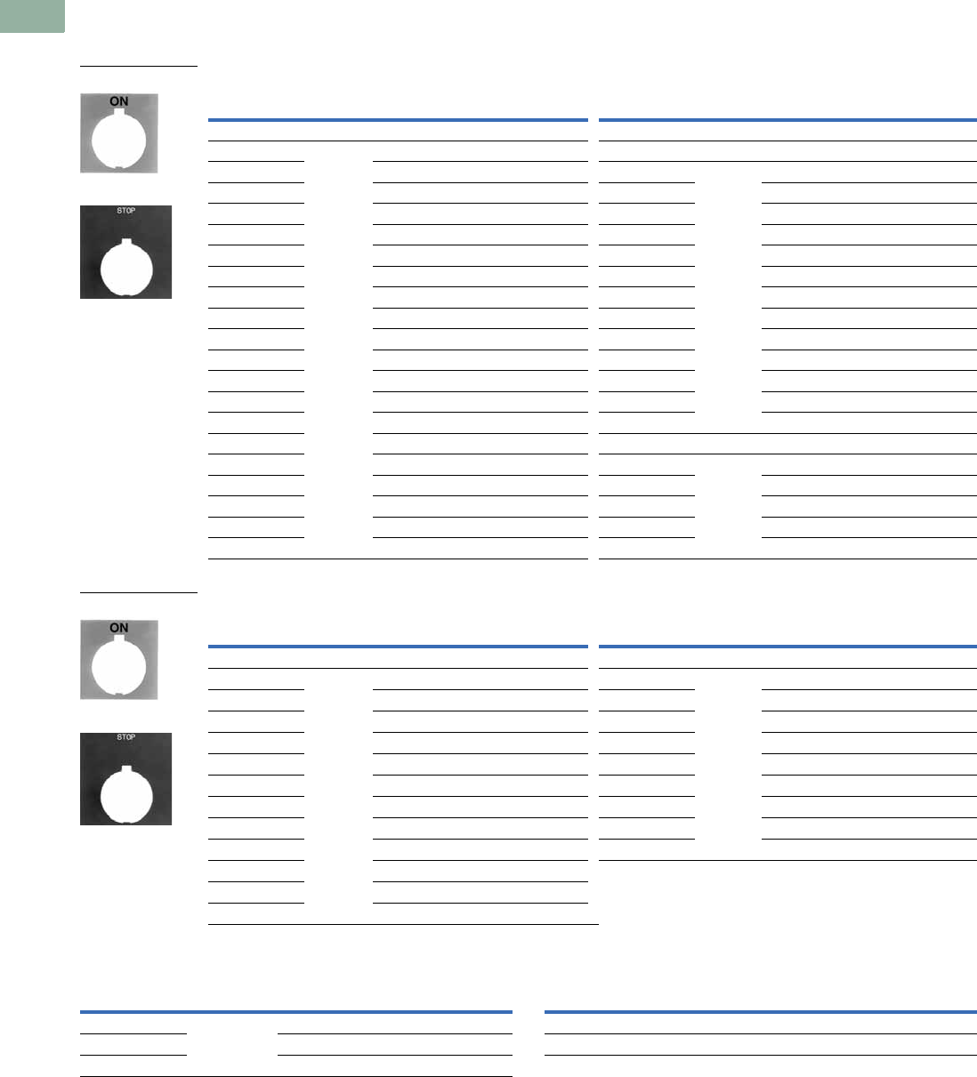
V7-T1-312 Volume 7—Logic Control, Operator Interface and Connectivity Solutions CA08100008E—March 2014 www.eaton.com
1
1
1
1
1
1
1
1
1
1
1
1
1
1
1
1
1
1
1
1
1
1
1
1
1
1
1
1
1
1
1.10
Pushbuttons and Indicating Lights
30.5 mm Watertight/Oiltight—HT800
Options
Legend Plates 1
For Pushbutton Operators and Indicating Lights
For Selector Switch Operators
For Push-Pull Units Blank Plastic Legend Plates—Square
Notes
1For dimensions, see Page V7-T1-320.
23/32 in high lettering.
31/8 in high lettering.
Legend
Color of
Field
Standard
Catalog Number
Jumbo
Catalog Number Legend
Color of
Field
Standard
Catalog Number
Jumbo
Catalog Number
Letters on Legend Plates Below are 3/16 in High
CLAMP Black HT8SP90 HT8LP90 OFF Red HT8SP24 HT8LP24
CLOSE HT8SP73 HT8LP73 ON Black HT8SP25 HT8LP25
DOWN HT8SP74 HT8LP74 OPEN HT8SP26 HT8LP26
EMERG. STOP HT8SP13 HT8LP13 OUT HT8SP27 HT8LP27
FAST HT8SP75 HT8LP75 POWER ON HT8SP80 HT8LP80
FASTER HT8SP87 HT8LP87 RAISE HT8SP28 HT8LP28
FEEDER ON HT8SP94 HT8LP94 READY HT8SP86 HT8LP86
FEEDER OFF HT8SP95 HT8LP95 RESET HT8SP29 HT8LP29
FORWARD HT8SP15 HT8LP15 REVERSE HT8SP30 HT8LP30
HIGH HT8SP16 HT8LP16 RUN HT8SP31 HT8LP31
IN HT8SP17 HT8LP17 SAFE HT8SP85 HT8LP85
INCH HT8SP18 HT8LP18 SLOW HT8SP32 HT8LP32
JOG HT8SP19 HT8LP19 SLOWER HT8SP88 HT8LP88
JOG FOR. HT8SP20 HT8LP20 START HT8SP33 HT8LP33
JOG REV. HT8SP21 HT8LP21 STOP Red HT8SP34 HT8LP34
LOW HT8SP22 HT8LP22 TEST Black HT8SP83 HT8LP83
LOWER HT8SP23 HT8LP23 TRANSFER HT8SP93 HT8LP93
LUBE-FAIL HT8SP92 HT8LP92 TRIP HT8SP84 HT8LP84
MOTOR RUN HT8SP81 HT8LP81 UNCLAMP HT8SP91 HT8LP91
MOTOR STOP HT8SP82 HT8LP82 UP HT8SP35 HT8LP35
Legend
Color of
Field
Standard
Catalog Number
Jumbo
Catalog Number Legend
Color of
Field
Standard
Catalog Number
Jumbo
Catalog Number
Two-Position—3/16 in High Lettering Three-Position—3/16 in High Lettering
FOR. REV. Black HT8SP38 HT8LP38 AUTO OFF HAND Black HT8SP49 HT8LP49
HAND AUTO HT8SP39 HT8LP39 FOR. OFF REV. HT8SP50 HT8LP50
HIGH LOW HT8SP40 HT8LP40 FOR. SAFE REV. HT8SP69 HT8LP69
JOG RUN HT8SP41 HT8LP41 HAND OFF AUTO HT8SP51 HT8LP51
MAN. AUTO HT8SP67 HT8LP67 MAN. OFF AUTO HT8SP68 HT8LP68
OFF ON HT8SP42 HT8LP42 OPEN OFF CLOSE HT8SP53 HT8LP53
OPEN CLOSE HT8SP43 HT8LP43 RUN SAFE JOG HT8SP70 HT8LP70
RUN JOG HT8SP44 HT8LP44 UP OFF DOWN HT8SP54 HT8LP54
SAFE RUN HT8SP45 HT8LP45 ON STOP SAFE HT8SP71 HT8LP71
START JOG HT8SP46 HT8LP46
START STOP HT8SP47 HT8LP47
UP DOWN HT8SP48 HT8LP48
Standard
Jumbo
Standard
Jumbo
Legend
Color of
Field
Standard 2
Catalog Number
Jumbo 3
Catalog Number
ON/OFF Black HT8PP5 HT8R5
OPEN/CLOSE HT8PP8 HT8R8
UP/DOWN HT8PP11 HT8R11
Legend
Color of
Field
Standard
Catalog Number
Jumbo
Catalog Number
Black White/Silver HT8SP76 HT8LP76
White Red/ Black HT8SP77 HT8LP77
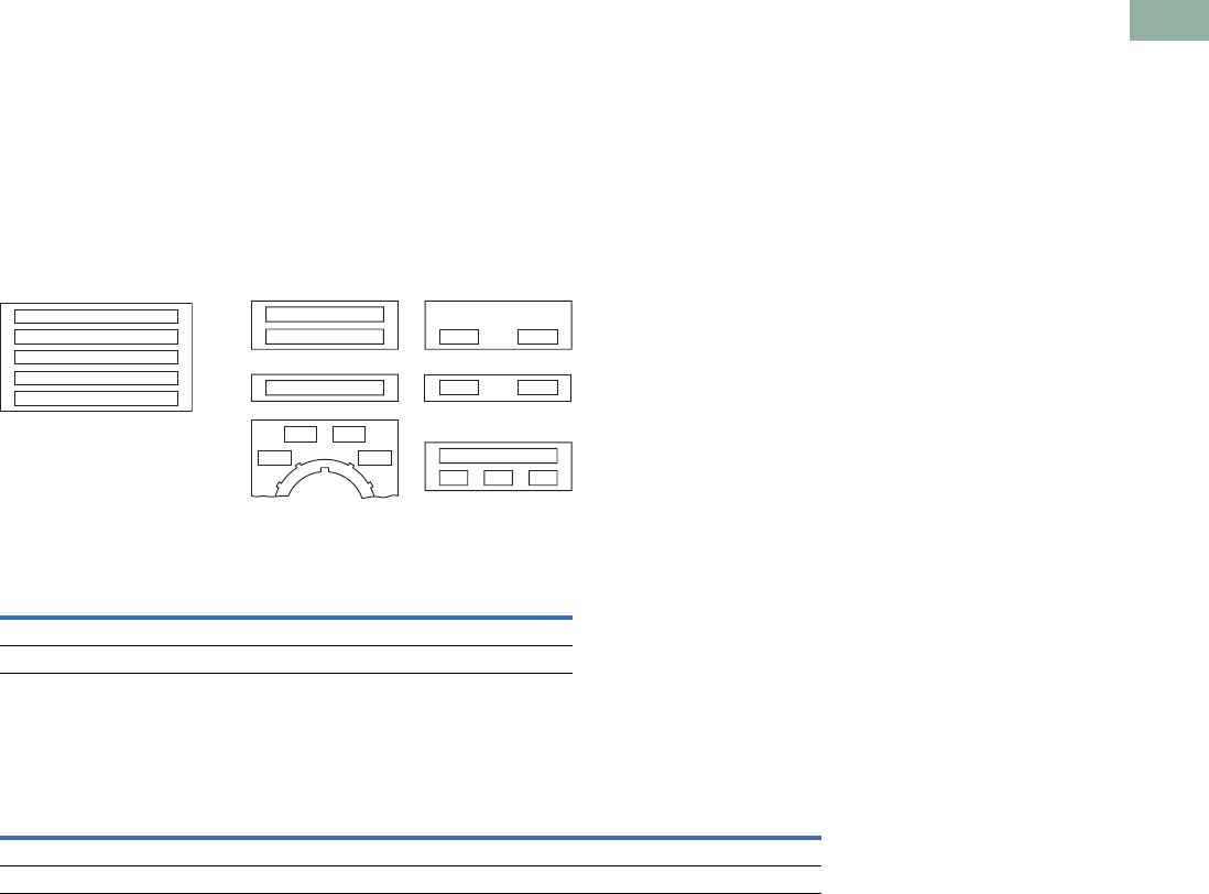
Volume 7—Logic Control, Operator Interface and Connectivity Solutions CA08100008E—March 2014 www.eaton.com V7-T1-313
1
1
1
1
1
1
1
1
1
1
1
1
1
1
1
1
1
1
1
1
1
1
1
1
1
1
1
1
1
1
1.10
Pushbuttons and Indicating Lights
30.5 mm Watertight/Oiltight—HT800
Legend Plates with Non-Standard Markings
When Ordering Specify
●Catalog number of blank
plate.
●Insert the following into
Order Notes: legend, letter
size and locations. See
information below.
Ordering Example:
Catalog no.: HT85P76STAMP
Letter size: 3/32 in (2.4 mm)
Pos. A—POWER HOUSE
Pos. B—START PUMP 1
Legend Characters
Available
A B C D E F G H I J K L M N O
P Q R S T U V W X Y Z / - . , 1
2 3 4 5 6 7 8 9 0
Legend Positions
Blank Plastic Legend Plates for Non-Standard Markings—Plastic
Maximum Characters per Legend Plate and Approximate Dimensions
Note
1Can be used on top row only of any enclosure.
Legend
Color of
Field
Standard
Catalog Number
Jumbo
Catalog Number
Black White/Silver HT8SP76STAMP HT8LP76STAMP
White Red/Black HT8SP77STAMP HT8LP77STAMP
Top
(Aluminum
and Plastic) Style
Character Size
3/32 in High 1/8 in High 3/16 in High
Number
of Lines
Number of
Characters
Number
of Lines
Number of
Characters
Number
of Lines
Number of
Characters
Standard Square 2 18 2 13 1 9
Jumbo 1Square 5 23 3 18 2 12
Jumbo Size
HT8LP Series
A
C
K
D
B
Standard Size
HT8SP Series
AB
B
A
GF
AE
GH
A
I
AF
D4
C4B4
A4
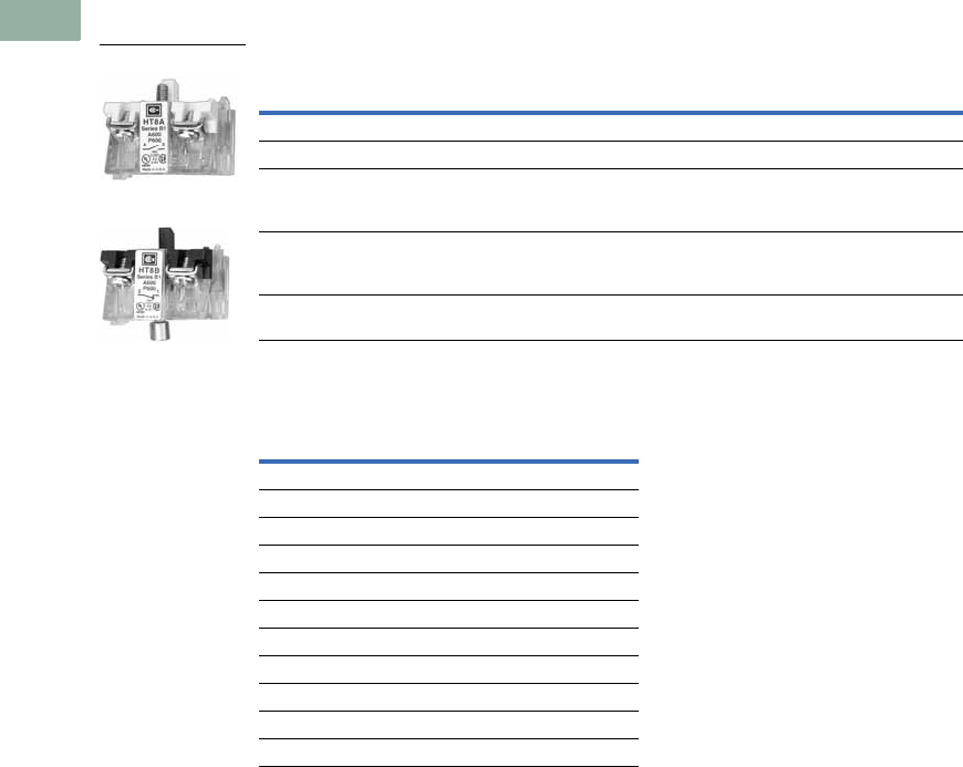
V7-T1-314 Volume 7—Logic Control, Operator Interface and Connectivity Solutions CA08100008E—March 2014 www.eaton.com
1
1
1
1
1
1
1
1
1
1
1
1
1
1
1
1
1
1
1
1
1
1
1
1
1
1
1
1
1
1
1.10
Pushbuttons and Indicating Lights
30.5 mm Watertight/Oiltight—HT800
Contact Blocks
Contact Blocks 12
Contact Block Location (Viewed from Rear)
Suffix Codes 34
Notes
1 See Page V7-T1-316 for contact block electrical ratings.
2 Maximum of four contact blocks per side or a total of eight contact blocks recommended.
3 Maximum of two contact blocks per side or a total of four contact blocks recommended.
4 Standard contact blocks without fingerproof protection.
Description/Function
Contact
Type
Without Guard
Catalog Number
Fingerproof
Catalog Number
Standard normally open contact NO HT8A HT8AP
Standard normally closed contact NC HT8B HT8BP
Normally open early make contact will
make circuit before standard NO contact.
DC ratings do not apply.
NOEM HT8C HT8CP
Normally closed late break contact will
open after standard NC contact.
DC ratings do not apply.
NCLB HT8D HT8DP
Logic level, low voltage NO contact.
Gold plated contacts.
NO HT8E HT8EP
Left Side Right Side
A=NO A5 =NO
A2 =2NO A6 =2NO
B1 =NC B=NC
B2 =2NC B6 =2NC
C=NOEM C5 = NOEM
C2 = 2 NOEM C6 = 2 NOEM
D1 = NCLB D= NCLB
D2 =2 NCLB D6 =2 NCLB
E1 =NOEM-NCLB E5 = NOEM-NCLB
F1 = NO and NC Q1 = NO and NC
F4 = 1NO-1NC
NO Contact Block
NC Contact Block
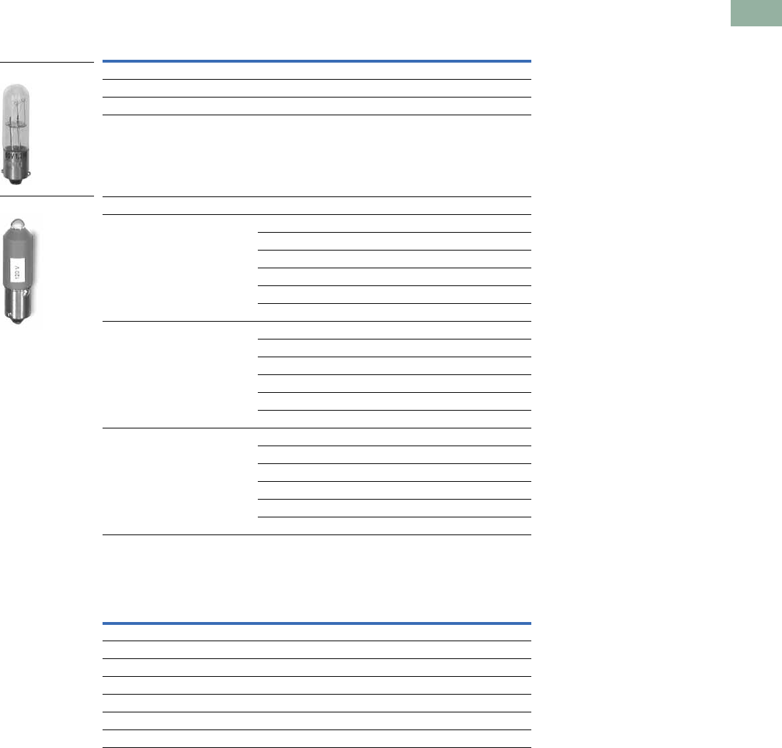
Volume 7—Logic Control, Operator Interface and Connectivity Solutions CA08100008E—March 2014 www.eaton.com V7-T1-315
1
1
1
1
1
1
1
1
1
1
1
1
1
1
1
1
1
1
1
1
1
1
1
1
1
1
1
1
1
1
1.10
Pushbuttons and Indicating Lights
30.5 mm Watertight/Oiltight—HT800
Replacement Parts
Replacement Bulbs and LEDs
Replacement Lenses
Voltage Color Catalog Number
Incandescent
6V — HT8BULBV1
24V — HT8BULBV3
120V — HT8BULBV7
LED
6–12V
(For use with transformers with 6V
secondary winding)
Red HT8LEDRF1
Green HT8LEDGF1
Amber/orange HT8LEDAF1
White/clear HT8LEDWF1
Yellow HT8LEDYF1
Blue HT8LEDBF1
24V Red HT8LEDRF3
Green HT8LEDGF3
Amber/orange HT8LEDAF3
White/clear HT8LEDWF3
Yellow HT8LEDYF3
Blue HT8LEDBF3
120V Red HT8LEDRF7
Green HT8LEDGF7
Amber/orange HT8LEDAF7
White/clear HT8LEDWF7
Yellow HT8LEDYF7
Blue HT8LEDBF7
Color
Indicating Lights
Catalog Number
PresTest Lights
Illuminated Pushbuttons
Catalog Number
Amber HT8LA HT8BA
Blue HT8LB HT8BB
Clear HT8LC HT8BC
Green HT8LG HT8BG
Red HT8LR HT8BR
White HT8LW HT8BW
Yellow HT8LY HT8BY
Incandescent Bulb
LED Bulb

V7-T1-316 Volume 7—Logic Control, Operator Interface and Connectivity Solutions CA08100008E—March 2014 www.eaton.com
1
1
1
1
1
1
1
1
1
1
1
1
1
1
1
1
1
1
1
1
1
1
1
1
1
1
1
1
1
1
1.10
Pushbuttons and Indicating Lights
30.5 mm Watertight/Oiltight—HT800
Technical Data and Specifications
HT800—Specifications
Electrical Ratings—HT800 Standard Contact Blocks, UL Rating
UL A600 and P600 Ratings
Notes
1Heavy-duty.
2Standard-duty.
3DC ratings do not apply to NOEM (Normally Open Early Make) and NCLB (Normal Closed Late Break) contact blocks HT8C and HT8D.
4Maximum make or break volt-amperes at 300V or less.
Description Specification
Mechanical Ratings
Frequency of operation
Pushbuttons 6,000 operations per hour
Selector switches 3,000 operations per hour
Push-pull operators 3,000 operations per hour
Mechanical endurance/life
Pushbuttons 10 x 106 operations 6K ops/hr with 6 NO on left and 6 NC on right
Selector switches 250 x 103 operations 3K ops/hr with 2 NO on left and 2 NC on right
Push-pull operators 250 x 103 operations 3K ops/hr with 6 NO on left and 6 NC on right
Climatic Conditions
Operating temperature 10° to 140°F (–12° to 60°C)
Storage temperature –40° to 176°F (–40° to 80°C)
Altitude 6,562 ft (2,000m)
Humidity 95% RH at 60°C
Te rm i n a l s
Contact blocks #6-32 posidrive saddle clamp type, 1 x 16 AWG to 2 x 14 AWG, 12 in-lbs max.
Light units #6-32 posidrive saddle clamp type, 1 x 22 AWG to 2 x 14 AWG, 7 in-lbs max.
Electrical Ratings
Standard contact blocks UL (NEMA) rating See table below.
Logic level contact block power rating 5V 1 mA (minimum)
28V 500 mA (maximum)
Description/Function
Contact
Type AC DC Catalog Number
Standard normally open contact NO A600 1P600 2HT8A
Standard normally closed contact NC A600 1P600 2HT8B
Normally open early make contact will make circuit before standard
NO contact. DC ratings do not apply.
NOEM A600 1—HT8C
Normally closed late break contact will open after standard NC
contact. DC ratings do not apply.
NCLB A600 1—HT8D
Logic level, low voltage NO contact. Gold plated contacts. NO 5V 1 mA (minimum)
28V 500 mA (maximum)
HT8E
Description
50 Vac or 60 Hz Vdc 3
120 240 480 600 125 250 600
Make and emerg. interrupting capacity (amp) 60 30 15 12 1.1 0.55 0.2
Normal load break (amp) 6 3 1.5 1.2 1.1 0.55 0.2
Thermal current (amp) 101010105 5 5
Voltamperes:
Make and emerg. interrupting capacity 7200 7200 7200 7200 138 4138 4138 4
Normal load break 720 720 720 720 138 138 138
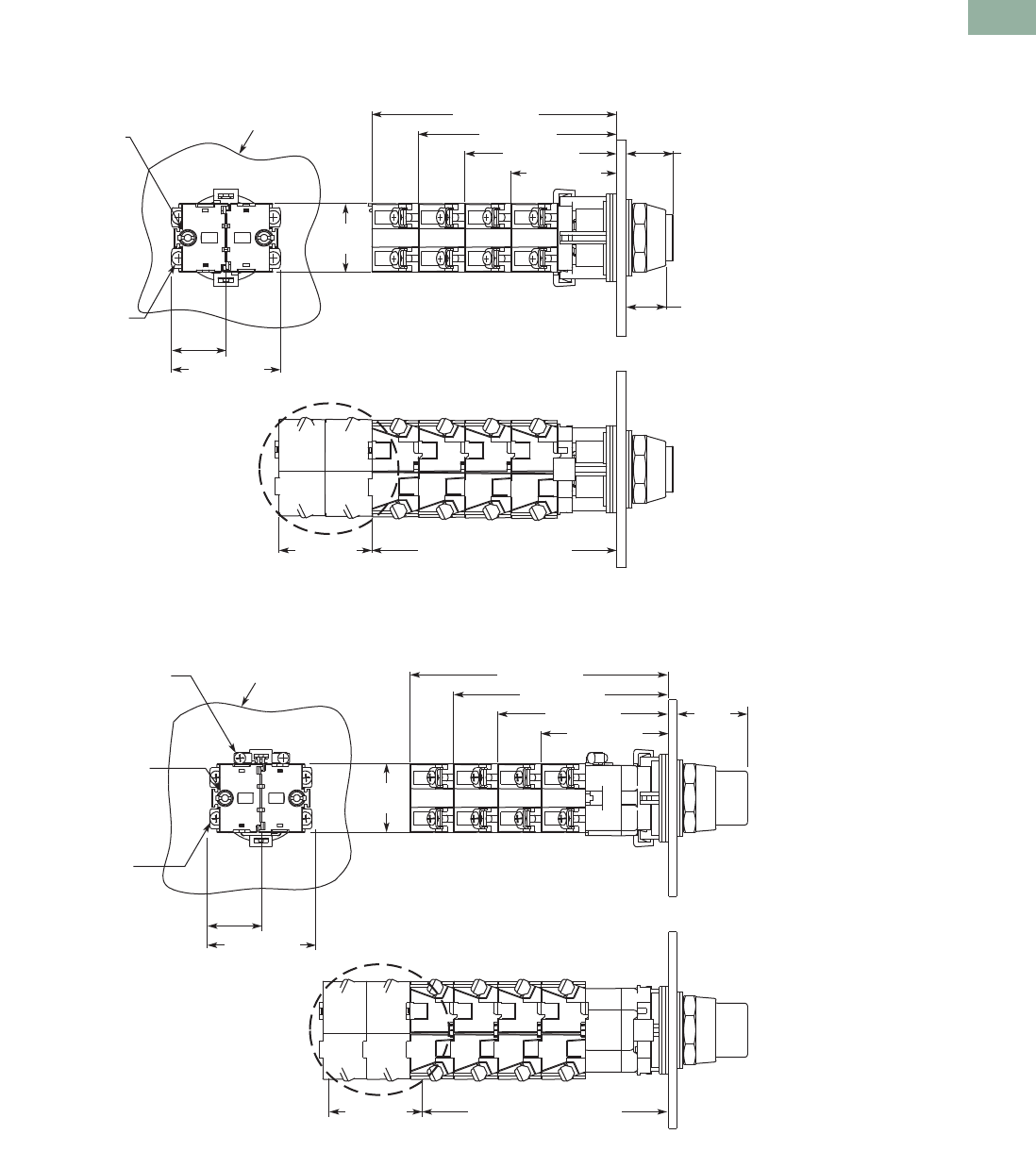
Volume 7—Logic Control, Operator Interface and Connectivity Solutions CA08100008E—March 2014 www.eaton.com V7-T1-317
1
1
1
1
1
1
1
1
1
1
1
1
1
1
1
1
1
1
1
1
1
1
1
1
1
1
1
1
1
1
1.10
Pushbuttons and Indicating Lights
30.5 mm Watertight/Oiltight—HT800
Dimensions
Approximate Dimensions in Inches (mm)
Momentary Pushbuttons—Non-Illuminated
Back, side and bottom views of pushbutton operator with attached contact blocks.
Illuminated Pushbuttons
Back, side and bottom views of pushbutton operator with attached contact blocks.
Note
1Recommended maximum of four tandem stacks of contact blocks behind operator. At users’ discretion, two additional tandem stacks may be added.
4.60 (116.8)
Side View
Back View
Bottom View
1.40
(35.6)
Panel
Stacking Screw Torque:
12 in-lbs Max.
#6-32 Posi-drive
Saddle Clamp Type
1x16 AWG to 2 x14 AWG
Terminal Torque:
12 in-lbs Max.
Copper Wire Only
3.70 (94.0)
2.90 (73.7) 0.90 (22.9)
Extended
0.75 (19.1)
Flush
2.00 (50.8)
1.0 0
(25.4)
2.00 (50.8)
Recommended 4 Stacks
(8 Contact Blocks Total)
Optional
2 Stacks
1
Panel
Light Unit #6-32 Posi-drive
Saddle Clamp Type
1x16 AWG to 2x14 AWG
Terminal Torque:
7 in-lbs Max.
Copper Wire Only
Contact Block
#6-32 Posi-drive
Saddle Clamp Type
1x16 AWG to 2 x14 AWG
Terminal Torque:
12 in-lbs Max.
Copper Wire Only
5.15 (130.8)
1.40
(35.6)
Side View
4.35 (110.5)
3.55 (90.2) 1.50
(38.1)
2.75 (69.9)
Back View
1.0 0
(25.4)
2.00 (50.8)
Bottom View
Recommended 4 Stacks
(8 Contact Blocks Total)
Optional
2 Stacks
Stacking Screw Torque:
12 in-lbs Max.
1
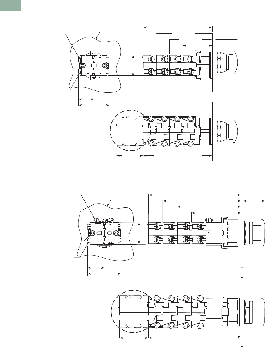
V7-T1-318 Volume 7—Logic Control, Operator Interface and Connectivity Solutions CA08100008E—March 2014 www.eaton.com
1
1
1
1
1
1
1
1
1
1
1
1
1
1
1
1
1
1
1
1
1
1
1
1
1
1
1
1
1
1
1.10
Pushbuttons and Indicating Lights
30.5 mm Watertight/Oiltight—HT800
Approximate Dimensions in Inches (mm)
Mushroom Head Pushbuttons and Round Head MRH Push-Pull Operators
Back, side and bottom views of mushroom head operator with attached contact blocks.
Illuminated and Non-Illuminated Flat Head MRH Push-Pull Operators
Back, side and bottom views of push-pull operator with attached contact blocks.
Notes
1Recommended maximum of four tandem stacks of contact blocks behind operator. At users’ discretion, two additional tandem stacks may be added.
2Contact blocks mount directly to operator adaptor in non-illuminated version.
4.60 (116.8)
Side View
1.40
(35.6)
Panel
Stacking Screw Torque:
12 in-lbs Max.
#6-32 Posi-drive
Saddle Clamp Type
1x16 AWG to 2x14 AWG
Terminal Torque:
12 in-lbs Max.
Copper Wire Only
3.70 (94.0)
2.90 (73.7)
1.50
(38.1)
2.00 (50.8)
Back View
1.0 0
(25.4)
2.00 (50.8)
Bottom View
Recommended 4 Stacks
(8 Contact Blocks Total)
Optional
2 Stacks
1
4.35 (110.5)
Side View
Back View
Bottom View
1.40
(35.6)
Panel
Stacking Screw Torque:
12 in-lbs Max.
Contact Block
#6-32 Posi-drive
Saddle Clamp Type
1x16 AWG to 2 x14 AWG
Terminal Torque:
12 in-lbs Max.
Copper Wire Only
Light Unit
#6-32 Posi-drive
Saddle Clamp Type
1x22 AWG to 2x14 AWG
Terminal Torque:
7 in-lbs Max.
Copper Wire Only
3.55 (90.2)
2.75 (69.9)
1.30
(33.0)
1.0 0
(25.4)
2.00 (50.8)
Recommended 4 Stacks
(8 Contact Blocks Total)
Optional
2 Stacks
5.15 (130.8)
1 2
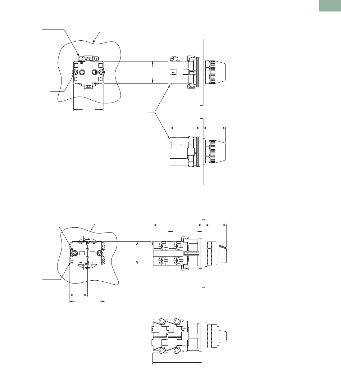
Volume 7—Logic Control, Operator Interface and Connectivity Solutions CA08100008E—March 2014 www.eaton.com V7-T1-319
1
1
1
1
1
1
1
1
1
1
1
1
1
1
1
1
1
1
1
1
1
1
1
1
1
1
1
1
1
1
1.10
Pushbuttons and Indicating Lights
30.5 mm Watertight/Oiltight—HT800
Approximate Dimensions in Inches (mm)
Indicating Lights
Back, side and bottom views of indicating light operator with attached contact blocks.
Selector Switches
Back, side and bottom views of selector switch operator with attached contact blocks.
Side View
Back View
Bottom View
1.30
(33.0)
Panel
Stacking Screw Torque:
12 in-lbs Max.
#6-32 Posi-drive
Saddle Clamp Type
1x22 AWG to 2x14 AWG
Terminal Torque:
7 in-lbs Max.
Copper Wire Only
1.67
(42.4)
Light Unit
Assembly
1.26
(32.0)
1.68
(42.7)
Side View
Back View
Bottom View
1.40
(35.6)
Panel
Stacking Screw Torque:
12 in-lbs Max.
#6-32 Posi-drive
Saddle Clamp Type
1x16 AWG to 2x14 AWG
Terminal Torque:
12 in-lbs Max.
Copper Wire Only
2.90 (73.7) 1.20
(38.1)
2.00 (50.8)
1.0 0
(25.4)
2.00 (50.8)
Recommended
2 Stacks
(4 Contact Blocks Total)
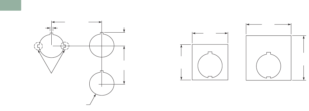
V7-T1-320 Volume 7—Logic Control, Operator Interface and Connectivity Solutions CA08100008E—March 2014 www.eaton.com
1
1
1
1
1
1
1
1
1
1
1
1
1
1
1
1
1
1
1
1
1
1
1
1
1
1
1
1
1
1
1.10
Pushbuttons and Indicating Lights
30.5 mm Watertight/Oiltight—HT800
Approximate Dimensions in Inches (mm)
Mounting Matrix and Minimum Panel Spacing Requirements Legend Plates
0.68
(17.3)
Optional Notch
Locations
1.20 (30.5)
Diameter
2.50
(63.5)
2.50 (63.5)
0.18 (4.6)
2.19
(55.6)
Jumbo
1.77
(45)
Standard
2.19
(55.6)
1.77
(45)
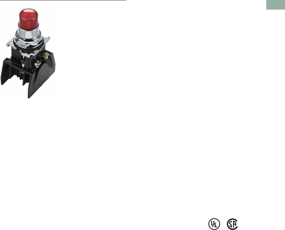
Volume 7—Logic Control, Operator Interface and Connectivity Solutions CA08100008E—March 2014 www.eaton.com V7-T1-321
1
1
1
1
1
1
1
1
1
1
1
1
1
1
1
1
1
1
1
1
1
1
1
1
1
1
1
1
1
1
1.11
Pushbuttons and Indicating Lights
30.5 mm Class I Division 2 Hazardous Locations—10250T/E34
30.5 mm Class I Division 2 Hazardous Locations—10250T/E34
Contents
Description Page
30.5 mm Class I Division 2 Hazardous Locations—
10250T/E34
Product Overview . . . . . . . . . . . . . . . . . . . . . . . V7-T1-322
Product Identification . . . . . . . . . . . . . . . . . . . . V7-T1-323
Catalog Number Selection . . . . . . . . . . . . . . . . V7-T1-323
Product Selection
Momentary Pushbutton Units . . . . . . . . . . . V7-T1-324
Non-Illuminated Pushbutton Units . . . . . . . V7-T1-328
Illuminated Pushbutton Units . . . . . . . . . . . V7-T1-330
Guarded Illuminated Pushbutton Units . . . . V7-T1-331
Indicating Light Units . . . . . . . . . . . . . . . . . V7-T1-332
Illuminated Pushbuttons and
Indicating Lights . . . . . . . . . . . . . . . . . . . . V7-T1-333
Push-Pull Units . . . . . . . . . . . . . . . . . . . . . . V7-T1-335
Illuminated Push-Pull Units . . . . . . . . . . . . . V7-T1-337
Push-Pull Operators . . . . . . . . . . . . . . . . . . . V7-T1-340
Selector Switch Units . . . . . . . . . . . . . . . . . V7-T1-344
Selector Switch Selection . . . . . . . . . . . . . . V7-T1-346
Selector Switch Operators . . . . . . . . . . . . . V7-T1-349
Illuminated Selector Switch Operators . . . . V7-T1-352
Options . . . . . . . . . . . . . . . . . . . . . . . . . . . . . . . V7-T1-354
Technical Data and Specifications . . . . . . . . . . V7-T1-357
Dimensions . . . . . . . . . . . . . . . . . . . . . . . . . . . V7-T1-359
Ratings . . . . . . . . . . . . . . . . . . . . . . . . . . . . . . . V7-T1-360
Product Description
All the Industry-Proven
Quality of Eaton’s 10250T and
E34 Series of Logic Devices,
plus Class I Division 2
Certification
The 10250T1H consists of a
normally open-normally
closed factory sealed contact
block that is UL Listed for use
in Class I, Division 2, Groups
B, C and D (NEC 500–503)—
Class I, Zone 2, IIB + H2 (NEC
505) hazardous locations and
is rated for both NEMA A600
and NEMA Q300. 10250T and
E34 illuminated components
have also been UL Listed for
use in Class I, Division 2,
Groups B, C and D (NEC 500–
503)—Class I, Zone 2, IIB +
H2 (NEC 505).
This, combined with the
industry-proven Eaton
10250T 30.5 mm pushbutton
line, offers a complete
solution to Division 2
hazardous location
requirements.
Single composite catalog
numbers for complete
assembled stations and
operators for use in Division 2
hazardous locations are
featured throughout this
section.
Features
●Factory sealed contact
blocks
●Heavy-duty zinc die cast
construction
●NEMA rated 1, 2, 3, 3R, 4,
4X, 12, 13
●Front-of-panel drainage
holes
●Grounding nibs on the
operator casing
●Solid thermosetting
cathodic epoxy coating on
E34
●Corrosion resistance in E34
Benefits
●Pushbutton for hazardous
locations
●Drainage holes prevent
buildup of liquid inside the
operator which can prevent
operation in freezing
environments
●Grounding nibs bite
through paint and other
coatings to provide secure
ground
●Suitable for corrosive
environments (E34 only)
●Earth terminal provides
additional grounding point
and allows for daisy chain
grounding (E34 line)
Standards and
Certifications
●UL 508—File No. E131568
●UL 1604—File No. E10323
●CSA Certified C22.2
No.14—File No. LR 68551
●CSA Certified C22.2 No.
213-M1987—File No. LR
20713
Ingress Protection
●Standard indicating lights
●UL (NEMA) Type 3, 3R,
3S, 4, 4X, 12, 13
●IEC IP65
●All other operators
●UL (NEMA) Type 3, 3R,
4, 4X, 12, 13
●IEC IP65
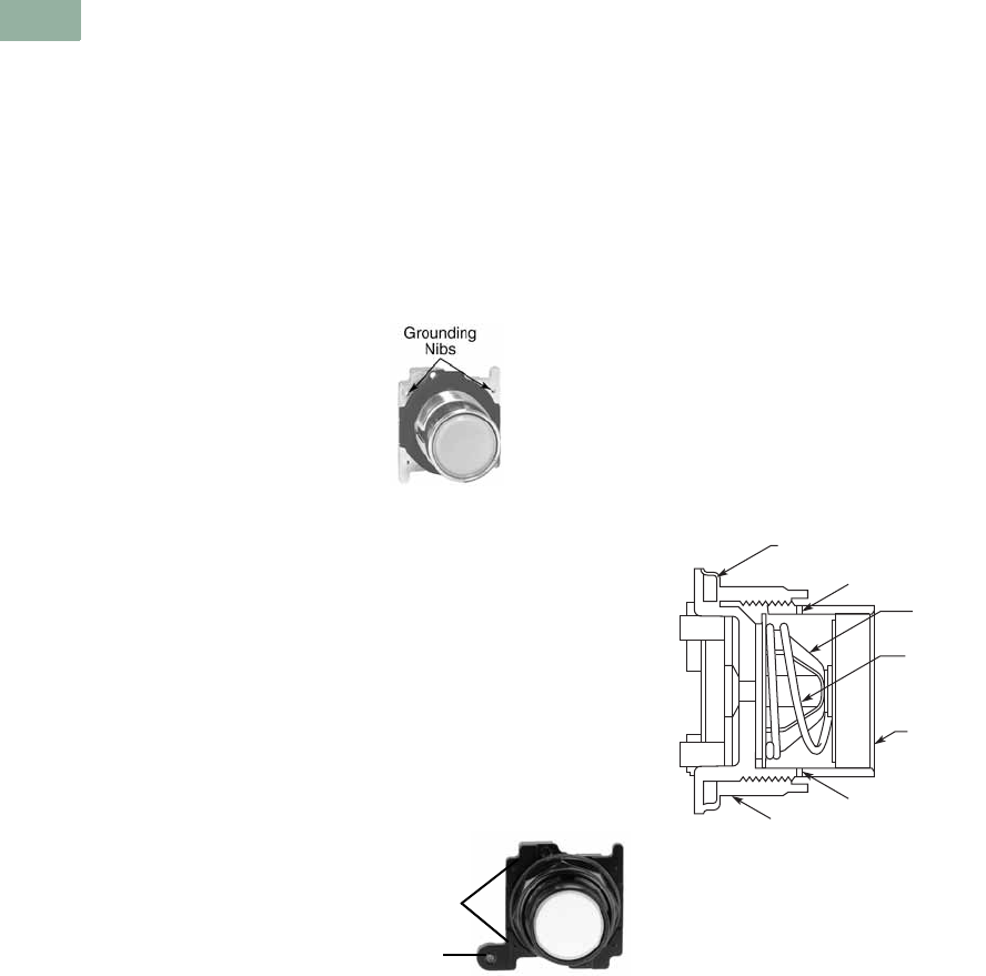
V7-T1-322 Volume 7—Logic Control, Operator Interface and Connectivity Solutions CA08100008E—March 2014 www.eaton.com
1
1
1
1
1
1
1
1
1
1
1
1
1
1
1
1
1
1
1
1
1
1
1
1
1
1
1
1
1
1
1.11
Pushbuttons and Indicating Lights
30.5 mm Class I Division 2 Hazardous Locations—10250T/E34
Product Overview
Operator
The 30.5 mm 10250T
pushbutton line features a
zinc die cast construction with
chrome-plated housing and
mounting nut.
Eaton’s E34 Series 30.5 mm
pushbutton line features the
same rugged die cast
construction of our 10250T
line with an additional two-
layer 100% solid thermosetting
cathodic epoxy coating. This
coating provides a flat black
smooth, consistent, corrosion
resistant surface that has
passed a demanding 600 hour
salt spray test. (The industry
standard for this 4X test
requires only 200 hours.)
Ultraviolet Light
E34 epoxy coating is not
recommended for use in
applications where exposure
to ultraviolet light exists—use
NEMA 4X 10250T operators.
Ratings
Our Class I Division 2 line of
pushbuttons are UL Listed
(NEMA type) 1, 2, 3, 3R, 4,
4X, 12 and 13. Our Class I
Division 2 E34 line meets IEC
947-1 IP66 standards and the
cathodic coating meets FDA
3A sanitary chemical
resistance requirements.
For a complete listing of all
applicable ratings see
Pages V7-T1-357 to
V7-T1-358.
10250T Grounding Nibs
10250T line operators have
“grounding nibs”—four metal
points on the operator casting
designed to bite through
most paints and other
coatings on metal panels to
enhance the grounding
connection when the
operator is securely
tightened.
10250T Grounding Nibs
E34 Grounding Nibs
E34 line of operators is
equipped with a ground
screw terminal as part of its
die cast construction. This
earthing terminal provides an
easily accessible point for
grounding operators when
used in a painted or
nonmetallic enclosure and
eliminates the need for extra
kits when daisy chain
grounding is required.
E34 Grounding Nibs
Nib
Earth
Ter min a l
Diaphragm Seal with
Drainage Holes
Liquid Drainage
Eaton’s pushbutton operators
offer front of panel drainage
via holes in the operator
bushing. Hidden from view by
the mounting nut, these
holes prevent buildup of liquid
inside the operator, which
can prevent operation in
freezing environments. The
holes also provide a route for
escaping liquid in high
pressure washdowns,
effectively relieving pressure
from the internal diaphragm
seal, ensuring reliable sealing
in applications even beyond
NEMA 4.
Diaphragm Seal
Foam Neoprene
Panel Sealing Gasket
Drainage Hole
Drainage Hole
Flexible
Diaphragm
Stainless
Steel
Operating
Spring
Mounting Nut
Colorfast
Molded
Button
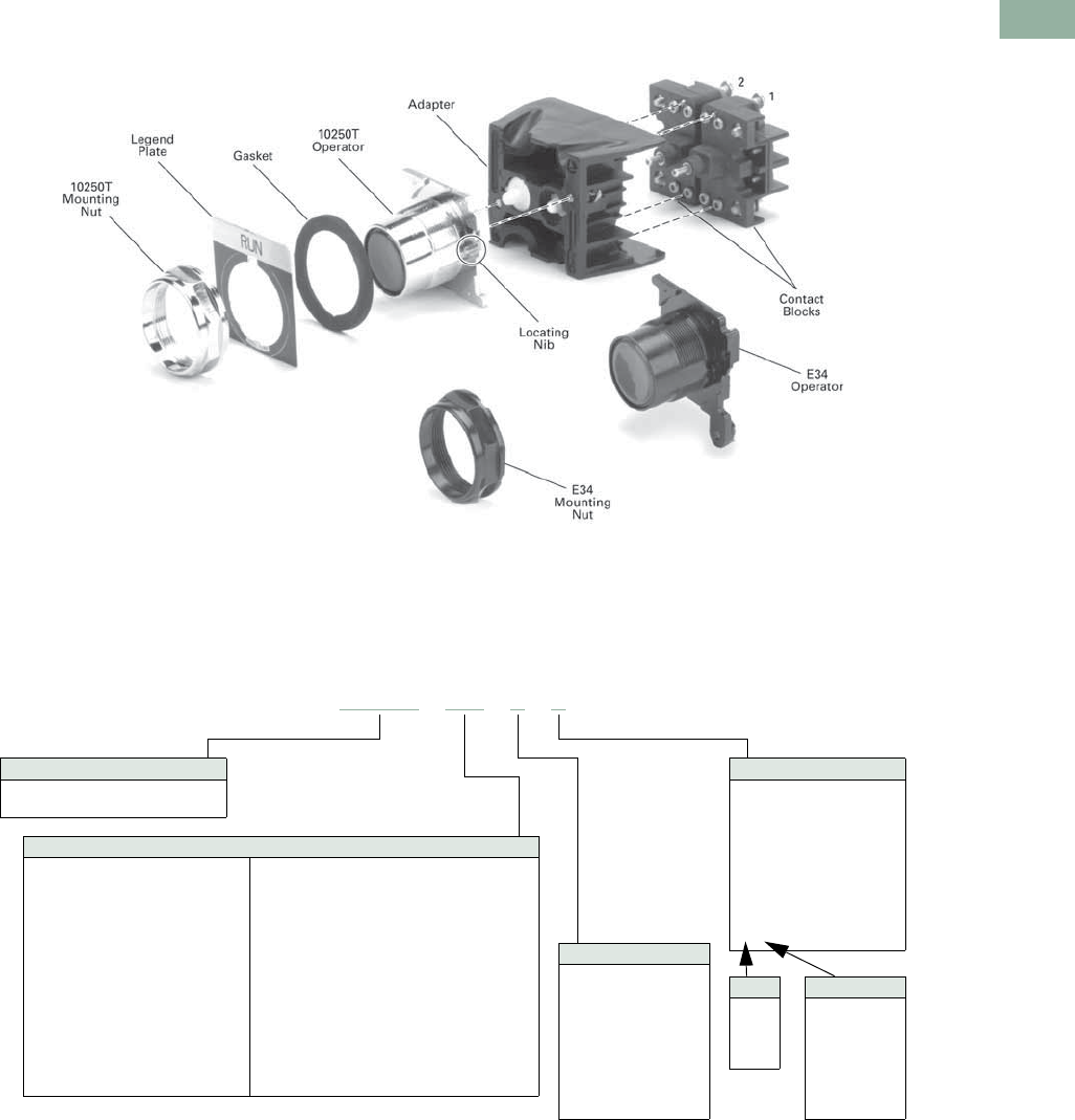
Volume 7—Logic Control, Operator Interface and Connectivity Solutions CA08100008E—March 2014 www.eaton.com V7-T1-323
1
1
1
1
1
1
1
1
1
1
1
1
1
1
1
1
1
1
1
1
1
1
1
1
1
1
1
1
1
1
1.11
Pushbuttons and Indicating Lights
30.5 mm Class I Division 2 Hazardous Locations—10250T/E34
Product Identification
30.5 mm Class I Division 2 Hazardous Locations
Catalog Number Selection
Catalog Number Selection is for illustrative purposes only and not to be used to create new catalog numbers.
Non-Illuminated Assembled Operators
ACC/SS Type
Blank = None
J = JMB push-pull
B = Booted-FL/EXT
G = Guarded-FL
K = Knob-SS
L = Lever-SS
A = Lever W/IP-SS
C = Coin-SS
Keyed-SS
——
Cam
1
2
3
7
Button Color
B= Black
R= Red
G= Green
Y= Yellow
W= White
L= Blue
N= Orange
E= Red EMERG. STOP
T= Keyed-SS
Key Removal
1 = RT only
2 = LT only
3 = RT and LT
4 = CT only
5 = RT and CT
6 = LT and CT
7 = All
Operator and Contact Block
706 = Flush 1NO-1NC
707 = Flush 2NO-2NC
708 = Extended 1NO-1NC
709 = Extended 2NO-2NC
710 = Mushroom 1NO-1NC
711 = Mushroom 2NO-2NC
712 = JMB mushroom 1NO-1NC
713 = JMB mushroom 2NO-2NC
714 = 2P MT push-pull 1NO-1NC
715 = 2P MT push-pull 2NO-2NC
716 = 3P MT push-mom pull 1NO-1NC
717 = 3P MT push-mom pull 2NO-2NC
718 = 3P mom push-pull 1NO-1NC
721 = 3P mom push-pull 2NO-2NC
722 = 2P SS MT XO,OX-CAM1
723 = 2P SS MT XO,OX,XO,OX-CAM1
724 = 2P SS SPR-R XO,OX-CAM1
725 = 2P SS SPR-R XO,OX,XO,OX-CAM1
726 = 3P SS MT XOO,OOX-CAM3
727 = 3P SS MT XOO,OXO,OOX-CAM3
728 = 3P SS SPR-L XOO,OOX-CAM3
729 = 3P SS SPR-L XOO,OXO,OOX-CAM3
730 = 3P SS SPR-L&R XOO,OOX-CAM3
731 = 3P SS SPR-L&R XOO,OXO,OOX-CAM3
732 = 3P SS SPR-R XOO,OOX-CAM3
733 = 3P SS SPR-R XOO,OXO,OOX-CAM3
743 = 4P SS MT XOOO,OXOO,OOXO,OOOX-CAM7
Operator Type
10250T = Heavy-duty oiltight
E34EX = Corrosion resistant oiltight
10250T 718 E J
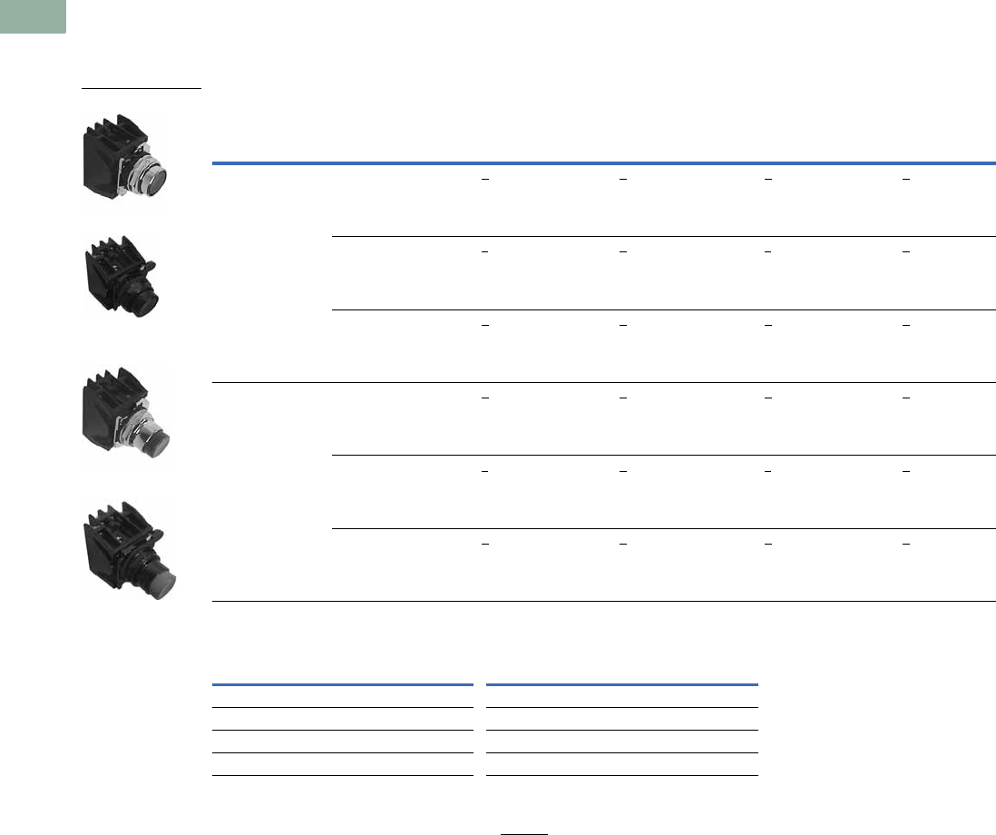
V7-T1-324 Volume 7—Logic Control, Operator Interface and Connectivity Solutions CA08100008E—March 2014 www.eaton.com
1
1
1
1
1
1
1
1
1
1
1
1
1
1
1
1
1
1
1
1
1
1
1
1
1
1
1
1
1
1
1.11
Pushbuttons and Indicating Lights
30.5 mm Class I Division 2 Hazardous Locations—10250T/E34
Product Selection
Momentary Pushbutton Units
UL (NEMA) Type 3, 3R, 4, 4X, 12, 13, NEC Class I Division 2, Groups B, C and D
Non-Illuminated Flush and Extended Pushbuttons
Color Selection
Notes
Use NEMA 4X 10250T operators where exposed to ultraviolet light.
1 To order different color guarded button, simply substitute the underlined character in catalog number with
appropriate suffix code from Color Selection table above. Example: 10250T710Y.
2 Blue not available on jumbo mushroom pushbutton.
3 Orange is only available on flush or extended pushbuttons.
4 Red with EMERG. STOP engraved on button head for jumbo mushroom pushbutton only.
Contact Type
Button
Color 1
Flush Button Extended Button
10250T
Catalog Number
E34
Catalog Number
10250T
Catalog Number
E34
Catalog Number
1NO-1NC Black 10250T706B E34EX706B 10250T708B E34EX708B
Red 10250T706R E34EX706R 10250T708R E34EX708R
Green 10250T706G E34EX706G 10250T708G E34EX708G
2NO-2NC Black 10250T707B E34EX707B 10250T709B E34EX709B
Red 10250T707R E34EX707R 10250T709R E34EX709R
Green 10250T707G E34EX707G 10250T709G E34EX709G
Color Suffix Code Color Suffix Code
Black BWhite W
Red RBlue L 2
Green GOrange 3N
Yellow YRed (EMERG. STOP) 4E
10250T Flush Button
E34 Flush Button
10250T Extended
Button
E34 Extended Button
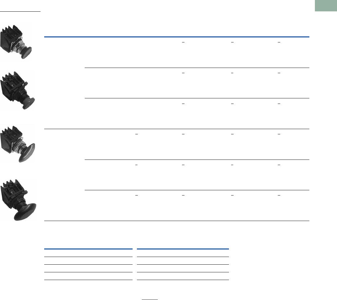
Volume 7—Logic Control, Operator Interface and Connectivity Solutions CA08100008E—March 2014 www.eaton.com V7-T1-325
1
1
1
1
1
1
1
1
1
1
1
1
1
1
1
1
1
1
1
1
1
1
1
1
1
1
1
1
1
1
1.11
Pushbuttons and Indicating Lights
30.5 mm Class I Division 2 Hazardous Locations—10250T/E34
UL (NEMA) Type 3, 3R, 4, 4X, 12, 13, NEC Class I Division 2, Groups B, C and D
Non-Illuminated Mushroom and Jumbo Mushroom Pushbuttons
Color Selection
Notes
Use NEMA 4X 10250T operators where exposed to ultraviolet light.
1 To order different color guarded button, simply substitute the underlined character in catalog number with
appropriate suffix code from Color Selection table above. Example: 10250T710Y.
2 Anodized aluminum head is not suitable for use in ultraviolet applications.
3 Blue not available on jumbo mushroom pushbutton.
4 Orange is only available on flush or extended pushbuttons.
5 Red with EMERG. STOP engraved on button head for jumbo mushroom pushbutton only.
Contact Type
Button
Color 1
Mushroom Button Jumbo Mushroom Button
10250T
Catalog Number
E34
Catalog Number
10250T 2
Catalog Number
E34 2
Catalog Number
1NO-1NC Black 10250T710B E34EX710B 10250T712B E34EX712B
Red 10250T710R E34EX710R 10250T712R E34EX712R
Green 10250T710G E34EX710G 10250T712G E34EX712G
2NO-2NC Black 10250T711B E34EX711B 10250T713B E34EX713B
Red 10250T711R E34EX711R 10250T713R E34EX713R
Green 10250T711G E34EX711G 10250T713G E34EX713G
Color Suffix Code Color Suffix Code
Black BWhite W
Red RBlue L 3
Green GOrange 4N
Yellow YRed (EMERG. STOP) 5E
10250T Mushroom
Button
E34 Mushroom Button
10250T Jumbo
Mushroom Button
E34 Jumbo Mushroom
Button
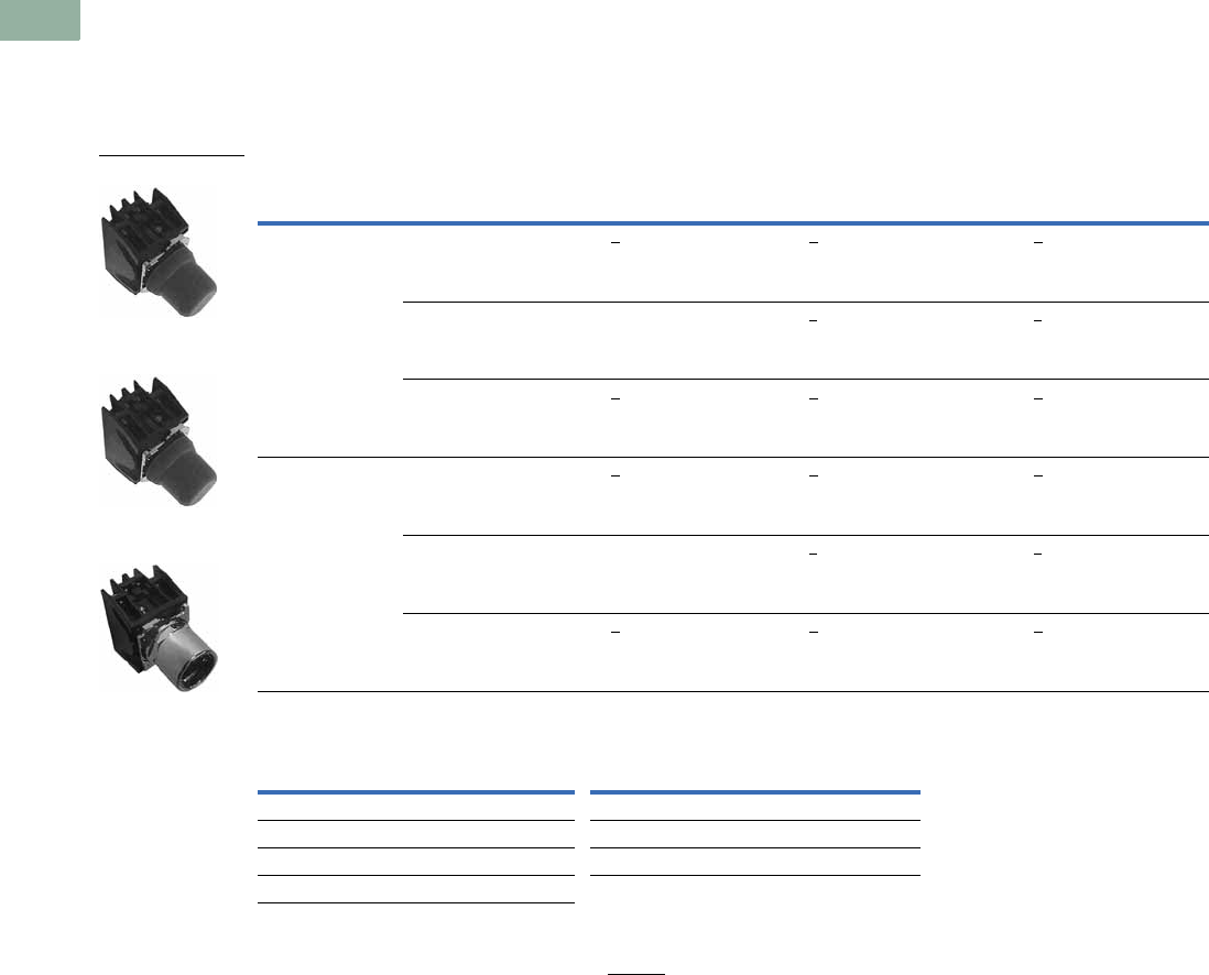
V7-T1-326 Volume 7—Logic Control, Operator Interface and Connectivity Solutions CA08100008E—March 2014 www.eaton.com
1
1
1
1
1
1
1
1
1
1
1
1
1
1
1
1
1
1
1
1
1
1
1
1
1
1
1
1
1
1
1.11
Pushbuttons and Indicating Lights
30.5 mm Class I Division 2 Hazardous Locations—10250T/E34
UL (NEMA) Type 3, 3R, 4, 4X, 12, 13, NEC Class I Division 2, Groups B, C and D
●Momentary contact
●Non-illuminated
●Booted or guarded
10250T Pushbuttons Booted and Guarded
Color Selection
Notes
Use NEMA 4X 10250T operators where exposed to ultraviolet light.
1 To order different color guarded button, simply substitute the underlined character in catalog number with
appropriate suffix code from Color Selection table above. Example: 10250T706YG.
2 Red booted flush pushbutton is not recommended for STOP function.
Contact Type Button Color
Booted Flush Button
Catalog Number
Booted Extended Button
Catalog Number
Guarded Extended Button 1
Catalog Number
1NO-1NC Black 10250T706BB 10250T708BB 10250T706BG
Red 10250T706RB 210250T708RB 10250T706RG
Green 10250T706GB 10250T708GB 10250T706GG
2NO-2NC Black 10250T707BB 10250T709BB 10250T707BG
Red 10250T707RB 210250T709RB 10250T707RG
Green 10250T707GB 10250T709GB 10250T707GG
Color Suffix Code Color Suffix Code
Black BWhite W
Red RBlue L
Green GOrange N
Yellow Y
Guarded Extended
Button
Booted Extended
Button
Booted Flush Button
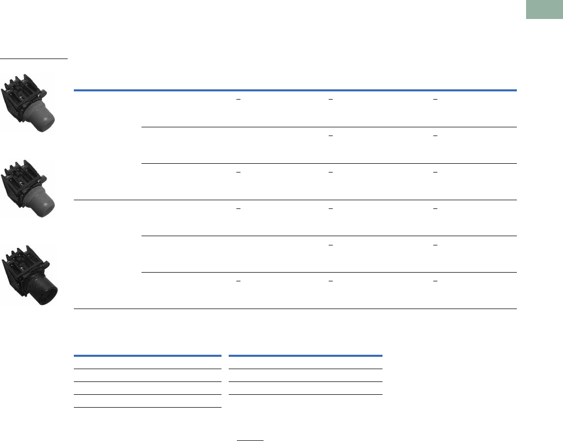
Volume 7—Logic Control, Operator Interface and Connectivity Solutions CA08100008E—March 2014 www.eaton.com V7-T1-327
1
1
1
1
1
1
1
1
1
1
1
1
1
1
1
1
1
1
1
1
1
1
1
1
1
1
1
1
1
1
1.11
Pushbuttons and Indicating Lights
30.5 mm Class I Division 2 Hazardous Locations—10250T/E34
UL (NEMA) Type 3, 3R, 4, 4X, 12, 13, NEC Class I Division 2, Groups B, C and D
●Momentary contact
●Non-illuminated
●Booted or guarded
E34 Pushbuttons Booted and Guarded
Color Selection
Notes
Use NEMA 4X 10250T operators where exposed to ultraviolet light.
1 To order different color guarded button, simply substitute the underlined character in catalog number with
appropriate suffix code from Color Selection table above. Example: 10250T706YG.
2 Red booted flush pushbutton is not recommended for STOP function.
Contact Type Button Color
Booted Flush Button
Catalog Number
Booted Extended Button
Catalog Number
Guarded Extended Button 1
Catalog Number
1NO-1NC Black E34EX706BB E34EX708BB E34EX706BG
Red E34EX706RB 2E34EX708RB E34EX706RG
Green E34EX706GB E34EX708GB E34EX706GG
2NO-2NC Black E34EX707BB E34EX709BB E34EX707BG
Red E34EX707RB 2E34EX709RB E34EX707RG
Green E34EX707GB E34EX709GB E34EX707GG
Color Suffix Code Color Suffix Code
Black BWhite W
Red RBlue L
Green GOrange N
Yellow Y
Booted Flush Button
Booted Extended
Button
Guarded Extended
Button
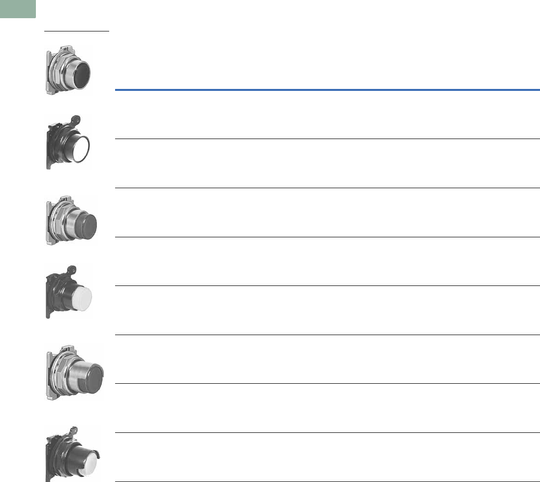
V7-T1-328 Volume 7—Logic Control, Operator Interface and Connectivity Solutions CA08100008E—March 2014 www.eaton.com
1
1
1
1
1
1
1
1
1
1
1
1
1
1
1
1
1
1
1
1
1
1
1
1
1
1
1
1
1
1
1.11
Pushbuttons and Indicating Lights
30.5 mm Class I Division 2 Hazardous Locations—10250T/E34
Non-Illuminated Pushbutton Units
UL (NEMA) Type 3, 3R, 4, 4X, 12, and 13
Non-Illuminated Pushbuttons, Momentary Contact
Notes
Use NEMA 4X 10250T operators where exposed to ultraviolet light.
1 To order operator with factory assembled extended retaining nut, 10250TA12, for thick panel applications, add suffix letter E to listed catalog number.
Color
Half Shrouded Button
Flush Button Extended Button 10250T E34
10250T 1
Catalog
Number
E34
Catalog
Number
10250T
Catalog
Number
E34
Catalog
Number
Vertical
Catalog
Number
Horizontal
Catalog
Number
Vertical
Catalog
Number
Horizontal
Catalog
Number
Black 10250T101 E34PB1 10250T111 E34EB1 10250T501 10250T511 E34EVB1 E34EHB1
Red 10250T102 E34PB2 10250T112 E34EB2 10250T502 10250T512 E34EVB2 E34EHB2
Green 10250T103 E34PB3 10250T113 E34EB3 10250T503 10250T513 E34EVB3 E34EHB3
Yellow 10250T104 E34PB4 10250T120 E34EB4 10250T504 10250T514 E34EVB4 E34EHB4
Gray 10250T105 E34PB5 — E34EB5 10250T505 10250T515 E34EVB5 E34EHB5
White 10250T106 E34PB6 10250T116 E34EB6 10250T506 10250T516 E34EVB6 E34EHB6
Blue 10250T108 E34PB7 10250T118 E34EB7 10250T508 10250T518 E34EVB7 E34EHB7
Orange 10250T109 E34PB8 10250T119 E34EB8 10250T509 10250T519 E34EVB8 E34EHB8
10250T Flush Button
E34 Flush Button
10250T Extended
Button
E34 Extended Button
10250T Half Shrouded
Button
E34 Half Shrouded
Button
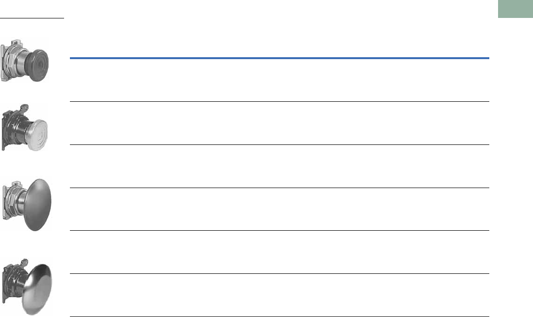
Volume 7—Logic Control, Operator Interface and Connectivity Solutions CA08100008E—March 2014 www.eaton.com V7-T1-329
1
1
1
1
1
1
1
1
1
1
1
1
1
1
1
1
1
1
1
1
1
1
1
1
1
1
1
1
1
1
1.11
Pushbuttons and Indicating Lights
30.5 mm Class I Division 2 Hazardous Locations—10250T/E34
UL (NEMA) Type 3, 3R, 4, 4X, 12, and 13
Mushroom Head Non-Illuminated Pushbuttons, Momentary Contact
Notes
Use NEMA 4X 10250T operators where exposed to ultraviolet light.
1 Anodized aluminum head is not suitable for use in ultraviolet light applications.
2 Anodized aluminum head may not be suitable for some corrosive environments.
Color
Mushroom Button Anodized Aluminum Jumbo Mushroom Button
10250T
Catalog Number
E34
Catalog Number
10250T 1
Catalog Number
E34 2
Catalog Number
Black 10250T121 E34LB1 10250T171 E34JB1
Red 10250T122 E34LB2 10250T172 E34JB2
Red (EMERG. STOP) — — 10250T17213 E34JB2N8
Green 10250T123 E34LB3 10250T173 E34JB3
Yellow 10250T124 E34LB4 10250T174 E34JB4
Blue 10250T129 E34LB6 — —
10250T Mushroom
Button
E34 Mushroom Button
10250T Jumbo
Mushroom Button
E34 Jumbo Mushroom
Button
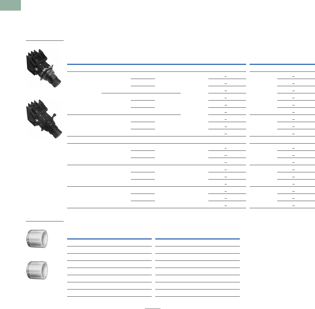
V7-T1-330 Volume 7—Logic Control, Operator Interface and Connectivity Solutions CA08100008E—March 2014 www.eaton.com
1
1
1
1
1
1
1
1
1
1
1
1
1
1
1
1
1
1
1
1
1
1
1
1
1
1
1
1
1
1
1.11
Pushbuttons and Indicating Lights
30.5 mm Class I Division 2 Hazardous Locations—10250T/E34
Illuminated Pushbutton Units
UL (NEMA) Type 3, 3R, 4, 4X, 12, 13, NEC Class I Division 2, Groups B, C and D
●Momentary contact
●Illuminated
●Plastic lenses
Illuminated Pushbuttons
Lens Selection
Note
1 To order different color lens, simply substitute the underlined character in the catalog number with appropriate
suffix code from Lens Selection table above. Example: 10250T828YD24.
Type Voltage Color Contact
10250T E34
LED/Lamp
Number Catalog Number 1
LED/Lamp
Number Catalog Number 1
LED Lamp
Full voltage 24 Vac/Vdc Red 1NO-1NC Bayonet
base
10250T828RD24 Bayonet
base
E34EX828RD24
Green 10250T828GD24 E34EX828GD24
Amber 10250T828AD24 E34EX828AD24
120 Vac Red 1NO-1NC 10250T828RD2A E34EX828RD2A
Green 10250T828GD2A E34EX828GD2A
Amber 10250T828AD2A E34EX828AD2A
Transformer 120 Vac Red 1NO-1NC 10250T802RD06 Bayonet
base
6 Vac
E34EX802RD06
Green 10250T802GD06 E34EX802GD06
Amber 10250T802AD06 E34EX802AD06
Incandescent Lamp
Full voltage 24 Vac/Vdc Red 1NO-1NC #757 10250T818RD#757 E34EX818RD
Green 10250T818GD E34EX818GD
Amber 10250T818AD E34EX818AD
Resistor 120 Vac/Vdc Red 1NO-1NC 120MB 10250T824RD120MB E34EX824RD
Green 10250T824GD E34EX824GD
Amber 10250T824AD E34EX824AD
Transformer 120 Vac Red 1NO-1NC #755 10250T802RD#755
6 Vac
E34EX802RD
Green 10250T802GD E34EX802GD
Amber 10250T802AD E34EX802AD
Color
Suffix
Code Catalog Number Color
Suffix
Code Catalog Number
10250T E34
Red R 10250TC21 Red R E34V2
Green G 10250TC22 Green G E34V3
Yellow Y 10250TC23 Yellow Y E34V4
Amber A 10250TC43 Amber A E34V9
Blue L 10250TC24 Blue L E34V6
Clear C 10250TC25 Clear C E34V0
White W 10250TC26 White W E34V5
10250T8_
E34EX8_
10250TC_
E34V _
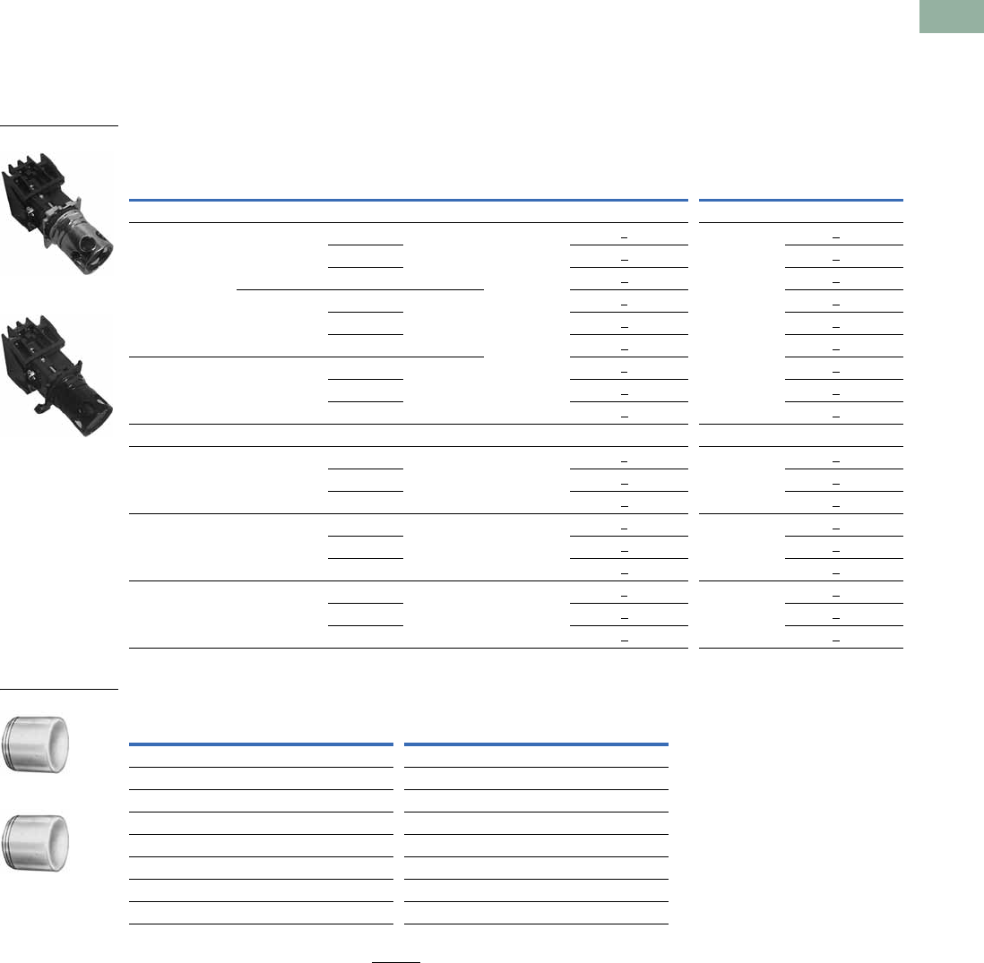
Volume 7—Logic Control, Operator Interface and Connectivity Solutions CA08100008E—March 2014 www.eaton.com V7-T1-331
1
1
1
1
1
1
1
1
1
1
1
1
1
1
1
1
1
1
1
1
1
1
1
1
1
1
1
1
1
1
1.11
Pushbuttons and Indicating Lights
30.5 mm Class I Division 2 Hazardous Locations—10250T/E34
Guarded Illuminated Pushbutton Units
UL (NEMA) Type 3, 3R, 4, 4X, 12, 13, NEC Class I Division 2, Groups B, C and D
●Momentary contact
●Guarded illuminated
●Plastic lenses
Guarded Illuminated Pushbuttons
Lens Selection
Note
1 To order different color lens, simply substitute the underlined character in the catalog number with appropriate
suffix code from Lens Selection table above. Example: 10250T828YD24.
Type Voltage Color Contact
10250T E34
LED/Lamp
Number Catalog Number 1
LED/Lamp
Number Catalog Number 1
LED Lamp
Full voltage 24 Vac/Vdc Red 1NO-1NC Bayonet
base
10250T828RG24 Bayonet
base
E34EX828RG24
Green 10250T828GG24 E34EX828GG24
Amber 10250T828AG24 E34EX828AG24
120 Vac Red 1NO-1NC 10250T828RG2A E34EX828RG2A
Green 10250T828GG2A E34EX828GG2A
Amber 10250T828AG2A E34EX828AG2A
Transformer 120 Vac Red 1NO-1NC 10250T802RG06 E34EX802RG06
Green 10250T802GG06 E34EX802GG06
Amber 10250T802AG06 E34EX802AG06
Incandescent Lamp
Full voltage 24 Vac/Vdc Red 1NO-1NC #757 10250T818RG#757 E34EX818RG
Green 10250T818GG E34EX818GG
Amber 10250T818AG E34EX818AG
Resistor 120 Vac/Vdc Red 1NO-1NC 120MB 10250T824RG120MB E34EX824RG
Green 10250T824GG E34EX824GG
Amber 10250T824AG E34EX824AG
Transformer 120 Vac Red 1NO-1NC #755 10250T802RG#755
6 Vac
E34EX802RG
Green 10250T802GG E34EX802GG
Amber 10250T802AG E34EX802AG
Color
Suffix
Code Catalog Number Color
Suffix
Code Catalog Number
10250T E34
Red R 10250TC21 Red R E34V2
Green G 10250TC22 Green G E34V3
Yellow Y 10250TC23 Yellow Y E34V4
Amber A 10250TC43 Amber A E34V9
Blue L 10250TC24 Blue L E34V6
Clear C 10250TC25 Clear C E34V0
White W 10250TC26 White W E34V5
10250T8_
E34EX8_
10250TC2_
E34V_
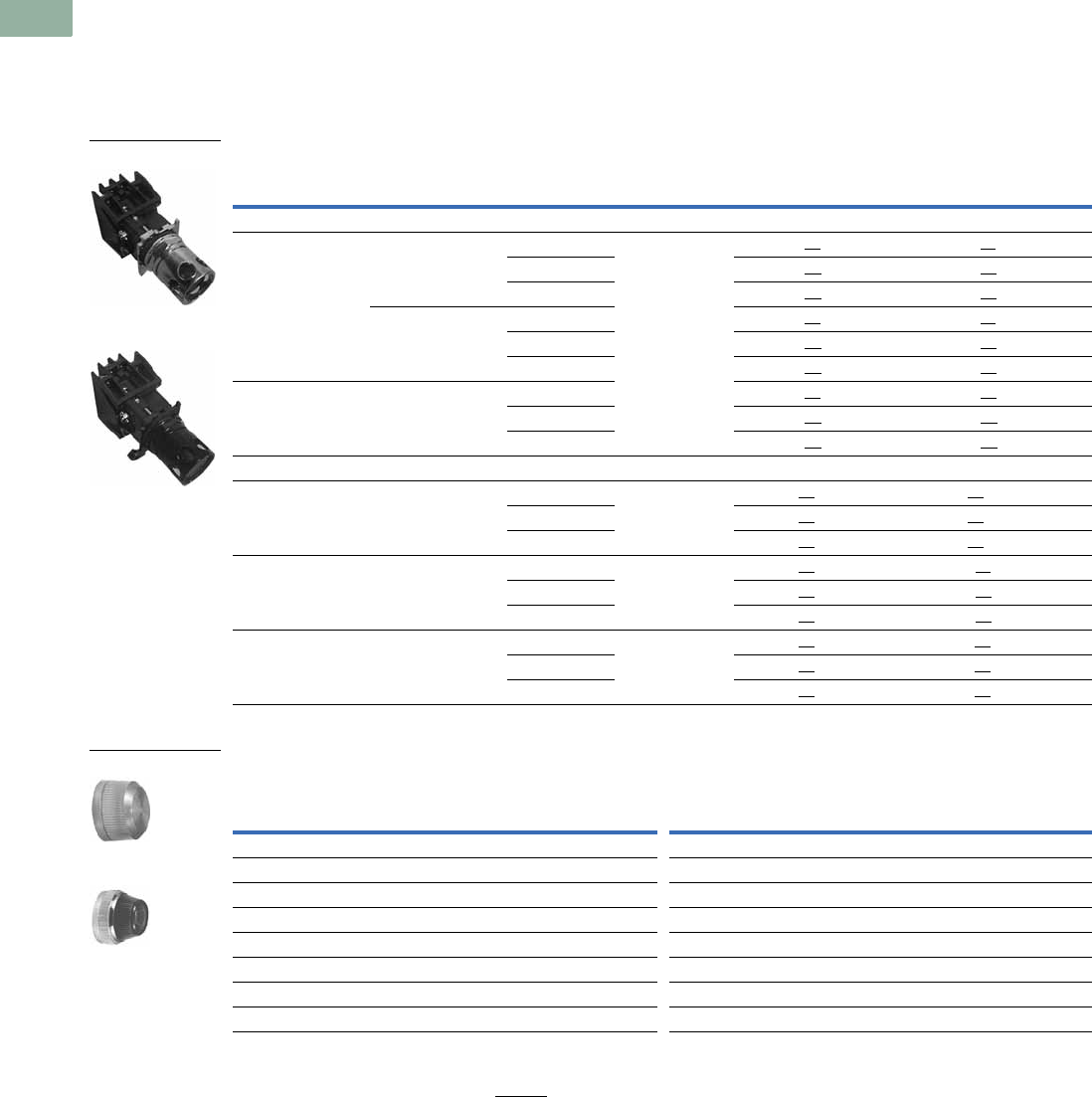
V7-T1-332 Volume 7—Logic Control, Operator Interface and Connectivity Solutions CA08100008E—March 2014 www.eaton.com
1
1
1
1
1
1
1
1
1
1
1
1
1
1
1
1
1
1
1
1
1
1
1
1
1
1
1
1
1
1
1.11
Pushbuttons and Indicating Lights
30.5 mm Class I Division 2 Hazardous Locations—10250T/E34
Indicating Light Units
UL (NEMA) Type 3, 3R, 3S, 4, 4X, 12, 13, NEC Class I Division 2, Groups B, C and D
●Standard
●Plastic lenses
Indicating Lights
Lens Selection
Notes
Use NEMA 4X 10250T operators where exposed to ultraviolet light.
1 To order different color lens, simply substitute the underlined characters in the catalog number with appropriate suffix code from the Lens Selection table above.
Example: 10250T201HYP.
Type Voltage Color
LED/Lamp
Number
10250T E34
Catalog Number 1Catalog Number 1
LED Lamp
Full voltage 24 Vac/Vdc Red Bayonet
base
10250T197HLRP24 E34FB197HLRP24
Green 10250T197HLGP24 E34FB197HLGP24
Amber 10250T197HLAP24 E34FB197HLAP24
120 Vac Red 10250T197HLRP2A E34FB197HLRP2A
Green 10250T197HLGP2A E34FB197HLGP2A
Amber 10250T197HLAP2A E34FB197HLAP2A
Transformer 120 Vac Red 10250T181HLRP06 E34TB120HLRP06
Green 10250T181HLGP06 E34TB120HLGP06
Amber 10250T181HLAP06 E34TB120HLAP06
Incandescent Lamp
Full voltage 24 Vac/Vdc Red #757 10250T206HRP E34FB24HRP
Green 10250T206HGP E34FB24HGP
Amber 10250T206HAP E34FB24HAP
Resistor 120 Vac/Vdc Red 120MB 10250T201HRP E34RB120HRP
Green 10250T201HGP E34RB120HGP
Amber 10250T201HAP E34RB120HAP
Transformer 120 Vac Red #755 10250T181HRP E34TB120HRP
Green 10250T181HGP E34TB120HGP
Amber 10250T181HAP E34TB120HAP
Color
Plastic Glass
Color
Plastic Glass
Suffix
Code Catalog Number
Suffix
Code Catalog Number
Suffix
Code Catalog Number
Suffix
Code Catalog Number
10250T E34
Red RP 10250TC1N RG 10250TC7N Red RP E34H2 RG E34G2
Green GP 10250TC2N GG 10250TC8N Green GP E34H3 GG E34G3
Amber AP 10250TC19N AG 10250TC9N Amber AP E34H9 AG E34G9
Yellow YP 10250TC3N — — Yellow YP E34H4 YG E34G4
Blue LP 10250TC4N LG 10250TC10N Blue LP E34H6 LG E34G6
Clear CP 10250TC5N CG 10250TC11N Clear CP E34H0 CG E34G0
White WP 10250TC6N WG 10250TC12N White WP E34H5 WG E34G5
10250T_
E34_
Glass
Plastic
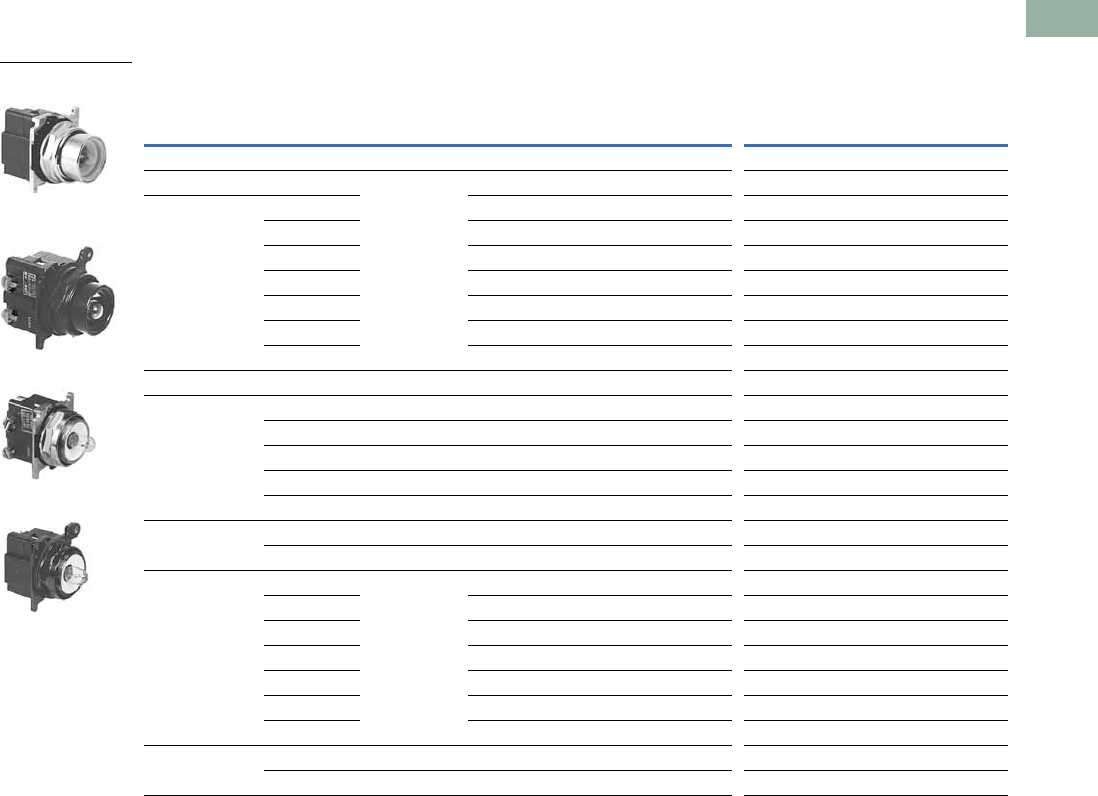
Volume 7—Logic Control, Operator Interface and Connectivity Solutions CA08100008E—March 2014 www.eaton.com V7-T1-333
1
1
1
1
1
1
1
1
1
1
1
1
1
1
1
1
1
1
1
1
1
1
1
1
1
1
1
1
1
1
1.11
Pushbuttons and Indicating Lights
30.5 mm Class I Division 2 Hazardous Locations—10250T/E34
Illuminated Pushbuttons and Indicating Lights
NEC Class I Division 2, Groups B, C and D
Operators without Lenses
Notes
Use NEMA 4X 10250T operators where exposed to ultraviolet light.
1 These units do not include lamps. Order LED separately to match lens color from the LED Selection table on Page V7-T1-343.
2 Resister units are not available for use with LEDs, choose either transformer or full voltage LED style.
Illuminated Pushbutton Indicating Light
Type Voltage
LED/Lamp
Number
10250T
Catalog Number
E34
Catalog Number
10250T
Catalog Number
E34
Catalog Number
LED Light Unit Type (LEDs not included) 1
Full voltage — Bayonet
base
10250T397HL E34CB497HL 10250T197HL E34FB197HL
Transformer
AC only
24 10250T416HL E34XB024HL — —
120 10250T411HL E34XB120HL 10250T181HL E34TB120HL
240 10250T412HL E34XB240HL 10250T182HL E34TB240HL
277 10250T419HL E34XB277HL 10250T198HL E34TB277HL
380 10250T413HL E34XB380HL 10250T183HL E34TB380HL
480 10250T414HL E34XB480HL 10250T184HL E34TB480HL
600 10250T415HL E34XB600HL 10250T185HL E34TB600HL
Incandescent Light Unit Type
Full voltage
AC/DC
6#75510250T473H E34CB06H 10250T203H E34FB06H
12 #756 10250T474H E34CB12H 10250T204H E34FB12H
24 #757 10250T476H E34CB24H 10250T206H E34FB24H
32 #1828 10250T477H E34CB32H 10250T207H E34FB32H
48 #1835 10250T478H E34CB48H 10250T208H E34FB48H
Resistor 2
AC/DC
120 120MB 10250T471H E34SB120H 10250T201H E34RB120H
240 120MB 10250T472H E34SB240H 10250T202H E34RB240H
Transformer
AC only
24 #755 10250T416H E34XB024H — —
120 10250T411H E34XB120H 10250T181H E34TB120H
240 10250T412H E34XB240H 10250T182H E34TB240H
277 10250T419H E34XB277H 10250T198H E34TB277H
380 10250T413H E34XB380H 10250T183H E34TB380H
480 10250T414H E34XB480H 10250T184H E34TB480H
600 10250T415H E34XB600H 10250T185H E34TB600H
Neon
AC/DC
120 NE51H-R-22 — — 10250T226H E34NB120H
240 NE51H-4-68 — — 10250T227H E34NB240H
10250T Illuminated
Pushbutton
E34 Illuminated
Pushbutton
10250T Indicating Light
E34 Indicating Light
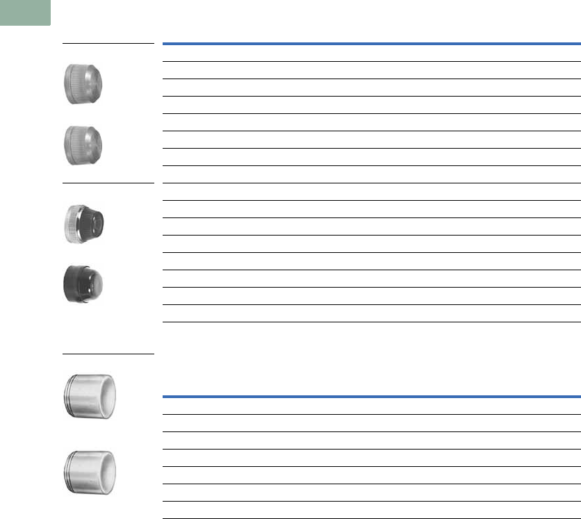
V7-T1-334 Volume 7—Logic Control, Operator Interface and Connectivity Solutions CA08100008E—March 2014 www.eaton.com
1
1
1
1
1
1
1
1
1
1
1
1
1
1
1
1
1
1
1
1
1
1
1
1
1
1
1
1
1
1
1.11
Pushbuttons and Indicating Lights
30.5 mm Class I Division 2 Hazardous Locations—10250T/E34
Indicating Light Lenses
Illuminated Pushbutton Lenses
Color
10250T
Catalog Number
E34
Catalog Number
Plastic
Red 10250TC1N E34H2
Green 10250TC2N E34H3
Amber 10250TC19N E34H9
Yellow 10250TC3N E34H4
Blue 10250TC4N E34H6
Clear 10250TC5N E34H0
White 10250TC6N E34H5
Glass
Red 10250TC7N E34G2
Green 10250TC8N E34G3
Amber 10250TC9N E34G9
Yellow — E34G4
Blue 10250TC10N E34G6
Clear 10250TC11N E34G0
White 10250TC12N E34G5
Color
10250T
Catalog Number
E34
Catalog Number
Red 10250TC21 E34V2
Green 10250TC22 E34V3
Yellow 10250TC23 E34V4
Amber 10250TC43 E34V9
Blue 10250TC24 E34V6
Clear 10250TC25 E34V0
White 10250TC26 E34V5
Plastic
Glass
10250TC_
E34H_
10250TC_
E34G_
10250TC_
E34V_
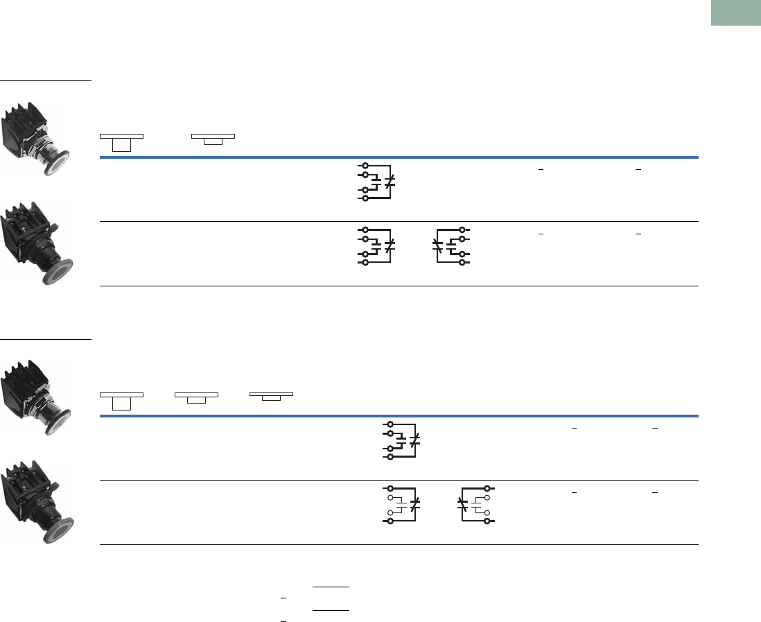
Volume 7—Logic Control, Operator Interface and Connectivity Solutions CA08100008E—March 2014 www.eaton.com V7-T1-335
1
1
1
1
1
1
1
1
1
1
1
1
1
1
1
1
1
1
1
1
1
1
1
1
1
1
1
1
1
1
1.11
Pushbuttons and Indicating Lights
30.5 mm Class I Division 2 Hazardous Locations—10250T/E34
Push-Pull Units
UL (NEMA) Type 3, 3R, 4, 4X, 12, 13, NEC Class I Division 2, Groups B, C and D
●Two- and three-position
●Non-illuminated
Two-Position Maintained Push, Maintained Pull
Three-Position Maintained Push, Momentary Pull
Notes
1 Bolded circuit corresponds to “X-O” circuit selection. X = closed circuit, O = open circuit.
2 To order different type or color buttons, simply substitute underlined character with appropriate suffix code from the Button and Color Selection
table on Page V7-T1-336. Example: 10250T714G.
3 To order different type or color buttons, simply substitute underlined character with appropriate suffix code from the Button and Color Selection
table on Page V7-T1-336. Example: 10250T716G.
Operator Function (Position) 1
Contact
Type
Maintained—
Pull
Maintained—
Push Red Standard Push-Pull 2
Mounting Location 110250T
Catalog Number
E34
Catalog Number12
O
X
X
O
1NO
1NC
10250T714R E34EX714R
O
X
O
X
X
O
X
O
2NO
2NC
10250T715R E34EX715R
10250T71_
E34EX71_
Operator Function (Position) 1
Contact
Type
Momentary—
Pull
Maintained—
Intermediate
Maintained—
Push Red Standard Push-Pull 3
Mounting Location 110250T
Catalog Number
E34
Catalog Number12
O
X
O
O
X
O
1NO
1NC
10250T716R E34EX716R
X
X
O
X
O
O
1NC
1NC
10250T717R E34EX717R
10250T71_
E34EX71_
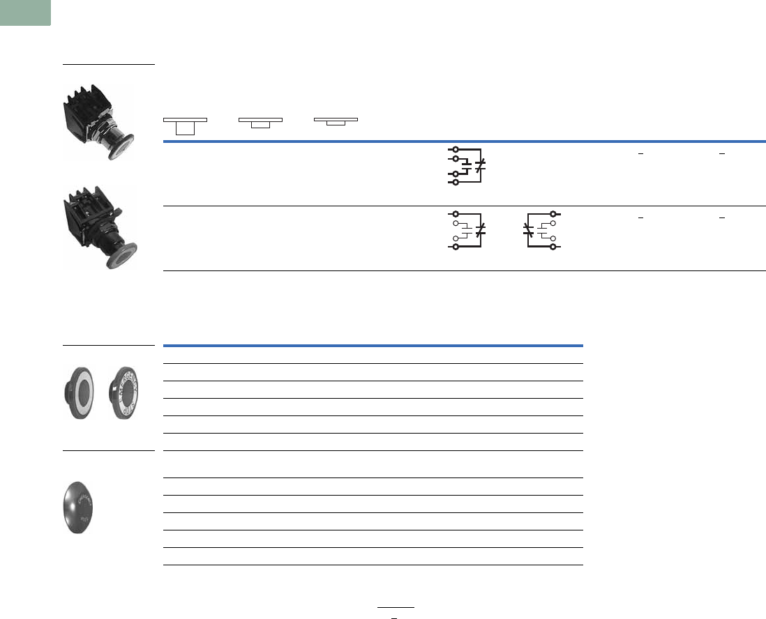
V7-T1-336 Volume 7—Logic Control, Operator Interface and Connectivity Solutions CA08100008E—March 2014 www.eaton.com
1
1
1
1
1
1
1
1
1
1
1
1
1
1
1
1
1
1
1
1
1
1
1
1
1
1
1
1
1
1
1.11
Pushbuttons and Indicating Lights
30.5 mm Class I Division 2 Hazardous Locations—10250T/E34
UL (NEMA) Type 3, 3R, 4, 4X, 12, 13, NEC Class I Division 2, Groups B, C and D
●Two- and three-position
●Non-illuminated
Three-Position Momentary Push, Momentary Pull
Button and Color Selection
Notes
1 Bolded circuit corresponds to “X-O” circuit selection. X = closed circuit, O = open circuit.
2 To order different type or color buttons, simply substitute underlined character with appropriate suffix code from the
Button and Color Selection table above. Example: 10250T718G.
Operator Function (Position) 1
Contact
Type
Momentary—
Pull
Maintained—
Intermediate
Momentary—
Push Red Standard Push-Pull 2
Mounting Location 110250T
Catalog Number
E34
Catalog Number12
O
X
O
O
X
O
1NO
1NC
10250T718R E34EX718R
X
X
O
X
O
O
1NC
1NC
10250T721R E34EX721R
Color
Suffix
Code
10250T
Catalog Number
E34
Catalog Number
Standard
Red R 10250TB62 E34C2
Red (EMERG. STOP) E 10250TB63 E34C2N8
Green G 10250TB61 E34C3
Black B 10250TB60 E34C1
Blue L 10250TB64 E34C6
Jumbo Mushroom Head
(Anodized) Aluminum
Red RJ 10250TJ62 E34J2
Red (EMERG. STOP) EJ 10250TJ63 E34J2N8
Green GJ 10250TJ61 —
Black BJ 10250TJ60 —
Yellow YJ 10250TJ64 —
10250T7_
E34EX7_
Standard
Jumbo Mushroom
Head
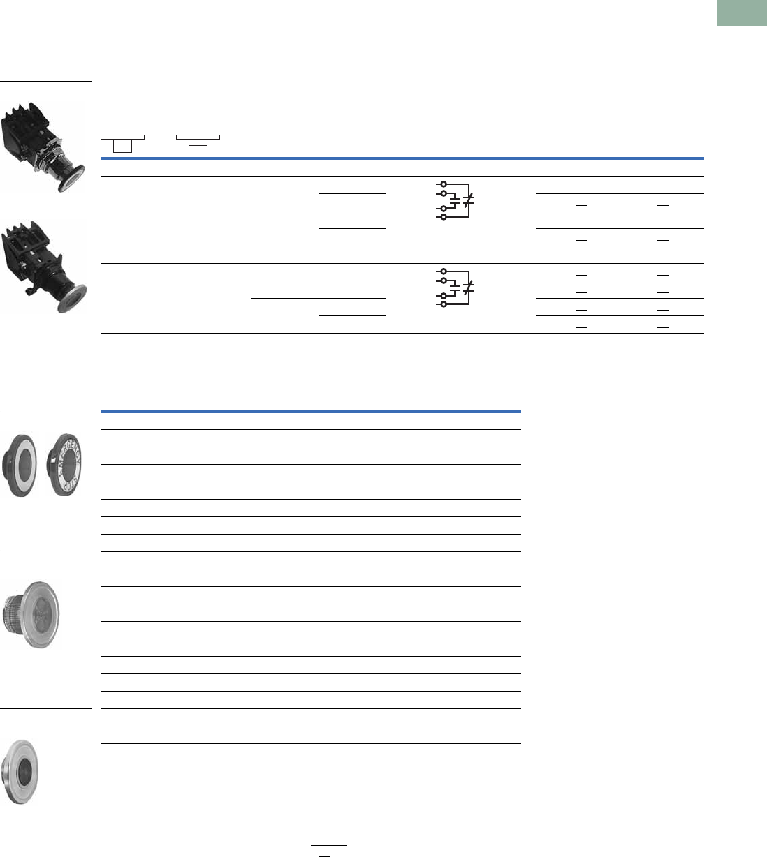
Volume 7—Logic Control, Operator Interface and Connectivity Solutions CA08100008E—March 2014 www.eaton.com V7-T1-337
1
1
1
1
1
1
1
1
1
1
1
1
1
1
1
1
1
1
1
1
1
1
1
1
1
1
1
1
1
1
1.11
Pushbuttons and Indicating Lights
30.5 mm Class I Division 2 Hazardous Locations—10250T/E34
Illuminated Push-Pull Units
UL (NEMA) Type 3, 3R, 4, 4X, 12, 13, NEC Class I Division 2, Groups B, C and D
●Two-position maintained
●Illuminated
Two-Position Illuminated Maintained Push, Maintained Pull
Lens and Color Selection
Notes
1 Bolded circuit corresponds to “X-O” circuit selection. X = closed circuit, O = open circuit.
2 To order different type or color lens, simply substitute the underlined characters with appropriate suffix code from the
Lens and Color Selection table above. Example: 10250T851GS.
Operator Function (Position) 1
Type Voltage
Contact
Type
Maintained—
Pull
Maintained—
Push Red Standard Push-Pull 2
Mounting Location 110250T
Catalog Number
E34
Catalog Number12
LED Lamp
O
X
X
O
Full voltage 24 Vac/Vdc 1NO
1NC
10250T853RD24 E34EX853RD24
120 Vac 10250T853RD2A E34EX853RD2A
Transformer 24 Vac 10250T843RD06 E34EX843RD06
120 Vac 10250T844RD06 E34EX844RD06
Incandescent Lamp
O
X
X
O
Full voltage 24 Vac/Vdc 1NO
1NC
10250T849RD E34EX849RD
Resistor 120 Vac/Vdc 10250T851RD E34EX851RD
Transformer 24 Vac 10250T843RD E34EX843RD
120 Vac 10250T844RD E34EX844RD
10250T E34
Color Suffix Code Catalog Number Suffix Code Catalog Number
Standard
Red RD 10250TC47 RD E34M2
Red (EMERG. STOP) ED 10250TC53 ED E34M2N8
Green GD 10250TC48 GD E34M3
Blue LD 10250TC49 LD E34M6
Amber AD 10250TC50 AD E34M9
White WD 10250TC51 WD E34M5
Clear CD 10250TC52 CD E34M0
Side-Lighted (Anodized) Aluminum
Red RS 10250TC57 — —
Red (EMERG. STOP) ES 10250TC63 — —
Green GS 10250TC58 — —
Blue LS 10250TC59 — —
Amber AS 10250TC64 — —
Yellow YS 10250TC60
White WS 10250TC61 — —
Clear CS 10250TC62 — —
Heavy-Duty Aluminum with Transparent Center
Red RH 10250TC65 — —
Green GH 10250TC66 — —
Amber AH 10250TC67 — —
10250T8_
E34EX8_
Standard
Side-Lighted
(Anodized) Aluminum
HD Aluminum with
Transparent Center
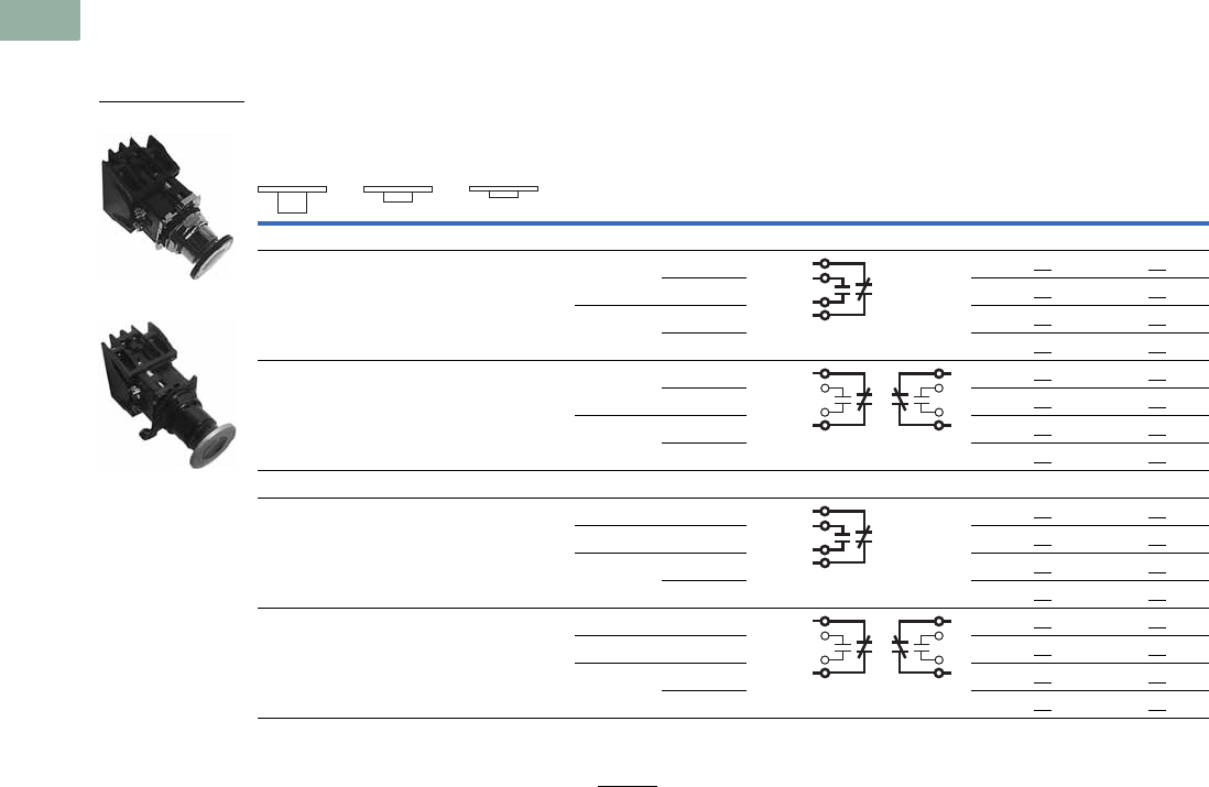
V7-T1-338 Volume 7—Logic Control, Operator Interface and Connectivity Solutions CA08100008E—March 2014 www.eaton.com
1
1
1
1
1
1
1
1
1
1
1
1
1
1
1
1
1
1
1
1
1
1
1
1
1
1
1
1
1
1
1.11
Pushbuttons and Indicating Lights
30.5 mm Class I Division 2 Hazardous Locations—10250T/E34
UL (NEMA) Type 3, 3R, 4, 4X, 12, 13, NEC Class I Division 2, Groups B, C and D
●Three-position—maintained push, momentary pull
●Illuminated
Three-Position Illuminated Maintained Push, Momentary Pull
Notes
1 Bolded circuit corresponds to “X-O” circuit selection. X = closed circuit, O = open circuit.
2 To order different type or color lens, simply substitute the underlined characters with appropriate suffix code from the Lens and
Color Selection table on the bottom of Page V7-T1-337. Example: 10250T862AS.
Operator Function (Position) 1
Type Voltage
Contact
Type
Momentary—
Pull
Maintained—
Intermediate
Maintained—
Push Red Standard Push-Pull 2
Mounting Location 110250T
Catalog Number
E34
Catalog Number12
LED Lamp
O
X
O
O
X
O
Full voltage 24 Vac/Vdc 1NO
1NC
10250T864RD24 E34EX864RD24
120 Vac 10250T864RD2A E34EX864RD2A
Transformer 24 Vac 10250T854RD06 E34EX854RD06
120 Vac 10250T855RD06 E34EX855RD06
X
X
O
X
O
O
Full voltage 24 Vac/Vdc 1NC
1NC
10250T875RD24 E34EX875RD24
120 Vac 10250T875RD2A E34EX875RD2A
Transformer 24 Vac 10250T865RD06 E34EX865RD06
120 Vac 10250T866RD06 E34EX866RD06
Incandescent Lamp
O
X
O
O
X
O
Full voltage 24 Vac/Vdc 1NO
1NC
10250T860RD E34EX860RD
Resistor 120 Vac 10250T862RD E34EX862RD
Transformer 24 Vac 10250T854RD E34EX854RD
120 Vac 10250T855RD E34EX855RD
X
X
O
X
O
O
Full voltage 24 Vac/Vdc 1NC
1NC
10250T871RD E34EX871RD
Resistor 120 Vac 10250T873RD E34EX873RD
Transformer 24 Vac 10250T865RD E34EX865RD
120 Vac 10250T866RD E34EX866RD
E34EX8_
10250T8_
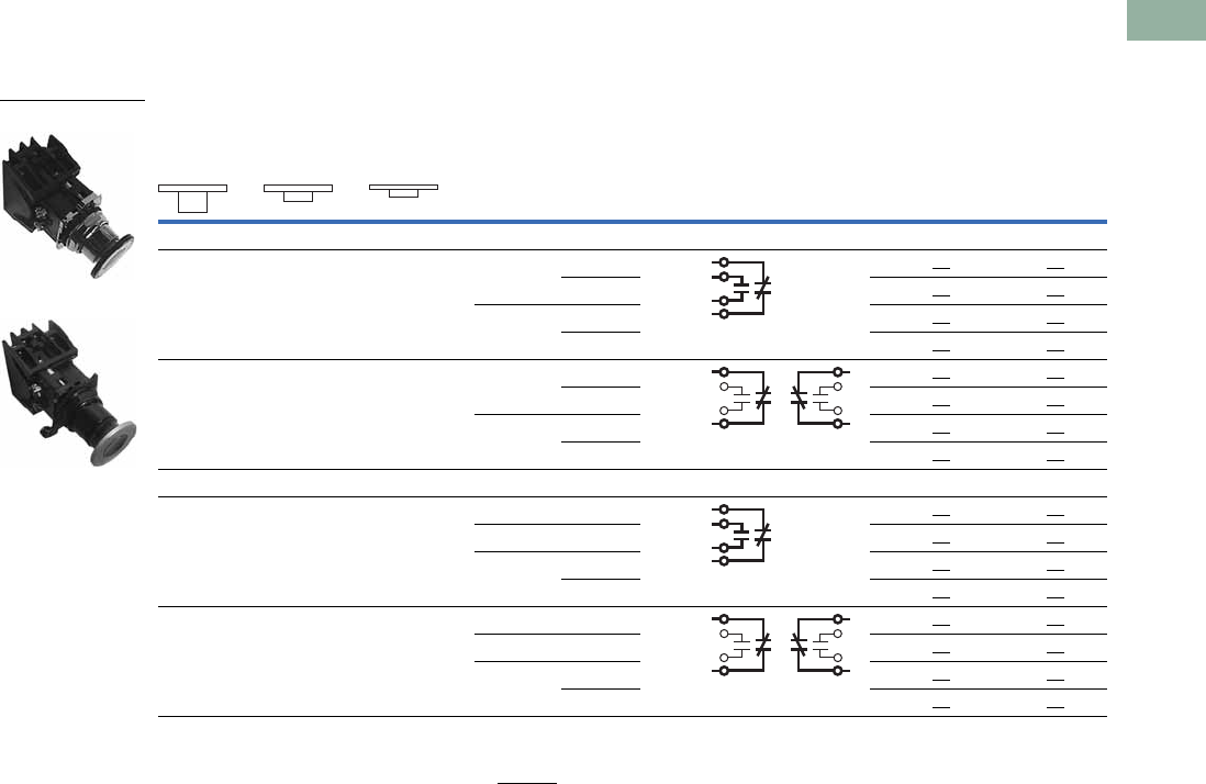
Volume 7—Logic Control, Operator Interface and Connectivity Solutions CA08100008E—March 2014 www.eaton.com V7-T1-339
1
1
1
1
1
1
1
1
1
1
1
1
1
1
1
1
1
1
1
1
1
1
1
1
1
1
1
1
1
1
1.11
Pushbuttons and Indicating Lights
30.5 mm Class I Division 2 Hazardous Locations—10250T/E34
UL (NEMA) Type 3, 3R, 4, 4X, 12, 13, NEC Class I Division 2, Groups B, C and D
●Three-position—momentary
●Illuminated
Three-Position Illuminated Momentary Push, Momentary Pull
Notes
1 Bolded circuit corresponds to “X-O” circuit selection. X = closed circuit, O = open circuit.
2 To order different type or color lens, simply substitute the underlined characters with appropriate suffix code from the Lens and
Color Selection table on the bottom of Page V7-T1-337. Example: 10250T862AS.
Operator Function (Position) 1
Type Voltage
Contact
Type
Momentary—
Pull
Maintained—
Intermediate
Maintained—
Push Red Standard Push-Pull 2
Mounting Location 110250T
Catalog Number
E34
Catalog Number12
LED Lamp
O
X
O
O
X
O
Full voltage 24 Vac/Vdc 1NO
1NC
10250T886RD24 E34EX886RD24
120 Vac 10250T886RD2A E34EX886RD2A
Transformer 24 Vac 10250T876RD06 E34EX876RD06
120 Vac 10250T877RD06 E34EX877RD06
X
X
O
X
O
O
Full voltage 24 Vac/Vdc 1NC
1NC
10250T897RD24 E34EX897RD24
120 Vac 10250T897RD2A E34EX897RD2A
Transformer 24 Vac 10250T887RD06 E34EX887RD06
120 Vac 10250T888RD06 E34EX888RD06
Incandescent Lamp
O
X
O
O
X
O
Full voltage 24 Vac/Vdc 1NO
1NC
10250T882RD E34EX882RD
Resistor 120 Vac 10250T884RD E34EX884RD
Transformer 24 Vac 10250T876RD E34EX876RD
120 Vac 10250T877RD E34EX877RD
X
X
O
X
O
O
Full voltage 24 Vac/Vdc 1NC
1NC
10250T893RD E34EX893RD
Resistor 120 Vac 10250T895RD E34EX895RD
Transformer 24 Vac 10250T887RD E34EX887RD
120 Vac 10250T888RD E34EX888RD
E34EX8_
10250T8_
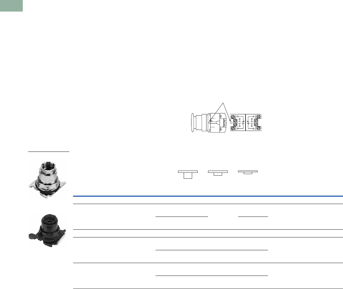
V7-T1-340 Volume 7—Logic Control, Operator Interface and Connectivity Solutions CA08100008E—March 2014 www.eaton.com
1
1
1
1
1
1
1
1
1
1
1
1
1
1
1
1
1
1
1
1
1
1
1
1
1
1
1
1
1
1
1.11
Pushbuttons and Indicating Lights
30.5 mm Class I Division 2 Hazardous Locations—10250T/E34
Push-Pull Operators
An illuminated push-pull
pushbutton unit, arranged for
one-hole mounting, can
replace two pushbuttons and
a pilot light or the non-
illuminated form can replace
two pushbuttons. These units
are available in three basic
types:
●Maintained—(Two-
position). Maintains in the
pulled or pushed position
until manually actuated to
the opposite mode.
●Momentary—(Three-
position). Spring returns to
an intermediate position
when pulled or pushed and
released.
●Momentary Pull,
Maintained Push—(Three-
position). Spring returns to
intermediate position when
pulled. Maintains in pushed
position until manually
returned to intermediate
(ready to reset) position.
Maintained stop holds
circuit open and will
prevent other series
connected operators from
starting the system.
The operators, buttons,
contact blocks, etc., are
offered as building block
components that can be
intermixed to satisfy many
requirements. This minimizes
the need for a varied and
costly inventory.
Application Guide
To assist in the selection of
contact blocks, the sketch
below shows pictorially by
symbols 1 and 2 locations of
contact circuits after
assembly of contact blocks
and adapter to the operator.
The table below shows the
effect of the push and pull
operations on either NO or
NC contacts. (X = contact
closed, O = contact open).
Locating Nibs
Push-Pull Operator Components
Note
Use NEMA 4X 10250T operators where exposed to ultraviolet light.
Locating Nib
12
Type of Operator
Contact
Block
Operator Position and Circuit Arrangement
10250T
Catalog Number
E34
Catalog Number
Out—Pull Intermediate In—Push
Contact Block Mounting Location
121212
Two-Position Operator without Lens
Maintained push-pull 1NO
1NC
O
Xor O
X
No intermediate
position
X
Oor X
O
10250T5 E34GDB
2NO
2NC
O
X
O
X
X
O
X
O
Three-Position Operator without Lens
Momentary push-pull
Maintained push-momentary pull
1NO
1NC
O
Xor O
X
O
Oor O
X
X
Oor O
O
10250T4
10250T9
E34GEB
E34GFB
2NO
2NC
O
X
O
X
O
O
O
X
X
O
O
O
Momentary push-pull 1NO
1NC
O
Xor O
X
O
Oor O
O
X
Oor X
O
10250T10 E34GHB
2NO
2NC
O
X
O
X
O
O
O
O
X
O
X
O
10250T_
E34G_

Volume 7—Logic Control, Operator Interface and Connectivity Solutions CA08100008E—March 2014 www.eaton.com V7-T1-341
1
1
1
1
1
1
1
1
1
1
1
1
1
1
1
1
1
1
1
1
1
1
1
1
1
1
1
1
1
1
1.11
Pushbuttons and Indicating Lights
30.5 mm Class I Division 2 Hazardous Locations—10250T/E34
Push-Pull Light Units, Lenses and Buttons
NEC Class I Division 2 Groups B, C and D
Light Units for Illuminated Push-Pull Devices
Note
1 These units do not include lamps. Order LED separately to match lens color from table on Page V7-T1-343.
Light Unit
Type Type Voltage
LED/Lamp
Number Catalog Number
LED
(LEDs not included) 1
Full voltage — Bayonet
base
10250T97HL
Transformer
AC only
50/60 Hz
24 10250T89HL
120 10250T63HL
208 10250T64HL
240 10250T65HL
277 10250T82HL
380 10250T66HL
480 10250T67HL
600 10250T68HL
Incandescent Full voltage
AC or DC
6#755
#756
#757
#1828
10250T69H
12 10250T70H
24/28 10250T79H
32 10250T83H
Resistor
AC or DC
120 120MB 10250T80H
240 10250T81H
Transformer
AC only
50/60 Hz
24 #755 10250T89H
120 10250T63H
208 10250T64H
240 10250T65H
277 10250T82H
380 10250T66H
480 10250T67H
600 10250T68H
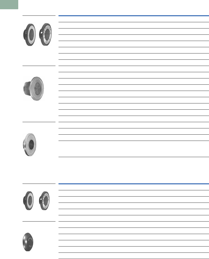
V7-T1-342 Volume 7—Logic Control, Operator Interface and Connectivity Solutions CA08100008E—March 2014 www.eaton.com
1
1
1
1
1
1
1
1
1
1
1
1
1
1
1
1
1
1
1
1
1
1
1
1
1
1
1
1
1
1
1.11
Pushbuttons and Indicating Lights
30.5 mm Class I Division 2 Hazardous Locations—10250T/E34
Alternate Lenses for Illuminated Push-Pull Devices
Buttons for Non-Illuminated Push-Pull Devices
Notes
Use NEMA 4X 10250T operators where exposed to ultraviolet light.
1 Anodized aluminum head is not suitable for use with ultraviolet light applications.
Color
10250T
Catalog Number
E34
Catalog Number
Standard
Red 10250TC47 E34M2
Red (EMERG. STOP) 10250TC53 E34M2N8
Green 10250TC48 E34M3
Blue 10250TC49 E34M6
Amber 10250TC50 E34M9
White 10250TC51 E34M5
Clear 10250TC52 E34M0
Side-Lighted Anodized Aluminum Ring
Red 10250TC57 —
Red (EMERG. STOP) 10250TC63 —
Green 10250TC58 —
Blue 10250TC59 —
Amber 10250TC64 —
Yellow 10250TC60 —
White 10250TC61 —
Clear 10250TC62 —
Heavy-Duty Aluminum with Transparent Center
Red 10250TC65 —
Green 10250TC66 —
Amber 10250TC67 —
Color
10250T
Catalog Number
E34
Catalog Number
Standard
Red 10250TB62 E34C2
Red (EMERG. STOP) 10250TB63 E34C2N8
Green 10250TB61 E34C3
Black 10250TB60 E34C1
Blue 10250TB64 E34C6
Jumbo Mushroom Head (Anodized) Aluminum 1
Red 10250TJ62 E34J2
Red (EMERG. STOP) 10250TJ63 E34J2N8
Green 10250TJ61 —
Black 10250TJ60 —
Yellow 10250TJ64 —
Standard
Side-Lighted
(Anodized) Aluminum
HD Aluminum with
Transparent Center
Standard
Jumbo Mushroom
Head
Volume 7—Logic Control, Operator Interface and Connectivity Solutions CA08100008E—March 2014 www.eaton.com V7-T1-343
1
1
1
1
1
1
1
1
1
1
1
1
1
1
1
1
1
1
1
1
1
1
1
1
1
1
1
1
1
1
1.11
Pushbuttons and Indicating Lights
30.5 mm Class I Division 2 Hazardous Locations—10250T/E34
LED Selection
Note
For a complete listing of all LEDs available, see Page V7-T1-239.
Voltage Color Catalog Number Voltage Color Catalog Number
6 Vac/Vdc
suitable for
use with
transformers
Red E22LED006RN 60 Vac/Vdc Red E22LED060RN
Orange E22LED006ON Orange E22LED060ON
Yellow E22LED006YN Yellow E22LED060YN
Green E22LED006GN Green E22LED060GN
Blue E22LED006BN Blue E22LED060BN
White E22LED006WN White E22LED060WN
12 Vac/Vdc Red E22LED012RN 120 Vac Red E22LED120RA
Orange E22LED012ON Orange E22LED120OA
Yellow E22LED012YN Yellow E22LED120YA
Green E22LED012GN Green E22LED120GA
Blue E22LED012BN Blue E22LED120BA
White E22LED012WN White E22LED120WA
24 Vac/Vdc Red E22LED024RN 120 Vdc Red E22LED120RD
Orange E22LED024ON Orange E22LED120OD
Yellow E22LED024YN Yellow E22LED120YD
Green E22LED024GN Green E22LED120GD
Blue E22LED024BN Blue E22LED120BD
White E22LED024WN White E22LED120WD
48 Vac/Vdc Red E22LED048RN
Orange E22LED048ON
Yellow E22LED048YN
Green E22LED048GN
Blue E22LED048BN
White E22LED048WN
Standard LED Lamp
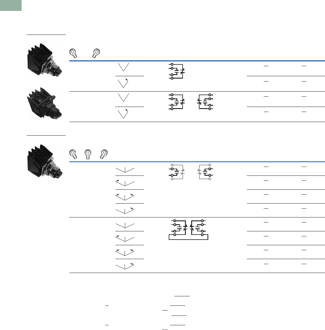
V7-T1-344 Volume 7—Logic Control, Operator Interface and Connectivity Solutions CA08100008E—March 2014 www.eaton.com
1
1
1
1
1
1
1
1
1
1
1
1
1
1
1
1
1
1
1
1
1
1
1
1
1
1
1
1
1
1
1.11
Pushbuttons and Indicating Lights
30.5 mm Class I Division 2 Hazardous Locations—10250T/E34
Selector Switch Units
UL (NEMA) Type 3, 3R, 4, 4X, 12, 13, NEC Class I Division 2, Groups B, C and D
●Two- and three-position
●Non-illuminated
Two-Position Selector Switch—Non-Illuminated
Three-Position Selector Switch—Non-Illuminated
Notes
1 Bolded circuit corresponds to “X-O” circuit selection. X = closed circuit, O = open circuit.
2 M = Maintained. S = Spring return in direction of arrow (W).
3 To order different type or color selector switch, simply substitute the underlined characters with appropriate
suffix code from the table on Page V7-T1-345.
Example: 10250T722LL. For keyed selector switch, substitute the underlined characters with
T_ (cam)+_ (key removal position). Example: 10250T722T13.
4 To order different type or color selector switch, simply substitute the underlined characters with appropriate
suffix code from the Switch and Color Selection table on Page V7-T1-345.
Example: 10250T726LL. For keyed selector switch, substitute the underlined characters with
T_ (cam)+_ (key removal position). Example: 10250T726T13.
Operator Position 1
Operator
Action 2
Contact
Type
Cam
Code
Black Knob—Selector Switch 3
Mounting Location 110250T
Catalog Number
E34
Catalog Number12
X
O
O
X
1NC
1NO
110250T722BK E34EX722BK
10250T724BK E34EX724BK
X
O
X
O
O
X
O
X
1NC
1NO
1NC
1NO
110250T723BK E34EX723BK
10250T725BK E34EX725BK
Operator Position 1
Operator
Action 2
Contact
Type
Cam
Code
Black Knob—Selector Switch 4
Mounting Location 110250T
Catalog Number
E34
Catalog Number12
X
O
O
O
O
X
1NO
1NO
310250T726BK E34EX726BK
10250T728BK E34EX728BK
10250T730BK E34EX730BK
10250T732BK E34EX732BK
X
O
O
O
X
O
O
O
X
1NO
1NC-1NC
(Series)
1NO
310250T727BK E34EX727BK
10250T729BK E34EX729BK
10250T731BK E34EX731BK
10250T733BK E34EX733BK
10250T72_
E34EX72_
MM
MS
MM
MS
10250T_
MM
M
MS
M
SS
M
MS
M
MM
M
MS
M
SS
M
MS
M
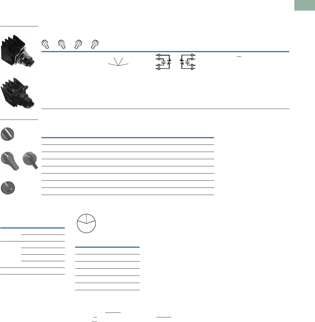
Volume 7—Logic Control, Operator Interface and Connectivity Solutions CA08100008E—March 2014 www.eaton.com V7-T1-345
1
1
1
1
1
1
1
1
1
1
1
1
1
1
1
1
1
1
1
1
1
1
1
1
1
1
1
1
1
1
1.11
Pushbuttons and Indicating Lights
30.5 mm Class I Division 2 Hazardous Locations—10250T/E34
UL (NEMA) Type 3, 3R, 4, 4X, 12, 13, NEC Class I Division 2, Groups B, C and D
●Four-position maintained
●Non-illuminated
Four-Position Selector Switch—Non-Illuminated
Switch and Color Selection
Key Operated Selection Key Removal Positions 7
Notes
1Bolded circuit corresponds to “X-O” circuit selection. X = closed circuit, O = open circuit.
2M = Maintained.
3To order different type or color selector switch, simply substitute the underlined characters with appropriate suffix code from the
Switch and Color Selection table above. Example: 10250T743LL. For keyed selector switch, substitute the underlined characters with
T_ (cam) + _ (key removal position). Example: 10250T743T77.
4Designed for added ingress protection. For use in maintained operators only.
510250T only.
6M = Maintained. S = Spring return in direction of arrow (W).
7Key removal in “spring return from” positions not recommended.
Operator Position 1
Operator
Action 2
Contact
Type
Cam
Code
Black Knob—Selector Switch 3
Mounting Location 110250T
Catalog Number
E34
Catalog Number12
X
O
O
O
O
X
O
O
O
O
X
O
O
O
O
X
1NC
1NO
1NO
1NC
710250T743BK E34EX743BK
Color
Knob
Suffix Code
Lever
Suffix Code
Lever 4
Suffix Code
Coin Slot 5
Suffix Code
Black BK BL BA BC
Red RK RL RA RC
Green GK GL GA GC
Yellow YK YL YA YC
White WK WL WA WC
Gray AK AL AA AC
Blue LK LL LA LC
Orange NK NL NA NC
10250T743_
E34EX743_
MM
MM
Knob
Lever
Coin Slot 5
Number of
Position
Operator
Action 6
Suffix and
Removal
Position
2 M M T1 + 1, 2, 3
M Q ST1 + 2
3 M M M T3 + 1–7
S W M M T3 + 1, 4, 5
S W M Q ST3 + 4
M M Q S T3 + 2, 4, 6
4 MMMM T7 + 7
Code
Suffix
Key Removal
Position
1Right only
2Left only
3Right and left
4Center only
6Left and center
7All positions
L
C
R
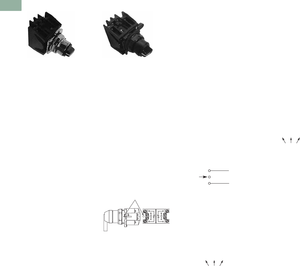
V7-T1-346 Volume 7—Logic Control, Operator Interface and Connectivity Solutions CA08100008E—March 2014 www.eaton.com
1
1
1
1
1
1
1
1
1
1
1
1
1
1
1
1
1
1
1
1
1
1
1
1
1
1
1
1
1
1
1.11
Pushbuttons and Indicating Lights
30.5 mm Class I Division 2 Hazardous Locations—10250T/E34
Selector Switch Selection
Cam and Contact Block Selection
Selector switches in their
varied forms (two-position,
three-position, and four-
position) are a big factor
contributing to the great
flexibility of control that a well
rounded line of “pushbuttons”
can achieve. Because of their
flexibility, they tend to cause
difficulty with product
selection and application.
The following systematic
approach should simplify
that task.
Cam and contact block
selection is better understood
if you:
●Work with each incoming
and outgoing wire/circuit
separately.
●Recognize the terms NO
and NC only identify the
type of contact by its mode
before mounting to the
operator. The “X-O” table
(Page V7-T1-348) shows
how that contact will act
after assembly to the
operator with the selected
cam shape. X = closed
circuit, O = open circuit.
●One NO-NC contact block
may be mounted behind
each plunger of the
mounting adapter for a
total of four circuits.
●Each cam has two
separate lobes, each of
which operates one of the
two contact block plungers
independently of each
other. Those are identified
as position 1 (locating nib
side) and position 2
(opposite of locating nib).
The position designations
give direction in selecting
and mounting of the
contact blocks.
Contact Circuit Locations
10250T E34
Locating Nib
12
Systematic Approach
Application: HAND-OFF-
AUTO selector switch. In this
circuit, one incoming line is
distributed to two other
outgoing circuits by the
switch. The two circuits can
be looked at individually.
Step 1: Elementary
Diagram.
Construct on paper, or in your
mind, a simple elementary
diagram of the switching
scheme as follows:
Step 2: “X-O” Pattern.
From the elementary
diagram, you can construct an
“X-O” diagram which
describes when the contacts
are to be closed (X) or open
(O) in the various positions of
the switch. The “X-O” for the
HAND circuit looks like this:
In this circuit, you want a
contact closed on the left
(HAND) but open in the
center and right.
For the AUTO circuit, the “X-
O” diagram would look like
this:
Putting them together, the
complete “X-O” diagram is:
Once the “X-O” diagram has
been generated, the next
step is to select the cam and
contact block, or blocks,
needed to perform the
desired “X-O” functions. The
selection tables on the
following pages list the
various types (shapes) of
cams by number to choose
from and the type of contact
and position to achieve the
function outlined in your
“X-O” diagram.
OFF
HAND Outgoing
Circuit
AUTO
Outgoing
Circuit
Incoming
Line
HAND OFF AUTO
XOO
HAND OFF AUTO
OOX
X O O
O O X
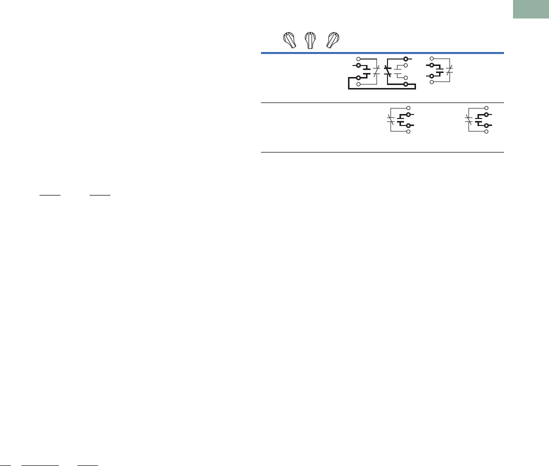
Volume 7—Logic Control, Operator Interface and Connectivity Solutions CA08100008E—March 2014 www.eaton.com V7-T1-347
1
1
1
1
1
1
1
1
1
1
1
1
1
1
1
1
1
1
1
1
1
1
1
1
1
1
1
1
1
1
1.11
Pushbuttons and Indicating Lights
30.5 mm Class I Division 2 Hazardous Locations—10250T/E34
Step 3: Cam Selection.
The cam you select
determines the operation of
all contact blocks mounted to
the operator. It is selected on
the basis that it provides the
simplest circuitry for the
desired “X-O” diagram. The
selection tables show all the
“X-O” combinations. For the
purpose of this example, the
applicable portion of those
tables is shown on this page.
Now to make the cam
selection, make a simple
worksheet such as below.
(1) or (2) = mounting location
from chart above:
It becomes obvious that
cam 3 is the better choice
because the series
connection can be avoided,
making it simpler to wire.
Step 4: Contact Block
Selection.
Having selected the cam,
contact block selection is
simply a matter of determining
if you require one NO-NC
contact block (Cat. No
10250T1H) or two. Given the
limitations of the factory
sealed contact block and the
desired “X-O” application,
you may have circuits that
will not be needed—as seen
here with the two additional
NC circuits. (1) or (2) =
mounting location from chart
above.
Step 5: Selector Switch
Operator.
Lastly, you have to choose
from the many types of
operators—knob and lever
in various colors or keyed.
Also what combinations of
maintained and spring
return functions are
required. Selection of these
operators can be found on
Page V7-T1-349. For the
example in step 4, you may
want a three-position
maintained black knob,
cam 3—Catalog Number
10250T1323 (or 34VHBK1).
The Complete Switch:
10250T1323 (or 34VHBK1)
with two 10250T1H or for
one composite catalog
number—10250T726BK (or
E34EX726BK) found on
Page V7-T1-344.
Diagrams
Circuits shown illustrate
connections to obtain a
selector circuit combination
and are shown with their
appropriate line diagrams in
BOLD. Field wiring of jumper
connections required as
shown.
X = Closed circuit
O = Open circuit
Cam 2 Cam 3
X O O
O O X
(1)NO-(2)NC
(2)NO
(1)NO
(2)NO
1
Qty Catalog No. Cam 3
2 10250TIH (1)NO (2)NC
(1)NC (2)NO
Example Selection Table
Note
1Wired in series.
No.
Desired Circuit and
Operator Position
Cam Code #2
Contact Blocks and
Mounting Location
Cam Code #3
Contact Blocks and
Mounting Location
1212
1XOO
NO NC 1 NO
—
4 OOX—
NO
—
NO
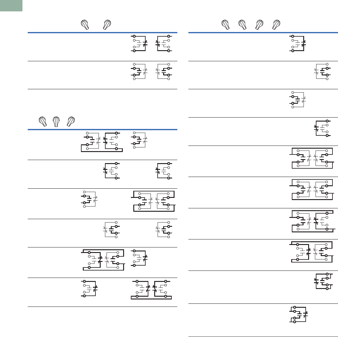
V7-T1-348 Volume 7—Logic Control, Operator Interface and Connectivity Solutions CA08100008E—March 2014 www.eaton.com
1
1
1
1
1
1
1
1
1
1
1
1
1
1
1
1
1
1
1
1
1
1
1
1
1
1
1
1
1
1
1.11
Pushbuttons and Indicating Lights
30.5 mm Class I Division 2 Hazardous Locations—10250T/E34
Two-Position Selector Switch
Three-Position Selector Switch
Four-Position Selector Switch
Number
Desired Circuit and
Operator Position
Cam Code #1
Contact Blocks and
Mounting Location
12
1XO
NC NC
2OX
NO NO
No.
Desired Circuit and
Operator Position
Cam Code #2
Contact Blocks and
Mounting Location
Cam Code #3
Contact Blocks and
Mounting Location
12 1 2
1X O O
NO (Series) NC NO
—
2XXO—
NC
—
NC
3X O X
NO
—
NO (Parallel) NO
4OOX—
NO
—
NO
5O X X
NC (Parallel) NO NC
—
6O X O
NC
—
NC (Series) NC
Number
Desired Circuit and
Operator Position
Cam Code #7
Contact Blocks and
Mounting Location
12
1XOOO
NC
—
2OXOO—
NO
3OOXO
NO
—
4OOOX—
NC
5XOOX
NC (Parallel) NC
6OXXO
NO (Parallel) NO
7OOXX
NO (Parallel) NC
8XXOO
NC (Parallel) NO
9 OXOX—
NO/NC
(Parallel)
10 XOXO
NO/NC
(Parallel)
—
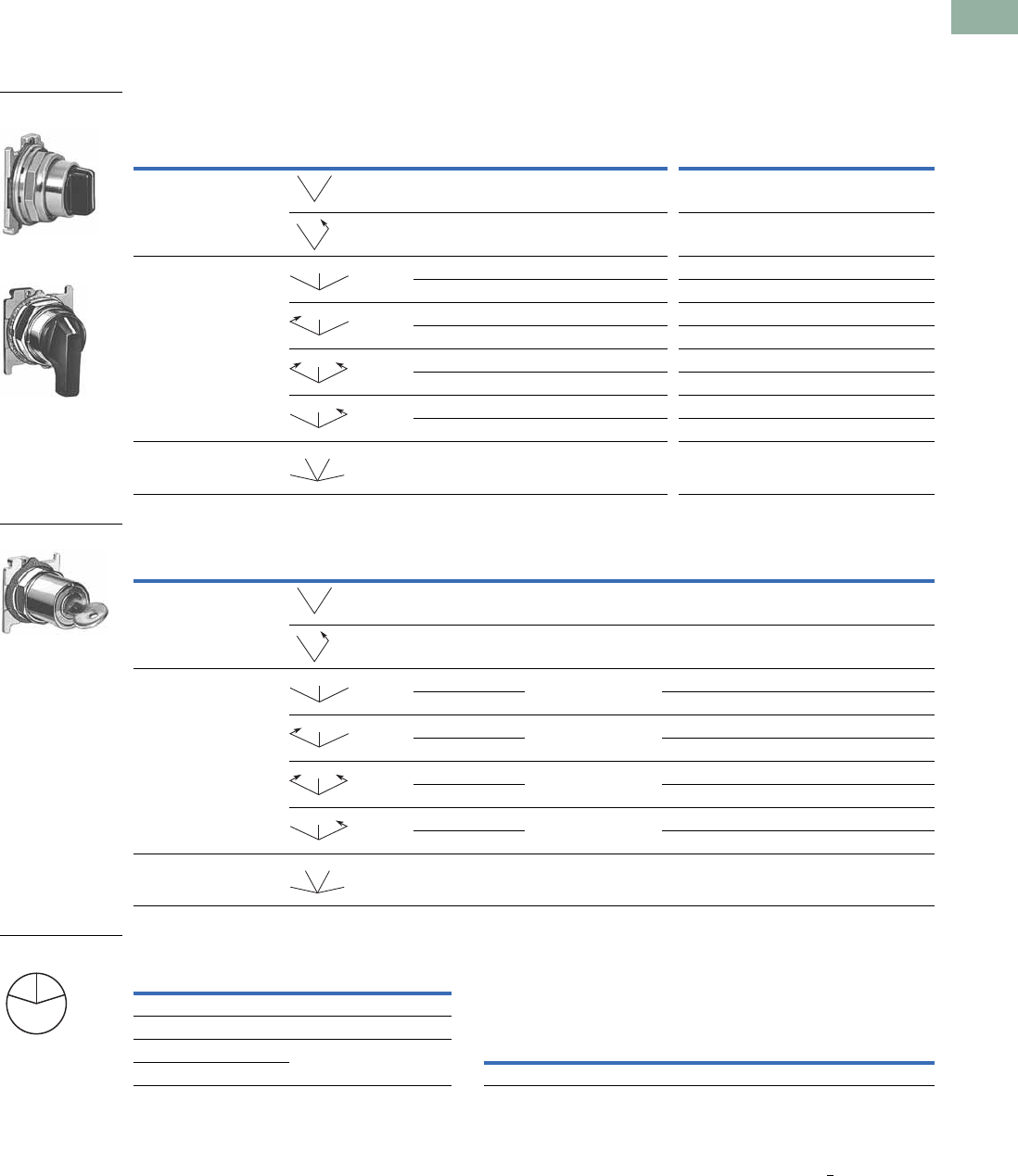
Volume 7—Logic Control, Operator Interface and Connectivity Solutions CA08100008E—March 2014 www.eaton.com V7-T1-349
1
1
1
1
1
1
1
1
1
1
1
1
1
1
1
1
1
1
1
1
1
1
1
1
1
1
1
1
1
1
1.11
Pushbuttons and Indicating Lights
30.5 mm Class I Division 2 Hazardous Locations—10250T/E34
Selector Switch Operators
10250T Selector Switch Operators with Caps
UL (NEMA) Type 3, 3R, 4, 4X, 12, 13
10250T Selector Switch Operators with Caps
10250T Key Operators with Cam
Key Removal Positions 5Replacement Keys or Dissimilar Locks for Above Key Operators
Listed operators have identical locks and keys (Key Code H661)
Catalog Number 10250ED824.
Replacement Keys
Notes
1 M = Maintained. S = Spring return in direction of arrow (W).
2 Field convertible to horizontal mounting or order operator only and separate operator cap.
3 For selection of the proper cam and contact block to obtain the proper circuit sequence, see selection instructions and table on Pages V7-T1-346 to V7-T1-348.
4 Choose key removal position required for application from table above. Add key removal code no. to listed catalog number. Example: 10250T15112.
5 Key removal in “spring return from” positions not recommended.
Positions Operator Action 1
Black Knob Selector Switch—
Vertical Mounting 2
Black Lever Selector Switch—
Vertical Mounting 2
Cam Code 3Catalog Number Cam Code 3Catalog Number
Two-position—60° throw 1 10250T1311 110250T3011
110250T1371 110250T3071
Three-position—60° throw 2 10250T1322 210250T3022
310250T1323 310250T3023
210250T1332 210250T3032
310250T1333 310250T3033
210250T1342 210250T3042
310250T1343 310250T3043
210250T1352 210250T3052
310250T1353 310250T3053
Four-position—40° throw 7 10250T1367 710250T3067
Positions Operator Action 1Cam Code 3
Optional Key
Removal Positions 4
Vertical Mounting
Catalog Number 4
Horizontal Mounting
Catalog Number 4
Two-position—60° throw 1 1, 2, 3 10250T1511_ 10250T1611_
12 10250T1571_ 10250T1581_
Three-position—60° throw 2 1–7 10250T1522_ 10250T1622_
310250T1523_ 10250T1623_
21, 4, 5 10250T1532_ 10250T1632_
310250T1533_ 10250T1633_
24 10250T1542_ 10250T1642_
310250T1543_ 10250T1643_
22, 4, 6 10250T1652_ 10250T1662_
310250T1653_ 10250T1663_
Four-position—40° throw 7 7 10250T1677_ 10250T1687_
Black Knob Selector
Switch
Black Lever Selector
Switch
MM
MS
MM
M
MS
M
SS
M
MS
M
MM
MM
Horizontal Mounting
MM
MS
MM
M
MS
M
SS
M
MS
M
MM
MM
Code
Suffix
Key Removal
Position
Code
Suffix
Key Removal
Position
1Right only 5Right and center
2Left only 6Left and center
3Right and left 7All positions
4Center only
L
C
R
Key Removal Positions
Description Catalog Number
Replacement keys (code H661)10250ED824
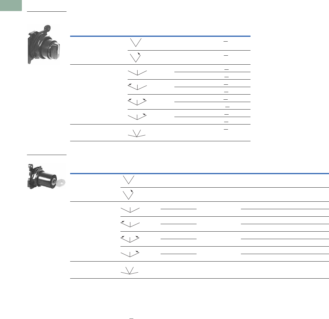
V7-T1-350 Volume 7—Logic Control, Operator Interface and Connectivity Solutions CA08100008E—March 2014 www.eaton.com
1
1
1
1
1
1
1
1
1
1
1
1
1
1
1
1
1
1
1
1
1
1
1
1
1
1
1
1
1
1
1.11
Pushbuttons and Indicating Lights
30.5 mm Class I Division 2 Hazardous Locations—10250T/E34
UL (NEMA) Type 3, 3R, 4, 4X, 12, 13
E34 Selector Switch Operators with Knob Assembled
E34 Key Operators with Cam and Cap
Notes
Use NEMA 4X 10250T operators where exposed to ultraviolet light, see Page V7-T1-349.
1 M = Maintained. S = Spring return in direction of arrow (W).
2 Field convertible to horizontal mounting.
3 For selection of the proper cam and contact block to obtain the proper circuit sequence, see selection instructions and table on Pages V7-T1-346 to V7-T1-348.
4 For other colors of either knob or lever, replace the underlined characters of the catalog number with the appropriate suffix code from Alternate Knobs and Levers table on
Page V7-T1-351. Example: E34VFBL2.
5 Choose key removal position required for application from table on Page V7-T1-351. Add key removal code no. to listed catalog number. Example: E34KFB2.
Positions Operator Action 1
Black Knob Selector Switch—
Vertical Mounting 2
Cam Code 3Catalog Number 4
Two-position—60° throw 1 E34VFBK1
1E34VEBK1
Three-position—60° throw 2 E34VGBK1
3E34VHBK1
2E34VJBK1
3E34VKBK1
2E34VLBK1
3E34VMBK1
2E34VNBK1
3E34VPBK1
Four-position—40° throw 7 E34VTBK1
Positions Operator Action 1Cam Code 3
Key Removal
Positions 5
Vertical Mounting
Catalog Number
Horizontal Mounting
Catalog Number
Two-position—60° throw 1 1, 2, 3 E34KFB_ E34KFHB_
12 E34KEB_ E34KEHB_
Three-position—60° throw 2 1–7 E34KGB_ E34KGHB_
3E34KHB_ E34KHHB_
21, 4, 5 E34KJB_ E34KJHB_
3E34KKB_ E34KKHB_
24 E34KLB_ E34KLHB_
3E34KMB_ E34KMHB_
22, 4, 6 E34KNB_ E34KNHB_
3E34KPB_ E34KPHB_
Four-position—40° throw 7 7 E34KTB_ E34KTHB_
Black Knob Selector
Switch
MM
MS
MM
M
MS
M
SS
M
MS
M
MM
MM
E34KFB_
MM
MS
MM
M
MS
M
SS
M
MS
M
MM
MM
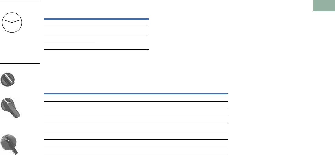
Volume 7—Logic Control, Operator Interface and Connectivity Solutions CA08100008E—March 2014 www.eaton.com V7-T1-351
1
1
1
1
1
1
1
1
1
1
1
1
1
1
1
1
1
1
1
1
1
1
1
1
1
1
1
1
1
1
1.11
Pushbuttons and Indicating Lights
30.5 mm Class I Division 2 Hazardous Locations—10250T/E34
Key Removal Positions
Alternate Knobs and Levers for Operators 1
Notes
1 Key removal in “spring return from” positions not recommended.
2 For use on maintained operators only.
Code
Suffix
Key Removal
Position
Code
Suffix
Key Removal
Position
1Right only 5Right and center
2Left only 6Left and center
3Right and left 7All positions
4Center only
Color
Knob Lever
Lever Designed for
Added Ingress Protection 2
Suffix
Code Catalog Number
Suffix
Code Catalog Number
Suffix
Code Catalog Number
Black K1 E34K1 L1 E34L1 A1 E34A1
Red K2 E34K2 L2 E34L2 A2 E34A2
Green K3 E34K3 L3 E34L3 A3 E34A3
Yellow K4 E34K4 L4 E34L4 A4 E34A4
White K5 E34K5 L5 E34L5 A5 E34A5
Blue K6 E34K6 L6 E34L6 A6 E34A6
Gray K7 E34K7 L7 E34L7 A7 E34A7
Orange K8 E34K8 L8 E34L8 A8 E34A8
L
C
R
Key Removal Positions
Knob
Lever
Lever for Added
Ingress Protection
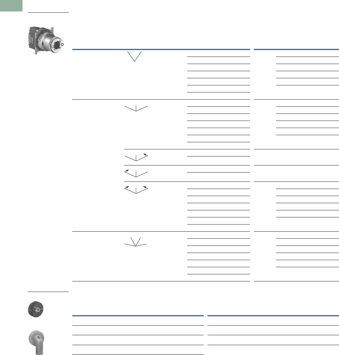
V7-T1-352 Volume 7—Logic Control, Operator Interface and Connectivity Solutions CA08100008E—March 2014 www.eaton.com
1
1
1
1
1
1
1
1
1
1
1
1
1
1
1
1
1
1
1
1
1
1
1
1
1
1
1
1
1
1
1.11
Pushbuttons and Indicating Lights
30.5 mm Class I Division 2 Hazardous Locations—10250T/E34
Illuminated Selector Switch Operators
10250T Illuminated Selector Switch Operator Only without Knob or Lever
Knobs and Levers
Notes
1 M = Maintained. S = Spring return in direction of arrow (W).
2 For selection of the proper cam and contact block, to obtain the proper circuit sequence, see selection table on Page V7-T1-348.
3 Operator includes lens gasket and lens attachment screws.
4 Full voltage light units can be used at other than listed voltages by changing lamp. Replacement lamps are listed on Page V7-T1-239.
5 Resistor type. May generate excess heat if used in high density.
6 Amber, clear and white lenses have a black arrow (pointer), red, green and blue lenses have a white arrow (pointer).
Position Operator Action 1
Full Voltage Type—AC or DC 4
Transformer Type—50/60 Hz
6V #755 Lamp
Lamps: 6V—#755, 12V—#756, 24V—#757,
48V—#1835, 120/240V—120MB
Cam
Code 3Voltage
Catalog and
Code Number 2
Cam
Code 3Voltage
Catalog and
Code Number 2
Two-position—60° throw 1 24 10250T5961H 1610250T6201H
120 10250T5971H 12 10250T6211H
208 10250T6511H 24 10250T6221H
240 10250T5981H 48 10250T6231H
380 10250T5991H 120 10250T6361H
480 10250T6001H 240 510250T6371H
600 10250T6011H
Three-position—60° throw + 2 or 3 24 10250T602_H + 2 or 3 6 10250T624_H
120 10250T603_H 12 10250T625_H
208 10250T652_H 24 10250T626_H
240 10250T604_H 48 10250T627_H
380 10250T605_H 120 10250T638_H
480 10250T607_H 240 510250T639_H
600 10250T607_H
+ 2 or 3 120 10250T620_H + 2 or 3 120 10250T622_H
240 10250T656_H
+ 2 or 3 120 10250T621_H + 2 or 3 120 10250T623_H
240 10250T662_H
+ 2 or 3 24 10250T614_H + 2 or 3 6 10250T628_H
120 10250T615_H 12 10250T629_H
208 10250T653_H 24 10250T630_H
240 10250T616_H 48 10250T631_H
380 10250T617_H 120 10250T640_H
480 10250T618_H 240 510250T641_H
600 10250T619_H
Four-position—40° throw 7 24 10250T6087H 7610250T6327H
120 10250T6097H 12 10250T6337H
208 10250T6547H 24 10250T6347H
240 10250T6107H 48 10250T6357H
380 10250T6117H 120 10250T6427H
480 10250T6127H 240 510250T6437H
600 10250T6137H
Color 6
Knob
Catalog and
Code Number
Lever
Catalog and
Code Number Color 6
Knob
Catalog and
Code Number
Lever
Catalog and
Code Number
Red 10250TER 10250TFR Clear 10250TEC 10250TFC
Green 10250TEG 10250TFG White 10250TEW 10250TFW
Yellow 10250TEA 10250TFA Amber 10250TEM 10250TFM
Blue 10250TEL 10250TFL
Two-Position Maint.
Selector Switch
MM
MM
M
MS
M
MS
M
SS
M
MM
MM
Knob
Lever
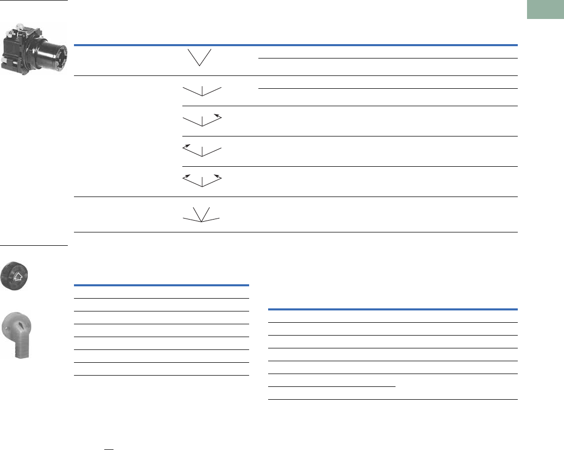
Volume 7—Logic Control, Operator Interface and Connectivity Solutions CA08100008E—March 2014 www.eaton.com V7-T1-353
1
1
1
1
1
1
1
1
1
1
1
1
1
1
1
1
1
1
1
1
1
1
1
1
1
1
1
1
1
1
1.11
Pushbuttons and Indicating Lights
30.5 mm Class I Division 2 Hazardous Locations—10250T/E34
Illuminated Selector Switch Operator Only without Knob or Lever
Knobs and Levers Light Unit Voltage Suffix
Add to operator catalog number listed in table above.
Notes
Use NEMA 4X 10250T operators where exposed to ultraviolet light, see Page V7-T1-352.
1 Operator includes lens gasket and lens attachment screws.
2 Replace underscore with proper voltage suffix code from Light Unit Voltage Suffix table above. Example: three-position maintained with 120V transformer type light unit:
E34VGB120H.
3 Full voltage light units can be used at other than listed voltages by changing lamp. Replacement lamps are listed on Page V7-T1-239.
4 120MB lamps are used on both 120V and 240V operators.
5 For selection of the proper cam and contact block required to obtain a specific circuit sequence, see selection table on Page V7-T1-348.
6 120 and 240V transformer only.
7 120 full voltage only.
8 Resistor type. May generate excess heat if used in high density.
9 Amber, clear and white lenses have a black arrow (pointer). Red, green and blue lenses have a white arrow (pointer).
Positions Operator Action
Transformer Type—50/60 Hz Full Voltage Type—AC or DC 3
6V #755 Lamp Lamps—#755, #757, #1835, 120MB 4
Catalog Number 12 Catalog Number
2
Two-position—60° throw Cam Code 1 5Cam Code 1 5
E34VFB_H E34SFB_H
Three-position—60° throw Cam Code 2 5Cam Code 3 5Cam Code 2 5Cam Code 3 5
E34VGB_H E34VHB_H E34SGB_H E34SHB_H
E34VNB_H 6E34VPB_H 6E34SNB_H 7E34SPB_H 7
E34VJB_H 6E34VKB_H 6E34SJB_H 7E34SKB_H 7
E34VLB_H E34VMB_H E34SLB_H E34SMB_H
Four-position—40° throw E34VRB_H — E34SRB_H —
120 Vac Transformer
Selector Switch, Cam 1
MM
MM
M
MS
M
MS
M
SS
M
MM
MM
Color 9
Knob
Catalog Number
and Code Number
Lever
Catalog Number
and Code Number
Red 10250TER 10250TFR
Green 10250TEG 10250TFG
Yellow 10250TEA 10250TFA
Blue 10250TEL 10250TFL
Clear 10250TEC 10250TFC
White 10250TEW 10250TFW
Amber 10250TEM 10250TFM
Knob
Lever
Type of Light Unit
Transformer Type
50/60 Hz
Full Voltage Type
AC or DC 3
Voltage Suffix Code Voltage Suffix Code
24 024 606
120 120 12 12
208 208 24 24
240 240 48 48
380 380 120 120
480 480 240 8240
600 600
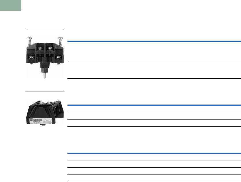
V7-T1-354 Volume 7—Logic Control, Operator Interface and Connectivity Solutions CA08100008E—March 2014 www.eaton.com
1
1
1
1
1
1
1
1
1
1
1
1
1
1
1
1
1
1
1
1
1
1
1
1
1
1
1
1
1
1
1.11
Pushbuttons and Indicating Lights
30.5 mm Class I Division 2 Hazardous Locations—10250T/E34
Options
Contact Blocks and Mounting Adapters
NEC Class I Division 2, Groups B, C and D
Contact Block
Mounting Adapter
Mounting Adapters with Contact Block(s)—Overpacked
Description Catalog Number
Class I Division 2 factory sealed contact block with 1NO-1NC 10250T1H
Dimensions, see Page V7-T1-359.
Description Catalog Number
Mounting adapter for pushbuttons 10250TD2
Mounting adapter for selector switches 10250TD3
Dimensions, see Page V7-T1-359.
Description Catalog Number
Pushbutton adapter with 1NO-1NC 10250TD21H
Pushbutton adapter with 2 (1NO-1NC) 10250TD21H1H
Selector switch adapter with 1NO-1NC 10250TD31H
Selector switch adapter with 2 (1NO-1NC) 10250TD31H1H
Contact Block
Mounting Adapter
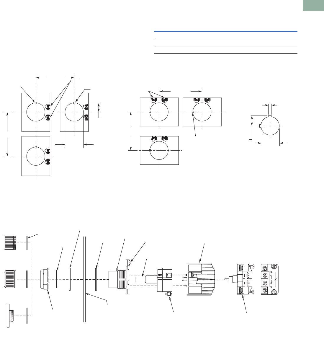
Volume 7—Logic Control, Operator Interface and Connectivity Solutions CA08100008E—March 2014 www.eaton.com V7-T1-355
1
1
1
1
1
1
1
1
1
1
1
1
1
1
1
1
1
1
1
1
1
1
1
1
1
1
1
1
1
1
1.11
Pushbuttons and Indicating Lights
30.5 mm Class I Division 2 Hazardous Locations—10250T/E34
Mounting and Assembly
Panel Thickness
●Minimum: 0.06 in (1.6 mm)
●Maximum: 0.25 in (8 mm) including legend plate
●Maximum can be increased to 0.375 in (15.9 mm) using
optional retaining nut
●Indicating light: 10250TA30/E34TA30
●Pushbutton/selector switch: 10250TA31/E34TA31
Mounting Matrix
Panel Spacing and Drilling
Operator Assembly
Legend
Plate
Dimensions in Inches (mm)
ABCD
Small 2.87 (72.6) 2.25 (57.2) 2.25 (57.2) 2.87 (72.6)
Jumbo 2.87 (72.6) 2.32 (58.6) 2.32 (58.6) 2.87 (72.6)
Extra large 2.87 (72.6) 2.56 (65.2) 2.52 (64.1) 2.87 (72.6)
Notch for
Locating Nib
Notch for
Locating Nib
.60
(15.2)
ø.14
(ø3.4)
ø1.2
(ø30.5)
“B” Min.
“A” Min.
Terminals for
Light Unit
Drilling for One Hole Mounting
and Dimensions for Minimum
Spacing in Vertical Rows.
“D” Min.
“C” Min.
Terminals for
Light Unit
Drilling for One Hole Mounting
and Dimensions for Minimum
Spacing in Horizontal Rows.
.19
(5.0)
.67
(17.0) ø1.2
(ø30.5)
NOTE: Suitable for Use
in This Alternate
Mounting Hole.
Nameplate
Retaining Nut
5 lb-ft (6.8 Nm)
Panel
0.06" – 0.25"
(1.6 – 8 mm)
with Optional
Retaining Nut
Up to 0.375"
(15.9 mm)
Thrust
Washer
(Optional)
Lens
Washer
Illuminated
Pushbutton
Indicator
Light
Push/Pull
Light Unit
Lamp
E34 Earth
Terminal
Operator
Gasket
Operator
Terminal Clamp:
One or Two Copper Conductors
22 – 12 AWG (0.34 – 4.0 mm2)
7 lb-in (0.8 Nm)
Contact Block
Mounting Adapter
RATINGS ARE STAMPED
ON LIGHT UNIT
AND CONTACT BLOCK
Terminal Clamp:
Single Copper Conductor
18 – 14 AWG (0.75 – 2.5 mm2)
9 lb-in (1.0 Nm)
Contact Block
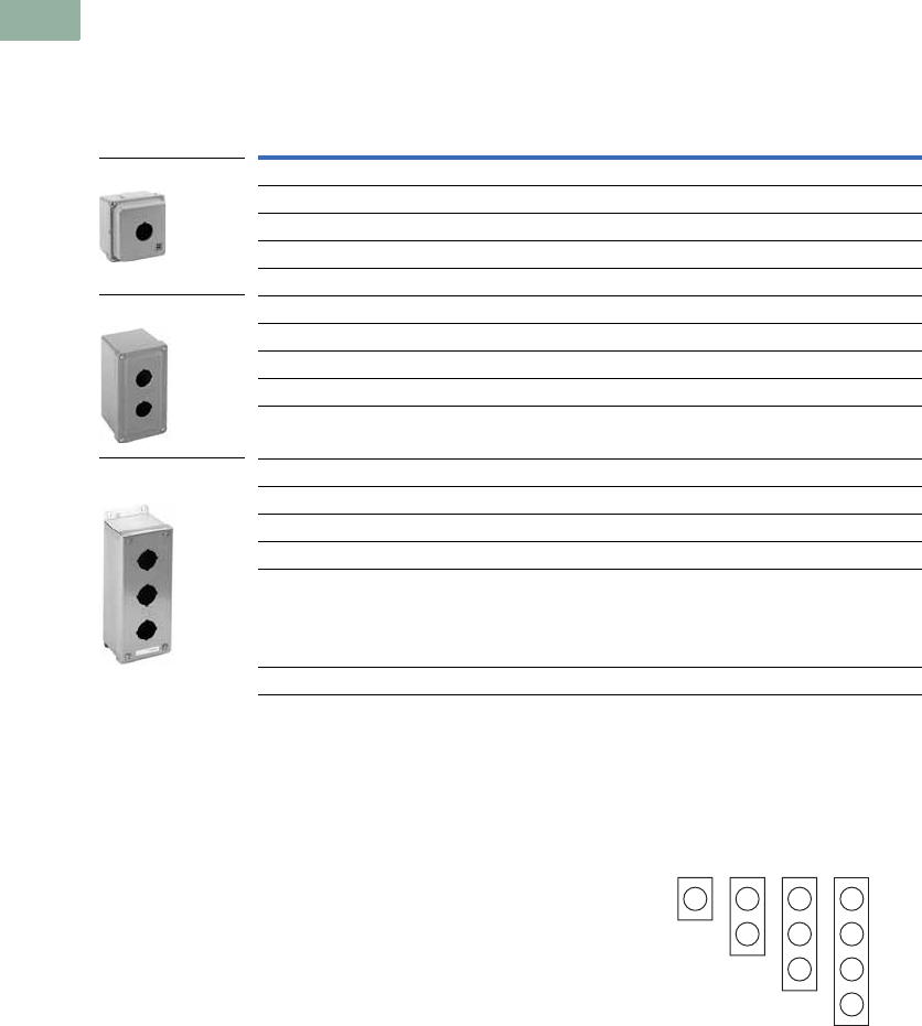
V7-T1-356 Volume 7—Logic Control, Operator Interface and Connectivity Solutions CA08100008E—March 2014 www.eaton.com
1
1
1
1
1
1
1
1
1
1
1
1
1
1
1
1
1
1
1
1
1
1
1
1
1
1
1
1
1
1
1.11
Pushbuttons and Indicating Lights
30.5 mm Class I Division 2 Hazardous Locations—10250T/E34
Enclosures
Die Cast, Polyester and Stainless Steel Enclosures
Enclosures (Case and Cover)—Surface Mounting 1
Notes
1 For spacing increments, see Page V7-T1-234.
2 14 gauge, type 304.
Application Notes:
1. Operators need to be
mounted in their
horizontal orientation for
all enclosures. For die
cast enclosures remove
locating nib on operators
and use thrust washer
(Catalog Number
10250TK3).
2. Polyester enclosures
must be used when
mounting illuminated
operators.
Enclosure Layouts
Number of
Elements
10250T
Catalog Number
E34
Catalog Number
Die Cast Enclosure—Deep Cover—In-Line NEMA 4, 4X, 12, 13
110250TN11 E34N11
210250TN12 E34N12
310250TN13 E34N13
410250TN14 E34N14
Polyester—In-Line NEMA 3, 4X, 12
1— E34N51
2— E34N52
3— E34N53
4— E34N54
Stainless Steel 2—In-Line NEMA 4, 4X, 12
1— 10250TN33
2— 10250TN34
3— 10250TN35
4— 10250TN36
Dimensions, see Page V7-T1-359.
Die Cast Enclosure
Polyester Enclosure
Stainless Steel
Enclosure
111
Top – For Vertical Mounting
Top – For Horizontal
Mounting
1
222
33
4

Volume 7—Logic Control, Operator Interface and Connectivity Solutions CA08100008E—March 2014 www.eaton.com V7-T1-357
1
1
1
1
1
1
1
1
1
1
1
1
1
1
1
1
1
1
1
1
1
1
1
1
1
1
1
1
1
1
1.11
Pushbuttons and Indicating Lights
30.5 mm Class I Division 2 Hazardous Locations—10250T/E34
Technical Data and Specifications
Mechanical Ratings
Climatic Conditions
Te rm i n a l s
Electrical Ratings
Description Specification
Frequency of Operation
All pushbuttons 6000 operations/hr.
Key and lever selector switches 3000 operations/hr.
Life
Pushbuttons 10 x 106 operations
Contact block 10 x 106 operations
Key and lever selector switches 0.25 x 10⁶ operations
Shock Resistance
Duration/force 20 ms >5g
Description Specification
Operating temperature 32° to 140°F (0° to 66°C)
Storage temperature –40° to 176°F (–40° to 80°C)
Altitude 6,562 ft (2,000m)
Humidity Max. 95% RH at 60°C
Description Specification
Light Units
Clamps Terminals are saddle clamp type for 1 x 22 AWG (0.34 mm2) to 2 x 14 AWG (4.0 mm2)
conductors
Torque 7 lb-in (0.8 Nm)
Degree of protection against direct electrical contact IP2X with fingerproof shroud
Contact Blocks
Clamps Terminals are stainless steel saddle clamp type for 1 x 18–14 AWG (0.75–2.5 mm2)
solid or stranded copper conductor
Torque 9 lb-in (1.0 Nm) with size 2 Phillips screwdriver
Degree of protection against direct electrical contact IP2X with fingerproof shroud
Description Specification
Light Units
Bulbs—average life:
Transformer type 20,000 hrs.
Resistor/direct voltage type 2500 hrs. minimum at rated voltage
LED 60,000 to 100,000 hrs.

V7-T1-358 Volume 7—Logic Control, Operator Interface and Connectivity Solutions CA08100008E—March 2014 www.eaton.com
1
1
1
1
1
1
1
1
1
1
1
1
1
1
1
1
1
1
1
1
1
1
1
1
1
1
1
1
1
1
1.11
Pushbuttons and Indicating Lights
30.5 mm Class I Division 2 Hazardous Locations—10250T/E34
Electrical Ratings—Contact Block
Temperature Codes
All illuminated devices have operating temperatures below
100°C except for the following catalog numbers with
temperature codes per NEC table 500.5(d) and UL 1604:
Note: For additional technical information, see Publication Number
TD.7.4.T.E.04.
Meet or Exceed NEMA Contact Rating Designations A600 and Q300
Description
A600 (AC) Q300 (DC)
120V 240V 480V 600V 125V 250V
Make and emerg. interrupting capacity (amps) 60 30 15 12 0.55 0.27
Normal load break (amps) 6 3 1.5 1.2 0.55 0.27
Thermal current (amps) 10 10 10 10 2.5 2.5
Voltamperes:
Maximum make 7200 7200 7200 7200 69 69
Maximum break 720 720 720 720 69 69
10250T E34 Temp. Code
10250T201H E34RB120H T3C
10250T202H E34RB240H T3A
10250T471H E34SB120H TC3
10250T472H E34SB240H T3B
10250T80H — T3C
10250T81H — T3B
All selector switches w/120 MB lamp T3C
All illuminated devices with lamp 1835 T4A
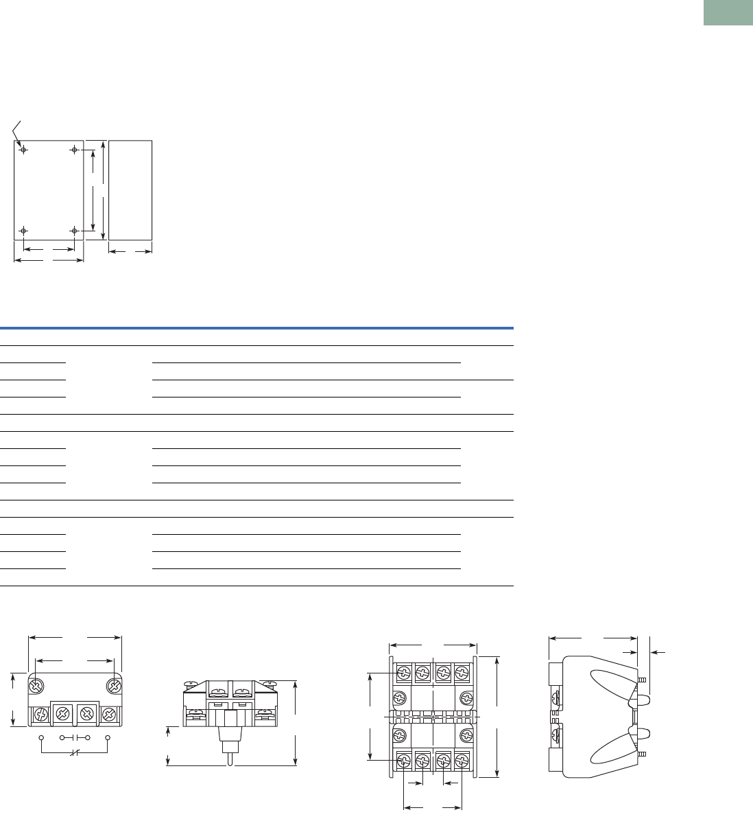
Volume 7—Logic Control, Operator Interface and Connectivity Solutions CA08100008E—March 2014 www.eaton.com V7-T1-359
1
1
1
1
1
1
1
1
1
1
1
1
1
1
1
1
1
1
1
1
1
1
1
1
1
1
1
1
1
1
1.11
Pushbuttons and Indicating Lights
30.5 mm Class I Division 2 Hazardous Locations—10250T/E34
Dimensions
Approximate Dimensions in Inches (mm)
Surface Mounting
Die Cast, Polyester and Stainless Steel Enclosures
Contact Block Mounting Adapter
Note
1No conduit entrance holes provided. Drill as required.
A
Surface
DC
B
E
4 Mtg. Holes — 10-32 Screw Size for
1 – 4 Element Die Cast/
Stainless Steel Enclosure
7/32 Screw Size for
Polyester
Number of
Elements
Element
Arrangement
Wide
A
High
B
Deep
C
Mounting Conduit
EntranceDE
Die Cast
1 In-line 3.88 (98.6) 4.00 (101.6) 3.00 (76.3) 2.69 (68.3) 3.25 (82.6) 3/4
2 3.88 (98.6) 5.88 (149.4) 3.00 (76.3) 2.69 (68.3) 5.13 (130.3)
3 3.88 (98.6) 7.75 (196.9) 3.00 (76.3) 2.69 (68.3) 7.00 (177.8) 1
4 3.88 (98.6) 9.63 (244.6) 3.00 (76.3) 2.69 (68.3) 8.88 (225.6)
Polyester
1 In-line 3.81 (96.8) 6.63 (168.4) 3.38 (85.9) 2.94 (74.7) 4.88 (124.0) 1
2 3.81 (96.8) 6.63 (168.4) 3.38 (85.9) 2.94 (74.7) 4.88 (124.0)
3 3.81 (96.8) 8.88 (225.6) 3.38 (85.9) 2.94 (74.7) 7.13 (181.1)
4 3.81 (96.8) 11.13 (282.7) 3.38 (85.9) 2.94 (74.7) 9.38 (238.3)
Stainless Steel
1 In-line 3.00 (76.2) 3.50 (88.9) 3.00 (76.2) 1.50 (38.1) 4.25 (108.0) 1
2 3.50 (88.9) 6.75 (171.5) 3.00 (76.2) 1.50 (38.1) 7.50 (190.5)
3 3.50 (88.9) 9.00 (228.6) 3.00 (76.2) 1.50 (38.1) 9.00 (228.6)
4 3.50 (88.9) 11.25 (285.8) 3.00 (76.2) 1.50 (38.1) 12.00 (304.8)
1.43
(36.3)
1.70
(43.2)
1.02
(25.9)
1.72
(43.7)
0.84
(21.3)
0.44
(11.2)
1.23
(31.2)
1.85
(47.0)
1.86
(47.2)
1.88
(47.8) 0.25
(6.4)
2.57
(65.3)
V7-T1-360 Volume 7—Logic Control, Operator Interface and Connectivity Solutions CA08100008E—March 2014 www.eaton.com
1
1
1
1
1
1
1
1
1
1
1
1
1
1
1
1
1
1
1
1
1
1
1
1
1
1
1
1
1
1
1.11
Pushbuttons and Indicating Lights
30.5 mm Class I Division 2 Hazardous Locations—10250T/E34
Ratings
Summary of NEC Article 500
The NEC Article 500 explains
in great detail the
requirements for the
installation of wiring and
electrical equipment in
hazardous locations. The
purpose of this summary is
for general reference only,
the National Electrical Code
along with other applicable
authorities having jurisdiction
over the site should be the
installer’s guidelines when
wiring or installing electrical
equipment in any hazardous
or potentially hazardous
location.
Class I, Division 2 Definition
Class I, Division 2 covers
hazardous locations where
flammable gases, vapors or
volatile liquids are handled
either in a closed system, or
confined within suitable
enclosures, or where
hazardous concentrations are
normally prevented by
positive mechanical
ventilation. Areas adjacent to
Division 1 locations, into
which gases might
occasionally flow, would
also belong to Division 2
(NEC (500.5[b])).
Hazardous Location
Any area where there is the
possibility of explosion and
fire resulting from the
presence of flammable
vapors, liquids or gas, or
combustible dust or fibers.
Summary of NEC Article 505
The NEC also classifies
hazardous locations for
flammable gases and vapors
into zones under NEC 505.
This system is more in line
with the European
Standards, CENELEC and
IEC, with the major
difference being that NEC
505 only classifies gases and
vapors while CENELEC and
IEC also include dusts.
Summary of Classifications
NEC 500–503
NEC 505
Note
For additional information on grouping of compounds, see NFPA 497M-1991 and NFPA 325-1994.
Class Division Group
I. Gas 1. Hazard may exist—May exist in
atmosphere under normal operating
conditions
A. Acetylene
B. Hydrogen and manufactured gases containing 30% hydrogen by
volume (e.g. butadiene, ethylene oxide, propylene oxide)
C. Petrochemicals (e.g. carbon monoxide, ether, ethylene, hydrogen
sulfide, morpholine, cyclopropane)
D. Petrochemicals (e.g. gasoline, benzene, butane, propane, acetone,
ammonia, vinyl chloride)
2. Potential hazard—May be present in
atmosphere only under abnormal
circumstances OR location adjacent to
Class I, Division 1 location
A. Acetylene
B. Hydrogen and manufactured gases containing 30% hydrogen by
volume (e.g. butadiene, ethylene oxide, propylene oxide)
C. Petrochemicals (e.g. carbon monoxide, ether, ethylene, hydrogen
sulfide, morpholine, cyclopropane)
D. Petrochemicals (e.g. gasoline, benzene, butane, propane, acetone,
ammonia, vinyl chloride)
II. Dust 1. Hazard may exist—May exist in
atmosphere under normal operating
conditions
E. Conductive and combustible dust (resistivity <105 ohm/cm)
(metal dusts)
F. Carbonaceous dusts (resistivity >102 ohms/cm but <108 ohms/cm) (e.g.
carbon black, coke dust, coal)
G. Non-conductive combustible dust (resistivity >105 ohms/cm) (e.g. grain
dust, flour, starch, sugar, plastics)
2. Potential hazard—May be present in
atmosphere only under abnormal
circumstances
F. Carbonaceous dusts (resistivity >102 ohms/cm but <108 ohms/cm) (e.g.
carbon black, coke dust, coal)
G. Non-conductive combustible dust (resistivity >105 ohms/cm) (e.g. grain
dust, flour, starch, sugar, plastics)
III. Fibers 1. Production areas Easily ignitable fibers or flyings
2. Handling and storage areas Easily ignitable fibers or flyings
Class Zone Group
I. Gas 0. Continuously present or present for long
periods of time
IIC. Acetylene, hydrogen or equivalent hazard
IIB. Acetaldehyde, ethylene or equivalent hazard
IIA. Acetone, ammonia, ethyl alcohol, gasoline, methane, propane or
equivalent hazard
IIC. Acetylene, hydrogen or equivalent hazard1. Likely to exist under normal operating or
maintenance conditions or adjacent to
Zone 0 IIB. Acetaldehyde, ethylene or equivalent hazard
IIA. Acetone, ammonia, ethyl alcohol, gasoline, methane, propane or
equivalent hazard
2. Not likely to occur in normal operation
and if they do occur will only exist for
short period or adjacent to Zone 1
IIC. Acetylene, hydrogen or equivalent hazard
IIB. Acetaldehyde, ethylene or equivalent hazard
IIA. Acetone, ammonia, ethyl alcohol, gasoline, methane, propane or
equivalent hazard
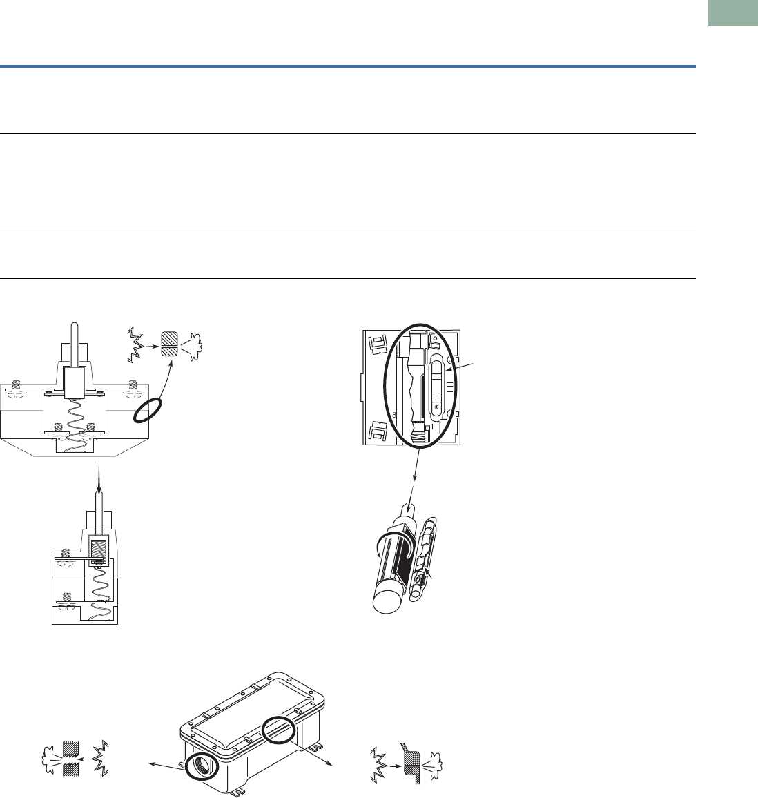
Volume 7—Logic Control, Operator Interface and Connectivity Solutions CA08100008E—March 2014 www.eaton.com V7-T1-361
1
1
1
1
1
1
1
1
1
1
1
1
1
1
1
1
1
1
1
1
1
1
1
1
1
1
1
1
1
1
1.11
Pushbuttons and Indicating Lights
30.5 mm Class I Division 2 Hazardous Locations—10250T/E34
Summary of Basic Methods Available for Class I, Division 2 Locations
Factory Sealed Contact Blocks Hermetically Sealed Reed Contact Block
Explosion Proof Enclosure
Method
Features
Configuration Advantages Disadvantages
Factory sealed contact block Closed-ended labyrinth contact block with an
incendive circuit incapable of external ignition
Higher continuous carrying amperages—up to 10A
Direct drive contacts—contacts can be forced open
Suitable for use in all enclosures
Best suited for motor control applications
May not be suitable for logic level circuits
Hermetically sealed block Reed switch sealed against an external
atmosphere
Suitable for low energy level circuits
Suitable for use in all enclosures
Lower continuous carrying amperages are not
suitable for motor control applications
(typically 3A to 5A rated)
Contacts cannot be forced open
Permanent magnet attracts metallic dust and
filings that can reduce the electrical creepage
distance between live terminals
Explosion proof enclosures
(Class I, Division 1 and 2)
Enclosures capable of withstanding an internal
explosion while preventing external ignition.
Enclosures designed for Class I, Division 1 can
safely be used in Class I, Division 2
Higher level of protection than required for Class I
Division 2
Higher material and installation costs
Conduit sealing is still required
Time consuming maintenance
Direct Drive Contacts
Contacts can be
mechanically forced
apart if subject to an
arch/fault current.
Cooled
Escaping
Gas
Internal
Ignition
•
Hermetically sealed
reed does not allow
external atmosphere to
enter switching chamber.
Depression of plunger
rotates magnet and either
opens/closes contacts.
Contacts can not be
forced apart if subject to
arch/fault current, because no
mechanical connection exists.
Cooled
Escaping
Gas
Threaded Joint Flat Joint
Internal
Ignition Internal
Ignition Cooled
Escaping
Gas
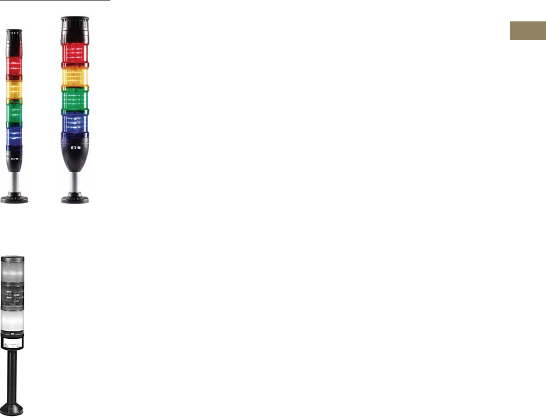
Volume 7—Logic Control, Operator Interface and Connectivity Solutions CA08100008E—March 2014 www.eaton.com V7-T2-1
2
2
2
2
2
2
2
2
2
2
2
2
2
2
2
2
2
2
2
2
2
2
2
2
2
2
2
2
2
2
Stacklights
E26 Series Stacklights
SL Series Stacklights
2.1 SL Series
Product Description . . . . . . . . . . . . . . . . . . . . . . . . . . . . . . . . . . . . . . . V7-T2-2
Features . . . . . . . . . . . . . . . . . . . . . . . . . . . . . . . . . . . . . . . . . . . . . . . . V7-T2-2
Benefits . . . . . . . . . . . . . . . . . . . . . . . . . . . . . . . . . . . . . . . . . . . . . . . . V7-T2-2
Standards and Certifications . . . . . . . . . . . . . . . . . . . . . . . . . . . . . . . . V7-T2-2
Product Overview . . . . . . . . . . . . . . . . . . . . . . . . . . . . . . . . . . . . . . . . V7-T2-3
Component Identification—SL7 . . . . . . . . . . . . . . . . . . . . . . . . . . . . . V7-T2-4
Product Selection—SL7 . . . . . . . . . . . . . . . . . . . . . . . . . . . . . . . . . . . . V7-T2-6
Component Identification—SL4 . . . . . . . . . . . . . . . . . . . . . . . . . . . . . V7-T2-12
Product Selection—SL4 . . . . . . . . . . . . . . . . . . . . . . . . . . . . . . . . . . . . V7-T2-14
Accessories . . . . . . . . . . . . . . . . . . . . . . . . . . . . . . . . . . . . . . . . . . . . . V7-T2-19
Technical Data and Specifications . . . . . . . . . . . . . . . . . . . . . . . . . . . . V7-T2-20
Dimensions . . . . . . . . . . . . . . . . . . . . . . . . . . . . . . . . . . . . . . . . . . . . . V7-T2-25
2.2 E26 Series
Product Description . . . . . . . . . . . . . . . . . . . . . . . . . . . . . . . . . . . . . . . V7-T2-32
Features . . . . . . . . . . . . . . . . . . . . . . . . . . . . . . . . . . . . . . . . . . . . . . . . V7-T2-32
Benefits . . . . . . . . . . . . . . . . . . . . . . . . . . . . . . . . . . . . . . . . . . . . . . . . V7-T2-32
Standards and Certifications . . . . . . . . . . . . . . . . . . . . . . . . . . . . . . . . V7-T2-32
Product Identification . . . . . . . . . . . . . . . . . . . . . . . . . . . . . . . . . . . . . . V7-T2-33
Catalog Number Selection . . . . . . . . . . . . . . . . . . . . . . . . . . . . . . . . . . V7-T2-34
Product Selection . . . . . . . . . . . . . . . . . . . . . . . . . . . . . . . . . . . . . . . . . V7-T2-35
Replacement Parts . . . . . . . . . . . . . . . . . . . . . . . . . . . . . . . . . . . . . . . V7-T2-40
Technical Data and Specifications . . . . . . . . . . . . . . . . . . . . . . . . . . . . V7-T2-41
Ratings . . . . . . . . . . . . . . . . . . . . . . . . . . . . . . . . . . . . . . . . . . . . . . . . . V7-T2-42
Mounting Instructions . . . . . . . . . . . . . . . . . . . . . . . . . . . . . . . . . . . . . V7-T2-43
Dimensions . . . . . . . . . . . . . . . . . . . . . . . . . . . . . . . . . . . . . . . . . . . . . V7-T2-44
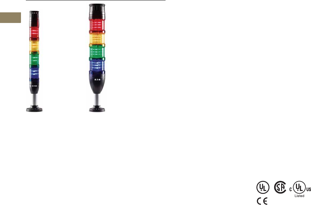
V7-T2-2 Volume 7—Logic Control, Operator Interface and Connectivity Solutions CA08100008E—March 2014 www.eaton.com
2
2
2
2
2
2
2
2
2
2
2
2
2
2
2
2
2
2
2
2
2
2
2
2
2
2
2
2
2
2
2.1
Stacklights
SL Series
Stacklights—SL Series
Contents
Description Page
SL Series
Product Overview . . . . . . . . . . . . . . . . . . . . . . V7-T2-3
Component Identification—SL7 . . . . . . . . . . . . V7-T2-4
Product Selection—SL7 . . . . . . . . . . . . . . . . . . V7-T2-6
Component Identification—SL4 . . . . . . . . . . . . V7-T2-12
Product Selection—SL4 . . . . . . . . . . . . . . . . . . V7-T2-14
Accessories . . . . . . . . . . . . . . . . . . . . . . . . . . . V7-T2-19
Technical Data and Specifications . . . . . . . . . . V7-T2-20
Dimensions . . . . . . . . . . . . . . . . . . . . . . . . . . . V7-T2-25
Product Description
The new Eaton SL7 and SL4
stacklights provide reliable
control over all key processes
and machine availability.
Now available in two sizes,
70 mm (SL7) and 40 mm
(SL4), the new stacklights
are engineered to keep you
informed about potential
material requirements,
downtime and hazards.
Modules are available in
a wide selection of audible,
illuminating and mounting
options that are well suited
to adapt to any industrial
application.
Highly Modular and
Versatile Line
●Easily configurable
components
●Simple bayonet mounting
mechanism for quick
assembly
●Flexible mounting and
lighting options
●Volume-adjustable alarms
Optimal Performance in
Rugged Applications
●All elements have IP66 and
UL Type 4/4X/13 ratings for
protection against strong
jets of water
●Bright and efficient LEDs
with a lifespan of up to
100,000 hours
●High-performance LEDs for
maximum illumination in
direct sunlight
●Acoustic modules with up
to 100 dB sound levels
●Operating temperatures:
–22° to +140°F
(–30º to +60ºC)
Features
●Six lens colors: red, amber,
yellow, green, blue, white
●Continuous, flashing,
strobe and multi-strobe
lighting functions
●Mono-tone, dual-tone and
multi-tone audible alarms
●LED or incandescent
lighting options
●Control up to five modules
on a single stack, 10 with
dual-arm base
●24V, 120 Vac and 230 Vac
operating voltages
Benefits
●Simplified twist-and-lock
assembly, no tools
required
●Compact components
reduce inventory
requirements and increase
flexibility
●Versatile hardware for
quick installation and
minimized downtime
●New slim 40 mm size is
ideal for applications with
constrained space
●Lean automation with
SmartWire-DT connectivity
●Ideal for indoor and
outdoor usage
Standards and
Certifications
●UL 508—File No. E29184
●IEC/EN 60947-5-1
●CSA C22.2 No. 14-10
●CSA C22.2 No. 94-91
●CSA Class No. NKCR7
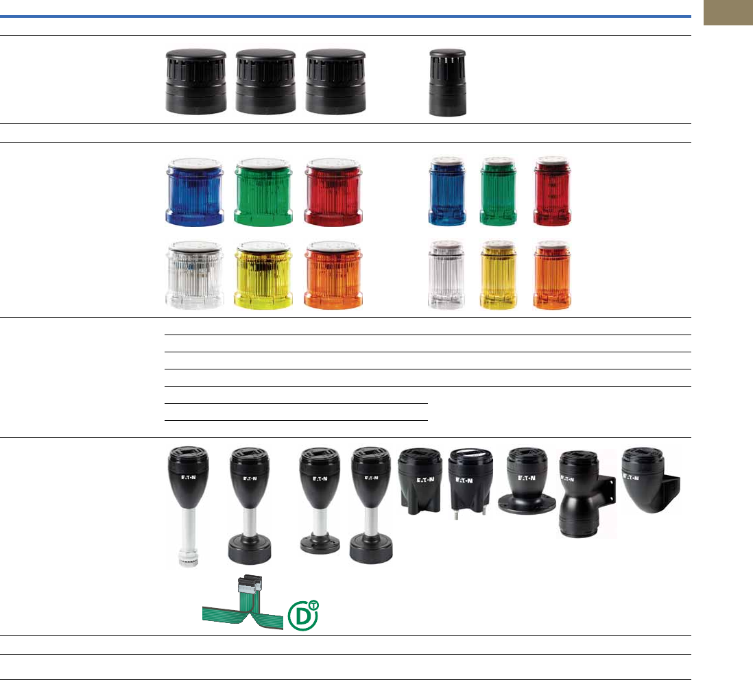
Volume 7—Logic Control, Operator Interface and Connectivity Solutions CA08100008E—March 2014 www.eaton.com V7-T2-3
2
2
2
2
2
2
2
2
2
2
2
2
2
2
2
2
2
2
2
2
2
2
2
2
2
2
2
2
2
2
2.1
Stacklights
SL Series
Product Overview
SL7 SL4
Diameter 70 mm 40 mm
Acoustic Modules Page V7-T2-9 Page V7-T2-16
Light Modules Continuous light, LED: Page V7-T2-6 Continuous light, LED: Page V7-T2-16
Flashing light, LED: Page V7-T2-7 Flashing light, LED: Page V7-T2-15
Strobe light, LED: Page V7-T2-7 Strobe light, LED: Page V7-T2-15
Continuous light, high-performance LED: Page V7-T2-8 Multi-strobe light, LED: Page V7-T2-17
Strobe light, high-performance LED: Page V7-T2-8 Continuous light, Incandescent: Page V7-T2-17
Multi-strobe light, high-performance LED: Page V7-T2-8
Continuous light, Incandescent: Page V7-T2-8
Base Modules Page V7-T2-10, V7-T2-11 Page V7-T2-17
Accessories Page V7-T2-19 Page V7-T2-19
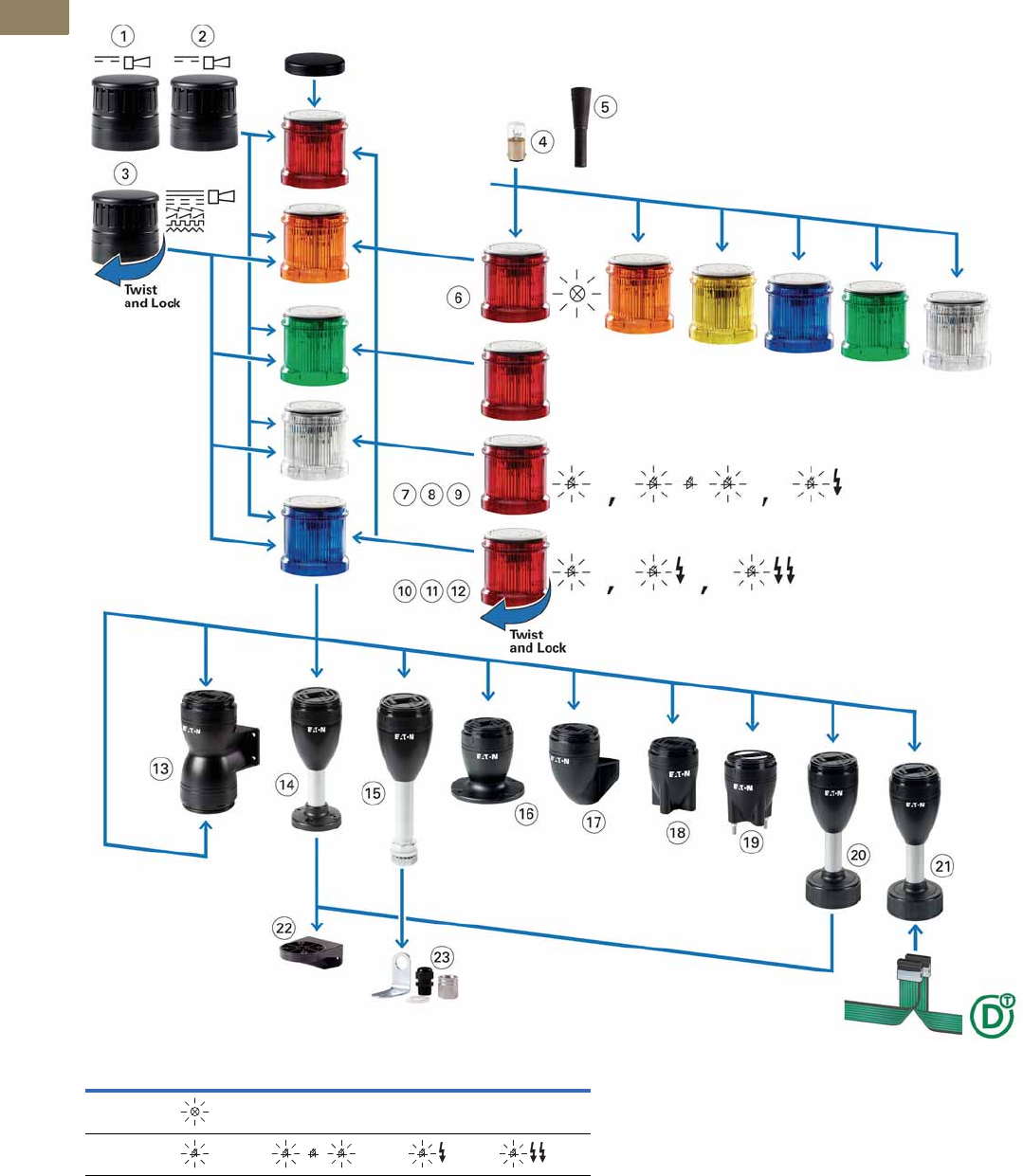
V7-T2-4 Volume 7—Logic Control, Operator Interface and Connectivity Solutions CA08100008E—March 2014 www.eaton.com
2
2
2
2
2
2
2
2
2
2
2
2
2
2
2
2
2
2
2
2
2
2
2
2
2
2
2
2
2
2
2.1
Stacklights
SL Series
Component Identification—SL7
Component Identification
Light Modes
Continuous Flashing Strobe Multi-Strobe
Incandescent ———
LED

Volume 7—Logic Control, Operator Interface and Connectivity Solutions CA08100008E—March 2014 www.eaton.com V7-T2-5
2
2
2
2
2
2
2
2
2
2
2
2
2
2
2
2
2
2
2
2
2
2
2
2
2
2
2
2
2
2
2.1
Stacklights
SL Series
SL7—Component Identification Descriptions
Item
Item
Number Description
Page
Reference
Acoustic Modules
Easy mounting with bayonet mount, place at highest position
Sound pressure up to 100 dB, adjustable with internal potentiometer
Operating mode: 100% DF (duty factor)
Degree of protection: UL Type 4/4X/13, IP66
Operational voltages: 24 Vac/Vdc, 110/120 Vac, 230/240 Vac
1 Continuous tone or pulsed tone, adjustable with internal DIP switches
Frequency: 2800 Hz
V7-T2-9
2 Continuous tone or pulsed tone; can be actuated externally; takes up to
two inputs (two modules)
Frequency: 2800 Hz
V7-T2-9
3 Multi-tone (eight tones) adjustable with internal DIP switch
Frequency 500–2700 Hz
V7-T2-9
Incandescent Bulb 4 Accessory V7-T2-19
Tool for Replacing Incandescent Bulb 5 Accessory V7-T2-19
Light Modules
Easy mounting with bayonet mount, modules can be arranged in any order
Operating mode: 100% DF (duty factor)
Degree of protection: UL Type 4/4X/13, IP66
Max. 5 modules per stack or up to 10 via dual-arm base option
Light Module for Incandescent Bulb
Continuous light 6 BA15d socket, without incandescent bulb V7-T2-7
Light Modules with LED
Continuous light 7V7-T2-6
Flashing light 8Flashing frequency: 2 Hz V7-T2-7
Strobe light 9Flashing frequency: 1.4 Hz V7-T2-7
Light Modules with High-Output LED
Continuous light 10 V7-T2-8
Strobe light 11 High-performance LED, flashing frequency: 1.4 Hz V7-T2-8
Strobe light, multi-strobe light 12 High-performance LED, with various strobe sequences
Flashing frequency: 1–2.6 Hz
V7-T2-8
Base Modules
Easy mounting with bayonet mount, includes cover plate, with spring-cage terminals
Degree of protection: UL Type 4/4X/13, IP66
Base for mounting on both sides 13 Max. 2 x 5 modules that can be actuated individually V7-T2-11
Base with aluminum tube and plastic foot 14 Aluminum tube 100 mm, 250 mm or 400 mm V7-T2-10
Base with aluminum tube and threaded 1/2 in NPT 15 Aluminum tube 100 mm, 250 mm or 400 mm V7-T2-10
Base with external fixing holes 16 — V7-T2-10
Vertical base with bracket 17 — V7-T2-11
Base with internal (on the inside) fixing holes 18 — V7-T2-10
Base with built-in fixing screws (pre-assembled) 19 — V7-T2-10
Base with base adapter for slipping onto place (rapid mounting and wiring system) 20 Aluminum tube 100 mm, 250 mm or 400 mm V7-T2-10
Base with base adapter for slipping onto place (rapid mounting and wiring system)
and SmartWire-DT ™ connection
21 Aluminum tube 100 mm V7-T2-10
Mounting Bracket
Bracket 22 Accessory V7-T2-19
Bracket 23 Accessory, includes M20 cable gland V7-T2-19
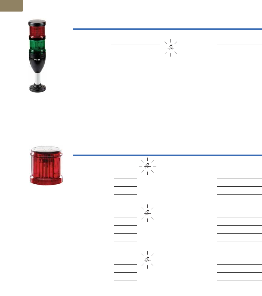
V7-T2-6 Volume 7—Logic Control, Operator Interface and Connectivity Solutions CA08100008E—March 2014 www.eaton.com
2
2
2
2
2
2
2
2
2
2
2
2
2
2
2
2
2
2
2
2
2
2
2
2
2
2
2
2
2
2
2.1
Stacklights
SL Series
Product Selection—SL7
Complete Devices
Continuous Light, LED, UL Type 4/4X/13, IP66
Light Module with LED
Continuous Light, UL Type 4/4X/13, IP66
Rated Operational
Voltage (Ue V)
Number of
Modules Color Function
Standard
Pack Catalog Number
Base Module with Foot and 100 mm Tube
24 Vac/Vdc 2 Red/Green 1 SL7-100-L-RG-24LED
3 Red/Amber/
Green
SL7-100-L-RAG-24LED
Rated Operational
Voltage (Ue V) Color Function
Standard
Pack Catalog Number
24 Vac/Vdc Blue 1 SL7-L24-B
Green SL7-L24-G
Red SL7-L24-R
White SL7-L24-W
Yellow SL7-L24-Y
Amber SL7-L24-A
110/120 Vac Blue 1 SL7-L120-B
Green SL7-L120-G
Red SL7-L120-R
White SL7-L120-W
Yellow SL7-L120-Y
Amber SL7-L120-A
230/240 Vac Blue 1 SL7-L230-B
Green SL7-L230-G
Red SL7-L230-R
White SL7-L230-W
Yellow SL7-L230-Y
Amber SL7-L230-A
SL7-100-L-R_
SL7-L_
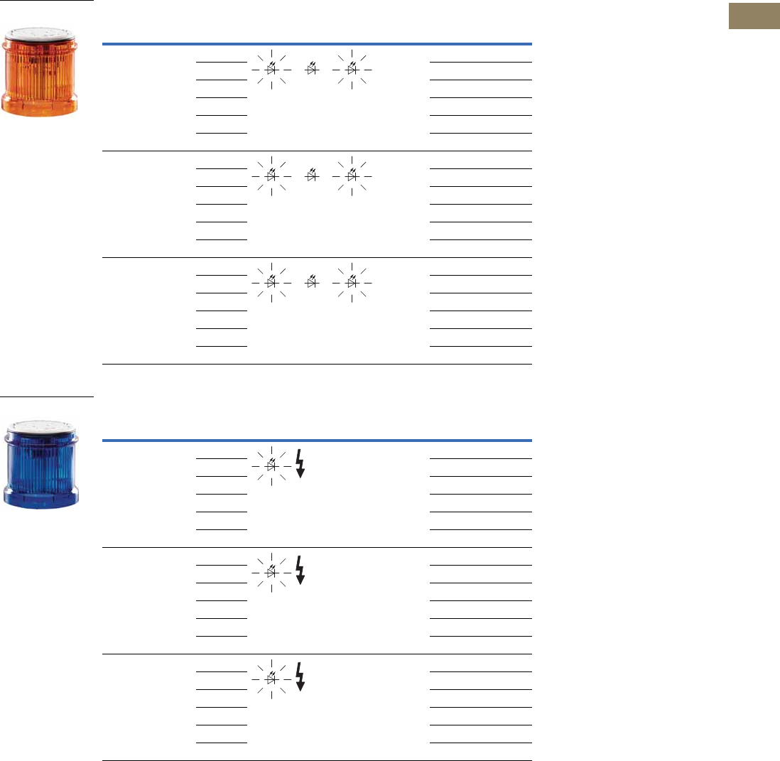
Volume 7—Logic Control, Operator Interface and Connectivity Solutions CA08100008E—March 2014 www.eaton.com V7-T2-7
2
2
2
2
2
2
2
2
2
2
2
2
2
2
2
2
2
2
2
2
2
2
2
2
2
2
2
2
2
2
2.1
Stacklights
SL Series
Light Module with LED, continued
Flashing Light, UL Type 4/4X/13, IP66, 2 Hz
Strobe Light, UL Type 4/4X/13, IP66, 1.4 Hz
Rated Operational
Voltage (Ue V) Color Function
Standard
Pack Catalog Number
24 Vac/Vdc Blue 1 SL7-BL24-B
Green SL7-BL24-G
Red SL7-BL24-R
White SL7-BL24-W
Yellow SL7-BL24-Y
Amber SL7-BL24-A
110/120 Vac Blue 1 SL7-BL120-B
Green SL7-BL120-G
Red SL7-BL120-R
White SL7-BL120-W
Yellow SL7-BL120-Y
Amber SL7-BL120-A
230/240 Vac Blue 1 SL7-BL230-B
Green SL7-BL230-G
Red SL7-BL230-R
White SL7-BL230-W
Yellow SL7-BL230-Y
Amber SL7-BL230-A
Rated Operational
Voltage (Ue V) Color Function
Standard
Pack Catalog Number
24 Vac/Vdc Blue 1 SL7-FL24-B
Green SL7-FL24-G
Red SL7-FL24-R
White SL7-FL24-W
Yellow SL7-FL24-Y
Amber SL7-FL24-A
110/120 Vac Blue 1 SL7-FL120-B
Green SL7-FL120-G
Red SL7-FL120-R
White SL7-FL120-W
Yellow SL7-FL120-Y
Amber SL7-FL120-A
230/240 Vac Blue 1 SL7-FL230-B
Green SL7-FL230-G
Red SL7-FL230-R
White SL7-FL230-W
Yellow SL7-FL230-Y
Amber SL7-FL230-A
SL7-BL_
SL7-FL_
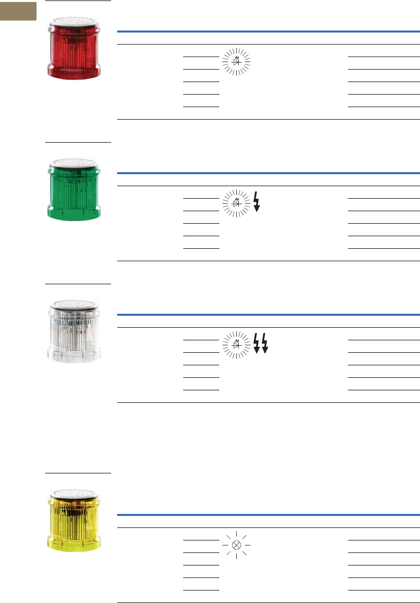
V7-T2-8 Volume 7—Logic Control, Operator Interface and Connectivity Solutions CA08100008E—March 2014 www.eaton.com
2
2
2
2
2
2
2
2
2
2
2
2
2
2
2
2
2
2
2
2
2
2
2
2
2
2
2
2
2
2
2.1
Stacklights
SL Series
SL7 Light Module with High-Output LED
Continuous Light, UL Type 4/4X/13, IP66
Strobe Light, UL Type 4/4X/13, IP66
Multi-Strobe Light, UL Type 4/4X/13, IP66
SL7 Light Module for Incandescent Bulb
Continuous Light, UL Type 4/4X/13, IP66
For incandescent bulb selection, see Page V7-T2-19.
Rated Operational
Voltage (Ue V) Color Function
Standard
Pack Catalog Number
High-Performance LED for Maximum Signaling Effect
24 Vac/Vdc Blue 1 SL7-L24-B-HP
Green SL7-L24-G-HP
Red SL7-L24-R-HP
White SL7-L24-W-HP
Yellow SL7-L24-Y-HP
Amber SL7-L24-A-HP
Rated Operational
Voltage (Ue V) Color Function
Standard
Pack Catalog Number
High-Performance LED for Maximum Signaling Effect, 1.4 Hz
24 Vac/Vdc Blue 1 SL7-FL24-B-HP
Green SL7-FL24-G-HP
Red SL7-FL24-R-HP
White SL7-FL24-W-HP
Yellow SL7-FL24-Y-HP
Amber SL7-FL24-A-HP
Rated Operational
Voltage (Ue V) Color Function
Standard
Pack Catalog Number
High-Performance LED for Maximum Signaling Effect, 1–2.6 Hz
24 Vac/Vdc Blue 1 SL7-FL24-B-HPM
Green SL7-FL24-G-HPM
Red SL7-FL24-R-HPM
White SL7-FL24-W-HPM
Yellow SL7-FL24-Y-HPM
Amber SL7-FL24-A-HPM
Rated Operational
Voltage (Ue V) Color Function
Standard
Pack Catalog Number
Without Light Elements, Incandescent Bulb, Maximum 7W
<250 Vac/Vdc Blue 1 SL7-L-B
Green SL7-L-G
Red SL7-L-R
White SL7-L-W
Yellow SL7-L-Y
Amber SL7-L-A
SL7-L24-_
SL7-FL24-_-HP
SL7-FL24-_-HPM
SL7-L-_
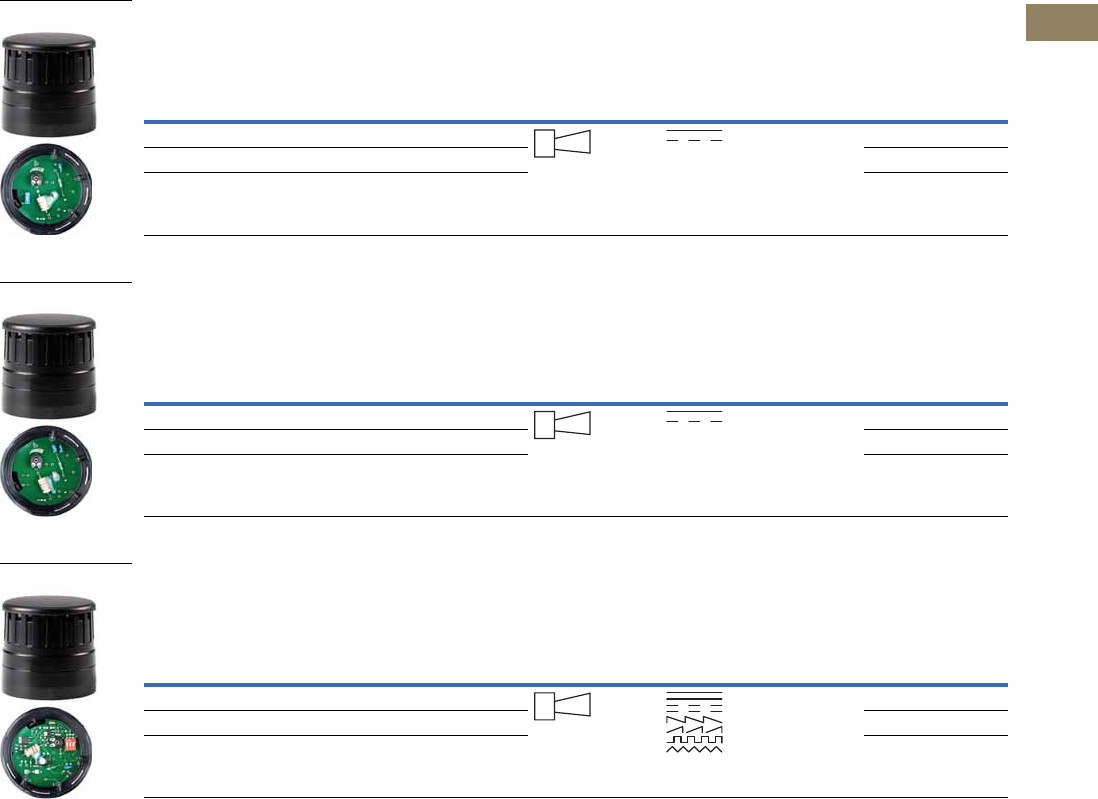
Volume 7—Logic Control, Operator Interface and Connectivity Solutions CA08100008E—March 2014 www.eaton.com V7-T2-9
2
2
2
2
2
2
2
2
2
2
2
2
2
2
2
2
2
2
2
2
2
2
2
2
2
2
2
2
2
2
2.1
Stacklights
SL Series
SL7 Acoustic Modules
Continuous Tone or Pulsed Tone, UL Type 4/4X/13, IP66 1
Adjustable with internal DIP switches.
Sound pressure 100 dB, adjustable with internal potentiometer.
f = 2800 Hz.
Continuous Tone or Pulsed Tone, External Actuation, UL Type 4/4X/13, IP66 1
Assigned two inputs (two modules).
Sound pressure 100 dB, adjustable with internal potentiometer.
f = 2800 Hz.
Multi-Tone; Eight Tones, UL Type 4/4X/13, IP66 1
Adjustable with internal DIP switch.
Sound pressure 100 dB, adjustable with internal potentiometer.
f = 500–2700 Hz.
Note
1 Place only at the highest position on a pole.
Rated Operational
Voltage (Ue V)
Rated Operational
Current (Ie mA) Color Function Sound Type
Standard
Pack Catalog Number
24 Vac/Vdc Maximum 92 Black 1 SL7-AP24
110/120 Vac Maximum 41 Black SL7-AP120
230/240 Vac Maximum 43 Black SL7-AP230
Rated Operational
Voltage (Ue V)
Rated Operational
Current (Ie mA) Color Function Sound Type
Standard
Pack Catalog Number
24 Vac/Vdc Maximum 92 Black 1 SL7-AP24-E
110/120 Vac Maximum 41 Black SL7-AP120-E
230/240 Vac Maximum 43 Black SL7-AP230-E
Rated Operational
Voltage (Ue V)
Rated Operational
Current (Ie mA) Color Function Sound Type
Standard
Pack Catalog Number
24 Vac/Vdc Maximum 115 Black 1 SL7-AP24-M
110/120 Vac Maximum 45 Black SL7-AP120-M
230/240 Vac Maximum 43 Black SL7-AP230-M
SL7-AP_
SL7-AP_-E
SL7-AP_-M
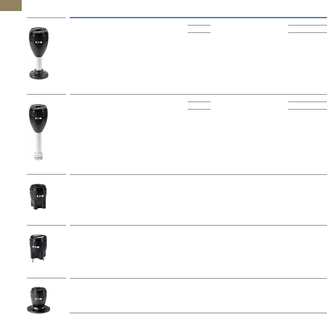
V7-T2-10 Volume 7—Logic Control, Operator Interface and Connectivity Solutions CA08100008E—March 2014 www.eaton.com
2
2
2
2
2
2
2
2
2
2
2
2
2
2
2
2
2
2
2
2
2
2
2
2
2
2
2
2
2
2
2.1
Stacklights
SL Series
SL7 Base Modules
For Horizontal Mounting—Includes Cover, Maximum 5 Modules
Description
Tube
Length Color
Standard
Pack For use with … Catalog Number
Base with aluminum tube and plastic foot
Spring-loaded terminals
100 mm Black
aluminum
color tube
1SL7-L-…
SL7-BL-…
SL7-FL-…
SL7-AP-…
SL7-CB-100
250 mm SL7-CB-250
400 mm SL7-CB-400
Base with aluminum tube and 3/4 in NPT threaded base
Spring-loaded terminals
100 mm Black
aluminum
color tube
1SL7-L-…
SL7-BL-…
SL7-FL-…
SL7-AP-…
SL7-CB-T-100
250 mm SL7-CB-T-250
400 mm SL7-CB-T-400
Base with internal (on the inside) fixing holes
Spring-loaded terminals
—Black1SL7-L-…
SL7-BL-…
SL7-FL-…
SL7-AP-…
SL7-CB-IMH
Base with built-in (pre-assembled) fixing screws
Spring-loaded terminals
—Black1SL7-L-…
SL7-BL-…
SL7-FL-…
SL7-AP-…
SL7-CB-IMS
Base with external fixing holes
Spring-loaded terminals
—Black1SL7-L-…
SL7-BL-…
SL7-FL-…
SL7-AP-…
SL7-CB-EMH
SL7-CB-T-_
SL7-CB-IMH
SL7-CB-IMS
SL7-CB-EMH
SL7-CB-_
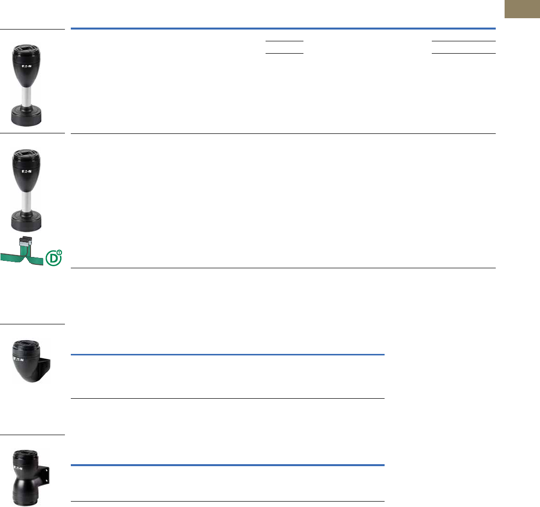
Volume 7—Logic Control, Operator Interface and Connectivity Solutions CA08100008E—March 2014 www.eaton.com V7-T2-11
2
2
2
2
2
2
2
2
2
2
2
2
2
2
2
2
2
2
2
2
2
2
2
2
2
2
2
2
2
2
2.1
Stacklights
SL Series
SL7 Base Modules, continued
For Horizontal Mounting—Includes Cover, Maximum 5 Modules, continued
For Vertical Mounting—Includes Cover, Maximum 5 Modules
For Mounting on Both Sides—Includes Cover, Maximum 2 x 5 Modules
Description
Tube
Length Color
Standard
Pack For use with … Catalog Number
Base with base adapter for slipping onto place (rapid mounting
and wiring system)
Screw terminals
100 mm Black
aluminum
color tube
1SL7-L-…
SL7-BL-…
SL7-FL-…
SL7-AP-…
SL7-FMS-100
250 mm SL7-FMS-250
400 mm SL7-FMS-400
Base with base adapter for slipping onto place (rapid mounting
and wiring system)
Blade terminal SWD4-8MF2
Maximum 0.3A per module
External power supply connectable (24 Vdc)
Configurable with SWD‐Assist (planning and ordering help)
100 mm — 1 SL7-L-…
SL7-BL-…
SL7-FL-…
SL7-AP-…
SL7-SWD
Description Color
Standard
Pack For use with … Catalog Number
Vertical base with bracket
Spring-loaded terminals
Black 1 SL7-L-…
SL7-BL-…
SL7-FL-…
SL7-AP-…
SL7-CB-FW
Description Color
Standard
Pack For use with … Catalog Number
Base with external fixing holes
Spring-loaded terminals
Black 1 SL7-L-…
SL7-BL-…
SL7-FL-…
SL7-AP-…
SL7-CB-D
SL7-FMS_
SL7-SWD
SL7-CB-FW
SL7-CB-D
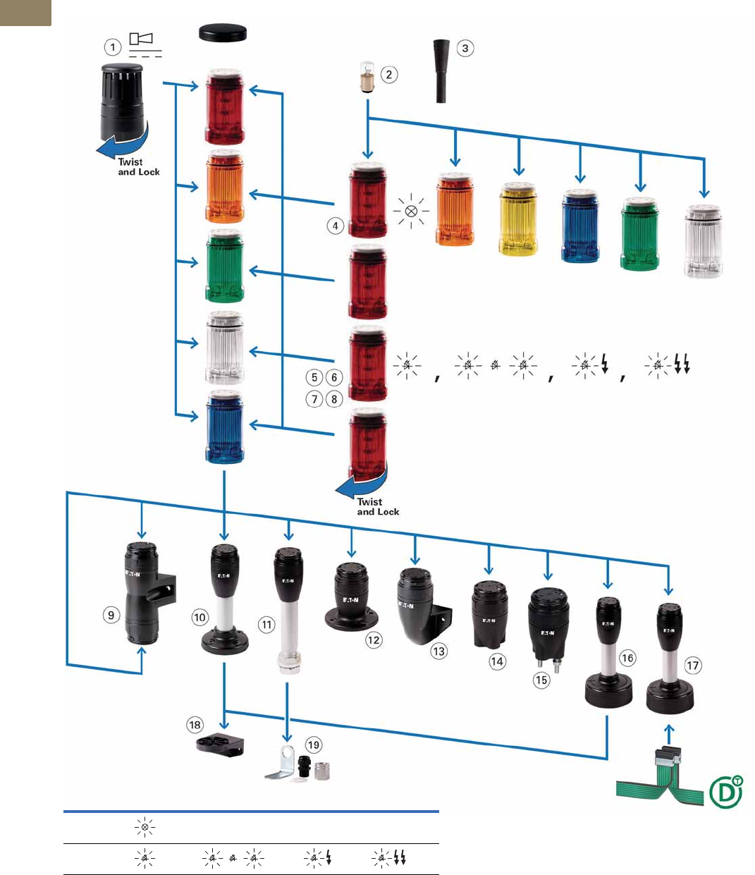
V7-T2-12 Volume 7—Logic Control, Operator Interface and Connectivity Solutions CA08100008E—March 2014 www.eaton.com
2
2
2
2
2
2
2
2
2
2
2
2
2
2
2
2
2
2
2
2
2
2
2
2
2
2
2
2
2
2
2.1
Stacklights
SL Series
Component Identification—SL4
Component Identification
Light Modes
Continuous Flashing Strobe Multi-Strobe
Incandescent ———
LED

Volume 7—Logic Control, Operator Interface and Connectivity Solutions CA08100008E—March 2014 www.eaton.com V7-T2-13
2
2
2
2
2
2
2
2
2
2
2
2
2
2
2
2
2
2
2
2
2
2
2
2
2
2
2
2
2
2
2.1
Stacklights
SL Series
SL4—Component Identification Descriptions
Item
Item
Number Description
Page
Reference
Acoustic Modules
Sound pressure 80 dB, adjustable with internal potentiometer, frequency 4000 Hz
Easy mounting with bayonet mount, set up as highest module
Permanently integrated cover plate
Operating mode: 100% DF (duty factor)
Degree of protection: UL Type 4/4X/13, IP66
1 Continuous tone or pulsed tone, adjustable with internal DIP switches
Frequency: 2800 Hz
V7-T2-16
Incandescent Bulb 2 Accessory V7-T2-19
Tool for Replacing Incandescent Bulb 3 Accessory V7-T2-19
Light Modules
Easy mounting with bayonet mount, modules can be arranged in any order
Without light element (incandescent bulb with BA15d socket),
easy mounting with bayonet mount.
Operating mode: 100% DF (duty factor)
Flashing frequency 2 Hz
Degree of protection: UL Type 4/4X/13, IP66
Light Module for Incandescent Bulb
Continuous light 4 BA15d socket, without incandescent bulb V7-T2-16
Light Modules with LED
Continuous light 5V7-T2-14
Flashing light 6Flashing frequency: 2 Hz V7-T2-15
Strobe light 7Flashing frequency: 1.4 Hz V7-T2-15
Strobe light, multi-strobe light 8 High-performance LED, with various strobe sequences
Flashing frequency: 1–2.6 Hz
V7-T2-16
Base Modules
Easy mounting with bayonet mount, includes cover plate, with spring-cage terminals
Degree of protection: UL Type 4/4X/13, IP66
Base for mounting on both sides 9 Max. 2 x 5 modules that can be actuated individually V7-T2-17
Base with aluminum tube and plastic foot 10 Aluminum tube 100 mm, 250 mm or 400 mm V7-T2-17
Base with aluminum tube and threaded 1/2 in NPT 11 Aluminum tube 100 mm, 250 mm or 400 mm V7-T2-17
Base with external fixing holes 12 — V7-T2-17
Vertical base with bracket 13 — V7-T2-17
Base with internal (on the inside) fixing holes 14 — V7-T2-17
Base with built-in fixing screws (pre-assembled) 15 — V7-T2-17
Base with base adapter for slipping onto place (rapid mounting and wiring system) 16 Aluminum tube 100 mm, 250 mm or 400 mm V7-T2-17
Base with base adapter for slipping onto place (rapid mounting and wiring system)
and SmartWire-DT ™ connection
17 Aluminum tube 100 mm V7-T2-17
Mounting Bracket
Bracket 18 Accessory V7-T2-19
Bracket 19 Accessory, includes M20 cable gland V7-T2-19
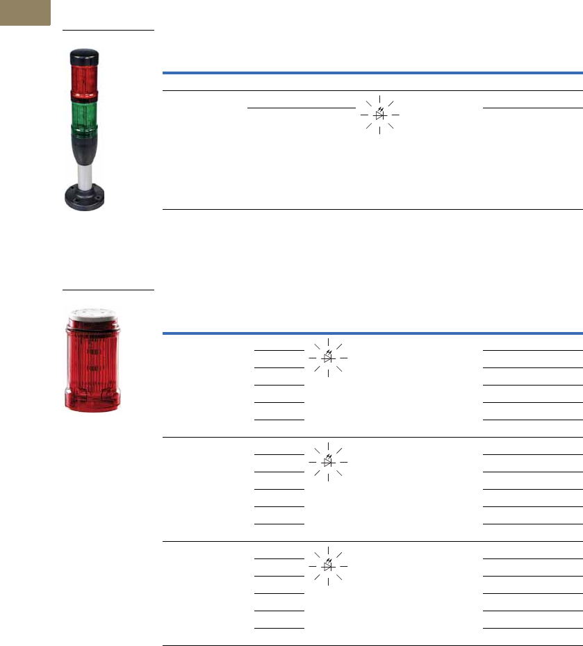
V7-T2-14 Volume 7—Logic Control, Operator Interface and Connectivity Solutions CA08100008E—March 2014 www.eaton.com
2
2
2
2
2
2
2
2
2
2
2
2
2
2
2
2
2
2
2
2
2
2
2
2
2
2
2
2
2
2
2.1
Stacklights
SL Series
Product Selection—SL4
Complete Devices
Continuous Light, LED, UL Type 4/4X/13, IP66
Light Module with LED
Continuous Light, UL Type 4/4X/13, IP66
Rated Operational
Voltage (Ue V)
Number of
Modules Color Function
Standard
Pack Catalog Number
Base Module with Foot and 100 mm Tube
24 Vac/Vdc 2 Red/Green 1 SL4-100-L-RG-24LED
3 Red/Amber/
Green
SL4-100-L-RAG-24LED
SL4-100-L-R_
Rated Operational
Voltage (Ue V) Color Function
Standard
Pack Catalog Number
24 Vac/Vdc Blue 1 SL4-L24-B
Green SL4-L24-G
Red SL4-L24-R
White SL4-L24-W
Yellow SL4-L24-Y
Amber SL4-L24-A
110/120 Vac Blue 1 SL4-L120-B
Green SL4-L120-G
Red SL4-L120-R
White SL4-L120-W
Yellow SL4-L120-Y
Amber SL4-L120-A
230/240 Vac Blue 1 SL4-L230-B
Green SL4-L230-G
Red SL4-L230-R
White SL4-L230-W
Yellow SL4-L230-Y
Amber SL4-L230-A
SL4-L_
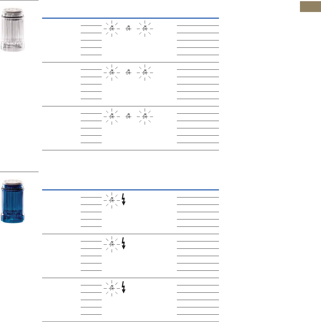
Volume 7—Logic Control, Operator Interface and Connectivity Solutions CA08100008E—March 2014 www.eaton.com V7-T2-15
2
2
2
2
2
2
2
2
2
2
2
2
2
2
2
2
2
2
2
2
2
2
2
2
2
2
2
2
2
2
2.1
Stacklights
SL Series
Light Module with LED, continued
Flashing Light, UL Type 4/4X/13, IP66, 2 Hz
Strobe Light, UL Type 4/4X/13, IP66, 1.4 Hz
Rated Operational
Voltage (Ue V) Color Function
Standard
Pack Catalog Number
24 Vac/Vdc Blue 1 SL4-BL24-B
Green SL4-BL24-G
Red SL4-BL24-R
White SL4-BL24-W
Yellow SL4-BL24-Y
Amber SL4-BL24-A
110/120 Vac Blue 1 SL4-BL120-B
Green SL4-BL120-G
Red SL4-BL120-R
White SL4-BL120-W
Yellow SL4-BL120-Y
Amber SL4-BL120-A
230/240 Vac Blue 1 SL4-BL230-B
Green SL4-BL230-G
Red SL4-BL230-R
White SL4-BL230-W
Yellow SL4-BL230-Y
Amber SL4-BL230-A
Rated Operational
Voltage (Ue V) Color Function
Standard
Pack Catalog Number
24 Vac/Vdc Blue 1 SL4-FL24-B
Green SL4-FL24-G
Red SL4-FL24-R
White SL4-FL24-W
Yellow SL4-FL24-Y
Amber SL4-FL24-A
110/120 Vac Blue 1 SL4-FL120-B
Green SL4-FL120-G
Red SL4-FL120-R
White SL4-FL120-W
Yellow SL4-FL120-Y
Amber SL4-FL120-A
230/240 Vac Blue 1 SL4-FL230-B
Green SL4-FL230-G
Red SL4-FL230-R
White SL4-FL230-W
Yellow SL4-FL230-Y
Amber SL4-FL230-A
SL4-BL_
SL4-FL_
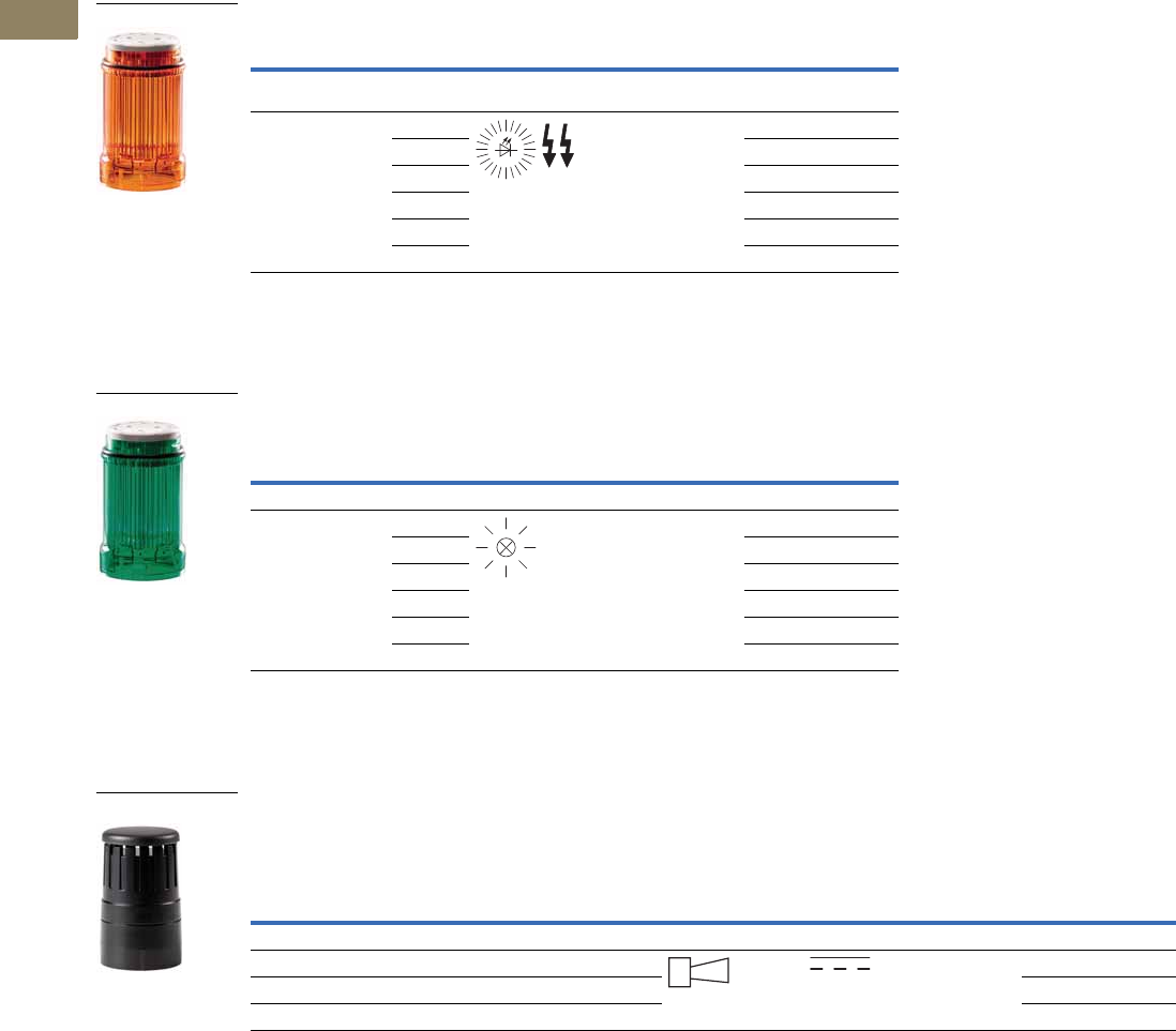
V7-T2-16 Volume 7—Logic Control, Operator Interface and Connectivity Solutions CA08100008E—March 2014 www.eaton.com
2
2
2
2
2
2
2
2
2
2
2
2
2
2
2
2
2
2
2
2
2
2
2
2
2
2
2
2
2
2
2.1
Stacklights
SL Series
Light Module with LED, continued
Multi-Strobe Light, UL Type 4/4X/13, IP66
SL4 Light Module for Incandescent Bulb
Continuous Light, UL Type 4/4X/13, IP66
For incandescent bulb selection, see Page V7-T2-19.
SL4 Acoustic Modules
Continuous Tone or Pulsed Tone, UL Type 4/4X/13, IP66
Adjustable with internal DIP switches.
Sound pressure 80 dB, adjustable with internal potentiometer.
f = 4000 Hz.
Rated Operational
Voltage (Ue V) Color Function
Standard
Pack Catalog Number
LED for Effective Signaling Effect
With Various Strobe Sequences, 1–2.6 Hz
24 Vac/Vdc Blue 1 SL4-FL24-B-M
Green SL4-FL24-G-M
Red SL4-FL24-R-M
White SL4-FL24-W-M
Yellow SL4-FL24-Y-M
Amber SL4-FL24-A-M
Rated Operational
Voltage (Ue V) Color Function
Standard
Pack Catalog Number
Without Light Elements, Incandescent Bulb, Maximum 4W
<250 Vac/Vdc Blue 1 SL4-L-B
Green SL4-L-G
Red SL4-L-R
White SL4-L-W
Yellow SL4-L-Y
Amber SL4-L-A
Rated Operational
Voltage (Ue V)
Rated Operational
Current (Ie mA) Color Function Sound Type
Standard
Pack Catalog Number
Place only at the highest position on a pole.
24 Vac/Vdc Maximum 39 Black 1 SL4-AP24
110/120 Vac Maximum 21 Black SL4-AP120
230/240 Vac Maximum 21 Black SL4-AP230
SL4-FL24-_-M
SL4-L-_
SL4-AP_
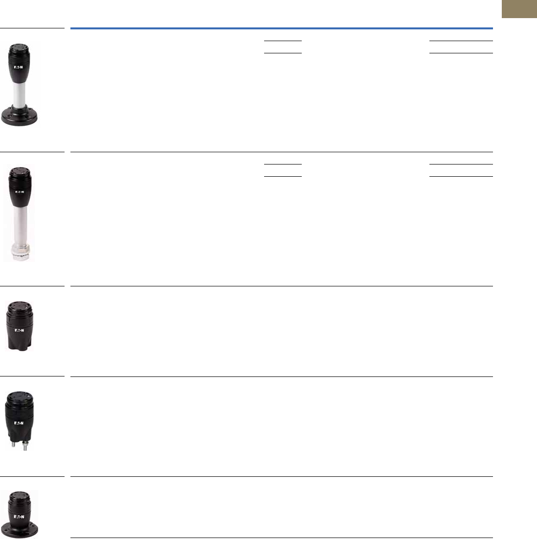
Volume 7—Logic Control, Operator Interface and Connectivity Solutions CA08100008E—March 2014 www.eaton.com V7-T2-17
2
2
2
2
2
2
2
2
2
2
2
2
2
2
2
2
2
2
2
2
2
2
2
2
2
2
2
2
2
2
2.1
Stacklights
SL Series
SL4 Base Modules
For Horizontal Mounting—Includes Cover, Maximum 5 Modules
Description
Tube
Length Color
Standard
Pack For use with … Catalog Number
Base with aluminum tube and plastic foot
Spring-loaded terminals
100 mm Black
aluminum
color tube
1SL4-L-…
SL4-BL-…
SL4-FL-…
SL4-AP-…
SL4-PIB-100
250 mm SL4-PIB-250
400 mm SL4-PIB-400
Base with aluminum tube and 3/4 in NPT threaded base
Spring-loaded terminals
100 mm Black
aluminum
color tube
1SL4-L-…
SL4-BL-…
SL4-FL-…
SL4-AP-…
SL4-PIB-T-100
250 mm SL4-PIB-T-250
400 mm SL4-PIB-T-400
Base with internal (on the inside) fixing holes
Spring-loaded terminals
—Black1SL4-L-…
SL4-BL-…
SL4-FL-…
SL4-AP-…
SL4-PIB-IMH
Base with built-in (pre-assembled) fixing screws
Spring-loaded terminals
—Black1SL4-L-…
SL4-BL-…
SL4-FL-…
SL4-AP-…
SL4-PIB-IMS
Base with external fixing holes
Spring-loaded terminals
—Black1SL4-L-…
SL4-BL-…
SL4-FL-…
SL4-AP-…
SL4-PIB-EMH
SL4-PIB-_
SL4-PIB-T-_
SL4-PIB-IMH
SL4-PIB-IMS
SL4-PIB-EMH
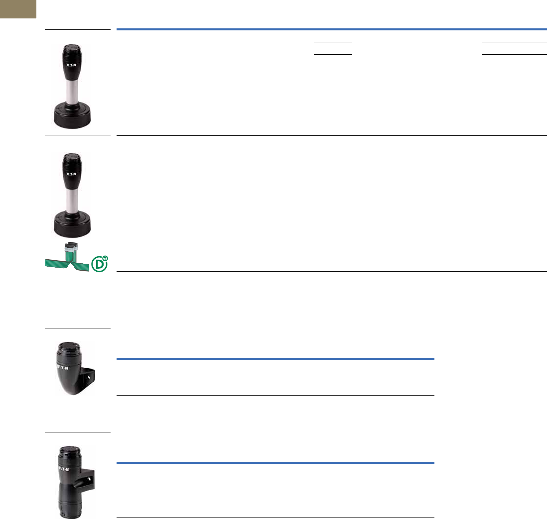
V7-T2-18 Volume 7—Logic Control, Operator Interface and Connectivity Solutions CA08100008E—March 2014 www.eaton.com
2
2
2
2
2
2
2
2
2
2
2
2
2
2
2
2
2
2
2
2
2
2
2
2
2
2
2
2
2
2
2.1
Stacklights
SL Series
SL4 Base Modules, continued
For Horizontal Mounting—Includes Cover, Maximum 5 Modules, continued
For Vertical Mounting—Includes Cover, Maximum 5 Modules
For Mounting on Both Sides—Includes Cover, Maximum 2 x 5 Modules
Description
Tube
Length Color
Standard
Pack For use with … Catalog Number
Base with base adapter for slipping onto place (rapid mounting
and wiring system)
Screw terminals
100 mm Black
aluminum
color tube
1SL4-L-…
SL4-BL-…
SL4-FL-…
SL4-AP-…
SL4-FMS-100
250 mm SL4-FMS-250
400 mm SL4-FMS-400
Base with base adapter for slipping onto place (rapid mounting
and wiring system)
Blade terminal SWD4-8MF2
Maximum 0.3A per module
External power supply connectable (24 Vdc)
Configurable with SWD‐Assist (planning and ordering help)
100 mm — 1 SL4-L-…
SL4-BL-…
SL4-FL-…
SL4-AP-…
SL4-SWD
Description Color
Standard
Pack For use with … Catalog Number
One-sided base with bracket
Spring-loaded terminals
Black 1 SL4-L-…
SL4-BL-…
SL4-FL-…
SL4-AP-…
SL4-PIB-FW
Description Color
Standard
Pack For use with … Catalog Number
Base with external fixing holes
Spring-loaded terminals
Black 1 SL4-L-…
SL4-BL-…
SL4-FL-…
SL4-AP-…
SL4-PIB-D
SL4-FMS_
SL4-SWD
SL4-PIB-FW
SL4-PIB-D
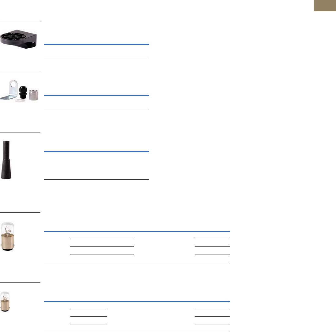
Volume 7—Logic Control, Operator Interface and Connectivity Solutions CA08100008E—March 2014 www.eaton.com V7-T2-19
2
2
2
2
2
2
2
2
2
2
2
2
2
2
2
2
2
2
2
2
2
2
2
2
2
2
2
2
2
2
2.1
Stacklights
SL Series
Accessories
SL7 and SL4 Series
Mounting Brackets
Mounting Brackets for Vertical
Mounting, Plastic
M20 Cable Gland for Vertical Mounting,
Metal (Includes Mounting Bracket)
Incandescent Bulb Tool
Tool for Replacing Incandescent Bulb
Incandescent Bulbs
SL7 Series
Incandescent Bulbs, Mounting: Ba15d
SL4 Series
Incandescent Bulbs, Mounting: Ba15d
Standard
Pack For Use With …
Catalog
Number
1SL4-PIB…
SL7-CB...
SL7/4-FW
Standard
Pack For Use With …
Catalog
Number
1 SL4-PIB-T…
SL7-CB-T...
SL7/4-FW-T
Standard
Pack For Use With …
Catalog
Number
1SL7-L-…
SL4-L-…
SL7/4-BET
Lifespan (h)
Rated Operational
Voltage (Ue V)
Power
(Watts)
Standard
Pack For Use With … Catalog Number
3000 12 5 1 SL7-L-… SL7-L12
24 6.5 SL7-L24
120 7 SL7-L120
230 6.5 SL7-L230
Lifespan (h)
Rated Operational
Voltage (Ue V)
Power
(Watts)
Standard
Pack For Use With … Catalog Number
3000 12 4 1 SL4-L-… SL4-L12
24 SL4-L24
120 SL4-L120
230 SL4-L230
SL7/4-FW
SL7/4-FW-T
SL7/4-BET
SL7-L12
SL4-L12

V7-T2-20 Volume 7—Logic Control, Operator Interface and Connectivity Solutions CA08100008E—March 2014 www.eaton.com
2
2
2
2
2
2
2
2
2
2
2
2
2
2
2
2
2
2
2
2
2
2
2
2
2
2
2
2
2
2
2.1
Stacklights
SL Series
Technical Data and Specifications
SL7 Series
SL7 General Specifications
Description Specification
Standards IEC/EN 60947-5-1
Lens color Blue, green, red, clear, yellow, amber
Number of signal elements Max. 5 with standard base
Max. 10 with base for mounting on both sides
Mechanical Ratings
Shock (IEC 68-2-27) 11 ms, 15g
Vibration (IEC 68-2-6) 20 sweeps 10–150 Hz, 1g
Climate Conditions
Climatic proofing Damp heat, constant, to IEC 60068-2-78
Damp heat, cyclic, to IEC 60069-2-30
Operating temperature –22° to +140°F (–30° to +60°C)
Storage temperature –22° to +185°F (–30° to +85°C)
Environmental Ratings
IEC degree of protection UL Type 4/4X/13, IP66
IEC/EN 60529
Protection type UL Type 4/4X/13
Materials
Cover Polycarbonate
Lenses Polycarbonate
Stacklight base Polycarbonate
Tubes Aluminum
Terminal Capacity
Solid or flexible conductor 0.13–2.5 mm2
Flexible with ferrule with plastic collar 0.25–1.5 mm2
AWG 24–AWG 14
Contacts
Rated impulse withstand voltage (Uimp) 4000 Vac
Rated insulation voltage (Ui)250V
Overvoltage category/pollution degree III/3

Volume 7—Logic Control, Operator Interface and Connectivity Solutions CA08100008E—March 2014 www.eaton.com V7-T2-21
2
2
2
2
2
2
2
2
2
2
2
2
2
2
2
2
2
2
2
2
2
2
2
2
2
2
2
2
2
2
2.1
Stacklights
SL Series
SL7 Light Module Specifications
Unit SL7-L-…-… SL7-BL-…-… SL7-FL-…-… SL7-L24-…-HP SL7-FL24-…-HP SL7-FL24-…-HPM SL7-L-…
Type of light Continuous light Flashing light Strobe light Continuous light Strobe light Multi-strobe light Continuous
light
Light elements LED LED LED High-performance LED High-performance LED High-performance LED Incandescent
bulb (max. 7W)
Mounting ——————Ba15d
Flashing/strobe
frequency
— 2 Hz 1.4 Hz — 1.4 Hz 1–2.6 Hz —
Transmission angle 360° 360° 360° 360° 360° 360° 360°
Leakage current A < 0.003 < 0.003 <0.003 < 0.003 < 0.003 < 0.003 < 0.003
Current-/power
consumption
24 Vac/Vdc A 0.049–0.054 0.058 0.130–0.135 0.170–0.200 0.260–0.265 0.260–0.265 —
110/120 Vac A 0.028–0.031 0.028–0.030 0.010 ————
230/240 Vac A 0.027–0.028 0.030–0.031 0.010 ————
Power
consumption
——————Max. 7W with
the specified
voltages
Voltage levels 24 Vac/Vdc ± 10%
110/120 Vac ± 10%
230/240 Vac ± 10%
24 Vac/Vdc ± 10%
110/120 Vac ± 10%
230/240 Vac ± 10%
24 Vac/Vdc ± 10%
110/120 Vac ± 10%
230/240 Vac ± 10%
18–30 Vdc/
18–26 Vac
18–30 Vdc/
18–26 Vac
18–30 Vdc/
18–26 Vac
Up to
250 Vac/Vdc
Lifespan h 100,000 100,000 100,000 50,000 50,000 50,000 3000
Weightg80808080 80 80 80
V7-T2-22 Volume 7—Logic Control, Operator Interface and Connectivity Solutions CA08100008E—March 2014 www.eaton.com
2
2
2
2
2
2
2
2
2
2
2
2
2
2
2
2
2
2
2
2
2
2
2
2
2
2
2
2
2
2
2.1
Stacklights
SL Series
SL7 Acoustic Module Specifications
SL7 Table of Sound Types
Unit SL7-AP… SL7-AP…-E SL7-AP…-M
Type of tone Continuous or pulsed tone Continuous or pulsed tone Continuous or pulsed tone
Eight types of sound
Types of sound Two versions,
table of sound types
Two versions,
table of sound types
Eight versions,
table of sound types
Sound setting Internal; single-pole DIP Can be externally actuated Internal; three-pole DIP
Sound pressure dB Max.: 100
Min.: 88
Max.: 100
Min.: 88
Max.: 100
Min.: 88
Sound pressure level adjustment Built-in, potentiometer Built-in, potentiometer Built-in, potentiometer
Transmission angle 360° 360° 360°
Current-/power consumption
24 Vac/Vdc A 0.092 0.092 0.115
110/120 Vac A 0.041 0.041 0.045
230/240 Vac A 0.043 0.043 0.043
Voltage levels 24 Vac/Vdc ± 10%
110/120 Vac ± 10%
230/240 Vac ± 10%
24 Vac/Vdc ± 10%
110/120 Vac ± 10%
230/240 Vac ± 10%
24 Vac/Vdc ± 10%
110/120 Vac ± 10%
230/240 Vac ± 10%
Weight g 102 102 102
Sound Type Frequency (Hz) Diagram Repeat Rate
DIP Switch
Position
Maximum
Volume
at 1M (dB)
SL7-AP… Continuous tone Approx. 2800 — — 100
Pulsed tone Approx. 2800 Approx. 2 Hz — 100
SL7-AP…-E Continuous tone Approx. 2800 — — 100
Pulsed tone Approx. 2800 Approx. 2 Hz — 100
SL7-AP…-M Continuous tone 2700 — ON Tone 01 100
Continuous tone 1350 — ON Tone 02 100
Pulsed tone 2700 250 ms on, 250 ms off ON Tone 03 100
Pulsed tone 1350 250 ms on, 250 ms off ON Tone 04 100
Falling 1200–500 1 Hz ON Tone 05 98
Rising 500–1200 Rising 3s, 0.5s off ON Tone 06 98
Alternating 800–1000 2 Hz ON Tone 07 94
rising/falling 500–1500 10 Hz ON Tone 08 94

Volume 7—Logic Control, Operator Interface and Connectivity Solutions CA08100008E—March 2014 www.eaton.com V7-T2-23
2
2
2
2
2
2
2
2
2
2
2
2
2
2
2
2
2
2
2
2
2
2
2
2
2
2
2
2
2
2
2.1
Stacklights
SL Series
SL4 Series
SL4 General Specifications
Description Specification
Standards IEC/EN 60947-5-1
Lens color Blue, green, red, clear, yellow, orange
Number of signal elements Max. 5 with standard base
Max. 10 with base for mounting on both sides
Mounting position As required
Mechanical Ratings
Mechanical shock resistance >15g according to IEC 60068-2-27
Shock duration 11 ms
Sinusoidal
Climate Conditions
Climatic proofing Damp heat, constant, to IEC 60068-2-78
Damp heat, cyclic, to IEC 60069-2-30
Ambient temperature –22°F to +140°F (–30°C to +60°C)
Environmental Ratings
IEC degree of protection UL Type 4/4X/13, IP66
IEC/EN 60529
Protection type UL Type 4/4X/13
Materials
Enclosure Polycarbonate (PC), black
Cap Polycarbonate (PC)
Terminal Capacity
Solid or flexible conductor 0.2–1.5 mm2
Solid or flexible conductor, with ferrule 0.25–1.5 mm2
Flexible with ferrule with plastic collar 0.25–0.75 mm2
AWG 24–AWG 16
Contacts
Rated impulse withstand voltage (Uimp) 4000 Vac
Rated insulation voltage (Ui)250V
Overvoltage category/pollution degree III/3
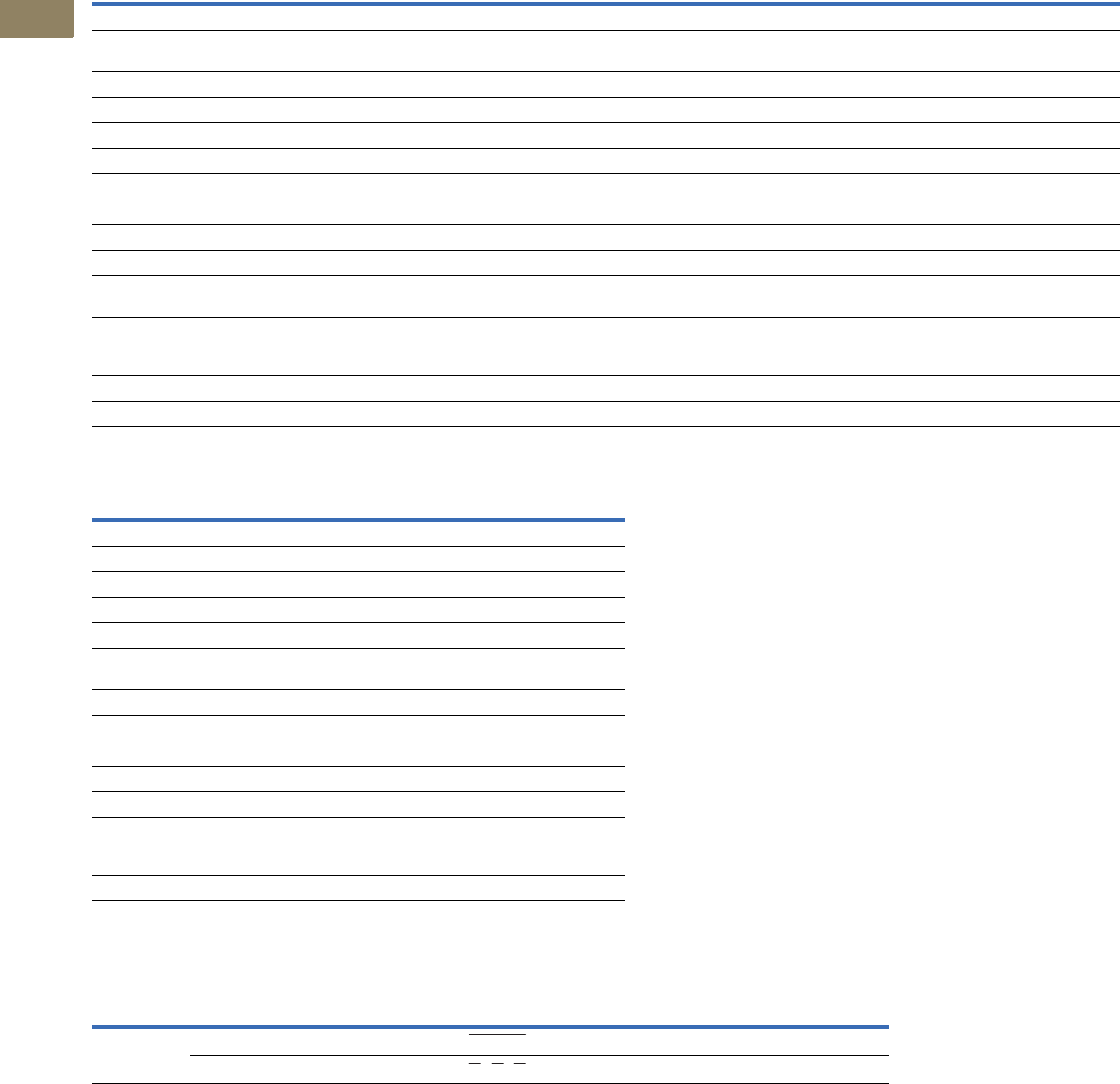
V7-T2-24 Volume 7—Logic Control, Operator Interface and Connectivity Solutions CA08100008E—March 2014 www.eaton.com
2
2
2
2
2
2
2
2
2
2
2
2
2
2
2
2
2
2
2
2
2
2
2
2
2
2
2
2
2
2
2.1
Stacklights
SL Series
SL4 Light Module Specifications
SL4 Acoustic Module Specifications
SL4 Table of Sound Types
Unit SL4-L…-… SL4-BL…-… SL4-FL…-… SL4-FL24-…-M SL4-L…
Type of light Continuous light Flashing light Strobe light Multi-strobe light Continuous light
Light elements LED LED LED LED Incandescent bulb
(max. 4W)
Mounting ————Ba15d
Flashing/strobe frequency — 2 Hz 1.4 Hz 1–2.6 Hz —
Transmission angle 360° 360° 360° 360° 360°
Leakage current A < 0.003 < 0.003 < 0.003 < 0.003 < 0.003
Current/power consumption
24 Vac/Vdc A 0.022–0.033 0.028–0.036 0.035–0.065 0.048–0.068 —
110/120 Vac A 0.030 0.030 0.10 — —
230/240 Vac A 0.030 0.030 0.10 — —
Power consumption ————Maximum 4W with the
specified voltages
Voltage levels 24 Vac/Vdc ± 10%
110/120 Vac ± 10%
230/240 Vac ± 10%
24 Vac/Vdc ± 10%
110/120 Vac ± 10%
230/240 Vac ± 10%
24 Vac/Vdc ± 10%
110/120 Vac ± 10%
230/240 Vac ± 10%
24 Vac/Vdc ± 10% Up to 250 Vac/Vdc
Lifespan h 100,000 100,000 100,000 100,000 100,000
Weight g4545454545
Unit SL4-AP…
Type of tone Continuous or pulsed tone
Types of sound Two versions, table of sound types
Sound setting Internal; single-pole DIP
Sound pressure dB 80
Sound pressure level adjustment —
Sound pressure can be lowered
to a minimum of
—
Transmission angle 360°
Current/power consumption
24 Vac/Vdc A 0.039
110/120 Vac A 0.021
230/240 Vac A 0.021
Voltage levels 24 Vac/Vdc ± 10%
110/120 Vac ± 10%
230/240 Vac ± 10%
Weight g 43
Sound Type Frequency (Hz) Diagram Repeat Rate
Maximum
Volume
at 1M (dB)
SL4-AP… Continuous tone Approx. 4000 — 80
Pulsed tone Approx. 4000 Approx. 2 Hz 80
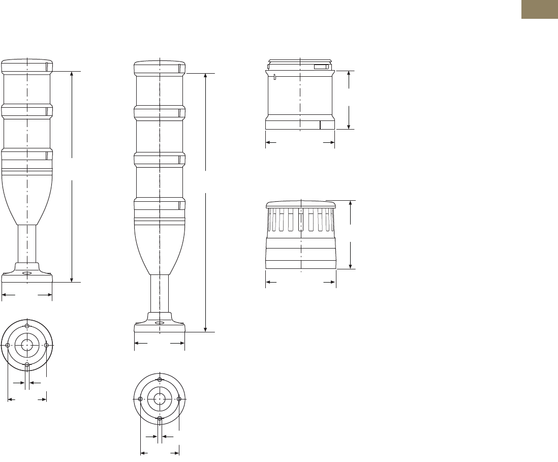
Volume 7—Logic Control, Operator Interface and Connectivity Solutions CA08100008E—March 2014 www.eaton.com V7-T2-25
2
2
2
2
2
2
2
2
2
2
2
2
2
2
2
2
2
2
2
2
2
2
2
2
2
2
2
2
2
2
2.1
Stacklights
SL Series
Dimensions
Approximate Dimensions in Inches (mm)
SL7 Series
Complete Devices
SL7-100-L-RG-24LED SL7-100-L-RYG-24LED
Light Modules
SL7-(B)(F)L…
Acoustic Modules
SL7-AP…
11.61
(295.0)
Ø2.84
(Ø72.0)
Ø0.22 (Ø5.5)
Ø2.13
(Ø54.0)
14.02
(356.0)
Ø2.84
(Ø72.0)
Ø0.22 (Ø5.5)
Ø2.13
(Ø54.0)
2.40
(61.0)
Ø2.87 (Ø73.0)
2.80
(71.0)
Ø2.88 (Ø73.2)
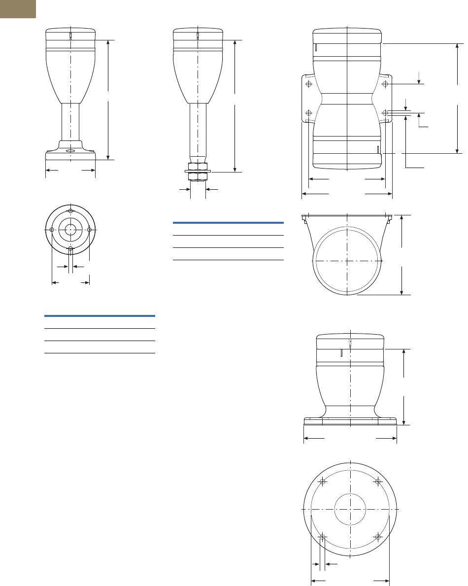
V7-T2-26 Volume 7—Logic Control, Operator Interface and Connectivity Solutions CA08100008E—March 2014 www.eaton.com
2
2
2
2
2
2
2
2
2
2
2
2
2
2
2
2
2
2
2
2
2
2
2
2
2
2
2
2
2
2
2.1
Stacklights
SL Series
Approximate Dimensions in Inches (mm)
Basic Modules
SL7-CB-…
SL7-CB-T…
Catalog
Number A
SL7-CB-100 6.73 (171.0)
SL7-CB-250 12.64 (321.0)
SL7-CB-400 18.54 (471.0)
A
Ø2.83
(Ø72.0)
Ø0.22 (Ø5.5)
Ø2.13
(Ø54.0)
Catalog
Number A
SL7-CB-T-100 7.48 (190.0)
SL7-CB-T-250 13.38 (340.0)
SL7-CB-T-400 19.29 (490.0)
A
M20
SL7-CB-D
SL7-CB-EMH
4.68
(119.0)
3.23 (82.0)
1.22
(31.0)
3.31
(84.0)
Ø0.23 (Ø5.8)
3.78 (96.0)
3.25
(82.5)
Ø0.23 (Ø5.8)
Ø3.35 (Ø85.0)
Ø3.94 (Ø100.0)
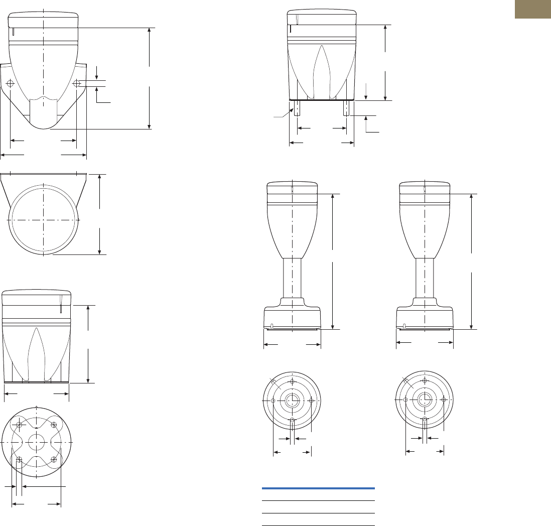
Volume 7—Logic Control, Operator Interface and Connectivity Solutions CA08100008E—March 2014 www.eaton.com V7-T2-27
2
2
2
2
2
2
2
2
2
2
2
2
2
2
2
2
2
2
2
2
2
2
2
2
2
2
2
2
2
2
2.1
Stacklights
SL Series
Approximate Dimensions in Inches (mm)
SL7-CB-FW
SL7-CB-IMH
SL7-CB-IMS
SL7-FMS-… SL7-SWD 1
Note
1For connecting to SmartWire-DT.
3.31
(84.0)
2.76 (70.0)
4.21
(107.0)
Ø0.24
(Ø6.0)
3.54 (90.0)
3.23
(82.0)
Ø2.05
(Ø52.0)
Ø0.23 (Ø5.8)
2.87 (72.0)
Catalog
Number A
SL7-FMS-100 7.55 (192.0)
SL7-FMS-250 13.46 (342.0)
SL7-FMS-400 19.37 (192.0)
3.23
(82.0)
2.87 (73.0)
2.05
(52.0) 0.79
(20.0)
M5
7.56
(192.0)
Ø2.13
(Ø54.0)
Ø0.22 (Ø5.5)
Ø3.15
(Ø80.0)
A
Ø2.13
(Ø54.0)
Ø0.22 (Ø5.5)
Ø3.15
(Ø80.0)
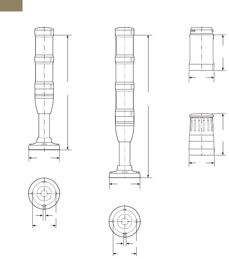
V7-T2-28 Volume 7—Logic Control, Operator Interface and Connectivity Solutions CA08100008E—March 2014 www.eaton.com
2
2
2
2
2
2
2
2
2
2
2
2
2
2
2
2
2
2
2
2
2
2
2
2
2
2
2
2
2
2
2.1
Stacklights
SL Series
Approximate Dimensions in Inches (mm)
SL4 Series
Complete Devices
SL4-100-L-RG-24LED SL4-100-L-RYG-24LED
Light Modules
SL4-(B)(F)L…
Acoustic Modules
SL4-AP…
10.28
(261.0)
Ø2.84
(Ø72.0)
Ø0.22 (Ø5.5)
Ø2.13
(Ø54.0)
12.72
(323.0)
Ø2.84
(Ø72.0)
Ø0.22 (Ø5.5)
Ø2.13
(Ø54.0)
2.44
(62.0)
1.69
(43.0)
2.80
(71.0)
1.73
(44.0)
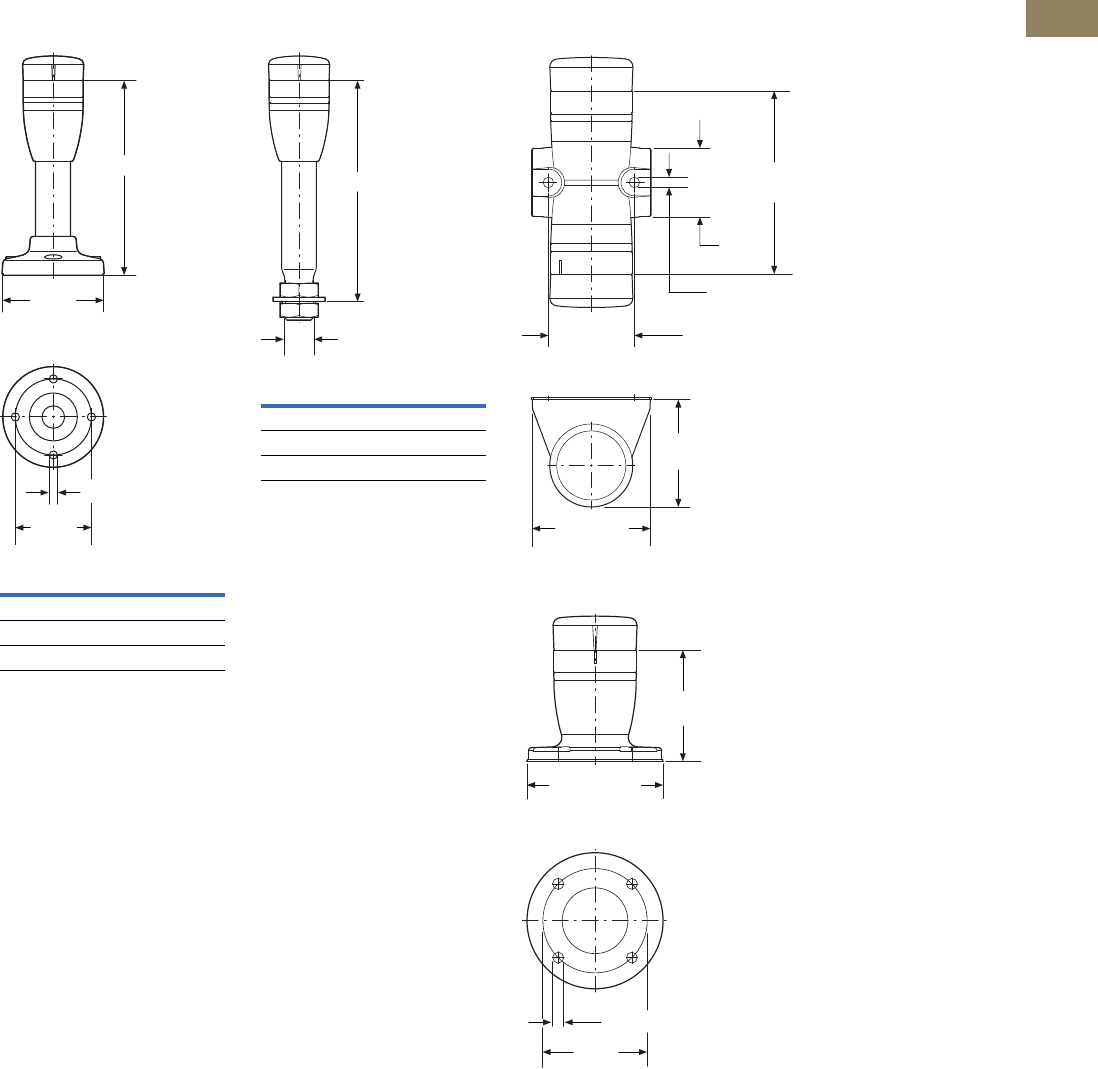
Volume 7—Logic Control, Operator Interface and Connectivity Solutions CA08100008E—March 2014 www.eaton.com V7-T2-29
2
2
2
2
2
2
2
2
2
2
2
2
2
2
2
2
2
2
2
2
2
2
2
2
2
2
2
2
2
2
2.1
Stacklights
SL Series
Approximate Dimensions in Inches (mm)
Basic Modules
SL4-PIB-…
SL4-PIB-T…
Catalog
Number A
SL4-PIB-100 3.53 (136.0)
SL4-PIB-250 11.26 (286.0)
SL4-PIB-400 17.16 (436.0)
A
Ø2.13
(Ø54.0)
Ø0.22 (Ø5.5)
Ø2.83
(Ø72.0)
Catalog
Number A
SL4-PIB-T-100 5.90 (150.0)
SL4-PIB-T-250 11.81 (300.0)
SL4-PIB-T-400 17.72 (450.0)
A
M20
SL4-PIB-D
SL4-PIB-EMH
2.21
(56.0)
2.44 (62.0)
3.82
(97.0)
1.38
(35.0)
Ø0.23 (Ø5.9)
1.77 (45.0)
2.24
(57.0)
Ø2.72 (Ø69.0)
Ø0.23 (Ø5.8)
Ø2.13
(Ø54.0)
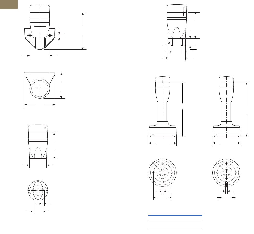
V7-T2-30 Volume 7—Logic Control, Operator Interface and Connectivity Solutions CA08100008E—March 2014 www.eaton.com
2
2
2
2
2
2
2
2
2
2
2
2
2
2
2
2
2
2
2
2
2
2
2
2
2
2
2
2
2
2
2.1
Stacklights
SL Series
Approximate Dimensions in Inches (mm)
SL4-PIB-FW
SL4-PIB-IMH
SL4-PIB-IMS
SL4-FMS-… SL4-SWD 1
Note
1For connecting to SmartWire-DT.
2.21
(56.0)
1.77 (45.0)
3.15
(80.0)
Ø0.23
(Ø5.8)
2.56
(65.0)
2.24
(57.0)
Ø0.23 (Ø5.8)
1.34 (43.0)
Ø0.87 (Ø22.0)
Catalog
Number A
SL4-FMS-100 6.18 (157.0)
SL4-FMS-250 12.09 (307.0)
SL4-FMS-400 17.99 (457.0)
2.24
(57.0)
1.69 (43.0)
0.87 (22.0) 0.83 (21.0)
M5
A
Ø2.13
(Ø54.0)
Ø0.22 (Ø5.5)
Ø3.15
(Ø80.0)
6.18
(157.0)
Ø2.13
(Ø54.0)
Ø0.22 (Ø5.5)
Ø3.15
(Ø80.0)
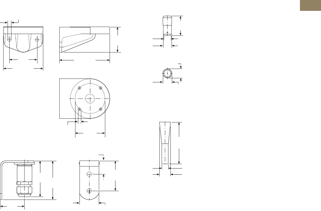
Volume 7—Logic Control, Operator Interface and Connectivity Solutions CA08100008E—March 2014 www.eaton.com V7-T2-31
2
2
2
2
2
2
2
2
2
2
2
2
2
2
2
2
2
2
2
2
2
2
2
2
2
2
2
2
2
2
2.1
Stacklights
SL Series
Approximate Dimensions in Inches (mm)
Mounting Brackets
SL7/4-FW
SL7/4-FW-T
Incandescent Bulbs
SL7-L12 and SL4-L12
Tool for Replacing Incandescent Bulb
SL7/4-BET
Ø2.13
(Ø54.0)
Ø0.22 (Ø5.5)
1.81
(46.0)
3.58 (91.0)
1.97
(50.0)
2.83 (72.0)
Ø0.25 (Ø6.4)
2.56
(65.0)
1.73
(44.0) 1.38 (35.0)
0.94 (24.0)
2.76
(70.0)
2.13
(54.0)
1.38
(35.0)
Ø0.51 (Ø13.0)
0.67 (17.0)
Ø0.60 (Ø15.3)
Ø0.64 (Ø16.2)
2.97
(75.5)
Ø0.79 (Ø20.0)
Ø0.47 (Ø12.0)
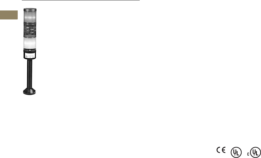
V7-T2-32 Volume 7—Logic Control, Operator Interface and Connectivity Solutions CA08100008E—March 2014 www.eaton.com
2
2
2
2
2
2
2
2
2
2
2
2
2
2
2
2
2
2
2
2
2
2
2
2
2
2
2
2
2
2
2.2
Stacklights
E26 Series
Stacklights—E26 Series
Contents
Description Page
E26 Series
Product Identification . . . . . . . . . . . . . . . . . . . . V7-T2-33
Catalog Number Selection . . . . . . . . . . . . . . . . V7-T2-34
Product Selection . . . . . . . . . . . . . . . . . . . . . . . V7-T2-35
Replacement Parts . . . . . . . . . . . . . . . . . . . . . . V7-T2-40
Technical Data and Specifications . . . . . . . . . . V7-T2-41
Ratings . . . . . . . . . . . . . . . . . . . . . . . . . . . . . . . V7-T2-42
Mounting Instructions . . . . . . . . . . . . . . . . . . . V7-T2-43
Dimensions . . . . . . . . . . . . . . . . . . . . . . . . . . . V7-T2-44
Product Description
The E26 stacklight unit is a
modular system that provides
illuminated and audible status
indication in all directions.
Easily assembled plug-in
modular units include
constant, flashing and strobe
light units, as well as mono-
tonal, bi-tonal, intermittent
audible alarms. Stacklights
may be assembled in a
variety of configurations,
which are identified in the
Maximum Configurations
table on Page V7-T2-33.
Several lamp, color and
mounting options further
enhance the stacklight’s
versatility.
Features
●Modular construction
●Six lens colors
●Variety of lamp types and
voltages
●Mono-tonal, bi-tonal and
intermittent audible alarms
Benefits
●Combination of visible and
audible alarms
●Modular components
reduce inventory
requirements, increase
flexibility
●Steady and flashing modes
allow one light to signal
multiple conditions
●No-tools assembly permits
easy lamp replacement
Standards and
Certifications
●CE 60947-5-1
●UL 508—File No. E131568
●cUL C22.2 No. 14—File
No. E131568
Ingress Protection
●Stacklight base and light
units: IP65, NEMA 4, 4X
and 13
●Alarm units: IP20, NEMA 1
Electrical Shock Protection
●Stacklight base and light
unit: IP2X
●Alarm units: IP0X
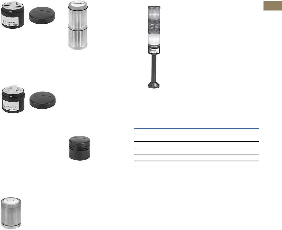
Volume 7—Logic Control, Operator Interface and Connectivity Solutions CA08100008E—March 2014 www.eaton.com V7-T2-33
2
2
2
2
2
2
2
2
2
2
2
2
2
2
2
2
2
2
2
2
2
2
2
2
2
2
2
2
2
2
2.2
Stacklights
E26 Series
Product Identification
Standard Stacklight Base
For use with incandescent or
standard LEDs for steady,
non-flashing illumination or
with flashing LEDs for
flashing illumination. Bases
include terminal block for
wiring, stacklight cover and
gasket. See Page V7-T2-38.
Flashing Stacklight Base
Allows configuration of each
light in the stack for either
steady or 60 times per
minute flashing illumination.
Flashing circuit for use with
incandescent lamps only.
(Maximum allowable number
of light modules is 2 at 12V, 4
at 24V and 6 at 48V and
above.) See Page V7-T2-38.
For flashing LEDs use
standard base with flashing
LED light module.
Light Modules
Available in a variety of colors
for both incandescent lamps
and LED lamps. To maximize
illumination and light dispersion,
i
ncandescent units include an
opal white diffuser while LED
diffusers are clear. See Page
V7-T2-36.
Xenon Strobe
Sets are similar to standard
lens/diffuser units, except
each set consists of two lens
units. The lower unit includes
the electronics and is
permanently fused to the
upper unit which contains the
Xenon lamp. Xenon units may
be placed in any position in a
complete stacklight unit.
They will flash 60 times per
minute when used with a
standard or flashing base.
See Page V7-T2-36.
Alarms
May be fitted to the top of a
complete stacklight unit or
directly to the stacklight
bases, if desired. Available in
three versions, each with
adjustable sound levels. See
Page V7-T2-39.
Complete Stacklight Modules
●Stacklights accept a
maximum of six
incandescent or LED light
modules or two Xenon
Flasher modules and can
be mounted in any position
on the stack.
●Alarm units are mounted in
the top most position only.
Maximum Configurations
Level
3
Level
2
Level
1
Extension
Tube
Mounting
Base
Stack-
light
Base
Incandescent
or
LED Modules
Xenon
Modules
Alarm
Modules
Max. Number
of Modules
6 ——6
5—16
41—5
3 115
22—4
1 214
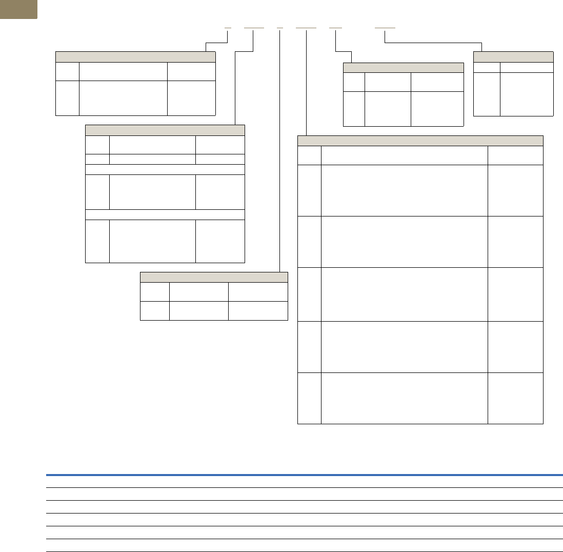
V7-T2-34 Volume 7—Logic Control, Operator Interface and Connectivity Solutions CA08100008E—March 2014 www.eaton.com
2
2
2
2
2
2
2
2
2
2
2
2
2
2
2
2
2
2
2
2
2
2
2
2
2
2
2
2
2
2
2.2
Stacklights
E26 Series
Catalog Number Selection
Stacklight Catalog Numbering System
Voltage C odes
Notes
1Unless base mount is specified, an extension tube must be selected for a complete unit.
2Component catalog numbers for flashing bases, alarm units and light modules are incomplete and require the addition of a suffix code to specify the required voltage rating. See table above.
3If no voltage is specified, assembled stacklight will be supplied without lamps or LEDs.
4240V not available for cylindrical LEDs.
5For complete length (extension tube and base), see Page V7-T2-39.
6Flashing base is for use with incandescent lamps.
Voltage Code Incandescent Lamp Cluster LED Cylindrical LED Xenon Flasher Flasher Base/Alarm
(Blank) No lamp supplied No LED supplied No LED supplied — —
V1 12 Vac/Vdc 12 Vac/Vdc 12 Vac/Vdc 12 Vac/Vdc 12 Vac/Vdc
V2 24 Vac/Vdc 24 Vac/Vdc 24 Vac/Vdc 24 Vac/Vdc 24 Vac/Vdc
V3 48 Vac/Vdc 48 Vac/Vdc 48 Vac/Vdc 48 Vac/Vdc 48 Vac/Vdc
V4 120 Vac/Vdc 120 Vac 120 Vac 120 Vac 120 Vac/Vdc
V5 240 Vac/Vdc 240 Vac — 240 Vac 240 Vac/Vdc
Voltage 3
Code Description
V1
V2
V3
V4
V5 4
12V
24V
48V
120V
240V
Alarm
Code Description Component
Catalog No. 2
W
Q
N
P
None
Mono-tonal
Bi-tonal
Intermittent
—
E26BQ_
E26BN_
E26BP_
Light Module
Code Description Component
Catalog No. 2
0
2
3
4
6
9
Clear incandescent
Red incandescent
Green incandescent
Yellow incandescent
Blue incandescent
Amber incandescent
E26B0_
E26B2_
E26B3_
E26B4_
E26B6_
E26B9_
W
R
G
Y
B
A
White cluster LED with clear lens
Red cluster LED with red lens
Green cluster LED with green lens
Yellow cluster LED with yellow lens
Blue cluster LED with blue lens
Amber cluster LED with amber lens
E26BW_
E26BR_
E26BG_
E26BY_
E26BB_
E26BA_
W1
R1
G1
Y1
B1
A1
White cylindrical LED with clear lens 4
Red cylindrical LED with red lens 4
Green cylindrical LED with green lens 4
Yellow cylindrical LED with yellow lens 4
Blue cylindrical LED with blue lens 4
Amber cylindrical LED with amber lens 4
E26BW1_
E26BR1_
E26BG1_
E26BY1_
E26BB1_
E26BA1_
M
E
U
V
K
Z
Flashing white cluster LED with clear lens
Flashing red cluster LED with red lens
Flashing green cluster LED with green lens
Flashing yellow cluster LED with yellow lens
Flashing blue cluster LED with blue lens
Flashing amber cluster LED with amber lens
E26BM_
E26BE_
E26BU_
E26BV_
E26BK_
E26BZ_
X0
X2
X3
X4
X6
X9
Xenon flasher with clear lens
Xenon flasher with red lens
Xenon flasher with green lens
Xenon flasher with yellow lens
Xenon flasher with blue lens
Xenon flasher with amber lens
E26BX0_
E26BX2_
E26BX3_
E26BX4_
E26BX6_
E26BX9_
Extension Tube 5
Code Description Component
Catalog No.
WNone (base mount) —
Gray Aluminum
HM
JM
KM
MM
20 mm 3/4 in NPT
160 mm 3/4 in NPT
360 mm 3/4 in NPT
760 mm 3/4 in NPT
E26BHM
E26BJM
E26BKM
E26BMM
Black Aluminum
HU
JU
KU
MU
RU
20 mm 3/4 in NPT
160 mm 3/4 in NPT
360 mm 3/4 in NPT
760 mm 3/4 in NPT
Right angle 3/4 in NPT
E26BHU
E26BJU
E26BKU
E26BMU
E26BRU
Mounting Base 1
Code Description Component
Catalog No.
W
4
8
9
None (base mount)
3/4 in NPT hub, chrome
Standard three-hole
Standard four-hole
—
E26S104
E26S108
E26S109
Stacklight Base
Code Description Component
Catalog No. 2
L
F
Standard
Flashing 6
E26BL
E26BF_
E26X 9 KM L39R W–V 4

Volume 7—Logic Control, Operator Interface and Connectivity Solutions CA08100008E—March 2014 www.eaton.com V7-T2-35
2
2
2
2
2
2
2
2
2
2
2
2
2
2
2
2
2
2
2
2
2
2
2
2
2
2
2
2
2
2
2.2
Stacklights
E26 Series
Product Selection
Assembled Units
One-, Two- and Three-Light Assembled Stacklights
●Base mountable
●Incandescent or LED versions
●24V and 120V versions
One-Light Unit Stacklight
Two-Light Unit Stacklight
Three-Light Unit Stacklight
Note
1 LED modules have very low current draw and should not be used with triac output devices like PLC triac output modules.
It is recommended that dry contact outputs be used to switch 120 Vac modules.
Volts
AC/DC Alarm
First Level
Color Illumination Type Catalog Number
24V None Red Incandescent—steady E26XWWL2W-V2
24V None Red Cylindrical LED—steady E26XWWLR1W-V2
24V None Green Incandescent—steady E26XWWL3W-V2
24V None Green Cylindrical LED—steady E26XWWLG1W-V2
24V None Amber Incandescent—steady E26XWWL9W-V2
24V None Amber Cylindrical LED—steady E26XWWLA1W-V2
120V None Red Incandescent—steady E26XWWL2W-V4
120V 1None Red Cylindrical LED—steady E26XWWLR1W-V4
120V None Green Incandescent—steady E26XWWL3W-V4
120V 1None Green Cylindrical LED—steady E26XWWLG1W-V4
120V None Amber Incandescent—steady E26XWWL9W-V4
120V 1None Amber Cylindrical LED—steady E26XWWLA1W-V4
Volts
AC/DC Alarm
First Level
Color Illumination Type
Second Level
Color Illumination Type Catalog Number
24V None Green Incandescent—steady Red Incandescent—steady E26XWWL32W-V2
24V None Green Cylindrical LED—steady Red Cylindrical LED—steady E26XWWLG1R1W-V2
120V None Green Incandescent—steady Red Incandescent—steady E26XWWL32W-V4
120V 1None Green Cylindrical LED—steady Red Cylindrical LED—steady E26XWWLG1R1W-V4
Volts
AC/DC Alarm
First
Level
Color Illumination Type
Second
Level
Color Illumination Type
Third
Level
Color Illumination Type Catalog Number
24V None Green Incandescent—steady Amber Incandescent—steady Red Incandescent—steady E26XWWL392W-V2
24V None Green Cylindrical LED—steady Amber Cylindrical LED—steady Red Cylindrical LED—steady E26XWWLG1A1R1W-V2
120V None Green Incandescent—steady Amber Incandescent—steady Red Incandescent—steady E26XWWL392W-V4
120V 1None Green Cylindrical LED—steady Amber Cylindrical LED—steady Red Cylindrical LED—steady E26XWWLG1A1R1W-V4
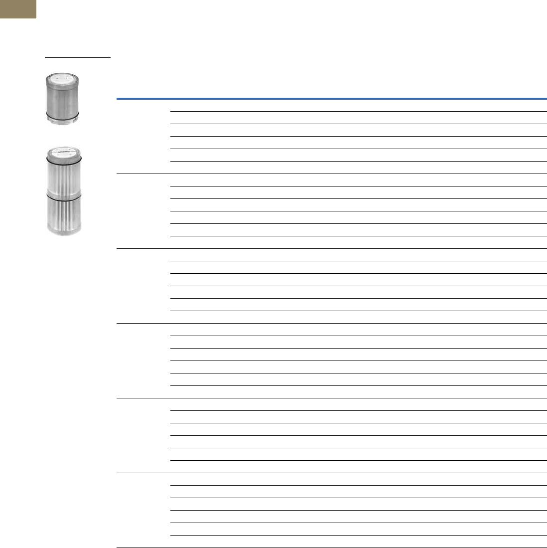
V7-T2-36 Volume 7—Logic Control, Operator Interface and Connectivity Solutions CA08100008E—March 2014 www.eaton.com
2
2
2
2
2
2
2
2
2
2
2
2
2
2
2
2
2
2
2
2
2
2
2
2
2
2
2
2
2
2
2.2
Stacklights
E26 Series
Light and Xenon Strobe Modules
●Light modules include lens
diffusers which provide
even illumination and
eliminate hot spots.
●Xenon strobes emit a
bright attention-getting
white flashing light. Flash
rate = 60/min.
●Xenon strobe modules
occupy two positions in the
stacklight assembly.
Light and Xenon Strobe Modules 1
Notes
1 Include lens, diffusers and lamps unless otherwise noted.
2 Incandescent bulbs are AC/DC rated, LEDs are AC rated only.
LED/Lamp
Voltage Lens Color
Incandescent Cylindrical LED Cluster LED Cluster LED Xenon
Steady or Flashing
Catalog Number
Steady Only
Catalog Number
Steady
Catalog Number
Flashing
Catalog Number
Flashing
Catalog Number
Without bulb
or LED
Red E26B2 E26B E26BR E26BR —
Green E26B3 E26BG E26BG E26BG —
Yellow E26B4 E26BY E26BY E26BY —
Blue E26B6 E26BB E26BB E26BB —
Amber E26B9 E26BA E26BA E26BA —
Clear E26B0 E26BW E26BW E26BW —
12 Vac/Vdc Red E26B2V1 E26BR1V1 E26BRV1 E26BEV1 E26BX2V1
Green E26B3V1 E26BG1V1 E26BGV1 E26BUV1 E26BX3V1
Yellow E26B4V1 E26BY1V1 E26BYV1 E26BVV1 E26BX4V1
Blue E26B6V1 E26BB1V1 E26BBV1 E26BKV1 E26BX6V1
Amber E26B9V1 E26BA1V1 E26BAV1 E26BZV1 E26BX9V1
Clear E26B0V1 E26BW1V1 E26BWV1 E26BMV1 E26BX0V1
24 Vac/Vdc Red E26B2V2 E26BR1V2 E26BRV2 E26BEV2 E26BX2V2
Green E26B3V2 E26BG1V2 E26BGV2 E26BUV2 E26BX3V2
Yellow E26B4V2 E26BY1V2 E26BYV2 E26BVV2 E26BX4V2
Blue E26B6V2 E26BB1V2 E26BBV2 E26BKV2 E26BX6V2
Amber E26B9V2 E26BA1V2 E26BAV2 E26BZV2 E26BX9V2
Clear E26B0V2 E26BW1V2 E26BWV2 E26BMV2 E26BX0V2
48 Vac/Vdc Red E26B2V3 E26BR1V3 E26BRV3 E26BEV3 E26BX2V3
Green E26B3V3 E26BG1V3 E26BGV3 E26BUV3 E26BX3V3
Yellow E26B4V3 E26BY1V3 E26BYV3 E26BVV3 E26BX4V3
Blue E26B6V3 E26BB1V3 E26BBV3 E26BKV3 E26BX6V3
Amber E26B9V3 E26BA1V3 E26BAV3 E26BZV3 E26BX9V3
Clear E26B0V3 E26BW1V3 E26BWV3 E26BMV3 E26BX0V3
120 Vac 2Red E26B2V4 E26BR1V4 E26BRV4 E26BEV4 E26BX2V4
Green E26B3V4 E26BG1V4 E26BGV4 E26BUV4 E26BX3V4
Yellow E26B4V4 E26BY1V4 E26BYV4 E26BVV4 E26BX4V4
Blue E26B6V4 E26BB1V4 E26BBV4 E26BKV4 E26BX6V4
Amber E26B9V4 E26BA1V4 E26BAV4 E26BZV4 E26BX9V4
Clear E26B0V4 E26BW1V4 E26BWV4 E26BMV4 E26BX0V4
240 Vac 2Red E26B2V5 — E26BRV5 E26BEV5 E26BX2V5
Green E26B3V5 — E26BGV5 E26BUV5 E26BX3V5
Yellow E26B4V5 — E26BYV5 E26BVV5 E26BX4V5
Blue E26B6V5 — E26BBV5 E26BKV5 E26BX6V5
Amber E26B9V5 — E26BAV5 E26BZV5 E26BX9V5
Clear E26B0V5 — E26BWV5 E26BMV5 E26BX0V5
Light/LED Module
Xenon Strobe Module
Volume 7—Logic Control, Operator Interface and Connectivity Solutions CA08100008E—March 2014 www.eaton.com V7-T2-37
2
2
2
2
2
2
2
2
2
2
2
2
2
2
2
2
2
2
2
2
2
2
2
2
2
2
2
2
2
2
2.2
Stacklights
E26 Series
LEDs—Cylindrical or Cluster
Cylindrical or Cluster LEDs
Voltage Color
Cylindrical LED Cluster LED Cluster LED
Steady Only
Catalog Number
Steady
Catalog Number
Flashing
Catalog Number
12 Vac/Vdc Red E26S110 E26S15 E26S48
Green E26S114 E26S19 E26S53
Yellow E26S112 E26S23 E26S58
Blue E26S115 E26S27 E26S63
White E26S116 E26S71 E26S75
Amber E26S111 E26S79 E26S84
24 Vac/Vdc Red E26S117 E26S16 E26S49
Green E26S121 E26S20 E26S54
Yellow E26S119 E26S24 E26S59
Blue E26S122 E26S28 E26S64
White E26S123 E26S72 E26S76
Amber E26S118 E26S80 E26S85
48 Vac/Vdc Red E26S124 E26S17 E26S50
Green E26S128 E26S21 E26S55
Yellow E26S126 E26S25 E26S60
Blue E26S129 E26S29 E26S65
White E26S130 E26S73 E26S77
Amber E26S125 E26S81 E26S86
120 Vac/Vdc Red E26S138 E26S18 E26S51
Green E26S142 E26S22 E26S56
Yellow E26S140 E26S26 E26S61
Blue E26S143 E26S30 E26S66
White — E26S74 E26S78
Amber E26S139 E26S82 E26S87
240 Vac/Vdc Red — E26S44 E26S52
Green — E26S45 E26S57
Yellow — E26S46 E26S62
Blue — E26S47 E26S67
White — E26S101 E26S102
Amber — E26S83 E26S88
Cluster LED
Cylindrical
Stacklight LED
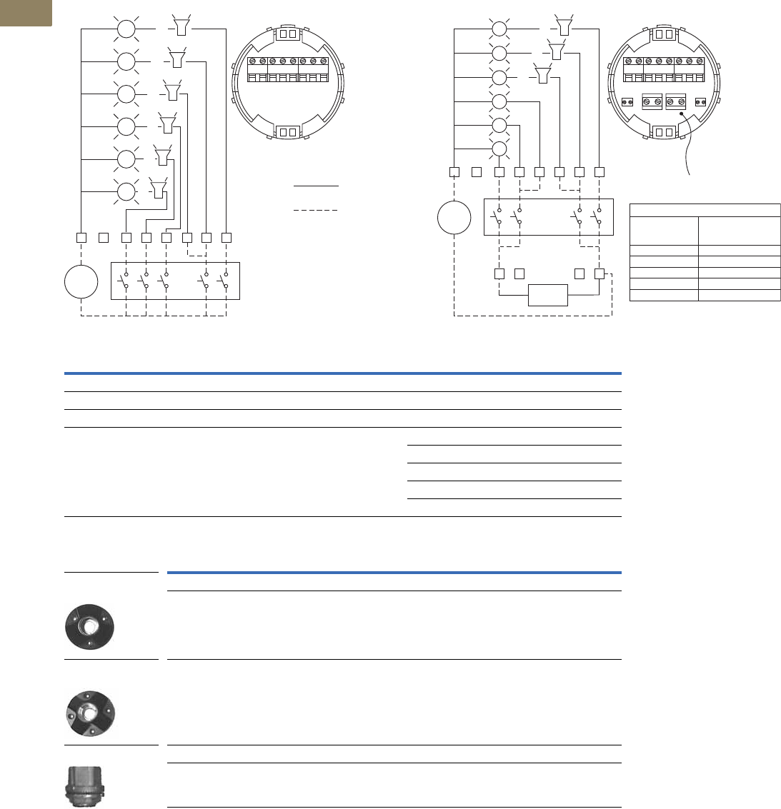
V7-T2-38 Volume 7—Logic Control, Operator Interface and Connectivity Solutions CA08100008E—March 2014 www.eaton.com
2
2
2
2
2
2
2
2
2
2
2
2
2
2
2
2
2
2
2
2
2
2
2
2
2
2
2
2
2
2
2.2
Stacklights
E26 Series
Mounting Bases Components
Standard Base Flashing Base
Mounting Bases and Hubs
Notes
1 Audible alarm units must be wired via the steady circuit on flashing base units.
2 Audible alarm units can be wired in positions as shown but only one unit is permitted on each stack and unit must occupy
the last or top mounting position.
65432
1
2
3
4
5
6
1
C
External
Switching
Devices
-
Supply
Factory
Wiring
Field
Wiring
C 123456
or
or
or
or
or
or
2
2
2
2
2
2
Flasher
Flasher
Base Voltage
Max. Allowable
No. of Light
Modules
6240 Vac/Vdc
6120 Vac/Vdc
648 Vac/Vdc
424 Vac/Vdc
212 Vdc
Orange Flasher
Wire
C1
78 910
23456
65432
1
2
3
4
5
6
1
10
9
Flashing
Module
8
7
C
External
Switching
Devices
Steady
Circuit
Flashing
Circuit
Orange
Wire
-
Supply
or
or
or
1 2
1 2
1 2
Description Voltage Catalog Number
Standard Base
For use with steady incandescent or steady/flashing LED 12 Vac/Vdc to 240 Vac/Vdc E26BL
Flashing Base
Enables configuration of incandescent light modules for steady or flashing operation 12 Vdc E26BFV1
24 Vac/Vdc E26BFV2
48 Vac/Vdc E26BFV3
120 Vac/Vdc E26BFV4
240 Vac/Vdc E26BFV5
Description Voltage Catalog Number
Mounting Base
Standard three-hole mounting base — E26S108
Standard four-hole mounting base — E26S109
Myers Type Hub
3/4 in NPT threaded hub — E26S104
Standard Three-Hole
Mounting Base
Standard Four-Hole
Mounting Base
Myers Type Hub
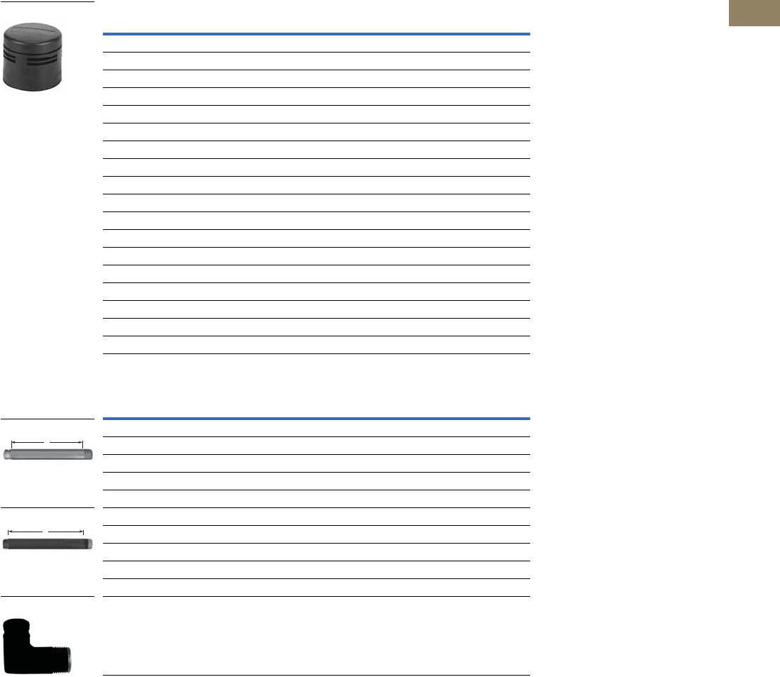
Volume 7—Logic Control, Operator Interface and Connectivity Solutions CA08100008E—March 2014 www.eaton.com V7-T2-39
2
2
2
2
2
2
2
2
2
2
2
2
2
2
2
2
2
2
2
2
2
2
2
2
2
2
2
2
2
2
2.2
Stacklights
E26 Series
Alarm Units and Extension Tubes Components
Audible Alarm Units-NEMA Type 1 (IP20) 1
Extension Tubes
Notes
1 Volume adjustment range: 64 dB to 90 dB typical current draw (mA).
2 For use with standard mounting base or 3/4 in NPT threaded hub—gray aluminum.
3 For use with standard mounting base or 3/4 in NPT threaded hub—black aluminum.
Description Voltage Catalog Number
Mono-Tonal
4.5 mA 12 Vac/Vdc E26BQV1
12.6 mA 24 Vac/Vdc E26BQV2
9.4 mA 48 Vac/Vdc E26BQV3
11.5 mA 120 Vac/Vdc E26BQV4
5.1 mA 240 Vac/Vdc E26BQV5
Bi-Tonal
4.5 mA 12 Vac/Vdc E26BNV1
12.6 mA 24 Vac/Vdc E26BNV2
9.4 mA 48 Vac/Vdc E26BNV3
11.5 mA 120 Vac/Vdc E26BNV4
5.1 mA 240 Vac/Vdc E26BNV5
Intermittent
4.5 mA 12 Vac/Vdc E26BPV1
12.6 mA 24 Vac/Vdc E26BPV2
9.4 mA 48 Vac/Vdc E26BPV3
11.5 mA 120 Vac/Vdc E26BPV4
5.1 mA 240 Vac/Vdc E26BPV5
Description Voltage Catalog Number
Extension “A” 2
0.79 in (20 mm) extension — E26BHM
6.30 in (160 mm) extension — E26BJM
14.17 in (360 mm) extension — E26BKM
29.92 in (760 mm) extension — E26BMM
Extension “A” 3
0.79 in (20 mm) extension — E26BHU
6.30 in (160 mm) extension — E26BJU
14.17 in (360 mm) extension — E26BKU
29.92 in (760 mm) extension — E26BMU
Right angle extension tube — E26BRU
E26B_
A
A
Extension Tube
Extension Tube
E26BRU
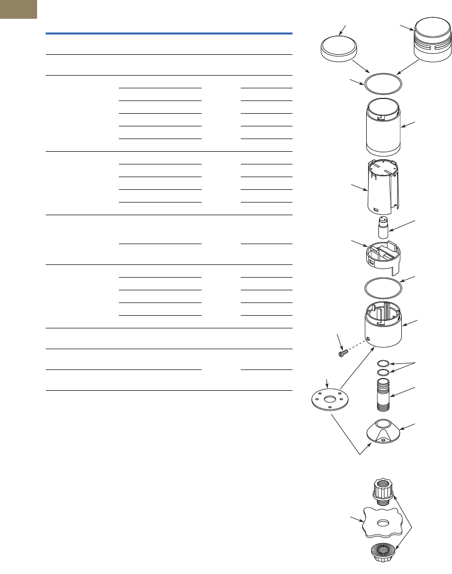
V7-T2-40 Volume 7—Logic Control, Operator Interface and Connectivity Solutions CA08100008E—March 2014 www.eaton.com
2
2
2
2
2
2
2
2
2
2
2
2
2
2
2
2
2
2
2
2
2
2
2
2
2
2
2
2
2
2
2.2
Stacklights
E26 Series
Replacement Parts
Stacklight Replacement Parts Typical Stacklight Assemblies
Notes
1Sold in packages of 5 pieces.
2For replacement LEDs, see table on Page V7-T2-37.
3Sold in packages of 10 pieces.
4Mounting gaskets have two sets of mounting holes—one set with center-to-center spacing of
1.75 in (44.5 mm) and another set with center-to-center spacing of 1.65 in (42 mm).
Description Notes
Number in
Diagram Catalog Number
Replacement
cover
Normally included with
stacklight base
1 E26S68
Replacement
lens O-ring
Normally included with light
modules
2 E26S106 1
Replacement lenses Clear 3 E26S38
Red E26S39
Green E26S40
Yellow E26S41
Blue E26S42
Amber E26S43
Replacement Xenon
strobe dual high
(does not include lenses)
12 Vac/Vdc 4 E26S33
24 Vac/Vdc E26S34
48 Vac/Vdc E26S35
120 Vac E26S36
240 Vac E26S37
Replacement diffusers White — normally supplied
with incandescent light
modules
4 E26S31
Clear — normally supplied
with LED light modules
E26S32
Replacement lamps 212V 5 E26S8
24V E26S9
48V E26S10
120V E26S11
240V E26S12
Replacement extension
tube O-rings
Normally included with
extension tubes
6 E26S107 3
Replacement mounting
gasket 4
Normally included with
stacklight base
7 E26S105
Lamp removal tool For E26 and E22
incandescent lamps
E22BA3
1 Cover Alarm
2 O-Ring
4
Light
Diffuser
Terminal
Board
Set Screw
Recommended
Tightening
Torque
Is 7 in-lb
(0.79 Nm)
7
Mounting
Gasket
Lens 3
Lamp 5
O-Ring 2
Mounting
Base
Stacklight
Base
Typical Stacklight Assembly
(Exploded View)
Alternate Conduit Hub
Myers Type
ST-2 or
ST-2CP Hub
Panel
Extension
Tube
O-Rings 6

Volume 7—Logic Control, Operator Interface and Connectivity Solutions CA08100008E—March 2014 www.eaton.com V7-T2-41
2
2
2
2
2
2
2
2
2
2
2
2
2
2
2
2
2
2
2
2
2
2
2
2
2
2
2
2
2
2
2.2
Stacklights
E26 Series
Technical Data and Specifications
General Specifications
Description Specification
Mechanical Ratings
Shock (IEC 68-2-27) 11 ms, 15g
Vibration (IEC 68-2-6) 10 sweeps 10–150 Hz, 2g
Bump (IEC 68-2-29) 1000 pulses, 6 ms, 15g
Climate Conditions
Operating Maximum 104°F (40°C) at 95% RH,
Temperature –4° to 140°F (–20° to 60°C)
Storage Temperature –40° to 176°F (–40° to 80°C)
Materials
Cover Polycarbonate
Lenses Polycarbonate
Stacklight base Nylon
Extension tubes Aluminum
Mounting base Zinc die cast
Te rm i n a l s
Single conductor 14–30 AWG (2.5–0.05 mm2)
Two conductors (same size)) 18–26 AWG (0.75–0.14 mm2)
Do not mix solid and stranded wire in the same terminal
Recommended tightening torque 4.4–5.3 lb-in (0.5–0.6 Nm)
Electrical Ratings
Insulation voltage (Ui)690V
Operational voltage (Ue)250V
Impulse withstand voltage (Uimp) 1.5 kV
Bulb Specifications
Incandescent lamp type BA15d
Maximum lamp wattage 6W
Bulbs—average life
Incandescent 7,000 to 12,000 hrs. (based on voltage)
Xenon flasher 20,000 hrs.
LED 60,000 to 100,000 hrs. (based on colors)
LED/Incandescent Comparison
Incandescent lamps Average operating life of 7,000 hours
Each lamp can be used with any color lens
Low cost results in short term savings
LED lamps Average operating life of 60,000 to 100,000 hours
Low power consumption
Extended life results in long-term savings

V7-T2-42 Volume 7—Logic Control, Operator Interface and Connectivity Solutions CA08100008E—March 2014 www.eaton.com
2
2
2
2
2
2
2
2
2
2
2
2
2
2
2
2
2
2
2
2
2
2
2
2
2
2
2
2
2
2
2.2
Stacklights
E26 Series
Ratings
Published theoretical lamp lives are based on ideal laboratory
conditions and should be used for comparison only.
Actual life may be shorter due to various application conditions.
Stacklight Incandescent Application Data
Xenon Flasher Application Data
LED Application Data
Note
1Represents average current draw, 1.6A peak for 120V and 0.8A peak at 240V.
Type
of Light
Lamp
Used
Approximate Current,
mA per Light
Theoretical Lamp Life,
Hours as Applied
12V BA15d 417 7,000
24V BA15d 208 7,000
48V BA15d 104 7,000
110–140V BA15d 36–50 7,000
220–260V BA15d 23–27 12,000
Type
of Light
Lamp
Used
Approximate Current,
mA per Light
Theoretical Lamp Life,
Hours as Applied
12V DC 460 mA 20,000
AC 780 mA 20,000
24V DC 190 mA 20,000
AC 320 mA 20,000
48V DC 100 mA 20,000
AC 150 mA 20,000
120V AC 60 mA 120,000
240V AC 30 mA 120,000
Type of
Light Color
Cluster LED
Approximate
Current, mA
at Rated Volts
Cylindrical LED
Approximate
Current, mA
at Rated Volts
Theoretical
Lamp Life,
Hours as Applied
Continuous/Flashing Stacklight LED
12
Vac/Vdc
Red 92 92 100,000
Amber 92 92 100,000
Yellow 92 92 100,000
Green 60 60 80,000
Blue 60 60 60,000
White 60 60 60,000
24
Vac/Vdc
Red 47 47 100,000
Amber 47 47 100,000
Yellow 47 47 100,000
Green 59 59 80,000
Blue 59 59 60,000
White 59 59 60,000
48
Vac/Vdc
Red 25 25 100,000
Amber 25 25 100,000
Yellow 25 25 100,000
Green 18 18 80,000
Blue 31 31 60,000
White 31 31 60,000
60
Vac/Vdc
Red 25 25 100,000
Amber 25 25 100,000
Yellow 25 25 100,000
Green 18 18 80,000
Blue 17 17 60,000
White 17 17 60,000
120
Vac/Vdc
Red 24 24 100,000
Amber 24 24 100,000
Yellow 24 24 100,000
Green 17 17 80,000
Blue 16 16 60,000
White 16 16 60,000
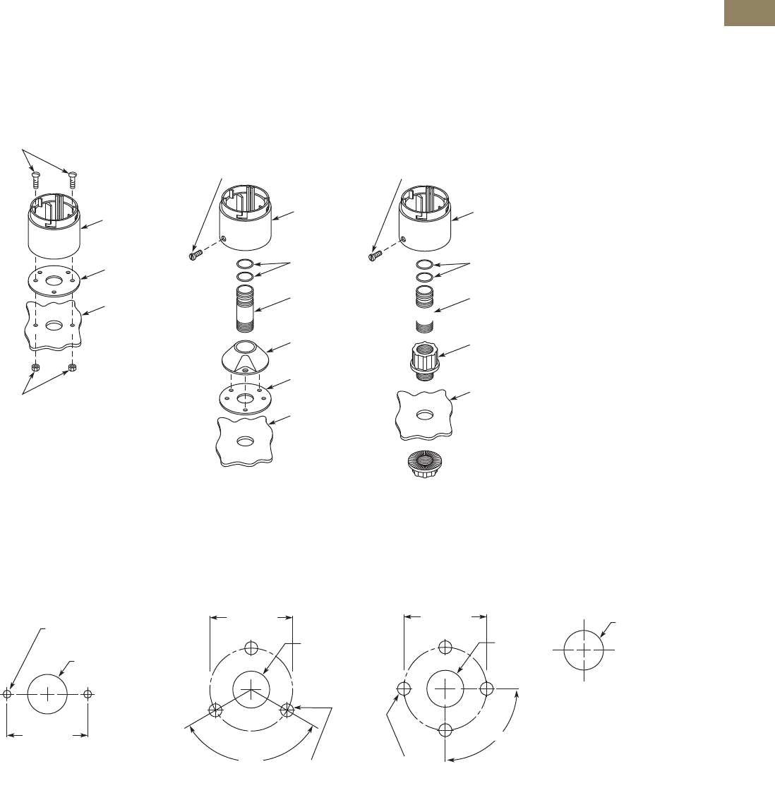
Volume 7—Logic Control, Operator Interface and Connectivity Solutions CA08100008E—March 2014 www.eaton.com V7-T2-43
2
2
2
2
2
2
2
2
2
2
2
2
2
2
2
2
2
2
2
2
2
2
2
2
2
2
2
2
2
2
2.2
Stacklights
E26 Series
Mounting Instructions
Stacklight bases may be
mounted without the use of
an extension tube or
mounting base. If additional
height is required, choose
0.8–30 in (20–760 mm)
extension tubes that fit
between the mounting base
and stacklight base. The
extension tubes are threaded
with 3/4 in NPT threads,
allowing for direct connection
to conduit fittings or threaded
holes without the use of a
mounting base.
Base Mounting
Utilizing Extension Tube
and Mounting Base
Utilizing Extension Tube
and 3/4 In (19.1 mm)
Conduit Hub
Mounting Dimensions
Approximate Dimensions in Inches (mm)
Base Mounting
Three-Hole Mounting for
E26S108
Four-Hole Mounting for
E26S109
Conduit Hub for E26S104—
3/4 In (19.1 mm)
Note
1Stacklight base and gasket are supplied as standard with two sets of base mount holes.
One set with center-to-center spacing of 1.75 in (44.5 mm) and another set with center-to-center spacing of 1.65 in (42 mm).
Stacklight
Base
Customer
Supplied
Customer
Supplied
Mounting
Gasket
Panel
Set Screw
Recommended
Tightening Torque
Is 7 in-lb
(0.79 Nm)
Mounting
Base
Mounting
Gasket
Panel
Stacklight
Base
Extension
Tube
O-Rings
Extension
Tube
O-Rings
Myers Type
ST-2 or
ST-2CP Hub
Panel
Stacklight
Base
(Use Rubber-Jawed Pliers for
Installation to Avoid Scratching
the Black Anodized Coating)
Set Screw
Recommended
Tightening Torque
Is 7 in-lb
(0.79 Nm)
1.75 (44.5)
or 1.65 (42.0) a
0.18 (4.6) Dia.
or #8–32 Thread
or (M4 x 0.7)
0.87
(22.1) Dia.
120°
0.87
(22.1)
Dia.
1.92 (48.8)
Dia.
0.18 (4.6) Dia.
or #8–32 Thread
or (M4 x 0.7)
90°
0.87
(22.1)
Dia.
2.12 (53.8)
Dia.
0.20 (5.08) Dia.
or #10–32 Thread
or (M5 x 0.7)
1.06
(27) Dia.
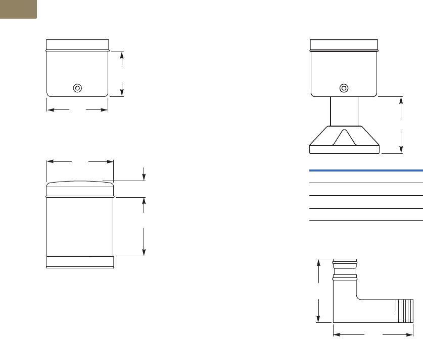
V7-T2-44 Volume 7—Logic Control, Operator Interface and Connectivity Solutions CA08100008E—March 2014 www.eaton.com
2
2
2
2
2
2
2
2
2
2
2
2
2
2
2
2
2
2
2
2
2
2
2
2
2
2
2
2
2
2
2.2
Stacklights
E26 Series
Dimensions
Approximate Dimensions in Inches (mm)
Standard and Flashing Bases 1
Alarm Units
Assembled Extension Tubes
Right Angle Extension Tubes
Notes
1Bases also suitable for mounting with extension tubes listed on Page V7-T2-39.
2Mounting gasket and cover are supplied as standard with stacklight bases.
1.75
(44)
2.32
(59)
2
2.56
(65)
0.59
(15)
1.69
(42.9)
A
Tube Extension Height A
0.79 (20) 1.77 (45)
6.30 (160) 7.28 (185)
14.17 (360) 15.16 (385)
29.92 (760) 30.91 (785)
2.50
(63.5)
2.00
(50.8)
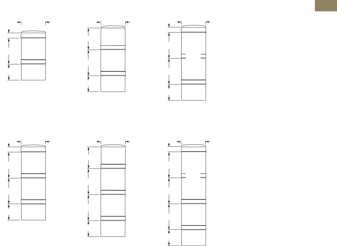
Volume 7—Logic Control, Operator Interface and Connectivity Solutions CA08100008E—March 2014 www.eaton.com V7-T2-45
2
2
2
2
2
2
2
2
2
2
2
2
2
2
2
2
2
2
2
2
2
2
2
2
2
2
2
2
2
2
2.2
Stacklights
E26 Series
Approximate Dimensions in Inches (mm)
One-Light Unit Stacklight
Standard With Alarm With Xenon Flasher
Two-Light Unit Stacklight
Standard With Alarm With Xenon Flasher
2.56 (65)
Light
Unit
Base
0.59 (15)
2.72 (69)
1.73 (44)
Light
Unit
Base
2.56 (65)
Alarm
2.24 (57)
2.72 (69)
1.73 (44)
Base
2.56 (65)
2.72 (69)
0.59 (15)
2.72 (69)
1.73 (44)
Xenon
Light
Unit
(2 High)
2.72 (69)
0.59 (15)
2.72 (69)
1.73 (44)
2.56 (65)
Light
Unit
Light
Unit
Base
2.72 (69)
1.73 (44)
2.72 (69)
Light
Unit
Light
Unit
Base
2.56 (65)
Alarm
2.24 (57)
2.72 (69)
0.59 (15)
2.72 (69)
1.73 (44)
2.72 (69)
Base
2.56 (65)
Xenon
Light
Unit
(2 High)
Light
Unit
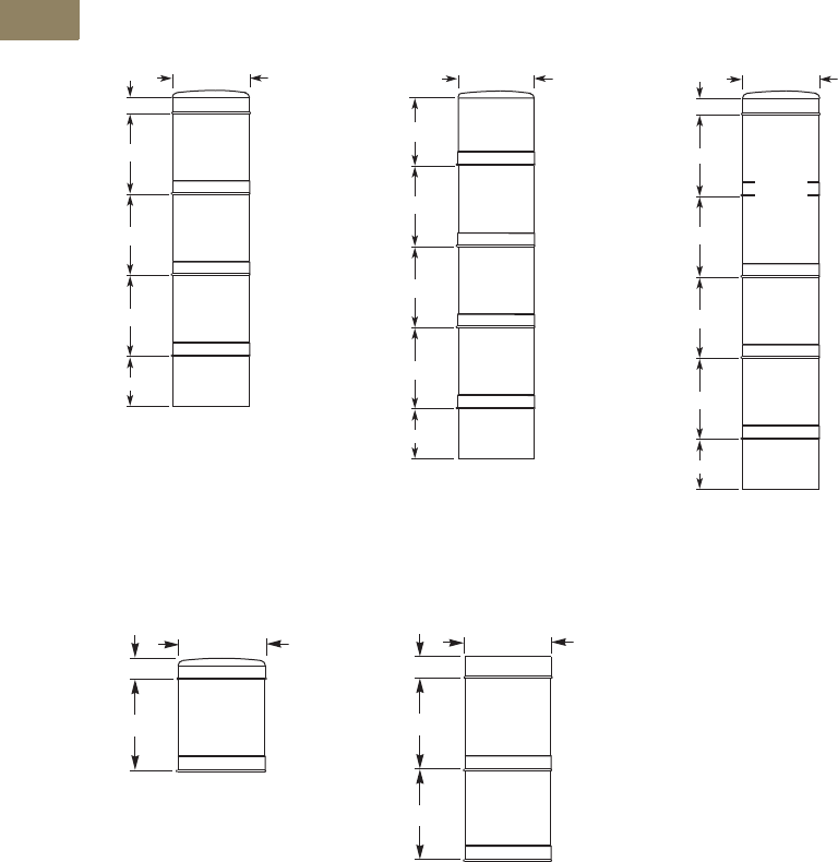
V7-T2-46 Volume 7—Logic Control, Operator Interface and Connectivity Solutions CA08100008E—March 2014 www.eaton.com
2
2
2
2
2
2
2
2
2
2
2
2
2
2
2
2
2
2
2
2
2
2
2
2
2
2
2
2
2
2
2.2
Stacklights
E26 Series
Approximate Dimensions in Inches (mm)
Three-Light Unit Stacklight
Standard With Alarm With Xenon Flasher
Light Modules
Standard Xenon
Note
1Cover included with stacklight base.
0.59 (15)
2.72 (69)
1.73 (44)
2.72 (69)
2.72 (69)
Base
2.56 (65)
Light
Unit
Light
Unit
Light
Unit
2.72 (69)
1.73 (44)
2.72 (69)
2.72 (69)
Base
2.56 (65)
Light
Unit
Light
Unit
Light
Unit
Alarm
2.24 (57)
2.72 (69)
0.59 (15)
2.72 (69)
1.73 (44)
2.72 (69)
2.72 (69)
Base
2.56 (65)
Xenon
Light
Unit
(2 High)
Light
Unit
Light
Unit
2.56 (65)
a
0.59 (15)
2.72 (69.1)
2.56 (65)
0.59 (15)
a
2.72 (69.1)
2.72 (69.1)
Volume 7—Logic Control, Operator Interface and Connectivity Solutions CA08100008E—February 2014 www.eaton.com V7-T3-1
3
3
3
3
3
3
3
3
3
3
3
3
3
3
3
3
3
3
3
3
3
3
3
3
3
3
3
3
3
3
Control Relays and Timers
easyRelay Programmable Relays
D96 Series Solid-State Relay
Universal TR Series Timing Relay
D1 Series General Purpose Relay
Safety Relay
3.1 Relay Products
Control Relays and Timers Comparison . . . . . . . . . . . . . . . . . . . . . . . . V7-T3-2
3.2 XR Series Terminal Block Relays
Standard, OptoCoupler and High Current
Catalog Number Selection . . . . . . . . . . . . . . . . . . . . . . . . . . . . . . . . . . V7-T3-3
3.3 Programmable Relays
easy500, easy700, easy800, easy802/806 Relays and
MFD-Titan Multi-Function Displays
Product Overview . . . . . . . . . . . . . . . . . . . . . . . . . . . . . . . . . . . . . . . . V7-T3-19
3.4 General Purpose Plug-In Relays
General Purpose Relays—D1, D2, D3, D4, D5, D7, D8 and D9 Series
Product Selection Guide . . . . . . . . . . . . . . . . . . . . . . . . . . . . . . . . . . . . V7-T3-49
3.5 General Purpose Open Style Relays
9575H Series 3000 Relay
9575H Series 3000—Type AA, AC and DC. . . . . . . . . . . . . . . . . . . . . . V7-T3-122
3.6 Solid-State Relays
D93, D96 and D99 Series
Product Overview . . . . . . . . . . . . . . . . . . . . . . . . . . . . . . . . . . . . . . . . V7-T3-126
3.7 Machine Tool Relays
D15, BF/BFD, AR/ARD and D26 Series
Product Overview. . . . . . . . . . . . . . . . . . . . . . . . . . . . . . . . . . . . . . . . . V7-T3-145
3.8 Timing Relays
Universal TR, TR and TMR Series
Product Selection Guide . . . . . . . . . . . . . . . . . . . . . . . . . . . . . . . . . . . . V7-T3-171
3.9 Alternating Relays
D85 Series
Product Description . . . . . . . . . . . . . . . . . . . . . . . . . . . . . . . . . . . . . . . V7-T3-192
3.10 Safety Relays
ESR5 Series
Product Description . . . . . . . . . . . . . . . . . . . . . . . . . . . . . . . . . . . . . . . V7-T3-197
3.11 easySafety
ES4P Series
Product Description . . . . . . . . . . . . . . . . . . . . . . . . . . . . . . . . . . . . . . . V7-T3-203
V7-T3-2 Volume 7—Logic Control, Operator Interface and Connectivity Solutions CA08100008E—February 2014 www.eaton.com
3
3
3
3
3
3
3
3
3
3
3
3
3
3
3
3
3
3
3
3
3
3
3
3
3
3
3
3
3
3
V7-T3-2 Volume 7—Logic Control, Operator Interface and Connectivity Solutions CA08100008E—February 2014 www.eaton.com
3
3
3
3
3
3
3
3
3
3
3
3
3
3
3
3
3
3
3
3
3
3
3
3
3
3
3
3
3
3
3.1
Control Relays and Timers
Relay Product Overview
Relay Products
Contents
Description Page
Terminal Block Relays . . . . . . . . . . . . . . . . . . . . . . V7-T3-3
Programmable Relays . . . . . . . . . . . . . . . . . . . . . . V7-T3-19
General Purpose Plug-In Relays . . . . . . . . . . . . . . . V7-T3-49
General Purpose Type AA Relays . . . . . . . . . . . . . V7-T3-122
Solid-State Relays . . . . . . . . . . . . . . . . . . . . . . . . . V7-T3-126
Machine Tool Relays . . . . . . . . . . . . . . . . . . . . . . . V7-T3-145
Timing Relays . . . . . . . . . . . . . . . . . . . . . . . . . . . . V7-T3-171
Alternating Relays . . . . . . . . . . . . . . . . . . . . . . . . . V7-T3-192
Safety Relays . . . . . . . . . . . . . . . . . . . . . . . . . . . . V7-T3-197
Control Relays and Timers Comparison
Selection Guide by Catalog Number Prefix
Relays Type Mounting Contacts
Maximum
Amperage
(AC) UL CSA CE
Page
Number
9575H3 General purpose Panel mount Fixed 40A — ■■■V7-T3-123
AR/ARD Machine tool Panel mount Convertible 10A — ■■—V7-T3-158
BF/BFD Machine tool Panel mount Fixed 10A ■—■—V7-T3-152
D2PF Full featured plug-in DIN rail / panel mount Fixed 10A ■—■■V7-T3-60
D2PR Standard plug-in DIN rail / panel mount / flange Fixed 10A ■—■■V7-T3-60
D3PF Full featured plug-in DIN rail / panel mount Fixed 16A ■—■■V7-T3-70
D3PR Standard plug-in DIN rail / panel mount Fixed 16A ■—■■V7-T3-70
D4PR Standard plug-in DIN rail / panel mount Fixed 10A ■—■■V7-T3-79
D5PF Full featured plug-in DIN rail / panel mount Fixed 16A ■—■■V7-T3-84
D5PR Standard plug-in DIN rail / panel mount / PC board Fixed 16A ■—■■V7-T3-84
D7PF Full featured plug-in DIN rail / panel mount Fixed 20A ■—■■V7-T3-93
D7PR Standard plug-in DIN rail / panel mount / flange Fixed 20A ■—■■V7-T3-94
D8PR Standard plug-in DIN rail / panel mount / flange Fixed 30A ■—■■V7-T3-107
D9PR Standard plug-in Panel mounting Fixed 25A ■—■—V7-T3-113
D15 Machine tool DIN rail / panel mount Fixed 10A — ■■■V7-T3-147
D26 Machine tool Panel or channel mount Convertible 10A — ■■—V7-T3-163
D85 Alternating relays DIN rail / panel mount Fixed 10A ■■—■V7-T3-193
D1PF Full featured plug-in DIN rail / panel mount Fixed 20A ■—■■V7-T3-54
D1PR Standard plug-in DIN rail / panel mount Fixed 20A ■—■■V7-T3-54
easyRelay Programmable relay DIN rail Fixed 8A — ■■■V7-T3-23
TMR5 Timing relay (non-programmable) DIN rail / panel mount Fixed 10A ■■—■V7-T3-184
TMR6 Timing relay (non-programmable) DIN rail / panel mount Fixed 10A ■■—■V7-T3-188
TR Timing relay (programmable) DIN rail / panel mount Fixed 10A — ■■—V7-T3-181
Universal TR Timing relay (programmable) DIN rail Fixed 8A — ■■■V7-T3-177
XR Terminal block relay DIN rail Fixed 6A, 10A ■——■V7-T3-5
Volume 7—Logic Control, Operator Interface and Connectivity Solutions CA08100008E—February 2014 www.eaton.com V7-T3-3
3
3
3
3
3
3
3
3
3
3
3
3
3
3
3
3
3
3
3
3
3
3
3
3
3
3
3
3
3
3
Volume 7—Logic Control, Operator Interface and Connectivity Solutions CA08100008E—February 2014 www.eaton.com V7-T3-3
3
3
3
3
3
3
3
3
3
3
3
3
3
3
3
3
3
3
3
3
3
3
3
3
3
3
3
3
3
3
3.2
Control Relays and Timers
Ter m i n a l B l o c k R el ay s
Terminal Block Relays
Contents
Description Page
Terminal Block Relays
Standard Terminal Block Relays . . . . . . . . . . . . V7-T3-4
OptoCoupler Terminal Block Relays . . . . . . . . . V7-T3-12
High Current Terminal Block Relays . . . . . . . . . V7-T3-15
XR Series Accessories . . . . . . . . . . . . . . . . . . . V7-T3-18
Catalog Number Selection
XR Series—Overview
Description
XR = XR terminal block relay
XR U1D12 G
Poles
1 =1PDT
2 =2PDT
Connection Type
U =Screw
P = Spring
R = Replacement relay
Gold-Flashed Contacts
Blank =No
G =Yes
Type
D = Standard relay
S = Octocoupler (solid-state)
H = High current
Voltage
12 = 12 Vdc
24 = 24 Vdc
24U = 24 Vac/Vdc
120U = 120 Vac/110 Vdc
230U = 230 Vac/220 Vdc
V7-T3-4 Volume 7—Logic Control, Operator Interface and Connectivity Solutions CA08100008E—February 2014 www.eaton.com
3
3
3
3
3
3
3
3
3
3
3
3
3
3
3
3
3
3
3
3
3
3
3
3
3
3
3
3
3
3
V7-T3-4 Volume 7—Logic Control, Operator Interface and Connectivity Solutions CA08100008E—February 2014 www.eaton.com
3
3
3
3
3
3
3
3
3
3
3
3
3
3
3
3
3
3
3
3
3
3
3
3
3
3
3
3
3
3
3.2
Control Relays and Timers
Ter m i n a l B l o c k Rel ay s
Standard Terminal Block Relay
Contents
Description Page
Standard Terminal Block Relays
Product Selection . . . . . . . . . . . . . . . . . . . . . . . V7-T3-5
Technical Data and Specifications . . . . . . . . . . V7-T3-6
Electrical Schematics . . . . . . . . . . . . . . . . . . . . V7-T3-11
Dimensions . . . . . . . . . . . . . . . . . . . . . . . . . . . V7-T3-11
OptoCoupler Terminal Block Relays . . . . . . . . . . . V7-T3-12
High Current Terminal Block Relays . . . . . . . . . . . V7-T3-15
XR Series Accessories . . . . . . . . . . . . . . . . . . . . . V7-T3-18
Standard Terminal Block Relays
Product Description
The XR Series Terminal
Block Relays are ideal for
applications that require a
high switching capacity and
long electrical service life.
The relays are plug-in
interfaces that connect to
basic terminal blocks. The
XR Series uses screw or
spring-cage technology, as
well as offers quick system
wiring, superior safety
features, clear labeling and
a high level of modularity.
Application Description
Used in automation systems,
electromechanical relays
guarantee a safe connection
between process I/O and
electronic controls. The
following functions are
covered by relay coupling
elements:
●Electrical isolation
between the input and
output circuits
●Independence of the type
of switching current (AC
and DC)
●High short-term overload
resistance in the event of
short circuits or voltage
peaks
●Low switching losses
●Ease of operation
Features
●Pluggable relay allows for
field replacement
●Functional plug-in bridges
●Choice of screw
connections or spring-cage
connection
●LED status indication
●DIN rail mount
●Only 6.2 mm wide for
single-pole versions,
14 mm wide for double-
pole
●All common input
voltages between
12 Vdc to 120 Vac
●Gold-plated contacts
available
●Equipped with a robust,
miniature relay:
●IP67 protection
●Environmentally friendly,
cadmium-free contact
material
●Easy, cost-effective
installation and
replacement using the
engagement lever
Standards and Certifications
●cULus listed
●CE
Volume 7—Logic Control, Operator Interface and Connectivity Solutions CA08100008E—February 2014 www.eaton.com V7-T3-5
3
3
3
3
3
3
3
3
3
3
3
3
3
3
3
3
3
3
3
3
3
3
3
3
3
3
3
3
3
3
Volume 7—Logic Control, Operator Interface and Connectivity Solutions CA08100008E—February 2014 www.eaton.com V7-T3-5
3
3
3
3
3
3
3
3
3
3
3
3
3
3
3
3
3
3
3
3
3
3
3
3
3
3
3
3
3
3
3.2
Control Relays and Timers
Ter m i n a l B l o c k R el ay s
Product Selection
Standard Terminal Block Relays
Standard Replacement Relays
Note
1 Voltage is the rating at the base. It may not match the voltage on the specific replacement relay.
Gold-Plated
Contacts
Rated
Current
Supply
Voltage
Standard
Pack
Catalog
Number
1PDT Screw Connection
No 6A 12 Vdc 10 XRU1D12
No 6A 120 Vac/110 Vdc 10 XRU1D120U
Yes 6A 120 Vac/110 Vdc 10 XRU1D120UG
No 6A 24 Vdc 10 XRU1D24
No 6A 24 Vac/Vdc 10 XRU1D24U
Yes 6A 24 Vac/Vdc 10 XRU1D24UG
No 6A 230 Vac/220 Vdc 10 XRU1D230U
1PDT Spring Cage Connection
No 6A 12 Vdc 10 XRP1D12
No 6A 120 Vac/110 Vdc 10 XRP1D120U
No 6A 24 Vdc 10 XRP1D24
No 6A 24 Vac/Vdc 10 XRP1D24U
No 6A 230 Vac/220 Vdc 10 XRP1D230U
DPDT Screw Connection
No 6A 12 Vdc 10 XRU2D12
No 6A 120 Vac/110 Vdc 10 XRU2D120U
No 6A 24 Vdc 10 XRU2D24
No 6A 24 Vac/Vdc 10 XRU2D24U
No 6A 230 Vac/220 Vdc 10 XRU2D230U
Gold-Plated
Contacts
Rated
Current
Supply
Voltage 1
Standard
Pack
Catalog
Number
1PDT
No 6A 12 Vdc 10 XRR1D12
No 6A 120 Vac/110 Vdc 10 XRR1D120U
Yes 6A 120 Vac/110 Vdc 10 XRR1D120UG
No 6A 24 Vdc 10 XRR1D24
Yes 6A 24 Vdc 10 XRR1D24G
DPDT
No 6A 12 Vdc 10 XRR2D12
No 6A 120 Vac/110 Vdc 10 XRR2D120U
No 6A 24 Vdc 10 XRR2D24
No 6A 230 Vac/220 Vdc 10 XRR2D230U
XRU1D 24U

V7-T3-6 Volume 7—Logic Control, Operator Interface and Connectivity Solutions CA08100008E—February 2014 www.eaton.com
3
3
3
3
3
3
3
3
3
3
3
3
3
3
3
3
3
3
3
3
3
3
3
3
3
3
3
3
3
3
V7-T3-6 Volume 7—Logic Control, Operator Interface and Connectivity Solutions CA08100008E—February 2014 www.eaton.com
3
3
3
3
3
3
3
3
3
3
3
3
3
3
3
3
3
3
3
3
3
3
3
3
3
3
3
3
3
3
3.2
Control Relays and Timers
Ter m i n a l B l o c k Rel ay s
Technical Data and Specifications
Standard 1PDT Screw Connection Terminal Block Relays
Note
1The separating plate, XRAPLCESK, should be installed for voltages greater than 250V (L1, L2, L3) between identical terminal points of adjacent modules.
Potential bridging is then possible with the XRAFBST bridge system.
Catalog Number XRU1D12 XRU1D24 XRU1D24U XRU1D120U
Replacement Relay XRR1D12 XRR1D24 XRR1D24 XRR1D120U
Input voltage 12 Vdc 24 Vdc 24 Vac/Vdc 120 Vac/110 Vdc
Connection Data
Rigid solid AWG (mm2) 26–14 (0.14–2.5) 26–14 (0.14–2.5) 26–14 (0.14–2.5) 26–14 (0.14–2.5)
Flexible stranded AWG (mm2) 26–14 (0.14–2.5) 26–14 (0.14–2.5) 26–14 (0.14–2.5) 26–14 (0.14–2.5)
Input Data for 1PDT Screw Connection Versions
Input voltage 12 Vdc 24 Vdc 24 Vac/Vdc 120 Vac/110 Vdc
Permissible range See Page V7-T3-10 See Page V7-T3-10 See Page V7-T3-10 See Page V7-T3-10
Typical input current 15.3 mA 9 mA 11 mA (24 Vac)/8.5 mA (24 Vdc) 3.5 mA (120 Vac)/3 mA (110 Vdc)
Typical response time 5 ms 5 ms 6 ms 6 ms
Typical release time 8 ms 8 ms 15 ms 15 ms
Input protection Polarity protection diode,
free-wheeling diode
Polarity protection diode,
free-wheeling diode
Bridge rectifier Bridge rectifier
Output Data
Contact type 1PDT 1PDT 1PDT 1PDT
Contact material AgSnO AgSnO AgSnO AgSnO
Max. switching voltage 250 Vac/Vdc 1250 Vac/Vdc 1250 Vac/Vdc 1250 Vac/Vdc 1
Min. switching voltage 12 Vac/Vdc 12 Vac/Vdc 12 Vac/Vdc 12 Vac/Vdc
Limiting continuous current 6A 6A 6A 6A
Min. switching current 10 mA 10 mA 10 mA 10 mA
Min. switching power 120 mW 120 mW 120 mW 120 mW
Miscellaneous Data
Ambient temp range –4° to 140°F (–20° to 60°C) –4° to 140°F (–20° to 60°C) –4° to 140°F (–20° to 60°C) –4° to 140°F (–20° to 60°C)
Rated operating mode 100% operating factor 100% operating factor 100% operating factor 100% operating factor
Inflammability class V0, in accordance with UL 94 V0, in accordance with UL 94 V0, in accordance with UL 94 V0, in accordance with UL 94
Mechanical service life 2 x 10⁷ cycles 2 x 10⁷ cycles 2 x 10⁷ cycles 2 x 10⁷ cycles

Volume 7—Logic Control, Operator Interface and Connectivity Solutions CA08100008E—February 2014 www.eaton.com V7-T3-7
3
3
3
3
3
3
3
3
3
3
3
3
3
3
3
3
3
3
3
3
3
3
3
3
3
3
3
3
3
3
Volume 7—Logic Control, Operator Interface and Connectivity Solutions CA08100008E—February 2014 www.eaton.com V7-T3-7
3
3
3
3
3
3
3
3
3
3
3
3
3
3
3
3
3
3
3
3
3
3
3
3
3
3
3
3
3
3
3.2
Control Relays and Timers
Ter m i n a l B l o c k R el ay s
Standard 1PDT Screw Connection Terminal Block Relays with Gold Contacts
Notes
1The separating plate, XRAPLCESK, should be installed for voltages greater than 250V (L1, L2, L3) between identical terminal
points of adjacent modules. Potential bridging is then possible with the XRAFBST bridge system.
2If the maximum values are exceeded, the gold layer is destroyed and the values in parentheses apply.
Catalog Number XRU1D24UG XRU1D120UG
Replacement Relay XRR1D24G XRR1D120UG
Input voltage 24 Vac/Vdc 120 Vac/110 Vdc
Connection Data
Rigid solid AWG (mm2) 26–14 (0.14–2.5) 26–14 (0.14–2.5)
Flexible stranded AWG (mm2) 26–14 (0.14–2.5) 26–14 (0.14–2.5)
Input Data for 1PDT Screw Connection Versions with Gold Contacts
Input voltage 24 Vac/Vdc 120 Vac/110 Vdc
Permissible range See Page V7-T3-10 See Page V7-T3-10
Typical input current 11 mA (24 Vac)/8.5 mA (24 Vdc) 3.5 mA (120 Vac)/3 mA (110 Vdc)
Typical response time 6 ms 6 ms
Typical release time 15 ms 15 ms
Input protection Bridge rectifier Bridge rectifier
Output Data
Contact type 1PDT 1PDT
Contact material AgSnO, gold plated 1AgSnO, gold plated 1
Max. switching voltage 30 Vac/36 Vdc (250 Vac/Vdc) 230 Vac/36 Vdc (250 Vac/Vdc) 2
Min. switching voltage 100 mV (12 Vac/Vdc) 2100 mV (12 Vac/Vdc) 2
Limiting continuous current 50 mA (6A) 250 mA (6A) 2
Min. switching current 1 mA (10 mA) 21 mA (10 mA) 2
Min. switching power 100 mW (120 mW) 2100 mW (120 mW) 2
Miscellaneous Data
Ambient temp range –4° to 140°F (–20° to 60°C) –40° to 131°F (–20° to 55°C)
Rated operating mode 100% operating factor 100% operating factor
Inflammability class V0, in accordance with UL 94 V0, in accordance with UL 94
Mechanical service life 2 x 10⁷ cycles 2 x 10⁷ cycles

V7-T3-8 Volume 7—Logic Control, Operator Interface and Connectivity Solutions CA08100008E—February 2014 www.eaton.com
3
3
3
3
3
3
3
3
3
3
3
3
3
3
3
3
3
3
3
3
3
3
3
3
3
3
3
3
3
3
V7-T3-8 Volume 7—Logic Control, Operator Interface and Connectivity Solutions CA08100008E—February 2014 www.eaton.com
3
3
3
3
3
3
3
3
3
3
3
3
3
3
3
3
3
3
3
3
3
3
3
3
3
3
3
3
3
3
3.2
Control Relays and Timers
Ter m i n a l B l o c k Rel ay s
Standard 1PDT Spring Cage Terminal Block Relays
Note
1The separating plate, XRAPLCESK, should be installed for voltages greater than 250V (L1, L2, L3) between identical terminal points of adjacent modules.
Potential bridging is then possible with the XRAFBST bridge system.
Catalog Number XRP1D12 XRP1D24 XRP1D24U XRP1D120U
Replacement Relay XRR1D12 XRR1D24 XRR1D24 XRR1D120U
Input voltage 12 Vdc 24 Vdc 24 Vac/Vdc 120 Vac/110 Vdc
Connection Data
Rigid solid AWG (mm2) 26–14 (0.14–2.5) 26–14 (0.14–2.5) 26–14 (0.14–2.5) 26–14 (0.14–2.5)
Flexible stranded AWG (mm2) 26–14 (0.14–2.5) 26–14 (0.14–2.5) 26–14 (0.14–2.5) 26–14 (0.14–2.5)
Input Data for 1PDT Spring Cage Versions
Input voltage 12 Vdc 24 Vdc 24 Vac/Vdc 120 Vac/110 Vdc
Permissible range See Page V7-T3-10 See Page V7-T3-10 See Page V7-T3-10 See Page V7-T3-10
Typical input current 15.3 mA 9 mA 11 mA (24 Vac)/8.5 mA (24 Vdc) 3.5 mA (120 Vac)/3 mA (110 Vdc)
Typical response time 5 ms 5 ms 6 ms 6 ms
Typical release time 8 ms 8 ms 15 ms 15 ms
Input protection Polarity protection diode,
free-wheeling diode
Polarity protection diode,
free-wheeling diode
Bridge rectifier Bridge rectifier
Output Data
Contact type 1PDT 1PDT 1PDT 1PDT
Contact material AgSnO AgSnO AgSnO AgSnO
Max. switching voltage 250 Vac/Vdc 1250 Vac/Vdc 1250 Vac/Vdc 1250 Vac/Vdc 1
Min. switching voltage 12 Vac/Vdc 12 Vac/Vdc 12 Vac/Vdc 12 Vac/Vdc
Limiting continuous current 6A 6A 6A 6A
Min. switching current 10 mA 10 mA 10 mA 10 mA
Min. switching power 120 mW 120 mW 120 mW 120 mW
Miscellaneous Data
Ambient temp range –4° to 140°F (–20° to 60°C) –4° to 140°F (–20° to 60°C) –4° to 140°F (–20° to 60°C) –4° to 131°F (–20° to 55°C)
Rated operating mode 100% operating factor 100% operating factor 100% operating factor 100% operating factor
Inflammability class V0, in accordance with UL 94 V0, in accordance with UL 94 V0, in accordance with UL 94 V0, in accordance with UL 94
Mechanical service life 2 x 10⁷ cycles 2 x 10⁷ cycles 2 x 10⁷ cycles 2 x 10⁷ cycles

Volume 7—Logic Control, Operator Interface and Connectivity Solutions CA08100008E—February 2014 www.eaton.com V7-T3-9
3
3
3
3
3
3
3
3
3
3
3
3
3
3
3
3
3
3
3
3
3
3
3
3
3
3
3
3
3
3
Volume 7—Logic Control, Operator Interface and Connectivity Solutions CA08100008E—February 2014 www.eaton.com V7-T3-9
3
3
3
3
3
3
3
3
3
3
3
3
3
3
3
3
3
3
3
3
3
3
3
3
3
3
3
3
3
3
3.2
Control Relays and Timers
Ter m i n a l B l o c k R el ay s
Standard DPDT Screw Connection Terminal Block Relays
Note
1The separating plate, XRAPLCESK, should be installed for voltages greater than 250V (L1, L2, L3) between identical terminal points of adjacent modules.
Potential bridging is then possible with the XRAFBST bridge system.
Catalog Number XRU2D12 XRU2D24 XRU2D24U XRU2D120U
Replacement Relay XRR2D12 XRR2D24 XRR2D24 XRR2D120U
Input voltage 12 Vdc 24 Vdc 24 Vac/Vdc 120 Vac/110 Vdc
Connection Data
Rigid solid AWG (mm2) 26–14 (0.14–2.5) 26–14 (0.14–2.5) 26–14 (0.14–2.5) 26–14 (0.14–2.5)
Flexible stranded AWG (mm2) 26–14 (0.14–2.5) 26–14 (0.14–2.5) 26–14 (0.14–2.5) 26–14 (0.14–2.5)
Input Data for 1PDT Spring Cage Versions
Input voltage 12 Vdc 24 Vdc 24 Vac/Vdc 120 Vac/110 Vdc
Permissible range See Page V7-T3-10 See Page V7-T3-10 See Page V7-T3-10 See Page V7-T3-10
Typical input current 33 mA 18 mA 17.5 mA 4.5 mA (120 Vac)/4.2 mA (110 Vdc)
Typical response time 8 ms 8 ms 8 ms 7 ms
Typical release time 10 ms 10 ms 10 ms 10 ms
Input protection Polarity protection diode,
free-wheeling diode
Polarity protection diode,
free-wheeling diode
Bridge rectifier Bridge rectifier
Output Data
Contact type 2PDT Single contact, 2PDT Single contact, 2PDT Single contact, 2PDT
Contact material AgNi AgNi AgNi AgNi
Max. switching voltage 250 Vac/Vdc 1250 Vac/Vdc 1250 Vac/Vdc 1250 Vac/Vdc 1
Min. switching voltage 5V 5V 5V 5V
Limiting continuous current 6A 6A 6A 6A
Max. inrush current 15A (300 ms) 15A (300 ms) 15A (300 ms) 15A (300 ms)
Min. switching current 10 mA 10 mA 10 mA 10 mA
Min. switching power 50 mW 50 mW 50 mW 50 mW
General Data
Ambient temp range –4° to 140°F (–20° to 60°C) –4° to 140°F (–20° to 60°C) –4° to 140°F (–20° to 60°C) –4° to 140°F (–20° to 60°C)
Rated operating mode 100% operating factor 100% operating factor 100% operating factor 100% operating factor
Inflammability class V0, in accordance with UL 94 V0, in accordance with UL 94 V0, in accordance with UL 94 V0, in accordance with UL 94
Mechanical service life 3 x 10⁷ cycles 3 x 10⁷ cycles 3 x 10⁷ cycles 3 x 10⁷ cycles
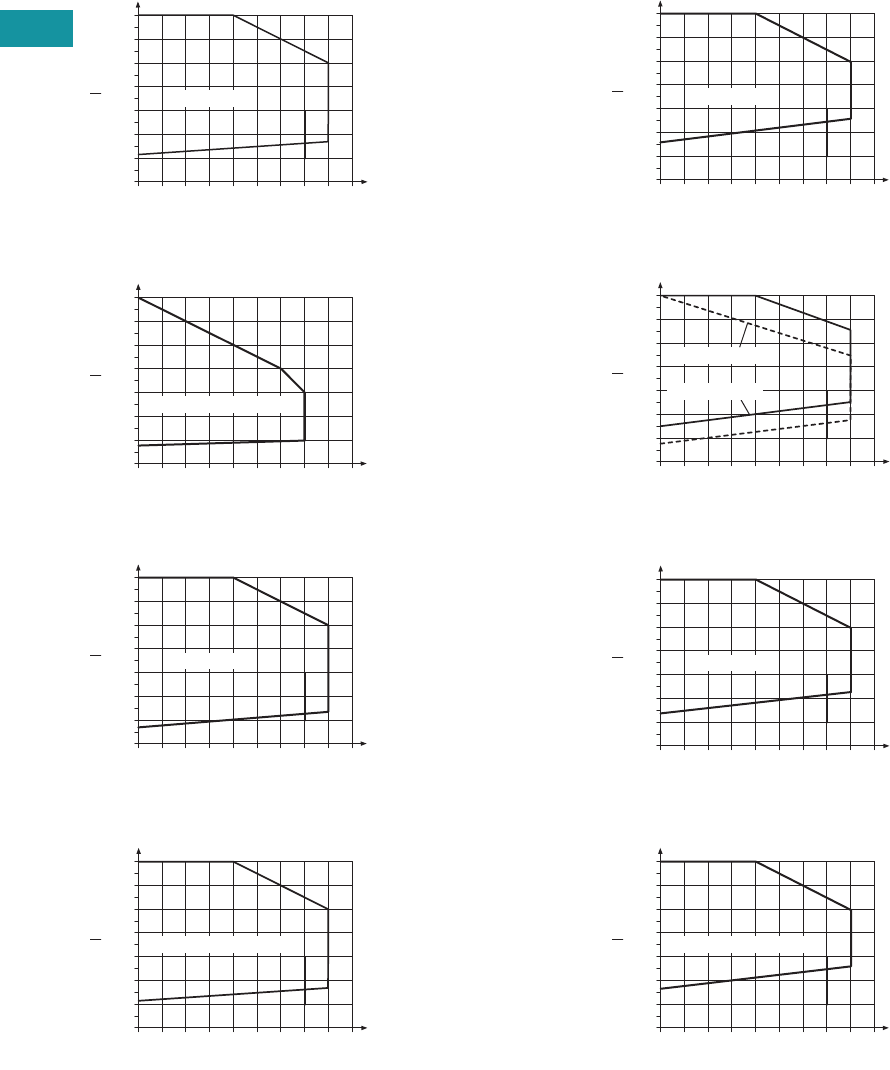
V7-T3-10 Volume 7—Logic Control, Operator Interface and Connectivity Solutions CA08100008E—February 2014 www.eaton.com
3
3
3
3
3
3
3
3
3
3
3
3
3
3
3
3
3
3
3
3
3
3
3
3
3
3
3
3
3
3
V7-T3-10 Volume 7—Logic Control, Operator Interface and Connectivity Solutions CA08100008E—February 2014 www.eaton.com
3
3
3
3
3
3
3
3
3
3
3
3
3
3
3
3
3
3
3
3
3
3
3
3
3
3
3
3
3
3
3.2
Control Relays and Timers
Ter m i n a l B l o c k Rel ay s
Permissible Range Diagrams
1PDT Relay Modules
Operating Range Voltage for 12 Vdc
Operating Range Voltage for 120 Vac/110 Vdc
Operating Range Voltage for 24 Vdc
Operating Range Voltage for 24 Vac/Vdc
DPDT Relay Modules
Operating Range Voltage for 12 Vdc
Operating Range Voltage for 120 Vac/110 Vdc
Operating Range Voltage for 24 Vdc
Operating Range Voltage for 24 Vac/Vdc
Notes
General Conditions — Direct alignment in the block, all devices 100% operating factor, horizontal or vertical mounting.
Curve A — Maximum permissible continuous operating voltage Umax with limiting continuous current on the contact side (see respective technical data).
Curve B — Minimum permissible relay operate voltage Uop after pre-excitation 1) (see respective technical data).
1Pre-excitation: Relay has been operated in a thermally steady state at the ambient temperature TU with nominal voltage UN and limiting continuous current on the contact side (see respective
technical data) (warm coil). After being switched off for a short time, the relay must reliably pick up again at Uop.
1.4
1.3
1.2
1.1
1.0
0.9
0.8
0.7
20 25 30
A
B
35 40 45 50 55 60 65
U
UN
TN [°C]
UN = 12 Vdc
1.4
1.3
1.2
1.1
1.0
0.9
0.8
0.7
20 25 30
A
B
35 40 45 50 55 60 65
U
UN
TN [°C]
UN = 110 Vdc/120 Vac
1.4
1.3
1.2
1.1
1.0
0.9
0.8
0.7
20 25 30
A
B
35 40 45 50 55 60 65
U
UN
TN [°C]
UN = 24 Vdc
1.4
1.3
1.2
1.1
1.0
0.9
0.8
0.7
20 25 30
A
B
35 40 45 50 55 60 65
U
UN
TN [°C]
UN = 24 Vdc/24 Vac
1.4
1.3
1.2
1.1
1.0
0.9
0.8
0.7
20 25 30
A
B
35 40 45 50 55 60 65
U
UN
TN [°C]
UN = 12 Vdc
1.4
1.3
1.2
1.1
1.0
0.9
0.8
0.7
20 25 30
A
B
35 40 45 50 55 60 65
U
UN
TN [°C]
UN = 120 Vac
UN = 110 Vdc
1.4
1.3
1.2
1.1
1.0
0.9
0.8
0.7
20 25 30
A
B
35 40 45 50 55 60 65
U
UN
TN [°C]
UN = 24 Vdc
1.4
1.3
1.2
1.1
1.0
0.9
0.8
0.7
20 25 30
A
B
35 40 45 50 55 60 65
U
UN
TN [°C]
UN = 24 Vdc/24 Vac
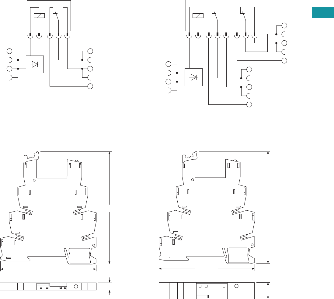
Volume 7—Logic Control, Operator Interface and Connectivity Solutions CA08100008E—February 2014 www.eaton.com V7-T3-11
3
3
3
3
3
3
3
3
3
3
3
3
3
3
3
3
3
3
3
3
3
3
3
3
3
3
3
3
3
3
Volume 7—Logic Control, Operator Interface and Connectivity Solutions CA08100008E—February 2014 www.eaton.com V7-T3-11
3
3
3
3
3
3
3
3
3
3
3
3
3
3
3
3
3
3
3
3
3
3
3
3
3
3
3
3
3
3
3.2
Control Relays and Timers
Ter m i n a l B l o c k R el ay s
Electrical Schematics
1PDT Terminal Block Relays DPDT Terminal Block Relays
Dimensions
Approximate Dimensions in Inches (mm)
Standard 1PDT Terminal Block Relays Standard DPDT Terminal Block Relays
11
14
12
A2
A1
12
22
24
21
A2
A1
11
14
3.70 (94.0)
0.24 (6.2)
3.15 (80.0)
3.70 (94.0)
0.55 (14.0)
3.15 (80.0)
V7-T3-12 Volume 7—Logic Control, Operator Interface and Connectivity Solutions CA08100008E—February 2014 www.eaton.com
3
3
3
3
3
3
3
3
3
3
3
3
3
3
3
3
3
3
3
3
3
3
3
3
3
3
3
3
3
3
V7-T3-12 Volume 7—Logic Control, Operator Interface and Connectivity Solutions CA08100008E—February 2014 www.eaton.com
3
3
3
3
3
3
3
3
3
3
3
3
3
3
3
3
3
3
3
3
3
3
3
3
3
3
3
3
3
3
3.2
Control Relays and Timers
Ter m i n a l B l o c k Rel ay s
OptoCoupler Terminal Block Relay
Contents
Description Page
Standard Terminal Block Relays . . . . . . . . . . . . . . V7-T3-4
OptoCoupler Terminal Block Relays
Product Selection . . . . . . . . . . . . . . . . . . . . . . . V7-T3-13
Technical Data and Specifications . . . . . . . . . . . V7-T3-13
Electrical Schematic . . . . . . . . . . . . . . . . . . . . . V7-T3-14
Dimensions . . . . . . . . . . . . . . . . . . . . . . . . . . . V7-T3-14
High Current Terminal Block Relays . . . . . . . . . . . V7-T3-15
XR Series Accessories . . . . . . . . . . . . . . . . . . . . . V7-T3-18
OptoCoupler Terminal Block Relays
Product Description
The XR Series OptoCoupler
Terminal Block Relays can be
used in all applications and
consist of a pluggable
miniature OptoCoupler and a
basic terminal block. The XR
Series uses screw or spring-
cage technology, as well as
offers quick system wiring,
superior safety features, clear
labeling and a high level of
modularity.
Application Description
The XR Series OptoCoupler
relays can be used as an input
or output interface. They
provide the typical reliability
of OptoCouplers and are
especially suited for high
operating frequencies.
Features
●Pluggable relay allows for
field replacement
●Functional plug-in bridges
●LED status indication
●DIN rail mount
●Only 6.2 mm wide
●Switching capacity up to 24
Vdc/3A
●IP67-protected optical
electronics
●Wear-resistant and bounce-
free switching
●Insensitive to shock and
vibration
●Integrated protection
circuit
●Zero voltage switch at AC
output
Standards and Certifications
●cULus listed
●CE
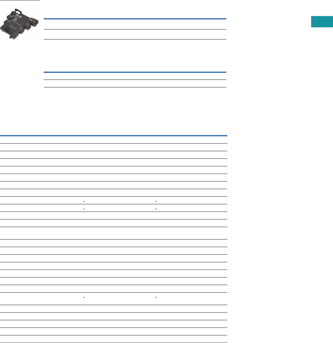
Volume 7—Logic Control, Operator Interface and Connectivity Solutions CA08100008E—February 2014 www.eaton.com V7-T3-13
3
3
3
3
3
3
3
3
3
3
3
3
3
3
3
3
3
3
3
3
3
3
3
3
3
3
3
3
3
3
Volume 7—Logic Control, Operator Interface and Connectivity Solutions CA08100008E—February 2014 www.eaton.com V7-T3-13
3
3
3
3
3
3
3
3
3
3
3
3
3
3
3
3
3
3
3
3
3
3
3
3
3
3
3
3
3
3
3.2
Control Relays and Timers
Ter m i n a l B l o c k R el ay s
Product Selection
OptoCoupler Terminal Block Relays
OptoCoupler Replacement Relays
Technical Data and Specifications
Pluggable Power OptoCoupler (Solid-State) Terminal Block Relays
Note
1Voltage is the rating at the base. It may not match the voltage on the specific replacement relay.
Rated Current Supply Voltage Standard Pack
Catalog
Number
2A 120 Vac/110 Vdc 10 XRU1S120U
2A 24 Vdc 10 XRU1S24
Rated Current Supply Voltage 1Standard Pack
Catalog
Number
2A 24 Vdc 18 XRR1S24
2A 120 Vac/110 Vdc 10 XRR1S120U
XRU1S24
Catalog Number XRU1S24 XRU1S120U
Replacement Relay XRR1S24 XRR1S120U
Input voltage 24 Vdc 120 Vac/110 Vdc
Connection Data
Rigid solid AWG (mm2) 26–14 (0.14–2.5) 26–14 (0.14–2.5)
Flexible stranded AWG (mm2) 26–14 (0.14–2.5) 26–14 (0.14–2.5)
Input Data
Input voltage 24 Vdc 120 Vac/110 Vdc
Permissible range 0.8–1.2 0.8 –1.1
Typical input current 9 mA 4 mA
Switching level 1 signal (“H”) >0.8 >0.8
Switching level 0 signal (“L”) <0.4 <0.25
Typical switch-on time 20 μS 6 ms
Typical turn-off time 500 μS 10 ms
Input protection Polarity protection diode,
free-wheeling diode
Bridge rectifier
Output Data
Max. switching voltage 33 Vdc 33 Vdc
Min. switching voltage 3 Vdc 3 Vdc
Limiting continuous current 3A (See derating curve) 3A (See derating curve)
Max. inrush current 15A (10 ms) 15A (10 ms)
Output circuit 2-conductor floating 2-conductor floating
Output protection Polarity protection, surge protection Polarity protection, surge protection
Voltage drop at maximum
limiting continuous current
< 200 mV < 200 mV
General Data
Ambient temp range –4° to 140°F (–20° to 60°C) –4° to 140°F (–20° to 60°C)
Rated operating mode 100% operating factor 100% operating factor
Inflammability class V0, in accordance with UL 94 V0, in accordance with UL 94
Mechanical service life 2 x 10⁷ cycles 2 x 10⁷ cycles
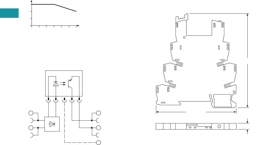
V7-T3-14 Volume 7—Logic Control, Operator Interface and Connectivity Solutions CA08100008E—February 2014 www.eaton.com
3
3
3
3
3
3
3
3
3
3
3
3
3
3
3
3
3
3
3
3
3
3
3
3
3
3
3
3
3
3
V7-T3-14 Volume 7—Logic Control, Operator Interface and Connectivity Solutions CA08100008E—February 2014 www.eaton.com
3
3
3
3
3
3
3
3
3
3
3
3
3
3
3
3
3
3
3
3
3
3
3
3
3
3
3
3
3
3
3.2
Control Relays and Timers
Ter m i n a l B l o c k Rel ay s
Derating Curve
OptoCoupler
Electrical Schematic
Pluggable Power OptoCoupler (Solid-State)
Terminal Block Relays
Dimensions
Approximate Dimensions in Inches (mm)
Pluggable Power OptoCoupler (Solid-State)
Terminal Block Relays
0
0
1
2
3
10 20 30
Ambient Temperature (°C)
Load Current (A)
40 50 60
13+
14
A2
A1
3.70 (94.0)
0.24 (6.2)
3.15 (80.0)
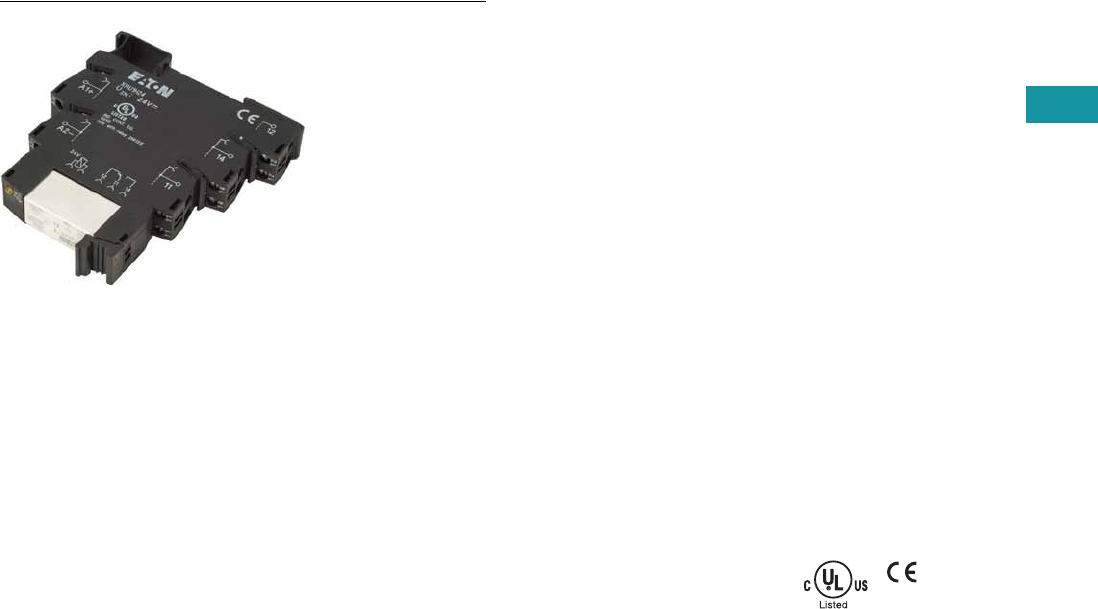
Volume 7—Logic Control, Operator Interface and Connectivity Solutions CA08100008E—February 2014 www.eaton.com V7-T3-15
3
3
3
3
3
3
3
3
3
3
3
3
3
3
3
3
3
3
3
3
3
3
3
3
3
3
3
3
3
3
Volume 7—Logic Control, Operator Interface and Connectivity Solutions CA08100008E—February 2014 www.eaton.com V7-T3-15
3
3
3
3
3
3
3
3
3
3
3
3
3
3
3
3
3
3
3
3
3
3
3
3
3
3
3
3
3
3
3.2
Control Relays and Timers
Ter m i n a l B l o c k R el ay s
High Current Terminal Block Relay
Contents
Description Page
Standard Terminal Block Relays . . . . . . . . . . . . . . . V7-T3-4
OptoCoupler Terminal Block Relays . . . . . . . . . . . . V7-T3-12
High Current Terminal Block Relays
Product Selection . . . . . . . . . . . . . . . . . . . . . . . V7-T3-16
Technical Data and Specifications . . . . . . . . . . V7-T3-16
Electrical Schematic . . . . . . . . . . . . . . . . . . . . . V7-T3-17
Dimensions . . . . . . . . . . . . . . . . . . . . . . . . . . . V7-T3-17
XR Series Accessories . . . . . . . . . . . . . . . . . . . . . V7-T3-18
High Current Terminal Block Relays
Product Description
The XR Series Relays include
products designed to meet
high continuous current and/
or long electrical service life
applications. The XR Series
Relays are plug-in interfaces
that connect to basic terminal
blocks that use screw
connection technology.
Overall width is 14 mm.
Application Description
These relays are best suited
for applications that require
higher continuous load
currents than miniature
relays can carry and switch.
They can withstand inrush
currents or brief overloads
without damage, and allow
for continuous load currents
of up to 10A. The XR Series
Relay boasts an average
service life of the contacts
that is two or three times
the normal life of a less
powerful relay, resulting in
service cost savings.
Features
●14 mm wide
●Pluggable relay allows for
field replacement
●Convenient plug-in bridge
system
●LED status indication
●DIN Rail Mount
●IP67-protected optical
electronics
●Wear-resistant and bounce-
free switching
●Insensitive to shock and
vibration
●Integrated protection
circuit
●Zero voltage switch at AC
output
●Environmentally friendly,
cadmium-free contact
material
●Electrical isolation
between input and output
Standards and Certifications
●cULus listed
●CE
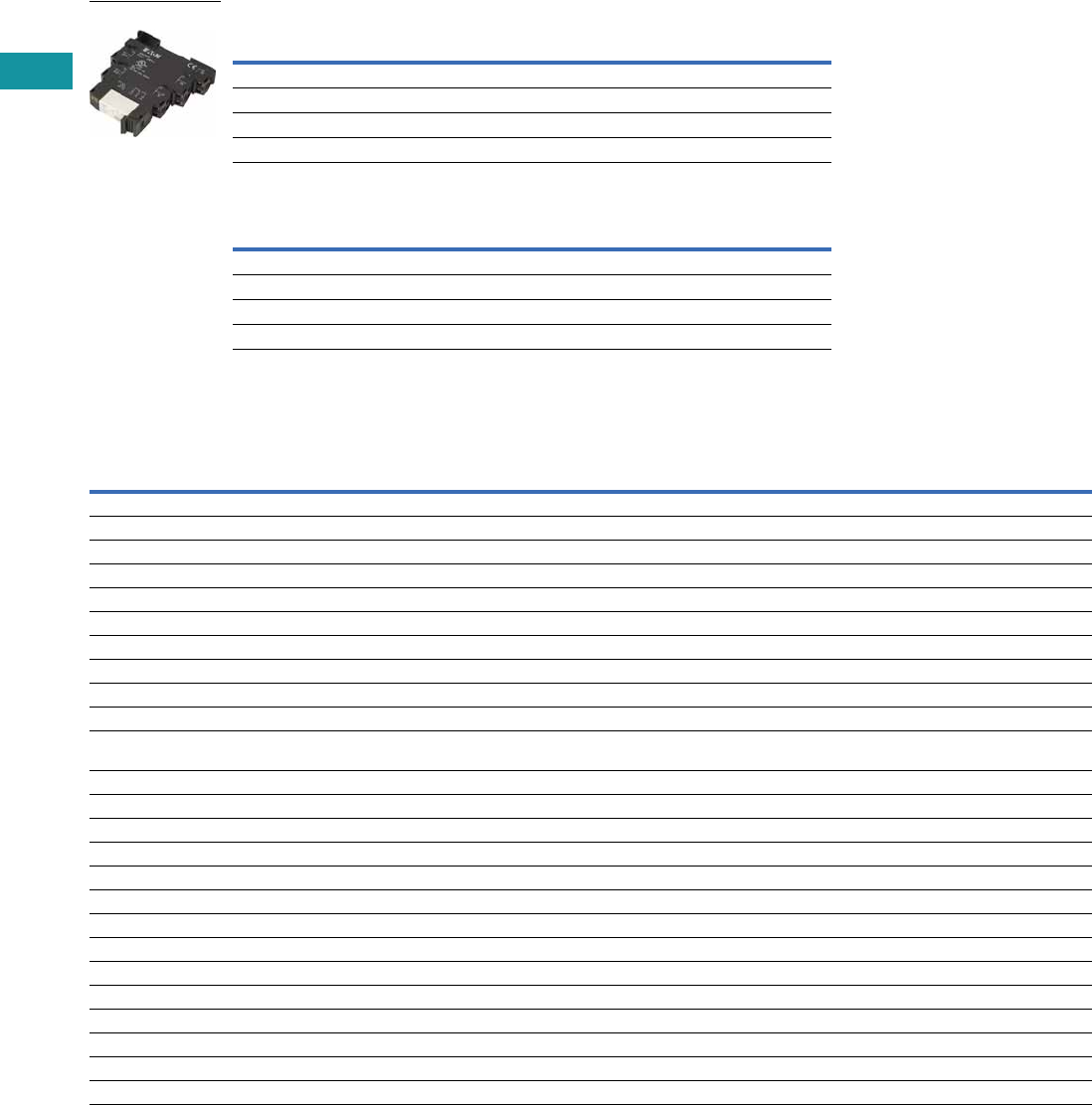
V7-T3-16 Volume 7—Logic Control, Operator Interface and Connectivity Solutions CA08100008E—February 2014 www.eaton.com
3
3
3
3
3
3
3
3
3
3
3
3
3
3
3
3
3
3
3
3
3
3
3
3
3
3
3
3
3
3
V7-T3-16 Volume 7—Logic Control, Operator Interface and Connectivity Solutions CA08100008E—February 2014 www.eaton.com
3
3
3
3
3
3
3
3
3
3
3
3
3
3
3
3
3
3
3
3
3
3
3
3
3
3
3
3
3
3
3.2
Control Relays and Timers
Ter m i n a l B l o c k Rel ay s
Product Selection
High Current Terminal Block Relays
High Current Replacement Relays
Technical Data and Specifications
High Current Terminal Block Relays (1PDT)
Notes
1Voltage is the rating at the base. It may not match the voltage on the specific replacement relay.
2The separating plate, XRAPLCESK, should be installed for voltages greater than 250V (L1, L2, L3) between identical terminal points of adjacent modules.
Potential bridging is then possible with the XRAFBST bridge system.
3The current rating for the normally open contact (#14) is 10A. The current rating for the normally closed contact (#12) is 6A and can be increased to 10A by bridging the
two #12 contact connections.
Rated Current Supply Voltage Standard Pack
Catalog
Number
10A 12 Vdc 10 XRU1H12
10A 120 Vac/110 Vdc 10 XRU1H120U
10A 24 Vdc 10 XRU1H24
10A 24 Vac/Vdc 10 XRU1H24U
Rated Current Supply Voltage 1Standard Pack
Catalog
Number
10A 24 Vdc 10 XRR1H24
10A 24 Vac/Vdc 10 XRR1H24U
10A 12 Vdc 10 XRR1H12
10A 120 Vac/110 Vdc 10 XRR1H120U
Catalog Number XRU1H12 XRU1H24 XRU1H24U XRU1H120U
Replacement Relay XRR1H12 XRR1H24 XRR1H24U XRR1H120U
Input voltage 12 Vdc 24 Vdc 24 Vac/Vdc 120 Vac/110 Vdc
Connection Data
Rigid solid AWG (mm2) 26–14 (0.14–2.5) 26–14 (0.14–2.5) 26–14 (0.14–2.5) 26–14 (0.14–2.5)
Flexible stranded AWG (mm2) 26–14 (0.14–2.5) 26–14 (0.14–2.5) 26–14 (0.14–2.5) 26–14 (0.14–2.5)
Input Data for 1PDT Spring Cage Versions
Input voltage 12 Vdc 24 Vdc 24 Vac/Vdc 120 Vac/110 Vdc
Permissible range See Page V7-T3-10 See Page V7-T3-10 See Page V7-T3-10 See Page V7-T3-10
Typical input current 33 mA 18 mA 17.5 mA 4.5 mA (120 Vac)/4.2 mA (110 Vdc)
Typical response time 8 ms 8 ms 8 ms 7 ms
Typical release time 10 ms 10 ms 10 ms 10 ms
Input protection Polarity protection diode,
free-wheeling diode
Polarity protection diode,
free-wheeling diode
Bridge rectifier Bridge rectifier
Output Data
Contact type Single contact, 1PDT Single contact, 1PDT Single contact, 1PDT Single contact, 1PDT
Contact material AgNi AgNi AgNi AgNi
Max. switching voltage 250 Vac/Vdc 2250 Vac/Vdc 2250 Vac/Vdc 2250 Vac/Vdc 2
Min. switching voltage 12 Vac/Vdc 12 Vac/Vdc 12 Vac/Vdc 12 Vac/Vdc
Limiting continuous current 10A 310A 310A 310A 3
Max. inrush current 30A (300 ms) 30A (300 ms) 30A (300 ms) 30A (300 ms)
Min. switching current 100 mA 100 mA 100 mA 100 mA
Min. switching power 1.2W 1.2W 1.2W 1.2W
Miscellaneous Data
Ambient temp range –4° to 140°F (–20° to 60°C) –4° to 140°F (–20° to 60°C) –4° to 140°F (–20° to 60°C) –4° to 140°F (–20° to 60°C)
Rated operating mode 100% operating factor 100% operating factor 100% operating factor 100% operating factor
Inflammability class V0, in accordance with UL 94 V0, in accordance with UL 94 V0, in accordance with UL 94 V0, in accordance with UL 94
Mechanical service life 3 x 10⁷ cycles 3 x 10⁷ cycles 3 x 10⁷ cycles 3 x 10⁷ cycles
XRU1H24
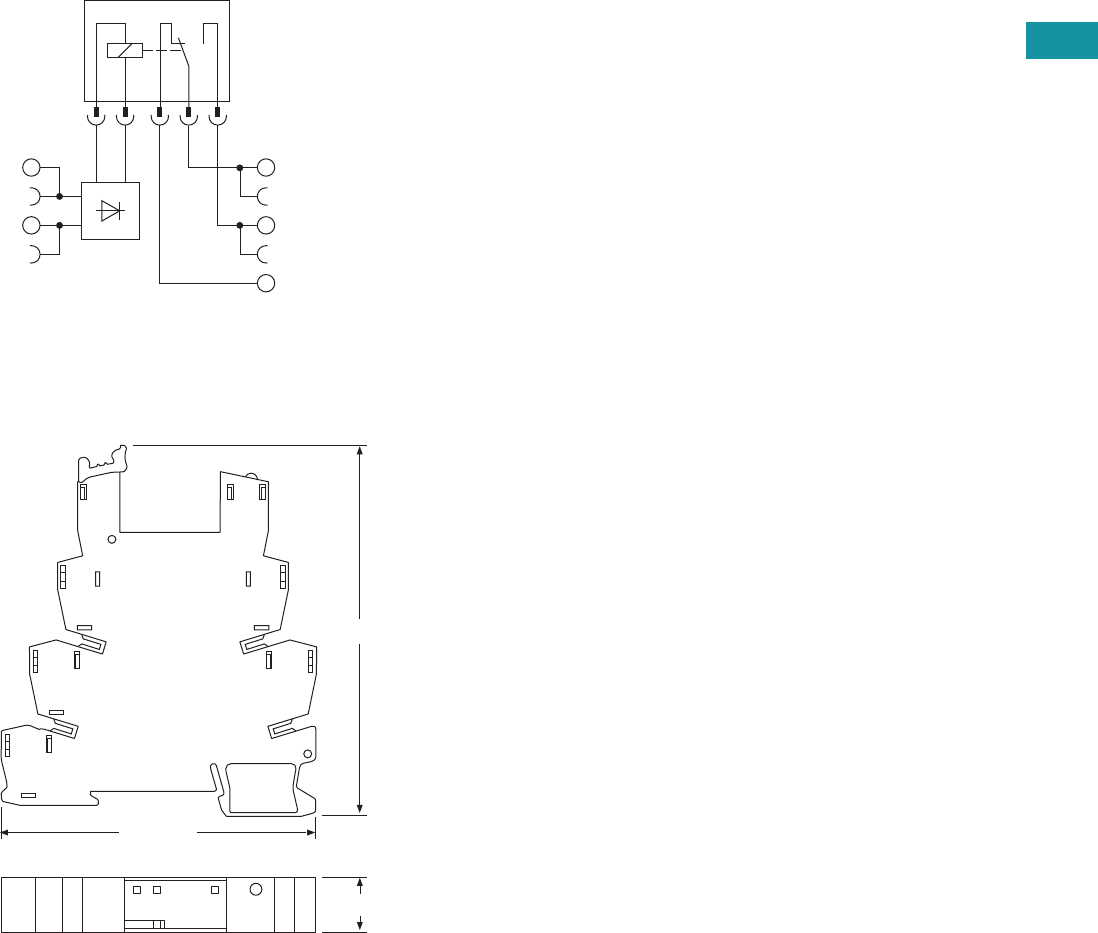
Volume 7—Logic Control, Operator Interface and Connectivity Solutions CA08100008E—February 2014 www.eaton.com V7-T3-17
3
3
3
3
3
3
3
3
3
3
3
3
3
3
3
3
3
3
3
3
3
3
3
3
3
3
3
3
3
3
Volume 7—Logic Control, Operator Interface and Connectivity Solutions CA08100008E—February 2014 www.eaton.com V7-T3-17
3
3
3
3
3
3
3
3
3
3
3
3
3
3
3
3
3
3
3
3
3
3
3
3
3
3
3
3
3
3
3.2
Control Relays and Timers
Ter m i n a l B l o c k R el ay s
Electrical Schematic
High Current Terminal Block Relays
Dimensions
Approximate Dimensions in Inches (mm)
High Current Terminal Block Relays
11
14
12
A2
A1
3.70 (94.0)
0.55 (14.0)
3.15 (80.0)
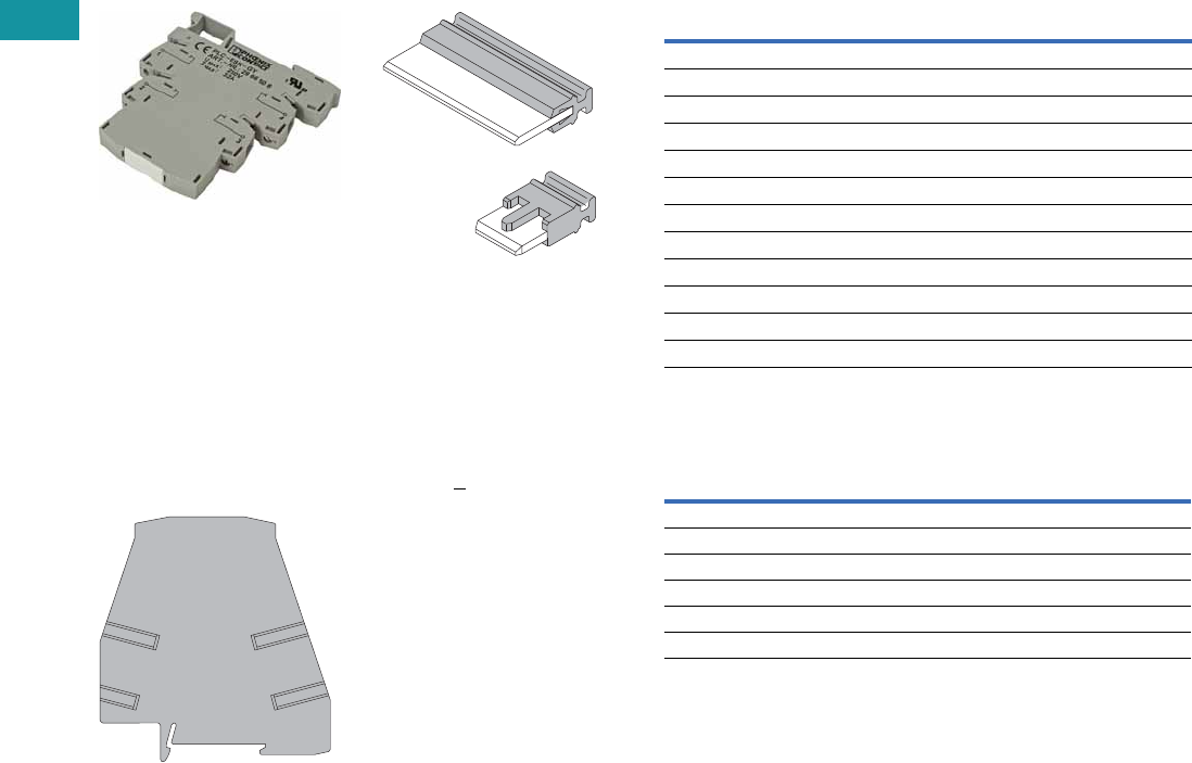
V7-T3-18 Volume 7—Logic Control, Operator Interface and Connectivity Solutions CA08100008E—February 2014 www.eaton.com
3
3
3
3
3
3
3
3
3
3
3
3
3
3
3
3
3
3
3
3
3
3
3
3
3
3
3
3
3
3
V7-T3-18 Volume 7—Logic Control, Operator Interface and Connectivity Solutions CA08100008E—February 2014 www.eaton.com
3
3
3
3
3
3
3
3
3
3
3
3
3
3
3
3
3
3
3
3
3
3
3
3
3
3
3
3
3
3
3.2
Control Relays and Timers
Ter m i n a l B l o c k Rel ay s
XR Series Accessories
Product Description
Power Terminal Block
The XRAPLCESK power
terminal block has the same
shape as the relay modules
and is used to feed in the
bridging potentials. The
nominal current is 32A. When
the total current is less than
or equal to 6A, supply can
take place directly at the
connecting terminal blocks of
one of the connected relays.
End Cover
The XRAATPBK end cover
is required at the start and
stop of a relay strip. It can
also be used for visual
separation of groups of
relays as well as separating
relays with voltages greater
than 250V and separating
neighboring bridges with
different potentials. It is
equipped with pre-scored
break out points at the
bridging positions so that
individual bridges can be
passed through as needed.
It may also be necessary to
use the end cover between
adjacent relays when three
phases (L1, L2, L3) are
used on the contact side
of the relay.
Bridges
The XRAFBST colored,
insulated plug-in bridge
system reduces wiring
time by up to 70% compared
to conventionally wired
relays. The XRAFBST2,
2-position bridges, are
suited for bridging a smaller
number of relays and total
currents <6A. When a circuit
is supplied from both sides,
the circuit can be opened at
any point, allowing all other
modules to continue being
supplied at the same time.
The XRAFBST500 allow up
to 80 modules to be bridged
at one time. If bridges with
different potentials meet in
neighboring modules, the
end cover XRAATPBK
should be used. All bridges
are equipped with a groove
for removal with a standard
screwdriver.
Product Selection
XR Series Accessories
Technical Data and Specifications
Power Terminal Block
Note
1The separating plate, XRAPLCESK, should be installed for voltages greater than 250V
(L1, L2, L3) between identical terminal points of adjacent modules. Potential bridging is
then possible with the XRAFBST bridge system.
Color
Standard
Pack
Catalog
Number
2-Position Snap-In Jumper
Red 10 XRAFBST2RD
Blue 10 XRAFBST2BU
Gray 10 XRAFBST2GY
80-Position Snap-In Jumper
Red 5 XRAFBST500RD
Blue 5 XRAFBST500BU
Gray 5 XRAFBST500GY
Power Terminal Block
Gray 5 XRAPLCESK
End Cover
Black 5 XRAATPBK
Description Specification
Connection Data
Rigid solid AWG (mm2) 24–10 (0.2–4)
Flexible stranded AWG (mm2) 24–10 (0.2–4)
Miscellaneous Data
Max. current 32A
Max. voltage 250 Vac 1
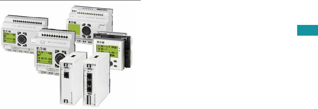
Volume 7—Logic Control, Operator Interface and Connectivity Solutions CA08100008E—February 2014 www.eaton.com V7-T3-19
3
3
3
3
3
3
3
3
3
3
3
3
3
3
3
3
3
3
3
3
3
3
3
3
3
3
3
3
3
3
Volume 7—Logic Control, Operator Interface and Connectivity Solutions CA08100008E—February 2014 www.eaton.com V7-T3-19
3
3
3
3
3
3
3
3
3
3
3
3
3
3
3
3
3
3
3
3
3
3
3
3
3
3
3
3
3
3
3.3
Control Relays and Timers
Programmable Relays
Programmable Relays
Contents
Description Page
Programmable Relays
easy500/700/800 Programmable Relays . . . . . V7-T3-20
easy802/806 Programmable Relays
with SmartWire-DT . . . . . . . . . . . . . . . . . . . . V7-T3-26
easyRelay and MFD Expansion Modules . . . . . V7-T3-30
MFD-Titan Multi-Function Displays . . . . . . . . . V7-T3-33
easyRelay Communication Modules . . . . . . . . V7-T3-40
easyRelay Power Supplies, Accessories
and Software . . . . . . . . . . . . . . . . . . . . . . . . . V7-T3-43
Product Overview
The easyRelays combine
timers, relays, counters,
special functions, inputs and
outputs into one compact
device that is easily
programmed. The easyRelay
family of products provides an
exceptional level of flexibility
together with a substantial
savings of commissioning
time and effort.
The easyRelays are available
in more than 35 styles that
support from 12 I/O up to
a network of up to 320 I/O
points, providing the ideal
solution for lighting, energy
management, industrial
control, irrigation, pump
control, HVAC and home
automation.
Once easyRelays are
installed, changes are
easily accomplished through
front panel programming,
eliminating the need
to change wiring and
minimizing downtime.
The easy802/806 relays are
even more powerful than
the easy800 series and
include an integrated
SmartWire-DT gateway.
Conventional hardwiring
to pushbuttons, selector
switches, pilot devices and
contactors can now be
eliminated, allowing for a
dramatic increase in panel
wiring productivity. For more
information on SmartWire-DT
and how it can increase
productivity, go to
www.eaton.com/smartwiredt.
Application Description
The easyRelays excel in
traditional applications where
multiple
relays, timers and
pushbuttons
are used.
Applications span residential,
commercial and industrial
installations.
Typical control
applications are:
●Lighting controls
●Duplex pump controls
●Water fountain controls
●Parking garage access
controls
●Refrigeration control
system
●Greenhouse temperature
and ventilation controls
●Booster pump controls
See publication no.
AP05013001E for the
easyRelay application guide.
Download from
www.eaton.com/easyrelays.
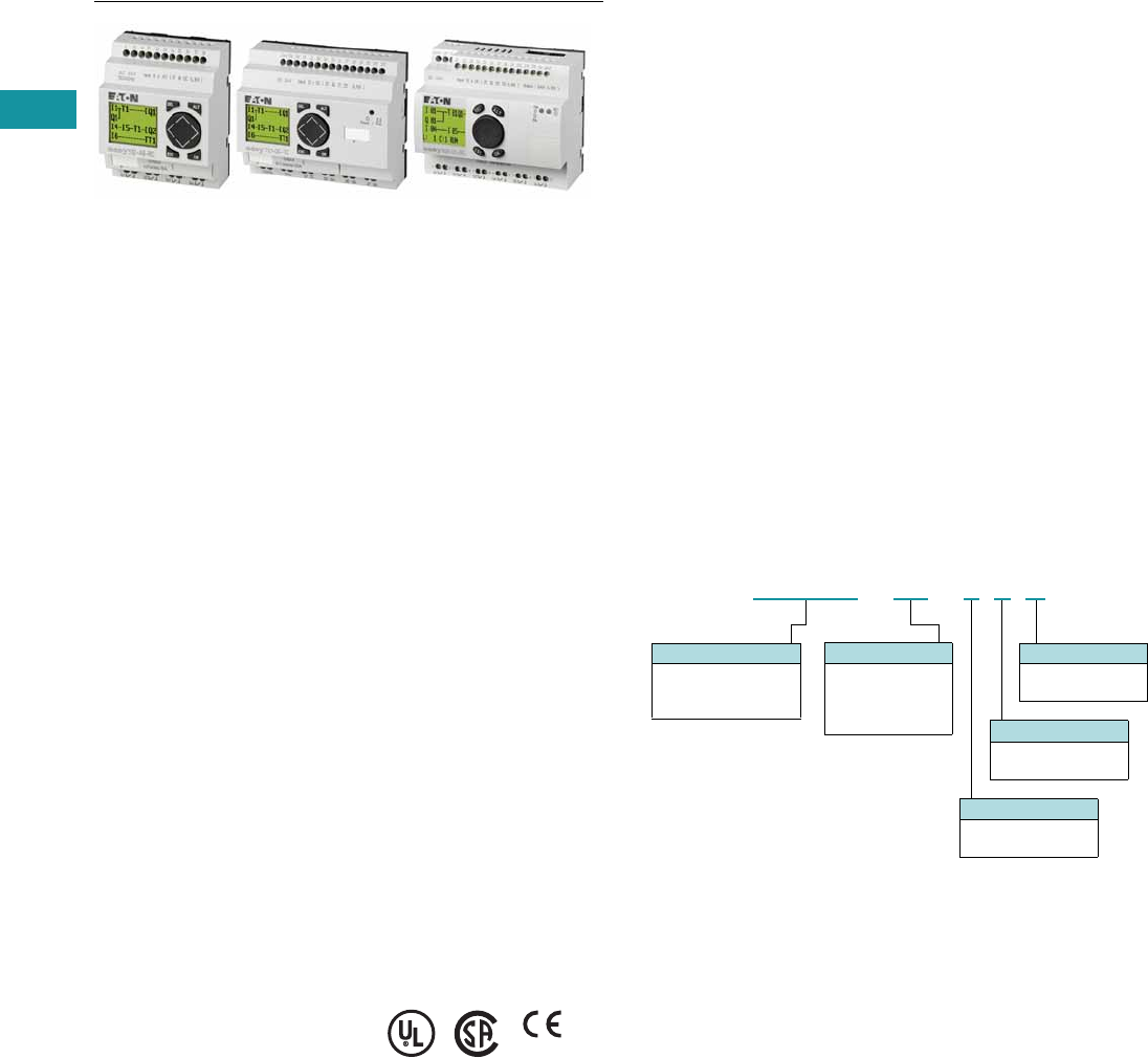
V7-T3-20 Volume 7—Logic Control, Operator Interface and Connectivity Solutions CA08100008E—February 2014 www.eaton.com
3
3
3
3
3
3
3
3
3
3
3
3
3
3
3
3
3
3
3
3
3
3
3
3
3
3
3
3
3
3
V7-T3-20 Volume 7—Logic Control, Operator Interface and Connectivity Solutions CA08100008E—February 2014 www.eaton.com
3
3
3
3
3
3
3
3
3
3
3
3
3
3
3
3
3
3
3
3
3
3
3
3
3
3
3
3
3
3
3.3
Control Relays and Timers
Programmable Relays
easy500/700/800 Programmable Relays
Contents
Description Page
easy500/700/800 Programmable Relays
System Overview . . . . . . . . . . . . . . . . . . . . . . . V7-T3-21
Product Selection . . . . . . . . . . . . . . . . . . . . . . . V7-T3-23
Technical Data and Specifications . . . . . . . . . . . V7-T3-24
Dimensions . . . . . . . . . . . . . . . . . . . . . . . . . . . V7-T3-25
easy802/806 Programmable Relays
with SmartWire-DT . . . . . . . . . . . . . . . . . . . . . . . V7-T3-26
easyRelay and MFD Expansion Modules . . . . . . . V7-T3-30
MFD-Titan Multi-Function Displays . . . . . . . . . . . . V7-T3-33
easyRelay Communication Modules . . . . . . . . . . . V7-T3-40
easyRelay Power Supplies, Accessories
and Software . . . . . . . . . . . . . . . . . . . . . . . . . . . V7-T3-43
easy500/700/800 Programmable Relays
Product Description
Three families make up the
easyRelay programmable
relay product line. All models
are available with and without
displays. DIN rail mounted.
easy500—for controlling
small applications with up
to 12 input/output signals.
Connectable to Ethernet.
easy700—for controlling
medium-sized applications
with 20 I/O points (expandable
to 40 I/O points). Connectable
to Ethernet and bus systems.
easy800—for controlling
large-scale applications
with 20 points, expandable
to 40 points locally, and
expandable using the
easyNet network up to
320 I/O points. Connectable
to Ethernet and bus systems.
The easyNet integrated
network provides easy and
inexpensive linking of up
to eight easy800 devices
over a distance of up to
1000 meters. Each easy800
device can run its own
program, or be used as a
distributed input/output
module. Connect up to
eight controllers with up
to 40 I/O to obtain 320 I/O.
Standards
●CSA C22.2 No. 142-M1987
●CSA C22.2 No. 213-M1987
●EN 55011
●EN 50178
●EN 61131-2
●IEC EN 61000-4
●IEC 60068-2-6
●IEC 60068-2-27
●UL 508
Certifications
●UL
●CSA
●CE
●CSA Class I, Div. 2,
Groups A, B, C, D;
Temp. Code T3C
●C-Tick
●GOST-R
●Ukrain-GOST
Shipping Approvals
●Bureau Veritas
●Det Norske Veritas
●Germanischer Lloyd
●Lloyd’s Register of Shipping
Catalog Number Selection
easy500/700/800
Note: Not all combinations are possible. See selection tables.
Display
Blank = Display
X = No display
Digital Outputs
R = Relay
T = Transistor
Clock
C = Clock
Blank = No clock
Digital Inputs
AB = 24 Vac
AC = 110–240 Vac
DA = 12 Vdc
DC = 24 Vdc
Module Type
EASY5xx = 500 Series
EASY7xx = 700 Series
EASY8xx = 800 Series
EASY512 -AC-RC
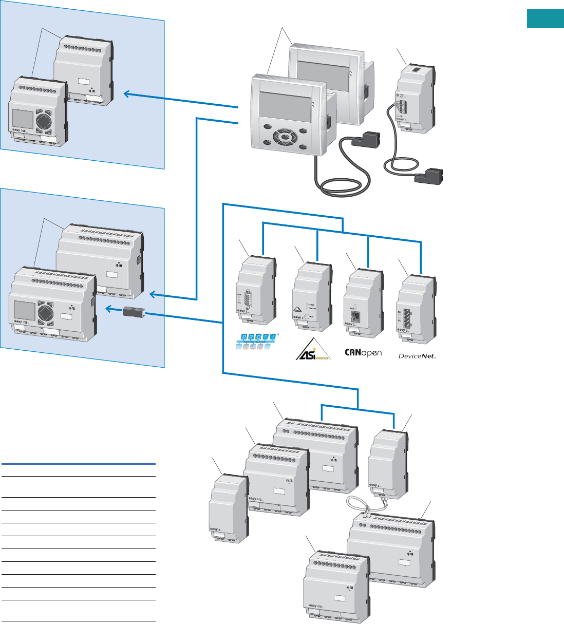
Volume 7—Logic Control, Operator Interface and Connectivity Solutions CA08100008E—February 2014 www.eaton.com V7-T3-21
3
3
3
3
3
3
3
3
3
3
3
3
3
3
3
3
3
3
3
3
3
3
3
3
3
3
3
3
3
3
Volume 7—Logic Control, Operator Interface and Connectivity Solutions CA08100008E—February 2014 www.eaton.com V7-T3-21
3
3
3
3
3
3
3
3
3
3
3
3
3
3
3
3
3
3
3
3
3
3
3
3
3
3
3
3
3
3
3.3
Control Relays and Timers
Programmable Relays
System Overview
easy500/700 Programmable Relays
5
6
8
7
4
3
9
11
10
11
12
10
1
2
Item Description
1 easy500 basic devices, standalone
2 easy700 basic devices, expandable:
digital inputs/outputs, bus systems
3 MFD-Titan remote text display
4 Ethernet gateway
5 PROFIBUS-DP bus module
6 AS-Interface bus module
7 CANopen bus module
8 DeviceNet bus module
9 Output expansion
10, 11 I/O expansions
12 Coupling module for the remote connection
of a digital input/output expansion
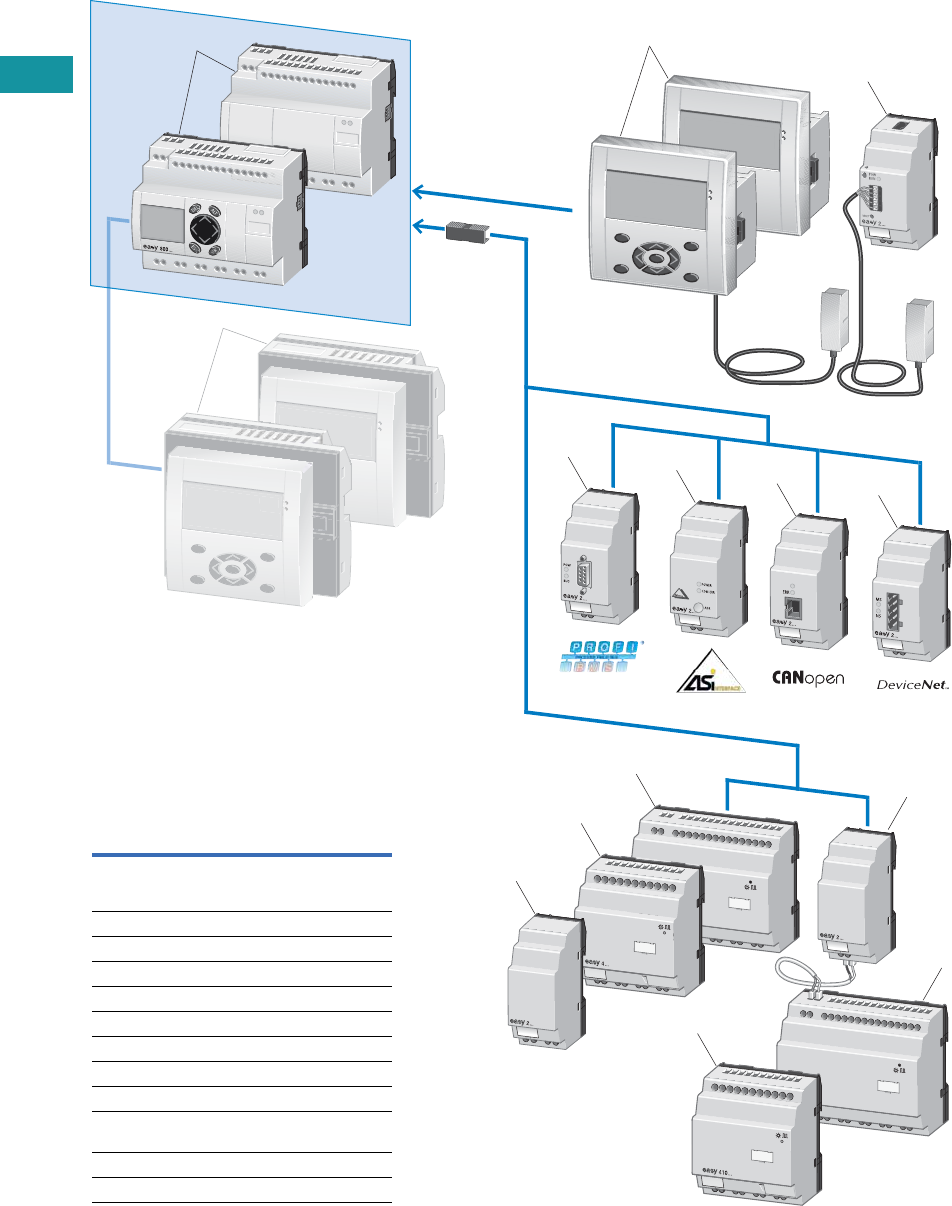
V7-T3-22 Volume 7—Logic Control, Operator Interface and Connectivity Solutions CA08100008E—February 2014 www.eaton.com
3
3
3
3
3
3
3
3
3
3
3
3
3
3
3
3
3
3
3
3
3
3
3
3
3
3
3
3
3
3
V7-T3-22 Volume 7—Logic Control, Operator Interface and Connectivity Solutions CA08100008E—February 2014 www.eaton.com
3
3
3
3
3
3
3
3
3
3
3
3
3
3
3
3
3
3
3
3
3
3
3
3
3
3
3
3
3
3
3.3
Control Relays and Timers
Programmable Relays
easy800 Programmable Relay
4
5
7
6
3
2
8
9, 12
10
12
10
11
13
1
Item Description
1 easy800 basic devices, expandable:
digital inputs/outputs and bus systems,
easyNet onboard
2 MFD-Titan remote text display
3 Ethernet gateway
4 PROFIBUS-DP bus module
5 AS-Interface bus module
6 CANopen bus module
7 DeviceNet bus module
8 Output expansion
9, 10 I/O expansions
11 Coupling module for the remote connection of
a digital input/output expansion
12 I/O expansion
13 MFD-Titan multi-function display
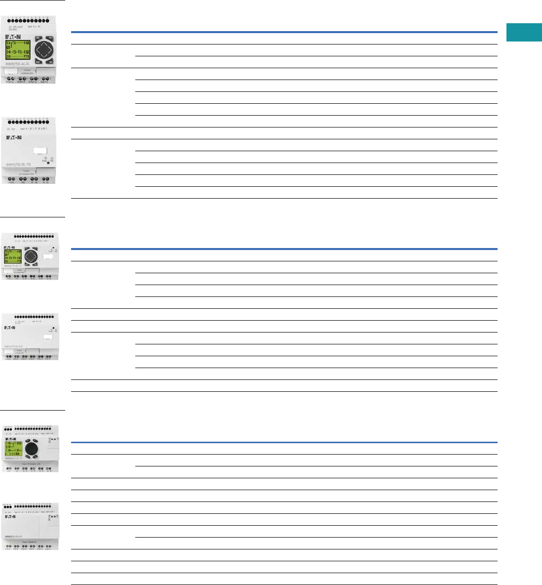
Volume 7—Logic Control, Operator Interface and Connectivity Solutions CA08100008E—February 2014 www.eaton.com V7-T3-23
3
3
3
3
3
3
3
3
3
3
3
3
3
3
3
3
3
3
3
3
3
3
3
3
3
3
3
3
3
3
Volume 7—Logic Control, Operator Interface and Connectivity Solutions CA08100008E—February 2014 www.eaton.com V7-T3-23
3
3
3
3
3
3
3
3
3
3
3
3
3
3
3
3
3
3
3
3
3
3
3
3
3
3
3
3
3
3
3.3
Control Relays and Timers
Programmable Relays
Product Selection
easy500 Programmable Relays (Standalone)
easy700 Programmable Relays (Expandable and Networkable)
easy800 Programmable Relays (Expandable and Networkable)
Note
1 Analog inputs optional. Use of analog inputs will result in a decrease in the same number of available digital inputs.
Inputs Outputs Catalog
NumberDescription 24 Vac 110–240 Vac 12 Vdc 24 Vdc Analog 1Relay Transistor
Display
12 I/O, no clock — 8 — — — 4 — EASY512-AC-R
———8 2 4 — EASY512-DC-R
12 I/O, clock8 ———2 4 — EASY512-AB-RC
—8 ——— 4 — EASY512-AC-RC
——8 —2 4 — EASY512-DA-RC
———8 2 4 — EASY512-DC-RC
———8 2 —4 EASY512-DC-TC
No Display
12 I/O, clock8 ———2 4 — EASY512-AB-RCX
—8 ——— 4 — EASY512-AC-RCX
——8 —2 4 — EASY512-DA-RCX
———8 2 4 — EASY512-DC-RCX
———8 2 —4 EASY512-DC-TCX
Inputs Outputs Catalog
NumberDescription 24 Vac 110–240 Vac 12 Vdc 24 Vdc Analog 1Relay Transistor
Display
18 I/O, clock12———4 6 — EASY719-AB-RC
—12 ——— 6 — EASY719-AC-RC
——12 —4 6 — EASY719-DA-RC
———12 4 6 — EASY719-DC-RC
20 I/O, clock———124 —8 EASY721-DC-TC
No Display
18 I/O, clock12———4 6 — EASY719-AB-RCX
—12 ——— 6 — EASY719-AC-RCX
——12 —4 6 — EASY719-DA-RCX
———12 4 6 — EASY719-DC-RCX
20 I/O, clock———124 —8 EASY721-DC-TCX
Inputs Outputs Catalog
NumberDescription 110–240 Vac 24 Vdc Analog 1Relay Transistor Analog
Display
18 I/O, clock 12 — — 6 — — EASY819-AC-RC
—124 6 —— EASY819-DC-RC
19 I/O, clock — 12 4 6 — 1 EASY820-DC-RC
20 I/O, clock — 12 4 — 8 — EASY821-DC-TC
21 I/O, clock — 12 4 — 8 1 EASY822-DC-TC
No Display
18 I/O, clock 12 — — 6 — — EASY819-AC-RCX
—124 6 —— EASY819-DC-RCX
19 I/O, clock — 12 4 6 — 1 EASY820-DC-RCX
20 I/O, clock — 12 4 — 8 — EASY821-DC-TCX
21 I/O, clock — 12 4 — 8 1 EASY822-DC-TCX
easy500—Display
easy500—No Display
easy700—Display
easy700—No Display
easy800—Display
easy800—No Display

V7-T3-24 Volume 7—Logic Control, Operator Interface and Connectivity Solutions CA08100008E—February 2014 www.eaton.com
3
3
3
3
3
3
3
3
3
3
3
3
3
3
3
3
3
3
3
3
3
3
3
3
3
3
3
3
3
3
V7-T3-24 Volume 7—Logic Control, Operator Interface and Connectivity Solutions CA08100008E—February 2014 www.eaton.com
3
3
3
3
3
3
3
3
3
3
3
3
3
3
3
3
3
3
3
3
3
3
3
3
3
3
3
3
3
3
3.3
Control Relays and Timers
Programmable Relays
Technical Data and Specifications
easy500 Series
easy700 Series
easy800 Series
Note
1Relay = 8A (10A to UL) with resistive load, 3A with inductive load. Transistor outputs = 0.5A/24 Vdc, maximum four outputs switchable in parallel.
Type EASY512-AB… EASY512-AC… EASY512-DA… EASY512-DC-R… EASY512-DC-TC.
Supply voltage 24 Vac 100–240 Vac 12 Vdc 24 Vdc 24 Vdc
Heat dissipation 5 VA 5 VA 2W 2W 2W
Continuous current outputs 18A 8A 8A 8A 0.5A
Short-circuit proof with power factor 1 Line protection B16, 600 A —
Short-circuit proof with power factor 0.7…0.7 Line protection B16, 900 A —
Mounting On 35 mm DIN rail or screw mounting with ZB4-101-GF1 mounting feet
Connection cables
Solid 0.2–4.0 mm2 (AWG 22–12) 0.2–4.0 mm2 (AWG 22–12) 0.2–4.0 mm2 (AWG 22–12) 0.2–4.0 mm2 (AWG 22–12) 0.2–4.0 mm2 (AWG 22–12)
Flexible 0.2–2.5 mm2 (AWG 22–12) 0.2–2.5 mm2 (AWG 22–12) 0.2–2.5 mm2 (AWG 22–12) 0.2–2.5 mm2 (AWG 22–12) 0.2–2.5 mm2 (AWG 22–12)
Degree of protection IP20 IP20 IP20 IP20 IP20
RFI suppression EN 55011, EN 55022 Class B, IEC 61000-6-1, 2, 3, 4
Ambient operating temperature –25° to 55°C –25° to 55°C –25° to 55°C –25° to 55°C –25° to 55°C
Transport and storage temperature –40° to 70°C –40° to 70°C –40° to 70°C –40° to 70°C –40° to 70°C
Hazardous location CSA Class I, Div. 2, Groups A, B, C, D; Temp. Code T3C
Type EASY719-AB… EASY719-AC… EASY719-DA… EASY719-DC-RC… EASY721-DC-TC.
Supply voltage 24 Vac 100–240 Vac 12 Vdc 24 Vdc 24 Vdc
Heat dissipation 7 VA 10 VA 3.5W 3.5W 3.5W
Continuous current outputs 18A 8A 8A 8A 0.5A
Short-circuit proof with power factor 1 Line protection B16, 600A Line protection B16, 600A Line protection B16, 600A Line protection B16, 600A —
Short-circuit proof with power factor 0.7…0.7 Line protection B16, 900A Line protection B16, 900A Line protection B16, 900A Line protection B16, 900A —
Mounting On 35 mm DIN rail or screw mounting with ZB4-101-GF1 mounting feet
Connection cables
Solid 0.2–4.0 mm2 (AWG 22–12) 0.2–4.0 mm2 (AWG 22–12) 0.2–4.0 mm2 (AWG 22–12) 0.2–4.0 mm2 (AWG 22–12) 0.2–4.0 mm2 (AWG 22–12)
Flexible 0.2–2.5 mm2 (AWG 22–12) 0.2–2.5 mm2 (AWG 22–12) 0.2–2.5 mm2 (AWG 22–12) 0.2–2.5 mm2 (AWG 22–12) 0.2–2.5 mm2 (AWG 22–12)
Degree of protection IP20 IP20 IP20 IP20 IP20
RFI suppression EN 55011, EN 55022 Class B, IEC 61000-6-1, 2, 3, 4
Ambient operating temperature –25° to 55°C –25° to 55°C –25° to 55°C –25° to 55°C –25° to 55°C
Transport and storage temperature –40° to 70°C –40° to 70°C –40° to 70°C –40° to 70°C –40° to 70°C
Hazardous location CSA Class I, Div. 2, Groups A, B, C, D; Temp. Code T3C
Type EASY819-AC… EASY819-DC-RC… EASY820-DC-RC… EASY821-DC-TC… EASY822-DC-TC.
Supply voltage 100–240 Vac 24 Vdc 24 Vdc 24 Vdc 24 Vdc
Heat dissipation 10 VA 3.4W 3.4W 3.4W 3.4W
Continuous current outputs 18A 8A 8A 8A 0.5A
Short-circuit proof with power factor 1 Line protection B16, 600A Line protection B16, 600A Line protection B16, 600A Line protection B16, 600A —
Short-circuit proof with power factor 0.7…0.7 Line protection B16, 900A Line protection B16, 900A Line protection B16, 900A Line protection B16, 900A —
Mounting On 35 mm DIN rail or screw mounting with ZB4-101-GF1 mounting feet
Connection cables
Solid 0.2–4.0 mm2 (AWG 22–12) 0.2–4.0 mm2 (AWG 22–12) 0.2–4.0 mm2 (AWG 22–12) 0.2–4.0 mm2 (AWG 22–12) 0.2–4.0 mm2 (AWG 22–12)
Flexible 0.2–2.5 mm2 (AWG 22–12) 0.2–2.5 mm2 (AWG 22–12) 0.2–2.5 mm2 (AWG 22–12) 0.2–2.5 mm2 (AWG 22–12) 0.2–2.5 mm2 (AWG 22–12)
Degree of protection IP20 IP20 IP20 IP20 IP20
RFI suppression EN 55011, EN 55022 Class B, IEC 61000-6-1, 2, 3, 4
Ambient operating temperature –25° to 55°C –25° to 55°C –25° to 55°C –25° to 55°C –25° to 55°C
Transport and storage temperature –40° to 70°C –40° to 70°C –40° to 70°C –40° to 70°C –40° to 70°C
Hazardous location CSA Class I, Div. 2, Groups A, B, C, D; Temp. Code T3C
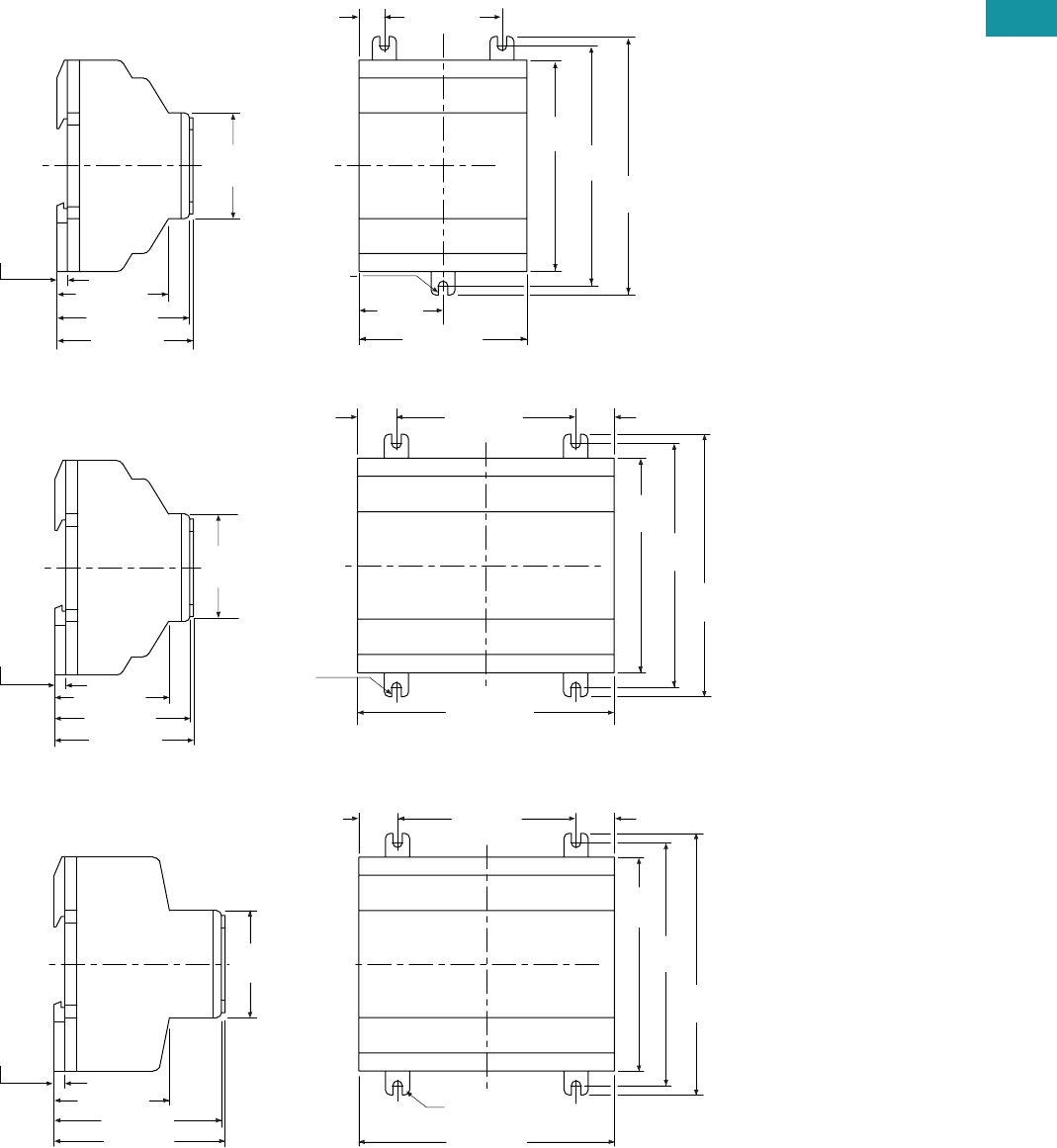
Volume 7—Logic Control, Operator Interface and Connectivity Solutions CA08100008E—February 2014 www.eaton.com V7-T3-25
3
3
3
3
3
3
3
3
3
3
3
3
3
3
3
3
3
3
3
3
3
3
3
3
3
3
3
3
3
3
Volume 7—Logic Control, Operator Interface and Connectivity Solutions CA08100008E—February 2014 www.eaton.com V7-T3-25
3
3
3
3
3
3
3
3
3
3
3
3
3
3
3
3
3
3
3
3
3
3
3
3
3
3
3
3
3
3
3.3
Control Relays and Timers
Programmable Relays
Dimensions
Approximate Dimensions in Inches (mm)
easy500 Series, Drawing Number MD05013001E
easy700 Series, Drawing Number MD05013002E
easy800 Series, Drawing Number MD05013003E
2.81 (71.5)
1.41
(35.8)
3.54
(90.0) 4.02
(102.0)
4.33
(110.0)
1.97 (50.0)0.42 (10.8)
(M4) 0.157
(3.9) Dia.
2.28 (58.0)
1.77
(45.0)
0.18 (4.5)
2.22 (56.5)
1.87 (47.5)
easy500
4.23 (107.5)
3.54
(90.0)
4.02
(102.0)
4.33
(110.0)
2.96 (75.0)0.64 (16.3) 0.64 (16.3)
(M4) 0.157
(3.9) Dia.
easy700
2.28 (58.0)
2.22 (56.5)
1.87 (47.5)
1.77
(45.0)
0.18 (4.5)
4.23 (107.5)
3.54
(90.0)
4.02
(102.0)
4.33
(110.0)
2.96 (75.0)0.64 (16.3)
(M4) 0.157
(3.9) Dia.
0.64 (16.3)
2.83 (72.0)
1.77
(45.0)
2.78 (70.5)
1.91 (48.5)
easy800
0.18 (4.5)
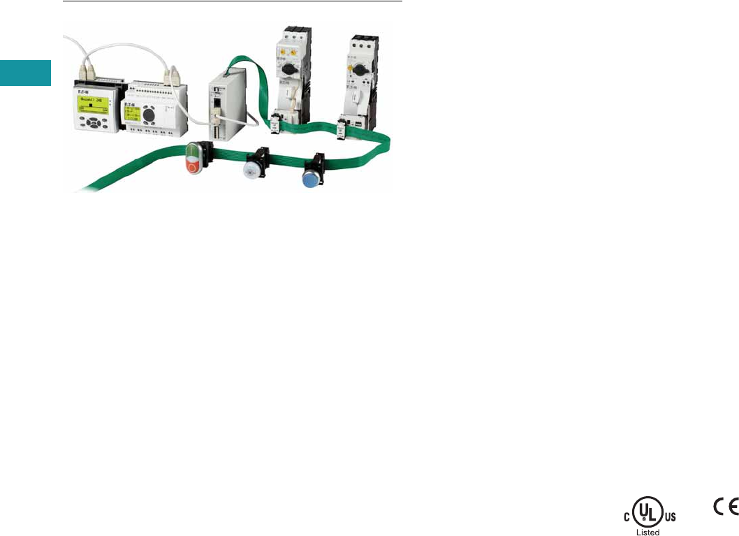
V7-T3-26 Volume 7—Logic Control, Operator Interface and Connectivity Solutions CA08100008E—February 2014 www.eaton.com
3
3
3
3
3
3
3
3
3
3
3
3
3
3
3
3
3
3
3
3
3
3
3
3
3
3
3
3
3
3
V7-T3-26 Volume 7—Logic Control, Operator Interface and Connectivity Solutions CA08100008E—February 2014 www.eaton.com
3
3
3
3
3
3
3
3
3
3
3
3
3
3
3
3
3
3
3
3
3
3
3
3
3
3
3
3
3
3
3.3
Control Relays and Timers
Programmable Relays
easy802/806 Programmable Relays with SmartWire-DT
Contents
Description Page
easy500/700/800 Programmable Relays . . . . . . . . V7-T3-20
easy802/806 Programmable Relays with SmartWire-DT
Product Selection . . . . . . . . . . . . . . . . . . . . . . . V7-T3-27
Accessories. . . . . . . . . . . . . . . . . . . . . . . . . . . . V7-T3-27
Technical Data and Specifications . . . . . . . . . . . V7-T3-28
Dimensions. . . . . . . . . . . . . . . . . . . . . . . . . . . . V7-T3-29
easyRelay and MFD Expansion Modules . . . . . . . V7-T3-30
MFD-Titan Multi-Function Displays . . . . . . . . . . . . V7-T3-33
easyRelay Communication Modules . . . . . . . . . . . V7-T3-40
easyRelay Power Supplies, Accessories
and Software . . . . . . . . . . . . . . . . . . . . . . . . . . . V7-T3-43
easy802/806 Programmable Relays with SmartWire-DT
Product Description
SmartWire-DT is a high-
performance system that can
be used to quickly and easily
connect motor control
components such as relays,
contactors, pilot devices,
manual motor protectors,
soft starters 1 and variable
frequency drives 1 as well
as digital and analog input/
output modules. On the new
easy800 with integrated
SmartWire-DT master, up to
99 SmartWire-DT devices in
total with up to 166 inputs/
outputs can be connected
via the SmartWire-DT line.
All required supply voltages,
including those for bus
devices as well as 24 Vdc for
the contactors, are provided
directly with the flat eight-
pole SmartWire-DT bus line.
This reduces wiring effort and
troubleshooting and saves
time and costs.
Note
1Soft starters and variable frequency
drives will be available with direct
SmartWire-DT connectivity in late 2013.
The easy802 features a POW
power feeder for regulating
power to the device as well
as the SmartWire-DT devices.
A second AUX power feeder
provides the connected
contactors with 24 Vdc. A
separate 24 Vdc power
supply is required to provide
24 Vdc power to the easy802
or easy806 controllers. The
configuration of the
SmartWire-DT devices is
undertaken at a touch of
the provided Configuration
button. LEDs provide
feedback on the connecting
states on the device and
the SmartWire-DT line. The
serial interface serves for
programming as well as for
connection of a remote text
display, touch panel or for
connection to the Ethernet.
In addition to the functionality
of the easy802, the easy806
also features four fast inputs
(5 kHz). Two of the four
inputs can also be configured
as fast outputs (5 kHz)
(transistor 24 Vdc, 0.1A).
In addition to the additional
inputs/outputs on easy806,
there is a connection option
to the easyNet. Up to eight
EASY806-DC-SWD
controllers
can be connected via
easyNet, allowing up to
1360 inputs/outputs.
For more information on
SmartWire-DT and related
components, see Ta b 9 of
this volume or go to
www.eaton.com/smartwiredt.
Standards
●EN 50178
●IEC/EN 60947
●UL 508
Certifications
●cULus
●CE
●C-Tick
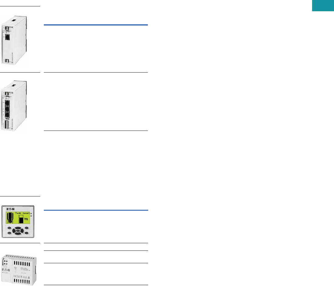
Volume 7—Logic Control, Operator Interface and Connectivity Solutions CA08100008E—February 2014 www.eaton.com V7-T3-27
3
3
3
3
3
3
3
3
3
3
3
3
3
3
3
3
3
3
3
3
3
3
3
3
3
3
3
3
3
3
Volume 7—Logic Control, Operator Interface and Connectivity Solutions CA08100008E—February 2014 www.eaton.com V7-T3-27
3
3
3
3
3
3
3
3
3
3
3
3
3
3
3
3
3
3
3
3
3
3
3
3
3
3
3
3
3
3
3.3
Control Relays and Timers
Programmable Relays
Product Selection
Control relay for connection of SmartWire-DT and
simultaneously for supply of power to the SmartWire-DT
devices, such as switchgear and contactors.
easy800 with SmartWire-DT
Remote Displays
Both the easy802 and easy806 controllers can be connected to
a MFD remote display or a XV touch panel display with Galileo.
Accessories
Accessories—easy800
Supply
Voltage Description Catalog Number
24 Vdc Control relay with
SmartWire-DT
EASY802-DC-SWD
24 Vdc Control relay with
SmartWire-DT, four inputs,
two of which can be used as
outputs (transistor 24 Vdc,
0.1A), easyNet onboard
EASY806-DC-SWD
EASY802-DC-SWD
EASY806-DC-SWD
Description Catalog Number
MFD display, NEMA 4X indoor rated MFD-80
24 Vdc power / communication module MFD-CP4
easy802/806 to MFD-CP4 communication
cable, 1.5m
EU4A-RJ45-CAB2
easy802/806 to XV HMI communication
cable, 2m
EU4A-RJ45-CAB1
MFD-80
MFD-CP4

V7-T3-28 Volume 7—Logic Control, Operator Interface and Connectivity Solutions CA08100008E—February 2014 www.eaton.com
3
3
3
3
3
3
3
3
3
3
3
3
3
3
3
3
3
3
3
3
3
3
3
3
3
3
3
3
3
3
V7-T3-28 Volume 7—Logic Control, Operator Interface and Connectivity Solutions CA08100008E—February 2014 www.eaton.com
3
3
3
3
3
3
3
3
3
3
3
3
3
3
3
3
3
3
3
3
3
3
3
3
3
3
3
3
3
3
3.3
Control Relays and Timers
Programmable Relays
Technical Data and Specifications
easy802/806 Programmable Relays with SmartWire-DT
Note
1Use power-feed modules if the cable length of the SWD line causes excessive voltage drop.
Description Unit Specification
Ambient Climatic Conditions
Cold to IEC 60068-2-1, heat to IEC 60068-2-2, damp heat, constant, to IEC 60068-2-78;
cyclical to IEC 60068-2-30; temperature change to IEC 68000-2-14
Operating ambient temperature °C (°F) –25° to +55° (–13° to +131°)
Condensation Prevent condensation by means of suitable measures
LCD display (reliable legible) °C (°F) 0° to +55° (32° to +131°)
Storage °C (°F) –40° to +70° (–40° to +158°)
Relative humidity, noncondensing (IEC EN 60068-2-30) % 5 to 95
Air pressure (in operation) hPa 795 up to 1080
Ambient Mechanical Conditions
Protection type EN 50178, IEC 60529, VBG4 IP20
Vibrations (IEC EN 60068-2-6)
Constant amplitude: easy800-SWD; 3.5 mm Hz 5–8.4
Constant acceleration: easy800-SWD: 1g Hz 8.4–150
Mechanical shock resistance (IEC EN 60068-2-27)
semi-sinusoidal 15g / 11 ms
Shocks 18
Drop (IEC EN 60068-2-31) Drop height mm 50
Free fall, packaged (IEC EN 60068-2-32) m 0.3
Electromagnetic Compatibility (EMC)
Electrostatic discharge (ESD), to IEC EN 61000-4-2
Air discharge kV 8
Contact discharge kV 6
Electromagnetic fields (RFI), to IEC EN 61000-4-3
0.8–1.0 GHz V/m 10
1.4–2.0 GHz V/m 3
2.0–2.7 GHz V/m 1
Radio interference suppression EN 55011 Class B
Burst, to IEC EN 61000-4-4
Supply cables kV 2
Signal cables kV 2
easyNet kV 2
SWD-line kV 2
Power pulses (surge), to IEC EN 61000-4-5 (supply cables, symmetrical) kV 1
Radiated RFI, to IEC EN 61000-4-6 V 10
Insulation Resistance
Overvoltage category III
Pollution degree 2
Clearance in air and creepage distances EN 50178, UL 508, CSA C22.2, No. 142
Insulation resistance EN 50178
Terminal Capacity
Solid, minimum to maximum mm20.2 to 1.5 (AWG 24–16)
Flexible with ferrule, minimum to maximum mm20.2 to 1.5 (AWG 24–16)
DC POW Rated Operational Voltage
Rated value UeVdc, (%) 24 DC (–15/+20)
Permissible range 1Vdc 20.4–28.8
Residual ripple % < 5
Protection against polarity reversal Yes
Input current
At rated operating voltage mA easy802: 500 / easy806: 900
Inrush current and duty factor 12.5A for 6 ms
Voltage dips (IEC EN 61131-2) ms 10
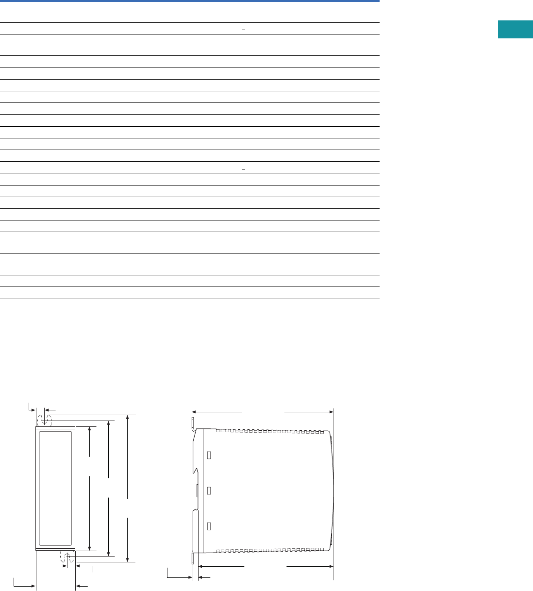
Volume 7—Logic Control, Operator Interface and Connectivity Solutions CA08100008E—February 2014 www.eaton.com V7-T3-29
3
3
3
3
3
3
3
3
3
3
3
3
3
3
3
3
3
3
3
3
3
3
3
3
3
3
3
3
3
3
Volume 7—Logic Control, Operator Interface and Connectivity Solutions CA08100008E—February 2014 www.eaton.com V7-T3-29
3
3
3
3
3
3
3
3
3
3
3
3
3
3
3
3
3
3
3
3
3
3
3
3
3
3
3
3
3
3
3.3
Control Relays and Timers
Programmable Relays
easy802/806 Programmable Relays with SmartWire-DT, continued
Notes
1If present.
2If contactors with a higher total power consumption are connected, an EU5C-SWD-PF1 or EU5C-SWD-PF2 power-feed module must be used.
Dimensions
Approximate Dimensions in Inches (mm)
easy802 and easy806 Controllers
Description Unit Specification
Heat dissipation
At 24 Vdc W easy802: max. 5 / easy806: max. 6
Fuse A > 3
Potential isolation (easy800-SWD)
To auxiliary 1Yes
To easyNet 1Yes
To serial interface Yes
To easyLink 1No
To inputs 1No
To outputs 1No
To SWD 1No
DC AUX Rated Operational Voltage (easy800-SWD)
Rated value UeVdc, (%) 24 (–15/+20)
Permissible range UAUX Vdc 20.4–28.8
Residual ripple % < 5
Input current 2 (max.) A 2 (UL) / 3 (CE)
Rated operational voltage of the 24 Vdc stations V UAUX –0.3V
Protection against polarity reversal Yes
Short-circuit strength No
Fuse A < 2 (UL) external fuse with FAZ B2
Heat dissipation
At 24 Vdc W Normally 1
Potential isolation (easy800-SWD)
To POW power supply, inputs and outputs Yes
To PC interface (COM), easyNet Yes
To SWD Yes
4.33
(110.0)
1.38 (35.0)
0.30 (7.5)
0.30 (7.5)
4.72
(120.0)
5.12
(130.0)
4.94 (125.5)
0.18 (4.5) 4.72 (120.0)
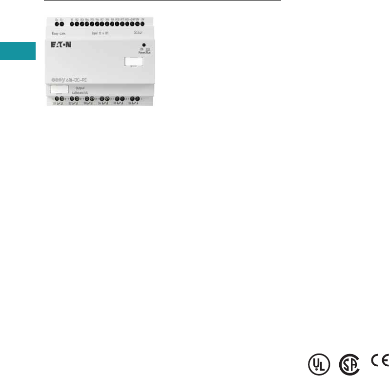
V7-T3-30 Volume 7—Logic Control, Operator Interface and Connectivity Solutions CA08100008E—February 2014 www.eaton.com
3
3
3
3
3
3
3
3
3
3
3
3
3
3
3
3
3
3
3
3
3
3
3
3
3
3
3
3
3
3
V7-T3-30 Volume 7—Logic Control, Operator Interface and Connectivity Solutions CA08100008E—February 2014 www.eaton.com
3
3
3
3
3
3
3
3
3
3
3
3
3
3
3
3
3
3
3
3
3
3
3
3
3
3
3
3
3
3
3.3
Control Relays and Timers
Programmable Relays
easyRelay Expansion Modules
Contents
Description Page
easy500/700/800 Programmable Relays . . . . . . . . V7-T3-20
easy802/806 Programmable Relays
with SmartWire-DT . . . . . . . . . . . . . . . . . . . . . . . V7-T3-26
easyRelay and MFD Expansion Modules
Product Selection . . . . . . . . . . . . . . . . . . . . . . . V7-T3-31
Technical Data and Specifications . . . . . . . . . . V7-T3-31
Dimensions . . . . . . . . . . . . . . . . . . . . . . . . . . . V7-T3-32
MFD-Titan Multi-Function Displays . . . . . . . . . . . . V7-T3-33
easyRelay Communication Modules . . . . . . . . . . . V7-T3-40
easyRelay Power Supplies, Accessories
and Software . . . . . . . . . . . . . . . . . . . . . . . . . . . V7-T3-43
easyRelay and MFD Expansion Modules
Product Description
Expansion modules are
available for increasing the
input/output of the easy700/
800 and MFD-Titan multi-
function displays to 24 inputs
and up to 16 outputs.
Expansion modules can be
mounted directly to the
easy700 or easy800 relays
or up to 98 ft (30m) away
using coupling module
EASY200-EASY.
Standards
●CSA C22.2 No. 142-M1987
●CSA C22.2 No. 213-M1987
●EN 55011
●EN 50178
●EN 61131-2
●IEC EN 61000-4
●IEC 60068-2-6
●IEC 60068-2-27
●UL 508
Certifications
●UL
●CSA
●CE
●CSA Class I, Div. 2,
Groups A, B, C, D;
Temp. Code T3C
●C-Tick
●GOST-R
●Ukrain-GOST
Shipping Approvals
●Bureau Veritas
●Det Norske Veritas
●Germanischer Lloyd
●Lloyd’s Register of Shipping
Volume 7—Logic Control, Operator Interface and Connectivity Solutions CA08100008E—February 2014 www.eaton.com V7-T3-31
3
3
3
3
3
3
3
3
3
3
3
3
3
3
3
3
3
3
3
3
3
3
3
3
3
3
3
3
3
3
Volume 7—Logic Control, Operator Interface and Connectivity Solutions CA08100008E—February 2014 www.eaton.com V7-T3-31
3
3
3
3
3
3
3
3
3
3
3
3
3
3
3
3
3
3
3
3
3
3
3
3
3
3
3
3
3
3
3.3
Control Relays and Timers
Programmable Relays
Product Selection
Digital I/O Expansion Modules
Can be used via easyLink.
Analog I/O Expansion Modules
Can be used via easyLink.
Technical Data and Specifications
easyRelay I/O Expansion Modules
Supply Voltage Digital Inputs
Outputs Catalog
NumberRelay 10A (UL) Transistor
100–240 Vac 12 6 — EASY618-AC-RE
24 Vdc 12 6 — EASY618-DC-RE
24 Vdc 12 — 8 EASY620-DC-TE
24 Vdc64—EASY410-DC-RE
24 Vdc 6 — 4 EASY410-DC-TE
24 Vdc — 2 — EASY202-RE
For distributed connection of a digital input/output expansion at up to 98 ft (30m) distance EASY200-EASY
Supply
Voltage
Inputs Digital Outputs
Analog
Outputs
Catalog
Number
Digital/
Analog
Can Be Used
for Digital Relay 10A (UL) Transistor
24 Vdc 1/2 2 — 2 1 EASY406-DC-ME
24 Vdc 1/6 2 — 2 2 EASY411-DC-ME
Type EASY202-RE EASY618-AC-RE EASY618-DC-RE EASY620-DC-TE EASY200-EASY
Supply voltage — 100 – 240 Vac 24
Vac
24
Vac
—
Heat dissipation 1W 10 VA 4W 4W 1W
Continuous current outputs 18A 8A 8A 0.5A —
Short-circuit proof with
power factor 1
Line protection
B16, 600A
Line protection
B16, 600A
Line protection
B16, 600A
Line protection
B16, 600A
—
Short-circuit proof with
power factor 0.7…0.7
Line protection
B16, 900A
Line protection
B16, 900A
Line protection
B16, 900A
Line protection
B16, 900A
—
Connection cables
Solid 0.2–4.0 mm2 (AWG 22–12) 0.2–4.0 mm2 (AWG 22–12) 0.2–4.0 mm2 (AWG 22–12) 0.2–4.0 mm2 (AWG 22–12) 0.2–4.0 mm2 (AWG 22–12)
Flexible 0.2–2.5 mm2 (AWG 22–12) 0.2–2.5 mm2 (AWG 22–12) 0.2–2.5 mm2 (AWG 22–12) 0.2–2.5 mm2 (AWG 22–12) 0.2–2.5 mm2 (AWG 22–12)
Degree of protection IP20 IP20 IP20 IP20 IP20
RFI suppression EN 55011, EN 55022 Class B, IEC 61000-6-1,2,3,4
Ambient operating temperature –25° to 55°C –25° to 55°C –25° to 55°C –25° to 55°C –25° to 55°C
Transport and storage temperature –40° to 70°C –40° to 70°C –40° to 70°C –40° to 70°C –40° to 70°C
Certification, standards
EN 50178, IEC/EN 60947, UL, CSA
Mounting On 35 mm DIN rail or screw mounting with ZB4-101-GF1 mounting feet
EASY618_
EASY406_
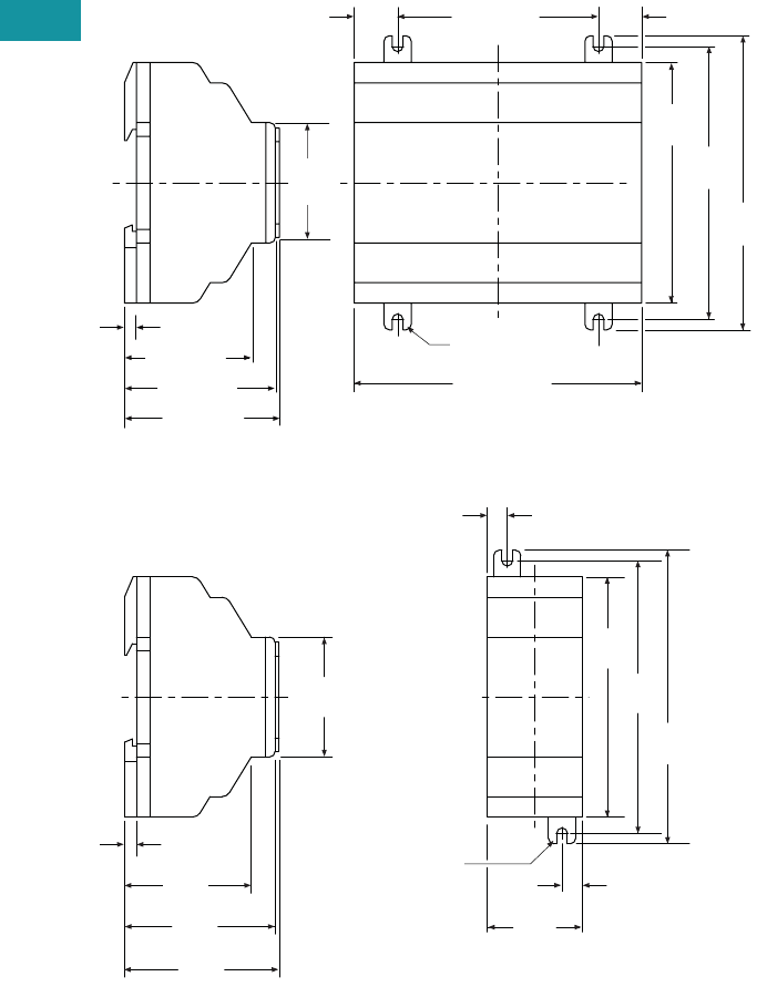
V7-T3-32 Volume 7—Logic Control, Operator Interface and Connectivity Solutions CA08100008E—February 2014 www.eaton.com
3
3
3
3
3
3
3
3
3
3
3
3
3
3
3
3
3
3
3
3
3
3
3
3
3
3
3
3
3
3
V7-T3-32 Volume 7—Logic Control, Operator Interface and Connectivity Solutions CA08100008E—February 2014 www.eaton.com
3
3
3
3
3
3
3
3
3
3
3
3
3
3
3
3
3
3
3
3
3
3
3
3
3
3
3
3
3
3
3.3
Control Relays and Timers
Programmable Relays
Dimensions
Approximate Dimensions in Inches (mm)
easy600 Series, Drawing Number MD05013002E
EASY202-RE/EASY200-EASY/EASY205-ASI Series, Drawing Number MD05013012E
4.23 (107.5)
3.54
(90.0)
4.02
(102.0)
4.33
(110.0)
2.96 (75.0)0.64 (16.3)
(M4) 0.157
(3.9) Dia.
0.64 (16.3)
easy600
2.28 (58.0)
0.18 (4.5)
2.22 (56.5)
1.87 (47.5)
1.77
(45.0)
(M4) 0.157
(3.9) Dia.
0.30
(7.5)
4.33
(110.0)
4.02
(102.0)
3.54
(90.0)
0.30
(7.5)
1.40
(35.5)
1.87
(47.5)
2.22
(56.5)
0.18
(4.5)
1.77
(45.0)
2.28
(58.0)
easy200
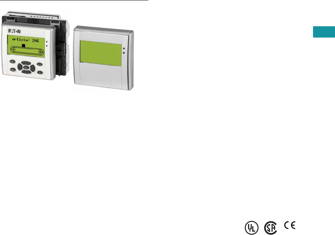
Volume 7—Logic Control, Operator Interface and Connectivity Solutions CA08100008E—February 2014 www.eaton.com V7-T3-33
3
3
3
3
3
3
3
3
3
3
3
3
3
3
3
3
3
3
3
3
3
3
3
3
3
3
3
3
3
3
Volume 7—Logic Control, Operator Interface and Connectivity Solutions CA08100008E—February 2014 www.eaton.com V7-T3-33
3
3
3
3
3
3
3
3
3
3
3
3
3
3
3
3
3
3
3
3
3
3
3
3
3
3
3
3
3
3
3.3
Control Relays and Timers
Programmable Relays
MFD-Titan Multi-Function Displays
Contents
Description Page
easy500/700/800 Programmable Relays . . . . . . . . V7-T3-20
easy802/806 Programmable Relays
with SmartWire-DT . . . . . . . . . . . . . . . . . . . . . . . V7-T3-26
easyRelay and MFD Expansion Modules . . . . . . . V7-T3-33
MFD-Titan Multi-Function Displays
System Overview . . . . . . . . . . . . . . . . . . . . . . . V7-T3-34
Product Selection . . . . . . . . . . . . . . . . . . . . . . . V7-T3-35
Accessories . . . . . . . . . . . . . . . . . . . . . . . . . . . V7-T3-36
Technical Data and Specifications . . . . . . . . . . V7-T3-37
Dimensions . . . . . . . . . . . . . . . . . . . . . . . . . . . V7-T3-38
easyRelay Communication Modules . . . . . . . . . . . V7-T3-40
easyRelay Power Supplies, Accessories
and Software . . . . . . . . . . . . . . . . . . . . . . . . . . . . V7-T3-43
MFD-Titan Multi-Function Displays
Product Description
The MFD-Titan multi-function
displays can be used as
remote text
displays for
easy500, easy700, easy800
and easy802/806 relays or
can be configured as
standalone or networked
multi-function displays. As a
multi-function display, the
MFD-Titan combines the
control functions of an
easy800 with a door-mounted
graphics display.
MFD-Titan multi-function
display is comprised of three
parts: display, controller and
I/O modules. Match each
piece to the needs of your
application. If you need to
both monitor and modify
parameters within your
application, choose the MFD-
80-B display. The
preprogrammed and user
programmable buttons give
you the capability to make
small changes to the way your
application is running, start or
stop a process, or change
your program completely.
Select a controller with or
without easyNet support, and
with AC or DC power. Finally,
add the MFD I/O module that
best suits your application.
MFD-Titan—for controlling
small applications that require
graphic visualization and for
large-scale applications with
20 points, expandable to 40
points locally, and expandable
using the easyNet network
up to 320 I/O points.
The MFD-Titan display can be
linked to the easy500/700/
800 models to provide an
enhanced text based operator
interface.
The easyNet integrated
network provides easy and
inexpensive linking of up to
eight MFD-Titan devices over
a distance of up to 1000
meters. Each MFD-Titan
device can run its program,
or be used as a distributed
input/output module. Connect
up to eight controllers with up
to 40 I/O to obtain 320 I/O.
Standards
●CSA C22.2 No. 142-M1987
●CSA C22.2 No. 213-M1987
●EN 55011
●EN 50178
●EN 61131-2
●IEC EN 61000-4
●IEC 60068-2-6
●IEC 60068-2-27
●UL 508
Certifications
●UL
●CSA
●CE
●CSA Class I, Div. 2,
Groups A, B, C, D;
Temp. Code T3C
●C-Tick
●GOST-R
●Ukrain-GOST
Shipping Approvals
●Bureau Veritas
●Det Norske Veritas
●Germanischer Lloyd
●Lloyd’s Register of Shipping
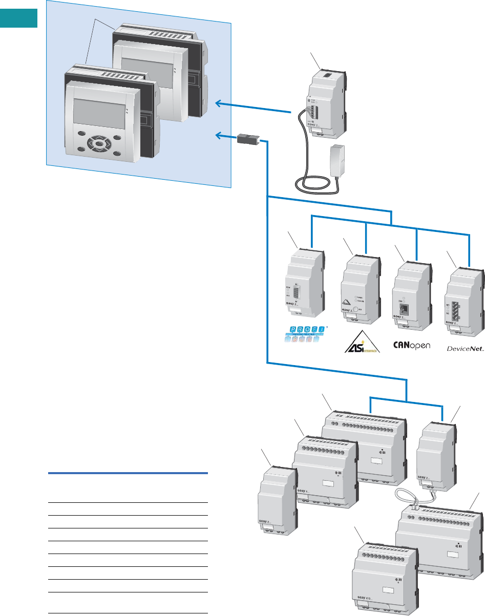
V7-T3-34 Volume 7—Logic Control, Operator Interface and Connectivity Solutions CA08100008E—February 2014 www.eaton.com
3
3
3
3
3
3
3
3
3
3
3
3
3
3
3
3
3
3
3
3
3
3
3
3
3
3
3
3
3
3
V7-T3-34 Volume 7—Logic Control, Operator Interface and Connectivity Solutions CA08100008E—February 2014 www.eaton.com
3
3
3
3
3
3
3
3
3
3
3
3
3
3
3
3
3
3
3
3
3
3
3
3
3
3
3
3
3
3
3.3
Control Relays and Timers
Programmable Relays
System Overview
MFD-Titan Multi-Function Display
3
4
6
5
2
7
9
10
9
11
8, 10
1
Item Description
1 MFD-Titan, consisting of:
display/operating unit, power supply unit,
CPU module, I/O module
2 Ethernet gateway
3 PROFIBUS-DP bus module
4 AS-Interface bus module
5 CANopen bus module
6 DeviceNet bus module
7 Output expansion
8, 9, 10 I/O expansions
11 Coupling module for the remote connection
of a digital input/output expansion
Volume 7—Logic Control, Operator Interface and Connectivity Solutions CA08100008E—February 2014 www.eaton.com V7-T3-35
3
3
3
3
3
3
3
3
3
3
3
3
3
3
3
3
3
3
3
3
3
3
3
3
3
3
3
3
3
3
Volume 7—Logic Control, Operator Interface and Connectivity Solutions CA08100008E—February 2014 www.eaton.com V7-T3-35
3
3
3
3
3
3
3
3
3
3
3
3
3
3
3
3
3
3
3
3
3
3
3
3
3
3
3
3
3
3
3.3
Control Relays and Timers
Programmable Relays
Product Selection
MFD-Titan Display/Operator Units
Monochrome display 132 x 64 pixels with switchable backlight and
removable front frame.
MFD-Titan Text/Graphics Display Power Module
For use with MFD-Titan displays for use as remote text/graphics display.
MFD-Titan Controller Modules
For use with MFD-Titan display/operator units.
Add MFD-Titan I/O modules as needed.
Notes
1 To order an MFD display with custom engraving, a marking file with the required text and/or graphics must be created
as a Labeleditor ZIP file. The ZIP file has to be sent to the Eaton factory, and the name of the file must be referenced
in the order notes section. To download the Labeleditor configuration software, please visit www.eaton.com/software.
2 To obtain a NEMA 4X indoor rating on MFD displays with keypads, use with a protective membrane cover MFD-XM-80.
Description Keypad
Eaton
Logo
Custom
Engraving
Catalog
Number
MFD display, NEMA 4X indoor rated — — — MFD-80-X
MFD display, NEMA 4X indoor rated — ■—MFD-80
MFD display, NEMA 4X indoor rated — — ■MFD-80-ETCH 1
MFD display with keypad 2■——MFD-80-B-X
MFD display with keypad 2■■—MFD-80-B
MFD display with keypad 2——■MFD-80-B-ETCH 1
Supply
Voltage Description
Catalog
Number
100–240 Vac AC power supply / communication module (no cable) MFD-AC-CP4
AC module for easy500/700 relays and cable MFD-CP4-500-CAB5 MFD-AC-CP4-500
AC module for easy800 relays and cable MFD-CP4-800-CAB5 MFD-AC-CP4-800
24 Vdc DC power supply / communication module (no cable) MFD-CP4
DC module for easy500/700 relays and cable MFD-CP4-500-CAB5 MFD-CP4-500
DC module for easy800 relays and cable MFD-CP4-800-CAB5 MFD-CP4-800
Supply
Voltage Description
Catalog
Number
100–240 Vac Program and screen memory MFD-AC-CP8-ME
Program and screen memory, with easyNet MFD-AC-CP8-NT
24 Vdc Program and screen memory MFD-CP8-ME
Program and screen memory, with easyNet MFD-CP8-NT
Double program and screen memory (as MFD-CP8) MFD-CP10-ME
Double program and screen memory (as MFD-CP8), with easyNet MFD-CP10-NT
MFD-80-B
MFD-CP4
MFD-CP
V7-T3-36 Volume 7—Logic Control, Operator Interface and Connectivity Solutions CA08100008E—February 2014 www.eaton.com
3
3
3
3
3
3
3
3
3
3
3
3
3
3
3
3
3
3
3
3
3
3
3
3
3
3
3
3
3
3
V7-T3-36 Volume 7—Logic Control, Operator Interface and Connectivity Solutions CA08100008E—February 2014 www.eaton.com
3
3
3
3
3
3
3
3
3
3
3
3
3
3
3
3
3
3
3
3
3
3
3
3
3
3
3
3
3
3
3.3
Control Relays and Timers
Programmable Relays
MFD-Titan I/O Modules
For use with MFD-Titan controller modules.
MFD-Titan I/O Modules with Temperature Detection
For use with MFD-CP8-_ 2 and MFD-CP10-_ MFD-Titan controller modules.
Accessories
Miscellaneous Parts
Notes
1 Analog inputs optional. Use of analog inputs will result in a decrease in the same number of available digital inputs
2 Version 8 and higher MFD-CP8_ controllers are compatible with the temperature detection modules.
Supply
Voltage Description
Inputs Outputs Catalog
NumberDigital Analog 1Relay Transistor Analog
100–240 Vac 16 I/O 12 — 4 — — MFD-AC-R16
24 Vdc 12 4 4 — — MFD-R16
12 4 — 4 — MFD-T16
24 Vdc 17 I/O 12 4 4 — 1 MFD-RA17
12 4 — 4 1 MFD-TA17
Supply
Voltage
Inputs Outputs
Catalog
NumberDigital
Can Be Used
For Analog Pt100
Relay
10A (UL) Transistor Analog Temperature Ranges
24 Vdc 6 2 2 — 4 — –40° to +90°C/0° to +250°C/0° to +400°C MFD-TP12-PT-A
6 2 2 — 4 — –200° to +200°C/0° to +850°C MFD-TP12-PT-B
6 2 — — 4 — –40° to +90°C/0° to +250°C MFD-TP12-NI-A
6 2 2 — 4 1 –40° to +90°C/0° to +250°C/0° to +400°C MFD-TAP13-PT-A
6 2 2 — 4 1 –200° to +200°C/0° to +850°C MFD-TAP13-PT-B
6 2 — — 4 1 –40° to +90°C/0° to +250°C MFD-TAP13-NI-A
Description Catalog Number
MFD-Titan display protective membrane cover MFD-XM-80
MFD-Titan display protective plastic cover MFD-XS-80
MFD-Titan display DIN rail mount kit MFD-TS-144
MFD-R16
MFD-TP_

Volume 7—Logic Control, Operator Interface and Connectivity Solutions CA08100008E—February 2014 www.eaton.com V7-T3-37
3
3
3
3
3
3
3
3
3
3
3
3
3
3
3
3
3
3
3
3
3
3
3
3
3
3
3
3
3
3
Volume 7—Logic Control, Operator Interface and Connectivity Solutions CA08100008E—February 2014 www.eaton.com V7-T3-37
3
3
3
3
3
3
3
3
3
3
3
3
3
3
3
3
3
3
3
3
3
3
3
3
3
3
3
3
3
3
3.3
Control Relays and Timers
Programmable Relays
Technical Data and Specifications
MFD-80, MFD-CP4, MFD-CP8
MFD-Titan I/O Modules
MFD-CP4 and CP8 Communication Modules
Note
1Relay = 8A with resistive load, 3A with inductive load.
Transistor outputs = 0.5A/24 Vdc, maximum four outputs switchable in parallel.
Type MFD-80… MFD-CP4/CP8
Connection cables
Solid — 0.2–4.0 mm2 (AWG 22–12)
Flexible — 0.2–2.5 mm2 (AWG 22–12)
Degree of protection IP65 IP20
RFI suppression EN 55011, EN 55022 Class B, IEC 61000-6-1, 2, 3, 4 EN 55011, EN 55022 Class B, IEC 61000-6-1, 2, 3, 4
Ambient operating temperature Clearly legible at –5° to 50°C –25° to 55°C
Transport and storage temperature –40° to 70°C –40° to 70°C
Hazardous location CSA Class I, Div. 2, Groups A, B, C, D; Temp. Code T3C CSA Class I, Div. 2, Groups A, B, C, D; Temp. Code T3C
Type MFD-AC-R16 MFD-R16 MFD-RA17 MFD-T16 MFD-TA17
Supply voltage Supply via
MFD-CP8 module
Supply via
MFD-CP8 module
Supply via
MFD-CP8 module
Supply via
MFD-CP8 module
Supply via
MFD-CP8 module
Heat dissipation 0.5W 0.5W 0.5W 0.5W 0.5W
Continuous current outputs 18A 8A 8A 0.5A 0.5A
Short-circuit proof with
power factor 1
Line protection
B16, 600A
Line protection
B16, 600A
Line protection
B16, 600A
——
Short-circuit proof with
power factor 0.7…0.7
Line protection
B16, 600A
Line protection
B16, 600A
Line protection
B16, 600A
——
Connection cables
Solid 0.2–4.0 mm2 (AWG 22–12) 0.2–4.0 mm2 (AWG 22–12) 0.2–4.0 mm2 (AWG 22–12) 0.2–4.0 mm2 (AWG 22–12) 0.2–4.0 mm2 (AWG 22–12)
Flexible 0.2–2.5 mm2 (AWG 22–12) 0.2–2.5 mm2 (AWG 22–12) 0.2–2.5 mm2 (AWG 22–12) 0.2–2.5 mm2 (AWG 22–12) 0.2–2.5 mm2 (AWG 22–12)
Degree of protection IP20 IP20 IP20 IP20 IP20
RFI suppression EN 55011, EN 55022 Class B, IEC 61000-6-1,2,3,4
Ambient operating temperature –25° to 55°C –25° to 55°C –25° to 55°C –25° to 55°C –25° to 55°C
Transport and storage temperature –40° to 70°C –40° to 70°C –40° to 70°C –40° to 70°C –40° to 70°C
Mounting Snap fitted to
MFD-CP8 module
Snap fitted to
MFD-CP8 module
Snap fitted to
MFD-CP8 module
Snap fitted to
MFD-CP8 module
Snap fitted to
MFD-CP8 module
Type MFD-80… MFD-CP4-… MFD-CP8… MFD-AC-CP8…
Supply voltage Supply from -CP 24 Vdc 24 Vdc 100–240 Vac
Heat dissipation 3W 1.5W 3W 8 VA
Mounting Front mounting in 2 x 22.5 mm
Standard drill holes
Snap fitted to MFD-80 Snap fitted to MFD-80 or on 35 mm DIN rail or screw mounting with
ZB4-101-GF1 mounting feet
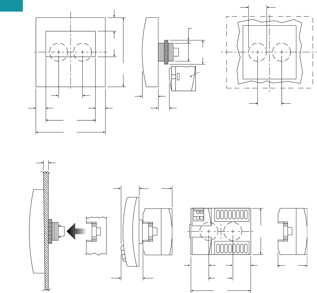
V7-T3-38 Volume 7—Logic Control, Operator Interface and Connectivity Solutions CA08100008E—February 2014 www.eaton.com
3
3
3
3
3
3
3
3
3
3
3
3
3
3
3
3
3
3
3
3
3
3
3
3
3
3
3
3
3
3
V7-T3-38 Volume 7—Logic Control, Operator Interface and Connectivity Solutions CA08100008E—February 2014 www.eaton.com
3
3
3
3
3
3
3
3
3
3
3
3
3
3
3
3
3
3
3
3
3
3
3
3
3
3
3
3
3
3
3.3
Control Relays and Timers
Programmable Relays
Dimensions
Approximate Dimensions in Inches (mm)
MFD-80 Series, Drawing Number MD05013005E
MFD-CP4, MFD-80 and MFD-CP4 Series Combined, Drawing Number MD013013E
3.41
(86.5)
2.44
(62.0)
1.11
(28.3)
1.18 ± 0.01
(30.0) ± 0.2
3.41
(86.5)
1.26
(32.0)
0.67
(17.0)
1.18
(30.0)
0.88 + 0.02
(22.3) + 0.4
0.54
(13.7)
0.79
(20.0)
1.11
(28.3)
0.89
(22.5)
1.18
(30.0)
Template for Holes, Scale 1:1
MFD-80
MFD-CP…
MFD-80
2.28
(58.0)
1.18
(30.0)
2.95
(75.0)
0.89
(22.5)
1.43
(36.2)
1.70
(43.2)
1-6 -0.24
(0.04)
1.08
(27.5)
0.81
(20.5)
0.89
(22.5)
MFD-CP4
MFD-80
MFD-CP4
MFD-CP4
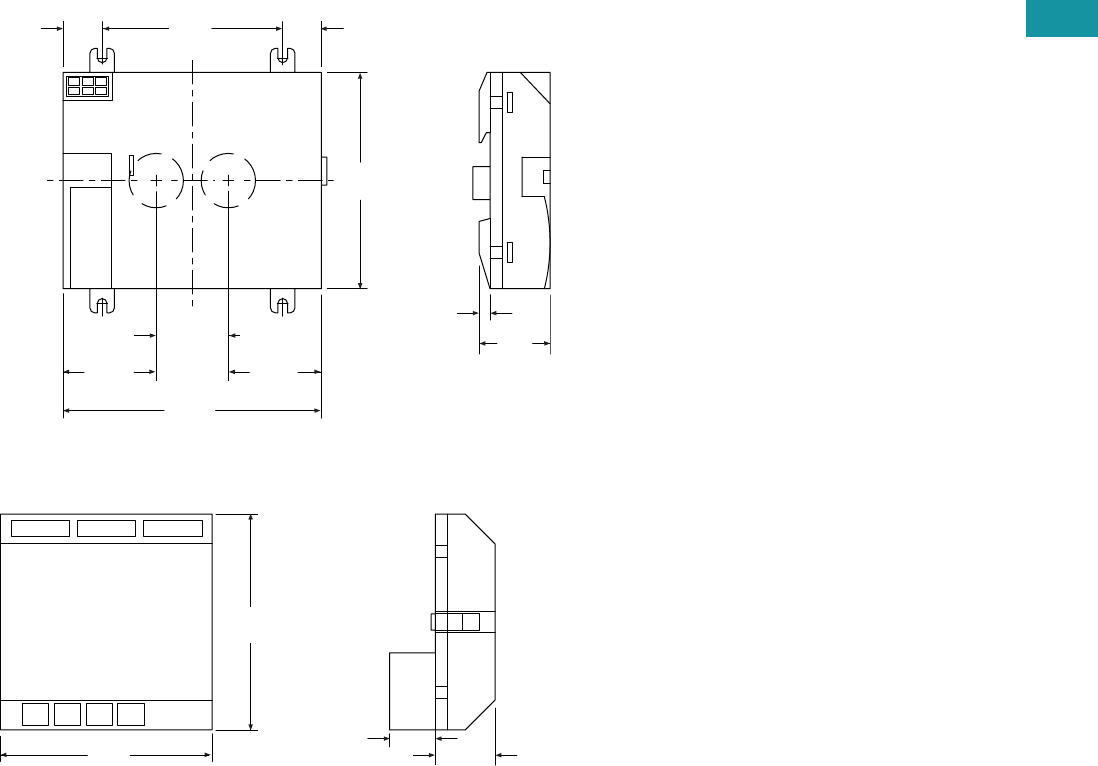
Volume 7—Logic Control, Operator Interface and Connectivity Solutions CA08100008E—February 2014 www.eaton.com V7-T3-39
3
3
3
3
3
3
3
3
3
3
3
3
3
3
3
3
3
3
3
3
3
3
3
3
3
3
3
3
3
3
Volume 7—Logic Control, Operator Interface and Connectivity Solutions CA08100008E—February 2014 www.eaton.com V7-T3-39
3
3
3
3
3
3
3
3
3
3
3
3
3
3
3
3
3
3
3
3
3
3
3
3
3
3
3
3
3
3
3.3
Control Relays and Timers
Programmable Relays
Approximate Dimensions in Inches (mm)
MFD-CP8 Series, Drawing Number MD05013006E
MFD-R/MFD-T I/O Module, Drawing Number MD05013007E
0.640
(16.3)
2.95
(75.0)
3.54
(90.0)
4.23
(107.5)
0.64
(16.3)
0.18
(4.5)
1.53
(38.8)
1.16
(29.5)
1.53
(38.8)
1.18 ± 0.01
(30.0 ± 0.2)
MFD-CP8
3.47
(88.1)
3.54
(90.0)
0.75
(19.0) 0.98
(25.0)
MFD-R and MFD-T I/O
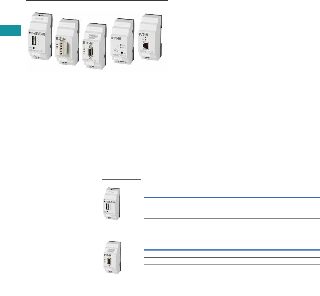
V7-T3-40 Volume 7—Logic Control, Operator Interface and Connectivity Solutions CA08100008E—February 2014 www.eaton.com
3
3
3
3
3
3
3
3
3
3
3
3
3
3
3
3
3
3
3
3
3
3
3
3
3
3
3
3
3
3
V7-T3-40 Volume 7—Logic Control, Operator Interface and Connectivity Solutions CA08100008E—February 2014 www.eaton.com
3
3
3
3
3
3
3
3
3
3
3
3
3
3
3
3
3
3
3
3
3
3
3
3
3
3
3
3
3
3
3.3
Control Relays and Timers
Programmable Relays
easyRelay Communication Modules
Contents
Description Page
easy500/700/800 Programmable Relays . . . . . . . . V7-T3-20
easy802/806 Programmable Relays
with SmartWire-DT . . . . . . . . . . . . . . . . . . . . . . . V7-T3-26
easyRelay and MFD Expansion Modules . . . . . . . V7-T3-33
MFD-Titan Multi-Function Displays . . . . . . . . . . . . V7-T3-33
easyRelay Communication Modules
Technical Data and Specifications . . . . . . . . . . V7-T3-41
Dimensions . . . . . . . . . . . . . . . . . . . . . . . . . . . V7-T3-41
easyRelay Power Supplies, Accessories
and Software . . . . . . . . . . . . . . . . . . . . . . . . . . . V7-T3-43
easyRelay
Communication Modules
Product Description
Four network modules are
available for easily connecting
to world-standard networks.
The network modules can be
used with the easy700/800
programmable relays and
MFD-Titan multi-function
displays.
Available communication
modules support:
●DeviceNet
●PROFIBUS-DP
●AS-Interface
●CANopen
All modules operate
exclusively as nodes on
the given network.
Product Selection
The Ethernet gateway connects devices provided with an RS-232 serial
interface with the Ethernet network. This gateway can be used with easy500
as well as easy700/800 relays and MFD-Titan displays.
Ethernet Gateway Module
Network Interface Modules
Note
1 To set up the Ethernet gateway, download the EASY209-SE configuration software at www.eaton.com/easyrelays.
Description
Catalog
Number
Ethernet gateway Serial interface easyRelay or MFD-…CP8/CP10_ to
Ethernet, for connecting to easyOPC server,
easySoft or easyCom
EASY209-SE 1
Description
Catalog
Number
DeviceNet interface module Addresses available 0 to 63 EASY222-DN
PROFIBUS-DP interface module Device addresses available 1 to 126 EASY204-DP
AS-Interface interface module with
4 in and 4 out
Device: 4 inputs, 4 outputs, 4 parameter bits
Addresses available 0 to 31
EASY205-ASI
CANopen interface module Addresses available 1 to 127 EASY221-CO
EASY209-SE
EASY204-DP
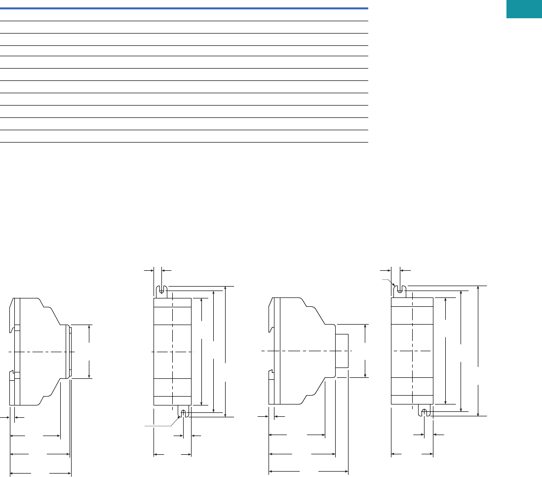
Volume 7—Logic Control, Operator Interface and Connectivity Solutions CA08100008E—February 2014 www.eaton.com V7-T3-41
3
3
3
3
3
3
3
3
3
3
3
3
3
3
3
3
3
3
3
3
3
3
3
3
3
3
3
3
3
3
Volume 7—Logic Control, Operator Interface and Connectivity Solutions CA08100008E—February 2014 www.eaton.com V7-T3-41
3
3
3
3
3
3
3
3
3
3
3
3
3
3
3
3
3
3
3
3
3
3
3
3
3
3
3
3
3
3
3.3
Control Relays and Timers
Programmable Relays
Technical Data and Specifications
easy700/800/MFD Communication Interface Modules
EASY204-DP, EASY205-ASI, EASY221-CO, EASY222-DN, EASY209-SE 1
Notes
1EASY209-SE is also compatible with easy500 programmable relays.
2EASY204-DP dissipates 2W.
Dimensions
Approximate Dimensions in Inches (mm)
EASY202-RE/EASY200-EASY/EASY205-ASI/
EASY209-SE Series, Drawing Number MD05013012E
EASY221-CO/EASY222-DN Series,
Drawing Number MD05013010E
Description Specification
Supply voltage 24 Vdc
Heat dissipation 21W
Connection cables
Solid 0.2–4.0 mm2 (AWG 22–12)
Flexible 0.2–2.5 mm2 (AWG 22–12)
Degree of protection IP20
RFI suppression EN 55011, EN 55022 Class B, IEC 61000-6-1,2,3,4
Ambient operating temperature –25° to +55°C
Transport and storage temperature –40° to +70°C
Certification, standards EN 50178, IEC/EN 60947, UL, CSA
Mounting On 35 mm DIN rail or screw mounting with ZB4-101-GF1 mounting feet
(M4) 0.157
(3.9) Dia.
0.30
(7.5)
4.33
(110.0)
4.02
(102.0)
3.54
(90.0)
0.30
(7.5)
1.40
(35.5)
1.87
(47.5)
2.22
(56.5)
0.18
(4.5)
1.77
(45.0)
2.28
(58.0)
EASY202-RE
EASY200-EASY
EASY205-ASI
2.64
(67.0)
1.77
(45.0)
0.18
(4.5)
2.22
(56.5)
1.87
(47.5)
(M4) 0.157
(3.9) Dia.
0.30
(7.5)
4.33
(110.0)
4.02
(102.0)
3.54
(90.0)
0.30
(7.5)
1.40
(35.5)
EASY222-DN
EASY221-CO
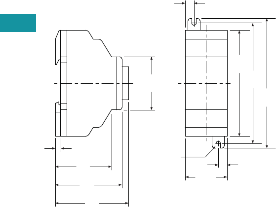
V7-T3-42 Volume 7—Logic Control, Operator Interface and Connectivity Solutions CA08100008E—February 2014 www.eaton.com
3
3
3
3
3
3
3
3
3
3
3
3
3
3
3
3
3
3
3
3
3
3
3
3
3
3
3
3
3
3
V7-T3-42 Volume 7—Logic Control, Operator Interface and Connectivity Solutions CA08100008E—February 2014 www.eaton.com
3
3
3
3
3
3
3
3
3
3
3
3
3
3
3
3
3
3
3
3
3
3
3
3
3
3
3
3
3
3
3.3
Control Relays and Timers
Programmable Relays
EASY204-DP Series,
Drawing Number MD05013011E
2.44
(62.0)
1.77
(45.0)
0.18
(4.5)
2.22
(56.5)
1.87
(47.5)
(M4) 0.157
(3.9) Dia.
0.30
(7.5)
4.33
(110.0)
4.02
(102.0)
3.54
(90.0)
0.30
(7.5)
1.40
(35.5)
EASY204-DP
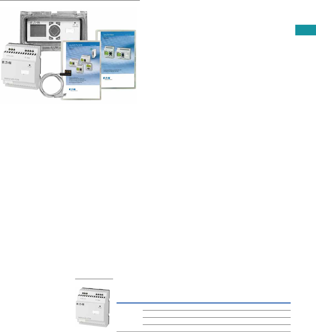
Volume 7—Logic Control, Operator Interface and Connectivity Solutions CA08100008E—February 2014 www.eaton.com V7-T3-43
3
3
3
3
3
3
3
3
3
3
3
3
3
3
3
3
3
3
3
3
3
3
3
3
3
3
3
3
3
3
Volume 7—Logic Control, Operator Interface and Connectivity Solutions CA08100008E—February 2014 www.eaton.com V7-T3-43
3
3
3
3
3
3
3
3
3
3
3
3
3
3
3
3
3
3
3
3
3
3
3
3
3
3
3
3
3
3
3.3
Control Relays and Timers
Programmable Relays
easyRelay Power Supplies, Accessories and Software
Contents
Description Page
easy500/700/800 Programmable Relays . . . . . . . . V7-T3-20
easy802/806 Programmable Relays
with SmartWire-DT . . . . . . . . . . . . . . . . . . . . . . . V7-T3-26
easyRelay and MFD Expansion Modules . . . . . . . V7-T3-30
MFD-Titan Multi-Function Displays . . . . . . . . . . . . V7-T3-33
easyRelay Communication Modules . . . . . . . . . . . V7-T3-40
easyRelay Power Supplies, Accessories
and Software
Accessories . . . . . . . . . . . . . . . . . . . . . . . . . . . V7-T3-44
Technical Data and Specifications . . . . . . . . . . V7-T3-46
Wiring Diagram . . . . . . . . . . . . . . . . . . . . . . . . V7-T3-46
Dimensions . . . . . . . . . . . . . . . . . . . . . . . . . . . V7-T3-47
easyRelay Power
Supplies, Accessories
and Software
Product Description
Power Supplies—12 Vdc
and 24 Vdc power supplies
for applications where only
100–240 Vac is available.
Accessories—Memory
modules, cables and other
components to complete
your automation solutions.
Software—The easySoft
software is used to program
all of the easyRelays and
MFD-Titan displays. The
Windows®-based software
provides straightforward
circuit diagram input and
editing and the diagrams can
be displayed in the format
desired. When easy800
and MFD-Titan controllers are
connected using easyNet,
all connected devices can
be accessed and their
programs loaded from a
single controller.
easySoft includes an
integrated offline simulation
tool that allows users to
test a circuit diagram
before commissioning.
Product Selection
Power supply units are
primary switched-mode
power supplies that are
optimally suited for the
easyRelay and easySafety
product series in terms of
functions and design. The
new and high-performance
power supply units support
safe operation in plants and
machines. They are simple
and flexible in handling.
Fast diagnosis of the voltage
output: continuous light on
the LED—fault-free
operation; flashing on the
LED—short circuit or
overload on voltage output.
●Suitable for worldwide
use due to wide range
input from 85V to 264 Vac,
50/60 Hz
●Output voltages can be
connected in parallel to
increase power output or
for redundant operation to
achieve greater system
availability
●Compliance with
international standards and
approvals
The primary switched-mode
power supply units can be
used everywhere:
●Safety extra low voltage
(SELV to EN 60 950)
●Radio interference Class B
to EN 55 011 and EN 55 022
for use in industrial and
public networks
Power Supply Units
Rated input voltage 100–240 Vac, single-phase.
Input Voltage
Range
Rated Output
Voltage
Output Voltage
Setting Range
Rated Output
Power
Rated Output
Current Catalog Number
100–240 Vac 24 Vdc/12 Vdc — 8W 0.35A/20 mA EASY200-POW
24 Vdc — 30W 1.25A EASY400-POW
24 Vdc — 60W 2.5A EASY500-POW
24 Vdc — 100W 4.2A EASY600-POW
EASY…-POW
V7-T3-44 Volume 7—Logic Control, Operator Interface and Connectivity Solutions CA08100008E—February 2014 www.eaton.com
3
3
3
3
3
3
3
3
3
3
3
3
3
3
3
3
3
3
3
3
3
3
3
3
3
3
3
3
3
3
V7-T3-44 Volume 7—Logic Control, Operator Interface and Connectivity Solutions CA08100008E—February 2014 www.eaton.com
3
3
3
3
3
3
3
3
3
3
3
3
3
3
3
3
3
3
3
3
3
3
3
3
3
3
3
3
3
3
3.3
Control Relays and Timers
Programmable Relays
Bluetooth Adapter
Conveniently commission and service machines and other equipment remotely.
●Simple communication
with easy800 or MFD-Titan
from outside loud and/or
dangerous areas
●An 8-digit PIN security
code prevents
unauthorized remote
access
●Simple recognition in
Windows 7
●Full online functionality
with easySoft-Pro
V6.91or higher
●Has all necessary radio
type approvals for USA,
Canada and Europe
Bluetooth Adapter
Accessories
Programming Software
Programming Cables
Cables and Connectors
Description Catalog Number
easy800/MFD Bluetooth adapter EASY800-BLT-ADP
The Blue tooth adapter provides wireless connectivity to easySoft-Pro for easy programming
download and upload. Use it with the easyRemote Display Android App for simple and fast access
to your easy800 relays up to a distance of 10 meters.
Description Catalog Number
Programming software for easy500/700 EASY-SOFT-BASIC
Programming software for easy800, easy 802/806 and MFD-Titan
includes SWD-Assist for configuration of the SmartWire-DT network
EASY-SOFT-PRO
Description Catalog Number
easy500/700 to PC programming cable—USB EASY-USB-CAB
easy500/700 to PC programming cable—RS-232 EASY-PC-CAB
easy800/MFD to PC programming cable—RS-232 EASY800-PC-CAB
easy800/MFD to PC programming cable—USB EASY800-USB-CAB
easy802/806 to PC programming cable—USB, 2m EU4A-RJ45-USB-CAB1
Description Catalog Number
easy500/700 to MFD-CP4 communication cable, 5m MFD-CP4-500-CAB5
easy800 to MFD-CP4 communication cable, 5m MFD-CP4-800-CAB5
easy800 to MFD-CP8 communication cable, 2m MFD-800-CAB
easy800 to MFD-CP8 communication cable, 5m MFD-800-CAB5
easy800 modem, printer, programming cable EASY800-MO-CAB
easy802/806 to MFD-CP4 communication cable, 1.5m EU4A-RJ45-CAB2
easy802/806 to XV HMI communication cable, 2m EU4A-RJ45-CAB1
easy800/MFD easyNet cable, 0.3m networking cable EASY-NT-30
easy800/MFD easyNet cable, 0.8m networking cable EASY-NT-80
easy800/MFD easyNet cable, 1.5m networking cable EASY-NT-150
easy800/MFD easyNet cable (cable only, no connectors, see EASY-NT-RJ45), 100m EASY-NT-CAB
RJ45 network connectors for easyNet cable (EASY-NT-CAB), 10/pack EASY-NT-RJ45
easy800/MFD network termination resistor, 2/pack EASY-NT-R
EASY800-BLT-ADP
easySoft
EASY-USB-CAB
MFD-CP4-800-CAB5
EASY800-MO-CAB
Volume 7—Logic Control, Operator Interface and Connectivity Solutions CA08100008E—February 2014 www.eaton.com V7-T3-45
3
3
3
3
3
3
3
3
3
3
3
3
3
3
3
3
3
3
3
3
3
3
3
3
3
3
3
3
3
3
Volume 7—Logic Control, Operator Interface and Connectivity Solutions CA08100008E—February 2014 www.eaton.com V7-T3-45
3
3
3
3
3
3
3
3
3
3
3
3
3
3
3
3
3
3
3
3
3
3
3
3
3
3
3
3
3
3
3.3
Control Relays and Timers
Programmable Relays
Memory Storage Modules
Miscellaneous Parts
Description Catalog Number
easy500/700 32K memory storage module EASY-M-32K
easy800/MFD 256K memory storage module EASY-M-256K
easy800/MFD 512K memory storage module EASY-M-512K
Description Catalog Number
easy500 panel window SKF-FF4
easy700/800 panel window SKF-FF6
easy500/700/800 panel window mounting kit to front mount units SKF-HA
High current input adapter, six-channel EASY256-HCI
Base to expander, interface connector EASY-LINK-DS
easy500 relay simulator EASY412-DC-SIM-NA
Mounting feet, 9/pack ZB4-101-GF1
Grounding kit ZB4-102-KS1
EASY-M-32K
EASY-M-256K
Panel Window
Mounting Kit
Simulator
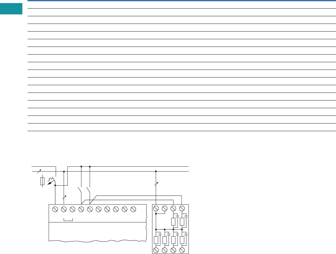
V7-T3-46 Volume 7—Logic Control, Operator Interface and Connectivity Solutions CA08100008E—February 2014 www.eaton.com
3
3
3
3
3
3
3
3
3
3
3
3
3
3
3
3
3
3
3
3
3
3
3
3
3
3
3
3
3
3
V7-T3-46 Volume 7—Logic Control, Operator Interface and Connectivity Solutions CA08100008E—February 2014 www.eaton.com
3
3
3
3
3
3
3
3
3
3
3
3
3
3
3
3
3
3
3
3
3
3
3
3
3
3
3
3
3
3
3.3
Control Relays and Timers
Programmable Relays
Technical Data and Specifications
easyRelay Power Supplies
Wiring Diagram
EASY256-HCI
Type EASY200-POW EASY400-POW
Supply voltage 100–240 Vac 100–240 Vac
Maximum range 85–264 Vac 85–264 Vac
Output voltage 24 Vdc (±3%) 24 Vdc (±3%)
Output current (rated value) 0.25A 1.25A
Overcurrent limitation form 0.3A 1.4A
Short-circuit proof (secondary) Yes Yes
Overload proof Yes Yes
Potential isolation (prim/sec.) Yes, SELV, (to EN 600950, VDE 805) Yes, SELV, (to EN 600950, VDE 805)
Others Additional output voltage 12 DC, 20 mA Additional output voltage 12 DC, 20 mA
Connection cables
Solid 0.2–4.0 mm2 (AWG 22–12) 0.2–4.0 mm2 (AWG 22–12)
Flexible 0.2–2.5 mm2 (AWG 22–12) 0.2–2.5 mm2 (AWG 22–12)
Degree of protection IP20 IP20
RFI suppression EN 55011, EN 55022 Class B, IEC 61000-6-1, 2, 3, 4 EN 55011, EN 55022 Class B, IEC 61000-6-1, 2, 3, 4
Ambient operating temperature –25° to 55°C –25° to 55°C
Transport and storage temperature –40° to 70°C –40° to 70°C
Mounting On 35 mm DIN rail or screw mounting with ZB4-101-GF1 mounting feet
L
N
> 1 A
S..S..
L
115/230 Vh Input 115/230 Vh
N N I1 I2 I3 I4 I5 NN1 2
3456
.....
EASY5..-AC-..
EASY7..-AC-..
EASY256-HCI
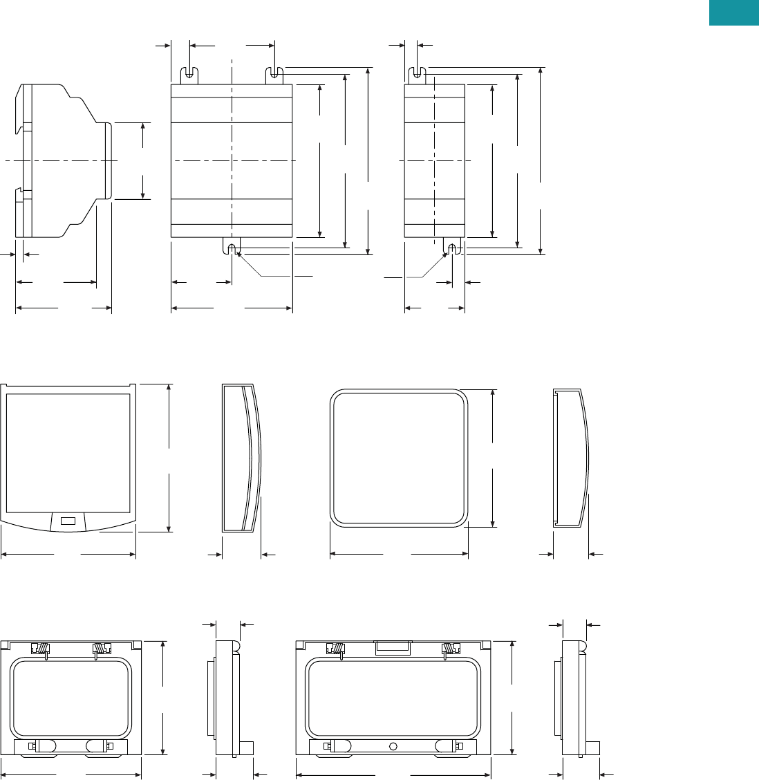
Volume 7—Logic Control, Operator Interface and Connectivity Solutions CA08100008E—February 2014 www.eaton.com V7-T3-47
3
3
3
3
3
3
3
3
3
3
3
3
3
3
3
3
3
3
3
3
3
3
3
3
3
3
3
3
3
3
Volume 7—Logic Control, Operator Interface and Connectivity Solutions CA08100008E—February 2014 www.eaton.com V7-T3-47
3
3
3
3
3
3
3
3
3
3
3
3
3
3
3
3
3
3
3
3
3
3
3
3
3
3
3
3
3
3
3.3
Control Relays and Timers
Programmable Relays
Dimensions
Approximate Dimensions in Inches (mm)
EASY200-POW/EASY256-HCI and EASY400-POW Series, Drawing Number MD05013004E
MFD-XS-80 and MFD-XM-80 Series, Drawing Number MD05013009E
SKF-FF4 and SKF-FF6 Series, Drawing Number MD05013014E
2.81
(71.5)
1.41
(35.8)
3.54
(90.0)
4.02
(102.0)
4.33
(110.0)
1.97
(50.0)
0.42
(10.8)
1.77
(45.0)
0.18
(4.5)
2.22
(56.5)
1.87
(47.5)
0.30
(7.5)
0.30
(7.5)
1.40
(35.5)
3.54
(90.0)
4.02
(102.0)
4.33
(110.0)
EASY400-POW EASY256-HCI
EASY200-POW
(M4) Dia.
0.157
(3.9)
0.98
(25.0)
3.74
(95.0)
3.41
(86.5)
3.48
(88.5)
3.48
(88.5)
0.89
(22.5)
MFD-XS-80 MFD-XM-80
3.70
(94.0)
2.99
(76.0)
0.98
(25.0)
0.63
(16.0)
0.63
(16.0)
5.12
(130.0)
2.99
(76.0)
0.98
(25.0)
SKF-FF4 SKF-FF6
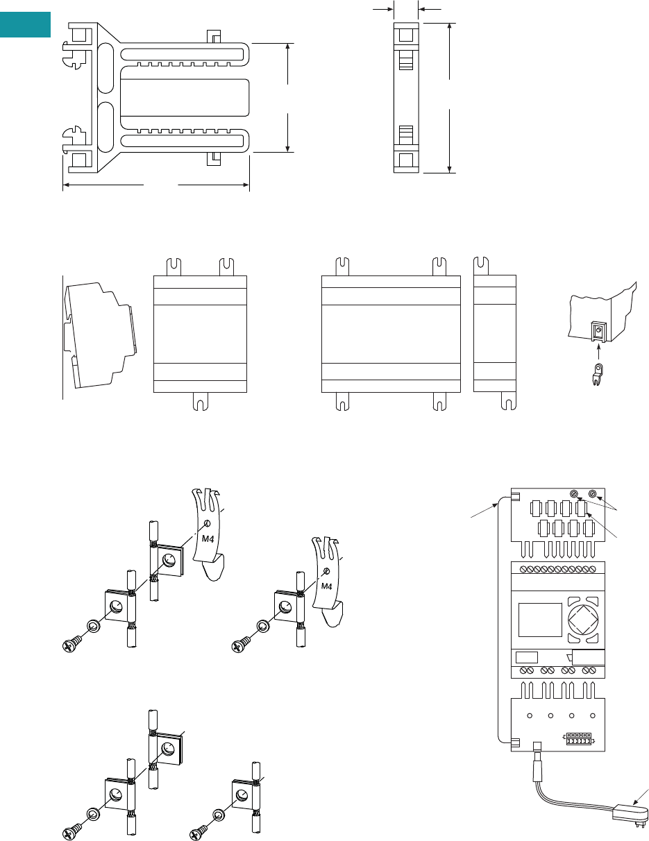
V7-T3-48 Volume 7—Logic Control, Operator Interface and Connectivity Solutions CA08100008E—February 2014 www.eaton.com
3
3
3
3
3
3
3
3
3
3
3
3
3
3
3
3
3
3
3
3
3
3
3
3
3
3
3
3
3
3
V7-T3-48 Volume 7—Logic Control, Operator Interface and Connectivity Solutions CA08100008E—February 2014 www.eaton.com
3
3
3
3
3
3
3
3
3
3
3
3
3
3
3
3
3
3
3
3
3
3
3
3
3
3
3
3
3
3
3.3
Control Relays and Timers
Programmable Relays
Approximate Dimensions in Inches (mm)
SKF-HA Series, Drawing Number MD05013015E
ZB4-101-GF1 Mounting Feet
ZB4-102-KS1 Series—
Grounding the Screen for Top-Hat Rail
ZB4-102-KS1 Series—
Grounding the Screen for Mounting Plate
EASY412-DC-SIM-NA Series
2.60
(66.0)
0.43
(11.0)
3.23
(82.0)
1.89
(48.0)
SKF-HA
Fitting on 35 mm Top-Hat Rail Fitting on Mounting Plate (Horizontal)
ZB4-101-GF1
* 3 mounting feet are sufcient
**
**
ESC OK
DEL ALT
Digital Inputs
Connection
Cable
Power Supply Unit
Connect Outputs
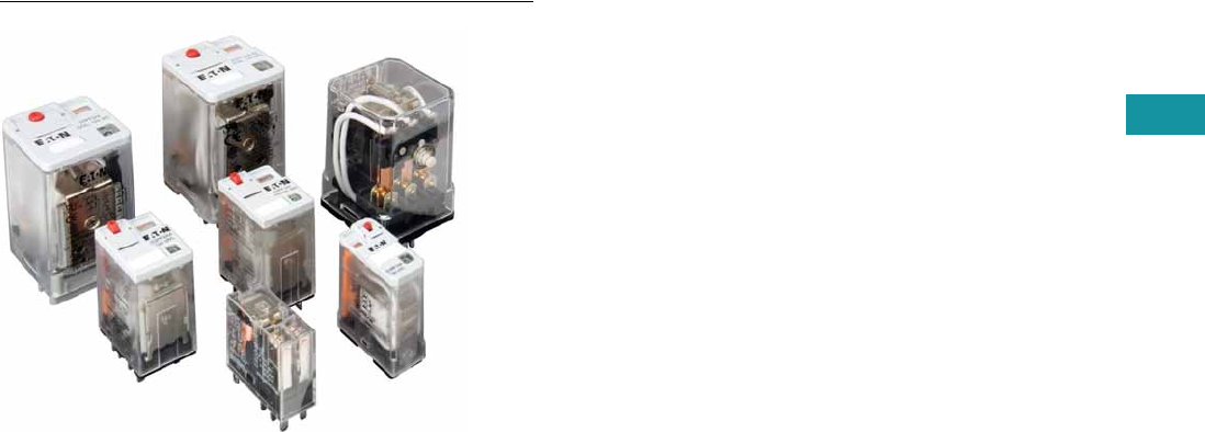
Volume 7—Logic Control, Operator Interface and Connectivity Solutions CA08100008E—February 2014 www.eaton.com V7-T3-49
3
3
3
3
3
3
3
3
3
3
3
3
3
3
3
3
3
3
3
3
3
3
3
3
3
3
3
3
3
3
Volume 7—Logic Control, Operator Interface and Connectivity Solutions CA08100008E—February 2014 www.eaton.com V7-T3-49
3
3
3
3
3
3
3
3
3
3
3
3
3
3
3
3
3
3
3
3
3
3
3
3
3
3
3
3
3
3
3.4
Control Relays and Timers
General Purpose Plug-In Relays
General Purpose Plug-In Relay
Contents
Description Page
D1PR/D1PF Series . . . . . . . . . . . . . . . . . . . . . . . . . V7-T3-53
D2PR/D2PF Series . . . . . . . . . . . . . . . . . . . . . . . . . V7-T3-58
D3PR/D3PF Series . . . . . . . . . . . . . . . . . . . . . . . . . V7-T3-68
D4 Series . . . . . . . . . . . . . . . . . . . . . . . . . . . . . . . . V7-T3-78
D5PR/D5PF Series . . . . . . . . . . . . . . . . . . . . . . . . . V7-T3-82
D7PR/D7PF Series . . . . . . . . . . . . . . . . . . . . . . . . . V7-T3-91
D8 Series . . . . . . . . . . . . . . . . . . . . . . . . . . . . . . . . V7-T3-106
D9 Series . . . . . . . . . . . . . . . . . . . . . . . . . . . . . . . . V7-T3-112
Accessories . . . . . . . . . . . . . . . . . . . . . . . . . . . . . . V7-T3-116
Product Selection Guide
General Purpose Relay Selection Characteristics
●Current rating: 1A–30A
●Contact arrangement:
SPDT, DPDT, 3PDT, 4PDT,
etc.
●Coil voltage: 6V–240 Vac/
6V–110 Vdc
●Mounting options: socket,
flange, DIN rail, panel
●Specifications: CSA, CE,
IEC, NEMA, UL, etc.
●Other: physical
dimensions, maximum
voltage, mechanical/
electrical life, etc.
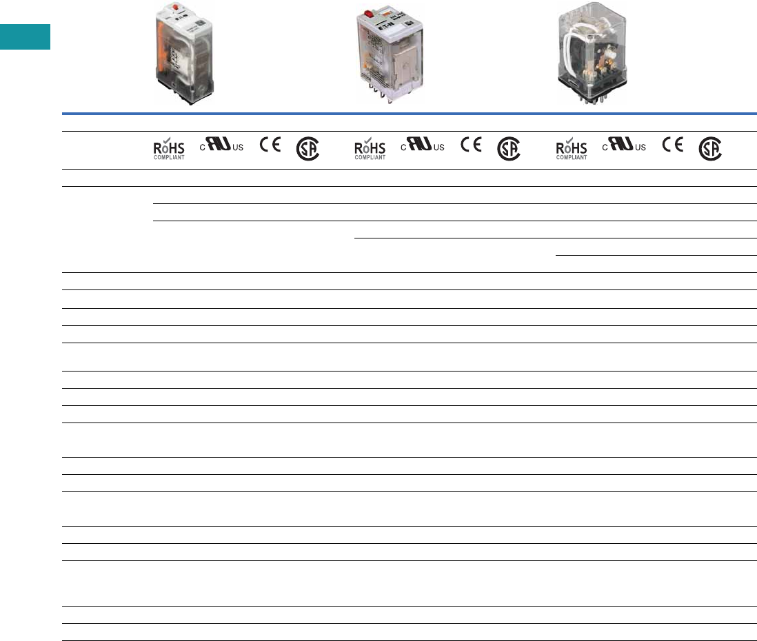
V7-T3-50 Volume 7—Logic Control, Operator Interface and Connectivity Solutions CA08100008E—February 2014 www.eaton.com
3
3
3
3
3
3
3
3
3
3
3
3
3
3
3
3
3
3
3
3
3
3
3
3
3
3
3
3
3
3
V7-T3-50 Volume 7—Logic Control, Operator Interface and Connectivity Solutions CA08100008E—February 2014 www.eaton.com
3
3
3
3
3
3
3
3
3
3
3
3
3
3
3
3
3
3
3
3
3
3
3
3
3
3
3
3
3
3
3.4
Control Relays and Timers
General Purpose Plug-In Relays
General Purpose Plug-In Relays
Relay Series D1PR/D1PF D2PR/D2PF D3PR/D3PF
Approvals
Features
Polycarbonate cover Polycarbonate cover Polycarbonate cover
Indicator lamp and pushbutton available Indicator lamp and pushbutton available Indicator lamp and pushbutton available
Panel and DIN mounting Panel, DIN and flange mounting Panel and DIN mounting
Latching 8- or 11-pin octal plug-in
Latching (D3PR version)
Contact Data
Configuration SPDT DPDT DPDT Latching 4PDT DPDT 3PDT
Max. allowable load 20A 10A 3A 10A 16A 16A 16A
Material Silver alloy Silver alloy Silver alloy
Dielectric strength
between poles
1500V 1500V 1500V
Coil Data
AC 6 to 240 Vac 6 to 240 Vac 6 to 240 Vac
DC 6 to 110 Vdc 6 to 110 Vdc 6 to 110 Vdc
Power
VA (Vac) 0.9 VA 1.2 VA 3 VA 1.4W (D3PR and D3PF)
Watts (Vdc) 0.7W 0.9W 2 VA 1.64W (D3PR5 latching)
General Data
Ambient temperature
Storage –40° to 185°F (–40° to 85°C) –40° to 185°F (–40° to 85°C) –40° to 185°F (–40° to 85°C)
Operational –40° to 131°F (–40° to 55°C) –40° to 131°F (–40° to 55°C) –40° to 131°F (–40° to 55°C)
Response time 20 milliseconds 20 milliseconds 20 milliseconds
Life
Mechanical operations 10 million 10 million 5 million (D3PR and D3PF)
10 million (D3PR5 latching)
Electrical operations 100,000 200,000 100,000
Page Numbers V7-T3-53 to V7-T3-57 V7-T3-58 to V7-T3-67 V7-T3-68 to V7-T3-77
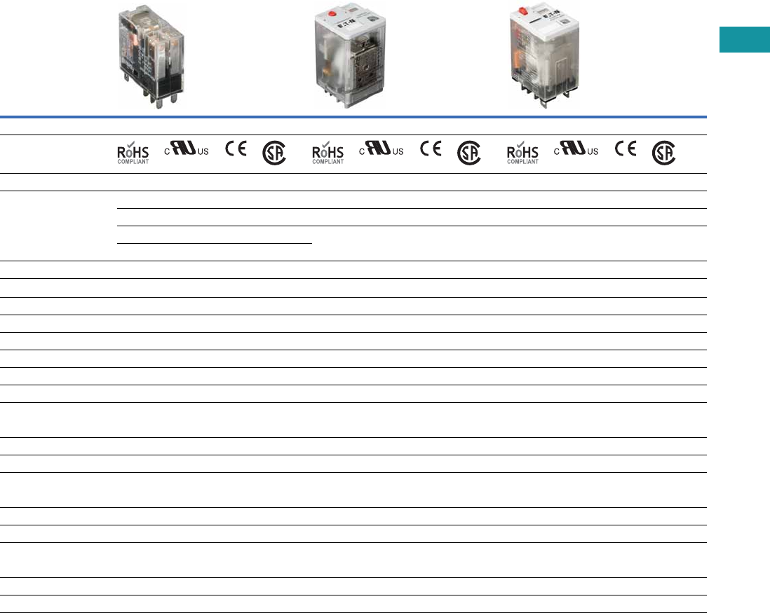
Volume 7—Logic Control, Operator Interface and Connectivity Solutions CA08100008E—February 2014 www.eaton.com V7-T3-51
3
3
3
3
3
3
3
3
3
3
3
3
3
3
3
3
3
3
3
3
3
3
3
3
3
3
3
3
3
3
Volume 7—Logic Control, Operator Interface and Connectivity Solutions CA08100008E—February 2014 www.eaton.com V7-T3-51
3
3
3
3
3
3
3
3
3
3
3
3
3
3
3
3
3
3
3
3
3
3
3
3
3
3
3
3
3
3
3.4
Control Relays and Timers
General Purpose Plug-In Relays
General Purpose Plug-In Relays, continued
Relay Series D4 D5PR/D5PF D7PR/D7PF
Approvals
Features
Polycarbonate cover Polycarbonate cover Polycarbonate cover
Indicator lamp available Indicator lamp and pushbutton available Indicator lamp and pushbutton available
Panel and DIN mounting Panel, DIN and flange mounting Panel and DIN mounting
Socket has built-in hold-down spring
Contact Data
Configuration SPDT DPDT DPDT 3PDT SPDT DPDT 3PDT 4PDT
Max. allowable load 10A at 250 Vac 5A at 240 Vac 16A 16A 20A 15A 15A 15A
Material AgCdO Silver alloy Silver alloy
Dielectric strength 5000V 1500V 1500V 1500V 2500V 2500V
Coil Data
AC 6 to 240 Vac 6 to 240 Vac 6 to 240 Vac
DC 6 to 110 Vdc 6 to 110 Vdc 6 to 110 Vdc
Power
VA (Vac) 0.9 VA 3 VA 1.2 VA 1.2 VA 1.5 VA 1.5 VA
Watts (Vdc) 0.5W 1.4W 0.9W 0.9W 1.4W 1.5W
General Data
Ambient temperature
Storage –40° to 158°F (–40° to 70°C) –40° to 185°F (–40° to 85°C) –40° to 185°F (–40° to 85°C)
Operational –40° to 158°F (–40° to 70°C) –40° to 131°F (–40° to 55°C) –40° to 131°F (–40° to 55°C)
Response time 15 milliseconds 20 milliseconds 20 milliseconds (30 milliseconds for latching)
Life
Mechanical operations 10 million 5 million 10 million
Electrical operations 100,000 100,000 100,000 100,000 200,000 200,000
Page Numbers V7-T3-78 to V7-T3-81 V7-T3-82 to V7-T3-90 V7-T3-91 to V7-T3-105
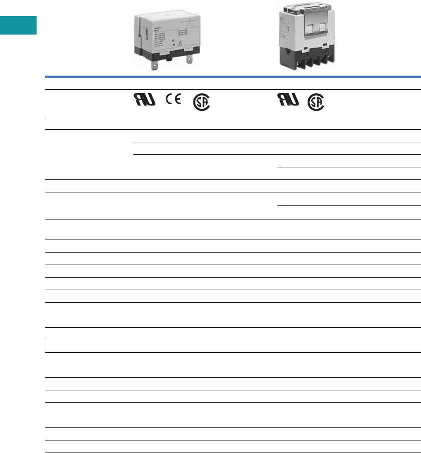
V7-T3-52 Volume 7—Logic Control, Operator Interface and Connectivity Solutions CA08100008E—February 2014 www.eaton.com
3
3
3
3
3
3
3
3
3
3
3
3
3
3
3
3
3
3
3
3
3
3
3
3
3
3
3
3
3
3
V7-T3-52 Volume 7—Logic Control, Operator Interface and Connectivity Solutions CA08100008E—February 2014 www.eaton.com
3
3
3
3
3
3
3
3
3
3
3
3
3
3
3
3
3
3
3
3
3
3
3
3
3
3
3
3
3
3
3.4
Control Relays and Timers
General Purpose Plug-In Relays
General Purpose Plug-In Relays, continued
Relay Series D8 D9
Approvals
Features
Dust cover Dust cover
Panel, DIN and flange mounting Pushbutton available
Quick-connect and screw terminals Panel mounting
Screw terminals
Contact Data
Configuration
SPST-NO DPST-NO
4PST
NO NC
Max. allowable load 30A at
220 Vac
25A at
220 Vac
25A at
220 Vac
8A at
220 Vac
Material AgCdO AgCdO
Dielectric strength 4000V 4000V
Coil Data
AC 6 to 240 Vac 24 to 240 Vac
DC 12 to 24 Vdc 12 to 110 Vdc
Power
VA (Vac) 2.5 VA 2.6 VA
Watts (Vdc) 1.9W 2.0W
General Data
Ambient temperature
Storage –4° to 185°F (–20° to 85°C) –13° to 140°F (–25° to 60°C)
Operational –4° to 131°F (–20° to 55°C) –13° to 140°F (–25° to 60°C)
Response time 30 milliseconds 50 milliseconds
Life
Mechanical operations 5 million 1 million
Electrical operations 100,000 100,000
Page Numbers V7-T3-106 to V7-T3-111 V7-T3-112 to V7-T3-115
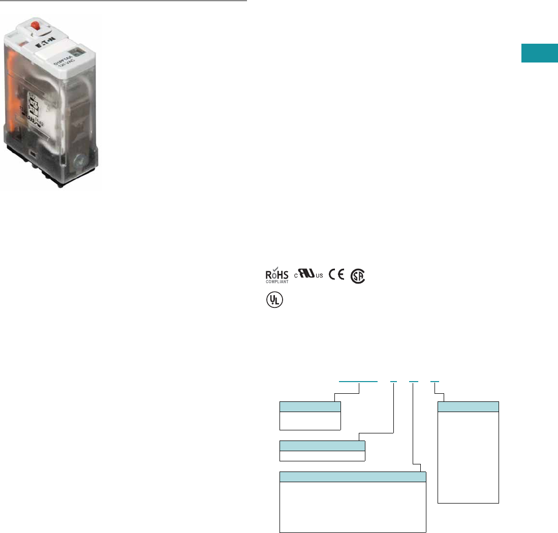
Volume 7—Logic Control, Operator Interface and Connectivity Solutions CA08100008E—February 2014 www.eaton.com V7-T3-53
3
3
3
3
3
3
3
3
3
3
3
3
3
3
3
3
3
3
3
3
3
3
3
3
3
3
3
3
3
3
Volume 7—Logic Control, Operator Interface and Connectivity Solutions CA08100008E—February 2014 www.eaton.com V7-T3-53
3
3
3
3
3
3
3
3
3
3
3
3
3
3
3
3
3
3
3
3
3
3
3
3
3
3
3
3
3
3
3.4
Control Relays and Timers
General Purpose Plug-In Relays
D1 Series Relay
Contents
Description Page
D1PR/D1PF Series
Product Selection . . . . . . . . . . . . . . . . . . . . . . . V7-T3-54
Accessories . . . . . . . . . . . . . . . . . . . . . . . . . . . . V7-T3-55
Technical Data and Specifications . . . . . . . . . . . V7-T3-56
Wiring Diagram . . . . . . . . . . . . . . . . . . . . . . . . . V7-T3-57
Dimensions . . . . . . . . . . . . . . . . . . . . . . . . . . . . V7-T3-57
D2PR/D2PF Series . . . . . . . . . . . . . . . . . . . . . . . . . V7-T3-58
D3PR/D3PF Series . . . . . . . . . . . . . . . . . . . . . . . . . V7-T3-68
D4 Series . . . . . . . . . . . . . . . . . . . . . . . . . . . . . . . . V7-T3-78
D5PR/D5PF Series . . . . . . . . . . . . . . . . . . . . . . . . . V7-T3-82
D7PR/D7PF Series . . . . . . . . . . . . . . . . . . . . . . . . . V7-T3-91
D8 Series . . . . . . . . . . . . . . . . . . . . . . . . . . . . . . . . V7-T3-106
D9 Series . . . . . . . . . . . . . . . . . . . . . . . . . . . . . . . . V7-T3-112
Accessories . . . . . . . . . . . . . . . . . . . . . . . . . . . . . . V7-T3-116
D1PR/D1PF Series
Product Description
The D1 Series of relay
provides a compact single-
pole relay capable of handling
20A. Multiple feature and
voltage options allow for the
perfect fit for any application.
Features
D1PR
●Compact relay capable of
breaking relatively large
load currents
●Panel and DIN rail
mounting
D1PF
●The contact operation
can be easily checked by
Push-to-Test button
●Flag indicator shows relay
status in manual or
powered condition
●LED status lamp shows
coil ON or OFF status—
ideal for use in low light
applications
●Push-to-Test button allows
for manual operation of
relay without the need for
coil power
●Lock-down door holds
pushbutton and contacts in
the operate position when
activated
●Finger-grip cover allows
operator to remove relays
from sockets easily
●ID tag/write label to
identify relays in multiple-
relay circuits
●Bipolar LED allows for
reverse polarity
applications
Standards and Certifications
When used with
accompanying Eaton
screw terminal socket.
Catalog Number Selection
D1PR/D1PF Series
UL Listed
D 1 P F 1 A A
Family Type
D1PF
D1PR
Contact Configuration
1 = SPDT
Standard Features
Blank = Mechanical flag indicator
(only with D1PR)
A = LED test button, flag indicator,
lock-down door, finger-grip cover,
ID tag (only with D1PF)
1 = LED and mechanical flag indicator
Coil Voltage
A = 120 Vac
A1 = 110 Vdc
B = 240 Vac
P = 6 Vac
P1 = 6 Vdc
R = 12 Vac
R1 = 12 Vdc
T = 24 Vac
T1 = 24 Vdc
W = 48 Vac
W1 = 48 Vdc
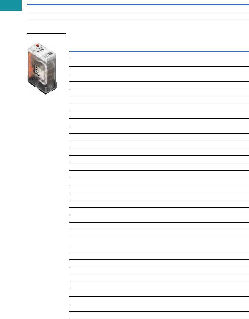
V7-T3-54 Volume 7—Logic Control, Operator Interface and Connectivity Solutions CA08100008E—February 2014 www.eaton.com
3
3
3
3
3
3
3
3
3
3
3
3
3
3
3
3
3
3
3
3
3
3
3
3
3
3
3
3
3
3
V7-T3-54 Volume 7—Logic Control, Operator Interface and Connectivity Solutions CA08100008E—February 2014 www.eaton.com
3
3
3
3
3
3
3
3
3
3
3
3
3
3
3
3
3
3
3
3
3
3
3
3
3
3
3
3
3
3
3.4
Control Relays and Timers
General Purpose Plug-In Relays
Product Selection
D1PR/D1PF Relay/Socket Quick Reference
D1PR/D1PF Series
Relay
Type Socket Clip
Module
Type
ID
Tag Jumper
D1PR1 D1PAA PMC-1781 B — —
D1PF1 D1PAA PMC-1781 B — —
Coil
Voltage
Contact
Configuration
Coil Resistance
(Ohms)
Catalog
Number
Full Featured
6 Vac SPDT 12.2 D1PF1AP
6 Vdc SPDT 47 D1PF1AP1
12 Vac SPDT 46 D1PF1AR
12 Vdc SPDT 188 D1PF1AR1
24 Vac 50/60 Hz SPDT 180 D1PF1AT
24 Vdc SPDT 750 D1PF1AT1
48 Vac SPDT 720 D1PF1AW
48 Vdc SPDT 2600 D1PF1AW1
110 Vdc SPDT 13,800 D1PF1AA1
120 Vac 50/60 Hz SPDT 4430 D1PF1AA
240 Vac 50/60 Hz SPDT 15,720 D1PF1AB
Plain Cover with LED Indicator
6 Vac SPDT 12.2 D1PR11P
6 Vdc SPDT 47 D1PR11P1
12 Vac SPDT 46 D1PR11R
12 Vdc SPDT 188 D1PR11R1
24 Vac 50/60 Hz SPDT 180 D1PR11T
24 Vdc SPDT 750 D1PR11T1
48 Vac SPDT 720 D1PR11W
48 Vdc SPDT 2600 D1PR11W1
240 Vac 50/60 Hz SPDT 15,720 D1PR11B
110 Vdc SPDT 13,800 D1PR11A1
120 Vac SPDT 4430 D1PR11A
24 Vac 50/60 Hz SPDT 180 D1PR1T
Plain Cover
6 Vac SPDT 12.2 D1PR1P
6 Vdc SPDT 47 D1PR1P1
12 Vac SPDT 46 D1PR1R
12 Vdc SPDT 188 D1PR1R1
24 Vdc SPDT 750 D1PR1T1
48 Vac SPDT 720 D1PR1W
48 Vdc SPDT 2600 D1PR1W1
110 Vdc SPDT 13,800 D1PR1A1
120 Vac 50/60 Hz SPDT 4430 D1PR1A
240 Vac SPDT 15,270 D1PR1B
D1PF Series Relay

Volume 7—Logic Control, Operator Interface and Connectivity Solutions CA08100008E—February 2014 www.eaton.com V7-T3-55
3
3
3
3
3
3
3
3
3
3
3
3
3
3
3
3
3
3
3
3
3
3
3
3
3
3
3
3
3
3
Volume 7—Logic Control, Operator Interface and Connectivity Solutions CA08100008E—February 2014 www.eaton.com V7-T3-55
3
3
3
3
3
3
3
3
3
3
3
3
3
3
3
3
3
3
3
3
3
3
3
3
3
3
3
3
3
3
3.4
Control Relays and Timers
General Purpose Plug-In Relays
Accessories
D1PR/D1PF Sockets and Accessories
Note
1Protection Category (Finger Safe), EN 60529: IP20.
Type
Module
Size
Nominal Voltage
(Max. for Sockets)
Nominal
Current Mounting Style Wire Size
Wire
Connection
Standard
Pack
Catalog
Number
Socket B 300 20 Panel/DIN rail 12 /14 (2) AWG, 4 /2.5 (2) mm2Screw clamping 10 D1PAA 1
Flange mount adapter — — — Flange — — 25 PFC-D11
Metal spring clip — — — — — — 25 PMC-1781
Protection diode B 6 to 250 Vdc — — — — 20 MOD-BD250
LED indicator B 24 Vac/Vdc — — — — 20 MOD-BLG24
B 120/240 Vac/Vdc — — — — 20 MOD-BLG240
MOV suppressor B 120 Vac/Vdc — — — — 20 MOD-BMV120
B 24 Vac/Vdc — — — — 20 MOD-BMV24
B240 Vac/Vdc —— — — 20MOD-BMV240
Plastic DIN rail end stop — — — — — — 25 PFP-P

V7-T3-56 Volume 7—Logic Control, Operator Interface and Connectivity Solutions CA08100008E—February 2014 www.eaton.com
3
3
3
3
3
3
3
3
3
3
3
3
3
3
3
3
3
3
3
3
3
3
3
3
3
3
3
3
3
3
V7-T3-56 Volume 7—Logic Control, Operator Interface and Connectivity Solutions CA08100008E—February 2014 www.eaton.com
3
3
3
3
3
3
3
3
3
3
3
3
3
3
3
3
3
3
3
3
3
3
3
3
3
3
3
3
3
3
3.4
Control Relays and Timers
General Purpose Plug-In Relays
Technical Data and Specifications
D1PF/D1PR Relay Specifications
Description D1PR D1PF
Contact Characteristics
Contact rating 20A 20A
Terminal style Plug-in Plug-in
Contact materials Silver alloy Silver alloy
Maximum switching voltage 300V 300V
Switching current at voltage—resistive 20A at 120 Vac 50/60 Hz 20A at 120 Vac 50/60 Hz
20A at 277 Vac 50/60 Hz 20A at 277 Vac 50/60 Hz
20A at 28 Vdc 20A at 28 Vdc
Switching current at voltage 1/2 hp at 120 Vac 1/2 hp at 120 Vac
1 hp at 277 Vac 1 hp at 277 Vac
Pilot duty B300 B300
Minimum switching requirement 100 mA at 5 Vdc (0.5W) 100 mA at 5 Vdc (0.5W)
Coil Characteristics
Operating range
% of nominal (AC) 85 to 110% 85 to 110%
% of nominal (DC) 80 to 110% 80 to 110%
Average consumption 0.9 VA 0.9 VA
0.7W 0.7W
Dropout voltage threshold 15% (AC) 15% (AC)
10% (DC) 10% (DC)
Performance
Electrical life (UL 508) operations at rated current 100,000 operations 100,000 operations
Mechanical life operations unpowered 10,000,000 operations 10,000,000 operations
Response time 20 ms 20 ms
Dielectric strength
Between coil and contact Vac (rms) 2500V (rms) 2500V (rms)
Between poles Vac (rms) 1500V (rms) 1500V (rms)
Environment
Ambient air temperature around the device
Storage –40° to 131°F (–40° to 55ºC) –40° to 131°F (–40° to 55°C)
Operation –40° to 185°F (–40° to 85ºC) –40° to 185°F (–40° to 85°C)
Vibration resistance—operational 3 g-n at 10–55 Hz 3 g-n at 10–55 Hz
Shock resistance 10 g-n 10 g-n
Degree of protection IP40 IP40
Features
Cover options Plain cover Full featured
Features Mechanical flag indicator (optional LED) Locking pushbutton/
Bipolar LED/
Removable ID tag/
Mechanical flag indicator
Product certifications RoHS/UL/CE/CSA RoHS/UL/CE/CSA
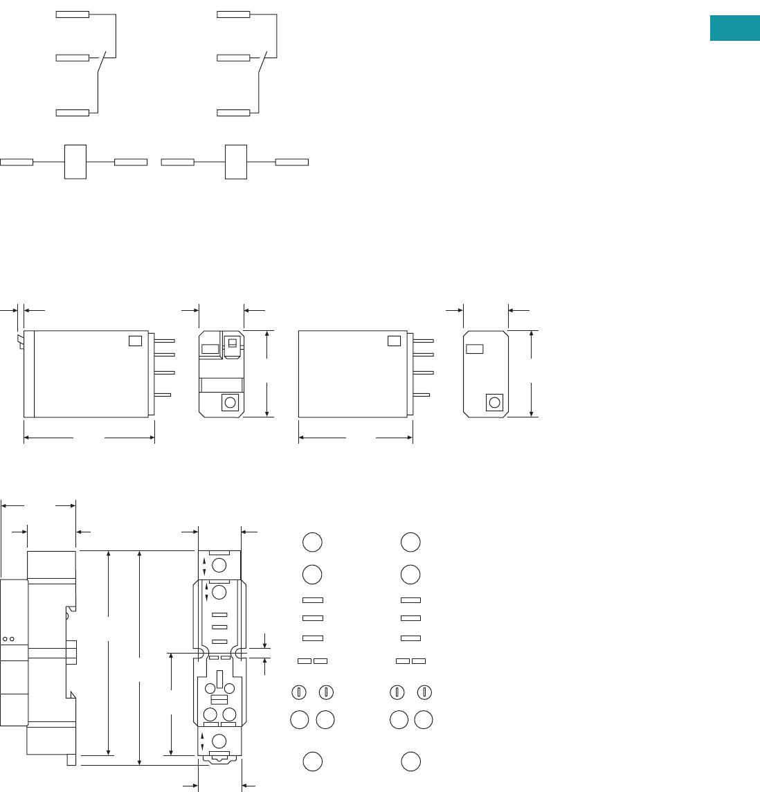
Volume 7—Logic Control, Operator Interface and Connectivity Solutions CA08100008E—February 2014 www.eaton.com V7-T3-57
3
3
3
3
3
3
3
3
3
3
3
3
3
3
3
3
3
3
3
3
3
3
3
3
3
3
3
3
3
3
Volume 7—Logic Control, Operator Interface and Connectivity Solutions CA08100008E—February 2014 www.eaton.com V7-T3-57
3
3
3
3
3
3
3
3
3
3
3
3
3
3
3
3
3
3
3
3
3
3
3
3
3
3
3
3
3
3
3.4
Control Relays and Timers
General Purpose Plug-In Relays
Wiring Diagram
D1PF/D1PR
Dimensions
Approximate Dimensions in Inches (mm)
D1PF/D1PR
D1PAA
NEMA
1
5
9
13 14
IEC
12
14
11
A1 A2
0.10
(2.1)
0.53
(14.0)
1.10
(27.9)
1.60
(40.6)
0.53
(14.0)
1.10
(27.9)
1.40
(35.5)
1.57
(40.0)
1.18
(30.0)
0.74
(19.0)
0.67
(17.0)
3.33
(84.0)
3.14
(80.0)
0.82
(21.0)
0.16
(4.0)
9
14 13
1
5
COM
N.C.
N.O.
14 13
Module
Input
Input
1
5
Input
9
Input
NEMA
11
A2 A1
12
14
COM
N.C.
N.O.
14 13
Module
Input
Input
1
5
Input
9
Input
IEC
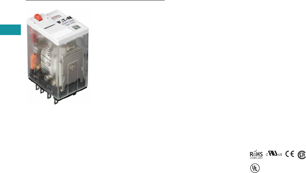
V7-T3-58 Volume 7—Logic Control, Operator Interface and Connectivity Solutions CA08100008E—February 2014 www.eaton.com
3
3
3
3
3
3
3
3
3
3
3
3
3
3
3
3
3
3
3
3
3
3
3
3
3
3
3
3
3
3
V7-T3-58 Volume 7—Logic Control, Operator Interface and Connectivity Solutions CA08100008E—February 2014 www.eaton.com
3
3
3
3
3
3
3
3
3
3
3
3
3
3
3
3
3
3
3
3
3
3
3
3
3
3
3
3
3
3
3.4
Control Relays and Timers
General Purpose Plug-In Relays
D2 Series Relay
Contents
Description Page
D1PR/D1PF Series . . . . . . . . . . . . . . . . . . . . . . . . . V7-T3-53
D2PR/D2PF Series
Catalog Number Selection . . . . . . . . . . . . . . . . V7-T3-59
Product Selection . . . . . . . . . . . . . . . . . . . . . . . V7-T3-59
Accessories. . . . . . . . . . . . . . . . . . . . . . . . . . . . V7-T3-61
Technical Data and Specifications . . . . . . . . . . . V7-T3-62
Wiring Diagrams . . . . . . . . . . . . . . . . . . . . . . . . V7-T3-63
Dimensions. . . . . . . . . . . . . . . . . . . . . . . . . . . . V7-T3-64
D3PR/D3PF Series . . . . . . . . . . . . . . . . . . . . . . . . . V7-T3-68
D4 Series . . . . . . . . . . . . . . . . . . . . . . . . . . . . . . . . V7-T3-78
D5PR/D5PF Series . . . . . . . . . . . . . . . . . . . . . . . . . V7-T3-82
D7PR/D7PF Series . . . . . . . . . . . . . . . . . . . . . . . . . V7-T3-91
D8 Series . . . . . . . . . . . . . . . . . . . . . . . . . . . . . . . . V7-T3-106
D9 Series . . . . . . . . . . . . . . . . . . . . . . . . . . . . . . . . V7-T3-112
Accessories . . . . . . . . . . . . . . . . . . . . . . . . . . . . . . V7-T3-116
D2PR/D2PF Series
Product Description
The D2 Series is a compact
line of relays with quick
response time and long life.
Available in DPDT, 4PDT and
DPDT latching configurations.
Features
D2PR
●Ultra-high sensitivity relay
with quick response
●High reliability, long life
●Panel, DIN rail and flange
mounting
●Small size
D2PF
●
Flag indicator shows relay
status in manual or powered
condition
●
Bipolar LED status lamp
allows for reverse polarity
applications
●
Shows coil ON or OFF
status
●
Ideal in low light
conditions
●
Color-coded pushbutton
identifies AC coils with red
or DC coils with blue
pushbuttons
●
Allows for manual
operation of relay without
the need for coil power
●
Ideal for field service
personnel to test control
circuits
●
Lock-down door, when
activated, holds pushbutton
and contacts in the operate
position
●
Excellent for analyzing
circuit problems
●
Finger-grip cover allows
operator to remove relays
from sockets more easily
than conventional relays
●
White plastic ID tag/write
label used for identification
of relays in multi-relay
circuits
Standards and Certifications
When used with
accompanying Eaton
screw terminal socket.
UL Listed
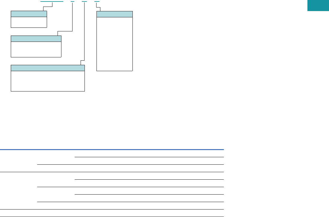
Volume 7—Logic Control, Operator Interface and Connectivity Solutions CA08100008E—February 2014 www.eaton.com V7-T3-59
3
3
3
3
3
3
3
3
3
3
3
3
3
3
3
3
3
3
3
3
3
3
3
3
3
3
3
3
3
3
Volume 7—Logic Control, Operator Interface and Connectivity Solutions CA08100008E—February 2014 www.eaton.com V7-T3-59
3
3
3
3
3
3
3
3
3
3
3
3
3
3
3
3
3
3
3
3
3
3
3
3
3
3
3
3
3
3
3.4
Control Relays and Timers
General Purpose Plug-In Relays
Catalog Number Selection
D2PF/D2PR 1
Product Selection
D2PF/D2PR Relay/Socket Quick Reference
Note
1For deciphering catalog numbers. Do not use for ordering as not all combinations are readily available.
Relay
Type Socket Clip
Module
Type
ID
Tag Jumper
D2PR2, D2PF2 D2PAL PWC-D24 B PWF-D2P D2PJ1
PQC-1782 — — —
D2PA6 PQC-1342 None — —
D2PR4, D2PF4 D2PAP PWC-D24 B PWF-D2P D2PJ1
PQC-1782 — — —
D2PA7 PWC-D24 B — —
PQC-1782 B — —
D2PA6 PQC-1342 None — —
D2PR5 D2PA4 PYC-A1 None — —
Family Type
D2PF
D2PR
Contact Configuration
2 = DPDT
4 = 4PDT
5 = DPDT latching
Standard Features
Blank = Plain cover (only with D2PR)
A = LED test button, flag indicator,
lock-down door, finger-grip cover,
ID tag (only with D2PF)
D 2 P F 2 A A
Coil Voltage
A = 120 Vac
A1 = 110 Vdc
B = 240 Vac
P = 6 Vac
P1 = 6 Vdc
R = 12 Vac
R1 = 12 Vdc
T = 24 Vac
T1 = 24 Vdc
W = 48 Vac
W1 = 48 Vdc

V7-T3-60 Volume 7—Logic Control, Operator Interface and Connectivity Solutions CA08100008E—February 2014 www.eaton.com
3
3
3
3
3
3
3
3
3
3
3
3
3
3
3
3
3
3
3
3
3
3
3
3
3
3
3
3
3
3
V7-T3-60 Volume 7—Logic Control, Operator Interface and Connectivity Solutions CA08100008E—February 2014 www.eaton.com
3
3
3
3
3
3
3
3
3
3
3
3
3
3
3
3
3
3
3
3
3
3
3
3
3
3
3
3
3
3
3.4
Control Relays and Timers
General Purpose Plug-In Relays
D2PF/D2PR Series
Coil
Voltage
Contact
Configuration
Coil Resistance
(Ohms)
Catalog
Number
Full Featured Style
6 Vac DPDT 9.6 D2PF2AP
6 Vdc DPDT 40 D2PF2AP1
12 Vac DPDT 46 D2PF2AR
12 Vdc DPDT 160 D2PF2AR1
24 Vac DPDT 180 D2PF2AT
24 Vdc DPDT 650 D2PF2AT1
48 Vdc DPDT 2600 D2PF2AW1
110/125 Vdc DPDT 11,000 D2PF2AA1
120 Vac DPDT 4430 D2PF2AA
220/240 Vac DPDT 15,720 D2PF2AB
12 Vac 4PDT 46 D2PF4AR
12 Vdc 4PDT 160 D2PF4AR1
24 Vac 4PDT 180 D2PF4AT
24 Vdc 4PDT 650 D2PF4AT1
48 Vdc 4PDT 2600 D2PF4AW1
110/125 Vdc 4PDT 11,000 D2PF4AA1
120 Vac 4PDT 4430 D2PF4AA
220/240 Vac 4PDT 15,720 D2PF4AB
Plain Cover Style
6 Vdc DPDT 40 D2PR2P1
12 Vdc DPDT 160 D2PR2R1
24 Vac DPDT 180 D2PR2T
24 Vdc DPDT 650 D2PR2T1
48 Vdc DPDT 2600 D2PR2W1
110/125 Vdc DPDT 11,000 D2PR2A1
120 Vac DPDT 4430 D2PR2A
220/240 Vac DPDT 15,720 D2PR2B
6 Vac 4PDT 9.6 D2PR4P
6 Vdc 4PDT 40 D2PR4P1
12 Vac 4PDT 46 D2PR4R
12 Vdc 4PDT 160 D2PR4R1
24 Vac 4PDT 180 D2PR4T
24 Vdc 4PDT 650 D2PR4T1
110/125 Vdc 4PDT 11,000 D2PR4A1
120 Vac 4PDT 4430 D2PR4A
220/240 Vac 4PDT 15,720 D2PR4B
Latching Style
24 Vac DPDT 180 D2PR5T
24 Vdc DPDT 650 D2PR5T1
110 Vac DPDT 11,000 D2PR5A
D2PF Series Relay

Volume 7—Logic Control, Operator Interface and Connectivity Solutions CA08100008E—February 2014 www.eaton.com V7-T3-61
3
3
3
3
3
3
3
3
3
3
3
3
3
3
3
3
3
3
3
3
3
3
3
3
3
3
3
3
3
3
Volume 7—Logic Control, Operator Interface and Connectivity Solutions CA08100008E—February 2014 www.eaton.com V7-T3-61
3
3
3
3
3
3
3
3
3
3
3
3
3
3
3
3
3
3
3
3
3
3
3
3
3
3
3
3
3
3
3.4
Control Relays and Timers
General Purpose Plug-In Relays
Accessories
D2PF/D2PR Sockets and Accessories
Note
1Protection category (finger safe), EN 60529: IP20.
Type
Module
Size
Nominal Voltage
(Max. for Sockets)
Nominal
Current Mounting Style Wire Size
Wire
Connection
Standard
Pack
Catalog
Number
Socket B 300 12 DIN rail/panel 14/16 (2) AWG, 2.5/1.5 (2) mm2Elevator 1 D2PAL 1
None 300 10 DIN rail/panel 12/14 (2) AWG, 4/2.5 (2) mm2Screw clamping 10 D2PA6
B 300 10 DIN rail/panel 14/16 (2) AWG, 2.5/1.5 (2) mm2Elevator 1 D2PAP 1
B 300 10 DIN rail/panel 12/14 (2) AWG, 4/2.5 (2) mm2Screw clamping 10 D2PA7 1
None 300 10 DIN rail/panel 12/14 (2) AWG, 4/2.5 (2) mm2Screw clamping 5 D2PA4
Flange mount adapter — — — Flange — — 25 PFC-D2D72
Plastic ejector clip — — — — — — 10 PWC-D24
Metal spring clip — — — — — — 25 PQC-1782
—— —— — — 25PQC-1342
Hold-down spring — — — — — — 100 PYC-A1
Protection diode B 6 to 250 Vdc — — — — 20 MOD-BD250
LED indicator B 24 Vac/Vdc — — — — 20 MOD-BLG24
B 120/240 Vac/Vdc — — — — 20 MOD-BLG240
MOV suppressor B 120 Vac/Vdc — — — — 20 MOD-BMV120
B 24 Vac/Vdc — — — — 20 MOD-BMV24
B240 Vac/Vdc —— — — 20MOD-BMV240
Coil bus jumpers — — — — — — 10 D2PJ1
Plastic DIN rail end stop — — — — — — 25 PFP-P

V7-T3-62 Volume 7—Logic Control, Operator Interface and Connectivity Solutions CA08100008E—February 2014 www.eaton.com
3
3
3
3
3
3
3
3
3
3
3
3
3
3
3
3
3
3
3
3
3
3
3
3
3
3
3
3
3
3
V7-T3-62 Volume 7—Logic Control, Operator Interface and Connectivity Solutions CA08100008E—February 2014 www.eaton.com
3
3
3
3
3
3
3
3
3
3
3
3
3
3
3
3
3
3
3
3
3
3
3
3
3
3
3
3
3
3
3.4
Control Relays and Timers
General Purpose Plug-In Relays
Technical Data and Specifications
D2PF/D2PR Relay Specifications
Description D2PR2/D2PR4 D2PR5 D2PF
Contact Characteristics
Contact rating 10A 5A 10A
Terminal style Plug-in Plug-in Plug-in
Contact materials Silver alloy Silver (gold flashed) Silver alloy
Maximum switching voltage 300V 250 Vac/125 Vdc 300V
Switching current at voltage—resistive 10A at 120 Vac
50/60 Hz
3A at 250 Vac 10A at 277 Vac
50/60 Hz
8A at 277 Vac
50/60 Hz
— 8A at 120 Vac
50/60 Hz
8A at 28 Vdc 5A at 30 Vdc 8A at 28 Vdc
Switching current at voltage 1/3 hp at 120 Vac
1 hp at 277 Vac
1/8 hp at 250 Vac 1/3 hp at 120 Vac
1 hp at 277 Vac
Pilot duty B300 — B300
Minimum switching requirement 100 mA at 5 Vdc
(0.5W)
100 mA, 1 Vdc 100 mA at 5 Vdc
(0.5W)
Coil Characteristics
Operating range
% of nominal (AC) 85 to 110% 80 to 110% 85 to 110%
% of nominal (DC) 80 to 110% 80 to 110% 80 to 110%
Average consumption 1.2 VA — 1.2 VA
0.9W — 0.9W
Dropout voltage threshold 15% (AC) 30% (AC) 15% (AC)
10% (DC) 10% (DC) 10% (DC)
Performance
Electrical life (UL 508) operations at rated current 200,000 200,000 200,000
Mechanical life operations unpowered 10,000,000 100,000,000 10,000,000
Response time 20 ms — 20 ms
Dielectric strength
Between coil and contact Vac (rms) 1500 rms — 1500 rms
Between poles Vac (rms) 1500 rms — 1500 rms
Environment
Ambient air temperature around the device
Operation –40° to 131°F (–40° to 55°C) — –40° to 131°F (–40° to 55°C)
Storage –40° to 185°F (–40° to 85°C) — –40° to 185°F (–40° to 85°C)
Vibration resistance—operational 3 g-n at 10–55 Hz — 3 g-n at 10–55 Hz
Shock resistance 10 g-n — 10 g-n
Degree of protection IP40 — IP40
Features
Cover options Plain cover Plain cover Full featured
Features Mechanical flag indicator Latching Locking pushbutton/
Bipolar LED/
Removable ID tag/
Mechanical flag indicator
Product certifications RoHS/UL/CE/CSA UL/CE/CSA RoHS/UL/CE/CSA
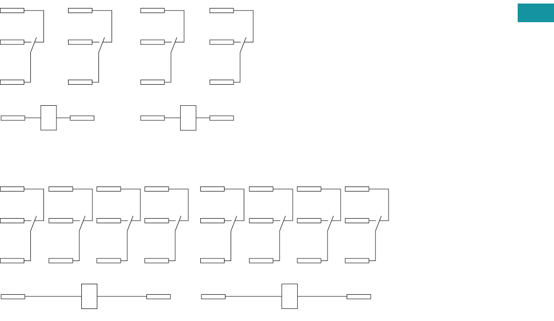
Volume 7—Logic Control, Operator Interface and Connectivity Solutions CA08100008E—February 2014 www.eaton.com V7-T3-63
3
3
3
3
3
3
3
3
3
3
3
3
3
3
3
3
3
3
3
3
3
3
3
3
3
3
3
3
3
3
Volume 7—Logic Control, Operator Interface and Connectivity Solutions CA08100008E—February 2014 www.eaton.com V7-T3-63
3
3
3
3
3
3
3
3
3
3
3
3
3
3
3
3
3
3
3
3
3
3
3
3
3
3
3
3
3
3
3.4
Control Relays and Timers
General Purpose Plug-In Relays
Wiring Diagrams
D2PF2/D2PR2
D2PF4/D2PR4
NEMA
1
5
9
4
8
12
13 14
IEC
42
44
41
12
14
11
A1 A2
IEC
42
44
41
32
34
31
22
24
21
12
14
11
A1 A2
NEMA
4
8
12
3
7
11
2
6
10
1
5
9
13 14
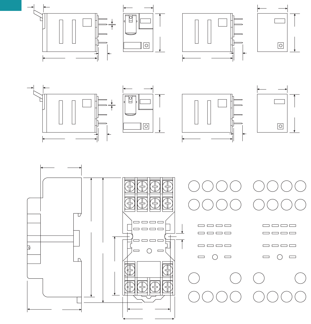
V7-T3-64 Volume 7—Logic Control, Operator Interface and Connectivity Solutions CA08100008E—February 2014 www.eaton.com
3
3
3
3
3
3
3
3
3
3
3
3
3
3
3
3
3
3
3
3
3
3
3
3
3
3
3
3
3
3
V7-T3-64 Volume 7—Logic Control, Operator Interface and Connectivity Solutions CA08100008E—February 2014 www.eaton.com
3
3
3
3
3
3
3
3
3
3
3
3
3
3
3
3
3
3
3
3
3
3
3
3
3
3
3
3
3
3
3.4
Control Relays and Timers
General Purpose Plug-In Relays
Dimensions
Approximate Dimensions in Inches (mm)
D2PF2/D2PR2
D2PF4/D2PR4
D2PA6
1.10
(27.9)
1.54
(39.1)
0.27
(7.0) 0.02
(0.5)
0.24
(6.0)
0.83
(21.0)
1.40
(35.5)
1.10
(27.9)
0.83
(21.0)
0.24
(6.0)
1.10
(27.9)
1.54
(39.1)
0.27
(7.0) 0.02
(0.5)
0.24
(6.0)
0.83
(21.0)
1.40
(35.5)
1.10
(27.9)
0.83
(21.0)
0.24
(6.0)
2.71
(69.0)
2.51
(64.0)
1.0 0
(25.4)
9
5
14
8
3
7
6
2
1
1
4
1
2
1
3
1
0
1
0.89
(22.7)
1.20
(30.7)
0.17
(4.3)
Dia.
Typ.
1.25
(32.0)
41 31 21 11
A2 A1
42 32 22 12
44 34 24 14
N.C.
N.O.
COM
INPUT
8765
4321
14 13
9
10
11
12
0.71
(18.0)
INPUT
8
4
75
6
31
2
10
11
12
14 13
9
N.C.
N.O.
COM
INPUT
8765
4321
14 13
9
10
11
12
NEMAIEC
INPUT
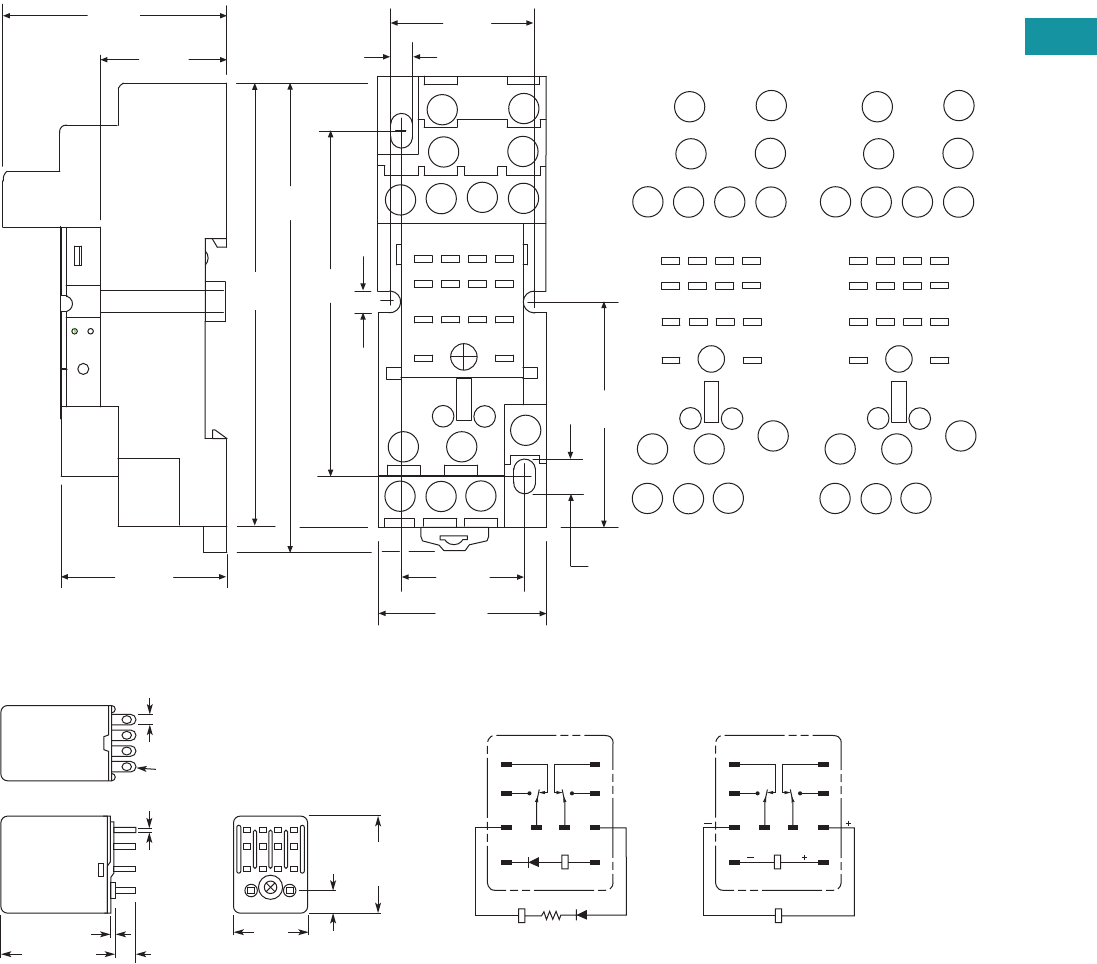
Volume 7—Logic Control, Operator Interface and Connectivity Solutions CA08100008E—February 2014 www.eaton.com V7-T3-65
3
3
3
3
3
3
3
3
3
3
3
3
3
3
3
3
3
3
3
3
3
3
3
3
3
3
3
3
3
3
Volume 7—Logic Control, Operator Interface and Connectivity Solutions CA08100008E—February 2014 www.eaton.com V7-T3-65
3
3
3
3
3
3
3
3
3
3
3
3
3
3
3
3
3
3
3
3
3
3
3
3
3
3
3
3
3
3
3.4
Control Relays and Timers
General Purpose Plug-In Relays
Approximate Dimensions in Inches (mm)
D2PA7
D2PR5
A2
41
A1
31 21
11
42
24
34
14
44
12
22
32
INPUT
COM
N.O.
N.C.
4321
5
86
7
12 11 10
14 13
9
0.14
(3.8)
1.0 0
(25.4)
1.55
(39.5)
0.25
(6.4)
0.82
(21.0)
0.14
(3.80)
3.30
(84.0)
3.11
(79.0)
1.57
(40.0)
1.18
(30.0)
2.40
(61.0)
1.18
(30.0)
44 14
11
12 10
INPUT
INPUT
31
14
A2
41
13 9
A1
21
11
3
4 2 1
8
32
42
5
22 12
34
7
24
6
0.74
(19.0)
MODULE
INPUT
IEC
INPUT
14
12
9
13
11 10
41
2
3
6
7
5
8
INPUT
COM
N.O.
N.C.
4321
5
86
7
12 11 10
14 13
9
MODULE
INPUT
NEMA
INPUT
0.10
(2.5)
0.02
(0.5)
0.24
(6.1)
0.25
(6.4)
0.85
(21.6)
Max.
1.10
(27.9)
Max.
14 – 0.05 (1.3) Dia. x 0.09 (2.3)
Elliptic Holes
0.02 (0.5)
1.42 (36.1)
Max.
1
5
9
13
4
8
121110
14
RESET R
1
5
9
13
4
8
121110
14
RESET
SET
Terminal Arrangement/Internal Connections (Bottom View)
AC DC
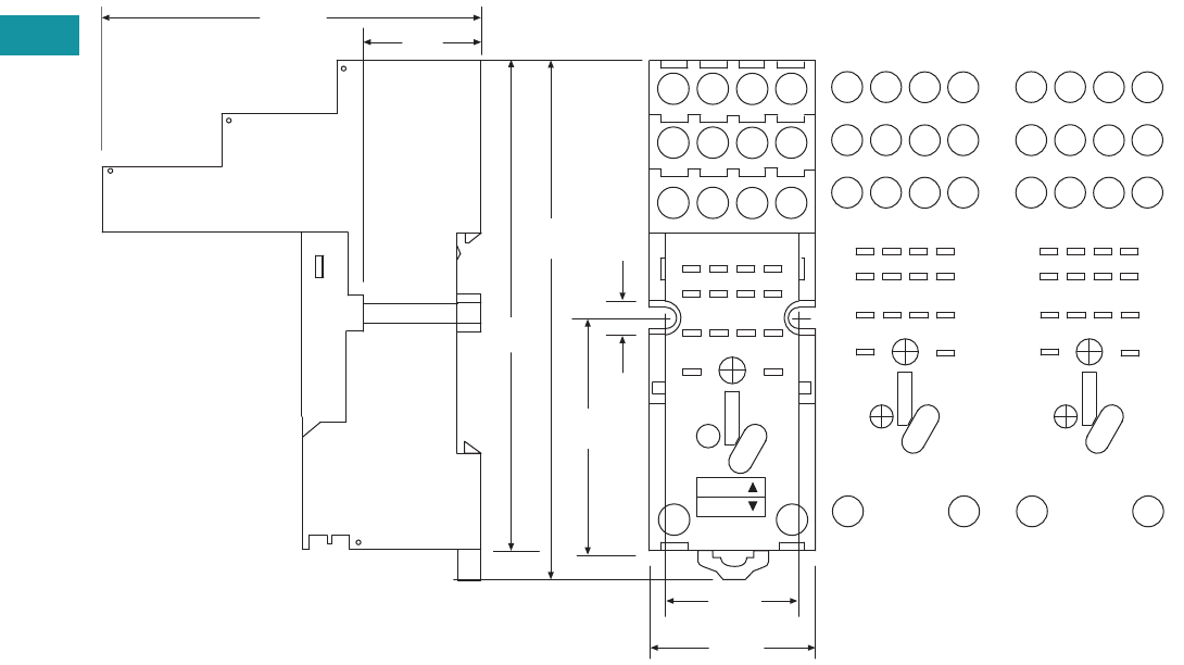
V7-T3-66 Volume 7—Logic Control, Operator Interface and Connectivity Solutions CA08100008E—February 2014 www.eaton.com
3
3
3
3
3
3
3
3
3
3
3
3
3
3
3
3
3
3
3
3
3
3
3
3
3
3
3
3
3
3
V7-T3-66 Volume 7—Logic Control, Operator Interface and Connectivity Solutions CA08100008E—February 2014 www.eaton.com
3
3
3
3
3
3
3
3
3
3
3
3
3
3
3
3
3
3
3
3
3
3
3
3
3
3
3
3
3
3
3.4
Control Relays and Timers
General Purpose Plug-In Relays
Approximate Dimensions in Inches (mm)
D2PAP
A2 INPUT A1
44
41
42 32 22 12
14
34 24
21
31 11
1
2
3
4
5
6
7
8
9
10
11
12
14 13
0.90
(22.0)
1.06
(26.9)
2.40
(61.0) 0.74
(19.0)
3.11
(79.0)
3.34
(85.0)
1.49
(38.0)
0.20
(5.6)
MODULE
INPUT
COM
INPUT
N.O.
N.C.
1
A1
12
5
9
11
14
INPUT
A2
14
3
4
7
8
11
12
32
42
41 31
34
44
13
2
6
10
22
21
24
NEMA:
IEC:
IEC
14 13
INPUT
4
8
12
2
31
6
75
10
11 9
1
2
3
4
5
6
7
8
9
10
11
12
14 13
MODULE
INPUT
COM
INPUT
N.O.
N.C.
NEMA
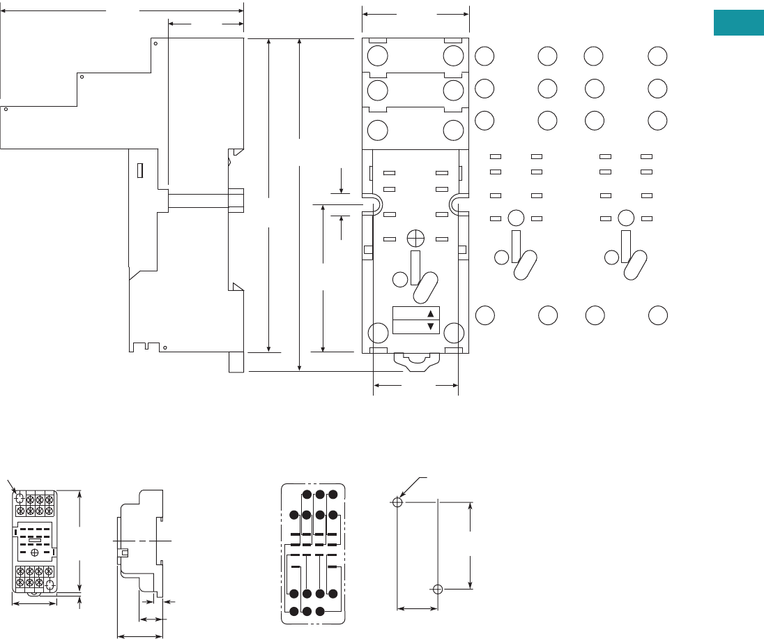
Volume 7—Logic Control, Operator Interface and Connectivity Solutions CA08100008E—February 2014 www.eaton.com V7-T3-67
3
3
3
3
3
3
3
3
3
3
3
3
3
3
3
3
3
3
3
3
3
3
3
3
3
3
3
3
3
3
Volume 7—Logic Control, Operator Interface and Connectivity Solutions CA08100008E—February 2014 www.eaton.com V7-T3-67
3
3
3
3
3
3
3
3
3
3
3
3
3
3
3
3
3
3
3
3
3
3
3
3
3
3
3
3
3
3
3.4
Control Relays and Timers
General Purpose Plug-In Relays
Approximate Dimensions in Inches (mm)
D2PAL
D2PA4 Socket for D2PR5 DPDT Latching Relays Only
A1
12
11
14
INPUT
A2
42
41
44
N.O.
INPUT
COM
N.C.
41
5
8
9
12
14 13
1.49
(38.0)
0.20
(5.6)
0.92
(23.5)
1.06
(27.0)
3.11
(79.0)
3.34
(85.0)
2.40
(61.0) 0.74
(19.0)
A1
INPUT
A2
14 13
12
5
9
11
14
41
8
12
42
41
44
NEMA:
IEC:
MODULE
INPUT
IEC
1
5
9
INPUT
14
4
8
12
13
N.O.
INPUT
COM
N.C.
41
5
8
9
12
14 13
MODULE
INPUT
NEMA
Two 0.17 (4.3) x 0.20 (5.1)
Mounting Holes
2.83
(71.9)
Max.
0.16
(4.1)
1.18
(30.0)
0.65 (16.5)
(22.09 0.20)
0.0080.870 +
–
+
–
(58.92 0.10)
0.0042.320+
–
+
–
0.24 (6.1)
8 7 6 5
12 11 10
414 13
9
321
Mounting Holes
Two 0.18 (4.6) Dia. or M4
(Two 0.16 (4.1) Dia. or M3)
Terminal Arrangement
(Top View)
1.16
(29.5)
Max.
Max.
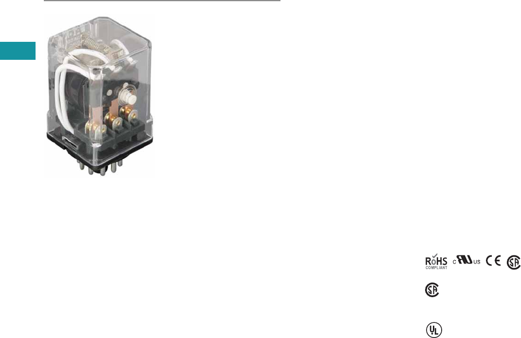
V7-T3-68 Volume 7—Logic Control, Operator Interface and Connectivity Solutions CA08100008E—February 2014 www.eaton.com
3
3
3
3
3
3
3
3
3
3
3
3
3
3
3
3
3
3
3
3
3
3
3
3
3
3
3
3
3
3
V7-T3-68 Volume 7—Logic Control, Operator Interface and Connectivity Solutions CA08100008E—February 2014 www.eaton.com
3
3
3
3
3
3
3
3
3
3
3
3
3
3
3
3
3
3
3
3
3
3
3
3
3
3
3
3
3
3
3.4
Control Relays and Timers
General Purpose Plug-In Relays
D3 Series Relay
Contents
Description Page
D1PR/D1PF Series . . . . . . . . . . . . . . . . . . . . . . . . . V7-T3-53
D2PR/D2PF Series . . . . . . . . . . . . . . . . . . . . . . . . . V7-T3-58
D3PR/D3PF Series
Catalog Number Selection . . . . . . . . . . . . . . . . V7-T3-69
Product Selection . . . . . . . . . . . . . . . . . . . . . . . V7-T3-69
Accessories. . . . . . . . . . . . . . . . . . . . . . . . . . . . V7-T3-71
Technical Data and Specifications . . . . . . . . . . . V7-T3-72
Dimensions. . . . . . . . . . . . . . . . . . . . . . . . . . . . V7-T3-73
D4 Series . . . . . . . . . . . . . . . . . . . . . . . . . . . . . . . . V7-T3-78
D5PR/D5PF Series . . . . . . . . . . . . . . . . . . . . . . . . . V7-T3-82
D7PR/D7PF Series . . . . . . . . . . . . . . . . . . . . . . . . . V7-T3-91
D8 Series . . . . . . . . . . . . . . . . . . . . . . . . . . . . . . . . V7-T3-106
D9 Series . . . . . . . . . . . . . . . . . . . . . . . . . . . . . . . . V7-T3-112
Accessories . . . . . . . . . . . . . . . . . . . . . . . . . . . . . . V7-T3-116
D3PR/D3PF Series
Product Description
The D3 Series of relays
provides excellent
functionality in a popular
octal base design. Rigid
pins and guide allow for
quick and easy installation
with little risk of damage.
Features
D3PR
●Compact relay capable of
breaking relatively large
load currents
●Panel and DIN rail
mounting
●8- or 11-pin octal plug-in
D3PF
●The contact operation can
be easily checked by Push-
to-Test button
●Flag indicator shows relay
status in manual or
powered condition
●LED status lamp shows
coil ON or OFF status—
ideal for use in low light
applications
●Push-to-Test button allows
for manual operation of
relay without the need for
coil power
●Lock-down door holds
pushbutton and contacts in
the operate position when
activated
●Finger-grip cover allows
operator to remove relays
from sockets easily
●ID tag/write label to
identify relays in multiple-
relay circuits
●Bipolar LED allows for
reverse polarity
applications
Standards and Certifications
When used with
accompanying Eaton
screw terminal socket
(for D3PF only)
(CSA approval
not applicable to
D3PR5 Relays)
UL Listed
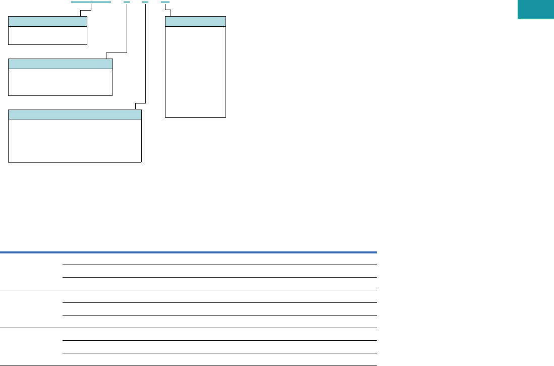
Volume 7—Logic Control, Operator Interface and Connectivity Solutions CA08100008E—February 2014 www.eaton.com V7-T3-69
3
3
3
3
3
3
3
3
3
3
3
3
3
3
3
3
3
3
3
3
3
3
3
3
3
3
3
3
3
3
Volume 7—Logic Control, Operator Interface and Connectivity Solutions CA08100008E—February 2014 www.eaton.com V7-T3-69
3
3
3
3
3
3
3
3
3
3
3
3
3
3
3
3
3
3
3
3
3
3
3
3
3
3
3
3
3
3
3.4
Control Relays and Timers
General Purpose Plug-In Relays
Catalog Number Selection
D3PR/D3PF Series 1
Product Selection
D3 Relay/Socket Quick Reference
Notes
1For deciphering catalog numbers. Do not use for ordering as not all combinations are readily available.
2D3PR only.
Relay
Type Socket Clip
Module
Type
ID
Tag Jumper
D3PR2, D3PF2 D3PA6 PQC-1332 A — D3PJ1
D3PAL8 PQC-1351 A PWF-D3D5 —
D3PA2 PQC-1351 None — —
D3PR3, D3PF3 D3PA7 PQC-1332 A — D3PJ1
D3PAL11 PQC-1351 A PWF-D3D5 —
D3PA3 PQC-1351 None — —
D3PR5 D3PA7 PQC-1351 A — D3PJ1
D3PAL11 PQC-1351 A PWF-D3D5 —
D3PA3 PQC-1351 None — —
D 3 P R 2 1 A
Family Type
D3PR = Standard relay
D3PF = Full featured relay
Coil Voltage
A = 120 Vac
A1 = 110 Vdc
B = 240 Vac
P = 6 Vac
P1 = 6 Vdc
R = 12 Vac
R1 = 12 Vdc
T = 24 Vac
T1 = 24 Vdc
W = 48 Vac
W1 = 48 Vdc
Contact Configuration
2 = DPDT (8-pin)
3 = 3PDT (11-pin)
5
= DPDT latching (11-pin)
2
Options
Blank = Plain cover relay (D3PR only)
A = LED test button, flag indicator,
lock-down door, finger-grip cover,
ID tag (D3PF only)
1 =
Indicating light (D3PR only)

V7-T3-70 Volume 7—Logic Control, Operator Interface and Connectivity Solutions CA08100008E—February 2014 www.eaton.com
3
3
3
3
3
3
3
3
3
3
3
3
3
3
3
3
3
3
3
3
3
3
3
3
3
3
3
3
3
3
V7-T3-70 Volume 7—Logic Control, Operator Interface and Connectivity Solutions CA08100008E—February 2014 www.eaton.com
3
3
3
3
3
3
3
3
3
3
3
3
3
3
3
3
3
3
3
3
3
3
3
3
3
3
3
3
3
3
3.4
Control Relays and Timers
General Purpose Plug-In Relays
D3PR/D3PF Series
Coil
Voltage
Contact
Configuration
Coil Resistance
(Ohms)
Catalog
Number
Full Featured Style
120 Vac DPDT 1700 D3PF2AA
240 Vac DPDT 7200 D3PF2AB
12 Vdc DPDT 120 D3PF2AR1
24 Vdc DPDT 470 D3PF2AT1
48 Vdc DPDT 1800 D3PF2AW1
120 Vac 3PDT 1700 D3PF3AA
220/240 Vac 3PDT 7200 D3PF3AB
6 Vdc 3PDT 32 D3PF3AP1
24 Vac 3PDT 72 D3PF3AT
24 Vdc 3PDT 470 D3PF3AT1
48 Vdc 3PDT 1800 D3PF3AW1
Latching Style
120 Vac DPDT 10,000 D3PR5A
110/125 Vdc DPDT 9000 D3PR5A1
240 Vac DPDT 36,000 D3PR5B
12 Vdc DPDT 90 D3PR5R1
24 Vac DPDT 470 D3PR5T
24 Vdc DPDT 350 D3PR5T1
48 Vdc DPDT 1400 D3PR5W1
Plain Cover with LED Indicator
120 Vac DPDT 1700 D3PR21A
24 Vac DPDT 72 D3PR21T
24 Vdc DPDT 470 D3PR21T1
220/240 Vac 3PDT 7200 D3PR31B
24 Vac 3PDT 72 D3PR31T
24 Vdc 3PDT 470 D3PR31T1
Plain Cover Style
120 Vac DPDT 1700 D3PR2A
110/125 Vdc DPDT 10,000 D3PR2A1
220/240 Vac DPDT 7200 D3PR2B
6 Vac DPDT 4.2 D3PR2P
6 Vdc DPDT 32 D3PR2P1
12 Vac DPDT 18 D3PR2R
12 Vdc DPDT 120 D3PR2R1
24 Vac DPDT 72 D3PR2T
24 Vdc DPDT 470 D3PR2T1
48 Vac DPDT 290 D3PR2W
48 Vdc DPDT 1800 D3PR2W1
120 Vac 3PDT 1700 D3PR3A
110/125 Vdc 3PDT 10,000 D3PR3A1
220/240 Vac 3PDT 7200 D3PR3B
12 Vac 3PDT 18 D3PR3R
12 Vdc 3PDT 120 D3PR3R1
24 Vac 3PDT 72 D3PR3T
24 Vdc 3PDT 470 D3PR3T1
48 Vdc 3PDT 1800 D3PR3W1
D3 Series Relay

Volume 7—Logic Control, Operator Interface and Connectivity Solutions CA08100008E—February 2014 www.eaton.com V7-T3-71
3
3
3
3
3
3
3
3
3
3
3
3
3
3
3
3
3
3
3
3
3
3
3
3
3
3
3
3
3
3
Volume 7—Logic Control, Operator Interface and Connectivity Solutions CA08100008E—February 2014 www.eaton.com V7-T3-71
3
3
3
3
3
3
3
3
3
3
3
3
3
3
3
3
3
3
3
3
3
3
3
3
3
3
3
3
3
3
3.4
Control Relays and Timers
General Purpose Plug-In Relays
Accessories
D3PR/D3PF Series Sockets and Accessories
Note
1Protection category (finger safe), EN 60529: IP20.
Type
Module
Size
Nominal Voltage
(Max. for Sockets)
Nominal
Current Mounting Style Wire Size
Wire
Connection
Standard
Pack
Catalog
Number
Socket A 300 16 DIN rail/panel 12/14 (2) AWG, 4/2.5 (2) mm2Screw clamping 1 D3PA6 1
A 300 12 DIN rail/panel 12/14 (2) AWG, 4/2.5 (2) mm2Elevator 10 D3PAL8 1
None 300/600 15/10 DIN rail/panel 12/14 (2) AWG, 4/2.5 (2) mm2Screw clamping 10 D3PA2
A 600 5 DIN rail/panel 12/14 (2) AWG, 4/2.5 (2) mm2Screw clamping 1 D3PA7 1
A 300 12 DIN rail/panel 12/14 (2) AWG, 4/2.5 (2) mm2Elevator 10 D3PAL11 1
None 300/600 15/5 DIN rail/panel 12/14 (2) AWG, 4/2.5 (2) mm2Screw clamping 10 D3PA3
Metal spring clip — — — — — — 25 PQC-1332
—— —— — — 10PQC-1351
Protection diode A 6 to 250 Vdc — — — — 20 MOD-AD250
LED indicator A 24 Vac/Vdc — — — — 20 MOD-ALG24
A 120/240 Vac/Vdc — — — — 20 MOD-ALG240
MOV suppressor A 120 Vac/Vdc — — — — 20 MOD-AMV120
A 24 Vac/Vdc — — — — 20 MOD-AMV24
A240 Vac/Vdc —— — — 20MOD-AMV240
R/C suppressor A 6 to 24 Vac/Vdc — — — — 20 MOD-RC24
A 110 to 240 Vac/Vdc — — — — 20 MOD-RC240
Write-on plastic labels — — — — — — 10 PWF-D3D5
Coil bus jumpers — — — — — — 10 D3PJ1
Plastic DIN rail end stop — — — — — — 25 PFP-P

V7-T3-72 Volume 7—Logic Control, Operator Interface and Connectivity Solutions CA08100008E—February 2014 www.eaton.com
3
3
3
3
3
3
3
3
3
3
3
3
3
3
3
3
3
3
3
3
3
3
3
3
3
3
3
3
3
3
V7-T3-72 Volume 7—Logic Control, Operator Interface and Connectivity Solutions CA08100008E—February 2014 www.eaton.com
3
3
3
3
3
3
3
3
3
3
3
3
3
3
3
3
3
3
3
3
3
3
3
3
3
3
3
3
3
3
3.4
Control Relays and Timers
General Purpose Plug-In Relays
Technical Data and Specifications
D3PR/D3PF Series Relay Specifications
Description D3PR D3PF
D3PR5
(Latching)
Contact Characteristics
Contact rating 16A 16A 16A
Terminal style Octal Octal 11-pin octal
Contact materials Silver alloy Silver alloy Silver alloy
Maximum switching voltage 300V 300V 300V
Switching current at voltage—resistive 16A at 277 Vac
50/60 Hz
16A at 277 Vac
50/60 Hz
16A at 277 Vac
50/60 Hz
16A at 120 Vac
50/60 Hz
16A at 120 Vac
50/60 Hz
—
16A at 28 Vdc 16A at 28 Vdc 16A at 28 Vdc
Switching current at voltage 1/2 hp at 240 Vac 1/2 hp at 240 Vac 1/2 hp at 240 Vac
1/3 hp at 120 Vac 1/3 hp at 120 Vac 1/3 hp at 120 Vac
Pilot duty B300 B300 B300
Minimum switching requirement 100 mA at 5 Vdc
(0.5W)
100 mA at 5 Vdc
(0.5W)
100 mA at 5 Vdc
(0.5W)
Coil Characteristics
Operating range
% of nominal (AC) 85 to 110% 85 to 110% 85 to 110%
% of nominal (DC) 80 to 110% 80 to 110% 80 to 110%
Average consumption 3 VA 3 VA 2 VA
1.4W 1.4W 1.64W
Dropout voltage threshold 15% (AC) 15% (AC) 15% (AC)
10% (DC) 10% (DC) 10% (DC)
Performance
Electrical life (UL 508) operations at rated current 100,000 operations 100,000 operations 100,000 operations
Mechanical life operations unpowered 5,000,000 operations 5,000,000 operations 10,000,000 operations
Response time 20 ms 20 ms 30 ms
Dielectric strength
Between coil and contact Vac (rms) 1500V (rms) 1500V (rms) 2500V (rms)
Between poles Vac (rms) 1500V (rms) 1500V (rms) 1500V (rms)
Environment
Ambient air temperature around the device
Storage –40° to 185°F (–40° to 85°C) –40° to 185°F (–40° to 85°C) –40° to 185°F (–40° to 85°C)
Operation –40° to 131°F (–40° to 55°C) –40° to 131°F (–40° to 55°C) –40° to 131°F (–40° to 55°C)
Vibration resistance—operational 3 g-n at 10–55 Hz 3 g-n at 10–55 Hz 3 g-n at 10–55 Hz
Shock resistance 10 g-n 10 g-n 10 g-n
Degree of protection IP40 IP40 IP40
Features
Cover options Plain cover Full Featured Latching
Features Mechanical flag indicator Bipolar LED/
Locking pushbutton/
Removable ID tag/
Mechanical flag indicator
—
Product certifications RoHS/UL/CE/CSA RoHS/UL/CE/CSA RoHS/UL/UR
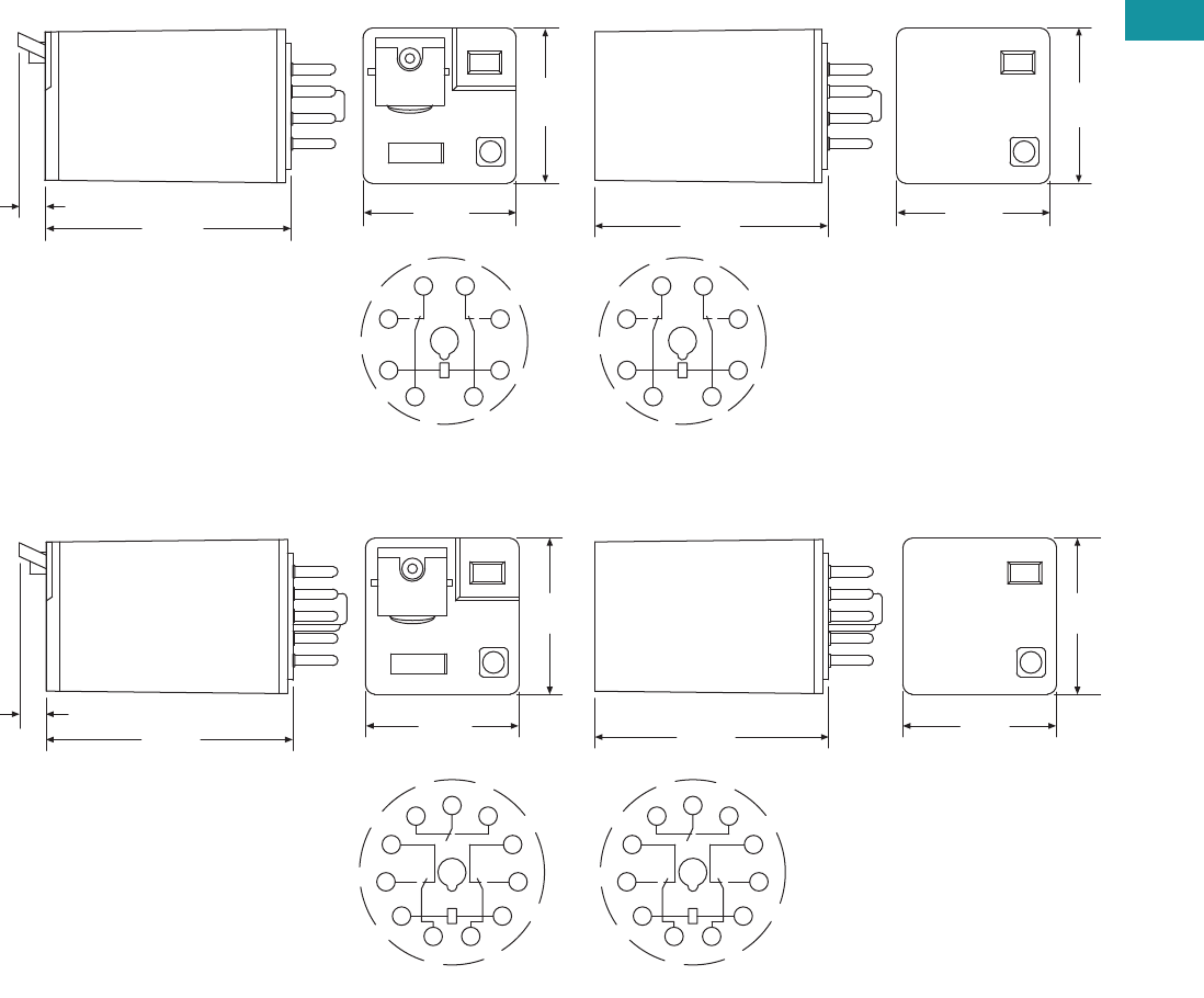
Volume 7—Logic Control, Operator Interface and Connectivity Solutions CA08100008E—February 2014 www.eaton.com V7-T3-73
3
3
3
3
3
3
3
3
3
3
3
3
3
3
3
3
3
3
3
3
3
3
3
3
3
3
3
3
3
3
Volume 7—Logic Control, Operator Interface and Connectivity Solutions CA08100008E—February 2014 www.eaton.com V7-T3-73
3
3
3
3
3
3
3
3
3
3
3
3
3
3
3
3
3
3
3
3
3
3
3
3
3
3
3
3
3
3
3.4
Control Relays and Timers
General Purpose Plug-In Relays
Dimensions
Approximate Dimensions in Inches (mm)
D3PR2/D3PF2
D3PR3/D3PF3
2.10
(50.3)
2.20
(55.2)
0.24
(6.1) 1.37
(34.8)
1.39
(35.3)
14
11
A1
12 22
24
A2
31
1.39
(35.3)
1.37
(34.8)
IEC
1
2
3
45
6
7
8
NEMA
2.10
(50.3)
2.20
(55.2)
0.24
(6.1) 1.37
(34.8)
1.39
(35.3)
1
2
3
4
567
8
9
10
11
1.39
(35.3)
1.37
(34.8)
NEMA
11
A1
14
12
22 21 24
32
34
A2
31
IEC
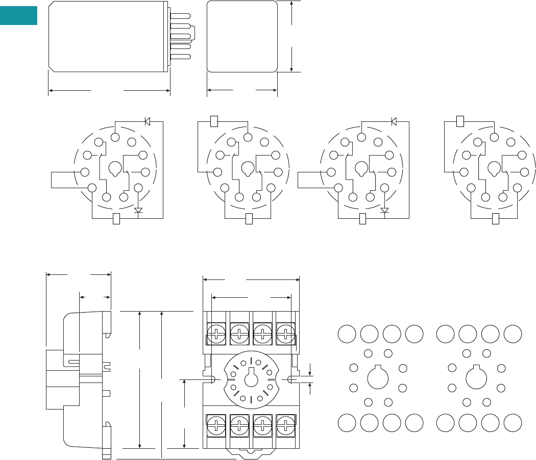
V7-T3-74 Volume 7—Logic Control, Operator Interface and Connectivity Solutions CA08100008E—February 2014 www.eaton.com
3
3
3
3
3
3
3
3
3
3
3
3
3
3
3
3
3
3
3
3
3
3
3
3
3
3
3
3
3
3
V7-T3-74 Volume 7—Logic Control, Operator Interface and Connectivity Solutions CA08100008E—February 2014 www.eaton.com
3
3
3
3
3
3
3
3
3
3
3
3
3
3
3
3
3
3
3
3
3
3
3
3
3
3
3
3
3
3
3.4
Control Relays and Timers
General Purpose Plug-In Relays
Approximate Dimensions in Inches (mm)
D3PR5—Octal Base Latching Relay
D3PA2
)CD( lioC lauD)CA( lioC elgniS
2.40
(61.0)
11
A1
14
12
22 21 24
32
34
A2
31
1.39
(35.3)
1.37
(34.8)
COMMON
RESET
SET
11
A1
14
12
22 21 24
32
34
A2
31
SET
RESET
COIL
COIL
2
1
IEC
)CD( lioC lauD)CA( lioC elgniS
1
2
3
4
567
8
9
10
11
COMMON
RESET
SET
1
2
3
4
567
8
9
10
11
SET
RESET
COIL
COIL
2
1
NEMA
3546
8 21
0.16
(4.2)
7
1.29
(33.0)
1.60
(40.0)
2.12
(54.0)
2.02
(51.0)
0.97
(24.6)
14 12 22 24
A1 11 21 A2
3
4
2
1
6
5
8
7
INPUT
1.01
(25.6)
INPUT
0.59
(15.0)
IEC
34
21
6
87
3
4
2
1
6
5
8
7
INPUT INPUT
NEMA
5
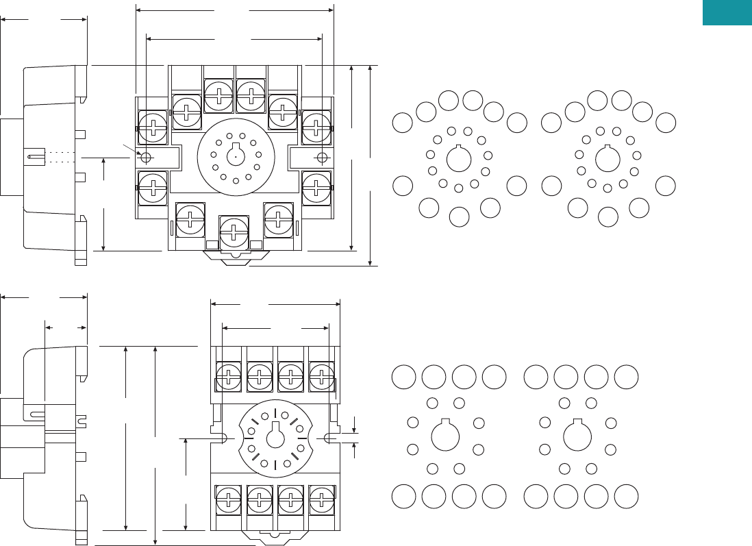
Volume 7—Logic Control, Operator Interface and Connectivity Solutions CA08100008E—February 2014 www.eaton.com V7-T3-75
3
3
3
3
3
3
3
3
3
3
3
3
3
3
3
3
3
3
3
3
3
3
3
3
3
3
3
3
3
3
Volume 7—Logic Control, Operator Interface and Connectivity Solutions CA08100008E—February 2014 www.eaton.com V7-T3-75
3
3
3
3
3
3
3
3
3
3
3
3
3
3
3
3
3
3
3
3
3
3
3
3
3
3
3
3
3
3
3.4
Control Relays and Timers
General Purpose Plug-In Relays
Approximate Dimensions in Inches (mm)
D3PA3
3
4
5
6
7
11
2
1
10
8
9
2.06
(52.0)
2.32
(59.0)
2.16
(54.8)
2.05
(52.0)
0.97
(24.6)
1.60 Dia.
(40.0)
1.02
(25.0)
5
14
A1 A2
11 31
34
12
22 24
21
32
11
1
39
10
2
48
67
INPUT INPUT
IEC
5
4
57
6
3
210
111
8
9
11
1
39
10
2
48
67
INPUT INPUT
NEMA
3 54 6
8 21
0.16
(4.2)
7
1.29
(33.0)
1.60
(40.0)
2.12
(54.0)
2.02
(51.0)
0.97
(24.6)
14 12 22 24
A1 11 21 A2
3
4
2
1
6
5
8
7
INPUT
1.01
(25.6)
INPUT
0.59
(15.0)
IEC
34
21
65
87
3
4
2
1
6
5
8
7
INPUT INPUT
NEMA
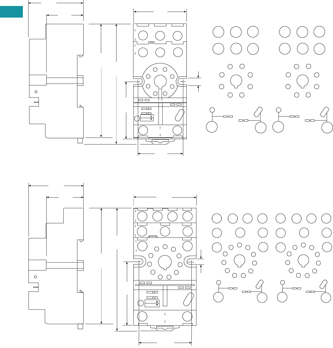
V7-T3-76 Volume 7—Logic Control, Operator Interface and Connectivity Solutions CA08100008E—February 2014 www.eaton.com
3
3
3
3
3
3
3
3
3
3
3
3
3
3
3
3
3
3
3
3
3
3
3
3
3
3
3
3
3
3
V7-T3-76 Volume 7—Logic Control, Operator Interface and Connectivity Solutions CA08100008E—February 2014 www.eaton.com
3
3
3
3
3
3
3
3
3
3
3
3
3
3
3
3
3
3
3
3
3
3
3
3
3
3
3
3
3
3
3.4
Control Relays and Timers
General Purpose Plug-In Relays
Approximate Dimensions in Inches (mm)
D3PA6
D3PA7
1.42
(36.0)
0.15
(3.8)
1.10
(27.9)
11
41
12
14
3
A2
7
5
22
21
24
68
A1
2
2.86
(72.0)
1.45
(37.0)
INPUT
INPUT
3.00
(76.0)
1.58
(40.0)
1.20
(30.0)
Coil Jumper Buss
A1
A2
54
7
81
2
63
21 14
24
11 12
22
MODULE
INPUT
INPUT
NEMA:
IEC:
IEC
2
7Coil Jumper Buss
54
7
81
2
63
63
8
5 1 4
MODULE
INPUT
INPUT
NEMA
1.50
(38.0)
0.15
(3.8)
5
3.01
(76.0)
1.45
(37.0)
3.18
(81.0)
1.58
(40.0)
1.35
(34.2)
34 14
31 21
32 22
24
11
12
11
1
3
9
10
2
4
8
6
7
A1
A2
Coil Jumper Buss
MODULE
INPUT
INPUT
11
4
1
12
14
3
A2
10
5
22
21
24
6
7
A1
2
INPUT
INPUT
34
9
31
11
32
8
1.10
(27.9)
IEC
NEMA:
IEC:
5
93
11
6
5
7
8
1
4
11
1
3
9
10
2
4
8
6
7
10 Coil Jumper Buss 2
MODULE
INPUT
INPUT
NEMA
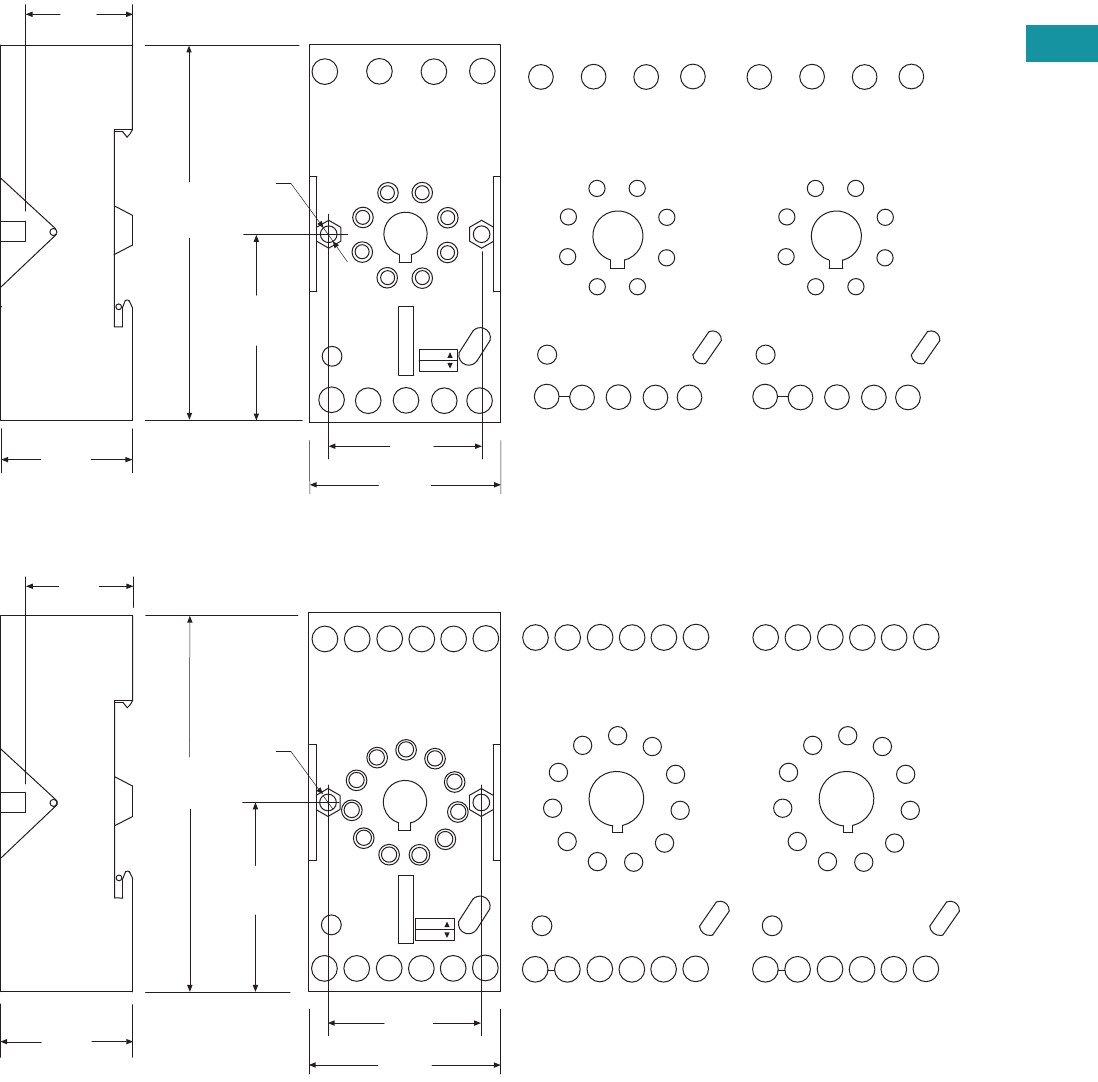
Volume 7—Logic Control, Operator Interface and Connectivity Solutions CA08100008E—February 2014 www.eaton.com V7-T3-77
3
3
3
3
3
3
3
3
3
3
3
3
3
3
3
3
3
3
3
3
3
3
3
3
3
3
3
3
3
3
Volume 7—Logic Control, Operator Interface and Connectivity Solutions CA08100008E—February 2014 www.eaton.com V7-T3-77
3
3
3
3
3
3
3
3
3
3
3
3
3
3
3
3
3
3
3
3
3
3
3
3
3
3
3
3
3
3
3.4
Control Relays and Timers
General Purpose Plug-In Relays
Approximate Dimensions in Inches (mm)
D3PAL8
D3PAL11
11
7
7
INPUT A1INPUT A2
A2
7
A2
8
21
21
A1
12
56
24
4
22
3
14
2
12
24 22 14
11
A2 21 A1A2
1
2
8
7
3
4
5
6
2.95
(75.0)
1.45
(37.0)
0.12
(30.0)
1.49
(38.0)
0.12
(3.10)
0.86
(22.0)
1.06
(27.0)
INPUT INPUT
MODULE
INPUT
IEC
465 3
17782
1
2
8
7
3
4
5
6
INPUT INPUT
MODULE
INPUT
NEMA
NEMA:
IEC:
INPUT A1
10
INPUT A2
2
A1
A2 A2 31 21 11
10 11
10 612
14
34 24
32 22 12
97
84
3
5
11
A2 31 21 A1
14
34 24 22 12
32
A2
4
3
9
8
75
6
1
10
11
2
4
3
9
8
75
6
1
10
11
2
2.95
(75.0)
INPUT
INPUT
0.86
(22.0)
1.06
(27.0)
1.45
(37.0)
1.49
(38.0)
0.12
(30.0)
NEMA:
IEC:
0.12
(3.1)
MODULE
INPUT
IEC
10 1
11 62
3
9754
10
8
INPUT
INPUT
MODULE
INPUT
NEMA
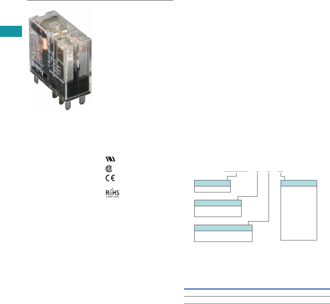
V7-T3-78 Volume 7—Logic Control, Operator Interface and Connectivity Solutions CA08100008E—February 2014 www.eaton.com
3
3
3
3
3
3
3
3
3
3
3
3
3
3
3
3
3
3
3
3
3
3
3
3
3
3
3
3
3
3
V7-T3-78 Volume 7—Logic Control, Operator Interface and Connectivity Solutions CA08100008E—February 2014 www.eaton.com
3
3
3
3
3
3
3
3
3
3
3
3
3
3
3
3
3
3
3
3
3
3
3
3
3
3
3
3
3
3
3.4
Control Relays and Timers
General Purpose Plug-In Relays
D4 Series Relay
Contents
Description Page
D1PR/D1PF Series . . . . . . . . . . . . . . . . . . . . . . . . . V7-T3-53
D2PR/D2PF Series . . . . . . . . . . . . . . . . . . . . . . . . . V7-T3-58
D3PR/D3PF Series . . . . . . . . . . . . . . . . . . . . . . . . . V7-T3-68
D4 Series
Technical Data and Specifications . . . . . . . . . . . V7-T3-80
Dimensions. . . . . . . . . . . . . . . . . . . . . . . . . . . . V7-T3-81
D5PR/D5PF Series . . . . . . . . . . . . . . . . . . . . . . . . . V7-T3-82
D7PR/D7PF Series . . . . . . . . . . . . . . . . . . . . . . . . . V7-T3-91
D8 Series . . . . . . . . . . . . . . . . . . . . . . . . . . . . . . . . V7-T3-106
D9 Series . . . . . . . . . . . . . . . . . . . . . . . . . . . . . . . . V7-T3-112
Accessories . . . . . . . . . . . . . . . . . . . . . . . . . . . . . . V7-T3-116
D4 Series
Product Description
The D4 Series is a slim-form
relay designed to fit into tight
spaces. The retaining clip is
built in to the socket to
provide easy and secure
assembly.
Features
●Slim-styled power relay
●Socket has built-in hold-
down clip
●Panel or DIN rail mounting
Standards and Certifications
File # E1491, E65657
File # LR701519
Catalog Number Selection
D4 Series 1
Product Selection
D4 Relay/Socket Quick Reference
Notes
1For deciphering catalog numbers. Do not use for ordering as not all combinations are
readily available.
2Socket has built-in hold-down spring.
D 4 P R 11A
Family Type
D4PR
Contact Configuration
1 = SPDT
2 = DPDT
Options
Blank = Plain cover
1 =
Indicating light
Coil Voltage
A = 120 Vac
A1 = 110 Vdc
B = 240 Vac
P = 6 Vac
P1 = 6 Vdc
R = 12 Vac
R1 = 12 Vdc
T = 24 Vac
T1 = 24 Vdc
W = 48 Vac
W1 = 48 Vdc
Relay Type Socket Hold-Down Clip
D4PR1 D4PA1 2
D4PR2 D4PA2 2
Volume 7—Logic Control, Operator Interface and Connectivity Solutions CA08100008E—February 2014 www.eaton.com V7-T3-79
3
3
3
3
3
3
3
3
3
3
3
3
3
3
3
3
3
3
3
3
3
3
3
3
3
3
3
3
3
3
Volume 7—Logic Control, Operator Interface and Connectivity Solutions CA08100008E—February 2014 www.eaton.com V7-T3-79
3
3
3
3
3
3
3
3
3
3
3
3
3
3
3
3
3
3
3
3
3
3
3
3
3
3
3
3
3
3
3.4
Control Relays and Timers
General Purpose Plug-In Relays
D4 Series
Voltage/Poles
Standard
Pack
Catalog
Number Voltage/Poles
Standard
Pack
Catalog
Number
DIN Rail Sockets DPDT with Indicating Light
Single-pole 10 D4PA1 120 Vac 1 D4PR21A
Two-pole 10 D4PA2 110 Vdc 1 D4PR21A1
SPDT with Indicating Light 240 Vac 1 D4PR21B
120 Vac 1 D4PR11A 6 Vac 50 D4PR21P
110 Vdc 1 D4PR11A1 6 Vdc 1 D4PR21P1
240 Vac 1 D4PR11B 12 Vac 50 D4PR21R
6 Vac 50 D4PR11P 12 Vdc 1 D4PR21R1
6 Vdc 50 D4PR11P1 24 Vac 1 D4PR21T
12 Vac 50 D4PR11R 24 Vdc 1 D4PR21T1
12 Vdc 1 D4PR11R1 48 Vdc 50 D4PR21W1
24 Vac 1 D4PR11T Standard DPDT
24 Vdc 1 D4PR11T1 120 Vac 1 D4PR2A
48 Vdc 50 D4PR11W1 110 Vdc 50 D4PR2A1
Standard SPDT 240 Vac 50 D4PR2B
120 Vac 1 D4PR1A 6 Vac 50 D4PR2P
110 Vdc 50 D4PR1A1 6 Vdc 1 D4PR2P1
240 Vac 50 D4PR1P 12 Vac 50 D4PR2R
6 Vac 1 D4PR1P1 12 Vdc 1 D4PR2R1
6 Vdc 50 D4PR1R 24 Vac 1 D4PR2T
12 Vac 1 D4PR1R1 24 Vdc 1 D4PR2T1
12 Vdc 1 D4PR1R1-A2 48 Vdc 1 D4PR2W1
24 Vac 1 D4PR1T
24 Vdc 1 D4PR1T1
48 Vdc 1 D4PR1W1
D4 Series Relay

V7-T3-80 Volume 7—Logic Control, Operator Interface and Connectivity Solutions CA08100008E—February 2014 www.eaton.com
3
3
3
3
3
3
3
3
3
3
3
3
3
3
3
3
3
3
3
3
3
3
3
3
3
3
3
3
3
3
V7-T3-80 Volume 7—Logic Control, Operator Interface and Connectivity Solutions CA08100008E—February 2014 www.eaton.com
3
3
3
3
3
3
3
3
3
3
3
3
3
3
3
3
3
3
3
3
3
3
3
3
3
3
3
3
3
3
3.4
Control Relays and Timers
General Purpose Plug-In Relays
Technical Data and Specifications
D4 Series
Description
Resistive Load
(p.f. = 1)
Inductive Load
(p.f. = 0.4, L/R = 7 ms)
D4PR1
Rated load 250 Vac 10A 250 Vac 7.5A
30 Vdc 10A 30 Vdc 5A
Carry current 10A 10A
Max. operating voltage 380 Vac/125 Vdc 380 Vac/125 Vdc
Max. operating current 10A 10A
Contact material AgCdO AgCdO
Max. switching capacity 2500 VA 1875 VA
300W 150W
Min. permissible load 100 mA, 5 Vdc 100 mA, 5 Vdc
Pickup voltage (max.) 80% AC/70% DC 80% AC/70% DC
Dropout voltage (min.) 30% AC/15% DC 30% AC/15% DC
Voltage (max.) 110% 110%
Mechanical life (min.) 10,000,000 AC/20,000,000 DC 10,000,000 AC/20,000,000 DC
Electrical life at all contact ratings (min.) 100,000 100,000
Maximum hp ratings 1/3 hp (125 Vac) 1/3 hp (125 Vac)
1/2 hp (250 Vac) 1/2 hp (250 Vac)
1/2 hp (277 Vac) 1/2 hp (277 Vac)
D4PR2
Rated load 240 Vac 5A 250 Vac 2A
30 Vdc 5A 30 Vdc 3A
Carry current 5A 5A
Max. operating voltage 380 Vac/125 Vdc 380 Vac/125 Vdc
Max. operating current 5A 5A
Contact material AgCdO AgCdO
Max. switching capacity 1250 VA 500 VA
150W 90W
Min. permissible load 10 mA, 5 Vdc 10 mA, 5 Vdc
Pickup voltage (max.) 80% AC/70% DC 80% AC/70% DC
Dropout voltage (min.) 30% AC/15% DC 30% AC/15% DC
Voltage (max.) 110% 110%
Mechanical life (min.) 10,000,000 AC/20,000,000 DC 10,000,000 AC/20,000,000 DC
Electrical life at all contact ratings (min.) 100,000 100,000
Maximum hp ratings 1/6 hp (120 Vac) 1/6 hp (120 Vac)
1/3 hp (240 Vac) 1/3 hp (240 Vac)
1/3 hp (265 Vac) 1/3 hp (265 Vac)
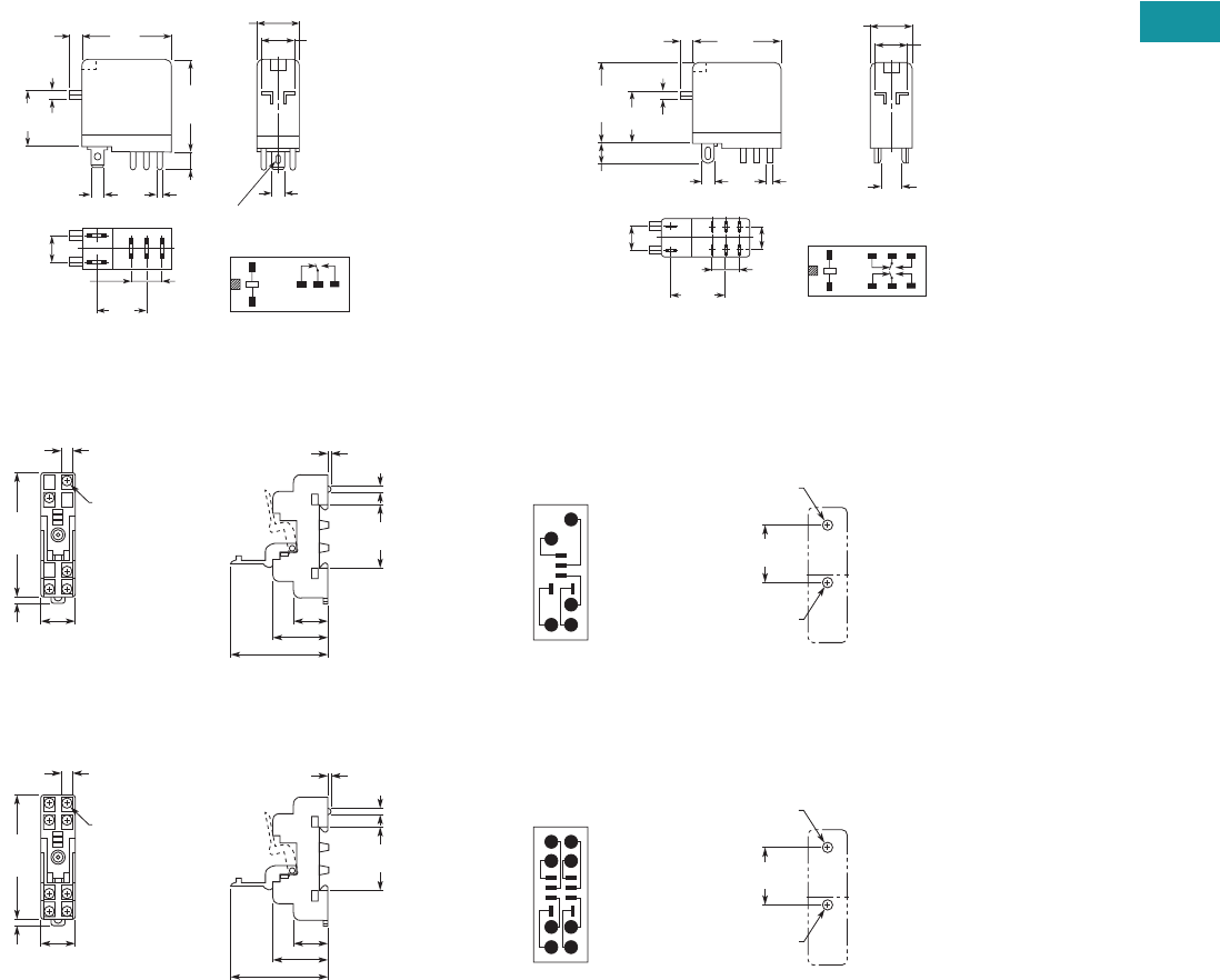
Volume 7—Logic Control, Operator Interface and Connectivity Solutions CA08100008E—February 2014 www.eaton.com V7-T3-81
3
3
3
3
3
3
3
3
3
3
3
3
3
3
3
3
3
3
3
3
3
3
3
3
3
3
3
3
3
3
Volume 7—Logic Control, Operator Interface and Connectivity Solutions CA08100008E—February 2014 www.eaton.com V7-T3-81
3
3
3
3
3
3
3
3
3
3
3
3
3
3
3
3
3
3
3
3
3
3
3
3
3
3
3
3
3
3
3.4
Control Relays and Timers
General Purpose Plug-In Relays
Dimensions
Approximate Dimensions in Inches (mm)
D4PR1 D4PR2
D4PA1
D4PA2
1
243
5
1.14
(29.0)
Max.
1.14
(29.0)
Max.
0.51
(13.0)
Max.
0.10
(2.5) 0.39
(10.0)
0.16
(4.0)
0.08
(2.0)
0.79
(20.0)
0.19
(4.8)
0.30
(7.5)
0.20
(5.2)
0.69
(17.5)
0.20
(5.2)
Terminal Arrangement/
Internal Connections
(Bottom View)
0.02
(0.5)
0.02
(0.5)
5 – 0.035 x 0.12
(0.9 x 3)
Elliptic Holes
1.14
(29.0)
Max.
1.10
(28.0)
Max.
0.01
(2.5)
0.24
(6.0)
0.79
(20.0) 0.08
(2.0)
0.10
(2.6) 0.02
(0.5)
0.30
(7.5)
0.35
(8.9)
0.02
(0.5)
0.02
(0.5)
1
8765
234
0.76
(19.4) Terminal Arrangement/
Internal Connections
(Bottom View)
0.16
(4.0)
0.51
(13.0)
Max. 0.39
(10.0)
0.28
(7.1) 0.08
(2.0)
Five
3.5 x 0.32
(88.9 x 8.0)
2.82
(71.6)
Max.
0.16
(4.1) 0.77
(19.6)
Max.
0.77 (19.6)
1.18 (30.0)
2.13 (54.1) Max.
1.180 0.002
(29.97 0.05)
1.40
(35.6)
0.16
(4.1)
Dia. Holes
15
3
2
4
M3 or
3.30 (0.13)
Dia. Holes
0.17 (4.2)
Dia. Holes
Mounting HolesTerminal Arrangement
0.28
(7.1) 0.08
(2.0)
Eight
3.5 x 0.32
(88.9 x 8.0)
2.82
(71.6)
Max.
0.16
(4.1) 0.77
(19.6)
Max.
0.77 (19.6)
1.18 (30.0)
2.13 (54.1) Max.
1.180 0.002
(29.97 0.05)
1.40
(35.6)
0.16
(4.1)
Dia. Holes
18
5
72
3
4
6
M3 or
0.13 (3.30)
Dia. Holes
0.17 (4.2)
Dia. Holes
Mounting HolesTerminal Arrangement
V7-T3-82 Volume 7—Logic Control, Operator Interface and Connectivity Solutions CA08100008E—February 2014 www.eaton.com
3
3
3
3
3
3
3
3
3
3
3
3
3
3
3
3
3
3
3
3
3
3
3
3
3
3
3
3
3
3
V7-T3-82 Volume 7—Logic Control, Operator Interface and Connectivity Solutions CA08100008E—February 2014 www.eaton.com
3
3
3
3
3
3
3
3
3
3
3
3
3
3
3
3
3
3
3
3
3
3
3
3
3
3
3
3
3
3
3.4
Control Relays and Timers
General Purpose Plug-In Relays
D5 Series Relay
Contents
Description Page
D1PR/D1PF Series . . . . . . . . . . . . . . . . . . . . . . . . . V7-T3-53
D2PR/D2PF Series . . . . . . . . . . . . . . . . . . . . . . . . . V7-T3-58
D3PR/D3PF Series . . . . . . . . . . . . . . . . . . . . . . . . . V7-T3-68
D4 Series . . . . . . . . . . . . . . . . . . . . . . . . . . . . . . . . V7-T3-78
D5PR/D5PF Series
Catalog Number Selection . . . . . . . . . . . . . . . . V7-T3-83
Product Selection . . . . . . . . . . . . . . . . . . . . . . . V7-T3-83
Accessories. . . . . . . . . . . . . . . . . . . . . . . . . . . . V7-T3-85
Technical Data and Specifications . . . . . . . . . . . V7-T3-86
Wiring Diagrams . . . . . . . . . . . . . . . . . . . . . . . V7-T3-87
Dimensions . . . . . . . . . . . . . . . . . . . . . . . . . . . V7-T3-88
D7PR/D7PF Series . . . . . . . . . . . . . . . . . . . . . . . . . V7-T3-91
D8 Series . . . . . . . . . . . . . . . . . . . . . . . . . . . . . . . . V7-T3-106
D9 Series . . . . . . . . . . . . . . . . . . . . . . . . . . . . . . . . V7-T3-112
Accessories . . . . . . . . . . . . . . . . . . . . . . . . . . . . . . V7-T3-116
D5PR/D5PF Series
Product Description
The D5 Series is rated at
16A and is available in full-
featured and plain cover
styles.
Features
D5PR
●Industrial rated 300V, 16A
relay in two-pole and three-
pole configurations
●Compact design can be
panel or DIN rail mounted
D5PF
●Flag indicator shows relay
status in manual or
powered condition
●LED status lamp shows
coil ON or OFF status—
ideal for use in low light
applications
●Push-to-Test button allows
for manual operation of
relay without the need for
coil power
●Lock-down door holds
pushbutton and contacts in
the operate position when
activated
●Finger-grip cover allows
operator to remove relays
from sockets easily
●ID tag/write label to
identify relays in multiple-
relay circuits
●Bipolar LED allows for
reverse polarity
applications
Standards and Certifications
When used with
accompanying Eaton
screw terminal socket
(D5PF only)
UL Listed
Volume 7—Logic Control, Operator Interface and Connectivity Solutions CA08100008E—February 2014 www.eaton.com V7-T3-83
3
3
3
3
3
3
3
3
3
3
3
3
3
3
3
3
3
3
3
3
3
3
3
3
3
3
3
3
3
3
Volume 7—Logic Control, Operator Interface and Connectivity Solutions CA08100008E—February 2014 www.eaton.com V7-T3-83
3
3
3
3
3
3
3
3
3
3
3
3
3
3
3
3
3
3
3
3
3
3
3
3
3
3
3
3
3
3
3.4
Control Relays and Timers
General Purpose Plug-In Relays
Catalog Number Selection
D5 Series
Product Selection
D5 Relay/Socket Quick Reference
Family Type
D5PR = Standard relay
D5PF = Full featured relay
Contact Configuration
2 = DPDT
3 = 3PDT
D 5 P R 3 1 A
Coil Voltage
A = 120 Vac
A1 = 110 Vdc
B = 240 Vac
G1 = 74 Vdc
P = 6 Vac
P1 = 6 Vdc
R = 12 Vac
R1 = 12 Vdc
T = 24 Vac
T1 = 24 Vdc
W = 48 Vac
W1 = 48 Vdc
Options
Blank = Plain cover (D5PR only)
A = LED test button, flag indicator,
lock-down door, finger-grip cover,
ID tag (D5PF only)
1 = Indicating light (D5PR only)
Relay
Type Socket Clip
Module
Type
ID
Tag Jumper
D5PR2, D5PF2,
D5PR3, D5PF3
D5PAL PQC-1351 A PWF-D3D5 D3PJ1
D5PA2 PQC-1351 None — —
D5PA3L PQC-1351 None — —
D5PA3S PQC-1351 None — —
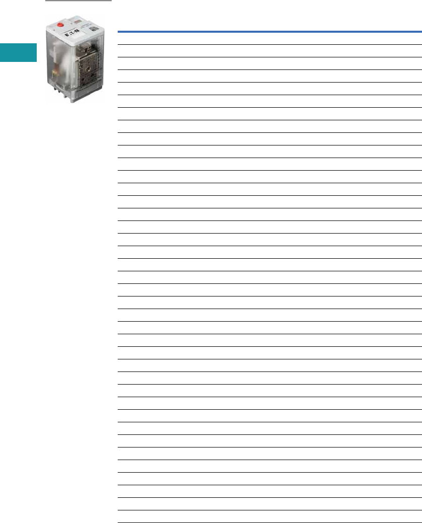
V7-T3-84 Volume 7—Logic Control, Operator Interface and Connectivity Solutions CA08100008E—February 2014 www.eaton.com
3
3
3
3
3
3
3
3
3
3
3
3
3
3
3
3
3
3
3
3
3
3
3
3
3
3
3
3
3
3
V7-T3-84 Volume 7—Logic Control, Operator Interface and Connectivity Solutions CA08100008E—February 2014 www.eaton.com
3
3
3
3
3
3
3
3
3
3
3
3
3
3
3
3
3
3
3
3
3
3
3
3
3
3
3
3
3
3
3.4
Control Relays and Timers
General Purpose Plug-In Relays
D5 Series
Coil
Voltage
Contact
Configuration
Coil Resistance
(Ohms)
Catalog
Number
Full Featured
120 Vac DPDT 1700 D5PF2AA
110/125 Vdc DPDT 10,000 D5PF2AA1
220/240 Vac DPDT 7200 D5PF2AB
12 Vdc DPDT 120 D5PF2AR1
24 Vac DPDT 72 D5PF2AT
24 Vdc DPDT 470 D5PF2AT1
48 Vdc DPDT 1800 D5PF2AW1
120 Vac 3PDT 1700 D5PF3AA
110/125 Vdc 3PDT 10,000 D5PF3AA1
220/240 Vac 3PDT 7200 D5PF3AB
12 Vdc 3PDT 120 D5PF3AR1
24 Vac 3PDT 72 D5PF3AT
24 Vdc 3PDT 470 D5PF3AT1
Plain Cover with LED
110/125 Vdc DPDT 10,000 D5PR21A1
6 Vac DPDT 4.2 D5PR21P
6 Vdc DPDT 32 D5PR21P1
12 Vac DPDT 18 D5PR21R
12 Vdc DPDT 120 D5PR21R1
24 Vdc DPDT 470 D5PR21T1
48 Vac DPDT 290 D5PR21W
48 Vdc DPDT 1800 D5PR21W1
120 Vac 3PDT 1700 D5PR31A
110/125 Vdc 3PDT 10,000 D5PR31A1
6 Vdc 3PDT 32 D5PR31P1
12 Vac 3PDT 18 D5PR31R
12 Vdc 3PDT 120 D5PR31R1
24 Vdc 3PDT 470 D5PR31T1
48 Vdc 3PDT 1800 D5PR31W1
Side Flange Cover
220/240 Vac DPDT 7200 D5PR24B
6 Vac DPDT 4.2 D5PR24P
6 Vdc DPDT 32 D5PR24P1
12 Vac DPDT 18 D5PR24R
12 Vdc DPDT 120 D5PR24R1
24 Vac DPDT 72 D5PR24T
24 Vdc DPDT 470 D5PR24T1
48 Vac DPDT 290 D5PR24W
D5 Series Relay
Volume 7—Logic Control, Operator Interface and Connectivity Solutions CA08100008E—February 2014 www.eaton.com V7-T3-85
3
3
3
3
3
3
3
3
3
3
3
3
3
3
3
3
3
3
3
3
3
3
3
3
3
3
3
3
3
3
Volume 7—Logic Control, Operator Interface and Connectivity Solutions CA08100008E—February 2014 www.eaton.com V7-T3-85
3
3
3
3
3
3
3
3
3
3
3
3
3
3
3
3
3
3
3
3
3
3
3
3
3
3
3
3
3
3
3.4
Control Relays and Timers
General Purpose Plug-In Relays
D5 Series, continued
Accessories
D5 Sockets and Accessories
Note
1Protection category (finger safe), EN 60529: IP20.
Coil
Voltage
Contact
Configuration
Coil Resistance
(Ohms)
Catalog
Number
Plain Cover
120 Vac DPDT 1700 D5PR2A
110/125 Vdc DPDT 10,000 D5PR2A1
220/240 Vac DPDT 7200 D5PR2B
74 Vdc DPDT 4800 D5PR2G1
6 Vac DPDT 4.2 D5PR2P
6 Vdc DPDT 32 D5PR2P1
12 Vac DPDT 18 D5PR2R
12 Vdc DPDT 120 D5PR2R1
24 Vac DPDT 72 D5PR2T
24 Vdc DPDT 470 D5PR2T1
48 Vac DPDT 290 D5PR2W
48 Vdc DPDT 1800 D5PR2W1
120 Vac 3PDT 1700 D5PR3A
110/125 Vdc 3PDT 10,000 D5PR3A1
220/240 Vac 3PDT 7200 D5PR3B
74 Vdc 3PDT 4800 D5PR3G1
6 Vac 3PDT 4.2 D5PR3P
6 Vdc 3PDT 32 D5PR3P1
12 Vac 3PDT 18 D5PR3R
12 Vdc 3PDT 120 D5PR3R1
24 Vac 3PDT 72 D5PR3T
24 Vdc 3PDT 470 D5PR3T1
48 Vdc 3PDT 1800 D5PR3W
48 Vdc 3PDT 1800 D5PR3W1
Type
Module
Size
Nominal Voltage
(Max. for Sockets)
Nominal
Current Mounting Style Wire Size
Wire
Connection
Standard
Pack
Catalog
Number
Socket A 300 25 DIN rail 10 /14 (2) AWG, 6/2.5 (2) mm2Elevator 10 D5PAL 1
None 300 15 DIN rail/panel 12/14 (2) AWG, 4/2.5 (2) mm2Screw clamping 10 D5PA2
None 300 15 Chassis (Output): 16 AWG, 1 mm2Solder 10 D5PA3L
None 300 15 Chassis (Output): 16 AWG, 1 mm2Solder 10 D5PA3S
Metal spring clip — — — — — — 10 PQC-1351
Protection diode A 6 to 250 Vdc — — — — 20 MOD-AD250
LED indicator A 24 Vac/Vdc — — — — 20 MOD-ALG24
A 120/240 Vac/Vdc — — — — 20 MOD-ALG240
MOV suppressor A 120 Vac/Vdc — — — — 20 MOD-AMV120
A 24 Vac/Vdc — — — — 20 MOD-AMV24
A240 Vac/Vdc —— — — 20MOD-AMV240
R/C suppressor A 6 to 24 Vac/Vdc — — — — 20 MOD-RC24
A 110 to 240 Vac/Vdc — — — — 20 MOD-RC240
Write-on plastic labels — — — — — — 10 PWF-D3D5
Coil bus jumpers — — — — — — 10 D3PJ1
Plastic DIN rail end stop — — — — — — 25 PFP-P
D5 Series Relay

V7-T3-86 Volume 7—Logic Control, Operator Interface and Connectivity Solutions CA08100008E—February 2014 www.eaton.com
3
3
3
3
3
3
3
3
3
3
3
3
3
3
3
3
3
3
3
3
3
3
3
3
3
3
3
3
3
3
V7-T3-86 Volume 7—Logic Control, Operator Interface and Connectivity Solutions CA08100008E—February 2014 www.eaton.com
3
3
3
3
3
3
3
3
3
3
3
3
3
3
3
3
3
3
3
3
3
3
3
3
3
3
3
3
3
3
3.4
Control Relays and Timers
General Purpose Plug-In Relays
Technical Data and Specifications
D5 Series
Description D5PR D5PF
Contact Characteristics
Contact rating 16A 16A
Terminal style Plug-in Plug-in
Contact materials Silver alloy Silver alloy
Maximum switching voltage 300V 300V
Switching current at voltage—resistive
16A at 277 Vac 50/60 Hz 16A at 277 Vac 50/60 Hz
16A at 120 Vac 50/60 Hz 16A at 120 Vac 50/60 Hz
16A at 28 Vdc 16A at 28 Vdc
Switching current at voltage 1/2 hp at 240 Vac 1/2 hp at 240 Vac
1/3 hp at 120 Vac 1/3 hp at 120 Vac
Pilot duty B300 B300
Minimum switching requirement 100 mA at 5 Vdc (0.5W) 100 mA at 5 Vdc (0.5W)
Coil Characteristics
Operating range
% of nominal (AC) 85 to 110% 85 to 110%
% of nominal (DC) 80 to 110% 80 to 110%
Average consumption 3 VA
1.4W
3 VA
1.4W
Drop-out voltage threshold 10%/15% (AC)
10% (DC)
10%/15% (AC)
10% (DC)
Performance
Electrical life (UL 508) operations at rated current 100,000 operations 100,000 operations
Mechanical life operations unpowered 5,000,000 operations 5,000,000 operations
Response time 20 ms 20 ms
Dielectric strength
Between coil and contact Vac (rms) 1500V (rms) 1500V (rms)
Between poles Vac (rms) 1500V (rms) 1500V (rms)
Environment
Ambient air temperature around the device
Storage –40° to 185°F (–40° to 85°C) –40° to 185°F (–40° to 85°C)
Operation –40° to 131°F (–40° to 55°C) –40° to 131°F (–40° to 55°C)
Vibration resistance—operational 3 g-n at 10–55 Hz 3 g-n at 10–55 Hz
Shock resistance 10 g-n 10 g-n
Degree of protection IP40 IP40
Features
Cover options Flange/plain cover with LED Full featured
Features Mechanical flag indicator
(LED optional)
Bipolar LED/
Mechanical flag indicator/
Locking pushbutton/
Removable ID tag
Product certifications RoHS/UL/CE/CSA RoHS/UL/CE/CSA

Volume 7—Logic Control, Operator Interface and Connectivity Solutions CA08100008E—February 2014 www.eaton.com V7-T3-87
3
3
3
3
3
3
3
3
3
3
3
3
3
3
3
3
3
3
3
3
3
3
3
3
3
3
3
3
3
3
Volume 7—Logic Control, Operator Interface and Connectivity Solutions CA08100008E—February 2014 www.eaton.com V7-T3-87
3
3
3
3
3
3
3
3
3
3
3
3
3
3
3
3
3
3
3
3
3
3
3
3
3
3
3
3
3
3
3.4
Control Relays and Timers
General Purpose Plug-In Relays
Wiring Diagrams
D5PA3L and D5PA3S
D5PR2/D5PF2 DPDT
D5PR3/D5PF3 3PDT
COM
N.O.
N.C.
INPUT
A1 A2
11
12
31 21
34 24
32 22
14
IEC
COM
N.O.
N.C.
INPUT
B
A
7
4
1
9
8
56
23
NEMA
A1
11
14
12
A2
21
24
22
IEC
A
7
4
1
B
9
6
3
NEMA
A1 A2
11
12
31 21
34 24
32 22
14
IEC
B
A
7
4
1
9
8
56
23
NEMA
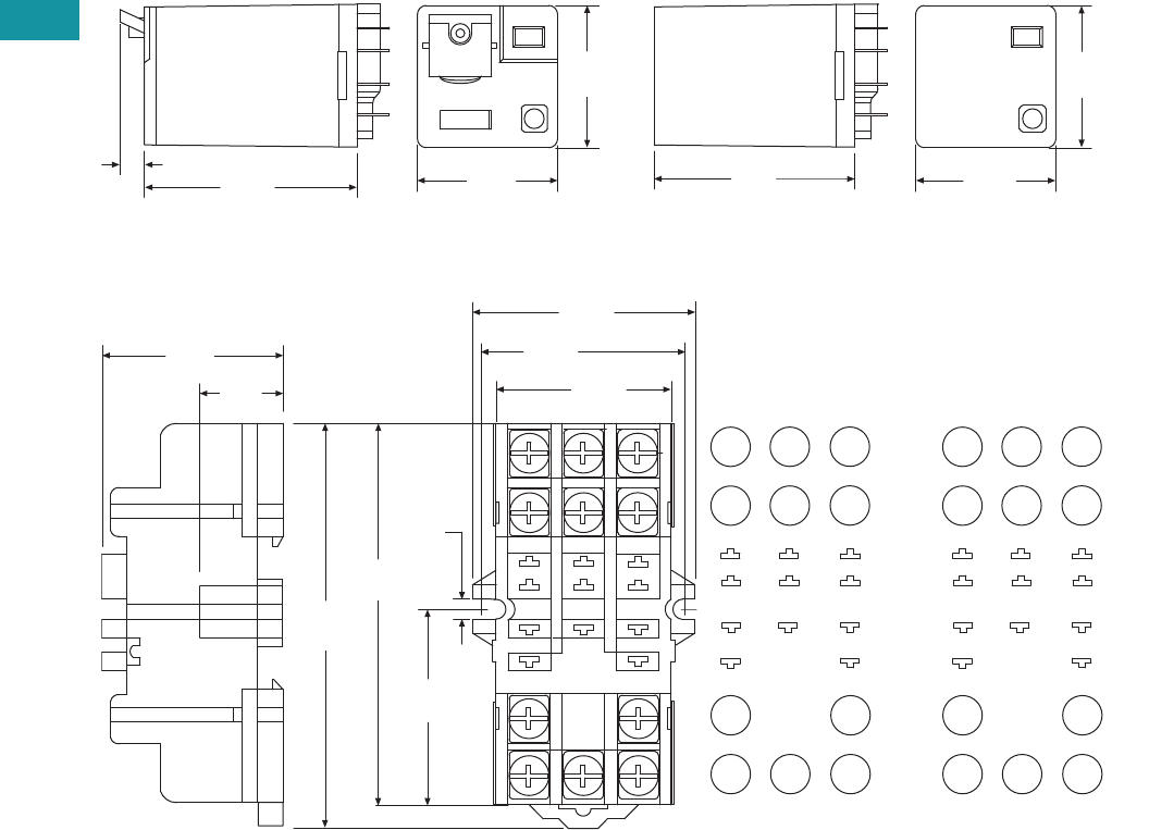
V7-T3-88 Volume 7—Logic Control, Operator Interface and Connectivity Solutions CA08100008E—February 2014 www.eaton.com
3
3
3
3
3
3
3
3
3
3
3
3
3
3
3
3
3
3
3
3
3
3
3
3
3
3
3
3
3
3
V7-T3-88 Volume 7—Logic Control, Operator Interface and Connectivity Solutions CA08100008E—February 2014 www.eaton.com
3
3
3
3
3
3
3
3
3
3
3
3
3
3
3
3
3
3
3
3
3
3
3
3
3
3
3
3
3
3
3.4
Control Relays and Timers
General Purpose Plug-In Relays
Dimensions
Approximate Dimensions in Inches (mm)
D5PR and D5PF
D5PA2
1.97
(50.0)
0.20
(6.1) 1.37
(34.9)
1.40
(35.4)
2.10
(53.1)
1.37
(34.9)
1.40
(35.4)
3.14
(80.0)
0.15
(3.8)
9 8
B
3.00
(76.0)
32
7
A
1
1.69
(43.0)
1.53
(39.0)
65
1.37
(35.0)
4
1.03
(26.0)
21 31 11
22 32 12
24 34 14
A2 A1
6
32
54
1
B
987
AINPUT
COM
N.C.
N.O.
1.50
(38.0)
0.40
(10.0)
IEC
INPUT
BA
79 8
21
3
45
6
6
32
54
1
B
987
AINPUT
COM
N.C.
N.O.
NEMA
INPUT
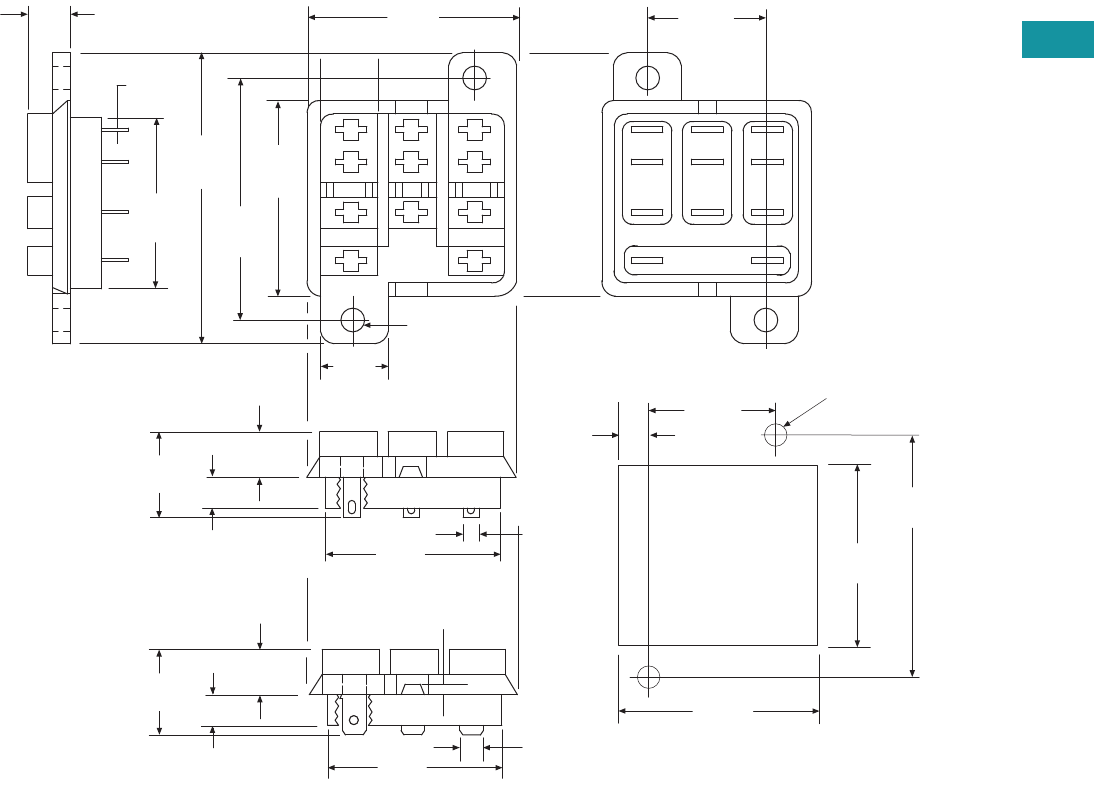
Volume 7—Logic Control, Operator Interface and Connectivity Solutions CA08100008E—February 2014 www.eaton.com V7-T3-89
3
3
3
3
3
3
3
3
3
3
3
3
3
3
3
3
3
3
3
3
3
3
3
3
3
3
3
3
3
3
Volume 7—Logic Control, Operator Interface and Connectivity Solutions CA08100008E—February 2014 www.eaton.com V7-T3-89
3
3
3
3
3
3
3
3
3
3
3
3
3
3
3
3
3
3
3
3
3
3
3
3
3
3
3
3
3
3
3.4
Control Relays and Timers
General Purpose Plug-In Relays
Approximate Dimensions in Inches (mm)
D5PA3L and D5PA3S
0.63
(16.2)
2.03
(51.0)
Solder Type Terminals
0.24
(6.1)
0.29
(7.5)
1.37
(34.7)
0.50
(2.5)
1.37
(34.7)
1.68
(42.8)
1.50
(38.1)
0.13
(3.3)
0.16 Dia.
(4.2)
2 Holes
0.30
(7.5)
0.02
(0.5)
1.25
(31.7)
4
7
1
A B
5
8
2
0.87
(22.2)
6
9
3
0.28
(5.3)
1.39
(35.4)
1.27
(32.3)
1.68
(42.6)
Recommended
Chassis Cutout 0.87
(22.2)
0.16 (3.9)
Dia. Holes
3/16 Q.C. Type Terminals 0.19 (4.7)
0.18
(4.7)
Typ.
1.37
(34.7)
0.63
(16.2)
0.24
(6.1)
0.29
(7.5)
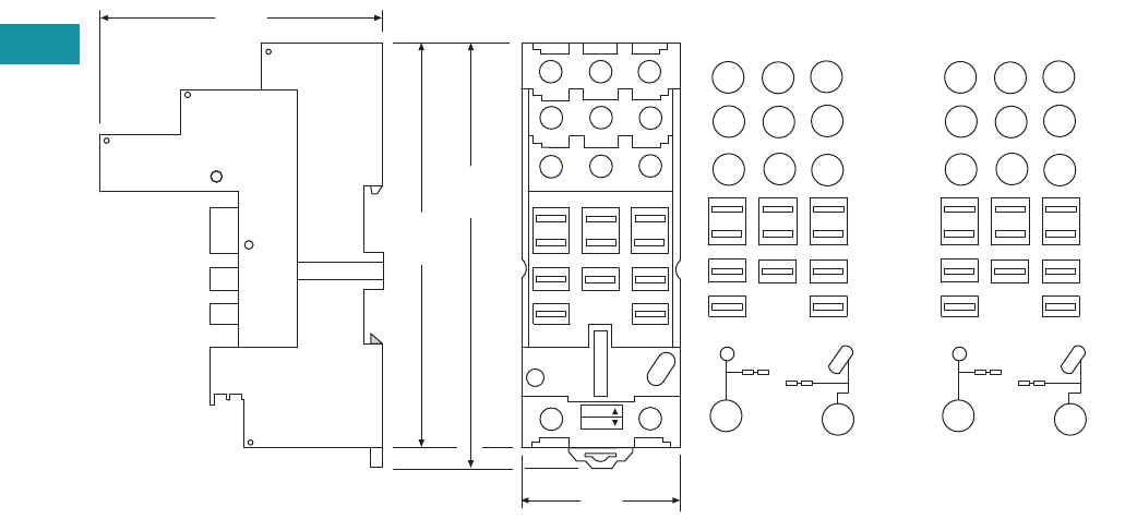
V7-T3-90 Volume 7—Logic Control, Operator Interface and Connectivity Solutions CA08100008E—February 2014 www.eaton.com
3
3
3
3
3
3
3
3
3
3
3
3
3
3
3
3
3
3
3
3
3
3
3
3
3
3
3
3
3
3
V7-T3-90 Volume 7—Logic Control, Operator Interface and Connectivity Solutions CA08100008E—February 2014 www.eaton.com
3
3
3
3
3
3
3
3
3
3
3
3
3
3
3
3
3
3
3
3
3
3
3
3
3
3
3
3
3
3
3.4
Control Relays and Timers
General Purpose Plug-In Relays
Approximate Dimensions in Inches (mm)
D5PAL
A2 A1
72
INPUT
12
1
14
4
11
7
22
3
32
2
21
24
9
34
5
6
31
8
12
14
11
22 32
21
24 34
31
A2 A1
Coil Jumper
Buss
BA
987
654
1
2
3
INPUT
MODULE
INPUT
COM
N.O.
N.C.
1.40
(36.0)
2.48
(63.0)
3.62
(92.0)
3.70
(96.0)
NEMA:
IEC:
IEC
INPUTINPUT
1
4
7
32
9
5
6
8
BA
Coil Jumper
Buss
BA
987
654
1
2
3
INPUT
MODULE
INPUT
COM
N.O.
N.C.
NEMA
INPUTINPUT
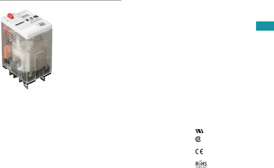
Volume 7—Logic Control, Operator Interface and Connectivity Solutions CA08100008E—February 2014 www.eaton.com V7-T3-91
3
3
3
3
3
3
3
3
3
3
3
3
3
3
3
3
3
3
3
3
3
3
3
3
3
3
3
3
3
3
Volume 7—Logic Control, Operator Interface and Connectivity Solutions CA08100008E—February 2014 www.eaton.com V7-T3-91
3
3
3
3
3
3
3
3
3
3
3
3
3
3
3
3
3
3
3
3
3
3
3
3
3
3
3
3
3
3
3.4
Control Relays and Timers
General Purpose Plug-In Relays
D7 Series Relay
Contents
Description Page
D1PR/D1PF Series . . . . . . . . . . . . . . . . . . . . . . . . . V7-T3-53
D2PR/D2PF Series . . . . . . . . . . . . . . . . . . . . . . . . . V7-T3-58
D3PR/D3PF Series . . . . . . . . . . . . . . . . . . . . . . . . . V7-T3-68
D4 Series . . . . . . . . . . . . . . . . . . . . . . . . . . . . . . . . V7-T3-78
D5PR/D5PF Series . . . . . . . . . . . . . . . . . . . . . . . . . V7-T3-82
D7PR/D7PF Series
Catalog Number Selection . . . . . . . . . . . . . . . . V7-T3-92
Product Selection . . . . . . . . . . . . . . . . . . . . . . . V7-T3-92
Accessories . . . . . . . . . . . . . . . . . . . . . . . . . . . . V7-T3-95
Technical Data and Specifications . . . . . . . . . . . V7-T3-96
Wiring Diagrams . . . . . . . . . . . . . . . . . . . . . . . . V7-T3-98
Dimensions . . . . . . . . . . . . . . . . . . . . . . . . . . . . V7-T3-99
D8 Series . . . . . . . . . . . . . . . . . . . . . . . . . . . . . . . . V7-T3-106
D9 Series . . . . . . . . . . . . . . . . . . . . . . . . . . . . . . . . V7-T3-112
Accessories . . . . . . . . . . . . . . . . . . . . . . . . . . . . . . V7-T3-116
D7PR/D7PF Series
Product Description
The D7 Series is a cost-
effective control relay with
high dielectric strength and
high current-carrying capacity.
Features
D7PR
●Arc barrier equipped relay
with high dielectric
strength
●Panel and DIN rail
mounting
D7PF
●Flag indicator shows relay
status in manual or
powered condition
●Bipolar LED status lamp
allows for reverse polarity
applications
●Shows coil ON or OFF
status
●Ideal in low light
conditions
●Color-coded pushbutton
identifies AC coils with red
or DC coils with blue
pushbuttons
●Allows for manual
operation of relay
without the need for
coil power
●Ideal for field service
personnel to test
control circuits
●Lock-down door, when
activated, holds
pushbutton and contacts in
the operate position
●Excellent for analyzing
circuit problems
●Finger-grip cover allows
operator to remove relays
from sockets more easily
than conventional relays
●White plastic ID tag/write
label used for identification
of relays in multi-relay
circuits
Standards and Certifications
File # E37317, E65657
File # LR217017,
LR217069
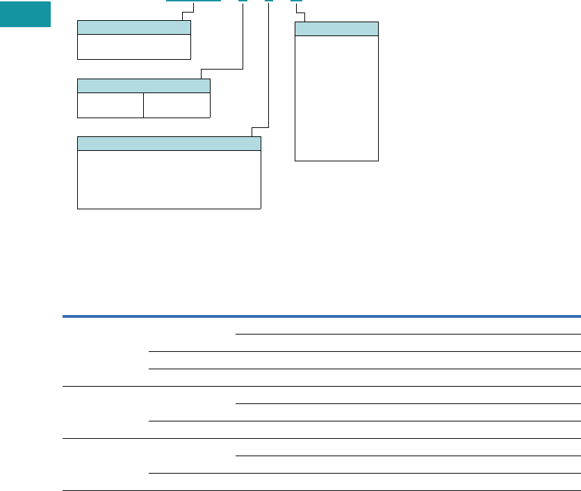
V7-T3-92 Volume 7—Logic Control, Operator Interface and Connectivity Solutions CA08100008E—February 2014 www.eaton.com
3
3
3
3
3
3
3
3
3
3
3
3
3
3
3
3
3
3
3
3
3
3
3
3
3
3
3
3
3
3
V7-T3-92 Volume 7—Logic Control, Operator Interface and Connectivity Solutions CA08100008E—February 2014 www.eaton.com
3
3
3
3
3
3
3
3
3
3
3
3
3
3
3
3
3
3
3
3
3
3
3
3
3
3
3
3
3
3
3.4
Control Relays and Timers
General Purpose Plug-In Relays
Catalog Number Selection
D7 Series
Product Selection
D7 Relay/Socket Quick Reference
D 7 P R 1 1 A
Contact Configuration
1 = SPDT
2 = DPDT
3 = 3PDT
4 = 4PDT
Options
Blank = Plain cover (D7PR only)
A = LED test button, flag indicator,
lock-down door, finger-grip cover,
ID tag (D7PF only)
1 = Indicating light (D7PR only)
Family Type
D7PR = Standard relay
D7PF = Full featured relay
Coil Voltage
A = 120 Vac
A1 = 110 Vdc
B = 240 Vac
P =6 Vac
P1 =6 Vdc
R = 12 Vac
R1 = 12 Vdc
T = 24 Vac
T1 = 24 Vdc
W = 48 Vac
W1 = 48 Vdc
Relay
Type Socket/Adapter Clip
Module
Type ID Tag Jumper
D7PR1, D7PR2,
D7PF1, D7PF2
D7PAA PQC-1342 B — —
PQC-1349 B — —
D7PA9 PQC-1342 None — —
PFC-D2D72 — None — —
D7PR3, D7PF3 D7PAB PQC-1783 A — —
PMC-1783 A — —
PFC-D73 — None — —
D7PR4, D7PF4 D7PAD PQC-1784 A — —
PMC-1784 A — —
PFC-D74 — None — —
Volume 7—Logic Control, Operator Interface and Connectivity Solutions CA08100008E—February 2014 www.eaton.com V7-T3-93
3
3
3
3
3
3
3
3
3
3
3
3
3
3
3
3
3
3
3
3
3
3
3
3
3
3
3
3
3
3
Volume 7—Logic Control, Operator Interface and Connectivity Solutions CA08100008E—February 2014 www.eaton.com V7-T3-93
3
3
3
3
3
3
3
3
3
3
3
3
3
3
3
3
3
3
3
3
3
3
3
3
3
3
3
3
3
3
3.4
Control Relays and Timers
General Purpose Plug-In Relays
D7 Series
Coil
Voltage
Contact
Configuration
Coil Resistance
(Ohms)
Catalog
Number
Full Featured
120 Vac SPDT 4430 D7PF1AA
6 Vac SPDT 9.6 D7PF1AP
6 Vdc SPDT 40 D7PF1AP1
12 Vac SPDT 46 D7PF1AR
24 Vdc SPDT 650 D7PF1AT1
48 Vac SPDT 788 D7PF1AW
48 Vdc SPDT 2600 D7PF1AW1
120 Vac DPDT 4430 D7PF2AA
110/125 Vdc DPDT 11,000 D7PF2AA1
220/240 Vac DPDT 15,720 D7PF2AB
6 Vac DPDT 9.6 D7PF2AP
6 Vdc DPDT 40 D7PF2AP1
12 Vac DPDT 46 D7PF2AR
12 Vdc DPDT 160 D7PF2AR1
24 Vac DPDT 180 D7PF2AT
24 Vdc DPDT 650 D7PF2AT1
48 Vac DPDT 788 D7PF2AW
48 Vdc DPDT 2600 D7PF2AW1
120 Vac 3PDT 2770 D7PF3AA
6 Vac 3PDT 6 D7PF3AP
6 Vdc 3PDT 25 D7PF3AP1
12 Vac 3PDT 25.3 D7PF3AR
24 Vac 3PDT 103 D7PF3AT
24 Vdc 3PDT 400 D7PF3AT1
48 Vac 3PDT 412 D7PF3AW
48 Vdc 3PDT 1600 D7PF3AW1
120 Vac 4PDT 2220 D7PF4AA
110/125 Vdc 4PDT 7340 D7PF4AA1
240 Vac 4PDT 9120 D7PF4AB
6 Vac 4PDT 5.4 D7PF4AP
6 Vdc 4PDT 24 D7PF4AP1
12 Vac 4PDT 21.2 D7PF4AR
12 Vdc 4PDT 96 D7PF4AR1
24 Vac 4PDT 84.5 D7PF4AT
24 Vdc 4PDT 388 D7PF4AT1
48 Vdc 4PDT 1550 D7PF4AW
48 Vac 4PDT 410 D7PF4AW1
D7 Series Relay

V7-T3-94 Volume 7—Logic Control, Operator Interface and Connectivity Solutions CA08100008E—February 2014 www.eaton.com
3
3
3
3
3
3
3
3
3
3
3
3
3
3
3
3
3
3
3
3
3
3
3
3
3
3
3
3
3
3
V7-T3-94 Volume 7—Logic Control, Operator Interface and Connectivity Solutions CA08100008E—February 2014 www.eaton.com
3
3
3
3
3
3
3
3
3
3
3
3
3
3
3
3
3
3
3
3
3
3
3
3
3
3
3
3
3
3
3.4
Control Relays and Timers
General Purpose Plug-In Relays
D7 Series, continued
Coil
Voltage
Contact
Configuration
Coil Resistance
(Ohms)
Catalog
Number
Plain Cover with LED
120 Vac SPDT 4430 D7PR11A
110/125 Vdc SPDT 11,000 D7PR11A1
6 Vac SPDT 9.6 D7PR11P
12 Vac SPDT 46 D7PR11R
12 Vdc SPDT 160 D7PR11R1
24 Vac SPDT 180 D7PR11T
24 Vdc SPDT 650 D7PR11T1
48 Vdc SPDT 2600 D7PR11W1
120 Vac 3PDT 2770 D7PR31A
240 Vac 3PDT 12,100 D7PR31B
24 Vac 3PDT 103 D7PR31T
24 Vdc 3PDT 400 D7PR31T1
48 Vdc 3PDT 1600 D7PR31W1
120 Vac 4PDT 2220 D7PR41A
12 Vdc 4PDT 100 D7PR41R1
24 Vdc 4PDT 388 D7PR41T1
Plain Cover
120 Vac SPDT 4430 D7PR1A
110/125 Vdc SPDT 11,000 D7PR1A1
220/240 Vac SPDT 15,720 D7PR1B
6 Vac SPDT 9.6 D7PR1P
12 Vdc SPDT 160 D7PR1R1
24 Vac SPDT 180 D7PR1T
24 Vdc SPDT 650 D7PR1T1
48 Vdc SPDT 2600 D7PR1W1
120 Vac DPDT 4430 D7PR2A
110/125 Vdc DPDT 11,000 D7PR2A1
220/240 Vac DPDT 15,720 D7PR2B
6 Vac DPDT 9.6 D7PR2P
6 Vdc DPDT 40 D7PR2P1
12 Vac DPDT 46 D7PR2R
12 Vdc DPDT 160 D7PR2R1
24 Vac DPDT 180 D7PR2T
24 Vdc DPDT 650 D7PR2T1
120 Vac 3PDT 2770 D7PR3A
240 Vac 3PDT 12,100 D7PR3B
6 Vac 3PDT 6 D7PR3P
12 Vac 3PDT 25.3 D7PR3R
12 Vdc 3PDT 100 D7PR3R1
24 Vac 3PDT 103 D7PR3T
24 Vdc 3PDT 400 D7PR3T1
48 Vdc 3PDT 1600 D7PR3W1
120 Vac 4PDT 2220 D7PR4A
110/125 Vdc 4PDT 7340 D7PR4A1
240 Vac 4PDT 9120 D7PR4B
6 Vac 4PDT 5.4 D7PR4P
24 Vac 4PDT 84.5 D7PR4T
24 Vdc 4PDT 388 D7PR4T1
48 Vdc 4PDT 1550 D7PR4W1
D7 Series Relay

Volume 7—Logic Control, Operator Interface and Connectivity Solutions CA08100008E—February 2014 www.eaton.com V7-T3-95
3
3
3
3
3
3
3
3
3
3
3
3
3
3
3
3
3
3
3
3
3
3
3
3
3
3
3
3
3
3
Volume 7—Logic Control, Operator Interface and Connectivity Solutions CA08100008E—February 2014 www.eaton.com V7-T3-95
3
3
3
3
3
3
3
3
3
3
3
3
3
3
3
3
3
3
3
3
3
3
3
3
3
3
3
3
3
3
3.4
Control Relays and Timers
General Purpose Plug-In Relays
Accessories
D7 Sockets and Accessories
Note
1Protection category (finger safe), EN 60529: IP20.
Type
Module
Size
Nominal Voltage
(Max. for Sockets)
Nominal
Current Mounting Style Wire Size
Wire
Connection
Standard
Pack
Catalog
Number
Socket B 300 16 DIN rail/panel 12/14 (2) AWG, 4/2.5 (2) mm2Screw clamping — D7PAA 1
None 300 10 DIN rail/panel 12/14 (2) AWG, 4/2.5 (2) mm2Screw clamping 1 D7PA9
A 300 16 DIN rail/panel 12/14 (2) AWG, 4/2.5 (2) mm2Screw clamping — D7PAD 1
A 300 16 DIN rail/panel 12/14 (2) AWG, 4/2.5 (2) mm2Screw clamping — D7PAB 1
Flange mount adapter — — — Flange — — 25 PFC-D2D72
— — — Flange — — 25 PFC-D73
— — — Flange — — 25 PFC-D74
Metal spring clip — — — — — — 25 PQC-1342
Plastic ID clip — — — — — — 10 PQC-1349
Metal spring clip — — — — — — 25 PQC-1784
Plastic ID clip — — — — — — 10 PMC-1784
Hold-down spring — — — — — — 25 PYC-B2
Metal spring clip — — — — — — 10 PQC-1783
Plastic ID clip — — — — — — 10 PMC-1783
Protection diode A 6 to 250 Vdc — — — — 20 MOD-AD250
LED indicator A 24 Vac/Vdc — — — — 20 MOD-ALG24
A 120/240 Vac/Vdc — — — — 20 MOD-ALG240
MOV suppressor A 120 Vac/Vdc — — — — 20 MOD-AMV120
A 24 Vac/Vdc — — — — 20 MOD-AMV24
A240 Vac/Vdc —— — — 20MOD-AMV240
R/C suppressor A 6 to 24 Vac/Vdc — — — — 20 MOD-RC24
A 110 to 240 Vac/Vdc — — — — 20 MOD-RC240
Protection diode B 6 to 250 Vdc — — — — 20 MOD-BD250
LED indicator B 24 Vac/Vdc — — — — 20 MOD-BLG24
B 120/240 Vac/Vdc — — — — 20 MOD-BLG240
MOV suppressor B 120 Vac/Vdc — — — — 20 MOD-BMV120
B 24 Vac/Vdc — — — — 20 MOD-BMV24
B240 Vac/Vdc —— — — 20MOD-BMV240
Plastic DIN rail end stop — — — — — — 25 PFP-P

V7-T3-96 Volume 7—Logic Control, Operator Interface and Connectivity Solutions CA08100008E—February 2014 www.eaton.com
3
3
3
3
3
3
3
3
3
3
3
3
3
3
3
3
3
3
3
3
3
3
3
3
3
3
3
3
3
3
V7-T3-96 Volume 7—Logic Control, Operator Interface and Connectivity Solutions CA08100008E—February 2014 www.eaton.com
3
3
3
3
3
3
3
3
3
3
3
3
3
3
3
3
3
3
3
3
3
3
3
3
3
3
3
3
3
3
3.4
Control Relays and Timers
General Purpose Plug-In Relays
Technical Data and Specifications
D7PR Relay
Description D7PR (SPDT) D7PR (DPDT) D7PR (3PDT) D7PR (4PDT)
Contact Characteristics
Contact rating 20A 15A 15A 15A
Terminal style Plug-in Plug-in Plug-in Plug-in
Contact materials Silver alloy Silver alloy Silver alloy Silver alloy
Maximum switching voltage 300V 300V 300V 300V
Switching current at voltage—resistive 20A at 277 Vac 50/60 Hz 15A at 120 Vac 50/60 Hz 15A at 120 Vac 50/60 Hz 15A at 120 Vac 50/60 Hz
20A at 120 Vac 50/60 Hz 12A at 277 Vac 50/60 Hz 12A at 277 Vac 50/60 Hz 12A at 277 Vac 50/60 Hz
— 10A at 277 Vac 50/60 Hz — —
20A at 28 Vdc 12A at 28 Vdc 12A at 28 Vdc 12A at 28 Vdc
Switching current at voltage 1/2 hp at 120 Vac 1/2 hp at 120 Vac 1/2 hp at 120 Vac 1/2 hp at 120 Vac
1 hp at 250 Vac 1 hp at 250 Vac 3/4 hp at 250 Vac 3/4 hp at 250 Vac
Pilot duty B300 B300 B300 B300
Minimum switching requirement 100 mA at 5 Vdc (0.5W) 100 mA at 5 Vdc (0.5W) 100 mA at 5 Vdc (0.5W) 100 mA at 5 Vdc (0.5W)
Coil Characteristics
Operating range
% of nominal (AC) 85 to 110% 85 to 110% 85 to 110% 85 to 110%
% of nominal (DC) 80 to 110% 80 to 110% 80 to 110% 80 to 110%
Average consumption 1.2 VA 1.2 VA 1.5 VA 1.5 VA
0.9W 0.9W 1.4W 1.5W
Dropout voltage threshold 15% (AC) 15% (AC) 15% (AC) 15% (AC)
10% (DC) 10% (DC) 10% (DC) 10% (DC)
Performance
Electrical life (UL 508) operations at rated current 100,000 operations 100,000 operations 200,000 operations 200,000 operations
Mechanical life operations unpowered 10,000,000 operations 10,000,000 operations 10,000,000 operations 10,000,000 operations
Response time 20 ms 20 ms 20 ms 20 ms
Dielectric strength
Between coil and contact Vac (rms) 2500V (rms) 2500V (rms) 2500V (rms) 2500V (rms)
Between poles Vac (rms) 1500V (rms) 1500V (rms) 2500V (rms) 2500V (rms)
Environment
Ambient air temperature around the device
Operation –40° to 131°F (–40° to 55°C) –40° to 131°F (–40° to 55°C) –40° to 131°F (–40° to 55°C) –40° to 131°F (–40° to 55°C)
Storage –40° to 185°F (–40° to 85°C) –40° to 185°F (–40° to 85°C) –40° to 185°F (–40° to 85°C) –40° to 185°F (–40° to 85°C)
Vibration resistance—operational 3 g-n at 10–55 Hz 3 g-n at 10–55 Hz 3 g-n at 10–55 Hz 3 g-n at 10–55 Hz
Shock resistance 10 g-n 10 g-n 10 g-n 10 g-n
Degree of protection IP40 IP40 IP40 IP40
Features
Cover options Plain cover Plain cover Plain cover Plain cover
Features Mechanical flag indicator
(optional LED)
Mechanical flag indicator
(optional LED)
Mechanical flag indicator
(optional LED)
Mechanical flag indicator
(optional LED)
Product certifications RoHS/UL/CE/CSA RoHS/UL/CE/CSA RoHS/UL/CE/CSA RoHS/UL/CE/CSA

Volume 7—Logic Control, Operator Interface and Connectivity Solutions CA08100008E—February 2014 www.eaton.com V7-T3-97
3
3
3
3
3
3
3
3
3
3
3
3
3
3
3
3
3
3
3
3
3
3
3
3
3
3
3
3
3
3
Volume 7—Logic Control, Operator Interface and Connectivity Solutions CA08100008E—February 2014 www.eaton.com V7-T3-97
3
3
3
3
3
3
3
3
3
3
3
3
3
3
3
3
3
3
3
3
3
3
3
3
3
3
3
3
3
3
3.4
Control Relays and Timers
General Purpose Plug-In Relays
D7PF Relay
Description D7PF (SPDT) D7PF (DPDT) D7PF (3PDT) D7PF (4PDT)
Contact Characteristics
Contact rating 20A 15A 15A 15A
Terminal style Plug-in Plug-in Plug-in Plug-in
Contact materials Silver alloy Silver alloy Silver alloy Silver alloy
Maximum switching voltage 300V 300V 300V 300V
Switching current at voltage—resistive
20A at 277 Vac 50/60 Hz 15A at 120 Vac 50/60 Hz 15A at 120 Vac 50/60 Hz 15A at 120 Vac 50/60 Hz
20A at 277 Vac 50/60 Hz 12A at 277 Vac 50/60 Hz 12A at 277 Vac 50/60 Hz 12A at 277 Vac 50/60 Hz
— 10A at 277 Vac 50/60 Hz — —
20A at 28 Vdc 12A at 28 VDC 12A at 28 Vdc 12A at 28 Vdc
Switching current at voltage 1/2 hp at 120 Vac 1/2 hp at 120 Vac 3/4 hp at 250 Vac 1/2 hp at 120 Vac
1 hp at 250 Vac 1 hp at 250 Vac 1/2 hp at 120 Vac 3/4 hp at 250 Vac
Pilot duty B300 B300 B300 B300
Minimum switching requirement 100 mA at 5 Vdc (0.5W) 100 mA at 5 Vdc (0.5W) 100 mA at 5 Vdc (0.5W) 100 mA at 5 Vdc (0.5W)
Coil Characteristics
Operating range
% of nominal (AC) 85 to 110% 85 to 110% 85 to 110% 85 to 110%
% of nominal (DC) 80 to 110% 80 to 110% 80 to 110% 80 to 110%
Average consumption 1.2 VA 1.2 VA 1.5 VA 1.5 VA
0.9W 0.9W 1.4W 1.5W
Dropout voltage threshold 15% (AC) 15% (AC) 15% (AC) 15% (AC)
10% (DC) 10% (DC) 10% (DC) 10% (DC)
Performance
Electrical life (UL 508) operations at rated current 100,000 operations 100,000 operations 200,000 operations 200,000 operations
Mechanical life operations unpowered 10,000,000 operations 10,000,000 operations 10,000,000 operations 10,000,000 operations
Response time 20 ms 20 ms 20 ms 20 ms
Dielectric strength
Between coil and contact Vac (rms) 2500V (rms) 2500V (rms) 2500V (rms) 2500V (rms)
Between poles Vac (rms) 1500V (rms) 1500V (rms) 2500V (rms) 2500V (rms)
Environment
Ambient air temperature around the device
Operation –40° to 131°F (–40° to 55°C) –40° to 131°F (–40° to 55°C) –40° to 131ºF (–40° to 55°C) –40° to 131°F (–40° to 55°C)
Storage –40° to 185°F (–40° to 85°C) –40° to 185°F (–40° to 85°C) –40° to 185ºF (–40° to 85°C) –40° to 185°F (–40° to 85°C)
Vibration resistance—operational 3 g-n at 10–55 Hz 3 g-n at 10–55 Hz 3 g-n at 10–55 Hz 3 g-n at 10–55 Hz
Shock resistance 10 g-n 10 g-n 10 g-n 10 g-n
Degree of protection IP40 IP40 IP40 IP40
Features
Cover options Full featured Full featured Full featured Full featured
Features Locking pushbutton/
Bipolar LED/
Removable ID tag/
Mechanical flag indicator
Locking pushbutton/
Bipolar LED/
Removable ID tag/
Mechanical flag indicator
Locking pushbutton/
Bipolar LED/
Removable ID tag/
Mechanical flag indicator
Locking pushbutton/
Bipolar LED/
Removable ID tag/
Mechanical flag indicator
Product certifications RoHS/UL/CE/CSA RoHS/UL/CE/CSA RoHS/UL/CE/CSA RoHS/UL/CE/CSA
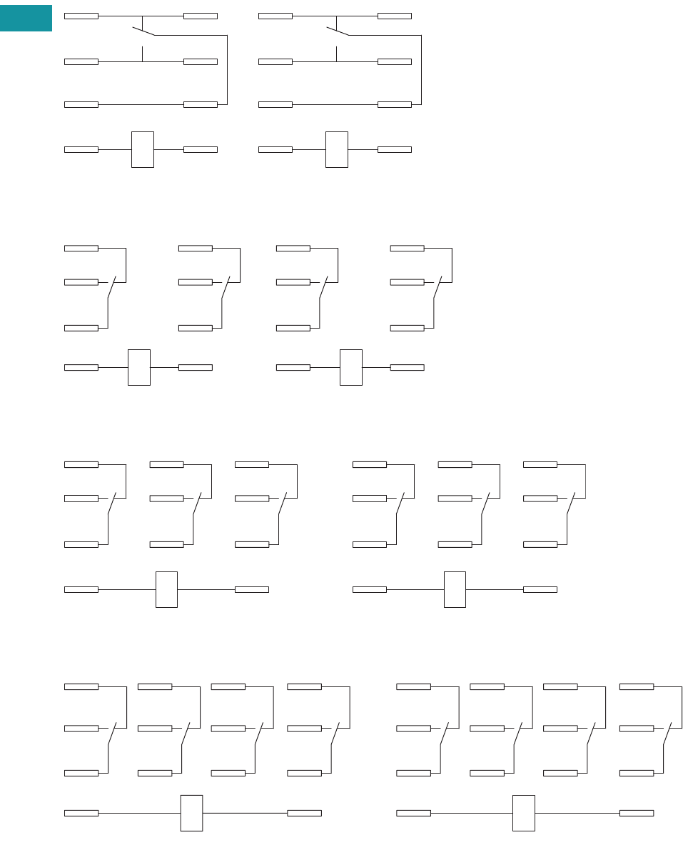
V7-T3-98 Volume 7—Logic Control, Operator Interface and Connectivity Solutions CA08100008E—February 2014 www.eaton.com
3
3
3
3
3
3
3
3
3
3
3
3
3
3
3
3
3
3
3
3
3
3
3
3
3
3
3
3
3
3
V7-T3-98 Volume 7—Logic Control, Operator Interface and Connectivity Solutions CA08100008E—February 2014 www.eaton.com
3
3
3
3
3
3
3
3
3
3
3
3
3
3
3
3
3
3
3
3
3
3
3
3
3
3
3
3
3
3
3.4
Control Relays and Timers
General Purpose Plug-In Relays
Wiring Diagrams
D7PR1/D7PF1
D7PR2/D7PF2
D7PR3/D7PF3
D7PR4/D7PF4
A2
A1
11
14
12
41
44
42
IEC
5
13
9
1
8
12
14
4
NEMA
42
44
12
14
A1
11
A2
41
IEC
4
8
1
5
13
12
14
9
NEMA
11
A1
14
21
24
12 22
41
44
42
A2
IEC
9
13
5
10
6
12
12
8
4
14
NEMA
A1 A2
11 21
14 24
31
34
22
12 32
44
41
42
IEC
13 14
10
911
56
12
7
3
12
4
8
NEMA
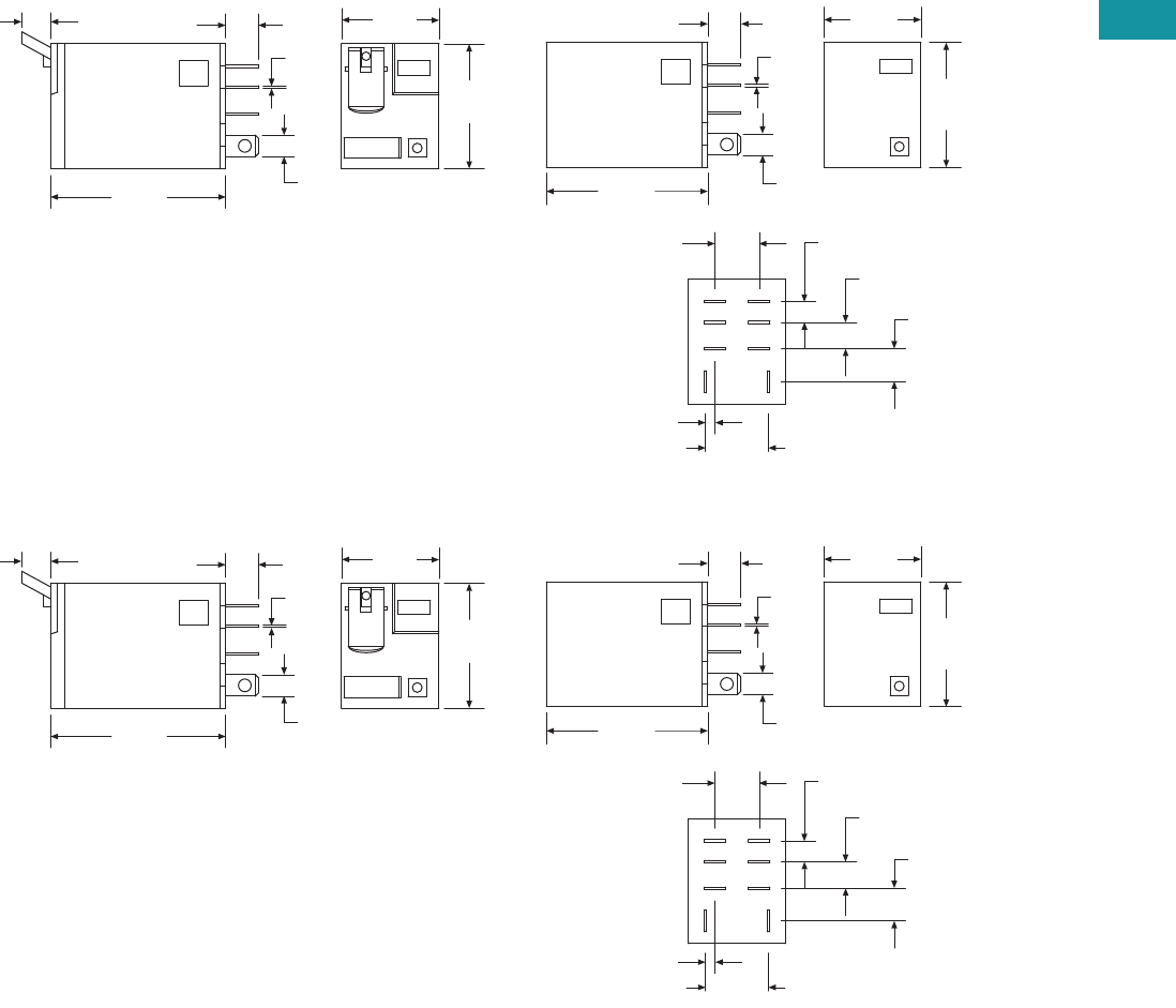
Volume 7—Logic Control, Operator Interface and Connectivity Solutions CA08100008E—February 2014 www.eaton.com V7-T3-99
3
3
3
3
3
3
3
3
3
3
3
3
3
3
3
3
3
3
3
3
3
3
3
3
3
3
3
3
3
3
Volume 7—Logic Control, Operator Interface and Connectivity Solutions CA08100008E—February 2014 www.eaton.com V7-T3-99
3
3
3
3
3
3
3
3
3
3
3
3
3
3
3
3
3
3
3
3
3
3
3
3
3
3
3
3
3
3
3.4
Control Relays and Timers
General Purpose Plug-In Relays
Dimensions
Approximate Dimensions in Inches (mm)
D7PR1/D7PF1
D7PR2/D7PF2
0.16
(4.7)
0.23
(5.9)
0.30
(7.5)
0.38
(9.9)
0.55
(14.1)
0.08
(2.1)2X
0.83
(21.0)
1.10
(27.9)
0.19
(4.8)
0.02
(0.5)
0.29
(7.4)
1.40
(35.5)
0.83
(21.0)
1.10
(27.9)
1.54
(39.1)
0.29
(7.4)
0.02
(0.5)
0.19
(4.8)
0.27
(7.0)
0.16
(4.7)
0.23
(5.9)
0.30
(7.5)
0.38
(9.9)
0.55
(14.1)
0.08
(2.1)2X
0.83
(21.0)
1.10
(27.9)
0.19
(4.8)
0.02
(0.5)
0.29
(7.4)
1.40
(35.5)
0.83
(21.0)
1.10
(27.9)
1.54
(39.1)
0.29
(7.4)
0.02
(0.5)
0.19
(4.8)
0.27
(7.0)
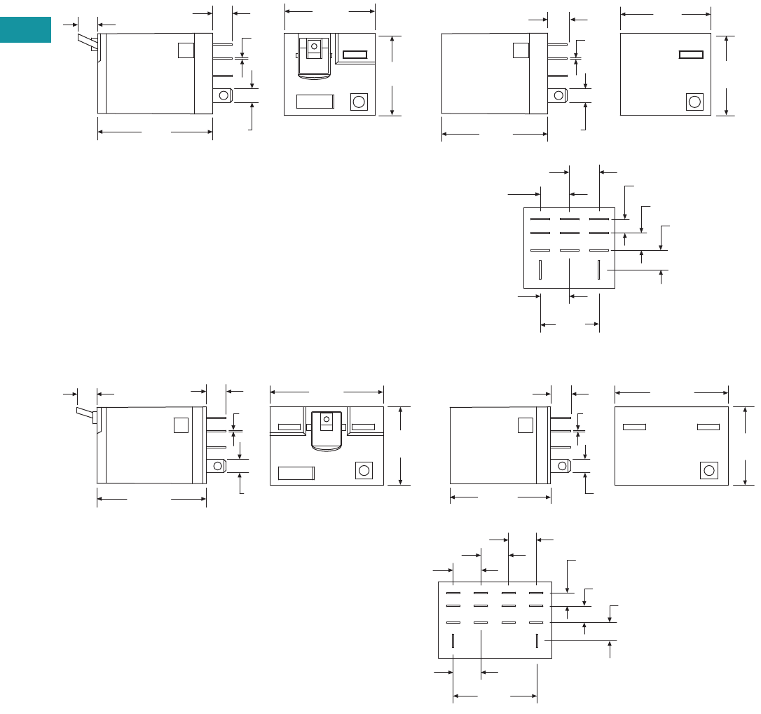
V7-T3-100 Volume 7—Logic Control, Operator Interface and Connectivity Solutions CA08100008E—February 2014 www.eaton.com
3
3
3
3
3
3
3
3
3
3
3
3
3
3
3
3
3
3
3
3
3
3
3
3
3
3
3
3
3
3
V7-T3-100 Volume 7—Logic Control, Operator Interface and Connectivity Solutions CA08100008E—February 2014 www.eaton.com
3
3
3
3
3
3
3
3
3
3
3
3
3
3
3
3
3
3
3
3
3
3
3
3
3
3
3
3
3
3
3.4
Control Relays and Timers
General Purpose Plug-In Relays
Approximate Dimensions in Inches (mm)
D7PR3/D7PF3
D7PR4/D7PF4
1.60
(40.0)
1.10
(27.9)
1.20
(30.8)
0.27
(7.0)
0.26
(6.6)
0.79
(20.0)
0.19
(4.7)
0.23
(5.9)0.26
(6.7)
0.39
(9.9)2X
0.19
(4.8)
0.02
(0.5)
0.39
(9.9)
0.39
(9.9)
1.20
(30.8)
1.10
(27.9)
0.02
(0.5)
0.19
(4.8)
0.29
(7.4)
1.40
(35.5)
1.60
(40.6)
1.60
(40.6)
1.54
(39.1)
0.02
(0.5)
0.19
(4.8)
0.38
(9.9)
0.16
(4.7)
0.23
(5.9) 0.26
(6.7)
1.18
(29.9)
0.38
(9.9)2X
1.10
(27.9)
0.38
(9.9)
0.38
(9.9)
0.26
(6.6)
1.10
(27.9)
1.40
(35.5)
0.19
(4.8)
0.29
(7.4) 0.02
(0.5)
0.27
(7.0)
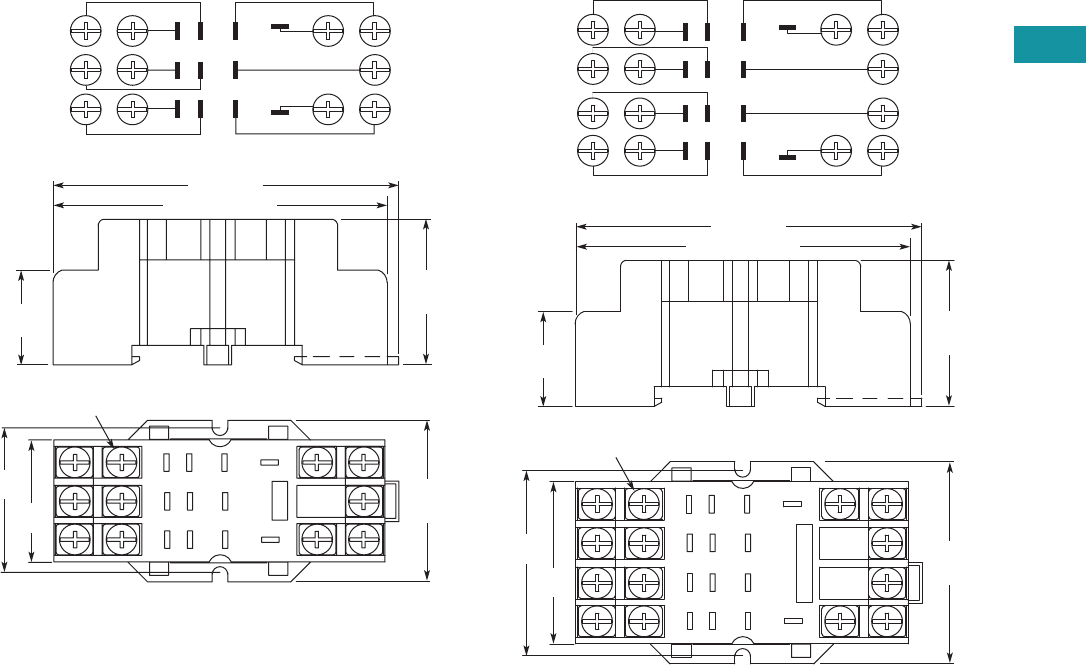
Volume 7—Logic Control, Operator Interface and Connectivity Solutions CA08100008E—February 2014 www.eaton.com V7-T3-101
3
3
3
3
3
3
3
3
3
3
3
3
3
3
3
3
3
3
3
3
3
3
3
3
3
3
3
3
3
3
Volume 7—Logic Control, Operator Interface and Connectivity Solutions CA08100008E—February 2014 www.eaton.com V7-T3-101
3
3
3
3
3
3
3
3
3
3
3
3
3
3
3
3
3
3
3
3
3
3
3
3
3
3
3
3
3
3
3.4
Control Relays and Timers
General Purpose Plug-In Relays
Approximate Dimensions in Inches (mm)
D7PA3 D7PA4
1.44
(36.6)
1.27
(32.5)
1
2
3
4
5
7
8
911
10
6
Combination Slotted/Phillips
Head Screws 6-32 x 5/16"
2.58 (67.5) Max.
2.74 (69.8)
0.65
(16.6)
1.59
(40.5)
Max.
1.09
(27.8)
Max.
Wiring Diagram (Top View)
1
2
3
4
6
10
11
7
58
9
1
2
5
6
3
4
7
8
9
1214
11
13
10
1.83
(46.5)
1.63
(41.4)
2.58 (67.5) Max.
2.74 (69.8)
Combination Slotted/Phillips
Head Screws 6-32 x 5/16"
0.65
(16.6)
1.98
(50.5)
Max.
1.09
(27.8)
Max.
Wiring Diagram (Top View)
2
3
4
6
1
5
8
7
13
9
10
11
14
12
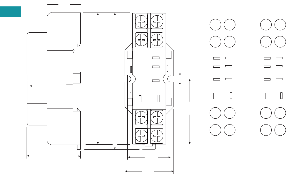
V7-T3-102 Volume 7—Logic Control, Operator Interface and Connectivity Solutions CA08100008E—February 2014 www.eaton.com
3
3
3
3
3
3
3
3
3
3
3
3
3
3
3
3
3
3
3
3
3
3
3
3
3
3
3
3
3
3
V7-T3-102 Volume 7—Logic Control, Operator Interface and Connectivity Solutions CA08100008E—February 2014 www.eaton.com
3
3
3
3
3
3
3
3
3
3
3
3
3
3
3
3
3
3
3
3
3
3
3
3
3
3
3
3
3
3
3.4
Control Relays and Timers
General Purpose Plug-In Relays
Approximate Dimensions in Inches (mm)
D7PA9 Standard Mount
8
5
1.02
(26.0)
1.17
(29.0)
4
14
12
1.03
(26.0)
0.16
(4.0)
1
13
1.26
(32.0)
9
2.73
(69.0)
2.52
(64.0)
44
42
14
12
41 11
A2 A1
N.C.
N.O.
COM
INPUT
85
4
1
14 13 14 13
12 9
0.71
(18.0)
IEC
INPUT
8
4
14
5
1
13
12 9
N.C.
N.O.
COM
INPUT
85
4
1
12 9
NEMA
INPUT
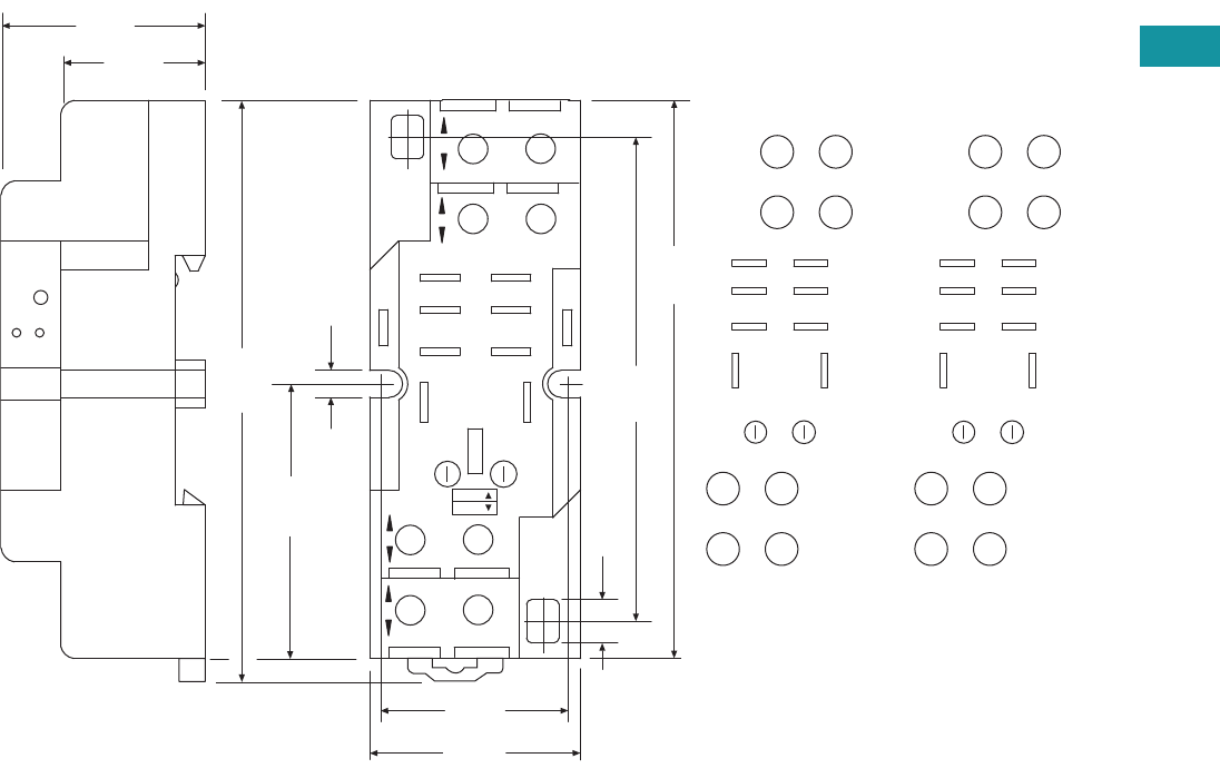
Volume 7—Logic Control, Operator Interface and Connectivity Solutions CA08100008E—February 2014 www.eaton.com V7-T3-103
3
3
3
3
3
3
3
3
3
3
3
3
3
3
3
3
3
3
3
3
3
3
3
3
3
3
3
3
3
3
Volume 7—Logic Control, Operator Interface and Connectivity Solutions CA08100008E—February 2014 www.eaton.com V7-T3-103
3
3
3
3
3
3
3
3
3
3
3
3
3
3
3
3
3
3
3
3
3
3
3
3
3
3
3
3
3
3
3.4
Control Relays and Timers
General Purpose Plug-In Relays
Approximate Dimensions in Inches (mm)
D7PAA
COM
N.O.
N.C.
INPUT
INPUT
1.18
(30.0)
0.24
(6.0)
2.67
(68.0)
3.14
(80.0)
1.18
(30.0)
3.33
(84.0)
1.57
(40.0)
11
41
A1
A2
12
42
14
44
1.06
(26.0)
12 9
14 13
41
85
41 11
A2 A1
42 12
14
44
85
41
14 13
12 9
INPUT INPUT
0.16
(4.0)
0.74
(19.0)
NEMA:
IEC:
MODULE
INPUT
IEC
COM
N.O.
N.C.
INPUT
INPUT
912
13
14
41
8 5
85
41
14 13
12 9
MODULE
INPUT
NEMA
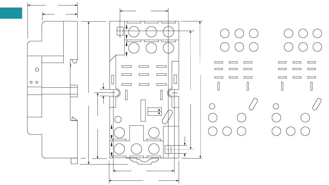
V7-T3-104 Volume 7—Logic Control, Operator Interface and Connectivity Solutions CA08100008E—February 2014 www.eaton.com
3
3
3
3
3
3
3
3
3
3
3
3
3
3
3
3
3
3
3
3
3
3
3
3
3
3
3
3
3
3
V7-T3-104 Volume 7—Logic Control, Operator Interface and Connectivity Solutions CA08100008E—February 2014 www.eaton.com
3
3
3
3
3
3
3
3
3
3
3
3
3
3
3
3
3
3
3
3
3
3
3
3
3
3
3
3
3
3
3.4
Control Relays and Timers
General Purpose Plug-In Relays
Approximate Dimensions in Inches (mm)
D7PAB
N.C.
N.O.
COM
INPUT
0.16
(4.0)
0.24
(6.0)
2.67
(68.0)
3.14
(80.0)
1.18
(30.0)
3.33
(84.0)
1.57
(40.0)
21 1141
12 10 9
INPUT
14
A2
13
A1
INPUT
8
4
42 22
65
21
44 24
12
14
A2
21
41
A1
11
44
42
14
12
24
22
421
865
12 10 9
14 13
1.57
(40.0)
1.45
(37.0)
1.10
(28.0)
0.74
(19.0)
MODULE
INPUT
IEC
NEMA:
IEC:
INPUT
N.C.
N.O.
COM
INPUT
1314
10 9
12
4
8
2
6
1
5
421
865
12 10 9
14 13
MODULE
INPUT
NEMA
INPUT
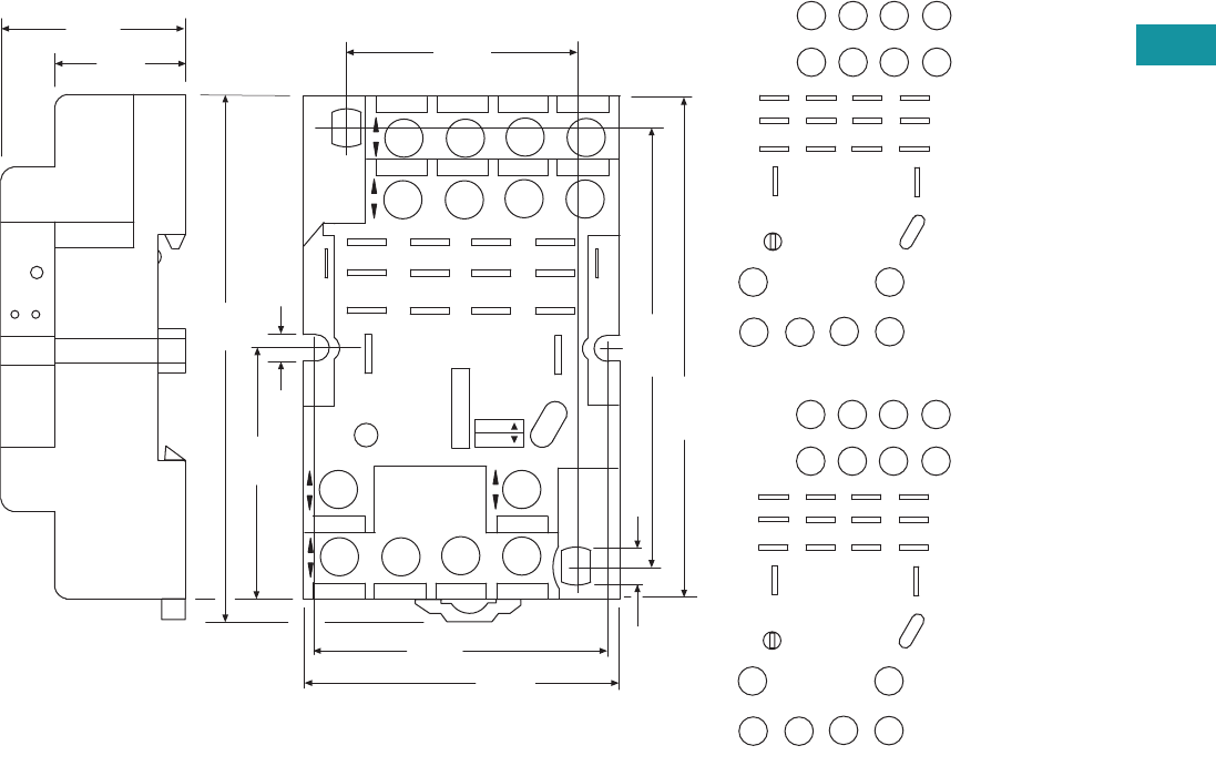
Volume 7—Logic Control, Operator Interface and Connectivity Solutions CA08100008E—February 2014 www.eaton.com V7-T3-105
3
3
3
3
3
3
3
3
3
3
3
3
3
3
3
3
3
3
3
3
3
3
3
3
3
3
3
3
3
3
Volume 7—Logic Control, Operator Interface and Connectivity Solutions CA08100008E—February 2014 www.eaton.com V7-T3-105
3
3
3
3
3
3
3
3
3
3
3
3
3
3
3
3
3
3
3
3
3
3
3
3
3
3
3
3
3
3
3.4
Control Relays and Timers
General Purpose Plug-In Relays
Approximate Dimensions in Inches (mm)
D7PAD
INPUT
N.O.
N.C.
COM
1.96
(50.0)
0.24
(6.0)
2.67
(68.0)
3.14
(80.0)
1.18
(30.0)
A2
14
12
41
INPUT INPUT
A1
13
9
10
11
21
31
11
6
7
24
34
8
44
2
3
4
42 22
32
5
14
1
12
41
A2
11
21
A1
31
223242 12
34 2444 14
4321
8765
12 11 10 9
1.81
(46.0)
1.41
(36.0)
0.74
(19.0)
NEMA:
IEC:
MODULE
INPUT
IEC
INPUT
INPUT
N.O.
N.C.
COM
14
12
13
9
10
11
6
7
8
2
3
4
5
1
4321
8765
12 11 10 9
MODULE
INPUT
NEMA
INPUT
0.16
(4.0)
3.33
(84.0)
1.57
(40.0)
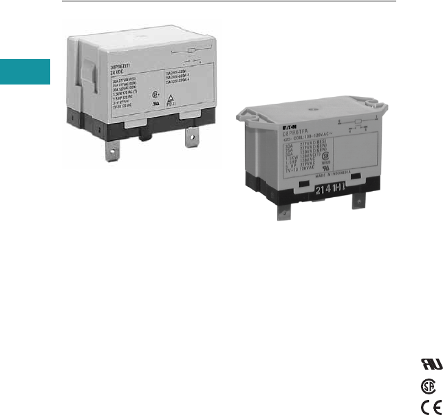
V7-T3-106 Volume 7—Logic Control, Operator Interface and Connectivity Solutions CA08100008E—February 2014 www.eaton.com
3
3
3
3
3
3
3
3
3
3
3
3
3
3
3
3
3
3
3
3
3
3
3
3
3
3
3
3
3
3
V7-T3-106 Volume 7—Logic Control, Operator Interface and Connectivity Solutions CA08100008E—February 2014 www.eaton.com
3
3
3
3
3
3
3
3
3
3
3
3
3
3
3
3
3
3
3
3
3
3
3
3
3
3
3
3
3
3
3.4
Control Relays and Timers
General Purpose Plug-In Relays
D8 Series Relay
Contents
Description Page
D1PR/D1PF Series . . . . . . . . . . . . . . . . . . . . . . . . . V7-T3-53
D2PR/D2PF Series . . . . . . . . . . . . . . . . . . . . . . . . . V7-T3-58
D3PR/D3PF Series . . . . . . . . . . . . . . . . . . . . . . . . . V7-T3-68
D4 Series . . . . . . . . . . . . . . . . . . . . . . . . . . . . . . . . V7-T3-78
D5PR/D5PF Series . . . . . . . . . . . . . . . . . . . . . . . . . V7-T3-82
D7PR/D7PF Series . . . . . . . . . . . . . . . . . . . . . . . . . V7-T3-91
D8 Series
Catalog Number Selection . . . . . . . . . . . . . . . . V7-T3-107
Product Selection . . . . . . . . . . . . . . . . . . . . . . . V7-T3-107
Technical Data and Specifications . . . . . . . . . . . V7-T3-108
Dimensions. . . . . . . . . . . . . . . . . . . . . . . . . . . . V7-T3-109
D9 Series . . . . . . . . . . . . . . . . . . . . . . . . . . . . . . . . V7-T3-112
Accessories . . . . . . . . . . . . . . . . . . . . . . . . . . . . . . V7-T3-116
D8 Series
Product Description
The D8 Series power relays
are perfect for loads up to
30A, with versions for flange
mounting and e-clip mounting
available.
Features
●Allows switching of 25A
and 30A loads
●A high-capacity, high-
withstand voltage relay
compatible with
momentary voltage drops
●No contact chattering for
momentary voltage drops
up to 50% of rated voltage
●UL Class B construction
standard
●Wide-range AC-activated
coil that handles 100 to 120
Vac at either 50
or 60 Hz
●Panel, DIN rail and flange
mounting
Standards and Certifications
File # E1491
File # LR701520
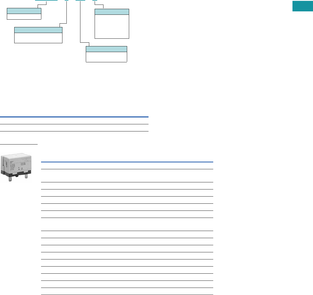
Volume 7—Logic Control, Operator Interface and Connectivity Solutions CA08100008E—February 2014 www.eaton.com V7-T3-107
3
3
3
3
3
3
3
3
3
3
3
3
3
3
3
3
3
3
3
3
3
3
3
3
3
3
3
3
3
3
Volume 7—Logic Control, Operator Interface and Connectivity Solutions CA08100008E—February 2014 www.eaton.com V7-T3-107
3
3
3
3
3
3
3
3
3
3
3
3
3
3
3
3
3
3
3
3
3
3
3
3
3
3
3
3
3
3
3.4
Control Relays and Timers
General Purpose Plug-In Relays
Catalog Number Selection
D8 Series 1
Product Selection
D8 Relay/Socket Quick Reference
D8 Series 2
Notes
1 For deciphering catalog numbers. Do not use for ordering as not all combinations are readily available.
2 Additional coil voltages available—consult Sales Office or Customer Support Center.
Relay
Type
Mounting
Bracket
Adapter Track/
Panel Mount
Front Connecting
Sockets Track/
Panel Mount
D8PR6TE D8PA5 D8PA1 D8PA2
D8PR7TE D8PA5 D8PA1 D8PA2
Type
Standard
Pack
Catalog
Number
SPST E-Bracket
Coil voltage
24 Vac 1 D8PR6TET
24 Vdc 1 D8PR6TET1
SPST Flange Mount
120 Vac 1 D8PR6TFA
24 Vdc 1 D8PR6TFT1
DPST E-Bracket
Coil voltage
120 Vac 1 D8PR7TEA
DPST Flange Mount
120 Vac 1 D8PR7TFA
24 Vdc 1 D8PR7TFT1
Sockets
DIN rail adapter 10 D8PA1
Screw terminal adapter 10 D8PA2
Bracket adapter 10 D8PA5
Accessory
DIN rail end stop 100 PFP-M
D 8 P R 6T E A
Family Type
D8PR
Contact Configuration
6 = SPST-NO
7 = DPST-NO
Options
TE = E-bracket
TF = Flange mount
Coil Voltage
A = 120 Vac
B = 240 Vac
R1 = 12 Vdc
T = 24 Vac
T1 = 24 Vdc
D8 Series Relay

V7-T3-108 Volume 7—Logic Control, Operator Interface and Connectivity Solutions CA08100008E—February 2014 www.eaton.com
3
3
3
3
3
3
3
3
3
3
3
3
3
3
3
3
3
3
3
3
3
3
3
3
3
3
3
3
3
3
V7-T3-108 Volume 7—Logic Control, Operator Interface and Connectivity Solutions CA08100008E—February 2014 www.eaton.com
3
3
3
3
3
3
3
3
3
3
3
3
3
3
3
3
3
3
3
3
3
3
3
3
3
3
3
3
3
3
3.4
Control Relays and Timers
General Purpose Plug-In Relays
Technical Data and Specifications
Coil Resistance
D8 Relays
Coil Data
Coil Voltage Ohms mA
24 Vac 303 71
110/120 Vac 5260 20.4
220/240 Vac 21,000 10.2
12 Vdc 75 158
24 Vdc 303 79
Description D8PR6 D8PR7
Rated load 220 Vac 30A 220 Vac 25A
Carry current 30A 25A
Max. operating voltage 250 Vac 250 Vac
Max. switching current 30A 25A
Contact material AgCdO AgCdO
Max. switching capacity 6600 VA 5500 VA
Min. permissible load 100 mA at 5 Vdc 100 mA at 5 Vdc
Mechanical life (min.) 5,000,000 operations 5,000,000 operations
Electrical life at all contact ratings (min.) 100,000 operations 100,000 operations
Maximum hp ratings 1-1/2 hp (120 Vac)
3 hp (240/265/277 Vac)
1-1/2 hp (120 Vac)
3 hp (240/265/277 Vac)
Coil Voltage Must Operate Must Release Maximum Voltage
24 Vdc/Vac, 12 Vdc 75% maximum 15% minimum 110%
120 Vac 75V 18V 132V
240 Vac 150V 36V 264V
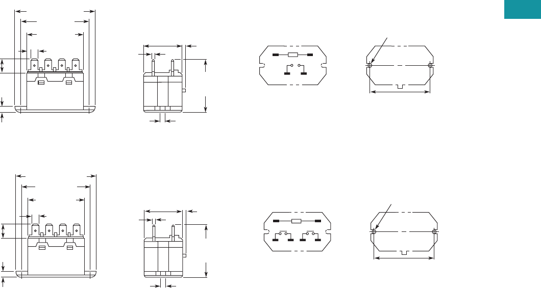
Volume 7—Logic Control, Operator Interface and Connectivity Solutions CA08100008E—February 2014 www.eaton.com V7-T3-109
3
3
3
3
3
3
3
3
3
3
3
3
3
3
3
3
3
3
3
3
3
3
3
3
3
3
3
3
3
3
Volume 7—Logic Control, Operator Interface and Connectivity Solutions CA08100008E—February 2014 www.eaton.com V7-T3-109
3
3
3
3
3
3
3
3
3
3
3
3
3
3
3
3
3
3
3
3
3
3
3
3
3
3
3
3
3
3
3.4
Control Relays and Timers
General Purpose Plug-In Relays
Dimensions
Approximate Dimensions in Inches (mm)
D8PR6TF
D8PR7TF
Two 0.18 (4.5) Dia. Holes
or M4 Tapped Holes
2.70 (68.5) Max.
1.32 (33.5)
Max. 0.08 (2.0)
1.85
(47.0)
Max.
0.18
(4.5)
0.03
(0.8)
2.36 (60.0)
1.99 (50.5)
Max.
0.25 (6.4)
0.43
(11.0)
0.12 (3.0)
01
46
2.362 0.007
(60.0 0.2)
Mounting Holes
(Bottom View)
Terminal Arrangement/
Internal Connections
(Top View)
Two 0.18 (4.5) Dia. Holes
or M4 Tapped Holes
2.70 (68.5) Max.
1.32 (33.5)
Max. 0.08 (2.0)
1.85
(47.0)
Max.
0.18
(4.5)
0.03
(0.8)
2.36 (60.0)
1.99 (50.5)
Max.
0.25 (6.4)
0.43
(11.0)
0.12
(3.0)
01
24
68
2.362 0.007
(60.0 0.2)
Mounting Holes
(Bottom View)
Terminal Arrangement/
Internal Connections
(Top View)
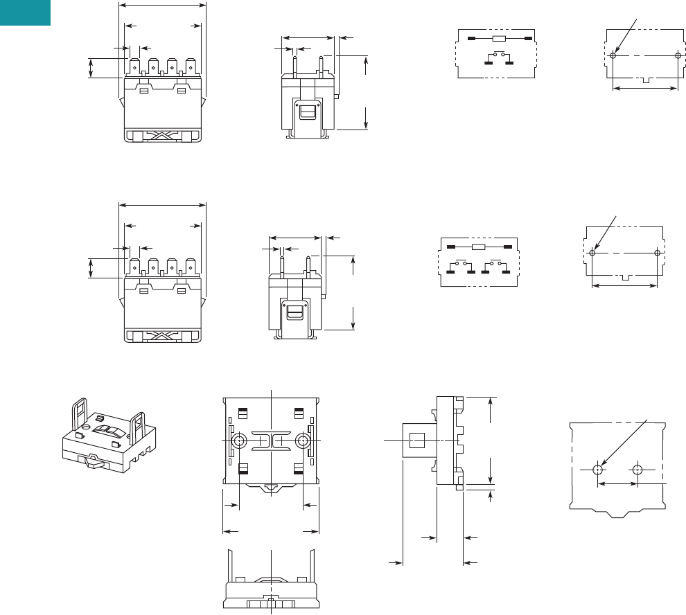
V7-T3-110 Volume 7—Logic Control, Operator Interface and Connectivity Solutions CA08100008E—February 2014 www.eaton.com
3
3
3
3
3
3
3
3
3
3
3
3
3
3
3
3
3
3
3
3
3
3
3
3
3
3
3
3
3
3
V7-T3-110 Volume 7—Logic Control, Operator Interface and Connectivity Solutions CA08100008E—February 2014 www.eaton.com
3
3
3
3
3
3
3
3
3
3
3
3
3
3
3
3
3
3
3
3
3
3
3
3
3
3
3
3
3
3
3.4
Control Relays and Timers
General Purpose Plug-In Relays
Approximate Dimensions in Inches (mm)
D8PR6TE with D8PA5 Bracket Attached
D8PR7TE with D8PA5 Bracket Attached
D8PA1
Note: Minimum spacing around relay = 0.20 inches (5 mm).
Two 0.18 (4.5) Dia. Holes
or M4 Tapped Holes
1.32 (33.5)
Max. 0.08 (2.0)
2.09
(53.0)
Max.
0.03
(0.8)
2.07 (52.5) Max.
1.99
(50.5) Max.
0.25 (6.4)
0.43
(11.0)
01
46
1.574 0.003
(40.0 0.1)
Mounting Holes
(Bottom View)
Terminal Arrangement/
Internal Connections
(Top View)
Two 0.18 (4.5) Dia. Holes
or M4 Tapped Holes
1.32 (33.5)
Max 0.08 (2.0)
2.09
(53.0)
Max.
0.03
(0.8)
2.07 (52.5) Max.
1.99
(50.5) Max.
0.25 (6.4) 01
24
68
1.574 0.003
(40.0 0.1)
Mounting Holes
(Bottom View)
Terminal Arrangement/
Internal Connections
(Top View)
0.43
(11.0)
2.19 (55.5)
Max.
2.03
(51.5)
Max.
0.20
(5.0)
1.574 0.003
(40.0 0.1)
1.39 (35.2)
Max.
0.57
(14.5)
1.574 0.003
(40.0 0.1)
Two M4 or
0.18 (4.5) Dia. Holes
Mounting Holes
(Bottom View)
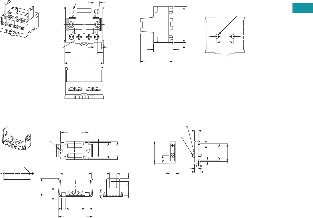
Volume 7—Logic Control, Operator Interface and Connectivity Solutions CA08100008E—February 2014 www.eaton.com V7-T3-111
3
3
3
3
3
3
3
3
3
3
3
3
3
3
3
3
3
3
3
3
3
3
3
3
3
3
3
3
3
3
Volume 7—Logic Control, Operator Interface and Connectivity Solutions CA08100008E—February 2014 www.eaton.com V7-T3-111
3
3
3
3
3
3
3
3
3
3
3
3
3
3
3
3
3
3
3
3
3
3
3
3
3
3
3
3
3
3
3.4
Control Relays and Timers
General Purpose Plug-In Relays
Approximate Dimensions in Inches (mm)
D8PA2
D8PA5 PFP-M DIN Rail End Stop
2.19 (55.5)
Max.
0.36 (9.2)
2.03
(51.5)
Max.
0.20
(5.0)
1.574 0.003
(40.0 0.1) 1.81 (46.0)
Max.
0.98
(25.0)
1.574 0.003
(40.0 0.1)
Two M4 or
0.18 (4.5) Dia. Holes
Two M3.5 Screws
for Coil
Four M4 Screws
for Contact
0.31 (8.0)
Mounting Holes
(Bottom View)
0.78
(19.7)
0.12
(3.0)
0.17
(4.4)
0.20
(5.0)
0.20
(5.0)
1.20 (50.0)
1.18
(30.0)
1.81
(46.0)
1.57
(40.0)
1.02
(26.0)
0.94
(24.0)
0.70
(17.8)
0.94
(24.0)
0.27
(7.0)
0.39
(10.0)
Two
0.18 (4.5)
Dia. Holes
1.574 0.003
(40.0 0.1)
Mounting
Holes
(Bottom View)
Two M4 or 0.18 (4.5)
Dia. Holes
1.97
(50.0)
0.45
(11.5)
1.47
(37.3)
1.39
(35.3)
0.39
(10.0)
0.39
(10.0)
0.19
(4.8) 0.05
(1.3)
0.24
(6.2)
0.07
(1.8)
0.07
(1.8)
M4 x 8 Pan
Head Screw
M4 Spring Washer
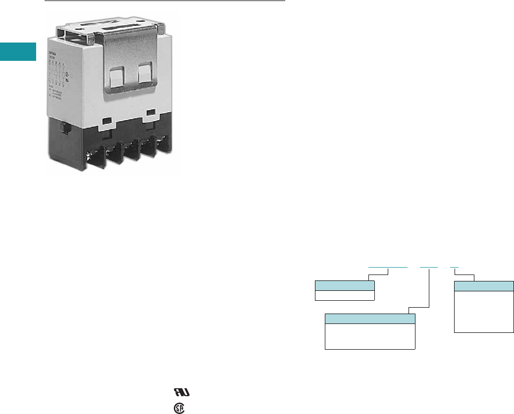
V7-T3-112 Volume 7—Logic Control, Operator Interface and Connectivity Solutions CA08100008E—February 2014 www.eaton.com
3
3
3
3
3
3
3
3
3
3
3
3
3
3
3
3
3
3
3
3
3
3
3
3
3
3
3
3
3
3
V7-T3-112 Volume 7—Logic Control, Operator Interface and Connectivity Solutions CA08100008E—February 2014 www.eaton.com
3
3
3
3
3
3
3
3
3
3
3
3
3
3
3
3
3
3
3
3
3
3
3
3
3
3
3
3
3
3
3.4
Control Relays and Timers
General Purpose Plug-In Relays
D9 Series Relay
Contents
Description Page
D1PR/D1PF Series . . . . . . . . . . . . . . . . . . . . . . . . . V7-T3-53
D2PR/D2PF Series . . . . . . . . . . . . . . . . . . . . . . . . . V7-T3-58
D3PR/D3PF Series . . . . . . . . . . . . . . . . . . . . . . . . . V7-T3-68
D4 Series . . . . . . . . . . . . . . . . . . . . . . . . . . . . . . . . V7-T3-78
D5PR/D5PF Series . . . . . . . . . . . . . . . . . . . . . . . . . V7-T3-82
D7PR/D7PF Series . . . . . . . . . . . . . . . . . . . . . . . . . V7-T3-91
D8 Series . . . . . . . . . . . . . . . . . . . . . . . . . . . . . . . . V7-T3-106
D9 Series
Product Selection . . . . . . . . . . . . . . . . . . . . . . . V7-T3-113
Technical Data and Specifications . . . . . . . . . . . V7-T3-113
Dimensions. . . . . . . . . . . . . . . . . . . . . . . . . . . . V7-T3-114
Accessories . . . . . . . . . . . . . . . . . . . . . . . . . . . . . . V7-T3-116
D9 Series
Product Description
The four-pole D9 Series is
ideal for three-phase motor
applications. Various contact
configurations are available.
Features
●Ideal for three-phase motor
control applications
●No contact chattering for
momentary voltage drops
up to 50% of rated voltage
●Push-to-Test button is a
standard feature to check
contact operation
●Mounting bracket is
supplied with relay
Standards and Certifications
File # E1491
File # LR701520
Catalog Number Selection
Contact Configuration
8B = 4PST-NO
9B = 3PST-NO/SPST-NC
10B = DPST-NO/DPST-NC
Family Type
D9PR
D 9 P R 8 B A
Coil Voltage
A = 120 Vac
B = 240 Vac
R1 = 12 Vdc
T = 24 Vac
T1 = 24 Vdc

Volume 7—Logic Control, Operator Interface and Connectivity Solutions CA08100008E—February 2014 www.eaton.com V7-T3-113
3
3
3
3
3
3
3
3
3
3
3
3
3
3
3
3
3
3
3
3
3
3
3
3
3
3
3
3
3
3
Volume 7—Logic Control, Operator Interface and Connectivity Solutions CA08100008E—February 2014 www.eaton.com V7-T3-113
3
3
3
3
3
3
3
3
3
3
3
3
3
3
3
3
3
3
3
3
3
3
3
3
3
3
3
3
3
3
3.4
Control Relays and Timers
General Purpose Plug-In Relays
Product Selection
D9 Series
Technical Data and Specifications
Coil Resistance
D9PR Specifications
Catalog
Number
Catalog
Number
4PST-NO Power Relay DPST-NO/DPST-NC Power Relay
Coil voltage Coil voltage
24 Vac D9PR8BT 24 Vac D9PR10BT
120 Vac D9PR8BA 120 Vac D9PR10BA
240 Vac D9PR8BB 24 Vac D9PR10BT1
24 Vdc D9PR8BT1
3PST-NO/SPST-NC Power Relay
120 Vac D9PR9BA
Coil Voltage Ohms mA Coil Voltage Ohms mA
24 Vac — 75 12 Vdc 72 167
120 Vac — 21.6 24 Vdc 288 83
240 Vac — 10.8 110 Vdc 6050 18
Description
NO Contacts
Resistive Load (p.f. = 1)
NC Contacts
Resistive Load (p.f. = 1)
Rated load 220 Vac 25A
30 Vdc 25A
220 Vac 8A
30 Vdc 8A
Carry current 25A 8A
Max. operating voltage 250 Vac/125 Vdc 250 Vac/125 Vdc
Max. switching current 25A 8A
Max. switching capacity 5500 VA
750W
1760 VA
240W
Min. permissible load 100 mA at 24 Vdc 100 mA at 24 Vdc
Mechanical life (min.) 1,000,000 operations 1,000,000 operations
Electrical life at all contact ratings (min.) 100,000 operations 100,000 operations
Maximum hp ratings 1-1/2 hp (120 Vac)
3 hp (240/265/277 Vac)
Three-phase 3 hp (240/265/277 Vac) 30,000 cycles
Three-phase 5 hp (240/265/277 Vac) 30,000 cycles
1-1/2 hp (120 Vac)
3 hp (240/265/277 Vac)
Three-phase 3 hp (240/265/277 Vac) 30,000 cycles
Three-phase 5 hp (240/265/277 Vac) 30,000 cycles
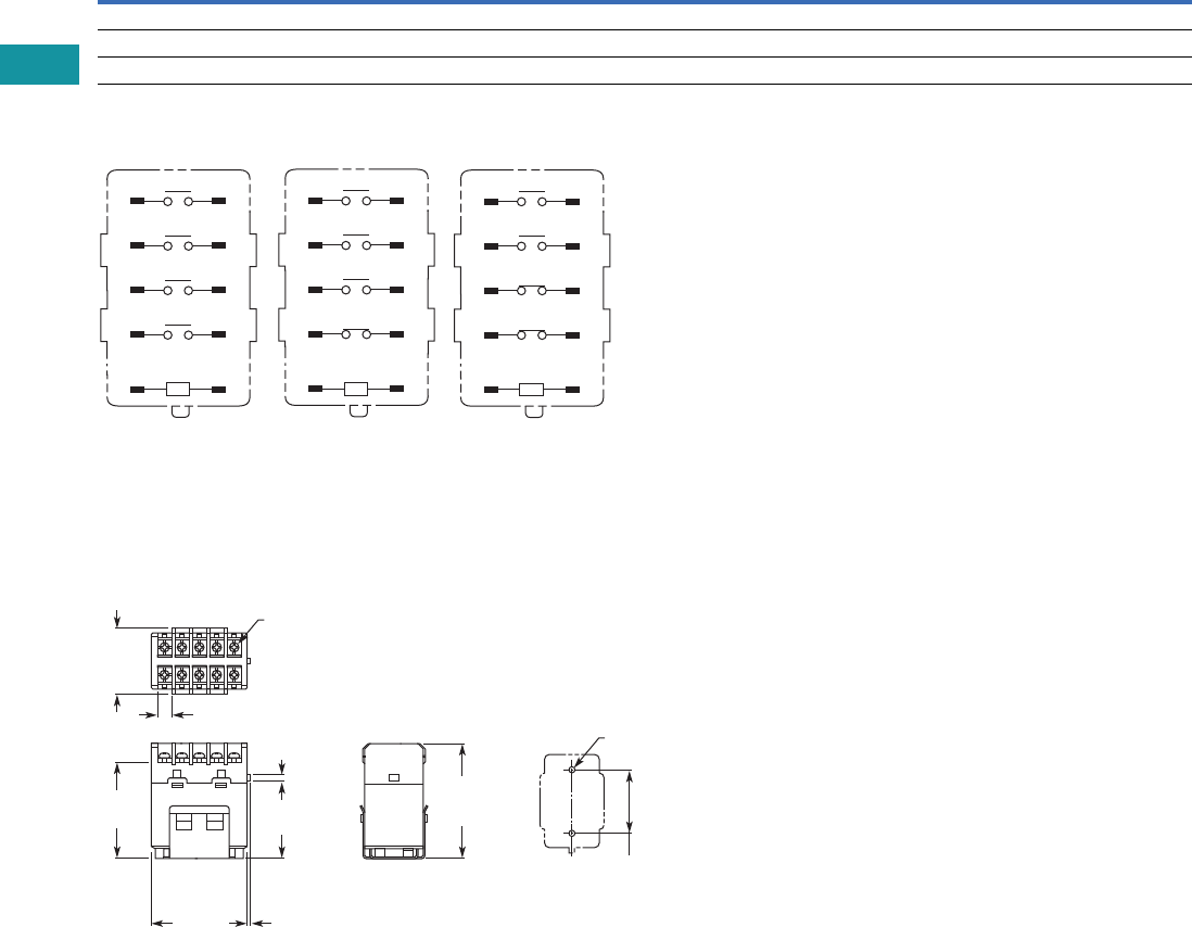
V7-T3-114 Volume 7—Logic Control, Operator Interface and Connectivity Solutions CA08100008E—February 2014 www.eaton.com
3
3
3
3
3
3
3
3
3
3
3
3
3
3
3
3
3
3
3
3
3
3
3
3
3
3
3
3
3
3
V7-T3-114 Volume 7—Logic Control, Operator Interface and Connectivity Solutions CA08100008E—February 2014 www.eaton.com
3
3
3
3
3
3
3
3
3
3
3
3
3
3
3
3
3
3
3
3
3
3
3
3
3
3
3
3
3
3
3.4
Control Relays and Timers
General Purpose Plug-In Relays
Coil Data
Terminal Arrangements
Dimensions
Approximate Dimensions in Inches (mm)
D9PR
Coil Voltage Must Operate Must Release Maximum Voltage
24 Vdc/Vac, 12 Vdc, 110 Vdc 75% maximum 10% minimum 110%
120 Vac 75V 18V 132V
240 Vac 150V 36V 264V
A2 A1
44 43
34 33
24 23
14 13
A2 A1
42 41
34 33
24 23
14 13
A2 A1
42 41
34 33
24 23
14 13
D9PR8 D9PR9 D9PR10
2.03
(51.5)
Max.
1.70
(43.2)
2.52
(64.0)
Max.
1.378 0.004
(35.0 0.1)
0.08
(2.0)
0.30
(7.6)
2.17
(55.2)
1.36
(34.5)
Max.
0.17
(4.3)
Two M4 or
0.18 (4.5) Dia.
Ten M3.5
Screw Terminal Brackets
Mounting Holes
(Bottom View)
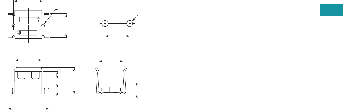
Volume 7—Logic Control, Operator Interface and Connectivity Solutions CA08100008E—February 2014 www.eaton.com V7-T3-115
3
3
3
3
3
3
3
3
3
3
3
3
3
3
3
3
3
3
3
3
3
3
3
3
3
3
3
3
3
3
Volume 7—Logic Control, Operator Interface and Connectivity Solutions CA08100008E—February 2014 www.eaton.com V7-T3-115
3
3
3
3
3
3
3
3
3
3
3
3
3
3
3
3
3
3
3
3
3
3
3
3
3
3
3
3
3
3
3.4
Control Relays and Timers
General Purpose Plug-In Relays
Approximate Dimensions in Inches (mm)
Mounting Bracket
Mounting Holes
1.37
(35.0)
0.95
(24.0)
1.18
(30.0)
1.73
(44.0)
1.14
(29.0)
0.35
(9.0)
0.17
(4.4)
1.10
(28.0)
0.28
(7.0)
1.378 0.004
(35.0 1.0)
Two M4 or
0.18 (4.5) Dia. Two M4
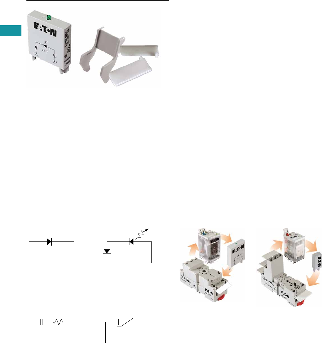
V7-T3-116 Volume 7—Logic Control, Operator Interface and Connectivity Solutions CA08100008E—February 2014 www.eaton.com
3
3
3
3
3
3
3
3
3
3
3
3
3
3
3
3
3
3
3
3
3
3
3
3
3
3
3
3
3
3
V7-T3-116 Volume 7—Logic Control, Operator Interface and Connectivity Solutions CA08100008E—February 2014 www.eaton.com
3
3
3
3
3
3
3
3
3
3
3
3
3
3
3
3
3
3
3
3
3
3
3
3
3
3
3
3
3
3
3.4
Control Relays and Timers
General Purpose Plug-In Relays
Accessories
Contents
Description Page
D1PR/D1PF Series . . . . . . . . . . . . . . . . . . . . . . . . . V7-T3-53
D2PR/D2PF Series . . . . . . . . . . . . . . . . . . . . . . . . . V7-T3-58
D3PR/D3PF Series . . . . . . . . . . . . . . . . . . . . . . . . . V7-T3-68
D4 Series . . . . . . . . . . . . . . . . . . . . . . . . . . . . . . . . V7-T3-78
D5PR/D5PF Series . . . . . . . . . . . . . . . . . . . . . . . . . V7-T3-82
D7PR/D7PF Series . . . . . . . . . . . . . . . . . . . . . . . . . V7-T3-91
D8 Series . . . . . . . . . . . . . . . . . . . . . . . . . . . . . . . . V7-T3-106
D9 Series . . . . . . . . . . . . . . . . . . . . . . . . . . . . . . . . V7-T3-112
Accessories
MOD Modules . . . . . . . . . . . . . . . . . . . . . . . . . V7-T3-117
Relay Clips . . . . . . . . . . . . . . . . . . . . . . . . . . . . V7-T3-118
Coil Bus Jumpers . . . . . . . . . . . . . . . . . . . . . . . V7-T3-120
Write-On Plastic Labels/ID Tags . . . . . . . . . . . . V7-T3-120
Flange Mount Adapters . . . . . . . . . . . . . . . . . . V7-T3-121
Accessories
Accessories Selection Guide
Eaton offers a variety of
simple-to-install relay
accessories that allow you to
customize the features of a
relay system to meet your
exact needs.
The MOD Module System
Eaton’s plug-in modules are a
simple way to add
functionality to your relay
without the hassle of messy
wiring and additional
mounting of external
electronics. They are available
in a variety of configurations
to meet the needs of almost
any application.
Circuit Diagrams
Diode Circuit
The diode module protects
external drive circuitry from
inductive voltages generated
when removing coil voltages.
RC Circuit
Snubs back EMF of relay coil.
LED Circuit
The LED status lamp verifies
that power is being supplied
to the coil. Ideal for both AC
and DC applications. Polarity
sensitive for DC applications.
Metal Oxide Varistor (MOV)
Circuit
The MOV circuit protects
by shunting potentially
damaging electrical spikes
away from the relay coil. Ideal
for AC and DC applications.
A2 A1
+
A2 A1
A2 A1
+
A2 A1
System Diagrams
The MOD Module System
Volume 7—Logic Control, Operator Interface and Connectivity Solutions CA08100008E—February 2014 www.eaton.com V7-T3-117
3
3
3
3
3
3
3
3
3
3
3
3
3
3
3
3
3
3
3
3
3
3
3
3
3
3
3
3
3
3
Volume 7—Logic Control, Operator Interface and Connectivity Solutions CA08100008E—February 2014 www.eaton.com V7-T3-117
3
3
3
3
3
3
3
3
3
3
3
3
3
3
3
3
3
3
3
3
3
3
3
3
3
3
3
3
3
3
3.4
Control Relays and Timers
General Purpose Plug-In Relays
MOD Modules
Eaton’s relay accessories
provide a complete solution
for add-on modules and
identification tags.
MOD Modules
Module
Size Description Nominal Voltage
Catalog
Number
Mating
Sockets
A Protection diode 6–250 Vdc MOD-AD250 D3PA6, D3PAL8,
D3PA7, D3PAL11,
D5PAL, D7PAB,
D7PAD
R/C suppressor 6–24 Vac MOD-RC24
110–240 Vac MOD-RC240
LED indicator 24 Vac MOD-ALG24
120/240 Vac MOD-ALG240
MOV suppressor 24 Vac MOD-AMV24
120 Vac MOD-AMV120
240 Vac MOD-AMV240
B Protection diode 6–250 Vdc MOD-BD250 D1PAA, D2PAL,
D2PAP, D2PA7,
D7PAA
LED indicator 24 Vac MOD-BLG24
120/240 Vac MOD-BLG240
MOV suppressor 24 Vac MOD-BMV24
120 Vac MOD-BMV120
240 Vac MOD-BMV240
MOD-AD250
MOD-ALG_
MOD-RC_
MOD-AMV_
MOD-BD250
MOD-BLG_
MOD-BMV_
V7-T3-118 Volume 7—Logic Control, Operator Interface and Connectivity Solutions CA08100008E—February 2014 www.eaton.com
3
3
3
3
3
3
3
3
3
3
3
3
3
3
3
3
3
3
3
3
3
3
3
3
3
3
3
3
3
3
V7-T3-118 Volume 7—Logic Control, Operator Interface and Connectivity Solutions CA08100008E—February 2014 www.eaton.com
3
3
3
3
3
3
3
3
3
3
3
3
3
3
3
3
3
3
3
3
3
3
3
3
3
3
3
3
3
3
3.4
Control Relays and Timers
General Purpose Plug-In Relays
Relay Clips
Eaton offers a variety of relay
clips designed to improve the
performance and
functionality within an
electrical panel.
Metal Hold-Down Clips
Metal hold-down clips, or
spring clips, are ideal for use
where high heat or humid
conditions are a factor. These
clips hold their shape and
tension and are designed
to withstand harsh
environments. All clips
are made of corrosion-
resistant stainless steel.
Metal Hold-Down Clips
Catalog
Number Mating Sockets Mating Relays
PMC-1781 D1PAA D1PR, D1PF
PQC-1782 D2PAL, D2PAP, D2PA7 D2PR2, D2PF2, D2PR3, D2PF4
PQC-1342 D2PA6, D7PAA, D7PA9 D2PR4, D2PF4
PQC-1332 D3PA6, D3PA7 D3PR2, D3PF2, D3PR3, D3PF3
PQC-1351 D3PAL8, D3PA2, D3PAL11, D3PA3,
D5PAL, D5PA2, D5PA3L, D5PA3S
D3PR2, D3PF2, D3PR3, D3PF4, D5PR, D5PF
PQC-1783 D7PAB D7PR1, D7PF1, D7PR2, D7PF3
PQC-1784 D7PAD D7PR4, D7PF4
PYC-A1 D2PA4 D2PR5
PYC-B2 D7PA3, D7PA4 D7PR1, D7PR2, D7PR4
PMC-1781
PQC-1782
PQC-1342
PQC-1332
PQC-1351
PQC-1783
PQC-1784
PYC- _
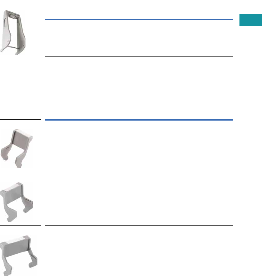
Volume 7—Logic Control, Operator Interface and Connectivity Solutions CA08100008E—February 2014 www.eaton.com V7-T3-119
3
3
3
3
3
3
3
3
3
3
3
3
3
3
3
3
3
3
3
3
3
3
3
3
3
3
3
3
3
3
Volume 7—Logic Control, Operator Interface and Connectivity Solutions CA08100008E—February 2014 www.eaton.com V7-T3-119
3
3
3
3
3
3
3
3
3
3
3
3
3
3
3
3
3
3
3
3
3
3
3
3
3
3
3
3
3
3
3.4
Control Relays and Timers
General Purpose Plug-In Relays
Plastic Ejector/
Hold-Down Clips
These clips are great for
applications where sockets
are located in dense or tight
areas. They allow for quick,
safe and firm securing of
relays in the sockets with the
added benefit that the relay
can be ejected with one
finger. Plastic clips also aid in
keeping operators’ fingers
away from live circuits. The
optional snap-in identification
tag allows for custom
marking of sockets when
used in multi-socket
applications.
Plastic ID Clips
Plastic ID clips allow for easy
circuit identification in multi-
relay applications. They are
designed for labeling and
are not ideal for securing
the relay in the socket.
Plastic Ejector/Hold-Down Clips
Plastic ID Clips
Catalog
Number Mating Sockets Mating Relays
PWC-D24 D2PAL, D2PAP, D2PA7 D2PF2, D2PF4
Catalog
Number Mating Sockets Mating Relays
PQC-1349 D7PAA D7PF1, D7PF2
PMC-1783 D7PAB D7PF1, D7PF2
PMC-1784 D7PAD D7PF4
PWC-D24
PQC-1349
PMC-1783
PMC-1784
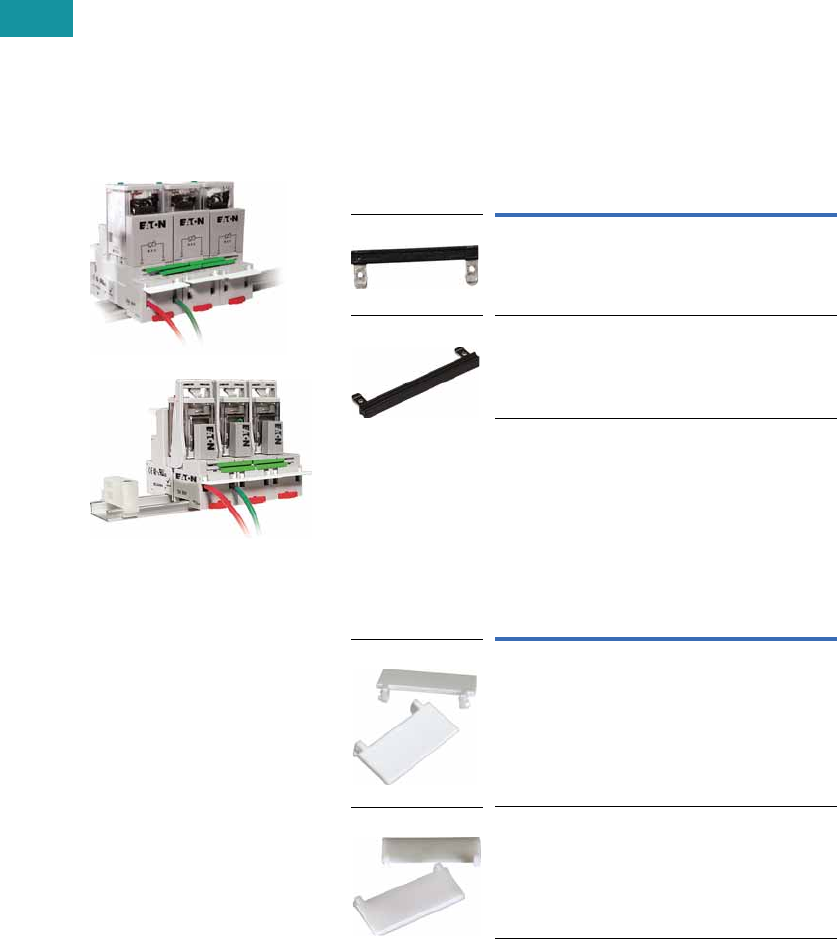
V7-T3-120 Volume 7—Logic Control, Operator Interface and Connectivity Solutions CA08100008E—February 2014 www.eaton.com
3
3
3
3
3
3
3
3
3
3
3
3
3
3
3
3
3
3
3
3
3
3
3
3
3
3
3
3
3
3
V7-T3-120 Volume 7—Logic Control, Operator Interface and Connectivity Solutions CA08100008E—February 2014 www.eaton.com
3
3
3
3
3
3
3
3
3
3
3
3
3
3
3
3
3
3
3
3
3
3
3
3
3
3
3
3
3
3
3.4
Control Relays and Timers
General Purpose Plug-In Relays
Coil Bus Jumpers
Eaton’s coil bus jumpers
allow inputs to be bridged
to adjacent sockets without
additional wiring, making
multi-relay connections quick
and easy. The easy-to-install
design requires no tools and
can be complete in a matter
of seconds.
System Diagrams
Coil Bus Jumpers 1
Write-On Plastic Labels/ID Tags
These convenient plastic
labels snap easily onto
the relay socket for clear
identification in multi-relay
panels. The hinged design
makes wiring simple and
allows for angular adjustment
of the tag to improve
readability in the panel.
Marking with a standard
permanent marker creates
a smudge-free surface.
Coil Bus Jumpers
Write-On Plastic Labels/ID Tags
Note
1 Jumpers in photo are colored green to improve visibility,
actual jumpers are black.
Catalog
Number Mating Sockets
D2PJ1 D2PAL, D2PAP
D3PJ1 D3PA6, D3PA7, D5PAL
Catalog
Number Mating Sockets
PWF-D2P D2PAL, D2PAP
PWF-D3D5 D3PAL8, D3PAL11, D5PAL
D2PJ1
D3PJ1
PWF-D2P
PWF-D3D5
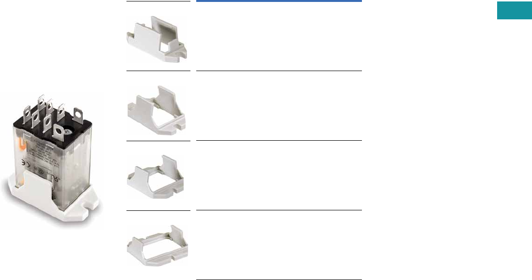
Volume 7—Logic Control, Operator Interface and Connectivity Solutions CA08100008E—February 2014 www.eaton.com V7-T3-121
3
3
3
3
3
3
3
3
3
3
3
3
3
3
3
3
3
3
3
3
3
3
3
3
3
3
3
3
3
3
Volume 7—Logic Control, Operator Interface and Connectivity Solutions CA08100008E—February 2014 www.eaton.com V7-T3-121
3
3
3
3
3
3
3
3
3
3
3
3
3
3
3
3
3
3
3
3
3
3
3
3
3
3
3
3
3
3
3.4
Control Relays and Timers
General Purpose Plug-In Relays
Flange Mount Adapters
Eaton’s relay flange mount
adapters create a modular
approach to flexible
mounting options. Each low-
cost adapter allows for panel
mounting of a standard
control relay and can
eliminate the need for
asocket.
Unit with Flange Mount
Adapter
Flange Mount Adapters
Catalog
Number Mating Relay
PFC-D11 D1PF1, D1PR1
PFC-D2D72 D2P, D7PF2, D7PR2
PFC-D73 D7PF3, D7PR3
PFC-D74 D7PF4, D7PR4
PFC-D11
PFC-D2D72
PFC-D73
PFC-D74
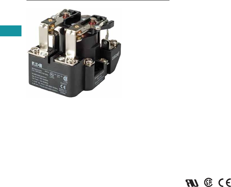
V7-T3-122 Volume 7—Logic Control, Operator Interface and Connectivity Solutions CA08100008E—February 2014 www.eaton.com
3
3
3
3
3
3
3
3
3
3
3
3
3
3
3
3
3
3
3
3
3
3
3
3
3
3
3
3
3
3
V7-T3-122 Volume 7—Logic Control, Operator Interface and Connectivity Solutions CA08100008E—February 2014 www.eaton.com
3
3
3
3
3
3
3
3
3
3
3
3
3
3
3
3
3
3
3
3
3
3
3
3
3
3
3
3
3
3
3.5
Control Relays and Timers
General Purpose Open Style Relays
9575H Series 3000 Relay
Contents
Description Page
9575H Series 3000—Type AA, AC and DC
Product Selection . . . . . . . . . . . . . . . . . . . . . . . V7-T3-123
Accessories. . . . . . . . . . . . . . . . . . . . . . . . . . . . V7-T3-123
Technical Data and Specifications . . . . . . . . . . . V7-T3-124
Dimensions. . . . . . . . . . . . . . . . . . . . . . . . . . . . V7-T3-125
9575H Series 3000—Type AA, AC and DC
Product Description
Type AA panel-mounted
relays are rated (each pole)
40A up to 300 Vac, 50/60 Hz;
5A at 480/600 Vac, 50/60 Hz
and 40A at 28 Vdc.
Application Description
9575H Series 3000 relays are
ideal for applications when
controlling smaller loads,
such as single-phase motors.
Standards and Certifications
●UL listed, E1491
●CSA 41729
●CE: EN60947-4-1,
EN60947-5-1
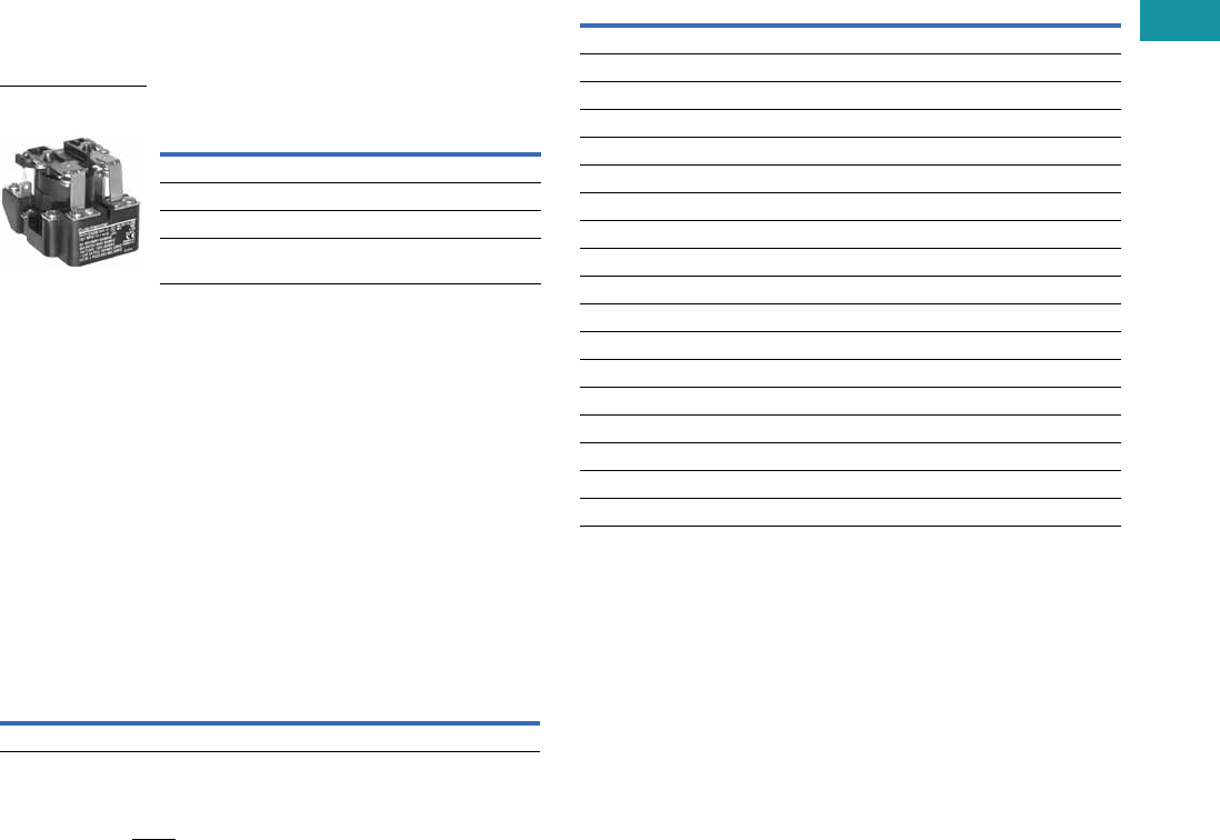
Volume 7—Logic Control, Operator Interface and Connectivity Solutions CA08100008E—February 2014 www.eaton.com V7-T3-123
3
3
3
3
3
3
3
3
3
3
3
3
3
3
3
3
3
3
3
3
3
3
3
3
3
3
3
3
3
3
Volume 7—Logic Control, Operator Interface and Connectivity Solutions CA08100008E—February 2014 www.eaton.com V7-T3-123
3
3
3
3
3
3
3
3
3
3
3
3
3
3
3
3
3
3
3
3
3
3
3
3
3
3
3
3
3
3
3.5
Control Relays and Timers
General Purpose Open Style Relays
Product Selection
When Ordering, Specify
Catalog number and magnet
coil code letter. Example: for
DPDT relay with auxiliary
switch and a 120V 50/60 Hz
coil, order Catalog Number
9575H3A010.
Type AA Relays 1
Accessories
Enclosure 3
Notes
1There are no “repair parts” available for these relays.
2Underscore indicates missing code suffix for magnet coil—see Selection table above.
3Only 9575H3 relays without an auxiliary switch should be mounted in the 9575H2449
enclosure.
Relay Style
Catalog
Number 2
Relay (DPDT) 9575H3_000
Relay with auxiliary switch 9575H3_010
Relay with blowout magnets 9575H3_100
Relay with auxiliary switch and
blowout magnets
9575H3_110
9575H Series 3000
Relay
Description
Catalog
Number
NEMA 1 Enclosure 9575H2449
Coil Voltage Selection
Coil Voltage Hz Suffix Code
Volts AC
120 50/60 A
240 50/60 B
480/440 60/50 C
600/550 60/50 D
208 50/60 E
277 50/60 H
6 50/60 J
12 50/60 K
24 50/60 L
48 50/60 M
Volts DC
110 — P
220 — Q
6—R
12 — S
24 — T
48 — W

V7-T3-124 Volume 7—Logic Control, Operator Interface and Connectivity Solutions CA08100008E—February 2014 www.eaton.com
3
3
3
3
3
3
3
3
3
3
3
3
3
3
3
3
3
3
3
3
3
3
3
3
3
3
3
3
3
3
V7-T3-124 Volume 7—Logic Control, Operator Interface and Connectivity Solutions CA08100008E—February 2014 www.eaton.com
3
3
3
3
3
3
3
3
3
3
3
3
3
3
3
3
3
3
3
3
3
3
3
3
3
3
3
3
3
3
3.5
Control Relays and Timers
General Purpose Open Style Relays
Technical Data and Specifications
Relay Specifications
Coil
●Pull-in voltage: 80%
DC coils, 85% AC coils
of nominal voltage
or less at 25ºC
●Dropout voltage: 10%
of nominal voltage
or more at 25ºC
●Coil resistance: ±10%
measured at 25ºC
●Max. DC coil dissipation
capability: 4 watts DC
continuous at 25ºC
Contacts
●Contact combination:
DPDT
●Contact rating each pole
(main contacts): Each pole
rated 40 amps up to 300
Vac, 50/60 Hz, 5 amps at
480/600 Vac 50/60 Hz,
0.75 PF load. 1-1/2 hp
motor load (each pole) at
120–600 Vac, 50/60 Hz.
2 hp motor load at
200–600 Vac, 50/60 Hz
only when using both
poles to switch both sides
of load, 40 amps at 28 Vdc
resistive load each pole.
NEMA A 600 pilot duty
50/60 Hz
●Additional contact ratings
for relays with blowout
magnets: 10A at 110 Vdc
resistive, 4A at 225 Vdc
resistive, 2A at 325 Vdc
resistive. For inductive
loads, contacts must be
derated accordingly.
●Contact material: Silver
cadmium oxide, gold
flashed. 5/16 in
(7.9 mm) diameter standard
Dielectric Withstanding Voltage
●Between open contacts:
1500 Vrms
●All other mutually insulated
conductive elements:
2200 Vrms
Miscellaneous
●Coil terminals: 6–32
screws
●Contact terminals: 8-–32
screws
●Main base material:
Molded phenolic, UL
recognized (QMFZ2)
●Weight (DPDT Relay):
11 oz (3 11 grams)
approximately
●Weight (DPDT Relay with
auxiliary switch) 14.5 oz
(411 grams) approximately
Auxiliary Switch Specifications
●Contact combination:
SPDT
●Contact rating: Auxiliary
switch rated 10 amps at
125 or 250 Vac, resistive
load; 1/4 hp at 125 or 250
Vac, motor load; 0.4 amps
at 125 Vdc or 0.20 amps at
250 Vdc, resistive load; 3
amps at 125 Vac lamp load.
All AC ratings are 50/60 Hz
●Dielectric withstanding
voltage: 500 Vac rms
between open contacts,
1500 Vac rms between all
other mutually insulated
conductive elements
●Terminals: 4–40 round
head screws for auxiliary
contacts standard
Average Operating Times (Milliseconds)
Temperature Ranges
Operation DPDT Relay DPDT Relay with Auxiliary Switch
Pickup 40 50
Dropout 35 35
Temperature AC DC
Operating range –30° to 55°C –30° to 55°C
Non-operating range –30° to 100°C –30° to 100°C
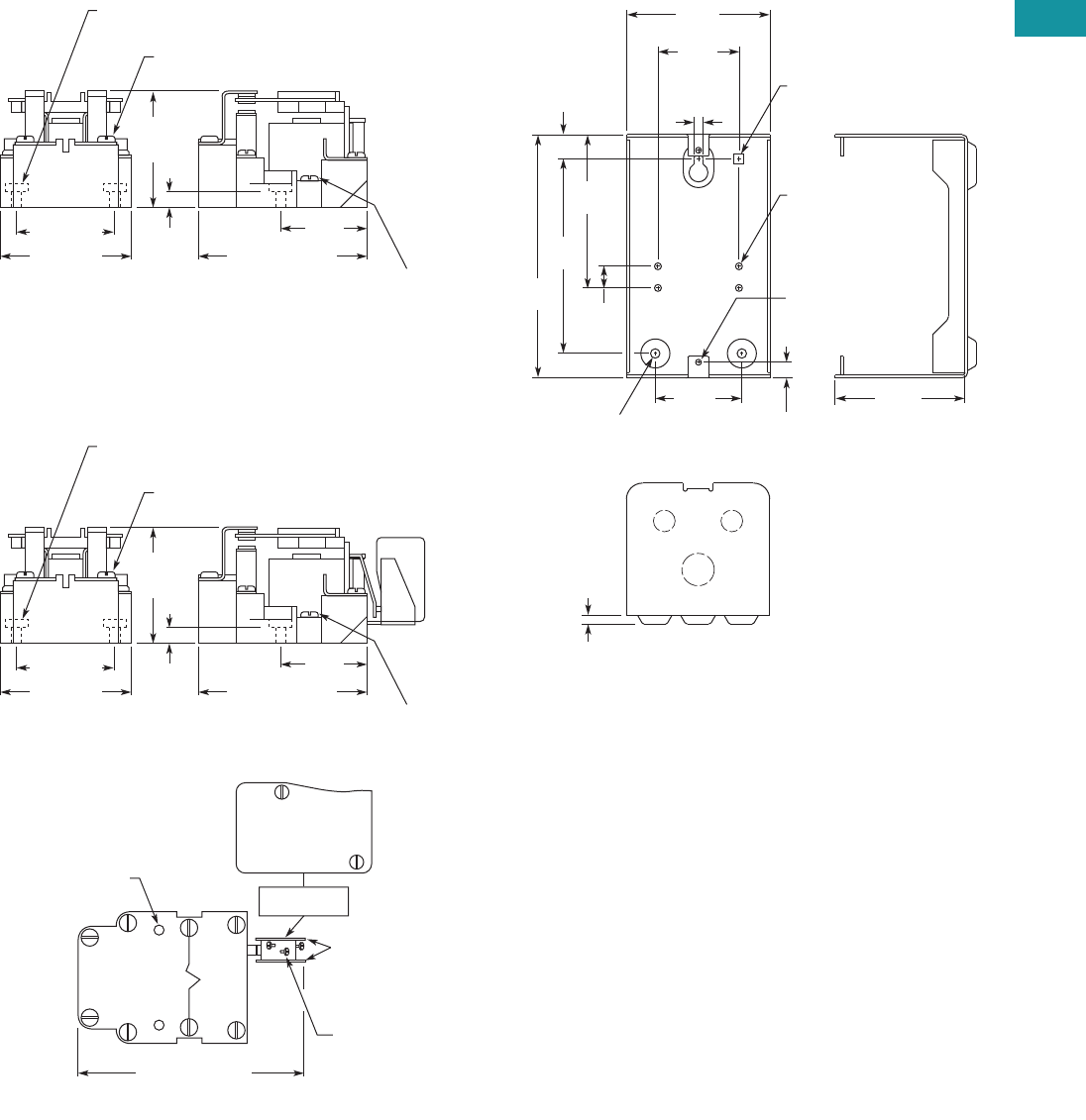
Volume 7—Logic Control, Operator Interface and Connectivity Solutions CA08100008E—February 2014 www.eaton.com V7-T3-125
3
3
3
3
3
3
3
3
3
3
3
3
3
3
3
3
3
3
3
3
3
3
3
3
3
3
3
3
3
3
Volume 7—Logic Control, Operator Interface and Connectivity Solutions CA08100008E—February 2014 www.eaton.com V7-T3-125
3
3
3
3
3
3
3
3
3
3
3
3
3
3
3
3
3
3
3
3
3
3
3
3
3
3
3
3
3
3
3.5
Control Relays and Timers
General Purpose Open Style Relays
Dimensions
Approximate Dimensions in Inches (mm)
9575H3 DPDT Relay
9575H3 DPDT Relay with Auxiliary SPDT Switch
9575H2449
2.25
(58.7)
Max.
8-32 Machine Screw on
Contact Terminals (6 Places)
Mounting Holes 0.187 (4.75) Dia. (2 Places)
0.38
(9.5)
1.87 (47.5) 1.62
(41.1)
6-32
Machine Screw
on Coil
Terminals
(2 Places)
2.50 (63.5) 3.12 (79.2) Max.
2.25
(58.7)
Max.
8-32 Machine Screw on
Contact Terminals (6 Places)
Mounting Holes 0.187 (4.75) Dia. (2 Places)
0.38
(9.5)
1.87 (47.5) 1.62
(41.1)
6-32
Machine Screw
on Coil
Terminals
(2 Places)
AUX. SWITCH
MARKING SURFACE
2.50 (63.5) 3.12 (79.2) Max.
Mounting Holes (2)
Screw Terminals
(4-40) RHMS
with External
Tooth Lockwashers
(3 Places)
Insulators
(2 Sides)
4.44 (112.7) Max.
NC
10A 1/4 hp 125 OR 250 Vac
0.4A at 125 Vdc, 0.2A at 250 Vdc
3A 125 Vac “LAMP”
278 VA 125/250 Vac P.D.
NO COM
RELAY TOP VIEW
0.159 (4) Dia.
10-32 Tap
Typ. 4 Places
0.36 (9.1)
Typ. 2 Places
0.218 (5.5) Dia.
Typ. 2 Places
0.218
(5.5)
Dia.
0.56
(4.3)
3.55
(90.1)
4.50
(114.3)
5.63
(142.9) 0.50
(2.7)
3.31
(84.2)
1.88
(47.6)
0.136 (3.4) Dia.
8-32 Tap
Typ. 2 Places
2.00
(50.8) 3.00
(76.2)
0.20
(5.1)
0.230 (5.8)
Square Hole
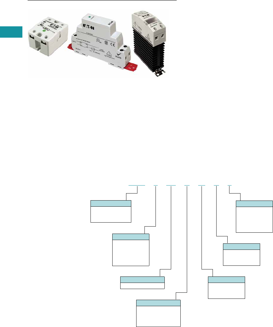
V7-T3-126 Volume 7—Logic Control, Operator Interface and Connectivity Solutions CA08100008E—February 2014 www.eaton.com
3
3
3
3
3
3
3
3
3
3
3
3
3
3
3
3
3
3
3
3
3
3
3
3
3
3
3
3
3
3
3.6
Control Relays and Timers
Solid-State Relays
Solid-State Relays
Contents
Description Page
Solid-State Relays
D93 Series . . . . . . . . . . . . . . . . . . . . . . . . . . . . V7-T3-127
D96 Series . . . . . . . . . . . . . . . . . . . . . . . . . . . . V7-T3-134
D99 Series . . . . . . . . . . . . . . . . . . . . . . . . . . . . V7-T3-139
Product Overview
Catalog Number Selection
Solid-State Relays—D93, D96 and D99 Series
Note
1For D96208ACZ3, output voltage is 3–150 Vdc.
Input Voltage
1 = 90–280 Vac
2 = 3–32 Vdc
3 = 3.5–32 Vdc
4 = 4–15 Vdc
5 = 20–50 Vdc
Output Type
C = SCR
T =Triac
M =MOSFET
Turn On Type
Z = Zero cross
R = Random
D =DC switch
Output Voltage
1 = 2–60 Vdc
2 = 24–280 Vac 1
3 = 3–200 Vdc
4 = 48–480 Vac
6 = 48–600 Vac
Current
Output current in amps
Contact Configuration
A = SPST-NO
B = SPST-NC
C = DPST-NO
D = DPST-NC
Description
D93 = Hockey puck
D96 = Compact
D99 = DIN rail
D 9 3 32 5 A M D 2
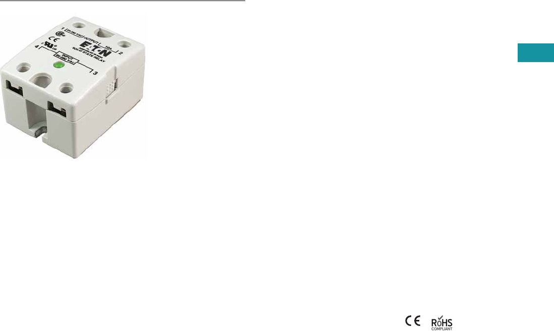
Volume 7—Logic Control, Operator Interface and Connectivity Solutions CA08100008E—February 2014 www.eaton.com V7-T3-127
3
3
3
3
3
3
3
3
3
3
3
3
3
3
3
3
3
3
3
3
3
3
3
3
3
3
3
3
3
3
3.6
Control Relays and Timers
Solid-State Relays
D93 Series—Solid-State Relays
Contents
Description Page
D93 Series
Product Selection . . . . . . . . . . . . . . . . . . . . . V7-T3-128
Accessories . . . . . . . . . . . . . . . . . . . . . . . . . . . V7-T3-128
Technical Data and Specifications . . . . . . . . . . V7-T3-129
Dimensions . . . . . . . . . . . . . . . . . . . . . . . . . . . V7-T3-133
D96 Series . . . . . . . . . . . . . . . . . . . . . . . . . . . . . . . V7-T3-134
D99 Series . . . . . . . . . . . . . . . . . . . . . . . . . . . . . . . V7-T3-139
D93 Series
Product Description
Eaton’s D93 series of solid-
state relays is a line of heavy-
duty industrial relays in the
common “hockey puck”
package. The removable,
finger-safe cover and optional
accessories make the D93
safe and easy to install in a
variety of applications.
Models are available in a
variety of input voltages and
switch types up to 75A.
Application Description
A solid-state relay (SSR) can
perform many applications
that an electromechanical
relay can perform. The SSR
differs in that it has no
moving mechanical parts
within it and has some
distinct advantages over an
electromechanical relay.
When used correctly in the
intended application, the SSR
provides a high degree of
reliability, a long service life,
significantly reduced
electromagnetic interference,
fast response and high
vibration resistance.
Applications for the SSR
typically include equipment
that requires high cycling
rates, low acoustical or
electrical noise, or high
vibration resistance. Some
examples are medical
equipment, heating/cooling
equipment, lighting control
and pumps/compressors,
among others.
Features and Benefits
●All solid-state circuitry with
no moving parts to wear
●Compact, panel mounting
for flexible installation
●Isolated input and output
terminals to protect the
system from electrical
noise
●Internal snubber circuitry
to protect the SSR from
transients
Standards and Certifications
●UL/cUL recognized—
UL 508
●CSA certified
●CE marked
●RoHS compliant
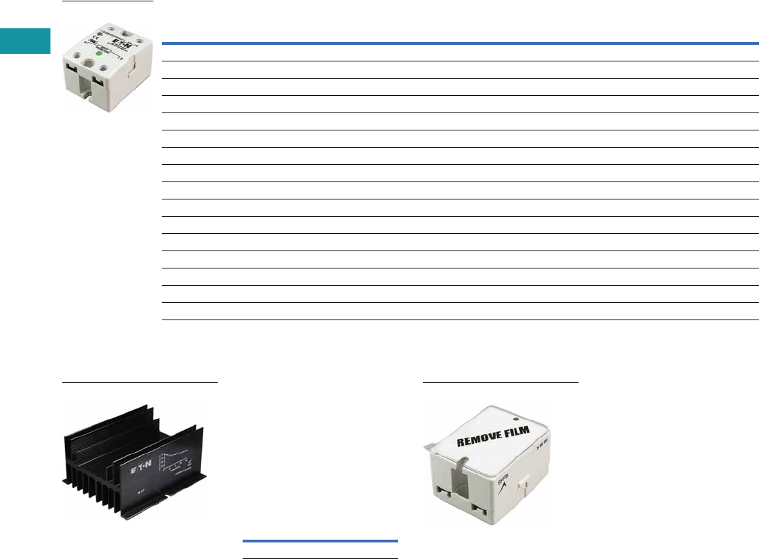
V7-T3-128 Volume 7—Logic Control, Operator Interface and Connectivity Solutions CA08100008E—February 2014 www.eaton.com
3
3
3
3
3
3
3
3
3
3
3
3
3
3
3
3
3
3
3
3
3
3
3
3
3
3
3
3
3
3
3.6
Control Relays and Timers
Solid-State Relays
Product Selection
D93 Series
Accessories
D93 Series—Heat Sink
Eaton’s D93HS1 heat sink is
specifically designed to be
used with D93 solid-state
relays. It is pre-drilled and
tapped, and matches the heat
dissipation requirements for
relays up to 50A.
Heat Sink Accessory
Note: Always ensure that all
details of the application are
considered when determining
heat dissipation requirements,
including ambient temperature.
The D93 relays must be firmly
mounted to the heat sink using a
suitable thermally conductive
grease or thermal transfer pad.
D93 Series—Thermal
Transfer Pad
The D93TP1 is a self-
adhesive transfer pad
designed for use with
Eaton’s D93 solid-state
relays. When used properly,
it will adequately conduct the
heat to a heat sink without
the use of grease.
Input Voltage Output Voltage
Contact
Configuration Switching Type
Rated Current
Load (Amps) Catalog Number
90–280 Vac 24–280 Vac SPST-NO Zero cross 10 D93210ACZ1
3–32 Vdc 24–280 Vac SPST-NO Zero cross 10 D93210ACZ2
3–32 Vdc 24–280 Vac SPST-NO Triac 10 D93210ATZ2
90–280 Vac 24–280 Vac SPST-NO Zero cross 25 D93225ACZ1
3–32 Vdc 24–280 Vac SPST-NO Zero cross 25 D93225ACZ2
3–32 Vdc 24–280 Vac SPST-NO Triac 25 D93225ATZ2
90–280 Vac 24–280 Vac SPST-NO Zero cross 40 D93240ACZ1
3–32 Vdc 24–280 Vac SPST-NO Zero cross 40 D93240ACZ2
3–32 Vdc 24–280 Vac SPST-NO Triac 40 D93240ATZ2
90–280 Vac 24–280 Vac SPST-NO Zero cross 50 D93250ACZ1
3–32 Vdc 24–280 Vac SPST-NO Zero cross 50 D93250ACZ2
90–280 Vac 24–280 Vac SPST-NO Zero cross 75 D93275ACZ1
3–32 Vdc 24–280 Vac SPST-NO Zero cross 75 D93275ACZ2
3–32 Vdc 3–200 Vdc SPST-NO MOSFET 12 D93312AMD2
3–32 Vdc 3–200 Vdc SPST-NO MOSFET 25 D93325AMD2
3–32 Vdc 3–200 Vdc SPST-NO MOSFET 40 D93340AMD2
D93210ACZ1
D93HS1
Description
Catalog
Number
Heat sink D93HS1
D93TP1

Volume 7—Logic Control, Operator Interface and Connectivity Solutions CA08100008E—February 2014 www.eaton.com V7-T3-129
3
3
3
3
3
3
3
3
3
3
3
3
3
3
3
3
3
3
3
3
3
3
3
3
3
3
3
3
3
3
3.6
Control Relays and Timers
Solid-State Relays
Technical Data and Specifications
D93 Series
Description Units D93210ACZ1 D93210ACZ2 D93210ATZ2 D93225ACZ1 D93225ACZ2 D93225ATZ2
Output Characteristics
Contact configuration SPST-NO SPST-NO SPST-NO SPST-NO SPST-NO SPST-NO
Switching device SCR SCR Triac SCR SCR Triac
Current rating A 10 10 10 25 25 25
Switching type Zero cross Zero cross Zero cross Zero cross Zero cross Zero cross
Maximum rate of rise off state voltage (DV/DT) V/us 200 250 700 500 500 250
Incandescent lamp ampere rating (rms) A 8 16 16 16 16 16
Motor load rating (rms) A 4.5 8 8 8 8 8
Min. load current to maintain on mA 50 120 250 120 120 120
Non-repetitive surge current (1 cycle) A 83 250 1000 250 250 250
Max. rms overload current (1 second) A 24 80 50 40 40 80
Max. off state leakage current (rms) mA 8 10 10 8 10 10
Peak blocking voltage Vpk 600 300 — 600 600 —
Typical on state voltage drop (rms) Vac 1.6 1.6 1.35 1.6 1.6 1.6
Max. on state voltage drop (rms) Vac 1.6 1.6 1.6 1.6 1.6 1.6
Max. I2t for fusing (A2) 72 300 1700 312 250 300
Input Characteristics
Must release voltage V 10 AC 1 DC 10 AC 10 AC 1 DC 1 DC
Typical input impedance ohms 13k Current regulator 16–25k 13k Current regulator 1.5k
Nominal input current at 5 Vdc or 240 Vac mA 20 2 12 20 16 2
Reverse polarity protection NA Yes NA NA Yes Yes
Performance Characteristics
Operating time (response time)
ON ms8.38.38.38.38.38.3
OFF ms 8.3 8.3 8.3 8.3 8.3 8.3
Rated insulation voltage—input to input Vac 4000 4000 4000 4000 4000 4000
Dielectric strength—terminal to chassis Vac 4000 4000 4000 4000 4000 4000
Environment
Product certifications UR, CSA, CE UR, CSA, CE UR, CSA, CE UR, CSA, CE UR, CSA, CE UR, CSA, CE
Ambient air temperature
Storage °C –40 to 100 –40 to 100 –40 to 100 –40 to 100 –40 to 100 –40 to 100
Operating °C –40 to 80 –40 to 80 –40 to 80 –40 to 80 –40 to 80 –40 to 80
Degree of protection IP20 IP20 IP20 IP20 IP20 IP20
Miscellaneous Characteristics
Thermal resistance (junction to case) °C/W 3.5 3.5 1.45 1.02 1.02 1.45
Weight g (oz) 100 (3.5) 100 (3.5) 100 (3.5) 100 (3.5) 100 (3.5) 100 (3.5)
LED—input Green Green Green Green Green Green
Input terminals M3.5 M3.5 M3.5 M3.5 M3.5 M3.5
Output terminals M4 M4 M4 M4 M4 M4
Terminal torque (max.) Nm 1.0 1.0 1.0 1.0 1.0 1.0

V7-T3-130 Volume 7—Logic Control, Operator Interface and Connectivity Solutions CA08100008E—February 2014 www.eaton.com
3
3
3
3
3
3
3
3
3
3
3
3
3
3
3
3
3
3
3
3
3
3
3
3
3
3
3
3
3
3
3.6
Control Relays and Timers
Solid-State Relays
D93 Series, continued
Description Units D93240ACZ1 D93240ACZ2 D93240ATZ2 D93250ACZ1 D93250ACZ2
Output Characteristics
Contact configuration SPST-NO SPST-NO SPST-NO SPST-NO SPST-NO
Switching device SCR SCR Triac SCR SCR
Current rating A 40 40 40 50 50
Switching type Zero cross Zero cross Zero cross Zero cross Zero cross
Maximum rate of rise off state voltage (DV/DT) V/us 500 500 250 500 500
Incandescent lamp ampere rating (rms) A 30 30 20 39 39
Motor load rating (rms) A 14 14 14 14 14
Min. load current to maintain on mA 250 250 50 250 250
Non-repetitive surge current (1 cycle) A 625 625 250 520 520
Max. rms overload current (1 second) A 80 80 80 100 100
Max. off state leakage current (rms)mA101010108
Peak blocking voltage Vpk 600 600 600 600 600
Typical on state voltage drop (rms) Vac 1.6 1.6 1.6 1.1 1.8
Max. on state voltage drop (rms) Vac 1.6 1.6 1.6 1.8 1.8
Max. I2t for fusing (A2) 1250 1250 438 1250 1250
Input Characteristics
Must release voltage V 10 AC 1 DC 1 DC 10 AC 1 DC
Typical input impedance ohms 13k ACL 1.5k 13k Current regulator
Nominal input current at 5 Vdc or 240 Vac mA 20 16 2 20 16
Reverse polarity protection N/A Yes Yes NA Yes
Performance Characteristics
Operating time (response time)
ON ms 8.3 8.3 8.3 8.3 8.3
OFF ms 8.3 8.3 8.3 8.3 8.3
Rated insulation voltage—input to input Vac 4000 4000 4000 4000 4000
Dielectric strength—terminal to chassis Vac 4000 4000 4000 4000 4000
Environment
Product certifications UR, CSA, CE UR, CSA, CE UR, CSA, CE UR, CSA, CE UR, CSA, CE
Ambient air temperature
Storage °C –40 to 100 –40 to 100 –40 to 100 –40 to 100 –40 to 100
Operating °C –40 to 80 –40 to 80 –40 to 80 –40 to 80 –40 to 80
Degree of protection IP20 IP20 IP20 IP20 IP20
Miscellaneous Characteristics
Thermal resistance (junction to case) °C/W 0.9 0.9 0.95 0.63 0.63
Weight g (oz) 100 100 100 135 (4.8) 135 (4.8)
LED—input Green Green Green Green Green
Input terminals M3.5 M3.5 M3.5 M3.5 M3.5
Output terminals M6M6M6M6M6
Terminal torque (max.) Nm 1.0 1.0 1.0 1.0 1.0

Volume 7—Logic Control, Operator Interface and Connectivity Solutions CA08100008E—February 2014 www.eaton.com V7-T3-131
3
3
3
3
3
3
3
3
3
3
3
3
3
3
3
3
3
3
3
3
3
3
3
3
3
3
3
3
3
3
3.6
Control Relays and Timers
Solid-State Relays
D93 Series, continued
Description Units D93275ACZ1 D93275ACZ2 D93312AMD2 D93325AMD2 D93340AMD2
Output Characteristics
Contact configuration SPST-NO SPST-NO SPST-NO SPST-NO SPST-NO
Switching device SCR SCR MOSFET MOSFET MOSFET
Current rating A 75 75 12 25 40
Switching type Zero cross Zero cross DC switching DC switching DC switching
Maximum rate of rise off state voltage (DV/DT) V/us 500 500 NA NA NA
Incandescent lamp ampere rating (rms) A 39 39 NA NA NA
Motor load rating (rms) A 25 25 NA NA NA
Min. load current to maintain on mA 250 250 20 20 20
Non-repetitive surge current (1 cycle) A 1150 1150 27 50 90
Max. rms overload current (1 second) A 150 150 NA NA NA
Max. off state leakage current (rms) mA 10 10 8 8 8
Peak blocking voltage Vpk 600 600 — — —
Typical on state voltage drop (rms) Vac 1.8 1.8 1.6 1.6 1.6
Max. on state voltage drop (rms) Vac 1.8 1.8 2.83 2.83 2.83
Max. I2t for fusing (A2) 5000 5000 NA NA NA
Input Characteristics
Must release voltage V 10 AC 1 DC 1 DC 1 DC 1 DC
Typical input impedance ohms 13k Current regulator 1k 1k 1k
Nominal input current at 5 Vdc or 240 Vac mA 20 16 10 10 10
Reverse polarity protection NA Yes No No No
Performance Characteristics
Operating time (response time)
ON ms 8.3 8.3 300 μs 600 μs 600 μs
OFF ms 8.3 8.3 1 2.6 2.6
Rated insulation voltage—input to input Vac 4000 4000 4000 4000 4000
Dielectric strength—terminal to chassis Vac 4000 4000 2500 2500 2500
Environment
Product certifications UR, CSA, CE UR, CSA, CE UR, CSA, CE UR, CSA, CE UR, CSA, CE
Ambient air temperature
Storage °C –40 to 100 –40 to 100 –40 to 100 –40 to 100 –40 to 100
Operating °C –40 to 80 –40 to 80 –40 to 80 –40 to 80 –40 to 80
Degree of protection IP20 IP20 IP20 IP20 IP20
Miscellaneous Characteristics
Thermal resistance (junction to case) °C/W 0.6 0.63 1.06 1.06 0.63
Weight g (oz) 200 135 (4.8) 110 (3.9) 110 (3.9) 135 (4.8)
LED—input Green Green Green Green Green
Input terminals M3.5 M3.5 M3.5 M3.5 M3.5
Output terminals M6M6M4M4M6
Terminal torque (max.) Nm 1.0 1.0 1.0 1.0 1.0
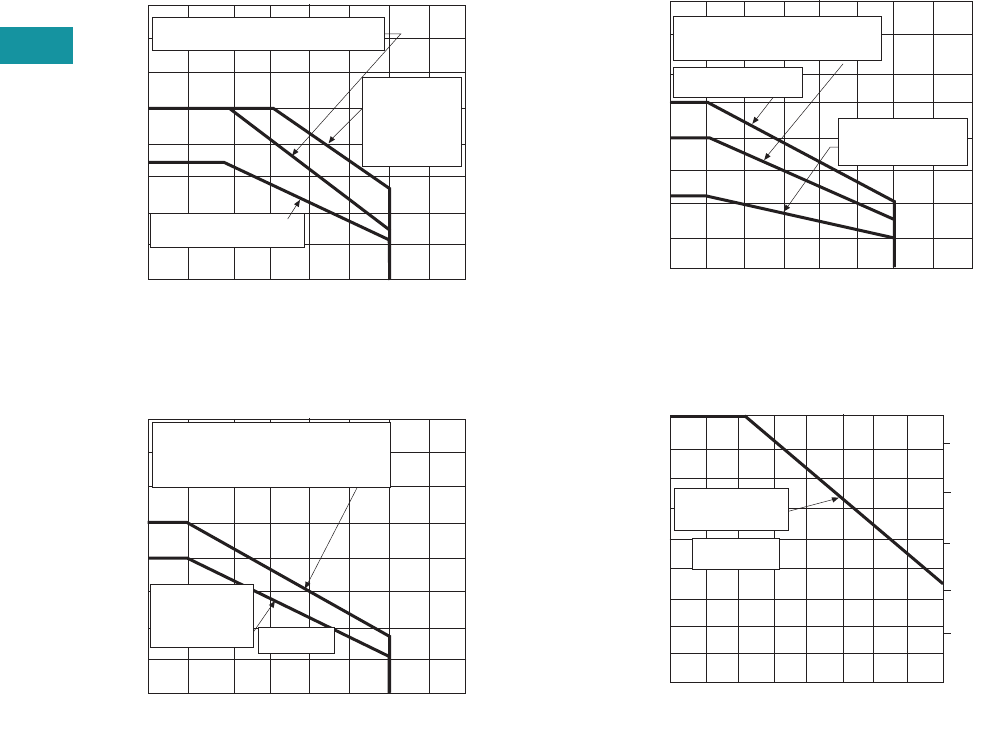
V7-T3-132 Volume 7—Logic Control, Operator Interface and Connectivity Solutions CA08100008E—February 2014 www.eaton.com
3
3
3
3
3
3
3
3
3
3
3
3
3
3
3
3
3
3
3
3
3
3
3
3
3
3
3
3
3
3
3.6
Control Relays and Timers
Solid-State Relays
Temperature Derating Curves
10 Amp Styles
25 Amp Styles
40 and 50 Amp Styles
75 Amp Styles
Load Current (amps rms)
16
14
12
10
8
6
4
2
20° 40° 60° 80° 100°
Max. Ambient Temperature (°C)
6" x 6" x 1/8" aluminum plate
Free air mounting
0
Heat sink
with 1°C/W
thermal
resistance
Load Current (amps rms)
40
35
30
25
20
15
10
5
20° 40° 60° 80° 100°
Max. Ambient Temperature (°C)
Mounted on heat sink with
1°C/W thermal resistance
(sink to ambient)
5" x 6" x 1/8"
aluminum
plate 1.5°C/W
Load Current (amps rms)
90
80
70
50
40
30
20
10
20° 40° 60° 80° 100°
Max. Ambient Temperature (°C)
Mounted on heat sink with
1°C/W thermal resistance
0
0.14°C/W (50A)
5" x 6" x 1/8"
aluminum plate
Load Current (amps rms)
75
60
45
40
30
20
10
20° 40° 60° 80°
Max. Ambient Temperature (°C)
030°0° 10° 70°
50°
90
95
100
105
110
Max. Allowable Temperature
5" x 6" x 1/8"
aluminum plate
0.14°C/W
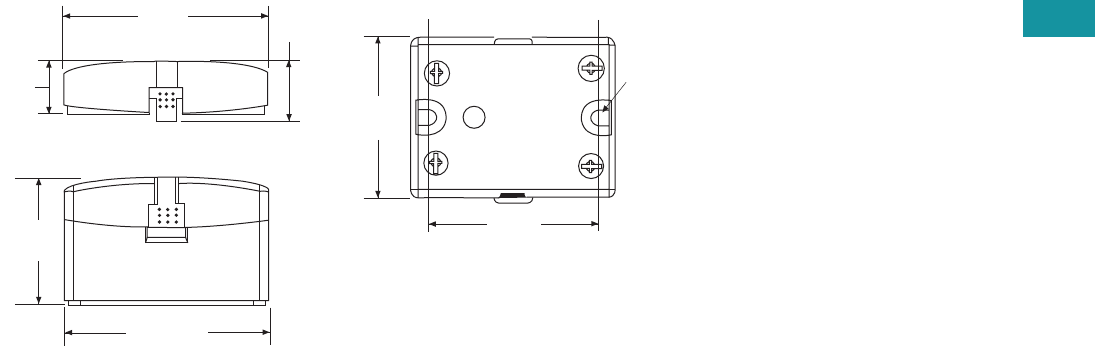
Volume 7—Logic Control, Operator Interface and Connectivity Solutions CA08100008E—February 2014 www.eaton.com V7-T3-133
3
3
3
3
3
3
3
3
3
3
3
3
3
3
3
3
3
3
3
3
3
3
3
3
3
3
3
3
3
3
3.6
Control Relays and Timers
Solid-State Relays
Dimensions
Approximate Dimensions in Inches (mm)
D93 Series
2.28
(57.9) 0.66
(16.8)
0.6
(15.1)
1.4
(35.9)
2.28
(57.9)
Screw Terminals
1.74
(44.1)
0.18
(4.4)
1.87
(47.5)
V7-T3-134 Volume 7—Logic Control, Operator Interface and Connectivity Solutions CA08100008E—February 2014 www.eaton.com
3
3
3
3
3
3
3
3
3
3
3
3
3
3
3
3
3
3
3
3
3
3
3
3
3
3
3
3
3
3
3.6
Control Relays and Timers
Solid-State Relays
D96 Series—Solid-State Relays
Contents
Description Page
D93 Series . . . . . . . . . . . . . . . . . . . . . . . . . . . . . . V7-T3-127
D96 Series
Product Selection . . . . . . . . . . . . . . . . . . . . V7-T3-135
Technical Data and Specifications . . . . . . . . . . V7-T3-136
Dimensions . . . . . . . . . . . . . . . . . . . . . . . . . . . V7-T3-138
D99 Series . . . . . . . . . . . . . . . . . . . . . . . . . . . . . . V7-T3-139
D96 Series
Product Description
Eaton’s D96 series of
solid-state relays is a
technologically advanced set
of electronic relays for tough
applications and harsh
environments. The compact
17.5 mm wide package
with an integrated heat sink
provides easy mounting
in tight spaces.
Application Description
A solid-state relay (SSR) can
perform many applications
that an electromechanical
relay can perform. The SSR
differs in that it has no
moving mechanical parts
within it and has some
distinct advantages over an
electromechanical relay.
When used correctly in the
intended application, the SSR
provides a high degree of
reliability, a long service life,
significantly reduced
electromagnetic interference,
fast response and high
vibration resistance.
Applications for the SSR
typically include equipment
that requires high cycling
rates, low acoustical or
electrical noise, or high
vibration resistance. Some
examples are medical
equipment, heating/cooling
equipment, lighting control
and pumps/compressors,
among others.
Features and Benefits
●All solid-state circuitry has
no moving parts to wear
●Integral heat sink
eliminates the need for
added accessories and
installation
●Flexible mounting allows
DIN rail or panel mounting
without additional
hardware or tools
●Isolated input and output
terminals protect the
system from electrical
noise
●Internal snubber circuitry
protects the SSR from
transients
Standards and Certifications
●UL/cUL listed—UL 508
●CSA certified
●CE marked
●RoHS compliant
Volume 7—Logic Control, Operator Interface and Connectivity Solutions CA08100008E—February 2014 www.eaton.com V7-T3-135
3
3
3
3
3
3
3
3
3
3
3
3
3
3
3
3
3
3
3
3
3
3
3
3
3
3
3
3
3
3
3.6
Control Relays and Timers
Solid-State Relays
Product Selection
D96 Series
Input Voltage Output Voltage
Contact
Configuration Switching Type
Rated Current
Load (Amps) Catalog Number
3.5–32 Vdc 3–50 Vdc SPST-NO DC switch 15 D96115ACZ3
3.5–32 Vdc 3–150 Vdc SPST-NO DC switch 8 D96208ACZ3
90–280 Vac 24–280 Vac SPST-NO Random 10 D96210ACR1
3–32 Vdc 24–280 Vac SPST-NO Random 10 D96210ACR2
90–280 Vac 24–280 Vac SPST-NO Zero cross 10 D96210ACZ1
3–32 Vdc 24–280 Vac SPST-NO Zero cross 10 D96210ACZ2
3–32 Vdc 24–280 Vac SPST-NC Random 10 D96210BCR2
90–280 Vac 48–480 Vac SPST-NO Random 10 D96410ACR1
3–32 Vdc 48–480 Vac SPST-NO Random 10 D96410ACR2
90–280 Vac 48–480 Vac SPST-NO Zero cross 10 D96410ACZ1
3–32 Vdc 48–480 Vac SPST-NO Zero cross 10 D96410ACZ2
90–280 Vac 48–600 Vac SPST-NO Random 10 D96610ACR1
90–280 Vac 48–600 Vac SPST-NO Zero cross 10 D96610ACZ1
3–32 Vdc 48–600 Vac SPST-NO Zero cross 10 D96610ACZ2
D96115ACZ3

V7-T3-136 Volume 7—Logic Control, Operator Interface and Connectivity Solutions CA08100008E—February 2014 www.eaton.com
3
3
3
3
3
3
3
3
3
3
3
3
3
3
3
3
3
3
3
3
3
3
3
3
3
3
3
3
3
3
3.6
Control Relays and Timers
Solid-State Relays
Technical Data and Specifications
D96 Series
Description Units D96210ACZ1 D96210ACZ2 D96210ACR1 D96210ACR2 D96115ACZ3 D96208ACZ3 D96210BCR2
Output Characteristics
Contact configuration SPST-NO SPST-NO SPST-NO SPST-NO SPST-NO SPST-NO SPST-NC
Switching device SCR SCR SCR SCR MOSFET MOSFET SCR
Current rating A10101010158 10
Switching type Zero cross Zero cross Random turn on Random turn on DC switching DC switching Random turn on
Maximum zero turn-on voltage (Vpk) V 35 35 35 35 NA NA 35
Maximum rate of rise off state voltage (DV/DT) V/us 500 500 500 500 NA NA 500
Incandescent lamp ampere rating (rms) A 8 8 8 8 NA NA 8
Motor load rating (rms) A 4.5 4.5 4.5 4.5 NA NA 4.5
Min. load current to maintain on mA 50 50 50 50 20 20 50
Non-repetitive surge current (1 cycle) A 500 500 500 500 50 35 500
Max. rms overload current (1 second) A 24 24 24 24 24 17 24
Max. off state leakage current (rms)mA10101010101010
Typical on state voltage drop (rms) V 1.25 AC 1.25 AC 1.25 AC 1.25 AC 1.25 DC 1.25 DC 1.25 AC
Max. on state voltage drop (rms) V 1.6 AC 1.6 AC 1.6 AC 1.6 AC 1.6 DC 1.6 DC 1.6 AC
Max. I2t for fusing (A2) 1250 1250 1250 1250 NA NA 1250
Input Characteristics
Must release voltage V 10 AC 1 DC 10 AC 1 DC 1 DC 1 DC 1 DC
Typical input impedance ohms 16–25k Current regulator 16–25k ACL Current regulator Current regulator ACL
Nominal input current at 5 Vdc or 240 Vac mA 12 16 12 16 12 12 12
Reverse polarity protection NA Yes NA Yes Yes Yes Yes
Performance Characteristics
Operating time (response time)
ON ms 40 8.3 8.3 8.3 5 5 8.3
OFF ms 80 8.3 8.3 8.3 5 5 8.3
Rated insulation voltage—input to input Vac 2500 2500 4000 4000 2500 2500 4000
Dielectric strength—terminal to chassis Vac 2500 2500 2500 2500 2500 2500 2500
Environment
Product certifications UL, CSA, CE UL, CSA, CE UL, CSA, CE UL, CSA, CE UL, CSA, CE UL, CSA, CE UL, CSA, CE
Ambient air temperature
Storage °C –40 to 100 –40 to 100 –40 to 100 –40 to 100 –40 to 100 –40 to 100 –40 to 100
Operating °C –30 to 80 –30 to 80 –30 to 80 –30 to 80 –30 to 80 –30 to 80 –30 to 80
Degree of protection IP20 IP20 IP20 IP20 IP20 IP20 IP20
Miscellaneous Characteristics
Thermal resistance (junction to case) °C/W 0.66 0.66 0.66 0.66 0.66 0.66 0.66
Integral heat sink °C/W 4.0 4.0 4.0 4.0 4.0 4.0 4.0
Weight g (oz) 127 (4.1) 127 (4.1) 127 (4.1) 127 (4.1) 127 (4.1) 127 (4.1) 127 (4.1)
LED—input Green Green Green Green Green Green Green
Terminal wire capacity AWG (mm2) 14 (2.1) 14 (2.1) 14 (2.1) 14 (2.1) 14 (2.1) 14 (2.1) 14 (2.1)
Terminal torque (max.) in-lb (Nm) 7.1 (0.8) 7.1 (0.8) 7.1 (0.8) 7.1 (0.8) 7.1 (0.8) 7.1 (0.8) 7.1 (0.8)
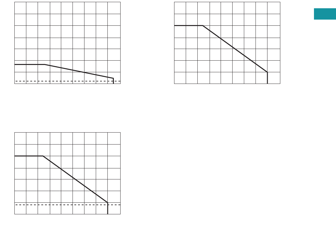
Volume 7—Logic Control, Operator Interface and Connectivity Solutions CA08100008E—February 2014 www.eaton.com V7-T3-137
3
3
3
3
3
3
3
3
3
3
3
3
3
3
3
3
3
3
3
3
3
3
3
3
3
3
3
3
3
3
3.6
Control Relays and Timers
Solid-State Relays
Temperature Derating Curves
8 Amp Style
10 Amp Style
15 Amp Style
Max. Ambient Temperature (°C)
0° 10° 20° 30° 40° 50° 60° 70° 80° 90°
85°
35
30
25
20
15
10
8
5
0
Load Current (amps rms)
1.5
Max. Ambient Temperature (°C)
0° 10° 20° 30° 40° 50° 60° 70° 80° 90°
14
12
10
8
6
4
2
0
Load Current (amps rms)
1.8
Ambient Temperature (°C)
0° 10° 20° 30° 40° 50° 60° 70° 80° 90°
24
18
15
12
9
6
3
0
Current (amps DC)
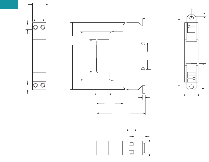
V7-T3-138 Volume 7—Logic Control, Operator Interface and Connectivity Solutions CA08100008E—February 2014 www.eaton.com
3
3
3
3
3
3
3
3
3
3
3
3
3
3
3
3
3
3
3
3
3
3
3
3
3
3
3
3
3
3
3.6
Control Relays and Timers
Solid-State Relays
Dimensions
Approximate Dimensions in Inches (mm)
D96 Series
0.69
(17.6)
1.40
(35.6)
1.78
(45.3)
0.20
(5.0)
0.56
(14.2)
0.27
(6.9)
0.55
(14.9)
0.62
(15.8)
0.24
(6.0)
2.63
(66.8)
3.54
(90.0)
2.56 Max.
(65.0)
0.63
(16.0)
1.36
(34.6)
0.13
(3.4)
1.39
(35.2)
3.64
(92.4)
0.20
(5.0)
0.07
(1.7)
0.56
(14.3)
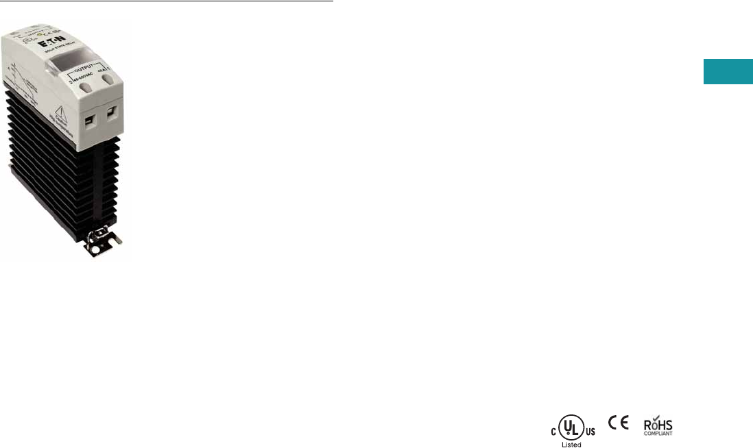
Volume 7—Logic Control, Operator Interface and Connectivity Solutions CA08100008E—February 2014 www.eaton.com V7-T3-139
3
3
3
3
3
3
3
3
3
3
3
3
3
3
3
3
3
3
3
3
3
3
3
3
3
3
3
3
3
3
3.6
Control Relays and Timers
Solid-State Relays
D99 Series—Solid-State Relays
Contents
Description Page
D93 Series . . . . . . . . . . . . . . . . . . . . . . . . . . . . . . . V7-T3-127
D96 Series . . . . . . . . . . . . . . . . . . . . . . . . . . . . . . . V7-T3-134
D99 Series
Product Selection . . . . . . . . . . . . . . . . . . . . . V7-T3-140
Technical Data and Specifications . . . . . . . . . . V7-T3-141
Dimensions . . . . . . . . . . . . . . . . . . . . . . . . . . . V7-T3-144
D99 Series
Product Description
Eaton’s D99 series of solid-
state relays is a line of
heavy-duty industrial relays
with an integrated heat sink.
The attached metal hardware
can be used for DIN rail or
panel mounting.
Models are available in a
variety of input voltages in
10A, 25A and 40A sizes.
Application Description
A solid-state relay (SSR) can
perform many applications
that an electromechanical
relay can perform. The SSR
differs in that it has no
moving mechanical parts
within it and has some
distinct advantages over an
electromechanical relay.
When used correctly in the
intended application, the SSR
provides a high degree of
reliability, a long service life,
significantly reduced
electromagnetic interference,
fast response and high
vibration resistance.
Applications for the SSR
typically include equipment
that requires high cycling
rates, low acoustical or
electrical noise, or high
vibration resistance. Some
examples are medical
equipment, heating/cooling
equipment, lighting control
and pumps/compressors,
among others.
Features and Benefits
●All solid-state circuitry has
no moving parts to wear
●Integral heat sink
eliminates the need for
added accessories and
installation
●Flexible mounting allows
DIN rail or panel mounting
without additional
hardware or tools
●Isolated input and output
terminals protect the
system from electrical
noise
●Internal snubber circuitry
protects the SSR from
transients
Standards and Certifications
●UL/cUL listed—UL 508
●CSA certified
●CE marked
●RoHS compliant
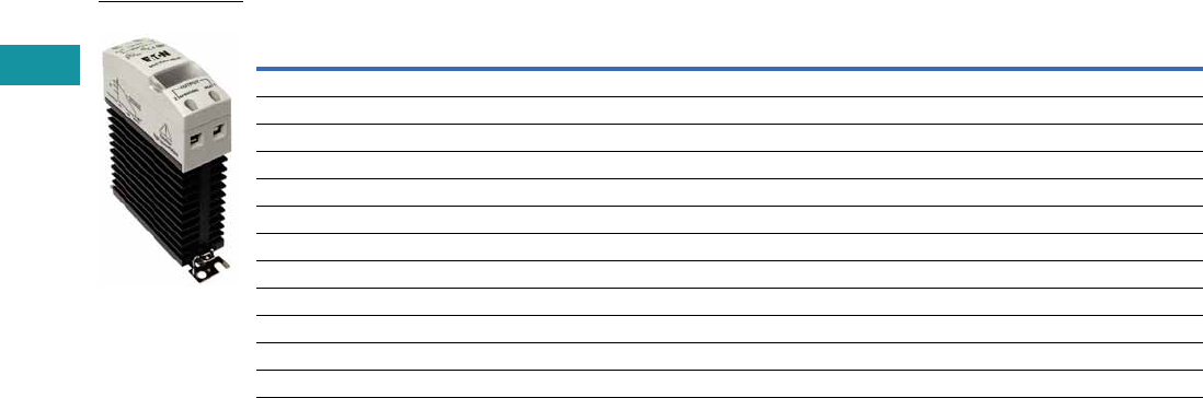
V7-T3-140 Volume 7—Logic Control, Operator Interface and Connectivity Solutions CA08100008E—February 2014 www.eaton.com
3
3
3
3
3
3
3
3
3
3
3
3
3
3
3
3
3
3
3
3
3
3
3
3
3
3
3
3
3
3
3.6
Control Relays and Timers
Solid-State Relays
Product Selection
D99 Series
Input Voltage Output Voltage
Contact
Configuration Switching Type
Rated Current
Load (Amps) Catalog Number
90–280 Vac 24–280 Vac SPST-NO Zero cross 10 D99210ACZ1
3–32 Vdc 24–280 Vac SPST-NO Zero cross 10 D99210ACZ2
90–280 Vac 24–280 Vac SPST-NO Zero cross 25 D99225ACZ1
3–32 Vdc 24–280 Vac SPST-NO Zero cross 25 D99225ACZ2
90–280 Vac 24–280 Vac SPST-NO Zero cross 40 D99240ACZ1
3–32 Vdc 24–280 Vac SPST-NO Zero cross 40 D99240ACZ2
90–280 Vac 48–600 Vac SPST-NO Zero cross 10 D99610ACZ1
3–32 Vdc 48–600 Vac SPST-NO Zero cross 10 D99610ACZ2
90–280 Vac 48–600 Vac SPST-NO Zero cross 25 D99625ACZ1
3–32 Vdc 48–600 Vac SPST-NO Zero cross 25 D99625ACZ2
90–280 Vac 48–600 Vac SPST-NO Zero cross 40 D99640ACZ1
3–32 Vdc 48–600 Vac SPST-NO Zero cross 40 D99640ACZ2
D99210ACZ1

Volume 7—Logic Control, Operator Interface and Connectivity Solutions CA08100008E—February 2014 www.eaton.com V7-T3-141
3
3
3
3
3
3
3
3
3
3
3
3
3
3
3
3
3
3
3
3
3
3
3
3
3
3
3
3
3
3
3.6
Control Relays and Timers
Solid-State Relays
Technical Data and Specifications
D99 Series
Description Units D99210ACZ1 D99210ACZ2 D99225ACZ1 D99225ACZ2 D99240ACZ1 D99240ACZ2
Output Characteristics
Contact configuration SPST-NO SPST-NO SPST-NO SPST-NO SPST-NO SPST-NO
Switching device SCR SCR SCR SCR SCR SCR
Current rating A 10 10 25 25 40 40
Switching type Zero cross Zero cross Zero cross Zero cross Zero cross Zero cross
Maximum zero turn-on voltage (Vpk) V 35 35 35 35 35 35
Maximum rate of rise off state voltage (DV/DT) V/us 500 200 500 500 500 500
Incandescent lamp ampere rating (rms) A 8 8 16 16 20 20
Motor load rating (rms) A 4.5 4.5 8 8 14 14
Min. load current to maintain on mA 50 50 120 120 250 250
Non-repetitive surge current (1 cycle) A 83 83 800 800 800 800
Max. rms overload current (1 second) A 24 24 40 40 100 100
Max. off state leakage current (rms) mA 10 10 10 10 10 10
Typical on state voltage drop (rms) Vac 1.25 1.25 1.35 1.35 1.6 1.6
Max. on state voltage drop (rms) Vac 1.6 1.6 1.8 1.8 1.6 1.6
Max. I2t for fusing (A2) 83 83 3700 3700 3700 83
Input Characteristics
Must release voltage V 10 AC 1 DC 10 AC 1 DC 10 AC 1 DC
Typical input impedance ohms 16–25k Current regulator 16–25k Current regulator 13k Current regulator
Nominal input current at 5 Vdc or 240 Vac mA 12 12 12 12 16 16
Reverse polarity protection NA Yes NA Yes NA Yes
Performance Characteristics
Operating time (response time)
ON ms8.38.38.38.38.310
OFF ms 8.3 8.3 8.3 8.3 8.3 10
Rated insulation voltage—input to input Vac 4000 4000 4000 4000 4000 4000
Dielectric strength—terminal to chassis Vac 4000 4000 4000 4000 4000 4000
Environment
Product certifications UL, CSA, CE UL, CSA, CE UL, CSA, CE UL, CSA, CE UL, CSA, CE UL, CSA, CE
Ambient air temperature
Storage °C –40 to 100 –40 to 100 –40 to 100 –40 to 100 –40 to 100 –40 to 100
Operating °C –30 to 80 –30 to 80 –30 to 80 –30 to 80 –30 to 80 –30 to 80
Degree of protection IP20 IP20 IP20 IP20 IP20 IP20
Miscellaneous Characteristics
Thermal resistance (junction to case) °C/W 1.5 1.5 1.5 0.43 1.5 0.43
Integral heat sink °C/W 2.2 2.2 2.2 2.2 2.2 2.2
Weight g (oz) 320 (11.3) 320 (11.3) 320 (11.3) 326 (11.5) 320 (11.3) 332 (11.7)
LED—input Green Green Green Green Green Green
Terminal wire capacity AWG (mm2) 8 (10) 8 (10) 8 (10) 8 (10) 8 (10) 8 (10)
Terminal torque (max.) in-lb (Nm) 12.5 (1.4) 12.5 (1.4) 12.5 (1.4) 12.5 (1.4) 12.5 (1.4) 12.5 (1.4)

V7-T3-142 Volume 7—Logic Control, Operator Interface and Connectivity Solutions CA08100008E—February 2014 www.eaton.com
3
3
3
3
3
3
3
3
3
3
3
3
3
3
3
3
3
3
3
3
3
3
3
3
3
3
3
3
3
3
3.6
Control Relays and Timers
Solid-State Relays
D99 Series, continued
Description Units D99610ACZ1 D99610ACZ2 D99625ACZ1 D99625ACZ2 D99640ACZ1 D99640ACZ2
Output Characteristics
Contact configuration SPST-NO SPST-NO SPST-NO SPST-NO SPST-NO SPST-NO
Switching device SCR SCR SCR SCR SCR SCR
Current rating A 10 10 25 10 40 40
Switching type Zero cross Zero cross Zero cross Zero cross Zero cross Zero cross
Maximum zero turn-on voltage (Vpk) V 35 35 35 35 35 35
Maximum rate of rise off state voltage (DV/DT) V/us 200 200 700 700 500 500
Incandescent lamp ampere rating (rms) A 8 8 16 16 20 20
Motor load rating (rms) A 4.5 4.5 8 8 14 14
Min. load current to maintain on mA 80 80 250 250 250 250
Non-repetitive surge current (1 cycle) A 83 83 1000 1000 800 800
Max. rms overload current (1 second) A 24 24 50 50 100 100
Max. off state leakage current (rms) mA 10 10 10 10 10 10
Typical on state voltage drop (rms) Vac 1.25 1.25 1.35 1.35 1.6 1.6
Max. on state voltage drop (rms) Vac 1.6 1.6 1.6 1.6 1.6 1.6
Max. I2t for fusing (A2) 83 83 1700 1700 3700 3700
Input Characteristics
Must release voltage V 10 AC 1 DC 10 AC 1 DC 10 AC 1 DC
Typical input impedance ohms 16–25k Current regulator 16–25k Current regulator 13k Current regulator
Nominal input current at 5 Vdc or 240 Vac mA 12 16 12 16 16 16
Reverse polarity protection NA Yes NA Yes NA Yes
Performance Characteristics
Operating time (response time)
ON ms 8.33 8.3 8.33 8.3 10 10
OFF ms 8.33 8.3 8.33 8.3 10 10
Rated insulation voltage—input to input Vac 4000 4000 4000 4000 4000 4000
Dielectric strength—terminal to chassis Vac 4000 4000 4000 4000 4000 4000
Environment
Product certifications UL, CSA, CE UL, CSA, CE UL, CSA, CE UL, CSA, CE UL, CSA, CE UL, CSA, CE
Ambient air temperature
Storage °C –40 to 100 –40 to 100 –40 to 100 –40 to 100 –40 to 100 –40 to 100
Operating °C –30 to 80 –30 to 80 –30 to 80 –30 to 80 –30 to 80 –30 to 80
Degree of protection IP20 IP20 IP20 IP20 IP20 IP20
Miscellaneous Characteristics
Thermal resistance (junction to case) °C/W 1.8 1.8 0.43 0.43 0.43 0.43
Integral heat sink °C/W 2.2 2.2 2.2 2.2 2.2 2.2
Weight g (oz) 320 (11.3) 321 (11.3) 326 (11.5) 326 (11.5) 332 (11.7) 332 (11.7)
LED—input Green Green Green Green Green Green
Terminal wire capacity AWG (mm2) 8 (10) 9 (10) 8 (10) 8 (10) 8 (10) 8 (10)
Terminal torque (max.) in-lb (Nm) 12.5 (1.4) 12.5 (1.4) 12.5 (1.4) 12.5 (1.4) 12.5 (1.4) 12.5 (1.4)
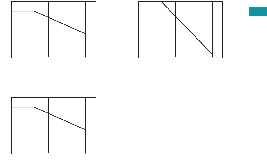
Volume 7—Logic Control, Operator Interface and Connectivity Solutions CA08100008E—February 2014 www.eaton.com V7-T3-143
3
3
3
3
3
3
3
3
3
3
3
3
3
3
3
3
3
3
3
3
3
3
3
3
3
3
3
3
3
3
3.6
Control Relays and Timers
Solid-State Relays
Temperature Derating Curves
10 Amp Styles
25 Amp Styles
40 Amp Styles
Ambient Temperature (°C)
0° 10° 20° 30° 40° 50° 60° 70° 80° 90°
12
10
8
6
4
2
0
Current in amps
Ambient Temperature (°C)
0° 10° 20° 30° 40° 50° 60° 70° 80° 90°
25
20
15
10
5
0
Current in amps
Ambient Temperature (°C)
0° 10° 20° 30° 40° 50° 60° 70° 80° 90°
40
30
25
20
15
10
0
Current in amps
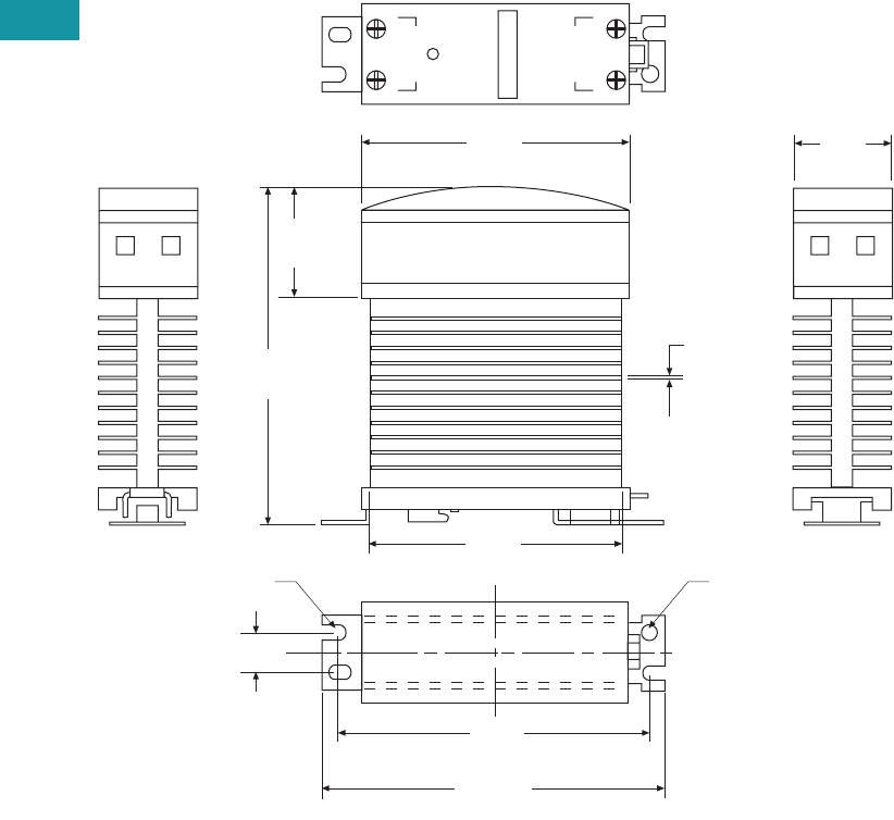
V7-T3-144 Volume 7—Logic Control, Operator Interface and Connectivity Solutions CA08100008E—February 2014 www.eaton.com
3
3
3
3
3
3
3
3
3
3
3
3
3
3
3
3
3
3
3
3
3
3
3
3
3
3
3
3
3
3
3.6
Control Relays and Timers
Solid-State Relays
Dimensions
Approximate Dimensions in Inches (mm)
D99 Series
1.20
(30.0)
4.20
(107.0)
0.50 (11.9)
0.05
(1.20)
1.20
(30.0)
3.20
(80.0)
Input
Output
+
21
–
3.10
(77.5)
3.70
(92.9)
4.00
(102.0)
0.20 (5.0)
Radius
0.20 (5.0)
Radius
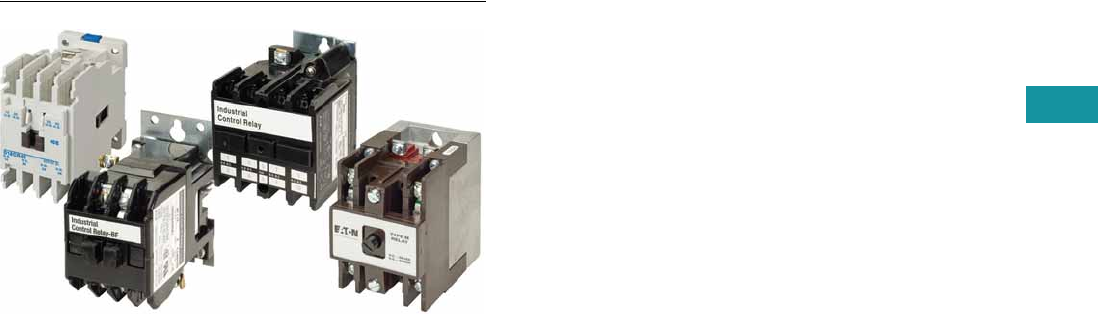
Volume 7—Logic Control, Operator Interface and Connectivity Solutions CA08100008E—February 2014 www.eaton.com V7-T3-145
3
3
3
3
3
3
3
3
3
3
3
3
3
3
3
3
3
3
3
3
3
3
3
3
3
3
3
3
3
3
3.7
Control Relays and Timers
Machine Tool Relays
Machine Tool Relays
Contents
Description Page
Machine Tool Relays
D15 Series—Freedom 600V Multipole . . . . . . . V7-T3-146
BF/BFD Series—Fixed Contact
Industrial Control . . . . . . . . . . . . . . . . . . . . . . V7-T3-151
AR/ARD Series—Convertible Contact
Industrial Control . . . . . . . . . . . . . . . . . . . . . . V7-T3-157
D26 Series—Type M, 600 Vac Multipole
with Convertible Contacts . . . . . . . . . . . . . . . V7-T3-162
D26 Series—Type M, DC Multipole
with Convertible Contacts . . . . . . . . . . . . . . . V7-T3-167
Product Overview
Eaton’s machine tool relay
offering includes a variety of
NEMA type relays. Included
in this are open style relays
and relays with convertible
or side-mount contacts. Also
included in this family are a
variety of accessories to
match the application,
including suppressors, timing
contacts and enclosures. The
relay coils are available in a
variety of line and control
level voltages.
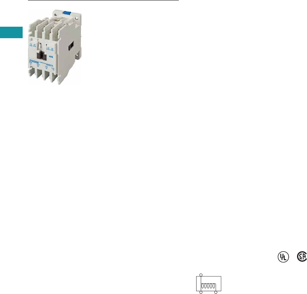
V7-T3-146 Volume 7—Logic Control, Operator Interface and Connectivity Solutions CA08100008E—February 2014 www.eaton.com
3
3
3
3
3
3
3
3
3
3
3
3
3
3
3
3
3
3
3
3
3
3
3
3
3
3
3
3
3
3
3.7
Control Relays and Timers
Machine Tool Relays
D15 Series—Freedom 600V Multipole
Contents
Description Page
D15 Series—Freedom 600V Multipole
Product Selection . . . . . . . . . . . . . . . . . . . . . . . V7-T3-147
Accessories . . . . . . . . . . . . . . . . . . . . . . . . . . . V7-T3-148
Technical Data and Specifications . . . . . . . . . . V7-T3-149
Dimensions . . . . . . . . . . . . . . . . . . . . . . . . . . . V7-T3-150
BF/BFD Series—Fixed Contact
Industrial Control . . . . . . . . . . . . . . . . . . . . . . . . . V7-T3-151
AR/ARD Series—Convertible Contact
Industrial Control . . . . . . . . . . . . . . . . . . . . . . . . . V7-T3-157
D26 Series—Type M, 600 Vac Multipole
with Convertible Contacts . . . . . . . . . . . . . . . . . V7-T3-162
D26 Series—Type M, DC Multipole
with Convertible Contacts . . . . . . . . . . . . . . . . . V7-T3-167
D15 Series—Freedom 600V Multipole
Product Description
Contact poles on the D15
relay are of the fixed design
and are not convertible. The
basic four-pole relay will
accept a front-mounted
contact pole deck and/or side-
mounted contact blocks (one
per side). In addition, a side-
mounted solid-state timer or
a front-mounted pneumatic
timer can be added to the
relay. Only one front-
mounted attachment can be
added to the basic relay.
Application Description
Side-mounted contact
blocks can be used to
provide additional poles
in applications where a
pneumatic timer is installed
on the front of the relay.
They can also be used where
panel depth is restricted.
The maximum number of
contacts recommended per
relay is eight, six of which can
be NC. When a pneumatic
timer is used, the maximum
recommended number of
NC contacts is three.
Relays with DC coils are
supplied with a coil clearing
NC contact mounted on the
side of the relay.
Features and Benefits
●600V, 10A continuous
thermal current
●State indicator visually
shows relay ON or OFF
status
●Relay base has mounting
holes on 35 x 60 mm
centers, permitting direct
replacement of
competitive relays
●Relay also mounts on
35 mm DIN rail as standard
●Magnet coil has three
terminals, permitting either
top or diagonal wiring—
easy to replace European
or U.S. relays without
changing wiring layout
●Contact pole terminals
have captive, backed-out,
self-lifting pressure plates
with ± screws—reduced
wiring time
●All terminals are shrouded
or
“finger-proofed” to
reduce possibility
of
electrical shock
Standards and Certifications
●UL
●CSA certified
Volume 7—Logic Control, Operator Interface and Connectivity Solutions CA08100008E—February 2014 www.eaton.com V7-T3-147
3
3
3
3
3
3
3
3
3
3
3
3
3
3
3
3
3
3
3
3
3
3
3
3
3
3
3
3
3
3
3.7
Control Relays and Timers
Machine Tool Relays
Product Selection
When Ordering, Specify
Catalog number and magnet coil code letter. Example: For a four-pole relay having
4NO contacts with a 120V 60 Hz coil, order Catalog Number D15CR40AB.
Factory-Assembled Multipole Relays
Additional Contact Poles Magnet Coil Selection
Notes
1Underscore indicates missing code suffix for magnet coil—see Magnet Coil Selection table above.
2Not all suffix codes available: consult Customer Support Center.
Number of
Poles
Type of Contacts Open Type
NO NC Catalog Number 1
440D15CR40_B
31D15CR31_B
22D15CR22_B
13D15CR13_B
04D15CR04_B
6
(four-pole relay with two-pole
front-mounted deck)
60D15CR60_B
51D15CR51_B
42D15CR42_B
33D15CR33_B
24D15CR24_B
15D15CR15_B 2
06D15CR06_B 2
8
(four-pole relay with four-pole
front-mounted deck)
80D15CR80_B
71D15CR71_B
62D15CR62_B
53D15CR53_B
44D15CR44_B
35D15CR35_B 2
26D15CR26_B 2
D15CR40_B
D15CR60_B
D15CR80_B
Description
Catalog
Number
Front Contact Pole Deck
1NO-1NC C320KGT3
2NO C320KGT4
2NC C320KGT5
1NO (early closing)–1NC (late opening) C320KGT7
4NO C320KGT13
3NO-1NC C320KGT14
2NO-2NC C320KGT15
1NO-3NC C320KGT16
4NC C320KGT17
Side-Mounted Contact Blocks
1NO-1NC C320KGS3
2NO C320KGS4
2NC C320KGS5
1NO (early closing)–1NC (late opening) C320KGS7
AC Coils
Volts and Hertz
Code
Suffix
DC Coils
Volts
Code
Suffix
120/60 or 110/50 A12 R1
240/60 or 220/50 B24 T1
480/60 or 440/50 C48 W1
600/60 or 550/50 D120 A1
208/60 E
277/60 H
208–240/60 J
24/60 T
V7-T3-148 Volume 7—Logic Control, Operator Interface and Connectivity Solutions CA08100008E—February 2014 www.eaton.com
3
3
3
3
3
3
3
3
3
3
3
3
3
3
3
3
3
3
3
3
3
3
3
3
3
3
3
3
3
3
3.7
Control Relays and Timers
Machine Tool Relays
Accessories
Pneumatic Timer Attachment
Maximum Ampere Ratings
Attachment mounts on top of
any Freedom Series relay
(top-mounted auxiliary
contacts can not be installed
on device when timer is
used). Timer unit has DPST
timed contacts—circuits in
each pole must be the same
polarity. Units are convertible
from OFF to ON delay or
vice-versa.
Finger Protection Shields
Snap-on shields for both
contactors and starters
provide IEC Type IP20
Finger Protection. Prevents
accidental contact with line/
load terminals.
Adhesive Dust Cover
These adhesive stickers
come 25 to a package and
provide extra protection from
contaminants when applied
to the sides of Freedom D15.
Adhesive covers are easily
applied to side opening
where auxiliaries are not
installed and provide extra
protection from metal filings
and other debris.
Solid-State ON DELAY Timer 1
This timer is designed to be
wired in series with the
load (typically a coil). When
the START button is pushed
(power applied to timer), the
ON delay timing function
starts. At the completion of
the set timing period, timer
and series wired load will
both be energized.
Timing Range
Catalog
Number
0.1 to 30 seconds C320TP1
10 to 180 seconds C320TP2
Volts AC
Description 120 240 480 600
Make 30 15 7.5 6
Break 3 1.5 0.75 0.6
C320 Pneumatic
Timer Attachment
Application
Catalog
Number
D15 C320LS1
Description
Catalog
Number
25 to a package C320DSTCVR
Timing Range
Catalog
Number 234
0.1 to 1.0 seconds C320TDN1_
1 to 30 seconds C320TDN30_
30 to 300 seconds C320TDN300_
5 to 30 minutes C320TDN3000_
Solid-State Timer
Metal Mounting Plate
Fits all D15 multipole relays.
Mounting Channel (DIN Rail)
Designed for DIN rail
mounting of Freedom
Series relays.
Transient Suppressor Kits
These kits limit high voltage
transients produced in the
control circuit when power is
removed from the contactor
or starter coil. There are three
separate suppressors for use
on 24–120V, 208–240V or 27–
480V coils respectively.
These devices mount directly
to the coil terminals.
Notes
1Side mounted on Freedom Series NEMA 00–2, D15, IECA-K and C25D, C25E and C25F frame.
2Add operating voltage suffix to catalog number; A = 120V, B = 240V, E = 208V.
3Rated 0.5 ampere pilot duty—not to be used on larger contactors.
4Terminal connections are quick connects only. Two per side.
5Suppressor is compatible with coil voltages/ranges as shown, both 50 and 60 Hz.
Description
Catalog
Number
Metal mounting plate C321MP1
C32MP1
Description
Catalog
Number
1 meter length XBANS3575P
DIN Rail
Description
Coil Voltage
50/60 Hz 5
Catalog
Number
Transient 24/120V C320TS1
Suppressor 208/240V C320TS2
277/480V C320TS3
C320TS2
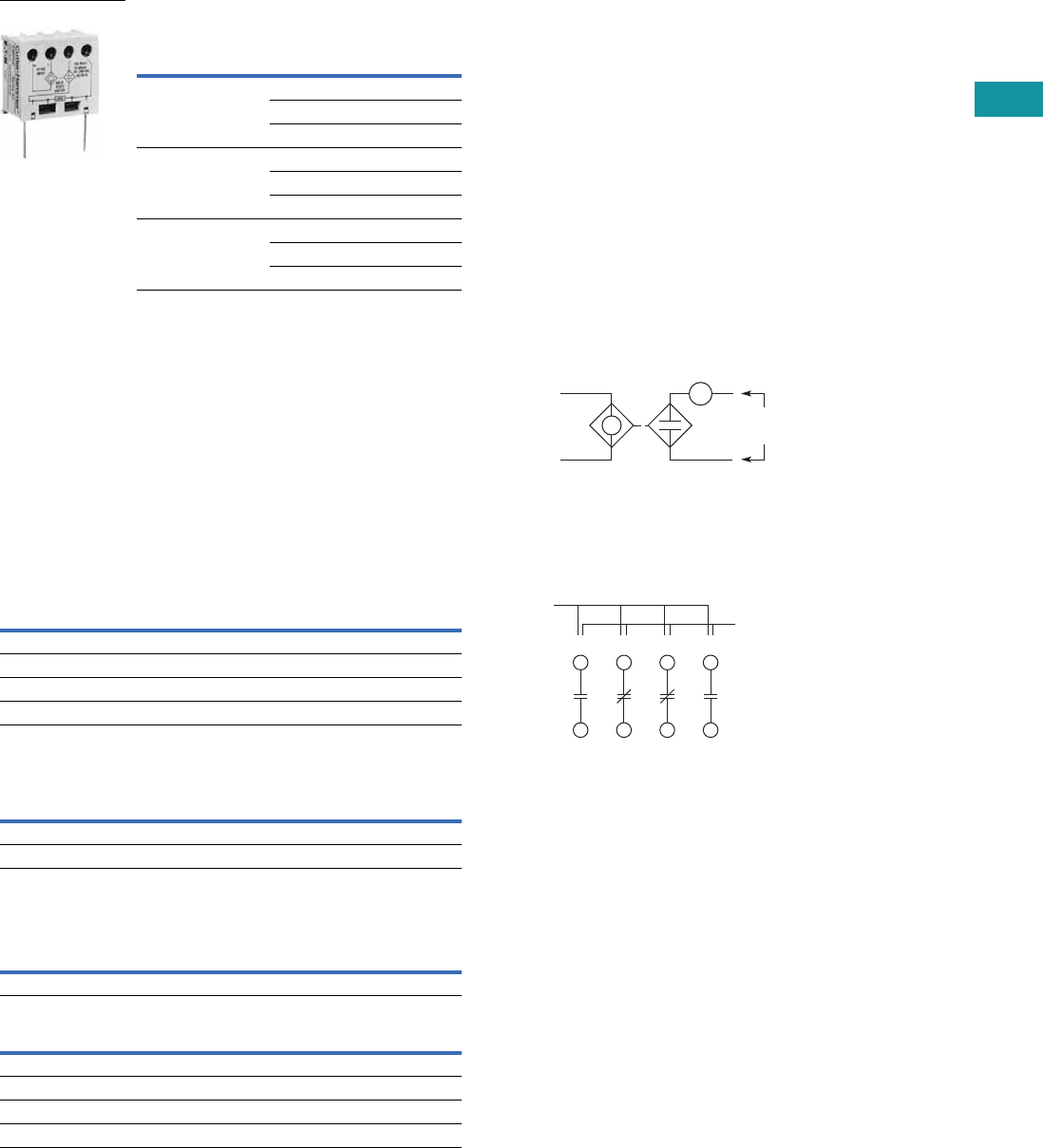
Volume 7—Logic Control, Operator Interface and Connectivity Solutions CA08100008E—February 2014 www.eaton.com V7-T3-149
3
3
3
3
3
3
3
3
3
3
3
3
3
3
3
3
3
3
3
3
3
3
3
3
3
3
3
3
3
3
3.7
Control Relays and Timers
Machine Tool Relays
AC/DC Interface Module—
Controller Coil Voltage Ranges
Technical Data and Specifications
Contact Ratings—NEMA A600
Contact Ratings—NEMA P300
Magnet Coil Data
Controller Catalog
Number Prefix
Controller
Size or Rating
Coil Range
Volts AC
AE16, AE17, AE56,
AE57, CE15, CE55
A–F 24–240
G–K 48–240
L–N 110–240
AN16, AN56,
CN15, CN55
00–0 24–240
1–2 48–240
3 110–240
CN35 10–30A 24–240
60A 48–240
100A 110–240
C320DC
Continuous Thermal Rating: 10A
AC Volts Make Break
120 60 6.0
240 30 3.0
480 15 1.5
600 12 1.2
Continuous Thermal Rating: 5A
DC Volts Make/Break Amperes
125 1.1
250 0.55
AC
Voltage
Pickup Sealed
VA Watts VA Watts
12–600V 80 49 7.5 2.4
DC
Voltage
Pickup Sealed
Amps Watts VA Watts
12 6.4 76.8 0.28 3.36
24 3.2 76.8 0.14 3.36
48 1.6 76.8 0.07 3.36
120 0.64 76.8 0.028 3.36
The Catalog Number C320DC
Interface Module is an
optically isolated solid-state
switch that provides a means
of operating AC coils with a
24 Vdc control signal. It acts
as a space-saving interposing
relay that can switch a
specified 50/60 Hz AC source
to the contactor or starter coil.
The module may be directly
attached to the coil terminals
of any Freedom Series
contactor or starter—NEMA
Sizes 00–3, D15, IEC Sizes
A–N and lighting contactors
10–100A. It also has
provisions for DIN rail
mounting.
The module will operate coils
within the voltage ranges
shown in the table to the left.
Design Characteristics
●DC input: 24V ±10% at
mA nominal
●AC operating voltage:
24–240 Vac ±10%
50/60 Hz
●AC current rating:
10A make (inrush),
1A break (sealed)
Typical Application—Solid-State Switch
Example of Terminal Marking with 2NO and 2NC Contacts
Relay terminals are identified
by a two-digit number in
accordance with International
Standards approved by
CENELEC (European
Committee for Electro-
technical Standardization).
The number is marked on
the relay and is used to
identify location and status
of the contacts.
The first digit indicates the
location of the contact on the
relay. The numbering begins
with 1 and continues without
a break from left to right.
The second digit indicates
the status of the contacts
(NO or NC). Terminal marking
1 and 2 mean NC and 3 and
4mean NO.
24 Vdc
Input
Observe
Polarity on
Module
24–240 Vac
50/60 Hz
Contactor Coil
Location
13 21 31 43
14 22 32 44
Status
(NO or NC)
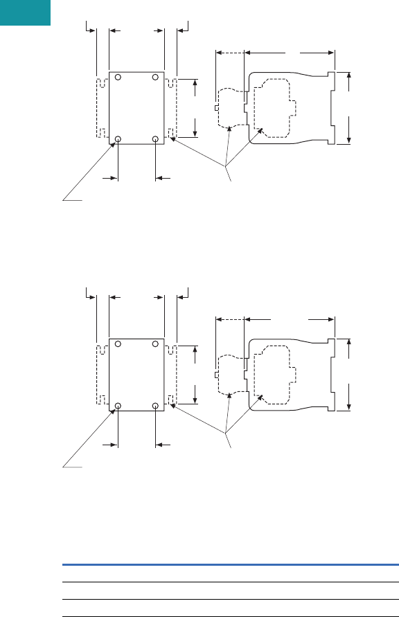
V7-T3-150 Volume 7—Logic Control, Operator Interface and Connectivity Solutions CA08100008E—February 2014 www.eaton.com
3
3
3
3
3
3
3
3
3
3
3
3
3
3
3
3
3
3
3
3
3
3
3
3
3
3
3
3
3
3
3.7
Control Relays and Timers
Machine Tool Relays
Dimensions
Approximate Dimensions in Inches (mm)
D15 Four-Pole Relay
D15 Six- and Eight-Pole Relays
Dimensions and Shipping Weights
Description Dimension C
Shipping Weights
Lbs (kg)
Relay only 3.30 (83.8) 1.3 (0.6)
Relay with timer attachment 5.55 (141.0) 1.5 (0.7)
Relay with front contact pole deck 4.66 (118.4) 1.7 (0.8)
2.36
(59.9)
2.96
(75.2)
1.36
(34.5) Optional Additional
Contact Poles
or Accessories
Mtg. Holes for
M4 or #8 Screws
1.8
(45.7)
C
0.54
(13.7)
0.54
(13.7)
Side
Mtd.
Blk.
Frt.
Mtd.
Acc.
4.66
(118.4)
2.36
(59.9)
2.96
(75.2)
1.36
(34.5) Optional Additional
Contact Poles
or Accessories
Mtg. Holes for
M4 or #8 Screws
1.8
(45.7)
0.54
(13.7)
0.54
(13.7)
Side
Mtd.
Blk.
Frt.
Mtd.
Acc.
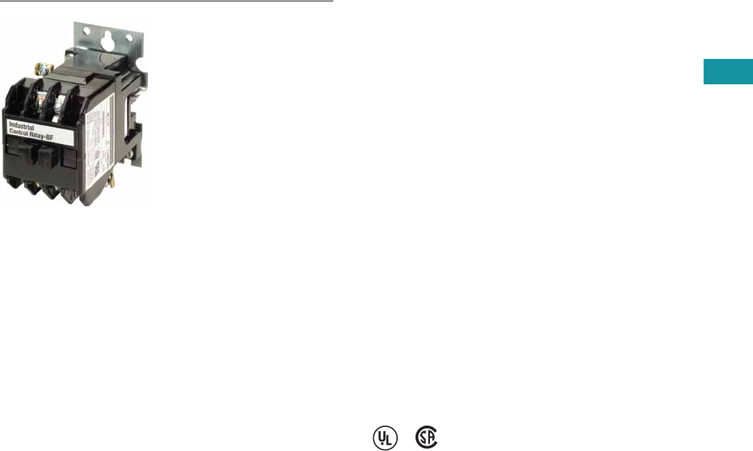
Volume 7—Logic Control, Operator Interface and Connectivity Solutions CA08100008E—February 2014 www.eaton.com V7-T3-151
3
3
3
3
3
3
3
3
3
3
3
3
3
3
3
3
3
3
3
3
3
3
3
3
3
3
3
3
3
3
3.7
Control Relays and Timers
Machine Tool Relays
BF/BFD Series—Fixed Contact Industrial Control
Contents
Description Page
D15 Series—Freedom 600V Multipole. . . . . . . . . . V7-T3-146
BF/BFD Series—Fixed Contact Industrial
Control
Product Selection . . . . . . . . . . . . . . . . . . . . . . . V7-T3-152
Options . . . . . . . . . . . . . . . . . . . . . . . . . . . . . . . V7-T3-154
Technical Data and Specifications . . . . . . . . . . V7-T3-155
Dimensions . . . . . . . . . . . . . . . . . . . . . . . . . . . V7-T3-156
AR/ARD Series—Convertible Contact
Industrial Control . . . . . . . . . . . . . . . . . . . . . . . . . V7-T3-157
D26 Series—Type M, 600 Vac Multipole
with Convertible Contacts . . . . . . . . . . . . . . . . . . V7-T3-162
D26 Series—Type M, DC Multipole
with Convertible Contacts . . . . . . . . . . . . . . . . . . V7-T3-167
BF/BFD Series—Fixed Contact Industrial Control
Product Description
Type BF is AC operated, 300V
maximum, and the BFD is DC
operated, 250V. Fixed contact
relays are available in any
combination of NO and NC
from two to 12 poles. BF and
BFD relays have captive
clamp terminals fully
accessible from the front,
a molded coil with low
operating temperature and
silver alloy contacts suitable
for low voltage circuits.
Features and Benefits
Wiring to Relay
●In parallel with coil—one
timed and up to 12
instantaneous contacts, or
●In series with coil—up
to 12 timed contacts in
one relay
Permanent Magnet Latch
●Field mountable on Catalog
Number BF; factory
installed on BFD
●Latch coil continuously
rated
●Latch plunger adjustable
for optimum performance
Standards and Certifications
●UL recognized, UL File No.
E19223 (AC relays only)
●CSA certified, File No.
LR39402-6, LR28548-10,
11 (AC and DC relays)
V7-T3-152 Volume 7—Logic Control, Operator Interface and Connectivity Solutions CA08100008E—February 2014 www.eaton.com
3
3
3
3
3
3
3
3
3
3
3
3
3
3
3
3
3
3
3
3
3
3
3
3
3
3
3
3
3
3
3.7
Control Relays and Timers
Machine Tool Relays
Product Selection
When Ordering, Specify
●Catalog number of basic relay
●If a coil voltage other than listed is required, select the suffix code from the Coil Voltage table and
substitute it for the last letter in the catalog number. Example: BF80V for a 110/60 AC coil
Complete Relay—Type BF and BFD, Two-, Three-, Four- and Six-Pole 1
Coil Voltage
Notes
1 Relays listed above with equal number of NO and NC contact poles are specially priced—1NO and 1NC pole
are supplied at no additional charge.
2 Consult Customer Support Center for availability.
Number
of Poles
Type of Contact
BF 300 Vac Basic Relays
120/60, 110/50 AC Coil
BFD 250 Vdc Basic
Relays
120 DC Coil
NO (Form A) NC (Form B)
Catalog
Number
Catalog
Number
22 0 BF20F BFD20S
11BF11F BFD11S
02BF02F BFD02S
33 0 BF30F BFD30S
21BF21F BFD21S 2
12BF12F BFD12S
03BF03F BFD03S
44 0 BF40F BFD40S
31BF31F BFD31S
22BF22F BFD22S
13BF13F BFD13S
04BF04F BFD04S
66 0 BF60F BFD60S
51BF51F BFD51S
42BF42F BFD42S
33BF33F BFD33S
24BF24F BFD24S
06BF06F BFD06S
BF Coils BFD Coils
Volts AC Hz Suffix Code Volts DC Suffix Code
12 60 H6C
24 60 I12 D
48 60 J24 L
110 60 V38 N
110/120 50/60 F48 M
208 60 K72 E
220/240 50/60 G95 B
440 60 C120 S
130 U
240 T
Type BF
Type BFD
Volume 7—Logic Control, Operator Interface and Connectivity Solutions CA08100008E—February 2014 www.eaton.com V7-T3-153
3
3
3
3
3
3
3
3
3
3
3
3
3
3
3
3
3
3
3
3
3
3
3
3
3
3
3
3
3
3
3.7
Control Relays and Timers
Machine Tool Relays
When Ordering, Specify
●Catalog number of basic relay
●If a coil voltage other than listed is required, select the suffix code from the Coil Voltage table and
substitute it for the last letter in the catalog number. Example: BF80V for a 110/60 AC coil
Complete Relay—Type BF and BFD, Eight-, 10- and 12-Pole 1
Coil Voltage
Notes
1 Relays listed above with equal number of NO and NC contact poles are specially priced—1NO and 1NC pole
are supplied at no additional charge.
2 Consult Customer Support Center for availability.
Number
of Poles
Type of Contact
BF 300 Vac Basic Relays
120/60, 110/50 AC Coil
BFD 250 Vdc Basic
Relays
120 DC Coil
NO (Form A) NC (Form B)
Catalog
Number
Catalog
Number
88 0 BF80F BFD80S
71BF71F BFD71S
62BF62F BFD62S
53BF53F BFD53S
44BF44F BFD44S
08BF08F BFD08S
10 10 0 BF100F BFD100S
82BF82F BFD82S 2
73BF73F 2BFD73S
64BF64F BFD64S
55BF55F BFD55S 2
46BF46F BFD46S
28BF28F BFD28S
12 12 0 BF120F BFD120S
84BF84F BFD84S
75BF75F BFD75S
66BF66F BFD66S
57BF57F BFD57S
48BF48F BFD48S
BF Coils BFD Coils
Volts AC Hz Suffix Code Volts DC Suffix Code
12 60 H6C
24 60 I12 D
48 60 J24 L
110 60 V38 N
110/120 50/60 F48 M
208 60 K72 E
220/240 50/60 G95 B
440 60 C120 S
130 U
240 T
Type BF
Type BFD
V7-T3-154 Volume 7—Logic Control, Operator Interface and Connectivity Solutions CA08100008E—February 2014 www.eaton.com
3
3
3
3
3
3
3
3
3
3
3
3
3
3
3
3
3
3
3
3
3
3
3
3
3
3
3
3
3
3
3.7
Control Relays and Timers
Machine Tool Relays
Permanent Magnet Latch
Options
FASTON Push-On Terminals
Overlapping Contacts
NEMA 1 Enclosure for Relay Types
Notes
1For panel mount, add Suffix F.
2Consult Customer Support Center for availability.
Coil
Volts Coil Hz
Catalog
Number
AC Relays
24 60 BFMLI 2
48 60 BFMLJ 2
110/120 50/60 BFMLF
220/240 50/60 BFMLG
DC Relays
24 — BFMLL
48 — BFMLM
120 — BFMLS
240 — BFMLT
Permanent Magnet
Latch, Relay Mounted
Description
Code
Letter
Catalog
Number
Insert letter F after relay type designation in listed catalog
number. Example: BFF20F or BFDF20S
F—
Description
Code
Letter
Catalog
Number
NO contact closes before corresponding NC contact opens—
supplied as NO/NC set(s). Insert letter A after relay
type designation in listed catalog number. Example: BFA22F
or BFDAF22S
A—
Description
Code
Letter
Catalog
Number
BF, AR—all poles — 4977D40G04
BFD—4–8 poles — 4977D40G04
ARD—4–8 poles — 4977D40G04

Volume 7—Logic Control, Operator Interface and Connectivity Solutions CA08100008E—February 2014 www.eaton.com V7-T3-155
3
3
3
3
3
3
3
3
3
3
3
3
3
3
3
3
3
3
3
3
3
3
3
3
3
3
3
3
3
3
3.7
Control Relays and Timers
Machine Tool Relays
Technical Data and Specifications
General Specifications
Permanent Magnet Latch Specifications
BF Relay Electrical Ratings—NEMA A300
Maximum Current Maximum VA
Volts Cont. Make Break Make Break
120 10 60 6 7200 720
240 10 30 3 7200 720
Horsepower Ratings (UL Recognized) DC Rating—NEMA P300
AC Volts Maximum Current Max. Make
or Break (VA)Phase 115 230 Volts Cont. Make Break
1 1/6 1/2 125 5.0 1.1 1.1 138
3 — 1 250 5.0 0.55 0.55 138
Resistive Rating
125 Vdc 3A
250 Vdc 1.5A
Coil Power Requirements
AC 72 VA open, 22 VA closed
DC 12 watts (nominal), 250V max.
Item Specification
Unlatching power requirements Open gap: 24 VA AC
Closed gap: 7 VA
Burden: 4 watts (AC)
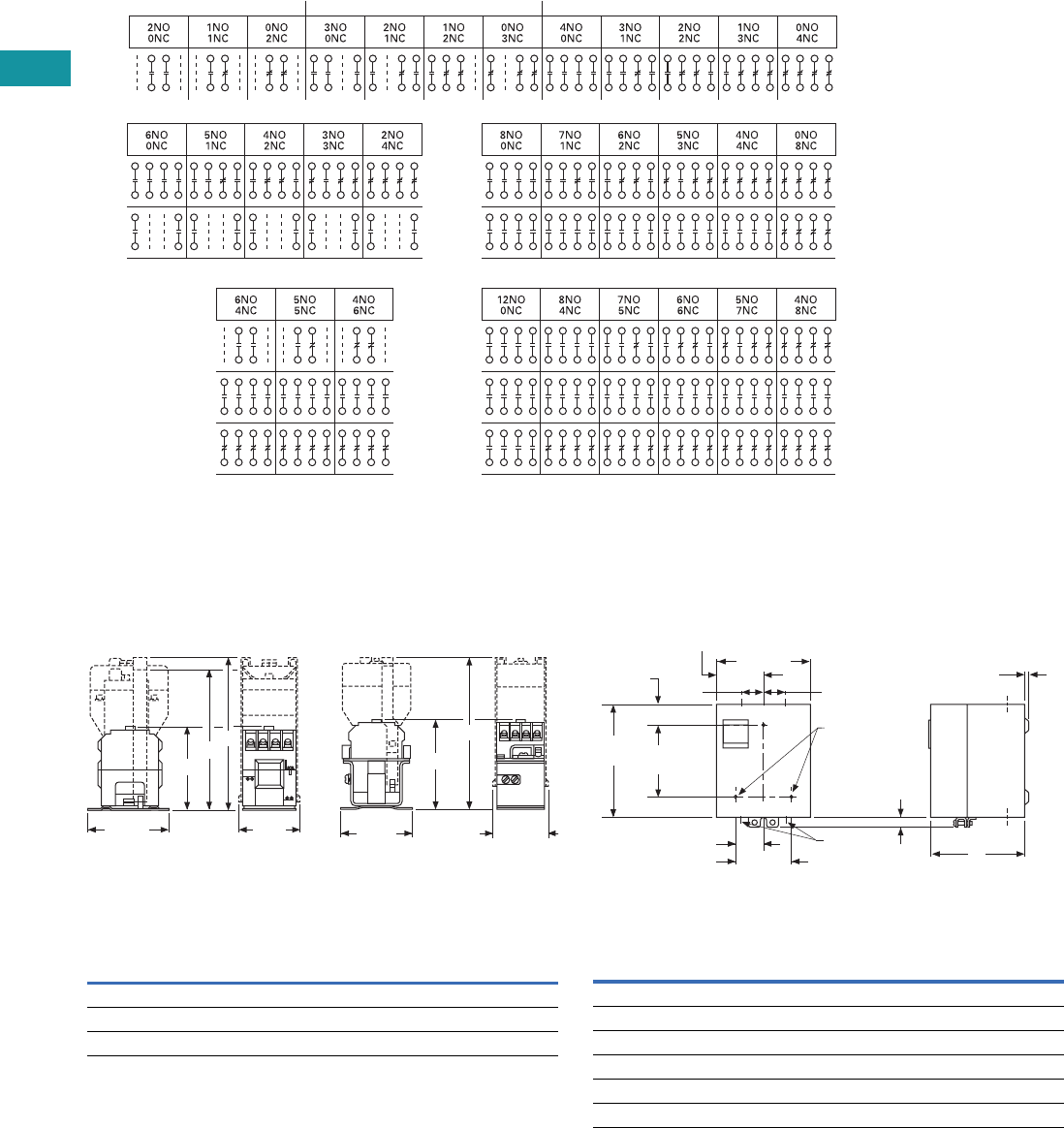
V7-T3-156 Volume 7—Logic Control, Operator Interface and Connectivity Solutions CA08100008E—February 2014 www.eaton.com
3
3
3
3
3
3
3
3
3
3
3
3
3
3
3
3
3
3
3
3
3
3
3
3
3
3
3
3
3
3
3.7
Control Relays and Timers
Machine Tool Relays
Contact Arrangements—BF and BFD Relays
Note: NO = Normally Open NC = Normally Closed
Dimensions
Approximate Dimensions in Inches (mm)
BF Relay with Permanent
Magnet Latch and Solid-
State Timer
BFD Relay with Solid-State
Timer
BF and BFD Relay Dimensions
2 Poles 3 Poles 4 Poles
6 Poles
Rear
Front
Rear
Center
12 Poles
Rear
Center
Front Front
8 Poles
Rear
Front
10 Poles
A
BC
3.13
(79.5) 1.97
(50)
D
E
3.13
(79.5) 1.69
(42.9)
Number
of Poles
A
BF Only
B
BF w/Latch
C
BF w/Timer
D
BFD Only
E
BFD w/Timer
4 3.22 (81.8) 6.22 (158.0) 5.88 (149.4) 4.03 (102.4) 7.06 (179.3)
8 4.19 (106.4) 7.19 (182.6) 6.88 (174.8) 4.97 (126.2) 8.00 (203.2)
12 4.81 (122.2) 7.81 (198.4) 7.50 (190.5) 5.63 (143.0) 8.66 (220.0)
Enclosures—NEMA 1 for BF, BFD, AR and ARD
NEMA 1 for BF, BFD, AR and ARD Dimensions
Poles
Catalog
Number
A
NEMA 1
Relays without Attachments
All BF, AR, ARD 5.34 (135.6)
4 – 8 BFD 5.34 (135.6)
10, 12 BFD 7.97 (202.4)
Relays with Attachments
All BF, AR, ARD 7.97 (202.4)
5.66
(143.8)
3.38 (85.9)
2.83
(71.9)
1.72
(43.7)
0.25 (6.4) Dia.
Mtg. Holes (3)
0.19 (4.8)
A
1.69 (42.9) 0.38 x 0.5
(9.7 x 12.7)
Conduit
(2 Top, 2 Bottom)
6.59
(167.4) 4.5
(114.3) 0.63
(16)
1.05
(26.7)
KO KO KO
KO KO KO
KO
KO
1.72
(43.7)
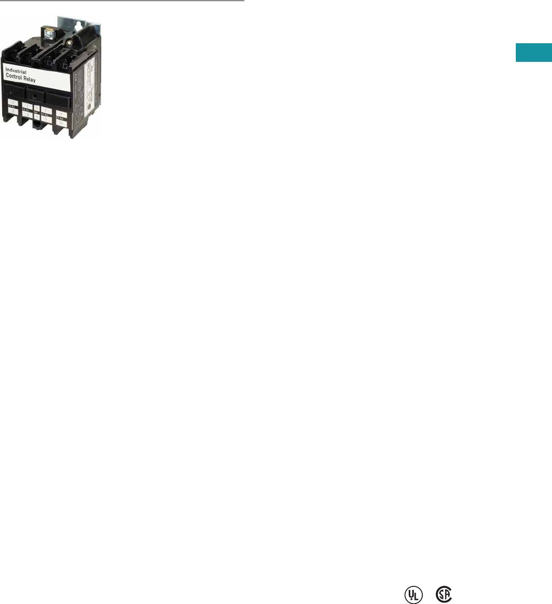
Volume 7—Logic Control, Operator Interface and Connectivity Solutions CA08100008E—February 2014 www.eaton.com V7-T3-157
3
3
3
3
3
3
3
3
3
3
3
3
3
3
3
3
3
3
3
3
3
3
3
3
3
3
3
3
3
3
3.7
Control Relays and Timers
Machine Tool Relays
AR/ARD Series—Convertible Contact Industrial Control
Contents
Description Page
D15 Series—Freedom 600V Multipole. . . . . . . . . . V7-T3-146
BF/BFD Series—Fixed Contact Industrial
Control . . . . . . . . . . . . . . . . . . . . . . . . . . . . . . . . . V7-T3-151
AR/ARD Series—Convertible Contact
Industrial Control
Product Selection . . . . . . . . . . . . . . . . . . . . . . . V7-T3-158
Accessories . . . . . . . . . . . . . . . . . . . . . . . . . . . V7-T3-159
Options . . . . . . . . . . . . . . . . . . . . . . . . . . . . . . . V7-T3-159
Technical Data and Specifications . . . . . . . . . . V7-T3-160
Dimensions . . . . . . . . . . . . . . . . . . . . . . . . . . . V7-T3-161
D26 Series—Type M, 600 Vac Multipole
with Convertible Contacts . . . . . . . . . . . . . . . . . . V7-T3-162
D26 Series—Type M, DC Multipole
with Convertible Contacts . . . . . . . . . . . . . . . . . . V7-T3-167
AR/ARD Series—Convertible Contact Industrial Control
Product Description
The AR/ARD relays are
electromechanical convertible
contact relays. AR relays are
AC devices and the ARD is
for DC applications.
Application Description
Type AR and ARD relays are
designed for use on machine
tools, process lines,
conveyors and similar
automatic and semi-
automatic equipment.
Features and Benefits
Permanent Magnet Latch
By energizing the relay coil,
the latch attachment “sets”
(when the base relay’s
armature/crossbar assembly
has closed) holding the relay
ON, even after the relay coil
has been de-energized. The
clearing coil on the latch is
energized to release the
armature/crossbar assembly.
●Field mountable to four-
and six-pole
●Latch plunger is adjustable
●Latch coil continuously
rated
●Unlatching power
requirements
●Open gap: 24 VA
●Closed gap: 7 VA
●Burden: 4 watts AC, 6
watts DC
Surge Suppressor
●Mounts in contact cavity of
AR relays
●Limits high transient
voltages resulting from de-
energizing relay coil or
other electromechanical
devices
●Protects sensitive
instruments and solid-state
devices
●120 Vac maximum, not
used on Vdc
●For noise suppression, see
Catalog Number SS-56
starter mounted surge
suppressor.
Operation
AR relays are available in
either
four- or six-pole
configurations.
AR relays are
easily converted
to eight- or
10-poles simply by adding a
four-pole deck. In addition,
mechanical latch attachments
are available with four- and
six-pole relays.
Contacts are convertible from
NO to NC, to provide any
combination desired up to a
maximum of 10. For the ARD,
the number of poles cannot
exceed four NC in any pole
configuration. Wide spacing
of contacts simplifies
installation, contact testing and
maintenance. Contacts are
electrically and mechanically
isolated from each other.
Overlap contacts are also
available in one or two sets.
These contacts should be
mounted in the center pole
positions. AC and DC contact
cartridges should not be used
in the same relay.
Standards and Certifications
●UL File No. E19223
●CSA File No. LR39402-6,
LR54517 and LR54520
Reference Information
●ART, ARTD: IL 14510,
IL 14485
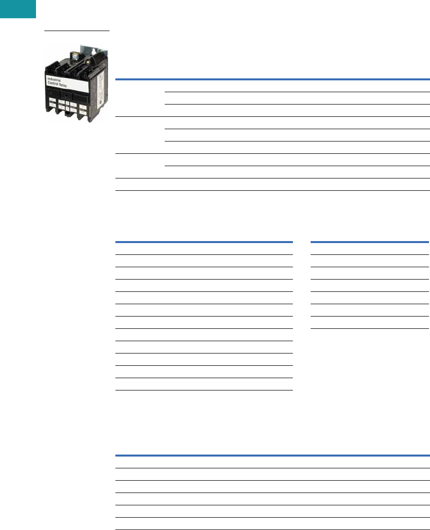
V7-T3-158 Volume 7—Logic Control, Operator Interface and Connectivity Solutions CA08100008E—February 2014 www.eaton.com
3
3
3
3
3
3
3
3
3
3
3
3
3
3
3
3
3
3
3
3
3
3
3
3
3
3
3
3
3
3
3.7
Control Relays and Timers
Machine Tool Relays
Product Selection
When Ordering, Specify
●Catalog number of basic relay with 120/60, 110/50 AC coil from AR/ARD Relays table.
●If a coil voltage other than listed is required, select the suffix code from the Coil Voltage table below
and substitute it for the last letter in the catalog number. Example: AR64V for a 110/60 AC coil.
AR/ARD Relays
Coil Voltage
Contact Cartridges—600V
Notes
1 Will not accept top-mounted latch or timers.
2 Contact Customer Support Center for availability.
3 Standard cartridges are sold in cartons of four cartridges. Catalog number is for single cartridge.
4 Overlap contact cartridges are sold in sets of two cartridges. Catalog number is for sets of two.
Number
of Poles
Contact
AR 600 Vac Relays
120/60, 110/50 AC Coil
ARD 600 Vdc Relays
120 DC Coil
NO NC
Blank
Cavities
Catalog
Number
Catalog
Number
4 004AR4A ARD4S
202AR420A ARD420S
400AR440A ARD440S
6 006AR6A ARD6S
402AR640A —
600AR660A ARD660S
8 1602AR860A ARD860S 2
800AR880A ARD880S
10 110 0 0 AR10100A ARD10100S
AR Coils ARD Coils
Volts AC Hz Suffix Code Volts DC Suffix Code
12 60 F12 D
24 60 I24 L
48 60 G48 M
110 60 V95 B
110/120 50/60 A120 S
208 60 B130 U
220/240 50/60 W240 T
277 60 C
380/440 50/60 H
440/480 50/60 X
550 60 D
550/600 50/60 E
Terminal
Type
Standard Contact
Cartridge
Overlap Contact
Cartridge
Catalog
Number 3
Catalog
Number 4
AC Cartridges
With clamp terminals ARC AROC
With screw terminals ARCR AROCR
DC Cartridges
With clamp terminals ARDC ARDOC
With screw terminals ARDCR ARDOCR
AR/ARD Relays
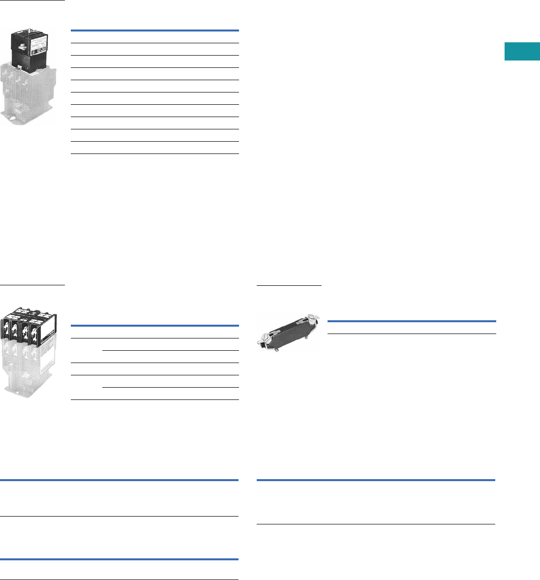
Volume 7—Logic Control, Operator Interface and Connectivity Solutions CA08100008E—February 2014 www.eaton.com V7-T3-159
3
3
3
3
3
3
3
3
3
3
3
3
3
3
3
3
3
3
3
3
3
3
3
3
3
3
3
3
3
3
3.7
Control Relays and Timers
Machine Tool Relays
Permanent Magnet Latch
Accessories
Four-Pole Top Deck Adder
●
Increases contact capacity from four/six-poles to eight/10-poles
●Mounts on top of basic relay using three screws
●Will not interfere with wiring, testing or convertible cartridges
●Screw terminals for ring connectors available; to order, add
Suffix R to catalog number listed below
Four-Pole Top Deck Adder Surge Suppressor
Options
Convertible Contacts
Screw Terminals
Overlapping Contacts
Note
1Consult Customer Support Center for availability.
Operating
Volts Coil Hz
Catalog
Number
For AC Control Circuits
24 60 ARMLI
48 60 ARMLG
120 60/50 ARMLA
240 60/50 ARMLW
For DC Control Circuits
24 — ARMLL
48 — ARMLM
120 — ARMLS
240 — ARMLT
ARML Permanent
Magnet Latch for
AR/ARD Relays
No. of
Poles
Contacts
Catalog
Number NO NC
Blank
Cavities
With 600 Vac Cartridges
4 202 ARA20
400 ARA40
With 600 Vdc Cartridges
4 202 ARDA20
400 ARDA40
Four-Pole Top
Deck Adder
Catalog
Number
Surge Suppressor ARSS
ARSS Surge
Suppressor for
AR Relays
Description
Code
Letter
Catalog
Number
AR and ARD relays listed are supplied with NO contacts that
are easily converted to NC. If both NO and NC poles are
required, order by catalog number. Example: four-pole relay
with 1NO and 3NC contacts, order AR413A.
1—
Description
Code
Letter
Catalog
Number
For ring-type connectors, add suffix R to the catalog number.
Example: AR420AR.
R—
Description
Code
Letter
Catalog
Number
NO contact closes before corresponding NC contact opens —
supplied as NO/NC sets of two cartridges. Insert letter S after
relay type designation in listed catalog number. Example:
AR402AS. Specify the number of sets required: S for one set
and S2 for two sets.
S or
S2 1
—

V7-T3-160 Volume 7—Logic Control, Operator Interface and Connectivity Solutions CA08100008E—February 2014 www.eaton.com
3
3
3
3
3
3
3
3
3
3
3
3
3
3
3
3
3
3
3
3
3
3
3
3
3
3
3
3
3
3
3.7
Control Relays and Timers
Machine Tool Relays
Technical Data and Specifications
General
Contact Ratings—600 Vac Cartridge NEMA A600
Maximum Current Maximum VA
Volts Cont. Make Break Make Break
120 10 60 6 7200 720
240 10 30 3 7200 720
480 10 15 1.5 7200 720
600 10 12 1.2 7200 720
DC Cartridges—NEMA P600
Maximum Current Maximum VA
Volts Continuous
Make or
Break
Make or
Break
125 5 1.10 138
250 5 0.55 138
600 5 0.20 138
Resistive Rating
125 Vdc 3A
250 Vdc 1.5A
Coil Power Requirements
AC 96 VA open, 14 VA closed
DC 14 watts open, 250V max.
Voltage AR Relays ARD Relays
Pickup voltage (max.) 85% 65%
Dropout voltage (min.) 60% 15%
Voltage (max.) 110% 110%
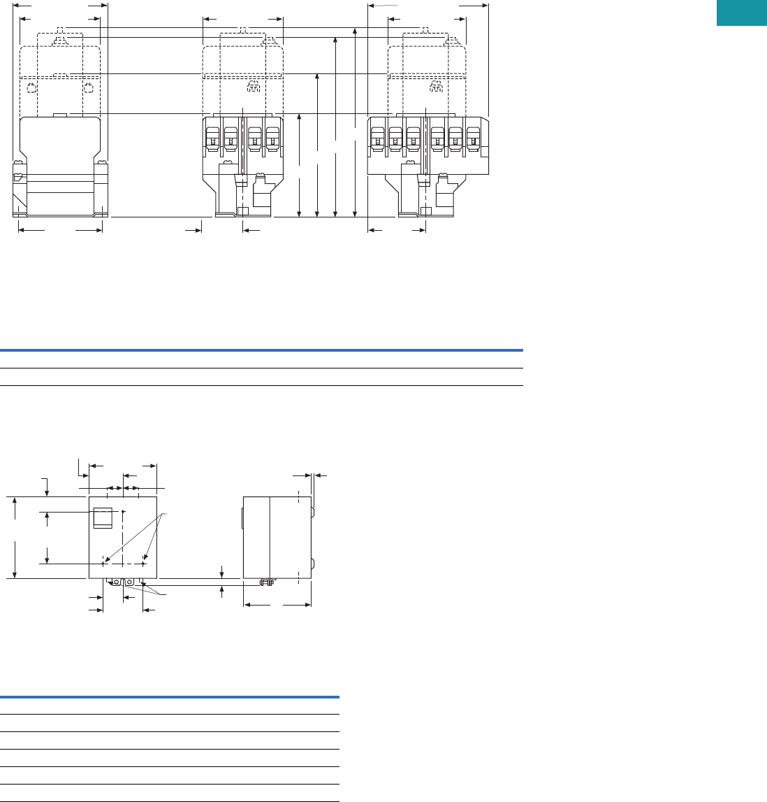
Volume 7—Logic Control, Operator Interface and Connectivity Solutions CA08100008E—February 2014 www.eaton.com V7-T3-161
3
3
3
3
3
3
3
3
3
3
3
3
3
3
3
3
3
3
3
3
3
3
3
3
3
3
3
3
3
3
3.7
Control Relays and Timers
Machine Tool Relays
Dimensions
Approximate Dimensions in Inches (mm)
Four- and Six-Pole with Four-Pole Adder, Solid-State Timer and Mechanical Latch
Four- and Six-Pole with Four-Pole Adder, Solid-State Timer and Mechanical Latch
Enclosures—NEMA 1 for BF, BFD, AR and ARD
Enclosures—NEMA 1 for BF, BFD, AR and ARD
Relay
Catalog
Number
A
Four-, Six-Pole Relays
B
Relay Adder
C
Relay with Timer
D
Relay with Latch
AR 3.56 (90.4) 4.94 (125.5) 6.00 (152.4) 6.39 (162.3)
ARD 4.63 (117.6) 6.00 (152.4) 7.06 (179.3) 7.45 (189.2)
Poles
Catalog
Number
Dimension A
NEMA 1
Relays without Attachments
All BF, AR, ARD 5.34 (135.6)
4–8 BFD 5.34 (135.6)
10, 12 BFD 7.97 (202.4)
Relays with Attachments
All BF, AR, ARD 7.97 (202.4)
A
Base Relay
Adder Deck
S.S. Timer
Latch
B
C
D
1.44 (36.6)
End View, 4- and 6-Pole Side View, 4-Pole Side View, 6-Pole
3.13
(79.5)
2.75 (69.9) 2.88 (73.2)
3.44 (87.4)
2.88 (73.2)
4.09 (103.9)
2.05
(52.1) C
L
C
L
C
L of Mounting Slots
(2) for 0.164 Screws
of Mounting Slots
(2) for 0.164 Screws
of Mounting Slots
(2) for 0.164 Screws
5.66
(143.8)
3.38 (85.9)
2.83
(71.9)
1.72
(43.7)
0.25 (6.4) Dia.
Mtg. Holes (3)
0.19 (4.8)
A
1.69 (42.9) 0.38 x 0.5
(9.7 x 12.7)
Conduit
(2 Top, 2 Bottom)
6.59
(167.4) 4.5
(114.3) 0.63
(16)
1.05
(26.7)
KO KO KO
KO KO KO
KO
KO
1.72
(43.7)
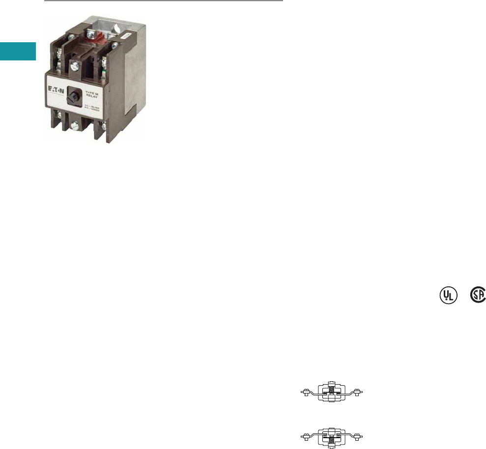
V7-T3-162 Volume 7—Logic Control, Operator Interface and Connectivity Solutions CA08100008E—February 2014 www.eaton.com
3
3
3
3
3
3
3
3
3
3
3
3
3
3
3
3
3
3
3
3
3
3
3
3
3
3
3
3
3
3
3.7
Control Relays and Timers
Machine Tool Relays
D26 Series—Type M, 600 Vac Multipole with Convertible Contacts
Contents
Description Page
D15 Series—Freedom 600V Multipole. . . . . . . . . . V7-T3-146
BF/BFD Series—Fixed Contact Industrial
Control. . . . . . . . . . . . . . . . . . . . . . . . . . . . . . . . . V7-T3-151
AR/ARD Series—Convertible Contact
Industrial Control . . . . . . . . . . . . . . . . . . . . . . . . . V7-T3-157
D26 Series—Type M, 600 Vac Multipole
with Convertible Contacts
Product Selection . . . . . . . . . . . . . . . . . . . . . . . V7-T3-163
Technical Data and Specifications . . . . . . . . . . V7-T3-165
Dimensions . . . . . . . . . . . . . . . . . . . . . . . . . . . V7-T3-166
D26 Series—Type M, DC Multipole
with Convertible Contacts . . . . . . . . . . . . . . . . . V7-T3-167
D26 Series—Type M, 600 Vac Multipole with Convertible Contacts
Product Description
Relays can be ordered as
complete devices in any pole
combination up to a
maximum of 12NO or 8NC
and 4NO poles, or can be
assembled from components
shown on Page V7-T3-164.
Relay base assembly
(D26MB) will accept from 1
to 4 rear poles (D26MPR,
D26MPS and/or D26MPL).
Features
Contact poles D26MPR and
D26MPF in 2- through 8-pole
relays are convertible NO to
NC or vice versa. Simply
reverse the terminal screws
and rotate the unit pole 180°
(in either direction).
Options
Adding a front deck, the total
number of poles can be
increased to 8, all convertible
NO to NC.
Adding a D26MF, 4-pole fixed
NO attachment, builds a 12-
pole relay with 8 convertible
poles and 4 fixed NO poles.
Relays with mechanical latch
are available in any
convertible pole combination
up to eight poles maximum.
To obtain overlapping
contacts, use D26MPS (NO
early closing) and D26MPL
(NC late opening) rear poles,
in related circuits.
Standards and Certifications
●UL listed—Class No.
NKCR2, File E1230(N)
●CSA certified—File LR353
Normally Closed
Contact
Normally Open
Contact
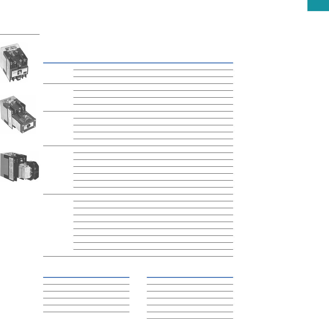
Volume 7—Logic Control, Operator Interface and Connectivity Solutions CA08100008E—February 2014 www.eaton.com V7-T3-163
3
3
3
3
3
3
3
3
3
3
3
3
3
3
3
3
3
3
3
3
3
3
3
3
3
3
3
3
3
3
3.7
Control Relays and Timers
Machine Tool Relays
Product Selection
Complete AC Relays
When Ordering, Specify
●Catalog number and magnet coil suffix letter.
●Example: For a 4-pole relay having 4NO contacts, order Catalog Number D26MR40, with a 120V,
60 Hz coil, order D26MR40A.
●For fast delivery and minimum inventory, it is recommended that component parts or complete
relays with NO poles be ordered.
Complete AC Relays—Open Type
Magnet Coil Selection
Notes
1 10- and 12-Poles: The 6 and 8 contact relays (without mechanical latch only) listed above can be provided
with four additional NO non-convertible contacts. Add suffix number 4 to above listed catalog number plus
magnet coil suffix. Example: For a 12 contact relay, order D26MR804A.
2 Consult Customer Support Center for availability.
Number
of Contacts
Type of Contact Relay Only
Relay with
Mechanical Latch
NO (Form A) NC (Form B)
Catalog
Number
Catalog
Number
22 0 D26MR20 D26MR202
11D26MR11 D26MR112
02D26MR02 D26MR022
33 0 D26MR30 D26MR302
21D26MR21 D26MR212
12D26MR12 D26MR122
03D26MR03 D26MR032
44 0 D26MR40 D26MR402
31D26MR31 D26MR312
22D26MR22 D26MR222
13D26MR13 D26MR132
04D26MR04 D26MR042
6 160D26MR60 D26MR602
51D26MR51 D26MR512
42D26MR42 D26MR422
33D26MR33 D26MR332
24D26MR24 D26MR242
15D26MR15 D26MR152
06D26MR06 D26MR062
8 180D26MR80 D26MR802
71D26MR71 D26MR712
62D26MR62 D26MR622
53D26MR53 D26MR532
44D26MR44 D26MR442
35D26MR35 D26MR352
26D26MR26 D26MR262
17D26MR17 D26MR172
08D26MR08 D26MR082
Volts/Hertz Suffix Code Volts/Hertz Suffix Code
120/60–110/50 A32/60 2V
240/60–220/50 B12/60 2R
208/60 2E6/60 P
24/60 T380/50 2L
277/60 H480/60 or 440/50 C
600/60 or 550/50 2D
4-Pole
4-Pole with Latch
4-Pole with Pneumatic
Timer Attachment
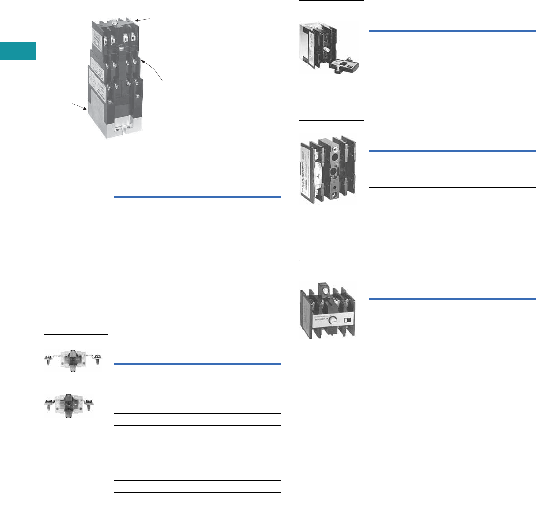
V7-T3-164 Volume 7—Logic Control, Operator Interface and Connectivity Solutions CA08100008E—February 2014 www.eaton.com
3
3
3
3
3
3
3
3
3
3
3
3
3
3
3
3
3
3
3
3
3
3
3
3
3
3
3
3
3
3
3.7
Control Relays and Timers
Machine Tool Relays
Relay Component Parts Location
Relay with Pneumatic Timer Attachment
Factory Installed (without Relay Contacts)
The relays listed above will
accept up to four catalog
number D26MPR contacts
(convertible—NO or NC) for
instantaneous operation.
Order contacts separately.
For additional information
on timer attachment, see
Page V7-T3-165.
For assembly of relays from
component parts and relay
accessories, see components
tables below.
Separate Contacts
Contact
Positions 1
Timer
Operation
Catalog
Number 2
4ON delayD26MR005
4 OFF delay D26MR006
D26MB
Relay Base
Assembly
D26MF
Front Attachment
Timer Attachments or
Mechanical Latch
D26MD10
Front Deck
Pneumatic Timer or
Mechanical Latch
D26MF
Front Attachment
Description
Catalog
Number
Convertible Contacts
Rear pole—NO D26MPR
Rear pole—NC D26MPR02
Front pole—NO D26MPF
Front pole—NC D26MPF02
Gold plated
(for low power circuits)
Rear pole—NO D26MPR03
Front pole—NO D26MPF03
Non-Convertible Contacts
Rear pole NO early closing 3D26MPS
Rear pole NC late opening 3D26MPL
Rear Pole
Front Pole
Relay Base Assembly (without Poles)
Basic four-pole D26 relay
without contacts. Provision
for adding one to four poles
as needed, D26MPR,
D26MPL and/or D26MPS
rear pole type.
Front Deck (Convertible Contact Poles)
Provides up to four additional
front pole type D26MPF
contacts. Convertible, NO
to NC.
Four-Pole Front Attachment
(4NO Fixed Circuit)
Can be added to any two- to
eight-pole Type M, D26 relay
to provide up to a 12-pole
relay. Four NO, non-
convertible contacts are
included in this assembly.
Notes
1Number of available instantaneous contact positions (order contacts
separately—Catalog Number D26MPR).
2Consult Customer Support Center for availability.
3To obtain overlapping contacts, these two special poles must be used in related circuits.
4Add magnet coil suffix letter, see Page V7-T3-163. Example: D26MBA.
Description
Catalog
Number
Relay base assembly D26MB 4
Relay Base
Assembly
Description
Catalog
Number
Front Deck with …
1NO contact pole D26MD10
2NO contact poles D26MD20
4NO contact poles D26MD40
Rear Pole
Description
Catalog
Number
Front attachment D26MF
Four-Pole Front
Attachment
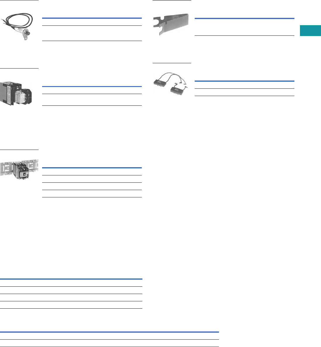
Volume 7—Logic Control, Operator Interface and Connectivity Solutions CA08100008E—February 2014 www.eaton.com V7-T3-165
3
3
3
3
3
3
3
3
3
3
3
3
3
3
3
3
3
3
3
3
3
3
3
3
3
3
3
3
3
3
3.7
Control Relays and Timers
Machine Tool Relays
Relay State Indicating Light
Light provided with leads and
bracket for mounting on two-
to 12-pole relays. May be
used to monitor state
of magnet coil or relay
contact operation.
Pneumatic Timer Attachment
Attachment mounts on any 0-
to four-pole D26 relay without
latch. Timer unit has DPDT
timed contacts (circuits in
each pole must be the same
polarity). Adjustable timing
range—0.1 to 180 seconds,
repeat accuracy ±10%.
Units are convertible from
OFF delay to ON delay or
vice versa.
Mounting Channel
Pre-spaced mounting for
adjacent relay installation.
Indexed for cutting to desired
length. Captive mounting
screws provided in channel
for easier installation.
Technical Data and Specifications
General
Note
1For DC contact ratings, see Page V7-T3-169.
Description
Catalog
Number
120 Vac, 50/60 Hz D26MAP120
240 Vac, 50/60 Hz D26MAP240
Relay State
Indicating Light
Description
Catalog
Number
ON delay D26MTE
OFF delay D26MTD
Pneumatic Timer
Attachment
Description
Catalog
Number
10 in length for 4 relays D26MC4
20 in length for 8 relays D26MC8
30 in length for 12 relays D26MC12
40 in length for 16 relays D26MC16
Mounting Channel
Contact Ratings (Amperes) A600
AC Volts 1
Make and
Emergency
Interrupting
Capacity Break
Continuous
Thermal Rating
120 60 6 10
240 30 3 10
480 15 1.5 10
600 12 1.2 10
Coil Power Operating Time
Watts VA Range in
MillisecondsRelay Inrush Sealed Inrush Sealed
Two- to 12-pole 95.0 9 155 22 Pickup: 6–13
Latch coil 18.5 11 41 17 Dropout: 8–26
Manual Test Accessory
Tool to manually hold relays
in the energized position for
circuitry testing on completed
panel. (10 per box, order in
multiples of 10.)
Transient Suppressor
May be mounted on any
120 Vac relay magnet coil
or latch coil or 120 Vdc latch
coil—connects directly across
coil terminals. All DC magnet
coils have a built-in varistor
for transient suppression.
Limits high voltage transients
produced in the circuit when
power is removed from the
coil.
Description
Catalog
Number
Manual test accessory D26MTA
Manual Test Accessory
Description
Catalog
Number
Magnet coil transient suppressor D26MAS1
Latch coil transient suppressor D26MAS2
Transient Suppressor
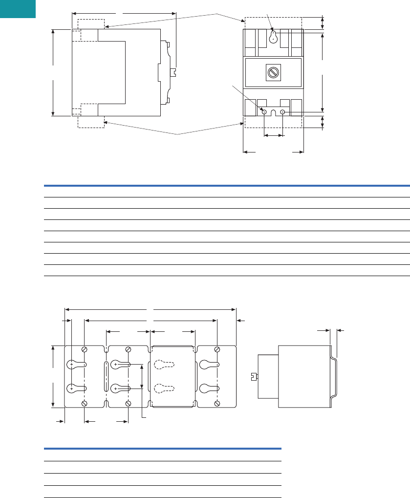
V7-T3-166 Volume 7—Logic Control, Operator Interface and Connectivity Solutions CA08100008E—February 2014 www.eaton.com
3
3
3
3
3
3
3
3
3
3
3
3
3
3
3
3
3
3
3
3
3
3
3
3
3
3
3
3
3
3
3.7
Control Relays and Timers
Machine Tool Relays
Dimensions
Approximate Dimensions in Inches (mm)
AC and DC D26 Relays
Mounting Channel
Note: Channel mounts through keyholes with #10 screws
(two each end and one every fourth relay). Relays mount with screws
captive in channel. All screws must be tightened firmly.
AC Relay
D26
DC Relay
D26 Dimension A
Ship. Wt.
Lbs (kg)
1–4 poles 1–3 poles 4.00 (101.6) 2.5 (1.1)
1–4 poles with timer D26 or D87 1–3 poles with timer D26 or D87 6.00 (152.4) 3.3 (1.5)
1–4 poles with latch 1–2 poles with latch 6.13 (155.7) 3.5 (1.6)
1–4 poles with D26MF 1–3 poles with D26MF 5.81 (147.6) 2.8 (1.3)
5–8 poles 4–7 poles 5.25 (133.4) 2.8 (1.3)
5–8 poles with timer D87 4–7 poles with timer D87 7.25 (184.2) 3.5 (1.6)
5–8 poles with latch 3–6 poles with latch 7.31 (185.7) 3.8 (1.7)
9–12 poles 8–11 poles 7.00 (177.8) 3.0 (1.4)
Catalog
Number Dimension A Dimension B
D26MC16 40 (1016) 37.5 (952.5)
D26MC12 30 (762) 27.5 (698.5)
D26MC8 20 (508) 17.5 (444.5)
D26MC4 10 (254) 7.5 (190.5)
2.38 (60.5)
Max.
D26MAS2
D26MAS1
0.75
(19.1)
3.13
(79.5)
0.44
(11.2)
0.44
(11.2)
3.50
(88.9)
A
1 Slot
#10 Screw
2 Holes
#10 Screw
2.50
(63.5)
2.50
(63.5) 2.38
(60.5)
B
0.69
(17.5) 1.06
(26.9)
A
1.25
(31.8)
3.63
(92.2)
1.38
(35.1)
0.38
(9.7)
Type
M
Relay
D26
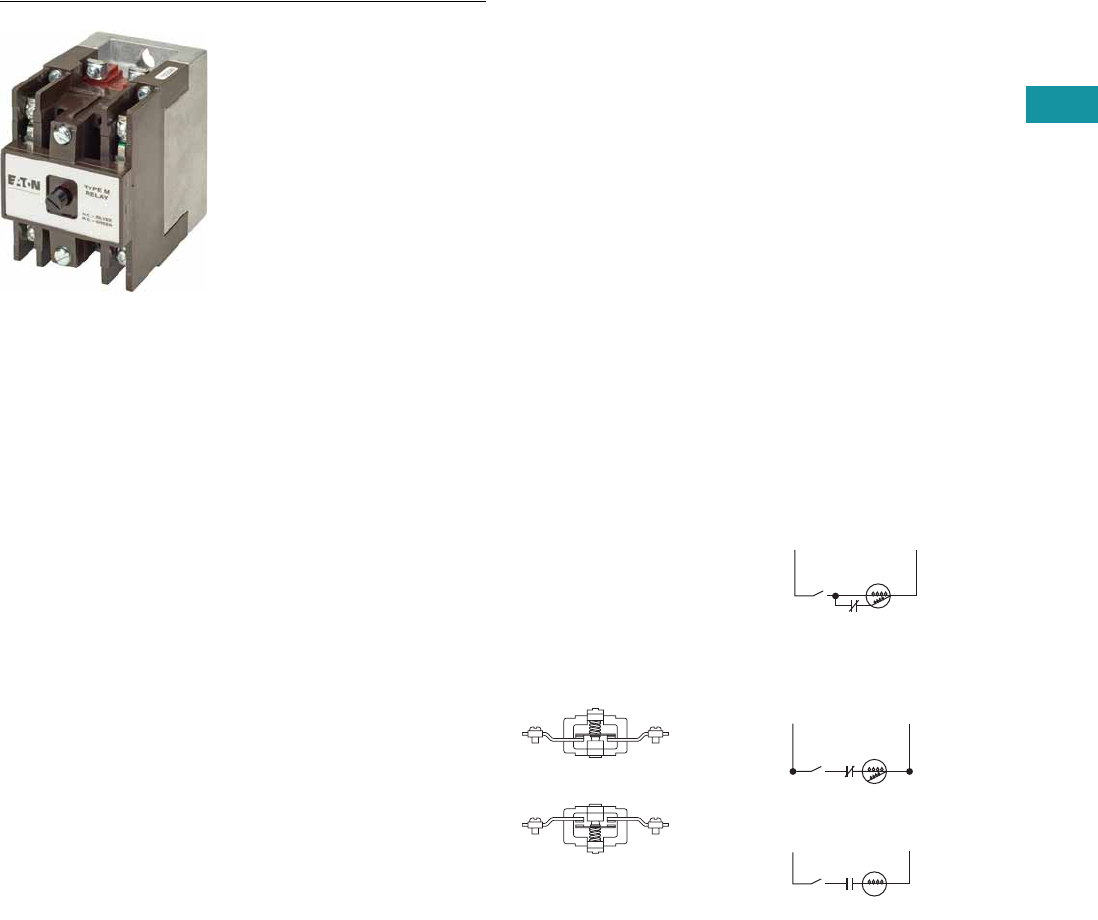
Volume 7—Logic Control, Operator Interface and Connectivity Solutions CA08100008E—February 2014 www.eaton.com V7-T3-167
3
3
3
3
3
3
3
3
3
3
3
3
3
3
3
3
3
3
3
3
3
3
3
3
3
3
3
3
3
3
3.7
Control Relays and Timers
Machine Tool Relays
D26 Series—Type M, DC Multipole with Convertible Contacts
Contents
Description Page
D15 Series—Freedom 600V Multipole. . . . . . . . . . V7-T3-146
BF/BFD Series—Fixed Contact Industrial
Control . . . . . . . . . . . . . . . . . . . . . . . . . . . . . . . . . V7-T3-151
AR/ARD Series—Convertible Contact
Industrial Control . . . . . . . . . . . . . . . . . . . . . . . . . V7-T3-157
D26 Series—Type M, 600 Vac Multipole
with Convertible Contacts . . . . . . . . . . . . . . . . . . V7-T3-162
D26 Series—Type M, DC Multipole
with Convertible Contacts
Product Selection . . . . . . . . . . . . . . . . . . . . . . . V7-T3-168
Technical Data and Specifications . . . . . . . . . . V7-T3-169
Dimensions . . . . . . . . . . . . . . . . . . . . . . . . . . . V7-T3-170
D26 Series—Type M, DC Multipole with Convertible Contacts
Product Description
Type M, DC multipole
relays are physically and
mechanically similar to
the (D26) Type M AC
relays described on Page
V7-T3-163. They differ only in
the electrical ratings and
available pole combinations
due to the use of a normally
closed late opening, coil
clearing contact, factory
wired to the pickup winding
of the magnet coil. (Contact is
shown as L in figure to the
right.) Magnet coil has built-in
varistor for transient
suppression.
The mechanically latched
relay has one extra contact,
normally open early closing,
factory wired in series with
the winding of the
intermittent rated latch coil.
(Contact is shown as S in
figure to the right.)
Component parts for
these relays are the same
as those listed for the (D26)
Type M AC relays on Page
V7-T3-163, except for the
Indicating Light, which is not
applicable to a DC relay.
Contact poles D26MPR and
D26MPF in 2- to 7-pole relays
are convertible NO to NC or
vice versa. Simply reverse the
terminal screws and rotate
the unit pole 180° (in either
direction).
Latch Operation
With the latch coil de-
energized, energizing the
relay coil will pick up the relay
and mechanically latch it in
the pickup position. With the
relay coil de-energized,
energizing the latch coil will
allow the relay to drop out.
Convertible Contacts
Normally Closed
Contact
Normally Open
Contact
LS1
LS1
LS1 L
S
DC Input
DC Input
DC Type M Relay
DC Type M Relay
with Latch
Pick-Up
Pick-Up
L = NC Late Opening
L = NC Late Opening
S = NO Early Closing
Relay
Coil
Latch
Coil
Hold
(Not Used)
Release
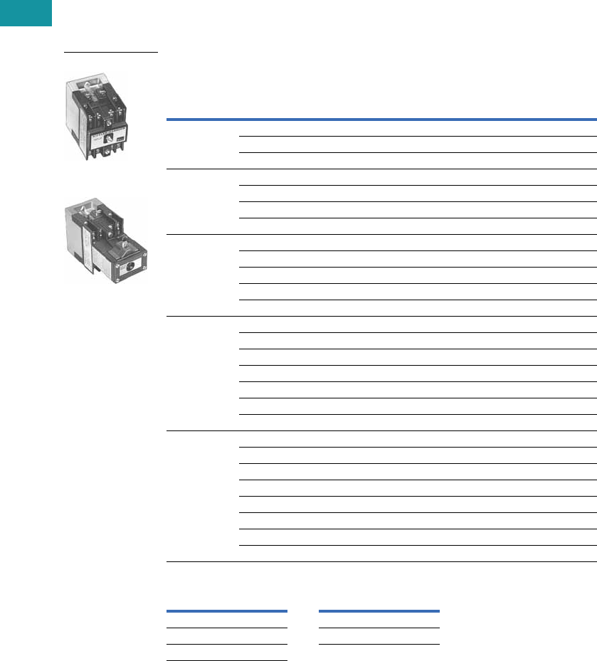
V7-T3-168 Volume 7—Logic Control, Operator Interface and Connectivity Solutions CA08100008E—February 2014 www.eaton.com
3
3
3
3
3
3
3
3
3
3
3
3
3
3
3
3
3
3
3
3
3
3
3
3
3
3
3
3
3
3
3.7
Control Relays and Timers
Machine Tool Relays
Product Selection
Complete DC Relays
When Ordering, Specify
●Catalog number and magnet coil suffix letter.
●Example: For a 4-pole relay having 4NO contacts, order Catalog Number D26MRD40, with a
120 Vdc coil, order D26MRD40A1.
Complete DC Relays—Open Type
Magnet Coil Selection
Notes
1 Relay has additional factory wired normally closed coil clearing contact (see diagram).
2 10- and 11-Poles: The 6 and 7 contact relays (without mechanical latch only) listed above can be provided with four
additional NO non-convertible contacts. Add suffix number 4 to above listed catalog number plus magnet coil suffix.
Example: For an 11 contact relay, order D26MRD704A1.
Number
of Contacts
Type of Contact 1Relay Only
Relay with
Mechanical Latch
NO (Form A) NC (Form B)
Catalog
Number
Catalog
Number
22 0 D26MRD20 D26MRD202
11D26MRD11 D26MRD112
02D26MRD02 D26MRD022
33 0 D26MRD30 D26MRD302
21D26MRD21 D26MRD212
12D26MRD12 D26MRD122
03D26MRD03 D26MRD032
44 0 D26MRD40 D26MRD402
31D26MRD31 D26MRD312
22D26MRD22 D26MRD222
13D26MRD13 D26MRD132
04D26MRD04 D26MRD042
6 260D26MRD60 D26MRD602
51D26MRD51 D26MRD512
42D26MRD42 D26MRD422
33D26MRD33 D26MRD332
24D26MRD24 D26MRD242
15D26MRD15 D26MRD152
06D26MRD06 D26MRD062
7 2 70D26MRD70 —
61D26MRD61 —
52D26MRD52 —
43D26MRD43 —
34D26MRD34 —
25D26MRD25 —
16D26MRD16 —
07D26MRD07 —
Volts/Hertz Suffix Code Volts/Hertz Suffix Code
12 R1 120 A1
24 T1 240 B1
48 W1
3-Pole
3-Pole with Latch
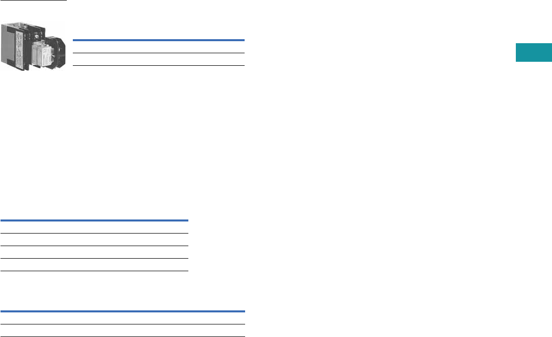
Volume 7—Logic Control, Operator Interface and Connectivity Solutions CA08100008E—February 2014 www.eaton.com V7-T3-169
3
3
3
3
3
3
3
3
3
3
3
3
3
3
3
3
3
3
3
3
3
3
3
3
3
3
3
3
3
3
3.7
Control Relays and Timers
Machine Tool Relays
Relay with Pneumatic Timer Attachment
(without Relay Contacts)
The relays listed above will
accept up to three catalog
number D26MPR contacts
(convertible—NO or NC) for
instantaneous operation.
Order contacts separately.
For additional information
on timer attachment, see
Page V7-T3-165.
Technical Data and Specifications
General
Notes
1Number of available instantaneous contact positions (order contacts
separately—Catalog Number D26MPR).
2Contact ratings do not apply to contacts D26MPL and D26MPS.
For AC contact ratings, see Page V7-T3-165.
Contact
Positions 1
Timer
Operation
Catalog
Number
3ON delayD26MRD005
3 OFF delay D26MRD006
3-Pole with Timer
Attachment
Contact Ratings (Amperes) 2
DC Volts
Inductive
Make/Break
Resistive
Make/Break
28 7.0 10.0
48 2.5 10.0
120 1.1 2.0
240 0.2 0.4
Coil Power Operating Time
Watts Average
MillisecondsRelay Inrush Sealed
Two- to 11-pole 168 13.2 Pickup: 10
Latch coil 21.6 intermittent 21.6 intermittent Dropout: 16
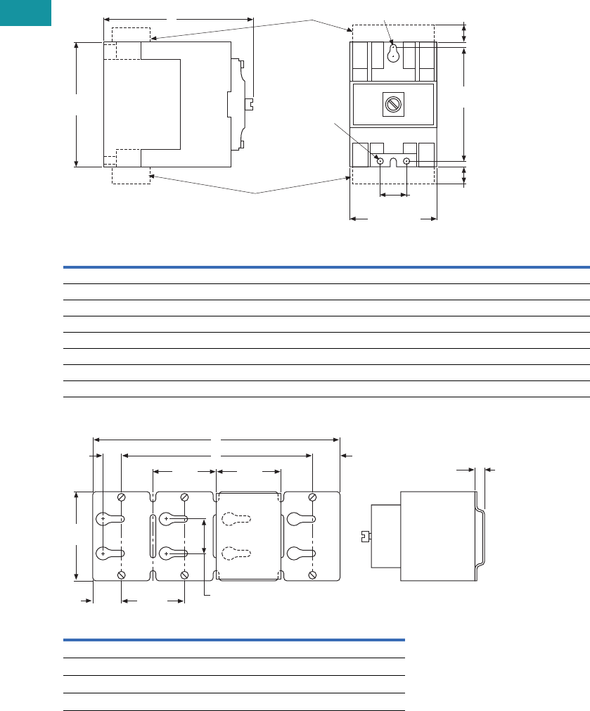
V7-T3-170 Volume 7—Logic Control, Operator Interface and Connectivity Solutions CA08100008E—February 2014 www.eaton.com
3
3
3
3
3
3
3
3
3
3
3
3
3
3
3
3
3
3
3
3
3
3
3
3
3
3
3
3
3
3
3.7
Control Relays and Timers
Machine Tool Relays
Dimensions
Approximate Dimensions in Inches (mm)
AC and DC D26 Relays
Mounting Channel
Note: Channel mounts through keyholes with #10 screws
(two each end and one every fourth relay). Relays mount with screws
captive in channel. All screws must be tightened firmly.
AC Relay
D26
DC Relay
D26 Dimension A
Ship. Wt.
Lbs (kg)
1–4 poles 1–3 poles 4.00 (101.6) 2.5 (1.1)
1–4 poles with timer D26 or D87 1–3 poles with timer D26 or D87 6.00 (152.4) 3.3 (1.5)
1–4 poles with latch 1–2 poles with latch 6.13 (155.7) 3.5 (1.6)
1–4 poles with D26MF 1–3 poles with D26MF 5.81 (147.6) 2.8 (1.3)
5–8 poles 4–7 poles 5.25 (133.4) 2.8 (1.3)
5–8 poles with timer D87 4–7 poles with timer D87 7.25 (184.2) 3.5 (1.6)
5–8 poles with latch 3–6 poles with latch 7.31 (185.7) 3.8 (1.7)
9–12 poles 8–11 poles 7.00 (177.8) 3.0 (1.4)
Catalog
Number Dimension A Dimension B
D26MC16 40 (1016) 37.5 (952.5)
D26MC12 30 (762) 27.5 (698.5)
D26MC8 20 (508) 17.5 (444.5)
D26MC4 10 (254) 7.5 (190.5)
2.38 (60.5)
Max.
D26MAS2
D26MAS1
0.75
(19.1)
3.13
(79.5)
0.44
(11.2)
0.44
(11.2)
3.50
(88.9)
A
1 Slot
#10 Screw
2 Holes
#10 Screw
2.50
(63.5)
2.50
(63.5) 2.38
(60.5)
B
0.69
(17.5) 1.06
(26.9)
A
1.25
(31.8)
3.63
(92.2)
1.38
(35.1)
0.38
(9.7)
Type
M
Relay
D26
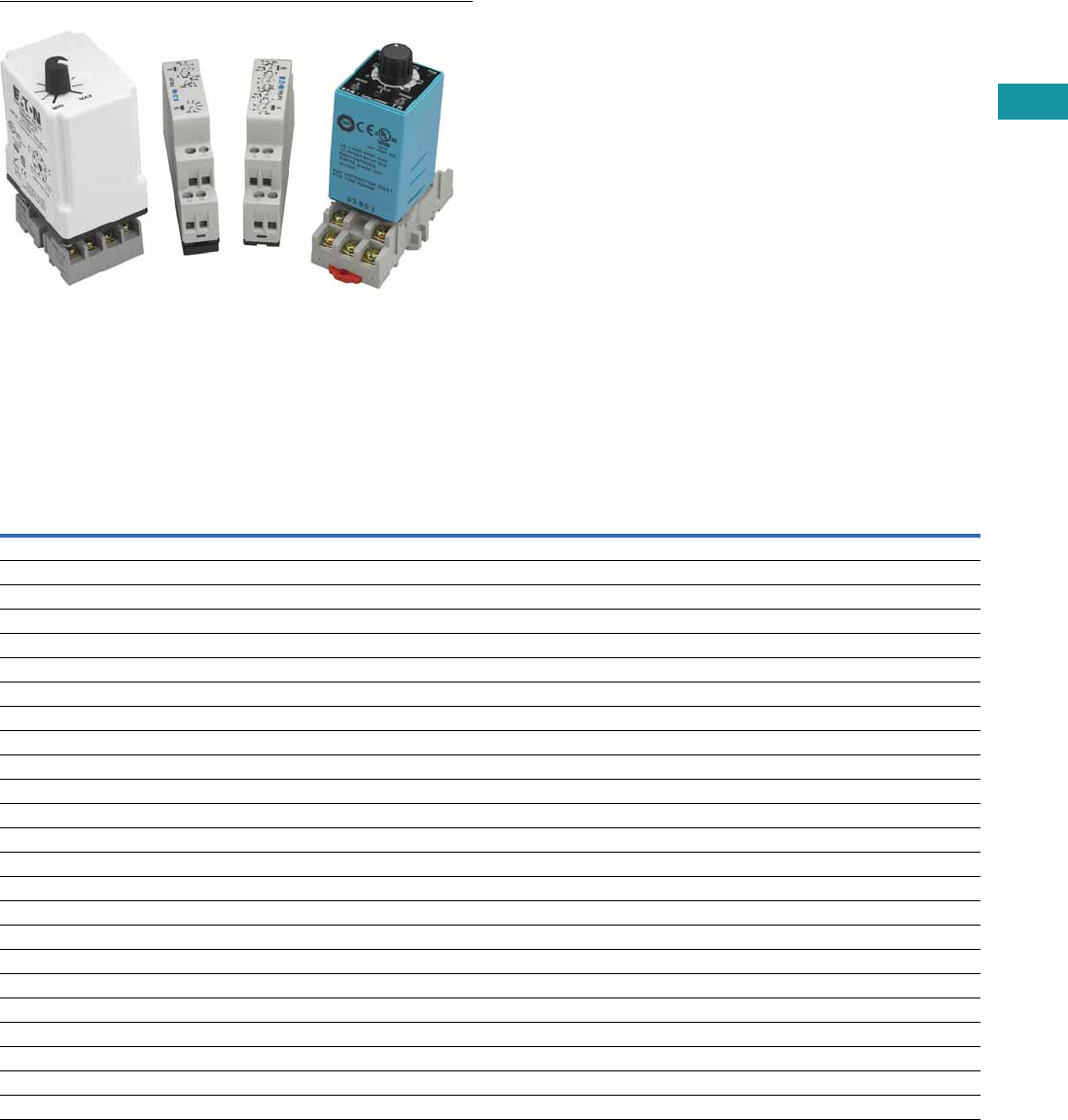
Volume 7—Logic Control, Operator Interface and Connectivity Solutions CA08100008E—February 2014 www.eaton.com V7-T3-171
3
3
3
3
3
3
3
3
3
3
3
3
3
3
3
3
3
3
3
3
3
3
3
3
3
3
3
3
3
3
3.8
Control Relays and Timers
Ti m i n g Rel ay s
Timing Relays
Contents
Description Page
Timing Relays
Universal TR Series . . . . . . . . . . . . . . . . . . . . . V7-T3-176
TR Series . . . . . . . . . . . . . . . . . . . . . . . . . . . . . V7-T3-180
TMR5 Series . . . . . . . . . . . . . . . . . . . . . . . . . . . V7-T3-183
TMR6 Series . . . . . . . . . . . . . . . . . . . . . . . . . . . V7-T3-187
TMRP Series . . . . . . . . . . . . . . . . . . . . . . . . . . V7-T3-189
Product Selection Guide
Function Code Cross-Reference Guide
Notes
1Applies to TRN model only.
2Applies to TRF model only.
3The E5-248 is battery powered and has three programmable trigger functions.
This product may perform somewhat differently from the standard timing relays.
Refer to the operator instructions for details.
Timer Series
Function Description Universal TR TR TMR5 TMR6 TMRP E5-248 3
1 Asymmetrical flasher, pause first lp — R/P — — RC DLY
2 Asymmetrical flasher, pulse first li — Y — — RC
3 ON delay and OFF delay with control contact ER — ————
4 ON delay and single shot leading edge voltage controlled EWu — ————
5 ON delay and single shot leading edge control contact EWs — ————
6 Single shot leading and single shot trailing edge with control contact WsWa — ————
7 Pulse sequence monitoring Wt — ————
8 ON delay, power triggered E A 1N—A—
9 Single shot leading edge voltage controlled Wu B 1T—C—
10 OFF delay/signal OFF delay R E 2F — D OFF DLY
11 Single shot leading edge with control input Ws F 2C/G — H SS
12 Single shot trailing edge with control input Wa — ————
13 ON delay control signal start, trailing edge OFF Es — ————
14 Flasher, pause first Bp C 1L—B—
15 Retriggerable single shot — — W/D — E SS
16 Flasher, ON first — D 1——F —
17 ON delay control signal start, leading edge OFF — A 2———ON DLY
18 Flasher—control signal start, pause first — B 2— — — RC DLY
19 Flasher—control signal start, ON first — C 2———RC
20 Signal ON/OFF delay — D 2————
21 ON/OFF delay — — — — I —
22 Single pulse generator — — — — G OS
23 Memory latch — — — — J —
24 True OFF delay — — — X — —
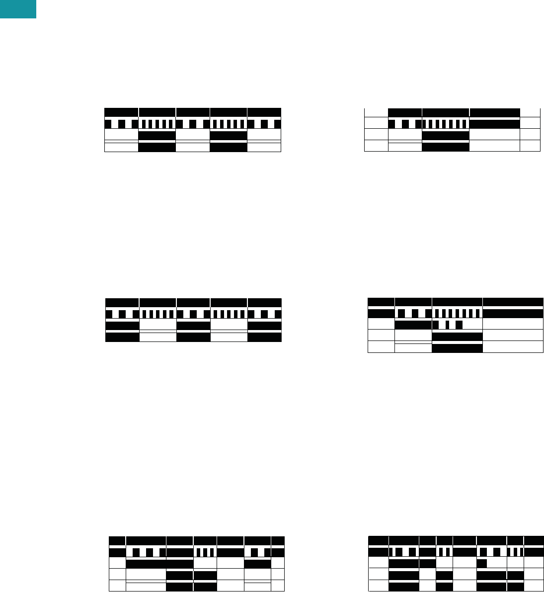
V7-T3-172 Volume 7—Logic Control, Operator Interface and Connectivity Solutions CA08100008E—February 2014 www.eaton.com
3
3
3
3
3
3
3
3
3
3
3
3
3
3
3
3
3
3
3
3
3
3
3
3
3
3
3
3
3
3
3.8
Control Relays and Timers
Ti m i ng Relay s
Product Overview
Timer Function Descriptions
Function #1—Universal TR, TMR5, E5-248
Asymmetrical Flasher, Pause First
Repeat Cycle, OFF/ON Delay
When the supply voltage U
is applied, the set interval t1
begins. After the interval t1
has expired, the output relay
R switches into ON position
and the set interval t2 begins.
After the interval t2 has
expired, the output relay
switches into OFF position.
The output relay is triggered
at the ratio of t1:t2 until the
supply voltage is interrupted.
Function #2—Universal TR, TMR5, E5-248
Asymmetrical Flasher, Pulse First
Repeat Cycle, ON/OFF Delay
When the supply voltage U
is applied, the output relay R
switches into the ON position
and the set interval t1 begins.
After the interval t1 has
expired, the output relay R
switches into OFF position
and the set interval t2 begins.
After the interval t2 has
expired, the output relay
switches into ON position.
The output relay is triggered
at the ratio of t1:t2 until the
supply voltage is interrupted.
Function #3—Universal TR
ON Delay and OFF Delay with Control Contact
The supply voltage U must
be constantly applied to the
device. When the control
contact S is closed, the set
interval t1 begins. After the
interval t1 has expired, the
output relay R switches into
ON position. If the control
contact is opened, the set
interval t2 begins. After the
interval t2 has expired, the
output relay R switches into
OFF position. If the control
contact is opened before the
interval t1 has expired, the
interval already expired is
erased and is restarted with
the next cycle.
Input Power (U)
LED U/t*
Output LED**
Output Relay (R)
t2t1 t1 t1t2
Input Power (U)
LED U/t*
Output LED**
Output Relay (R) t2t1 t1 t1t2
Input Power (U)
LED U/t*
Trigger Signal (S)
Output LED**
Output Relay (R) t1 <t1t2
Function #4—Universal TR
ON Delay and Single Shot Leading Edge Voltage Controlled
When the supply voltage U
is applied, the set interval t1
begins. After the interval t1
has expired, the output relay
R switches into ON position
and the set interval t2 begins.
After the interval t2 has
expired, the output relay
switches into OFF position. If
the supply voltage is
interrupted before the interval
t1 + t2 has expired, the
interval already expired is
erased and is restarted
when the supply voltage is
next applied.
Function #5—Universal TR
ON Delay and Single Shot Leading Edge Control Contact
The supply voltage U must
be constantly applied to the
device. When the control
contact S is closed, the set
interval t1 begins. After the
interval t1 has expired, the
output relay R switches into
ON position and the set
interval t2 begins. After the
interval t2 has expired, the
output relay R switches into
OFF position. During the
interval, the control contact is
ignored. A new cycle can only
be initiated when the cycle
has been completed.
Function #6—Universal TR
Single Shot Leading and Single Shot Trailing Edge
with Control Contact
Asymmetrical Signal ON/OFF Delay
The supply voltage U must
be constantly applied to the
device. When the control
contact S is closed, the
output relay R switches to
the ON position and the set
interval t1 begins. After the
interval t1 has expired, the
output relay R switches into
OFF position. If the control
contact S is opened, the
output relay again switches to
the ON position and the set
interval t2 begins. After the
interval t2 has expired, the
output relay R switches into
OFF position. During
the interval, the control
contact is ignored. During
the interval, the control
contact can be operated
any number of times.
Input Power (U)
LED U/t*
Output LED**
Output Relay (R) t1 t2
Input Power (U)
LED U/t*
Trigger Signal (S)
Output LED**
Output Relay (R) t1 t2
t2t2t1 t1
Input Power (U)
LED U/t*
Trigger Signal (S)
Output LED**
Output Relay (R)
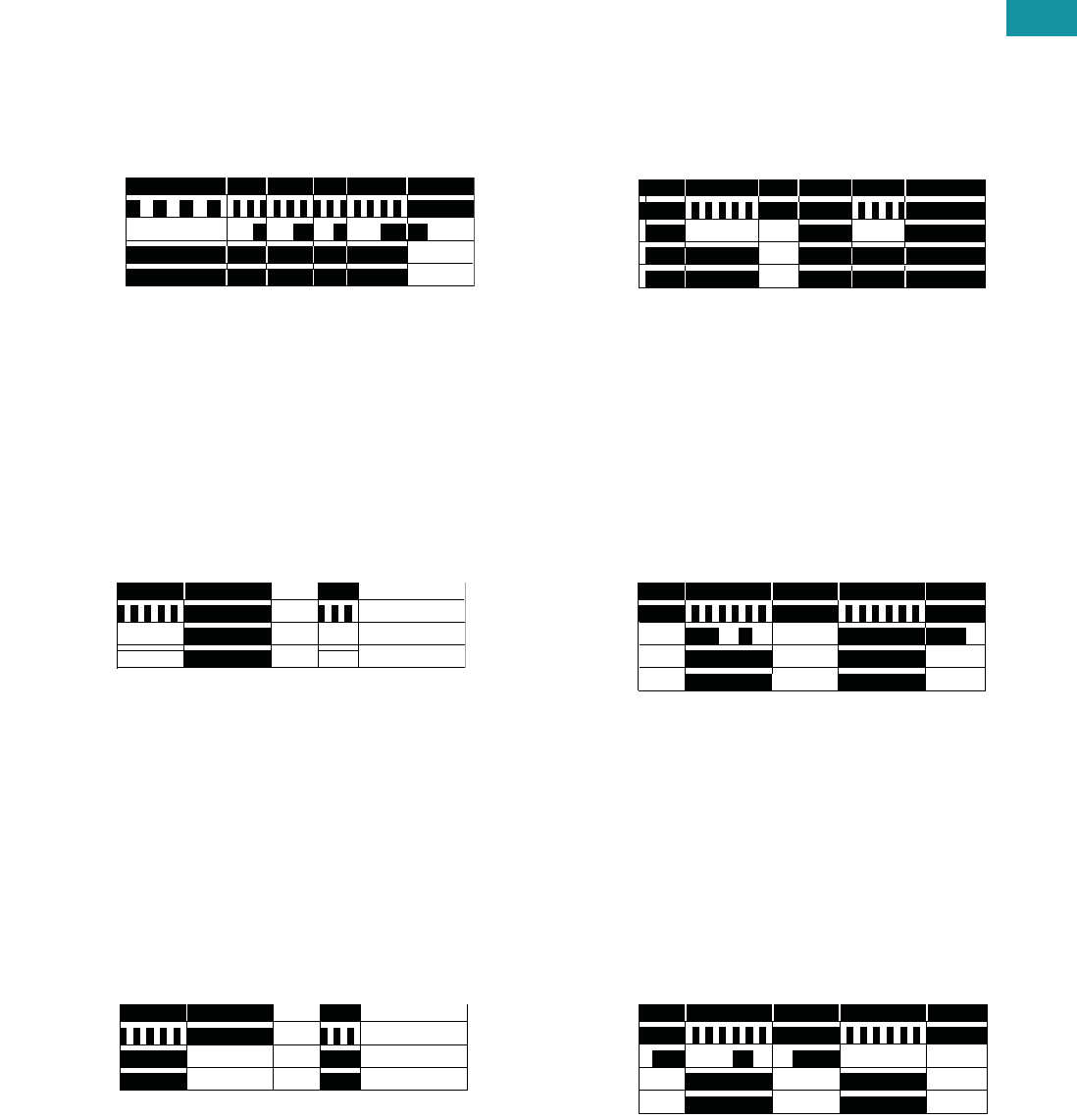
Volume 7—Logic Control, Operator Interface and Connectivity Solutions CA08100008E—February 2014 www.eaton.com V7-T3-173
3
3
3
3
3
3
3
3
3
3
3
3
3
3
3
3
3
3
3
3
3
3
3
3
3
3
3
3
3
3
3.8
Control Relays and Timers
Ti m i n g Rel ay s
Function #7—Universal TR
Pulse Sequence Monitoring
When the supply voltage U
is applied, the set interval t1
begins and the output relay
R switches to the ON
position. After the interval
t1 has expired, the interval
t2 begins. As long as the
control switch S is closed
and opened within the
interval t2, the relay will
remain in the ON position.
If the control switch is not
closed and opened within
the interval t2, the relay
will change to the OFF
position until supply
voltage U is interrupted
and reapplied.
Function #8—Universal TR, TRN, TMR5, TMRP
ON Delay, Power Triggered
Delay ON Make
When the supply voltage U
is applied, the set interval t
begins. After the interval t
has expired, the output relay
R switches to the ON
position. The relay will remain
in that position until supply
voltage U is interrupted.
Function #9—Universal TR, TRN, TMR5, TMRP
Single Shot Leading Edge Voltage Controlled
Interval ON/Interval (Power Start)
When the supply voltage U
is applied, the output relay R
switches to the ON position
and set interval t begins.
After the interval t has
expired, the output relay R
switches to the OFF position.
The relay will remain in that
position until supply voltage U
is interrupted. If the supply
voltage is interrupted prior to
interval t timing out, the relay
will immediately switch to the
OFF position.
Input Power (U)
LED U/t*
Trigger Signal (S)
Output LED**
Output Relay (R) t1 <t2 <t2 t2<t2
Input Power (U)
LED U/t*
Output LED**
Output Relay (R) t<t
Input Power (U)
LED U/t*
Output LED**
Output Relay (R) t<t
Function #10—Universal TR, TRF, TMR5, TMRP, E5-248
OFF Delay/Signal OFF Delay
Delay ON Release
The supply voltage U must
be constantly applied to the
device. When the control
contact S is closed, the
output relay R switches to
the ON position. When the
control contact is opened,
interval t begins. After the
interval t has expired, the
output relay R switches
to the OFF position. If the
control contact S is closed
before interval t expires,
the output relay will remain
in the ON position until the
control switch opens, at
which time the interval t
will begin again.
Function #11—Universal TR, TRF, TMR5, TMRP, E5-248
Single Shot Leading Edge with Control Input
Single Shot/One Shot (Signal Start)/Momentary Interval
The supply voltage U must
be constantly applied to the
device. When the control
contact S is closed, the
output relay R switches to
the ON position and the set
interval t begins. After the
interval t has expired, the
output relay R switches to
the OFF position. The control
contact is ignored during the
interval t, and a new cycle
cannot be started until the
set interval t has timed out.
Function #12—Universal TR
Single Shot Trailing Edge with Control Input
The supply voltage U must
be constantly applied to the
device. When the control
contact S is closed and
reopened, the output relay
R switches to the ON
position and the set interval t
begins. After the interval t
has expired, the output
relay R switches to the
OFF position. The control
contact is ignored during
the interval t, and a new
cycle must be started
after the set interval t has
timed out.
Input Power (U)
LED U/t*
Trigger Signal (S)
Output LED**
Output Relay (R) <tt
Input Power (U)
LED U/t*
Trigger Signal (S)
Output LED**
Output Relay (R) tt
Input Power (U)
LED U/t*
Trigger Signal (S)
Output LED**
Output Relay (R) tt
V7-T3-174 Volume 7—Logic Control, Operator Interface and Connectivity Solutions CA08100008E—February 2014 www.eaton.com
3
3
3
3
3
3
3
3
3
3
3
3
3
3
3
3
3
3
3
3
3
3
3
3
3
3
3
3
3
3
3.8
Control Relays and Timers
Ti m i ng Relay s
Function #13—Universal TR
ON Delay Control Signal Start, Trailing Edge OFF
The supply voltage U must
be constantly applied to the
device. When the control
switch S is applied, the set
interval t begins. After the
interval t has expired, the
output relay R switches to
the ON position. The relay
will remain in that position
until the control switch
opens. If the control switch is
opened prior to interval t
timing out, the relay will
remain in the OFF position
and any elapsed time will be
erased.
Function #14—Universal TR, TRN, TMR5, TMRP
Flasher, Pause First
Cycle 1 (Power Start, OFF First)
When the supply voltage U
is applied, the set interval t
begins. After the interval t
has expired, the output relay
R switches to the ON
position and set interval t will
begin again. After interval t
has expired, the relay will
switch to the OFF position
for the set interval t. This
cycle will repeat at a 1:1
ratio until supply voltage U
is interrupted.
Function #15—TMR5, TMRP, E5-248
Watchdog
Retriggerable Single Shot
The supply voltage U must
be constantly applied to the
device. When the control
switch S is applied, the relay
switches to the ON position
and the set interval t begins.
After the interval t has
expired, the output relay R
switches to the OFF position.
Closing the control switch
during interval t will reset the
time. Continuous cycling of
the trigger signal at a rate
faster than the preset time
will cause the relay to remain
in the ON position.
Input Power (U)
LED U/t*
Trigger Signal (S)
Output LED**
Output Relay (R) t<t
Input Power (U)
LED U/t*
Output LED**
Output Relay (R) t<ttttt
Input Power (U)
Trigger Signal (S)
Output Relay (R) t<t<tt
Function #16—TRN, TMRP
Flasher, ON First
Cycle 3 (Power Start, ON First)
When the supply voltage U
is applied, the relay switches
to the ON position and set
interval t begins. After the
interval t has expired, the
output relay R switches to
the OFF position and set
interval t will begin again.
After interval t has expired,
the relay will again switch to
the ON position for the set
interval t. This cycle will
repeat at a 1:1 ratio until
supply voltage U is
interrupted.
Function #17—TRF, E5-248
ON Delay Control Signal Start, Leading Edge OFF
The supply voltage U must
be constantly applied to the
device. When the control
switch S is applied, the set
interval t begins. After the
interval t has expired, the
output relay R switches to
the ON position. The relay
will remain in that position
until the control switch has
opened and closed. If the
control switch is opened and
closed prior to interval t
timing out, the relay will
remain in the OFF position
and any elapsed time will be
erased.
Function #18—TRF, E5-248
Flasher—Control Signal Start, Pause First
The supply voltage U must
be constantly applied to the
device. When the control
switch S is closed, the set
interval t begins. After the
interval t has expired, the
output relay R switches to
the ON position and set
interval t will begin again.
After interval t has expired,
the relay will switch to the
OFF position for the set
interval t. This cycle will
repeat at a 1:1 ratio until
supply voltage U is
interrupted. The control
switch is ignored during
the cycle.
Input Power (U)
Output LED**
Output Relay (R) ttttt<tt
Input Power (U)
Trigger Signal
Output LED**
Output Relay (R) tt
Input Power (U)
Trigger Signal
Output LED**
Output Relay (R) tttt<t
Volume 7—Logic Control, Operator Interface and Connectivity Solutions CA08100008E—February 2014 www.eaton.com V7-T3-175
3
3
3
3
3
3
3
3
3
3
3
3
3
3
3
3
3
3
3
3
3
3
3
3
3
3
3
3
3
3
3.8
Control Relays and Timers
Ti m i n g Rel ay s
Function #19—TRF, E5-248
Flasher—Control Signal Start, ON First
The supply voltage U must
be constantly applied to the
device. When the control
switch S is closed, the relay
switches to the ON position
and set interval t begins.
After the interval t has
expired, the output relay R
switches to the OFF position
and set interval t will begin
again. After interval t has
expired, the relay will again
switch to the ON position
for the set interval t. This
cycle will repeat at a 1:1
ratio until supply voltage U
is interrupted. The control
switch is ignored during
the cycle.
Function #20—TRF
Signal ON/OFF Delay
The supply voltage U must
be constantly applied to the
device. When the control
switch S is closed, the relay
switches to the ON position
and set interval t begins.
After the interval t has
expired with the control
switch still closed, the output
relay R switches to the OFF
position. When the control
switch is opened, the relay
will switch to the ON position
again and the interval t will
begin. If the control switch is
closed and opened within the
interval t, the relay will remain
in the ON position until
interval t has timed out after
the control switch is opened.
Function #21—TMRP
ON/OFF Delay
Make/Break with Control Switch Trigger
The supply voltage U must
be constantly applied to the
device. When the control
switch S is closed, the set
interval t begins. After the
interval t has expired, the
output relay R switches to
the ON position. When the
control switch is opened,
interval t will begin again.
After interval t has timed out,
the relay will switch to the
OFF position. If supply
voltage U is removed at any
time, the relay will return to
the OFF position.
Input Power (U)
Trigger Signal
Output LED**
Output Relay (R) <tt ttt
Input Power (U)
Trigger Signal
Output LED**
Output Relay (R) t t <t t
Input Power (U)
Trigger Signal
Output LED**
Output Relay (R) tt t
Function #22—TMRP, E5-248
Single Pulse Generator, Voltage Controlled
When the supply voltage U
is applied, the set interval t
begins. After the interval t
has expired, the relay will
switch to the ON position for
0.5 seconds before returning
to the OFF position. Supply
voltage U must be removed
and reapplied to repeat the
pulse.
Function #23—N/A
Memory Latch
Control Switch Make
The supply voltage U must
be constantly applied to the
device. Output changes state
with every closure of the
control switch S (leading
edge).
Function #24—TMR6
True OFF Delay
When the supply voltage U
is applied, the relay switches
to the ON position. When
supply power is removed, set
time interval t begins. After
interval t has expired, the
relay switches to the OFF
position and will remain there
until supply power U is
applied again.
Input Power (U)
Output LED**
Output Relay (R) tt
Input Power (U)
Trigger Signal
Output LED**
Output Relay (R)
Input Power (U)
Output Relay (R) t
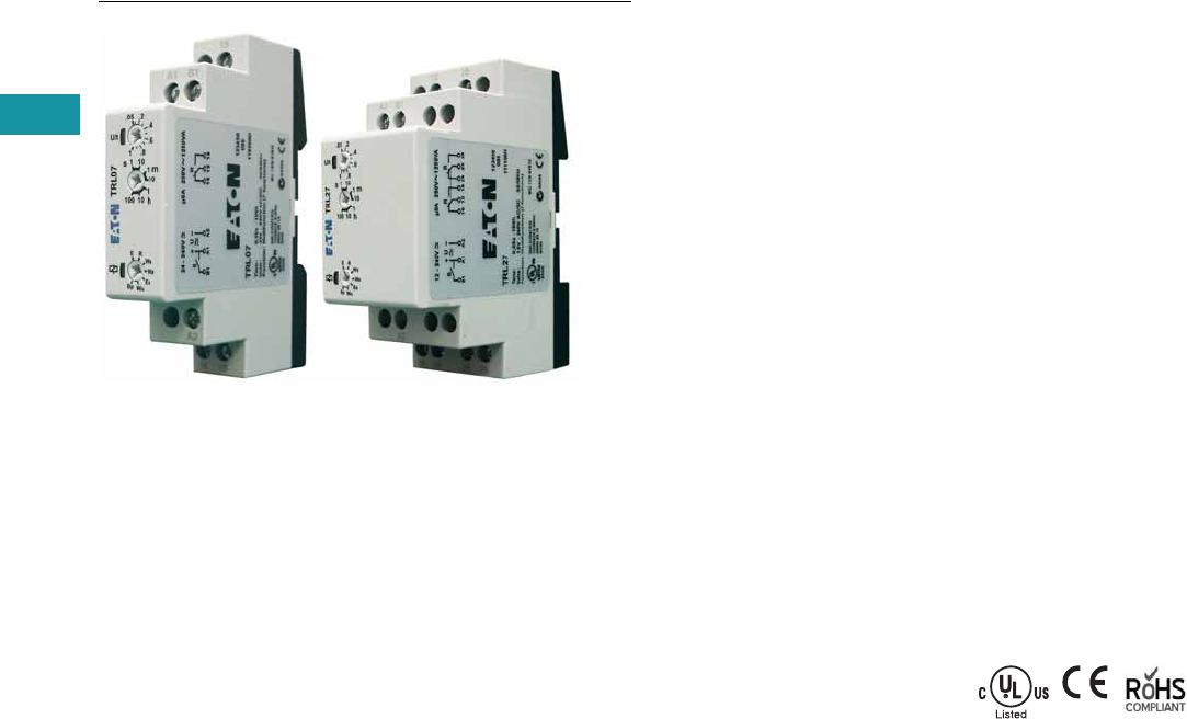
V7-T3-176 Volume 7—Logic Control, Operator Interface and Connectivity Solutions CA08100008E—February 2014 www.eaton.com
3
3
3
3
3
3
3
3
3
3
3
3
3
3
3
3
3
3
3
3
3
3
3
3
3
3
3
3
3
3
3.8
Control Relays and Timers
Ti m i ng Relay s
Universal TR Series
Contents
Description Page
Universal TR Series
Product Selection . . . . . . . . . . . . . . . . . . . . . . . V7-T3-177
Technical Data and Specifications . . . . . . . . . . V7-T3-177
Wiring Diagrams . . . . . . . . . . . . . . . . . . . . . . . V7-T3-178
Dimensions . . . . . . . . . . . . . . . . . . . . . . . . . . . V7-T3-179
TR Series . . . . . . . . . . . . . . . . . . . . . . . . . . . . . . . . V7-T3-180
TMR5 Series . . . . . . . . . . . . . . . . . . . . . . . . . . . . . V7-T3-183
TMR6 Series . . . . . . . . . . . . . . . . . . . . . . . . . . . . . V7-T3-187
TMRP Series . . . . . . . . . . . . . . . . . . . . . . . . . . . . . V7-T3-189
Universal TR Series
Product Description
Eaton’s Universal TR Series
timers are our most flexible
and cost-effective timing
relays available. Products are
available with up to seven
user-selectable functions and
seven user-selectable time
ranges. Each unit is DIN rail
mountable with a direct
connection, eliminating the
need for additional sockets.
The Universal TR Series
timers are available in SPDT
and DPDT contact
configurations, and have a
compact IEC-style footprint
and a universal input voltage
range for AC and DC
applications.
Application Description
A timing relay is a simple
form of time-based control,
allowing the user to open or
close the contacts based on
a specified timing function.
The Universal TR Series
timers are equipped with a
set of selector switches,
which can easily be set to a
specific function and time,
thereby reducing the number
of product variations required.
The universal input voltage
(either 12–240 Vac/Vdc or
24–240 Vac/Vdc, depending
on the model) further
reduces the number of
product variations.
The Universal TR Series
timers are ideal for high-
variability operations, such
as systems integrators,
distributors, and small
equipment manufacturers.
The compact design saves
panel space, and the low
cost and high flexibility of
the units reduce inventory
requirements.
Features
●Multiple user-selectable
timing functions and timing
ranges in a single unit
reduce product variations
and stock keeping units
(SKUs)
●Universal input voltages
from 12 or 24 to 240 Vac or
Vdc eliminate the need to
order and stock separate
coil voltages
●Compact, DIN rail
mountable case reduces
panel size
●Advanced LED indication
makes troubleshooting
easy
●Staggered terminal
locations allow access
to lower-level terminals
after wiring
●SPDT or DPDT contacts
with 8A ratings
Standards and Certifications
●cULus listed
●CE marked
●RoHS compliant
●IEC/EN 61812
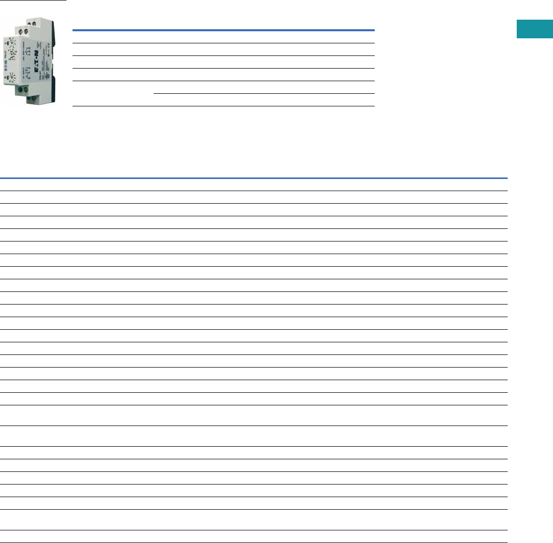
Volume 7—Logic Control, Operator Interface and Connectivity Solutions CA08100008E—February 2014 www.eaton.com V7-T3-177
3
3
3
3
3
3
3
3
3
3
3
3
3
3
3
3
3
3
3
3
3
3
3
3
3
3
3
3
3
3
3.8
Control Relays and Timers
Ti m i n g Rel ay s
Product Selection
Universal TR Timing Relays
Technical Data and Specifications
Universal TR Timing Relays
Note
1Refer to Function Code Cross-Reference Guide on Page V7-T3-171 for function details.
Supply Voltage Description
Catalog
Number
4-Function
24–240 Vac/Vdc Compact DIN rail mount, SPDT TRL04
7-Function
24–240 Vac/Vdc Compact DIN rail mount, SPDT TRL07
12–240 Vac/Vdc Compact DIN rail mount, DPDT TRL27
Asymmetrical pulse generator, DPDT TRW27
Single-Pole Model
Description TRL04 TRL07 TRL27 TRW27
Functions 1E, R, Wu, Bp E, R, Wu, Bp, Ws, Wa, Es E, R, Wu, Bp, Ws, Wa, Es Ii, Ip, ER, Ewu, Ews, WsWa, Wt
Time range 0.05 sec to 100 hours 0.05 sec to 100 hours 0.05 sec to 100 hours 0.05 sec to 100 hours
Input
Supply voltage 24–240 Vac/Vdc 24–240 Vac/Vdc 12–240 Vac/Vdc 12–240 Vac/Vdc
Rated supply frequency +10% /–15% +10% /–15% ±10% ±10%
Rated consumption 4 VA (1.5W) 4 VA (1.5W) 6 VA (2W) 6 VA (2W)
Duty cycle 100% 100% 100% 100%
Reset time 100 ms 100 ms 100 ms 100 ms
Residual ripple for DC 10% 10% 10% 10%
dropout voltage >30% of rated supply voltage >30% of rated supply voltage >30% of rated supply voltage >30% of rated supply voltage
Overvoltage category III (in accordance with IEC 60664-1) III (in accordance with IEC 60664-1) III (in accordance with IEC 60664-1) III (in accordance with IEC 60664-1)
Rated surge voltage 4 kV 4 kV 4 kV 4 kV
Output
Contact configuration SPDT (one changeover contact) SPDT (one changeover contact) DPDT (two changeover contacts) DPDT (two changeover contacts)
Rated voltage 250 Vac 250 Vac 250 Vac 250 Vac
Switching capacity 2000 VA (8A/250V) 2000 VA (8A/250V) 2000 VA (8A/250V) 2000 VA (8A/250V)
Fusing 8A fast acting 8A fast acting 8A fast acting 8A fast acting
Mechanical life 20 x 10^6 operations 20 x 10^6 operations 20 x 10^6 operations 20 x 10^6 operations
Electrical life 2 x 10^5 operations at 1000 VA load,
resistive
2 x 10^5 operations at 1000 VA load,
resistive
2 x 10^5 operations at 1000 VA load,
resistive
2 x 10^5 operations at 1000 VA load,
resistive
Switching frequency Max. 6/min. at 1000 VA resistive load
(in accordance with IEC 60947-5-1)
Max. 6/min. at 1000 VA resistive load
(in accordance with IEC 60947-5-1)
Max. 6/min. at 1000 VA resistive load
(in accordance with IEC 60947-5-1)
Max. 6/min. at 1000 VA resistive load
(in accordance with IEC 60947-5-1)
Overvoltage category III (in accordance with IEC 60664-1) III (in accordance with IEC 60664-1) III (in accordance with IEC 60664-1) III (in accordance with IEC 60664-1)
Rated surge voltage 4 kV 4 kV 4 kV 4 kV
Control Signal
Loadable Yes Yes Yes Yes
Maximum cable length 10m 10m 10m 10m
Trigger level (sensitivity) Automatic adaption to
supply voltage
Automatic adaption to
supply voltage
Automatic adaption to
supply voltage
Automatic adaption to
supply voltage
Minimum control pulse length DC 50 ms/AC 100 ms DC 50 ms/AC 100 ms DC 50 ms/AC 100 ms DC 50 ms/AC 100 ms
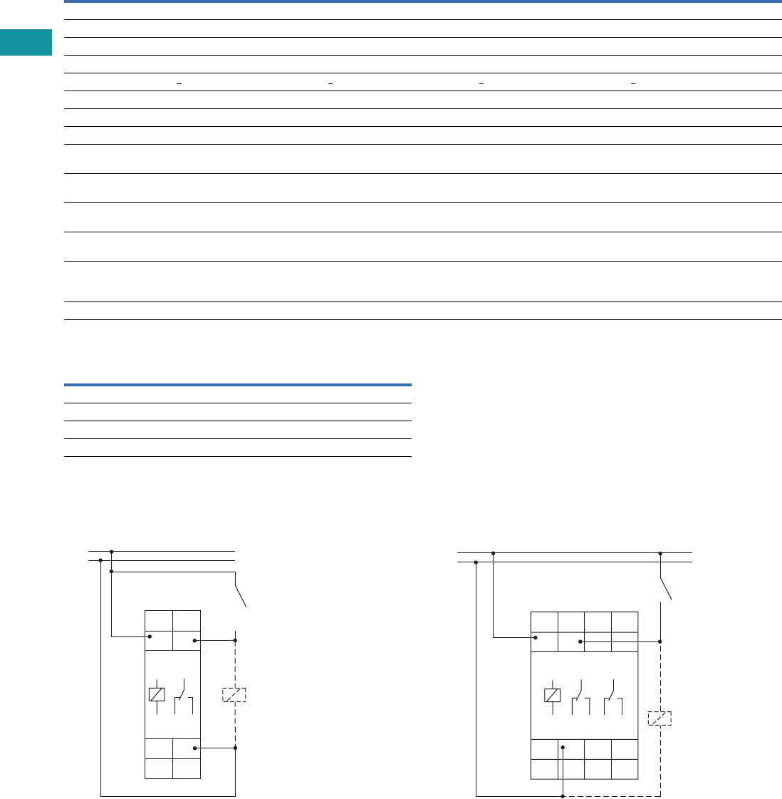
V7-T3-178 Volume 7—Logic Control, Operator Interface and Connectivity Solutions CA08100008E—February 2014 www.eaton.com
3
3
3
3
3
3
3
3
3
3
3
3
3
3
3
3
3
3
3
3
3
3
3
3
3
3
3
3
3
3
3.8
Control Relays and Timers
Ti m i ng Relay s
Universal TR Timing Relays, continued
Terminal Capacity
Wiring Diagrams
Single-Pole, Double-Throw Units (SPDT)—
TRL04 and TRL07
Double-Pole, Double-Throw Units (DPDT)—
TRL27 and TRW27
Description TRL04 TRL07 TRL27 TRW27
Accuracy
Base accuracy ±1% of maximum scale value ±1% of maximum scale value ±1% of maximum scale value ±1% of maximum scale value
Adjustment accuracy <5% of maximum scale value <5% of maximum scale value <5% of maximum scale value <5% of maximum scale value
Repetition accuracy <0.5% or ±5 ms <0.5% or ±5 ms <0.5% or ±5 ms <0.5% or ±5 ms
Temperature influence <0.01% /°C <0.01% /°C <0.01% /°C <0.01% /°C
Physical
Ambient temperature –25 to 55°C –25 to 55°C –25 to 55°C –25 to 55°C
Storage temperature –25 to 70°C –25 to 70°C –25 to 70°C –25 to 70°C
Relative humidity 15% to 85% (in accordance
with IEC 60721-3-3 Class 3K3)
15% to 85% (in accordance
with IEC 60721-3-3 Class 3K3)
15% to 85% (in accordance
with IEC 60721-3-3 Class 3K3)
15% to 85% (in accordance
with IEC 60721-3-3 Class 3K3)
Pollution degree 2, if built in 3 (in accordance
with IEC 60664-1)
2, if built in 3 (in accordance
with IEC 60664-1)
2, if built in 3 (in accordance
with IEC 60664-1)
2, if built in 3 (in accordance
with IEC 60664-1)
Housing material Self-extinguishing plastic housing,
IP40 rating
Self-extinguishing plastic housing,
IP40 rating
Self-extinguishing plastic housing,
IP40 rating
Self-extinguishing plastic housing,
IP40 rating
Mounting Mounted on DIN rail TS 35 according
to EN 60715, any position
Mounted on DIN rail TS 35 according
to EN 60715, any position
Mounted on DIN rail TS 35 according
to EN 60715, any position
Mounted on DIN rail TS 35 according
to EN 60715, any position
Terminal rating Shockproof terminal connection
according to VBG 4 (PZ1 required),
IP20 rating
Shockproof terminal connection
according to VBG 4 (PZ1 required),
IP20 rating
Shockproof terminal connection
according to VBG 4 (PZ1 required),
IP20 rating
Shockproof terminal connection
according to VBG 4 (PZ1 required),
IP20 rating
Tightening torque Max. 1 Nm Max. 1 Nm Max. 1 Nm Max. 1 Nm
Description
1 x 0.5 to 2.5 mm2 with/without multicore cable end
1 x 4 mm2 without multicore cable end
2 x 0.5 to 1.5 mm2 with/without multicore cable end
2 x 2.5 mm2 flexible without multicore cable end
15
16 18
A2
A1 B1
A1
A2
15
16 18
R
U =
(+)
(–)
S(Used only for
control switch
triggered functions)
15
16 18
25
26 28
A2
A1 B1
A1
A2
15
16 18
R
25
26 28
R
U =
(+)
(–)
S(Used only for
control switch
triggered functions)
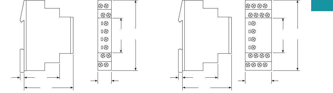
Volume 7—Logic Control, Operator Interface and Connectivity Solutions CA08100008E—February 2014 www.eaton.com V7-T3-179
3
3
3
3
3
3
3
3
3
3
3
3
3
3
3
3
3
3
3
3
3
3
3
3
3
3
3
3
3
3
3.8
Control Relays and Timers
Ti m i n g Rel ay s
Dimensions
Approximate Dimensions in Inches (mm)
17.5 mm (TRL04 and TRL07) 35 mm (TRL27 and TRW27)
0.20
(5.0)
1.73
(44.0)
2.36
(60.0)
0.69
(17.5)
1.77
(45.0)
3.43
(87.0)
0.20
(5.0)
1.73
(44.0)
2.36
(60.0)
1.38
(35.0)
1.77
(45.0)
3.43
(87.0)
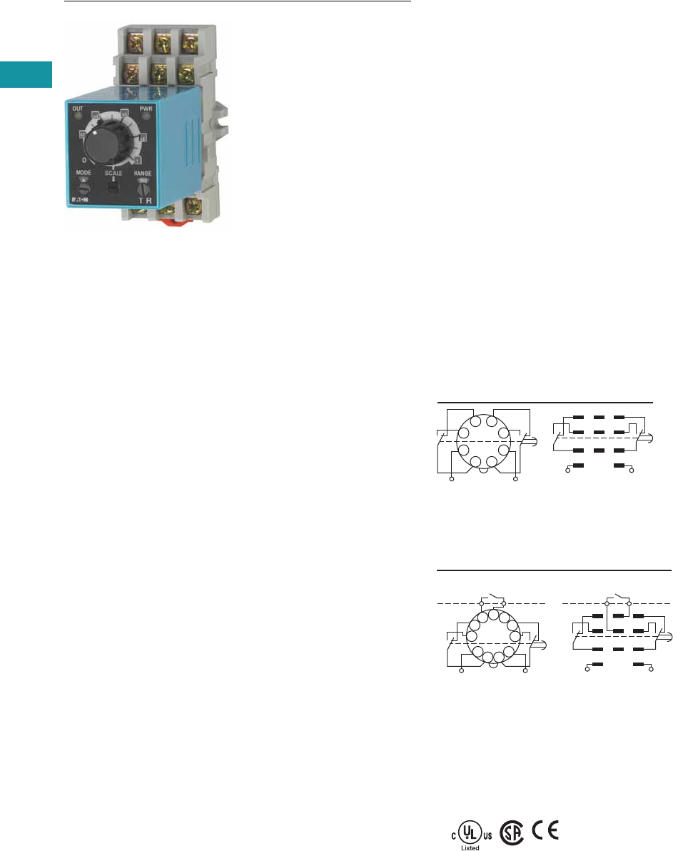
V7-T3-180 Volume 7—Logic Control, Operator Interface and Connectivity Solutions CA08100008E—February 2014 www.eaton.com
3
3
3
3
3
3
3
3
3
3
3
3
3
3
3
3
3
3
3
3
3
3
3
3
3
3
3
3
3
3
3.8
Control Relays and Timers
Ti m i ng Relay s
TR Series
Contents
Description Page
Universal TR Series . . . . . . . . . . . . . . . . . . . . . . . . V7-T3-176
TR Series
Catalog Number Selection . . . . . . . . . . . . . . . . V7-T3-181
Product Selection . . . . . . . . . . . . . . . . . . . . . . . V7-T3-181
Accessories . . . . . . . . . . . . . . . . . . . . . . . . . . . V7-T3-181
Technical Data and Specifications . . . . . . . . . . V7-T3-182
Dimensions . . . . . . . . . . . . . . . . . . . . . . . . . . . V7-T3-182
TMR5 Series . . . . . . . . . . . . . . . . . . . . . . . . . . . . . V7-T3-183
TMR6 Series . . . . . . . . . . . . . . . . . . . . . . . . . . . . . V7-T3-187
TMRP Series . . . . . . . . . . . . . . . . . . . . . . . . . . . . . V7-T3-189
TR Series
Product Description
The upgraded TR Series
Timing Relays are designed
to meet most timing
requirements by offering
more flexibility in range of
input voltage, timing range
and functionality. Use a rotary
switch to choose from
20 selectable time ranges
from 0.1 second to 600
hours. We offer both a power
triggered and signal triggered
model—each with expanded
operation modes. There is a
green LED to indicate when
power is ON and an orange
LED when output is ON.
Features
●20 time ranges and 10
timing functions
●Time delays from 0.1 sec
to 600 hrs
●Space-saving, compact
package
●High repeat accuracy of
±0.2%
●LED indication
●Standard 8- or 11-pin and
11-blade termination
●2 Form C DPDT delayed
output contacts
●10A contact rating
Operation
TRNP and TRNB
TRFP and TRFB
Standards and Certifications
●cULus listed
●CSA
●CE marked
●TUV
Internal Connections
2
36
7
45
18
(
–
/
–
)(
–
/+)
1
(
–
/
–
)
2 3
4 5 6
7 8 9
A B
(
–
/+)
TRNBTRNP
Internal Connections
210
(
–
/+)
3
67
45
111
8
9
(
–
/
–
)
2
(
–
/+)
1
(
–
/
–
)
3
4 5 6
7 8 9
A B
Start
Start
TRFP TRFB
External
Control
Signal
External
Control
Signal
TUV
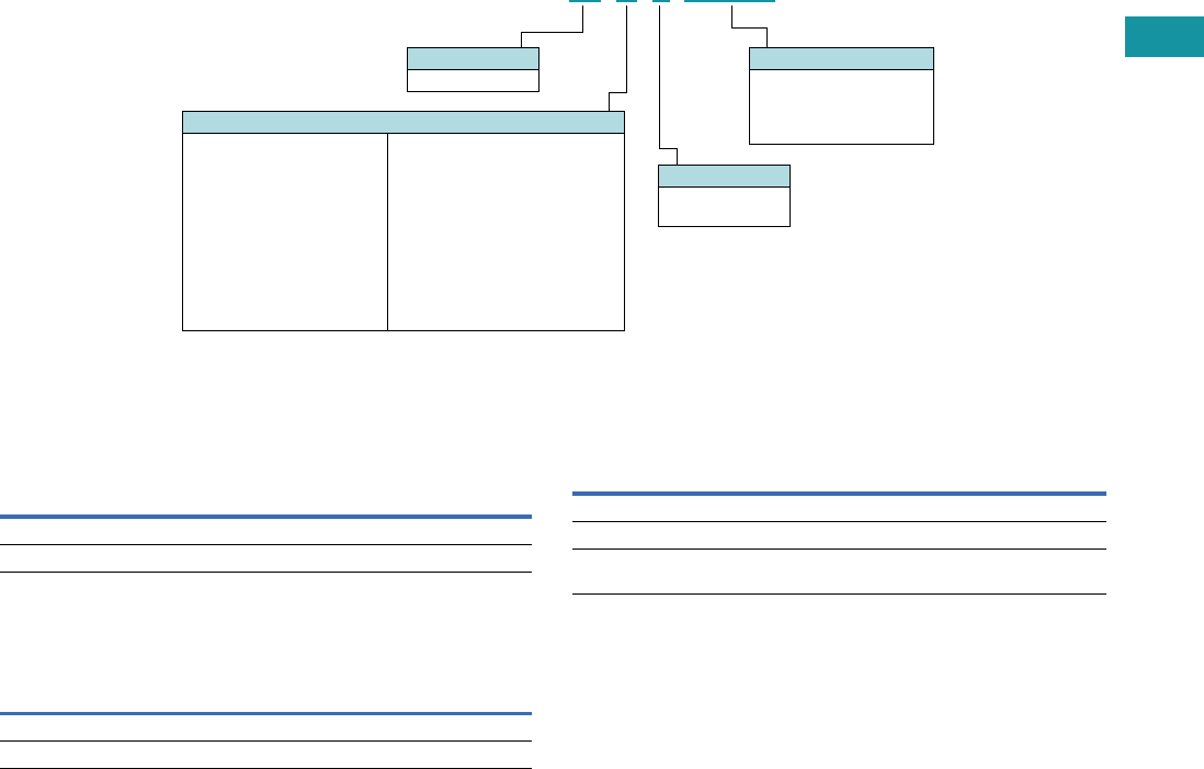
Volume 7—Logic Control, Operator Interface and Connectivity Solutions CA08100008E—February 2014 www.eaton.com V7-T3-181
3
3
3
3
3
3
3
3
3
3
3
3
3
3
3
3
3
3
3
3
3
3
3
3
3
3
3
3
3
3
3.8
Control Relays and Timers
Ti m i n g Rel ay s
Catalog Number Selection
Product Selection
TR Plug-In Timing Relays—Power Triggered
TR Plug-In Timing Relays—Signal Triggered
Accessories
Sockets for Use with TR Timers—Standard Pack of 10
Operational Mode
N = Power Triggered
A = ON delay
B = Interval
C = Flasher (pause first)
D = Flasher (ON first)
F = Signal Triggered
A = ON delay, control signal start
(leading edge OFF)
B = Flasher, control signal start
(pause first)
C = Flasher, control signal Start
(ON first)
D = Signal ON/OFF delay
E = OFF delay
F = Single shot leading edge with
control input
Input Voltage
24AD = 24 Vac
(50/60 Hz)/24 Vdc
240AC = 100–240 Vac
(50/60 Hz)
Model Type
P = Pin/octal
B = Blade style
Family Type
TR
TR N P 240 AC
Octal Blade
Coil Voltage
Catalog
Number
Catalog
Number
24 Vac/Vdc TRNP24AD TRNB24AD
100–240 Vac TRNP240AC TRNB240AC
Octal Blade
Coil Voltage
Catalog
Number
Catalog
Number
24 Vac/Vdc TRFP24AD TRFB24AD
100–240 Vac TRFP240AC TRFB240AC
Timing Relay Terminal Style
Catalog
Number
TRNP 8-pin octal D3PA2
TRFP 11-pin octal D3PA3
TRNB, TRFB 0.187 in solder/QC terminals
(blade style)
D5PA2
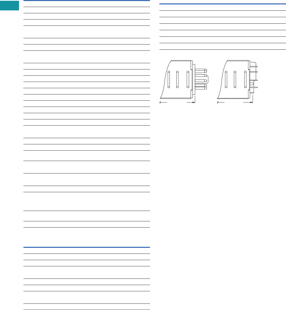
V7-T3-182 Volume 7—Logic Control, Operator Interface and Connectivity Solutions CA08100008E—February 2014 www.eaton.com
3
3
3
3
3
3
3
3
3
3
3
3
3
3
3
3
3
3
3
3
3
3
3
3
3
3
3
3
3
3
3.8
Control Relays and Timers
Ti m i ng Relay s
Technical Data and Specifications
General
TR Series Contact Ratings
Dimensions
Approximate Dimensions in Inches (mm)
TR Series Dimensions and Weights
Note
1For the value of the error against a preset time, whichever value is larger should apply.
Description Specification
Operation system Solid-state CMOS circuit
Time range 0.1 sec to 600 hours
Pollution degree 2 (IE60664-1)
Overvoltage category III (IE60664-1)
Rated operational voltage
240 AC 100–240 Vac (50/60 Hz)
24 AC 24 Vac (50/60 Hz)/24 Vdc
12 DC 12 Vdc
Voltage tolerance
240 AC 85–264 Vac (50/60 Hz)
24 AC 20.4–26.4 Vac (50/60 Hz)/21.6–26.4 Vdc
12 DC 10.8–13.2 Vdc
Input OFF voltage Rated voltage x 10% minimum
Ambient operating temperature –4 to 149°F (–20 to 65°C)
Reset time 100 ms maximum
Repeat error ± 0.2%, ± 20 ms 1
Voltage error ± 0.2%, ± 20 ms 1
Temperature error ± 0.5%, ± 20 ms 1
Setting error ± 10% maximum
Insulation resistance 100M ohm minimum (500 Vdc)
Dielectric strength
Between power and output terminals 2000 Vac, 1 minute
Between contacts of different poles 2000 Vac, 1 minute
Between contacts of same pole 1000 Vac, 1 minute
Vibration resistance 10–55 Hz amplitude 0.5 mm;
2 hrs in each of 3 axes
Shock resistance
Operating extremes 10G
Damage limits —
TRNP, TRFP 40G (3x in each of 3 axes)
TRNB, TRFB 10G (3x in each of 3 axes)
Power consumption (approx.)
240 AC 6.5 VA TRNP, TRNB/6.6 VA TRFP, TRFB
240 Vac/60 Hz 11.6 VA TRNP, TRNB/12.1 VA TRFP, TRFB
24 AC (AC/DC) 3.4 VA–1.7W TRNP, TRNB/3.5 VA–1.7W TRFP,
TRFB
12 DC 1.6W
Description Specification
Contact configuration 2 Form C, DPDT (delayed output)
Allowable voltage/current 240 Vac, 30 Vdc/10A
Max. permissible operating frequency 1800 cycles per hour
Rated load
Resistive 10A, 240 Vac/30 Vdc
Inductive 7A, 240 Vac/30 Vdc
Horsepower rating 1/6 hp 120 Vac, 1/3 hp 240 Vac
Life
Electrical 500,000 operations minimum (resistive)
Mechanical 50,000,000 operations minimum
Description Specification
Dimensions
TRNP, TRFP 1.58H x 1.42W x 3.07D in. (40H x 36W x 77.9D mm)
TRNB, TRFB 1.58H x 1.42W x 2.95D in. (40H x 36W x 74.9D mm)
Weights
TRNP 87g
TRFP 89g
TRNB, TRFB 85g
3.07 (77.9)
Pin (P) Type Blade (B) Type
2.95 (74.9)
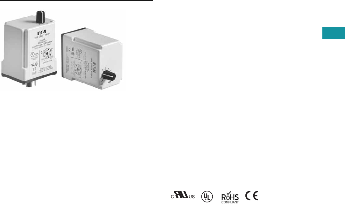
Volume 7—Logic Control, Operator Interface and Connectivity Solutions CA08100008E—February 2014 www.eaton.com V7-T3-183
3
3
3
3
3
3
3
3
3
3
3
3
3
3
3
3
3
3
3
3
3
3
3
3
3
3
3
3
3
3
3.8
Control Relays and Timers
Ti m i n g Rel ay s
TMR5 Series
Contents
Description Page
Universal TR Series . . . . . . . . . . . . . . . . . . . . . . . . V7-T3-176
TR Series . . . . . . . . . . . . . . . . . . . . . . . . . . . . . . . . V7-T3-180
TMR5 Series
Catalog Number Selection . . . . . . . . . . . . . . . . V7-T3-184
Product Selection . . . . . . . . . . . . . . . . . . . . . . . V7-T3-184
Accessories . . . . . . . . . . . . . . . . . . . . . . . . . . . V7-T3-184
Technical Data and Specifications . . . . . . . . . . V7-T3-185
Wiring Diagrams . . . . . . . . . . . . . . . . . . . . . . . . V7-T3-185
Dimensions . . . . . . . . . . . . . . . . . . . . . . . . . . . V7-T3-186
TMR6 Series . . . . . . . . . . . . . . . . . . . . . . . . . . . . . V7-T3-187
TMRP Series . . . . . . . . . . . . . . . . . . . . . . . . . . . . . V7-T3-189
TMR5 Series
Product Description
The TMR5 Series Time
Delay Relays are designed
for a broad range of
OEM applications. The
TMR5 Series offers
non-programmable plug-in
style timers with a variety
of functions available. Each
unit offers a single function
and single input voltage, and
operates over a defined time
delay range. Units with fixed
time delays are also available.
Eaton also offers
customization
capabilities for
these timers—remote
adjustments, special pin
configurations, and more.
Contact us to discuss your
specific application and
design of a custom timer.
Features
●Single timing range for
each unit
●Ranges available from
0.02 sec to 24 hours
●Wide variety of functions
available
●Plugs into standard 8- or
11-pin socket
●10A DPDT output contacts
●Can be easily customized
to meet your needs
Standards and Certifications
●cRUus
●UL listed (with Eaton socket)
●RoHS compliant
●CE marked
with
Eaton
socket
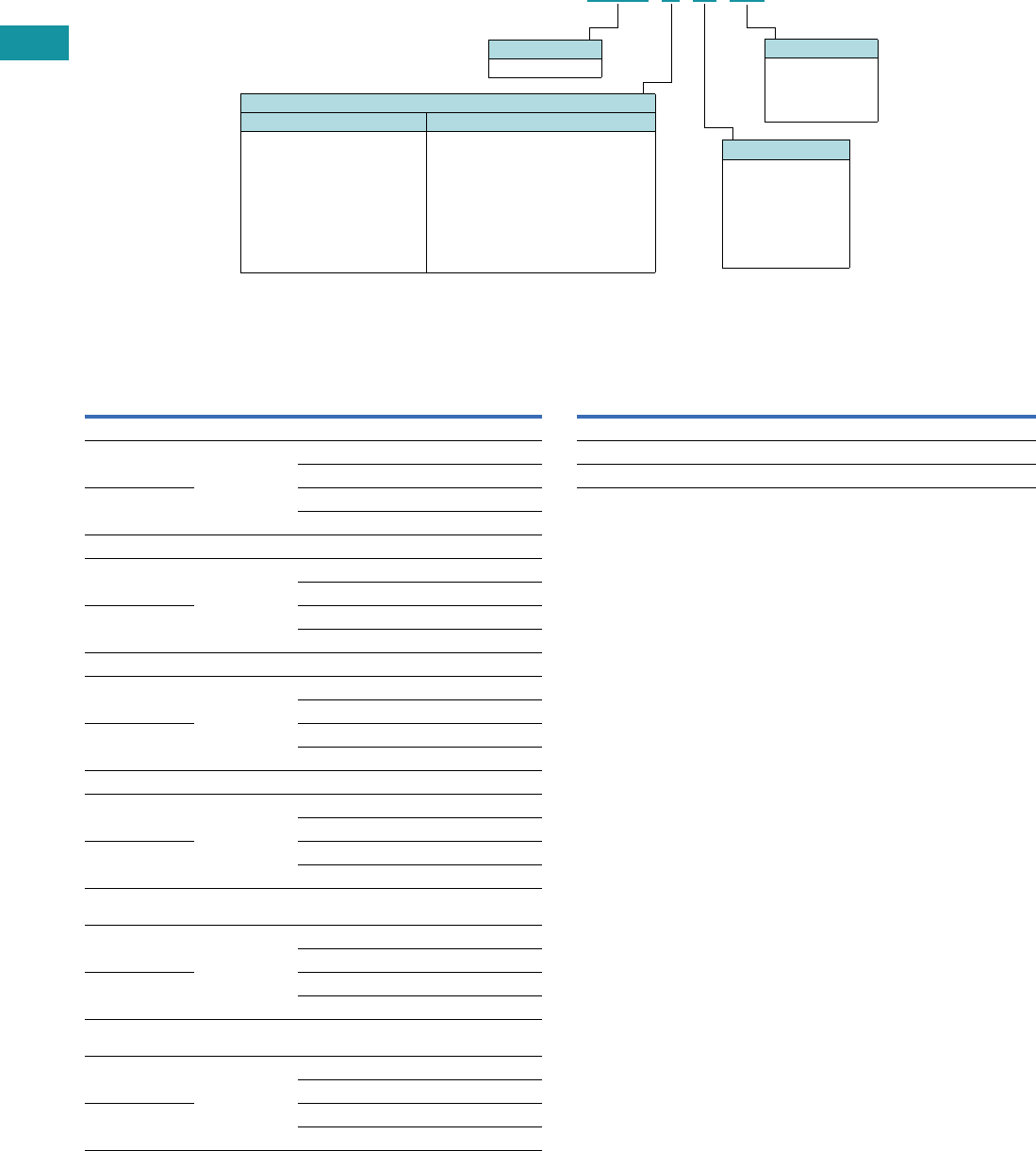
V7-T3-184 Volume 7—Logic Control, Operator Interface and Connectivity Solutions CA08100008E—February 2014 www.eaton.com
3
3
3
3
3
3
3
3
3
3
3
3
3
3
3
3
3
3
3
3
3
3
3
3
3
3
3
3
3
3
3.8
Control Relays and Timers
Ti m i ng Relay s
Catalog Number Selection
Product Selection
TMR5 Time Delay Relays
Accessories
Accessories for Use with TMR5 Time Delay Relays
Notes
1Indicates DUAL knob unit. All dual knob units can have independently selectable and
adjustable ON and OFF times. If different ON and OFF times are desired, add two codes for
time ranges in the part number. The first code listed indicates the first timing range of the
unit (OFF time for R, ON time for Y) and the second code indicates the second timing range
(ON time for R, OFF Time for Y).
2Fixed time delay settings are available for orders of 50 pieces or more. Contact EatonCare for
additional information at 877-ETN-CARE (386-2273).
Operational Mode
8-Pin Octal Sockets 11-Pin Octal Sockets
N=ON delay
T= Interval ON
L= Flasher-pause-first
R = Repeat cycle 1
(OFF time first followed by
ON time and repeating)
Y = Repeat cycle 1
(ON time first followed by
OFF time and repeating)
F= OFF delay, control switch trigger
C= Single shot, control switch trigger
W= Watchdog, control switch trigger
(retriggerable single shot)
P= OFF delay, power trigger
G= Single shot, power trigger
D= Watchdog, power trigger (retriggerable
single shot)
TMR5 N05 120
Input Voltage
120 = 120 Vac/Vdc
24 = 24 Vac/Vdc
12 = 12 Vac/Vdc
240 = 240 Vac/Vdc
Timing Range 2
04 = 0.05–5 sec
05 = 0.1–10 sec
08 = 0.6–60 sec
12 = 3–300 sec
15 = 0.3–30 min
16 = 0.6–60 min
22 = 6 sec–10 min
Family Type
TMR5
All configurations from Catalog Number Selection are available.
Input
Voltage Socket
Timing
Range
Catalog
Number
ON Delay
120 Vac/Vdc 8-pin 0.1–10 sec TMR5N05120
0.6–60 sec TMR5N08120
24 Vac/Vdc 0.1–10 sec TMR5N0524
0.6–60 sec TMR5N0824
OFF Delay, Control Switch Trigger
120 Vac/Vdc 11-pin 0.1–10 sec TMR5F05120
0.6–60 sec TMR5F08120
24 Vac/Vdc 0.1–10 sec TMR5F0524
0.6–60 sec TMR5F0824
Interval ON
120 Vac/Vdc 8-pin 0.1–10 sec TMR5T05120
0.6–60 sec TMR5T08120
24 Vac/Vdc 0.1–10 sec TMR5T0524
0.6–60 sec TMR5T0824
Single Shot, Control Switch Trigger
120 Vac/Vdc 11-pin 0.1–10 sec TMR5C05120
0.6–60 sec TMR5C08120
24 Vac/Vdc 0.1–10 sec TMR5C0524
0.6–60 sec TMR5C0824
Repeat Cycle
(OFF Time First Followed by ON Time and Repeating)
120 Vac/Vdc 8-pin 0.1–10 sec TMR5R05120
0.6–60 sec TMR5R08120
24 Vac/Vdc 0.1–10 sec TMR5R0524
0.6–60 sec TMR5R0824
Repeat Cycle
(ON Time First Followed by OFF Time and Repeating)
120 Vac/Vdc 8-pin 0.1–10 sec TMR5Y05120
0.6–60 sec TMR5Y08120
24 Vac/Vdc 0.1–10 sec TMR5Y0524
0.6–60 sec TMR5Y0824
Description Standard Pack
Catalog
Number
8-pin socket 10 D3PA2
11-pin socket 10 D3PA3-A2
Hold-down spring 10 D65CHDS
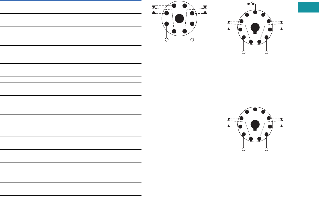
Volume 7—Logic Control, Operator Interface and Connectivity Solutions CA08100008E—February 2014 www.eaton.com V7-T3-185
3
3
3
3
3
3
3
3
3
3
3
3
3
3
3
3
3
3
3
3
3
3
3
3
3
3
3
3
3
3
3.8
Control Relays and Timers
Ti m i n g Rel ay s
Technical Data and Specifications
TMR5 Time Delay Relays
Description Specification
Voltage tolerance
AC operation +10/–15% of nominal at 50/60 Hz
DC operation +10/–15% of nominal
Load burden 2 VA
Setting accuracy
Maximum setting (adjustable) +5%, –0%
Minimum setting (adjustable) +0%, –50%
Fixed time delay
< 2 seconds +1%
0.1–2 seconds ±5%
Repeat accuracy (constant voltage and temperature)
> 2 seconds delay ±0.1%
0.1–2 seconds delay ±2%
Reset time
ON Delay/interval/repeat cycle 0.1 second
OFF Delay/single shot/watchdog 0.04 second
Startup time (time from when power is applied until unit is timing)
120 and 240V units 0.05 second
12, 24 and 48V units 0.08 second
Maintain function time (time unit
continues to time after power is
removed)
0.01 second
Temperature
12–120V input voltage –18 to 150°F (–28 to 65°C)
240V input voltage –18 to 122°F (–28 to 50°C)
Insulation voltage 2000V
Output contacts DPDT 10A @ 240 Vac/30 Vdc,
1/2 hp @ 120/240 Vac (NO contacts)
1/3 hp @ 120/240 Vac (NC contacts)
B300 and R300; AC-15 and DC-13
Life
Mechanical 10,000,000 operations
Full load 100,000 operations
Wiring Diagrams
Wiring for 8-Pin Units Wiring for 11-Pin Control
Switch Trigger Units
Wiring for 11-Pin Power
Tri g g e r U n i t s
1
(DC)+
L1
−(DC)
L2
8
Input Voltage
4
36
27
5
1
(DC)+
L1
(DC)−
L2
11
Input Voltage
Control
Switch
48
39
6
210
75
1
(DC)+
L1
(DC)−
L2
−+
11
Input Voltage
* Should Be Same Voltage
as Input Voltage
Power
Trigger *
48
39
6
210
75
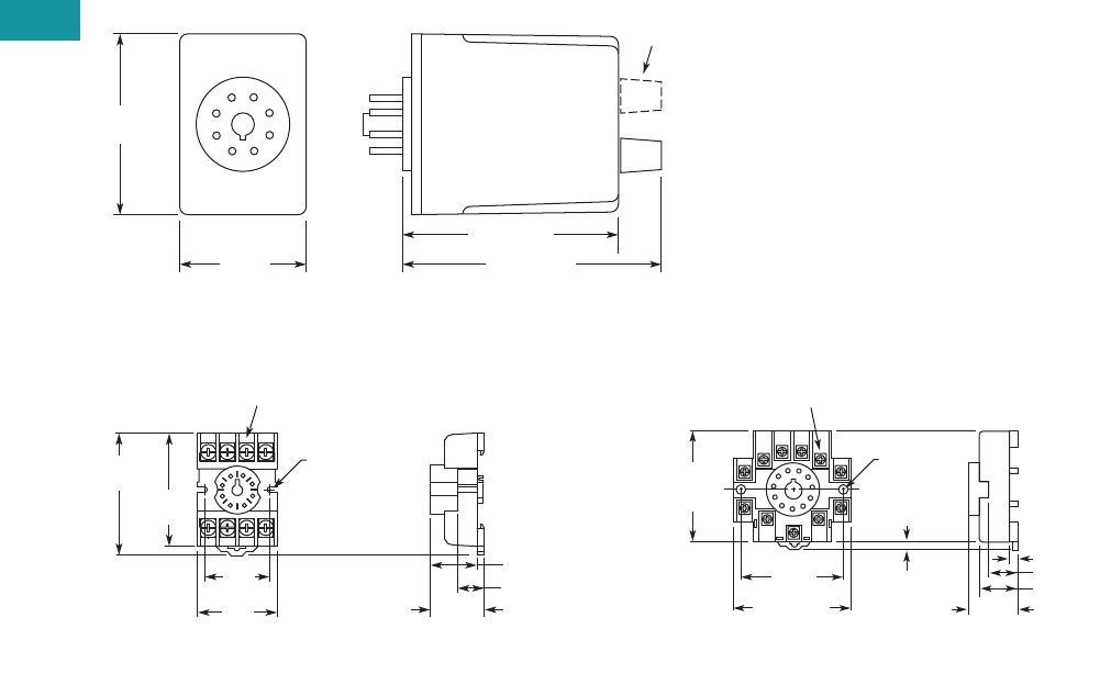
V7-T3-186 Volume 7—Logic Control, Operator Interface and Connectivity Solutions CA08100008E—February 2014 www.eaton.com
3
3
3
3
3
3
3
3
3
3
3
3
3
3
3
3
3
3
3
3
3
3
3
3
3
3
3
3
3
3
3.8
Control Relays and Timers
Ti m i ng Relay s
Dimensions
Approximate Dimensions in Inches (mm)
TMR5
D3PA2 Socket D3PA3 Socket
2.40
(61.0)
Dual Knob
Only
1.70
(43.2)
2.90 (73.7)
3.50 (88.9)
0.97
(24.6)
Max.
0.82 (20.8)
0.58 (14.7)
2.03
(51.6)
Two 0.165
(4.2) Dia.
Slots
2.14
(54.3)
1.60
(40.6)
Max.
1.30
(33.0)
6–32 x 0.312 Combination
Head Screw and Pressure Clamping Plate
(8 places)
Tolerances: ± 0.010
± (0.25)
Unless Otherwise Shown
6–32 x 0.312 Combination
Head Screw and Pressure Clamp
(11 places)
2.05
(52.1)
Max.
2.33 (59.2)
Max.
2.06
(52.3)
0.97
(24.6)
0.77 (19.6)
0.58 (14.7)
0.15 (3.8)
0.13–0.16
(3.2–4.0)
Two 0.17
(4.3) Dia.
Holes
Tolerances: ± 0.010
± (0.25)
Unless Otherwise Shown
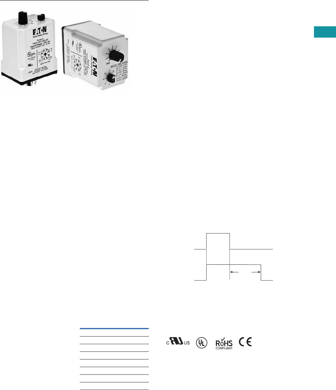
Volume 7—Logic Control, Operator Interface and Connectivity Solutions CA08100008E—February 2014 www.eaton.com V7-T3-187
3
3
3
3
3
3
3
3
3
3
3
3
3
3
3
3
3
3
3
3
3
3
3
3
3
3
3
3
3
3
3.8
Control Relays and Timers
Ti m i n g Rel ay s
TMR6 Series
Contents
Description Page
Universal TR Series . . . . . . . . . . . . . . . . . . . . . . . . V7-T3-176
TR Series . . . . . . . . . . . . . . . . . . . . . . . . . . . . . . . . V7-T3-180
TMR5 Series . . . . . . . . . . . . . . . . . . . . . . . . . . . . . V7-T3-183
TMR6 Series
Catalog Number Selection . . . . . . . . . . . . . . . . V7-T3-188
Product Selection . . . . . . . . . . . . . . . . . . . . . . . V7-T3-188
Accessories . . . . . . . . . . . . . . . . . . . . . . . . . . . V7-T3-188
Technical Data and Specifications . . . . . . . . . . V7-T3-188
Wiring Diagram . . . . . . . . . . . . . . . . . . . . . . . . V7-T3-188
Dimensions . . . . . . . . . . . . . . . . . . . . . . . . . . . V7-T3-188
TMRP Series . . . . . . . . . . . . . . . . . . . . . . . . . . . . . V7-T3-189
TMR6 Series
Product Description
Most electronic time delay
relays with an OFF delay
function require input voltage
to be applied continuously
in order to operate correctly.
However, there are many
applications where this is
not possible—-keeping a
relay energized for some
amount of time after input
voltage has been removed.
Eaton’s TMR6 true OFF
delay product provides
this function even when
input voltage is removed.
It duplicates the operation
of the older OFF delay
pneumatic time delay relays.
Features
●Provides OFF delay
function without requiring
input voltage during OFF
time delay
●Duplicates operation of
pneumatic OFF delay
timers
●Each unit has eight timing
ranges built in, covering
0.05 seconds to
30 minutes
●Selecting a range is easy
using a rotary switch
(no math is required or
DIP switches to set)
●Uses industry-standard
8-pin octal socket
●10A DPDT output contacts
Timing Ranges
Select one of the eight timing
ranges using the selector
knob, and then adjust the
time within that range for an
accurate delay setting.
Timing Ranges
Dial Setting Timing Range
A 0.05–5 sec.
B 0.1–10 sec.
C 0.3–30 sec.
D 0.6–60 sec.
E 1.8–180 sec.
F 3–300 sec.
G 0.1–10 min.
H 0.3–30 min
Operation
True OFF Delay
Upon application of input
voltage, the relay is
energized. When the input
voltage is removed, the
preset time begins. At the
end of the preset time, the
relay is de-energized.
Voltage must be applied for
a minimum of 0.1 second to
assure proper operation.
Any application of the input
voltage during the preset
time will keep the relay
energized and reset the time
delay. No external trigger
switch is required.
True OFF Delay
Standards and Certifications
●cRUus
●UL listed (with Eaton socket)
●RoHS compliant
●CE marked
Delay
Input
Power
(Voltage)
Output
(Load)
ON
OFF
ON
OFF
with
Eaton
socket
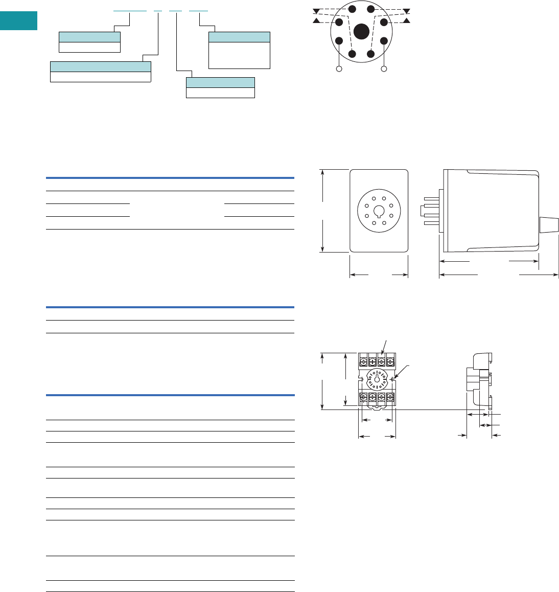
V7-T3-188 Volume 7—Logic Control, Operator Interface and Connectivity Solutions CA08100008E—February 2014 www.eaton.com
3
3
3
3
3
3
3
3
3
3
3
3
3
3
3
3
3
3
3
3
3
3
3
3
3
3
3
3
3
3
3.8
Control Relays and Timers
Ti m i ng Relay s
Catalog Number Selection
Product Selection
TMR6 True OFF Delay Relays
Accessories
Accessories for Use with TMR6 Time Delay Relays
Technical Data and Specifications
TMR6 Time Delay Relays
Wiring Diagram
Wiring for 8-Pin Units
Dimensions
Approximate Dimensions in Inches (mm)
TMR6
D3PA2 Socket
Input
Voltage
Timing
Range
Catalog
Number
True OFF Delay
120 Vac/Vdc 0.05 sec–30 min
(user selectable, 8 ranges)
TMR6X00120
24 Vac/Vdc TMR6X0024
240 Vac/Vdc TMR6X00240
Description Standard Pack
Catalog
Number
8-pin socket 10 D3PA2
Hold-down spring 10 D65CHDS
Description Specification
Voltage tolerance
AC operation +10/–15% of nominal at 50/60 Hz
DC operation +10/–15% of nominal
Load burden 2 VA
Setting accuracy
Maximum setting (adjustable) +5%, –0%
Minimum setting (adjustable) +0%, –50%
Repeat accuracy (constant voltage
and temperature)
±0.1% or 50 ms, whichever is greater
Temperature –18 to 150°F (–28 to 65°C)
Insulation voltage 2,000V
Output contacts DPDT 10A @ 240 Vac/30 Vdc,
1/2 hp @ 120/240 Vac (NO contacts)
1/3 hp @ 120/240 Vac (NC contacts)
B300 and R300; AC-15 and DC-13
Life
Mechanical 2,000,000 operations
Full load 100,000 operations
Operational Mode
X= True OFF delay
TMR6 X00 120
Input Voltage
120 = 120 Vac/Vdc
24 = 24 Vac/Vdc
240 = 240 Vac/Vdc
Timing Range
00 = Programmable
Family Type
TMR6
All configurations from Catalog Number Selection are available.
1
(DC)+
L1
−(DC)
L2
8
Input Voltage
4
36
27
5
2.40
(61.0)
1.70
(43.2)
2.90 (73.7)
3.50 (88.9)
0.97
(24.6)
Max.
0.82 (20.8)
0.58 (14.7)
2.03
(51.6)
Two 0.165
(4.2) Dia.
Slots
2.14
(54.3)
1.60
(40.6)
Max.
1.30
(33.0)
6–32 x 0.312 Combination
Head Screw and Pressure Clamping Plate
(8 places)
Tolerances: ± 0.010
± (0.25)
Unless Otherwise Shown
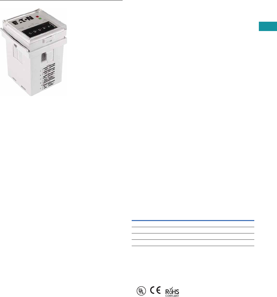
Volume 7—Logic Control, Operator Interface and Connectivity Solutions CA08100008E—February 2014 www.eaton.com V7-T3-189
3
3
3
3
3
3
3
3
3
3
3
3
3
3
3
3
3
3
3
3
3
3
3
3
3
3
3
3
3
3
3.8
Control Relays and Timers
Ti m i n g Rel ay s
TMRP Series
Contents
Description Page
Universal TR Series . . . . . . . . . . . . . . . . . . . . . . . . V7-T3-176
TR Series . . . . . . . . . . . . . . . . . . . . . . . . . . . . . . . . V7-T3-180
TMR5 Series . . . . . . . . . . . . . . . . . . . . . . . . . . . . . V7-T3-183
TMR6 Series . . . . . . . . . . . . . . . . . . . . . . . . . . . . . V7-T3-187
TMRP Series
Product Selection . . . . . . . . . . . . . . . . . . . . . . . V7-T3-190
Technical Data and Specifications . . . . . . . . . . V7-T3-190
Wiring Diagrams . . . . . . . . . . . . . . . . . . . . . . . . V7-T3-191
Dimensions . . . . . . . . . . . . . . . . . . . . . . . . . . . V7-T3-191
TMRP Series
Product Description
Eaton’s TMRP Series timers
combine flexibility with ease
of use and installation to
make the most versatile timer
in our offering. The thumb-
wheel setting design allows
for quick selection and review
of up to 10 timing functions
and seven timing ranges. The
TMRP units can be mounted
in a 1/16 DIN cutout or on a
DIN rail with our D3 series
sockets. Input voltage is 12–
240 Vac/Vdc to work with all
popular control voltages.
Application Description
A timing relay is a simple
form of time-based control,
allowing the user to open or
close the contacts based on
a specified timing function.
The TMRP series is equipped
with a set of thumb-wheel
style selector switches, which
can easily be set to a specific
function and time, thereby
reducing the number of
product variations required.
The universal input voltage
of 12–240 Vac/Vdc further
reduces the number of
product variations.
The TMRP timers are ideal
for high-variability operations,
such as systems integrators,
distributors, and small equip-
ment manufacturers. The
flexible enclosure design
allows for back-panel mounting,
through-panel mounting, or
DIN rail mounting.
Features
●Multiple user-selectable
timing functions and timing
ranges in a single unit
reduce product variations
and stock keeping units
(SKUs)
●Universal input voltages
from 12–240 Vac/Vdc
eliminate the need to
order and stock separate
coil voltages
●Timing ranges up to 9990
hours
●Dual LED indication makes
troubleshooting easy
●Flexible design for back-
panel, through-panel
(45 mm x 45 mm cutout),
or DIN rail mounting
●SPDT or DPDT contacts
with 12A ratings
●Plastic dust cover keeps
out contaminants and
eliminates accidental set
point changes
●Use with standard Eaton
D3 sockets—see Technical
Data and Specifications
LED Indicator
Standards and Certifications
●UL recognized
●CE marked
●RoHS compliant
LED Description Function
Solid green “Input” Supply voltage present
Solid red “Output” Relay energized
Slowly flashing red “Output” Timing cycle activated, relay not energized
Rapidly flashing red “Output” Timing cycle activated, relay energized
V7-T3-190 Volume 7—Logic Control, Operator Interface and Connectivity Solutions CA08100008E—February 2014 www.eaton.com
3
3
3
3
3
3
3
3
3
3
3
3
3
3
3
3
3
3
3
3
3
3
3
3
3
3
3
3
3
3
3.8
Control Relays and Timers
Ti m i ng Relay s
Product Selection
TMRP Timing Relays
Technical Data and Specifications
TMRP Timing Relays
Note
1Refer to Function Code Cross-Reference Guide on Page V7-T3-171 for function details.
Supply Voltage Description
Catalog
Number
10-Function
12–240 Vac/Vdc Control switch trigger, DPDT TMRP5100
Control switch trigger, SPDT TMRP5101
Power trigger, DPDT TMRP5102
TMRP5100
Description TMRP5100 TMRP5101 TMRP5102
Functions 1A, B, C, D, E, F, G, H, I, J A, B, C, D, E, F, G, H, I, J A, B, C
Time range 0.1 sec to 9,990 hours 0.1 sec to 9,990 hours 0.1 sec to 9,990 hours
Input
Supply voltage 12–240 Vac/Vdc 12–240 Vac/Vdc 12–240 Vac/Vdc
Supply voltage tolerance ±15% ±15% ±15%
Rated consumption 2.5 VA (2W) maximum 2.5 VA (2W) maximum 2.5 VA (2W) maximum
Reset time 150 ms 150 ms 150 ms
Reverse polarity protection Yes Yes Yes
Operate time 25 ms maximum 25 ms maximum 25 ms maximum
Release time 25 ms maximum 25 ms maximum 25 ms maximum
Rated surge voltage 4 kV 4 kV 4 kV
Output
Contact configuration DPDT SPDT DPDT
Contact rating (AC) 12A resistive at 120, 240 UL 508 12A resistive at 120, 240 UL 508 12A resistive at 120, 240 UL 508
Contact rating (DC) 12A resistive at 30 UL 508 12A resistive at 30 UL 508 12A resistive at 30 UL 508
Contact rating horsepower 1/2 at 120 Vac, 1 at 240 Vac 1/2 at 120 Vac, 1 at 240 Vac 1/2 at 120 Vac, 1 at 240 Vac
Contact rating pilot duty A300, 720 VA at 240 Vac A300, 720 VA at 240 Vac A300, 720 VA at 240 Vac
Minimum load 12V/100 mA 12V/100 mA 12V/100 mA
Contact material Silver-nickel 90/10 Silver-nickel 90/10 Silver-nickel 90/10
Contact resistance 100 milliohms max. at 1A 12 Vdc 100 milliohms max. at 1A 12 Vdc 100 milliohms max. at 1A 12 Vdc
Mechanical life—full load 10 million operations 10 million operations 10 million operations
Electrical life—full load 100,000 operations 100,000 operations 100,000 operations
Control Signal
Minimum control pulse length 50 ms minimum 50 ms minimum 50 ms minimum
Accuracy
Repetition accuracy 0.10% at constant voltage and temperature 0.10% at constant voltage and temperature 0.10% at constant voltage and temperature
Physical
Ambient temperature –10 to 55°C –10 to 55°C –10 to 55°C
Storage temperature –40 to 85°C –40 to 85°C –40 to 85°C
Mounting Use with D3PA3 socket Use with D3PA2 socket Use with D3PA2 socket
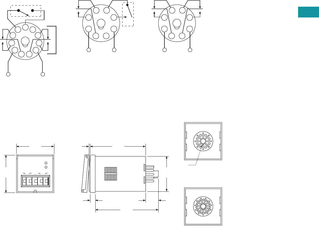
Volume 7—Logic Control, Operator Interface and Connectivity Solutions CA08100008E—February 2014 www.eaton.com V7-T3-191
3
3
3
3
3
3
3
3
3
3
3
3
3
3
3
3
3
3
3
3
3
3
3
3
3
3
3
3
3
3
3.8
Control Relays and Timers
Ti m i n g Rel ay s
Wiring Diagrams
TMRP5100 TMRP5101 TMRP5102
Dimensions
Approximate Dimensions in Inches (mm)
TMRP Series
External Control Switch
Instant if 6–7 Shorted
INPUT
5
111
2
3
4
67
8
9
10
External Control Switch
INPUT
4
1
2
3
5
8
7
6
INPUT
4
1
2
3
5
8
7
6
0.06
(1.5)
1.88
(47.8)
1.88
(47.8)
FUNCTION
A 0 0 0 S
TIME
SET
TIME
BASE
OUTPUT
INPUT
2.83
(71.9)
1.76
(44.7)
0.25
(6.4)
0.64
(16.3)
3.15
(80.0)
1
2
3
4
5
6
7
8
R.045
8-Pin Octal Base
1
2
3
4
5
6
7
8
11-Pin Octal Base
9
10
11
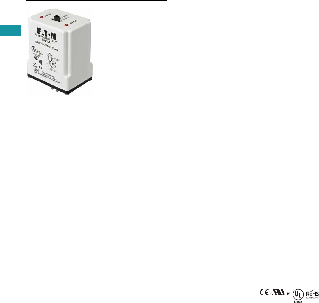
V7-T3-192 Volume 7—Logic Control, Operator Interface and Connectivity Solutions CA08100008E—February 2014 www.eaton.com
3
3
3
3
3
3
3
3
3
3
3
3
3
3
3
3
3
3
3
3
3
3
3
3
3
3
3
3
3
3
3.9
Control Relays and Timers
Alternating Relays
D85 Series—Alternating Relays
Contents
Description Page
D85 Series—Alternating Relays
Product Selection . . . . . . . . . . . . . . . . . . . . . . . V7-T3-193
Accessories . . . . . . . . . . . . . . . . . . . . . . . . . . . V7-T3-193
Technical Data and Specifications . . . . . . . . . . V7-T3-194
Wiring Diagrams . . . . . . . . . . . . . . . . . . . . . . . V7-T3-194
Dimensions . . . . . . . . . . . . . . . . . . . . . . . . . . . V7-T3-196
Product Description
Alternating relays are used
in applications where the
optimization of load usage is
required by equalizing the run
time of two loads. They are
also used where additional
capacity is required in case
of excess load requirements.
This alternating action is
initiated by a control switch—
such as a float switch, manual
switch, timing relay, pressure
switch or other isolated
contact. Each time the
initiating switch is opened,
the output relay contacts will
change state, thus alternating
the two loads. Two LED
indicators show the status of
the output relay.
The D851 and D852 Series
Relays are used with one
control switch and are
available in either SPDT or
DPDT output configurations
with or without a selector
switch to lock in one
sequence. The D852X Series
Relays are available in DPDT
cross-wired output
configurations for use with
one or two control switches
(LEAD and LAG).
The D853 Series is designed
for use with three-switch
applications (LEAD, LAG and
STOP). The D853 Series
combines a standard DPDT
Cross-Wired alternating relay,
contactor auxiliary contacts,
and a control relay into one
compact and economical
product. This saves space
and labor, while reducing the
number of components
needed. The D853 Series
uses Sequence On–
Simultaneous Off (S.O.S.O.)
operation, where the two
loads are energized
sequentially, but remain on
together until the STOP
switch is opened. This device
also protects against failure of
the STOP and LEAD
switches. If both switches
fail, the two pump motors will
be energized simultaneously
when the LAG switch is
closed.
Each of the D85 Series
alternating relays is available
with an optional three-
position selector switch,
which allows the unit to
alternate the two loads as
normal, or lock the relay to
one load or the other. By
locking the alternating relay to
one load, the other load can
be removed for service
without rewiring the first load
for continuous operation. The
selector switch has a low
profile to prevent any
accidental actuation.
Features
●For duplex loads
●Works with one-, two-, or
three-switch applications
●Compact plug-in design
using industry standard
sockets
●10A SPDT or DPDT output
configurations
●Optional low profile
selector switch to lock in
one sequence
●Two LEDs indicate relay
status
●D853 Series replaces
separate components in
duplex panel—saving
space and reducing labor
Standards and
Certifications
●CE
●cRUus
●UL listed 1
●RoHS compliant
Note
1When used with appropriate Eaton
socket.

Volume 7—Logic Control, Operator Interface and Connectivity Solutions CA08100008E—February 2014 www.eaton.com V7-T3-193
3
3
3
3
3
3
3
3
3
3
3
3
3
3
3
3
3
3
3
3
3
3
3
3
3
3
3
3
3
3
3.9
Control Relays and Timers
Alternating Relays
Product Selection
D85 Series—Alternating Relays 1
Accessories
D85 Series—Alternating Relays
Note
1 Contact Eaton for relays for 3-switch applications (Lead-Lag-Stop).
Output Contacts
Control
Voltage Socket
Catalog
Number
SPDT 12 Vac 8-pin D851NR
SPDT 24 Vac 8-pin D851NT
SPDT 120 Vac 8-pin D851NA
SPDT 240 Vac 8-pin D851NB
SPDT w/selector switch 12 Vac 8-pin D851LR
SPDT w/selector switch 24 Vac 8-pin D851LT
SPDT w/selector switch 120 Vac 8-pin D851LA
SPDT w/selector switch 240 Vac 8-pin D851LB
DPDT 12 Vac 11-pin D852NR
DPDT 24 Vac 11-pin D852NT
DPDT 120 Vac 11-pin D852NA
DPDT 240 Vac 11-pin D852NB
DPDT w/selector switch 12 Vac 11-pin D852LR
DPDT w/selector switch 24 Vac 11-pin D852LT
DPDT w/selector switch 120 Vac 11-pin D852LA
DPDT w/selector switch 240 Vac 11-pin D852LB
DPDT cross-wired 12 Vac 8-pin D852XNR
DPDT cross-wired 24 Vac 8-pin D852XNT
DPDT cross-wired 120 Vac 8-pin D852XNA
DPDT cross-wired 240 Vac 8-pin D852XNB
DPDT cross-wired w/selector switch 12 Vac 8-pin D852XLR
DPDT cross-wired w/selector switch 24 Vac 8-pin D852XLT
DPDT cross-wired w/selector switch 120 Vac 8-pin D852XLA
DPDT cross-wired w/selector switch 240 Vac 8-pin D852XLB
Description
Standard
Pack
Catalog
Number
8-pin socket 10 D3PA2
11-pin socket 10 D3PA3-A2
Hold-down spring 10 D65CHDS
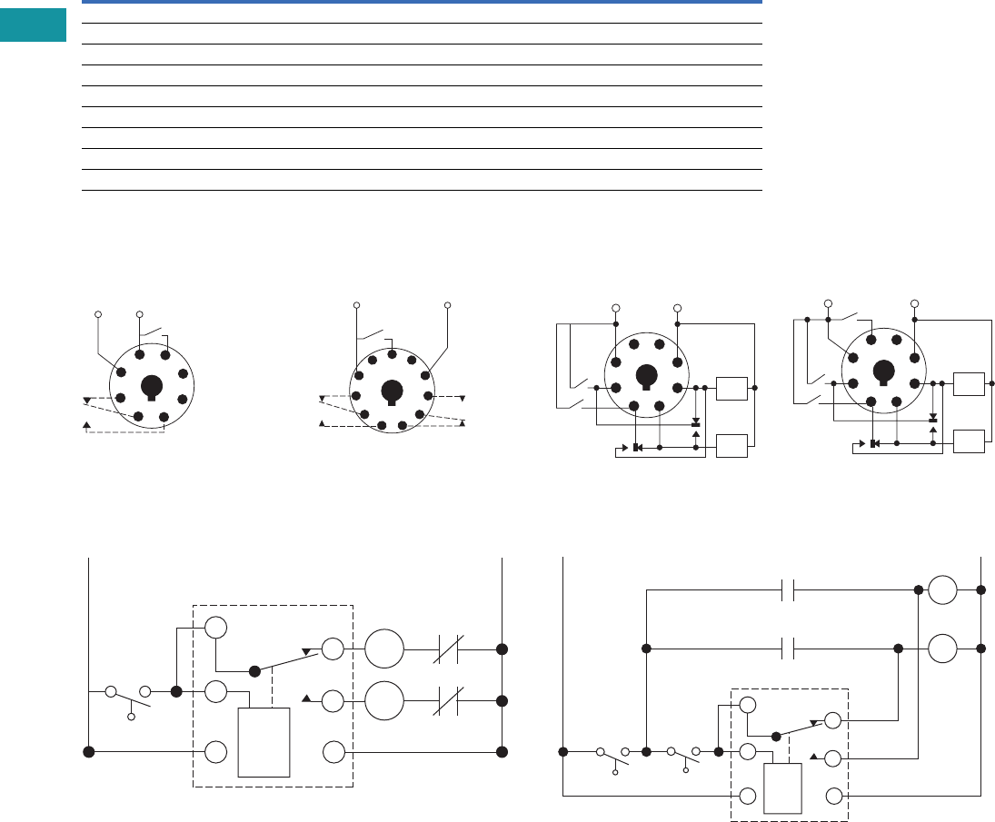
V7-T3-194 Volume 7—Logic Control, Operator Interface and Connectivity Solutions CA08100008E—February 2014 www.eaton.com
3
3
3
3
3
3
3
3
3
3
3
3
3
3
3
3
3
3
3
3
3
3
3
3
3
3
3
3
3
3
3.9
Control Relays and Timers
Alternating Relays
Technical Data and Specifications
D85 Series—Alternating Relays
Wiring Diagrams
D851 Series Relays, SPDT D852 Series Relays, DPDT
Typical Installations for SPDT and DPDT Alternating Relays,
Standard Installation
In the OFF state (standard
installation), the control
switch is open, the
alternating relay is in the
LOAD A position, and both
loads (M1 and M2) are off.
When the control switch
closes, it energizes the first
load (M1). The red LED
marked “LOAD A” glows. As
long as the control switch
remains closed, M1 remains
energized.
When the control switch
opens, the first load (M1) is
turned off and the alternating
relay toggles to the LOAD B
position. When the control
switch closes again, it
energizes the second load
(M2). The red LED marked
“LOAD B” glows.
Description Specification
Voltage tolerance +10%/-15% of control voltage at 50/60 Hz
Load (burden) Less than 3 VA
Output contacts 10A resistive at 240 Vac / 30 Vdc, 1/2 hp at 120/240 Vac (NO), 1/3 hp at 120/240 Vac (NC)
Mechanical life 10,000,000 operations
Electrical life 100,000 operations
Temperature –20° to 150°F (–28° to 65°C)
Transient protection 10,000 volts for 20 microseconds
Indicator LEDs 2 LEDs marked LOAD A and LOAD B
Optional selector switch settings ALTERNATE, LOCK LOAD A, LOCK LOAD B
Load A: Pin 2
Load B: Pin 8
1
4
Input
Voltage
Control
Switch
L2 L1
36
27
8
5
1
Load A: Pins 3 or 11
Load B: Pins 1 or 9
L2L1
11
Input
Voltage
Control
Switch
48
39
6
210
75
L1
SPDT
Control
Switch
O/L
O/L
1
2
8
3
4
5
L2
M1
M2
D852X Series Relays,
DPDT Cross-Wired
D853 Series Relays,
Three-Switch Applications
Typical Installations for SPDT and DPDT Alternating Relays,
Anti-Bounce Installation
When the control switch
opens, the second load (M2)
is turned off, the alternating
relay toggles back to the
LOAD A position, and the
process can be repeated
again. On relays with DPDT
contacts, two pilot lights can
be used for remote indication
of LOAD A or LOAD B status.
To eliminate any bounce
condition of the control
switch, the addition of a
second switch (OFF) along
with two auxiliary contacts is
recommended as shown in
the Anti-Bounce Installation.
1
Lead
Lag
Load
B
Load
A
L1 L2
8
Input
Voltage
4
36
27
5
1
Lead
Lag
Load
B
Load
A
L1 L2
Stop
8
Input Voltage
4
36
27
5
SPDT
Control
Switch
L1
1
2
3
4
5
Off
M1
M1
M2
L2
M2
8
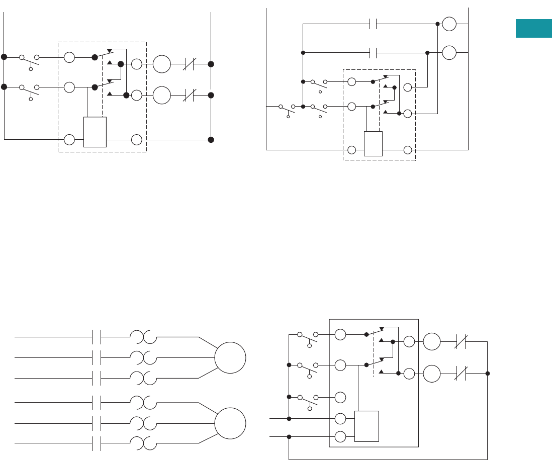
Volume 7—Logic Control, Operator Interface and Connectivity Solutions CA08100008E—February 2014 www.eaton.com V7-T3-195
3
3
3
3
3
3
3
3
3
3
3
3
3
3
3
3
3
3
3
3
3
3
3
3
3
3
3
3
3
3
3.9
Control Relays and Timers
Alternating Relays
Typical Installations for DPDT Cross-Wired Alternating
Relays, Standard Installation
In the OFF state, both the LEAD control switch and the LAG
control switch are open, the alternating relay is in the LOAD A
position, and both loads are off. When the LEAD control switch
closes, it energizes the first load (M1). The red LED marked
“LOAD A” glows. As long as the LEAD control switch remains
closed, M1 remains energized. If the LAG control switch closes,
it energizes the second load (M2).
When the LAG control switch opens, the second load (M2) is
turned off. When the LEAD control switch opens, the first load
(M1) is turned off and the alternating relay toggles to the LOAD
B position.
Typical Installations for DPDT Cross-Wired Alternating
Relays, Anti-Bounce Installation
When the LEAD control switch closes, it turns on the second
load (M2). The red LED marked “LOAD B” glows. If the LAG
control switch closes, it will energize the first load (M1). When
the LAG control switch opens, the first load (M1) is turned off.
When the LEAD control switch opens, the second load (M2) is
turned off, the alternating relay toggles back to the LOAD A
position, and the process can be repeated again.
To eliminate any bounce condition of the control switch, the
addition of a second switch (OFF) along with two auxiliary
contacts is recommended as shown in the Anti-Bounce
Installation.
Typical Installations for DPDT Cross-Wired Relays for Three-Switch Applications
In the OFF state, all three switches are open, the alternating relay
is in the LOAD A position, and both loads are off. No action
happens with the alternating relay or either load when the STOP
switch closes. When the LEAD switch closes, Load #1 (M1) turns
on. When the LAG switch closes, Load #2 (M2) turns on. Both
loads remain on as long as all three switches are closed.
When the LAG switch opens, Load #2 (M2) remains on because
the STOP switch is still closed. When the LEAD switch opens,
Load #1 (M1) remains on because the STOP switch is still
closed. When the STOP switch opens, both Load #1 (M1) and
Load #2 (M2) are turned off simultaneously.
The alternating relay toggles to the LOAD B position. The entire
cycle is then repeated, but with Load #2 (M2) energized first
followed by Load #1 (M1). This type of operation is known as
“Sequence On–Simultaneously Off (S.O.S.O.)”—the two loads
are energized sequentially, but remain on together until the
STOP switch is opened.
If both the STOP switch and LEAD switch fail to close and turn
on the first load, both loads will be turned on simultaneously
when the LAG switch is closed.
L1
Lag
Lead
Cross-Wired
O/L
O/L
1
28
3
7
6
L2
M1
M2
Lag
Off Lead
L2
L1
M1
Cross-Wired
M2
1
2
3
7
6
M1
M2
8
L1
Motor
1
Motor
2
L2
L3
L1
M1
M1
M1
M2
M2
M2
M2
M1
L2 L1
Lag
Switch
Lead
Switch
Stop
Switch
L2
L3
1
2
4
8
7
3
6
O/L
O/L
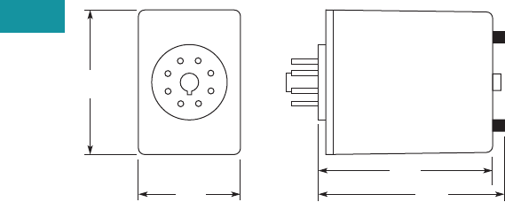
V7-T3-196 Volume 7—Logic Control, Operator Interface and Connectivity Solutions CA08100008E—February 2014 www.eaton.com
3
3
3
3
3
3
3
3
3
3
3
3
3
3
3
3
3
3
3
3
3
3
3
3
3
3
3
3
3
3
3.9
Control Relays and Timers
Alternating Relays
Dimensions
Approximate Dimensions in Inches (mm)
D85 Series—Alternating Relays
2.4
(60)
1.7
(43)
2.9
(74) 3.1
(79)
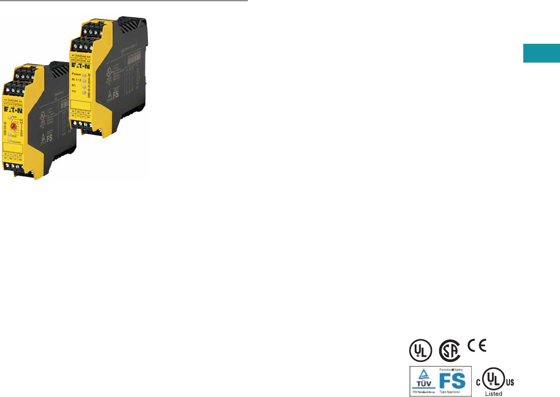
Volume 7—Logic Control, Operator Interface and Connectivity Solutions CA08100008E—February 2014 www.eaton.com V7-T3-197
3
3
3
3
3
3
3
3
3
3
3
3
3
3
3
3
3
3
3
3
3
3
3
3
3
3
3
3
3
3
3.10
Control Relays and Timers
Safety Relays
Safety Relays
Contents
Description Page
Safety Relays
Product Selection . . . . . . . . . . . . . . . . . . . . . . . V7-T3-198
Technical Data and Specifications . . . . . . . . . . V7-T3-199
Dimensions . . . . . . . . . . . . . . . . . . . . . . . . . . . V7-T3-202
Product Description
Safety relays are intended to
reliably monitor the signals
from safety devices at all
times and switch off quickly
and reliably in an emergency.
Single-channel and dual
channel versions are available
for the construction of safety
applications. The internal
logic of the safety relays
monitors the safety circuits
(emergency stop, guard door,
and so on) and activates the
enable paths in a fault-free
condition. Upon actuation of
the safety device or in the
even of a fault, the enable
paths are switched off. Any
faults that occur in the control
circuit, such as ground fault,
cross connection fault or wire
breakage are also detected.
Application Description
Eaton’s ESR5 safety relays
provide optimal safety and a
high degree of reliability on
plant machinery. Applications
that meet the highest
safety requirements in
accordance with EN 954-1,
EN ISO 13849-1 up to PL e
and accordance with
IEC 62061 up to SILCL 3
can be realized with the
ESR5 safety relay.
Compatible with a wide
variety of safety devices:
●Emergency stops
●Rope pulls
●Two-hand control stations
●Light curtain (OSSD)
●Gate enable device
●Safety switches
Features
●Use for the highest
safety requirements in
accordance with EN 954-1
EN ISO 13849-1,
IEC 62061 and EC 61508
●Suitable for the world
market with UL, cUL
certifications and TÜV
Rhineland functional
safety certifications
●Applicable for EN 60204
stop categories 0 or 1
●Plug-in screw terminals
for fast and fault-free
replacement
●Multi-voltage versions
(24–230 Vac/Vdc) for a
flexible range of application
●Delayed and non-delayed
contact expansions
accommodate a wide
variety of applications
Standards and
Certifications
●UL 508; CSA C22.2 No
14-95; CE Marked
●UL/cUL file number:
E29184
●Degree of protection: IP20
●TÜV Rhineland certified
●UL/cULus listed
V7-T3-198 Volume 7—Logic Control, Operator Interface and Connectivity Solutions CA08100008E—February 2014 www.eaton.com
3
3
3
3
3
3
3
3
3
3
3
3
3
3
3
3
3
3
3
3
3
3
3
3
3
3
3
3
3
3
3.10
Control Relays and Timers
Safety Relays
Product Selection
Technical Overview
Application Overview
Application Overview, continued
Notes
1 Laser scanners or light curtains with OSSD outputs.
2 All main units can also be reset automatically or manually.
Single
Channel
Dual
Channel
Safety
Output (NO)
Safety
Output (NO)
(Delayed)
Output
Delay
Signal
Output
(NC)
Feedback
Output
Control
Voltage
Removable
Terminal
Blocks
Type of
Unit Catalog Number
■ — 4 — — 1 — 24 Vac/Vdc ■ Main ESR5-NO-41-24VAC-DC
■ ■ 2 — —1 —24 Vac/Vdc■ Main ESR5-NO-21-24VAC-DC
■ ■ 3 — —1 —24 Vac/Vdc■ Main ESR5-NO-31-24VAC-DC
■ ■ 3 — —1 —230 Vac ■ Main ESR5-NO-31-230VAC
■ ■ 3 — —1 —24–230 Vac/Vdc■ Main ESR5-NO-31-AC-DC
■ ■ 2 2 0.1–30s — — 24 Vdc ■ Main ESR5-NV3-30
—■ 2 — —1 —24 Vac/Vdc■ Main ESR5-NZ-21-24VAC-DC
■ — 5 — — 1 1 24 Vac/Vdc ■ Expansion ESR5-NE-51-24VAC-DC
■ — — 4 0.3–3s 1 1 24 Vdc ■ Expansion ESR5-VE3-42
Emergency
Stop
Safety
Switches
Light Curtain/
OSSD 1
Two-Hand Control
(EN 574 Type III C)
Contact
Expansion Off-Delayed
Cross Circuit
Recognition
Monitored
Manual Reset 2Catalog Number
■ ■ —— ——— — ESR5-NO-41-24VAC-DC
■ ■ —— ——■ — ESR5-NO-21-24VAC-DC
■ ■ —— ——■ — ESR5-NO-31-24VAC-DC
■ ■ —— ——■ ■ ESR5-NO-31-230VAC
■ ■ —— ——■ ■ ESR5-NO-31-AC-DC
■ ■ ■ ——■ ■ ■ ESR5-NV3-30
—■ — ■ —— ■ — ESR5-NZ-21-24VAC-DC
——— — ■ —— — ESR5-NE-51-24VAC-DC
——— — ■ ■ —— ESR5-VE3-42
Single
Channel
Dual
Channel
Stop Category
EN 60204
Control Category
to EN 954-1
Achievable PL per
ISO 13849-1
Achievable SIL per
EN IEC 62061 Catalog Number
■ —0 2 PL d SIL 3 ESR5-NO-41-24VAC-DC
■ ■ 04 PL e SIL 3 ESR5-NO-21-24VAC-DC
■ ■ 04 PL e SIL 3 ESR5-NO-31-24VAC-DC
■ ■ 04 PL e SIL 3 ESR5-NO-31-230VAC
■ ■ 04 PL e SIL 3 ESR5-NO-31-AC-DC
■ ■ 0/1 4 PL e SIL 3 ESR5-NV3-30
—■ 04 PL e SIL 3 ESR5-NZ-21-24VAC-DC
■ —0 4 PL e SIL 3 ESR5-NE-51-24VAC-DC
■ —1 3 PL d SIL 2 ESR5-VE3-42
Safety Relays

Volume 7—Logic Control, Operator Interface and Connectivity Solutions CA08100008E—February 2014 www.eaton.com V7-T3-199
3
3
3
3
3
3
3
3
3
3
3
3
3
3
3
3
3
3
3
3
3
3
3
3
3
3
3
3
3
3
3.10
Control Relays and Timers
Safety Relays
Technical Data and Specifications
Safety Relay
Description Unit ESR5-NO-21_ ESR5-NO-41_ ESR5-NO-31-24VAC-DC ESR5-NZ-21_
General
Standards EN ISO 13849-1, IEC 62061,
IEC 61508, DIN EN 50178,
UL/CUL listed
EN ISO 13849-1, IEC 62061,
IEC 61508, DIN EN 50178,
UL/CUL listed
EN ISO 13849-1, IEC 62061,
IEC 61508, DIN EN 50178,
UL/CUL listed
EN ISO 13849-1, IEC 62061,
IEC 61508, DIN EN 50178,
UL/CUL listed
Type-dependent standards ———EN 574 Part no. IIIC
Lifespan, mechanical—c (contacts) x 10610 10 10 10
Maximum operating frequency Ops/h 3600 3600 3600 3600
Climatic proofing Cold according to
EN 60068-2-1, dry heat
according to EN60068-2-2,
damp heat according to
EN 60068-2-3
Dry heat according to
EN60068-2-2, damp heat
according to EN 60068-2-3
Cold according to
EN 60068-2-1, dry heat
according to EN60068-2-2,
damp heat according to
EN 60068-2-3
Dry heat according to
EN60068-2-2, damp heat
according to EN 60068-2-3
Ambient temperature °F (°C) –4° to 131° (–20° to 55°) –4° to 131° (–20° to 55°) –4° to 131° (–20° to 55°) –4° to 131° (–20° to 55°)
Ambient temperature storage °F (°C) –13° to 167° (–25° to 75°) –13° to 167° (–25° to 75°) –13° to 167° (–25° to 75°) –13° to 167° (–25° to 75°)
Mounting position Any Any Any Any
Vibration resistance (IEC/EN 60068-2-6) 2g, frequency: 10–150 Hz,
amplitude: 0.15 mm
2g, frequency: 10–150 Hz,
amplitude: 0.15 mm
2g, frequency: 10–150 Hz,
amplitude: 0.15 mm
2 g, frequency: 10–150 Hz,
amplitude: 0.15 mm
Shock resistance (IEC 60068-2-27) ————
Protection type
Housing IP20 IP20 IP20 IP20
Terminals IP20 IP20 IP20 IP20
Protection against direct contact when
actuated from front (IEC 0106 Part 100)
Finger- and back-of-hand
proof
Finger- and back-of-hand
proof
Finger- and back-of-hand
proof
Finger- and back-of-hand
proof
Weight kg 0.17 0.22 0.17 0.22
Terminal capacity
Solid or flexible mm21 x (0.2–2.5)
2 x (0.2–1)
1 x (0.2–2.5)
2 x (0.2–1)
1 x (0.2–2.5)
2 x (0.2–1)
1 x (0.2–2.5)
2 x (0.2–1)
Flexible with ferrule mm21 x (0.25–2.5)
2 x (0.25–1)
1 x (0.25–2.5)
2 x (0.25–1)
1 x (0.25–2.5)
2 x (0.25–1)
1 x (0.25–2.5)
2 x (0.25–1)
Solid or stranded AWG 24–12 24–12 24–12 24–12
Terminal screw
Pozidriv screwdriverSize2222
Flat-blade screwdriver mm 0.6 x 3.5 0.6 x 3.5 0.6 x 3.5 0.6 x 3.5
Max. tightening torque Nm 0.6 0.6 0.6 0.6
Main Contacts
Rated impulse withstand voltage—Uimp Vac 6000 4000 4000 6000
Overvoltage category/pollution degree
Outside III/2 III/2 III/2 III/2
Inside ————
Rated insulation voltage—UiVac 250 250 250 250
Rated operating voltage—UeVac 230 230 230 230
Rated operation current
AC-15
230V (360 ops./h)—IeA5454
230V (3600 ops./h)—IeA3333
DC-13
24V (360 ops./h)—IeA6464
24V (3600 ops./h)—IeA 3 2.5 3 2.5
Max. summation current of all poles
24 Vac/Vdc devices A 72 72 72 72
230 Vac devices A————
Square of the total current
(and total current)
of all current paths
72 A2 (6 + 6) 72 A2 (4.2 + 4.2 + 4.2 + 4.2) 72 A2 (4.9 + 4.9 + 4.9) 72 A2 (6 + 6)
Short-circuit protection
Max. fuse A gG/gL 10 6 10 6

V7-T3-200 Volume 7—Logic Control, Operator Interface and Connectivity Solutions CA08100008E—February 2014 www.eaton.com
3
3
3
3
3
3
3
3
3
3
3
3
3
3
3
3
3
3
3
3
3
3
3
3
3
3
3
3
3
3
3.10
Control Relays and Timers
Safety Relays
Safety Relay, continued
Description Unit ESR5-NO-21_ ESR5-NO-41_ ESR5-NO-31-24VAC-DC ESR5-NZ-21_
Power Supply Circuit
Actuating voltage 50/60 Hz Vac 24 24 24 24
Actuating voltage—UsVdc24242424
Voltage tolerance pick-up voltage x e0.85–1.1 0.85–1.1 0.85–1.1 0.85–1.1
Power consumption
AC operated 50/60 Hz VA ————
AC operated 50/60 Hz W 3.4 3.4 3.4 3
DC operated W 1.6 1.6 1.6 1.5
Fuse for control circuit supply
24V Short-circuit proof Short-circuit proof Short-circuit proof Short-circuit proof
115/230V ————
Control Circuit
Rated output voltage Vdc 24 24 24 24
Rated operational current mA S12, S22: 30, S34: 45 S12: 65, S34: 40 S12, S22: 30, S34: 45 S11, S21: 60, Y2: 45
Resistance—R 50225022
Short-circuit current A 2.3 2.3 2.3 2.3
Response time ms 100 65 100 50
Recovery time ms————
Response time with reset monitoring—tA1 ms————
Response time without reset monitoring—tA2 ms 100 65 100 50
Reset time—tR/tR1 ms Single-channel 45;
dual-channel 10
45 Single-channel 45;
dual-channel 10
20
Minimum on duration—tMms————
Recovery time—tWms Approx. 1000 Approx. 1000 Approx. 1000 Approx. 1000
Synchronous monitoring time—tSms———500
Electromagnetic Compatibility (EMC)
Emitted interference EN 61000-6-4 EN 61000-6-4 EN 61000-6-4 EN 61000-6-4
Interference immunity According to EN 61000-6-2,
EN 62061
According to EN 61000-6-2 According to EN 61000-6-2,
EN 62061
According to EN 61000-6-2

Volume 7—Logic Control, Operator Interface and Connectivity Solutions CA08100008E—February 2014 www.eaton.com V7-T3-201
3
3
3
3
3
3
3
3
3
3
3
3
3
3
3
3
3
3
3
3
3
3
3
3
3
3
3
3
3
3
3.10
Control Relays and Timers
Safety Relays
Safety Relay, continued
Description Unit ESR5-NO-31-230VAC
ESR5-NO-31-24V-
230VAC-DC ESR5-NV3_ ESR5-VE3_ ESR5-NE-51_
General
Standards EN ISO 13849-1, IEC 62061,
IEC 61508, DIN EN 50178,
UL/CUL listed
EN ISO 13849-1, IEC 62061,
IEC 61508, DIN EN 50178,
UL/CUL listed
EN ISO 13849-1, IEC 62061,
IEC 61508, DIN EN 50178,
UL/CUL listed
EN ISO 13849-1, IEC 62061,
IEC 61508, DIN EN 50178,
UL/CUL listed
EN ISO 13849-1, IEC 62061,
IEC 61508, DIN EN 50178,
UL/CUL listed
Type-dependent standards EN 60204
(if applicable)
EN 60204
(if applicable)
EN 60204
(if applicable)
——
Lifespan, mechanical—c (contacts) x 10610 10 10 10 10
Maximum operating frequency Ops/h 3600 3600 3600 900 3600
Climatic proofing Dry heat according to
EN60068-2-2, damp heat
according to EN 60068-2-3
Dry heat according to
EN60068-2-2, damp heat
according to EN 60068-2-3
Cold in accordance with:
EN 60068-2-1, dry heat in
accordance with EN
60068-2-2, humidity
storage test in accordance
with 60068-2-78
Dry heat according to
EN60068-2-2, damp heat
according to EN 60068-2-3
Dry heat according to
EN60068-2-2, damp heat
according to EN 60068-2-3
Ambient temperature °F (°C) –4° to 131° (–20° to 55°) –4° to 131° (–20° to 55°) –4° to 113° (–20° to 45°) –4° to 131° (–20° to 55°) –4° to 131° (–20° to 55°)
Ambient temperature storage °F (°C) –13° to 167° (–25° to 75°) –13° to 167° (–25° to 75°) –13° to 167° (–25° to 75°) –13° to 167° (–25° to 75°) –13° to 167° (–25° to 75°)
Mounting position Any Any Any Any Any
Vibration resistance (IEC/EN 60068-2-6) 2g, frequency: 10–150 Hz,
amplitude: 0.15 mm
2g, frequency: 10–150 Hz,
amplitude: 0.15 mm
2g, frequency: 10–150 Hz,
amplitude: 0.15 mm
2g, frequency: 10–150 Hz,
amplitude: 0.15 mm
2g, frequency: 10–150 Hz,
amplitude: 0.15 mm
Shock resistance (IEC 60068-2-27)—————
Protection type
Housing IP40 IP40 IP20 IP20 IP20
Terminals IP20 IP20 IP20 IP20 IP20
Protection against direct contact when
actuated from front (IEC 0106 Part 100)
Finger- and back-of-hand
proof
Finger- and back-of-hand
proof
Finger- and back-of-hand
proof
Finger- and back-of-hand
proof
Finger- and back-of-hand
proof
Weight kg 0.3 0.3 0.17 0.17 0.22
Terminal capacity
Solid or flexible mm21 x (0.2–2.5)
2 x (0.2–1)
1 x (0.2–2.5)
2 x (0.2–1)
1 x (0.2–2.5)
2 x (0.2–1)
1 x (0.2–2.5)
2 x (0.2–1)
1 x (0.2–2.5)
2 x (0.2–1)
Flexible with ferrule mm21 x (0.25–2.5)
2 x (0.25–1)
1 x (0.25–2.5)
2 x (0.25–1)
1 x (0.25–2.5)
2 x (0.25–1)
1 x (0.25–2.5)
2 x (0.25–1)
1 x (0.25–2.5)
2 x (0.25–1)
Solid or stranded AWG 24–12 24–12 24–12 24–12 24–12
Terminal screw
Pozidriv screwdriverSize22222
Flat-blade screwdriver mm 0.6 x 3.5 0.6 x 3.5 0.6 x 3.5 0.6 x 3.5 0.6 x 3.5
Max. tightening torque Nm 0.6 0.6 0.6 0.6 0.6
Main Contacts
Rated impulse withstand voltage—Uimp Vac 6000 6000 4000 4000 4000
Overvoltage category/pollution degree
Outside III/2 III/2 III/2 III/2 III/2
Inside —————
Rated insulation voltage—UiVac 250 250 250 250 250
Rated operating voltage—UeVac 230 230 230 230 230
Rated operation current
AC-15
230V (360 ops./h)—IeA44—54
230V (3600 ops./h)—IeA33333
DC-13
24V (360 ops./h)—IeA44—64
24V (3600 ops./h)—IeA2.52.5332.5
Max. summation current of all poles
24 Vac/Vdc devices A 50 50 49 50 50
230 Vac devices A 50 50 — — —
Square of the total current
(and total current)
of all current paths
50 A2 (4 + 4 + 4) 50 A2 (4 + 4 + 4) 50 A2 (4 + 4 + 4) 49 A2
(3.5 + 3.5 + 3.5 + 3.5)
50 A2
(3.7 + 3.7 + 3.7 + 3.7
+ 3.7)
Short-circuit protection
Max. fuse A gG/gL 6 6 10 10 6
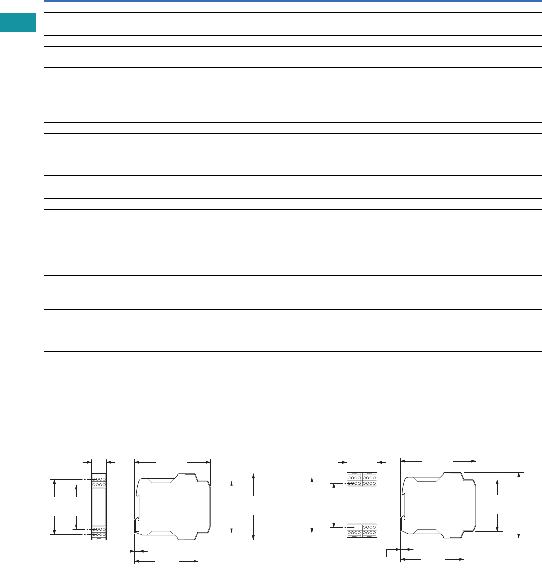
V7-T3-202 Volume 7—Logic Control, Operator Interface and Connectivity Solutions CA08100008E—February 2014 www.eaton.com
3
3
3
3
3
3
3
3
3
3
3
3
3
3
3
3
3
3
3
3
3
3
3
3
3
3
3
3
3
3
3.10
Control Relays and Timers
Safety Relays
Safety Relay, continued
Dimensions
Approximate Dimensions in Inches (mm)
Safety Relays, Contact Expansion Modules
ESR5_ 24 Vac/Vdc ESR5_ 230 Vac
Description Unit ESR5-NO-31-230VAC
ESR5-NO-31-24V-
230VAC-DC ESR5-NV3_ ESR5-VE3_ ESR5-NE-51_
Power Supply Circuit
Actuating voltage 50/60 Hz Vac 230 24–230 — — 24
Actuating voltage—UsVdc—230242424
Voltage tolerance pick-up voltage x e0.85–1.1 0.85–1.1 0.85–1.1 0.85–1.1 0.8–1.1
Power consumption
AC operated 50/60 Hz VA —————
AC operated 50/60 Hz W 5.8 5.8 — — 2.2
DC operated W 2.9 2.9 1.8 2 2.2
Fuse for control circuit supply
24V — Short-circuit proof — — —
115/230V Short-circuit proof Short-circuit proof — — —
Control Circuit
Rated output voltage Vdc 24 24 24 24 24
Rated operational current mA S10, S12, S22: 35, S34,
S35: 45
S10, S12, S22: 35, S34,
S35: 45
S12, S22: 3.5, S34, S35: 7 A1, A2: 84, K1/K2: 5 A1, A2: 92
Resistance—R 11 11 500 — —
Short-circuit current A 0.7 0.7 0.1 — —
Response time ms 250 250 150 20 20
Recovery time ms—————
Response time with reset
monitoring—tA1
ms 60 60 150 20 20
Response time without reset
monitoring—tA2
ms 250 250 150 20 20
Reset time—tR/tR1 ms 20 20 20 (non-delayed enable
paths); 100 (min. delayed
enable paths)
0.3–3 s (+50%)
adjustable
20
Minimum on duration—tMms—————
Recovery time—tWms Approx. 1000 Approx. 1000 Approx. 330 Approx. 1000 —
Synchronous monitoring time—tSms—————
Electromagnetic Compatibility (EMC)
Emitted interference EN 61000-6-4 EN 61000-6-4 EN 61000-6-4 EN 61000-6-4 EN 61000-6-4
Interference immunity According to
EN 61000-6-2
According to
EN 61000-6-2
According to EN 61000-6-2,
EN 62061
According to
EN 61000-6-2
According to
EN 61000-6-2
0.88
(22.5)
0.26
(6.6)
4.51
(114.5)
3.74
(95.1)
3.26
(82.8)
2.62
(66.5)
3.06
(77.6)
3.90
(99.0)
0.26
(6.6)
4.51
(114.5)
3.74
(95.1)
3.06
(77.6)
3.90
(99.0)
3.26
(82.8)
2.62
(66.5)
1.77
(45.0)
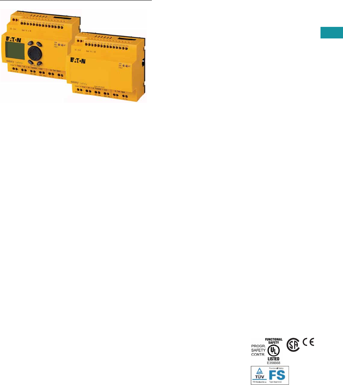
Volume 7—Logic Control, Operator Interface and Connectivity Solutions CA08100008E—February 2014 www.eaton.com V7-T3-203
3
3
3
3
3
3
3
3
3
3
3
3
3
3
3
3
3
3
3
3
3
3
3
3
3
3
3
3
3
3
3.11
Control Relays and Timers
easySafety
easySafety
Contents
Description Page
easySafety
Product Selection . . . . . . . . . . . . . . . . . . . . . . . V7-T3-204
Accessories . . . . . . . . . . . . . . . . . . . . . . . . . . . V7-T3-204
Technical Data and Specifications . . . . . . . . . . V7-T3-205
Dimensions . . . . . . . . . . . . . . . . . . . . . . . . . . . V7-T3-208
Product Description
The easySafety control relay
for safety-related applications
monitors all commonly used
safety devices and also takes
over the required control tasks
for the machine. Packed with
a host of conventional safety
relays in the form of safety
function blocks, easySafety
not only features integrated
safety functions but also
standard functions in a single
device—all in one.
In addition to the safety circuit
diagram containing the safety
configuration, the safety
control relay also contains a
standard circuit diagram. This
circuit diagram can be used
for standard tasks, such as
the processing of diagnostics
signals or general control
tasks of a machine.
Application Description
Because of the large number
of safety function blocks,
the user can tackle a large
number of application options
with only one device. The
user can also respond
directly
to future and changing
application requirements.
This saves financial resources
and offers future investment
security. Last but not least,
it reduces the stock-keeping
required for special safety
relays. The easySafety meets
the requirements of
Category 4 to EN 954‐1, PL e
to EN ISO 13849‐1, SILCL 3
to EN IEC 62061 and SIL 3 to
EN IEC 61508. With easySafety,
it is possible to implement
applications meeting the
most stringent safety
requirements.
Safety function blocks:
●Emergency stop
●Guard door monitoring
with and without interlock/
guard locking
●Two-hand control (EN 574)
●Electro-sensitive protective
devices (light curtains)
●Light curtain muting
●Enable switch
●Start device
●Operating mode selector
●Safety timing relay
●Overspeed monitoring
●Feedback loop monitoring
(EDM)
●Zero speed monitoring
Features
●All-in-one: Safety and
control functions combined
in one device
●Simple configuration
through prefabricated and
tested safety components
●Direct state display and
increased machine
availability due to fast
error diagnosis through
integrated display
●Multistep password
concept prevents
unwanted manipulation
Standards and
Certifications
●Product standards:
CE marked; UL 508;
CSA C22.20.4-04;
CSA 22.2 No. 142-MI1987
●UL CCN: NRAQ
●CSA File No. 012528
●CSA Class No. 2252-81
and 2252-01
●TÜV Rhineland certified
●Degree of Protection IEC:
IP20
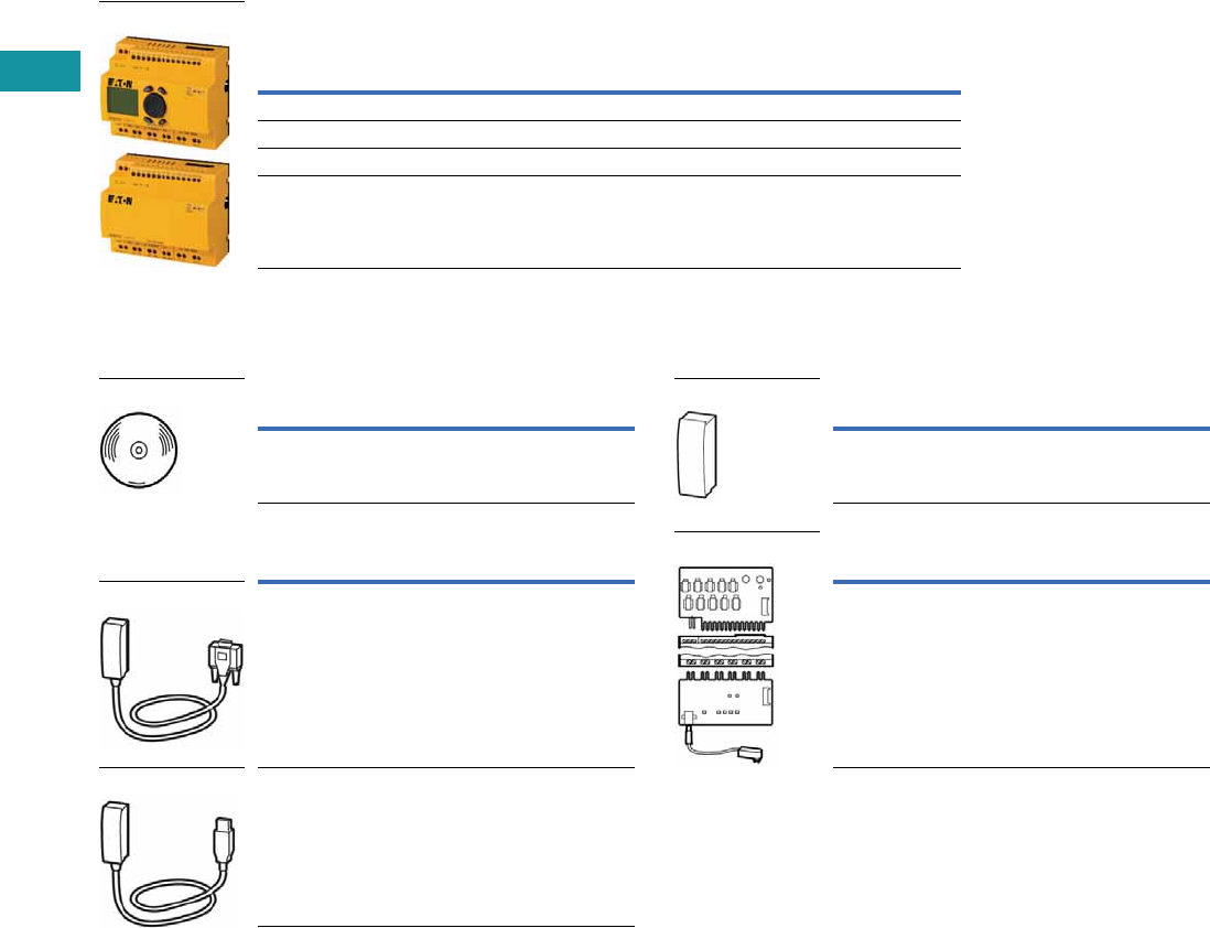
V7-T3-204 Volume 7—Logic Control, Operator Interface and Connectivity Solutions CA08100008E—February 2014 www.eaton.com
3
3
3
3
3
3
3
3
3
3
3
3
3
3
3
3
3
3
3
3
3
3
3
3
3
3
3
3
3
3
3.11
Control Relays and Timers
easySafety
Product Selection
easySafety Relays 1
Accessories
Programming Software
Programming Cables
Memory Card
Input/Output Simulator
Notes
1EN 954-1: 1996, Category 4.
EN ISO 13849-1: 2006, PL e (Performance Level).
IEC 61508: 1998, SIL 3 (Safety Integrity Level).
IEC 62061: 2005, SILCL 3 (Safety Integrity Level Claim Limit).
Expandable: standard inputs/outputs and standard bus systems.
24 Vdc supply voltage.
2Operating systems:
Windows® 2000 SP4, Windows XP SP1, Windows Vista (32 bit).
Inputs (Safety)
Outputs
(Safety)
Outputs
(Safety)
Outputs
(Safety) Display +
KeypadDigital 6A Relay Transistor Test Signal Catalog Number
14 1 (redundant) 4 4 — ES4P-221-DMXX1
14 1 (redundant) 4 4 Yes ES4P-221-DMXD1
144—4—ES4P-221-DRXX1
144—4YesES4P-221-DRXD1
easySafety
Description Catalog Number
easySoft-Safety
(including easySoftPro) 2
ESP-SOFT
Description Catalog Number
SUB-D, nine-pole, serial, 2m EASY800-PC-CAB
USB, 2m EASY800-USB-CAB
easySoft
SUB-D Cable
USB Cable
Description Catalog Number
256 kB module ES4A-MEM-CARD1
Description Catalog Number
With plug-in power supply unit
100–240 Vac/24 Vdc
ES4A-221-DMX-SIM
Memory Card
Input/Output Simulator

Volume 7—Logic Control, Operator Interface and Connectivity Solutions CA08100008E—February 2014 www.eaton.com V7-T3-205
3
3
3
3
3
3
3
3
3
3
3
3
3
3
3
3
3
3
3
3
3
3
3
3
3
3
3
3
3
3
3.11
Control Relays and Timers
easySafety
Technical Data and Specifications
easySafety Relay
Description Unit ES4P_
General
Standards EN 55011, EN 55022, IEC/EN 61000-4, IEC 60068-2-6,
IEC 60068-2-27, EN 954-1: Category 4,
EN ISO 13849-1: PL e, EN IEC 62061: SILCL 3, EN IEC 61508: SIL 3
Dimensions (W x H x D) mm 107.5 (6 space units) x 90 x 72
Mounting Top-hat rail IEC/EN 60715, 35 mm or screw fixing using fixing brackets ZB4-101-GF1 (accessories)
Times
Inputs
Maximum duration of external test pulse ms 1
Semi-conductor output
Off test pulse ms <1
Switch-off delay ms <0.15
Terminal Capacity
Solid mm2 0.2–4 (AWG 22–12)
Flexible with ferrule mm2 0.2–2.5 (AWG 22–12)
Standard screwdriver mm 3.5 x 0.8
Maximum tightening torque Nm 0.6
Ambient Climatic Conditions
Operating ambient temperature °C –25 to +55, low temperatures to IEC 60068-2-1, high temperatures to IEC 60068-2-2
Condensation Prevent condensation by means of suitable measures
LCD display (clearly legible) °C 0 to +55
Storage °C –40 to +70
Relative humidity, noncondensing (IEC/EN 60068-2-30) % 5 to 95
Air pressure (in operation) hPa 795 to 1080
Ambient Mechanical Conditions
Protection type, IEC/EN 60529 IP20
Vibrations (IEC/EN 60068-2-6)
Constant amplitude 0.15 mm Hz 10 to 57
Constant acceleration, 2g Hz 57 to 150
Mechanical shock resistance (IEC/EN 60068-2-27)
semi-sinusoidal 15g/11 ms
Shocks 18
Drop to IEC/EN 60068-2-31 Drop mm 50
Mounting position Horizontal/vertical
Electromagnetic Compatibility (EMC) According
to IEC/EN 61000-6-2
Electrostatic discharge (IEC/EN 61000-4-2, Level 3, ESD)
Air discharge kV 8
Contact discharge kV 6
Radio interference suppression (EN 55011) EN 55011 Class B, EN 55022 Class B
Power pulses (surge) (IEC/EN 61000-4-5, Level 2) kV 1 (supply cables, symmetrical)
Insulation Resistance
Overvoltage category/pollution degree III/2
Clearance in air and creepage distances EN 50178, UL 508, CSA C22.2, No. 142, EN 60664-1:2003
Insulation resistance EN 50178
Backup/Accuracy of the Real-Time Clock
Accuracy of the real-time clock s/day Normally ±5 (±0.5 h/year)
Repetition Accuracy of Timing Relays in
Standard Circuit
Accuracy of timing relay (of value) % ±0.02
Resolution
Range “S” ms 5
Range “M:S” s 1
Retentive Memory
Write cycles of the retentive memory (minimum) 10,000,000,000 (1010) (read/write cycles)

V7-T3-206 Volume 7—Logic Control, Operator Interface and Connectivity Solutions CA08100008E—February 2014 www.eaton.com
3
3
3
3
3
3
3
3
3
3
3
3
3
3
3
3
3
3
3
3
3
3
3
3
3
3
3
3
3
3
3.11
Control Relays and Timers
easySafety
easySafety Relay, continued
Description Unit ES4P_
Power Supply
Rated operational voltage Ue V 24 Vdc (–15/+20%)
Permissible range Vdc 20.4 to 28.8
Ripple % 5
Interfaces
EASYNet (CAN-based)
Bus termination (first and last station) Yes
Control operating mode EASYNet
Number of users Maximum 8
NET Network
Stations Number Maximum 8
Data transfer rate/distance 1000 Kbit/s, 6m
500 Kbit/s, 25m
250 Kbit/s, 60m
125 Kbit/s, 125m
50 Kbit/s, 300m
20 Kbit/s, 700m
10 Kbit/s, 1000m
Bus lengths greater than 40m can only be achieved with enhanced cross-section conductors and
terminal adapters
Potential isolation
From power supply Yes
From the inputs Yes
From the outputs Yes
From the PC interface, memory card, NET network, EASYLink Yes
Bus termination (first and last station) Yes
Terminal type RJ45
Digital Inputs 24 Vdc
Number 14
Inputs can be used as analog inputs —
Status display LCD display (if provided)
Potential isolation
From power supply No
Between digital inputs No
From the outputs Yes
From PC interface, memory card, EASYLink No
From network EASYNet Yes
Rated operational voltage Ue Vdc 24
At signal “0” Ue Vdc <5
At signal “1” Ue Vdc >15
Clock Outputs
Number 4
Voltage Vdc 24
Electrical isolation No

Volume 7—Logic Control, Operator Interface and Connectivity Solutions CA08100008E—February 2014 www.eaton.com V7-T3-207
3
3
3
3
3
3
3
3
3
3
3
3
3
3
3
3
3
3
3
3
3
3
3
3
3
3
3
3
3
3
3.11
Control Relays and Timers
easySafety
easySafety Relay, continued
Description Unit ES4P_
Relay Outputs
Number 4 for ES4P-…-DR_, 1 redundant for ES4P-…-DM_
Outputs in groups of 1
Parallel switching of outputs to increase power Not permissible
Protection of an output relay Fuse: 6A gG, circuit breaker with characteristic C: 24 Vdc 4A, Short-circuit current <250A
Potential isolation
From power supply Yes
From the inputs Yes
From PC interface, memory card, EASYNet, EASYLink Yes
Safe isolation according to EN 50178 Vac 300
Basic insulation Vac 600
Lifespan, mechanical Operations x 106 10
Contacts
Conventional thermal current A 6
Rated impulse withstand voltage Uimp contact coil kV 6
Rated operational voltage Ue Vac 250
Rated insulation voltage Ui Vac 250
Safe isolation to EN 50178 between coil and contact Vac 300
Making capacity
AC-15, 230 Vac, 3A Operations 80,000
DC-13, 24 Vdc, 5A, 0.1 Hz Operations 40,000
Switching frequency
Mechanical operations x 106 10
Switching frequency Hz 10
UL/CSA
UL 508 B300/R300
Transistor Outputs
Number 4
Rated operational voltage Ue Vdc 24
Permissible range Ue Vdc 20.4–28.8
Ripple % 5
Protection against polarity reversal Yes (Caution: A short-circuit will result if 0V or GND is applied to the outputs in the event that the
supply voltage is connected to the wrong poles.)
Potential isolation
From power supply Yes
From the inputs Yes
From PC interface, memory card, network, EASYNet, EASYLink Yes
Rated operational current at signal “1” DC Ie A Maximum 0.5
At signal “1” with Ie = 0.5A V U = Ue –1 V
Short-circuit protection Yes, thermal
Short-circuit tripping current for RA 10 m ohms A 0.7 Ie2 per output
Total short-circuit current A 8
Peak short-circuit current A 16
Thermal cutout Yes
Maximum operating frequency at constant resistive load RL <100 kO
(dependant on program and load)
Ops/h 40,000
Parallel connection of outputs No
Status indication of the outputs LCD display (if provided)
Inductive load
Without external suppressor circuit
Duty factor T0.95 ≈ 3 x T0.65 = 3 x L/R T0.95 = Time in ms, until 95% of the
steady-state current has been reached
With external suppressor circuit
Utilization factor g 1
Duty factor % DF 100
Maximum switching frequency, maximum duty factor Operations Depending on the suppressor circuit
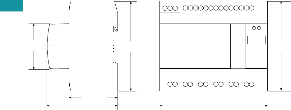
V7-T3-208 Volume 7—Logic Control, Operator Interface and Connectivity Solutions CA08100008E—February 2014 www.eaton.com
3
3
3
3
3
3
3
3
3
3
3
3
3
3
3
3
3
3
3
3
3
3
3
3
3
3
3
3
3
3
3.11
Control Relays and Timers
easySafety
Dimensions
Approximate Dimensions in Inches (mm)
ESR5_
1.87 (47.5)
2.68 (68.0)
1.77
(45.0) 3.54
(90.0)
4.23 (107.5)
3.54
(90.0)
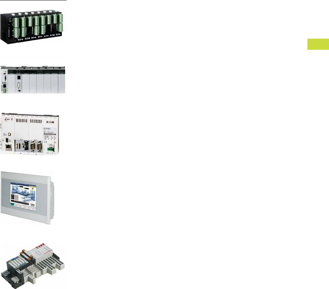
Volume 7—Logic Control, Operator Interface and Connectivity Solutions CA08100008E—February 2014 www.eaton.com V7-T4-1
4
4
4
4
4
4
4
4
4
4
4
4
4
4
4
4
4
4
4
4
4
4
4
4
4
4
4
4
4
4
PLC, I/O and Communications Products
ELC Series PLCs
XC Series PLCs
XI/ON Series Distributed I/O
XV Series HMI-PLC
XC152 Series PLCs
4.1 ELC Series Programmable Logic Controllers
Product Overview . . . . . . . . . . . . . . . . . . . . . . . . . . . . . . . . . . . . . . . . V7-T4-2
Product Selection Guide . . . . . . . . . . . . . . . . . . . . . . . . . . . . . . . . . . . V7-T4-3
System Overview . . . . . . . . . . . . . . . . . . . . . . . . . . . . . . . . . . . . . . . . V7-T4-4
Product Selection . . . . . . . . . . . . . . . . . . . . . . . . . . . . . . . . . . . . . . . . . V7-T4-5
Accessories . . . . . . . . . . . . . . . . . . . . . . . . . . . . . . . . . . . . . . . . . . . . . V7-T4-14
Technical Data and Specifications . . . . . . . . . . . . . . . . . . . . . . . . . . . . V7-T4-16
Circuit Diagrams . . . . . . . . . . . . . . . . . . . . . . . . . . . . . . . . . . . . . . . . . V7-T4-18
Dimensions . . . . . . . . . . . . . . . . . . . . . . . . . . . . . . . . . . . . . . . . . . . . . V7-T4-18
4.2 XC Series Programmable Logic Controllers
Product Overview . . . . . . . . . . . . . . . . . . . . . . . . . . . . . . . . . . . . . . . . V7-T4-24
Product Selection Guide . . . . . . . . . . . . . . . . . . . . . . . . . . . . . . . . . . . V7-T4-25
Catalog Number Selection . . . . . . . . . . . . . . . . . . . . . . . . . . . . . . . . . . V7-T4-26
System Overview . . . . . . . . . . . . . . . . . . . . . . . . . . . . . . . . . . . . . . . . V7-T4-26
Product Selection . . . . . . . . . . . . . . . . . . . . . . . . . . . . . . . . . . . . . . . . . V7-T4-28
Accessories . . . . . . . . . . . . . . . . . . . . . . . . . . . . . . . . . . . . . . . . . . . . . V7-T4-31
Technical Data and Specifications . . . . . . . . . . . . . . . . . . . . . . . . . . . . V7-T4-34
Dimensions . . . . . . . . . . . . . . . . . . . . . . . . . . . . . . . . . . . . . . . . . . . . . V7-T4-50
4.3 XC152 Series Programmable Logic Controllers
Product Description . . . . . . . . . . . . . . . . . . . . . . . . . . . . . . . . . . . . . . . V7-T4-52
Catalog Number Selection . . . . . . . . . . . . . . . . . . . . . . . . . . . . . . . . . . V7-T4-53
Product Selection . . . . . . . . . . . . . . . . . . . . . . . . . . . . . . . . . . . . . . . . . V7-T4-53
Accessories . . . . . . . . . . . . . . . . . . . . . . . . . . . . . . . . . . . . . . . . . . . . . V7-T4-53
Technical Data and Specifications . . . . . . . . . . . . . . . . . . . . . . . . . . . . V7-T4-54
Dimensions. . . . . . . . . . . . . . . . . . . . . . . . . . . . . . . . . . . . . . . . . . . . . . V7-T4-55
4.4 XV Series HMI-PLCs
Product Description . . . . . . . . . . . . . . . . . . . . . . . . . . . . . . . . . . . . . . . V7-T4-56
Catalog Number Selection . . . . . . . . . . . . . . . . . . . . . . . . . . . . . . . . . . V7-T4-56
Product Selection . . . . . . . . . . . . . . . . . . . . . . . . . . . . . . . . . . . . . . . . . V7-T4-57
Accessories . . . . . . . . . . . . . . . . . . . . . . . . . . . . . . . . . . . . . . . . . . . . . V7-T4-57
4.5 XI/ON Series Remote I/O
Product Overview . . . . . . . . . . . . . . . . . . . . . . . . . . . . . . . . . . . . . . . . V7-T4-58
Product Selection Guide . . . . . . . . . . . . . . . . . . . . . . . . . . . . . . . . . . . V7-T4-59
Catalog Number Selection . . . . . . . . . . . . . . . . . . . . . . . . . . . . . . . . . . V7-T4-60
System Overview . . . . . . . . . . . . . . . . . . . . . . . . . . . . . . . . . . . . . . . . V7-T4-62
Product Selection . . . . . . . . . . . . . . . . . . . . . . . . . . . . . . . . . . . . . . . . . V7-T4-66
Accessories . . . . . . . . . . . . . . . . . . . . . . . . . . . . . . . . . . . . . . . . . . . . . V7-T4-75
Technical Data and Specifications . . . . . . . . . . . . . . . . . . . . . . . . . . . . V7-T4-76
Connection Diagrams . . . . . . . . . . . . . . . . . . . . . . . . . . . . . . . . . . . . . V7-T4-89
Dimensions . . . . . . . . . . . . . . . . . . . . . . . . . . . . . . . . . . . . . . . . . . . . . V7-T4-101
Note: For EASY Programmable Relays, see Tab 3 in this volume.
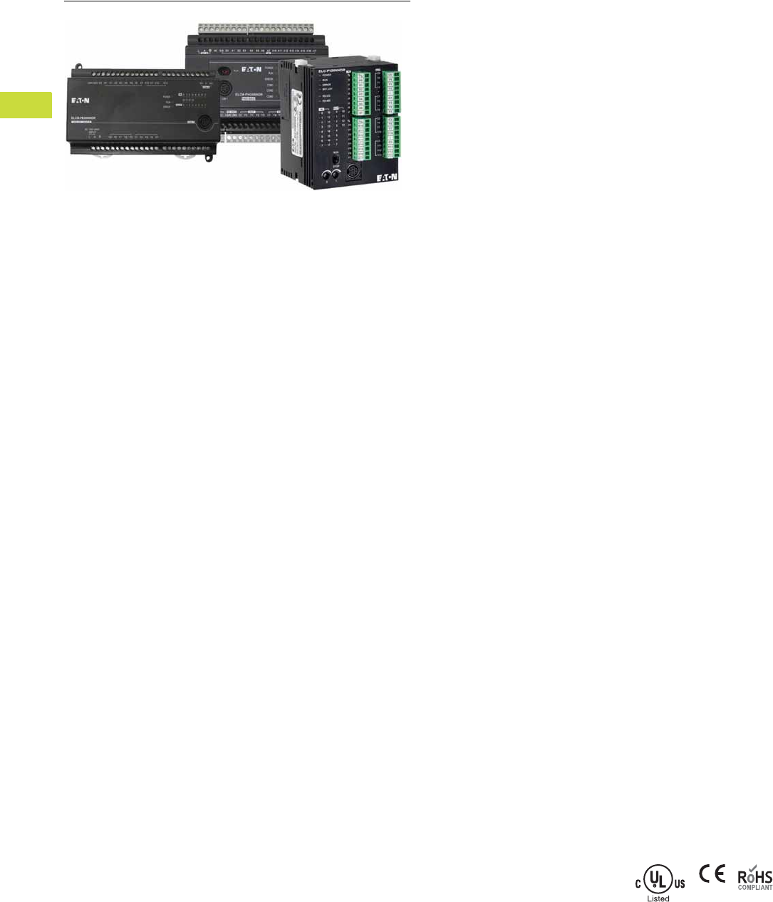
V7-T4-2 Volume 7—Logic Control, Operator Interface and Connectivity Solutions CA08100008E—February 2014 www.eaton.com
4
4
4
4
4
4
4
4
4
4
4
4
4
4
4
4
4
4
4
4
4
4
4
4
4
4
4
4
4
4
4.1
PLC, I/O and Communications Products
ELC Series Programmable Logic Controllers
ELC Series Programmable Logic Controllers
Contents
Description Page
ELC Series Programmable Logic Controllers
Product Selection Guide . . . . . . . . . . . . . . . . . V7-T4-3
System Overview . . . . . . . . . . . . . . . . . . . . . . . V7-T4-4
Product Selection
ELCB Brick Style PLCs . . . . . . . . . . . . . . . . V7-T4-5
ELCM Modular Brick PLCs . . . . . . . . . . . . . V7-T4-6
ELC Modular PLCs . . . . . . . . . . . . . . . . . . . V7-T4-8
ELC Master Communication Modules . . . . V7-T4-10
ELC Distributed I/O Adapters . . . . . . . . . . . V7-T4-11
Digital Expansion Modules
(Right Side Bus) . . . . . . . . . . . . . . . . . . . . V7-T4-12
Accessories . . . . . . . . . . . . . . . . . . . . . . . . . . . V7-T4-14
Technical Data and Specifications . . . . . . . . . . V7-T4-16
Circuit Diagrams . . . . . . . . . . . . . . . . . . . . . . . . V7-T4-18
Dimensions . . . . . . . . . . . . . . . . . . . . . . . . . . . V7-T4-18
Product Overview
Controllers
There are five controller styles:
ELCB Brick-Style Controllers
The ELCB controllers are the
simplest and most affordable
members of the ELC
portfolio. With ELCB, the
focus is on “just enough
control” for applications up
to 40 I/O points. These
controllers pack a lot into a
small, low-profile package.
Like the ELCM controllers,
these controllers are AC
powered and provide 24 Vdc
sensor power. But unlike the
rest of the ELC family, the
ELCB controllers do not offer
expansion I/O. The ELCB is
great as a standalone
controller, or is capable of
networking with other
controllers, operator
interfaces, drives, or other
Modbus® serial devices.
ELCM Modular Brick-Style
Controllers
The next member of the ELC
portfolio of controllers is the
ELCM. This midrange family
comprises “brick-style”
controllers, with expansion
I/O modules. These all-in-one
controllers combine inputs,
outputs, logic processing, and
an integrated AC power
supply into a compact
package—but also provide
the means to expand as
applications change or grow.
The controller also provides
24 Vdc power for sensors,
eliminating the space, wiring,
and expense of an additional
power supply. And with three
communication ports, the
ELCM is able to interface into
a local operator interface,
connect to other controllers
or supervisory computers,
and still maintain an open port
for programming.
ELC Modular Controllers
The ELC lineup is focused
on compact size, powerful
features, and affordability.
Whether your needs involve
discrete standalone control,
necessitate distributed
control networks, or even
a control system, using
centralized control with
distributed I/O, ELCs provide
the solution your application
demands.
While the ELCs are perfectly
suited for small applications
of <40 I/O with a diverse mix
of I/O, they can also expand
to hundreds of I/O points
when needed. These
controllers are modular,
with a wide range of digital,
analog, thermocouple, RTD,
and even motion expansion
modules. Despite a world-
class small footprint—with
controllers as small as 1.00-
inch wide, these controllers
perform like much larger
PLCs. With online editing,
high-speed processing (basic
instructions
as fast as 0.24
microseconds),
multiple high-
speed inputs/outputs (up to
200 kHz), and multiple
independent master
communication channels,
these controllers excel where
only the largest PLCs could
go only a few years ago.
Electrical/EMC
●ESD Immunity
●8 kV air discharge
●EFT Immunity
●
Power Line: 2 kV
●
Digital I/O: 1 kV
●
Analog and
Communication
I/O: 250V
●Damped-Oscillatory Wave
●
Power Line: 1 kV
●Digital I/O: 1 kV
●RS Immunity
●26 MHz–1 GHz, 10 V/m
Standards and Certifications
●cULus
●CE; C-Tick
●RoHS
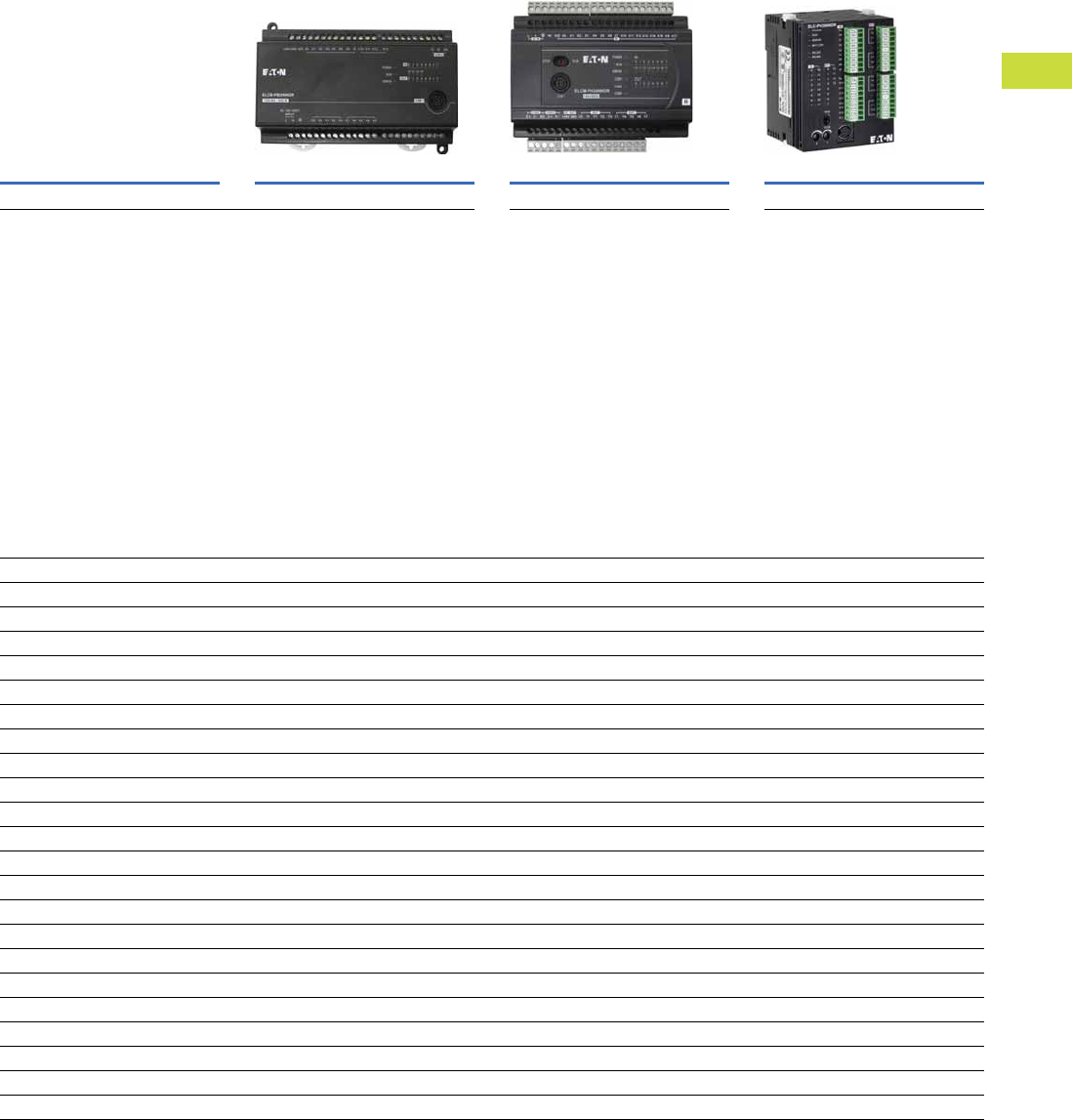
Volume 7—Logic Control, Operator Interface and Connectivity Solutions CA08100008E—February 2014 www.eaton.com V7-T4-3
4
4
4
4
4
4
4
4
4
4
4
4
4
4
4
4
4
4
4
4
4
4
4
4
4
4
4
4
4
4
4.1
PLC, I/O and Communications Products
ELC Series Programmable Logic Controllers
Product Selection Guide
ELC Series Programmable Logic Controllers
Model ELCB Brick Style PLCs ELCM Modular Brick PLCs ELC Modular PLCs
Page V7-T4-5 Page V7-T4-6 Page V7-T4-8
Product Description Compact and economical PLCs
●Digital I/O only
●10, 14, 20, 30 or 40 I/O controllers
●24 Vdc inputs
●Relay or transistor outputs
●Non-expandable I/O
●Built-in 110 Vac power supply
●On board 400 mA 24 Vdc sensor power
●RS-232 programming port
●RS-485 Modbus serial port
●DIN rail or panel mount
Expandable brick PLCs
●Digital, analog, thermocouple and
RTD I/O
●16, 20, 24, 32 or 40 I/O base controllers
●8 and 16 digital I/O expansion modules
●2, 4 and 6 analog I/O expansion
modules
●24 Vdc inputs
●Relay or transistor outputs
●Built-in 110 Vac power supply
●On board 400 mA 24 Vdc sensor power
●RS-232 programming port
●Two RS-485 Modbus serial ports
●DIN rail or panel mount
Modular and expandable PLCs with
distributed I/O capability
●Digital, analog, thermocouple and
RTD I/O
●10, 12, 14 and 28 I/O base controllers
●6, 8 or 16 digital I/O expansion modules
●2, 4 and 6 analog I/O expansion
modules
●24 Vdc and 110 Vac inputs
●Relay or transistor outputs
●High current relay output module
●High speed pulse capture and high
speed pulse output up to 200 kHz
●Two RS-485 Modbus serial ports
●DIN rail mounting only
●Distributed I/O adapters for
EtherNet/IP, Modbus TCP, DeviceNet,
PROFIBUS-DP and RS-485
Features
Input voltage 120 Vac 120 Vac 24 Vdc
Maximum local I/O points 40 264 252
Built-in power supply Yes Yes No
Built-in 24 Vdc sensor power supply Yes Yes No
DC inputs Yes Yes Yes
AC inputs No No Yes
Transistor outputs Yes Yes Yes
Relay outputs Yes Yes Yes
High current relay outputs No No Yes
Clock/calendar No No Yes
Expandable No Yes Yes
Removable terminal blocks No Yes Yes
Built-in display No No Yes
RS-232 communication ports 1 1 1
RS-485 communication ports 1 2 1
High speed counters No Yes Yes
Analog I/O No Yes Yes
Thermocouple module No Yes Yes
Platinum RTD module No Yes Yes
Single axis motion control module No No Yes
DeviceNet master No No Yes
Ethernet (Modbus TCP) master No No Yes
Distributed I/O adapters No No Yes
V7-T4-4 Volume 7—Logic Control, Operator Interface and Connectivity Solutions CA08100008E—February 2014 www.eaton.com
4
4
4
4
4
4
4
4
4
4
4
4
4
4
4
4
4
4
4
4
4
4
4
4
4
4
4
4
4
4
4.1
PLC, I/O and Communications Products
ELC Series Programmable Logic Controllers
System Overview
Configuration and Layout
123456789101112131487654321
ANALOG
ANALOG
ANALOG
ANALOG
ANALOG
ANALOG
ANALOG
ANALOG
ANALOG
ANALOG
ANALOG
ANALOG
ANALOG
ANALOG
ANALOG
ANALOG
DIGITALDIGITAL
DIGITALDIGITAL
DIGITALDIGITAL
DIGITALDIGITAL
DIGITALDIGITAL
DIGITALDIGITAL
ELC-CAENET
ELC-COENETM
ELC-COENETM
ELC-COENETM
ELC-COENETM
ELC-COENETM
ELC-COENETM
ELC-COENETM
ELC-COENETM
ELC-PV
Right Side Bus Modules
— Up to 8 analog modules
— Up to 14 digital modules
Left Side Bus Modules
—Up to 8 modules
Ethernet I/O Adapters
— Up to 4 adapter modules per master
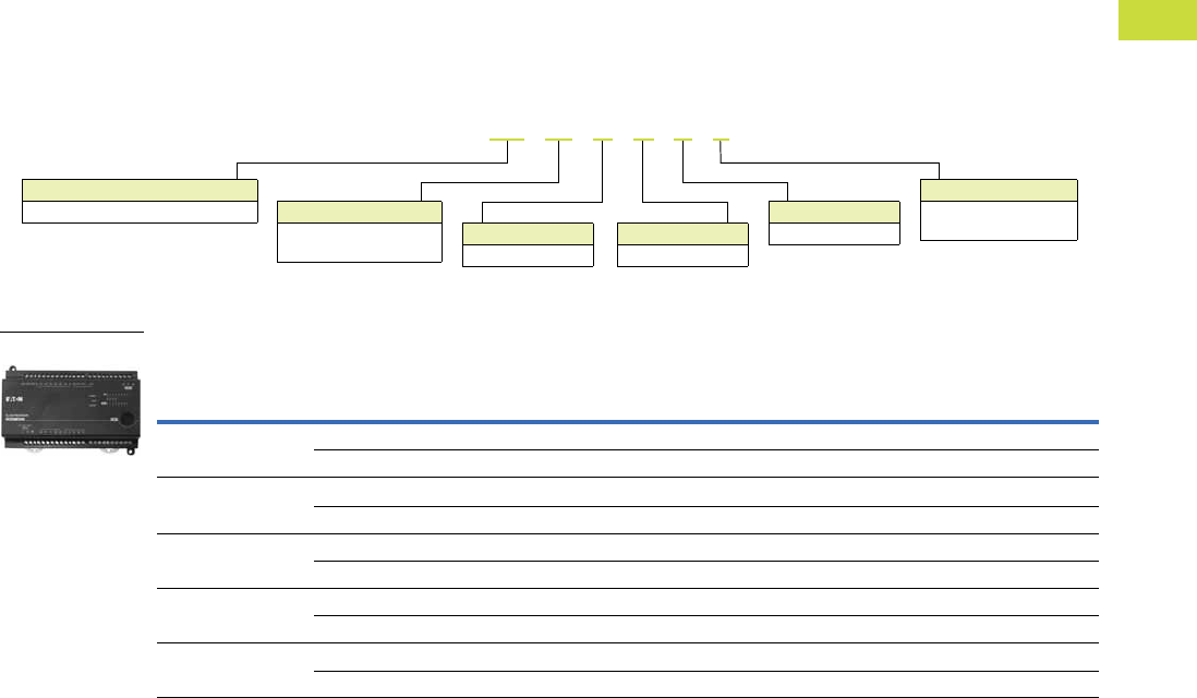
Volume 7—Logic Control, Operator Interface and Connectivity Solutions CA08100008E—February 2014 www.eaton.com V7-T4-5
4
4
4
4
4
4
4
4
4
4
4
4
4
4
4
4
4
4
4
4
4
4
4
4
4
4
4
4
4
4
4.1
PLC, I/O and Communications Products
ELC Series Programmable Logic Controllers
Product Selection
ELCB Brick Style PLCs
Features
●Basic PLC logic with just
enough I/O for simple DC
in/relay or transistor out
applications
●This non-expandable PLC
has a built-in AC power
supply and provides up to
400 mA of DC sensor
power
●Each controller supports
one RS-232 programming
port and one RS-485
Modbus serial (master/
slave) port
Controllers
Controllers
Description
Inputs Outputs
Catalog NumberAC DC Analog Relay
NPN Sinking
Transistor Analog
10 I/O —6—4— — ELCB-PB10NNDR
—6 ——4 — ELCB-PB10NNDT
14 I/O —8—6— — ELCB-PB14NNDR
—8 ——6 — ELCB-PB14NNDT
20 I/O — 12 — 8 — — ELCB-PB20NNDR
—12 ——8 — ELCB-PB20NNDT
30 I/O — 18 — 12 — — ELCB-PB30NNDR
—18 ——12 — ELCB-PB30NNDT
40 I/O — 24 — 16 — — ELCB-PB40NNDR
—24 ——16 — ELCB-PB40NNDT
Device Types
PB = Base model Digital Inputs
D=DC
Digital Outputs
T= Transistor
R=Relay
I/O Count
xx = Total number of I/O
(10, 14, 20, 30, 40)
Analog Inputs
N= None
Analog Outputs
N= None
ELCB – PB 10 N N D R
ELCB-PB10NNDR
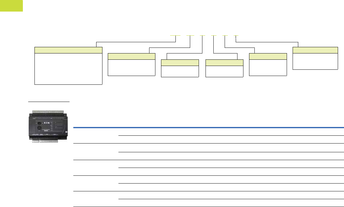
V7-T4-6 Volume 7—Logic Control, Operator Interface and Connectivity Solutions CA08100008E—February 2014 www.eaton.com
4
4
4
4
4
4
4
4
4
4
4
4
4
4
4
4
4
4
4
4
4
4
4
4
4
4
4
4
4
4
4.1
PLC, I/O and Communications Products
ELC Series Programmable Logic Controllers
ELCM Modular Brick PLCs
Features
●Midrange brick style
controller with digital,
analog, thermocouple and
RTD expansion capability
●Expansion modules can
optionally be used to
increase the total number
of I/O, to provide a mix of
different types of I/O, or
both
●These controllers include
an embedded AC power
supply and provide up to
400 mA of DC sensor
power
●Each controller supports
two RS-485 Modbus serial
(master/node) and one RS-
232 programming port
Controllers
Controllers
Description
Inputs Outputs
Catalog NumberAC DC Analog Relay
NPN Sinking
Transistor Analog
16 I/O PH model — 8 — 8 — — ELCM-PH16NNDR
—8 ——8 — ELCM-PH16NNDT
24 I/O PH model — 16 — 8 — — ELCM-PH24NNDR
—16 ——8 — ELCM-PH24NNDT
32 I/O PH model — 16 — 16 — — ELCM-PH32NNDR
—16 ——16 — ELCM-PH32NNDT
40 I/O PH model — 24 — 16 — — ELCM-PH40NNDR
—24 ——16 — ELCM-PH40NNDT
20 I/O PA model—846— 2 ELCM-PA20AADR
—84—6 2 ELCM-PA20AADT
Device Types
PH = High-speed model
PA = Analog model
AN = Analog expansion module
EX = Digital expansion module
PT = Platinum rtd expansion module
TC = Thermocouple expansion module
ELCM – PA 16 A A D R
Digital Inputs
A=AC
D=DC
N= None
Digital Outputs
T= Transistor
R=Relay
N=None
I/O Count
xx = Total number of I/O
(16, 24, 32, 40 digital;
20 analog and digital)
Analog Inputs
A= Analog
N= None
Analog Outputs
A= Analog
N= None
ELCM-PH16NNDR

Volume 7—Logic Control, Operator Interface and Connectivity Solutions CA08100008E—February 2014 www.eaton.com V7-T4-7
4
4
4
4
4
4
4
4
4
4
4
4
4
4
4
4
4
4
4
4
4
4
4
4
4
4
4
4
4
4
4.1
PLC, I/O and Communications Products
ELC Series Programmable Logic Controllers
Right Side Digital Expansion Modules
Right Side Analog and Specialty Modules
Description
Inputs Outputs
Catalog NumberAC
DC
Sink/Source Relay
NPN Sinking
Transistor
8 DC input module — 8 — — ELCM-EX08NNDN
16 DC input module — 16 — — ELCM-EX16NNDN
8 Relay output module — — 8 — ELCM-EX08NNNR
16 Relay output module — — 16 — ELCM-EX16NNNR
8 Transistor output module — — 8 — ELCM-EX08NNNT
16 Transistor output module — — 16 — ELCM-EX16NNNT
8 DC input/relay output module — 4 4 — ELCM-EX08NNDR
16 DC input/relay output module — 8 8 — ELCM-EX16NNDR
8 DC input/output module — 4 — 4 ELCM-EX08NNDT
16 DC input/output module — 8 — 8 ELCM-EX16NNDT
Description Analog Inputs Analog Outputs Catalog Number
4 Analog input module 4 — ELCM-AN04ANNN
2 Analog input module — 2 ELCM-AN02NANN
4 Analog input module — 4 ELCM-AN04NANN
6 Analog input/output module 4 2 ELCM-AN06AANN
4 Thermocouple input module (J, K, R, S, T) 4 — ELCM-TC04ANNN
4 Platinum RTD input module (PT100) 4 — ELCM-PT04ANNN

V7-T4-8 Volume 7—Logic Control, Operator Interface and Connectivity Solutions CA08100008E—February 2014 www.eaton.com
4
4
4
4
4
4
4
4
4
4
4
4
4
4
4
4
4
4
4
4
4
4
4
4
4
4
4
4
4
4
4.1
PLC, I/O and Communications Products
ELC Series Programmable Logic Controllers
ELC Modular PLCs
Features
●PB Base Model—
●
14 I/O (8i/6o)
●
Over 130 instructions
●
Two Modbus (ASCII/RTU)
serial ports for master/
slave communications
●
RS-485 master port with
the ability to
communicate to 31 other
devices
●
The master port can also
be configured to
communicate to devices
such as ASCII, bar code
readers, and so on
●
EEPROM program
retention in the event of
power loss
Note: This model does not
provide a real-time clock
●PC Clock/Calendar Model
●
12 I/O (8i/4o)
●
Same features as the basic
model plus clock/calendar
●
Distributed I/O capability
with up to 16 devices
●
File area for data storage
and retrieval
●
RAM program memory
with battery backup
●
Replaceable battery has
greater than a 5-year life
●
Two digital potentiometers
that vary the data in
internal registers
●PH High-Speed Model
●
12 I/O (8i/4o)
●
All the features of the PC
model
●
High speed pulse capture
up to 100 kHz
●
Single-axis motion control
●PA Anal og Model
●
10 I/O (6i/4o)
●
Same features as PC
model with a different
I/O mix
●
Four digital inputs, two
digital outputs, two
analog inputs, and two
analog outputs
●
Analog channels can be
set up for either voltage or
current
●
Two 7-segment LEDs that
can be used to display
unit ID, error codes,
process steps, and so on
●PV Advanced Model
●
28 I/O (16i/12o)
●
The PV model has the
most extensive features
●
Programs written for the
other controllers can be
migrated to a PV model
controller where greater
speed or more I/O
is required
●
10 times increase in
processing speed for
about 0.24μ seconds/step
●
RAM program storage
and backed using a
rechargeable lithium-ion
battery that charges with
normal use
●
Includes 2-axis motion
control
●
Additional expansion bus
to the left of the controller
●
Add high-speed and
specialty modules to
the left
●
Left side Ethernet master
and DeviceNet master
modules are available for
use with the PV model
controller
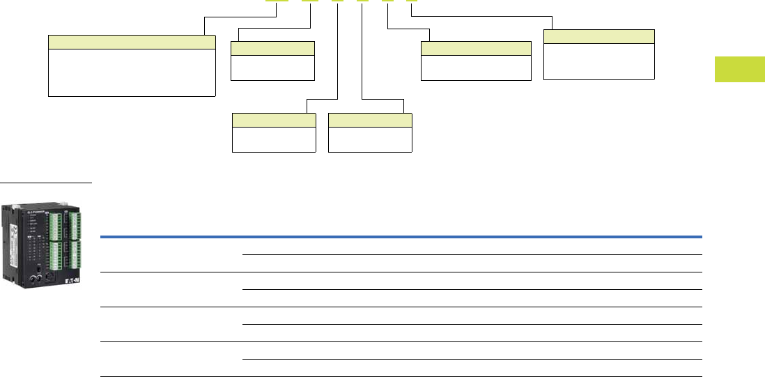
Volume 7—Logic Control, Operator Interface and Connectivity Solutions CA08100008E—February 2014 www.eaton.com V7-T4-9
4
4
4
4
4
4
4
4
4
4
4
4
4
4
4
4
4
4
4
4
4
4
4
4
4
4
4
4
4
4
4.1
PLC, I/O and Communications Products
ELC Series Programmable Logic Controllers
Controllers and Modules
Controllers (PB, PC, PH, PV, PA)
Description Inputs Outputs Analog
High
Speed I/O
Max. Current
Consumption
(at 24 Vdc)
Catalog
Number
ELC-PB model and 14 I/O built-in (8) 24 Vdc (6) Relay, 1.5A — (2) 20 kHz inputs 150 mA ELC-PB14NNDR
(8) 24 Vdc (6) Transistor, 100 mA — (2) 20 kHz inputs 150 mA ELC-PB14NNDT
ELC-PC model and 12 I/O built-in (8) 24 Vdc (4) Relay, 1.5A — (1) 30 kHz inputs 150 mA ELC-PC12NNDR
(8) 24 Vdc (4) Transistor, 100 mA — (1) 30 kHz inputs 150 mA ELC-PC12NNDT
ELC-PA model and 10 I/O built-in (4) 24 Vdc (2) Relay, 1.5A (2) In and (2) Out (1) 30 kHz inputs 210 mA ELC-PA10AADR
(4) 24 Vdc (2) Relay, 1.5A (2) In and (2) Out (1) 30 kHz inputs 210 mA ELC-PA10AADT
ELC-PV model and 28 I/O built-in (16) 24 Vdc (12) Relay, 1.5A — (2) 200 kHz inputs 220 mA ELC-PV28NNDR
(16) 24 Vdc (12) Transistor, 100 mA — (2) 200 kHz inputs 220 mA ELC-PV28NNDT
Device Type
PB = Base model
PC = Clock/calendar model
PA = Analog model
PV = Advanced model
ELC - PA 10 A A D R
Digital Inputs
A =AC
D = DC (sink or source)
Analog Inputs
A = Analog
N = None
I/O Count
xx = Total number
of I/O
Analog Outputs
A = Analog
N = None
Digital Outputs
T = Transistor (NPN)
P = Transistor (PNP)
R =Relay
ELC-PV_
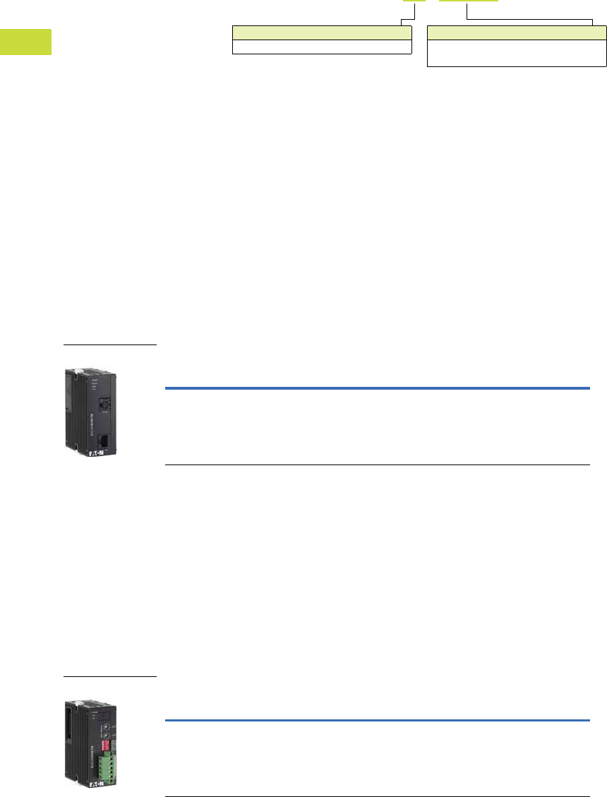
V7-T4-10 Volume 7—Logic Control, Operator Interface and Connectivity Solutions CA08100008E—February 2014 www.eaton.com
4
4
4
4
4
4
4
4
4
4
4
4
4
4
4
4
4
4
4
4
4
4
4
4
4
4
4
4
4
4
4.1
PLC, I/O and Communications Products
ELC Series Programmable Logic Controllers
ELC Master Communication Modules
ELC Master Communication Modules
Ethernet Master Communication Module (Left Side Bus)
Features
●Ethernet communication
module
●Enables the ELC-PV model
controller to connect to
Modbus TCP networks
auto detecting 10/100MB
connections
●Enables the uploading and
downloading of programs
in addition to program
monitoring
●Use ELCSoft to search for
all the Ethernet modules
attached to the network
and manage them
remotely
●Share data in a peer-to-peer
network to reduce long I/O
wiring
●Send e-mails for alerts and
notifications. For example,
advise personnel of alarm
condition or send daily
production yield summaries
●Keep accurate time with
the NTP (Network Time
Protocol) feature, which
synchronizes your
controller with an NTP
server
●The Ethernet module will
automatically detect and
use the type of patch or
crossover cable attached
●IP addresses may be
filtered to manage module
traffic in order to maximize
communication
performance.
Ethernet Master Communication Module (Left Side Bus)
DeviceNet Master Communication Module (Left Side Bus)
Features
●DeviceNet master module
maps up to 380 bytes of
data directly into the PV
model controller for quick
and easy access
●Use Polled, Bit-Strobe and
Change of State/Cyclic
DeviceNet commands, or
send explicit messages
●Configuration of DeviceNet
components in ELCSoft is
easy with the drag-and-
drop interface
●Use the pre-populated EDS
files within ELCSoft and
add others to simplify the
configuration
DeviceNet Master Communication Module (Left Side Bus)
Note
1Left side bus communications module—for use with ELC-PV controllers only.
Module Type
DNETM = DeviceNet master module 1
ENETM = Ethernet master module 1
Device Type
CO = Communication interface module
ELC - CO ENETM
Description
Inputs
Points Type
Outputs
Points
Catalog
Number
Ethernet Modbus TCP (master/slave) N/A Modbus TCP N/A ELC-COENETM
ELC-COENETM
Description
Inputs
Points Type
Outputs
Points
Catalog
Number
DeviceNet Scanner (master/slave) 190 bytes DeviceNet 190 bytes ELC-CODNETM
ELC-CODNETM
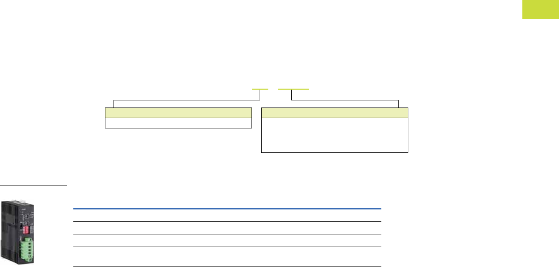
Volume 7—Logic Control, Operator Interface and Connectivity Solutions CA08100008E—February 2014 www.eaton.com V7-T4-11
4
4
4
4
4
4
4
4
4
4
4
4
4
4
4
4
4
4
4
4
4
4
4
4
4
4
4
4
4
4
4.1
PLC, I/O and Communications Products
ELC Series Programmable Logic Controllers
ELC Distributed I/O Adapters
Features
●Combine with ELC
expansion modules to
create distributed I/O racks
for different PLC networks
●Use ELC-CAENET and
ELC-COENETM to create
distributed I/O racks to the
ELC-PV controllers
●Connect cost effective ELC
expansion modules to
third-party PLCs using
standard networks
●EtherNet/IP, Modbus TCP,
DeviceNet, PROFIBUS-DP
and Modbus serial RS-485
distributed I/O adapters
●Connect up to 8 analog
expansion modules or 14
digital expansion modules
ELC Distributed I/O Adapters
Distributed I/O Adapter Modules
Description Catalog Number
EtherNet/IP or Modbus TCP I/O adapter ELC-CAENET
Modbus serial RS-485 I/O adapter ELC-CARS485
DeviceNet I/O adapter ELC-CADNET
PROFIBUS-DP I/O adapter ELC-CAPBDP
Device Type
CA = Distributed I/O adapter
Module Type
ENET = EtherNet/IP or Modbus TCP I/O adapter
DNET = DeviceNet I/O adapter
RS485 = Modbus serial RS-485 I/O adapter
PBDP = PROFIBUS-DP I/O adapter
ELC – CA ENET
ELC-CAENET
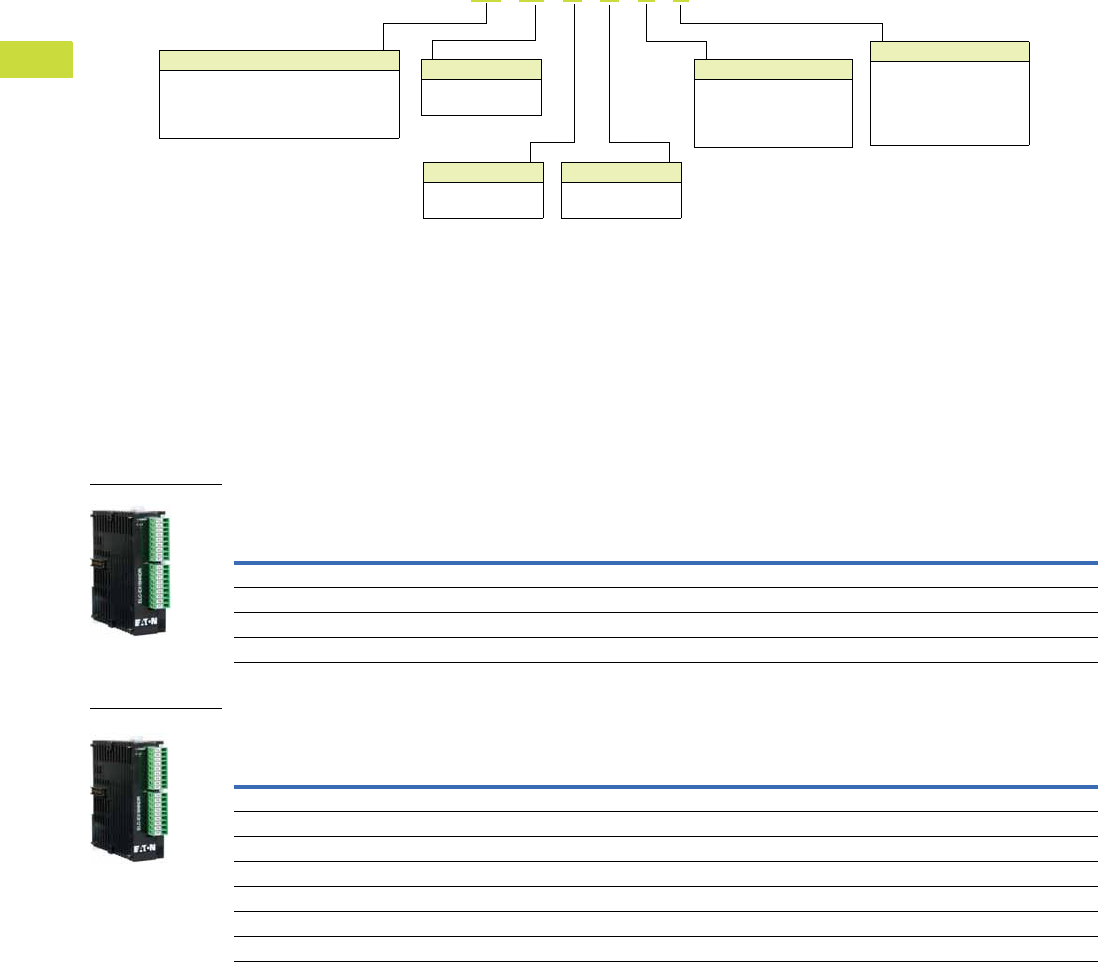
V7-T4-12 Volume 7—Logic Control, Operator Interface and Connectivity Solutions CA08100008E—February 2014 www.eaton.com
4
4
4
4
4
4
4
4
4
4
4
4
4
4
4
4
4
4
4
4
4
4
4
4
4
4
4
4
4
4
4.1
PLC, I/O and Communications Products
ELC Series Programmable Logic Controllers
Digital Expansion Modules (Right Side Bus)
Expansion Modules
Features
●Digital right side expansion
modules can be used with
any ELC controller
●They simply snap together
to allow the ELC backplane
to pass through each
connected module
●Add only the amount of I/O
you need
●Choose I/O counts as small
as 6 points and as large as
14 points per module
●I/O modules are available in
a broad selection of AC/DC
inputs, relay/transistor and
high current outputs that
may be used together in
any combination
●Maximum of 14 modules
per controller
Digital Expansion Modules (Right Side Bus) 1 of 2
Digital Expansion Modules (Right Side Bus) 2 of 2
Device Type
AN = Analog expansion module
EX = Digital expansion module
PT = Platinum RTD expansion module
TC = Thermocouple expansion module
ELC - EX 16 N N D P
Digital Inputs
A =AC
D = DC (sink or source)
S =Switch
N =None
Analog Inputs
A = Analog
N = None
I/O Count
xx = Total number
of I/O
Analog Outputs
A = Analog
N = None
Digital Outputs
T = Transistor (NPN)
P = Transistor (PNP)
R =Relay
I = Relay—high current
N =None
Description Inputs Outputs
Max. Current
Consumption
(at 24 Vdc)
Catalog
Number
8 DC input module (8) 24 Vdc — 50 mA ELC-EX08NNDN
8 AC input module (8) 110 Vac — 50 mA ELC-EX08NNAN
8 Transistor output module — (8) Transistor (sink), 0.3A 70 mA ELC-EX08NNNT
8 Relay output module — (8) Relay, 1.5A 70 mA ELC-EX08NNNR
Description Inputs Outputs
Max. Current
Consumption
(at 24 Vdc)
Catalog
Number
8 DC input/output module (4) 24 Vdc (4) Transistor (sink), 0.3A 70 mA ELC-EX08NNDT
8 DC input/relay output module (4) 24 Vdc (4) Relay, 1.5A 70 mA ELC-EX08NNDR
6 High current relay output module — (6) Relay, 6A 70 mA ELC-EX06NNNI
16 DC input module (16) 24 Vdc — 100 mA ELC-EX16NNDN
16 DC input/output module (8) 24 Vdc (8) Transistor (sink), 0.3A 90 mA ELC-EX16NNDT
16 DC input/output module (8) 24 Vdc (8) Transistor (source), 0.3A 100 mA ELC-EX16NNDP
16 DC input/relay output module (8) 24 Vdc (8) Relay, 1.5A 90 mA ELC-EX16NNDR
ELC-EX08NNDN
ELC-EX08NNDT
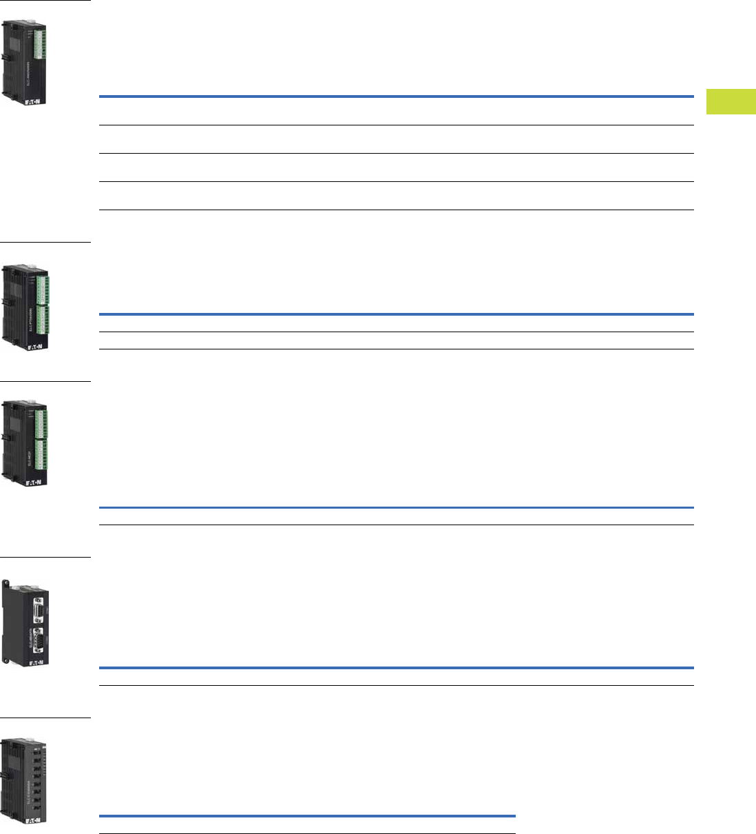
Volume 7—Logic Control, Operator Interface and Connectivity Solutions CA08100008E—February 2014 www.eaton.com V7-T4-13
4
4
4
4
4
4
4
4
4
4
4
4
4
4
4
4
4
4
4
4
4
4
4
4
4
4
4
4
4
4
4.1
PLC, I/O and Communications Products
ELC Series Programmable Logic Controllers
Analog Input and Output Modules (Right Side Bus)
Analog input/output modules uses voltage or current mode for any channel—see table
for resolution based on type and mode.
Temperature Input Modules (Right Side Bus)
Thermocouple and Platinum RTD temperature sensor input modules with 14 bit resolution.
Motion Control Module (Right Side Bus)
Single axis motion control module—up to 8 modules can be added to controllers.
If used with PH controller, it can provide a second axis since the PH controller has
a single axis built-in.
If used with the PV controller, it can provide a third axis since the PV incorporated
two axis of motion control and is capable of output pules up to 200 kHz
RS-485 Adapter Module (Right Side Bus—End Module)
Passive RS-485 connection device module.
RJ12 port for connecting to a drive.
2-pin screw terminal to connect to ELC controller.
Male and female DB9 connectors to connect to other RS-485 devices.
Toggle Switch Input Module (Right Side Bus)
8 input switch module for manual switch inputs to
the ELC controllers—used for debugging applications
or product training demonstrations
Description
Input
Points Resolution Mode
Output
Points Resolution Mode
Maximum
Current
Consumption
(at 24 Vdc)
Catalog
Number
4 Analog input module 4 V = 12 bit
I = 13 bit
±10V
±20 mA
—— — 90 mA ELC-AN04ANNN
2 Analog output module — — — 2 12 bit 0–20 mA; 4–20 mA
0–10V; 2–10V
125 mA ELC-AN02NANN
4 Analog output module — — — 2 12 bit 0–20 mA; 4–20 mA
0–10V; 2–10V
170 mA ELC-AN04NANN
6 Analog input/output
module
4 V = 12 bit
I = 11 bit
±10V
±20 mA
2 12 bit 0–20 mA
0–10V
170 mA ELC-AN06AANN
Description
Input
Points Resolution
Sensor
Type
Maximum Current
Consumption
(at 24 Vdc)
Catalog
Number
4 Thermocouple input module 4 — J, K, R, S, T 90 mA ELC-TC04ANNN
4 Platinum RTD input module 4 14 bit PT100 90 mA ELC-PT04ANNN
Description
Input
Type
Output
Type
Catalog
Number
Single axis motion control module Phase in, start, stop, and so on Phase, pulse, direction ELC-MC01
Description
Connector
Types
Catalog
Number
RS-485 Connect adapter module RJ12, DB9 (male and female), 2-pin screw terminals ELC-485APTR
Description
Maximum Current
Consumption
(at 24 Vdc)
Catalog
Number
8 Toggle switch input module 20 mA ELC-EX08NNSN
ELC-AN04ANNN
ELC-PT04ANNN
ELC-MC01
ELC-485APTR
ELC-EX08NNSN
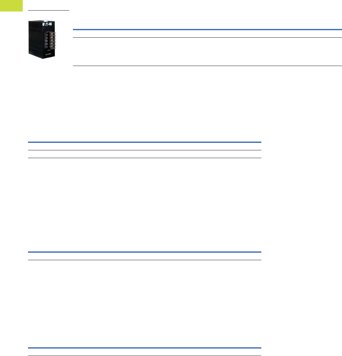
V7-T4-14 Volume 7—Logic Control, Operator Interface and Connectivity Solutions CA08100008E—February 2014 www.eaton.com
4
4
4
4
4
4
4
4
4
4
4
4
4
4
4
4
4
4
4
4
4
4
4
4
4
4
4
4
4
4
4.1
PLC, I/O and Communications Products
ELC Series Programmable Logic Controllers
Accessories
Power Supplies
All ELC controllers, analog
and specialty expansion
modules operate from
24 Vdc.
These power supplies
provide a convenient way to
provide robust DC voltage for
ELC and other products.
Power Supplies
Cables
Use these cables to connect
your PC’s RS-232 serial
port to your ELC controller
to download, upload and
monitor your ELC controllers,
or to connect any ELC-GP
to an ELC controller. The
ELC-CBPCELC1 cable is
1 meter long and has a
right angle connector to
the ELC controller to help
reduce depth when cable
is attached. The ELC-
CBPCELC3 is 3 meters long
with a straight connector.
Cables
Storage Devices
The ELC-ACPGMXFR module
is a multifunction device that
provides the ability to back up
an application already loaded
onto one of the ELC
controllers. The transfer
module can be used for
copying the same application
to multiple controllers and to
transfer an existing
application to a new controller
in the event of a failure. It will
store system settings,
passwords and the
application, including the data
registers for pre-loaded
recipes. Once stored in the
module, the application, data
registers and settings can be
transferred to another ELC
controller of the same model
number.
Storage Devices
Hand-Held Programmer
ELC-HHP is an easy-to-use,
hand-held programming and
monitoring tool for ELC
controllers when a PC is not
available. With ELC-HHP,
applications can be
programmed directly with the
attached keypad. Applications
can also be uploaded from an
ELC, saved and transferred to
a different ELC, or
downloaded from a PC and
transferred to other ELCs.
External power is not
required when using the
hand-held programmer
because it draws its power
from either the ELC or the PC
through the attached cable.
Hand-Held Programmer
Description Input Power
Output
Volts
Output
Current (A) Watts
Catalog
Number
24 watt, 1 amp power supply 100–240 Vac 50/60 Hz 24 Vdc 1A 24 ELC-PS01
48 watt, 2 amp power supply 100–240 Vac 50/60 Hz 24 Vdc 2A 48 ELC-PS02
ELC-PS01
Description
Catalog
Number
Cable to connect a PC or an ELC-GP unit to ELC, 3 meters (DB 9-pin female to 8-pin DIN) ELC-CBPCELC3
Cable to connect a PC or an ELC-GP unit to ELC, 1 meter with right angle connector (DB 9-pin female to 8-pin DIN) ELC-CBPCELC1
Description
Catalog
Number
Program transfer module for ELC controllers ELC-ACPGMXFR
Description
Catalog
Number
Hand-held programmer (Includes interface cables) ELC-HHP
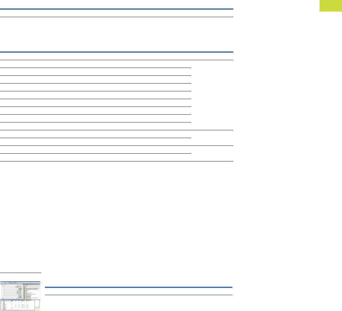
Volume 7—Logic Control, Operator Interface and Connectivity Solutions CA08100008E—February 2014 www.eaton.com V7-T4-15
4
4
4
4
4
4
4
4
4
4
4
4
4
4
4
4
4
4
4
4
4
4
4
4
4
4
4
4
4
4
4.1
PLC, I/O and Communications Products
ELC Series Programmable Logic Controllers
Plate Mount
Use the ELC-ACCOVER
surface mount stand-alone
modules instead of mounting
to a DIN rail. This may be
used to mount analog,
temperature or the RS-485
adapters remotely.
Plate Mount
Spare Parts
ELC Spare Parts
Programming Software
ELCSoft programming
software configures all ELC
controllers. With ELCSoft,
applications can be created,
edited and monitored. Move
programs from one controller
to another with ease.
Program in ladder, sequential
function chart or instruction
language. ELCSoft is the
single program to develop
ELC controller applications.
ELCSoft is also used to
configure the DeviceNet
master and Modbus TCP
Ethernet modules.
New program simulation
capabilities are available in
ELCSoft ver. 2.
Requirements
Operating Systems
●Windows® 2000
●Windows XP
●Windows Vista
●Windows 7
Hard Drive
●At least 100M bytes
RAM
●At least 512M bytes
ELC Software
Description Catalog Number
Plate mount for specialty modules, qty. 10 ELC-ACCOVER
Description Quantity Catalog Number
Kit consists of: ELC-SPKIT
Module to module locking clips (white) 4
Module DIN rail clip (white) 2
3-pin power plug and cable assembly (white) 4
2-pin RS-485 communications connector (green—for latest version PA, PB, PC and PH) 4
3-pin RS-485 communications connector (green—PV controllers only) 2
Left side expansion port cover (PV controllers and left side communications modules) 2
Right side I/O expansion port cover (all controllers and I/O modules) 2
Battery cover door (for PA, PC and PH controllers) 2
Metal mounting clips (only for PV controllers) 2
Kit consists of: ELC-IOBLOCK
9-pin replacement I/O blocks (green) 4
Kit consists of: ELC-BAT
Battery with pigtail and connector (for PA, PC and PH controllers only) 2
Description Catalog Number
Programming Software for ELC Controllers ELCSOFT
ELCSoft Editor

V7-T4-16 Volume 7—Logic Control, Operator Interface and Connectivity Solutions CA08100008E—February 2014 www.eaton.com
4
4
4
4
4
4
4
4
4
4
4
4
4
4
4
4
4
4
4
4
4
4
4
4
4
4
4
4
4
4
4.1
PLC, I/O and Communications Products
ELC Series Programmable Logic Controllers
Technical Data and Specifications
Controllers
Description ELC-PB14NNDR/DT ELC-PC12NNAR/DR/DT ELC-PH12NNDT ELC-PA10AADR/DT ELC-PV28NNDR/DT
Dimensions W x H x D (mm) 25.2 x 90 x 60 37.4 x 90 x 60 37.4 x 90 x 60 37.4 x 90 x 60 70 x 90 x 60
I/O type—embedded 14 (8DI/6DO) 12 (8DI/4DO) 12 (8DI/4DO) 10 (4DI/2DO/2AI/2AO) 28 (16DI/12DO)
Maximum additional I/O points Up to 14 expansion modules
(maximum of 8 analog/
specialty modules)
Up to 14 expansion modules
(maximum of 8 analog/
specialty modules)
Up to 14 expansion modules
(maximum of 8 analog/
specialty modules)
Up to 14 expansion modules
(maximum of 8 analog/
specialty modules)
Up to 14 expansion modules
(maximum of 8 analog/
specialty modules)
DC in sink/source Yes Yes Yes Yes Yes
Execution speed Basic Instructions—
2 µs minimum
Basic Instructions—
2 µs minimum
Basic Instructions—
2 µs minimum
Basic Instructions—
2 µs minimum
0.24 µs minimum
Program language Instructions + Ladder Logic + Sequential Function Chart
Program capacity (steps) 3792 7920 7920 7920 15,872
Data memory capacity (bits) 1280 4096 4096 4096 4096
Data memory capacity (words) 744 5000 5000 5000 10,000
Index registers 288816
File memory capacity (words) None 1600 words 1600 words 1600 words 10,000 words
Retentive storage Yes Yes Yes Yes Yes
Commands basic/advanced 32/107 32/168 32/168 32/168 32/193
Floating point Yes Yes Yes Yes Yes
SFC commands (steps) 128 1024 1024 1024 1024
Timers qty. 128 244 Standard with additional timers for subroutine and retentive applications
Timers resolution 1–100 ms 1–100 ms 1–100 ms 1–100 ms 1–100 ms
Counters qty. 128 250 250 250 253
High-speed counters (see note) Up to 4 Up to 6 Up to 8 Up to 6 Up to 8
Max. high-speed counting (see note) 2 at 20 kHz 1 at 30 kHz 1 at 100 kHz 1 at 30 kHz 2 at 200 kHz
Pulse output 2 channels, 10 kHz max. 2 channels, 50 kHz max. 100 kHz 2 channels, 50 kHz max. 200 kHz
PID Yes Yes Yes Yes Yes
Master control loop 8 loops 8 loops 8 loops 8 loops 8 loops
Subroutines 64 subroutines 256 subroutines 256 subroutines 256 subroutines 256 subroutines
For/next loops Yes Yes Yes Yes Yes
Interrupts 6 15 15 15 22
Real-time clock/calendar No Built-in Built-in Built-in Built-in
Password security Yes Yes Yes Yes Yes
Diagnostic relays Yes Yes Yes Yes Yes
Diagnostic word registers Yes Yes Yes Yes Yes
Specialty expansion modules Up to a maximum of 8 (Analog In/Analog Out/TC/RTD/PT) Modules
Serial ports 2 Modbus (ASCII/RTU) 1 = Slave (RS-232)/11 = Master-Slave (RS-485)
Remote I/O No With 16 other devices With 16 other devices With 16 other devices With 32 other devices
Runtime editing No Yes Yes Yes Yes
Run/stop switch Yes Yes Yes Yes Yes
Removable terminal strips Yes Yes Yes Yes Yes
Special features — 2 potentiometers 2 potentiometers 2, 7-segment displays 2 potentiometers high-
speed, left side bus

Volume 7—Logic Control, Operator Interface and Connectivity Solutions CA08100008E—February 2014 www.eaton.com V7-T4-17
4
4
4
4
4
4
4
4
4
4
4
4
4
4
4
4
4
4
4
4
4
4
4
4
4
4
4
4
4
4
4.1
PLC, I/O and Communications Products
ELC Series Programmable Logic Controllers
Distributed I/O Adapter Modules
ELC-CANET, refer to Volume 9—OEM, CA08100011E, Tab 3, section 3.2.
Environmental Ratings
DC Input Point Electrical Specifications
Output Point Electrical Specifications
Description Specification
Transportation and Storage
Temperature –13° to +158°F (–25° to +70°C)
Humidity 5–95%
Operating
Temperature 32° to 131°F (0° to 55°C)
Humidity 50–95%
Power supply voltage ELC: 24 Vdc (–15%–20%) (with DC input reverse polarity protection), expansion unit: supplied by the ELC
Power consumption 3–6W
Insulation resistance >5M ohms at 500 Vdc (between all inputs/outputs and earth)
Grounding The diameter of grounding wire cannot be smaller than the wire diameter of terminals L and N (All ELC units should be grounded directly to the ground pole)
Vibration / shock resistance IEC1131-2, IEC 68-2-6 (TEST Fc)/IEC1131-2 and IEC 68-2-27 (TEST Ea)
Description Specification
Input type DC (SINK or SOURCE)
Input current 24 Vdc 5 mA
Active level OFF ➔ ON, above 16 Vdc
ON ➔ OFF, below 14.4 Vdc
Response time About 10 ms (an adjustment range of 0–10,000 ms could be selected through D1020 and D1021)
Output Type Relay–R Transistor–T
Current specification 1.5A/1 point (5A/COM) 0.3A/1 point @ 40°C; When the output of Y0 and Y1 is high-speed pulse, Y0 and Y1 = 30 mA
Voltage specification Below 250 Vac, 30 Vdc 30 Vdc
Maximum loading 75 VA (inductive) 9W/1 point When the output of Y0 and Y1 is high-speed pulse, Y0 and Y1 = 0.9W
(Y0 = 32 kHz, Y1 = 10 kHz), Y0 can be 50 kHz using D registers
90W (resistive)
Response time Adjustable 0–15 ms,
default is 10 ms
OFF ➔ ON 20 µs. Y0 and Y1 are specified points for high-speed pulse
ON ➔ OFF 30 µs. Y0 and Y1 are specified points for high-speed pulse
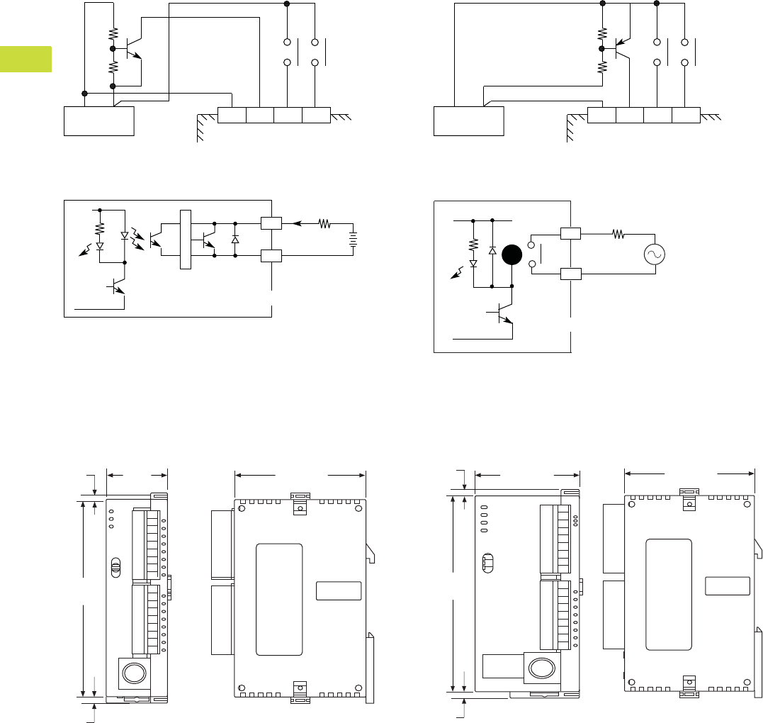
V7-T4-18 Volume 7—Logic Control, Operator Interface and Connectivity Solutions CA08100008E—February 2014 www.eaton.com
4
4
4
4
4
4
4
4
4
4
4
4
4
4
4
4
4
4
4
4
4
4
4
4
4
4
4
4
4
4
4.1
PLC, I/O and Communications Products
ELC Series Programmable Logic Controllers
Circuit Diagrams
DC Input Sink Mode
DC Transistor Sinking Output
DC Input Source Mode
Relay Outputs
Dimensions
Approximate Dimensions in Inches (mm)
ELC-PB14 Controllers ELC-PC12, ELC-PH12 and ELC-PA10 Controllers
Sink Mode
S/S X0 X1 X2
+24V 0V
DC Power Supply
Y0
LED
C0
<0.5A
Transistor Output
Load
Trigger Circuit
Source Mode
S/S X0 X1 X2
+24V 0V
DC Power Supply
Y0
LED
C0
Load
Power
Relay Output
RY
EXTENSION
PORT
2.36 (60.0)
3.54
(90.0)
0.12
(3.0)
0.12
(3.0)
0.99
(25.2)
POWER
RUN
RUN
STOP
ERROR
BAT.LOW
EXTENSION
PORT
3.54
(90.0)
0.12
(3.0)
1.47 (37.4) 2.36 (60.0)
0.12
(3.0)
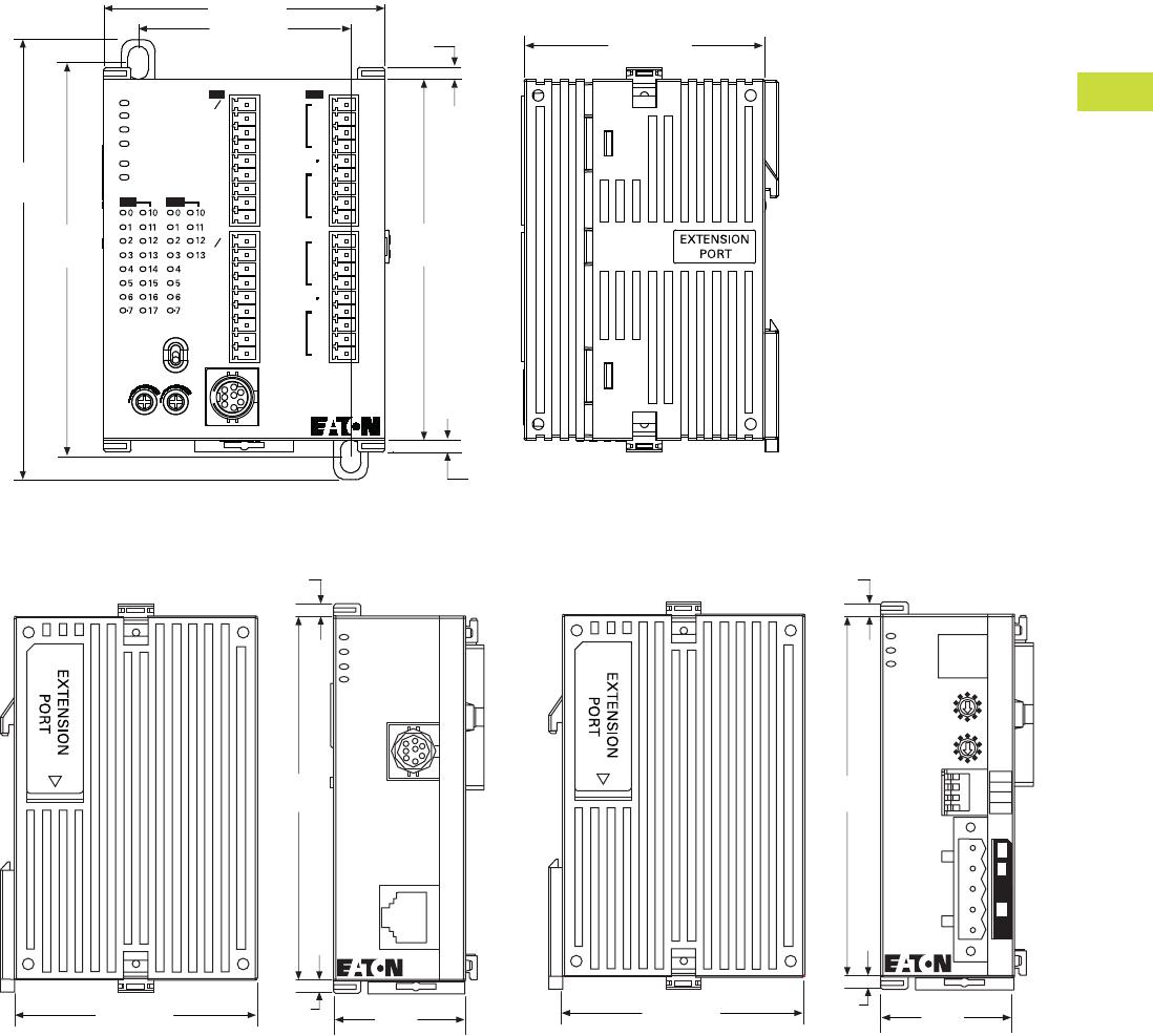
Volume 7—Logic Control, Operator Interface and Connectivity Solutions CA08100008E—February 2014 www.eaton.com V7-T4-19
4
4
4
4
4
4
4
4
4
4
4
4
4
4
4
4
4
4
4
4
4
4
4
4
4
4
4
4
4
4
4.1
PLC, I/O and Communications Products
ELC Series Programmable Logic Controllers
Approximate Dimensions in Inches (mm)
ELC-PV Controller
ELC-COENETM ELC-CODNETM
POWER
RUN
ERROR
BAT. LOW
RS-232
RS-495
IN
OUT
IN
OUT
SS
X0
X1
X2
X3
X4
X5
X6
X7
SS
X10
X11
X12
X13
X14
X15
X16
X17
Y11
Y12
Y13
C3
Y0
Y1
Y2
C0
C1
Y3
Y4
Y5
C2
Y6
Y7
Y10
RUN
STOP
01
0.12
(3.0)
3.54
(90.0)
2.75 (70.0)
3.98
(101.0)
4.31
(109.4)
ELC-PV28NNDR
2.09 (53.2)
2.36 (60.0)
0.12
(3.0)
2.36 (59.9)
3.54
(89.9)
0.12
(3.0) 1.29
(32.8)
ELC-COENETM
POWER
RS-232
100M
LAN
RS-232
LINK
0.12
(3.0)
2.36 (59.9)
3.54
(89.9)
0.12
(3.0) 1.29
(32.8)
ELC-CODNETM
POWER
MS
NS
Node Address
x10
x10
0
1
2
3
4
5
6
7
8
9
0
1
2
3
4
5
6
7
8
9
DP On
1234
DR 1
DR 0
IN 1
IN 0
0.12
(3.0)
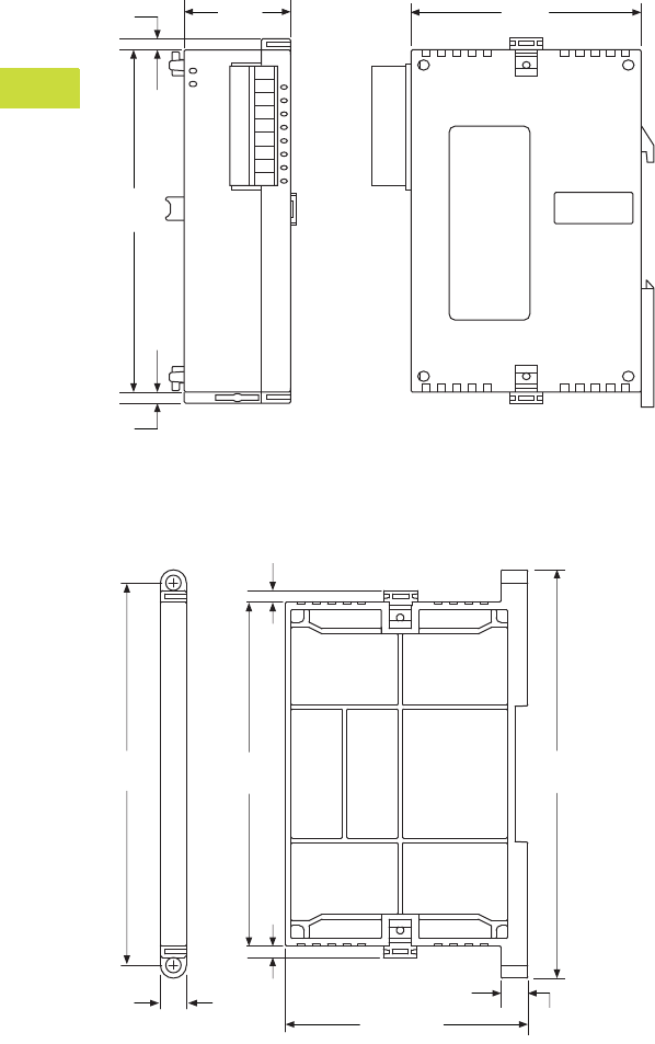
V7-T4-20 Volume 7—Logic Control, Operator Interface and Connectivity Solutions CA08100008E—February 2014 www.eaton.com
4
4
4
4
4
4
4
4
4
4
4
4
4
4
4
4
4
4
4
4
4
4
4
4
4
4
4
4
4
4
4.1
PLC, I/O and Communications Products
ELC Series Programmable Logic Controllers
Approximate Dimensions in Inches (mm)
Right Side Specialty and Expansion Modules
ELC-ACCOVER Plate Mount for Specialty Modules
EXTENSION
PORT
3.54
(90.0)
0.12
(3.0)
0.12
(3.0)
0.99
(25.2)
2.36
(60.0)
2.51 (63.4)
3.94
(100.0)
3.54
(89.9)
0.27
(6.8)
0.12
(3.0) 0.28
(7.1)
4.20
(106.5)
0.12
(3.0)
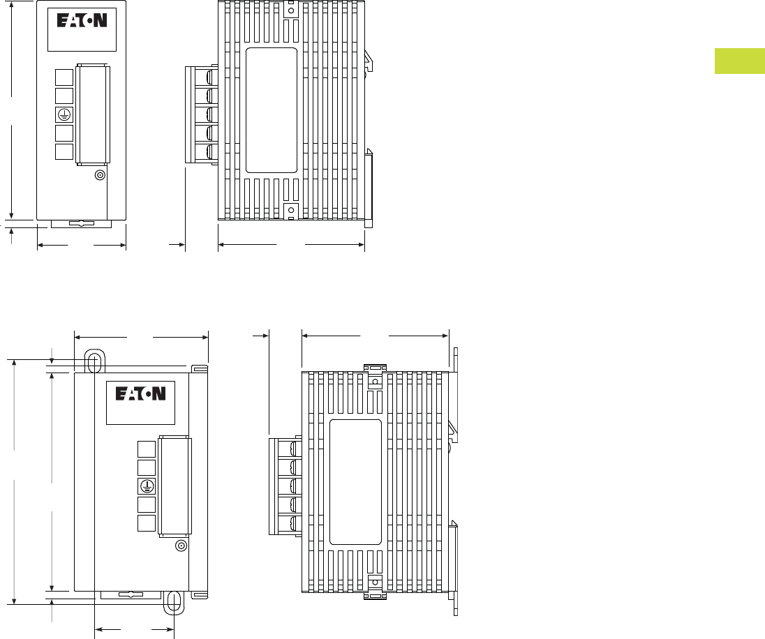
Volume 7—Logic Control, Operator Interface and Connectivity Solutions CA08100008E—February 2014 www.eaton.com V7-T4-21
4
4
4
4
4
4
4
4
4
4
4
4
4
4
4
4
4
4
4
4
4
4
4
4
4
4
4
4
4
4
4.1
PLC, I/O and Communications Products
ELC Series Programmable Logic Controllers
Approximate Dimensions in Inches (mm)
ELC-PS01
ELC-PS02
ELC-PS01
POWER
L
N
24V
0V
1.44
(36.5)
3.54
(90.0)
0.12
(3.0)
2.36
(60.0)
13.30
(0.5)
ELC-PS02
POWER
L
N
24V
0V
3.94
(100.0)
0.12
(3.0)
1.28
(32.5)
3.54
(90.0)
2.17
(55.0)
0.12
(3.0)
2.36
(60.0)
13.30
(0.5)
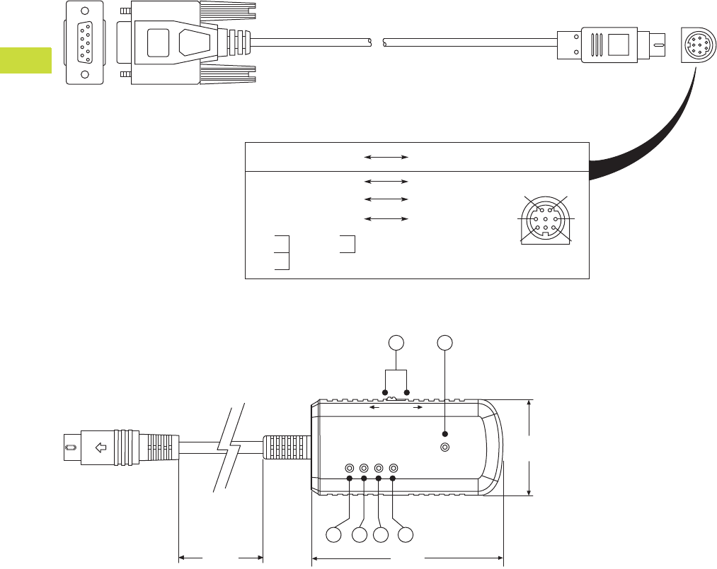
V7-T4-22 Volume 7—Logic Control, Operator Interface and Connectivity Solutions CA08100008E—February 2014 www.eaton.com
4
4
4
4
4
4
4
4
4
4
4
4
4
4
4
4
4
4
4
4
4
4
4
4
4
4
4
4
4
4
4.1
PLC, I/O and Communications Products
ELC Series Programmable Logic Controllers
Approximate Dimensions in Inches (mm)
ELC-CBPCELC1 Cable (Right Angle Connector not Shown) and ELC-CBPCELC3 Cable (Straight Connector as Shown)
ELC-ACPGMXFER Storage Device
PC/HMI COM Port
9 PIN D-SUB Female PLC COM1 Port
8 PIN MINI DIN
12
3
4
5
6
7
8
Rx 2 5 Tx
Tx 3 4 Rx
GND 5 8 GND
1,2 5V
1
4
6
7
8
POWER
COM
OK
ERR
ERASE
ELC-ACPGMXFR
WR RD
1.29
(32.8)
2.61
(66.3)
1234
11.81
(292.4)
56
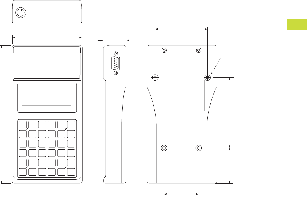
Volume 7—Logic Control, Operator Interface and Connectivity Solutions CA08100008E—February 2014 www.eaton.com V7-T4-23
4
4
4
4
4
4
4
4
4
4
4
4
4
4
4
4
4
4
4
4
4
4
4
4
4
4
4
4
4
4
4.1
PLC, I/O and Communications Products
ELC Series Programmable Logic Controllers
Approximate Dimensions in Inches (mm)
ELC-HHP Hand-Held Programmer
7.09
(180.0)
3.60
(91.5)
M3 p0.5
4 Places
1.81
(46.0)
3.54
(90.0) 1.14
(29.0)
2.64
(67.0)
1.73
(44.0)
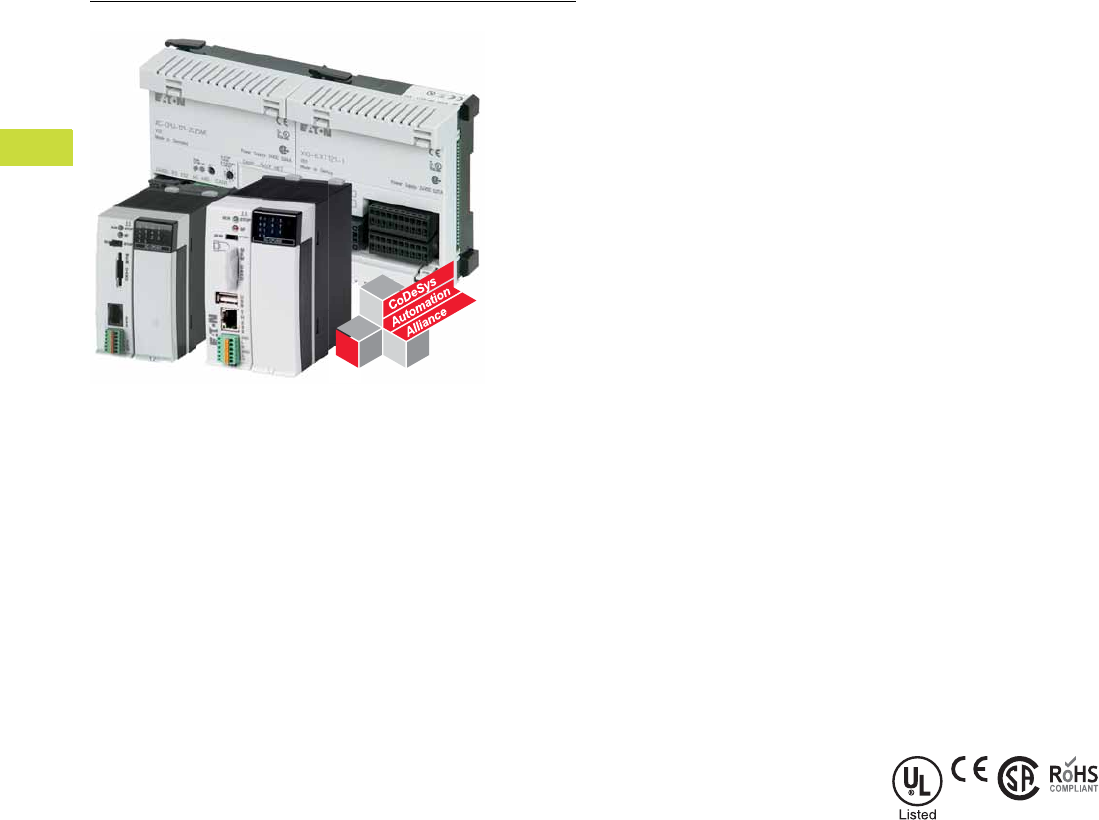
V7-T4-24 Volume 7—Logic Control, Operator Interface and Connectivity Solutions CA08100008E—February 2014 www.eaton.com
4
4
4
4
4
4
4
4
4
4
4
4
4
4
4
4
4
4
4
4
4
4
4
4
4
4
4
4
4
4
4.2
PLC, I/O and Communications Products
XC Series Programmable Logic Controllers
XC Series Programmable Logic Controllers
Contents
Description Page
XC Series Programmable Logic Controllers
Product Selection Guide . . . . . . . . . . . . . . . . . V7-T4-25
Catalog Number Selection . . . . . . . . . . . . . . . . V7-T4-26
System Overview . . . . . . . . . . . . . . . . . . . . . . . V7-T4-26
Product Selection . . . . . . . . . . . . . . . . . . . . . . . V7-T4-28
Accessories . . . . . . . . . . . . . . . . . . . . . . . . . . . V7-T4-31
Technical Data and Specifications . . . . . . . . . . V7-T4-34
Dimensions . . . . . . . . . . . . . . . . . . . . . . . . . . . V7-T4-50
Product Overview
The XC100 and XC200 series
modular PLCs stand out on
account of their highly
scalable design. Different
CPU performance classes
and a wide range of
expansion modules are
available. An important
feature is their ability to be
integrated in modern
communication systems.
Innovative solutions can be
created thanks to the
possibility of exchanging data
with OPC clients via the
Ethernet interface and the
integrated web server.
Features and Benefits
Flexible Range
●Compact and modular CPU
versions to suit the needs
of the application
●With or without on-board
Ethernet and/or built-in
web server
●
Range of CPU performance
●Integrated CANopen
interface for easy
integration with XI/ON
remote I/O
High Performance
●Parallel backplane bus for
faster processing speed
●Fiber optic CANopen
interface for environments
with severe electromagnetic
interference
●High performance XC202
CPU with
●10/100 Mbit Ethernet
●XSoft-CoDeSys
programming software
Standards and
Certifications
●IEC—UL508; CSA C22.2
No. 0-
M;
CSA C22.2
No. 142-M; CE marking
●UL File No.—E135462
●UL CCN—NRAQ
●CSA File No. 012528
●CSA Class No. 2252-01
●NA Certification—
●UL Listed
●CSA certified/cUL
●RoHS
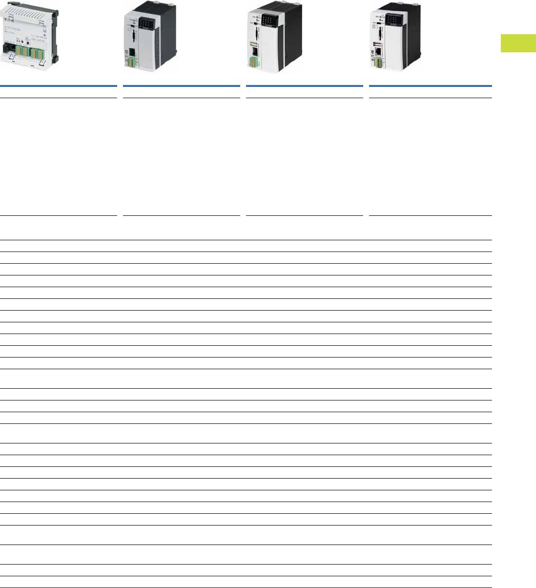
Volume 7—Logic Control, Operator Interface and Connectivity Solutions CA08100008E—February 2014 www.eaton.com V7-T4-25
4
4
4
4
4
4
4
4
4
4
4
4
4
4
4
4
4
4
4
4
4
4
4
4
4
4
4
4
4
4
4.2
PLC, I/O and Communications Products
XC Series Programmable Logic Controllers
Product Selection Guide
XC Series Programmable Logic Controllers
XC121 Compact PLC XC101 Modular PLCs XC201 Modular PLCs XC202 Modular PLCs
Page V7-T4-28 Page V7-T4-28 Page V7-T4-29 Page V7-T4-29
This PLC is particularly suitable for
applications where space is at premium and
with high communication requirements.
●Two serial and two CAN interfaces enable:
– the coupling of two CAN networks
– Modbus master/slave coupling
(RS-232 or RS-485)—CAN
– RS-232—CAN coupling
●I/O expansion with 18 digital and 8 analog
inputs/outputs
●6 interrupt inputs
●Expandable with standard XIOC modules
The modular PLCs of the XC101 series are
universal automation devices for small and
medium-sized applications.
●Locally expandable with up to 15
XIOC modules
●Data storage on SD card
●CAN interface
The modular PLCs of the XC201 series offer a
high CPU performance, a high speed and a
wide range of communication options.
●Locally expandable with up to 15
XIOC modules
●Ethernet interface for communication
and programming
●CAN interface
●Data storage on SD card or USB stick
●Web server enables visualization via
CoDeSys
●Operating system update SD card or USB
The modular PLCs of the XC202 series offer
higher CPU performance and memory than the
XC201 PLCs.
●Locally expandable with up to 15
XIOC modules
●Ethernet interface for communication
and programming
●CAN interface
●Data storage on SD card or USB stick
●Operating system update via Ethernet,
SD card or USB
●Up to three IP addresses can be configured
●29-bit CAN identifier
Features XC121 XC101 XC201 XC202
Input voltage 24 Vdc 24 Vdc 24 Vdc 24 Vdc
Memory size 256 kB 64, 128 or 256 kB 256 kB or 2 MB 4 MB
Microprocessor Infineon CC161 Infineon C164 MIPS RISC ARM11
Processor speed 36 MHz 24 MHz 131 MHz 532 MHz
Cycle time per 1k instructions <0.3 ms <0.5 ms <0.15 ms <0.025 ms
SD card slot Yes Yes Yes Yes
USB interface No No Yes Yes
Real time clock Yes Yes Yes Yes
On-board digital inputs — 8 8 8
On-board digital outputs — 6 6 6
Interrupt inputs 6422
Expandability XIO-EXT base module +
Up to 15 XIOC modules
Up to 15 XIOC modules Up to 15 XIOC modules Up to 15 XIOC modules
Removable terminal blocks Yes Yes Yes Yes
Screw terminal option No Yes Yes Yes
Spring-cage terminal option Yes Yes Yes Yes
Serial interface 1, RS-232
1, RS-232/RS-485
1, RS-232 1, RS-232 1, RS-232
Ethernet port No No Yes Yes
CANopen interface2111
On-board high speed counters No No Yes Yes
On-board encoder inputs No No Yes Yes
OPC server Yes Yes Yes Yes
Integrated web server No No On suffix “-XV” models Yes
FTP server No No On suffix “-XV” models Yes
Networks master CANopen/easyNet CANopen/PROFIBUS-DP/easyNet Ethernet/CANopen/PROFIBUS-DP/
easyNet
Ethernet/CANopen/PROFIBUS-DP/
easyNet
Networks node/device CANopen/PROFIBUS-DP®/
easyNet
CANopen/PROFIBUS-DP/
easyNet
Ethernet/CANopen/PROFIBUS-DP/
easyNet
Ethernet/CANopen/PROFIBUS-DP/
easyNet
Operating system Proprietary Proprietary Windows CE Windows CE
X-Soft-CoDeSys version V2.3 V2.3 V2.3 V2.3 and 3.0
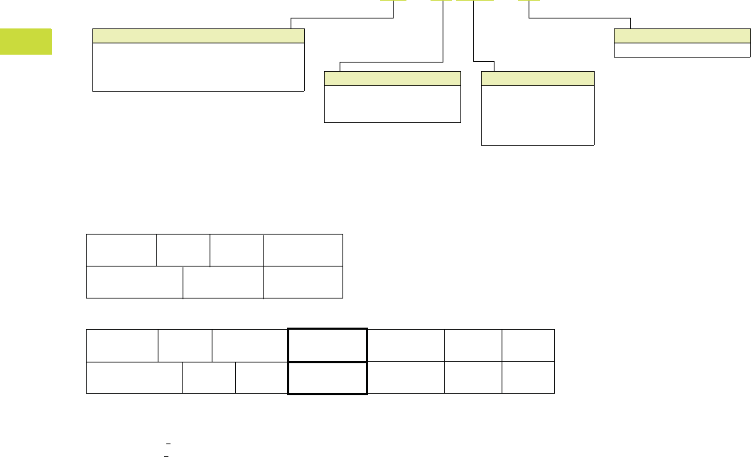
V7-T4-26 Volume 7—Logic Control, Operator Interface and Connectivity Solutions CA08100008E—February 2014 www.eaton.com
4
4
4
4
4
4
4
4
4
4
4
4
4
4
4
4
4
4
4
4
4
4
4
4
4
4
4
4
4
4
4.2
PLC, I/O and Communications Products
XC Series Programmable Logic Controllers
Catalog Number Selection
Controllers
System Overview
System Configuration
Notes
1Maximum basic version, <7 signal modules.
2Maximum total version, <15 signal modules.
Model Number
101 = Modular (Infineon C164—16 bit at 24 MHz)
121 = Compact (Infineon XC161—16 bit at 36 MHz)
201 = Modular (MIPS RISC—32 bit at 131 MHz)
202 = Modular (ARM 11—32 bit at 532 MHz)
XC - CPU 201 - EC 512K - XV
User Memory
64K = 64 kB
128K = 128 kB
256K = 256 kB
512K =2 MB
4M =4 MB
Communication Ports
C = 1 CANopen
2C = 2 CANopen
EC = Ethernet and CANopen
Visualization Option
XV = Web server
CPU 2 4 713 65
CPU 2 4 713 6511109812131415
XIOC-BP-XC XIOC-BP-2 XIOC-BP-2 XIOC-BP-3
XIOC-BP-3XIOC-BP-3XIOC-BP-XC1
XIOC-BP-XC XIOC-BP-2
XIOC-BP-2 XIOC-BP-2
XIOC-BP-3 XIOC-BP-3
XIOC-BP-3
XIOC-BP-2
XIOC-BP-2
XIOC-BP-2
XIOC-BP-2XIOC-BP-XC1
XIOC-BP-EXT
XIOC-BP-EXT
1
2
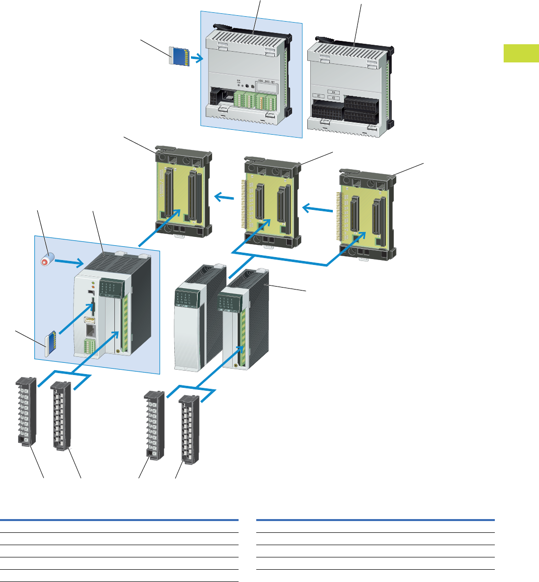
Volume 7—Logic Control, Operator Interface and Connectivity Solutions CA08100008E—February 2014 www.eaton.com V7-T4-27
4
4
4
4
4
4
4
4
4
4
4
4
4
4
4
4
4
4
4
4
4
4
4
4
4
4
4
4
4
4
4.2
PLC, I/O and Communications Products
XC Series Programmable Logic Controllers
Product Identification
Item
Number Description
Item
Number Description
1XC121 Compact PLC CPU 6Battery
2XC121 I.O Expansion module 7SD Memory card
3XC100/XC200 Modular PLC 8XIOC Terminal block, screw terminals
4XIOC I/O modules 9XIOC Terminal block, spring-cage terminals
5XIOC Module backplane
7
12
5
5
5
36
4
7
89 89
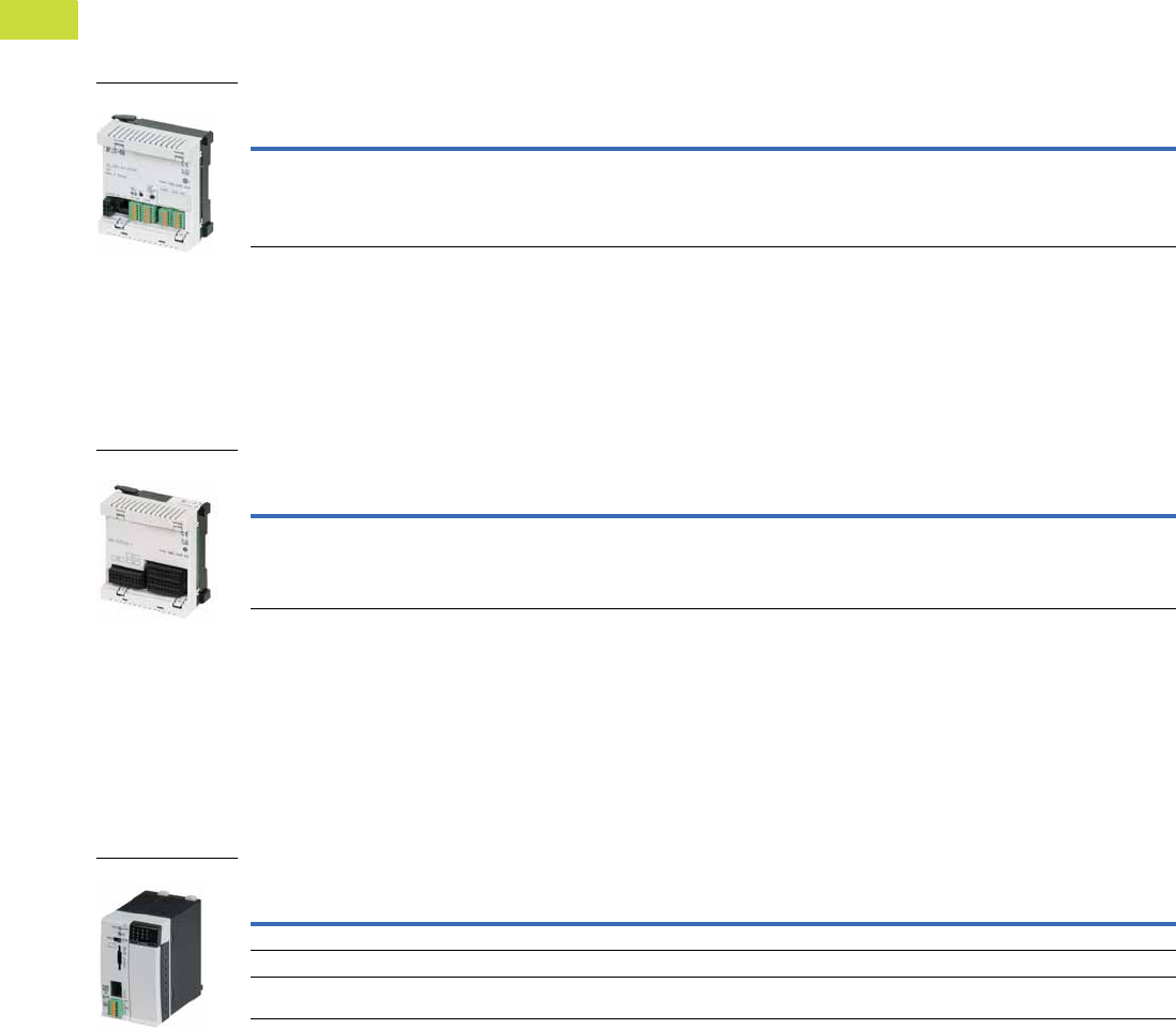
V7-T4-28 Volume 7—Logic Control, Operator Interface and Connectivity Solutions CA08100008E—February 2014 www.eaton.com
4
4
4
4
4
4
4
4
4
4
4
4
4
4
4
4
4
4
4
4
4
4
4
4
4
4
4
4
4
4
4.2
PLC, I/O and Communications Products
XC Series Programmable Logic Controllers
Product Selection
XC121 Compact PLC CPU
Can be locally expanded with I/O module XIO-EXT-121-1.
●24 Vdc input supply
●Real time clock
●2 CANopen interfaces
(500 kB)
●RS-232 interface for
programming and
communication
●Second RS-232/RS-485
interface
●Slot for SD memory card
●Spring-cage terminal
blocks
●OPC server
●RUN/STOP switch
XC121 Compact PLC
XC121 I/O Expansion Module
Base I/O module for the XC121.
●10 digital inputs 24 Vdc
●6 interrupt inputs
●8 digital inputs/outputs
24 Vdc 0.5A
●2 analog inputs 0–10V
●2 analog inputs 0–20 mA
●2 analog inputs PT100 RTD
●2 analog outputs 0–10V
●Removable spring-cage
terminals
●Expandable with 15 XIOC
modules 2
XC121 I/O Expansion Module
XC101 Modular PLCs
Order backplane, terminals and battery separately.
●24 Vdc input supply
●Real time clock
●Expandable with 15 XIOC
modules
●8 digital inputs
●4 interrupt inputs
●6 digital outputs
●RS-232 interface for
programming and
communication
●CANopen interface
(500 kB)
●Slot for SD memory card
●RUN/STOP switch and
LED indicators
XC101 Modular PLCs
Notes
1Cycle time per 1k of instructions.
2Except the XIOC-NET-DP-M module.
Program
Memory Size
Cycle
Time 1Ethernet CAN
Serial
Interface
Web
Server
Pkg.
Qty.
Style
Number
Catalog
Number
256 kB <0.3 ms — 2 1, RS-232
1, RS-232/RS-485
— 1 290446 XC-CPU121-2C256K
XC121
Digital
Inputs
Digital
Inputs/Outputs
Analog
Inputs
Analog
Outputs
Pkg.
Qty.
Style
Number
Catalog
Number
10, 24 Vdc 8, 24 Vdc 0.5A 2, 0–10V
2, 0–20 mA
2, PT100 RTD
2, 0–10V 1 290450 XIO-EXT121-1
XC121 I/O Module
Program
Memory Size
Cycle
Time 1Ethernet CANOpen
Serial
Interface
Web
Server
Pkg.
Qty.
Style
Number
Catalog
Number
64 kB <0.5 ms — 1 1, RS-232 typ. — 1 262152 XC-CPU101-C64K
128 kB <0.5 ms — 1 1, RS-232 typ. — 1 262146 XC-CPU101-C128K
256 kB <0.5 ms — 1 1, RS-232 typ. — 1 274399 XC-CPU101-C256K
XC101
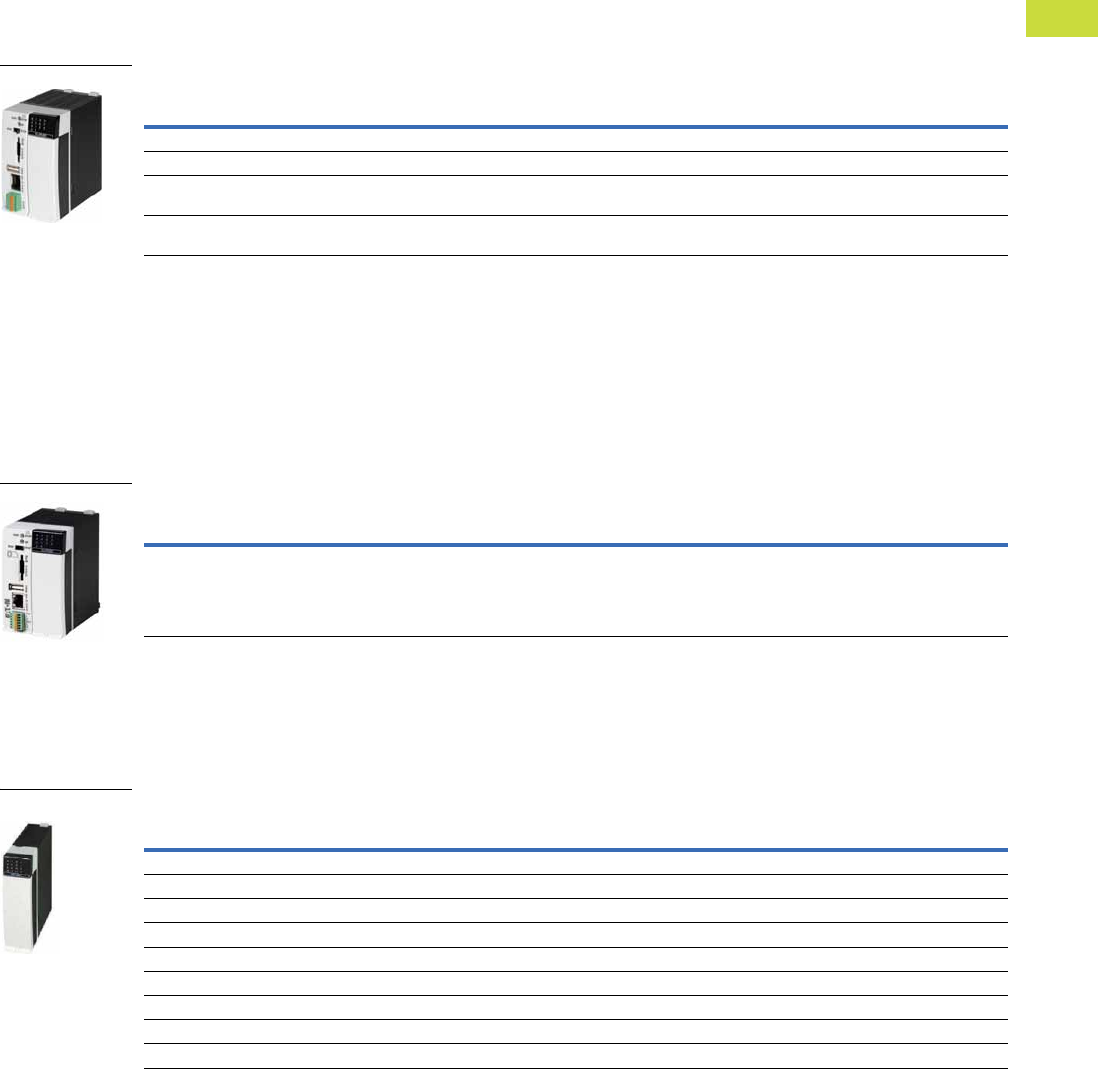
Volume 7—Logic Control, Operator Interface and Connectivity Solutions CA08100008E—February 2014 www.eaton.com V7-T4-29
4
4
4
4
4
4
4
4
4
4
4
4
4
4
4
4
4
4
4
4
4
4
4
4
4
4
4
4
4
4
4.2
PLC, I/O and Communications Products
XC Series Programmable Logic Controllers
XC201 Modular PLCs
Order backplane, terminals and battery accessories separately.
●24 Vdc input supply
●Real time clock
●Expandable with 15 XIOC
modules
●8 digital inputs
●2 interrupt inputs
●Incremental encoder
inputs
●High speed counter
(50 kHz) inputs
●6 digital outputs
●Ethernet and RS-232
interface for programming
and communication
●CANopen interface (1 MB)
●
Slot for SD memory card
●USB interface
●RUN/STOP switch and LED
indicators
●Built-in Web server on
XV models
XC201 Modular PLCs
XC202 Modular PLCs
Order backplane, terminals and battery accessories separately.
●24 Vdc input supply
●Real time clock
●Expandable with 15 XIOC
modules
●8 digital inputs
●2 interrupt inputs
●Incremental encoder
inputs
●High speed counter
(50 kHz) inputs
●6 digital outputs
●Ethernet and RS-232
interface for programming
and communication
●CANopen interface (1 MB)
●
Slot for SD memory card
●USB interface
●RUN/STOP switch and LED
indicators
●Built-in Web server
XC202 Modular PLCs
XIOC Expansion Modules
Order screw, spring-cage terminals or 40-pin connector cable for 32 I/O modules separately.
●8, 16 and 32 input modules
●8, 16 and 32 output
modules
●User configurable input/
output module
●Isolated relay output
module
XIOC Digital Expansion Modules
Note
1Cycle time per 1k of instructions.
Program
Memory Size
Cycle
Time 1Ethernet CANOpen
Serial
Interface
Web
Server
Pkg.
Qty.
Style
Number
Catalog
Number
256 kB <0.15 ms ✓1 1, RS-232 — 1 262155 XC-CPU201-EC256K
2 MB <0.15 ms ✓1 1, RS-232 — 1 262157 XC-CPU201-EC512K
256 kB
Integrated web server
<0.15 ms ✓11, RS-232✓1 262156 XC-CPU201-EC256K-XV
2 MB
Integrated web server
<0.15 ms ✓11, RS-232✓1 262158 XC-CPU201-EC512K-XV
XC201
Program
Memory Size
Cycle
Time 1Ethernet CANOpen
Serial
Interface
Web
Server
Pkg.
Qty.
Style
Number
Catalog
Number
4 MB
Integrated web server
<0.025 ms ✓11, RS-232✓1 134238 XC-CPU202-EC4M-XV
XC202
Description
Pkg.
Qty.
Style
Number
Catalog
Number
8 inputs, 24 Vdc 1 257891 XIOC-8DI
16 inputs, 24 Vdc 1 257892 XIOC-16DI
32 inputs, 24 Vdc 1 267411 XIOC-32DI
8 outputs, 24 Vdc, 0.3A 1 257894 XIOC-8DO
16 outputs, 24 Vdc, 0.3A 1 257896 XIOC-16DO
16 outputs, 24 Vdc, 0.8A, short-circuit protected 1 257895 XIOC-16DO-S
16 terminals, 4 inputs, 12 configurable as inputs/outputs, 24 Vdc—outputs 0.5A 1 262322 XIOC-16DX
32 outputs, 24 Vdc, 0.2A 1 267413 XIOC-32DO
12 relay outputs, isolated 1 257897 XIOC-12DO-R
XIOC—Digital
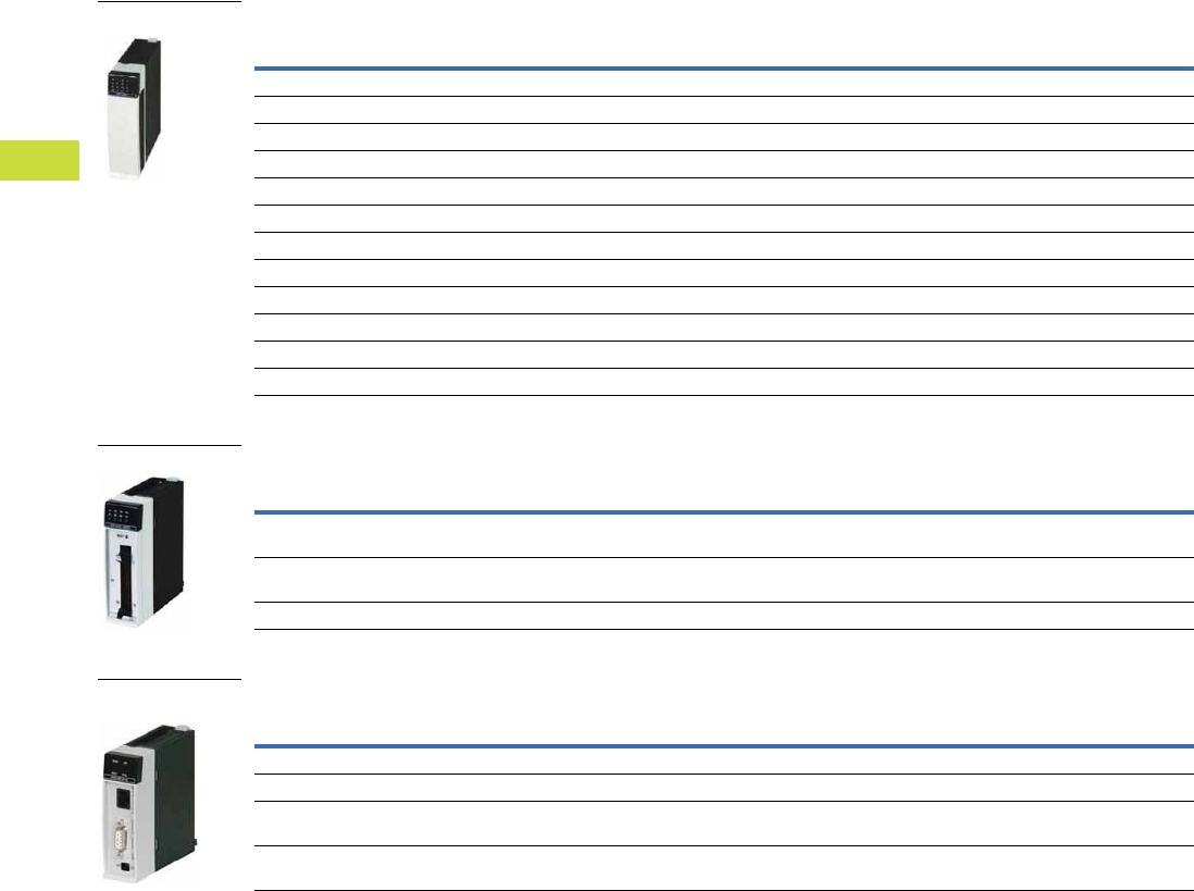
V7-T4-30 Volume 7—Logic Control, Operator Interface and Connectivity Solutions CA08100008E—February 2014 www.eaton.com
4
4
4
4
4
4
4
4
4
4
4
4
4
4
4
4
4
4
4
4
4
4
4
4
4
4
4
4
4
4
4.2
PLC, I/O and Communications Products
XC Series Programmable Logic Controllers
XIOC Analog Modules
Counter Modules
Communication Modules
Description
Pkg.
Qty.
Style
Number
Catalog
Number
Inputs: 8 inputs 4–20 mA 1 262549 XIOC-8AI-I2
Inputs: 8 voltage inputs 0–10V 1 257899 XIOC-8AI-U1
Inputs: 8 voltage inputs, ±10V 1 257900 XIOC-8AI-U2
Inputs: 4 inputs for temperature monitoring, PT100/1000 1 257901 XIOC-4T-PT
Inputs: 4 inputs for thermocouples Type K, J, L, B, N, E, R, S, T 1 289933 XIOC-4AI-T
Outputs: 2 outputs, ±10V 1 257904 XIOC-2AO-U2
Outputs: 2 outputs 0–10V, 2 outputs 4–20 mA 1 257902 XIOC-2AO-U1-2AO-I2
Outputs: 4 outputs 0–10 V 1 257903 XIOC-4AO-U1
Combination modules: 2 inputs and 1 output 0–10V/1 ms conversion time 1 262409 XIOC-2AI-1AO-U1
Combination modules: 2 inputs and 1 output 0–10V, 0–20 mA/1 ms conversion time, individual changeover 1 281545 XIOC-2AI-1AO-U1-I1
Combination modules: 4 inputs and 2 outputs 0–10V/1 ms conversion time 1 262405 XIOC-4AI-2AO-U1
Combination modules: 4 inputs and 2 outputs 0–10V, 0–20 mA/1 ms conversion time, individual changeover 1 281544 XIOC-4AI-2AO-U1-I1
Description
Pkg.
Qty.
Style
Number
Catalog
Number
1 input up to 100 kHz, 24 Vdc, 5 Vdc, 2 digital transistor outputs, opto-isolated, 24 Vdc
30-pin connector required for counter module
1 257906 XIOC-1CNT-100KHZ
2 inputs up to 100 kHz, (24 Vdc or 5V diff), 4 digital transistor outputs, opto-isolated, 24 Vdc
30-pin connector required for counter module
1 257907 XIOC-2CNT-100KHZ
2 incremental encoders up to 400 kHz, 5 Vdc, 2 analog outputs ±10V 1 262417 XIOC-2CNT-2AO-INC
Description
Pkg.
Qty.
Style
Number
Catalog
Number
PROFIBUS-DP master module 1 257908 XIOC-NET-DP-M
PROFIBUS-DP node module 1 286419 XIOC-NET-DP-S
Serial interfaces: RS-232C, RS-485, RS-422 (for XC101, XC201 and XC202)
Modes of operation: Transparent mode, Modbus master/node
1 267191 XIOC-SER
Serial interfaces: RS-232C, RS-485, RS-422 (for XC201 and XC202 only)
Modes of operation: Transparent mode, Modbus master/node
1 135265 XIOC-TC1
XIOC—Analog
XIOC—Counter
XIOC—Communication
Card
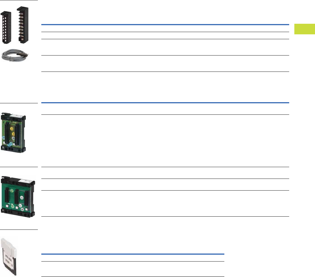
Volume 7—Logic Control, Operator Interface and Connectivity Solutions CA08100008E—February 2014 www.eaton.com V7-T4-31
4
4
4
4
4
4
4
4
4
4
4
4
4
4
4
4
4
4
4
4
4
4
4
4
4
4
4
4
4
4
4.2
PLC, I/O and Communications Products
XC Series Programmable Logic Controllers
Accessories
Te rm i n a l s
One 18 pole terminal plug is required for each digital and analog module.
Module Backplane
Memory Card
For storage of programs, data, recipes for XC100, XC121, XC200.
Note
1 Module backplane for expansion with up to 15 modules, must be plugged into the 6th slot.
Description
Pkg.
Qty.
Style
Number
Catalog
Number
18-pin connector with screw terminals for digital or analog I/O 10 258102 XIOC-TERM-18S
18-pin connector with spring-cage terminal for digital or analog I/O 10 258104 XIOC-TERM-18T
40-pin connector for digital module, with 4 m cable
XIOC-32DI
XIOC-32DO
1 267414 XIOC-TERM32
30-pin connector for counter module, with 4 m cable
XIOC-1CNT-100KHZ
XIOC-2CNT-100KHZ
1 262248 XIOC-TERM30-CNT4
Description
Pkg.
Qty.
Style
Number
Catalog
Number
Basic backplane for mounting XC100/200 on top-hat rail, can be expanded
Width: 2 slots for controller
1 260792 XIOC-BP-XC
Expansion backplane for mounting XIOC modules on top-hat rail, can be expanded
Width: 2 slots for XIOC modules
1 260794 XIOC-BP-2
Basic backplane for mounting XC100/200 on DIN rail, can be expanded
Width: 3 slots for controller and one XIOC module
1 260793 XIOC-BP-XC1
Expansion backplane for mounting XIOC modules on DIN rail, can be expanded
Width: 3 slots for XIOC modules
1 260795 XIOC-BP-3
Expansion backplane for mounting XIOC modules on DIN rail, can be expanded
Width: 3 slots for XIOC modules 1
1 274291 XIOC-BP-EXT
Description
Pkg.
Qty.
Style
Number
Catalog
Number
512 MB 1 138257 XT-MEM-MM512M
32 MB 1 262731 XT-MEM-MM32M
Terminals
Backplane
Backplane
Memory Card
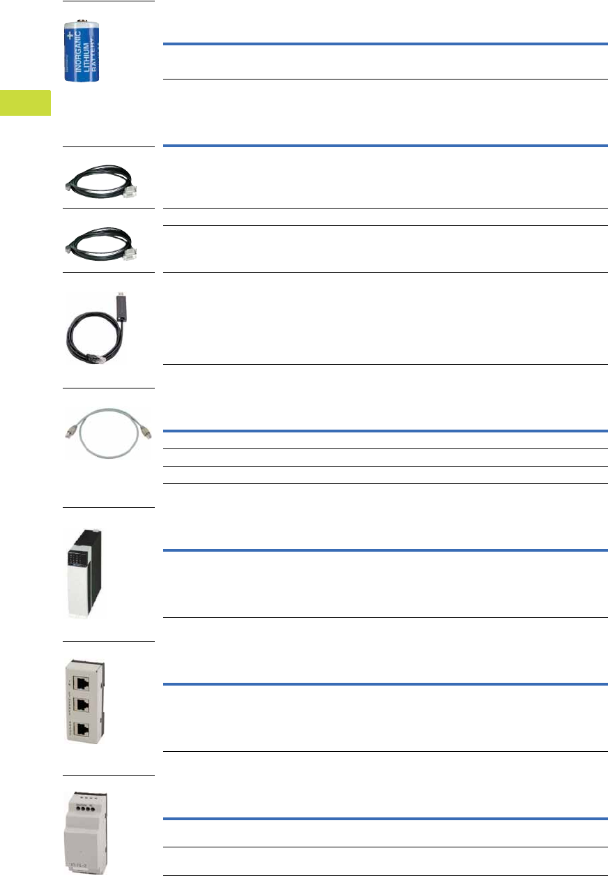
V7-T4-32 Volume 7—Logic Control, Operator Interface and Connectivity Solutions CA08100008E—February 2014 www.eaton.com
4
4
4
4
4
4
4
4
4
4
4
4
4
4
4
4
4
4
4
4
4
4
4
4
4
4
4
4
4
4
4.2
PLC, I/O and Communications Products
XC Series Programmable Logic Controllers
Battery
Programming Cables
Connection Cables
Empty Module
Interface Switch
Filter
Description
Pkg.
Qty.
Style
Number
Catalog
Number
Lithium 1/2 AA 3.6V battery for backup of real-time clock 1 256209 XT-CPU-BAT1
Description
Pkg.
Qty.
Style
Number
Catalog
Number
2m, D-sub 9-pin, serial 1 262186 XT-SUB-D/RJ45
2m, Ethernet cross 1 256487 XT-CAT5-X-2
5m, Ethernet cross 1 256488 XT-CAT5-X-5
Programming cable for XC through USB interface 1 115735 EU4A-RJ45-USB-CAB1
Description
Pkg.
Qty.
Style
Number
Catalog
Number
0.3m: Connection cable for XC200 to interface switch 1 256283 EASY-NT-30
0.8m: Connection cable for XC200 to interface switch 1 256284 EASY-NT-80
1.5m: Connection cable for XC200 to interface switch 1 256285 EASY-NT-150
Description
Pkg.
Qty.
Style
Number
Catalog
Number
Empty module to cover open XIOC slots 1 288894 XIOC-NOP
Description
Pkg.
Qty.
Style
Number
Catalog
Number
Interface adapter to split the combined RS-232/Ethernet
interface of the XC200 into RJ45 sockets. Connection cable
EASY-NT-30/80/150 usable for connection to XC200
1 289170 XT-RJ45-ETH-RS232
Description
Pkg.
Qty.
Style
Number
Catalog
Number
Interference suppression of the external 24 Vdc supply of the
XC100/200. Maximum current consumption: 2.2A
1 285316 XT-FIL-1
Power supply interference suppression of I/O modules of
XC100/200. Maximum current consumption: 12A
1 118980 XT-FIL-2
Battery
D-Sub 9-Pin
Ethernet Cross
Programming
Connection Cable
Empty Module
Interface Switch
Filter

Volume 7—Logic Control, Operator Interface and Connectivity Solutions CA08100008E—February 2014 www.eaton.com V7-T4-33
4
4
4
4
4
4
4
4
4
4
4
4
4
4
4
4
4
4
4
4
4
4
4
4
4
4
4
4
4
4
4.2
PLC, I/O and Communications Products
XC Series Programmable Logic Controllers
XSoft-CoDeSys-2 Software
Combined Logic and Visualization Development for XC Series PLCs and XV Series HMI-PLCs
IEC 61131-3 Programming Languages
●Ladder Diagram
●Structured Text
●Sequential function chart
●Function block diagram
●Freely definable function block chart/continuous function chart
●Instruction List
Project Development
●Automatic variable
declaration
●On-line editing
●Pop-up variable and
function search/pick tools
●Automatic formatting and
color coding of logic/
declaration text
●Re-usable Visual-Logic
Function Blocks
Debugging and
commissioning
XSoft-CoDeSys-2 offers you
a number of important
functions for debugging,
testing and commissioning
your applications quickly and
efficiently.
All these features are
available as soon as you log
on to the XV HMI-PLC or
XC200 PLC (online mode)
over an Ethernet connection.
Target Visualization
Integrated design of Operator
Interface screens for the XV
HMI-PLC series. Visualization
and logic developed as part of
the same project. Simplifies
screen design and always
keeps the Logic and
visualization in synch.
Web Visualization
Optionally XSoft-CoDeSys-2
can automatically generate
XML-based runtime screens
to make the screens from the
XV HMI-PLC accessible
remotely using a web
browser with a JavaScript
plug-in such as Internet
Explorer®, Firefox®
and others.
Simulation
Users can also test the
application when the XV HMI-
PLC is not connected to the
process. This is possible
thanks to the integrated
online simulation feature.
Simulation supports both the
screens and logic that have
been designed using XSoft-
CoDeSys.
Advanced Features
●Up to 16 time and/or event
driven tasks per project
●Each task can include
multiple logic programs or
subroutines
●Programs and screen
designs can be exported
and imported to support
reuse
●Powerful, built-in function
block libraries
●Ability to create user-
defined function blocks
●Fieldbus Configurator
for CANopen, PROFIBUS-
DP and SmartWire-DT
device I/O
●Ethernet and serial
communication function
blocks (OPC server, UDP,
TCP/IP, FTP client/ server,
Modbus Master/Node,
email, SMS, and more)
●8 level password
protection
●Web access selectable
per screen
●System function libraries
(OS Storage Card, and
more)
●On-line and historical
alarms
●On-line and historical
trends
System Requirements
Windows XP and Windows 7
32-bit systems
XSoft-CoDeSys-2 Software
Description Catalog Number
Single Seat License SW-XSOFT-CODESYS-2-S
Multiple Seat License (3) SW-XSOFT-CODESYS-2-M
XSoft-CoDeSys-2

V7-T4-34 Volume 7—Logic Control, Operator Interface and Connectivity Solutions CA08100008E—February 2014 www.eaton.com
4
4
4
4
4
4
4
4
4
4
4
4
4
4
4
4
4
4
4
4
4
4
4
4
4
4
4
4
4
4
4.2
PLC, I/O and Communications Products
XC Series Programmable Logic Controllers
Technical Data and Specifications
XC121 Compact PLC
Description Unit XC-CPU121-2C256K
General
Standards IEC/EN 61131-2; EN 50178
Ambient temperature °F (°C) 32° to 131° (0° to 55°)
Storage °F (°C) –13° to 158° (–25° to 70°)
Mounting position Horizontal
Relative humidity, noncondensing (IEC/EN 60068-2-30) % 10–95
Air pressure (in operation) hPa 795–1080
Vibration resistance Frequency 5–9 Hz; 3.5 mm amplitude
9–150 Hz; 1.0g constant acceleration
Mechanical shock resistance 15g/11 ms
Overvoltage category II
Pollution degree 2
Degree of protection IP20
Rated insulation voltage (Ui)V500
Emitted interference EN 61000-6-4
Interference immunity EN 61000-6-2
Backup time At least 72 hours
Weight kg 0.15
Electromagnetic Compatibility (EMC) Refer to Page V7-T4-49
Connections
Supply voltage
Connection type —
Terminal capacity mm20.14–1 (AWG28-18)
COM1 interface
Connection type RJ45
COM2, CAN1, CAN2 interfaces
Connection type Spring-loaded terminal block, 6-pole
Terminal capacity mm² 0.14–0.5 (AWG28-20)
Power Supply
Input voltage Vdc 24
Permissible range Vdc 20.4–28.8
Input power W Max. 1.44
Input current mA 60
Ripple % <5
Maximum heat dissipation (without local I/O) (Pv)W6
Overvoltage protection Yes
Protection against polarity reversal Yes
Inrush current x InNo limitation
(limited only by upstream 24 Vdc power supply unit)
Supply failure bridging
Duration of power failure ms 10
Repetition rate s 1
External supply filter Part No.: XT-FIL-1, Refer to Page V7-T4-32
Memory
Program code/program data kByte 256/244
Marker/input/output/retain data kByte 16/4/4/8
Cycle time for 1k of instructions (bits, bytes) ms <0.3

Volume 7—Logic Control, Operator Interface and Connectivity Solutions CA08100008E—February 2014 www.eaton.com V7-T4-35
4
4
4
4
4
4
4
4
4
4
4
4
4
4
4
4
4
4
4
4
4
4
4
4
4
4
4
4
4
4
4.2
PLC, I/O and Communications Products
XC Series Programmable Logic Controllers
XC121 Compact PLC, continued
Description Unit XC-CPU121-2C256K
Interfaces
Serial interface (RS-232) without handshake lines
Baud rate kbit/s Programming (character format: 8 data bits,
No parity, 1 stop bit) 19.2, 38.4 (default), 57.6
Connector type RJ45
Potential isolation No
In transparent mode
Baud rate kbit/s 0.3, 0.6, 1.2, 2.4, 4.8, 9.6, 19.2, 38.4, 57.6, 115.2
Character formats 8E1, 8O1, 8N1, 8N2, 7E2, 7O2, 7N2, 7E1
Number of send bytes for block 190
Number of receive bytes for block 190
COM2 (RS-232/RS-485) without handshake lines
Baud rate kbit/s Transparent mode (setting through function blocks)
0.3, 0.6, 1.2, 2.4, 4.8, 9.6, 19.2, 38.4, 57.6
Character formats 8E1, 8O1, 8N1, 8N2, 7E2, 7O2, 7N2, 7E1
(setting through function blocks)
Potential isolation No
Bus termination External, for RS-485
CAN1/CAN2 interface
Baud rate kbit/s 10 – 500
Potential isolation No
Stations 126
Bus termination Adjustable for each interface (CAN1/CAN2)
PDO type Asyn., cyc., acyc.
Power Supply of Local Inputs/Outputs (24 VQ/0 VQ)
Input voltage Vdc 24
Voltage range Vdc 19.2–30, observe polarity
Potential isolation
Between power supply and CPU voltage Yes
Overvoltage protection Yes

V7-T4-36 Volume 7—Logic Control, Operator Interface and Connectivity Solutions CA08100008E—February 2014 www.eaton.com
4
4
4
4
4
4
4
4
4
4
4
4
4
4
4
4
4
4
4
4
4
4
4
4
4
4
4
4
4
4
4.2
PLC, I/O and Communications Products
XC Series Programmable Logic Controllers
XC121 Expansion Module
Description Unit XIO-EXT121-1
General
Standards IEC/EN 61131-2; EN 50178
Ambient temperature °F (°C) 32° to 131° (0° to 55°)
Storage °F (°C) –13° to 158° (–25° to 70°)
Mounting position Horizontal
Relative humidity, noncondensing (IEC/EN 60068-2-30) % 10–95
Air pressure (in operation) hPa 795–1080
Vibration resistance Frequency 5–9 Hz; 3.5 mm amplitude
9–150 Hz; 1.0g constant acceleration
Mechanical shock resistance 15g/11 ms
Overvoltage category II
Pollution degree 2
Degree of protection IP20
Rated insulation voltage (Ui)V500
Emitted interference EN 61000-6-4
Interference immunity EN 61000-6-2
Backup time At least 72 hours
Weight kg 0.15
Electromagnetic Compatibility (EMC) Refer to Page V7-T4-49
Connections
X1 connector
Connector type Spring-loaded terminal block, 20 pole, B2L 3.5
Terminal capacity (solid) mm20.5–1
X2/X3 connector
Connector type Spring-loaded terminal block, 10-pole, BLZF 3.5/180 or
BLI/O 3.5/10F with LEDs
Terminal capacity (solid) mm² 0.5–1
Power Supply
Supply failure bridging
Duration of power failure ms 10
Repetition rate s 1
Input voltage Vdc 24
Permissible range Vdc 20.4 – 28.8
Input power W Max.1.68
Input current mA 70
Ripple % <5
Overvoltage protection Yes
Protection against polarity reversal Yes
Inrush current x InMax. 1A
Output voltage for signal modules
Max. field current (IL)A2
Digital Inputs
Number X2: 9 with plug BLI/O 3.5/10F or 10 with plug BLZF 3.5/
180 X3: 8 (can also be used as outputs)
Rated voltage (Ue) Vdc 24
At state “0” (Ue) Vdc <5
At state “1” (Ue) Vdc >15
Rated operational current
At state “1” (Ie)mA3.3
Delay time
X2: DI0–DI3 µs 20
X2: DI4–DI9 µs 250
X2: DX0–DX7 ms 20
Potential isolation No

Volume 7—Logic Control, Operator Interface and Connectivity Solutions CA08100008E—February 2014 www.eaton.com V7-T4-37
4
4
4
4
4
4
4
4
4
4
4
4
4
4
4
4
4
4
4
4
4
4
4
4
4
4
4
4
4
4
4.2
PLC, I/O and Communications Products
XC Series Programmable Logic Controllers
XC121 Expansion Module, continued
Description Unit XIO-EXT121-1
Digital Outputs
Number At X3: 8 (can also be used as inputs)
Rated voltage
Rated voltage (Ue) Vdc 24
Permissible range 20.4–28.8 Vdc
Ripple % <5
Rated operational current
At state “1” (Ie) A 0.5 at 24 Vac
Utilization factor (%) g 1
Maximum duty factor ms 100%
Lamp load without (Rv)W5
Potential isolation No
Residual current at state “0” per channel mA <0.1
Max. output voltage
At state “0” with external load <10M ohms V 2.5
At state “1” at Ie = 0.5A V U = Ue–1V
Short-circuit tripping current
Short-circuit tripping current for Ra <10M ohms A 0.7 < Ie <2 for output
Total short-circuit current A 16
Peak short-circuit current A 32
Max. operating frequency ops/h 40,000
Parallel connection capability Yes
Analog Inputs 0–10V
Number of channels 2
Primary voltage range V 0–10
Resolution bit 10
Conversion time ms <5
Overall accuracy < ± 1% (of full-scale value)
Input resistance kohm 200
Analog Inputs 0–20 mA
Number of channels 2
Primary voltage range mA 0–20
Resolution bit 10
Conversion time ms <5
Overall accuracy < ± 1% (of full-scale value)
Input resistance ohm 50
PT100 RTD
Number of channels 2
Temperature range °F (°C) –348° to 392° (–200° to 200°)
Resistance range ohm 18.5–175.8
Resolution bit 10
Overall accuracy < ± 2%
Analog Outputs
Number of channels 2
Secondary voltage range V 0–10
Resolution bit 12
Conversion time ms <5
Overall accuracy < ± 1% (of full-scale value)
External load resistance (R) kohm 10

V7-T4-38 Volume 7—Logic Control, Operator Interface and Connectivity Solutions CA08100008E—February 2014 www.eaton.com
4
4
4
4
4
4
4
4
4
4
4
4
4
4
4
4
4
4
4
4
4
4
4
4
4
4
4
4
4
4
4.2
PLC, I/O and Communications Products
XC Series Programmable Logic Controllers
XC101 Modular PLCs
Description Unit XC-CPU101-C64K-8DI-6DO XC-CPU101-C128K-8DI-6DO XC-CPU101-FC128K-8DI-6DO XC-CPU101-C256K-8DI-6DO
General
Standards IEC/EN 61131-2; EN 50178 IEC/EN 61131-2; EN 50178 IEC/EN 61131-2; EN 50178 IEC/EN 61131-2; EN 50178
Ambient temperature °F (°C) 32° to 131° (0° to 55°) 32° to 131° (0° to 55°) 32° to 131° (0° to 55°) 32° to 131° (0° to 55°)
Storage °F (°C) –13° to 158° (–25° to 70°) –13° to 158° (–25° to 70°) –13° to 158° (–25° to 70°) –13° to 158° (–25° to 70°)
Mounting position Horizontal Horizontal Horizontal Horizontal
Relative humidity, noncondensing
(IEC/EN 60068-2-30)
% 10–95 10–95 10–95 10–95
Air pressure (in operation) hPa 795–1080 795–1080 795–1080 795–1080
Vibration resistance 10–57 Hz ±0.075 mm/57–150 Hz ±1.0g
Mechanical shock resistance 15g/11 ms 15g/11 ms 15g/11 ms 15g/11 ms
Overvoltage category II II II II
Pollution degree 2 2 2 2
Degree of protection IP20 IP20 IP20 IP20
Rated insulation voltage (Ui) V 500 500 500 500
Emitted interference UiEN 61000-6-4, Class A EN 61000-6-4, Class A EN 61000-6-4, Class A EN 61000-6-4, Class A
Interference immunity EN 61000-6-2 EN 61000-6-2 EN 61000-6-2 EN 61000-6-2
Battery (lifespan) Normally 5 years Normally 5 years Normally 5 years Normally 5 years
Weight kg 0.23 0.23 0.23 0.23
Terminals Plug-in terminal block Plug-in terminal block Plug-in terminal block Plug-in terminal block
Terminal capacity
Screw terminals
Flexible with ferrule mm20.5–1.5 0.5–1.5 0.5–1.5 0.5–1.5
Solid mm20.5–2.5 0.5–2.5 0.5–2.5 0.5–2.5
Spring-cage terminal
Flexible mm20.34–1.0 0.34–1.0 0.34–1.0 0.34–1.0
Solid mm20.14–1.0 0.14–1.0 0.14–1.0 0.14–1.0
Electromagnetic Compatibility (EMC) Refer to Page V7-T4-49
Power Supply
Mains failure duration ms 10 10 10 10
Repetition rate s 1 1 1 1
Input voltage Vdc 24 24 24 24
Permissible range Vdc 20.4–28.8 20.4–28.8 20.4–28.8 20.4–28.8
Input power W Max. 26 Max. 26 Max. 26 Max. 26
Ripple % <5<5<5<5
Maximum heat dissipation
(without local I/O) (Pv)
W6666
Overvoltage protection Yes Yes Yes Yes
Protection against polarity reversal Yes Yes Yes Yes
Mains filter (external) Yes Yes Yes Yes
Inrush current x InNot limited, (limiting only by a supply-side 24 Vdc PSU)
Output voltage for signal modules
Rated value Vdc 5 5 5 5
Output current A 3.2 3.2 3.2 3.2
Short-circuit rating Yes Yes Yes Yes
Isolated from supply voltage No No No No
CPU
Microprocessor Infineon C164 Infineon C164 Infineon C164 Infineon C164
Memory
Program code/program data kByte 64/64 128/128 128/128 256/256
Marker/retain data kByte 4/4 8/8 8/8 8/8
Cycle time for 1k of instructions
(bits, bytes)
ms <0.5 <0.5 <0.5 <0.5

Volume 7—Logic Control, Operator Interface and Connectivity Solutions CA08100008E—February 2014 www.eaton.com V7-T4-39
4
4
4
4
4
4
4
4
4
4
4
4
4
4
4
4
4
4
4
4
4
4
4
4
4
4
4
4
4
4
4.2
PLC, I/O and Communications Products
XC Series Programmable Logic Controllers
XC101 Modular PLCs, continued
Description Unit XC-CPU101-C64K-8DI-6DO XC-CPU101-C128K-8DI-6DO XC-CPU101-FC128K-8DI-6DO XC-CPU101- C256K-8DI-6DO
Interfaces
Serial interface (RS-232)
without handshake lines
Baud rate kbit/s Max. 57.6 Max. 57.6 Max. 57.6 Max. 57.6
Connections RJ45 RJ45 RJ45 RJ45
Potential isolation No No No No
CANopen
Maximum data transfer rate bit/s 500,000 500,000 500,000 500,000
Potential isolation Yes Yes Yes Yes
Device profile To DS 301 V4 To DS 301 V4 To DS 301 V4 To DS 301 V4
PDO type Asyn., cyc., acyc. Asyn., cyc., acyc. Asyn., cyc., acyc. Asyn., cyc., acyc.
Connection Plug-in terminal block Plug-in terminal block Optical fiber interface, wavelength
660 mm, plug for example
HFBR-4516 Agilent Technologies
Plug-in terminal block
Bus terminating resistors External External External External
Stations Number Max. 126 Max. 126 Max. 126 Max. 126
Watchdog Yes Yes Yes Yes
RTC (real-time clock) Yes Yes Yes Yes
Power Supply of Local Inputs/Outputs (24 VQ/0 VQ)
Input voltage Vdc 24 24 24 24
Voltage range Vdc 19.2–30, observe polarity 19.2–30, observe polarity 19.2–30, observe polarity 19.2–30, observe polarity
Potential isolation
Between power supply and
CPU voltage
Yes Yes Yes Yes
Overvoltage protection Yes Yes Yes Yes
Protection against polarity reversal Yes Yes Yes Yes
Digital Inputs
Input current for channel at rated
voltage
mA Normally 3.5 Normally 3.5 Normally 3.5 Normally 3.5
Heat dissipation for channel mW Normally 85 Normally 85 Normally 85 Normally 85
Voltage level to IEC/EN 61131-2
Limit value type 1 Low <5 Vdc/High >15 Vdc Low <5 Vdc,/High >15 Vdc Low <5 Vdc/High >15 Vdc Low <5 Vdc/High >15 Vdc
Input delay
OFF ON ms Normally 0.1 Normally 0.1 Normally 0.1 Normally 0.1
ON OFF ms Normally 0.1 Normally 0.1 Normally 0.1 Normally 0.1
Inputs Number 8 (of which 4 interrupt inputs) 8 (of which 4 interrupt inputs) 8 (of which 4 interrupt inputs) 8 (of which 4 interrupt inputs)
Channels with the same reference
potential
Number 8 8 8 8
Status indication LED LED LED LED
Digital Outputs
Channels Number 6 6 6 6
Heat dissipation for channel W 0.08 0.08 0.08 0.08
Load circuits A 0.5 0.5 0.5 0.5
Output delay
OFF ON Normally 0.1 ms Normally 0.1 ms Normally 0.1 ms Normally 0.1 ms
ON OFF Normally 0.1 ms Normally 0.1 ms Normally 0.1 ms Normally 0.1 ms
Channels with the same reference
potential
Number 6 6 6 6
Status indication LED LED LED LED
Switching capacity IEC/EN 60947-5-1,
utilization category DC-13
IEC/EN 60947-5-1,
utilization category DC-13
IEC/EN 60947-5-1,
utilization category DC-13
IEC/EN 60947-5-1,
utilization category DC-13
Duty factor % DF 100 100 100 100
Utilization factor g 1 1 1 1

V7-T4-40 Volume 7—Logic Control, Operator Interface and Connectivity Solutions CA08100008E—February 2014 www.eaton.com
4
4
4
4
4
4
4
4
4
4
4
4
4
4
4
4
4
4
4
4
4
4
4
4
4
4
4
4
4
4
4.2
PLC, I/O and Communications Products
XC Series Programmable Logic Controllers
XC200 Series Modular PLCs
Description Unit XC-CPU201-EC256K-8DI-6DO(-XV) XC-CPU201-EC512K-8DI-6DO(-XV) XC-CPU202-EC4M-8DI-6DO-XV
General
Standards IEC/EN 61131-2; EN 50178 IEC/EN 61131-2; EN 50178 IEC/EN 61131-2; EN 50178
Ambient temperature °F (°C) 32° to 131° (0° to 55°) 32° to 131° (0° to 55°) 32° to 131° (0° to 55°)
Storage °F (°C) –13° to 158° (–25° to 70°) –13° to 158° (–25° to 70°) –13° to 158° (–25° to 70°)
Mounting position Horizontal Horizontal Horizontal
Relative humidity, noncondensing (IEC/EN 60068-2-30) % 10–95 10–95 10–95
Air pressure (in operation) hPa 795–1080 795–1080 795–1080
Vibration resistance 10–57 Hz ±0.075 mm
57–150 Hz ±1.0g
10–57 Hz ±0.075 mm
57–150 Hz ±1.0g
10–57 Hz ±0.075 mm
57–150 Hz ±1.0g
Mechanical shock resistance 15g/11 ms 15g/11 ms 15g/11 ms
Overvoltage category II II II
Pollution degree 2 2 2
Degree of protection IP20 IP20 IP20
Rated impulse withstand voltage (Uimp) V 850 850 850
Emitted interference EN 61000-6-4, Class A EN 61000-6-4, Class A EN 61000-6-4, Class A
Interference immunity EN 61000-6-2 EN 61000-6-2 EN 61000-6-2
Battery (lifespan) Normally 5 years Normally 5 years Normally 5 years
Weight kg 0.23 0.23 0.23
Terminals Plug-in terminal block Plug-in terminal block Plug-in terminal block
Terminal capacity
Screw terminals
Flexible with ferrule mm20.5–1.5 0.5–1.5 0.5–1.5
Solid mm20.5–2.5 0.5–2.5 0.5–2.5
Spring-cage terminal
Flexible mm20.34–1.0 0.34–1.0 0.34–1.0
Solid mm20.14–1.0 0.14–1.0 0.14–1.0
Electromagnetic Compatibility (EMC) Refer to Page V7-T4-49
Power Supply
Duration of mains failure ms 10 10 10
Repetition rate s 1 1 1
Input voltage Vdc 24 24 24
Permissible range Vdc 20.4–28.8 20.4–28.8 20.4–28.8
Input power W Max. 33 Max. 33 Max. 33
Ripple % <5<5<5
Maximum heat dissipation (Pv)W666
Overvoltage protection Yes Yes Yes
Protection against polarity reversal Yes Yes Yes
Line filter Yes Yes Yes
Inrush current x InNot limited (limiting only by a supply-side 24 Vdc PSU)
Output voltage for signal modules
Rated value Vdc 5 5 5
Output current A 3.2 3.2 3.2
Short-circuit rating Yes Yes Yes
Isolated from supply voltage No No No
CPU
Microprocessor NEC VR4181 A MIPS NEC VR4181 A MIPS ARM 532 MHz
Memory
Program code/program data 256 kByte/256 kByte 2 Mbyte/512 kByte 4 Mbyte/512 kByte
Marker/retain data kByte 16/32 16/32 16/64
Cycle time for 1k of instructions (bits, bytes) ms <0.15 <0.15 <0.025

Volume 7—Logic Control, Operator Interface and Connectivity Solutions CA08100008E—February 2014 www.eaton.com V7-T4-41
4
4
4
4
4
4
4
4
4
4
4
4
4
4
4
4
4
4
4
4
4
4
4
4
4
4
4
4
4
4
4.2
PLC, I/O and Communications Products
XC Series Programmable Logic Controllers
XC200 Series Modular PLCs, continued
Description Unit XC-CPU201-EC256K-8DI-6DO(-XV) XC-CPU201-EC512K-8DI-6DO(-XV) XC-CPU202-EC4M-8DI-6DO-XV
Interfaces
Ethernet
Baud rate Mbit/s 10/100–Autodetect 10/100–Autodetect 10/100–Autodetect
Connector type RJ45 RJ45 RJ45
Potential isolation No No No
Serial interface (RS-232) without handshake lines
Baud rate kbit/s Max. 115.2 Max. 115.2 Max. 115.2
Connector type RJ45 RJ45 RJ45
Potential isolation No No No
USB interface 1.0 1.0 2.0
CANopen
Maximum data transfer rate Mbit/s 1 1 1
Potential isolation Yes Yes Yes
Device profile To DS 301 V4 To DS 301 V4 To DS 301 V4
PDO type Asyn., cyc., acyc. Asyn., cyc., acyc. Asyn., cyc., acyc.
Connection Plug-in terminal block Plug-in terminal block Plug-in terminal block
Bus terminating resistors External External Internal
Stations Number Max. 126 Max. 126 Max. 126
Watchdog Yes Yes Yes
RTC (real-time clock) Yes Yes Yes
Power Supply of Local Inputs/Outputs (24 VQ/0 VQ)
Input voltage Vdc 24 24 24
Voltage range Vdc 19.2–30, observe polarity 19.2–30, observe polarity 19.2–30, observe polarity
Potential isolation
Between power supply and CPU voltage Yes Yes Yes
Between power supply and inputs/outputs No No No
Status indication LED LED LED
Terminals Plug-in terminal block Plug-in terminal block Plug-in terminal block
Overvoltage protection Yes Yes Yes
Protection against polarity reversal Yes Yes Yes
Digital Inputs
Input current per channel at rated voltage mA Normally 3.5 Normally 3.5 Normally 3.5
Heat dissipation per channel Normally 85m W Normally 85m W Normally 85m W
Voltage level to IEC/EN 61131-2
Limit value type 1 Low <5 Vdc/High >15 Vdc Low <5 Vdc/High >15 Vdc Low <5 Vdc/High >15 Vdc
Input delay
OFF ON ms Type 0.1 Type 0.1 Type 0.1
ON OFF ms Type 0.1 Type 0.1 Type 0.1
Inputs Number 8, of which parameterizable: 2 counters, 50 kHz, 2 interrupt inputs, 1 incremental input
Channels with the same reference potential Number 8 8 8
Status indication LED LED LED
Digital Outputs
Channels Number 6 6 6
Heat dissipation per channel W 0.08 0.08 0.08
Load circuits A 0.5 0.5 0.5
Output delay
OFF ON Normally 0.1 ms Normally 0.1 ms Normally 0.1 ms
ON OFF Normally 0.1 ms Normally 0.1 ms Normally 0.1 ms
Channels with the same reference potential Number 6 6 6
Status indication LED LED LED
Switching capacity IEC/EN 60947-5-1, utilization category DC-13
Duty factor % DF 100 100 100
Utilization factor g 1 1 1

V7-T4-42 Volume 7—Logic Control, Operator Interface and Connectivity Solutions CA08100008E—February 2014 www.eaton.com
4
4
4
4
4
4
4
4
4
4
4
4
4
4
4
4
4
4
4
4
4
4
4
4
4
4
4
4
4
4
4.2
PLC, I/O and Communications Products
XC Series Programmable Logic Controllers
XIOC Digital Input Modules
XIOC Digital Output Modules
Description Unit XIOC-8DI XIOC-16DI XIOC-32DI
Modules
Input type DC input DC input DC input
Input voltage Vdc 24 24 24
Permissible range Vdc 20.4–28.8 20.4–28.8 20.4–28.8
Input voltage Vac — — —
Permissible range Vac — — —
Input resistance Normally 3.5 kohm Normally 5.9 kohm Normally 5.6 kohm
Input current mA Normally 6.9 Normally 4.0 Normally 4.3
Voltage level to IEC 61131-2, limit value type 1
ON Vdc >15 >15 >15
OFF Vdc <5<5<5
Input delay
OFF ON ms 5 (normally 4) 5 (normally 4) 5 (normally 4)
OFF ON ms 5 (normally 4) 5 (normally 4) 5 (normally 4)
Input channels Number 8 16 32
Channels with the same reference potential Number 8 16 32
Potential isolation With optocouplers With optocouplers With optocouplers
Indication LED (green) LED (green) 16 LEDs (green),
switchable: 0–15, 16–31
Terminals Plug-in terminal block Plug-in terminal block XIOC-TERM32
(connector and cable)
Internal current consumption (5 Vdc) mA Normally 26 Normally 51 Normally 100
Weight kg 0.16 0.16 0.16
Description Unit XIOC-8DO XIOC-16DO XIOC-16DO-S XIOC-32DO
Modules
Output type Transistor (source type) Transistor (source type) Transistor (source type) Transistor (source type)
Output voltage Vdc 24 (–15 to +20%) 24 (–15 to +20%) 24 (–15 to +20%) 24 (–15 to +20%)
Switching current, minimummA1111
Leakage current mA 0.1 0.1 0.1 0.1
Maximum load current
Per circuit A 0.3 0.3 0.8 0.2
Per common potential terminal A 2.4 4 5 3.2
Output delay
OFF ON ms <0.3 <0.3 <0.3 <0.3
OFF ON ms <1<1<1<1
Output channels Number 8 16 16 32
Channels with the same reference potential Number 8 16 16 32
Overvoltage protection Diode Diode Integrated Diode
Fuse rating A 4 8 None 8
Potential isolation With optocouplers With optocouplers With optocouplers With optocouplers
Indication LED (green) LED (green) LED (green) 16 LEDs (green)
switchable: 0–15, 16–31
Terminals Plug-in terminal block Plug-in terminal block Plug-in terminal block XIOC-TERM32
(connector and cable)
Internal current consumption (5 Vdc) mA Normally 30 Normally 50 Normally 50 Normally 250
External voltage for outputs/module
(30 mA for module supply) (Us)
Vdc 24 (–15 to +20%) 24 (–15 to +20%) 24 (–15 to +20%) 24 (–15 to +20%)
Short-circuit protection — — Yes —
Weight kg 0.16 0.16 0.16 0.16

Volume 7—Logic Control, Operator Interface and Connectivity Solutions CA08100008E—February 2014 www.eaton.com V7-T4-43
4
4
4
4
4
4
4
4
4
4
4
4
4
4
4
4
4
4
4
4
4
4
4
4
4
4
4
4
4
4
4.2
PLC, I/O and Communications Products
XC Series Programmable Logic Controllers
XIOC Relay Output Module
Description Unit XIOC-12DO-R
Modules
Output type Relays
Output voltage Vdc 24
Output voltage Vac 100/240
Switching current, minimum mA 1
Maximum load current
Per circuit A 2
Per common potential terminal A 5
Output delay
OFF ON ms <10
OFF ON ms <10
Output channels Number 12
Channels with the same reference potential Number 12
Overvoltage protection External
Fuse rating A External
Potential isolation With optocouplers
Indication LED (green)
Terminals Plug-in terminal block
Internal current consumption (5 Vdc) mA Normally 40
External voltage for operating the relay 24 Vdc (–15 to +20%, max. 70 mA)
Weight kg 0.2

V7-T4-44 Volume 7—Logic Control, Operator Interface and Connectivity Solutions CA08100008E—February 2014 www.eaton.com
4
4
4
4
4
4
4
4
4
4
4
4
4
4
4
4
4
4
4
4
4
4
4
4
4
4
4
4
4
4
4.2
PLC, I/O and Communications Products
XC Series Programmable Logic Controllers
XIOC Digital Input/Output Module
Description Unit XIOC-16DX
Power Supply
Supply voltage 24 Vdc (–15 to +20%)
Ripple % <5
Overvoltage protection Yes
Protection against polarity reversal Yes
Potential isolation
Between power supply and I/O bus Yes
Between power supply and I/O No
Internal current consumption (5 Vdc) mA Normally 80
Channels Number 16
Terminals Plug-in terminal block
Status indication LED
Inputs
Input type DC input
Input voltage Vdc 24
Inputs Number 4, 12, configurable
Input current mA Normally 4
Voltage level to IEC 61131-2, limit value type 1
ON Vdc >15
OFF Vdc <5
Input delay
OFF ON ms Normally 0.1
OFF ON ms Normally 0.1
Outputs
Output type Transistor (source type)
Output voltage Vdc 12/24 –15 to +20%)
Output current A Normally 0.5
Outputs Number Max. 12, configurable
Short-circuit tripping current A Max. 1.2 over 3 ms for output
Lamp load W Max. 3
Drop-out delay (High Low) µs Normally 100
Switching capacity IEC/EN 60947-5-1, utilization category DC-13
Short-circuit rating Yes
Parallel connection of outputs In groups 0 – 3, 4 – 7, 8 – 11; Actuation of the outputs
within a group only in the same program cycle
Number of outputs that can be switched in parallel Max. 3
Total maximum current A 2 for group
Weight kg 0.16

Volume 7—Logic Control, Operator Interface and Connectivity Solutions CA08100008E—February 2014 www.eaton.com V7-T4-45
4
4
4
4
4
4
4
4
4
4
4
4
4
4
4
4
4
4
4
4
4
4
4
4
4
4
4
4
4
4
4.2
PLC, I/O and Communications Products
XC Series Programmable Logic Controllers
XIOC Analog Modules
XIOC Thermocouple Module
Description Unit XIOC-8AI-I2 XIOC-8AI-U1 XIOC-8AI-U2 XIOC-4T-PT
Modules
Input voltage Vdc — 0 to 10 –10 to +10 —
Input current mA 4–20 — — —
Resolution, digital bit 12 12 12 15 bit with sign
Conversion time <5 ms <5 ms <5 ms —
Total errors % < ± 1 (of full-scale value) < ± 1 (of full-scale value) < ± 1 (of full-scale value) < ± 1 (of full-scale value)
Input resistance kohm — 100 100 —
Potential isolation
Circuit within each channel With optocouplers With optocouplers With optocouplers With optocouplers
Between the input channels No No No No
Input channels Number 8 8 8 4
Terminals Plug-in terminal block Plug-in terminal block Plug-in terminal block Plug-in terminal block
External power supply 24 Vdc (–15 to +20%),
approx. 150 mA
24 Vdc (–15 to +20%),
approx. 150 mA
24 Vdc (–15 to +20%),
approx. 150 mA
24 Vdc (–15 to +20%),
100 mA
External resistance (R) kohm — — — Max. 0.4, 4 channels
Connection type 2-core shielded cable (<20m) 2-core shielded cable (<20m) 2-core shielded cable (<20m) Shielded cable
Platinum RTD — — — PT100 (IEC 751), PT1000
Accuracy
–20° to 40°C (PT100) °C — — — ±0.5
–50° to 400°C (PT100) °C — — — ±3
–50° to 400°C (PT1000) °C — — — ±6
Temperature measuring range — — — –20 to 40°/–50 to 400°
(uninterrupted current: 2 mA)
Internal current consumption (5 Vdc) mA Normally 100 Normally 100 Normally 100 Max. 200
Additional function — — — Linearization
Fault detection
–20° to 40°C —— — < –25°C or > +45°C = resistance
value 7FFFFhex
–50° to 400°C — — — < –60°C or > +410°C =
resistance value 7FFFFhex
Response to cable break or unused inputs — — — In these cases, the resistance
value is 7FFFhex
Weight kg 0.18 0.18 0.18 0.18
Description Unit XIOC-4AI-T
Channels
Number 4
Temperature measuring range °C Type K: –270 to 1370
Type J: –210 to 1200
Type B: 100 to 1800
Type N: –270 to 1300
Type E: –270 to 1000
Type R: –50 to 1760
Type T: –200 to 400
Voltage measurement mV –50 to 50
–100 to 100
–500 to 500
–1000 to 1000
Cold-junction compensation Yes, built-in
Interference suppression 50 Hz, 60 Hz
Unit 0.1°C, 0.1 F
Resolution bit 16
Total errors % ±0.5 of measurement range
Conversion time <1s
Temperature coefficient <200 ppm/°C of measurement range

V7-T4-46 Volume 7—Logic Control, Operator Interface and Connectivity Solutions CA08100008E—February 2014 www.eaton.com
4
4
4
4
4
4
4
4
4
4
4
4
4
4
4
4
4
4
4
4
4
4
4
4
4
4
4
4
4
4
4.2
PLC, I/O and Communications Products
XC Series Programmable Logic Controllers
XIOC Analog Modules
XIOC Analog Modules
Description Unit XIOC-2AO-U1-2AO-I2 XIOC-4AO-U1 XIOC-2AO-U2
Modules
Output voltage Vdc 0–10 0–10 –10 to 10
Output current mA 4–20 — —
Resolution bit121212
Conversion time <5 ms <5 ms <5 ms
Total errors % < ±1 (of full-scale value) < ±1 (of full-scale value) < ±1 (of full-scale value)
External load resistance
Voltage output >10 kohm >10 kohm >10 kohm
Current output ohm 0 to 500 ohm — —
Potential isolation
Circuit within each channel With optocouplers
Between channels No No No
Number of outputs
Output voltage 2 (channels 0 and 1) 4 2
Output current 2 (channels 2 and 3) — —
Terminals Plug-in terminal block Plug-in terminal block Plug-in terminal block
Internal current consumption (5 Vdc) mA Normally 100 Normally 100 Normally 100
External power supply 24 Vdc (–15/+20%), approx. 150 mA 24 Vdc (–15/+20%), approx. 150 mA 24 Vdc (–15/+20%), approx. 150 mA
Connection type 2-core shielded cable (<20m) 2-core shielded cable (<20m) 2-core shielded cable (<20m)
Description Unit XIOC-2AI-1AO-U1 XIOC-2AI-1AO-U1-I1 XIOC-4AI-2AO-U1 XIOC-4AI-2AO-U1-I1
Inputs
Input voltage Vdc 0–10 0–10 0–10 0–10
Input current mA — 0–20 — 0–20
Resolution bit14141414
Conversion time <1 ms <1 ms <1 ms <1 ms
Total errors % Normally 0.4 Normally 0.4 Normally 0.4 Normally 0.4
Potential isolation
Circuit within each channel No No No No
Between the input channels No No No No
Between input/output channels No No No No
Channels Number 2244
Input resistance kohm 40 40 40 40
Outputs
Output voltage Vdc 0–10 0–10 0–10 0–10
Output current mA — 0–20 — 0–20
Resolution bit12121212
Errors Normally 0.4% Normally 0.4% Normally 0.4% Normally 0.4%
Potential isolation
Circuit within each channel No No No No
Between the output channels No No No No
Number of channels 1122
External load resistance >2 kohm >2 kohm >2 kohm >2 kohm
Short-circuit rating Yes Yes Yes Yes
Terminal Connection
Terminals Plug-in terminal block Plug-in terminal block Plug-in terminal block Plug-in terminal block
Internal current consumption (5 Vdc) mA Normally 200 Normally 200 Normally 200 Normally 200
Weight kg 0.16 0.16 0.16 0.16

Volume 7—Logic Control, Operator Interface and Connectivity Solutions CA08100008E—February 2014 www.eaton.com V7-T4-47
4
4
4
4
4
4
4
4
4
4
4
4
4
4
4
4
4
4
4
4
4
4
4
4
4
4
4
4
4
4
4.2
PLC, I/O and Communications Products
XC Series Programmable Logic Controllers
XIOC Communication Modules
Description Unit XIOC-NET-DP-M XIOC-NET-DP-S XIOC-SER XIOC-TC1
Interfaces
Interfaces PROFIBUS-DP, RS-485, EN 50170 PROFIBUS-DP, RS-485, EN 50170 RS-232(C), RS-422, RS-485 RS-232(C), RS-422, RS-485
Protocol PROFIBUS-DP master (class 1) PROFIBUS-DP slave Transparent mode, Modbus
master/slave
Transparent mode, Modbus
master/slave, DNP3 protocol
Character formats — — 8E1, 8O1, 8N1, 8N2, 7E2, 7O2,
7N2, 7E1
8E1, 8O1, 8N1, 8N2, 7E2, 7O2,
7N2, 7E1
Control and signal cables — — RTS, CTS, DTR, DSR, DCD RTS, CTS, DTR, DSR, DCD
Transfer rate kbit/s 9.6 to 12,000 9.6 to 12,000 0.3 –57.6 0.3–57.6
Potential isolation Yes Yes Yes (RS-485, RS-422) Yes (RS-485, RS-422)
Number of slaves 124 — — —
Send/receive data 3500 Byte each Max. 244 Byte 250 Byte per slave
120 Byte per slave
250/500
Bus terminating resistors Switchable Switchable Switchable for RS-485, RS-422 Switchable for RS-485, RS-422
Connector type D-sub 9-pin socket D-sub 9-pin socket RS-232: D-sub 9-pin
RS-485, 422: plug-in
terminal block
RS-232: D-sub 9-pin
RS-485, 422: plug-in
terminal block
Current consumption mA <300 <300 <275 <275
Weight kg Approx. 0.2 Approx. 0.2 Approx. 0.2 Approx. 0.2
Number of modules XC100: 1/XC200: 3 XC100: 1/XC200: 3 XC100: 2/XC200: 4 XC200: 4
Slots 1, 2, 3 1, 2, 3 Any Any

V7-T4-48 Volume 7—Logic Control, Operator Interface and Connectivity Solutions CA08100008E—February 2014 www.eaton.com
4
4
4
4
4
4
4
4
4
4
4
4
4
4
4
4
4
4
4
4
4
4
4
4
4
4
4
4
4
4
4.2
PLC, I/O and Communications Products
XC Series Programmable Logic Controllers
XIOC Counter Modules
Description Unit XIOC-1CNT-100KHZ XIOC-2CNT-100KHZ XIOC-2CNT-2AO-INC
Inputs
Counter limits 0–4294967295 (32 bit) 0–4294967295 (32 bit) 0–4294967295 (32 bit)
Internal current consumption mA 200 200 450
Frequency kHz 100 (25 with four times resolution) 100 (25 with four times resolution) 400 (100 with four times resolution)
Number of channels 1 2 2
Input voltage Vdc 12–24 12–24 —
Voltage for ON Vdc >10 >10 —
Voltage for OFF VA/W <4 <4 —
Input current mA > 4> 4—
Differential input voltage Vdc ±5 ±5 ±5
Voltage for ON Vdc 2–5 2–5 0.2–5
Voltage for OFF Vdc –5 to 8 –5 to 8 –5 to –0.2
Differential input current mA 35 35 5
Minimum pulse width µs ON >4/OFF >4ON
>4/OFF >4—
Potential isolation With optocouplers With optocouplers —
Connection for external cabling 30-pin plug: XIOC-TERM30-CNT4 30-pin plug: XIOC-TERM30-CNT4 Plug-in terminal block
External cabling Shielded, twisted pair cable Shielded, twisted pair cable Shielded, twisted pair cable
Outputs
Output type Transistor (open collector) Transistor (open collector) Analog
External power supply 12/24 Vdc (30 max.) 12/24 Vdc (30 max.) —
Minimum load current mA 1 1 —
Maximum load current (Ie)mA2020—
Max. leakage current mA 0.5 0.5 —
Max. voltage drop at ON V 1.5 1.5 —
Debounce OFF
OFF ON ms <1<1—
OFF ON ms <1<1—
Output channels Number 2 4 2
Potential isolation With optocouplers With optocouplers —
Output voltage Vdc — — –10 to 10
Resolution bit — — 12
Conversion time — — <1 ms
Total errors % — — Normally 0.4
Load resistance — — >1 kohm
Connection for external cabling 30-pin plug: XIOC-TERM30-CNT4 30-pin plug: XIOC-TERM30-CNT4 Plug-in terminal block
External cabling Shielded, twisted pair cable Shielded, twisted pair cable Shielded 2-core cable
Current per channel mA — — <300
Power supply of encoders — — 5 Vdc
Current consumption mA 200 200 Max. 450
Weight kg 0.16 0.16 0.18

Volume 7—Logic Control, Operator Interface and Connectivity Solutions CA08100008E—February 2014 www.eaton.com V7-T4-49
4
4
4
4
4
4
4
4
4
4
4
4
4
4
4
4
4
4
4
4
4
4
4
4
4
4
4
4
4
4
4.2
PLC, I/O and Communications Products
XC Series Programmable Logic Controllers
Power Supply Suppression Filters
General Information on Electromagnetic Compatibility (EMC) of Automation Systems
Description Unit XT-FIL-1 XT-FIL-2
General
Standards IEC/EN 61131-2; EN 50178 IEC/EN 61131-2; EN 50178
Ambient temperature °F (°C) 32° to 131° (0° to 55°) 32° to 131° (0° to 55°)
Storage °F (°C) –13° to 158° (–25° to 70°) –13° to 158° (–25° to 70°)
Mounting position Vertical or horizontal Vertical or horizontal
Vibration resistance 10–57 Hz ± 0.075 mm
57–150 Hz ± 1.0g
10–57 Hz ± 0.075 mm
57–150 Hz ± 1.0g
Mechanical shock resistance 15g/11 ms 15g/11 ms
Impact strength 500g /50 mm ±25g 500g/50 mm ±25g
Overvoltage category II II
Pollution degree 2 2
Protection type IP20 IP20
Rated impulse withstand voltage (Uimp)V850 850
Interference immunity EN 61000-6-2 EN 61000-6-2
Weight kg 0.1 0.1
Dimensions (W x H x D) mm 35 x 90 x 30 35 x 90 x 57
Terminals Screw terminals Screw terminals
Terminal capacity
Screw terminals
Flexible with ferrule mm20.2–2.5 (AWG22–12) 0.2–2.5 (AWG22–12)
Solid mm20.2–2.5 (AWG22–12) 0.2–2.5 (AWG22–12)
Power Supply
Input voltage Vdc 24 24
Permissible range Vdc 20.4–28.8 20.4–28.8
Ripple % < 5< 5
Mains overvoltage protection Yes Yes
Potential isolation
Between input voltage and PE Yes Yes
Between input voltage and output voltage No No
Between output voltage and PE Yes Yes
Rated value Vdc 24 24
Output current A 2.2 12
Description Specification
Emitted interference EN 55011/22 Class A (VDE 0875, Part 11)
Interference immunity
ESD IEC/EN 61000-4-2 Contact discharge: 4 kV
Air discharge 8 kV
RFI IEC/EN 61000-4-3 AM (80%) 80–1000 MHz 10V/m
Mobile phones/cellphones IEC/EN 61000-4-3 PM 800–960 MHz 10V/m
Burst IEC/EN 61000-4-4 Mains/digital I/O (direct): 2 kV
Analog I/O, fieldbus (capacitive coupling): 1 kV
Surge IEC/EN 61000-4-5 Digital I/O, asymmetric, analog I/O, asymmetric, connection to shielding: 0.5 kV
Mains DC, asymmetric: 1 kV
Mains DC, symmetric: 1 kV
Mains AC, asymmetric: 0.5 kV
Mains AC, symmetric: 2 kV
Conducted interference, induced by
high-frequency fields
IEC/EN 61000-4-6; 2003 AM (80%) 150 kHz–80 MHz 3V
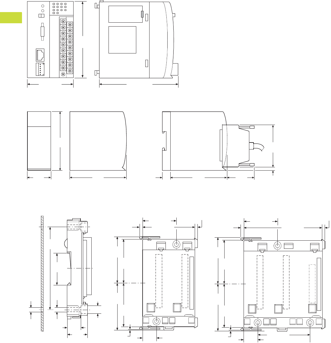
V7-T4-50 Volume 7—Logic Control, Operator Interface and Connectivity Solutions CA08100008E—February 2014 www.eaton.com
4
4
4
4
4
4
4
4
4
4
4
4
4
4
4
4
4
4
4
4
4
4
4
4
4
4
4
4
4
4
4.2
PLC, I/O and Communications Products
XC Series Programmable Logic Controllers
Dimensions
Approximate Dimensions in Inches (mm)
XC-CPU101, XC-CPU201, XC-CPU202
XIOC_
Backplates
XIOC-BP-2 XIOC-BP-3 XIOC-BP-XC1
XIOC-BP-XC XIOC-BP-EXT
3.94 (100.0)
3.94
(100.0)
2.36 (60.0)
3.94
(100.0)
1.18
(30.0)
3.74
(95.0)
2.87
(73.0)
0.19
(5.0)
1.97
(50.0)
3.74
(95.0)
0.83
(21.0)
M4
3.46
(88.0)
1.40
(35.5)
0.18
(4.5) 0.33
(8.5)
0.55
(14.0) 0.83
(21.0)
1.54 (39.0)
2.11
(53.5)
1.97
(50.0)
2.11
(53.5)
1.97
(50.0)
0.04
(1.0) 0.63
(16.0)
2.36 (60.0)
0.14
(3.5)
0.12 (3.0)
1.54 (39.0)
3.54 (90.0)
0.14
(3.5)
0.12 (3.0)
2.11
(53.5)
1.97
(50.0)
2.11
(53.5)
1.97
(50.0)
0.04
(1.0) 0.63 (16.0)
2.36 (60.0)
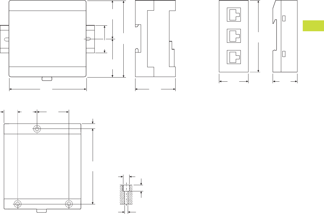
Volume 7—Logic Control, Operator Interface and Connectivity Solutions CA08100008E—February 2014 www.eaton.com V7-T4-51
4
4
4
4
4
4
4
4
4
4
4
4
4
4
4
4
4
4
4
4
4
4
4
4
4
4
4
4
4
4
4.2
PLC, I/O and Communications Products
XC Series Programmable Logic Controllers
Approximate Dimensions in Inches (mm)
XC-CPU-121_, XIO-EXT121-1 XT-RJ45-ETH-RS232
3.54
(90.0)
1.97
(50.0)
1.97
(50.0)
1.38
(35.0)
3.94
(100.0)
1.85
(47.0)
3.54
(90.0)
1.38
(35.0)
1.18
(30.0)
3.46
(88.0)
0.34
(8.5)
0.27
(6.8)
0.18
(4.5)
1.47
(37.3)
0.90
(22.8)
0.63
(16.0) 0.24
(6.0)
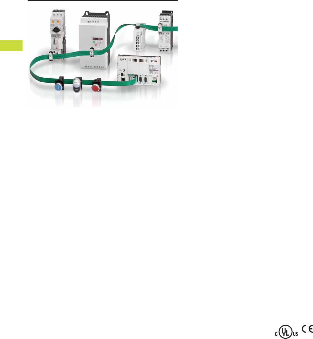
V7-T4-52 Volume 7—Logic Control, Operator Interface and Connectivity Solutions CA08100008E—February 2014 www.eaton.com
4
4
4
4
4
4
4
4
4
4
4
4
4
4
4
4
4
4
4
4
4
4
4
4
4
4
4
4
4
4
4.3
PLC, I/O and Communications Products
XC152 Series Programmable Logic Controllers
XC152 Series Programmable Logic Controllers
Contents
Description Page
XC152 Series Programmable Logic Controllers
Catalog Number Selection . . . . . . . . . . . . . . . . V7-T4-53
Product Selection . . . . . . . . . . . . . . . . . . . . . . . V7-T4-53
Accessories . . . . . . . . . . . . . . . . . . . . . . . . . . . V7-T4-53
Technical Data and Specifications . . . . . . . . . . V7-T4-54
Dimensions . . . . . . . . . . . . . . . . . . . . . . . . . . . V7-T4-55
Product Description
The XC152 compact
PLC combines plenty of
processing power with a
large number of
communication interfaces.
This makes the device
particularly well-suited to
standardized automation
solutions in modular machine
building applications.
The XC152 not only provides
machine segment control
functions that can be
programmed with CoDeSys,
but it can store module-
specific visualizations.
These visualizations can be
retrieved and displayed on
a central HMI or a computer
as needed.
In addition, the XC152
connects SmartWire-DT
systems to standard fieldbus
systems via its interfaces.
This enables the XC152 PLC
to support Eaton’s Lean
Automation strategy while
enabling users to design
automation systems in a
flexible manner and run them
cost-effectively.
Application Description
Flexible Solutions for
Modular Machine Units
In the field of automation,
complex processes are
subdivided into easily
manageable functional units
to make programming,
production and installation
easier. For example, a
packaging machine can be
subdivided into infeed,
positioning (erector), filling
and sealing (gluing) modules.
Other systems and machines
can also be effectively
subdivided to create a wide
variety of different models or
to delimit various expansion
stages.
With the XC152, a powerful
PLC controls individual
system modules while
making it possible to directly
connect SmartWire-DT
system devices and standard
fieldbus components. Data
transfers via the Ethernet
interface to OPC clients,
together with the available
remote visualization system,
support a connection to a
central control and
visualization system.
SmartWire-DT
The XC152 relies on Eaton’s
tried-and-true SmartWire-DT
connection system,
eliminating the need for
control current wiring in
every single machine
module and simplifying the
commissioning process by
means of better diagnostic
options. This results in
significant design,
commissioning and
maintenance cost reductions.
Standard CAN and
PROFIBUS Fieldbus
Systems
Servo drives, frequency
inverters and hydraulic
components can all be easily
connected using the large
number of fieldbus interfaces
available on the XC152.
Visualization
The integrated Web
visualization function offers a
key advantage, as machine
module diagnostic and
visualization information can
be displayed on a central HMI
or a terminal.
Features and Benefits
●CoDeSys PLC and Web
visualization
●Galileo/CoDeSys remote
visualization
●Ethernet port on all models
●Windows® CE 5 operating
system
●32-bit RISC CPU at
400 MHz
●64 MB internal memory
●SD card slot for external
memory
●Run/Stop switch
●Optional: Integrated
SmartWire-DT master
for 99 nodes
●Optional: RS-232, RS-485,
PROFIBUS-DP/MPI,
CANopen/easyNet
Standards and
Certifications
●IEC/EN 61131-2, EN 50178
●
EN 61000-6-2, EN 61000-6-4
●cULus
●CE
Volume 7—Logic Control, Operator Interface and Connectivity Solutions CA08100008E—February 2014 www.eaton.com V7-T4-53
4
4
4
4
4
4
4
4
4
4
4
4
4
4
4
4
4
4
4
4
4
4
4
4
4
4
4
4
4
4
4.3
PLC, I/O and Communications Products
XC152 Series Programmable Logic Controllers
Catalog Number Selection
XC152 PLCs with and without SmartWire-DT
Product Selection
XC152 PLC
XC152 PLC SmartWire-DT
Accessories
XC PLC Accessories
CoDeSys
Firmware
Fieldbus
Type RS-232 RS-485 Ethernet
Catalog
Number
Yes CANopen Yes Yes Yes XC-152-D6-11
Yes PROFIBUS-DP Yes Yes Yes XC-152-D8-11
CoDeSys
Firmware
Fieldbus
Type RS-232 RS-485 Ethernet SmartWire-DT
Catalog
Number
Yes None Y None Yes Yes XC-152-E3-11
Yes CANopen None Yes Yes Yes XC-152-E6-11
Yes PROFIBUS-DP None Yes Yes Yes XC-152-E8-11
Description
Catalog
Number
PLC programming software, single seat license SW-XSOFT-CODESYS-2-S
PLC programming software, multiple seat license SW-XSOFT-CODESYS-2-M
SD memory card MEMORY-SD-A1-S
Family
XC-152 = Windows CE OS CoDeSys firmware
Mounting
11 = DIN rail or panel mount
Features
Base Unit Variant
Features
Additional COMM Options
D = Ethernet, RS-485 and USB host
E = SmartWire-DT, Ethernet and
USB host
3 =None
6 = 1-CANopen
8 = 1-PROFIBUS-DP
XC-152 – E6 – 11
XC152 PLC
XC152 PLC
SmartWire-DT

V7-T4-54 Volume 7—Logic Control, Operator Interface and Connectivity Solutions CA08100008E—February 2014 www.eaton.com
4
4
4
4
4
4
4
4
4
4
4
4
4
4
4
4
4
4
4
4
4
4
4
4
4
4
4
4
4
4
4.3
PLC, I/O and Communications Products
XC152 Series Programmable Logic Controllers
Technical Data and Specifications
XC152 Series Programmable Logic Controllers
Note
1Interface not galvanically isolated.
Description Unit XC-152-D6-11 XC-152-D8-11 XC-152-E3-11 XC-152-E6-11 XC-152-E8-11
System
Processor RISC, 32 bit at 400 MHz RISC, 32 bit at 400 MHz RISC, 32 bit at 400 MHz RISC, 32 bit at 400 MHz RISC, 32 bit at 400 MHz
Internal memory
DRAM
(OS-, program and data memory)
Mbyte6464646464
NAND FLASH
(can be used for data security)
Mbyte Approx. 128 available Approx. 128 available Approx. 128 available Approx. 128 available Approx. 128 available
NVRAM (retain) kByte Approx. 32 available Approx. 32 available Approx. 32 available Approx. 32 available Approx. 32 available
External memory
SD memory card slot SDA Specification 1.00 SDA Specification 1.00 SDA Specification 1.00 SDA Specification 1.00 SDA Specification 1.00
Real-time clock (battery backup)
Battery (not rechargeable) Zero maintenance Zero maintenance Zero maintenance Zero maintenance Zero maintenance
Backup time at zero voltage Normally 10 years Normally 10 years Normally 10 years Normally 10 years Normally 10 years
Operating system Windows CE 5 Windows CE 5 Windows CE 5 Windows CE 5 Windows CE 5
Engineering
PLC-Programming software CoDeSys 2/3 CoDeSys 2/3 CoDeSys 2/3 CoDeSys 2/3 CoDeSys 2/3
Visualization
WEB-VISU CoDeSys CoDeSys CoDeSys CoDeSys CoDeSys
Remote Client Galileo/CoDeSys Galileo/CoDeSys Galileo/CoDeSys Galileo/CoDeSys Galileo/CoDeSys
Communication Interfaces
Ethernet 100Base-TX/10Base-T 100Base-TX/10Base-T 100Base-TX/10Base-T 100Base-TX/10Base-T 100Base-TX/10Base-T
USB host 1—————
USB device 1USB 2.0 USB 2.0 USB 2.0 USB 2.0 USB 2.0
System port (RS-232) 1■■■——
SmartWire-DT 1——■■■
CAN 1■——■—
PROFIBUS/MP 1—■——■
RS-485 1■■—■■
General
Rated operating voltage 24 Vdc SELV 24 Vdc SELV 24 Vdc SELV 24 Vdc SELV 24 Vdc SELV
Power consumption W Max. 5 Max. 5 Max. 5 Max. 5 Max. 5
Protect against polarity reversal Yes Yes Yes Yes Yes
Approvals CE, cULus CE, cULus CE, cULus CE, cULus CE, cULus
Ambient air temperature °C 0 to 55 0 to 55 0 to 55 0 to 55 0 to 55
Storage temperature °C –40 to +70 –40 to +70 –40 to +70 –40 to +70 –40 to +70
Protection type IP20 IP20 IP20 IP20 IP20
Flush mounting DIN rail EN 60715, 35 mm DIN rail EN 60715, 35 mm DIN rail EN 60715, 35 mm DIN rail EN 60715, 35 mm DIN rail EN 60715, 35 mm
Dimensions (H x W x D) mm 105 x 155 x 40 105 x 155 x 40 105 x 155 x 40 105 x 155 x 40 105 x 155 x 40
Weight (approximate) kg 0.3 0.3 0.3 0.3 0.3
Applied standards and directives
Product standard
IEC/EN 61131-2, EN50178 IEC/EN 61131-2, EN50178 IEC/EN 61131-2, EN50178 IEC/EN 61131-2, EN50178 IEC/EN 61131-2, EN50178
EMC
EN 61000-6-2, EN 61000-6-4 EN 61000-6-2, EN 61000-6-4 EN 61000-6-2, EN 61000-6-4 EN 61000-6-2, EN 61000-6-4 EN 61000-6-2, EN 61000-6-4
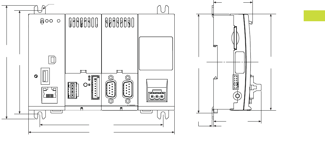
Volume 7—Logic Control, Operator Interface and Connectivity Solutions CA08100008E—February 2014 www.eaton.com V7-T4-55
4
4
4
4
4
4
4
4
4
4
4
4
4
4
4
4
4
4
4
4
4
4
4
4
4
4
4
4
4
4
4.3
PLC, I/O and Communications Products
XC152 Series Programmable Logic Controllers
Dimensions
Approximate Dimensions in Inches (mm)
XC152 Series Programmable Logic Controllers
4.77
(121.2)
1.99 (50.6)
0.06 (1.5)
Ø 0.18 (4.5)
5.15 (130.8)
6.11 (155.1)
4.34
(110.2)
1.63 (41.5)
4.04
(102.6)
4.16
(105.6)
With Fixing Brackets Without Fixing Brackets
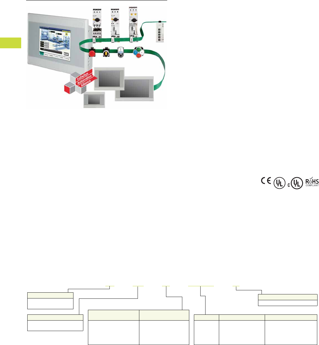
V7-T4-56 Volume 7—Logic Control, Operator Interface and Connectivity Solutions CA08100008E—February 2014 www.eaton.com
4
4
4
4
4
4
4
4
4
4
4
4
4
4
4
4
4
4
4
4
4
4
4
4
4
4
4
4
4
4
4.4
PLC, I/O and Communications Products
XV Series HMI-PLCs
XV Series HMI-PLC
Contents
Description Page
XV Series HMI-PLC
Product Selection . . . . . . . . . . . . . . . . . . . . . . . V7-T4-57
Accessories . . . . . . . . . . . . . . . . . . . . . . . . . . . V7-T4-57
Product Description
The XV HMI-PLC is a
powerful combination of logic
and visualization based on the
open CoDeSys programming
platform. It is ideal for small
to mid-range PLC applications
where integrated logic and
visualization is advantageous
and/or where remote
administration is critical.
The XV HMI-PLC is also
available with an integrated
SmartWire-DT™ master. This
combination of visualization,
control and SmartWire-DT
connectivity is the ultimate
lean automation solution.
Features
●Built-in SmartWire-DT
master for 99 nodes
●Brilliant image display with
65,536 colors
●High resolution resistive
touch TFT displays
●3.5 in, 5.7 in or 7 in
widescreen displays in a
robust plastic housings
and bezels, or
●5.7 in, 8.4 in or 10.4 in
displays in high-end
aluminum front bezels
and metal housings
●Ethernet on all models
●RS-232 or RS-485 serial
ports available
●PROFIBUS-DP or
CANopen master on all
models larger than 3.5 in
●Programmable with
IEC 61131-3 compliant
XSoft-CoDeSys software
●Easy connection direct to
motor control components
or I/O modules on the
SmartWire-DT flat cable
Standards and
Certifications
●CE
●UL
●cUL
●RoHS
Catalog Number Selection
XV HMI-PLC
XV –102–E6–35TQRG–10
Family
XV = Windows® CE
operating system
Bezel
10 = Standard blank front bezel
Display Size Display Technology OS Build
35 = 3.5 in
57 = 5.7 in
70 = 7.0 in
84 = 8.4 in
10 = 10.4 in
TQR = TFT (QVGA) resistive
TVR = TFT (VGA) resistive
TWR = TFT (WGA) resistive
C = XSoft-CoDeSys
Features
Base Unit Variant
Features
Additional COMM Options
B = Retentive memory
D = Retentive memory, USB
host, RS-232
E = SmartWire-DT, retentive
memory, USB host, RS-232
6 = 1-CANopen
8 = 1-PROFIBUS-DP
E = SmartWire-DT
Housing
102 = Plastic housing
152 = Metal housing
Volume 7—Logic Control, Operator Interface and Connectivity Solutions CA08100008E—February 2014 www.eaton.com V7-T4-57
4
4
4
4
4
4
4
4
4
4
4
4
4
4
4
4
4
4
4
4
4
4
4
4
4
4
4
4
4
4
4.4
PLC, I/O and Communications Products
XV Series HMI-PLCs
Product Selection
XV HMI-PLC
XV HMI-PLC SmartWire-DT
Accessories
XV HMI-PLC Accessories
Note
1For details on SW-XSoft-CoDeSys software, see Page V7-T4-33.
Display Size/Type
Display
Resolution
CoDeSys
Firmware Fieldbus Type RS485 Ethernet Catalog Number
Plastic Housing
3.5 in TFT
Resistive
QVGA
320x240
Y CANopen Y Y XV-102-B6-35TQRC-10
Y PROFIBUS-DP Y Y XV-102-B8-35TQRC-10
5.7 in TFT
Resistive
VGA
640x480
Y CANopen Y Y XV-102-D6-57TVRC-10
Y PROFIBUS-DP Y Y XV-102-D8-57TVRC-10
7.0 in TFT
Resistive
WGA
800x480
Y CANopen Y Y XV-102-D6-70TWRC-10
Y PROFIBUS-DP Y Y XV-102-D8-70TWRC-10
Metal Housing
5.7 in TFT
Resistive
VGA
640x480
Y CANopen Y Y XV-152-D6-57TVRC-10
Y PROFIBUS-DP Y Y XV-152-D8-57TVRC-10
8.4 in TFT
Resistive
VGA
640x480
Y CANopen Y Y XV-152-D6-84TVRC-10
Y PROFIBUS-DP Y Y XV-152-D8-84TVRC-10
10.4 in TFT
Resistive
VGA
640x480
Y CANopen Y Y XV-152-D6-10TVRC-10
Y PROFIBUS-DP Y Y XV-152-D8-10TVRC-10
Display
Size/Type
Display
Resolution
CoDeSys
Firmware Fieldbus Type RS485 Ethernet SmartWire-DT Catalog Number
Plastic Housing
3.5 in TFT QVGA
320x240
Y None None Y Y XV-102-BE-35TQRC-10
5.7 in TFT VGA
640x480
Y CANopen Y Y Y XV-102-E6-57TVRC-10
Y PROFIBUS-DP Y Y Y XV-102-E8-57TVRC-10
7.0 in TFT WGA
800x480
Y CANopen Y Y Y XV-102-E6-70TWRC-10
Y PROFIBUS-DP Y Y Y XV-102-E8-70TWRC-10
Metal Housing
5.7 in TFT VGA
640x480
Y CANopen Y Y Y XV-152-E6-57TVRC-10
Y PROFIBUS-DP Y Y Y XV-152-E8-57TVRC-10
8.4 in TFT VGA
640x480
Y CANopen Y Y Y XV-152-E6-84TVRC-10
Y PROFIBUS-DP Y Y Y XV-152-E8-84TVRC-10
10.4 in TFT VGA
640x480
Y CANopen Y Y Y XV-152-E6-10TVRC-10
Y PROFIBUS-DP Y Y Y XV-152-E8-10TVRC-10
Description Catalog Number
HMI-PLC programming software, single seat license SW-XSOFT-CODESYS-2-S 1
HMI-PLC programming software, multiple seat license SW-XSOFT-CODESYS-2-M 1
SD memory card MEMORY-SD-A1-S
XV-102 parts kit (1 power conductor, 8 mounting brackets, 1 sealing strip, 1 touch pen) ACC-TP-57-KG-1
XV-152 parts kit (1 power conductor, 8 mounting brackets, 1 sealing strip, 1 touch pen) ACC-TP-10-12-RES-1
XV HMI-PLC
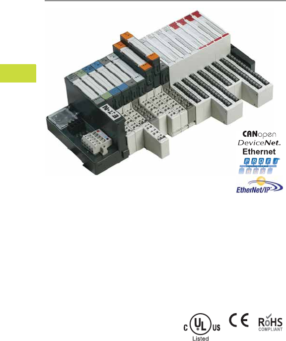
V7-T4-58 Volume 7—Logic Control, Operator Interface and Connectivity Solutions CA08100008E—February 2014 www.eaton.com
4
4
4
4
4
4
4
4
4
4
4
4
4
4
4
4
4
4
4
4
4
4
4
4
4
4
4
4
4
4
4.5
PLC, I/O and Communications Products
XI/ON Series Remote I/O
XI/ON Series Remote I/O
Contents
Description Page
XI/ON Series Remote I/O
Product Selection Guide . . . . . . . . . . . . . . . . . V7-T4-59
Catalog Number Selection . . . . . . . . . . . . . . . . V7-T4-60
System Overview . . . . . . . . . . . . . . . . . . . . . . . V7-T4-62
Product Selection . . . . . . . . . . . . . . . . . . . . . . . V7-T4-66
Accessories . . . . . . . . . . . . . . . . . . . . . . . . . . . V7-T4-75
Technical Data and Specifications . . . . . . . . . . V7-T4-76
Connection Diagrams . . . . . . . . . . . . . . . . . . . . V7-T4-89
Dimensions . . . . . . . . . . . . . . . . . . . . . . . . . . . V7-T4-101
Product Overview
Whether for controlling
movements, measuring
temperature or speed, or
logging currents and
voltages, the application
ranges for remote I/Os
are as extensive as the
different applications
involved. They are used
wherever decentralized
signal processing is the
essential element of the
automation concept.
Thanks to the high modularity
of the XI/ON system and
the wide range of functions,
Eaton is able to offer the
right I/O solution for every
application. XI/ON: A modular
concept with simple handling—
adaptable to any application,
intelligent and ready for
future developments.
Standards and
Certifications
●UL File No. E205091
●UL CCN—NRAQ, NRAQ7
●cULus
●CE
●RoHS
Volume 7—Logic Control, Operator Interface and Connectivity Solutions CA08100008E—February 2014 www.eaton.com V7-T4-59
4
4
4
4
4
4
4
4
4
4
4
4
4
4
4
4
4
4
4
4
4
4
4
4
4
4
4
4
4
4
4.5
PLC, I/O and Communications Products
XI/ON Series Remote I/O
Product Selection Guide
XI/ON Series Remote I/O
XI/ON
XNE Gateways and
Integrated Modules
XN Standard Gateways and
Plug-in Modules
Page V7-T4-66 Page V7-T4-68
As many as needed, as few as possible—
this is the principle on which the XI/ON
modular I/O system was built. An extensive
range of digital and analog I/Os as well as
technology modules are available.
●High level of modularity
●Fieldbuses: CANopen, PROFIBUS-DP,
DeviceNet and Ethernet
●Bus-independent, pluggable modules
●Low wiring requirement
●Precise diagnostics
●Space and cost saving with XNE
modules
●Programmable CANopen gateway
●Standard and XNE modules can be
mixed
XI/ON XNE completes the XI/ON I/O
system with price and space optimized I/O
modules and gateways. The XNE gateways
use the EtherNet/IP, Modbus TCP Ethernet,
CANopen and PROFIBUS-DP bus systems.
●XNE gateways with integrated bus
terminating resistors
●Full compatibility with the standard
XI/ON system
●No base module required
●High channel density (up to 16 DI/DO
on 12.5 mm width)
●“Push-In” spring-loaded terminals
●Multi-functional slices
●Diagnostics interface
The standard gateways use the Modbus
TCP, DeviceNet, Ethernet, CANopen and
PROFIBUS-DP bus systems.
●The use of pluggable I/O modules is
independent on the fieldbus used
●Wiring is implemented on the base
module, fixed wiring
●Fast module exchange under power
(hot swapping)
●Generation of diagnostics information
to higher-level controller
●Up to 74 slice modules can be
connected per gateway
●Mechanical coding of modules
●Diagnostics interface
Programmable CANopen Gateway Base Modules for Every Requirement
I/Oassistant—the Universal
Configuration and Diagnostics Tool
Page V7-T4-68 Page V7-T4-72
The programmable CANopen gateway
brings the power of the PLC directly to the
fieldbus terminal. The device is ideal for
handling decentralized automation tasks
and thus for relieving the load of a higher-
level PLC.
The serial onboard interface is used for
local programming access and as an
interface for the I/Oassistant configuration
and diagnostics tool. Alternatively, this
interface can also be used as a free user
interface. The gateway is programmed with
XSoft-CoDeSys-2.
The base modules are used to connect
the field wiring for the standard XI/ON
modules. They are available for 2-, 3- and
4-wire connections, as block or slice
modules, with either spring-loaded
terminals or screw terminals—the right
format for every application.
The I/Oassistant provides you with a
universal tool that offers interactive
support with the entire planning and
implementation of your XI/ON installation.
The I/Oassistant is integrated in
XSoft-CoDeSys-2.
A project is first of all created and
structured on the screen. For this you
choose gateways, electronic and base
modules as well as the appropriate
accessories. The individual stations are
then configured offline or online. Once
everything is set to your satisfaction, you
simply put your installation into operation.
The I/Oassistant also automatically
generates a parts list for your order.
I/Oassistant checks the station, reads the
process data, outputs values and visualizes
the diagnostics data of the channel. This
enables you to commission your station
without a higher-level PLC and ensure that
a section of the system is functioning
correctly.
V7-T4-60 Volume 7—Logic Control, Operator Interface and Connectivity Solutions CA08100008E—February 2014 www.eaton.com
4
4
4
4
4
4
4
4
4
4
4
4
4
4
4
4
4
4
4
4
4
4
4
4
4
4
4
4
4
4
4.5
PLC, I/O and Communications Products
XI/ON Series Remote I/O
Catalog Number Selection
Gateway Modules
Digital I/O Modules
Analog I/O Modules
Module Type
XNE = Integrated I/O Modules
XN = Plug-in I/O Modules
XNE -GWBR - 2ETH - IP
Fieldbus Type
2ETH-IP = EtherNet/IP
2ETH-MB = Modbus TCP/Ethernet
MODBUS-TCP = Modbus TCP/Ethernet
DVP1 = PROFIBUS-DP (DVP1)
PBDP = PROFIBUS-DP (DVP0)
CANOPEN = CANopen
DNET = DeviceNet
Gateway Type
GWBR = Standard Gateway
PLC = Programmable Gateway
XNE -16DO - 24VDC - 0.5A - P
Number of Digital I/O
DI = Number of digital inputs
DO = Number of digital outputs
Rated Voltage
VDC =24 Vdc
VAC = 120/230 Vac
Switching
P = Positive switching
N = Negative switching
Module Type
XNE = Integrated I/O Modules
XN = Plug-in I/O Modules
Current Rating
XN -2AO - U - (–10/0 … +10 Vdc)
Input/Output Range
I = 0/4 to 20 mA
U = –10/0 to +10 Vdc
U/I = 0/4 to 20 mA or –10/0 to +10 Vdc
Number of Analog I/O
AI = Number of analog inputs
AO = Number of analog outputs
Module Type
XNE = Integrated I/O Modules
XN = Plug-in I/O Modules
Volume 7—Logic Control, Operator Interface and Connectivity Solutions CA08100008E—February 2014 www.eaton.com V7-T4-61
4
4
4
4
4
4
4
4
4
4
4
4
4
4
4
4
4
4
4
4
4
4
4
4
4
4
4
4
4
4
4.5
PLC, I/O and Communications Products
XI/ON Series Remote I/O
Base Modules
Module Type
B = Block module (white)
P = Power module (gray)
S = Slice module (white)
Module Type
XN = Plug-in I/O modules
XN -S 6 T - S B C S B C
Terminal Connections
S = Screw terminals
T = Spring-cage terminals
Connection Levels
3 = 3 levels
4 = 4 levels
6 = 6 levels
Terminals 16 and 26
B = Bridged terminals
C = Common bus terminals
S = Signal terminals
Terminals 15 and 25
B = Bridged terminals
C = Common bus terminals
S = Signal terminals
Terminals 14 and 24
B = Bridged terminals
C = Common bus terminals
S = Signal terminals
Terminals 13 and 23
B = Bridged terminals
C = Common bus terminals
S = Signal terminals
Terminals 12 and 22
B = Bridged terminals
C = Common bus terminals
S = Signal terminals
Terminals 11 and 21
B = Bridged terminals
C = Common bus terminals
S = Signal terminals

V7-T4-62 Volume 7—Logic Control, Operator Interface and Connectivity Solutions CA08100008E—February 2014 www.eaton.com
4
4
4
4
4
4
4
4
4
4
4
4
4
4
4
4
4
4
4
4
4
4
4
4
4
4
4
4
4
4
4.5
PLC, I/O and Communications Products
XI/ON Series Remote I/O
System Overview
System Configuration
XN Module and Base Compatibility Chart
Notes
1Base module for gateway supply.
2Base module for bus refreshing within the station.
Base Modules
XN-S3S-SBB
XN-S3T-SBB
XN-S3S-SBC
XN-S3T-SBC
XN-S4S-SBBC
XN-S4T-SBBC
XN-S4S-SBBS
XN-S4T-SBBS
XN-S4S-SBCS
XN-S4T-SBCS
XN-S4S-SBBS-CJ
XN-S4T-SBBS-CJ
XN-S6S-SBBSBB
XN-S6T-SBBSBB
XN-S6S-SBCSBC
XN-S6T-SBCSBC
XN-B3S-SBB
XN-B3T-SBB
XN-B3S-SBC
XN-B3T-SBC
XN-B4S-SBBC
XN-B4T-SBBC
XN-B6S-SBBSBB
XN-B6T-SBBSBB
XN-B6S-SBCSBC
XN-B6T-SBCSBC
XN-P3S-SBB
XN-P3T-SBB
XN-P3S-SBB-B
XN-P3T.-SBB-B
XN-P4S-SBBC
XN-P4T-SBBC
XN-P4S-SBBC-B
XN-P4T-SBBC-B
Electronics Modules
Digital Input Modules
XN-2DI-24VDC-P ✓—✓——————————————
XN-2DI-24VDC-N ✓—✓——————————————
XN-2DI-120/230VAC ✓—✓——————————————
XN-4DI-24VDC-P — — — ✓—— ✓——————————
XN-4DI-24VDC-N — — — ✓—— ✓——————————
XN-16DI-24VDC-P ———————— ✓—✓——————
XN-32DI-24VDC-P ——————————— ✓—————
Digital Output Modules
XN-2DO-24VDC-0.5A-P — ✓—— ✓————————————
XN-2DO-24VDC-0.5A-N — ✓—— ✓————————————
XN-2DO-24VDC-2A-P — ✓—— ✓————————————
XN-2DO-120/230VAC-0.5A — ✓—— ✓————————————
XN-4DO-24VDC-0.5A-P ———— ✓—— ✓—————————
XN-16DO-24VDC-0.5A-P ————————— ✓———————
XN-32DO-24VDC-0.5A-P ———————————— ✓————
Relay Modules
XN-2DO-R-NC — — — ✓✓
————————————
XN-2DO-R-NO — — — ✓✓
————————————
XN-2DO-R-CO — — — ✓—————————————
Analog Input Modules
XN-1AI-I(0/4…20MA) ✓—— ✓—————————————
XN-2AI-I(0/4…20MA) ✓—— ✓—————————————
XN-1AI-U(-10/0…+10VDC) ✓—— ✓—————————————
XN-2AI-U(-10/0…+10VDC) ✓—— ✓—————————————
XN-2AI-PT/NI-2/3 ✓—— ✓—————————————
XN-2AI-THERMO-PI ————— ✓———————————
XN-4AI-U/I ——————— ✓—————————
Analog Output Modules
XN-1AO-I(0/4…20MA) ✓————————————————
XN-2AO-I(0/4…20MA) ✓————————————————
XN-2AO-U(-10/0…+10VDC) ✓————————————————
Technology Modules
XN-1CNT-24VDC — — — ✓—————————————
XN-1RS232 ——— ✓—————————————
XN-1RS485/422 — — — ✓—————————————
XN-1SSI ——— ✓—————————————
Supply Modules
XN-BR-24VDC-D —————————————
✓ 1✓ 2✓ 1✓ 2
XN-PF-24VDC-D ————————————— ✓—✓—
XN-PF-120/230VAC-D ————————————— ✓—✓—
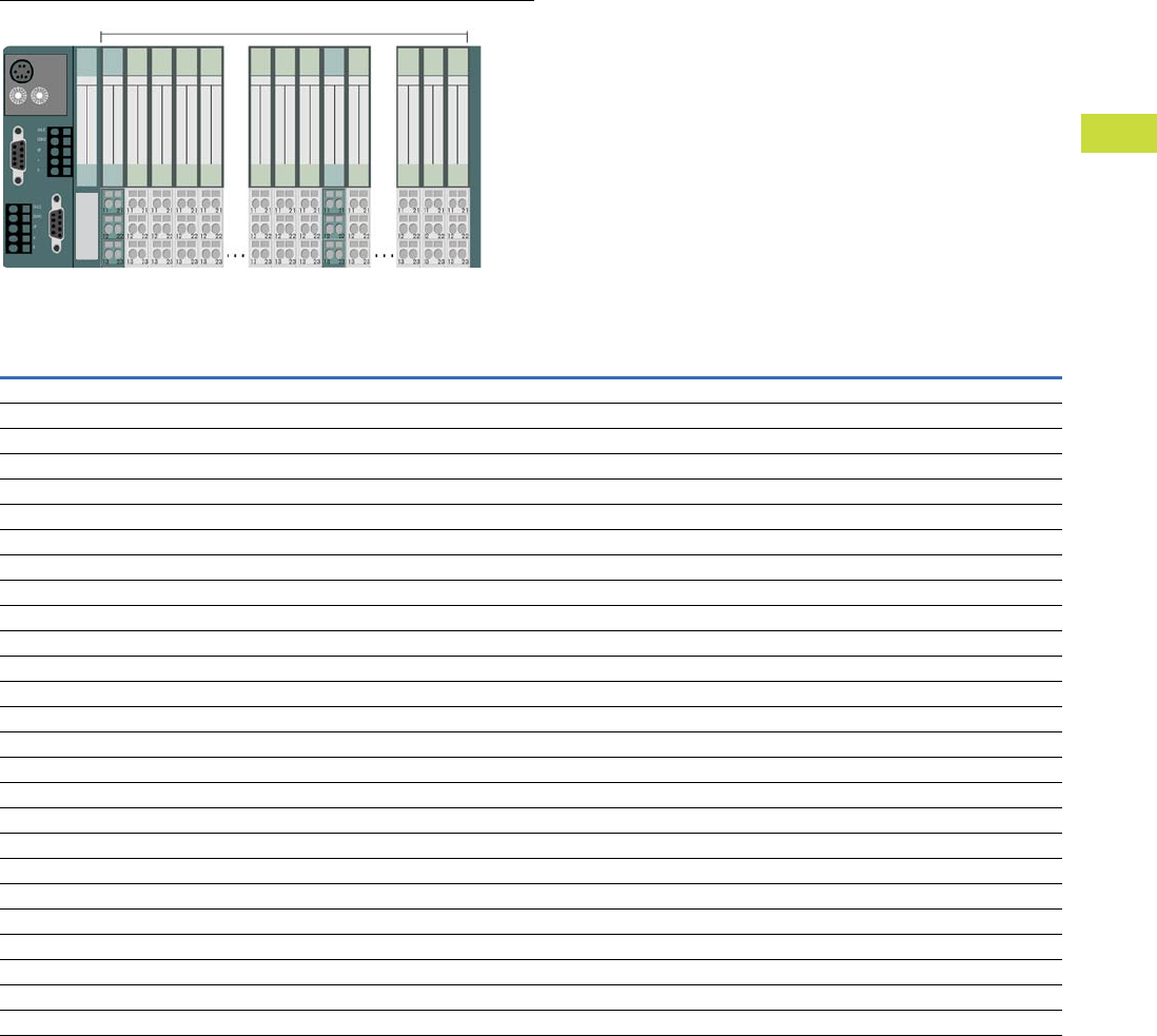
Volume 7—Logic Control, Operator Interface and Connectivity Solutions CA08100008E—February 2014 www.eaton.com V7-T4-63
4
4
4
4
4
4
4
4
4
4
4
4
4
4
4
4
4
4
4
4
4
4
4
4
4
4
4
4
4
4
4.5
PLC, I/O and Communications Products
XI/ON Series Remote I/O
Maximum System Configuration
Plan your XI/ON station with the software “I/Oassistant”.
Advantage 1:
Automatically generates a full parts list for your order.
Advantage 2:
Generates an error message as soon as the system limits are
exceeded.
IMPORTANT:
When extending your system, make sure that you have a
sufficient number of bus refresh or power feed modules.
Note
Numeric values in parentheses. Maximum number when diagnostic alarm disabled.
The supply module XN-BR-24VDC-D must be mounted immediately next to the gateway XN-GW-_ to provide power for the gateways.
Style Number: 140045 140044 140047 152279
Catalog Number: XNE-GWBR-PBDP XNE-GWBR-CANOPEN XNE-GWBR-2ETH-IP XNE-GWBR-2ETH-MB
Channels Modules Channels Modules Channels Modules Channels Modules
Modules
XN-4DI-24VDC-P 136 34 244 61 288 72 288 72
XN-4DI-24VDC-N 136 34 244 61 288 72 288 72
XN-16DI-24VDC-P 128 8 128 8 128 8 128 8
XN-32DI-24VDC-P 256 8 256 8 256 8 256 8
XNE-8DI-24VDC-P 384 48 512 64 512 64 512 64
XNE-16DI-24VDC-P 768 48 512 32 512 32 512 32
XN-4DO-24VDC-0.5A-P 132 33 244 61 288 72 288 72
XN-16DO-24VDC-0.5A-P 128 8 128 8 128 8 128 8
XN-32DO-24VDC-0.5A-P 256 8 256 8 256 8 256 8
XNE-8DO-24VDC-0.5A-P 384 48 488 61 512 64 512 64
XNE-16DO-24VDC-0.5A-P 640 40 512 32 512 32 512 32
XN-2DO-R-_ 70 35 122 61 144 72 144 72
XN-2AI-I(0/4…20MA) 56 28 100 50 126 63 126 63
XN-2AI-U(-10/0…+10VDC) 56 28 100 50 126 63 126 63
XN-2AI-PT/NI2/3 44 22 98 49 126 63 126 63
XN-2AI-THERMO-PI 44 22 98 49 126 63 126 63
XN-4AI-U/I 64 (132) 16 (33) 108 27 124 31 124 31
XNE-8AI-U/I-4PT/NI 72 (120) 9 (15) 144 18 128 16 128 16
XN-2AO-I(0/4…20MA) 50 25 70 35 126 63 126 63
XN-2AO-U(-10/0…+10VDC) 46 23 70 35 126 63 126 63
XNE-4AO-U/I 64 (76) 16 (19) 108 27 64 16 64 16
XN-1CNT-24VDC 13 13 27 27 31 31 31 31
XN-1RS232 7 7 272731313131
XN-1RS485/422 1616272731313131
XN-1SSI 2020272731313131
Maximum 74 XI/ON Modules in Slice Design
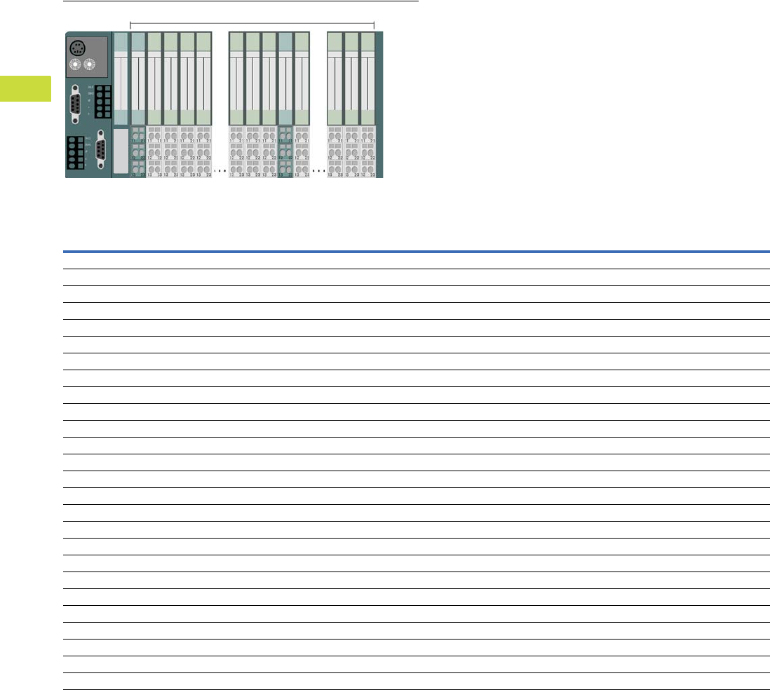
V7-T4-64 Volume 7—Logic Control, Operator Interface and Connectivity Solutions CA08100008E—February 2014 www.eaton.com
4
4
4
4
4
4
4
4
4
4
4
4
4
4
4
4
4
4
4
4
4
4
4
4
4
4
4
4
4
4
4.5
PLC, I/O and Communications Products
XI/ON Series Remote I/O
Maximum System Configuration, continued
Plan your XI/ON station with the software “I/Oassistant”.
Advantage 1:
Automatically generates a full parts list for your order.
Advantage 2:
Generates an error message as soon as the system limits are
exceeded.
IMPORTANT:
When extending your system, make sure that you have a
sufficient number of bus refresh or power feed modules.
Note
Numeric values in parentheses. Maximum number when diagnostic alarm disabled.
Style Number: 140154 140055 140156 140162
Catalog Number: XN-GWBR-PBDP XN-GWBR-CANOPEN XN-GWBR-DNET XN-GWBR-MODBUS-TCP
Channels Modules Channels Modules Channels Modules Channels Modules
Modules
XN-4DI-24VDC-P 288 72 288 72 288 72 288 72
XN-4DI-24VDC-N 288 72 288 72 288 72 288 72
XN-16DI-24VDC-P 128 8 128 8 128 8 128 8
XN-32DI-24VDC-P 256 8 256 8 256 8 256 8
XNE-8DI-24VDC-P 592 74 512 64 576 72 512 64
XNE-16DI-24VDC-P 1184 74 512 32 1152 72 512 32
XN-4DO-24VDC-0.5A-P 288 72 288 72 128 32 288 72
XN-16DO-24VDC-0.5A-P 128 8 128 8 128 8 128 8
XN-32DO-24VDC-0.5A-P 256 8 256 8 256 8 256 8
XNE-8DO-24VDC-0.5A-P 592 74 512 64 256 32 512 64
XNE-16DO-24VDC-0.5A-P 1168 73 512 32 512 32 512 32
XN-2DO-R-_ 144 72 144 72 64 32 144 72
XN-2AI-I(0/4…20MA) 78 39 144 72 32 16 144 72
XN-2AI-U(-10/0…+10VDC) 78 39 144 72 32 16 144 72
XN-2AI-PT/NI-2/3 46 23 144 72 32 16 144 72
XN-2AI-THERMO-PI 58 (76) 29 (38) 144 72 32 16 144 72
XN-4AI-U/I 112 28 144 36 64 16 144 36
XNE-8AI-U/I-4PT/NI 88 11 144 18 128 16 144 18
XN-2AO-I(0/4…20MA) 38 19 144 72 32 16 144 72
XN-2AO-U(-10/0…+10VDC) 38 19 144 72 32 16 144 72
XNE-4AO-U/I 36 9 144 36 64 16 124 31
XN-1CNT-24VDC 7 7 727216167272
XN-1RS232 222268688 8 6868
XN-1RS485/422 222272728 8 7272
XN-1SSI 222272728 8 7272
Maximum 74 XI/ON Modules in Slice Design
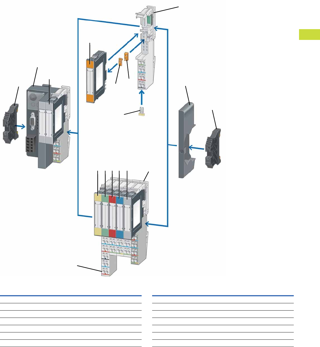
Volume 7—Logic Control, Operator Interface and Connectivity Solutions CA08100008E—February 2014 www.eaton.com V7-T4-65
4
4
4
4
4
4
4
4
4
4
4
4
4
4
4
4
4
4
4
4
4
4
4
4
4
4
4
4
4
4
4.5
PLC, I/O and Communications Products
XI/ON Series Remote I/O
System Overview
Item
Number Description
Item
Number Description
1Gateway 8End bracket
2Digital input module 9Power supply module
3Relay module 10 Analog input module
4Coding element 11 Digital output module
5Base module 12 Analog output module
6Relay jumper 13 Technology module
7End plate 14 Marker
1
2
3
4
5
7
8
910111213
14
4
8
6
5

V7-T4-66 Volume 7—Logic Control, Operator Interface and Connectivity Solutions CA08100008E—February 2014 www.eaton.com
4
4
4
4
4
4
4
4
4
4
4
4
4
4
4
4
4
4
4
4
4
4
4
4
4
4
4
4
4
4
4.5
PLC, I/O and Communications Products
XI/ON Series Remote I/O
Product Selection
XNE Series
The following are included as standard with all gateways:
2 x End bracket XN-WEW-32/2-SW,
1 x End plate XN-ABPL.
XNE Gateway with Integrated Supply
Description
Fieldbus
Connection
Terminal Capacity
(Fieldbus/Supply
Voltage)
Servicing
Interface
Transfer
Rate
Style
Number Catalog Number
Ethernet
Supports up to 74 disc type modules (XN, XNE)
2xRJ45 socket
Address set with decimal rotary coding switches,
BootP, DHCP or I/Oassistant
Address range: 1–254 (dec.)
Ethernet
(EtherNet/IP
protocol)
Push-in spring-cage
terminals
Mini USB 10/100
MBit/s
140047 XNE-GWBR-2ETH-IP
Supports up to 74 disc type modules (XN, XNE)
RJ45 Ethernet switch
Address set with decimal rotary coding switches,
BootP, DHCP or I/Oassistant
Address range: 1–254 (dec.)
Ethernet
(Modbus TCP)
Push-in spring-cage
terminals
Mini USB 10/100
MBit/s
152279 XNE-GWBR-2ETH-MB
PROFIBUS-DP
Supports up to 48 slice type modules (XN, XNE)
Address setting through DIP switch
Address range: 1–125 (dec.)
PROFIBUS-DP
(DPV0/DPV1
protocol)
Push-in spring-cage
terminals
PS/2 socket 9.6 kbit/s to
12 Mbit/s
140045 XNE-GWBR-PBDP
CANopen
Supports up to 62 disc type modules (XN, XNE)
Address set with DIP switch
Address range: 1–63 (dec.)
CANopen Push-in spring-cage
terminals
PS/2 socket 1000 kbit/s
800 kbit/s
500 kbit/s
250 kbit/s
125 kbit/s
50 kbit/s
20 kbit/s
140044 XNE-GWBR-CANOPEN
XNE Gateways

Volume 7—Logic Control, Operator Interface and Connectivity Solutions CA08100008E—February 2014 www.eaton.com V7-T4-67
4
4
4
4
4
4
4
4
4
4
4
4
4
4
4
4
4
4
4
4
4
4
4
4
4
4
4
4
4
4
4.5
PLC, I/O and Communications Products
XI/ON Series Remote I/O
XNE Digital Input Modules
Positive switching.
XNE Digital Output Modules
Resistive inductive and lamp load connectable.
XNE Analog Input and RTD Module
Rated voltage via power supply terminal: 24 Vdc.
XNE Analog Output Module
Rated voltage via power supply terminal: 24 Vdc.
XNE Counter Module
Rated voltage via power supply terminal: 24 Vdc.
Signal evaluation A, B: Pulse and direction, rotary encoder single/double/quadruple.
Note
1 cUL pending.
Channels
Rated Voltage via
Power Supply Terminal
Input Delay
tRise/tFall
Input Voltage
High Signal
Style
Number Catalog Number
8 24 Vdc <100/<200 µs 11 V-UL140035 XNE-8DI-24VDC-P
16 24 Vdc <150/<300 µs 11 V-UL140040 XNE-16DI-24VDC-P
Channels
Rated Voltage via
Power Supply Terminal
Switching Frequency with
Resistive Load in Hz
Utilization Factor
g in %
Style
Number Catalog Number
8 24 Vdc <100 100 140036 XNE-8DO-24VDC-0.5A-P
16 24 Vdc <100 50%, maximum 4A 140039 XNE-16DO-24VDC-0.5A-P
Channels Measured Variables Measuring Ranges Value Representation
Limit
Frequency
in Hz
Style
Number Catalog Number
8 (U/I)/
4 (PT/NI/R)
Voltage, current
temperature (PT, NI),
resistance R
–10 to 10 Vdc/0 to 10 Vdc
PT100, 200, 500, 1000,
NI100, 1000 2-, 3-wire
Standard:
16-bit/12-bit (flush-left)
1.5 140037 XNE-8AI-U/I-4PT/NI
Extended range:
16-bit/12-bit (flush-left) PA (NE43),
16-bit/12-bit (flush-left)
Channels Measured Variables Output Variables Value Representation
Style
Number Catalog Number
4 Voltage, current –10 to 10 Vdc/0 to 10 Vdc
0 to 20 mA
4 to 20 mA
Standard:
16-bit/12-bit (flush-left)
140034 XNE-4AO-U/I 1
Channels Operating Modes Pulse Duration
PWM
Module Resolution
Style
Number Catalog Number
2 Continuous, once only and
periodic counting
32-bit/maximum 120s ✓32-bit 140038 XNE-2CNT-2PWM
XNE Digital Input
XNE Digital Output
XNE Analog Input
XNE Analog Output
XNE Counter
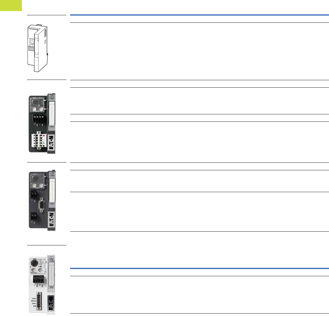
V7-T4-68 Volume 7—Logic Control, Operator Interface and Connectivity Solutions CA08100008E—February 2014 www.eaton.com
4
4
4
4
4
4
4
4
4
4
4
4
4
4
4
4
4
4
4
4
4
4
4
4
4
4
4
4
4
4
4.5
PLC, I/O and Communications Products
XI/ON Series Remote I/O
XN Series
The following are included as standard with all gateways:
2 x End bracket XN-WEW-32/2-SW,
1 x End plate XN-ABPL.
XN Gateway with Integrated Supply
XN Programmable Gateway with Integrated Supply
Description
Fieldbus
Connection
Terminal Capacity
(Fieldbus/Supply
Voltage)
Servicing
Interface
Transfer
Rate
Style
Number Catalog Number
Ethernet
Supports up to 74 slice type modules (XN, XNE)
1 x RJ45 socket
Address set with decimal rotary coding switches,
BootP, DHCP or I/Oassistant
Address range: 1–254 (dec.)
Ethernet
(Modbus TCP
protocol)
Screw terminals PS/2 socket 10/100 Mbit/s 140162 XN-GWBR-MODBUS-TCP
DeviceNet
Supports up to 74 disc type modules (XN, XNE)
1 x open-style connector
Address set with two decimal rotary coding
switches
Address range: 1–63 (dec.)
DeviceNet Screw terminals PS/2 socket 500 kbit/s
250 kbit/s
125 kbit/s
140156 XN-GWBR-DNET
CANopen
Supports up to 74 disc type modules (XN, XNE)
1 x open-style connector
Address set with two decimal rotary coding
switches
Address range: 1–99 (dec.)
CANopen Screw terminals PS/2 socket 1000 kbit/s
800 kbit/s
500 kbit/s
250 kbit/s
125 kbit/s
50 kbit/s
20 kbit/s
10 kbit/s
140155 XN-GWBR-CANOPEN
PROFIBUS-DP
Supports up to 74 disc type modules (XN, XNE)
1 x D-sub 9-pin socket
Address set with decimal rotary coding switches
Address range: 1–99 (dec.)
PROFIBUS-DP
(DVP1 protocol)
Screw terminals PS/2 socket 9.6 kbit/s to
12 Mbit/s
148561 XN-GWBR-DVP1
Supports up to 74 disc type modules (XN, XNE)
1 x D-sub 9-pin socket
Address set with decimal rotary coding switches
Address range: 1–99 (dec.)
PROFIBUS-DP
(DVP0 protocol)
Screw terminals PS/2 socket 9.6 kbit/s to
12 Mbit/s
140154 XN-GWBR-PBDP
Description
Fieldbus
Connection
Terminal Capacity
(Fieldbus/Supply
Voltage)
Servicing
Interface
Transfer
Rate
Style
Number Catalog Number
CANopen
Supports up to 74 disc type modules
(XN, XNE to limited extent)
1 x open-style connector
Operating mode and address setting with two
hexadecimal rotary coding switches
Address range: 1–99 (dec.)
CANOpen Screw terminals PS/2 socket Adjustable up
to 1 Mbit/s
140157 XN-PLC-CANOPEN
XN-GWBR-D_,
XN-GWBR-C_
XN-GWBR-DVP1
XN-GWBR-MODBUS_
XN-PLC-CANOPEN
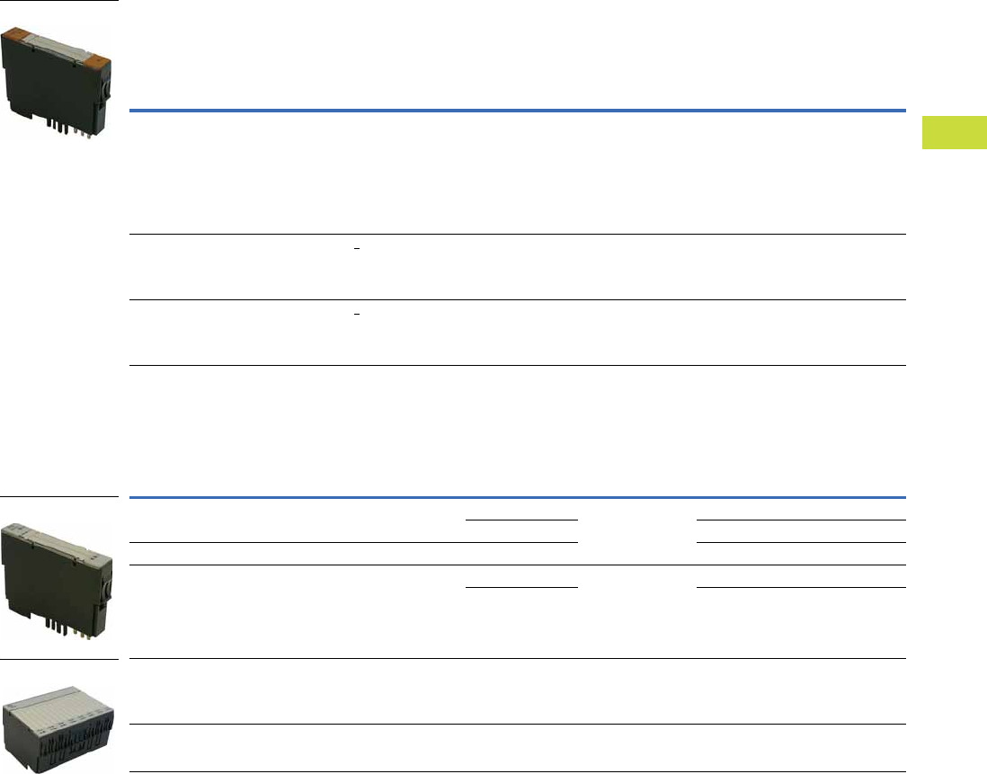
Volume 7—Logic Control, Operator Interface and Connectivity Solutions CA08100008E—February 2014 www.eaton.com V7-T4-69
4
4
4
4
4
4
4
4
4
4
4
4
4
4
4
4
4
4
4
4
4
4
4
4
4
4
4
4
4
4
4.5
PLC, I/O and Communications Products
XI/ON Series Remote I/O
XN Power Supply Modules
Number of diagnostic bits: 4.
Ripple <5% (to EN 61131-2).
XN Digital Input Modules
Base module required.
Operating and
Field Voltage
System
Power Supply
Rated Current
Consumption
from Modbus
Maximum
System Supply
Current
For Use
With …
Style
Number Catalog Number
24 Vdc 24 Vdc — 1.5A XN-P3T-SBB
XN-P3S-SBB
XN-P4T-SBBC
XN-P4S-SBBC
XN-P3T-SBB-B
XN-P3S-SBB-B
XN-P4T-SBBC-B
XN-P4S-SBBC-B
140071 XN-BR-24VDC-D
24 Vdc — <28 mA — XN-P3T-SBB
XN-P3S-SBB
XN-P4T-SBBC
XN-P4S-SBBC
140070 XN-PF-24VDC-D
120/230 Vac — <25 mA — XN-P3T-SBB
XN-P3S-SBB
XN-P4T-SBBC
XN-P4S-SBBC
140072 XN-PF-120/230VAC-D
Channels
Rated Voltage via
Power Supply
Terminal
Input Delay
tRise/tFall
Input Voltage
High Signal
For Use
With …
Style
Number Catalog Number
2 24 Vdc <200/<200 µs 11–30 Vdc XN-S3T-SBB
XN-S3S-SBB
XN-S4T-SBBC
XN-S4S-SBBC
140056 XN-2DI-24VDC-P
0–5 Vdc 140057 XN-2DI-24VDC-N
2 120/230 Vac <20,000/<20,000 µs 79–265 Vac 140058 XN-2DI-120/230VAC
4 24 Vdc <200/<200 µs 15–30 Vdc XN-S4T-SBBS
XN-S4S-SBBS
XN-S6T-SBBSBB
XN-S6S-SBBSBB
140052 XN-4DI-24VDC-P
0–5 Vdc 140059 XN-4DI-24VDC-N
16 24 Vdc <200/<200 µs 15–30 Vdc XN-B3T-SBB
XN-B3S-SBB
XN-B4T-SBBC
XN-B4S-SBBC
140142 XN-16DI-24VDC-P
32 24 Vdc <200/<200 µs 15–30 Vdc XN-B6T-SBBSBB
XN-B6S-SBBSBB
140147 XN-32DI-24VDC-P
Slice Module
Slice Module
Block Module
V7-T4-70 Volume 7—Logic Control, Operator Interface and Connectivity Solutions CA08100008E—February 2014 www.eaton.com
4
4
4
4
4
4
4
4
4
4
4
4
4
4
4
4
4
4
4
4
4
4
4
4
4
4
4
4
4
4
4.5
PLC, I/O and Communications Products
XI/ON Series Remote I/O
XN Digital Output Modules
Base module required.
Resistive inductive and lamp load connectable.
XN Relay Modules
Base module required.
Rated voltage via power supply terminal: 24 Vdc.
Resistive inductive and lamp load connectable.
XN Analog Input Modules
Base module required.
Rated voltage via power supply terminal: 24 Vdc.
Channels
Rated Voltage via
Power Supply
Terminal
Switching Frequency
with Resistive
Load in Hz
Utilization
Factor g in %
For Use
With …
Style
Number Catalog Number
2 24 Vdc <5000 (RLO <1 kohm) 100 XN-S3T-SBC
XN-S3S-SBC
XN-S4T-SBCS
XN-S4S-SBCS
140053 XN-2DO-24VDC-0.5A-P
<100 (RLO <1 kohm) 140060 XN-2DO-24VDC-0.5A-N
<5000 (RLO <1 kohm) 140055 XN-2DO-24VDC-2A-P
2 120–230 Vac
(45–65 Hz)
— 100 (observe derating
requirements)
140150 XN-2DO-120/230VAC-0.5A
4 24 Vdc <1000 (RLO <1 kohm) 100 XN-S4T-SBCS
XN-S4S-SBCS
XN-S6T-SBCSBC
XN-S6S-SBCSBC
140148 XN-4DO-24VDC-0.5A-P
16 24 Vdc <100 (RLO <1 kohm) 100 XN-B3T-SBC
XN-B3S-SBC
140141 XN-16DO-24VDC-0.5A-P
32 24 Vdc <100 (RLO <1 kohm) See total
module current
XN-B6T-SBCSBC
XN-B6S-SBCSBC
140161 XN-32DO-24VDC-0.5A-P
Channels Contact Type
Rated Load
Voltage
Maximum Continuous
Current per Channel/
230 Vac Resistive Load
For Use
With …
Style
Number Catalog Number
2 Changeover
Contacts
230 Vac, 30 Vdc 5A XN-S4T-SBBS
XN-S4S-SBBS
140054 XN-2DO-R-CO
2 NC 230 Vac, 30 Vdc 5A XN-S4T-SBBS
XN-S4S-SBBS
XN-S4T-SBCS
XN-S4S-SBCS
140061 XN-2DO-R-NC
NO 140062 XN-2DO-R-NO
Channels
Measured
Variables
Measuring
Range
Value
Representation
Limit
Frequency
in Hz
For Use
With …
Style
Number Catalog Number
1 Current 0–20 mA,
4–20 mA
Standard
16-bit/12-bit
(flush left)
— XN-S3T-SBB
XN-S3S-SBB
XN-S4T-SBBS
XN-S4S-SBBS
140063 XN-1AI-I
2 — 140144 XN-2AI-I
1 Voltage –10…10 Vdc,
0…10 Vdc
200 140064 XN-1AI-U
2 50 140145 XN-2AI-U
4 Voltage/Current –10…10 Vdc,
0…10 Vdc
20 XN-S6T-SBCSBC
XN-S6S-SBCSBC
140158 XN-4AI-U/I
Slice Module
Block Module
Slice Module
Slice Module
Volume 7—Logic Control, Operator Interface and Connectivity Solutions CA08100008E—February 2014 www.eaton.com V7-T4-71
4
4
4
4
4
4
4
4
4
4
4
4
4
4
4
4
4
4
4
4
4
4
4
4
4
4
4
4
4
4
4.5
PLC, I/O and Communications Products
XI/ON Series Remote I/O
XN Temperature Modules
Base module required.
Rated voltage via power supply terminal: 24 Vdc.
XN Analog Output Modules
Base module required.
Rated voltage via power supply terminal: 24 Vdc.
XN Counter Modules
Base module required.
Rated voltage via power supply terminal: 24 Vdc.
Signal evaluation A, B: Pulse and direction, rotary encoder single/double/quadruple.
XN Serial Interfaces
Base module required.
Rated voltage via power supply terminal: 24 Vdc.
Note
1 cUL pending.
Channels
Connectable
Sensors
Measuring
Range (°C)
Value
Representation
For Use
With …
Style
Number Catalog Number
2 PT100. 200. 500, 1000 Platinum sensors:
–200…850/–200…150
Standard
16-bit/12-bit
(flush left)
XN-S3T-SBB
XN-S3S-SBB
XN-S4T-SBBS
XN-S4S-SBBS
140067 XN-2AI-PT/NI-2/3
Ni100, Ni1000 Nickel sensors:
–60…250/–60…150
2 Type B, E, J, K, N, R,
S, T Thermocouples
See user manual Standard
16-bit/12-bit
(flush left)
XN-S4T-SBBS-CJ
XN-S4S-SBBS-CJ
140068 XN-2AI-THERMO-PI 1
Channels
Measured
Variables
Output
Variables
Value
Representation
For Use
With …
Style
Number Catalog Number
1 Current 0–20 mA/4–20 mA Standard
16-bit/12-bit
(flush left)
XN-S3T-SBB
XN-S3S-SBB
140065 XN-1AO-I
2140146 XN-2AO-I
2 Voltage –10…10 Vdc/0…10 Vdc 140066 XN-2AO-U
Channels
Operating
Modes
Pulse
Duration Resolution
For Use
With …
Style
Number Catalog Number
1 Continuous, once only and
periodic counting
8-bit
max. 0.51s
32-bit XN-S4T-SBBS
XN-S4S-SBBS
140069 XN-1CNT-24VDC
Type
Transfer
Channels
Bit Transfer
Rate Cable Length
For Use
With …
Style
Number Catalog Number
RS-232 RxD, TxD, RTS, CTS Max. 115,200 bits/s
(adjustable)
Max. 15m XN-S4T-SBBS
XN-S4S-SBBS
140151 XN-1RS232
RS-485/RS-422 RxD, TxD Max. 30m 140152 XN-1RS485/422
SS1 CL, D Max. 1 MHz (adjustable) Max. 30m 140153 XN-1SSI
Slice Module
Slice Module
Slice Module
Slice Module
V7-T4-72 Volume 7—Logic Control, Operator Interface and Connectivity Solutions CA08100008E—February 2014 www.eaton.com
4
4
4
4
4
4
4
4
4
4
4
4
4
4
4
4
4
4
4
4
4
4
4
4
4
4
4
4
4
4
4.5
PLC, I/O and Communications Products
XI/ON Series Remote I/O
Base Modules
Spring-Cage Terminals
Description For Use With …
Style
Number Catalog Number
Three Connection Levels
Base module for field power supply
Base module for the gateway supply
(with XN-BR-24VDC-D)
XN-BR-24VDC-D
XN-PF-24VDC-D
XN-PF-120/230VAC-D
140074 XN-P3T-SBB
Base module for bus refresh within the station XN-BR-24VDC-D 140073 XN-P3T-SBB-B
—XN-2DI-_
XN-1AI-_
XN-2AI-I(0/4…20MA)
XN-2AI-U(-10/0…+10VDC)
XN-2AI-PT/NI-2/3
XN-1AO-I(0/4…20MA)
XN-2AO-_
140077 XN-S3T-SBB
Connection to C rail XN-2DO-24VDC-_
XN-2DO-120/230VAC-0.5A
140079 XN-S3T-SBC
— XN-16DI-24VDC-P 140133 XN-B3T-SBB
Connection to C rail XN-16DO-24VDC-0.5-P 140134 XN-B3T-SBC
Four Connection Levels
Base module for field power supply
Base module for the gateway supply
(with XN-BR-24VDC-D)
Connection to C rail
XN-BR-24VDC-D
XN-PF-24VDC-D
XN-PF-120/230VAC-D
140076 XN-P4T-SBBC
Base module for bus refresh within the station
Connection to C rail
XN-BR-24VDC-D 140075 XN-P4T-SBBC-B
Connection to C rail XN-2DI-24VDC-P
XN-2DI-24VDC-N
XN-2DI-120/230VAC
140078 XN-S4T-SBBC
Connection to C rail XN-2DO-24VDC-_
XN-2DO-120/230VAC-0.5A
XN-4DO-24VDC-0.5A-P
XN-2DO-R-NO
XN-2DO-R-NC
140080 XN-S4T-SBCS
—XN-4DI-_
XN-2DO-R-_
XN-1AI-_
XN-2AI-I(0/4…20MA)
XN-2AI-U(-10/0…+10VDC)
XN-2AI-PT/NI-2/3
XN-1CNT-24VDC
XN-1RS_
140081 XN-S4T-SBBS
Base module with temperature sensors for
cold-junction compensation
XN-2AI-THERMO-PI 140084 XN-S4T-SBBS-CJ
Connection to C rail XN-16DI-24VDC-P 140135 XN-B4T-SBBC
Slice Module
Block Module
Slice Module
Block Module
Volume 7—Logic Control, Operator Interface and Connectivity Solutions CA08100008E—February 2014 www.eaton.com V7-T4-73
4
4
4
4
4
4
4
4
4
4
4
4
4
4
4
4
4
4
4
4
4
4
4
4
4
4
4
4
4
4
4.5
PLC, I/O and Communications Products
XI/ON Series Remote I/O
Spring-Cage Terminals, continued
Screw Terminals
Description For Use With …
Style
Number Catalog Number
Six Connection Levels
— XN-4DI-24VDC-P
XN-4DI-24VDC-N
140082 XN-S6T-SBBSBB
Connection to C rail XN-4DO-24VDC-0.5A-P
XN-4AI-U/I
140083 XN-S6T-SBCSBC
— XN-32DI-24VDC-P 140136 XN-B6T-SBBSBB
Connection to C rail XN-32DO-24VDC-0.5A-P 140159 XN-B6T-SBCSBC
Description For Use With …
Style
Number Catalog Number
Three Connection Levels
Base module for field power supply
Base module for the gateway supply
(with XN-BR-24VDC-D)
XN-BR-24VDC-D
XN-PF-24VDC-D
XN-PF-120/230VAC-D
140085 XN-P3S-SBB
— XN-2DI-24VDC-P
XN-2DI-24VDC-N
XN-2DI-120/230VAC
XN-1AI-_
XN-2AI-I(0/4…20MA)
XN-2AI-U(-10/0…+10VDC)
XN-2AI-PT/NI-2/3
XN-1AO-I(0/4…20MA)
XN-2AO-_
140088 XN-S3S-SBB
Connection to C rail XN-2DO-24VDC-_
XN-2DO-120/230VAC-0.5A
140090 XN-S3S-SBC
— XN-16DI-24VDC-P 140137 XN-B3S-SBB
Connection to C rail XN-16DO-24VDC-0.5A-P 140138 XN-B3S-SBC
Slice Module
Block Module
Slice Module
Block Module
V7-T4-74 Volume 7—Logic Control, Operator Interface and Connectivity Solutions CA08100008E—February 2014 www.eaton.com
4
4
4
4
4
4
4
4
4
4
4
4
4
4
4
4
4
4
4
4
4
4
4
4
4
4
4
4
4
4
4.5
PLC, I/O and Communications Products
XI/ON Series Remote I/O
Screw Terminals, continued
Description For Use With …
Style
Number Catalog Number
Four Connection Levels
Base module for field power supply
Base module for the gateway supply
(with XN-BR-24VDC-D)
Connection to C rail
XN-BR-24VDC-D
XN-PF-24VDC-D
XN-PF-120/230VAC-D
140087 XN-P4S-SBBC
Base module for bus refresh within the station
Connection to C rail
XN-BR-24VDC-D 140086 XN-P4S-SBBC-B
Connection to C rail XN-2DI-24VDC-P
XN-2DI-24VDC-N
XN-2DI-120/230VAC
140089 XN-S4S-SBBC
Connection to C rail XN-2DO-24VDC-_
XN-2DO-120/230VAC-0.5A
XN-4DO-24VDC-0.5A-P
XN-2DO-R-NO
XN-2DO-R-NC
140091 XN-S4S-SBCS
—XN-4DI-_
XN-2DO-R-_
XN-1AI-_
XN-2AI-I(0/4…20MA)
XN-2AI-U(-10/0…+10VDC)
XN-2AI-PT/NI-2/3
XN-1CNT-24VDC
XN-1RS_
XN-1SSI
140092 XN-S4S-SBBS
Base module with temperature sensors for
cold-junction compensation
XN-2AI-THERMO-PI 140095 XN-S4S-SBBS-CJ
Connection to C rail XN-16DI-24VDC-P 140139 XN-B4S-SBBC
Six Connection Levels
— XN-4DI-24VDC-P
XN-4DI-24VDC-N
140093 XN-S6S-SBBSBB
Connection to C rail XN-4DO-24VDC-0.5A-P
XN-4AI-U/I
140094 XN-S6S-SBCSBC
— XN-32DI-24VDC-P 140140 XN-B6S-SBBSBB
Connection to C rail XN-32DO-24VDC-0.5A-P 140160 XN-B6S-SBCSBC
Slice Module
Block Module
Slice Module
Block Module
Volume 7—Logic Control, Operator Interface and Connectivity Solutions CA08100008E—February 2014 www.eaton.com V7-T4-75
4
4
4
4
4
4
4
4
4
4
4
4
4
4
4
4
4
4
4
4
4
4
4
4
4
4
4
4
4
4
4.5
PLC, I/O and Communications Products
XI/ON Series Remote I/O
Accessories
Coding Elements
Relay Jumpers
Servicing Cable
End Bracket
End Cover
Connection Level Labels
Labels
Description For Use With …
Style
Number Catalog Number
Included as standard with every electronics
module. Prevents incorrect connection of the
electronics modules
XN-…DI-24VDC_ 140114 XN-KO/2
XN-2DI-120/230VAC 140117 XN-KO/5
XN-xDO-24VDC_ 140118 XN-KO/6
XN-2DO-R-NO 140119 XN-KO/8
XN-2DO-R-NC 140120 XN-KO/9
XN-2DO-R-CO 140121 XN-KO/10
XN-1AI-I(0/4…20MA)
XN-2AI-I(0/4…20MA)
140122 XN-KO/11
XN-1AI-U(-10/0…+10VDC)
XN-2AI-U(-10/0…+10VDC)
XN-2AI-PT/NI-2/3
XN-2AI-THERMO-PI
XN-4AI-U/I
140123 XN-KO/12
XN-1AO-I(0/4…20MA)
XN-2AO-I(0/4…20MA)
140124 XN-KO/13
XN-2AO-U(-10/0…+10VDC) 140125 XN-KO/14
XN-1CNT-24VDC
XN-1RS232
XN-1RS485/422
XN-1SSI
140126 XN-KO/15
XN-BR-24VDC-D
XN-PF-24VDC-D
140127 XN-KO/16
XN-PF-120/230VAC-D 140128 XN-KO/17
Coding Elements
Description
Style
Number
Catalog
Number
1-grid 140097 XN-QV/1
2-grid 140098 XN-QV/2
3-grid 140099 XN-QV/3
4-grid 140100 XN-QV/4
5-grid 140101 XN-QV/5
6-grid 140102 XN-QV/6
7-grid 140103 XN-QV/7
8-grid 140104 XN-QV/8
Description
Style
Number Catalog Number
Establishes the connection
between I/O assistant and the
service interface at the
gateway
140096 XN-PS2-CABLE
Description
Style
Number Catalog Number
For fixing the XI/ON station on
the top-hat rail. Two end
brackets are supplied as
standard with the gateways
140130 XN-WEW-35/2-SW
Relay Jumper
End Bracket
Description
Style
Number Catalog Number
For covering an XI/ON station.
An end cover is supplied with
the gateway as standard
140129 XN-ABPL
Description
Style
Number Catalog Number
Blue 140105 XN-ANBZ-BL
Red 140106 XN-ANBZ-RT
Green 140107 XN-ANBZ-GN
Black 140108 XN-ANBZ-SW
Brown 140109 XN-ANBZ-BR
Red/blue 140110 XN-ANBZ-RT/BL-BED
Yellow/green 140111 XN-ANBZ-GN/GE-BED
White 140112 XN-ANBZ-WS
Description
Style
Number Catalog Number
A5 sheet, perforated, 1 x 57 labels 140131 XN-LABEL/SCHEIBE
A5 sheet, perforated, 1 x 6 labels 140132 XN-LABEL/BLOCK
End Cover
Connection
Level Labels

V7-T4-76 Volume 7—Logic Control, Operator Interface and Connectivity Solutions CA08100008E—February 2014 www.eaton.com
4
4
4
4
4
4
4
4
4
4
4
4
4
4
4
4
4
4
4
4
4
4
4
4
4
4
4
4
4
4
4.5
PLC, I/O and Communications Products
XI/ON Series Remote I/O
Technical Data and Specifications
XI/ON General
Te r m i n a l s
Description Unit Specification
Standards EN 61000-6-2, EN 61000-6-4, EN 61131-2
Supported fieldbus systems PROFIBUS-DP, CANopen, DeviceNet, Modbus TCP, EtherNet/IP (depending
on gateway)
Potential isolation Yes, through optocoupler
Ambient temperature °F (°C) 32° to 131° (0° to 55°)
Ambient temperature, storage °F (°C) –13° to 185° (–25° to 85°)
Relative humidity % 5–95 (indoor), Level RH-2, noncondensing (for storage at 45°C)
Harmful gases
SO2ppm 10 (relative humidity <75%, noncondensing)
H2S ppm 1.0 (relative humidity <75%, noncondensing)
Vibration resistance, operating conditions According to IEC 60068-2-6
Mechanical shock resistance According to IEC 60068-2-27
Repetitive shock resistance According to IEC 60068-2-29
Drop and free fall According to IEC 60068-2-31, free fall to IEC 60068-2-32
Protection type IP20
Electromagnetic compatibility (EMC)
ESD EN 61000-4-2
Electromagnetic fields EN 61000-4-3
Burst EN 61000-4-4
Surge EN 61000-4-5
HF, asymmetric EN 61000-4-6
Radiated interference (RFI) EN 55016-2-3
Voltage fluctuations EN 61131-2
Type test To EN 61131-2
Approvals CE, cUL
Description Unit
XN Gateways and
XN Basic Modules
XNE Gateways and
Integrated XNE Modules
Dimensional data To VDE 0611 Part 1/8.92/
IEC/EN 60947-7-1
To VDE 0611 Part 1/8.92/
IEC/EN 60947-7-1
Connection from above Spring-loaded/screw terminals Push-in spring-cage terminals
Cable stripped length mm 8 8
Max. terminal capacity mm20.5–2.5 0.14–1.5
Connectable conductors
“e” solid H07V-U mm20.5–2.5 0.25–1.5
“f” flexible H 07V-K mm20.5–1.5 0.25–1.5
“f” with ferrule without plastic collar
to DIN 46228-1 (ferrules gas-tight)
mm20.5–1.5 0.25–1.5
“f” with ferrule with plastic collar
to DIN 46228-1 (ferrules gas-tight)
mm20.5–1.5 0.25–0.75
Gauge pin IEC/EN 60947-1 A1 A1

Volume 7—Logic Control, Operator Interface and Connectivity Solutions CA08100008E—February 2014 www.eaton.com V7-T4-77
4
4
4
4
4
4
4
4
4
4
4
4
4
4
4
4
4
4
4
4
4
4
4
4
4
4
4
4
4
4
4.5
PLC, I/O and Communications Products
XI/ON Series Remote I/O
XNE Gateways
XN Gateways with Built-In Supply Module
Description Unit XNE-GWBR-PBDP XNE-GWBR-CANOPEN XNE-GWBR-2ETH-IP
Fieldbus PROFIBUS-DP CANopen Ethernet
Protocol PROFIBUS-DPV0 and PROFIBUS-DPV1 CANopen EtherNet/IP
Maximum number of stations 48 modules (XN, XNE) of slice design or
max. length of station: 1m
62 modules (XN, XNE) of slice design or
max. length of station: 1m
74 modules (XN, XNE) of slice design or
max. length of station: 1m
System supply (USYS) Vdc 24/5 24/5 24/5
Permissible range, 5 Vdc (USYS) Vdc 4.7–5.3 4.7–5.3 4.7–5.3
Permissible range, 24 Vdc (USYS) Vdc 18–30 18–30 18–30
Field voltage (UL) Vdc 24 24 24
Permissible range (UL) Vdc 18–30 18–30 18–30
Ripple % <5 (to EN 61131-2) <5 (to EN 61131-2) <5 (to EN 61131-2)
Servicing interface PS/2 socket PS/2 socket Mini USB
Fieldbus terminals Push-in spring-cage terminals Push-in spring-cage terminals 2x RJ45 socket
Transfer rate kBit/s 9.6–12,000 20, 50, 125, 250, 500, 800, 1000 10,000, 100,000
Data transfer rate setting Automatic Through DIP switch or automatically Automatic
Address assignment Through DIP switch Through DIP switch Through DIP switch, BootP, DHCP or PGM
Fieldbus termination Through DIP switch Through DIP switch —
Number of parameter bytes 2 — —
Number of diagnosis bytes 2 — —
Address range 1–125 decimal 1–63 decimal 1–254 decimal
Description Unit XN-GWBR-PBDP XN-GWBR-CANOPEN XN-GWBR-DNET XN-GWBR-MODBUS-TCP XN-PLC-CANOPEN
Fieldbus PROFIBUS-DP CANopen DeviceNet Ethernet CANopen
Protocol PROFIBUS-DPV0 CANopen DeviceNet Modbus-TCP CANopen
Maximum number of stations 74 modules (XN, XNE) of
slice design or max. length
of station: 1m
74 modules (XN, XNE) of
slice design or max. length
of station: 1m
74 modules (XN) of slice
design or max. length of
station: 1m
74 modules (XN, XNE) of slice
design or max. length of station:
1m
74 modules (XN, XNE with
limitations) of slice design or
max. length of station: 1m
System supply (USYS) Vdc 24/5 24/5 24/5 24/5 24/5
Permissible range, 5 Vdc (USYS) Vdc 4.7–5.3 4.7–5.3 4.7–5.3 4.7–5.3 4.7–5.3
Permissible range, 24 Vdc (USYS) Vdc 18–30 18–30 18–30 18–30 18–30
Field voltage (UL) 24 24 24 24 24
Permissible range (UL) Vdc 18–30 18–30 18–30 18–30 18–30
Ripple % <5 (to EN 61131-2) <5 (to EN 61131-2) <5 (to EN 61131-2) <5 (to EN 61131-2) <5 (to EN 61131-2)
Servicing interface PS/2 socket PS/2 socket PS/2 socket PS/2 socket PS/2 socket
Fieldbus terminals 1 x D-sub 9-pin socket Open style connector Open style connector RJ45 bus Open style connector
Transfer rate kBit/s 9.6–12,000 10, 20, 50, 125, 250, 500,
800, 1000
125, 250, 500 10,000, 100,000 10, 20, 50, 125, 250, 500, 800,
1000
Data transfer rate setting — Through DIP switch Through DIP switch Automatic Software
Address assignment 2 decimal rotary coding
switches
2 decimal rotary coding
switches
2 decimal rotary coding
switches
Decimal rotary coding switch,
BootP, DHCP or I/Oassistant
Software
Fieldbus termination External External External — External
Number of parameter bytes 5 — — — —
Number of diagnosis bytes 3 — — — —
Address range 1–99 decimal 1–99 decimal 1–63 decimal 1–254 decimal 1–127 decimal
Program data kByte — — — — 128
Program code kByte — — — — 128
Cycle time for 1k of instructions
(bits, bytes)
ms———— 0.5
Real-time clock — — — — Yes

V7-T4-78 Volume 7—Logic Control, Operator Interface and Connectivity Solutions CA08100008E—February 2014 www.eaton.com
4
4
4
4
4
4
4
4
4
4
4
4
4
4
4
4
4
4
4
4
4
4
4
4
4
4
4
4
4
4
4.5
PLC, I/O and Communications Products
XI/ON Series Remote I/O
Supply Modules
Digital Input Modules
Notes
1Permissible range for system supply: for USYS = 24 Vdc: 18 to 30 Vdc (to EN 61131-2).
2Permissible range for field voltage UL: to EN 61131-2 (18 to 30 Vdc).
3Permissible range for rated voltage and field voltage UL: to EN 61131-2.
4The supply terminal (UL) provides power for the module electronics and for the sensors at the inputs. The total current required for each module consists of the sum of all partial currents.
5Part of the XI/ON module’s electronics is supplied with module bus voltage (5 Vdc), the other part through the supply terminal (UL).
6Maximum permissible capacity: 141 nF at 79 Vac/50 Hz; 23 nF at 265 Vac/50 Hz.
Description Unit XN-BR-24VDC-D XN-PF-24VDC-D XN-PF-120/230VAC-D
Operating voltage 24 Vdc 24 Vdc 120/230 Vac
System supply (USYS) Vdc 24 — —
Permissible range, 24 Vdc (USYS) Vdc 18–30 1——
Permissible range, 5 Vdc (UMB
[built into system]
) Vdc 4.7–5.3 — —
Field voltage (UL) 24 Vdc 24 Vdc 120/230 Vac
Permissible range (UL) 18–30 Vdc 18–30 Vdc 2102–132 Vac (120 Vac)
195.5–253 Vac (230 Vac) 3
Rated current drawn from module bus (IMB)mA — <28 <25
Insulation test (Ui) Vac 500 500 1500
Ripple % <5 (to EN 61131-2) <5 (to EN 61131-2) <5 (to EN 61131-2)
Maximum operating current (IL) A 10 10 10
Maximum system supply current (IMB)A 1.5 — —
Number of diagnostic bits 4 4 4
Base module without gateway power supply
Without C connection XN-P3…-SBB/XN-P3…-SBB-B XN-P3…-SBB XN-P3…-SBB
With C connection XN-P4…-SBBC/XN-P4…-SBBC-B XN-P4…-SBBC XN-P4…-SBBC
Description Unit XN-2DI-24VDC-P XN-2DI-24VDC-N XN-2DI-120/230VAC XN-4DI-24VDC-P XN-4DI-24VDC-N
Channels Number 2 2 2 4 4
Rated voltage at supply
terminal (UL)
24 Vdc 24 Vdc 120/230 Vac 24 Vdc 24 Vdc
Rated current drawn from
supply terminal (IL) 45
mA <20 <20 <20 <40 <40
Rated current drawn from
module bus (IMB) 5
mA <28 <28 <28 <29 <28
Insulation test (Ui) Vac 500 500 1500 500 500
Heat dissipation W 0.7 0.7 1 1 1
Input voltage
Input voltage, rated value 24 Vdc 24 Vdc 120/230 Vac 24 Vdc 24 Vdc
Low level –30V to 5V 30V (UL–11V) 0–20 Vac –30V to 5V 30V (UL–11V)
High level 11–30V 0–5V 79 Vac–265 Vac 615 V–30V 0–5V
Frequency range Hz — — 48–63 — —
Input current
Low level/active level 0 mA–1.5 mA 0 mA–1.7 mA 0 mA–1 mA 0 mA–1.5 mA 0 mA–1.2 mA
High level/active level 2 mA–10 mA 1.8 mA–10 mA 3 mA–10 mA 2 mA–10 mA 1.3 mA–6 mA
Input delay
trising edge µs <200 <200 <20,000 <200 <200
tfalling edge µs <200 <200 <20,000 <200 <200
Basic modules
Without C connection XN-S3…-SBB 2-conductor proximity switches (Bero®)
can be connected, with a permissible quiescent
current of up to 1.5 mA
XN-S3…-SBB XN-S4…-SBBS
XN-S6…-SBBSBB
XN-S4…-SBBS
XN-S6…-SBBSBB
With C connection XN-S4…-SBBC XN-S4…-SBBC XN-S4…-SBBC — —

Volume 7—Logic Control, Operator Interface and Connectivity Solutions CA08100008E—February 2014 www.eaton.com V7-T4-79
4
4
4
4
4
4
4
4
4
4
4
4
4
4
4
4
4
4
4
4
4
4
4
4
4
4
4
4
4
4
4.5
PLC, I/O and Communications Products
XI/ON Series Remote I/O
Digital Input Modules, continued
Notes
1The supply terminal (UL) provides power for the module electronics and for the sensors at the inputs. The total current required for each module consists of the sum of all partial currents.
2Part of the XI/ON module’s electronics is supplied with module bus voltage (5 Vdc), the other part through the supply terminal (UL).
Description Unit XN-16DI-24VDC-P XN-32DI-24VDC-P XNE-8DI-24VDC-P XNE-16DI-24VDC-P
Channels Number 16 32 8 16
Rated voltage at supply terminal (UL) Vdc242424 24
Rated current drawn from supply terminal (IL) 12 mA <40 <30 <1.5 <3
Rated current drawn from module bus (IMB) 2mA <45 <30 <15 <15
Insulation test (Ui) Vac 500 500 500 500
Heat dissipation W 2.5 4.2 <1.5 <2.5
Input voltage
Input voltage, rated value Vdc 24 24 24 24
Low level –30V to 5V –30V to 5V –ULto 5V –UL to 5V
High level 15V–30V 15V–30V 11V–UL11V–UL
Frequency range Hz ————
Input current
Low level/active level 0 mA–1.5 mA 0 mA–1.5 mA –1 mA–1.5 mA –1 mA–1.5 mA
High level/active level 2 mA–10 mA 2 mA–10 mA 2 mA–5 mA 2 mA–5 mA
Input delay
trising edge µs <200 <200 <100 <150
tfalling edge µs <200 <200 <200 <300
Basic modules
Without C connection XN-B3…-SBB XN-B6…-SBBSBB Already built in Already built in
With C connection XN-B4…-SBBC — — —

V7-T4-80 Volume 7—Logic Control, Operator Interface and Connectivity Solutions CA08100008E—February 2014 www.eaton.com
4
4
4
4
4
4
4
4
4
4
4
4
4
4
4
4
4
4
4
4
4
4
4
4
4
4
4
4
4
4
4.5
PLC, I/O and Communications Products
XI/ON Series Remote I/O
Digital Output Modules
Notes
1The supply terminal (UL) provides power for the module electronics and for the consumers at the outputs. The total current required for each module consists of the sum of all partial currents.
2Part of the XI/ON module’s electronics is supplied with module bus voltage (5 Vdc), the other part through the supply terminal (UL).
3To increase the maximum output current to up to 1A, two outputs can be connected in parallel.
Description Unit XN-2DO-24VDC-0.5A-P XN-2DO-24VDC-0.5A-N XN-2DO-120/230VAC-0.5A XN-2DO-24VDC-2A-P XN-4DO-24VDC-0.5A-P
Channels Number 2 2 2 2 4
Rated voltage at supply terminal (UL) 24 Vdc 24 Vdc 120/230 Vac (45–65 Hz) 24 Vdc 24 Vdc
Rated current drawn from supply
terminal (for 0 mA load current) (IL) 1
mA <20 <20 <20 <50 <25
Rated current drawn from module
bus (IMB) 2
mA <32 <32 <35 <33 <30
Insulation test (Ui) Vac 500 500 1500 500 500
Heat dissipation W Normally 1 Normally 1 Normally 1 Normally 1 Normally 1
Output voltage
High level >UL–1 Vdc <GNDL +1 Vdc >UL–2 Vac,
(zero-point switching triac)
>UL–1 Vdc >UL–1 Vdc
Output current
High level (rated) A 0.5 0.5 0.5 320.5
High level (permissible range) A <0.6 <0.6 0.02–0.5 <2.4 <0.6
Low level mA — — <1.5 — —
Back-up fuse — — 500 mA FF — —
Surge current (IS) A — — 8 (1 period at 60 Hz) — —
Number of parallel-switchable
outputs (maximum)
——— —4
Total module current A 1 1 1 4 2
Delay for signal changeover,
resistive load
From Low to High level µs <100 <100 <T/2 +1 ms <100 <250
From High to Low level µs <100 <100 <T/2 +1 ms <100 <250
Load resistance range >48 ohm >48 ohm At 120 Vac:
240 ohm to 6 kohm
At 230 Vac:
460 ohm to 11.5 kohm
<12 ohm >48 ohm
Utilization factor (%) g 100 100 100 (observe derating) 100 100
The following can be connected: Resistive loads/Inductive loads/Lamp loads
Resistive load ohm >48 >48 — >12 >48
Inductive load H <1.2 <1.2 — <1.2 <1.2
Lamp load (RLL) W <3 <12 — <6 <6
Switching frequency
For resistive load (f) Hz <5000 (RLO <1 kohm) <100 (RLO <1 kohm) — <5000 (RLO <1 kohm) <1000 (RLO <1 kohm)
For inductive load Hz <2 <2 — <2 <2
For lamps Hz <10 <10 — <10 <10
Number of diagnostic bits 2 2 — 2 1
Diagnostics Yes Yes No Yes Yes
Outputs to EN 61131-1 Protected Protected — Protected Short-circuit proof
Retriggering after elimination of short
circuit (Ii)
Self-acting Self-acting — Self-acting Self-acting
Basic modules
With C connection XN-S3…-SBC
XN-S4…-SBCS
XN-S3…-SBC
XN-S4…-SBCS
XN-S3…-SBC
XN-S4…-SBCS
XN-S3…-SBC
XN-S4…-SBCS
XN-S4…-SBCS
XN-S4…-SBCSBC

Volume 7—Logic Control, Operator Interface and Connectivity Solutions CA08100008E—February 2014 www.eaton.com V7-T4-81
4
4
4
4
4
4
4
4
4
4
4
4
4
4
4
4
4
4
4
4
4
4
4
4
4
4
4
4
4
4
4.5
PLC, I/O and Communications Products
XI/ON Series Remote I/O
Digital Output Modules, continued
Notes
1The supply terminal (UL) provides power for the module electronics and for the consumers at the outputs. The total current required for each module consists of the sum of all partial currents.
2Part of the XI/ON module’s electronics is supplied with module bus voltage (5 Vdc), the other part through the supply terminal (UL).
3To increase the maximum output current to up to 1A, two outputs can be connected in parallel.
Description Unit XN-16DO-24VDC-0.5A-P XN-32DO-24VDC-0.5A-P XNE-8DO-24VDC-0.5A-P XNE-16DO-24VDC-0.5A-P
Channels Number 16 32 8 16
Rated voltage at supply terminal (UL) Vdc 24 24 24 24
Rated current drawn from supply terminal (for
0 mA load current) (IL) 1
mA <30 <50 <3 (all outputs OFF) <3 (all outputs OFF)
Rated current drawn from module bus (IMB) 2mA <120 <30 <15 <25
Insulation test (Ui) Vac 500 500 500 500
Heat dissipation W Normally 4 Normally 5 Normally 1.5 Normally 2.5
Output voltage
High level Vdc >UL–1 >UL–1 >UL–1 >UL–1
Output current
High level (rated) A 0.5 0.5 0.5 30.5 3
High level (permissible range) A <0.6 <1.0 <1.0 <1.0
Low level mA————
Back-up fuse ————
Surge current (IS)A————
Number of parallel-switchable outputs
(maximum)
—2 ——
Total module current A 8 10 4 4
Delay for signal changeover, resistive load
From Low to High level µs <100 <300 <300 <300
From High to Low level µs <100 <300 <300 <300
Load resistance range >48 ohm >48 ohm >48 ohm >48 ohm
Utilization factor (%) g 100 See total module current 100 50%, max. 4A
The following can be connected: Resistive loads/Inductive loads/Lamp loads
Resistive load ohm >48 >48 >48 >48
Inductive load H <1.2 <1.2 As for DC13 to IEC 60947-5-1 As for DC13 to IEC 60947-5-1
Lamp load (RLL) W <3 <6 <6 <6
Switching frequency
For resistive load (f) Hz <100 (RLO <1 kohm) <100 (RLO <1 kohm) <100 <100
For inductive load Hz — — As for DC13 to IEC 60947-5-1 As for DC13 to IEC 60947-5-1
For lamps Hz——<10<10
Number of diagnostic bits 4 8 — —
Diagnostics Yes Yes — —
Outputs to EN 61131-1 Short-circuit proof Short-circuit proof Short-circuit proof Short-circuit proof
Retriggering after elimination of
short circuit (Ii)
Self-acting Self-acting Self-acting Self-acting
Basic modules
With C connection XN-B3…-SBC XN-B6…-SBCSBC Already built in Already built in

V7-T4-82 Volume 7—Logic Control, Operator Interface and Connectivity Solutions CA08100008E—February 2014 www.eaton.com
4
4
4
4
4
4
4
4
4
4
4
4
4
4
4
4
4
4
4
4
4
4
4
4
4
4
4
4
4
4
4.5
PLC, I/O and Communications Products
XI/ON Series Remote I/O
Analog Input Modules
Notes
1The supply terminal (UL) provides power for the module electronics and for the analog transmitters at the inputs. The total current required for each module consists of the sum of all partial currents.
2Part of the XI/ON module’s electronics is supplied with module bus voltage (5 Vdc), the other part through the supply terminal (UL).
Description Unit XN-1AI-I(0/4…20MA) XN-2AI-I(0/4…20MA) XN-1AI-U(-10/0…+10VDC) XN-2AI-U(-10/0…+10VDC)
Measured variables Current Current Voltage Voltage
Channels Number 1212
Rated voltage at supply terminal (UL) Vdc 24 24 24 24
Rated current drawn from supply
terminal (IL) 12
mA <50 <12 <50 <12
Rated current drawn from module
bus (IMB) 2
mA <41 <35 <41 <35
Heat dissipation W <1 <1 <1 <1
Sensor/transmitter supply Bridged with UL and GNDL of
incoming unit; not protected
<250 mA; bridged with UL and
GNDL of incoming unit; not
protected
Bridged with UL and GNDL of
incoming unit; not protected
<250 mA; bridged with UL and
GNDL of incoming unit; not
protected
Voltage measurement
Measurement ranges — — –10 to 10 Vdc/0 to 10 Vdc –10 to 10 Vdc/0 to 10 Vdc
Value representation — — Standard, 16-bit/12-bit
left-aligned
Standard, 16-bit/12-bit
left-aligned
The following can be connected: — — 2-/3-/4-conductor + shield 2-/3-conductor + shield
Maximum input voltage (Umax.)Vdc——35 35
Input resistance (RL) kohm — — >98.5 >98.5
Limiting frequency (fG)Hz——20050
Basic error limit at 23°C % — — <0.2 <0.2
Temperature coefficient — — <300 ppm/°C of full-scale value <150 ppm/°C of full-scale value
Current measurement
Measurement ranges mA 0–20/4–20 0–20/4–20 — —
Value representation Standard, 16-bit/12-bit
(left-aligned)
Standard, 16-bit/12-bit
(left-aligned)
——
The following can be connected: 2-/3-/4-conductor + shield 2-/3-conductor + shield — —
Maximum input current (Imax.)mA50 50 — —
Input resistance (RL) ohm <125 ohm <125 ohm — —
Limiting frequency (fG)Hz200 50 — —
Basic error limit at 23°C % <0.2 <0.2 — —
Temperature coefficient <300 ppm/°C of full-scale value <300 ppm/°C of full-scale value — —
Temperature measurement
Connectable sensors ————
Measurement ranges ————
Value representation ————
The following can be connected:————
Measuring current (Imess) ————
Destruction limit (Umax.)Vdc————
Basic error limit at 23°C%————
Temperature coefficient ————
R (resistance measurement)
Measurement ranges ————
Value representation ————
The following can be connected:————
Destruction limit (Umax.)Vdc————
Limiting frequency (fG)Hz————
Basic error limit at 23°C%————
Temperature coefficient ————
Basic modules
Without C connection XN-S3…-SBB XN-S3…-SBB XN-S3…-SBB XN-S3…-SBB
Without C connection, for sensor supply XN-S4…-SBBS XN-S4…-SBBS XN-S4…-SBBS XN-S4…-SBBS

Volume 7—Logic Control, Operator Interface and Connectivity Solutions CA08100008E—February 2014 www.eaton.com V7-T4-83
4
4
4
4
4
4
4
4
4
4
4
4
4
4
4
4
4
4
4
4
4
4
4
4
4
4
4
4
4
4
4.5
PLC, I/O and Communications Products
XI/ON Series Remote I/O
Analog Input Modules, continued
Notes
1The supply terminal (UL) provides power for the module electronics and for the analog transmitters at the inputs. The total current required for each module consists of the sum of all partial currents.
2Part of the XI/ON module’s electronics is supplied with module bus voltage (5 Vdc), the other part through the supply terminal (UL).
Description Unit XN-4AI-U/I XN-2AI-THERMO-PI XN-2AI-PT/NI-2/3 XNE-8AI-U/I-4PT/NI
Measured variables Voltage, current Temperature (thermocouples) Temperature PT, NI resistance R Voltage, current, temperature PT,
NI resistance R
Channels Number 4228 (U/I)/4 (PT/NI/R)
Rated voltage at supply terminal (UL) Vdc 24 24 24 24
Rated current drawn from supply
terminal (IL) 12
mA <20 <30 <30 Normally 35
Rated current drawn from module
bus (IMB) 2
mA <50 <45 <45 <30
Heat dissipation W <1 <1 <1 <1.5
Sensor/transmitter supply ————
Voltage measurement
Measurement ranges –10 to 10 Vdc/0 to 10 Vdc –50 to 50 mV, –100 to 100 mV
–500 to 500 mV,
–1,000 to 1,000 mV
— –10 to 10 Vdc/0 to 10 Vdc
Value representation Standard, 16-bit/12-bit
(left-aligned)
Standard, 16-bit/12-bit
(left-aligned)
— Standard, 16-bit/12-bit
(left-aligned)
Extended range, 16-bit/12-bit
(left-aligned)
PA (NE43), 16-bit/12-bit
(left-aligned)
The following can be connected: 2-conductor + shield 2-conductor — 2-conductor
Maximum input voltage (Umax.) Vdc 30 10 — ±20
Input resistance (RL) kohm >98.5 — — >200
Limiting frequency (fG)Hz20——1.5
Basic error limit at 23°C % <0.3 <0.2 (normally) — <0.2
Temperature coefficient <300 ppm/°C of full-scale value <300 ppm/°C of full-scale value — <200 ppm/°C of full-scale value
Current measurement
Measurement ranges mA 0–20/4–20 — — 0–20/4–20
Value representation Standard, 16-bit/12-bit
(left-aligned)
— — Standard, 16-bit/12-bit
(left-aligned)
Extended range, 16-bit/12-bit
(left-aligned)
PA (NE43), 16-bit/12-bit
(left-aligned)
The following can be connected: 2-conductor + shield — — 2-conductor
Maximum input current (Imax.) mA 50 — — 40 (Max. input voltage: <17V)
Input resistance (RL) ohm <62 — — <52
Limiting frequency (fG)Hz20——1.5
Basic error limit at 23°C % <0.3 — — <0.2
Temperature coefficient <300 ppm/°C of full-scale value — — <200 ppm/°C of full-scale value
Temperature measurement
Connectable sensors — Thermocouple type B, E, J, K, N,
R, S, T to IEC 584, Class 1, 2, 3
PT100 RTD, PT200, PT500, PT100
RTD0 (EN 60751)
NI100, NI1000 (DIN 43760)
PT100 RTD, PT200, PT500, PT100
RTD0 (all: EN 60751)
NI100, NI1000 (DIN 43760),
NI1000TK5000
Measurement ranges — Type B: 100 to 1820 °C
Type E: –270 to 1000 °C
Type J: –210 to 1200 °C
Type K: –270 to 1370 °C
Type N: –270 to 1300 °C
Type R: –50 to 1760 °C
Type S: –50 to 1540 °C
Type T: –270 to 400 °C
Platinum RTDs:
–200 to 850°C/–200 to 150°C
Nickel RTDs:
–60 to 250°C/–60 to 150°C
Platinum RTDs:
–200 to 850°C/–200 to 150°C
Nickel RTDs:
–60 to 250°C/–60 to 150°C

V7-T4-84 Volume 7—Logic Control, Operator Interface and Connectivity Solutions CA08100008E—February 2014 www.eaton.com
4
4
4
4
4
4
4
4
4
4
4
4
4
4
4
4
4
4
4
4
4
4
4
4
4
4
4
4
4
4
4.5
PLC, I/O and Communications Products
XI/ON Series Remote I/O
Analog Input Modules, continued
Description Unit XN-4AI-U/I XN-2AI-THERMO-PI XN-2AI-PT/NI-2/3 XNE-8AI-U/I-4PT/NI
Temperature measurement, continued
Value representation — Standard, 16-bit/12-bit left-aligned
The following can be connected: — 2-conductor (cold-junction
compensation in base module)
2-conductor/3-conductor 2-conductor/3-conductor
Measuring current (Imess)——<1 mA<0.5 mA
Destruction limit (Umax.) Vdc — — >30 >30
Basic error limit at 23°C % — <0.2 (type T, –200 to 0°C: 0.6%) <0.2 PT100 RTD, NI100: 0.35%,
PT200, PT500, PT100 RTD0,
NI1000, NI1000TK5000: 0.2%
Temperature coefficient — <300 ppm/°C of full-scale value <300 ppm/°C of full-scale value <200 ppm/°C of full-scale value
R (resistance measurement)
Measurement ranges — — 0–100 ohm, 0–200 ohm,
0–400 ohm, 0–1000 ohm
0–250 ohm, 0–400 ohm,
0–800 ohm, 0–2000 ohm,
0–4000 ohm
Value representation — — Standard, 16-bit/
12-bit left-aligned
Standard, 16-bit/
12-bit left-aligned
The following can be connected: — — 2-conductor/3-conductor 2-conductor/3-conductor
Destruction limit (Umax.) Vdc — — >30 >30
Limiting frequency (fG)Hz— — — 1.5
Basic error limit at 23°C % — — <0.2 <0.2
Temperature coefficient — — <300 ppm/°C of full-scale value <200 ppm/°C of full-scale value
Basic modules
Without C connection XN-S6…-SBCSBC — XN-S3…-SBB Already built in
Without C connection, for sensor supply — With integrated cold-junction
compensation XN-S4…-SBBS-CJ
XN-S4…-SBBS —

Volume 7—Logic Control, Operator Interface and Connectivity Solutions CA08100008E—February 2014 www.eaton.com V7-T4-85
4
4
4
4
4
4
4
4
4
4
4
4
4
4
4
4
4
4
4
4
4
4
4
4
4
4
4
4
4
4
4.5
PLC, I/O and Communications Products
XI/ON Series Remote I/O
Analog Output Modules
Note
1Part of the XI/ON module’s electronics is supplied with module bus voltage (5 Vdc), the other part through the supply terminal (UL).
Description Unit XN-1AO-I(0/4…20MA) XN-2AO-I(0/4…20MA) XN-2AO-U(-10/0…+10VDC) XNE-4AO-U/I
Measured variables Current Current Voltage Voltage, current
Channels Number 1 2 2 4
Rated voltage at supply terminal (UL) Vdc 24 24 24 24
Rated current drawn from supply
terminal (IL) 1
mA <50 <50 <50 <150
Rated current drawn from module
bus (IMB) 1
mA <39 <40 <43 <40
Heat dissipation W Normally 1 Normally 1 Normally 1 <3
Output Value, Voltage
Output voltage Vdc — — –10 to 10 Vdc/0 to 10 Vdc –10 to 10 Vdc/0 to 10 Vdc
Value representation — — Standard, 16-bit/12-bit
(left-aligned)
Standard, 16-bit/12-bit (left-aligned)
Extended range, 16-bit/12-bit (left-aligned)
PA (NE43), 16-bit/12-bit (left-aligned)
The following can be connected: — — 2-conductor + shield 2-conductor
Load resistor
Resistive load ohm — — >1000 >1000
Capacitive load µF — — <1 <1
Transfer frequency Hz — — <100 <20
Recovery time — —
Resistive load ms — — <0.1 <1
Inductive load ms — — <0.5 <2
Capacitive load ms — — <0.5 <2
Short-circuit current mA — — <40 <40
Basic error limit at 23°C % — — <0.2 <0.2
Temperature coefficient — — <300 ppm/°C of full-scale value <200 ppm/°C of full-scale value
Output Value, Current
Output current mA 0–20/4–20 0–20/4–20 — 0–20/4–20
Value representation Standard, 16-bit/12-bit
(left-aligned)
Standard, 16-bit/12-bit
(left-aligned)
— Standard, 16-bit/12-bit (left-aligned)
Extended range, 16-bit/12-bit (left-aligned)
PA (NE43), 16-bit/12-bit (left-aligned)
The following can be connected: 2-conductor + shield 2-conductor + shield — 2-conductor
Load resistor
Resistive load ohm <550 <450 — <450
Inductive load H <1 <1 — <1
Transfer frequency Hz <200 <200 — <20
Recovery time
Resistive load ms <0.1 <2 — <1
Inductive load ms <0.5 <2 — <2
Capacitive load ms <0.5 — — <2
Short-circuit current mA — — — <40
Basic error limit at 23°C % <0.2 <0.2 — <0.2
Temperature coefficient <300 ppm/°C of
full-scale value
<300 ppm/°C of
full-scale value
—<200 ppm/°C of
full-scale value
Basic modules
Without C connection XN-S3…-SBB XN-S3…-SBB XN-S3…-SBB Already built in

V7-T4-86 Volume 7—Logic Control, Operator Interface and Connectivity Solutions CA08100008E—February 2014 www.eaton.com
4
4
4
4
4
4
4
4
4
4
4
4
4
4
4
4
4
4
4
4
4
4
4
4
4
4
4
4
4
4
4.5
PLC, I/O and Communications Products
XI/ON Series Remote I/O
Relay Modules
Description Unit XN-2DO-R-NC XN-2DO-R-NO XN-2DO-R-CO
Contact type 2 NC 2 N/O 2 change-over contacts
Rated voltage at supply terminal (UL) Vdc 24 24 24
Rated current drawn from supply terminal (IL)mA <20 <20 <20
Rated current drawn from module bus (IMB)mA <28 <28 <28
Insulation test (Ui) Vac 1500, 500 1500, 500 1500, 500
Heat dissipation W Normally 1 Normally 1 Normally 1
The following can be connected: Resistive loads/Inductive loads/Lamp loads
Nominal load voltage 230 Vac, 30 Vdc 230 Vac, 30 Vdc 230 Vac, 30 Vdc
Output current for channel/230 Vac
Maximum continuous current A 2 2 2
Maximum continuous current, resistive load 5A, load-dependent 5A, load-dependent 5A, load-dependent
Minimum load current mA 100 at 12 Vdc 100 at 12 Vdc 100 at 12 Vdc
Output current for DC voltage (resistive) Load limit curve, see Page V7-T4-99
Utilization factor (g) % 100 100 100
Lifespan at 230 Vac
At 5A (Operations) x 106>0.1 >0.1 >0.1
At 0.5A (Operations) x 106>1 >1 >1
Basic modules
Without C connection XN-S4…-SBBS XN-S4…-SBBS XN-S4…-SBBS
With C connection XN-S4…-SBCS XN-S4…-SBCS —

Volume 7—Logic Control, Operator Interface and Connectivity Solutions CA08100008E—February 2014 www.eaton.com V7-T4-87
4
4
4
4
4
4
4
4
4
4
4
4
4
4
4
4
4
4
4
4
4
4
4
4
4
4
4
4
4
4
4.5
PLC, I/O and Communications Products
XI/ON Series Remote I/O
Technology Modules
Note
1The figures for rated operational current from the supply terminal apply for load current = 0 mA.
Description Unit XN-1CNT-24VDC XNE-2CNT-2PWM
Rated voltage at supply terminal (UL) Vdc 24 24
Rated current drawn from supply terminal (IL)mA <50 1<20
Rated current drawn from module bus (IMB)mA <40 <50
Heat dissipation W <1.3 <3
Power supply of encoders Output voltage UL (–0.8V)
Output current <0.5A, short-circuit proof
Output voltage UL, GNDL
Output current 0.5A, not protected
Digital Inputs
Input voltage
Input voltage, rated value Vdc 24 24
Low level Vdc –30 to 5 –30 to 5
High level Vdc 11 to 30 11 to 30
Input current
Low level mA –8 to 1.5 –1 to 1.5
High level mA 2 to 10 2 to 10
Minimum pulse width µs Filter on: >25 (20 kHz)
Filter off: <2.5 (200 kHz)
Filter on: >25 (20 kHz)
Filter off: <2.5 (200 kHz)
Counter Modules
Channels Number 1 2
Resolution bit 32 32
Measurement Ranges
Frequency 0.1 Hz–200 kHz 0.01 Hz–200 kHz (scaleable)
Rotational speed 1–25,000 rpm Scaleable
Period duration 5 ms to 120s 5 ms to 120s (scaleable)
Counter Modes
Signal evaluation A, B Pulse and direction, rotary encoder: single/double/quadruple Pulse and direction, rotary encoder: single/double/quadruple
Operating mode Endless count, count once, count periodically Endless count, count once, count periodically
Hysteresis bit 8 32
Pulse duration 8-bit/max. 0.51s 32-bit/max. 120s
Synchronization Once/periodic Once/periodic
Counter limits Upper count limit: 0–7FFF FFFF
Lower count limit: 8000 0000–FFFF FFFF
Upper count limit: 0–7FFF FFFF
Lower count limit: 8000 0000–FFFF FFFF
Measurement Modes
Signal evaluation A, B Pulse and direction, single rotary encoder Pulse and direction, single rotary encoder
Digital Outputs
Output voltage
Output voltage, nominal value Vdc 24 24
Low level Vdc <3 <3
High level >UL (–1V) >UL (–1V)
Output current
High level (permissible range) 5 mA to 2A 5 mA to 0.6A
High level (nominal) <0.5A (55°C) 0.5A (55°C)
Switching frequency
For resistive load Hz 100 20,000/100
For inductive load Hz 2 —
For lamps Hz <10 —
Lamp load (RLL)W
<10 —
Output delay s 100 (resistive load) 25 (resistive load)
Short-circuit rating Yes Yes

V7-T4-88 Volume 7—Logic Control, Operator Interface and Connectivity Solutions CA08100008E—February 2014 www.eaton.com
4
4
4
4
4
4
4
4
4
4
4
4
4
4
4
4
4
4
4
4
4
4
4
4
4
4
4
4
4
4
4.5
PLC, I/O and Communications Products
XI/ON Series Remote I/O
Technology Modules, continued
Interfaces
Note
1The figures for rated operational current from the supply terminal apply when there is no sensor/transmitter current.
Description Unit XN-1CNT-24VDC XNE-2CNT-2PWM
PWM Module
Channels Number — 2
PWM — 0.01Hz–20 kHz
Period duration/duty cycle — 32-bit at 41.6 ns/bit
Pulse duration — 32-bit at 41.6 ns/bit
Pause time — 32-bit at 41.6 ns/bit
Output, number of pulses — 32-bit counter
Pulse output modes — Once, endless
General Data
Diagnostics 1 bit 4 Byte
Parameters 15 bit 16 Byte
Basic Modules
No C-connection for sensor/transmitter supply XN-S4…-SBBS Already built in
Description Unit XN-1RS232 XN-1RS485/422 XN-1SSI
Type RS-232 RS-485/RS-422 SSI
Rated voltage at supply terminal (UL) Vdc 24 24 24
Rated current drawn from supply terminal (IL)mA 0 <25 <25 1
Rated current drawn from module bus (IMB)mA <140 <60 <50
Heat dissipation W Normally 1 Normally 1 Normally 1
Transfer channels RxD, TxD, RTS, CTS RxD, TxD CL, D
Data buffer
Receive Byte 128 128 —
Send Byte 64 64 —
Connection type
RS-232 Full-duplex — —
RS-485 — 2-wire, half-duplex —
RS-422 — 2-conductor, half-duplex or
4-conductor, full-duplex
4-conductor, full-duplex
(clock output/signal input)
Bit transfer rate Max. 115200 bits/s (parameterizable),
Standard: 9600 bits/s, 7 data bits,
odd parity and 2 stop bits
Max. 115200 bits/s (parameterizable),
Standard: 9600 bits/s, 7 data bits,
odd parity and 2 stop bits
Max. 1 MHz (parameterizable),
default settings: 500 kBit/s
Insulation test (Ui)
Between interface and module bus⁄
system voltage
Veff 500 500 500
Between interface and field voltage Veff 500 500 500
Common-mode range Vdc –7 to 12 — —
Cable impedance ohm — 120 120
Bus termination ohm — 120 (external) Internal
Cable length m Max. 15 Max. 30 Max. 30
Number of diagnosis bytes 1 1 1
Number of parameter bytes 4 4 4
Basic modules
No C-connection for sensor/transmitter supply XN-S4…-SBBS XN-S4…-SBBS XN-S4…-SBBS
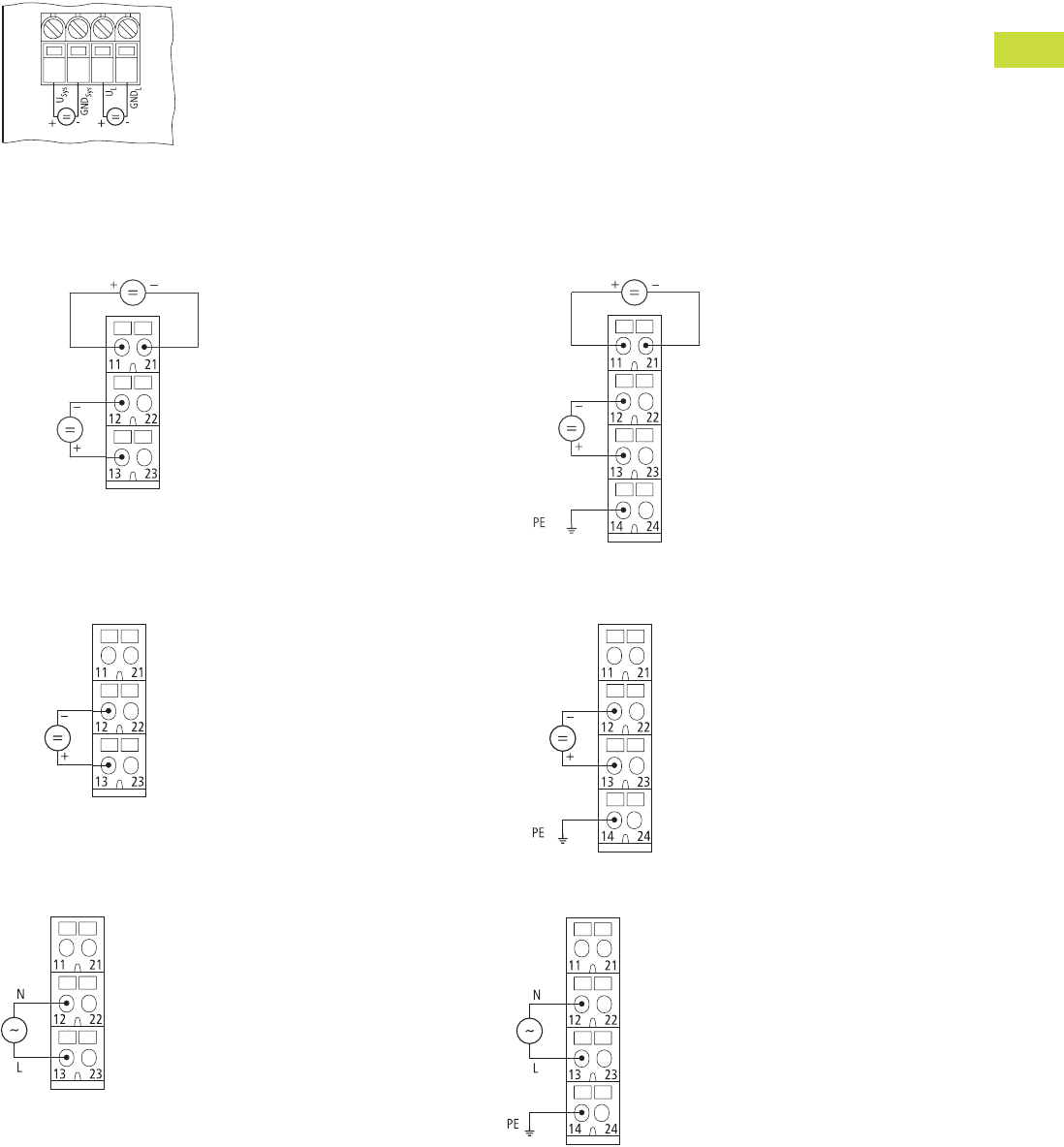
Volume 7—Logic Control, Operator Interface and Connectivity Solutions CA08100008E—February 2014 www.eaton.com V7-T4-89
4
4
4
4
4
4
4
4
4
4
4
4
4
4
4
4
4
4
4
4
4
4
4
4
4
4
4
4
4
4
4.5
PLC, I/O and Communications Products
XI/ON Series Remote I/O
Connection Diagrams
Gateway XN…GWBR_
24V Supply from Gateway (UL) and System Bus (Usys)
Bus Refreshing Modules
XN-P3x-SBB with Gateway Power Supply
XN-P3…-SBB-B without Gateway Power Supply
XN-P4…-SBBC with Gateway Power Supply
XN-P4…-SBBC-B without Gateway Power Supply
Power Feeding Modules
XN-P3…-SBB for XN-PF-24VDC-D
XN-P3…-SBB for XN-PF-120/230VAC-D
XN-P4…-SBBC for XN-PF-24VDC-D
XN-P4…-SBB for XN-PF-120/230VAC-D
24V
24V
24V
Module Bus Supply
Fieldbus
Supply
24V
24V
Module Bus Supply
Fieldbus
Supply
24V
24V
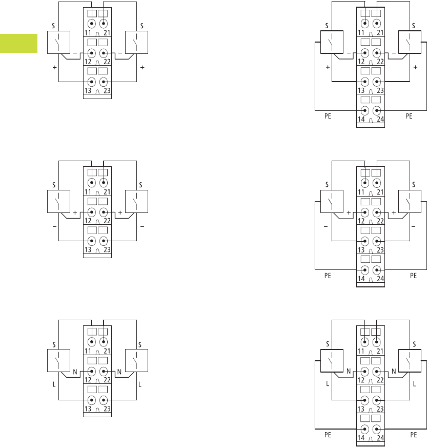
V7-T4-90 Volume 7—Logic Control, Operator Interface and Connectivity Solutions CA08100008E—February 2014 www.eaton.com
4
4
4
4
4
4
4
4
4
4
4
4
4
4
4
4
4
4
4
4
4
4
4
4
4
4
4
4
4
4
4.5
PLC, I/O and Communications Products
XI/ON Series Remote I/O
Digital Input Modules
XN-S3…-SBB for XN-2DI-24VDC-P
XN-S3…-SBB for XN-2DI-24VDC-N
XN-S3…-SBB for XN-2DI-120/230VAC
XN-S4…-SBBC for XN-2DI-24VDC-P
XN-S4…-SBBC for XN-2DI-24VDC-N
XN-S4…-SBBC for XN-2DI-120/230VAC
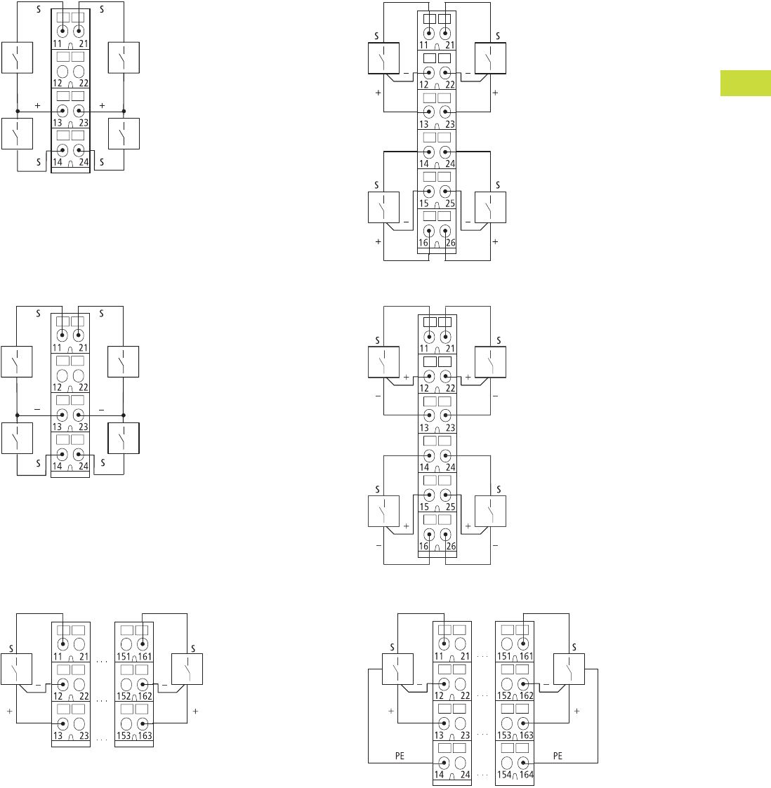
Volume 7—Logic Control, Operator Interface and Connectivity Solutions CA08100008E—February 2014 www.eaton.com V7-T4-91
4
4
4
4
4
4
4
4
4
4
4
4
4
4
4
4
4
4
4
4
4
4
4
4
4
4
4
4
4
4
4.5
PLC, I/O and Communications Products
XI/ON Series Remote I/O
XN-S4…-SBBS for XN-4DI-24VDC-P
XN-S4…-SBBS for XN-4DI-24VDC-N
XN-B3…-SBB for XN-16DI-24VDC-P
XN-S6…-SBBSBB for XN-4DI-24VDC-P
XN-S6…-SBBSBB for XN-4DI-24VDC-N
XN-B4…-SBBC for XN-16DI-24VDC-P
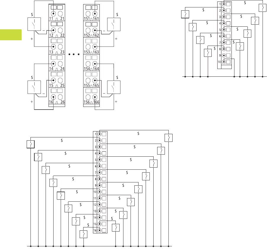
V7-T4-92 Volume 7—Logic Control, Operator Interface and Connectivity Solutions CA08100008E—February 2014 www.eaton.com
4
4
4
4
4
4
4
4
4
4
4
4
4
4
4
4
4
4
4
4
4
4
4
4
4
4
4
4
4
4
4.5
PLC, I/O and Communications Products
XI/ON Series Remote I/O
XN-B6…-SBBSBB for XN-32DI-24VDC-P XNE-8DI-24VDC-P
XNE-16DI-24VDC-P
24V
24V
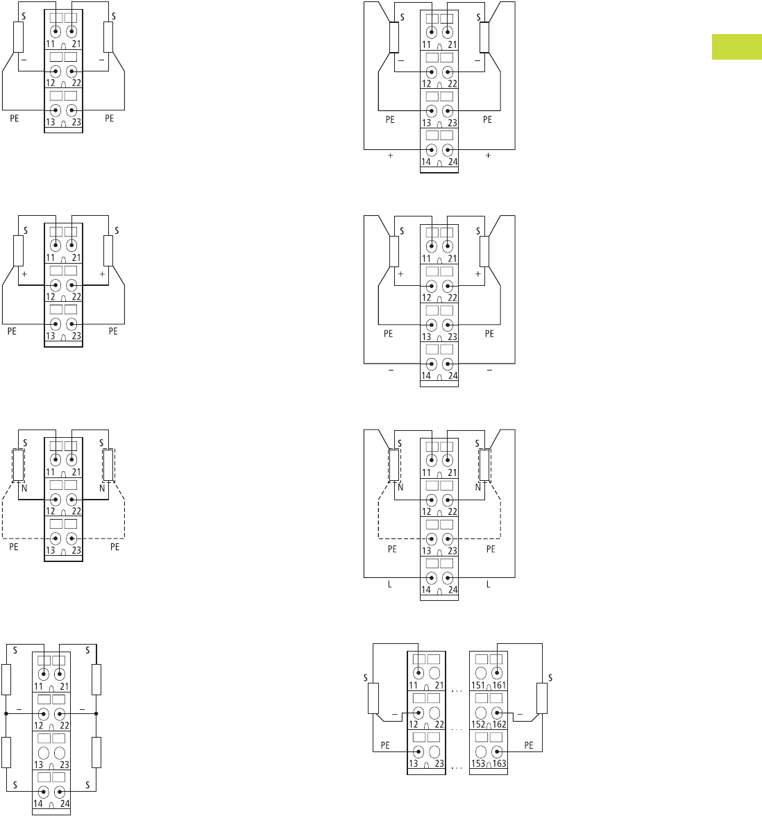
Volume 7—Logic Control, Operator Interface and Connectivity Solutions CA08100008E—February 2014 www.eaton.com V7-T4-93
4
4
4
4
4
4
4
4
4
4
4
4
4
4
4
4
4
4
4
4
4
4
4
4
4
4
4
4
4
4
4.5
PLC, I/O and Communications Products
XI/ON Series Remote I/O
Digital Output Modules
XN-S3…-SBC for XN-2DO-24VDC-0.5A-P and
XN-2DO-24VDC-2A-P
XN-S3…-SBC for XN-2DO-24VDC-0.5A-N
XN-S3…-SBC for XN-2DO-120/230VAC-0.5A
XN-S4…-SBCS for XN-4DO-24VDC-0.5A-P
XN-S4…-SBCS for XN-2DO-24VDC-0.5A-P and
XN-2DO-24VDC-2A-P
XN-S4…-SBCS for XN-2DO-24VDC-0.5A-N
XN-S4…-SBCS for XN-2DO-120/230VAC-0.5A
XN-B3…-SBC for XN-16DO-24VDC-0.5A-P
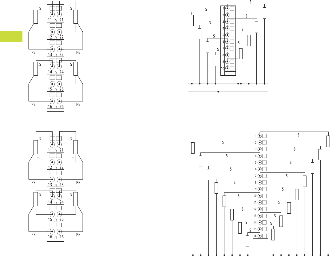
V7-T4-94 Volume 7—Logic Control, Operator Interface and Connectivity Solutions CA08100008E—February 2014 www.eaton.com
4
4
4
4
4
4
4
4
4
4
4
4
4
4
4
4
4
4
4
4
4
4
4
4
4
4
4
4
4
4
4.5
PLC, I/O and Communications Products
XI/ON Series Remote I/O
XN-S6…-SBCSBC for XN-4DO-24VDC-0.5A-P
XN-B6…-SBCSBC for XN-32DO-24VDC-0.5A-P
XNE-8DO-24VDC-0.5A-P
XNE-16DO-24VDC-0.5A-P
24V
GND
GND
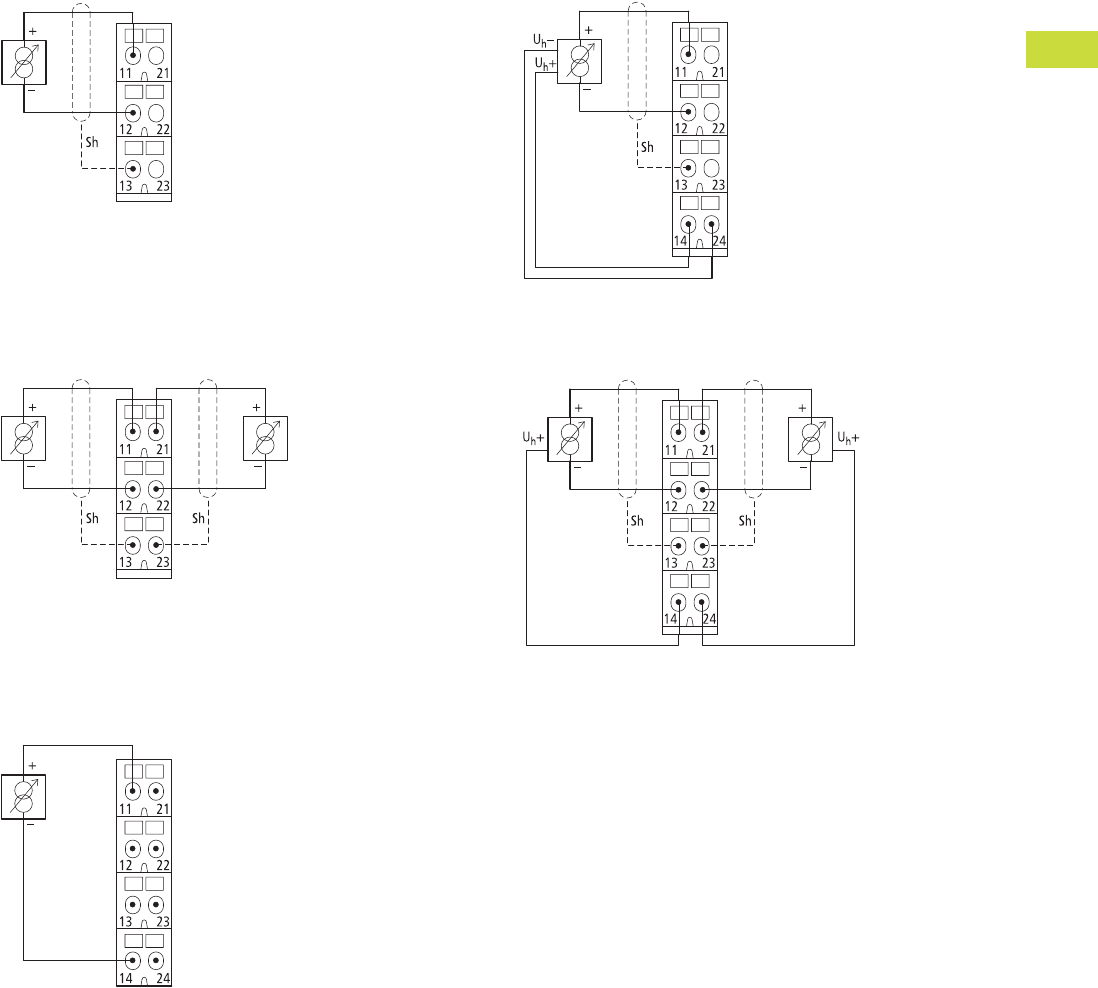
Volume 7—Logic Control, Operator Interface and Connectivity Solutions CA08100008E—February 2014 www.eaton.com V7-T4-95
4
4
4
4
4
4
4
4
4
4
4
4
4
4
4
4
4
4
4
4
4
4
4
4
4
4
4
4
4
4
4.5
PLC, I/O and Communications Products
XI/ON Series Remote I/O
Analog Input Modules
XN-S3…-SBB for XN-1AI-I(0/4…20MA)
XN-S3…-SBB for XN-1AI-U(-10/0…+10VDC)
Analog Sensor/Transmitter, without Transmitter Supply
XN-S3…-SBB for XN-2AI-I(0/4…20MA),
XN-2AI-U(-10/0…+10VDC)
Analog Sensor/Transmitter, without Transmitter Supply
XN-S4…-SBBS for XN-2AI-I(0/4…20MA)
Two-Conductor Connection without
External Transmitter Supply
XN-S4…-SBBS for XN-1AI-I(0/4…20MA)
XN-S4…-SBBS for XN-1AI-U(-10/0…+10VDC)
Analog Transmitter with Non-Isolated Transmitter Supply
XN-S4…-SBBS for XN-2AI-I(0/4…20MA),
XN-2AI-U(-10/0…+10VDC)
Analog Transmitter with Non-Isolated Transmitter Supply
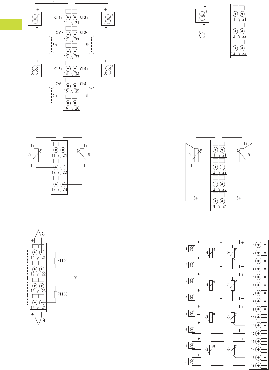
V7-T4-96 Volume 7—Logic Control, Operator Interface and Connectivity Solutions CA08100008E—February 2014 www.eaton.com
4
4
4
4
4
4
4
4
4
4
4
4
4
4
4
4
4
4
4
4
4
4
4
4
4
4
4
4
4
4
4.5
PLC, I/O and Communications Products
XI/ON Series Remote I/O
XN-S6…-SBCSBC for XN-4AI-U/I
Analog Sensor/Transmitter,
without Transmitter Supply
XN-S3…-SBB for XN-2AI-PT/NI-2/3
Two-Conductor Connection
XN-S4…-SBBS-CJ for XN-2AI-THERMO-PI
Note
1Cold-junction compensation in base module.
XN-S3…-SSB for XN-AI-U/I
Two-Conductor Connection without
External Transmitter Supply
XN-S4…-SBBS for XN-2AI-PT/NI-2/3
Three-Conductor Connection
XNE-8AI-U/I-4PT/NI
24V
U/I PT/NI
2-Conductor 2-Conductor 3-Conductor
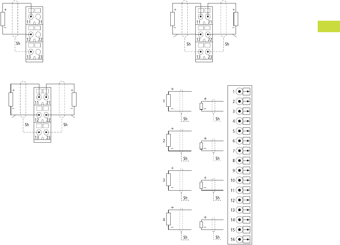
Volume 7—Logic Control, Operator Interface and Connectivity Solutions CA08100008E—February 2014 www.eaton.com V7-T4-97
4
4
4
4
4
4
4
4
4
4
4
4
4
4
4
4
4
4
4
4
4
4
4
4
4
4
4
4
4
4
4.5
PLC, I/O and Communications Products
XI/ON Series Remote I/O
Analog Output Modules
XN-S3…-SSB for XN-1AO-I(0/4…20MA)
XN-S3…-SBB for XN-2AO-U(-10/0…+10VDC)
XN-S3…-SBB for XN-2AO-I(0/4…20MA)
XNE-4AO-U/I
Channel 1 Channel 2
Channel 1 Channel 2
UI
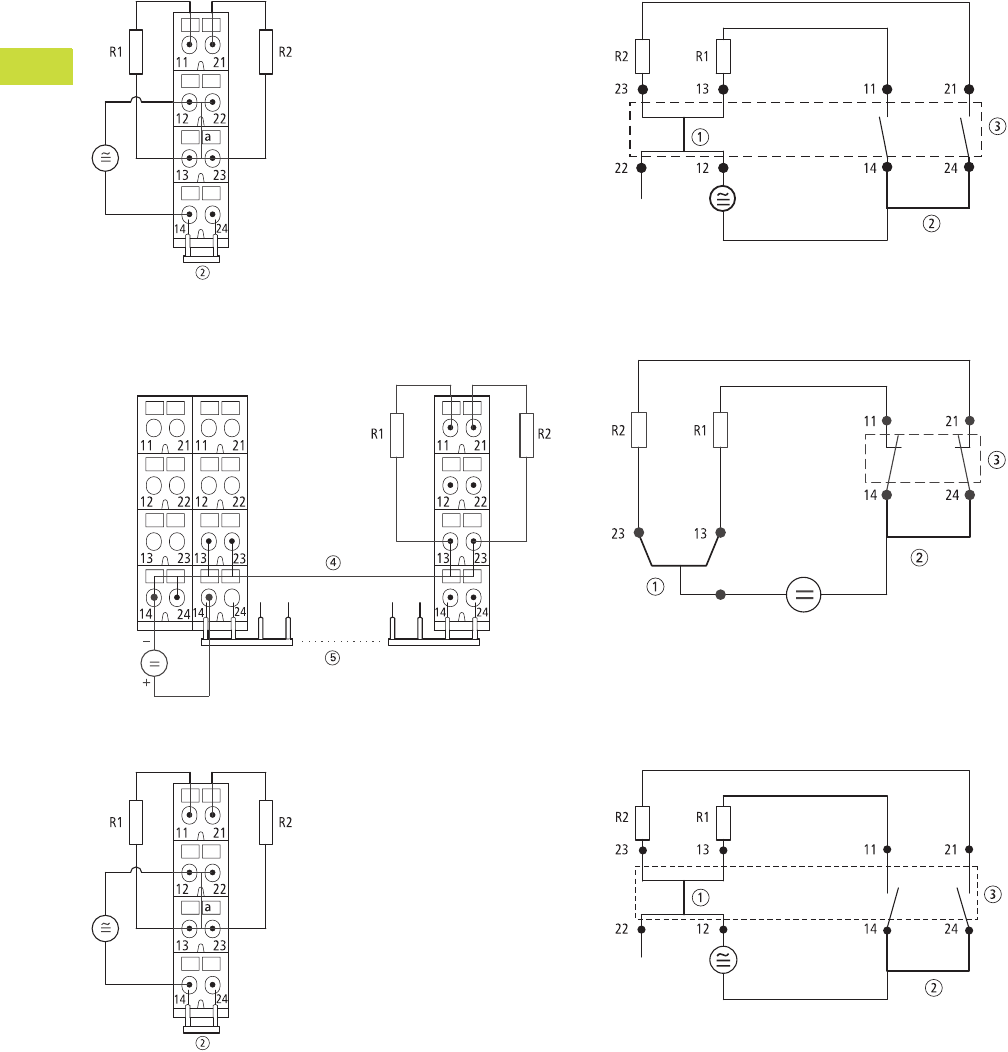
V7-T4-98 Volume 7—Logic Control, Operator Interface and Connectivity Solutions CA08100008E—February 2014 www.eaton.com
4
4
4
4
4
4
4
4
4
4
4
4
4
4
4
4
4
4
4
4
4
4
4
4
4
4
4
4
4
4
4.5
PLC, I/O and Communications Products
XI/ON Series Remote I/O
Relay Modules
XN-S4x…-SBBS with Externally Applied Supply and
Common Potential Link for XN-2DO-R-NC
XN-S4x…-SBCS Supply via C-Rail and Common Potential
Link for XN-2DO-R-NC
XN-S4x…-SBBS with Externally Applied Supply and
Common Potential Link for XN-2DO-R-NO
Module Circuit XN-S4x…SBBS for XN-2DO-R-NC
Module Circuit XN-S4x…-SBCS for XN-2DO-R-NC
Module Circuit XN-S4x…-SBBS for XN-2DO-R-NO
Notes
1Linked in the electronics.
2Cross-link via QVR in the base module.
3Electronics module.
4Supply via C-rail.
5Maximum eight relay modules.
24V
Power
Feeding
Relais 1 Relais n
24V
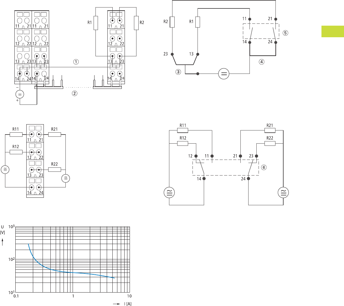
Volume 7—Logic Control, Operator Interface and Connectivity Solutions CA08100008E—February 2014 www.eaton.com V7-T4-99
4
4
4
4
4
4
4
4
4
4
4
4
4
4
4
4
4
4
4
4
4
4
4
4
4
4
4
4
4
4
4.5
PLC, I/O and Communications Products
XI/ON Series Remote I/O
XN-S4x…-SBCS Supply via C-rail and Common
Potential Link for XN-2DO-R-NO
XN-S4x…-SBBS for XN-2DO-R-CO
Load Limit Curve
Module Circuit XN-S4x…SBCS for XN-2DO-R-NO
Module Circuit XN-S4x…-SBBS for XN-2DO-R-CO
Notes
1Supply via C-rail.
2Maximum eight relay modules.
3Top-hat rail.
4Cross-link via QVR in the base module.
5Electronics module.
6Electronics module—
Definition: At 1000 operations, no arc with a duration >10 ms must occur.
24V
Power
Feeding
Relais 1 Relais n
24V
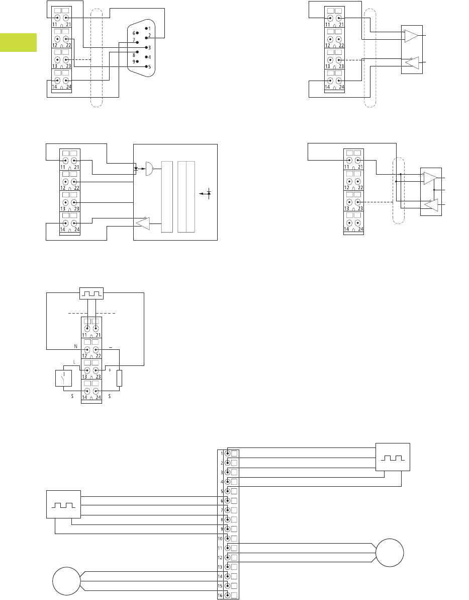
V7-T4-100 Volume 7—Logic Control, Operator Interface and Connectivity Solutions CA08100008E—February 2014 www.eaton.com
4
4
4
4
4
4
4
4
4
4
4
4
4
4
4
4
4
4
4
4
4
4
4
4
4
4
4
4
4
4
4.5
PLC, I/O and Communications Products
XI/ON Series Remote I/O
Serial Interfaces
XN-S4x…-SBBS for XN-1RS232 and D-Sub Plug
XN-S4x…-SBBS for XN-1SSI on an SSI Rotary Encoder
XN-S4x…SBBS for XN-1RS485/422 in RS422 Mode
XN-S4…-SBBS for XN-1RS485/422 in RS485 Mode
Technology Modules/Counter
XN-S4…-SBBS for XN-1CNT-24VDC
XNE-2CNT-2PWM
SHLD
RTS
CTS
GND
TxD
RxD
CL+ CL-
GND GND GND
UL UL UL
D+ D-
SSI Device
Parallel-Serial-Converter
Opto Array
Analog Array
Data Out
Clock
TxD-TxD+
GND GND
SHLD
RxD+ RxD-
Data In
Data Out
SHLD
SHLD
TxD-/RxD-/NTxD+/RxD+/P
GND GND Data In
Data Out
TxEnable
SHLD
SHLD SHLD
Counter Input A
or
Pulse Input
Counter Input B
or
Direction Input
M
M
Counter Input A, Pulse Input Counter 1
Synchronization Z
Counter Input B, Directional Input
Supply 24 Vdc
Supply GND
Output PWM
Output Direction
GND
Drive 1
Counter Input A, Pulse Input
Counter 2
Synchronization Z
Counter Input B, Directional Input
Supply 24 Vdc
Supply GND
Output PWM
Output Direction
GND
Drive 2
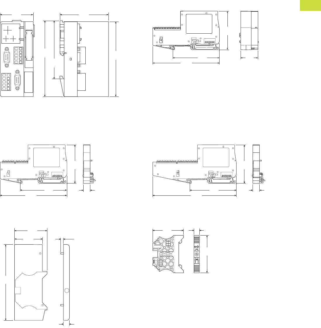
Volume 7—Logic Control, Operator Interface and Connectivity Solutions CA08100008E—February 2014 www.eaton.com V7-T4-101
4
4
4
4
4
4
4
4
4
4
4
4
4
4
4
4
4
4
4
4
4
4
4
4
4
4
4
4
4
4
4.5
PLC, I/O and Communications Products
XI/ON Series Remote I/O
Dimensions
Approximate Dimensions in Inches (mm)
XN Gateways XNE Gateways
Note: The plugs/connectors used depends on the version.
XNE Electronics Modules
End Cover
XN-ABPL
End Bracket
XN-WEW-35/2-SW
XN-GWBR-PBDP XN-GWBR-MODBUS-TCP
XN-GWBR-CANOPEN XN-PLC-CANOPEN
XN-GWBR-DNET
1.99
(50.6)
2.93
(74.4)
4.46
(113.3)
4.52
(114.8)
3.35
(85.0)
XNE-GWBR-PBDP
XNE-GWBR-CANOPEN
XNE-GWBR-2ETH-IP
5.08
(129.0)
3.54
(90.0)
2.95
(75.0)
1.32
(33.5)
XNE-8DO-24VDC-0.5A-P
XNE-8DI-24VDC-P
5.10
(129.5)
3.54
(90.0)
0.51
(13.0)
2.93
(74.5)
4.50
(114.4)
0.36
(9.2)
0.18
(4.5)
1.63
(41.3)
1.91
(48.4)
XNE-16DI-24VDC-P XNE-4AO-U/I
XNE-16DO-24VDC-0.5A-P XNE-2CNT-2PWM
XNE-8AI-U/I/4PT/NI
6.36
(161.5)
3.54
(90.0)
2.93
(74.5)
0.51
(13.0)
1.85
(47.0)
0.31
(8.0)
2.20
(56.0)
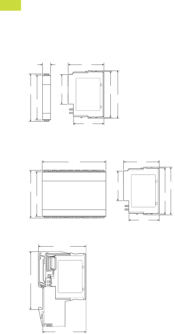
V7-T4-102 Volume 7—Logic Control, Operator Interface and Connectivity Solutions CA08100008E—February 2014 www.eaton.com
4
4
4
4
4
4
4
4
4
4
4
4
4
4
4
4
4
4
4
4
4
4
4
4
4
4
4
4
4
4
4.5
PLC, I/O and Communications Products
XI/ON Series Remote I/O
Approximate Dimensions in Inches (mm)
XN Electronics Modules in Slice Design
XN Electronics Modules in Block Design
XN Electronics Modules Completed with Base Module
All Types
XN-BR-24VDC-D XN-2DI-24VDC-P XN-1AI-I(0/4…20MA) XN-1CNT-24VDC
XN-PF-24VDC-D XN-2DI-24VDC-N XN-2AI-I(0/4…20MA) XN-1RS232
XN-PF-120/230VAC-D XN-2DI-120/230VAC XN-1AI-U(-10/0…+10VDC) XN-1RS485/422
XN-4DI-24VDC-P XN-2AI-U(-10/0…+10VDC) XN-1SSI
XN-4DI-24VDC-N XN-2AI-PT/NI-2/3
XN-2DO-24VDC-2A-P XN-2AI-THERMO-PI
XN-2DO-24VDC-0.5A-P XN-4AI-U/I
XN-2DO-24VDC-0.5A-N XN-1AO-I(0/4…20MA)
XN-2DO-120/230VAC-0.5A XN-2AO-I(0/4…20MA)
XN-4DO-24VDC-0.5A-P XN-2AO-U(-10/0…+10VDC)
XN-2DO-R-CO
XN-2DO-R-NC
XN-2DO-R-NO
XN-16DI-24VDC-P XN-16DO-24VDC-0.5A-P
XN-32DI-24VDC-P XN-32DO-24VDC-0.5A-P
2.92
(74.1)
2.84
(72.1)
0.50
(12.6)
1.81
(46.1)
1.86
(47.3)
2.18
(55.4)
2.84
(72.1)
2.92
(74.1)
3.97
(100.8)
2.92
(74.1)
2.84
(72.1)
1.81
(46.1)
2.18
(55.4)
1.86
(47.3)
2.84
(72.1)
2.92
(74.1)
2.93 (74.5)
2.67 (67.8)
3.54
(90.0)
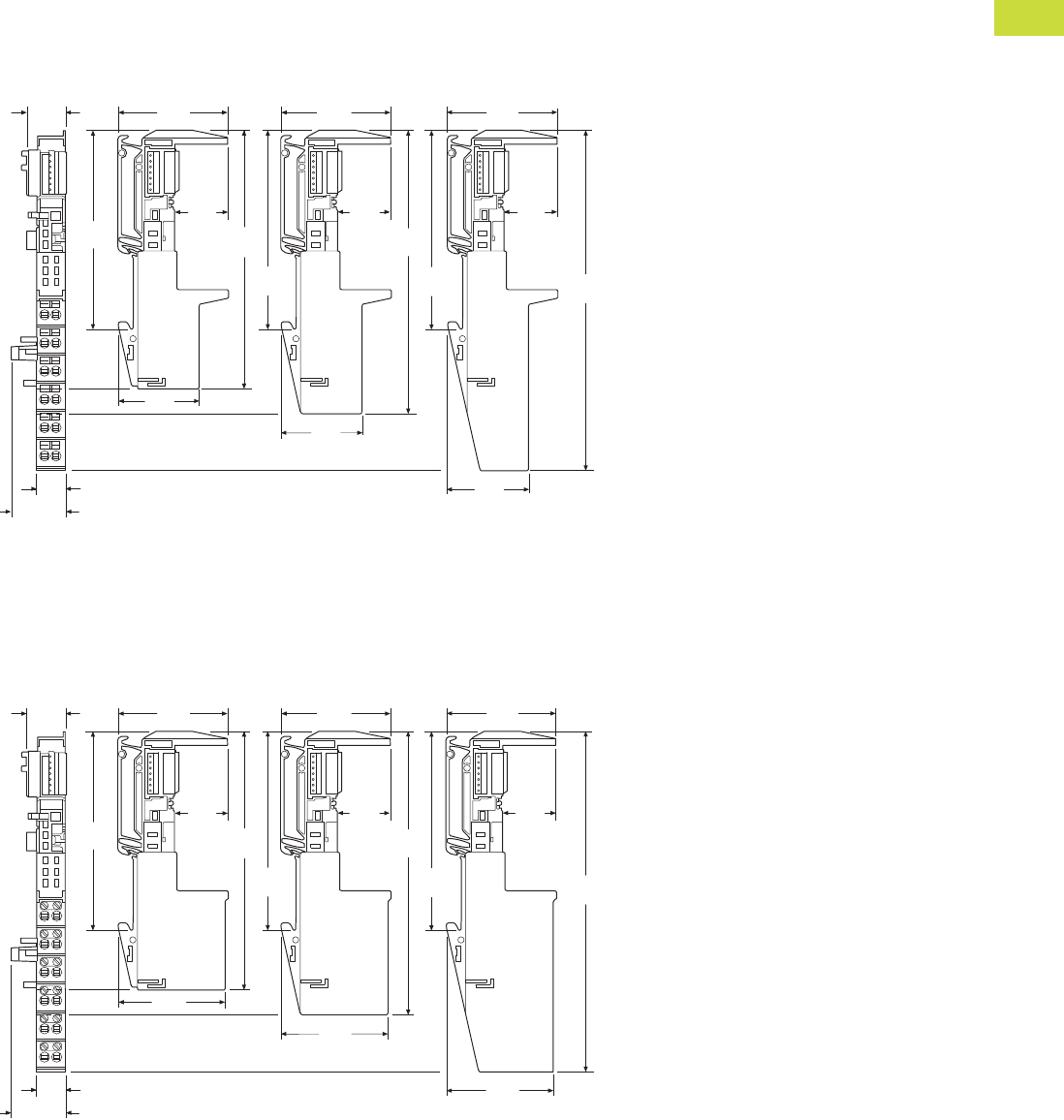
Volume 7—Logic Control, Operator Interface and Connectivity Solutions CA08100008E—February 2014 www.eaton.com V7-T4-103
4
4
4
4
4
4
4
4
4
4
4
4
4
4
4
4
4
4
4
4
4
4
4
4
4
4
4
4
4
4
4.5
PLC, I/O and Communications Products
XI/ON Series Remote I/O
Approximate Dimensions in Inches (mm)
Base Modules in Slice Design
Spring-Cage Terminals
Screw Terminals
3 Connection Levels 4 Connection Levels 6 Connection Levels
XN-S3T-SBB XN-S4T-SBBC XN-S6T-SBBSBB
XN-S3T-SBC XN-S4T-SBBS XN-S6T-SBCSBC
XN-P3T-SBB XN-S4T-SBBS-CJ
XN-P3T-SBB-B XN-S4T-SBCS
XN-P4T-SBBC
XN-P4T-SBBC-B
0.69
(17.6)
1.96
(49.9)
1.96
(49.9)
1.96
(49.9)
3.54
(90.0)
0.95
(24.1)
0.95
(24.1)
0.95
(24.1)
4.63
(117.6)
5.07
(128.9)
6.08
(154.5)
1.64
(41.6)
1.64
(41.6)
1.64
(41.6)
3.54
(90.0)
3.54
(90.0)
0.50 (12.6)
0.93 (23.5)
3 Connection Levels 4 Connection Levels 6 Connection Levels
XN-S3S-SBB XN-S4S-SBBC XN-S6S-SBBSBB
XN-S3S-SBC XN-S4S-SBBS XN-S6S-SBCSBC
XN-P3S-SBB XN-S4S-SBBS-CJ
XN-P3S-SBB-B XN-S4S-SBCS
XN-P4S-SBBC
XN-P4S-SBBC-B
0.69
(17.6)
1.96
(49.9)
1.96
(49.9)
1.96
(49.9)
3.54
(90.0)
0.95
(24.1)
0.95
(24.1)
0.95
(24.1)
4.63
(117.6)
5.07
(128.9)
6.08
(154.5)
1.90
(48.3)
1.90
(48.3)
1.90
(48.3)
3.54
(90.0)
3.54
(90.0)
0.50 (12.6)
0.93 (23.5)
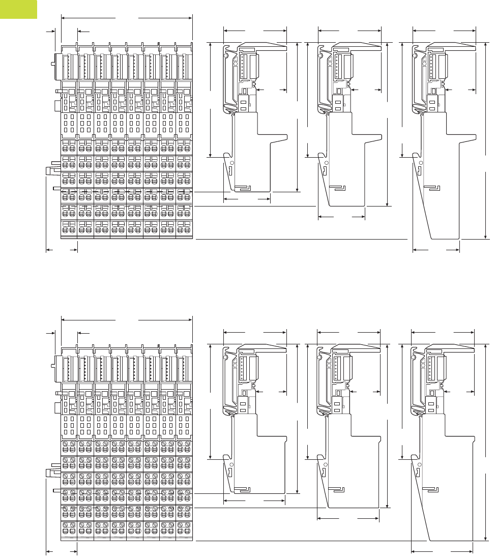
V7-T4-104 Volume 7—Logic Control, Operator Interface and Connectivity Solutions CA08100008E—February 2014 www.eaton.com
4
4
4
4
4
4
4
4
4
4
4
4
4
4
4
4
4
4
4
4
4
4
4
4
4
4
4
4
4
4
4.5
PLC, I/O and Communications Products
XI/ON Series Remote I/O
Approximate Dimensions in Inches (mm)
Base Modules in Block Design
Spring-Cage Terminals
Screw Terminals
3 Connection Levels 4 Connection Levels 6 Connection Levels
XN-B3T-SBB XN-B4T-SBBC XN-B6T-SBBSBB
XN-B3T-SBC XN-B6T-SBCSBC
3.97
(100.8) 1.96
(49.9)
1.96
(49.9)
1.96
(49.9)
0.69
(17.6)
0.93
(23.5)
0.95
(24.1)
0.95
(24.1)
0.95
(24.1)
3.54
(90.0)
1.64
(41.6)
1.64
(41.6)
1.64
(41.6)
4.63
(117.6)
3.54
(90.0)
5.07
(128.9)
3.54
(90.0)
6.08
(154.5)
3 Connection Levels 4 Connection Levels 6 Connection Levels
XN-B3S-SBB XN-B4S-SBBC XN-B6S-SBBSBB
XN-B3S-SBC XN-B6S-SBCSBC
3.97
(100.8) 1.96
(49.9)
1.96
(49.9)
1.96
(49.9)
0.69
(17.6)
0.93
(23.5)
0.95
(24.1)
0.95
(24.1)
0.95
(24.1)
3.54
(90.0)
1.90
(48.3)
1.90
(48.3)
1.90
(48.3)
4.63
(117.6)
3.54
(90.0)
5.07
(128.9)
3.54
(90.0)
6.08
(154.5)
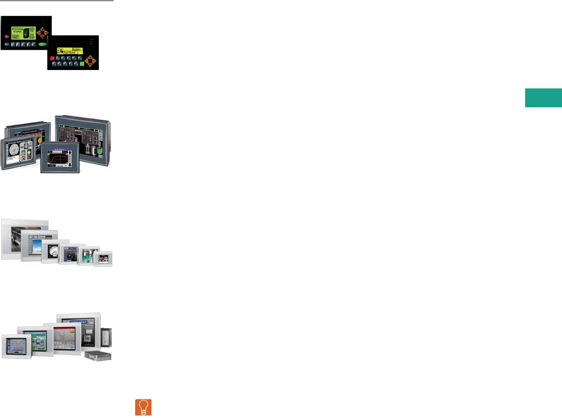
Volume 7—Logic Control, Operator Interface and Connectivity Solutions CA08100008E—February 2014 www.eaton.com V7-T5-1
5
5
5
5
5
5
5
5
5
5
5
5
5
5
5
5
5
5
5
5
5
5
5
5
5
5
5
5
5
5
Operator Interface Products
ELC Graphics Panel
HMi Operator Interface
XV Operator Interface
XP Operator Interface
5.1 Product Overview
Product and Software Selection Guides . . . . . . . . . . . . . . . . . . . . . . . V7-T5-2
5.2 ELC Graphics Panels
Product Description . . . . . . . . . . . . . . . . . . . . . . . . . . . . . . . . . . . . . . . V7-T5-5
Features . . . . . . . . . . . . . . . . . . . . . . . . . . . . . . . . . . . . . . . . . . . . . . . . V7-T5-5
Standards and Certifications . . . . . . . . . . . . . . . . . . . . . . . . . . . . . . . . V7-T5-6
Catalog Number Selection . . . . . . . . . . . . . . . . . . . . . . . . . . . . . . . . . . V7-T5-7
Product Selection . . . . . . . . . . . . . . . . . . . . . . . . . . . . . . . . . . . . . . . . . V7-T5-7
Software and Accessories . . . . . . . . . . . . . . . . . . . . . . . . . . . . . . . . . . V7-T5-8
Technical Data and Specifications . . . . . . . . . . . . . . . . . . . . . . . . . . . . V7-T5-10
Dimensions . . . . . . . . . . . . . . . . . . . . . . . . . . . . . . . . . . . . . . . . . . . . . V7-T5-11
5.3 HMi Operator Interface
Product Description . . . . . . . . . . . . . . . . . . . . . . . . . . . . . . . . . . . . . . . V7-T5-13
Features . . . . . . . . . . . . . . . . . . . . . . . . . . . . . . . . . . . . . . . . . . . . . . . . V7-T5-13
Standards and Certifications . . . . . . . . . . . . . . . . . . . . . . . . . . . . . . . . V7-T5-14
Catalog Number Selection . . . . . . . . . . . . . . . . . . . . . . . . . . . . . . . . . . V7-T5-15
Product Selection . . . . . . . . . . . . . . . . . . . . . . . . . . . . . . . . . . . . . . . . . V7-T5-15
Software and Accessories . . . . . . . . . . . . . . . . . . . . . . . . . . . . . . . . . . V7-T5-16
Technical Data and Specifications . . . . . . . . . . . . . . . . . . . . . . . . . . . . V7-T5-18
Dimensions . . . . . . . . . . . . . . . . . . . . . . . . . . . . . . . . . . . . . . . . . . . . . V7-T5-19
5.4 XV and XP Operator Interface
XV with Visual Designer, Galileo or XSoft-CoDeSys-2. . . . . . . . . . . . . . V7-T5-21
Product Selection Guide . . . . . . . . . . . . . . . . . . . . . . . . . . . . . . . . . . . V7-T5-23
XP with Visual Designer . . . . . . . . . . . . . . . . . . . . . . . . . . . . . . . . . . . . V7-T5-28
Visual Designer Software . . . . . . . . . . . . . . . . . . . . . . . . . . . . . . . . . . . V7-T5-32
Galileo Software . . . . . . . . . . . . . . . . . . . . . . . . . . . . . . . . . . . . . . . . . V7-T5-35
XSoft-CoDeSys-2 Software. . . . . . . . . . . . . . . . . . . . . . . . . . . . . . . . . . V7-T5-36
Learn
Online
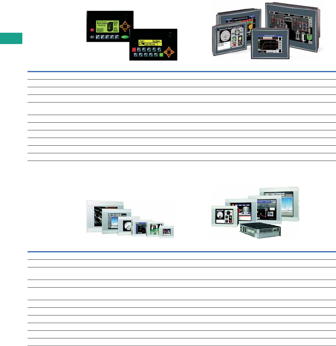
V7-T5-2 Volume 7—Logic Control, Operator Interface and Connectivity Solutions CA08100008E—February 2014 www.eaton.com
5
5
5
5
5
5
5
5
5
5
5
5
5
5
5
5
5
5
5
5
5
5
5
5
5
5
5
5
5
5
5.1
Operator Interface Products
Product Overview
Product and Software Selection Guides
Operator Interfaces and Programming Software Selection Guide
Operator Interfaces and Programming Software Selection Guide, continued
Description ELC-GP Graphics Panel HMi Operator Interface
Page V7-T5-5 Page V7-T5-13
Screen size Two-line and four-line 3.5-inch, 5.7-inch, 7.0-inch, 8.0-inch and 10.4-inch
Screen options Monochrome 65k color TFT
Interface Keypad only Resistive touchscreen only or touchscreen and keypad
Communication ports 2 serial 3 serial; USB; Expansion port for Ethernet or Local I/O,
onboard Ethernet VU models
Simultaneous protocols 1 3 or 4
Ethernet drivers — Yes
Upload/download Serial cable Serial, Ethernet, and/or USB
Operating system Proprietary Proprietary
Third-party software support — —
Screen saver — Yes
Description XV Operator Interface XP Operator Interface
Page V7-T5-21 Page V7-T5-28
Screen size 3.5-inch, 5.7-inch, 7.0-inch, 8.4-inch and 10.4-inch 8.4-inch, 10.4-inch, 12.1-inch, 15.0-inch and blind node (no screen)
Screen options Color TFT, 64k colors; resolutions from QVGA (320 x 240) to WVGA (800 x 480) Color TFT, 16 million colors; resolutions from SVGA (800 x 600) to
UVGA (1600 x1200)
Interface Resistive touchscreen Infrared, non-reflective safety glass
Communication ports Ethernet, RS-232 and/or RS-485, USB; CANopen or PROFIBUS®-DP,
SmartWire-DT, USB and RS-485 on CoDeSys models
2 serial; 2 Ethernet; removable CompactFlash®; 4 USB; VGA
Simultaneous protocols 3 on Visual Designer, varies for Galileo and XSoft-CoDeSys-2 5 or 8
Ethernet drivers Yes Yes
Upload/download Serial, Ethernet, USB Serial, Ethernet, USB
Operating system Windows® CE 5.0 Professional Windows XP Embedded (protected)
Third-party software support — Yes
Screen saver Yes Yes
Volume 7—Logic Control, Operator Interface and Connectivity Solutions CA08100008E—February 2014 www.eaton.com V7-T5-3
5
5
5
5
5
5
5
5
5
5
5
5
5
5
5
5
5
5
5
5
5
5
5
5
5
5
5
5
5
5
5.1
Operator Interface Products
Product Overview
Software Product Selection Guide
Notes
1See the logic section of the catalog for details on the logic features in the XSoft-CoDeSys-2 software package.
2Includes XSoft-CoDeSys-2 software for developing applications, runtime software for the XV Series. Single User License.
3Includes XSoft-CoDeSys-2 software for developing applications, runtime software for the XV Series. Multi User License.
Description Visual Designer XSoft-CoDeSys-2 1Galileo HMiSoft ELCSoftGP
Overview Feature-rich software package
with SCADA functionality and
Web serving capabilities that
can be run on XV, XP, ePro PS
operator interfaces or
personal computers
Feature-rich software package
with integrated logic and
visualization that can be run
on specific XV operator
interface models
Intuitive visualization tool. Use
Galileo on XV-102-H_ units or
on XV units running CoDeSys
when a stronger visualization
package is needed
Use HMi Soft to create, edit,
upload and download
applications to the HMi
family of operator interfaces
Use ELCSoftGP to create,
edit, upload and download
applications to ELC
Graphics Panels
Catalog ID
Development software seat license VISUALDCE (CE hardware)
VISUALDXP5 (5-pack of
VISUALDXP)
VISUALDCE5 (5-pack of
VISUALDCE)
VISUALDXP (PCs, XPe, and CE
hardware)
SW-XSOFT-CODESYS-2-S 2
SW-XSOFT-CODESYS-2-M 3
SW-GALILEO-S
SW-GALILEO-M
HMISOFT ELCSOFTGP
Runtime software for a PC VISUALRTPC N/A ■N/A N/A
Time-Saving Editor Features
Online and offline simulation ■■■■—
Macro capability ■■■■—
VB scripting ■————
Multi-language ■■■■—
System/internal variables ■■■■—
Auto-scale application to different
resolution/screen size
■■■■—
Scripting
(IF, THEN, ELSE, GOTO)
■■■■—
Graphics library ■—■■—
Master pages ■ Screen groups ■ One ■ Screen groups ■ Base screen —
User-created controls ■■■■—
Customizable application symbols ■■■——
Full math evaluation ■■■ With macros ■ With macros —
Reusable controls, images
and pages
■ Via indirect tag and/
or PLC assignments
■■——
Advanced search and replace ■■■——
Advanced context sensitive help ■■■——
Conversion of legacy PanelMate™
configurations
■————
Optional PanelBuilder™ conversion
utility
■————
Online configuration/editing ■■———
V7-T5-4 Volume 7—Logic Control, Operator Interface and Connectivity Solutions CA08100008E—February 2014 www.eaton.com
5
5
5
5
5
5
5
5
5
5
5
5
5
5
5
5
5
5
5
5
5
5
5
5
5
5
5
5
5
5
5.1
Operator Interface Products
Product Overview
Software Product Selection Guide, continued
Note
1See the logic section of the catalog for details on the logic features in the XSoft-CoDeSys-2 software package.
Description Visual Designer XSoft-CoDeSys-2 1Galileo HMiSoft ELCSoftGP
Runtime Features
Clock synchronization with
controller
■ ■ Configured via visualization
screens
■ ■ ■
Sound actions or control ■ —■ ■ ■
Security ■ Advanced multi-level ■ ■ ■ Multi-level ■
Pop-up screens ■ And group screens — ■ ■ —
Animated graphics ■ ■ ■ ■ —
Real-time trending ■ ■ ■ ■ —
Recipes ■ ■ ■ ■ —
Report generation ■ —■ ■ Using Excel and VU Server —
Timer scheduling ■ ■ ■ ■ —
Calendar scheduling ■ ■ ———
Notification of data and events
via email/text messaging
■ ■ ———
Data archiving ■ ■ ■ ■ —
Archive to shared network drive ■ ■ ■ ——
Alarm and event archiving ■ ■ ■ ■ —
Historical trending ■ ■ ■ ■ —
Import/export from XML or CSV ■ ■ ■ ——
Database interface ■ ADO.net compliant ■ DDE — ■ —
Vision system interfaces ■ —■ ——
Secure document and Web network
browser
■ ■ With user created
passwords
———
Web server—viewing and control ■ ■ ———
Automatic scaling of Web clients ■ ————
Remote desktop ■ VNC and RemoteClient ■ VNC and RemoteClient ■ VNC and RemoteClient ■ VU Remote —
Launch/control third-party
applications
■ ————
Embedded PLC logic — ■ ———
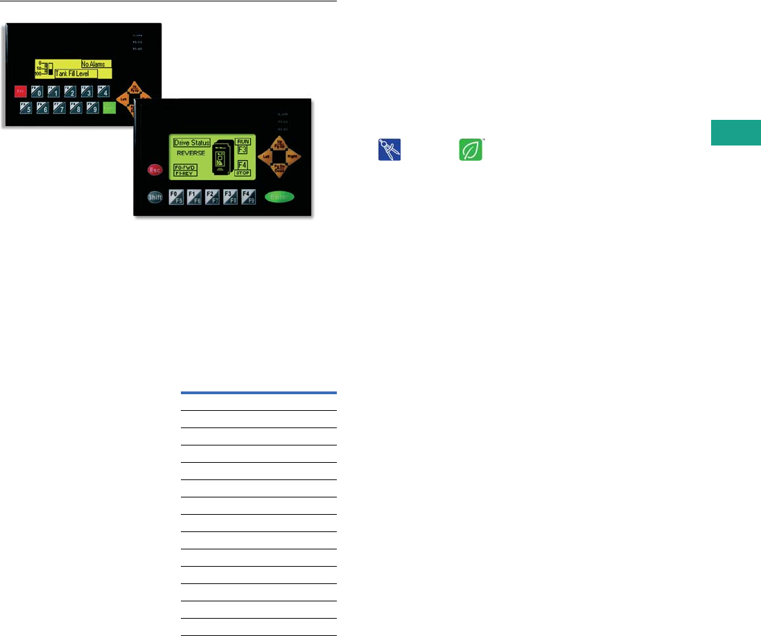
Volume 7—Logic Control, Operator Interface and Connectivity Solutions CA08100008E—February 2014 www.eaton.com V7-T5-5
5
5
5
5
5
5
5
5
5
5
5
5
5
5
5
5
5
5
5
5
5
5
5
5
5
5
5
5
5
5
5.2
Operator Interface Products
ELC Graphics Panels
ELC Graphics Panels
Contents
Description Page
ELC Graphics Panels
Standards and Certifications . . . . . . . . . . . . . . . V7-T5-6
Catalog Number Selection . . . . . . . . . . . . . . . . . V7-T5-7
Product Selection . . . . . . . . . . . . . . . . . . . . . . . . V7-T5-7
Technical Data and Specifications . . . . . . . . . . . V7-T5-10
Dimensions . . . . . . . . . . . . . . . . . . . . . . . . . . . . V7-T5-11
Drawings An Eaton
Green SolutionOnline
Product Description
ELC Graphics Panels are
simple to program and easily
connect to ELC products.
ELC graphics panels make
modifying an application quick
and easy.
With more than
30 objects that can be placed
anywhere on the display,
these tough panels also
communicate to other major
controllers. These graphics
panels have two serial ports
that can be used
simultaneously to
communicate. Transfer
applications to or from these
graphics panels using the
handy transfer module. Ten
programmable functions keys
on the outdoor rated display
provide easy-to-change
pages, input numeric values,
enter alpha-numeric
passwords, set, reset and
more. Create alarms,
password protect, import
bitmaps and use many
different fonts.
Features
Protocols
Supported Protocols
And more...
Protocol
Eaton ELC
Eaton D50/D32LT, D320
Eaton MVX ASCII
Eaton MVX RTU
Modbus ASCII
Modbus RTU
Allen-Bradley DF1
Mitsubishi FX Series
Mitsubishi FX2N Series
Koyo K-Sequence
LG 200S
OMRON C-Series
Siemens S7-200 Series
ASCII Slave Mode
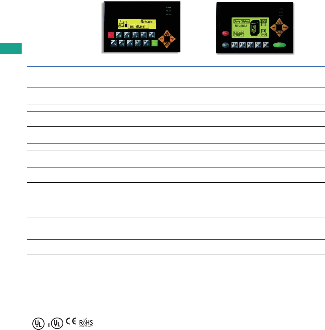
V7-T5-6 Volume 7—Logic Control, Operator Interface and Connectivity Solutions CA08100008E—February 2014 www.eaton.com
5
5
5
5
5
5
5
5
5
5
5
5
5
5
5
5
5
5
5
5
5
5
5
5
5
5
5
5
5
5
5.2
Operator Interface Products
ELC Graphics Panels
ELC Graphics Panel Features
Standards and Certifications
●UL 508
●cUL (CSA C22.2 No. 14)
●CE (Low Voltage Directive);
Class 1 Div 2 Groups A, B,
C, D
●RoHS
Item ELC-GP02 ELC-GP04
Display screen
Screen STN-LCD STN-LCD
Color Monochromatic Monochromatic
Backlight The backlight automatic turn off time is 1–99 minutes
(0 = do not to turn off)
(backlight life is 50 thousand hours at 25°C)
The backlight automatic turn off time is 1–99 minutes
(0 = do not to turn off)
(backlight life is 50 thousand hours at 25°C)
Resolution 160 x 32 pixels 128 x 64 pixels
Display range 72 mm (W) x 22 mm (H) 67 mm (W) x 32 mm (H)
Contrast adjustment 15-step contrast adjustment 10-step contrast adjustment
Language font ASCII: characters (including European fonts)
Taiwan: (BIG 5 code) traditional Chinese character font
China: (GB2324-80 code) simplified Chinese character font
ASCII: characters (including European fonts)
Taiwan: (BIG 5 code) traditional Chinese character font
China: (GB2324-80 code) simplified Chinese character font
Font size (ASCII) 5 x 8, 8 x 8, 8 x 12, 8 x 16 5 x 8, 8 x 8, 8 x 12, 8 x 16
ALARM indication LED 1. Power-on indication (flash three times)
2. Flash for communication error or other alarm
3. Special indication by user programming
1. Power-on indication (flash three times)
2. Flash for communication error or other alarm
3. Special indication by user programming
RS-232 LED (yellow) Flashes when communicating Flashes when communicating
RS-485 LED (green) Flashes when communicating Flashes when communicating
Program memory 256 KB flash memory 256 KB flash memory
External interface
Serial communication port
RS-232 (COM1)
9 PIN D-SUB male
Data length: 7 or 8 bits
Stop bits: 1 or 2 bits
Parity: None/Odd/Even
Baud rate: 4800 bps–115,200 bps
Data length: 7 or 8 bits
Stop bits: 1 or 2 bits
Parity: None/Odd/Even
Baud rate: 4800 bps–115,200 bps
Extension communication port
RS-485 (COM2)
5-pin removal terminal
(RS-485 or RS-422)
Data length: 7 or 8 bits
Stop bits: 1 or 2 bits
Parity: None/Odd/Even
Baud rate: 4800 bps–115,200 bps
Data length: 7 or 8 bits
Stop bits: 1 or 2 bits
Parity: None/Odd/Even
Baud rate: 4800 bps–115,200 bps
Extension slot The slot for program copy card The slot for program copy card
Power 24 Vdc input 24 Vdc input
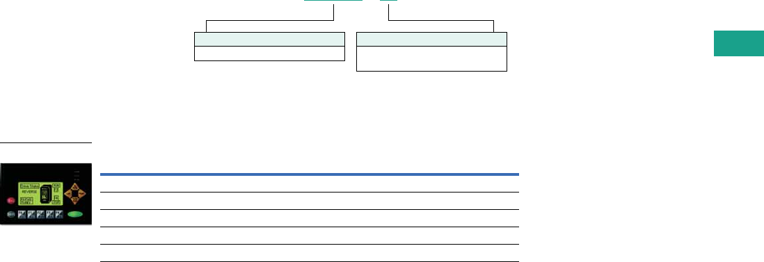
Volume 7—Logic Control, Operator Interface and Connectivity Solutions CA08100008E—February 2014 www.eaton.com V7-T5-7
5
5
5
5
5
5
5
5
5
5
5
5
5
5
5
5
5
5
5
5
5
5
5
5
5
5
5
5
5
5
5.2
Operator Interface Products
ELC Graphics Panels
Catalog Number Selection
ELC-GP Graphics Panel
ELC-GP
Product Selection
Graphics Panels
Description Catalog Number
Panels
160 x 32 pixels, 10 function keys, monochrome ELC-GP02
128 x 64 pixels, 10 function keys, monochrome ELC-GP04
Spare Parts Kit
Includes several power connectors, battery doors, gaskets, mounting clips, etc. ELC-GPSPKIT
ELC-GP 02
Series
ELC-GP = ELC Graphics Panel
Display
02 = Monochromatic, two-line
04 = Monochromatic, four-line
ELC-GP04
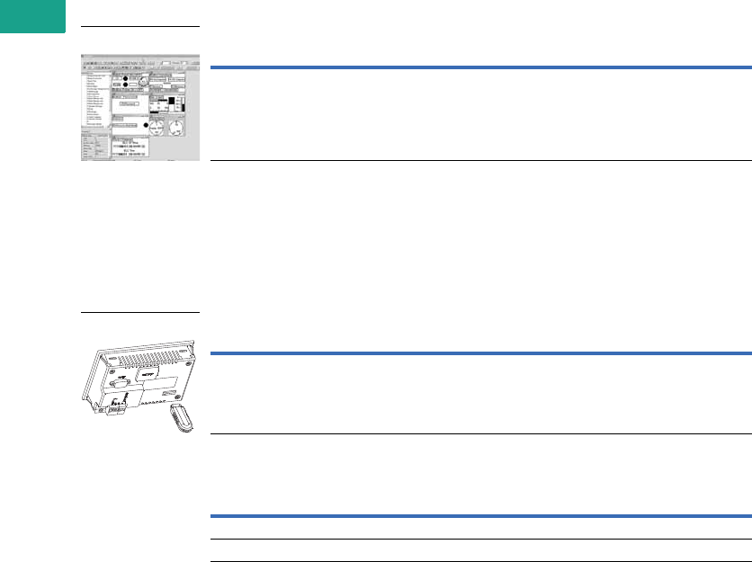
V7-T5-8 Volume 7—Logic Control, Operator Interface and Connectivity Solutions CA08100008E—February 2014 www.eaton.com
5
5
5
5
5
5
5
5
5
5
5
5
5
5
5
5
5
5
5
5
5
5
5
5
5
5
5
5
5
5
5.2
Operator Interface Products
ELC Graphics Panels
Software and Accessories
ELCSoftGP Programming Software
System Requirements
●Operating Systems—Windows 2000, Windows XP
ELCSoftGP Programming Software configures all ELC graphic panels. With ELCSoftGP,
applications can be created, edited, downloaded and uploaded. Move programs from one
controller to a different one with ease.
ELCSoftGP Editing Environment
ELC-GPXFERMOD Program Transfer Module
The ELC-GPXFERMOD is a multifunction device that provides the ability to back up an
application already loaded onto one of the ELC-GP units. It will store all system settings such as
baud and ID, as well as passwords and the application itself. Once stored in the module, the
application and settings can be transferred to another ELC-GP unit of the same model number.
ELC-GPXFERMOD
ELC-CBPCELC_
Description Catalog Number
Programming software for GP units ELCSOFTGP
Description Catalog Number
Program transfer module ELC-GPXFERMOD
Description Catalog Number
1 meter cable to connect between the HMi and Eaton Logic Controller (ELC) ELC-CBPCELC1
3 meter cable to connect between the HMi and Eaton Logic Controller (ELC) ELC-CBPCELC3
ELCSoftGP
ELC-GPXFERMOD
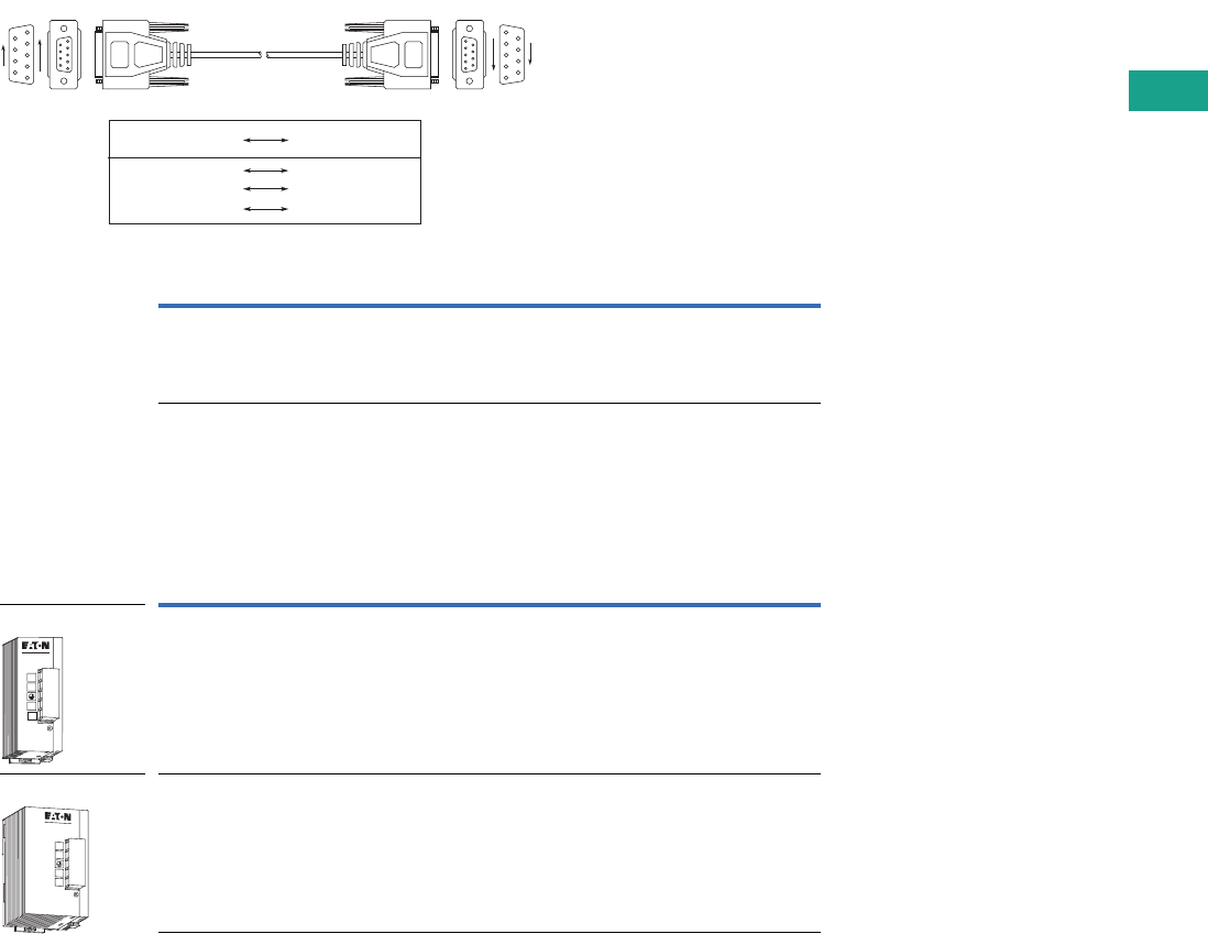
Volume 7—Logic Control, Operator Interface and Connectivity Solutions CA08100008E—February 2014 www.eaton.com V7-T5-9
5
5
5
5
5
5
5
5
5
5
5
5
5
5
5
5
5
5
5
5
5
5
5
5
5
5
5
5
5
5
5.2
Operator Interface Products
ELC Graphics Panels
ELC-CBPCGP3 Cable
Use this cable to download or upload applications between a PC and the ELC-GP graphics
panels. This cable can also be used to transfer a program from an ELC-GP to another ELC-GP.
Pin definition of 9 PIN D-SUB RS-232:
PC to ELC-GPxx Cable
Power Supplies
All ELC modules operate from 24 Vdc. These power supplies provide a convenient way to
provide robust DC voltage.
ELC Power Supplies
Description Catalog Number
Cable, PC to ELC-GP, 9.8 ft (3m) ELC-CBPCGP3
Description Catalog Number
Power supply, 24 watt, 1 amp ELC-PS01
Power supply, 48 watt, 2 amp ELC-PS02
9 PIN D-SUB
ON PC (RS-232)
9 PIN D-SUB
ON ELC-GP02/04
PC COM Port
9 PIN D-SUB Female
GP02/04 COM Port
9 PIN D-SUB Female
Rx 2 3Tx
Tx 3 2Rx
GND 5 5GND
1
5
6
9
5
1
9
6
L
N
24V
0V
POWER
ELC-PS01
L
N
24V
0V
POWER
ELC-PS02
ELC-PS01
ELC-PS02

V7-T5-10 Volume 7—Logic Control, Operator Interface and Connectivity Solutions CA08100008E—February 2014 www.eaton.com
5
5
5
5
5
5
5
5
5
5
5
5
5
5
5
5
5
5
5
5
5
5
5
5
5
5
5
5
5
5
5.2
Operator Interface Products
ELC Graphics Panels
Technical Data and Specifications
ELC Graphics Panels
ELC Power Supply
Description Specification
Environmental
Transportation and storage
Temperature –4° to 140°F (–20° to 60°C)
Operating
Temperature 32° to 122°F (0° to 50°C)
Humidity 20–90% RH (noncondensing)
Communication interface COM1: RS-232; COM2: RS-485/RS-422
Vibration 0.5 mm displacement, 10–55 Hz, X, Y, Z three directions and two hours for each direction
Impact 10G, 11 ms, from X, Y, Z three directions and three times for each direction
Weight 0.53 lbs (0.24 kg)
Cooling method Natural air cooling
Electrical/EMC Approvals
Electrostatic discharge immunity EN61000-4-2/1995
Radiated immunity EN61000-4-3/1995
Electrical fast transient EN61000-4-4/1995
Radiated emission CISPR22, Class A
Other Approvals
Waterproof class of front panel UL Type 4X outdoor rated
UV resistant UL 746C
Item ELC-PS01 ELC-PS02
Dimensions W x H x D
in inches (mm)
1.44 x 3.54 x 2.36
(36.5 x 90 x 60)
2.17 x 3.54 x 2.36
(55 x 90 x 60)
Input power 100–240 Vac 50/60 Hz 100–240 Vac 50/60 Hz
Output volts 24 Vdc 24 Vdc
Output current (A) 1A 2A
Watts 24 48
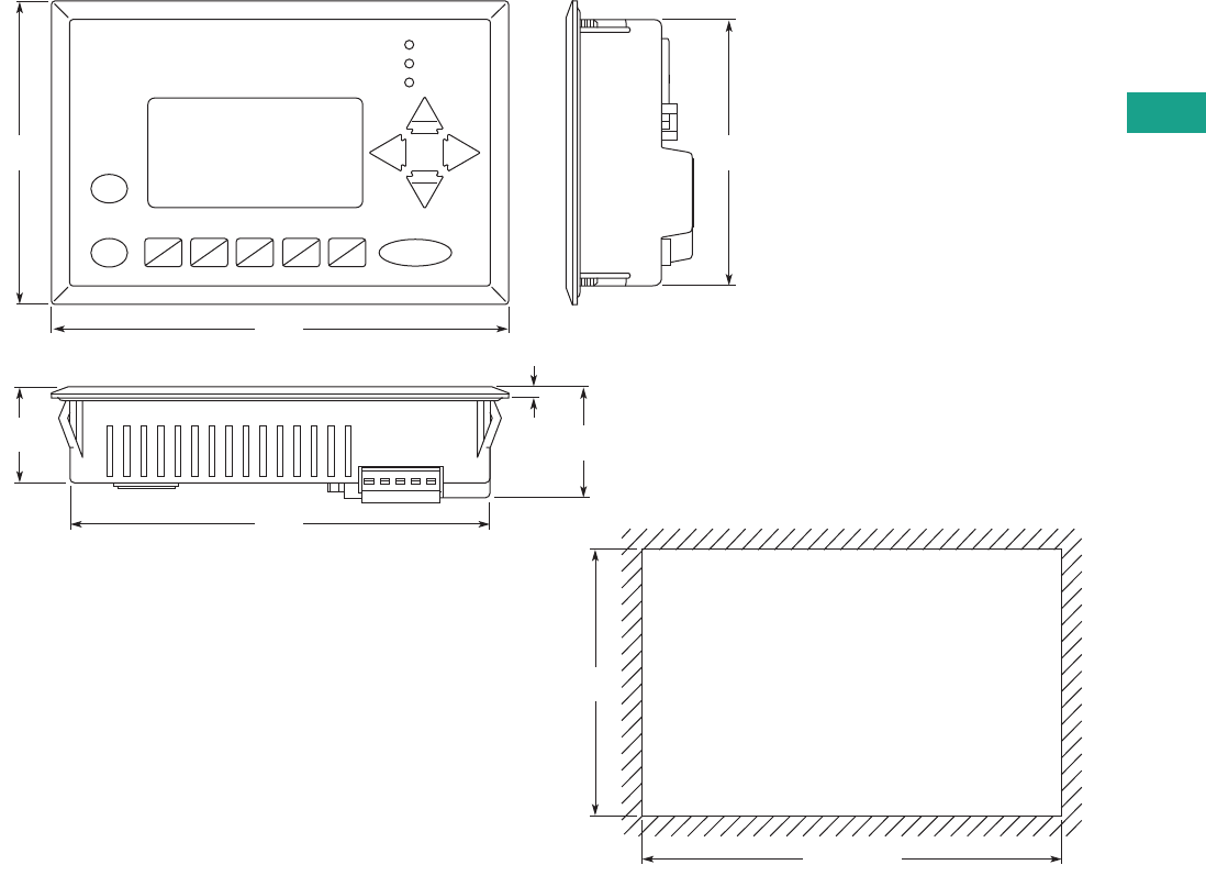
Volume 7—Logic Control, Operator Interface and Connectivity Solutions CA08100008E—February 2014 www.eaton.com V7-T5-11
5
5
5
5
5
5
5
5
5
5
5
5
5
5
5
5
5
5
5
5
5
5
5
5
5
5
5
5
5
5
5.2
Operator Interface Products
ELC Graphics Panels
Dimensions
Approximate Dimensions in Inches (mm)
ELC-GP04
3.82
(97.0)
3.35
(85.0)
1.20
(30.5) 0.14
(3.5) 1.40
(35.5)
3.35
(85.0)
5.79
(147.0)
ALARM
RS-232
RS-485
Up
Pg Up
Pg Dn
Down
Left
Esc
Enter
F0
F5
F1
F6
F2
F7
F3
F8
F4
F9
Shift
Right
5.31
(135.0)
5.31 ~ 5.37
(135 ~ 136.5)
Cut-Out Dimensions
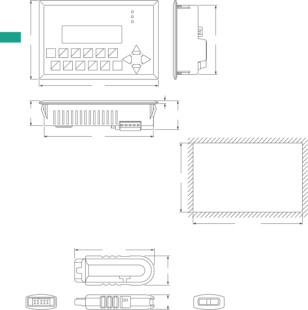
V7-T5-12 Volume 7—Logic Control, Operator Interface and Connectivity Solutions CA08100008E—February 2014 www.eaton.com
5
5
5
5
5
5
5
5
5
5
5
5
5
5
5
5
5
5
5
5
5
5
5
5
5
5
5
5
5
5
5.2
Operator Interface Products
ELC Graphics Panels
Approximate Dimensions in Inches (mm)
ELC-GP02
ELC-GPXFERMOD
3.82
(97.0)
3.35
(85.0)
1.20
(30.5) 0.14
(3.5) 1.40
(35.5)
3.35
(85.0)
5.79
(147.0)
ALARM
RS-232
RS-485
Up
Pg Up
Pg Dn
Down
Left
Esc F0
0
Right
5.31
(135.0)
5.31 ~ 5.37
(135 ~ 136.5)
Cut-Out Dimensions
F1
1
F2
2
F3
3
F4
4
Enter
F5
5
F6
6
F7
7
F8
8 9
F9
0.78 (19.8)
2.00 (50.9)
0.39 (10.0)

Volume 7—Logic Control, Operator Interface and Connectivity Solutions CA08100008E—February 2014 www.eaton.com V7-T5-13
5
5
5
5
5
5
5
5
5
5
5
5
5
5
5
5
5
5
5
5
5
5
5
5
5
5
5
5
5
5
5.3
Operator Interface Products
HMi Operator Interface
HMi Operator Interface
Contents
Description Page
HMi Operator Interface
Features
Protocols . . . . . . . . . . . . . . . . . . . . . . . . . . . V7-T5-14
Standards and Certifications . . . . . . . . . . . . . . . V7-T5-14
Catalog Number Selection . . . . . . . . . . . . . . . . . V7-T5-15
Product Selection . . . . . . . . . . . . . . . . . . . . . . . . V7-T5-15
Technical Data and Specifications . . . . . . . . . . . V7-T5-18
Dimensions . . . . . . . . . . . . . . . . . . . . . . . . . . . . V7-T5-19
Drawings An Eaton
Green SolutionOnline
Product Description
Positioned between the ELC
graphics panels and the XV
series of operator interfaces,
HMi is the workhorse of the
industry. Ideal for machinery
OEMs, the HMi series
provides the most value with
the latest technology and
advanced feature set in an
economical hardware and
software package. All units
offer RS-232, RS-485 and
RS-422 communications.
The 7-, 8- and 10-inch units
also offer Ethernet
communication options.
Features
●Auto-scale application from
10 to 4 inches
●Screen and backlight saver
●Pop-up screens
●Animated graphics
●Conditional visibility
●Application lock for IP
protection
●Data archiving
●Multi-language
●Eight levels of security
●Ethernet communication
drivers
●Ethernet, COMM port and
USB upload/download
●USB ports for data storage
●Three serial ports
●Up to four simultaneous
protocols
●Math and logic functions
●CSV import/export tags
and recipes
●Macro capability
●Alarm/event recording and
viewing
●Real-time and historical
trending
●Online and offline
simulation
HMi VU Exclusive Features
●VU server
●VU remote
●Multi-link
●Onboard Ethernet on
some models
●Audio and SD on
some models
●Supports USB mouse
and other industrial
pointing devices

V7-T5-14 Volume 7—Logic Control, Operator Interface and Connectivity Solutions CA08100008E—February 2014 www.eaton.com
5
5
5
5
5
5
5
5
5
5
5
5
5
5
5
5
5
5
5
5
5
5
5
5
5
5
5
5
5
5
5.3
Operator Interface Products
HMi Operator Interface
Protocols
Supported Protocols
Standards and Certifications
●CE
●UL
●cUL
●C-Tick
●RoHS
Manufacturer and Protocol
Allen-Bradley
MicroLogix
SLC 5
DH485
EtherNet/IP (Micro, Compact and
ControlLogix, SCL 5
Cimon
BP Series Loader Protocol
CP Series Loader Protocol
XP Series Loader Protocol
Copley
Stepnet
Danfoss
VLT 2800 (FC Protocol)
Delta
Delta DVP PLC
Delta DVP EH/SA ES/EX/SS (V5.1)
Delta Controller ASCII
Delta Controller RTU
Delta DVP TCP/IP
Eaton
ELC Series Serial
ELC Series TCP/IP
GVX—RTU
GVX—ASCII
MVX—RTU
MVX—ASCII
NFX—RTU
NFX—ASCII
Eaton Controller ASCII
Eaton Controller RTU
EasyPLC 800/MFD (EasyCom)
Emerson
EC20 Series
Facon
FB Series
Manufacturer and Protocol
Festo
Festo PLC
FuFeng
APC
Fuji Electric
Frenic Inverter
GE Fanuc
Series 90 SNP
Hitachi
EH Series Procedure 1
EH Series Procedure 2
Hust
Hust CNC Controller
Hust CNC Controller v2
IDEC
Micro Smart
Jetter
JC Series
Nano Series
Keyence
KV/KZ Series
Koyo
DL/SU Series
K-Sequence
Lenze
LECOM-A/B Protocol
LG
Master-K 120S/200S
Glofa GM6 CNET
Master-K CNET
XGT CNET
LiYan
LYPLC EX
Manufacturer and Protocol
M2i
M2i Master
M2i Slave
Matsushita
FP Series
Mirle
FAMA SC
Mitsubishi
FX Series
FX2N
FX3U
FX Series Computer Link
A Series/J71UC24
A2A/A2AS/A2USH
A1SH/A3N/A2ASH CPU Port
Q Series CPU Port
Q Series Ethernet
Q Series Computer Link
J2s Series
MKS
BY125
CT150
MC700/720
Modbus
ASCII (Master)
984 RTU (Master)
RTU 2W (Master)
ASCII Hex Address (Master)
RTU Hex Address (Master)
ASCII nW (Master)
RTU nW (Master)
ASCII (Slave)
RTU (Slave)
TCP/IP
Manufacturer and Protocol
Modicon
TSX Micro (Uni-Telway)
TSX Premium (Uni-Telway 1-1)
NEZA (Uni-Telway)
TWIDO
Moeller
PS3 Series
PS4 Series
NIKKI DENSO
NCS-FI/FS Series
Omron
C Series
CJ1 Series
TPM1A
Parker
Compax 3
SIEMENS
S7 200
S7 300 (with PC Adapter)
S7 300 (without PC Adapter)
S7 300 (Direct MPI)
S7 300 (ISO TCP)
S7 1200 (ISO TCP)
Ta i a n
TP02
Ti
Ti435
Vigor
M Series
VIPA
S7 300 (with PC Adapter)
YOKOGAWA
ACE
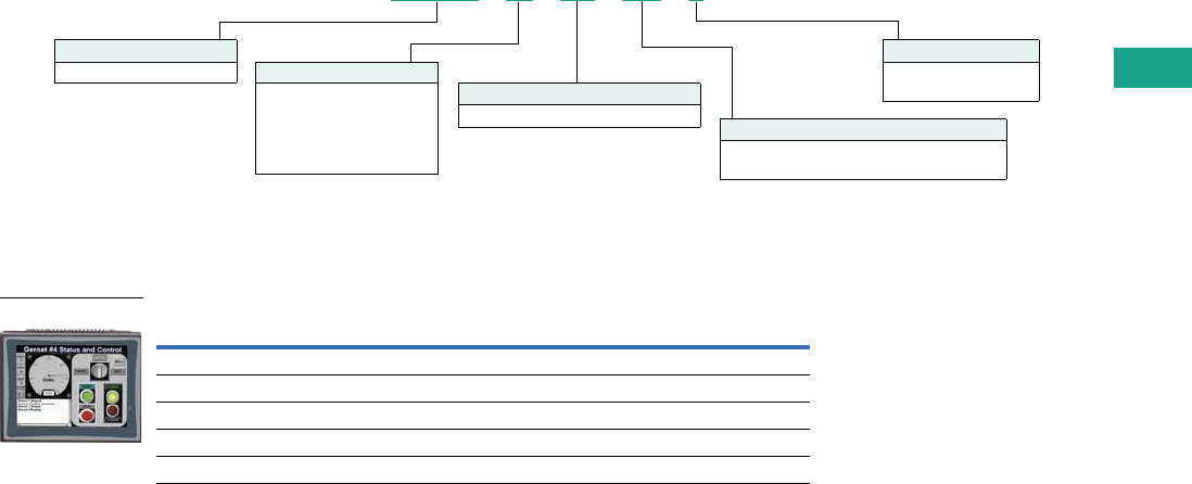
Volume 7—Logic Control, Operator Interface and Connectivity Solutions CA08100008E—February 2014 www.eaton.com V7-T5-15
5
5
5
5
5
5
5
5
5
5
5
5
5
5
5
5
5
5
5
5
5
5
5
5
5
5
5
5
5
5
5.3
Operator Interface Products
HMi Operator Interface
Catalog Number Selection
HMi Operator Interface
HMi
Product Selection
HMi VU Products
Description Catalog Number
4-inch color TFT, no function buttons, on-board Ethernet HMIVU04CUNBE
6-inch color TFT, no function buttons, no Ethernet HMIVU06CUNB1
7-inch color TFT, no function buttons, on-board Ethernet HMIVU07CUNBE
8-inch color TFT, no function buttons, on-board Ethernet HMIVU08CUNBE
10-inch color TFT, no function buttons, on-board Ethernet HMIVU10WCUNBE
Series
HMIVU = HMi VU Series
Options
E = On-board Ethernet
and audio out
Display
04 = 4.3-inch LCD
06 = 5.6-inch LCD
07 = 7.0-inch LCD
08 = 8.0-inch LCD
10W = 10.1-inch-wide LCD
Options
CU = Color TFT without expansion port
HMIVU 07 CU NB E
Options
NBx = HMi VU Firmware Series
NB = HMi VU Series no function buttons
HMI_
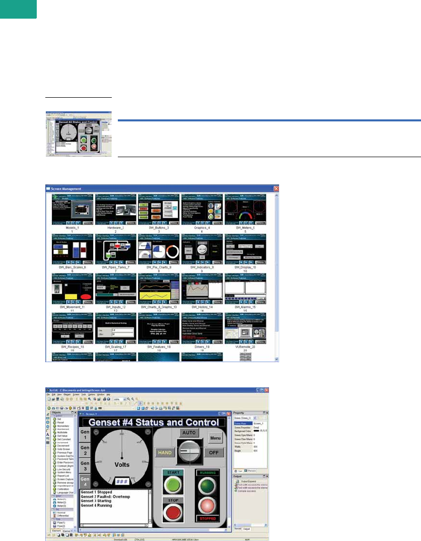
V7-T5-16 Volume 7—Logic Control, Operator Interface and Connectivity Solutions CA08100008E—February 2014 www.eaton.com
5
5
5
5
5
5
5
5
5
5
5
5
5
5
5
5
5
5
5
5
5
5
5
5
5
5
5
5
5
5
5.3
Operator Interface Products
HMi Operator Interface
Software and Accessories
HMiSoft Programming Software
For use with the of HMi and
HMi VU series touchscreens.
This easy to use Windows
based software can run
on Windows XP and
Windows 7 32-bit and 64-bit
systems.
●Ethernet and serial
communication drivers
●Up to four simultaneous
protocols
●Screen manager
●Over 70 on-screen objects
●Pop-up screens
●Animated graphics
●Conditional visibility
●Built-in picture library
●Create your own picture
library
●Multi-language
●Eight levels of security
●Macro editing with math
and logic functions
●CSV import/export tags
and recipes
●Alarm/event recording and
viewing
●Store archived data, alarms
and events to USB
●Real-time and historical
trending
●Auto-scale application from
10 to 4 inches
●On and offline simulation
●Upload/download
applications over USB,
serial or Ethernet
●Application lock for IP
protection
●Screen and backlight saver
●Multi-link allows sharing of
PLC data over Ethernet 1
●VU Server optional
download 1
●VU Remote optional
download 1
HMi Editor
HMi Screen Management
HMiSoft Editor
Note
1Exclusive HMiVU features.
Description Catalog Number
Programming software for HMi and HMi VU models HMISOFT
HMi Editor

Volume 7—Logic Control, Operator Interface and Connectivity Solutions CA08100008E—February 2014 www.eaton.com V7-T5-17
5
5
5
5
5
5
5
5
5
5
5
5
5
5
5
5
5
5
5
5
5
5
5
5
5
5
5
5
5
5
5.3
Operator Interface Products
HMi Operator Interface
Adapter Plate
Kits
Replacement Gaskets
Cable
Power Supply
Description Catalog Number
6-inch HMi adapter plate for PM1000 APPM1HMI6
Description Catalog Number
HMi spare parts kits (includes several power connectors, battery doors,
gaskets, mounting clips, etc.)
HMI-SPKIT
Description Catalog Number
4-inch HMi replacement gasket (2/kit) HMI04-GASKET
6-inch HMi and 7-inch HMi VU replacement gasket (2/kit) HMI06-GASKET
8-inch HMi replacement gasket (2/kit) HMI08-GASKET
10-inch HMi replacement gasket (2/kit) HMI10-GASKET
Description Catalog Number
1 meter cable to connect between the HMi and Eaton Logic Controller (ELC) ELC-CBPCELC1
3 meter cable to connect between the HMi and Eaton Logic Controller (ELC) ELC-CBPCELC3
Description Catalog Number
1 amp 24 Vdc power supply ELC-PS01
2 amp 24 Vdc power supply ELC-PS02

V7-T5-18 Volume 7—Logic Control, Operator Interface and Connectivity Solutions CA08100008E—February 2014 www.eaton.com
5
5
5
5
5
5
5
5
5
5
5
5
5
5
5
5
5
5
5
5
5
5
5
5
5
5
5
5
5
5
5.3
Operator Interface Products
HMi Operator Interface
Technical Data and Specifications
HMi VU Operator Interface
Notes
1The half-life of backlight is defined as original luminance being reduced by 50% when the maximum driving current is supplied to HMi. The life of LED backlight shown is an estimated
value under 25°C normal temperature and humidity conditions
2USB Host port can provide up to 5V/500 mA of power.
3The withstand voltage of the isolated power circuit is 1500V peak for 1 minute.
4The value of the power consumption indicates the electrical power consumed by HMi only without connecting to any peripheral devices. In order to ensure the normal operation, it is recommended
to use a power supply where the capacity is 1.5~2 times the value of the power consumption.
Specification
Description HMIVU04CUNBE HMIVU06CUNB1 HMIVU07CUNBE HMIVU08CUNBE HMIVU10WCUNBE
LCD module
Display type 4.3-inch TFT LCD 5.6-inch TFT LCD 7-inch TFT LCD 8-inch TFT LCD 10.1-inch widescreen TFT LCD
Display color 65536 colors 65536 colors 65536 colors 65536 colors 65536 colors
Resolution 480 x 234 pixels 320 x 234 pixels 800 x 600 pixels 800 x 600 pixels 1024 x 600 pixels
Backlight LED backlight (20,000 hours
half-life at 25°C) 1
LED backlight (20,000 hours
half-life at 25°C) 1
LED backlight (10,000 hours
half-life at 25°C) 1
LED backlight (10,000 hours
half-life at 25°C) 1
LED backlight (10,000 hours
half-life at 25°C) 1
Brightness NIT rating 400 DC/m2 200 DC/m2 200 DC/m2 250 DC/m2 200 DC/m2
Display size 95.04 x 53.856 mm 113.28 x 84.70 mm 141 x 105.75 mm 162 x 121.5 mm 226 x 128.7 mm
Operation system Real Time OS Real Time OS Real Time OS Real Time OS Real Time OS
MCU 32-bit RISC micro-controller 32-bit RISC micro-controller 32-bit RISC micro-controller 32-bit RISC micro-controller 32-bit RISC micro-controller
NOR Flash ROM Flash ROM 128 MB
OS System: 30 MB
Backup: 16 MB
User Application: 82 MB
Flash ROM 128 MB
OS System: 30 MB
Backup: 16 MB
User Application: 82 MB
Flash ROM 128 MB
OS System: 30 MB
Backup: 16 MB
User Application: 82 MB
Flash ROM 128 MB
OS System: 30 MB
Backup: 16 MB
User Application: 82 MB
Flash ROM 128 MB
OS System: 30 MB
Backup: 16 MB
User Application: 82 MB
SDRAM 64M bytes 64M bytes 64M bytes 64M bytes 64M bytes
Backup memory 16M bytes 16M bytes 16M bytes 16M bytes 16M bytes
Sound effect output
Buzzer Multi-tone frequency (2–4 kHz)/85 dB
AUX N/A N/A Stereo output Stereo output Stereo output
Ethernet interface IEEE 802.3, IEEE 802.3u
10/100 Mbps auto-sensing has
built-in isolated power circuit 3
N/A IEEE 802.3, IEEE 802.3u
10/100 Mbps auto-sensing has
built-in isolated power circuit 3
IEEE 802.3, IEEE 802.3u
10/100 Mbps auto-sensing has
built-in isolated power circuit 3
IEEE 802.3, IEEE 802.3u
10/100 Mbps auto-sensing has
built-in isolated power circuit 3
Memory card N/A N/A SD card (supports SDHC) SD card (supports SDHC) SD card (supports SDHC)
USB 1 USB Host
2 Ver 2.0 1 USB Client Ver 1.1
Serial COM port
COM1 RS-232 (supports hardware
flow control) / RS-485
RS-232 (supports
hardware flow control)
RS-232 (supports
hardware flow control)
RS-232 (supports
hardware flow control)
RS-232 (supports
hardware flow control)
COM2 RS-422/RS-485 RS-232/RS-485 RS-232/RS-422/RS-485 (has built-in isolated power circuit) 3
COM3 N/A RS-422/RS-485 RS-232/RS-422/RS-485 (has built-in isolated power circuit) 3
Perpetual calendar (RTC) Built-in Built-in Built-in Built-in Built-in
Cooling method Natural air circulation Natural air circulation Natural air circulation Natural air circulation Natural air circulation
Safety approval CE/UL CE/UL CE/UL CE/UL CE/UL
Waterproof degree IP65/NEMA 4X (indoor use only)
Operation voltage 4DC +24V (–10 to +15%) Please use isolated power supply
Voltage endurance AC500V for 1 minute (between charging [DC24 terminal] and FG terminals)
Power consumption 44.8W 3.0W 7.68W 7.8W 12W
Backup battery 3V lithium battery CR2032 x 1 3V lithium battery CR2032 x 1 3V lithium battery CR2032 x 1 3V lithium battery CR2032 x 1 3V lithium battery CR2032 x 1
Backup battery life It depends on the temperature used and the conditions of usage, about 3 years or more at 25°C
Operation temp. 0° to 50°C 0° to 50°C 0° to 50°C 0° to 50°C 0° to 50°C
Storage temp. –20° to 60°C –20° to 60°C –20° to 60°C –20° to 60°C –20° to 60°C
Ambient humidity 10%~90% RH [0° to 40°C], 10%~55% RH [41° to 50°C] / Pollution Degree 2
Vibration resistance 5 Hz < f < 8.3 Hz = continuous: 3.5 mm
8.3 Hz < f < 150 Hz = continuous: 1.0g
Shock IEC 61131-2 Compliant
5 Hz < f < 9 Hz = continuous: 1.75 mm/occasional: 3.5 mm
9 Hz < f < 150 Hz = continuous: 0.5g/occasional: 1.0g
X, Y, Z directions for 10 times
Dimensions
(W) x (H) x (D) mm 129 x 103 x 39 184 x 144 x 50 184 x 144 x 50 227.1 x 174.1 x 61 272 x 200 x 61
Panel cutout
(W) x (H) mm 118.8 x 92.8 172.4 x 132.4 172.4 x 132.4 219.4 x 166.5 261.3 x 189.3
Weight Approx. 264g Approx. 670g Approx. 800g Approx. 1228g Approx.1520g
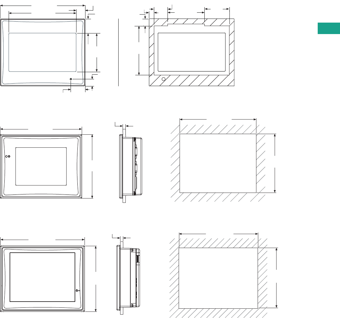
Volume 7—Logic Control, Operator Interface and Connectivity Solutions CA08100008E—February 2014 www.eaton.com V7-T5-19
5
5
5
5
5
5
5
5
5
5
5
5
5
5
5
5
5
5
5
5
5
5
5
5
5
5
5
5
5
5
5.3
Operator Interface Products
HMi Operator Interface
Dimensions
Approximate Dimensions in Inches (mm)
HMIVU04
HMIVU06
HMIVU07
2.82
(71.7)
2.11 (53.7)
0.79 (20.0)
0.41
(10.4)
Cutout
4.88 (124.0)
3.87 (98.3)
0.52 (13.1)
0.83
(21.2)
2.21
(56.1)
0.83 (21.0)
0.39
(10.0)
0.28
(7.0) 1.43
(36.3)
5.21
(132.4)
6.79 (172.4)
0.063 (1.6) to 0.24 (6.0)
7.24 (184.0)
5.67
(144.0)
5.21
(132.4)
6.79 (172.4)
0.063 (1.6) to 0.24 (6.0)
7.24 (184.0)
5.67
(144.0)
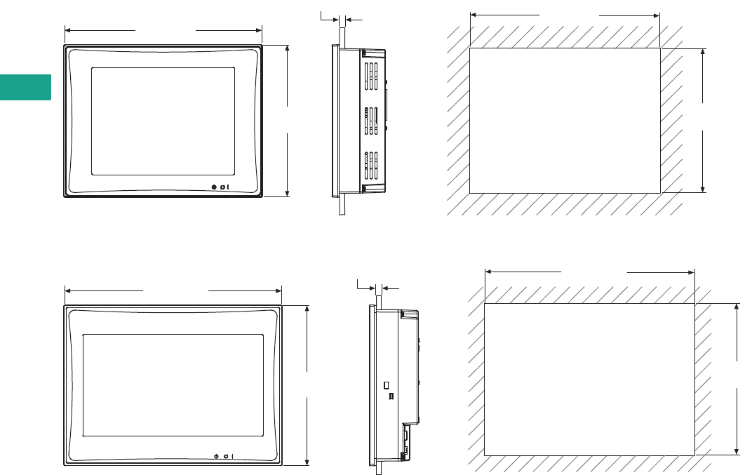
V7-T5-20 Volume 7—Logic Control, Operator Interface and Connectivity Solutions CA08100008E—February 2014 www.eaton.com
5
5
5
5
5
5
5
5
5
5
5
5
5
5
5
5
5
5
5
5
5
5
5
5
5
5
5
5
5
5
5.3
Operator Interface Products
HMi Operator Interface
Approximate Dimensions in Inches (mm)
HMIVU08
HMIVU10
8.64 (219.4)
0.063 (1.6) to 0.24 (6.0)
8.94 (227.1)
6.85
(174.1)
6.56
(166.5)
10.29 (261.3)
0.063 (1.6) to 0.24 (6.0)
10.71 (272.0)
7.88
(200.0)
7.45
(189.3)
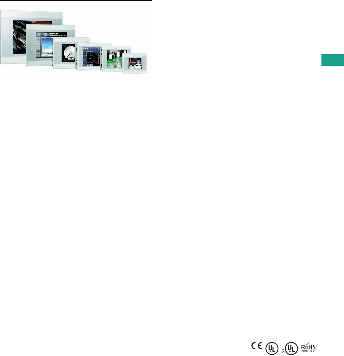
Volume 7—Logic Control, Operator Interface and Connectivity Solutions CA08100008E—February 2014 www.eaton.com V7-T5-21
5
5
5
5
5
5
5
5
5
5
5
5
5
5
5
5
5
5
5
5
5
5
5
5
5
5
5
5
5
5
5.4
Operator Interface Products
XV and XP Operator Interface
XV Operator Interface
Contents
Description Page
XV with Visual Designer, Galileo or XSoft-CoDeSys-2
Catalog Number Selection . . . . . . . . . . . . . . . . . V7-T5-25
Product Selection . . . . . . . . . . . . . . . . . . . . . . . . V7-T5-25
Accessories . . . . . . . . . . . . . . . . . . . . . . . . . . . . V7-T5-26
Technical Data and Specifications . . . . . . . . . . . V7-T5-27
XP with Visual Designer . . . . . . . . . . . . . . . . . . . . . V7-T5-28
Visual Designer Software . . . . . . . . . . . . . . . . . . . . V7-T5-32
Galileo Software . . . . . . . . . . . . . . . . . . . . . . . . . . . V7-T5-35
XSoft-CoDeSys-2 Software . . . . . . . . . . . . . . . . . . . V7-T5-36
XV with Visual Designer, Galileo or XSoft-CoDeSys-2
Product Description
XV with Visual Designer
Positioned between the HMi
and the XP series of operator
interface, the XV series is
ideal for applications requiring
extensive connectivity and
the advanced features
available in Visual Designer
without the expense
associated with more
powerful open platforms.
The XV models were
designed with OEMs in mind
featuring an attractive bezel
and slim and light weight
housing. The clip mount
design simplifies installation.
XV with Galileo
The XV Series with Galileo
offers a global visualization
software package for all
applications in system and
machine building. It is
designed to optimize
performance on the XV
platform. Galileo can also
run as the visualization
package on XV CoDeSys
units when a stronger
visualization tool is required.
XV with XSoft-CoDeSys
The XV series with XSoft-
CoDeSys combines powerful
logic and visualization
capabilities into a single
device. It is ideal for OEM
applications where low
component count and ease
of program development
and remote administration
is critical.
The XV Models with XSoft-
CoDeSys offer multiple field
bus options built directly on-
board the unit to provide an
overall solution optimized
both for size and cost.
Features
XV with Visual Designer
XV Series operator interface
with Windows CE operating
system
●3.5-, 5.7-, 7.0- (widescreen),
8.4- and 10.4-inch screen
sizes
●Cost effective plastic or
metal housing
●Resistive touch with flush
bezel
●Ethernet and serial ports
on all models
●Visual Designer XP or CE
development software
●Pre-installed Visual
Designer runtime and
Web serving licenses
XV with Galileo only units
●3.5-, 5.7- and 7.0-inch
(widescreen)
●Plastic housing
●Resistive touch with
flush bezel
●Ethernet on all models
●RS-232 or RS-485 serial
ports available
●Prelicensed for Galileo
Run Time (GRS)
XV with XSoft-CoDeSys
XV Series operator interface
with Windows CE operating
system
●3.5-, 5.7-, 7.0- (widescreen),
8.4- and 10.4-inch screen
sizes
●Cost effective plastic or
metal housing
●Resistive touch with flush
bezel
●Ethernet and serial ports
on all models
●PROFIBUS, CANopen and
SmartWire-DT optional
●XSoft-CoDeSys-2
programming software
●Pre-licensed for CoDeSys
run time
Standards and Certifications
●CE
●UL
●cUL
●RoHS
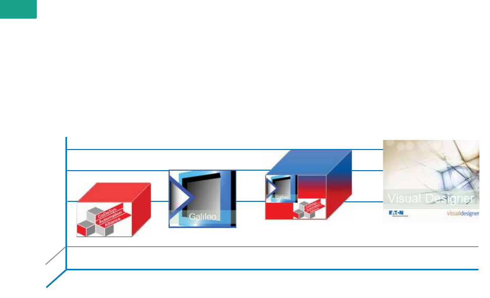
V7-T5-22 Volume 7—Logic Control, Operator Interface and Connectivity Solutions CA08100008E—February 2014 www.eaton.com
5
5
5
5
5
5
5
5
5
5
5
5
5
5
5
5
5
5
5
5
5
5
5
5
5
5
5
5
5
5
5.4
Operator Interface Products
XV and XP Operator Interface
Selecting the right model for your application
The XV product offered
with Visual Designer, Galileo
or XSoft-CoDeSys offers
the highest level of flexibility
for one operator interface
product.
Visual Designer provides a
fully integrated SCADA and
HMI platform. Use Visual
Designer when Web
enabling, remote access,
database and
connectivity,
and when one operator
software package is required
across XV and XP platforms.
Galileo provides a visualization
environment designed around
the needs of machine building
OEMs. Use Galileo when
designing high-performance
machines in the OEM space.
XSoft-CoDeSys turns the
XV into a fully integrated
Logic and OI platform
(HMI-PLC). Use XSoft-
CoDeSys to unleash the
PLC functionality on an XV.
With optional communication
interfaces like SmartWire-DT,
CANopen and PROFIBUS,
Eaton welcomes you into the
Lean Automation space.
Take advantage of the best of
both worlds with Galileo and
XSoft-CoDeSys together.
Combining the power of
these two software platforms
provides limitless possibilities
on an HMI/PLC platform.
Software Suite
FTP, Remote Client, Real VNC Gateway, SD Slot
®
Features
PLC
HMI

Volume 7—Logic Control, Operator Interface and Connectivity Solutions CA08100008E—February 2014 www.eaton.com V7-T5-23
5
5
5
5
5
5
5
5
5
5
5
5
5
5
5
5
5
5
5
5
5
5
5
5
5
5
5
5
5
5
5.4
Operator Interface Products
XV and XP Operator Interface
Product Selection Guide
XV and XP Operator Interface with Visual Designer
Series XV XP
Model XV-102 XV-152 XP-702
Screen Size 3.5, 5.7, 7.0 5.7, 8.4, 10.4 8.4, 10.4, 12.1, 15.0 Blind Node (no display)
Housing material Plastic Metal Metal
Operating system WinCE 5.0 Professional Windows XPe
Touchscreen technology Resistive Infrared, non-reflective safety glass N/A
Communication ports 1 Ethernet, 1 or 2 serial, 0 or 1 USB 2 Ethernet, 2 serial, 4 USB
Development software Visual Designer (VISUALDCE or VISUALDXP) Visual Designer (VISUALDXP)
Pre-licensed tags, drivers, Web sessions 1500 tags, 3 drivers, 1 Web session Standard models 4000 tags, 5 drivers, 1 Web session
Enterprise models 64,000 tags, 8 drivers, 1 Web session
Field upgradeable max tags, drivers, Web sessions 4000 tags, 3 drivers, 1, 2, 4, or 8
Web sessions simultaneously
64,000 tags, 8 drivers, 1, 2, 4, 8, 16, 32, 64, 128, or 256
Web sessions simultaneously
Alarm online/history Yes Yes
Trend online/history Yes Yes
Scripting Yes (VB Script) Yes (VB Script)
Scheduler Yes Yes
Recipe Yes Yes
Reports Yes Yes
OPC, TCP/IP, and communication drivers Yes Yes
Web Server and Web Thin Client support Yes Yes
Full remote access Yes Yes
Local/remote database interface Yes Yes
Ability to run third-party software No Yes
ActiveX and .NET controls No Yes
Full document viewing No Yes
Windows media player No Yes
Vision system interfaces No Yes
Network camera monitoring No Yes

V7-T5-24 Volume 7—Logic Control, Operator Interface and Connectivity Solutions CA08100008E—February 2014 www.eaton.com
5
5
5
5
5
5
5
5
5
5
5
5
5
5
5
5
5
5
5
5
5
5
5
5
5
5
5
5
5
5
5.4
Operator Interface Products
XV and XP Operator Interface
XV Series with Galileo Only Run Time Option (Not Available on XP Series)
XV Series with CoDeSys Run Time (Not Available on XP Series)
Series XV
Model Model XV-102-H
Screen Size 3.5, 5.7, 7.0
Housing material Plastic
Operating system WinCE 5.0 standard
Touchscreen Resistive
Communications ports 1 Ethernet, 1 RS-232, or 1 RS-485, 1 USB
Optional field buses N/A
Development software Galileo
Alarm online/historical Yes
Trend online/historical Yes
Scripting Structured text
Scheduler No
Recipe Yes
Reports No
Full remote access Yes
Ability to run third-party software No
Vision system interfaces Yes
Multi-language support Yes
PLC variable import Yes
Series XV
Model XV-102 XV-152
Screen Size 3.5, 5.7, 7.0 5.7, 8.4, 10.4
Housing material Plastic Metal
Operating system WinCE 5.0 Standard
Touchscreen Resistive
Communications ports 1 Ethernet, 1 or 2 serial, 0 or 1 USB
Optional field buses PROFIBUS, CANopen, SmartWire-DT
Development software XSoft-CoDeSys-2
IEC-61131-3 logic programming (LD, ST, SFC, IL, FBD, CFC) Yes
Integrated screen design Yes
Integrated field bus configuration Yes
Alarm online/historical Yes
Trend online/historical Yes
Scripting Structured Text
Scheduler Yes
Recipe Yes
Reports No
OPC, TCP/IP and communication driver Yes (OPC Server for PC)
Web Server and Web Thin Client support Yes
Full remote access Yes
Local/remote data base access Limited (DDE)
Ability to run third-party software No
ActiveX and .NET controls No
Full document viewing No
Windows media player No
Vision system interfaces No
Network camera monitoring No
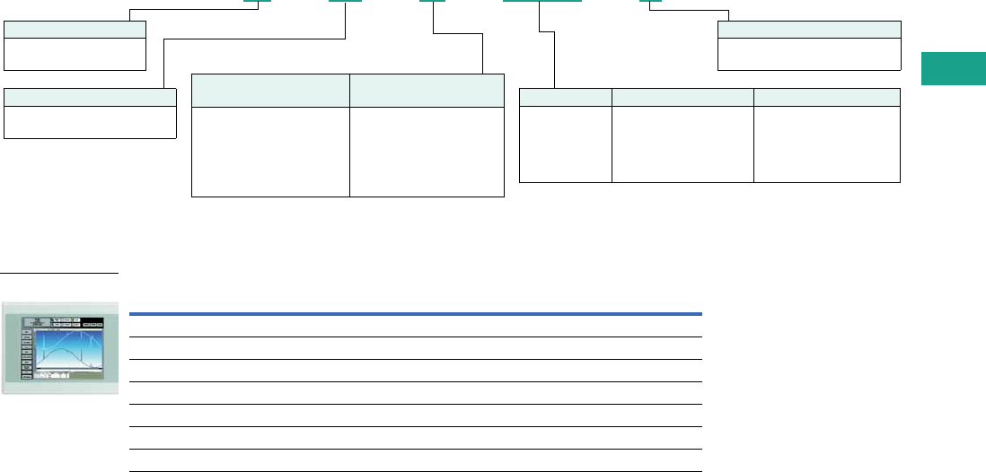
Volume 7—Logic Control, Operator Interface and Connectivity Solutions CA08100008E—February 2014 www.eaton.com V7-T5-25
5
5
5
5
5
5
5
5
5
5
5
5
5
5
5
5
5
5
5
5
5
5
5
5
5
5
5
5
5
5
5.4
Operator Interface Products
XV and XP Operator Interface
Catalog Number Selection
XV Operator Interface
XV
Product Selection
XV Operator Interface with Visual Designer
Notes
1 All 1xx performance class units have 400 MHz processor, 64 MB DRAM, 1 x 10/100 Ethernet, and 1 x USB device.
2 Standard software on embedded hardware. These XV models have a Microsoft Windows CE 5.0 Professional operating
system and are pre-licensed with Visual Designer runtime for up to 1500 tags, 3 simultaneous communication drivers,
and 1 Web session. Field upgrades are available for up to 4000 tags, 3 drivers, and 2, 4 or 8 simultaneous Web sessions.
Description Catalog Number
XV 3.5-inch TFT, plastic housing, resistive touch, Ethernet and RS-232 XV-102-B3-35TQRG-10
XV 3.5-inch TFT, plastic housing, resistive touch, Ethernet and RS-485 XV-102-B4-35TQRG-10
XV 5.7-inch TFT, plastic housing, resistive touch, Ethernet, RS-232, RS-485 XV-102-D4-57TVRG-10
XV 7.0-inch TFT wide screen, plastic housing, resistive touch, Ethernet, RS-232, RS-485 XV-102-D4-70TWRG-10
XV 5.7-inch TFT, metal housing, resistive touch, Ethernet, RS-232, RS-485 XV-152-D4-57TVRG-10
XV 8.4-inch TFT, metal housing, resistive touch, Ethernet, RS-232, RS-485 XV-152-D4-84TVRG-10
XV 10.4-inch TFT, metal housing, resistive touch, Ethernet, RS-232, RS-485 XV-152-D4-10TVRG-10
XV –102–B3–35TQRG–10
Family
XV = Microsoft Windows
CE operating system
Branding and Bezel
10 = Standard blank front bezel with
Eaton branded product label
Display Size Display Technology OS Build
35 = 3.5-inch
57 = 5.7-inch
70 = 7.0-inch
84 = 8.4-inch
10 = 10.4-inch
TQR = TFT (QVGA) resistive
TVR = TFT (VGA) resistive
TWR = TFT (widescreen)
resistive
C = XSoft-CoDeSys/Galileo
G = CE Professional OS and
Visual Designer runtime
1500 tags 2
L = Galileo only unit
Features
Base Unit Variant 1
Features
Additional COMM Options
B = Retentive memory
D = Retentive memory, USB
host, RS-232
E = Retentive memory, USB
host, SmartWire-DT
H = Galileo only unit, USB host
3 = 1-RS-232
4 = 1-RS-485
6 = 1-CANopen
8 = 1-PROFIBUS
E = 1-SmartWire-DT
Performance Class
102 = CE, plastic housing, 2nd gen
152 = CE, metal housing, 2nd gen
XV Operator Interface
V7-T5-26 Volume 7—Logic Control, Operator Interface and Connectivity Solutions CA08100008E—February 2014 www.eaton.com
5
5
5
5
5
5
5
5
5
5
5
5
5
5
5
5
5
5
5
5
5
5
5
5
5
5
5
5
5
5
5.4
Operator Interface Products
XV and XP Operator Interface
XV Operator Interface with XSoft-CoDeSys, HMI-PLC
XV Operator Interface with Galileo Only
Accessories
XV Family Accessories
Description Catalog Number
XV 3.5-inch TFT plastic housing, resistive touch, CANopen, RS-485 XV-102-B6-35TQRC-10
XV 3.5-inch TFT plastic housing, resistive touch, PROFIBUS, RS-485 XV-102-B8-35TQRC-10
XV 3.5-inch TFT plastic housing, resistive touch, SmartWire-DT XV-102-BE-35TQRC-10
XV 5.7-inch TFT plastic housing, resistive touch, CANopen, RS-232, RS-485 XV-102-D6-57TVRC-10
XV 5.7-inch TFT plastic housing, resistive touch, PROFIBUS, RS-232, RS-485 XV-102-D8-57TVRC-10
XV 5.7-inch TFT plastic housing, resistive touch, CANopen, SmartWire-DT, RS-485 XV-102-E6-57TVRC-10
XV 5.7-inch TFT plastic housing, resistive touch, PROFIBUS, SmartWire-DT, RS-485 XV-102-E8-57TVRC-10
XV 7.0-inch TFT plastic housing, resistive touch, CANopen, RS-232, RS-485 XV-102-D6-70TWRC-10
XV 7.0-inch TFT plastic housing, resistive touch, PROFIBUS, RS-232, RS-485 XV-102-D8-70TWRC-10
XV 7.0-inch TFT plastic housing, resistive touch, CANopen, SmartWire-DT, RS-485 XV-102-E6-70TWRC-10
XV 7.0-inch TFT plastic housing, resistive touch, PROFIBUS, SmartWire-DT, RS-485 XV-102-E8-70TWRC-10
XV 5.7-inch TFT metal housing, resistive touch, CANopen, RS-232, RS-485 XV-152-D6-57TVRC-10
XV 5.7-inch TFT metal housing, resistive touch, PROFIBUS, RS-232, RS-485 XV-152-D8-57TVRC-10
XV 5.7-inch TFT metal housing, resistive touch, CANopen, SmartWire-DT, RS-485 XV-152-E6-57TVRC-10
XV 5.7-inch TFT metal housing, resistive touch, PROFIBUS, SmartWire-DT, RS-485 XV-152-E8-57TVRC-10
XV 8.4-inch TFT metal housing, resistive touch, CANopen, RS-232, RS-485 XV-152-D6-84TVRC-10
XV 8.4-inch TFT metal housing, resistive touch, PROFIBUS, RS-232, RS-485 XV-152-D8-84TVRC-10
XV 8.4-inch TFT metal housing, resistive touch, CANopen, SmartWire-DT, RS-485 XV-152-E6-84TVRC-10
XV 8.4-inch TFT metal housing, resistive touch, PROFIBUS, SmartWire-DT, RS-485 XV-152-E8-84TVRC-10
XV 10.4-inch TFT metal housing, resistive touch, CANopen, RS-232, RS-485 XV-152-D6-10TVRC-10
XV 10.4-inch TFT metal housing, resistive touch, PROFIBUS, RS-232, RS-485 XV-152-D8-10TVRC-10
XV 10.4-inch TFT metal housing, resistive touch, CANopen, SmartWire-DT, RS-485 XV-152-E6-10TVRC-10
XV 10.4-inch TFT metal housing, resistive touch, PROFIBUS, SmartWire-DT, RS-485 XV-152-E8-10TVRC-10
Description Catalog Number
XV 3.5-inch TFT plastic housing, resistive touch, Ethernet RS-232 XV-102-H3-35TQRL-10
XV 3.5-inch TFT plastic housing, resistive touch, Ethernet RS-485 XV-102-H4-35TQRL-10
XV 5.7-inch TFT plastic housing, resistive touch, Ethernet RS-232 XV-102-H3-57TVRL-10
XV 5.7-inch TFT plastic housing, resistive touch, Ethernet RS-485 XV-102-H4-57TVRL-10
XV 7.0-inch TFT plastic housing, resistive touch, Ethernet RS-232 XV-102-H3-70TWRL-10
XV 7.0-inch TFT plastic housing, resistive touch, Ethernet RS-485 XV-102-H4-70TWRL-10
Description Catalog Number
SD memory card for all XV models MEMORY-SD-A1-S
Spare part kit for XV-102 models—1 power connector, 8 mounting brackets,
1 sealing strip, 1 touch pen
ACC-TP-57-KG-1 XV-102
Spare part kit for XV-152 models—1 power connector, 8 mounting brackets,
1 sealing strip, 1 touch pen
ACC-TP-10-12-RES-1

Volume 7—Logic Control, Operator Interface and Connectivity Solutions CA08100008E—February 2014 www.eaton.com V7-T5-27
5
5
5
5
5
5
5
5
5
5
5
5
5
5
5
5
5
5
5
5
5
5
5
5
5
5
5
5
5
5
5.4
Operator Interface Products
XV and XP Operator Interface
Technical Data and Specifications
XV Operator Interface
Series XV Midrange Operator Interface
Model XV-102 XV-152
Screen Size 3.5-Inch 5.7-Inch 7.0-Inch 5.7-Inch 8.4-Inch 10.4-Inch
Operating system WinCE 5.0 Professional/Standard WinCE 5.0 Professional/Standard
Touchscreen technology Resistive Resistive Resistive Resistive Resistive Resistive
Display, colors Color TFT, 64k colors Color TFT, 64k colors Color TFT, 64k colors Color TFT, 64k colors Color TFT, 64k colors Color TFT, 64k colors
Pixel resolution (landscape)
portrait mode also available
QVGA 320 x 240 VGA 640 x 480 WVGA 800 x 480 VGA 640 x 480 VGA 640 x 480 VGA 640 x 480
Brightness (cd/m2) 250 250 250 350 350 350
Backlight LED, selectable dimming LED, selectable dimming LED, selectable dimming LED, selectable dimming LED, selectable dimming LED, selectable dimming
Lifespan of backlight (half-life) 40,000 hrs 40,000 hrs 40,000 hrs 40,000 hrs 40,000 hrs 40,000 hrs
Processor 32 bit RISC, 400 MHz 32 bit RISC, 400 MHz 32 bit RISC, 400 MHz 32 bit RISC, 400 MHz 32 bit RISC, 400 MHz 32 bit RISC, 400 MHz
Volatile memory 64 MB DRAM 64 MB DRAM 64 MB DRAM 64 MB DRAM 64 MB DRAM 64 MB DRAM
Non-volatile memory 125 KB NVRAM/64 MB
NAND, 1 SD card slot
125 KB NVRAM/64 MB NAND/
2 MB NOR, 1 SD card slot
125 KB NVRAM/64 MB NAND/
2 MB NOR, 1 SD card slot
Real time clock Yes Yes Yes Yes Yes Yes
Communication ports Ethernet 10/100, RS-485
or RS-232 USB Device
Ethernet 10/100, RS-485, RS-232
USB Host, USB Device
Ethernet 10/100, RS-485, RS-232 USB Host, USB Device
Slots for COMM modules None None None None None None
Power supply rated voltage 24 Vdc nominal (–20%/+25%) with polarity protection 24 Vdc nominal (–20%/+25%) with polarity protection
Continuous current consumption
(max. amps)
0.2 0.4 0.4 0.4 0.6 0.6
Starting current inrush (A2s) 1.5 1.5 1.5 1.5 1.5 1.5
Ambient conditions
Operation—relative humidity,
noncondensing
0 to 50°C, 10 to 95% 0 to 50°C, 10 to 95% 0 to 50°C, 10 to 95% 0 to 50°C, 10 to 95% 0 to 50°C, 10 to 95% 0 to 50°C, 10 to 95%
Storage/transport—relative
humidity, noncondensing
–20 to 60°C, 10 to 95% –20 to 60°C, 10 to 95% –20 to 60°C, 10 to 95% –20 to 60°C, 10 to 95% –20 to 60°C, 10 to 95% –20 to 60°C, 10 to 95%
Shock IEC 60068-2-27 15g for 11 ms duration IEC 60068-2-27 15g for 11 ms duration
Vibration IEC 60068-2-6
5–9 Hz: 3.5 mm displacement
9–60 Hz: 0.15 mm displacement
60–150 Hz: 2g acceleration
IEC 60068-2-6
5–9 Hz: 3.5 mm displacement
9–60 Hz: 0.15 mm displacement
60–150 Hz: 2g acceleration
Agency certifications and
standards
CE, UL/cUL, CSA (pending), RoHS CE, UL/cUL, CSA (pending), RoHS
Protection type
Front IP65, NEMA 4X (indoor) IP65, NEMA 4X (indoor) IP65, NEMA 4X (indoor) IP65, NEMA 4X (indoor) IP65, NEMA 4X (indoor) IP65, NEMA 4X (indoor)
Rear IP20, NEMA 1 IP20, NEMA 1 IP20, NEMA 1 IP20, NEMA 1 IP20, NEMA 1 IP20, NEMA 1
Housing material Plastic Plastic Plastic Metal Metal Metal
Dimensions W x H x D (mm) 136 x 100 x 30 170 x 130 x 39 210 x 135 x 38 212 x 156 x 53 275 x 208 x 53 345 x 260 x 54
Mounting cutout W x H (mm) 123 x 87 157 x 117 197 x 122 198 x 142 261 x 194 329 x 238
Approximate weight lbs (kg) 0.7 (0.3) 1.3 (0.6) 1.3 (0.6) 2.9 (1.3) 4.3 (2.1) 6.1 (3.0)
Ability to run third-party
software
No No No No No No
Visual Designer
development software
VISUALDCE or VISUALDXP VISUALDCE or VISUALDXP
Pre-licensed tags, drivers, Web
sessions (Visual Designer
models)
1500 tags, 3 drivers, 1 Web session 1500 tags, 3 drivers, 1 Web session
Field upgradeable max tags,
drivers, Web sessions (Visual
Designer Models)
4000 tags, 3 drivers, 1, 2, 4, or 8 Web sessions simultaneously 4000 tags, 3 drivers, 1, 2, 4, or 8 Web sessions simultaneously
XSoft-CoDeSys-2 development
software
SW-XSOFT-CODESYS-2-S (seat)
SW-XSOFT-CODESYS-2-M (multi-seat)
SW-XSOFT-CODESYS-2-S (seat)
SW-XSOFT-CODESYS-2-M (multi-seat)
Galileo development software SW-GALILEO-S (seat)
SW-GALILEO-M (multi-seat)
SW-GALILEO-S (seat)
SW-GALILEO-M (multi-seat)
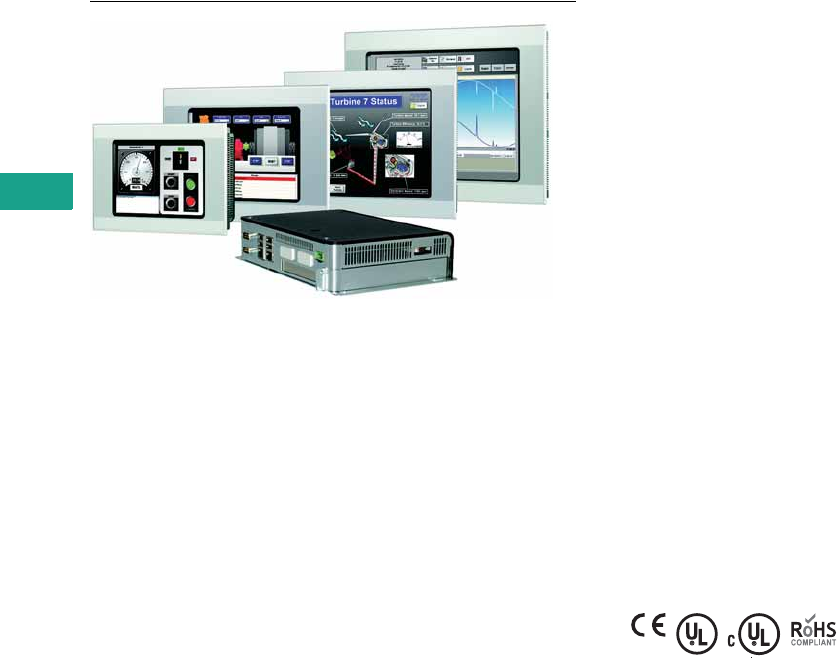
V7-T5-28 Volume 7—Logic Control, Operator Interface and Connectivity Solutions CA08100008E—February 2014 www.eaton.com
5
5
5
5
5
5
5
5
5
5
5
5
5
5
5
5
5
5
5
5
5
5
5
5
5
5
5
5
5
5
5.4
Operator Interface Products
XV and XP Operator Interface
XP Operator Interface
Contents
Description Page
XV with Visual Designer, Galileo,
or XSoft-CoDeSys-2 . . . . . . . . . . . . . . . . . . . . . . . V7-T5-21
XP with Visual Designer
Catalog Number Selection . . . . . . . . . . . . . . . . . . V7-T5-29
Product Selection . . . . . . . . . . . . . . . . . . . . . . . . . V7-T5-29
Accessories . . . . . . . . . . . . . . . . . . . . . . . . . . . . . V7-T5-30
Technical Data and Specifications . . . . . . . . . . . . V7-T5-30
Visual Designer Software . . . . . . . . . . . . . . . . . . . . V7-T5-32
Galileo Software . . . . . . . . . . . . . . . . . . . . . . . . . . . V7-T5-35
XSoft-CoDeSys-2 Software . . . . . . . . . . . . . . . . . . . V7-T5-36
XP with Visual Designer
Product Description
The XP models were designed
for performance. This series
is perfect for OEMs who
require extensive connectivity,
the advanced features
available in Visual Designer,
have large or high speed
applications, or need an open
platform for running third-
party software. The unique
infrared touchscreen with
scratch resistant safety glass
is ideal for harsh environments
where traditional touchscreens
are easily damaged. The
two externally accessible
solid state CompactFlash®
drives provide both easy
access and reliability. Protect
Mode, available only on
Eaton’s XP embedded
operator interface products,
protects the operating
system from unwanted
changes providing improved
up-time and reliability.
Features
XP Series operator interface
with Windows XP Embedded
operating system
●8.4-, 10.4-, 12.1- and 15.0-
inch screen sizes as well
as blind node
●Infrared touch screen,
safety glass and metal
housing for demanding
environments
●Multiple Ethernet, serial,
and USB ports on all
models
●All solid-state media
increases reliability
●Open architecture
compatible with third-party
software and hardware
●Non-corruptible OS with
Protect Mode® increases
security and minimizes
emergency and
preventative maintenance
downtime
●Visual Designer XP
development software
●Pre-installed Visual
Designer runtime and
Web serving licenses
Standards and Certifications
●CE
●UL
●cUL
●RoHS
Volume 7—Logic Control, Operator Interface and Connectivity Solutions CA08100008E—February 2014 www.eaton.com V7-T5-29
5
5
5
5
5
5
5
5
5
5
5
5
5
5
5
5
5
5
5
5
5
5
5
5
5
5
5
5
5
5
5.4
Operator Interface Products
XV and XP Operator Interface
Catalog Number Selection
XP Operator Interface
XP
Product Selection
Series Information
All XP models have a Microsoft Windows XP embedded operating system and are pre-licensed
with Visual Designer runtime. The standard models are licensed for 4000 tags, 5 simultaneous
communication drivers and 1 Web session. The enterprise models are licensed for 64,000 tags,
8 simultaneous communication drivers and 1 Web session. Field upgrades are available for up
to 64,000 tags, 8 drivers, and 2, 4, 8, 16, 32, 64, 128 or 256 simultaneous Web sessions.
XP Operator Interface
Notes
1All 7xx Performance Class units have 1 x 10/100, 1 x 10/100/1000 Ethernet, 4 x USB Host V2.0, 2 x RS-232.
2Standard software on embedded hardware.
Description Catalog Number
XP 8.4-inch TFT, 1 GHz Celeron, 1 GB RAM, 4 GB C drive, 1 GB D drive, 4000 tags, 5 drivers, 1 Web session XP-702-E0-84TSIJ-10
XP 10.4-inch TFT, 1 GHz Celeron, 1 GB RAM, 4 GB C drive, 1 GB D drive, 4000 tags, 5 drivers, 1 Web session XP-702-E0-10TSIJ-10
XP 12.1-inch TFT, 1 GHz Celeron, 1 GB RAM, 4 GB C drive, 1 GB D drive, 4000 tags, 5 drivers, 1 Web session XP-702-E0-12TXIJ-10
XP 15.0-inch TFT, 1 GHz Celeron, 1 GB RAM, 4 GB C drive, 1 GB D drive, 4000 tags, 5 drivers, 1 Web session XP-702-E0-15TXIJ-10
XP blind node (no display), 1 GHz Celeron, 1 GB RAM, 4 GB C drive, 1 GB D drive, 4000 tags, 5 drivers, 1 Web session XP-702-E0-BOXJ-00
XP 8.4-inch TFT, 1.8 GHz Pentium, 2 GB RAM, 4 GB C drive, 1 GB D drive, 64k tags, 8 drivers, 1 Web session XP-702-F0-84TSIK-10
XP 10.4-inch TFT, 1.8 GHz Pentium, 2 GB RAM, 4 GB C drive, 1 GB D drive, 64k tags, 8 drivers, 1 Web session XP-702-F0-10TSIK-10
XP 12.1-inch TFT, 1.8 GHz Pentium, 2 GB RAM, 4 GB C drive, 1 GB D drive, 64k tags, 8 drivers, 1 Web session XP-702-F0-12TXIK-10
XP 15.0-inch TFT, 1.8 GHz Pentium, 2 GB RAM, 4 GB C drive, 1 GB D drive, 64k tags, 8 drivers, 1 Web session XP-702-F0-15TXIK-10
XP blind node (no display), 1.8 GHz Pentium, 2 GB RAM, 4 GB C drive, 1 GB D drive, 64k tags, 8 drivers, 1 Web session XP-702-F0-BOXK-00
Family
XP =X86 Microsoft Windows
XPe operating system
Branding and Bezel
00 = No bezel (blind node)
10 = Standard blank front bezel with
Eaton branded product label
Display Size Display Technology OS Build 2
84 =8.4-inch
10 = 10.4-inch
12 = 12.1-inch
15 = 15.0-inch
BOX = Blind node
(no display)
TSI = TFT (SVGA) Infrared
TXI = TFT (XVGA) Infrared
Blank = No display
J = XPe OS and License
Visual Designer Runtime
4000 tags
K = XPe OS and License
Visual Designer Runtime
64,000 tags
Features
Base Unit Variant 1
Features
Additional COMM Options
E = 1 GHz Celeron with 1 GB RAM
4 GB C drive CF and 1 GB D drive CF
F = 1.8 GHz Pentium with 2GB RAM
4 GB C drive CF and 1 GB D drive CF
0 = No additional
communication options
Performance Class
702 = XPe, metal housing,
2nd gen
XP – 702 –F0–84TSIK–10
XP Operator Interface

V7-T5-30 Volume 7—Logic Control, Operator Interface and Connectivity Solutions CA08100008E—February 2014 www.eaton.com
5
5
5
5
5
5
5
5
5
5
5
5
5
5
5
5
5
5
5
5
5
5
5
5
5
5
5
5
5
5
5.4
Operator Interface Products
XV and XP Operator Interface
Accessories
XP Operator Interface
Technical Data and Specifications
XP Operator Interface
Note
1All are removable CompactFlash.
Description Catalog Number
Hard drive, 80 GB minimum for all XP models for application or data storage HDU-A7-S XP700
Industrial grade hard drive, 80 GB minimum for all XP models for application or data storage HDU-A7-SI XP700
XP700 externally mounted fan for all XP models (included with 1.8 GHz Enterprise models) ACC-FAN-700-S
CompactFlash memory card, minimum 4 GB MEMORY-CF-A8-S
XP-702 spare part kit for all XP models—1 power connector, 8 mounting brackets, 1 sealing strip ACC-TP-57-RES-1
Series XP Performance Operator Interface
Model XP-702
Screen Size 8.4-Inch 10.4-Inch 12.1-Inch 15.0-Inch Blind Node (no display)
Operating system Windows XPe Windows XPe Windows XPe Windows XPe Windows XPe
Touchscreen technology Infrared, non-reflective safety glass N/A
Display, colors Color TFT, selectable 16 million, 64k, or 256 colors VGA and DVI-D output
Pixel resolution (landscape)—
Portrait mode also available
SVGA 800 x 600 SVGA 800 x 600 XGA 1024 x 768 XGA 1024 x 768 800 x 600 to 1920 x 1200
Brightness (cd/m2) 400 400 400 400 N/A
Backlight 2 CCFL 2 CCFL 2 CCFL 4 CCFL N/A
Lifespan of backlight
(half-life)
50,000 hrs 50,000 hrs 50,000 hrs 50,000 hrs N/A
Processor
Standard models 1 GHz Celeron M 1 GHz Celeron M 1 GHz Celeron M 1 GHz Celeron M 1 GHz Celeron M
Enterprise models 1.8 GHz Pentium M 1.8 GHz Pentium M 1.8 GHz Pentium M 1.8 GHz Pentium M 1.8 GHz Pentium M
Volatile memory
Standard models 1 GB 1 GB 1 GB 1 GB 1 GB
Enterprise models 2 GB 2 GB 2 GB 2 GB 2 GB
Non-volatile memory
Standard models 14 GB min C drive (OS), 1 GB min D drive
Enterprise models 14 GB min C drive (OS), 1 GB min D drive
Real time clock Yes Yes Yes Yes Yes
Communication ports Ethernet 1 x 10/100 and 1 x 10/100/1000; 2 x RS-232; 4 x USB 2.0 Host
Slots for COMM modules 1 x PCI 32-bit 1 x PCI 32-bit 1 x PCI 32-bit 1 x PCI 32-bit 1 x PCI 32-bit
Power supply rated voltage 24 Vdc nominal (–15%/+20%) with polarity protection

Volume 7—Logic Control, Operator Interface and Connectivity Solutions CA08100008E—February 2014 www.eaton.com V7-T5-31
5
5
5
5
5
5
5
5
5
5
5
5
5
5
5
5
5
5
5
5
5
5
5
5
5
5
5
5
5
5
5.4
Operator Interface Products
XV and XP Operator Interface
XP Operator Interface, continued
Series XP Performance Operator Interface
Model XP-702
Screen Size 8.4-Inch 10.4-Inch 12.1-Inch 15.0-Inch Blind Node (no display)
Continuous current
consumption (maximum amps)
Standard models 2.0 2.0 2.1 2.1 1.4
Enterprise models 3.1 3.1 3.2 3.2 2.8
Starting Current Inrush (A2s) 2.0 2.0 2.0 2.0 2.0
Ambient conditions
Operation—relative humidity,
noncondensing
0 to 50°C, 10 to 95% 0 to 50°C, 10 to 95% 0 to 50°C, 10 to 95% 0 to 50°C, 10 to 95% 0 to 50°C, 10 to 95%
Storage/transport—relative
humidity, noncondensing
–20° to 60°C, 10 to 95% –20° to 60°C, 10 to 95% –20° to 60°C, 10 to 95% –20° to 60°C, 10 to 95% –20° to 60°C, 10 to 95%
Shock IEC 60068-2-27 15g for 11 ms duration
Vibration IEC 60068-2-6 IEC 60068-2-6 IEC 60068-2-6 IEC 60068-2-6 IEC 60068-2-6
5–9 Hz 3.5 mm displacement 3.5 mm displacement 3.5 mm displacement 3.5 mm displacement 3.5 mm displacement
9–60 Hz 0.15 mm displacement 0.15 mm displacement 0.15 mm displacement 0.15 mm displacement 0.15 mm displacement
60–150 Hz 1g acceleration 1g acceleration 1g acceleration 1g acceleration 1g acceleration
Agency certifications and
standards
CE, UL/cUL, CSA (pending), RoHS
Protection type
Front IP65, NEMA 4X (indoor) IP65, NEMA 4X (indoor) IP65, NEMA 4X (indoor) IP65, NEMA 4X (indoor) IP20, NEMA 1
Rear IP20, NEMA 1 IP20, NEMA 1 IP20, NEMA 1 IP20, NEMA 1 IP20, NEMA 1
Housing material Metal Metal Metal Metal Metal
Dimensions W x H x D (mm) 275 x 208 x 102/140 345 x 260 x 91/129 361 x 279 x 98/136 427 x 322 x 101/139 264 x 194 x 58/96
Mounting cutout W x H (mm) 261 x 194 329 x 238 344 x 262 410 x 315 N/A
Approximate weight lbs (kg) 6.4/7.3 (3.2/3.6) 8.3/9.1 (4.1/4.5) 9.5/10.3 (4.7/5.1) 12.8/13.6 (6.3/6.7) 3.9/4.7 (1.9/2.3)
Development software Visual Designer (VISUALDXP) Visual Designer (VISUALDXP) Visual Designer (VISUALDXP) Visual Designer (VISUALDXP) Visual Designer (VISUALDXP)
Ability to run third-party
software
Yes Yes Yes Yes Yes
Pre-licensed tags, drivers,
Web sessions
Standard models 4000 tags, 5 drivers, 1 Web session
Enterprise models 64,000 tags, 8 drivers, 1 Web session
Field upgradeable max. tags,
drivers, Web sessions
64,000 tags, 8 drivers, 1, 2, 4, 8, 16, 32, 64, 128, or 256 Web sessions simultaneously
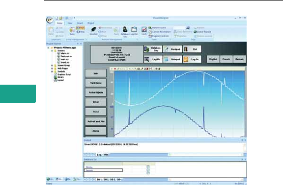
V7-T5-32 Volume 7—Logic Control, Operator Interface and Connectivity Solutions CA08100008E—February 2014 www.eaton.com
5
5
5
5
5
5
5
5
5
5
5
5
5
5
5
5
5
5
5
5
5
5
5
5
5
5
5
5
5
5
5.4
Operator Interface Products
XV and XP Operator Interface
Visual Designer Software
Contents
Description Page
XV with Visual Designer, Galileo,
or XSoft-CoDeSys-2 . . . . . . . . . . . . . . . . . . . . . . . V7-T5-21
XP with Visual Designer . . . . . . . . . . . . . . . . . . . . . V7-T5-28
Visual Designer Software
Product Selection . . . . . . . . . . . . . . . . . . . . . . . . . V7-T5-33
Galileo Software . . . . . . . . . . . . . . . . . . . . . . . . . . . V7-T5-35
XSoft-CoDeSys-2 Software . . . . . . . . . . . . . . . . . . . V7-T5-36
Visual Designer Software
Product Description
Advanced GUI Development,
Made Easy
Time-saving solutions, lower
costs.
With application development
expense often outweighing
the hardware expense, the
demand to quickly design and
implement advanced GUI
solutions is greater than ever.
Even advanced features such
as data archiving, recipe
management, multi-language,
SQL database access, and
Web serving are made easy
through an elegant and
modern user interface. Visual
Designer’s ease-of-use and
time-saving features lower
your total installed cost.
Features
Visual Designer is a software
development package
optimized for OEMs. New
tools streamline the
application development
process, and the creation of
Web-based applications has
never been easier. In addition
to basic monitor and control
functionality, Visual Designer
is packed with advanced
features streamlining the
design of sophisticated
applications.
Advanced Features
●Pop-ups and group screens
●Full mathematical and
logical evaluation
●Web browsing and
document viewing
●Remote access and control
without having to install
software to the remote PC
●Database interfacing
●Historical alarms and
events
●Historical data archiving
and trending
●Recipe management
●Multi-language
●VB scripting
●Report generation
●Scheduling
●Resolution conversion
●Emailing and text
messaging
●Launch and control of third-
party applications
Advanced Development
Features
●Conversion of legacy
PanelMate configurations
●Optional PanelBuilder
conversion utility
●Online configuration/
editing
●Advanced search and
replace
●Automatic scaling of Web
clients
●Customizable application
symbols
●Reusable controls, images,
and screens via indirect tag
and/or PLC assignments
System Requirements
Windows XP and Windows 7
32-bit and 64-bit systems
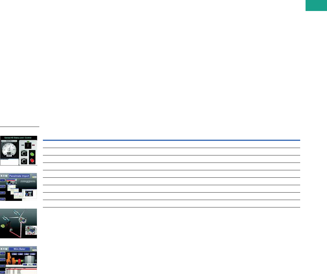
Volume 7—Logic Control, Operator Interface and Connectivity Solutions CA08100008E—February 2014 www.eaton.com V7-T5-33
5
5
5
5
5
5
5
5
5
5
5
5
5
5
5
5
5
5
5
5
5
5
5
5
5
5
5
5
5
5
5.4
Operator Interface Products
XV and XP Operator Interface
Fully connected, Web-enabled
Today’s operator interface applications range from basic monitor and control to high-end, feature-
rich HMI software with Supervisory Control and Data Acquisition (SCADA). Customers demand
communications capability with any network, PLC, Web client, and database. The answer: Eaton’s
Web-enabled Visual Designer operator interface software.
Web-based thin client
●
Zero admin client—no need
to install software on the
remote PC
●Supports multiple
simultaneous and
independent Web clients
●
Simplified security—the same
local user accounts and
passwords for viewing and
control also apply remotely
Connectivity
●Extensive list of over 240
native communication
drivers for PLCs, drives,
and many other industrial
and commercial devices
●
Visual Designer software can
interface to any relational
database—access both local
and enterprise
functions
such as MRP/ERP
through
databases such as
Microsoft
®
Access, Fox Pro,
SQL Server, Oracle®,
PI System
®
and many others
●Other connectivity tools
provide redundancy
capabilities, Real-Time Data
Exchange, Centralized Alarm
Management, and more
Open platform
●Visual Designer Software
can host third-party
ActiveX® and .NET controls
and Visual Basic
®
programs
●In addition to Eaton’s
Operator Interface families,
Visual Designer’s runtime
may be licensed on any 32
or 64-bit Windows PC
Interoperability
●Software is designed to
open standards such as
XML, OPC, ActiveX, .NET,
ODBC, ADO, SOAP, DDE
and more
Peace of mind
All of these capabilities—
combined with Eaton’s
commitment to provide free
technical support for both OI
hardware and software—
make it quick and easy to
purchase, develop and deploy
XV and XP operator interface
solutions.
Product Selection
Visual Designer Software
Visual Designer Development Software License Key
Description Catalog Number
For CE hardware VISUALDCE
For PCs, XPe and CE hardware VISUALDXP
For CE hardware, 5-pack of VISUALDCE VISUALDCE5
For PCs, XPe and CE hardware, 5-pack of VISUALDXP VISUALDXP5
For a PC Runtime software license with a maximum of 64k tags, 8 drivers, 1 Web session VISUALRTPC64K
Visual Designer development software and PC runtime software licenses for a maximum of 64k tags, 8 drivers, 1 Web session VISUALRTDEVPC
For a PC Runtime software license with a maximum of 4k tags, 5 drivers, 1 Web session VISUALRTPC4K
For a PC Runtime software license with a maximum of 1500 tags, 3 drivers, 1 Web session VISUALRTPC1500
For a PC Runtime software license with a maximum of 300 tags, 3 drivers, 1 Web session VISUALRTPC300
Visual Designer
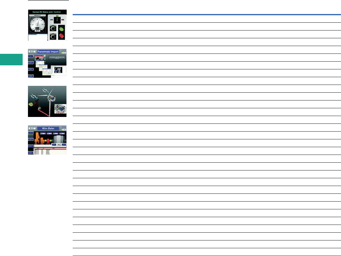
V7-T5-34 Volume 7—Logic Control, Operator Interface and Connectivity Solutions CA08100008E—February 2014 www.eaton.com
5
5
5
5
5
5
5
5
5
5
5
5
5
5
5
5
5
5
5
5
5
5
5
5
5
5
5
5
5
5
5.4
Operator Interface Products
XV and XP Operator Interface
Software Updates and Upgrades
Description Catalog Number
Update to current version Visual Designer development software for CE hardware VISUALDUPCE
Update to current version Visual Designer development software PCs/XPe/CE VISUALDUPXP
Update to current version of Visual Designer runtime license for PCs VISUALRTUPPC
Upgrade from Visual Designer CE 1500 tag to 4000 tag runtime VISUALRT4KCE
Upgrade from Visual Designer XPe 4000 tag, 5 driver to 64k tag, 8 driver runtime license VISUALRT64KXP
Upgrade from Visual Designer development software CE to CE plus PC and XPe (64k tag, 8 drivers) VISUALDCE2XP
Visual Designer PanelBuilder conversion utility optional plug-in (requires Visual Designer software) VISUALDPBCU
Visual Designer 1 additional Web thin client license for Internet Explorer: Total of 2 VISUALWEB1
Visual Designer 3 additional Web thin client licenses for Internet Explorer: Total of 4 VISUALWEB3
Visual Designer 7 additional Web thin client licenses for Internet Explorer Total of 8 VISUALWEB7
Visual Designer 15 additional Web thin client licenses for Internet Explorer: Total of 16 VISUALWEB16
Visual Designer 31 additional Web thin client licenses for Internet Explorer: Total of 32 VISUALWEB32
Visual Designer 63 additional Web thin client licenses for Internet Explorer: Total of 64 VISUALWEB64
Visual Designer 127 additional Web thin client licenses for Internet Explorer: Total of 128 VISUALWEB128
Visual Designer 1 additional Secure Viewer Thin Client license: Total of 2 VISUALSVT2
Visual Designer 3 additional Secure Viewer Thin Client license: Total of 4 VISUALSVT4
Visual Designer 7 additional Secure Viewer Thin Client license: Total of 8 VISUALSVT8
Visual Designer 15 additional Secure Viewer Thin Client license: Total of 16 VISUALSVT16
Visual Designer 31 additional Secure Viewer Thin Client license: Total of 32 VISUALSVT32
Visual Designer 63 additional Secure Viewer Thin Client license: Total of 64 VISUALSVT64
Visual Designer 127 additional Secure Viewer Thin Client license: Total of 128 VISUALSVT128
Visual Designer 1 additional SMA Thin Client license: Total of 2 VISUALSMA2
Visual Designer 3 additional SMA Thin Client license: Total of 4 VISUALSMA4
Visual Designer 7 additional SMA Thin Client license: Total of 8 VISUALSMA8
Visual Designer 15 additional SMA Thin Client license: Total of 16 VISUALSMA16
Visual Designer 31 additional SMA Thin Client license: Total of 32 VISUALSMA32
Visual Designer 63 additional SMA Thin Client license: Total of 64 VISUALSMA64
Visual Designer 127 additional SMA Thin Client license: Total of 128 VISUALSMA128
Visual Designer collaborative server VISUALCBSERVER
Visual Designer business dashboard tool VISUALDASHBOARD
Visual Designer communication package for electrical products VISUALDELECDRVS
Visual Designer
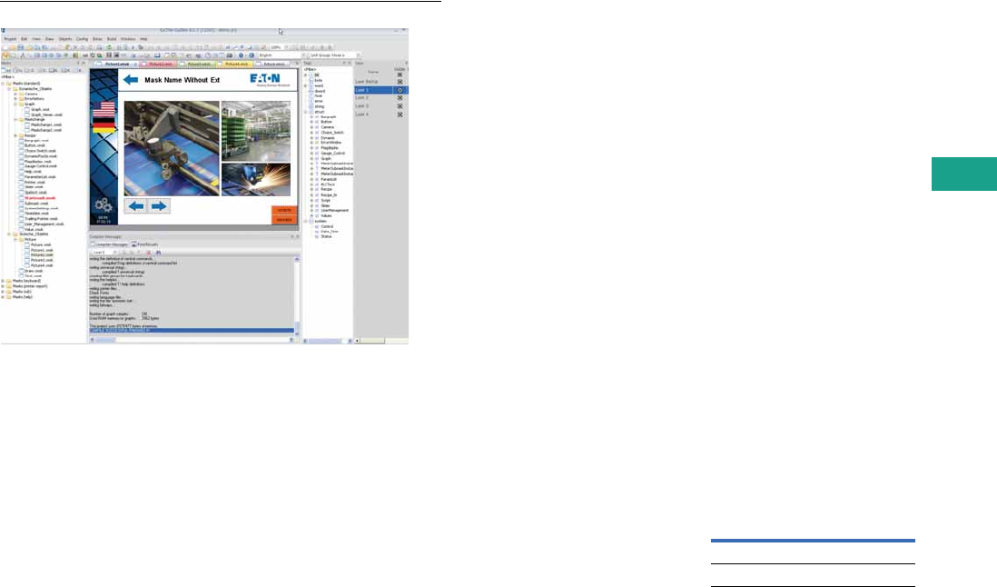
Volume 7—Logic Control, Operator Interface and Connectivity Solutions CA08100008E—February 2014 www.eaton.com V7-T5-35
5
5
5
5
5
5
5
5
5
5
5
5
5
5
5
5
5
5
5
5
5
5
5
5
5
5
5
5
5
5
5.4
Operator Interface Products
XV and XP Operator Interface
Galileo Software
Contents
Description Page
XV with Visual Designer, Galileo,
or XSoft-CoDeSys-2 . . . . . . . . . . . . . . . . . . . . . . . V7-T5-21
XP with Visual Designer . . . . . . . . . . . . . . . . . . . . . V7-T5-28
Visual Designer Software . . . . . . . . . . . . . . . . . . . . V7-T5-32
Galileo Software
XSoft-CoDeSys-2 Software . . . . . . . . . . . . . . . . . . . V7-T5-36
Galileo Software
Product Description
The Intuitive Visualization Tool
Galileo is an easy to learn
yet powerful and extensive
project design environment
that can be used ideally in all
system and machine building
applications close to the
machine and process.
Galileo is designed for use
in all sectors and offers
comprehensive project
design tools. Galileo provides
a full range of functions without
any graduated restrictions on
tags or screens, and is
optimized for our XV operator
interface panels.
Features
●Easy to learn and intuitive
graphical user interface
with a project overview
window
●User-friendly project design
with project simulation on
development PC
●Different user interface
styles
●
Drag and drop positioning of
objects, WYSIWYG (what
you see is what you get)
●Simple, clear user
guidance
●Tabular object properties,
easy and fast assignment
of attributes—copy and
paste
●Convenient series
assignment of texts
and images to tags
●Many graphical objects
such as bar graph, slide
adjuster, graph plotter,
curve chart, camera
●Anti-aliased gauge display
●Enhanced password
handling with complex
password and aging
●Extensive recipe handling
●Alarm handling with
time stamp, history and
diagnostics support with
image display
●Multi-line display of
alarm entries
●Online language selection
●Unicode support (also
Asian character sets)
●Text import/export in XML
format (example, Excel®)
●Brilliant image display,
up to 65536 colors
●Import of 15 different
image formats
●Dynamic objects
●Object parameter list, any
number of data objects in
a screen
●Dynamic unit of measure
selection (example, °C–°F,
inch–mm)
●Direct printing on panel
(reports, forms)
●Many specific objects and
system functions
●Simple import of PLC
variables
●Full functionality always
available, no graduated
performance level
System Requirements
Windows XP and Windows 7
Product Selection
Galileo Development
Software
Description
Catalog
Number
Single-seat license SW-GALILEO-S
Multiple-seat license SW-GALILEO-M
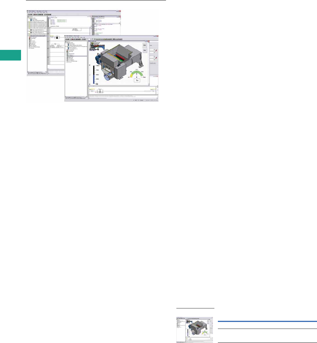
V7-T5-36 Volume 7—Logic Control, Operator Interface and Connectivity Solutions CA08100008E—February 2014 www.eaton.com
5
5
5
5
5
5
5
5
5
5
5
5
5
5
5
5
5
5
5
5
5
5
5
5
5
5
5
5
5
5
5.4
Operator Interface Products
XV and XP Operator Interface
XSoft-CoDeSys-2 Software
Contents
Description Page
XV with Visual Designer, Galileo,
or XSoft-CoDeSys-2 . . . . . . . . . . . . . . . . . . . . . . . V7-T5-21
XP with Visual Designer . . . . . . . . . . . . . . . . . . . . . V7-T5-28
Visual Designer Software . . . . . . . . . . . . . . . . . . . . V7-T5-32
Galileo Software . . . . . . . . . . . . . . . . . . . . . . . . . . . V7-T5-35
XSoft-CoDeSys-2 Software
XSoft-CoDeSys-2 Software
Product Description
Combined Logic and
Visualization Development
IEC 61131-3 Logic
Programming
●Ladder Diagram (LD)
●Structured Text (ST)
●Sequential function chart
(SFC)
●Function block diagram
(FBD)
●Freely definable function
block chart/continuous
function chart (CFC)
●Instruction List (IL)
Target Visualization
Integrated design of Operator
Interface screens for the XV
series. Visualization and logic
developed as part of the
same project. Simplifies
screen design and always
keeps the Logic and
visualization in synch.
Web Visualization
Optionally XSoft-CoDeSys-2
can automatically generate
XML-based runtime screens
to make the screens from the
XV accessible remotely using
a Web browser with a
JavaScript plug-in such as
Internet Explorer®, Firefox®
and others.
Features
Project Development
●Automatic variable
declaration
●On line editing
●Pop-up variable and
function search/pick tools
●Automatic formatting and
color coding of logic/
declaration text
●Re-usable Visual-Logic
Function Blocks
Debugging and
commissioning
XSoft-CoDeSys-2 offers you
a number of important
functions for debugging,
testing and commissioning
your XV applications quickly
and efficiently.
All these features are
available as soon as you log
on to the XV (online mode)
over an Ethernet connection.
Simulation
Users can also test the
application when the XV is
not connected to the process.
This is possible thanks to the
integrated online simulation
feature. Simulation supports
both the screens and logic
that have been designed
using XSoft-CoDeSys.
Advanced Features
●Up to 16 time and/or event
driven tasks per project
●Each task can include
multiple logic programs or
subroutines
●Programs and screen
designs can be exported
and imported to support
reuse
●Powerful, built-in function
block libraries
●Ability to create user-
defined function blocks
●Fieldbus Configurator
for CANopen, PROFIBUS-
DP and SmartWire-DT
device I/O
●Ethernet and serial
communication function
blocks (OPC server, UDP,
TCP/IP, FTP client/ server,
Modbus Master/Slave,
email, SMS, and more)
●8-level password
protection
●Web access selectable
per screen
●System function libraries
(OS Storage Card, and
more)
●Online and historical
alarms
●Online and historical trends
System Requirements
Windows XP and Windows 7
32-bit systems
Product Selection
XSoft-CoDeSys-2 Software
Description Catalog Number
Single Seat License SW-XSOFT-CODESYS-2-S
Multiple Seat License (3) SW-XSOFT-CODESYS-2-M
XSoft-CoDeSys-2
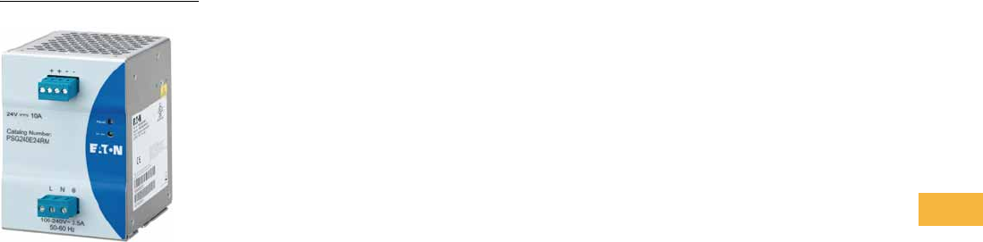
Volume 7—Logic Control, Operator Interface and Connectivity Solutions CA08100008E—May 2014 www.eaton.com V7-T6-1
6
6
6
6
6
6
6
6
6
6
6
6
6
6
6
6
6
6
6
6
6
6
6
6
6
6
6
6
6
6
Power Supplies
Power Supply
6.1 General Purpose and Sensor Power Supplies
Product Selection Guide . . . . . . . . . . . . . . . . . . . . . . . . . . . . . . . . . . . V7-T6-2
PSG Series . . . . . . . . . . . . . . . . . . . . . . . . . . . . . . . . . . . . . . . . . . . . . . V7-T6-3
ELC Series . . . . . . . . . . . . . . . . . . . . . . . . . . . . . . . . . . . . . . . . . . . . . . V7-T6-22
easyRelay Power Supply . . . . . . . . . . . . . . . . . . . . . . . . . . . . . . . . . . . V7-T6-25
Sensor Power Supply . . . . . . . . . . . . . . . . . . . . . . . . . . . . . . . . . . . . . . V7-T6-29
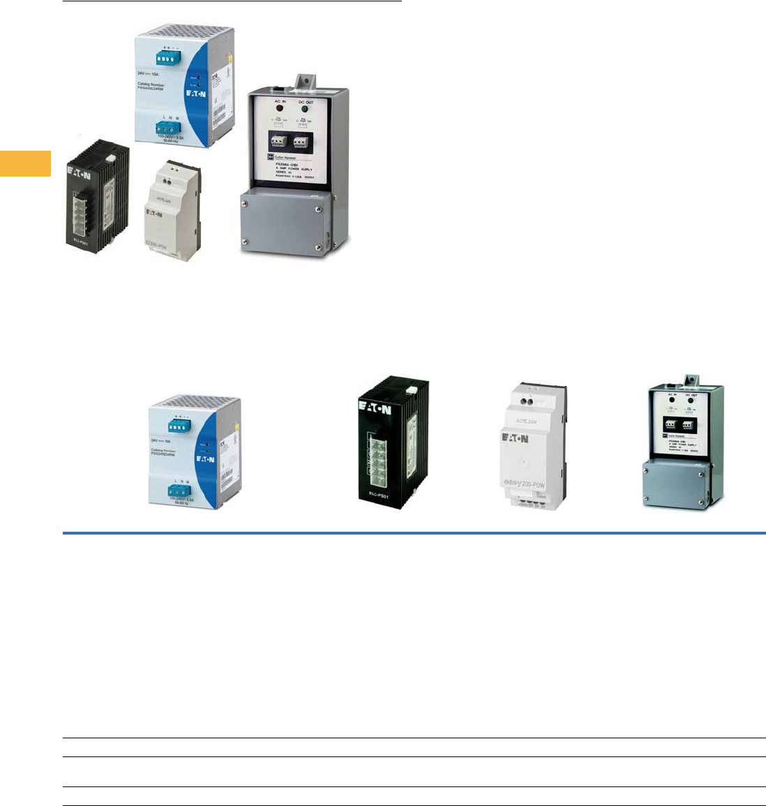
V7-T6-2 Volume 7—Logic Control, Operator Interface and Connectivity Solutions CA08100008E—May 2014 www.eaton.com
6
6
6
6
6
6
6
6
6
6
6
6
6
6
6
6
6
6
6
6
6
6
6
6
6
6
6
6
6
6
6.1
Power Supplies
General-Purpose and Sensor Power Supplies
Power Supplies
Contents
Description Page
General-Purpose and Sensor Power Supplies
PSG Series . . . . . . . . . . . . . . . . . . . . . . . . . . . . V7-T6-3
ELC Series . . . . . . . . . . . . . . . . . . . . . . . . . . . . V7-T6-22
easyRelay Power Supply . . . . . . . . . . . . . . . . . V7-T6-25
Sensor Power Supply . . . . . . . . . . . . . . . . . . . . V7-T6-29
Product Selection Guide
Power Supply Series and Features
PSG Series ELC Series easyRelay Power Series Sensor Power Supplies
Features General-purpose 12 Vdc and 24 Vdc output
for 1.25A to 40A loads
Single-phase and three-phase inputs
up to 500 Vac
150% power surge output
Redundancy modules
Buffer module
DIN rail mount
Rugged metal and plastic housing options
Heavy-duty screw and finger-safe terminals
Hazardous Location Class I, Division 2 rated models
NEC® Class II rated model
Protection from overvoltage, overcurrent and
overtemperature conditions
Compact, low cost 24 Vdc control
for loads up to 2A
Plastic enclosure can be DIN rail
or panel mounted
Single-phase (100–240 Vac) input
Low profile power supplies for
12 Vdc or 24 Vdc applications
8W, 30W, 60W or 100W output
power
easyRelay styling provides optimal
panel aesthetics
Plastic enclosure can be DIN rail or
panel mounted (with optional kit)
CSA Class 1, Division 2 qualified
Single-phase (100–240 Vac) input
27 Vdc supplies for tough
sensor applications
Rugged housings with
integrated junction box for
mounting outside of electrical
enclosures
Advanced diagnostic features
Product Selection Page V7-T6-4 Page V7-T6-23 Page V7-T6-26 Page V7-T6-30
Technical Data and
Specifications
Page V7-T6-5 Page V7-T6-23 Page V7-T6-27 Page V7-T6-30
Dimensions Page V7-T6-16 Page V7-T6-24 Page V7-T6-28 Page V7-T6-31
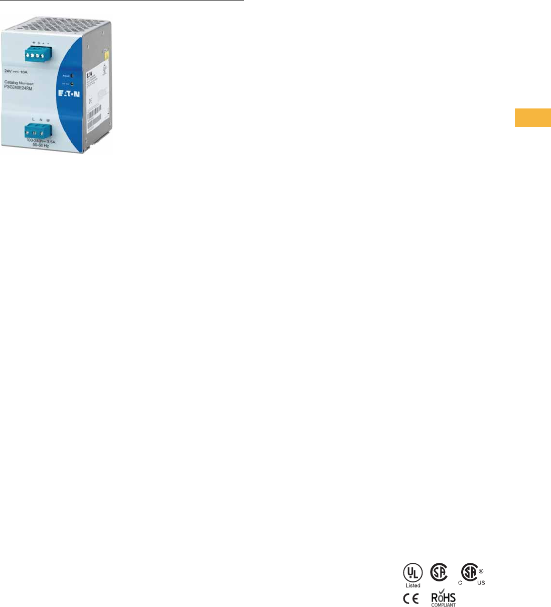
Volume 7—Logic Control, Operator Interface and Connectivity Solutions CA08100008E—May 2014 www.eaton.com V7-T6-3
6
6
6
6
6
6
6
6
6
6
6
6
6
6
6
6
6
6
6
6
6
6
6
6
6
6
6
6
6
6
6.1
Power Supplies
General-Purpose and Sensor Power Supplies
PSG Series
Contents
Description Page
PSG Series
Catalog Number Selection . . . . . . . . . . . . . . . . V7-T6-4
Technical Data and Specifications . . . . . . . . . . V7-T6-5
Power Derating Curves . . . . . . . . . . . . . . . . . . V7-T6-13
Dimensions . . . . . . . . . . . . . . . . . . . . . . . . . . . V7-T6-16
ELC Series . . . . . . . . . . . . . . . . . . . . . . . . . . . . . . . V7-T6-22
easyRelay Power Supply . . . . . . . . . . . . . . . . . . . . V7-T6-25
Sensor Power Supply . . . . . . . . . . . . . . . . . . . . . . V7-T6-29
PSG Series
Product Description
Eaton’s PSG Series of power
supplies is designed to be
a high-performance, high-
quality line of products
covering a majority of 12 Vdc
and 24 Vdc control
applications. With global
certifications, a compact
size and an impressive
operating temperature range,
the PSG Series fits a wide
variety of applications at a
competitive price.
Our expansive 22 model
offering is able to provide
solutions for most
applications with PSG
outputs ranging from 12 Vdc
at 1.25A up to 24 Vdc at 40A,
plus redundancy and buffer
modules to ensure uptime.
Application Description
The PSG Series is a line of
general-purpose power
supplies for use in a wide
variety of industrial control
applications. Applications
include communication
networks, sensors, PLCs
and many other electrical
systems. Each model is
equipped with the options
of a rugged metal or plastic
housing, heavy-duty screw
or finger-safe terminals and
a variety of protection
features, making the PSG
one of the most versatile
industrial power supply lines
on the market.
Features, Benefits and
Functions
●Universal input voltages:
100–240 Vac for single-
phase units, 400–500 Vac
for three-phase units
●General-purpose 12 Vdc
and 24 Vdc adjustable
output
●150% power surge output
●
Wide operating temperature
range: –25°C to +80°C
●MTBF up to 1,000,000
hours ensures uptime
and reliability
●
Protection from overvoltage,
overcurrent and over-
temperature conditions
●Rugged aluminum and
plastic housings provide
the durability required to
stand up to harsh
environments
●All-metal DIN rail mounting
hardware
●Heavy-duty screw and
finger-safe terminals
●LED indicating light for
DC OK simplifies
troubleshooting
●Conformal coated
electronics
●
Hazardous Location Class I,
Division 2 rated models
●NEC® Class II rated model
●Redundancy modules keep
loads up and running in the
event of a device failure
●Buffer module has the
stored power needed to
keep loads running through
a short duration power
failure
●Three-year standard
warranty
Standards and Certifications
●cULus listed—UL 508
●CSA listed—CSA 22.2
No. 107.1-01
●
Hazardous Location, Class I,
Div. 2, Groups A, B, C, D
●IEC
●EN
●NEC Class 2
●CE marked
●RoHS compliant
Note: Some models may not
carry all certifications listed.
V7-T6-4 Volume 7—Logic Control, Operator Interface and Connectivity Solutions CA08100008E—May 2014 www.eaton.com
6
6
6
6
6
6
6
6
6
6
6
6
6
6
6
6
6
6
6
6
6
6
6
6
6
6
6
6
6
6
6.1
Power Supplies
General-Purpose and Sensor Power Supplies
Catalog Number Selection
PSG Series
Note: Not all combinations are available. See Pages V7-T6-5–V7-T6-12 for all available combinations.
Series
PSG = PSG power supply
Output Power
15 = 15W
30 = 30W
60 = 60W
100 = 100W
120 = 120W
240 = 240W
480 = 480W
960 = 960W
Model
E = Single-phase
F = Three-phase
R = Redundancy module
B = Buffer module
N = NEC Class II
Output Voltage
24 = 24 Vdc
12 = 12 Vdc
Blank = 24 Vdc
Terminals
S =Screw
R = Finger-safe
Blank =Screw
Housing
M = Aluminum
P = Plastic
Blank = Aluminum
PSG 240 F 24 R M

Volume 7—Logic Control, Operator Interface and Connectivity Solutions CA08100008E—May 2014 www.eaton.com V7-T6-5
6
6
6
6
6
6
6
6
6
6
6
6
6
6
6
6
6
6
6
6
6
6
6
6
6
6
6
6
6
6
6.1
Power Supplies
General-Purpose and Sensor Power Supplies
Technical Data and Specifications
PSG Series
Note
1Ratings for single-phase models are at 115 Vac; three-phase models are at 400 Vac.
Single-Phase
PSG15E12SP PSG30E12SP PSG60E12SM PSG100E12SM PSG60E PSG60E24SP PSG60E24RM
Input
Nominal voltage 100–240 Vac 100–240 Vac 100–240 Vac 100–240 Vac 100–240 Vac 100–240 Vac 100–240 Vac
AC input range 85–264 Vac 85–264 Vac 85–264 Vac 85–264 Vac 85–264 Vac 85–264 Vac 85–264 Vac
DC input range 120–375 Vdc 120–375 Vdc 120–375 Vdc 120–375 Vdc 120–375 Vdc 120–375 Vdc 120–375 Vdc
Frequency 47–63 Hz 47–63 Hz 47–63 Hz 47–63 Hz 47–63 Hz 47–63 Hz 47–63 Hz
Nominal current 1<0.37A <0.7A <1.35A <2.5A 1.1A <1.10A <1.4A
Inrush current limitation 1<30A <30A <50A <100A 30A <40A <20A
Internal fuse T3.15AH / 250V T3.15AH / 250V T3.15AH / 250V T3.15AH / 250V T3.15AH / 250V T3.15AH / 250V T3.15AH / 250V
External fusing 4A or 6A 4A or 6A 6A, 10A or 16A 6A, 10A or 16A 6A, 10A or 16A 6A, 10A or 16A 6A, 10A or 16A
Leakage current <1 mA <1 mA <1 mA <1 mA <1 mA <1 mA <1 mA
Output
Power 15W 30W 60W 100W 60W 60W 60W
Nominal output voltage 12 Vdc ±2% 12 Vdc ±2% 12 Vdc ±2% 12 Vdc ±2% 24 Vdc ±2% 24 Vdc ±2% 24 Vdc ±2%
Adjustment range 11–14 Vdc 11–14 Vdc 11–14 Vdc 11–14 Vdc 22–28 Vdc 22–28 Vdc 24–28 Vdc
Nominal current 1.25A 2.5A 5A 8.33A 2.5A 2.5A 2.5A
Startup with capacitive loads Max. 5000 μF Max. 6600 μF Max. 8000 μF Max. 10,000 μF Max. 8000 μF Max. 8000 μF Max. 8000 μF
Efficiency >84% at 115 Vac,
>83% at 230 Vac
>85% at 115 Vac
and 230 Vac
>85% at 115 Vac
and 230 Vac
>85.5% at 115 Vac,
>87.5% at 230 Vac
>85% typ >86% at 115 Vac,
>87% at 230 Vac
>90% at 115 Vac
and 230 Vac
Current surge 1.875A 3.75A 7.5A 12.495A 3.75A 3.75A 3.75A
Current surge time 3s 3s 3s 3s 1s (at 10s intervals) 3s 5s
Residual ripple/peak switching
(20 MHz)
<100m Vpp <100m Vpp <100m Vpp <100m Vpp <50m V /
<240m Vpp
<50m V /
<240m Vpp
<50m Vpp /
<150m Vpp
Turn-on time <2.5s <2.5s <2.5s <0.6s <2.5s <3s <2s
Mains buffering at nominal
load (typ.) 1
>22 ms >22 ms >22 ms >22 ms >20 ms >20 ms >20 ms
Parallel operation With o-ring diode With o-ring diode With o-ring diode With o-ring diode PSG480R24RM /
PSG960R24RM /
With o-ring diode
PSG480R24RM /
PSG960R24RM /
With o-ring diode
PSG480R24RM /
PSG960R24RM /
With o-ring diode
Galvanic Isolation
Input/output 4k Vac 4k Vac 4k Vac 4k Vac 4k Vac (type test) /
3k Vac (routine test)
4k Vac 4k Vac
Input/ground 1.5k Vac 1.5k Vac 1.5k Vac 1.5k Vac 1.5k Vac (type test) /
1.5k Vac (routine test)
1.5k Vac 1.5k Vac
Output/ground 1.5k Vac 1.5k Vac 1.5k Vac 1.5k Vac 1.5k Vac (type test) /
500 Vac (routine test)
1.5k Vac 1.5k Vac
General/Physical Data
Housing material Plastic Plastic Aluminum Aluminum Aluminum Plastic Aluminum
Signals Green LED for DC OK Green LED for DC OK Green LED for DC OK Green LED for DC OK Green LED for DC OK Green LED for DC OK Green LED for DC OK
MTBF >1,000,000 hr >1,000,000 hr >800,000 hr >800,000 hr >800,000 hr >800,000 hr >1,000,000 hr
Dimensions (L) 100 mm 100 mm 121 mm 121 mm 121 mm 120.6 mm 121 mm
Dimensions (W) 32 mm 32 mm 32 mm 50 mm 32 mm 32 mm 32 mm
Dimensions (H) 100.6 mm 100.6 mm 120 mm 118.7 mm 120 mm 113 mm 125 mm
Weight (kg) 0.18 0.2 0.33 0.64 0.37 0.33 0.37
Terminals Screw Screw Screw Screw Screw Screw Finger-safe,
removable
Wire size AWG 22–14AWG 22–14AWG 22–14AWG 18–24AWG 22–14AWG 22–14AWG 22–12
Operating temperature –20°C to +75°C –20°C to +75°C –20°C to +75°C –20°C to +75°C –20°C to +75°C –20°C to +75°C –20°C to +80°C
Storage temperature –25°C to +85°C –25°C to +85°C –25°C to +85°C –25°C to +85°C –25°C to +85°C –25°C to +85°C –25°C to +85°C

V7-T6-6 Volume 7—Logic Control, Operator Interface and Connectivity Solutions CA08100008E—May 2014 www.eaton.com
6
6
6
6
6
6
6
6
6
6
6
6
6
6
6
6
6
6
6
6
6
6
6
6
6
6
6
6
6
6
6.1
Power Supplies
General-Purpose and Sensor Power Supplies
PSG Series, continued
Single-Phase
PSG15E12SP PSG30E12SP PSG60E12SM PSG100E12SM PSG60E PSG60E24SP PSG60E24RM
General/Physical Data, continued
Power derating—
vertical mounting
>50°C derate
power by 2.5% / °C,
>70°C derate
power by 4% / °C
>50°C derate
power by 2.5% / °C,
>70°C derate
power by 4% / °C
>50°C derate
power by 2.5% / °C,
>70°C derate
power by 4% / °C
>50°C derate
power by 2.5% / °C
>50°C derate
power by 2.5% / °C
<0°C to –20°C derate
power by 1% / °C,
>50°C derate
power by 2.5% / °C,
>70°C derate
power by 4% / °C
>50°C derate
power by 2.5% / °C
Power derating—
horizontal mounting
N/A N/A N/A >50°C derate
power by 2.5% / °C,
>70°C derate power
by 4% / °C
N/A N/A >50°C derate
power by 2.5% / °C
Operating humidity <95% RH,
noncondensing
<95% RH,
noncondensing
<95% RH,
noncondensing
<95% RH,
noncondensing
<95% RH,
noncondensing
<95% RH,
noncondensing
<95% RH,
noncondensing
Vibration 10 to 150 Hz, 0.35 mm acc. 50 m/s2, single amplitude (5G max.) for 90 min. in each X, Y and Z directions, in accordance with IEC 60068-2-6
Pollution degree 2222222
Climatic class 3K3 according to
EN 60721
3K3 according to
EN 60721
3K3 according to
EN 60721
3K3 according to
EN 60721
3K3 according to
EN 60721
3K3 according to
EN 60721
3K3 according to
EN 60721
Safety and Protection
Transient surge voltage Varistor Varistor Varistor Varistor Varistor Varistor Varistor
Surge voltage protection against
internal surge
Yes Yes Yes Yes Yes Yes Yes
Safety class Class I with ground
connection
Class I with ground
connection
Class I with ground
connection
Class I with ground
connection
Class I with ground
connection
Class I with ground
connection
Class I with ground
connection
Shock 30G (300 m/s2) in all
directions according
to IEC60068-2-27
30G (300 m/s2) in all
directions according
to IEC60068-2-27
30G (300 m/s2) in all
directions according
to IEC60068-2-27
30G (300 m/s2) in all
directions according
to IEC60068-2-27
30G (300 m/s2) in all
directions according
to IEC60068-2-27
30G (300 m/s2) in all
directions according
to IEC60068-2-27
30G (300 m/s2) in all
directions according
to IEC60068-2-27

Volume 7—Logic Control, Operator Interface and Connectivity Solutions CA08100008E—May 2014 www.eaton.com V7-T6-7
6
6
6
6
6
6
6
6
6
6
6
6
6
6
6
6
6
6
6
6
6
6
6
6
6
6
6
6
6
6
6.1
Power Supplies
General-Purpose and Sensor Power Supplies
PSG Series, continued
Note
1Ratings for single-phase models are at 115 Vac; three-phase models are at 400 Vac.
Single-Phase, continued
PSG60N24RP PSG120E PSG120E24RM PSG240E PSG240E24RM PSG480E PSG480E24RM
Input
Nominal voltage 100–240 Vac 100–240 Vac 100–240 Vac 100–240 Vac 100–240 Vac 100–240 Vac 100–240 Vac
AC input range 85–264 Vac 85–264 Vac 85–264 Vac 85–264 Vac 85–264 Vac 85–264 Vac 85–264 Vac
DC input range N/A 120–375 Vdc 120–375 Vdc 120–375 Vdc 120–375 Vdc 120–375 Vdc 120–375 Vdc
Frequency 47–63 Hz 47–63 Hz 47–63 Hz 47–63 Hz 47–63 Hz 47–63 Hz 47–63 Hz
Nominal current 1<1.5A at 100 Vac 1.4A <2.2A 2.9A <2.5A 5.7A <5A
Inrush current limitation 1<40A <80A <35A N/A <35A N/A <35A
Internal fuse T3.15AH / 250V T3.15AH / 250V T4AH / 250V T6.3AH / 250V T6.3AH / 250V F10H / 250A T8AH / 250V
External fusing 6A, 10A or 16A 6A, 10A or 16A 6A, 10A or 16A 10A or 16A 10A or 16A 10A or 16A 10A or 16A
Leakage current <1 mA <1 mA <1 mA <3.5 mA <1 mA <1 mA <3 mA
Output
Power 60W 120W 120W 240W 240W 480W 480W
Nominal output voltage 24 Vdc ±2% 24 Vdc ±2% 24 Vdc ±2% 24 Vdc ±2% 24 Vdc ±2% 24 Vdc ±2% 24 Vdc ±2%
Adjustment range 22–28 Vdc 22–28 Vdc 24–28 Vdc 22–28 Vdc 24–28 Vdc 22–28 Vdc 22–28 Vdc
Nominal current 2.5A 5A 5A 10A 10A 20A 20A
Startup with capacitive loads Max. 8000 μF Max. 10,000 μF Max. 10,000 μF Max. 10,000 μF Max. 10,000 μF Max. 10,000 μF Max. 10,000 μF
Efficiency >86% at 115 Vac,
>87% at 230 Vac
>84% typ >89% at 115 Vac,
>90% at 230 Vac
>84% typ >90% at 115 Vac
and 230 Vac
>86% typ >90% at 115 Vac
and 230 Vac
Current surge N/A 7.5A 7.5A 15A 15A 30A 30A
Current surge time N/A 1s (at 10s intervals) 5s 1s (at 10s intervals) 5s 1s (at 10s intervals) 5s
Residual ripple/peak switching
(20 MHz)
<50m Vpp /
<240m Vpp
<50m V /
<240m Vpp
<50m Vpp /
<150m Vpp
<50m V /
<240m Vpp
<50m Vpp /
<150m Vpp
<50m V /
<240m Vpp
<50m Vpp
Turn-on time <3s <1s <1s <1s <1s <1s <1s
Mains buffering at nominal
load (typ.) 1
>20 ms >35ms >20 ms >20 ms >20 ms >20 ms >20 ms
Parallel operation PSG480R24RM /
PSG960R24RM /
With o-ring diode
PSG480R24RM /
PSG960R24RM /
With o-ring diode
PSG480R24RM /
PSG960R24RM /
With o-ring diode
PSG480R24RM /
PSG960R24RM /
With o-ring diode
PSG480R24RM /
PSG960R24RM /
With o-ring diode
PSG480R24RM /
PSG960R24RM /
With o-ring diode
PSG480R24RM /
PSG960R24RM /
With o-ring diode
Galvanic Isolation
Input/output 4k Vac 4k Vac (type test) /
3k Vac (routine test)
4k Vac 4k Vac (type test) /
3k Vac (routine test)
4k Vac 4k Vac (type test) /
3k Vac (routine test)
4k Vac
Input/ground 1.5k Vac 1.5k Vac (type test) /
1.5k Vac (routine test)
1.5k Vac 1.5k Vac (type test) /
1.5k Vac (routine test)
1.5k Vac 1.5k Vac (type test) /
1.5k Vac (routine test)
1.5k Vac
Output/ground 1.5k Vac 1.5k Vac (type test) /
500 Vac (routine test)
1.5k Vac 1.5k Vac (type test) /
500 Vac (routine test)
1.5k Vac 1.5k Vac (type test) /
500 Vac (routine test)
1.5k Vac
General/Physical Data
Housing material Aluminum Aluminum Aluminum Aluminum Aluminum Aluminum Aluminum
Signals Green LED for DC OK Green LED for DC OK Green LED for DC OK Green LED for DC OK Green LED for DC OK Green LED for DC OK Green LED for DC OK
MTBF >800,000 hr >800,000 hr >800,000 hr >300,000 hr >500,000 hr >300,000 hr >500,000 hr
Dimensions (L) 120.6 mm 121 mm 121 mm 121 mm 121 mm 121 mm 121 mm
Dimensions (W) 32 mm 32 mm 50 mm 85 mm 85 mm 160 mm 144 mm
Dimensions (H) 119.3 mm 120 mm 123.1 mm 118.5 mm 124.1 mm 115 mm 118.6 mm
Weight (kg) 0.33 0.54 0.72 1.04 1.1 1.8 1.37
Terminals Finger-safe, fixed Screw Finger-safe,
removable
Screw Finger-safe,
removable
Screw Finger-safe, fixed
Wire size AWG 22–10 AWG 22–14 AWG 20–12 AWG 22–14 AWG 16–12 AWG 16–14 (input)
AWG 12–10 (output)
AWG 18–10
Operating temperature –20°C to +80°C –20°C to +75°C –20°C to +80°C –20°C to +75°C –20°C to +80°C –20°C to +75°C –25°C to +75°C
Storage temperature –25°C to +85°C –25°C to +85°C –25°C to +85°C –25°C to +85°C –25°C to +85°C –25°C to +85°C –25°C to +85°C

V7-T6-8 Volume 7—Logic Control, Operator Interface and Connectivity Solutions CA08100008E—May 2014 www.eaton.com
6
6
6
6
6
6
6
6
6
6
6
6
6
6
6
6
6
6
6
6
6
6
6
6
6
6
6
6
6
6
6.1
Power Supplies
General-Purpose and Sensor Power Supplies
PSG Series, continued
Single-Phase, continued
PSG60N24RP PSG120E PSG120E24RM PSG240E PSG240E24RM PSG480E PSG480E24RM
General/Physical Data, continued
Power derating—
vertical mounting
>50°C derate power
by 2.5% / °C,
>70°C derate power
by 4% / °C
>50°C derate power
by 2.5% / °C
>50°C derate power
by 2.5% / °C
>50°C derate power
by 2.5% / °C,
>70°C derate power
by 4% / °C
>50°C derate power
by 2.5% / °C
>50°C derate power
by 2.5% / °C
>50°C derate power
by 2.5% / °C,
>70°C to 75°C derate
power by 5% / °C
Power derating—
horizontal mounting
>50°C derate power
by 2.5% / °C,
>70°C derate power
by 4% / °C
N/A >50°C derate power
by 2.5% / °C
N/A N/A N/A N/A
Operating humidity <95% RH,
noncondensing
<95% RH,
noncondensing
<95% RH,
noncondensing
<95% RH,
noncondensing
<95% RH,
noncondensing
<95% RH,
noncondensing
<95% RH,
noncondensing
Vibration
10 to 500 Hz, 0.35 mm
acc. 30 m/s2, single
amplitude (3G max.)
for 60 min. in each
X, Y and Z directions,
in accordance with
IEC 60068-2-6
10 to 150 Hz, 0.35 mm
acc. 50 m/s2, single
amplitude (5G max.)
for 90 min. in each
X, Y and Z directions,
in accordance with
IEC 60068-2-6
10 to 150 Hz, 0.35 mm
acc. 50 m/s2, single
amplitude (5G max.)
for 90 min. in each
X, Y and Z directions,
in accordance with
IEC 60068-2-6
10 to 150 Hz, 0.35 mm
acc. 50 m/s2, single
amplitude (5G max.)
for 90 min. in each
X, Y and Z directions,
in accordance with
IEC 60068-2-6
10 to 150 Hz, 0.35 mm
acc. 50 m/s2, single
amplitude (5G max.)
for 90 min. in each
X, Y and Z directions,
in accordance with
IEC 60068-2-6
10 to 150 Hz, 0.35 mm
acc. 50 m/s2, single
amplitude (5G max.)
for 90 min. in each
X, Y and Z directions,
in accordance with
IEC 60068-2-6
10 to 150 Hz, 0.35 mm
acc. 50 m/s2, single
amplitude (5G max.)
for 90 min. in each
X, Y and Z directions,
in accordance with
IEC 60068-2-6
Pollution degree 2222222
Climatic class 3K3 according to
EN 60721
3K3 according to
EN 60721
3K3 according to
EN 60721
3K3 according to
EN 60721
3K3 according to
EN 60721
3K3 according to
EN 60721
3K3 according to
EN 60721
Safety and Protection
Transient surge voltage Varistor Varistor Varistor Varistor Varistor Varistor Varistor
Surge voltage protection against
internal surge
Yes Yes Yes Yes Yes Yes Yes
Safety class Class I with ground
connection
Class I with ground
connection
Class I with ground
connection
Class I with ground
connection
Class I with ground
connection
Class I with ground
connection
Class I with ground
connection
Shock 30G (300 m/s2) in all
directions according
to IEC60068-2-27
30G (300 m/s2) in all
directions according
to IEC60068-2-27
30G (300 m/s2) in all
directions according
to IEC60068-2-27
30G (300 m/s2) in all
directions according
to IEC60068-2-27
30G (300 m/s2) in all
directions according
to IEC60068-2-27
30G (300 m/s2) in all
directions according
to IEC60068-2-27
30G (300 m/s2) in all
directions according
to IEC60068-2-27

Volume 7—Logic Control, Operator Interface and Connectivity Solutions CA08100008E—May 2014 www.eaton.com V7-T6-9
6
6
6
6
6
6
6
6
6
6
6
6
6
6
6
6
6
6
6
6
6
6
6
6
6
6
6
6
6
6
6.1
Power Supplies
General-Purpose and Sensor Power Supplies
PSG Series, continued
Note
1Ratings for single-phase models are at 115 Vac; three-phase models are at 400 Vac.
Three-Phase
PSG60F24RM PSG120F24RM PSG240F24RM PSG480F24RM PSG960F24RM
Input
Nominal voltage 3 x 400–500 Vac 3 x 400–500 Vac 3 x 400–500 Vac 3 x 400–500 Vac 3 x 400–500 Vac
AC input range 3 x 320–600 Vac 3 x 320–600 Vac 3 x 320–600 Vac 3 x 320–600 Vac 3 x 320–600 Vac
DC input range 450–800 Vdc 450–800 Vdc 450–800 Vdc 450–800 Vdc 450–800 Vdc
Frequency 47–63 Hz 47–63 Hz 47–63 Hz 47–63 Hz 47–63 Hz
Nominal current 1<0.3A <0.5A <0.75A <1A <1.7A
Inrush current limitation 1<30A <30A <40A <50A <40A
Internal fuse T 3.15AH / 500V, 600V T 3.15AH / 500V, 600V T 3.15AH / 500V, 600V T 3.15AH / 500V T 4 AH / 500V
External fusing 3 x circuit breakers
6A, 10A or 16A
3 x circuit breakers
6A, 10A or 16A
3 x circuit breakers
6A, 10A or 16A
3 x circuit breakers
6A, 10A or 16A
3 x circuit breakers
10A or 16A
Leakage current <3.5 mA <3.5 mA <3.5 mA <3.5 mA <3.5 mA
Output
Power 60W 120W 240W 480W 960W
Nominal output voltage 24 Vdc ±2% 24 Vdc ±2% 24 Vdc ±2% 24 Vdc ±2% 24 Vdc ±2%
Adjustment range 24–28 Vdc 24–28 Vdc 24–28 Vdc 24–28 Vdc 24–28 Vdc
Nominal current 2.5A 5A 10A 20A 40A
Startup with capacitive loads Max. 10,000 μF Max. 10,000 μF Max. 10,000 μF Max. 10,000 μF Max. 10,000 μF
Efficiency >86% at 3 x 400 Vac
and 3 x 500 Vac
>88% at 3 x 400 Vac
and 3 x 500 Vac
>92% at 3 x 400 Vac
and 3 x 500 Vac
>91% at 3 x 400 Vac
and 3 x 500 Vac
>92% at 3 x 400 Vac
and 3 x 500 Vac
Current surge 3.75A 7.5A 15A 30A 60A
Current surge time 5s 5s 5s 5s 5s
Residual ripple/peak switching
(20 MHz)
<50m Vpp <50m Vpp <150m Vpp <150m Vpp <240m Vpp
Turn-on time <1s <1s <1s <1s <1.5s
Mains buffering at nominal
load (typ.) 1
>20 ms >20 ms >20 ms >20 ms >20 ms
Parallel operation PSG480R24RM /
PSG960R24RM /
With o-ring diode
PSG480R24RM /
PSG960R24RM /
With o-ring diode
PSG480R24RM /
PSG960R24RM /
With o-ring diode
PSG480R24RM /
PSG960R24RM /
With o-ring diode
PSG960R24RM /
With o-ring diode
Galvanic Isolation
Input/output 4k Vac 4k Vac 4k Vac 4k Vac 4k Vac
Input/ground 2k Vac 2k Vac 2k Vac 2k Vac 2k Vac
Output/ground 1.5k Vac 1.5k Vac 1.5k Vac 1.5k Vac 1.5k Vac
General/Physical Data
Housing material Aluminum Aluminum Aluminum Aluminum Aluminum
Signals Green LED for DC OK Green LED for DC OK Green LED for DC OK Green LED for DC OK Green LED for DC OK
MTBF >500,000 hr >500,000 hr >300,000 hr >500,000 hr >300,000 hr
Dimensions (L) 121 mm 121 mm 121 mm 121 mm 121 mm
Dimensions (W) 50 mm 50 mm 70 mm 140 mm 255 mm
Dimensions (H) 117.3 mm 117.3 mm 117.3 mm 117.3 mm 117.3 mm
Weight (kg) 0.66 0.66 0.89 1.35 2.6
Terminals Finger-safe, fixed Finger-safe, fixed Finger-safe, fixed Finger-safe, fixed Finger-safe, fixed
Wire size AWG 18–12 AWG 18–12 AWG 18–12 (input)
AWG 16–12 (output)
AWG 18–8 (input)
AWG 12–10 (output)
AWG 18–8 (input)
AWG 12–10 (output)
Operating temperature –25°C to +75°C –25°C to +75°C –25°C to +75°C –25°C to +80°C –25°C to +65°C
Storage temperature –25°C to +85°C –25°C to +85°C –25°C to +85°C –25°C to +85°C –25°C to +85°C

V7-T6-10 Volume 7—Logic Control, Operator Interface and Connectivity Solutions CA08100008E—May 2014 www.eaton.com
6
6
6
6
6
6
6
6
6
6
6
6
6
6
6
6
6
6
6
6
6
6
6
6
6
6
6
6
6
6
6.1
Power Supplies
General-Purpose and Sensor Power Supplies
PSG Series, continued
Three-Phase, continued
PSG60F24RM PSG120F24RM PSG240F24RM PSG480F24RM PSG960F24RM
General/Physical Data, continued
Power derating—
vertical mounting
>50°C derate power
by 2.5% / °C,
>70°C derate power
by 5% / °C
>50°C derate power
by 2.5% / °C,
>70°C derate power
by 5% / °C
>50°C derate power
by 2.5% / °C,
>70°C derate power
by 5% / °C
>50°C derate power
by 2.5% / °C,
>70°C derate power
by 5% / °C
>50°C derate power
by 2.5% / °C
Power derating—
horizontal mounting
>45°C derate power
by 2.5% / °C,
>55°C derate power
by 1.66% / °C,
>70°C derate power
by 5% / °C
>40°C derate power
by 2.5% / °C,
>60°C derate power
by 5% / °C
>40°C derate power
by 2.5% / °C,
>60°C derate power
by 5% / °C
N/A N/A
Operating humidity <95% RH, noncondensing <95% RH, noncondensing <95% RH, noncondensing 5 to 95% RH, noncondensing 5 to 95% RH, noncondensing
Vibration 10 to 500 Hz, 0.35 mm acc. 30 m/s2, single amplitude (3G max.) for 60 min. in each X, Y and Z directions, in accordance with IEC 60068-2-6
Pollution degree22222
Climatic class 3K3 according to EN 60721 3K3 according to EN 60721 3K3 according to EN 60721 3K3 according to EN 60721 3K3 according to EN 60721
Safety and Protection
Transient surge voltage Varistor Varistor Varistor Varistor Varistor
Surge voltage protection against
internal surge
Yes Yes Yes Yes Yes
Safety class Class I with ground connection Class I with ground connection Class I with ground connection Class I with ground connection Class I with ground connection
Shock 30G (300 m/s2) in all directions
according to IEC60068-2-27
30G (300 m/s2) in all directions
according to IEC60068-2-27
30G (300 m/s2) in all directions
according to IEC60068-2-27
30G (300 m/s2) in all directions
according to IEC60068-2-27
30G (300 m/s2) in all directions
according to IEC60068-2-27

Volume 7—Logic Control, Operator Interface and Connectivity Solutions CA08100008E—May 2014 www.eaton.com V7-T6-11
6
6
6
6
6
6
6
6
6
6
6
6
6
6
6
6
6
6
6
6
6
6
6
6
6
6
6
6
6
6
6.1
Power Supplies
General-Purpose and Sensor Power Supplies
PSG Series, continued
Note
1The LED will turn on when the Vin1 and Vin2 > 18V ±5% (for 24V system) or > 36V ±5% (for 48V system) and not more than 30V (for 24V system) or not more than 60V (for 48V system), the relay
contacts will be closed. If Vin1 and Vin2 is under or over this range, the LED will be turned off.
Redundancy Modules
PSG480R24RM PSG960R24RM
Input
Nominal voltage 24–48 Vdc 24–48 Vdc
DC input range 22–60 Vdc 22–60 Vdc
Nominal current <20A <40A
Inrush current limitation <25A <50A
Output
Nominal output voltage Vin–0.65V (typ.) Vin–0.65V (typ.)
Nominal current <20A <40A
Efficiency >97% typ. >97% typ.
Galvanic Isolation
Input/ground 1.5k Vac 1.5k Vac
Output/ground 1.5k Vac 1.5k Vac
General/Physical Data
Housing material Aluminum Aluminum
Signals 1Green LED for DC Vin1 OK and DC Vin2 OK Green LED for DC Vin1 OK and DC Vin2 OK
MTBF >800,000 hr >800,000 hr
Dimensions (L) 121 mm 121 mm
Dimensions (W) 50 mm 50 mm
Dimensions (H) 122.1 mm 122.1 mm
Weight (kg) 0.375 0.515
Terminals Finger safe—fixed Finger safe—fixed
Wire size AWG 12–10 AWG 12–10
Operating temperature –40°C to +80°C –40°C to +80°C
Storage temperature –40°C to +85°C –40°C to +85°C
Power de-rating—vertical mounting > 50°C de-rate power by 2.5% / °C > 50°C de-rate power by 2.5% / °C
Power de-rating—horizontal mounting N/A N/A
Operating humidity < 95% RH, noncondensing < 95% RH, noncondensing
Vibration 10 to 500 Hz, 0.35 mm acc. 30m/s², single amplitude (3G max.) for 60 min.
in each X, Y and Z directions, in accordance with IEC 60068-2-6
10 to 500 Hz, 0.35 mm acc. 30m/s², single amplitude (3G max.) for 60 min.
in each X, Y and Z directions, in accordance with IEC 60068-2-6
Pollution degree 2 2
Climatic class 3K3 according to EN 60721 3K3 according to EN 60721
Safety and Protection
Safety class Class III with ground connection Class III with ground connection
Shock 30G (300m/S²) in all directions according to IEC 60068-2-27 30G (300m/S²) in all directions according to IEC 60068-2-27

V7-T6-12 Volume 7—Logic Control, Operator Interface and Connectivity Solutions CA08100008E—May 2014 www.eaton.com
6
6
6
6
6
6
6
6
6
6
6
6
6
6
6
6
6
6
6
6
6
6
6
6
6
6
6
6
6
6
6.1
Power Supplies
General-Purpose and Sensor Power Supplies
PSG Series, continued
Buffer Module
PSG480B24RM
Input
Nominal voltage 24 Vdc
DC input range 22.8–28.8 Vdc
Maximum voltage 35 Vdc
Current Charging mode: <0.6A
Discharging mode: 20A max.
Power (standby mode) 2.5W average
Maximum signal (inhibit) 35V / 10 mA
Max inrush current < 20A
Charging time < 30s
Output
Nominal voltage 24 Vdc typ.
DC adjustment range Switch = “Fix 22V”: Buffering starts if terminal voltage falls below 22V
Switch = “Vin-1V” (Factory Setting): Buffering starts if terminal voltage is decreased by >1V
Maximum voltage 35 Vdc
Current 20A max.
buffering time 250 ms min. at 24V/20A load, 5s min. at 24V/1A load
Maximum signal 35V / 10 mA
PARD (20MHz) <200 mVpp
Galvanic isolation
Input/ground 1.5 kVac
Output/ground 1.5 kVac
Signal/ground 1.5 kVac
General/Physical Data
Housing material Aluminum
Signals Green LED off: unit is discharged or Vin < 22 Vdc
Green LED on: unit is fully charged
Green LED blinking slowly: unit is charging
Green LED blinking quickly: unit is discharging
MTBF >800,000 hr
Parallel connection Yes
Series connection No
Dimensions (L) 121 mm
Dimensions (W) 70 mm
Dimensions (H) 120.1 mm
Weight (kg) 0.76
Terminals Finger safe–fixed
Wire Size Input / Output: AWG 12–10
Signal: AWG 24–10
Operating temperature –25°C to +75°C
Storage temperature –25°C to +85°C
Power de-rating—vertical mounting >70°C de-rate power by 5% / °C
Operating humidity < 95% RH, noncondensing
Vibration 10 to 500 Hz, 0.35 mm acc. 30m/s², single amplitude (3G max.) for 60 min. in each X, Y and Z directions, in accordance with IEC 60068-2-6
Pollution degree 2
Safety and Protection
Shock 30G (300m/S²) in all directions according to IEC60068-2-27
Safety class Class I with ground connection
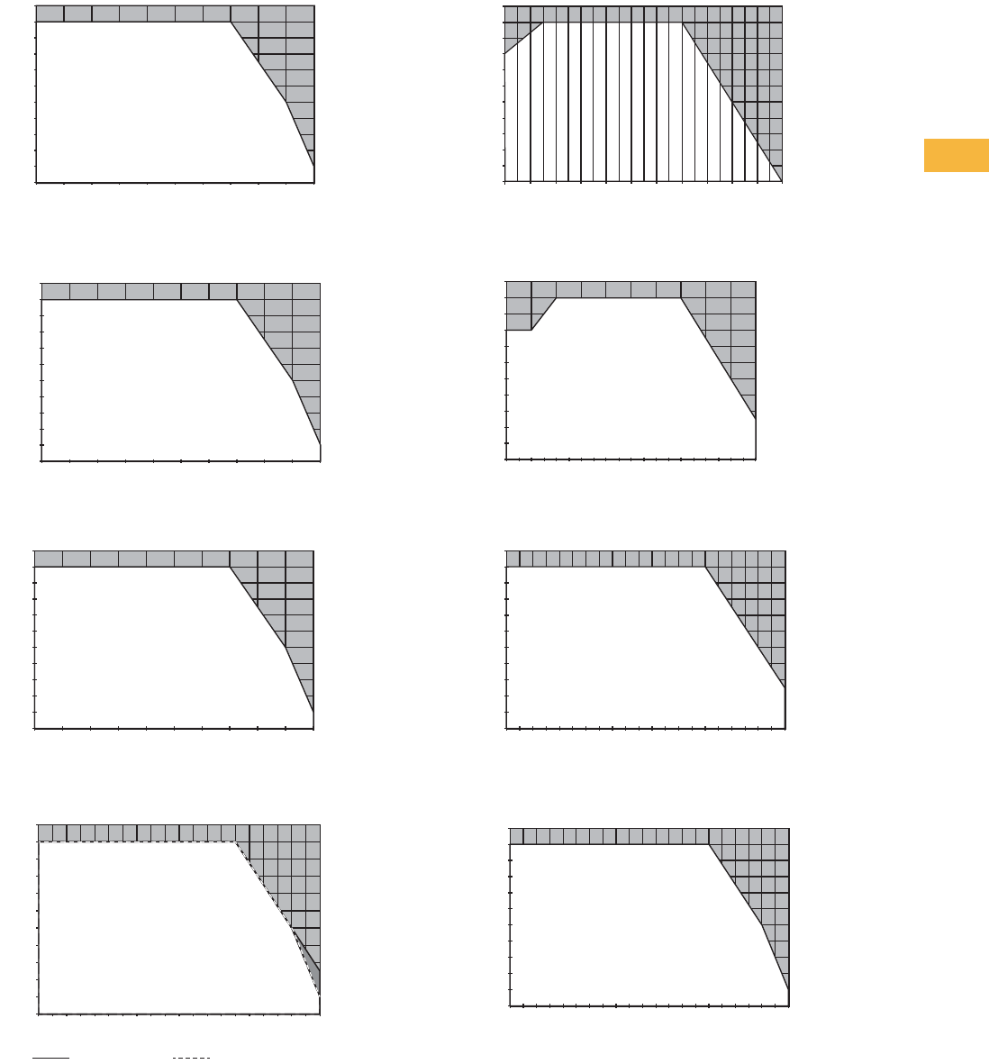
Volume 7—Logic Control, Operator Interface and Connectivity Solutions CA08100008E—May 2014 www.eaton.com V7-T6-13
6
6
6
6
6
6
6
6
6
6
6
6
6
6
6
6
6
6
6
6
6
6
6
6
6
6
6
6
6
6
6.1
Power Supplies
General-Purpose and Sensor Power Supplies
Power Derating Curves
Vertical Mounting Position PSG15E12SP
Vertical Mounting Position PSG30E12SP
Vertical Mounting Position PSG60E12SM
Vertical and Horizontal Mounting Position PSG100E12SM
Vertical Mounting Position PSG60E
Vertical Mounting Position PSG60E24SP
Vertical and Horizontal Mounting Position PSG60E24RM
Vertical and Horizontal Mounting Position PSG60N24RP
0
10
20
30
40
50
60
70
80
90
100
110
-20 -10 0 10 20 30 40 50 60 70 80
Load (%)
Ambient Temperature (°C)
0
10
20
30
40
50
60
70
80
90
100
110
-20-10 0 1020304050607080
Load (%)
Ambient Temperature (°C)
0
10
20
30
40
50
60
70
80
90
100
110
-20-10 0 1020304050607080
Load (%)
Ambient Temperature (°C)
0
10
20
30
40
50
60
70
80
90
100
110
-20-10 0 1020304050607080
Load (%)
Ambient Temperature (°C)
Horizontal Mounting
Vertical Mounting
Load (%)
Ambient Temperature (°C)
-20 -10 0 10 20 30 40 50 60 70 80 85
110
100
90
80
70
60
50
40
30
20
10
0
0
10
20
30
40
50
60
70
80
90
100
110
-20-10 0 1020304050607080
Load (%)
Ambient Temperature (°C)
0
10
20
30
40
50
60
70
80
90
100
110
-20-10 0 10 2030 4050 607080
Load (%)
Ambient Temperature (°C)
0
10
20
30
40
50
60
70
80
90
100
110
-20-10 0 1020 304050607080
Load (%)
Ambient Temperature (°C)
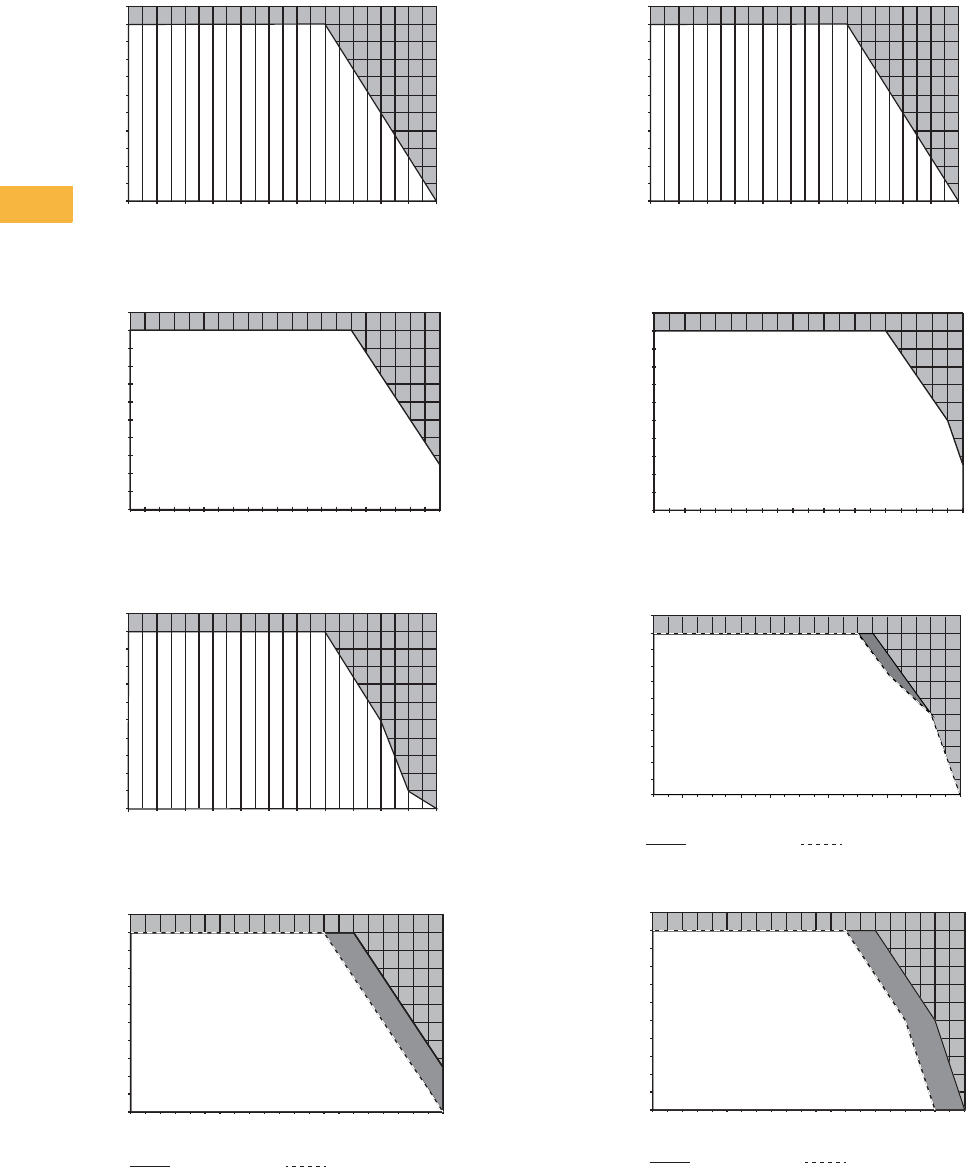
V7-T6-14 Volume 7—Logic Control, Operator Interface and Connectivity Solutions CA08100008E—May 2014 www.eaton.com
6
6
6
6
6
6
6
6
6
6
6
6
6
6
6
6
6
6
6
6
6
6
6
6
6
6
6
6
6
6
6.1
Power Supplies
General-Purpose and Sensor Power Supplies
Vertical Mounting Position PSG120E
Vertical and Horizontal Mounting Position PSG120E24RM
Vertical Mounting Position PSG240E
Vertical and Horizontal Mounting Position PSG240E24RM
Vertical Mounting Position PSG480E
Vertical Mounting Position PSG480E24RM
Vertical and Horizontal Mounting Position PSG60F24RM
Vertical and Horizontal Mounting Position PSG120F24RM
Load (%)
Ambient Temperature (°C)
-20 -10 0 10 20 30 40 50 60 70 80 85
110
100
90
80
70
60
50
40
30
20
10
0
0
10
20
30
40
50
60
70
80
90
100
110
-20-10 0 1020304050607080
Load (%)
Ambient Temperature (°C)
Load (%)
Ambient Temperature (°C)
-20 -10 0 10 20 30 40 50 60 70 80 85
110
100
90
80
70
60
50
40
30
20
10
0
0
10
20
30
40
50
60
70
80
90
100
110
-2 0 -10 0 1 0 2 0 3 0 4 0 5 0 6 0 7 0 8 0
Load (%)
Ambient Temperature (°C)
Horizontal Mounting
Vertical Mounting
Load (%)
Ambient Temperature (°C)
-20 -10 0 10 20 30 40 50 60 70 80 85
110
100
90
80
70
60
50
40
30
20
10
0
0
10
20
30
40
50
60
70
80
90
100
110
-2 5 -1 5 - 5 5 1 5 2 5 3 5 4 5 5 5 6 5 75
Load (%)
Ambient Temperature (°C)
Load (%)
Ambient Temperature (°C)
110
100
90
80
70
60
50
40
30
20
10
0
010 20 30 40 50 60 70 80-20 -10
Horizontal Mounting
Vertical Mounting
0
10
20
30
40
50
60
70
80
90
100
110
-2 0 -10 0 1 0 2 0 3 0 4 0 5 0 6 0 7 0 8 0
Load (%)
Horizontal Mounting
Vertical Mounting
Ambient Temperature (°C)
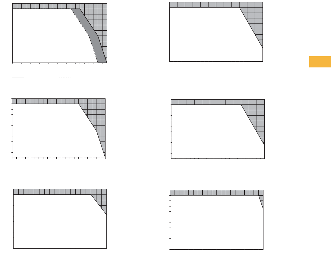
Volume 7—Logic Control, Operator Interface and Connectivity Solutions CA08100008E—May 2014 www.eaton.com V7-T6-15
6
6
6
6
6
6
6
6
6
6
6
6
6
6
6
6
6
6
6
6
6
6
6
6
6
6
6
6
6
6
6.1
Power Supplies
General-Purpose and Sensor Power Supplies
Vertical and Horizontal Mounting Position PSG240F24RM
Vertical Mounting Position PSG480F24RM
Vertical Mounting Position PSG960F24RM
Vertical Mounting Position PSG480R24RM
Vertical Mounting Position PSG960R24RM
Vertical Mounting Position PSG480B24RM
0
10
20
30
40
50
60
70
80
90
100
110
-20 -10 0 10 20 30 40 50 60 70 80
Load (%)
Ambient Temperature (°C)
Horizontal Mounting
Vertical Mounting
0
10
20
30
40
50
60
70
80
90
100
110
-2 0 -10 0 10 2 0 3 0 4 0 5 0 6 0 7 0 8 0
Load (%)
Ambient Temperature (°C)
0
10
20
30
40
50
60
70
80
90
100
110
-25-15-5 5 152535455565
Load (%)
Ambient Temperature (°C)
0
10
20
30
40
50
60
70
80
90
100
110
-40 -30 -20 -10 0 10 20 30 40 50 60 70 80
Load (%)
Ambient Temperature (°C)
0
10
20
30
40
50
60
70
80
90
100
110
-40-30-20-10 0 1020304050607080
Load (%)
Ambient Temperature (°C)
0
10
20
30
40
50
60
70
80
90
100
110
-25-15-5 5 15253545556575
Load (%)
Ambient Temperature (°C)
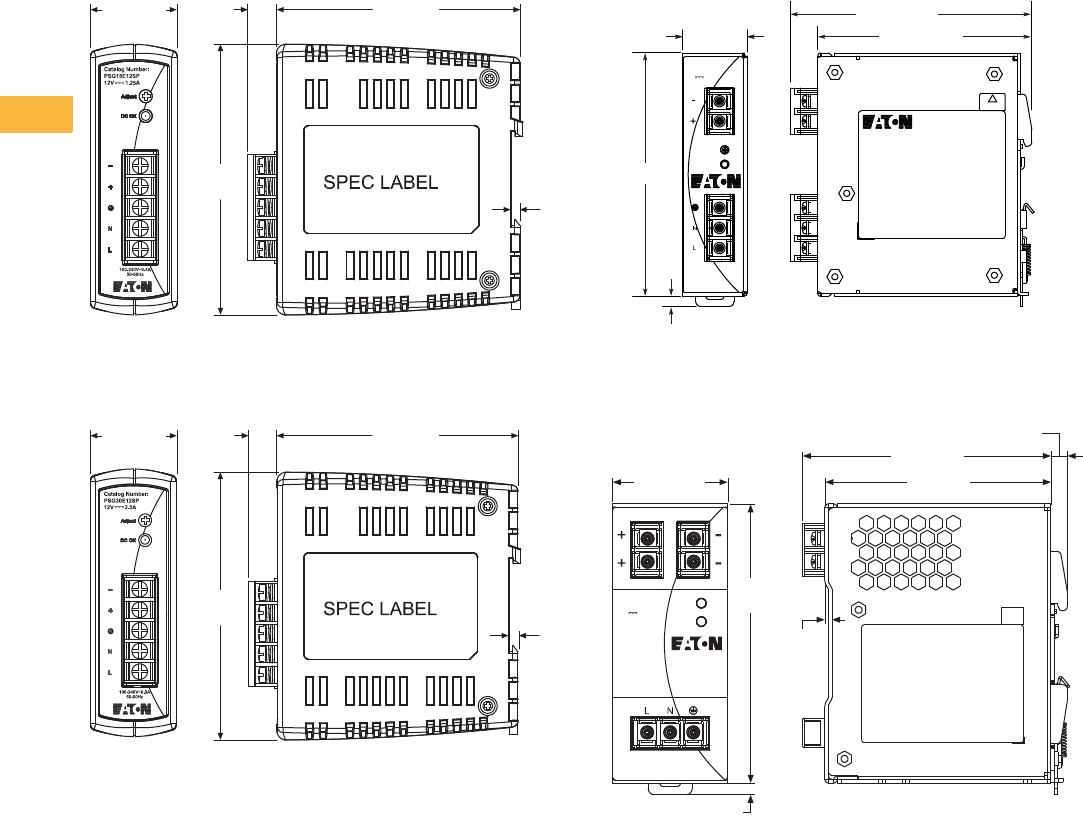
V7-T6-16 Volume 7—Logic Control, Operator Interface and Connectivity Solutions CA08100008E—May 2014 www.eaton.com
6
6
6
6
6
6
6
6
6
6
6
6
6
6
6
6
6
6
6
6
6
6
6
6
6
6
6
6
6
6
6.1
Power Supplies
General-Purpose and Sensor Power Supplies
Dimensions
Approximate Dimensions in mm
Note: Dimensions are for reference only.
PSG15E12SP
PSG30E12SP
PSG60E12SM
PSG100E12SM
32.0 ±0.5
(C)
10.6 90.0 ±0.5
3.3
100.0
±0.5
32.0 ±0.5 10.6 90.0 ±0.5
3.3
100.0
±0.5
32.0
±0.5
5.0 ±0.2
Catalog Number:
PSG60E12SM
24V 2.5A
Adjust
DC OK
100-240V~1.5A
50-60Hz
SPEC LABEL
CAUTION
HOT SURFACE
121.0 ±0.5
106.4 ±0.5
120.5 ±0.5
50.0 ±0.5
SPEC LABEL
Catalog Number:
PSG100E12SM
24V 8.33A
Adjust
DC OK
100–240V~ 2.5A
50–60 Hz
111.6 ±0.5
98.0 ±0.5
7.1 ±0.5
121.0
±0.5
1.6
5.0
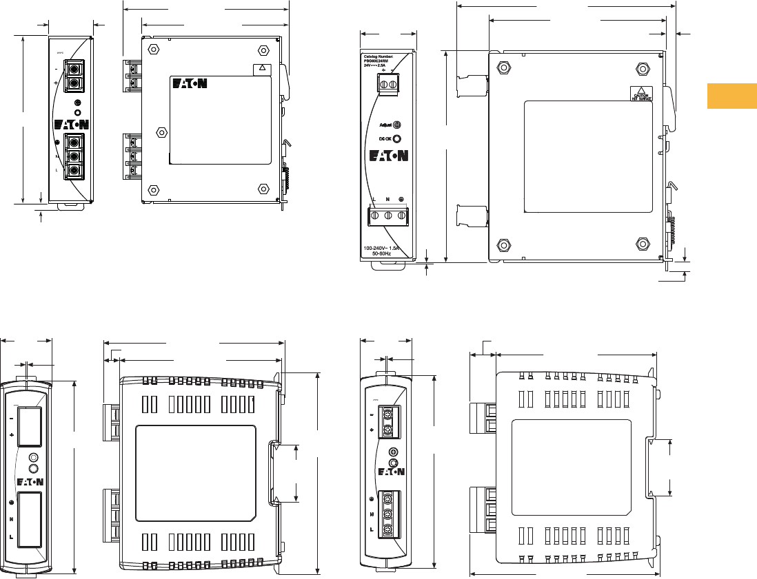
Volume 7—Logic Control, Operator Interface and Connectivity Solutions CA08100008E—May 2014 www.eaton.com V7-T6-17
6
6
6
6
6
6
6
6
6
6
6
6
6
6
6
6
6
6
6
6
6
6
6
6
6
6
6
6
6
6
6.1
Power Supplies
General-Purpose and Sensor Power Supplies
Approximate Dimensions in mm
Note: Dimensions are for reference only.
PSG60E
PSG60E24SP
PSG60E24RM
PSG60N24RP
32.0 ±0.5
5.0 ±0.2
Catalog Number:
PSG60E
24V 2.5A
Adjust
DC OK
100-240V~1.5A
50-60Hz
SPEC LABEL
CAUTION
HOT SURFACE
121.0 ±0.5
105.2 ±0.5
120.5 ±0.5
Adjust
DC OK SPEC LABEL
32.0
±0.6
0.8 ±0.4
113.0 ±0.6
101.0 ±0.3
120.6
35.5
±0.2
126.0
±0.6
10.0 ±0.3
100–240V~ 1.5A
50–60 Hz
Catalog Number:
PSG60E24SP
24V 2.5A
5.5 ±0.4
Spec Label
32.0
±0.3
106.6 ±0.5
125.0 ±1.0
5.5 ±0.2
121.0
±0.4
1.5 ±0.4
32.0
±0.6
0.8 (ref.)
120.6
±0.3
Catalog Number:
PSG60N24RP
24V 2.5A
Adjust
DC OK
NEC Class 2
100–240V~ 1.5A
50–60 Hz
101.0 ±0.3
16.4 ±0.5
35.5
±0.5
119.3 (ref.)
SPEC LABEL
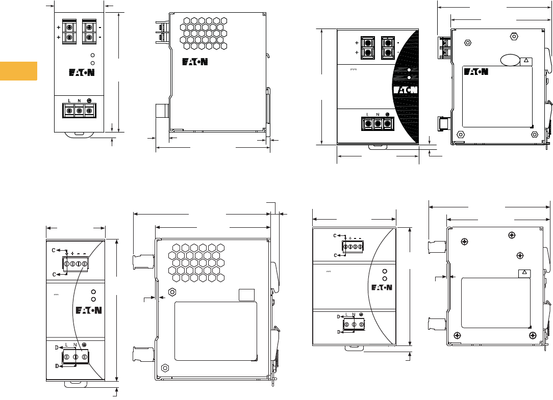
V7-T6-18 Volume 7—Logic Control, Operator Interface and Connectivity Solutions CA08100008E—May 2014 www.eaton.com
6
6
6
6
6
6
6
6
6
6
6
6
6
6
6
6
6
6
6
6
6
6
6
6
6
6
6
6
6
6
6.1
Power Supplies
General-Purpose and Sensor Power Supplies
Approximate Dimensions in mm
Note: Dimensions are for reference only.
PSG120E
PSG120E24RM
PSG240E
PSG240E24RM
115.0 ±0.6
13.0 4.0
5.5
121.0
±0.2
DC 24V 5A
AC 100-240V 2A
50-60 Hz
Adjust
DC OK
50.0 ±0.2
50.0 ±0.5
SPEC LABEL
116.6 ±1.0
98.0 ±0.5
5.5 ±0.2
121.0
±0.5
1.6
5.0
Catalog Number:
PSG120E24RM
24V 5A
100–240V~ 2.5A
50–60 Hz
Adjust
DC OK
5.0 ±0.2
SPEC LABEL
CAUTION
HOT SURFACE
Catalog Number:
PSG240E
Adjust
DC OK
24V 10A
100-240V~5A
50-60Hz
121.0
±0.5
105.2 ±0.5
118.5 ±0.5
85.0 ±0.5
100–240V~ 3.5A
50–60 Hz
Adjust
DC OK
CAUTION
HOT SURFACE
SPEC LABEL
121.0
±0.5
85.0 ±0.5
1.6
105.2 ±0.5
124.1 ±1.0
5.0
24V 10A
Catalog Number:
PSG240E24RM
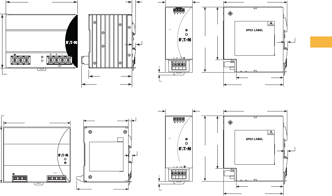
Volume 7—Logic Control, Operator Interface and Connectivity Solutions CA08100008E—May 2014 www.eaton.com V7-T6-19
6
6
6
6
6
6
6
6
6
6
6
6
6
6
6
6
6
6
6
6
6
6
6
6
6
6
6
6
6
6
6.1
Power Supplies
General-Purpose and Sensor Power Supplies
Approximate Dimensions in mm
Note: Dimensions are for reference only.
PSG480E
PSG480E24RM
PSG60F24RM
PSG120F24RM
121.0
±0.5
24V 20A
Catalog Number:
PSG480E
100-240V~ 7 A 50-60Hz
160.0 ±0.5 7. 1
6.6
±0.1
111.4 ±0.5
96.6 ±0.5
N L Adjust
DC OK
121.0
±0.5
Adjust
DC OK
100–240V ~6A
50–60 Hz
Catalog Number:
PSG480E24RM
+NL +––
6.6
±0.5
24V 20A
7.1
96.7 ±0.5
144.0 ±1.0
111.5 ±1.0
121.0
±0.5
117.3 ±0.5
50.0 ±0.5
5.0
97.5
±0.5 6.6
±0.35
110.2 ±0.5
86.8 ±0.5
24V 2.5A Adjust
DC OK
Three-Phase 400–500V ~0.3A
50–60 Hz
Catalog Number:
PSG60F24RM
121.0
±0.5
117.3 ±0.5
50.0 ±0.5
5.0
97.5
±0.5 6.6
±0.35
110.2 ±0.5
86.8 ±0.5
24V 5A Adjust
DC OK
Three-Phase 400–500V ~0.3A
50–60 Hz
Catalog Number:
PSG120F24RM
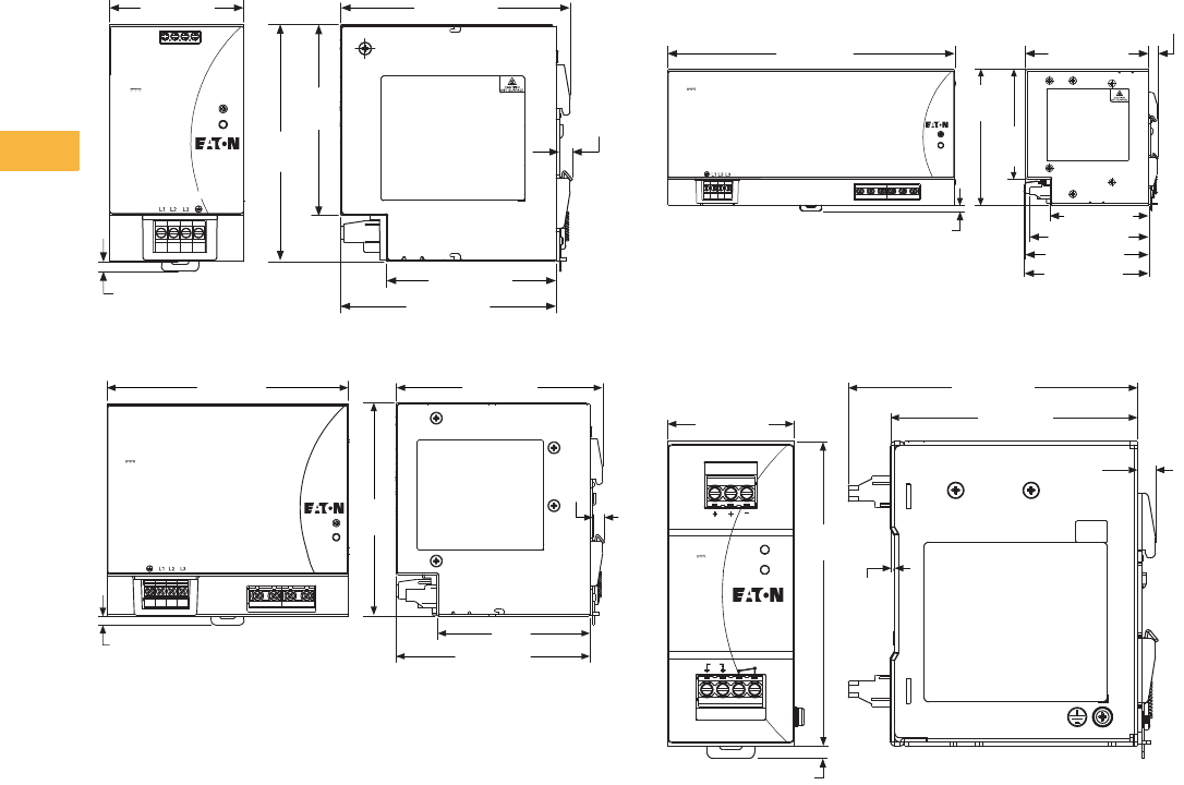
V7-T6-20 Volume 7—Logic Control, Operator Interface and Connectivity Solutions CA08100008E—May 2014 www.eaton.com
6
6
6
6
6
6
6
6
6
6
6
6
6
6
6
6
6
6
6
6
6
6
6
6
6
6
6
6
6
6
6.1
Power Supplies
General-Purpose and Sensor Power Supplies
Approximate Dimensions in mm
Note: Dimensions are for reference only.
PSG240F24RM
PSG480F24RM
PSG960F24RM
PSG480R24RM
++––
117.3 ±0.5
70.0 ±0.5
5.0
97.5
±0.5 6.6
±0.5
110.2 ±0.5
86.8 ±0.5
24V 5A
Adjust
DC OK
Three-Phase 400–500V ~0.75A
50–60 Hz
Catalog Number:
PSG240F24RM 121.0
±0.5
SPEC LABEL
117.3 ±0.7
140.0 ±0.5
5.0
6.6
110.2 ±0.5
87.0
24V 20A
Adjust
DC OK
Three-Phase 400–500V ~1A
50–60 Hz
Catalog Number:
PSG480F24RM
121.0
±0.8
SPEC LABEL
++ – –
6.6
±0.35
SPEC LABEL
Adjust
DC OK
24V 40A
Catalog Number:
PSG960F24RM
Three-Phase 400–500V ~1.7A
50–60 Hz
+++–––
5.0
255.0 ±0.5
97.5
±0.5
121.0
±0.5
117.3 ±0.5
106.0 ±0.5
110.2 ±0.5
111.3 ±0.5
88.1 ±0.5
24V–60V 20A
Catalog Number:
PSG480R24SM
20A Max.
Redundancy Module
OK
Vin1 Vin2 Com
Vin1
Vin2
115.0 ±1.0
98.0 ±0.5
1.6
OK
OK
Vout
7.1 (ref)
SPEC LABEL
*121.0
±0.5
50.0 ±0.5
5.0
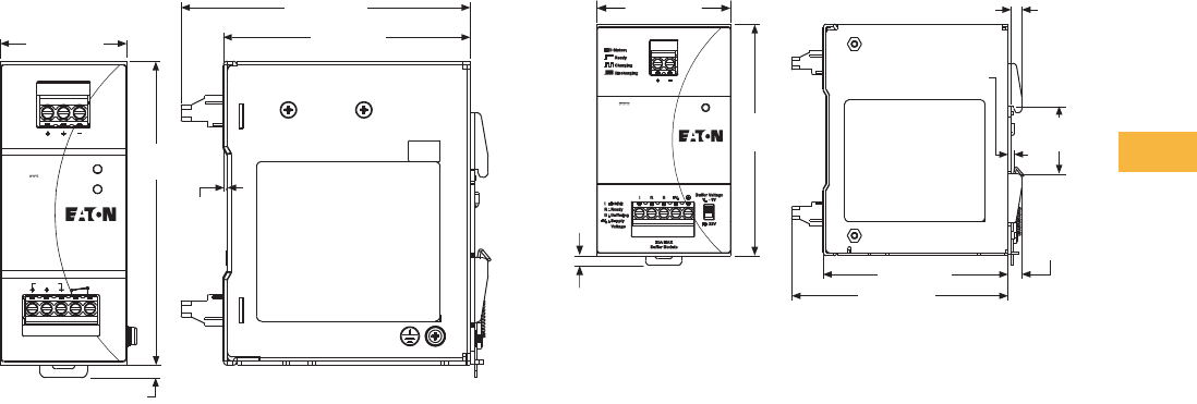
Volume 7—Logic Control, Operator Interface and Connectivity Solutions CA08100008E—May 2014 www.eaton.com V7-T6-21
6
6
6
6
6
6
6
6
6
6
6
6
6
6
6
6
6
6
6
6
6
6
6
6
6
6
6
6
6
6
6.1
Power Supplies
General-Purpose and Sensor Power Supplies
Approximate Dimensions in mm
Note: Dimensions are for reference only.
PSG960R24RM PSG480B24RM
22V–60V 40A
Catalog Number:
PSG960R24RM
20A Max.
Redundancy Module
OK
Vin1 Vin2 Com
Vin1
Vin2
115.0 ±1.0
98.0 ±0.5
1.6
OK
OK
Vout
SPEC LABEL
121.0
±0.5
50.0 ±0.5
5.0
Status
24V 20A
Catalog Number:
PSG480B24RM
SPEC LABEL
5.0
121.0
±0.5
70.0 ±0.5 5.5 ±0.5
+0.5
–0.3
1.2
35.5
±0.5
96.6 ±0.8
113.0 ±1.0
7.1
±0.5
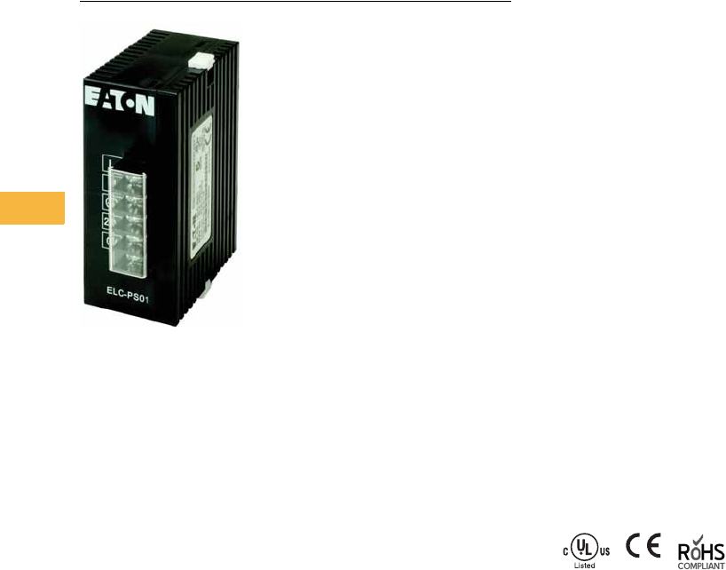
V7-T6-22 Volume 7—Logic Control, Operator Interface and Connectivity Solutions CA08100008E—May 2014 www.eaton.com
6
6
6
6
6
6
6
6
6
6
6
6
6
6
6
6
6
6
6
6
6
6
6
6
6
6
6
6
6
6
6.1
Power Supplies
General Purpose and Sensor Power Supplies
ELC Series
Contents
Description Page
PSG Series . . . . . . . . . . . . . . . . . . . . . . . . . . . . . . V7-T6-3
ELC Series
Product Selection . . . . . . . . . . . . . . . . . . . . . . . V7-T6-23
Technical Data and Specifications . . . . . . . . . . V7-T6-23
Dimensions . . . . . . . . . . . . . . . . . . . . . . . . . . . V7-T6-24
easyRelay Power Supply . . . . . . . . . . . . . . . . . . . . V7-T6-25
Sensor Power Supply . . . . . . . . . . . . . . . . . . . . . . V7-T6-29
ELC Series
Product Description
Eaton’s ELC power supplies
are the perfect products for
those applications requiring a
very compact and low-cost
source for 24 Vdc power.
While these products were
developed to be a perfect
match for our Eaton Logic
Controllers, they can be used
in a variety of applications.
The lightweight, DIN rail
mounted enclosures, wide
input voltage range and
robust screw terminals
make these power supplies
easy to install and use.
They are available in 1A
and 2A models.
Features, Benefits and
Functions
●Universal input voltage:
85–264 Vac
●Compact size, with
common depth and height
across models allows for
common panel depths and
family consistency
●ELC styling provides
maximum aesthetic appeal
when used with Eaton
Logic Controllers
●Front-mounted pressure
plate screw terminals for
a robust connection
●Removable finger-safe
protective cover for
terminals
●Power ON indication LED
●Integrated mounting
hardware for panel
mounting or DIN rail
mounting
Standards and Certifications
●cULus listed
●CE marked
●RoHS compliant
Volume 7—Logic Control, Operator Interface and Connectivity Solutions CA08100008E—May 2014 www.eaton.com V7-T6-23
6
6
6
6
6
6
6
6
6
6
6
6
6
6
6
6
6
6
6
6
6
6
6
6
6
6
6
6
6
6
6.1
Power Supplies
General Purpose and Sensor Power Supplies
Product Selection
ELC Series
Technical Data and Specifications
ELC Series
Description
Catalog
Number
24 watt, 1 amp power supply ELC-PS01
48 watt, 2 amp power supply ELC-PS02
Capacity
ELC-PS01
24W
ELC-PS02
48W
Input
Nominal voltage 100–240 Vac 100–240 Vac
Voltage range 85–264 Vac 85–264 Vac
Frequency 47–63 Hz 47–63 Hz
Output
Nominal output voltage 24 Vdc ± 3% 24 Vdc ± 3%
Nominal current 1A 2A
Efficiency 78% to 87% typical at full load 78% to 87% typical at full load
Residual ripple/peak switching
(20 MHz)
< 100 mV typical at full load < 240 mV typical at full load
General/Physical Data
Housing material Plastic Plastic
Dimensions (D) 60 mm 60 mm
Dimensions (W) 36.5 mm 55 mm
Dimensions (H) 90 mm 90 mm
Weight (g) 158 250
Operating temperature 0°C to +55°C 0°C to +55°C
Storage temperature –25°C to +70°C –25°C to +70°C
Operating humidity 50% to 95% RH, noncondensing 50% to 95% RH, noncondensing
Pollution degree 2 2
Approvals/Certifications
UL 508, CE, RoHS, EMC directive
89/336/EEC, low voltage
directive 73/23/EEC
UL 508, CE, RoHS, EMC directive
89/336/EEC, low voltage
directive 73/23/EEC
Safety and Protection
Overload/short circuit
protection
Auto recovery Auto recovery
ELC-PS01
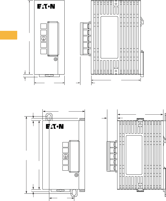
V7-T6-24 Volume 7—Logic Control, Operator Interface and Connectivity Solutions CA08100008E—May 2014 www.eaton.com
6
6
6
6
6
6
6
6
6
6
6
6
6
6
6
6
6
6
6
6
6
6
6
6
6
6
6
6
6
6
6.1
Power Supplies
General Purpose and Sensor Power Supplies
Dimensions
Approximate Dimensions in Inches (mm)
ELC-PS01 Power Supply
ELC-PS02 Power Supply
ELC-PS01
POWER
L
N
24V
0V
2.36
(60.0)
3.54
(90.0)
0.12
(3.0)
1.44
(36.5)
13.3
(0.52)
ELC-PS02
POWER
L
N
24V
0V
2.36
(60.0)
3.94
(100.0)
0.12
(3.0)
1.28
(32.5)
13.3
(0.52)
3.54
(90.0)
0.12
(3.0)
2.17
(55.0)
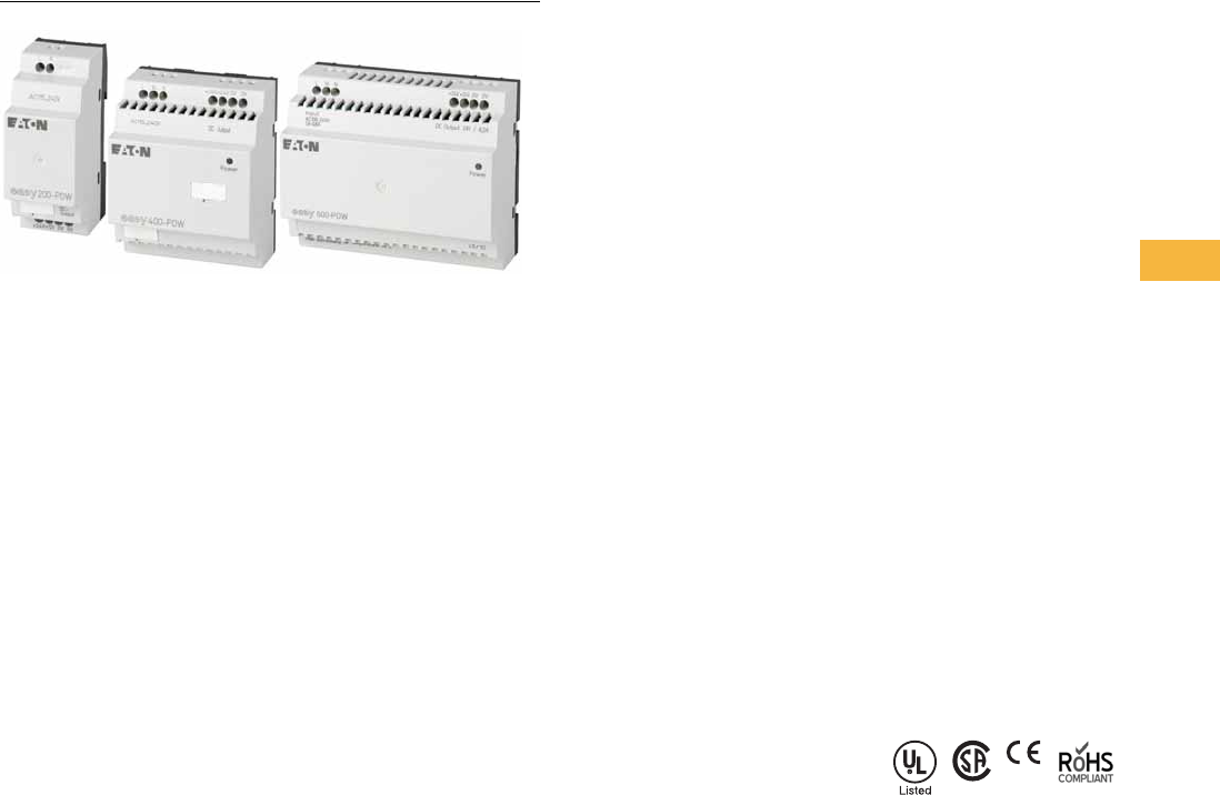
Volume 7—Logic Control, Operator Interface and Connectivity Solutions CA08100008E—May 2014 www.eaton.com V7-T6-25
6
6
6
6
6
6
6
6
6
6
6
6
6
6
6
6
6
6
6
6
6
6
6
6
6
6
6
6
6
6
6.1
Power Supplies
General Purpose and Sensor Power Supplies
easyRelay Power Supply
Contents
Description Page
PSG Series . . . . . . . . . . . . . . . . . . . . . . . . . . . . . . V7-T6-3
ELC Series . . . . . . . . . . . . . . . . . . . . . . . . . . . . . . . V7-T6-22
easyRelay Power Supply
Product Selection . . . . . . . . . . . . . . . . . . . . . . . V7-T6-26
Technical Data and Specifications . . . . . . . . . . V7-T6-27
Dimensions . . . . . . . . . . . . . . . . . . . . . . . . . . . V7-T6-28
Sensor Power Supply . . . . . . . . . . . . . . . . . . . . . . V7-T6-29
easyRelay Power Supply
Product Description
Eaton’s easyRelay power
supplies are the perfect
products for those applications
requiring a low amperage
24 Vdc power source. While
these products were
developed to be a perfect
match for our easyRelay
products, they can be used
in a variety of applications.
Features, Benefits and
Functions
●Universal input voltage:
85–264 Vac, 50/60 Hz
●Wide operating
temperature range
(–25°C to +55°C)
●
Power ON / diagnostics
LED:
continuous light on—
fault-free operation;
flashing LED—short circuit
overload on voltage output
●Optional mounting
hardware for panel
mounting (EZB4-101-GF1)
or standard DIN rail
mounting
●Finger-safe, side-entry
screw clamp terminals for
clean wiring
●Primary switched-mode
power supplies
●Output voltages can be
connected in parallel to
increase power output or
for redundant operation to
achieve greater system
availability
●Safety extra low voltage
(SELV to EN 55 022)
●Radio interference Class B
to EN 55 011 and EN 55 022
for use in industrial and
public networks
Standards and Certifications
●UL listed
●CSA certified
●CE marked
●RoHS compliant
●CSA Class I, Division 2
rated for groups A, B, C, D
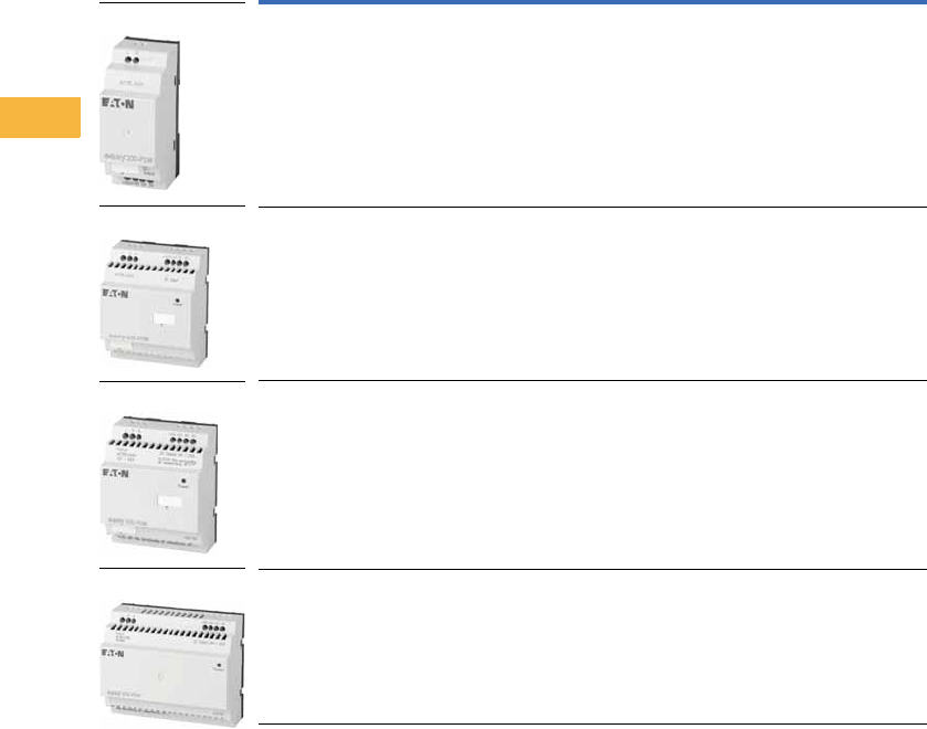
V7-T6-26 Volume 7—Logic Control, Operator Interface and Connectivity Solutions CA08100008E—May 2014 www.eaton.com
6
6
6
6
6
6
6
6
6
6
6
6
6
6
6
6
6
6
6
6
6
6
6
6
6
6
6
6
6
6
6.1
Power Supplies
General Purpose and Sensor Power Supplies
Product Selection
easyRelay Power Supply Units
Rated input voltage 100–240 Vac, single-phase.
Input Voltage
Range
Rated Output
Voltage
Output Voltage
Setting Range
Rated Output
Power
Rated Output
Current Catalog Number
100–240 Vac 24 Vdc/12 Vdc — 8W 0.35A / 20 mA EASY200-POW
100–240 Vac 24 Vdc — 30W 1.25A EASY400-POW
100–240 Vac 24 Vdc — 60W 2.5A EASY500-POW
100–240 Vac 24 Vdc — 100W 4.2A EASY600-POW
EASY200-POW
EASY400-POW
EASY500-POW
EASY600-POW

Volume 7—Logic Control, Operator Interface and Connectivity Solutions CA08100008E—May 2014 www.eaton.com V7-T6-27
6
6
6
6
6
6
6
6
6
6
6
6
6
6
6
6
6
6
6
6
6
6
6
6
6
6
6
6
6
6
6.1
Power Supplies
General Purpose and Sensor Power Supplies
Technical Data and Specifications
easyRelay Series
Capacity
EASY200-POW
8W
EASY400-POW
30W
EASY500-POW
60W
EASY600-POW
100W
Input
Nominal voltage 100–240 Vac 100–240 Vac 100–240 Vac 100–240 Vac
Voltage range 85–264 Vac 85–264 Vac 85–264 Vac 85–264 Vac
Frequency 47–63 Hz 47–63 Hz 47–63 Hz 47–63 Hz
Output
24 Vdc
Nominal output voltage 24 Vdc ± 3% 24 Vdc ± 3% 24 Vdc ± 3% 24 Vdc ± 3%
Nominal current 0.35A 1.25A 2.5A 4.2A
12 Vdc
Nominal output voltage 12 Vdc — — —
Nominal current 20 mA — — —
General/Physical Data
Housing material Plastic Plastic Plastic Plastic
Dimensions (D) 2.22 in (56.5 mm) 2.22 in (56.5 mm) 2.22 in (56.5 mm) 2.22 in (56.5 mm)
Dimensions (W) 1.40 in (35.5 mm) 2.81 in (71.5 mm) 2.81 in (71.5 mm) 4.23 in (107.5 mm)
Dimensions (H) 3.54 in (90 mm) 3.54 in (90 mm) 3.54 in (90 mm) 3.54 in (90 mm)
Operating temperature –25°C to +55°C –25°C to +55°C –25°C to +55°C –25°C to +55°C
Storage temperature –40°C to +70°C –40°C to +70°C –40°C to +70°C –40°C to +70°C
Pollution degree2222
Connection cables
Solid 0.2–4.0 mm2 (AWG 22-12) 0.2–4.0 mm2 (AWG 22-12) 0.2–4.0 mm2 (AWG 22-12) 0.2–4.0 mm2 (AWG 22-12)
Flexible 0.2–2.5 mm2 (AWG 221-12) 0.2–2.5 mm2 (AWG 221-12) 0.2–2.5 mm2 (AWG 221-12) 0.2–2.5 mm2 (AWG 221-12)
Approvals/Certifications
UL, CE, RoHS, CSA,
EN 50178m IEC/EN 60947
UL, CE, RoHS, CSA,
EN 50178m IEC/EN 60947
UL, CE, RoHS, CSA,
EN 50178m IEC/EN 60947
UL, CE, RoHS, CSA,
EN 50178m IEC/EN 60947
Safety and Protection
Overload/short circuit protection Yes Yes Yes Yes
Overcurrent limitation form 0.3A 1.4A 2.8A 4.6A
Degree of protection IP20 IP20 IP20 IP20
RFI suppression EN 55011, EN 55022 Class B,
IEC 61000-6-1, 2, 3, 4
EN 55011, EN 55022 Class B,
IEC 61000-6-1, 2, 3, 4
EN 55011, EN 55022 Class B,
IEC 61000-6-1, 2, 3, 4
EN 55011, EN 55022 Class B,
IEC 61000-6-1, 2, 3, 4
Potential isolation (prim./sec.) Yes, SELV, (to EN 600950, VDE 805) Yes, SELV, (to EN 600950, VDE 805) Yes, SELV, (to EN 600950, VDE 805) Yes, SELV, (to EN 600950, VDE 805)
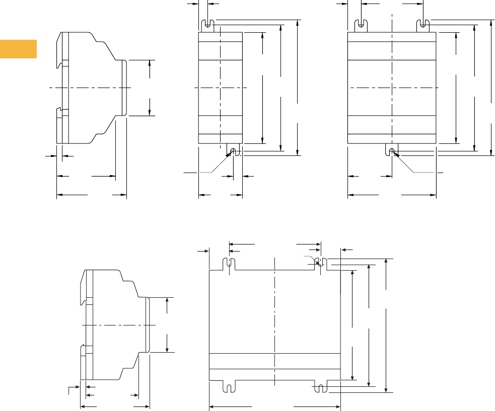
V7-T6-28 Volume 7—Logic Control, Operator Interface and Connectivity Solutions CA08100008E—May 2014 www.eaton.com
6
6
6
6
6
6
6
6
6
6
6
6
6
6
6
6
6
6
6
6
6
6
6
6
6
6
6
6
6
6
6.1
Power Supplies
General Purpose and Sensor Power Supplies
Dimensions
Approximate Dimensions in Inches (mm)
EASY200-POW, EASY400-POW and EASY500-POW Series
EASY600-POW Series
2.81
(71.5)
1.41
(35.8)
3.54
(90.0)
4.02
(102.0)
4.33
(110.0)
1.97
(50.0)
0.42
(10.8)
1.77
(45.0)
0.18
(4.5)
2.22
(56.5)
1.87
(47.5)
(M4) .157
(3.9) DIA.
0.30
(7.5)
0.30
(7.5)
1.40
(35.5)
3.54
(90.0)
4.02
(102.0)
4.33
(110.0)
EASY400-POW
EASY500-POWEASY200-POW
(M4) .157
(3.9) DIA.
3.54
(90.0)
4.23 (107.5)
0.64 (16.25) M4 #8
1.77
(45.0)
0.18 (4.5) 1.87 (47.5)
2.22 (56.5)
2.96 (75.0)
4.02
(102.0)
4.33
(110.0)
0.64 (16.25)
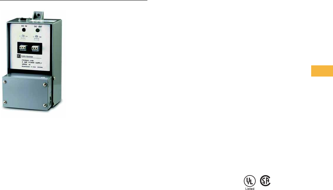
Volume 7—Logic Control, Operator Interface and Connectivity Solutions CA08100008E—May 2014 www.eaton.com V7-T6-29
6
6
6
6
6
6
6
6
6
6
6
6
6
6
6
6
6
6
6
6
6
6
6
6
6
6
6
6
6
6
6.1
Power Supplies
General Purpose and Sensor Power Supplies
Sensor Power Supply
Contents
Description Page
PSG Series . . . . . . . . . . . . . . . . . . . . . . . . . . . . . . V7-T6-3
ELC Series . . . . . . . . . . . . . . . . . . . . . . . . . . . . . . . V7-T6-22
easyRelay Power Supply . . . . . . . . . . . . . . . . . . . . V7-T6-25
Sensor Power Supply
Product Selection . . . . . . . . . . . . . . . . . . . . . . . V7-T6-30
Technical Data and Specifications . . . . . . . . . . V7-T6-30
Wiring Diagram . . . . . . . . . . . . . . . . . . . . . . . . V7-T6-31
Dimensions . . . . . . . . . . . . . . . . . . . . . . . . . . . V7-T6-31
Sensor Power Supply
Product Description
Eaton’s sensor power supply
was specially designed to be
used with the 200 Series and
E68 Series zero pressure
accumulation systems, but is
also suitable for use in a wide
variety of applications. The
unit delivers 100W output at
27 Vdc and supports easy,
Class II wiring. The power
supply is a tamper-proof,
rugged component easily
mounted to a conveyor side-
channel or support. Internal
components are fully
encapsulated in a strong die-
cast housing to stand up to
rugged handling, ensuring
flawless performance in any
material handling environment.
Features, Benefits and
Functions
●Integrated AC junction box
for one-step mounting and
wiring without the need for
additional accessories
●Built-in DC power health
contact allows easy
monitoring of power supply
status
●Unitized design features a
tamper-proof encapsulated
construction to reduce the
risk of damage associated
with conventional open
control-panel type
construction
●Built-in slug-release input
converts an AC or DC input
to the appropriate DC
signal for integration with
the 200 Series and E68
Series zero pressure
accumulation systems
●Dual output connection
terminals to make it easy
and convenient to locate
the power supply at the
center of the cable run
●Power switch protected
against accidental
operation
●Power in and out indicators
show status at a glance
●Conduit entry box for NEC
compliance
●Simple mounting with two
1/4-inch bolts
●Rugged die-cast housing
●Fully encapsulated
electronics
Standards and Certifications
●UL listed
●CSA approved
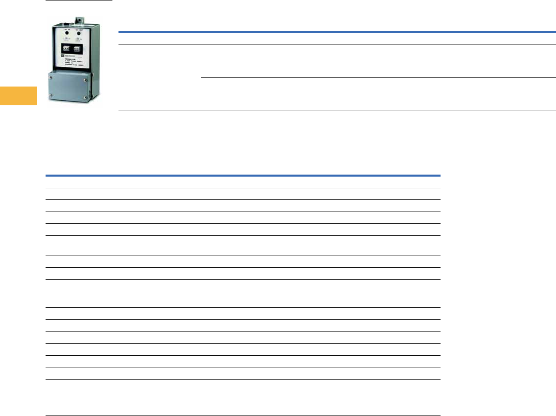
V7-T6-30 Volume 7—Logic Control, Operator Interface and Connectivity Solutions CA08100008E—May 2014 www.eaton.com
6
6
6
6
6
6
6
6
6
6
6
6
6
6
6
6
6
6
6
6
6
6
6
6
6
6
6
6
6
6
6.1
Power Supplies
General Purpose and Sensor Power Supplies
Product Selection
Sensor Power Supply
Technical Data and Specifications
Sensor Power Supply
Notes
1Total output power of supply is 100W. Total supply output power (100W) = main output power + slug output power.
2Stocked product, typical order quantities guaranteed in stock.
Output Slug Input Type Slug Output
Catalog
Number
Operating Voltage 105–132 Vac
27 Vdc, 100W;
short circuit, overload and
overvoltage protection
(cycle power to reset)
15–132 Vac/Vdc
3 mA minimum
Standard
For use with 200 Series and
E68 systems
Sinking or sourcing, switch selectable;
80 mA maximum; short circuit protection for
loads less than 32 Vac or Vdc (auto reset)
PS256A-01B1 2
15–132 Vac/Vdc
3 mA minimum
High current slug
For use with solenoid valve systems
requiring full current slug signals
Sinking only; 100W output; short circuit,
overload and overvoltage protection
(cycle power to reset) 1
PS256A-04B1 2
Description PS256A-01B1 PS256A-04B1
Input power 144W, maximum inrush 30A from cold start 144W, maximum inrush 30A from cold start
Input voltage 105–132 Vac 105–132 Vac
Input current (full load) 105 Vac–1.92A, 115 Vac–1.65A, 132 Vac–1.5A 105 Vac–1.92A, 115 Vac–1.65A, 132 Vac–1.5A
Output power 100W 100W
Output voltage 27 Vdc 27 Vdc
Output protection Short circuit, overload and overvoltage protection
(cycle power to reset), diode protected
Short circuit, overload and overvoltage protection
(cycle power to reset), diode protected
Regulation ± 3% ± 3%
Slug input 15–132 Vac/Vdc 15–132 Vac/Vdc
Slug output Sinking or sourcing, switch selectable; 80 mA maximum;
short circuit protection for loads less than 32 Vac or Vdc
(auto reset)
Sinking only; 100W output; short circuit, overload and
overvoltage protection (cycle power to reset) 1
Indicators Red LED: AC In; Green LED: DC Out Red LED: AC In; Green LED: DC Out
DC fail indication output NO contact, solid-state relay, 80 mA maximum NO contact, solid-state relay, 80 mA maximum
Temperature range –13° to 131°F (–25° to 55°C) –13° to 131°F (–25° to 55°C)
Vibration 20g 20g
Enclosure material Die-cast aluminum Die-cast aluminum
Enclosure rating NEMA 1 NEMA 1
Connections Main output/slug output:
Two three-position finger protected barrier strips;
AC line input, DC fail indication and slug input:
8-position screw terminal strip inside conduit entry box
Main output/slug output:
Two three-position finger protected barrier strips;
AC line input, DC fail indication and slug input:
8-position screw terminal strip inside conduit entry box
PS256A_
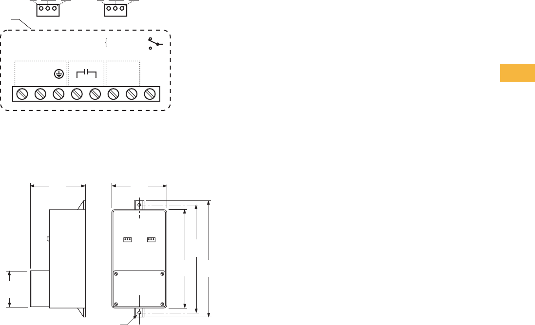
Volume 7—Logic Control, Operator Interface and Connectivity Solutions CA08100008E—May 2014 www.eaton.com V7-T6-31
6
6
6
6
6
6
6
6
6
6
6
6
6
6
6
6
6
6
6
6
6
6
6
6
6
6
6
6
6
6
6.1
Power Supplies
General Purpose and Sensor Power Supplies
Wiring Diagram
Sensor Power Supply
Dimensions
Approximate Dimensions in Inches (mm)
Sensor Power Supply
AC Input Power
L1 L2 GND
Power Monitor
L1 L2 Not
Used
15-132 VAC/
15-132 VDC
Slug In
L1 L2
Chassis internally
connected to AC GND
V+ Slug
Output Com
V+ Slug
Output Com
Sinking Slug
Sourcing Slug
Junction
Box
PS256A-01B1 only
4.6
(117)
9.7
(246)
8.2
(208)
9.0
(229)
Hole for 1/4 Inch Hardware
4.6
(117)
3.0
(76)
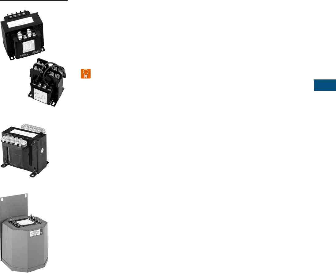
Volume 7—Logic Control, Operator Interface and Connectivity Solutions CA08100008E—February 2014 www.eaton.com V7-T7-1
7
7
7
7
7
7
7
7
7
7
7
7
7
7
7
7
7
7
7
7
7
7
7
7
7
7
7
7
7
7
Industrial Control Transformers
Types MTE and MTK
CE Marked
Type AP
7. 1 Tr a n s f o r m e r s
Standards and Certifications. . . . . . . . . . . . . . . . . . . . . . . . . . . . . . . . . V7-T7-2
Catalog Number Selection . . . . . . . . . . . . . . . . . . . . . . . . . . . . . . . . . . V7-T7-3
Type MTE . . . . . . . . . . . . . . . . . . . . . . . . . . . . . . . . . . . . . . . . . . . . . . . V7-T7-4
Type MTK . . . . . . . . . . . . . . . . . . . . . . . . . . . . . . . . . . . . . . . . . . . . . . . V7-T7-13
CE Marked . . . . . . . . . . . . . . . . . . . . . . . . . . . . . . . . . . . . . . . . . . . . . . V7-T7-18
Type AP. . . . . . . . . . . . . . . . . . . . . . . . . . . . . . . . . . . . . . . . . . . . . . . . . V7-T7-25
Learn
Online
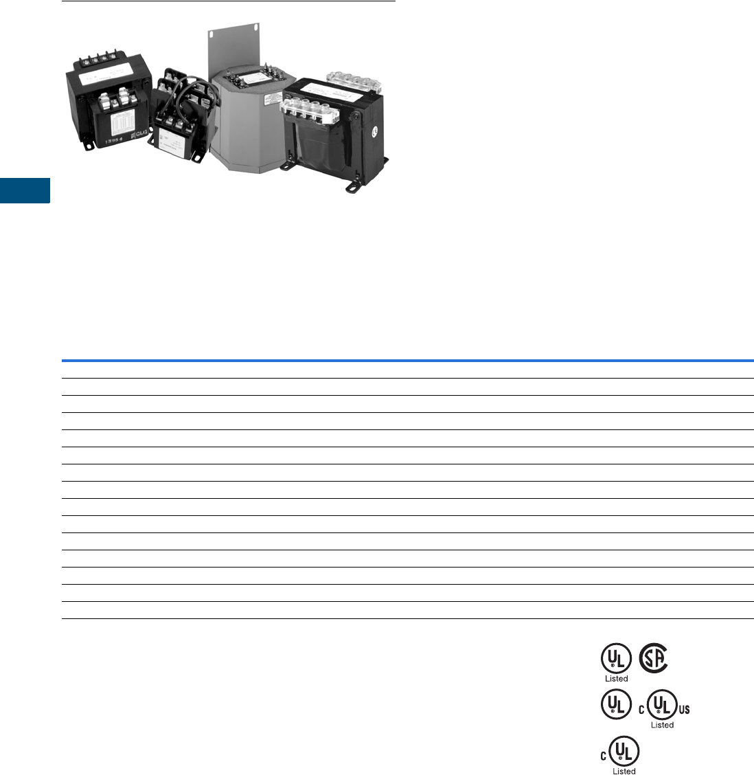
V7-T7-2 Volume 7—Logic Control, Operator Interface and Connectivity Solutions CA08100008E—February 2014 www.eaton.com
7
7
7
7
7
7
7
7
7
7
7
7
7
7
7
7
7
7
7
7
7
7
7
7
7
7
7
7
7
7
7.1
Industrial Control Transformers
Trans for mer s
Industrial Control Transformers
Contents
Description Page
Transformers
Type MTE . . . . . . . . . . . . . . . . . . . . . . . . . . . . . V7-T7-4
Type MTK . . . . . . . . . . . . . . . . . . . . . . . . . . . . . V7-T7-13
CE Marked . . . . . . . . . . . . . . . . . . . . . . . . . . . . V7-T7-18
Type AP . . . . . . . . . . . . . . . . . . . . . . . . . . . . . . . V7-T7-25
Standards and Certifications
Eaton dry-type distribution transformers are approved, listed, recognized or may comply with the following standards.
Engineering Standards
Notes
1UL 5085 replaces UL 506.
2Applies to 25–50 kVA.
3Applies to 25 kVA.
4Applies to 15–25 kVA.
5Applies to 37.5 kVA.
6Applies to 3 kVA.
7Applies to 5–9 kVA.
8Applies to 30–75 kVA.
9Applies to 30 kVA.
In addition to the above standards, Eaton
dry-type distribution transformers are also
manufactured in compliance with the
applicable standards listed below.
Not all of the following standards apply
to every transformer.
NEC: National Electrical Code®.
NEMA ST-1: Specialty Transformers (C89.1)
(control transformers).
NEMA ST-20: General-Purpose
Transformers.
NEMA TP-1: Guide for Determining Energy
Efficiency for Distribution Transformers.
NEMA 250: Enclosures for Electrical
Equipment (1000 volts maximum).
IEEE C57.12.01: General Requirements
for Dry-Type Distribution and Power
Transformers (including those with solid-
cast and/or resin-encapsulated windings).
ANSI C57.12.70: Terminal Markings and
Connections for Distribution and Power
Transformers.
ANSI C57.12.91: Standard Test Code
for Dry-Type Distribution and Power
Transformers.
CSA C22 No. 47-M90: Air-Cooled
Transformers (Dry-Type).
CSA C9-M1981: Dry-Type Transformers.
CSA C22.2 No. 66: Specialty Transformers.
CSA 802-94: Maximum Losses for
Distribution, Power and Dry-Type
Transformers.
NEMA TP-2: Standard Test Method for
Measuring the Energy Consumption of
Distribution Transformers.
NEMA TP-3
Catalog
Product
Name
UL
Standard 1
UL/cUL
File
Number
UL Listed
Control
Number
cUL Energy
Efficiency
File Number
CSA
File
Number
Insulation
System
Temp/ºC
kVA
Single-
Phase
kVA
Three-
Phase
Applicable
IEC
Standard
Industrial Control Transformer
MTE 5085 E46323 702X — — 105 0.025–1.5 N/A 61558
MTK 5085 E46323 702X — — 180 0.05–5 N/A 61558
Encapsulated Transformer
AP 5085 E10156 591H — — 180 3–10 N/A 61558
AP 1561 E78389 591H — — 180 15 N/A 61558
EP 5085 E10156 591H — LR60545 180 0.05–10 N/A 61558
EP 1561 E78389 591H EV157 2LR60545 3180 15–50 N/A 61558 4 / 726 5
EPT 5085 E10156 591H — LR60545 180 N/A 3–9 61558 6 / 726 7
EPT 1561 E78389 591H EV157 8LR60545 9180 N/A 15–75 726
MPC 1062 E53449 591H — LR60546 180 3–25 15–30 —
Ventilated Transformer
DS-3 1561 E78389 591H — — 220 15–167 N/A 60726
DT-3 1561 E78389 591H — — 220 N/A 15–750 60726
KT 1561 E78389 591H — — 220 N/A 9–500 N/A
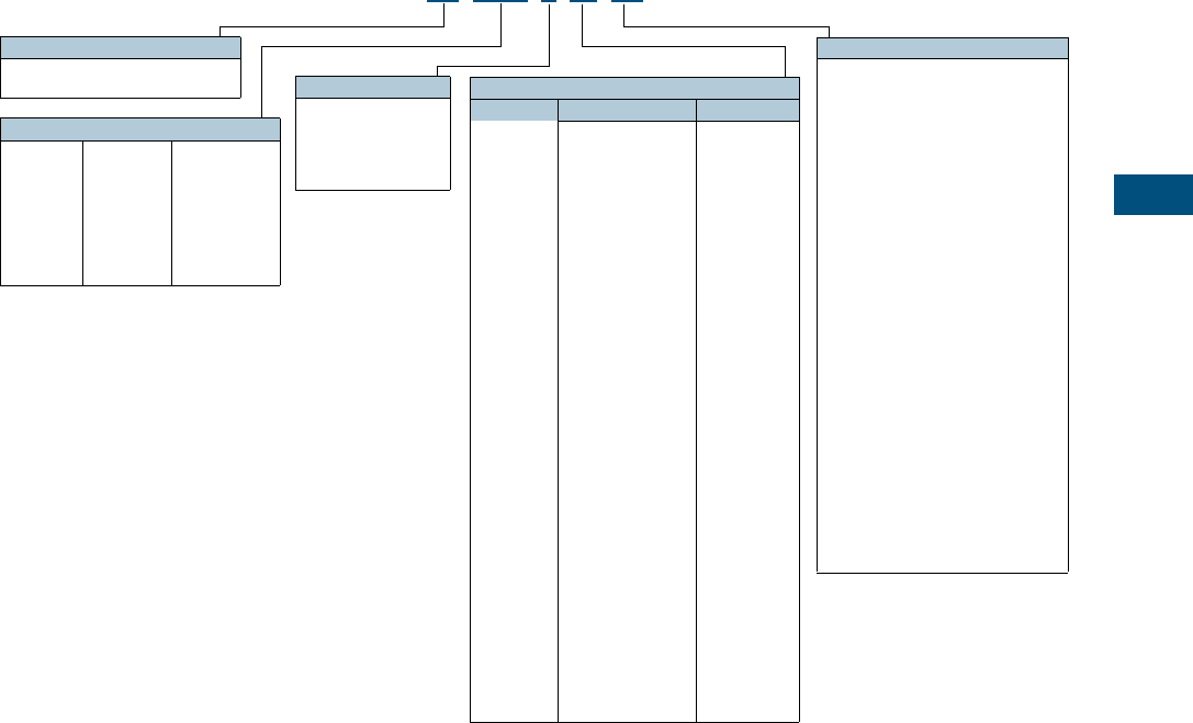
Volume 7—Logic Control, Operator Interface and Connectivity Solutions CA08100008E—February 2014 www.eaton.com V7-T7-3
7
7
7
7
7
7
7
7
7
7
7
7
7
7
7
7
7
7
7
7
7
7
7
7
7
7
7
7
7
7
7.1
Industrial Control Transformers
Trans for mer s
Catalog Number Selection
Industrial Control Transformers, CE Marked Control Transformers—Example: CE0250E2FCE 1
Notes
1For Eaton’s dry-type transformers catalog number selection, see Volume 2, CA08100003E.
Contact your local Eaton sales office for voltage combinations not shown. Use table for catalog number breakdown only.
Do not use to create catalog numbers because all combinations may not be valid.
Modifications
Type MTE/MTK
CE = CE Marked control transformer
FB = Factory-mounted two-pole primary
fuse block for rejection type fuses
FBN = Factory-mounted two-pole primary
fuse block for non-rejection–type
fuses
Q = Secondary fuse clips for
1/4 x 1-1/4 inch fuses
XX = No secondary fuse clips
RT = Ring type terminals for
connection to fuse block
ES = Electrostatic shield
FS = Factory-mounted finger-safe
terminal shields
Type AP
B = Bottom mounted
S = Side/wall mounted
ES = Electrostatic shield
CU = Copper windings
Type MTA/MTC
FB = Factory-mounted three-pole fuse
block (two-pole primary rejection
type with single-pole secondary
non-rejection type)
ES = Electrostatic shield
L = Lead terminations
CE 0250 E2F CE
Type
C = Industrial control transformer
CE = CE Marked control transformer
VA Rating
0025 =25
0050 =50
0075 =75
0100 =100
0150 =150
0200 =200
0250 =250
0300 =300
0350 =350
0500 =500
0750 =750
1000 = 1000
1500 = 1500
2000 = 2000
3000 = 3000
5000 = 5000
Type AP Only:
0003 =3000
0005 =5000
0007 =7500
0010 = 10000
0015 = 15000
Transformer Design
A =MTA
C =MTC
E =MTE
K =MTK
P =AP
Voltage
Primary Secondary
AC
AG
1B
2A
2B
2C
2F
2G
2U
2V
2W
3A
3B
3C
3D
4B
4C
4D
4E
4H
4W
5E
6U
7G (Type
AP only)
=
=
=
=
=
=
=
=
=
=
=
=
=
=
=
=
=
=
=
=
=
=
=
=
380 x 415
208/240/277/380/480
120 x 240
240 x 480,
230 x 460,
220 x 440
240 x 480
240 x 480
230/460
230/460
220/380/440/550,
230/400/460/575,
240/416/480/600
208/230/400/460/575
208/230/400/460/575
208/277
115
230/460/575
208/380/416
208/230/460/575
550/575/600
380/400/415
208/230/460/575
380/400/415
550/575/600
200/220/440,
208/230/460,
240/480
240/416/480/600,
230/400/460/575,
220/380/440/550,
208/500
240 x 480
24
24
24
120/115/110
24
120 x 240
115
115/230
23/110, 24/115,
25/120
24/115/230
115/230
120
24
115/95
115/95
24
110/115/120
110 x 220
115
22/23/24
22/23/24
23/110, 24/115,
25/120
99/120/130,
95/115/125,
91/110/120,
85/100/110
120/240
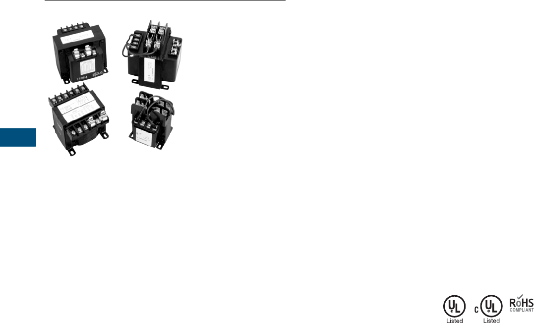
V7-T7-4 Volume 7—Logic Control, Operator Interface and Connectivity Solutions CA08100008E—February 2014 www.eaton.com
7
7
7
7
7
7
7
7
7
7
7
7
7
7
7
7
7
7
7
7
7
7
7
7
7
7
7
7
7
7
7.1
Industrial Control Transformers
Trans for mer s
Type MTE Transformer
Contents
Description Page
Type MTE
Product Selection . . . . . . . . . . . . . . . . . . . . . . . V7-T7-5
Accessories. . . . . . . . . . . . . . . . . . . . . . . . . . . . V7-T7-10
Technical Data and Specifications . . . . . . . . . . . V7-T7-10
Wiring Diagrams . . . . . . . . . . . . . . . . . . . . . . . . V7-T7-11
Type MTK. . . . . . . . . . . . . . . . . . . . . . . . . . . . . . . . V7-T7-13
CE Marked . . . . . . . . . . . . . . . . . . . . . . . . . . . . . . . V7-T7-18
Type AP . . . . . . . . . . . . . . . . . . . . . . . . . . . . . . . . . V7-T7-25
Type MTE
Product Description
Note: The following pages
provide listings for most standard
transformer ratings and styles.
For other ratings or styles not
shown, or for special enclosure
types (including stainless steel),
refer to Eaton.
●Epoxy-encapsulated coils
Application Description
Transformers provide
stepped-down voltages to
machine tool control devices,
enabling control circuits to
be isolated from all power
and lighting circuits. This
allows the use of grounded
or ungrounded circuits that
are independent of the power
or lighting grounds; thus,
greater safety is afforded
the operator. The control
transformer line is particularly
adaptable on applications
where compact construction
is demanded.
Note: The MTG “open core-coil
design” has been superseded by
the epoxy-encapsulated core-coil
design MTE with no change to
dimensions or functionality.
Features, Benefits
and Functions
●Epoxy encapsulated
●Laminations of high-quality
silicon steel to minimize
core losses and optimize
performance
●Copper magnet wire for
high-quality, efficient
operation
●Secondary fuse clips
where applicable
●Optional primary fusing
●Molded in terminals
●50/60 Hz operation
●130°C insulation
system standard
●Performance meets/
exceeds requirements
of ANSI/NEMA ST-1
●Regulation exceeds
ANSI/NEMA requirements
for all ratings
●25–1500 VA ratings
●Molded-in terminals for
maximum durability
Standards and Certifications
●UL listed
●cUL listed
●RoHS compliant
Industry Standards
All Eaton dry-type distribution
and control transformers are
built and tested in accordance
with applicable NEMA, ANSI
and IEEE Standards. All
600 volt class transformers
are UL listed unless
otherwise noted.
Catalog Number Selection
Please refer to
Page V7-T7-3.

Volume 7—Logic Control, Operator Interface and Connectivity Solutions CA08100008E—February 2014 www.eaton.com V7-T7-5
7
7
7
7
7
7
7
7
7
7
7
7
7
7
7
7
7
7
7
7
7
7
7
7
7
7
7
7
7
7
7.1
Industrial Control Transformers
Trans for mer s
Product Selection
Additional Product Selection information is available in Volume 2, CA08100003E.
Type MTE
Primary: 240 x 480, 230 x 460, 220 x 440 with Jumpers
Secondary: 120/115/110 with Fuse Clips for
13/32 x 1-1/2 Fuses
Primary: 240 x 480 with Jumpers
Secondary: 24 with Fuse Clips for 13/32 x 1-1/2 Fuses
(through 500 VA)
Primary: 120 X 240 with Jumpers
Secondary: 24 with Fuse Clips for 13/32 x 1-1/2 Fuses
Primary: 208/277
Secondary: 120 with Fuse Clips for 13/32 x 1-1/2 Fuses
Notes
1See Page V7-T7-11 for wiring diagrams.
2105°C insulation system.
VA
Wiring
Diagram 1
Weight
Lbs (kg)
Style
Number
25 1 1.7 (0.8) C0025E2A 2
50 1 2.6 (1.2) C0050E2A 2
75 1 3.5 (1.6) C0075E2A 2
100 1 4.2 (1.9) C0100E2A 2
150 1 6.7 (3.0) C0150E2A
200 1 8.5 (3.9) C0200E2A
250 1 10.0 (4.5) C0250E2A
300 1 11.3 (5.1) C0300E2A
350 1 13.6 (6.2) C0350E2A
500 1 19.2 (8.7) C0500E2A
750 1 28.1 (12.8) C0750E2A
1000 1 29.5 (13.4) C1000E2A
1500 1 40.0 (18.1) C1500E2A
VA
Wiring
Diagram 1
Weight
Lbs (kg)
Style
Number
50 2 2.7 (1.2) C0050E2B 2
75 2 3.5 (1.6) C0075E2B 2
100 2 4.2 (1.9) C0100E2B 2
150 2 6.7 (3.0) C0150E2B
200 2 8.5 (3.9) C0200E2B
250 2 10.1 (4.6) C0250E2B
300 2 11.4 (5.2) C0300E2B
350 2 13.4 (6.1) C0350E2B
500 2 17.5 (7.9) C0500E2B
750 2 28.1 (12.8) C0750E2B
VA
Wiring
Diagram 1
Weight
Lbs (kg)
Style
Number
50 3 2.6 (1.2) C0050E1B 2
75 3 3.6 (1.6) C0075E1B 2
100 3 4.4 (2.0) C0100E1B 2
150 3 6.7 (3.0) C0150E1B
200 3 8.3 (3.8) C0200E1B
250 3 10.1 (4.6) C0250E1B
300 3 11.2 (5.1) C0300E1B
350 3 13.2 (6.0) C0350E1B
500 3 17.5 (7.9) C0500E1B
VA
Wiring
Diagram 1
Weight
Lbs (kg)
Style
Number
50 4 2.9 (1.3) C0050E3A 2
75 4 3.8 (1.7) C0075E3A 2
100 4 4.5 (2.0) C0100E3A 2
150 4 6.9 (3.1) C0150E3A
200 4 8.7 (3.9) C0200E3A
250 4 10.2 (4.6) C0250E3A
300 4 11.4 (5.2) C0300E3A
350 4 13.7 (6.2) C0350E3A
500 4 17.2 (7.8) C0500E3A
750 4 25.7 (11.7) C0750E3A

V7-T7-6 Volume 7—Logic Control, Operator Interface and Connectivity Solutions CA08100008E—February 2014 www.eaton.com
7
7
7
7
7
7
7
7
7
7
7
7
7
7
7
7
7
7
7
7
7
7
7
7
7
7
7
7
7
7
7.1
Industrial Control Transformers
Trans for mer s
Primary: 240 x 480 with Jumpers
Secondary: 120 x 240 with Jumpers,
Secondary Fuse Clips Not Applicable
Primary: 550/575/600
Secondary: 110/115/120 with for 13/32 x 1-1/2 Fuses
Primary: 380/400/415
Secondary: 22/23/24 with Fuse Clips for 13/32 x 1-1/2 Fuses
Primary: 550/575/600
Secondary: 22/23/24 with Fuse Clips for 13/32 x 1-1/2 Fuses
Primary: 230/460/575
Secondary: 115/95 with Fuse Clips for 13/32 x 1-1/2 Fuses
Primary: 380/400/415
Secondary: 110 x 220 with Jumpers;
Fuse Clips Not Applicable
Notes
1See Page V7-T7-11 for wiring diagrams.
2105°C insulation system.
3Secondary fuse clips are not available on this catalog number.
VA
Wiring
Diagram 1
Weight
Lbs (kg)
Style
Number
50 11 2.6 (1.2) C0050E2CXX 2
75 11 3.5 (1.6) C0075E2CXX 2
100 11 4.2 (1.9) C0100E2CXX 2
150 11 6.7 (3.1) C0150E2CXX
200 11 8.5 (3.9) C0200E2CXX
250 11 10.0 (4.6) C0250E2CXX
300 11 11.8 (5.4) C0300E2CXX
350 11 13.6 (6.2) C0350E2CXX
500 11 17.5 (8.0) C0500E2CXX
750 11 26.4 (12.0) C0750E2CXX
VA
Wiring
Diagram 1
Weight
Lbs (kg)
Style
Number
50 10 2.7 (1.2) C0050E4C 2
75 10 3.6 (1.6) C0075E4C 2
100 10 4.2 (1.9) C0100E4C 2
150 10 6.8 (3.1) C0150E4C
200 10 8.4 (3.8) C0200E4C
250 10 10.0 (4.6) C0250E4C
300 10 11.3 (5.1) C0300E4C
350 10 13.6 (6.2) C0350E4C
500 10 16.8 (7.6) C0500E4C
750 10 25.7 (11.7) C0750E4C
VA
Wiring
Diagram 1
Weight
Lbs (kg)
Style
Number
50 13 2.5 (1.1) C0050E4H 2
75 13 3.5 (1.6) C0075E4H 2
100 13 4.0 (1.8) C0100E4H 2
150 13 6.5 (3.0) C0150E4H
200 13 8.2 (3.7) C0200E4H
250 13 10.0 (4.5) C0250E4H
300 13 11.0 (5.0) C0300E4H
350 13 13.6 (6.2) C0350E4H
500 13 17.7 (8.0) C0500E4H
VA
Wiring
Diagram 1
Weight
Lbs (kg)
Style
Number
50 12 2.5 (1.1) C0050E4W 2
75 12 3.5 (1.6) C0075E4W 2
100 12 4.0 (1.8) C0100E4W 2
150 12 6.5 (3.0) C0150E4W
200 12 8.2 (3.7) C0200E4W
250 12 10.0 (4.5) C0250E4W
300 12 11.0 (5.0) C0300E4W
350 12 13.6 (6.2) C0350E4W
500 12 17.7 (8.0) C0500E4W
750 12 28.0 (12.7) C0750E4WXX 3
VA
Wiring
Diagram 1
Weight
Lbs (kg)
Style
Number
50 5 3.5 (1.6) C0050E3C 2
75 5 4.5 (2.0) C0075E3C 2
100 5 6.0 (2.7) C0100E3C 2
150 5 7.7 (3.5) C0150E3C
200 5 9.0 (4.1) C0200E3C
250 5 9.7 (4.4) C0250E3C
300 5 11.7 (5.3) C0300E3C
350 5 16.5 (7.5) C0350E3C
500 5 21.5 (9.8) C0500E3C
750 5 28.0 (12.7) C0750E3C
VA
Wiring
Diagram 1
Weight
Lbs (kg)
Style
Number
50 6 3.0 (1.4) C0050E4D 2
75 6 4.0 (1.8) C0075E4D 2
100 6 5.2 (2.4) C0100E4D 2
150 6 7.0 (3.2) C0150E4D
200 6 8.7 (3.9) C0200E4D
250 6 10.2 (4.6) C0250E4D
300 6 11.0 (5.0) C0300E4D
350 6 13.0 (5.9) C0350E4D
500 6 20.0 (9.1) C0500E4D
750 6 28.0 (12.7) C0750E4D

Volume 7—Logic Control, Operator Interface and Connectivity Solutions CA08100008E—February 2014 www.eaton.com V7-T7-7
7
7
7
7
7
7
7
7
7
7
7
7
7
7
7
7
7
7
7
7
7
7
7
7
7
7
7
7
7
7
7.1
Industrial Control Transformers
Trans for mer s
Primary: 200/220/440, 208/230/460, 240/480
Secondary: 23/110, 24/115, 25/120 with Fuse Clips for
13/32 x 1-1/2 Fuses
Universal Design (MTE Epoxy Encapsulated)
Primary: 240/416/480/600, 230/400460/575,
220/380/440/550, 208/500
Secondary: 99/120/130, 95/115/125, 91/110/120,
85/100/110 with Fuse Clips for 13/32 x 1-1/2 Fuses
Transformers with Primary Fuse Blocks
Primary: 240 x 480, 230 x 460, 220 x 440 with Jumpers and
Two-Pole Primary Fuse Block for Rejection-Type Fuses
Secondary: 120/115/110 with Fuse Clips for
13/32 x 1-1/2 Fuses
Primary: 240 x 480 with Jumpers and
Two-Pole Primary Fuse Block for Rejection-Type Fuses
Secondary: 24 with Fuse Clips for 13/32 x 1-1/2 Fuses
Notes
1See Page V7-T7-11 for wiring diagrams.
2105°C insulation system.
3Type MTG open core-coil universal design has been superseded by Type MTE epoxy
encapsulated universal design with no changes to form, fit or function.
4Type MTE epoxy encapsulated universal design.
VA
Wiring
Diagram 1
Weight
Lbs (kg)
Style
Number
50 7 3.4 (1.5) C0050E5E 2
75 7 4.8 (2.2) C0075E5E 2
100 7 5.9 (2.7) C0100E5E 2
150 7 7.9 (3.6) C0150E5E
200 7 10.6 (4.8) C0200E5E
250 7 13.9 (6.3) C0250E5E
300 7 15.5 (7.0) C0300E5E
350 7 16.8 (7.6) C0350E5E
500 7 23.4 (10.6) C0500E5E
VA
Wiring
Diagram 1
Weight
Lbs (kg)
Style
Number
50 8 4.0 (1.8) C0050E6U 23
100 8 6.6 (3.0) C0100E6U 23
150 8 8.8 (4.0) C0150E6U 24
250 8 14.7 (6.7) C0250E6U 24
350 8 18.6 (8.4) C0350E6U 24
500 8 25.6 (11.6) C0500E6U 24
750 8 30.5 (13.8) C0750E6U 24
VA
Wiring
Diagram 1
Weight
Lbs (kg)
Style
Number
50 1 2.8 (1.3) C0050E2AFB 2
75 1 3.7 (1.7) C0075E2AFB 2
100 1 4.4 (2.0) C0100E2AFB 2
150 1 6.9 (3.1) C0150E2AFB
200 1 8.7 (3.9) C0200E2AFB
250 1 10.2 (4.6) C0250E2AFB
300 1 11.5 (5.2) C0300E2AFB
350 1 13.8 (6.3) C0350E2AFB
500 1 19.4 (8.8) C0500E2AFB
750 1 28.3 (12.8) C0750E2AFB
1000 1 29.7 (13.4) C1000E2AFB
1500 1 40.2 (18.1) C1500E2AFB
VA
Wiring
Diagram 1
Weight
Lbs (kg)
Style
Number
50 2 2.8 (1.3) C0050E2BFB 2
75 2 3.8 (1.7) C0075E2BFB 2
100 2 4.4 (2.1) C0100E2BFB 2
150 2 6.9 (3.1) C0150E2BFB
200 2 8.7 (3.9) C0200E2BFB
250 2 10.3 (4.7) C0250E2BFB
300 2 11.6 (5.3) C0300E2BFB
350 2 13.6 (6.2) C0350E2BFB
500 2 17.7 (8.0) C0500E2BFB

V7-T7-8 Volume 7—Logic Control, Operator Interface and Connectivity Solutions CA08100008E—February 2014 www.eaton.com
7
7
7
7
7
7
7
7
7
7
7
7
7
7
7
7
7
7
7
7
7
7
7
7
7
7
7
7
7
7
7.1
Industrial Control Transformers
Trans for mer s
Primary: 120 x 240 with Jumpers and
Two-Pole Primary Fuse Block for Rejection-Type Fuses
Secondary: 24 with Fuse Clips for 13/32 x 1-1/2 Fuses
Primary: 208/277 with Two-Pole
Primary Fuse Block for Rejection-Type Fuses
Secondary: 120 with Fuse Clips for 13/32 x 1-1/2 Fuses
Primary: 550/575/600 with Two-Pole
Primary Fuse Block for Rejection-Type Fuses
Secondary: 110/115/120 with Fuse Clips for 13/32 x 1-1/2
Fuses
Primary: 380/400/415 with Two-Pole
Primary Fuse Block for Rejection-Type Fuses
Secondary: 22/23/24 with Fuse Clips for 13/32 x 1-1/2 Fuses
Primary: 550/575/600 with Two-Pole
Primary Fuse Block for Rejection-Type Fuses
Secondary: 22/23/24 with Fuse Clips for 13/32 x 11/2 Fuses
Primary: 230/460/575 with Two-Pole
Primary Fuse Block for Rejection-Type Fuses
Secondary: 115/95 with Fuse Clips for 13/32 x 1-1/2 Fuses
Notes
1See Page V7-T7-11 for wiring diagrams.
2105°C insulation system.
VA
Wiring
Diagram 1
Weight
Lbs (kg)
Style
Number
50 3 2.8 (1.3) C0050E1BFB 2
75 3 3.8 (1.7) C0075E1BFB 2
100 3 4.6 (2.1) C0100E1BFB 2
150 3 6.9 (3.1) C0150E1BFB
200 3 8.5 (3.9) C0200E1BFB
250 3 10.3 (4.7) C0250E1BFB
300 3 11.4 (5.2) C0300E1BFB
350 3 13.4 (6.1) C0350E1BFB
500 3 17.7 (8.0) C0500E1BFB
VA
Wiring
Diagram 1
Weight
Lbs (kg)
Style
Number
50 4 3.1 (1.4) C0050E3AFB 2
75 4 4.0 (1.8) C0075E3AFB 2
100 4 4.7 (2.1) C0100E3AFB 2
150 4 7.1 (3.2) C0150E3AFB
200 4 8.9 (4.0) C0200E3AFB
250 4 10.4 (4.7) C0250E3AFB
300 4 11.6 (5.3) C0300E3AFB
350 4 13.9 (6.3) C0350E3AFB
500 4 17.4 (7.9) C0500E3AFB
VA
Wiring
Diagram 1
Weight
Lbs (kg)
Style
Number
50 10 2.9 (1.3) C0050E4CFB 2
75 10 3.8 (1.7) C0075E4CFB 2
100 10 4.4 (2.0) C0100E4CFB 2
150 10 7.0 (3.2) C0150E4CFB
200 10 8.6 (3.9) C0200E4CFB
250 10 10.2 (4.6) C0250E4CFB
300 10 11.5 (5.2) C0300E4CFB
350 10 13.8 (6.3) C0350E4CFB
500 10 17.0 (7.7) C0500E4CFB
750 10 25.9 (11.8) C0750E4CFB
VA
Wiring
Diagram 1
Weight
Lbs (kg)
Style
Number
50 13 2.6 (1.2) C0050E4HFB 2
75 13 3.7 (1.7) C0075E4HFB 2
100 13 4.2 (1.9) C0100E4HFB 2
150 13 6.7 (3.0) C0150E4HFB
200 13 8.4 (3.8) C0200E4HFB
250 13 10.2 (4.6) C0250E4HFB
VA
Wiring
Diagram 1
Weight
Lbs (kg)
Style
Number
50 12 2.7 (1.2) C0050E4WFB 2
75 12 3.7 (1.7) C0075E4WFB 2
100 12 4.2 (1.9) C0100E4WFB 2
150 12 6.7 (3.0) C0150E4WFB
200 12 8.4 (3.8) C0200E4WFB
250 12 10.2 (4.6) C0250E4WFB
VA
Wiring
Diagram 1
Weight
Lbs (kg)
Style
Number
50 5 3.7 (1.7) C0050E3CFB 2
75 5 4.7 (2.1) C0075E3CFB 2
100 5 6.2 (2.8) C0100E3CFB 2
150 5 7.9 (3.6) C0150E3CFB
200 5 9.2 (4.2) C0200E3CFB
250 5 9.9 (4.5) C0250E3CFB
300 5 11.9 (5.4) C0300E3CFB
350 5 16.7 (7.6) C0350E3CFB
500 5 21.7 (9.9) C0500E3CFB

Volume 7—Logic Control, Operator Interface and Connectivity Solutions CA08100008E—February 2014 www.eaton.com V7-T7-9
7
7
7
7
7
7
7
7
7
7
7
7
7
7
7
7
7
7
7
7
7
7
7
7
7
7
7
7
7
7
7.1
Industrial Control Transformers
Trans for mer s
Primary: 380/400/415 with Two-Pole
Primary Fuse Block for Rejection-Type Fuses
Secondary: 110 x 220 with Jumpers;
Fuse Clips Not Available
Primary: 200/220/440, 208/230/460, 240/480 with
Two-Pole Primary Fuse Block for Rejection-Type Fuses
Secondary: 23/110, 24/115, 25/120 with Fuse Clips
for 13/32 x 1-1/2 Fuses
Universal Design (MTE Epoxy Encapsulated)
Primary: 240/416/480/600, 230/400/460/575,
220/380/440/550, 208/500 with Two-Pole
Primary Fuse Block for Rejection-Type Fuses
Secondary: 99/120/130, 95/115/125, 91/110/120,
85/100/110 with Fuse Clips for 13/32 x 1-1/2 Fuses
Notes
1See Page V7-T7-11 for wiring diagrams.
2105°C insulation system.
3Type MTG open core-coil universal design has been superseded by Type MTE epoxy
encapsulated universal design with no changes to form, fit or function.
4Type MTE epoxy encapsulated universal design.
VA
Wiring
Diagram 1
Weight
Lbs (kg)
Style
Number
50 6 3.2 (1.5) C0050E4DFB 2
75 6 4.2 (1.9) C0075E4DFB 2
100 6 5.4 (2.5) C0100E4DFB 2
150 6 7.2 (3.3) C0150E4DFB
200 6 8.9 (4.0) C0200E4DFB
250 6 10.4 (4.7) C0250E4DFB
300 6 11.2 (5.1) C0300E4DFB
350 6 13.2 (6.0) C0350E4DFB
500 6 20.2 (9.2) C0500E4DFB
VA
Wiring
Diagram 1
Weight
Lbs (kg)
Style
Number
50 7 3.6 (1.6) C0050E5EFB 2
75 7 5.0 (2.3) C0075E5EFB 2
100 7 6.1 (2.8) C0100E5EFB 2
150 7 8.1 (3.7) C0150E5EFB
200 7 10.8 (4.9) C0200E5EFB
250 7 14.1 (6.4) C0250E5EFB
300 7 15.7 (7.1) C0300E5EFB
350 7 17.0 (7.7) C0350E5EFB
500 7 23.6 (10.7) C0500E5EFB
VA
Wiring
Diagram 1
Weight
Lbs (kg)
Style
Number
50 8 4.2 (1.9) C0050E6UFB 23
100 8 6.8 (3.1) C0100E6UFB 23
150 8 9.0 (4.1) C0150E6UFB 24
250 8 14.9 (6.8) C0250E6UFB 24
350 8 18.8 (8.5) C0350E6UFB 24
500 8 25.8 (11.7) C0500E6UFB 24
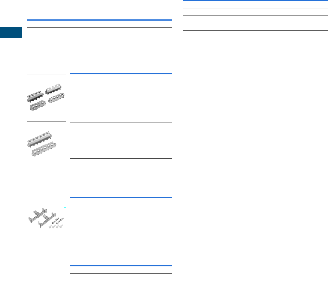
V7-T7-10 Volume 7—Logic Control, Operator Interface and Connectivity Solutions CA08100008E—February 2014 www.eaton.com
7
7
7
7
7
7
7
7
7
7
7
7
7
7
7
7
7
7
7
7
7
7
7
7
7
7
7
7
7
7
7.1
Industrial Control Transformers
Trans for mer s
Accessories
Primary Fuse Kit
The primary fuse kit includes a two-pole class CC fuse block,
instructions, and all associated mounting and wiring hardware.
Fuses are not included. When installed, the primary fuse kit
will add a maximum of 11/16 inch to the transformer depth
and 1-15/16 inches to the transformer height.
Primary Fuse Kit
Finger-Safe Terminal Covers (Optional)
●Fits CE Marked designs 50–750 VA
●Fits MTE designs 0.25–750 VA
Finger-Safe Terminal Covers
Finger-Safe Primary Fuse Block Covers
●Fits two-pole primary fuse blocks on MTE designs
Finger-Safe Primary Fuse Block Covers
Secondary Fuse Clip Cover
Secondary Fuse Clip Cover
Technical Data and Specifications
Insulation System and Temperature Rise
Industry standards classify insulation systems and rise as
shown below:
Insulation System Classification
The design life of transformers having different insulation
systems is the same—the lower-temperature systems are
designed for the same life as the higher-temperature systems.
Series-Multiple Windings
Series-multiple windings consist of two similar coils in each
winding that can be connected in series or parallel (multiple).
Transformers with series-multiple windings are designated with
an “x” or “/” between the voltage ratings, such as voltages of
“120/240” or “240 x 480.” If the series-multiple winding is
designated by an “x,” the winding can be connected only
for a series or parallel. With the “/” designation, a mid-point
also becomes available in addition to the series or parallel
connection. As an example, a 120 x 240 winding can be
connected for either 120 (parallel) or 240 (series), but a
120/240 winding can be connected for 120 (parallel),
240 (series) or 240 with a 120 mid-point.
For additional information, please refer to Volume 2,
CA08100003E.
Description Catalog Number
Primary fuse kit PFK1
Description Catalog Number
Four terminal transformers FSK4
Four terminal Series 2 transformers only FSK4S2
Six terminal transformers FSK6
Description Catalog Number
Primary fuse block covers FSKFB
Description Catalog Number
Fits 500 VA and smaller models SFCS
Fits models greater than 500 VA SFCL
FSK4
FSK6
FSKFB
Ambient + Winding Rise + Hot Spot = Temp. Class
40°C 55°C 10°C 105°C
40°C 80°C 30°C 150°C
25°C 135°C 20°C 180°C
40°C 115°C 30°C 185°C
40°C 150°C 30°C 220°C
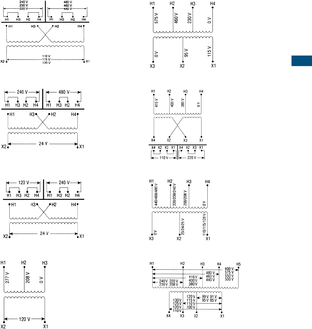
Volume 7—Logic Control, Operator Interface and Connectivity Solutions CA08100008E—February 2014 www.eaton.com V7-T7-11
7
7
7
7
7
7
7
7
7
7
7
7
7
7
7
7
7
7
7
7
7
7
7
7
7
7
7
7
7
7
7.1
Industrial Control Transformers
Trans for mer s
Wiring Diagrams
Diagram 1
Diagram 2
Diagram 3
Diagram 4
Diagram 5
Diagram 6
Diagram 7
Diagram 8
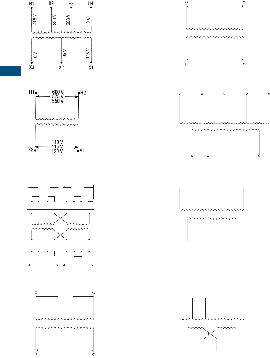
V7-T7-12 Volume 7—Logic Control, Operator Interface and Connectivity Solutions CA08100008E—February 2014 www.eaton.com
7
7
7
7
7
7
7
7
7
7
7
7
7
7
7
7
7
7
7
7
7
7
7
7
7
7
7
7
7
7
7.1
Industrial Control Transformers
Trans for mer s
Diagram 9
Diagram 10
Diagram 11
Diagram 12
Diagram 13
Diagram 14
Diagram 15
Diagram 16
H1 H3 H2 H4 H1 H3 H2 H4
H1 H3 H2 H4
X4 X2 X3 X1
X4 X2 X3 X1 X4 X2 X3 X1
240 V 480 V
240 V
120 V
H1 H2
X2 X1
600 V
575 V
550 V
24 V
23 V
22 V
H1 H2
X2 X1
420 V
400 V
380 V
24 V
23 V
22 V
H1 H2 H3 H4 H5
X3 X2 X1
550,575,600 V
440,460,480 V
380,400,416 V
220,230,240 V
23/24/25
110,115,120 V
0 V
0 V
X4 X3 X2 X1
H1 H2 H3 H4 H5 H6
575 V
460 V
400 V
230 V
208 V
0 V
0 V
24 V
115 V
230 V
X4 X3 X2 X1
H1 H2 H3 H4 H5 H6
575 V
460 V
400 V
230 V
208 V
0 V
0 V
0 V
115 V
115 V
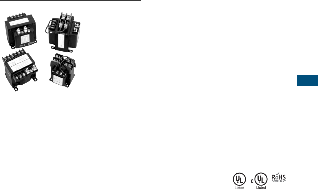
Volume 7—Logic Control, Operator Interface and Connectivity Solutions CA08100008E—February 2014 www.eaton.com V7-T7-13
7
7
7
7
7
7
7
7
7
7
7
7
7
7
7
7
7
7
7
7
7
7
7
7
7
7
7
7
7
7
7.1
Industrial Control Transformers
Trans for mer s
Type MTK Transformer
Contents
Description Page
Type MTE . . . . . . . . . . . . . . . . . . . . . . . . . . . . . . . . V7-T7-4
Type MTK
Product Selection . . . . . . . . . . . . . . . . . . . . . . . V7-T7-14
Technical Data and Specifications . . . . . . . . . . . V7-T7-15
Wiring Diagrams . . . . . . . . . . . . . . . . . . . . . . . . V7-T7-15
CE Marked . . . . . . . . . . . . . . . . . . . . . . . . . . . . . . . V7-T7-18
Type AP . . . . . . . . . . . . . . . . . . . . . . . . . . . . . . . . . V7-T7-25
Type MTK
Product Description
Note: The following pages
provide listings for most standard
transformer ratings and styles.
For other ratings or styles not
shown, or for special enclosure
types (including stainless steel),
refer to Eaton.
●Epoxy resin-impregnated
coil
●Economical solution for
high inrush applications
Application Description
Transformers provide
stepped-down voltages to
machine tool control devices,
enabling control circuits to be
isolated from all power and
lighting circuits. This allows
the use of grounded or
ungrounded circuits that
are independent of the
power or lighting grounds;
thus, greater safety is
afforded the operator. The
control transformer line is
particularly adaptable on
applications where compact
construction is demanded.
Features, Benefits
and Functions
●Epoxy resin impregnated
coil design
●Copper magnet wire for
high-quality, efficient
operation
●50/60 Hz operation
●180ºC insulation system
●Performance meets/
exceeds requirements
of ANSI/NEMA ST-1
●Regulation exceeds
ANSI/NEMA requirements
for all ratings
●500–5000 VA ratings
Standards and Certifications
●UL listed
●cUL listed
●RoHS compliant
Industry Standards
All Eaton dry-type distribution
and control transformers are
built and tested in accordance
with applicable NEMA,
ANSI and IEEE Standards. All
600 volt class transformers
are UL listed unless
otherwise noted.
Catalog Number Selection
Please refer to
Page V7-T7-3.

V7-T7-14 Volume 7—Logic Control, Operator Interface and Connectivity Solutions CA08100008E—February 2014 www.eaton.com
7
7
7
7
7
7
7
7
7
7
7
7
7
7
7
7
7
7
7
7
7
7
7
7
7
7
7
7
7
7
7.1
Industrial Control Transformers
Trans for mer s
Product Selection
Additional Product Selection information is available in Volume 2, CA08100003E.
Type MTK
Primary: 240 x 480, 230 x 460, 220 x 440
Secondary: 120/115/110
Primary: 208/277 Secondary: 120
Primary: 230/460/575 Secondary: 115/95
Primary: 208/380/416 Secondary: 115/95
Primary: 550/575/600 Secondary: 110/115/120
Primary: 380/400/415 Secondary: 110 x 220
Primary: 240 x 480 with Jumpers
Secondary: 120 x 240 with Jumpers,
Secondary Fuse Clips Not Applicable
Primary: 120 x 240 with Jumpers Secondary: 24
Primary: 240/416/480/600, 230/400/460/575,
220/380/440/550, 208/500
Secondary: 99/120/130, 95/115/125, 91/110/120, 85/100/110
Note
1See Page V7-T7-15 for wiring diagrams.
VA
Wiring
Diagram 1
Weight
Lbs (kg)
Style
Number
500 1 13.0 (5.9) C0500K2A
750 1 19.5 (8.9) C0750K2A
1000 1 29.8 (13.6) C1000K2A
1500 1 30.0 (13.6) C1500K2A
2000 1 38.0 (17.3) C2000K2A
3000 1 53.0 (24.1) C3000K2A
5000 1 89.0 (40.5) C5000K2A
VA
Wiring
Diagram 1
Weight
Lbs (kg)
Style
Number
1000 4 29.0 (13.1) C1000K3A
1500 4 33.0 (15.0) C1500K3A
2000 4 43.0 (19.5) C2000K3A
3000 4 64.0 (29.0) C3000K3A
5000 4 102.0 (46.3) C5000K3A
VA
Wiring
Diagram 1
Weight
Lbs (kg)
Style
Number
1000 5 29.2 (13.3) C1000K3C
1500 5 33.5 (15.2) C1500K3C
2000 5 42.5 (19.3) C2000K3C
3000 5 63.7 (29.0) C3000K3C
5000 5 102.0 (46.4) C5000K3C
VA
Wiring
Diagram 1
Weight
Lbs (kg)
Style
Number
1000 9 29.0 (13.1) C1000K3D
1500 9 43.0 (19.5) C1500K3D
2000 9 55.0 (25.0) C2000K3D
3000 9 74.0 (33.5) C3000K3D
5000 9 108.0 (49.0) C5000K3D
VA
Wiring
Diagram 1
Weight
Lbs (kg)
Style
Number
1000 10 29.0 (13.1) C1000K4C
1500 10 33.0 (15.0) C1500K4C
2000 10 43.0 (19.5) C2000K4C
3000 10 64.0 (29.0) C3000K4C
5000 10 102.0 (46.3) C5000K4C
VA
Wiring
Diagram 1
Weight
Lbs (kg)
Style
Number
1000 6 28.0 (12.7) C1000K4D
1500 6 33.0 (15.0) C1500K4D
2000 6 43.0 (19.5) C2000K4D
3000 6 64.0 (29.0) C3000K4D
5000 6 102.0 (46.3) C5000K4D
VA
Wiring
Diagram 1
Weight
Lbs (kg)
Style
Number
1000 11 26.4 (12.0) C1000K2CXX
1500 11 31.0 (14.1) C1500K2CXX
2000 11 40.0 (18.2) C2000K2CXX
3000 11 56.0 (25.5) C3000K2CXX
5000 11 85.5 (28.9) C5000K2CXX
VA
Wiring
Diagram 1
Weight
Lbs (kg)
Style
Number
750 3 19.0 (8.6) C0750K1B
1000 3 26.4 (12.0) C1000K1B
VA
Wiring
Diagram 1
Weight
Lbs (kg)
Style
Number
1000 8 26.5 (12.0) C1000K6U
1500 8 38.5 (17.5) C1500K6U
2000 8 52.0 (23.6) C2000K6U
3000 8 68.0 (30.9) C3000K6U
5000 8 105.0 (47.7) C5000K6U
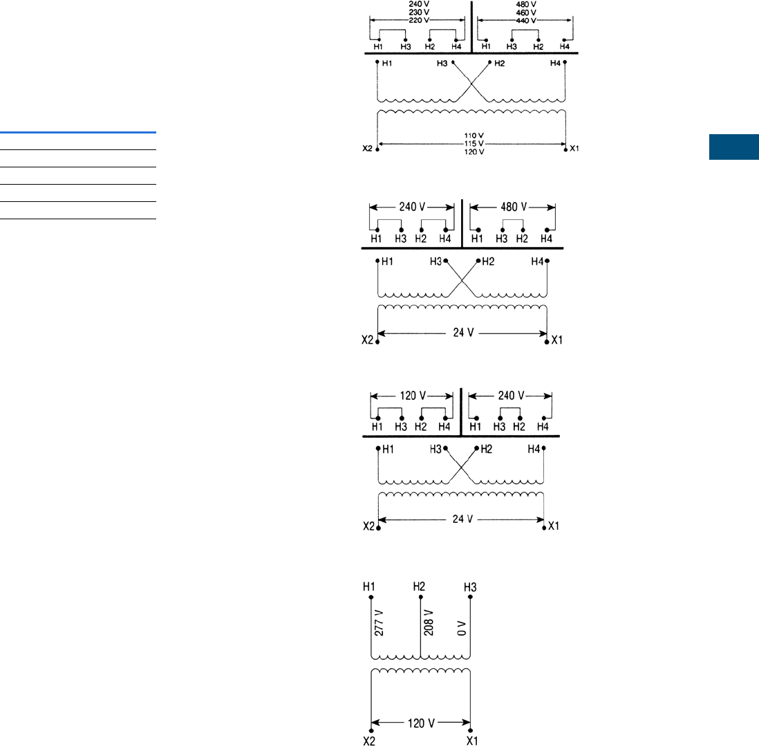
Volume 7—Logic Control, Operator Interface and Connectivity Solutions CA08100008E—February 2014 www.eaton.com V7-T7-15
7
7
7
7
7
7
7
7
7
7
7
7
7
7
7
7
7
7
7
7
7
7
7
7
7
7
7
7
7
7
7.1
Industrial Control Transformers
Trans for mer s
Technical Data and Specifications
Insulation System and
Temperature Rise
Industry standards classify
insulation systems and rise as
shown below:
Insulation System
Classification
The design life of transformers
having different insulation
systems is the same—the
lower-temperature systems
are designed for the same life
as the higher-temperature
systems.
Series-Multiple Windings
Series-multiple windings
consist of two similar coils in
each winding that can be
connected in series or parallel
(multiple). Transformers with
series-multiple windings are
designated with an “x” or
“/” between the voltage
ratings, such as voltages of
“120/240” or “240 x 480.”
If the series-multiple winding
is designated by an “x,” the
winding can be connected
only for a series or parallel.
With the “/” designation,
a mid-point also becomes
available in addition to the
series or parallel connection.
As an example, a 120 x 240
winding can be connected
for either 120 (parallel) or
240 (series), but a 120/240
winding can be connected for
120 (parallel), 240 (series) or
240 with a 120 mid-point.
For additional information,
please refer to Volume 2,
CA08100003E.
Ambient
+
Winding
Rise
+
Hot
Spot
=
Temp.
Class
40°C 55°C 10°C 105°C
40°C 80°C 30°C 150°C
25°C 135°C 20°C 180°C
40°C 115°C 30°C 185°C
40°C 150°C 30°C 220°C
Wiring Diagrams
Diagram 1
Diagram 2
Diagram 3
Diagram 4
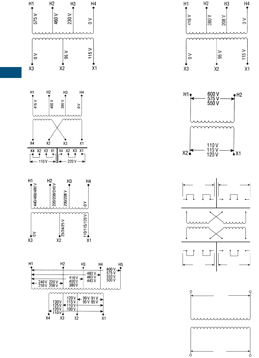
V7-T7-16 Volume 7—Logic Control, Operator Interface and Connectivity Solutions CA08100008E—February 2014 www.eaton.com
7
7
7
7
7
7
7
7
7
7
7
7
7
7
7
7
7
7
7
7
7
7
7
7
7
7
7
7
7
7
7.1
Industrial Control Transformers
Trans for mer s
Diagram 5
Diagram 6
Diagram 7
Diagram 8
Diagram 9
Diagram 10
Diagram 11
Diagram 12
H1 H3 H2 H4 H1 H3 H2 H4
H1 H3 H2 H4
X4 X2 X3 X1
X4 X2 X3 X1 X4 X2 X3 X1
240 V 480 V
240 V
120 V
H1 H2
X2 X1
600 V
575 V
550 V
24 V
23 V
22 V
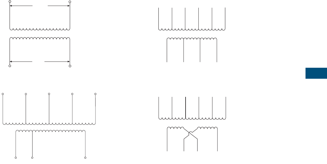
Volume 7—Logic Control, Operator Interface and Connectivity Solutions CA08100008E—February 2014 www.eaton.com V7-T7-17
7
7
7
7
7
7
7
7
7
7
7
7
7
7
7
7
7
7
7
7
7
7
7
7
7
7
7
7
7
7
7.1
Industrial Control Transformers
Trans for mer s
Diagram 13
Diagram 14
Diagram 15
Diagram 16
H1 H2
X2 X1
420 V
400 V
380 V
24 V
23 V
22 V
H1 H2 H3 H4 H5
X3 X2 X1
550,575,600 V
440,460,480 V
380,400,416 V
220,230,240 V
23/24/25
110,115,120 V
0 V
0 V
X4 X3 X2 X1
H1 H2 H3 H4 H5 H6
575 V
460 V
400 V
230 V
208 V
0 V
0 V
24 V
115 V
230 V
X4 X3 X2 X1
H1 H2 H3 H4 H5 H6
575 V
460 V
400 V
230 V
208 V
0 V
0 V
0 V
115 V
115 V
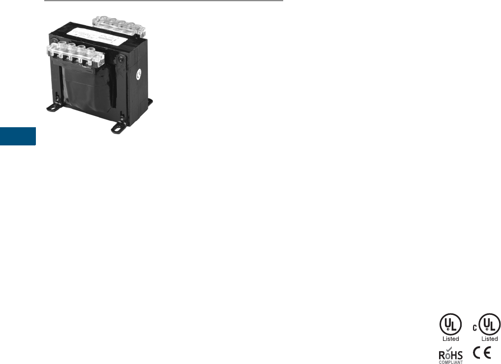
V7-T7-18 Volume 7—Logic Control, Operator Interface and Connectivity Solutions CA08100008E—February 2014 www.eaton.com
7
7
7
7
7
7
7
7
7
7
7
7
7
7
7
7
7
7
7
7
7
7
7
7
7
7
7
7
7
7
7.1
Industrial Control Transformers
Trans for mer s
Type MTE CE-Marked CPT
Contents
Description Page
Type MTE. . . . . . . . . . . . . . . . . . . . . . . . . . . . . . . . V7-T7-4
Type MTK. . . . . . . . . . . . . . . . . . . . . . . . . . . . . . . . V7-T7-13
CE Marked
Product Selection . . . . . . . . . . . . . . . . . . . . . . . V7-T7-19
Accessories. . . . . . . . . . . . . . . . . . . . . . . . . . . . V7-T7-21
Technical Data and Specifications . . . . . . . . . . . V7-T7-21
Wiring Diagrams . . . . . . . . . . . . . . . . . . . . . . . . V7-T7-22
Type AP . . . . . . . . . . . . . . . . . . . . . . . . . . . . . . . . . V7-T7-25
CE Marked
Product Description
Note: The following pages
provide listings for most standard
transformer ratings and styles.
For other ratings or styles not
shown, or for special enclosure
types (including stainless steel),
refer to Eaton.
Application Description
Transformers provide stepped-
down voltages to machine
tool control devices, enabling
control circuits to be isolated
from all power and lighting
circuits. This allows the use
of grounded or ungrounded
circuits that are independent
of the power or lighting
grounds; thus, greater safety
is afforded the operator. The
control transformer line is
particularly adaptable on
applications where compact
construction is demanded.
Features, Benefits
and Functions
Type MTE
●Epoxy encapsulated
coil design
●Copper magnet wire for
high-quality, efficient
operation
●Laminations of high-quality
silicon steel to minimize
core losses and optimize
performance
●Molded-in terminals
●50/60 Hz operation
●130°C insulation
system standard
●Performance meets/
exceeds requirements of
ANSI/NEMA ST-1
●Regulation exceeds
ANSI/NEMA requirements
for all ratings
●Non-short circuit-proof
transformer, isolation type
Type MTK
●Epoxy resin-impregnated
coil design
●Copper magnet wire for
high-quality, efficient
operation
●50/60 Hz operation
●180°C insulation system
●Performance meets/
exceeds requirements
of ANSI/NEMA ST-1
●Regulation exceeds
ANSI/NEMA requirements
for all ratings
●500–5000 VA ratings
Standards and Certifications
●UL listed
●cUL listed
●CE Marked units comply
with IEC EN-61558-2
●RoHS compliant
Industry Standards
All Eaton dry-type distribution
and control transformers are
built and tested in accordance
with applicable NEMA, ANSI
and IEEE Standards. All
600 volt class transformers
are UL listed unless
otherwise noted.
Catalog Number Selection
Please refer to
Page V7-T7-3.

Volume 7—Logic Control, Operator Interface and Connectivity Solutions CA08100008E—February 2014 www.eaton.com V7-T7-19
7
7
7
7
7
7
7
7
7
7
7
7
7
7
7
7
7
7
7
7
7
7
7
7
7
7
7
7
7
7
7.1
Industrial Control Transformers
Trans for mer s
Product Selection
Additional Product Selection information is available in Volume 2, CA08100003E.
Type MTE CE Marked IP00
Primary: 240 x 480, 230 x 460, 220 x 440 with Jumpers
Secondary: 120/115/110
Primary: 240 x 480 with Jumpers
Secondary: 24
Primary: 120 x 240 with Jumpers
Secondary: 24
Primary: 550/575/600
Secondary: 110/115/1204
Primary: 380/400/415
Secondary: 110 x 220 with Jumpers
Primary: 200/220/440, 208/230/460, 240/480
Secondary: 23/110, 24/115, 25/120
Notes
1See Page V7-T7-22 for wiring diagrams.
2105°C insulation system.
Transformers are designed to operate in a maximum ambient of 40°C. Contact your local Eaton
sales office for availability on additional CE Marked control transformers. For other ratings or
styles not shown, refer to Eaton.
VA
Wiring
Diagram 1
Weight
Lbs (kg)
Style
Number
50 1 3.5 (1.6) CE0050E2ACE 2
75 1 4.8 (2.2) CE0075E2ACE 2
100 1 5.9 (2.7) CE0100E2ACE 2
150 1 8.5 (3.9) CE0150E2ACE
200 1 10.6 (4.8) CE0200E2ACE
250 1 11.3 (5.1) CE0250E2ACE
300 1 13.2 (6.0) CE0300E2ACE
350 1 14.9 (6.8) CE0350E2ACE
500 1 21.0 (9.5) CE0500E2ACE
750 1 29.8 (13.5) CE0750E2ACE
VA
Wiring
Diagram 1
Weight
Lbs (kg)
Style
Number
50 2 3.4 (1.5) CE0050E2BCE 2
75 2 4.2 (1.9) CE0075E2BCE 2
100 2 5.9 (2.7) CE0100E2BCE 2
150 2 8.5 (3.9) CE0150E2BCE
200 2 10.6 (4.5) CE0200E2BCE
250 2 11.3 (5.1) CE0250E2BCE
300 2 13.2 (6.0) CE0300E2BCE
350 2 14.9 (6.8) CE0350E2BCE
500 2 19.2 (8.7) CE0500E2BCE
750 2 28.1 (12.8) CE0750E2BCE
VA
Wiring
Diagram 1
Weight
Lbs (kg)
Style
Number
50 3 3.4 (1.5) CE0050E1BCE 2
75 3 4.2 (1.9) CE0075E1BCE 2
100 3 5.9 (2.7) CE0100E1BCE 2
150 3 8.5 (3.9) CE0150E1BCE
200 3 10.6 (4.5) CE0200E1BCE
250 3 11.3 (5.1) CE0250E1BCE
300 3 13.2 (6.0) CE0300E1BCE
350 3 14.9 (6.8) CE0350E1BCE
500 3 19.2 (8.7) CE0500E1BCE
750 3 29.8 (13.5) CE0750E1BCE
VA
Wiring
Diagram 1
Weight
Lbs (kg)
Style
Number
50 10 3.5 (1.6) CE0050E4CCE 2
75 10 4.8 (2.2) CE0075E4CCE 2
100 10 5.9 (2.7) CE0100E4CCE 2
150 10 8.5 (3.9) CE0150E4CCE
200 10 10.6 (4.8) CE0200E4CCE
250 10 11.3 (5.1) CE0250E4CCE
300 10 13.2 (6.0) CE0300E4CCE
350 10 14.9 (6.8) CE0350E4CCE
500 10 21.0 (9.5) CE0500E4CCE
750 10 29.8 (13.5) CE0750E4CCE
VA
Wiring
Diagram 1
Weight
Lbs (kg)
Style
Number
50 6 3.5 (1.6) CE0050E4DCE 2
75 6 4.8 (2.2) CE0075E4DCE 2
100 6 5.9 (2.7) CE0100E4DCE 2
150 6 8.5 (3.9) CE0150E4DCE
200 6 10.6 (4.8) CE0200E4DCE
250 6 11.3 (5.1) CE0250E4DCE
300 6 13.2 (6.0) CE0300E4DCE
350 6 15.2 (6.9) CE0350E4DCE
500 6 21.0 (9.5) CE0500E4DCE
750 6 29.8 (13.5) CE0750E4DCE
VA
Wiring
Diagram 1
Weight
Lbs (kg)
Style
Number
50 7 4.2 (1.9) CE0050E5ECE 2
75 7 5.9 (2.7) CE0075E5ECE 2
100 7 7.9 (3.6) CE0100E5ECE 2
150 7 10.0 (4.5) CE0150E5ECE
200 7 12.8 (5.8) CE0200E5ECE
250 7 15.2 (6.9) CE0250E5ECE
300 7 16.8 (7.6) CE0300E5ECE
350 7 19.2 (8.7) CE0350E5ECE
500 7 27.0 (12.3) CE0500E5ECE

V7-T7-20 Volume 7—Logic Control, Operator Interface and Connectivity Solutions CA08100008E—February 2014 www.eaton.com
7
7
7
7
7
7
7
7
7
7
7
7
7
7
7
7
7
7
7
7
7
7
7
7
7
7
7
7
7
7
7.1
Industrial Control Transformers
Trans for mer s
Type MTK CE Marked with Factory Mounted Finger-Safe Terminal Covers IP20
Primary: 240 x 480, 230 x 460, 220 x 440 with Jumpers
Secondary: 120/115/110
Primary: 240 x 480 with Jumpers
Secondary: 24
Primary: 120 x 240 with Jumpers
Secondary: 24
Primary: 200/220/440, 208/230/460, 240/480
Secondary: 23/110, 24/115, 25/120
Primary: 220/380/440/550, 230/400/460/575,
240/416/480/600
Secondary: 23/110, 24/115, 25/120
Primary: 208/230/400/460/575
Secondary: 24 2/115/230
Primary: 240/416/480/600, 230/400/460/575,
220/380/440/550, 208/500
Secondary: 99/120/130, 95/115/125, 91/110/120, 85/100/110
Notes
1See Page V7-T7-22 for wiring diagrams.
224 volt secondary only available through 1000 VA.
VA
Terminal
Type
Wiring
Diagram 1
Weight
Lbs (kg)
Style
Number
250 A 1 8.8 (4.0) CE0250K2ACEFS
300 A 1 11.0 (5.0) CE0300K2ACEFS
350 A 1 11.2 (5.1) CE0350K2ACEFS
500 A 1 14.8 (6.7) CE0500K2ACEFS
750 A 1 18.0 (8.2) CE0750K2ACEFS
1000 A 1 26.3 (11.9) CE1000K2ACEFS
1500 C 1 40.0 (18.1) CE1500K2ACEFS
2000 C 1 45.1 (20.5) CE2000K2ACEFS
3000 C 1 65.2 (29.6) CE3000K2ACEFS
5000 C 1 104.8 (47.5) CE5000K2ACEFS
VA
Terminal
Type
Wiring
Diagram 1
Weight
Lbs (kg)
Style
Number
250 C 2 8.2 (3.7) CE0250K2BCEFS
300 C 2 9.5 (4.3) CE0300K2BCEFS
350 C 2 12.2 (5.5) CE0350K2BCEFS
500 C 2 14.4 (6.5) CE0500K2BCEFS
750 C 2 19.5 (8.9) CE0750K2BCEFS
1000 C 2 26.2 (11.9) CE1000K2BCEFS
VA
Terminal
Type
Wiring
Diagram 1
Weight
Lbs (kg)
Style
Number
250 C 3 8.3 (3.8) CE0250K1BCEFS
300 C 3 9.3 (4.2) CE0300K1BCEFS
350 C 3 12.0 (5.4) CE0350K1BCEFS
500 C 3 14.4 (6.5) CE0500K1BCEFS
750 C 3 19.5 (8.9) CE0750K1BCEFS
1000 C 3 25.2 (11.4) CE1000K1BCEFS
VA
Terminal
Type
Wiring
Diagram 1
Weight
Lbs (kg)
Style
Number
250 B 7 12.5 (5.7) CE0250K5ECEFS
300 B 7 14.0 (6.3) CE0300K5ECEFS
350 B 7 15.3 (6.9) CE0350K5ECEFS
500 B 7 20.8 (9.4) CE0500K5ECEFS
750 C 7 29.8 (13.5) CE0750K5ECEFS
1000 C 7 30.2 (13.7) CE1000K5ECEFS
VA
Terminal
Type
Wiring
Diagram 1
Weight
Lbs (kg)
Style
Number
250 B 14 14.3 (6.5) CE0250K2UCEFS
300 B 14 15.8 (7.2) CE0300K2UCEFS
350 B 14 16.5 (7.5) CE0350K2UCEFS
500 B 14 20.5 (9.3) CE0500K2UCEFS
750 C 14 28.8 (13.1) CE0750K2UCEFS
1000 C 14 39.4 (17.9) CE1000K2UCEFS
VA
Terminal
Type
Wiring
Diagram 1
Weight
Lbs (kg)
Style
Number
250 B 15 14.9 (6.8) CE0250K2VCEFS
300 B 15 17.4 (7.9) CE0300K2VCEF
350 B 15 17.8 (8.1) CE0350K2VCEFS
500 B 15 26.6 (12.1) CE0500K2VCEFS
750 B 15 32.5 (14.7) CE0750K2VCEFS
1000 C 15 44.0 (20.0) CE1000K2VCEFS
1500 C 15 45.4 (20.6) CE1500K2WCEFS
2000 C 16 58.6 (26.6) CE2000K2WCEFS
3000 C 16 92.9 (42.1) CE3000K2WCEFS
5000 C 16 127.4 (57.8) CE5000K2WCEFS
VA
Terminal
Type
Wiring
Diagram 1
Weight
Lbs (kg)
Style
Number
250 A 8 11.4 (5.2) CE0250K6UCEFS
300 A 8 13.6 (6.2) CE0300K6UCEFS
350 A 8 14.2 (6.4) CE0350K6UCEFS
500 A 8 17.4 (7.9) CE0500K6UCEFS
750 A 8 27.5 (12.5) CE0750K6UCEFS
1000 A 8 27.9 (12.6) CE1000K6UCEFS
1500 A 8 43.1 (19.5) CE1500K6UCEFS
2000 B 8 56.0 (25.4) CE2000K6UCEFS
3000 B 8 76.2 (34.6) CE3000K6UCEFS
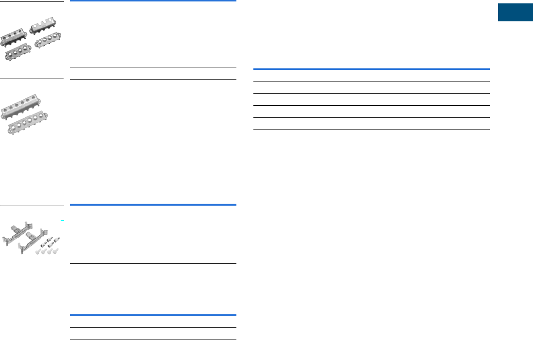
Volume 7—Logic Control, Operator Interface and Connectivity Solutions CA08100008E—February 2014 www.eaton.com V7-T7-21
7
7
7
7
7
7
7
7
7
7
7
7
7
7
7
7
7
7
7
7
7
7
7
7
7
7
7
7
7
7
7.1
Industrial Control Transformers
Trans for mer s
Accessories
Protection Index IP00
When terminal covers are installed on primary and secondary,
and fuse block covers are used, the protection index is IP20.
Finger-Safe Terminal Covers (Optional)
●Fits CE Marked designs 50–750 VA
●Fits MTE designs 0.25–750 VA
Finger-Safe Terminal Covers
Finger-Safe Primary Fuse Block Covers
●Fits two-pole primary fuse blocks on MTE designs
Finger-Safe Primary Fuse Block Covers
Secondary Fuse Clip Cover
Secondary Fuse Clip Cover
Technical Data and Specifications
Overload Capability
Short-term overload is designed into transformers as required by
ANSI. Basically, dry-type distribution transformers will deliver
200% nameplate load for one-half hour, 150% load for one hour
and 125% load for four hours without being damaged, provided
that a constant 50% load precedes and follows the overload.
See ANSI C57.96-01.250 for additional limitations.
Continuous overload capacity is not deliberately designed into
a transformer because the design objective is to be within the
allowed winding temperature rise with nameplate loading.
Insulation System and Temperature Rise
Industry standards classify insulation systems and rise as
shown below:
Insulation System Classification
The design life of transformers having different insulation
systems is the same—the lower-temperature systems are
designed for the same life as the higher-temperature systems.
Series-Multiple Windings
Series-multiple windings consist of two similar coils in each
winding that can be connected in series or parallel (multiple).
Transformers with series-multiple windings are designated
with an “x” or “/” between the voltage ratings, such as voltages
of “120/240” or “240 x 480.” If the series-multiple winding is
designated by an “x,” the winding can be connected only
for a series or parallel. With the “/” designation, a mid-point
also becomes available in addition to the series or parallel
connection. As an example, a 120 x 240 winding can be
connected for either 120 (parallel) or 240 (series), but a
120/240 winding can be connected for 120 (parallel),
240 (series) or 240 with a 120 mid-point.
For additional information, please refer to Volume 2,
CA08100003E.
Description Catalog Number
Four terminal transformers FSK4
Four terminal Series 2 transformers only FSK4S2
Six terminal transformers FSK6
Description Catalog Number
Primary fuse block covers FSKFB
Description Catalog Number
Fits 500 VA and smaller models SFCS
Fits models greater than 500 VA SFCL
FSK4
FSK6
FSKFB
Ambient + Winding Rise + Hot Spot = Temp. Class
40°C 55°C 10°C 105°C
40°C 80°C 30°C 150°C
25°C 135°C 20°C 180°C
40°C 115°C 30°C 185°C
40°C 150°C 30°C 220°C
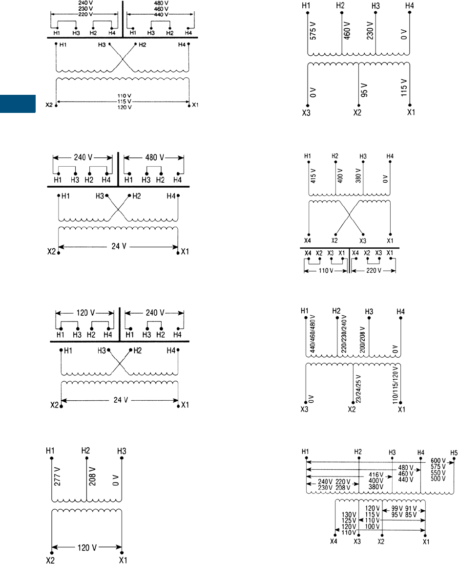
V7-T7-22 Volume 7—Logic Control, Operator Interface and Connectivity Solutions CA08100008E—February 2014 www.eaton.com
7
7
7
7
7
7
7
7
7
7
7
7
7
7
7
7
7
7
7
7
7
7
7
7
7
7
7
7
7
7
7.1
Industrial Control Transformers
Trans for mer s
Wiring Diagrams
Diagram 1
Diagram 2
Diagram 3
Diagram 4
Diagram 5
Diagram 6
Diagram 7
Diagram 8
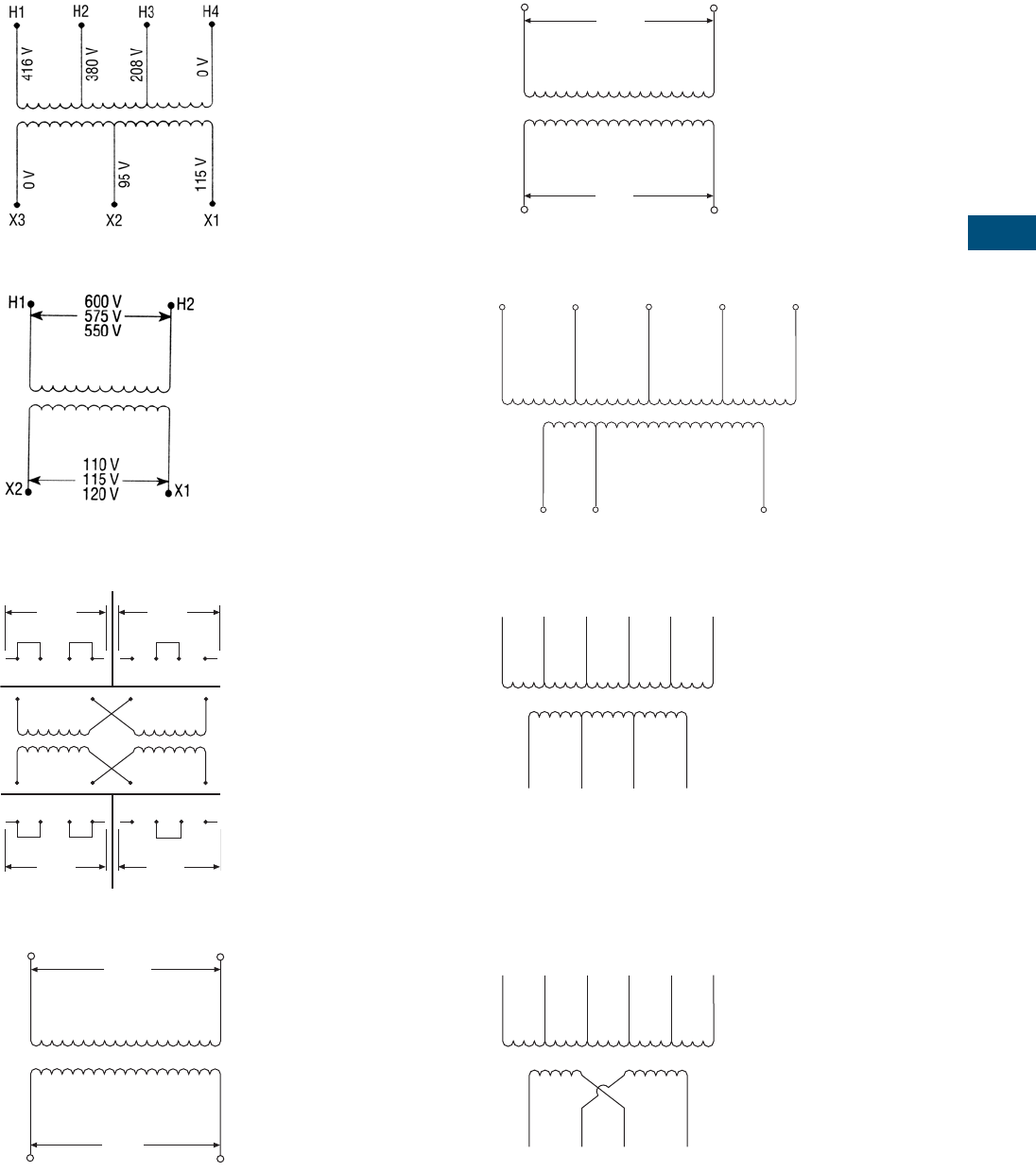
Volume 7—Logic Control, Operator Interface and Connectivity Solutions CA08100008E—February 2014 www.eaton.com V7-T7-23
7
7
7
7
7
7
7
7
7
7
7
7
7
7
7
7
7
7
7
7
7
7
7
7
7
7
7
7
7
7
7.1
Industrial Control Transformers
Trans for mer s
Diagram 9
Diagram 10
Diagram 11
Diagram 12
Diagram 13
Diagram 14
Diagram 15
Diagram 16
H1 H3 H2 H4 H1 H3 H2 H4
H1 H3 H2 H4
X4 X2 X3 X1
X4 X2 X3 X1 X4 X2 X3 X1
240 V 480 V
240 V
120 V
H1 H2
X2 X1
600 V
575 V
550 V
24 V
23 V
22 V
H1 H2
X2 X1
420 V
400 V
380 V
24 V
23 V
22 V
H1 H2 H3 H4 H5
X3 X2 X1
550,575,600 V
440,460,480 V
380,400,416 V
220,230,240 V
23/24/25
110,115,120 V
0 V
0 V
X4 X3 X2 X1
H1 H2 H3 H4 H5 H6
575 V
460 V
400 V
230 V
208 V
0 V
0 V
24 V
115 V
230 V
X4 X3 X2 X1
H1 H2 H3 H4 H5 H6
575 V
460 V
400 V
230 V
208 V
0 V
0 V
0 V
115 V
115 V

V7-T7-24 Volume 7—Logic Control, Operator Interface and Connectivity Solutions CA08100008E—February 2014 www.eaton.com
7
7
7
7
7
7
7
7
7
7
7
7
7
7
7
7
7
7
7
7
7
7
7
7
7
7
7
7
7
7
7.1
Industrial Control Transformers
Trans for mer s
Acceptable Rating of Primary Overcurrent Protection
for CE Marked Control Transformers 1
Acceptable Maximum Rating of Secondary
Overcurrent Protection 1
Regulation Data Chart
Notes
1For values over 6.3A, use 10 x 38 mm timelag (IEC - 269-3-1). Ta = 40°C control type.
2For units with Class 105°C insulation system.
3For units with Class 130°C insulation system.
4For units with Class 180°C insulation system.
To comply with NEMA standards that require all magnetic devices to operate successfully at
85% of rated voltage, the 90% secondary column is most often used in selecting a transformer.
No comparable requirement is available for IEC.
Fuses 13/32 x 1-1/2 Inches (10 x 38 mm) Timelag (IEC 269)
Sec.
Voltage 50 75 100 150 200 250 300 350 500 750
115 2.0 2.0 4.0 4.0 6.0 6.0 8.0 10.0 12.0 20.0
120 2.0 2.0 4.0 4.0 6.0 6.0 8.0 10.0 12.0 20.0
200 1.0 2.0 2.0 4.0 4.0 4.0 4.0 6.0 8.0 12.0
208 1.0 2.0 2.0 4.0 4.0 4.0 4.0 6.0 8.0 12.0
220 1.0 1.0 2.0 4.0 4.0 4.0 4.0 6.0 6.0 10.0
230 1.0 1.0 2.0 4.0 4.0 4.0 4.0 6.0 6.0 10.0
240 1.0 1.0 2.0 4.0 4.0 4.0 4.0 4.0 6.0 10.0
277 0.5 1.0 1.0 2.0 4.0 4.0 4.0 4.0 6.0 8.0
380 0.5 1.0 1.0 2.0 2.0 4.0 4.0 4.0 6.0 6.0
400 0.5 0.5 1.0 2.0 2.0 4.0 4.0 4.0 4.0 6.0
415 0.5 0.5 1.0 1.0 2.0 4.0 4.0 4.0 4.0 6.0
440 0.5 0.5 1.0 1.0 2.0 2.0 4.0 4.0 4.0 6.0
460 0.5 0.5 1.0 1.0 2.0 2.0 4.0 4.0 4.0 6.0
480 0.5 0.5 0.5 1.0 2.0 2.0 4.0 4.0 4.0 6.0
550 0.5 0.5 0.5 1.0 1.0 2.0 2.0 4.0 4.0 4.0
575 0.5 0.5 0.5 1.0 1.0 2.0 2.0 4.0 4.0 4.0
600 0.5 0.5 0.5 1.0 2.0 2.0 2.0 4.0 4.0 4.0
Miniature Fuses 5 x 20 mm Timelag (IEC 127-2/III)
Sec.
Voltage 50 75 100 150 200 250 300 350 500 750
23 2.50 4.00 5.00 8.00 10.0 12.00 16.00 16.00 25.00 —
24 2.50 4.00 5.00 8.00 10.0 12.00 16.00 16.00 25.00 32.00
25 2.50 4.00 5.00 8.00 10.0 12.00 16.00 16.00 25.00 32.00
90 0.63 1.00 1.25 2.00 2.50 3.15 4.00 4.00 6.30 10.00
95 0.63 0.80 1.25 1.60 2.50 3.15 4.00 4.00 6.30 8.00
100 0.50 0.80 1.00 1.60 2.00 2.50 3.15 4.00 5.00 8.00
110 0.50 0.80 1.00 1.60 2.00 2.50 3.15 4.00 5.00 8.00
115 0.50 0.80 1.00 1.60 2.00 2.50 3.15 3.15 5.00 8.00
120 0.50 0.63 1.00 1.25 2.00 2.50 2.50 3.15 5.00 6.30
220 0.25 0.40 0.50 0.80 1.00 1.25 1.60 1.60 2.50 4.00
230 0.25 0.40 0.50 0.80 1.00 1.25 1.60 1.60 2.50 4.00
240 0.25 0.32 0.50 0.63 1.00 1.25 1.25 1.60 2.50 3.15
Transformer
VA Rating
Inrush VA at 20% Power Factor
NEMA/IEC
95% Sec. Voltage
NEMA/IEC
90% Sec. Voltage
NEMA/IEC
85% Sec. Voltage
25 2100/— 130/— 150/—
50 2170/190 200/220 240/270
75 2310/350 410/460 450/600
100 2370/410 540/600 730/810
150 3780/850 930/1030 1150/1270
200 3810/900 1150/1270 1450/1600
250 31400/1540 1900/2090 2300/2530
300 31900/2090 2700/2970 3850/4240
350 33100/3410 3650/4020 4800/5280
500 34000/4400 5300/5830 7000/7700
750 38300/9130 11,000/12,100 14,000/15,400
1000 315,000/16,500 21,000/23,000 27,000/29,500
1000 49000/9900 13,000/14,300 18,500/20,300
1500 410,500/11,500 15,000/16,500 20,500/22,500
2000 417,000/18,900 25,500/27,300 34,000/36,400
3000 424,000/25,700 36,000/38,500 47,500/50,200
5000 455,000/58,800 92,500/98,900 115,000/122,000
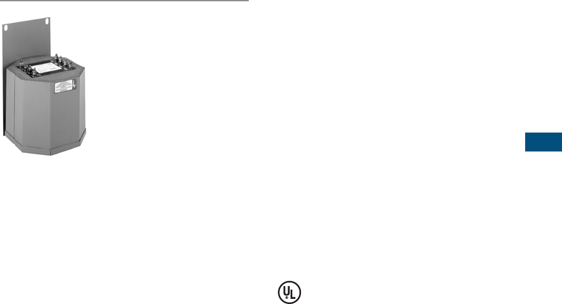
Volume 7—Logic Control, Operator Interface and Connectivity Solutions CA08100008E—February 2014 www.eaton.com V7-T7-25
7
7
7
7
7
7
7
7
7
7
7
7
7
7
7
7
7
7
7
7
7
7
7
7
7
7
7
7
7
7
7.1
Industrial Control Transformers
Trans for mer s
Type AP Transformer
Contents
Description Page
Type MTE . . . . . . . . . . . . . . . . . . . . . . . . . . . . . . . . V7-T7-4
Type MTK . . . . . . . . . . . . . . . . . . . . . . . . . . . . . . . . V7-T7-13
CE Marked . . . . . . . . . . . . . . . . . . . . . . . . . . . . . . . V7-T7-18
Type AP
Catalog Number Selection . . . . . . . . . . . . . . . . V7-T7-26
Product Selection . . . . . . . . . . . . . . . . . . . . . . . V7-T7-26
Technical Data and Specifications . . . . . . . . . . . V7-T7-26
Type AP
Product Description
●Encapsulated designs
Application Description
Transformers provide
stepped-down voltages to
machine tool control devices,
enabling control circuits to be
isolated from all power and
lighting circuits. This allows
the use of grounded or
ungrounded circuits that
are independent of the
power or lighting grounds;
thus, greater safety is
afforded the operator. The
control transformer line is
particularly adaptable on
applications where compact
construction is demanded.
Features, Benefits
and Functions
●Resin encapsulated
●60 Hz operation
●180°C insulation system
●115°C rise standard;
80°C rise optional
●Convenient screw-type
terminal board
●Bottom or side/wall-
mounting designs
●Performance meets/
exceeds requirements
of ANSI/NEMA ST-1
●Regulation exceeds
ANSI/NEMA requirements
for all ratings
Standards and Certifications
●UL recognized
Industry Standards
All Eaton dry-type distribution
and control transformers are
built and tested in accordance
with applicable NEMA, ANSI
and IEEE Standards.

V7-T7-26 Volume 7—Logic Control, Operator Interface and Connectivity Solutions CA08100008E—February 2014 www.eaton.com
7
7
7
7
7
7
7
7
7
7
7
7
7
7
7
7
7
7
7
7
7
7
7
7
7
7
7
7
7
7
7.1
Industrial Control Transformers
Trans for mer s
Catalog Number Selection
Please refer to Page V7-T7-3.
Product Selection
Additional Product Selection information is available in Volume 2, CA08100003E.
240/480 Volts to 120/240 Volts, 60 Hz
Technical Data and Specifications
Overload Capability
Short-term overload is
designed into transformers
as required by ANSI. Dry-type
distribution transformers will
deliver 200% nameplate load
for one-half hour, 150% load
for one hour and 125% load
for four hours without being
damaged, provided that a
constant 50% load precedes
and follows the overload.
See ANSI C57.96-01.250
for additional limitations.
Continuous overload capacity
is not deliberately designed
into a transformer because
the design objective is to be
within the allowed winding
temperature rise with
nameplate loading.
Insulation System and
Temperature Rise
Industry standards classify
insulation systems and rise as
shown below:
Insulation System
Classification
The design life of transformers
having different insulation
systems is the same—the
lower-temperature systems
are designed for the same life
as the higher-temperature
systems.
Sound Levels
All Eaton 600 volt class
general-purpose dry-type
distribution transformers are
designed to meet NEMA
ST-20 levels.
Winding Terminations
Eaton recommends external
cables be rated 90ºC
(sized at 75°C ampacity) for
encapsulated designs.
Series-Multiple Windings
Series-multiple windings
consist of two similar coils in
each winding that can be
connected in series or parallel
(multiple). Transformers with
series-multiple windings are
designated with an “x” or
“/” between the voltage
ratings, such as voltages of
“120/240” or “240 x 480.”
If the series-multiple winding
is designated by an “x,” the
winding can be connected
only for a series or parallel.
With the “/” designation,
a mid-point also becomes
available in addition to the
series or parallel connection.
As an example, a 120 x 240
winding can be connected
for either 120 (parallel) or
240 (series), but a 120/240
winding can be connected for
120 (parallel), 240 (series) or
240 with a 120 mid-point.
For additional information,
please refer to Volume 2,
CA08100003E.
Note: For additional information,
refer to Eaton’s Industrial Control
Transformer Binder B1228A.
For other ratings or styles not
shown, or for special enclosure
types (including stainless steel),
refer to Eaton.
Note
1See Page V7-T7-22 for wiring diagrams.
kVA Mounting Frame
Wiring
Diagram 1
Weight
Lbs (kg)
Style
Number
3 Bottom FR133 5 65 (29.5) C0003P7GB
5 Bottom FR99 5 104 (47.2) C0005P7GB
7.5 Bottom FR100 5 129 (58.6) C0007P7GB
10 Bottom FR101 5 148 (67.2) C0010P7GB
15 Bottom FR134 5 197 (89.4) C0015P7GB
3 Side/Wall FR292 5 65 (29.5) C0003P7GS
5 Side/Wall FR256 5 104 (47.2) C0005P7GS
7.5 Side/Wall FR257 5 129 (58.6) C0007P7GS
10 Side/Wall FR258 5 148 (67.2) C0010P7GS
15 Side/Wall FR259 5 197 (89.4) C0015P7GS
Ambient
+
Winding
Rise
+
Hot
Spot
=
Temp.
Class
40°C 55°C 10°C 105°C
40°C 80°C 30°C 150°C
25°C 135°C 20°C 180°C
40°C 115°C 30°C 185°C
40°C 150°C 30°C 220°C
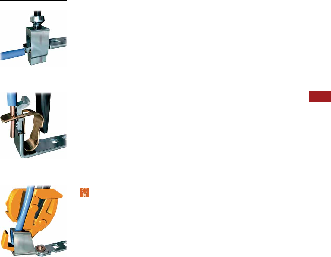
Volume 7—Logic Control, Operator Interface and Connectivity Solutions CA08100008E—July 2014 www.eaton.com V7-T8-1
8
8
8
8
8
8
8
8
8
8
8
8
8
8
8
8
8
8
8
8
8
8
8
8
8
8
8
8
8
8
Te
rm
inal Blocks, Fuse Blocks
and Fuse Holders
Screw Connection
Spring Cage
Insulation Displacement Connection
8.1 IEC—XB Series
IEC—XB Series Overview . . . . . . . . . . . . . . . . . . . . . . . . . . . . . . . . . . V7-T8-2
Screw Connection Terminal Blocks . . . . . . . . . . . . . . . . . . . . . . . . . . . V7-T8-4
Spring Cage Terminal Blocks . . . . . . . . . . . . . . . . . . . . . . . . . . . . . . . . V7-T8-31
Pluggable Spring Cage Connection Terminal Blocks. . . . . . . . . . . . . . . V7-T8-58
IDC Terminal Blocks . . . . . . . . . . . . . . . . . . . . . . . . . . . . . . . . . . . . . . . V7-T8-67
Miniature Circuit Breakers . . . . . . . . . . . . . . . . . . . . . . . . . . . . . . . . . . V7-T8-82
XB Series Accessories . . . . . . . . . . . . . . . . . . . . . . . . . . . . . . . . . . . . . V7-T8-90
8.2 NEMA
NEMA Overview . . . . . . . . . . . . . . . . . . . . . . . . . . . . . . . . . . . . . . . . . V7-T8-106
C381 Series Terminal Blocks, Rail Mounted . . . . . . . . . . . . . . . . . . . . V7-T8-107
TB Series Terminal Blocks, Modular . . . . . . . . . . . . . . . . . . . . . . . . . . . V7-T8-111
8.3 Power Distribution
Power Distribution Overview . . . . . . . . . . . . . . . . . . . . . . . . . . . . . . . . V7-T8-116
CHDB Series—Power Distribution Blocks . . . . . . . . . . . . . . . . . . . . . . V7-T8-117
CH160 Series—Power Terminal Blocks . . . . . . . . . . . . . . . . . . . . . . . . V7-T8-123
Power Terminal Block Accessories . . . . . . . . . . . . . . . . . . . . . . . . . . . V7-T8-126
8.4 Fuse Blocks and Fuse Holders
Fuse Blocks and Fuse Holders Overview . . . . . . . . . . . . . . . . . . . . . . . V7-T8-128
C383 Series Disconnect Fuse Holders . . . . . . . . . . . . . . . . . . . . . . . . . V7-T8-129
C350 Series Fuse Blocks and W Series Fuse Holders . . . . . . . . . . . . . V7-T8-131
Learn
Online
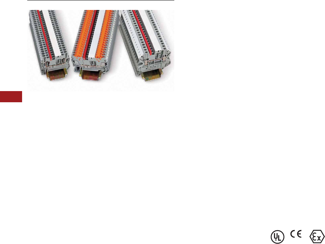
V7-T8-2 Volume 7—Logic Control, Operator Interface and Connectivity Solutions CA08100008E—July 2014 www.eaton.com
8
8
8
8
8
8
8
8
8
8
8
8
8
8
8
8
8
8
8
8
8
8
8
8
8
8
8
8
8
8
8.1
Terminal Blocks, Fuse Blocks and Fuse Holders
IEC—XB Series
IEC—XB Series
Contents
Description Page
IEC—XB Series
Screw Connection Terminal Blocks . . . . . . . . . V7-T8-4
Spring Cage Terminal Blocks . . . . . . . . . . . . . . V7-T8-31
Pluggable Spring Cage Connection
Terminal Blocks. . . . . . . . . . . . . . . . . . . . . . . . V7-T8-58
IDC Terminal Blocks . . . . . . . . . . . . . . . . . . . . . V7-T8-67
Miniature Circuit Breakers. . . . . . . . . . . . . . . . . V7-T8-82
XB Series Accessories . . . . . . . . . . . . . . . . . . . V7-T8-90
IEC—XB Series Overview
Product Description
The XB Series from Eaton
offers a complete terminal
block system with a universal
range of accessories.
Marking, bridging and testing
accessories are standardized
across the different
termination technologies—
reducing inventory and
logistics costs. The modular
terminal block design allows
for use of the different
terminal block types together
or individually, providing the
highest degree of flexibility.
Application Description
The metal portion of the XB
Series terminal blocks are
made from high-grade, strain-
crack and corrosion-proof
copper alloys. They won’t
experience any electrolytic
corrosion or rusting, even
when moisture is present.
The metal surfaces are
protected with a lead-free,
galvanic nickel or tin plating.
The good electrical
conductivity permits only a
low temperature rise. The
Polyamide 6.6 housings
allow for operating
temperatures up to 257°F
(125°C) and are certified for
inflammability Class V0 in
accordance with UL 94.
Features
Global acceptance—The XB
Series terminal blocks are
designed to worldwide
standards and meet the latest
international requirements.
Flexible Plug-in bridge
system—All three
technologies (screw, spring
and IDC) use the same bridge
system, allowing for
individual potential
distribution and quickly
bridged connections among
the same terminal block type
or across different types. The
XB Series terminal blocks
have two bridge shafts
arranged in one line, making
flexible chain bridging and
skip bridging between non-
adjacent terminal blocks
possible. Plug-in bridges are
available from 2 to 50
positions. Reducing bridges
are also available to connect a
larger terminal block to a
smaller one.
Large surface area for
marking—All XB Series
terminal blocks have
generously sized surface
areas for labeling. This allows
for clearly labeled wiring that
results in reduced startup
time and simplifies activities
such as testing and
maintenance. There are
provisions for marking
individual terminal blocks and
end stops, strips of terminal
blocks, and large groups of
terminal blocks.
Standardized testing
system—All test plugs make
contact in one of the easily
accessible bridge shafts. A
2.3 mm diameter test plug is
available for individual
measuring wires. Modular
test plugs are also available
for more advanced testing.
Standards and Certifications
●UL® and cUL®
recognized—File No.
E67464
●CE approved
●LVD 1
●EN 60947-7-1
●EN 60947-7-2
●EN 60998-2-3
●EN 60352-4/A1
●ATEX approval
(Eex e applications)
Note
1Not all standards apply to all terminal
blocks. Contact Eaton for details.
Volume 7—Logic Control, Operator Interface and Connectivity Solutions CA08100008E—July 2014 www.eaton.com V7-T8-3
8
8
8
8
8
8
8
8
8
8
8
8
8
8
8
8
8
8
8
8
8
8
8
8
8
8
8
8
8
8
8.1
Terminal Blocks, Fuse Blocks and Fuse Holders
IEC—XB Series
Technical Data and Specifications
IEC—XB Series
Modular Terminal Blocks for Potentially Explosive Environments
The standard modular
terminal blocks from Eaton
are approved for potentially
explosive environments. In
addition to the usual
approvals, they also have
been approved by a testing
center authorized by the EU.
No extra approval is required
in Intrinsic Safety type
applications.
Modular terminal blocks on
www.eaton.com fulfill the
requirements for “Increased
Safety” protection type when
installation instructions are
followed, and have a type
examination certificate
in accordance with the
Ex directive Ex-RL 94/9/EU.
These test certificates are
recognized in all the EU
member states and beyond.
The modular terminal blocks
are approved for fitting in
Zone 1, the Ex environment,
as well as Zone 2. Zone 1
fitting is conditional upon
terminal blocks being used in
connection boxes approved
for EEx e type protection and
having the equivalent of at
least IP54 protection.
The EEx approved modular
terminal blocks can be
divided into the following
groups:
●Screw connection
terminal blocks
●Spring-cage connection
terminal blocks
●Insulation Displacement
Connection terminal blocks
●Mini terminal blocks
●Terminal blocks for
specialized applications
More detailed information
on modular terminal
blocks in the EEx e area is
available on the Internet
at www.eaton.com for
downloading.
Here you will find the
following:
●
Technical data in accordance
with EN 50 019
●Approved accessories
●Important installation
instructions and mounting
diagrams
●EU type examination
certificates
●General information on
Ex protection
Identifications
Explosion protected electrical
equipment must be marked
so that the safety
characteristics are
identifiable. The identification
of electrical equipment is
described in the harmonized
standard EN 50014, as shown
in the following example:
EN 50014
Standard Example
Identification in Accordance
with ATEX-RL
Electrical equipment that is
certified in accordance with
the ATEX 100a guideline also
receives identification
describing the site for use.
ATE X
Guideline Example
Description Specification
Insulation material Polyamide 6.6
Dielectric strength 600 kV/cm
Creep resistance 600 CTI
Internal insulation resistance 1012 ohms cm
Surface resistance 1010 ohms
Flammability rating UL 94 V0
Continuous operating temperature –40 to 257°F (–40 to 125°C)
Description Identification
Manufacturer or
trademark
Eaton
Type designation XBUT25
Abbreviation of
explosion protection
EEx e ll
Protection type
increased safety “e”
e
Equipment group II
Mark of the
testing body
KEMA
Approval number 05ATEX2158 U
Description Identification
Manufacturing data 02.01.2004
Address of the
manufacturer
Duncan, SC
Number of the
appointed dept.
344
Common marking Ex symbol
Equipment group II
Category 2
Use in gas and/or
dust atmospheres
G D
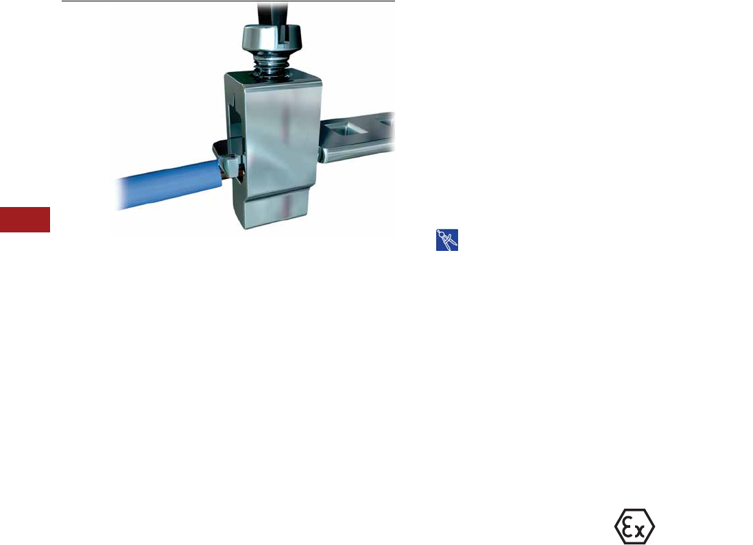
V7-T8-4 Volume 7—Logic Control, Operator Interface and Connectivity Solutions CA08100008E—July 2014 www.eaton.com
8
8
8
8
8
8
8
8
8
8
8
8
8
8
8
8
8
8
8
8
8
8
8
8
8
8
8
8
8
8
8.1
Terminal Blocks, Fuse Blocks and Fuse Holders
IEC—XB Series
Screw Connection
Contents
Description Page
Screw Connection Terminal Blocks
Single Level—Through-Feed . . . . . . . . . . . . . . . V7-T8-5
Single Level—Ground Blocks . . . . . . . . . . . . . . V7-T8-10
Multi-Conductor Terminal Blocks . . . . . . . . . . . V7-T8-12
Multi-Conductor Ground Blocks . . . . . . . . . . . . V7-T8-14
Double Level . . . . . . . . . . . . . . . . . . . . . . . . . . . V7-T8-16
Triple Level Sensor/Actuator . . . . . . . . . . . . . . . V7-T8-18
Fuse Terminal Blocks . . . . . . . . . . . . . . . . . . . . V7-T8-21
Disconnect and Component Terminal
Blocks . . . . . . . . . . . . . . . . . . . . . . . . . . . . . . V7-T8-24
High Current Blocks . . . . . . . . . . . . . . . . . . . . . V7-T8-27
Mini Screw Connection . . . . . . . . . . . . . . . . . . V7-T8-29
Drawings
Online
Screw Connection Terminal Blocks Overview
Product Description
The XBUT Series uses a
screw connection system
that is accepted worldwide
and is suitable in most
applications. The
maintenance-free connection
provides the reliability you
expect from Eaton.
Application Description
Designed for applications with
high demands, the XBUT
Series screw terminal block
has a maintenance-free wire
connection. re-tightening of
the terminal screws is not
necessary to ensure proper
operation. The screw locking
technique prevents the
screws from backing out.
Copper wires can be clamped
without pre-treatment or
ferrules can be used for
splicing protection. Multiple
conductors can be connected
in the same clamping
mechanism, saving space.
Features
●Maintenance-free
connections
●Global acceptance
●Multi-conductor
connections
●Flexible Plug-in bridge
system
●Large surface area for
marking
●Standardized testing
system
●Metal parts made of tin-
plated copper alloy
Standards and Certifications
●UL and cUL recognized—
File No. E67464
●CE approved
●LVD 1:
●EN 60947-7-1
●EN 60947-7-2
●EN 60998-2-3
●EN 60352-4/A1
●ATEX approval
(Eex e applications)
Note
1Not all standards apply to all terminal
blocks. Contact Eaton for details.

Volume 7—Logic Control, Operator Interface and Connectivity Solutions CA08100008E—July 2014 www.eaton.com V7-T8-5
8
8
8
8
8
8
8
8
8
8
8
8
8
8
8
8
8
8
8
8
8
8
8
8
8
8
8
8
8
8
8.1
Terminal Blocks, Fuse Blocks and Fuse Holders
IEC—XB Series
Single Level—Through-Feed
Contents
Description Page
Single Level—Through-Feed
Product Selection . . . . . . . . . . . . . . . . . . . . . . . V7-T8-6
Accessories . . . . . . . . . . . . . . . . . . . . . . . . . . . V7-T8-7
Technical Data and Specifications . . . . . . . . . . V7-T8-9
Dimensions . . . . . . . . . . . . . . . . . . . . . . . . . . . V7-T8-9
Single Level—Ground Blocks . . . . . . . . . . . . . . . . V7-T8-10
Multi-Conductor Terminal Blocks . . . . . . . . . . . . . . V7-T8-12
Multi-Conductor Ground Blocks . . . . . . . . . . . . . . V7-T8-14
Double Level. . . . . . . . . . . . . . . . . . . . . . . . . . . . . . V7-T8-16
Triple Level Sensor/Actuator . . . . . . . . . . . . . . . . . V7-T8-18
Fuse Terminal Blocks . . . . . . . . . . . . . . . . . . . . . . . V7-T8-21
Disconnect and Component Terminal Blocks . . . . V7-T8-24
High Current Blocks . . . . . . . . . . . . . . . . . . . . . . . . V7-T8-27
Mini Screw Connection . . . . . . . . . . . . . . . . . . . . . V7-T8-29
Single Level—Through-Feed
Product Description
The XBUT terminal blocks
feature a compact design and
maintenance-free screw
connection. There is a double
bridge shaft providing
maximum flexibility.
The double bridge shaft can
accommodate individual
chain bridging and step-down
bridging from other terminal
blocks. There are numerous
options for accessories,
including those for testing
and marking. Terminal blocks
are available for wire cross-
sections ranging from
12 AWG (2.5 mm2) to
2/0 AWG (150 mm2).
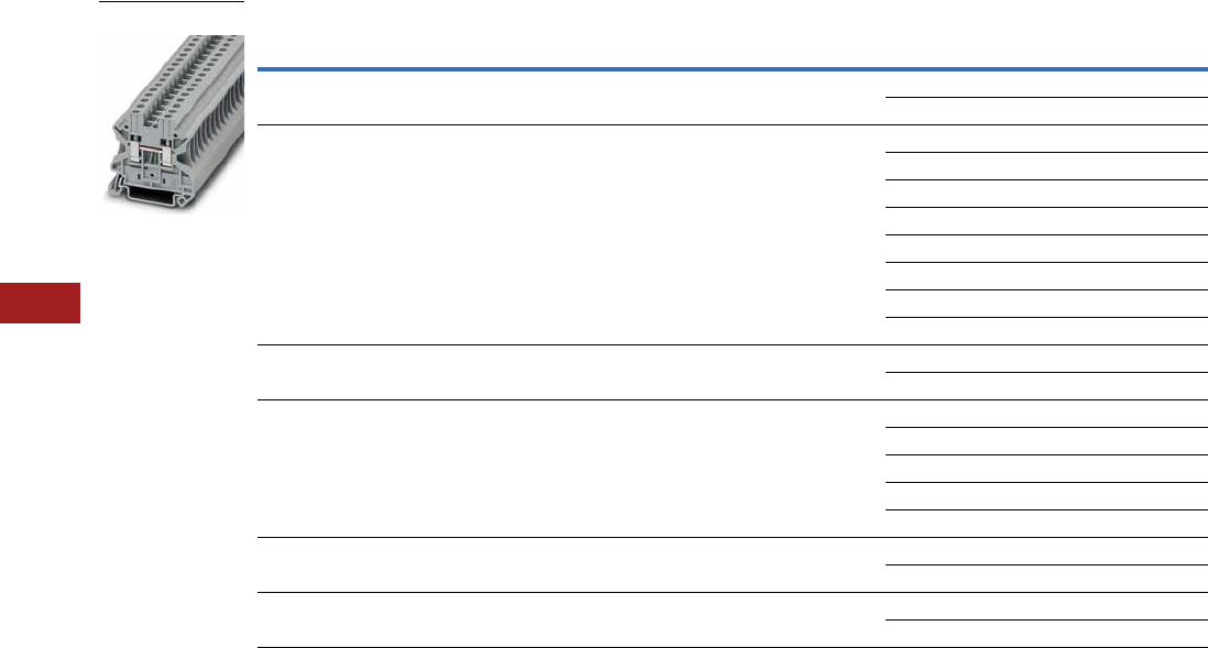
V7-T8-6 Volume 7—Logic Control, Operator Interface and Connectivity Solutions CA08100008E—July 2014 www.eaton.com
8
8
8
8
8
8
8
8
8
8
8
8
8
8
8
8
8
8
8
8
8
8
8
8
8
8
8
8
8
8
8.1
Terminal Blocks, Fuse Blocks and Fuse Holders
IEC—XB Series
Product Selection
Screw Connection Single Level—Through-Feed
Note
1 EU type—examination certificate number: KEMA 05ATEX2158 U.
Terminal
Width
Maximum
Wire Size
IEC 60 947-7-1
in V/A/AWG
EN 50 019 1
in V/A/AWG
UL-cUL Ratings
in V/A/AWG Color
Standard
Pack
Catalog
Number
5.2 mm 12 AWG/2.5 mm2800/32/26–12 750/22/28/26–12 600/20/26–12 Gray 50 XBUT25
Blue 50 XBUT25BU
6.2 mm 10 AWG/4 mm2800/41/26–10 750/30/38/26–10 600/30/26–10 Gray 50 XBUT4
Blue 50 XBUT4BU
Orange 50 XBUT4OR
Yellow 50 XBUT4YE
Red 50 XBUT4RD
White 50 XBUT4WH
Black 50 XBUT4BK
Green 50 XBUT4GN
8.2 mm 8 AWG/6 mm2800/57/24–8 750/40/50/24–8 600/50/24–8 Gray 50 XBUT6
Blue 50 XBUT6BU
10.2 mm 6 AWG/10 mm21000/76/20–6 750/54/69/20–6 600/65/20–6 Gray 50 XBUT10
Blue 50 XBUT10BU
Orange 50 XBUT10OR
Yellow 50 XBUT10YE
Red 50 XBUT10RD
12 mm 4 AWG/16 mm21000/101/17–4 — 600/85/16–4 Gray 50 XBUT16
Blue 50 XBUT16BU
16 mm 0 AWG/35 mm21000/150/15–0 — 600/150/14–1/0 Gray 50 XBUT35
Blue 50 XBUT35BU
XBUT4

Volume 7—Logic Control, Operator Interface and Connectivity Solutions CA08100008E—July 2014 www.eaton.com V7-T8-7
8
8
8
8
8
8
8
8
8
8
8
8
8
8
8
8
8
8
8
8
8
8
8
8
8
8
8
8
8
8
8.1
Terminal Blocks, Fuse Blocks and Fuse Holders
IEC—XB Series
Accessories
Screw Connection Single Level—Through-Feed
Notes
1Enclosed block, no end cover needed.
2For information on Printed Marking Tag Options, see Page V7-T8-98.
For additional accessories, see Page V7-T8-90.
Description Color
Number of
Positions
Standard
Pack
XBUT25 XBUT4 XBUT6 XBUT10 XBUT16 XBUT35
Catalog
Number
Catalog
Number
Catalog
Number
Catalog
Number
Catalog
Number
Catalog
Number
End cover Gray — 10 XBACUT10 XBACUT10 XBACUT10 XBACUT10 XBACUT16 1
Partition plate Gray — 10 XBATUT10 XBATUT10 XBATUT10 XBATUT10 — —
Plug-in bridge—
for cross connections
in the bridge shaft
Red 2 10 XBAFBS25 XBAFBS26 XBAFBS28 XBAFBS210 XBAFBS212 XBAFBS216
310XBAFBS35 XBAFBS36 — — — —
510XBAFBS55 XBAFBS56 — — — —
10 10 XBAFBS105 XBAFBS106 — — — —
50 10 XBAFBS505 XBAFBS506 — — — —
Test adapter — — 10 XBATSPAI4 XBATSPAI4 XBATSPAI4 — — —
2.3 mm diameter test plug — — — XBATSMPS-_ 1XBATSMPS-_ 1————
Modular test plug — — 10 XBATSPS5 XBATSPS6 XBATSPS8 — — —
Blank marker strip (strip of 10) White — 10 XBMZB5 2XBMZB6 2XBMZB8 2XBMZB10 2XBMZB12 2XBMZB15 2
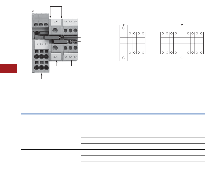
V7-T8-8 Volume 7—Logic Control, Operator Interface and Connectivity Solutions CA08100008E—July 2014 www.eaton.com
8
8
8
8
8
8
8
8
8
8
8
8
8
8
8
8
8
8
8
8
8
8
8
8
8
8
8
8
8
8
8.1
Terminal Blocks, Fuse Blocks and Fuse Holders
IEC—XB Series
XBUT with Reducing Bridge
Step-Down Bridge with Standard Feed-Through Terminal Blocks
Input Pick-Off
One-Sided
Input Imax
Central
Input Imax
Bridge
Terminal
Blocks Cross-Section
Terminal
Blocks
Cross-Section
AWG (mm2)
Catalog
Number
XBUT10 6 AWG (10 mm2) XBUT25 12 (2.5) 40 65 XBARBUT10
XBUT4 10 (4) 45 65 XBARBUT10
XBPT25 12 (2.5) 40 65 XBARBUT10ST
XBPT4 10 (4) 45 65 XBARBUT10ST
XBQT15 14 (1.5) 35 65 XBARBUT10ST
XBQT25 12 (2.5) 40 65 XBARBUT10ST
XBUT16 4 AWG (16 mm2) XBUT25 12 (2.5) 40 80 XBARBUT16
XBUT4 10 (4) 45 90 XBARBUT16
XBPT25 12 (2.5) 40 80 XBARBUT16ST
XBPT4 10 (4) 45 90 XBARBUT16ST
XBQT15 14 (1.5) 35 70 XBARBUT16ST
XBQT25 12 (2.5) 40 80 XBARBUT16ST
XBPU25D12
lmax
One-Sided Input Central Input
lmax
XBACUT10
XBARBUT10ST
XBARBUT10
XBUT10 XBUT25
XBACPU25D12

Volume 7—Logic Control, Operator Interface and Connectivity Solutions CA08100008E—July 2014 www.eaton.com V7-T8-9
8
8
8
8
8
8
8
8
8
8
8
8
8
8
8
8
8
8
8
8
8
8
8
8
8
8
8
8
8
8
8.1
Terminal Blocks, Fuse Blocks and Fuse Holders
IEC—XB Series
Technical Data and Specifications
Screw Connection Single Level—Through-Feed
Dimensions
Approximate Dimensions in Inches (mm)
Screw Connection Single Level—Through-Feed
Notes
1XBUT35 has an enclosed design. The use of an end cover is not required.
2For information on Printed Marking Tag Options, see Page V7-T8-98.
Description XBUT25 XBUT4 XBUT6 XBUT10 XBUT16 XBUT35
Technical Data in Accordance with IEC
Maximum load current in A/cross-section in mm232/4 41/6 57/10 76/16 101/25 150/50
Rated surge voltage in kV/contamination class 8/3 8/3 8/3 8/3 8/3 8/3
Surge voltage category/insulating material group III/II III/I III/I III/I III/I III/I
Connection Capacity
Stranded with ferrule/with ferrule and
plastic sleeve in mm2
0.25–2.5/0.25–2.5 0.25–4/0.25–4 0.25–6/0.25–6 0.5–10/0.5–10 1.0–16/1.0–16 1.5–35/1.5–35
Multi-Conductor Connection
(same cross-section)
Solid/stranded in mm20.14–1.5/0.14–1.5 0.14–1.5/0.14–1.5 0.2–2.5/0.2–2.5 0.5–4/0.5–4 1.0–6/1.0–4 1.5–16/1.5–10
Stranded with ferrules without plastic sleeve in mm20.25–1.5 0.25–1.5 0.25–1.5 0.5–2.5 1.0–4 1.5–10
Stranded with twin ferrule with plastic sleeve in mm20.5–1.5 0.5–2.5 0.5–4 0.5–6 0.75–10 1.5–10
Stripping length in inches (mm) 0.35 (9) 0.35 (9) 0.39 (10) 0.39 (10) 0.39 (10) 0.63 (16)
Thread M3 M3 M4 M4 M5 M6
Torque in in-lb (Nm) 5.3–7.1 (0.6–0.8) 5.3–7.1 (0.6–0.8) 13.3–15.9 (1.5–1.8) 13.3–15.9 (1.5–1.8) 22.1–26.6 (2.5–3) 28.3–32.7 (3.2–3.7)
Catalog
Number Width Length
Cover
Width
Height for—
35 x 7.5 in 35 x 15 in
XBUT25 0.20 (5.2) 1.85 (46.9) 0.09 (2.2) 1.87 (47.5) 2.17 (55.0)
XBUT4 0.24 (6.2) 1.85 (46.9) 0.09 (2.2) 1.87 (47.5) 2.17 (55.0)
XBUT6 0.32 (8.2) 1.85 (46.9) 0.09 (2.2) 1.87 (47.5) 2.17 (55.0)
XBUT10 0.40 (10.2) 1.85 (46.9) 0.09 (2.2) 1.87 (47.5) 2.17 (55.0)
XBUT16 0.47 (12.0) 2.08 (52.8) 0.09 (2.2) 2.16 (54.8) 2.45 (62.3)
XBUT35 0.63 (16.0) 2.37 (60.2) — 2.59 (65.7) 2.88 (73.2)
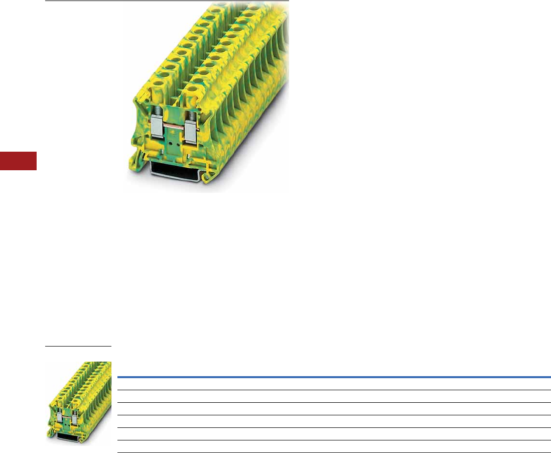
V7-T8-10 Volume 7—Logic Control, Operator Interface and Connectivity Solutions CA08100008E—July 2014 www.eaton.com
8
8
8
8
8
8
8
8
8
8
8
8
8
8
8
8
8
8
8
8
8
8
8
8
8
8
8
8
8
8
8.1
Terminal Blocks, Fuse Blocks and Fuse Holders
IEC—XB Series
Single Level—Ground Blocks
Contents
Description Page
Single Level—Through-Feed . . . . . . . . . . . . . . . . . V7-T8-5
Single Level—Ground Blocks
Accessories . . . . . . . . . . . . . . . . . . . . . . . . . . . V7-T8-11
Technical Data and Specifications . . . . . . . . . . V7-T8-11
Dimensions . . . . . . . . . . . . . . . . . . . . . . . . . . . V7-T8-11
Multi-Conductor Terminal Blocks . . . . . . . . . . . . . V7-T8-12
Multi-Conductor Ground Blocks . . . . . . . . . . . . . . V7-T8-14
Double Level . . . . . . . . . . . . . . . . . . . . . . . . . . . . . V7-T8-16
Triple Level Sensor/Actuator . . . . . . . . . . . . . . . . . V7-T8-18
Fuse Terminal Blocks . . . . . . . . . . . . . . . . . . . . . . . V7-T8-21
Disconnect and Component Terminal Blocks . . . . V7-T8-24
High Current Blocks . . . . . . . . . . . . . . . . . . . . . . . V7-T8-27
Mini Screw Connection . . . . . . . . . . . . . . . . . . . . . V7-T8-29
Single Level—Ground Blocks
Product Description
The ground terminal blocks
have the same shape and
pitch as the standard terminal
block, in a green-yellow
housing. They easily snap
onto the DIN rail to make a
reliable mechanical and
electrical contact that meets
all requirements of IEC 60-
947-7-2.
Product Selection
Screw Connection Single Level—Ground Blocks
Note
1 EU type—examination certificate number: KEMA 05ATEX2158 U.
Terminal
Width
Maximum
Wire Size
IEC 60 947-7-1
in V/A/AWG
EN 50 019 1
in V/A/AWG
UL-cUL Ratings
in V/A/AWG Color
Standard
Pack
Catalog
Number
5.2 mm 12 AWG/2.5 mm2—/—/26–12 —/—/26–12 —/—/26–12 Green/Yellow 50 XBUT25PE
6.2 mm 10 AWG/4 mm2—/—/26–10 —/—/26–10 —/—/26–10 Green/Yellow 50 XBUT4PE
8.2 mm 8 AWG/6 mm2—/—/24–8 —/—/24–8 —/—/24–8 Green/Yellow 50 XBUT6PE
10.2 mm 6 AWG/10 mm2—/76/20–6 —/54/69/20–6 —/—/20–6 Green/Yellow 50 XBUT10PE
12 mm 4 AWG/16 mm2—/101/15–4 — —/—/16–4 Green/Yellow 50 XBUT16PE
16 mm 2 AWG/35 mm2—/125/15–2 — —/—/14–1/0 Green/Yellow 50 XBUT35PE
XBUT6PE

Volume 7—Logic Control, Operator Interface and Connectivity Solutions CA08100008E—July 2014 www.eaton.com V7-T8-11
8
8
8
8
8
8
8
8
8
8
8
8
8
8
8
8
8
8
8
8
8
8
8
8
8
8
8
8
8
8
8.1
Terminal Blocks, Fuse Blocks and Fuse Holders
IEC—XB Series
Accessories
Screw Connection Single Level—Ground Blocks
Technical Data and Specifications
Screw Connection Single Level—Ground Blocks
Dimensions
Approximate Dimensions in Inches (mm)
Screw Connection Single Level—Ground Blocks
Notes
1For ordering information, see Page V7-T8-105.
2For information on Printed Marking Tag Options, see Page V7-T8-98.
3XBUT35PE has an enclosed design. The use of an end cover is not required.
For additional accessories, see Page V7-T8-90.
Description Color
Number of
Positions
Standard
Pack
XBUT25PE XBUT4PE XBUT6PE XBUT10PE XBUT16PE XBUT35PE
Catalog
Number
Catalog
Number
Catalog
Number
Catalog
umber
Catalog
Number
Catalog
Number
End cover Gray — 10 XBACUT10 XBACUT10 XBACUT10 XBACUT10 XBACUT16 3
Partition plate — — 10 XBATUT10 XBATUT10 XBATUT10 XBATUT10 — —
Plug-in bridge—
for cross connections
in the bridge shaft
Red 2 10 XBAFBS25 XBAFBS26 XBAFBS28 XBAFBS210 XBAFBS212 XBAFBS212
310XBAFBS35 XBAFBS36 — — — —
510XBAFBS55 XBAFBS56 — — — —
10 10 XBAFBS105 XBAFBS106 — — — —
50 10 XBAFBS505 XBAFBS506 — — — —
Test adapter — — 10 XBATSPAI4 XBATSPAI4 XBATSPAI4 — — —
2.3 mm diameter test plug — — — XBATSMPS-_ 1XBATSMPS-_ 1—— ——
Modular test plug — — 10 XBATSPS5 XBATSPS6 XBATSPS8 — — —
Blank marker strip (strip of 10) White — 10 XBMZB5 2XBMZB6 2XBMZB8 2XBMZB10 2XBMZB12 2XBMZB15 2
Description XBUT25PE XBUT4PE XBUT6PE XBUT10PE XBUT16PE XBUT35PE
Technical Data in Accordance with IEC
Maximum load current in A/cross-section in mm2———76/16101/25125/50
Rated surge voltage in kV/contamination class 8/3 8/3 8/3 8/3 8/3 8/3
Surge voltage category/insulating material group III/II III/I III/I III/I III/I III/I
Connection Capacity
Stranded with ferrule/with ferrule and
plastic sleeve in mm2
0.25–2.5/0.25–2.5 0.25–4/0.25–4 0.25–6/0.25–6 0.5–10/0.5–10 1.0–16/1.0–16 1.5–35/1.5–35
Multi-Conductor Connection
(same cross-section)
Solid/stranded in mm20.14–1.5/0.14–1.5 0.14–1.5/0.14–1.5 0.2–2.5/0.2–2.5 0.5–4/0.5–4 1.0–6/1.0–4 1.5–16/1.5–10
Stranded with ferrules without plastic sleeve in mm20.25–1.5 0.25–1.5 0.25–1.5 0.5–2.5 1.0–4 1.5–10
Stranded with twin ferrule with plastic sleeve in mm20.5–1.5 0.5–2.5 0.5–4 0.5–6 0.75–10 1.5–10
Stripping length in inches (mm) 0.35 (9) 0.35 (9) 0.39 (10) 0.39 (10) 0.39 (10) 0.63 (16)
Thread M3 M3 M4 M4 M5 M6
Torque in in-lb (Nm) 5.3–7.1 (0.6–0.8) 5.3–7.1 (0.6–0.8) 13.3–15.9 (1.5–1.8) 13.3–15.9 (1.5–1.8) 22.1–26.6 (2.5–3) 28.3–32.7 (3.2–3.7)
Catalog
Number Width Length
Cover
Width
Height for—
35 x 7.5 in 35 x 15 in
XBUT25PE 0.20 (5.2) 1.85 (46.9) 0.09 (2.2) 1.87 (47.5) 2.17 (55.0)
XBUT4PE 0.24 (6.2) 1.85 (46.9) 0.09 (2.2) 1.87 (47.5) 2.17 (55.0)
XBUT6PE 0.32 (8.2) 1.85 (46.9) 0.09 (2.2) 1.87 (47.5) 2.17 (55.0)
XBUT10PE 0.40 (10.2) 1.85 (46.9) 0.09 (2.2) 1.87 (47.5) 2.17 (55.0)
XBUT16PE 0.47 (12.0) 2.08 (52.8) 0.09 (2.2) 2.16 (54.8) 2.45 (62.3)
XBUT35PE 0.63 (16.0) 2.37 (60.2) — 2.59 (65.7) 2.88 (73.2)
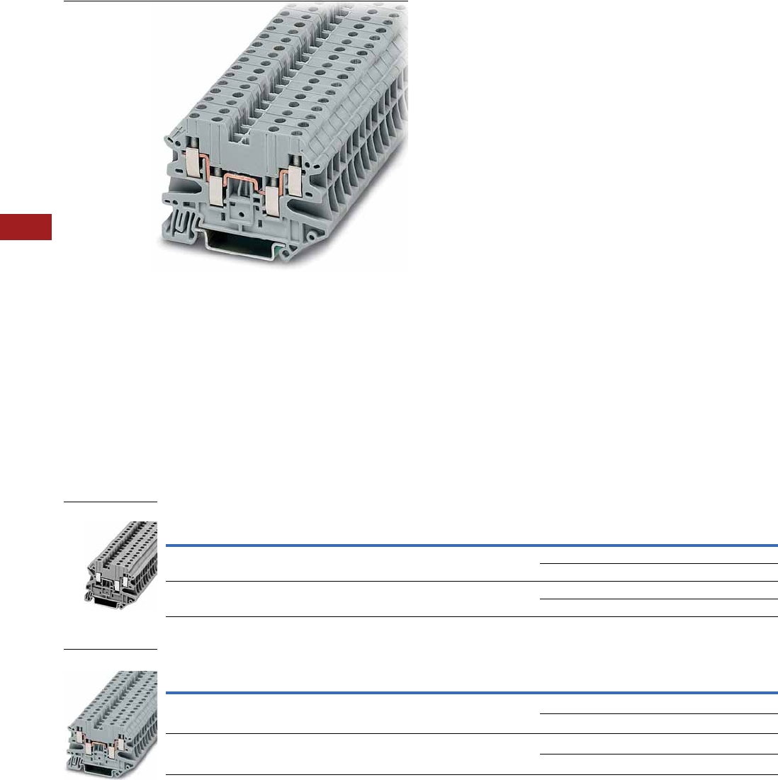
V7-T8-12 Volume 7—Logic Control, Operator Interface and Connectivity Solutions CA08100008E—July 2014 www.eaton.com
8
8
8
8
8
8
8
8
8
8
8
8
8
8
8
8
8
8
8
8
8
8
8
8
8
8
8
8
8
8
8.1
Terminal Blocks, Fuse Blocks and Fuse Holders
IEC—XB Series
Multi-Conductor Terminal Blocks
Contents
Description Page
Single Level—Through-Feed . . . . . . . . . . . . . . . . . V7-T8-5
Single Level—Ground Blocks . . . . . . . . . . . . . . . . V7-T8-10
Multi-Conductor Terminal Blocks
Accessories . . . . . . . . . . . . . . . . . . . . . . . . . . . V7-T8-13
Technical Data and Specifications . . . . . . . . . . V7-T8-13
Dimensions . . . . . . . . . . . . . . . . . . . . . . . . . . . V7-T8-13
Multi-Conductor Ground Blocks . . . . . . . . . . . . . . V7-T8-14
Double Level . . . . . . . . . . . . . . . . . . . . . . . . . . . . . V7-T8-16
Triple Level Sensor/Actuator . . . . . . . . . . . . . . . . . V7-T8-18
Fuse Terminal Blocks . . . . . . . . . . . . . . . . . . . . . . . V7-T8-21
Disconnect and Component Terminal Blocks . . . . V7-T8-24
High Current Blocks . . . . . . . . . . . . . . . . . . . . . . . V7-T8-27
Mini Screw Connection . . . . . . . . . . . . . . . . . . . . . V7-T8-29
Multi-Conductor Terminal Blocks
Product Description
The multi-conductor terminal
blocks offer a space-saving
alternative to standard feed-
through terminal blocks
allowing for high density
wiring. Often, three
connections have to be led
to one terminal block. The
XBUT…D12 terminal block
accomplishes this without
any additional terminal blocks
or bridging required.
The XBUT…D22 terminal
blocks allow four wires to be
connected to one potential—
and can therefore be used as
compact power distributors.
Product Selection
Screw Connection Multi-Conductor Terminal Blocks, Three-Wire
Screw Connection Multi-Conductor Terminal Blocks, Four-Wire
Terminal
Width
Maximum
Wire Size
IEC 60 947-7-1
in V/A/AWG
UL-cUL Ratings
in V/A/AWG Color
Standard
Pack
Catalog
Number
5.2 mm 12 AWG/2.5 mm2500/28/26–12 150/20/26–12 Gray 50 XBUT25D12
Blue 50 XBUT25D12BU
6.2 mm 10 AWG/4 mm2500/39/26–10 150/30/26–10 Gray 50 XBUT4D12
Blue 50 XBUT4D12BU
Terminal
Width
Maximum
Wire Size
IEC 60 947-7-1
in V/A/AWG
UL-cUL Ratings
in V/A/AWG Color
Standard
Pack
Catalog
Number
5.2 mm 12 AWG/2.5 mm2500/28/26–12 150/20/26–12 Gray 50 XBUT25D22
Blue 50 XBUT25D22BU
6.2 mm 10 AWG/4 mm2500/39/26–10 150/30/26–10 Gray 50 XBUT4D22
Blue 50 XBUT4D22BU
XBUT25D12
XBUT4D22

Volume 7—Logic Control, Operator Interface and Connectivity Solutions CA08100008E—July 2014 www.eaton.com V7-T8-13
8
8
8
8
8
8
8
8
8
8
8
8
8
8
8
8
8
8
8
8
8
8
8
8
8
8
8
8
8
8
8.1
Terminal Blocks, Fuse Blocks and Fuse Holders
IEC—XB Series
Accessories
Screw Connection Multi-Conductor Terminal Blocks
Technical Data and Specifications
Screw Connection Multi-Conductor Terminal Blocks
Dimensions
Approximate Dimensions in Inches (mm)
Screw Connection Multi-Conductor Terminal Blocks
Notes
1For ordering information, see Page V7-T8-105.
2For information on Printed Marking Tag Options, see Page V7-T8-98.
For additional accessories, see Page V7-T8-90.
Description Color
Number of
Positions
Standard
Pack
XBUT25D12 XBUT4D12 XBUT25D22 XBUT4D22
Catalog
Number
Catalog
Number
Catalog
Number
Catalog
Number
End cover Gray — 10 XBACUT4D12 XBACUT4D12 XBACUT4D22 XBACUT4D22
End cover segment Gray — 10 XBASUT4 XBASUT4 XBASUT4 XBASUT4
Partition plate — — 10 XBATUTD12 XBATUTD12 XBATUTD22 XBATUTD22
Plug-in bridge—for cross
connections in the bridge shaft
Red 2 10 XBAFBS25 XBAFBS26 XBAFBS25 XBAFBS26
310XBAFBS35 XBAFBS36 XBAFBS35 XBAFBS36
510XBAFBS55 XBAFBS56 XBAFBS55 XBAFBS56
10 10 XBAFBS105 XBAFBS106 XBAFBS105 XBAFBS106
50 10 XBAFBS505 XBAFBS506 XBAFBS505 XBAFBS506
Test adapter — — 10 XBATSPAI4 XBATSPAI4 XBATSPAI4 XBATSPAI4
2.3 mm diameter test plug — — — XBATSMPS-_ 1XBATSMPS-_ 1XBATSMPS-_ 1XBATSMPS-_ 1
Modular test plug — — 10 XBATSPS5 XBATSPS6 XBATSPS5 XBATSPS6
Blank marker strip (strip of 10) White — 10 XBMZB5 2XBMZB6 2XBMZB5 2XBMZB6 2
Description XBUT25D12 XBUT4D12 XBUT25D22 XBUT4D22
Technical Data in Accordance with IEC
Maximum load current in A/cross-section in mm228/4 39/6 28/4 39/6
Rated surge voltage in kV/contamination class 6/3 6/3 6/3 6/3
Surge voltage category/insulating material group III/I III/I III/I III/I
Connection Capacity
Stranded with ferrule/with ferrule and
plastic sleeve in mm2
0.25–2.5/0.25–2.5 0.25–4/0.25–4 0.25–2.5/0.25–2.5 0.25–4/0.25–4
Multi-Conductor Connection
(same cross-section)
Solid/stranded in mm20.14–1.0/0.14–1.0 0.14–1.0/0.14–1.5 0.14–1.0/0.14–1.0 0.14–1/0.14–1.5
Stranded with ferrules without plastic sleeve in mm20.25–1.0 0.25–1.5 0.25–1.0 0.25–1.5
Stranded with twin ferrule with plastic sleeve in mm20.5–1.0 0.5–1.0 0.5–1.0 0.5–1.0
Stripping length in inches (mm) 0.31 (8) 0.31 (8) 0.31 (8) 0.31 (8)
Thread M3 M3 M3 M3
Torque in in-lb (Nm) 5.3–7.1 (0.6–0.8) 5.3–7.1 (0.6–0.8) 5.3–7.1 (0.6–0.8) 5.3–7.1 (0.6–0.8)
Catalog
Number Width Length
Cover
Width
Height for—
35 x 7.5 in 35 x 15 in
XBUT25D12 0.20 (5.2) 2.24 (56.8) 0.09 (2.2) 1.87 (47.5) 2.17 (55.0)
XBUT4D12 0.24 (6.2) 2.24 (56.8) 0.09 (2.2) 1.87 (47.5) 2.17 (55.0)
XBUT25D22 0.20 (5.2) 2.52 (64.1) 0.09 (2.2) 1.87 (47.5) 2.17 (55.0)
XBUT4D22 0.24 (6.2) 2.52 (64.1) 0.09 (2.2) 1.87 (47.5) 2.17 (55.0)
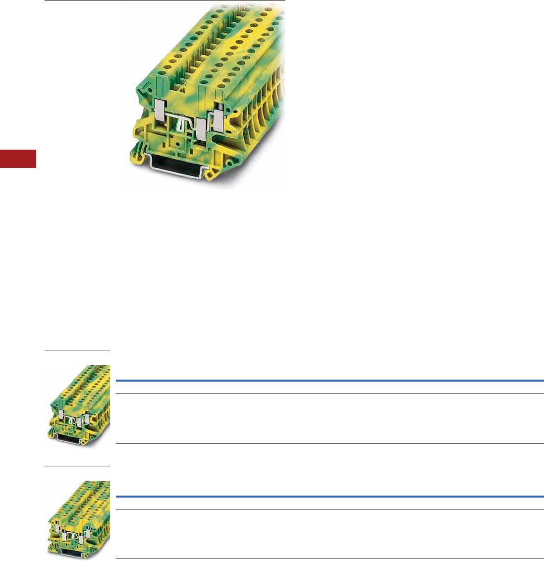
V7-T8-14 Volume 7—Logic Control, Operator Interface and Connectivity Solutions CA08100008E—July 2014 www.eaton.com
8
8
8
8
8
8
8
8
8
8
8
8
8
8
8
8
8
8
8
8
8
8
8
8
8
8
8
8
8
8
8.1
Terminal Blocks, Fuse Blocks and Fuse Holders
IEC—XB Series
Multi-Conductor Ground Blocks
Contents
Description Page
Single Level—Through-Feed . . . . . . . . . . . . . . . . . V7-T8-5
Single Level—Ground Blocks . . . . . . . . . . . . . . . . V7-T8-10
Multi-Conductor Terminal Blocks . . . . . . . . . . . . . V7-T8-12
Multi-Conductor Ground Blocks
Accessories . . . . . . . . . . . . . . . . . . . . . . . . . . . V7-T8-15
Technical Data and Specifications . . . . . . . . . . V7-T8-15
Dimensions . . . . . . . . . . . . . . . . . . . . . . . . . . . V7-T8-15
Double Level . . . . . . . . . . . . . . . . . . . . . . . . . . . . . V7-T8-16
Triple Level Sensor/Actuator . . . . . . . . . . . . . . . . . V7-T8-18
Fuse Terminal Blocks . . . . . . . . . . . . . . . . . . . . . . . V7-T8-21
Disconnect and Component Terminal Blocks . . . . V7-T8-24
High Current Blocks . . . . . . . . . . . . . . . . . . . . . . . V7-T8-27
Mini Screw Connection . . . . . . . . . . . . . . . . . . . . . V7-T8-29
Multi-Conductor Ground Blocks
Product Description
The ground terminal blocks
have the same shape and
pitch as the standard terminal
block, in a green-yellow
housing. They easily snap
onto the DIN rail to make
a reliable mechanical and
electrical contact that
meets all requirements
of IEC 60-947-7-2.
Product Selection
Screw Connection Multi-Conductor Ground Blocks—Three-Wire
Screw Connection Multi-Conductor Ground Blocks—Four-Wire
Terminal
Width
Maximum
Wire Size
IEC 60 947-7-1
in V/A/AWG
UL-cUL Ratings
in V/A/AWG Color
Standard
Pack
Catalog
Number
5.2 mm 12 AWG/2.5 mm2—/—/26–12 —/—/26–12 Green/Yellow 50 XBUT25D12PE
6.2 mm 10 AWG/4 mm2—/—/26–10 —/—/26–10 Green/Yellow 50 XBUT4D12PE
Terminal
Width
Maximum
Wire Size
IEC 60 947-7-1
in V/A/AWG
UL-cUL Ratings
in V/A/AWG Color
Standard
Pack
Catalog
Number
5.2 mm 12 AWG/2.5 mm2—/—/26–12 —/—/26–12 Green/Yellow 50 XBUT25D22PE
6.2 mm 10 AWG/4 mm2—/—/26–10 —/—/26–10 Green/Yellow 50 XBUT4D22PE
XBUT4D12PE
XBUT25D22PE

Volume 7—Logic Control, Operator Interface and Connectivity Solutions CA08100008E—July 2014 www.eaton.com V7-T8-15
8
8
8
8
8
8
8
8
8
8
8
8
8
8
8
8
8
8
8
8
8
8
8
8
8
8
8
8
8
8
8.1
Terminal Blocks, Fuse Blocks and Fuse Holders
IEC—XB Series
Accessories
Screw Connection Multi-Conductor Ground Blocks
Technical Data and Specifications
Screw Connection Multi-Conductor Ground Blocks
Dimensions
Approximate Dimensions in Inches (mm)
Screw Connection Multi-Connector Ground Blocks
Notes
1For ordering information, see Page V7-T8-105.
2For information on Printed Marking Tag Options, see Page V7-T8-98.
For additional accessories, see Page V7-T8-90.
Description Color
Number of
Positions
Standard
Pack
XBUT25D12PE XBUT4D12PE XBUT25D22PE XBUT4D22PE
Catalog
Number
Catalog
Number
Catalog
Number
Catalog
Number
End cover Gray — 10 XBACUT4D12 XBACUT4D12 XBACUT4D22 XBACUT4D22
End cover segment Gray — 10 XBASUT4 XBASUT4 XBASUT4 XBASUT4
Partition plate — — 10 XBATUTD12 XBATUTD12 XBATUTD22 XBATUTD22
Plug-in bridge—for cross
connections in the bridge shaft
Red 2 10 XBAFBS25 XBAFBS26 XBAFBS25 XBAFBS26
310XBAFBS35 XBAFBS36 XBAFBS35 XBAFBS36
510XBAFBS55 XBAFBS56 XBAFBS55 XBAFBS56
10 10 XBAFBS105 XBAFBS106 XBAFBS105 XBAFBS106
50 10 XBAFBS505 XBAFBS506 XBAFBS505 XBAFBS506
Test adapter — — 10 XBATSPAI4 XBATSPAI4 XBATSPAI4 XBATSPAI4
2.3 mm diameter test plug — — — XBATSMPS-_ 1XBATSMPS-_ 1XBATSMPS-_ 1XBATSMPS-_ 1
Modular test plug — — 10 XBATSPS5 XBATSPS6 XBATSPS5 XBATSPS6
Blank marker strip (strip of 10) White — 10 XBMZB5 2XBMZB6 2XBMZB5 2XBMZB6 2
Description XBUT25D12PE XBUT4D12PE XBUT25D22PE XBUT4D22PE
Technical Data in Accordance with IEC
Maximum load current in A/cross-section in mm2————
Rated surge voltage in kV/contamination class 6/3 6/3 6/3 6/3
Surge voltage category/insulating material group III/I III/I III/I III/I
Connection Capacity
Stranded with ferrule/with ferrule and
plastic sleeve in mm2
0.25–2.5/0.25–2.5 0.25–4/0.25–4 0.25–2.5/0.25–2.5 0.25–4/0.25–4
Multi-Conductor Connection
(same cross-section)
Solid/stranded in mm20.14–1.0/0.14–1.0 0.14–1.0/0.14–1.5 0.14–1.0/0.14–1.0 0.14–1.0/0.14–1.5
Stranded with ferrules without plastic sleeve in mm20.25–1.0 0.25–1.5 0.25–1.0 0.25–1.5
Stranded with twin ferrule with plastic sleeve in mm20.5–1.0 0.5–1.0 0.5–1 0.5–1
Stripping length in inches (mm) 0.31 (8) 0.31 (8) 0.31 (8) 0.31 (8)
Thread M3 M3 M3 M3
Torque in in-lb (Nm) 5.3–7.1 (0.6–0.8) 5.3–7.1 (0.6–0.8) 5.3–7.1 (0.6–0.8) 5.3–7.1 (0.6–0.8)
Catalog
Number Width Length
Cover
Width
Height for—
35 x 7.5 in 35 x 15 in
XBUT25D12PE 0.20 (5.2) 2.24 (56.8) 0.09 (2.2) 1.87 (47.5) 2.17 (55.0)
XBUT4D12PE 0.24 (6.2) 2.24 (56.8) 0.09 (2.2) 1.87 (47.5) 2.17 (55.0)
XBUT25D22PE 0.20 (5.2) 2.52 (64.1) 0.09 (2.2) 1.87 (47.5) 2.17 (55.0)
XBUT4D22PE 0.24 (6.2) 2.52 (64.1) 0.09 (2.2) 1.87 (47.5) 2.17 (55.0)
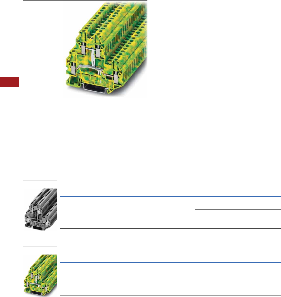
V7-T8-16 Volume 7—Logic Control, Operator Interface and Connectivity Solutions CA08100008E—July 2014 www.eaton.com
8
8
8
8
8
8
8
8
8
8
8
8
8
8
8
8
8
8
8
8
8
8
8
8
8
8
8
8
8
8
8.1
Terminal Blocks, Fuse Blocks and Fuse Holders
IEC—XB Series
Double Level
Contents
Description Page
Single Level—Through-Feed . . . . . . . . . . . . . . . . . V7-T8-5
Single Level—Ground Blocks . . . . . . . . . . . . . . . . V7-T8-10
Multi-Conductor Terminal Blocks . . . . . . . . . . . . . V7-T8-12
Multi-Conductor Ground Blocks . . . . . . . . . . . . . . V7-T8-14
Double Level
Accessories . . . . . . . . . . . . . . . . . . . . . . . . . . . V7-T8-17
Technical Data and Specifications . . . . . . . . . . V7-T8-17
Dimensions . . . . . . . . . . . . . . . . . . . . . . . . . . . V7-T8-17
Triple Level Sensor/Actuator . . . . . . . . . . . . . . . . . V7-T8-18
Fuse Terminal Blocks . . . . . . . . . . . . . . . . . . . . . . . V7-T8-21
Disconnect and Component Terminal Blocks . . . . V7-T8-24
High Current Blocks . . . . . . . . . . . . . . . . . . . . . . . V7-T8-27
Mini Screw Connection . . . . . . . . . . . . . . . . . . . . . V7-T8-29
Double Level
Product Description
The potentials of the XBUTT
double-level terminal blocks
are on two levels to reduce
space requirements by 50%
over single-level terminal
blocks. The XBUTT Series can
be bridged on both levels for
maximum flexibility. Marking
can be provided at each
termination point.
Product Selection
Screw Connection Double Level Blocks, XBUTT4
Screw Connection Double Level Ground Block, XBUTT4PE
Terminal
Width
Maximum
Wire Size
IEC 60 947-7-1
in V/A/AWG
UL-cUL Ratings
in V/A/AWG Color
Standard
Pack
Catalog
Number
Screw Connection Double Level Blocks
6.2 mm 10 AWG/4 mm2800/36/26–10 300/30/26–10 Gray 50 XBUTT4
Blue 50 XBUTT4BU
Red 50 XBUTT4RD
Screw Connection Double Level Block (terminal block with potential distribution between the levels)
6.2 mm 10 AWG/4 mm2800/36/26–10 300/30/26–10 Gray 50 XBUTT4PV
Terminal
Width
Maximum
Wire Size
IEC 60 947-7-1
in V/A/AWG
UL-cUL Ratings
in V/A/AWG Color
Standard
Pack
Catalog
Number
Screw Connection Double Level—Ground Blocks
6.2 mm 10 AWG/4 mm2—/—/26–10 —/—/26–10 Green/Yellow 50 XBUTT4PE
XBUTT4
XBUTT4PE

Volume 7—Logic Control, Operator Interface and Connectivity Solutions CA08100008E—July 2014 www.eaton.com V7-T8-17
8
8
8
8
8
8
8
8
8
8
8
8
8
8
8
8
8
8
8
8
8
8
8
8
8
8
8
8
8
8
8.1
Terminal Blocks, Fuse Blocks and Fuse Holders
IEC—XB Series
Accessories
Screw Connection Terminal/Ground Blocks, Double Level
Technical Data and Specifications
Screw Connection Double Level
Dimensions
Approximate Dimensions in Inches (mm)
Screw Connection Double Level
Notes
1For ordering information, see Page V7-T8-105.
2For information on Printed Marking Tag Options, see Page V7-T8-98.
For additional accessories, see Page V7-T8-90.
Description Color
Number of
Positions
Standard
Pack
XBUTT4 XBUTT4PE
Catalog
Number
Catalog
Number
End cover Gray — 10 XBACUTT4 XBACUTT4
End cover segment Gray — 10 XBDPUTT4 XBDPUTT4
Partition plate — — 10 XBATUTT4 XBATUTT4
Plug-in bridge—for cross connections in
the bridge shaft
Red 2 10 XBAFBS26 XBAFBS26
310 XBAFBS36 XBAFBS36
510 XBAFBS56 XBAFBS56
10 10 XBAFBS106 XBAFBS106
50 10 XBAFBS506 XBAFBS506
Test adapter — — 10 XBATSPAI4 XBATSPAI4
2.3 mm diameter test plug — — — XBATSMPS-_ 1XBATSMPS-_ 1
Modular test plug — — 10 XBATSPS6 XBATSPS6
Blank marker strip (strip of 10) White — 10 XBMZB6 2XBMZB6 2
Description XBUTT4 XBUTT4PE
Technical Data in Accordance with IEC
Maximum load current in A/cross-section in mm230/6 —/6
Rated surge voltage in kV/contamination class 8/3 6/3
Surge voltage category/insulating material group III/I III/I
Connection Capacity
Stranded with ferrule/with ferrule and
plastic sleeve in mm2
0.25–4/0.25–4 0.25–4/0.25–4
Multi-Conductor Connection
(same cross-section)
Solid/stranded in mm20.14–1.5/0.14–1.5 0.14–1.5/0.14–1.5
Stranded with ferrules without plastic sleeve in mm20.25–1.5 0.25–1.5
Stranded with twin ferrule with plastic sleeve in mm20.5–2.5 0.5–2.5
Stripping length in inches (mm) 0.35 (9) 0.35 (9)
Thread M3 M3
Torque in in-lb (Nm) 5.3–7.1 (0.6–0.8) 5.3–7.1 (0.6–0.8)
Catalog
Number Width Length
Cover
Width
Height for—
35 x 7.5 in 35 x 15 in
XBUTT4 0.24 (6.2) 2.75 (69.9) 0.09 (2.2) 2.56 (65.0) 2.85 (72.5)
XBUTT4PE 0.24 (6.2) 2.75 (69.9) 0.09 (2.2) 2.56 (65.0) 2.85 (72.5)
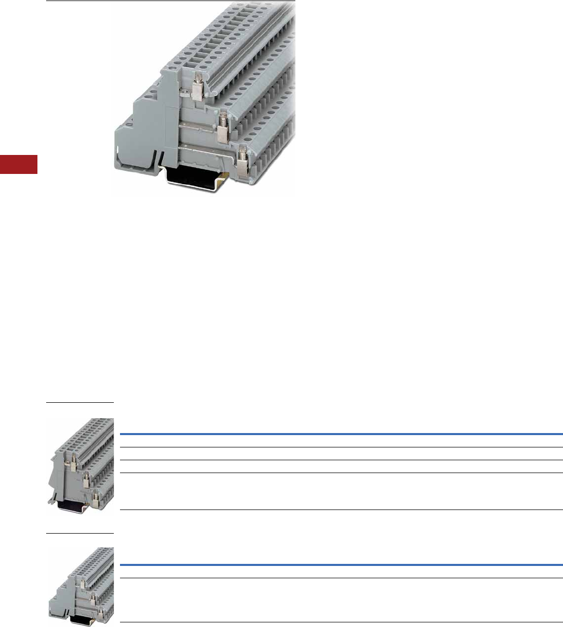
V7-T8-18 Volume 7—Logic Control, Operator Interface and Connectivity Solutions CA08100008E—July 2014 www.eaton.com
8
8
8
8
8
8
8
8
8
8
8
8
8
8
8
8
8
8
8
8
8
8
8
8
8
8
8
8
8
8
8.1
Terminal Blocks, Fuse Blocks and Fuse Holders
IEC—XB Series
Triple Level Sensor/Actuator
Contents
Description Page
Single Level—Through-Feed . . . . . . . . . . . . . . . . . V7-T8-5
Single Level—Ground Blocks . . . . . . . . . . . . . . . . V7-T8-10
Multi-Conductor Terminal Blocks . . . . . . . . . . . . . V7-T8-12
Multi-Conductor Ground Blocks . . . . . . . . . . . . . . V7-T8-14
Double Level . . . . . . . . . . . . . . . . . . . . . . . . . . . . . V7-T8-16
Triple Level Sensor/Actuator
Accessories . . . . . . . . . . . . . . . . . . . . . . . . . . . V7-T8-19
Technical Data and Specifications . . . . . . . . . . V7-T8-20
Dimensions . . . . . . . . . . . . . . . . . . . . . . . . . . . V7-T8-20
Fuse Terminal Blocks . . . . . . . . . . . . . . . . . . . . . . . V7-T8-21
Disconnect and Component Terminal Blocks . . . . V7-T8-24
High Current Blocks . . . . . . . . . . . . . . . . . . . . . . . V7-T8-27
Mini Screw Connection . . . . . . . . . . . . . . . . . . . . . V7-T8-29
Triple Level Sensor/Actuator
Product Description
The XB3UK sensor terminal
blocks reduce installation
time by terminating three-
wire devices such as
photoelectric and proximity
sensors in a single terminal
block. The XB3UK Series
accommodates a design
where the positive and
negative connections are
grouped so that only the
signal lines and one pair of
wires for the power supply
need to be wired between
the terminal box and the
control. The upper level
accommodates the markable
feed-through terminals for
the signal line. The two lower
terminal points can be
bridged. These are used for
the sensor power supply.
The positive and negative
potential can be fed into the
bridges with XB3UKF25. The
first sensor can also be
connected to this three-wire
feed-through block.
Product Selection
Screw Connection Triple Level Sensor/Actuator
Screw Connection Triple Level Sensor/Actuator
Terminal
Width
Maximum
Wire Size
Connection Data
in V/A/AWG
IEC 60 947-7-1
in V/A/AWG
UL-cUL Ratings
in V/A/AWG Color
Standard
Pack
Catalog
Number
Screw Connection Triple Level
6.2 mm 14 AWG/2.5 mm2250/26/24–12 — 300/15/30–14 Gray 50 XB3UKA25
Screw Connection Triple Level with Red LED, 15–30 Vdc, 2.5–7.5A
6.2 mm 14 AWG/2.5 mm2250/26/24–12 — 300/15/30–14 Gray 50 XB3UKA25L24
Terminal
Width
Maximum
Wire Size
Connection Data
in V/A/AWG
IEC 60 947-7-1
in V/A/AWG
UL-cUL Ratings
in V/A/AWG Color
Standard
Pack
Catalog
Number
Screw Connection Triple Level
6.2 mm 14 AWG/2.5 mm2— 250/30/24–12 300/15/30–14 Gray 50 XB3UKF25
XB3UKA25
XB3UKF25
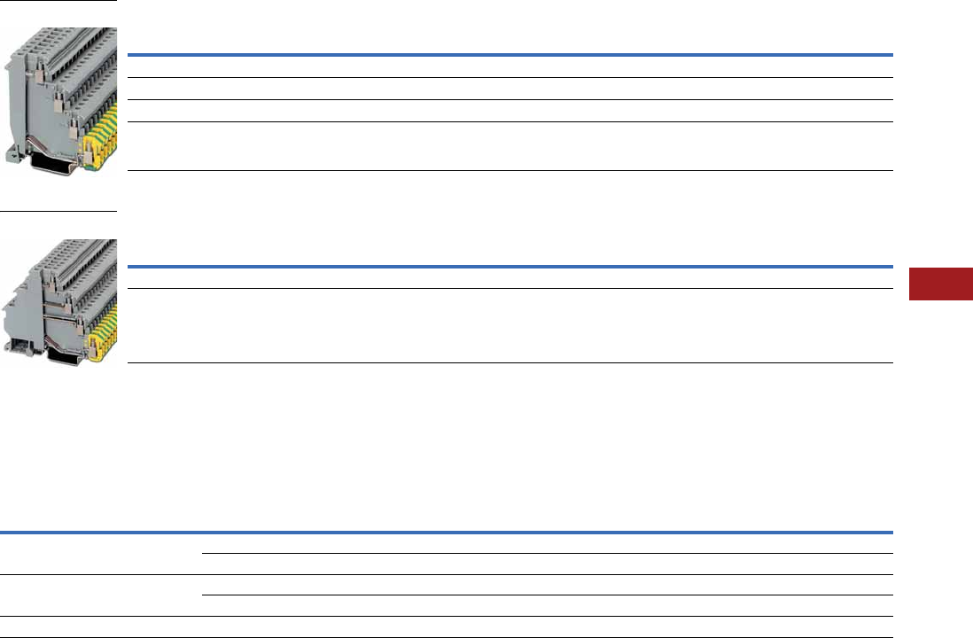
Volume 7—Logic Control, Operator Interface and Connectivity Solutions CA08100008E—July 2014 www.eaton.com V7-T8-19
8
8
8
8
8
8
8
8
8
8
8
8
8
8
8
8
8
8
8
8
8
8
8
8
8
8
8
8
8
8
8.1
Terminal Blocks, Fuse Blocks and Fuse Holders
IEC—XB Series
Screw Connection Triple Level Sensor/Actuator
Screw Connection Triple Level Sensor/Actuator
Accessories
Screw Connection Triple Level Sensor/Actuator
Notes
1For information on Printed Marking Tag Options, see Page V7-T8-98.
For additional accessories, see Page V7-T8-90.
Terminal
Width
Maximum
Wire Size
Connection Data
in V/A/AWG
UL-cUL Ratings
in V/A/AWG Color
Standard
Pack
Catalog
Number
Screw Connection Triple Level
6.2 mm 14 AWG/2.5 mm2250/26/24–12 300/15/30–14 Gray 50 XB3UKA25PE
Screw Connection Triple Level with Red LED, 15–30 Vdc, 2.5–7.5A
6.2 mm 14 AWG/2.5 mm2250/26/24–12 300/15/30–14 Gray 50 XB3UKA25PEL24
Terminal
Width
Maximum
Wire Size
Connection Data
in V/A/AWG
UL-cUL Ratings
in V/A/AWG Color
Standard
Pack
Catalog
Number
Screw Connection Triple Level
6.2 mm 14 AWG/2.5 mm2— 300/15/30–14 Gray 50 XB3UKF25PE
Description Color
Number of
Positions
Standard
Pack
XB3UKA25 XB3UKF25 XB3UKA25PE XB3UKF25PE
Catalog
Number
Catalog
Number
Catalog
Number
Catalog
Number
Insertion bridge Blue 80 1 XBAEB80DIKB XBAEB80DIKB XBAEB80DIKB XBAEB80DIKB
Red 80 1 XBAEB80DIKR XBAEB80DIKR XBAEB80DIKR XBAEB80DIKR
Insertion bridge Blue 10 10 XBAEB10DIKB XBAEB10DIKB XBAEB10DIKB XBAEB10DIKB
Red 10 10 XBAEB10DIKR XBAEB10DIKR XBAEB10DIKR XBAEB10DIKR
Blank marker strip (strip of 10) White — 10 XBMZB6 1XBMZB6 2XBMZB6 2XBMZB6 2
XB3UKA25PE
XB3UKF25PE
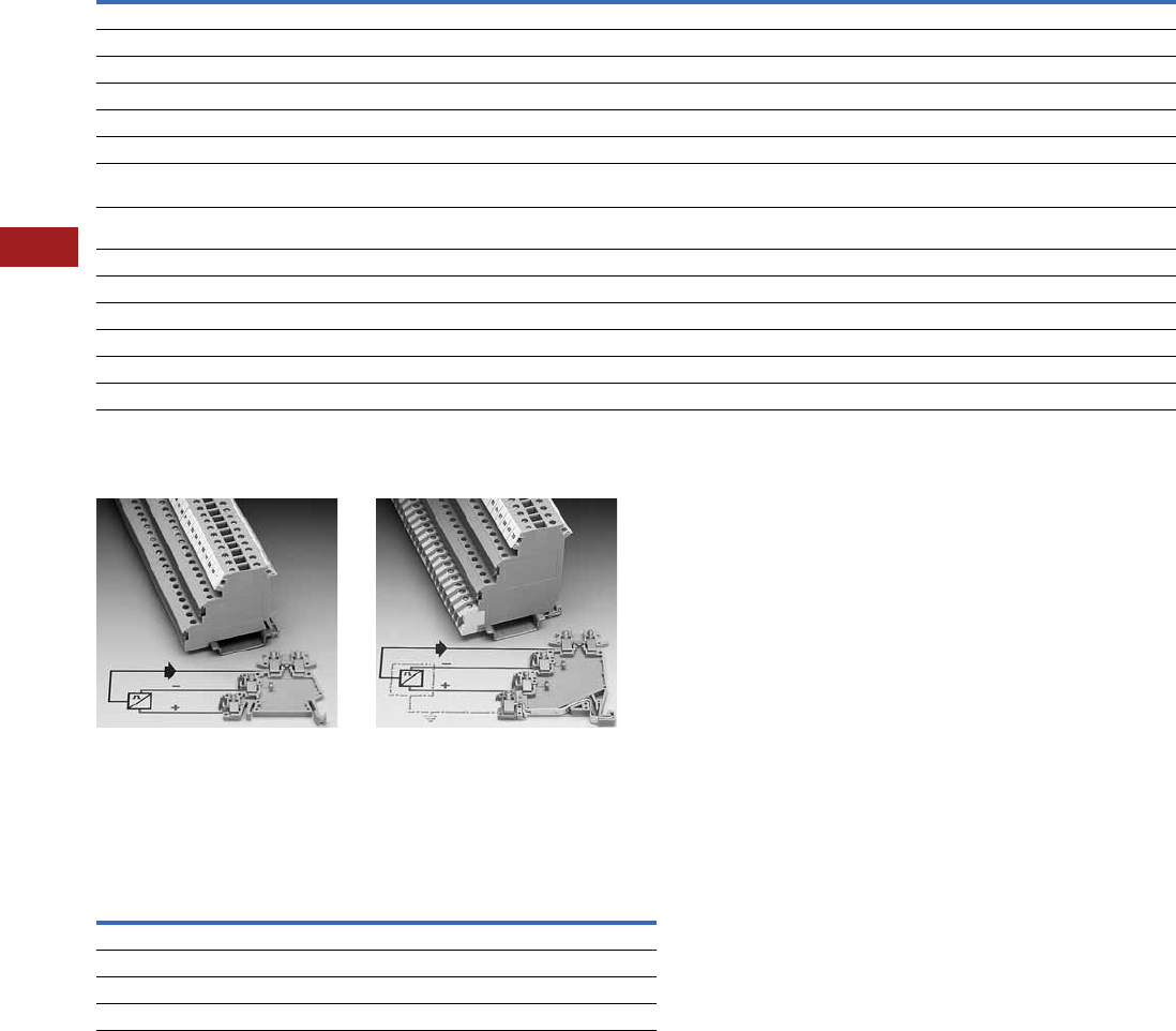
V7-T8-20 Volume 7—Logic Control, Operator Interface and Connectivity Solutions CA08100008E—July 2014 www.eaton.com
8
8
8
8
8
8
8
8
8
8
8
8
8
8
8
8
8
8
8
8
8
8
8
8
8
8
8
8
8
8
8.1
Terminal Blocks, Fuse Blocks and Fuse Holders
IEC—XB Series
Technical Data and Specifications
Screw Connection Triple Level Sensor/Actuator
Wiring for Three-Level
Sensor Terminal Blocks
Wiring for Four-Level
Sensor Terminal Blocks
Dimensions
Approximate Dimensions in Inches (mm)
Screw Connection Triple Level Sensor/Actuator
Description XB3UKA25 XB3UKF25 XB3UKA25PE XB3UKF25PE
Technical Data in Accordance with IEC
Maximum load current in A/cross-section in mm226/2.5 30/4 26/2.5 26/2.5
Maximum cross section with insertion bridge solid/stranded in mm24/2.5 4/2.5 4/2.5 4/2.5
Rated surge voltage in kV/contamination class 4/3 4/3 4/3 6/3
Surge voltage category/insulating material group III/I III/I III/I III/I
Connection Capacity
Stranded with ferrule/with ferrule and
plastic sleeve in mm2
0.25–2.5/0.25–2.5 0.25–2.5/0.25–2.5 0.25–2.5/0.25–2.5 0.25–2.5/0.25–2.5
Multi-Conductor Connection
(same cross-section)
Solid/stranded in mm20.2–1.0/0.2–1.0 0.2–1.0/0.2–1.0 0.2–1.0/0.2–1.0 0.2–1.0/0.2–1.0
Stranded with ferrules without plastic sleeve in mm20.25–1.0 0.25–1.0 0.25–1.0 0.25–1.0
Stranded with twin ferrule with plastic sleeve in mm20.5–1.0 0.5–1.0 0.5–1.0 0.5–1.0
Stripping length in inches (mm) 0.31 (8) 0.31 (8) 0.31 (8) 0.31 (8)
Thread M3 M3 M3 M3
Torque in in-lb (Nm) 4.4–5.3 (0.5–0.6) 4.4–5.3 (0.5–0.6) 4.4–5.3 (0.5–0.6) 4.4–5.3 (0.5–0.6)
Catalog
Number Width Length
Height for—
35 x 7.5 in 35 x 15 in
XB3UKA25 0.24 (6.2) 2.17 (55.0) 2.15 (54.5) 2.44 (62.0)
XB3UKF25 0.24 (6.2) 2.85 (72.5) 2.15 (54.5) 2.44 (62.0)
XB3UKA25PE 0.24 (6.2) 2.46 (62.5) 2.76 (70.0) 3.05 (77.5)
XB3UKF25PE 0.24 (6.2) 3.25 (82.5) 2.76 (70.0) 3.05 (77.5)
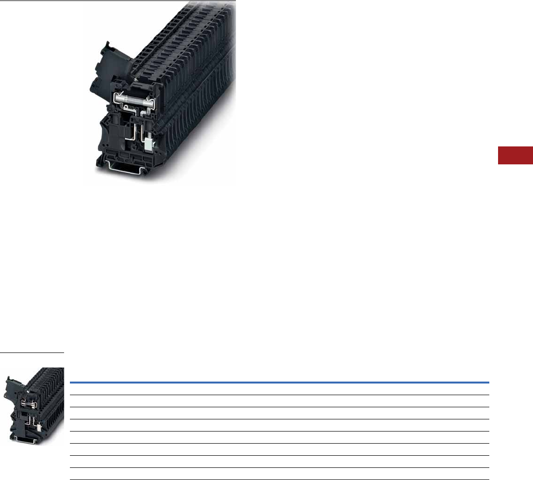
Volume 7—Logic Control, Operator Interface and Connectivity Solutions CA08100008E—July 2014 www.eaton.com V7-T8-21
8
8
8
8
8
8
8
8
8
8
8
8
8
8
8
8
8
8
8
8
8
8
8
8
8
8
8
8
8
8
8.1
Terminal Blocks, Fuse Blocks and Fuse Holders
IEC—XB Series
Fuse Terminal Blocks
Contents
Description Page
Single Level—Through-Feed . . . . . . . . . . . . . . . . . V7-T8-5
Single Level—Ground Blocks . . . . . . . . . . . . . . . . V7-T8-10
Multi-Conductor Terminal Blocks . . . . . . . . . . . . . . V7-T8-12
Multi-Conductor Ground Blocks . . . . . . . . . . . . . . V7-T8-14
Double Level. . . . . . . . . . . . . . . . . . . . . . . . . . . . . . V7-T8-16
Triple Level Sensor/Actuator . . . . . . . . . . . . . . . . . V7-T8-18
Fuse Terminal Blocks
Accessories . . . . . . . . . . . . . . . . . . . . . . . . . . . V7-T8-23
Technical Data and Specifications . . . . . . . . . . V7-T8-23
Dimensions . . . . . . . . . . . . . . . . . . . . . . . . . . . V7-T8-23
Disconnect and Component Terminal Blocks . . . . V7-T8-24
High Current Blocks . . . . . . . . . . . . . . . . . . . . . . . . V7-T8-27
Mini Screw Connection . . . . . . . . . . . . . . . . . . . . . V7-T8-29
Fuse Terminal Blocks
Product Description
The UT Series fuse terminal
blocks come in two varieties—
lever type and cap. Each
performs two functions. They
act as a fuse carrier for most
common North American and
European fuses and they
allow for potential distribution
with the double bridge shaft.
The terminal blocks therefore
allow bypass routing of two
separate potentials next to
each other. This has the
advantage of a time-saving
potential infeed and a correct,
functional configuration of the
terminal strip. For signaling a
triggered fuse, fuse terminal
blocks with light indicators
are available (for both AC and
DC voltage).
Product Selection
Screw Connection Fuse Terminal Blocks, for 5 x 20 mm Fuse
Note
1 As disconnect terminal block 400V, as fuse terminal block 250V.
Terminal
Width
Maximum
Wire Size
IEC 60 947-7-3
in V/A/AWG
UL-cUL Ratings
in V/A/AWG Color
Standard
Pack
Catalog
Number
Fuse Terminal Blocks
6.2 mm 10 AWG/4 mm21/6.3/26–10 600/6.3/26–10 Black 50 XBUT4FBE
Fuse Terminal Blocks with LED 12–30V, 1–2.5 mA
6.2 mm 10 AWG/4 mm21/6.3/26–10 600/6.3/26–10 Black 50 XBUT4FBEL24
Fuse Terminal Blocks with LED 30–60V, 0.8–2.0 mA
6.2 mm 10 AWG/4 mm21/6.3/26–10 600/6.3/26–10 Black 50 XBUT4FBEL60
Fuse Terminal Blocks with LED 110–250V, 0.5–2.5 mA
6.2 mm 10 AWG/4 mm21/6.3/26–10 600/6.3/26–10 Black 50 XBUT4FBEL250
XBUT4FBE
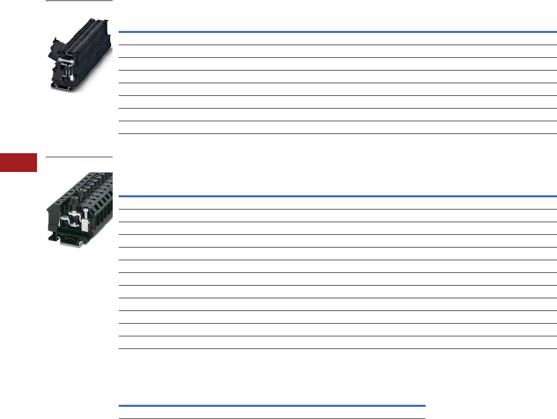
V7-T8-22 Volume 7—Logic Control, Operator Interface and Connectivity Solutions CA08100008E—July 2014 www.eaton.com
8
8
8
8
8
8
8
8
8
8
8
8
8
8
8
8
8
8
8
8
8
8
8
8
8
8
8
8
8
8
8.1
Terminal Blocks, Fuse Blocks and Fuse Holders
IEC—XB Series
Screw Connection Fuse Terminal Blocks for 6.3 x 32 mm (1/4 in x 1–1/4 in) Fuse
Screw Connection Fuse Terminal Blocks, XBUK10FBC
Cartridge Fuse Inserts 5 x 20 mm Based on DIN EN 60 947-7-3: 2003-7
Notes
Max. power dissipation at 73.4°F (23°C) based on DIN EN 60 947-7-3: 2003-7.
When selecting cartridge fuse inserts, please ensure that the maximum power dissipation specified above
is not exceeded. Details can be obtained from the fuse suppliers.
If the fuse is defective, the downstream circuit is not off load.
1 As disconnect terminal block 500V, as fuse terminal block 400V.
Terminal
Width
Maximum
Wire Size
IEC 60 947-7-3
in V/A/AWG
UL-cUL Ratings
in V/A/AWG Color
Standard
Pack
Catalog
Number
Fuse Terminal Blocks
8.2 mm 8 AWG/6 mm21/10/24–8 400/10/24–8 Black 50 XBUT6FBN
Fuse Terminal Blocks with LED 12–30V, 1–2.5 mA
8.2 mm 8 AWG/6 mm21/10/24–8 400/10/24–8 Black 50 XBUT6FBNL24
Fuse Terminal Blocks with LED 30–60V, 0.8–2.0 mA
8.2 mm 8 AWG/6 mm21/10/24–8 400/10/24–8 Black 50 XBUT6FBNL60
Fuse Terminal Blocks with LED 110–250V, 0.5–2.5 mA
8.2 mm 8 AWG/6 mm21/10/24–8 400/10/24–8 Black 50 XBUT6FBNL250
Terminal
Width
Maximum
Wire Size
IEC 60 947-7-3
with Fuse in
V/A/AWG
IEC 60 947-7-3
as Disconnected
t.b. in V/A/AWG
UL-cUL Ratings
in V/A/AWG Color
Standard
Pack
Catalog
Number
Fuse Terminal Blocks for 5 x 20 mm fuse
12 mm 6 AWG/16 mm21/1/20–4 800/10/20–6 300/20/22–6 Black 50 XBUK10FBCE
Fuse Terminal Blocks for 6.3 x 32 mm (1/4 in x 1–1/4 in) fuse
12 mm 6 AWG/16 mm21/1/20–4 800/10/20–6 300/20/22–6 Black 50 XBUK10FBCN
Fuse Terminal Blocks with Light Indicator 15–30V, 1–2.5 mA, 5 x 20 mm
12 mm 6 AWG/16 mm21/1/20–4 800/10/20–6 300/20/22–6 Black 50 XBUK10FBCEL24
Fuse Terminal Blocks with Light Indicator 15–30V, 1–2.5 mA, 6.3 x 32 mm
12 mm 6 AWG/16 mm21/1/20–4 800/10/20–6 300/20/22–6 Black 50 XBUK10FBCNL24
Fuse Terminal Blocks with Light Indicator 110–250V, 0.5–1.1A, 5 x 20 mm
12 mm 6 AWG/16 mm21/1/20–4 800/10/20–6 300/20/22–6 Black 50 XBUK10FBCEL250
Fuse Terminal Blocks with Light Indicator 110–250V, 0.5–1.1A, 6.3 x 32 mm
12 mm 6 AWG/16 mm21/1/20–4 800/10/20–6 300/20/22–6 Black 50 XBUK10FBCNL250
Terminal
Blocks U (V)
Overload Protection Short-Circuit Protection Only
Individual Interconnected Individual Interconnected Imax. (A)
XBUT4FBE 250 1.6W 1.6W 4W 2.5W 6.3
XBUT6FBN
XBUK10FBCE

Volume 7—Logic Control, Operator Interface and Connectivity Solutions CA08100008E—July 2014 www.eaton.com V7-T8-23
8
8
8
8
8
8
8
8
8
8
8
8
8
8
8
8
8
8
8
8
8
8
8
8
8
8
8
8
8
8
8.1
Terminal Blocks, Fuse Blocks and Fuse Holders
IEC—XB Series
Accessories
Screw Connection Fuse Terminal Blocks
Technical Data and Specifications
Screw Connection Fuse Terminal Blocks
Dimensions
Approximate Dimensions in Inches (mm)
Screw Connection Fuse Terminal Blocks
Notes
1XBUT4FBE and XBUT6FBN have an enclosed design. The use of an end cover is not required.
2For information on Printed Marking Tag Options, see Page V7-T8-98.
For additional accessories, see Page V7-T8-90.
Description Color
Number of
Positions
Standard
Pack
XBUT4FBE XBUT6FBN XBUK10FBCE
Catalog
Number
Catalog
Number
Catalog
Number
End cover — — — 11 —
Plug-in bridge—for cross connections in
the bridge shaft
Red 2 10 XBAFBS26 XBAFBS28 —
310XBAFBS36 XBAFBS38 —
510XBAFBS56 XBAFBS58 —
10 10 XBAFBS106 XBAFBS108 —
50 10 XBAFBS506 — —
Blank marker strip center labeling (strip of 10) White — — XBMZB5 2XBMZB6 2—
Blank marker strip external labeling (strip of 10) White — — XBMZB6 2XBMZB8 2—
Fixed bridge — 2 10 — — XBAFBI212
Screw heads with insulating collar — 10 10 — — XBAFBI1012
Blank marker strip (strip of 10) White — 10 —— XBMZB6
2
Description XBUT4FBE XBUT4FBN XBUK10FBCE
Technical Data in Accordance with IEC
Fuse type/dimensions in (mm) — — G/5 x 20/5 x 25/6.3 x 32
Maximum cross section with insertion bridge solid/stranded in mm26.3/6 10/10 10/10
Rated surge voltage in kV/contamination class 4/3 4/3 4/3
Surge voltage category/insulating material group III/II III/II III/I
Connection Capacity
Stranded with ferrule/with ferrule and plastic sleeve in mm20.25–4/0.25–4 0.25–6/0.25–6 0.5–10/0.5–10
Multi-Conductor Connection (same cross-section)
Solid/stranded in mm20.14–1.5/0.14–1.5 — 0.5–4/0.5–4
Stranded with ferrules without plastic sleeve in mm20.25–1.5 — 0.5–4
Stranded with twin ferrule with plastic sleeve in mm20.5–2.5 0.5–4 0.5–10
Stripping length in inches (mm) 0.35 (9) 0.39 (10) 0.43 (11)
Thread M3 M4 M4
Torque in in-lb (Nm) 5.3–7.1 (0.6–0.8) 13.3–15.9 (1.5–1.8) 13.3–15.9 (1.5–1.8)
Catalog
Number Width Length
Height for—
35 x 7.5 in 35 x 15 in 32 in
XBUT4FBE 0.24 (6.2) 2.24 (56.8) 2.87 (73.0) 3.17 (80.5) —
XBUT4FBN 0.32 (8.2) 2.24 (56.8) 2.87 (73.0) 3.17 (80.5) —
XBUK10FBCE 0.47 (12.0) 2.44 (62.0) 2.32 (59.0) 2.62 (66.5) 2.52 (64.0)
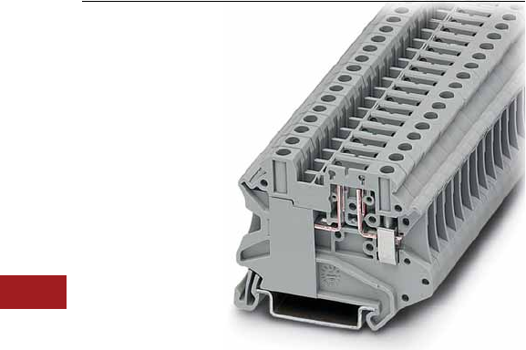
V7-T8-24 Volume 7—Logic Control, Operator Interface and Connectivity Solutions CA08100008E—July 2014 www.eaton.com
8
8
8
8
8
8
8
8
8
8
8
8
8
8
8
8
8
8
8
8
8
8
8
8
8
8
8
8
8
8
8.1
Terminal Blocks, Fuse Blocks and Fuse Holders
IEC—XB Series
Disconnect and Component Terminal Blocks
Contents
Description Page
Single Level—Through-Feed . . . . . . . . . . . . . . . . . V7-T8-5
Single Level—Ground Blocks . . . . . . . . . . . . . . . . V7-T8-10
Multi-Conductor Terminal Blocks . . . . . . . . . . . . . V7-T8-12
Multi-Conductor Ground Blocks . . . . . . . . . . . . . . V7-T8-14
Double Level . . . . . . . . . . . . . . . . . . . . . . . . . . . . . V7-T8-16
Triple Level Sensor/Actuator . . . . . . . . . . . . . . . . . V7-T8-18
Fuse Terminal Blocks . . . . . . . . . . . . . . . . . . . . . . . V7-T8-21
Disconnect and Component Terminal Blocks
Product Selection . . . . . . . . . . . . . . . . . . . . . . . V7-T8-25
Accessories . . . . . . . . . . . . . . . . . . . . . . . . . . . V7-T8-26
Technical Data and Specifications . . . . . . . . . . V7-T8-26
Dimensions . . . . . . . . . . . . . . . . . . . . . . . . . . . V7-T8-26
High Current Blocks . . . . . . . . . . . . . . . . . . . . . . . V7-T8-27
Mini Screw Connection . . . . . . . . . . . . . . . . . . . . . V7-T8-29
Disconnect and Component Terminal Blocks
Product Description
The XB Series includes
application specific terminal
blocks like the XBUT4TG
disconnect block that
accommodates disconnect
component and fuse terminal
blocks. It can also be bridged
with standard terminal blocks
via the double bridge shaft.
The component plug XBPCO
serves to accommodate
different components such
as resistors or capacitors.
5 x 20 mm fuses can be
inserted into the fuse plug
XBPFU, also available with
light indication. The XBUT4MT
knife disconnect terminal
block features a compact
design and a high current
carrying capacity of 16A.
Versions with test socket
screws provide a test option
for 2.3 mm diameter test
plugs on both sides of the
disconnect point.
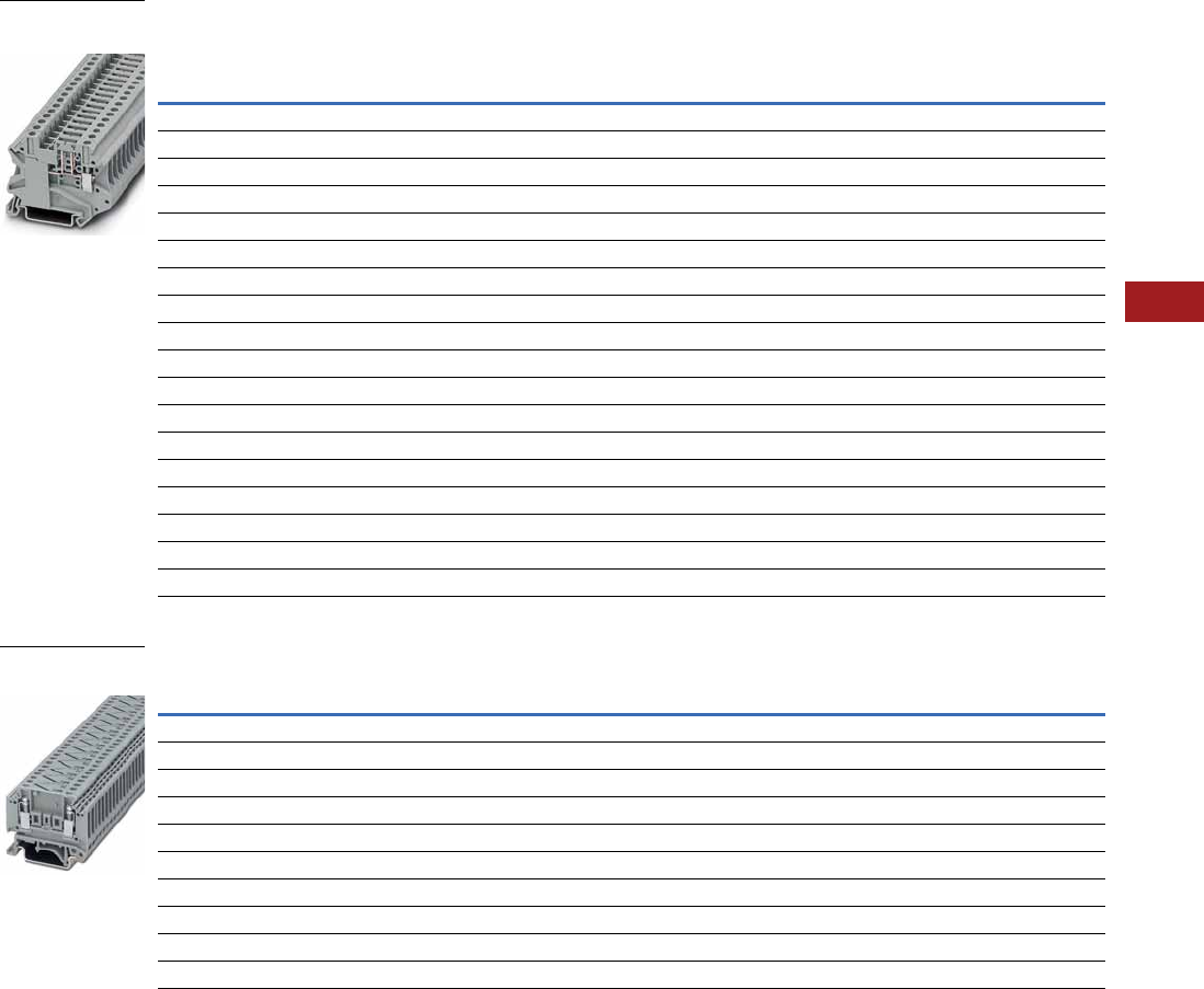
Volume 7—Logic Control, Operator Interface and Connectivity Solutions CA08100008E—July 2014 www.eaton.com V7-T8-25
8
8
8
8
8
8
8
8
8
8
8
8
8
8
8
8
8
8
8
8
8
8
8
8
8
8
8
8
8
8
8.1
Terminal Blocks, Fuse Blocks and Fuse Holders
IEC—XB Series
Product Selection
Screw Connection Disconnect and Component Terminal Blocks
Screw Connection Thermoelectric Voltage Terminal Blocks
Terminal
Width
Maximum
Wire Size
Connection Data
in V/A/AWG
UL-cUL Ratings
for Disconnect
in V/A/AWG
UL-cUL Ratings
for Disconnect
with Test Sockets
in V/A/AWG Color
Standard
Pack
Catalog
Number
Screw Connection Disconnect
6.2 mm 10 AWG/4 mm2500/16/26–10 600/16/26–10 300/16/26–10 Gray 50 XBUT4TG
Screw Connection Disconnect with Test Sockets
6.2 mm 10 AWG/4 mm2500/16/26–10 600/16/26–10 300/16/26–10 Gray 50 XBUT4TGP
Component Plug
6.2 mm 10 AWG/4 mm2500/16/26–10 600/16/26–10 300/16/26–10 Gray 10 XBPCO
Fuse Plug
6.2 mm 10 AWG/4 mm2500/16/26–10 600/16/26–10 300/16/26–10 Black 10 XBPFU
Fuse Plug with Light Indicator for 12–30V, 1–2.5 mA
6.2 mm 10 AWG/4 mm2500/16/26–10 600/16/26–10 300/16/26–10 Black 10 XBPFUL24
Fuse Plug with Light Indicator for 110–250V, 0.5–2.5 mA
6.2 mm 10 AWG/4 mm2500/16/26–10 600/16/26–10 300/16/26–10 Black 10 XBPFUL250
Screw Connection Disconnect Knife Disconnect
6.2 mm 10 AWG/4 mm2500/16/26–10 600/16/26–10 300/16/26–10 Gray 50 XBUT4MT
Screw Connection Disconnect Knife Disconnect with Test Sockets
6.2 mm 10 AWG/4 mm2500/16/26–10 600/16/26–10 300/16/26–10 Gray 50 XBUT4MTP
Screw Connection Terminal Blocks with Integrated Diodes
6.2 mm 12 AWG/4 mm2500/32/24–10 600/30/26–10 — Gray 50 XBUKK4DIO
Terminal
Width
Maximum
Wire Size
Connection Data
in V/A/AWG
UL-cUL Ratings
in V/A/AWG Color
Standard
Pack
Catalog
Number
Copper/Constantan (CU/CUNI44)
10.4 mm 12 AWG/2.5 mm2400/—/24–12 300/10/28–12 Gray 50 XBTKT25 (Type T)
Iron/Constantan (FE/CUNI44)
10.4 mm 12 AWG/2.5 mm2400/—/24–12 300/10/28–12 Gray 50 XBTKJ25 (Type J)
Nickel-Chrome/Constantan (NICR/CUNI44)
10.4 mm 12 AWG/2.5 mm2400/—/24–12 300/10/28–12 Gray 50 XBTKE25 (Type E)
Nickel-Chrome/Nickel (NICRNI)
10.4 mm 12 AWG/2.5 mm2400/—/24–12 300/10/28–12 Gray 50 XBTKK25 (Type K)
Copper/Copper Nickel (E-CU/A-CU)
10.4 mm 12 AWG/2.5 mm2400/—/24–12 300/10/28–12 Gray 50 XBTKR25 (Type R)
XBUT4TG
Disconnect
XBTKT25 Thermal
Electric Voltage

V7-T8-26 Volume 7—Logic Control, Operator Interface and Connectivity Solutions CA08100008E—July 2014 www.eaton.com
8
8
8
8
8
8
8
8
8
8
8
8
8
8
8
8
8
8
8
8
8
8
8
8
8
8
8
8
8
8
8.1
Terminal Blocks, Fuse Blocks and Fuse Holders
IEC—XB Series
Accessories
Screw Connection Disconnect and Component Terminal Blocks
Technical Data and Specifications
Screw Connection Disconnect and Component Terminal Blocks
Dimensions
Approximate Dimensions in Inches (mm)
Screw Connection Disconnect and Component Terminal Blocks
Notes
1For ordering information, see Page V7-T8-105.
2For information on Printed Marking Tag Options, see Page V7-T8-98.
For additional accessories, see Page V7-T8-90.
Description Color
Number of
Positions
Standard
Pack
XBUT4TG XBUT4MT XBUKK4DI0 XBTKT25
Catalog
Number
Catalog
Number
Catalog
Number
Catalog
Number
Plug-in bridge—for cross connections in
the bridge shaft
Red 2 10 XBAFBS26 XBAFBS26 — —
310XBAFBS36 XBAFBS36 — —
510XBAFBS56 XBAFBS56 — —
10 10 XBAFBS106 XBAFBS106 — —
50 10 XBAFBS506 XBAFBS506 — —
Test adapter — — 10 XBATSPAI4 XBATSPAI4 — —
2.3 mm diameter test plug — — — XBATSMPS-_ 1XBATSMPS-_ 1——
Modular test plug — — 10 XBATSDPPS6 XBATSDPPS6 — —
Blank marker strip (strip of 10) White — 10 XBMZB6 2XBMZB6 2XBMZB6 2XBMZB10 2
End cover Gray — 10 — — XBACUKK35 XBACTK4
Spacer cover Gray — 10 — — XBADGUKK35 —
Spacer plate — — 10 — — XBADPUKK35 —
Partition plate — — — — — — XBATTK4
Fixed bridge — 10 10 ——XBAFBI106—
Description XBUT4TG XBUT4MT XBUKK4DI0 XBTK
Technical Data in Accordance with IEC
Maximum load current in A/cross-section in mm216/6 16/6 32/4 —
Rated surge voltage in kV/contamination class 6/3 6/3 6/3 —
Surge voltage category/insulating material group III/I III/I III/I —
Connection Capacity
Stranded with ferrule/with ferrule and
plastic sleeve in mm2
0.25–4/0.25–4 0.25–4/0.25–4 0.25–4/0.25–2.5 —
Multi-Conductor Connection
(same cross-section)
Solid/stranded in mm20.14–1.5/0.14–1.5 0.14–1.5/0.14–1.5 0.2–1.5/0.2–1.5 —
Stranded with ferrules without plastic sleeve in mm20.25–1.5 0.25–1.5 0.25–1.5 —
Stranded with twin ferrule with plastic sleeve in mm20.5–2.5 0.5–2.5 0.5–1.5 —
Stripping length in inches (mm) 0.35 (9) 0.35 (9) 0.31 (8) 0.28 (7)
Thread M3 M3 M3 M3
Torque in in-lb (Nm) 5.3–7.1 (0.6–0.8) 5.3–7.1 (0.6–0.8) 5.3–7.1 (0.6–0.8) 5.3–7.1 (0.6–0.8)
Catalog
Number Width Length
Cover
Width
Height for—
35 x 7.5 in 35 x 15 in 32 in
XBUT4TG 0.24 (6.2) 2.24 (56.8) — 1.87 (47.5) 2.17 (55.0) —
XBUT4MT 0.24 (6.2) 2.24 (56.8) — 1.87 (47.5) 2.17 (55.0) —
XBUKK4DI0 0.24 (6.2) 2.20 (56.0) 0.10 (2.5) 2.44 (62.0) 2.74 (69.5) 2.64 (67.0)
XBTK 0.20 (5.2) 1.81 (46.0) 0.04 (1.0) 1.57 (40.0) 1.87 (47.5) 1.77 (45.0)
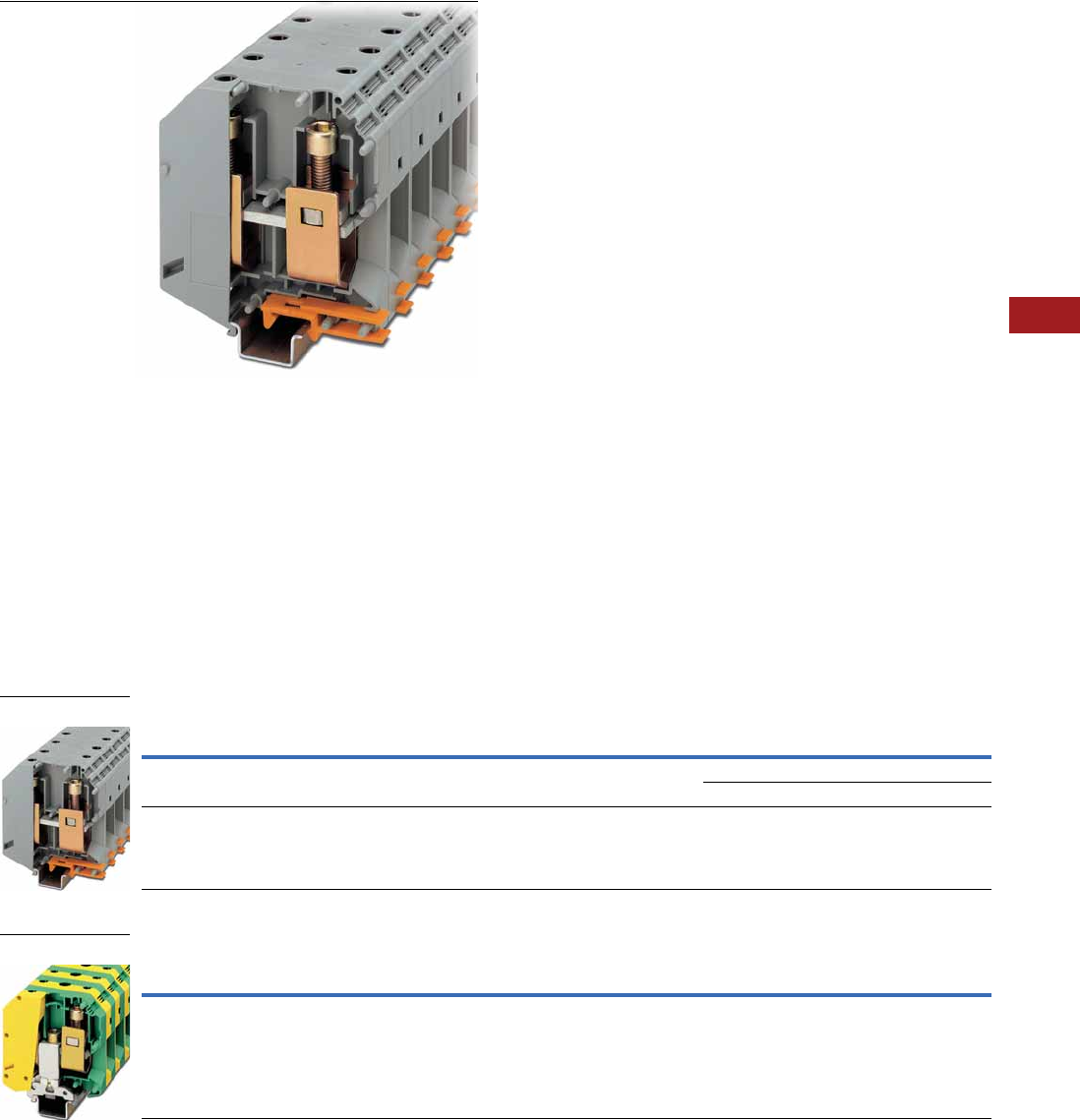
Volume 7—Logic Control, Operator Interface and Connectivity Solutions CA08100008E—July 2014 www.eaton.com V7-T8-27
8
8
8
8
8
8
8
8
8
8
8
8
8
8
8
8
8
8
8
8
8
8
8
8
8
8
8
8
8
8
8.1
Terminal Blocks, Fuse Blocks and Fuse Holders
IEC—XB Series
High Current Blocks
Contents
Description Page
Single Level—Through-Feed . . . . . . . . . . . . . . . . . V7-T8-5
Single Level—Ground Blocks . . . . . . . . . . . . . . . . V7-T8-10
Multi-Conductor Terminal Blocks . . . . . . . . . . . . . . V7-T8-12
Multi-Conductor Ground Blocks . . . . . . . . . . . . . . V7-T8-14
Double Level. . . . . . . . . . . . . . . . . . . . . . . . . . . . . . V7-T8-16
Triple Level Sensor/Actuator . . . . . . . . . . . . . . . . . V7-T8-18
Fuse Terminal Blocks . . . . . . . . . . . . . . . . . . . . . . . V7-T8-21
Disconnect and Component Terminal Blocks . . . . V7-T8-24
High Current Blocks
Accessories . . . . . . . . . . . . . . . . . . . . . . . . . . . V7-T8-28
Technical Data and Specifications . . . . . . . . . . V7-T8-28
Dimensions . . . . . . . . . . . . . . . . . . . . . . . . . . . V7-T8-28
Mini Screw Connection . . . . . . . . . . . . . . . . . . . . . V7-T8-29
High Current Blocks
Product Description
Eaton’s XBUK high current
terminal blocks offer a reliable
connection via the superior
construction that includes
three-point centering of the
wire in the
prism-shaped sleeve base,
a fluted contact surface
for low contact resistance,
and screws secured with
spring-loaded elements.
The terminal blocks have
an enclosed housing made
from polyamide 6.6. Green-
yellow ground terminal blocks
are also available.
Product Selection
Screw Connection High Current Blocks
Screw Connection High Current Ground Blocks
Note
1 U type—examination certificate number: KEMA 05ATEX2170 U (XBUK50), KEMA 05ATEX2171 U (XBUK150).
Terminal
Width
Maximum
Wire Size
IEC 60 947-7-1
in V/A/AWG
EN 50 019 1
in V/A/AWG
UL-cUL Ratings
in V/A/AWG Color
Standard
Pack
Catalog
Number
20.0 mm 1/0/50 mm21000/150/1/0 750/135/1/0 600/150/1/0 Gray 10 XBUK50
Blue 10 XBUK50BU
31.0 mm 300 kcmil/150 mm21000/309/2–300 726/265/2–300 600/285/
2 AWG–300 kcmil
Gray 10 XBUK150
Terminal
Width
Maximum
Wire Size
IEC 60 947-7-1
in V/A/AWG
EN 50 019 1
in V/A/AWG
UL-cUL Ratings
in V/A/AWG Color
Standard
Pack
Catalog
Number
25.0 mm 000 AWG/95 mm2—/232/4–000 —/—/4–000 —/—/2–4/0 Green/Yellow 10 XBUK95PE
XBUK150
XBUK95PE

V7-T8-28 Volume 7—Logic Control, Operator Interface and Connectivity Solutions CA08100008E—July 2014 www.eaton.com
8
8
8
8
8
8
8
8
8
8
8
8
8
8
8
8
8
8
8
8
8
8
8
8
8
8
8
8
8
8
8.1
Terminal Blocks, Fuse Blocks and Fuse Holders
IEC—XB Series
Accessories
Screw Connection High Current Blocks
Technical Data and Specifications
Screw Connection High Current Blocks
Dimensions
Approximate Dimensions in Inches (mm)
Screw Connection High Current Blocks
Notes
1For information on Printed Marking Tag Options, see Page V7-T8-98.
For additional accessories, see Page V7-T8-90.
Description Color
Number of
Positions
Standard
Pack
XBUK50 XBUK150 XBUK95PE
Catalog
Number
Catalog
Number
Catalog
Number
Fixed bridge, screw heads with insulating color — 2 10 XBAFBI220 — —
Insertion bridge — 2 10 — XBAEB231 —
Blank marker strip external labeling (strip of 10) White — 10 XBMZB10 1XBMZB10 1XBMZB10 1
Description XBUK50 XBUK150 XBUK95PE
Technical Data in Accordance with IEC
Maximum load current in A/cross-section in mm2150/50 309/150 232/95
Maximum cross-section with insertion bridge
solid/stranded in mm2
—/— 150/120 —/—
Rated surge voltage in kV/contamination class 8/3 8/3 8/3
Surge voltage category/insulating material group III/I III/I III/I
Connection Capacity
Stranded with ferrule/with ferrule and
plastic sleeve in mm2
25–50/25–50 50–150/50–150 35–95/35–95
Multi-Conductor Connection
(same cross-section)
Solid/stranded in mm210–16/10–16 25–50/35–50 25–35/25–35
Stranded with ferrules without plastic sleeve in mm210–16 25–50 16–35
Stripping length in inches (mm) 0.94 (24) 1.57 (40) 1.18 (30)
Thread M6 M10 M8
Terminal point—thread/torque in in-lb (Nm) 53–71 (6–8) 221–267 (25–30) 133–177 (15–20)
Fastening—thread/torque in in-lb (Nm) 53–71 (6–8) 221–267 (25–30) 133–177 (15–20)
Catalog
Number Width Length
Height for—
35 x 7.5 in 35 x 15 in 32 in
XBUK50 0.79 (20.0) 2.78 (70.5) 3.29 (83.5) 3.21 (81.5) —
XBUK150 1.22 (31.0) 3.94 (100.0) 4.67 (118.5) 4.57 (116.0) —
XBUK95PE 0.98 (25.0) 3.27 (83.0) — 3.90 (99.0) 3.80 (96.5)
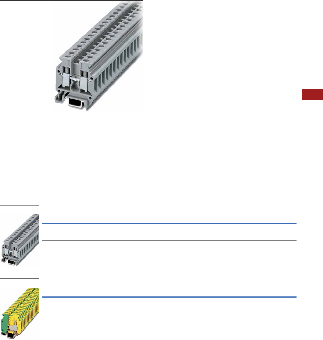
Volume 7—Logic Control, Operator Interface and Connectivity Solutions CA08100008E—July 2014 www.eaton.com V7-T8-29
8
8
8
8
8
8
8
8
8
8
8
8
8
8
8
8
8
8
8
8
8
8
8
8
8
8
8
8
8
8
8.1
Terminal Blocks, Fuse Blocks and Fuse Holders
IEC—XB Series
Mini Screw Connection Terminal Blocks
Contents
Description Page
Single Level—Through-Feed. . . . . . . . . . . . . . . . . . V7-T8-5
Single Level—Ground Blocks . . . . . . . . . . . . . . . . V7-T8-10
Multi-Conductor Terminal Blocks . . . . . . . . . . . . . . V7-T8-12
Multi-Conductor Ground Blocks . . . . . . . . . . . . . . V7-T8-14
Double Level. . . . . . . . . . . . . . . . . . . . . . . . . . . . . . V7-T8-16
Triple Level Sensor/Actuator . . . . . . . . . . . . . . . . . V7-T8-18
Fuse Terminal Blocks . . . . . . . . . . . . . . . . . . . . . . . V7-T8-21
Disconnect and Component Terminal Blocks . . . . V7-T8-24
High Current Blocks . . . . . . . . . . . . . . . . . . . . . . . . V7-T8-27
Mini Screw Connection
Accessories . . . . . . . . . . . . . . . . . . . . . . . . . . . V7-T8-30
Technical Data and Specifications . . . . . . . . . . V7-T8-30
Dimensions . . . . . . . . . . . . . . . . . . . . . . . . . . . V7-T8-30
Mini Screw Connection
Product Description
The XB miniature terminal
blocks have a connection
cross-section from 2 mm2
through 4 mm2 and mount on
15 mm DIN rail. There is an
opening for bridging with a
fixed bridge in the center of
the terminal blocks. These
miniature terminal blocks also
offer the same accessories
that you would find with the
larger blocks—including
marking tags, end covers,
end stop and ground blocks.
Product Selection
Mini Screw Connection Terminal Blocks
Mini Screw Connection Ground Blocks
Note
1 EU type—examination certificate number: KEMA 05ATEX2169 U (XBMUK25).
Terminal
Width
Maximum
Wire Size
IEC 60 947-7-1
in V/A/AWG
EN 50 019 1
in V/A/AWG
UL-cUL Ratings
in V/A/AWG Color
Standard
Pack
Catalog
Number
5.2 mm 12 AWG/2.5 mm2400/32/24–12 275/28/21/24–12 600/20/28–12 Gray 50 XBMUK25
Blue 50 XBMUK25BU
6.2 mm 10 AWG/4 mm2500/41/24–10 —/—/— 600/10/26–10 Gray 50 XBMUK4
Blue 50 XBMUK4BU
Terminal
Width
Maximum
Wire Size
IEC 60 947-7-2
in V/A/AWG
UL-cUL Ratings
in V/A/AWG Color
Standard
Pack
Catalog
Number
5.2 mm 12 AWG/2.5 mm2—/—/24–12 —/—/30–12 Green/
Yellow
50 XBMUK25PE
6.2 mm 10 AWG/2.4 mm2—/—/24–10 —/—/26–14 Green/
Yellow
50 XBMUK4PE
XBMUK4
XBMUK25PE

V7-T8-30 Volume 7—Logic Control, Operator Interface and Connectivity Solutions CA08100008E—July 2014 www.eaton.com
8
8
8
8
8
8
8
8
8
8
8
8
8
8
8
8
8
8
8
8
8
8
8
8
8
8
8
8
8
8
8.1
Terminal Blocks, Fuse Blocks and Fuse Holders
IEC—XB Series
Accessories
Mini Screw Connection Terminal/Ground Blocks
Technical Data and Specifications
Mini Spring Cage Terminal/Ground Blocks
Dimensions
Approximate Dimensions in Inches (mm)
Mini Spring Cage Terminal/Ground Blocks
Notes
1For information on Printed Marking Tag Options, see Page V7-T8-98.
For additional accessories, see Page V7-T8-90.
Description Color
Number of
Positions
Standard
Pack
XBMUK25 XBMUK4 XBMUK25PE XBMUK4PE
Catalog
Number
Catalog
Number
Catalog
Number
Catalog
Number
End cover Gray — 10 XBACMU254 XBACMU254 — —
Blue — 10 XBACMU254B XBACMU254B — —
Partition plate — — 10 XBATMU254 XBATMU254 — —
Fixed bridge — 10 10 XBAFBR105N — — —
Separating plate — — 10 XBATMPKK15 XBATMPKK15 — —
Blank marker strip (strip of 10) White — 10 XBMZB5 1XBMZB6 1XBMZB5 1XBMZB6 1
Description XBMUK25 XBMUK4 XBMUK25PE XBMUK4PE
Technical Data in Accordance with IEC
Maximum load current in A/cross-section in mm232/4 41/6 — —
Maximum cross-section with insertion bridge (solid/stranded) 2.5/2.5 4/4 — —
Rated surge voltage in kV/contamination class 6/3 6/3 6/3 6/3
Surge voltage category/insulating material group III/I III/I III/I III/I
Connection Cross-Section
Stranded with ferrule with plastic sleeve in mm20.25–1.5 0.25–2.5 0.25–1.5 0.25–2.5
Stranded with ferrule without plastic sleeve in mm20.25–2.5 0.25–4 0.25–2.5 0.25–4
Multi-Conductor Connection (same cross-section)
Solid/stranded in mm20.2–1.0/0.2–1.5 0.2–1.5/0.2–1.5 0.2–1.0/0.2–1.5 0.2–1.5/0.2–1.5
Stranded with ferrule without plastic sleeve in mm20.25–1.5 0.25–1.5 0.25–1.5 0.25–1.5
Stranded with ferrule with plastic sleeve in mm20.5–1.0 0.5–2.5 0.5–1.5 0.5–2.5
Stripping length in Inches (mm) 0.31 (8) 0.31 (8) 0.31 (8) 0.31 (8)
Thread M3 M3 M3 M3
Torque in in-lb (Nm) 5.3–7.1 (0.6–0.8) 4.4–5.3 (0.5–0.6) 5.3–7.1 (0.6–0.8) 5.3–7.1 (0.6–0.8)
Catalog
Number Width Length
Cover
Length
Height for—
15 in
XBMUK25 0.20 (5.2) 1.10 (28.0) 0.04 (1.0) 1.26 (32.0)
XBMUK4 0.24 (6.2) 1.10 (28.0) 0.04 (1.0) 1.26 (32.0)
XBMUK25PE 0.20 (5.2) 1.10 (28.0) — 1.24 (31.5)
XBMUK4PE 0.24 (6.2) 1.10 (28.0) — 1.26 (32.0)
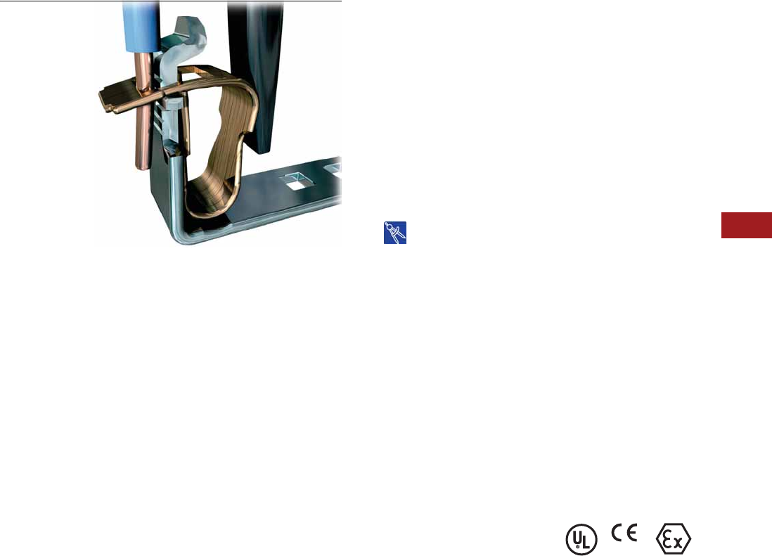
Volume 7—Logic Control, Operator Interface and Connectivity Solutions CA08100008E—July 2014 www.eaton.com V7-T8-31
8
8
8
8
8
8
8
8
8
8
8
8
8
8
8
8
8
8
8
8
8
8
8
8
8
8
8
8
8
8
8.1
Terminal Blocks, Fuse Blocks and Fuse Holders
IEC—XB Series
Spring Cage Connection
Contents
Description Page
Spring Cage Terminal Blocks
Single Level—Through-Feed . . . . . . . . . . . . . . . V7-T8-32
Single Level—Ground Blocks . . . . . . . . . . . . . . V7-T8-37
Multi-Conductor Terminal Blocks . . . . . . . . . . . V7-T8-39
Multi-Conductor Ground Blocks . . . . . . . . . . . . V7-T8-42
Double Level Blocks . . . . . . . . . . . . . . . . . . . . . V7-T8-44
Triple Level Blocks . . . . . . . . . . . . . . . . . . . . . . V7-T8-46
Fuse Terminal Blocks . . . . . . . . . . . . . . . . . . . . V7-T8-48
Disconnect and Component Terminal Blocks . . V7-T8-51
Hybrid Terminal Blocks . . . . . . . . . . . . . . . . . . . V7-T8-54
Mini Spring Cage. . . . . . . . . . . . . . . . . . . . . . . . V7-T8-56
Drawings
Online
Spring Cage Terminal Blocks Overview
Product Description
The XBPT Series incorporates
a spring cage connection
system proven in applications
that are sensitive to vibration.
The spring mechanism
always exerts the same
constant force on the wire,
resulting in a vibration-
proof, gas-tight connection,
independent of the user.
The space-saving front
connection, with the wire
and screwdriver coming in
parallel from the same
direction, allows for simple
wiring in places where there
is little space available.
Application Description
The connection point is
opened with a standard
screwdriver. After the wire
has been inserted into the
wire guide of the terminal
block, the screwdriver is
removed and the wire
automatically makes contact.
Features
●Vibration-resistance
●Global acceptance
●Multi-conductor
connections
●Flexible Plug-in bridge
system
●Large surface area for
marking
●Standardized testing
system
Standards and Certifications
●UL recognized—File No.
E67464
●CE approved
●LVD 1:
●EN 60947-7-1
●EN 60947-7-2
●EN 60998-2-3
●EN 60352-4/A1
●ATEX approval
(Eex e applications)
Note
1Not all standards apply to all terminal
blocks. Contact Eaton for details.
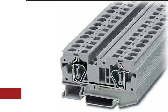
V7-T8-32 Volume 7—Logic Control, Operator Interface and Connectivity Solutions CA08100008E—July 2014 www.eaton.com
8
8
8
8
8
8
8
8
8
8
8
8
8
8
8
8
8
8
8
8
8
8
8
8
8
8
8
8
8
8
8.1
Terminal Blocks, Fuse Blocks and Fuse Holders
IEC—XB Series
Single Level—Through-Feed
Contents
Description Page
Single Level—Through-Feed
Accessories . . . . . . . . . . . . . . . . . . . . . . . . . . . V7-T8-34
Technical Data and Specifications . . . . . . . . . . V7-T8-36
Dimensions . . . . . . . . . . . . . . . . . . . . . . . . . . . V7-T8-36
Single Level—Ground Blocks . . . . . . . . . . . . . . . . V7-T8-37
Multi-Conductor Terminal Blocks . . . . . . . . . . . . . V7-T8-39
Multi-Conductor Ground Blocks . . . . . . . . . . . . . . V7-T8-42
Double Level Blocks . . . . . . . . . . . . . . . . . . . . . . . V7-T8-44
Triple Level Blocks . . . . . . . . . . . . . . . . . . . . . . . . . V7-T8-46
Fuse Terminal Blocks . . . . . . . . . . . . . . . . . . . . . . . V7-T8-48
Disconnect and Component Terminal Blocks . . . . V7-T8-51
Hybrid Terminal Blocks . . . . . . . . . . . . . . . . . . . . . V7-T8-54
Mini Spring Cage . . . . . . . . . . . . . . . . . . . . . . . . . . V7-T8-56
Single Level—Through-Feed
Product Description
The space-saving design and
front entry design make the
XBPT Series ideal for control
systems where there is little
space. Even so, they offer
maximum connection
space, resulting in fast
wiring of stranded and
solid conductors with or
without ferrules.
XBPT terminal blocks are
available with cross-sections
from 2.5 mm2 up to 35 mm2.
The double bridge shaft can
accommodate individual
chain bridging and step-
down bridging from other
terminal blocks.
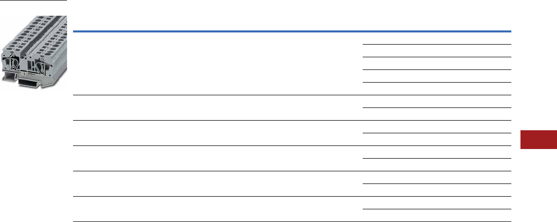
Volume 7—Logic Control, Operator Interface and Connectivity Solutions CA08100008E—July 2014 www.eaton.com V7-T8-33
8
8
8
8
8
8
8
8
8
8
8
8
8
8
8
8
8
8
8
8
8
8
8
8
8
8
8
8
8
8
8.1
Terminal Blocks, Fuse Blocks and Fuse Holders
IEC—XB Series
Product Selection
Spring Cage Connection Single Level—Through-Feed
Note
1 EU type—examination certificate number: KEMA 05ATEX2158 U.
Terminal
Width
Maximum
Wire Size
IEC 60 947-7-1
in V/A/AWG
EN 50 019 1
in V/A/AWG
UL-cUL Ratings
in V/A/AWG Color
Standard
Pack
Catalog
Number
5.2 mm 12 AWG/2.5 mm2800/31/28–12 550/25/21/24–12 600/20/26–12 Gray 50 XBPT25
Blue 50 XBPT25BU
White 50 XBPT25WH
Red 50 XBPT25RD
Black 50 XBPT25BK
6.2 mm 10 AWG/4 mm2800/40/28–10 550/34/30/24–10 600/30/20–10 Gray 50 XBPT4
Blue 50 XBPT4BU
8.2 mm 8 AWG/6 mm2800/52/24–8 550/45/36/20–8 600/50/20–8 Gray 50 XBPT6
Blue 50 XBPT6BU
10.2 mm 6 AWG/10 mm2800/65/24–6 550/50/63/16–6 600/65/16–6 Gray 50 XBPT10
Blue 50 XBPT10BU
12 mm 4 AWG/16 mm2800/90/24–4 550/65/82/16–4 600/50/16–4 Gray 50 XBPT16
Blue 50 XBPT16BU
16 mm 2 AWG/35 mm2800/125/14–2 750/108/14–2 600/115/14–2 Gray 50 XBPT35
Blue 50 XBPT35BU
XBPT6

V7-T8-34 Volume 7—Logic Control, Operator Interface and Connectivity Solutions CA08100008E—July 2014 www.eaton.com
8
8
8
8
8
8
8
8
8
8
8
8
8
8
8
8
8
8
8
8
8
8
8
8
8
8
8
8
8
8
8.1
Terminal Blocks, Fuse Blocks and Fuse Holders
IEC—XB Series
Accessories
Spring Cage Connection Single Level—Through-Feed, XBPT25, XBPT4 and XBPT6
Spring Cage Connection Single Level—Through-Feed, XBPT10, XBPT16 and XBPT35
Notes
1For ordering information, see Page V7-T8-105.
2For information on Printed Marking Tag Options, see Page V7-T8-98.
3XBPT35 has an enclosed design. The use of an end cover is not required.
For additional accessories, see Page V7-T8-90.
XBPT25 XBPT4 XBPT6
Description Color
Number of
Positions
Standard
Pack
Catalog
Number
Catalog
Number
Catalog
Number
End cover Gray — 10 XBACPT25 XBACPT4 XBACPT6
Partition plate Gray — 10 XBATPT4 XBATPT4 XBATPT6
Plug-in bridge—for cross connections
in the bridge shaft
Red 2 10 XBAFBS25 XBAFBS26 XBAFBS28
310XBAFBS35 XBAFBS36 —
510XBAFBS55 XBAFBS56 —
10 10 XBAFBS105 XBAFBS106 —
50 10 XBAFBS505 XBAFBS506 —
Test adapter — — 10 XBATSPAI4 XBATSPAI4 XBATSPAI4
2.3 mm diameter test plug — — — XBATSMPS-_ 1XBATSMPS-_ 1XBATSMPS-_ 1
Modular test plug — — 10 XBATSPS5 XBATSPS6 XBATSPS8
Blank marker strip external labeling White — 10 XBMZBF5 2XBMZBF6 2XBMZF8 2
Blank marker strip center labeling (strip of 10) White — 10 XBMZB5 2XBMZB6 2XBMZB8 2
Description Color
Number of
Positions
Standard
Pack
XBPT10 XBPT16 XBPT35
Catalog
Number
Catalog
Number
Catalog
Number
End cover Gray — 10 XBACPT10 XBACPT16 3
Plug-in bridge—for cross connections in
the bridge shaft
Red 2 10 XBAFBS210 XBAFBS212 1XBAFBS216 2
2.3 mm diameter test plug — — 10 XBATSMPS-_ 1XBATSMPS-_ 1XBATSMPS-_ 1
Blank marker strip external labeling White — 10 XBMZF10 2XBMZBF12 2XBMZBF15 2
Blank marker strip center labeling (strip of 10) White — 10 XBMZB10 2XBMZB12 2XBMZB15 2
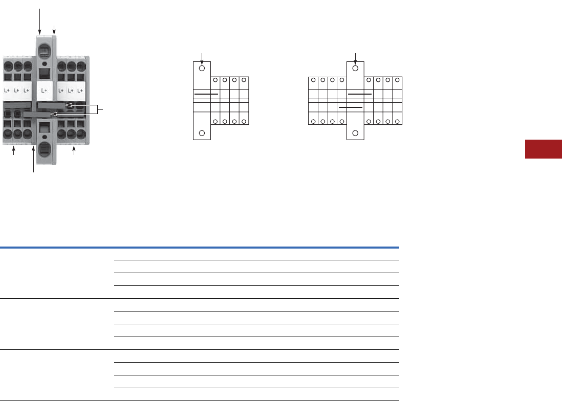
Volume 7—Logic Control, Operator Interface and Connectivity Solutions CA08100008E—July 2014 www.eaton.com V7-T8-35
8
8
8
8
8
8
8
8
8
8
8
8
8
8
8
8
8
8
8
8
8
8
8
8
8
8
8
8
8
8
8.1
Terminal Blocks, Fuse Blocks and Fuse Holders
IEC—XB Series
XBPT with Reducing Bridge
Step-Down Bridge with Standard Feed-Through Terminal Blocks
Input Pick-Off One-Sided
Input
Imax
Central
Input
Imax
Bridge
Terminal
Blocks Cross-Section
Terminal
Blocks
Cross-Section
AWG (mm2)
Catalog
Number
XBPT6 8 AWG (6 mm2) XBPT25 12 (2.5) 40 56 XBARBST6
XBPT4 10 (4) 45 56 XBARBST6
XBQT15 14 (1.5) 35 56 XBARBST6
XBQT25 12 (2.5) 40 56 XBARBST6
XBPT10 6 AWG (10 mm2) XBPT25 12 (2.5) 40 65 XBARBST10
XBPT4 10 (4) 45 65 XBARBST10
XBQT15 14 (1.5) 35 65 XBARBST10
XBQT25 12 (2.5) 40 65 XBARBST10
XBPT16 4 AWG (16 mm2) XBPT25 12 (2.5) 40 80 XBARBST16
XBPT4 10 (4) 45 90 XBARBST16
XBQT15 14 (1.5) 35 70 XBARBST16
XBQT25 12 (2.5) 40 80 XBARBST16
lmax
One-Sided Input Central Input
lmax
XBACPT6
XBARBST6
XBPT25XBPT25
XBPT6
XBACPT25

V7-T8-36 Volume 7—Logic Control, Operator Interface and Connectivity Solutions CA08100008E—July 2014 www.eaton.com
8
8
8
8
8
8
8
8
8
8
8
8
8
8
8
8
8
8
8
8
8
8
8
8
8
8
8
8
8
8
8.1
Terminal Blocks, Fuse Blocks and Fuse Holders
IEC—XB Series
Technical Data and Specifications
Spring Cage Connection Single Level—Through-Feed
Dimensions
Approximate Dimensions in Inches (mm)
Spring Cage Connection Single Level—Through-Feed
Note
1XBPT35 has an enclosed design. The use of an end cover is not required.
Description XBPT25 XBPT4 XBPT6 XBPT10 XBPT16 XBPT35
Technical Data in Accordance with IEC
Maximum load current in A/cross-section in mm231/4 40/6 52/10 65/16 90/25 125/35
Rated surge voltage in kV/contamination class 8/3 8/3 8/3 8/3 8/3 8/3
Surge voltage category/insulating material group III/I III/I III/I III/I III/I III/I
Connection Capacity
Stranded with ferrule/with ferrule and
plastic sleeve in mm2
0.25–2.5 0.25–4 0.25–6 0.25–10 0.25–16 2.5–35
Stranded with ferrules without plastic sleeve in mm20.25–2.5 0.25–4 0.25–6 0.25–10 0.25–16 2.5–35
Stranded with twin ferrule with plastic sleeve in mm20.5 0.5–1 0.5–1.5 1.5–2.5 1.5–4 2.5–10
Stripping length in inches (mm) 0.39 (10) 0.39 (10) 0.47 (12) 0.71 (18) 0.71 (18) 0.98 (25)
Catalog
Number Width Length
Cover
Width
Height for—
35 x 7.5 in 35 x 15 in
XBPT25 0.20 (5.2) 1.91 (48.5) 0.09 (2.2) 1.45 (36.8) 1.73 (44.0)
XBPT4 0.24 (6.2) 2.20 (56.0) 0.09 (2.2) 1.45 (36.8) 1.73 (44.0)
XBPT6 0.32 (8.2) 2.74 (69.5) 0.09 (2.2) 1.71 (43.5) 2.01 (51.0)
XBPT10 0.39 (10.0) 2.81 (71.5) 0.09 (2.2) 1.99 (50.5) 2.30 (58.5)
XBPT16 0.47 (12.0) 3.15 (80.0) 0.09 (2.2) 2.01 (51.0) 2.30 (58.5)
XBPT35 0.63 (16.0) 3.94 (100.0) 12.32 (59.0) 2.62 (66.5)
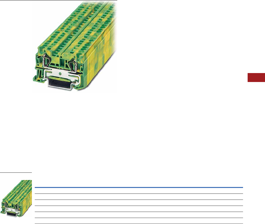
Volume 7—Logic Control, Operator Interface and Connectivity Solutions CA08100008E—July 2014 www.eaton.com V7-T8-37
8
8
8
8
8
8
8
8
8
8
8
8
8
8
8
8
8
8
8
8
8
8
8
8
8
8
8
8
8
8
8.1
Terminal Blocks, Fuse Blocks and Fuse Holders
IEC—XB Series
Single Level—Ground Blocks
Contents
Description Page
Single Level—Through-Feed . . . . . . . . . . . . . . . . . V7-T8-32
Single Level—Ground Blocks
Accessories . . . . . . . . . . . . . . . . . . . . . . . . . . . V7-T8-38
Technical Data and Specifications . . . . . . . . . . V7-T8-38
Dimensions . . . . . . . . . . . . . . . . . . . . . . . . . . . V7-T8-38
Multi-Conductor Terminal Blocks . . . . . . . . . . . . . . V7-T8-39
Multi-Conductor Ground Blocks . . . . . . . . . . . . . . V7-T8-42
Double Level Blocks . . . . . . . . . . . . . . . . . . . . . . . V7-T8-44
Triple Level Blocks . . . . . . . . . . . . . . . . . . . . . . . . . V7-T8-46
Fuse Terminal Blocks . . . . . . . . . . . . . . . . . . . . . . . V7-T8-48
Disconnect and Component Terminal Blocks . . . . V7-T8-51
Hybrid Terminal Blocks . . . . . . . . . . . . . . . . . . . . . V7-T8-54
Mini Spring Cage . . . . . . . . . . . . . . . . . . . . . . . . . . V7-T8-56
Single Level—Ground Blocks
Product Description
The XBPT ground blocks are
the same shape as the feed-
through terminal blocks with
the same wide range of
cross-sections available.
They easily snap onto the
DIN rail to make a reliable
mechanical and electrical
contact that meets all
requirements of
IEC 60-947-7-2.
Product Selection
Spring Cage Connection Single Level—Ground Blocks
Notes
1 EU type—examination certificate number: KEMA 05ATEX2154 U (XBPT25PE), KEMA 05ATEX2155 U (XBPT4PE).
2 EU type—examination certificate number: KEMA 05ATEX2156 U.
Terminal
Width
Maximum
Wire Size
IEC 60 947-7-2
in V/A/AWG
EN 50 019 1
in V/A/AWG
UL-cUL Ratings
in V/A/AWG Color
Standard
Pack
Catalog
Number
5.2 mm 12 AWG/2.5 mm2—/—/28–12 —/—/24–12 —/—/26–12 Green/Yellow 50 XBPT25PE
6.2 mm 10 AWG/4 mm2—/—/28–10 —/—/24–10 —/—/20–10 Green/Yellow 50 XBPT4PE
8.2 mm 8 AWG/6 mm2—/—/24–8 —/—/20–8 —/—/20–8 Green/Yellow 50 XBPT6PE
10.2 mm 6 AWG/10 mm2—/65/24–6 —/—/16–6 —/—/16–6 Green/Yellow 50 XBPT10PE
12 mm 4 AWG/16 mm2—/90/24–4 —/—/16–4 2—/—/16–4 Green/Yellow 25 XBPT16PE
16 mm 2 AWG/35 mm2—/125/14–2 —/—/14–2 2—/—/14–2 Green/Yellow 10 XBPT35PE
XBPT4PE

V7-T8-38 Volume 7—Logic Control, Operator Interface and Connectivity Solutions CA08100008E—July 2014 www.eaton.com
8
8
8
8
8
8
8
8
8
8
8
8
8
8
8
8
8
8
8
8
8
8
8
8
8
8
8
8
8
8
8.1
Terminal Blocks, Fuse Blocks and Fuse Holders
IEC—XB Series
Accessories
Spring Cage Connection Single Level Ground Blocks, XBPT25PE, XBPT4PE and XBPT6PE
Spring Cage Connection Single Level Ground Blocks, XBPT10PE, XBPT16PE and XBPT35PE
Technical Data and Specifications
Spring Cage Connection Single Level Ground Blocks
Dimensions
Approximate Dimensions in Inches (mm)
Spring Cage Connection Single Level Ground Blocks
Notes
1For information on Printed Marking Tag Options, see Page V7-T8-98.
2XBPT35PE has an enclosed design. The use of an end cover is not required.
For additional accessories, see Page V7-T8-90.
Description Color
Number of
Positions
Standard
Pack
XBPT25PE XBPT4PE XBPT6PE
Catalog
Number
Catalog
Number
Catalog
Number
End cover Gray — 10 XBACPT25 XBACPT4 XBACPT6
Blank marker strip external labeling White — 10 XBMZBF5 1XBMZBF6 1XBMZBF8 1
Blank marker strip center labeling (strip of 10) White — 10 XBMZB5 1XBMZB6 1XBMZB8 1
Description Color
Number of
Positions
Standard
Pack
XBPT10PE XBPT16PE XBPT35PE
Catalog
Number
Catalog
Number
Catalog
Number
End cover Gray — 10 XBACPT10 XBACPT16 2
Plug-in bridge—for cross connections in
the bridge shaft
—2 10XBAFBS210 XBAFBS212 XBAFBS216
Blank marker strip external labeling White — 10 XBMZBF10 1XBMZBF12 1XBMZBF15 1
Blank marker strip center labeling (strip of 10) White — 10 XBMZB10 1XBMZB12 1XBMZB15 1
Description XBPT25PE XBPT4PE XBPT6PE XBPT10PE XBPT16PE XBPT35PE
Technical Data in Accordance with IEC
Maximum load current in A/cross-section in mm2———65/1690/25125/35
Rated surge voltage in kV/contamination class 8/3 8/3 8/3 8/3 8/3 8/3
Surge voltage category/insulating material group III/I III/I III/I III/I III/I III/I
Connection Capacity
Stranded with ferrule with plastic sleeve in mm20.25–2.5 0.25–4 0.25–6 0.25–10 0.25–16 2.5–35
Stranded with ferrules without plastic sleeve in mm20.25–2.5 0.25–4 0.25–6 0.25–10 0.25–16 2.5–35
Stranded with twin ferrule with plastic sleeve in mm20.5 0.5–1 0.5–1.5 1.5–2.5 1.5–4 2.5–10
Stripping length in inches (mm) 0.39 (10) 0.39 (10) 0.47 (12) 0.71 (18) 0.71 (18) 0.98 (25)
Catalog
Number Width Length
Cover
Width
Height for—
35 x 7.5 in 35 x 15 in
XBPT25PE 0.20 (5.2) 1.91 (48.5) 0.09 (2.2) 1.45 (36.8) 1.73 (44.0)
XBPT4PE 0.24 (6.2) 2.20 (56.0) 0.09 (2.2) 1.45 (36.8) 1.73 (44.0)
XBPT6PE 0.32 (8.2) 2.74 (69.5) 0.09 (2.2) 1.71 (43.5) 2.01 (51.0)
XBPT10PE 0.39 (10.0) 2.81 (71.5) 0.09 (2.2) 1.99 (50.5) 2.28 (58.0)
XBPT16PE 0.47 (12.0) 3.15 (80.0) 0.09 (2.2) 2.01 (51.0) 2.30 (58.5)
XBPT35PE 0.63 (16.0) 3.94 (100.0) — 2.32 (59.0) 2.62 (66.5)
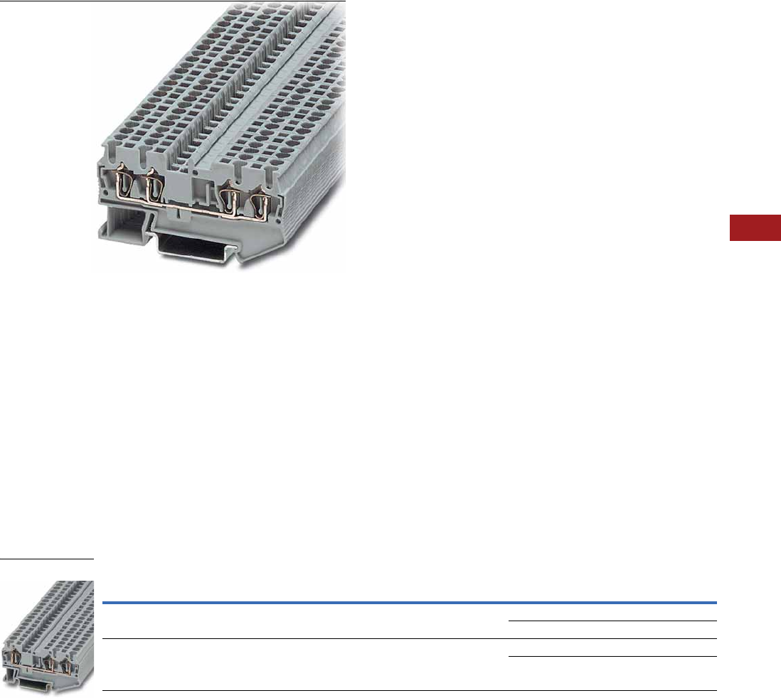
Volume 7—Logic Control, Operator Interface and Connectivity Solutions CA08100008E—July 2014 www.eaton.com V7-T8-39
8
8
8
8
8
8
8
8
8
8
8
8
8
8
8
8
8
8
8
8
8
8
8
8
8
8
8
8
8
8
8.1
Terminal Blocks, Fuse Blocks and Fuse Holders
IEC—XB Series
Multi-Conductor Terminal Blocks
Contents
Description Page
Single Level—Through-Feed . . . . . . . . . . . . . . . . . V7-T8-32
Single Level—Ground Blocks . . . . . . . . . . . . . . . . . V7-T8-37
Multi-Conductor Terminal Blocks
Accessories . . . . . . . . . . . . . . . . . . . . . . . . . . . V7-T8-40
Technical Data and Specifications . . . . . . . . . . V7-T8-41
Dimensions . . . . . . . . . . . . . . . . . . . . . . . . . . . V7-T8-41
Multi-Conductor Ground Blocks . . . . . . . . . . . . . . V7-T8-42
Double Level Blocks . . . . . . . . . . . . . . . . . . . . . . . V7-T8-44
Triple Level Blocks . . . . . . . . . . . . . . . . . . . . . . . . . V7-T8-46
Fuse Terminal Blocks . . . . . . . . . . . . . . . . . . . . . . . V7-T8-48
Disconnect and Component Terminal Blocks . . . . V7-T8-51
Hybrid Terminal Blocks . . . . . . . . . . . . . . . . . . . . . V7-T8-54
Mini Spring Cage . . . . . . . . . . . . . . . . . . . . . . . . . . V7-T8-56
Multi-Conductor Terminal Blocks
Product Description
The multi-conductor terminal
blocks offer a space-saving
alternative to standard feed-
through terminal blocks,
allowing for high-density
wiring. Often, three
connections have to be led
to one terminal block. The
XBPT…D12 terminal block
accomplishes this without
any additional terminal blocks
or bridging required. The
XBPT…D22 terminal blocks
allow four wires to be
connected to one potential—
and can therefore be used as
compact power distributors.
There is also a version,
XBPT25D22U or XBPT4D22U,
with an interrupted bus bar in
the terminal center. This
makes two feed-through
terminal blocks available in
one level. One side of this
block can be bridged using
the standard Plug-in bridges.
Double marker carriers are
available for clear marking of
the feed-through levels.
Product Selection
Spring Cage Connection Multi-Conductor Terminal Blocks, Three-Wire
Note
1 EU type—examination certificate number: KEMA 05ATEX2154 U (XBPT25D12), KEMA 05ATEX2155 U (XBPT4D12).
Terminal
Width
Maximum
Wire Size
IEC 60 947-7-1
in V/A/AWG
EN 50 019 1
in V/A/AWG
UL-cUL Ratings
in V/A/AWG Color
Standard
Pack
Catalog
Number
5.2 mm 12 AWG/2.5 mm2800/28/28–12 550/25/21/24–12 600/20/26–12 Gray 50 XBPT25D12
Blue 50 XBPT25D12BU
6.2 mm 10 AWG/4 mm2800/40/28–10 550/34/29/24–10 600/30/20–10 Gray 50 XBPT4D12
Blue 50 XBPT4D12BU
XBPT4D12
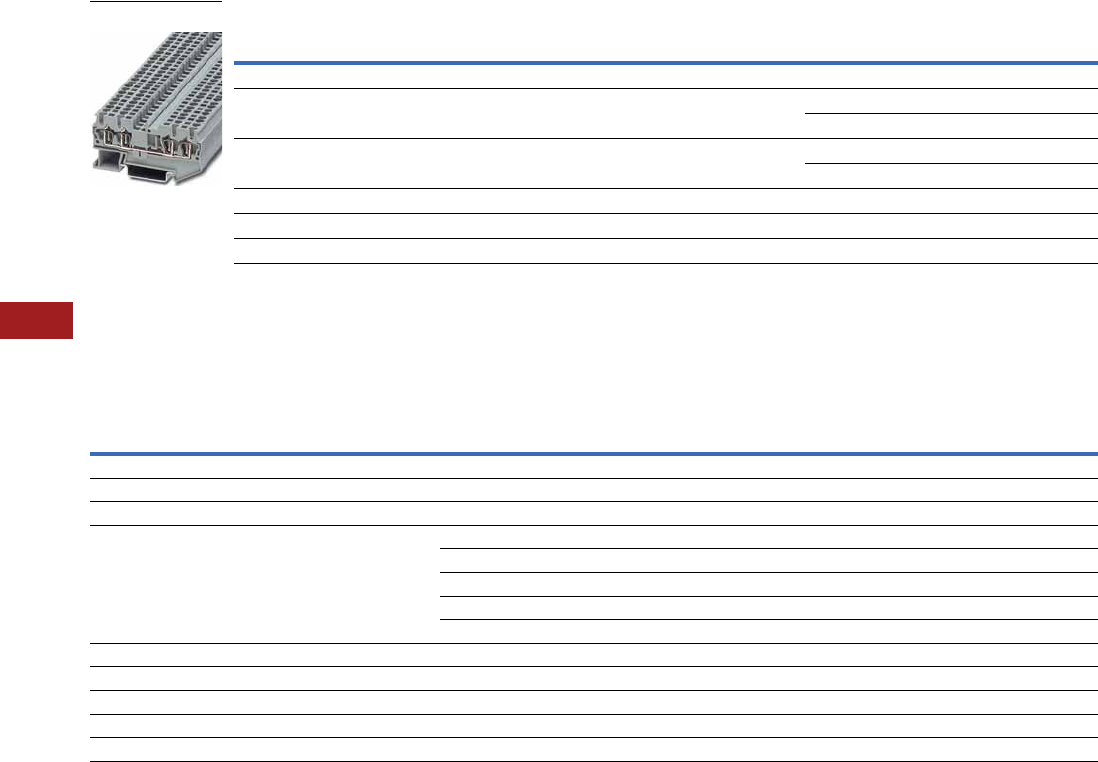
V7-T8-40 Volume 7—Logic Control, Operator Interface and Connectivity Solutions CA08100008E—July 2014 www.eaton.com
8
8
8
8
8
8
8
8
8
8
8
8
8
8
8
8
8
8
8
8
8
8
8
8
8
8
8
8
8
8
8.1
Terminal Blocks, Fuse Blocks and Fuse Holders
IEC—XB Series
Spring Cage Connection Multi-Conductor Terminal Blocks, Four-Wire
Accessories
Spring Cage Connection Multi-Conductor Terminal Blocks
Notes
1EU type—examination certificate number: KEMA 05ATEX2154 U (XBPT25D22), KEMA 05ATEX2155 (XBPT4D22).
2For ordering information, see Page V7-T8-105.
3For information on Printed Marking Tag Options, see Page V7-T8-98.
For additional accessories, see Page V7-T8-90.
Terminal
Width
Maximum
Wire Size
IEC 60 947-7-1
in V/A/AWG
EN 50 019 1
in V/A/AWG
UL-cUL Ratings
in V/A/AWG Color
Standard
Pack
Catalog
Number
Spring Cage Multi-Conductor
5.2 mm 12 AWG/2.5 mm2800/28/28–12 550/24/21/24–12 600/20/26–12 Gray 50 XBPT25D22
Blue 50 XBPT25D22BU
6.2 mm 10 AWG/4 mm2800/40/28–10 550/34/25/24–10 600/30/20–10 Gray 50 XBPT4D22
Blue 50 XBPT4D22BU
Spring Cage Multi-Conductor with Interrupted Bus Bar
5.2 mm 12 AWG/2.5 mm2800/28/28–12 550/24/21/24–12 600/20/26–12 Blue 50 XBPT25D22U
6.2 mm 10 AWG/4 mm2800/40/28–10 550/34/25/24–10 600/30/20–10 Blue 50 XBPT4D22U
Description Color
Number of
Positions
Standard
Pack
XBPT25D12 XBPT4D12 XBPT25D22 XBPT4D22
Catalog
Number
Catalog
Number
Catalog
Number
Catalog
Number
End cover Gray — 10 XBACPT25D12 XBACPT4D12 XBACPT25D22 XBACPT4D22
End cover segment Gray — 10 XBASPT25 XBASPT4 XBASPT25 XBASPT4
Partition plate — — 10 XBATPTD12 XBATPTD12 XBATPTD22 XBATPTD22
Plug-in bridge—for cross connections in
the bridge shaft
Red 2 10 XBAFBS25 XBAFBS26 XBAFBS25 XBAFBS26
310XBAFBS35 XBAFBS36 XBAFBS35 XBAFBS36
510XBAFBS55 XBAFBS56 XBAFBS55 XBAFBS56
10 10 XBAFBS105 XBAFBS106 XBAFBS105 XBAFBS106
50 10 XBAFBS505 XBAFBS506 XBAFBS505 XBAFBS506
Test adapter — — 10 XBATSPAI4 XBATSPAI4 XBATSPAI4 XBATSPAI4
2.3 mm diameter test plug — — — XBATSMPS-_ 2XBATSMPS-_ 2XBATSMPS-_ 2XBATSMPS-_ 2
Modular test plug — — 10 XBATSPS5 XBATSPS6 XBATSPS5 XBATSPS6
Blank marker strip external labeling White — 10 XBMZBF5 3XBMZBF6 3XBMZBF5 3XBMZBF6 3
Blank marker strip center labeling (strip of 10) White — 10 XBMZB5 3XBMZB6 3XBMZB5 3XBMZB6 3
XBPT25D22

Volume 7—Logic Control, Operator Interface and Connectivity Solutions CA08100008E—July 2014 www.eaton.com V7-T8-41
8
8
8
8
8
8
8
8
8
8
8
8
8
8
8
8
8
8
8
8
8
8
8
8
8
8
8
8
8
8
8.1
Terminal Blocks, Fuse Blocks and Fuse Holders
IEC—XB Series
Technical Data and Specifications
Spring Cage Connection Multi-Conductor Terminal Blocks
Dimensions
Approximate Dimensions in Inches (mm)
Spring Cage Connection Multi-Conductor Terminal Blocks
Description XBPT25D12 XBPT4D12 XBPT25D22 XBPT4D22
Technical Data in Accordance with IEC
Maximum load current in A/cross-section in mm228/4 40/6 28/4 40/6
Rated surge voltage in kV/contamination class 8/3 8/3 8/3 8/3
Surge voltage category/insulating material group III/I III/I III/I III/I
Connection Capacity
Stranded with ferrule with plastic sleeve in mm20.25–2.5 0.25–4 0.25–2.5 0.25–4
Stranded with ferrules without plastic sleeve in mm20.25–2.5 0.25–4 0.25–2.5 0.25–4
Stranded with twin ferrule with plastic sleeve in mm20.5 0.5–1 0.5 0.5–1
Stripping length in inches (mm) 0.39 (10) 0.39 (10) 0.39 (10) 0.39 (10)
Catalog
Number Width Length
Cover
Width
Height for—
35 x 7.5 in 35 x 15 in
XBPT25D12 0.20 (5.2) 2.38 (60.5) 0.09 (2.2) 1.44 (36.5) 1.73 (44.0)
XBPT4D12 0.24 (6.2) 2.81 (71.5) 0.09 (2.2) 1.44 (36.5) 1.73 (44.0)
XBPT25D22 0.20 (5.2) 2.83 (72.0) 0.09 (2.2) 1.44 (36.5) 1.73 (44.0)
XBPT4D22 0.24 (6.2) 3.43 (87.0) 0.09 (2.2) 1.44 (36.5) 1.73 (44.0)
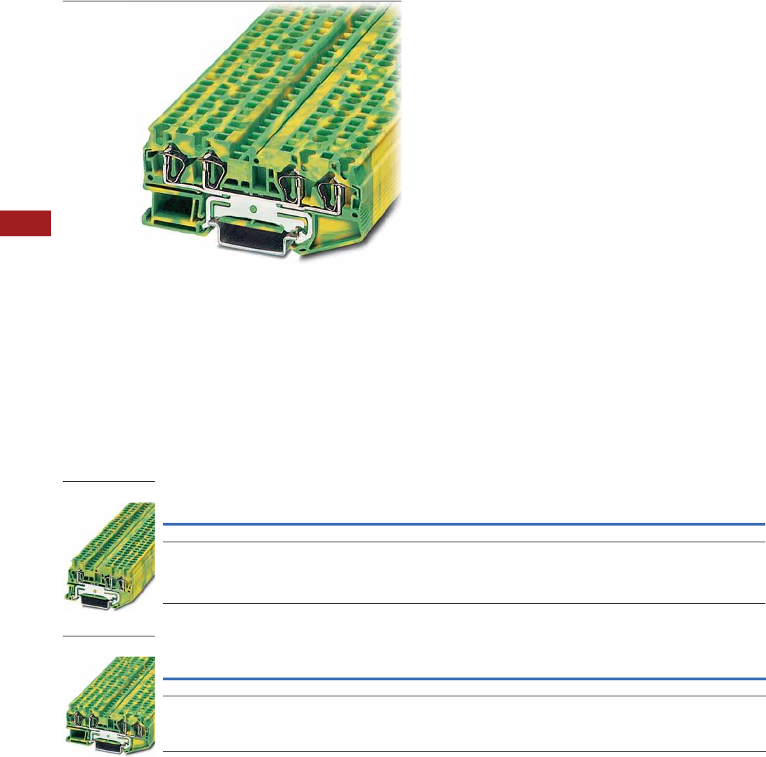
V7-T8-42 Volume 7—Logic Control, Operator Interface and Connectivity Solutions CA08100008E—July 2014 www.eaton.com
8
8
8
8
8
8
8
8
8
8
8
8
8
8
8
8
8
8
8
8
8
8
8
8
8
8
8
8
8
8
8.1
Terminal Blocks, Fuse Blocks and Fuse Holders
IEC—XB Series
Multi-Conductor Terminal Blocks
Contents
Description Page
Single Level—Through-Feed . . . . . . . . . . . . . . . . . V7-T8-32
Single Level—Ground Blocks . . . . . . . . . . . . . . . . . V7-T8-37
Multi-Conductor Terminal Blocks . . . . . . . . . . . . . V7-T8-39
Multi-Conductor Ground Blocks
Accessories . . . . . . . . . . . . . . . . . . . . . . . . . . . V7-T8-43
Technical Data and Specifications . . . . . . . . . . V7-T8-43
Dimensions . . . . . . . . . . . . . . . . . . . . . . . . . . . V7-T8-43
Double Level Blocks . . . . . . . . . . . . . . . . . . . . . . . V7-T8-44
Triple Level Blocks . . . . . . . . . . . . . . . . . . . . . . . . . V7-T8-46
Fuse Terminal Blocks . . . . . . . . . . . . . . . . . . . . . . . V7-T8-48
Disconnect and Component Terminal Blocks . . . . V7-T8-51
Hybrid Terminal Blocks . . . . . . . . . . . . . . . . . . . . . V7-T8-54
Mini Spring Cage . . . . . . . . . . . . . . . . . . . . . . . . . . V7-T8-56
Multi-Conductor Ground Blocks
Product Description
The ground terminal blocks
have the same shape and
pitch as the standard terminal
block, in a green-yellow
housing. They easily snap
onto the DIN rail to make
a reliable mechanical and
electrical contact that
meets all requirements
of IEC 60-947-7-2.
Product Selection
Spring Cage Connection Multi-Conductor Ground Blocks, Three-Wire
Spring Cage Connection Multi-Conductor Ground Blocks, Four-Wire
Note
1 EU type—examination certificate number: KEMA 05ATEX2154 U (XBPT25D12PE), KEMA 05ATEX2155 U (XBPT4D12PE).
Terminal
Width
Maximum
Wire Size
IEC 60 947-7-2
in V/A/AWG
EN 50 019 1
in V/A/AWG
UL-cUL Ratings
in V/A/AWG Color
Standard
Pack
Catalog
Number
5.2 mm 12 AWG/2.5 mm2—/—/28–12 —/—/24–12 —/—/26–12 Green/Yellow 50 XBPT25D12PE
6.2 mm 10 AWG/4 mm2—/—/28–10 —/—/24–10 —/—/20–10 Green/Yellow 50 XBPT4D12PE
Terminal
Width
Maximum
Wire Size
IEC 60 947-7-2
in V/A/AWG
EN 50 019 1
in V/A/AWG
UL-cUL Ratings
in V/A/AWG Color
Standard
Pack
Catalog
Number
5.2 mm 12 AWG/2.5 mm2—/—/28–12 —/—/24–12 —/—/26–12 Green/Yellow 50 XBPT25D22PE
6.2 mm 10 AWG/4 mm2—/—/28–10 —/—/24–10 —/—/20–10 Green/Yellow 50 XBPT4D22PE
XBPT25D12PE
XBPT4D22PE

Volume 7—Logic Control, Operator Interface and Connectivity Solutions CA08100008E—July 2014 www.eaton.com V7-T8-43
8
8
8
8
8
8
8
8
8
8
8
8
8
8
8
8
8
8
8
8
8
8
8
8
8
8
8
8
8
8
8.1
Terminal Blocks, Fuse Blocks and Fuse Holders
IEC—XB Series
Accessories
Spring Cage Connection Multi-Conductor Ground Blocks
Technical Data and Specifications
Spring Cage Connection Multi-Conductor Ground Blocks
Dimensions
Approximate Dimensions in Inches (mm)
Spring Cage Connection Multi-Conductor Ground Blocks
Notes
1For information on Printed Marking Tag Options, see Page V7-T8-98.
For additional accessories, see Page V7-T8-90.
Description Color
Number of
Positions
Standard
Pack
XBPT25D12PE XBPT4D12PE XBPT25D22PE XBPT4D22PE
Catalog
Number
Catalog
Number
Catalog
Number
Catalog
Number
End cover Gray — 10 XBACPT25D12 XBACPT4D12 XBACPT25D22 XBACPT4D22
End cover segment Gray — 10 XBASPT25 XBASPT4 XBASPT25 XBASPT4
Blank marker strip external labeling White — 10 XBMZBF5 1XBMZBF6 1XBMZBF5 1XBMZBF6 1
Blank marker strip center
labeling (strip of 10)
White — 10 XBMZB5 1XBMZB6 1XBMZB5 1XBMZB6 1
Description XBPT25D12PE XBPT4D12PE XBPT25D22PE XBPT4D22PE
Technical Data in Accordance with IEC
Maximum load current in A/cross-section in mm2————
Rated surge voltage in kV/contamination class 8/3 8/3 8/3 8/3
Surge voltage category/insulating material group III/I III/I III/I III/I
Connection Capacity
Stranded with ferrule with plastic sleeve in mm20.25–2.5 0.25–4 0.25–2.5 0.25–4
Stranded with ferrules without plastic sleeve in mm20.25–2.5 0.25–4 0.25–2.5 0.25–4
Stranded with twin ferrule with plastic sleeve in mm20.5 0.5–1 0.5 0.5–1
Stripping length in inches (mm) 0.39 (10) 0.39 (10) 0.39 (10) 0.39 (10)
Catalog
Number Width Length
Cover
Width
Height for—
35 x 7.5 in 35 x 15 in
XBPT25D12PE 0.20 (5.2) 2.38 (60.5) 0.09 (2.2) 1.44 (36.5) 1.73 (44.0)
XBPT4D12PE 0.24 (6.2) 2.81 (71.5) 0.09 (2.2) 1.44 (36.5) 1.73 (44.0)
XBPT25D22PE 0.20 (5.2) 2.83 (72.0) 0.09 (2.2) 1.44 (36.5) 1.73 (44.0)
XBPT4D22PE 0.24 (6.2) 3.43 (87.0) 0.09 (2.2) 1.44 (36.5) 1.73 (44.0)
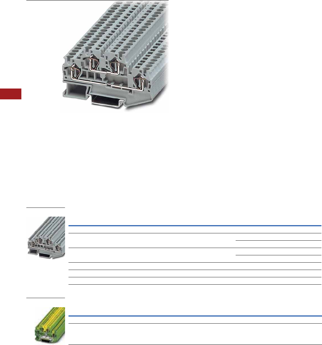
V7-T8-44 Volume 7—Logic Control, Operator Interface and Connectivity Solutions CA08100008E—July 2014 www.eaton.com
8
8
8
8
8
8
8
8
8
8
8
8
8
8
8
8
8
8
8
8
8
8
8
8
8
8
8
8
8
8
8.1
Terminal Blocks, Fuse Blocks and Fuse Holders
IEC—XB Series
Double Level Blocks
Contents
Description Page
Single Level—Through-Feed . . . . . . . . . . . . . . . . . V7-T8-32
Single Level—Ground Blocks . . . . . . . . . . . . . . . . . V7-T8-37
Multi-Conductor Terminal Blocks . . . . . . . . . . . . . V7-T8-39
Multi-Conductor Ground Blocks . . . . . . . . . . . . . . V7-T8-42
Double Level Blocks
Accessories . . . . . . . . . . . . . . . . . . . . . . . . . . . V7-T8-45
Technical Data and Specifications . . . . . . . . . . V7-T8-45
Dimensions . . . . . . . . . . . . . . . . . . . . . . . . . . . V7-T8-45
Triple Level Blocks . . . . . . . . . . . . . . . . . . . . . . . . . V7-T8-46
Fuse Terminal Blocks . . . . . . . . . . . . . . . . . . . . . . . V7-T8-48
Disconnect and Component Terminal Blocks . . . . V7-T8-51
Hybrid Terminal Blocks . . . . . . . . . . . . . . . . . . . . . V7-T8-54
Mini Spring Cage . . . . . . . . . . . . . . . . . . . . . . . . . . V7-T8-56
Double Level Blocks
Product Description
The potentials of the XB
double level terminal blocks
routed on two levels reduce
space requirements by 50%
compared with single level
terminal blocks.
The XBPTT blocks can be
bridged on both levels with
the Plug-in bridge system and
labeling options are available
for each terminal point,
resulting in maximum
customization for each
application. The XBPTT25PV
and XBPTT4PV terminal
blocks have two
interconnected levels.
Equipotential bonding is
marked by an imprint on
the housing. These terminal
blocks can also be bridged and
used to construct compact
potential distributor blocks.
Product Selection
Spring Cage Connection Double Level Blocks
Spring Cage Connection Double Level Ground Blocks
Note
1 EU type—examination certificate number: KEMA 05ATEX2154 U (XBPTT25), KEMA 05ATEX2155 U (XBPTT4).
Terminal
Width
Maximum
Wire Size
IEC 60 947-7-1
in V/A/AWG
EN 50 019 1
in V/A/AWG
UL-cUL Ratings
in V/A/AWG Color
Standard
Pack
Catalog
Number
Spring Cage Connection Double Level Blocks
5.2 mm 12 AWG/2.5 mm2500/26/28–12 420/23/19/24–12 600/20/26–12 Gray 50 XBPTT25
Blue 50 XBPTT25BU
6.2 mm 10 AWG/4 mm2500/32/28–10 420/32/27/24–10 300/30/20–10 Gray 50 XBPTT4
Blue 50 XBPTT4BU
Spring Cage Connection Double Level Blocks (terminal block with potential distribution between the levels)
5.2 mm 12 AWG/2.5 mm2500/26/28–12 420/23/19/24–12 600/20/26–12 Gray 50 XBPTT25PV
6.2 mm 10 AWG/4 mm2500/32/28–10 420/32/27/24–10 300/30/20–10 Gray 50 XBPTT4PV
Terminal
Width
Maximum
Wire Size
IEC 60 947-7-2
in V/A/AWG
EN 50 019 1
in V/A/AWG
UL-cUL Ratings
in V/A/AWG Color
Standard
Pack
Catalog
Number
5.2 mm 12 AWG/2.5 mm2—/—/28–12 —/—/24–12 —/—/26–12 Green/Yellow 50 XBPTT25PE
6.2 mm 10 AWG/4 mm2—/—/28–10 —/—/24–10 —/—/20–10 Green/Yellow 50 XBPTT4PE
XBPTT4
XBPTT25PE

Volume 7—Logic Control, Operator Interface and Connectivity Solutions CA08100008E—July 2014 www.eaton.com V7-T8-45
8
8
8
8
8
8
8
8
8
8
8
8
8
8
8
8
8
8
8
8
8
8
8
8
8
8
8
8
8
8
8.1
Terminal Blocks, Fuse Blocks and Fuse Holders
IEC—XB Series
Accessories
Spring Cage Connection Double Level Blocks
Technical Data and Specifications
Spring Cage Connection Double Level Blocks
Dimensions
Approximate Dimensions in Inches (mm)
Spring Cage Connection Double Level Blocks
Notes
1For information on Printed Marking Tag Options, see Page V7-T8-98.
For additional accessories, see Page V7-T8-90.
Description Color
Number of
Positions
Standard
Pack
XBPTT25 XBPTT4 XBPTT25PE XBPTT4PE
Catalog
Number
Catalog
Number
Catalog
Number
Catalog
Number
End cover Gray — 10 XBACPTT25 XBACPTT4 XBACPTT25 XBACPTT4
Partition plate — — 10/50 XBATPTT4 XBATPTT4 — —
Plug-in bridge—for cross connections in
the bridge shaft
Red 2 10 XBAFBS25 XBAFBS26 XBAFBS25 XBAFBS26
310 XBAFBS35 XBAFBS36 XBAFBS35 XBAFBS36
510 XBAFBS55 XBAFBS56 XBAFBS55 XBAFBS56
10 10 XBAFBS105 XBAFBS106 XBAFBS105 XBAFBS106
50 10 XBAFBS505 XBAFBS506 XBAFBS505 XBAFBS506
Test adapter — — 10 XBATSPAI4 XBATSPAI4 — —
Modular test plug — — 10 XBATSPS5 XBATSPS6 — —
Blank marker strip (strip of 10) White — 10 XBMZBF5 1XBMZBF6 1XBMZBF5 1XBMZBF6 1
Description XBPTT25 XBPTT4 XBPTT25PE XBPTT4PE
Technical Data in Accordance with IEC
Maximum load current in A/cross-section in mm226/4 32/6 — —
Rated surge voltage in kV/contamination class 6/3 6/3 6/3 6/3
Surge voltage category/insulating material group III/I III/I III/I III/I
Connection Capacity
Stranded with ferrule with plastic sleeve in mm20.25–2.5 0.25–4 0.25–2.5 0.25–4
Stranded with ferrules without plastic sleeve in mm20.25–2.5 0.25–4 0.25–2.5 0.25–4
Stranded with twin ferrule with plastic sleeve in mm20.5 0.5–1 0.5 0.5–1
Stripping length in inches (mm) 0.39 (10) 0.39 (10) 0.39 (10) 0.39 (10)
Catalog
Number Width Length
Cover
Width
Height for—
35 x 7.5 in 35 x 15 in
XBPTT25 0.20 (5.2) 2.66 (67.5) 0.09 (2.2) 1.87 (47.5) 2.17 (55.0)
XBPTT4 0.24 (6.2) 3.29 (83.5) 0.09 (2.2) 1.87 (47.5) 2.17 (55.0)
XBPTT25PE 0.20 (5.2) 2.66 (67.5) 0.09 (2.2) 1.87 (47.5) 2.17 (55.0)
XBPTT4PE 0.24 (6.2) 3.29 (83.5) 0.09 (2.2) 1.87 (47.5) 2.17 (55.0)
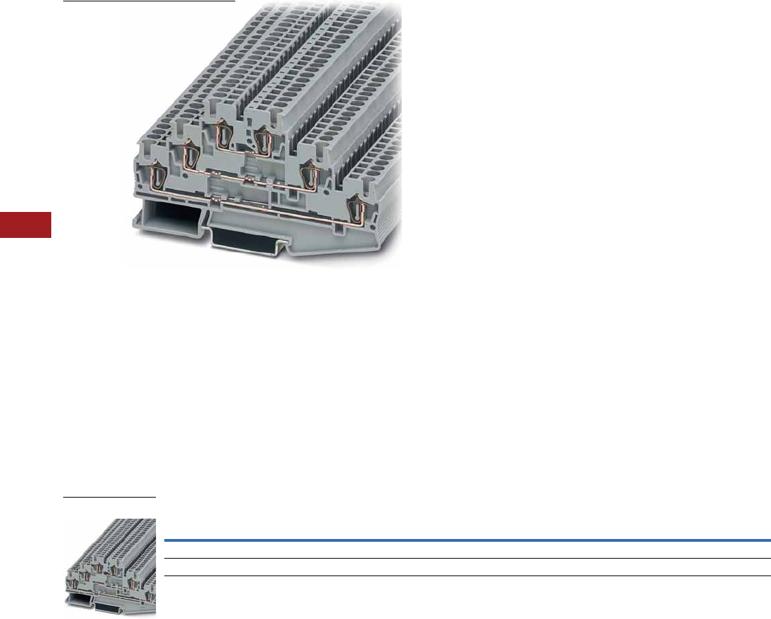
V7-T8-46 Volume 7—Logic Control, Operator Interface and Connectivity Solutions CA08100008E—July 2014 www.eaton.com
8
8
8
8
8
8
8
8
8
8
8
8
8
8
8
8
8
8
8
8
8
8
8
8
8
8
8
8
8
8
8.1
Terminal Blocks, Fuse Blocks and Fuse Holders
IEC—XB Series
Triple Level Blocks
Contents
Description Page
Single Level—Through-Feed . . . . . . . . . . . . . . . . . V7-T8-32
Single Level—Ground Blocks . . . . . . . . . . . . . . . . . V7-T8-37
Multi-Conductor Terminal Blocks . . . . . . . . . . . . . V7-T8-39
Multi-Conductor Ground Blocks . . . . . . . . . . . . . . V7-T8-42
Double Level Blocks . . . . . . . . . . . . . . . . . . . . . . . V7-T8-44
Triple Level Blocks
Accessories . . . . . . . . . . . . . . . . . . . . . . . . . . . V7-T8-47
Technical Data and Specifications . . . . . . . . . . V7-T8-47
Dimensions . . . . . . . . . . . . . . . . . . . . . . . . . . . V7-T8-47
Fuse Terminal Blocks . . . . . . . . . . . . . . . . . . . . . . . V7-T8-48
Disconnect and Component Terminal Blocks . . . . V7-T8-51
Hybrid Terminal Blocks . . . . . . . . . . . . . . . . . . . . . V7-T8-54
Mini Spring Cage . . . . . . . . . . . . . . . . . . . . . . . . . . V7-T8-56
Triple Level Blocks
Product Description
The spring cage triple level
terminal block incorporates
three feed-through levels
in a 5.2 mm wide housing.
This is ideal for high density
wiring, especially important
when switchgear space is
restricted. There is a bridge
shaft on each level allowing
use of this block as a compact
potential distributor or as
a sensor terminal.
The XBPTK25PV has
all six terminal points
interconnected. All the
triple level blocks can be
labeled on each level.
Product Selection
Spring Cage Connection Triple Level Blocks
Note
1 Terminal block with potential distribution between the levels.
Terminal
Width
Maximum
Wire Size
IEC 60 947-7-1
in V/A/AWG
UL-cUL Ratings
in V/A/AWG Color
Standard
Pack
Catalog
Number
5.2 mm 12 AWG/2.5 mm2500/28/28–12 600/20/26–12 Gray 50 XBPTK25
5.2 mm 12 AWG/2.5 mm2500/28/28–12 600/20/26–12 Gray 50 XBPTK25PV 1
XBPTK25

Volume 7—Logic Control, Operator Interface and Connectivity Solutions CA08100008E—July 2014 www.eaton.com V7-T8-47
8
8
8
8
8
8
8
8
8
8
8
8
8
8
8
8
8
8
8
8
8
8
8
8
8
8
8
8
8
8
8.1
Terminal Blocks, Fuse Blocks and Fuse Holders
IEC—XB Series
Accessories
Spring Cage Connection Triple Level Blocks
Technical Data and Specifications
Spring Cage Connection Triple Level Blocks
Dimensions
Approximate Dimensions in Inches (mm)
Spring Cage Connection Triple Level Blocks
Notes
1For information on Printed Marking Tag Options, see Page V7-T8-98.
For additional accessories, see Page V7-T8-90.
Description Color
Number of
Positions
Standard
Pack
XBPTK25 XBPTK25PV
Catalog
Number
Catalog
Number
End cover Gray — 10 XBACPT25K XBACPT25K
Plug-in bridge—for cross connections in
the bridge shaft
Red 2 10 XBAFBS25 XBAFBS25
310 XBAFBS35 XBAFBS35
510 XBAFBS55 XBAFBS55
10 10 XBAFBS105 XBAFBS105
50 10 XBAFBS505 XBAFBS505
Test adapter — — 10 XBATSPAI4 XBATSPAI4
Modular test plug — — 10 XBATSPS5 XBATSPS5
Blank marker strip (strip of 10) White — 10 XBMZBF5 1XBMZBF5 1
Description XBPTK25 XBPTK25PV
Technical Data in Accordance with IEC
Maximum load current in A/cross-section in mm228/4 28/4
Rated surge voltage in kV/contamination class 6/3 6/3
Surge voltage category/insulating material group III/I III/I
Connection Capacity
Stranded with ferrule with plastic sleeve in mm20.25–2.5 0.25–2.5
Stranded with ferrules without plastic sleeve in mm20.25–2.5 0.25–2.5
Stranded with twin ferrule with plastic sleeve in mm20.5 0.5
Stripping length in inches (mm) 0.39 (10) 0.39 (10)
Catalog
Number Width Length
Cover
Length
Height for—
35 x 7.5 in 35 x 15 in
XBPTK25 0.20 (5.2) 3.92 (99.5) 0.09 (2.2) 2.28 (58.0) 2.58 (65.5)
XBPTK25PV 0.20 (5.2) 3.92 (99.5) 0.09 (2.2) 2.28 (58.0) 2.58 (65.5)
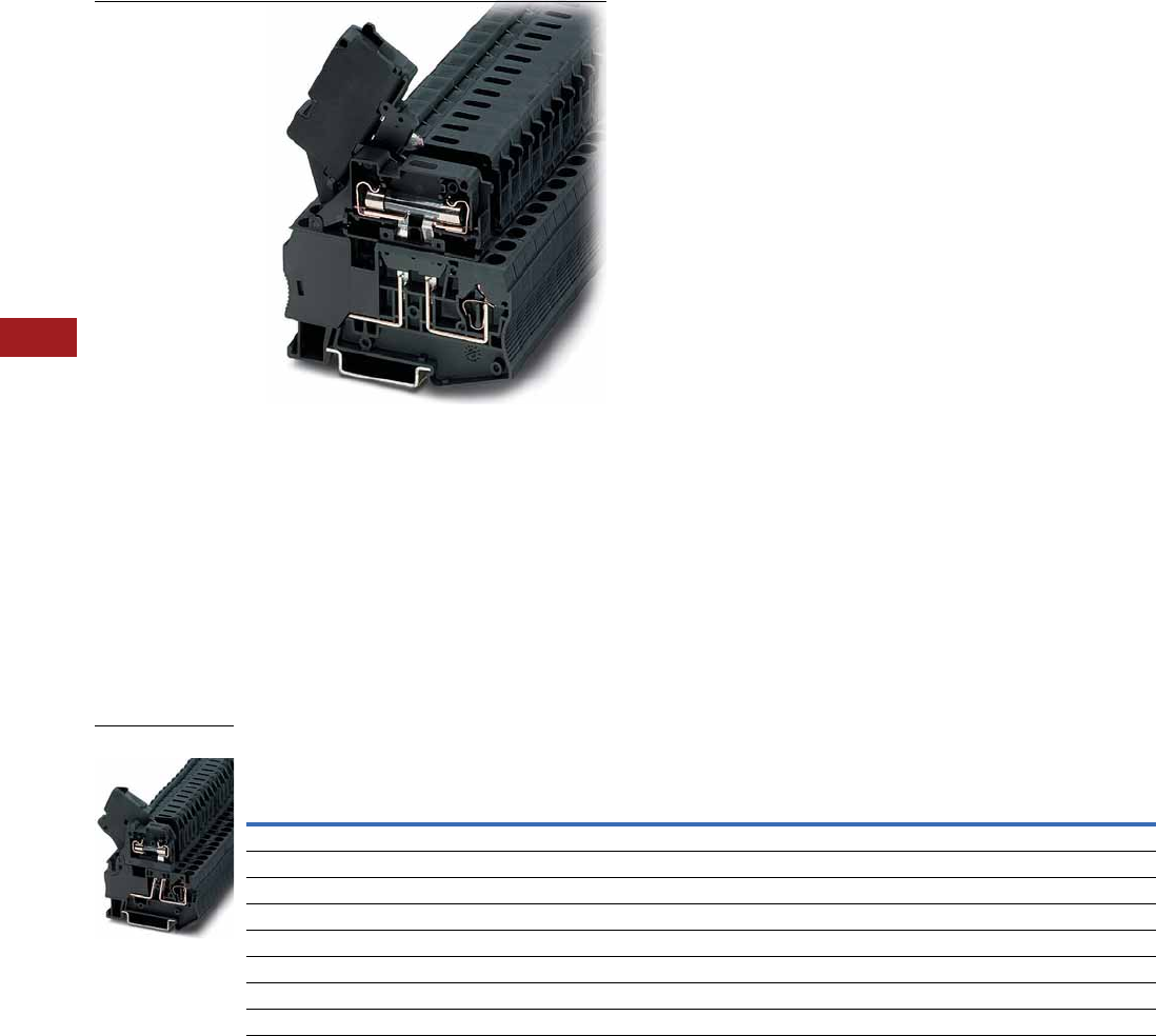
V7-T8-48 Volume 7—Logic Control, Operator Interface and Connectivity Solutions CA08100008E—July 2014 www.eaton.com
8
8
8
8
8
8
8
8
8
8
8
8
8
8
8
8
8
8
8
8
8
8
8
8
8
8
8
8
8
8
8.1
Terminal Blocks, Fuse Blocks and Fuse Holders
IEC—XB Series
Fuse Terminal Blocks
Contents
Description Page
Single Level—Through-Feed . . . . . . . . . . . . . . . . . V7-T8-32
Single Level—Ground Blocks . . . . . . . . . . . . . . . . . V7-T8-37
Multi-Conductor Terminal Blocks . . . . . . . . . . . . . V7-T8-39
Multi-Conductor Ground Blocks . . . . . . . . . . . . . . V7-T8-42
Double Level Blocks . . . . . . . . . . . . . . . . . . . . . . . V7-T8-44
Triple Level Blocks . . . . . . . . . . . . . . . . . . . . . . . . . V7-T8-46
Fuse Terminal Blocks
Accessories . . . . . . . . . . . . . . . . . . . . . . . . . . . V7-T8-49
Technical Data and Specifications . . . . . . . . . . V7-T8-50
Dimensions . . . . . . . . . . . . . . . . . . . . . . . . . . . V7-T8-50
Disconnect and Component Terminal Blocks . . . . V7-T8-51
Hybrid Terminal Blocks . . . . . . . . . . . . . . . . . . . . . V7-T8-54
Mini Spring Cage . . . . . . . . . . . . . . . . . . . . . . . . . . V7-T8-56
Fuse Terminal Blocks
Product Description
The spring cage fuse terminal
blocks act as a fuse carrier for
5 x 20 mm or 6.3 x 32 mm
fuses. They also allow for
potential distribution with the
double bridge shaft. For
signaling a triggered fuse,
fuse terminal blocks with light
indicators are available (for
both AC and DC voltage).
Product Selection
Spring Cage Connection Fuse Terminal Blocks, for 5 x 20 mm Fuse
Notes
The cartridge fuse holders should be selected according to the maximum power dissipation (self-heating) of the cartridge
fuse inserts. The thermal conditions in closed fuse holes should be checked according to the application and installation.
Higher ambient temperatures are an additional strain on fuse inserts. In applications of this kind, the shift of the rated
current should be taken into consideration accordingly.
Maximum power dissipation at 73.4°F (23°C) (in accordance with IEC 60 947-7-3).
When selecting cartridge fuse inserts, please ensure that the maximum power dissipation specified at right is not exceeded.
Details can be obtained from the fuse suppliers.
Cartridge Fuse Inserts 5 x 20 and 6.3 x 32 mm in accordance. with IEC 60 947-7-3.
1 The current is determined by the fuse used, the voltage by the selected light indicator. See Page V7-T8-49.
Terminal
Width
Maximum
Wire Size
IEC 60 947-7-3
with Fuse
in V/A/AWG
IEC 60 947-7-3
as Disconnect
Terminal Blocks
in V/A/AWG
UL-cUL Ratings
in V/A/AWG Color
Standard
Pack
Catalog
Number
Fuse Terminal Blocks
6.2 mm 10 AWG/4 mm21/1/28–10 250/6.3/28–10 300/6.3/24–10 Black 50 XBPT4FBE
Fuse Terminal Blocks with LED 15–30V, 3.5–8.1A
6.2 mm 10 AWG/4 mm21/1/28–10 250/6.3/28–10 300/6.3/24–10 Black 50 XBPT4FBEL24
Fuse Terminal Blocks with LED 30–60V, 0.8–2.0A
6.2 mm 10 AWG/4 mm21/1/28–10 250/6.3/28–10 300/6.3/24–10 Black 50 XBPT4FBEL60
Fuse Terminal Blocks with LED 110–250V, 0.5–1.0A
6.2 mm 10 AWG/4 mm21/1/28–10 250/6.3/28–10 300/6.3/24–10 Black 50 XBPT4FBEL250
XBPT4FBE
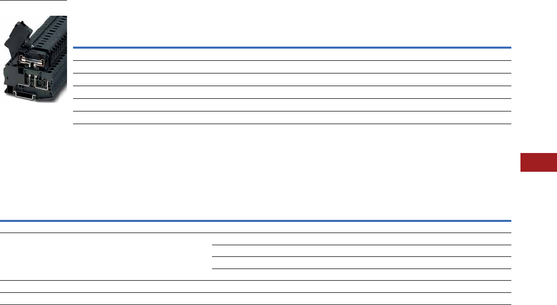
Volume 7—Logic Control, Operator Interface and Connectivity Solutions CA08100008E—July 2014 www.eaton.com V7-T8-49
8
8
8
8
8
8
8
8
8
8
8
8
8
8
8
8
8
8
8
8
8
8
8
8
8
8
8
8
8
8
8.1
Terminal Blocks, Fuse Blocks and Fuse Holders
IEC—XB Series
Spring Cage Connection Fuse Terminal Blocks, for 6.3 x 32 mm (1/4 in x 1–1/4 in) Fuse
Accessories
Spring Cage Connection Fuse Terminal Blocks
Notes
The cartridge fuse holders should be selected according to the maximum power dissipation (self-heating) of the cartridge
fuse inserts. The thermal conditions in closed fuse holes should be checked according to the application and installation.
Higher ambient temperatures are an additional strain on fuse inserts. In applications of this kind, the shift of the rated
current should be taken into consideration accordingly.
Maximum power dissipation at 73.4°F (23°C) (in accordance with IEC 60 947-7-3).
When selecting cartridge fuse inserts, please ensure that the maximum power dissipation specified at right is not exceeded.
Details can be obtained from the fuse suppliers.
Cartridge Fuse Inserts 5 x 20 and 6.3 x 32 mm in accordance. with IEC 60 947-7-3.
1For information on Printed Marking Tag Options, see Page V7-T8-98.
For additional accessories, see Page V7-T8-90.
Terminal
Width
Maximum
Wire Size
IEC 60 947-7-3
with Fuse
in V/A/AWG
IEC 60 947-7-3
as Disconnect
Terminal Blocks
in V/A/AWG
UL-cUL Ratings
in V/A/AWG Color
Standard
Pack
Catalog
Number
Fuse Terminal Blocks
8.2 mm 10 AWG/4 mm2400/10/28–10 400/10/28–10 300/10/24–10 Black 50 XBPT4FBN
Fuse Terminal Blocks with LED 12–30V, 1.0–2.5 mA
8.2 mm 10 AWG/4 mm2400/10/28–10 400/10/28–10 300/10/24–10 Black 50 XBPT4FBNL24
Fuse Terminal Blocks with LED 110–250V, 0.5–2.5 mA
8.2 mm 10 AWG/4 mm2400/10/28–10 400/10/28–10 300/10/24–10 Black 50 XBPT4FBNL250
Description Color
Number of
Positions
Standard
Pack
XBPT4FBE XBPT4FBN
Catalog
Number
Catalog
Number
Partition plate — — 10 XBATPT4 XBATQTD12
Plug-in bridge—for cross connections in
the bridge shaft
Red 2 10 XBAFBS26 XBAFBS28
310 XBAFBS36 —
510 XBAFBS56 —
10 10 XBAFBS106 —
Blank marker strip external labeling White — 10 XBMZBF6 1XBMZBF8 1
Blank marker strip center labeling (strip of 10) White — 10 XBMZB5 1XBMZB6 1
XBPT4FBN

V7-T8-50 Volume 7—Logic Control, Operator Interface and Connectivity Solutions CA08100008E—July 2014 www.eaton.com
8
8
8
8
8
8
8
8
8
8
8
8
8
8
8
8
8
8
8
8
8
8
8
8
8
8
8
8
8
8
8.1
Terminal Blocks, Fuse Blocks and Fuse Holders
IEC—XB Series
Technical Data and Specifications
Overload and Short-Circuit Protection
Spring Cage Connection Fuse Terminal Blocks
Dimensions
Approximate Dimensions in Inches (mm)
Spring Cage Connection Fuse Terminal Blocks
Note
1The current is determined by the fuse used, the voltage by the selected light indicator. See Page V7-T8-49.
Terminal
Blocks
Overload Protection Short-Circuit Protection Only
U (V) Individual Interconnected Individual Interconnected Imax. (A)
XBPT4FBN 400 1.6W 1.6W 4W 2.5W 10.0
XBPT4FBE 250 1.6W 1.6W 4W 2.5W 6.3
Description XBPT4FBE XBPT4FBN
Technical Data in Accordance with IEC
Fuse type/dimensions in mm2G/5 x 20 G/6.3 x 32
Maximum current with single arrangement in A 6.3 10
Maximum Power Dissipation
At 73.4°F (23°C) in accordance with IEC 60 947-7-3 in W 11
Rated surge voltage in kV/contamination class 4/3 6/3
Surge voltage category/insulating material group III/I III/I
Connection Capacity
Stranded with ferrule/with ferrule and plastic sleeve in mm20.25–4/0.25–4 0.25–4/0.25–4
Stranded with twin ferrule and plastic sleeve in mm20.5 0.5
Stripping length in inches (mm) 0.39 (10) 0.39 (10)
Catalog
Number Width Length
Height for—
35 x 7.5 in 35 x 15 in
XBPT4FBE 0.24 (6.2) 2.42 (61.5) 2.46 (62.5) 2.76 (70.0)
XBPT4FBN 0.32 (8.2) 3.01 (76.5) 2.72 (69.0) 3.01 (76.5)
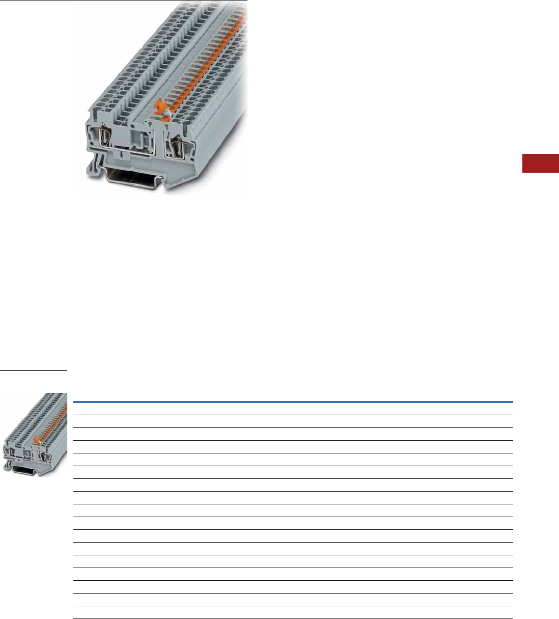
Volume 7—Logic Control, Operator Interface and Connectivity Solutions CA08100008E—July 2014 www.eaton.com V7-T8-51
8
8
8
8
8
8
8
8
8
8
8
8
8
8
8
8
8
8
8
8
8
8
8
8
8
8
8
8
8
8
8.1
Terminal Blocks, Fuse Blocks and Fuse Holders
IEC—XB Series
Disconnect and Component Terminal Blocks
Contents
Description Page
Single Level—Through-Feed . . . . . . . . . . . . . . . . . V7-T8-32
Single Level—Ground Blocks . . . . . . . . . . . . . . . . . V7-T8-37
Multi-Conductor Terminal Blocks . . . . . . . . . . . . . . V7-T8-39
Multi-Conductor Ground Blocks . . . . . . . . . . . . . . V7-T8-42
Double Level Blocks . . . . . . . . . . . . . . . . . . . . . . . V7-T8-44
Triple Level Blocks . . . . . . . . . . . . . . . . . . . . . . . . . V7-T8-46
Fuse Terminal Blocks . . . . . . . . . . . . . . . . . . . . . . . V7-T8-48
Disconnect and Component Terminal Blocks
Accessories . . . . . . . . . . . . . . . . . . . . . . . . . . . V7-T8-52
Technical Data and Specifications . . . . . . . . . . V7-T8-53
Dimensions . . . . . . . . . . . . . . . . . . . . . . . . . . . V7-T8-53
Hybrid Terminal Blocks . . . . . . . . . . . . . . . . . . . . . V7-T8-54
Mini Spring Cage . . . . . . . . . . . . . . . . . . . . . . . . . . V7-T8-56
Disconnect and Component Terminal Blocks
Product Description
The XBPT knife disconnect
terminal blocks feature
narrow construction and high
current carrying capacity.
They also have a test
connection parallel to the
disconnect point for a 2.3 mm
diameter test plug. Potential
distribution is easily
accomplished with the Plug-
in bridges. There are front
connection spring cage
terminal blocks available for
multi-conductor connections
in the smallest possible
space. The XBPT4TG
disconnect terminal block
accommodates component
plugs for resistors, diodes,
or capacitors, and fuse plugs
with or without indication.
Product Selection
Disconnect and Component Terminal Blocks
Terminal
Width
Maximum
Wire Size
IEC 60 947-7-1
in V/A/AWG
UL-cUL Ratings
in V/A/AWG Color
Standard
Pack
Catalog
Number
Single Level Knife Disconnect
5.2 mm 12 AWG/2.5 mm2400/16/28–12 600/16/26–12 Gray 50 XBPT25MT
6.2 mm 10 AWG/4 mm2400/16/28–10 300/6.3/24–10 Gray 50 XBPT4MT
Three-Wire Knife Disconnect
5.2 mm 12 AWG/2.5 mm2400/16/28–12 600/16/26–12 Gray 50 XBPT25D12MT
Four-Wire Knife Disconnect
5.2 mm 12 AWG/2.5 mm2400/16/28–12 600/16/26–12 Gray 50 XBPT25D22MT
Spring Cage Disconnect/Component Plug
6.2 mm 10 AWG/4 mm2400/16/28–10 300/6.3/24–10 Gray 50 XBPT4TG
Component Plug
6.2 mm 10 AWG/4 mm2400/16/28–10 300/6.3/24–10 Gray 10 XBPCO
Fuse Plug
6.2 mm 10 AWG/4 mm2400/16/28–10 300/6.3/24–10 Black 10 XBPFU
Fuse Plug with Light Indicator for 12–30V, 1–2.5 mA
6.2 mm 10 AWG/4 mm2400/16/28–10 300/6.3/24–10 Black 10 XBPFUL24
Fuse Plug with Light Indicator for 110–250V, 0.5–2.5 mA
6.2 mm 10 AWG/4 mm2400/16/28–10 300/6.3/24–10 Black 10 XBPFUL250
XBPT25MT
Knife Disconnect

V7-T8-52 Volume 7—Logic Control, Operator Interface and Connectivity Solutions CA08100008E—July 2014 www.eaton.com
8
8
8
8
8
8
8
8
8
8
8
8
8
8
8
8
8
8
8
8
8
8
8
8
8
8
8
8
8
8
8.1
Terminal Blocks, Fuse Blocks and Fuse Holders
IEC—XB Series
Accessories
Spring Cage Connection Disconnect and Component Terminal Blocks
Notes
1For ordering information, see Page V7-T8-105.
2For information on Printed Marking Tag Options, see Page V7-T8-98.
3XBPT4MT and XBPT4TG have an enclosed design. The use of an end cover is not required.
For additional accessories, see Page V7-T8-90.
Description Color
Number of
Positions
Standard
Pack
XBPT25MT XBPT25D12MT XBPT25D22MT XBPT4MT XBPT4TG
Catalog
Number
Catalog
Number
Catalog
Number
Catalog
Number
Catalog
Number
End cover Gray — 10 XBACPT25D12 XBACPT25D22 XBACPT25D22MT 33
End cover segment Gray — 10 — XBACPT25 XBACPT25 — —
Partition plate — — — XBATPTD12 XBATPTD22 — XBATPT4 XBATPT4
Plug-in bridge—for cross connections
in the terminal center
Red 2 10 XBAFBS25 XBAFBS25 XBAFBS25 XBAFBS26 XBAFBS26
310XBAFBS35 XBAFBS35 XBAFBS35 XBAFBS36 XBAFBS36
510XBAFBS55 XBAFBS55 XBAFBS55 XBAFBS56 XBAFBS56
10 10 XBAFBS105 XBAFBS105 XBAFBS105 XBAFBS106 XBAFBS106
50 10 XBAFBS505 XBAFBS505 XBAFBS505 XBAFBS506 XBAFBS506
Test adapter — — 10 XBATSPAI4 XBATSPAI4 XBATSPAI4 XBATSPAI4 XBATSPAI4
2.3 mm diameter test plug — — — XBATSMPS-_ 1XBATSMPS-_ 1XBATSMPS-_ 1XBATSMPS-_ 1XBATSMPS-_ 1
Modular test plug — — 10 XBATSPS5 XBATSPS5 XBATSPS5 XBATSPS6 XBATSPS6
Blank marker strip external labeling White — 10 XBMZBF5 2XBMZBF5 2XBMZBF5 2XBMZBF6 2XBMZBF6 2
Blank marker strip center labeling
(strip of 10)
White — 10 XBMZB5 2XBMZB5 2XBMZB5 2XBMZB6 2XBMZB6 2

Volume 7—Logic Control, Operator Interface and Connectivity Solutions CA08100008E—July 2014 www.eaton.com V7-T8-53
8
8
8
8
8
8
8
8
8
8
8
8
8
8
8
8
8
8
8
8
8
8
8
8
8
8
8
8
8
8
8.1
Terminal Blocks, Fuse Blocks and Fuse Holders
IEC—XB Series
Technical Data and Specifications
Spring Cage Connection Disconnect and Component Terminal Blocks,
XBPT25MT, XBPT25D12MT and XBPT25D22MT
Spring Cage Connection Disconnect and Component Terminal Blocks,
XBPT25D12MT and XBPT4TG
Dimensions
Approximate Dimensions in Inches (mm)
Spring Cage Connection Disconnect and Component Terminal Blocks
Description XBPT25MT XBPT25D12MT XBPT25D22MT
Technical Data in Accordance with IEC
Maximum load current in A/cross-section in mm216/4 16/4 16/4
Rated surge voltage in kV/contamination class 6/3 6/3 6/3
Surge voltage category/insulating material group III/I III/I III/I
Connection Capacity
Stranded with ferrule with plastic sleeve in mm20.25–2.5 0.25–2.5 0.25–2.5
Stranded with ferrules without plastic sleeve in mm20.25–2.5 0.25–2.5 0.25–2.5
Stranded with twin ferrule with plastic sleeve in mm20.5 0.5 0.5
Stripping length in inches (mm) 0.39 (10) 0.39 (10) 0.39 (10)
Description XBPT4MT XBPT4TG
Technical Data in Accordance with IEC
Maximum load current in A/cross-section in mm216/6 16/6
Rated surge voltage in kV/contamination class 6/3 6/3
Surge voltage category/insulating material group III/I III/I
Connection Capacity
Stranded with ferrule with plastic sleeve in mm20.25–4 0.25–4
Stranded with ferrules without plastic sleeve in mm20.25–4 0.25–4
Stranded with twin ferrule with plastic sleeve in mm20.5 0.5
Stripping length in inches (mm) 0.39 (10) 0.39 (10)
Catalog
Number Width Length
Cover
Length
Height for—
35 x 7.5 in 35 x 15 in
XBPT25MT 0.20 (5.2) 2.38 (60.5) 0.09 (2.2) 1.44 (36.5) 1.73 (44.0)
XBPT25D12MT 0.20 (5.2) 2.83 (72.0) 0.09 (2.2) 1.44 (36.5) 1.73 (44.0)
XBPT25D22MT 0.20 (5.2) 3.31 (84.0) 0.09 (2.2) 1.44 (36.5) 1.73 (44.0)
XBPT4MT 0.24 (6.2) 2.42 (61.5) — 1.44 (36.5) 1.73 (44.0)
XBPT4TG 0.24 (6.2) 2.42 (61.5) — 1.44 (36.5) 1.73 (44.0)
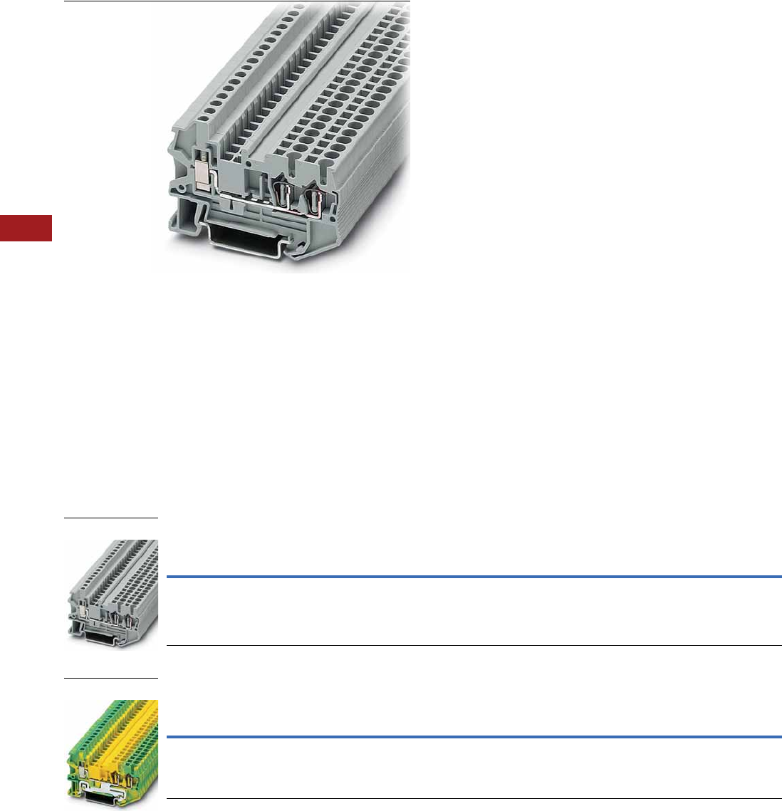
V7-T8-54 Volume 7—Logic Control, Operator Interface and Connectivity Solutions CA08100008E—July 2014 www.eaton.com
8
8
8
8
8
8
8
8
8
8
8
8
8
8
8
8
8
8
8
8
8
8
8
8
8
8
8
8
8
8
8.1
Terminal Blocks, Fuse Blocks and Fuse Holders
IEC—XB Series
Hybrid Terminal Blocks
Contents
Description Page
Single Level—Through-Feed . . . . . . . . . . . . . . . . . V7-T8-32
Single Level—Ground Blocks . . . . . . . . . . . . . . . . . V7-T8-37
Multi-Conductor Terminal Blocks . . . . . . . . . . . . . V7-T8-39
Multi-Conductor Ground Blocks . . . . . . . . . . . . . . V7-T8-42
Double Level Blocks . . . . . . . . . . . . . . . . . . . . . . . V7-T8-44
Triple Level Blocks . . . . . . . . . . . . . . . . . . . . . . . . . V7-T8-46
Fuse Terminal Blocks . . . . . . . . . . . . . . . . . . . . . . . V7-T8-48
Disconnect and Component Terminal Blocks . . . . V7-T8-51
Hybrid Terminal Blocks
Accessories . . . . . . . . . . . . . . . . . . . . . . . . . . . V7-T8-55
Technical Data and Specifications . . . . . . . . . . V7-T8-55
Dimensions . . . . . . . . . . . . . . . . . . . . . . . . . . . V7-T8-55
Mini Spring Cage . . . . . . . . . . . . . . . . . . . . . . . . . . V7-T8-56
Hybrid Terminal Blocks
Product Description
The XBPU spring cage hybrid
terminal blocks offer the best
of both worlds. One side
offers a spring cage
connection and the other side
offers the universal screw
connection. Use the spring
cage connection on the
internal (factory) control
cabinet side and the screw
connection on the end
customer (field) side. Ground
terminal blocks of the same
shape are also available.
Product Selection
Spring Cage Hybrid Terminal Blocks
Spring Cage Hybrid Ground Blocks
Terminal
Width
Maximum
Wire Size
IEC 60 947-7-1 with … IEC 60 947-7-2 with … UL-cUL Ratings with …
Color
Std.
Pack
Catalog
Number
Spring in
V/A/AWG
Screw in
V/A/AWG
Spring in
V/A/AWG
Screw in
V/A/AWG
Spring in
V/A/AWG
Screw in
V/A/AWG
5.2 mm 12 AWG/
2.5 mm2
800/28/28–12 800/28/26–14 — — 600/15/28–12 600/15/26–12 Gray 50 XBPU25D12
Terminal
Width
Maximum
Wire Size
IEC 60 947-7-1 with … IEC 60 947-7-2 with … UL-cUL Ratings with …
Color
Std.
Pack
Catalog
Number
Spring in
V/A/AWG
Screw in
V/A/AWG
Spring in
V/A/AWG
Screw in
V/A/AWG
Spring in
V/A/AWG
Screw in
V/A/AWG
5.2 mm 12 AWG/
2.5 mm2
— — —/—/28–12 —/—/26–14 —/—/28–12 —/—/28–12 Green/
Yellow
50 XBPU25D12PE
XBPU25D12
XBPU25D12PE

Volume 7—Logic Control, Operator Interface and Connectivity Solutions CA08100008E—July 2014 www.eaton.com V7-T8-55
8
8
8
8
8
8
8
8
8
8
8
8
8
8
8
8
8
8
8
8
8
8
8
8
8
8
8
8
8
8
8.1
Terminal Blocks, Fuse Blocks and Fuse Holders
IEC—XB Series
Accessories
Spring Cage Hybrid Terminal/Ground Blocks
Technical Data and Specifications
Spring Cage Hybrid Blocks
Dimensions
Approximate Dimensions in Inches (mm)
Spring Cage Hybrid Blocks
Notes
1For ordering information, see Page V7-T8-105.
2For information on Printed Marking Tag Options, see Page V7-T8-98.
For additional accessories, see Page V7-T8-90.
Description Color
Number of
Positions
Standard
Pack
XBPU25D12 XBPU25D12PE
Catalog
Number
Catalog
Number
End cover Gray — 10 XBACPU25D12 XBACPU25D12
Plug-in bridge—for cross connections
in the terminal center
Red 2 10 XBAFBS25 XBAFBS25
310XBAFBS35 XBAFBS35
510XBAFBS55 XBAFBS55
10 10 XBAFBS105 XBAFBS105
50 10 XBAFBS505 XBAFBS505
Test adapter — — 10 XBATSPAI4 —
2.3 mm diameter test plug — — — XBATSMPS-_ 1—
Modular test plug — — 10 XBATSPS5 —
Blank marker strip external labeling White — 10 XBMZBF5 2XBMZBF5 2
Blank marker strip center labeling
(strip of 10)
White — 10 XBMZB5 2XBMZB5 2
Description XBPU25D12 XBPU25D12PE
Technical Data in Accordance with IEC
Maximum load current in A/cross-section in mm228/4 —
Rated surge voltage in kV/contamination class 8/3 8/3
Surge voltage category/insulating material group III/I III/I
Connection Capacity
Stranded with ferrule with plastic sleeve in mm20.25–2.5 0.25–2.5
Stranded with ferrules without plastic sleeve in mm20.25–2.5 0.25–2.5
Stranded with twin ferrule with plastic sleeve in mm20.5–1 0.5–1
Stripping length in inches (mm) 0.39 (10) 0.39 (10)
Catalog
Number Width Length
Cover
Length
Height for—
35 x 7.5 in 35 x 15 in
XBPU25D12 0.20 (5.2) 2.57 (65.3) 0.09 (2.2) 1.69 (42.8) 1.98 (50.3)
XBPU25D12PE 0.20 (5.2) 2.57 (65.3) 0.09 (2.2) 1.69 (42.8) 1.98 (50.3)
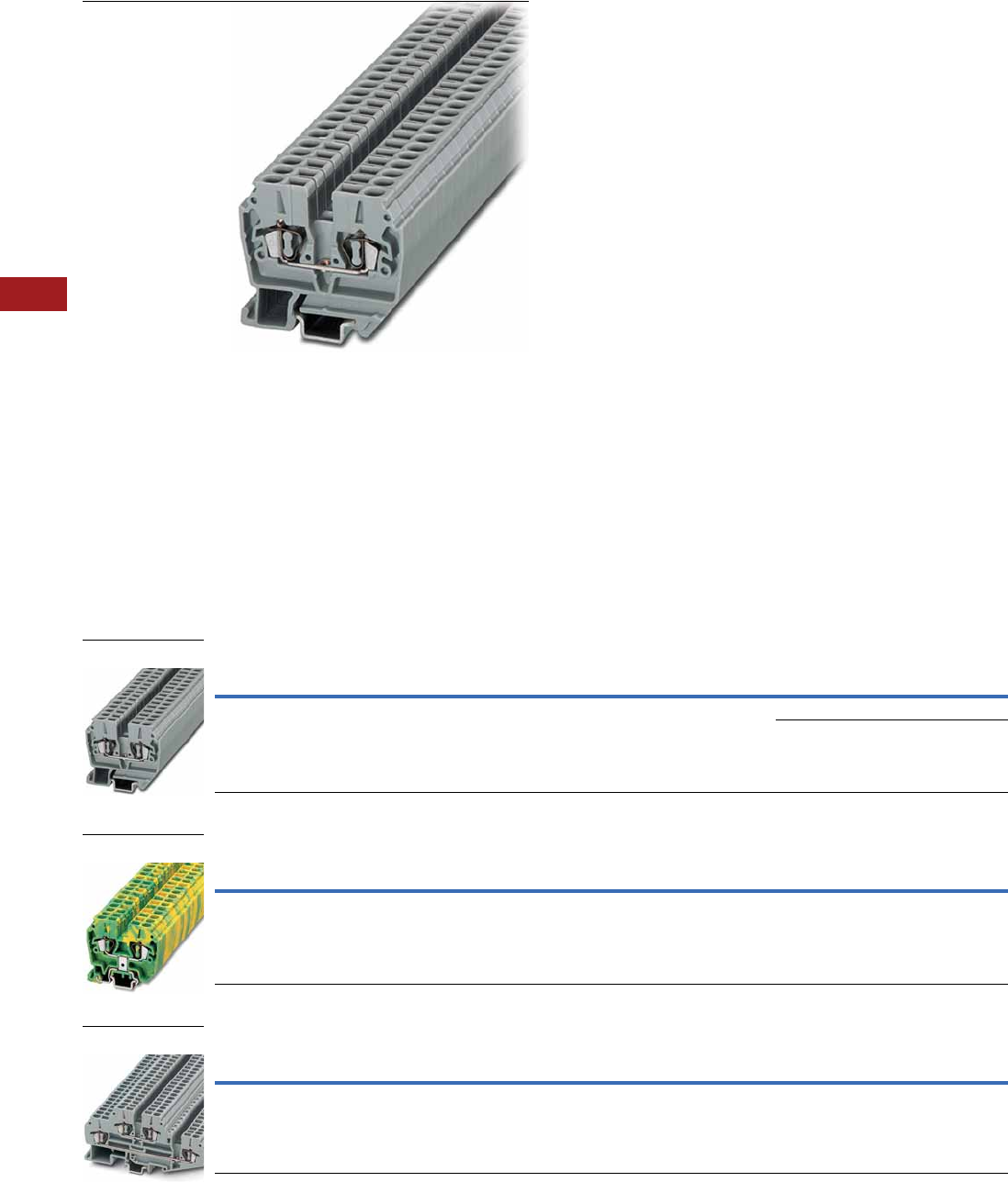
V7-T8-56 Volume 7—Logic Control, Operator Interface and Connectivity Solutions CA08100008E—July 2014 www.eaton.com
8
8
8
8
8
8
8
8
8
8
8
8
8
8
8
8
8
8
8
8
8
8
8
8
8
8
8
8
8
8
8.1
Terminal Blocks, Fuse Blocks and Fuse Holders
IEC—XB Series
Mini Spring Cage
Contents
Description Page
Single Level—Through-Feed . . . . . . . . . . . . . . . . . V7-T8-5
Single Level—Ground Blocks . . . . . . . . . . . . . . . . V7-T8-10
Multi-Conductor Terminal Blocks . . . . . . . . . . . . . V7-T8-12
Multi-Conductor Ground Blocks . . . . . . . . . . . . . . V7-T8-14
Double Level . . . . . . . . . . . . . . . . . . . . . . . . . . . . . V7-T8-16
Triple Level Sensor/Actuator . . . . . . . . . . . . . . . . . V7-T8-18
Fuse Terminal Blocks . . . . . . . . . . . . . . . . . . . . . . . V7-T8-21
Disconnect and Component Terminal Blocks . . . . V7-T8-24
High Current Blocks . . . . . . . . . . . . . . . . . . . . . . . V7-T8-27
Mini Spring Cage
Accessories . . . . . . . . . . . . . . . . . . . . . . . . . . . V7-T8-57
Technical Data and Specifications . . . . . . . . . . V7-T8-57
Dimensions . . . . . . . . . . . . . . . . . . . . . . . . . . . V7-T8-57
Mini Spring Cage
Product Description
The XB miniature terminal
blocks have a connection
cross-section from 1.5 mm2
through 4 mm2 and mount on
15 mm DIN rail. There is an
opening for bridging with a
fixed bridge in the center of
the terminal blocks. These
miniature terminal blocks also
offer the same accessories
that you would find with the
larger blocks—including
marking tags, end covers,
end stop and ground blocks.
Product Selection
Mini Spring Cage Terminal Blocks
Mini Spring Cage Ground Blocks
Mini Spring Cage Terminal Blocks—Double Level
Terminal
Width
Maximum
Wire Size
IEC 60 947-7-1
in V/A/AWG
IEC 60 947-7-2
in V/A/AWG
UL-cUL Ratings
in V/A/AWG Color
Standard
Pack
Catalog
Number
5.2 mm 14 AWG/1.5 mm2800/24/26–14 — 600/15/26–14 Gray 50 XBMPK15
Blue 50 XBMPK15BU
Terminal
Width
Maximum
Wire Size
IEC 60 947-7-1
in V/A/AWG
IEC 60 947-7-2
in V/A/AWG
UL-cUL Ratings
in V/A/AWG Color
Standard
Pack
Catalog
Number
5.2 mm 14 AWG/1.5 mm2— —/—/26–14 —/—/26–14 Green/
Yellow
50 XBMPK15PE
Terminal
Width
Maximum
Wire Size
IEC 60 947-7-1
in V/A/AWG
UL-cUL Ratings
in V/A/AWG Color
Standard
Pack
Catalog
Number
5.2 mm 14 AWG/1.5 mm2500/20/26–14 600/15/26–14 Gray 50 XBMPKK15
XBMPK15
XBMPK15PE
XBMPKK15

Volume 7—Logic Control, Operator Interface and Connectivity Solutions CA08100008E—July 2014 www.eaton.com V7-T8-57
8
8
8
8
8
8
8
8
8
8
8
8
8
8
8
8
8
8
8
8
8
8
8
8
8
8
8
8
8
8
8.1
Terminal Blocks, Fuse Blocks and Fuse Holders
IEC—XB Series
Accessories
Mini Spring Cage Terminal/Ground Blocks
Technical Data and Specifications
Mini Spring Cage Terminal/Ground Blocks
Dimensions
Approximate Dimensions in Inches (mm)
Mini Spring Cage Terminal/Ground Blocks
Notes
1For information on Printed Marking Tag Options, see Page V7-T8-98.
For additional accessories, see Page V7-T8-90.
Description Color
Number of
Positions
Standard
Pack
XBMPK15 XBMPK15PE XBMPKK15
Catalog
Number
Catalog
Number
Catalog
Number
End cover Gray — 10 XBACMPK15 XBACMPK15 XBACMPKK15
Fixed bridge — 2 10 XBAFBR25N — XBAFBR25N
Separating plate — — 10 XBATMPKK15 — XBATMPKK15
Blank marker strip White — 10 XBMZBF5 1XBMZBF5 1XBMZBF5 1
Description XBMPK15 XBMPK15PE XBMPKK15
Technical Data in Accordance with IEC
Maximum load current in A/cross-section in mm224/2.5 — 20/2.5
Rated surge voltage in kV/contamination class 8/3 8/3 6/3
Surge voltage category/insulating material group III/I III/I III/I
Connection Cross-Section
Stranded with ferrule with plastic sleeve in mm20.25–1.5 0.25–1.5 0.25–1.5
Stranded with ferrule without plastic sleeve in mm20.25–1.5 0.25–1.5 0.25–1.5
Stranded with twin ferrule with plastic sleeve in mm2———
Stripping length in Inches (mm) 0.35 (9) 0.35 (9) 0.35 (9)
Catalog
Number Width Length
Cover
Length
Height for—
15 x 5.5 in 35 x 7.5 in 35 x 15 in
XBMPK15 0.20 (5.2) 1.57 (40.0) 0.04 (1.1) 1.36 (34.5) — —
XBMPK15PE 0.20 (5.2) 1.57 (40.0) 0.04 (1.1) 1.36 (34.5) — —
XBMPKK15 0.20 (5.2) 3.35 (85.0) 0.04 (1.1) 1.65 (42.0) 1.67 (42.5) 1.97 (50.0)
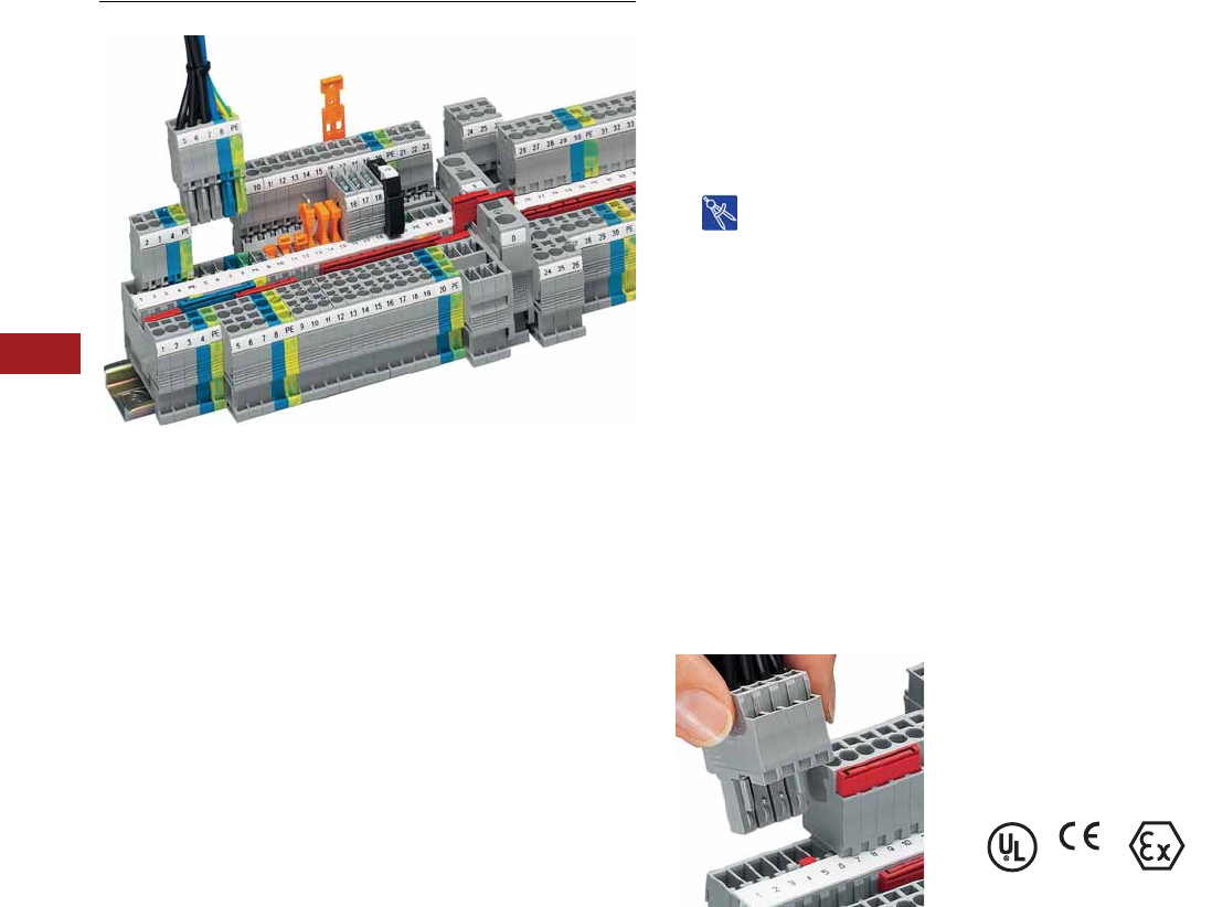
V7-T8-58 Volume 7—Logic Control, Operator Interface and Connectivity Solutions CA08100008E—July 2014 www.eaton.com
8
8
8
8
8
8
8
8
8
8
8
8
8
8
8
8
8
8
8
8
8
8
8
8
8
8
8
8
8
8
8.1
Terminal Blocks, Fuse Blocks and Fuse Holders
IEC—XB Series
Pluggable Spring Cage Terminal Blocks
Contents
Description Page
Pluggable Spring Cage Terminal Blocks
Connection Terminal Blocks . . . . . . . . . . . . . . . V7-T8-59
Connection Plugs . . . . . . . . . . . . . . . . . . . . . . . V7-T8-62
Connection Receptacles . . . . . . . . . . . . . . . . . V7-T8-64
Connection Accessories . . . . . . . . . . . . . . . . . V7-T8-66
Drawings
Online
Pluggable Spring Cage Terminal Blocks Overview
Product Description
The pluggable spring cage
connection terminal blocks
allow signal and power wiring
to be made pluggable. This
complete pluggable system
has a spring that provides
maximum connection space
in a space-saving design.
The pluggable system
accommodates stranded
conductors with a nominal
cross-section of 2.5 mm2,
with or without ferrules.
Application Description
For applications requiring
pluggable wiring up to a rated
current of 32A and a rated
voltage of 800V. The
integrated overspring meets
the most stringent vibration
requirements. Also ideal
where safety is a concern and
flexibility is required. The
basic terminal blocks and the
plugs are finger-safe, which
also means the supply
voltage can be input via either
the terminal blocks or the
plugs. With the XBAPSC
receptacles, plug-in contacts
can be accommodated safely
in cable ducts and distributor
shafts using minimal space.
A test hole can accommodate
a 2.3 mm diameter test plug
in each receptacle, providing
a practical solution. The
XBAPSP plugs are intended
for connecting one wire,
while the XBAPSPDB plugs
are designed to connect
two wires and provide an
optional bridge.
Features
●Space-saving design
●Powerful contact
●Finger-safe
Pluggability
Standards and Certifications
●UL recognized—File No.
E67464
●CE approved
●LVD 1:
●EN 60947-7-1
●EN 60947-7-2
●EN 60998-2-3
●EN 60352-4/A1
●ATEX approval
(Eex e applications)
Note
1Not all standards apply to all terminal
blocks. Contact Eaton for details.
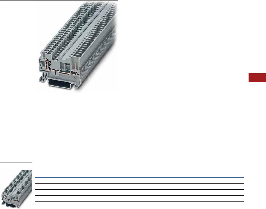
Volume 7—Logic Control, Operator Interface and Connectivity Solutions CA08100008E—July 2014 www.eaton.com V7-T8-59
8
8
8
8
8
8
8
8
8
8
8
8
8
8
8
8
8
8
8
8
8
8
8
8
8
8
8
8
8
8
8.1
Terminal Blocks, Fuse Blocks and Fuse Holders
IEC—XB Series
Connection Terminal Blocks
Contents
Description Page
Connection Terminal Blocks
Accessories . . . . . . . . . . . . . . . . . . . . . . . . . . . V7-T8-60
Technical Data and Specifications . . . . . . . . . . V7-T8-60
Dimensions . . . . . . . . . . . . . . . . . . . . . . . . . . . V7-T8-61
Connection Plugs . . . . . . . . . . . . . . . . . . . . . . . . . V7-T8-62
Connection Receptacles . . . . . . . . . . . . . . . . . . . . V7-T8-64
Connection Accessories . . . . . . . . . . . . . . . . . . . . V7-T8-66
Connection Terminal Blocks
Product Description
Contact to the DIN rail is
made by simply snapping the
terminal block onto the rail.
These blocks act as the
stationary position of the
pluggable terminal blocks.
Product Selection
Pluggable Spring Cage Connection Terminal Blocks
Terminal
Width
Maximum
Wire Size
IEC 61 984
in V/A/AWG
UL-cUL Ratings
in V/A/AWG Color
Standard
Pack
Catalog
Number
Single Level
5.2 mm 12 AWG/2.5 mm2500/24/28–12 300/20/26–12 Gray 50 XBPT25P
Three-Wire
5.2 mm 12 AWG/2.5 mm2500/24/28–12 300/20/26–12 Gray 50 XBPT25PD12
XBPT25P
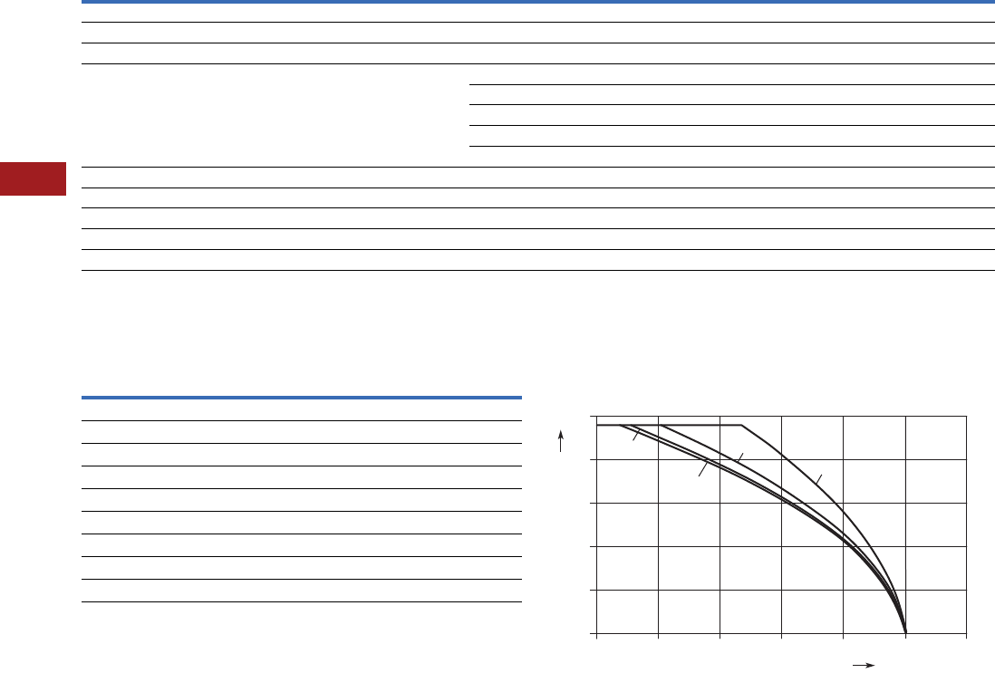
V7-T8-60 Volume 7—Logic Control, Operator Interface and Connectivity Solutions CA08100008E—July 2014 www.eaton.com
8
8
8
8
8
8
8
8
8
8
8
8
8
8
8
8
8
8
8
8
8
8
8
8
8
8
8
8
8
8
8.1
Terminal Blocks, Fuse Blocks and Fuse Holders
IEC—XB Series
Accessories
Pluggable Spring Cage Connection Terminal Blocks
Technical Data and Specifications
Pluggable Spring Cage Connection Terminal Blocks Derating Curve for Pluggable Terminal Blocks
XBPT25P and XBPT25PD12
Notes
1For ordering information, see Page V7-T8-105.
2For information on Printed Marking Tag Options, see Page V7-T8-98.
For additional accessories, see Page V7-T8-90.
Description Color
Number of
Positions
Standard
Pack
XBPT25P XBPT25PD12
Catalog
Number
Catalog
Number
End cover Gray — 10 XBACPT25 XBACPT25D12
End cover segment Gray — 10 — XBASPT25
Partition plate — — 10 XBATPT4 XBATPTD12
Plug-in bridge—for cross connections
in the terminal center
Red 2 10 XBAFBS25 XBAFBS25
310XBAFBS35 XBAFBS35
510XBAFBS55 XBAFBS55
10 10 XBAFBS105 XBAFBS105
50 10 XBAFBS505 XBAFBS505
Test adapter — — 10 XBATSPAI4 XBATSPAI4
2.3 mm diameter test plug — — — XBATSMPS-_ 1XBATSMPS-_ 1
Modular test plug — — 10 XBATSPS5 XBATSPS5
Blank marker strip external labeling White — 10 XBMZBF5 2XBMZBF5 2
Blank marker strip center labeling (strip of 10) White — 10 XBMZB5 2XBMZB5 2
Description XBPT25P XBPT25PD12
Technical Data in Accordance with IEC
Maximum load current in A/cross-section in mm224/4 24/4
Rated surge voltage in kV/contamination class 6/3 6/3
Surge voltage category/insulating material group III/I III/I
Connection Capacity
Stranded with ferrule with plastic sleeve in mm20.25–2.5 0.25–2.5
Stranded with ferrules without plastic sleeve in mm20.25–2.5 0.25–2.5
Stranded with twin ferrule with plastic sleeve in mm20.5 0.5
Stripping length in inches (mm) 0.39 (10) 0.39 (10)
25
15 pos.
5 pos.
20
15
10
5
0
Ambient Temperature – °C
Maximum Load Current – A
020406080100120
10 pos.
2 pos.
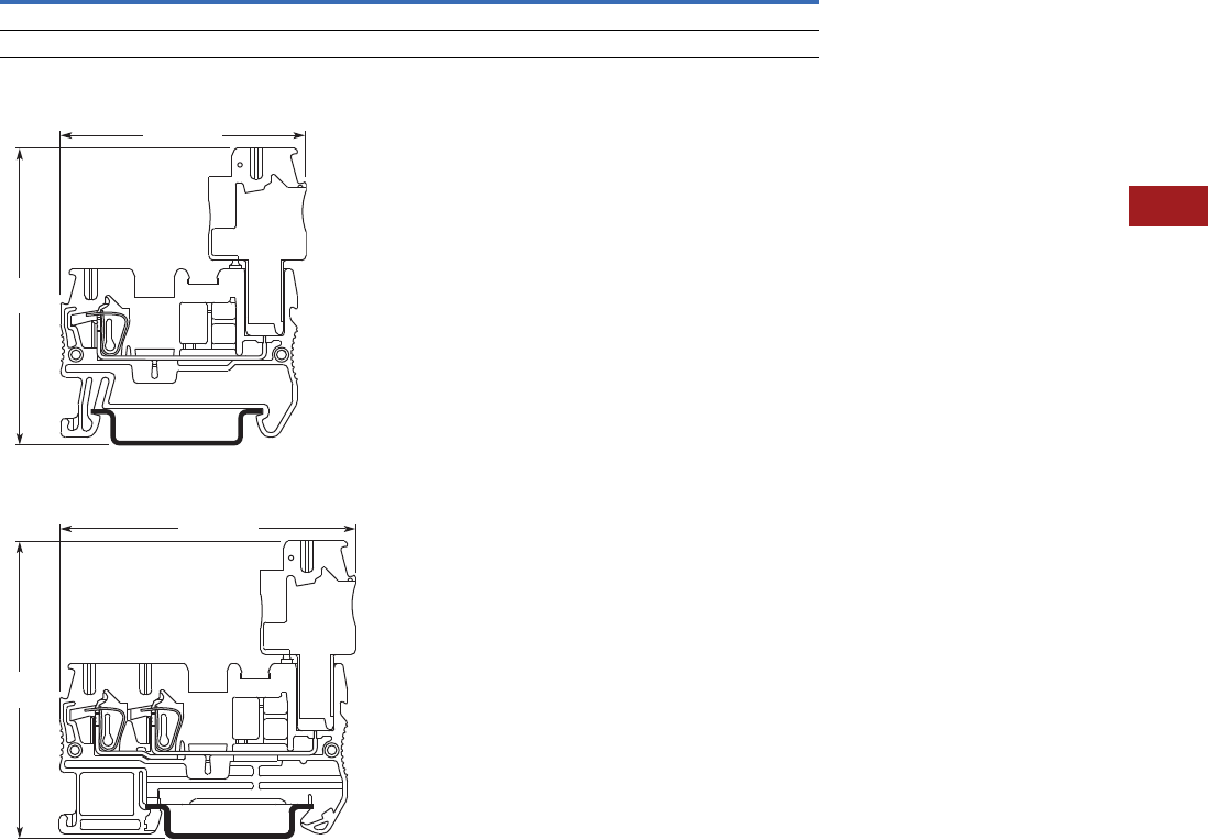
Volume 7—Logic Control, Operator Interface and Connectivity Solutions CA08100008E—July 2014 www.eaton.com V7-T8-61
8
8
8
8
8
8
8
8
8
8
8
8
8
8
8
8
8
8
8
8
8
8
8
8
8
8
8
8
8
8
8.1
Terminal Blocks, Fuse Blocks and Fuse Holders
IEC—XB Series
Dimensions
Approximate Dimensions in Inches (mm)
Pluggable Spring Cage Connection Terminal Blocks—Without Plug
XBPT25P
XBPT25PD12
Catalog
Number Width Length
Cover
Length
Height for—
35 x 7.5 in 35 x 15 in
XBPT25P 0.20 (5.2) 1.91 (48.5) 0.09 (2.2) 1.44 (36.5) 1.73 (44.0)
XBPT25PD12 0.20 (5.2) 2.38 (60.5) 0.09 (2.2) 1.44 (36.5) 1.73 (44.0)
1.99 (50.5)
2.42
(61.5)
2.42 (61.5)
2.42
(61.5)
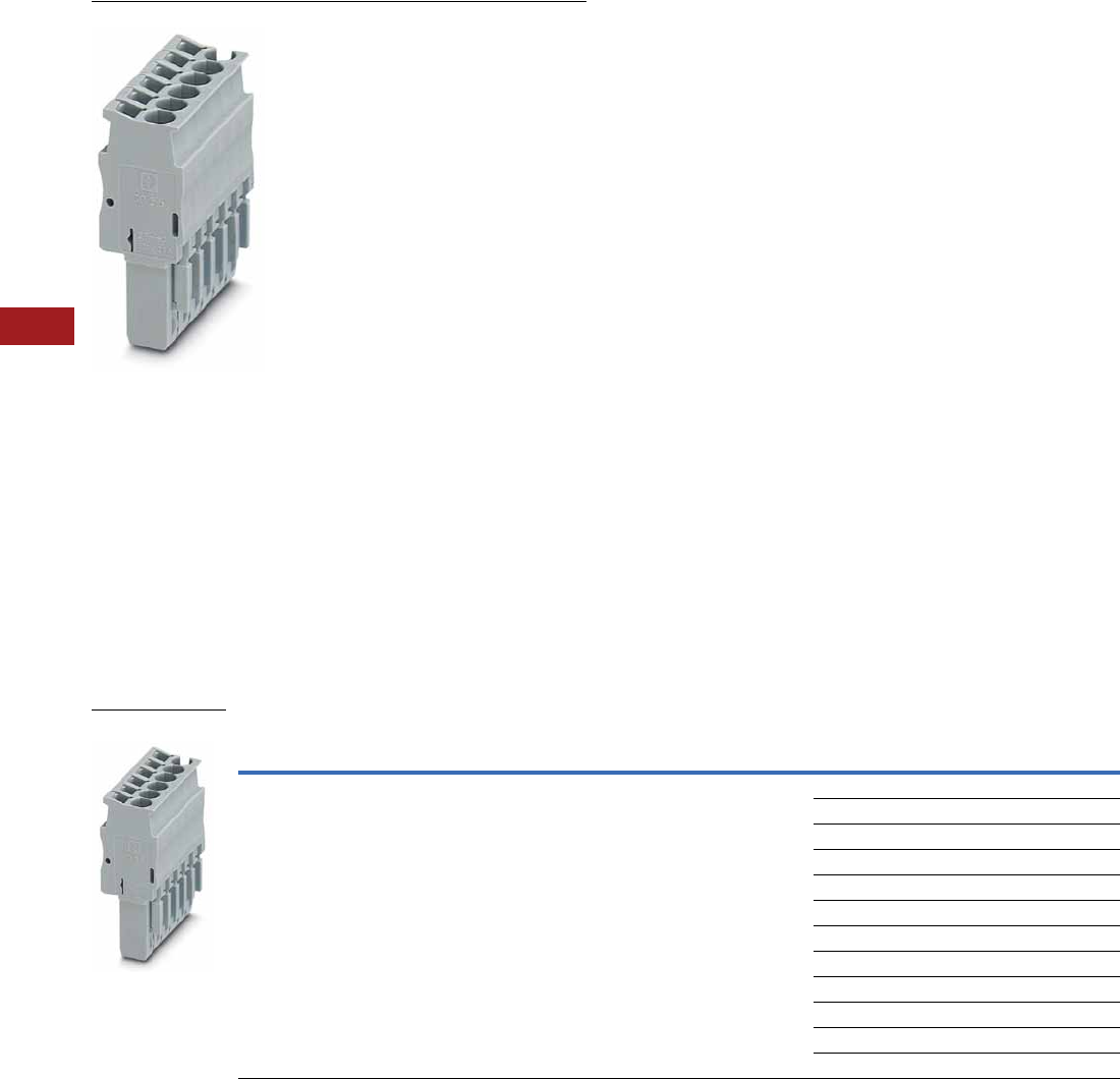
V7-T8-62 Volume 7—Logic Control, Operator Interface and Connectivity Solutions CA08100008E—July 2014 www.eaton.com
8
8
8
8
8
8
8
8
8
8
8
8
8
8
8
8
8
8
8
8
8
8
8
8
8
8
8
8
8
8
8.1
Terminal Blocks, Fuse Blocks and Fuse Holders
IEC—XB Series
Connection Plugs
Contents
Description Page
Connection Terminal Blocks . . . . . . . . . . . . . . . . . V7-T8-59
Connection Plugs
Accessories . . . . . . . . . . . . . . . . . . . . . . . . . . . V7-T8-63
Technical Data and Specifications . . . . . . . . . . V7-T8-63
Dimensions . . . . . . . . . . . . . . . . . . . . . . . . . . . V7-T8-63
Connection Receptacles . . . . . . . . . . . . . . . . . . . . V7-T8-64
Connection Accessories . . . . . . . . . . . . . . . . . . . . V7-T8-66
Connection Plugs
Product Description
Just like the basic terminal
blocks, the plugs also offer
the perfect solution for every
application. The XBAPSP25_
plugs are designed for
connecting one conductor.
The XBAPSPDB25_ plug is
designed for connecting two
conductors and provides an
additional bridging option.
Product Selection
Spring Cage Connection Plugs, Single, Not Bridgeable
Terminal
Width
Maximum
Wire Size
Connection Data
in V/A/AWG
UL-cUL Ratings
in V/A/AWG Color
Number of
Positions
Standard
Pack
Catalog
Number
5.2 mm 12 AWG/2.5 mm2500/24/28–12 300/20/26–12 Gray 1 25 XBAPSP251
225 XBAPSP252
325 XBAPSP253
425 XBAPSP254
525 XBAPSP255
625 XBAPSP256
725 XBAPSP257
825 XBAPSP258
925 XBAPSP259
10 25 XBAPSP2510
11 10 XBAPSP2511
12 10 XBAPSP2512
XBAPSP25_
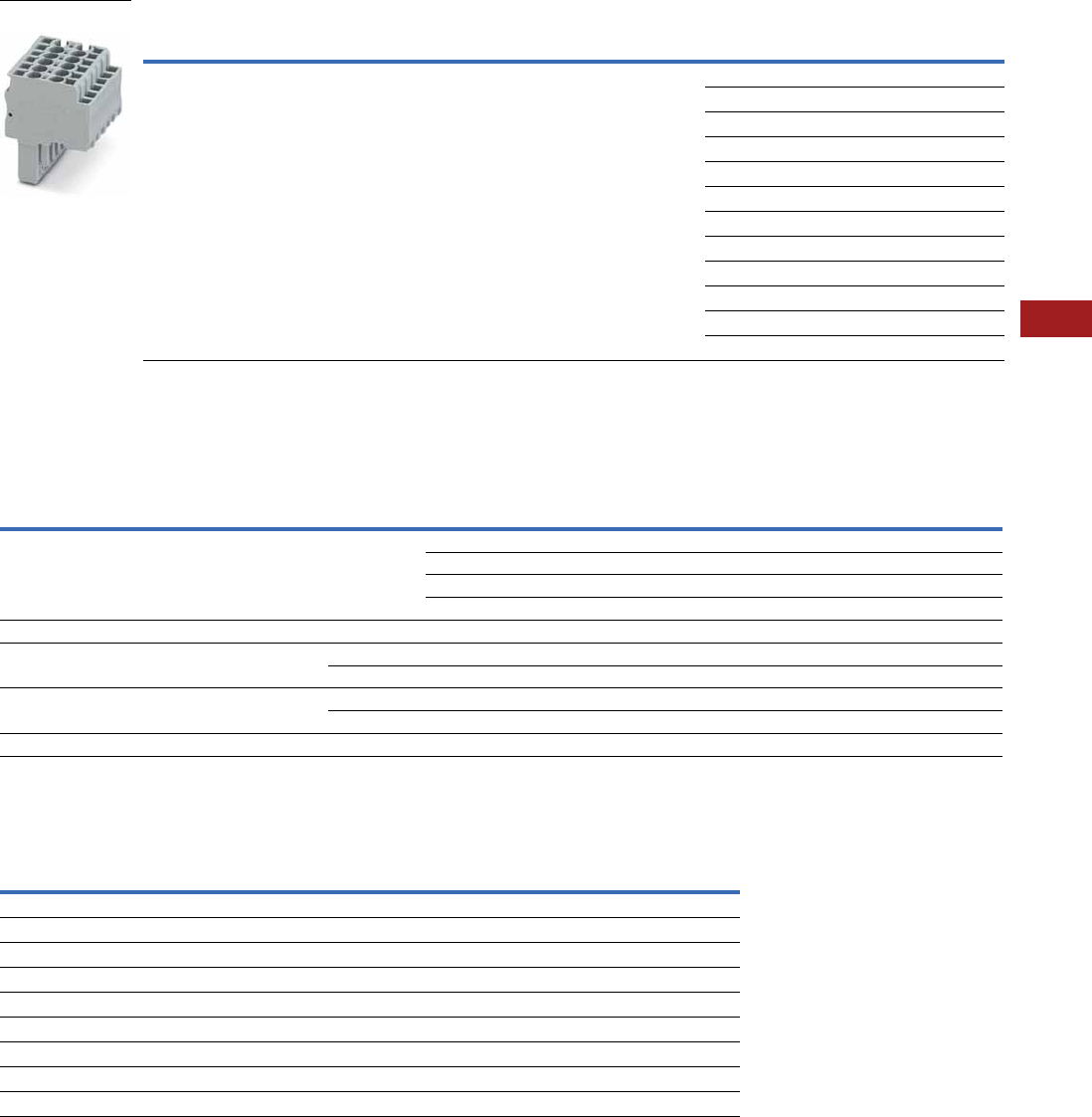
Volume 7—Logic Control, Operator Interface and Connectivity Solutions CA08100008E—July 2014 www.eaton.com V7-T8-63
8
8
8
8
8
8
8
8
8
8
8
8
8
8
8
8
8
8
8
8
8
8
8
8
8
8
8
8
8
8
8.1
Terminal Blocks, Fuse Blocks and Fuse Holders
IEC—XB Series
Spring Cage Connection Plugs, Double, Bridgeable
Accessories
Spring Cage Connection Plugs
Technical Data and Specifications
Spring Cage Connection Plugs
Dimensions
See Page V7-T8-61 for dimensions.
Notes
1For information on Printed Marking Tag Options, see Page V7-T8-98.
For additional accessories, see Page V7-T8-90.
Terminal
Width
Maximum
Wire Size
Connection Data
in V/A/AWG
UL-cUL Ratings
in V/A/AWG Color
Number of
Positions
Standard
Pack
Catalog
Number
5.2 mm 12 AWG/2.5 mm2500/24/28–12 300/20/26–12 Gray 1 25 XBAPSPDB251
225 XBAPSPDB252
325 XBAPSPDB253
425 XBAPSPDB254
525 XBAPSPDB255
625 XBAPSPDB256
725 XBAPSPDB257
825 XBAPSPDB258
925 XBAPSPDB259
10 25 XBAPSPDB2510
11 10 XBAPSPDB2511
12 10 XBAPSPDB2512
Description Color
Number of
Positions
Standard
Pack
XBAPSP25_ XBAPSPDB25_
Catalog
Number
Catalog
Number
Plug-in bridge—for cross connections
in the terminal center
Red 2 10 — XBAFBS25
310— XBAFBS35
510— XBAFBS55
10 10 — XBAFBS105
Snap-lock fitting and strain relief Orange 2 10 XBAPPRZ XBAPPRZ
Snap-lock fitting Orange 1 10 XBAPPR XBAPPR
Orange 2 10 XBAPPR2 XBAPPR2
Strain relief Black 2 10 XBAPPZ2 XBAPPDZ2
Black 4 10 XBAPPZ4 XBAPPDZ4
Blank marker strip White — 10 XBMZBF5 1XBMZBF5 1
Description XBAPSP25_ XBAPSPDB25_
Technical Data in Accordance with IEC
Maximum load current in A/cross-section in mm224/4 24/4
Rated surge voltage in kV/contamination class 6/3 6/3
Surge voltage category/insulating material group III/I III/I
Connection Capacity
Stranded with ferrule with plastic sleeve in mm20.25–2.5 0.25–2.5
Stranded with ferrules without plastic sleeve in mm20.25–2.5 0.25–2.5
Stranded with twin ferrule with plastic sleeve in mm20.5 0.5
Stripping length in inches (mm) 0.39 (10) 0.39 (10)
XBAPSPDB25_
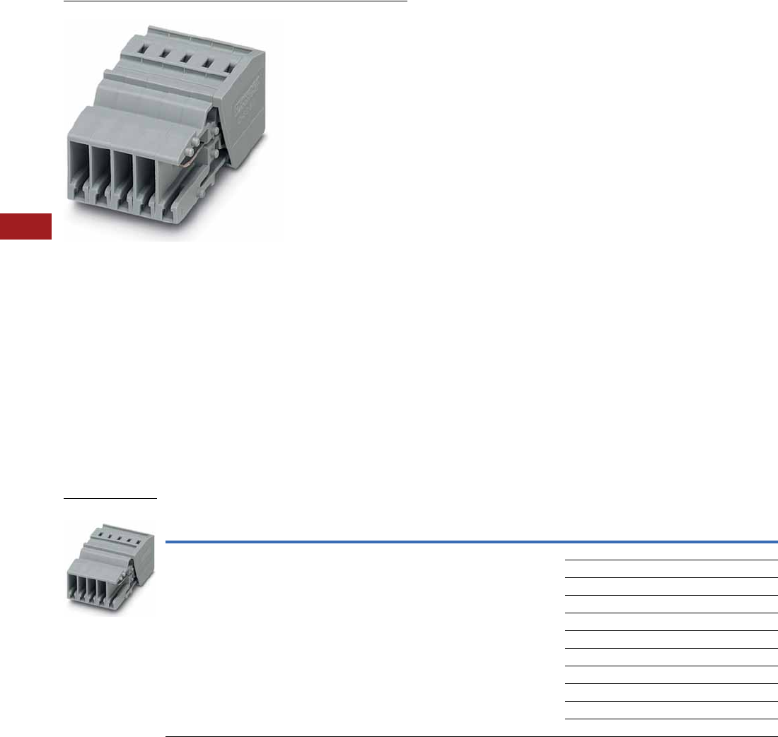
V7-T8-64 Volume 7—Logic Control, Operator Interface and Connectivity Solutions CA08100008E—July 2014 www.eaton.com
8
8
8
8
8
8
8
8
8
8
8
8
8
8
8
8
8
8
8
8
8
8
8
8
8
8
8
8
8
8
8.1
Terminal Blocks, Fuse Blocks and Fuse Holders
IEC—XB Series
Connection Receptacles
Contents
Description Page
Connection Terminal Blocks . . . . . . . . . . . . . . . . . V7-T8-59
Connection Plugs . . . . . . . . . . . . . . . . . . . . . . . . . V7-T8-62
Connection Receptacles
Accessories . . . . . . . . . . . . . . . . . . . . . . . . . . . V7-T8-65
Technical Data and Specifications . . . . . . . . . . V7-T8-65
Dimensions . . . . . . . . . . . . . . . . . . . . . . . . . . . V7-T8-65
Connection Accessories . . . . . . . . . . . . . . . . . . . . V7-T8-66
Connection Receptacles
Product Description
With the XBAPSC25_,
Plug-in contacts can be
accommodated safely in
cable ducts and distributor
shafts without using much
space. The standard strain
reliefs can also be used.
Large-surface labeling makes
it possible to mark the
terminal points and the entire
receptacle. A test hole can
accommodate a 2.3 mm
diameter test plug in each
receptacle element, providing
a practical solution.
Product Selection
Pluggable Spring Connection Receptacles
Terminal
Width
Maximum
Wire Size
Connection Data
in V/A/AWG
UL-cUL Ratings
in V/A/AWG Color
Number of
Positions
Standard
Pack
Catalog
Number
5.2 mm 12 AWG/2.5 mm2500/24/28–12 300/20/26–12 Gray 2 25 XBAPSC252
325 XBAPSC253
425 XBAPSC254
525 XBAPSC255
625 XBAPSC256
725 XBAPSC257
825 XBAPSC258
925 XBAPSC259
10 25 XBAPSC2510
11 10 XBAPSC2511
12 10 XBAPSC2512
XBAPSC25_

Volume 7—Logic Control, Operator Interface and Connectivity Solutions CA08100008E—July 2014 www.eaton.com V7-T8-65
8
8
8
8
8
8
8
8
8
8
8
8
8
8
8
8
8
8
8
8
8
8
8
8
8
8
8
8
8
8
8.1
Terminal Blocks, Fuse Blocks and Fuse Holders
IEC—XB Series
Accessories
Pluggable Spring Connection Receptacles
Technical Data and Specifications
Spring Cage Connection Plugs
Dimensions
Approximate Dimensions in Inches (mm)
Spring Cage Connection Plugs
Receptacle Widths
Notes
1For ordering information, see Page V7-T8-105.
2For information on Printed Marking Tag Options, see Page V7-T8-98.
For additional accessories, see Page V7-T8-90.
Description Color
Number of
Positions
Standard
Pack
XBAPSC25_
Catalog
Number
2.3 mm diameter test plug Red — — XBATSMPS-_ 1
Strain relief Black 2 10 XBAPPDZ2
Black 4 10 XBAPPDZ4
Blank marker strip White — 10 XBMZBF5 2
Description XBAPSP25_
Technical Data in Accordance with IEC
Maximum load current in A/cross-section in mm224/4
Rated surge voltage in kV/contamination class 6/3
Surge voltage category/insulating material group III/I
Connection Capacity
Stranded with ferrule with plastic sleeve in mm20.25–2.5
Stranded with ferrules without plastic sleeve in mm20.25–2.5
Stranded with twin ferrule with plastic sleeve in mm20.5
Stripping length in inches (mm) 0.39 (10)
Catalog
Number Width Length
Cover
Length Height
XBAPSP25_ 0.20 (5.2) 1.46 (37.2) 0.09 (2.2) 0.71 (18.0)
Catalog
Number Width
Catalog
Number Width
XBAPSC252 0.41 (10.4) XBAPSC258 1.64 (41.6)
XBAPSC253 0.61 (15.6) XBAPSC259 1.84 (46.8)
XBAPSC254 0.82 (20.8) XBAPSC2510 2.05 (52.0)
XBAPSC255 1.02 (26.0) XBAPSC2511 2.25 (57.2)
XBAPSC256 1.23 (31.2) XBAPSC2512 2.46 (62.4)
XBAPSC257 1.43 (36.4)
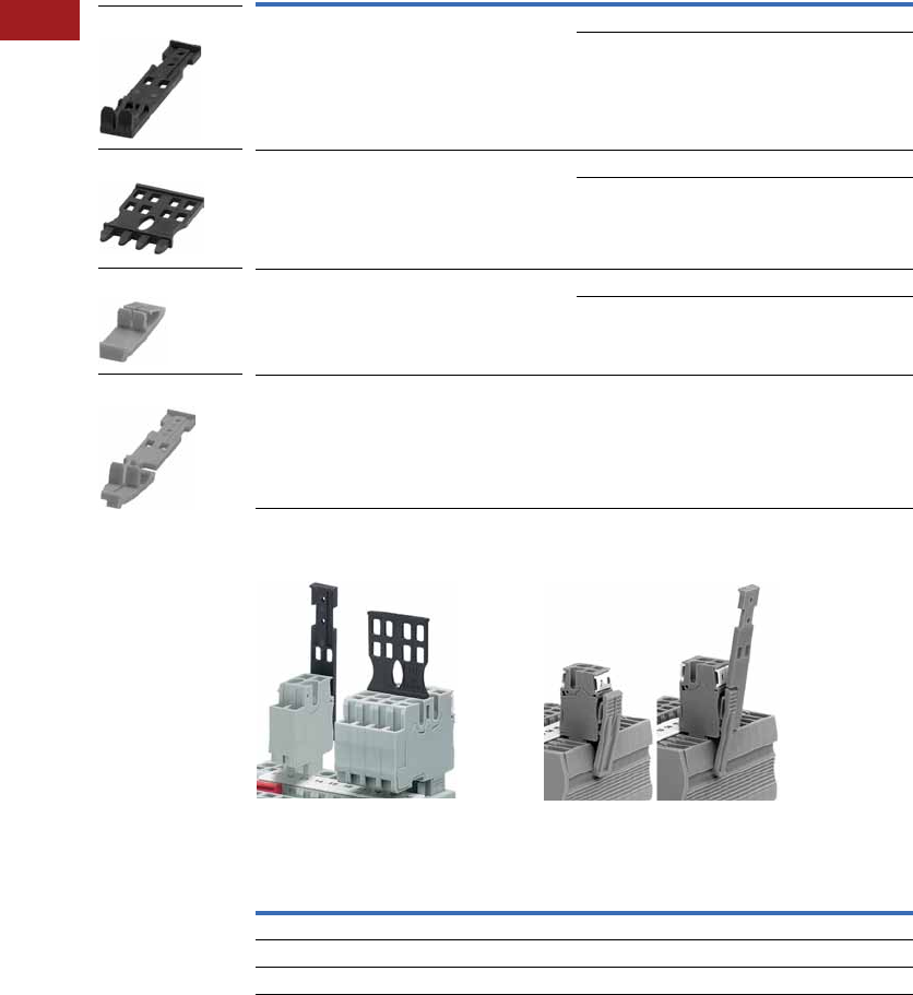
V7-T8-66 Volume 7—Logic Control, Operator Interface and Connectivity Solutions CA08100008E—July 2014 www.eaton.com
8
8
8
8
8
8
8
8
8
8
8
8
8
8
8
8
8
8
8
8
8
8
8
8
8
8
8
8
8
8
8.1
Terminal Blocks, Fuse Blocks and Fuse Holders
IEC—XB Series
Connection Accessories
Product Description
The pluggable XBPT series
features an extensive range
of application-oriented
accessories. Strain reliefs are
available for the plugs and
can be snapped on at the
required points as an option.
The snap-lock fitting can be
used for all plug variants. It is
snapped into the outside of
the plug housing as an option
and hooks onto the terminal
block housing when the plug
is snapped on.
Product Selection
Pluggable Spring Cage Connection Accessories
Strain Relief Snap-Lock Fitting
Optional Accessory Recommendations
Description
Number of
Positions
Standard
Pack
Catalog
Number
Strain relief for single plugs 2 10 XBAPPZ2
410XBAPPZ4
Strain relief for double plugs and receptacles 2 10 XBAPPDZ2
410XBAPPDZ4
Snap-lock fitting for plugs 1 10 XBAPPR
210XBAPPR2
Snap-lock fitting and strain relief for plugs 2 10 XBAPPRZ
Number of Positions
Receptacle Strain Relief
2–4 XBAPPZ2
5–10 XBAPPZ4 or (2) XBAPPZ2
11–15 (2) XBAPPZ4 or (4) XBAPPZ2
XBAPPZ2
XBAPPDZ4
XBAPPR2
XBAPPRZ
Volume 7—Logic Control, Operator Interface and Connectivity Solutions CA08100008E—July 2014 www.eaton.com V7-T8-67
8
8
8
8
8
8
8
8
8
8
8
8
8
8
8
8
8
8
8
8
8
8
8
8
8
8
8
8
8
8
8.1
Terminal Blocks, Fuse Blocks and Fuse Holders
IEC—XB Series
IDC Terminal Blocks
Contents
Description Page
IDC Terminal Blocks
Single Level . . . . . . . . . . . . . . . . . . . . . . . . . . . V7-T8-68
Multi-Conductor . . . . . . . . . . . . . . . . . . . . . . . . V7-T8-70
Double Level . . . . . . . . . . . . . . . . . . . . . . . . . . . V7-T8-73
Fuse Terminal Blocks . . . . . . . . . . . . . . . . . . . . V7-T8-75
Disconnect and Component Terminal Blocks . . V7-T8-77
Hybrid Terminal Blocks . . . . . . . . . . . . . . . . . . . V7-T8-79
Drawings
Online
IDC (Insulation Displacement Connection) Terminal Blocks Overview
Product Description
The superior design of
Eaton’s Insulation
Displacement Connection
(IDC) technology terminal
blocks reduces wiring
installation time and labor,
especially in high-volume
applications. IDC terminal
blocks are suited for
applications in automated
equipment and machine
tools, packaging and material
handling machinery, railway/
mass transit systems, petro-
chemical, and any other
application requiring high-
volume connections for low-
voltage control and signal
circuitry where labor cost
reduction and ease of
assembly is desired. These
terminal blocks are designed
for long-term use under
demanding conditions.
The XBQT Series allows for
wire to be connected without
any prior stripping. The quick
connection provides up to
60% reduction in wiring time.
One turn of a standard
screwdriver results in a
simple, fast and reliable
connection.
Application Description
The XBQT is operated with a
standard screwdriver. The
switching states are clearly
signaled by engagement
points in the start and end
positions. Solid and stranded
wires of 0.25 to 2.5 mm2 can
be wired without the use of
ferrules. Stripping the wire is
not required—the wire's
insulation is cut open when it
is properly connected. The
wire is securely placed in the
end position where it makes
large-area, gas-tight contact.
Connections are made in
seconds!
Features
●Quick connection capability
●Global acceptance
●Flexible plug-in bridge
system
●Large surface area for
marking
●Standardized testing
system
Standards and Certifications
●UL recognized—File No.
E67464
●CE approved
●LVD 1
●EN 60947-7-1
●EN 60947-7-2
●EN 60998-2-3
●EN 60352-4/A1
●ATEX approval
(Eex e applications)
Note
1Not all standards apply to all terminal
blocks. Contact Eaton for details.
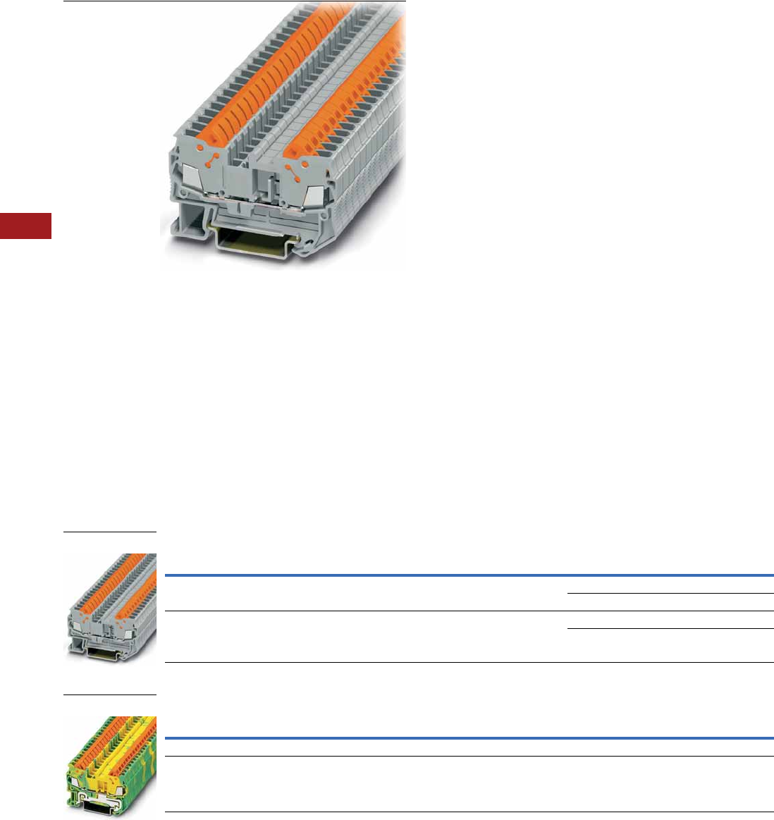
V7-T8-68 Volume 7—Logic Control, Operator Interface and Connectivity Solutions CA08100008E—July 2014 www.eaton.com
8
8
8
8
8
8
8
8
8
8
8
8
8
8
8
8
8
8
8
8
8
8
8
8
8
8
8
8
8
8
8.1
Terminal Blocks, Fuse Blocks and Fuse Holders
IEC—XB Series
Single Level
Contents
Description Page
Single Level
Accessories . . . . . . . . . . . . . . . . . . . . . . . . . . . V7-T8-69
Technical Data and Specifications . . . . . . . . . . V7-T8-69
Dimensions . . . . . . . . . . . . . . . . . . . . . . . . . . . V7-T8-69
Multi-Conductor . . . . . . . . . . . . . . . . . . . . . . . . . . V7-T8-70
Double Level . . . . . . . . . . . . . . . . . . . . . . . . . . . . . V7-T8-73
Fuse Terminal Blocks . . . . . . . . . . . . . . . . . . . . . . . V7-T8-75
Disconnect and Component Terminal Blocks . . . . V7-T8-77
Hybrid Terminal Blocks . . . . . . . . . . . . . . . . . . . . . V7-T8-79
Single Level
Product Description
The XBQT IDC terminal block
has the fastest connection
time in a compact design.
The space-saving front
connection design offers
additional space for wiring
between the cable ducts.
The double bridge shaft can
accommodate individual
chain bridging and step-down
bridging from other terminal
blocks. The XBQT ground
blocks are the same shape
as the feed-through terminal
blocks with the same wide
range of cross-sections
available. They easily snap
onto the DIN rail to make
a reliable mechanical and
electrical contact that
meets all requirements
of IEC 60-947-7-2.
Product Selection
IDC—Single Level Terminal Blocks
IDC—Single Level Terminal Ground Blocks
Note
1 EU type—examination certificate number: KEMA 05ATEX2157 U (XBQT15), KEMA 05ATEX2160 U (XBQT25).
Terminal
Width
Maximum
Wire Size
Connection Data
in V/A/AWG
EN 50 019 1
in V/A/AWG
UL-cUL Ratings
in V/A/AWG Color
Standard
Pack
Catalog
Number
5.2 mm 16 AWG/1.5 mm2800/17.5/24–16 550/16/24–16 600/10/24–16 Gray 50 XBQT15
Blue 50 XBQT15BU
6.2 mm 14 AWG/2.5 mm2800/24/20–14 — 600/15/20–14 Gray 50 XBQT25
Blue 50 XBQT25BU
Terminal
Width
Maximum
Wire Size
Connection Data
in V/A/AWG
EN 50 019 1
in V/A/AWG
UL-cUL Ratings
in V/A/AWG Color
Standard
Pack
Catalog
Number
5.2 mm 16 AWG/1.5 mm2—/—/24–16 —/—/24–16 —/—/24–16 Green/Yellow 50 XBQT15PE
6.2 mm 14 AWG/2.5 mm2—/—/20–14 — —/—/20–14 Green/Yellow 50 XBQT25PE
XBQT25
XBQT15PE

Volume 7—Logic Control, Operator Interface and Connectivity Solutions CA08100008E—July 2014 www.eaton.com V7-T8-69
8
8
8
8
8
8
8
8
8
8
8
8
8
8
8
8
8
8
8
8
8
8
8
8
8
8
8
8
8
8
8.1
Terminal Blocks, Fuse Blocks and Fuse Holders
IEC—XB Series
Accessories
IDC—Single Level Terminal/Ground Blocks
Technical Data and Specifications
IDC—Single Level Terminal/Ground Blocks
Dimensions
Approximate Dimensions in Inches (mm)
IDC—Single Level Terminal/Ground Blocks
Notes
1For ordering information, see Page V7-T8-105.
2For information on Printed Marking Tag Options, see Page V7-T8-98.
For additional accessories, see Page V7-T8-90.
Description Color
Number of
Positions
Standard
Pack
XBQT15 XBQT25 XBQT15PE XBQT25PE
Catalog
Number
Catalog
Number
Catalog
Number
Catalog
Number
End cover Gray — 10 XBACQT15 XBACQT25 XBACQT15 XBACQT25
Partition plate — — 10 XBATQT25 XBATQT25 XBATQT25 XBATQT25
Plug-in bridge Red 2 10 XBAFBS25 XBAFBS26 XBAFBS25 XBAFBS26
310XBAFBS35 XBAFBS36 XBAFBS35 XBAFBS36
510XBAFBS55 XBAFBS56 XBAFBS55 XBAFBS56
10 10 XBAFBS105 XBAFBS106 XBAFBS105 XBAFBS106
50 10 XBAFBS505 XBAFBS506 XBAFBS505 XBAFBS506
Test adapter — — 10 XBATSPAI4 XBATSPAI4 XBATSPAI4 XBATSPAI4
2.3 mm diameter test plug — — — XBATSMPS-_ 1XBATSMPS-_ 1XBATSMPS-_ 1XBATSMPS-_ 1
Modular test plug — — 10 XBATSPS5 XBATSPS6 XBATSPS5 XBATSPS6
Blank marker strip center
and external marking
White — 10 XBMZBF5 2XBMZBF6 2XBMZBF5 2XBMZBF6 2
Blank marker strip center
labeling (strip of 10)
White — 10 XBMZB5 2XBMZB6 2XBMZB5 2XBMZB6 2
Description XBQT15 XBQT25 XBQT15PE XBQT25PE
Technical Data in Accordance with IEC
Maximum load current in A/cross-section in mm217.5/1.5 24/2.5 — —
Rated surge voltage in kV/contamination class 8/3 8/3 8/3 8/3
Surge voltage category/insulating material group III/I III/I III/I III/I
Connection Cross-Section
Core insulation PVC/PE PVC/PE PVC/PE PVC/PE
Single/multiple/fine strand in mm21.5 2.5 1.5 2.5
Halogen-free in mm21.5 2.5 1.5 2.5
Fine strand/superfine strand in AWG (mm2) 24–16 (0.25–0.34) 20–14 (—) 24–16 (0.25–0.34) 20–14 (—)
Repeated connections minimum 100 x in mm20.25–1.5 0.5–2.5 0.25–1.5 0.5–2.5
Catalog
Number Width Length
Cover
Length
Height for—
35 x 7.5 in 35 x 15 in
XBQT15 0.20 (5.2) 2.31 (58.8) 0.09 (2.2) 1.55 (39.3) 1.84 (46.8)
XBQT25 0.24 (6.2) 2.46 (62.6) 0.09 (2.2) 1.55 (39.3) 1.84 (46.8)
XBQT15PE 0.20 (5.2) 2.31 (58.8) 0.09 (2.2) 1.55 (39.3) 1.84 (46.8)
XBQT25PE 0.24 (6.2) 2.46 (62.6) 0.09 (2.2) 1.55 (39.3) 1.84 (46.8)
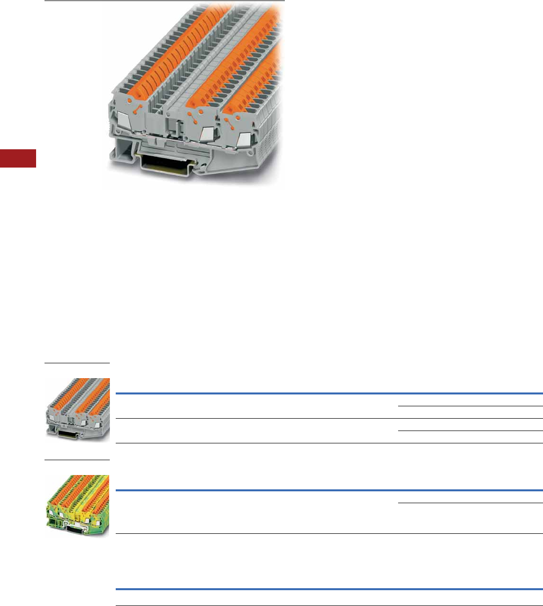
V7-T8-70 Volume 7—Logic Control, Operator Interface and Connectivity Solutions CA08100008E—July 2014 www.eaton.com
8
8
8
8
8
8
8
8
8
8
8
8
8
8
8
8
8
8
8
8
8
8
8
8
8
8
8
8
8
8
8.1
Terminal Blocks, Fuse Blocks and Fuse Holders
IEC—XB Series
Multi-Conductor
Contents
Description Page
Single Level . . . . . . . . . . . . . . . . . . . . . . . . . . . . . . V7-T8-68
Multi-Conductor
Accessories . . . . . . . . . . . . . . . . . . . . . . . . . . . V7-T8-71
Technical Data and Specifications . . . . . . . . . . V7-T8-72
Dimensions . . . . . . . . . . . . . . . . . . . . . . . . . . . V7-T8-72
Double Level . . . . . . . . . . . . . . . . . . . . . . . . . . . . . V7-T8-73
Fuse Terminal Blocks . . . . . . . . . . . . . . . . . . . . . . . V7-T8-75
Disconnect and Component Terminal Blocks . . . . V7-T8-77
Hybrid Terminal Blocks . . . . . . . . . . . . . . . . . . . . . V7-T8-79
Multi-Conductor
Product Description
The XBQT IDC terminal block
has the fastest connection
time in a compact design.
The space-saving front
connection design offers
additional space for wiring
between the cable ducts.
The double bridge shaft can
accommodate individual
chain bridging and step-down
bridging from other terminal
blocks. The XBQT ground
blocks are the same shape
as the feed-through terminal
blocks with the same wide
range of cross-sections
available. They easily snap
onto the DIN rail to make
a reliable mechanical and
electrical contact that
meets all requirements
of IEC 60-947-7-2.
Product Selection
IDC—Multi-Conductor Terminal Blocks, Three-Wire
IDC—Multi-Conductor Terminal Blocks, Four-Wire
IDC—Multi-Conductor Terminal Blocks, Four-Wire Ground Blocks
Note
1 EU type—examination certificate number: KEMA 05ATEX2157 U (XBQT15), KEMA 05ATEX2160 U (XBQT25).
Terminal
Width
Maximum
Wire Size
Connection Data
in V/A/AWG
EN 50 019 1
in V/A/AWG
UL-cUL Ratings
in V/A/AWG Color
Standard
Pack
Catalog
Number
5.2 mm 16 AWG/1.5 mm2800/17.5/24–16 550/16/24–16 600/10/24–16 Gray 50 XBQT15D12
Blue 50 XBQT15D12BU
6.2 mm 14 AWG/2.5 mm2800/24/20–14 — 600/15/20–14 Gray 50 XBQT25D12
Blue 50 XBQT25D12BU
Terminal
Width
Maximum
Wire Size
Connection Data
in V/A/AWG
EN 50 019 1
in V/A/AWG
UL-cUL Ratings
in V/A/AWG Color
Standard
Pack
Catalog
Number
5.2 mm 16 AWG/1.5 mm2800/17.5/24–16 550/16/24–16 600/10/24–16 Gray 50 XBQT15D22
Blue 50 XBQT15D22BU
Terminal
Width
Maximum
Wire Size
Connection Data
in V/A/AWG
EN 50 019 1
in V/A/AWG
UL-cUL Ratings
in V/A/AWG Color
Standard
Pack
Catalog
Number
5.2 mm 16 AWG/1.5 mm2—/—/24–16 —/—/24–16 —/—/24–16 Green/Yellow 50 XBQT15D22PE
XBQT25D12
XBQT15D22PE
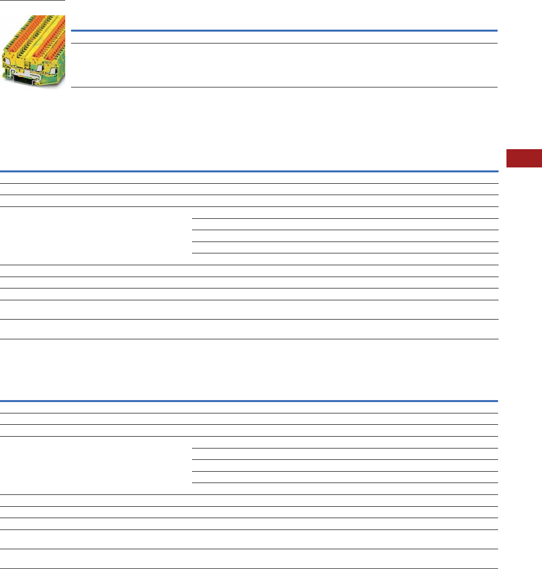
Volume 7—Logic Control, Operator Interface and Connectivity Solutions CA08100008E—July 2014 www.eaton.com V7-T8-71
8
8
8
8
8
8
8
8
8
8
8
8
8
8
8
8
8
8
8
8
8
8
8
8
8
8
8
8
8
8
8.1
Terminal Blocks, Fuse Blocks and Fuse Holders
IEC—XB Series
IDC—Multi-Conductor Terminal Blocks, Three-Wire Ground Blocks
Accessories
IDC—Multi-Conductor Terminal Blocks
IDC—Multi-Conductor Terminal/Ground Blocks
Notes
1EU type—examination certificate number: KEMA 05ATEX2157 U (XBQT15PE), KEMA 05ATEX2160 U (XBQT25PE).
2For ordering information, see Page V7-T8-105.
3For information on Printed Marking Tag Options, see Page V7-T8-98.
For additional accessories, see Page V7-T8-90.
Terminal
Width
Maximum
Wire Size
Connection Data
in V/A/AWG
EN 50 019 1
in V/A/AWG
UL-cUL Ratings
in V/A/AWG Color
Standard
Pack
Catalog
Number
5.2 mm 16 AWG/1.5 mm2—/—/24–16 —/—/24–16 —/—/24–16 Green/Yellow 50 XBQT15D12PE
6.2 mm 14 AWG/2.5 mm2—/—/20–14 — —/—/20–14 Green/Yellow 50 XBQT25D12PE
Description Color
Number of
Positions
Standard
Pack
XBQT15D12 XBQT25D12 XBQT15D22
Catalog
Number
Catalog
Number
Catalog
Number
End cover Gray — 10 XBACQT15D12 XBACQT25D12 XBACQT15D22
End cover segment Gray — 10 XBASQT15 XBASQT25 XBASQT15
Partition plate — — 10 XBATQTD12 XBATQTD12 XBATQTD22
Plug-in bridge—for cross connections
in the terminal center
Red 2 10 XBAFBS25 XBAFBS26 XBAFBS25
310XBAFBS35 XBAFBS36 XBAFBS35
510XBAFBS55 XBAFBS56 XBAFBS55
10 10 XBAFBS105 XBAFBS106 XBAFBS105
50 10 XBAFBS505 XBAFBS506 XBAFBS505
Test adapter — — 10 XBATSPAI4 XBATSPAI4 XBATSPAI4
2.3 mm diameter test plug — — — XBATSMPS-_ 2XBATSMPS-_ 2XBATSMPS-_ 2
Modular test plug — — 10 XBATSPS5 XBATSPS6 XBATSPS5
Blank marker strip center
and external marking
White — 10 XBMZBF5 3XBMZBF6 3XBMZBF5 3
Blank marker strip center
labeling (strip of 10)
White — 10 XBMZB5 3XBMZB6 3XBMZB5 3
Description Color
Number of
Positions
Standard
Pack
XBQT15D12PE XBQT25D12PE XBQT15D22PE
Catalog
Number
Catalog
Number
Catalog
Number
End cover Gray — 10 XBACQT15D12 XBACQT25D12 XBACQT15D22
End cover segment Gray — 10 XBASQT15 XBASQT25 XBASQT15
Partition plate — — 10 XBATQTD12 XBATQTD12 XBATQTD22
Plug-in bridge—for cross connections
in the terminal center
Red 2 10 XBAFBS25 XBAFBS26 XBAFBS25
310XBAFBS35 XBAFBS36 XBAFBS35
510XBAFBS55 XBAFBS56 XBAFBS55
10 10 XBAFBS105 XBAFBS106 XBAFBS105
50 10 XBAFBS505 XBAFBS506 XBAFBS505
Test adapter — — 10 XBATSPAI4 XBATSPAI4 XBATSPAI4
2.3 mm diameter test plug — — — XBATSMPS-_ 2XBATSMPS-_ 2XBATSMPS-_ 2
Modular test plug — — 10 XBATSPS5 XBATSPS6 XBATSPS5
Blank marker strip center
and external marking
White — 10 XBMZBF5 3XBMZBF6 3XBMZBF5 3
Blank marker strip center
labeling (strip of 10)
White — 10 XBMZB5 3XBMZB6 3XBMZB5 3
XBQT15D12PE

V7-T8-72 Volume 7—Logic Control, Operator Interface and Connectivity Solutions CA08100008E—July 2014 www.eaton.com
8
8
8
8
8
8
8
8
8
8
8
8
8
8
8
8
8
8
8
8
8
8
8
8
8
8
8
8
8
8
8.1
Terminal Blocks, Fuse Blocks and Fuse Holders
IEC—XB Series
Technical Data and Specifications
IDC—Multi-Conductor Terminal Blocks
Dimensions
Approximate Dimensions in Inches (mm)
IDC—Multi-Conductor Terminal Blocks
Description XBQT15D12 XBQT25D12 XBQT15D12PE XBQT25D12PE XBQT15D22 XBQT15D22PE
Technical Data in Accordance with IEC
Maximum load current in A/cross-section in mm217.5/1.5 24/2.5 — — 17.5/1.5 —
Rated surge voltage in kV/contamination class 8/3 8/3 8/3 8/3 8/3 8/3
Surge voltage category/insulating material group III/I III/I III/I III/I III/I III/I
Connection Cross-Section
Core insulation PVC/PE PVC/PE PVC/PE PVC/PE PVC/PE PVC/PE
Single/multiple/fine strand in mm21.5 2.5 1.5 2.5 1.5 1.5
Halogen-free in mm21.5 2.5 1.5 2.5 1.5 1.5
Fine strand/superfine strand in AWG (mm2) 24–16 (0.25–0.34) 20–14 (—) 24–16 (0.25–0.34) 20–14 (—) 24–16 (0.25–0.34) 24–16 (0.25–0.34)
Repeated connections minimum 100 x in mm20.25–1.5 0.5–2.5 0.25–1.5 0.5–2.5 0.25–1.5 0.25–1.5
Catalog
Number Width Length
Cover
Length
Height for—
35 x 7.5 in 35 x 15 in
XBQT15D12 0.20 (5.2) 3.01 (76.4) 0.09 (2.2) 1.55 (39.3) 1.84 (46.8)
XBQT25D12 0.24 (6.2) 3.25 (82.5) 0.09 (2.2) 1.69 (42.8) 1.98 (50.3)
XBQT15D12PE 0.20 (5.2) 3.01 (76.4) 0.09 (2.2) 1.55 (39.3) 1.84 (46.8)
XBQT25D12PE 0.20 (5.2) 3.25 (82.5) 0.09 (2.2) 1.69 (42.8) 1.98 (50.3)
XBQT15D22 0.20 (5.2) 3.70 (94.0) 0.09 (2.2) 1.55 (39.3) 1.84 (46.8)
XBQT15D22PE 0.20 (5.2) 3.70 (94.0) 0.09 (2.2) 1.55 (39.3) 1.84 (46.8)
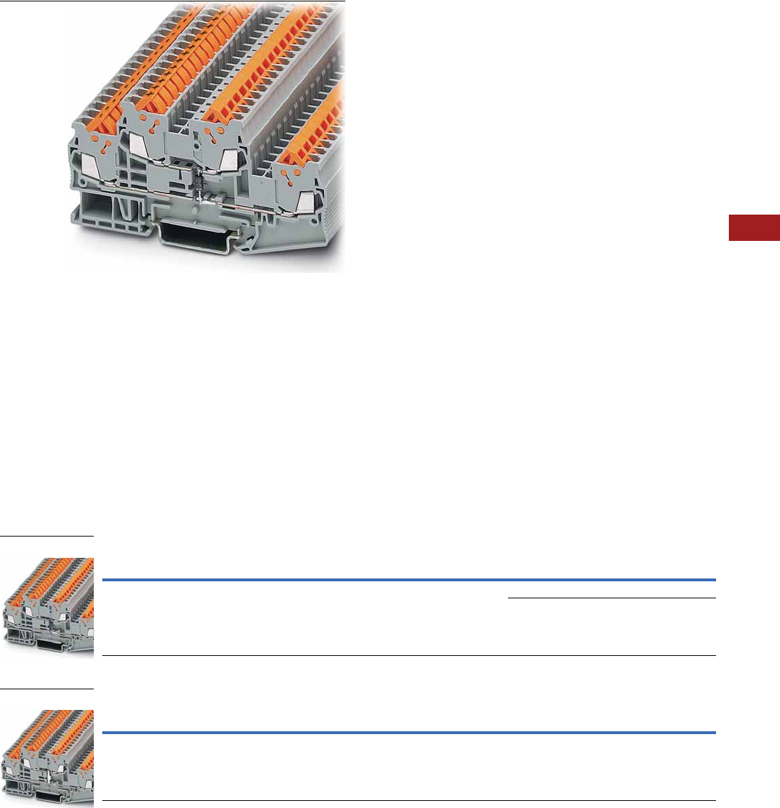
Volume 7—Logic Control, Operator Interface and Connectivity Solutions CA08100008E—July 2014 www.eaton.com V7-T8-73
8
8
8
8
8
8
8
8
8
8
8
8
8
8
8
8
8
8
8
8
8
8
8
8
8
8
8
8
8
8
8.1
Terminal Blocks, Fuse Blocks and Fuse Holders
IEC—XB Series
Double Level
Contents
Description Page
Single Level . . . . . . . . . . . . . . . . . . . . . . . . . . . . . . V7-T8-68
Multi-Conductor . . . . . . . . . . . . . . . . . . . . . . . . . . . V7-T8-70
Double Level
Accessories . . . . . . . . . . . . . . . . . . . . . . . . . . . V7-T8-74
Technical Data and Specifications . . . . . . . . . . V7-T8-74
Dimensions . . . . . . . . . . . . . . . . . . . . . . . . . . . V7-T8-74
Fuse Terminal Blocks . . . . . . . . . . . . . . . . . . . . . . . V7-T8-75
Disconnect and Component Terminal Blocks . . . . V7-T8-77
Hybrid Terminal Blocks . . . . . . . . . . . . . . . . . . . . . V7-T8-79
Double Level
Product Description
The XBQTT IDC terminal
block has the fastest
connection time in a compact
design. The space-saving
front connection design
offers additional space for
wiring between the cable
ducts. The double bridge
shaft, found in each level, can
accommodate individual
chain bridging and step-down
bridging from other terminal
blocks. The XBQTT ground
blocks are the same shape as
the feed-through terminal
blocks with the same wide
range of cross-sections
available. They easily snap
onto the DIN rail to make a
reliable mechanical and
electrical contact that
meets all requirements of
IEC 60-947-7-2.
Product Selection
IDC—Double Level Terminal Blocks
IDC—Double Level Ground Blocks
Note
1 EU type—examination certificate number: KEMA 05ATEX2157 U (XBQT15), KEMA 05ATEX2160 U (XBQT25).
Terminal
Width
Maximum
Wire Size
Connection Data
in V/A/AWG
EN 50 019 1
in V/A/AWG
UL-cUL Ratings
in V/A/AWG Color
Standard
Pack
Catalog
Number
5.2 mm 16 AWG/1.5 mm2800/17.5/24–16 420/15/24–16 600/10/24–16 Gray 50 XBQTT15
Blue 50 XBQTT15BU
Terminal
Width
Maximum
Wire Size
Connection Data
in V/A/AWG
EN 50 019 1
in V/A/AWG
UL-cUL Ratings
in V/A/AWG Color
Standard
Pack
Catalog
Number
6.2 mm 14 AWG/2.5 mm2—/—/24–16 —/—/24–16 —/—/24–16 Green/Yellow 50 XBQTT15PE
XBQTT15
XBQTT15PE

V7-T8-74 Volume 7—Logic Control, Operator Interface and Connectivity Solutions CA08100008E—July 2014 www.eaton.com
8
8
8
8
8
8
8
8
8
8
8
8
8
8
8
8
8
8
8
8
8
8
8
8
8
8
8
8
8
8
8.1
Terminal Blocks, Fuse Blocks and Fuse Holders
IEC—XB Series
Accessories
IDC—Double Level Terminal/Ground Blocks
Technical Data and Specifications
IDC—Double Level Terminal/Ground Blocks
Dimensions
Approximate Dimensions in Inches (mm)
IDC—Double Level Terminal/Ground Blocks
Notes
1For ordering information, see Page V7-T8-105.
2For information on Printed Marking Tag Options, see Page V7-T8-98.
For additional accessories, see Page V7-T8-90.
Description Color
Number of
Positions
Standard
Pack
XBQTT15 XBQTT15PE
Catalog
Number
Catalog
Number
End cover Gray — 10 XBACQTT15 XBACQTT15
Partition plate — — 10 XBATQTT15 XBATQTT15
Plug-in bridge—for cross connections
in the terminal center
Red 2 10 XBAFBS25 XBAFBS25
310 XBAFBS35 XBAFBS35
510 XBAFBS55 XBAFBS55
10 10 XBAFBS105 XBAFBS105
20 10 XBAFBS505 XBAFBS505
Test adapter — — 10 XBATSPAI4 XBATSPAI4
2.3 mm diameter test plug — — — XBATSMPS-_ 1XBATSMPS-_ 1
Modular test plug — — 10 XBATSPS5 XBATSPS5
Blank marker strip White — 10 XBMZBF5 2XBMZBF5 2
Description XBQTT15 XBQTT15PE
Technical Data in Accordance with IEC
Maximum load current in A/cross-section in mm217.5/1.5 —
Rated surge voltage in kV/contamination class 6/3 6/3
Surge voltage category/insulating material group III/I III/I
Connection Cross-Section
Core insulation PVC/PE PVC/PE
Single/multiple/fine strand in mm21.5 1.5
Halogen-free in mm21.5 1.5
Fine strand/superfine strand in AWG (mm2) 24–16 (0.25–0.34) 24–16 (0.25–0.34)
Repeated connections minimum 100 x in mm20.25–1.5 0.25–1.5
Catalog
Number Width Length
Cover
Length
Height for—
35 x 7.5 in 35 x 15 in
XBQTT15 0.20 (5.2) 3.92 (99.6) 0.09 (2.2) 1.96 (49.9) 2.26 (57.4)
XBQTT15PE 0.20 (5.2) 3.92 (99.6) 0.09 (2.2) 1.96 (49.9) 2.26 (57.4)
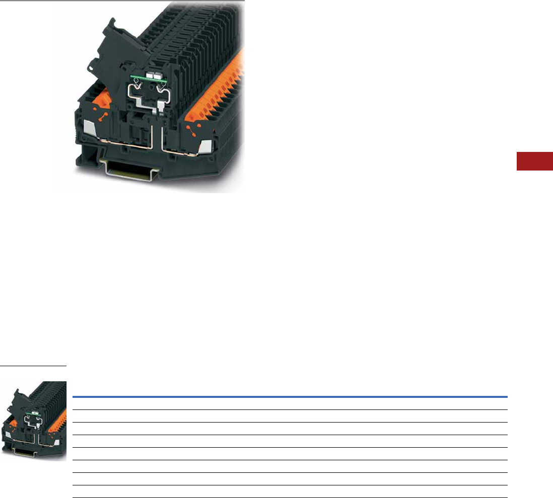
Volume 7—Logic Control, Operator Interface and Connectivity Solutions CA08100008E—July 2014 www.eaton.com V7-T8-75
8
8
8
8
8
8
8
8
8
8
8
8
8
8
8
8
8
8
8
8
8
8
8
8
8
8
8
8
8
8
8.1
Terminal Blocks, Fuse Blocks and Fuse Holders
IEC—XB Series
Fuse Terminal Blocks
Contents
Description Page
Single Level . . . . . . . . . . . . . . . . . . . . . . . . . . . . . . V7-T8-68
Multi-Conductor . . . . . . . . . . . . . . . . . . . . . . . . . . . V7-T8-70
Double Level . . . . . . . . . . . . . . . . . . . . . . . . . . . . . V7-T8-73
Fuse Terminal Blocks
Accessories . . . . . . . . . . . . . . . . . . . . . . . . . . . V7-T8-76
Technical Data and Specifications . . . . . . . . . . V7-T8-76
Dimensions . . . . . . . . . . . . . . . . . . . . . . . . . . . V7-T8-76
Disconnect and Component Terminal Blocks . . . . V7-T8-77
Hybrid Terminal Blocks . . . . . . . . . . . . . . . . . . . . . V7-T8-79
Fuse Terminal Blocks
Product Description
The XBQT lever-type fuse
terminal blocks perform two
main functions. It is a carrier
for a 5 x 20 mm cartridge
fuse insert and can also
allow for potential distribution
via the double bridge shaft.
This means that two
potentials can be carried
separately alongside each
other. Versions with light
indication (AC and DC
voltage) are available to
signal a triggered fuse.
Product Selection
IDC—Fuse Terminal Blocks
Note
1 As disconnect terminal block, 400V; as fuse terminal blocks 250V.
Terminal
Width
Maximum
Wire Size
Connection Data
in V/A/AWG
UL-cUL Ratings
in V/A/AWG Color
Standard
Pack
Catalog
Number
IDC Fuse Terminal Blocks
6.2 mm 14 AWG/2.5 mm21/6.3/20–14 300/15/20–14 Black 50 XBQT25FBE
IDC Fuse Terminal Blocks with LED 12–30V, 1–2.5 mA
6.2 mm 14 AWG/2.5 mm21/6.3/20–14 300/15/20–14 Black 50 XBQT25FBEL24
IDC Fuse Terminal Blocks with LED 30–60V, 0.8–2.0 mA
6.2 mm 14 AWG/2.5 mm21/6.3/20–14 300/15/20–14 Black 50 XBQT25FBEL60
IDC Fuse Terminal Blocks with LED 110–250V, 0.5–2.5 mA
6.2 mm 14 AWG/2.5 mm21/6.3/20–14 300/15/20–14 Black 50 XBQT25FBEL250
XBQT25FB

V7-T8-76 Volume 7—Logic Control, Operator Interface and Connectivity Solutions CA08100008E—July 2014 www.eaton.com
8
8
8
8
8
8
8
8
8
8
8
8
8
8
8
8
8
8
8
8
8
8
8
8
8
8
8
8
8
8
8.1
Terminal Blocks, Fuse Blocks and Fuse Holders
IEC—XB Series
Accessories
IDC—Fuse Terminal Blocks
Technical Data and Specifications
IDC—Fuse Terminal Blocks
Dimensions
Approximate Dimensions in Inches (mm)
IDC—Fuse Terminal Blocks
Notes
1For ordering information, see Page V7-T8-105.
2For information on Printed Marking Tag Options, see Page V7-T8-98.
For additional accessories, see Page V7-T8-90.
Description Color
Number of
Positions
Standard
Pack
XBQT25FBE
Catalog
Number
End cover Gray — 10 XBACQT25D12
Partition plate — — 10 XBATQTD12
Plug-in bridge—for cross connections
in the terminal center
Red 2 10 XBAFBS26
310XBAFBS36
510XBAFBS56
10 10 XBAFBS106
Test adapter — — 10 XBATSPAI4
2.3 mm diameter test plug — — — XBATSMPS-_ 1
Modular test plug — — 10 XBATSPS5
Blank marker strip center
and external marking
White — 10 XBMZBF6 2
Blank marker strip lever labeling White — 10 XBMZB5 2
Blank marker strip center
labeling (strip of 10)
White — 10 XBMZB6 2
Description XBQT25FBE
Technical Data in Accordance with IEC
Maximum load current in A/cross-section in mm26.3/2.5
Rated surge voltage in kV/contamination class 4/3
Surge voltage category/insulating material group III/I
Connection Cross-Section
Core insulation PVC/PE
Single/multiple/fine strand in mm22.5
Halogen-free in mm22.5
Fine strand/superfine strand in AWG (mm2) 24–14 (—)
Repeated connections minimum 100 x in mm20.5–2.5
Catalog
Number Width Length
Cover
Length
Height for—
35 x 7.5 in 35 x 15 in
XBQT25FBE 0.24 (6.2) 3.25 (82.5) 0.09 (2.2) 1.69 (42.8) 1.98 (50.3)
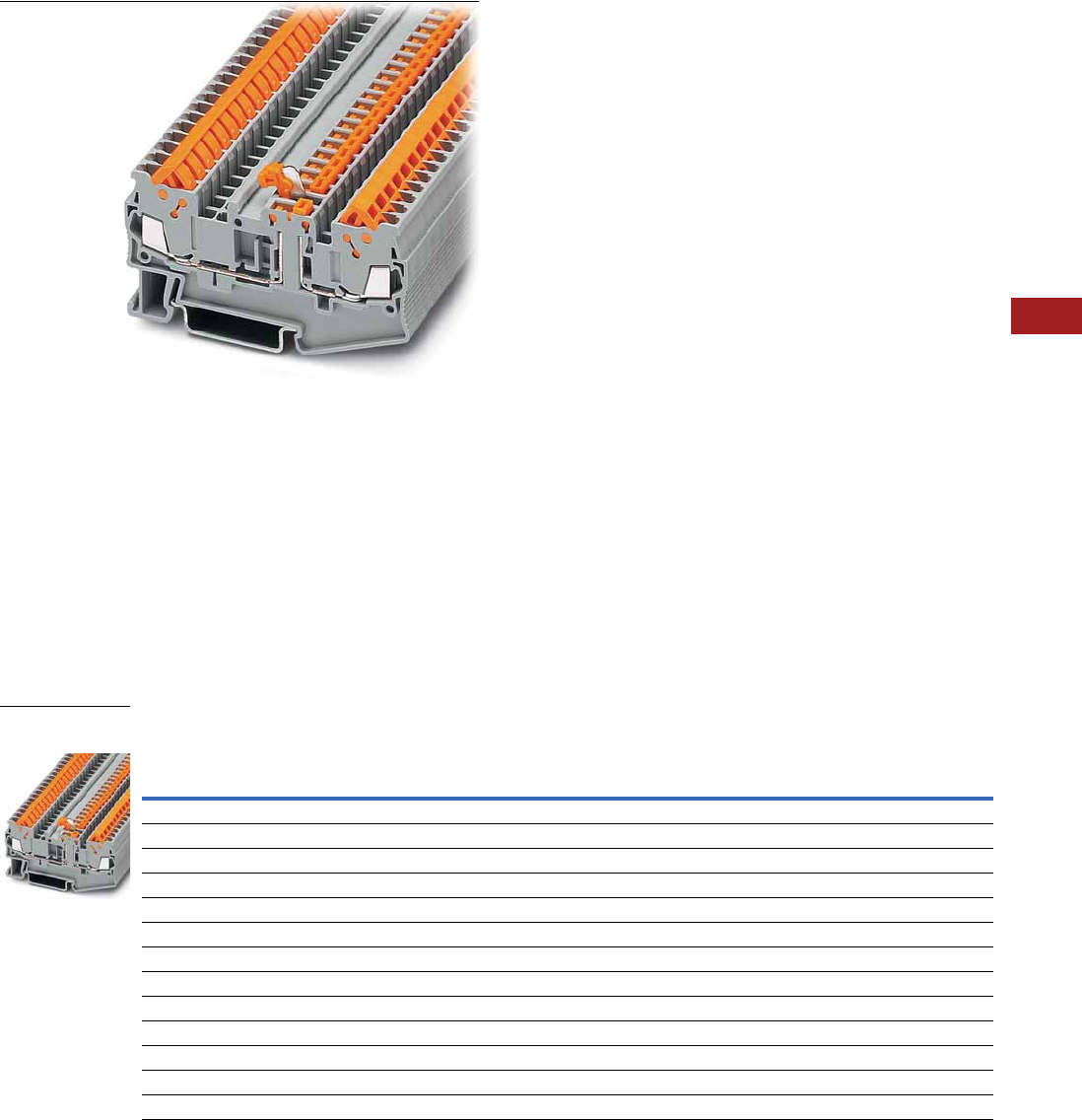
Volume 7—Logic Control, Operator Interface and Connectivity Solutions CA08100008E—July 2014 www.eaton.com V7-T8-77
8
8
8
8
8
8
8
8
8
8
8
8
8
8
8
8
8
8
8
8
8
8
8
8
8
8
8
8
8
8
8.1
Terminal Blocks, Fuse Blocks and Fuse Holders
IEC—XB Series
Disconnect and Component Terminal Blocks
Contents
Description Page
Single Level . . . . . . . . . . . . . . . . . . . . . . . . . . . . . . V7-T8-68
Multi-Conductor . . . . . . . . . . . . . . . . . . . . . . . . . . . V7-T8-70
Double Level . . . . . . . . . . . . . . . . . . . . . . . . . . . . . V7-T8-73
Fuse Terminal Blocks . . . . . . . . . . . . . . . . . . . . . . . V7-T8-75
Disconnect and Component Terminal Blocks
Accessories . . . . . . . . . . . . . . . . . . . . . . . . . . . V7-T8-78
Technical Data and Specifications . . . . . . . . . . V7-T8-78
Dimensions . . . . . . . . . . . . . . . . . . . . . . . . . . . V7-T8-78
Hybrid Terminal Blocks . . . . . . . . . . . . . . . . . . . . . V7-T8-79
Disconnect and Component Terminal Blocks
Product Description
The XB Series includes
application specific terminal
blocks like disconnect blocks.
The knife disconnect terminal
blocks (XBQT15MT) has a
fitted knife. The XBQT15TG
can accommodate component
plugs for resistors or
capacitors and fuse plugs
for 5 x 20 mm fuses with or
without a light indicator for
signaling a triggered fuse.
Both terminal blocks have
three bridge shafts—two in
the standard positions and
one on the other side of the
disconnect point.
Product Selection
IDC—Disconnect and Component Terminal Blocks
Terminal
Width
Maximum
Wire Size
Connection Data
in V/A/AWG
UL-cUL Ratings
in V/A/AWG
UL-cUL Ratings
for Disconnect
in V/A/AWG
UL-cUL Ratings
for Disconnect
with Test Sockets
in V/A/AWG Color
Standard
Pack
Catalog
Number
Knife Disconnect
5.2 mm 16 AWG/1.5 mm2400/16/24–16 600/10/24–16 — — Gray 50 XBQT15MT
Component Disconnect
5.2 mm 16 AWG/1.5 mm2400/16/24–16 600/10/24–16 — — Gray 50 XBQT15TG
6.2 mm 14 AWG/2.5 mm2400/16/20–14 300/10/20–14 — — Gray 50 XBQT25TG
Component Plug
6.2 mm 10 AWG/4 mm2500/16/26–10 — 600/16/26–10 300/16/26–10 Gray 10 XBPCO
Fuse Plug
6.2 mm 10 AWG/4 mm2500/16/26–10 — 600/16/26–10 300/16/26–10 Black 10 XBPFU
Fuse Plug with Light Indicator for 12–30V, 1–2.5 mA
6.2 mm 10 AWG/4 mm2500/16/26–10 — 600/16/26–10 300/16/26–10 Black 10 XBPFUL24
Fuse Plug with Light Indicator for 110–250V, 0.5–2.5 mA
6.2 mm 10 AWG/4 mm2500/16/26–10 — 600/16/26–10 300/16/26–10 Black 10 XBPFUL250
XBQT15MT
Knife Disconnect

V7-T8-78 Volume 7—Logic Control, Operator Interface and Connectivity Solutions CA08100008E—July 2014 www.eaton.com
8
8
8
8
8
8
8
8
8
8
8
8
8
8
8
8
8
8
8
8
8
8
8
8
8
8
8
8
8
8
8.1
Terminal Blocks, Fuse Blocks and Fuse Holders
IEC—XB Series
Accessories
IDC—Disconnect and Component Terminal Blocks
Technical Data and Specifications
IDC—Disconnect and Component Terminal Blocks
Dimensions
Approximate Dimensions in Inches (mm)
IDC—Disconnect and Component Terminal Blocks
Notes
1For ordering information, see Page V7-T8-105.
2For information on Printed Marking Tag Options, see Page V7-T8-98.
For additional accessories, see Page V7-T8-90.
Description Color
Number of
Positions
Standard
Pack
XBQT15MT XBQT15TG XBQT25TG
Catalog
Number
Catalog
Number
Catalog
Number
End cover Gray — 10 XBACQT15D12 XBACQT15D12 XBACQT25D12
End cover segment Gray — 10 XBASQT15 XBASQT15 XBASQT25
Partition plate — — 10 XBATQTD12 XBATQTD12 XBATQTD12
Plug-in bridge Red 2 10 XBAFBS25 XBAFBS25 XBAFBS26
310XBAFBS35 XBAFBS35 XBAFBS36
510XBAFBS55 XBAFBS55 XBAFBS56
10 10 XBAFBS105 XBAFBS105 XBAFBS106
Test adapter — — 10 XBATSPAI4 XBATSPAI4 XBATSPAI4
2.3 mm diameter test plug — — — XBATSMPS-_ 1XBATSMPS-_ 1XBATSMPS-_ 1
Modular test plug — — 10 XBATSPS5 XBATSPS5 XBATSPS5
Blank marker strip center and
external marking
White — 10 XBMZBF5 2XBMZBF5 2XBMZBF6 2
Blank marker strip center labeling
(strip of 10)
White — 10 XBMZB5 2XBMZB5 2XBMZB6 2
Description XBQT15MT XBQT15TG XBQT25TG
Technical Data in Accordance with IEC
Maximum load current in A/cross-section in mm216/1.5 16/1.5 16/2.5
Rated surge voltage in kV/contamination class 6/3 6/3 6/3
Surge voltage category/insulating material group III/I III/I III/I
Connection Cross-Section
Core insulation PVC/PE PVC/PE PVC/PE
Single/multiple/fine strand in mm21.5 1.5 2.5
Halogen-free in mm21.5 1.5 2.5
Fine strand/superfine strand in AWG (mm2) 24–16 (0.25–0.34) 24–16 (0.25–0.34) 20–14 (—)
Repeated connections minimum 100 x in mm20.25–1.5 0.25–1.5 0.5–2.5
Catalog
Number Width Length
Cover
Length
Height for—
35 x 7.5 in 35 x 15 in
XBQT15MT 0.20 (5.2) 3.01 (76.4) 0.09 (2.2) 1.55 (39.3) 1.84 (46.8)
XBQT15TG 0.20 (5.2) 3.01 (76.4) 0.09 (2.2) 1.55 (39.3) 1.84 (46.8)
XBQT25TG 0.24 (6.2) 3.25 (82.5) 0.09 (2.2) 1.69 (42.8) 1.98 (50.3)
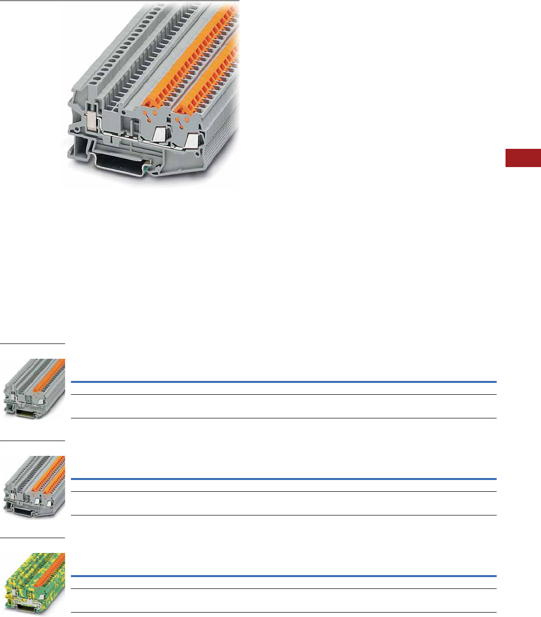
Volume 7—Logic Control, Operator Interface and Connectivity Solutions CA08100008E—July 2014 www.eaton.com V7-T8-79
8
8
8
8
8
8
8
8
8
8
8
8
8
8
8
8
8
8
8
8
8
8
8
8
8
8
8
8
8
8
8.1
Terminal Blocks, Fuse Blocks and Fuse Holders
IEC—XB Series
Hybrid Terminal Blocks
Contents
Description Page
Single Level . . . . . . . . . . . . . . . . . . . . . . . . . . . . . . V7-T8-68
Multi-Conductor . . . . . . . . . . . . . . . . . . . . . . . . . . . V7-T8-70
Double Level . . . . . . . . . . . . . . . . . . . . . . . . . . . . . V7-T8-73
Fuse Terminal Blocks . . . . . . . . . . . . . . . . . . . . . . . V7-T8-75
Disconnect and Component Terminal Blocks . . . . V7-T8-77
Hybrid Terminal Blocks
Accessories . . . . . . . . . . . . . . . . . . . . . . . . . . . V7-T8-80
Technical Data and Specifications . . . . . . . . . . V7-T8-81
Dimensions . . . . . . . . . . . . . . . . . . . . . . . . . . . V7-T8-81
Hybrid Terminal Blocks
Product Description
The XBQT hybrid terminal
blocks offer the best of both
worlds. One side offers the
time-saving advantage of our
insulation displacement
connection technology,
while the other side offers a
universal screw connection.
Use the IDC side on the
internal (factory) control
cabinet side and the screw
connection on the end
customer (field) side. Ground
terminal blocks of the same
shape are also available
Product Selection
IDC—Hybrid Terminal Blocks, Single Level
IDC—Hybrid Terminal Blocks, Three-Wire
IDC—Hybrid Terminal/Ground Blocks
Terminal
Width
Maximum
Wire Size
IEC Screw
Connection
in V/A/AWG
IEC IDC
Connection
in V/A/AWG
UL-cUL Screw
Connection
in V/A/AWG
UL-cUL IDC
Connection
in V/A/AWG Color
Standard
Pack
Catalog
Number
5.2 mm 12 AWG/2.5 mm2800/17.5/26–12 800/17.5/24–16 600/10/26–12 600/10/24–16 Gray 50 XBQU15
6.2 mm 10 AWG/4 mm2800/24/26–10 800/24/20–14 600/15/26–10 600/15/20–14 Gray 50 XBQU25
Terminal
Width
Maximum
Wire Size
IEC Screw
Connection
in V/A/AWG
IEC IDC
Connection
in V/A/AWG
UL-cUL Screw
Connection
in V/A/AWG
UL-cUL IDC
Connection
in V/A/AWG Color
Standard
Pack
Catalog
Number
5.2 mm 12 AWG/2.5 mm2800/17.5/26–12 800/17.5/24–16 800/10/26–12 800/10/24–16 Gray 50 XBQU15D12
6.2 mm 10 AWG/4 mm2800/24/26–10 800/24/20–14 600/15/26–10 600/15/20–14 Gray 50 XBQU25D12
Terminal
Width
Maximum
Wire Size
IEC Screw
Connection
in V/A/AWG
IEC IDC
Connection
in V/A/AWG
UL-cUL Screw
Connection
in V/A/AWG
UL-cUL IDC
Connection
in V/A/AWG Color
Standard
Pack
Catalog
Number
5.2 mm 12 AWG/2.5 mm2—/—/26–12 —/—/24–16 —/—/26–12 —/—/24–16 Gray 50 XBQU15PE
6.2 mm 10 AWG/4 mm2—/—/26–10 —/—/20–14 —/—/26–10 —/—/20–14 Gray 50 XBQU25PE
XBQU25
XBQU15D12
XBQU25PE

V7-T8-80 Volume 7—Logic Control, Operator Interface and Connectivity Solutions CA08100008E—July 2014 www.eaton.com
8
8
8
8
8
8
8
8
8
8
8
8
8
8
8
8
8
8
8
8
8
8
8
8
8
8
8
8
8
8
8.1
Terminal Blocks, Fuse Blocks and Fuse Holders
IEC—XB Series
Accessories
IDC—Hybrid Terminal Blocks
IDC—Hybrid Terminal/Ground Blocks
Notes
1For ordering information, see Page V7-T8-105.
2For information on Printed Marking Tag Options, see Page V7-T8-98.
For additional accessories, see Page V7-T8-90.
Description Color
Number of
Positions
Standard
Pack
XBQU15 XBQU25 XBQU15D12 XBQU25D12
Catalog
Number
Catalog
Number
Catalog
Number
Catalog
Number
End cover Gray — 10 XBACQU15 XBACQU25 XBACQU15D12 XBACQU25D12
End segment Gray — 10 — — XBASQT15 XBASQT25
Partition plate — — 10 XBATQT25 XBATQT25 XBATQTD12 XBATQTD12
Plug-in bridge—for cross
connections in the bridge shaft
Red 2 10 XBAFBS25 XBAFBS26 XBAFBS25 XBAFBS26
310XBAFBS35 XBAFBS36 XBAFBS35 XBAFBS36
510XBAFBS55 XBAFBS56 XBAFBS55 XBAFBS56
10 10 XBAFBS105 XBAFBS106 XBAFBS105 XBAFBS106
50 10 XBAFBS505 XBAFBS506 XBAFBS505 XBAFBS506
Test adapter — — 10 XBATSPAI4 XBATSPAI4 XBATSPAI4 XBATSPAI4
2.3 mm diameter test plug — — — XBATSMPS-_ 1XBATSMPS-_ 1XBATSMPS-_ 1XBATSMPS-_ 1
Modular test plug — — 10 XBATSPS5 XBATSPS6 XBATSPS5 XBATSPS6
Blank marker strip center
and external marking
White — 10 XBMZBF5 2XBMZBF6 2XBMZBF5 2XBMZBF6 2
Blank marker strip center
labeling (strip of 10)
XBMZB5 2XBMZB6 2XBMZB5 2XBMZB6 2
Description Color
Number of
Positions
Standard
Pack
XBQU15PE XBQU25PE
Catalog
Number
Catalog
Number
End cover Gray — 10 XBACQU15 XBACQU25
Partition plate — — 10 XBATQT25 XBATQT25
Plug-in bridge—for cross
connections in the bridge shaft
Red 2 10 XBAFBS25 XBAFBS26
310XBAFBS35 XBAFBS36
510XBAFBS55 XBAFBS56
10 10 XBAFBS105 XBAFBS106
50 10 XBAFBS505 XBAFBS506
Test adapter — — 10 XBATSPAI4 XBATSPAI4
2.3 mm diameter test plug — — — XBATSMPS-_ 1XBATSMPS-_ 1
Modular test plug — — 10 XBATSPS5 XBATSPS6
Blank marker strip center
and external marking
White — 10 XBMZBF5 2XBMZBF6 2
Blank marker strip center
labeling (strip of 10)
XBMZB5 2XBMZB6 2

Volume 7—Logic Control, Operator Interface and Connectivity Solutions CA08100008E—July 2014 www.eaton.com V7-T8-81
8
8
8
8
8
8
8
8
8
8
8
8
8
8
8
8
8
8
8
8
8
8
8
8
8
8
8
8
8
8
8.1
Terminal Blocks, Fuse Blocks and Fuse Holders
IEC—XB Series
Technical Data and Specifications
Screw Connection Single Level—Through-Feed
Dimensions
Approximate Dimensions in Inches (mm)
Screw Connection Single Level—Through-Feed
Description XBQU15 XBQU25 XBQU15PE XBQU25PE XBQU15D12 XBQU25D12
Technical Data in Accordance with IEC
Maximum load current in A/cross-section in mm217.5/1.5 24/2.5 — — 17.5/1.5 24/2.5
Rated surge voltage in kV/contamination class 8/3 8/3 8/3 8/3 8/3 8/3
Surge voltage category/insulating material group III/I III/I III/I III/I III/I III/I
Connection Cross-Section
Core insulation PVC/PE PVC/PE PVC/PE PVC/PE PVC/PE PVC/PE
Single/multiple/fine strand in mm21.5 2.5 1.5 2.5 1.5 2.5
Halogen-free in mm21.5 2.5 1.5 2.5 1.5 2.5
Fine strand/superfine strand in AWG (mm2) 24–16 (0.25–0.34) 20–14 (—) 24–16 (0.25–0.34) 20–14 (—) 24–16 (0.25–0.34) 20–14 (—)
Repeated connections minimum 100 x in mm20.25–1.5 0.5–2.5 0.25–1.5 0.5–2.5 0.25–1.5 0.5–2.5
Connection Capacity—Screw Connection
Stranded with ferrule/with ferrule and
plastic sleeve in mm2
0.25–2.5/0.25–2.5 0.25–4/0.25–4 0.25–2.5/0.25–2.5 0.25–4/0.25–4 0.25–2.5/0.25–2.5 0.25–4/0.25–4
Multi-Conductor Connection
(same cross-section)
Solid/stranded in mm20.14–1.5/0.14–1.5 0.14–1.5/0.14–1.5 0.14–1.5/0.14–1.5 0.14–1.5/0.14–1.5 0.14–1.5/0.14–1.5 0.14–1.5/0.14–1.5
Stranded with ferrules without plastic sleeve in mm20.25–1.5 0.25–1.5 0.25–1.5 0.25–1.5 0.25–1.5 0.25–1.5
Stranded with twin ferrule with plastic sleeve in mm20.5–1.5 0.5–2.5 0.5–1.5 0.5–2.5 0.5–1.5 0.5–2.5
Stripping length in inches (mm) 0.35 (9) 0.35 (9) 0.35 (9) 0.35 (9) 0.35 (9) 0.35 (9)
Thread M3 M3 M3 M3 M3 M3
Torque in in-lb (Nm) 5.3–7.1 (0.6–0.8) 5.3–7.1 (0.6–0.8) 5.3–7.1 (0.6–0.8) 5.3–7.1 (0.6–0.8) 5.3–7.1 (0.6–0.8) 5.3–7.1 (0.6–0.8)
Catalog
Number Width Length
Cover
Width
Height for—
35 x 7.5 in 35 x 15 in
XBQU15 0.20 (5.2) 2.31 (58.8) 0.09 (2.2) 1.69 (42.8) 1.98 (50.3)
XBQU25 0.24 (6.2) 2.46 (62.6) 0.09 (2.2) 1.69 (42.8) 1.98 (50.3)
XBQU15PE 0.20 (5.2) 2.31 (58.8) 0.09 (2.2) 1.69 (42.8) 1.98 (50.3)
XBQU25PE 0.24 (6.2) 2.46 (62.6) 0.09 (2.2) 1.69 (42.8) 1.98 (50.3)
XBQU15D12 0.20 (5.2) 3.01 (76.4) 0.09 (2.2) 1.69 (42.8) 1.98 (50.3)
XBQU25D12 0.24 (6.2) 3.25 (82.5) 0.09 (2.2) 1.69 (42.8) 1.98 (50.3)
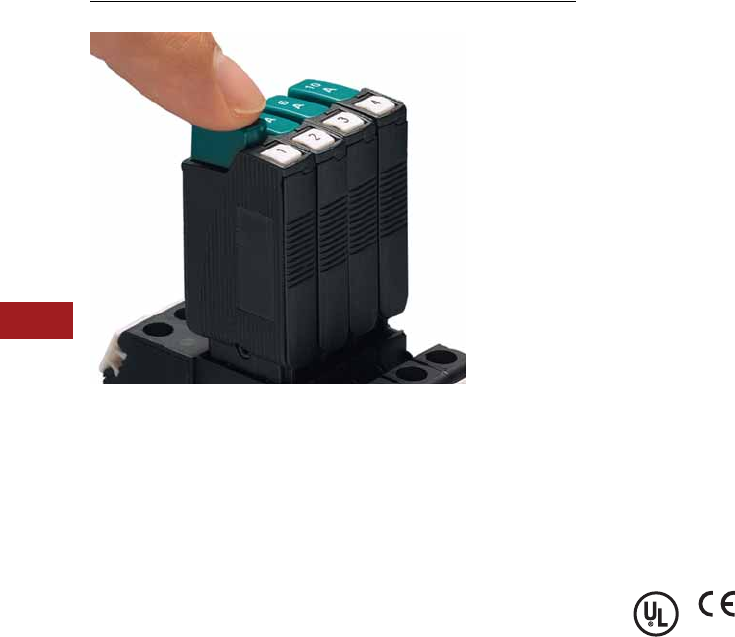
V7-T8-82 Volume 7—Logic Control, Operator Interface and Connectivity Solutions CA08100008E—July 2014 www.eaton.com
8
8
8
8
8
8
8
8
8
8
8
8
8
8
8
8
8
8
8
8
8
8
8
8
8
8
8
8
8
8
8.1
Terminal Blocks, Fuse Blocks and Fuse Holders
IEC—XB Series
Miniature Circuit Breakers
Contents
Description Page
Miniature Circuit Breakers
Circuit Breakers. . . . . . . . . . . . . . . . . . . . . . . . . V7-T8-83
Flat-Type Fuse Terminal Blocks . . . . . . . . . . . . . V7-T8-86
Spring Cage Fuse Terminal Blocks . . . . . . . . . . V7-T8-88
Miniature Circuit Breakers Overview
Product Description
The new XB Series thermal
miniature circuit breaker
offers convenient overload
protection. This space-saving
single-pole circuit breaker,
available up to 10 amps,
can be inserted into a screw
connection fuse terminal
block, XBUK6FSI, or a spring
cage fuse terminal block,
XBPT4FSI, which is available
with or without light indication.
The XBATCP combines the
reclosing capability of a circuit
breaker with the overload
protection of a fuse. The
integrated switching function
makes it possible to switch
the circuit breaker back on
immediately, guaranteeing
system availability. The
device can also be used for
switching purposes, as an
ON/OFF switch. The Plug-in
design allows for quick and
efficient replacement.
Standards and Certifications
●UL and cUL recognized
●UL 1077—File No. E301915
●CE approved
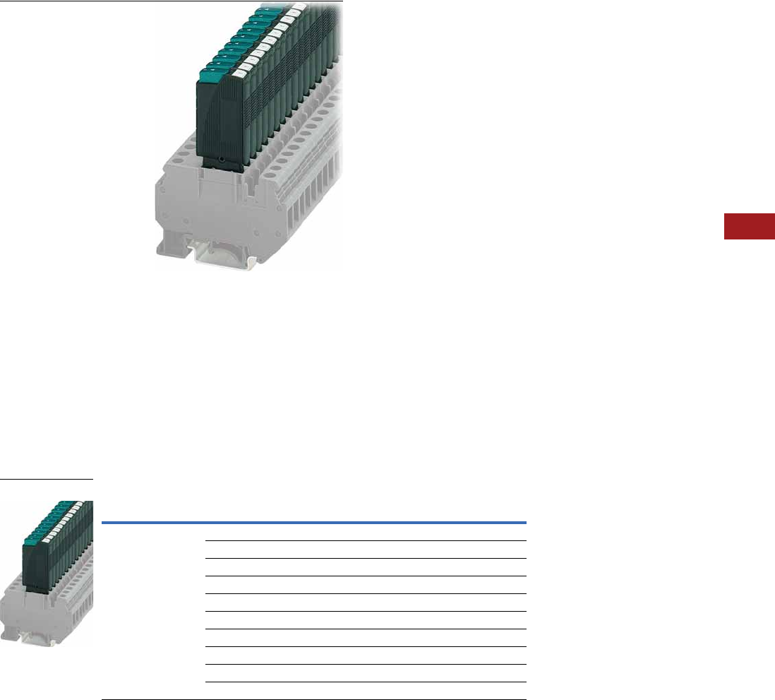
Volume 7—Logic Control, Operator Interface and Connectivity Solutions CA08100008E—July 2014 www.eaton.com V7-T8-83
8
8
8
8
8
8
8
8
8
8
8
8
8
8
8
8
8
8
8
8
8
8
8
8
8
8
8
8
8
8
8.1
Terminal Blocks, Fuse Blocks and Fuse Holders
IEC—XB Series
Circuit Breakers
Contents
Description Page
Circuit Breakers
Accessories . . . . . . . . . . . . . . . . . . . . . . . . . . . V7-T8-84
Technical Data and Specifications . . . . . . . . . . V7-T8-84
Time/Current Curve . . . . . . . . . . . . . . . . . . . . . V7-T8-85
Dimensions . . . . . . . . . . . . . . . . . . . . . . . . . . . V7-T8-85
Flat-Type Fuse Terminal Blocks . . . . . . . . . . . . . . . V7-T8-86
Spring Cage Fuse Terminal Blocks . . . . . . . . . . . . . V7-T8-88
Circuit Breakers
Product Description
The thermal miniature circuit
breaker can be switched back
on again, has a compact
design, and is available
in 10 finely graded steps
for nominal currents from
0.1 to 10A.
Product Selection
Thermal Miniature Circuit Breaker
Connection Data
in Vac/Vdc
Nominal
Current Color
Standard
Pack
Catalog
Number
250/65 0.1A Black 20 XBATCPT
0.25A Black 20 XBATCPQ
0.5A Black 20 XBATCPH
1.0A Black 20 XBATCP1
2.0A Black 20 XBATCP2
3.0A Black 20 XBATCP3
4.0A Black 20 XBATCP4
6.0A Black 20 XBATCP6
8.0A Black 20 XBATCP8
10.0A Black 20 XBATCP10
XBAT

V7-T8-84 Volume 7—Logic Control, Operator Interface and Connectivity Solutions CA08100008E—July 2014 www.eaton.com
8
8
8
8
8
8
8
8
8
8
8
8
8
8
8
8
8
8
8
8
8
8
8
8
8
8
8
8
8
8
8.1
Terminal Blocks, Fuse Blocks and Fuse Holders
IEC—XB Series
Accessories
Thermal Miniature Circuit Breaker
Technical Data and Specifications
Thermal Miniature Circuit Breaker
Nominal Currents and Internal Resistances
Note
1For information on Printed Marking Tag Options, see Page V7-T8-98.
Description Color
Number of
Positions
Standard
Pack
XBAT
Catalog
Number
Blank marker strip White — 10 XBMZBF5 1
Flat type terminal blocks — — — XBUK6FSI
XBUK6FSIL12
XBUK6FSIL24
XBPT4FSI
XBPT4FSIL12
XBPT4FSIL24
Description XBAT
Technical Data in Accordance with IEC
Nominal voltage in Vac/Vdc 250/65
Nominal current in A 0.25–10
Ambient temperature –4 to 140°F (–20 to 60°C)
Maximum Power Dissipation
Rated surge voltage in kV/contamination class 2.5/2
Surge voltage category/insulating material group III/I
Switching Capacity
Cycles with 1 x IN (low-induction) 6000
Cycles with 1 x IN (induction) 3000
Cycles with 2 x IN (induction) 500
Switching Capacity I CN
For nominal currents of 0.25–4A/6–10A 6 x IN/8 x IN
Switching capacity (UL 1077) 250 Vac/65 Vdc 2000/200
Nominal
Current (A)
Internal
Resistance (3/4)
0.25 14
0.5 3.4
1.0 0.9
2.0 0.25
3.0 0.11
4.0 0.07
6.0 <0.05
8.0 <0.05
10.0 <0.05
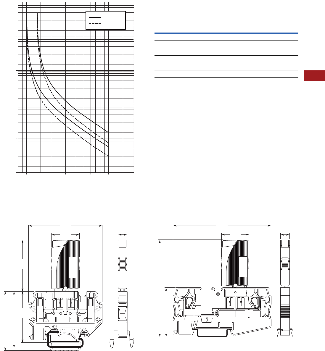
Volume 7—Logic Control, Operator Interface and Connectivity Solutions CA08100008E—July 2014 www.eaton.com V7-T8-85
8
8
8
8
8
8
8
8
8
8
8
8
8
8
8
8
8
8
8
8
8
8
8
8
8
8
8
8
8
8
8.1
Terminal Blocks, Fuse Blocks and Fuse Holders
IEC—XB Series
Time/Current Curve
Total Switch-Off Period for Nominal Current, 73.4°F (23°C)
Note: When mounted in rows, the nominal current of
the devices can only be transmitted at 80% or must
be correspondingly over-dimensioned.
Temperature Factor
Dimensions
Approximate Dimensions in Inches (mm)
XBUK6FSI with XBAT XBPT4FSI with XBAT
10,000
Multiples of IN
Response Time in Seconds
56 810 2043210.8
1000
100
10
1
0.1
0.25A - 4A
6A- 10A
Ambient Temperature Temperature Factor
–4°F (–20°C) 0.76
14°F (–10°C) 0.84
32°F (0°C) 0.91
73.4°F (23°C) 1.00
104°F (40°C) 1.08
122°F (50°C) 1.16
140°F (60°C) 1.24
0.96
(24.4)
2.52
(64) 0.32
(8.2)
1.73
(44)
1.75
(44.5)
1.93
(49)
2.03
(51.5)
0.96
(24.4)
3.39
(86.2)
3.41
(86.5) 0.32
(8.2)
1.72
(43.7)
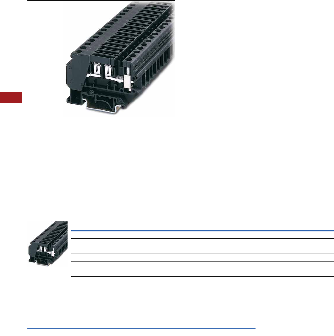
V7-T8-86 Volume 7—Logic Control, Operator Interface and Connectivity Solutions CA08100008E—July 2014 www.eaton.com
8
8
8
8
8
8
8
8
8
8
8
8
8
8
8
8
8
8
8
8
8
8
8
8
8
8
8
8
8
8
8.1
Terminal Blocks, Fuse Blocks and Fuse Holders
IEC—XB Series
Flat-Type Fuse Terminal Blocks
Contents
Description Page
Circuit Breakers . . . . . . . . . . . . . . . . . . . . . . . . . . . V7-T8-83
Flat-Type Fuse Terminal Blocks
Accessories . . . . . . . . . . . . . . . . . . . . . . . . . . . V7-T8-86
Technical Data and Specifications . . . . . . . . . . V7-T8-87
Dimensions . . . . . . . . . . . . . . . . . . . . . . . . . . . V7-T8-87
Spring Cage Fuse Terminal Blocks . . . . . . . . . . . . V7-T8-88
Flat-Type Fuse Terminal Blocks
Product Description
The fuse terminal blocks can
be used as a basic terminal
blocks for the XBAT overload
miniature circuit breaker, see
Page V7-T8-83.
Product Selection
Screw Connection Flat-Type Fuse Terminal Blocks
Accessories
Flat-Type Fuse Terminal Blocks
Note
1For information on Printed Marking Tag Options, see Page V7-T8-98.
Terminal
Width
Maximum
Wire Size
Connection Data
in V/A/AWG
UL-cUL Ratings
in V/A/AWG Color
Standard
Pack
Catalog
Number
Flat-Type Fuse Terminal Block
8.2 mm 8 AWG/6 mm2250/—/24–8 300/30/26–8 Black 50 XBUK6FSI
Flat-Type Fuse Terminal Block with LED, Red 12 Vdc, 2.0 mA
8.2 mm 8 AWG/6 mm2250/—/24–8 300/30/26–8 Black 50 XBUK6FSIL12
Flat-Type Fuse Terminal Block with LED, Red 24 Vdc, 2.0 mA
8.2 mm 8 AWG/6 mm2250/—/24–8 300/30/26–8 Black 50 XBUK6FSIL24
Description Color
Number of
Positions
Standard
Pack
XBUK6FSI XBUK6FSIL_
Catalog
Number
Catalog
Number
Blank marker strip White — 10 XBMZB8 1XBMZB8 1
XBUK6FSI

Volume 7—Logic Control, Operator Interface and Connectivity Solutions CA08100008E—July 2014 www.eaton.com V7-T8-87
8
8
8
8
8
8
8
8
8
8
8
8
8
8
8
8
8
8
8
8
8
8
8
8
8
8
8
8
8
8
8.1
Terminal Blocks, Fuse Blocks and Fuse Holders
IEC—XB Series
Technical Data and Specifications
Flat-Type Fuse Terminal Blocks
Dimensions
Approximate Dimensions in Inches (mm)
Flat-Type Fuse Terminal Blocks
Description XBUK6FSI XBUK6FSIL_
Technical Data in Accordance with IEC
Fuse type ISO C C
Maximum current with single arrangement in A 30 30
Maximum Power Dissipation
Rated surge voltage in kV/contamination class 4/3 4/3
Surge voltage category/insulating material group III/I III/I
Connection Capacity
Stranded with ferrule with plastic sleeve in mm20.25–4 0.25–4
Stranded with ferrule without plastic sleeve in mm20.25–6 0.25–6
Stranded with twin ferrule with plastic sleeve in mm2——
Multi-Conductor Connection
(same cross-section)
Solid/stranded in mm20.2–2.5/0.2–2.5 0.2–2.5/0.2–2.5
Stranded with ferrules without plastic sleeve in mm20.25–2.5 0.25–2.5
Stranded with twin ferrule with plastic sleeve in mm20.5–4.0 0.5–4.0
Stripping length in inches (mm) 0.39 (10) 0.39 (10)
Thread M4 M4
Torque in in-lb (Nm) 13.3–14.2 (1.5–1.6) 13.3–14.2 (1.5–1.6)
Catalog
Number Width Length
Height for—
32 in 35 x 7.5 in 35 x 15 in
XBUK6FSI 0.32 (8.2) 2.91 (74.0) 2.24 (57.0) 2.05 (52.0) 2.34 (59.5)
XBUK6FSIL12 0.32 (8.2) 2.91 (74.0) 2.24 (57.0) 2.05 (52.0) 2.34 (59.5)
XBUK6FSIL24 0.32 (8.2) 2.91 (74.0) 2.24 (57.0) 2.05 (52.0) 2.34 (59.5)
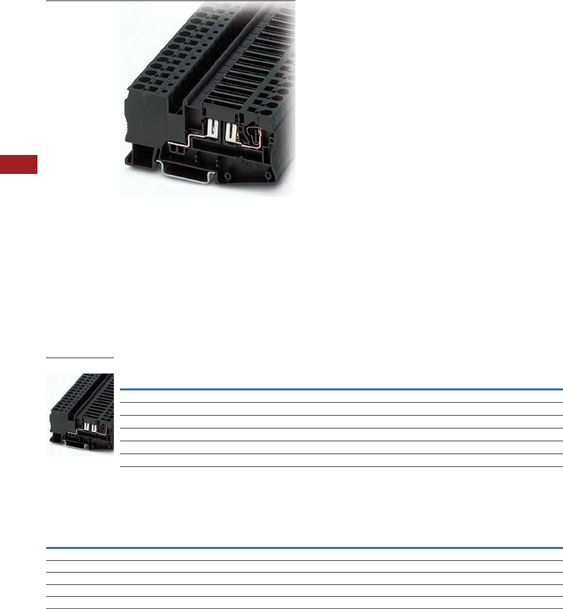
V7-T8-88 Volume 7—Logic Control, Operator Interface and Connectivity Solutions CA08100008E—July 2014 www.eaton.com
8
8
8
8
8
8
8
8
8
8
8
8
8
8
8
8
8
8
8
8
8
8
8
8
8
8
8
8
8
8
8.1
Terminal Blocks, Fuse Blocks and Fuse Holders
IEC—XB Series
Spring Cage Fuse Terminal Blocks
Contents
Description Page
Circuit Breakers . . . . . . . . . . . . . . . . . . . . . . . . . . . V7-T8-83
Flat-Type Fuse Terminal Blocks . . . . . . . . . . . . . . . V7-T8-86
Spring Cage Fuse Terminal Blocks
Accessories . . . . . . . . . . . . . . . . . . . . . . . . . . . V7-T8-88
Technical Data and Specifications . . . . . . . . . . V7-T8-89
Dimensions . . . . . . . . . . . . . . . . . . . . . . . . . . . V7-T8-89
Spring Cage Fuse Terminal Blocks
Product Description
Flat-type fuses or the XBAT
miniature circuit breaker (see
Page V7-T8-83) can be used
as the fuse element in these
XBPT
Spring Cage Fuse Terminal
Blocks. Terminal blocks with
a light indicator are available
for quick error diagnosis.
Product Selection
Spring Cage Fuse Terminal Blocks
Accessories
Flat-Type Fuse Terminal Blocks
Notes
1For ordering information, see Page V7-T8-105.
2For information on Printed Marking Tag Options, see Page V7-T8-98.
Terminal
Width
Maximum
Wire Size
Connection Data
in V/A/AWG
UL-cUL Ratings
in V/A/AWG Color
Standard
Pack
Catalog
Number
Spring Cage Fuse Terminal Block
8.2 mm 10 AWG/4 mm2400/30/28–10 300/30/24–10 Black 50 XBPT4FSI
Spring Cage Fuse Terminal Block with LED, Red 12 Vdc, 2.0 mA
8.2 mm 10 AWG/4 mm2400/30/28–10 300/30/24–10 Black 50 XBPT4FSIL12
Spring Cage Fuse Terminal Block with LED, Red 24 Vdc, 2.0 mA
8.2 mm 10 AWG/4 mm2400/30/28–10 300/30/24–10 Black 50 XBPT4FSIL24
Description Color
Number of
Positions
Standard
Pack
XBPT4FSI XBPT4FSIL_
Catalog
Number
Catalog
Number
Test adapter — — 10 XBATSPAI4 XBATSPAI4
2.3 mm diameter test plug — — — XBATSMPS-_ 1XBATSMPS-_ 1
Modular test plug — — 10 XBATSPS8 XBATSPS8
Blank marker strip center and external marking White — 10 XBMZBF8 2XBMZBF8 2
Blank marker strip center labeling (strip of 10) White — 10 XBMZB8 2XBMZB8 2
XBPT4FSI

Volume 7—Logic Control, Operator Interface and Connectivity Solutions CA08100008E—July 2014 www.eaton.com V7-T8-89
8
8
8
8
8
8
8
8
8
8
8
8
8
8
8
8
8
8
8
8
8
8
8
8
8
8
8
8
8
8
8.1
Terminal Blocks, Fuse Blocks and Fuse Holders
IEC—XB Series
Technical Data and Specifications
Flat-Type Fuse Terminal Blocks
Dimensions
Approximate Dimensions in Inches (mm)
Flat-Type Fuse Terminal Blocks
Description XBPT4FSI XBPT4FSIL_
Technical Data in Accordance with IEC
Fuse type ISO C C
Maximum current with single arrangement in A 30 30
Maximum Power Dissipation
Rated surge voltage in kV/contamination class 6/3 6/3
Surge voltage category/insulating material group III/I III/I
Connection Capacity
Stranded with ferrule with plastic sleeve in mm20.25–4 0.25–4
Stranded with ferrule without plastic sleeve in mm20.25–4 0.25–4
Stranded with twin ferrule with plastic sleeve in mm20.5 0.5
Stripping length in inches (mm) 0.39 (10) 0.39 (10)
Catalog
Number Width Length
Height for—
35 x 7.5 in 35 x 15 in
XBPT4FSI 0.32 (8.2) 3.41 (86.5) 1.71 (43.5) 2.01 (51.0)
XBPT4FSIL12 0.32 (8.2) 3.41 (86.5) 1.71 (43.5) 2.01 (51.0)
XBPT4FSIL24 0.32 (8.2) 3.41 (86.5) 1.71 (43.5) 2.01 (51.0)
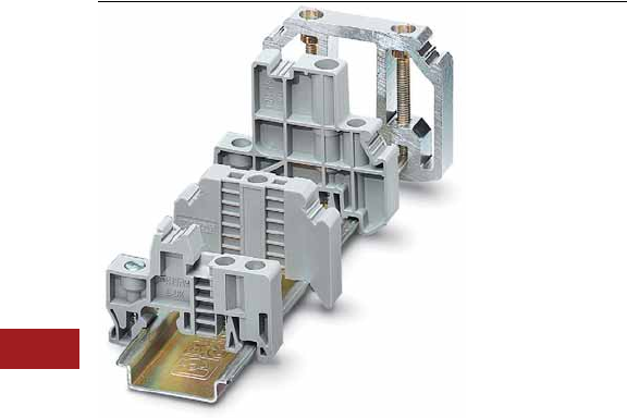
V7-T8-90 Volume 7—Logic Control, Operator Interface and Connectivity Solutions CA08100008E—July 2014 www.eaton.com
8
8
8
8
8
8
8
8
8
8
8
8
8
8
8
8
8
8
8
8
8
8
8
8
8
8
8
8
8
8
8.1
Terminal Blocks, Fuse Blocks and Fuse Holders
IEC—XB Series
XB Series Accessories
Contents
Description Page
XB Series Accessories
End Stops . . . . . . . . . . . . . . . . . . . . . . . . . . . . . V7-T8-91
DIN Rails . . . . . . . . . . . . . . . . . . . . . . . . . . . . . V7-T8-92
Angled Mounting Brackets . . . . . . . . . . . . . . . . V7-T8-93
Ferrules . . . . . . . . . . . . . . . . . . . . . . . . . . . . . . V7-T8-94
Hand Tools . . . . . . . . . . . . . . . . . . . . . . . . . . . . V7-T8-97
Marking Accessories . . . . . . . . . . . . . . . . . . . . V7-T8-98
Testing Accessories . . . . . . . . . . . . . . . . . . . . . V7-T8-105
Separating Plates, Covers and Bridges . . . . . . V7-T8-105
XB Series Accessories Overview
End Stops
The end stop provides an
anchor point at each end of
the rail assembly by attaching
directly to the DIN rail. A wide
range of end stop options are
available, including those that
mount with one or multiple
screws and those that do not
require screws for mounting.
End stops also have a
location for marking material
to be placed.
DIN Rail
Eaton offers ways for time-
saving and secure mounting
of components needed for
electrical connections. DIN
rail provides the basis for the
inner design of the control
cabinet and ensures a firm
hold of the rail-mountable
components. Eaton offers a
wide range of standard DIN
rails sizes and materials,
solid or slotted. Or, contact
us about custom lengths of
pre-cut rail or ordering pre-
drilled rail. The DIN rails are
designed in accordance with
the European standard
EN 60715.
Angled Mounting Brackets
Angled mounting brackets
are used to mount DIN rail at
a more accessible angle for
wiring and troubleshooting.
Ferrules
Ferrules are available with or
without an insulating sleeve.
The plastic insulating sleeve
simplifies the fitting of the
conductor and the color
indicates the size of the
cross-section. The closer the
connections are, the more
reliable the insulation is and
the less likely the wires are to
splice. Twin ferrules are also
available allowing two wires
to be easily compressed in
one ferrule. Chain bridging,
frequently used in industry,
becomes easier with twin
ferrules.
Hand Tools
Eaton offers an array of hand
tools to make it easier to work
with our terminal blocks. The
XBTCUTSTP tool is
recommended for cutting and
stripping PVC insulated wires.
The ergonomically shaped
crimping pliers, XBTCRMP66,
result in fatigue-free work by
spreading the manual force
equally between the six jaws.
The XBTDVR screwdrivers
have a rotating cap that
prevents user discomfort
even at high torques and
allows rapid rotation. The
ergonomically shaped handle
further aids the user’s
comfort. The blade is made
from CVM steel, hardened
and chrome-plated.
Marking Accessories
The marking system provides
logical and clear identification
of the modular terminal
blocks and interface modules.
The blank marker strip is
designed for marking terminal
blocks, equipment and
smaller modules with marker
grooves. The marker strip is
available in all common
pitches in printed and
unprinted versions.
Testing Accessories
The range of test accessories
available includes different
test plugs, so that an
optimum solution can be
realized for every application.
In addition to pre-assembled
test plugs, plugs are also
available that can be
configured individually to
form test adapters.
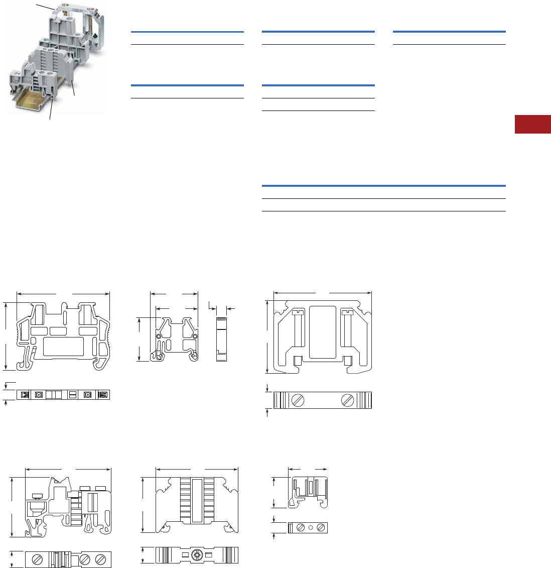
Volume 7—Logic Control, Operator Interface and Connectivity Solutions CA08100008E—July 2014 www.eaton.com V7-T8-91
8
8
8
8
8
8
8
8
8
8
8
8
8
8
8
8
8
8
8
8
8
8
8
8
8
8
8
8
8
8
8.1
Terminal Blocks, Fuse Blocks and Fuse Holders
IEC—XB Series
End Stops
Product Selection
Snap-On End Stop (15 mm)
Snap-On End Stop (35 mm)
Snap-on end stops for 35 mm
and 15 mm DIN rails can
be fitted with blank marker
strips and adjustable terminal
strip markers, parking facility
for bridges and testing
accessories.
Dimensions
Approximate Dimensions in Inches (mm)
Snap-On End Stop
XBAES35N XBAES15N
Universal End Stop
XBAES35T XBAES35C
XBAES35AL
XBAES35C
XBAES35T
Standard
Pack
Catalog
Number
50 XBAES15N
Standard
Pack
Catalog
Number
50 XBAES35N
1.38
(35)
0.20
(5)
1.91
(48.5)
0.89
(22.6)
0.87
(22)
0.20
(5.2)
0.98
(24.8)
1.3 9
(35.3)
0.37 (9.5)
1.9 9
(50.5)
1.2 9
(32.8)
0.37 (9.5)
1.9 1
(48.6)
Universal End Stop (15 mm)
Universal End Stop (35 mm)
Screwed on, labeling with
blank marker strips and
terminal strip markers.
Aluminum End
Snaps on, for end support of
50–240 mm terminal blocks,
labeling with XBMZB10.
Cross-Reference of Terminal Blocks Marking, End Stops
Aluminum End Stop
XBAES35AL
XBAES15C
Standard
Pack
Catalog
Number
50 XBAES15C
Standard
Pack
Catalog
Number
50 XBAES35T
50 XBAES35C
Standard
Pack
Catalog
Number
10 XBAES35AL
Catalog
Number XBMKLM2 XBMGLMA XBMUBE
XBAES35N X——
XBAES35T —X X
1.7 3
(44)
0.39
(10)
2.32
(59)
0.71
(18)
0.24 (6.1)
0.83
(21.2)
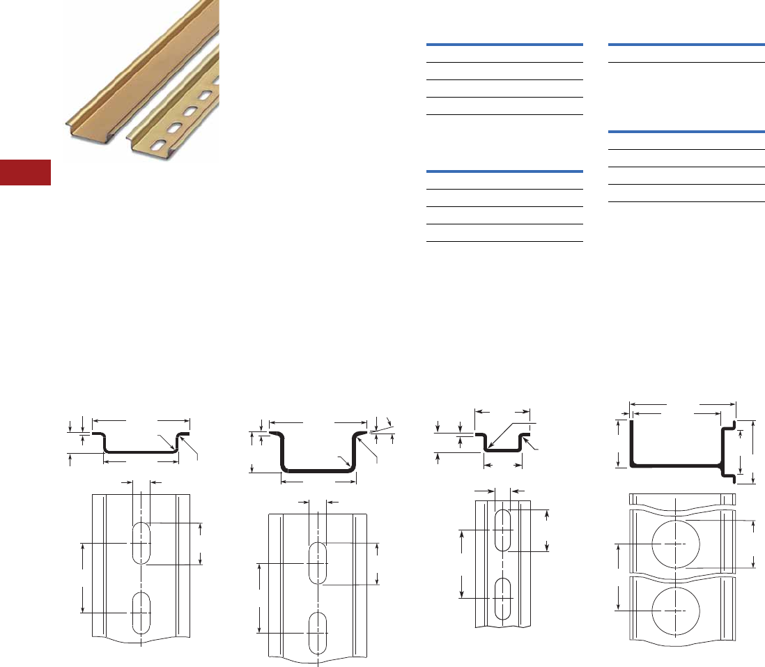
V7-T8-92 Volume 7—Logic Control, Operator Interface and Connectivity Solutions CA08100008E—July 2014 www.eaton.com
8
8
8
8
8
8
8
8
8
8
8
8
8
8
8
8
8
8
8
8
8
8
8
8
8
8
8
8
8
8
8.1
Terminal Blocks, Fuse Blocks and Fuse Holders
IEC—XB Series
DIN Rails
Product Selection
Perforated and unperforated
DIN rails in accordance with
E 60715.
Features
●High dimensional accuracy
●Restricted tolerances
●Double surface tempering,
galvanized and chromated
●All 2m in length
●Customization available
35 x 7.5 mm x 2m
35 x 15 mm x 2m
15 x 5.5 mm x 2m
Aluminum DIN Rails
(Perforated)
Dimensions
Approximate Dimensions in Inches (mm)
35 x 7.5 mm DIN Rail 35 x 15 mm DIN Rail 15 x 5.5 mm x 2m DIN Rail XBANS35PL Raised Rail
Standard
Pack
Catalog
Number
Slotted
25 XBANS3575P
Solid
25 XBANS3575U
Standard
Pack
Catalog
Number
Slotted
25 XBANS3515P
Solid
25 XBANS3515U
Standard
Pack
Catalog
Number
25 XBANS15P
Standard
Pack
Catalog
Number
35/7.5/2m
25 XBANS3575PL
35/58/2m
6XBANS35PL
0.24
(6.2)
1.06 (27)
0.03 (0.8)
Rad.
0.03 (0.8)
Rad.
1.38 (35)
0.98
(25)
0.30
(7.5)
0.04
(1)
0.59
(15)
0.05 (1.25)
Rad.
0.05 (1.25)
Rad.
0.24
(6.2)
0.98
(25)
0.59
(15)
0.03
(0.8)
15°
1.38 (35)
0.59
(15)
0.06
(1.5)
1.06 (27)
0.02 (0.5)
Rad.
0.01 (0.2)
Rad.
0.17
(4.2)
0.59
(15)
0.41
(10.5)
0.22
(5.5)
0.04
(1)
0.48
(12.2)
0.79
(20)
5.00
(127)
1.38
(35)
0.08
(2)
0.95
(24)
1.0 2
(26)
1.0 2
(26)
2.28 (58)
1.89 (48)

Volume 7—Logic Control, Operator Interface and Connectivity Solutions CA08100008E—July 2014 www.eaton.com V7-T8-93
8
8
8
8
8
8
8
8
8
8
8
8
8
8
8
8
8
8
8
8
8
8
8
8
8
8
8
8
8
8
8.1
Terminal Blocks, Fuse Blocks and Fuse Holders
IEC—XB Series
Angled Mounting Brackets
Product Selection
The angled brackets enable
the DIN rail to be mounted
with a spacing or at an angle
of 30°.
Features
●For mounting DIN rail at
30° angle
●For use with M6 screw
●Chromated steel
●Provides better visibility
Angled Mounting Bracket
Dimensions
Approximate Dimensions in Inches (mm)
XBANBGS XBANBGSH
Standard
Pack
Catalog
Number
Height Inches (mm)
1.39 (35.4)
10 XBANBGS
Height Inches (mm)
1.81 (46)
10 XBANBGSH
3.43
(87)
0.08
(2)
2.54
(64.5)
0.61
(15.4)
0.65
(16.5)
1.39
(35.4) 0.79
(20)
0.28 (7)
Dia.
M6
Screw
30°
3.31
(84)
0.08
(2)
30°
2.44
(62)
0.54
(13.7)
0.55
(14)
1.81
(46) 0.79
(20)
0.28 (7)
Dia.
M6
Screw
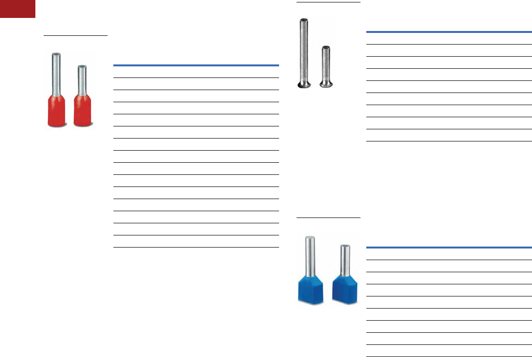
V7-T8-94 Volume 7—Logic Control, Operator Interface and Connectivity Solutions CA08100008E—July 2014 www.eaton.com
8
8
8
8
8
8
8
8
8
8
8
8
8
8
8
8
8
8
8
8
8
8
8
8
8
8
8
8
8
8
8.1
Terminal Blocks, Fuse Blocks and Fuse Holders
IEC—XB Series
Ferrules
Product Selection
Ferrules are offered in two
basic designs—an insulated
style available in models for
wire sizes 20 through 4 AWG
and a non-insulated type
available in models for wire
sizes 22 through 6 AWG.
Note: UL Ratings do not typically
pertain to the use of Ferrules—
Ferrules are covered under
DIN VDE 0611.
Insulated
●Tube: soft electrolytic copper (E-CU), tin plated
●Plastic sleeve: polypropylene
●Long-term temperature 105°C
●Short-term temperature 120°C
Insulated Ferrules
Wire Size
AWG (mm2) Color 1
Standard
Pack 2
Catalog
Number
20 (0.5) White 100 XBAF1
18 (0.75) Gray 100 XBAF3
18 (1) Red 100 XBAF4
16 (1.5) Black 100 XBAF6
14 (2.5) Blue 100 XBAF9
14 (2.5) Blue 100 XBAF10
12 (4) Gray 100 XBAF11
12 (4) Gray 100 XBAF12
10 (6) Yellow 100 XBAF13
10 (6) Yellow 100 XBAF14
8 (10) Red 100 XBAF15
8 (10) Red 100 XBAF16
6 (16) Blue 100 XBAF17
6 (16) Blue 100 XBAF18
4 (25) Yellow 50 XBAF19
XBAF1
Non-Insulated
●Tube: soft electrolytic copper (E-CU), tin plated
Non-Insulated Ferrules
Special Applications
The twin ferrules allow two
conductors to be compressed
practically in one ferrule.
The colored coding of the
various cross sections
corresponds to DIN 46 228-4.
Non-Insulated Twin Ferrules
Notes
1The colored coding of the various cross-sections corresponds to DIN 46 228-4.
2Standard pack is the number of ferrules that come in each bag. Must order in
multiples of standard pack.
Example: XBAF1—an order for 200 pieces will receive 2 bags of ferrules,
each with 100 pieces.
Wire Size
AWG (mm2)
Standard
Pack 2
Catalog
Number
20 (0.5) 100 XBAF20
18 (0.75) 100 XBAF21
18 (1) 100 XBAF23
16 (1.5) 100 XBAF24
14 (2.5) 100 XBAF25
12 (4) 100 XBAF26
10 (6) 100 XBAF27
8 (10) 100 XBAF28
6 (16) 100 XBAF29
XBAF20
Wire Size
AWG (mm2) Color 1
Standard
Pack 2
Catalog
Number
20 (0.5) White 100 XBAFT1
18 (0.75) Gray 100 XBAFT3
18 (1) Red 100 XBAFT4
16 (1.5) Black 100 XBAFT6
14 (2.5) Blue 100 XBAFT9
12 (4) Gray 100 XBAFT11
10 (6) Yellow 100 XBAFT13
8 (10) Red 100 XBAFT15
6 (16) Blue 50 XBAFT18
XBAFT1
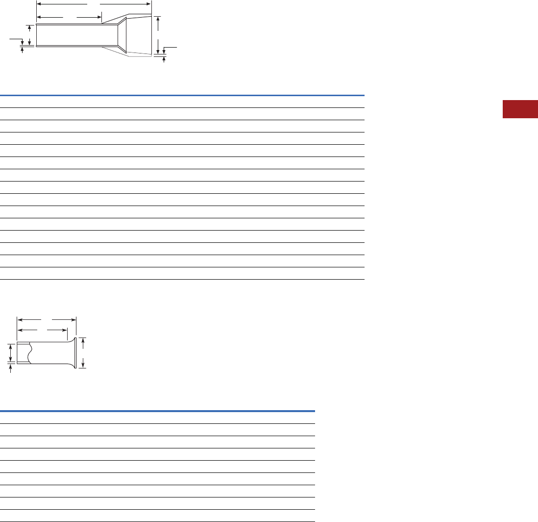
Volume 7—Logic Control, Operator Interface and Connectivity Solutions CA08100008E—July 2014 www.eaton.com V7-T8-95
8
8
8
8
8
8
8
8
8
8
8
8
8
8
8
8
8
8
8
8
8
8
8
8
8
8
8
8
8
8
8.1
Terminal Blocks, Fuse Blocks and Fuse Holders
IEC—XB Series
Dimensions
Approximate Dimensions in Inches (mm)
Ferrules with Insulating Collar
Ferrules without Insulating Collar
Catalog
Number
Approximate Dimensions
D1 D2 L1 L2 S1 S2
XBAF1 0.04 (1.1) 0.10 (2.5) 0.55 (14.0) 0.31 (8.0) 0.006 (0.15) 0.010 (0.25)
XBAF3 0.05 (1.3) 0.11 (2.8) 0.55 (14.0) 0.31 (8.0) 0.006 (0.15) 0.010 (0.25)
XBAF4 0.06 (1.5) 0.12 (3.0) 0.55 (14.0) 0.31 (8.0) 0.006 (0.15) 0.012 (0.30)
XBAF6 0.07 (1.8) 0.13 (3.4) 0.55 (14.0) 0.31 (8.0) 0.006 (0.15) 0.012 (0.30)
XBAF9 0.09 (2.3) 0.17 (4.2) 0.55 (14.0) 0.31 (8.0) 0.006 (0.15) 0.012 (0.30)
XBAF10 0.09 (2.3) 0.17 (4.2) 0.94 (24.0) 0.71 (18.0) 0.006 (0.15) 0.012 (0.30)
XBAF11 0.11 (2.8) 0.19 (4.8) 0.67 (17.0) 0.39 (10.0) 0.008 (0.20) 0.012 (0.30)
XBAF12 0.11 (2.8) 0.19 (4.8) 1.02 (26.0) 0.71 (18.0) 0.008 (0.20) 0.012 (0.30)
XBAF13 0.14 (3.5) 0.24 (6.2) 0.79 (20.0) 0.47 (12.0) 0.008 (0.20) 0.012 (0.30)
XBAF14 0.14 (3.5) 0.24 (6.2) 1.02 (26.0) 0.71 (18.0) 0.008 (0.20) 0.012 (0.30)
XBAF15 0.18 (4.6) 0.30 (7.5) 0.87 (22.0) 0.47 (12.0) 0.008 (0.20) 0.012 (0.30)
XBAF16 0.18 (4.6) 0.30 (7.5) 1.10 (28.0) 0.71 (18.0) 0.008 (0.20) 0.012 (0.30)
XBAF17 0.23 (5.8) 0.35 (8.8) 0.94 (24.0) 0.47 (12.0) 0.008 (0.20) 0.016 (0.40)
XBAF18 0.23 (5.8) 0.35 (8.8) 1.10 (28.0) 0.71 (18.0) 0.008 (0.20) 0.016 (0.40)
XBAF19 0.29 (7.3) 0.43 (11.0) 1.26 (32.0) 0.71 (18.0) 0.008 (0.20) 0.020 (0.50)
Catalog
Number
Approximate Dimensions
D1 D2 L1 L2 S
XBAF20 0.04 (1.0) 0.08 (2.1) 0.24 (6.0) 0.21 (5.3) 0.006 (0.15)
XBAF21 0.05 (1.2) 0.09 (2.3) 0.24 (6.0) 0.21 (5.3) 0.006 (0.15)
XBAF23 0.06 (1.4) 0.10 (2.5) 0.24 (6.0) 0.21 (5.3) 0.006 (0.15)
XBAF24 0.07 (1.7) 0.11 (2.8) 0.28 (7.0) 0.24 (6.0) 0.006 (0.15)
XBAF25 0.09 (2.2) 0.13 (3.4) 0.28 (7.0) 0.24 (6.0) 0.006 (0.15)
XBAF26 0.11 (2.8) 0.16 (4.0) 0.35 (9.0) 0.31 (8.0) 0.008 (0.20)
XBAF27 0.14 (3.5) 0.19 (4.7) 0.47 (12.0) 0.35 (9.0) 0.008 (0.20)
XBAF28 0.18 (4.5) 0.23 (5.8) 0.47 (12.0) 0.43 (10.8) 0.008 (0.20)
XBAF29 0.23 (5.8) 0.30 (7.5) 0.47 (12.0) 0.41 (10.5) 0.008 (0.20)
D2
S2
L2
L1
S1 D1
D2
D1
L2
L1
S
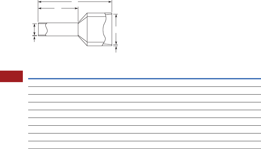
V7-T8-96 Volume 7—Logic Control, Operator Interface and Connectivity Solutions CA08100008E—July 2014 www.eaton.com
8
8
8
8
8
8
8
8
8
8
8
8
8
8
8
8
8
8
8
8
8
8
8
8
8
8
8
8
8
8
8.1
Terminal Blocks, Fuse Blocks and Fuse Holders
IEC—XB Series
Approximate Dimensions in Inches (mm)
Twin Ferrules
Catalog
Number
Approximate Dimensions
D1 D2 L1 L2 S1 S2
XBAFT1 0.06 (1.5) 0.10 (2.5) 0.59 (15.0) 0.31 (8.0) 0.006 (0.15) 0.010 (0.25)
XBAFT3 0.07 (1.8) 0.11 (2.8) 0.59 (15.0) 0.31 (8.0) 0.006 (0.15) 0.010 (0.25)
XBAFT4 0.08 (2.1) 0.13 (3.4) 0.59 (15.0) 0.31 (8.0) 0.006 (0.15) 0.012 (0.30)
XBAFT6 0.09 (2.3) 0.14 (3.6) 0.63 (16.0) 0.31 (8.0) 0.006 (0.15) 0.012 (0.30)
XBAFT9 0.11 (2.9) 0.17 (4.2) 0.73 (18.5) 0.39 (10.0) 0.008 (0.20) 0.012 (0.30)
XBAFT11 0.15 (3.8) 0.19 (4.9) 0.91 (23.0) 0.47 (12.0) 0.008 (0.20) 0.012 (0.30)
XBAFT13 0.19 (4.9) 0.23 (5.9) 0.98 (25.0) 0.55 (14.0) 0.008 (0.20) 0.016 (0.40)
XBAFT15 0.26 (6.5) 0.28 (7.2) 1.02 (26.0) 0.55 (14.0) 0.008 (0.20) 0.016 (0.40)
XBAFT18 0.33 (8.5) 0.35 (8.8) 1.22 (31.0) 0.63 (16.0) 0.008 (0.20) 0.020 (0.50)
D2
S2
L2
L1
D1
S1

Volume 7—Logic Control, Operator Interface and Connectivity Solutions CA08100008E—July 2014 www.eaton.com V7-T8-97
8
8
8
8
8
8
8
8
8
8
8
8
8
8
8
8
8
8
8
8
8
8
8
8
8
8
8
8
8
8
8.1
Terminal Blocks, Fuse Blocks and Fuse Holders
IEC—XB Series
Hand Tools
Stripping Tools
Product Selection
Stripping Tools
Technical Data and Specifications
Conductor/Cable Stripping Range
Dimensions
Approximate Dimensions in Inches (mm)
Stripping Tools
Crimping Pliers
The crimping pliers deform the ferrules hexagonally.
For 0.25–6 mm2 ferrules in accordance with
DIN 46 228-1: 1992-08 and DIN 46 228-4: 1990-09.
Product Selection
Crimping Pliers
Technical Data and Specifications
Areas of Application
Dimensions
Approximate Dimensions in Inches (mm)
Crimping Pliers
Slotted Screwdrivers
The crimping pliers deform the ferrules hexagonally.
For 0.25–6 mm2 ferrules in accordance with
DIN 46 228-1: 1992-08 and DIN 46 228-4: 1990-09.
Product Selection
Slotted Screwdrivers
Standard
Pack
Catalog
Number
1XBTCUTSTP
Description Specification
Conductor/cable 0.2–6 mm2/24–10 AWG
Wire cutter 6 mm2/10 AWG
Length
Stripping
Length
Weight
In lbs (g)
8.07 (205) Up to 18 mm 0.44 (200)
Standard
Pack
Catalog
Number
1XBTCRMP66
Description Specification
Conductor 0.25–6 mm2
Conductor 23–10 AWG
Length
Weight
In lbs (g)
6.85 (175) 0.79 (360)
Standard
Pack
Catalog
Number
3.5 mm
1XBTDVR35
4.0 mm
1XBTDVR40
V7-T8-98 Volume 7—Logic Control, Operator Interface and Connectivity Solutions CA08100008E—July 2014 www.eaton.com
8
8
8
8
8
8
8
8
8
8
8
8
8
8
8
8
8
8
8
8
8
8
8
8
8
8
8
8
8
8
8.1
Terminal Blocks, Fuse Blocks and Fuse Holders
IEC—XB Series
Marking Accessories
Printed Marking Tag Options
Horizontally Printed Marking Tags and Marking Directions
Marking Tags for 5.2 mm Wide Terminal Blocks Marking Tags for 6.2 mm Wide Terminal Blocks
Note
1For text printed horizontally, change “V” in catalog number to “H.”
12345678910
Marking Direction: Horizontal
1
2
3
4
5
6
7
8
9
10
Marking Direction: Vertical
Standard
Pack
Number
Sequence
Catalog
Number
ZB5 Tags Vertically Numbered
10 1–10 1XBMZB5V/1
10 11–20 XBMZB5V/11
10 21–30 XBMZB5V/21
10 31–40 XBMZB5V/31
10 41–50 XBMZB5V/41
10 51–60 XBMZB5V/51
10 61–70 XBMZB5V/61
10 71–80 XBMZB5V/71
10 81–90 XBMZB5V/81
10 91–100 XBMZB5V/91
ZBF5 Tags Vertically Numbered
10 1–10 1XBMZBF5V/1
10 11–20 XBMZBF5V/11
10 21–30 XBMZBF5V/21
10 31–40 XBMZBF5V/31
10 41–50 XBMZBF5V/41
10 51–60 XBMZBF5V/51
10 61–70 XBMZBF5V/61
10 71–80 XBMZBF5V/71
10 81–90 XBMZBF5V/81
10 91–100 XBMZBF5V/91
Standard
Pack
Number
Sequence
Catalog
Number
ZB6 Tags Vertically Numbered
10 1–10 1XBMZB6V/1
10 11–20 XBMZB6V/11
10 21–30 XBMZB6V/21
10 31–40 XBMZB6V/31
10 41–50 XBMZB6V/41
10 51–60 XBMZB6V/51
10 61–70 XBMZB6V/61
10 71–80 XBMZB6V/71
10 81–90 XBMZB6V/81
10 91–100 XBMZB6V/91
ZBF6 Tags Vertically Numbered
10 1–10 1XBMZBF6V/1
10 11–20 XBMZBF6V/11
10 21–30 XBMZBF6V/21
10 31–40 XBMZBF6V/31
10 41–50 XBMZBF6V/41
10 51–60 XBMZBF6V/51
10 61–70 XBMZBF6V/61
10 71–80 XBMZBF6V/71
10 81–90 XBMZBF6V/81
10 91–100 XBMZBF6V/91

Volume 7—Logic Control, Operator Interface and Connectivity Solutions CA08100008E—July 2014 www.eaton.com V7-T8-99
8
8
8
8
8
8
8
8
8
8
8
8
8
8
8
8
8
8
8
8
8
8
8
8
8
8
8
8
8
8
8.1
Terminal Blocks, Fuse Blocks and Fuse Holders
IEC—XB Series
Marking Tags for 8.2 mm Wide Terminal Blocks
Marking Tags for 10.2 mm Wide Terminal Blocks
Marking Tags for 12 mm Wide Terminal Blocks
Marking Tags for 16 mm Wide Terminal Blocks
Note
1For text printed horizontally, change “V” in catalog number to “H.”
Standard
Pack
Number
Sequence
Catalog
Number
ZB8 Tags Vertically Numbered
10 1–10 1XBMZB8V/1
10 11–20 XBMZB8V/11
10 21–30 XBMZB8V/21
10 31–40 XBMZB8V/31
10 41–50 XBMZB8V/41
10 51–60 XBMZB6V/51
10 61–70 XBMZB8V/61
10 71–80 XBMZB8V/71
10 81–90 XBMZB8V/81
10 91–100 XBMZB8V/91
ZBF8 Tags Vertically Numbered
10 1–10 1XBMZBF8V/1
10 11–20 XBMZBF8V/11
10 21–30 XBMZBF8V/21
10 31–40 XBMZBF8V/31
10 41–50 XBMZBF8V/41
10 51–60 XBMZBF8V/51
10 61–70 XBMZBF8V/61
10 71–80 XBMZBF8V/71
10 81–90 XBMZBF8V/81
10 91–100 XBMZBF8V/91
Standard
Pack
Number
Sequence
Catalog
Number
ZB10 Tags Vertically Numbered
10 1–10 1XBMZB10V/1
10 11–20 XBMZB10V/11
10 21–30 XBMZB10V/21
ZBF10 Tags Vertically Numbered
10 1–10 1XBMZBF10V/1
10 11–20 XBMZBF10V/11
10 21–30 XBMZBF10V/21
Standard
Pack
Number
Sequence
Catalog
Number
ZB12 Tags Vertically Numbered
10 1–10 1XBMZB12V/1
10 11–20 XBMZB12V/11
10 21–30 XBMZB12V/21
ZBF12 Tags Vertically Numbered
10 1–10 1XBMZBF12V/1
10 11–20 XBMZBF12V/11
10 21–30 XBMZBF12V/21
Standard
Pack
Number
Sequence
Catalog
Number
ZB15 Tags Vertically Numbered
10 1–10 1XBMZB15V/1
10 11–20 XBMZB15V/11
10 21–30 XBMZB15V/21
ZBF15 Tags Vertically Numbered
10 1–10 1XBMZBF15V/1
10 11–20 XBMZBF15V/11
10 21–30 XBMZBF15V/21

V7-T8-100 Volume 7—Logic Control, Operator Interface and Connectivity Solutions CA08100008E—July 2014 www.eaton.com
8
8
8
8
8
8
8
8
8
8
8
8
8
8
8
8
8
8
8
8
8
8
8
8
8
8
8
8
8
8
8.1
Terminal Blocks, Fuse Blocks and Fuse Holders
IEC—XB Series
Pre-Printed Marking Tags
Terminal Blocks Marking Tags
The tags are made of white self-extinguishing polyamide 6.6 and the imprint is hot stamped
with rubproof black ink.
●White marking strip
available preprinted. Strip
covers 10 terminals.
Marking 1–10, 11–20, up to
991–999. Contact Eaton for
more options.
●XBMZB5 or XBMZBF5
for terminal blocks
5.2 mm wide
●XBMZB6 or XBMZBF6
for terminal blocks
6.2 mm wide
●XBMZB8 or XBMZBF8
for terminal blocks
8.2 mm wide
●XBMZB10 or XBMZBF10
for terminal blocks
10.2 mm wide
●XBMZB12 or XBMZBF12
for terminal blocks
12 mm wide
●XBMZB15 or XBMZBF15
for terminal blocks
16 mm wide
Marking Tag Sizes
Note: Marking Tag Sizes are for all catalog numbers starting with given prefix, EXCEPT FUSE TERMINAL Blocks.
Proper Marking Tag Size
Notes
1For center labeling.
2For external labeling.
3For center and outside labeling.
4For lever labeling.
5Two (2) XBMZB10 tags fit in one (1) XBMKLMZ.
XBMZB5 XBMZBF5 XBMZB6 XBMZBF6 XBMZB8 XBMZBF8 XBMZB10 XBMZBF10 XBMZB12 XBMZBF12 XBMZB15 XBMZBF15 XBMSSZB
XBUT25 XBPT25 2XBUT4 XBPT4 2XBUT6 XBPT6 2XBUT10 XBPT10 2XBPT16 1XBPT16 2XBUT35 XBPT35 2XBMKLMZ
XBUT4FBE 1XBPTT25 XBUTT4 XBPTT4 XBPT6 1XBPT4FBN 2XBUT16 — — — XBPT35 1——
XBUT6FBN 1XBPTK XB3UKA XBPT4FBE 2XBUK6 XBPT4FSI 2XBTK — — — — — —
XBPT25 1XBPU25 2XB3UKF XBQT25 3XBPT4FSI 1— XBUK50 — — — — — —
XBPT4FBE 1XBAP … XBUT4FBE 2XBQT25FBE 3— — XBUK150——————
XBPU25 1XBQT15 3XBUT6FBN 2XBQU25 3— — XBUK95 — — — — — —
XBQT15 1XBQTT15 XBUK10 — — — XBPT10 1——————
XBQT25FBE 4XBQU15 3XBUKK4 — — — XBMKLMZ 5——————
XBQU15 1XBMPK15 XBPT4 1— —————————
XBMUK25 XBMPKK15 XBPT4FBN 1— —————————
— XBATCP… XBQT25 1— —————————
— — XBQT25FBE 1— —————————
— — XBQU25 1— —————————
— — XBMUK4 — — — — — — — — — —
Volume 7—Logic Control, Operator Interface and Connectivity Solutions CA08100008E—July 2014 www.eaton.com V7-T8-101
8
8
8
8
8
8
8
8
8
8
8
8
8
8
8
8
8
8
8
8
8
8
8
8
8
8
8
8
8
8
8.1
Terminal Blocks, Fuse Blocks and Fuse Holders
IEC—XB Series
Marker Strips and Sheets (for use with XBAPLT2006K1 plotter)
The XB Series marking system provides logical and clear
identification of the modular terminal blocks and interface
modules.
Product Selection
Marker Strips (Strip of 10)
Label Sheets for Laser Printers
The XBM labels have been specially developed for laser printers
and have considerable advantages:
●Can be printed on all commercially available laser printers
●Or can use plotter or pen for printing
●Good adhesive properties
●A4 size
●XBMKL25X12WH designed to fit XBGBS2512 group marker
●XBMLMAL447 is perforated for terminal strip marker
XBMGLMA and is 44 x 7 mm
Marker Sheets (Strip of 10)
Product Selection
Label Sheets
Note
1All markers are strips of 10, except XBMZB15, which is a strip of 5.
Terminal
Width
Standard
Pack
Catalog
Number
Blank Strips
5.2 mm 10 XBMZB5
6.2 mm 10 XBMZB6
8.2 mm 10 XBMZB8
10.2 mm 10 XBMZB10
12 mm 10 XBMZB12
16 mm 10 XBMZB15 1
Flat Strips
5.2 mm 10 XBMZBF5
6.2 mm 10 XBMZBF6
8.2 mm 10 XBMZBF8
10.2 mm 10 XBMZBF10
12 mm 10 XBMZBF12
16 mm 10 XBMZBF15
XBMZB_
Terminal
Width) Color
Standard
Pack
Catalog
Number
Marker Sheets (10 rows of 12)
5.2 mm White 50 XBMPZB5
Blue 50 XBMPZB5BU
Red 50 XBMPZB5RD
Yellow 50 XBMPZB5YE
Green 50 XBMPZB5GN
Marker Sheets (10 rows of 10)
6.2 mm White 50 XBMPZB6
Blue 50 XBMPZB6BU
Red 50 XBMPZB6RD
Yellow 50 XBMPZB6YE
Green 50 XBMPZB6GN
Flat Marker Sheets (10 rows of 10)
5.2 mm White 10 XBMPZBF5
Orange 10 XBMPZBF5OG
White 10 XBMPZBF6
Orange 10 XBMPZBF6OG
White 10 XBMPZBF8
Standard
Pack
Catalog
Number
10 XBMKL25X12WH
10 XBMLMAL447
XBMPZB_
XBMPZBF_
XBM_
V7-T8-102 Volume 7—Logic Control, Operator Interface and Connectivity Solutions CA08100008E—July 2014 www.eaton.com
8
8
8
8
8
8
8
8
8
8
8
8
8
8
8
8
8
8
8
8
8
8
8
8
8
8
8
8
8
8
8.1
Terminal Blocks, Fuse Blocks and Fuse Holders
IEC—XB Series
Terminal Block Group Marking
Terminal block groups are marked using marking labels that are
snapped into the marker strip groove of the terminal blocks. The
group is marked using either labels or insert markers.
Product Selection
Terminal Block Group Marking 1
Terminal Strip Markers
Adjustable height for end bracket labeling.
Product Selection
Terminal Strip Markers 1
Terminal Strip Marker Carriers
For labeling terminal groups, for mounting on DIN rail. Lettering
field is 40 x 17 mm.
Product Selection
Terminal Strip Marker Carriers
Insert Markers for Laser Printers
One sheet = 56 labels. Lettering field is 40 x 17 mm.
Product Selection
Insert Markers for XBMUBE(D)
Refillable Marker Pen
Refillable marker pen for manual labeling, line thickness
0.35 mm.
Product Selection
Terminal Strip Markers 1
Non-Refillable Marker Pen
For manual labeling, line thickness 0.5 mm.
Product Selection
Non-Refillable Marker Pen
Note
1 See Page V7-T8-101 for insert labels.
Standard
Pack
Catalog
Number
100 XBGBS2512
Standard
Pack
Catalog
Number
20 x 8 mm Wide
10 XBMKLM2
44 x 7 mm Wide
10 XBMGLMA
Standard
Pack
Catalog
Number
10 XBMUBE
10 XBMUBED
XBGBS2512
XBM_
XBMUB_
Standard
Pack
Catalog
Number
10 XBMUBEL4017
Standard
Pack
Catalog
Number
Pen
1XBMXPEN
Ink Cartridge
1XBMINK
Standard
Pack
Catalog
Number
1XBMBSTIFT
XBMUBEL4017
XBMXPEN
XBMUBE

Volume 7—Logic Control, Operator Interface and Connectivity Solutions CA08100008E—July 2014 www.eaton.com V7-T8-103
8
8
8
8
8
8
8
8
8
8
8
8
8
8
8
8
8
8
8
8
8
8
8
8
8
8
8
8
8
8
8.1
Terminal Blocks, Fuse Blocks and Fuse Holders
IEC—XB Series
Marking Plotter
The automatic Prepare Pen
function ensures optimum
marking results right from the
first character.
Pens can remain in the pen
station even for prolonged
intervals without drying out.
Custom Marking Tag System
This plotter system uses
Windows®-based software to
interface with a PC, allowing
custom printing on standard
terminal blocks marking tags.
These standard marking tags
provide circuit identification
for Eaton DIN rail mount
terminal blocks.
Features
●Enter tag text directly into
EMARK software program
or import file from
AutoCAD or Excel®
●Selectable font sizes, types
and colors including
common symbols for
circuit identification
(ground, ~ etc.)
●Various text formatting
options including copy,
paste, increment functions,
text alignment, etc.
●Durable templates allow
printing of four different tag
sizes at the same time
●Automatic prepare pen
function for optimum
results
Technical Data and Specifications
Marking Plotter
Dimensions
Approximate Dimensions in Inches (mm)
Marking Plotter
Description Specification
Plotter
Plotter type Flatbed plotter
Maximum plotting surface 440 mm x 296 mm
Maximum material height 10.5 mm
Maximum plotting speed 40 cm/sec
Pen station Four depots with double sealing
Drive Two-phase impulse-driven motor
Interfaces Parallel (Centronics)/USB Level 1.1
Electronics
Command language Based on HP-GL 7475A
Data buffer 16 MB
Addressable resolution 0.01 mm
Repeat accuracy 0.05 mm
Repeat accuracy on pen change 0.05 mm with optimum pen
Power Supply
Power supply Via separate power supply unit with
exchangeable mains feeder cable
Power supply unit input voltage 100–240 Vac/50–60 Hz
Power supply unit input current (maximum) 0.3A at 230V~
Power supply unit output voltage 24 Vdc
Power supply unit output current (maximum) 1.4A
Environmental conditions
Operation 50° to 95°F (10° to 35°C)
35% to 75% relative humidity
Storage 14° to 122°F (–10° to 50°C)
10% to 90% relative humidity
Approx. Weight
L W H In Lbs (kg)
25.98 (660) 17.32 (440) 4.92 (125) 18 (8)

V7-T8-104 Volume 7—Logic Control, Operator Interface and Connectivity Solutions CA08100008E—July 2014 www.eaton.com
8
8
8
8
8
8
8
8
8
8
8
8
8
8
8
8
8
8
8
8
8
8
8
8
8
8
8
8
8
8
8.1
Terminal Blocks, Fuse Blocks and Fuse Holders
IEC—XB Series
Marking Plotter
EMARK Software
Eaton’s EMARK software makes labeling your terminal blocks quick and simple.
You can import your data from ECHART, any other CAD/CAE program, or enter
text directly into EMARK. The software allows marking tags to be printed on the
PLT2006 plotter in a professional manner.
Note
1 Plotter kit includes PLT2006 plotter system with EMARK software and user manual, starter ink and cleaning
sets, and templates for marking all XBMZB and XBMZBF tags.
Description
Standard
Pack
Catalog
Number
Plotter kit 11XBAPLT2006K1
Pen station sealing set 1 XBMP1PENDEPOT
Plotter pen preparation plate 1 XBMP1PREPLATES
Template for marker strips 1 XBMP1MZB
Template for flat marker strips 1 XBMP1MZBF
Template for XBMPZB marker sheets 1 XBMP1MPZB
Template for XBMPZBF marker sheets 1 XBMP1MPZBF
Template for Weidmuller multicard sheet 1 XBMP1MCSF46
Template for Weidmuller multicard sheet universal 1 XBMP1MCU
Template for Entrelec sheets 1 XBMP1MRC
0.25 mm disposal pen 1 XBMDPEN25R
0.35 mm disposal pen 1 XBMDPEN35R
0.25 mm pen 1 XBMPEN25
0.35 mm pen 1 XBMPEN35
Ink Cartridge 2 XBMINK
Pen cleaning set 1 XBMRSET
Cleaning cartridges 2 XBMRMEKFC2
Volume 7—Logic Control, Operator Interface and Connectivity Solutions CA08100008E—July 2014 www.eaton.com V7-T8-105
8
8
8
8
8
8
8
8
8
8
8
8
8
8
8
8
8
8
8
8
8
8
8
8
8
8
8
8
8
8
8.1
Terminal Blocks, Fuse Blocks and Fuse Holders
IEC—XB Series
Testing Accessories
Test Adapter
For 4 mm diameter test plug and 4 mm diameter safety test
plug. Makes contact in the bridge shaft.
Product Selection
Te s t A d a p t e r
Modular Test Plugs
For individual assembly of test plug strips.
Product Selection
Modular Test Plugs
Test Plugs
Consisting of metal part for socket hole and insulating sleeve.
Product Selection
Test Plugs
Separating Plates, Covers and Bridges
End Cover
Used to cover an open end of terminal block
when changing sizes within an assembly and/
or for last terminal block in a row.
Partition Plate
Protrudes over the terminal block and is used
to increase electrical clearance between
terminals. Also provides visual indications of
the functions of terminal blocks. For
example, terminal blocks between two
partition plates may provide an exact location
for test points.
End Cover Segment
Covers protruding terminal block segments
of three- and four-wire terminal blocks when
next to a two wire blocks. This ensures that
all is touch-proof and saves space over using
a standard end cover.
Jumper/Bridge
Provides the ability to electrically connect
terminal blocks. Non-adjacent blocks may be
bridged by snapping off the contact tabs of
the standard bridge. The reducing bridge
permits simple connection of terminal blocks
with different nominal cross-sections.
Note
See these accessories as listed with terminal blocks for more information.
Standard
Pack
Catalog
Number
1XBATSPAI4
Standard
Pack
Catalog
Number
Test Plugs
10 XBATSPS5
10 XBATSPS6
10 XBATSPS8
Spacer Plate
10 XBATSDPPS5
10 XBATSDPPS6
10 XBATSDPPS8
Standard
Pack
Catalog
Number
2.3 mm
10 — XBATSMPSMT
10 Blue XBATSMPSIHBU
10 White XBATSMPSIHWH
10 Red XBATSMPSIHRD
10 Black XBATSMPSIHBK
4 mm
10 — XBATSPSMT
10 Blue XBATSPSIHBU
10 White XBATSPSIHWH
10 Red XBATSPSIHRD
10 Black XBATSPSIHBK
XBATSPAI4
XBATS_
XBATSMP_
XBATSMP_
V7-T8-106 Volume 7—Logic Control, Operator Interface and Connectivity Solutions CA08100008E—July 2014 www.eaton.com
8
8
8
8
8
8
8
8
8
8
8
8
8
8
8
8
8
8
8
8
8
8
8
8
8
8
8
8
8
8
8.2
Terminal Blocks, Fuse Blocks and Fuse Holders
NEMA
NEMA
Contents
Description Page
NEMA
C381 Series Terminal Blocks, Rail Mounted . . V7-T8-107
TB Series Terminal Blocks, Modular . . . . . . . . . V7-T8-111
NEMA Overview
Product Description
NEMA terminal blocks
provide a panel or DIN rail
mount block that can be
assembled from modular
pieces. These blocks
accommodate wire from
22 to 1/0 AWG and up to
175A and 600V.
Standards and Certifications
●UL File #E67464 and
#E56797
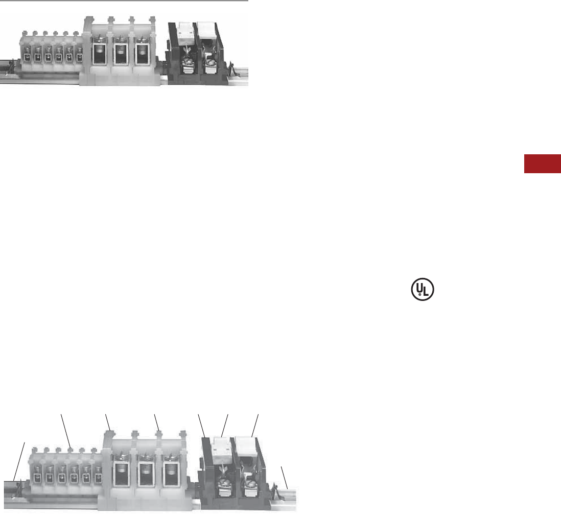
Volume 7—Logic Control, Operator Interface and Connectivity Solutions CA08100008E—July 2014 www.eaton.com V7-T8-107
8
8
8
8
8
8
8
8
8
8
8
8
8
8
8
8
8
8
8
8
8
8
8
8
8
8
8
8
8
8
8.2
Terminal Blocks, Fuse Blocks and Fuse Holders
NEMA
C381 Series Terminal Blocks, Rail Mounted
Contents
Description Page
C381 Series Terminal Blocks, Rail Mounted
Product Selection . . . . . . . . . . . . . . . . . . . . . . . V7-T8-108
Accessories . . . . . . . . . . . . . . . . . . . . . . . . . . . V7-T8-109
Modifications . . . . . . . . . . . . . . . . . . . . . . . . . . V7-T8-109
Technical Data and Specifications . . . . . . . . . . V7-T8-110
Dimensions . . . . . . . . . . . . . . . . . . . . . . . . . . . V7-T8-110
TB Series Terminal Blocks, Modular . . . . . . . . . . . . V7-T8-111
C381 Series Terminal Blocks, Rail Mounted
Product Description
●600V
●Snap-fit nylon sections
●Control circuit blocks
●Power circuit blocks
●Fuse blocks
●Switch blocks
●Sections can be interlocked
in any quantity and any
mixture for direct panel
mounting or channel
mounting
●Three terminal choices in
control circuit blocks, up to
32 circuits per foot
●Power circuit blocks for
heavy-duty applications, up
to 16 circuits per foot
●Fuse blocks accommodate
any 0.406 x 1.5 in (10.3 x
38.1 mm) ferrule type
cartridge fuse up to 30A
●Switch blocks have
removable blade for extra
safety
Standards and Certifications
●UL File #E67464
A Typical Mixture of Control Circuit Blocks, Power Blocks, Switch and
Fuse Blocks in a Mounting Channel
C381PEC381TP C381PT C381EF C381SB C381FB
C381MC
C381CC
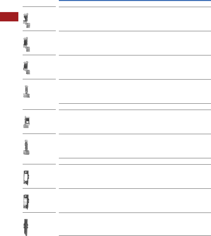
V7-T8-108 Volume 7—Logic Control, Operator Interface and Connectivity Solutions CA08100008E—July 2014 www.eaton.com
8
8
8
8
8
8
8
8
8
8
8
8
8
8
8
8
8
8
8
8
8
8
8
8
8
8
8
8
8
8
8.2
Terminal Blocks, Fuse Blocks and Fuse Holders
NEMA
Product Selection
When Ordering Specify
Catalog number and quantity,
which must be in a multiple
of the available minimum
standard package.
Examples:
●200 Cat. No. C381ST
●20 Cat. No. C381PT
●100 Cat. No. C381CC
Catalog number and quantity
of end sections also in
minimum quantity standard
package.
Example:
●25 Cat. No. C381ES
Control, Power, Switch and Fuse Blocks 1
Notes
1 Available only in minimum quantity standard packages.
2 Must be ordered in standard package quantity or in multiples of these quantities.
Description
AWG
Wire Size
Standard
Pack 2
Catalog
Number
Control Circuit Terminal Blocks—Rated 50A
Type ST (screw terminal) 22–14 AWG 100 C381ST
Type TP (tubular pressure plt) 22–10 100 C381TP
Type TS (tubular screw) end section 18–8 100 C381TS
End section — 25 C381ES
Power Circuit Terminal Blocks—Rated 155A
Type PT (tubular screw) 10–1/0 10 C381PT
End section — 10 C381PE
Switch Blocks—Rated 15A and Fuse Blocks—Rated 30A
Switch blocks 18–8 10 C381SB
Fuse blocks 18–8 10 C381FB
End section — 10 C381EF
C381ST
C381TP
C381TS
C381ES
C381PT
C381PE
C381SB
C381FB
C381EF
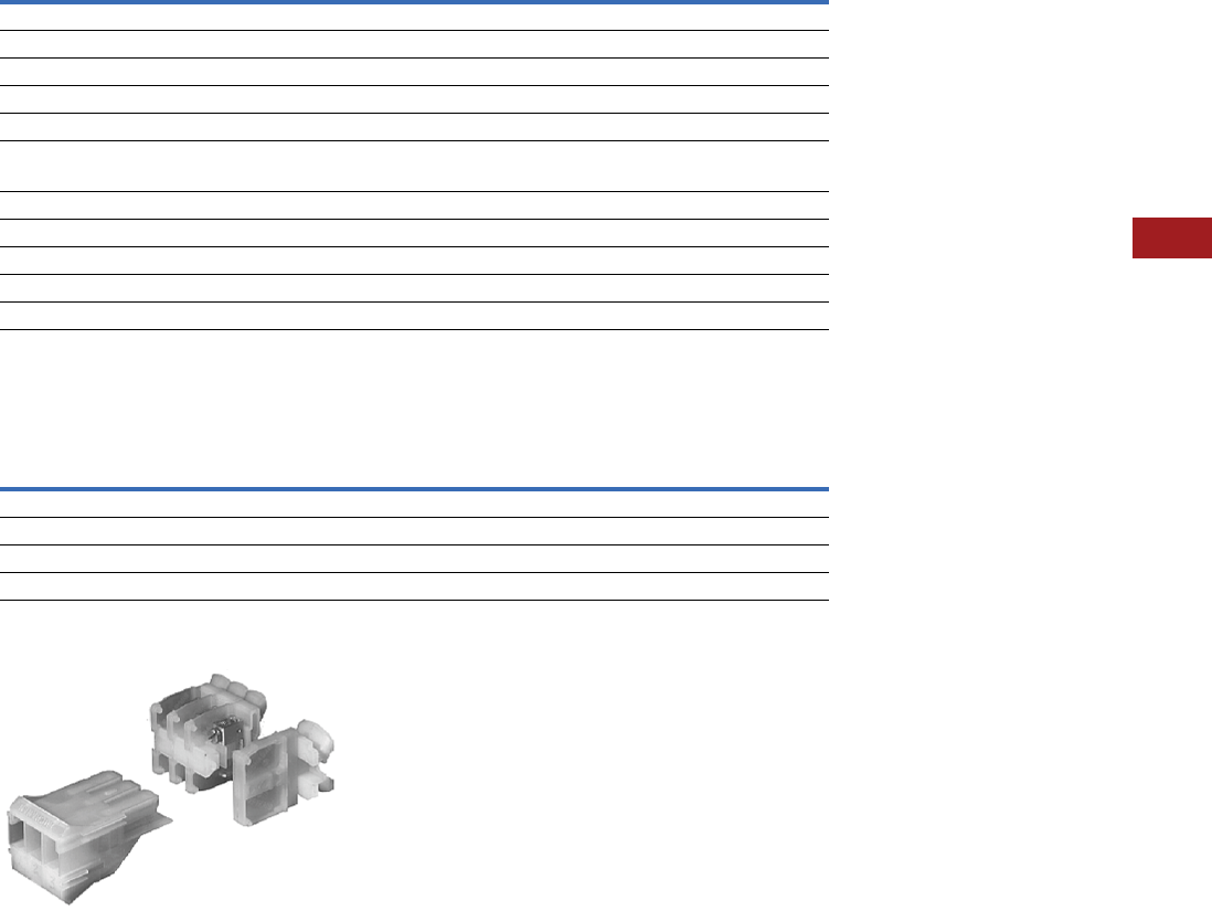
Volume 7—Logic Control, Operator Interface and Connectivity Solutions CA08100008E—July 2014 www.eaton.com V7-T8-109
8
8
8
8
8
8
8
8
8
8
8
8
8
8
8
8
8
8
8
8
8
8
8
8
8
8
8
8
8
8
8.2
Terminal Blocks, Fuse Blocks and Fuse Holders
NEMA
Accessories
C381 Series Terminal Blocks, Rail Mounted 1
Modifications
Pull Apart Terminal Blocks 1
Pull Apart Terminal Blocks
Illustrates: One–Three-Pole Movable Section,
Three–One-Pole Stationary Sections and One–End Piece
Notes
1Available only in minimum quantity standard packages.
2Must be ordered in standard package quantity or in multiples of these quantities.
3C381CC is a snap-in, one time use disposable type. C381VC can be readjusted or reused as desired.
4For use on adjacent Type TP and/or TS control circuit sections.
5May be used on section covers or to gang fuse and/or switch blocks.
6L shaped plug installs in end of stationary section, Catalog Number C381PS, and prevents incorrect installation of movable section, Catalog Number C381PM.
Description
Standard
Pack 2
Catalog
Number
Aluminum mounting channel—6 ft (1.8m) lengths 25 C381MC
Screw type channel clamp (one required each end) 3100 C381VC
Spring type channel clamp (one required each end) 3100 C381CC
Vinyl marking strip—3/8 in x 25 ft (9.5 mm x 7.6m) coil 1 C381MS
Marking paper—pressure sensitive—5/16 x 11-11/16 in (7.9 x 296.9 mm), 24 strips/sheet 5 sheets C381MP
Marking strip retainer (one required/grouping)
For use on control circuit blocks 100 C381SR
For use on power circuit blocks 100 C381SP
Fanning strip—for type TP and/or TS 50 C381TF
Fanning strip—for type ST 50 C381SF
Terminal jumper (two-pole) 4100 C381TJ
Ganging rod—1/8 in x 6 in (3.2 mm x 152.4 mm) 510 C381GR
Description
AWG
Wire Size
Standard
Pack 2
Catalog
Number
One-pole stationary section (tubular pressure plt) 22–10 100 C381PS
Three-pole movable section (tubular pressure plt) 22–10 12 C381PM
End section — 25 C381ES
Polarizing plug (promotes alignment of poles) 6— 100 C381PP
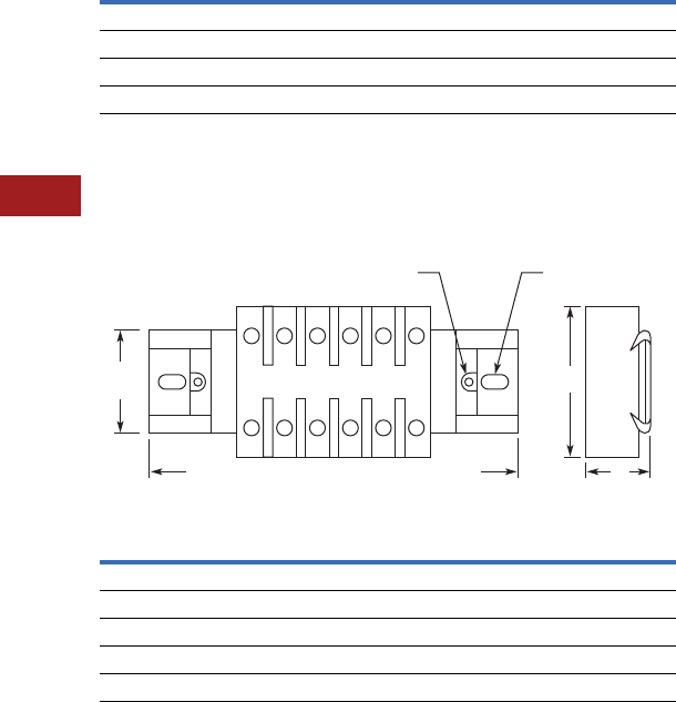
V7-T8-110 Volume 7—Logic Control, Operator Interface and Connectivity Solutions CA08100008E—July 2014 www.eaton.com
8
8
8
8
8
8
8
8
8
8
8
8
8
8
8
8
8
8
8
8
8
8
8
8
8
8
8
8
8
8
8.2
Terminal Blocks, Fuse Blocks and Fuse Holders
NEMA
Technical Data and Specifications
Formulas for Calculating Blocks and Channel Lengths
N = Number of Blocks
C381 Series Terminal Blocks, Rail Mounted
Dimensions
Approximate Dimensions in Inches (mm)
C381 Series Terminal Blocks, Rail Mounted
Description Blocks Length
Control blocks and pull apart blocks 0.762 + (0.375 x N)
Power circuit blocks 0.812 + (0.750 x N)
Fuse and switch blocks 0.812 + (0.755 x N)
Mounting channel (minimum channel length) 0.75 + blocks length
Block A B
Control circuit blocks 1.25 (31.8) 1.55 (39.4)
Power circuit blocks 1.75 (44.5) 2.00 (50.8)
Fuse blocks 2.75 (69.9) 2.00 (50.8)
Switch blocks 2.75 (69.9) 2.00 (50.8)
Pull apart blocks 1.88 (47.8) 2.75 (69.9)
A
1.19
(30.2)
Channel
Mounting
Terminal Block Mounting
Without Channel
B
Mounting Channel in 6' (1.8m) Lengths,
Can Be Cut to Desired Length
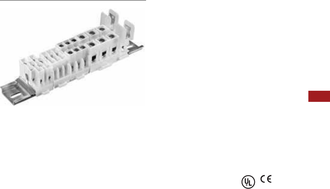
Volume 7—Logic Control, Operator Interface and Connectivity Solutions CA08100008E—July 2014 www.eaton.com V7-T8-111
8
8
8
8
8
8
8
8
8
8
8
8
8
8
8
8
8
8
8
8
8
8
8
8
8
8
8
8
8
8
8.2
Terminal Blocks, Fuse Blocks and Fuse Holders
NEMA
TB Series Terminal Blocks, Modular
Contents
Description Page
C381 Series Terminal Blocks, Rail Mounted . . . . . V7-T8-107
TB Series Terminal Blocks, Modular
Product Selection . . . . . . . . . . . . . . . . . . . . . . . V7-T8-112
Accessories . . . . . . . . . . . . . . . . . . . . . . . . . . . V7-T8-113
Technical Data and Specifications . . . . . . . . . . V7-T8-114
Dimensions . . . . . . . . . . . . . . . . . . . . . . . . . . . V7-T8-115
TB Series Terminal Blocks, Modular
Product Description
TBA and TBD modular terminal
blocks are designed to
conserve space, while
allowing maximum flexibility
and ease of installation.
Available as one-, two- and
three-pole circuits, simple
and uniform installation is
possible because their
design is based on 5/8 in
(15.9 mm) modules. Standard
blocks are white nylon.
Breathing Action
Clamping Collar
The unique design of the
clamping collar permits the
collar to breathe as the wire
expands and contracts,
maintaining a constant
and permanent clamping
pressure. This eliminates
loose connections resulting
from the gradual flattening
of conductors and joint
deterioration caused by
heating and cooling cycles.
Features
Blocks—Design Features
●Compact design permits
mounting 48–600V or
90–300V terminals per foot
●Fully shielded construction,
600V spacings
●Nylon construction
provides anti-tracking and
impact resistance
●TBA types are available
in rail mounted, base
mounted and power
distribution types
●Terminal blocks easily snap
on or off mounting rails;
not necessary to disturb
adjacent units
●No end pieces or backing
plates are needed when
rail mounting
●A 12 circuit subminiature
blocks, rated 20A at 300V,
is available for “high
density” applications
●Popular blocks are also
available in dual mount for
use with standard TBA or
35 mm DIN rails
Terminals—Design Features
●Insulated walls of lug
guide wire into lug
●Blocks are shipped
with clamping screw
backed out
●Constant locking torque
keeps terminal screws in
position
●Terminal screws are captive;
cannot be lost in shipment
or handling
●Hardened stainless steel
clamping collar eliminates
stripped threads
●Large opening in clamping
collar accommodates
oversized conductors;
smallest collar will accept
three 14 AWG stranded
conductors
Standards and Certifications
●UL recognized: File No.
E56797
●CE approved
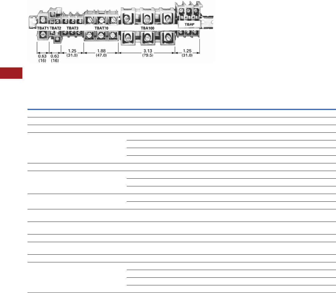
V7-T8-112 Volume 7—Logic Control, Operator Interface and Connectivity Solutions CA08100008E—July 2014 www.eaton.com
8
8
8
8
8
8
8
8
8
8
8
8
8
8
8
8
8
8
8
8
8
8
8
8
8
8
8
8
8
8
8.2
Terminal Blocks, Fuse Blocks and Fuse Holders
NEMA
Product Selection
TBA Modular Terminal Blocks
Rail and Base Mounted Terminal Blocks
Notes
1Based on 50°C rise, test at 25°C ambient while using maximum wire size.
2Must be ordered in standard package quantity or in multiples of these quantities.
3Dual mounting blocks—mount on either TMR/TBA rail or 35 mm DIN rail.
4May also be mounted on mini-DIN rail (15 mm). Catalog Number C383TS15.
5May also be base mounted.
6TBU Series = 60A with crimped wire.
Description
AWG
Wire Size
Number
of Poles
Ampacity
(per Circuit) 1
Carton
Quantity 2
TBA Rail DIN Rail 3
Catalog
Number
Catalog
Number
Rail Mounted—600V
Subminiature blocks (2) 14–12 12 5A 100 TBDSM12 4TBDSM12 4
Miniature blocks 22–10 4 30A 100 TBDV4 TBDV4
Standard blocks—screw terminals
with tang clamping collars
18–2 1 90A 100 — TBDT1
22–8 2 40A 100 TBAT2 —
22–8 3 40A 20 TBAT3-20 TBDT3-20
18–4 3 90A 100 TBDT70 TBDT70
High current blocks 14–2/0 3 175A 12 TBA100 5—
Standard blocks—plug-in terminals 22–8 3 40A 20 TBAP —
18–4 3 70A 20 TBAP70 —
14–8 3 40A 20 TBAPL70 —
Panel mount blocks 22–10 3 30A 100 TBAL30 —
8–4 3 115A 12 TBAL90 —
Disconnect blocks—for 1/4 in (6.4 mm) dia.
by 1–1-7/16 in (25.4–36.5 mm) fuse
22–8 1 30A 50 TBAD —
Fuse blocks—for 13/32 in (10.3 mm) dia.
by 1-1/2 in (38.1 mm) fuse
22–8 1 30A 50 TBDTF TBDTF
Base Mounted—600V
Miniature blocks—screw terminals
with tang clamping collars
22–10 4 30A (600V) 90 TBBT4 —
Standard blocks—standard screw terminals 22–8 3 40A 80 TBABT3 —
Universal mounting blocks 8 maximum 4 50A 625 TBU4 —
8 maximum 6 50A 660 TBU6 —
8 maximum 8 50A 6 45 TBU8 —
8 maximum 12 50A 635 TBU12 —

Volume 7—Logic Control, Operator Interface and Connectivity Solutions CA08100008E—July 2014 www.eaton.com V7-T8-113
8
8
8
8
8
8
8
8
8
8
8
8
8
8
8
8
8
8
8
8
8
8
8
8
8
8
8
8
8
8
8.2
Terminal Blocks, Fuse Blocks and Fuse Holders
NEMA
Accessories
TB Series Terminal Blocks, Modular
Notes
1Length in inches (mm) except as noted.
2Must be ordered in standard package quantity or in multiples of these quantities.
Description Length 1
Number
of Poles
Carton
Quantity 2
Catalog
Number
Mounting Rail
Aluminum 12.5 (317.5) — 25 TMR12
37.5 (952.5) — 25 TMR37
72.0 (1828.8) — 25 TBATR72
35 mm DIN—steel 1m — 20 MC382MA1-20
Marking Strips
Miniature blocks—TBDV4 and TBBT4 6.0 (152.4) — 50 TMS6
TBU Series—matte finish 7.5 (190.5) — 25 TMSU
All other blocks 12.5 (317.5) — 50 TMS
Jumpers
TBAT1 and TBAP70 — 2-pole 100 TJ1
TBAT2 — 2-pole 100 TJ2
TBAT3, TBABT3, TBAP and TBBP — 2-pole 100 TJ3
TBDV4 and TBBT4 — 4-pole 100 TJ4
TBAD and TBATF — 2-pole 100 TJ5
TBAL30 — 2-pole 100 TJ6
TBU — 12-pole 10 TJ7
TBDT3 — 2-pole 100 TJ8
Miscellaneous
End piece for TBABT3 and TBBP — — 50 TAD
Lug shield for TBA100 and TBAL90 — — 50 TAS
Fuse puller — — 50 TBP
Lighted fuse puller—blown fuse indication — — 25 TBLP
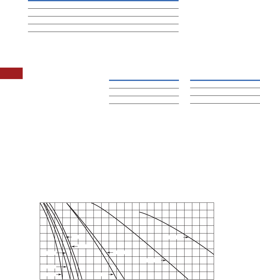
V7-T8-114 Volume 7—Logic Control, Operator Interface and Connectivity Solutions CA08100008E—July 2014 www.eaton.com
8
8
8
8
8
8
8
8
8
8
8
8
8
8
8
8
8
8
8
8
8
8
8
8
8
8
8
8
8
8
8.2
Terminal Blocks, Fuse Blocks and Fuse Holders
NEMA
Technical Data and Specifications
TB Series Terminal Blocks, Modular
●Chemical resistance to:
●Acetone
●Ammonia gas
●Benzene
●Gasoline
●Mineral oil
●Sodium bisulfate
●Sodium chloride
●Sodium nitrate
●Water up to 50°C
Flashover Voltages Recommended Terminal
Tightening Torque
To find a current rating, place
a straight edge horizontally at
the value of anticipated
maximum internal panel
ambient (scale on the left),
and read the current rating for
the device on the bottom
scale. Example: at 60°C,
TBAT3 is rated 54 amperes.
Ampere rating is based
on maximum allowable
temperature—ambient
temperature plus
temperature rise due
to current.
Ratings based on 90°C total
temperature of a three-pole
block with each pole carrying
current and wired with largest
size conductors.
Temperature Rating
Description Specification
Continuous temperature 212°F (100°C)
Tensile strength 10,000–12,000 psi
Impact resistance 2.0 ft-lb/in (arc)
Arc resistance 140 seconds
Vac rms, 60 Hz
Catalog
Number
Opposite
Polarity To Ground
TBAT1 9100 6600
TBAT2 9600 7300
TBAT3 8600 7300
Wire Size Torque
Up to 8 AWG 20 lb-in
Up to 4 AWG 35 lb-in
Up to 2/0 AWG 50 lb-in
30
20
Ambient Temp. in C°
Temp. Rise in C°
40 60 80 100 120 140 160 180
Current in Amps
200 220 240
40
50
60
70
80
60
50
40
30
20
10
TBAM4 TBAB70
TBAL90
TBAL100
TBAT2
TBAT3
TBAT1
TBAP
TBAL30
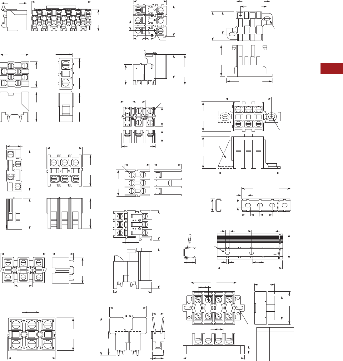
Volume 7—Logic Control, Operator Interface and Connectivity Solutions CA08100008E—July 2014 www.eaton.com V7-T8-115
8
8
8
8
8
8
8
8
8
8
8
8
8
8
8
8
8
8
8
8
8
8
8
8
8
8
8
8
8
8
8.2
Terminal Blocks, Fuse Blocks and Fuse Holders
NEMA
Dimensions
Approximate Dimensions in Inches (mm)
TB Series Terminal Blocks, Modular
0.88
(22.4)
1.09
(27.7)
TBDSM12
TBAP70 & TBAPL70
2.4 (61)
1.88
(47.8)
0.63
(16)
1.48
(37.6) 1.86
(47.2)
1.25
(31.8)
2 (50.8)
1
(25.4)
TBDV4 TBDT1
TBAT3 & TBDT3
1.25
(31.8)
1.23
(31.2)
1.71
(43.4)
1.3
(33)
0.59
(15)
TBAT2
TBA100
TBDT70
1.69
(42.9)
1.3
(33)
0.63 (16) 1.25
(31.8)
1.34
(34)
1.75
(44.5)
0.63
(16)
3.13 (79.5) 1.53 (38.9)
1.25 (31.8)
TBAL30
1.25
(31.8)
1.25
(31.8)
#6-32
Screw 1.33
(33.8)
1.23
(31.2)
1.3
(33)
TBAP
0.59
(15)
1.25
(31.8)
1.86
(47.2)
1.77 (45)
TBU4, TBU6, TBU8 & TBU12
0.31 (7.9)
0.25 (6.4) 0.63 (16)
0.66
(16.8) 0.19
(4.8)
12.5 – 37.5
(317.5 – 952.5)
TMR12 & TMR37
2
(50.8)
1.5
(38.1)
0.5
(12.7)
1.25
(31.8)
0.63 (16)
#10 Screw
Clearance
B
0.63
(16)
1.23
(31.2)
1.25
(31.8)
1 (25.4)
1.38 (35.1)
1.78 (45.2)
TBBT4
0.17 – 0.28
(4.3 – 7.1)
Clearance for
#8 Screw
0.44 (11.2)
A
1.88 (47.8)
TBAD & TBDTF
2
(50.8)
1.25
(31.8)
0.63 (16)
0.63 (16)
0.47 (11.9)
1.94 (49.3)
3 Holes
0.09 (2.3) Dia.
0.33 (8.4) Deep
0.67
(17) 0.59
(15)
1.75
(44.5)
1/4-28
Screw
TBAL90
1.53
(38.9)
0.63
(16) 1.25
(31.8)
3.13 (79.5)
TBABT3
1.25
(31.8)
1.19
(30.2)
2.47 (62.7)
1.88 (47.8)
0.17 – 0.27
(4.3 – 6.9)
Clearance for
#8 Screw
Footlock
Cat. #TAD
#10 Screw
Clearance 1.31
(33.3)
72 (1828.8)
0.13 (3.3) 0.63 (16)
0.56
(14.2) TBATR72
0.25 (6.4) 1.25 (31.8)
TBU4
TBU6
TBU8
TBU12
3.75
(95.3)
5
(127)
6.25
(158.8)
8.75
(222.3)
2.87
(72.9)
AB
4.12
(104.6)
5.37
(136.4)
7.87
(199.9)
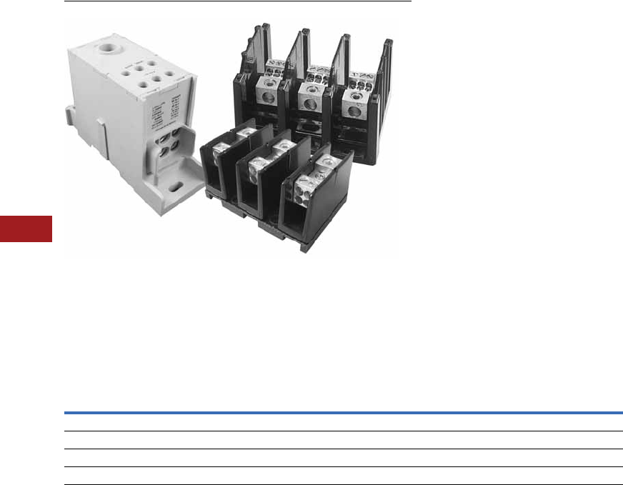
V7-T8-116 Volume 7—Logic Control, Operator Interface and Connectivity Solutions CA08100008E—July 2014 www.eaton.com
8
8
8
8
8
8
8
8
8
8
8
8
8
8
8
8
8
8
8
8
8
8
8
8
8
8
8
8
8
8
8.3
Terminal Blocks, Fuse Blocks and Fuse Holders
Power Distribution
Power Distribution Products
Contents
Description Page
Power Distribution
CHDB Series—Power Distribution Blocks . . . . V7-T8-117
CH160 Series—Power Terminal Blocks . . . . . . V7-T8-123
Power Terminal Block Accessories . . . . . . . . . . V7-T8-126
Power Distribution Overview
Product Selection Guide
Notes
1Refer to Page V7-T8-118 to determine short circuit current ratings with fuses and Pages V7-T8-119 and V7-T8-120 to determine short circuit current ratings
in conjunction with specific Eaton circuit breakers.
2Single-pole units, when installed with proper spacings, may meet requirements for UL 508A feeder circuits.
Series
Current
Range UL Certification
High Short
Circuit Current
Rating 1
UL 508A Approved for Industrial Control Panels
HVAC UL 1995Branch Circuits Feeder Circuits
CH162 115–175A UL 1059 Recognized No Yes No 2Yes
CH163 175–420A UL 1059 Recognized No Yes No 2Yes
CH165 620–840A UL 1059 Recognized No Yes No 2Yes
CHDB 175–570A UL 1953 Listed Yes Yes Yes Yes
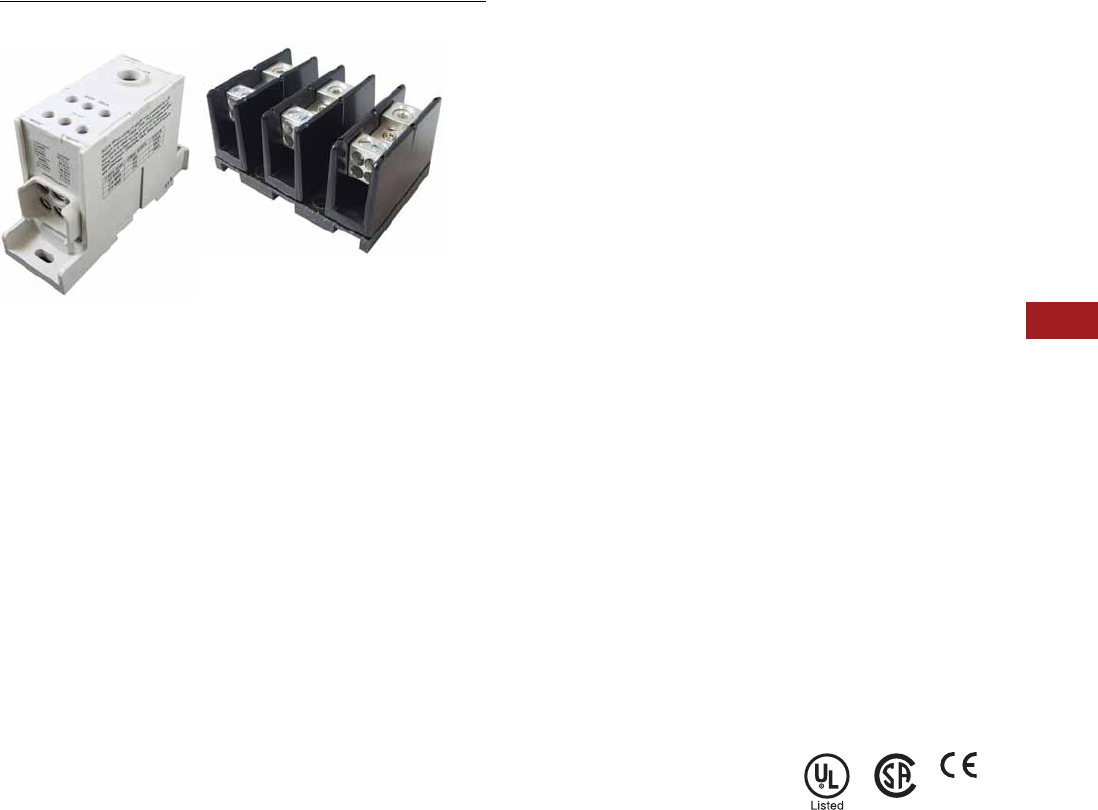
Volume 7—Logic Control, Operator Interface and Connectivity Solutions CA08100008E—July 2014 www.eaton.com V7-T8-117
8
8
8
8
8
8
8
8
8
8
8
8
8
8
8
8
8
8
8
8
8
8
8
8
8
8
8
8
8
8
8.3
Terminal Blocks, Fuse Blocks and Fuse Holders
Power Distribution
CHDB Series—Power Distribution Blocks, Enclosed and Open
Contents
Description Page
CHDB Series—Power Distribution Blocks
Product Selection . . . . . . . . . . . . . . . . . . . . . . . V7-T8-118
Technical Data and Specifications . . . . . . . . . . V7-T8-118
Dimensions . . . . . . . . . . . . . . . . . . . . . . . . . . . V7-T8-121
CH160 Series—Power Terminal Blocks . . . . . . . . . V7-T8-123
Power Terminal Block Accessories . . . . . . . . . . . . V7-T8-126
CHDB Series—Power Distribution Blocks
Product Description
Eaton’s CHDB Series of
Power Distribution Blocks
was designed for high short
circuit current rating (SCCR)
applications up to 200,000
amperes. They are assembled
with the minimum spacing to
meet UL 1953 requirements
for feeder circuits in UL 508A
industrial control panels,
and provide significant
wiring flexibility.
Available in three-pole
open style and single-pole
enclosed style with a variety
of terminal arrangements
and current-carrying capability
up to 570 amperes.
Features and Benefits
Enclosed Style
●IP20 finger-safe enclosure
●600 Vac or Vdc (UL 1953),
690 Vac or Vdc
●DIN rail or panel mount
●Captive termination screws
prevent lost screws
●Single-pole, gang
mountable for multi-pole
applications
●Tin plated Al connections
suitable for Cu conductors
●Flammability, UL 94V-0
Open Style
●600 Vac or Vdc (UL 1953)
●Panel mount
●Three-pole open design for
easy wiring
●Tin-plated Al connections
suitable for Cu conductors
●Flammability, UL 94V-0
●Available covers for
additional protection
(does not meet IP20)
Standards and Certifications
●UL Listed 1953, Guide
QPQS, File E256146
●CSA Certified,
Class 6228-01, File 15364
(enclosed style)
●CE Component
IEC 60947-7-1
(enclosed style)
●IEC 60529, IP20 (finger-
safe) under specific wiring
conditions (enclosed style)
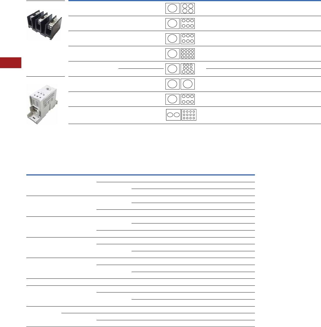
V7-T8-118 Volume 7—Logic Control, Operator Interface and Connectivity Solutions CA08100008E—July 2014 www.eaton.com
8
8
8
8
8
8
8
8
8
8
8
8
8
8
8
8
8
8
8
8
8
8
8
8
8
8
8
8
8
8
8.3
Terminal Blocks, Fuse Blocks and Fuse Holders
Power Distribution
Product Selection
CHDB Series—Power Distribution Blocks
Technical Data and Specifications
Power Terminal Block Short-Circuit Current Ratings (SCCR) with Fuses
Note
1Finger-safe.
Line Connection Load Connection Configuration Amperes Style Poles
Catalog
Number
2/0–#8 AWG (4) #4–#14 AWG 175 Open 3 CHDB2203
2/0–#8 AWG (6) #4–#14 AWG 175 Open 3 CHDB3213
300 kcmil–#4 AWG (6) #4–#12 AWG 310 Open 3 CHDB3233
300 kcmil–#4 AWG (12) #4–#14 AWG 310 Open 3 CHDB3703
300 kcmil–#4 AWG (6) #2–#12 AWG 310 Open 3 CHDB3713
(3) 1/0–#12 AWG 310 Open 3 CHDB3713
2/0–#8 AWG 2/0–#8 AWG 175 Enclosed 11CHDB204F
500 kcmil–#6 AWG (6) #2–#14 AWG 380 Enclosed 11CHDB330F
300 kcmil–#4 AWG (12) #4–#14 AWG 570 Enclosed 11CHDB377F
Catalog
Number
Terminal Copper Conductors
Maximum Fuse Class and Amperes
J T RK-1 RK-5
SCCR (kA)Line Load LPJ JJS/JJN LPS-RK/LPN-RK FRS-R/FRN-R
CHDB2203 2/0–#8 AWG #4–#12 AWG 200 200 200 60 200
#4–#14 AWG 175 175 100 60 100
200 200 100 60 50
CHDB3213 2/0–#8 AWG #4–#12 AWG 400 400 200 100 200
400 400 400 100 100
#4–#14 AWG 175 175 100 60 100
CHDB3233 300 kcmil–#4 AWG #4–#8 AWG 400 400 200 100 200
400 400 400 100 100
#4–#12 AWG 175 175 100 60 100
CHDB3703 300 kcmil–#4 AWG #4–#8 AWG 400 400 200 100 200
#4–#14 AWG 400 400 400 100 100
175 175 100 60 100
CHDB3713 300 kcmil–#4 AWG 1/0–#6 AWG 400 400 200 100 200
#4–#12 AWG 400 400 400 100 100
175 175 100 60 100
CHDB204F 2/0–#8 AWG 2/0–#8 AWG 200 200 100 60 200
CHDB330F 500 kcmil–#6 AWG #2–#6 AWG 400 400 200 100 200
#2–#14 AWG 200 200 100 30 50
175 175 100 30 100
CHDB377F 300 kcmil #4–#8 AWG 600 600 400 200 200
300 kcmil–#4 AWG #4 AWG 600 600 400 200 50
#4–#14 AWG 200 200 100 30 50
CHDB2203 (Open)
CHDB204F (Enclosed)
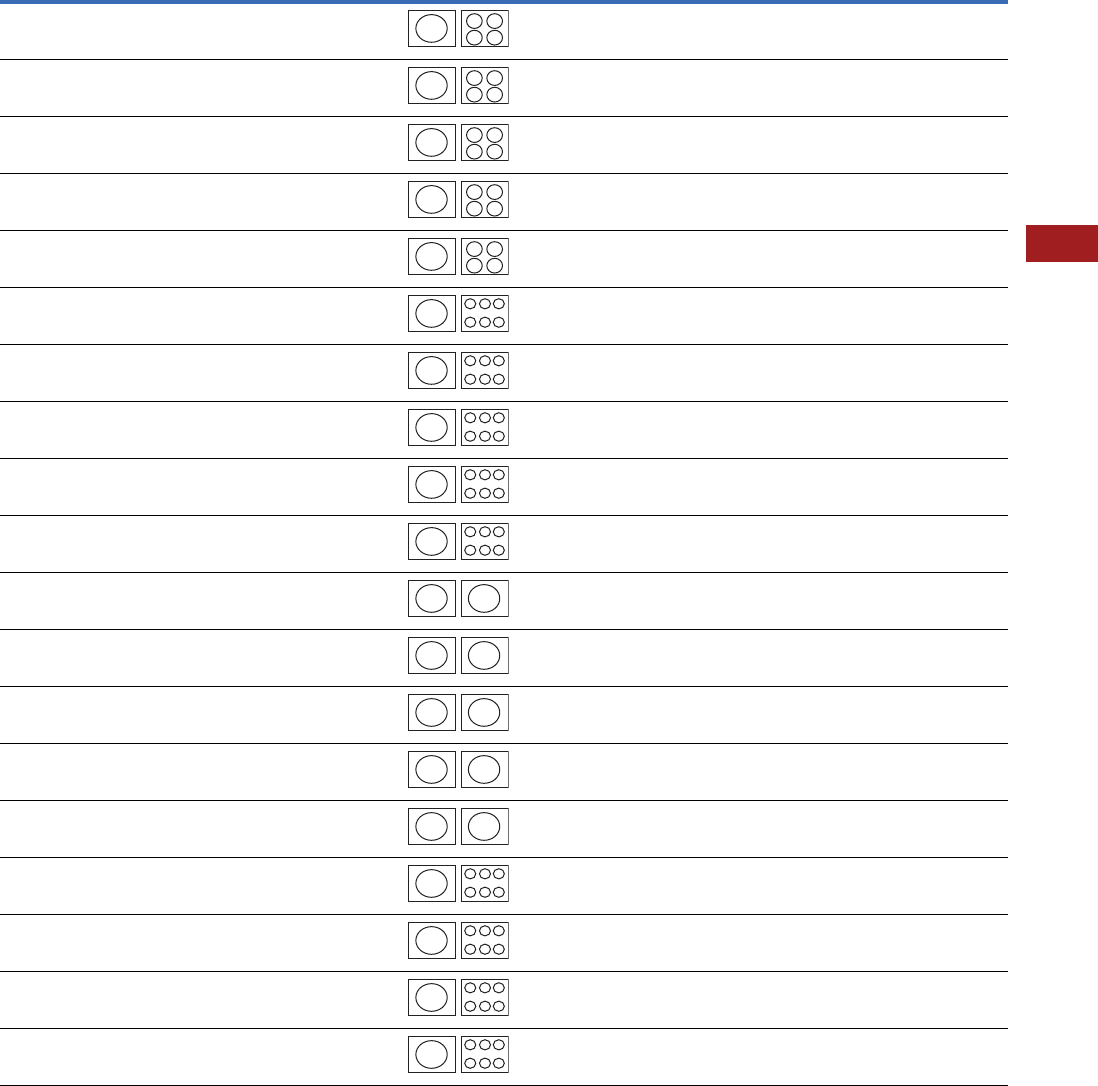
Volume 7—Logic Control, Operator Interface and Connectivity Solutions CA08100008E—July 2014 www.eaton.com V7-T8-119
8
8
8
8
8
8
8
8
8
8
8
8
8
8
8
8
8
8
8
8
8
8
8
8
8
8
8
8
8
8
8.3
Terminal Blocks, Fuse Blocks and Fuse Holders
Power Distribution
Power Terminal Block Short-Circuit Ratings (SCCR) for UL 508A Applications with Circuit Breakers
Note
1This breaker frame is marked current limiting and suitable for use as current limiting per UL 508A SB.4.3.2.
Catalog
Number Description
Enclosure Size in
Inches (mm)
Current
Rating
Opening per Pole Line
Conductors
Cu
Load
Conductors
Cu
SCCR @ 480V
(Load Side)
Eaton
Breaker
Available Breaker
Current RatingsLine Load
CHDB2203 Feeder Listed
Open PDB
16.00 x 16.00 x 6.75
(406.4 x 406.4 x 171.5)
175 2/0–#8 #4–#10
#12
#14
18 kA
18 kA
14 kA
EGB125 15, 20, 25, 30, 35, 40,
45, 50, 60, 70, 80, 90,
100, 125
CHDB2203 Feeder Listed
Open PDB
16.00 x 16.00 x 6.75
(406.4 x 406.4 x 171.5)
175 2/0–#8 #4–#10
#12
#14
25 kA
22 kA
14 kA
EGE125 15, 20, 25, 30, 35, 40,
45, 50, 60, 70, 80, 90,
100, 125
CHDB2203 Feeder Listed
Open PDB
16.00 x 16.00 x 6.75
(406.4 x 406.4 x 171.5)
175 2/0–#8 #4–#10
#12
#14
50 kA
22 kA
14 kA
EGS125 15, 20, 25, 30, 35, 40,
45, 50, 60, 70, 80, 90,
100, 125
CHDB2203 Feeder Listed
Open PDB
16.00 x 16.00 x 6.75
(406.4 x 406.4 x 171.5)
175 2/0–#8 #4–#10
#12
#14
65 kA
22 kA
14 kA
EGH125 15, 20, 25, 30, 35, 40,
45, 50, 60, 70, 80, 90,
100, 125
CHDB2203 Feeder Listed
Open PDB
16.00 x 16.00 x 6.75
(406.4 x 406.4 x 171.5)
175 2/0–#8 #4–#10
#12
#14
65 kA
22 kA
14 kA
EGC125 115, 20, 25, 30, 35, 40,
45, 50, 60, 70, 80, 90,
100, 125
CHDB3213 Feeder Listed
Open PDB
24.00 x 20.00 x 6.75
(609.6 x 508.0 x 171.5)
175 2/0–#8 #4–#10
#12
#14
18 kA
18 kA
18 kA
EGB125 15, 20, 25, 30, 35, 40,
45, 50, 60, 70, 80, 90,
100, 125
CHDB3213 Feeder Listed
Open PDB
24.00 x 20.00 x 6.75
(609.6 x 508.0 x 171.5)
175 2/0–#8 #4–#10
#12
#14
25 kA
22 kA
18 kA
EGE125 15, 20, 25, 30, 35, 40,
45, 50, 60, 70, 80, 90,
100, 125
CHDB3213 Feeder Listed
Open PDB
24.00 x 20.00 x 6.75
(609.6 x 508.0 x 171.5)
175 2/0–#8 #4–#10
#12
#14
50 kA
22 kA
18 kA
EGS125 15, 20, 25, 30, 35, 40,
45, 50, 60, 70, 80, 90,
100, 125
CHDB3213 Feeder Listed
Open PDB
24.00 x 20.00 x 6.75
(609.6 x 508.0 x 171.5)
175 2/0–#8 #4–#10
#12
#14
65 kA
22 kA
18 kA
EGH125 15, 20, 25, 30, 35, 40,
45, 50, 60, 70, 80, 90,
100, 125
CHDB3213 Feeder Listed
Open PDB
24.00 x 20.00 x 6.75
(609.6 x 508.0 x 171.5)
175 2/0–#8 #4–#10
#12
#14
65 kA
22 kA
18 kA
EGC125 115, 20, 25, 30, 35, 40,
45, 50, 60, 70, 80, 90,
100, 125
CHDB204F Feeder Listed
Enclosed PDB
16.00 x 16.00 x 6.75
(406.4 x 406.4 x 171.5)
175 2/0–#8 2/0–#8 18 kA EGB125 15, 20, 25, 30, 35, 40,
45, 50, 60, 70, 80, 90,
100, 125
CHDB204F Feeder Listed
Enclosed PDB
16.00 x 16.00 x 6.75
(406.4 x 406.4 x 171.5)
175 2/0–#8 2/0–#8 25 kA EGE125 15, 20, 25, 30, 35, 40,
45, 50, 60, 70, 80, 90,
100, 125
CHDB204F Feeder Listed
Enclosed PDB
16.00 x 16.00 x 6.75
(406.4 x 406.4 x 171.5)
175 2/0–#8 2/0–#8 35 kA EGS125 15, 20, 25, 30, 35, 40,
45, 50, 60, 70, 80, 90,
100, 125
CHDB204F Feeder Listed
Enclosed PDB
16.00 x 16.00 x 6.75
(406.4 x 406.4 x 171.5)
175 2/0–#8 2/0–#8 65 kA EGH125 15, 20, 25, 30, 35, 40,
45, 50, 60, 70, 80, 90,
100, 125
CHDB204F Feeder Listed
Enclosed PDB
16.00 x 16.00 x 6.75
(406.4 x 406.4 x 171.5)
175 2/0–#8 2/0–#8 65 kA EGC125 115, 20, 25, 30, 35, 40,
45, 50, 60, 70, 80, 90,
100, 125
CHDB3233 Feeder Listed
Open PDB
24.00 x 20.00 x 6.75
(609.6 x 508.0 x 171.5)
310 350 kmil–#4 #4–#6
#8
#10
25 kA
25 kA
14 kA
JGE250 70, 90, 100, 125, 150,
175, 200, 225, 250
CHDB3233 Feeder Listed
Open PDB
24.00 x 20.00 x 6.75
(609.6 x 508.0 x 171.5)
310 350 kmil–#4 #4–#6
#8
#10
35 kA
35 kA
14 kA
JGS250 70, 90, 100, 125, 150,
175, 200, 225, 250
CHDB3233 Feeder Listed
Open PDB
24.00 x 20.00 x 6.75
(609.6 x 508.0 x 171.5)
310 350 kmil–#4 #4–#6
#8
#10
65 kA
42 kA
14 kA
JGH250 70, 90, 100, 125, 150,
175, 200, 225, 250
CHDB3233 Feeder Listed
Open PDB
24.00 x 20.00 x 6.75
(609.6 x 508.0 x 171.5)
310 350 kmil–#4 #4–#6
#8
#10
65 kA
42 kA
25 kA
JGC250 170, 90, 100, 125, 150,
175, 200, 225, 250
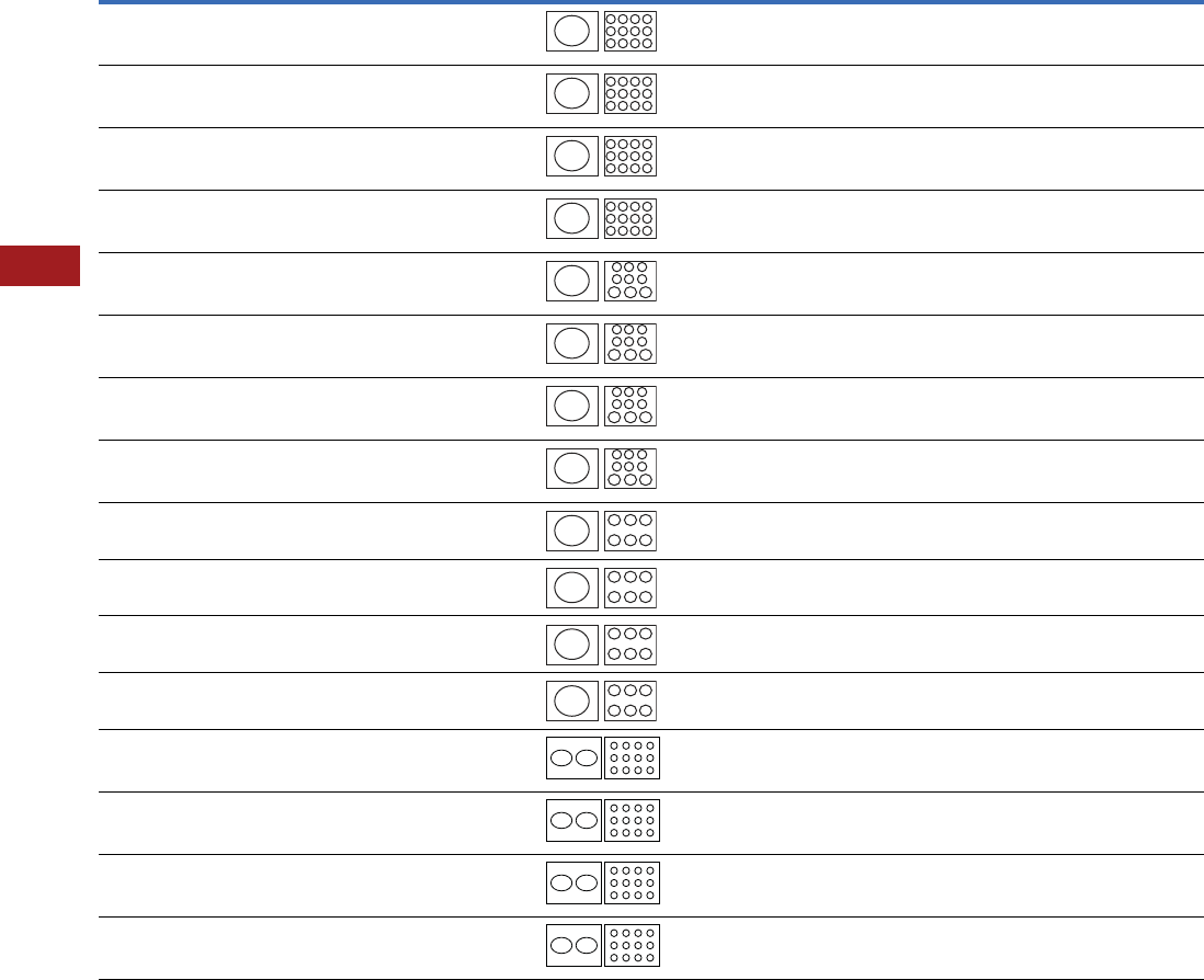
V7-T8-120 Volume 7—Logic Control, Operator Interface and Connectivity Solutions CA08100008E—July 2014 www.eaton.com
8
8
8
8
8
8
8
8
8
8
8
8
8
8
8
8
8
8
8
8
8
8
8
8
8
8
8
8
8
8
8.3
Terminal Blocks, Fuse Blocks and Fuse Holders
Power Distribution
Power Terminal Block Short-Circuit Ratings (SCCR) for UL 508A Applications with Circuit Breakers, continued
Note
1This breaker frame is marked current limiting and suitable for use as current limiting per UL 508A SB.4.3.2.
Catalog
Number Description
Enclosure Size in
Inches (mm)
Current
Rating
Opening per Pole Line
Conductors
Cu
Load
Conductors
Cu
SCCR at 480V
(Load Side)
Eaton
Breaker
Available Breaker
Current RatingsLine Load
CHDB3703 Feeder Listed
Open PDB
24.00 x 20.00 x 6.75
(609.6 x 508.0 x 171.5)
310 350 kmil–#4 #4–#6
#8
#10
25 kA
25 kA
14 kA
JGE250 70, 90, 100, 125, 150,
175, 200, 225, 250
CHDB3703 Feeder Listed
Open PDB
24.00 x 20.00 x 6.75
(609.6 x 508.0 x 171.5)
310 350 kmil–#4 #4–#6
#8
#10
35 kA
35 kA
14 kA
JGS250 70, 90, 100, 125, 150,
175, 200, 225, 250
CHDB3703 Feeder Listed
Open PDB
24.00 x 20.00 x 6.75
(609.6 x 508.0 x 171.5)
310 350 kmil–#4 #4–#6
#8
#10
65 kA
42 kA
14 kA
JGH250 70, 90, 100, 125, 150,
175, 200, 225, 250
CHDB3703 Feeder Listed
Open PDB
24.00 x 20.00 x 6.75
(609.6 x 508.0 x 171.5)
310 350 kmil–#4 #4–#6
#8
#10
65 kA
42 kA
25 kA
JGC250 170, 90, 100, 125, 150,
175, 200, 225, 250
CHDB3713 Feeder Listed
Open PDB
24.00 x 20.00 x 6.75
(609.6 x 508.0 x 171.5)
310 350 kmil–#4 #4–#6
#8
#10
25 kA
25 kA
14 kA
JGE250 70, 90, 100, 125, 150,
175, 200, 225, 250
CHDB3713 Feeder Listed
Open PDB
24.00 x 20.00 x 6.75
(609.6 x 508.0 x 171.5)
310 350 kmil–#4 #4–#6
#8
#10
35 kA
35 kA
14 kA
JGS250 70, 90, 100, 125, 150,
175, 200, 225, 250
CHDB3713 Feeder Listed
Open PDB
24.00 x 20.00 x 6.75
(609.6 x 508.0 x 171.5)
310 350 kmil–#4 #4–#6
#8
#10
50 kA
42 kA
14 kA
JGH250 70, 90, 100, 125, 150,
175, 200, 225, 250
CHDB3713 Feeder Listed
Open PDB
24.00 x 20.00 x 6.75
(609.6 x 508.0 x 171.5)
310 350 kmil–#4 #4–#6
#8
#10
65 kA
50 kA
25 kA
JGC250 170, 90, 100, 125, 150,
175, 200, 225, 250
CHDB330F Feeder Listed
Enclosed PDB
24.00 x 20.00 x 6.75
(609.6 x 508.0 x 171.5)
380 500 kmil–#3 #2–#8 14 kA LGE400 250, 300, 350, 400
CHDB330F Feeder Listed
Enclosed PDB
24.00 x 20.00 x 6.75
(609.6 x 508.0 x 171.5)
380 500 kmil–#3 #2–#8 14 kA LGS400 250, 300, 350, 400
CHDB330F Feeder Listed
Enclosed PDB
24.00 x 20.00 x 6.75
(609.6 x 508.0 x 171.5)
380 500 kmil–#3 #2–#8 14 kA LGH400 250, 300, 350, 400
CHDB330F Feeder Listed
Enclosed PDB
24.00 x 20.00 x 6.75
(609.6 x 508.0 x 171.5)
380 500 kmil–#3 #2–#8 25 kA LGC400 1250, 300, 350, 400
CHDB377F Feeder Listed
Enclosed PDB
24.00 x 20.00 x 6.75
(609.6 x 508.0 x 171.5)
570 (2) 300 kmil–#2 #4
#6
#8
30 kA
18 kA
14 kA
LGE600 250, 300, 350, 400,
500, 600
CHDB377F Feeder Listed
Enclosed PDB
24.00 x 20.00 x 6.75
(609.6 x 508.0 x 171.5)
570 (2) 300 kmil–#2 #4
#6
#8
30 kA
18 kA
14 kA
LGS600 250, 300, 350, 400,
500, 600
CHDB377F Feeder Listed
Enclosed PDB
24.00 x 20.00 x 6.75
(609.6 x 508.0 x 171.5)
570 (2) 300 kmil–#2 #4
#6
#8
30 kA
18 kA
14 kA
LGH600 250, 300, 350, 400,
500, 600
CHDB377F Feeder Listed
Enclosed PDB
24.00 x 20.00 x 6.75
(609.6 x 508.0 x 171.5)
570 (2) 300 kmil–#2 #4
#6
#8
42 kA
35 kA
14 kA
LGC600 1250, 300, 350, 400,
500, 600
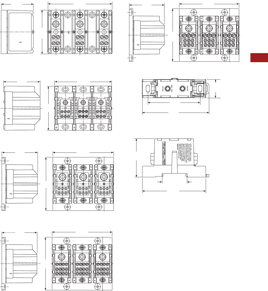
Volume 7—Logic Control, Operator Interface and Connectivity Solutions CA08100008E—July 2014 www.eaton.com V7-T8-121
8
8
8
8
8
8
8
8
8
8
8
8
8
8
8
8
8
8
8
8
8
8
8
8
8
8
8
8
8
8
8.3
Terminal Blocks, Fuse Blocks and Fuse Holders
Power Distribution
Dimensions
Approximate Dimensions in Inches (mm)
CHDB2203
CHDB3213
CHDB3233
CHDB3703
CHDB3713
CHDB204F
2.13
(54.1)
4.25
(108.0)
2.88
(73.2)
2221
1211 12
22
11
21 21
11
22
12
3.32
(84.3)
5.19
(131.8)
4.00
(101.6)
3.70
(94.0)
6.30
(160.0)
5.50
(139.7)
3.70
(94.0)
6.30
(160.0)
5.50
(139.7)
3.70
(94.0)
6.30
(160.0)
5.50
(139.7)
1.03
(26.2)
3.73
(94.7)
2.15
(54.6)
1.40
(35.6)
3.55
(90.2)
Line
Side
Load
Side
2.92
(74.2)
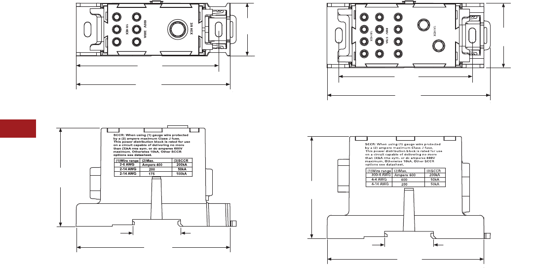
V7-T8-122 Volume 7—Logic Control, Operator Interface and Connectivity Solutions CA08100008E—July 2014 www.eaton.com
8
8
8
8
8
8
8
8
8
8
8
8
8
8
8
8
8
8
8
8
8
8
8
8
8
8
8
8
8
8
8.3
Terminal Blocks, Fuse Blocks and Fuse Holders
Power Distribution
Approximate Dimensions in Inches (mm)
CHDB330F CHDB377F
1.54
(39.1)
Line
Side
Load
Side
4.66
(118.4)
3.82
(97.0)
2.87
(72.9)
1.40 (35.6)
4.49
(114.0)
Line
Side
Load
Side 1.86
(47.2)
4.66
(118.4)
2.93
(74.4)
1.40 (35.6)
4.49
(114.0)
3.82
(97.0)
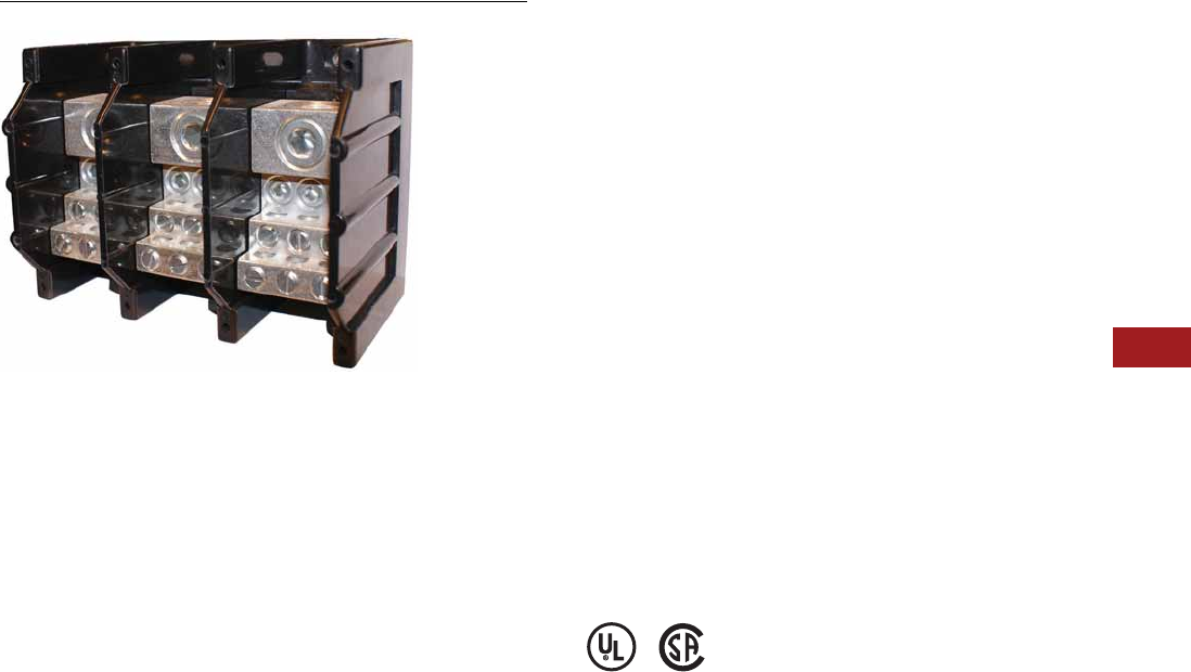
Volume 7—Logic Control, Operator Interface and Connectivity Solutions CA08100008E—July 2014 www.eaton.com V7-T8-123
8
8
8
8
8
8
8
8
8
8
8
8
8
8
8
8
8
8
8
8
8
8
8
8
8
8
8
8
8
8
8.3
Terminal Blocks, Fuse Blocks and Fuse Holders
Power Distribution
CH160 Series—Power Terminal Blocks
Contents
Description Page
CHDB Series—Power Distribution Blocks . . . . . . . V7-T8-117
CH160 Series—Power Terminal Blocks
Product Selection . . . . . . . . . . . . . . . . . . . . . . . V7-T8-124
Technical Data and Specifications . . . . . . . . . . V7-T8-125
Dimensions . . . . . . . . . . . . . . . . . . . . . . . . . . . V7-T8-125
Power Terminal Block Accessories . . . . . . . . . . . . V7-T8-126
CH160 Series—Power Terminal Blocks
Product Description
The CH160 Series of Power
Terminal Blocks are UL 1059
recognized power terminal
blocks for branch circuit
applications. All short circuit
current ratings (SCCR) are
10 kA per UL 508A Table
SB4.1. The blocks are
available in a wide variety
of wiring configurations,
providing excellent flexibility.
Features and Benefits
●Ratings: To 840A, 600V
●Materials
●Molded material; black,
UL rated 94V-0
thermoplastic
●Operating temperature:
302°F (150°C)
●Optional cover:
See Page V7-T8-125
Standards and Certifications
●UL Recognized
●CSA Certified

V7-T8-124 Volume 7—Logic Control, Operator Interface and Connectivity Solutions CA08100008E—July 2014 www.eaton.com
8
8
8
8
8
8
8
8
8
8
8
8
8
8
8
8
8
8
8
8
8
8
8
8
8
8
8
8
8
8
8.3
Terminal Blocks, Fuse Blocks and Fuse Holders
Power Distribution
Product Selection
When Ordering, Specify
●Catalog number
●Number of poles (up to three-pole available)
CH160 Power Terminal Blocks—CH162 Series
CH160 Power Terminal Blocks—CH163 Series
CH160 Power Terminal Blocks—CH165 Series
Note
1Incomplete catalog number—add code suffix -1, -2, -3 for number of poles.
Example: For a 150A 1/0-#14 Cu to 1/0-#14 Cu three-pole PDB, order CH16201-3.
Line Connection Load Connection
Connector Material
and Ampacity
Catalog
Number 1
#2–#14 Cu/#8 Al #2–#14 Cu/#8 Al Al 115A CH16200_
1/0–#14 Cu 1/0–#14 Cu Cu 150A CH16201_
2/0–#8 Cu/Al 2/0–#8 Cu/Al Al 175A CH16204_
2/0–#14 Cu/#8 Al (4) #4–#14 Cu/#8 Al Al 175A CH16220_
Line Connection Load Connection
Connector Material
and Ampacity
Catalog
Number 1
250 kcmil-#6 Cu 250 kcmil-#6 Cu Cu 255A CH16301_
350 kcmil-#6 Cu/Al 350 kcmil-#6 Cu/Al Al 310A CH16303_
500 kcmil-#6 Cu/Al 500 kcmil-#6 Cu/Al Al 380A CH16306_
2/0–#14 Cu/Al (6) #4–#14 Cu/#8 Al Al 175A CH16321_
350 kcmil-#6 Cu/Al (6) #4–#14 Cu/#8 Al Al 310A CH16323_
(2) 2/0–#14 Cu/#8 Al (6) #4–#14 Cu/#8 Al Al 350A CH16325_
500 kcmil-#6 Cu/Al (6) #2–#14 Cu/#8 Al Al 380A CH16330_
350 kcmil-#6 Cu/Al (3) #2–#14 Cu/#8 Al Al 310A CH16332_
(2) 1/0–#14 Cu/#8 Al Al 310A CH16332_
350 kcmil-#6 Cu/Al (12) #4–#14 Cu/#8 Al Al 310A CH16370_
350 kcmil-#6 Cu/Al (6) #2–#14 Cu/#8 Al Al 310A CH16371_
(3) 1/0–#14 Cu/#8 Al Al 310A CH16371_
350 kcmil-#6 Cu/Al (21) #10–#14 Cu/#10 Al Al 310A CH16372_
350 kcmil-#6 Cu/Al (3) 1/0–#14 Cu/#8 Al Al 310A CH16373_
(14) #10–#14 Cu/#8 Al Al 310A CH16373_
600 kcmil-#2 Cu/Al (12) #4–#14 Cu/#8 Al Al 420A CH16375_
600 kcmil-#2 Cu/Al (6) #2–#14 Cu/#8 Al Al 420A CH16376_
(3) 1/0–#14 Cu/#8 Al Al 420A CH16376_
Line Connection Load Connection
Connector Material
and Ampacity
Catalog
Number 1
(2) 350 kcmil-4 Cu/Al (2) 350 kcmil-4 Cu/Al Al 620A CH16500_
(2) 500 kcmil-#6 Cu/Al (2) 500 kcmil-#6 Cu/Al Al 760A CH16504_
(2) 600 kcmil-#2 Cu/Al (4) 3/0–#8 Cu/Al Al 840A CH16528_
(4) #4–#14 Cu/#8 Al Al 840A CH16528_
(2) 500 kcmil-#6 Cu/Al (12) #4–#14 Cu/#8 Al Al 760A CH16530_
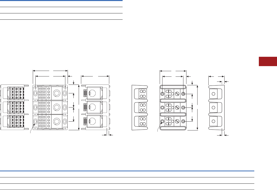
Volume 7—Logic Control, Operator Interface and Connectivity Solutions CA08100008E—July 2014 www.eaton.com V7-T8-125
8
8
8
8
8
8
8
8
8
8
8
8
8
8
8
8
8
8
8
8
8
8
8
8
8
8
8
8
8
8
8.3
Terminal Blocks, Fuse Blocks and Fuse Holders
Power Distribution
Technical Data and Specifications
CH160 Power Terminal Blocks
Note: For optional cover, see Power Terminal Block
Accessories, Page V7-T8-126.
Dimensions
Approximate Dimensions in Inches (mm)
Series CH163
(Single-, Two- and Three-Pole Available)
Series CH162 and CH165
(Single-, Two- and Three-Pole Available)
CH160 Power Terminal Block Dimensions
Description Specification
Ratings To 840A, 600V
Materials Molded material; black, UL rated 94V-0 thermoplastic
Operating temperature 302°F (150°C)
F
B
Mtg. Holes 0.21 x 0.41 (5.3 x 10.4)
C'Bore 0.42 x 0.62 x 0.12 Deep
(10.7 x 15.7 x 3.0 Deep)
D
G
J
A
E
E
C
F
B
0.20 (5.1) Dia. Hole with
0.40 (10.2) C’Bore
DG
J
H
A
E
E
C
Series A B
CCC
DE4F GHJSingle-Pole Two-Pole Three-Pole
CH162 2.87 (72.9) 2.25 (57.2) 1.06 (26.9) 1.87 (47.5) 2.68 (68.1) 1.75 (44.5) 0.81 (20.6) 0.53 (13.5) 0.31 (7.9) 0.84 (21.3) 0.31 (7.9)
CH163 4.00 (101.6) 3.37 (85.6) 1.96 (49.8) 3.58 (90.9) 5.20 (132.1) 3.32 (84.3) 1.62 (41.1) 0.97 (24.6) 0.31 (7.9) 0.87 (22.1) 0.35 (8.9)
CH165 5.50 (139.7) 4.75 (120.7) 3.12 (79.2) 5.81 (147.6) 8.50 (215.9) 3.12 (79.2) 2.68 (68.1) 1.56 (39.6) 0.37 (9.4) 1.37 (34.8) 0.62 (15.7)
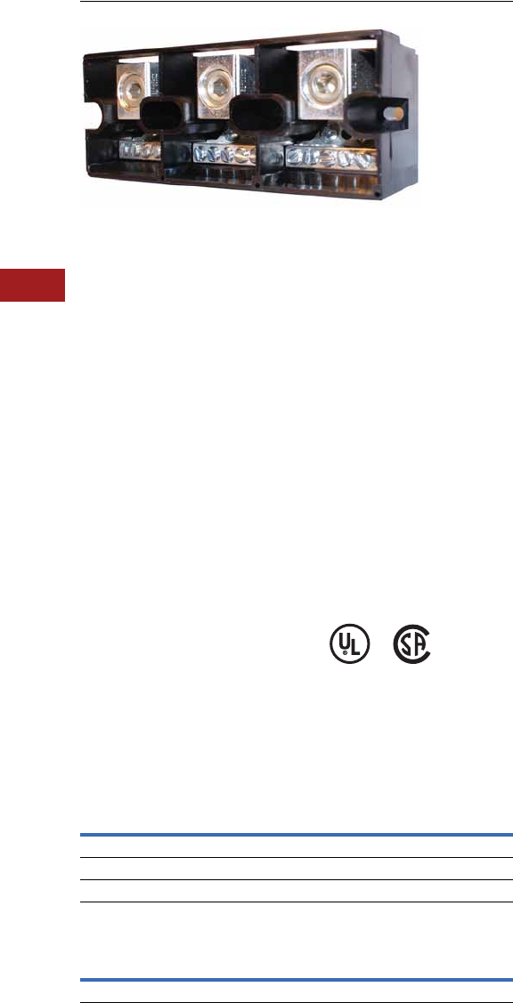
V7-T8-126 Volume 7—Logic Control, Operator Interface and Connectivity Solutions CA08100008E—July 2014 www.eaton.com
8
8
8
8
8
8
8
8
8
8
8
8
8
8
8
8
8
8
8
8
8
8
8
8
8
8
8
8
8
8
8.3
Terminal Blocks, Fuse Blocks and Fuse Holders
Power Distribution
Power Terminal Block Accessories
Contents
Description Page
CHDB Series—Power Distribution Blocks . . . . . . . V7-T8-117
CH160 Series—Power Terminal Blocks . . . . . . . . . V7-T8-123
Power Terminal Block Accessories
Technical Data and Specifications . . . . . . . . . . V7-T8-127
Dimensions . . . . . . . . . . . . . . . . . . . . . . . . . . . V7-T8-127
Power Terminal Block Accessories
Product Description
Protective Cover
●Guards against accidental
contact
●Clear with write-on surface
for field termination
identification
●Available in single-, two-
and three-pole
Standards and Certifications
TB Series Power Blocks
●Contact Eaton for the
latest UL 508A short circuit
ratings on terminal blocks
●UL Recognized:
File No. E62622
●CSA Certified:
File No. LR15364
Product Selection
When Ordering, Specify
●Catalog number
CH163 Series Cover
TB Series Power Blocks
Note
1Standard pack, five pieces.
Description
Catalog
Number
Single-pole cover CHCPDB-1 1
Two-pole cover CHCPDB-2 1
Three-pole cover CHCPDB-3 1
Line
Connection
Load
Connection
Catalog
Number
#300 kcmil-#6 Cu/Al (6) #6–#14 Cu/#8Al TBAN63
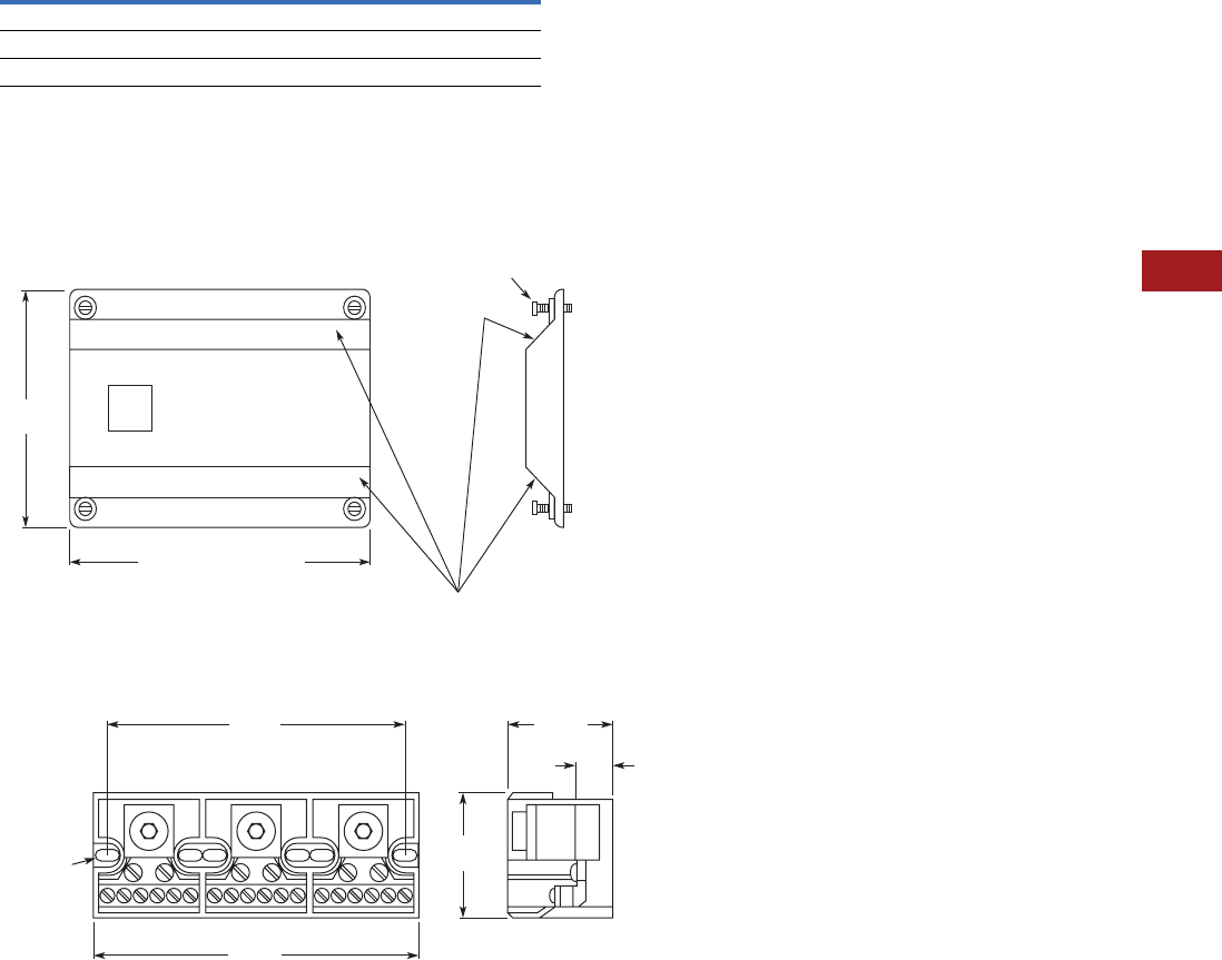
Volume 7—Logic Control, Operator Interface and Connectivity Solutions CA08100008E—July 2014 www.eaton.com V7-T8-127
8
8
8
8
8
8
8
8
8
8
8
8
8
8
8
8
8
8
8
8
8
8
8
8
8
8
8
8
8
8
8.3
Terminal Blocks, Fuse Blocks and Fuse Holders
Power Distribution
Technical Data and Specifications
TB Series Power Blocks
Dimensions
Approximate Dimensions in Inches (mm)
CH163 Series Cover
TB Series Power Blocks
Description Specification
Ratings 285A, 600V; UL/CSA
Materials Molded material; black, UL rated 94V-2 thermoplastic
Operating temperature 257°F (125°C)
CHCPDB-1 = 2.1 (53.3)
CHCPDB-2 = 3.72 (94.5)
CHCPDB-3 = 5.34 (135.6)
Textured
Surfaces
Supplied with
(4) #4 Thread-Cutting Screws
Assembled as Shown
4.14
(105.2)
5.37
(136.4)
0.2 x 0.37
(5.1 x 9.4)
Mtg. Slot
4.93
(125.2) 1.68
(42.7)
2.12
(53.8)
0.5
(12.7)
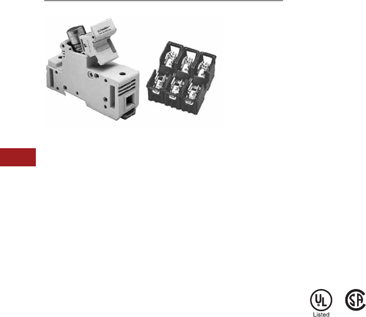
V7-T8-128 Volume 7—Logic Control, Operator Interface and Connectivity Solutions CA08100008E—July 2014 www.eaton.com
8
8
8
8
8
8
8
8
8
8
8
8
8
8
8
8
8
8
8
8
8
8
8
8
8
8
8
8
8
8
8.4
Terminal Blocks, Fuse Blocks and Fuse Holders
Fuse Blocks and Fuse Holders
Fuse Blocks and Fuse Holders
Contents
Description Page
Fuse Blocks and Fuse Holders
C383 Series Disconnect Fuse Holders . . . . . . . V7-T8-129
C350 Series Fuse Blocks and
W Series Fuse Holders. . . . . . . . . . . . . . . . . . V7-T8-131
Fuse Blocks and Fuse Holders Overview
Product Description
Available in compact finger
safe (C383) and an open
(C350) design. Eaton’s fuse
blocks and holders provide a
simple DIN mounting device
for protection in control
circuits.
Application Description
Fuse holders and blocks
available for Class CC,
midget, H, M and R.
Standards and Certifications
●UL listed
●CSA certified
(may not apply to all styles)
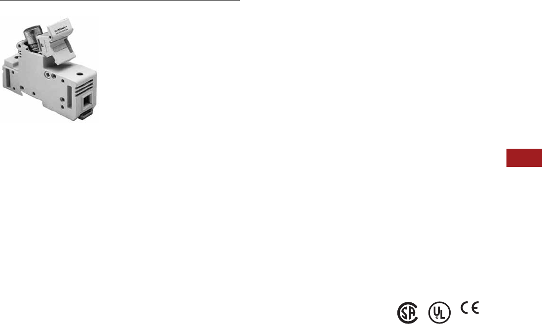
Volume 7—Logic Control, Operator Interface and Connectivity Solutions CA08100008E—July 2014 www.eaton.com V7-T8-129
8
8
8
8
8
8
8
8
8
8
8
8
8
8
8
8
8
8
8
8
8
8
8
8
8
8
8
8
8
8
8.4
Terminal Blocks, Fuse Blocks and Fuse Holders
Fuse Blocks and Fuse Holders
C383 Series Fuse Holders
Contents
Description Page
C383 Series Disconnect Fuse Holders
Product Selection . . . . . . . . . . . . . . . . . . . . . . . V7-T8-130
Accessories . . . . . . . . . . . . . . . . . . . . . . . . . . . V7-T8-130
Technical Data and Specifications . . . . . . . . . . V7-T8-130
Dimensions . . . . . . . . . . . . . . . . . . . . . . . . . . . V7-T8-130
C350 Series Fuse Blocks and
W Series Fuse Holders . . . . . . . . . . . . . . . . . . . . V7-T8-131
C383 Series Disconnect Fuse Holders
Product Description
Eaton’s C383 Series
disconnect fuse holders
offer 600V fused circuit
protection and subsequently
“no load” switching.
These compact disconnects
are designed as components
in switchboards, panels and
control consoles where
positive and safe circuit
protection is required and
where space is at a premium.
The C383 fuse holders
mount directly on standard
TS35 DIN rails.
Features
●“Finger-Safe” design—
Recessed termination
screws and a fuse
extraction door afford you
IP20 grade protection and
qualify as “finger-safe” per
IEC standards
●Easy to adjust position on
rail—Simply unlatch the
DIN rail adapter, slide the
holder to desired position
and relock
●Quick change of fuse—
A permanently attached
pivoting fuse door
simplifies and speeds fuse
extraction. No tools or
accessories needed
●Class CC model is UL
listed and CSA certified for
branch circuit protection.
Midget models are UL
Recognized and CSA
certified for supplementary
and high-speed protection
●Runs cool—The vented
design provides adequate
air flow around the holders
at all times
●Self-extinguishing
UL 94-VO rated polyester
material
Standards and Certifications
Rated voltage:
●CSA/UL: 600 Vac/Vdc, 30A
●IEC (midget only):
690 Vac, 32A
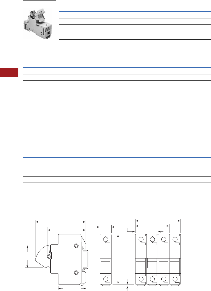
V7-T8-130 Volume 7—Logic Control, Operator Interface and Connectivity Solutions CA08100008E—July 2014 www.eaton.com
8
8
8
8
8
8
8
8
8
8
8
8
8
8
8
8
8
8
8
8
8
8
8
8
8
8
8
8
8
8
8.4
Terminal Blocks, Fuse Blocks and Fuse Holders
Fuse Blocks and Fuse Holders
Product Selection
Disconnect Fuse Holders
Accessories
Disconnect Fuse Holders
Accessory Details
C383MPCL
Multi-pole connection links
can be used to connect fuse
holders together for multi-
pole applications. Use two
per connection.
C383MPHP
Handle pins can be used to
connect handles in multi-pole
applications.
Technical Data and Specifications
Disconnect Fuse Holders 1
Dimensions
Approximate Dimensions in Inches (mm)
CH163 Series Cover
Notes
1For additional technical information, consult the Eaton web site or Customer Support Center.
2UL recognizes both solid and stranded wire. Ferrules are not required. CSA requires ferrules on stranded wire to achieve approval.
Description Standard Pack Catalog Number
For Class CC Fuse
Single-pole fuse holder 12 C383FHCC
For Midget Fuse (1-1/2 in x 13/32 in)
Single-pole fuse holder 12 C383FHMD
Description Standard Pack Catalog Number
Midget or Class CC Fuse Holder
Multi-pole connection links 100 C383MPCL
Multi-pole handle pins 100 C383MPHP
C383FH_
Description Specification
Housing Polyester UL 94-VO rated
Color White
Wire size 8–18 AWG 2
Torque 22 lb-in (2.5 Nm)
Fuse size 0.41 x 1.5 in
3.07
(78.0)
0.13
(3.2)
1.77
(45.0)
1.40
(35.6)
0.70 (17.8)
2.10 (53.4)
2.40 (61.0)
1.69 (43.0)
2.80 (71.2)
3.13 (79.5)
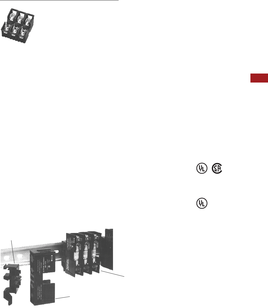
Volume 7—Logic Control, Operator Interface and Connectivity Solutions CA08100008E—July 2014 www.eaton.com V7-T8-131
8
8
8
8
8
8
8
8
8
8
8
8
8
8
8
8
8
8
8
8
8
8
8
8
8
8
8
8
8
8
8.4
Terminal Blocks, Fuse Blocks and Fuse Holders
Fuse Blocks and Fuse Holders
C350 Series Fuse Blocks and W Series Fuse Holders
Contents
Description Page
C383 Series Disconnect Fuse Holders . . . . . . . . . V7-T8-129
C350 Series Fuse Blocks and W Series Fuse
Holders
Product Selection . . . . . . . . . . . . . . . . . . . . . . . V7-T8-132
Accessories . . . . . . . . . . . . . . . . . . . . . . . . . . . V7-T8-133
Technical Data and Specifications . . . . . . . . . . V7-T8-133
Dimensions . . . . . . . . . . . . . . . . . . . . . . . . . . . V7-T8-133
C350 Series Fuse Blocks and W Series Fuse Holders
Product Description
Fuse Blocks
These space-saving Type
C350 Fuse Blocks are UL
approved for motor loads and
are rated 600V, 30A.
Fuse Holders
●Class H, M and R
Features
Fuse Blocks
●Mount to 35 mm flat
and 32 mm asymmetrical
DIN rails
●600V, 30A rated captive
pressure plate terminals
with copper alloy fuse clips
●Interlocking fuse blocks
permit single, double or
three-pole application—
reduce inventory
●Class CC fuses have an
interrupting rating of
200,000A
●Rejection feature prevents
insertion of fuses with
lower interrupting or
voltage ratings
Fuse Holders
●Break-resistant: molded of
heat-stabilized nylon
●Fuse clips: spring-
reinforced for cool
operation
●Fuse clip terminations:
one-piece construction
●Universal mounting
dimensions, for easy
assembly and retrofit
●Breathing action collar:
maintenance-free
●Pressure wire connectors:
vibration resistant
Standards and Certifications
Contact Eaton for the latest
UL 508A short circuit ratings
on terminal blocks.
Fuse Blocks
●UL listed
●CSA certified
Fuse Holders
●UL tested for OEM
subfeed applications
Fuse Blocks and Adapters
Cat. No. C350BD3C61
Three-Pole with Adapter
(Mounted on DIN Rail)
Cat. No. C350B1C61
One-Pole Fuse Blocks
Cat. No. C350KD DIN Rail Adapter
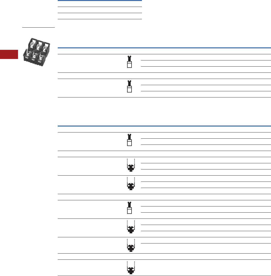
V7-T8-132 Volume 7—Logic Control, Operator Interface and Connectivity Solutions CA08100008E—July 2014 www.eaton.com
8
8
8
8
8
8
8
8
8
8
8
8
8
8
8
8
8
8
8
8
8
8
8
8
8
8
8
8
8
8
8.4
Terminal Blocks, Fuse Blocks and Fuse Holders
Fuse Blocks and Fuse Holders
Product Selection
Class CC Fuse Blocks
Fuse Holders—250V
Fuse Holders—600V
Note
1 Three-pole device is supplied with DIN rail adapter.
Type
Catalog
Number
Three-pole 1C350BD3C61
Single-pole C350B1C61
DIN adapter C350KD
Wire Termination
Number
of Poles
Carton
Qty.
30A
Carton
Qty.
60A
Catalog
Number
Catalog
Number
Class H Fuse Holders
Single collar (box lug)—
sized to ampere rating
110W231HA 10 W261HA
25W232HA 5W262HA
35W233HA 5W263HA
Class R Fuse Holders
Single collar (box lug)—
sized to ampere rating
110WR231HA ——
2————
35WR233HA 1WR263HA
Wire Termination
Number
of Poles
Carton
Qty.
30A
Carton
Qty.
60A
Catalog
Number
Catalog
Number
Class H Fuse Holders
Single collar (box lug)—
sized to ampere rating
110W631HA 1W661HA
25W632HA 1W662HA
31W633HA 2W663HA
Class M Fuse Holders
Combination of double quick-connect,
20A max., and binding head screw,
#10 max., Cu/Al
110WM631F ——
28WM632F ——
36WM633F ——
Combination of double quick-connect,
20A max., and pressure plate screw,
#10 max., Cu only
110WM631G ——
28WM632G ——
36WM633G ——
Class R Fuse Holders
Single collar (box lug)—
sized to ampere rating
110WR631HA ——
25WR632HA ——
35WR633HA 5WR663HA
Combination of double quick-connect,
20A max., and binding head screw,
#10 max., Cu/Al
1————
21WMR632F ——
36WMR633F ——
Combination of double quick-connect,
20A max., and pressure plate screw,
#10 max., Cu only
110WMR631G ——
36WMR633G ——
Class R Fuse Holder, Type WRR Control Transformer Fuse Blocks
Combination of double quick-connect,
20A max., and pressure plate screw,
#14–#10 Cu only
36WRR633G ——
Class R, Three-Pole
Fuse Holder
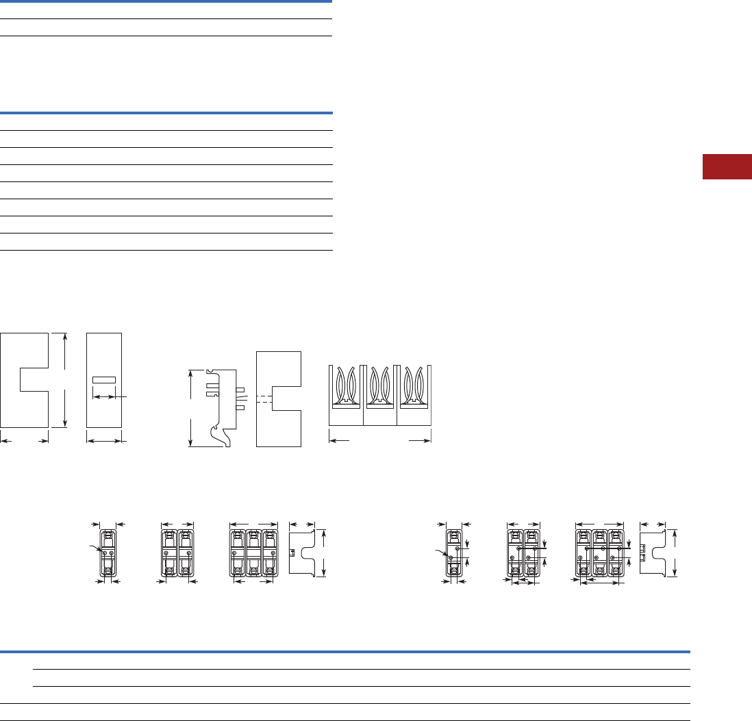
Volume 7—Logic Control, Operator Interface and Connectivity Solutions CA08100008E—July 2014 www.eaton.com V7-T8-133
8
8
8
8
8
8
8
8
8
8
8
8
8
8
8
8
8
8
8
8
8
8
8
8
8
8
8
8
8
8
8.4
Terminal Blocks, Fuse Blocks and Fuse Holders
Fuse Blocks and Fuse Holders
Accessories
Fuse Holder Accessories
Technical Data and Specifications
Fuse Blocks
Dimensions
Approximate Dimensions in Inches (mm)
Fuse Blocks
Fuse Holders
Description Catalog Number
Fuse puller TBP
Lighted fuse puller (120 Vac) TBLP
Description Specification
Voltage rating 600V
Ampere rating Pressure plate terminals rated for 30A
Dielectric strength 1200V maximum
Ambient temperature 221°F (105°C) maximum
Clip/terminals Tin-plated copper alloy
Screw and captive pressure plate Zinc-plated steel
Base Thermoplastic UL 94VO flammability rating
DIN rail adapter Thermoplastic UL 94VO flammability rating
Class
Volts/
Amperes
Width A
Height
B
Depth
C
Mounting Holes Number of Mounting Holes
Single-
Pole
Two-
Pole
Three-
Pole D
Two-Pole
D1
Three-Pole
D1 E
Diameter
F
Single-
Pole
Two-
Pole
Three-
Pole
H, R 250V, 30A 1.00 (25.4) 2.00 (50.8) 3.00 (76.2) 3.13 (79.5) 1.56 (39.6) 0.38 (9.7) 1.25 (31.8) 2.50 (63.5) — 0.22 (5.6) 2 2 2
250V, 60A 1.44 (36.6) 2.88 (73.2) 4.31 (109.5) 4.75 (120.7) 2.06 (52.3) 0.50 (12.7) 1.81 (46.0) 3.13 (79.5) 1.25 (31.8) 0.22 (5.6) 2 4 4
600V, 30/60A 1.69 (42.9) 3.38 (85.9) 5.06 (128.5) 6.94 (176.3) 2.63 (66.8) 0.63 (16.0) 2.19 (55.6) 3.75 (95.3) 3.13 (79.5) 0.28 (7.1) 2 4 4
M, R 600V, 30A 0.84 (21.3) 1.63 (41.4) 2.41 (61.2) 3.00 (76.2) 1.28 (32.5) 0.38 (9.7) 0.75 (19.1) 1.50 (38.1) — 0.17 (4.3) 2 2 2
2.24
(56.9)
3.00
(76.2)
2.35 (59.7)
Three-Pole Width
Three-Pole WidthCatalog No. C350 Fuse Block Catalog No. C350 Fuse Block
with DIN Rail Adapter
1.25
(31.8) 0.78
(19.8)
0.60
(15.2)
CA
Single-
Pole AA
F
Dia. B
DD1D1
Two-
Pole Three-
Pole
Class H & R
250V, 30A
Class M & R
600V, 30A
CA
E
Single-
Pole AA
F
Dia. B
DD1
D
Two-
Pole Three-
Pole
D1
D
E E
Class H & R
250V, 60A
600V, 30/60A
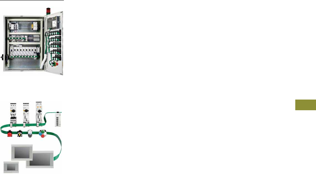
Volume 7—Logic Control, Operator Interface and Connectivity Solutions CA08100008E—February 2014 www.eaton.com V7-T9-1
9
9
9
9
9
9
9
9
9
9
9
9
9
9
9
9
9
9
9
9
9
9
9
9
9
9
9
9
9
9
Connectivity Solutions
SmartWire-DT
XV Series HMI-PLC
with SmartWire-DT
9.1 SmartWire-DT Panel Wiring Solution
System Overview
Product Description . . . . . . . . . . . . . . . . . . . . . . . . . . . . . . . . . . . . V7-T9-2
Features . . . . . . . . . . . . . . . . . . . . . . . . . . . . . . . . . . . . . . . . . . . . . V7-T9-2
System Overview Diagram . . . . . . . . . . . . . . . . . . . . . . . . . . . . . . . V7-T9-3
System Components
Product Description . . . . . . . . . . . . . . . . . . . . . . . . . . . . . . . . . . . . V7-T9-6
Product Selection . . . . . . . . . . . . . . . . . . . . . . . . . . . . . . . . . . . . . . V7-T9-7
Accessories . . . . . . . . . . . . . . . . . . . . . . . . . . . . . . . . . . . . . . . . . . . V7-T9-8
System Controllers
Product Description . . . . . . . . . . . . . . . . . . . . . . . . . . . . . . . . . . . . V7-T9-11
Features . . . . . . . . . . . . . . . . . . . . . . . . . . . . . . . . . . . . . . . . . . . . . V7-T9-11
Standards and Certifications . . . . . . . . . . . . . . . . . . . . . . . . . . . . . . V7-T9-11
Contactor Modules
Product Description . . . . . . . . . . . . . . . . . . . . . . . . . . . . . . . . . . . . V7-T9-12
Features . . . . . . . . . . . . . . . . . . . . . . . . . . . . . . . . . . . . . . . . . . . . . V7-T9-12
Product Identification . . . . . . . . . . . . . . . . . . . . . . . . . . . . . . . . . . . V7-T9-13
Product Selection . . . . . . . . . . . . . . . . . . . . . . . . . . . . . . . . . . . . . . V7-T9-14
Pilot Device Modules
Product Description . . . . . . . . . . . . . . . . . . . . . . . . . . . . . . . . . . . . V7-T9-15
Features . . . . . . . . . . . . . . . . . . . . . . . . . . . . . . . . . . . . . . . . . . . . . V7-T9-15
Product Identification . . . . . . . . . . . . . . . . . . . . . . . . . . . . . . . . . . . V7-T9-16
Product Selection . . . . . . . . . . . . . . . . . . . . . . . . . . . . . . . . . . . . . . V7-T9-18
Technical Data and Specifications . . . . . . . . . . . . . . . . . . . . . . . . . . . . V7-T9-20
Dimensions . . . . . . . . . . . . . . . . . . . . . . . . . . . . . . . . . . . . . . . . . . . . . V7-T9-34
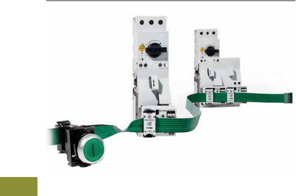
V7-T9-2 Volume 7—Logic Control, Operator Interface and Connectivity Solutions CA08100008E—February 2014 www.eaton.com
9
9
9
9
9
9
9
9
9
9
9
9
9
9
9
9
9
9
9
9
9
9
9
9
9
9
9
9
9
9
9.1
Connectivity Solutions
SmartWire-DT Panel Wiring Solution
SmartWire-DT Panel Wiring Solution
Contents
Description Page
SmartWire-DT Panel Wiring Solution
System Components . . . . . . . . . . . . . . . . . . . . V7-T9-6
System Controllers . . . . . . . . . . . . . . . . . . . . . V7-T9-11
Contactor Modules . . . . . . . . . . . . . . . . . . . . . V7-T9-12
Pilot Device Modules . . . . . . . . . . . . . . . . . . . . V7-T9-15
Technical Data and Specifications . . . . . . . . . . V7-T9-20
Dimensions . . . . . . . . . . . . . . . . . . . . . . . . . . . V7-T9-34
System Overview
Product Description
The SmartWire-DT system
uses a continuous green
flat cable located in the
control cabinet to connect
motor starters, pushbutton
actuators, and indicator lights.
It eliminates the need for
most of the conventional
point-to-point control wiring—
and even integrates 24 Vdc
control power for contactor
coils on the eight conductor
flat cable. The start of the
SmartWire-DT system is a
gateway—it establishes the
connection to standard
programmable logic controller
(PLC) fieldbuses, such as
EtherNet/IP, Modbus TCP,
PROFIBUS-DP and CANopen.
Because SmartWire-DT directly
integrates the input/output
(I/O) level in the switching
devices, no conventional PLC
I/O modules are needed—
instead communication
enabled modules are attached
to standard Eaton motor
control components. Thus,
the PLC in the control cabinet
simply consists of a central
processing unit (CPU) module.
Typical faults such as loose
connections and miswired
terminations are eliminated
using the flat cable and the
specialized connectors.
Furthermore, each
SmartWire-DT enabled device
has individual
diagnostic LEDs
built in, which r
educe
commissioning time and
troubleshooting in the field.
Nodes on the SmartWire-DT
network are automatically
assigned addresses on the
gateway with the push of a
button—assigning addresses
in the order that the nodes
are connected. The system
employs time monitoring
and a watchdog timeout
using the established
target configuration as a
reference—safely monitoring
the integrity of the control
scheme. SmartWire-DT has
a maximum network length
of 2000 ft, can be extended
to pushbutton control stations
outside of the control cabinet,
and can connect up to
99 nodes per gateway. A
software program called
SWD-Assist enables the
layout, planning, and
system configuration of a
SmartWire-DT network.
Features
●Connects directly to
standard XTCE contactors,
XTRE control relays, and
M22 pilot devices
●Supports EtherNet/IP,
Modbus TCP,
PROFIBUS-DP and
CANopen fieldbuses
●Supports up to 99 nodes
on Ethernet and CANopen,
and 58 nodes on
PROFIBUS-DP
●Automatically assigns
addresses to SmartWire-DT
nodes
●Integrates and supplies
24 Vdc power to contactor
and relay coils over the
network
●Includes diagnostic bi-color
LEDs on each node
connection
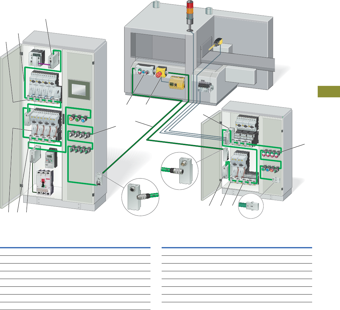
Volume 7—Logic Control, Operator Interface and Connectivity Solutions CA08100008E—February 2014 www.eaton.com V7-T9-3
9
9
9
9
9
9
9
9
9
9
9
9
9
9
9
9
9
9
9
9
9
9
9
9
9
9
9
9
9
9
9.1
Connectivity Solutions
SmartWire-DT Panel Wiring Solution
System Overview Diagram
SmartWire-DT Connection System
Item
Number Description
Item
Number Description
1Gateway to PLC fieldbus network 9Round cable
2Flat cable 10 Pilot device control station
3Modules for XT contactors with XTPR manual motor protectors 11 Emergency stop control station
4Powerfeed module 1 (optional 24 Vdc power feeder) 12 Cabinet cable adapter plug
5Modules for XT contactors with XTPE electronic manual motor protectors 13 Powerfeed module 2 (optional 15 Vdc and 24 Vdc power feeder)
6Digital I/O module 14 Digital I/O module (for connection of sensors and actuators)
7Modules for M22 pilot devices 15 Terminating resistor
8Cabinet cable adapter socket
7
10 11
9
8
45 6
3
2
1
14
12
13 5 3
15
7
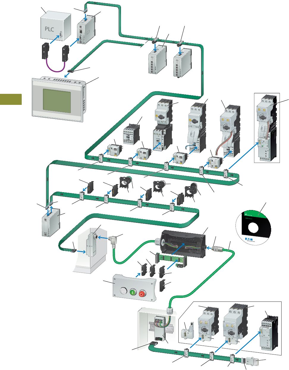
V7-T9-4 Volume 7—Logic Control, Operator Interface and Connectivity Solutions CA08100008E—February 2014 www.eaton.com
9
9
9
9
9
9
9
9
9
9
9
9
9
9
9
9
9
9
9
9
9
9
9
9
9
9
9
9
9
9
9.1
Connectivity Solutions
SmartWire-DT Panel Wiring Solution
System Components Overview
Future Product
Future Products
13
12
10
10
5
6
5
2
4
1
4
3
5555
555
15 16
17
19
18
8
9
911
7
5
5
17
17
18
19
19 32
44
14
4
20
21
22
21
31
22 25
24
23
24 24
26
4
4
555
29
27
27 27
30
28
28

Volume 7—Logic Control, Operator Interface and Connectivity Solutions CA08100008E—February 2014 www.eaton.com V7-T9-5
9
9
9
9
9
9
9
9
9
9
9
9
9
9
9
9
9
9
9
9
9
9
9
9
9
9
9
9
9
9
9.1
Connectivity Solutions
SmartWire-DT Panel Wiring Solution
Item
Number Description
Item
Number Description
1Programmable logic controller (PLC) 17 M22 mounting adapter
2Gateway 18 SmartWire-DT M22 modules
3XV HMI-PLC 19 M22 pilot devices
4Flat plugs 20 Cabinet cable adapter
5Device plug 21 Plug connector
6I/O modules 22 M22 surface mounting enclosure
7Contactor module 23 PCB module for M22 pushbutton stations
8XT Contactors 24 M22 modules, base mount
9Contactor module with HOA switch 25 Universal module, base mount
10 XTPR manual motor controller 26 Adapter for flat/round cable for DIN rail mounting
11 PKE contactor module 27 XTPE module (manual motor protection)
12 XTPE manual motor controller 28 XTPE manual motor protector
13 Soft starter DS7 with electronic motor protection from XTPE 29 Terminating resistor
14 Powerfeed module 30 DS7 soft starters
15 Universal module, front mount 31 Round cable, 8-pole
16 M22 LED elements, front mount 32 SmartWire-DT configuration software, SWD-Assist
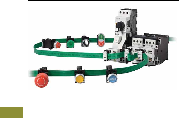
V7-T9-6 Volume 7—Logic Control, Operator Interface and Connectivity Solutions CA08100008E—February 2014 www.eaton.com
9
9
9
9
9
9
9
9
9
9
9
9
9
9
9
9
9
9
9
9
9
9
9
9
9
9
9
9
9
9
9.1
Connectivity Solutions
SmartWire-DT Panel Wiring Solution
System Components
Contents
Description Page
System Components
Product Selection . . . . . . . . . . . . . . . . . . . . . . . V7-T9-7
Accessories . . . . . . . . . . . . . . . . . . . . . . . . . . . V7-T9-8
System Controllers . . . . . . . . . . . . . . . . . . . . . . . . V7-T9-11
Contactor Modules . . . . . . . . . . . . . . . . . . . . . . . . V7-T9-12
Pilot Device Modules . . . . . . . . . . . . . . . . . . . . . . V7-T9-15
Technical Data and Specifications . . . . . . . . . . . . . V7-T9-20
Dimensions . . . . . . . . . . . . . . . . . . . . . . . . . . . . . . V7-T9-34
System Components
Product Description
The start of the SmartWire-DT
system is a gateway module.
The gateway connects as a
node to a programmable
logic controller (PLC) fieldbus.
The PLC used must have a
fieldbus polling master
module or input/output (I/O)
scanner card so that the
gateway can connect as a node
on the fieldbus network.
SmartWire-DT can connect to
EtherNet/IP, Modbus TCP,
PROFIBUS-DP and CANopen
fieldbuses.
To plan and lay
out a SmartWire-DT
network, a MS Windows
compatible software
program called SWD-Assist
is available as a free
download from the Eaton
website. The
SWD-Assist
configuration software will
calculate the control power
requirements needed and
generate a bill of materials of
all the required components.
Gateway Modules
Gateway modules connect
the SmartWire-DT system to
the PLC. They are connected
as nodes to the existing PLC
fieldbus and are the start of
the SmartWire-DT connection
system. Gateways are
available with Ethernet,
PROFIBUS-DP and CANopen
protocols.
Powerfeed Modules
Powerfeed modules feed
auxiliary 24 Vdc power and/or
15 Vdc network power into
the SmartWire-DT flat cable.
The auxiliary 24 Vdc power is
needed for the power supply
of contactors and the 15 Vdc
network power is used for
supplying power to additional
SmartWire-DT nodes.
Powerfeed modules are also
used to create zone control or
groups of devices controlled
by a single Emergency Stop.
Digital and Analog I/O Modules
Digital and analog I/O modules
are connected as nodes on
the SmartWire-DT network
and allow standard or generic
devices to be connected to
the SmartWire-DT system.
They can be connected
anywhere along the flat cable
network and can therefore be
positioned in the control
panel to help reduce the
I/O wiring.
Contactor Modules
Contactor modules fit into
standard XT contactors and
control relays directly on top,
in place of a top mounted
auxiliary contact block. The
modules fit all XTCE size B
and C frame contactors and
XTRE control relays.
Pilot Device Modules
Pilot device modules fit into
standard M22 pilot devices in
both front mount and base
mount configurations. Single
and double contact modules
with and without LEDs are
available to meet a wide
variety of control circuit
requirements.
Flat and Round Cables
The flat cable is an 8 AWG 24
conductor cable that is flexible,
durable, and rated for 600V so
that it can be placed in the
panel wiring duct along with
480V or 600V power
conductors. It has two
prominent features: (a) arrows
indicating the front of the cable
and the direction away from
the gateway and (b) black
edging indicating the polarity
of the flat cable, the 15 Vdc
wire and the reference mark
for installing the device plugs
and flat plugs.
The round cable has 4 AWG
20 and 4 AWG 24 wires and
is 300V rated. It is used
outside the control panel to
connect peripherals such as
pushbutton control stations
to the SmartWire-DT
network. Cable adapters are
available to transition a flat
cable to a round cable
connection and IP67 type
connectors are available to
provide quick-disconnect
cable connections on the
round cable.
Other System Accessories
Other accessories for the
SmartWire-DT system
include connectors, jumpers,
bushings, plugs, and sockets,
flat to round cable adapters
and crimping tools.
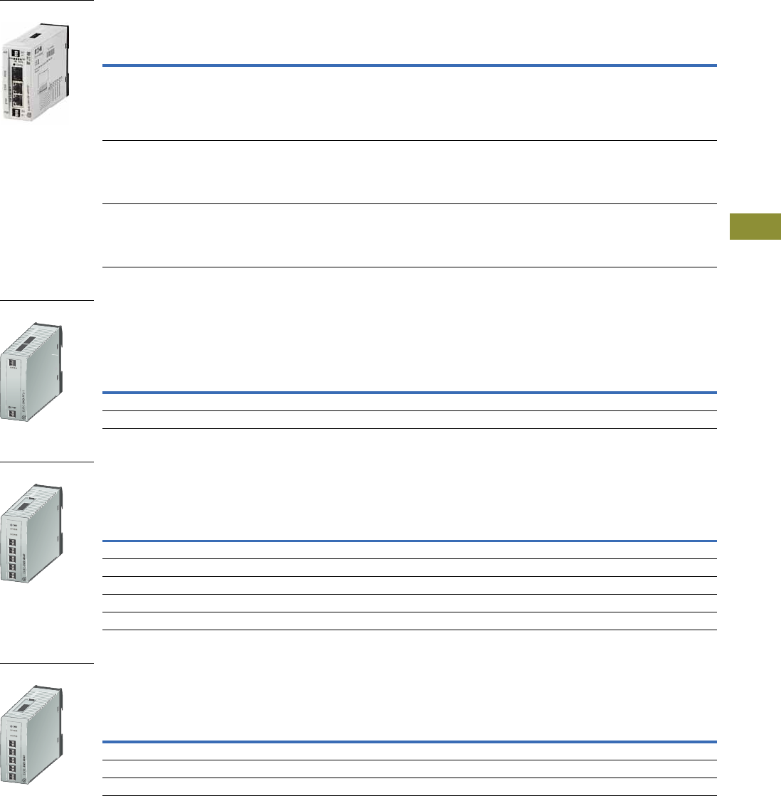
Volume 7—Logic Control, Operator Interface and Connectivity Solutions CA08100008E—February 2014 www.eaton.com V7-T9-7
9
9
9
9
9
9
9
9
9
9
9
9
9
9
9
9
9
9
9
9
9
9
9
9
9
9
9
9
9
9
9.1
Connectivity Solutions
SmartWire-DT Panel Wiring Solution
Product Selection
Gateway Modules
Gateway modules connect the SmartWire-DT system to the programmable logic controller (PLC). They are
connected as nodes to the existing PLC fieldbus and are the start of the SmartWire-DT connection system.
Powerfeed Modules
Powerfeed modules feed auxiliary 24 Vdc power and/or 15 Vdc network power into the SmartWire-DT flat cable.
The auxiliary 24 Vdc power is needed for the power supply of contactors and the 15 Vdc network power is used for
supplying power to additional SmartWire-DT nodes. Powerfeed modules are also used to create zone control or
groups of devices controlled by a single Emergency Stop.
Digital I/O Modules
Digital input/output (I/O) modules are connected as nodes on the SmartWire-DT network and allow standard or
generic devices to be connected to the SmartWire-DT system. They can be connected anywhere along the flat
cable network and can therefore be positioned in the control panel to help reduce the I/O wiring.
Analog I/O Modules
Analog input/output (I/O) modules are connected as nodes on the SmartWire-DT network and allow standard or
generic devices to be connected to the SmartWire-DT system. They can be connected anywhere along the flat
cable network and can therefore be positioned in the control panel to help reduce the I/O wiring.
Description Pkg. Qty. Catalog Number
Ethernet Gateway
Connection to EtherNet/IP or Modbus TCP
Automatic baud rate detection 10/100 Mbps
Address set with DIP switch or DHCP
Two RJ45 sockets
Connection of up to 99 SmartWire-DT nodes
1 EU5C-SWD-EIP-MODTCP
PROFIBUS-DP Gateway
Automatic baud rate detection from 9.6 Kbps to 12 Mbps
Address range 1–126
9-pole SUB-D socket
Connection of up to 58 SmartWire-DT modes
1 EU5C-SWD-DP
CANopen Gateway
Automatic baud rate detection from 10 Kbps to 1 Mbps
Address range 1–32
9-pole SUB-D socket
Connection of up to 99 SmartWire-DT modes
1 EU5C-SWD-CAN
Description Pkg. Qty. Catalog Number
Powerfeed module 1 (for 24 Vdc auxiliary power) 1 EU5C-SWD-PF1-1
Powerfeed module 2 (for 24 Vdc auxiliary power and 15 Vdc network power) 1 EU5C-SWD-PF2-1
Description Pkg. Qty. Catalog Number
Digital module with 8 digital inputs 24 Vdc 1 EU5E-SWD-8DX
Digital module with 4 digital inputs 24 Vdc three-wire connections 1 EU5E-SWD-4DX
Digital module with 8 digital outputs 24 Vdc 10.5A 1 EU5E-SWD-X8D
Digital module with 4 digital inputs 24 Vdc and 4 transistor outputs 24 Vdc/0.5A 1 EU5E-SWD-4D4D
Digital module with 4 digital inputs 24 Vdc and 2 relay outputs 250 Vac 1 EU5E-SWD-4D2R
Description Pkg. Qty. Catalog Number
Analog module with 4 analog inputs 0–10V or 0–20 mA 1 EU5E-SWD-4AX
Analog module with 2 analog inputs 0–10V or 0–20 mA and 2 analog outputs 0–10V or 0–20 mA 1 EU5E-SWD-2A2A
RTD module with 4 temperature inputs PT100, PT1000 or Ni1000 1 EU5E-SWD-4PT
Gateway Module
Powerfeed Module
Digital I/O Module
Analog I/O Module
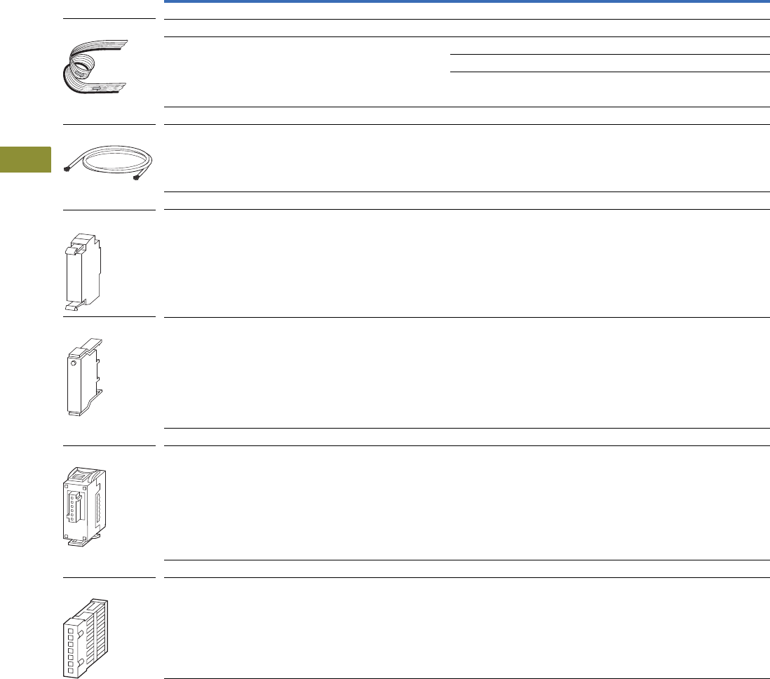
V7-T9-8 Volume 7—Logic Control, Operator Interface and Connectivity Solutions CA08100008E—February 2014 www.eaton.com
9
9
9
9
9
9
9
9
9
9
9
9
9
9
9
9
9
9
9
9
9
9
9
9
9
9
9
9
9
9
9.1
Connectivity Solutions
SmartWire-DT Panel Wiring Solution
Accessories
System Accessories
Accessories for the SmartWire-DT system includes cables, connectors, jumpers, bushings, plugs, sockets,
flat to round cable adapters, and crimping tools.
Description Length Pkg. Qty. Catalog Number
Flat Cable, 8 AWG 24, 600V
For SmartWire-DT network inside the control panel 328.1 ft (100m) 1 SWD4-100LF8-24
Complete with flat plugs SWD4-8MF2 installed at both ends 9.8 ft (3m) 1 SWD4-3LF8-24-2S
16.4 ft (5m) 1 SWD4-5LF8-24-2S
32.8 ft (10m) 1 SWD4-10LF8-24-2S
Round Cable, 4 AWG 20 and 4 AWG 24, 300V
For SmartWire-DT network outside of the control panel 164.0 ft (50m) 1 SWD4-50LR8-24
Universal (Placeholder) Modules
Front mount 20 M22-SWD-NOP
Base mount 20 M22-SWD-NOPC
Device Plugs
For connection to SmartWire-DT modules or nodes — 10 SWD4-8SF2-5
Flat Plugs
For connection to SmartWire-DT system components: gateways, powerfeed
modules, coupling and terminating resistor
—10SWD4-8MF2
Flat Cable
SWD4-8SF2
SWD4-8SF2 SWD4-8S
Round Cable
Device Plug
Flat Plug
Universal—Front
Universal—Base
Volume 7—Logic Control, Operator Interface and Connectivity Solutions CA08100008E—February 2014 www.eaton.com V7-T9-9
9
9
9
9
9
9
9
9
9
9
9
9
9
9
9
9
9
9
9
9
9
9
9
9
9
9
9
9
9
9
9.1
Connectivity Solutions
SmartWire-DT Panel Wiring Solution
System Accessories, continued
Description Pkg. Qty. Catalog Number
Device Plug Jumpers
For bridging open, spare or inverted device plugs 5 SWD4-SEL8-10
Control Station PCB Jumpers
For bridging open mounting locations on the control station printed
circuit board
5M22-SWD-SEL8-10
Coupling
For connecting or joining flat cables with flat plugs 1 SWD4-8SFF2-5
Terminating Resistor
For terminating the end of the network on a flat cable 1 SWD4-RC8-10
Panel Cable Adapter
For flat cable (plug) to round cable terminals 1 SWD4-8FRF-10
Cabinet Cable Adapter Socket
For flat cable (plug) to round cable (plug) 1 SWD4-SFL8-20
Cabinet Cable Adapter Plug
For flat cable (plug) to round cable (socket) 1 SWD4-SML8-20
PCBs
For surface mounting M22 enclosures and for base-mount pilot device modules
Includes a built-in switchable terminating resistor
Element enclosure PCB 1 1 M22-SWD-I1-LP01
Element enclosure PCB 2 1 M22-SWD-I2-LP01
Element enclosure PCB 3 1 M22-SWD-I3-LP01
Element enclosure PCB 4 1 M22-SWD-I4-LP01
Element enclosure PCB 6 1 M22-SWD-I6-LP01
Adapter Socket
Adapter Plug
PCB
IN
OUT
OFF
ON
Device Plug Jumper
PCB Jumper
Coupling
+ 15V
SWD4-8SFF2-5
Terminating Resistor
+ 15V
SWD4-RC8-10
Adapter
1 2 3 4 5 6 7 8
+ 15 V
V7-T9-10 Volume 7—Logic Control, Operator Interface and Connectivity Solutions CA08100008E—February 2014 www.eaton.com
9
9
9
9
9
9
9
9
9
9
9
9
9
9
9
9
9
9
9
9
9
9
9
9
9
9
9
9
9
9
9.1
Connectivity Solutions
SmartWire-DT Panel Wiring Solution
System Accessories, continued
Description Pkg. Qty. Catalog Number
Connectors for Round Cables
Round cable 8-pole socket 1 SWD4-SF8-67
Round cable 8-pole plug 1 SWD4-SM8-67
Right angle round cable 8-pole socket 1 SWD4-SF8-67W
Right angle round cable 8-pole plug 1 SWD4-SM8-67W
Enclosure Bushings
Enclosure bushing, 8-pole socket, M20 1 SWD4-SF8-20
Enclosure bushing, 8-pole plug, M20 1 SWD4-SM8-20
Cord Grip
Round cable cord grip, M20 1 V-M20
Crimping Tool
Device plug crimping tool 1 SWD4-CRP-1
Flat plug crimping tool 1 SWD4-CRP-2
Connector Socket
Connector
(Right Angle)
Bushing Socket
Bushing Plug
Cord Grip
Device Plug Tool
Flat Plug Tool
Connector Plug
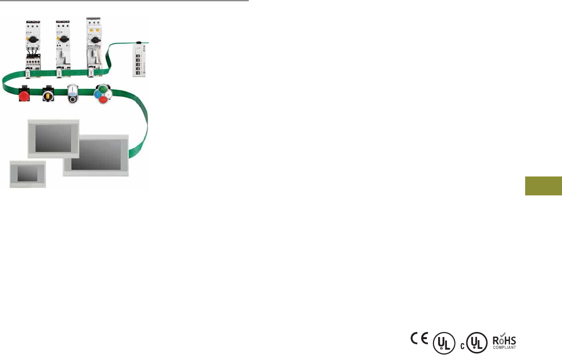
Volume 7—Logic Control, Operator Interface and Connectivity Solutions CA08100008E—February 2014 www.eaton.com V7-T9-11
9
9
9
9
9
9
9
9
9
9
9
9
9
9
9
9
9
9
9
9
9
9
9
9
9
9
9
9
9
9
9.1
Connectivity Solutions
SmartWire-DT Panel Wiring Solution
System Controllers
Contents
Description Page
System Components . . . . . . . . . . . . . . . . . . . . . . . V7-T9-6
System Controllers
Contactor Modules . . . . . . . . . . . . . . . . . . . . . . . . V7-T9-12
Pilot Device Modules . . . . . . . . . . . . . . . . . . . . . . V7-T9-15
Technical Data and Specifications . . . . . . . . . . . . . V7-T9-20
Dimensions . . . . . . . . . . . . . . . . . . . . . . . . . . . . . . V7-T9-34
System Controllers
XV Series HMI-PLC with SmartWire-DT
Product Description
The XV HMI-PLC controller
with SmartWire-DT™ master
is a powerful combination
of logic, visualization and
connectivity to motor control
devices. It is ideal for small to
mid-range PLC applications
where integrated logic and
visualization is advantageous
and/or where remote
administration is critical. The
SmartWire-DT master can
accept 99 nodes on a 2000
foot-long network.
Features
●Built-in SmartWire-DT
master for 99 nodes
●Brilliant image display with
65,536 colors
●High resolution resistive
touch TFT displays
●3.5 in, 5.7 in or 7 in
widescreen displays in
robust plastic housings
and bezels, or
●5.7 in, 8.4 in or 10.4 in
displays in high-end
aluminum front bezels
and metal housings
●Ethernet and RS485 serial
ports on all models
●PROFIBUS-DP or
CANopen master on all
models larger than 3.5 in
●Programmable with
IEC 61131-3 compliant
XSoft-CoDeSys software
●Easy connection direct to
motor control components
or I/O modules on
SmartWire-DT flat cable
Standards and Certifications
●CE
●UL
●cUL
●RoHS
Note: For product selection of XV Series HMI-PLCs with SmartWire-DT,
see Tab 4 in this volume.
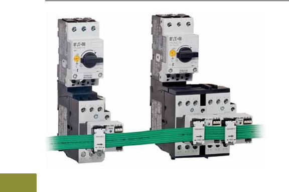
V7-T9-12 Volume 7—Logic Control, Operator Interface and Connectivity Solutions CA08100008E—February 2014 www.eaton.com
9
9
9
9
9
9
9
9
9
9
9
9
9
9
9
9
9
9
9
9
9
9
9
9
9
9
9
9
9
9
9.1
Connectivity Solutions
SmartWire-DT Panel Wiring Solution
Contactor Modules
Contents
Description Page
System Components . . . . . . . . . . . . . . . . . . . . . . V7-T9-6
System Controllers . . . . . . . . . . . . . . . . . . . . . . . . V7-T9-11
Contactor Modules
Product Identification . . . . . . . . . . . . . . . . . . . . V7-T9-13
Product Selection . . . . . . . . . . . . . . . . . . . . . . . V7-T9-14
Pilot Device Modules . . . . . . . . . . . . . . . . . . . . . . V7-T9-15
Technical Data and Specifications . . . . . . . . . . . . . V7-T9-20
Dimensions . . . . . . . . . . . . . . . . . . . . . . . . . . . . . . V7-T9-34
Contactor Modules
Product Description
Contactor modules fit onto
standard XT contactors and
control relays directly on top,
in place of a top mounted
auxiliary contact block. The
modules fit all XTCE size B
and C frame contactors and
XTRE control relays.
These modules facilitate
direct connection to the
SmartWire-DT flat cable and
eliminate the traditional point-
to-point wiring to the PLC
input and output modules as
well as wiring to the
contactor coils.
Features
●Integrated 24 Vdc coil
power on network and
plug-in modules
●Integrated switch position
polling
●Integrated mechanical
switch position display
●Integrated feedback circuit
to PLC
●Built-in diagnostic bi-color
LEDs on each module
●
Connection to SmartWire-DT
flat cable via quick
disconnect device plugs
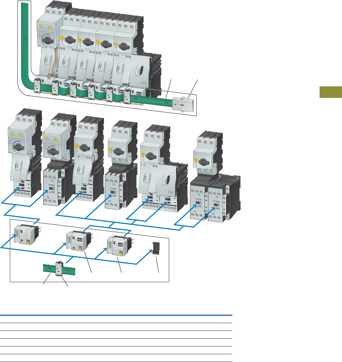
Volume 7—Logic Control, Operator Interface and Connectivity Solutions CA08100008E—February 2014 www.eaton.com V7-T9-13
9
9
9
9
9
9
9
9
9
9
9
9
9
9
9
9
9
9
9
9
9
9
9
9
9
9
9
9
9
9
9.1
Connectivity Solutions
SmartWire-DT Panel Wiring Solution
Product Identification
SmartWire-DT Contactor Modules
Item
Number Description
1Flat cable
2Terminating resistor (SWD4-RC8-10)
3Device plug (SWD4-85F2-5)
4Modules for XT contactors with XTPR manual motor protectors, with 1-0-A switch (DIL-SWD-32-002)
5Modules for XT contactors with XTPR manual motor protectors (DIL-SWD-32-001)
6Device plug jumper (SWD4-SEL8-10)
21
45 6
13
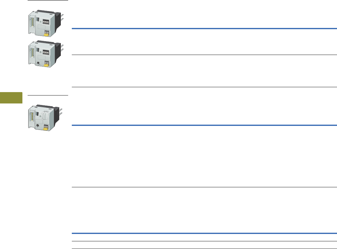
V7-T9-14 Volume 7—Logic Control, Operator Interface and Connectivity Solutions CA08100008E—February 2014 www.eaton.com
9
9
9
9
9
9
9
9
9
9
9
9
9
9
9
9
9
9
9
9
9
9
9
9
9
9
9
9
9
9
9.1
Connectivity Solutions
SmartWire-DT Panel Wiring Solution
Product Selection
Contactor Modules 123
SmartWire-DT module for attachment to XTCE007–XTCE032 contactors and XTRE control relays.
One module is required per contactor.
PKE Contactor Module
SmartWire-DT module for connection of XTPE manual motor controllers.
One module is required per contactor and XTPE manual motor protector.
Design Note
The number of motor starters or XTCE contactors that can be connected is dependent
upon the power consumption of the contactor coils. To increase the number of
SmartWire-DT modules that can be connected. Powerfeed modules can be used.
Notes
1 Take account of the maximum current consumption of the contactor coils per SmartWire-DT line.
2 A2 connections must not be linked.
3 Connection terminals for electrical interlocking are not suitable for safety technology.
Description Pkg. Qty. Catalog Number
Two digital inputs for voltage-free contacts.
One electrical interlock for the surface mounting of reversing combinations.
Messages: Switch status contactor, status of the digital inputs 1 and 2.
Commands: Contactor actuation.
5 DIL-SWD-32-001
Two digital inputs for voltage-free contacts.
One electrical interlock for the surface mounting of reversing combinations.
1-0-A switch for manual or automatic operation.
Messages: Contactor switching position, status of the digital inputs 1 and 2, 1-0-A switch position.
Commands: Contactor actuation.
5 DIL-SWD-32-002
Description Pkg. Qty. Catalog Number
Connecting cable between module and XTPE trip block included as standard.
One electrical interlock for the surface mounting of reversing starters.
1-0-A switch for manual or automatic operation.
Selectable overload relay function for connecting the contactor on overload.
Messages:
Switch position contactor/PKE/1-0-A switch
Motor current in %
Thermal motor image in %
Trip-indicating auxiliary contact (Overload, Short-circuit,...)
Set value of overload releases
Set value Verification time (CLASS), Part no. Trip block.
Commands: Contactor actuation, activation of overload relay function (ZMR)
4 PKE-SWD-32
24 Vdc XTCE007 XTCE009 XTCE012 XTCE015 XTCE018 XTCE025 XTCE032
Pick-up power W 3 3 4.5 4.5 12 12 12
Sealing power W 3 3 4.5 4.5 0.5 0.5 0.5
Contactor Modules
PKE Contactor Module

Volume 7—Logic Control, Operator Interface and Connectivity Solutions CA08100008E—February 2014 www.eaton.com V7-T9-15
9
9
9
9
9
9
9
9
9
9
9
9
9
9
9
9
9
9
9
9
9
9
9
9
9
9
9
9
9
9
9.1
Connectivity Solutions
SmartWire-DT Panel Wiring Solution
Pilot Device Modules
Contents
Description Page
System Components . . . . . . . . . . . . . . . . . . . . . . . V7-T9-6
System Controllers . . . . . . . . . . . . . . . . . . . . . . . . V7-T9-11
Contactor Modules . . . . . . . . . . . . . . . . . . . . . . . . V7-T9-12
Pilot Device Modules
Product Identification . . . . . . . . . . . . . . . . . . . . V7-T9-16
Product Selection . . . . . . . . . . . . . . . . . . . . . . . V7-T9-18
Technical Data and Specifications . . . . . . . . . . . . . V7-T9-20
Dimensions . . . . . . . . . . . . . . . . . . . . . . . . . . . . . . V7-T9-34
Pilot Device Modules
Product Description
Pilot device modules fit onto
standard M22 pilot devices in
both front mount and base
mount configurations. Single
and double contact modules
with and without LEDs are
available to meet a wide
variety of control circuit
requirements.
These modules facilitate
direct connection to the
SmartWire-DT flat cable and
eliminate the traditional point-
to-point wiring to the PLC
input and output modules.
Features
●Front or base mount
modules
●Built-in diagnostic bi-color
LEDs on each module
●
Connection to SmartWire-DT
flat cable via quick
disconnect device plugs
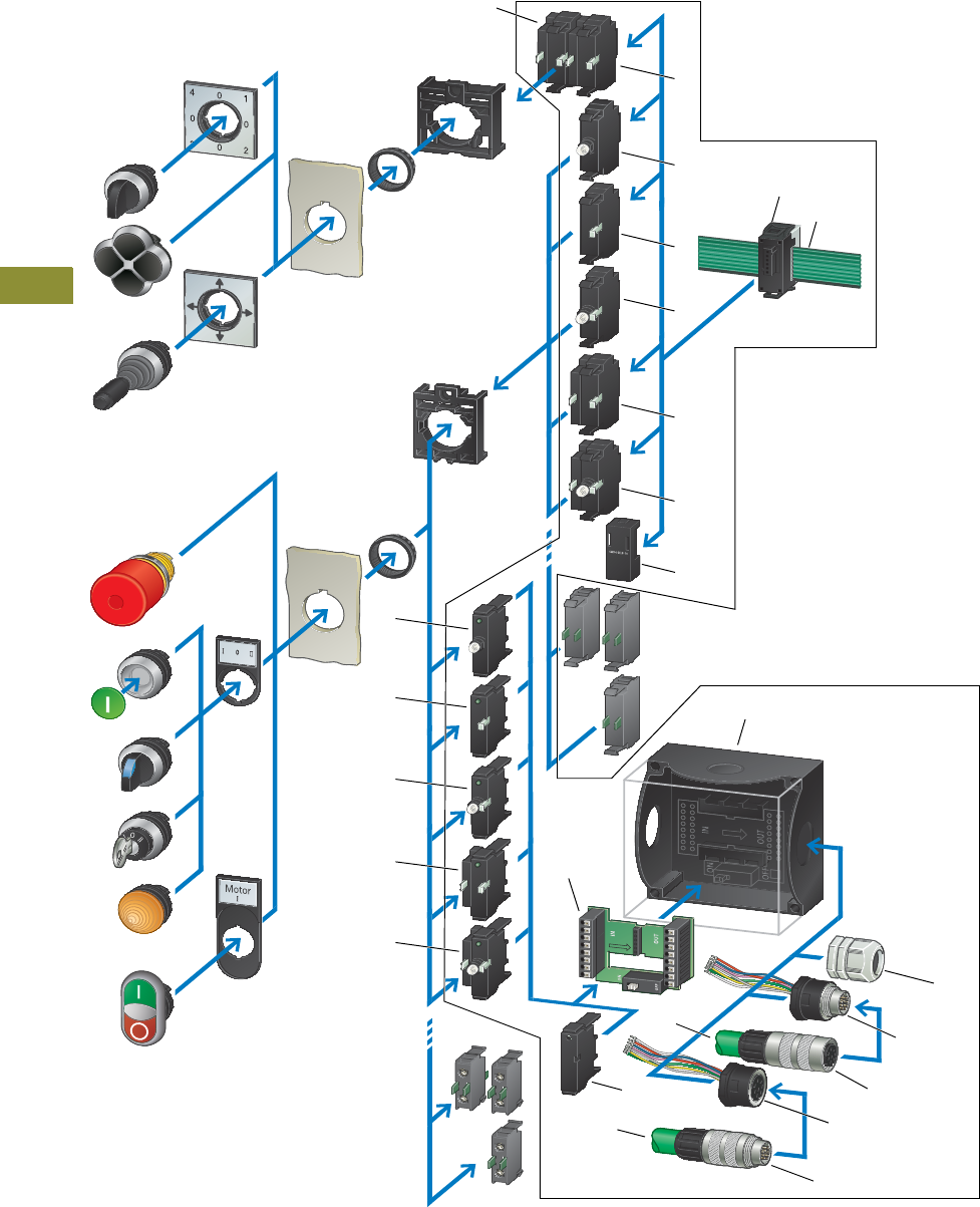
V7-T9-16 Volume 7—Logic Control, Operator Interface and Connectivity Solutions CA08100008E—February 2014 www.eaton.com
9
9
9
9
9
9
9
9
9
9
9
9
9
9
9
9
9
9
9
9
9
9
9
9
9
9
9
9
9
9
9.1
Connectivity Solutions
SmartWire-DT Panel Wiring Solution
Product Identification
Pilot Device Modules Connections
1
18
20
22
17
16
17
21
19
14
15
1
2
3
4
1
5
6
8
7
10
11
12
13
9

Volume 7—Logic Control, Operator Interface and Connectivity Solutions CA08100008E—February 2014 www.eaton.com V7-T9-17
9
9
9
9
9
9
9
9
9
9
9
9
9
9
9
9
9
9
9
9
9
9
9
9
9
9
9
9
9
9
9.1
Connectivity Solutions
SmartWire-DT Panel Wiring Solution
Pilot Device Modules Connections
Item
Number Description
1M22 contact module, front mount (M22-SWD-KC22)
2M22 LED module, front mount (M22-SWD-LED_)
3Module, front mount (M22-SWD-K11)
4M22 contact module with LED, front mount (M22-SWD-K11LED_)
5M22 contact module with LED, front mount (M22-SWD-K22LED_)
6Device plug jumper (SWD4-SEL8-10)
7Device plug (SWD4-85F2-5)
8Flat cable
9M22 LED module, base mount (M22-SWD-LEDC_)
10 M22 contact module, base mount (M22-SWD-KC11)
11 M22 contact module with LED, base mount (M22-SWD-K11LEDC_)
12 M22 contact module, base mount (M22-SWD-KC22)
13 M22 contact module with LED, base mount (M22-SWD-K22LEDC_)
14 1 element enclosure PCB (M22-SWD-I1-1P01)
15 M22 control station enclosure with M20 knockouts
16 Control station PCB jumper (M22-SWD-SEL8-10)
17 Round cable
18 Round cable plug (SWD4-SM8-67)
19 Enclosure bushing socket (SWD4-SF8-20)
20 Round cable socket (SWD4-SF8-67)
21 Enclosure bushing plug (SWD4-SM8-20)
22 M20 cord grip (V-M20)
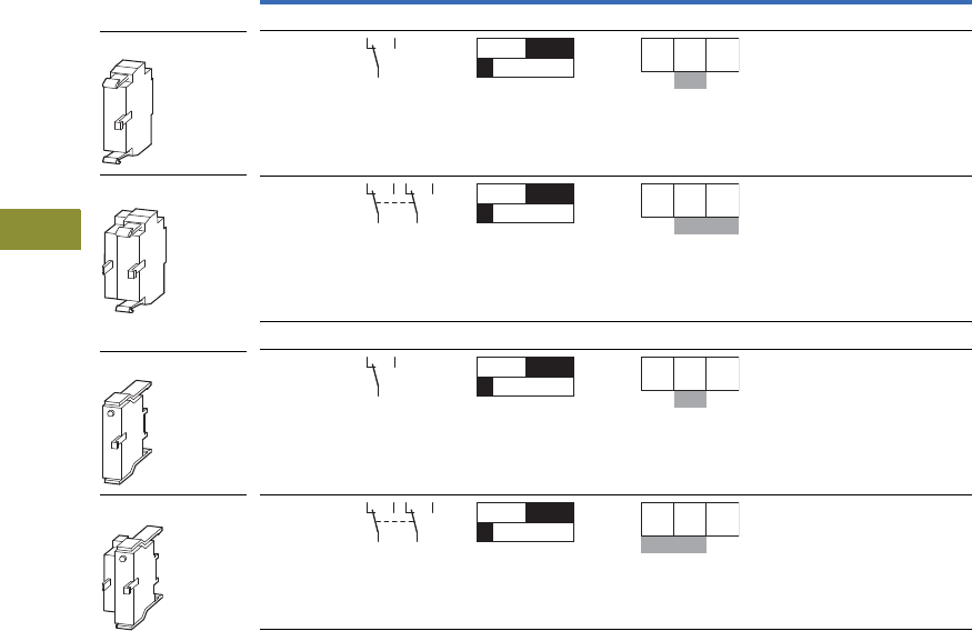
V7-T9-18 Volume 7—Logic Control, Operator Interface and Connectivity Solutions CA08100008E—February 2014 www.eaton.com
9
9
9
9
9
9
9
9
9
9
9
9
9
9
9
9
9
9
9
9
9
9
9
9
9
9
9
9
9
9
9.1
Connectivity Solutions
SmartWire-DT Panel Wiring Solution
Product Selection
M22 Pilot Device Modules Connections
M22 Contact Modules, without LEDs
Number of
Changeover
Contacts
Contact
Sequence
Contact Travel Diagram
Stroke in Connection
with Front Element Configuration Pkg. Qty. Catalog Number
Front Mount
120M22-SWD-K11
210M22-SWD-K22
Base Mount
120M22-SWD-KC11
210M22-SWD-KC22
M22-SWD-K11
M22-SWD-K22
M22-SWD-KC11
M22-SWD-KC22
0 1.2 2.8 5.5
143625
0 1.2 2.8 5.5
143625
0 1.2 2.8 5.5
312
0 1.2 2.8 5.5
312
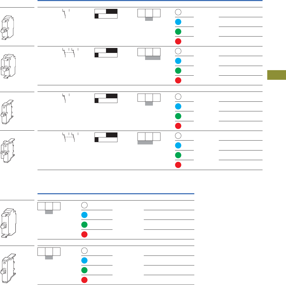
Volume 7—Logic Control, Operator Interface and Connectivity Solutions CA08100008E—February 2014 www.eaton.com V7-T9-19
9
9
9
9
9
9
9
9
9
9
9
9
9
9
9
9
9
9
9
9
9
9
9
9
9
9
9
9
9
9
9.1
Connectivity Solutions
SmartWire-DT Panel Wiring Solution
M22 Contact Modules, with LEDs
M22 LED Modules
Number of
Changeover
Contacts
Contact
Sequence
Contact Travel Diagram
Stroke in Connection
with Front Element Configuration Color LED Pkg. Qty. Catalog Number
Front Mount
120 M22-SWD-K11LED-W
M22-SWD-K11LED-B
M22-SWD-K11LED-G
M22-SWD-K11LED-R
210 M22-SWD-K22LED-W
M22-SWD-K22LED-B
M22-SWD-K22LED-G
M22-SWD-K22LED-R
Base Mount
120 M22-SWD-K11LEDC-W
M22-SWD-K11LEDC-B
M22-SWD-K11LEDC-G
M22-SWD-K11LEDC-R
210 M22-SWD-K22LEDC-W
M22-SWD-K22LEDC-B
M22-SWD-K22LEDC-G
M22-SWD-K22LEDC-R
Configuration Color LED Pkg. Qty. Catalog Number
Front Mount
20 M22-SWD-LED-W
M22-SWD-LED-B
M22-SWD-LED-G
M22-SWD-LED-R
Base Mount
20 M22-SWD-LEDC-W
M22-SWD-LEDC-B
M22-SWD-LEDC-G
M22-SWD-LEDC-R
M22-SWD-K11LED_
M22-SWD-K22LED_
M22-SWD-K11LEDC_
M22-SWD-K22LEDC_
0 1.2 2.8 5.5
143625
0 1.2 2.8 5.5
143625
0 1.2 2.8 5.5
312
0 1.2 2.8 5.5
312
M22-SWD-LED_
M22-SWD-LEDC_
143625
312

V7-T9-20 Volume 7—Logic Control, Operator Interface and Connectivity Solutions CA08100008E—February 2014 www.eaton.com
9
9
9
9
9
9
9
9
9
9
9
9
9
9
9
9
9
9
9
9
9
9
9
9
9
9
9
9
9
9
9.1
Connectivity Solutions
SmartWire-DT Panel Wiring Solution
Technical Data and Specifications
XV Series HMI-PLCs
Model XV-102 XV-152
Screen Size 3.5 in 5.7 in 7.0 in 5.7 in 8.4 in 10.4 in
Operating system WinCE 5.0 Professional WinCE 5.0 Professional WinCE 5.0 Professional WinCE 5.0 Professional WinCE 5.0 Professional WinCE 5.0 Professional
Touchscreen technology Resistive Resistive Resistive Resistive Resistive Resistive
Display, colors Color TFT, 64k colors Color TFT, 64k colors Color TFT, 64k colors Color TFT, 64k colors Color TFT, 64k colors Color TFT, 64k colors
Pixel resolution (landscape)
portrait mode also available
QVGA 320 x 240 VGA 640 x 480 WVGA 800 x 480 VGA 640 x 480 VGA 640 x 480 VGA 640 x 480
Brightness (cd/m2) 250 250 250 350 350 350
Backlight LED, selectable dimming LED, selectable dimming LED, selectable dimming LED, selectable dimming LED, selectable dimming LED, selectable dimming
Lifespan of backlight (half-life) 40,000 hrs 40,000 hrs 40,000 hrs 40,000 hrs 40,000 hrs 40,000 hrs
Processor 32 bit RISC, 400 MHz 32 bit RISC, 400 MHz 32 bit RISC, 400 MHz 32 bit RISC, 400 MHz 32 bit RISC, 400 MHz 32 bit RISC, 400 MHz
Volatile memory 64 MB DRAM 64 MB DRAM 64 MB DRAM 64 MB DRAM 64 MB DRAM 64 MB DRAM
Non-volatile memory 125 KB NVRAM/64 MB
NAND, 1 SD card slot
125 KB NVRAM/64 MB NAND/
2 MB NOR, 1 SD card slot
125 KB NVRAM/64 MB NAND/
2 MB NOR, 1 SD card slot
Real time clock Yes Yes Yes Yes Yes Yes
Communication ports Ethernet 10/100, RS-485
or RS-232 USB Device
Ethernet 10/100, RS-485, RS-232
USB Host, USB Device
Ethernet 10/100, RS-485, RS-232 USB Host, USB Device
Slots for COMM modules None None None None None None
Power supply rated voltage 24 Vdc nominal (–20%/+25%) with polarity protection 24 Vdc nominal (–20%/+25%) with polarity protection
Continuous current consumption
(max. amps)
0.2 0.4 0.4 0.4 0.6 0.6
Starting current inrush (A2s) 1.5 1.5 1.5 1.5 1.5 1.5
Ambient conditions
Operation—relative humidity,
non-condensing
0 to 50°C, 10 to 95% 0 to 50°C, 10 to 95% 0 to 50°C, 10 to 95% 0 to 50°C, 10 to 95% 0 to 50°C, 10 to 95% 0 to 50°C, 10 to 95%
Storage/transport—relative
humidity, non-condensing
–20 to 60°C, 10 to 95% –20 to 60°C, 10 to 95% –20 to 60°C, 10 to 95% –20 to 60°C, 10 to 95% –20 to 60°C, 10 to 95% –20 to 60°C, 10 to 95%
Shock IEC 60068-2-27 15g for 11 ms duration IEC 60068-2-27 15g for 11 ms duration
Vibration IEC 60068-2-6
5–9 Hz: 3.5 mm displacement
9–60 Hz: 0.15 mm displacement
60–150 Hz: 2g acceleration
IEC 60068-2-6
5–9 Hz: 3.5 mm displacement
9–60 Hz: 0.15 mm displacement
60–150 Hz: 2g acceleration
Agency certifications and
standards
CE, UL/cUL, CSA (pending), RoHS CE, UL/cUL, CSA (pending), RoHS
Protection type
Front IP65, NEMA 4X (indoor) IP65, NEMA 4X (indoor) IP65, NEMA 4X (indoor) IP65, NEMA 4X (indoor) IP65, NEMA 4X (indoor) IP65, NEMA 4X (indoor)
Rear IP20, NEMA 1 IP20, NEMA 1 IP20, NEMA 1 IP20, NEMA 1 IP20, NEMA 1 IP20, NEMA 1
Housing material Plastic Plastic Plastic Metal Metal Metal
Dimensions WxHxD (mm) 136 x 100 x 30 170 x 130 x 39 210 x 135 x 38 212 x 156 x 53 275 x 208 x 53 345 x 260 x 54
Mounting cutout WxH (mm) 123 x 87 157 x 117 197 x 122 198 x 142 261 x 194 329 x 238
Approximate weight lbs (kg) 0.7 (0.3) 1.3 (0.6) 1.3 (0.6) 2.9 (1.3) 4.3 (2.1) 6.1 (3.0)
Ability to run third party
software
No No No No No No
XSoft-CoDeSys-2 development
software
SW-XSOFT-CODESYS-2-S (seat)
SW-XSOFT-CODESYS-2-M (multi-seat)
SW-XSOFT-CODESYS-2-S (seat)
SW-XSOFT-CODESYS-2-M (multi-seat)

Volume 7—Logic Control, Operator Interface and Connectivity Solutions CA08100008E—February 2014 www.eaton.com V7-T9-21
9
9
9
9
9
9
9
9
9
9
9
9
9
9
9
9
9
9
9
9
9
9
9
9
9
9
9
9
9
9
9.1
Connectivity Solutions
SmartWire-DT Panel Wiring Solution
Gateways and Powerfeed Modules
Note
1If contactors with a total current consumption >3A are connected, a powerfeed module EU5C-SWD-PF1/2 has to be used.
Description Unit
EU5C-SWD-EIP-MODTCP
Gateway
EU5C-SWD-DP
Gateway
EU5C-SWD-CAN
Gateway
EU5C-SWD-PF1-1
Powerfeed
EU5C-SWD-PF2-1
Powerfeed
General
Standards IEC/EN 61131-2
EN 50178
IEC/EN 61131-2
EN 50178
IEC/EN 61131-2
EN 50178
IEC/EN 61131-2
EN 50178
IEC/EN 61131-2
EN 50178
Dimensions (W x H x D) in
(mm)
1.38 x 3.54 x 4.88
(35 x 90 x 124)
1.38 x 3.54 x 5.0
(35 x 90 x 127)
1.38 x 3.54 x 5.0
(35 x 90 x 127)
1.38 x 3.54 x 4.88
(35 x 90 x 124)
1.38 x 3.54 x 4.88
(35 x 90 x 124)
Weight lbs (kg) 0.37 (0.17) 0.35 (0.16) 0.35 (0.16) 0.24 (0.11) 0.37 (0.17)
Mounting Top-hat rail IEC/EN 60715, 35 mm DIN rail IEC/EN 60715, 35 mm
Mounting position Vertical Vertical Vertical Vertical Vertical
Ambient Conditions, Mechanical
Degree of protection (IEC/EN 60529) IP20 IP20 IP20 IP20 IP20
Vibrations (IEC/EN 61131-2:2008)
Constant amplitude 3.5 mm Hz 5–8.4 5–8.4 5–8.4 5–8.4 5–8.4
Constant acceleration 1g Hz 8.4–150 8.4–150 8.4–150 8.4–150 8.4–150
Mechanical shock resistance (IEC/EN 60068-2-27)
semi-sinusoidal 15g/11 ms
Impacts9 9999
Drop to IEC/EN 60068-2-31 (drop height) in (mm) 1.97 (50) 1.97 (50) 1.97 (50) 1.97 (50) 1.97 (50)
Free fall, packaged (IEC/EN 60068-2-32) ft (m) 1.0 (0.3) 1.0 (0.3) 1.0 (0.3) 1.0 (0.3) 1.0 (0.3)
Electromagnetic Compatibility (EMC)
Overvoltage category II II II II II
Pollution degree 2 2222
Electrostatic discharge (IEC/EN 61131-2:2008)
Air discharge (Level 3) kV8 8888
Contact discharge (Level 2) kV4 4444
Electromagnetic fields (IEC/EN 61131-2:2008)
80–1000 MHz V/m 10 10 10 10 10
1.4–2 GHz V/m3 3333
2–2.7 GHz V/m1 1111
Radio interference suppression (SmartWire-DT) EN 55011 Class A
Burst (IEC/EN 61131-2:2008, Level 3)
Supply cables kV2 2222
CAN/DP bus cable kV 1 1 1 — —
SmartWire-DT cables kV1 1111
Surge (IEC/EN 61131-2:2008, Level 1)
Supply cables kV 0.5 0.5 0.5 0.5 0.5
CAN/DP bus cable kV1 1111
Radiated RFI (IEC/EN 61131-2:2008, Level 3) V 10 10 10 10 10
Climatic Environmental Conditions
Operating ambient temperature (IEC 60068-2) °F (°C) –13° to 131° (–25° to 55°)
Condensation Prevent with suitable measures
Storage °F (°C) –40° to 158° (–40° to 70°)
Relative humidity, non-condensing (IEC/EN 60068-2-30) % 5–95 5–95 5–95 5–95 5–95
Supply Voltage UAux
SM Puffer Bremer V 24 Vdc (–15%/+20%)
Residual ripple on the input voltage % <5 5555
Protection against polarity reversal Yes Yes Yes Yes Yes
Max. current (Imax)A3
13 13 133
Short-circuit rating No, external fuse FAZ Z3
Power loss W Normally 1 Normally 1 Normally 1 Normally 1 Normally 1
Potential isolation No No No No No
Rated operating voltage of 24 Vdc modes V Typ. UAux –0.2 Typ. UAux –0.2 Typ. UAux –0.2 Typ. UAux –0.2 Typ. UAux –0.2

V7-T9-22 Volume 7—Logic Control, Operator Interface and Connectivity Solutions CA08100008E—February 2014 www.eaton.com
9
9
9
9
9
9
9
9
9
9
9
9
9
9
9
9
9
9
9
9
9
9
9
9
9
9
9
9
9
9
9.1
Connectivity Solutions
SmartWire-DT Panel Wiring Solution
Gateways and Powerfeed Modules, continued
Note
1If contactors with a total current consumption >0.7 A are connected, a Power Feeder module EU5C-SWD-PF2 has to be used.
Description Unit
EU5C-SWD-EIP-MODTCP
Gateway
EU5C-SWD-DP
Gateway
EU5C-SWD-CAN
Gateway
EU5C-SWD-PF1-1
Powerfeed
EU5C-SWD-PF2-1
Powerfeed
Supply Voltage UPow
Supply voltage V 24 Vdc (–15%/+20%)
Input voltage ripple % <5<5<5<5<5
Siemens MPI, (optional) Yes Yes Yes — Yes
Rated current (I) A 0.7 0.7 0.7 0.7 0.7
Overload proof Yes Yes Yes Yes Yes
Inrush current and duration A 12.5 A/6 ms 12.5 A/6 ms 12.5 A/6 ms 12.5 A/6 ms 12.5 A/6 ms
Heat dissipation at 24 Vdc W 3.8 3.8 3.8 3.8 3.8
Potential isolation between UPow and
15V SmartWire-DT supply voltage
No No No — Yes
Bridging voltage dips ms 10 10 10 — 10
Repetition rate s 1 1 1 — 1
Status indication (LED) Yes Yes Yes No Yes
SmartWire-DT Supply Voltage
Rated operating voltage (Ue) V 14.5 ±3% 14.5 ±3% 14.5 ±3% 14.5 ±3% 14.5 ±3%
Max. current (Imax) A 0.7 10.7 10.7 10.7 0.7
Short-circuit proof Yes Yes Yes No Yes
Connection Supply Voltages
Connection type Push in terminals Push in terminals Push in terminals Push in terminals Push in terminals
Solid mm20.2–1.5 (AWG 24–16) 0.2–1.5 (AWG 24–16) 0.2–1.5 (AWG 24–16) 0.2–1.5 (AWG 24–16) 0.2–1.5 (AWG 24–16)
Flexible with ferrule mm20.25–1.5 0.25–1.5 0.25–1.5 0.25–1.5 0.25–1.5
SmartWire-DT Network
Station type SmartWire-DT master SmartWire-DT master SmartWire-DT master — —
Number of SmartWire-DT modes 99 58 99 — —
Baud rates 125
250
125 125 — —
Address allocation Automatic Automatic Automatic None None
Status indication (LED)
SmartWire-DT master Green Green Green Green Green
Configurations Red Red Red Red Red
Connections Plug, 8-pole Plug, 8-pole Plug, 8-pole 2 x plug, 8-pole 2 x plug, 8-pole
Plug connectors Blade terminal SWD4-8MF2 Flat plug SWD4-8MF2 Flat plug SWD4-8MF2 Two flat plugs SWD4-8MF2 Two flat plugs SWD4-8MF2
Fieldbus Interface
Bus protocol Ethernet IP/Modbus TCP slave PROFIBUS-DP CANopen — —
Baud rates 10/100 mB Up to 12 mB To 1 mB — —
Address allocation Automatic Automatic Automatic — —
Station address — 2–125 2–32 — —
Address allocation DIP switch/DHCP/BOOTP
selection via DIP switch
DIP switch DIP switch — —
Status display fieldbus interface (LED) Link status: yellow (10 mB),
green (100 mB) flashing
Two-colored red/green Two-colored red/green — —
Terminating resistor — Switchable via plug DIP switches — —
Connection design for field bus 2 x RJ45 (2-channel switch) 1 x SUB-D socket, 9-pole 1 x SUB-D plug, 9-pole — —
Potential isolation Yes Yes Yes — —

Volume 7—Logic Control, Operator Interface and Connectivity Solutions CA08100008E—February 2014 www.eaton.com V7-T9-23
9
9
9
9
9
9
9
9
9
9
9
9
9
9
9
9
9
9
9
9
9
9
9
9
9
9
9
9
9
9
9.1
Connectivity Solutions
SmartWire-DT Panel Wiring Solution
Input/Output Modules
Note
1Minimum length 8 mm.
Description Unit EU5E-SWD-8DX EU5E-SWD-4DX EU5E-SWD-4D4D EU5E-SWD-4D2R EU5E-SWD-X8D
General
Standards IEC/EN 61131-2; EN 50178
Dimensions (W x H x D) in
(mm)
1.38 x 3.54 x 3.97
(35 x 90 x 101)
1.38 x 3.54 x 3.97
(35 x 90 x 101)
1.38 x 3.54 x 3.97
(35 x 90 x 101)
1.38 x 3.54 x 3.97
(35 x 90 x 101)
1.38 x 3.54 x 3.97
(35 x 90 x 101)
Weight lbs (kg) 0.22 (0.10) 0.22 (0.10) 0.22 (0.10) 0.22 (0.10) 0.22 (0.10)
Mounting DIN rail IEC/EN 60715,
35 mm
Top-hat rail IEC/
EN 60715, 35 mm
DIN rail IEC/EN 60715,
35 mm
DIN rail IEC/EN 60715,
35 mm
Top-hat rail IEC/
EN 60715, 35 mm
Mounting position Vertical Vertical Vertical Vertical Vertical
Ambient Conditions, Mechanical
Degree of protection (IEC/EN 60529) IP20 IP20 IP20 IP20 IP20
Vibrations (IEC/EN 61131-2:2008)
Constant amplitude 3.5 mm Hz 5–8.4 5–8.4 5–8.4 5–8.4 5–8.4
Constant acceleration 1g Hz 8.4–150 8.4–150 8.4–150 8.4–150 8.4–150
Mechanical shock resistance (IEC/EN 60068-2-27)
semi-sinusoidal 15g/11 ms
Impacts99999
Drop to IEC/EN 60068-2-31 (drop height) in (mm) 1.97 (50) 1.97 (50) 1.97 (50) 1.97 (50) 1.97 (50)
Free fall, packaged (IEC/EN 60068-2-32) ft (m) 1.0 (0.3) 1.0 (0.3) 1.0 (0.3) 1.0 (0.3) 1.0 (0.3)
Electromagnetic Compatibility (EMC)
Overvoltage category II II II II II
Pollution degree 22222
Electrostatic discharge (IEC/EN 61131-2:2008)
Air discharge (Level 3) kV88888
Contact discharge (Level 2) kV44444
Electromagnetic fields (IEC/EN 61131-2:2008)
80–1000 MHz V/m 10 10 10 10 10
1.4–2 GHz V/m33333
2–2.7 GHz V/m11111
Radio interference suppression (SmartWire-DT) EN 55011 Class A EN 55011 Class A EN 55011 Class A EN 55011 Class A EN 55011 Class A
Burst (IEC/EN 61131-2:2008, Level 3)
Supply cables kV22222
Signal lines kV11111
SmartWire-DT cables kV11111
Surge (IEC/EN 61131-2:2008, Level 1)
Supply cables kV 0.5 0.5 0.5 0.5 0.5
Radiated RFI (IEC/EN 61131-2:2008, Level 3) V 10 10 10 10 10
Climatic Environmental Conditions
Operating ambient temperature (IEC 60068-2) °F (°C) –13° to 131° (–25° to 55°)
Condensation Prevent with suitable measures
Storage °F (°C) –40° to 158° (–40° to 70°)
Relative humidity, non-condensing (IEC/
EN 60068-2-30)
% 5–95 5–95 5–95 5–95 5–95
SmartWire-DT Network
Station type SmartWire-DT (node) SmartWire-DT (slave) SmartWire-DT (node) SmartWire-DT (node) SmartWire-DT (slave)
Address allocation Automatic Automatic Automatic Automatic Automatic
SmartWire-DT status (LED) Green Green Green Green Green
Connection
Plug 8-pole Plug, 8-pole 8-pole 8-pole Plug, 8-pole
Connection plug External device plug SWD4-8SF2-5
Current consumption (15V SWD supply) See Page V7-T9-33 See Page V7-T9-33 See Page V7-T9-33 See Page V7-T9-33 See Page V7-T9-33

V7-T9-24 Volume 7—Logic Control, Operator Interface and Connectivity Solutions CA08100008E—February 2014 www.eaton.com
9
9
9
9
9
9
9
9
9
9
9
9
9
9
9
9
9
9
9
9
9
9
9
9
9
9
9
9
9
9
9.1
Connectivity Solutions
SmartWire-DT Panel Wiring Solution
Input/Output Modules, continued
Note
1Three-wire connection with power supply l+, l-.
Description Unit EU5E-SWD-8DX EU5E-SWD-4DX EU5E-SWD-4D4D EU5E-SWD-4D2R EU5E-SWD-X8D
Connection Supply and I/O
Connection type Push in terminals Push in terminals Push in terminals Push in terminals Push in terminals
Solid mm20.2–1.5 (AWG 24–16) 0.2–1.5 (AWG 24–16) 0.2–1.5 (AWG 24–16) 0.2–1.5 (AWG 24–16) 0.2–1.5 (AWG 24–16)
Flexible with ferrule 1mm20.25–1.5 (AWG 24–16) 0.25–1.5 0.25–1.5 0.25–1.5 0.25–1.5 (AWG 24–16)
24 Vdc Supply for Output Supply
Rated operational voltage (Ue) V 24 Vdc (–15%/+20%) 24 Vdc (–15%/+20%) 24 Vdc (–15%/+20%) 24 Vdc (–15%/+20%) 24 Vdc (–15%/+20%)
Residual ripple on the input voltage % — <55 —<5
Protection against polarity reversal — Yes Yes — Yes
Digital Inputs
Quantity 8 4 144—
Input current mA Typ. 4 at 24 Vdc Typ. 4 at 24 Vdc Typ. 4 at 24 Vdc Typ. 4 at 24 Vdc Typ. 4 at 24 Vdc
Voltage level to IEC/EN 61131-2
Limit value type 1 Low <5 Vdc; High >15 Vdc
Input delay
High <0.2 ms <0.2 ms <0.2 ms <0.2 ms <0.2 ms
Low <0.2 ms <0.2 ms <0.2 ms <0.2 ms <0.2 ms
SmartWire-DT status (LED) Yellow Yellow Yellow Yellow —
Power Supply l+, l-
Overload proof — Yes, with diagnostics — — —
Output current per input supply A — <0.5———
Supply voltage V — Ue 0.16V — — —
Transistor Outputs
Number ——4 —8
Output current A — — Normally 0.5 at 24 Vdc — Normally 0.5 at 24 Vdc
Short-circuit tripping current A — — Max. 1.2 over 3 ms — Max. 1.2 over 3 ms
Lamp load (RLL) W——3 —<3
Overload proof — — Yes, with diagnostics — Yes, with diagnostics
Switching capacity — — EN 60947-5-1 utilization
category DC-13
— EN 60947-5-1 utilization
category DC-13
Status display LED————Yellow
Relay Outputs
Number ———2 —
Contact type art ———N/O contact—
Operations
Utilization category AC-1, 250V, 6A — — >6 x 10⁴—
Utilization category AC-15, 250V, 3A ———>5 x 10
4—
Utilization category DC-13, 24V, 1A ———>2 x 10
5—
Safe isolation Vac———230—
Minimum load current mA ———100 mA, 12 Vdc—
Pick-up/drop-out time ms———5/2.5—
Bounce duration ms———Normally 1.5—
Short-circuit protection ———External 4A gL/gG—
Status display outputs (LED) — — Yellow Yellow —
Potential Isolation
Inputs for SmartWire-DT Yes Yes Yes Yes Yes
Transistor outputs for SmartWire-DT — Yes Yes — —
Transistor outputs for inputs — — No — —
Relays for SmartWire-DT ———Yes—
Relays for inputs ———Yes—
Relays for relays ———Yes—

Volume 7—Logic Control, Operator Interface and Connectivity Solutions CA08100008E—February 2014 www.eaton.com V7-T9-25
9
9
9
9
9
9
9
9
9
9
9
9
9
9
9
9
9
9
9
9
9
9
9
9
9
9
9
9
9
9
9.1
Connectivity Solutions
SmartWire-DT Panel Wiring Solution
Analog I/O Modules
Note
1Minimum length 8 mm.
Description Unit EU5E-SWD-4AX EU5E-SWD-2A2A EU5E-SWD-4PT
General
Standards IEC/EN 61131-2/EN 50178 IEC/EN 61131-2/EN 50178 IEC/EN 61131-2/EN 50178
Dimensions (W x H x D) in (mm) 1.38 x 3.54 x 3.97 (35 x 90 x 101) 1.38 x 3.54 x 3.97 (35 x 90 x 101) 1.38 x 3.54 x 3.97 (35 x 90 x 101)
Weight lbs (kg) 0.22 (0.10) 0.22 (0.10) 0.22 (0.10)
Mounting Top-hat rail IEC/EN 60715, 35 mm Top-hat rail IEC/EN 60715, 35 mm Top-hat rail IEC/EN 60715, 35 mm
Mounting position Vertical Vertical Vertical
Ambient Conditions, Mechanical
Protection type (IEC/EN 60529) IP20 IP20 IP20
Vibrations (IEC/EN 61131-2:2008)
Constant amplitude 3.5 mm Hz 5–8.4 5–8.4 5–8.4
Constant acceleration 1g Hz 8.4–150 8.4–150 8.4–150
Mechanical shock resistance (IEC/EN 60068-2-27)
semi-sinusoidal 15g/11 ms
Impacts 9 9 9
Drop to IEC/EN 60068-2-31 (drop height) in (mm) 1.97 (50) 1.97 (50) 1.97 (50)
Free fall, packaged (IEC/EN 60068-2-32) ft (m) 1.0 (0.3) 1.0 (0.3) 1.0 (0.3)
Electromagnetic Compatibility (EMC)
Overvoltage category II II II
Pollution degree 2 2 2
Electrostatic discharge (IEC/EN 61131-2:2008)
Air discharge (Level 3) kV 8 8 8
Contact discharge (Level 2) kV 4 4 4
Electromagnetic fields (IEC/EN 61131-2:2008)
80–1000 MHz V/m 10 10 10
1.4–2 GHz V/m 3 3 3
2–2.7 GHz V/m 1 1 1
Radio interference suppression (SmartWire-DT) EN 55011 Class A EN 55011 Class A EN 55011 Class A
Burst (IEC/EN 61131-2:2008, Level 3)
Supply cables kV 2 2 2
Signal lines kV 2 2 2
SmartWire-DT cables kV 2 2 2
Surge (IEC/EN 61131-2:2008, Level 1) Supply cables 1.0 kV Supply cables 1.0 kV Supply cables 1.0 kV
Radiated RFI (IEC/EN 61131-2:2008, Level 3) V 10 10 10
Climatic Environmental Conditions
Operating ambient temperature (IEC 60068-2) °F (°C) 13° to 131° (–25° to 55°) 13° to 131° (–25° to 55°) 13° to 131° (–25° to 55°)
Condensation Prevent with suitable measures Prevent with suitable measures Prevent with suitable measures
Storage °F (°C) –40° to 158° (–40° to 70°) –40° to 158° (–40° to 70°) –40° to 158° (–40° to 70°)
Relative humidity, non-condensing (IEC/EN 60068-2-30) % 5–95 5–95 5–95
SmartWire-DT Network
Station type SmartWire-DT slave SmartWire-DT slave SmartWire-DT slave
Baud rate setting Automatic Automatic Automatic
SmartWire-DT status LED LED Green Green Green
Connection Plug: 8-pole/Connection plug: External device plug SWD4-8SF2-5
Current consumption (15V SWD supply) See Page V7-T9-33 See Page V7-T9-33 See Page V7-T9-33
Connection Supply and I/O
Connection type Push in terminals Push in terminals Push in terminals
Solid mm20.25–1.5 (AWG 24–16) 0.25–1.5 (AWG 24–16) 0.25–1.5 (AWG 24–16)
Flexible with ferrule 1mm20.25–1.5 (AWG 24–16) 0.25–1.5 (AWG 24–16) 0.25–1.5 (AWG 24–16)
24 Vdc Supply for Output Supply
Rated operational voltage (Ue) V 24 Vdc –15%/+20% 24 Vdc –15%/+20% 24 Vdc –15%/+20%
Residual ripple on the input voltage % <5<5<5
Current consumption mA 10 50 —
Protection against polarity reversal Yes Yes Yes

V7-T9-26 Volume 7—Logic Control, Operator Interface and Connectivity Solutions CA08100008E—February 2014 www.eaton.com
9
9
9
9
9
9
9
9
9
9
9
9
9
9
9
9
9
9
9
9
9
9
9
9
9
9
9
9
9
9
9.1
Connectivity Solutions
SmartWire-DT Panel Wiring Solution
Analog I/O Modules, continued
Description Unit EU5E-SWD-4AX EU5E-SWD-2A2A EU5E-SWD-4PT
Analog Inputs
Quantity Four (two-wire connection,
screened, length <10m)
Two (two-wire connection,
screened, length <10m)
—
Parameterization
Part no. Voltage, current Voltage, current —
Averaging Adjustable Adjustable —
Voltage
Input voltage V 0–10 0–10 —
Input impedance k ohms 13.3 13.3 —
Maximum current
Input current mA 0–20 0–20 —
Input impedance ohms < 250 < 250 —
Resolution Bit 12 12 —
Conversion time ms 20 20 —
Total error % ±1 ±1 —
Repetition accuracy % ±0.5 ±0.5 —
Dielectric strength V ±30 ±30 —
Analog Outputs
Number — Two (two-wire connection, screened) —
Parameterization
Part no. — Voltage, current —
Averaging ———
Voltage
Output voltage V — 0–10 —
Maximum output current mA — 10 —
Maximum current
Output current mA — 0–20 —
Load resistance ohms — <500 —
Overload and short-circuit proof — Yes —
Resolution Bit — 12 —
Conversion time ms — 20 —
Total error % — ±1 —
Repetition accuracy % — ±0.5 —
Temperature Inputs
Number — — Four (two-, three-wire connection,
screened, length <10m)
Parameterization
Averaging — — Adjustable
Temperature sensor — — PT100, PT1000, Ni1000
Temperature range °F (°C) — — PT100, PT1000:
–58° to 392° (–50° to 200°)
Ni1000:
–58° to 302° (–50° to 150°)
Resolution °F (°C) — — 32° (0.1°)
Conversion time ms — — 250
Display — — °C, °F, raw value
Total error %——±1
Repetition accuracy % — — ±0.5
Potential Isolation
Inputs for SmartWire-DT Yes Yes Yes
Outputs to SmartWire-DT — Yes —
Input to input No No No
Output to input — No —
Output to output — No —

Volume 7—Logic Control, Operator Interface and Connectivity Solutions CA08100008E—February 2014 www.eaton.com V7-T9-27
9
9
9
9
9
9
9
9
9
9
9
9
9
9
9
9
9
9
9
9
9
9
9
9
9
9
9
9
9
9
9.1
Connectivity Solutions
SmartWire-DT Panel Wiring Solution
Accessories
Description Unit
SWD4-RC8-10
Resistor
SWD4-8SF2-5
Plug
SWD4-8SFF2-5
Coupling
SWD4-SF8-20
Bushing
General
Standards IEC/EN 61131-2; EN 50178 IEC/EN 61131-2; EN 50178 IEC/EN 61131-2; EN 50178 IEC/EN 61131-2; EN 50178
Dimensions (W x H x D) in
(mm)
1.91 x 1.36 x 0.34
(48.5 x 34.5 x 10)
0.59 x 1.44 x 0.69
(15 x 36.5 x 17.5)
1.91 x 1.36 x 0.34
(48.5 x 34.5 x 10)
0.94 x 1.02 x 6.34
(24 x 26 x 162)
Weight lbs (g) 0.022 (10) 0.012.1 (5.5) 0.010 (4.5) 0.044 (20)
Mounting position As required As required As required As required
Ambient Conditions, Mechanical
Degree of protection (IEC/EN 60529) IP20 IP20 IP20 IP67
Vibrations (IEC/EN 61131-2:2008)
Constant amplitude 3.5 mm Hz 5–8.4 5–8.4 5–8.4 —
Constant acceleration 1g Hz 8.4–150 8.4–150 8.4–150 —
Mechanical shock resistance (IEC/EN 60068-2-27)
semi-sinusoidal 15g/11 ms
Impacts999—
Drop to IEC/EN 60068-2-31 (drop height) in (mm) 1.97 (50) — — —
Free fall, packaged (IEC/EN 60068-2-32) ft (m) 1.0 (0.3) — — —
Electromagnetic Compatibility (EMC)
Overvoltage category II — — —
Pollution degree 2 — — —
Electrostatic discharge (IEC/EN 61131-2:2008)
Air discharge (Level 3) kV 8 — — —
Contact discharge (Level 2) kV 4 — — —
Electromagnetic fields (IEC/EN 61131-2:2008)
80–1000 MHz V/m 10 — — —
1.4–2 GHz V/m 3 — — —
2–2.7 GHz V/m 1 — — —
Radio interference suppression (SmartWire-DT) EN 55011 Class A — — —
Burst (IEC/EN 61131-2:2008, Level 3)
SmartWire-DT cables kV 1 — — —
Radiated RFI (IEC/EN 61131-2:2008, Level 3) V 10 — — —
Climatic Environmental Conditions
Operating ambient temperature (IEC 60068-2) °F (°C) –13° to 131° (–25° to 55°) –13° to 131° (–25° to 55°) –13° to 131° (–25° to 55°) –13° to 131° (–25° to 55°)
Condensation Prevent with suitable measures
Storage °F (°C) –40° to 158° (–40° to 70°) –40° to 158° (–40° to 70°) –40° to 158° (–40° to 70°) –40° to 158° (–40° to 70°)
Relative humidity, non-condensing (IEC/EN 60068-2-30) % 5 –95 5 –95 5 –95 5 –95
Connection Options
SWD-In Plug, 8-pole Plug connector Plug, 8-pole —
Number of insertion cycles >200 1 >200 —
SWD-Out — Socket, 8-pole Plug, 8-pole Socket, 8-pole
Number of insertion cycles — >200 >200 >500
Current consumption (15V SWD supply) See Page V7-T9-33 See Page V7-T9-33 See Page V7-T9-33 See Page V7-T9-33

V7-T9-28 Volume 7—Logic Control, Operator Interface and Connectivity Solutions CA08100008E—February 2014 www.eaton.com
9
9
9
9
9
9
9
9
9
9
9
9
9
9
9
9
9
9
9
9
9
9
9
9
9
9
9
9
9
9
9.1
Connectivity Solutions
SmartWire-DT Panel Wiring Solution
Accessories, continued
Description Unit
SWD4-SM8-20
Bushing
SWD4-8FRF-10
Adapter
SWD4-SFL8-20
Adapter
SWD4-SML8-20
Adapter
General
Standards IEC/EN 61131-2; EN 50178 IEC/EN 61131-2; EN 50178 IEC/EN 61131-2; EN 50178 IEC/EN 61131-2; EN 50178
Dimensions (W x H x D) in
(mm)
0.94 x 1.02 x 6.69
(24 x 26 x 170)
1.38 x 3.54 x 1.38
(35 x 90 x 35)
1.38 x 3.27 x 1.57
(35 x 83 x 40)
1.38 x 3.27 x 1.82
(35 x 83 x 46)
Weight lbs (g) 0.050 (22.5) 0.093 (42) 0.110 (50) 0.110 (50)
Mounting position As required As required As required As required
Ambient Conditions, Mechanical
Degree of protection (IEC/EN 60529) IP67 IP20 IP67 IP67
Vibrations (IEC/EN 61131-2:2008)
Constant amplitude 3.5 mm Hz — 5–8.4 5–8.4 5–8.4
Constant acceleration 1g Hz — 8.4–150 8.4–150 8.4–150
Mechanical shock resistance (IEC/EN 60068-2-27)
semi-sinusoidal 15g/11 ms
Impacts — 9 9 9
Drop to IEC/EN 60068-2-31 (drop height) in (mm) ————
Free fall, packaged (IEC/EN 60068-2-32) ft (m) ————
Electromagnetic Compatibility (EMC)
Overvoltage category ————
Pollution degree ————
Electrostatic discharge (IEC/EN 61131-2:2008)
Air discharge (Level 3) kV — 8 8 8
Contact discharge (Level 2) kV — 4 4 4
Electromagnetic fields (IEC/EN 61131-2:2008)
80–1000 MHz V/m — — 10 10
1.4–2 GHz V/m — — 3 3
2–2.7 GHz V/m — — 1 1
Radio interference suppression (SmartWire-DT) ————
Burst (IEC/EN 61131-2:2008, Level 3) ————
SmartWire-DT cables kV————
Radiated RFI (IEC/EN 61131-2:2008, Level 3) V — — 10 10
Climatic Environmental Conditions
Operating ambient temperature (IEC 60068-2) °F (°C) –13° to 131° (–25° to 55°) –13° to 131° (–25° to 55°) –13° to 131° (–25° to 55°) –13° to 131° (–25° to 55°)
Condensation Prevent with suitable measures
Storage °F (°C) –40° to 158° (–40° to 70°) –40° to 158° (–40° to 70°) –40° to 158° (–40° to 70°) –40° to 158° (–40° to 70°)
Relative humidity, non-condensing (IEC/EN 60068-2-30) % 5–95 5–95 5–95 5–95
Connection Options
SWD-In Plug, 8-pole Plug, 8-pole Plug, 8-pole Plug, 8-pole
Number of insertion cycles >500 >200 >200 >500
SWD-Out — Push in terminals Socket, 8-pole Plug, 8-pole
Number of insertion cycles — — >500 >200
Current consumption (15V SWD supply) See Page V7-T9-33 See Page V7-T9-33 See Page V7-T9-33 See Page V7-T9-33

Volume 7—Logic Control, Operator Interface and Connectivity Solutions CA08100008E—February 2014 www.eaton.com V7-T9-29
9
9
9
9
9
9
9
9
9
9
9
9
9
9
9
9
9
9
9
9
9
9
9
9
9
9
9
9
9
9
9.1
Connectivity Solutions
SmartWire-DT Panel Wiring Solution
Contactor Modules
Description Unit DIL-SWD-32-001 DIL-SWD-32-002 PKE-SWD-32
General
Standards IEC/EN 61131-2
EN 50178
IEC/EN 60947
IEC/EN 61131-2
EN 50178
IEC/EN 60947
IEC/EN 61131-2
EN 50178
IEC/EN 60947
Dimensions (W x H x D) in
(mm)
1.77 x 1.50 x 3.0
(45 x 38 x 76)
1.77 x 1.50 x 3.0
(45 x 38 x 76)
1.77 x 1.50 x 3.0
(45 x 38 x 76)
Weight lbs (kg) 0.9 (0.04) 0.9 (0.04) 0.9 (0.04)
Mounting on XTCE007–XTCE032 on XTCE007–XTCE032 —
Mounting position as XTCE007–XTCE032 as XTCE007–XTCE032 —
Ambient Conditions, Mechanical
Degree of protection (IEC/EN 60529) IP20 IP20 —
Vibrations (IEC/EN 61131-2:2008)
Constant amplitude 3.5 mm Hz 5–8.4 5–8.4 5–8.4
Constant acceleration 1g Hz 8.4–150 8.4–150 8.4–150
Mechanical shock resistance (IEC/EN 60068-2-27)
semi-sinusoidal 15g/11 ms
Impacts 9 9 9
Drop to IEC/EN 60068-2-31 (drop height) in (mm) 1.97 (50) 1.97 (50) 1.97 (50)
Free fall, packaged (IEC/EN 60068-2-32) ft (m) 1.0 (0.3) 1.0 (0.3) 1.0 (0.3)
Electromagnetic Compatibility (EMC)
Overvoltage category II II II
Pollution degree 2 2 2
Electrostatic discharge (IEC/EN 61131-2:2008)
Air discharge (Level 3) kV 8 8 8
Contact discharge (Level 2) kV 4 4 4
Electromagnetic fields (IEC/EN 61131-2:2008)
80–1000 MHz V/m 10 10 10
1.4–2 GHz V/m 3 3 3
2–2.7 GHz V/m 1 1 1
Radio interference suppression (SmartWire-DT) EN 55011 Class A EN 55011 Class A EN 55011 Class A
Burst (IEC/EN 61131-2:2008, Level 3)
CAN/DP bus cable kV 1 1 1
SmartWire-DT cables kV 1 1 1
Radiated RFI (IEC/EN 61131-2:2008, Level 3) V 10 10 10
Climatic Environmental Conditions
Operating ambient temperature (IEC 60068-2) °F (°C) –13° to 140° (–25° to 60°) –13° to 140° (–25° to 60°) –13° to 140° (–25° to 60°)
Condensation Prevent with suitable measures Prevent with suitable measures Prevent with suitable measures
Storage °F (°C) –22° to 158° (–30° to 70°) –22° to 158° (–30° to 70°) –22° to 158° (–30° to 70°)
Relative humidity, non-condensing (IEC/EN 60068-2-30) % 5–95 5–95 5–95

V7-T9-30 Volume 7—Logic Control, Operator Interface and Connectivity Solutions CA08100008E—February 2014 www.eaton.com
9
9
9
9
9
9
9
9
9
9
9
9
9
9
9
9
9
9
9
9
9
9
9
9
9
9
9
9
9
9
9.1
Connectivity Solutions
SmartWire-DT Panel Wiring Solution
Contactor Modules, continued
Notes
1Own supply.
2Minimum length: 8 mm.
Description Unit DIL-SWD-32-001 DIL-SWD-32-002 PKE-SWD-32
SmartWire-DT Network
Station type SmartWire-DT station (mode) SmartWire-DT station (mode) SmartWire-DT (slave)
Address allocation Automatic Automatic Automatic
SmartWire-DT status LED Green/orange Green/orange Green/orange
Connections
Plug 8-pole 8-pole 8-pole
Plug connectors External device plug SWD4-8SF2-5 External device plug SWD4-8SF2-5 External device plug SWD4-8SF2-5
Current consumption (15V SWD supply) See Page V7-T9-33 See Page V7-T9-33 See Page V7-T9-33
Mode Parameter
Manual/automatic mode No Yes Yes
Setting — Rotary switch Rotary switch
Connection Auxiliary Contact
Number 2 2 —
Rated voltage (Ue) 1Vdc1515—
Input current at 1 signal, typical mA 3 3 —
Potential isolation No No —
Cable length ft (m) <9.2 (2.8) <9.2 (2.8) <9.2 (2.8)
Connection type Push in terminals Push in terminals Push in terminals
Terminal Capacities
Solid mm20.2–1.5 (AWG 24–16) 0.2–1.5 (AWG 24–16) 0.2–1.5 (AWG 24–16)
Flexible with ferrule 2mm20.25–1.5 0.25–1.5 0.25–1.5

Volume 7—Logic Control, Operator Interface and Connectivity Solutions CA08100008E—February 2014 www.eaton.com V7-T9-31
9
9
9
9
9
9
9
9
9
9
9
9
9
9
9
9
9
9
9
9
9
9
9
9
9
9
9
9
9
9
9.1
Connectivity Solutions
SmartWire-DT Panel Wiring Solution
Pilot Device Modules
Description Unit M22-SWD-K11 M22-SWD-KC11 M22-SWD-LED-_ M22-SWD-LEDC-_ M22-SWD-K11-LED_
General
Standards IEC/EN 61131-2
EN 50178
IEC/EN 61131-2
EN 50178
IEC/EN 61131-2
EN 50178
IEC/EN 61131-2
EN 50178
IEC/EN 61131-2
EN 50178
Dimensions (W x H x D) in
(mm)
0.47 x 1.65 x 1.54
(12 x 42 x 39)
0.47 x 1.77x 1.46
(12 x 45 x 37)
0.39 x 1.65 x 1.77
(10 x 42 x 45)
0.39 x 1.77 x 1.65
(10 x 45 x 42)
0.47 x 1.65 x 1.77
(12 x 42 x 45)
Weight lbs (g) 0.022 (10) 0.022 (10) 0.022 (10) 0.022 (10) 0.022 (10)
Mounting position As required As required As required As required As required
Ambient Conditions, Mechanical
Degree of protection (IEC/EN 60529) IP20 IP20 IP20 IP20 IP20
Vibrations (IEC/EN 61131-2:2008)
Constant amplitude 3.5 mm Hz 5–8.4 5–8.4 5–8.4 5–8.4 5–8.4
Constant acceleration 1g Hz 8.4–150 8.4–150 8.4–150 8.4–150 8.4–150
Mechanical shock resistance
(IEC/EN 60068-2-27) semi-sinusoidal
15g/11 ms
Impacts99999
Drop to IEC/EN 60068-2-31 (drop height) in (mm) 1.97 (50) 1.97 (50) 1.97 (50) 1.97 (50) 1.97 (50)
Free fall, packaged (IEC/EN 60068-2-32) ft (m) 1.0 (0.3) 1.0 (0.3) 1.0 (0.3) 1.0 (0.3) 1.0 (0.3)
Electromagnetic Compatibility (EMC)
Overvoltage category Not applicable Not applicable Not applicable Not applicable Not applicable
Pollution degree 22222
Electrostatic discharge (IEC/EN 61131-2:2008)
Air discharge (Level 3) kV88888
Contact discharge (Level 2)kV44444
Electromagnetic fields (IEC/EN 61131-2:2008)
80–1000 MHz V/m 10 10 10 10 10
1.4–2 GHz V/m33333
2–2.7 GHz V/m11111
Radio interference suppression (SmartWire-DT) EN 55011 Class A EN 55011 Class A EN 55011 Class A EN 55011 Class A EN 55011 Class A
Burst (IEC/EN 61131-2:2008, Level 3)
Supply cables kV22222
SmartWire-DT cables kV11111
Radiated RFI (IEC/EN 61131-2:2008, Level 3) V 10 10 10 10 10
Climatic Environmental Conditions
Operating ambient temperature (IEC 60068-2) °F (°C)
–22° to 131° (–30° to 55°) –22° to 131° (–30° to 55°) –22° to 131° (–30° to 55°) –22° to 131° (–30° to 55°) –22° to 131° (–30° to 55°)
Condensation Prevent with suitable measures
Storage °F (°C)
–40° to 176° (–40° to 80°) –40° to 176° (–40° to 80°) –40° to 176° (–40° to 80°) –40° to 176° (–40° to 80°) –40° to 176° (–40° to 80°)
Relative humidity, non-condensing
(IEC/EN 60068-2-30)
% 9–95 9–95 9–95 9–95 9–95
SmartWire-DT Network
Station type SmartWire-DT station (node)
Address allocation Automatic Automatic Automatic Automatic Automatic
SmartWire-DT status LED Green Green Green Green Green
Connections
Plug 8-pole 8-pole 8-pole 8-pole 8-pole
Plug connectors SWD4-8SF2-5 M22-SWD-I_LP SWD4-8SF2-5 M22-SWD-I_LP SWD4-8SF2-5
Number of insertion cycles >50 >50 >50 >50 >50
Current consumption (15V SWD supply) See Page V7-T9-33 See Page V7-T9-33 See Page V7-T9-33 See Page V7-T9-33 See Page V7-T9-33
Function Element
Contacts 1 changeover contact 1 changeover contact — — 1 changeover contact
Lifespan mechanical/electrical (operations) 1 x 1061 x 106——1 x 10
6
LED display No No Yes Yes Yes
Diagnostics Yes Yes No No Yes
Mounting Front mount Base mount Front mount Base mount Front mount

V7-T9-32 Volume 7—Logic Control, Operator Interface and Connectivity Solutions CA08100008E—February 2014 www.eaton.com
9
9
9
9
9
9
9
9
9
9
9
9
9
9
9
9
9
9
9
9
9
9
9
9
9
9
9
9
9
9
9.1
Connectivity Solutions
SmartWire-DT Panel Wiring Solution
Pilot Device Modules, continued
Description Unit M22-SWD-K11LEDC-_ M22-SWD-K22 M22-SWD-KC22 M22-SWD-K22-LED_ M22-SWD-K22LEDC-_
General
Standards IEC/EN 61131-2
EN 50178
IEC/EN 61131-2
EN 50178
IEC/EN 61131-2
EN 50178
IEC/EN 61131-2
EN 50178
IEC/EN 61131-2
EN 50178
Dimensions (W x H x D) in
(mm)
0.47 x 1.77 x 1.65
(12 x 45 x 42)
0.67 x 1.65 x 1.54
(17 x 42 x 39)
0.67 x 1.77 x 1.46
(17 x 45 x 37)
0.67 x 1.65 x 1.77
(17 x 42 x 45)
0.67 x 1.77 x 1.65
(17 x 45 x 42)
Weight lbs (g) 0.022 (10) 0.030 (14) 0.030 (14) 0.030 (14) 0.030 (14)
Mounting position As required As required As required As required As required
Ambient Conditions, Mechanical
Degree of protection (IEC/EN 60529) IP20 IP20 IP20 IP20 IP20
Vibrations (IEC/EN 61131-2:2008)
Constant amplitude 3.5 mm Hz 5–8.4 5–8.4 5–8.4 5–8.4 5–8.4
Constant acceleration 1g Hz 8.4–150 8.4–150 8.4–150 8.4–150 8.4–150
Mechanical shock resistance
(IEC/EN 60068-2-27) semi-sinusoidal
15g/11 ms
Impacts99999
Drop to IEC/EN 60068-2-31 (drop height) in (mm) 1.97 (50) 1.97 (50) 1.97 (50) 1.97 (50) 1.97 (50)
Free fall, packaged (IEC/EN 60068-2-32) ft (m) 1.0 (0.3) 1.0 (0.3) 1.0 (0.3) 1.0 (0.3) 1.0 (0.3)
Electromagnetic Compatibility (EMC)
Overvoltage category Not applicable Not applicable Not applicable Not applicable Not applicable
Pollution degree 22222
Electrostatic discharge (IEC/EN 61131-2:2008)
Air discharge (Level 3) kV88888
Contact discharge (Level 2)kV44444
Electromagnetic fields (IEC/EN 61131-2:2008)
80–1000 MHz V/m 10 10 10 10 10
1.4–2 GHz V/m33333
2–2.7 GHz V/m11111
Radio interference suppression (SmartWire-DT) EN 55011 Class A EN 55011 Class A EN 55011 Class A EN 55011 Class A EN 55011 Class A
Burst (IEC/EN 61131-2:2008, Level 3)
Supply cables kV22222
SmartWire-DT cables kV11111
Radiated RFI (IEC/EN 61131-2:2008, Level 3) V 10 10 10 10 10
Climatic Environmental Conditions
Operating ambient temperature (IEC 60068-2) °F (°C)
–22° to 131° (–30° to 55°) –22° to 131° (–30° to 55°) –22° to 131° (–30° to 55°) –22° to 131° (–30° to 55°) –22° to 131° (–30° to 55°)
Condensation Prevent with suitable measures
Storage °F (°C)
–40° to 176° (–40° to 80°) –40° to 176° (–40° to 80°) –40° to 176° (–40° to 80°) –40° to 176° (–40° to 80°) –40° to 176° (–40° to 80°)
Relative humidity, non-condensing
(IEC/EN 60068-2-30)
% 9–95 5–95 5–95 5–95 5–95
SmartWire-DT Network
Station type SmartWire-DT station (node)
Address allocation Automatic Automatic Automatic Automatic Automatic
SmartWire-DT status LED Green Green Green Green Green
Connections
Plug 8-pole 8-pole 8-pole 8-pole 8-pole
Plug connectors M22-SWD-I_LP SWD4-8SF2-5 M22-SWD-I_LP SWD4-8SF2-5 M22-SWD-I_LP
Number of insertion cycles >50 >50 >50 >50 >50
Current consumption (15V SWD supply) See Page V7-T9-33 See Page V7-T9-33 See Page V7-T9-33 See Page V7-T9-33 See Page V7-T9-33
Function Element
Contacts 1 contact 2 contacts 2 contacts 2 contacts 2 contacts
Lifespan mechanical/electrical (operations) 1 x 1061 x 1061 x 1061 x 1061 x 106
LED display Yes No No Yes Yes
Diagnostics Yes Yes Yes Yes Yes
Mounting Base mount Front mount Base mount Front mount Base mount

Volume 7—Logic Control, Operator Interface and Connectivity Solutions CA08100008E—February 2014 www.eaton.com V7-T9-33
9
9
9
9
9
9
9
9
9
9
9
9
9
9
9
9
9
9
9
9
9
9
9
9
9
9
9
9
9
9
9.1
Connectivity Solutions
SmartWire-DT Panel Wiring Solution
Current Consumption Ratings
Power Consumption/Current Consumption
24 Vdc Control Voltage UAUX
Current Consumption 15 Vdc Supply Voltage
Note
1With terminating resistor switched on.
Description Unit DIL-SWD-32-_
Pick-Up Power
For XTCE007–XTCE009 W 3
For XTCE012–XTCE015 W 4,5
For XTCE018–XTCE032 W 12
Pick-Up Current
For XTCE007–XTCE009 mA 125
For XTCE012–XTCE015 mA 188
For XTCE018–XTCE032 mA 500
Holding Power
For XTCE007–XTCE009 W 3
For XTCE012–XTCE015 W 4,5
For XTCE018–XTCE032 W 0,5
Holding Current
For XTCE007–XTCE009 mA 125
For XTCE012–XTCE015 mA 188
For XTCE018–XTCE032 mA 21
Catalog Number
Current
Consumption (mA) Catalog Number
Current
Consumption (mA)
DIL-SWD-32-001 40 M22-SWD-K22 7
DIL-SWD-32-002 40 M22-SWD-K22LED-B 19
EU5E-SWD-4D2R 45 M22-SWD-K22LED-G 19
EU5E-SWD-4D4D 45 M22-SWD-K22LED-R 19
EU5E-SWD-8DX 12 M22-SWD-K22LED-W 19
M22-SWD-I1-LP01 117 M22-SWD-K22LEDC-B 19
M22-SWD-I2-LP01 117 M22-SWD-K22LEDC-G 19
M22-SWD-I3-LP01 117 M22-SWD-K22LEDC-R 19
M22-SWD-I4-LP01 117 M22-SWD-K22LEDC-W 19
M22-SWD-I6-LP01 117 M22-SWD-KC11 7
M22-SWD-K11 7M22-SWD-KC22 7
M22-SWD-K11LED-B 19 M22-SWD-LED-B 19
M22-SWD-K11LED-G 19 M22-SWD-LED-G 19
M22-SWD-K11LED-R 19 M22-SWD-LED-R 19
M22-SWD-K11LED-W 19 M22-SWD-LED-W 19
M22-SWD-K11LEDC-B 19 M22-SWD-LEDC-B 19
M22-SWD-K11LEDC-G 19 M22-SWD-LEDC-G 19
M22-SWD-K11LEDC-R 19 M22-SWD-LEDC-R 19
M22-SWD-K11LEDC-W 19 M22-SWD-LEDC-W 19
SWD4-RC8-10 17
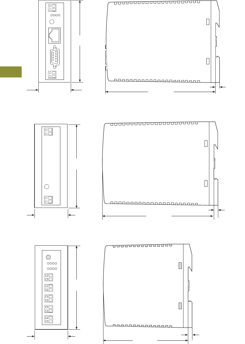
V7-T9-34 Volume 7—Logic Control, Operator Interface and Connectivity Solutions CA08100008E—February 2014 www.eaton.com
9
9
9
9
9
9
9
9
9
9
9
9
9
9
9
9
9
9
9
9
9
9
9
9
9
9
9
9
9
9
9.1
Connectivity Solutions
SmartWire-DT Panel Wiring Solution
Dimensions
Approximate Dimensions in Inches (mm)
Gateways
EU5C-SWD_
Powerfeed Modules
EU5C-SWD-PF_
I/O Modules
EU5E-SWD_
3.54
(90.0)
1.38 (35.0) 0.18 (4.5)
4.80 (122.0)
0.18 (4.5)
4.72 (120.0)
3.54
(90.0)
1.38 (35.0)
3.54
(90.0)
3.82 (97.0)
1.38 (35.0) 0.18 (4.5)
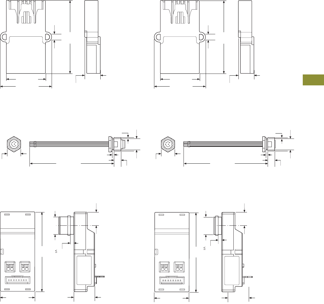
Volume 7—Logic Control, Operator Interface and Connectivity Solutions CA08100008E—February 2014 www.eaton.com V7-T9-35
9
9
9
9
9
9
9
9
9
9
9
9
9
9
9
9
9
9
9
9
9
9
9
9
9
9
9
9
9
9
9.1
Connectivity Solutions
SmartWire-DT Panel Wiring Solution
Approximate Dimensions in Inches (mm)
Terminating Resistor
SWD4-RC8-10
Coupling
SWD4-8SFF2-5
Enclosure Bushing Plug
SWD4-SM8-20
Enclosure Bushing Socket
SWD4-SF8-20
Cabinet Cable Adapter Plug
SWD4-SML8-20
Cabinet Cable Adapter Socket
SWD4-SFL8-20
1.91
(48.4)
1.02 (25.9)
0.40 (10.2)
0.16
(4.0)
1.35 (34.3)
1.91
(48.4)
1.02 (25.9)
0.40 (10.2)
0.16
(4.0)
1.35 (34.3)
5.67 (144.0)
0.95 (24.0)
0.50 (12.5)
0.12 (3.0)
M20 x 1.5
Ø 0.94 (24.0)
5.95 (151.0)
0.95 (24.0)
0.47 (12.0)
0.12 (3.0)
M20 x 1.5
Ø 0.94 (24.0)
3.24
(82.4)
1.38 (35.0)
0.55
(14.0)
M18 x 0.75
0.83
(21.0)
0.16
(4.0)
3.24
(82.4)
1.38 (35.0)
0.55
(14.0)
M18 x 0.75
0.83
(21.0)
0.16
(4.0)
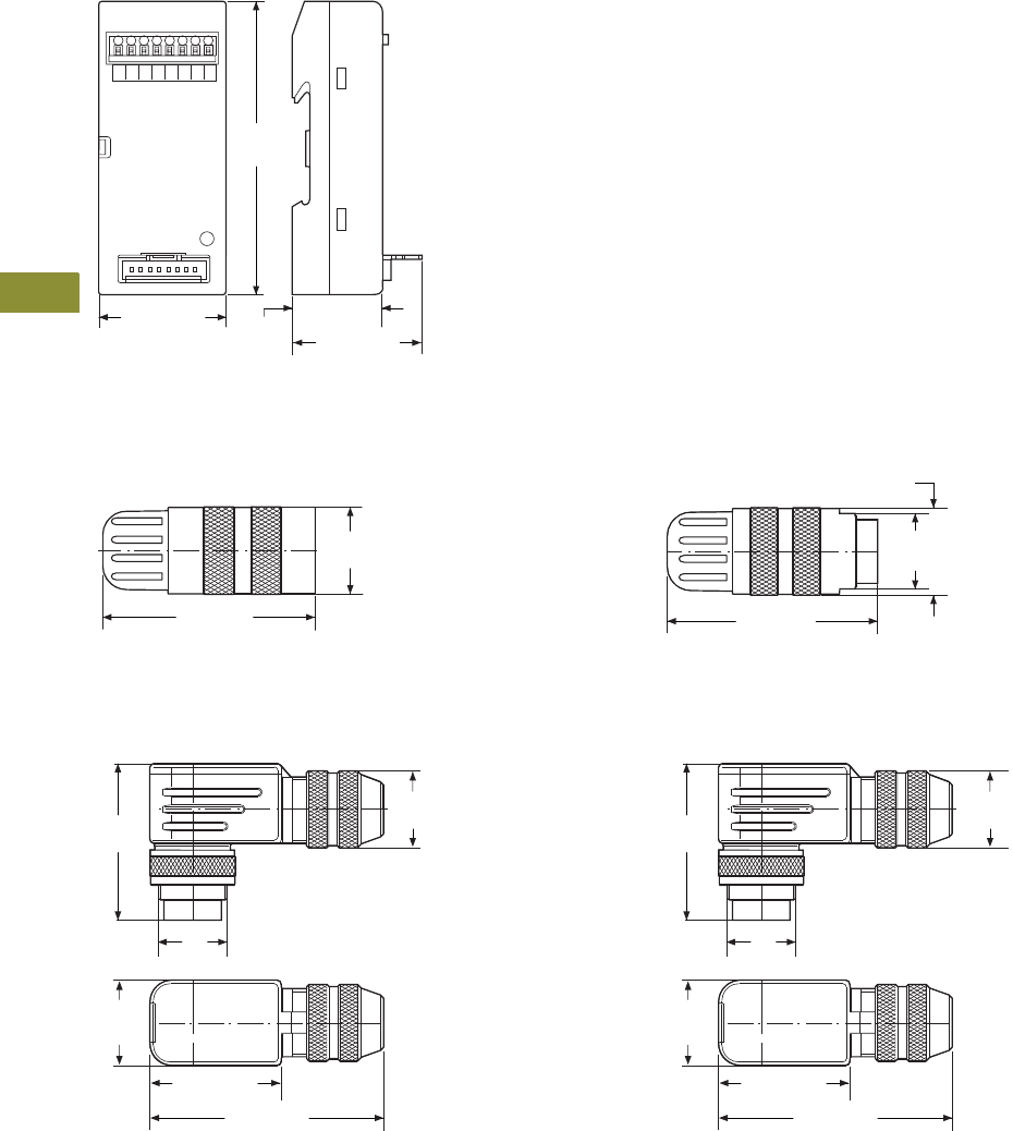
V7-T9-36 Volume 7—Logic Control, Operator Interface and Connectivity Solutions CA08100008E—February 2014 www.eaton.com
9
9
9
9
9
9
9
9
9
9
9
9
9
9
9
9
9
9
9
9
9
9
9
9
9
9
9
9
9
9
9.1
Connectivity Solutions
SmartWire-DT Panel Wiring Solution
Approximate Dimensions in Inches (mm)
Panel Cable Adapter
SWD4-8FRF-10
Round Cable Socket
SWD4-SF8-67
Round Cable Plug
SWD4-SM8-67
Right Angle Round Cable Socket
SWD4-SF8-67W
Right Angle Round Cable Plug
SWD4-SM8-67W
3.54
(90.0)
1.38 (35.0) 0.91
(23.2) 1.42 (36.0)
Ø 0.73
(18.5)
1.77 (45.0)
1.75 (44.5)
M16 x 0.75
Ø 0.73
(18.5)
Ø 0.71
(18.0)
M16 x 0.75
1.47
(37.4)
2.13 (54.0)
0.79
(20.0)
1.21 (30.8)
M16 x 0.75
1.46
(37.1)
2.17 (55.0)
0.79
(20.0)
1.21 (30.8)
Ø 0.71
(18.0)
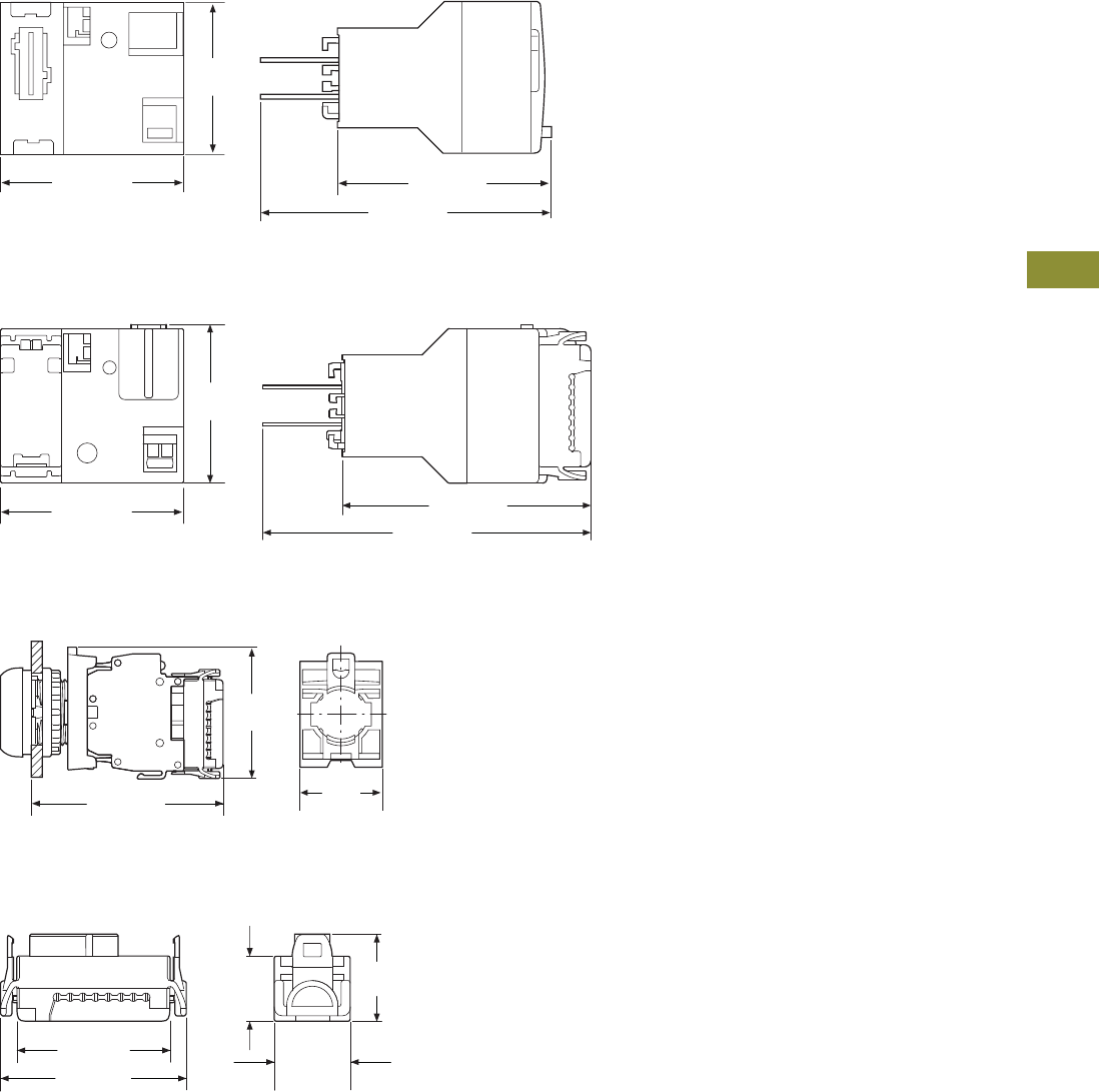
Volume 7—Logic Control, Operator Interface and Connectivity Solutions CA08100008E—February 2014 www.eaton.com V7-T9-37
9
9
9
9
9
9
9
9
9
9
9
9
9
9
9
9
9
9
9
9
9
9
9
9
9
9
9
9
9
9
9.1
Connectivity Solutions
SmartWire-DT Panel Wiring Solution
Approximate Dimensions in Inches (mm)
Contactor Modules
DIL-SWD-32-001 and DIL-SWD-32-002
SmartWire-DT PKE Modules
PKE-SWD-32
Pilot Device Modules
M22-SWD-K_, M22-SWD-LED_
Device Plug
SWD4-8SF2-5
1.50
(38.0)
1.77 (45.0) 2.10 (53.1)
2.85 (72.3)
1.54
(39.0)
1.77 (45.0) 2.41 (61.1)
3.17 (80.6)
2.52 (64.0)
1.73
(44.0)
1.18
(30.0)
0.68
(17.2)
1.43 (36.4)
0.50
(12.8)
1.18 (30.0) 0.59
(14.9)
Volume 7—Logic Control, Operator Interface and Connectivity Solutions CA08100008E—February 2014 www.eaton.com V7-A1-1
Appendix 1—Eaton Terms & Conditions
Effective Date: November 1, 2008
Eaton Terms & Conditions
Contents
Description Page
Terms and Conditions of Sale. . . . . . . . . . . . . . . . . V7-A1-1
Terms of Payment . . . . . . . . . . . . . . . . . . . . . . . . . V7-A1-2
Freight . . . . . . . . . . . . . . . . . . . . . . . . . . . . . . . . . . V7-A1-3
Warranty. . . . . . . . . . . . . . . . . . . . . . . . . . . . . . . . . V7-A1-3
Selling Policy (Supersedes Selling Policy 25-000, dated February 20, 2006)
Terms and Conditions of Sale
The Terms and Conditions of
Sale set forth herein, and any
supplements which may be
attached hereto, constitute
the full and final expression
of the contract for the sale
of products or services
(hereinafter referred to as
Product(s) or Services by
Eaton Corporation
(hereinafter referred to as
Seller) to the Buyer, and
supersedes all prior
quotations, purchase orders,
correspondence or
communications whether
written or oral between the
Seller and the Buyer.
Notwithstanding any contrary
language in the Buyer’s
purchase order,
correspondence or other
form of acknowledgment,
Buyer shall be bound by
these Terms and Conditions
of Sale when it sends a
purchase order or otherwise
indicates acceptance of this
contract, or when it accepts
delivery from Seller of the
Products or Services.
THE CONTRACT FOR SALE
OF THE PRODUCTS OR
SERVICES IS EXPRESSLY
LIMITED TO THE TERMS
AND CONDITIONS OF SALE
STATED HEREIN. ANY
ADDITIONAL OR DIFFERENT
TERMS PROPOSED BY
BUYER ARE REJECTED
UNLESS EXPRESSLY
AGREED TO IN WRITING BY
SELLER. No contract shall
exist except as herein
provided.
Complete Agreement
No amendment or
modification hereto nor any
statement, representation or
warranty not contained herein
shall be binding on the Seller
unless made in writing by an
authorized representative of
the Seller. Prior dealings,
usage of the trade or a course
of performance shall not be
relevant to determine the
meaning of this contract even
though the accepting or
acquiescing party had
knowledge of the nature
of the performance and
opportunity for objection.
Quotations
Written quotations are valid
for 30 days from its date
unless otherwise stated in
the quotation or terminated
sooner by notice.
Verbal quotations, unless
accepted, expire the same
day they are made.
A complete signed order
must be received by Seller
within 20 calendar days of
notification of award,
otherwise the price and
shipment will be subject to
re-negotiation.
Termination and Cancellation
Any order may be terminated
by the Buyer only by written
notice and upon payment
of reasonable termination
charges, including all costs
plus profit.
Seller shall have the right to
cancel any order at any time
by written notice if Buyer
breaches any of the terms
hereof, becomes the subject
of any proceeding under state
or federal law for the relief
of debtors, or otherwise
becomes insolvent or
bankrupt, generally does not
pay its debts as they become
due or makes an assignment
for the benefit of creditors.
V7-A1-2 Volume 7—Logic Control, Operator Interface and Connectivity Solutions CA08100008E—February 2014 www.eaton.com
Appendix 1—Eaton Terms & Conditions
Effective Date: November 1, 2008
Prices
All prices are subject to
change without notice. In the
event of a price change, the
effective date of the change
will be the date of the new
price or discount sheet, letter
or telegram. All quotations
made or orders accepted
after the effective date will be
on the new basis. For existing
orders, the price of the
unshipped portion of an order
will be the price in effect at
time of shipment.
Price Policy—Products and
Services
When prices are quoted as
firm for quoted shipment, they
are firm provided the following
conditions are met:
1. The order is released
with complete
engineering details.
2. Shipment of Products are
made, and Services
purchased are provided
within the quoted
lead time.
3. When drawings for
approval are required
for any Products, the
drawings applicable to
those Products must be
returned within 30*
calendar days from the
date of the original
mailing of the drawings
by Seller. The return
drawings must be
released for manufacture
and shipment and must
be marked “APPROVED”
or “APPROVED AS
NOTED.” Drawing
re-submittals which are
required for any other
reason than to correct
Seller errors will not
extend the 30-day period.
* 60 days for orders
through contractors
to allow time for their
review and approval
before and after
transmitting them
to their customers.
If the Buyer initiates or in
any way causes delays
in shipment, provision of
Services or return of approval
drawings beyond the periods
stated above, the price of the
Products or Services will be
increased 1% per month
or fraction thereof up to a
maximum of 18 months from
the date of the Buyer’s order.
For delays resulting in
shipment or provision of
Services beyond 18 months
from the date of the Buyer’s
order, the price must be
renegotiated.
Price Policy—BLS
Refer to Price Policy 25-050.
Minimum Billing
Orders less than $1,000 will
be assessed a shipping and
handling charge of 5% of the
price of the order, with a
minimum charge of $25.00
unless noted differently on
Product discount sheets.
Taxes
The price does not include
any taxes. Buyer shall be
responsible for the payment
of all taxes applicable to, or
arising from the transaction,
the Products, its sale, value,
or use, or any Services
performed in connection
therewith regardless of
the person or entity
actually taxed.
Terms of Payment
Products
Acceptance of all orders is
subject to the Buyer meeting
Seller’s credit requirements.
Terms of payment are subject
to change for failure to meet
such requirements. Seller
reserves the right at any time
to demand full or partial
payment before proceeding
with a contract of sale as a
result of changes in the
financial condition of the
Buyer. Terms of Payment are
either Net 30 days from the
date of invoice of each
shipment or carry a cash
discount based on Product
type. Specific payment terms
for Products are outlined in
the applicable Product
discount schedules.
Services
Terms of payment are net
within 30 days from date of
invoice for orders amounting
to less than $50,000.00.
Terms of payment for orders
exceeding $50,000.00 shall
be made according to the
following:
1. Twenty percent (20%) of
order value with the
purchase order payable
30 days from date of
invoice.
2. Eighty percent (80%) of
order value in equal
monthly payments over
the performance period
payable 30 days from
date of invoice.
Except for work performed (i)
under a firm fixed price basis
or (ii) pursuant to terms of a
previously priced existing
contract between Seller and
Buyer, invoices for work
performed by Seller shall
have added and noted on
each invoice a charge of 3%
(over and above the price of
the work) which is related
to Seller compliance with
present and proposed
environmental, health, and
safety regulations associated
with prescribed requirements
covering hazardous materials
management and employee
training, communications,
personal protective
equipment, documentation
and record keeping
associated therewith.
Adequate Assurances
If, in the judgment of Seller,
the financial condition of the
Buyer, at any time during the
period of the contract, does
not justify the terms of
payment specified, Seller
may require full or partial
payment in advance.
Delayed Payment
If payments are not made in
accordance with these terms,
a service charge will, without
prejudice to the right of Seller
to immediate payment, be
added in an amount equal to
the lower of 1.5% per month
or fraction thereof or the
highest legal rate on the
unpaid balance.
Volume 7—Logic Control, Operator Interface and Connectivity Solutions CA08100008E—February 2014 www.eaton.com V7-A1-3
Appendix 1—Eaton Terms & Conditions
Effective Date: November 1, 2008
Freight
Freight policy will be listed on
the Product discount sheets,
or at option of Seller one of
the following freight terms
will be quoted.
F.O.B.—P/S—Frt./Ppd. and
Invoiced
Products are sold F.O.B. point
of shipment freight prepaid
and invoiced to the Buyer.
F.O.B.—P/S—Frt./Ppd.
and Allowed
Products sold are delivered
F.O.B. point of shipment,
freight prepaid and included
in the price.
F.O.B. Destination—Frt./Ppd.
and Allowed
At Buyer’s option, Seller will
deliver the Products F.O.B.
destination freight prepaid
and 2% will be added to the
net price.
The term “freight prepaid”
means that freight charges
will be prepaid to the
accessible common carrier
delivery point nearest the
destination for shipments
within the United States and
Puerto Rico unless noted
differently on the Product
discount sheets. For any
other destination contact
Seller’s representative.
Shipment and Routing
Seller shall select the point of
origin of shipment, the
method of transportation, the
type of carrier equipment and
the routing of the shipment.
If the Buyer specifies a
special method of
transportation, type of carrier
equipment, routing, or
delivery requirement, Buyer
shall pay all special freight
and handling charges.
When freight is included in
the price, no allowance will
be made in lieu of
transportation if the Buyer
accepts shipment at factory,
warehouse, or freight station
or otherwise supplies its own
transportation.
Risk of Loss
Risk of loss or damage to the
Products shall pass to Buyer
at the F.O.B. point.
Concealed Damage
Except in the event of F.O.B.
destination shipments, Seller
will not participate in any
settlement of claims for
concealed damage.
When shipment has been
made on an F.O.B. destination
basis, the Buyer must unpack
immediately and, if damage is
discovered must:
1. Not move the Products
from the point of
examination.
2. Retain shipping container
and packing material.
3. Notify the carrier in
writing of any apparent
damage.
4. Notify Seller
representative within
72 hours of delivery.
5. Send Seller a copy of
the carrier’s inspection
report.
Witness Tests/Customer
Inspection
Standard factory tests may be
witnessed by the Buyer
at Seller’s factory for an
additional charge calculated
at the rate of $2,500 per day
(not to exceed eight (8) hours)
per Product type. Buyer may
final inspect Products at the
Seller’s factory for $500 per
day per Product type.
Witness tests will add one (1)
week to the scheduled
shipping date. Seller will
notify Buyer fourteen (14)
calendar days prior to
scheduled witness testing
or inspection. In the event
Buyer is unable to attend, the
Parties shall mutually agree
on a rescheduled date.
However, Seller reserves
the right to deem the witness
tests waived with the right to
ship and invoice Products.
Held Orders
For any order held, delayed
or rescheduled at the request
of the Buyer, Seller may, at
its sole option (1) require
payment to be based on any
reasonable basis, including
but not limited to the contract
price, and any additional
expenses, or cost resulting
from such a delay; (2) store
Products at the sole cost and
risk of loss of the Buyer; and/
or (3) charge to the Buyer
those prices under the
applicable price policy.
Payment for such price,
expenses and costs, in any
such event, shall be due by
Buyer within thirty (30) days
from date of Seller’s invoice.
Any order so held delayed or
rescheduled beyond six (6)
months will be treated as a
Buyer termination.
Drawing Approval
Seller will design the
Products in line with, in
Seller’s judgment, good
commercial practice. If at
drawing approval Buyer
makes changes outside of
the design as covered in their
specifications, Seller will then
be paid reasonable charges
and allowed a commensurate
delay in shipping date based
on the changes made.
Drawing Re-Submittal
When Seller agrees to do so
in its quotation, Seller shall
provide Buyer with the first
set of factory customer
approval drawing(s) at Seller’s
expense. The customer
approval drawing(s) will be
delivered at the quoted
delivery date. If Buyer
requests drawing changes
or additions after the initial
factory customer approval
drawing(s) have been
submitted by Seller, the
Seller, at its option, may
assess Buyer drawing
charges. Factory customer
approval drawing changes
required due to
misinterpretation by Seller
will be at Seller’s expense.
Approval drawings generated
by Bid Manager are excluded
from this provision.
Warranty
Warranty for Products
Seller warrants that the
Products manufactured by
it will conform to Seller’s
applicable specifications and
be free from failure due to
defects in workmanship and
material for one (1) year from
the date of installation of
the Product or eighteen (18)
months from the date of
shipment of the Product,
whichever occurs first.
In the event any Product fails
to comply with the foregoing
warranty Seller will, at its
option, either (a) repair or
replace the defective
Product, or defective part or
component thereof, F.O.B.
Seller’s facility freight
prepaid, or (b) credit Buyer
for the purchase price of the
Product. All warranty claims
shall be made in writing.
Seller requires all non-
conforming Products be
returned at Seller’s expense
for evaluation unless
specifically stated otherwise
in writing by Seller.
This warranty does not
cover failure or damage
due to storage, installation,
operation or maintenance not
in conformance with Seller’s
recommendations and
industry standard practice
or due to accident, misuse,
abuse or negligence. This
warranty does not cover
reimbursement for labor,
gaining access, removal,
installation, temporary power
or any other expenses, which
may be incurred in connection
with repair or replacement.
This warranty does not
apply to equipment not
manufactured by Seller.
Seller limits itself to
extending the same warranty
it receives from the supplier.
V7-A1-4 Volume 7—Logic Control, Operator Interface and Connectivity Solutions CA08100008E—February 2014 www.eaton.com
Appendix 1—Eaton Terms & Conditions
Effective Date: November 1, 2008
Extended Warranty for Products
If requested by the Buyer and
specifically accepted in
writing by Seller, the
foregoing standard warranty
for Products will be extended
from the date of shipment for
the period and price indicated
below:
●24 months—2% of
Contract Price
●30 months—3% of
Contract Price
●36 months—4% of
Contract Price
Special Warranty (In and Out)
for Products
If requested by the Buyer
and specifically accepted in
writing by Seller, Seller will,
during the warranty period
for Products, at an additional
cost of 2% of the contract
price, be responsible for the
direct cost of:
1. Removing the Product
from the installed
location.
2. Transportation to the
repair facility and return
to the site.
3. Reinstallation on site.
The total liability of Seller for
this Special Warranty for
Products is limited to 50%
of the contract price of the
particular Product being
repaired and excludes
expenses for removing
adjacent apparatus, walls,
piping, structures, temporary
service, etc.
Warranty for Services
Seller warrants that the
Services performed by it
hereunder will be performed
in accordance with generally
accepted professional
standards.
The Services, which do not
so conform, shall be
corrected by Seller upon
notification in writing by the
Buyer within one (1) year
after completion of the
Services.
Unless otherwise agreed to in
writing by Seller, Seller
assumes no responsibility
with respect to the suitability
of the Buyer’s, or its
customer’s, equipment or
with respect to any latent
defects in equipment not
supplied by Seller. This
warranty does not cover
damage to Buyer’s, or its
customer’s, equipment,
components or parts
resulting in whole or in part
from improper maintenance
or operation or from their
deteriorated condition. Buyer
will, at its cost, provide Seller
with unobstructed access
to the defective Services,
as well as adequate free
working space in the
immediate vicinity of the
defective Services and such
facilities and systems,
including, without limitation,
docks, cranes and utility
disconnects and connects,
as may be necessary in order
that Seller may perform its
warranty obligations. The
conducting of any tests shall
be mutually agreed upon and
Seller shall be notified of, and
may be present at, all tests
that may be made.
Warranty for Power Systems
Studies
Seller warrants that any
power systems studies
performed by it will conform
to generally accepted
professional standards. Any
portion of the study, which
does not so conform, shall
be corrected by Seller upon
notification in writing by the
Buyer within six (6) months
after completion of the study.
All warranty work shall be
performed in a single shift
straight time basis Monday
through Friday. In the event
that the study requires
correction of warranty items
on an overtime schedule,
the premium portion of such
overtime shall be for the
Buyer’s account.
Limitation on Warranties for
Products, Services and Power
Systems Studies
THE FOREGOING
WARRANTIES ARE
EXCLUSIVE EXCEPT FOR
WARRANTY OF TITLE.
SELLER DISCLAIMS ALL
OTHER WARRANTIES
INCLUDING ANY IMPLIED
WARRANTIES OF
MERCHANTABILITY
AND FITNESS FOR A
PARTICULAR PURPOSE.
CORRECTION OF NON-
CONFORMITIES IN THE
MANNER AND FOR THE
PERIOD OF TIME PROVIDED
ABOVE SHALL CONSTITUTE
SELLER’S SOLE LIABILITY
AND BUYER’S EXCLUSIVE
REMEDY FOR FAILURE OF
SELLER TO MEET ITS
WARRANTY OBLIGATIONS,
WHETHER CLAIMS OF
THE BUYER ARE BASED
IN CONTRACT, IN TORT
(INCLUDING NEGLIGENCE
OR STRICT LIABILITY), OR
OTHERWISE.
Asbestos
Federal Law requires that
building or facility owners
identify the presence,
location and quantity of
asbestos containing material
(hereinafter “ACM”) at work
sites. Seller is not licensed to
abate ACM. Accordingly, for
any contract which includes
the provision of Services,
prior to (i) commencement of
work at any site under a
specific Purchase Order, (ii) a
change in the work scope of
any Purchase Order, the
Buyer will certify that the
work area associated with the
Seller’s scope of work
includes the handling of Class
II ACM, including but not
limited to generator wedges
and high temperature gaskets
which include asbestos
materials. The Buyer shall, at
its expense, conduct
abatement should the
removal, handling,
modification or reinstallation,
or some or all of them, of said
Class II ACM be likely to
generate airborne asbestos
fibers; and should such
abatement affect the cost
of or time of performance
of the work then Seller shall
be entitled to an equitable
adjustment in the schedule,
price and other pertinent
affected provisions of
the contract.
Compliance with Nuclear
Regulation
Seller’s Products are sold as
commercial grade Products
not intended for application in
facilities or activities licensed
by the United States Nuclear
Regulatory Commission for
atomic purposes. Further
certification will be required
for use of the Products in any
safety-related application in
any nuclear facility licensed
by the U.S. Nuclear
Regulatory Commission.
Volume 7—Logic Control, Operator Interface and Connectivity Solutions CA08100008E—February 2014 www.eaton.com V7-A1-5
Appendix 1—Eaton Terms & Conditions
Effective Date: November 1, 2008
Returning Products
Authorization and shipping
instructions for the return
of any Products must be
obtained from Seller before
returning the Products.
When return is occasioned
due to Seller error, full credit
including all transportation
charges will be allowed.
Product Notices
Buyer shall provide the user
(including its employees) of
the Products with all Seller
supplied Product notices,
warnings, instructions,
recommendations, and
similar materials.
Force Majeure
Seller shall not be liable for
failure to perform or delay
in performance due to fire,
flood, strike or other labor
difficulty, act of God, act of
any governmental authority or
of the Buyer, riot, embargo,
fuel or energy shortage, car
shortage, wrecks or delays in
transportation, or due to any
other cause beyond Seller’s
reasonable control. In the
event of delay in performance
due to any such cause, the
date of delivery or time for
completion will be extended
by a period of time reasonably
necessary
to overcome the
effect of such delay.
Liquidated Damages
Contracts which include
liquidated damage clauses for
failure to meet shipping or job
completion promises are not
acceptable or binding on
Seller, unless such clauses
are specifically accepted in
writing by an authorized
representative of the Seller at
its headquarters office.
Patent Infringement
Seller will defend or, at its
option, settle any suit or
proceeding brought against
Buyer, or Buyer’s customers,
to the extent it is based upon
a claim that any Product or
part thereof, manufactured by
Seller or its subsidiaries and
furnished hereunder,
infringes any United States
patent, other than a claim of
infringement based upon use
of a Product or part thereof in
a process, provided Seller is
notified in reasonable time
and given authority,
information and assistance
(at Seller’s expense) for the
defense of same. Seller shall
pay all legal and court costs
and expenses and court-
assessed damages awarded
therein against Buyer
resulting from or incident to
such suit or proceeding. In
addition to the foregoing, if at
any time Seller determines
there is a substantial question
of infringement of any United
States patent, and the use of
such Product is or may be
enjoined, Seller may, at its
option and expense: either (a)
procure for Buyer the right to
continue using and selling the
Product; (b) replace the
Product with non-infringing
apparatus; (c) modify the
Product so it becomes non-
infringing; or (d) as a last
resort, remove the Product
and refund the purchase
price, equitably adjusted for
use and obsolescence. In no
case does Seller agree to pay
any recovery based upon its
Buyer’s savings or profit
through use of Seller’s
Products whether the use be
special or ordinary. The
foregoing states the entire
liability of Seller for patent
infringement.
The preceding paragraph
does not apply to any claim of
infringement based upon: (a)
any modification made to a
Product other than by Seller;
(b) any design and/or
specifications of Buyer to
which a Product was
manufactured; or (c) the use
or combination of Product
with other products where
the Product does not itself
infringe. As to the above-
identified claim situations
where the preceding
paragraph does not apply,
Buyer shall defend and hold
Seller harmless in the same
manner and to the extent as
Seller’s obligations described
in the preceding paragraph.
Buyer shall be responsible for
obtaining (at Buyer’s
expense) all license rights
required for Seller to be able
to use software products in
the possession of Buyer
where such use is required in
order to perform any Service
for Buyer.
With respect to a Product or
part thereof not manufactured
by Seller or its subsidiaries,
Seller will attempt to obtain
for Buyer, from the supplier(s),
the patent indemnification
protection normally provided
by the supplier(s) to
customers.
Compliance with OSHA
Seller offers no warranty and
makes no representation that
its Products comply with the
provisions or standards of the
Occupational Safety and
Health Act of 1970, or any
regulation issued thereunder.
In no event shall Seller be
liable for any loss, damage,
fines, penalty or expenses
arising under said Act.
Limitation of Liability
THE REMEDIES OF THE
BUYER SET FORTH IN THIS
CONTRACT ARE EXCLUSIVE
AND ARE ITS SOLE
REMEDIES FOR ANY
FAILURE OF SELLER
TO COMPLY WITH ITS
OBLIGATIONS HEREUNDER.
NOTWITHSTANDING
ANY PROVISION IN THIS
CONTRACT TO THE
CONTRARY, IN NO EVENT
SHALL SELLER BE LIABLE
IN CONTRACT, IN TORT
(INCLUDING NEGLIGENCE
OR STRICT LIABILITY) OR
OTHERWISE FOR DAMAGE
TO PROPERTY OR
EQUIPMENT OTHER THAN
PRODUCTS SOLD
HEREUNDER, LOSS OF
PROFITS OR REVENUE,
LOSS OF USE OF
PRODUCTS, COST OF
CAPITAL, CLAIMS OF
CUSTOMERS OF THE
BUYER OR ANY SPECIAL,
INDIRECT, INCIDENTAL OR
CONSEQUENTIAL
DAMAGES WHATSOEVER,
REGARDLESS OF WHETHER
SUCH POTENTIAL
DAMAGES ARE
FORESEEABLE OR IF
SELLER HAS BEEN ADVISED
OF THE POSSIBILITY OF
SUCH DAMAGES.
THE TOTAL CUMULATIVE
LIABILITY OF SELLER
ARISING FROM OR
RELATED TO THIS
CONTRACT WHETHER
THE CLAIMS ARE BASED
IN CONTRACT, IN TORT
(INCLUDING NEGLIGENCE
OR STRICT LIABILITY) OR
OTHERWISE, SHALL NOT
EXCEED THE PRICE OF THE
PRODUCT OR SERVICES
ON WHICH SUCH LIABILITY
IS BASED.
Volume 7—Logic Control, Operator Interface and Connectivity Solutions CA08100008E—March 2014 www.eaton.com V7-A2-1
Appendix 2—Catalog Parent Number Index
A
APP . . . . . . . . . . . V7-T5-17
AR . . . . . . . . . . . . V7-T3-158
ARA . . . . . . . . . . . V7-T3-159
ARC . . . . . . . . . . . V7-T3-158
ARD. . . . . . . . . . . V7-T3-158, V7-T3-159
ARM . . . . . . . . . . V7-T3-159
ARO. . . . . . . . . . . V7-T3-158
ARS . . . . . . . . . . . V7-T3-159
B
BF . . . . . . . . . . . . V7-T3-152, V7-T3-153
BFD . . . . . . . . . . . V7-T3-152, V7-T3-153
BFM . . . . . . . . . . V7-T3-154
C
CE0 . . . . . . . . . . . V7-T7-19, V7-T7-20
CE1 . . . . . . . . . . . V7-T7-20
CE2 . . . . . . . . . . . V7-T7-20
CE3 . . . . . . . . . . . V7-T7-20
CE5 . . . . . . . . . . . V7-T7-20
CHCP. . . . . . . . . . V7-T8-126
CHD. . . . . . . . . . . V7-T8-118
CH16 . . . . . . . . . . V7-T8-124
C0 . . . . . . . . . . . . V7-T7-14
C00 . . . . . . . . . . . V7-T7-5–V7-T7-9, V7-T7-26
C01 . . . . . . . . . . . V7-T7-5–V7-T7-9
C02 . . . . . . . . . . . V7-T7-5–V7-T7-9
C03 . . . . . . . . . . . V7-T7-5–V7-T7-9
C05 . . . . . . . . . . . V7-T7-5–V7-T7-9
C07 . . . . . . . . . . . V7-T7-5–V7-T7-8
C1 . . . . . . . . . . . . V7-T7-14
C10 . . . . . . . . . . . V7-T7-5–V7-T7-7
C15 . . . . . . . . . . . V7-T7-5–V7-T7-7
C2 . . . . . . . . . . . . V7-T7-14
C22 . . . . . . . . . . . V7-T1-141–V7-T1-148
C22-L. . . . . . . . . . V7-T1-150
C22-P. . . . . . . . . . V7-T1-152, V7-T1-153
C22S . . . . . . . . . . V7-T1-141–V7-T1-148
C22S-W . . . . . . . . V7-T1-155–V7-T1-158
C22-W . . . . . . . . . V7-T1-155–V7-T1-158
C3 . . . . . . . . . . . . V7-T7-14
C320 . . . . . . . . . . V7-T3-147, V7-T3-148
C321 . . . . . . . . . . V7-T3-148
C350 . . . . . . . . . . V7-T8-132
C381 . . . . . . . . . . V7-T8-108, V7-T8-109
C383 . . . . . . . . . . V7-T8-130
C5 . . . . . . . . . . . . V7-T7-14
D
DIL-SWD . . . . . . V7-T9-14
D1PA . . . . . . . . . V7-T3-55
D1PF . . . . . . . . . V7-T3-54
D1PR . . . . . . . . . V7-T3-54
D15C . . . . . . . . . V7-T3-147
D2PA . . . . . . . . . V7-T3-61
D2PF . . . . . . . . . V7-T3-60
D2PJ . . . . . . . . . V7-T3-61, V7-T3-120
D2PR . . . . . . . . . V7-T3-60
D26 . . . . . . . . . . V7-T3-168, V7-T3-169
D26M. . . . . . . . . V7-T3-163–V7-T3-165
D3PA . . . . . . . . . V7-T3-71, V7-T3-181, V7-T3-184, V7-T3-188,
V7-T3-193
D3PF . . . . . . . . . V7-T3-70
D3PJ . . . . . . . . . V7-T3-71, V7-T3-85, V7-T3-120
D3PR . . . . . . . . . V7-T3-70
D4PA . . . . . . . . . V7-T3-79
D4PR . . . . . . . . . V7-T3-79
D5PA . . . . . . . . . V7-T3-85, V7-T3-181
D5PF . . . . . . . . . V7-T3-84
D5PR . . . . . . . . . V7-T3-84, V7-T3-85
D65C . . . . . . . . . V7-T3-184, V7-T3-188, V7-T3-193
D7PA . . . . . . . . . V7-T3-95
D7PF . . . . . . . . . V7-T3-93
D7PR . . . . . . . . . V7-T3-94
D8PA . . . . . . . . . V7-T3-107
D8PR . . . . . . . . . V7-T3-107
D851 . . . . . . . . . V7-T3-193
D852 . . . . . . . . . V7-T3-193
D9PR . . . . . . . . . V7-T3-113
D93 . . . . . . . . . . V7-T3-128
D96 . . . . . . . . . . V7-T3-135
D99 . . . . . . . . . . V7-T3-140
E
EASY . . . . . . . . . V7-T3-23, V7-T3-31, V7-T3-40, V7-T3-43,
V7-T3-45
EASY-LINK . . . . . V7-T3-45
EASY-NT . . . . . . V7-T4-32
EASYSOFT. . . . . V7-T3-44
ELC . . . . . . . . . . V7-T4-9–V7-T4-13, V7-T5-7–V7-T5-9, V7-T5-17,
V7-T6-13
ELC-AC . . . . . . . V7-T4-14
ELC-ACC . . . . . . V7-T4-15
ELCB . . . . . . . . . V7-T4-5
ELC-BAT . . . . . . V7-T4-15
ELC-CB . . . . . . . V7-T4-14
ELC-HHP . . . . . . V7-T4-14
ELC-IO . . . . . . . . V7-T4-15
ELCM. . . . . . . . . V7-T4-6, V7-T4-7
ELC-PS. . . . . . . . V7-T4-14
ELCSOFT . . . . . . V7-T4-15
ELC-SP. . . . . . . . V7-T4-15
V7-A2-2 Volume 7—Logic Control, Operator Interface and Connectivity Solutions CA08100008E—March 2014 www.eaton.com
Appendix 2—Catalog Parent Number Index
ESR5 . . . . . . . . . . V7-T3-198
ES16 . . . . . . . . . . V7-T1-41
ES4P . . . . . . . . . . V7-T3-204
EU4A-RJ45 . . . . . V7-T4-32
EU5 . . . . . . . . . . . V7-T9-7
EZ . . . . . . . . . . . . V7-T6-16
E01 . . . . . . . . . . . V7-T1-40
E10 . . . . . . . . . . . V7-T1-40
E10E . . . . . . . . . . V7-T1-4, V7-T1-5, V7-T1-9
E10P . . . . . . . . . . V7-T1-5
E10T . . . . . . . . . . V7-T1-4, V7-T1-5, V7-T1-9
E22B . . . . . . . . . . V7-T2-40
E22C . . . . . . . . . . V7-T1-175, V7-T1-229, V7-T1-280
E22L . . . . . . . . . . V7-T1-239, V7-T1-271, V7-T1-343
E26B . . . . . . . . . . V7-T2-36, V7-T2-38, V7-T2-39
E26S . . . . . . . . . . V7-T2-37, V7-T2-38, V7-T2-40
E26X . . . . . . . . . . V7-T2-35
E29K . . . . . . . . . . V7-T1-229
E30A . . . . . . . . . . V7-T1-166, V7-T1-167
E30B . . . . . . . . . . V7-T1-167
E30C . . . . . . . . . . V7-T1-167
E30D . . . . . . . . . . V7-T1-168
E30E . . . . . . . . . . V7-T1-168
E30J . . . . . . . . . . V7-T1-168
E30K . . . . . . . . . . V7-T1-169–V7-T1-175, V7-T1-178, V7-T1-229
E34A . . . . . . . . . . V7-T1-277, V7-T1-351
E34C . . . . . . . . . . V7-T1-262, V7-T1-264, V7-T1-270, V7-T1-333,
V7-T1-336, V7-T1-342
E34E . . . . . . . . . . V7-T1-260, V7-T1-261, V7-T1-328
E34EX . . . . . . . . . V7-T1-23, V7-T1-324, V7-T1-325, V7-T1-327,
V7-T1-330, V7-T1-331, V7-T1-335–V7-T1-339,
V7-T1-344, V7-T1-345
E34F . . . . . . . . . . V7-T1-260, V7-T1-262, V7-T1-284, V7-T1-332,
V7-T1-333
E34G . . . . . . . . . . V7-T1-263–V7-T1-268, V7-T1-332, V7-T1-334,
V7-T1-340
E34H . . . . . . . . . . V7-T1-263, V7-T1-334
E34J . . . . . . . . . . V7-T1-260, V7-T1-261, V7-T1-264, V7-T1-270,
V7-T1-329, V7-T1-336, V7-T1-342
E34K . . . . . . . . . . V7-T1-276, V7-T1-277, V7-T1-350, V7-T1-351
E34L . . . . . . . . . . V7-T1-202, V7-T1-260, V7-T1-261, V7-T1-267,
V7-T1-277, V7-T1-281, V7-T1-282, V7-T1-329,
V7-T1-351
E34M. . . . . . . . . . V7-T1-265, V7-T1-270, V7-T1-337, V7-T1-342
E34N . . . . . . . . . . V7-T1-233, V7-T1-262, V7-T1-283, V7-T1-333,
V7-T1-356
E34P . . . . . . . . . . V7-T1-260, V7-T1-261, V7-T1-263, V7-T1-267,
V7-T1-282, V7-T1-328
E34R . . . . . . . . . . V7-T1-260, V7-T1-262, V7-T1-282, V7-T1-332,
V7-T1-333
E34S . . . . . . . . . . V7-T1-262, V7-T1-278, V7-T1-281, V7-T1-282,
V7-T1-333, V7-T1-353
E34T . . . . . . . . . . V7-T1-260, V7-T1-262, V7-T1-279, V7-T1-280,
V7-T1-332, V7-T1-333
E34V . . . . . . . . . . V7-T1-263, V7-T1-272, V7-T1-276, V7-T1-278,
V7-T1-330, V7-T1-331, V7-T1-334, V7-T1-350,
V7-T1-353
E34X . . . . . . . . . . V7-T1-262, V7-T1-333
E8 . . . . . . . . . . . . V7-T1-40
F
FAK . . . . . . . . . . V7-T1-109, V7-T1-110
FSK . . . . . . . . . . V7-T7-10, V7-T7-21
H
HMI . . . . . . . . . . V7-T5-15–V7-T5-17
HMIVU . . . . . . . . V7-T5-15
HT8A . . . . . . . . . V7-T1-298, V7-T1-299, V7-T1-311, V7-T1-314
HT8B . . . . . . . . . V7-T1-314, V7-T1-315
HT8C . . . . . . . . . V7-T1-298, V7-T1-306, V7-T1-314
HT8D . . . . . . . . . V7-T1-306, V7-T1-314
HT8E . . . . . . . . . V7-T1-314
HT8F . . . . . . . . . V7-T1-298, V7-T1-307, V7-T1-311
HT8G . . . . . . . . . V7-T1-298, V7-T1-300–V7-T1-305, V7-T1-311
HT8H . . . . . . . . . V7-T1-304, V7-T1-305
HT8J . . . . . . . . . V7-T1-298, V7-T1-308, V7-T1-309
HT8L . . . . . . . . . V7-T1-309, V7-T1-311–V7-T1-313, V7-T1-315
HT8P . . . . . . . . . V7-T1-312
HT8R . . . . . . . . . V7-T1-312
HT8S . . . . . . . . . V7-T1-312, V7-T1-313
HT8W. . . . . . . . . V7-T1-311
HT8X . . . . . . . . . V7-T1-311
I
ISH . . . . . . . . . . . V7-T1-40
I8 . . . . . . . . . . . . V7-T1-40
L
LEDWB . . . . . . . V7-T1-40
M
MC . . . . . . . . . . . V7-T8-113
MFD. . . . . . . . . . V7-T3-35, V7-T3-44
MOD . . . . . . . . . V7-T3-55, V7-T3-61, V7-T3-71, V7-T3-85,
V7-T3-95, V7-T3-117
M22-A . . . . . . . . V7-T1-106, V7-T1-108, V7-T1-112, V7-T1-117
M22-B . . . . . . . . V7-T1-117
M22-C . . . . . . . . V7-T1-16, V7-T1-55, V7-T1-57, V7-T1-59,
V7-T1-61, V7-T1-65, V7-T1-67, V7-T1-69,
V7-T1-71, V7-T1-77, V7-T1-83, V7-T1-87,
V7-T1-91, V7-T1-95, V7-T1-97, V7-T1-101,
V7-T1-103, V7-T1-105, V7-T1-110, V7-T1-112,
V7-T1-113
M22-D . . . . . . . . V7-T1-51, V7-T1-53–V7-T1-71,
V7-T1-94–V7-T1-97, V7-T1-99, V7-T1-100,
V7-T1-103, V7-T1-107
M22-E . . . . . . . . V7-T1-77, V7-T1-91, V7-T1-116
M22-G . . . . . . . . V7-T1-117
M22G-X . . . . . . . V7-T1-77, V7-T1-117
M22-H . . . . . . . . V7-T1-116
M22-I . . . . . . . . . V7-T1-116, V7-T1-117
M22-K . . . . . . . . V7-T1-55, V7-T1-57, V7-T1-59, V7-T1-61,
V7-T1-65, V7-T1-67, V7-T1-69, V7-T1-71,
V7-T1-77, V7-T1-83, V7-T1-87, V7-T1-91,
V7-T1-95, V7-T1-97, V7-T1-101, V7-T1-103,
V7-T1-105, V7-T1-110, V7-T1-112, V7-T1-117
M22-L . . . . . . . . V7-T1-51, V7-T1-65, V7-T1-67, V7-T1-69,
V7-T1-71–V7-T1-73, V7-T1-77, V7-T1-87,
V7-T1-101, V7-T1-112, V7-T1-113
Volume 7—Logic Control, Operator Interface and Connectivity Solutions CA08100008E—March 2014 www.eaton.com V7-A2-3
Appendix 2—Catalog Parent Number Index
M22-M . . . . . . . . V7-T1-117
M22M-D . . . . . . . V7-T1-53–V7-T1-71, V7-T1-94–V7-T1-97
M22M-W. . . . . . . V7-T1-80–V7-T1-91
M22-P . . . . . . . . . V7-T1-51, V7-T1-75–V7-T1-77
M22-R . . . . . . . . . V7-T1-106, V7-T1-107
M22S-B . . . . . . . . V7-T1-117
M22S-D . . . . . . . . V7-T1-53–V7-T1-71, V7-T1-94–V7-T1-97,
V7-T1-99, V7-T1-100, V7-T1-103
M22S-R . . . . . . . . V7-T1-106, V7-T1-117
M22S-S . . . . . . . . V7-T1-114, V7-T1-115
M22S-T . . . . . . . . V7-T1-68
M22S-W . . . . . . . V7-T1-80–V7-T1-91, V7-T1-104
M22-SWD . . . . . . V7-T9-9, V7-T9-18, V7-T9-19
M22-T . . . . . . . . . V7-T1-68, V7-T1-117
M22-U . . . . . . . . . V7-T1-116
M22-W . . . . . . . . V7-T1-51, V7-T1-80–V7-T1-91, V7-T1-104
M22-X . . . . . . . . . V7-T1-55, V7-T1-57, V7-T1-59, V7-T1-61,
V7-T1-65, V7-T1-67, V7-T1-69, V7-T1-71,
V7-T1-73, V7-T1-77, V7-T1-83, V7-T1-87,
V7-T1-91, V7-T1-95, V7-T1-97, V7-T1-106,
V7-T1-107, V7-T1-111–V7-T1-117
M22(S). . . . . . . . . V7-T1-118
P
PFC . . . . . . . . . . . V7-T3-55, V7-T3-61, V7-T3-95, V7-T3-121
PFK . . . . . . . . . . . V7-T7-10
PFP . . . . . . . . . . . V7-T3-55, V7-T3-61, V7-T3-71, V7-T3-85,
V7-T3-95, V7-T3-107
PKE-SWD . . . . . . V7-T9-14
PMC . . . . . . . . . . V7-T3-55, V7-T3-95, V7-T3-118, V7-T3-119
PQC. . . . . . . . . . . V7-T3-61, V7-T3-71, V7-T3-85, V7-T3-95,
V7-T3-118, V7-T3-119
PSG . . . . . . . . . . . V7-T6-4
PSS . . . . . . . . . . . V7-T6-9
PS2 . . . . . . . . . . . V7-T6-19
PWC . . . . . . . . . . V7-T3-61, V7-T3-119
PWF . . . . . . . . . . V7-T3-71, V7-T3-85, V7-T3-120
PYC . . . . . . . . . . . V7-T3-61, V7-T3-95, V7-T3-118
Q
Q18B . . . . . . . . . . V7-T1-40
Q18D. . . . . . . . . . V7-T1-32
Q18DR . . . . . . . . V7-T1-32
Q18LF . . . . . . . . . V7-T1-34
Q18LH. . . . . . . . . V7-T1-34
Q18LT . . . . . . . . . V7-T1-33
Q18LTR . . . . . . . . V7-T1-33
Q18S1 . . . . . . . . . V7-T1-38, V7-T1-39
Q18S3 . . . . . . . . . V7-T1-38, V7-T1-39
Q18S3R. . . . . . . . V7-T1-38
Q18WK . . . . . . . . V7-T1-36
Q25A . . . . . . . . . V7-T1-40
Q25B . . . . . . . . . V7-T1-40
Q25D . . . . . . . . . V7-T1-32
Q25DR . . . . . . . . V7-T1-32
Q25LF . . . . . . . . V7-T1-34
Q25LH . . . . . . . . V7-T1-34
Q25LPV . . . . . . . V7-T1-35
Q25LT . . . . . . . . V7-T1-33
Q25LTR . . . . . . . V7-T1-33
Q25PV . . . . . . . . V7-T1-35
Q25S1 . . . . . . . . V7-T1-38, V7-T1-39
Q25S3 . . . . . . . . V7-T1-38, V7-T1-39
Q25S3R . . . . . . . V7-T1-39
Q25TS . . . . . . . . V7-T1-41
Q25WK . . . . . . . V7-T1-36
S
SFC . . . . . . . . . . V7-T7-10, V7-T7-21
SKF . . . . . . . . . . V7-T3-45
SL4-AP . . . . . . . . V7-T2-16
SL4-BL . . . . . . . . V7-T2-15
SL4-FL . . . . . . . . V7-T2-15, V7-T2-16
SL4-FMS . . . . . . V7-T2-18
SL4-L . . . . . . . . . V7-T2-14, V7-T2-16, V7-T2-19
SL4-PIB . . . . . . . V7-T2-17, V7-T2-18
SL4-SWD . . . . . . V7-T2-18
SL4-100 . . . . . . . V7-T2-14
SL7-AP . . . . . . . . V7-T2-9
SL7-BL . . . . . . . . V7-T2-7
SL7-CB. . . . . . . . V7-T2-10, V7-T2-11
SL7-FL . . . . . . . . V7-T2-7, V7-T2-8
SL7-FMS . . . . . . V7-T2-11
SL7-L . . . . . . . . . V7-T2-6, V7-T2-8, V7-T2-19
SL7-SWD . . . . . . V7-T2-11
SL7-100 . . . . . . . V7-T2-6
SL7/4 . . . . . . . . . V7-T2-19
SQT . . . . . . . . . . V7-T1-41
SRA . . . . . . . . . . V7-T1-40
SRT . . . . . . . . . . V7-T1-41
SWD4 . . . . . . . . V7-T9-8–V7-T9-10
SW-GALILEO . . . V7-T5-35
SW-XSOFT. . . . . V7-T4-33, V7-T4-53, V7-T4-57, V7-T5-36
T
TA . . . . . . . . . . . V7-T8-113
TB . . . . . . . . . . . V7-T8-112, V7-T8-113, V7-T8-126, V7-T8-133
TBAN . . . . . . . . . V7-T8-126
TBLP . . . . . . . . . V7-T8-133
TBP . . . . . . . . . . V7-T8-133
TJ . . . . . . . . . . . . V7-T8-113
TM . . . . . . . . . . . V7-T8-113
TMRP. . . . . . . . . V7-T3-190
TMR5 . . . . . . . . . V7-T3-184
TMR6 . . . . . . . . . V7-T3-188
TRF . . . . . . . . . . V7-T3-181
TRL . . . . . . . . . . V7-T3-177
TRN . . . . . . . . . . V7-T3-181
TRW. . . . . . . . . . V7-T3-177
V7-A2-4 Volume 7—Logic Control, Operator Interface and Connectivity Solutions CA08100008E—March 2014 www.eaton.com
Appendix 2—Catalog Parent Number Index
V
VISUAL . . . . . . . . V7-T5-33
V-M20 . . . . . . . . . V7-T1-116, V7-T9-10
VS . . . . . . . . . . . . V7-T1-40
W
WBG . . . . . . . . . . V7-T1-40
WBLED . . . . . . . . V7-T1-40
WMR. . . . . . . . . . V7-T8-132
WM63 . . . . . . . . . V7-T8-132
WRR . . . . . . . . . . V7-T8-132
WR23 . . . . . . . . . V7-T8-132
WR26 . . . . . . . . . V7-T8-132
WR63 . . . . . . . . . V7-T8-132
WR66 . . . . . . . . . V7-T8-132
W23. . . . . . . . . . . V7-T8-132
W26. . . . . . . . . . . V7-T8-132
W63. . . . . . . . . . . V7-T8-132
W66. . . . . . . . . . . V7-T8-132
X
XBAC. . . . . . . . . . V7-T8-7, V7-T8-11, V7-T8-13, V7-T8-15,
V7-T8-17, V7-T8-26, V7-T8-30, V7-T8-34,
V7-T8-38, V7-T8-40, V7-T8-43, V7-T8-45,
V7-T8-47, V7-T8-52, V7-T8-55, V7-T8-57,
V7-T8-60, V7-T8-69, V7-T8-71, V7-T8-74,
V7-T8-76, V7-T8-78, V7-T8-80
XBAD. . . . . . . . . . V7-T8-26
XBAE . . . . . . . . . . V7-T8-19, V7-T8-28, V7-T8-91
XBAF . . . . . . . . . . V7-T8-7, V7-T8-11, V7-T8-13, V7-T8-15,
V7-T8-17, V7-T8-23, V7-T8-26, V7-T8-28,
V7-T8-30, V7-T8-34, V7-T8-38, V7-T8-40,
V7-T8-45, V7-T8-47, V7-T8-49, V7-T8-52,
V7-T8-55, V7-T8-57, V7-T8-60, V7-T8-63,
V7-T8-69, V7-T8-71, V7-T8-74, V7-T8-76,
V7-T8-78, V7-T8-80, V7-T8-94
XBAN. . . . . . . . . . V7-T3-148, V7-T8-92, V7-T8-93
XBAP . . . . . . . . . . V7-T8-62–V7-T8-66, V7-T8-104
XBAR. . . . . . . . . . V7-T8-8, V7-T8-35
XBAS . . . . . . . . . . V7-T8-13, V7-T8-15, V7-T8-40, V7-T8-43,
V7-T8-60, V7-T8-71, V7-T8-78, V7-T8-80
XBAT . . . . . . . . . . V7-T8-7, V7-T8-11, V7-T8-13, V7-T8-15,
V7-T8-17, V7-T8-26, V7-T8-30, V7-T8-34,
V7-T8-40, V7-T8-45, V7-T8-47, V7-T8-49,
V7-T8-52, V7-T8-55, V7-T8-57, V7-T8-60,
V7-T8-65, V7-T8-69, V7-T8-71, V7-T8-74,
V7-T8-76, V7-T8-78, V7-T8-80, V7-T8-83,
V7-T8-88, V7-T8-105
XBDP. . . . . . . . . . V7-T8-17
XBGB. . . . . . . . . . V7-T8-102
XBMB . . . . . . . . . V7-T8-102
XBMD . . . . . . . . . V7-T8-104
XBMG . . . . . . . . . V7-T8-102
XBMI . . . . . . . . . . V7-T8-102, V7-T8-104
XBMK . . . . . . . . . V7-T8-101, V7-T8-102
XBML . . . . . . . . . V7-T8-101
XBMP. . . . . . . . . V7-T8-56, V7-T8-101, V7-T8-104
XBMR . . . . . . . . V7-T8-104
XBMU . . . . . . . . V7-T8-29, V7-T8-102
XBMX. . . . . . . . . V7-T8-102
XBMZ. . . . . . . . . V7-T8-7, V7-T8-11, V7-T8-13, V7-T8-15,
V7-T8-17, V7-T8-19, V7-T8-23, V7-T8-26,
V7-T8-28, V7-T8-30, V7-T8-34, V7-T8-38,
V7-T8-40, V7-T8-43, V7-T8-45, V7-T8-47,
V7-T8-49, V7-T8-52, V7-T8-55, V7-T8-57,
V7-T8-60, V7-T8-63, V7-T8-65, V7-T8-69,
V7-T8-71, V7-T8-74, V7-T8-76, V7-T8-78,
V7-T8-80, V7-T8-84, V7-T8-86, V7-T8-88,
V7-T8-98, V7-T8-99, V7-T8-101
XBPC . . . . . . . . . V7-T8-25, V7-T8-51, V7-T8-77
XBPF . . . . . . . . . V7-T8-25, V7-T8-51, V7-T8-77
XBPT . . . . . . . . . V7-T8-33, V7-T8-37, V7-T8-39, V7-T8-40,
V7-T8-42, V7-T8-44, V7-T8-46, V7-T8-48,
V7-T8-49, V7-T8-51, V7-T8-59, V7-T8-84,
V7-T8-88
XBPU . . . . . . . . . V7-T8-54
XBQT . . . . . . . . . V7-T8-68, V7-T8-70, V7-T8-71, V7-T8-73,
V7-T8-75, V7-T8-77
XBQU. . . . . . . . . V7-T8-79
XBTC . . . . . . . . . V7-T8-97
XBTD . . . . . . . . . V7-T8-97
XBTK . . . . . . . . . V7-T8-25
XBUK . . . . . . . . . V7-T8-22, V7-T8-25, V7-T8-27, V7-T8-84,
V7-T8-86
XBUT . . . . . . . . . V7-T8-6, V7-T8-10, V7-T8-12, V7-T8-14,
V7-T8-16, V7-T8-21, V7-T8-22, V7-T8-25
XB3U . . . . . . . . . V7-T8-18, V7-T8-19
XC-CPU . . . . . . . V7-T4-28, V7-T4-29
XIO. . . . . . . . . . . V7-T4-28
XIOC . . . . . . . . . V7-T4-29–V7-T4-32
XN . . . . . . . . . . . V7-T4-68–V7-T4-74
XN-ANBZ . . . . . . V7-T4-75
XNE . . . . . . . . . . V7-T4-66, V7-T4-67
XN-KO . . . . . . . . V7-T4-75
XN-LABEL . . . . . V7-T4-75
XN-PS. . . . . . . . . V7-T4-75
XN-QV . . . . . . . . V7-T4-75
XN-WEW . . . . . . V7-T4-75
XP-702 . . . . . . . . V7-T5-29
XRA . . . . . . . . . . V7-T3-18
XRP . . . . . . . . . . V7-T3-5
XRR . . . . . . . . . . V7-T3-5, V7-T3-13, V7-T3-16
XRU . . . . . . . . . . V7-T3-5, V7-T3-13, V7-T3-16
XT-CAT. . . . . . . . V7-T4-32
XT-CPU . . . . . . . V7-T4-32
XT-FIL. . . . . . . . . V7-T4-32
XT-MEM. . . . . . . V7-T4-31
XT-RJ45 . . . . . . . V7-T4-32
XT-SUB . . . . . . . V7-T4-32
XV-10 . . . . . . . . . V7-T5-25
XV-102 . . . . . . . . V7-T4-57, V7-T5-26
XV-152 . . . . . . . . V7-T4-57, V7-T5-25
Volume 7—Logic Control, Operator Interface and Connectivity Solutions CA08100008E—March 2014 www.eaton.com V7-A2-5
Appendix 2—Catalog Parent Number Index
Z
ZB4 . . . . . . . . . . . V7-T3-45
Numerics
10250ED . . . . . . . V7-T1-18, V7-T1-19, V7-T1-188, V7-T1-190,
V7-T1-191, V7-T1-197, V7-T1-199, V7-T1-204,
V7-T1-207, V7-T1-212, V7-T1-226, V7-T1-228,
V7-T1-239, V7-T1-287, V7-T1-349
10250H . . . . . . . . V7-T1-18–V7-T1-20, V7-T1-23, V7-T1-27
10250T . . . . . . . . V7-T1-269
10250TA . . . . . . . V7-T1-189, V7-T1-190, V7-T1-217,
V7-T1-225–V7-T1-229, V7-T1-240, V7-T1-279,
V7-T1-280, V7-T1-288
10250TB . . . . . . . V7-T1-21, V7-T1-197, V7-T1-198, V7-T1-206,
V7-T1-336, V7-T1-342
10250TC . . . . . . . V7-T1-195, V7-T1-200, V7-T1-206, V7-T1-213,
V7-T1-330–V7-T1-332, V7-T1-334, V7-T1-337,
V7-T1-342
10250TD . . . . . . . V7-T1-354
10250TE . . . . . . . V7-T1-215, V7-T1-230, V7-T1-278, V7-T1-281,
V7-T1-352, V7-T1-353
10250TF . . . . . . . V7-T1-215, V7-T1-228, V7-T1-234, V7-T1-278,
V7-T1-280, V7-T1-352, V7-T1-353
10250TG . . . . . . . V7-T1-21
10250TJ . . . . . . . V7-T1-197, V7-T1-198, V7-T1-206, V7-T1-218,
V7-T1-232, V7-T1-336, V7-T1-342
10250TK . . . . . . . V7-T1-213, V7-T1-227
10250TL . . . . . . . V7-T1-213, V7-T1-230, V7-T1-232, V7-T1-281
10250TM. . . . . . . V7-T1-228, V7-T1-230–V7-T1-232, V7-T1-280
10250TN . . . . . . . V7-T1-232, V7-T1-233, V7-T1-283, V7-T1-356
10250TP . . . . . . . V7-T1-231, V7-T1-232
10250TR . . . . . . . V7-T1-231, V7-T1-232, V7-T1-240, V7-T1-288
10250TS . . . . . . . V7-T1-213, V7-T1-230–V7-T1-232, V7-T1-234,
V7-T1-281, V7-T1-284
10250T1 . . . . . . . V7-T1-17, V7-T1-187, V7-T1-188, V7-T1-193,
V7-T1-194, V7-T1-198, V7-T1-201, V7-T1-204,
V7-T1-211, V7-T1-212, V7-T1-218,
V7-T1-236–V7-T1-238, V7-T1-286, V7-T1-287,
V7-T1-328, V7-T1-329, V7-T1-332, V7-T1-333,
V7-T1-340, V7-T1-349, V7-T1-354
10250T2 . . . . . . . V7-T1-17, V7-T1-186, V7-T1-187, V7-T1-193,
V7-T1-194, V7-T1-207, V7-T1-218–V7-T1-220,
V7-T1-236–V7-T1-238, V7-T1-286, V7-T1-287,
V7-T1-332, V7-T1-333
10250T3 . . . . . . . V7-T1-17, V7-T1-21, V7-T1-186, V7-T1-187,
V7-T1-192–V7-T1-194, V7-T1-202, V7-T1-212,
V7-T1-216, V7-T1-220, V7-T1-236–V7-T1-238,
V7-T1-286, V7-T1-287, V7-T1-333, V7-T1-349
10250T4 . . . . . . . V7-T1-186, V7-T1-191, V7-T1-192, V7-T1-194,
V7-T1-198, V7-T1-201, V7-T1-204, V7-T1-207,
V7-T1-213, V7-T1-215–V7-T1-218,
V7-T1-236–V7-T1-238, V7-T1-286, V7-T1-287,
V7-T1-333, V7-T1-340
10250T5. . . . . . . V7-T1-17, V7-T1-186, V7-T1-188, V7-T1-196,
V7-T1-197, V7-T1-199, V7-T1-204, V7-T1-214,
V7-T1-216, V7-T1-236–V7-T1-238, V7-T1-286,
V7-T1-287, V7-T1-328, V7-T1-340, V7-T1-352
10250T6. . . . . . . V7-T1-205, V7-T1-214, V7-T1-236, V7-T1-238,
V7-T1-286, V7-T1-341, V7-T1-352
10250T7. . . . . . . V7-T1-22, V7-T1-192, V7-T1-193, V7-T1-205,
V7-T1-219, V7-T1-236–V7-T1-238, V7-T1-286,
V7-T1-287, V7-T1-324–V7-T1-326, V7-T1-335,
V7-T1-336, V7-T1-341, V7-T1-344, V7-T1-345
10250T8. . . . . . . V7-T1-205, V7-T1-330, V7-T1-331,
V7-T1-337–V7-T1-339, V7-T1-341
10250T9. . . . . . . V7-T1-198, V7-T1-201, V7-T1-204, V7-T1-205,
V7-T1-340, V7-T1-341
11-11 . . . . . . . . . V7-T1-240, V7-T1-288
11-16 . . . . . . . . . V7-T1-240, V7-T1-288
11-20 . . . . . . . . . V7-T1-26, V7-T1-27, V7-T1-240, V7-T1-288
11-21 . . . . . . . . . V7-T1-26
11-45 . . . . . . . . . V7-T1-240, V7-T1-288
11-46 . . . . . . . . . V7-T1-27
11-54 . . . . . . . . . V7-T1-240, V7-T1-288
11-57 . . . . . . . . . V7-T1-27
11-95 . . . . . . . . . V7-T1-27
15-15 . . . . . . . . . V7-T1-240, V7-T1-288
15-18 . . . . . . . . . V7-T1-179
15-19 . . . . . . . . . V7-T1-240, V7-T1-288
16-MS . . . . . . . . V7-T1-40
16-15 . . . . . . . . . V7-T1-240, V7-T1-288
16-19 . . . . . . . . . V7-T1-26
16-20 . . . . . . . . . V7-T1-179, V7-T1-240, V7-T1-288
16-34 . . . . . . . . . V7-T1-240
17-16 . . . . . . . . . V7-T1-27
17-19 . . . . . . . . . V7-T1-27
24-50 . . . . . . . . . V7-T1-240
24-65 . . . . . . . . . V7-T1-240
25-18 . . . . . . . . . V7-T1-240, V7-T1-288
28-10 . . . . . . . . . V7-T1-179
28-15 . . . . . . . . . V7-T1-179
28-22 . . . . . . . . . V7-T1-239, V7-T1-287
28-30 . . . . . . . . . V7-T1-239, V7-T1-287
28-37 . . . . . . . . . V7-T1-239, V7-T1-287
28-49 . . . . . . . . . V7-T1-27, V7-T1-239, V7-T1-287
28-51 . . . . . . . . . V7-T1-239, V7-T1-287
28-88 . . . . . . . . . V7-T1-27
28-90 . . . . . . . . . V7-T1-27
28-94 . . . . . . . . . V7-T1-179
29-37 . . . . . . . . . V7-T1-240, V7-T1-288
30-44 . . . . . . . . . V7-T1-240, V7-T1-288
32-25 . . . . . . . . . V7-T1-27
32-80 . . . . . . . . . V7-T1-240, V7-T1-288
35-15 . . . . . . . . . V7-T1-179
V7-A2-6 Volume 7—Logic Control, Operator Interface and Connectivity Solutions CA08100008E—March 2014 www.eaton.com
Appendix 2—Catalog Parent Number Index
41-78 . . . . . . . . . . V7-T1-240, V7-T1-288
42-26 . . . . . . . . . . V7-T1-179
49-34 . . . . . . . . . . V7-T1-26
49-35 . . . . . . . . . . V7-T1-26
4977 . . . . . . . . . . V7-T3-154
52-11 . . . . . . . . . . V7-T1-179
52-12 . . . . . . . . . . V7-T1-240
52-91 . . . . . . . . . . V7-T1-240
53-11 . . . . . . . . . . V7-T1-26
53-12 . . . . . . . . . . V7-T1-26
53-13 . . . . . . . . . . V7-T1-240, V7-T1-288
53-31 . . . . . . . . . . V7-T1-240
54-12 . . . . . . . . . . V7-T1-240
54-71 . . . . . . . . . V7-T1-240
54-72 . . . . . . . . . V7-T1-240
56-10 . . . . . . . . . V7-T1-240, V7-T1-288
56-93 . . . . . . . . . V7-T1-227
57-25 . . . . . . . . . V7-T1-179
69-25 . . . . . . . . . V7-T1-26
73-13 . . . . . . . . . V7-T1-27
79-66 . . . . . . . . . V7-T1-26, V7-T1-27
80-55 . . . . . . . . . V7-T1-240, V7-T1-288
86-25 . . . . . . . . . V7-T1-26, V7-T1-27
86-35 . . . . . . . . . V7-T1-27
911-3 . . . . . . . . . V7-T1-27
9575. . . . . . . . . . V7-T3-123
Volume 7—Logic Control, Operator Interface and Connectivity Solutions CA08100008E—February 2014 www.eaton.com V7-A3-1
Appendix 3—Alphabetical Product Index
A
Accessories
ELC Series PLCs . . . . . . . . . . . . . . . . . . . . . . . . . . . . . V7-T4-14
M22 and Commercial Control Stations . . V7-T1-111–V7-T1-117
Power Distribution Blocks. . . . . . . . . . . . . . . . . . . . . V7-T8-126
Pushbutton Control Stations . . . . . . . . . . V7-T1-111–V7-T1-117
M22 and Commercial . . . . . . . . . . . . . . . . . . . . . . . . V7-T1-23
Pushbuttons
10250T 30.5 mm Heavy-Duty
Watertight/Oiltight . . . . . . . . . . . . . . . V7-T1-225–V7-T1-229
E30 30.5 mm Square Multifunction
Watertight/Oiltight . . . . . . . . . . . . . . . . . . . . . . . . V7-T1-175
E34 30.5 mm Corrosion Resistant
Watertight/Oiltight . . . . . . . . . . . . . . . . . . . . . . . . V7-T1-279
HT800 30.5 mm Watertight/Oiltight. . . . . . . . . . . . V7-T1-311
RMQ . . . . . . . . . . . . . . . . . . . . . . . . . . . . . . . . . . . . . . V7-T1-40
SmartWire-DT Panel Wiring System . . . . . . . V7-T9-8–V7-T9-10
Stacklights
SL7 and SL4 Series . . . . . . . . . . . . . . . . . . . . . . . . . V7-T2-19
Toggle Switches
E10 . . . . . . . . . . . . . . . . . . . . . . . . . . . . . . . . . . . . . . . V7-T1-5
XB Series Terminal Blocks . . . . . . . . . . . . V7-T8-90–V7-T8-105
DIN Rails. . . . . . . . . . . . . . . . . . . . . . . . . . . . . . . . . . V7-T8-92
End Stops . . . . . . . . . . . . . . . . . . . . . . . . . . . . . . . . . V7-T8-91
Ferrules . . . . . . . . . . . . . . . . . . . . . . . . . . . . . . . . . . V7-T8-94
Hand Tools . . . . . . . . . . . . . . . . . . . . . . . . . . . . . . . . V7-T8-97
Marking Accessories . . . . . . . . . . . . . . . V7-T8-98–V7-T8-104
Mounting Brackets . . . . . . . . . . . . . . . . . . . . . . . . . . V7-T8-93
Plates, Covers and Bridges . . . . . . . . . . . . . . . . . . V7-T8-105
Software, EMARK . . . . . . . . . . . . . . . . . . . . . . . . . V7-T8-104
Testing Accessories . . . . . . . . . . . . . . . . . . . . . . . . V7-T8-105
XC Series PLCs . . . . . . . . . . . . . . . . . . . . . . . . . . . . . . V7-T4-31
XI/ON Series I/O Modules. . . . . . . . . . . . . . . . . . . . . . V7-T4-75
XV Series HMI-PLCs . . . . . . . . . . . . . . . . . . V7-T4-53, V7-T4-57
Acoustic Devices
Buzzers . . . . . . . . . . . . . . . . . . . . . . . . . . . . . . . . . . . V7-T1-106
Complete Devices. . . . . . . . . . . . . . . . . . . . . . . . . . . V7-T1-106
ASi Adapter Modules . . . . . . . . . . . . . . . . . . . . . . . . . . . . V7-T1-108
B
Bulkhead Interfaces . . . . . . . . . . . . . . . . . . . . . . . . . . . . . V7-T1-107
Button Plates
RMQ . . . . . . . . . . . . . . . . . . . . . . . . . . . . . . . . . . . . . . V7-T1-42
C
CE Marked
Industrial Control Transformers . . . . . . . . . . . . . . . . . V7-T7-18
Commercial Control Stations
10250H Series Heavy-Duty. . . . . . . . . . . . . V7-T1-20, V7-T1-21
Class I Division 2 10250T Series Heavy-Duty . . . . . . . V7-T1-22
Class I Division 2 E34 Series Corrosion Resistant . . . V7-T1-23
Custom Assembled . . . . . . . . . . . . . . . . . . . . . . . . . . V7-T1-24
General Purpose . . . . . . . . . . . . . . . . . . . . . . . . . . . . . V7-T1-18
Key Specifications. . . . . . . . . . . . . . . . . . . . . . . . . . . . V7-T1-17
Special Purpose . . . . . . . . . . . . . . . . . . . . . . . . . . . . . V7-T1-19
Connectivity Solutions
SmartWire-DT . . . . . . . . . . . . . . . . . . . . . . . . . . . . . . . V7-T9-1
Control Relays and Timers
Alternating Relays . . . . . . . . . . . . . . . . . . . . . . . . . . . V7-T3-192
Catalog Number Selection. . . . . . . . . . . . . . . . . . . . . . . V7-T3-3
EZ Programmable Relays . . . . . . . . . . . . . . V7-T3-19–V7-T3-48
General Purpose Plug-In Relays . . . . . . . . V7-T3-49–V7-T3-121
Machine Tool Relays . . . . . . . . . . . . . . . . V7-T3-145–V7-T3-170
Product Overview . . . . . . . . . . . . . . . . . . . . . . . . . . . . . V7-T3-2
Solid-State Relays . . . . . . . . . . . . . . . . . . V7-T3-126–V7-T3-144
Timing Relays . . . . . . . . . . . . . . . . . . . . . V7-T3-171–V7-T3-191
XR Series Terminal Block Relays . . . . . . . . . V7-T3-3–V7-T3-18
Control Station Components, M22
Acoustic Devices . . . . . . . . . . . . . . . . . . . . . . . . . . . . V7-T1-106
ASi Adapter Modules. . . . . . . . . . . . . . . . . . . . . . . . . V7-T1-108
Bulkhead Interfaces. . . . . . . . . . . . . . . . . . . . . . . . . . V7-T1-107
Double Pushbuttons . . . . . . . . . . . . . . . . . . . . . . . . . . V7-T1-99
Emergency Stops, Illuminated. . . . . . . . . . . . . . . . . . . V7-T1-76
Four-Way Pushbuttons . . . . . . . . . . . . . . . . . . . . . . . V7-T1-103
Indicating Lights, Flush . . . . . . . . . . . . . . . . . . . . . . . . V7-T1-73
Joysticks . . . . . . . . . . . . . . . . . . . . . . . . . . . . . . . . . . V7-T1-104
Mushroom Head Pushbuttons,
Non-Illuminated. . . . . . . . . . . . . . . . . . . . . V7-T1-95, V7-T1-97
Palm Switches. . . . . . . . . . . . . . . . . . . . . . . . . . . . . . V7-T1-109
Potentiometers . . . . . . . . . . . . . . . . . . . . . . . . . . . . . V7-T1-106
Pushbuttons
Illuminated . . . . . . . . . . . . . . . . . . . . . . . V7-T1-65, V7-T1-67,
V7-T1-69, V7-T1-71
Non-Illuminated. . . . . . . . . . . . . . . . . . . . V7-T1-55, V7-T1-57,
V7-T1-59, V7-T1-61
Selector Switches, Illuminated . . . . . . . . . . V7-T1-85, V7-T1-86
Selector Switches, Key-Operated . . . . . . . . V7-T1-88–V7-T1-91
Selector Switches, Non-Illuminated . . . . . . V7-T1-81–V7-T1-83
Symbols Library . . . . . . . . . . . . . . . . . . . . . . . . . . . . . V7-T1-129
Through-the-Door Operators . . . . . . . . . . . . . . . . . . . V7-T1-107
Control Stations—Assembled . . . . . . . . . . . . . . V7-T1-14–V7-T1-131
D
Double Pushbutton Components . . . . . . . . . . . . . . . . . . . . V7-T1-99
Double Pushbuttons
Catalog Number Selection. . . . . . . . . . . . . . . . . . . . . . V7-T1-98
Extended and Flush, Center Light . . . . . . . . . . . . . . . V7-T1-100
E
E10
Hesitation Switches, Heavy-Duty . . . . . . . . . . . . . . . . . V7-T1-5
Pushbuttons, Non-Illuminated . . . . . . . . . . . . . . . . . . . . V7-T1-5
Toggle Switches, General Purpose Toggles . . . . . . . . . V7-T1-4
E10E
Econoswitch . . . . . . . . . . . . . . . . . . . . . . . . . . . . . . . . . V7-T1-9
Molded-In Screw Terminal . . . . . . . . . . . . . . . . . . . . . . V7-T1-9
Switch Guard . . . . . . . . . . . . . . . . . . . . . . . . . . . . . . . . . V7-T1-9
EASY Programmable Relays
EASY MFD (Multi-Function Displays) . . . . . . . . . . . . . V7-T3-33
EASY/MFD Accessories . . . . . . . . . . . . . . . . . . . . . . . V7-T3-43
EASY/MFD Communication Modules . . . . . . . . . . . . . V7-T3-40
EASY/MFD Expansion Modules . . . . . . . . . . . . . . . . . V7-T3-30
EASY/MFD Power Supplies. . . . . . . . . . . . . . . . . . . . . V7-T3-43
EASY/MFD Software . . . . . . . . . . . . . . . . . . . . . . . . . . V7-T3-43
easySafety Relays and Timers . . . . . . . . . . . . V7-T3-191–V7-T3-196
V7-A3-2 Volume 7—Logic Control, Operator Interface and Connectivity Solutions CA08100008E—February 2014 www.eaton.com
Appendix 3—Alphabetical Product Index
Eaton Terms & Conditions
Freight . . . . . . . . . . . . . . . . . . . . . . . . . . . . . . . . . . . . . . V7-A1-3
Limitation of Liability . . . . . . . . . . . . . . . . . . . . . . . . . . . V7-A1-5
Terms and Conditions of Sale . . . . . . . . . . . . . . . . . . . . V7-A1-1
Terms of Payment. . . . . . . . . . . . . . . . . . . . . . . . . . . . . V7-A1-2
Warranty . . . . . . . . . . . . . . . . . . . . . . . . . . . . . . . . . . . . V7-A1-3
ELC Graphics Panels . . . . . . . . . . . . . . . . . . . . . . . . . . . . . . . V7-T5-5
Cable . . . . . . . . . . . . . . . . . . . . . . . . . . . . . . . . . . . . . . . V7-T5-9
Products . . . . . . . . . . . . . . . . . . . . . . . . . . . . . . . . . . . . V7-T5-7
Protocols . . . . . . . . . . . . . . . . . . . . . . . . . . . . . . . . . . . . V7-T5-5
Software and Accessories . . . . . . . . . . . . . . . . . . . . . . V7-T5-8
Technical Data. . . . . . . . . . . . . . . . . . . . . . . . . . . . . . . V7-T5-10
ELC Series Programmable Logic Controllers
Digital Expansion Modules (Right Side Bus) . . . . . . . . V7-T4-12
ELC Distributed I/O Adapters . . . . . . . . . . . . . . . . . . . V7-T4-11
ELC Master Communication Modules . . . . . . . . . . . . V7-T4-10
ELC Modular PLCs . . . . . . . . . . . . . . . . . . . . . . . . . . . . V7-T4-8
ELCB Brick Style PLCs . . . . . . . . . . . . . . . . . . . . . . . . . V7-T4-5
ELCM Modular Brick PLCs . . . . . . . . . . . . . . . . . . . . . . V7-T4-6
Emergency Stop Components
Illuminated. . . . . . . . . . . . . . . . . . . . . . . . . . . . . . . . . . V7-T1-76
Emergency Stops
Catalog Number Selection . . . . . . . . . . . . . . . . . . . . . V7-T1-74
Illuminated. . . . . . . . . . . . . . . . . . . . . . . . . . V7-T1-75, V7-T1-76
Non-Illuminated . . . . . . . . . . . . . . . . . . . . . . V7-T1-75, V7-T1-76
RMQ . . . . . . . . . . . . . . . . . . . . . . . . . . . . . . . . . . . . . . V7-T1-35
F
Four-Way Pushbutton Components . . . . . . . . . . . . . . . . . V7-T1-103
Four-Way Pushbuttons
Catalog Number Selection . . . . . . . . . . . . . . . . . . . . V7-T1-102
Fuse Blocks and Fuse Holders . . . . . . . . . . . . V7-T8-128–V7-T8-134
C350 Series Fuse Blocks . . . . . . . . . . . . . . . . . . . . . V7-T8-131
C383 Series Fuse Holders. . . . . . . . . . . . . . . . . . . . . V7-T8-129
W Series Fuse Holders . . . . . . . . . . . . . . . . . . . . . . . V7-T8-131
G
Galileo Software . . . . . . . . . . . . . . . . . . . . . . . . . . . . . . . . . V7-T5-35
General Purpose Plug-In Relays
Accessories. . . . . . . . . . . . . . . . . . . . . . . V7-T3-116–V7-T3-121
D1PR/D1PF Series . . . . . . . . . . . . . . . . . . . . . . . . . . V7-T3-55
D2PR/D2PF Series . . . . . . . . . . . . . . . . . . . . . . . . . . V7-T3-61
D3PR/D3PF Series . . . . . . . . . . . . . . . . . . . . . . . . . . V7-T3-71
D5PR/D5PF Series . . . . . . . . . . . . . . . . . . . . . . . . . . V7-T3-85
D7PR/D7PF Series . . . . . . . . . . . . . . . . . . . . . . . . . . V7-T3-95
D1PR/D1PF Series . . . . . . . . . . . . . . . . . . . . . . . . . . . V7-T3-53
D2PR/D2PF Series . . . . . . . . . . . . . . . . . . . . . . . . . . . V7-T3-58
D3PR/D3PF Series . . . . . . . . . . . . . . . . . . . . . . . . . . . V7-T3-68
D4 Series. . . . . . . . . . . . . . . . . . . . . . . . . . . . . . . . . . . V7-T3-78
D5PR/D5PF Series . . . . . . . . . . . . . . . . . . . . . . . . . . . V7-T3-82
D7PR/D7PF Series . . . . . . . . . . . . . . . . . . . . . . . . . . . V7-T3-91
D8 Series. . . . . . . . . . . . . . . . . . . . . . . . . . . . . . . . . . V7-T3-106
D9 Series. . . . . . . . . . . . . . . . . . . . . . . . . . . . . . . . . . V7-T3-112
General Purpose Relays
9575H Series 3000 . . . . . . . . . . . . . . . . . . . . . . . . . . V7-T3-122
Accessories
Type AA . . . . . . . . . . . . . . . . . . . . . . . . . . . . . . . . . V7-T3-123
Type AA . . . . . . . . . . . . . . . . . . . . . . . . . . . . . . . . . . . V7-T3-122
Type AA, AC and DC . . . . . . . . . . . . . . . . . . . . . . . . . V7-T3-122
Graphics Panels
Power Supplies . . . . . . . . . . . . . . . . . . . . . . . . . . . . . . . V7-T5-9
H
HMi Operator Interface . . . . . . . . . . . . . . . . . . . . . . . . . . . . V7-T5-13
Products. . . . . . . . . . . . . . . . . . . . . . . . . . . . . . . . . . . . V7-T5-15
Protocols . . . . . . . . . . . . . . . . . . . . . . . . . . . . . . . . . . . V7-T5-14
Software and Accessories . . . . . . . . . . . . . . . . . . . . . . V7-T5-16
Technical Data . . . . . . . . . . . . . . . . . . . . . . . . . . . . . . . V7-T5-18
I
IEC—XB Series Terminal Blocks
IDC (Insulation Displacement
Connection). . . . . . . . . . . . . . . . . . . . . . . . V7-T8-67–V7-T8-81
Miniature Circuit Breakers . . . . . . . . . . . . . . V7-T8-82–V7-T8-89
Pluggable Spring Cage. . . . . . . . . . . . . . . . . V7-T8-58–V7-T8-66
Product Overview . . . . . . . . . . . . . . . . . . . . . . . . . . . . . V7-T8-2
Screw Connection . . . . . . . . . . . . . . . . . . . . . V7-T8-4–V7-T8-30
Spring Cage . . . . . . . . . . . . . . . . . . . . . . . . . V7-T8-31–V7-T8-57
Indicating Lights
10250T/E34 30.5 mm Class I
Division 2 Hazardous Locations . . . . . . V7-T1-321–V7-T1-359
E34 30.5 mm Class I Division 2 . . . . . . . . . . . . . . . . . V7-T1-332
HT800 30.5 mm Watertight/Oiltight . . . . V7-T1-296–V7-T1-317
M22, Flush. . . . . . . . . . . . . . . . . . . . . . . . . . . . . . . . . . V7-T1-72
Catalog Number Selection . . . . . . . . . . . . . . . . . . . . V7-T1-72
Components . . . . . . . . . . . . . . . . . . . . . . . . . . . . . . . V7-T1-73
Ratings. . . . . . . . . . . . . . . . . . . . . . . . . . . . . . . . . . . . V7-T1-360
RMQ . . . . . . . . . . . . . . . . . . . . . . . . . . . . . . . . . . . . . . V7-T1-34
Symbols Library . . . . . . . . . . . . . . . . . . . . . . . . . . . . . V7-T1-129
Industrial Control Transformers . . . . . . . . . . . . . . . V7-T7-2–V7-T7-26
CE Marked . . . . . . . . . . . . . . . . . . . . . . . . . . . . . . . . . . V7-T7-18
Type AP . . . . . . . . . . . . . . . . . . . . . . . . . . . . . . . . . . . . V7-T7-25
Type MTE . . . . . . . . . . . . . . . . . . . . . . . . . . . . . . . . . . . V7-T7-4
Type MTK . . . . . . . . . . . . . . . . . . . . . . . . . . . . . . . . . . V7-T7-13
J
Joystick Components . . . . . . . . . . . . . . . . . . . . . . . . . . . . V7-T1-104
Joysticks
10250T 30.5 mm Heavy-Duty . . . . . . . . . . . . . . . . . . V7-T1-216
M22 . . . . . . . . . . . . . . . . . . . . . . . . . . . . . V7-T1-104, V7-T1-105
K
Key-Operated Selector Switch Components . . . . V7-T1-88–V7-T1-91
Key-Operated Selector Switches. . . . . . . . . . . . . V7-T1-88–V7-T1-91
Catalog Number Selection . . . . . . . . . . . . . . . . . . . . . . V7-T1-88
Volume 7—Logic Control, Operator Interface and Connectivity Solutions CA08100008E—February 2014 www.eaton.com V7-A3-3
Appendix 3—Alphabetical Product Index
M
M22 Assembled Control Stations . . . . . . . . . . . . . . . . . . . . V7-T1-16
Machine Tool Relays
Accessories
AR/ARD Series . . . . . . . . . . . . . . . . . . . . . . . . . . . . V7-T3-159
D15 Series . . . . . . . . . . . . . . . . . . . . . . . . . . . . . . . V7-T3-148
AR/ARD Series . . . . . . . . . . . . . . . . . . . . . . . . . . . . . V7-T3-157
BF/BFD Series. . . . . . . . . . . . . . . . . . . . . . . . . . . . . . V7-T3-151
D15 Series . . . . . . . . . . . . . . . . . . . . . . . . . . . . . . . . V7-T3-146
D26 Series—Type M, 600 Vac . . . . . . . . . . . . . . . . . V7-T3-162
D26 Series—Type M, DC . . . . . . . . . . . . . . . . . . . . . V7-T3-167
Options
AR/ARD Series . . . . . . . . . . . . . . . . . . . . . . . . . . . . V7-T3-159
BF/BFD Series . . . . . . . . . . . . . . . . . . . . . . . . . . . . V7-T3-154
Mushroom Head Pushbutton Components
Non-Illuminated
Maintained . . . . . . . . . . . . . . . . . . . . . . . . . . . . . . . . V7-T1-97
Momentary. . . . . . . . . . . . . . . . . . . . . . . . . . . . . . . . V7-T1-95
Mushroom Head Pushbuttons
Catalog Number Selection . . . . . . . . . . . . . . . . . . . . . V7-T1-93
Non-Illuminated
Maintained . . . . . . . . . . . . . . . . . . . . . . . . V7-T1-96, V7-T1-97
Momentary. . . . . . . . . . . . . . . . . . . . . . . . V7-T1-94, V7-T1-95
N
NEMA
Terminal Blocks. . . . . . . . . . . . . . . . . . . . V7-T8-106–V7-T8-115
O
Operator Components
E30, Square Multifunction . . . . . . . . . . . V7-T1-169–V7-T1-173
Operator Interface Products . . . . . . . . . . . . . . . . . . . . . . . . . V7-T5-1
ELC Graphics Panels . . . . . . . . . . . . . . . . . . . V7-T5-5–V7-T5-12
HMi Operator Interface. . . . . . . . . . . . . . . . V7-T5-13–V7-T5-20
Visual Designer Software . . . . . . . . . . . . . . . . . . . . . . V7-T5-32
XP with Visual Designer . . . . . . . . . . . . . . . V7-T5-28–V7-T5-31
XV and XP Operator Interface . . . . . . . . . . . V7-T5-21–V7-T5-36
XV and XP Operator Interface with Visual Designer and XSoft-
CoDeSys-2 . . . . . . . . . . . . . . . . . . . . . . . . . . . . . . . . V7-T5-36
Operators
10250T 30.5 mm Heavy-Duty
Watertight/Oiltight . . . . . . . . . . . . . . . . V7-T1-182–V7-T1-247
10250T/E34 30.5 mm Class I
Division 2 Hazardous Locations . . . . . . V7-T1-321–V7-T1-359
E30 30.5 mm Square Multifunction
Watertight/Oiltight . . . . . . . . . . . . . . . . V7-T1-164–V7-T1-181
E30 Square Multifunction Components . V7-T1-169–V7-T1-173
E30, Square Multifunction . . . . . . . . . . . . . . . . . . . . V7-T1-166
E30, Square Multifunction and
Indicating Lights . . . . . . . . . . . . . . . . . . V7-T1-169–V7-T1-173
E30, Square Multifunction Components . . . . . . . . . . V7-T1-174
E34 30.5 mm Corrosion Resistant
Watertight/Oiltight . . . . . . . . . . . . . . . . V7-T1-254–V7-T1-293
Symbols Library . . . . . . . . . . . . . . . . . . . . . . . . . . . . V7-T1-129
Options
10250T/E34 30.5 mm Class I
Division 2 Hazardous Locations . . . . . . . . . . . . . . . V7-T1-354
Pushbuttons
10250T 30.5 mm Heavy-Duty
Watertight/Oiltight . . . . . . . . . . . . . . . . . . . . . . . . V7-T1-230
E30 30.5 mm Square Multifunction
Watertight/Oiltight . . . . . . . . . . . . . . . V7-T1-176–V7-T1-178
E34 30.5 mm Corrosion Resistant
Watertight/Oiltight . . . . . . . . . . . . . . . . . . . . . . . . V7-T1-281
HT800 30.5 mm Watertight/Oiltight . . . . . . . . . . . . V7-T1-312
Toggle Switches
E10E . . . . . . . . . . . . . . . . . . . . . . . . . . . . . . . . . . . . . . V7-T1-8
P
Palm Switches
Catalog Number Selection. . . . . . . . . . . . . . . . . . . . . V7-T1-109
Complete Devices . . . . . . . . . . . . . . . . . . . . . . . . . . . V7-T1-109
Components . . . . . . . . . . . . . . . . . . . . . . . . . . . . . . . V7-T1-110
Panel Wiring
SmartWire-DT . . . . . . . . . . . . . . . . . . . . . . . . . . . . . . . . V7-T9-1
Contactor Modules Diagram . . . . . . . . . . . . . . . . . . . V7-T9-13
Pilot Device Modules Diagram . . . . . . . . . . . . . . . . . V7-T9-16
System Components Diagram . . . . . . . . . . . . . . . . . . V7-T9-4
System Overview Diagram . . . . . . . . . . . . . . . . . . . . . V7-T9-3
PanelMate Operator Interface
Product Selection Guide . . . . . . . . . . . . . . . . . . . . . . . . V7-T5-2
PLC, I/O and Communication Products . . . . . . . . . . . . . . . . . V7-T4-1
ELC Series Programmable
Logic Controllers . . . . . . . . . . . . . . . . . . . . . V7-T4-2–V7-T4-23
XC Series Programmable
Logic Controllers . . . . . . . . . . . . . . . . . . . . V7-T4-24–V7-T4-51
XI/ON Series Remote I/O . . . . . . . . . . . . . V7-T4-58–V7-T4-104
XV Series HMI-PLCs . . . . . . . . . . . . . . . . . . V7-T4-56, V7-T4-57
Potentiometers
Complete Devices . . . . . . . . . . . . . . . . . . . . . . . . . . . V7-T1-106
Components . . . . . . . . . . . . . . . . . . . . . . . . . . . . . . . V7-T1-106
Power Distribution Blocks . . . . . . . . . . . . . . . . V7-T8-116–V7-T8-127
CH160 Series. . . . . . . . . . . . . . . . . . . . . . . . . . . . . . . V7-T8-123
CHDB Series . . . . . . . . . . . . . . . . . . . . . . . . . . . . . . . V7-T8-117
Terminal Block Accessories. . . . . . . . . . . . . . . . . . . . V7-T8-126
Power Supplies . . . . . . . . . . . . . . . . . . . . . . . . . . . V7-T6-1–V7-T6-20
ELC Series . . . . . . . . . . . . . . . . . . . . . . . . . . . . . . . . . . V7-T6-12
EZ Power Supply . . . . . . . . . . . . . . . . . . . . . . . . . . . . . V7-T6-15
PSG Series. . . . . . . . . . . . . . . . . . . . . . . . . . . . . . . . . . . V7-T6-3
PSS Series . . . . . . . . . . . . . . . . . . . . . . . . . . . . . . . . . . . V7-T6-8
Sensor Power Supply . . . . . . . . . . . . . . . . . . . . . . . . . V7-T6-18
Programmable Relays
easy500/700/800 . . . . . . . . . . . . . . . . . . . . . . . . . . . . . V7-T3-20
easy802/806 with SmartWire-DT . . . . . . . . . . . . . . . . V7-T3-26
V7-A3-4 Volume 7—Logic Control, Operator Interface and Connectivity Solutions CA08100008E—February 2014 www.eaton.com
Appendix 3—Alphabetical Product Index
Pushbutton Components, M22
Illuminated
Extended, Maintained . . . . . . . . . . . . . . . . . . . . . . . V7-T1-71
Extended, Momentary . . . . . . . . . . . . . . . . . . . . . . . V7-T1-69
Flush, Maintained . . . . . . . . . . . . . . . . . . . . . . . . . . . V7-T1-67
Flush, Momentary . . . . . . . . . . . . . . . . . . . . . . . . . . V7-T1-65
Non-Illuminated
Extended, Maintained . . . . . . . . . . . . . . . . . . . . . . . V7-T1-61
Extended, Momentary . . . . . . . . . . . . . . . . . . . . . . . V7-T1-59
Flush, Maintained . . . . . . . . . . . . . . . . . . . . . . . . . . . V7-T1-57
Flush, Momentary . . . . . . . . . . . . . . . . . . . . . . . . . . V7-T1-55
Pushbutton Control Stations
Coding Adapter Guide . . . . . . . . . . . . . . . . . . . . . . . . V7-T1-118
Commercial . . . . . . . . . . . . . . . . . . . . . . . . . . . . . . . . . V7-T1-17
10250H Series Heavy-Duty . . . . . . . . . . . . . . . . . . . V7-T1-20
10250T Series Heavy-Duty. . . . . . . . . . . . . . . . . . . . V7-T1-21
Class I Division 2 10250T Series Heavy-Duty. . . . . . V7-T1-22
Class I Division 2 E34 Series Corrosion Resistant . . V7-T1-23
General Purpose. . . . . . . . . . . . . . . . . . . . . . . . . . . . V7-T1-18
Special Purpose . . . . . . . . . . . . . . . . . . . . . . . . . . . . V7-T1-19
Custom Assembled. . . . . . . . . . . . . . . . . . . . . . . . . . . V7-T1-24
Pushbutton Control Stations—Assembled . . . . V7-T1-14–V7-T1-131
Pushbuttons
10250T
Catalog Number Selection . . . . . . . . . . V7-T1-184, V7-T1-185
Point-of-Purchase Packaging . . . . . . . . . . . . . . . . . V7-T1-186
10250T 30.5 mm Heavy-Duty
Emergency Stops . . . . . . . . . . . . . . . . . V7-T1-196–V7-T1-201
Indicating Light Units . . . . . . . . . . . . . . V7-T1-193, V7-T1-194
Joystick Units . . . . . . . . . . . . . . . . . . . . V7-T1-215–V7-T1-217
Key Operators . . . . . . . . . . . . . . . . . . . . . . . . . . . . V7-T1-211
Operators and Pushbutton Units . . . . . . . . . . . . . . V7-T1-190
Potentiometers. . . . . . . . . . . . . . . . . . . . . . . . . . . . V7-T1-202
Push-Pull Operators . . . . . . . . . . . . . . . . . . . . . . . . V7-T1-203
Roto-Push. . . . . . . . . . . . . . . . . . . . . . . V7-T1-219–V7-T1-224
Selector Switches . . . . . . . . . . . . . . . . . . . . . . . . . V7-T1-207
10250T 30.5 mm Heavy-Duty
Watertight/Oiltight . . . . . . . . . . . . . . . . V7-T1-182–V7-T1-247
10250T/E34 30.5 mm Class I
Division 2 Hazardous Locations . . . . . . V7-T1-321–V7-T1-359
E30 30.5 mm Square Multifunction
Watertight/Oiltight . . . . . . . . . . . . . . . . V7-T1-164–V7-T1-181
E34 30.5 mm Corrosion Resistant
Watertight/Oiltight . . . . . . . . . . . . . . . . V7-T1-254–V7-T1-293
HT800 30.5 mm Watertight/Oiltight . . . . V7-T1-296–V7-T1-317
Illuminated
E34 . . . . . . . . . . . . . . . . . . . . . . . . . . . . . . . . . . . . . V7-T1-262
E34 30.5 mm Class I Division 2 . . . . . . . . . . . . . . . V7-T1-330
HT800. . . . . . . . . . . . . . . . . . . . . . . . . . . . . . . . . . . V7-T1-300
Key Operators, E34 . . . . . . . . . . . . . . . . . . . . . . . . . . V7-T1-276
Pushbuttons, continued
M22
Button Plates . . . . . . . . . . . . . . . . . . . . . . . . . . . . . V7-T1-111
Double. . . . . . . . . . . . . . . . . . . . . . . . . . . . . . . . . . . . V7-T1-98
Emergency Stops . . . . . . . . . . . . . . . . . . . . . . . . . . . V7-T1-74
Four-Way. . . . . . . . . . . . . . . . . . . . . . . . . . . . . . . . . V7-T1-102
Illuminated
Catalog Number Selection . . . . . . . . . . . . . . . . . . . V7-T1-62
Extended, Maintained . . . . . . . . . . . . . . V7-T1-70, V7-T1-71
Extended, Momentary . . . . . . . . . . . . . . V7-T1-68, V7-T1-69
Flush, Maintained . . . . . . . . . . . . . . . . . . V7-T1-66, V7-T1-67
Flush, Momentary . . . . . . . . . . . . . . . . . V7-T1-63–V7-T1-65
Key-Operated Selector Switches . . . . . . . . . . . . . . . V7-T1-88
Mushroom Head . . . . . . . . . . . . . . . . . . . . . . . . . . . . V7-T1-92
Non-Illuminated
Catalog Number Selection . . . . . . . . . . . . . . . . . . . V7-T1-53
Extended, Maintained . . . . . . . . . . . . . . V7-T1-60, V7-T1-61
Extended, Momentary . . . . . . . . . . . . . . V7-T1-58, V7-T1-59
Flush, Maintained . . . . . . . . . . . . . . . . . . V7-T1-56, V7-T1-57
Flush, Momentary . . . . . . . . . . . . . . . . . V7-T1-53–V7-T1-55
Product Selection Guide . . . . . . . . . . . . . . V7-T1-48–V7-T1-51
Selector Switches . . . . . . . . . . . . . . . . . . . . . . . . . . . V7-T1-78
Momentary Units
E34 30.5 mm Class I Division 2 . . . . . . . . . . . . . . . V7-T1-324
Non-Illuminated
E34 . . . . . . . . . . . . . . . . . . . . . . . . . . . . . . . . . . . . . V7-T1-260
E34 30.5 mm Class I Division 2 . . . . . . . . . . . . . . . V7-T1-328
HT800 . . . . . . . . . . . . . . . . . . . . . . . . . . . . . . . . . . . V7-T1-298
Push-Pull Units
E34 . . . . . . . . . . . . . . . . . . . . . . . . . . . . . . . . . . . . . V7-T1-264
E34 30.5 mm Class I Division 2 . . . . . . . . . . . . . . . V7-T1-335
HT800 . . . . . . . . . . . . . . . . . . . . . . . . . . . . . . . . . . . V7-T1-306
Ratings. . . . . . . . . . . . . . . . . . . . . . . . . . . . . . . . . . . . V7-T1-360
RMQ
Button Plates . . . . . . . . . . . . . . . . . . . . . . . . . . . . . . V7-T1-42
Illuminated . . . . . . . . . . . . . . . . . . . . . . . . . . . . . . . . V7-T1-33
Non-Illuminated. . . . . . . . . . . . . . . . . . . . . . . . . . . . . V7-T1-32
Product Selection Guide . . . . . . . . . . . . . . . . . . . . . . V7-T1-31
Selector Switches
E34 . . . . . . . . . . . . . . . . . . . . . . . . . . . . . . . . . . . . . V7-T1-272
E34 30.5 mm Class I Division 2 . . . . . . . . . . . . . . . V7-T1-344
HT800 . . . . . . . . . . . . . . . . . . . . . . . . . . . . . . . . . . . V7-T1-308
Symbols Library . . . . . . . . . . . . . . . . . . . . . . . . . . . . . V7-T1-129
Pushbuttons and Indicating Lights. . . . . . . . . . . . . . . . . . . . . V7-T1-1
Volume 7—Logic Control, Operator Interface and Connectivity Solutions CA08100008E—February 2014 www.eaton.com V7-A3-5
Appendix 3—Alphabetical Product Index
R
Relays and Timers
easySafety . . . . . . . . . . . . . . . . . . . . . . . V7-T3-191–V7-T3-196
Renewal Parts
M22 and Commercial Control Stations . . . . . . . . . . . . V7-T1-26
Replacement Parts
Pushbuttons
10250T 30.5 mm Heavy-Duty
Watertight/Oiltight . . . . . . . . . . . . . . . . . . . . . . . . V7-T1-239
E30 30.5 mm Square Multifunction
Watertight/Oiltight . . . . . . . . . . . . . . . . . . . . . . . . V7-T1-179
E34 30.5 mm Corrosion Resistant
Watertight/Oiltight . . . . . . . . . . . . . . . . . . . . . . . . V7-T1-287
HT800 30.5 mm Watertight/Oiltight. . . . . . . . . . . . V7-T1-315
Stacklights, E26 Series . . . . . . . . . . . . . . . . . . . . . . . . V7-T2-40
RMQ
16.22 mm Pushbuttons . . . . . . . . . . . . . . . V7-T1-30–V7-T1-46
Accessories. . . . . . . . . . . . . . . . . . . . . . . . . . . . . . . . . V7-T1-40
S
Selector Switch Components
Illuminated . . . . . . . . . . . . . . . . . . . . . . . . . V7-T1-85, V7-T1-86
Non-Illuminated . . . . . . . . . . . . . . . . . . . . . . V7-T1-81–V7-T1-83
Selector Switches
10250T 30.5 mm Heavy-Duty
Watertight/Oiltight . . . . . . . . . . . . . . . . V7-T1-182–V7-T1-247
10250T/E34 30.5 mm Class I
Division 2 Hazardous Locations . . . . . . V7-T1-321–V7-T1-359
E34 30.5 mm Corrosion Resistant
Watertight/Oiltight . . . . . . . . . . . . . . . . V7-T1-254–V7-T1-293
HT800 30.5 mm Watertight/Oiltight . . . . V7-T1-296–V7-T1-317
M22
Catalog Number Selection
Illuminated . . . . . . . . . . . . . . . . . . . . . . . . . . . . . . . V7-T1-84
Non-Illuminated . . . . . . . . . . . . . . . . . . . . . . . . . . . V7-T1-79
Illuminated . . . . . . . . . . . . . . . . . . . . . . . . . . . . . . . . V7-T1-85
Non-Illuminated . . . . . . . . . . . . . . . . . . . . V7-T1-80–V7-T1-83
Selector Switches, continued
RMQ
Illuminated . . . . . . . . . . . . . . . . . . . . . . . . . . . . . . . . V7-T1-37
Keyed . . . . . . . . . . . . . . . . . . . . . . . . . . . . V7-T1-38, V7-T1-39
Non-Illuminated . . . . . . . . . . . . . . . . . . . . . . . . . . . . V7-T1-36
Sensor Power Supply . . . . . . . . . . . . . . . . . . . . . . . . . . . . . V7-T6-18
SmartWire-DT
Contactor Modules . . . . . . . . . . . . . . . . . . . . . . . . . . . V7-T9-12
Pilot Device Modules . . . . . . . . . . . . . . . . . . . . . . . . . V7-T9-15
System Components . . . . . . . . . . . . . . . . . . . . . . . . . . V7-T9-6
System Controllers . . . . . . . . . . . . . . . . . . . . . . . . . . . V7-T9-11
System Overview . . . . . . . . . . . . . . . . . . . . . . . . . . . . . V7-T9-2
Solid-State Relays
Accessories
D93 Series . . . . . . . . . . . . . . . . . . . . . . . . . . . . . . . V7-T3-128
D93 Series . . . . . . . . . . . . . . . . . . . . . . . . . . . . . . . . V7-T3-127
D93, D96 and D99 Series
Catalog Number Selection . . . . . . . . . . . . . . . . . . . V7-T3-126
Overview . . . . . . . . . . . . . . . . . . . . . . . . . . . . . . . . V7-T3-126
D96 Series . . . . . . . . . . . . . . . . . . . . . . . . . . . . . . . . V7-T3-134
D99 Series . . . . . . . . . . . . . . . . . . . . . . . . . . . . . . . . V7-T3-139
Stacklights
E26 Series . . . . . . . . . . . . . . . . . . . . . . . . . . . . . . . . . . V7-T2-32
Assembled Units. . . . . . . . . . . . . . . . . . . . . . . . . . . . V7-T2-35
Components . . . . . . . . . . . . . . . . . . . . . . . . . . . . . . . V7-T2-38
LEDs—Cylindrical or Cluster . . . . . . . . . . . . . . . . . . . V7-T2-37
Light and Xenon Strobe Modules . . . . . . . . . . . . . . . V7-T2-36
SL4 Series
Acoustic Modules . . . . . . . . . . . . . . . . . . . . . . . . . . . V7-T2-16
Base Modules . . . . . . . . . . . . . . . . . . . . . . V7-T2-17, V7-T2-18
Complete Devices. . . . . . . . . . . . . . . . . . . . . . . . . . . V7-T2-14
Component Identification . . . . . . . . . . . . . V7-T2-12, V7-T2-13
Light Modules . . . . . . . . . . . . . . . . . . . . . . V7-T2-14–V7-T2-16
SL7 Series
Acoustic Modules . . . . . . . . . . . . . . . . . . . . . . . . . . . . V7-T2-9
Base Modules . . . . . . . . . . . . . . . . . . . . . . V7-T2-10, V7-T2-11
Complete Devices. . . . . . . . . . . . . . . . . . . . . . . . . . . . V7-T2-6
Component Identification . . . . . . . . . . . . . . . V7-T2-4, V7-T2-5
Light Modules . . . . . . . . . . . . . . . . . . . . . . . . V7-T2-6–V7-T2-8
T
Terminal Blocks
IDC (Insulation Displacement Connection) . V7-T8-67–V7-T8-81
Miniature Circuit Breakers . . . . . . . . . . . . . . V7-T8-82–V7-T8-89
NEMA . . . . . . . . . . . . . . . . . . . . . . . . . . . V7-T8-106–V7-T8-115
C381 Series. . . . . . . . . . . . . . . . . . . . . . . . . . . . . . . V7-T8-107
TB Series. . . . . . . . . . . . . . . . . . . . . . . . . . . . . . . . . V7-T8-111
Pluggable Spring Cage. . . . . . . . . . . . . . . . . V7-T8-58–V7-T8-66
Screw Connection . . . . . . . . . . . . . . . . . . . . . V7-T8-4–V7-T8-30
Spring Cage . . . . . . . . . . . . . . . . . . . . . . . . . V7-T8-31–V7-T8-57
Terminal Blocks, Fuse Blocks and Fuse Holders . . . . . . . . . . V7-T8-1
Through-the-Door Operators
Complete Devices . . . . . . . . . . . . . . . . . . . . . . . . . . . V7-T1-107
Components . . . . . . . . . . . . . . . . . . . . . . . . . . . . . . . V7-T1-107
Timing Relays
Accessories
TMR5 Series . . . . . . . . . . . . . . . . . . . . . . . . . . . . . . V7-T3-184
TMR6 Series . . . . . . . . . . . . . . . . . . . . . . . . . . . . . . V7-T3-188
TR Series. . . . . . . . . . . . . . . . . . . . . . . . . . . . . . . . . V7-T3-181
Product Selection Guide . . . . . . . . . . . . . . . . . . . . . . V7-T3-171
TMR5 Series . . . . . . . . . . . . . . . . . . . . . . . . . . . . . . . V7-T3-183
TMR6 Series . . . . . . . . . . . . . . . . . . . . . . . . . . . . . . . V7-T3-187
TMRP Series . . . . . . . . . . . . . . . . . . . . . . . . . . . . . . . V7-T3-189
TR Series . . . . . . . . . . . . . . . . . . . . . . . . . . . . . . . . . . V7-T3-180
Universal TR Series . . . . . . . . . . . . . . . . . . . . . . . . . . V7-T3-176
Toggle Switches
E10 . . . . . . . . . . . . . . . . . . . . . . . . . . . . . . . . . V7-T1-2–V7-T1-7
Accessories. . . . . . . . . . . . . . . . . . . . . . . . . . . . . . . . . V7-T1-5
E10E Environmentally Sealed . . . . . . . . . . . . V7-T1-8–V7-T1-11
Options . . . . . . . . . . . . . . . . . . . . . . . . . . . . . . . . . . . . V7-T1-8
Transformers
Industrial Control . . . . . . . . . . . . . . . . . . . . . . V7-T7-1–V7-T7-26
Type AP
Industrial Control Transformers . . . . . . . . . . . . . . . . . . V7-T7-25
Type MTE
Industrial Control Transformers . . . . . . . . . . . . . . . . . . . V7-T7-4
Type MTK
Industrial Control Transformers . . . . . . . . . . . . . . . . . . V7-T7-13
V7-A3-6 Volume 7—Logic Control, Operator Interface and Connectivity Solutions CA08100008E—February 2014 www.eaton.com
Appendix 3—Alphabetical Product Index
V
Visual Designer Software . . . . . . . . . . . . . . . . . . . . . . . . . . V7-T5-32
Products . . . . . . . . . . . . . . . . . . . . . . . . . . . . . . . . . . . V7-T5-33
X
XC Series Programmable Logic Controllers
XC101 Modular PLCs . . . . . . . . . . . . . . . . . . . . . . . . . V7-T4-28
XC121 Compact PLC CPU . . . . . . . . . . . . . . . . . . . . . V7-T4-28
XC121 I/O Expansion Module . . . . . . . . . . . . . . . . . . . V7-T4-28
XC201 Modular PLCs . . . . . . . . . . . . . . . . . . . . . . . . . V7-T4-29
XC202 Modular PLCs . . . . . . . . . . . . . . . . . . . . . . . . . V7-T4-29
XI/ON Series Remote I/O
Base Modules . . . . . . . . . . . . . . . . . . . . . . . . . . . . . . . V7-T4-72
XN Series . . . . . . . . . . . . . . . . . . . . . . . . . . . . . . . . . . V7-T4-68
XNE Series . . . . . . . . . . . . . . . . . . . . . . . . . . . . . . . . . V7-T4-66
XP Operator Interface
Products . . . . . . . . . . . . . . . . . . . . . . . . . . . . . . . . . . . V7-T5-29
XP with Visual Designer . . . . . . . . . . . . . . . . . . . . . . . . . . . V7-T5-28
Technical Data. . . . . . . . . . . . . . . . . . . . . . . . . . . . . . . V7-T5-30
XR Series Terminal Block Relays
Accessories. . . . . . . . . . . . . . . . . . . . . . . . . . . . . . . . . V7-T3-18
High Current . . . . . . . . . . . . . . . . . . . . . . . . . . . . . . . . V7-T3-15
OptoCoupler . . . . . . . . . . . . . . . . . . . . . . . . . . . . . . . . V7-T3-12
Standard . . . . . . . . . . . . . . . . . . . . . . . . . . . . . . . . . . . . V7-T3-4
XSoft-CoDeSys-2. . . . . . . . . . . . . . . . . . . . . . . . . V7-T5-21, V7-T5-36
Products . . . . . . . . . . . . . . . . . . . . . . . . . . . . . . . . . . . V7-T5-36
XV and XP Operator Interface . . . . . . . . . . . . . . . . . . . . . . . V7-T5-21
XV and XP Operator Interface with Visual Designer
Product Selection Guide . . . . . . . . . . . . . . . . . . . . . . . V7-T5-23
XV Operator Interface
Products . . . . . . . . . . . . . . . . . . . . . . . . . . . V7-T5-25, V7-T5-26
XV Series HMI-PLCs . . . . . . . . . . . . . . . . . . . . . . . . . . . . . . V7-T4-56
XV with Visual Designer . . . . . . . . . . . . . . . . . . . . . . . . . . . V7-T5-21
XV with Visual Designer or XSoft-CoDeSys
Technical Data. . . . . . . . . . . . . . . . . . . . . . . . . . . . . . . V7-T5-27
XV with XSoft-CoDeSyS-2 . . . . . . . . . . . . . . . . . . . . . . . . . . V7-T5-21
