The DatasheetArchive Datasheet Search Engine 10028 Catalog
100995-Catalog 100995-Catalog 100995-Catalog 079458 Batch7 unilog cesco-content
2014-07-30
: Pdf 10028-Catalog 10028-Catalog 079458 Batch6 unilog
Open the PDF directly: View PDF ![]() .
.
Page Count: 212 [warning: Documents this large are best viewed by clicking the View PDF Link!]
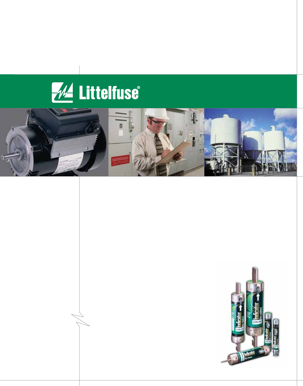
POWR-GARD™ PRODUCTS CATALOG

An Exceptional Portfolio
Makes All the Difference
When you work with Littelfuse, you are working with the broadest
and deepest circuit protection portfolio available. We leverage
7 different technologies, giving you access to an unparalleled
selection – helping you find the right solution for your application.
• Fuses, Holders & Accessories
• PTCs
• GDTs
• SIDACtors®
• Varistors
• Diodes
• Polymer ESD devices
Commitment to Circuit Protection
For over 75 years Littelfuse has maintained its focus on
circuit protection. As we expand in global reach and technical
sophistication, you can continue to count on us for solid circuit
protection solutions, innovative technologies, and industry-leading
expertise. It is a commitment that only a world-class leader with
staying power can support.
© 2005 Littelfuse • POWR-GARD™ Products Catalog
Littelfuse®
The World’s Leading Provider of Circuit Protection Solutions
www.littelfuse.com
Littelfuse is committed to providing every one of our customers
with the right solutions to meet all of your circuit protection needs.
That is why we carry the broadest range of technologies available
on the market today.
The breadth of our offering, combined with our depth of product
and application expertise, gives us the freedom to provide
objective, comprehensive solutions to meet the specific needs
of each application. This allows for a true partnership with
our customers.
The Industries We Serve
Solutions from Littelfuse can be found in virtually every application
that uses electrical energy, including:
• Automotive applications
• Digital consumer electronics
• Industrial/Electrical applications
• Telecom/Datacom circuits

© 2005 Littelfuse • POWR-GARD™ Products Catalog
Contents
POWR-PRO® Fuses 3
Indicator ® Introduction 4
Global Pro
™ Introduction 5
MROplus
™ 6
POWR-PRO ® In tro duc tion 7
KLPC 8-10
LLS RK_ID 11 - 13
LLNRK, LLSRK 14-16
JTD_ID 17-19
CCMR 20-21
IDSR 22
LDC 23-24
General Purpose Fuses 25
KLLU 26-28
FLNR_ID/FLSR_ID 29-32
FLNR/FLSR 33
KLNR/KLSR 34-35
NLN/NLS 36-37
RLN/RLS 38
JLS 39-40
JLLN/JLLS 41-43
SLC 44
CCMR, KLDR, KLKR 45-47
Plug Fuses 48
Midget & Electronic Fuses 49
Midget Fuses 50-54
Electronic Fuses
3AG/3AB 55
Indicating 56
5x20 mm IEC Type 57
5x20 mm & 2AG 58
Sub min ia ture 59
Automotive Fuses
SFE & Blade Type 60
Bolt-on Type 61
Miscellaneous Types 62
Medium Voltage Fuses 63
Medium Voltage Fuses 64-75
Telecom Products 76
L17T 77
TLN 78
TLS 79
70 Series 80
481 Series 80
LTFD 101 81
LTFD 6 0 01 82
LTFD 12 0 0 82
Special Purpose Fuses 83
Semiconductor Fuses 84-106
Fork-Lift Fuses 107
Cable Limiters 108
LMF, LGR, LHR 109
Blocks & Holders 110
Class H/K5 & R 111-116
Clas s J 117-119
Class T 120-123
Class G 124
Class CC & Midget 125-126
Class CC & Midget Accessories 127
POWR-SAFE Fuseholders 128-129
POWR-Covers 130
Pullers, POWR-JAW 131
571 Fuseholder 132
LFFB Limiter Block 133
LHFB Inline 3AG Holder 133
Semiconductor Blocks 134-136
POWR-BLOKS™
Distribution/Splicer 137-141
Dimensions 142-144
In-Line Watertight Fuseholders 145-150
Miscellaneous Products 151
POWR-Switch and LPMP Panel 152-155
Disconnect Switches 156
Fuse Reducers 157
Box Covers 158-159
Fuse Cabinet, Display 160
International Products 161
Global Pro Fuses 162
Global Pro Fuseholders 163
NH Fuse Links 164-165
Diazed/Neozed Fuse 166-167
Cylindrical Fuses 168
British Dimension 169
Overvoltage Suppression Products 170
Introduction 171-172
Industrial Varistor Products 173
LVSP 174
Fuseology 175
Terms and Definitions 177-181
Electrical Safety 182-183
Fuse Application Guide 184-203
Motor Protection Tables 204-206
Condensed Cross Reference 207
Alphanumeric Index 208
POWR-PRO® Fuses
1
www.littelfuse.com
POWR-PRO® Fuses
2
POWR-PRO® Fuses
www.littelfuse.com © 2005 Littelfuse • POWR-GARD™ Products Catalog
* LDC and IDSR are rated 600 volts AC/DC.
** Series are UL Listed with I.R. of 200,000 amps and Littelfuse self-certified with 300,000A I.R.
UL Class Fuse Overload
Characteristics
Interrupting
Rating, Amperes AC Voltage Rating Available Ampere
Ratings
Littelfuse Series
Number Page Number
LTime-Delay 200,000
300,000** 600
200 – 6000
601 – 4000
150 – 2000
KLPC**
KLLU
LDC*
8-10
26-28
23-24
RK1
Time-Delay 200,000
300,000**
250
600
600
1/10 – 600
LLNRK**
LLSRK**
LLSRK_ID**
14-16
14-16
11-13
Fast-Acting 200,000 250
600 1 – 600 KLNR
KLSR 34-35
RK5 Time-Delay 200,000
300,000**
250
600
600
1/10 – 600
FLNR/FLNR_ID**
FLSR/FLSR_ID**
IDSR**,*
29-32
29-32
22
TFast-Acting 200,000 300
600 1 – 1200 JLLN
JLLS 41-43
JTime-Delay 200,000/300,000** 600 8/10 – 600 JTD/JTD_ID** 17-19
Fast-Acting 200,000 600 1 – 600 JLS 39-40
CC Time-Delay 200,000
300,000** 600 1/10 – 30
2/10 – 30
KLDR
CCMR**
45-47
20-21
Fast-Acting 200,000 600 1/10 – 30 KLKR 45-47
CD Time-Delay 200,000/300,000** 600 35 – 60 CCMR** 20-21
GTime-Lag 100,000 600
480
1/2 – 20
25 – 60
SLC
SLC 44
K5 “One-Time” Fuses
Fast-Acting 50,000 250
600
1 – 600
1 – 600
NLN
NLS 36-37
H
Renewable Fuses
Fast-Acting
Time-Delay
10,000 250
600
1 – 600
1 – 600
RLN
RLS 38
Plug Time-Delay 10,000 125 1/4 – 30 SOO, TOO 48
Medium Time-Delay 10,000 125 15 – 30 SLO, TLO 48
Supplementary
Midget Fuses
Electronic Fuses
Automotive Fuses
Varies 32 to 1000
1/10 – 30
1/500 – 30
1-250
See Product Listings
50-54
55-59
60-62
Telecommunications Fast-Acting 100,000 170VDC
70 – 1200
1 – 600
1 – 70
L17T
TLN
TLS
77
78
79
www.littelfuse.com
© 2005 Littelfuse • POWR-GARD™ Products Catalog
POWR-PRO® Fuses
Littelfuse Indicator® Fuses 4
Littelfuse Global Pro™ System 5
Littelfuse MROplus™ 6
Littelfuse POWR-PRO System 7
KLPC Series POWR-PRO Class L Fuses 8-10
LLSRK_ID Series Indicator POWR-PRO Class RK1 Fuses 11-13
LLNRK/LLSRK Series POWR-PRO Class RK1 Fuses 14-16
JTD_ID Series Indicator POWR-PRO Class J Fuses 17-19
CCMR Series POWR-PRO Class CC and CD Fuses 20-21
IDSR Series Indicator POWR-PRO Class RK5 Fuses 22
LDC Series POWR-PRO Class L Fuses 23-24
POWR-PRO® Fuses
4
POWR-PRO® Fuses
www.littelfuse.com © 2005 Littelfuse • POWR-GARD™ Products Catalog
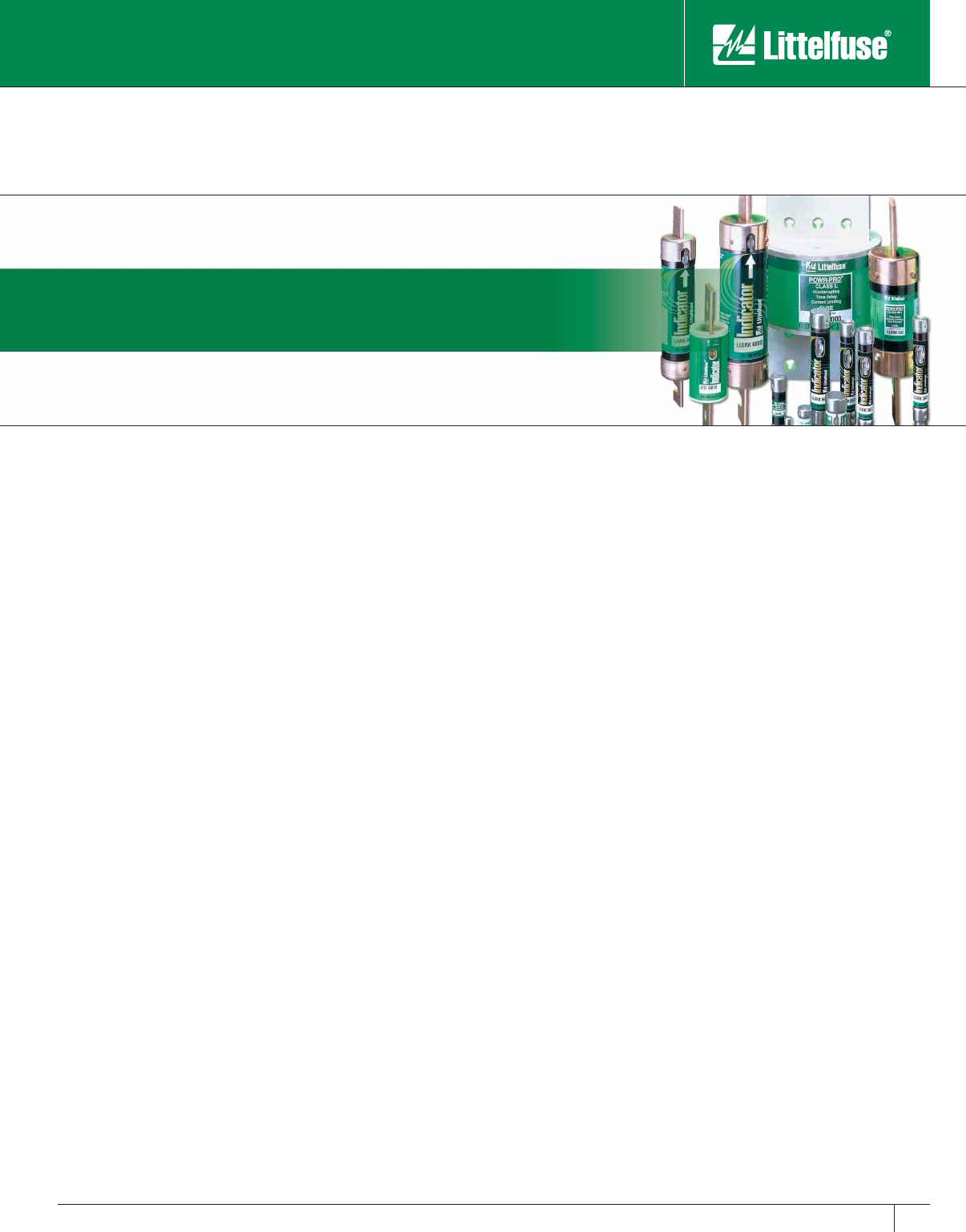
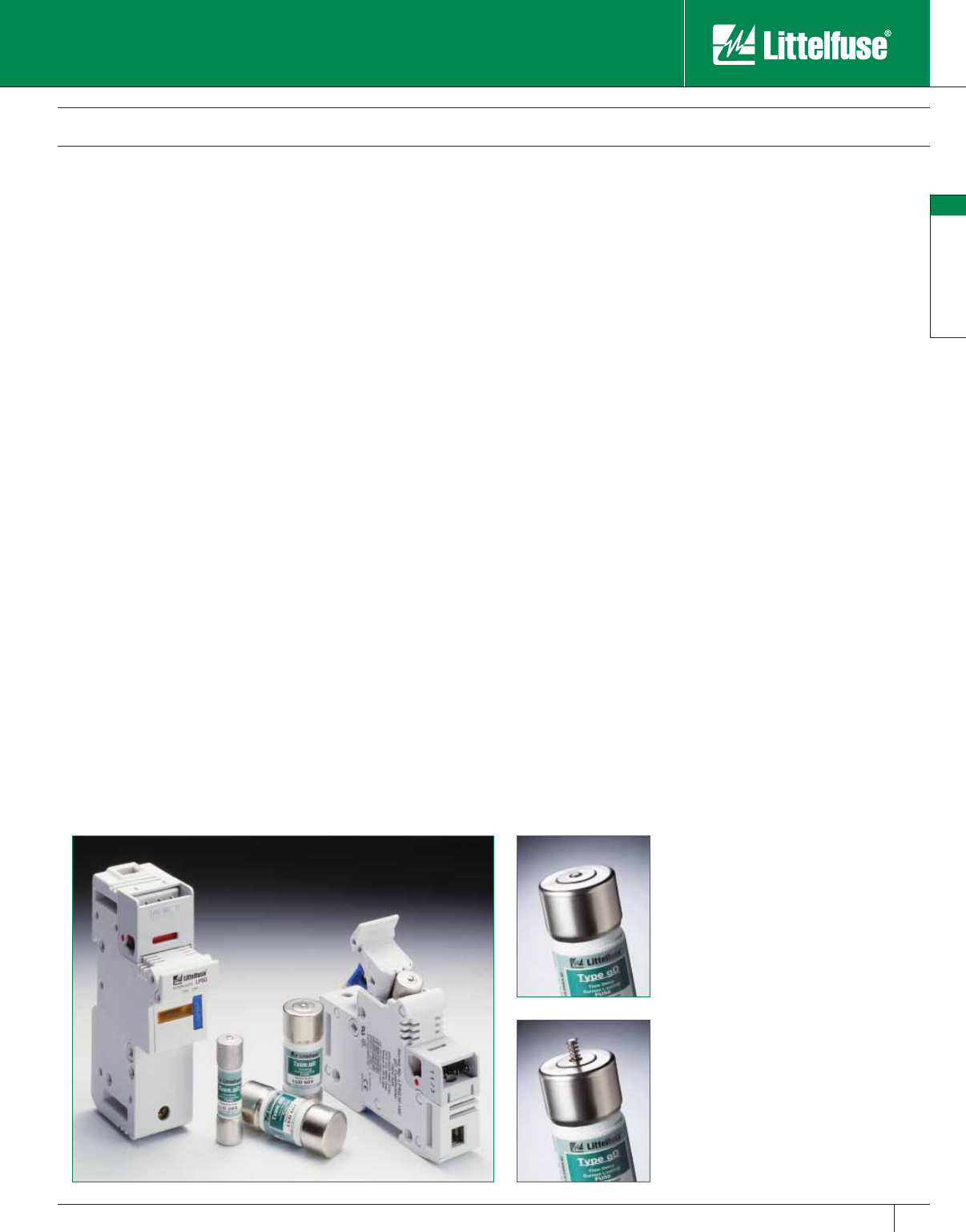
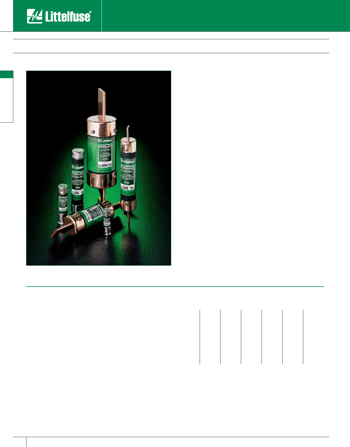
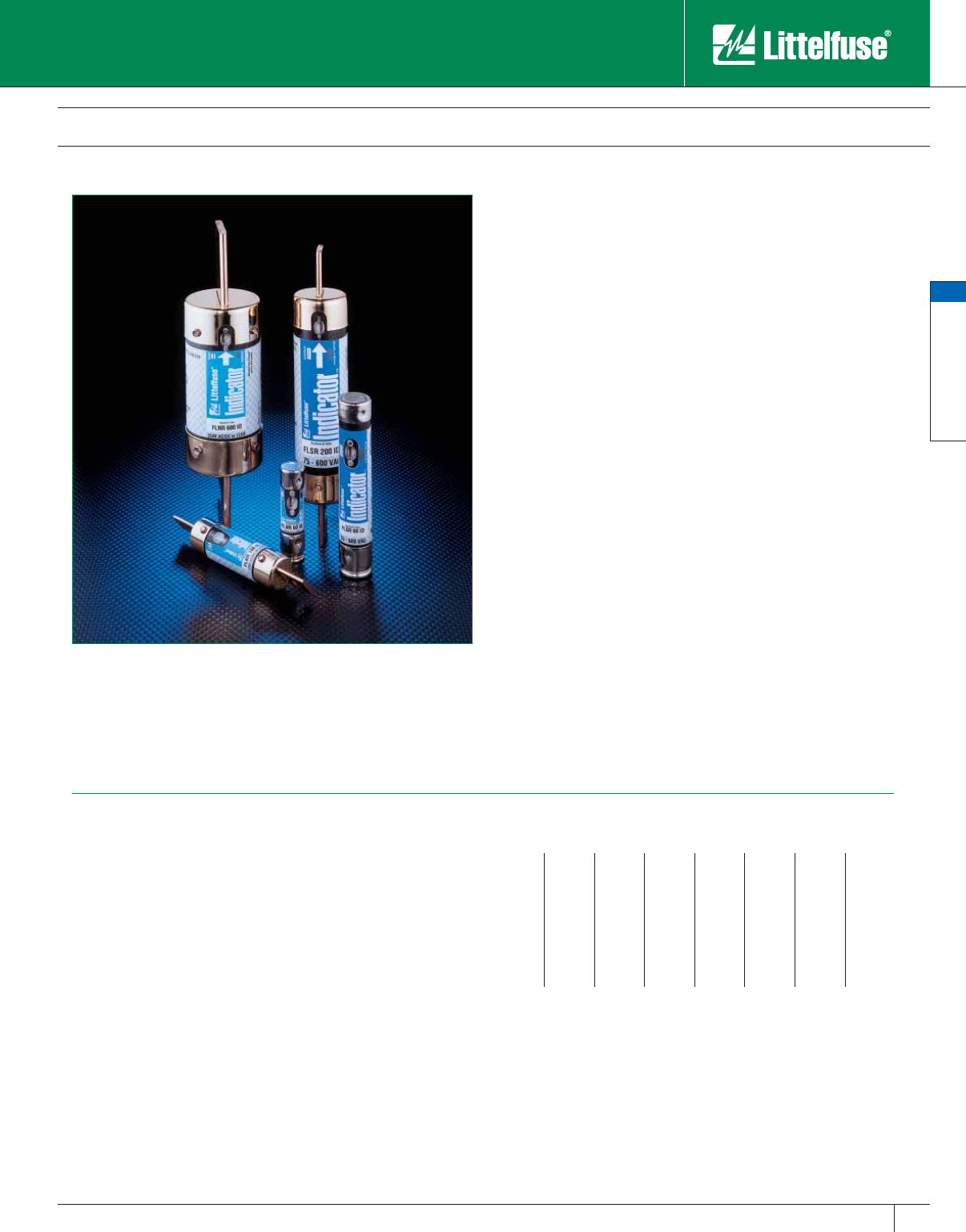
Littelfuse Indicator® Fuses
LLSRK_ID see pages 11-13
• Class RK1
• 600 VAC
• Dual-El e ment, Time-Delay
• 1/10-600 Amperes
FLNR_ID/FLSR_ID see pages 29-32
• Class RK5
• 250/600 VAC
• Dual-El e ment, Time-Delay
• 1/10-600 Amperes
IDSR see page 22
• Class RK5
• 600 V AC/DC
• Dual-El e ment, Time-Delay
• 1/10-600 Amperes
JTD_ID see pages 17-19
• Class J
• 600 VAC
• Dual-Element, Time-Delay
• 8/10-600 Amperes
313_ID see page 56
• Electronic 3AG
• 125/32 VAC
• Slo-Blo®
• 1/2-10 Amperes
Good
Blown
Indicator fuses combat one of the most com mon and frustrating
obstacles to productivity: downtime. Every time a fuse opens and
production stops, money is wasted. Locating a blown fuse used to take
20 min utes or more. Blown Littelfuse Indicator fuses can be spotted
quickly and safely, while the power is turned off.
Now it couldn’t be easier to locate the blown fuse. Simply look at the
Indicator window. When the fuse blows, the window turns from clear
to dark instantly, indicating which fuse needs to be replaced without
headaches or hassles.
These technologically advanced fuses feature solid-state designs that
improve overall performance and in crease fuse life. When properly
applied, Indicator fuses provide superior protection and improved time-
delay over conventional fuse designs. The patented solid-state overload
section provides consistent and reliable op er a tion by eliminating moving
parts which are subject to fatigue. This provides longer fuse life by
eliminating needless fuse openings due to motor inrush currents. The
superior performance allows you to consolidate your inventories by
replacing older, con ven tion al fuses which have limited per for mance
characteristics.
• Re duce Downtime
• Re duce Nuisance Opening
• Re duce Fuse In ven to ry
• Reduce Equipment Dam age
• Reduce Accidents
• Reduce Housekeeping Headaches
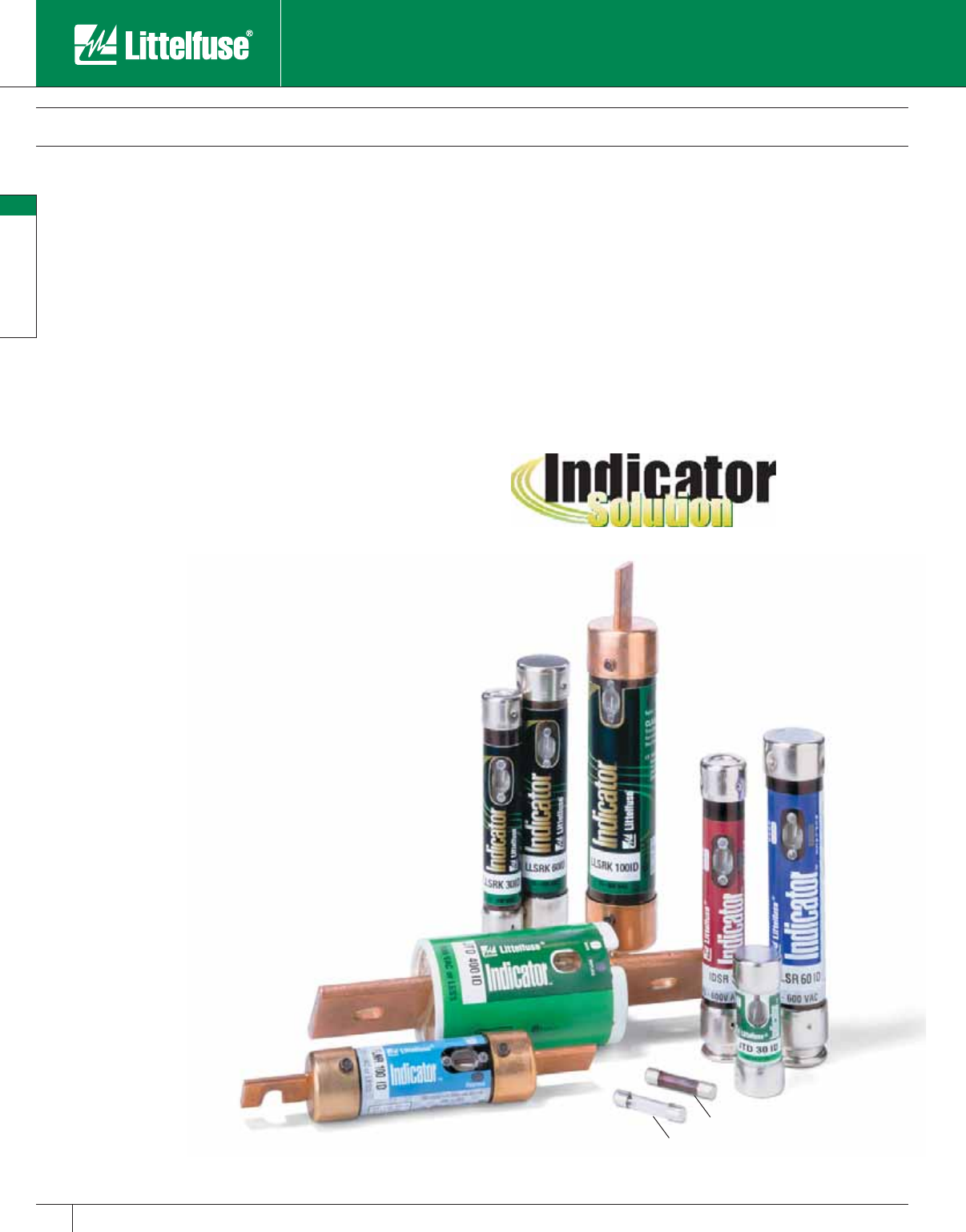
The Indicator® Solution Software
Complete Circuit Protection Plus Time Saving Indication.
This easy to use software analyzes your plant
operations and calculates six areas of cost savings
when you use Indicator fuses.
To calculate your savings, call 1-800-TEC-FUSE
for a free copy of the Indicator Solution software.
Use Indicator fuses and you can:
POWR-PRO® Fuses
5
POWR-PRO® Fuses
www.littelfuse.com
© 2005 Littelfuse • POWR-GARD™ Products Catalog
Introducing the Global Pro System
Offering World Class Performance and Global Acceptance
The International Challenge
Engineers and equipment designers are faced with a dilemma when
choosing the right circuit protection for their globally distributed
equipment. They need to worry about which markets the product
will be used in, what appropriate electrical standards apply in each
of those markets, and what fuses should be used so that users can
find replacements easily. These can be daunting questions particularly
because some of this information often is not available to the engineer
when a particular piece of equipment is being designed.
The Global Pro system resolves these design issues by incorporating
North American standards to fit internationally accepted IEC fuse
dimensions. This allows use of touchsafe fuseholders that can be used
in virtually any market and permits equipment to be easily adapted by
simply replacing the fuse with one that meets local standards. It’s that
simple.
The benefits of the Global Pro system include:
• Global acceptance
• UL and IEC approval
• Universal voltages
• Touch-safe components
• Integrated lockout/tagout device for compliance
• Pin-indication
• Design versatility for OEMs
Global Acceptance – Total Protection
The Littelfuse Global Pro circuit protection system combines fuses, fuse
holders and fusible disconnect switches in a simple, integrated package
designed to comply with UL and IEC requirements. The result is the
single best solution for your worldwide circuit protection needs. No
matter where your product is used, Global Pro will be accepted. More
significantly, it’s easy too! It meets universal voltage standards, offers
universal fuse sizes and uses universally understood product labels and
part numbers.
Flexible Components
The components of the Global Pro system are vital to its revolutionary
performance, and the key component within the system is the fuse. The
Littelfuse Global Fuse is designed to offer UL Class J performance, but
with the compact size and the international compatibility associated with
fuses manufactured to IEC dimensions.
More Protection In Less Space
Littelfuse Global Pro fuses are significantly smaller in size than 30 amp,
60 amp, and 100 amp Class J fuses. But their small size does not limit
their performance. All Global Pro fuses offer the following:
• Extremely compact size
• Pop-up indication
• Performance to UL Class J fuse requirements
• Compatibility with IEC style fuseholders
Note: For more information refer to pages 162–163 of this catalog.
Littelfuse Global Pro™ System
Good
Blown

© 2005 Littelfuse • POWR-GARD™ Products Catalog
TM
POWR-PRO® Fuses
6
POWR-PRO® Fuses
www.littelfuse.com
Circuit Protection Simplified!
The Littelfuse exclusive MROplus (Material Reduction Opportunity Plus)
program is designed to help lower costs, reduce inventory and improve
circuit protection performance. A team of Littelfuse technical experts will
analyze inventory and generate a variety of detailed reports including:
a total cost savings report, a cross reference report and a duplicate or
obsolete inventory report. On average, customers who use the Littelfuse
MROplus program are able to reduce their inventory by 28%. All you
have to do is supply a list of current inventory and the Littlefuse MROplus
program will do the rest. And, best of all, it is absolutely FREE!
For more information call 1-800-TEC-FUSE
Full Color Presentation Brochure
1
2
3
4
Your Customized Inventory Analysis Is Inside
Customized Inventory Analysis Reports
POWR-PRO® Fuses
7
POWR-PRO® Fuses
www.littelfuse.com
© 2005 Littelfuse • POWR-GARD™ Products Catalog
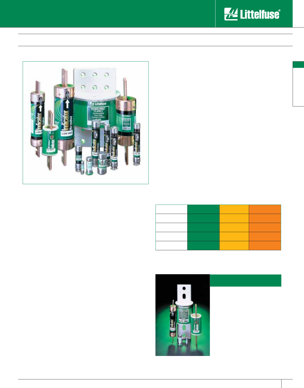
Littelfuse POWR-PRO® System
The Littelfuse POWR-PRO
System of fuses gives you all
the fuses you need for complete
circuit protection coverage
while reducing inventory and
controlling costs.
COLOR COORDINATED FOR EASE OF IDENTITY AND REPLACEMENT
Green label fuses provide all
the inventory you need for:
• Superior current-limitation from
1/10 – 6000 amperes.
• Type 2 “No Damage”
coordination with NEMA and
IEC motor circuits.
• Blown fuse indication
(LLSRK_ID and JTD_ID).
• Compact protection for motor
circuits (JTD, JTD_ID, and
CCMR).
• 300,000 AIR to meet future
trends toward higher available
short circuit currents.
The POWR-PRO System will:
• Provide superior current-limiting protection with innovative, tested
designs to prevent or reduce electrical system damage.
• Reduce inventory by standardizing system protection.
• Provide visual blown fuse indication with LLSRK_ID, and JTD_ID
Indicator® fuses.
• Reduce fuse replacement downtime with simple color coded fuse
labels.
See for yourself why the POWR-PRO System gives you the widest range
of circuit protection available today when compared to other systems.
UL Fuse Class POWR-PRO®Low Peak System 2000
Class L KLPC KRPC A4BQ
Class RK1 LLNRK/LLSRK_ID LPNRK/LPSRK A2DR/A6DR
Class J JTD/JTD_ID LPJ AJT
Class CC CCMR (2/10–60) LPCC (1/2–30) ATDR (0–30)
Minimize Arc-Flash Hazards
Some of the factors that determine the severity of an Arc-Flash
are the magnitude of the fault current and the time the current is
allowed to flow. Current-limiting fuses applied within their current-
limiting range minimize the current flow and clear the fault in
0.00833 seconds or less. The more current-limiting the device
and the faster it clears the fault minimizes Arc-Flash hazards and
potentially reduces the amount of personal protective equipment
(PPE) required. Using Littelfuse POWR-PRO Fuses will not only
minimize Arc-Flash hazards with superior current limitation, but also
provide maximum protection to equipment.
One of the quickest and easiest ways to reduce Arc-Flash hazards is to
replace UL Class H, K5, and Class RK5 fuses with POWR-PRO current-
limiting Class RK1 or Class J fuses. For a given current and voltage
rating, Class H, K5, RK5, and RK1 fuses are the same physical size.
Therefore, it is easy to upgrade to better fuse protection and increased
safety. To insure that only the most current-limiting fuse is used, it
is recommended to change fuse clips to a rejection style for Class R
or Class J fuses. Class J fuses provides the best option by assuring
non-interchangeability with non-current-limiting fuses. Whichever
your choice, the equipment should be labeled to inform maintenance
personnel of the proper fuse replacement. The Littelfuse MROplusTM
Program can assist with analyzing and upgrading from non-current-
limiting fuses.
POWR-PRO® Fuses
8
POWR-PRO® Fuses
www.littelfuse.com © 2005 Littelfuse • POWR-GARD™ Products Catalog
KLPC Series POWR-PRO® Class L Fuses
600 VAC • Time-Delay • 200 – 6000 Amperes
Specifications
Voltage Ratings: AC: 600 Volts
DC: 480 Volts
Interrupting Ratings: AC: 200,000 am peres rms sym met ri cal
300,000 amperes rms sym met ri cal
(Littelfuse self-certified)
DC: 20,000 amperes
Ampere Range: 200 – 6000 am peres
Approvals: AC: Standard 248-10, Class L
UL Listed 601 – 6000 amps
(File No: E81895)
UL Recognized 200 – 600 amps
(File No: E71611)
CSA Certified 200 – 6000 amps
(File No: LR29862)
QPL Federal Specifications WF-1814
700 – 6000 amps
DC: Littelfuse self-certified
Ampere Ratings
200 500 800 1350 2000 3500
250 600 900 1400 2100 4000
300 601 1000 1500 2200 4500
350 650 1100 1600 2300 5000
400 700 1200 1800 2500 6000
450 750 1300 1900 3000
Example part number (series & amperage): KLPC 1000
KLPC series POWR-PRO fuses provide ideal overcurrent protection
for circuits from 200 through 6000 amperes. KLPC series POWR-PRO
fuses specification-grade con struc tion and performance meet or exceed
the most strin gent project specifications: 99.9% pure silver links, silver-
plat ed copper end bells, glass-reinforced melamine bodies, O-ring seals
between body and end bells, and granular quartz fillers.
KLPC series POWR-PRO fuses are the only UL listed Class L fuses
that provide a minimum of ten seconds time delay at 500% rated
current and are also as current-limiting as the fastest Class L fuse on the
market. On average, the peak let-through currents of KLPC series fuses
are 10% less than any other time-delay Class L fuse.
Applications
Service switches
Switchboard mains and feeders
Bolted pressure contact switches
Motor control center mains
Large motor branch circuits
UL Listed series-rated protection for molded case circuit breaker
panelboards and loadcenters. (See panelboard manufacturers’
literature for recommended fuse rating.)
Primary and secondary protection for transformers
Protection of power circuit breakers
Features and Benefits
• Eliminate unnecessary downtime — KLPC POWR-PRO series time-
delay withstands system surges and keeps your circuits in service.
• Best protection for system components — Maximum current
limitation means less equipment and system damage when short
circuits occur. Reduced dam age means that electrical service can
be restored quickly, re duc ing costly downtime, and often permitting
equipment repair rather than replacement.
• Coordinates with other system components — KLPC series fuses
provide maximum coordination with fuses and circuit breakers both
on the line and load side of the fuses. See the Fuseology section of
this catalog for additional information.
• Eliminate need to oversize fuses — This may permit the use of smaller,
less expensive switches. Since lower rated fuses are more current-
limiting, equipment receives even better protection.
• 300kA Interrupting Rating — Littelfuse self-certified to 300,000
am peres as standard. Meets future trend towards higher available
short circuit currents.
POWR-PRO® Fuses
9
POWR-PRO® Fuses
www.littelfuse.com
© 2005 Littelfuse • POWR-GARD™ Products Catalog
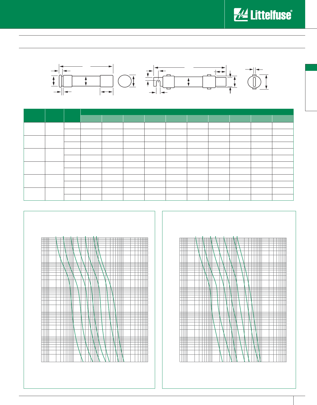
KLPC Series POWR-PRO® Class L Fuses
600 VAC • Time-Delay • 200 – 6000 Amperes
B
C
J
F
M
FIG.1
AABC
J
DEF
N
M
FIG.2
DEF
ABC
G
H
N
M
J
FIG. 3
BD
G
AF
H
J
M
FIG. 5
N
MG
DEF
ABC
H
J
FIG. 4
K
L
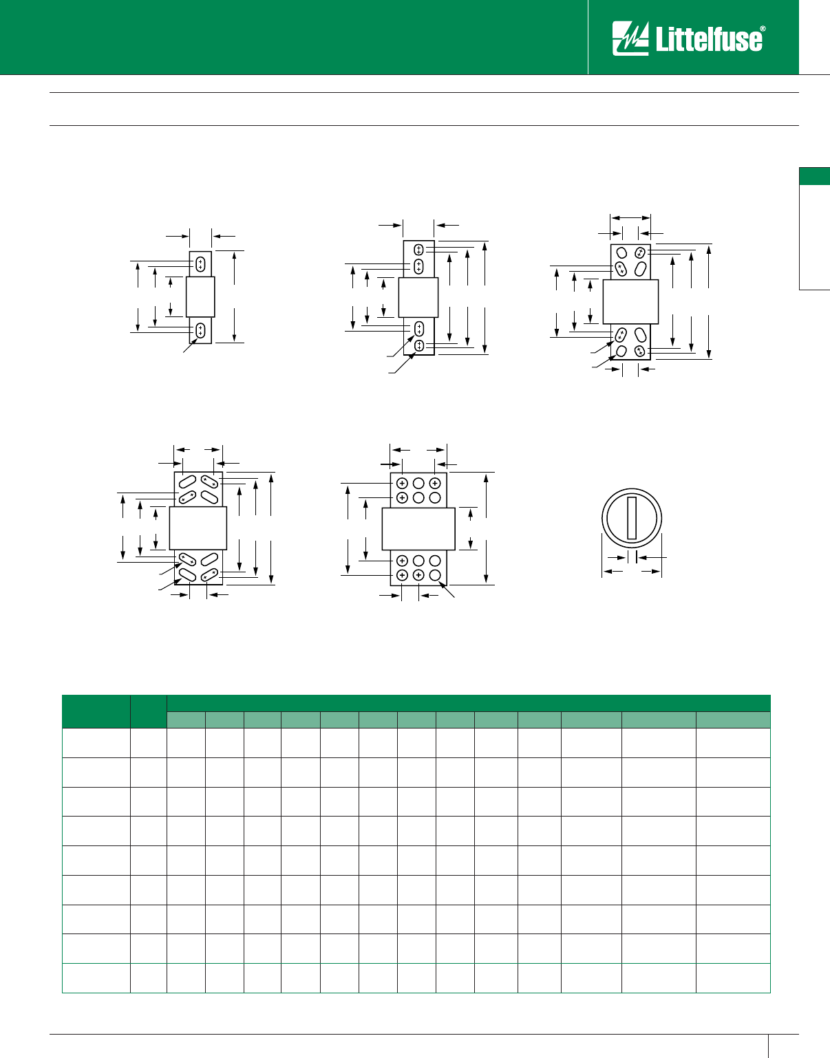
Amperes Fig. No. Dimensions in Inches (mm in parentheses)
ABCDE FGH J K L M N
200 – 800 1 33⁄4
(95.3)
53⁄4
(146.1)
63⁄4
(171.5) ——
85⁄8
(219.1) —— 2
(50.8)
21⁄2
(63.5)
3⁄8
(9.5)
5⁄8 x 11⁄8
(15.9) x (28.6) —
801 – 1200 2 33⁄4
(95.3)
53⁄4
(146.1)
63⁄4
(171.5)
91⁄4
(235.0)
91⁄2
(241.3)
103⁄4
(273.1) —— 2
(50.8)
21⁄2
(63.5)
3⁄8
(9.5)
5⁄8 x 3⁄4
(15.9) X (19.1)
5⁄8 x 11⁄8
(15.9) X (28.6)
1201 – 1600 2 33⁄4
(95.3)
53⁄4
(146.1)
63⁄4
(171.5)
91⁄4
(235.0)
91⁄2
(241.3)
103⁄4
(273.1) ——23⁄8
(60.3)
3
(76.2)
7⁄16
(11.1)
5⁄8 X 3⁄4
(15.9) X (19.1)
5⁄8 X 11⁄8
(15.9) X (28.6)
1601 – 2000 2 33⁄4
(95.3)
53⁄4
(146.1)
63⁄4
(171.5)
91⁄4
(235.0)
91⁄2
(241.3)
103⁄4
(273.1) ——23⁄4
(69.9)
31⁄2
(88.9)
1⁄2
(12.7)
5⁄8 x 3⁄4
(15.9) x (19.1)
5⁄8 x 11⁄8
(15.9) x (28.6)
2001 – 2500 3 4
(101.6)
53⁄4
(146.1)
63⁄4
(171.5)
91⁄4
(235.0)
91⁄2
(241.3)
103⁄4
(273.1)
15⁄8
(41.3)
13⁄4
(44.5)
31⁄2
(88.9)
5
(127.0)
3⁄4
(19.1)
5⁄8 X 3⁄4
(15.9) x (19.1)
5⁄8 X 11⁄8
(15.9) x (28.6)
2501 – 3000 3 4
(101.6)
53⁄4
(146.1)
63⁄4
(171.5)
91⁄4
(235.0)
91⁄2
(241.3)
103⁄4
(273.1)
15⁄8
(41.3)
13⁄4
(44.5)
4
(101.6)
5
(127.0)
3⁄4
(19.1)
5⁄8 x 3⁄4
(15.9) x (19.1)
5⁄8 x 11⁄8
(15.9) x (28.6)
3001 – 4000 4 4
(101.6)
53⁄4
(146.1)
63⁄4
(171.5)
91⁄4
(235.0)
91⁄2
(241.3)
103⁄4
(273.1)
13⁄4
(44.5)
31⁄4
(82.6)
43⁄4
(120.7)
53⁄4
(146.1)
3⁄4
(19.1)
5⁄8 x 13⁄8
(15.9) x (34.9)
5⁄8 x 13⁄8
(15.9) x (34.9)
4001 – 5000 5 4
(101.6)
53⁄4
(146.1) —91⁄4
(235.0) —103⁄4
(273.1)
15⁄8
(41.3)
31⁄4
(82.6)
51⁄4
(133.4)
71⁄8
(181.0)
1
(25.4)
5⁄8 DIA.
(15.9) —
5001 – 6000 5 4
(101.6)
53⁄4
(146.1) —91⁄4
(235.0) —103⁄4
(273.1)
15⁄8
(41.3)
31⁄4
(82.6)
53⁄4
(146.1)
71⁄8
(181.0)
1
(25.4)
5⁄8 DIA.
(15.9) —
POWR-PRO® Fuses
10
POWR-PRO® Fuses
www.littelfuse.com © 2005 Littelfuse • POWR-GARD™ Products Catalog
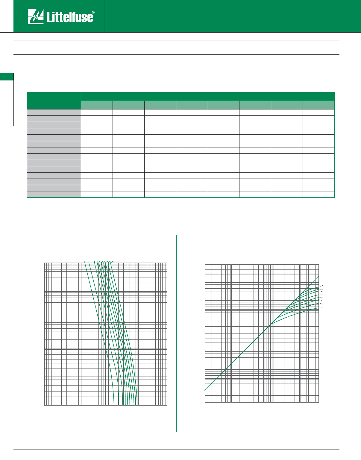
KLPC Series POWR-PRO® Class L Fuses
600 VAC • Time-Delay • 200 – 6000 Amperes
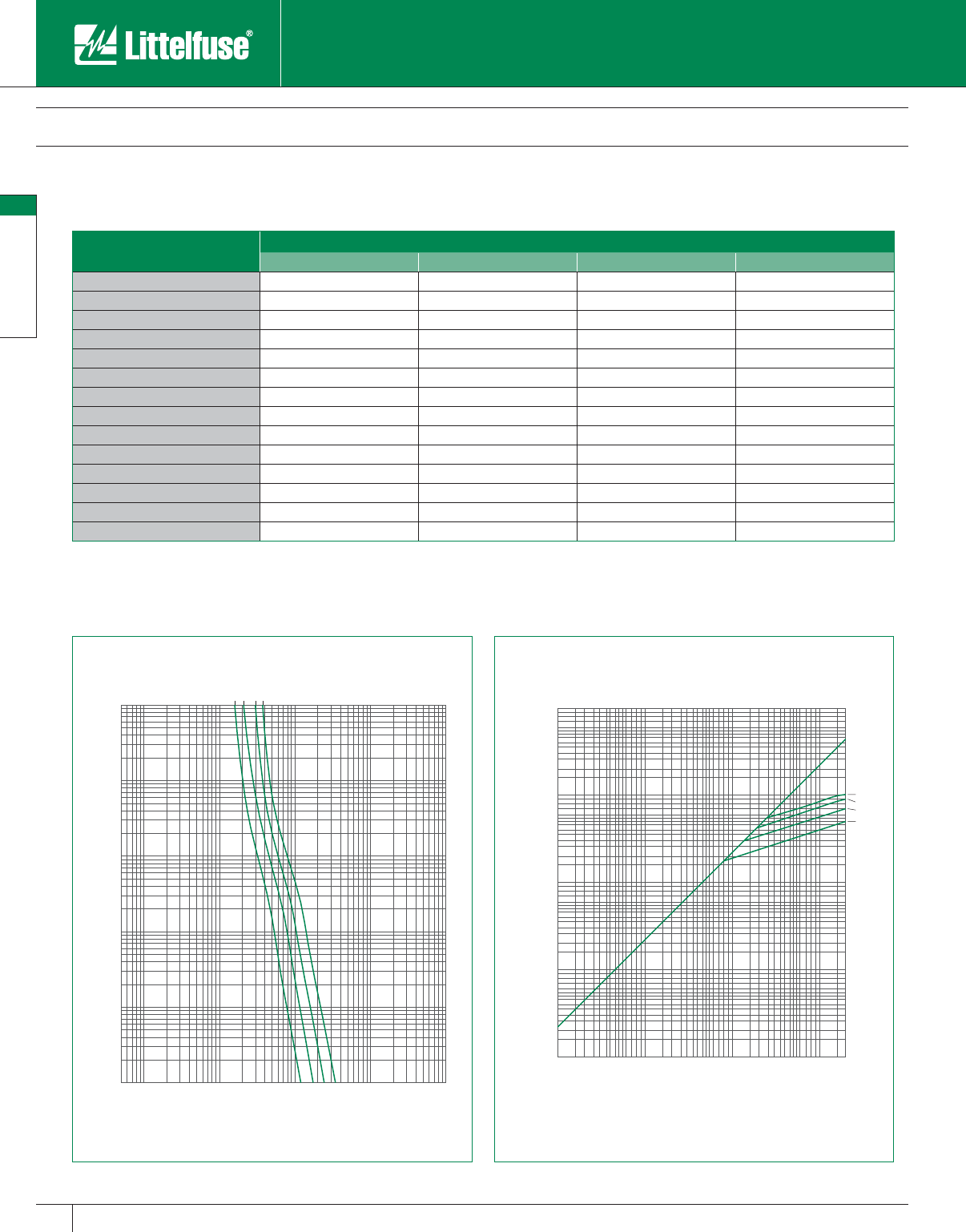
* Prospective RMS Sym met ri cal Amperes Short-Circuit Current
Note: Data derived from Peak Let-Thru Curves
Current-Limiting Effects of KLPC (600V) fuses
2000
3000
4000
6000
8000
10000
20000
30000
40000
60000
80000
100000
200000
100
200
300
400
600
800
1000
100
200
300
400
600
800
1000
2000
3000
4000
6000
8000
10000
20000
30000
40000
60000
80000
100000
200000
300000
400000
600000
800000
1000000
6000A
5000A
4000A
3000A
2000A
1600A
1200A
800A
PEAK LET-THRU IN AMPERES
AVAILABLE FAULT CURRENT
SYMMETRICAL R. M. S. AMPERES
1000
800
600
400
300
200
100
80
60
40
30
20
10
8
6
4
3
2
1
.8
.6
.4
.3
.2
.1
.08
.06
.04
.03
.02
.01
2000
3000
4000
6000
8000
10000
20000
30000
40000
60000
80000
100000
200000
300000
400000
600000
800000
1000000
80
100
200
300
400
600
800
1000
50
800A
1200A
1600A
2000A
2500A
3000A
3500A
4000A
5000A
6000A
TIME IN SECONDS
CURRENT IN AMPERES
Short Circuit Current* Apparent RMS Symmetrical Current for Various Fuse Ratings
800A 1200A 1600A 2000A 3000A 4000A 5000A 6000A
5,000 5,000 5,000 5,000 5,000 5,000 5,000 5,000 5,000
10,000 8,800 10,000 10,000 10,000 10,000 10,000 10,000 10,000
15,000 10,500 13,500 15,000 15,000 15,000 15,000 15,000 15,000
20,000 12,000 15,000 19,000 20,000 20,000 20,000 20,000 20,000
25,000 13,000 16,000 21,000 24,000 25,000 25,000 25,000 25,000
30,000 14,000 18,000 23,000 26,000 30,000 30,000 30,000 30,000
35,000 15,000 19,000 24,000 27,000 32,000 35,000 35,000 35,000
40,000 16,000 20,000 25,000 28,000 34,000 40,000 40,000 40,000
50,000 17,000 22,000 27,000 31,000 37,000 42,500 50,000 50,000
60,000 18,000 24,000 29,000 34,000 40,000 46,000 52,000 60,000
80,000 20,000 26,000 32,000 37,000 44,000 51,000 57,000 70,000
100,000 21,000 27,000 34,000 40,000 46,000 57,000 65,000 75,000
150,000 23,000 31,000 38,000 44,000 54,000 67,000 75,000 87,000
200,000 24,000 34,000 42,000 46,000 57,000 70,000 80,000 95,000
POWR-PRO® Fuses
11
POWR-PRO® Fuses
www.littelfuse.com
© 2005 Littelfuse • POWR-GARD™ Products Catalog
LLSRK_ID Series Indicator® POWR-PRO® Class RK1 Fuses
600 VAC • Dual-Element, Time-Delay • 1/10 – 600 Amperes
The all new LLSRK_ID series fuse is the most advanced Class RK1
fuse available today providing unparalleled performance and protection
to modern circuits. The patented Indicator technology provides instant
identification of a blown fuse greatly enhancing system up-time, while
the precision formed short-circuit elements virtually eliminate damage
to components from unexpected electrical faults. In addition, the all new
solid-state overload section has no moving parts, stopping unnecessary
fatigue failures commonly found in other spring loaded fuses.
Applications
All general purpose circuits
Motors
Transformers
Solenoids
Fluorescent lighting
All system components with high in-rush currents
Features/Benefits
• Reduce downtime — The indicating window of the LLSRK_ID
immediately identifies the open fuse. If the indicating strip is black,
the fuse has opened. It’s that simple. Maintenance personnel can
immediately determine that there is an open fuse.
• Reduce fuse inventory — The superior performance of the LLSRK_ID
allows it to be used in a variety of applications, thus decreasing fuse
inventory.
• Reduce nuisance opening — Indicator fuses offer superior time-delay
and cycling characteristics, which can lengthen fuse life.
• Reduce equipment damage — Indicator fuses provide superior
overload and short-circuit protection that can reduce equipment
damage. The LLSRK_ID is extremely current-limiting and provides
IEC Type 2 “No Damage” protection to IEC and NEMA type motor
starters.
• Reduce accidents — The LLSRK_ID Indicator fuse improves safety
by minimizing exposure to live circuits. Unlike other forms of blown
fuse indication, once the indicating strip darkens, it stays dark. Other
forms of indication require the power to remain on, which causes a
potential safety hazard to personnel.
Ordering Information
For online ordering use part number LSRK.
Specifications
Voltage Rating: 600 VAC/300 VDC
Interrupting Ratings: AC: 200,000 amperes rms symmetrical
300,000 amperes rms symmetrical
(Littelfuse self-certified)
DC: 20,000 amperes
Ampere Range: 1/10 – 600 amperes
Approvals: AC: Standard 248-12, Class RK1
UL Listed (File No: E81895)
CSA Certified (File No: LR29862)
DC: Littelfuse self-certified
Ampere Ratings
1⁄10 12
8⁄10 61⁄425 80 250
15 ⁄100 11⁄83 7 30 90 300
2⁄10 11⁄432⁄10 835100 350
1⁄414⁄10 31⁄2940110 400
3⁄10 16⁄10 41045125 450
4⁄10 18⁄10 41⁄212 50 150 500
1⁄22 5 15 60 175 600
6⁄10 21⁄456⁄10 171⁄270 200
8⁄10 21⁄262075225
Example part number (series & amperage): LLSRK30ID.
NOTE: All fuses rated 1 amp and above are Indicator fuses.
Recommended Fuse Blocks
LR600 Series
Refer to the Blocks & Holders section of this catalog for
additional information.
POWR-PRO® Fuses
12
POWR-PRO® Fuses
www.littelfuse.com © 2005 Littelfuse • POWR-GARD™ Products Catalog
LLSRK_ID Series Indicator® POWR-PRO® Class RK1 Fuses
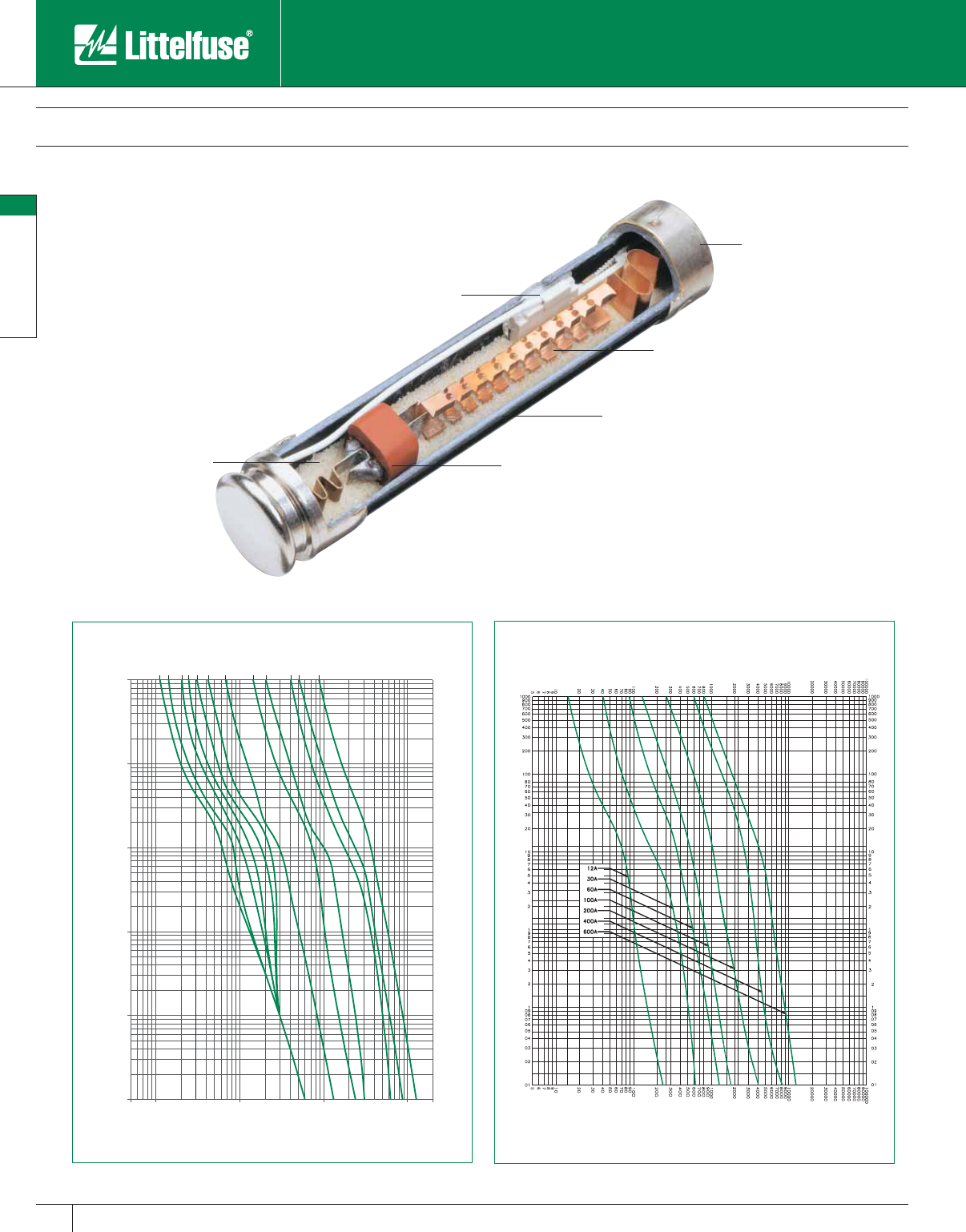
600 VAC • Dual-Element, Time-Delay • 1/10 – 600 Amperes
TIME IN SECONDS
CURRENT IN AMPERES
60A
35A
30A
15A
12A
5A
3.5A
2.8A
2A
1.6A
1.25A
1A
1000
100
10
1
200010001001010.5
0.01
0.1
Blown Fuse Indicator Assembly
Granular Quartz Filling
Precision Formed Short Circuit Element
Fiberglass Reinforced Pultruded Body
Elastomeric Silicone Overload Section
Contact Littelfuse for additional fuse curves.
Plated End Caps
TIME IN SECONDS
CURRENT IN AMPERES
POWR-PRO® Fuses
13
POWR-PRO® Fuses
www.littelfuse.com
© 2005 Littelfuse • POWR-GARD™ Products Catalog
SYMMETRICAL R.M.S. AMPERES
AVAILABLE FAULT CURRENT
PEAK LET-THRU IN AMPERES
3.5A
5A
12A
30A
60A
200000
100000
10000
1000
100
1000000
100000
10000
1000
100
PEAK LET-THRU IN AMPERES
AVAILABLE FAULT CURRENT
SYMMETRICAL R.M.S. AMPERES
Current-Limiting Effects of LLSRK_ID (600V) Fuses
Short Circuit Current* Apparent RMS Symmetrical Current for Various Fuse Ratings
30A 60A 100A 200A 400A 600A
5,000 1,060 1,600 2,100 2,600 4,100 --
10,000 1,350 2,000 2,800 3,400 5,250 8,000
15,000 1,600 2,300 3,200 3,900 6,000 9,000
20,000 1,700 2,600 3,600 4,500 6,700 10,000
25,000 1,900 2,800 3,800 4,800 7,500 11,000
30,000 2,000 3,000 4,100 5,200 8,000 12,000
35,000 2,100 3,100 4,400 5,700 8,500 12,500
40,000 2,200 3,300 4,600 6,000 9,000 13,000
50,000 2,400 3,500 4,900 6,500 9,500 14,000
60,000 2,500 3,800 5,200 7,000 10,000 15,000
80,000 2,700 4,000 5,700 7,750 11,000 17,000
100,000 2,900 4,200 6,200 8,500 12,000 18,000
150,000 3,200 4,600 7,300 10,000 14,000 21,000
200,000 3,300 4,700 8,000 11,000 16,000 23,000
* Prospective RMS Symmetrical Amperes Short-Circuit Current
Note: Data derived from Peak Let-Thru Curves
LLSRK_ID Series Indicator® POWR-PRO® Class RK1 Fuses
600 VAC • Dual-Element, Time-Delay • 1/10 – 600 Amperes
POWR-PRO® Fuses
14
POWR-PRO® Fuses
www.littelfuse.com © 2005 Littelfuse • POWR-GARD™ Products Catalog
LLNRK/LLSRK Series POWR-PRO® Class RK1 Fuses
250/600 VAC • Dual-Element, Time-Delay • 1/10 – 600 Amperes
Littelfuse LLNRK and LLSRK series POWR-PRO fuses provide superior
over load and short-circuit protection for service entrance, main, feeder
and general-purpose branch circuits up to 600 amperes.
LLNRK/LLSRK series fuses can be installed in existing Class H fuse
blocks to upgrade systems containing lower in ter rupt ing rating Class H
one-time or renewable fuses.
Applications
All general purpose circuits
Motors
Transformers
Solenoids
Fluorescent lighting
All system components with high in-rush currents
Features/Benefits
• Extremely current-limiting — Reduces damage to circuits and
equipment under short-circuit conditions. Stops damaging short-
circuits faster than any mechanical protective device.
• 300kA Interrupting Rating — Littelfuse self-certified to 300,000
am peres as standard. Meets future trend towards higher available
short-circuit currents.
• Reduced costs — Current-limiting design often permits use of readily
available, less costly equipment. Low resistance design reduces
power con sump tion and utility bills.
• Excellent time-delay — True dual-element construction, with sep a rate
non-fatiguing thermally-reversible spring-loaded thermal overload
element, withstands repeated surges within rated time delay without
opening needlessly. Eliminates needless downtime caused by power
surges or equipment demands.
Specifications
Voltage Ratings: AC: 250 Volts (LLNRK)
600 Volts (LLSRK)
DC: 125 Volts (LLNRK)
300 Volts (LLSRK)
Interrupting Ratings: AC: 200,000 am peres rms sym met ri cal
300,000 amperes rms sym met ri cal
(Littelfuse self-certified)
DC: 20,000 amperes
Ampere Range: 1/10 – 600 amperes
Approvals: AC: Standard 248-12, Class RK1
UL Listed (File No: E81895)
CSA Certified (File No: LR29862)
QPL: Federal Specification No. WF-1814
DC: Littelfuse self-certified
Ampere Ratings
1⁄10 12
8⁄10 61⁄425 80 250
15 ⁄100 11⁄83 7 30 90 300
2⁄10 11⁄432⁄10 835100350
1⁄4*1
4⁄10 31⁄2940110400
3⁄10 16⁄10 41045125450
4⁄10 18⁄10 41⁄212 50 150 500
1⁄2251560175600
6⁄10 21⁄456⁄10 171⁄270 200
8⁄10 21⁄262075*225
* LLSRK Only.
Example part number (series & amperage): LLNRK 450.
For online ordering, use numbers LNRK and LSRK for LLNRK/LLSRK.
Recommended Fuse Blocks
LR250 series (LLNRK Series)
LR600 series (LLSRK Series)
Refer to the Blocks & Holders section of this catalog for ad di tion al in for ma tion.
POWR-PRO® Fuses
15
POWR-PRO® Fuses
www.littelfuse.com
© 2005 Littelfuse • POWR-GARD™ Products Catalog
LLNRK/LLSRK Series POWR-PRO® Class RK1 Fuses
250/600 VAC • Dual-Element, Time-Delay • 1/10 – 600 Amperes
A
F
EC
D
GB
A
J
K
H
B
C
FDG
70-600A
FIG. 1 FIG. 2
E
1000
800
600
400
300
200
100
80
60
40
30
20
10
8
6
4
3
2
1
.8
.6
.4
.3
.2
.1
.08
.06
.04
.03
.02
.01
200
300
400
600
800
1000
2000
3000
4000
6000
8000
10000
20000
30000
40000
60000
80000
100000
8
10
20
30
40
60
80
100
5
15A
30A
60A
100A
200A
400A
600A
TIME IN SECONDS
CURRENT IN AMPERES
1000
800
600
400
300
200
100
80
60
40
30
20
10
8
6
4
3
2
1
.8
.6
.4
.3
.2
.1
.08
.06
.04
.03
.02
.01
200
300
400
600
800
1000
2000
3000
4000
6000
8000
10000
20000
30000
40000
60000
80000
100000
8
10
20
30
40
60
80
100
5
15A
30A
60A
100A
200A
400A
600A
TIME IN SECONDS
CURRENT IN AMPERES
LLNRK LLSRK
Amperes Refer to
Fig. No. Series Dimensions in Inches (mm in parentheses)
ABCDEFGHJK
1/10 – 30 1 LLNRK 2 (50.8) 1⁄2 (12.7) 1⁄2 (12.7) 9⁄16 (14.3) 5⁄64 (2.0) 5⁄32 (4.0) 3⁄8 (9.5) — — —
LLSRK 5 (127.0) 3⁄4 (19.1) 5⁄8 (15.9) 3⁄16 (20.6) 3⁄32 (2.4) 3⁄16 (4.8) 5⁄8 (15.9) — — —
35 – 60 1 LLNRK 3 (76.2) 3⁄4 (19.1) 5⁄8 (15.9) 3⁄16 (20.6) 3⁄32 (2.4) 3⁄16 (4.8) 5⁄8 15.9) — — —
LLSRK 51⁄2 (139.7) 1 (25.4) 5⁄8 (15.9) 11⁄16 (27.0) 3⁄32 (2.4) 1⁄4 (6.4) 7⁄8 (22.2) — — —
70 – 100 2 LLNRK 57⁄8 (149.2) 1 (25.4) 11⁄16 (27.0) 11⁄16 (27.0) 1⁄8 (3.2) 3⁄4 (19.1) 11⁄4 (31.8) 1⁄4 (6.4) 9⁄32 (7.1) 1⁄2 (12.7)
LLSRK 77⁄8 (200.0) 11⁄4 (31.8) 11⁄16 (27.0) 15⁄16 (33.3) 1⁄8 (3.2) 3⁄4 (19.1) 11⁄2 (38.1) 1⁄4 (6.4) 9⁄32 (7.1) 1⁄2 (12.7)
110 – 200 2 LLNRK 71⁄8 (181.0) 11⁄2 (38.1) 115 ⁄32 (37.3) 119 ⁄32 (40.5) 3⁄16 (4.8) 11⁄8 (28.6) 127⁄32 (46.8) 7⁄16 (11.1) 9⁄32 (7.1) 11 ⁄16 (17.5)
LLSRK 95⁄8 (244.5) 13⁄4 (44.5) 115 ⁄32 (37.3) 127⁄32 (46.8) 3⁄16 (4.8) 11⁄8 (28.6) 23⁄32 (53.2) 7⁄16 (11.1) 9⁄32 (7.1) 11 ⁄16 (17.5)
225 – 400 2 LLNRK 85⁄8 (219.1) 2 (50.8) 115 ⁄16 (49.2) 23⁄32 (53.2) 1⁄4 (6.4) 15⁄8 (41.3) 211 ⁄32 (59.5) 5⁄8 (15.9) 13⁄32 (10.3) 15 ⁄16 (23.8)
LLSRK 115⁄8 (295.3) 21⁄2 (63.5) 2 (50.8) 219 ⁄32 (65.9) 1⁄4 (6.4) 15⁄8 (41.3) 227⁄32 (72.2) 5⁄8 (15.9) 13 ⁄32 (10.3) 15 ⁄16 (23.8)
450 – 600 2 LLNRK 103⁄8 (263.5) 21⁄2 (63.5) 23⁄8 (60.3) 219 ⁄32 (65.9) 1⁄4 (6.4) 2 (50.8) 227⁄32 (72.2) 3⁄4 (19.1) 17⁄32 (13.5) 11⁄8 (28.6)
LLSRK 133⁄8 (339.7) 3 (76.2) 213 ⁄32 (61.1) 33⁄32 (78.6) 1⁄4 (6.4) 2 (50.8) 311⁄32 (84.9) 3⁄4 (19.1) 17⁄32 (13.5) 11⁄8 (28.6)
POWR-PRO® Fuses
16
POWR-PRO® Fuses
www.littelfuse.com © 2005 Littelfuse • POWR-GARD™ Products Catalog
LLNRK/LLSRK Series POWR-PRO® Class RK1 Fuses
250/600 VAC • Dual-Element, Time-Delay • 1/10 – 600 Amperes
Current-Limiting Effects of LLSRK (600V) fuses
2000
3000
4000
6000
8000
10000
20000
30000
40000
60000
80000
100000
200000
100
200
300
400
600
800
1000
100
200
300
400
600
800
1000
2000
3000
4000
6000
8000
10000
20000
30000
40000
60000
80000
100000
200000
300000
400000
600000
800000
1000000
600A
400A
200A
100A
60A
30A
PEAK LET-THRU IN AMPERES
AVAILABLE FAULT CURRENT
SYMMETRICAL R. M. S. AMPERES
2000
3000
4000
6000
8000
10000
20000
30000
40000
60000
80000
100000
200000
100
200
300
400
600
800
1000
100
200
300
400
600
800
1000
2000
3000
4000
6000
8000
10000
20000
30000
40000
60000
80000
100000
200000
300000
400000
600000
800000
1000000
600A
400A
200A
100A
60A
30A
PEAK LET-THRU IN AMPERES
AVAILABLE FAULT CURRENT
SYMMETRICAL R. M. S. AMPERES
Current-Limiting Effects of LLNRK (250V) fuses
LLNRK LLSRK
Short
Circuit
Current*
Apparent RMS Sym met ri cal for Various Fuse Ratings
30A 60A 100A 200A 400A 600A
5,000 1,060 1,600 2,100 2,600 4,100 —
10,000 1,350 2,000 2,800 3,400 5,250 8,000
15,000 1,600 2,300 3.200 3,900 6,000 9,000
20,000 1,700 2,600 3,600 4,500 6,700 10,000
25,000 1,900 2,800 3,800 4,800 7,500 11,000
30,000 2,000 3,000 4,100 5,200 8,000 12,000
35,000 2,100 3,100 4,400 5,700 8,500 12,500
40,000 2,200 3,300 4,600 6,000 9,000 13,000
50,000 2,400 3,500 4,900 6,500 9,500 14,000
60,000 2,500 3,800 5,200 7,000 10,000 15,000
80,000 2,700 4,000 5,700 7,750 11,000 17,000
100,000 2,900 4,200 6,200 8,500 12,000 18,000
150,000 3,200 4,600 7,300 10,000 14,000 21,000
200,000 3,300 4,700 8,000 11,000 16,000 23,000
* Prospective RMS Sym met ri cal Amperes Short-Circuit Current
Note: Data derived from Peak Let-Thru Curves
Short
Circuit
Current*
Apparent RMS Sym met ri cal for Various Fuse Ratings
30A 60A 100A 200A 400A 600A
5,000 900 1,400 2,000 2,700 4,800 5,000
10,000 1,100 1,900 2,700 3,500 6,200 8,500
15,000 1,250 2,100 3,100 4,200 7,000 9,500
20,000 1,400 2,400 3,500 4,600 8,000 10,800
25,000 1,500 2,600 3,900 5,000 8,300 11,500
30,000 1,600 2,800 4,000 5,250 9,000 12,000
35,000 1,700 2,850 4,300 5,500 9,500 12,500
40,000 1,800 3,000 4,600 5,800 9,800 13,500
50,000 1,900 3,200 4,800 6,300 10,200 14,000
60,000 2,000 3,500 5,200 6,700 11,000 15,000
80,000 2,200 3,900 5,700 7,200 12,200 16,000
100,000 2,300 4,000 6,000 8,100 12,700 17,000
150,000 2,500 4,500 6,700 9,100 14,000 19,000
200,000 2,600 4,800 7,000 9,700 15,000 20,000
* Prospective RMS Sym met ri cal Amperes Short-Circuit Current
Note: Data derived from Peak Let-Thru Curves
POWR-PRO® Fuses
17
POWR-PRO® Fuses
www.littelfuse.com
© 2005 Littelfuse • POWR-GARD™ Products Catalog
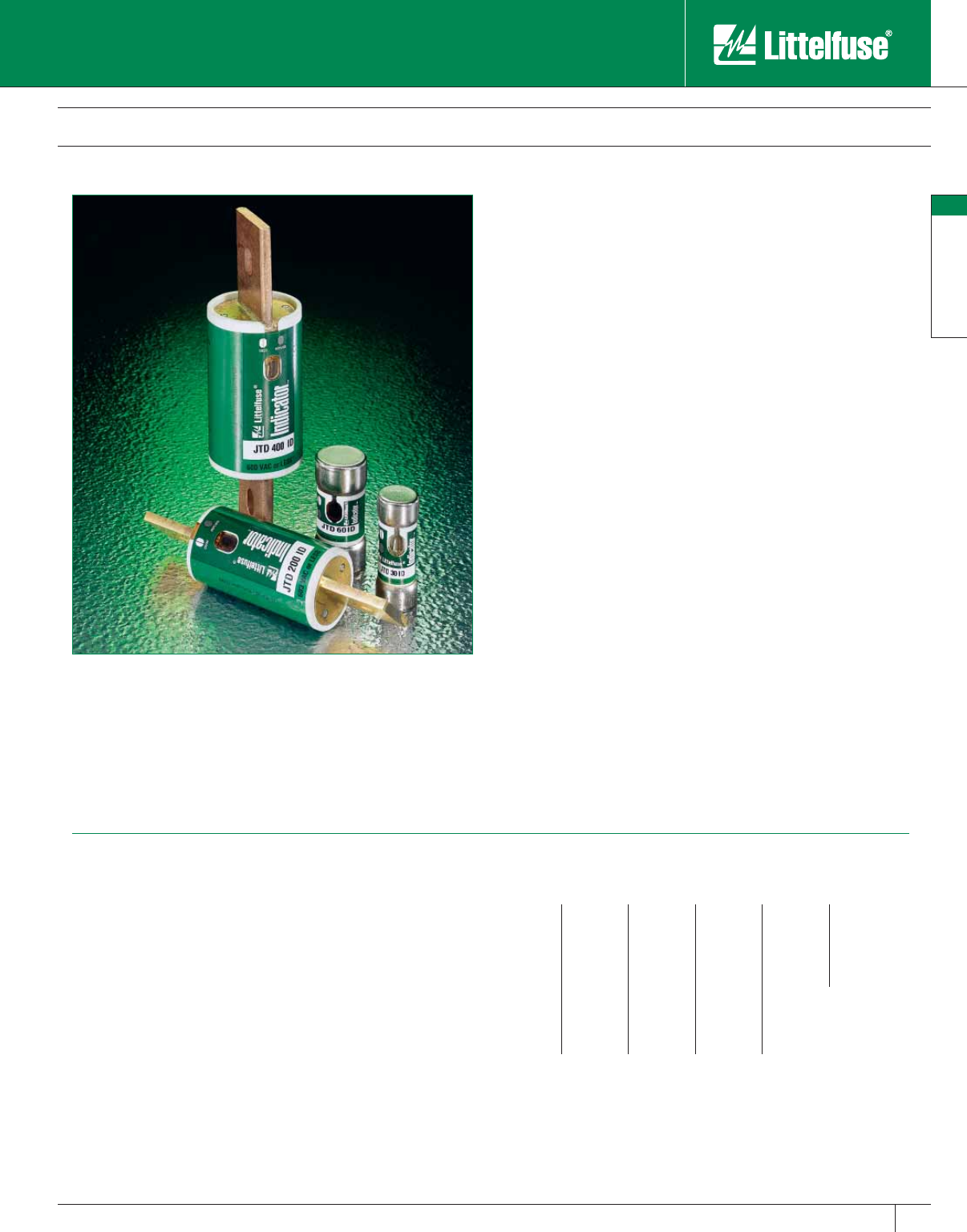
JTD_ID Series Indicator® POWR-PRO® Class J Fuses
600 VAC • Time Delay • 8/10 – 600 Amperes
The Littelfuse POWR-PRO JTD_ID Indicator Class J fuse provides visual
blown fuse indication and maximum protection in a compact package.
The compact Class J package was designed specifically for circuits
where space is at a premium. The current-limiting time delay JTD_ID
offers a patented, true dual-element design that is ideal for use in circuits
with high, in-rush currents. The Superior performance characteristics of
JTD_ID Indicator fuses reduce nuisance fuse opening, and the blown
fuse indication reduces downtime while increasing safety.
Applications
Fused combination motor controllers to provide IEC Type 2 (“No
Damage”) motor branch circuit short-circuit and ground fault
protection
Motor control centers
Transformer protection
Protection for UL Listed series rated molded case circuit breaker panels
General purpose circuits — mains, feeders and branch circuits —
especially when space is limited.
Features/Benefits
• Reduce downtime — A glance at the indicating window of a JTD_ID
Indicator fuse pinpoints open fuses immediately. If the indicating
window is dark, the fuse has opened. It’s that simple.
• Reduce nuisance opening — Indicator fuses have superior time-delay
and cycling characteristics which can lengthen fuse life and decrease
needless opening.
• Reduce fuse inventory — JTD _ID Indicator fuses have superior
performance characteristics, which means they can be used on a
variety of applications; therefore, decreasing fuse inventory.
• Reduce equipment damage — Indicator fuses provide superior
overload and short-circuit protection that can reduce equipment
damage. Indicator fuses also provide IEC Type 2 “No Damage”
protection to IEC and NEMA type motor starters.
• Reduce accidents — The JTD_ID Indicator fuse improves safety
by minimizing exposure to live circuits. Unlike other forms of blown
fuse indication, once the indicating window darkens, it stays dark. It
does not matter if the power is on or off or if the fuse is in a tool box.
Other forms of indication require the power to remain on, which is a
safety hazard for personnel.
Specifications
Voltage Ratings: AC: 600 Volts
DC: 300 Volts (8⁄10 – 100A)
500 Volts (110 – 600A)
Interrupting Ratings: AC: 200,000 am peres rms sym met ri cal
300,000 amperes rms symmetrical
(Littelfuse self-certified)
Ampere Range: 8/10 – 600 amperes
Approvals: AC: Standard 248-8, Class J
ULListed (File No: E81895)
CSA Certified (File No: LR29862)
DC: Littelfuse self-certified
8⁄10 - 100A: 300VDC self certified
110 – 600A: 500VDC self certified
Ampere Ratings
8⁄10 28⁄10 730100350
13835110400
11⁄432⁄10 940125450
11⁄231⁄210 45 150 500
16⁄10 41250175600
18⁄10 41⁄215 60 200
2517
1⁄270 225
21⁄456⁄10 20 80 250
21⁄262590300
Example part number (series & amperage): JTD 60 ID
Recommended Fuse Blocks
LJ600 series, LPSJ series
Refer to Blocks & Holders section of this catalog for ad di tion al in for ma tion.

POWR-PRO® Fuses
18
POWR-PRO® Fuses
www.littelfuse.com © 2005 Littelfuse • POWR-GARD™ Products Catalog
JTD_ID Series Indicator® POWR-PRO® Class J Fuses
600 VAC • Time-Delay • 8/10 – 600 Amperes
A
C
DGF
E
H
A
B
D
FIG. 1 FIG.2
An Inside Look . . .
Superior Short-Circuit Elements
Reduce damage to equipment and enables
the Littelfuse JTD_ID to provide IEC Type 2
“No Damage” protection to IEC and NEMA
motor starters.
Stone-Sand Filler
Helps provide I2t and Ipeak values well below
UL maximum limits and improves heat
dissipation and reliability.
Elastomeric Silicone EPR Plug
A space-age material used in the patented
overload section of the Littelfuse JTD_ID.
Plated End Caps
Help reduce corrosion and provide superior
contact for lower heat generation.
Blown Fuse Indicator
Incorporates precision wound elements to
provide consistent and reliable blown fuse
indication.
Solid State Overload Section
Patented thermally reversible design utilizes
high-tech aircraft grade polymers to ensure
reliable operation every time.
Granular Quartz Filler
Assists in quenching the arc that occurs during
overload conditions.
Amperes Refer to
Fig. No.
Dimensions in Inches (mm in parentheses)
ABCDEFGH
8/10– 30 1 21⁄4 (57.2) —1⁄2 (12.7) 13 ⁄16 (20.6) ————
35 – 60 1 23⁄8 (60.3) —5⁄8 (15.9) 11⁄16 (27.0) ————
70 – 100 2 25⁄8 (66.7) 35⁄8 (92.1) —45⁄8 (117.5) 11⁄8 (28.6) 3⁄4 (19.1) 9⁄32 (7.1) 1⁄8 (3.2)
110 – 200 2 3 (76.2) 43⁄8 (111.1) —53⁄4 (146.1) 15⁄8 (41.3) 11⁄8 (28.6) 9⁄32 (7.1) 3⁄16 (4.8)
225 – 400 2 33⁄8 (85.7) 51⁄4 (133.4) —71⁄8 (181.0) 21⁄8 (54.0) 15⁄8 (41.3) 13 ⁄32 (10.3) 1⁄4 (6.4)
450 – 600 2 33⁄4 (95.3) 6 (152.4) — 8 (203.2) 25⁄8 (66.7) 2 (50.8) 17⁄32 (13.5) 3⁄8 (9.5)
POWR-PRO® Fuses
19
POWR-PRO® Fuses
www.littelfuse.com
© 2005 Littelfuse • POWR-GARD™ Products Catalog
JTD_ID Series Indicator® POWR-PRO® Class J Fuses
600 VAC • Time-Delay • 8/10 – 600 Amperes
Current-Limiting Effects of JTD_ID (600V) fuses
1000000
100000
10000
1000
1000 10000 100000 200000
100
100
600A
400A
200A
100A
60A
30A
15A
12A
5.6A
AVAILABLE FAULT
SYMMETRICAL R.M.S. AMPERES
PEAK LET-THRU IN AMPERES
Short Circuit
Current*
Apparent RMS Sym met ri cal for Various Fuse Ratings
15A 30A 60A 100A 200A 400A 600A
5,000 565 750 1,500 1,800 2,800 4,800 5,000
10,000 675 925 1,900 2,450 3,600 5,700 7,750
15,000 775 1,050 2,100 2,800 4,100 6,500 9,000
20,000 825 1,125 2,300 3,000 4,400 7,250 9,700
25,000 900 1,200 2,500 3,300 5,000 8,000 10,500
30,000 950 1,300 2,600 3,500 5,100 8,400 11,000
35,000 1,000 1,350 2,700 3,700 5,400 9,000 12,000
40,000 1,050 1,400 2,800 3,900 5,600 9,200 12,500
50,000 1,100 1,500 3,000 4,200 6,000 10,000 13,000
60,000 1,200 1,600 3,200 4,500 6,400 10,500 14,000
80,000 1,300 1,700 3,400 4,900 7,200 11,200 15,500
100,000 1,375 1,800 3,600 5,200 7,800 12,200 16,500
150,000 1,500 2,000 3,950 6,000 9,000 14,500 19,000
200,000 1,600 2,175 4,000 6,500 10,000 16,000 20,500
* Prospective RMS Symmetrical Amperes Short-Circuit Current
Note: Data derived from Peak Let-Thru Curves
POWR-PRO® Fuses
20
POWR-PRO® Fuses
www.littelfuse.com © 2005 Littelfuse • POWR-GARD™ Products Catalog
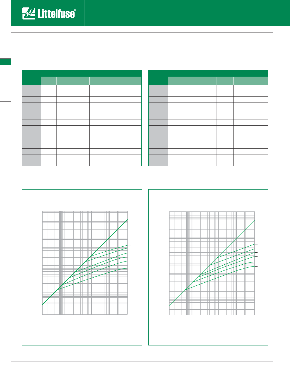
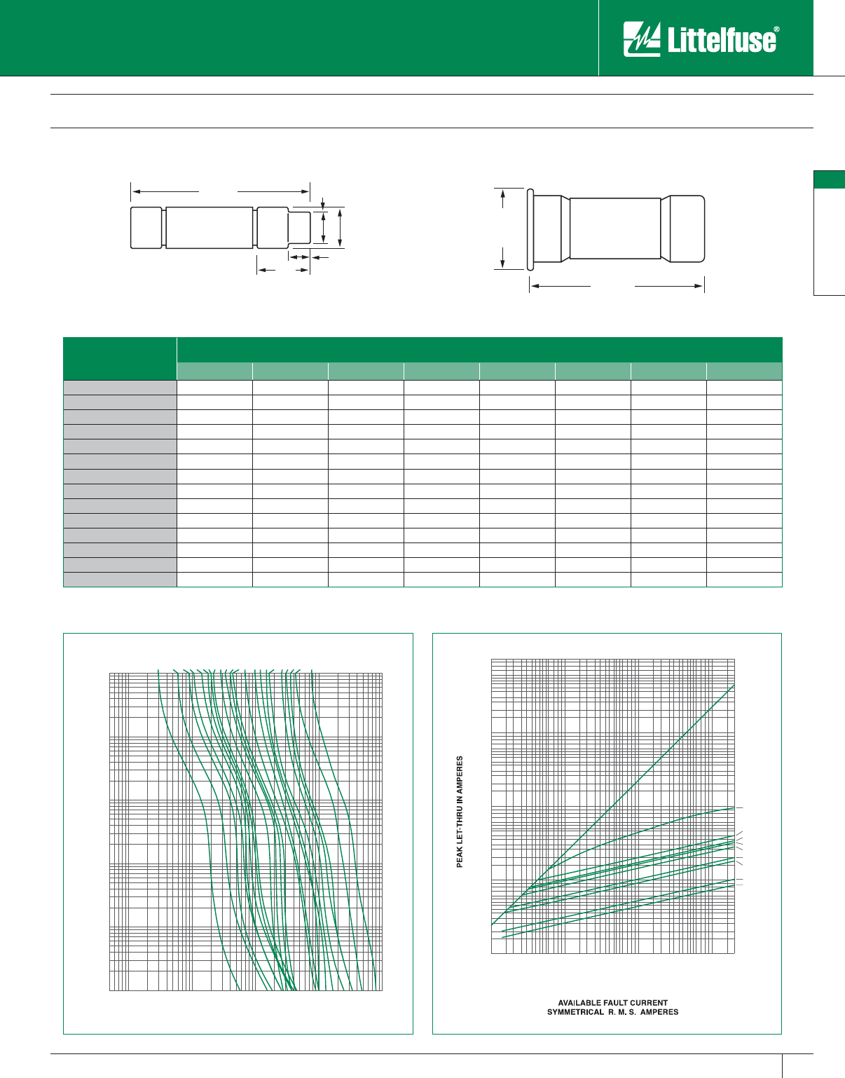
CCMR Series POWR-PRO® Class CC and CD Fuses
600 VAC • Dual-Element, Time-Delay • 2/10 – 60 Amperes
For space saving protection of motor circuits up to 40 HP*, we
recommend Littelfuse POWR-PRO CCMR series fuses. These fuses
are the only true dual-element, time-delay fuses that come in a small
package specifically en gi neered for motor branch circuit pro tec tion.
CCMR series fuses pro vide Type 2 “No Damage” pro tec tion to both
NEMA-rated and the more sensitive IEC (International Electrotechnical
Com mis sion) type motor circuit com po nents.
Rating for rating, CCMR fuses are the most current-limiting fuses
available. They also provide superior short-circuit protection since their
time-delay characteristics permit the use of smaller fuse ratings in motor
circuits than would be possible if using fast-acting fuses. CCMR series
fuses provide superior pro tec tion in a fraction of the space required by
other fuse classes. For example, when 600V three pole, 30 ampere Class
R fuse blocks are replaced by Littelfuse Class CC fuse blocks, mounting
space requirements may be re duced 70% or more. This is especially
im por tant when a panel contains control devices for many motors.
In addition to the UL Listed smaller sizes, Littelfuse CCMR series fuses
are now available in larger sizes — from 35 to 60 amperes! No other
fuse is available with this current carrying capacity in a package
this small. In fact, the 60 ampere CCMR fuse is the smallest 60A
fuse available rated at 600 volts.
Applications
CCMR series fuses are specifically designed to withstand sustained
starting currents of small motors
Provide short-circuit protection for motor branch circuits
Use with IEC- and NEMA-rated motor controllers and contactors
General purpose circuits up to 60 amps
Features/Benefits
• Space savings — No other fuse class approved for branch circuit
protection has a 600 volt rating and 300,000 A.I.R. in such a small
package.
• Extremely current-limiting — Reduces dam age caused by heating
and magnetic effects of short-circuit currents. Stops damaging short-
circuit currents faster than any me chan i cal protective device.
• Excellent time-delay — Eliminates needless down time caused by
power surges or equip ment demands. Permits selection of fuse sizes
closer to actual load conditions, which provides better protection.
• 300kA Interrupting Rating — Littelfuse self-certified to 300,000
am peres as standard. Meets future trend towards higher available
short-circuit currents.
*Consult the Motor Protection Tables in the Fuseology section for specific motor sizing information
Specifications
Voltage Ratings: AC: 600 Volts
DC: 250 Volts (CCMR
2⁄10 — 2A)
(CCMR 41⁄2 — 10A)
(CCMR 35 — 60A)
300 Volts (CCMR 21⁄4 — 4A)
500 Volts (CCMR 12 — 30A)
Interrupting Ratings: AC: 200,000 amperes rms symmetrical
300,000 amperes rms symmetrical
(Littelfuse self-certified)
DC: 20,000 amperes
Ampere Range: 2⁄10 — 60 amperes
Approvals: AC: Standard 248-4, Class CC
UL Listed
2⁄10 – 30 amps (File No: E81895)
Standard 248, Class CD
UL Listed 35 – 60 amps (File No: E81895)
CSA Certified
2⁄10 – 60 amps
(File No: LR29862)
DC: Littelfuse self-certified
Ampere Ratings
2⁄10 123
1⁄261⁄412 35
1⁄411⁄421⁄4471540
3⁄10 14⁄10 21⁄241⁄271⁄2171⁄245
1⁄211⁄228⁄10 582050
6⁄10 16⁄10 35
6⁄10 92560
8⁄10 18⁄10 32⁄10 61030
Example part number (series & amperage): CCMR 40
Recommended Fuse Blocks
LPSC (CCMR 2⁄10 — 30A)
L60030C series (CCMR 2⁄10 — 30A)
L60060C series (CCMR 35 — 60A)
Refer to Blocks & Holders section of this catalog for additional in for ma tion.
POWR-PRO® Fuses
21
POWR-PRO® Fuses
www.littelfuse.com
© 2005 Littelfuse • POWR-GARD™ Products Catalog
CCMR Series POWR-PRO® Class CC and CD Fuses
600 VAC • Dual-Element, Time-Delay • 2/10 – 60 Amperes
2000
3000
4000
6000
8000
10000
20000
30000
40000
60000
80000
100000
200000
100
200
300
400
600
800
1000
100
200
300
400
600
800
1000
2000
3000
4000
6000
8000
10000
20000
30000
40000
60000
80000
100000
200000
300000
400000
600000
800000
1000000
60A
30A
20A
15A
12A
10A
6 1/4A
4A
2A
Current-Limiting Effects of CCMR (600V) fuses
1.880"
(47.8 mm)
.850"
(21.6 mm)
1.50"
(38.1 mm)
.50"
(12.7 mm)
.41"
(10.3 mm)
.25"
(6.4 mm)
.125"
(3.2 mm)
35-60A
0-30A
1000
800
600
400
300
200
100
80
60
40
30
20
10
8
6
4
3
2
1
.8
.6
.4
.3
.2
.1
.08
.06
.04
.03
.02
.01
2
3
4
6
8
10
20
30
40
60
80
100
200
300
400
600
800
1000
.08
.1
.2
.3
.4
.6
.8
1
.05
1/4A
1/2A
8/10A
1A
1 1/4A
1 1/2A
1 8/10A
2A
2 1/2A
3A
3 1/2A
4A
6A
8A
10A
12A
15A
20A
25A
30A
35A
60A
TIME IN SECONDS
CURRENT IN AMPERES
Short Circuit Current* Apparent RMS Symmetrical For Various Fuse Ratings
2A 4A 61⁄4A10A 12A 15A 20A 30A
5,000 160 190 330 370 525 600 625 750
10,000 180 220 400 440 600 700 725 875
15,000 200 250 430 480 675 775 800 950
20,000 220 260 460 520 720 825 850 1,000
25,000 230 280 480 550 750 850 900 1,050
30,000 240 290 500 570 800 900 950 1,125
35,000 245 300 520 590 825 925 975 1,175
40,000 255 310 550 600 850 975 1,000 1,200
50,000 260 330 570 640 875 1,000 1,100 1,300
60,000 280 340 600 670 900 1,050 1,125 1,350
80,000 300 360 625 700 1,000 1,125 1,200 1,400
100,000 310 380 650 750 1,050 1,200 1,250 1,500
150,000 340 420 700 800 1,150 1,300 1,400 1,600
200,000 350 440 750 850 1,200 1,400 1,450 1,750
*Prospective RMS Symmetrical Amperes Short-Circuit Current
Note: Data Derived from Peak Let-Thru Curves
POWR-PRO® Fuses
22
POWR-PRO® Fuses
www.littelfuse.com © 2005 Littelfuse • POWR-GARD™ Products Catalog
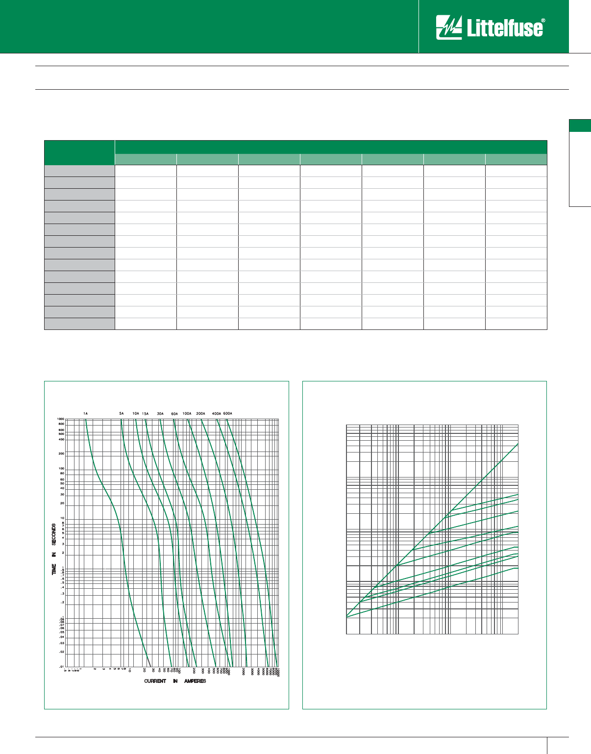
IDSR Series Indicator® POWR-PRO® Class RK5 Fuse
600 V AC/DC • Time-Delay • 1/10 – 600 Amperes
The Littelfuse IDSR Indicator fuse offers a patented solid-state design
and provides state-of-the-art reliability along with the convenience of
blown fuse indication. The unique design of the IDSR also features a
600 volt AC/DC rating making it ideal for DC applications.
Money is wasted each time a circuit opens and halts production.
The indicator window of the IDSR allows maintenance personnel to
pinpoint blown fuses immediately. The circuit can then be tested and
any problem corrected without unnecessary delay, minimizing costly
downtime.
Applications
DC circuits
All general purpose circuits
Motors
Transformers
Solenoids
Fluorescent lighting
All system components with high in-rush currents
Features/Benefits
• Superior Performance – Littelfuse leading edge metallurgy
eliminates all moving parts in a true dual-element design. The IDSR
also provides superior time-delay to withstand minor current surges
without sacrificing protection for sustained overloads or short-
circuit conditions.
• 600 Volt AC/DC Rating – The IDSR is UL Listed for 600 volts
AC/DC, which makes it ideal for a variety of applications. It is also
MSHA approved.
• Reduce Downtime – Costly downtime is minimized using Littelfuse
Indicator fuses. A glance at the indicator window tells if the fuse
has blown. If the window is dark, the fuse has opened. It’s that
simple.
• Increase Safety – Littelfuse Indicator Fuses minimize exposure to
“live” circuit parts while searching for a blown fuse. Other forms of
indication require current to power a light. Littelfuse Indicator fuses
can be identified with the power off.
Specifications
Voltage Ratings: AC: 600 Volts
DC: 600 Volts
Interrupting Ratings: AC: 200,000 am peres rms symmetrical
300,000 amperes rms sym met ri cal
(Littelfuse self-certified)
DC: 20,000 amperes
Ampere Range: 1⁄10 – 600 amperes
Approvals: Standard 248-12 and UL 198M, Class RK5
UL Listed (File No: E81895)
CSA Certified (File No: LR29862)
MSHA 600 Volt Listing
Dimensions
Please refer to the FLSR_ID dimensions.
Ampere Ratings
1⁄10 6⁄10 18⁄10 483080225
1⁄88⁄10 24
1⁄293590250
15 ⁄100 12
1⁄451040100300
2⁄10 11⁄821⁄256⁄10 12 45 110 350
1⁄411⁄428⁄10 61550125400
3⁄10 14⁄10 36
1⁄4171⁄260 150 450
4⁄10 11⁄232⁄10 72070175500
1⁄216⁄10 31⁄271⁄225 75 200 600
Example part number (series & amperage): IDSR 30
Note: All fuses rated 1 amp and above are Indicator
® fuses.
Recommended Fuse Blocks
LR600 series
Refer to the Blocks & Holders section of this catalog for ad di tion al in for ma tion.
Contact Littelfuse for characteristic curves.
POWR-PRO® Fuses
23
POWR-PRO® Fuses
www.littelfuse.com
© 2005 Littelfuse • POWR-GARD™ Products Catalog
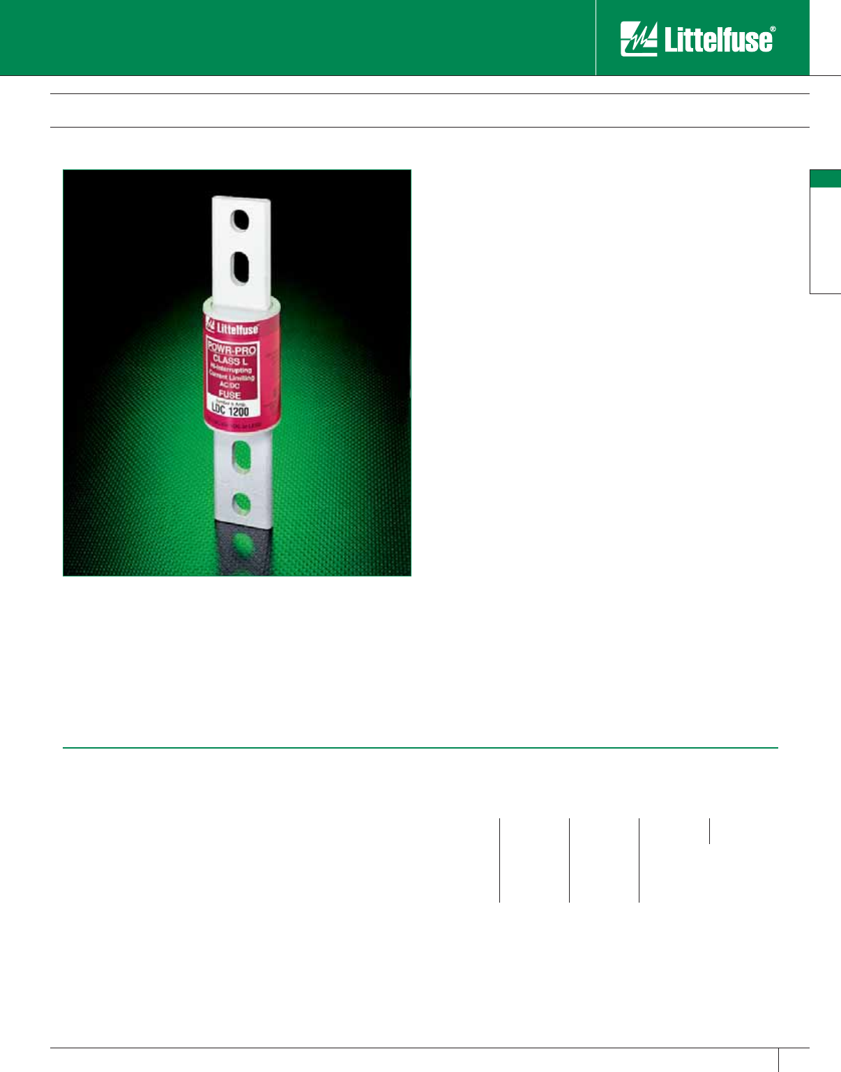
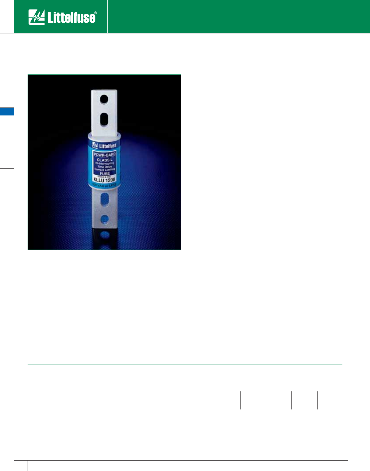
LDC Series POWR-PRO® Class L Fuses
600 V AC/DC Time-Delay • 150 – 2000 Amperes
Littelfuse POWR-PRO LDC series Class L fuses represent another
first in fuse protection. LDC series fuses are the first UL Listed 600
volts AC and DC Class L fuses. Since they may be used for both
AC and DC, they eliminate the concern that AC only fuses may be
inserted into DC circuits.
While LDC series fuses UL Listed DC interrupting rating is more than
adequate for most applications (50,000 amperes at a 16 millisecond
time constant), tests in our high power laboratory have shown that
this remarkable fuse is capable of performing at much longer time
constants. This makes the fuse uniquely suited for applications such
as crane rail circuits and mass transit systems. Contact the factory for
application information.
For AC only systems, consider the use of POWR-PRO KLPC series
fuses. They have a full 10 seconds time-delay at 500% rated current,
and have a wider range of ratings.
Applications
UPS protection, especially for large battery circuits
DC distribution
DC variable speed drives
Protection of crane rail circuits and other large DC equipment such as
electrical power shovels, ship and dock cranes, etc.
Mass transit systems, including new light rail applications
General purpose AC/DC circuits for mains, feeders, and branch circuits
Features/Benefits
• 600 Volt AC/DC rated — “All-purpose” Class L fuses reduce
inventory requirements because the need for separate AC and DC
fuses is elim i nat ed.
• UL Listed 200,000 A.I.R. AC – 50,000 A.I.R. DC — Reliable
interruption of all overcurrents up to their ratings. Minimizes the need
for time consuming and expensive short-circuit studies.
• Moderate time-delay — Four seconds time-delay at 500% current
provides adequate time-delay for many AC ap pli ca tions and most
DC ap pli ca tions. They will withstand most harmless overloads or line
surges. If your needs exceed the LDC capabilities, consider the use
of KLPC fuses for AC applications.
• Selective coordination — LDC series fuses coordinate well with all
Littelfuse fuses rated 600 amperes or less. A combination of LDC
and IDSR series fuses provide a complete 600 volt rated DC system.
• Extremely current-limiting — Maximum current limitation reduces
damage to circuits and equipment under short-circuit conditions.
Stops damaging short-circuits faster than any mechanical protective
device.
Specifications
Voltage Ratings: AC: 600 Volts
DC: 600 Volts
Interrupting Ratings: AC: 200,000 am peres rms symmetrical
DC: 50,000 amperes
(16 millisecond time-constant)
Ampere Range: 150 – 2000 amperes
Approvals: Standard 248-10, Class L
UL Listed 601 – 2000 amps (File No: E81895)
UL Recognized 150 – 600 amps
(File No: E71611)
CSA Certified 150 – 2000 amps
(File No: LR29862)
Ampere Ratings
150 450 750 1300 1900
200 500 800 1350 2000
250 600 900 1400
300 601 1000 1500
350 650 1100 1600
400 700 1200 1800
Example part number (series & amperage): LDC 1200
Dimensions
Please refer to the KLPC dimensions
POWR-PRO® Fuses
24
POWR-PRO® Fuses
www.littelfuse.com © 2005 Littelfuse • POWR-GARD™ Products Catalog
LDC Series POWR-PRO® Class L Fuses
600 V AC/DC Time-Delay • 150 – 2000 Amperes
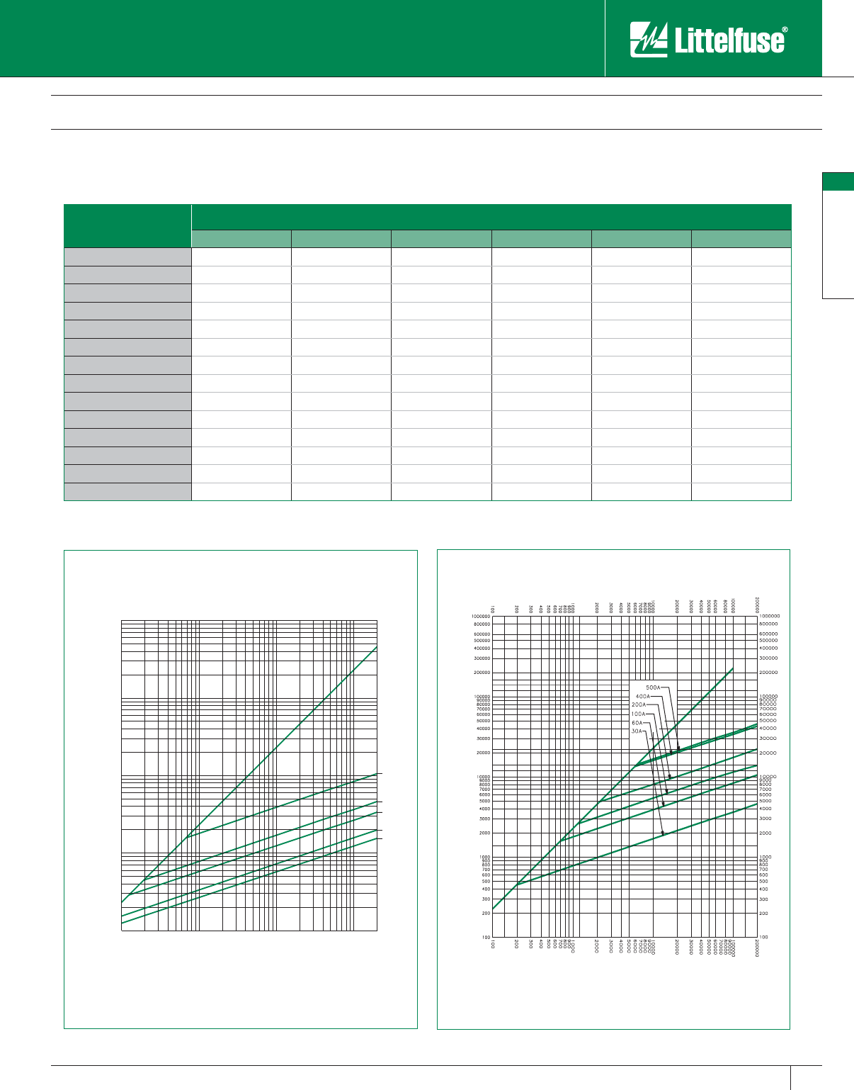
Current-Limiting Effects of LDC (600V) Fuses
1000
800
600
400
300
200
100
80
60
40
30
20
10
8
6
4
3
2
1
.8
.6
.4
.3
.2
.1
.08
.06
.04
.03
.02
.01
2000
3000
4000
6000
8000
10000
20000
30000
40000
60000
80000
100000
200000
300000
400000
600000
800000
1000000
100
200
300
400
600
800
1000
800A
1200A
1600A
2000A
TIME IN SECONDS
CURRENT IN AMPERES
2000
3000
4000
6000
8000
10000
20000
30000
40000
60000
80000
100000
200000
100
200
300
400
600
800
1000
100
200
300
400
600
800
1000
2000
3000
4000
6000
8000
10000
20000
30000
40000
60000
80000
100000
200000
300000
400000
600000
800000
1000000
2000A
1600A
1200A
800A
PEAK LET-THRU IN AMPERES
AVAILABLE FAULT CURRENT
SYMMETRICAL R. M. S. AMPERES
Short-Circuit Current* Apparent RMS Sym met ri cal for Various Fuse Ratings
800A 1200A 1600A 2000A
5,000 5,000 5,000 5,000 5,000
10,000 8,500 10,000 10,000 10,000
15,000 9,750 14,000 15,000 15,000
20,000 10,500 15,000 19,000 20,000
25,000 11,500 16,000 21,000 25,000
30,000 12,000 17,000 22,000 26,000
35,000 12,500 18,000 23,000 28,000
40,000 13,500 19,000 24,000 30,000
50,000 14,000 21,000 26,000 32,000
60,000 15,000 22,000 28,000 34,000
80,000 16,000 24,000 30,000 36,000
100,000 18,000 25,000 33,000 40,000
150,000 20,000 30,000 38,000 44,000
200,000 23,000 32,000 41,000 46,000
* Prospective RMS Sym met ri cal Amperes Short-Circuit Current
Note: Data Derived from Peak Let-Thru Curves
www.littelfuse.com
© 2005 Littelfuse • POWR-GARD™ Products Catalog
General Purpose Fuses
KLLU Class L Fuses 26-28
FLNR_ID/FLSR_ID Indicator® Class RK5 Fuses 29-32
FLNR/FLSR Class RK5 Fuses 33
KLNR/KLSR Class RK1 Fuses 34-35
NLN/NLS Class K5 Fuses 36-37
RLN/RLS Class H Fuses 38
JLS Class J Fuses 39-40
JLLN/JLLS POWR-T ™ Class T Fuses 41-43
SLC Class G Fuses 44
Class CC and Class CD Fuses 45-47
Plug Fuses 48
Catalog 25-48.indd 25 5/30/07 6:18:47 PM
General Purpose Fuses
General Purpose Fuses
26 www.littelfuse.com © 2005 Littelfuse • POWR-GARD™ Products Catalog
KLLU series UL Listed, time-delay, Class L fus es are quality fuses,
de vel oped to provide a some what lower priced al ter nate to the
POWR-PRO® KLPC series fuses. KLLU series fuses meet or exceed
all UL re quire ments for Class L fus es. For superior protection and
performance, spec i fi ca tion-grade POWR-PRO KLPC series fus es are
the rec om mend ed fuse. Com plete in for ma tion on KLPC fus es may
be found in the POWR-PRO Fuse section of this catalog.
Applications
Service switches
Switchboard mains and feeders
Bolted pressure contact switches
Motor control center mains
Large motor branch circuits
UL Listed series rated protection for molded case circuit breaker
panelboards and loadcenters. See panelboard manufacturers’
literature for recommended fuse rating.
Safety
• 200,000 A.I.R. — Provides reliable in ter rup tion of all overcurrents up
to 200,000 am peres.
• When used for motor branch circuit pro tec tion, KLLU fuses may be
sized close to the motor full load current, providing excellent protection
to branch circuit con duc tors, motor control equip ment and motors.
Longer Equipment Life
• Current-Limiting — Reduces short-circuit damage to systems and
equipment.
• Reduced downtime.
• Ten second minimum time-delay at 500% current eliminates
needless downtime caused by heavy starting currents of large
motors and other in duc tive loads.
• Selective coordination — KLLU fuses co or di nate well with other
Class L fuses and with all current-limiting Littelfuse fuses rated 600
amps or less. This means less time spent trying to locate short-
circuits or over load ed equipment, because only the fuse im me di ate ly
on the line side of the af fect ed circuit opens.
Easy To Use
• 200,000 A.I.R. rating minimizes need for short-circuit cal cu la tions,
while meeting present and future system re quire ments.
• KLLU fuse time-current characteristics closely match typical time-
current curves of circuit breakers. Although fuse/circuit breaker systems
can seldom be 100% coordinated, KLLU series fuses permit use of a
wider range of breaker setting than fast acting Class L fuses.
Ex cel lent protection for a single breaker or a group of breakers.
KLLU Class L Fuses
600 VAC • Time-Delay • 601 – 4000 Amperes
Specifications
Voltage Ratings: AC: 600 Volts
DC: Contact factory
Interrupting Ratings: 200,000 am peres rms symmetrical
Ampere Range: 601 – 4000 amperes
Approvals: Standard 248-10, Class L
UL Listed (File No: E81895)
CSA Certified (File No: LR29862)
Ampere Ratings
601 750 1000 1400 1800 3000
650 800 1200 1500 2000 3500
700 900 1350 1600 2500 4000
Example part number (series & amperage): KLLU 1000
Catalog 25-48.indd 26 5/30/07 6:18:52 PM
General Purpose Fuses
General Purpose Fuses
27
www.littelfuse.com
© 2005 Littelfuse • POWR-GARD™ Products Catalog
KLLU Class L Fuses
600 VAC • Time-Delay • 601 – 4000 Amperes
B
C
J
F
M
FIG.1
AABC
J
DEF
N
M
FIG.2
DEF
ABC
G
H
N
M
J
FIG. 3
N
MG
DEF
ABC
H
J
FIG. 4
K
L
Amperes Fig.
No.
Dimensions In Inches (mm in parentheses)
ABCDEFGHJKL M N
601 – 800 133⁄4
(95.3)
53⁄4
(146.1)
63⁄4
(171.5) ——
85⁄8
(219.1) —— 2
(50.8)
21⁄2
(63.5)
3⁄8
(9.5)
5⁄8 x 11⁄8
(15.9) x (28.6)
—
801 – 1200 233⁄4
(95.3)
53⁄4
(146.1)
63⁄4
(171.5)
91⁄4
(235.0)
91⁄2
(241.3)
103⁄4
(273.1) —— 2
(50.8)
21⁄2
(63.5)
3⁄8
(9.5)
5⁄8 x 3⁄4
(15.9) x (19.1)
5⁄8 x 11⁄8
(15.9) x (28.6)
1201 – 1600 233⁄4
(95.3)
53⁄4
(146.1)
63⁄4
(171.5)
91⁄4
(235.0)
91⁄2
(241.3)
103⁄4
(273.1) ——23⁄8
(60.3)
3
(76.2)
7⁄16
(11.1)
5⁄8 x 3⁄4
(15.9) x (19.1)
5⁄8 x 11⁄8
(15.9) x (28.6)
1601 – 2000 233⁄4
(95.3)
53⁄4
(146.1)
63⁄4
(171.5)
91⁄4
(235.0)
91⁄2
(241.3)
103⁄4
(273.1) —— 23⁄4
(69.9)
31⁄2
(88.9)
1⁄2
(12.7)
5⁄8 x 3⁄4
(15.9) x (19.1)
5⁄8 x 11⁄8
(15.9) x (28.6)
2001 – 2500 3453⁄4
(146.1)
63⁄4
(171.5)
91⁄4
(235.0)
91⁄2
(241.3)
103⁄4
(273.1)
15⁄8
(41.3)
13⁄4
(44.5)
31⁄2
(88.9)
5
(127.0)
3⁄4
(19.1)
5⁄8 x 3⁄4
(15.9) x (19.1)
5⁄8 x 11⁄8
(15.9) x (28.6)
2501 – 3000 3453⁄4
(146.1)
63⁄4
(171.5)
91⁄4
(235.0)
91⁄2
(241.3)
103⁄4
(273.1)
15⁄8
(41.3)
13⁄4
(44.5)
4
(101.6)
5
(127.0)
3⁄4
(19.1)
5⁄8 x 3⁄4
(15.9) x (19.1)
5⁄8 x 11⁄8
(15.9) x (28.6)
3001 – 4000 4453⁄4
(146.1)
63⁄4
(171.5)
91⁄4
(235.0)
91⁄2
(241.3)
103⁄4
(273.1)
13⁄4
(44.5)
31⁄4
(82.6)
43⁄4
(120.7)
53⁄4
(146.1)
3⁄4
(19.1)
5⁄8 x 13⁄8
(15.9) x (34.9)
5⁄8 x 13⁄8
(15.9) x (34.9)
Catalog 25-48.indd 27 5/30/07 6:18:54 PM
General Purpose Fuses
General Purpose Fuses
28 www.littelfuse.com © 2005 Littelfuse • POWR-GARD™ Products Catalog
KLLU Class L Fuses
600 VAC • Time-Delay • 601 – 4000 Amperes
1000
800
600
400
300
200
100
80
60
40
30
20
10
8
6
4
3
2
1
.8
.6
.4
.3
.2
.1
.08
.06
.04
.03
.02
.01
2000
3000
4000
6000
8000
10000
20000
30000
40000
60000
80000
100000
200000
300000
400000
600000
800000
1000000
80
100
200
300
400
600
800
1000
50
601A
800A
1200A
1600A
2000A
3000A
3500A
4000A
TIME IN SECONDS
CURRENT IN AMPERES SYMMETRICAL R.M.S. AMPERES
AVAILABLE FAULT CURRENT
PEAK LET-THRU IN AMPERES
800A
1200A
1600A
2000A
3000A
4000A
10000000
1000000
100000
10000
1000
1000
100
200000
100000
10000
Current-Limiting Effects of KLLU (600V) fuses
Short-Circuit Current* Apparent RMS Symmetrical Current for Various Fuse Ratings
800A 1200A 1600A 2000A 3000A 4000A
5,000 5,000 5,000 5,000 5,000 5,000 5,000
10,000 10,000 10,000 10,000 10,000 10,000 10,000
15,000 11,900 15,000 15,000 15,000 15,000 15,000
20,000 13,000 18,500 20,000 20,000 20,000 20,000
25,000 14,000 20,000 25,000 25,000 25,000 25,000
30,000 14,500 21,000 26,500 30,000 30,000 30,000
35,000 15,000 22,000 28,500 34,000 35,000 35,000
40,000 16,000 23,000 30,000 35,000 37,000 40,000
50,000 17,000 24,000 32,000 38,000 39,000 44,000
60,000 18,000 26,000 34,000 42,000 43,000 50,000
80,000 19,000 28,000 36,000 44,000 46,000 54,500
100,000 21,000 30,000 38,000 46,000 48,000 57,500
150,000 24,000 35,000 44,000 50,000 51,000 68,000
200,000 26,000 38,000 48,000 53,000 60,000 74,000
* Prospective RMS Symmetrical Amperes Short-Circuit Current
Note: Data Derived from Peak Let-Thru Curves
Catalog 25-48.indd 28 5/30/07 6:18:55 PM
General Purpose Fuses
General Purpose Fuses
29
www.littelfuse.com
© 2005 Littelfuse • POWR-GARD™ Products Catalog
Littelfuse FLNR_ID/FLSR_ID Indicator fuses provide blown fuse
indication at a glance. The patented state-of-the-art solid state design
provides maximum reliability and superior performance characteristics
in a true dual-element design. The use of Indicator fuses reduces
downtime and nuisance openings, increases safety, and can save
thousands of dollars in lost production time.
Applications
Service entrance switches
Switchboard main and feeder switches
Motor control center mains and motor branch circuits
Individual fused combination motor controllers
Distribution panelboards
Industrial control panels
Protection of fully rated panelboards and loadcenters
All general purpose circuits
Features/Benefits
• Reduce Downtime — A glance at the indicating window of a FLNR_ID
or FLSR_ID Indicator fuse pinpoints open fuses. If the indicating strip
is black, the fuse has opened. It’s that simple.
• Reduce Nuisance Opening — FLNR_ID and FLSR_ID Indicator
fuses have superior time-delay and cycling characteristics which can
lengthen fuse life and decrease needless opening.
• Reduce Fuse Inventory — Because FLNR_ID and FLSR_ID Indicator
fuses have superior performance characteristics, they can be used on a
variety of ap pli ca tions, thus decreasing fuse inventory.
• Reduce Equipment Damage — FLNR_ID and FLSR_ID Indicator
fuses have superior overload and short-circuit protection which can
reduce equipment damage.
• Reduce Accidents — The FLNR_ID and FLSR_ID Indicator fuses
improve safety by minimizing exposure to live circuits. Unlike other
forms of blown fuse indication, it doesn’t matter if the power is on
or off. No second guessing whether a light means a fuse is good or
bad, and no current going across a blown fuse to power a lighted
accessory.
FLNR_ID/FLSR_ID Indicator® Class RK5 Fuses
250/600 VAC • Dual-Element, Time Delay • 1/10 – 600 Amperes
Specifications
Voltage Ratings: AC: 250 Volts (FLNR_ID);
600 Volts (FLSR_ID)
DC: 125 Volts (FLNR 1⁄10 – 30A);
125 Volts (FLNR_ID 35 – 600A);
300 Volts (FLSR_ID)
Interrupting Ratings: AC: 200,000 amperes rms symmetrical
300,000 amperes rms sym met ri cal
(Littelfuse self-certified)
DC: 20,000 amperes
Ampere Range: 1⁄10 – 600 amperes
Approvals: Standard 248-12, Class RK5
UL Listed (File No: E81895)
CSA Certified (File No: LR29862)
MSHA 300 Volt Listing (FLSR_ID)
QPL: Federal Specification WF-1814
Ampere Ratings
1⁄10** 6⁄10 18⁄10 483080225
1⁄88⁄10 24
1⁄293590250
15 ⁄100 12
1⁄451040100300
2⁄10 11⁄821⁄256⁄10 12 45 110 350
1⁄411⁄428⁄10 61550125400
3⁄10 14⁄10 36
1⁄4171⁄260 150 450
4⁄10 11⁄232⁄10 72070175500
1⁄216⁄10 31⁄271⁄225 75* 200 600
*FLSR_ID only **FLNR only
Ex am ple part number (series & am per age): FLSR100ID
NOTE: For 1⁄10 – 30 ampere 250 volt fuses, order non-indicating FLNR series fuses.
NOTE: All FLNR_ID fuses rated 35 – 600A are Indicator fuses.
NOTE: All FLSR_ID fuses rated 1 amp and above are Indicator fuses.
Recommended Fuse Blocks
LR250 series (for FLNR_ID series fuses)
LR600 series (for FLSR_ID series fuses)
Refer to Blocks & Holders section of this catalog for ad di tion al in for ma tion.
Catalog 25-48.indd 29 5/30/07 6:18:56 PM
General Purpose Fuses
General Purpose Fuses
30 www.littelfuse.com © 2005 Littelfuse • POWR-GARD™ Products Catalog
FLNR_ID/FLSR_ID Indicator® Class RK5 Fuses
250/600 VAC • Dual-Element, Time Delay • 1/10 – 600 Amperes
TIME IN SECONDS
CURRENT IN AMPERES
FLSR_ID
.01
.02
.03
.04
.06
.08
.1
.2
.3
.4
.6
.8
1
2
3
4
6
8
10
20
30
40
60
80
100
200
300
400
600
800
1000
10
8
6
4
3
2
1
10000
8000
6000
4000
3000
2000
1000
800
600
400
300
200
100
80
60
40
30
20
1A
1.25A
1.6A
2A
2.5A
3A
4A
6A
10A
15A
20A
25A
30A
1000
800
600
400
300
200
100
80
60
40
30
20
10
8
6
4
3
2
1
.8
.6
.4
.3
.2
.1
.08
.06
.04
.03
.02
.01
2
3
4
6
8
10
20
30
40
60
80
100
200
300
400
600
800
1000
.1
.2
.3
.4
.6
.8
1
2/10A
1/4A
3/10A
4/10A
1/2A
6/10A
8/10A
1A
1 1/4A
1 4/10A
2A
2 1/2A
4 1/2A
5A
7A
7 1/2A
9A
FLNR
TIME IN SECONDS
CURRENT IN AMPERES
A
F
EC
D
GB
A
J
K
H
B
C
FDG
70-600A
FIG. 1 FIG. 2
E
Amperes Refer To
Fig. No. Series Dimensions In Inches (mm in parentheses)
ABCDEFGHJK
1/10 – 30 1 FLNR 2 (50.8)
1⁄2
(12.7)
1⁄2
(12.7)
9⁄16
(14.3)
5⁄64
(2.0)
5⁄32
(4.0)
3⁄8
(9.5) — — —
FLSR_ID 5 (127.0)
3⁄4
(19.1)
5⁄8
(15.9)
13⁄16
(20.6)
3⁄32
(2.4)
3⁄16
(4.8)
5⁄8
(15.9) — — —
35 – 60 1 FLNR_ID 3 (76.2)
3⁄4
(19.1)
5⁄8
(15.9)
13⁄16
(20.6)
3⁄32
(2.4)
3⁄16
(4.8)
5⁄8
(15.9) — — —
FLSR_ID 5
1⁄2
(139.7) 1 (25.4)
5⁄8
(15.9) 1
1⁄16
(27.0)
3⁄32
(2.4)
1⁄4
(6.4)
7⁄8
(22.2) — — —
70 – 100 2 FLNR_ID 5
7⁄8
(149.2) 1 (25.4) 1
1⁄16
(27.0) 1
1⁄16
(27.0)
1⁄8
(3.2)
3⁄4
(19.1) 1
1⁄4
(31.8)
1⁄4
(6.4)
9⁄32
(7.1)
1⁄2
(12.7)
FLSR_ID 7
7⁄8
(200.0) 1
1⁄4
(31.8) 1
1⁄16
(27.0) 1
5⁄16
(33.3)
1⁄8
(3.2)
3⁄4
(19.1) 1
1⁄2
(38.1)
1⁄4
(6.4)
9⁄32
(7.1)
1⁄2
(12.7)
110 – 200 2 FLNR_ID 7
1⁄8
(181.0) 1
1⁄2
(38.1) 1
15 ⁄32
(37.3) 1
19 ⁄32
(40.5)
3⁄16
(4.8) 1
1⁄8
(28.6) 1
27⁄32
(46.8)
7⁄16
(11.1)
9⁄32
(7.1)
11⁄16
(17.5)
FLSR_ID 9
5⁄8
(244.5) 1
3⁄4
(44.5) 1
15 ⁄32
(37.3) 1
27⁄32
(46.8)
3⁄16
(4.8) 1
1⁄8
(28.6) 2
3⁄32
(53.2)
7⁄16
(11.1)
9⁄32
(7.1)
11⁄16
(17.5)
225 – 400 2 FLNR_ID 8
5⁄8
(219.1) 2 (50.8) 1
15 ⁄16
(49.2) 2
3⁄32
(53.2)
1⁄4
(6.4) 1
5⁄8
(41.3) 2
11⁄32
(59.5)
5⁄8
(15.9)
13⁄32
(10.3)
15 ⁄16
(23.8)
FLSR_ID 11
5⁄8
(295.3) 2
1⁄2
(63.5) 2 (50.8) 2
19 ⁄32
(65.9)
1⁄4
(6.4) 1
5⁄8
(41.3) 2
27⁄32
(72.2)
5⁄8
(15.9)
13⁄32
(10.3)
15 ⁄16
(23.8)
450 – 600 2 FLNR_ID 10
3⁄8
(263.5) 2
1⁄2
(63.5) 2
3⁄8
(60.3) 2
19 ⁄32
(65.9)
1⁄4
(6.4) 2 (50.8) 2
27⁄32
(72.2)
3⁄4
(19.1)
17⁄32
(13.5) 1
1⁄8
(28.6)
FLSR_ID 13
3⁄8
(339.7) 3 (76.2) 2
13⁄32
(61.1) 3
3⁄32
(78.6)
1⁄4
(6.4) 2 (50.8) 3
11⁄32
(84.9)
3⁄4
(19.1)
17⁄32
(13.5) 1
1⁄8
(28.6)
For additional application information request Product Bulletin EL-4
Catalog 25-48.indd 30 5/30/07 6:19:03 PM
General Purpose Fuses
General Purpose Fuses
31
www.littelfuse.com
© 2005 Littelfuse • POWR-GARD™ Products Catalog
Current-Limiting Effects of FLNR_ID (250V) fuses
Short-Circuit Current* Apparent RMS Symmetrical Current for Various Fuse Ratings
30A 60A 100A 200A 400A 600A
5,000 1,400 2,100 3,100 5,000 5,000 5,000
10,000 1,550 2,500 3,900 6,500 9,500 10,000
15,000 2,000 3,150 4,400 7,250 10,500 14,000
20,000 2,250 3,400 5,000 8,250 12,000 16,000
25,000 2,400 3,750 5,250 9,000 12,500 16,500
30,000 2,550 4,100 5,600 9,500 13,500 18,000
35,000 2,650 4,300 5,800 9,750 14,000 19,000
40,000 2,800 4,400 6,250 10,250 15,000 20,000
50,000 3,000 5,000 6,500 10,500 16,000 21,000
60,000 3,200 5,250 7,000 11,500 17,000 23,000
80,000 3,400 5,750 7,500 12,500 19,000 25,500
100,000 3,850 6,000 8,000 13,500 21,000 27,500
150,000 4,100 7,000 9,000 15,200 24,000 31,500
200,000 4,300 7,500 9,750 16,500 26,000 34,000
* Prospective RMS Symmetrical Amperes Short-Circuit Current
Note: Data Derived from Peak Let-Thru Curves
Current-Limiting Effects of FLSR_ID (600V) fuses
Short-Circuit Current* Apparent RMS Symmetrical Current for Various Fuse Ratings
30A 60A 100A 200A 400A 600A
5,000 1,250 2,100 3,200 5,000 5,000 5,000
10,000 1,600 2,850 4,300 7,250 10,000 10,000
15,000 1,800 3,400 5,000 8,500 13,500 15,000
20,000 2,250 3,800 5,500 9,500 15,750 19,000
25,000 2,450 4,100 5,700 10,250 17,000 21,000
30,000 2,700 4,500 6,400 10,750 18,000 23,000
35,000 2,900 4,800 6,700 11,500 19,000 24,250
40,000 3,000 5,000 7,250 12,000 19,500 27,000
50,000 3,400 5,250 7,750 13,000 21,000 29,000
60,000 3,600 5,750 8,100 14,000 22,000 30,500
80,000 3,900 6,250 9,000 15,000 24,000 33,000
100,000 4,300 6,750 9,750 16,500 26,000 35,000
150,000 4,500 7,600 11,100 19,000 28,000 38,000
200,000 4,600 8,400 12,250 21,500 30,000 40,000
* Prospective RMS Symmetrical Amperes Short-Circuit Current
Note: Data Derived from Peak Let-Thru Curves
FLNR_ID/FLSR_ID Indicator® Class RK5 Fuses
250/600 VAC • Dual-Element, Time Delay • 1/10 – 600 Amperes
Catalog 25-48.indd 31 5/30/07 6:19:05 PM
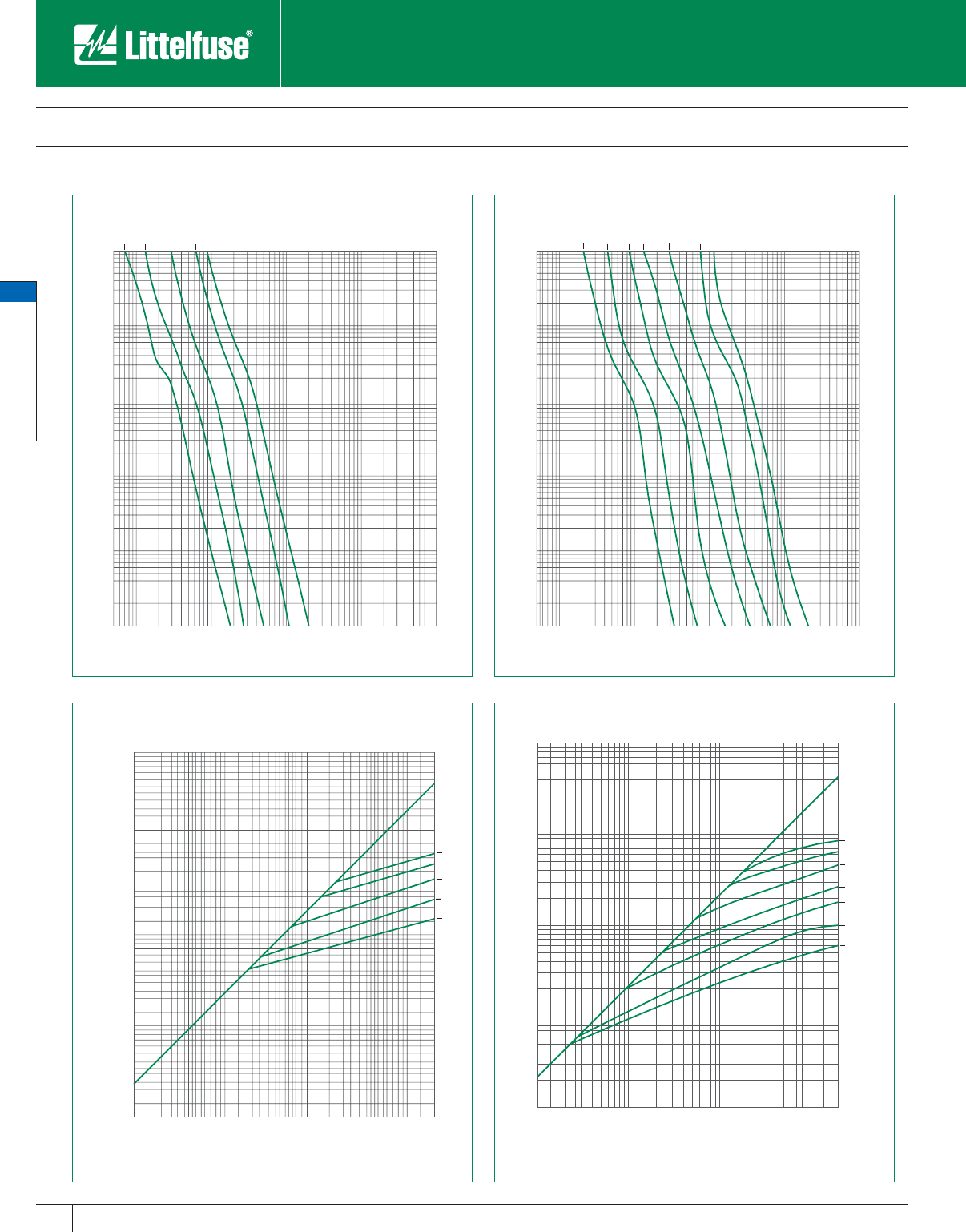
General Purpose Fuses
General Purpose Fuses
32 www.littelfuse.com © 2005 Littelfuse • POWR-GARD™ Products Catalog
FLNR_ID/FLSR_ID Indicator® Class RK5 Fuses
250/600 VAC • Dual-Element, Time Delay • 1/10 – 600 Amperes
600A
400A
200A
100A
60A
30A
15A
5
100
80
60
40
30
20
10
8
6
100000
80000
60000
40000
30000
20000
10000
8000
6000
4000
3000
2000
1000
800
600
400
300
200
.01
.02
.03
.04
.05
.06
.08
.1
.2
.3
.4
.6
.8
1
2
3
4
6
8
10
20
30
40
60
80
100
200
300
400
600
800
1000
CURRENT IN AMPERES
TIME IN SECONDS
FLSR_ID
600A
400A
200A
100A
60A
50
1000
800
600
400
300
200
100
80
60
1000000
800000
600000
400000
300000
200000
100000
80000
60000
40000
30000
20000
10000
8000
6000
4000
3000
2000
.01
.02
.03
.04
.06
.08
.1
.2
.3
.4
.6
.8
1
2
3
4
6
8
10
20
30
40
60
80
100
200
300
400
600
800
1000
TIME IN SECONDS
CURRENT IN AMPERES
FLNR_ID
60A
100A
200A
400A
600A
1000000
800000
600000
400000
300000
200000
100000
80000
60000
40000
30000
20000
10000
8000
6000
4000
3000
2000
1000
800
600
400
300
200
100
1000
800
600
400
300
200
100
200000
100000
80000
60000
40000
30000
20000
10000
8000
6000
4000
3000
2000
FLNR_ID
PEAK LET - THRU IN AMPERES
AVAILABLE FAULT CURRENT
SYMMETRICAL R.M.S. AMPERES
600A
400A
200A
100A
60A
30A
15A
1000000
800000
600000
400000
300000
200000
100000
80000
60000
50000
40000
30000
20000
10000
8000
6000
5000
4000
3000
2000
1000
800
600
400
300
200
100
1000
800
600
400
300
200
100
200000
100000
80000
60000
40000
30000
20000
10000
8000
6000
4000
3000
2000
PEAK LET - THRU IN AMPERES
AVAILABLE FAULT CURRENT
SYMMETRICAL R. M. S. AMPERES
FLSR_ID
Catalog 25-48.indd 32 5/30/07 6:19:06 PM
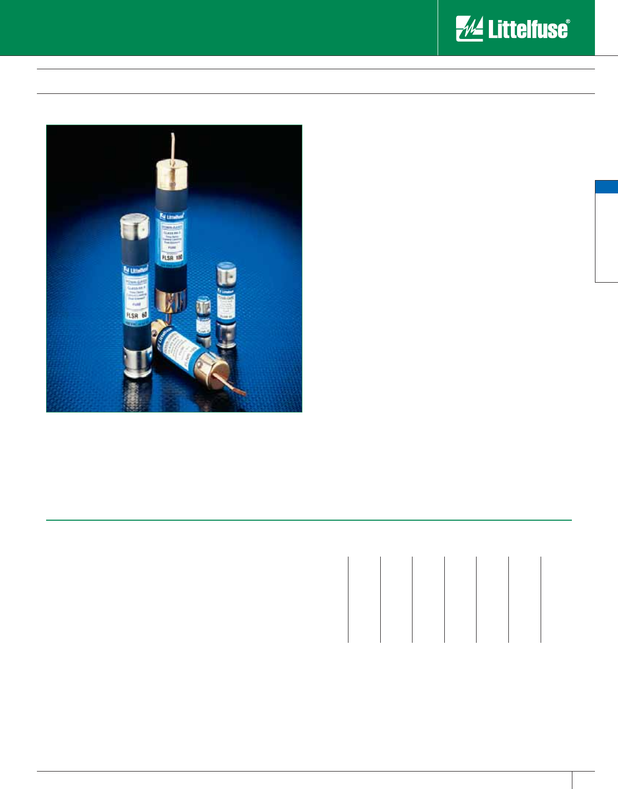
General Purpose Fuses
General Purpose Fuses
33
www.littelfuse.com
© 2005 Littelfuse • POWR-GARD™ Products Catalog
Littelfuse FLNR/FLSR series fuses have been the superior UL Class
RK5 dual-element time-delay fuses, and are the most widely used class
of fuses. FLNR/FLSR series fuses provide excellent protection for all
types of circuits especially those containing motors. However, users and
specifiers should consider the significant benefits offered by Indicator
fuses. Complete information on these fuses may be found earlier in this
section.
Applications
Service entrance switches
Switchboard main and feeder switches
Motor control center mains and motor branch circuits
Individual fused combination motor controllers
Distribution panelboards
Industrial control panels
Protection of fully rated panelboards and loadcenters
All general purpose circuits
Safety
• 200,000 A.I.R. — Reliable interruption of all overcurrents up to
200,000 amperes.
• Faster acting short-circuit protection than any non-current-limiting
mechanical protective device.
Reliability
• Accurate and reliable — Automated, precision manufactured and
assembled parts ensure accurate, consistent response to overloads
and short-circuits.
Longer Equipment Life
• Reduced damage to equipment caused by heating and magnetic
forces of short-circuits.
• Equipment runs cooler with low-resistance dual-element fuses.
FLNR/FLSR Class RK5 Fuses
250/600 VAC • Dual-Element, Time-Delay • 1/10 – 600 Amperes
Specifications
Voltage Ratings: AC: 250 Volts (FLNR)
600 Volts (FLSR)
DC: 125 Volts (FLNR)
300 Volts (FLSR)
Interrupting Ratings: AC: 200,000 amperes rms symmetrical
DC: 20,000 amperes
Ampere Range: 1⁄10 – 600 amperes
Approvals: Standard 248-12, Class RK5
UL Listed (File No: E81895)
CSA Certified (File No: LR29862)
MSHA 300 Volt Listing (FLSR)
QPL: Federal Specification WF-1814
Dimensions
Refer to FLNR_ID series for FLNR dimensions and FLSR_ID series for FLSR
dimensions.
Ampere Ratings
1⁄10 6⁄10 18⁄10 483080225
1⁄88⁄10 24
1⁄293590250
15 ⁄100 12
1⁄451040100300
2⁄10 11⁄821⁄256⁄10 12 45 110 350
1⁄411⁄428⁄10 61550125400
3⁄10** 14⁄10 36
1⁄4171⁄260 150 450
4⁄10 11⁄232⁄10 72070175500
1⁄216⁄10 31⁄271⁄225 75 200 600
**FLNR only,
Ex am ple part number (series & am per age): FLSR100
Recommended Fuse Blocks
LR250 series (for FLNR series fuses)
LR600 series (for FLSR series fuses)
Refer to Blocks & Holders section of this catalog for ad di tion al in for ma tion.
Catalog 25-48.indd 33 5/30/07 6:19:07 PM
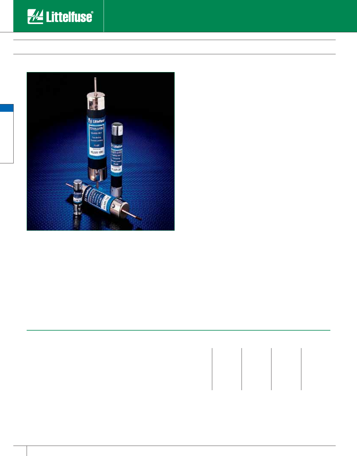
General Purpose Fuses
General Purpose Fuses
34 www.littelfuse.com © 2005 Littelfuse • POWR-GARD™ Products Catalog
KLNR/KLSR Class RK1 Fuses
250/600 VAC • Fast Acting • 1 – 600 Amperes
Specifications
Voltage Ratings: AC: 250 Volts (KLNR); 600 Volts (KLSR)
DC: 125 Volts (1 – 600A KLNR);
250 Volts (1 – 30A KLSR);
300 Volts (35 – 600A KLSR).
In ter rupt ing Ratings: AC: 200,000 amperes rms sym met ri cal
DC: 20,000 amperes
Ampere Range: 1 – 600 amperes.
Approvals: AC: Standard 248-12, Class RK1
UL Listed (File No: E81895)
CSA Certified (File No: LR29862)
DC: Littelfuse self-certified
Ampere Ratings
11040100250
21245110300
31550125350
42060150400
52570175450
63080200500
83590225600
Example part number (series & amperage): KLNR 200
Recommended Fuse Blocks
LR250 series (for KLNR series fuses)
LR600 series (for KLSR series fuses)
Refer to the Blocks & Holders section of this catalog for additional in for ma tion.
KLNR/KLSR series RK1 fuses were the earliest type of current-limiting
fuses developed. Their single-element, silver link design enables them
to provide fast-acting overload and short-circuit pro tec tion. When used
to protect inductive loads such as motors, solenoids, and trans form ers,
KLNR/KLSR series fuses must be greatly oversized to prevent opening
the fuses on harmless in-rush currents. In such applications, KLNR/
KLSR series fuses may only provide short-circuit pro tec tion.
We recommend using POWR-PRO® LLNRK/LLSRK series Class RK1,
dual-element, time-de lay fuses in all new applications re quir ing the
current-limiting ability of UL Class RK1 fuses. POWR-PRO LLNRK/
LLSRK series fuses are also recommended in existing applications
where fast-acting RK1 or RK5 fuses have been open ing on harmless
system surges such as motor start ing currents.
Applications
Resistance heaters
Lighting circuits
Non-inductive loads
Molded case circuit breaker load centers and panelboards have
increased in ter rupt ing ratings when series rated with Littelfuse
KLNR/KLSR Class RK1 fuses. Refer to panelboard manufacturer’s
literature for UL Listed com bi na tion of fuses and panelboards. Series
ratings up to 200,000 amperes are available.
Safety
• 200,000 A.I.R. — Reliable interruption of all overcurrents up to
200,000 amperes.
• Extremely current-limiting — Stops dam ag ing short-circuit current
faster than any mechanical pro tec tive device.
• Fast-acting — Provides fast acting protection to equipment such
as variable speed drives, rectifiers and other equip ment containing
surge-sensitive com po nents.
Longer Equipment Life
• Current-limiting design reduces damage to equip ment caused by
heating and magnetic effects of short-circuit currents.
Economical
• Extremely current-limiting — often permits use of readily available,
less costly equipment.
• Used as input or output fuses for surge sensitive com po nents such
as variable speed drives and rectifiers, fast acting KLNR/KLSR fuses
may prevent opening of ex pen sive semiconductor fuses protecting
individual components.
Easy To Use
• 200,000 A.I.R. rating min i miz es need for short-circuit calculations.
Dimensions
• Refer to FLNR_ID for KLNR dimensions and FLSR_ID for KLSR
dimensions.
Catalog 25-48.indd 34 5/30/07 6:19:10 PM
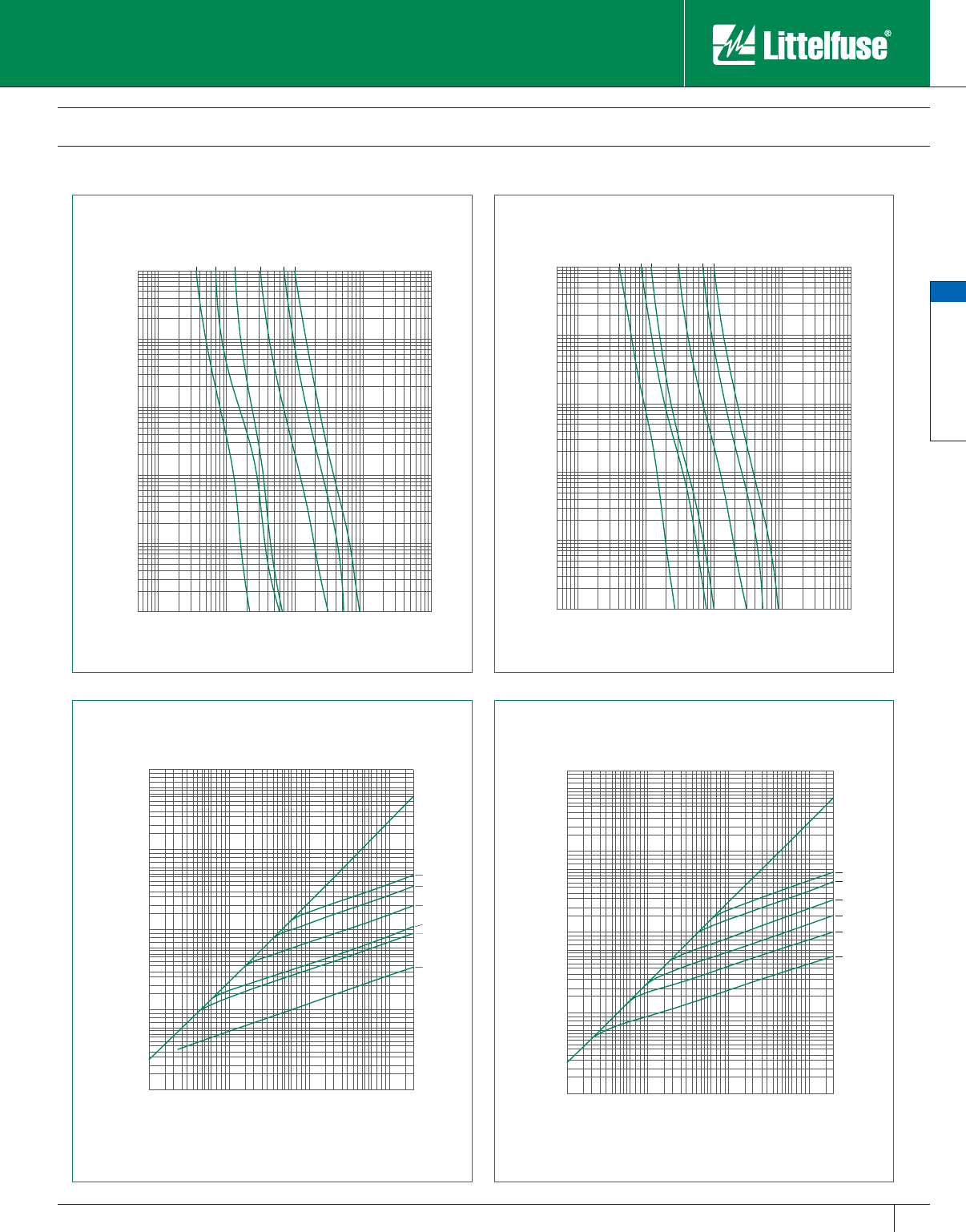
General Purpose Fuses
General Purpose Fuses
35
www.littelfuse.com
© 2005 Littelfuse • POWR-GARD™ Products Catalog
KLNR/KLSR Class RK1 Fuses
250/600 VAC • Fast Acting • 1 – 600 Amperes
1000
800
600
400
300
200
100
80
60
40
30
20
10
8
6
4
3
2
1
.8
.6
.4
.3
.2
.1
.08
.06
.04
.03
.02
.01
200
300
400
600
800
1000
2000
3000
4000
6000
8000
10000
20000
30000
40000
60000
80000
100000
10
20
30
40
60
80
100
30A
60A
100A
200A
400A
600A
TIME IN SECONDS
CURRENT IN AMPERES
1000
800
600
400
300
200
100
80
60
40
30
20
10
8
6
4
3
2
1
.8
.6
.4
.3
.2
.1
.08
.06
.04
.03
.02
.01
200
300
400
600
800
1000
2000
3000
4000
6000
8000
10000
20000
30000
40000
60000
80000
100000
10
20
30
40
60
80
100
5
30A
60A
100A
200A
400A
600A
TIME IN SECONDS
CURRENT IN AMPERES
2000
3000
4000
6000
8000
10000
20000
30000
40000
60000
80000
100000
200000
100
200
300
400
600
800
1000
100
200
300
400
600
800
1000
2000
3000
4000
6000
8000
10000
20000
30000
40000
60000
80000
100000
200000
300000
400000
600000
800000
1000000
600A
400A
200A
100A
60A
30A
PEAK LET-THRU IN AMPERES
AVAILABLE FAULT CURRENT
SYMMETRICAL R. M. S. AMPERES
2000
3000
4000
6000
8000
10000
20000
30000
40000
60000
80000
100000
200000
100
200
300
400
600
800
1000
100
200
300
400
600
800
1000
2000
3000
4000
6000
8000
10000
20000
30000
40000
60000
80000
100000
200000
300000
400000
600000
800000
1000000
600A
400A
200A
100A
60A
30A
PEAK LET-THRU IN AMPERES
AVAILABLE FAULT CURRENT
SYMMETRICAL R. M. S. AMPERES
KLSRKLNR
KLSRKLNR
Catalog 25-48.indd 35 5/30/07 6:19:13 PM
General Purpose Fuses
General Purpose Fuses
36 www.littelfuse.com © 2005 Littelfuse • POWR-GARD™ Products Catalog
NLN/NLS Class K5 Fuses
250/600 VAC • “One-Time” • 1 – 600 Amperes
NLN and NLS series fuses provide low cost protection for general purpose
feeder and branch circuits when avail able short-circuit currents are less
than 50,000 amperes. They replace all Class H fuses which have only a
10,000 ampere interrupting rating. They are suitable for use in many res i-
den tial and smaller commercial and industrial applications.
NLKP series fuses are Canadian “Code” fuses specifically de signed to
meet Canadian Electrical Code Type P fuse re quire ments for residential
use. They have a 10,000 ampere interrupting rating.
However, to obtain the added benefits of time-delay, cur rent-limitation, and
higher interrupting rating, consider the use of POWR-PRO® FLNR_ID and
FLSR_ID Indicator® fuses for circuits up to 600 volts. The user gets all the
benefits of time-delay RK5 fuses plus the added benefits of an indicating
fuse that shows when it has opened. Complete information on these
fuses may be found in the POWR-PRO fuse section of this catalog. For
circuits up to 250 volts, see FLNR fuses in this section of the catalog.
Applications
General purpose residential and commercial circuits with little or no
motor load.
Resistive heating loads.
Economical
• For use in applications where lowest initial cost is the major consideration.
Safety
• 50,000 A.I.R., Class K5 — Adequate in ter rupt ing capacity for
residences and many smaller facilities.
NOTE: NLKP series fuses have limited interrupting rating and should be
used only where available short-circuit current is known to be less than the
fuse interrupting rating. Where available fault current is unknown, where
it exceeds NLN/NLS interrupting rating, or where it may increase in the
future, 200,000 ampere interrupting rating Littelfuse POWR-PRO
FLNR_ID/FLSR_ID Indicator fuses and FLNR/FLSR series fuses provide
superior pro tec tion for all motor and general purpose circuits con tain ing
inductive loads.
Specifications
Voltage Ratings: AC: 250 Volts (NLN, NLKP)
600 Volts (NLS)
DC: 250 Volts (NLN)
400 Volts (NLS 35 – 60A)
500 Volts (NLS 8 – 30A)
(NLS 225 – 600A)
600 Volts (NLS 1 – 7A)
(NLS 70 – 200A)
Interrupting Ratings: AC: 50,000 amperes rms sym met ri cal (NLN/NLS)
10,000 amperes (NLKP)
DC: 20,000 amperes
(NLN/NLS 1 – 60A)
50,000 amperes
(NLN/NLS 70 – 600A)
Ampere Range: 1– 600 amperes (NLN/NLS)
15 – 60 amperes (NLKP)
Ap prov als: NLN/NLS: Standard 248-9, Class K5
UL Listed (File No: E81895)
CSA Certified (File No: LR29862)**
**Excludes NLN 15-60A
NLKP: Standard 248-6, Class H
UL Listed (File No: E81895)
CSA Certified (File No: LR29865)
Meets CSA “Type P” requirements
Ampere Ratings
17*25*60125300
28*3070150350
310*3580175400
412*4090200450
5 *15 *45 100 225 500
6*20*50110250600
* NLKP series avail able only in those amperages preceded by an asterisk.
Example part number (series & amperage): NLS 125
Recommended Fuse Blocks
LH250 series (for NLN and NLKP series fuses)
LH600 series (for NLS series fuses)
Refer to the Blocks & Holders section of this catalog for additional in for ma tion.
Catalog 25-48.indd 36 5/30/07 6:19:13 PM
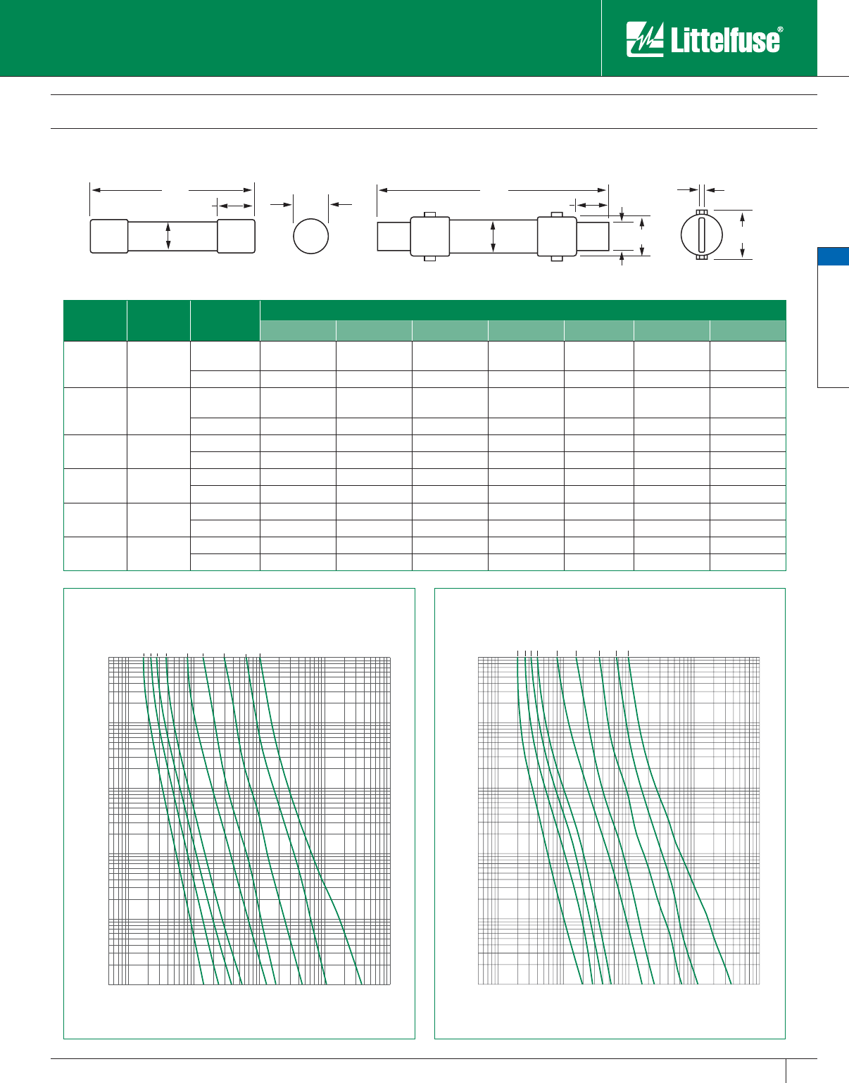
General Purpose Fuses
General Purpose Fuses
37
www.littelfuse.com
© 2005 Littelfuse • POWR-GARD™ Products Catalog
NLN/NLS Class K5 Fuses
250/600 VAC • “One-Time” • 1 – 600 Amperes
CURRENT IN AMPERES
TIME IN SECONDS
NLS
600A
.01
.02
.03
.04
.05
.06
.08
.1
.2
.3
.4
.6
.8
1
2
3
4
6
8
10
20
30
40
60
80
100
200
300
400
600
800
1000
5
100
80
60
40
30
20
10
8
6
100000
80000
60000
40000
30000
20000
10000
8000
6000
4000
3000
2000
1000
800
600
400
300
200
400A
200A
100A
60A
30A
25A
20A
15A
TIME IN SECONDS
CURRENT IN AMPERES
NLN
.01
.02
.03
.04
.06
.08
.1
.2
.3
.4
.6
.8
1
2
3
4
6
8
10
20
30
40
60
80
100
200
300
400
600
800
1000
5
100
80
60
40
30
20
10
8
6
100000
80000
60000
40000
30000
20000
10000
8000
6000
4000
3000
2000
1000
800
600
400
300
200
200A
100A
400A
600A
60A
30A
25A
20A
15A
A
CC
D
AE
B
BFD G
FIG. 1 FIG. 2
Amperes Refer to
Fig. No. Series Dimensions In Inches (mm in parentheses)
ABCDEFG
1 – 30 1
NLN
NLKP 2 (50.8) 1⁄2 (12.7) 1⁄2 (12.7) 9⁄16 (14.3) — — —
NLS 5 (127.0) 3⁄4 (19.1) 5⁄8 (15.9) 13 ⁄16 (20.6) — — —
35 – 60 1
NLN
NLKP 3 (76.2) 3⁄4 (19.1) 5⁄8 (15.9) 13 ⁄16 (20.6) — — —
NLS 51⁄2 (139.7) 1 (25.4) 5⁄8 (15.9) 11⁄16 (27.0) — — —
70 – 100 2 NLN 57⁄8 (149.2) 1 (25.4) 1 (25.4) 11⁄16 (27.0) 1⁄8 (3.2) 3⁄4 (19.1) 15⁄16 (33.3)
NLS 77⁄8 (200.0) 11⁄4 (31.8) 1 (25.4) 15⁄16 (33.3) 1⁄8 (3.2) 3⁄4 (19.1) 19⁄16 (39.7)
110 – 200 2 NLN 71⁄8 (181.0) 11⁄2 (38.1) 13⁄8 (34.9) 19⁄16 (39.7) 3⁄16 (4.8) 11⁄8 (28.6) 17⁄8 (47.6)
NLS 95⁄8 (244.5) 13⁄4 (44.5) 13⁄8 (34.9) 127⁄32 (46.8) 3⁄16 (4.8) 11⁄8 (28.6) 23⁄32 (53.2)
225 – 400 2 NLN 85⁄8 (219.1) 2 (50.8) 17⁄8 (47.6) 23⁄32 (53.2) 1⁄4 (6.4) 15⁄8 (41.3) 213 ⁄32 (61.1)
NLS 115⁄8 (295.3) 21⁄2 (63.5) 17⁄8 (47.6) 219 ⁄32 (65.9) 1⁄4 (6.4) 15⁄8 (41.3) 27⁄8 (73.0)
450 – 600 2 NLN 103⁄8 (263.5) 21⁄2 (63.5) 21⁄4 (57.2) 219 ⁄32 (65.9) 1⁄4 (6.4) 2 (50.8) 27⁄8 (73.0)
NLS 133⁄8 (339.7) 3 (76.2) 21⁄4 (57.2) 33⁄32 (78.6) 1⁄4 (6.4) 2 (50.8) 37⁄16 (87.3)
Catalog 25-48.indd 37 5/30/07 6:19:16 PM
General Purpose Fuses
General Purpose Fuses
38 www.littelfuse.com © 2005 Littelfuse • POWR-GARD™ Products Catalog
RLN/RLS Class H Fuses
250/600 VAC • Renewable • 1 – 600 Amperes
Littelfuse RLN/RLS series renewable fuses are a quality product that
have traditionally been used to provide low cost protection of general
purpose feeder and branch circuits where available short-circuit currents
do not exceed 10,000 amperes. However, increased levels of available
fault current and the possibility that renewable fuses may be im prop erly
renewed is a potential safety hazard. In addition, escalating labor costs
and increasing automation, which makes down time very expensive,
have greatly re duced or eliminated the cost savings attributed to
renewable fuses.
We recommend the use of POWR-PRO® FLSR_ID series Indicator®
fuses for circuits between 250 and 600 volts and FLNR_ID series for
circuits 250 volts and below. Complete information on POWR-PRO
Indicator fuses may be found in the POWR-PRO fuse section of this
catalog. FLNR fuses are in this section of the catalog.
Cost Considerations
• When comparing the cost of using re new able fuses with the cost of
other fuses, the labor required for replacing links and the cost of ad di-
tion al downtime should be included.
Cautions
• Renewable fuses should only be used where short-circuit currents
are known to be less than 10,000 amperes, and where correct
replacement of open links is assured.
• After disassembly of fuse, examine carefully. Discard any fuses
which show evidence of weak ened tube or damaged components.
• Remove all link residue from fuse tube.
• Carefully clean all contact surfaces, and remove metal spatter from
all surfaces.
• Install the proper rated fuse link and tighten all con nec tions
securely.
• Vi su al ly ex am ine fuses for cor rect align ment of blades.
Dimensions
• For dimensions, please refer to NLN series for RLN di men sions and
NLS series for RLS dimensions.
Specifications
Voltage Ratings: AC: 250 Volts (RLN); 600 Volts (RLS)
In ter rupt ing Ratings: AC: 10,000 am peres rms sym met ri cal
Ampere Range: 1 – 600 amperes
Ap prov als: Standard 248-6, Class H
UL Listed (File No: E81895)
CSA Certified (File No: LR29862)
FUSE LINKS: To order, specify LKN (250V) or LKS (600V) plus
ampere rating.
Ampere Ratings
16204590175350*
28**2550100200400*
3103060110225*450*
4 12** 35 70 125 250* 500*
5154080150300*600*
*These ampere ratings require two links per fuse.
**RLS Only.
Example part number (series & amperage): RLN 20
Recommended Fuse Blocks
LH250 series (for RLN series fuses)
LH600 series (for RLS series fuses)
Refer to the Blocks & Holders section of this catalog for additional in for ma tion.
Catalog 25-48.indd 38 5/30/07 6:19:18 PM
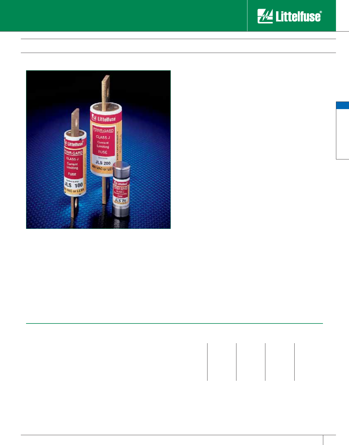
General Purpose Fuses
General Purpose Fuses
39
www.littelfuse.com
© 2005 Littelfuse • POWR-GARD™ Products Catalog
JLS Class J Fuses
600 VAC • Fast Acting • 1 – 600 Amperes
Specifications
Voltage Ratings: 600 Volts AC
Interrupting Ratings: 200,000 amperes rms symmetrical
Ampere Range: 1 – 600 amperes
Approvals: Standard 248-8, Class J
UL Listed (File No: E81895)
CSA Certified (File No: LR29862)
QPL: Federal Specification No: WF-1814
Ampere Ratings
12560125300
33070150350
63580175400
10 40 90 200 450
15 45 100 225 500
20 50 110 250 600
Example part number (series & amperage): JLS 110
Recommended Fuse Blocks
LPSJ series, LJ600 series
Refer to the Blocks and Holders section of this catalog for additional in for ma tion.
JLS series fuses provide space saving, fast acting overload and short-
circuit protection for non-inductive loads. When used for motors or other
inductive loads, the ampere rating of JLS series fuses must be increased
to prevent nuisance opening on in-rush currents. In such applications, JLS
fuses may provide only short-circuit protection. Con sid er using Littelfuse
POWR-PRO® JTD or JTD_ID series time-delay fuses in such circuits.
Applications
General purpose circuits with little or no motor load.
Resistive loads, such as resistance electric heat.
Loads requiring fast acting overload protection, such as equipment
containing solid-state devices.
Space Saving
• JLS fuse characteristics are similar to KLNR/KLSR fast acting Class
RK1 fuses, but dimensionally are much smaller.
Safety
• 200,000 A.I.R. — Reliable interruption of all overcurrents up to
200,000 amperes.
• Extremely current-limiting — Stops dam ag ing short-circuit current
faster than any mechanical pro tec tive device.
• Fast acting — Provides fast acting protection to equipment such as
variable speed drives, rectifiers and other equip ment containing surge
sensitive com po nents.
Longer Equipment Life
• Current-limiting design reduces damage to equip ment caused by
heating and magnetic effects of short-circuit currents.
Economical
• Extremely current-limiting design often permits use of readily
available, less costly equipment.
• Manufacturers of equipment containing dual voltage devices can
simplify manufacturing and reduce inventory by stan dard iz ing on 600
volt JLS fuses and Class J fuse blocks for all AC voltage ratings.
Easy to use
• 200,000 A.I.R. rating minimizes need for short-circuit cal cu la tions.
NOTE: Littelfuse JLS fuses are not time-delay fuses. For ap pli ca tions
where short-duration surg es and spikes may cause nuisance fuse
opening, consider the use of Littelfuse POWR-PRO JTD or JTD_ID
series time-delay fuses.
Catalog 25-48.indd 39 5/30/07 6:19:20 PM
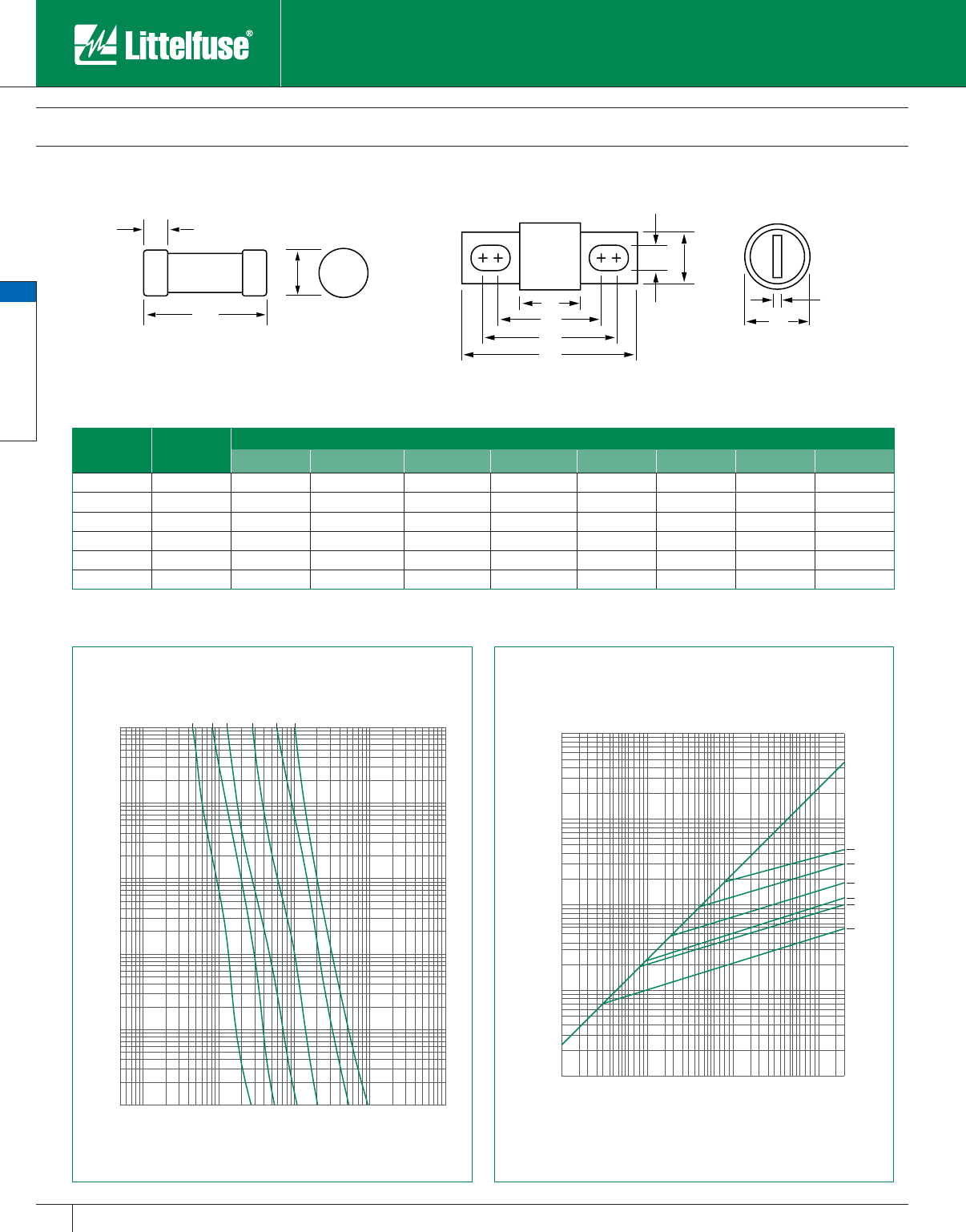
General Purpose Fuses
General Purpose Fuses
40 www.littelfuse.com © 2005 Littelfuse • POWR-GARD™ Products Catalog
JLS Class J Fuses
600 VAC • Fast Acting • 1 — 600 Amperes
1000
800
600
400
300
200
100
80
60
40
30
20
10
8
6
4
3
2
1
.8
.6
.4
.3
.2
.1
.08
.06
.04
.03
.02
.01
200
300
400
600
800
1000
2000
3000
4000
6000
8000
10000
20000
30000
40000
60000
80000
100000
8
10
20
30
40
60
80
100
5
30A
60A
100A
200A
400A
600A
TIME IN SECONDS
CURRENT IN AMPERES
A
C
DGF
E
H
A
B
C
D
Fig. 1 Fig. 2
2000
3000
4000
6000
8000
10000
20000
30000
40000
60000
80000
100000
200000
100
200
300
400
600
800
1000
100
200
300
400
600
800
1000
2000
3000
4000
6000
8000
10000
20000
30000
40000
60000
80000
100000
200000
300000
400000
600000
800000
1000000
600A
400A
200A
100A
60A
30A
PEAK LET-THRU IN AMPERES
AVAILABLE FAULT CURRENT
SYMMETRICAL R. M. S. AMPERES
Amperes Refer to
Fig. No.
Dimensions In Inches (mm in parentheses)
AB CDEFGH
1 – 30 1 21⁄4 (57.2) — 1⁄2 (12.7) 13 ⁄16 (20.6)————
35 – 60 1 23⁄8 (60.3) — 5⁄8 (15.9) 11⁄16 (27.0)————
70 – 100 2 25⁄8 (66.7) 317⁄32 (89.7) 323⁄32 (94.5) 45⁄8 (117.5) 1 (25.4) 3⁄4 (19.1) 9⁄32 (7.1) 1⁄8 (3.2)
110 – 200 2 3 (76.2) 49⁄32 (108.7) 415 ⁄32 (113.5) 53⁄4 (146.1) 11⁄2 (38.1) 11⁄8 (28.6) 9⁄32 (7.1) 3⁄16 (4.8)
225 – 400 2 33⁄8 (85.7) 51⁄8 (130.2) 53⁄8 (136.5) 71⁄8 (181.0) 2 (50.8) 15⁄8 (41.3) 13⁄32 (10.3) 1⁄4 (6.4)
450 – 600 2 33⁄4 (95.3) 527⁄32 (148.4) 65⁄32 (156.4) 8 (203.2) 21⁄2 (63.5) 2 (50.8) 17⁄32 (13.5) 3⁄8 (9.5)
Catalog 25-48.indd 40 5/30/07 6:19:22 PM
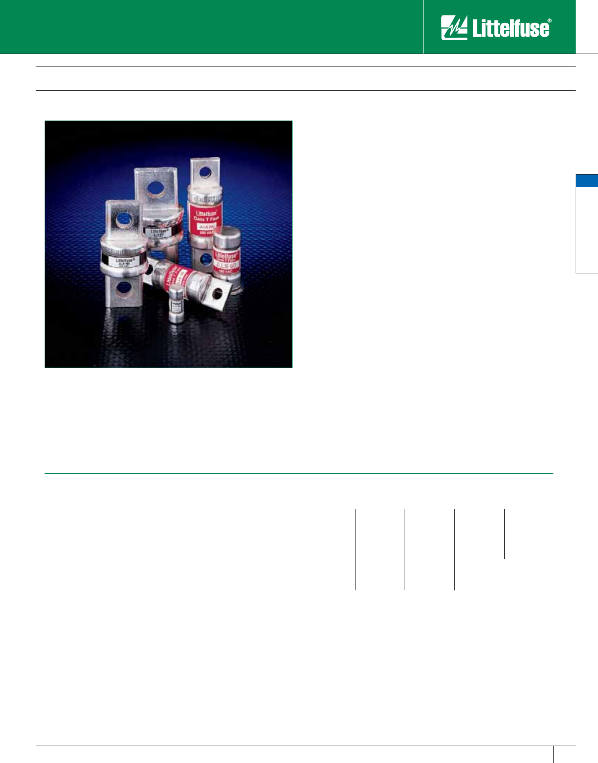
General Purpose Fuses
General Purpose Fuses
41
www.littelfuse.com
© 2005 Littelfuse • POWR-GARD™ Products Catalog
JLLN/JLLS POWR-T™ Class T Fuses
300/600 VAC • Fast-Acting • 1 – 1200 Amperes
Specifications
Voltage Ratings: AC: 300 Volts (JLLN); 600 Volts (JLLS)
DC: 125 Volts (JLLN 1 – 30A)
160 Volts (JLLN 35 – 60A)
125 Volts (JLLN 110 – 1200A)
300 Volts (JLLS)
Interrupting Ratings: AC: 200,000 amperes rms symmetrical
DC: 20,000 amperes
(JLLN 110 – 1200A)
(JLLS 1 – 1200A)
Ampere Range: 1– 1200 amperes
Approvals: AC: Standard 248-15, Class T
UL Listed (File No: E81895):
JLLN/JLLS (1 – 800A)
UL Recognized (File No: E71611):
JLLS (900 – 1200A)
CSA Certified (File No: LR29862):
JLLN/JLLS (1 – 600A)
DC: UL Listed (File No: E81895):
JLLN (110 – 1200A)
Littelfuse self-certified: JLLN 1-60A
JLLS (1 – 1200A)
Ampere Ratings
13090250800
2 35 100 300 900*
3 40 110 350 1000
6451254001100
10 50 150 450 1200
15 60 175 500
20 70 200 600
25 80 225 700
* JLLS only
Example part number (series & amperage): JLLS 100
Note: Contact the factory for RoHS compliant Class T fuses.
Recommended Fuse Blocks
LT300 series (for JLLN series fuses)
LT600 series (for JLLS series fuses)
LSCR002 (for JLLN/JLLS 700-1200A fuses)
Refer to the Blocks and Holders section of this catalog for additional in for ma tion.
Space saving POWR-T fuses are the most compact fuses available in
ratings above 30 amperes — less than one-third the size of comparable
Class R fuses. When rated in ac cor dance with the NEC®, POWR-T fuses
provide fast acting overload and short-circuit protection for non-inductive
circuits and equipment. Used in inductive circuits, the ampere rating of
POWR-T fuses must be increased to prevent opening on in-rush currents.
In such instances, POWR-T fuses may provide only short-circuit protection.
Applications
Littelfuse Class T fuses can be used in applications that require fast-
acting protection, such as equipment containing variable speed drives,
rectifiers, and other surge-sensitive components. Main switches
containing Class T fuses may be used to provide protection to individual
electric services and meter stacks. Molded case circuit breaker load
centers and Panelboards also will have increased interrupting ratings
when “series rated” with Class T fuses.
Features/Benefits
Space-Saving – Switch enclosures, fuse pullouts, and other equipment
using Class T fuses are usually more compact. Typical three-pole Class
T fuse blocks require less than 50% of the panel space required by
similar Class R blocks.
Longer Equipment Life and Increased Safety – Class T fuses provide
fast, reliable protection against overcurrents up to 200,000 amperes.
Extremely current-limiting design minimizes the damaging heating and
magnetic effects caused by short-circuit currents.
Optional Mounting Types – In addition to the Class T dimensions,
Littelfuse offers select ratings with PC board mounting tabs for specialty
applications. PC board mount versions are UL Recognized. Contact the
factory for more information.
NOTE: JLLN Class T 300 volt fuses are UL Listed for circuits not
exceeding 300 volts to ground. However, since UL does not include
testing 300 volt Class T fuses on 277/480 volt three-phase bolted faults,
Littelfuse does not rec om mend using 300 volt Class T fuses where
phase-to-phase voltage exceeds 300 volts.
Catalog 25-48.indd 41 5/30/07 6:19:23 PM
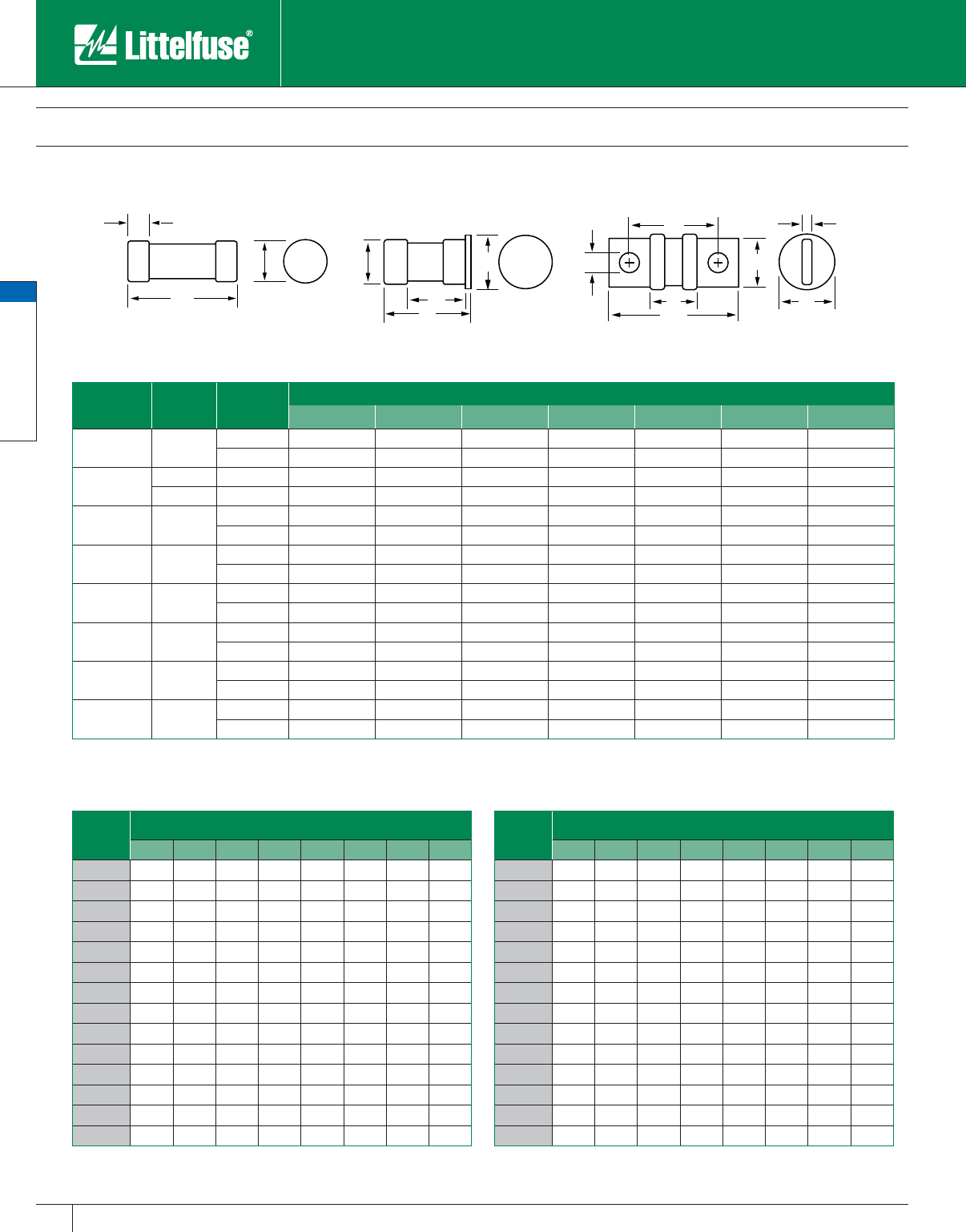
General Purpose Fuses
General Purpose Fuses
42 www.littelfuse.com © 2005 Littelfuse • POWR-GARD™ Products Catalog
JLLN/JLLS POWR-T™ Class T Fuses
300/600 VAC • Fast Acting • 1 – 1200 Amperes
B
C
AF
DF
E
A
B
C
D
G
A
C
D
Fig. 1 Fig. 2 Fig. 3
Amperes Refer to
Fig. No. Series Dimensions in Inches (mm in parentheses)
ABCDE FG
1 – 30 1 JLLN 7⁄8 (22.2) — 9⁄32 (7.1) 13⁄32 (10.3) — — —
JLLS 11⁄2 (38.1) — 9⁄32 (7.1) 9⁄16 (14.3) — — —
35 – 60 1JLLN
7⁄8 (22.2) — 9⁄32 (7.1) 9⁄16 (14.3) — — —
2JLLS1
9⁄16 (39.7) 13 ⁄16 (20.6) 13 ⁄32 (10.3) 1 (25.4) 1⁄16 (1.6) 13⁄32 (27.8) —
70 – 100 3 JLLN 25⁄32 (54.8) 19⁄16 (39.7) 3⁄4 (19.1) 13⁄16 (20.6) 27⁄32 (21.4) 9⁄32 (7.1) 1⁄8 (3.2)
JLLS 261⁄64 (75.0) 223⁄64 (59.9) 3⁄4 (19.1) 13 ⁄16 (20.6) 141⁄64 (41.7) 9⁄32 (7.1) 1⁄8 (3.2)
110 – 200 3 JLLN 27⁄16 (61.9) 111⁄16 (42.9) 7⁄8 (22.2) 11⁄16 (27.0) 27⁄32 (21.4) 11 ⁄32 (8.7) 3⁄16 (4.8)
JLLS 31⁄4 (82.6) 21⁄2 (63.5) 7⁄8 (22.2) 11⁄16 (27.0) 121⁄32 (42.1) 11⁄32 (8.7) 3⁄16 (4.8)
225 – 400 3 JLLN 23⁄4 (69.9) 127⁄32 (46.8) 1 (25.4) 15⁄16 (33.3) 53⁄64 (21.0) 13 ⁄32 (10.3) 1⁄4 (6.4)
JLLS 35⁄8 (92.1) 223⁄32 (69.1) 1 (25.4) 119 ⁄32 (40.5) 123⁄32 (43.7) 13⁄32 (10.3) 1⁄4 (6.4)
450 – 600 3 JLLN 31⁄16 (77.8) 21⁄32 (51.6) 11⁄4 (31.8) 119 ⁄32 (40.5) 7⁄8 (22.2) 31⁄64 (12.3) 5⁄16 (7.9)
JLLS 363⁄64 (101.2) 261⁄64 (75.0) 11⁄4 (31.8) 21⁄16 (52.4) 149⁄64 (44.8) 31⁄64 (12.3) 5⁄16 (7.9)
700 – 800 3 JLLN 33⁄8 (85.7) 27⁄32 (64.3) 13⁄4 (44.5) 21⁄16 (52.4) 7⁄8 (22.2) 35⁄64 (13.9) 3⁄8 (9.5)
JLLS 421⁄64 (109.9) 311⁄64 (80.6) 13⁄4 (44.5) 21⁄2 (63.5) 155⁄64 (47.2) 35⁄64 (13.9) 3⁄8 (9.5)
900 – 1200 3 JLLN 4 (101.6) 217⁄32 (64.3) 2 (50.8) 21⁄2 (63.5) 11⁄32 (26.2) 39⁄64 (15.5) 7⁄16 (11.1)
JLLS 5.27 (133.9) 3.80 (96.5) 2 (50.8) 2.63 (66.8) 2.30 (58.4) 0.67 (15.5) 0.44 (11.2)
Current-Limiting Effects of JLLS (600V) fuses
Short
Circuit
Current*
Apparent RMS Symmetrical Current for Various fuse ratings
30A 60A 100A 200A 400A 600A 800A 1200A
5,000 750 1,225 1,400 2,850 4,600 5,000 5,000 5,000
10,000 945 1,525 1,700 3,600 6,000 8,500 9,400 10,000
15,000 1,050 1,700 2,000 4,050 6,600 9,750 10,500 13,000
20,000 1,150 1,900 2,200 4,450 7,250 10,500 11,000 14,750
25,000 1,300 2,050 2,400 4,800 8,000 11,500 12,500 15,500
30,000 1,375 2,150 2,450 5,000 8,250 12,000 13,750 16,500
35,000 1,400 2,250 2,600 5,100 8,500 13,000 14,000 17,000
40,000 1,425 2,400 2,800 5,200 8,700 14,000 14,750 18,000
50,000 1,600 2,450 2,900 6,000 9,500 14,500 16,000 20,000
60,000 1,650 2,625 3,100 6,250 10,000 15,500 17,300 21,000
80,000 1,825 2,800 3,400 7,000 11,000 17,000 18,750 23,000
100,000 2,000 3,100 3,700 7,250 12,000 18,000 20,000 25,000
150,000 2,250 3,400 4,300 8,500 13,000 21,000 23,000 28,500
200,000 2,450 3,800 4,600 9,000 15,000 23,000 25,000 31,000
* Prospective RMS Symmetrical Amperes Short-Circuit Current
Note: Data Derived from Peak Let-Thru Curves
Current-Limiting Effects of JLLN (300V) fuses
Short
Circuit
Current*
Apparent RMS Symmetrical Current for Various fuse ratings
30A 60A 100A 200A 400A 600A 800A 1200A
5,000 700 775 1,100 1,650 3,500 4,000 5,000 5,000
10,000 900 1,000 1,400 2,100 4,400 5,100 6,750 8,250
15,000 1,000 1,100 1,600 2,400 5,000 5,900 7,750 10,000
20,000 1,100 1,250 1,800 2,700 5,500 6,500 8,750 11,000
25,000 1,230 1,300 1,950 2,900 6,000 7,000 9,500 12,000
30,000 1,300 1,475 2,050 3,100 6,400 7,500 10,000 12,500
35,000 1,330 1,575 2,150 3,300 6,750 7,750 10,500 13,500
40,000 1,430 1,600 2,300 3,500 7,000 8,000 11,000 14,000
50,000 1,500 1,750 2,400 3,700 7,500 8,750 12,000 15,000
60,000 1,700 1,900 2,700 4,000 8,000 9,500 12,500 16,000
80,000 1,850 2,100 2,800 4,400 9,000 10,500 14,000 17,500
100,000 2,000 2,250 3,150 4,800 9,750 11,500 15,000 18,500
150,000 2,300 2,600 3,600 5,500 11,000 13,000 17,500 22,000
200,000 2,600 2,800 3,900 6,000 12,000 14,500 19,500 24,000
* Prospective RMS Symmetrical Amperes Short-Circuit Current
Note: Data Derived from Peak Let-Thru Curves
Catalog 25-48.indd 42 5/30/07 6:19:26 PM

General Purpose Fuses
General Purpose Fuses
43
www.littelfuse.com
© 2005 Littelfuse • POWR-GARD™ Products Catalog
JLLN/JLLS POWR-T™ Class T Fuses
300/600 VAC • Fast Acting • 1 – 1200 Amperes
1000
800
600
400
300
200
100
80
60
40
30
20
10
8
6
4
3
2
1
.8
.6
.4
.3
.2
.1
.08
.06
.04
.03
.02
.01
200
300
400
600
800
1000
2000
3000
4000
6000
8000
10000
20000
30000
40000
60000
80000
100000
8
10
20
30
40
60
80
100
5
30A
60A
100A
200A
400A
600A
800A
1200A
TIME IN SECONDS
CURRENT IN AMPERES
1000
800
600
400
300
200
100
80
60
40
30
20
10
8
6
4
3
2
1
.8
.6
.4
.3
.2
.1
.08
.06
.04
.03
.02
.01
200
300
400
600
800
1000
2000
3000
4000
6000
8000
10000
20000
30000
40000
60000
80000
100000
8
10
20
30
40
60
80
100
5
30A
60A
100A
200A
400A
600A
800A
TIME IN SECONDS
CURRENT IN AMPERES
2000
3000
4000
6000
8000
10000
20000
30000
40000
60000
80000
100000
200000
100
200
300
400
600
800
1000
100
200
300
400
600
800
1000
2000
3000
4000
6000
8000
10000
20000
30000
40000
60000
80000
100000
200000
300000
400000
600000
800000
1000000
1200A
800A
600A
400A
200A
100A
60A
30A
PEAK LET-THRU IN AMPERES
AVAILABLE FAULT CURRENT
SYMMETRICAL R. M. S. AMPERES
2000
3000
4000
6000
8000
10000
20000
30000
40000
60000
80000
100000
200000
100
200
300
400
600
800
1000
100
200
300
400
600
800
1000
2000
3000
4000
6000
8000
10000
20000
30000
40000
60000
80000
100000
200000
300000
400000
600000
800000
1000000
800A
600A
400A
200A
100A
60A
30A
PEAK LET-THRU IN AMPERES
AVAILABLE FAULT CURRENT
SYMMETRICAL R. M. S. AMPERES
JLLSJLLN
JLLSJLLN
Catalog 25-48.indd 43 5/30/07 6:19:28 PM
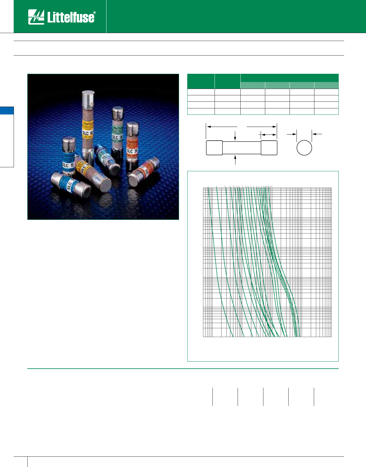
General Purpose Fuses
General Purpose Fuses
44 www.littelfuse.com © 2005 Littelfuse • POWR-GARD™ Products Catalog
SLC Class G Fuses
480 VAC, 600 VAC • Medium Time-Delay • 1/2 – 60 Amperes
The compact design of Littelfuse SLC series Class G fuses offers a cost
effective, space saving alternative to other fuse classes. The unique
design of the SLC series provides superior time-delay characteristics
over competitive products, which can increase system reliability and
minimize downtime. Class G fuses meet NEC requirements for branch
circuit protection and vary in length to prevent over-fusing when used
with the appropriate Class G fuse block.
Features/Benefits
• Current-limiting – Reduces damage to equipment caused by heating
and magnetic effects of short-circuit currents.
• 100,000 A.I.R. – Reliable interruption of all overcurrents up to
100,000 amperes.
• Time-Delay – Allows fuses to be sized closer to actual equipment
requirements and may reduce downtime caused by power surges.
Note: For ap pli ca tions where greater time-delay is re quired, or where
ratings exceed 60 am peres, con sid er se lect ing Littelfuse time-delay
Class RK1, RK5, J or CC fuses.
A
B
CD
Specifications
Voltage Ratings: 600 Volts AC (1⁄2 – 20A)
480 Volts AC (25 – 60A)
Interrupting Ratings: 100,000 amperes rms symmetrical
Ampere Range: 1⁄2 – 60 amperes
Ap prov als: Standard 248-5, Class G
UL Listed (File No: E81895)
CSA Certified (File No: LR29862)
QPL: Federal Specification No: WF-1814
Ampere Ratings
1⁄236153045
148203550
2510254060
Example part number (series & amperage): SLC 10
Recommended Fuse Blocks
LG300 series; L300G30 (for 25 and 30 amp fuses)
Refer to the Blocks & Holders section of this catalog for additional information.
Amperes Refer to
Fig. No.
Dimensions in Inches (mm in parentheses)
ABCD
1⁄2 – 15 1 15⁄16 (33.3) 3⁄8 (9.5) 9⁄32 (7.1) 13 ⁄32 (10.3)
20 1 113 ⁄32 (35.7) 3⁄8 (9.5) 9⁄32 (7.1) 13 ⁄32 (10.3)
25, 30 1 15⁄8 (41.3) 3⁄8 (9.5) 9⁄32 (7.1) 13 ⁄32 (10.3)
35 – 60 1 21⁄4 (57.2) 3⁄8 (9.5) 1⁄2 (12.7) 13 ⁄32 (10.3)
1000
800
600
400
300
200
100
80
60
40
30
20
10
8
6
4
3
2
1
.8
.6
.4
.3
.2
.1
.08
.06
.04
.03
.02
.01
20
30
40
60
80
100
200
300
400
600
800
1000
2000
3000
4000
6000
8000
10000
1
2
3
4
6
8
10
1/2A
1A
2A
3A
4A
5A
6A
8A
10A
12A
15A
20A
25A
30A
35A
40A
45A
50A
60A
TIME IN SECONDS
CURRENT IN AMPERES
Fig. 1
Catalog 25-48.indd 44 5/30/07 6:19:29 PM
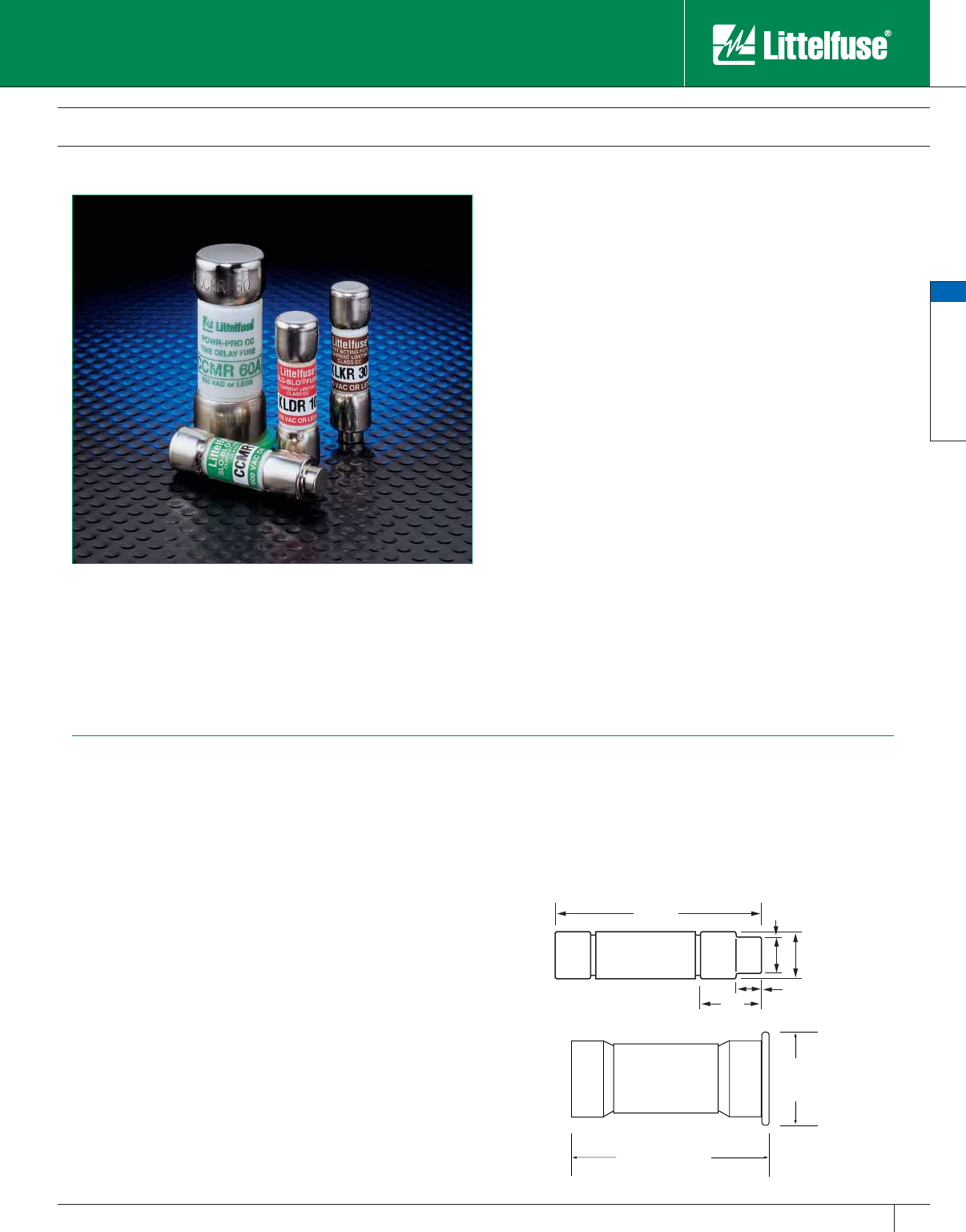
General Purpose Fuses
General Purpose Fuses
45
www.littelfuse.com
© 2005 Littelfuse • POWR-GARD™ Products Catalog
Class CC and Class CD Fuses
600 VAC • 1/10 – 60 Amperes
Compared to other UL Listed fuses, Class CC has the most current-
limiting fuse design available, rating for rating. Be cause they are
physically compact, they provide this superior protection in a fraction
of the space required by other fuse classes. For example, when 600V
three-pole, 30 ampere Class R fuse blocks are replaced by Littelfuse
Class CC fuse blocks, panel mounting space is reduced ap proximate ly
70%. This is especially important when a panel contains many fuses to
protect multiple circuit components.
Applications
Three types of Class CC fuses, specifically designed to protect different
types of components
1) Motor protection — CCMR series; dual-element, time-delay fuses
specifically designed to protect motor circuits up to 40 HP**.
2) Small transformer protection (control power transformers) — KLDR
series, time-delay fuses designed to withstand the high magnetizing
in-rush of transformers.
3) General purpose protection of equipment requiring fast overload
protection — KLKR series, fast-acting fuses used for protection
of equip ment containing solid-state devices or other electronic
components requiring fast response on overloads.
Safety
• 200,000 A.I.R. — Reliable interruption of all overcurrents up to
200,000 amperes.
• Extremely current-limiting — Reduces damage caused by heating
and magnetic effects of short-circuit currents. Stops damaging short-
circuit currents faster than any me chani cal protective device.
Space Saving
• Class CC and CD fuses are the smallest 600V, 200,000 A.I.R. fuses
approved for branch circuit protection.
Economical
• Current-limiting design often permits use of readily avail able, less
costly equipment.
Specifications
Voltage Ratings: AC: 600 Volts
DC: 250 – 500 Volts (CCMR) †
300 Volts (KLDR)
300 Volts (KLKR)
Interrupting Ratings: AC: 200,000 amperes
rms symmetrical
DC: 20,000 amperes
Ampere Range: CCMR:
2⁄10 – 60 amperes
KLDR:
1⁄10 – 30 amperes
KLKR:
1⁄10 – 30 amperes
Approvals: AC: Standard 248-4, Class CC
UL Listed
1⁄10-30 Amps (File No: E81895)
Standard 248, Class CD
UL Listed 35-60 Amps (File No: E71611)
CSA Certified
1⁄10-30 Amps
(File No: LR29862)
DC: Littelfuse Self-certified
Recommended Fuse Blocks
LPSC series (for 1⁄10 –30A)
L60030C series (for 1⁄10 –30A)
L60060C series (for CCMR 35–60A)
Refer to the Blocks and Holders section of this catalog for ad di tion al in for ma tion.
†Refer to the POWR-PRO® section for additional information.
1.880 REF.
.850
+
-.020
35-60A
** Consult the Motor Protection Tables in the Fuseology section for specific
motor sizing information
1.50"
(38.1 mm)
.50"
(12.7 mm)
.41"
(10.3 mm)
.25"
(6.4 mm)
.125"
(3.2 mm)
0-30A
Catalog 25-48.indd 45 5/30/07 6:19:32 PM
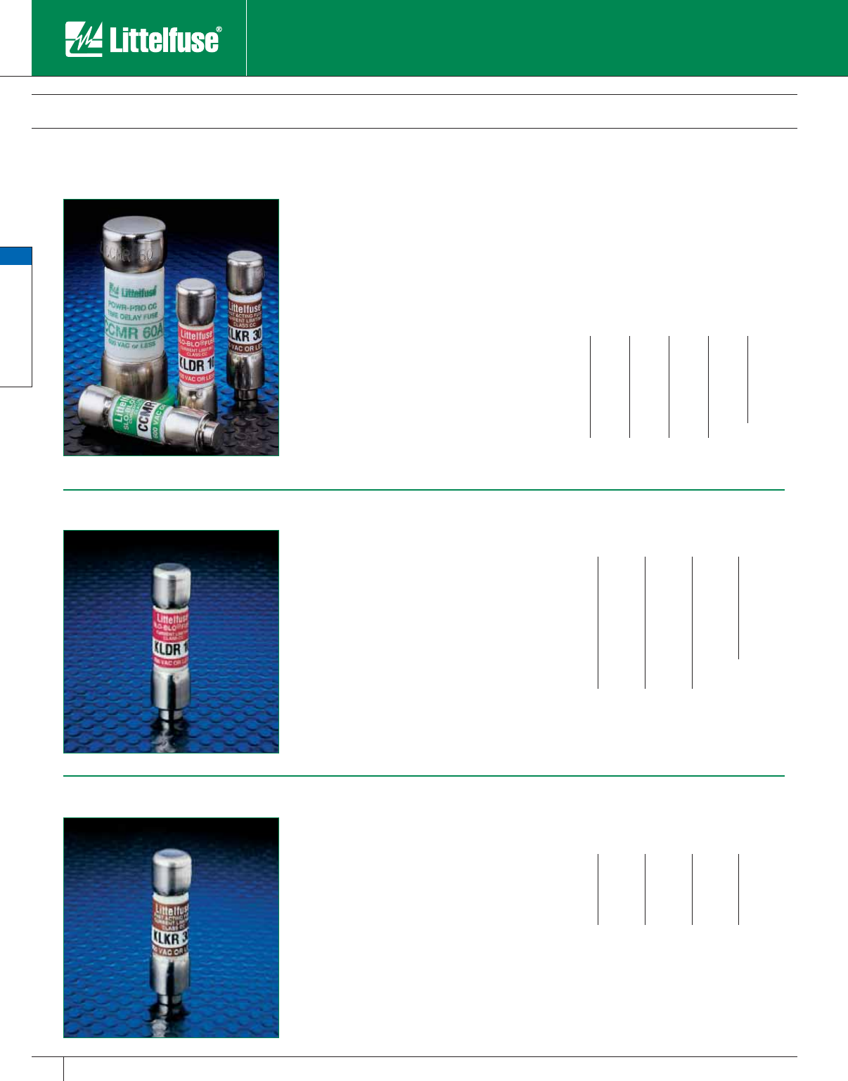
General Purpose Fuses
General Purpose Fuses
46 www.littelfuse.com © 2005 Littelfuse • POWR-GARD™ Products Catalog
Class CC and Class CD Fuses
600 VAC • 1/10 – 60 Amperes
For space saving protection of motor
circuits up to 40 HP**, we recommend
Littelfuse POWR-PRO® CCMR series fuses.
These fuses are the only true dual-element
time-delay CC fuses specifically en gi neered
for motor branch circuit pro tec tion. They pro vide
Type 2 “No Damage” pro tec tion to both
NEMA-rated and the more sensitive IEC
(International Electrotechnical Commission)
type motor circuit components.
CCMR series fuses are now available in larger
sizes — from 35 to 60 amperes! No other
600V fuse is avail able with this current
carrying capacity in a package this small.
For more information on CCMR series Class
CC fuses, see the CCMR series pages in the
POWR-PRO section of this catalog.
1⁄10 – 30A: UL Listed Class CC
35 – 60A: UL Listed Class CD
KLDR fuses are time-delay fuses specifically
designed for the protection of control
transformers, so le noids and similar inductive
com ponents with high mag ne tiz ing currents
during the first half-cycle. They closely match
most control power transformer characteristics,
which permits the fuses to be sized in
ac cor dance with the latest revisions of UL 508
(Industrial Control) and UL 845 (Motor Control
Centers). When the time delay of KLDR fuses
is adequate to carry motor starting current, they
provide ex cel lent protection of motor branch
circuits con tain ing IEC or NEMA rated motor
con trol lers or contactors.
CCMR Series
KLKR Series
KLDR Series
KLKR series Class CC fuses are fast acting
fuses intended for general purpose branch
circuit protection. Their compact size, fast
acting overload response, and highly current-
limiting design make them ideal for use in
OEM equipment and control panels. Solid state
devices such as SCRs and other electronic
equipment generally require fast acting
protection.
Ampere Ratings
2⁄10 11⁄421⁄25930
1⁄414⁄10 28⁄10 56⁄10 10 35
3⁄10 11⁄2361240
1⁄216⁄10 32⁄10 61⁄415 45
6⁄10 18⁄10 31⁄2717
1⁄250
8⁄10 247
1⁄220 60
12
1⁄441⁄2825
Example part number (series & amperage): CCMR 30
**Consult the Motor Protection Tables in the Fuse-
ology section for specific motor sizing information
Ampere Ratings
1⁄10 6⁄10 18⁄10 41⁄210
1⁄83⁄42512
15 ⁄100 8⁄10 21⁄456⁄10 15
⁄16 12
1⁄2617
1⁄2
2⁄10 11⁄828⁄10 61⁄420
1⁄411⁄43725
3⁄10 14⁄10 32⁄10 71⁄230
4⁄10 11⁄231⁄28
1⁄216⁄10 49
Example part number (series & amperage): KLDR 5 6⁄10
Ampere Ratings
1⁄10 1⁄221⁄2612
1⁄83⁄43715
2⁄10 13
1⁄2820
1⁄411⁄24925
3⁄10 251030
Example part number (series & amperage): KLKR 25
Catalog 25-48.indd 46 5/30/07 6:19:36 PM
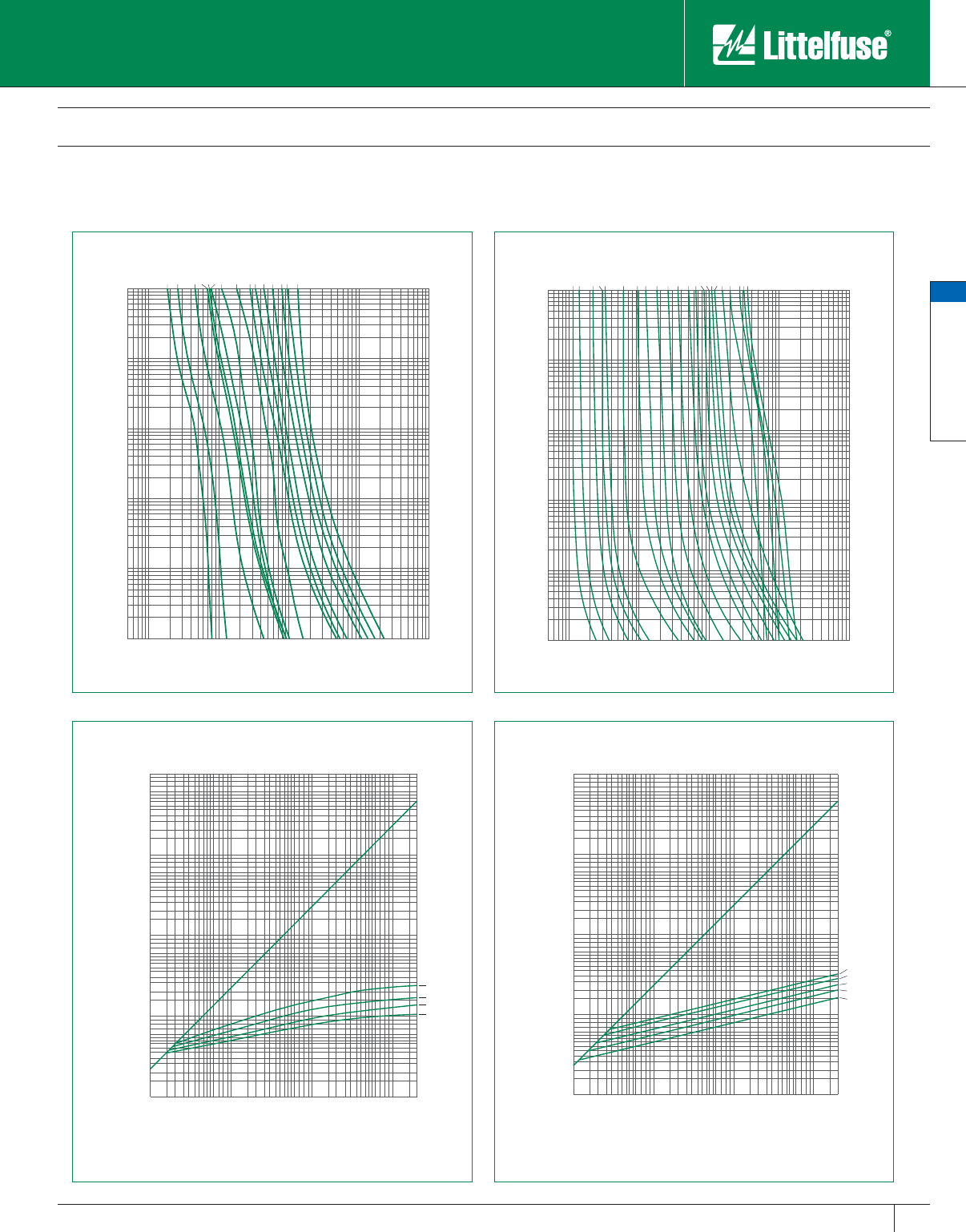
General Purpose Fuses
General Purpose Fuses
47
www.littelfuse.com
© 2005 Littelfuse • POWR-GARD™ Products Catalog
Class CC and Class CD Fuses
600 VAC • 1/10 – 60 Amperes
1000
800
600
400
300
200
100
80
60
40
30
20
10
8
6
4
3
2
1
.8
.6
.4
.3
.2
.1
.08
.06
.04
.03
.02
.01
2
3
4
6
8
10
20
30
40
60
80
100
200
300
400
600
800
1000
.1
.2
.3
.4
.6
.8
1
1/8A
2/10A
3/10A
1/2A
6/10A
3/4A
1A
1.8A
2A
2 1/2A
3A
4A
6 1/4A
8A
10A
TIME IN SECONDS
CURRENT IN AMPERES
1000
800
600
400
300
200
100
80
60
40
30
20
10
8
6
4
3
2
1
.8
.6
.4
.3
.2
.1
.08
.06
.04
.03
.02
.01
2
3
4
6
8
10
20
30
40
60
80
100
200
300
400
600
800
1000
.1
.2
.3
.4
.6
.8
1
1/10A
1/8A
2/10A
1/4A
3/10A
1/2A
3/4A
1A
1 1/2A
2A
3A
4A
5A
6A
8A
9A
10A
12A
15A
20A
25A
30A
TIME IN SECONDS
CURRENT IN AMPERES
PEAK LET-THRU IN AMPERES
AVAILABLE FAULT CURRENT
SYMMETRICAL R. M. S. AMPERES
2000
3000
4000
6000
8000
10000
20000
30000
40000
60000
80000
100000
200000
100
200
300
400
600
800
1000
100
200
300
400
600
800
1000
2000
3000
4000
6000
8000
10000
20000
30000
40000
60000
80000
100000
200000
300000
400000
600000
800000
1000000
10A
8A
6A
4A
2000
3000
4000
6000
8000
10000
20000
30000
40000
60000
80000
100000
200000
100
200
300
400
600
800
1000
100
200
300
400
600
800
1000
2000
3000
4000
6000
8000
10000
20000
30000
40000
60000
80000
100000
200000
300000
400000
600000
800000
1000000
30A
25A
20A
15A
12A
PEAK LET-THRU IN AMPERES
AVAILABLE FAULT CURRENT
SYMMETRICAL R. M. S. AMPERES
For performance data on Littelfuse CCMR series Class CC fuses, see the CCMR pages in the POWR-PRO® section of this catalog.
KLDR KLKR
KLDR KLKR
Catalog 25-48.indd 47 5/30/07 6:19:42 PM
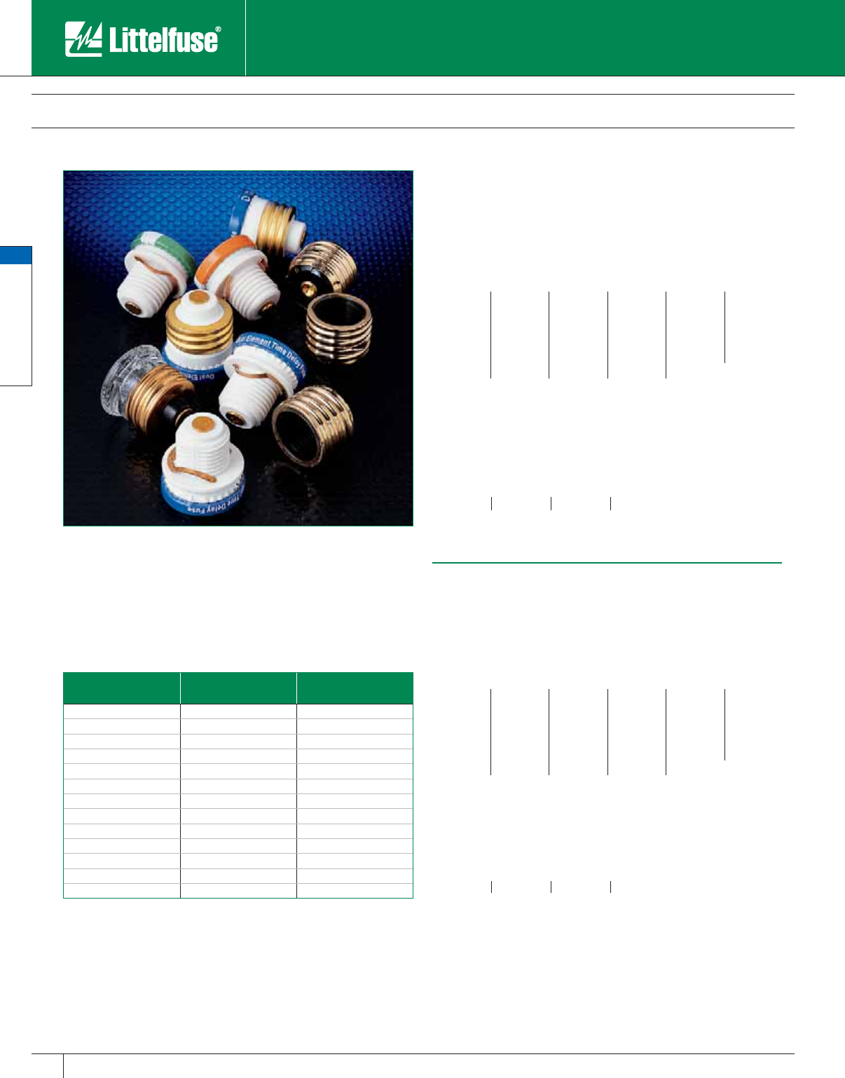
General Purpose Fuses
General Purpose Fuses
48 www.littelfuse.com © 2005 Littelfuse • POWR-GARD™ Products Catalog
Plug Fuses
125 VAC • Time-Delay • 1/4 – 30 Amperes
Edison-base Plug fuses
TOO Fuses are dual-element time-delay Edison-base fuses designed for
motor and motor branch circuit protection; also suitable for all general purpose
circuits. Use for replacement purposes only.
Ampere Ratings
3⁄10 11⁄821⁄44715
4⁄10 11⁄421⁄241⁄2820
1⁄214⁄10 28⁄10 5925
6⁄10 16⁄10 35
6⁄10 10 30
8⁄10 18⁄10 32⁄10 612
123
1⁄261⁄414
TLO Fuses are medium time-delay Edison-base fuses designed for general
purpose branch circuit protection. See TOO and SOO fuses for motor
protection. Use for re place ment purposes only.
Ampere Ratings
15 20 25 30
Type S Plug fuses
SOO Fuses are dual-element time-delay Type S fuses designed for motor and
motor branch circuit protection; also suitable for all general purpose circuits.
Ampere Ratings
1⁄4123
1⁄261⁄414
3⁄10 11⁄821⁄44715
4⁄10 11⁄421⁄241⁄2820
1⁄214⁄10 28⁄10 5925
6⁄10 16⁄10 35
6⁄10 10 30
8⁄10 18⁄10 32⁄10 612
SLO Fuses are medium time-delay Type S fuses for general purpose branch
circuit protection.
Ampere Ratings
15 20 25 30
Littelfuse Plug fuses provide overcurrent protection to general purpose
circuits and small motor loads. Edison-base Plug fuses (TOO and TLO
series) feature metal threads similar to incandescent lamp bases. Type S
Plug fuses (SOO and SLO series) utilize a nonmetallic threaded base and
must be used with Type S adapters (SAO series). The National Electrical
Code permits Edison-base Plug fuses to be used for replacement
purposes only. Type S fuses and adapters prevent shunting open fuses
and over-fusing.
SAO
Adapter Rating
Accepts
Fuse Ratings:
Other SOO Fuse
Ratings Which Fit
SAO 1 3⁄10 – 1 —
SAO 11⁄411⁄8, 11⁄43⁄10 – 1
SAO 16⁄10 14⁄10, 16⁄10 3⁄10 – 11⁄4
SAO 2 18⁄10, 2 —
SAO 21⁄221⁄4, 21⁄218⁄10, 2
SAO 32⁄10 28⁄10, 32⁄10 18⁄10 – 21⁄2
SAO 4 31⁄2, 4 —
SAO 5 41⁄2, 5 31⁄2, 4
SAO 61⁄431⁄2, 61⁄431⁄2 – 5
SAO 8 7, 8 —
SAO 15 7, 8, 9 10, 12, 14, 15 7, 8, 9, 10
SAO 20 20 only —
SAO 30 20, 25, 30 —
Specifications
Voltage Rating: 125 VAC
Interrupting Rating: 10,000 amperes rms symmetrical
Approvals: UL Listed Plug Fuses, Standard UL 248-11
Note: See NEC Article 240-V for additional information on Plug fuse applications.
Catalog 25-48.indd 48 5/30/07 6:19:43 PM

www.littelfuse.com
© 2005 Littelfuse • POWR-GARD™ Products Catalog
Midget & Electronic Fuses
www.littelfuse.com
© 2005 Littelfuse • POWR-GARD™ Products Catalog
Midget Fuses 50-54
Electronic Fuses 55-59
Automotive Fuses 60-62
Catalog 49-62.indd 49 5/30/07 6:27:10 PM

Midget & Electronic Fuses
50 www.littelfuse.com
Midget & Electronic Fuses
© 2005 Littelfuse • POWR-GARD™ Products Catalog
Midget Fuses
Supplementary Overcurrent Protection
Fast-acting, high-in ter rupt ing capacity, current-lim it-
ing type fuse. Especially suited for control circuits,
street lighting, H.I.D. light ing, computers, and other
applications without high in-rush currents.
Voltage Rating: 600 Volts AC
500 Volts DC
Interrupting Rating: UL Listed 100,000 amperes rms
symmetrical
(Capable of 200,000 amperes)
Di men sions: 13 ⁄32" x 11⁄2"
Example part number (series & amperage): KLK 1
1⁄2
Ampere Ratings:
1⁄10 1515
1⁄811⁄2620
2⁄10 2725
1⁄421⁄2830
3⁄10 39
1⁄231⁄210
3⁄4412
Approvals: Standard 248-14
UL Listed 3/10-30A (File No: E10480)
CSA Certified 3/10-30A (File No: LR29862)
Ampere Ratings:
1⁄10 11⁄838
15 ⁄100 11⁄432⁄10 9
2⁄10 14⁄10 31⁄210
1⁄411⁄2412
3⁄10 16⁄10 41⁄215
4⁄10 18⁄10 520
1⁄225
6⁄10 25
6⁄10 21⁄4630
8⁄10 21⁄261⁄4
12
8⁄10 7
Approvals: Standard 248-14
UL Listed (File No: E10480)
CSA Certified (File No: LR29862)
Ampere Ratings:
1⁄10 1515
1⁄811⁄2620
2⁄10 2725
1⁄421⁄2830
3⁄10 39
1⁄231⁄210
3⁄4 412
Approvals: Standard 248-14
UL Listed 3/10-30A (File No: E10480)
CSA Certified 3/10-30A (File No: LR29862)
Versions avail able to meet
MIL-F-5160/60, QPL F60C:
Contact Factory.
Fast acting, high in ter rupt ing capacity, current-
lim it ing type fuse. Especially suited for DC control
circuits, street lighting, H.I.D. light ing, computers,
and other applications.
Voltage Rating: 600 Volts AC/DC
Interrupting Rating: AC: 100,000 am peres rms
symmetrical;
DC: 10,000 amperes
Dimensions: 13 ⁄32" x 11⁄2"
Example part number (series & amperage): KLKD 30
Use FLM 250 volt time-delay fuses to protect
control circuit trans form ers, solenoids, and other
circuits with high in-rush currents. Excellent for
supple men tal protection of small motors. For motor
branch circuit protection, Refer to Class CC fuses.
Voltage Rating: 125 Volts AC
125 Volts DC self-certified @ 10KA
Interrupting Rating: AC: 10,000 amperes rms
symmetrical.
Dimensions: 13 ⁄32" x 11⁄2"
Example part number (series & amperage): FLM 15
KLK Fuses
Fast-Acting • 600 VAC
KLKD Fuses
Fast-Acting • 600 VAC/DC
FLM Fuses
Time-Delay • 250 VAC
Recommended Fuse Blocks
L60030M and LPSM series. Refer to the Blocks & Holders section of this catalog for additional in for ma tion.
Catalog 49-62.indd 50 5/30/07 6:27:14 PM
Midget & Electronic Fuses
51
www.littelfuse.com
Midget & Electronic Fuses
© 2005 Littelfuse • POWR-GARD™ Products Catalog
Midget Fuses
Supplementary Overcurrent Protection
Ampere Ratings:
1⁄10 8⁄10 32⁄10 9
1⁄813
1⁄210
15 ⁄100 11⁄8412
3⁄16 11⁄441⁄214
2⁄10 11⁄2515
1⁄416⁄10 56⁄10 20
3⁄10 2625
4⁄10 21⁄461⁄430
1⁄221⁄27
6⁄10 38
Approvals: Standard 248-14
UL Listed (File No: E10480)
CSA Certified (File No: LR29862)
Recommended Fuse Blocks
L60030M and LPSM series. Refer to the Blocks & Holders section of this catalog for additional in for ma tion.
These 500 volt time-delay fuses provide excellent
sup ple men tal protection of control power
transformers, solenoids, and circuits with high
inrush currents. UL and CSA 500 volt ratings
permit use on 480 volt circuits. FLQ fuses also
provide supplemental protection to small motors.
For motor branch circuit protection, refer to Class
CC fuses.
Voltage Rating: 500 Volts AC
300 Volts DC self-certified @ 10KA
Interrupting Rating: 10,000 amperes rms
symmetrical
Dimensions: 13 ⁄32" x 11⁄2"
Example part number (series & amperage): FLQ 1⁄2
Fiber tube, 250 volt BLN fuses provide low-cost
protection for military ap pli ca tions and control
circuits.
Voltage Rating: 250 Volts AC
Interrupting Rating: 10,000 amperes rms
symmetrical
Dimensions: 13 ⁄32" x 11⁄2"
Example part number (series & amperage): BLN 30
Ampere Ratings:
1481530
251020
361225
Approvals: Standard 248-14
UL Listed (File No: E10480)
CSA Certified (File No: LR29862)
Versions available to meet MIL-F-15160/9,
QPL F09A: Contact Factory
Laminated tube BLF fuses are the lowest price
midget fuse. They are suitable for control circuit
and in stru ment protection in dry locations.
Voltage Ratings: 250 Volts AC: 1⁄2 – 15 amperes;
125 Volts AC: 20 – 30 amperes
Interrupting Rating: 10,000 amperes rms
symmetrical
Dimensions: 13 ⁄32" x 11⁄2"
Example part number (series & amperage): BLF 5
Ampere Ratings:
1⁄23715
14820
11⁄25925
261030
21⁄261⁄412
Approvals: Standard 248-14
UL Listed (File No: E10480)
CSA Certified (File No: LR29862)
FLQ Fuses
Time-Delay • 500 VAC
BLF Fuses
Fast-Acting • 125/250 VAC
BLN Fuses
Fast-Acting • 250 VAC
Catalog 49-62.indd 51 5/30/07 6:27:20 PM
Midget & Electronic Fuses
52 www.littelfuse.com
Midget & Electronic Fuses
© 2005 Littelfuse • POWR-GARD™ Products Catalog
BLS fuses are 13⁄8" long in contrast to other midget
fuses which are 11/
2". They provide space saving,
low cost protection to street lighting, metering,
control and electronic circuits.
Voltage Rating: 600 Volts AC: 2⁄10 – 5 amperes;
250 Volts AC: 6 – 10 amperes
Interrupting Rating: 10,000 amperes rms
symmetrical
Dimen sions: 13 ⁄32" x 13⁄8"
Example part number (series & amperage): BLS 10
Ampere Ratings:
2⁄10 138
4⁄10 11⁄2410
1⁄216⁄10 5
3⁄418⁄10 6
8⁄10 27
Approvals: Standard 248-14
UL Listed
2⁄10 -10 Amps (File No: E10480)
CSA Certified
1⁄2 – 5 Amps
(File No: LR29862)
FLA fuses are 125 volt, pin-indicating time-delay
fuses for protection of control circuit transformers,
so le noids, and other circuits with high in-rush
currents. Metal indicating pin pops-out when fuse
opens, giving visual indication of blown fuse. Use
FLA fuses in con junc tion with special fuseblocks
to operate me chan i cal signal switches or energize
alarm circuits. Fuses rated 12 amperes and above
have dual-tube construction.
Voltage Rating: 125 Volts AC
Interrupting Rating: 10,000 amperes rms
symmetrical
Dimensions: 13 ⁄32" x 11⁄2"
Example part number (series & amperage): FLA 15
* Note: Dual tube construction
Ampere Ratings:
1⁄10 11⁄838
15 ⁄100 11⁄432⁄10 10
2⁄10 14⁄10 31⁄2 12*
1⁄411⁄24 15
*
3⁄10 16⁄10 41⁄2 20*
4⁄10 18⁄10 5 25
*
1⁄225
6⁄10 30*
6⁄10 21⁄46
8⁄10 21⁄261⁄4
12
8⁄10 7
Approvals: Standard 248-14
UL Listed (File No: E10480)
CSA Certification Pending
Midget Fuses
Supplementary Overcurrent Protection
BLS Fuses
Fast-Acting • 250/600 VAC
FLA Fuses
Time-Delay • 125 VAC
Recommended Fuse Blocks
L60030M and LPSM series. Refer to the Blocks & Holders section of this catalog for additional in for ma tion.
Catalog 49-62.indd 52 5/30/07 6:27:28 PM
Midget & Electronic Fuses
53
www.littelfuse.com
Midget & Electronic Fuses
© 2005 Littelfuse • POWR-GARD™ Products Catalog
Midget Fuses
Supplementary Overcurrent Protection
The Littelfuse KLQ series is designed to protect
gaseous vapor fixtures, HID ballasts, and other
electronic and lighting circuits. The KLQ is the
same physical size as the Littelfuse BLS, but has
more time-delay to handle transient and in-rush
currents.
Voltage Rating: 600 VAC
Interrupting Rating: 10,000 amperes
Approvals: Standard 248-14 UL Listed
(File No: E10480)
Dimensions: 13 ⁄32" x 13⁄8"
The Littelfuse FLU series is designed specifically
for the protection of multimeters. The 1000 VAC/
VDC rating also makes the FLU ideal for a variety
of other applications.
Voltage Rating: 1000 VAC/VDC
Interrupting Rating: 44⁄100 A: 10kA
11A: 20k A
Ampere Range: FLU 44⁄100 =1A and FLU 11 = 15A
Approvals: UL Recognized under the
components program.
(File No: E10480)
CSA Certified (File No: LR29862)
Dimensions: 44⁄100A: 13 ⁄32" x 13⁄8"
11A:
13 ⁄32" x 11⁄2"
Also known as a “neutral”, the LNNB is actually
not a fuse. It is the same physical size as a
standard Midget fuse. The LNNB001 is a hollow
body design for use with standard fuse clips. The
LNNB002 is a solid body design for use with LEB/
LEX series inline style fuse holders.
Ampere Ratings:
125
16⁄10 36
Recommended Fuse Blocks:
L60030M Series. Refer to the Blocks & Holders section
of this catalog for additional information.
Ordering Information:
Example catalog number: KLQ005
Example system number: 0KLQ005.T
Ordering Information
Example catalog number: FLU011
Example system number: 0FLU011.T
Specifications
Dimensions: 13 ⁄32" x 11⁄2"
Ordering Information
Example catalog number: LNNB001
Example system number: LNNB0001Z
Example catalog number: LNNB002
Example system number: LNNB0002Z
KLQ Series Fuses
FLU Series Fuses
LNNB “Dummy” Fuse
LNNB002
LNNB001
Catalog 49-62.indd 53 5/30/07 6:27:34 PM
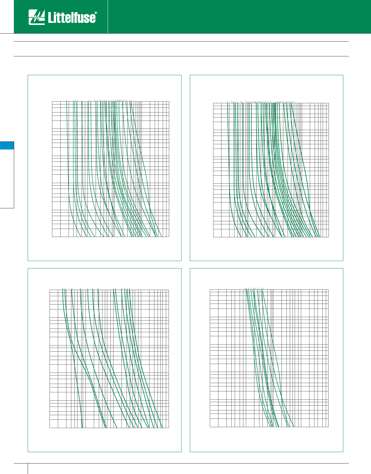
Midget & Electronic Fuses
54 www.littelfuse.com
Midget & Electronic Fuses
© 2005 Littelfuse • POWR-GARD™ Products Catalog
Midget Fuses
Supplementary Overcurrent Protection
1000
800
600
400
300
200
100
80
60
40
30
20
10
8
6
4
3
2
1
.8
.6
.4
.3
.2
.1
.08
.06
.04
.03
.02
.01
2
3
4
6
8
10
20
30
40
60
80
100
200
300
400
600
800
1000
.1
.2
.3
.4
.6
.8
1
1/8A
2/10A
1/4A
3/10A
1/2A
3/4A
1A
1 1/2A
2A
2 1/2A
3A
3 1/2A
4A
5A
6A
7A
8A
9A
10A
12A
15A
20A
25A
30A
TIME IN SECONDS
CURRENT IN AMPERES
1000
800
600
400
300
200
100
80
60
40
30
20
10
8
6
4
3
2
1
.8
.6
.4
.3
.2
.1
.08
.06
.04
.03
.02
.01
2
3
4
6
8
10
20
30
40
60
80
100
200
300
400
600
800
1000
.1
.2
.3
.4
.6
.8
1
1/10A
15/100A
1/4A
1/2A
1A
1 1/2A
2A
8A
10A
15A
20A
25A
30A
TIME IN SECONDS
CURRENT IN AMPERES
1000
800
600
400
300
200
100
80
60
40
30
20
10
8
6
4
3
2
1
.8
.6
.4
.3
.2
.1
.08
.06
.04
.03
.02
.01
2
3
4
6
8
10
20
30
40
60
80
100
200
300
400
600
800
1000
.1
.2
.3
.4
.6
.8
1
1/8A
2/10A
1/4A
3/10A
1/2A
3/4A
1A
1 1/2A
2A
2 1/2A
3A
3 1/2A
4A
5A
6A
7A
8A
9A
10A
12A
15A
20A
25A
30A
TIME IN SECONDS
CURRENT IN AMPERES
1000
800
600
400
300
200
100
80
60
40
30
20
10
8
6
4
3
2
1
.8
.6
.4
.3
.2
.1
.08
.06
.04
.03
.02
.01
20
30
40
60
80
100
200
300
400
600
800
1000
2000
3000
4000
6000
8000
10000
1
2
3
4
6
8
10 8A
9A
10A
12A
14A
15A
20A
25A
30A
TIME IN SECONDS
CURRENT IN AMPERES
KLK KLKD
FLM FLQ
Catalog 49-62.indd 54 5/30/07 6:27:38 PM
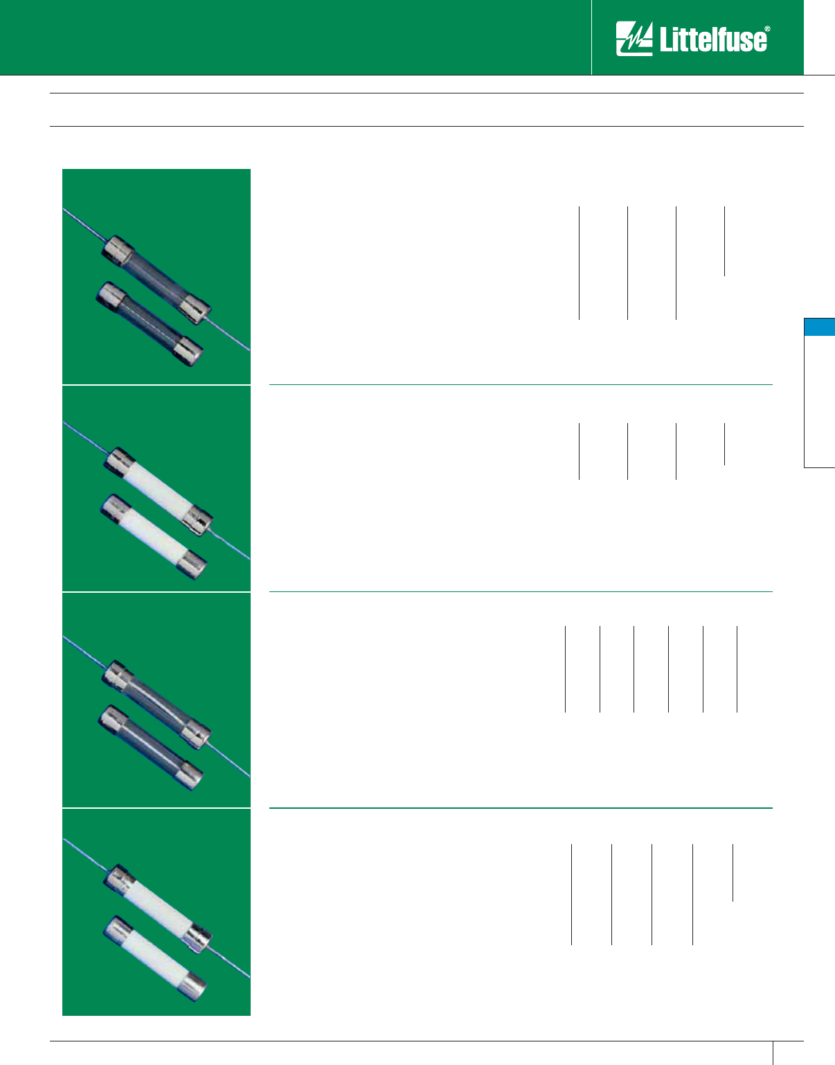
Midget & Electronic Fuses
55
www.littelfuse.com
Midget & Electronic Fuses
© 2005 Littelfuse • POWR-GARD™ Products Catalog
Electronic Fuses
3AG/3AB Type
312/ 318 Series
3AG Fast Acting Fuse
Ampere Ratings:
1⁄100 2⁄10 12
1⁄212
1⁄32 1⁄411⁄4315
1⁄16 3⁄10 11⁄2420
1⁄10 3⁄816⁄10 525
1⁄81⁄213⁄4630
15 ⁄100 6⁄10 18⁄10 735
0.175 8⁄10 28
3⁄16 3⁄421⁄410
Approvals: Standard 248-14, UL Listed 1⁄100 -10 Amps
and UL Listed 12 – 30 Amps per Standard UL 275. CSA
Certified through 30 Amps.
Ampere Ratings:
1⁄83⁄44820
1⁄4151025
3⁄8261230
1⁄23715
Approvals: Standard 248-14, UL Listed and CSA
Certified 1⁄8 – 15 Amps. UL Recognized under the
Components Program and CSA Recognized under
the Component Acceptance Program 20 – 30 Amps.
Approved by MITI from 10 – 30 Amps.
Ampere Ratings:
1⁄100 15 ⁄100 3⁄88⁄10 18⁄10 32⁄10 10
1⁄32 0.175 4⁄10 12412
4⁄100 3⁄16 1⁄212⁄10 21⁄4515
1⁄16 2⁄10 6⁄10 11⁄421⁄261⁄420
1⁄10 1⁄47⁄10 11⁄228⁄10 725
1⁄83⁄10 3⁄416⁄10 3830
Approvals: Standard 248-14, UL Listed and CSA Certified
1⁄100 -8 Amps. UL Recognized under the Components Program
and CSA Recognized under the Component Acceptance
Program 10 – 30 Amps. MITI approved 1 – 5 Amps.
Ampere Ratings:
1⁄100 3⁄16 6⁄10 11⁄2415
1⁄32 2⁄10 7⁄10 16⁄10 520
1⁄16 1⁄43⁄426
1⁄425
1⁄10 3⁄10 8⁄10 21⁄2730
1⁄83⁄812
8⁄10 8
15 ⁄100 4⁄10 12⁄10 310
0.175 1⁄211⁄432⁄10 12
Approvals: Standard 248-14, UL Listed 1⁄4 – 10 Amps.
UL Recognized under the Components Program 12-30
Amps. CSA Certified 1⁄4 – 30 Amps.
Designed for fast acting protection of electronic
equipment and ap pli anc es. The “standard” fast
acting, glass tube fuse.
Voltage Rating: 250V: 1⁄100 – 10A.
32V: 12 – 35A.
Dimensions: 1⁄4" x 11⁄4" (6.4 x 31.8mm)
Order 312 series without leads.
Example part number (series & amperage): 312.375
Note: For fuses with axial leads, request 318 series.
To order a 3AG “Dummy” fuse request part number
310033.
Similar to 312 series, but ceramic tube permits
additional ampere ratings: 250 volt ratings through
30 amps.
Voltage Rating: 250V:
1⁄8 – 30A
Dimensions: 1⁄4" x 11⁄4" (6.4 x 31.8mm)
Order 314 series without leads.
Example part number (series & amperage): 324.375
Note: For fuses with axial leads, request 324 series.
313 and 315 series fuses have time-delay in the
overload range, which provides superior protection
for inductive loads such as motors, transformers,
and solenoids.
Voltage Rating: 250V: 1⁄100 – 8A. 32V: 10 – 30A.
Dimensions: 1⁄4" x 11⁄4" (6.4 x 31.8mm)
Order 313 series without leads.
Example part number (series & amperage): 313.500
Note: For fuses with axial leads, request 315 series.
To order a 3AG “Dummy” fuse request part number
310033.
The 326 series fuse has time-delay similar to the
313 series, but the ceramic body permits higher
voltage ratings for the 8 – 30 ampere sizes and
faster opening of short-circuits.
Voltage Rating: 250V: 1⁄100 – 20A.
125V: 25 – 30A.
Dimensions: 1⁄4" x 11⁄4" (6.4 x 31.8mm)
Order 326 series without leads.
Example part number (series & amperage): 326012
Note: For fuses with axial leads, request 325 series.
326/ 325 Series
3AB SLO-BLO® Fuse
313/ 315 Series
3AG SLO-BLO® Fuse
314/ 324 Series
3AB Fast Acting Fuse
Catalog 49-62.indd 55 5/30/07 6:27:39 PM
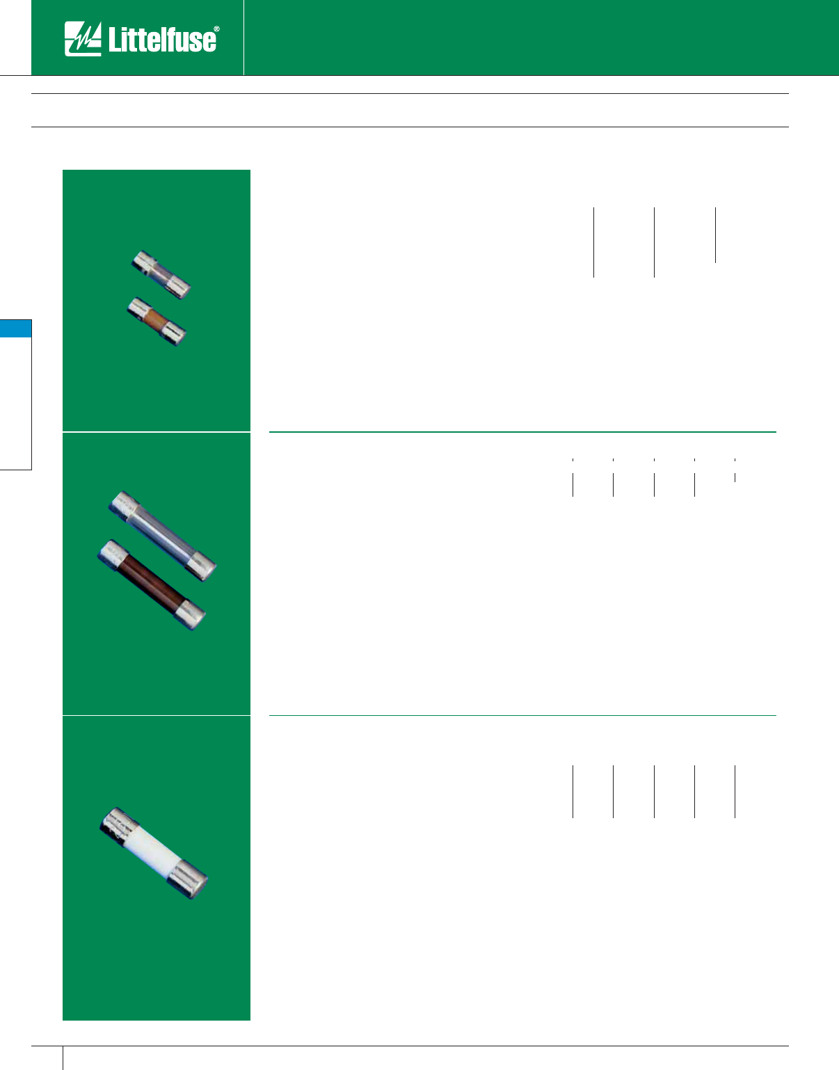
Midget & Electronic Fuses
56 www.littelfuse.com
Midget & Electronic Fuses
© 2005 Littelfuse • POWR-GARD™ Products Catalog
Time-delay protection of electronic equipment and
ap pli anc es when fuses to In ter na tion al Standards
are required. Replacement fuses for foreign
equipment.
Voltage Rating: 250V AC
Design Standards: Meets IEC 60127-2, Sheet 5
Specification for Time Lag fuses.
Dimensions: 5mm x 20mm (.2 x .79 in.)
Example part number (series & amperage): 215.315
Note: For fuses with axial leads add “XE” extension to
the part number. Example 215.630XE
Ampere Ratings:
.200 .400 .800 1.6 3.15 6.3
.250.5001248*
.315 .630 1.25 2.5 5 10*
*Available but not included in International Standards.
Interrupting Capacity: 1500A
Approvals: UL Recognized under the Components
Program and CSA Recognized under the Component
Acceptance Program. SEMKO, VDE, and BSI approved
1 – 6.3 Amps. MITI approved 1 – 10 Amps.
Electronic Fuses
Indicating Types
229/ 230 Series
2AG SLO-BLO® Indicating Fuse
313 Series
3AG SLO-BLO® Indicating Fuse
2AG indicating fuses instantly identify
them selves
upon opening by showing a dis col or a tion of their
glass bod ies. Guesswork and time con sum ing cir-
cuit testing is elim i nat ed. This unique design offers
the same quality per for mance char ac ter is tics as
the standard 2AG fuse design.
Voltage Rating: 250V: 1⁄4 – 31⁄2A; 125V: 4 – 7A
Dimensions: .177" x .57" (4.5 x 14.5mm)
For fuses with axial leads, request 230___S series.
Order 229___S series without leads.
Example part number (series & amperage): 22902.5S
3AG indicating fuses instantly identify
themselves
upon opening by showing a discoloration of their
glass bodies. Guesswork and time consuming cir-
cuit testing is eliminated. This unique design offers
the same quality per for mance char ac ter is tics as
the standard 3AG fuse design.
Voltage Rating: 250V:
1⁄2 – 8A; 32V: 10A.
Dimensions: 1⁄4" x 11⁄4": (6.4 x 31.8mm)
Example part number (series plus amperage, followed
by “ID”): 313007ID
Ampere Ratings:
1⁄211⁄235710
1246
1⁄48
Approvals: Standard 248-14, UL Listed and CSA
Certified 1⁄2 – 8 Amps. The 10 Amp is UL Recognized
under the Components Program and CSA Recognized
under the Component Acceptance Program.
Ampere Ratings:
1⁄43⁄424
.350 8⁄10 21⁄45
3⁄812
1⁄26
1⁄211⁄437
6⁄10 11⁄231⁄2
Approvals: Standard 248-14, UL Listed and CSA
Certified 1⁄4 – 31⁄2 Amps. UL Recognized under the
Components Program and CSA Recognized under the
Component Acceptance Program 4 – 7 Amps.
215 Series (Type T)
5 x 20mm SLO-BLO® Fuse
Catalog 49-62.indd 56 5/30/07 6:27:48 PM
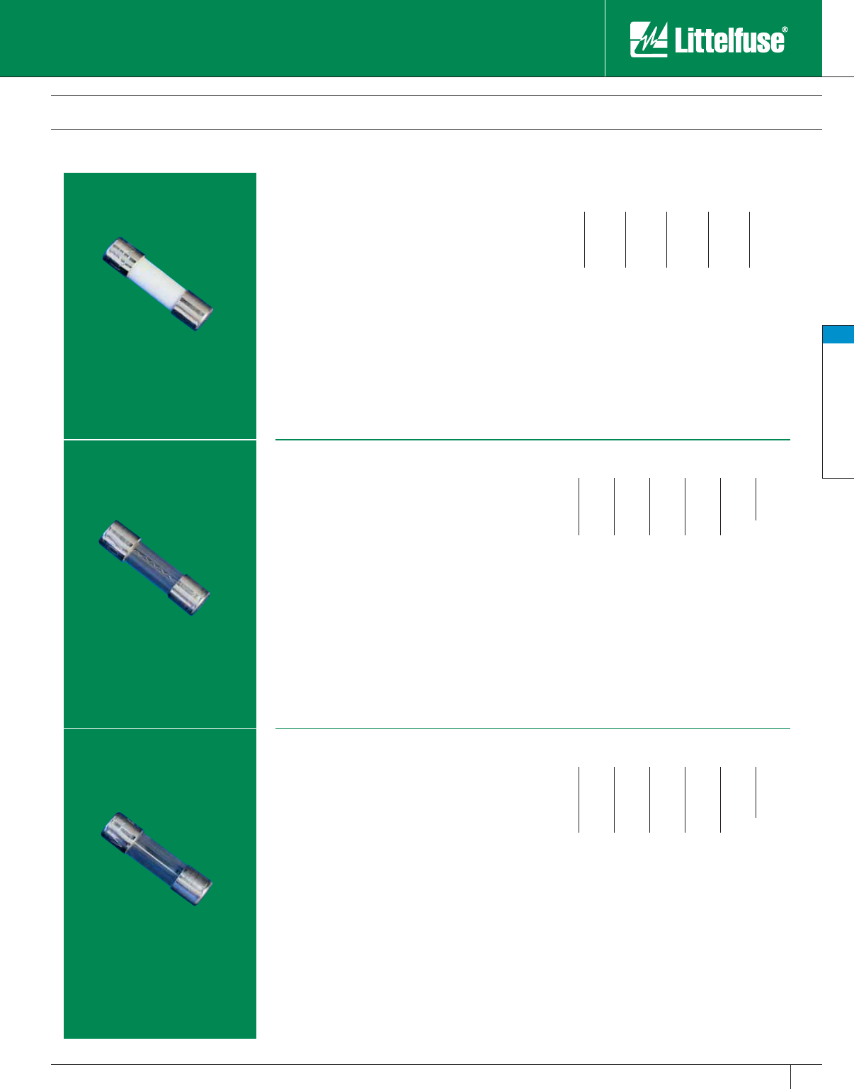
Midget & Electronic Fuses
57
www.littelfuse.com
Midget & Electronic Fuses
© 2005 Littelfuse • POWR-GARD™ Products Catalog
Electronic Fuses
5 x 20mm IEC Type
217 Series (Type F)
5 x 20mm Fast-Acting Fuse
216 Series (Type F)
5 x 20mm Fast-Acting Fuse
218 Series (Type T)
5 x 20mm SLO-BLO® Fuse
Fast acting protection of electronic equipment and
appliances when fuses to In ter na tion al Standards are
required. Re place ment fuse for foreign equip ment.
Voltage Rating: 250V AC
Design Standards: Meets IEC 60127-2, Sheet 1
Specification for Fast-Acting Fuses.
Dimensions: 5mm x 20mm (.2 x .79 in.)
Example part number (series & amperage): 216.200
Note: For fuses with axial leads add “XE” extension to
the part number. Example 216.630XE
Fast-acting protection of electronic equipment and
appliances when fuses to In ter na tion al Standards are
required. Re place ment fuse for foreign equip ment.
Voltage Rating: 250V AC
Dimensions: 5mm x 20mm (.2 x .79 in.)
Example part number (series & amperage): 217.050
Design Standards: Meets IEC 60127-2, Sheet 2
Specification for Fast Acting Fuses.
Note: For fuses with axial leads add “XE” extension to
the part number. Example 217.630XE
Time-delay protection of electronic equipment and
appliances when fuses to In ter na tion al Standards
are required. Re place ment fuses for foreign
equipment.
Voltage Rating: 250V AC
Dimensions: 5mm x 20mm (.2 x .79 in.)
Example part number (series & amperage): 218.630
Design Standards: Meets IEC 60127-2, Sheet 3
Specification for Time Lag Fuses.
Note: For fuses with axial leads add “XE” extension to
the part number. Example 218.630XE
Ampere Ratings:
.050 .125 .315 .800 2 5
.063 .160 .400 1 2.5 6.3
.080 .200 .500 1.25 3.15 8*
.100 .250 .630 1.6 4 10*
*Available but not included in International Standards.
Interrupting Capacity: 1500A
Approvals: UL Recognized under the Components
Program and CSA Recognized under the Component
Acceptance Program. SEMKO and VDE approved
through 6.3 Amps. BSI approved 1 – 6.3 Amps.
Ampere Ratings:
.032 .080 .200 .500 1.25 3.15 8*
.040 .100 .250 .630 1.6 4 10*
.050 .125 .315 .800 2 5 15*
.063 .160 .400 1 2.5 6.3
*Available but not included in International Standards.
Interrupting Capacity: 35A or 10x rated current, which-
ever is greater.
Approvals: UL Recognized under the Components
Program and CSA Recognized under the Component
Acceptance Program. SEMKO and VDE approved
through 6.3 Amps. BSI approved 0.4 – 6.3 Amps.
Ampere Ratings:
.032 .080 .200 .500 1.25 3.15 8*
.040 .100 .250 .630 1.6 4 10*
.050 .125 .315 .800 2 5 15*
.063 .160 .400 1 2.5 6.3
*Available but not included in International Standards.
Interrupting Capacity: 35A or 10x rated current, which-
ever is greater.
Approvals: UL Recognized under the Components
Program and CSA Recognized under the Component
Acceptance Program. SEMKO and VDE approved
through 6.3 Amps. BSI approved 0.8 – 6.3 Amps.
Catalog 49-62.indd 57 5/30/07 6:27:59 PM
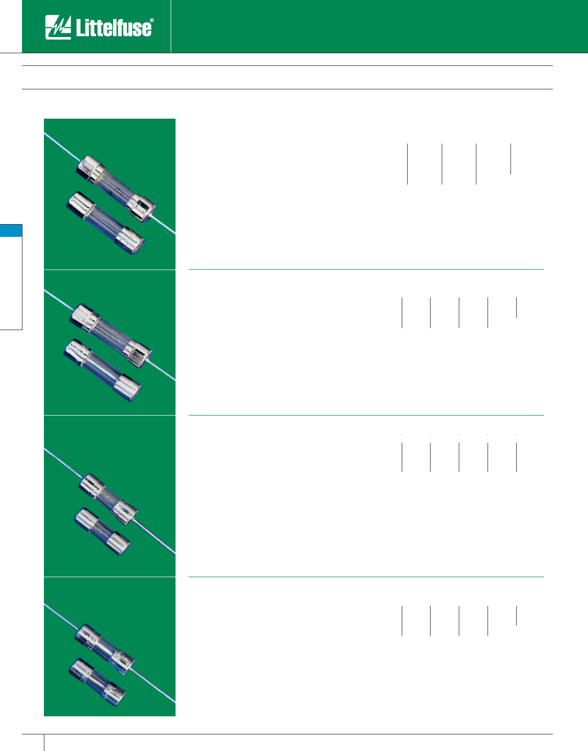
Midget & Electronic Fuses
58 www.littelfuse.com
Midget & Electronic Fuses
© 2005 Littelfuse • POWR-GARD™ Products Catalog
Electronic Fuses
5 x 20mm and 2AG Type
5 x 20mm fuses designed to UL and CSA
standards. Fast Acting pro tec tion of electronic
equipment appliances.
Voltage Rating: 250V:
1⁄10 – 3A; 125V: 4 – 6A.
Dimensions: 5mm x 20mm (.2 x .79 in.)
Example part number (series & amperage): 235.600
Note: For fuses with axial leads add “XE” extension to
the part number. Example 235.600XE
5 x 20mm fuses de signed to UL and CSA
standards. For protection of electronic equip ment
and appliances.
Voltage Rating: 250V:
2⁄10 – 3A. 125V: 4A.
Dimensions: 5mm x 20mm (.2 x .79 in.)
Example part number (series & amperage): 239.400
Note: For fuses with axial leads add “XE” extension to
the part number. Example 239.600XE
Fast acting performance of the 312, 3AG fuses
in less than one-third the space. For protection of
electronic equipment and ap pli anc es.
Voltage Rating: 250V:
1⁄10 – 31⁄2A. 125V: 4 – 10A
Dimensions: 2AG Fuse .177" x .57" (4.5 x 14.5mm)
Example part number (series & amperage): 224.500
Note: For fuses with axial leads, request series number
224. Order 225 series without leads.
229 series 2AG fuses have time-delay of 313
series 3AG fuses in less than one-third the space.
They provide superior protection for inductive
loads such as motors, trans form ers, and solenoids.
Use whenever time-delay fuses are indicated.
Voltage Rating: 250V:
1⁄4 – 31⁄2A; 125V: 4 – 7A.
Dimensions: 2AG Fuse .177" x .57" (4.5 x 14.5mm)
Example part number (series & amperage): 229.375
Note: For fuses with axial leads, request series number
230. Order 229 series without leads.
Ampere Ratings:
1⁄10 3⁄10 7⁄10 16⁄10 4
1⁄84⁄10 8⁄10 25
2⁄10 1⁄212
1⁄26
1⁄46⁄10 11⁄43
Approvals: Standard 248-14, UL Listed and CSA
Certified. MITI approved 1 – 5 Amps.
Ampere Ratings:
2⁄10 4⁄10 7⁄10 124
1⁄41⁄23⁄411⁄421⁄25
3⁄10 6⁄10 8⁄10 16⁄10 3
Approvals: Standard 248–14, UL Listed and CSA
Certified. MITI approved 1 – 5 Amps.
Ampere Ratings:
1⁄10 3⁄812
1⁄247
1⁄81⁄211⁄2358
1⁄43⁄423
1⁄2610
Approvals: Standard 248–14, UL Listed and CSA
Certified. 224 series approved by MITI 1 – 5 Amps.
Ampere Ratings:
1⁄46⁄10 11⁄221⁄246
3⁄83⁄42357
1⁄212
1⁄431⁄2
Approvals: Standard 248-14, UL Listed and
CSA Certified 1⁄4 – 31⁄2 Amps. UL Recognized under the
Components Program and CSA Recognized under the
Component Acceptance Program 4 – 7 Amps.
229/ 230 Series
2AG SLO-BLO® fuse
225/ 224 Series
2AG Fast-Acting fuse
239 Series
5 x 20mm SLO-BLO® fuse
235 Series
5 x 20mm Fast-Acting fuse
Catalog 49-62.indd 58 5/30/07 6:28:03 PM
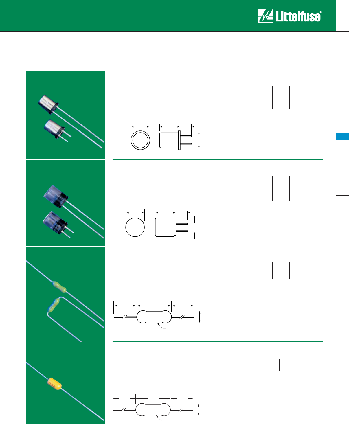
Midget & Electronic Fuses
59
www.littelfuse.com
Midget & Electronic Fuses
© 2005 Littelfuse • POWR-GARD™ Products Catalog
Electronic Fuses
Subminiature Type
.235" .29" .17"
.10"
.25" .35" .17"
.10"
1.47" 1.47".28"
.095"
DIA.
LF 1A
EPOXY COATING
Fast acting Microfuses for pro tec tion of printed circuit
boards and similar equipment.
Voltage Rating: 125V AC
Example part number (series & amperage): 27201.5
Note: 278 series has 1" leads
Ampere Ratings:
1⁄500 1⁄32 1⁄84⁄10 3⁄42
1⁄200 1⁄20 2⁄10 1⁄28⁄10 3
1⁄100 1⁄16 1⁄46⁄10 14
1⁄64 1⁄10 3⁄10 7⁄10 11⁄25
Approvals: UL Recognized under the Components
Program and CSA Recognized under the Component
Acceptance Program.
For data on 262 and 268 series High Reliability (Hi-Rel)
microfuses, request Electronic Catalog.
Similar to 272 and 278 series, except has trans parent
cap for visual indication of fuse status.
Voltage Rating: 125V AC
Example part number (series & amperage): 273002
Note: 279 series has 1" leads
Ampere Ratings:
1⁄500 1⁄32 1⁄84⁄10 3⁄42
1⁄200 1⁄20 2⁄10 1⁄28⁄10 3
1⁄100 1⁄16 1⁄46⁄10 14
1⁄64 1⁄10 3⁄10 7⁄10 11⁄25
Approvals: UL Recognized under the Components
Program and CSA Recognized under the Component
Acceptance Program.
Subminiature fuse for soldered mounting on
printed circuit boards. Available on tape and reel
for automatic insertion.
Voltage Rating: 125V: 1⁄16 – 10A; 32V: 12 – 15A.
Example part number (series & amperage): 251.125
Ampere Ratings:
1⁄16 3⁄812
1⁄2410
1⁄81⁄211⁄23512
1⁄43⁄423
1⁄2715
Approvals: UL Recognized under the Components
Program and CSA Recognized under the Component
Acceptance Program.
Order 252 series for radial leads. To order PICO II fuses
with ampere ratings color-coded, order 255 series for
axial leads and 256 for radial leads.
For data on 265 and 266 series High Reliability (Hi-Rel)
Picofuses, request Electronic Catalog. For information
on PICO II 250V fast-acting fuses, contact factory.
Subminiature time-delay fuse for soldered
mounting on printed circuit boards. Available on
tape and reel for automatic in ser tion. Request
bulletin PB-1027 for further information.
Voltage Rating: 125V AC
Example part number (series & amperage): 473005
Ampere Ratings:
3⁄83⁄411⁄221⁄4347
1⁄2122
1⁄231⁄25
Approvals: UL Recognized under the Components
Program and CSA Recognized under the Component
Acceptance Program. MITI approved 1 – 5 Amp.
272/ 278 Series
Fast-Acting Microfuse
273/ 279 Series
Fast-Acting Microfuse
251/ 252 Series
Fast-Acting Pico®II Fuse
473 Series
SLO-BLO® Pico®II Fuse
1.47" 1.47".28"
.095"
DIA.
LF 1A
EPOXY COATING
Catalog 49-62.indd 59 5/30/07 6:28:10 PM
Midget & Electronic Fuses
60 www.littelfuse.com
Midget & Electronic Fuses
© 2005 Littelfuse • POWR-GARD™ Products Catalog
Automotive Fuses
SFE and Blade Type
Low voltage fuse for automotive and electronic
ap pli ca tions.
Voltage Rating: 32V AC/DC
Approvals: UL Listed under UL Standard #275.
Society of Automotive Engineers (SAE) J554.
Example part number (series & amperage): SFE006
Ampere Ratings/Dimensions:
The 257 series ATO fuse is a low voltage blade
type fuse for au to mo tive and elec tron ic ap pli-
ca tions. Designed, originated and patented by
Littelfuse, it has become the standard for OEM
circuit pro tec tion on foreign and do mes tic autos
and trucks. They are color-coded and readily iden-
ti fi able and may be specified for a variety of low
voltage applications.
Voltage Rating: 32V AC/DC
Example part number (series & amperage): ATO015
Approvals: UL Listed. CSA Certified 3 – 30 A.
Catalog No. Amp. Rating Volt. Rating Color Code
ATO 001 1 32 Black
ATO 002 2 32 Grey
ATO 003 3 32 Violet
ATO 004 4 32 Pink
ATO 005 5 32 Tan
ATO 07.5 71⁄232 Brown
ATO 010 10 32 Red
ATO 015 15 32 Blue
ATO 020 20 32 Yellow
ATO 025 25 32 Natural
ATO 030 30 32 Green
ATO 040 40 32 Orange
The MINI fuse is smaller than its predecessor,
the ATO fuse, which permits using more fuses
in the same amount of space. More fuses in the
same space satisfies the requirement that more
circuits be individually fused in newer au to mobiles.
Patented by Littelfuse.
Voltage Rating: 32V AC/DC
Example part number (series & amperage): MIN025
Approvals: UL Listed.
Note: For low-profile MINI® fuse, request 897 series
The patented MAXI Fuse is available in a higher
range of amperage ratings (20 – 80 amperes) than
the ATO or MINI fuses, and is physically larger
in size. It is color-coded for easy identification. A
typical MAXI Fuse application, in today’s more
sophisticated automobile circuits, is protection of
the wiring harness by replacing the fusible wire
or fusible link which is often a plain piece of small
wire.
Voltage Rating: 32V AC/DC
Example part number (series & amperage): MAX070
Approvals: UL Listed.
Ampere Rating Length Diameter
45⁄8"1⁄4"
63⁄4"1⁄4"
71⁄27⁄8"1⁄4"
97⁄8"1⁄4"
14 11⁄16"1⁄4"
20 11⁄4"1⁄4"
30 17⁄16"1⁄4"
MAX/ 299 Series
MAXI™ SLO-BLO® Fuse
MIN/ 297 Series
MINI® Fast-Acting Fuse
ATO® / 257 Series
Fast-Acting Fuse
SFE Series
Fast-Acting Fuse
Catalog No. Amp. Rating Volt. Rating Color Code
MAX 020 20 32 Yellow
MAX 030 30 32 Green
MAX 040 40 32 Orange
MAX 050 50 32 Red
MAX 060 60 32 Blue
MAX 070 70 32 Tan
MAX 080 80 32 Natural
Catalog No. Amp. Rating Volt. Rating Color Code
MIN 002 2 32 Grey
MIN 003 3 32 Violet
MIN 004 4 32 Pink
MIN 005 5 32 Tan
MIN 07.5 71⁄232 Brown
MIN 010 10 32 Red
MIN 015 15 32 Blue
MIN 020 20 32 Yellow
MIN 025 25 32 Natural
MIN 030 30 32 Green
Catalog 49-62.indd 60 5/30/07 6:28:19 PM
Midget & Electronic Fuses
61
www.littelfuse.com
Midget & Electronic Fuses
© 2005 Littelfuse • POWR-GARD™ Products Catalog
Automotive Fuses
Bolt-On Type
MEGA® SLO-BLO® Bolt-On Fuse
The MEGA Fuse is designed for the protection of high current
applications. Designed and patented by Littelfuse, it is ideal for battery
and alternator protection and other heavy gauge cable applications.
MIDI® SLO-BLO® Bolt-On Fuse
The patented design of the Littelfuse MIDI fuse offers a bolt-on space
saving fuse with SLO-BLO characteristics for high current wiring
protection.
Specifications
Voltage Rating: 32V AC/DC
Interrupting Rating: 2000 A @ 32VDC
Example part number (series & amperage): MEG200
Recommended Fuse Holder
298900
Specifications
Voltage Rating: 32V AC/DC
Interrupting Rating: 1000 A @ 32VDC
Example part number (series & amperage): 498080
Recommended Fuse Holder
498900
Catalog No. Amp. Rating Volt. Rating Color Code
MEG100 100 32 Yellow
MEG125 125 32 Green
MEG150 150 32 Orange
MEG175 175 32 White
MEG200 200 32 Blue
MEG225 225 32 Tan
MEG250 250 32 Pink
Catalog No. Amp. Rating Volt. Rating Color Code
498030 30 32 Pink
498040 40 32 Green
498050 50 32 Red
498060 60 32 Yellow
498070 70 32 Brown
498080 80 32 White
498100 100 32 Blue
498125 125 32 Orange
498150 150 32 Grey
498200 200 32 Violet
Catalog 49-62.indd 61 5/30/07 6:28:30 PM
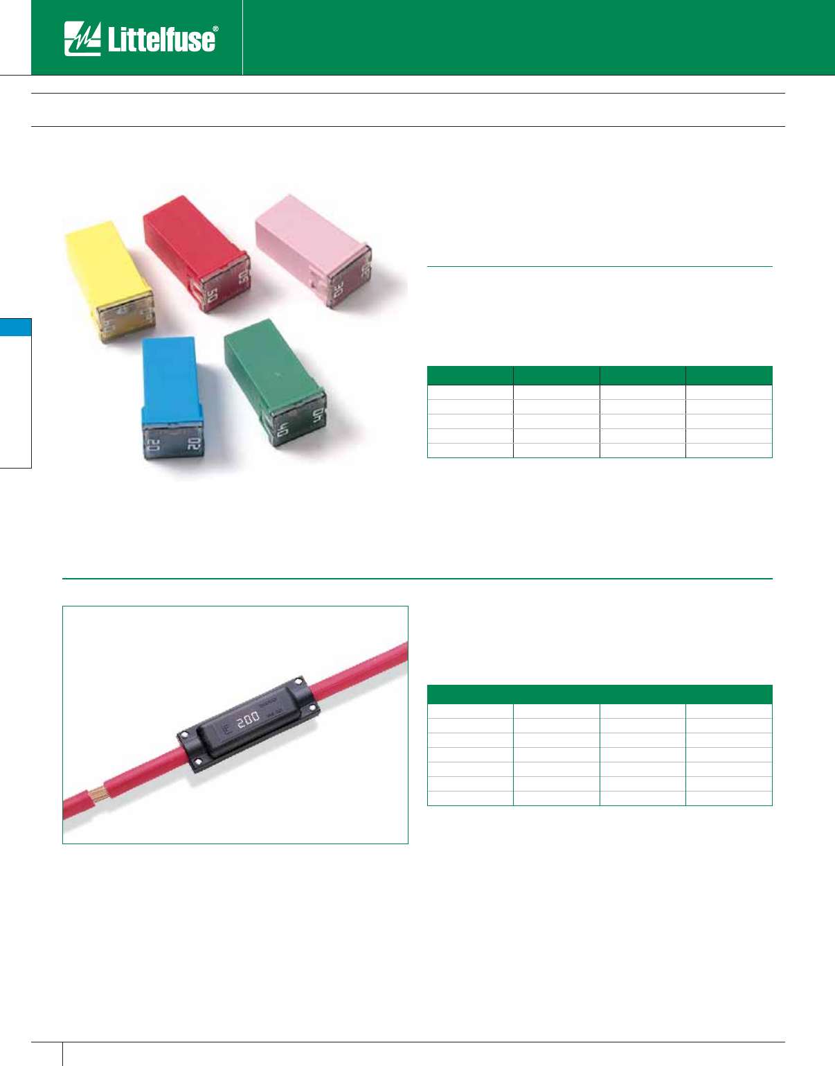
Midget & Electronic Fuses
62 www.littelfuse.com
Midget & Electronic Fuses
© 2005 Littelfuse • POWR-GARD™ Products Catalog
Automotive Fuses
Miscellaneous
CablePro® Cable Protector Fuse
The CablePro Fuse is a high performance alternative for providing a
reliable, safe, and cost effective fusible link. It provides similar circuit
protection as the MEGA® fuse in a slim package that fits into tight
locations. The standard CablePro features 1 one foot wire lead and 1
three foot wire lead. Contact the factory for custom wire lead lengths.
JCASE® SLO-BLO® Fuse
The patented JCASE is a cartridge style fuse with female terminals. It
was designed to provide increased time-delay to handle in-rush currents
and low voltage drop to protect high current automotive circuits.
Specifications
Voltage Rating: 32V AC/DC
Interrupting Rating: 1000 A @ 32VDC
Example part number (series & amperage): JCAS60
Specifications
Voltage Rating: 32V AC/DC
Interrupting Rating: 2000 A @ 32VDC
Example part number (series & amperage): 496060
Standard item: 1 foot cable on one side; 3 foot cable on the other side.
Catalog No. Amp. Rating Volt. Rating Wire Gauge
496060
496060
60
60
32
32
10AWG
10AWG
496080
496080
80
80
32
32
8AWG
8AWG
496100
496100
100
100
32
32
8AWG
8AWG
496125
496125
125
125
32
32
6AWG
6AWG
496150
496150
150
150
32
32
4AWG
4AWG
496175
496175
175
175
32
32
4AWG
4AWG
496200
496200
200
200
32
32
4AWG
4AWG
Catalog No. Amp. Rating Volt. Rating Color Code
JCAS20 20 32 Blue
JCAS30 30 32 Pink
JCAS40 40 32 Green
JCAS50 50 32 Red
JCAS60 60 32 Yellow
Catalog 49-62.indd 62 5/30/07 6:28:32 PM
www.littelfuse.com
© 2005 Littelfuse • POWR-GARD™ Products Catalog
Medium Voltage Fuses
Medium Voltage Fuses 64
R Rated Medium Voltage Fuses 65-68
E Rated Medium Voltage Fuses 69-73
E Rated Potential Transformer Fuses 74
Live Parts 75
Catalog 63-75.indd 63 5/30/07 6:34:47 PM
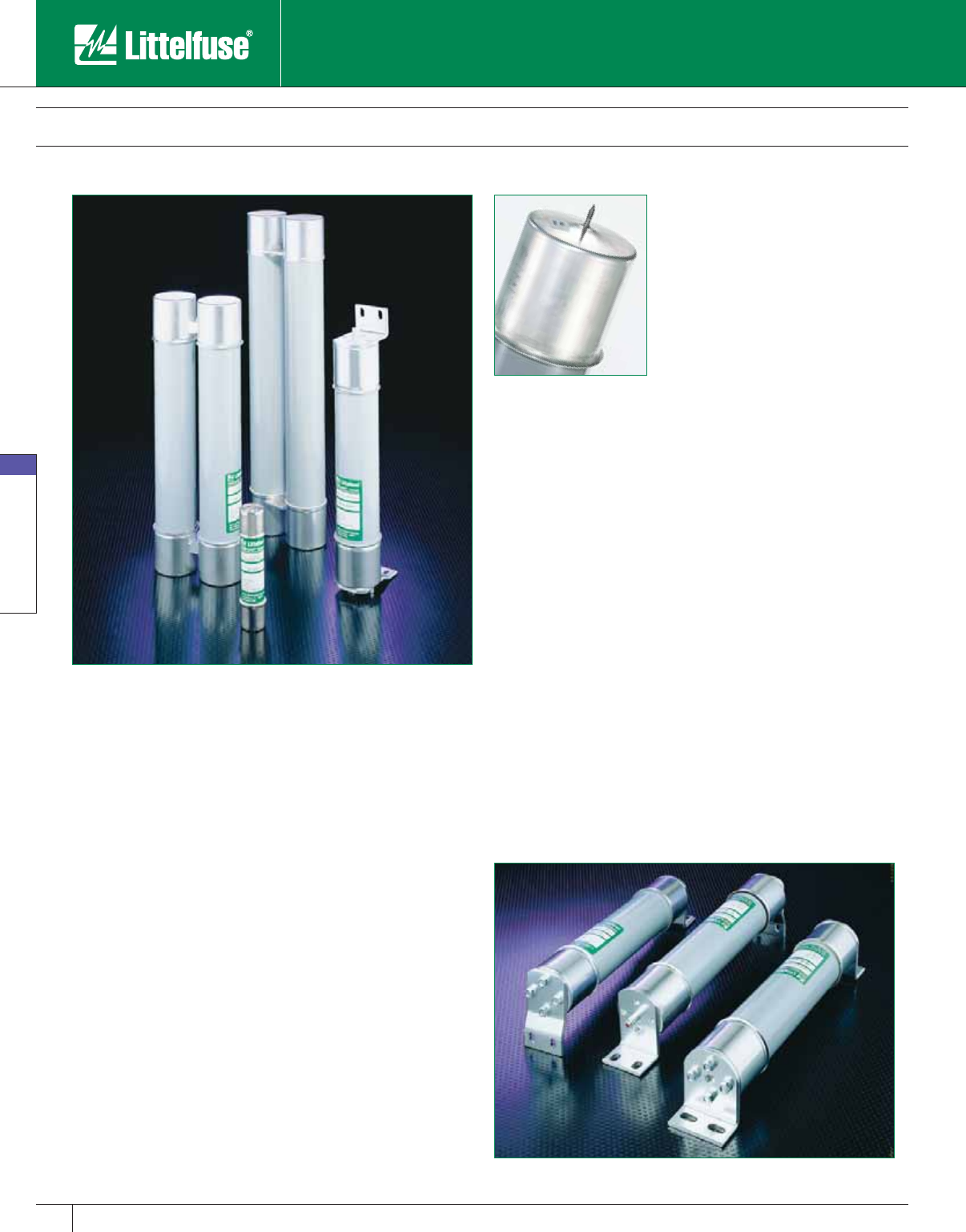
Medium Voltage Fuses
64 www.littelfuse.com
Medium Voltage Fuses
© 2005 Littelfuse • POWR-GARD™ Products Catalog
Medium Voltage Fuses
2,400 - 38,000 VAC • Current-Limiting
Littelfuse now offers a complete selection of “E” and “R” rated
medium voltage fuses for the protection of trans formers, potential
transformers, feeders, and motor circuits. Single, double, and triple
barrel designs are available to cover a wide range of current, voltage,
and interrupting ratings. Conventional ferrule type, clip lock, and bolt-in
mounting configurations are now available for virtually any application.
Hermetically sealed fuses for use in hazardous environments are also
offered.
Contact the factory or your local Littelfuse representative for additional
fuse ratings or custom mounting configurations.
24 Hour Emergency Service is available. Call 847 824 1188.
Applications
Power Transformer Protection
Potential Transformer Protection
Motor Controller Back-up Protection
Fused Switches
Feeder Circuits
General Information
The terms “Medium Voltage” and “High Voltage” have been used
interchangeably by many people to describe fuses operating above 600
volts. Technically speaking, “medium voltage” fuses are those intended
for the voltage range from 2,400 to 38,000 VAC. “High voltage” fuses
are for circuits carrying voltages greater than 38,000 VAC.
“E” rated fuses are considered to be general purpose fuses and can be
used to protect against low and high values of fault current. “R” rated
fuses are designed for back-up protection. They must be used in series
with other devices such as motor overload relays in order to achieve
both overload and short-circuit protection.
Medium voltage fuses are not intended to provide overload protection in
the same sense as fuses rated 600 volts or less. Medium voltage fuse
current ratings do not have the same meanings as the ampere ratings of
low voltage fuses.
All medium voltage fuses are limited in their ability to interrupt low value
overcurrents, especially those between 100% and 200% of the fuse’s
continuous current rating. They are designed to carry their rated current
without exceeding the temperature rise permitted by NEMA and ANSI
standards.
Additional application data can be found in the Fuse Application section
of this catalog.
Current-limiting “E” and “R” rated fuses
are equipped with a mechanical indicator
or striker pin that protrudes through the
fuse cap upon operation of the fuse. This
provides visual identification of a blown
fuse and can be used as a trigger for
external devices.
Note: Extension distance 1/2” min; extension
force 2lb. min
Bolt-in Mount Fuses
Catalog 63-75.indd 64 5/30/07 6:34:50 PM
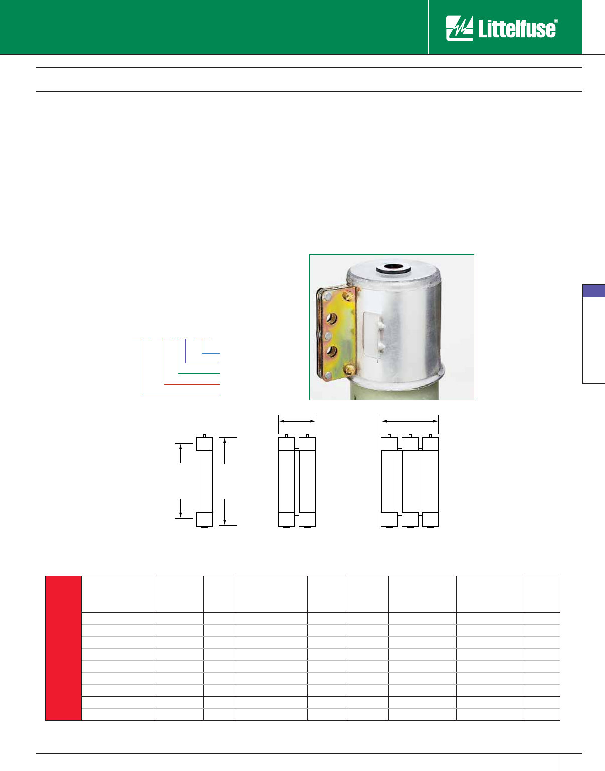
Medium Voltage Fuses
65
www.littelfuse.com
Medium Voltage Fuses
© 2005 Littelfuse • POWR-GARD™ Products Catalog
Features
“R” rated fuses provide required short-circuit protection for medium
voltage motors, motor controllers and associated circuitry. These
components have limited ability to absorb the energy of large short-
circuit currents. Medium voltage motor controllers contain overload
relays which provide both overload protection and locked rotor
protection to the motor. The controllers are also intended to interrupt
low value short-circuits within the capability of the motor controller. This
protects the medium voltage fuse from sustained overcurrents which
are less than their minimum interrupting rating.
NEMA Standards for “R” rated medium voltage power fuses require
they operate within 15-35 seconds when subjected to an rms current
100 times the “R” rating. For example, a fuse with a 2R rating will open
within 15 to 35 seconds on an applied current of 2 x 100 = 200 amperes.
Part Number System
130-4R-1C-5.5
R Rated Medium Voltage Fuses
Current-Limiting
3"DIA
Dim.A
Clip
Center
6.38"
Dim.B
9.75"
D DD DDD
Figure 1 Figure 2 Figure 3
Hookeye Feature*
* For hookeye attach-
ment; add “W” suffix
to part number
Max Voltage (KV)
Style (C-Cartridge)
No. of Barrels
Rating (size)
Continuous Current
Add “w” suffix to part number for hookeye attachment.
Characteristics
Voltage Rating: 2,400 volts – 8,250 volts
Current Range: 2R – 36R
Options
• Hermitically sealed for use in hazardous locations
(add “S” suffix to part number)
• Bolt-in mounting configurations
R
Rated
Catalog
Number
Old
Catalog
Number
Size
Maximum
Continuous Current
@ 40 deg C.
Dim. A
(inches)
Dim. B
(inches)
Min. Interrupting
Rating RMS Amps
Max Interrupting
Rating RMS Asym
Figure
Number
2.75 KV
70-2R-1C-2.75 LCK 2R 2R 70 7" 10.875" 170 80,000 1
100-3R-1C-2.75 LCK 3R 3R 100 7" 10.875" 250 80,000 1
130-4R-1C-2.75 LCK 4R 4R 130 7" 10.875" 340 80,000 1
150-5R-1C-2.75 LCK 5R 5R 150 7" 10.875" 390 80,000 1
170-6R-1C-2.75 LCK 6R 6R 170 7" 10.875" 500 80,000 1
200-9R-1C-2.75 LCK 9R 9R 200 7" 10.875" 760 80,000 1
230-12R-1C-2.75 LCK 12R 12R 230 7" 10.875" 1000 80,000 1
390-18R-2C-2.75 LCK 18R 18R 390 7" 10.875" 1500 80,000 2
450-24R-2C-2.75 LCK 24R 24R 450 7" 10.875" 1950 80,000 2
Catalog 63-75.indd 65 5/30/07 6:34:54 PM
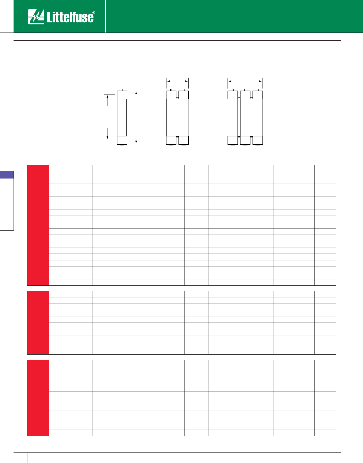
Medium Voltage Fuses
66 www.littelfuse.com
Medium Voltage Fuses
© 2005 Littelfuse • POWR-GARD™ Products Catalog
R Rated Medium Voltage Fuses
Current-Limiting
3"DIA
Dim.A
(Clip
Center)
6.38"
Dim.B
9.75"
R
Rated
Catalog
Number
Old
Catalog
Number
Size
Maximum
Continuous Current
@ 40 Degrees C°
Dim. A
(inches)
Dim. B
(inches)
Min. Interrupting
Rating RMS Amps
Max Interrupting
Rating RMS (Asym)
Figure
Number
5.5 KV
70-2R-1C-5.5 LCL 2R 2R 70 12" 15.875" 170 80,000 4
100-3R-1C-5.5 LCL 3R 3R 100 12" 15.875" 250 80,000 4
130-4R-1C-5.5 LCL 4R 4R 130 12" 15.875" 340 80,000 4
150-5R-1C-5.5 LCL 5R 5R 150 12" 15.875" 390 80,000 4
170-6R-1C-5.5 LCL 6R 6R 170 12" 15.875" 500 80,000 4
200-9R-1C-5.5 LCL 9R 9R 200 12" 15.875" 760 80,000 4
230-12R-1C-5.5 LCL 12R 12R 230 12" 15.875" 1000 80,000 4
390-18R-2C-5.5 LCL 18R 18R 390 12" 15.875" 1500 80,000 5
450-24R-2C-5.5 LCL 24R 24R 450 12" 15.875" 1950 80,000 5
480-26R-2C-5.5 — 26R 480 12" 15.875" 2100 80,000 5
550-30R-2C-5.5 — 30R 550 12" 15.875" 2400 80,000 5
600-32R-2C-5.5 — 32R 600 12" 15.875" 2600 80,000 5
650-36R-2C-5.5 — 36R 650 12" 15.875" 2900 80,000 5
550-30R-3C-5.5 — 30R 550 12" 15.875" 2400 80,000 6
600-32R-3C-5.5 — 32R 600 12" 15.875" 2600 80,000 6
650-36R-3C-5.5 LCL 36R 36R 650 12" 15.875" 2900 80,000 6
5.5 KV
14”Clip Centers
70-2R-1C-5.5X —2R 70 14" 17.875" 170 80,000 4
100-3R-1C-5.5X —3R 100 14" 17.875" 250 80,000 4
130-4R-1C-5.5X —4R 130 14" 17.875" 340 80,000 4
150-5R-1C-5.5X —5R 150 14" 17.875" 390 80,000 4
170-6R-1C-5.5X —6R 170 14" 17.875" 500 80,000 4
200-9R-1C-5.5X —9R 200 14" 17.875" 760 80,000 4
230-12R-1C-5.5X —12R 230 14" 17.875" 1000 80,000 4
390-18R-2C-5.5X —18R 390 14" 17.875" 1500 80,000 5
450-24R-2C-5.5X —24R 450 14" 17.875" 1950 80,000 5
550-30R-2C-5.5X —30R 550 14” 17.875” 2400 80,000 5
R
Rated
Catalog
Number
Old
Catalog
Number
Size
Maximum
Continuous Current
@ 40 Degrees C°
Dim. A
(inches)
Dim. B
(inches)
Min. Interrupting
Rating RMS Amps
Max Interrupting
Rating RMS (Asym)
Figure
Number
8.25 KV
70-2R-1C-8.25 — 2R 70 12" 15.875" 190 80,000 4
100-3R-1C-8.25 — 3R 100 12" 15.875" 225 80,000 4
130-4R-1C-8.25 — 4R 130 12" 15.875" 330 80,000 4
150-5R-1C-8.25 — 5R 150 12" 15.875" 440 80,000 4
170-6R-1C-8.25 — 6R 170 12" 15.875" 500 80,000 4
200-9R-1C-8.25 — 9R 200 12" 15.875" 740 80,000 4
230-12R-1C-8.25 — 12R 230 12" 15.875" 955 80,000 4
390-18R-2C-8.25 — 18R 390 12" 15.875" 1440 80,000 5
450-24R-2C-8.25 — 24R 450 12" 15.875" 1910 80,000 5
Add “w” suffix to part number for hookeye attachment.
Figure 4 Figure 5 Figure 6
Catalog 63-75.indd 66 5/30/07 6:34:56 PM
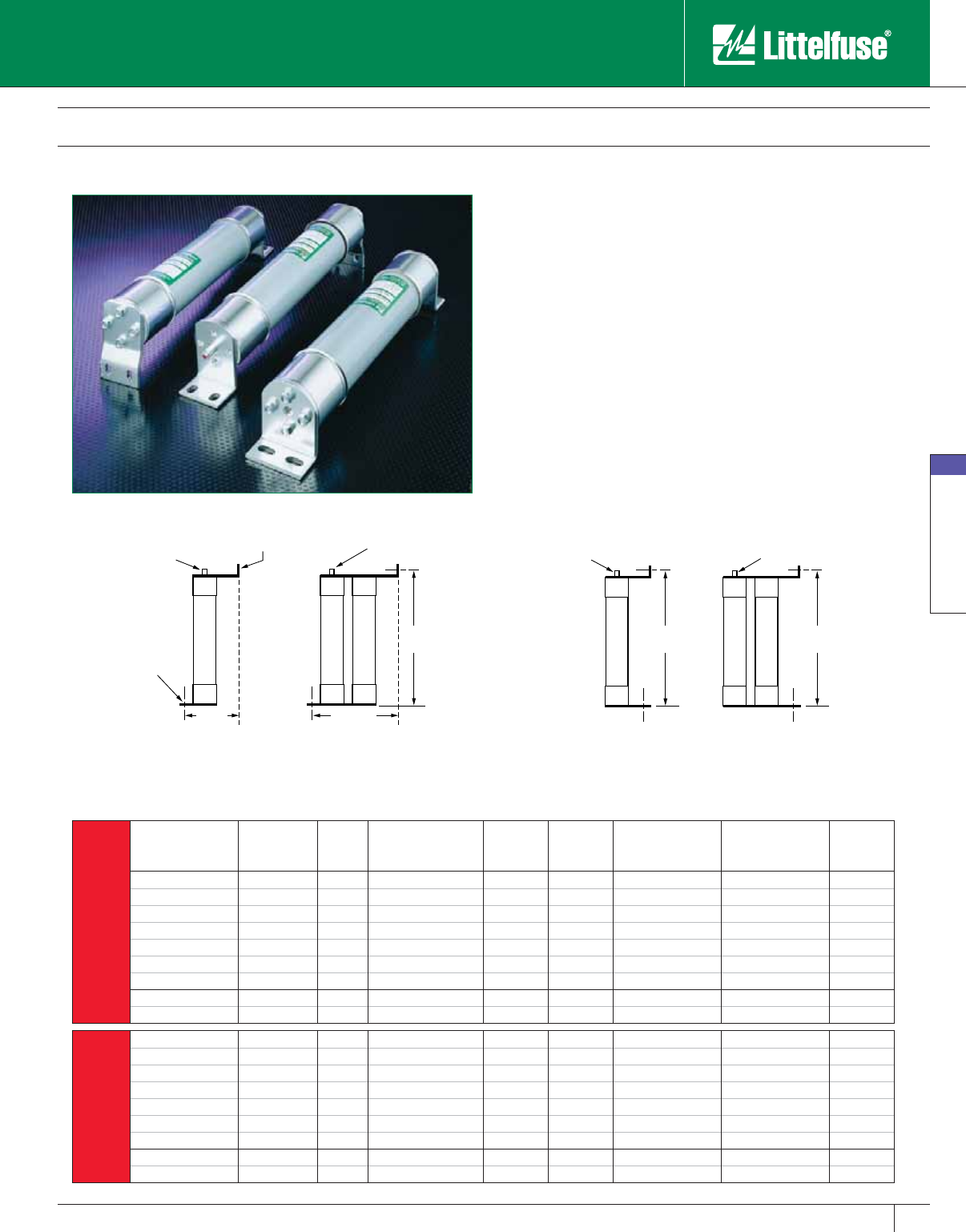
Medium Voltage Fuses
67
www.littelfuse.com
Medium Voltage Fuses
© 2005 Littelfuse • POWR-GARD™ Products Catalog
R Rated Medium Voltage Fuses
Current-Limiting
R
Rated
Catalog
Number
Old
Catalog
Number
Size
Maximum
Continuous Current
@ Degrees C°
Dim. A
(inches)
Dim. B
(inches)
Min. Interrupting
Rating RMS Amps
Max Interrupting
Rating RMS (Asym)
Figure
Number
2.75 KV
Bolt Mount “B”
70-2R-1B-2.75 —2R 70 4.6" 13" 170 80,000 7
00-3R-1B-2.75 —3R 100 4.6" 13" 250 80,000 7
30-4R-1B-2.75 —4R 130 4.6" 13" 240 80,000 7
150-5R-1B-2.75 —5R 150 4.6" 13" 390 80,000 7
170-6R-1B-2.75 —6R 170 4.6" 13" 500 80,000 7
200-9R-1B-2.75 —9R 200 4.6" 13" 760 80,000 7
230-12R-1B-2.75 —12R 230 4.6" 13" 1000 80,000 7
390-18R-2B-2.75 —18R 390 7.4" 13" 1500 80,000 8
450-24R-2B-2.75 —24R 450 7.4" 13" 1950 80,000 8
2.75 KV
Inverted Bolt “IB”
70-2R-1IB-2.75 —2R 70 — 13" 170 80,000 9
100-3R-1IB-2.75 —3R 100 — 13" 250 80,000 9
130-4R-1IB-2.75 —4R 130 — 13" 340 80,000 9
150-5R-1IB-2.75 —5R 150 — 13" 390 80,000 9
170-6R-1IB-2.75 —6R 170 — 13" 500 80,000 9
200-9R-1IB-2.75 —9R 200 — 13" 760 80,000 9
230-12R-1IB-2.75 —12R 230 — 13" 1000 80,000 9
390-18R-2IB-2.75 —18R 390 — 13" 1500 80,000 10
450-24R-2IB-2.75 —24R 450 — 13" 1950 80,000 10
Dim.B
Dim.ADim.A
(2) .34" X .660 Slots
1.38" Apart
3" Dia.
(2) .34" Holes
1.38" Apart
Indicator
Indicator
Dim.BDim.B
3" Dia. Indicator
Indicator
Bolt Mount “B” Inverted-Bolt “IB”
Figure 7 Figure 8 Figure 9 Figure 10
Littelfuse POWR-GARD™ medium voltage fuses are available in
several bolt-in mounting configurations. Contact factory for custom
configurations.
“B” Bolt mount
“BI” Bolt-In mount
“IB” Inverted-Bolt mount
Refer to illustrations for mounting dimensions.
Catalog 63-75.indd 67 5/30/07 6:34:58 PM
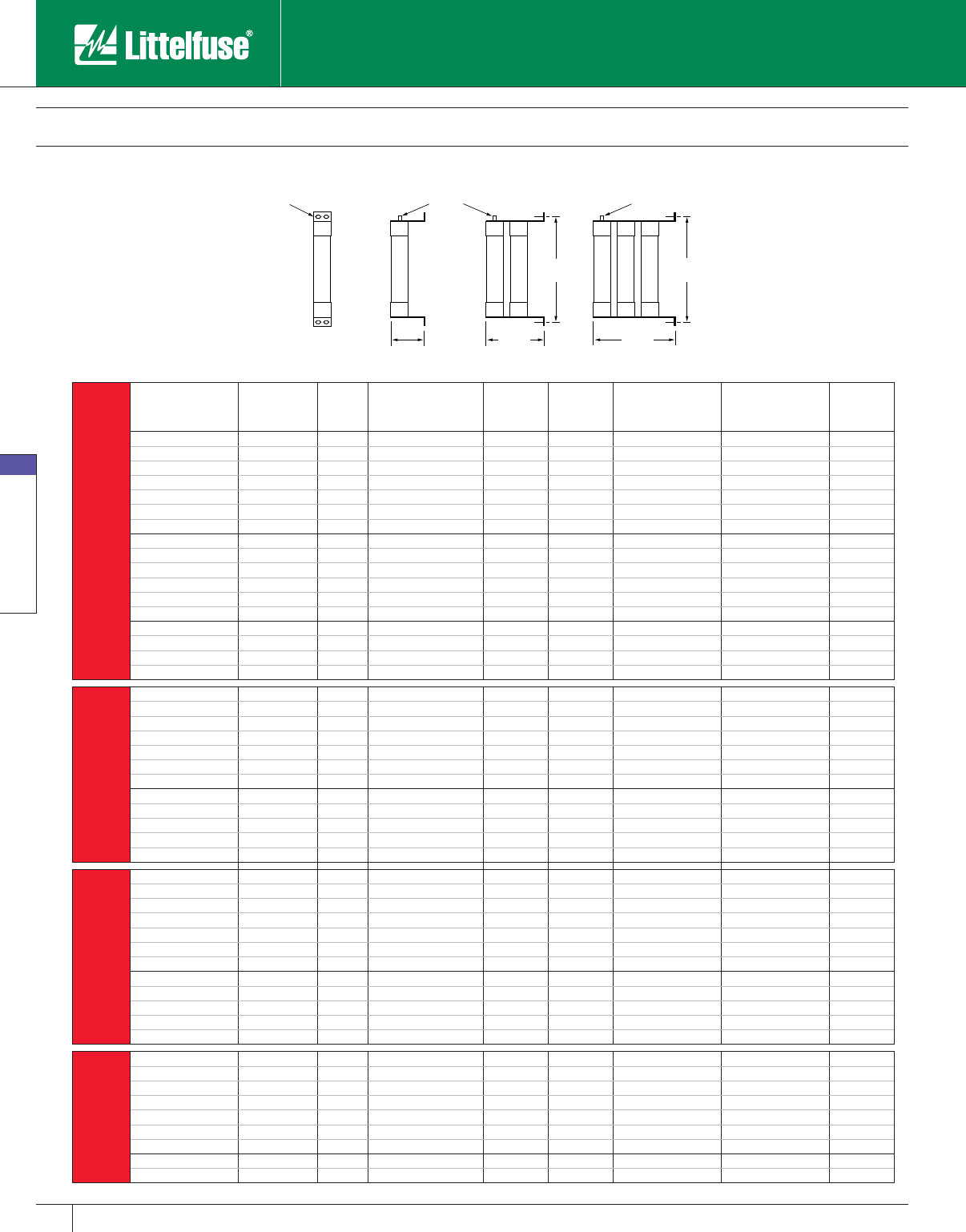
Medium Voltage Fuses
68 www.littelfuse.com
Medium Voltage Fuses
© 2005 Littelfuse • POWR-GARD™ Products Catalog
R Rated Medium Voltage Fuses
Current-Limiting
R
Rated
Catalog
Number
Old
Catalog
Number
Size
Maximum
Continuous Current
@ 40˚ C.
Dim. A
(inches)
Dim. B
(inches)
Min. Interrupting
Rating RMS Amps
Max Interrupting
Rating RMS (Asym)
Figure
Number
5.5 KV
Bolt In Mount “BI”
70-2R-1BI-5.5 — 2R 70 3.6 ” 18" 170 80,000 11
100-3R-1BI-5.5 — 3R 100 3.6 ” 18" 250 80,000 11
130-4R-1BI-5.5 — 4R 130 3.6 ” 18" 340 80,000 11
150-5R-1BI-5.5 — 5R 150 3.6 ” 18" 390 80,000 11
170-6R-1BI-5.5 — 6R 170 3.6 ” 18" 500 80,000 11
200-9R-1BI-5.5 — 9R 200 3.6 ” 18" 760 80,000 11
230-12R-1BI-5.5 — 12R 230 3.6 ” 18" 1000 80,000 11
390-18R-2BI-5.5 — 18R 390 7.6” 18" 1500 80,000 12
450-24R-2BI-5.5 — 24R 450 7.6” 18" 1950 80,000 12
480-26R-2BI-5.5 — 26R 480 7.6” 18" 2200 80,000 12
550-30R-2BI-5.5 — 30R 550 7.6” 18" 2400 80,000 12
600-32R-2BI-5.5 — 32R 600 7.6” 18" 2650 80,000 12
650-36R-2BI-5.5 — 36R 650 7.6” 18" 2900 80,000 12
550-30R-3BI-5.5 — 30R 550 — 18" — 80,000 13
600-32R-3BI-5.5 — 32R 600 — 18" — 80,000 13
650-36R-3BI-5.5 — 36R 650 — 18" — 80,000 13
700-38R-3BI-5.5 — 38R 700 — 18" — 80,000 13
5.5 KV
Bolt Mount “B”
70-2R-1B-5.5 — 2R 70 4.6” 18" 170 80,000 7
100-3R-1B-5.5 — 3R 100 4.6” 18" 250 80,000 7
130-4R-1B-5.5 — 4R 130 4.6” 18" 340 80,000 7
150-5R-1B-5.5 — 5R 150 4.6” 18" 390 80,000 7
170-6R-1B-5.5 — 6R 170 4.6” 18" 500 80,000 7
200-9R-1B-5.5 — 9R 200 4.6” 18" 760 80,000 7
230-12R-1B-5.5 — 12R 230 4.6” 18" 1000 80,000 7
390-18R-2B-5.5 — 18R 390 7.4” 18" 1500 80,000 8
450-24R-2B-5.5 — 24R 450 7.4” 18" 1950 80,000 8
550-30R-2B-5.5 — 30R 550 8.4” 18" 2400 80,000 8
600-32R-2B-5.5 — 32R 600 8.4” 18" 2650 80,000 8
650-36R-2B-5.5 — 36R 650 8.4” 18" 2900 80,000 8
5.5 KV
Inverted Bolt “IB”
70-2R-1IB-5.5 — 2R 70 — 18" 170 80,000 9
100-3R-1IB-5.5 — 3R 100 — 18" 250 80,000 9
130-4R-1IB-5.5 — 4R 130 — 18" 340 80,000 9
150-5R-1IB-5.5 — 5R 150 — 18" 390 80,000 9
170-6R-1IB-5.5 — 6R 170 — 18" 500 80,000 9
200-9R-1IB-5.5 — 9R 200 — 18" 760 80,000 9
230-12R-1IB-5.5 — 12R 230 — 18" 1000 80,000 9
390-18R-2IB-5.5 — 18R 390 — 18" 1500 80,000 10
450-24R-2IB-5.5 — 24R 450 — 18" 1950 80,000 10
550-30R-2IB-5.5 — 30R 550 — 18" 2400 80,000 10
600-32R-2IB-5.5 — 32R 600 — 18" 2650 80,000 10
650-36R-2IB-5.5 — 36R 650 — 18" 2900 80,000 10
8.25 KV
Bolt-In Mount “BI”
70-2R-1BI-8.25 — 2R 70 3.6” 18" 190 80,000 11
100-3R-1BI-8.25 — 3R 100 3.6” 18" 225 80,000 11
130-4R-1BI-8.25 — 4R 130 3.6” 18" 330 80,000 11
150-5R-1BI-8.25 — 5R 150 3.6” 18" 400 80,000 11
170-6R-1BI-8.25 — 6R 170 3.6” 18" 500 80,000 11
200-9R-1BI-8.25 — 9R 200 3.6” 18" 740 80,000 11
230-12R-1BI-8.25 — 12R 230 3.6” 18" 955 80,000 11
390-18R-2BI-8.25 — 18R 390 7.6” 18" 1440 80,000 12
450-24R-2BI-8.25 — 24R 450 7.6” 18" 1910 80,000 12
Dim.B
Dim.A
Dim.B
Dim.A
Dim.A
3"Dia.
Front View
.44" X .91" Slots (1.53" c.t.c.) Indicator Indicator
Bolt-In Mount “BI”
Figure 11 Figure 12 Figure 13
Catalog 63-75.indd 68 5/30/07 6:35:00 PM
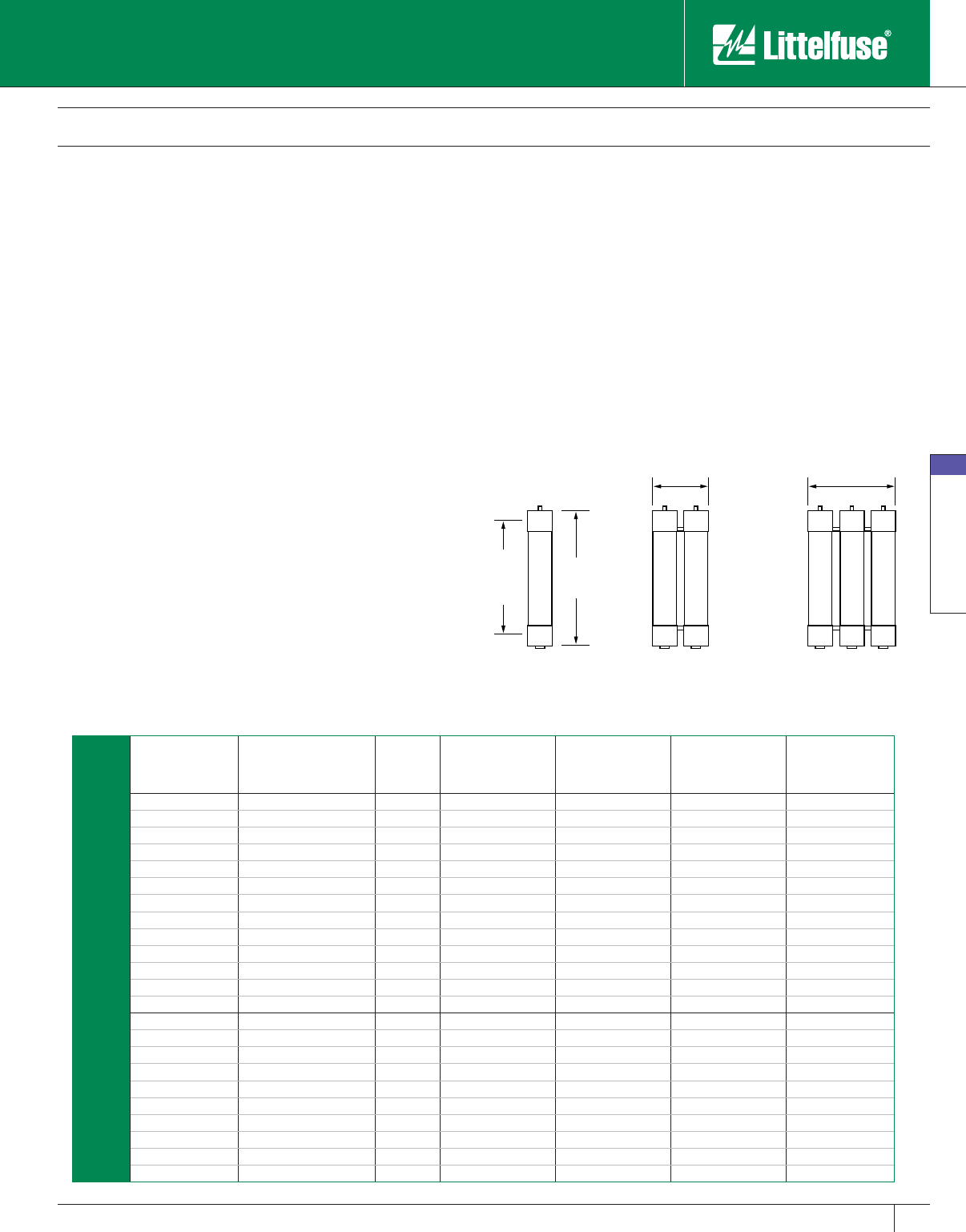
Medium Voltage Fuses
69
www.littelfuse.com
Medium Voltage Fuses
© 2005 Littelfuse • POWR-GARD™ Products Catalog
E Rated Medium Voltage Fuses
Current-Limiting
“E” Rated fuses have time current characteristics designed to
provide current-limiting protection for power transformers, potential
transformers, power centers, feeder centers, and unit sub stations.
When properly applied, they can protect against high and low fault
currents.
NEMA Standards for “E” rated medium voltage fuses require that
fuses rated 100E or less open within 300 seconds (5 minutes) when
subjected to an RMS value of 200-240% of the fuse continuous current
rating; and fuses with an “E” rating larger than 100E must open within
600 seconds (10 minutes) when subjected to an RMS current of 220-
240% of the fuse’s continuous current rating. These values establish
one point on the time-current curve.
Application Note:
Since these fuses are used for the protection of general purpose
circuits which may contain transformers, motors, and other equipment
producing in-rush and/or overload currents, fuses should generally be
rated at 140% of the normal full load current, and circuits should be
analyzed to ensure that system load currents will not exceed the current
rating of the fuse.
3"DIA
Dim.A
(Clip
Center)
6.38"
Dim.B
9.75"
Figure 14 Figure 15 Figure 16
Characteristics
Voltage Rating: 2,400 volts – 38,000 volts
Current Range: 10E – 600E
Options
• Hermetically sealed for use in hazardous locations
(add “S” suffix to part number)
• Clip-lock (CL) and bolt-in styles available.
E
Rated Catalog Number Old Catalog Number Size Dim. A (inches) Dim. B (inches) Max Interrupting
Rating RMS (Asym) Figure Number
2.75 Max. KV
10E-1C-2.75 LCX 10E 10E 7" 10.875" 80,000 14
15E-1C-2.75 — 15E 7" 10.875" 80,000 14
20E-1C-2.75 — 20E 7" 10.875" 80,000 14
25E-1C-2.75 — 25E 7" 10.875" 80,000 14
30E-1C-2.75 LCX 30E 30E 7" 10.875" 80,000 14
40E-1C-2.75 LCX 40E 40E 7" 10.875" 80,000 14
50E-1C-2.75 LCX 50E 50E 7" 10.875" 80,000 14
65E-1C-2.75 LCX 65E 65E 7" 10.875" 80,000 14
80E-1C-2.75 LCX 80E 80E 7" 10.875" 80,000 14
100E-1C-2.75 LCX 100E 100E 7" 10.875" 80,000 14
125E-1C-2.75 — 125E 7" 10.875" 80,000 14
150E-1C-2.75 — 150E 7" 10.875" 80,000 14
200E-1C-2.75 — 200E 7" 10.875" 80,000 14
125E-2C-2.75 LCX 125E 125E 7" 10.875" 80,000 15
150E-2C-2.75 LCX 150E 150E 7" 10.875" 80,000 15
175E-2C-2.75 LCX 175E 175E 7" 10.875" 80,000 15
200E-2C-2.75 LCX 200E 200E 7" 10.875" 80,000 15
225E-2C-2.75 — 225E 7" 10.875" 80,000 15
250E-2C-2.75 LCX 250E 250E 7" 10.875" 80,000 15
300E-2C-2.75 LCX 300E 300E 7" 10.875" 80,000 15
350E-2C-2.75 — 350E 7" 10.875" 80,000 15
400E-2C-2.75 LCX 400E 400E 7" 10.875" 80,000 15
450E-2C-2.75 — 450E 7" 10.875" 80,000 15
Catalog 63-75.indd 69 5/30/07 6:35:03 PM

Medium Voltage Fuses
70 www.littelfuse.com
Medium Voltage Fuses
© 2005 Littelfuse • POWR-GARD™ Products Catalog
E
Rated Catalog Number Old Catalog Number Size Dim. A (inches) Dim. B (inches) Max Interrupting
Rating RMS (Asym) Diagram
5.5 Max. KV
10E-1C-5.5 — 10E 12" 15.875" 80,000 14
15E-1C-5.5 — 15E 12" 15.875" 80,000 14
20E-1C-5.5 — 20E 12" 15.875" 80,000 14
25E-1C-5.5 — 25E 12" 15.875" 80,000 14
30E-1C-5.5 LCY 30E 30E 12" 15.875" 80,000 14
40E-1C-5.5 LCY 40E 40E 12" 15.875" 80,000 14
50E-1C-5.5 LCY 50E 50E 12" 15.875" 80,000 14
65E-1C-5.5 LCY 60E 65E 12" 15.875" 80,000 14
80E-1C-5.5 LCY 80E 80E 12" 15.875" 80,000 14
100E-1C-5.5 LCY 100E 100E 12" 15.875" 80,000 14
125E-1C-5.5 LCY 125E 125E 12" 15.875" 80,000 14
150E-1C-5.5 LCY 150E 150E 12" 15.875" 80,000 14
175E-1C-5.5 LCY 175E 175E 12" 15.875" 80,000 14
200E-1C-5.5 LCY 200E 200E 12" 15.875" 80,000 14
125E-2C-5.5 — 125E 12" 15.875" 80,000 15
150E-2C-5.5 — 150E 12" 15.875" 80,000 15
175E-2C-5.5 — 175E 12" 15.875" 80,000 15
200E-2C-5.5 — 200E 12" 15.875" 80,000 15
250E-2C-5.5 LCY 250E 250E 12" 15.875" 80,000 15
300E-2C-5.5 LCY 300E 300E 12" 15.875" 80,000 15
350E-2C-5.5 LCY 350E 350E 12" 15.875" 80,000 15
400E-2C-5.5 LCY 400E 400E 12" 15.875" 80,000 15
450E-2C-5.5 LCY 450E 450E 12" 15.875" 80,000 15
500E-3C-5.5 — 500E 12" 15.875" 80,000 16
550E-3C-5.5 — 550E 12" 15.875" 80,000 16
600E-3C-5.5 — 600E 12" 15.875" 80,000 16
5.5 Max. KV
5NLE-10E — 10E 14” 177⁄8" 80,000 14
5NLE-15E — 15E 14” 177⁄8" 80,000 14
5NLE-20E — 20E 14” 177⁄8" 80,000 14
5NLE-25E — 25E 14” 177⁄8" 80,000 14
5NLE-30E LCU 30E 30E 14” 177⁄8" 80,000 14
5NLE-40E LCU 40E 40E 14” 177⁄8" 80,000 14
5NLE-50E LCU 50E 50E 14” 177⁄8" 80,000 14
5NLE-65E LCU 65E 65E 14” 177⁄8" 80,000 14
5NLE-80E LCU 80E 80E 14” 177⁄8" 80,000 14
5NLE-100E LCU 100E 100E 14” 17 7⁄8" 80,000 14
5NLE-125E LCU 125E 125E 14“ 17 7⁄8" 80,000 14
5NLE-150E LCU 150E 150E 14” 17 7⁄8" 80,000 14
5NLE-175E LCU 175E 175E 14” 17 7⁄8" 80,000 14
5NLE-200E LCU 200E 200E 14” 177⁄8" 80,000 14
5NLE2-225E — 225E 14” 177⁄8" 80,000 15
5NLE2-250E LCU 250E 250E 14” 177⁄8" 80,000 15
5NLE2-300E LCU 300E 300E 14” 177⁄8" 80,000 15
5NLE2-350E LCU 350E 350E 14” 177⁄8" 80,000 15
5NLE2-400E LCU 400E 400E 14” 177⁄8" 80,000 15
5NLE2-450E LCU 450E 450E 14” 177⁄8" 80,000 15
E Rated Medium Voltage Fuses
Current-Limiting
Catalog 63-75.indd 70 5/30/07 6:35:04 PM
Medium Voltage Fuses
71
www.littelfuse.com
Medium Voltage Fuses
© 2005 Littelfuse • POWR-GARD™ Products Catalog
E
Rated Catalog Number Old Catalog Number Size Dim. A (inches) Dim. B (inches) Max Interrupting
Rating RMS (Asym) Diagram
8.25 Max. KV
10E-1C-8.25 — 10E 12" 15 7⁄8" 80,000, 14
15E-1C-8.25 — 15E 12" 15 7⁄8" 80,000 14
20E-1C-8.25 — 20E 12" 157⁄8" 80,000 14
25E-1C-8.25 — 25E 12" 157⁄8" 80,000 14
30E-1C-8.25 LDZ 30E 30E 12" 157⁄8" 80,000 14
40E-1C-8.25 LDZ 40E 40E 12" 157⁄8" 80,000 14
50E-1C-8.25 LDZ 50E 50E 12" 157⁄8" 80,000 14
65E-1C-8.25 LDZ 65E 65E 12" 157⁄8" 80,000 14
80E-1C-8.25 LDZ 80E 80E 12" 157⁄8" 80,000 14
100E-1C-8.25 LDZ 100E 100E 12" 15 7⁄8" 80,000 14
125E-1C-8.25 LDZ 125E 125E 12" 157⁄8" 80,000 14
150E-1C-8.25 LDZ 150E 150E 12" 15 7⁄8" 80,000 14
125E-2C-8.25 LDZ 125E 125E 12" 15 7⁄8" 80,000 15
150E-2C-8.25 LDZ 150E 150E 12" 157⁄8" 80,000 15
200E-2C-8.25 LDZ 200E 200E 12" 157⁄8" 80,000 15
250E-2C-8.25 LDZ 250E 250E 12" 157⁄8" 80,000 15
300E-2C-8.25 LDZ 300E 300E 12" 157⁄8" 80,000 15
350E-3C-8.25 LDZ 350Z 350E 12" 157⁄8" 80,000 16
400E-3C-8.25 — 400E 12" 157⁄8" 80,000 16
8.25 Max. KV
8NLE-10E — 10E 14" 177⁄8" 80,000 14
8NLE-15E — 15E 14" 177⁄8" 80,000 14
8NLE-20E — 20E 14" 177⁄8" 80,000 14
8NLE-25E — 25E 14" 177⁄8" 80,000 14
8NLE-30E LCZ 30E 30E 14" 177⁄8" 80,000 14
8NLE-40E LCZ 40E 40E 14" 177⁄8" 80,000 14
8NLE-50E LCZ 50E 50E 14" 177⁄8" 80,000 14
8NLE-65E LCZ 65E 65E 14" 177⁄8" 80,000 14
8NLE-80E LCZ 80E 80E 14" 177⁄8" 80,000 14
8NLE-100E LCZ 100E 100E 14" 17 7⁄8" 80,000 14
8NLE2-100E LCZ 100E 100E 14" 17 7⁄8" 80,000 14
8NLE2-125E LCZ 125E 125E 14" 177⁄8" 80,000 15
8NLE2-150E LCZ 150E 150E 14" 17 7⁄8" 80,000 15
8NLE2-200E LCZ 200E 200E 14" 177⁄8" 80,000 15
8NLE2-250E — 250E 14" 177⁄8" 80,000 15
E
Rated Catalog Number Old Catalog Number Size Dim. A (inches) Dim. B (inches) Max Interrupting
Rating RMS (Asym)
Figure
Number
15.5 Max. KV
10E-1C-15.5 LDN 10E 10E 15" 18.875" 80,000 14
15E-1C-15.5 LDN 15E 15E 15" 18.875" 80,000 14
20E-1C-15.5 LDN 20E 20E 15" 18.875" 80,000 14
25E-1C-15.5 LDN 25E 25E 15" 18.875" 80,000 14
30E-1C-15.5 LDN 30E 30E 15" 18.875" 80,000 14
40E-1C-15.5 LDN 40E 40E 15" 18.875" 80,000 14
50E-1C-15.5 LDN 50E 50E 15" 18.875" 80,000 14
65E-1C-15.5 LDN 65E 65E 15" 18.875" 80,000 14
80E-1C-15.5 LDN 80E 80E 15" 18.875" 80,000 14
100E-1C-15.5 LDN 100E 100E 15" 18.875" 80,000 14
65E-2C-15.5 — 65E 15" 18.875" 80,000 15
80E-2C-15.5 — 80E 15" 18.875" 80,000 15
100E-2C-15.5 — 100E 15" 18.875" 80,000 15
125E-2C-15.5 — 125E 15" 18.875" 80,000 15
150E-2C-15.5 LDN 150E 150E 15" 18.875" 80,000 15
175E-2C-15.5 LDN 175E 175E 15" 18.875" 80,000 15
200E-2C-15.5 — 200E 15" 18.875" 80,000 15
200E-3C-15.5 — 200E 15" 18.875" 80,000 16
250E-3C-15.5 — 250E 15" 18.875" 80,000 16
300E-3C-15.5 — 300E 15" 18.875" 80,000 16
E Rated Medium Voltage Fuses
Current-Limiting
Catalog 63-75.indd 71 5/30/07 6:35:06 PM

Medium Voltage Fuses
72 www.littelfuse.com
Medium Voltage Fuses
© 2005 Littelfuse • POWR-GARD™ Products Catalog
E
Rated Catalog Number Old Catalog Number Size Dim. A (inches) Dim. B (inches) Max Interrupting
Rating RMS (Asym)
Figure
Number
15.5
Max. KV
15GSE-65E — 65E 18" 217⁄8" 60,000 14
15GSE-80E — 80E 18" 217⁄8" 60,000 14
15GSE-100E — 100E 18" 21 7⁄8" 60,000 14
15GSE2-125E — 125E 18" 21 7⁄8" 60,000 15
15GSE2-150E — 150E 18" 21 7⁄8" 60,000 15
15GSE2-175E — 175E 18" 21 7⁄8" 60,000 15
15GSE2-200E — 200E 18" 21 7⁄8" 60,000 15
15.5 Max. KV
15NLE-10E — 10E 20" 23 7⁄8" 60,000 14
15NLE-15E — 15E 20" 23 7⁄8" 60,000 14
15NLE-20E — 20E 20" 237⁄8" 60,000 14
15NLE-25E — 25E 20" 237⁄8" 60,000 14
15NLE-30E LCN 30E 30E 20" 237⁄8" 60,000 14
15NLE-40E LCN 40E 40E 20" 237⁄8" 60,000 14
15NLE-50E LCN 50E 50E 20" 237⁄8" 60,000 14
15NLE-65E LCN 65E 65E 20" 237⁄8" 60,000 14
15NLE-80E LCN 80ES 80E 20" 237⁄8" 60,000 14
15NLE-100E LCN 100ES 100E 20" 23 7⁄8" 60,000 14
15NLE2-80E LCN 80E 80E 20" 237⁄8" 60,000 15
15NLE2-100E LCN 100E 100E 20" 237⁄8" 60,000 15
15NLE2-125E LCN 125X 125E 20" 23 7⁄8" 60,000 15
15NLE2-150E LCN 150E 150E 20" 23 7⁄8" 60,000 15
15NLE2-175E — 175E 20" 23 7⁄8" 60,000 15
15NLE2-200E LCN 200ED 200E 20" 237⁄8" 60,000 15
15NLE3-150E — 150E 20" 23 7⁄8" 60,000 16
15NLE3-175E — 175E 20" 23 7⁄8" 60,000 16
15NLE3-25 0E — 250E 20" 23 7⁄8" 60,000 16
15NLE3-300E — 300E 20" 23 7⁄8" 60,000 16
E
Rated Catalog Number Old Catalog Number Size Dim. A (inches) Dim. B (inches) Max Interrupting
Rating RMS (Asym)
Figure
Number
25.8 Max. KV
15E-1C-25.8 — 15E 21" 24 5⁄8" 40,000 14
20E-1C-25.8 — 20E 21" 245⁄8" 40,000 14
25E-1C-25.8 — 25E 21" 245⁄8" 40,000 14
30E-1C-25.8 — 30E 21" 245⁄8" 40,000 14
40E-1C-25.8 — 40E 21" 245⁄8" 40,000 14
50E-1C-25.8 — 50E 21" 245⁄8" 40,000 14
65E-2C-25.8 — 65E 21" 245⁄8" 40,000 14
80E-2C-25.8 — 80E 21" 245⁄8" 40,000 15
100E-2C-25.8 — 100E 21" 24 5⁄8" 40,000 15
E
Rated Catalog Number Old Catalog Number Size Dim. A (inches) Dim. B (inches) Max Interrupting
Rating RMS (Asym)
Figure
Number
38 Max. KV
3E-1C-38.0 — 3E 27" 305⁄8" 20,000 14
7E-1C-38.0 — 7E 27" 305⁄8" 20,000 14
10E-1C-38.0 — 10E 27" 305⁄8" 20,000 14
15E-1C-38.0 — 15E 27" 30 5⁄8" 20,000 14
20E-1C-38.0 — 20E 27" 305⁄8" 20,000 14
25E-1C-38.0 — 25E 27" 305⁄8" 20,000 14
30E-1C-38.0 — 30E 27" 305⁄8" 20,000 14
40E-1C-38.0 — 40E 27" 305⁄8" 20,000 14
50E-2C-38.0 — 50E 27" 305⁄8" 20,000 15
65E-2C-38.0 — 65E 27" 305⁄8" 20,000 15
80E-2C-38.0 — 80E 27" 305⁄8" 20,000 15
E Rated Medium Voltage Fuses
Current-Limiting
Catalog 63-75.indd 72 5/30/07 6:35:08 PM
Medium Voltage Fuses
73
www.littelfuse.com
Medium Voltage Fuses
© 2005 Littelfuse • POWR-GARD™ Products Catalog
E
Rated Catalog Number Old Catalog Number Size Dim. A (inches) Dim. B (inches) Max Interrupting
Rating RMS (Asym)
Figure
Number
5.5 Max. KV
Clip Lock
10E-1CL-5.5 — 10E 16.38" 15.13" 80,000 17
15E-1CL-5.5 — 15E 16.38" 15.13" 80,000 17
20E-1C-5.5 — 20E 16.38" 15.13" 80,000 17
25E-1CL-5.5 — 25E 16.38" 15.13" 80,000 17
30E-1CL-5.5 — 30E 16.38" 15.13" 80,000 17
40E-1CL-5.5 — 40E 16.38" 15.13" 80,000 17
50E-1CL-5.5 — 50E 16.38" 15.13" 80,000 17
65E-1CL-5.5 — 65E 16.38" 15.13" 80,000 17
80E-1CL-5.5 — 80E 16.38" 15.13" 80,000 17
100E-1CL-5.5 — 100E 16.38" 15.13" 80,000 17
125E-1CL-5.5 — 125E 16.38" 15.13" 80,000 17
150E-1CL-5.5 — 150E 16.38" 15.13" 80,000 17
225E-2CL-5.5 — 225E 17.38" 16.13" 80,000 18
250E-2CL-5.5 — 250E 17.38" 16.13" 80,000 18
300E-2CL-5.5 — 300E 17.38" 16.13" 80,000 18
350E-2CL-5.5 — 350E 17.38" 16.13" 80,000 18
400E-2CL-5.5 — 400E 17.38" 16.13" 80,000 18
450E-2CL-5.5 — 450E 17.38" 16.13" 80,000 18
500E-3CL-5.5 — 500E 17.38" 16.13" 80,000 19
550E-3CL-5.5 — 550E 17.38" 16.13" 80,000 19
600E-3CL-5.5 — 600E 17.38" 16.13" 80,000 19
E
Rated Catalog Number Old Catalog Number Size Dim. A (inches) Dim. B (inches) Max Interrupting
Rating RMS (Asym)
Figure
Number
8.25 Max. KV
Clip Lock
10E-1CL-8.25 — 10E 17.38" 16.13" 80,000 17
15E-1CL-8.25 — 15E 17.38" 16.13" 80,000 17
20E-1C-8.25 — 20E 17.38" 16.13" 80,000 17
25E-1CL-8.25 — 25E 17.38" 16.13" 80,000 17
30E-1CL-8.25 — 30E 17.38" 16.13" 80,000 17
40E-1CL-8.25 — 40E 17.38" 16.13" 80,000 17
50E-1CL-8.25 — 50E 17.38" 16.13" 80,000 17
65E-1CL-8.25 — 65E 17.38" 16.13" 80,000 17
80E-1CL-8.25 — 80E 17.38" 16.13" 80,000 17
100E-1CL-8.25 — 100E 17.38" 16.13" 80,000 17
125E-2CL-8.25 — 125E 17.38" 16.13" 80,000 18
150E-2CL-8.25 — 150E 17.38" 16.13" 80,000 18
175E-2CL-8.25 — 175E 17.38" 16.13" 80,000 18
200E-2CL-8.25 — 200E 17.38" 16.13" 80,000 18
225E-2CL-8.25 — 225E 17.38" 16.13" 80,000 18
250E-2CL-8.25 — 250E 17.38" 16.13" 80,000 18
300E-2CL-8.25 — 300E 17.38" 16.13" 80,000 18
350E-3CL-8.25 — 350E 17.38" 16.13" 80,000 19
E
Rated Catalog Number Old Catalog Number Size Dim. A (inches) Dim. B (inches) Max Interrupting
Rating RMS (Asym)
Figure
Number
15.5 Max. KV
Clip Lock
10E-1CL-15.5 — 10E 19.8" 18.1" 60,000 17
15E-1CL-15.5 — 15E 19.8" 18.1" 60,000 17
20E-1CL-15.5 — 20E 19.8" 18.1" 60,000 17
25E-1CL-15.5 — 25E 19.8" 18.1" 60,000 17
30E-1CL-15.5 — 30E 19.8" 18.1" 60,000 17
40E-1CL-15.5 — 40E 19.8" 18.1" 60,000 17
50E-1CL-15.5 — 50E 19.8" 18.1" 60,000 17
65E-1CL-15.5 — 65E 22.81" 21.13" 60,000 17
80E-1CL-15.5 — 80E 22.81" 21.13" 60,000 17
100E-1CL-15.5 — 100E 22.81" 21.13" 60,000 17
125E-2CL-15.5 — 125 22.81" 19.1" 60,000 18
150E-3CL-15.5—150E22.81" 19.1" 60,000 19
175E-3CL-15.5—175E22.81" 19.1" 60,000 19
200E-3CL-15.5 — 200E 22.81" 19.1" 60,000 19
225E-3CL-15.5—225E22.81" 19.1" 60,000 19
250E-3CL-15.5—250E22.81" 19.1" 60,000 19
300E-3CL-15.5 — 300E 22.81" 19.1" 60,000 19
E Rated Medium Voltage Fuses
Current-Limiting
4.75 7.94 11.56
1.25
AB
1.25
.25
3.0
Clip Lock Design
The clip lock type designs ensures a positive contact between the fuse
and the connection cam. The fuse’s clip lock tab slides in between the
clip casting and the cam to prevent the fuse from slipping or blowing out
of the holder. This positive contact improves heat dissipation and allows
fuses to run cooler. Figure 17 Figure 18 Figure 19
Catalog 63-75.indd 73 5/30/07 6:35:10 PM
Medium Voltage Fuses
74 www.littelfuse.com
Medium Voltage Fuses
© 2005 Littelfuse • POWR-GARD™ Products Catalog
E Rated Potential Transformer Fuses
Current-Limiting
A
B
Potential Transformer (PT) fuses are current-limiting fuses with high
interrupting ratings designed for the protection of potential transformers.
Application Note:
When applying fuses for the protection of transformers, the magnetizing
current in-rush must be considered. The characteristics of the in-rush,
which can be matched with a fuse time-current curve, should be
available from the transformer manufacturer.
Characteristics
Voltage Rating: 600VAC – 25,500 VAC
Current Range: 1/2E – 10E
E
Rated Catalog Number Old Catalog Number Size Length Dim. A (inches) Diameter Dim. B (inches) Max Interrupting
Rating RMS (Sym)
600
Volt
3E-4PT-6 — 3E 4.6” 0.8125” 37,500
5E-4PT-6 — 5E 4.6” 0.8125” 37,500
7E-4PT-6 — 7E 4.6” 0.8125” 37,500
10E-4PT-6 — 10E 4.6” 0.8125” 37,500
2.75
Max.
kV
500E-4PT-2.4 — 1/2E 4.6” 0.8125” 37,000
1E-4PT-2.4 LCD 1E-4 1E 4.6” 0.8125” 37,000
2E-4PT-2.4 LCD 2E-4 2E 4.6” 0.8125” 37,000
2.75
Max.KV
1E-6PT-2.75 — 1E 7.4” 1.5625” 37,500
2E-6PT-2.75 — 2E 7.4” 1.5625” 37,500
3E-6PT-2.75 — 3E 7.4” 1.5625” 37,500
1E-8PT-2.75 — 1E 9.5” 1.5625” 37,000
2E-8PT-2.75 — 2E 9.5” 1.5625” 37,000
3E-8PT-2.75 — 3E 9.5” 1.5625” 37,000
4.8
Max.
kV
1E-5PT-4.8 LCE 1E-4 1E 5.6” 0.8125” 50,000
2E-5PT-4.8 LCE 2E-4 2E 5.6” 0.8125” 50,000
5.5
Max. kV
1/2E-6PT-5.5 — 1/2E 7.4” 1.5625” 50,000
1E-6PT-5.5 — 1E 7.4” 1.5625” 50,000
2E-6PT-5.5 — 2E 7.4” 1.5625” 50,000
3E-6PT-5.5 — 3E 7.4” 1.5625” 50,000
5E-6PT-5.5 — 5E 7.4” 1.5625” 50,000
1/2E-8PT-5.5 LCQ .5E 1/2E 9.5” 1.5625” 50,000
1E-8PT-5.5 LCQ 1E 1E 9.5” 1.5625” 50,000
2E-8PT-5.5 LCQ 2E 2E 9.5” 1.5625” 50,000
3E-8PT-5.5 LCQ 3E 3E 9.5” 1.5625” 50,000
5E-8PT-5.5 LCQ 5E 5E 9.5” 1.5625” 50,000
10E-8PT-5.5 LCQ 10E 10E 9.5” 1.5625” 50,000
8.25
Max.
kV
1/2E-8PT-8.25 — 1/2E 9.5” 1.5625” 50,000
1E-8PT-8.25 — 1E 9.5” 1.5625” 50,000
2E-8PT-8.25 — 2E 9.5” 1.5625” 50,000
3E-8PT-8.25 — 3 9.5” 1.5625” 50,000
15.5
Max. kV
1/2E-11PT-15.5 LCT .5E 1/2E 12.8” 1.5625” 35,000
1E-11PT-15.5 LCT 1E 1E 12.8” 1.5625” 35,000
2E-11PT-15.5 LCT 2E 2E 12.8” 1.5625” 35,000
3E-11PT-15.5 LCT 3E 3E 12.8” 1.5625” 35,000
3E-16PT-15.5 — 3E 17.5” 1.5625” 35,000
5E-16PT-15.5 — 5E 17.5” 1.5625” 35,000
25.8
Max.
kV
1/2E-16PT-25.5 LCJ 1E-4 1/2E 17.5” 1.5625” 43,500
1E-16PT-25.5 LCJ 2E-4 1E 17.5” 1.5625” 43,500
Catalog 63-75.indd 74 5/30/07 6:35:13 PM
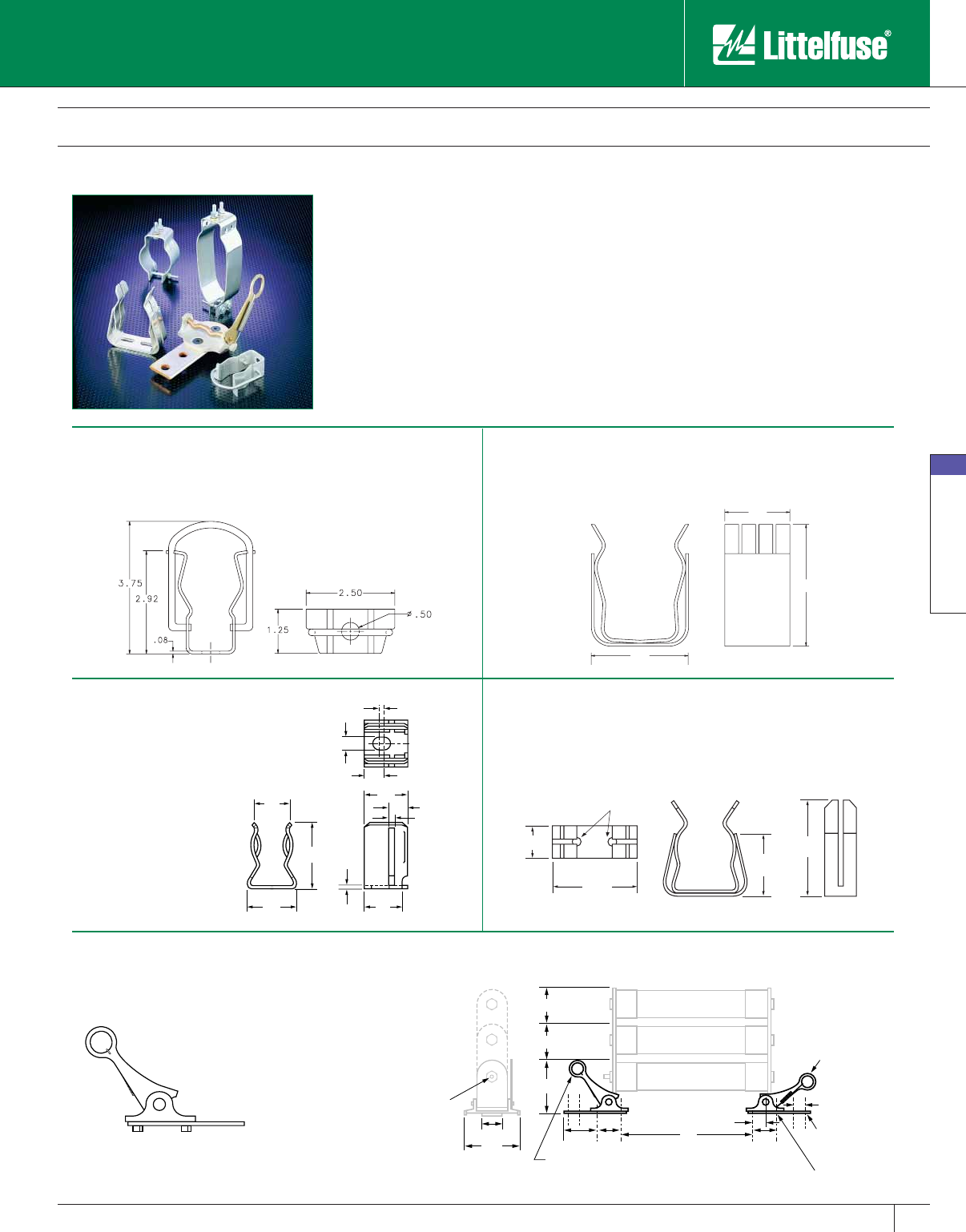
Medium Voltage Fuses
75
www.littelfuse.com
Medium Voltage Fuses
© 2005 Littelfuse • POWR-GARD™ Products Catalog
Live Parts
TRIPLE BARREL
Bottom Lever In
Closed Position
.56 Dia. (2) Holes
For Mounting
Cable/Bus
.44 DIA. (2) HOLES
DOUBLE BARREL
SINGLE BARREL
1.75
1.00
2.00
2.00
2.00
4.9
4.85
3.63
3.63
3.75
Top Lever in
Open Position
A
Blown Fuse
Indicator
TOP
VIEW
4.50
3.08
1.50
4.16
.038" HOLES
.78 .63
.08
.30
.31
.08
.71
1.15 .05
.78
Live parts are available for mounting “E”, “R”, and “PT” single, double, and triple barrel fuses.
Mounting clips are available for ferrule type and clip lock style fuses. All clips are sold in pairs.
Contact factory for additional live parts.
Part Number: 700-520-CL*
System Number: 0700520.ZXCL
Clip Lock Design (For CL-14)
Part Number: 700-530*
System Number: 0700530.Z
For use with all 3" diameter fuses.
* One Pair. Dimensions for reference only.
Part Number: 700-500*
System Number: 0700500.Z
For use with all 13 /16" (.8125”)
diameter PT fuses.
Mounting Details for Clip Lock
Part Number: 700-156*
System Number: 0700156.Z
For use with 1-9/16" to 1-5/8” (1.625”) diameter PT fuses.
Part Number: 700-300*
System Number: 0700300.Z
For use with 3" diameter fuses.
2.85
2.00
3.74
Catalog 63-75.indd 75 5/30/07 6:35:14 PM
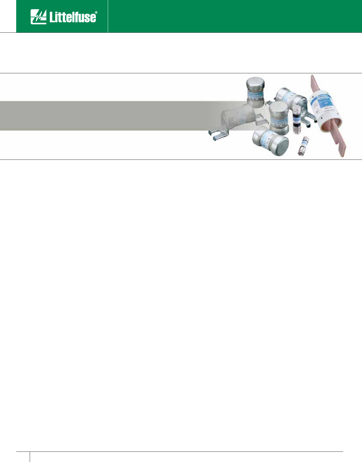
Telecom Products
www.littelfuse.com © 2005 Littelfuse • POWR-GARD™ Products Catalog
Telecom Products
L17T Series Telecommunications Power Fuse 77
TLN Series Telecommunications Power Fuse 78
TLS Series Telecommunications Power Fuse 79
Alarm Indicating Fuses 80
LTFD 101 Series Telecommunications Disconnect Switch 81
LTFD Series Telecommunications Disconnect Switch 82
Telecom Products
77
www.littelfuse.com
Telecom Products
© 2005 Littelfuse • POWR-GARD™ Products Catalog
Catalog Number Ampere Rating Competitor A
Part Number
Competitor B
Part Number
L17T 70 70 TPL-BA TGL-BA
L17T 90 90 TPL-BC TGL-BC
L17T 100 100 TPL-BD TGL-BD
L17T 125 125 TPL-BE TGL-BE
L17 T 15 0 15 0 TPL-BF TGL- BF
L17T 175 175 TPL-BG TGL-BG
L17T 200 200 TPL-BH TGL-BH
L17T 225 225 TPL-BK TGL-BK
L17T 250 250 TPL-BL TGL-BL
L17T 300 300 TPL-CN TGL-CN
L17T 350 350 TPL-CO TGL-CO
L17T 400 400 TPL-CR TGL-CR
L17T 450 450 TPL-CU TGL-CU
L17T 500 500 TPL-CV TGL-CV
L17T 600 600 TPL-CZ TGL-CZ
L17T 800 800 TPL-CZH TGL-CZH
L17T 900 900 – –
L17T 1000 1000 – –
L17T 1100 1100 – –
L17T 1200 1200 – –
L17T Series Telecommunications Power Fuse
170 VDC • Current-Limiting • 70 – 1200 Amperes
Specifically designed for short-circuit protection of telecommunications
circuits, the Littelfuse L17T series fuses provide reliable protection of
sensitive DC power distribution systems. Constructed with silver plated
elements for low I2t and peak let-through, these advanced fuses virtually
eliminate equipment damage due to surges and spikes. The L17T series
fuse unique element geometry also provides cooler running temperatures,
helping to minimize heat within enclosures.
Contact Littelfuse for characteristic curves.
A
B
C
D
F
G
E
H
Ordering Information & Cross Reference
Specifications
Voltage Rating: 170 VDC
Interrupting Rating: 100,000 amperes
Ampere Range: 70 – 1200 amperes
Approvals: UL Recognized under the Components Program
(File No: E71611)
CSA Recognized under the Component Acceptance
Program (File No: LR29862)
Recommended Fuse Blocks
LTFD 6001 and LTFD 1200 series
Refer to the LTFD series in this catalog section for additional information.
Ampere Ratings
70 100 175 250 400 600 1000
80 125 200 300 450 800 1100
90 150 225 350 500 900 1200
Example part number (series & amperage): L17T 200
Features
• Low I2t
• Extremely current-limiting
• Low operating temperature
• 170 VDC rating
Ampere
Rating
Dimensions in Inches (mm in parentheses)
ABCDEFGH
70 – 250 15⁄32
(29.4)
17⁄8
(47.6)
23⁄16
(55.6)
2 21⁄32
(67.5)
1
(25.4)
7⁄8
(22.2)
5⁄16
(7.9)
3⁄16
(4.8)
300 – 800 11⁄4
(31.8)
115 ⁄16
(49.2)
29⁄16
(65.1)
31⁄2
(88.9)
11⁄2
(38.1)
1
(25.4)
13 ⁄32
(10.3)
1⁄4
(6.35)
1000–1200 111 ⁄32
(34.0) — —
41⁄16
(103.1) —11⁄2
(38.1) —
1⁄4
(6.35)
Telecom Products
78 www.littelfuse.com
Telecom Products
© 2005 Littelfuse • POWR-GARD™ Products Catalog
TLN Series Telecommunications Power Fuse
170 VDC • Current-Limiting • 1 – 600 Amperes
The TLN Series fuses are specifically designed for the protection of
telecommunications DC power distribution circuits.
FA
FIG. 1
D
G
EC
BD
J
F
FIG. 2
A
B
C
A
H
K
Ampere Rating Dimensions in Inches (mm in parentheses)
ABCDEFGHJK
Figure 1
1 – 30 2 (50.8) 1⁄2 (12.7) 1⁄2 (12.7) 9⁄16 (14.3) 5⁄64 (2.0) 5⁄32 (4.0) 3⁄8 (9.5) — — —
35 – 60 3 (76.2) 3⁄4 (19.1) 5⁄8 (15.9) 13 ⁄16 (20.6) 3⁄32 (2.4) 3⁄16 (4.8) 5⁄8 (15.9) — — —
Figure 2
70 – 100 57⁄8 (149.2) 1 (25.4) 11⁄16 (27.0) 11⁄16 (27.0) 1⁄8 (3.2) 3⁄4 (19.1) 11⁄4 (31.6) 1⁄4 (6.4) 9⁄32 (7.1) 1⁄2 (12.7)
110 – 200 71⁄8 (181.0) 11⁄2 (38.1) 115 ⁄32 (37.3) 119 ⁄32 (40.5) 3⁄16 (4.8) 11⁄8 (28.6) 127⁄32 (46.8) 7⁄16 (11.1) 9⁄32 (7.1) 11 ⁄16 (17.5)
225 – 400 8 5⁄8 (219.1) 2 (50.8) 115 ⁄16 (49.2) 23⁄32 (53.2) 1⁄4 (6.4) 15⁄8 (41.3) 211 ⁄32 (59.5) 5⁄8 (15.9) 13⁄32 (10.3) 15 ⁄16 (23.8)
450 – 600 10 3⁄8 (263.5) 21⁄2 (63.5) 23⁄8 (60.3) 219 ⁄32 (65.9) 1⁄4 (6.4) 2 (50.8) 227⁄32 (72.2) 3⁄4 (19.1) 17⁄32 (13.5) 11⁄8 (28.6)
Specifications
Voltage Rating: 170 VDC
Interrupting Rating: 100,000 amperes
Ampere Range: 1 – 600 amperes
Approvals: UL Recognized under the components program
(File No: E71611)
Ampere Ratings
1154080150300600
3204590175350
5 25 50 100 200 400
63060110225450
10 35 70 125 250 500
Example part number (series & amperage): TLN450
Recommended Fuse Blocks
LR250 Series
Refer to the Blocks & Holders section of this catalog for additional information.
Features
• 170 VDC
• Fast acting and current-limiting
• 1 to 600 amperes
• Dimensionally similar to 250V Class R fuses
Replaces competitors’ TPN and TGN Series.
Telecom Products
79
www.littelfuse.com
Telecom Products
© 2005 Littelfuse • POWR-GARD™ Products Catalog
TLS Series Telecommunications Power Fuse
170 VDC • Current-Limiting • 1 – 125 Amperes
Littelfuse TLS Series fuses are designed specifically for the protection
of telecommunications equipment. TLS fuses have been engineered to
operate up to 170 VDC to provide current-limiting short-circuit protection
for cables and components found in the DC power distribution circuits
of telecommunications systems. The compact design and multiple
mounting configurations of the TLS series allow it to be used in a variety
of applications.
Features
• 170 VDC
• Current-limiting
• 1 to 125 amperes
• Multiple mounting configurations
• RoHS Compliant
TLS-V TLS-L TLS-LB
TLS
Specifications
Voltage Rating: 170 VDC
Interrupting Rating: 100,000 amperes
Ampere Range: 1 – 125 amperes
Approvals: UL Recognized under the components program
(File No: E71611)
Construction: Caps: Silver-plated brass
Body: Glass melamine
Ampere Ratings
16255090
2103060100
3153570110
5204080125
Example part number (series & amperage): TLS050
Note: To order leaded versions of TLS fuses, add suffix V, L, LB, or LS to part
number.
Recommended Fuse Blocks
LTFD series disconnect switches
LT30060 for TLS series cartridge style fuse
Contact factory for more information.
Contact Littelfuse for characteristic curves. Dimensions for refer-
ence only. Replaces competitors’ TPS and TGS Series.
TLS-LS
Vertical Mount Leaded Bolt-In SolderCartridge
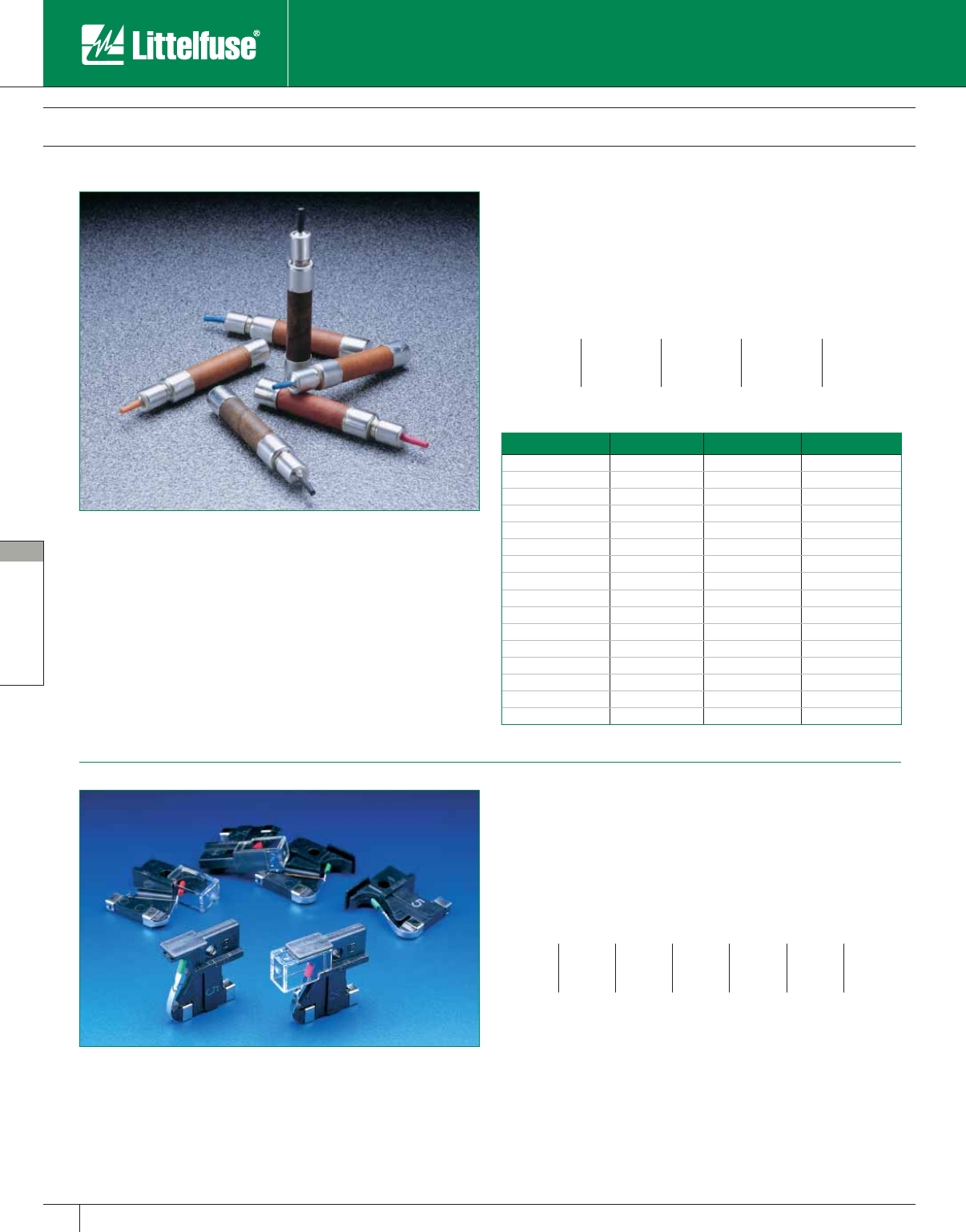
Telecom Products
80 www.littelfuse.com
Telecom Products
© 2005 Littelfuse • POWR-GARD™ Products Catalog
Telecommunications Power Fuses
Alarm Indicating Fuses
Specifications
Voltage Rating: 125 VAC, 300 VDC
Interrupting Rating: 1,000 amperes @ 125 VAC
1,000 amperes @ 300 VDC
Ampere Ratings
100mA 200mA 500mA 2 5
150mA 250mA 750mA 3 8
180mA 350mA 1.33 3.5 10
Ordering Information
10 Minute Rating Catalog Number System Number Color Code
100mA 70P 70P00000Z Grey/White
150mA 70R 70R00000Z Red/White
180mA 70E 70E00000Z Yellow
200mA 70X 70X00000Z Black
250mA 70F 70F00000Z Violet
250mA 70K 70K00000Z Violet/White
350mA 70S 70S00000Z Gray
500mA 70G 70G00000Z Red
750mA 70H 70H00000Z Brown
1.33A 70A 70A00000Z White
2A 70B 70B00000Z Orange
3A 70C 70C00000Z Blue
3.5A 70J 70J00000Z Black/White
5A 70D 70D00000Z Green/Black
8A 70M 70M00000Z Tan/White
10A 70N 70N00000Z Yellow/Purple
70 Series Alarm Indicating Fuses
The 70 Series alarm indicating fuses are designed for use in
telecommunications equipment. A color coded tip provides visual
identification of the ampere rating and the fuse status.
Features
• Color coded tip
• Rated 125 VAC, 300 VDC
481 Series Alarm Indicating Fuses
For telecommunications equipment and similar applications. Color coded
indicator flags indicate ampere rating. Body is constructed of black
polyphenylene sulfide with UL 94V0 flammability rating, contacts are of
bright alloy-plated beryllium copper. Available with or without protective lens.
Specifications
Voltage Rating: 125V AC, DC
Approvals: UL Recognized under the Components Program and
CSA Recognized under the Component Acceptance
Program.
Ampere Ratings
18 ⁄100 3⁄83⁄411⁄23512
1⁄51⁄2123
1⁄271⁄215
1⁄465⁄100 11⁄321⁄241020
Example part number (series & amperage): 481005
Recommended Fuse Blocks
482 Series
Available 1-20 pole with PCB or panel mounting
To order with protective lens add suffix XL
NOTE: For 481 Dummy fuse order 481000.
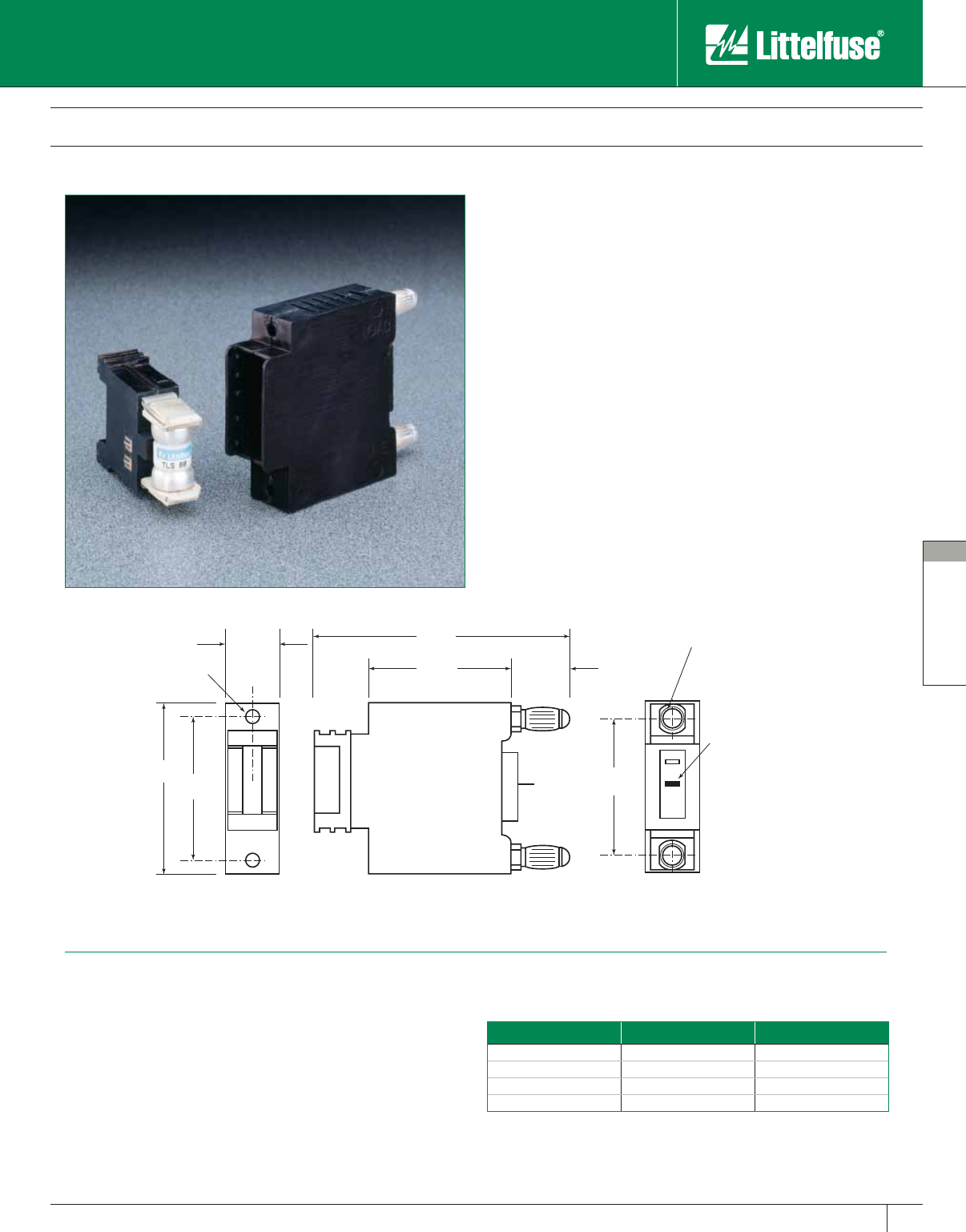
Telecom Products
81
www.littelfuse.com
Telecom Products
© 2005 Littelfuse • POWR-GARD™ Products Catalog
LTFD 101 Series Telecommunications Disconnect Switch
80 VDC • 1 – 125 Amperes
Specifications
Voltage Rating: 80 VDC
Ampere Range: 1 – 125 A
Approvals: UL Recognized (File No. E122874)
Recommended Fuses
Littelfuse TLS Series fuses
Littelfuse 481 Series Alarm fuses
Ordering Information
Catalog Number System Number Terminal Type
LTFD101-1 LTFD0101ZX1 Bullet
LTFD101-2 LTFD0101ZX2 Screw
LTFD101-3 LTFD0101ZX3 Stud
LTFD101-4 LTFD0101ZX4 Clip
Littelfuse compact LTFD 101 fuseholders for TLS fuses are designed for
quick installation into telecom equipment panels. Their modular design
fits into spaces originally designed for circuit breakers and they can
be front panel mounted or rear mounted using bullet connectors. The
innovative new pull-out design eliminates the need for tools to replace
fuses and includes an alarm signaling circuit to identify the blown fuse.
Features
• Extremely compact
• Quick mounting
• Replaces circuit breakers
• Includes alarm signaling circuit
Dimensions for reference only. For additional options and dimensions, contact the factory.
6-32 INSERT
0.75"
2.50"
2.062" 1.940"
2.00" 0.85"
LOAD
LINE
3.75" 0.305" Dia.
Bullet Terminal
Alarm pin
0.02" x 0.11"
position optional
C
L
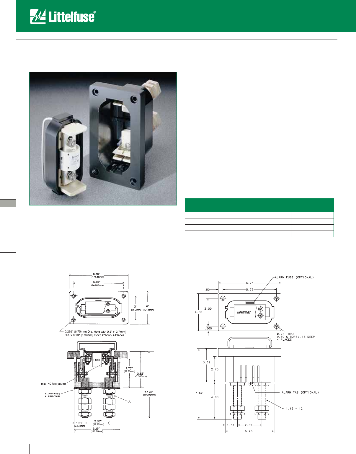
Telecom Products
82 www.littelfuse.com
Telecom Products
© 2005 Littelfuse • POWR-GARD™ Products Catalog
LTFD Series Telecommunications Disconnect Switch
145 VDC, 60 VDC • 70 – 1200 Amperes
Features
• Innovative pullout design of the 1200A switch eliminates the need for
tools to replace the fuse
• Thermoplastic housing material
• Alarm signaling circuit
Specifications
Voltage Rating: 145 VDC for 70 – 600 amperes
60 VDC for 800 – 1200 amperes
Ampere Range: 70 – 1200 amperes
Approvals: UL Recognized (E122674)
Recommended fuses
L17T Series fuses
Ordering Information
LTFD 6001 Series
(70–800 Amperes)
Catalog Number Stud Size (A) Amperes Contact Nut Max.
Torque
LTFD6001-00 3⁄4 – 16 x 3.5 in. 70 – 600 100 feet-pound
LTFD6001-01 7⁄8 – 14 x 3.5 in. 70 – 800 120 feet-pound
LTFD1200-01 1.12 – 12 x 4 in 900 – 1200 120 feet-pound
LTFD1200-01A 1.12 – 12 x 4 in 900 – 1200 120 feet-pound
LTFD 1200A
(900–1200 Amperes)
Littelfuse compact LTFD Series holders are designed for use as a
combination fuseholder and disconnect switch for telecommunications
equipment. The rugged unit utilizes a pull-out fuse carrier to safely
disconnect power and provide easy fuse replacement.
www.littelfuse.com
© 2005 Littelfuse • POWR-GARD™ Products Catalog
Special Purpose Fuses
Semiconductor Fuses 84
Traditional Semiconductor Fuses 85-87
LA15QS Semiconductor Fuses 88-89
LA30QS Semiconductor Fuses 90-91
LA50QS Semiconductor Fuses 92-93
LA60Q Semiconductor Fuses 94
LA60X Semiconductor Fuses 95
LA70QS Semiconductor Fuses 96-97
LA70QS French Cylindrical Fuses 98
LA100P Semiconductor Fuses 99-100
LA120X Semiconductor Fuses 101
Square Body Semiconductor Fuses 102-106
Fork-Lift and Stud-Mounted Fuses 107
Cable Limiters 108
LGR/LMF In-Line Fuses 109
LHR Holder 109
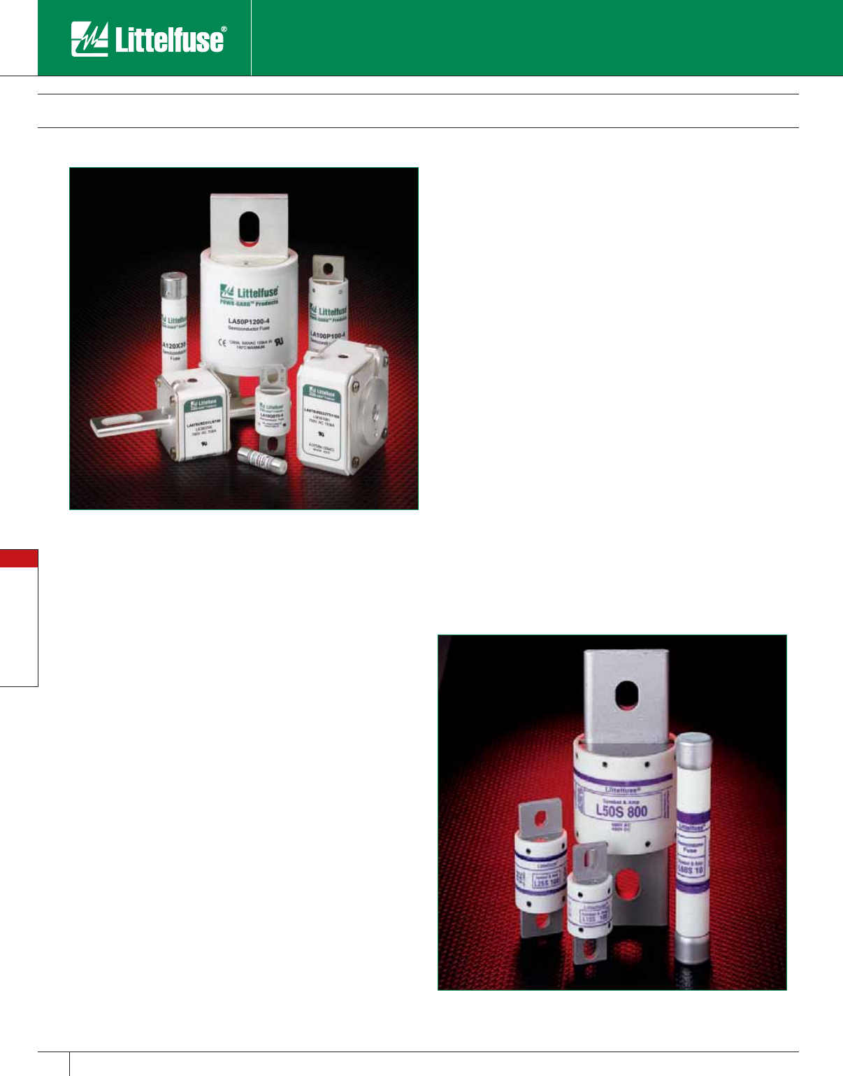
Special Purpose Fuses
84 www.littelfuse.com
Special Purpose Fuses
© 2005 Littelfuse • POWR-GARD™ Products Catalog
Semiconductor Fuses
150 – 1300 VAC • Very Fast Acting • 1 – 6000 Amperes
Semiconductor Fuses
Littelfuse Semiconductor fuses are very fast acting fuses designed
specifically for the protection of diodes, thyristors, triacs, and other
solid-state power semiconductor devices. These fuses are used in
power electronic applications including variable speed drives, power
rectifiers, UPS systems, and DC power supplies. They can be used
wherever extremely fast acting, current-limiting fuses are needed to
provide superior protection against the potentially damaging effects of
short-circuit currents.
The extensive line of Littelfuse Semiconductor fuses includes the
traditional round body fuses, enhanced state-of-the-art round body
fuses, and North American style square body fuses. Available ratings
range from 150 to 1300 volts and up to 6000 amps.
Applications
Semiconductor fuses are designed specifically for supplementary
protection of semiconducting devices such as silicon controlled rectifiers
(SCR’s), diodes, thyristors, triacs, transistors, and similar solid-state
devices. These devices are used in power equipment including variable
speed drives, power rectifiers, UPS systems, DC power supplies, and in
a wide range of electronic equipment.
May be used wherever extremely fast acting, current-limiting fuses with
no time-delay are required.Features & Benefits
• Extremely current-limiting
• Low I2t and peak let-through currents
• Low watts loss
• High Interrupting ratings
• UL Recognized
• Wide range of ampere ratings
• Optional mounting types
• DC ratings
• Superior cycling abilities
• Compact sizes
• Optional blown fuse indicators
Ratings
150V: 1 – 6000A
250V: 1 – 4500A
300V: 35 – 4500A
500V: 10 – 1200A
600V: 1 – 2000A
700V: 6 – 2500A
1000V: 15 – 1000A
1200V: 1 – 30A
1300V: 50 – 1800A
Recommended Fuse Blocks:
LSCR and 1LS series: Refer to the Blocks & Holders section of this catalog
for additional information.
Special Purpose Fuses
85
www.littelfuse.com
Special Purpose Fuses
© 2005 Littelfuse • POWR-GARD™ Products Catalog
Traditional Semiconductor Fuses
150/250/500/600/700 VAC • Very Fast Acting • 1 – 1200 Amperes
Ampere
Ratings
Series & Voltage
L15S
150V AC
150V DC (1 – 60A)
100V DC (70 – 1000A)
L25S
250V AC
250V DC (1 – 200A)
200V DC (225 – 800A)
L50S
500V AC
450V DC
L60S
600V AC
KLC‡
600V AC
L70S
700V AC
650V DC
1 L15S 1 L25S 1 – L60S 1 KLC 1 –
2 L15S 2 L25S 2 – L60S 2 KLC 2 –
3 L15S 3 L25S 3 – L60S 3 KLC 3 –
4 L15S 4 L25S 4 – L60S 4 KLC 4 –
5 L15S 5 L25S 5 – L60S 5 KLC 5 –
6 L15S 6 L25S 6 – L60S 6 KLC 6 –
7L15S 7 – – – KLC 7 –
8 L15S 8 L25S 8 – L60S 8 KLC 8 –
9L15S 9 – – – – –
10 L15S 10 L25S 10 L50S 10 L60S 10 KLC 10 L70S 10
12 L15S 12 L25S 12 L50S 12 L60S 12 KLC 12 –
15 L15S 15 L25S 15 L50S 15 L60S 15 KLC 15 L70S 15
171⁄2–––L60S 17
1⁄2KLC 171⁄2–
20 L15S 20 L25S 20 L50S 20 L60S 20 KLC 20 L70S 20
25 L15S 25 L25S 25 L50S 25 L60S 25 KLC 25 L70S 25
30 L15S 30 L25S 30 L50S 30 L60S 30 KLC 30 L70S 30
35 L15S 35 L25S 35 L50S 35 L60S 35 KLC 35 L70S 35
40 L15S 40 L25S 40 L50S 40 L60S 40 KLC 40 L70S 40
45 L15S 45 L25S 45 – L60S 45 KLC 45 –
50 L15S 50 L25S 50 L50S 50 L60S 50 KLC 50 L70S 50
60 L15S 60 L25S 60 L50S 60 L60S 60 KLC 60 L70S 60
70 L15S 70 L25S 70 L50S 70 L60S 70 KLC 70 L70S 70
80 L15S 80 L25S 80 L50S 80 L60S 80 KLC 80 L70S 80
90 L15S 90 L25S 90 L50S 90 L60S 90 KLC 90 L70S 90
100 L15S 100 L25S 100 L50S 100 L60S 100 KLC 100 L70S 100
110 – – – – KLC 110 –
125 L15S 125 L25S 125 L50S 125 L60S 125 KLC 125 L70S 125
150 L15S 150 L25S 150 L50S 150 L60S 150 KLC 150 L70S 150
175 – L25S 175 L50S 175 L60S 175 KLC 175 L70S 175
200 L15S 200 L25S 200 L50S 200 L60S 200 KLC 200 L70S 200
225 – L25S 225 L50S 225 L60S 225 KLC 225 L70S 225
250 L15S 250 L25S 250 L50S 250 L60S 250 KLC 250 L70S 250
275 – L25S 275 L50S 275 – – –
300 L15S 300 L25S 300 L50S 300 L60S 300 KLC 300 L70S 300
350 L15S 350 L25S 350 L50S 350 L60S 350 KLC 350 L70S 350
400 L15S 400 L25S 400 L50S 400 L60S 400 KLC 400 L70S 400
450 L15S 450 L25S 450 L50S 450 L60S 450 KLC 450 L70S 450
500 L15S 500 L25S 500 L50S 500 L60S 500 KLC 500 L70S 500
550 – – L50S 550 – – –
600 L15S 600 L25S 600 L50S 600 L60S 600 KLC 600 L70S 600
700 – L25S 700 L50S 700 L60S 700 KLC 700 L70S 700
800 L15S 800 L25S 800 L50S 800 L60S 800 KLC 800 L70S 800
900 – – LA50P9004 – – LA70P9004
1000 L15S 1000 – LA50P10004 – – LA70P10004
1200 – – LA50P12004 – – LA70P12004
‡ KLC series fuses are recommended for replacement use only.
Specifications
Voltage Ratings:
L15S: 150 V AC/DC (1 – 60A)
150 VAC (70 – 1000A)
100 VDC (70 – 1000A)
L25S: 250 V AC/DC (1 – 200A)
250 VAC (225 – 800A)
200 VDC (225 – 800A)
L50S: 500 VAC/450 VDC
L60S: 600 VAC
KLC: 600 VAC
L70S: 700VAC/650VDC
Interrupting Rating:
AC: 200,000 rms amperes
(L15S series 100,000A)
DC: 20,000 amperes
Ampere Range:
1 – 1200 amperes
See Rating Table for ratings available in each
series.
Approvals:
UL Recognized under the Components
Program and CSA Recognized under the
Component Acceptance Program.
UL File No: E71611
CSA File No: LR29862
L25S series fuses are Littelfuse Certified for
DC ratings shown in Rating Table.
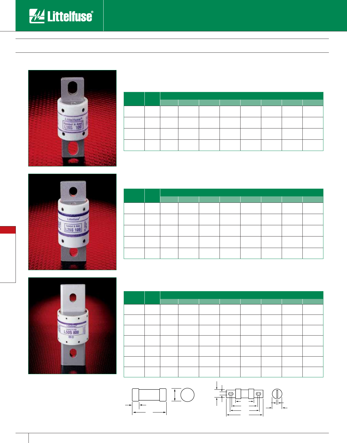
Special Purpose Fuses
86 www.littelfuse.com
Special Purpose Fuses
© 2005 Littelfuse • POWR-GARD™ Products Catalog
Traditional Semiconductor Fuses
150/250/500/600/700 VAC • Very Fast Acting • 1 – 1000 Amperes
L15S SERIES, 150 VOLTS AC
(Replaces KLA, KLW, L13S)
Ampere
Rating
Fig.
No.
Dimensions in Inches (mm in parentheses)
ABCDE FGH
1 – 30 1 11⁄2
(38.1) —
3⁄8
(9.5)
13 ⁄32
(10.3) ————
31 – 60 1 2
(50.8) —
5⁄8
(15.9)
13 ⁄16
(20.6) ————
61 – 450 3 15⁄32
(29.4)
17⁄8
(47.6)
23⁄16
(55.6)
221⁄32
(67.5)
1
(25.4)
43⁄64
(17.1)
5⁄16
(7.9)
3⁄16
(4.8)
451 – 1000 3 11⁄4
(31.8)
115 ⁄16
(49.2)
29⁄16
(65.1)
31⁄2
(88.9)
11⁄2
(38.1)
1
(25.4)
13 ⁄32
(10.3)
1⁄4
(6.4)
E
H
F
GA
B
C
D
Fig, 2
A
C
D
Fig. 1
Contact Littelfuse for characteristic curves.
L25S SERIES, 250 VOLTS AC
(Replaces KLB)
Ampere
Rating
Fig.
No.
Dimensions in Inches (mm in parentheses)
ABCDE FGH
1 – 30 1 2
(50.8) —
1⁄2
(12.7)
9⁄16
(14.3) ————
31 – 60 2 15⁄8
(41.3)
21⁄4
(57.2)
21⁄2
(63.5)
33⁄16
(81.0)
13⁄16
(20.6)
23⁄32
(18.3)
11⁄32
(8.7)
1⁄8
(3.2)
61 – 200 3 15⁄8
(41.3)
25⁄16
(58.7)
27⁄16
(61.9)
31⁄8
(79.4)
17⁄32
(31.0)
1
(25.4)
5⁄16
(7.9)
3⁄16
(4.8)
201 – 700 3 119 ⁄32
(40.5)
29⁄32
(57.9)
229⁄32
(73.8)
327⁄32
(97.6)
11⁄2
(38.1)
1
(25.4)
13⁄32
(10.3)
1⁄4
(6.4)
701 – 800 3 119 ⁄32
(40.5)
29⁄32
(57.9)
229⁄32
(73.8)
327⁄32
(97.6)
2
(50.8)
11⁄2
(38.1)
13⁄32
(10.3)
1⁄4
(6.4)
L50S SERIES, 500 VOLTS AC / 450 VOLTS DC
(Replaces KLH)
Ampere
Rating
Fig.
No.
Dimensions in Inches (mm in parentheses)
ABCDE FGH
10 – 30 1 2
(50.8) —
1⁄2
(12.7)
9⁄16
(14.3) ————
31 – 60 2 15⁄8
(41.3)
21⁄4
(57.2)
21⁄2
(63.5)
33⁄16
(81.0)
13⁄16
(20.6)
23⁄32
(18.3)
11⁄32
(8.7)
1⁄8
(3.2)
61 – 100 3 21⁄8
(54.0)
211⁄16
(68.3)
3
(76.2)
35⁄8
(92.1)
1
(25.4)
3⁄4
(19.1)
11⁄32
(8.7)
1⁄8
(3.2)
101 – 200 3 21⁄8
(54.0)
213⁄16
(71.4)
215 ⁄16
(74.6)
35⁄8
(92.1)
17⁄32
(31.0)
1
(25.4)
5⁄16
(7.9)
3⁄16
(4.8)
201 – 400 3 23⁄32
(53.2)
225⁄32
(70.6)
313⁄32
(86.5)
411⁄32
(110.3)
11⁄2
(38.1)
1
(25.4)
13⁄32
(10.3)
1⁄4
(6.4)
401 – 600 3 27⁄32
(56.4)
229⁄32
(73.8)
317⁄32
(89.7)
415 ⁄32
(113.5)
2
(50.8)
11⁄2
(38.1)
13⁄32
(10.3)
1⁄4
(6.4)
601 – 800 3 27⁄32
(56.4)
49⁄32
(108.7)
45⁄8
(117.5)
615 ⁄32
(164.3)
21⁄2
(63.5)
2
(50.8)
17⁄32
(13.5)
3⁄8
(9.5)
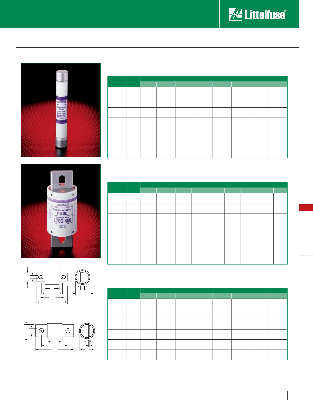
Special Purpose Fuses
87
www.littelfuse.com
Special Purpose Fuses
© 2005 Littelfuse • POWR-GARD™ Products Catalog
F
GA
B
CE
J
H
Fig. 4
Traditional Semiconductor Fuses
150/250/500/600/700 VAC • Very Fast Acting • 1 – 1000 Amperes
L70S SERIES, 700 VOLTS AC / 650 VOLTS DC
Ampere
Rating
Fig.
No.
Dimensions in Inches (mm in parentheses)
ABCDEFGHJ
10 – 30 1 2
(50.8) —
1⁄2
(12.7)
9⁄16
(14.3) —————
31 – 60 3 27⁄8
(73.0)
37⁄16
(87.3)
325⁄32
(96.0)
43⁄8
(111.1)
1
(25.4)
43⁄64
(17.1)
11 ⁄32
(8.7)
1⁄8
(3.2) —
61 – 100 3 27⁄8
(73.0)
39⁄16
(90.5)
311⁄16
(93.7)
43⁄8
(111.1)
17⁄32
(31.0)
29⁄32
(22.9)
5⁄16
(7.9)
3⁄16
(4.8) —
101 – 200 3 227⁄32
(72.2)
317⁄32
(89.7)
45⁄32
(105.6)
53⁄32
(129.4)
11⁄2
(38.1)
1
(25.4)
13 ⁄32
(10.3)
1⁄4
(6.4) —
201 – 400 3 227⁄32
(72.2)
317⁄32
(89.7)
45⁄32
(105.6)
53⁄32
(129.4)
2
(50.8)
11⁄2
(38.1)
13 ⁄32
(10.3)
1⁄4
(6.4) —
401 – 600 3 227⁄32
(72.2)
429⁄32
(124.6)
51⁄4
(133.4)
73⁄32
(180.2)
21⁄2
(63.5)
2
(50.8)
17⁄32
(13.5)
3⁄8
(9.5) —
601 – 800 4 35⁄16
(84.1)
55⁄16
(134.9)
613⁄16
(173.0) —27⁄8
(73.0)
2
(50.8)
5⁄8
(15.9)
3⁄8
(9.5)
5⁄16
(7.9)
KLC SERIES, 600 VOLTS AC
Ampere
Rating
Fig.
No.
Dimensions in Inches (mm in parentheses)
ABCDE FGH
1 – 30 2 17⁄8
(47.6)
21⁄2
(63.5) —27⁄8
(73.0)
9⁄16
(14.3)
13 ⁄32
(10.3)
1⁄4
(6.4)
3⁄64
(1.2)
31 – 60 2 23⁄4
(69.9)
33⁄8
(85.7)
35⁄8
(92.1)
45⁄16
(109.5)
13⁄16
(20.6)
23⁄32
(18.3)
11 ⁄32
(8.7)
1⁄8
(3.2)
61 – 100 3 27⁄8
(73.0)
321⁄32
(92.9)
41⁄16
(103.2)
5
(127.0)
1
(25.4)
3⁄4
(19.1)
13 ⁄32
(10.3)
1⁄8
(3.2)
101 – 200 3 227⁄32
(72.2)
317⁄32
(89.7)
43⁄8
(111.1)
53⁄32
(129.4)
11⁄2
(38.1)
1
(25.4)
13 ⁄32
(10.3)
1⁄4
(6.4)
201 – 400 3 227⁄32
(72.2)
421⁄32
(118.3)
427⁄32
(123.0)
61⁄4
(158.8)
2
(50.8)
15⁄8
(41.3)
9⁄16
(14.3)
1⁄4
(6.4)
401 – 800 3 227⁄32
(72.2)
421⁄32
(118.3)
511 ⁄32
(135.7)
61⁄4
(158.8)
21⁄2
(63.5)
2
(50.8)
9⁄16
(14.3)
3⁄8
(9.5)
L60S SERIES, 600 VOLTS AC
Ampere
Rating
Fig.
No.
Dimensions in Inches (mm in parentheses)
ABCDE FGH
1 – 30 1 5
(127.0) —
5⁄8
(15.9)
13⁄16
(20.6) ————
31 – 60 2 225⁄32
(70.6)
37⁄16
(87.3)
311⁄16
(93.7)
43⁄8
(111.1)
13⁄16
(20.6)
23⁄32
(18.3)
11⁄32
(8.7)
1⁄8
(3.2)
61 – 100 2 229⁄32
(73.8)
317⁄32
(89.7)
325⁄32
(96.0)
415 ⁄32
(113.5)
11⁄16
(27.0)
23⁄32
(18.3)
11⁄32
(8.7)
1⁄8
(3.2)
101 – 200 2 229⁄32
(73.8)
39⁄16
(90.5)
33⁄4
(95.3)
413⁄32
(111.9)
15⁄16
(33.3)
1
(25.4)
5⁄16
(7.9)
3⁄16
(4.8)
201 – 400 2 229⁄32
(73.8)
331⁄32
(100.8)
45⁄32
(105.6)
51⁄8
(130.2)
137⁄64
(40.1)
1
(25.4)
13⁄32
(10.3)
1⁄4
(6.4)
401 – 600 2 27⁄8
(73.0)
331⁄32
(100.8)
49⁄64
(105.2)
51⁄8
(130.2)
21⁄16
(52.8)
11⁄2
(38.1)
13⁄32
(10.3)
1⁄4
(6.4)
601 – 800 2 31⁄32
(77.0)
55⁄32
(133.4)
511⁄32
(135.7)
71⁄4
(184.2)
21⁄2
(63.5)
2
(50.8)
17⁄32
(13.5)
3⁄8
(9.5
A
B
C
D
F
G
E
H
Fig. 3
Contact Littelfuse for characteristic curves.
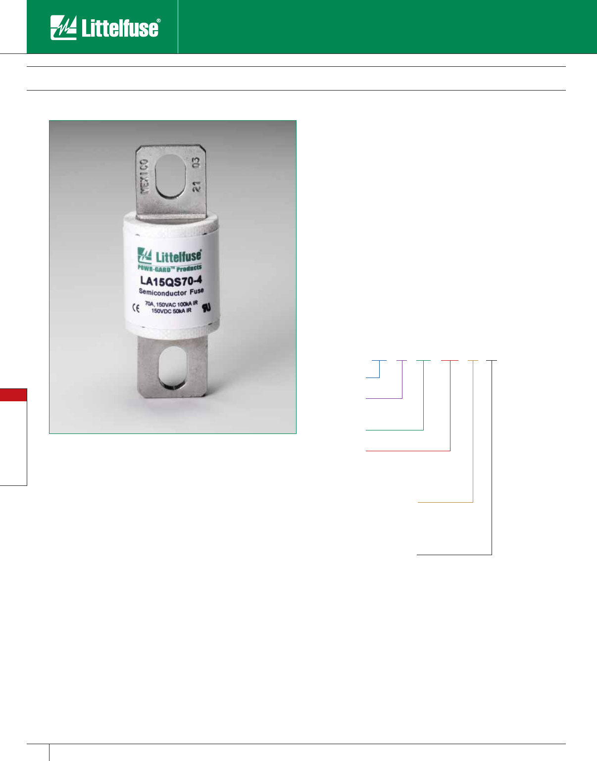
Special Purpose Fuses
88 www.littelfuse.com
Special Purpose Fuses
© 2005 Littelfuse • POWR-GARD™ Products Catalog
LA15QS Semiconductor Fuses
150 VAC • Very Fast Acting • 1 – 6000 Amperes
Specifications
Voltage Rating: AC: 150 volts
DC: 150 volts
Interrupting Rating: 100,000 Amperes
Ampere Range: 1 – 6000 Amperes
Approvals: UL Recognized under the components program.
LA 15 QS 400 -4 TI
Style
Littelfuse
Ampere Rating
Mounting Type
Voltage
(150)
Integral Blown-
Fuse Indicator
Ferrule 1
Ferrule, midget dim. 2
Blades/Bolt-in 4
Hockey Puck, bolt-in 128
Trigger Indicator TI
Trigger Actuator IL
Contact Littelfuse for characteristic curves.
Note: Mounting types and integral blown fuse indicators are optional for
specified ratings.
Littelfuse LA15QS series Semiconductor fuses were designed for the
specific protection of diodes and other semiconductor devices rated
150VAC/DC. The LA15QS product line compact design is perfect for
those applications that have limitations on available space.
Features
• Low I2t minimizes damage to protected components on short-circuit.
• Controlled arc voltage reduces stress to circuit components during
fuse clearing.
• Choice of mounting types provides options for unique termination
requirements.
• Indicator options allow identification of blown fuses.
Applications
Protection of heavy duty devices such as electromechanical rectifiers.
Ordering Information
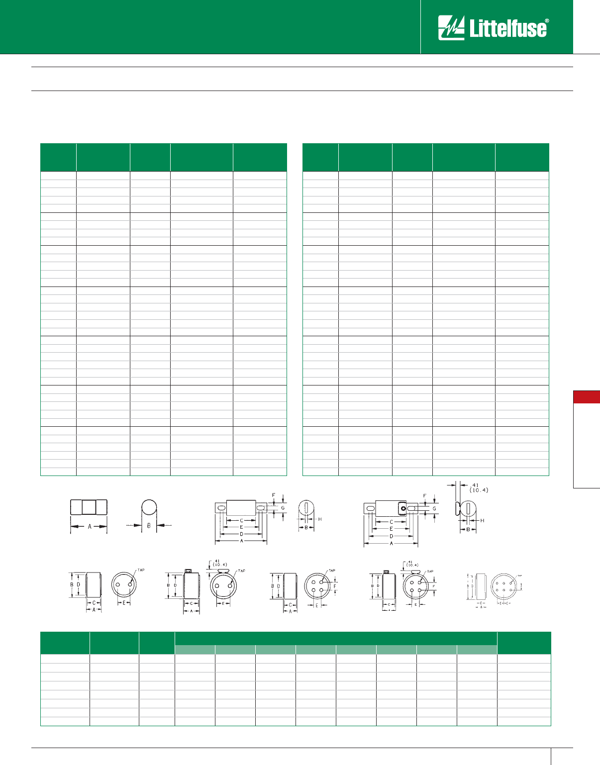
Special Purpose Fuses
89
www.littelfuse.com
Special Purpose Fuses
© 2005 Littelfuse • POWR-GARD™ Products Catalog
Ampere
Rating
Littelfuse
Catalog Number
Mounting
Type
Maximum
Clearing I2t @150
VAC (A2S x 103)
Watts Loss @
Rated Current
(W)
1 LA15QS1-2 2 0.0002 0.68
2 LA15QS2-2 2 0.001 1.3
3 LA15QS3-2 2 0.003 1.7
4 LA15QS4-2 2 0.007 2.1
5 LA15QS5-2 2 0.012 2.8
6 LA15QS6-2 2 0.022 3.1
7 LA15QS7-2 2 0.011 2.2
8 LA15QS8-2 2 0.015 2.5
10 LA15QS10-2 2 0.019 2.6
12 LA15QS12-2 2 0.030 3
15 LA15QS15-2 2 0.042 3
20 LA15QS20-2 2 0.072 4
25 LA15QS25-2 2 0.14 5.2
30 LA15QS30-2 2 0.25 5.6
35 LA15QS35-1 1 0.21 9
40 LA15QS40-1 1 0.28 10
40 LA15QS40-4TI 4TI 0.39 3.1
45 LA15QS45-1 1 0.34 12
50 LA15QS50-1 1 0.47 13
50 LA15QS50-4 4 0.64 4
55 LA15QS55-1 1 Contact Factory Contact Factory
60 LA15QS60-1 1 0.94 14
70 LA15QS70-4 4 2 5.6
70 LA15QS70-4TI 4TI 2 5.6
80 LA15QS80-4 4 2.5 8
80 LA15QS80-4TI 4TI 2.5 8
90 LA15QS90-4 4 3.1 9
100 LA15QS100-4 4 3.6 10
100 LA15QS100-4TI 4TI 3.6 10
130 LA15QS130-4 4 5.3 14
130 LA15QS130-4TI 4TI 5.3 14
150 LA15QS150-4 4 6.8 16
150 LA15QS150-4IL 4IL 6.8 16
150 LA15QS150-4TI 4TI 6.8 16
200 LA15QS200-4 4 9 22
200 LA15QS200-4IL 4IL 9 22
250 LA15QS250-4 4 15 22
LA15QS Semiconductor Fuses
150 VAC • Very Fast Acting • 1 – 6000 Amperes
Catalog Numbers & Technical Data
Ampere
Rating
Littelfuse
Catalog Number
Mounting
Type
Maximum
Clearing I2t @150
VAC (A2S x 103)
Watts Loss @
Rated Current
(W)
250 LA15QS250-4TI 4TI 15 27
300 LA15QS300-4 4 22 33
300 LA15QS300-4IL 4IL 22 33
300 LA15QS300-4TL 4TI 22 33
350 LA15QS350-4 4 32 40
350 LA15QS350-4TI 4TI 32 40
400 LA15QS400-4 4 40 45
400 LA15QS400-4IL 4IL 40 45
400 LA15QS400-4TI 4TI 40 45
450 LA15QS450-4 4 50 50
450 LA15QS450-4IL 4IL 50 50
500 LA15QS500-4 4 90 30
500 LA15QS500-4IL 4IL 90 30
600 LA15QS600-4 4 130 35
600 LA15QS600-4IL 4IL 130 35
800 LA15QS800-4 4 290 57
1000 LA15QS1000-4 4 520 75
1000 LA15QS1000-4IL 4IL 520 75
1000 LA15QS1000-4TI 4TI 520 75
1000 LA15QS1000-128 128 540 88
1000 LA15QS1000-128IL 128IL 540 88
1200 LA15QS1200-128 128 680 100
1200 LA15QS1200-128IL 128IL 680 100
1500 LA15QS1500-128 128 1200 130
1500 LA15QS1500-128IL 128IL 1200 130
2000 LA15QS2000-128 128 1900 165
2000 LA15QS2000-128IL 128IL 1900 165
2500 LA15QS2500-128 128 3200 195
2500 LA15QS2500-128IL 128IL 3200 195
3000 LA15QS3000-128 128 4800 240
3000 LA15QS3000-128IL 128IL 4800 240
3500 LA15QS3500-128 128 6500 260
4000 LA15QS4000-128 128 8500 270
4000 LA15QS4000-128IL 128IL 8500 270
5000 LA15QS5000-128 128 Contact Factory Contact Factory
6000 LA15QS6000-128 128 Contact Factory Contact Factory
Dimensions Dimensions for reference only.
Amperes Mount.
Type
Fig.
No.
Dimensions in Inches (mm in parentheses) Tap
ABCDEFGH
1 – 30 2 11.50 (38.1)0.41 (10.4)–––––– –
35 – 60 1 12.00 (50.8)0.81 (20.6)–––––– –
70 – 450 4, 4TI*, 4IL* 2, 3* 2.66 (67.6) 1.13 (28.7) 1.16 (29.5) 2.19 (55.6) 1.91 (48.5) 0.31 (7.9) 0.88 (22.4) 0.19 (4.8) –
500 – 1000 4, 4TI*, 4IL* 2, 3* 3.50 (88.9) 1.50 (38.1) 1.25 (31.8) 2.56 (65.0) 1.94 (49.3) 0.41 (10.4) 1.00 (25.4) 0.25 (6.4) –
750 – 2000 128, 128IL* 4, 5* 1.88 (47.9) 2.00 (50.8) 1.63 (41.4) 1.75 (44.5) 1.00 (25.4) – – – 3⁄8-24-1⁄2 deep
2500 – 3000 128, 128IL* 4, 5* 1.88 (47.9) 3.00 (76.2) 1.63 (41.4) 2.50 (63.5) 1.50 (38.1) – – – 1⁄2-20-1⁄2 deep
3500 – 4000 128, 128IL* 6, 7* 1.88 (47.9) 3.50 (88.9) 1.63 (41.4) 3.00 (76.2) 1.06 (27.0) 1.06 (27.0) – – 1⁄2-20-1⁄2 deep
5000 – 6000 128 8 2.38 (60.5) 5.75 (146) 1.88 (47.7) 5.00 (127) 1.50 (38.1) 1.50 (38.1) – – 1⁄2-20-1⁄2 deep
* Optional Trigger Actuator (IL)
Figure 1 Figure 2 Figure 3
Figure 4 Figure 5 Figure 6 Figure 7 Figure 8
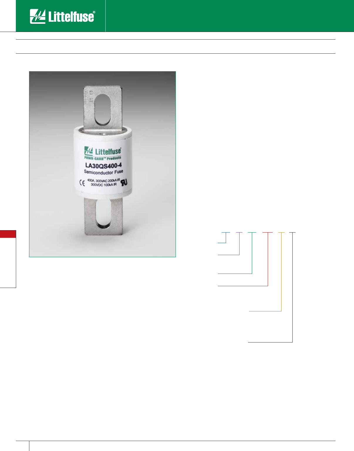
Special Purpose Fuses
90 www.littelfuse.com
Special Purpose Fuses
© 2005 Littelfuse • POWR-GARD™ Products Catalog
LA 30 QS 600 -4 TI
Style
Littelfuse
Ampere Rating
Mounting Type
Voltage
(300)
Integral Blown-
Fuse Indicator
Ferrule 1
Blades/Bolt-in 4
Hockey Puck, bolt-in 128
Trigger Indicator TI
Trigger Actuator IL
LA30QS Semiconductor Fuses
300 VAC • Very Fast Acting • 35 – 4500 Amperes
Specifications
Voltage Rating: AC: 300 volts
DC: 300 volts
Interrupting Rating: 200,000 Amperes
Ampere Range: 35 – 4500 Amperes
Approvals: UL Recognized under the components program.
Littelfuse LA30QS series Semiconductor protection fuses are intended
for the protection of Power Semiconductors such as diodes, phase
control SCR’s and other power semiconductor devices. The LA30QS is
recommended for new applications providing solutions for your critical
protection needs for 300V and less semiconductors.
Features
• Low I2t minimizes damage to protected components on short-circuit.
• Controlled arc voltage reduces stress to circuit components during
fuse clearing.
• Choice of mounting types provides options for unique termination
requirements.
• Indicator options allow identification of blown fuses.
• Superior DC capabilities.
Applications
Protection of 300 volt heavy duty rectifiers and similar heavy duty
power supplies.
Ordering Information
Note: Mounting types and integral blown fuse indicators are optional for
specified ratings.
Contact Littelfuse for characteristic curves.
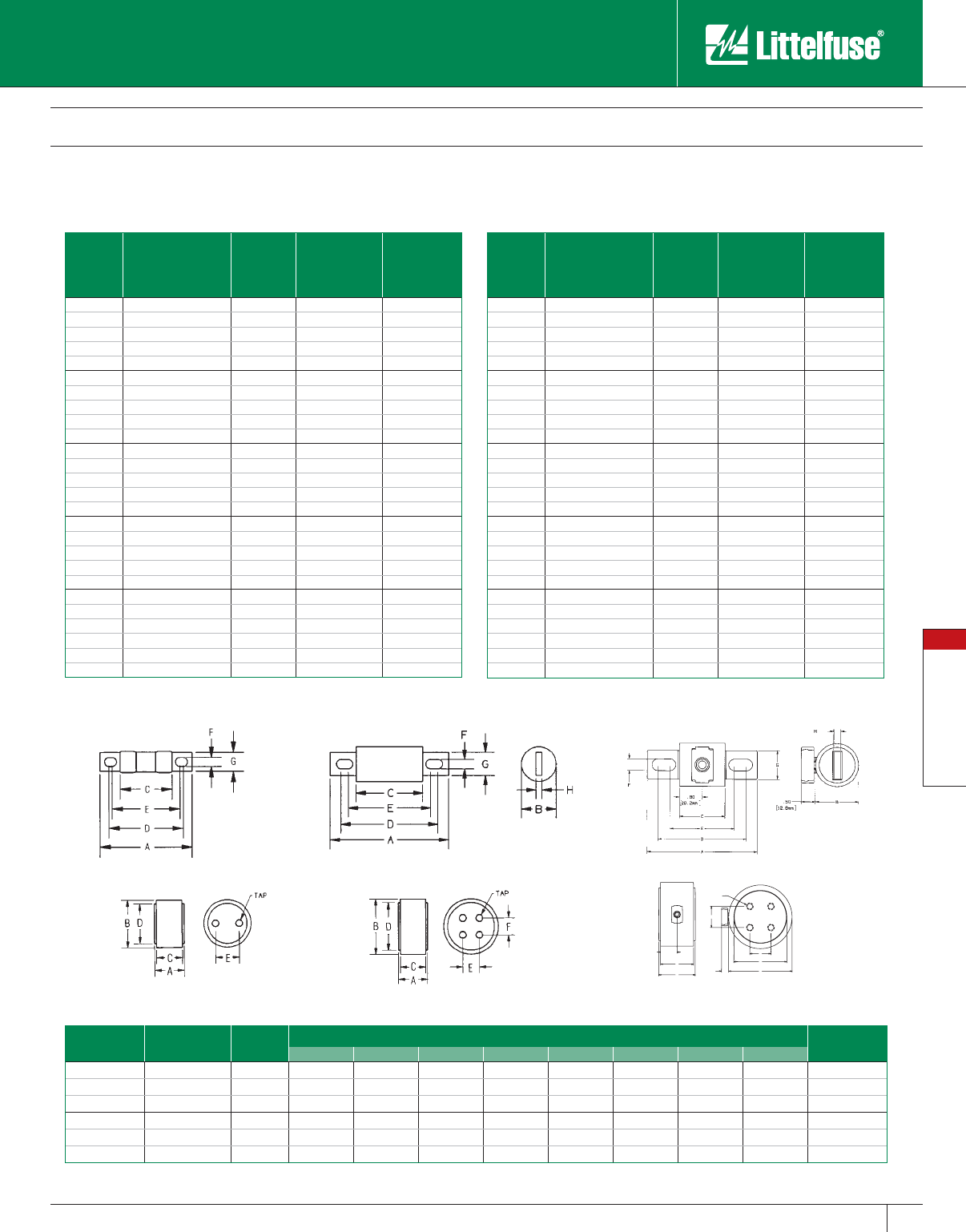
Special Purpose Fuses
91
www.littelfuse.com
Special Purpose Fuses
© 2005 Littelfuse • POWR-GARD™ Products Catalog
LA30QS Semiconductor Fuses
300 VAC • Very Fast Acting • 35 – 4500 Amperes
Ampere
Rating
Littelfuse
Catalog
Number
Mounting
Type
Maximum
Clearing I2t
@300 VAC
(A2S x 103)
Watts Loss
@ Rated
Current (W)
35 LA30QS35-4 4 0.9 6.4
40 LA30QS40-4 4 1.2 7
50 LA30QS50-4 4 2 9.9
60 LA30QS60-4 4 2.7 11.6
70 LA30QS70-4 4 1.6 11
80 LA30QS80-4 4 2.6 11
90 LA30QS90-4 4 3.2 13
100 LA30QS100-4 4 4.1 13
100 LA30QS100-4TI 4TI 4.1 13
125 LA30QS125-4 4 6.3 16
130 LA30QS130-4 4 6.3 16
150 LA30QS150-4 4 9.3 19
150 LA30QS150-4TI 4TI 9.3 19
175 LA30QS175-4 4 10 27
200 LA30QS200-4 4 15 30
200 LA30QS200-4TI 4TI 15 30
225 LA30QS225-4 4 22 33
250 LA30QS250-4 4 25 41
250 LA30QS250-4TI 4TI 25 41
300 LA30QS300-4 4 37 47
300 LA30QS300-4TI 4TI 37 47
350 LA30QS350-4 4 62 49
400 LA30QS400-4 4 83 56
400 LA30QS400-4IL 4IL 83 56
400 LA30QS400-4TI 4TI 83 56
450 LA30QS450-4 4 130 53
Catalog Numbers & Technical Data
Ampere
Rating
Littelfuse
Catalog
Number
Mounting
Type
Maximum
Clearing I2t
@300 VAC
(A2S x 103)
Watts Loss
@ Rated
Current (W)
500 LA30QS500-4 4 160 59
550 LA30QS550-4 4 190 65
600 LA30QS600-4 4 230 69
600 LA30QS600-4TI 4TI 230 69
600 LA30QS600-4IL 4IL 230 69
700 LA30QS700-4 4 260 90
700 LA30QS700-128 128 260 73
800 LA30QS800-4 4 330 108
800 LA30QS800-4IL 4IL 330 108
800 LA30QS800-128 128 330 84
1000 LA30QS1000-128 128 460 105
1000 LA30QS1000-128IL 128IL 460 105
1200 LA30QS1200-128 128 880 110
1500 LA30QS1500-128 128 1400 140
1500 LA30QS1500-128IL 128IL 1400 140
1600 LA30QS1600-128 128 1690 150
2000 LA30QS2000-128 128 2600 190
2000 LA30QS2000-128IL 128IL 2600 190
2500 LA30QS2500-128 128 4000 230
2500 LA30QS2500-128IL 128IL 4000 230
3000 LA30QS3000-128 128 4700 340
3500 LA30QS3500-128 128 6500 380
3500 LA30QS3500-128IL 128IL 6500 380
4000 LA30QS4000-128 128 8600 450
4500 LA30QS4500-128 128 11000 500
1.17
C
A
D
B
E
F
0.50
TAP
[ 29.8 mm ]
[ 12.8 mm ]
Figure 1 Figure 2 Figure 3
Figure 4 Figure 5 Figure 6
Dimensions Dimensions for reference only.
Amperes Mount. Type Fig. No. Dimensions in Inches (mm in parentheses) Tap
ABCDEFGH
35 – 60 4 1 3.19 (81.0) 0.81 (20.6) 1.63 (41.4) 2.50 (63.5) 2.25 (57.5) 0.34 (8.6) 0.72 (18.3) 0.13 (3.3) –
70 – 200 4 2 3.13 (79.5) 1.22 (31.0) 1.63 (41.4) 2.44 (62.0) 2.31 (58.7) 0.31 (7.9) 1.00 (25.4) 0.19 (4.8) –
225 – 700 4, 4IL* 2, 3* 3.84 (97.5) 1.50 (38.1) 1.59 (40.1) 2.91 (73.9) 2.28 (57.9) 0.41 (10.4) 1.00 (25.4) 0.25 (6.4) –
700 – 1200 128 4 2.59 (65.8) 3.00 (76.2) 2.34 (59.4) 2.50 (63.5) 1.50 (38.1) – – – 3⁄8-24-1⁄2 deep
1500 – 2500 128, 128IL* 5, 6* 2.59 (65.8) 3.50 (88.9) 2.34 (59.4) 3.00 (76.2) 1.50 (38.1) 1.50 (38.1) – – 3⁄8-24-1⁄2 deep
3000 – 4500 128, 128IL* 5, 6* 2.59 (65.8) 4.50 (114) 2.34 (59.4) 3.75 (95.3) 1.50 (38.1) 1.50 (38.1) – – 1⁄2-20-1⁄2 deep
* Optional Actuator (IL)
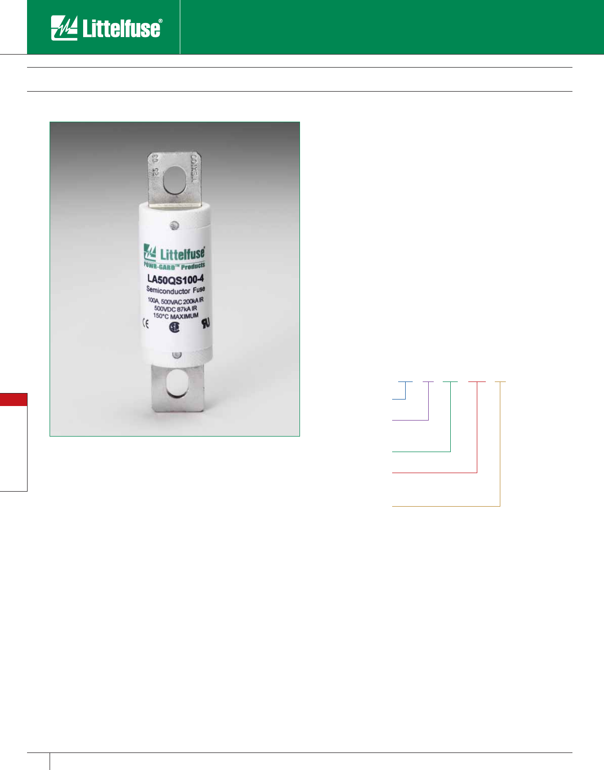
Special Purpose Fuses
92 www.littelfuse.com
Special Purpose Fuses
© 2005 Littelfuse • POWR-GARD™ Products Catalog
LA 50 QS 250 -4
Style
Littelfuse
Ampere Rating
Mounting Type
(Blades/Bolt-in)
Voltage
(500)
LA50QS Semiconductor Fuses
500 VAC • Very Fast Acting • 35 – 1200 Amperes
Specifications
Voltage Rating: AC: 500 volts
DC: 500 volts
Interrupting Rating: AC: 200,000 Amperes
DC: 100,000 Amperes
Ampere Range: 35 – 1200 Amperes
Approvals: UL Recognized under the components program
CSA Certified.
In response to new equipment requirements, Littelfuse LA50QS
series fuses were developed to improve the overall performance
of semiconductor fuses. The LA50QS provides the best protection
features including lower I2t, longer life when subjected to cyclic loading
and lower watts loss. LA50QS is today’s choice for the protection of
dynamic solid state equipment.
Features
• Lowest I2t for greatest protection of semiconductor circuits.
• Low watts loss for cooler operation.
• Superior cycling ability gives an equipment design advantage.
• State-of-the-art protection for 500 volt equipment.
• Ultra compact sizes allow down-sizing of existing equipment.
Applications
Protection of 500 volts or less solid state equipment such as motor
drives, UPS, inverters, etc.
Ordering Information
Special Purpose Fuses
93
www.littelfuse.com
Special Purpose Fuses
© 2005 Littelfuse • POWR-GARD™ Products Catalog
LA50QS Semiconductor Fuses
500 VAC • Very Fast Acting • 35 – 1200 Amperes
Ampere
Rating
Littelfuse
Catalog
Number
Mounting
Type
Maximum
Clearing I2t @500
VAC (A2S x 103)
Watts Loss
@ Rated
Current (W)
35 LA50QS35-4 4 0.56 6
40 LA50QS40-4 4 0.69 7
50 LA50QS50-4 4 1.1 8
60 LA50QS60-4 4 1.8 10
70 LA50QS70-4 4 1.9 12
80 LA50QS80-4 4 2.6 14
90 LA50QS90-4 4 3.6 15
100 LA50QS100-4 4 4.4 17
125 LA50QS125-4 4 5.6 21
150 LA50QS150-4 4 9 25
175 LA50QS175-4 4 15 29
200 LA50QS200-4 4 20 33
225 LA50QS225-4 4 25 37
Catalog Numbers & Technical Data
Ampere
Rating
Littelfuse
Catalog
Number
Mounting
Type
Maximum
Clearing I2t @500
VAC (A2S x 103)
Watts Loss
@ Rated
Current (W)
250 LA50QS250-4 4 29 41
300 LA50QS300-4 4 55 49
350 LA50QS350-4 4 88 57
400 LA50QS400-4 4 98 65
450 LA50QS450-4 4 130 69
500 LA50QS500-4 4 160 77
600 LA50QS600-4 4 220 92
700 LA50QS700-4 4 270 110
800 LA50QS800-4 4 360 130
900 LA50QS900-4 4 500 140
1000 LA50QS1000-4 4 560 160
1200 LA50QS1200-4 4 930 175
Dimensions
Dimensions for reference only.
Amperes Mount.
Type
Dimensions in Inches (mm in parentheses)
ABCDEFGH
35 – 100 4 3.63
(92.2)
1.00
(25.4)
2.13
(54.1)
2.94
(74.7)
2.75
(69.9)
0.31
(7.9)
0.75
(19.1)
0.13
(3.3)
125 – 200 4 3.63
(92.2)
1.22
(31.0)
2.13
(54.1)
2.94
(74.7)
2.81
(71.4)
0.31
(7.9)
1.00
(25.4)
0.19
(4.8)
225 – 400 4 4.34
(110)
1.50
(38.1)
2.09
(53.1)
3.41
(86.6)
2.78
(70.6)
0.41
(10.4)
1.00
(25.4)
0.25
(6.4)
450 – 600 4 4.47
(114)
2.00
(50.8)
2.22
(56.4)
3.53
(89.7)
2.91
(73.9)
0.41
(10.4)
1.50
(38.1)
0.25
(6.4)
700 – 800 4 6.47
(164.3)
2.50
(63.5)
2.22
(56.4)
5.00
(127.0)
3.44
(87.3)
0.53
(13.5)
1.50
(38.1)
0.25
(6.4)
900 – 1200 4 6.97
(177.0)
3.00
(76.2)
3.22
(81.8)
5.47
(138.9)
4.47
(113.5)
0.63
(15.9)
2.38
(60.3)
0.44
(11.1)
Contact Littelfuse for characteristic curves.
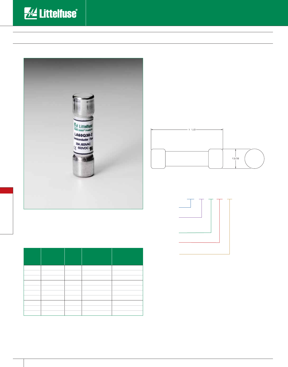
Special Purpose Fuses
94 www.littelfuse.com
Special Purpose Fuses
© 2005 Littelfuse • POWR-GARD™ Products Catalog
LA 60 Q 30 -2
Style
Littelfuse
Ampere Rating
Mounting Type
Voltage
(300)
Ferrule, midget dim. 1-½” x 13 /32”
LA60Q Semiconductor Fuses
600 VAC • Very Fast Acting • 5 – 40 Amperes
Specifications
Voltage Rating: AC: 600 volts
DC: 600 volts
Interrupting Rating: AC: 200,000 Amperes
DC: 100,000 Amperes
Ampere Range: 5 – 40 Amperes
Approvals: UL Recognized under the components program.
Recommended Fuse Blocks
LPSM or L60030M
Catalog Numbers & Technical Data
Ampere
Rating
Littelfuse
Catalog
Number
Mounting
Type
Maximum
Clearing I2t @600
VAC (A2S)
Watts Loss @
Rated Current (W)
5LA60Q5-22 60 0.7
8LA60Q8-22 70 1.1
10 LA60Q10-2 2 110 1.6
12 LA60Q12-2 2 150 2
15 LA60Q15-2 2 180 3
20 LA60Q20-2 2 330 4.4
25 LA60Q25-2 2 440 5.5
30 LA60Q30-2 2 860 5.6
35 LA60Q35-2 2 1300 6.4
40 LA60Q40-2 2 1800 7
Contact Littelfuse for characteristic curves.
Littelfuse LA60Q semiconductor protection fuses feature a 600 volt
AC/DC rating in a compact size (11⁄2” x 13 ⁄32”). LA60Q also has the lowest
I2t of all similar fuses and excellent cycling ability. Applications include
inverters and small equipment requiring extremely fast response to
faults, without the need to carry sustained heavy overloads.
Features
• Lowest I2t of any fuse this size for greater protection.
• Excellent cycling ability gives advantage in equipment design.
Dimensions (in inches)
Ordering Information
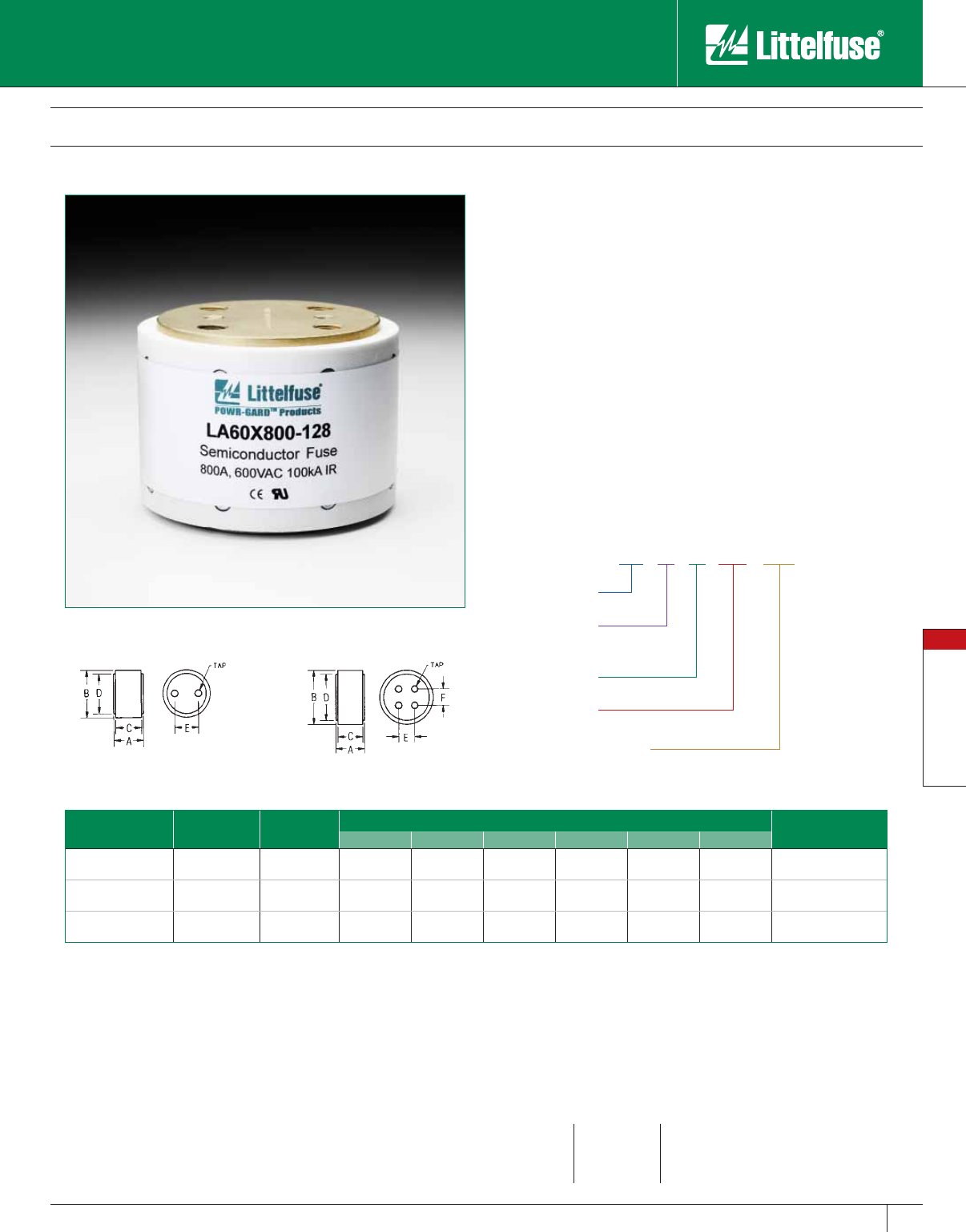
Special Purpose Fuses
95
www.littelfuse.com
Special Purpose Fuses
© 2005 Littelfuse • POWR-GARD™ Products Catalog
LA 60 X 700 -128
Style
Littelfuse
Ampere Rating
Mounting Type
Voltage
(300)
Hockey Puck, bolt-in
LA60X Semiconductor Fuses
600 VAC • Very Fast Acting • 700 – 2000 Amperes
Littelfuse LA60X semiconductor protection fuses are popular for the
protection of higher voltage heavy rectifiers such as traction rectifiers.
They can carry long sustained overloads common with heavy-duty
apparatus. The compact “hockey puck” design provides high power
protection in a small space.
Features
• Lowest I2t minimizes damage to protected components on
short- circuit.
• Controlled arc voltage reduces stress to circuit components during
fuse clearing.
Applications
Protection of heavy traction and electrochemical as well as rectifiers and
other heavy-duty equipment.
Ordering Information
Dimensions Dimensions for reference only.
Amperes Mount.
Type
Fig.
No.
Dimensions in Inches (mm in parentheses) Tap
ABCDEF
700 – 800 128 1 4.00
(102)
3.00
(76.2)
3.75
(95.3)
2.50
(63.5)
1.50
(38.1) -3⁄8-24-1⁄2 deep
1000 – 1200 128 2 4.00
(102)
3.50
(88.9)
3.75
(95.3)
3.00
(76.2)
1.50
(38.1)
1.50
(38.1)
3⁄8-24-1⁄2 deep
1500 – 2000 128 2 4.00
(102)
4.50
(114)
3.75
(95.3)
3.75
(95.3)
1.50
(38.1)
1.50
(38.1)
1⁄2-20-1⁄2 deep
Contact Littelfuse for technical information.
Figure 1 Figure 2
Specifications
Voltage Rating: AC: 600 volts
Interrupting Rating: AC: 100,000 Amperes
Ampere Range: 700 – 2000 Amperes
Approvals: UL Recognized under the components program.
Ampere Ratings
700 1200 1800
800 1500 2000
1000 1600
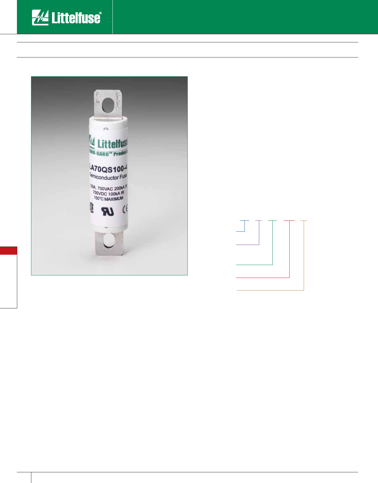
Special Purpose Fuses
96 www.littelfuse.com
Special Purpose Fuses
© 2005 Littelfuse • POWR-GARD™ Products Catalog
LA 70 QS 150 -4
Style
Littelfuse
Ampere Rating
Mounting Type
Voltage
(300)
Blades/Bolt-in
LA70QS Semiconductor Fuses
700 VAC • Very Fast Acting • 35 – 800 Amperes
Littelfuse LA70QS semiconductor fuses were developed to provide
improved performance required by today’s new equipment. The
LA70QS features lower I2t, improved cycling, and lower watts loss. It is
the best choice for the protection of dynamic solid-state equipment.
Features
• Very low I2t improved protection of equipment.
• Superior cycling ability for long, reliable life on high cycling loading.
• Lower watts loss for cooler operation.
• 700 Volt AC/DC rating provides greater design versatility.
• Compact sizes allow downsizing of equipment.
Applications
Protection of 700 volt or less solid state equipment such as motor
drives, UPS, inverters, etc.
Ordering Information
Specifications
Voltage Rating: AC: 700 Volts
DC: 700 Volts
Interrupting Rating: AC: 200,000 Amperes
DC: 100,000 Amperes
Ampere Range: 35 – 800 Amperes
Approvals: UL Recognized under the components program.
CSA Certified.
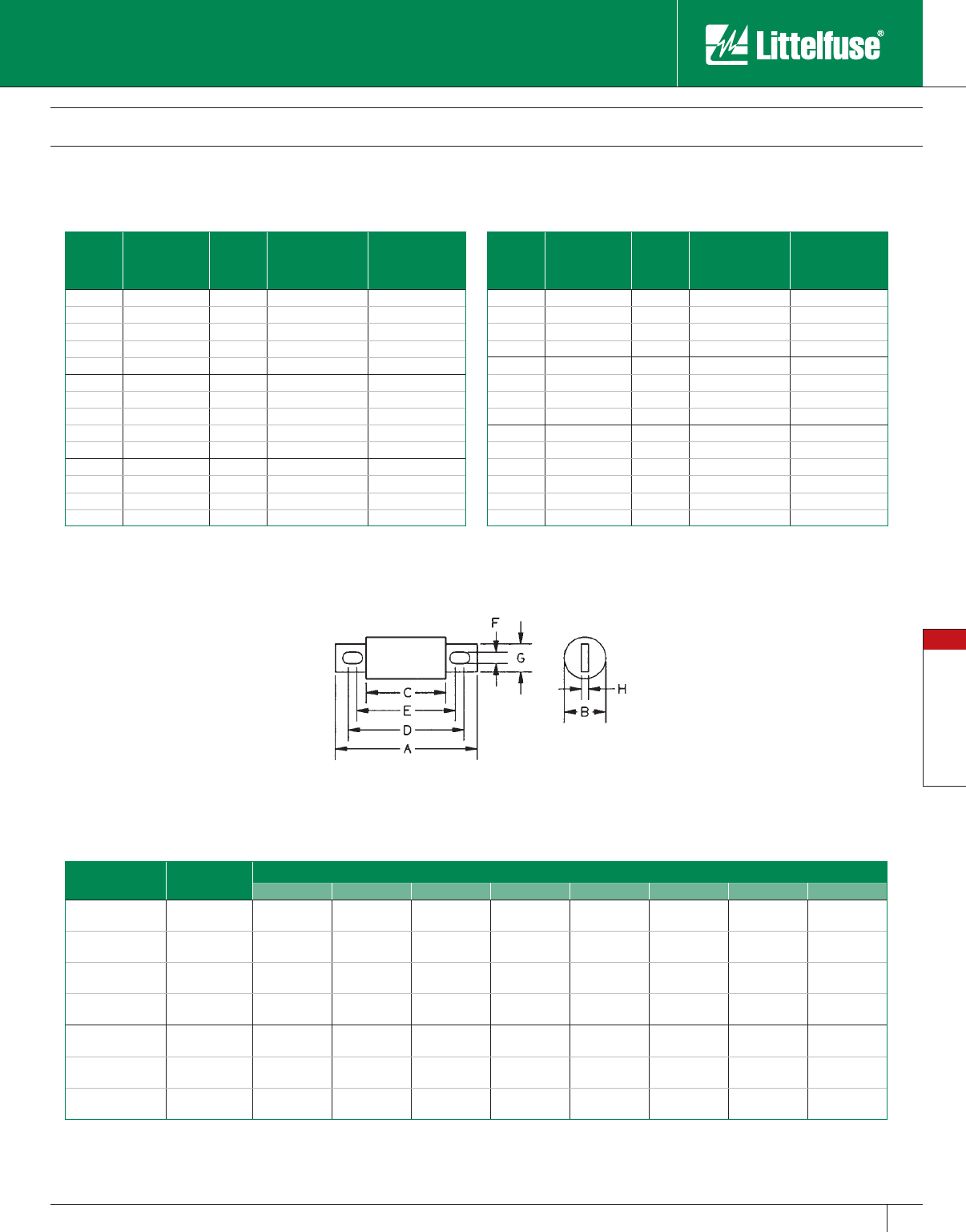
Special Purpose Fuses
97
www.littelfuse.com
Special Purpose Fuses
© 2005 Littelfuse • POWR-GARD™ Products Catalog
Ampere
Rating
Littelfuse
Catalog Number
Mounting
Type
Maximum
Clearing I2t @700
VAC (A2S x 103)
Watts Loss @
Rated Current (W)
200 LA70QS200-4 4 19 41
200 LA70QS200-4K 4 19 41
250 LA70QS250-4 4 42 42
300 LA70QS300-4 4 55 53
350 LA70QS350-4 4 72 64
400 LA70QS400-4 4 99 75
450 LA70QS450-4 4 125 75
450 LA70QS450-4K 4K 125 75
500 LA70QS500-4 4 150 92
500 LA70QS500-4K 4K 160 92
600 LA70QS600-4 4 222 116
600 LA70QS600-4K 4K 222 116
700 LA70QS700-4 4 332 125
800 LA70QS800-4 4 433 143
Ampere
Rating
Littelfuse
Catalog
Number
Mounting
Type
Maximum
Clearing I2t @700
VAC (A2S x 103)
Watts Loss @
Rated Current (W)
35 LA70QS35-4 4 0.47 6.2
40 LA70QS40-4 4 0.58 7.5
50 LA70QS50-4 4 0.88 9.8
60 LA70QS60-4 4 1.2 12
70 LA70QS70-4 4 1.8 15
80 LA70QS80-4 4 2.3 16
90 LA70QS90-4 4 3 20
100 LA70QS100-4 4 3.6 24
125 LA70QS125-4 4 6.9 22
125 LA70QS125-4K 4K 6.9 22
150 LA70QS150-4 4 11 28
150 LA70QS150-4K 4K 11 29
175 LA70QS175-4 4 14 35
175 LA70QS175-4K 4K 14 35
LA70QS Semiconductor Fuses
700 VAC • Very Fast Acting • 35 – 800 Amperes
Catalog Numbers & Technical Data
Dimensions Dimensions for reference only.
Amperes Mount. Type Dimensions in Inches (mm in parentheses)
ABCDEFGH
35 – 100 4 4.38
(111)
1.00
(25.4)
2.88
(73)
3.69
(93.6)
3.50
(88.9)
0.31
(7.9)
0.75
(19.0)
0.13
(3.2)
125 – 200 4 4.38
(111)
1.22
(31.0)
2.88
(73)
3.69
(93.6)
3.56
(90.5)
0.31
(7.9)
1.00
(25.4)
0.19
(4.8)
125 – 200 4K 5.09
(129)
1.22
(31.0)
2.88
(73)
4.19
(106)
3.50
(88)
0.41
(10.3)
1.00
(25.4)
0.19
(4.8)
225 – 400 4 5.09
(129)
1.50
(38.1)
2.84
(72.2)
4.16
(106)
3.53
(89.7)
0.40
(10.3)
1.50
(38.1)
0.25
(6.4)
450 – 600 4 5.09
(129)
2.00
(50.8)
2.84
(72.2)
4.16
(106)
3.53
(89.7)
0.41
(10.3)
1.50
(38.1)
0.25
(6.4)
450 – 600 4K 7.09
(180)
2.00
(50.8)
2.84
(72.2)
6.16
(156)
3.53
(89.7)
0.53
(13.5)
1.50
(38.1)
0.25
(6.4)
700 – 800 4 7.09
(180)
2.50
(63.5)
2.84
(72.2)
5.28
(134)
4.91
(125)
0.53
(13.5)
2.00
(50.8)
0.38
(9.5)
Contact Littelfuse for characteristic curves.
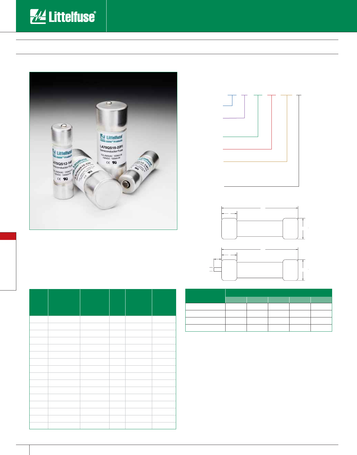
Special Purpose Fuses
98 www.littelfuse.com
Special Purpose Fuses
© 2005 Littelfuse • POWR-GARD™ Products Catalog
LA 70 QS 20 -14F I
Style
Littelfuse
Ampere Rating
Size
Voltage
(700)
Optional Striker
14 x 51mm 14F
22 x 58mm 22F
(I)
LA70QS French Cylindrical Fuses
690 Volts • Very Fast Acting • 10 – 100 Amperes
Specifications
Voltage Rating: AC: 690 Volts
DC: 700 Volts
Interrupting Rating: AC: 200,000 Amperes
DC: 100,000 Amperes
Ampere Range: 10 – 100 Amperes
Approvals: UL Recognized under the components program.
CSA Certified.
Recommended Fuse Blocks
CYH series for non-striker fuses LA70QS(amp)22F
LPSG series for the striker style LA70QS(amp)22FI
Ordering Information
Catalog Numbers & Technical Data
Ampere
Rating
Littelfuse
Catalog
Number
(No Striker)
Littelfuse
Catalog
Number
(With Striker)
Body
Size
Maximum
Clearing I2t
@700 VAC
(A2S x 103)
Watts Loss
@ Rated
Current (W)
10 LA70QS10-14F LA70QS10-14FI 14x51 0.04 3.5
12 LA70QS12-14F LA70QS12-14FI 14x51 0.06 4.4
16 LA70QS16-14F LA70QS16-14FI 14x51 0.10 4.8
20 LA70QS20-14F LA70QS20-14FI 14x51 0.16 5.2
25 LA70QS25-14F LA70QS25-14FI 14x51 0.27 5.8
32 LA70QS32-14F LA70QS32-14FI 14x51 1.50 7.0
40 LA70QS40-14F LA70QS40-14FI 14x51 0.70 10.7
50 LA70QS50-14F LA70QS50-14FI 14x51 1.50 11.6
20 LA70QS20-22F LA70QS20-22FI 22x58 0.076 8.0
25 LA70QS25-22F LA70QS25-22FI 22x58 0.125 10.0
32 LA70QS32-22F LA70QS32-22FI 22x58 0.27 11.0
40 LA70QS40-22F LA70QS40-22FI 22x58 0.48 13.0
50 LA70QS50-22F LA70QS50-22FI 22x58 0.80 14.9
63 LA70QS63-22F LA70QS63-22FI 22x58 1.85 16.0
80 LA70QS80-22F LA70QS80-22FI 22x58 3.80 17.8
100 LA70QS100-22F LA70QS100-22FI 22x58 8.00 19.0
Fuse Size Dimensions in mm
ABCDE
14x51 (no striker) 14 51 14 – –
22x58 (no striker) 22 58 16 – –
14x51 (with striker) 14 51 14 7.5 3.8
22x58 (with striker) 22 58 16 7.5 3.8
Dimensions for reference only.
A
B
C
A
B
C
D
E
Littelfuse French Cylindrical style semiconductor fuses are an extension
to the LA70QS series. They offer a solid-fill design with high interrupting
ratings and an optional striker for visual or remote blown fuse indication.
The international 14x51mm and 22x58mm sizes are accepted
worldwide.
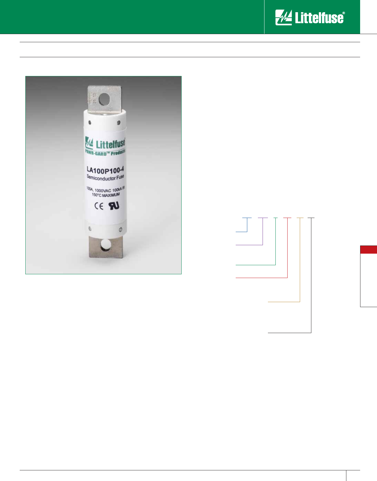
Special Purpose Fuses
99
www.littelfuse.com
Special Purpose Fuses
© 2005 Littelfuse • POWR-GARD™ Products Catalog
LA 100 P 80 -4 TI
Style
Littelfuse
Ampere Rating
Mounting Type
Voltage
(1000)
Integral Blown-
Fuse Indicator
Ferrule 1
Blades/Bolt-in 4
Trigger Indicator TI
LA100P Semiconductor Fuses
1000 VAC • Very Fast Acting • 15 – 1000 Amperes
Specifications
Voltage Rating: AC: 1000 Volts
DC: 750 Volts
Interrupting Rating: 100,000 Amperes
Ampere Range: 15 – 1000 Amperes
Approvals: UL Recognized under the components program.
Littelfuse LA100P semiconductor protection fuses are rated 1000V,
extending the range of protection for UPS systems, AC and DC drives,
reduced voltage motor starters and similar applications where lower I2t
and superior reliability are needed. With ratings from 15-1000 amperes,
a wide range of high voltage applications can be served.
Features
• Low I2t minimizes damage to protected components on short-circuit.
• Controlled arc voltage reduces stress to circuit components during
fuse clearing.
Applications
Protection of UPS systems, AC/DC drives, reduced voltage motor
starters and other 1000V or less semiconductor devices.
Ordering Information
Note: Mounting types and integral blown fuse indicators are optional for
specified ratings.
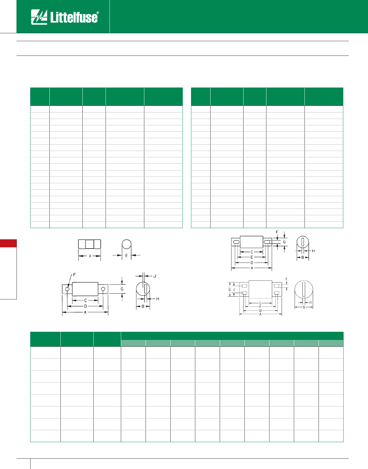
Special Purpose Fuses
100 www.littelfuse.com
Special Purpose Fuses
© 2005 Littelfuse • POWR-GARD™ Products Catalog
Ampere
Rating
Littelfuse
Catalog
Number
Mounting
Type
Maximum
Clearing I2t @1000
VAC (A2S x 103)
Watts Loss @
Rated Current (W)
200 LA100P200-4 4 72 36
200 LA100P200-4TI 4TI 72 36
225 LA100P225-4 4 91 40
250 LA100P250-4 4 110 46
300 LA100P300-4 4 160 55
300 LA100P300-4TI 4TI 160 55
350 LA100P350-4 4 220 65
350 LA100P350-4TI 4TI 220 65
400 LA100P400-4 4 290 70
400 LA100P400-4TI 4TI 290 70
500 LA100P500-4 4 450 90
500 LA100P500-4TI 4TI 450 90
600 LA100P600-4 4 650 110
600 LA100P600-4TI 4TI 650 110
650 LA100P650-4 4 780 120
700 LA100P700-4 4 880 125
800 LA100P800-4 4 1200 140
800 LA100P800-4TI 4TI 1200 140
1000 LA100P1000-4 4 1900 190
Ampere
Rating
Littelfuse
Catalog
Number
Mounting
Type
Maximum
Clearing I2t @1000
VAC (A2S x 103)
Watts Loss @
Rated Current (W)
15 LA100P15-1 1 0.6 3.4
20 LA100P20-1 1 0.8 5.9
25 LA100P25-1 1 1,3 9
30 LA100P30-1 1 1.5 12.8
35 LA100P35-4 4 2.2 7.3
40 LA100P40-4 4 2.9 8.3
50 LA100P50-4 4 4.5 11
50 LA100P50-4TI 4TI 4.5 11
60 LA100P60-4 4 6.5 13
60 LA100P60-4TI 4TI 6.5 13
70 LA100P70-4TI 4TI 8.8 13
80 LA100P80-4 4 12 14
80 LA100P80-4TI 4TI 12 14
100 LA100P100-4 4 18 18
100 LA100P100-4TI 4TI 18 18
125 LA100P125-4 4 28 23
125 LA100P125-4TI 4TI 28 23
150 LA100P150-4 4 41 28
150 LA100P150-4TI 4TI 41 28
LA100P Semiconductor Fuses
1000 VAC • Very Fast Acting • 15 – 1000 Amperes
Catalog Numbers & Technical Data
Dimensions Dimensions for reference only.
Amperes Mount. Type Fig. No. Dimensions in Inches (mm in parentheses)
ABCDEFGHJ
15 – 30 1 1 2.53
(66.8)
0.56
(14.2) –––––––
35 – 60 4, 4TI 2 5.00
(127)
1.00
(25.4)
3.50
(173)
4.31
(109)
4.19
(106)
0.31
(7.9)
0.75
(19.1)
0.13
(3.3) –
65 – 100 4, 4TI 2 5.00
(127)
1.22
(31)
3.50
(173)
4.31
(109)
4.19
(106)
0.31
(7.9)
1.00
(25.4)
0.19
(4.8) –
125 – 200 4, 4TI 2 5.72
(145)
2.00
(38.1)
3.47
(88.1)
4.78
(121)
4.16
(106)
0.41
(10.4)
1.00
(25.4)
0.25
(6.4) –
225 – 400 4, 4TI 2 5.72
(145)
2.00
(50.8)
3.47
(88.1)
4.78
(121)
4.16
(106)
0.41
(10.4)
1.50
(25.4)
0.25
(6.4) –
500 – 600 4, 4TI 2 7.72
(196)
2.50
(63.5)
3.47
(88.1)
5.88
(149)
5.56
(147)
0.53
(13.5)
2.00
(50.8)
0.38
(9.7) –
650 – 800 4, 4TI 3 7.4 4
(189)
2.88
(73.2)
3.94
(100)
5.94
(151) –0.63
(16)
2.00
(50.8)
0.38
(9.7)
0.31
(7.9)
1000 4 4 8.22
(209)
3.50
(88.9)
4.47
(114)
6.59
(167)
5.84
(148)
0.63
(16)
2.75
(69.9)
0.50
(12.7)
1.38
(35.1)
Contact Littelfuse for characteristic curves.
Figure 1
Figure 3
Figure 2
Figure 4
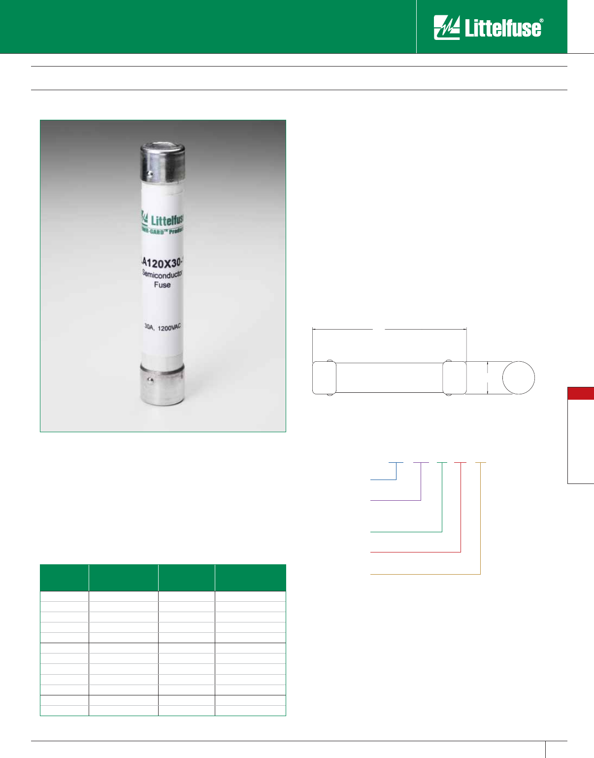
Special Purpose Fuses
101
www.littelfuse.com
Special Purpose Fuses
© 2005 Littelfuse • POWR-GARD™ Products Catalog
LA 120 X 25 -1
Style
Littelfuse
Ampere Rating
Mounting Type
Voltage
(1200)
Ferrule
Catalog Numbers & Technical Data
Ampere
Rating
Littelfuse Catalog
Number Mounting Type Maximum Clearing I2t
@1200 VAC (A2S)
1⁄2LA120A1/2-1 1 1.9
1LA120X1-1 1 7.5
2LA120X2-1 1 30
3LA120X3-1 1 69
4 LA120X4-1 1 120
5LA120X5-1 1 190
6LA120X6-1 1 280
10 LA120X10-1 1 970
15 LA120X15-1 1 2100
20 LA120X20-1 1 3700
25 LA120X25-1 1 5700
30 LA120X30-1 1 8300
LA120X Semiconductor Fuses
1200 VAC • Very Fast Acting • 1/2 – 30 Amperes
Littelfuse LA120X semiconductor protection fuses, rated 1/2 through
30A, 1200 VAC are popular for use in traction drive auxiliary circuits and
similar applications. LA120X fuses are also suitable for use on 1000VDC
auxiliary circuits with low time constants.
Features
• 1000 Volt DC rating for a wide range of circuits.
• Compact size fits in where competitive sizes will not fit.
Applications
Protection of traction drive auxiliary circuits, etc.
Dimensions
In Inches (mm in parentheses)
Ordering Information
Specifications
Voltage Rating: AC: 1200 Volts
DC: 1000 Volts
Interrupting Rating: 100,000 Amperes
Ampere Range: 1⁄2 – 30 Amperes
Note: Mounting type 1 can use 109002 and 129002 clips.
4 5/8
(117)
.812
(20.6)
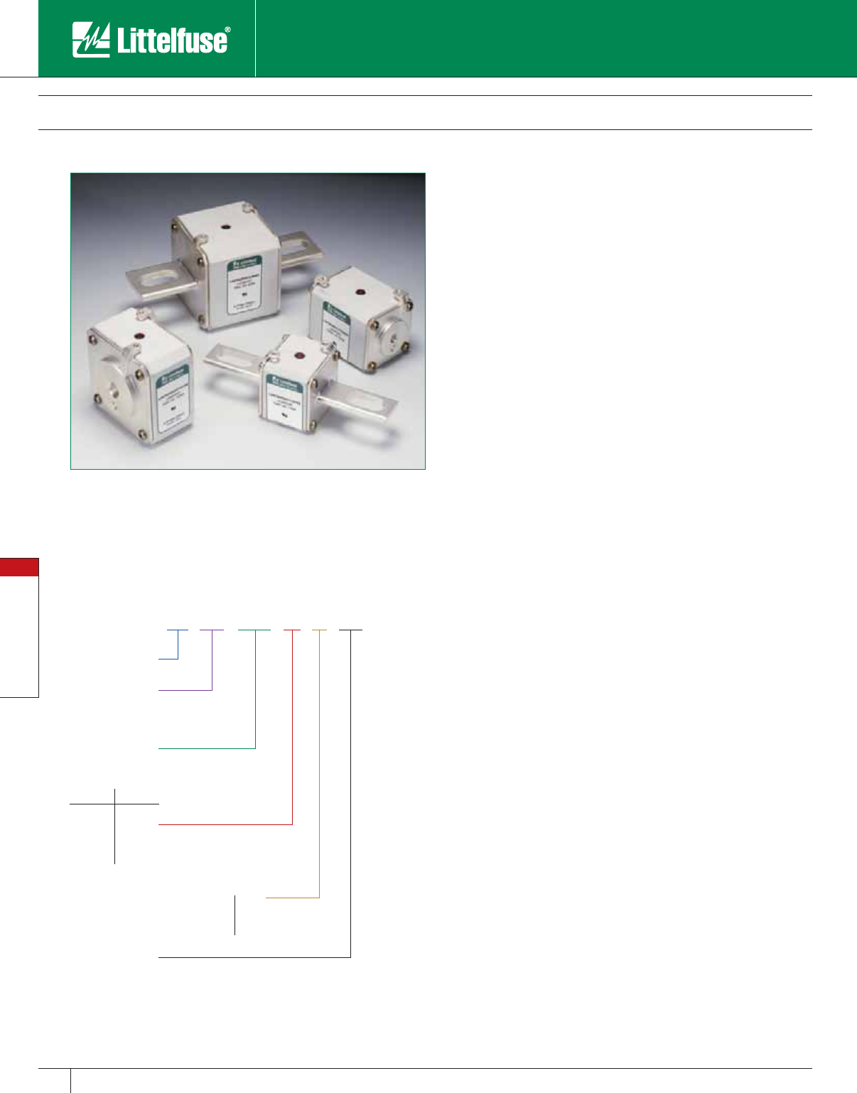
Special Purpose Fuses
102 www.littelfuse.com
Special Purpose Fuses
© 2005 Littelfuse • POWR-GARD™ Products Catalog
LA 070 URD 31 LI 350
Class
Littelfuse
Size
Mounting Type
Voltage
(070=700V
130 =1300V)
Amp Rating
Straight-blade KI LI
Straight-blade LI LLI
Flat-type, one hole TTI TTI
700V 1300V
30
31
32
33
70
71
72
73
Square Body Semiconductor Fuses
700/1300 VAC • Very Fast Acting • 40 – 2500 Amperes
Littelfuse North American style square body semiconductor fuses
provide maximum flexibility in equipment design and ultimate protection
for today’s power conversion equipment. Available in different body
sizes and multiple mounting styles, the broad range of ampere ratings
allows great flexibility in equipment design.
Engineered to provide state-of-the-art protection for SCR’s, diodes,
thyristors, GTO’s, and IGBT devices, Littelfuse square body fuses have
pure die-cut elements embedded in solidified sand to control arcing and
lower I2t. All fuses are also equipped with a blown fuse trip indicator.
Features
• Choice of mounting styles provides a wide choice for equipment
design.
• Broad range of ampere ratings in a given body size for design
flexibility.
• Very low I2t minimizes damage to protected components.
• Superior cycling ability for long, reliable life on high cyclic loading.
• Extremely fast acting and current-limiting for improved protection to
equipment.
Applications
Protection of rectifiers, inverters, DC drives, UPS systems, reduced
voltage motor starters, and other equipment in globally accepted
applications.
Specifications
Voltage Rating: AC: 700 Volts (LA070)
1300 Volts (LA130)
DC: Contact factory
Interrupting Rating: AC: 200,000 Amperes (LA070)
100,000 Amperes (LA130)
DC: Contact factory
Ampere Range: 40 – 2500 Amperes
Approvals: UL Recognized Component
Ordering Information

Special Purpose Fuses
103
www.littelfuse.com
Special Purpose Fuses
© 2005 Littelfuse • POWR-GARD™ Products Catalog
700 Volt North American Style Ratings and Application Data
Body Size Amp
Rating
Rated
Voltage
Melting I2t
(A2S x 103)
Total I2t
@ Rated
Voltage
(A2S x 103)
**Watts
Loss @ Rated
Current
(W)
Long Blade
Catalog No.
Type LI
Short Blade
Catalog No.
Type KI
Tapped Terminal
Catalog No.
Type TTI
63 700 0.2 1.2 14 LA070URD30LI0063 LA070URD30KI0063 LA070URD30TTI0063
80 700 0.33 1.9 19 LA070URD30LI0080 LA070URD30KI0080 LA070URD30TTI0080
100 700 0.47 2.7 26 LA070URD30LI0100 LA070URD30KI0100 LA070URD30TTI0100
125 700 0.85 4.9 30 LA070URD30LI0125 LA070URD30KI0125 LA070URD30TTI0125
160 700 1.6 9.2 37 LA070URD30LI0160 LA070URD30KI0160 LA070URD30TTI0160
200 700 3 16.7 42 ⁄ 43 LA070URD30LI0200 LA070URD30KI0200 LA070URD30TTI0200
30 250 700 5.8 32.4 48 ⁄ 50 LA070URD30LI0250 LA070URD30KI0250 LA070URD30TTI0250
315 700 12 67 53 ⁄ 55 LA070URD30LI0315 LA070URD30KI0315 LA070URD30TTI0315
350 700 15.5 86 57 ⁄ 60 LA070URD30LI0350 LA070URD30KI0350 LA070URD30TTI0350
400 700 23 130 60 ⁄ 65 LA070URD30LI0400 LA070URD30KI0400 LA070URD30TTI0400
450 700 26 165 80 ⁄ 88 LA070URD30LI0450 LA070URD30KI0450 LA070URD30TTI0450
500 700 41 264 80 ⁄ 88 LA070URD30LI0500 LA070URD30KI0500 LA070URD30TTI0500
550 700 52 330 80 ⁄ 90 LA070URD30LI0550 LA070URD30KI0550 LA070URD30TTI0550
200 700 2.5 14.6 45 LA070URD31LI0200 LA070URD31KI0200 LA070URD31TTI0200
250 700 4.7 27 52 LA070URD31LI0250 LA070URD31KI0250 LA070URD31TTI0250
315 700 7.5 43 65 LA070URD31LI0315 LA070URD31KI0315 LA070URD31TTI0315
350 700 10.5 59 67 LA070URD31LI0350 LA070URD31KI0350 LA070URD31TTI0350
400 700 19 110 68 LA070URD31LI0400 LA070URD31KI0400 LA070URD31TTI0400
31 450 700 26.5 150 70 LA070URD31LI0450 LA070URD31KI0450 LA070URD31TTI0450
500 700 37 210 70 ⁄ 72 LA070URD31LI0500 LA070URD31KI0500 LA070URD31TTI0500
550 700 52 300 70 ⁄ 75 LA070URD31LI0550 LA070URD31KI0550 LA070URD31TTI0550
630 700 75 421 75 ⁄ 85 LA070URD31LI0630 LA070URD31KI0630 LA070URD31TTI0630
700 700 95 530 85 ⁄ 95 LA070URD31LI0700 LA070URD31KI0700 LA070URD31TTI0700
800 700 140 880 105 ⁄ 120 LA070URD31LI0800 LA070URD31KI0800 LA070URD31TTI0800
400 700 15 86 72 ⁄ 75 LA070URD32LI0400 LA070URD32KI0400 LA070URD32TTI0400
450 700 22 124 77 ⁄ 80 LA070URD32LI0450 LA070URD32KI0450 LA070URD32TTI0450
500 700 28 157 85 ⁄ 90 LA070URD32LI0500 LA070URD32KI0500 LA070URD32TTI0500
550 700 37 211 90 ⁄ 95 LA070URD32LI0550 LA070URD32KI0550 LA070URD32TTI0550
630 700 54 302 95 ⁄ 105 LA070URD32LI0630 LA070URD32KI0630 LA070URD32TTI0630
700 700 76 432 100 ⁄ 110 LA070URD32LI0700 LA070URD32KI0700 LA070URD32TTI0700
32 800 700 115 648 110 ⁄ 120 LA070URD32LI0800 LA070URD32KI0800 LA070URD32TTI0800
900 700 170 972 110 ⁄ 125 LA070URD32LI0900 LA070URD32KI0900 LA070URD32TTI0900
1000 700 240 1350 115 ⁄ 135 LA070URD32LI1000 LA070URD32KI1000 LA070URD32TTI1000
1100 650 270 1620 140 ⁄ 165 LA065URD32LI1100 – LA065URD32TTI1100
1250 600 410 2100 150 ⁄ 180 LA060URD32LI1250 – LA060URD32TTI1250
1400 550 555 2600 160 ⁄ 190 LA055URD32LI1400 – LA055URD32TTI1400
1600 550 870 4000 165 ⁄ 195 LA055URD32LI1600 – LA055URD32TTI1600
1800 500 1050 4400 195 ⁄ 330 LA050URD32LI1800 – LA050URD32TTI1800
500 700 19 108 105 LA070URD33LI0500 LA070URD33KI0500 LA070URD33TTI0500
550 700 27 151 105 ⁄ 110 LA070URD33LI0550 LA070URD33KI0550 LA070URD33TTI0550
630 700 40 227 110 ⁄ 120 LA070URD33LI0630 LA070URD33KI0630 LA070URD33TTI0630
700 700 55 324 115 ⁄ 125 LA070URD33LI0700 LA070URD33KI0700 LA070URD33TTI0700
800 700 95 529 120 ⁄ 130 LA070URD33LI0800 LA070URD33KI0800 LA070URD33TTI0800
900 700 135 760 120 ⁄ 135 LA070URD33LI0900 LA070URD33KI0900 LA070URD33TTI0900
1000 700 170 970 135 ⁄ 155 LA070URD33LI1000 LA070URD33KI1000 LA070URD33TTI1000
33 1100 700 240 1360 135 ⁄ 160 LA070URD33LI1100 LA070URD33KI1100 LA070URD33TTI1100
1250 700 350 2000 150 ⁄ 180 LA070URD33LI1250 LA070URD33KI1250 LA070URD33TTI1250
1400 700 480 2700 160 ⁄ 200 LA070URD33LI1400 LA070URD33KI1400 LA070URD33TTI1400
1600 650 555 3250 210 ⁄ 240 LA065URD33LI1600 – LA065URD33TTI1600
1800 650 720 4330 225 ⁄ 260 LA065URD33LI1800 – LA065URD33TTI1800
2000 600 950 5000 250 ⁄ 290 LA060URD33LI2000 – LA060URD33TTI2000
2250 550 1250 5900 280 ⁄ 330 LA050URD33LI2250 – LA055URD33TTI2250
2500 500 1870 7600 280 ⁄ 330 LA050URD33LI2500 – LA050URD33TTI2500
** Watts loss data is published for both blade and tapped style mounting configurations.
When two watts loss values are shown, this represents tapped/blade values respectively.
Contact Littelfuse for characteristic curves.
Square Body Semiconductor Fuses
700/1300 VAC • Very Fast-Acting • 40 – 2500 Amperes
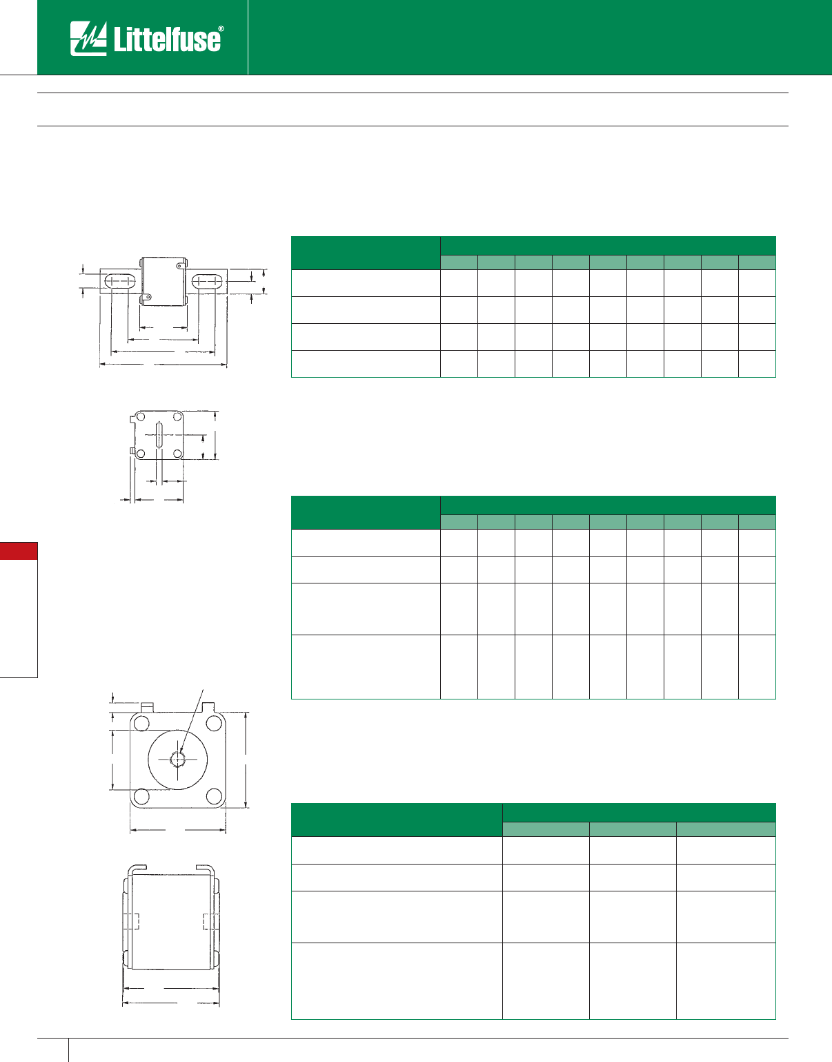
Special Purpose Fuses
104 www.littelfuse.com
Special Purpose Fuses
© 2005 Littelfuse • POWR-GARD™ Products Catalog
Square Body Semiconductor Fuses
700/1300 VAC • Very Fast Acting • 40 – 2500 Amperes
1.93 MAX
[49]
2
[50.6]
A
B
C
A
.26
[6.7]
North American Straight Blade, Type KI
Dimensions - 700V Fuses Dimensions for reference only.
Catalog Number Dimensions in Inches (mm in parentheses)
ABCDEFGHJ
LA070URD30KI (63-550) 1.57
(40)
0.98
(25)
0.49
(12.5)
0.83
(21)
0.71
(18)
2.68
(68)
4.21
(107)
5.08
(129)
0.41
(10.5)
LA070URD31KI (200-800) 2.01
(51)
0.98
(25)
0.49
(12.5)
1.0
(25.5)
0.89
(22.5)
2.66
(67.6)
4.22
(107.1)
5.07
(128.8)
0.56
(14.3)
LA070URD32KI (400-1000) 2.36
(60)
1.26
(32)
0.63
(16)
1.18
(30)
1.06
(27)
2.92
(74.2)
4.29
(109)
5.28
(134)
0.57
(14.6)
LA070URD33KI (500-1400) 2.93
(74.5)
1.57
(40)
0.79
(20)
1.46
(37.2)
1.35
(34.2)
2.97
(75.4)
4.24
(107.6)
5.28
(134)
0.63
(15.9)
North American Straight Blade Types LI
Dimensions - 700V Fuses Dimensions for reference only.
Catalog Number Dimensions in Inches (mm in parentheses)
ABCDEFGHJ
LA070URD30LI (63-550) 1.57
(40)
0.98
(25)
0.49
(12.5)
0.83
(21)
0.71
(18)
3.45
(87.6)
4.98
(126.6)
5.85
(148.6)
0.41
(10.5)
LA070URD31LI (200-800) 2.01
(51)
0.98
(25)
0.49
(12.5)
1.0
(25.5)
0.89
(22.5)
3.61
(91.6)
4.82
(122.4)
5.85
(148.6)
0.57
(14.6)
LA070URD32LI (400-1000)
LA065URD32LI (1250)
LA055URD32LI (1400-1600)
LA050URD32LI (1800)
2.36
(60)
1.26
(32)
0.63
(16)
1.18
(30)
1.06
(27)
3.71
(94.2)
5.08
(129)
6.02
(153)
0.57
(14.6)
LA070URD33LI (500-1400)
LA065URD33LI (1600-1800)
LA060URD33LI (2000)
LA055URD33LI (2250)
LA050URD33LI (2500)
2.93
(74.5)
1.57
(40)
0.79
(20)
1.46
(37.2)
1.35
(34.2)
3.72
(94.4)
4.98
(126.6)
6.02
(153)
0.63
(15.9)
North American Flat Single Hole, Type TTI
Dimensions - 700V Fuses Dimensions for reference only.)
Catalog Number Dimensions in Inches (mm in parentheses)
AB C
LA070URD30TTI (100-550) 1.57
(40)
1.00
(25)
5⁄16-18 x 0.35
LA070URD31TTI (200-800) 2.00
(50.8)
1.19
(30.2)
5⁄16-18 x 0.35
LA070URD32TTI (400-1000)
LA065URD32TTI (1100)
LA060URD32TTI (1250)
LA055URD32TTI (1400-1600)
2.37
(60.3)
1.50
(38.1)
3⁄8-16 x 0.35
LA060URD33TTI (1800)
LA070URD33TTI (500-1400)
LA065URD33TTI (1600)
LA060URD33TTI (2000)
LA055URD33TTI (2250)
LA050URD33TTI (2500)
2.94
(74.5)
1.81
(46)
1⁄2-18 x 0.35
TYPE TTI
TYPES KI AND LI
CB
F
G
H
J
1.925 MAX
[47.6]
D
A
E
A
.24
[6]

Special Purpose Fuses
105
www.littelfuse.com
Special Purpose Fuses
© 2005 Littelfuse • POWR-GARD™ Products Catalog
Square Body Semiconductor Fuses
700/1300 VAC • Very Fast Acting • 40 – 2500 Amperes
1300 Volt North American Style Ratings and Application Data
Body
Size Amp Rating Rated Voltage Melting I2t
(A2S x 103)
Total I2t @
Rated Voltage
(A2S x 103)
**Watts Loss @
Rated Current (W)
Long Blade
Catalog No. Type LI/LLI
Tapped Terminal
Catalog No. Type TTI
70
63 1300 0.21 1.8 26 LA130URD70LI0063 LA130URD70TTI0063
80 1300 0.47 4 27 LA130URD70LI0080 LA130URD70TTI0080
100 1300 0.83 7.2 30 LA130URD70LI0100 LA130URD70TTI0100
125 1300 1.3 11 38 LA130URD70LI0125 LA130URD70TTI0125
160 1300 2.5 22 45 LA130URD70LI0160 LA130URD70TTI0160
200 1300 4.7 40 54 ⁄ 56 LA130URD70LI0200 LA130URD70TTI0200
250 1300 9.6 82 58 ⁄ 61 LA130URD70LI0250 LA130URD70TTI0250
315 1300 20 172 66 ⁄ 72 LA130URD70LI0315 LA130URD70TTI0315
350 1200 28 205 68 ⁄ 75 LA120URD70LI0350 LA120URD70TTI0350
71
160 1300 2.6 22 46 LA130URD71IL0160 LA130URDT1TTI0160
200 1300 4.7 40 54 LA130URD71LLI0200 LA130URD71TTI0200
250 1300 8.9 76 61 LA130URD71LLI0250 LA130URD71TTI0250
280 1300 12 102 68 ⁄ 70 LA130URD71IL0280 LA130URD71TTI0280
315 1300 16 138 73 ⁄ 76 LA130URD71LLI0315 LA130URD71TTI0315
350 1300 22 190 76 ⁄ 80 LA130URD71LLI0350 LA130URD71TTI0350
400 1300 38 330 76 ⁄ 80 LA130URD71LLI0400 LA130URD71TTI0400
450 1300 47 405 87 ⁄ 95 LA130URD71LLI0450 LA130URD71TTI0450
500 1200 68 500 90 ⁄ 100 LA120URD71LLI0500 LA120URD71TTI0500
550 1200 84 620 98 ⁄ 112 LA120URD71LLI0550 LA120URD71TTI0550
630 1100 125 930 105 LA110URD71LLI0630 –
630 1200 125 930 120 – LA120URD71TTI0630
72
280 1300 10 90 72 LA130URD72LI0280 LA130URD72TTI0280
315 1300 15 130 76 LA130URD72LI0315 LA130URD72TTI0315
350 1300 21 180 77 LA130URD72LI0350 LA130URD72TTI0350
400 1300 32 285 80 LA130URD72LI0400 LA130URD72TTI0400
450 1300 44 380 87 ⁄ 89 LA130URD72LI0450 LA130URD72TTI0450
500 1300 57 500 94 ⁄ 98 LA130URD72LI0500 LA130URD72TTI0500
550 1300 68 590 110 ⁄ 120 LA130URD72LI0550 LA130URD72TTI0550
630 1200 105 920 113 LA120URD72LI0630 –
630 1300 105 920 125 – LA130URD72TTI0630
700 1100 145 1040 122 LA110URD72LI0700 -
700 1200 145 1040 140 – LA120URD72TTI0700
800 1100 215 1590 125 LA110URD72LI0800 –
800 1200 215 1590 146 – LA120URD72TTI0800
73
315 1300 12 102 84 LA130URD73LI0315 LA130URD73TTI0315
350 1300 17 150 86 LA130URD73LI0350 LA130URD73TTI0350
400 1300 25 220 93 LA130URD73LI0400 LA130URD73TTI0400
450 1300 35 310 99 ⁄ 100 LA130URD73LI0450 LA130URD73TTI0450
500 1300 44 390 110 ⁄ 112 LA130URD73LI0500 LA130URD73TTI0500
550 1300 57 500 116 ⁄ 120 LA130URD73LI0550 LA130URD73TTI0550
630 1300 84 730 125 ⁄ 132 LA130URD73LI0630 LA130URD73TTI0630
700 1300 110 960 135 ⁄ 146 LA130URD73LI0700 LA130URD73TTI0700
800 1200 190 1630 136 LA120URD73LI0800 –
800 1300 190 1630 148 – LA130URD73TTI0800
900 1100 250 2160 150 LA110URD73LI0900 –
900 1300 250 2160 170 – LA130URD73TTI0900
1000 1100 370 2430 152 ⁄ 174 LA100URD73LI1000 LA100URD73TTI1000
1100 1000 445 2580 168 ⁄ 208 LA100URD73LI1100 LA100URD73TTI1100
1250 1000 585 3480 186 ⁄ 200 LA100URD73LI1250 LA100URD73TTI1250
1400 900 755 3880 210 ⁄ 228 LA090URD73LI1400 LA090URD73TTI1400
1600 700 1430 5630 203 LA070URD73LI1600 LA070URD73TTI1600
1800 660 2040 7600 206 LA065URD73LI1800 LA065URD73TTI1800
** Watts loss data is published for both blade and tapped style mounting configurations.
When two watts loss values are shown, this represents tapped/blade values respectively.
Contact Littelfuse for characteristic curves.
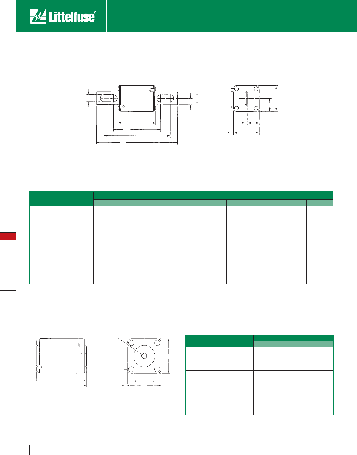
Special Purpose Fuses
106 www.littelfuse.com
Special Purpose Fuses
© 2005 Littelfuse • POWR-GARD™ Products Catalog
Square Body Semiconductor Fuses
700/1300 VAC • Very Fast Acting • 40 – 2500 Amperes
2.85 MAX
[72.5]
2.91
[74]
A
B
A
C
0.2
[5.03]
North American Straight Blade, Types LI and LLI
Dimensions - 1300V Fuses Dimensions for reference only.
Catalog Number Dimensions In Inches (mm in parentheses)
ABCDEFGHJ
LA130URD70LI (63-315)
LA120URD70LI (350)
1.57
(40)
0.98
(25)
0.49
(12.5)
0.83
(21)
0.71
(18)
3.60
(91.4)
5.13
(130.4)
6.00
(152.4)
0.41
(10.5)
LA130URD71LLI (160-450)
LA120URD71LLI (500-550)
LA110URD71LLI (630)
2.01
(51)
0.98
(25)
0.49
(12.5)
1.0
(26.5)
0.89
(22.5)
3.60
(91.4)
5.13
(130.4)
6.00
(152.4)
0.57
(14.6)
LA130URD72LI (280-550)
LA120URD72LI (800)
LA110URD72LI (700-800)
2.36
(60)
1.26
(32)
0.63
(16)
1.18
(30)
1.06
(27)
3.84
(97.6)
5.2
(132.4)
6.20
(157.4)
0.57
(14.6)
LA130URD73LI (315-700)
LA120URD73LI (800)
LA110URD73LI (900-1000)
LA090URD73LI (1400)
LA070URD73LI (1600)
LA065URD73LI (1800)
2.93
(74.5)
1.57
(40)
0.79
(20)
1.46
(37.2)
1.35
(34.2)
3.89
(98.8)
5.21
(132.4)
6.20
(157.4)
0.63
(15.9)
North American Flat Single Hole, Type TTI
Dimensions - 1300V Fuses Dimensions for reference only.
Catalog Number Dimensions in Inches (mm)
ABC
LA130URD70TTI (63-315)
LA120URD70TTI (350)
1.57
(40)
1.00
(26.4)
5⁄16-18 x 0.23 DP
LA130URD71TTI (160-450)
LA120URD71TTI (550-630)
2.01
(51)
1.19
(30.2)
5⁄16-18 x 0.36 DP
LA130URD72TTI (280-630)
LA120URD72TTI (700-800)
2.36
(60)
1.50
(38.1)
3⁄8-18 x 0.36 DP
LA130URD73TTI (315-900)
LA120URD73TTI (1000)
LA110URD73TTI (1250)
LA090URD73TTI (1400)
LA070URD73TTI (1600)
LA065URD73TTI (1800)
2.93
(74.5)
1.81
(46)
1⁄2-18 x 0.36 DP
TYPES LI AND LLI
TYPE TTI
J
2.85
[72.5]
F
G
H
B
C
A
D
E
A
0.2
[5.03]
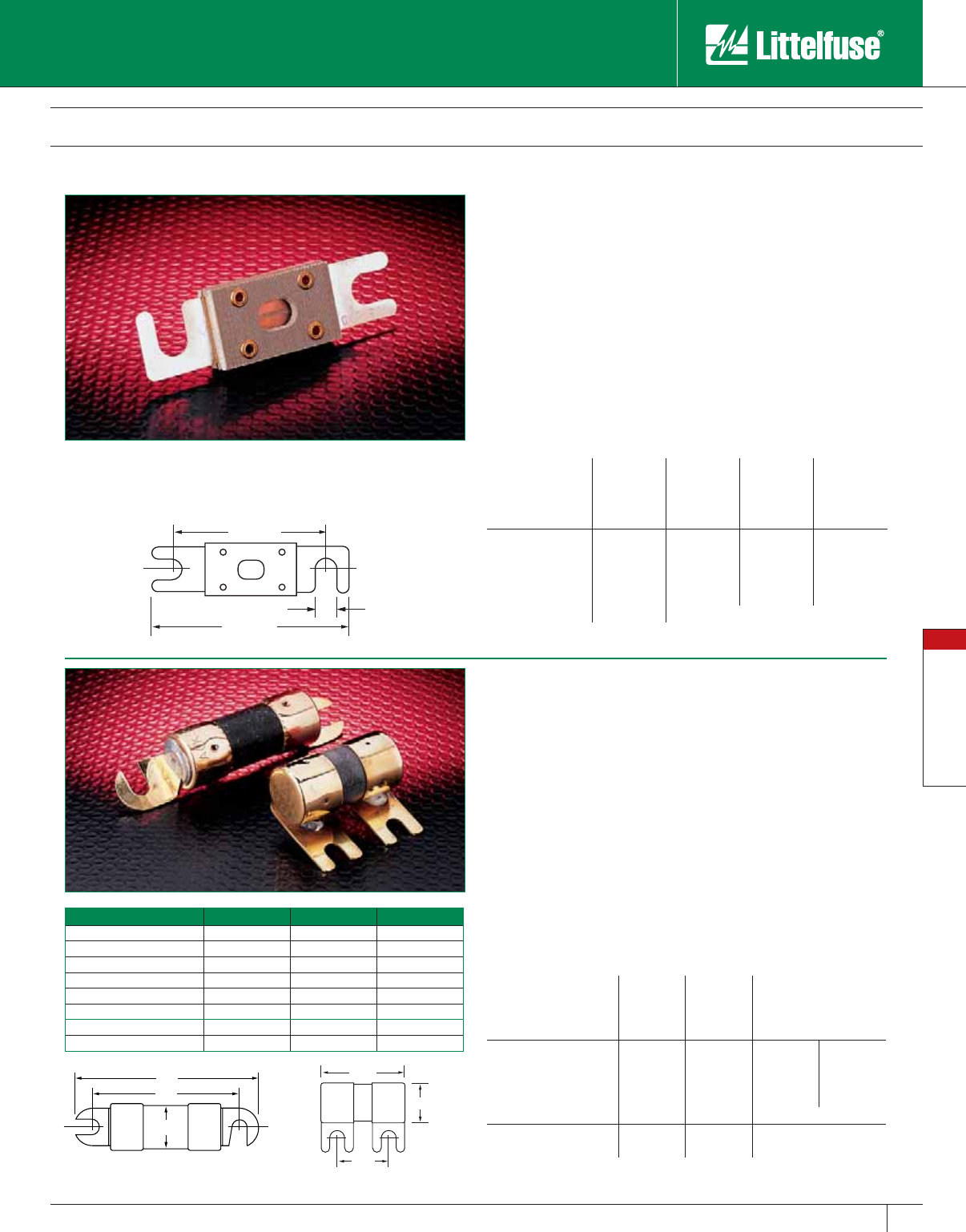
Special Purpose Fuses
107
www.littelfuse.com
Special Purpose Fuses
© 2005 Littelfuse • POWR-GARD™ Products Catalog
Fork-Lift and Stud-Mounted Fuses
32 – 130 Volts DC • Fast Acting and Time-Delay
Part No. A B C
CCK 1-15A 2.810 2.204 0.510
CCK 20-30A 3.060 2.454 0.510
CCK 35-60A 3.629 0.750
CCK 70-120A 4.129 3.454 1.00
CCK 140-200A 4.362 3.579 1.00
CCK 225-300A 4.612 3.829 1.00
CCL 30-60A 3.060 2.454 0.51
CCL 80-120A 3.38 2.70 0.75
0.812"
1.00"
1.625"
A
B
C
3.18"
0.343
"
2.43"
CCK/CCL CBO
CNL/ CNN Limiter Fuses
Specifications
Voltage Ratings: CNL: 32 Volts DC
CNN: 48 Volts DC, 75 Volts AC
Interrupting Rating: 2,500 amperes
Ampere Range: 10 – 800 amperes
Maximum Torque: 90 Inch lbs.
Recommended Fuse Block
LFFB001
Ampere ratings
CNL 35 80 150 250 350
40 100 175 275 400
50 125 200 300 500
60 130 225 325
CNN 10 80 175 300 500
35 90 200 325 600
40 100 225 350 700
50 125 250 400 800
60 150 275
Example part number (series & amperage): CNN 700
CBO/ CCK/ CCL Lift-Truck Fuses
CBO fast acting, and CCK and CCL dual-element time-delay fuses are rec-
ommended for fork lift trucks and other similar battery operated equipment.
Specifications
Voltage Ratings: CBO: 32 Volts DC
CCK: 130 Volts DC (1-100A)
72 Volts DC (120-200A)
48 Volts DC (225-300A)
CCL: 125 Volts DC
Interrupting Rating: CBO, CCK & CCL: 10,000A
Ampere Range: 1 – 300 amperes
For operating characteristics contact factory
Ampere ratings
CBO 10 25 50 80
Fast Acting 12 30 60 100
15 35 70 125
20 40 75 150
CCK 1 25 60 120 200
Time-Delay 23070140225
10 35 75 150 250
15 40 80 160 300
20 50 100 175
CCL 30 40 60 100
Time-Delay 35 50 80 120
Example part number (series & amperage): CCK 150
CNL fast-acting and CNN very fast acting fuses are rec om mend ed for
use on battery operated lift trucks and other low voltage battery operated
equipment.
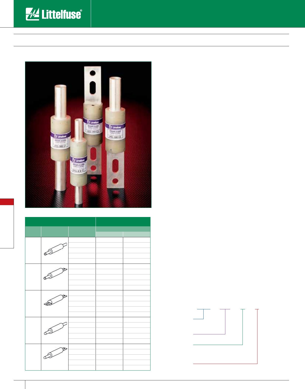
Special Purpose Fuses
108 www.littelfuse.com
Special Purpose Fuses
© 2005 Littelfuse • POWR-GARD™ Products Catalog
LFCL - 500 - C - 1
Terminal Material
Littelfuse
Cable Limiter
Type of
Termination
Conductor Size
(Aluminum or Copper)
Cable Limiters
600 Volts AC
Description Catalog Number
Type Termination Cable Size Cable Type
Cop per Aluminum
1
Cable to Cable
4/0 LFCL4/0C1 LFCL4/0A1
250MCM LFCL250C1 LFCL250A1
350MCM LFCL350C1 LFCL350A1
500MCM LFCL500C1 LFCL500A1
750MCM LFCL750C1 LFCL750A1
3
Cable to Offset
Bus
4/0 LFCL4/0C3 LFCL4/0A3
250MCM LFCL250C3 LFCL250A3
350MCM LFCL350C3 LFCL350A3
500MCM LFCL500C3 LFCL500A3
750MCM LFCL750C3 LFCL750A3
5
Straight Bus to
Offset Bus
4/0 LFCL4/0C5 –
250MCM LFCL250C5 –
350MCM LFCL350C5 –
500MCM LFCL500C5 –
750MCM LFCL750C5 –
6
Mole to Cable
4/0 LFCL4/0C6 LFCL4/0A6
250MCM LFCL250C6 LFCL250A6
350MCM LFCL350C6 LFCL350A6
500MCM LFCL500C6 LFCL500A6
750MCM LFCL750C6 LFCL750A6
8
Mole to Offset
Bus
4/0 LFCL4/0C8 –
250MCM LFCL250C8 –
350MCM LFCL350C8 –
500MCM LFCL500C8 –
750MCM LFCL750C8 –
Cable limiters are fusible devices that provide very fast short-circuit
protection, primarily to faulted cables, but also to other conductors such
as busway. Cable limiters do not have an ampere rating, and cannot be
used to provide overload protection. They are instead selected by cable
size; for example, a 500 kcmil cable requires a 500 kcmil cable limiter.
Their main use is to isolate faulted cables in circuits con tain ing three or
more parallel conductors per phase. They may be installed on the line
side of the main service to provide short-circuit protection to the service
conductors. This is especially important when service conductors are
tapped from large low voltage networks or from large low impedance
transformers.
Cable limiters have terminals which permit them to be installed in a
variety of equipment. The most common configuration is the offset
blade on one end and the crimp terminal on the other end. This permits
the limiter to replace a cable terminal (lug).
Applications
Service entrance conductors
Between transformer or network bus and busway terminal boxes
Large feeders with three or more conductors per phase
Features
• Current-limiting characteristics provide pro tec tion to conductor
insulation and reduce damage when faults occur.
• Properly applied cable limiters may permit the use of equip ment with
reduced withstand ratings
• Wide variety of terminations and cable ratings permit use in almost
every situation.
Specifications
Voltage Rating: 600 volts AC
Interrupting Rating: 200,000 Amperes
Cable Size Range: 4⁄0 – 750MCM Copper or Aluminum
Note: For Type 5 and Type 8 Aluminum cable limiters, use the Copper Type C5
and C8.
Ordering Information
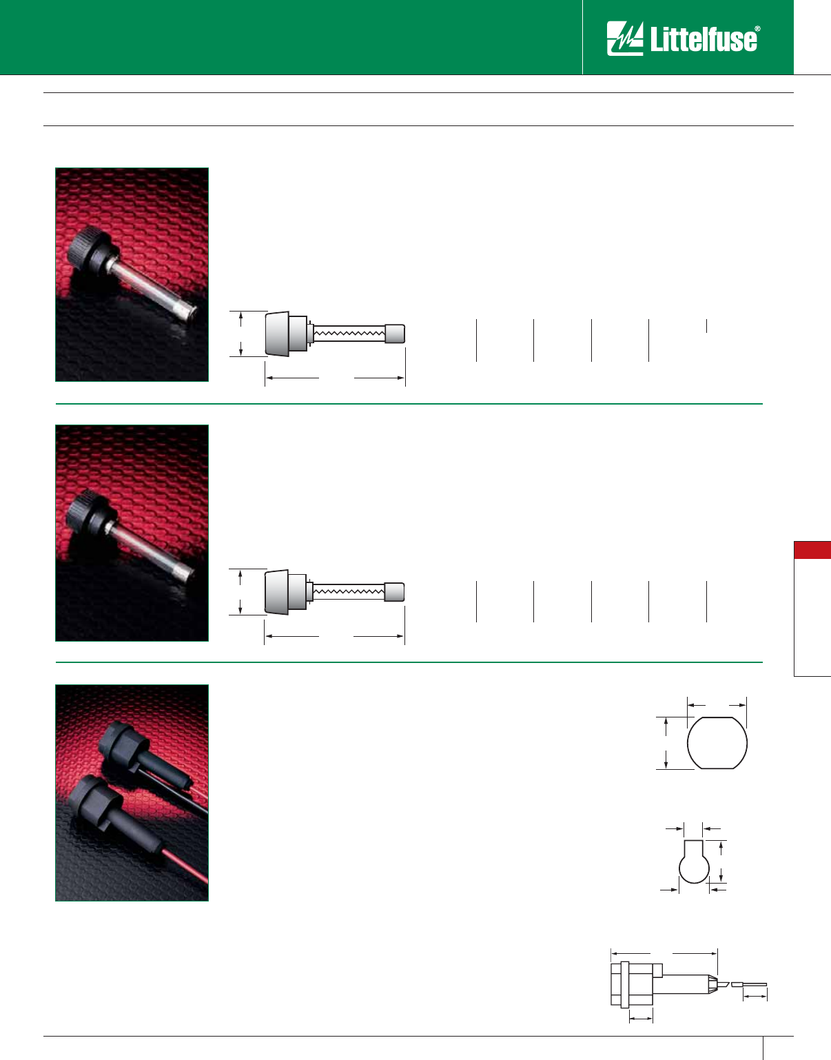
Special Purpose Fuses
109
www.littelfuse.com
Special Purpose Fuses
© 2005 Littelfuse • POWR-GARD™ Products Catalog
LGR/ LMF In-Line Fuses and LHR Holder
LGR Fuses
Fast Acting • 300 VAC
Used as in-line protection for
fluorescent fixtures, this fast
acting fuse is ideal for increasing
the safety and reliability of lighting
fixtures.
LMF Fuses
Time-Delay • 300 VAC
Perfect for use in lighting systems,
this 300 VAC time-delay fuse
is designed to handle ballast
transformer in-rush currents.
7/8"
3/4"
0.263"
0.423"
0.630"
LHR Fuse Holder
Used as in-line protection for
fluorescent fixtures, the Littelfuse
LGR and LMF series fuses and LHR
holder offer increased safety and
reliability to lighting systems. On a
277 volt system, a fault occurring
in an unfused fixture could take out
the entire branch circuit affecting
as many as 100 fixtures. This could
cause safety problems as well as
shut down operations.
By individually fusing fixtures, these
problems will be avoided. The
added benefits of this is the ability to quickly identify the problem fixture
and reduce the repair time.
Fuse holders are rated up to 10 amperes at 300 volts and are equipped
with 7" 18 AWG leads. Order part number LHR 000 for two leads, and
part number LHR 001 for one lead with the other terminal used for
insertion of 18 AWG ballast lead.
Keyhole Punch
Knock-out Hole
1.82"
0.610"
1.82"
0.610"
Specifications
Voltage Rating: 300 volts AC
Ampere Rating: LHR 000: 10A
LHR 001: 10A
Approvals: UL Recognized
Flammability Rating: 94VO
Example part number: LHR 000
Mounting Information
LHR 001/LHR 000 will fit keyhole punch or
0.875" knock-out hole. Anti-ro ta tion fea ture is
pro vid ed when used with key hole punch.
A “U-shaped” clip is avail able for panel mount-
ing (pack aged 10 clips per bag): Order part
number LHR OCA.
Specifications
Voltage Rating: 300 volts AC
Maximum In ter rupt ing Rating: 10,000A
Approvals: Standard 248-14,
UL Listed (File No: E10480)
CSA Certified (File No: LR29862)
Ampere Ratings
3⁄10 8⁄10 16⁄10 28⁄10 47
1⁄212358
6⁄10 11⁄421⁄232⁄10 61⁄410
Example part number (series & amperage): LMF 21⁄2
Specifications
Voltage Rating: 300 volts AC
Maximum Interrupting Rating: 10,000A
Approvals: Standard 248-14,
UL Listed (File No: E10480)
CSA Certified (File No: LR29862)
Ampere Ratings
1⁄216⁄10 36915
124710
11⁄221⁄25812
Example part number (series & amperage): LGR 11⁄2
2.25"
0.50"
0.50"
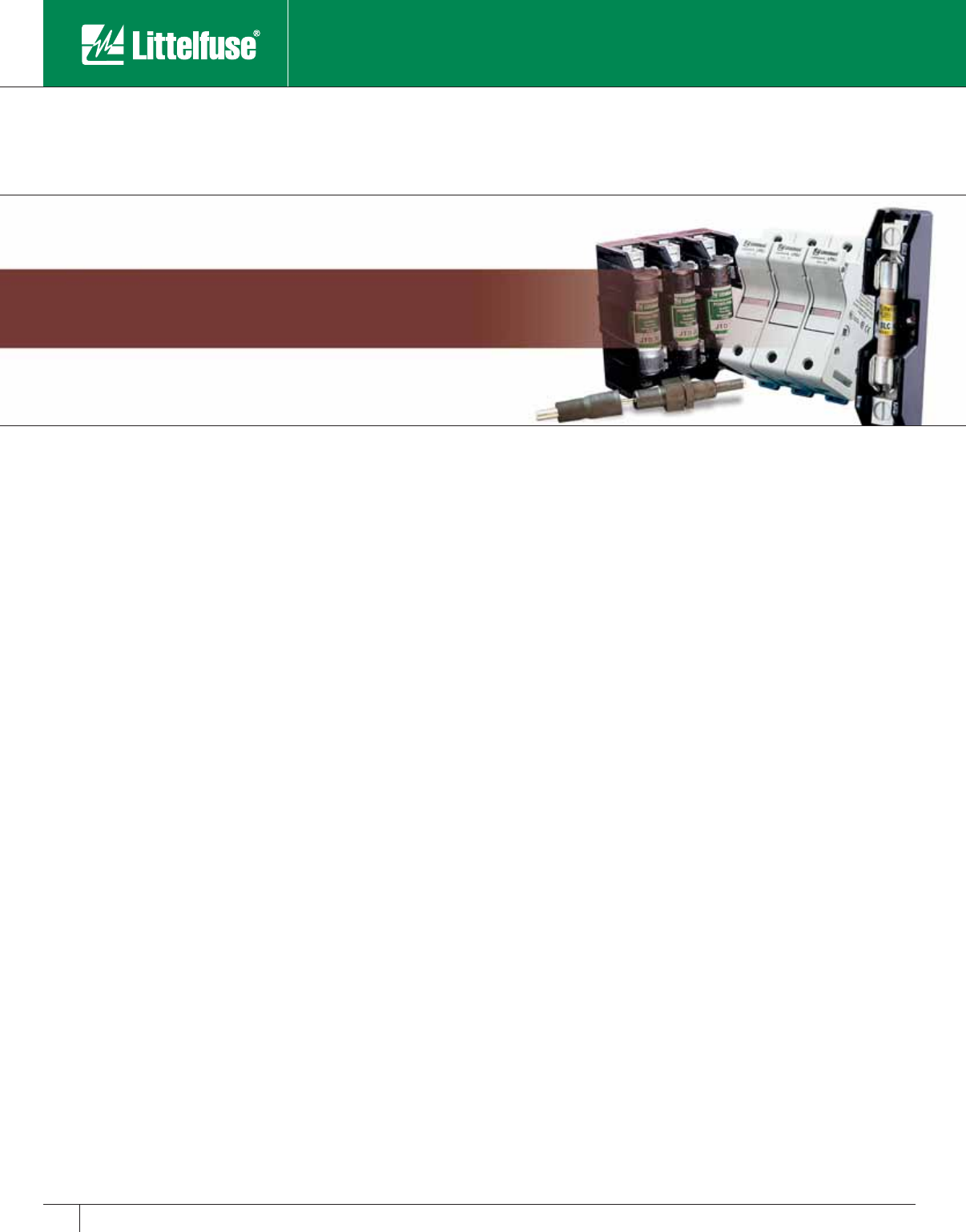
Blocks and Holders
www.littelfuse.com © 2005 Littelfuse • POWR-GARD™ Products Catalog
Fuse Blocks 111
Class H/K5 and R Fuse Blocks 112-116
Class J Fuse Blocks 117-119
Class T Fuse Blocks 120-123
Class G Fuse Blocks 124
Class CC/CD and Midget Fuse Blocks 125-126
Class CC and Midget Fuse Block Accessories 127
Fuse Block, Holders and Accessories 128-133
Semiconductor Fuse Blocks 134-136
POWR-BLOKS
™ Distribution/Splicer Blocks 137-144
In-Line Watertight Fuseholders 145-150
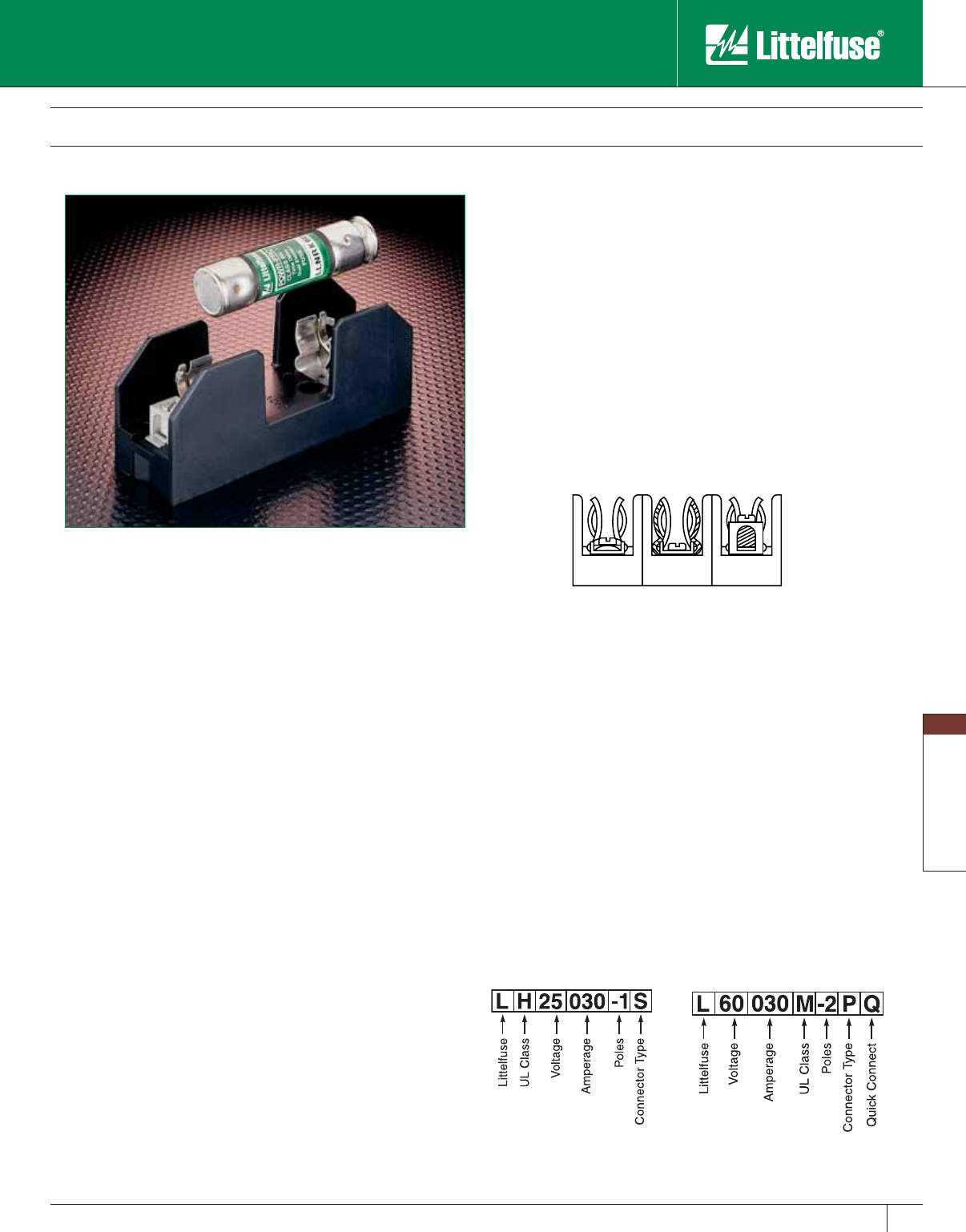
Blocks and Holders
111
www.littelfuse.com
Blocks and Holders
© 2005 Littelfuse • POWR-GARD™ Products Catalog
Fuse Blocks
General Information
Fuse Block Selection
The following guidelines should help simplify the selection of proper
fuse blocks:
1. Determine the system voltage
Since fuses are selected on the basis of sys tem voltage, fuse blocks are
selected to match the voltage rating of the fuse.
2. Determine the design short-circuit current
Available and/or design short-circuit current is an important
consideration when de ter min ing the class of fuse and fuse blocks to
use. If available short-circuit current cannot be determined, or if it will
vary with equip ment location, select fuses with a 200,000 ampere
interrupting rating (A.I.R.) and mating fuse blocks with a withstand rating
of 200,000 amperes for maximum safety.
Class H fuse blocks will accept Class H or K5 fuses (which have an
interrupting rating of up to 50,000 amperes) and Class R fuses (which
have a 200,000 A.I.R.). To prevent the possibility of inserting a fuse
with the incorrect in ter rupt ing rating, the use of Class R fuse blocks is
recommended for use with Class R fuses. Use Class H fuse blocks with
Class H or K5 fuses. These fuse blocks are dimensionally the same, but
the Class R fuse blocks incorporate a rejection feature which allows only
Class R fuses to be inserted.
3. Determine the type and ampere rating of the fuse to be used
In addition to voltage and interrupting rating as discussed above, the
fuse ampere rating, opening characteristics (fast acting or time-delay)
and size are other important con sid er ations in fuse selection. Once the
fuse type is selected, the mating fuse block can be chosen. Fuse blocks
are available in 30, 60, 100, 200, 400 and 600 amp ratings, and may be
used with a fuse rated at the cor re spond ing amperage rating or below.
For example, a fuse block rated at 30 amperes may be used with a fuse
rated from 0 to 30 amperes.
4. Determine if NEC, CSA, UL, or other requirements
are applicable
If fuse blocks will be installed in equipment to be submitted for agency
approval, the requirements should be obtained from the approving
agency in advance of fuse and fuse block selection.
5. Select the type of wire termination
A choice of three types of wire termination is available:
a) Screw* — for use with spade lugs or ring terminals.
b) Screw with Pressure Plate* — for use with solid or stranded wire
without terminal. Recommended where vibration will be a factor.
c) Box Lug — the most durable. For use with all types of solid wire and
Class B and Class C stranded wire. Not for use with welding cable or
other rope-stranded conductors.
* 1/4” Quick Connect terminals rated for up to 20A are
available on the Midget and Class CC fuse blocks.
6. Decide on the number of poles in each block
The number of poles for each set of fuses is determined by the
characteristics of the circuit. The option to gang individual fuse blocks
into long strips will be determined by the avail able space and by the
type of wire being used.
7. Determine if fuse clips need to be re in forced
Fuse clips may have a tendency to lose some of their tension over a
period of time. This may be prevented by specifying reinforced fuse
clips. Reinforced clips are standard on certain fuse blocks (see individual
product pages).
Ordering Information
The Littelfuse fuse block part number con sists of 6 or 7 components, as
shown below and in the individual fuse block data tables.
For all Class R, H, J, T and 15, 20
& 60A Class G Fuse Blocks
For all Class CC, Midget and 30A
Class G Fuse Blocks
Screw
with
Pressure
Plate
(P)
Screw
(S) Box
Lug
(C)
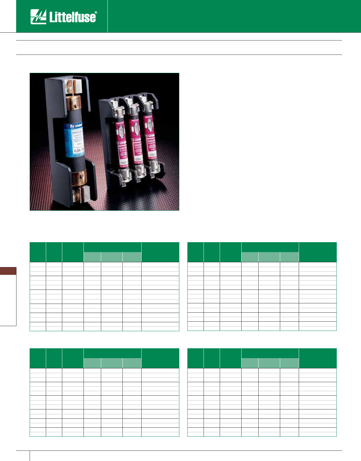
Blocks and Holders
112 www.littelfuse.com
Blocks and Holders
© 2005 Littelfuse • POWR-GARD™ Products Catalog
Class H/K5 and R Fuse Blocks
250 and 600 Volt
Class H 600V
Amp
Rating
No. of
Poles
Catalog
Number
Connector Type
(Add Suffix Shown) Max i mum Wire
Size
Screw
Pres sure
Plate
Box
Lug
1 LH60030-1 S (R) P (R) C (R) S & P = #10 CU
30 2 LH60030-2 S (R) P (R) C (R) C = #6 CU-AL
3 LH60030-3 S (R) P (R) C (R)
1 LH60060-1 C (R) S = #10 CU
60 2 LH60060-2 C (R) C = #2 CU-AL
3LH60060-3 C (R)
1LH60100-1 C
100 2 LH60100-2 C #2/0 CU-AL
3LH60100-3 C
1LH60200-1 C
200 3 LH60200-3 C 250 MCM CU-AL
1LH60400-1 CR
400 3 LH60400-3 CR (2) 350 MCM CU-AL
1LH60600-1 C
600 3 LH60600-3 C (2) 500 MCM CU-AL
Note: Reinforcing springs standard on all Class H fuse blocks 100 amperes and above.
Class H 250V
Amp
Rating
No. of
Poles
Catalog
Number
Connector Type
(Add Suffix Shown) Max i mum Wire
Size
Screw
Pres sure
Plate
Box
Lug
1 LH25030-1 S (R) P (R) C (R) S & P = #10 CU
30 2 LH25030-2 S (R) P (R) C (R) C = #6 CU-AL
3 LH25030-3 S (R) P (R) C (R)
1 LH25060-1 S (R) C (R) S = #10 CU
60 2 LH25060-2 S (R) C (R) C = #2 CU-AL
3 LH25060-3 S (R) C (R)
1LH25100-1 C
100 2 LH25100-2 C #2/0 CU-AL
3 LH25100-3 C
1 LH25200-1 C
200 3 LH25200-3 C 250 MCM CU-AL
1LH25400-1 CR
400 3 LH25400-3 CR (2) 350 MCM CU-AL
1 LH25600-1 C
600 3 LH25600-3 C (2) 500 MCM CU-AL
Note: Reinforcing springs standard on all Class H fuseblocks 100 amperes and above.
Class R 250V
Amp
Rating
No. of
Poles
Catalog
Number
Connector Type
(Add Suffix Shown) Max i mum Wire
Size
Screw
Pres sure
Plate
Box
Lug
1 LR25030-1 SR PR CR S & P = #10 CU
30 2 LR25030-2 SR PR CR C = #6 CU-AL
3 LR25030-3 SR PR CR
1 LR25060-1 CR S = #10 CU
60 2 LR25060-2 CR C = #2 CU-AL
3LR25060-3 CR
1LR25100-1 C
100 2 LR25100-2 C #2/0 CU-AL
3LR25100-3 C
1 LR25200-1 C
200 3 LR25200-3 C 250 MCM CU-AL
1LR25400-1 CR
400 3 LR25400-3 CR (2) 350 MCM CU-AL
1 LR25600-1 C
600 3 LR25600-3 C (2) 500 MCM CU-AL
Note: Reinforcing springs standard on all Class R fuse blocks.
Class R 600V
Amp
Rating
No. of
Poles
Catalog
Number
Connector Type
(Add Suffix Shown) Max i mum Wire
Size
Screw
Pres sure
Plate
Box
Lug
1 LR60030-1 SR PR CR S & P = #10 CU
30 2 LR60030-2 SR PR CR C = #6 CU-AL
3LR60030-3SR PR CR
1 LR60060-1 CR S = #10 CU
60 2 LR60060-2 CR C = #2 CU-AL
3LR60060-3 CR
1LR60100-1 C
100 2 LR60100-2 C #2/0 CU-AL
3LR60100-3 C
1LR60200-1 C
200 3 LR60200-3 C 250 MCM CU-AL
1LR60400-1 CR
400 3 LR60400-3 CR (2) 350 MCM CU-AL
1LR60600-1 C
600 3 LR60600-3 C (2) 500 MCM CU-AL
Note: Reinforcing springs standard on all Class R fuse blocks.
Class H and Class R fuse blocks are dimensionally the same, but Class R blocks
incorporate a rejection feature, which only allows Class R fuses to be inserted.
Features/Benefits
• Class H and Class R fuse blocks feature clip designs to maximize
electrical contact and minimize heat rise.
• Reinforcing clips are standard on all Class H fuse blocks rated 100
amp and higher. Note: For reinforcing clips on Class H blocks rated 30-60
amp, add “R” suffix to connector type.
• Reinforcing clips are standard on all Class R fuse blocks
Specifications
Voltage Rating: 250 Volts; 600 Volts
Ampere Ratings: 0 – 600 amperes
Approvals: UL Listed (File No. E14721)
CSA Certified (File No. LR73091)
Recommended Fuses
Note: For optional fuse block covers, refer to POWR-Covers section of this catalog.
Class H Blocks Class R Blocks
250V 600V 250V 600V
NLN NLS FLNR/FLNR_ID FLSR/FLSR_ID
RLN RLS KLNR KLSR
LLNRK LLSRK/LLSRK_ID
TLN IDSR
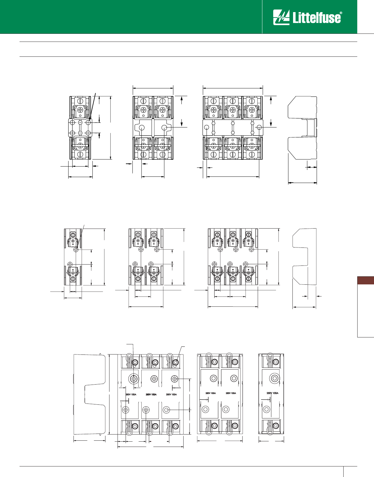
Blocks and Holders
113
www.littelfuse.com
Blocks and Holders
© 2005 Littelfuse • POWR-GARD™ Products Catalog
.28 (7.1) THRU
.53 (13.5) C'BORE x .60 (15.2) DP
6.13
.61
.63
1.56
TYP. 1.56
TYP. FUSE q
2.37
1.88
.187 HEX
SOCKET
3 POLE 2 POLE 1 POLE
STRIP
GAUGE
STRIP
GAUGE
STRIP
GAUGE
STRIP
GAUGE
3.49
[88.6] 1.93
[49.0]
5.05
[128.3]
2.44
[62.0]
Class H/K5 and R Fuse Blocks
250 Volt
3.00"
[76.2]
.50"
[13]
1.25"
[31.8]
.22/5.6 DIA. HOLE THRU
4 PLACES
.75"
[19]
1.25"
[31.7]
1.12"
[28.4]
1.91"
[48.5]
2.95"
[74.9]
2.50"
[63.5]
.22"
[5.7]
.33"
[8.4]
.19"
[4.8]
1.38"
[35.1]
.53"
[13]
1.50"
[38.1] 1.50"
[38.1]
1 POLE 2 POLE 3 POLE
2.01"
[51.1]
.74"
[19]
4.23"
[108]
.50"
[12.7]
.49
[12] 1.33"
[33.7]
4.83"
[122.7]
1.33"
[33.7]
1.24"
[31.5]
1.79"
[45.6]
2.86"
[72.7]
.50"
[12.7]
.49"
[12]
4.83"
[122.7]
1.33"
[33.7]
1.24"
[31.5]
1.79"
[45.6]
1.48"
[37.6]
.50"
[12.7]
4.83"
[122.7]
.49"
[12]
1.24"
[31.5]
1.79"
[45.6]
.218/[5.54] DIA.
C'BORE .400/[10.16] DIA. X .63[16] DP
1 POLE 2 POLE 3 POLE
250V 30A
250V 60A
250V 100A
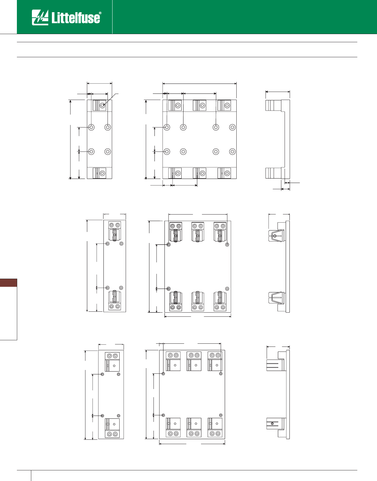
Blocks and Holders
114 www.littelfuse.com
Blocks and Holders
© 2005 Littelfuse • POWR-GARD™ Products Catalog
[355.6]
[279.4]
[19]
[111]
4.37"
4.50"
[317.5]
[114.3]
14.00"
.75"
5.00"
12.50"
[127]
11.00"
[355.6]
4.50"
[114.3]
14.00"
4.50"
[114.3]
5.00"
[127]
1 POLE 3 POLE
10.50"
3.31"
9.25"
[235] [84]
[266.7]
3.75"
[292.1]
11.50"
[95.3]
3.75
[292.1]
11.50"
4.00"
[101.6] 4.00"
[101.6]
[95.2]
3.50"
[88.9]
1 POLE 3 POLE
Class H/K5 and R Fuse Blocks
250 Volt
.66"
2.00"
9.00"
.50"
[229]
[52.3]
2.06"
3.01"
1.06"
[76.5]
[102]
4.00"
[16.8]
[26.9]
3.00"
[31.2] [76.2]
1.23"
[50.8]
[13]
2.00"
3.00"
.50"
[76.2]
3.00"
[76.2]
3.00"
[76.2]
[52.3]
2.06"
.312" HEX.
7.13"
[181.1]
7.13"
[181.1]
[50.8]
[13]
1 POLE 3 POLE
250V 400A
250V 200A
250V 600A
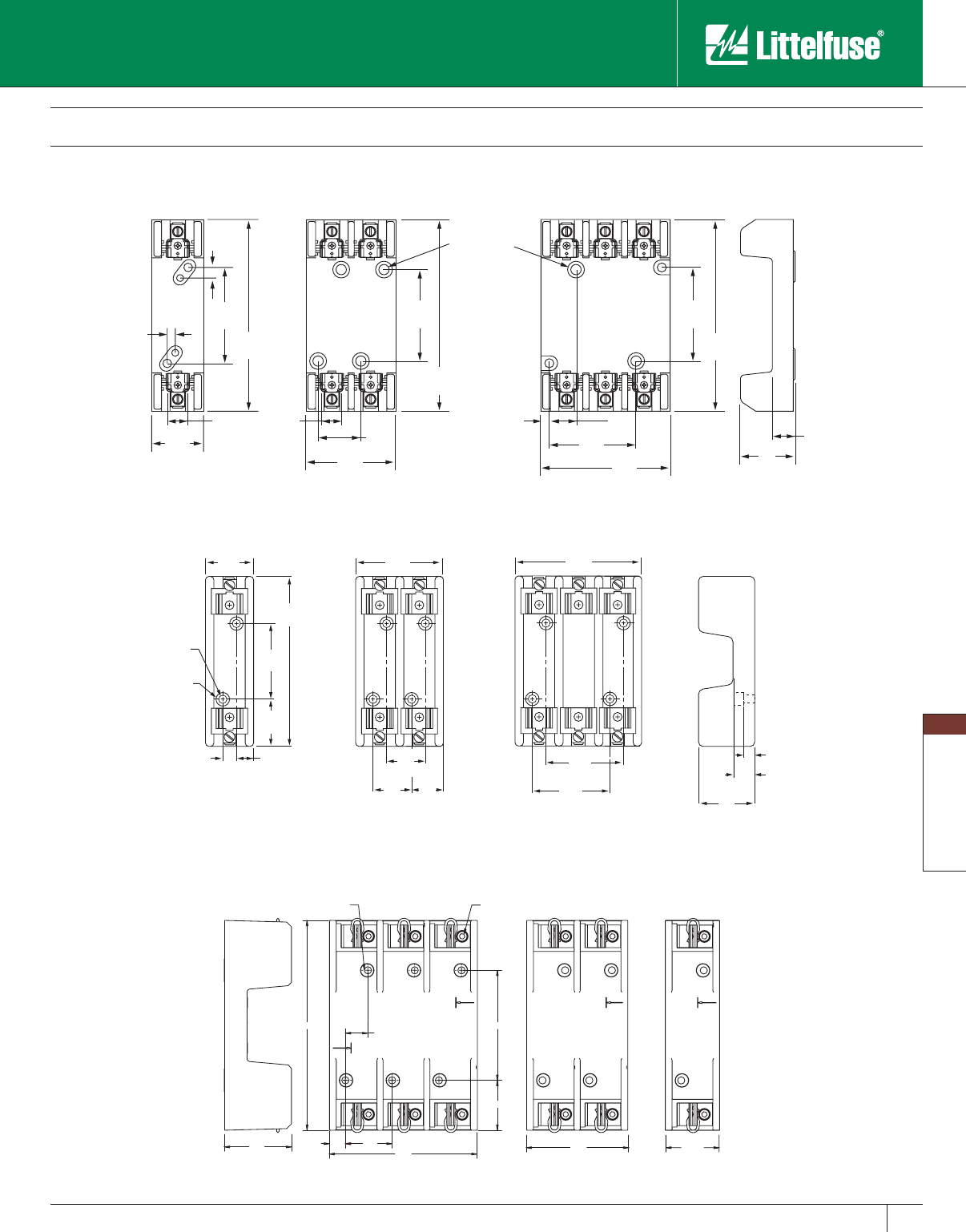
Blocks and Holders
115
www.littelfuse.com
Blocks and Holders
© 2005 Littelfuse • POWR-GARD™ Products Catalog
8.13 .87
.61 1.81
TYP.
4.26
1.93
3 POLE
.187 HEX
SOCKET
.28 (7.1) DIA. THRU
.59 (14.9) C'BORE x .64 (16.2) DP.
TYP.
2 POLE 1 POLE
2.10
[53.3]
3.91
[99.3]
5.73
[145.5]
2.60
[66.0]
STRIP
GAUGE
STRIP
GAUGE
STRIP
GAUGE
STRIP
GAUGE
Class H/K5 and R Fuse Blocks
600 Volt
6.25"
[159]
6.25"
[159]
6.25"
[159]
1.69"
[42.9]
1.63"
[41.4]
2.94"
[74.7]
4.25"
[108]
3.13"
[79.2]
.62"
[16]
1.56"
[39.6]
3.13"
[79.4]
3.13"
[79.4]
3.13"
[79.4]
.34"
[8.7]
.31"
[7.9]
.38"
[97]
.25"
[6.5]
.69"
[18]
.265" [6.7] DIA. THRU
.05" [12.7] C'BORE
x .44 [11.2] DP.
1 POLE 2 POLE 3 POLE
3.51"
[89.2]
.77"
[19.6]
.27"
[6.8]
.66"
[19.6]
.62"
[15.7]
3.12"
[79.2]
6.75"
[171.4]
1.95"
[49.5]
.281" D.
[7.1]
.50" D.
[12.7]
1.81"
[46]
1.29"
[32.8]
1.56"
[39.6]
1.56"
[39.6]
5.08"
[1.29]
3.12"
[79.2]
3.12"
[79.2]
2.12"
[53.8]
1 POLE 2 POLE 3 POLE
600V 30A
600V 60A
600V 100A
Blocks and Holders
116 www.littelfuse.com
Blocks and Holders
© 2005 Littelfuse • POWR-GARD™ Products Catalog
10.50"
3.31"
9.25"
[235] [84.1]
[266.7][57.2]
3.75"
7.00"
[177.8]
[95.3]
2.25"
3.75
[368.3]
14.50"
[368.3]
14.50"
7.00"
[177.8]
[95.3]
3.50 "
[88.9]
1 POLE 3 POLE
[431.8]
[279.4]
[19] [109.5]
4.31"
4.50"
[317.5]
[114]
17.00"
.75"
8.00"
12.50"
[203]
11.00"
[431.8]
4.50"
[114]
17.00"
4.50"
[114.3]
8.00"
[203]
[76.2 ]
3.00"
1 POLE 3 POLE
.66"
2.00"
9.00"
.50"
[229]
[84.1]
3.31"
3.00"
[76.2]
3.01"
1.06"
[76.5]
[102]
4.00"
[244]
[16.8]
[26.0]
3.00"
[31.2] [76.2]
1.23"
[50.8]
[13]
2.00"
3.00"
.50"
[76.2]
[84.1]
3.31"
3.00"
[76.2]
.312" HEX.
9.62" 9.62"
[244]
[50.8]
[13]
1 POLE 3 POLE
Class H/K5 and R Fuse Blocks
600 Volt
600V 200A
600V 400A
600V 600A
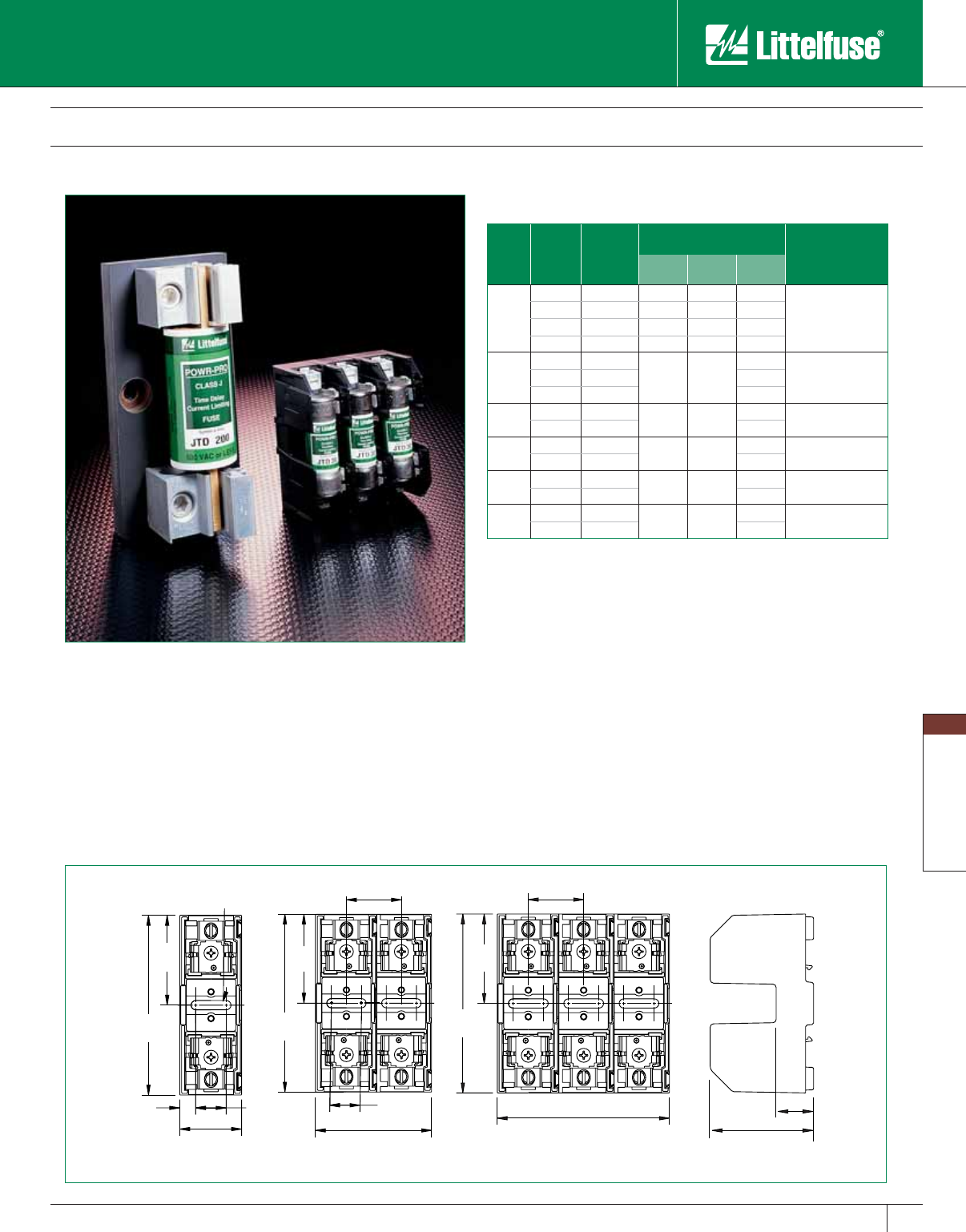
Blocks and Holders
117
www.littelfuse.com
Blocks and Holders
© 2005 Littelfuse • POWR-GARD™ Products Catalog
Class J Fuse Blocks
600 Volt
1.16"
[29.4]
.30"
TYP.
[7.6]
1.69"
[42.8]
3.38"
[85.7]
.57"
[14.5]
.71"
[17.9]
1.95"
[49.5]
.216[5.5] x .79[20.0] SLOT
MOUNTING HOLE
1.69"
[42.8]
3.38"
[85.7]
.57
[14.5]
" TYP.
2.20"
[56.0]
1.04"
[26.4]
1.69"
[42.8]
3.38"
[85.7]
3.25"
[82.5]
1.04"
[26.4]
1 POLE 2 POLE 3 POLE
Class J 600V
Amp
Rating
No. of
Poles
Catalog
Number
Connector Type
(Add Suffix Shown) Max i mum
Wire Size
Screw
Pres sure
Plate
Box
Lug
30
1 LJ60030-1 S (R) P (R) C (R)
S & P = #10 CU
C = #6 CU
2 LJ60030-2 S (R) P (R) C (R)
3 LJ60030-3 S (R) P (R) C (R)
Adder LJ60030-A S (R) P (R) C (R)
60
1LJ60060-1 C (R)
C = #2 CU-AL2LJ60060-2 C (R)
3LJ60060-3 C (R)
100 1LJ60100-1 CR #2/0 CU-AL
3LJ60100-3 CR
200 1LJ60200-1 C 250 MCM CU-AL
3LJ60200-3 C
400 1LJ60400-1 CR
(2) 350 MCM CU-AL
3LJ60400-3 CR
600 1LJ60600-1 CR
(2) 500 MCM CU-AL
3LJ60600-3 CR
Note: Reinforcing springs standard on all Class J fuse blocks rated 100A and above.
*For optional fuse block covers, refer to POWR-Covers section of this catalog. For
reinforcing clips on blocks rated 30-60 amp, add “R” suffix to connector type.
Features/Benefits
• Phenolic blocks have side barriers for isolation.
• Spring reinforced fuse clips are standard on 100A and larger blocks.
Reinforcing springs are optional on 30 and 60 amp blocks.
• Space saving 30A design — Up to 45% smaller than existing
30A fuse blocks. 30A interlocking adder block available to create
any number of poles (consult factory for availability). Integral DIN rail
mount allows this block to be securely fastened to 35 mm “hat” type
DIN rails without the use of tools.
Specifications
Voltage Ratings: 600 Volts
Ampere Ratings: 0 – 600 amperes
Approvals: UL Listed: File No. E14721
CSA Certified: File No. LR73091
Recommended Fuses
JTD_ID/JTD (time-delay) and JLS (fast acting) series fuses
LJ60030
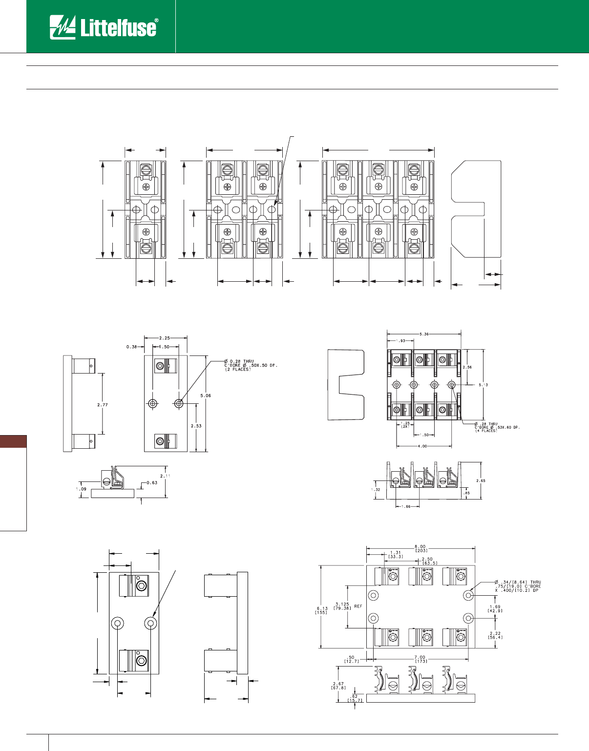
Blocks and Holders
118 www.littelfuse.com
Blocks and Holders
© 2005 Littelfuse • POWR-GARD™ Products Catalog
Class J Fuse Blocks
600 Volt
1.53"
[38.8]
1.53"
[38.8]
1.53"
[38.8]
.76"
[19]
.76"
[19]
.76"
[19]
.45"
[12]
.45"
[12] .45"
[12]
.57"
[14 ]
2.03"
[51.7]
.265" x .325" SLOT
[6.7 x 8.3] TYP.
1 POLE 2 POLE 3 POLE
4.07"
[103]
2.03"
[51.7]
4.07"
[103]
4.07"
[103]
2.03"
[51.7]
2.09"
[53.0]
4.72"
[120]
3.20"
[81.2]
1.67"
[42.4]
LJ60060
.50"
2.00"
3.00"
1.31"
.62"
2.67"
6.13"
.34" THRU
.75" C'BORE
x .400" DP.
[33.39]
[76.2]
[8.6]
[19.1]
[10.2]
[156]
[13]
[50.8] [67.9]
[16]
1 POLE 3 POLE
LJ60100
LJ60200
1 POLE 3 POLE
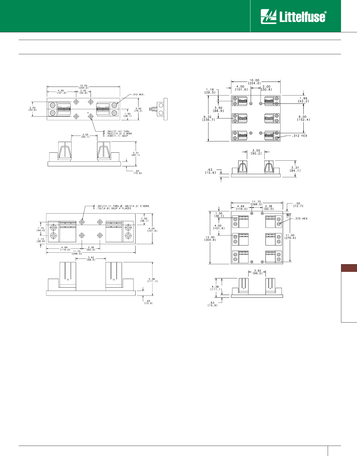
Blocks and Holders
119
www.littelfuse.com
Blocks and Holders
© 2005 Littelfuse • POWR-GARD™ Products Catalog
Class J Fuse Blocks
600 Volt
1 POLE
1 POLE 3 POLE
LJ60400
3 POLE
LJ60600
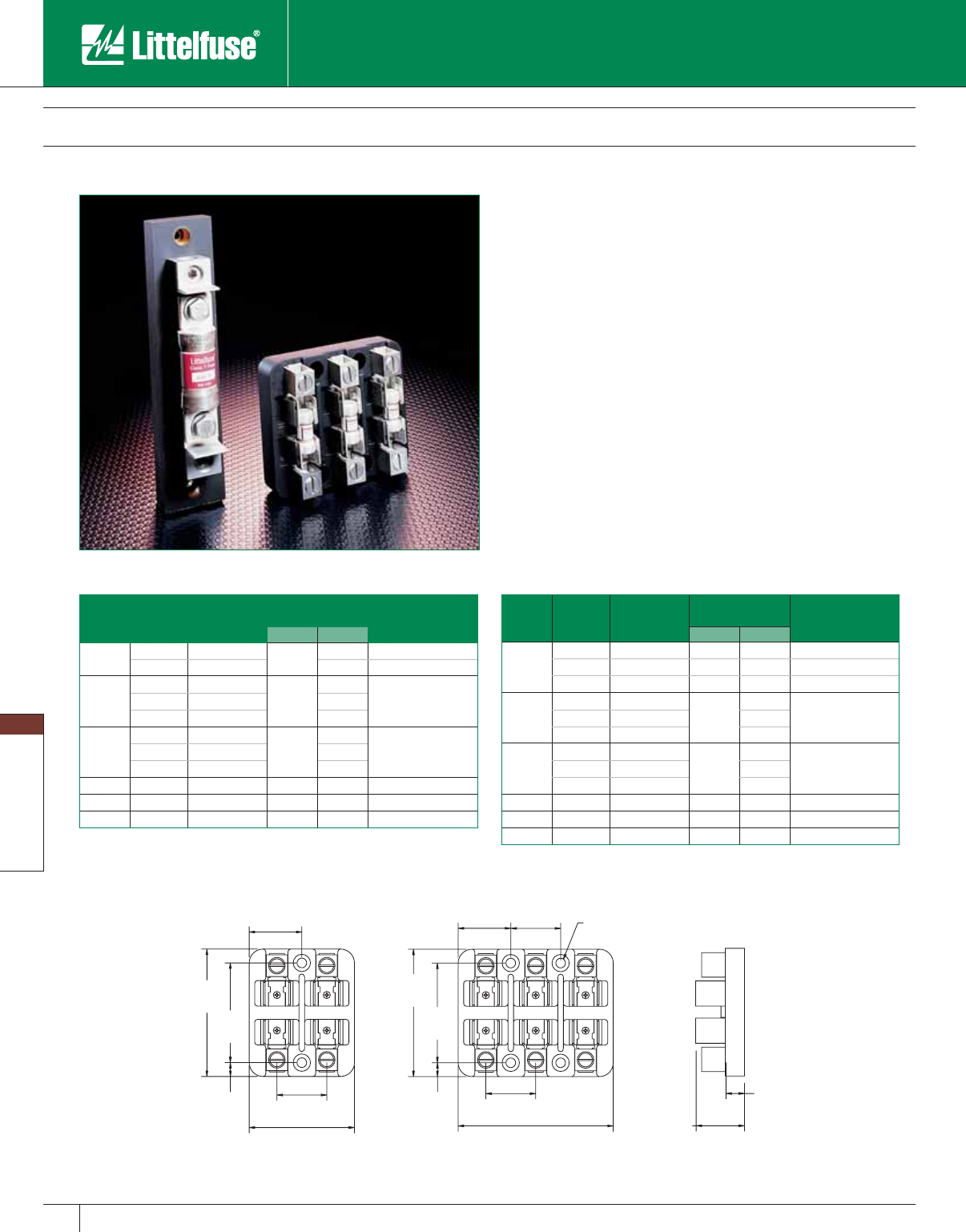
Blocks and Holders
120 www.littelfuse.com
Blocks and Holders
© 2005 Littelfuse • POWR-GARD™ Products Catalog
Class T Fuse Blocks
300 and 600 Volt
.31"
[7.9]
2.88"
[73.0]
2.25"
[57.2]
1.19"
[30.2]
1.13"
[28.6]
0.62"
[15.9]
3.50"
[88.9]
1.12"
[28.5]
1.13"
[28.6]
0.218" [5.54] THRU
0.39" [9.91] C'BORE
x 0.44" [9.91] DP.
2.88
[73.0]
2.25
[57.2]
1.19
[30.2]
1.13
[28.6]
2.38
[60.3]
.31
[7.9]
2 POLE 3 POLE
LT30030
Class T 300V
Amp
Rating
No. of
Poles
Catalog
Number
Connector Type
(Add Suffix Shown) Max i mum
Wire Size
Screw Box Lug
30 2 LT30030-2 CR S = #10 CU
3 LT30030-3 CR C = #2 CU
60
2LT30060-2 CR
C = #2 CU-AL3LT30060-3 CR
4LT30060-4 CR
100
1LT30100-1 C
#2⁄0 CU-AL2LT30100-2 C
3LT30100-3 C
200 1 LT30200-1 C 250 MCM CU-AL
400 1 LT30400-1 C (2) 250 MCM CU-AL
600 1 LT30600-1 C (2) 500 MCM CU-AL
Note: Reinforcing springs standard on all 300 volt Class T fuse blocks up to 100
amperes. 300 volt Class T blocks 200 amperes and larger have stud mountings.
Class T 600V
Amp
Rating
No. of
Poles
Catalog
Number
Connector Type
(Add Suffix Shown) Max i mum
Wire Size
Screw Box Lug
30
1 LT60030-1 SR CR S = #10 CU
2 LT60030-2 SR CR C = #2 CU-AL
3LT60030-3SRCR
60
1LT60060-1 CR
C = #2 CU-AL2LT60060-2 CR
3LT60060-3 CR
100
1LT60100-1 C
#2⁄0 CU-AL2LT60100-2 C
3LT60100-3 C
200 1 LT60200-1 C 250 MCM CU-AL
400 1 LT60400-1 C (2) 250 MCM CU-AL
600 1 LT60600-1 C (2) 500 MCM CU-AL
Note: Reinforcing springs standard on all 600 volt Class T fuse blocks up to 60
amperes. 600 volt Class T blocks 100 amperes and larger have stud mountings.
Features/Benefits
Bases are molded phenolic. To provide a low resistance connection and
long-range re li abil i ty, steel re in forc ing springs are supplied as standard.
Larger blocks employ an in te gral heat sink for maximum heat dissipation.
Specifications
Voltage Ratings: 300 Volts AC
600 Volts AC
Ampere Ratings: 0 – 600 amperes
Approvals: UL Listed (File No. E14721)
CSA Certified (File No. LR73091)
Recommended Fuses
JLLN (300V) and JLLS (600V) series fuses
300 and 600 volt fuse blocks are designed for use with miniaturized Class T
fuses. Class T fuses are very fast acting, current-limiting, and approximately
one-third the size of electrically comparable Class RK1 fuses.
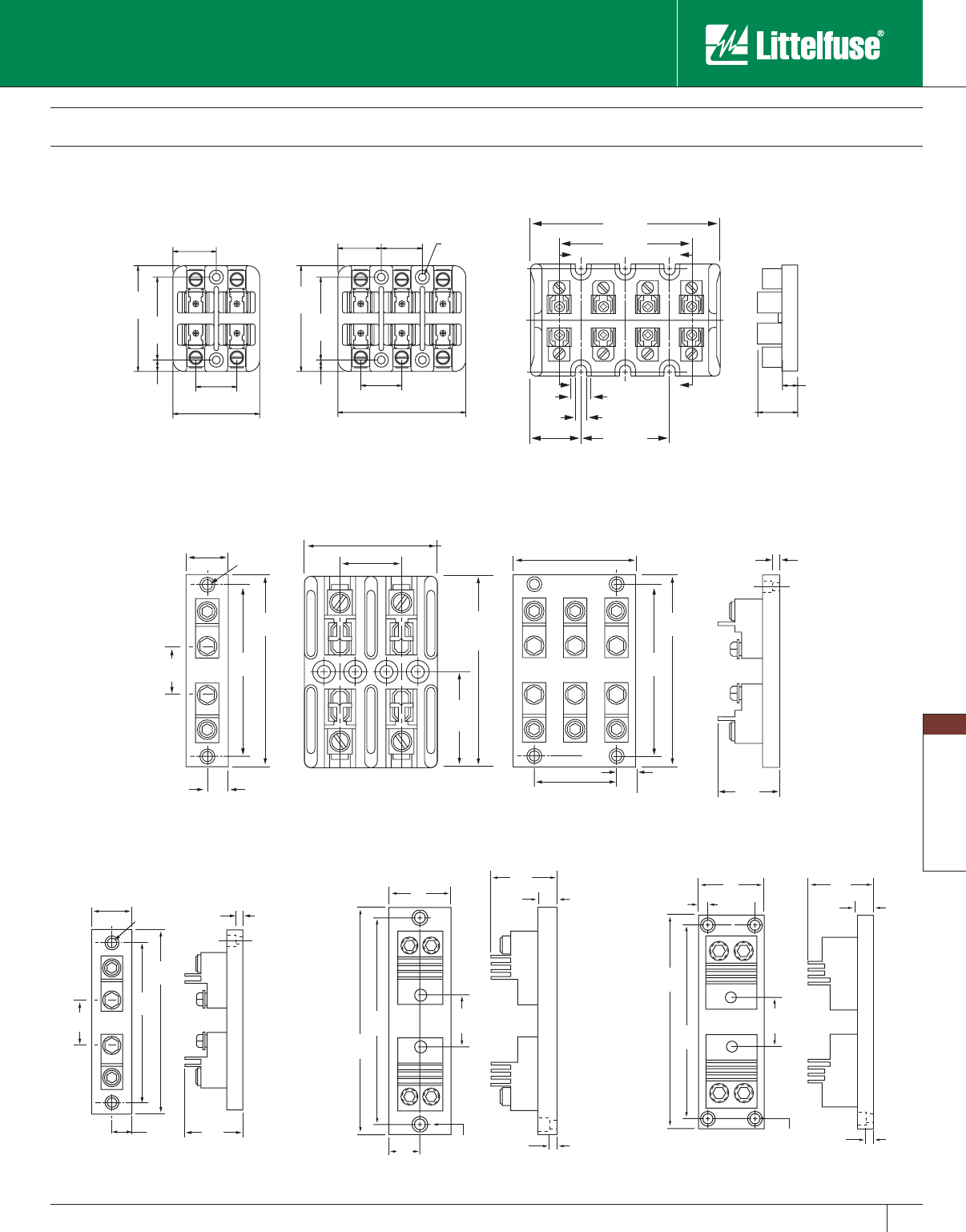
Blocks and Holders
121
www.littelfuse.com
Blocks and Holders
© 2005 Littelfuse • POWR-GARD™ Products Catalog
.31"
[7.9]
2.88"
[73.0]
2.25"
[57.2]
1.19"
[30.2]
1.13"
[28.6]
0.62"
[15.9]
3.50"
[88.9]
1.28"
[32.5]
1.13"
[28.6]
0.20"
[5.2]
1.20"
[30.6]
2.06"
52.4]
0.44"
[11.1]
3.09"
[78.6]
4.47"
[113.5]
0.218" [5.54] THRU
0.39" [9.91] C'BORE
x 0.44" [9.91] DP.
2.88
[73.0]
2.25
[57.2]
1.19
[30.2]
1.13
[28.6]
2.38
[60.3]
0.31
[7.9]
2 POLE 3 POLE 4 POLE
4.50"
[114.3]
5.25"
[133.3]
3.09"
[78.6]
1.56"
[39.6]
1.37
[34.8]
.203" [5.1]
DIA.HOLE
0.69"
[17.5]
.37" [9.5]
C'BORE
4.78"
[121.4]
2.39"
[60.7]
0.18"
[4.6]
1.87"
[47.5]
1 POLE 2 POLE
1.41"
[35.7]
4.50"
[114.3]
5.25"
[133.3]
4.12"
[104.6]
2.75"
[69.8]
0.69"
[17.5]
3 POLE
6.25"
[158.7]
7.00"
[177.8]
1.69"
[42.9]
1.50"
[38.1]
.281" [7.1]
DIA.HOLE
.69"
[17.5]
.50" [12.7]
C'BORE
1 POLE
.18"
[4.6]
2.25"
[57.1]
1 POLE
8.12"
[206.2]
7.37"
[187.3]
1.12"
[28.6]
1.84"
[46.7]
0.28" [7.1] DIA HOLE
0.50" [12.7] C'BORE
x 0.43" [10.9] DEEP
2.25"
[57.1]
0.19"
[48]
2.37"
[60.2]
0.62"
[15.7]
1 POLE
8.75"
[222.2]
8.06"
[203.2]
2.03"
[51.6]
0.28" [7.1] DIA HOLE
0.50" [12.7] C'BORE
x 0.43" [10.9] DEEP
2.75"
[69.8]
0.37"
[9.5]
0.19"
[4.8]
2.62"
[66.5]
0.62"
[15.7]
Class T Fuse Blocks
300 Volt
LT30060
LT30100
LT30200 LT30400 LT30600
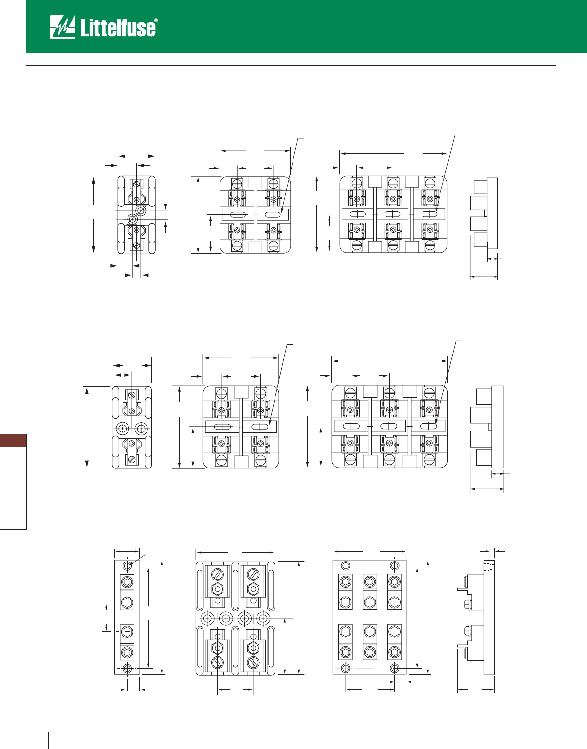
Blocks and Holders
122 www.littelfuse.com
Blocks and Holders
© 2005 Littelfuse • POWR-GARD™ Products Catalog
5.31"
[134.9]
[153.9]
2.36"
[6.0]
1.37
[34.8]
0.203" [5.1]
DIA.HOLE
0.69"
[17.5]
0.37" [9.5]
C'BORE
5.31"
[134.9]
2.39"
[60.7]
4.78"
[121.4]
6.06"
[153.9]
3.09'"
[78.6]
1.41"
[35.7]
4.12"
[104.6]
2.75"
[69.8]
0.69"
[17.5]
0.18"
[4.6]
1.87"
[47.5]
1 POLE 3 POLE
2 POLE
6.06'
3.13"
[79.4]
1.56"
[39.7]
0.218" x 0.655"
[5.54 x 16.64]
SLOT 2 PLS.
0.78"
[20]
3.38"
[85.7]
1.69"
[42.9]
2 POLE1 POLE
1.81"
[46.0]
2.31"
[58.7]
0.91"
[23.0]
0.63"
[16]
1.74"
[44.2]
0.218" x 0.655"
[5.54 x 16.64]
SLOT 2 PLS.
4.69"
[119]
1.56"
[39.7]
0.78"
[20]
3.38"
[85.7]
1.69"
[42.9]
3 POLE
3.13"
[79.4]
0.91"
[23.0]
0.33"
[8.3]
1.44"
[36.5]
0.33"
[8.3]
0.55"
[13.9]
1.56"
[39.7]
0.218" x 0.655"
[5.54 x 16.64]
SLOT 2 PLS.
0.78"
[20]
3.38"
[85.7]
1.69"
[42.9]
0.218" x 0.655"
[5.54 x 16.64]
SLOT 2 PLS.
4.69"
[119]
1.56"
[39.7]
0.78"
[20]
3.38"
[85.7]
1.69"
[42.9]
2 POLE1 POLE 3 POLE
0.62"
[15.9]
1.28"
[32.5]
3.19"
[81.0]
Class T Fuse Blocks
600 Volt
LT60030
LT60060
LT60100
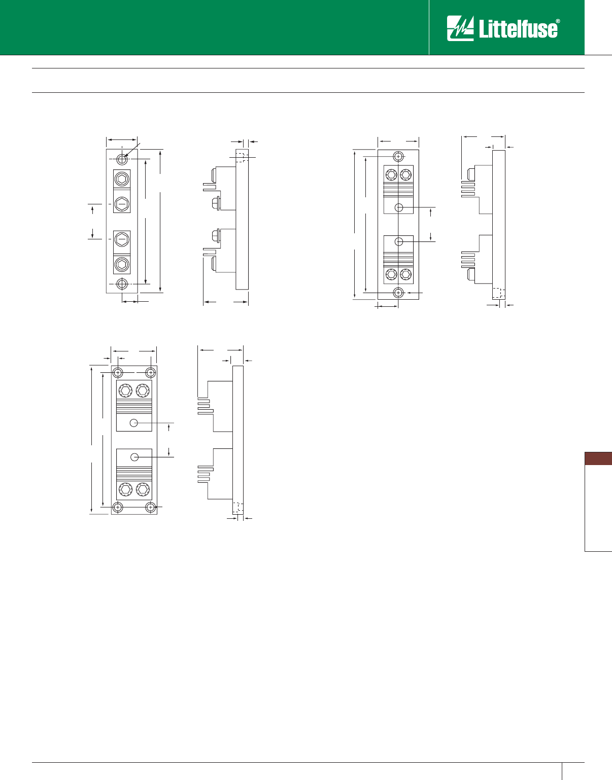
Blocks and Holders
123
www.littelfuse.com
Blocks and Holders
© 2005 Littelfuse • POWR-GARD™ Products Catalog
7.0"
[177.8]
7.75"
[196.8]
2.50"
[63.5]
1.50"
[38.1]
0.281" [7.1]
DIA.HOLE
0.75"
[19.0]
0.50" [12.7]
C'BORE
1 POLE
.18"
[4.6]
2.25"
[57.1]
9.00"
[228.6]
8.25"
[209.5]
1.12"
[28.6]
2.72"
[69.1]
0.28" [7.1] DIA HOLE
0.50" [12.7] C'BORE
x 0.43" [10.9] DEEP
2.25"
[57.1]
0.19"
[4.8]
2.37"
[60.2]0.62"
[15.7]
1 POLE
9.75"
[247.6]
9.0"
[228.6]
2.95"
[75.0]
0.28" [7.1] DIA HOLE
0.50" [12.7] C'BORE
x 0.43" [10.9] DEEP
2.75"
[69.8]
0.37"
[9.5]
0.19"
[4.8]
2.62"
[66.5] 0.62"
[15.7]
1 POLE
Class T Fuse Blocks
600 Volt
LT60200 LT60400
LT60600

Blocks and Holders
124 www.littelfuse.com
Blocks and Holders
© 2005 Littelfuse • POWR-GARD™ Products Catalog
Class G Fuse Blocks
Specifications
Voltage Ratings: 600 Volts AC (0 – 20A)
480 Volts AC (25 – 60A)
Ampere Ratings: 0 – 60 amperes
Approvals: UL Listed: 15, 20 & 30A (File No. E14721)
60A (File No. E14853)
CSA Certified: 15, 20 & 30A (File No. LR7316)
60A (File No. LR47235)
Recommended Fuses
SLC series fuses
0.36"
[9.13]
0.86"
[21.83] 1.675"
[42.55]
2.375"
[60.33]
0.22"
[5.56]
3.0"
[76.2]
1.53"
[38.89]
0.42"
[10.72]
0.77"
[19.45]
0.42"
[10.72]
MOUNTING
SLOTS
0.17" X 0.22"
[4.37 x 5.56]
1 POLE 2 POLE
3 POLE
Note: Refer to the Midget/Class CC Fuse Blocks for L30030G 30A Class G Block dimensions.
Class G fuse blocks are designed for use with 480 volt time-delay,
current-limiting Class G fuses. They meet requirements for branch
circuit protection.
Amp
Rating
No. of
Poles
Cat a log
Number
Connector Type
(Add Suffix Shown) Max i mum
Wire Size
Screw Pres sure
Plate
Box
Lug
15*
1LG30015-1SQ
#10 CU2LG30015-2SQ
3LG30015-3SQ
20*
1LG30020-1SQ
#10 CU2LG30020-2SQ
3LG30020-3SQ
30*
1L30030G-1SQ PQ
#10 CU2L30030G-2SQ PQ
3L30030G-3SQ PQ
60
1LG30060-1 CR
#2 CU-AL2LG30060-2 CR
3LG30060-3 CR
* Note: 15, 20 & 30A Class G fuse blocks are equipped with 20A Quick Connect
Terminals. 60A fuse block equipped with reinforcing spring as standard.
LG30015 &
LG30020
LG30060
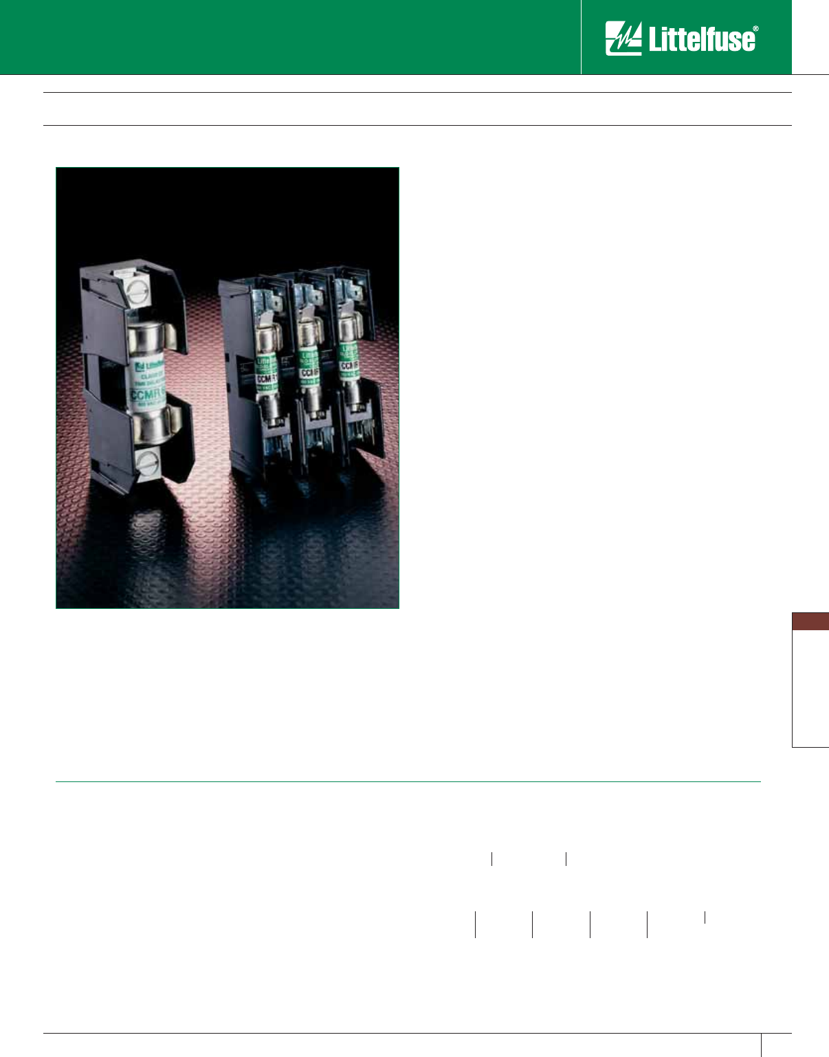
Blocks and Holders
125
www.littelfuse.com
Blocks and Holders
© 2005 Littelfuse • POWR-GARD™ Products Catalog
Class CC/CD and Midget Fuse Blocks
600 Volt
Space saving 600 volt, 30 amp molded case fuse blocks with side
barriers for isolation. Class CC blocks and Midget blocks are identical
except Class CC blocks incorporate a rejection feature to assure proper
fusing.
Safety
• Rejection feature — Class CC fuse blocks have a rejection feature
which prevents the insertion of fuses with lower interrupting rating
or voltage ratings. Class CC fuses are rated 600 volts and have an
interrupting rating of 200,000 amperes. Midget fuse voltage ratings
vary and their interrupting rating may be as low as 10,000 amperes.
Note that Class CC fuses may be used in Midget fuse blocks, but Midget
fuses cannot be used in Class CC blocks.
Long life
• High-strength materials — Class CC and Midget fuse blocks are
molded of high-strength, high-temperature material to min i mize
block breakage during handling and installation, as well as damage
caused by overheating.
• Reduced resistance, less heat — High con duc tiv i ty, one-piece copper
alloy fuse clips have lower resistance than traditional two-piece brass
or phosphor bronze fuse clips, which minimizes heat rise and watts
loss within the fuse block.
Reduced inventory
• Gangable — Interlocking fuse blocks allow ganging to produce a fuse
block with any number of poles.
• Flexible terminal arrangements — 30A Class CC and Midget fuse
blocks are available with type C box lug, type SQ screw, or type
PQ pressure plate terminals. Type SQ ter mi nals have binding-head
screws, while type PQ terminals have captive pressure plates. Both
terminal types can ac com mo date side or top mounted quick-connect
ter mi nals. This flexibility allows the ac com mo da tion of most needs
and reduces part inventory requirements.
• 60A CD fuse blocks are available with type C box lug terminals.
• DIN rail mountable — FBDIN1 adapters permit snap-mounting
Littelfuse Class CC and Midget 30 amp fuse blocks directly to
standard or low profile 35mm sym met ri cal “hat” and 32mm
asymmetrical DIN rails. Patented DIN rail adapters snap securely to
Littelfuse fuse blocks and to DIN rails without tools. They can be
readily removed from rails by lifting the disconnect tab.
• L60060C 60A fuse blocks have patented integral DIN rail adapters
which allow direct mounting to 35mm “hat” type DIN rails.
Specifications
Voltage Rating: 600 Volts AC/600 Volts DC
Ampere ratings: L60030C: 30 amps
L60030M: 30 amps
L60060C: 60 amps
Dielectric strength: 1200 volts minimum
Clip/terminals: Tin-plated copper alloy
Box lug: Copper
Screw and captive pressure plate: Zinc-plated steel
Base: Thermoplastic. UL 94VO flammability rating.
Approvals: Class CC: UL Listed (File No. E14721)
Midget: UL Recognized (File No. E14721)
Class CC/Midget: CSA Certified (File No. LR7316)
Recommended Fuses
Class CC Blocks:
CCMR KLDR KLKR
Midget Blocks:
BLF BLS FLM FLU KLKD LA60Q-2
BLN FLA FLQ KLK KLQ
Class CD Blocks:
CCMR
Note: L60030M can be used up to 40A.
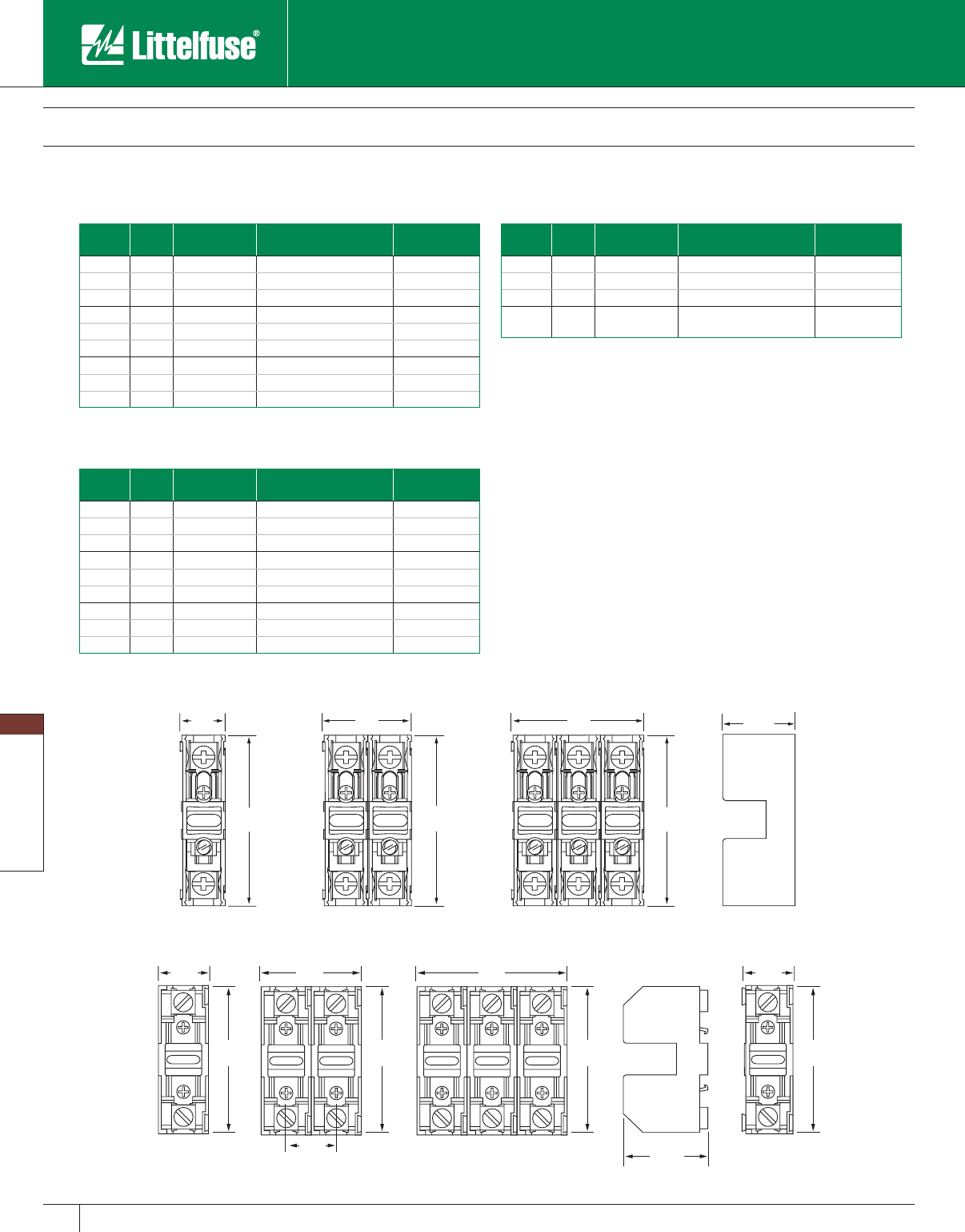
Blocks and Holders
126 www.littelfuse.com
Blocks and Holders
© 2005 Littelfuse • POWR-GARD™ Products Catalog
1.89"
[48.0]
3.35"
[85.09]
3.35"
[85.09]
3.35"
[85.09]
1.01"
[25.65]
1 POLE 2 POLE 3 POLE ADDER
0.783"
[19.89]
3.0"
[76.2]
1.533"
[38.15]
2.283"
[57.15]
1.25"
[31.75]
1 POLE 2 POLE 3 POLE
3.12"
[79.25]
1.01"
[25.65]
1.01"
[25.65]
2.12"
[53.85]
3.0"
[76.2]
3.0"
[76.2]
3.35"
[85.09]
Class CC/CD and Midget Fuse Blocks
600 Volt
Class CC 30A Fuse Blocks
Amp
Rating
No. of
Poles
Catalog
Number
Connector Type
(Add Suffix Shown)
Maximum
Wire Size
1 L60030C-1C
30 2 L60030C-2C Box Lug #6 CU
3 L60030C-3C
1 L60030C-1PQ
30 2 L60030C-2PQ Pres sure Plate/ #10 CU
3 L60030C-3PQ Q. C. Terminal
1 L60030C-1SQ
30 2 L60030C-2SQ Screw/ Q. C. Terminal #10 CU
3L60030C-3SQ
Note: Quick Connect Terminals are rated at 20 amperes.
Class CD 60A Fuse Blocks
Amp
Rating
No. of
Poles
Catalog
Number
Connector Type
(Add Suffix Shown)
Maximum
Wire Size
1L60060C-1C
60 2 L60060C-2C Box Lug #6 CU
3L60060C-3C
60 Adder
Block L60060C-AC Box Lug #6 CU
Midget Fuse Blocks
Amp
Rating
No. of
Poles
Catalog
Number
Connector Type
(Add Suffix Shown)
Maximum
Wire Size
1L60030M-1C
30 2 L60030M-2C Box Lug #6 CU
3L60030M-3C
1L60030M-1PQ
30 2 L60030M-2PQ Pres sure Plate/ #10 CU
3L60030M-3PQ Q. C. Terminal
1L60030M-1SQ
30 2 L60030M-2SQ Screw/ Q. C. Terminal #10 CU
3 L60030M-3SQ
Note: Quick Con nect Terminals are rated at 20 amperes.
L60030
L60060
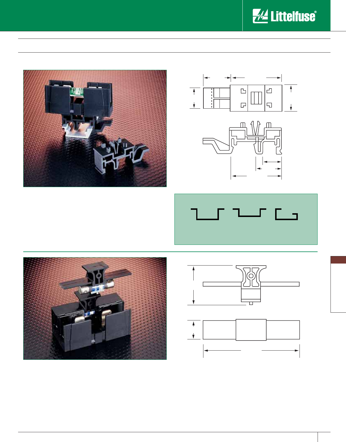
Blocks and Holders
127
www.littelfuse.com
Blocks and Holders
© 2005 Littelfuse • POWR-GARD™ Products Catalog
DIN Rail Adapter — FBDIN1
FBDIN1 is for use with 30A Midget, Class CC and Class G fuse blocks.
The patented design permits snap-mounting of Littelfuse Class CC and
Midget 30A fuse blocks directly to standard and low profile 35mm sym-
met ri cal “hat” and 32mm asymmetrical DIN rails. Adapt ers snap securely
to Littelfuse fuse blocks and to DIN rails with out tools. They may be
readily re moved from rails by lifting the disconnect tab.
Class CC and Midget Fuse Block Accessories
DIN Rail Adapters and Cover Pullers
Cover Puller — SPL001
Littelfuse Class CC and Midget fuse cover puller is designed to provide
protection to personnel, as well as make removal of fuses from fuse
blocks easy and safe. Once in stalled on the fuse, the cover puller allows
removal of the fuse without the use of a separate puller.
• Meets “Dead Front” requirements for use in control panels.
• Permits safe, easy removal.
• Works with existing fuse block. No special hinged fuse blocks are required.
• Easily gangable with 1/8" diameter wire.
• For use with all 600 volt Class CC and Midg et 1/10 — 30A fuses.
• Use with Class CC L60030C series and L60030M series fuse blocks.
• Label provided for easy fuse identification.
• For 2-pole cover puller, order DSPL001.
0.484"
0.670"
1.360"
0.750" 1.490"
0.576" 0.770"
DIN 35
Standard Rail DIN 35
Low Profile DIN 32
Standard Rail
1.22"
0.665"
3.0"
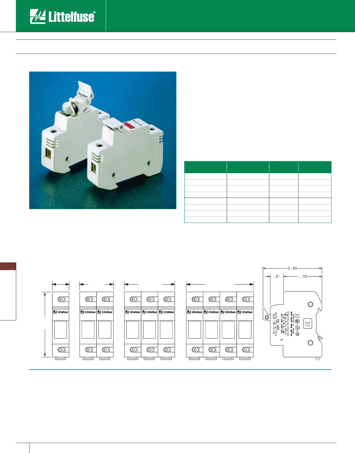
Blocks and Holders
128 www.littelfuse.com
Blocks and Holders
© 2005 Littelfuse • POWR-GARD™ Products Catalog
Fuse Blocks, Holders and Accessories
POWR-SAFE “Dead Front” Holders
Specifications
Voltage Rating: 600 Volts AC/DC
Ampere Rating: 30 amperes
Interrupting Rating: 200 kA (Class CC)
100 kA (Midget)
Terminal type: Pressure plate
Suggested Torque: 15 lb.
Wire Range: #6—#14CU
Material: Thermo-Plastic
Flammability Rating: 94VO
Approvals: UL Listed (LPSC File No: E14721)
UL Recognized (LPSM File No: E14721)
CSA Certified (LPSC/LPSM File No: LR7316)
IEC Type IP20 Protection
CE Certified
Indicating
Part Num ber
Non-Indicating
Part Num ber Fuse Type Number of Poles
LPSC001ID LPSC001 Class CC 1
LPSC002ID LPSC002 Class CC 2
LPSC003ID LPSC003 Class CC 3
LPSC004ID LPSC004 Class CC 4
LPSM001ID LPSM001 Midget 1
LPSM002ID LPSM002 Midget 2
LPSM003ID LPSM003 Midget 3
LPSM004ID LPSM004 Midget 4
Multi-pole Assembly Kit: Order No: CYHP001
(Kit contains 20 connector pincers and 10 handle pins.)
NOTE: Contact factory for DC rated versions.
3.032
(77.01)
.689
(17.50) 1.38
(35.05)
2.07
(52.58)
2.76
(70.10)
Features/benefits
• Meets “Dead Front” requirements and IEC Type IP20 Protection
• Mountable on 35mm Din Rail
• Blown fuse identification (Indicating versions only)
• Easy installation and removal of fuses. No special fuse pullers or tools
required.
• UL Listed for branch circuit protection (Class CC versions only)
• Compact design
• Ventilated design for cooler operation
• Indicates above 80 volts (ID versions only)
Ordering information
Littelfuse POWR-SAFE “Dead Front” holders provide optimum
protection to personnel. Indicating and non-indicating versions are
available in 1, 2, 3, or 4 poles for Class CC and Midget fuses.
Dimensions in inches (mm in parentheses)
• LPSM/LPSC POWR-SAFE Holders
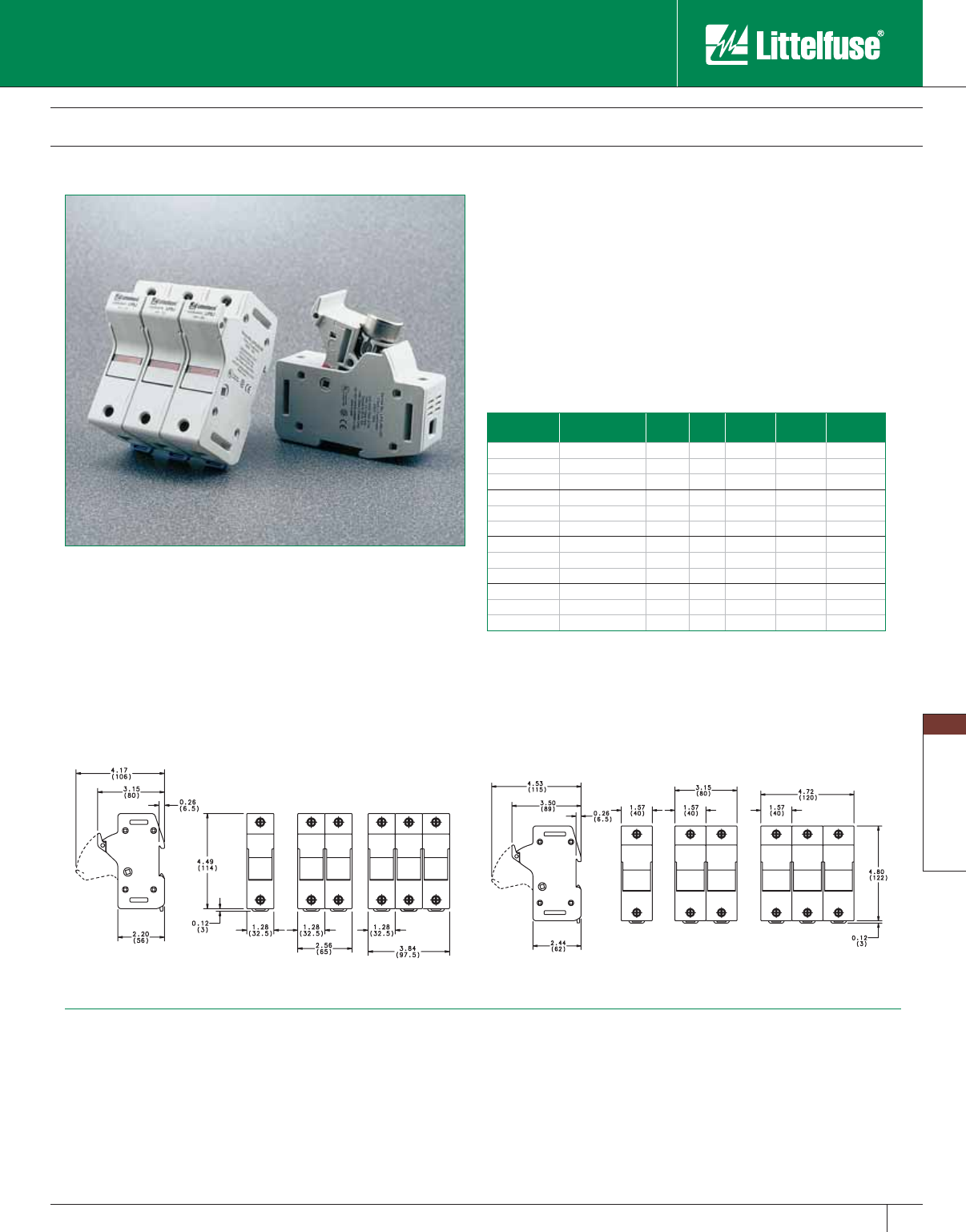
Blocks and Holders
129
www.littelfuse.com
Blocks and Holders
© 2005 Littelfuse • POWR-GARD™ Products Catalog
Littelfuse
Catalog No.
Littelfuse
System No.
No. of
Poles
Pack
Qty.
Voltage
Rating
Ampere
Rating
Options
LPSJ30-1 LPSJ301.Z 1 6 600V 30A –
LPSJ30-2 LPSJ302.Z 2 3 600V 30A –
LPSJ30-3 LPSJ303.Z 3 2 600V 30A –
LPSJ30-1ID LPSJ301.ZXID 1 6 600V 30A Indicating
LPSJ30-2ID LPSJ302.ZXID 2 3 600V 30A Indicating
LPSJ30-3ID LPSJ303.ZXID 3 2 600V 30A Indicating
LPSJ60-1 LPSJ601.Z 1 6 600V 60A –
LPSJ60-2 LPSJ602.Z 2 3 600V 60A –
LPSJ60-3 LPSJ603.Z 3 2 600V 60A –
LPSJ60-1ID LPSJ601.ZXID 1 6 600V 60A Indicating
LPSJ60-2ID LPSJ602.ZXID 2 3 600V 60A Indicating
LPSJ60-3ID LPSJ603.ZXID 3 2 600V 60A Indicating
Fuse Blocks, Holders and Accessories
Class J POWR-SAFE Holders
Specifications
Voltage Rating: 600 VAC
Interrupting Rating: 200 kA
Ampere Rating: 30 and 60 amperes
Terminal Type: Pressure plate
Suggested Torque: 30A – 35 inch-pounds
60A – 45 inch-pounds
Wire Range: #2 – #14CU
Material: Thermo-plastic
Flammability Rating: 94V0
Approvals: UL Listed
CSA Certified
IEC Type IP20 Protection
CE
Littelfuse POWR-SAFE “Dead Front” fuseholders provide optimum
protection to personnel. An integral DIN-Rail adapter system allows fuse
holders to be mounted on 35mm DIN-Rail without the use of tools or
special parts. Indicating and non-indicating versions are available in 1, 2,
or 3 poles for Class J fuses.
Dimensions in inches (mm in parentheses)
30 Amp
Features/benefits
• Meets “Dead Front” requirements and IEC Type IP20 protection.
• Mountable on 35mm DIN-Rail.
• Blown fuse identification (Indicating versions only).
• Easy installation and removal of fuses. No special fuse pullers or tools
required.
• UL listed for branch circuit protection.
• Ventilated design for cooler operation.
Ordering Information
60 Amp
Multi-Pole Assembly Kit: Order No: US3J2PAK to assemble two LPSJ30-1
US3J3PAK to assemble three LPSJ30-1
US6J2PAK to assemble two LPSJ60-1
US6J3PAK to assemble three LPSJ60-1
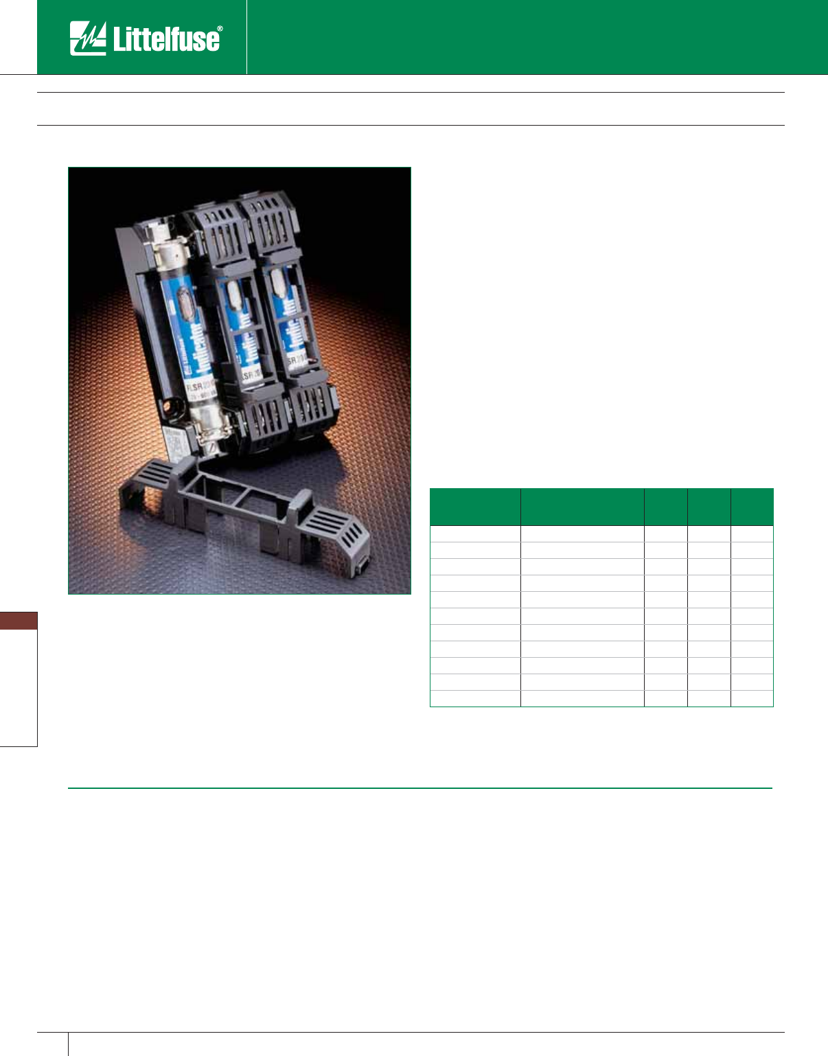
Blocks and Holders
130 www.littelfuse.com
Blocks and Holders
© 2005 Littelfuse • POWR-GARD™ Products Catalog
Fuse Blocks, Holders and Accessories
POWR-Covers - Fuse Block Covers
Littelfuse fuse block covers protect personnel from ac ci den tal ly
contacting energized contacts. Covers are available for Class H, R, J,
and CD type fuses up to 100 amps.
Features/benefits
• Meets “Dead Front” requirements and IEC Type IP20 Protection for
most applications (see note)
• Easily gangable with optional “gang-slide” adapters
• Added safety to personnel
• Unique design allows Littelfuse Indicator® fuses to be seen through
covers
• Ventilated to avoid fuse derating
• Covers are reusable
• Covers fit most competitor blocks
• LJ60100-3PC is a three pole clear plastic cover
For “Gang Slide” Adapters order:
PCGS-2 for 2 poles
PCGS-3 for 3 poles
NOTE: Contact Factory for specific applications.
Ordering information
Littelfuse Part
Number
For Use With Fuse
Block Number Voltage Amp Fuse
Class
LH25030-PC LH25030/LR25030 series 250 30 H/R
LH25060-PC LH25060/LR25060 series 250 60 H/R
LH25100-PC LH25100/LR25100 series 250 100 H/R
LH60030-PC LH60030/LR60030 series 600 30 H/R
LH60060-PC LH60060/LR60060 series 600 60 H/R
LH60100-PC LH60100/LR60100 series 600 100 H/R
LJ60030-PC LJ60030 series only 600 30 J
LJ60060-PC LJ60060 series only 600 60 J
LJ60100-PC* LJ60100-1CR only 600 100 J
LJ60100-3PC LJ60100-3CR only 600 100 J
L60060C-PC L60060C series only 600 60 CD
*Note: For use with Class J fuses with 1” diameter, Littelfuse series JLS.
Specifications
Voltage Rating: 600 Volts
Ampere Rating: Class H: 0-100 amps
Class R: 0-100 amps
Class J: 0-100 amps
Class CD: 0-60 amps
Material: Thermoplastic
Approvals: UL Listed (File No: E184929)
CSA Certified (File No: LR7316)
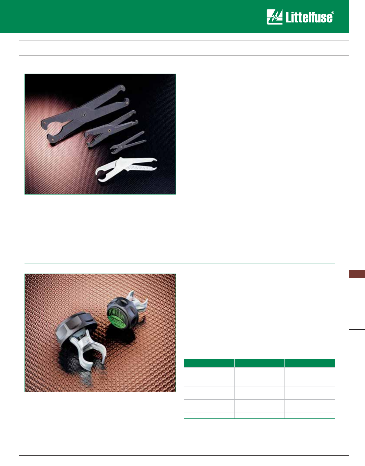
Blocks and Holders
131
www.littelfuse.com
Blocks and Holders
© 2005 Littelfuse • POWR-GARD™ Products Catalog
Fuse Pullers
Littelfuse ergonomically designed fuse pullers are the safe way of
handling power fuses. They offer greater ease in removing fuses. This
new molded design is superior to standard pullers because it offers
a more comfortable and natural grip when pulling fuses, improving
performance. Part No. LPFP
Part Number & Application
Midget Fuse Puller MFP: For
3/16" to 1/2" dia. fuses.
Pocket Fuse Puller LPFP: For 0 – 200A 250V,
0 – 100A 600V
(
9/16" – 119/32" dia. fuses)
Giant Fuse Puller GFP: 61 – 600A 250V,
61 – 400A 600V
(1
1/16" – 219/32" dia. fuses)
Tri-Puller 097023: For ATO® and glass fuses.
Fuse Blocks, Holders and Accessories
Part Number Volts Amperes
LCC 1 250 0-30
LCC 2 250 35-60
LCC 2 600 0-30
LCC 4 600 35-60
LCC 5 250/600 70-100
LCC 6 250/600 110-200
LCC 7 250/600 225-400
LCC 8 250/600 450-600
Note: POWR-JAW Clip Clamps are sold individually, not in pairs. A minimum
of 1/8” of clearance between the fuse block barrier and fuse clip is required to
install clip clamps.
POWR-JAW Clip Clamps
POWR-JAW clamps improve the contact be tween fuse and clip. The
unnecessary heat from poor contact due to the loss of spring force in
the clips can cause nuisance fuse opening and premature aging of sur-
round ing components.
• High temperature phenolic resin knob de signed for the most severe
en vi ron ments.
• 7 sizes to provide effective coverage.
• Simple design makes installation easy.
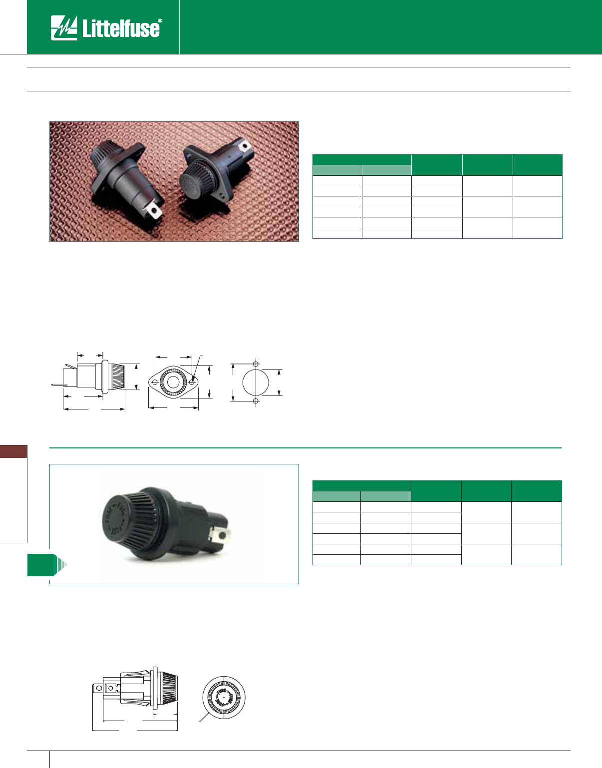
Blocks and Holders
132 www.littelfuse.com
Blocks and Holders
© 2005 Littelfuse • POWR-GARD™ Products Catalog
Fuse Blocks, Holders and Accessories
571 Series Panel Mounted Fuseholders
Panel mount fuseholders are available for sup ple men ta ry or Class CC
branch circuit protection. Class CC fuses have a rejection feature on
one end cap which mates with the rejection feature of Littelfuse Class
CC fuse blocks and fuseholders to prevent the installation of fuses with
lower voltage ratings or interrupting ratings. Watertight version must be
front panel mounted.
0.86"
[21.84]
0.92"
[23.37] 0.890"
[22.6]
1.12"
[28.45]
1.310"
[33.3]
1.34"
[34.04]
2.10"
[53.34]
1.74"
[44.20]
1.312"
[33.33]
.172 DIA.
[4.37]
Mounting Hole
Part Number Bottom
Terminal
Fuse Length
Range*
For Use
With
Standard Watertight
571 027 571 027P Straight 15⁄16” – 13⁄8”Midget Fuses
571 028 571 028P Rt. Angle
571 007 571 007P Straight 113 ⁄32” – 11⁄2”Midget Fuses
571 008 571 008P Rt. Angle
571 OCC 571 OCCP Straight 11⁄2”Class CC Fuses
571 RCC 571 RCCP Rt. Angle
*Fuse diameter is 13/32”.
Note: Contact the factory for versions with pre-assembled wire leads.
O-Rings: 901-184 (body)
901-260 (knob)
Specifications
Voltage Rating: 600 Volts
Ampere Rating: 30 amperes for Class CC and
Midget fuses
Dielectric strength: 4000 Volts
Terminals : Tin-plated brass combination solder
and quick-connect
Molded parts: Black thermoplastic
Approvals: UL Recognized (File No. E14721) — 571 series
UL Recognized for branch circuit protection
— 571 OCC/RCC
CSA Certified (File No. LR7316)
Ordering Information
0.69”
2.10”
2.40”
1.20”
DIA
572 Series Panel Mounted Fuseholders
The 572 series panel mount fuse holders are designed to minimize
installation time. The unique design incorporates a snap-mount feature
that allows the holder to be installed without any tools or mounting
hardware.
NEW
Ordering Information
Part Number Bottom
Terminal
Fuse Length
Range* For Use With
Standard Watertight
572 027 572 027P Straight 15⁄16” – 13⁄8”Midget Fuses
572 028 572 028P Rt. Angle
572 007 572 007P Straight 113 ⁄32” – 11⁄2”Midget Fuses
572 008 572 008P Rt. Angle
572 OCC 572 OCCP Straight 11⁄2”Class CC Fuses
572 RCC 572 RCCP Rt. Angle
*Fuse diameter is 13/32”
Note: Contact the factory for versions with preassembled wire leads.
Specifications
Voltage Rating: 600 Volts
Ampere Rating: 30 Amperes for Class CC and Midget fuses
Dielectric Strength: 4000 Volts
Terminals : Tin-plated brass combination solder and quick-connect
Molder Parts: Black thermoplastic
Approvals: UL Recognized (File No. E14721) – 572 Series
UL Recognized for branch circuit
protection – 571 OCC/RCC
CSA Certified (File No. LR7316)
Mounting: Designed to fit 14-18 gauge panels with Double
”D” punch or 0.875” knock-out hole.
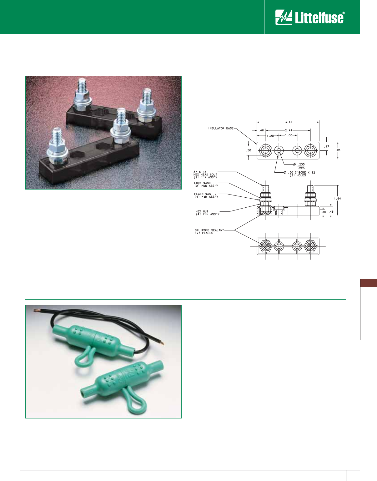
Blocks and Holders
133
www.littelfuse.com
Blocks and Holders
© 2005 Littelfuse • POWR-GARD™ Products Catalog
LFFB Series Limiter Fuse Block
The Littelfuse LFFB fuse block is designed to accept CNL and CNN
style limiter fuses. Typical applications include: forklifts, golf carts, and
other low voltage battery-operated equipment.
Fuse Blocks, Holders and Accessories
LHFB Inline Fuse Holder
Specifications
Voltage Rating: 150 VAC/VDC
Ampere Range: 1 – 400 amperes
Approvals: Pending
Construction: Base — thermoplastic
Studs — steel zinc plated
Ordering Information
Example catalog number: LFFB001
Example system number: LFFB0001Z
Dimensions
The Littelfuse LHFB waterproof inline fuse holder is ideal for harsh
environments. The easy to assemble one-piece molded thermoplastic
body is a bright green color for high visibility. The LHFB holder accepts
#12 to #18 gauge wire and features the voltage and ampere rating
molded into the body, along with a wire strip gauge. Withstands
solvents and vibration, for use with 1/4” x 11/4” fuses.
Installation Instructions
1. Thread wire through fuse holder body.
2. Strip wire insulation per strip gauge.
3. Crimp wire to fuse clip.*
4. Pull wire through and seat fuse clip in the holder body.
5. Insert desired fuse type and rating.
6. Snap holder body together.
*Recommended crimping tools: Thomas & Betts No. WT-111M
NOTE: Wire is not supplied with the holder.
Specifications
Voltage Rating: 32 Volts
Ampere Rating: 30 amperes
Recommended fuses
Littelfuse CNL/CNN limiter fuses and competitors’ equivalents.
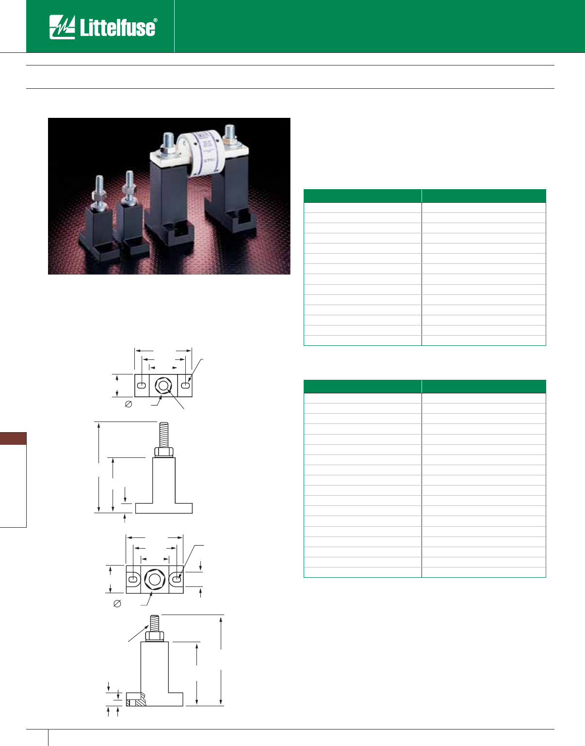
Blocks and Holders
134 www.littelfuse.com
Blocks and Holders
© 2005 Littelfuse • POWR-GARD™ Products Catalog
Semiconductor Fuse Blocks
LSCR001
LSCR002
1.88"
1.30"
0.70"
0.70"
0.203" × 0.30" SL
0.50" 1/4-20" × 1.00"
USABLE LENGTH
2.38"
1.34"
0.25"
2.13"
1.60"
1.00"
1.00"
0.75"
0.50"
0.203" × 0.30" SLO
T
3/8-16"x1.00"
USABLE LENGTH
0.25"
0.50"
3.44"
2.44"
Modular-designed Semiconductor fuse blocks are designed to
accommodate a wide range of Semiconductor fuses, with a max i-
mum diameter of 3". This modular design greatly reduces inventory
requirements. They are sold in pairs and are constructed of molded
phenolic, with plated steel studs.
Recommended Fuses
Semiconductor fuses. See tables below.
Specifications
Voltage rating: LSCR001: Accepts fuses 1” diameter or less at 600V.
Also accepts
13 ⁄16" diameter fuses at 700 — 1000V.
LSCR002: Accepts fuses up to 3" diameter at 1000V.
Ampere ratings: LSCR001: 1 – 400 ampere capacity.
LSCR002: 70 – 800 ampere capacity.
Approvals: UL Recognized (File No. E14721)
Stud Size: LSCR001:
1⁄4 - 20 thread (Torque: 65 In. LBS.)
LSCR002:
3⁄8 - 16 thread (Torque: 192 In. LBS.)
Base: Molded phenolic. 150° C temperature rating.
Terminal construction: Plated steel. Supplied with nut and belleville washer.
LSCR001
Semiconductor fuse block selection guide
Fuse Series Ampere Rating
L15S 70 – 400
L25S, LA30QS 35 – 60
L25S 70 – 200
L50S, LA50QS 35 – 60
L50S, LA50QS 70 – 100
L50S 125 – 200
L60S 35 – 60
L60S 70 – 100
L60S 125 – 200
L70S, LA70QS 35 – 60
L70S, LA70QS 70 – 100
KLC 1 – 30
KLC 35 – 60
LA100P 35 – 60
LSCR002
Semiconductor fuse block se lec tion guide
Fuse Series Ampere Rating
L15S, LA15QS 500 – 800
L25S, LA30QS 225 – 700
L25S, LA30QS 800
L50S, LA50QS 225 – 400
L50S, LA50QS 450 – 600
L50S, LA50QS 700 – 800
L60S 225 – 400
L60S 450 – 600
L60S 700 – 800
L70S, LA70QS 125 – 200
L70S, LA70QS 225 – 400
L70S, LA70QS 450 – 800
KLC 70 – 100
KLC 125 – 200
KLC 225 – 400
KLC 450 – 800
LA100P 70 – 800
JLLN 700 – 1200
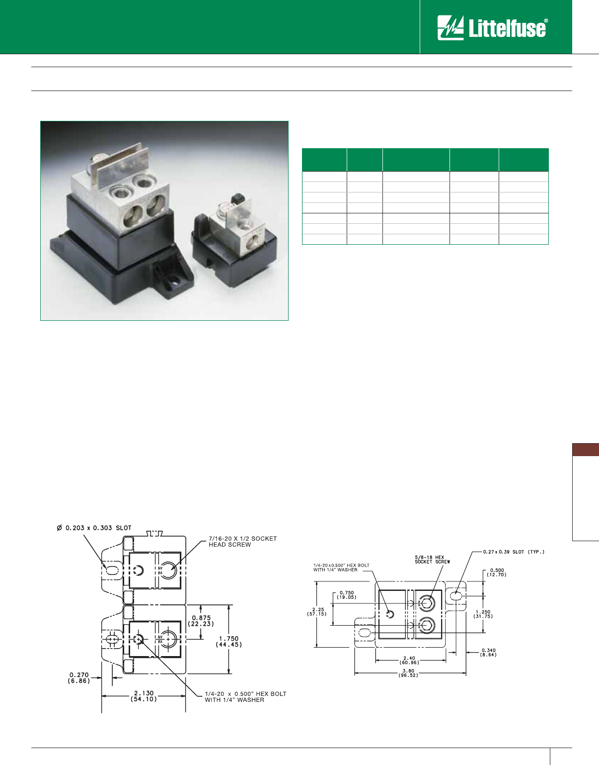
Blocks and Holders
135
www.littelfuse.com
Blocks and Holders
© 2005 Littelfuse • POWR-GARD™ Products Catalog
Semiconductor Fuse Blocks
Littelfuse 1LS series modular style semiconductor fuse blocks
accommodate a wide range of semiconductor fuses. Blocks are
provided in pairs with fuse mounting hardware.
• 2-piece modular design
• General purpose phenolic base
• Tin plated aluminum box lugs
• Dove-tailed interlocking feature (1LS101 only)
• Hex-head bolts and belleville washers provided
Littelfuse
Catalog No.
Ampere
Rating Wire Range Torque Rating Approvals
1LS101 100A #2/0 - 14 CU/AL 120 IN. LBS. UL Recognized
1LS102 400A 250MCM - #6 CU/AL 275 IN. LBS. UL Recognized
1LS103 400A 250MCM - #6 CU/AL 275 IN. LBS. UL Recognized
1LS104 600A 500MCM - #6 CU/AL 375 IN. LBS. UL Recognized
1LS108 400A 250MCM - #6 CU/AL 275 IN. LBS. Self-Certified
1LS109 400A 250MCM - #6 CU/AL 275 IN. LBS. Self-Certified
1LS110 400A 250MCM - #6 CU/AL 275 IN. LBS. Self-Certified
1LS101 1LS102
Dimensions for reference only.
Ordering Information
Dimensions
Specifications
Voltage Rating: 600 Volts
Ampere Range: 1 – 600 amperes
Approvals: UL Recognized under the components program
Insulator Base: 150° C general purpose phenolic
Box Lug Terminal: Tin plated aluminum
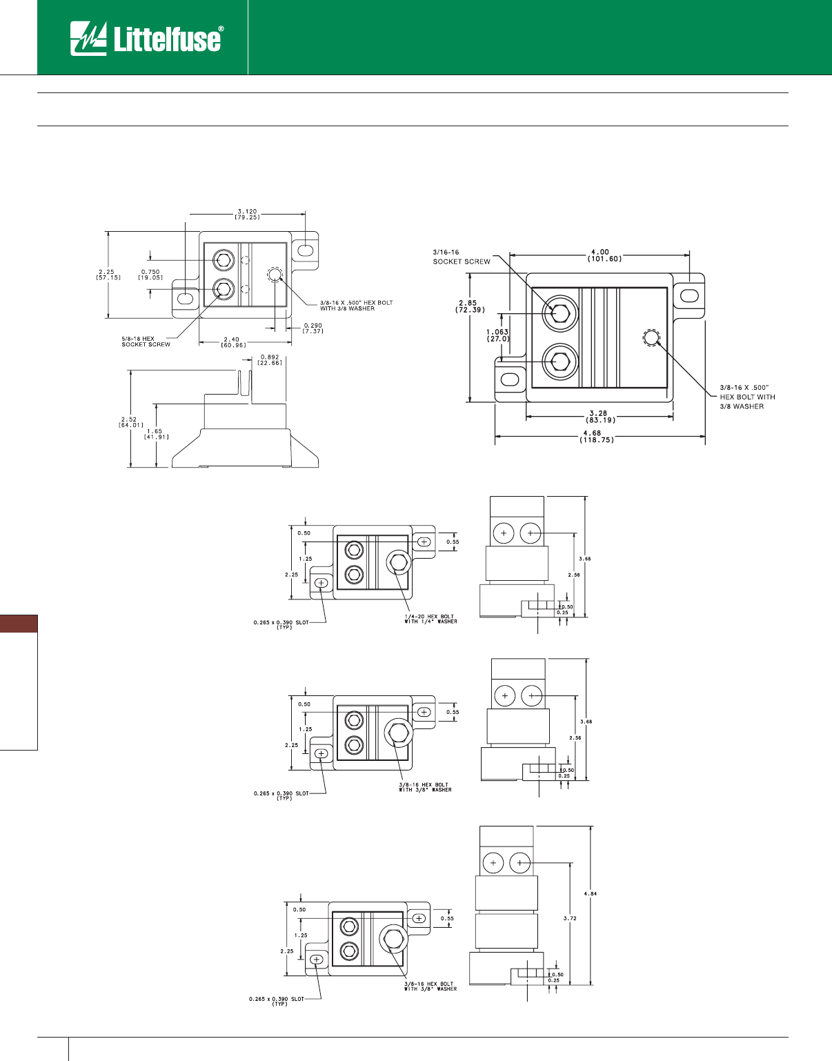
Blocks and Holders
136 www.littelfuse.com
Blocks and Holders
© 2005 Littelfuse • POWR-GARD™ Products Catalog
Semiconductor Fuse Blocks
Dimensions
1LS103 1LS104
1LS108
1LS109
1LS110
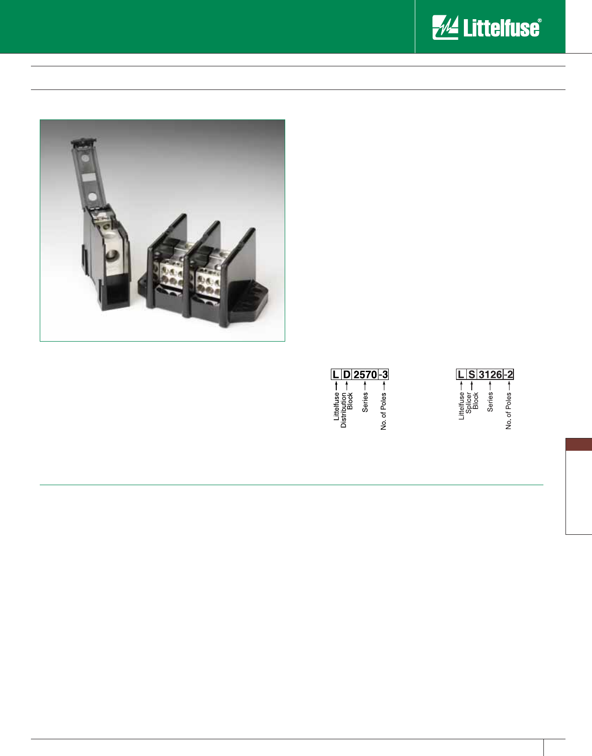
Blocks and Holders
137
www.littelfuse.com
Blocks and Holders
© 2005 Littelfuse • POWR-GARD™ Products Catalog
POWR-BLOKS™
Distribution/Splicer Blocks and Covers
POWR-BLOKS power distribution blocks offer a safe, convenient way
of splicing cables, providing a fixed junction tap-off point or splitting
primary power into secondary circuits. LX2xxx-DIN series offers integral
DIN-Rail mount and an optional hinged safety cover.
Applications
Typical applications include heating, air conditioning and refrigeration
systems, el e va tor systems, material handling equipment, control
panels, motor controls, switchgear, and anywhere power needs to be
distributed to more than one load.
Connectors
Box lug connectors are designed for use with a single, solid or class
B or C stranded conductor. Use of more than one con ductor per
connector opening or use of extra-flexible, fine stranded conductors,
such as welding cable, voids the UL Listing, and may cause overheating.
Manufacturers of cable ter minations can furnish crimp-on sleeves for
fine stranded conductors which permit these conductors to be used with
box lugs.
Ampere Ratings
The ampere rating per pole for power distribution blocks is based on
the line ampacity of 75°C insulated conductors per NEC Table 310.16. If
60°C insulated conductors are used, load must not exceed the ampacity
of 60°C conductors. Use of conductors rated in excess of 75°C is
permitted (for example 90°C), however, load must not exceed the
ampacity of 75°C conductors.
Ordering Information
Note: Aluminum blocks can use copper or aluminum wire; copper blocks can
only use copper wire.
Specifications
Voltage Rating: 600V
Amperage: Based on NEC Table 310.16,
using 75°C copper wire
Material: Phenolic rated at 150°C and Thermoplastic rated at
125°C (LD1400 and LS1300 series only)
Connector: Standard: Highly con duc tive aluminum, tin plated
Copper: Highly conductive copper, tin plated
Flammability Rating: 94V-0
Approvals: UL Recognized (File No. E171395)
CSA Certified (File No. LR700111)
Distribution Block
Example Part No.
Splicer Block
Example Part No.
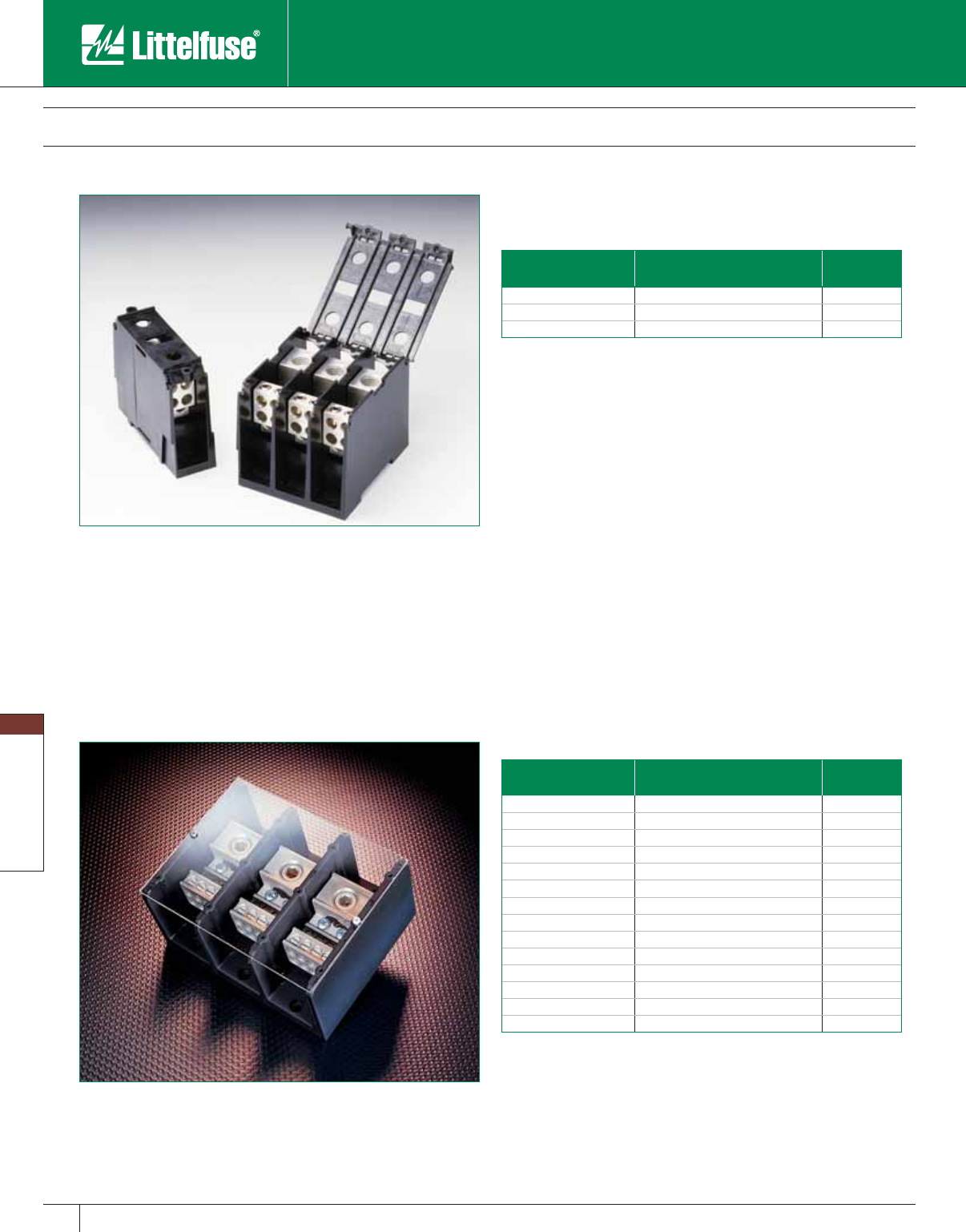
Blocks and Holders
138 www.littelfuse.com
Blocks and Holders
© 2005 Littelfuse • POWR-GARD™ Products Catalog
Littelfuse optional power distribution block covers provide protection
against accidental shorting between poles caused by loose wires,
tools, or other conductive material. They also protect personnel from
accidentally contacting energized connectors. Clear plastic covers are
available for most blocks. New Lx2xxx-xDIN series blocks offer a hinged
cover. To order protective covers, match the number of poles for the
block to the cover.
Distribution Block Covers
POWR-BLOKS™
Distribution/Splicer Blocks and Covers
Clear Plastic Covers
Littelfuse
Part Number
For use with
Distribution/Splicer Block No.
Number
of Poles
LPBC0-2 LD0xxx-2 / LS0xxx-2 2
LPBC0-3 LD0xxx-3 / LS0xxx-3 3
LPBC2-1 LD2xxx-1 / LS2xxx-1 1
LPBC2-2 LD2xxx-2 / LS2xxx-2 2
LPBC2-3 LD2xxx-3 / LS2xxx-3 3
LPBC3-1 LD3xxx-1 / LS3xxx-1 1
LPBC3-2 LD3xxx-2 / LS3xxx-2 2
LPBC3-3 LD3xxx-3 / LS3xxx-3 3
LPBC4-1 LD4xxx-1 / LS4xxx-1 1
LPBC4-2 LD4xxx-2 / LS4xxx-2 2
LPBC4-3 LD4xxx-3 / LS4xxx-3 3
LPBC5-1 LD5xxx-1 / LS5xxx-1 1
LPBC5-2 LD5xxx-2 / LS5xxx-2 2
LPBC5-3 LD5xxx-3 / LS5xxx-3 3
Note: For installation of optional clear plastic covers, use the screws provided with
each cover.
Hinged Plastic Covers
Littelfuse
Part Number
For use with
Distribution/Splicer Block No.
Number
of Poles
LCH132-1 LD2xxx-1DIN / LS2xxx-1DIN 1
LCH132-2 LD2xxx-2DIN / LS2xxx-2DIN 2
LCH132-3 LD2xxx-3DIN / LS2xxx-3DIN 3
Note: Optional hinged covers snap on to blocks.
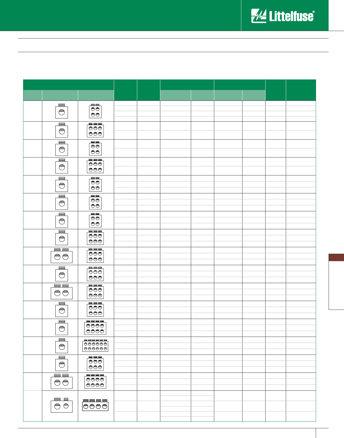
Blocks and Holders
139
www.littelfuse.com
Blocks and Holders
© 2005 Littelfuse • POWR-GARD™ Products Catalog
Distribution Block Selection Guide
Connector
Configuration Amp
Rating
per Pole
Number
of Poles
Line Load
Figure
Littelfuse
Catalog
Number
Mat’l Line Load Wire Range Openings
per Pole Wire Range Openings
per Pole
AL
115 1 #2 - #14 1 #10 - #18 4 2 LD1400-1
115 2 #2 - #14 1 #10 - #18 4 2 LD1400-2
115 3 #2 - #14 1 #10 - #18 4 2 LD1400-3
115 4 #2 - #14 1 #10 - #18 4 2 LD1400-4
AL
175 2 2⁄ 0 - #14 1 #4 - #14 6 1 LD0401-2
175 3 2⁄ 0 - #14 1 #4 - #14 6 1 LD0401-3
AL
175 2 2⁄ 0 - #14 1 #4 - #14 4 1 LD0402-2
175 3 2⁄ 0 - #14 1 #4 - #14 4 1 LD0402-3
AL
310 2 350mcm - #6 1 #4 - #14 6 1 LD0404-2
310 3 350mcm - #6 1 #4 - #14 6 1 LD0404-3
AL
175 1 2⁄ 0 - #14 1 #4 - #14 4 3 LD2570-1
175 2 2⁄ 0 - #14 1 #4 - #14 4 3 LD2570-2
175 3 2⁄ 0 - #14 1 #4 - #14 4 3 LD2570-3
CU
175 1 2⁄ 0 - #14 1 #4 - #14 4 3 LD2970-1
175 2 2⁄ 0 - #14 1 #4 - #14 4 3 LD2970-2
175 3 2⁄ 0 - #14 1 #4 - #14 4 3 LD2970-3
AL
335 1 400mcm - #6 1 #2 - #14 4 5 LD3552-1
335 2 400mcm - #6 1 #2 - #14 4 5 LD3552-2
335 3 400mcm - #6 1 #2 - #14 4 5 LD3552-3
AL
335 1 400mcm - #6 1 #2 - #14 6 5 LD3553-1
335 2 400mcm - #6 1 #2 - #14 6 5 LD3553-2
335 3 400mcm - #6 1 #2 - #14 6 5 LD3553-3
AL
350 1 2⁄ 0 - #14 2 #4 - #14 6 5 LD3555-1
350 2 2⁄0 - #14 2 #4 - #14 6 5 LD3555-2
350 3 2⁄ 0 - #14 2 #4 - #14 6 5 LD3555-3
CU
380 1 500mcm - #4 1 #2 - #14 6 5 LD3953-1
380 2 500mcm - #4 1 #2 - #14 6 5 LD3953-2
380 3 500mcm - #4 1 #2 - #14 6 5 LD3953-3
CU
350 1 2⁄ 0 - #14 2 #4 - #14 6 5 LD3955-1
350 2 2⁄ 0 - #14 2 #4 - #14 6 5 LD3955-2
350 3 2⁄ 0 - #14 2 #4 - #14 6 5 LD3955-3
AL
380 1 500mcm - #4 1 #2 - #14 6 6 LD4551-1
380 2 500mcm - #4 1 #2 - #14 6 6 LD4551-2
380 3 500mcm - #4 1 #2 - #14 6 6 LD4551-3
AL
335 1 400mcm - #6 1 #2 - #14 8 6 LD4560-1
335 2 400mcm - #6 1 #2 - #14 8 6 LD4560-2
335 3 400mcm - #6 1 #2 - #14 8 6 LD4560-3
AL
380 1 500mcm - #4 1 #2 - #14 12 7 LD5552-1
380 2 500mcm - #4 1 #2 - #14 12 7 LD5552-2
380 3 500mcm - #4 1 #2 - #14 12 7 LD5552-3
AL
380 1 500mcm - #4 1 2⁄0 - #14 6 7 LD5579-1
380 2 500mcm - #4 1 2⁄0 - #14 6 7 LD5579-2
380 3 500mcm - #4 1 2⁄0 - #14 6 7 LD5579-3
AL
760 1 500mcm - #4 2 2⁄0 - #14 8 7 LD5586-1
760 2 500mcm - #4 2 2⁄0 - #14 8 7 LD5586-2
760 3 500mcm - #4 2 2⁄0 - #14 8 7 LD5586-3
AL
665 1 500mcm - #4 1 2⁄0 - #14 4 7 LD5587-1
350mcm - #6 1
665 2 500mcm - #4 1 2⁄0 - #14 4 7 LD5587-2
350mcm - #6 1
665 3 500mcm - #4 1 2⁄0 - #14 4 7 LD5587-3
350mcm - #6 1
POWR-BLOKS™
Distribution/Splicer Blocks and Covers
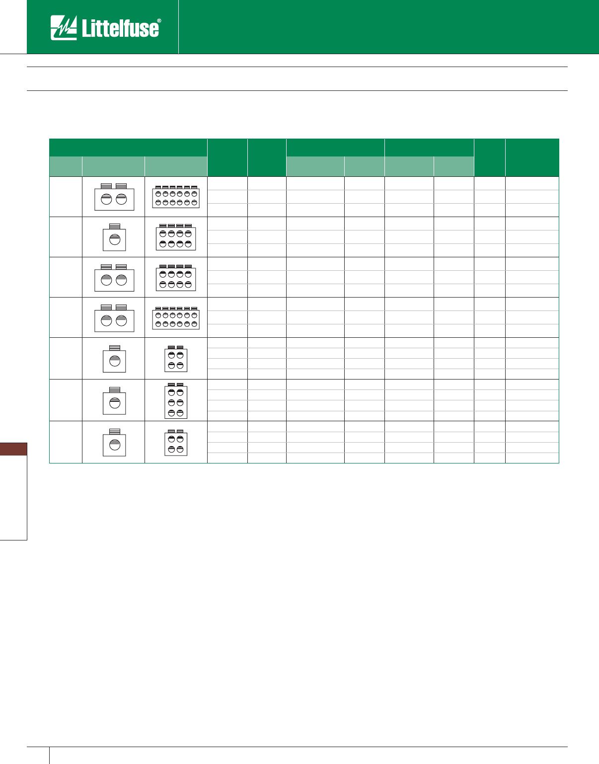
Blocks and Holders
140 www.littelfuse.com
Blocks and Holders
© 2005 Littelfuse • POWR-GARD™ Products Catalog
POWR-BLOKS™
Distribution/Splicer Blocks and Covers
Distribution Block Selection Guide
Connector Configuration Amp
Rating
per Pole
Number
of Poles
Line Load
Figure
Littelfuse
Catalog
Number
Mat’l Line Load Wire Range Openings
per Pole Wire Range Openings
per Pole
AL
760 1 500mcm-#4 2 #4 - #14 12 7 LD5592-1
760 2 500mcm-#4 2 #4 - #14 12 7 LD5592-2
760 3 500mcm-#4 2 #4 - #14 12 7 LD5592-3
AL
380 1 500mcm-#4 1 #2 - #14 8 7 LD5594-1
380 2 500mcm-#4 1 #2 - #14 8 7 LD5594-2
380 3 500mcm-#4 1 #2 - #14 8 7 LD5594-3
CU
760 1 500mcm-#4 2 2⁄0 - #14 8 7 LD5986-1
760 2 500mcm-#4 2 2⁄0 - #14 8 7 LD5986-2
760 3 500mcm-#4 2 2⁄0 - #14 8 7 LD5986-3
CU
760 1 500mcm-#4 2 #2 - #14 12 7 LD5992-1
760 2 500mcm-#4 2 #2 - #14 12 7 LD5992-2
760 3 500mcm-#4 2 #2 - #14 12 7 LD5992-3
AL
175 1 2⁄0 - #14 1 #4 - #14 4 4 LD2570-1DIN
175 2 2⁄0 - #14 1 #4 - #14 4 4 LD2570-2DIN
175 3 2⁄0 - #14 1 #4 - #14 4 4 LD2570-3DIN
175 Adder 2⁄ 0 - #14 1 #4 - #14 4 4 LD2570-ADIN
AL
175 1 2⁄0 - #14 1 #4 - #14 6 4 LD2580-1DIN
175 2 2⁄0 - #14 1 #4 - #14 6 4 LD2580-2DIN
175 3 2⁄0 - #14 1 #4 - #14 6 4 LD2580-3DIN
175 Adder 2⁄ 0 - #14 1 #4 - #14 6 4 LD2580-ADIN
CU
175 1 2⁄0 - #14 1 #4 - #14 4 4 LD2970-1DIN
175 2 2⁄0 - #14 1 #4 - #14 4 4 LD2970-2DIN
175 3 2⁄0 - #14 1 #4 - #14 4 4 LD2970-3DIN
175 Adder 2⁄ 0 - #14 1 #4 - #14 4 4 LD2970-ADIN
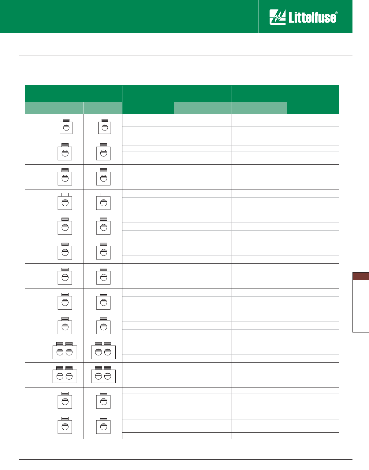
Blocks and Holders
141
www.littelfuse.com
Blocks and Holders
© 2005 Littelfuse • POWR-GARD™ Products Catalog
Splicer Block Selection Guide
Connector
Configuration Amp
Rating
per Pole
Number
of Poles
Line Load
Figure
Littelfuse
Catalog
Number
Mat’l Line Load Wire Range Openings
per Pole Wire Range Openings
per Pole
AL
310 2 350mcm-#6 1 350mcm-#6 1 1 LS0303-2
310 3 350mcm-#6 1 350mcm-#6 1 1 LS0303-3
AL
115 1 #2 - #14 1 #2 - #14 1 2 LS1300-1
115 2 #2 - #14 1 #2 - #14 1 2 LS1300-2
115 3 #2 - #14 1 #2 - #14 1 2 LS1300-3
115 4 #2 - #14 1 #2 - #14 1 2 LS1300-4
CU
150 1 1⁄0 - #18 1 1⁄0 - #18 1 3 LS2121-1
150 2 1⁄0 - #18 1 1⁄0 - #18 1 3 LS2121-2
150 3 1⁄0 - #18 1 1⁄0 - #18 1 3 LS2121-3
AL
115 1 #2 - #14 1 #2 - #14 1 3 LS2552-1
115 2 #2 - #14 1 #2 - #14 1 3 LS2552-2
115 3 #2 - #14 1 #2 - #14 1 3 LS2552-3
AL
175 1 2⁄0 - #14 1 2⁄0 - #14 1 3 LS2572-1
175 2 2⁄0 - #14 1 2⁄0 - #14 1 3 LS2572-2
175 3 2⁄0 - #14 1 2⁄0 - #14 1 3 LS2572-3
AL
255 1 250mcm-#6 1 250mcm-#6 1 5 LS3123-1
255 2 250mcm-#6 1 250mcm-#6 1 5 LS3123-2
255 3 250mcm-#6 1 250mcm-#6 1 5 LS3123-3
CU
255 1 250mcm-#6 1 250mcm-#6 1 5 LS3124-1
255 2 250mcm-#6 1 250mcm-#6 1 5 LS3124-2
255 3 250mcm-#6 1 250mcm-#6 1 5 LS3124-3
AL
310 1 350mcm-#6 1 350mcm-#6 1 5 LS3126-1
310 2 350mcm-#6 1 350mcm-#6 1 5 LS3126-2
310 3 350mcm-#6 1 350mcm-#6 1 5 LS3126-3
AL
420 1 600mcm-#4 1 600mcm-#4 1 6 LS4557-1
420 2 600mcm-#4 1 600mcm-#4 1 6 LS4557-2
420 3 600mcm-#4 1 600mcm-#4 1 6 LS4557-3
AL
620 1 350mcm-#4 2 350mcm-#4 2 7 LS5129-1
620 2 350mcm-#4 2 350mcm-#4 2 7 LS5129-2
620 3 350mcm-#4 2 350mcm-#4 2 7 LS5129-3
AL
760 1 500mcm-#4 2 500mcm-#4 2 7 LS5301-1
760 2 500mcm-#4 2 500mcm-#4 2 7 LS5301-2
760 3 500mcm-#4 2 500mcm-#4 2 7 LS5301-3
AL
175 1 2⁄0 - #14 1 2⁄0 - #14 1 4 LS2572-1DIN
175 2 2⁄0 - #14 1 2⁄0 - #14 1 4 LS2572-2DIN
175 3 2⁄0 - #14 1 2⁄0 - #14 1 4 LS2572-3DIN
175 A 2⁄0 - #14 1 2⁄0 - #14 1 4 LS2572-ADIN
CU
175 1 2⁄0 - #14 1 2⁄0 - #14 1 4 LS2972-1DIN
175 2 2⁄0 - #14 1 2⁄0 - #14 1 4 LS2972-2DIN
175 3 2⁄0 - #14 1 2⁄0 - #14 1 4 LS2972-3DIN
175 A 2⁄0 - #14 1 2⁄0 - #14 1 4 LS2972-ADIN
POWR-BLOKS™
Distribution/Splicer Blocks and Covers
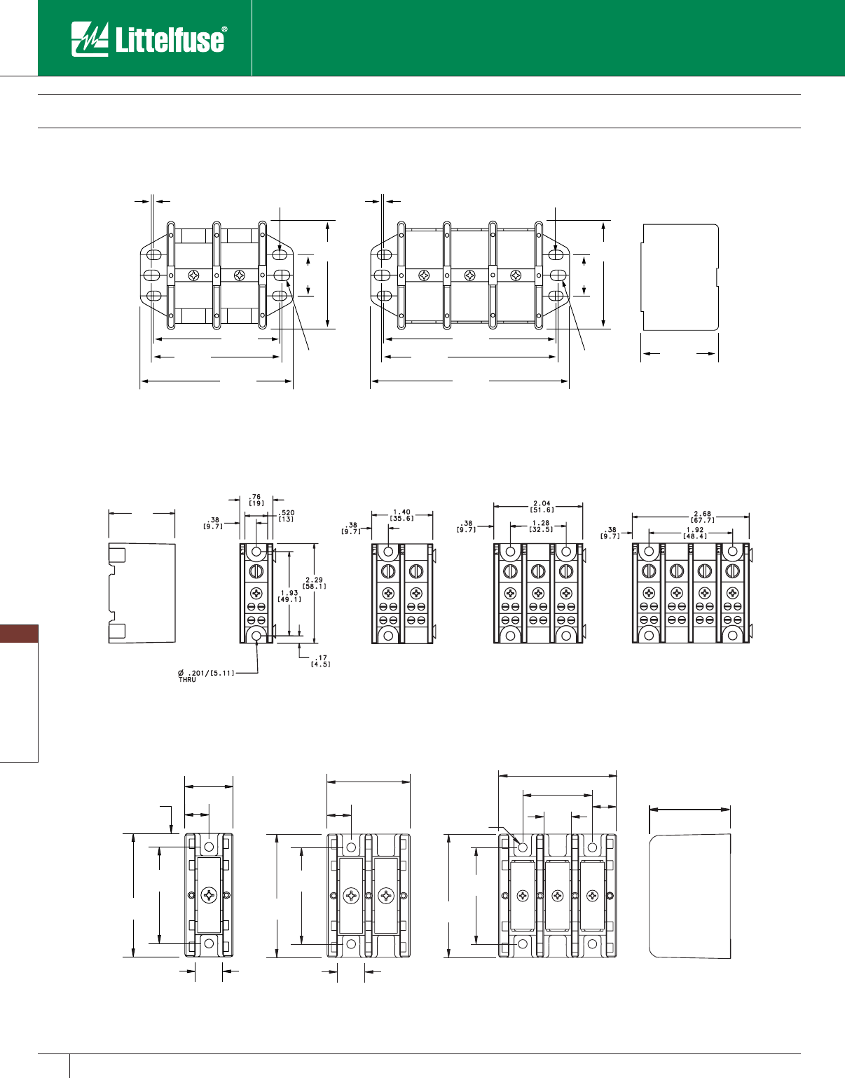
Blocks and Holders
142 www.littelfuse.com
Blocks and Holders
© 2005 Littelfuse • POWR-GARD™ Products Catalog
1.00"
[25.4]
2.90"
[73.7]
.07"
[1.8] .07"
[1.8]
.218 x .375"
[5.5 x 9.5]SLOT
3.52"
[89.3]
4.13"
[104.8]
.65 x .375"
[6.7 x 9.5] SLOT
1.00"
[25.4]
2.90"
[73.7]
.218 x .375"
[5.5 x 9.5]SLOT
.265 x .375"
[6.7 x 9.5] SLOT
3.38"
[85.8] 4.73"
[121]
5.38"
[137]
4.63"
[118] 3.38"
[85.8]
2 POLE 3 POLE
2.88"
[73.0]
2.25"
[57.2]
.56"
[14]
1.94"
[49.2]
2.75"
[69.9]
1.62"
[42]
2.25"
[57.2]
2.88"
[73.0]
.63"
[16.1]
.56"
[14]
.205 [5.2]
DIA. HOLE
1.13"
[28.6]
.56"
[14]
.62"
[16] .62"
[16]
2.25"
[57.2]
2.88"
[73.0]
1.78"
[45.2]
1 POLE 2 POLE 3 POLE
.31"
[7.9]
LX0XXX
LX2XXX
Figure 1
Figure 3
1.52
[38.7]
1 POLE 2 POLE 4 POLE3 POLE
LX1XXX
Figure 2
POWR-BLOKS™
Distribution/Splicer Blocks and Covers
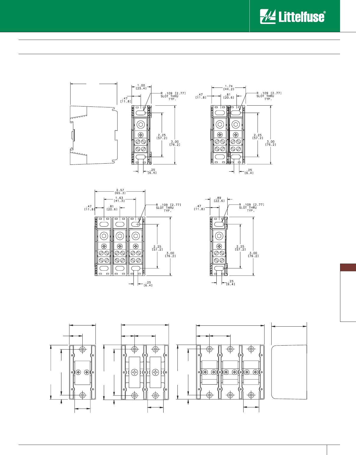
Blocks and Holders
143
www.littelfuse.com
Blocks and Holders
© 2005 Littelfuse • POWR-GARD™ Products Catalog
2.61"
[66.2]
1.94"
[49.3]
.97"
[25]
1.17"
[29.7]
.31"
[7.9] .31"
[7.9]
4.00"
[102]
3.38"
(85.7)
1.17"
[29.7]
.97"
(25)
3.47"
[88.1]
1.53"
[38.9]
4.00"
[102]
3.38"
(85.7)
4.00"
[101.6]
3.38"
[85.7]
.97"
[25]
5.00"
[127.0]
.31"
[7.9]
1.17"
[29.7]
1 POLE 2 POLE 3 POLE
1.53"
[38.9]
POWR-BLOKS™
Distribution/Splicer Blocks and Covers
Figure 5
Figure 4
2.42
[61.5]
1 POLE 2 POLE
3 POLE ADDER
LX3XXX
LX2XXX-XDIN
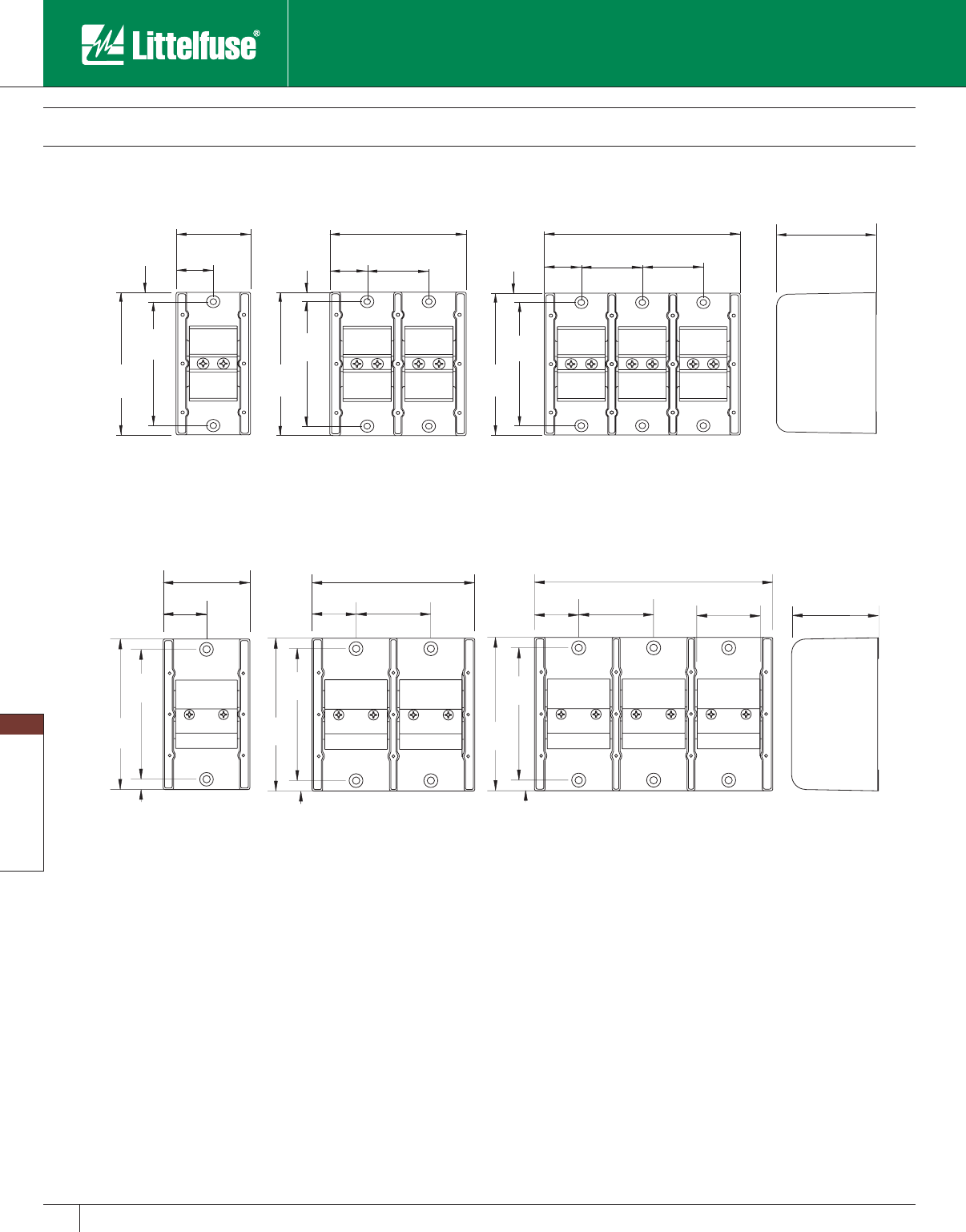
Blocks and Holders
144 www.littelfuse.com
Blocks and Holders
© 2005 Littelfuse • POWR-GARD™ Products Catalog
POWR-BLOKS™
Distribution/Splicer Blocks and Covers
.31"
[7.9] .31"
[7.9]
.31"
[7.9]
2.28"
[57.9]
1.14"
[29.0]
4.75"
[121]
4.13"
[105]
1.14"
[29.0]
1.88"
[47.8]
4.16"
[106]
4.13"
[105]
4.75"
[121]
2.92
(74.0)
1.88"
[47.8]
6.04"
[153]
1.88"
[47.8]
1.14"
[29.0]
4.13"
[105]
4.75"
[121]
1 POLE 2 POLE 3 POLE
3.12"
[79.2]
.37"
(9.5)
.37"
[9.5]
.37"
[9.5]
5.50"
[140]
4.75"
[121]
1.58"
[40.2]
3.17"
[80.4]
4.75"
[121]
5.50"
[140]
1.58"
[40.2]
2.69"
[68.2]
5.88"
[149]
4.75"
[121]
5.50"
[140]
2.30"
[58.5]
8.54"
[217]
2.69"
[68.2]
1.58"
[40.2]
1 POLE 2 POLE 3 POLE
Figure 7
Figure 6
LX4XXX
LX5XXX
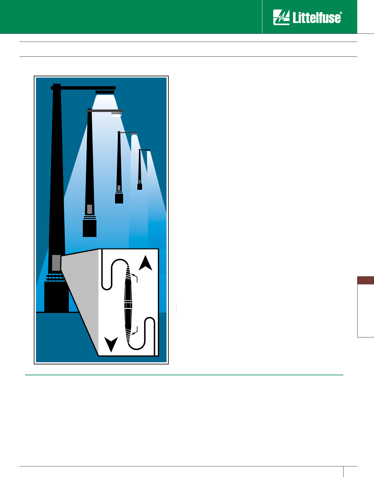
Blocks and Holders
145
www.littelfuse.com
Blocks and Holders
© 2005 Littelfuse • POWR-GARD™ Products Catalog
In-Line Watertight Fuseholders
TO
LOAD
TO
SOURCE
ELECTRICAL TAPE
Littelfuse 600 volt in-line watertight fuse holders are the ideal answer
for all high humidity and corrosive environments where fuses are
required. Available in both break away and non-break away, single and
double pole versions, these fuse hold ers allow maximum flexibility for
any ap pli ca tion.
Applications
Street, alley, and parking lot lighting
Security and perimeter lighting
Traffic signals
Outdoor illuminated signs
Sports lighting
Boat electrical circuits
Tractors and yard equipment
General outdoor circuit protection
Benefits
• Safety — Permits individual fixture or device to be dis con nect ed from
circuit for servicing. Eliminates possibility of shock.
• Individual fixture fusing — Prevents loss of one fixture through
accident, vandalism, or end of life from darkening the entire circuit.
• Simplifies maintenance — Being able to immediately identify the one
faulted fixture eliminates testing the entire circuit, speeds repair, and
allows the individual unit to be serviced while the rest of the circuit is
functioning.
• Reduces damage from fault — Can prevent faulted ballast or other
failure from severely damaging fixture or device, reducing necessary
repair or need of replacement.
Features
• Watertight — Internal O-ring provides watertight seal.
• Superior terminal seals — Ultrasonically-welded terminals provide
maximum strength and eliminate leaking at terminals.
• Break resistant — Fiberglass reinforced polymer body resists damage
from dropping or impact much better than phenolic look-alikes.
• Flexible terminations — Accommodates a wide range of stranded or
solid copper or aluminum conductors. Ter mi na tions are available for
one or two conductors, with either crimp or screw terminals.
• One-pole and two-pole models available to ac com mo date all system
voltages up to 600V.
Specifications
Voltage rating: 600 Volts
Ampere rating: 30 amperes
200,000 amperes rms symmetrical (with Class CC fuses)
Approvals:
LEB/ LEX series: UL Recognized Miscellaneous
Fuseholder per UL 512 (File No. E14721)
CSA Certified per C22.2, No. 39 (File No. LR7316)
LEC/ LEY series: UL Listed Class CC Branch Circuit
Fuseholder per UL 512 (File No. E14721)
CSA Certified per C22.2, No. 39 (File No. LR7316)
Mating fuses
LEB/LEX series: Accepts all 1 1⁄2” x 13 ⁄32” Midget and Class CC fuses
Littelfuse types BLF, BLN, FLM, FLQ, KLK, KLKD, KLKR,
KLDR and CCMR.
LEC/LEY series: Accepts only Class CC fuses.
Littelfuse types KLKR, KLDR and CCMR.
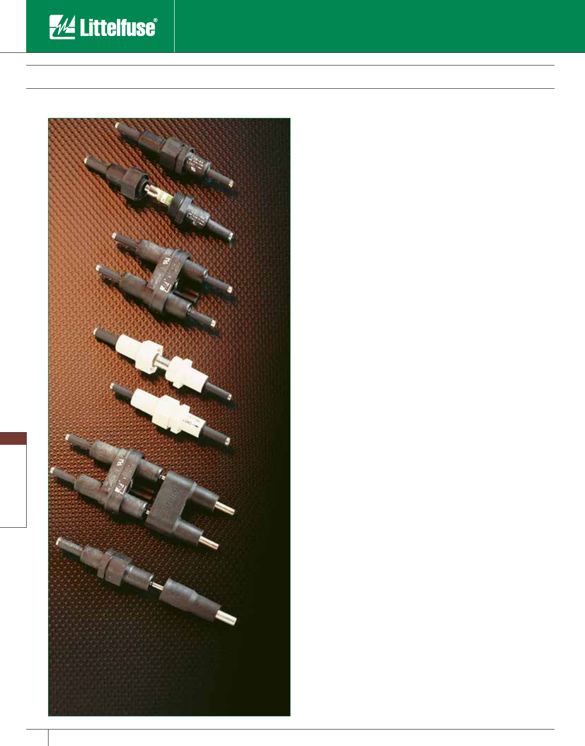
Blocks and Holders
146 www.littelfuse.com
Blocks and Holders
© 2005 Littelfuse • POWR-GARD™ Products Catalog
One-pole LEB and LEC Fuseholders
Basic single-pole LEB and LEC watertight fuseholders provide
protection for a variety of circuits. LEB fuseholders ac cept all
13/32” x 11/2” midget fuses providing sup ple men tal overcurrent
protection. LEC fuseholders are UL Listed Class CC fuseholders
which accept only Class CC fuses and meet National Electrical Code
requirements for branch circuit protection. The most common use for
either fuseholder is for protection of lighting circuits. However, consider
them wherever there is a need for secure in-line protection, from boat
circuits to electric wheelchairs. Great flexibility is achieved when the
basic holders are combined with breakaway receptacles, Y-terminals
and insulating boots.
Two-pole LEX and LEY Fuseholders
LEX and LEY fuseholders are intended for use on line-to-line circuits up
to 600 volts and are ideal for line-to-line loads such as 240 or 480 volt
ballasts. When the line and load sections of LEX and LEY fuseholders
are separated, or when the fuseholder is removed from a two-pole
breakaway receptacle, both lines are disconnected simultaneously. This
prevents the possibility of shock from backfeeding through an exposed
fuse, which could happen with single-pole fuseholders. The LEX holder
is a two-pole version of the LEB and accepts midget fuses, providing
supplementary overcurrent protection. The LEY holder is a two-pole
version of the LEC, which accepts only Class CC fuses, and may be
used to provide branch circuit protection. Both fuseholders may be
equipped with Y-terminals, breakaway receptacles and insulating boots.
One-pole LET Solid Neutral Disconnects
The LET solid neutral disconnect is designed for use as a no-load
non-fused disconnect. Similar in design to the LEB series fuseholders,
the LET is easily identified by its all white body. Internally, it has
a permanently installed solid tin-plated copper neutral slug which
eliminates the possibility of placing a fuse in the neutral side of the
circuit. Fusing the neutral side causes a safety hazard and also violates
the National Electrical Code. The LET is available in both breakaway and
non-breakaway configurations with a wide variety of ter mi na tions.
Breakaway Feature
Littelfuse LEB, LEC, and LET single-pole fuseholders and LEX and LEY
two-pole fuseholders are available with an optional breakaway feature
required to meet state and federal highway commission standards
requiring fuseholders to readily disconnect from the line in case of
a pole knockdown. The breakaway feature consists of a receptacle
permanently attached to the power line and a fuseholder with matching
terminals. When knockdown occurs, the parts separate readily. The
breakaway receptacle terminal is deeply recessed so that energized
parts are not exposed. The fuse remains safely enclosed inside the now
de-energized water tight fuseholder. After the pole has been reinstalled,
the fuseholder is easily plugged into the receptacle, im me di ate ly
restoring service. The breakaway feature may also be used in marinas,
travel trailer parks and other locations
where circuits subjected to strain
must be safely dis con nect ed.
In-Line Watertight Fuseholders
LEB/LEC
LEX/LEY
LET
Breakaway
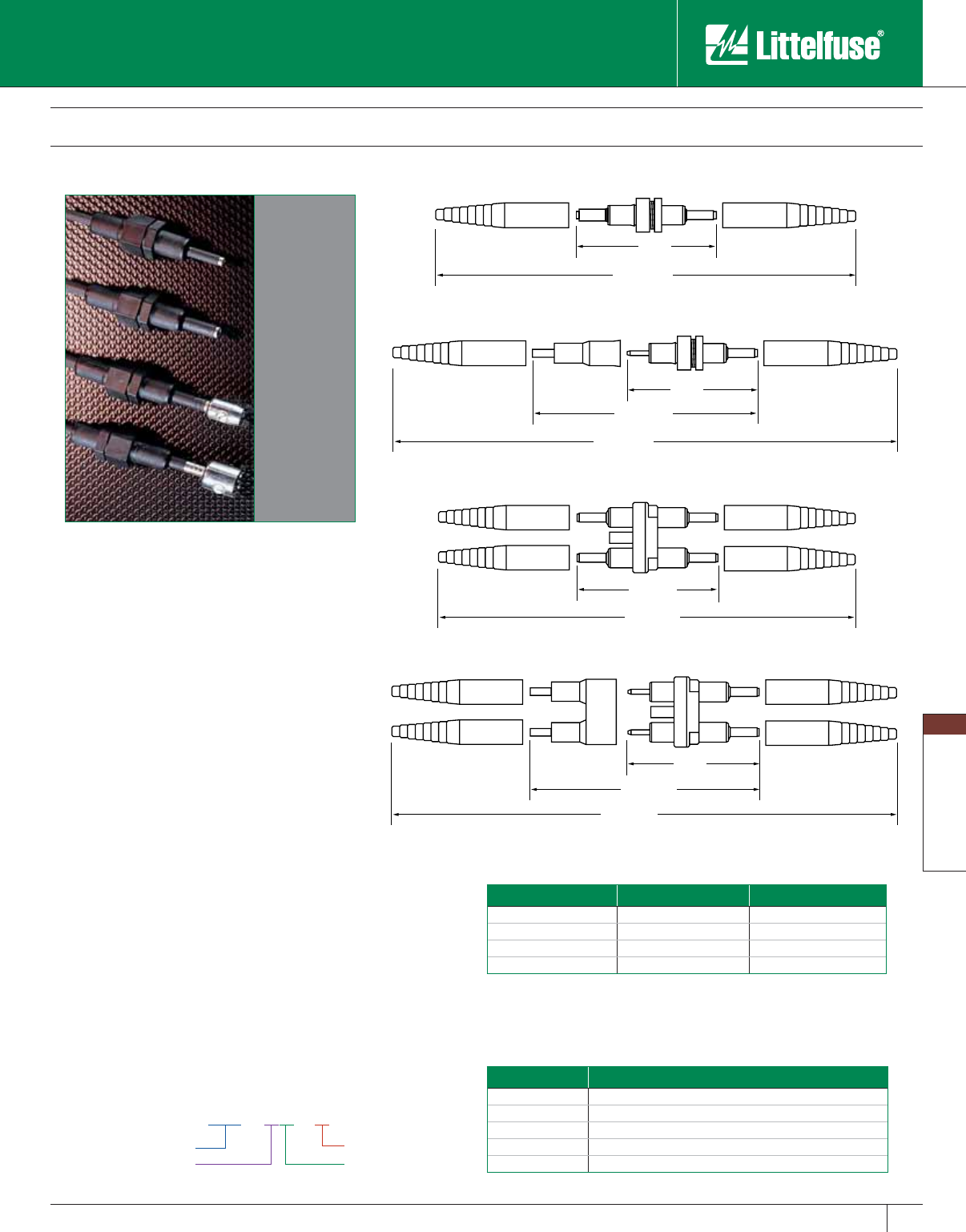
Blocks and Holders
147
www.littelfuse.com
Blocks and Holders
© 2005 Littelfuse • POWR-GARD™ Products Catalog
In-Line Watertight Fuseholders
Insulating Boots
Molded from engineering grade ther mo plas tics, the
WPB1 and WPB2 provide a high resistance to cor-
ro sive en vi ron ments and deliver a watertight seal.
Boots are supplied as standard with all breakaway
versions. Weath er proof boots WPB1 and WPB2
can be pur chased separately for all non-breakaway
holders. Part number WPB1 contains one standard
boot for use with A, B, C, D, or J ter mi na tion. Part
number WPB2 contains one Y-pole boot for use with
the Y-pole termination. For watertight protection
of non-breakaway Y-pole fuseholders, order one
WPB1 and one WPB2 boot. For non-breakaway
double-pole LEX and LEY holders with A, B, C, D,
or J terminations, order four WPB1 boots. These
insulating boots are designed to fit snugly onto wire
insulation, but for best results with varying wire
insulation sizes, a tape wrap should be completed.
A & B Crimp
Terminal
C & D Crimp
Terminal
J Terminal
Y Terminal
4.5"
10.3"
( ASSEMBLED LENGTH )
5.4"
( ASSEMBLED LENGTH )
4.5"
9.3"
( ASSEMBLED LENGTH )
WPB1 BOOT
(OPTIONAL) WPB1 BOOT
(OPTIONAL)
INSULATING BOOT
(STANDARD) INSULATING BOOT
(STANDARD)
4.2"
4.5"
9.3"
( ASSEMBLED LENGTH )
10.3"
( ASSEMBLED LENGTH )
5.3"
( ASSEMBLED LENGTH )
Terminal Size T&B Part No. Burndy Part No.
AWT161M –
BWT161MMR4C
CWT115AHypress Y34A
DWT115AHypress Y34A
Recommended Crimping Tools
The following crimping tools or equivalents may be used on either the
non-breakaway or breakaway watertight in-line fuseholders.
Ordering Information
To order Littelfuse in-line fuseholders and disconnects by part number,
refer to the charts on the next page.
LEB - AA - S
Type
Load Side/Term Size
Breakaway Feature
Line Side/Term Size
Fuseholder Type Description
LEB One-pole in-line fuseholder for Midget and Class CC fuses
LEC One-pole in-line fuseholder for Class CC fuses
LET One-pole in-line solid neutral disconnect
LEX Two-pole in-line fuseholder for Midget and Class CC fuses
LEY Two-pole in-line fuseholder for Class CC fuses
Blocks and Holders
148 www.littelfuse.com
Blocks and Holders
© 2005 Littelfuse • POWR-GARD™ Products Catalog
In-Line Watertight Fuseholders
Selection Guide For Single Pole LEB/ LEC Fuse hold ers
Standard
Part No.
Breakaway
Part No. Fuse Type
Load Terminal Selection Line Terminal Selection
Terminal
Type
Load
Terminal
Wire Size
Range
No. of
Wires per
Terminal
Solid
Wire
Stranded
Wire
Terminal
Type
Line
Terminal
Wire Size
Range
No. of
Wires per
Terminal
Solid
Wire
Stranded
Wire
LEB-AA
LEC-AA
LEB-AA-S
LEC-AA-S
Midget
Class CC
Copper
Crimp
#12 to #8 1 X X Copper
Crimp
#12 to #8 1 X X
#12 2 X X #12 2 X X
LEB-AB
LEC-AB
LEB-AB-S
LEC-AB-S
Midget
Class CC
Copper
Crimp
#12 to #8 1 X X Copper
Crimp
#10 2 X X
#12 2 X X #6 1 X X
#4 1 — X
LEB-AC
LEC-AC
—
—
Midget
Class CC
Copper
Crimp
#12 to #8 1 X X Copper
Crimp
#8 2 X X
#12 2 X X #4 1 — X
LEB-AD
LEC-AD
—
—
Midget
Class CC
Copper
Crimp
#12 to #8 1 X X Copper
Crimp
#6 2 X X
#12 2 X X #2 1 — X
LEB-AJ
LEC-AJ
LEB-AJ-S
LEC-AJ-S
Midget
Class CC
Copper
Crimp
#12 to #8 1 X X Copper
Set-Screw
#12 to #8 1 X —
#12 2 X X #10 to #2 1 — X
LEB-AYC
LEC-AYC
LEB-AYC-S
LEC-AYC-S
Midget
Class CC
Copper
Crimp
#12 to #8 1 X X “Y” Type
Copper
Set-Screw
#12 to #8 1 X —
#12 2 X X #10 to #2 1 — X
LEB-BA
LEC-BA
LEB-BA-S
LEC-BA -S
Midget
Class CC
Copper
Crimp
#10 2 X X Copper
Crimp
#12 to #8 1 X X
#6 1 X X #12 2 X X
#4 1 — X
LEB-BB
LEC-BB
LEB-BB-S
LEC-BB-S
Midget
Class CC
Copper
Crimp
#10 2 X X Copper
Crimp
#10 2 X X
#6 1 X X #6 1 X X
#4 1 — X #4 1 — X
LEB-BC
LEC-BC
—
—
Midget
Class CC
Copper
Crimp
#10 2 X X Copper
Crimp
#8 2 X X
#6 1 X X #4 1 — X
#4 1 — X
LEB-BD
LEC-BD
—
—
Midget
Class CC
Copper
Crimp
#10 2 X X Copper
Crimp
#6 2 X X
#6 1 X X #2 1 — X
#4 1 — X
LEB-BJ
LEC-BJ
LEB-BJ-S
LEC-BJ-S
Midget
Class CC
Copper
Crimp
#10 2 X X Copper
Set-Screw
#12 to #8 1 X —
#6 1 X X #10 to #2 1 — X
#4 1 — X
LEB-BYC
LEC-BYC
LEB-BYC-S
LEC-BYC-S
Midget
Class CC
Copper
Crimp
#10 2 X X “Y” Type
Copper
Set-Screw
#12 to #8 1 X —
#6 1 X X #10 to #2 1 — X
#4 1 — X
LEB-CA
LEC-CA
—
—
Midget
Class CC
Copper
Crimp
#8 2 X X Copper
Crimp
#12 to #8 1 X X
#4 1 — X #12 2 X X
LEB-CB
LEC-CB
—
—
Midget
Class CC
Copper
Crimp
#8 2 X X Copper
Crimp
#10 2 X X
#4 1 — X #6 1 X X
#4 1 — X
LEB-CC
LEC-CC
—
—
Midget
Class CC
Copper
Crimp
#8 2 X X Copper
Crimp
#8 2 X X
#4 1 — X #4 1 — X
LEB-CD
LEC-CD
—
—
Midget
Class CC
Copper
Crimp
#8 2 X X Copper
Crimp
#6 2 X X
#4 1 — X #2 1 — X
LEB-CJ
LEC-CJ
—
—
Midget
Class CC
Copper
Crimp
#8 2 X X Copper
Set-Screw
#12 to #8 1 X X
#4 1 — X #10 to #2 1 — X
LEB-CYC
LEC-CYC
—
—
Midget
Class CC
Copper
Crimp
#8 2 X X “Y” Type
Copper
Set-Screw
#12 to #8 1 X —
#4 1 — X #10 to #2 1 — X
LEB-DA
LEC-DA
—
—
Midget
Class CC
Copper
Crimp
#6 2 X X Copper
Crimp
#12 to #8 1 X —
#2 1 — X #12 2 X X
LEB-DB
LEC-DB
—
—
Midget
Class CC
Copper
Crimp
#6 2 X X Copper
Crimp
#10 2 X X
#2 1 — X #6 1 X X
#4 1 — X
LEB-DC
LEC-DC
—
—
Midget
Class CC
Copper
Crimp
#6 2 X X Copper
Crimp
#8 2 X X
#2 1 — X #4 1 — X
LEB-DD
LEC-DD
—
—
Midget
Class CC
Copper
Crimp
#6 2 X X Copper
Crimp
#6 2 X X
#2 1 — X #2 1 — X
LEB-DJ
LEC-DJ
—
—
Midget
Class CC
Copper
Crimp
#6 2 X X Copper
Set-Screw
#12 to #8 2 X X
#2 1 — X #10 to #2 1 — X
LEB-DYC
LEC-DYC
—
—
Midget
Class CC
Copper
Crimp
#6 2 X X “Y” Type
Copper
Set-Screw
#12 to #8 1 X —
#2 1 — X #10 to #2 1 — X
LEB-JJ
LEC-JJ
LEB-JJ-S
LEC-JJ-S
Midget
Class CC
Copper
Set Screw
#12 to #8 1X
—Copper
Set-Screw
#12 to #8 1X—
#10 to #2 1—X#10 to #2 1—X
LEB-JYC
LEC-JYC
LEB-JYC-S
LEC-JYC-S
Midget
Class CC
Copper
Set Screw
#12 to #8 1X
—“Y” Type
Copper
Set-Screw
#12 to #8 1X—
#10 to #2 1—X#10 to #2 1—X
Blocks and Holders
149
www.littelfuse.com
Blocks and Holders
© 2005 Littelfuse • POWR-GARD™ Products Catalog
Standard
Part No.
Breakaway
Part No. Fuse Type
Load Terminal Selection Line Terminal Selection
Terminal
Type
Load
Terminal
Wire Size
Range
No. of
Wires per
Terminal
Solid
Wire
Stranded
Wire
Terminal
Type
Line
Terminal
Wire Size
Range
No. of
Wires per
Terminal
Solid
Wire
Stranded
Wire
LEX-AA
LEY-AA
LEX-AA-S
LEY-AA-S
Midget
Class CC
Copper
Crimp
#12 to #8 1 X X Copper
Crimp
#12 to #8 1 X X
#12 2 X X #12 2 X X
LEX-AB
LEY-AB
LEX-AB-S
LEY-AB-S
Midget
Class CC
Copper
Crimp
#12 to #8 1 X X Copper
Crimp
#10 2 X X
#12 2 X X #6 1 X X
#4 1 — X
LEX-AC
LEY-AC
—
—
Midget
Class CC
Copper
Crimp
#12 to #8 1 X X Copper
Crimp
#8 2 X X
#12 2 X X #4 1 — X
LEX-AD
LEY-AD
—
—
Midget
Class CC
Copper
Crimp
#12 to #8 1 X X Copper
Crimp
#6 2 X X
#12 2 X X #2 1 — X
LEX-AYC
LEY-AYC
LEX-AYC-S
LEY-AYC-S
Midget
Class CC
Copper
Crimp
#12 to #8 1 X X “Y” Type
Copper
Set-Screw
#12 to #8 1 X —
#12 2 X X #10 to #2 1 — X
LEX-BA
LEY-BA
LEX-BA-S
LEY-BA -S
Midget
Class CC
Copper
Crimp
#10 2 X X Copper
Crimp
#12 to #8 1 X X
#6 1 X X #12 2 X X
#4 1 — X
LEX-BB
LEY-BB
LEX-BB-S
LEY-BB-S
Midget
Class CC
Copper
Crimp
#10 2 X X Copper
Crimp
#10 2 X X
#6 1 X X #6 1 X X
#4 1 — X #4 1 — X
LEX-BC
LEY-BC
—
—
Midget
Class CC
Copper
Crimp
#10 2 X X Copper
Crimp
#8 2 X X
#6 1 X X #4 1 — X
#4 1 — X
LEX-BD
LEY-BD
—
—
Midget
Class CC
Copper
Crimp
#10 2 X X Copper
Crimp
#6 2 X X
#6 1 X X #2 1 — X
#4 1 — X
LEX-BYC
LEY-BYC
LEX-BYC-S
LEY-BYC-S
Midget
Class CC
Copper
Crimp
#10 2 X X “Y” Type
Copper
Set-Screw
#12 to #8 1 X —
#6 1 X X #10 to #2 1 — X
#4 1 — X
LEX-CA
LEY-CA
—
—
Midget
Class CC
Copper
Crimp
#8 2 X X Copper
Crimp
#12 to #8 1 X X
#4 1 — X #12 2 X X
LEX-CB
LEY-CB
—
—
Midget
Class CC
Copper
Crimp
#8 2 X X Copper
Crimp
#10 2 X X
#4 1 — X #6 1 X X
#4 1 — X
LEX-CC
LEY-CC
—
—
Midget
Class CC
Copper
Crimp
#8 2 X X Copper
Crimp
#8 2 X X
#4 1 — X #4 1 — X
LEX-CD
LEY-CD
—
—
Midget
Class CC
Copper
Crimp
#8 2 X X Copper
Crimp
#6 2 X X
#4 1 — X #2 1 — X
LEX-CJ
LEY-CJ
—
—
Midget
Class CC
Copper
Crimp
#8 2 X X Copper
Set-Screw
#12 to #8 1 X —
#4 1 — X #10 to #2 1 — X
LEX-CYC
LEY-CYC
—
—
Midget
Class CC
Copper
Crimp
#8 2 X X “Y” Type
Copper
Set-Screw
#12 to #8 1 X —
#4 1 — X #10 to #2 1 — X
LEX-DA
LEY-DA
—
—
Midget
Class CC
Copper
Crimp
#6 2 X X Copper
Crimp
#12 to #8 1 X X
#2 1 — X 12 2 X X
LEX-DB
LEY-DB
—
—
Midget
Class CC
Copper
Crimp
#6 2 X X Copper
Crimp
#10 2 X X
#2 1 — X #6 1 X X
#4 1 — X
LEX-DC
LEY-DC
—
—
Midget
Class CC
Copper
Crimp
#6 2 X X Copper
Crimp
#8 2 X X
#2 1 — X #4 1 — X
LEX-DD
LEY-DD
—
—
Midget
Class CC
Copper
Crimp
#6 2 X X Copper
Crimp
#6 2 X X
#2 1 — X #2 1 — X
LEX-DJ
LEY-DJ
—
—
Midget
Class CC
Copper
Crimp
#6 2 X X Copper
Set-Screw
#12 to #8 1 X —
#2 1 — X #10 to #2 1 — X
LEX-DYC
LEYDYC
—
—
Midget
Class CC
Copper
Crimp
#6 2 X X “Y” Type
Copper
Set-Screw
#12 to #8 1 X —
#2 1 — X #10 to #2 1 — X
LEX-JJ
LEY-JJ
LEX-JJ-S
LEY-JJ-S
Midget
Class CC
Copper
Set-Screw
#12 to #8 1 X — Copper
Set-Screw #12 to #8 1X—
#10 to #2 1 — X 1 — X
In-Line Watertight Fuseholders
Selection Guide For Double Pole LEX/ LEY Fuse hold ers
Blocks and Holders
150 www.littelfuse.com
Blocks and Holders
© 2005 Littelfuse • POWR-GARD™ Products Catalog
In-Line Watertight Fuseholders
Selection Guide For Solid Neutral LET Fuse hold ers
Standard
Part No.
Breakaway
Part No. Fuse Type
Load Terminal Selection Line Terminal Selection
Terminal
Type
Load
Terminal
Wire Size
Range
No. of
Wires per
Terminal
Solid
Wire
Stranded
Wire
Terminal
Type
Line
Terminal
Wire Size
Range
No. of
Wires per
Terminal
Solid
Wire
Stranded
Wire
LET-AA LET-AA-S Solid
Neutral
Copper
Crimp
#12 to #8 1 X X Copper
Crimp
#12 to #8 1 X X
#12 2 X X #12 2 X X
LET-AB LET-AB-S Solid
Neutral
Copper
Crimp
#12 to #8 1 X X Copper
Crimp
#10 2 X X
#12 2 X X #6 1 X X
#4 1 — X
LET-AYC LET-AYC-S Solid
Neutral
Copper
Crimp
#12 to #8 1 X X “Y” Type
Copper
Set-Screw
#12 to #8 1 X —
#12 2 X X #10 to #2 1 — X
LET-BA LET-BA-S Solid
Neutral
Copper
Crimp
#10 2 X X Copper
Crimp
#12 to #8 1 X X
#6 1 X X #12 2 X X
#4 1 — X
LET-BB LET-BB-S Solid
Neutral
Copper
Crimp
#10 2 X X Copper
Crimp
#10 2 X X
#6 1 X X #6 1 X X
#4 1 — X #4 1 — X
LET-BYC LET-BYC-S Solid
Neutral
Copper
Crimp
#10 2 X X “Y” Type
Copper
Set-Screw
#12 to #8 1 X —
#6 1 X X #10 to #2 1 — X
#4 1 — X
LET-JJ LET-JJ-S Solid
Neutral
Copper
Set-Screw
#12 to #8 1 X — Copper
Set-Screw
#12 to #8 1 X —
#10 to #2 1 — X #10 to #2 1 — X
LET-JYC LET-JYC-S Solid
Neutral
Copper
Set-Screw
#12 to #8 1 X — “Y” Type
Copper
Set-Screw
#12 to #8 1 X —
#10 to #2 1 — X #10 to #2 1 — X
Terminal Selec tion Guide
Terminal Designation Terminal Description Number of Wires per Terminal Wire Range Wire Type
A Copper Crimp 1
2
#12-#8
#12
Solid/Stranded
Solid/Stranded
B Copper Crimp
2
1
1
#10
#6
#4
Solid/Stranded
Solid/Stranded
Stranded
C Copper Crimp 2
1
#8
#4
Solid/Stranded
Stranded
D Copper Crimp 2
1
#6
#2
Solid/Stranded
Stranded
J Copper Set Screw 1
2
#12-#8
#10-#2
Solid
Stranded
Y (2 terminals) “Y” Style Copper Set Screw 1
1
#12-#8
#10-#2
Solid
Stranded
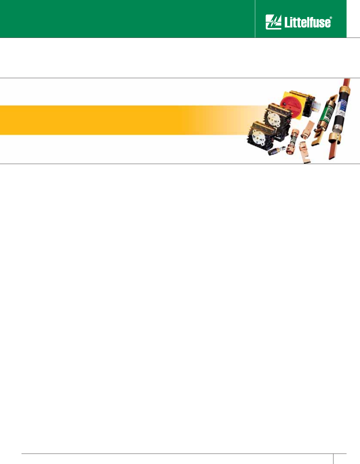
www.littelfuse.com
© 2005 Littelfuse • POWR-GARD™ Products Catalog
Miscellaneous Products
LPS Series POWR-Switch 152-153
LPMP Series POWR-Switch Panel 154-155
Disconnect Switches 156
Misc. Products - Fuse Reducers 157
Box Cover Units 158-159
Misc. Products - Electronic Fuse Display; Spare Fuse Cabinet 160
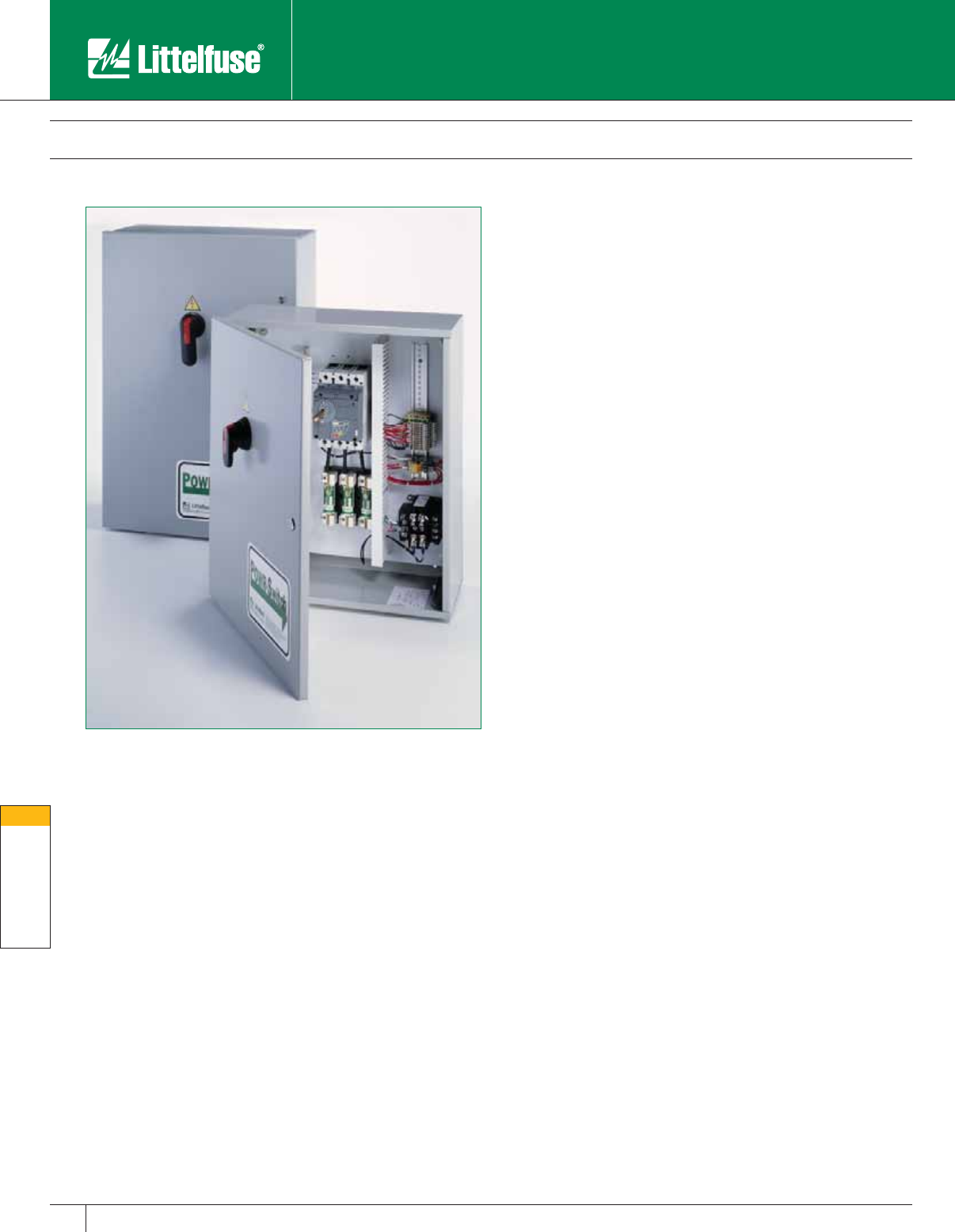
Miscellaneous Products
152 www.littelfuse.com
Misc. Products
© 2005 Littelfuse • POWR-GARD™ Products Catalog
LPS Series POWR-Switch
The Littelfuse POWR-Switch provides a simple and economical
solution for applications that require selective coordination and shunt
trip capabilities. Common applications include elevator circuits, data
processing rooms, and building emergency systems.
By utilizing Class J time-delay fuses, the POWR-Switch is easily
coordinated with other system overcurrent devices. The shunt trip
capability allows the POWR-Switch to meet the ANSI/ASME standard
that requires power to be automatically disconnected before water is
turned on by the fire safety system. The POWR-Switch also features
pre-wired control circuits that can help reduce installation costs.
Standard Features
• 600V 3-pole fuse power switch
• 200,000 RMS interrupting rating
• Shunt trip 120V
• Control power terminal block
• Ground lug per NEC
• Class J fuse block
• NEMA 1 enclosures
Optional Features
• Control power transformer with fuses and blocks
• Fire safety interface relay
• Key to test switch
• Pilot light ”On”
• Isolated neutral lug
• Mechanical interlock auxilliary contact for hydraulic elevators with
automatic recall (5 amp 120 VAC rated)
• Fire alarm voltage monitoring relay
• NEMA 3R, 4, and 12 enclosures
Benefits
• Optional features offer flexibility for a variety of applications
• UL Listed package
• Lower installation costs than systems with many separate components
• Pre-wired control circuits lower installation time
• Lockable Operating handle meets all code and safety requirements
• No confusion over which building trade is supplying the components
• POWR-Switch is a single unit, which makes procurement easier than
systems with multiple components
Miscellaneous Products
153
www.littelfuse.com
Misc. Products
© 2005 Littelfuse • POWR-GARD™ Products Catalog
Littelfuse
Switch Catalog
Number
Control Power
Transformer
Std. 100VA with
PRI & SEC Fuse
(120V Sec.)
Fire Safety
Interface Relay
(3PDT, 10amp, 120V)
Key to
Test Switch
Pilot Light
“ON”
Isolated
Neutral Lug
Mechanical
Interlock Auxilliary
Contact for Hydraulic
Elevators w/
Automatic Recall
(5 amp 120 VAC rated)
Fire Alarm Voltage
Monitoring Relay
(To Monitor Shunt
Trip Voltage)
Optional
Enclosures
Catalog
No. Rating Rating Option
Code Rating Option
Code Rating Option
Code Rating Option
Code Rating Option
Code Rating Option
Code Rating Option
Code Rating Option
Code
LPS3 30A 208V T20 24 VDC Coil R2 120V K Red R 30–60A N6 1 NO & 1 NC A Single Pole F1 NEMA 3R U
LPS6 60A 240V T24 120 VAC Coil R1 Green G 100A N1 2 NO & 2 NC B Three Pole F3 NEMA 4 Y
LPS1 100A 480V T48 White W 200A N2 NEMA 12 Z
LPS2 200A 600V T60 400A N4
LPS4 400A
Note: Desired options must appear in the order shown above. Typical options include Control Power Transformer, Fire Safety Interface Relay, Mechanical Interlock Auxiliary Contact
and Fire Alarm Voltage Monitoring Relay.
Catalog Series Amp Rating NEMA 1 Dimensions NEMA 3R Dimensions NEMA 4, 12 Dimensions Lug Size
LPS3 30 24”H x 20”W x 9”D 24”H* x 20”W x 8”D 24”H x 20”W x 10”D #14 - #8 AL or CU
LPS6 60 24”H x 20”W x 9”D 24”H* x 20”W x 8”D 24”H x 20”W x 10”D #14 - #2 AL or CU
LPS1 100 24”H x 20”W x 9”D 24”H* x 20”W x 8”D 24”H x 20”W x 10”D #8 - 1/0 AL or CU
LPS2 200 30”H x 20”W x 9”D 30”H* x 20”W x 8”D 30”H x 20”W x 10”D #6 - 250kcmil AL or CU
LPS4 400 48”H x 36”W x 12”D Contact Factory Contact Factory 3/0 AL or CU
Note: Over-size enclosures used to accomodate control power transformer, interface relay and terminal blocks.
*For NEMA 3R enclosures add 2 inches to height for mounting tabs.
Amp Rating Voltage Rating Max Inrush Max Ontime Momentary Inrush
30–400A 120V, 60Hz 4A 1.5 cycles 140VA
LPS Series POWR-Switch
Specifications
Approvals: UL Listed and CSA Certified
Rating: 30A, 60A, 100A, 200A, 400A
Shunt Trip Ratings:
Enclosure Dimensions
Example Catalog Number:
LPS1 T48 R1 K N1 U = Littelfuse Catalog Number LPS1T48R1KN1U
Ordering Information
Complete catalog numbers consist of switch catalog numbers and the desired options. See example below.
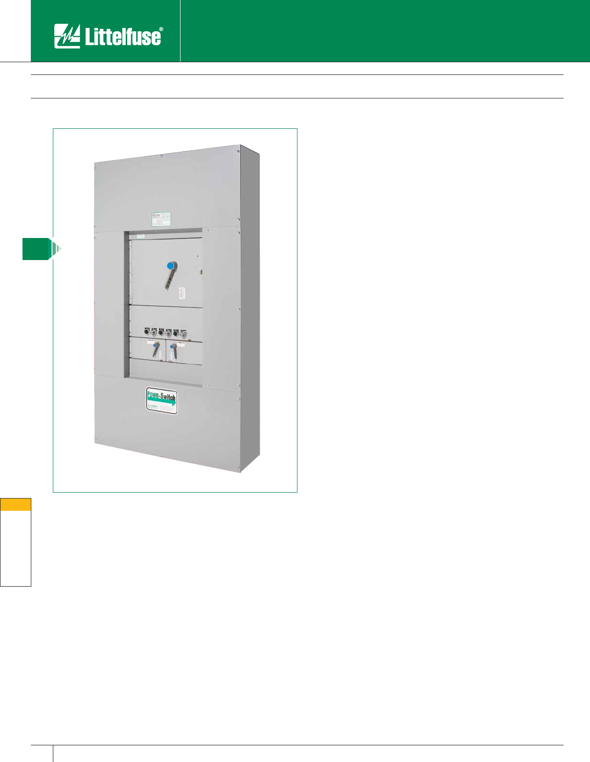
Miscellaneous Products
154 www.littelfuse.com
Misc. Products
© 2005 Littelfuse • POWR-GARD™ Products Catalog
Littelfuse LPMP series POWR-Switch Panel is designed specifically
for applications that require shunt-trip capabilities and the need to
individually control power for a bank of equipment. The POWR-Switch
Panel offers the flexibility to incorporate multiple switches into a panel
enclosure and meet all applicable code requirements.
Standard Features
• UL Listed Package
• NEMA 1 Enclosure
• Fusible Class J Switches (rated 30-400 amps)
• 200,000 amp RMS Short-Circuit Rating
Optional Features
• Control Power Transformers
• Fire Safety Interface Relay
• Key to Test Switch
• Pilot Light “On”
• Mechanical Interlock Auxiliary Contact (for hydraulic elevators
with recall)
• Fire Alarm Voltage Monitor Relay
• NEMA 3R Enclosures
Ordering Information
Catalog Numbers
LPMP 400
LPMP 600
LPMP 800
Specifications
Voltage Rating: 600V
Short-Circuit Rating: 200,000 amps RMS
Ampere Ratings: 400, 600, 800A
Approvals: UL Listed to UL 67 Panelboards and
UL 891 Dead Front Switches
LPMP Series POWR-Switch Panel
600 Volts • Shunt-Trip Disconnect Switch
NEW
Miscellaneous Products
155
www.littelfuse.com
Misc. Products
© 2005 Littelfuse • POWR-GARD™ Products Catalog
LPMP Series POWR-Switch Panel
600 Volts • Shunt-Trip Disconnect Switch
Standard Panel Dimensions
Panel
Rating
Dimensions (in.)
H x W x D
Available Space (X units)
3W 4W
400 A 57 x 40 x 12 18X 16X
600 A 73.5 x 40 x 12 26X 24X
800 A 90 x 40 x 12 38X 35X
Note: “X” Space = 13⁄8 inches (refers to height only)
Main Lug Terminal Information
Panel
Rating
Cond.
/Phase Wire Range Bending Space
Top /Bot. Side
400 A (2) # 6 - 300 kcmil Al or Cu 11.31" 10.00"
(1) 3 ⁄ 0 - 750 kcmil Al or Cu
600 A (2) 3 ⁄ 0 - 500 kcmil Al or Cu 11.31" 10.00"
800 A (3) 3 ⁄ 0 - 500 kcmil Al or Cu 11.31" 10.00"
(2) 3 ⁄ 0 - 750 kcmil Al or Cu
Note: Local codes may change minimum wire bends.
POWR-Switch Panel “Bucket” Options
Bucket/Switch Rating Description Space Conductors
Per Phase Wire Range
30 ⁄ 30 Twin 30 amp switches 4X (1) # 14 – # 8 Al or Cu
30 / Blank Single 30 amp switch 4X (1) # 14 – # 8 Al or Cu
60 ⁄ 60 Twin 60 amp switches 4X (1) # 14 – # 2 Al or Cu
60 / Blank Single 60 amp switch 4X (1) # 14 – # 2 Al or Cu
100 ⁄ 100 Twin 100 amp switches 4X (1) # 8 – 1/0 Al or Cu
100 / Blank Single 100 amp switch 4X (1) # 8 – 1/0 Al or Cu
200 ⁄ 200 Twin 200 amp switches 6X (1) # 6 – 250 kcmil Al or Cu
200 / Blank Single 200 amp switch 6X (1) # 6 – 250 kcmil Al or Cu
400 Single 400 amp switch 12X (2) 3 ⁄ 0 – 750 kcmil Al or Cu
Accessory Contains CPT, Pilot Lights, etc. 6X N/A N/A
Panel Spacing
Main Lugs Only
6X Accessory Bucket
4X 30A Switch 30A Switch
4X 60A Switch 60A Switch
4X 100A Switch 100A Switch
6X 200A Switch 200A Switch
6X Accessory Bucket
12X 400A Switch
Thru-Feed Lugs
Note: Main Lug Only is standard.
One Accessory bucket is required for every four switch units.
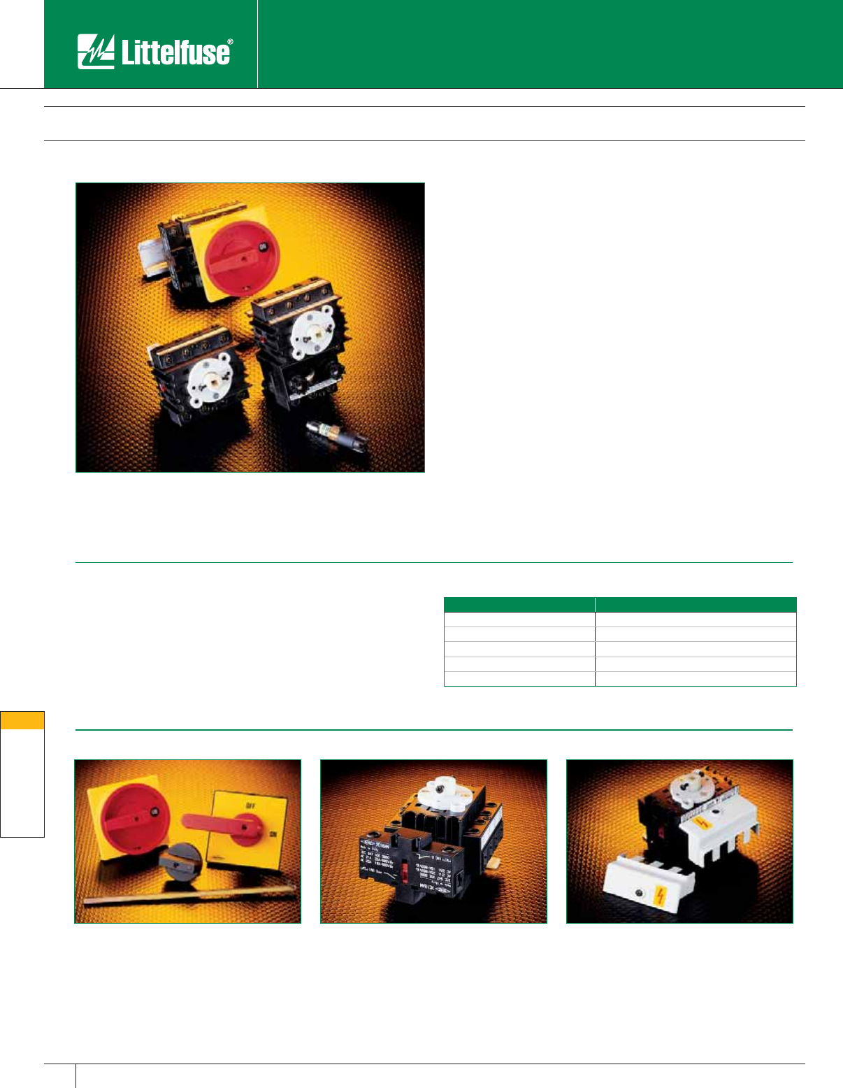
Miscellaneous Products
156 www.littelfuse.com
Misc. Products
© 2005 Littelfuse • POWR-GARD™ Products Catalog
Disconnect Switches
Fusible/Non-fusible
Accessories
The LFFS series fusible switches eliminate the need for a separate
fuse block by integrating a three pole fuse holder into the switch body.
This saves precious panel space and reduces wiring time. These rod-
operated devices are UL Listed and CSA Certified.
Applications
Littelfuse disconnect switches are perfect for use where the National
Electrical Code requires that a separate disconnect means be located
within sight of all motor loads. Commonly used as a main switch
or distribution switches, these units are also ideal for use as safety
switches for air conditioners, pumps and compressors. The LFDS series
disconnect switches can be used with external fuse blocks, permitting
the use of Class RK1, RK5, J and CC fuses.
Features/Benefits
• Reduce panel costs – Compact size minimizes panel space and
reduces enclosure costs. The fusible 30 amp Class CC switch is the
smallest available in the market.
• Reduce installation time – Panel-mount or integral DIN rail-mount
allows quick and easy mounting.
• Flexible design – Optional accessories offer flexibility for various
applications.
• Protect personnel – Dead-front design and optional terminal covers
minimizes exposure to live parts.
• Lockable operator knob/handle – LFRK001 style knob meets
OSHA standard for control of hazardous energy sources. Other knobs
and handles meet IP65.
Specifications
Voltage: 600VAC
Interrupting Rating: 10,000 amperes
Required Screw Torque: 16 inch pounds
Ampere Ratings: 30–100 Amperes
Approvals: UL Listed (File No. E166081)
CSA Certified
Ordering Information
Part Number Description
LFFS030CC 30A Fusible Class CC Switch
LFDS030 30A Non-Fusible Switch
LFDS040 40A Non-Fusible Switch
LFDS060 60A Non-Fusible Switch
LFDS100 100A Non-Fusible Switch
Note: Handles and accessories sold separately.
LFRH001*Red Handle LFCB001 Add-on Con tact Block (N. O.) LFTC001 Terminal Cover (1 Pair)
LFRK001*Red Knob LFCB002 Add-on Contact Block (N. C.) LFTC002 LFDS030 Terminal Cover (1 Pair)
LFBH001*Black Handle LFCB003 100A Add-on Contact Block (N. C.) LFTC003 LFDS100 Terminal Cover (1 Pair)
LFBK001*Black Knob LFCB004 100A Add-on Contact Block (N. C.)
LFBK002** Black Knob LFPP001 30A Add-on Power Pole (N. O.)
SHFT002 Shaft (19.68") LFPP002 30A Add-on Power Pole (N. C.)
SHFT003 Shaft (11.81")
SHFT005 Shaft (7.78")
* Includes mounting hardware and standard length shaft for enclosures 3.5" through 8" deep.
** Supplied with 2" shaft Note: LFRH001, LFBH001, LFBK001 and LFBK002 are not lockable.
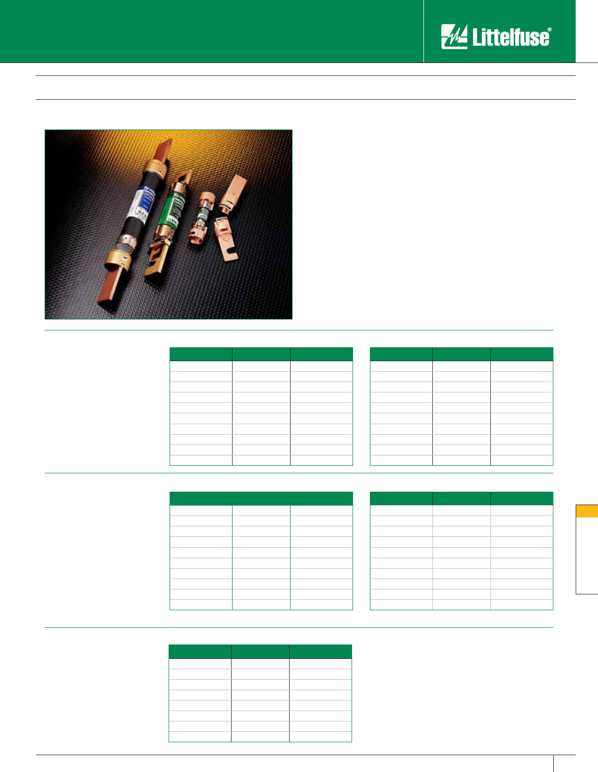
Miscellaneous Products
157
www.littelfuse.com
Misc. Products
© 2005 Littelfuse • POWR-GARD™ Products Catalog
Miscellaneous Products
Fuse Reducers
600 Volt
Part No. (pair) Fuse Clip Fuse Case Size
LRUJ63 60A 30A
LRUJ13 100A 30A
LRUJ16* 100A 60A
LRUJ26 200A 60A
LRUJ21 200A 100A
LRUJ41 400A 100A
LRUJ42 400A 200A
LRUJ64 600A 400A
* Fuse and reducer com bi na tion is slightly larger in diameter than
100A Class J fuses. For specific ap pli ca tions, contact factory.
Class J reducers can not be used in bolt-on applications.
Littelfuse fuse reducers allow smaller size fuses to be installed into
existing fuse clips to prevent overfusing.
• Allows lower ampere-rated fuses to be used in existing fuse clips.
• Simple installation.
• Reduces inventory requirements.
• Silver brazed joints for maximum strength.
• UL Listed (File No. E136855) CSA Certified (File No. LR92899)
Refer to fuse section of this catalog for fuse di men sions.
600 Volt
Part No. (pair) Fuse Clip Fuse Case Size
LRU 663 M 60A 30A
LRU 216 100A 30A
LRU 616 100A 60A
LRU 626 200A 60A
LRU 2621 200A 100A
LRU 2641 400A 100A
LRU 2642 400A 200A
LRU 2661 600A 100A
LRU 2662 600A 200A
LRU 2664 600A 400A
600 Volt
Part No. (pair) Fuse Clip Fuse Case Size
LRU 663 R 60A 30A
LRU 216 R 100A 30A
LRU 616 R 100A 60A
LRU 626 R 200A 60A
LRU 2621 R 200A 100A
LRU 2641 R 400A 100A
LRU 2642 R 400A 200A
LRU 2661 R 600A 100A
LRU 2662 R 600A 200A
*LRU 2664 R 600A 400A
* Only one reducer required.
250 Volt
Part No. (pair) Fuse Clip Fuse Case Size
LRU 263 M 60A 30A
LRU 213 M 100A 30A
LRU 216 100A 60A
LRU 226 200A 60A
LRU 2621 200A 100A
LRU 2641 400A 100A
LRU 2642 400A 200A
LRU 2661 600A 100A
LRU 2662 600A 200A
LRU 2664 600A 400A
250 Volt
Part No. (pair) Fuse Clip Fuse Case Size
LRU 263 R 60A 30A
LRU 213 R 100A 30A
LRU 216 R 100A 60A
LRU 226 R 200A 60A
LRU 2621 R 200A 100A
LRU 2641 R 400A 100A
LRU 2642 R 400A 200A
LRU 2661 R 600A 100A
LRU 2662 R 600A 200A
*LRU 2664 R 600A 400A
* Only one reducer required.
Class H/K5
Fuse Reducers
For use with Littelfuse NLN/NLS
and RLN/RLS series fuses.
Class R
Fuse Reducers
For use with Littelfuse FLNR_ID/
FLSR_ID, IDSR, LLNRK/LLSRK,
LLSRK_ID, and KLNR/KLSR
series fuses.
Class J
Fuse Reducers
For use with Littelfuse JTD_ID/
JTD and JLS series fuses.
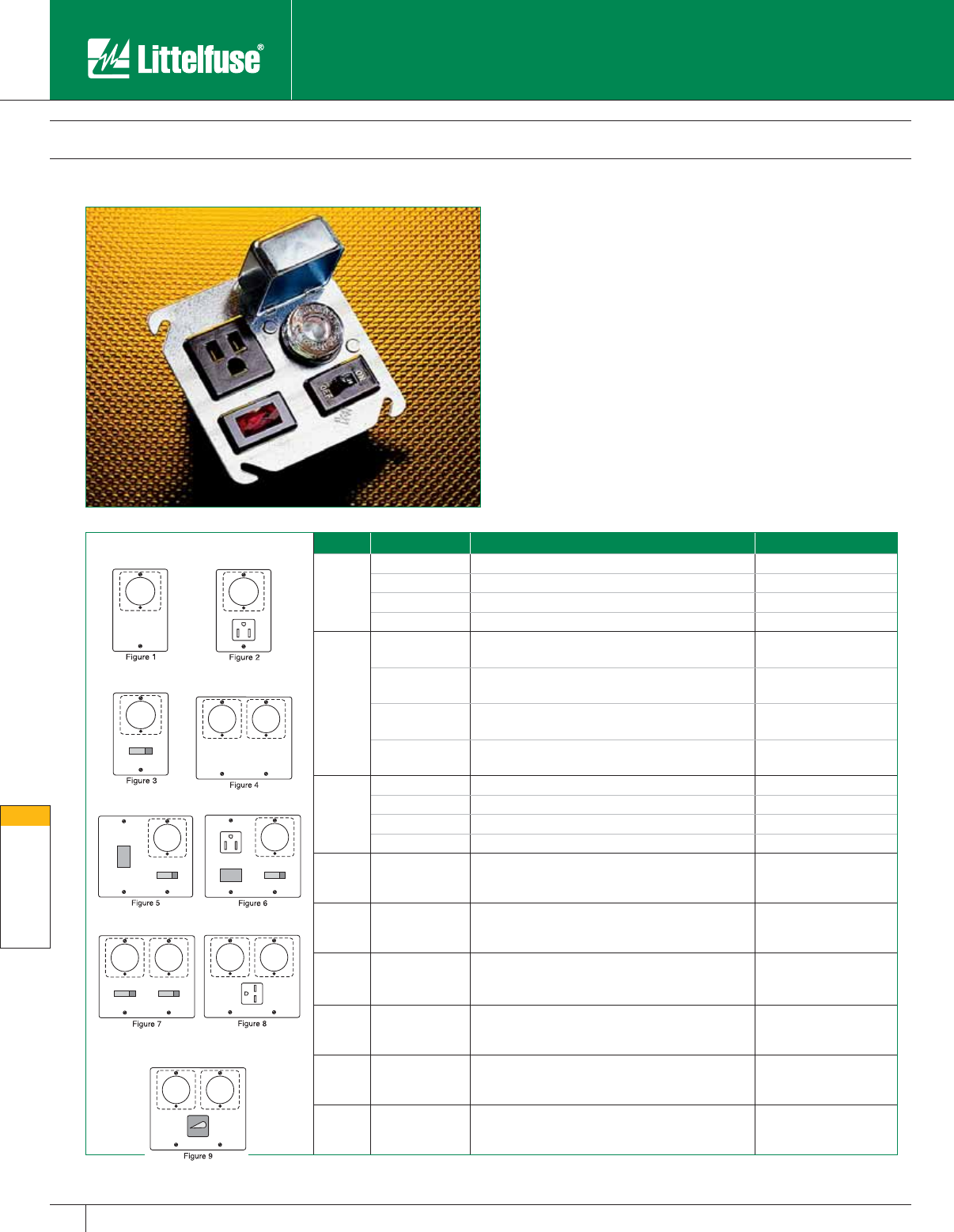
Miscellaneous Products
158 www.littelfuse.com
Misc. Products
© 2005 Littelfuse • POWR-GARD™ Products Catalog
Fig. No. Littelfuse Part No. Box Cover Features To Be Mounted On:
11
LSOU One Edison-Base Fuse Holder 21⁄4" Handy Box
LSOW One Edison-Base Fuse Holder 23⁄4" Switch Box
LSOX One Edison-Base Fuse Holder 4" Octagon Box
LSOY One Edison-Base Fuse Holder 4" Square Box
2
LSRU One Edison-Base Fuse Holder and Grounding Receptacle 21⁄4" Handy Box
LSRW One Edison-Base Fuse Holder and Grounding Receptacle 23⁄4" Switch Box
LSRX One Edison-Base Fuse Holder and Grounding Receptacle 4" Octagon Box
LSRY One Edison-Base Fuse Holder and Grounding Receptacle 4" Square Box
3
LSSU One Edison-Base Fuse Holder and Single Pole Switch 21⁄4" Handy Box
LSSW One Edison-Base Fuse Holder and Single Pole Switch 23⁄4" Switch Box
LSSX One Edison-Base Fuse Holder and Single Pole Switch 4" Octagon Box
LSSY One Edison-Base Fuse Holder and Single Pole Switch 4" Square Box
4 LSOY-B Two Edison-Base Fuse Holders 4" Square Box
5LSSY-L One Edison-Base Fuse Holder
One Single Pole Switch and Pilot Light 4" Square Box
6LSSY-RL
One Edison-Base Fuse Holder
One Grounding Receptacle
One Single Pole Switch and Pilot Light
4" Square Box
7 LSCY Two Edison-Base Fuse Holders and Two Single Pole Switches 4" Square Box
8 LSKA Two Edison-Base Fuse Holders
One 250V Grounding Receptacle 411 ⁄16" Square Box
9 LSTY Two Edison-Base Fuse Holders and One 2-Pole Switch 4" Square Box
Box Cover Units
Box cover units provide an eco nom i cal method of protecting small
motors against overcurrent damage. For use with Edison-Base plug
fuses (TOO, TLO) or Type S plug fuses (SOO, SLO) with adapters (SAO).
Specifications
Voltage: 125V
Ampere Rating: 15 Amperes
Approvals: UL Listed
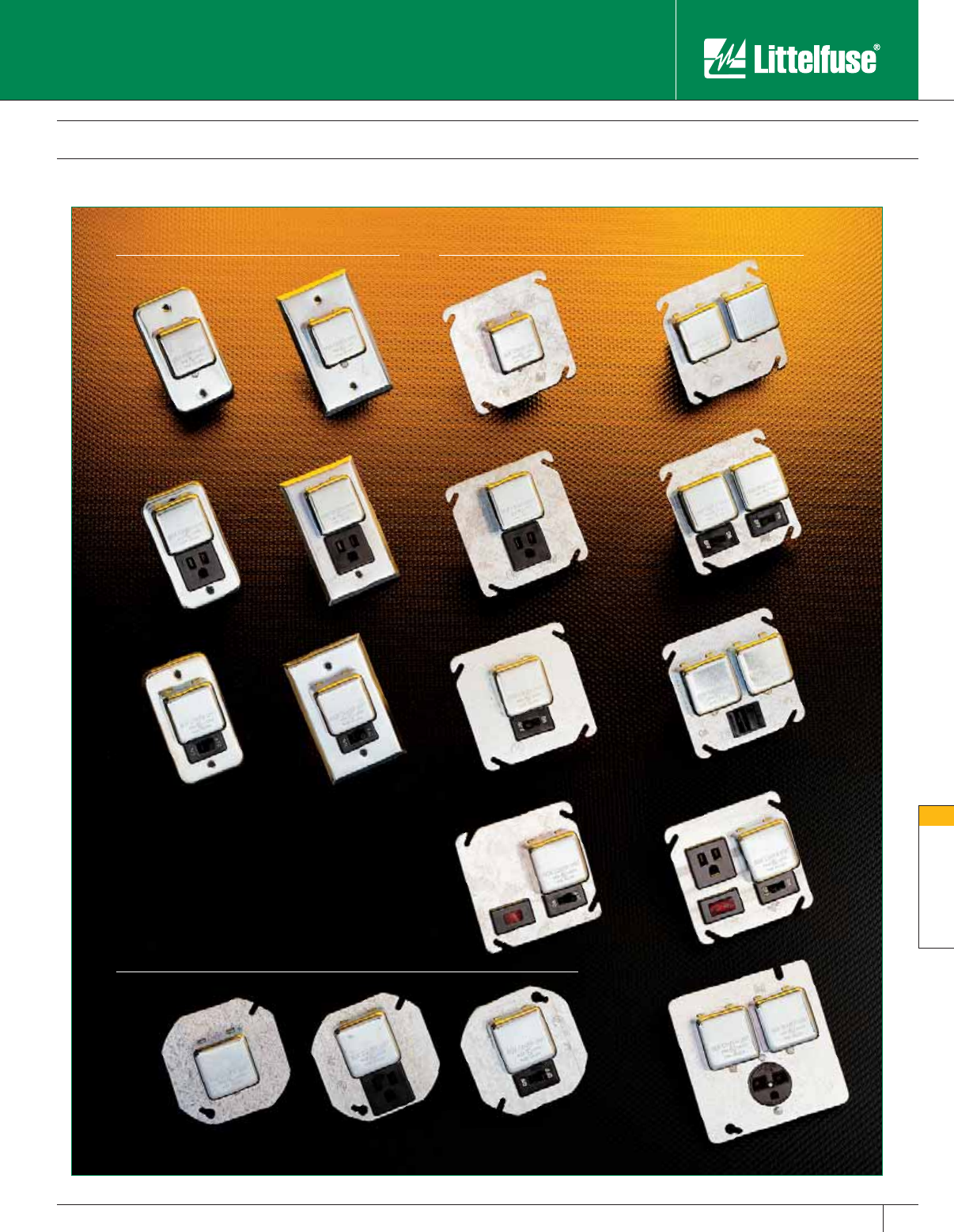
Miscellaneous Products
159
www.littelfuse.com
Misc. Products
© 2005 Littelfuse • POWR-GARD™ Products Catalog
Box Cover Units
LSSU LSSW LSSY LSTY
LSRU LSRW LSRY LSCY
LSOU LSOW LSOY LSOY-B
LSSY-L LSSY-RL
LSOX LSRX LSSX
41⁄2” Box
LSKA
31⁄2” Octagonal Box
2-1/4” Handy Box 4” Handy Box
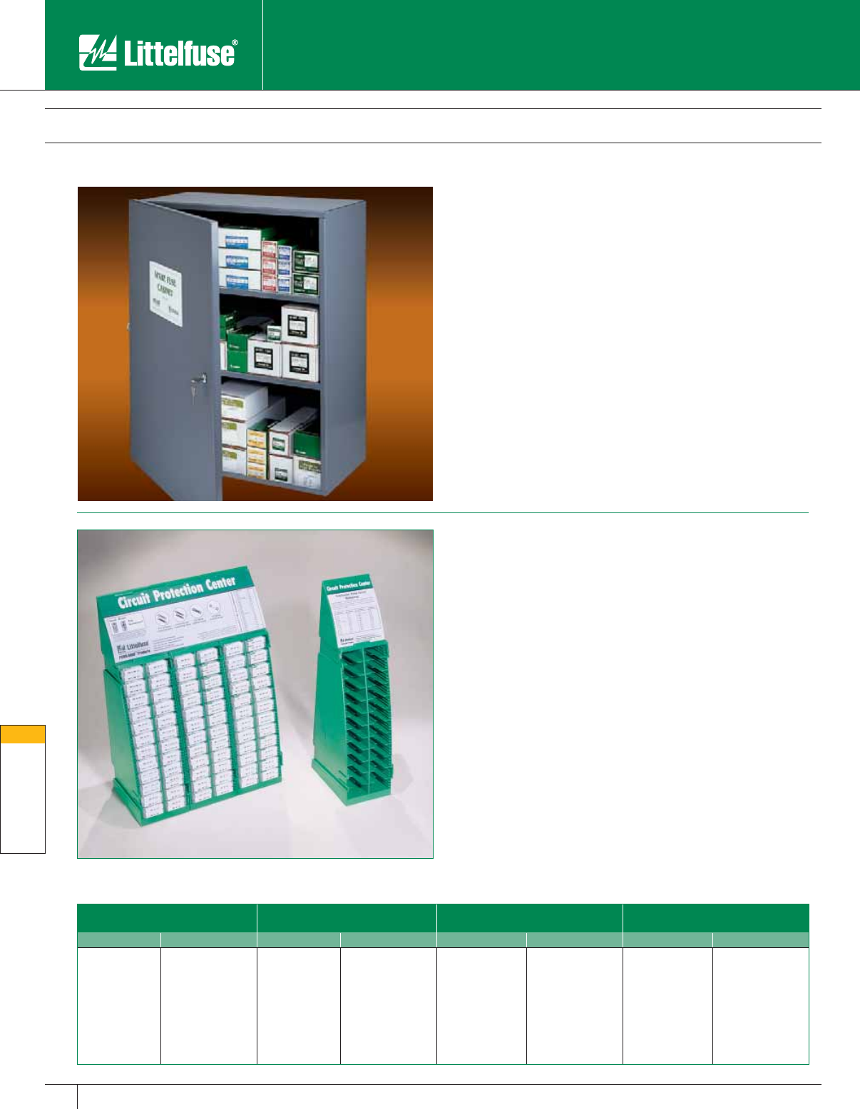
Miscellaneous Products
160 www.littelfuse.com
Misc. Products
© 2005 Littelfuse • POWR-GARD™ Products Catalog
Misc. Products
Electronic Fuse Display • Spare Fuse Cabinet
Electronic Fuse Display
Fully stocked rack includes the following parts:
3AG (Glass)
Fast Acting Fuses
3AG (Glass)
Slo-Blo® Fuses
3AB (Ceramic)
Normal-Blo Fuses
3AB (Ceramic)
Slo-Blo® Fuses
Quantity Part No. Quan ti ty Part No. Quan ti ty Part No. Quan ti ty Part No.
25 312 1⁄2A25313 1⁄2A25314 15A25 326 8A
50 312 1A 25 313 3⁄4A 25 314 20A 20 326 10A
25 312 11⁄2A 25 313 1A 25 314 30A
75 312 2A 25 313 11⁄2A
25 312 21⁄2A50 313 2A
75 312 3A 25 313 21⁄2A
25 312 4A 25 313 3A
25 312 5A 25 313 4A
25 312 10A 25 313 5A
Sturdy steel cabinet holds spare fuses. Cabinet can be locked to prevent
un au tho rized access and is weather stripped to reduce the ac cu mu la-
tion of dust, dirt and moisture. Con ve nient inventory card located inside
door. Measures 30" H × 24" W × 12" D. Keyhole mounting holes 16" on
center for easy installation.
Ordering Information
Spare Fuse Cabinet: Part No. LSFC
Spare Keys: Part No. LKEY001
The sturdy wall-mountable or free-standing modular rack system
prominently displays the most popular Littelfuse glass and automotive
fuses. Additional sections can be quickly snapped on to provide a larger
product selection. Each rack features a cross reference and full color
identification guide to help customers locate the proper replacement fuse.
• Holds 720 (144 5-packs) of the most popular glass, ceramic, and
automotive fuses.
• Designed to save space—measures 14" H × 9" W × 4" D.
• Suitable for wall or counter mounting.
• Includes cross reference, product identification guide, and back-up
card for easy reordering.
• Expandable with modular section that can hold 240 fuses
(48 5-packs) per section.
Ordering Information
Fully stocked display: Littelfuse part number: 094324PG
Littelfuse system number: 00940324ZXPG
Empty display rack: Littelfuse part number: FDR001PG
Littelfuse system number: 0FDR0001ZXPG
Additional sections: Littelfuse part number: MRS001PG
Littelfuse system number: 0MRS0001ZXPG
Spare Fuse Cabinet

www.littelfuse.com
© 2005 Littelfuse • POWR-GARD™ Products Catalog
International Products
LgD Series Global Pro™ Fuses 162
LPSG Series Global Pro™ Fuseholders 163
NH Fuse Links 164-165
Diazed/Neozed Fuses 166-167
Cylindical Fuses 168
British Dimension HRCII-C Fuses 169
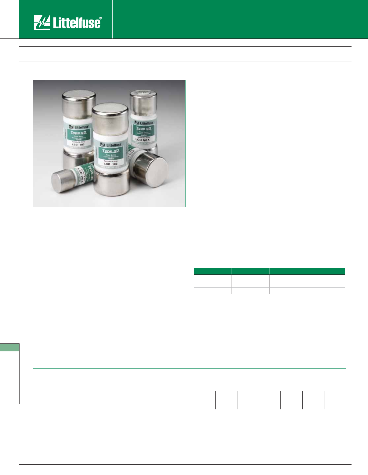
International Products
162 www.littelfuse.com
International Products
© 2005 Littelfuse • POWR-GARD™ Products Catalog
LgD Series Global Pro™ Fuses
600 Volts AC • Time-Delay • 1 – 100 Amperes
Littelfuse Global Pro is the world’s only fuse system designed for use
anywhere, in any equipment, in virtually any country. Global Pro simplifies
circuit protection by incorporating North American electrical requirements
into fuse styles found in the rest of the world. Reduced size, touch-safe
design, and international acceptance make the Global Pro system the easy
circuit protection choice for engineers and equipment designers everywhere.
Global Pro fuses provide quick and positive visual identification of blown
fuses by using a pop-up indicator design that protrudes from the top of
the fuse, immediately alerting maintenance personnel that it needs to
be replaced. The pop-up indicator is designed to activate a microswitch
built into every Global Pro fuseholders that can activate stack-lights or
to integrate into PLC networks and provide equipment operators with a
remote method of determining when the fuse needs to be replaced.
The Global Pro system is designed to save valuable space in a crowded
panel while providing designers with the flexibility of a universally
accepted design for easy replacement. These fuses are far more
compact and have greater power handling capability than conventional
products. Global Pro fuses are up to 75% smaller than Class RK5 fuses
and up to 50% smaller than Class J fuses while providing the time-delay
characteristics that are necessary for motor circuit protection.
Applications
• Motor control centers
• Motor branch circuits
• Primary and secondary protection for transformers
• Equipment designed for export
Features And Benefits
The Global Pro fuse is physically compatible with IEC style fuseholders
allowing it to be used in virtually any market. The IEC dimensions of the
Global Pro fuseholder allow easy adaptation of exported equipment by
simply replacing the fuse with one that meets local standards.
• Extremely compact size
• Pop-up pin indication
• Meets performance requirements of UL Class J fuses
• Global acceptance
• UL approval
• Universal voltages
• Touch -safe components
• Integrated lockout/tagout device for compliance
• Design versatility for OEMs
• Designed to IEC standards
Size Chart
Part Number Amperage English Metric
LgD 0–30A 0–30A 9⁄16” x 2” 14mm x 51mm
LgD 35–60A 35–60A 13 ⁄16” x 21⁄4”22mm x 58mm
LgD 70–100A 70–100A 11⁄16” x 23⁄8” 27mm x 60mm
Specifications
Voltage Ratings: AC: 600 Volts (UL)
690 Volts (IEC)
DC: 300 Volts
Interrupting Rating: AC: 200,000 amperes rms symmetrical
DC: 20,000 amperes rms symmetrical
Ampere Range: 1 – 100* amperes
Approvals: UL Listed Special Purpose 1–30 amps
(File No. E71611)
UL Recognized 35–60 amps (File No. E71611)
CSA Certified 1–60 amps (File No. LR29862)
Ampere ratings
151225406090*
2715304570*100*
31020355080*
*Contact factory for ratings above 60A
Example part number (series & amperage): LgD 60
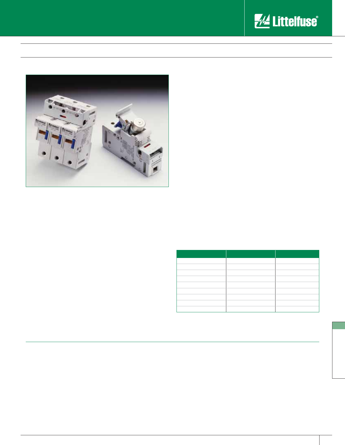
International Products
163
www.littelfuse.com
International Products
© 2005 Littelfuse • POWR-GARD™ Products Catalog
LPSG Series Global Pro™ Fuseholders
Contact factory for dimensions.
Specifications
Voltage Ratings: 600 Volts (UL)
690 Volts (IEC)
Interrupting Rating: AC: 200kA rms symmetrical
DC: 20kA
Ampere Range: 30, 60, and 100* amperes
Terminal Type: Pressure Plate
Wire Range: #2 – #14 CU
Material: Thermo-plastic
Approvals: UL Recognized
CSA Certified
*Contact factory for ratings above 60A
Littelfuse Global Pro is the world’s only fuse system designed for
use anywhere, in any equipment, in virtually any country. Global Pro
simplifies circuit protection by incorporating North American electrical
requirements into fuse styles found in the rest of the world. Reduced
size, touch-safe design, and international acceptance make the Global
Pro system the easy circuit protection choice for engineers and
equipment designers everywhere.
Every Global Pro fuseholder includes a microswitch that is activated by
a blown fuse. This allows the Global Pro system to be integrated into
PLC networks and provide equipment operators with a remote method
of determining when the fuse needs to be replaced. Global Pro holders
also feature a blown fuse indicator light to help maintenance personnel
quickly locate the proper circuit.
The Global Pro system is designed to save valuable space in a crowded
panel, while providing designers with the flexibility of a universally
accepted design for easy replacement. These fuses are far more
compact and have greater power handling capability than conventional
products. Global Pro fuses are up to 75% smaller than Class RK5 fuses
and up to 50% smaller than Class J fuses while providing the time-delay
characteristics that are necessary for motor circuit protection.
Applications
• Motor control centers
• Motor branch circuits
• Primary and secondary protection for transformers
• Equipment designed for export
Features And Benefits
The Global Pro Fuseholder also accepts IEC dimension cartridge style
fuses, allowing equipment to be easily adapted for export markets by
simply replacing the fuse with one that meets local standards.
• Extremely compact size
• Blown fuse indicator
• Integrated lockout/tagout tab
• Din-Rail mountable (35mm DIN-Rail)
• Integrated microswitch with N.O. and N.C. contacts
• Global compatibility – Accepts Global Pro fuses and European IEC
dimension cartridge style fuses
• UL and IEC approval
• Touch-safe design with integrated lockout/tagout device for
compliance
• Design versatility for OEMs
Ordering Information
Catalog No. Amp Rating Poles
LPSG30-1MI 30A 1
LPSG30-2MI 30A 2
LPSG30-3MI 30A 3
LPSG60-1MI 60A 1
LPSG60-2MI 60A 2
LPSG60-3MI 60A 3
LPSG100-1MI 100A 1
LPSG100-2MI 100A 2
LPSG100-3MI 100A 3
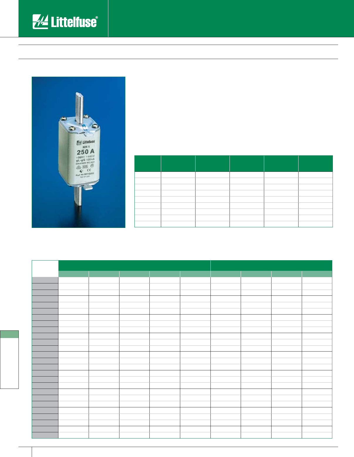
International Products
164 www.littelfuse.com
International Products
© 2005 Littelfuse • POWR-GARD™ Products Catalog
All NH fuse links incorporate a blown fuse indicator.
NH Fuse Links
500 Volts • 2 – 630 Amperes
Littelfuse European style NH fuse links are designed for the protection of conductors and
motors. The gL-gG characteristic fuse links are generally used to protect cables and installation
lines from overloads and short-circuits. The aM characteristic fuse links are used for the short-
circuit protection of motors and switchgear. They are available in NH00C to NH3 sizes up to 630
amperes.
Specifications
Standards: DIN 43.620, IEC 269-2-1
Approvals: VDE
Example part number: NH1CG25 (size, characteristic and amperage)
Size Current Range Voltage
(AC/DC)
Interrupting
Rating
Nominal
Frequency Selectivity
00C 2A up to 100A 500V/440V 120kA/25kA 45 - 62 Hz 1:1 25
00 2A up to 160A 500V/440V 120kA/25kA 45 - 62 Hz 1:1 25
0 6A up to 160A 500V/440V 120kA/25kA 45 - 62 Hz 1:1 25
1C 25A up to 160A 500V/440V 120kA/25kA 45 - 62 Hz 1:1 25
1 63A up to 250A 500V/440V 120kA/25kA 45 - 62 Hz 1:1 25
2C 40A up to 250A 500V/440V 120kA/25kA 45 - 62 Hz 1:1 25
2 125A up to 400A 500V/440V 120kA/25kA 45 - 62 Hz 1:1 25
3C 315A up to 400A 500V/440V 120kA/25kA 45 - 62 Hz 1:1 25
3 315A up to 630A 500V/440V 120kA/25kA 45 - 62 Hz 1:1 25
Amperage gL-gG 500V aM 500V
NH00C/NH00 NH0 NH1C/NH1 NH2C/NH2 NH3C/NH3 NH00M NH1 NH2 NH3
2NH00CG2————NH00M2———
4NH00CG4————NH00M4———
6NH00CG6NH0G6———NH00M6———
10 NH00CG10 NH0G10 — — — NH00M10 — — —
16 NH00CG16 NH0G16 — — — NH00M16 — — —
20 NH00CG20 NH0G20 — — — NH00M20 — — —
25 NH00CG25 NH0G25 NH1CG25 — — NH00M25 — — —
32 NH00CG32 NH0G32 NH1CG32 — — NH00M32 — — —
35 NH00CG35 NH0G35 NH1CG35 — — NH00M35 — — —
40 NH00CG40 NH0G40 NH1CG40 NH2CG40 — NH00M40 — — —
50 NH00CG50 NH0G50 NH1CG50 NH2CG50 — NH00M50 — — —
63 NH00CG63 NH0G63 NH1CG63 NH2CG63 — NH00M63 NH1M63 — —
80 NH00CG80 NH0G80 NH1CG80 NH2CG80 — NH00M80 NH1M80 — —
100 NH00CG100 NH0G100 NH1CG100 NH2CG100 — NH00M100 NH1M100 — —
125 NH00G125 NH0G125 NH1CG125 NH2CG125 — NH00M125 NH1M125 NH2M125 —
160 NH00G160 NH0G160 NH1CG160 NH2CG160 — NH00M160 NH1M160 NH2M160 —
200 — — NH1G200 NH2CG200 — — NH1M200 NH2M200 —
224 — — NH1G224 NH2CG224 — — NH1M224 NH2M224 —
250 — — NH1G250 NH2CG250 — — NH1M250 NH2M250 —
300———NH2G300———NH2M300—
315 — — — NH2G315 NH3CG315 — — NH2M315 NH3M315
355 — — — NH2G355 NH3CG355 — — NH2M355 NH3M355
400 — — — NH2G400 NH3CG400 — — NH2M400 NH3M400
425————NH3G425————
500————NH3G500———NH3M500
630————NH3G630———NH3M630
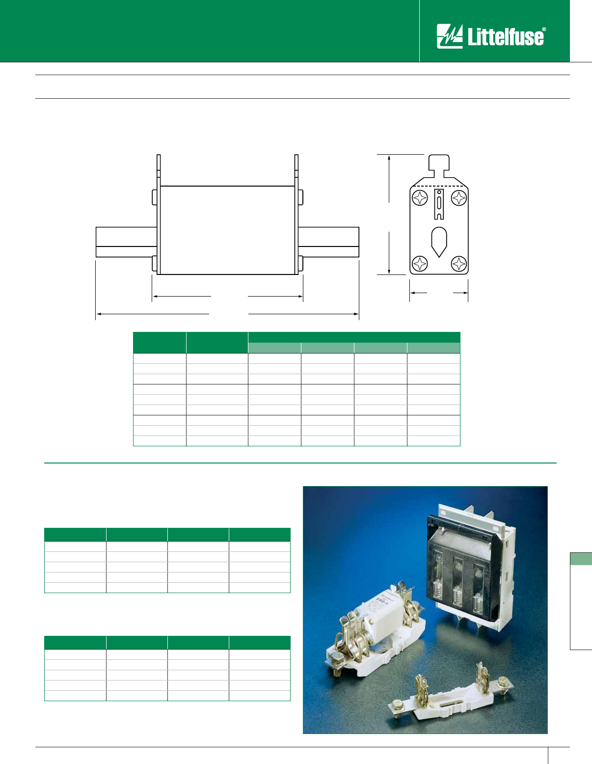
International Products
165
www.littelfuse.com
International Products
© 2005 Littelfuse • POWR-GARD™ Products Catalog
NH Fuse Links
NH Fuse Link Dimensions
NH Bases / Disconnects
Fuse Bases
Part No. Size Rating Connection
NHB00B 00 690V/160A Bolt
NHB00C 00 690V/160A V-Clamp
NHB1B 1 690V/250A Bolt
NHB2B 2 690V/400A Bolt
NHB3B 3 690V/630A Bolt
All fuse bases are single pole and gangable.
Fuse Disconnects
Part No. Size Rating Connection
NHFSC00B C00 690V/100A Bolt
NHFS0B 0 690V/160A Bolt
NHFS1B 1 690V/250A Bolt
NHFS2B 2 690V/400A Bolt
NHFS3B 3 690V/630A Bolt
All disconnects are 3 pole.
B
C
D
A
Contact factory for dimensional information.
Size Current Range Dimensions (mm)
ABCD
00C 2-100A 78.00 54.00 51.30 20.00
00 2-160A 78.00 54.00 56.40 30.00
0 6-160A 123.95 70.11 53.34 30.00
1C 25-160A 135.00 75.00 56.40 30.00
1 63-250A 135.00 75.00 64.30 40.00
2C 40-250A 150.00 75.00 64.26 40.00
2 125-400A 150.00 75.00 74.20 50.00
3C 315-400A 150.00 75.00 74.20 50.00
3315-630A150.0075.0087.3771.88
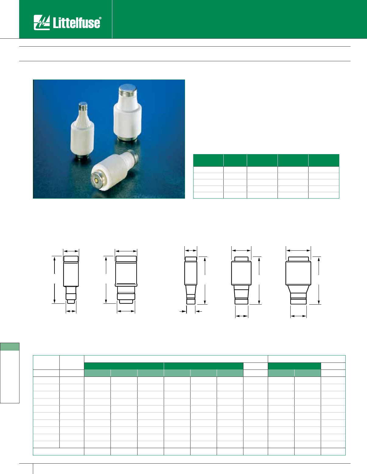
International Products
166 www.littelfuse.com
International Products
© 2005 Littelfuse • POWR-GARD™ Products Catalog
Base Size Type Current Range Voltage AC/DC Interrupting
Rating
14 D01 2-16A 380V/250V 50kA
18 D02 20-63A 380V/250V 50kA
16 DI 2-25A 500V 80kA
27 DII 2-25A 500V 80kA
33 DIII 35-63A 500V 80kA
All Diazed and Neozed fuses incorporate a blown fuse indicator.
Diazed/ Neozed Fuses
380-500 Volts AC • 2 – 63 Amperes
Littelfuse fast acting (gL-gG) fuses are used for the protection of cables
against short-circuits. Time-lag (aM) fuses are used for protection of
motors. Ratings are available in standard Diazed and compact Neozed
styles.
Specifications
Standards: DIN 49.522-DIN 49.525, IEC 269-3
Approvals: VDE
Example part number: DZ27F4
Diazed Fuses Neozed Fuses
gL-gG aM DIM.gL-gG DIM.
Amperage Color DI DII DIII DI DII DIII A (mm) D01 D02 A (mm)
2 Pink DZ16F2 DZ27F2 — DZ16T2 DZ27T2 — 6 D0Z14G2 — 7.3
4 Brown DZ16F4 DZ27F4 — DZ16T4 DZ27T4 — 6 D0Z14G4 — 7.3
6 Green DZ16F6 DZ27F6 — DZ16T6 DZ27T6 — 6 D0Z14G6 — 7.3
10 Red DZ16F10 DZ27F10 — DZ16T10 DZ27T10 — 8 D0Z14G10 — 8.5
16 Grey DZ16F16 DZ27F16 — DZ16T16 DZ27T16 — 10 D0Z14G16 — 9.7
20 Blue DZ16F20 DZ27F20 — DZ16T20 DZ27T20 — 12 — D0Z18G20 10.9
25 Yellow DZ16F25 DZ27F25 — DZ16T25 DZ27T25 — 14 — D0Z18G25 12.1
35 Black — — DZ33F35 — — DZ33T35 16 — D0Z18G35 13.3
50 White — — DZ33F50 — — DZ33T50 18 — D0Z18G50 14.5
63 Copper — — DZ33F63 — — DZ33T63 20 — D0Z18G63 15.9
Base Size (mm) 16 27 33 16 27 33 — 14 18 —
36 36
11
AA
15
50
A
21.5
D01 D02 DI DII DIII
50
A
13.2
50
A
27
Neozed Fuses Diazed Fuses
All dimensions are in “mm”
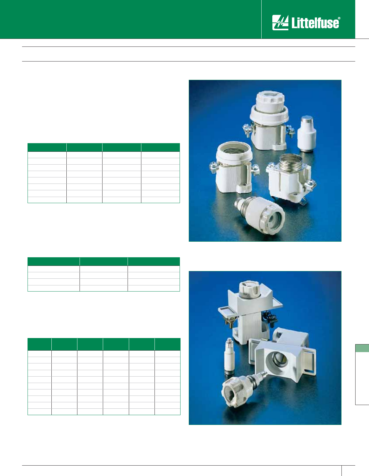
International Products
167
www.littelfuse.com
International Products
© 2005 Littelfuse • POWR-GARD™ Products Catalog
Diazed/ Neozed Fuses
Fuse bases, carriers, and gauge rings are available for Diazed (DZ) and
Neozed (D0Z) type fuses. Fuse holders are comprised of a fuse base
and carrier. Optional gauge rings act as a rejection feature and are used
to prevent over-sizing of fuses. All bases and carriers are single pole
units. Contact factory for additional information.
Fuse Bases
Part No. Fuse Type Base Size (mm) Mounting Type
DZB27S DZ 27 Screw
DZB27DR DZ 27 Din Rail
DZB33S DZ 33 Screw
DZB33DR DZ 33 Din Rail
D0ZB14S D0Z 14 Screw
D0ZB14DR D0Z 14 Din Rail
D0ZB18S D0Z 18 Screw
D0ZB18DR D0Z 18 Din Rail
Fuse Carriers
Part No. Fuse Type Base Size (mm)
DZC27 DZ 27
DZC33 DZ 33
D0ZC14 D0Z 14
D0ZC18 D0Z 18
Gauge Rings
Amp
Rating Color DZ DZ D0Z D0Z
2PinkDZ27PK—D0Z14PKD0Z18PK
4BrownDZ27BR—D0Z14BRD0Z18BR
6 Green DZ27GN — D0Z14GN D0Z18GN
10 Red DZ27RD — D0Z14RD D0Z18RD
16 Grey DZ27GY — — D0Z18GY
20 Blue DZ27BE — — D0Z18BE
25 Yellow DZ27YW — — D0Z18YW
35 Black — DZ33BK — D0Z18BK
50 White — DZ33WE — D0Z18WE
63 Copper — DZ33CR — —
Contact factory for dimensional information.
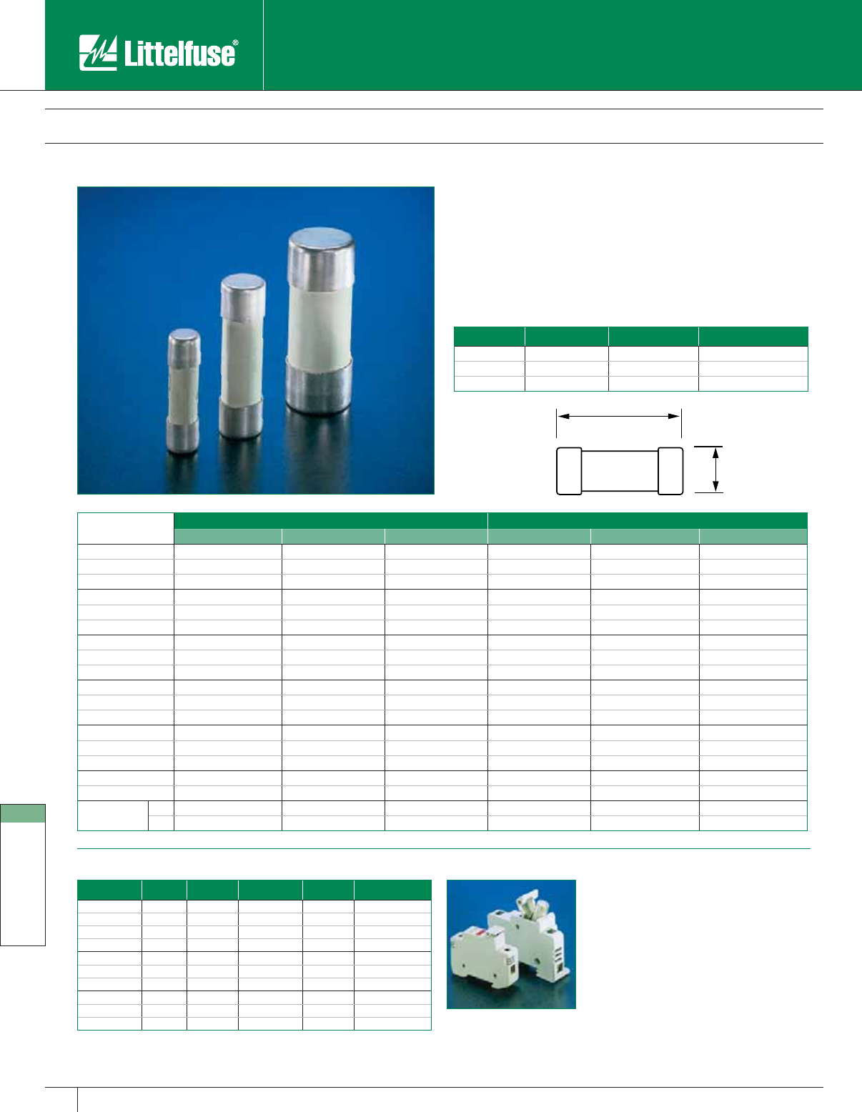
International Products
168 www.littelfuse.com
International Products
© 2005 Littelfuse • POWR-GARD™ Products Catalog
Assembly kit is designed for use with
CYH1038 and LPSC/LPSM fuse holders.
Kit contains 20 connector pincers and 10
handle pins.
Part No: CYHP001
Cylindrical Fuses
500 Volts • 0.5 – 100 Amperes
Size Current Range Voltage AC Interrupting Rating
10 x 38 mm 0.5-32A 500V 120kA
14 x 51 mm 2-50A 500V 80kA
22 x 58 mm 16-100A 500V 80kA
A
B
gL-gG aM
Amperage 10X38 14X51 22X58 10X38 14X51 22X58
0.5 CY10X38G.5 — — CY10X38M.5 — —
1 CY10X38G1 — — CY10X38M1 — —
2 CY10X38G2 CY14X51G2 — CY10X38M2 CY14X51M2 —
4 CY10X38G4 CY14X51G4 — CY10X38M4 CY14X51M4 —
6 CY10X38G6 CY14X51G6 — CY10X38M6 CY14X51M6 —
8 CY10X38G8 CY14X51G8 — CY10X38M8 CY14X51M8 —
10 CY10X38G10 CY14X51G10 — CY10X38M10 CY14X51M10 —
12 CY10X38G12 CY14X51G12 — CY10X38M12 CY14X51M12 —
16 CY10X38G16 CY14X51G16 CY22X58G16 CY10X38M16 CY14X51M16 CY22X58M16
20 CY10X38G20 CY14X51G20 CY22X58G20 CY10X38M20 CY14X51M20 CY22X58M20
25 CY10X38G25 CY14X51G25 CY22X58G25 CY10X38M25 CY14X51M25 CY22X58M25
32 CY10X38G32 CY14X51G32 CY22X58G32 CY10X38M32 CY14X51M32 CY22X58M32
40 — CY14X51G40 CY22X58G40 — CY14X51M40 CY22X58M40
50 — CY14X51G50 CY22X58G50 — CY14X51M50 CY22X58M50
63——CY22X58G63——CY22X58M63
80 — — CY22X58G80 — — CY22X58M80
100 — — CY22X58G100 — — CY22X58M100
Dimensions
(mm)
A10 142210 14 22
B3851583851 58
Fuseholders Multi-pole Assembly Kit
Part No. Size # of Poles Amp Rating Voltage Terminal Type
CYH10381 10X38 1 32A 690V Pressure Plate
CYH10382 10X38 2 32A 690V Pressure Plate
CYH10383 10X38 3 32A 690V Pressure Plate
CYH10381ID* 10X38 1 32A 690V Pressure Plate
CYH14511 14X51 1 50A 690V Pressure Plate
CYH14512 14X51 2 50A 690V Pressure Plate
CYH14513 14X51 3 50A 690V Pressure Plate
CYH22581 22X58 1 125A 690V Pressure Plate
CYH22582 22X58 2 125A 690V Pressure Plate
CYH22583 22X58 3125A 690V Pressure Plate
* Indicating
NOTE: All fuseholders are DIN-Rail mountable.
Contact factory for dimensional information.
Littelfuse fast acting (gL-gG) fuses are used for the protection of cables
against short-circuits. Time-lag (aM) fuses are used for protection of
motors.
Specifications
Standards: IEC 269-2-1
Example part number: CY22X58G50
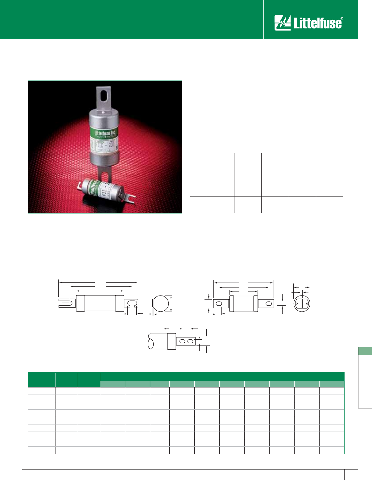
International Products
169
www.littelfuse.com
International Products
© 2005 Littelfuse • POWR-GARD™ Products Catalog
JJ
F
B
B
A
G
D
F
H
H
A
G
G
D
K
E
E
FIG. 1 FIG. 2
FIG. 3
British Dimension HRCII-C Fuses
600 Volts AC • 2 – 600 Amperes
Specifications
Voltage Rating: 600 Volts AC, 250 Volts DC
Interrupting Rating: 200,000 amperes rms symmetrical AC
80,000 amperes rms symmetrical DC
Ampere Range: 2 – 600 amperes
Approvals: CSA Certified to Standard C22.2 No. 106-M90
(File No. LR90341)
Ampere ratings
2CO 210255080
4153060100
62040
2CC 125 200 300 400 500
150 250 350 450 600
2CM 80 125 200 300 400
100 150 250 350
Example part number (series & amperage): 2CM 150
Recommended Fuse Blocks
DF30 (F, B, FB) — Fits 2 – 30 amps
DF60 (F, B, FB) — Fits 40 – 60 amps
DF100 (F, B, FB) — Fits 80 – 100 amps
For additional information on HRCII-C fuse holders, contact factory.
Cat. No. Old LF
Part No.
Refer To
Fig. No.
Dimensions in mm (inches in parentheses)
A BCD E F G H J K
2CO 2-30 FII 1 56 (2.2) 21 (0.83) — 85 (3.3) 9 (0.35) 1 (0.04) 73 (2.87) 5.5 (0.21) 7.5 (0.29) —
2CO 40-60 FII 1 57 (2.24) 26 (1.02) — 88 (3.45) 13 (0.51) 1.6 (0.06) 73 (2.87) 5.5 (0.21) 7.5 (0.29) —
2CO 80-100 FII 1 68 (2.88) 36 (1.42) — 110 (4.33) 19 (0.75) 2.4 (0.09) 94 (3.7) 8.7 (0.34) — —
2CC 125-200 FIIC 2 76 (3) 41 (1.61) — 137 (5.39) 19 (0.75) 3.6 (0.14) 111 (4.37) 8.7 (0.34) 16 (0.63) —
2CC 250-400 FIIC 3 81 (3.19) 58 (2.28) — 210 (8.27) 26 (1.02) 6.5 (0.26) 133 (5.24) 10.3 (0.4) 16 (0.63) 25.4 (1)
2CC 450-600 FIIC 3 83 (3.27) 74 (2.91) — 210 (8.27) 26 (1.02) 6.5 (0.25) 133 (5.24) 10.3 (0.4) 16 (0.63) 25.4 (1)
2CM 80-100 FIIM 2 66 (2.6) 31 (1.22) — 135 (5.31) 19 (0.75) 3.6 (0.14) 111 (4.37) 8.7 (0.34) 16 (0.63) —
2CM 125-200 FIIM 1 77 (3.03) 41 (1.81) — 110 (4.33) 19 (0.75) 2.4 (0.09) 94 (3.7) 8.7 (0.34) 10.3 (0.4) —
2CM 250-400 FIIM 2 81 (3.19) 58 (2.25) — 136 (5.35) 26 (1.02) 5.2 (0.2) 111 (4.37) 8.7 (0.34) 16 (0.63) —
*Hole diameter to accept insulated stud (types C and D) mm min
HRCII-C fuses are stud-mounted fuses designed to British standard
dimensions. They are generally used for motor short-circuit protection in
dead-front holders, and are normally required to be used in conjunction
with a motor running overload device.

Suppression Products
www.littelfuse.com © 2005 Littelfuse • POWR-GARD™ Products Catalog
Overvoltage Suppression Products: Introduction 171-172
Industrial Varistor Products 173
Surge Suppression Fuses 174
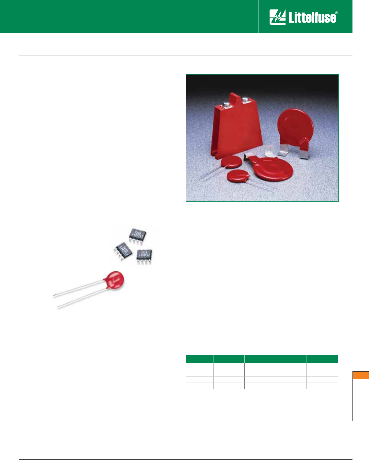
Suppression Products
171
www.littelfuse.com
Suppression
© 2005 Littelfuse • POWR-GARD™ Products Catalog
Overvoltage Suppression Products
Introduction
Voltage Current Rise-Time Duration
Lighting 25kV 20kA 10µs 1ms
Switching 600V 500A 50µs 500ms
EMP 1kV 10A 20ns 1ms
SSD 15kV 30A 1-5ns 100ns
Overvoltage conditions are rapidly becoming an increasing concern
in the electrical industry. Component miniaturization has resulted in
increased sensitivity to many devices as the trend towards downsizing
equipment and components continues. The majority of these devices
are unable to handle high currents that result from Electrostatic
Discharge (ESD) and other voltage transients.
Did you know?
• 75% of field equipment failure is caused by
Electrical Over-Stress (EOS)
• Semiconductor devices are becoming increasingly
intolerant to voltage transients
• A lightning strike several miles away can induce
transients in your equipment
• Power distribution transformers susceptibility
impacts clean power condition
What Are Transients?
Voltage Transients are defined as short duration surges of electrical
energy. Transients result from the sudden release of previously stored
energy. In terms of electrical and electronic circuits, this energy can be
released through intentional, controlled switching action, or induced into
a circuit from external sources. If the voltage magnitude of the transient
is large enough, circuit component damage or malfunction of the circuit
may result.
Transients occur in either repeatable fashion or as random impulses.
Repeatable transients are frequently caused by the operation of motors,
generators, or the switching of reactive circuit components. Random
transients, on the other hand, are often caused by lightning and ESD.
Lightning and ESD generally occur unpredictably, and may require
elaborate monitoring to be accurately measured.
Transient Sources and Magnitude
Typical Overvoltage Applications
Industrial, High Energy AC Products
(Solenoids, Motor Drives, Robotics, etc.)
Telecommunications Products
TVSS Products (UPS, AC Panels, Power Supplies,
Circuit Breakers, etc.)
Portable Electronic Equipment
Automotive Electronics

Suppression Products
172 www.littelfuse.com
Suppression
© 2005 Littelfuse • POWR-GARD™ Products Catalog
Overvoltage Suppression Products
Introduction
Transient Voltage Scenarios
The switching of inductive loads generates high energy transients
which increase in magnitude with increasingly heavy loads. When the
inductive load is switched off, the collapsing magnetic field is converted
into electrical energy which takes the form of a double exponential
transient. Depending on the source, these transients can be as large
as hundreds of volts and hundreds of amps with duration times of 400
milliseconds.
Typical sources of inductive transients are:
• Generator
• Motor
• Relay
• Transformer
These examples are extremely common in electrical and electronic
systems. Because the sizes of the loads vary according to the
application, the wave shape, duration, peak current, and peak voltage
are all variables which exist in real world transients. Once these
variables can be approximated, a suitable suppressor technology can be
selected.
ESD (Electrostatic Discharge)
Electrostatic discharge is characterized by very fast rise times and
very high peak voltages and currents. This energy is the result of an
imbalance of positive and negative charges between objects.
Lightning Induced Transients
Even though a direct strike is clearly destructive, transients induced
by lightning are not the result of a direct strike. When a lightning strike
occurs, the event creates a magnetic field which can induce transients
of large magnitude in nearby electrical cables.
Technological Solutions for Transient Threats
Because of the various types of transients and applications, it is
necessary to employ protection devices with different characteristics
in different applications. Littelfuse offers the broadest range of circuit
protection technologies. Our overvoltage protection portfolio includes:
MOVs
Metal Oxide Varistors (MOV)
Ceramic Technology
Available in screw terminal, radial, square and axial leaded connections.
Offers medium to very high energy ratings for a wide range of
applications.
Surface Mount MOV
Metal Oxide Varistor (MOV)
Ceramic Technology
Available in a wide range of voltage ratings. Offers low to medium
energy ratings for a variety of applications and is available with screw
terminal, radial, square and axial leaded connections.
MLV
Multilayer Metal Oxide Varistor
Ceramic Technology
Available in a wide range of surface mount packages. Offers a lower voltage
range and enhanced performance and filtering characteristics for applications
requiring protection from low to medium energy transients.
PulseGuard® Suppressor
Voltage Variable Polymer Technology
Available in surface mount and ‘D-Sub connector’ format packages.
Specifically designed for high data-rate applications requiring ESD
protection and the lowest possible capacitance.
TVS Diode Arrays
Silicon Avalanche Diode Technology
Available in surface mount multi-pin packages or CSP (chip scale
package) arrays. Designed for applications requiring multiline ESD
protection and the lowest possible clamp voltage.
Discrete TVS Diode
Silicon Avalanche Diode Technology
Available in surface mount and axial leaded packages. Offers protection
from medium to very high energy transients and can be used in wide
range of applications.
SIDACTOR® Thyristor
Thyristor Breakover Technology
Available in surface mount, axial leaded and TO-220 through hole
package options. Offers protection from medium to high energy
transients, SIDACTOR thyristors are specifically designed for transient
suppression in telecom and data transmission systems.
Gas Plasma Protector/Gas Discharge Tube
Gas Plasma Technology
Available in surface mount, axial leaded, radial leaded and special
packages. The Littelfuse Gas Plasma technology offers high surge
ratings and very low capacitance for use in telecommunication and
broadband systems.
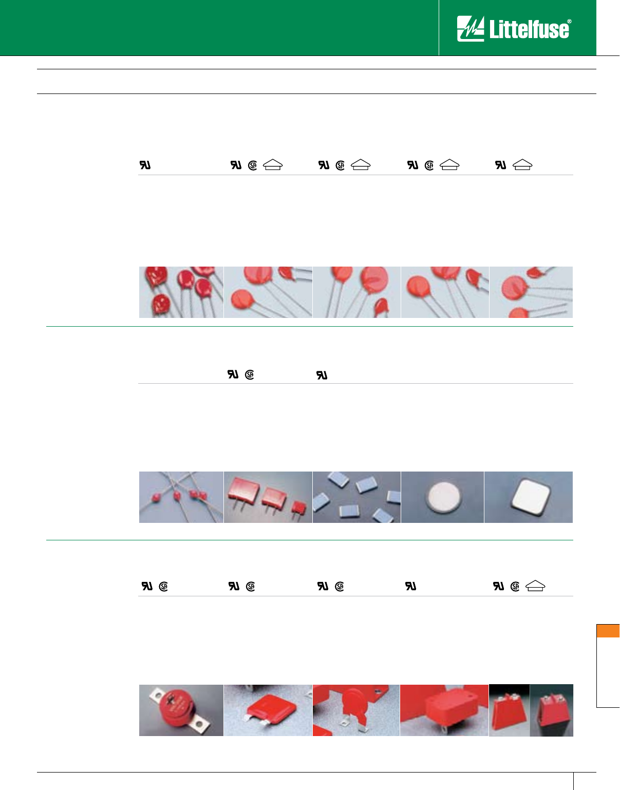
Suppression Products
173
www.littelfuse.com
Suppression
© 2005 Littelfuse • POWR-GARD™ Products Catalog
CH Series
14-275 VAC
18-369 VDC
250-500A
1-23J
Surface Mount
N/A
Overvoltage Suppression Products
Industrial Varistor Products
Operating Voltage:
Peak Current:
Peak Energy:
Mount/Form Factor:
Disc Size:
Indicating:
TMOV™/iTMOV™
Varistor Series
115-420 VAC
170-420 VDC
6,000-10,000A
50-320
Radial Leaded
14, 20mm
iTMOV Varistor Only
UltraMov™
Varistor Series
130-625 VAC
170-825 VDC
1,750-10,000A
50-273J
Radial Leaded
7, 10, 14, 20mm
N/A
C-III Series
130-320 VAC
6,000-9,000A
45-220J
Radial Leaded
14, 20mm
N/A
LA Series
130-1000 VAC
175-1200 VDC
1,200-6,500A
11-360J
Radial Leaded
7, 10, 14, 20mm
N/A
®
MA Series
9-264 VAC
13-365 VDC
40-100A
0.06-1.7J
Axial Leaded
3mm
RA Series
4-275 VAC
5.5-369 VDC
150-6,500A
0.4-140J
Packaged
8, 6, 22mm
CA Series
250-2800 VAC
330-3500 VDC
20,000-70,000A
200-10,000J
Bare Disc
32, 40, 60mm
NA Series
250-750 VAC
330-970 VDC
40,000A
370-1,050J
Bare Disc
34mm
®
PA Series
130-660 VAC
175-850 VDC
6,500A
70-250J
Packaged
20mm
HB34 Series
130-750 VAC
175-970 VDC
40,000A
270-1,050J
Industrial Packaged
34mm
HA Series
130-750 VAC
175-970 VDC
25,000-40,000A
200-1,050J
Packaged
32, 40mm
DA/DB Series
130-970 VAC
175-970 VDC
40,000A
270-1,050J
Industrial Packaged
40mm
BB/BA Series
130-2800 VAC
175-3500 VDC
50,000-70,000A
450-10,000J
Packaged
60mm
®
ZA Series
4-460 VAC
5.5-615 VDC
50-6,500A
0.1-52J
Radial Leaded
5, 7, 10, 14, 20mm
N/A
®
®
V
D E
®
V
D E
®
®
®
®
®
®
®
®
®
®
V
D E
®
V
D E
®
V
D E
®
®
Operating Voltage:
Peak Current:
Peak Energy:
Mount/Form Factor:
Disc Size:
Operating Voltage:
Peak Current:
Peak Energy:
Mount/Form Factor:
Disc Size:
Contact factory for additional information.
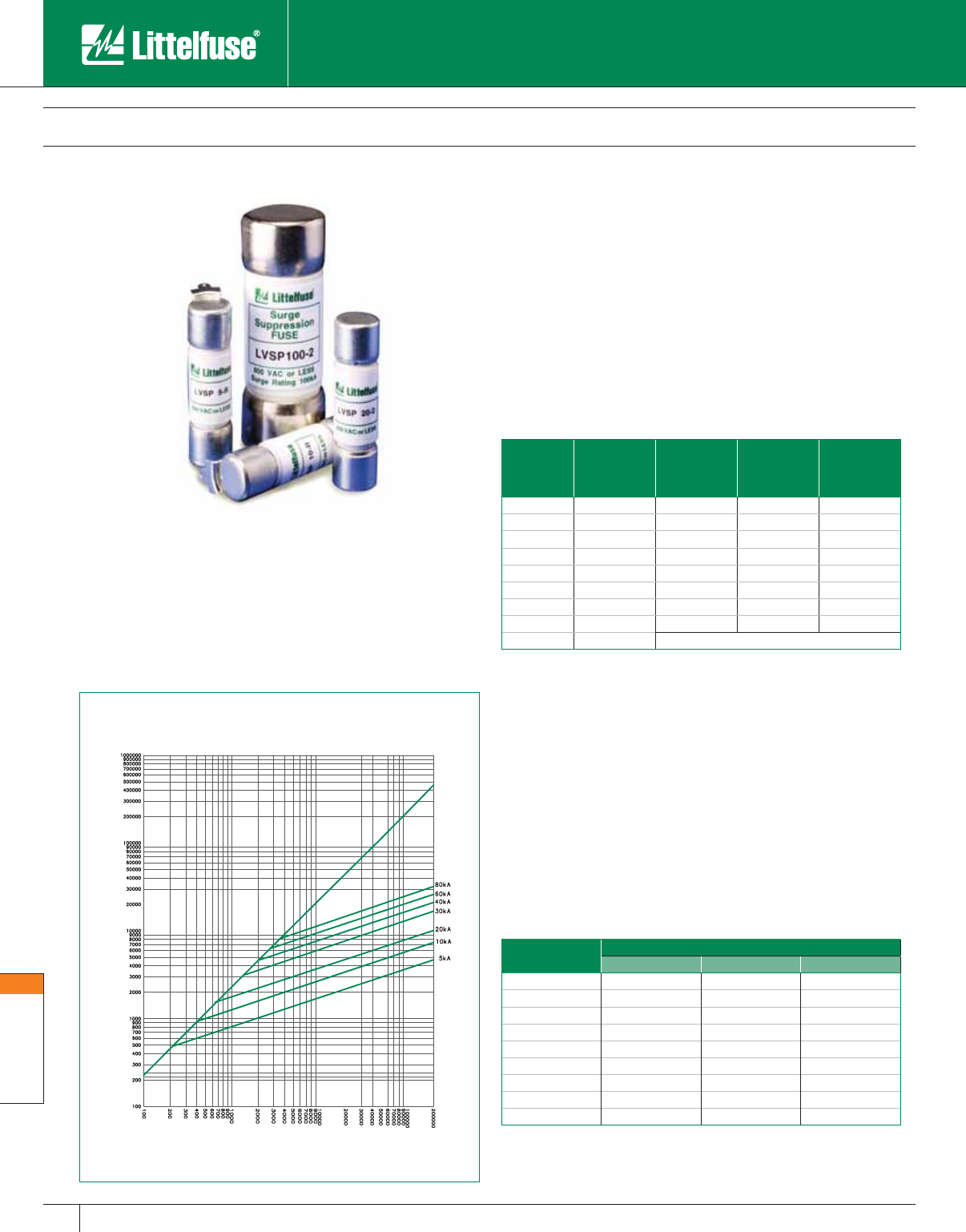
Suppression Products
174 www.littelfuse.com
Suppression
© 2005 Littelfuse • POWR-GARD™ Products Catalog
Features
• Very current-limiting under AC short-circuit conditions.
• Available in multiple mounting configurations (cartridge, bolt-in, PC
board mount).
• Provides short-circuit protection in TVSS systems and complements
the Littelfuse line of overvoltage products (HA, HB34, TMOVTM and
iTMOVTM varistors as well as the AK-10 series TVS diodes).
Applications
• TVSS products
• Surge arrestors
Overvoltage Suppression Products
Surge Suppression Fuses
SYMMETRICAL R.M.S. AMPERES
AVAILABLE FAULT CURRENT
PEAK LET-THRU IN AMPERES
LVSP
The Littelfuse Varistor Protection ( LVSP) Fuses are intended for the
protection of TVSS products. The LVSP series has been designed to
survive the 8x20µs lightning surges described in various standards
(UL1449, IEC61000-4-5 & IEEE C62.41) without opening. This allows
the TVSS to perform the necessary suppression. The LVSP is not
rated for continuous current and the ratings are specific 8x20µs surge
capability. The LVSP series can be used to facilitate TVSS module
compliance to UL 1449 in permanently connected applications
(abnormal overvoltage, unlimited current conditions).
Catalog No. 8x20µs
Surge Rating
Nominal
Melting I2t
(A2s)
Nominal
Clearing I2t
(A2s)
Ipeak@100kA
60Hz (A)
LVSP 5 5,000 359 981 3,700
LVSP 10 10,000 1,300 3,210 5,823
LVSP 15 15,000 3,267 6,235 7,765
LVSP 20 20,000 4,940 11,710 8,135
LVSP 30 30,000 11,950 35,325 12,478
LVSP 40 40,000 20,550 61,700 15,250
LVSP 60 60,000 39,240 145,555 19,604
LVSP 80 80,000 75,000 254,000 24,600
LVSP 100 100,000 Contact Factory
Note: Contact factory for dimensions and availability of specific mounting
configurations.
Specifications
Voltage Rating: 600 VAC
Interrupting Rating: 200,000 amps
Ratings: 5 – 100kA 8x20µs surge withstand
Approvals: UL Recognized under the components program.
(File No. E71611)
Recommended Fuse Blocks
L60030M and LPSM series – LVSP (5-20)-2
LJ60030 and LPSJ30 series – LVSP (30-80)-2
Mounting Options
Surge Rating Catalog Number
Cartridge Leaded Bolt-In
5 LVSP 5-2 LVSP 5-R –
10 LVSP 10-2 LVSP 10-R –
15 LVSP 15-2 LVSP 15-R –
20 LVSP 20-2 LVSP 20-R –
30 LVSP 30-2 – LVSP 30
40 LVSP 40-2 – LVSP 40
60 LVSP 60-2 – LVSP 60
80 LVSP 80-2 – LVSP 80
100 – – LVSP 100-L
www.littelfuse.com
© 2005 Littelfuse • POWR-GARD™ Products Catalog
Fuseology
Terms and Definitions 177-181
Electrical Safety Guide 182-183
Fuse Application Guide 184-203
Motor Protection Tables 204-206
Condensed Cross Reference 207
Alphanumeric Index 208

Fuseology
176 www.littelfuse.com
Fuseology
© 2005 Littelfuse • POWR-GARD™ Products Catalog
Fuseology
Introduction
Fuseology provides the information needed to choose the correct
types of Littelfuse POWR-GARD™ fuses for most applications.
Definition of Terms is followed by Overcurrent Protection
Fundamentals. If there are any questions or if additional data is
needed for a specific use, call the Littelfuse Technical Support and
Engineering Service Group at 1-800-TEC-FUSE (1-800-832-3873)
or visit us online at www.littelfuse.com/technicalcenter.
Call 1-800-TEC-FUSE for
Technical Support and
Engineering Services or visit
www.littelfuse.com/technicalcenter
Definitions 177–181
Electrical Safety 182-183
Overcurrent Protection Fundamentals
(Fuses and How They Work) Index 184
Why Overcurrent Protection 184
What is Quality Overcurrent Protection 184
Overcurrent Types and Effects 184
Fuse Characteristics (600 volts and below) 185
Time-Current Characteristics 186-187
Peak Let-through Charts 187-189
Fuse Ampere Ratings 189
Fuse Dimensions 189
Fuse Coordination (Developing a Selective System) 190-191
Component Short-circuit Protecting Ability 190
UL/CSA Fuse Classes and Their Applications 192-193
Fuses for Specific Applications
(600 Volts and Below) Index 194
Protecting Service Entrance and Feeder Conductors 194
Main Services and Feeders 194
Motor Protection 194-198
Motor Overload Protection (running overcurrent) 195-197
Motor Feeder (100% Motor Load) Protection over 600A 197
Motor Branch Circuit Protection over 600A 197
Motor Controller (Starter) Protection over 600A 197
Control Transformer Protection 197-198
Primary Fusing With Secondary Fusing 198
Secondary Fusing of Transformers 198
Lighting Fixture Protection 198
Street Lighting & Other Weatherproof Overcurrent Protection 198
Cable Short-circuit Protection (Cable Limiter Application) 199
Semiconductor and Solid-state Device Protection 199
Effect of Ambient Temperature on Fuses 199
Medium Voltage Protection (2400 volts to 38.0 kV) 200-203
Motor Protection Tables 204-206
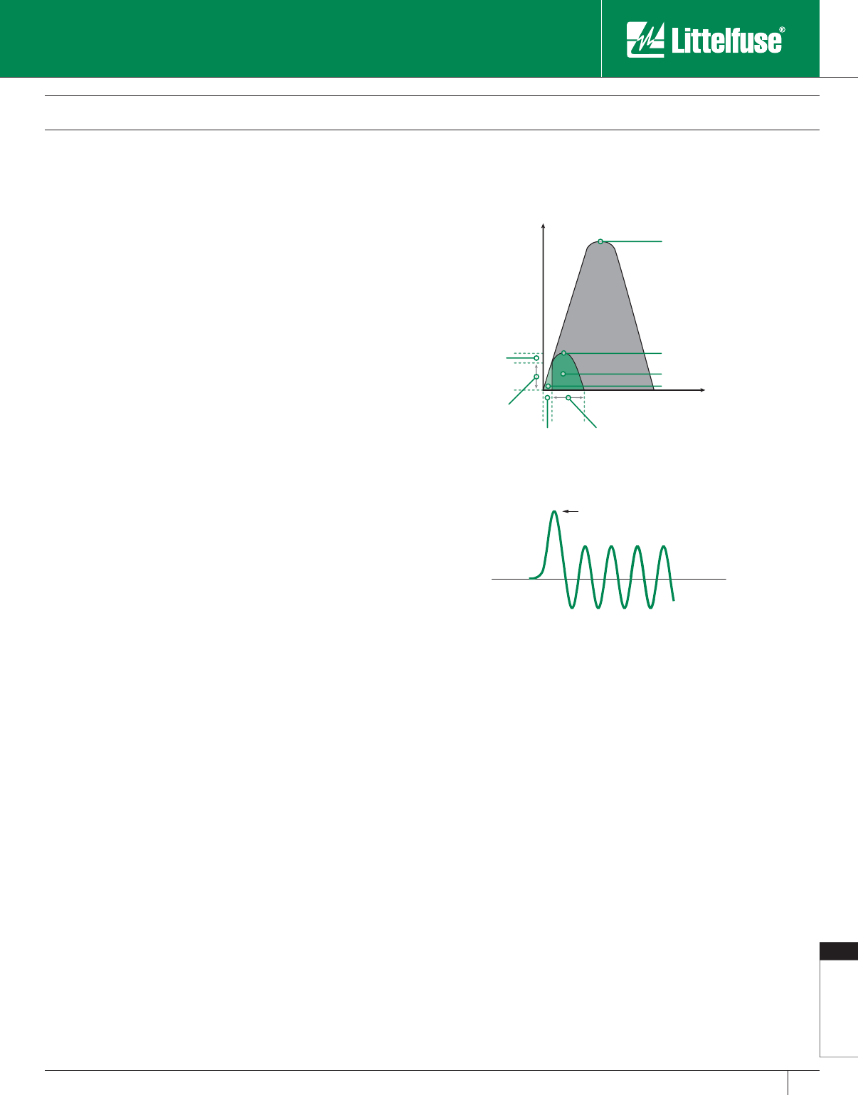
Fuseology
177
www.littelfuse.com
Fuseology
© 2005 Littelfuse • POWR-GARD™ Products Catalog
Fuse Application Guide
Definitions
AIC or A.I.C.
See Interrupting Capacity.
AIR or A.I.R.
See Interrupting Rating.
Ambient Temperature
The air temperature surrounding a device. For fuses or circuit breakers in
an enclosure, the air temperature within the enclosure.
Ampacity
The current in amperes that a conductor can carry con tin u ous ly under
the conditions of use without exceeding its tem per a ture rating. It is
sometimes informally applied to switches or other devices. These are
more properly referred to by their ampere rating.
Ampere Rating
The current rating, in amperes, that is marked on fuses, circuit breakers,
or other equipment.
Ampere-Squared-Seconds (I2t)
A means of describing the thermal energy generated by current flow.
When a fuse is interrupting a current within its current-limiting range,
the term is usually expressed as melting, arcing, or total clearing I2t.
Melting I2t is the heat energy passed by a fuse after an overcurrent
occurs and until the fuse link melts. It equals the rms current squared
multiplied by melting time in seconds. For times less than 0.004
seconds, melting I2t approaches a constant value for a given fuse.
Arcing I2t is the heat energy passed by a fuse during its arcing time.
It is equal to the rms arcing current squared (see below), multiplied by
arcing time.
Clearing I2t (also Total Clearing I2t) is the ampere-squared seconds
(I2t) through an overcurrent device from the inception of the overcurrent
until the current is com plete ly interrupted. Clearing I2t is the sum of the
Melting I2t and the Arcing I2t.
Arc-Flash
The suddent release of heat energy and intense light at the point of an
arc. Can be considered a short-circuit through the air, usually created by
accidental contact between live conductors.
Arcing Current (See Figure 1)
The current that flows through the fuse after the fuse link has melted
and until the circuit is interrupted.
Arcing I2t
See Ampere-Squared-Seconds (I2t).
Arcing Fault
A short-circuit that arcs at the point of fault. The arc impedance
(resistance) tends to reduce the short-circuit current. Arcing faults may
turn into bolted faults by welding of the faulted components. Arcing
faults may be phase-to-phase or phase-to-ground.
Arcing Time (See Figure 1)
The time between the melting of a fuse link, or parting of circuit breaker
contacts, until the overcurrent is interrupted.
Arc Voltage (See Figure 2)
Arc voltage is a transient voltage that occurs across an overcurrent
protection device during the arcing time. It is usually expressed as peak
instantaneous voltage (Vpeak or Epeak), rarely as rms voltage.
Asymmetrical Current
See Symmetrical Current.
Available Short-Circuit Current
(also Available or Pro spec tive Fault Current)
The maximum rms Symmetrical Current that would flow at a given
point in a system under bolted-fault conditions. Short-circuit current
is maximum during the first half-cycle after the fault occurs. See
definitions of Bolted Fault and Symmetrical Current.
Blade Fuse
See Knife Blade Fuse.
Body
The part of a fuse enclosing the fuse elements and supporting the
contacts. Body is also referred to as cartridge, tube, or case.
INSTANTANEOUS ARC VOLTAGE
183% OF CYCLEPEAK
RESTORED VOLTAGE
PEAK
Figure 2
Figure 1
Showing arcing and melting currents and arcing, melting and clearing times.
Peak Let-through Current
Peak Current which would occur
without current limitation
Current
Time
Melting
Time
Arcing
Current
Arcing
Time
Melting
Current
Arcing Energy (l2t)
Melting Energy (l2t)
Definition of Terms Frequently Used
When Selecting Overcurrent Pro tec tion
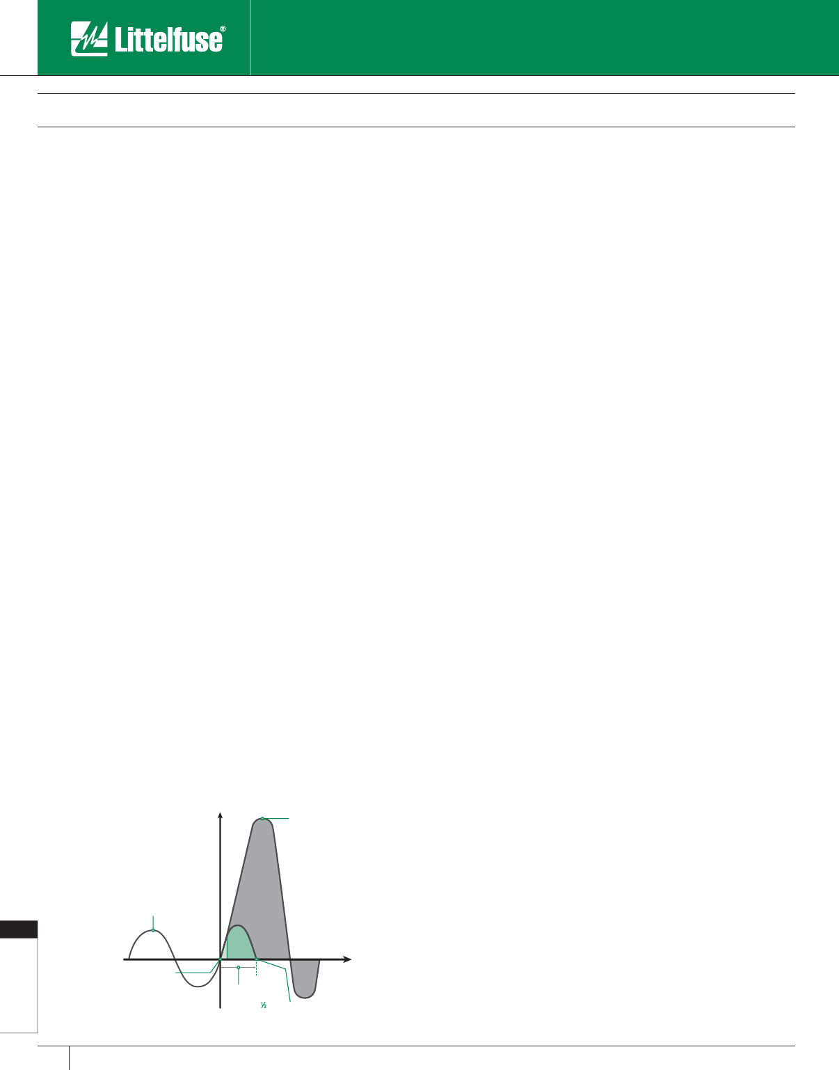
Fuseology
178 www.littelfuse.com
Fuseology
© 2005 Littelfuse • POWR-GARD™ Products Catalog
Bolted Fault
A short-circuit that has no electrical resistance at the point of the fault.
It results from a firm mechanical connection between two conductors,
or a conductor and ground. Bolted faults are characterized by a lack of
arcing. Ex am ples of bolted faults are a heavy wrench lying across two
bare bus bars, or a crossed-phase condition due to incorrect wiring.
Cartridge Fuse
A fuse that contains a current-re spon sive element inside a tubular fuse
body with cylindrical ferrules (endcaps).
Case Size (also Cartridge Size)
The maximum allowable ampere rating of a cartridge fuse having
defined dimensions and shape. For example, case sizes for UL Listed
Class H, K, J, RK1, and RK5 are 30, 60, 100, 200, 400, and 600
amperes. The physical di men sions vary with fuse class, voltage, and
ampere rating. UL Standards establish the dimensions for each UL Fuse
Class. This catalog’s product section contains case size dimensions for
all Littelfuse POWR-GARDTM fuses.
Clearing I2t
See Ampere-Square-Seconds (I2t).
Clearing Time (see Figure 1)
The time between the initiation of an overcurrent condition to the point
at which the overcurrent is interrupted. Clearing Time is the sum of
Melting Time and Arcing Time.
Contacts (Fuse)
The external metal parts of the fuse used to complete the circuit. These
consist of ferrules, caps, blades or terminals, as shown in this catalog.
Coordination or Coordinated System
See Selective Coordination.
Continuous Load
An electrical load where the maximum current is expected to continue
for 3 hours or more.
Current-limiting Fuse (See Figure 3)
A fuse which, when interrupting currents within its current-limiting range,
reduces the current in the faulted circuit to a magnitude substantially less
than that obtainable in the same circuit if the device was replaced with a
solid conductor having comparable impedance. To be labeled “current-
limiting,” a fuse must mate with a fuseblock or fuseholder that has either a
rejection feature or dimensions that will reject non-current-limiting fuses.
Current-limiting Range
For an individual overcurrent protective device, the current-limiting range
begins at the lowest value of rms sym met ri cal current at which the
device becomes current-limiting (the threshold current) and extends
to the max i mum interrupting capacity of the device. See definitions of
Threshold Current and Interrupting Capacity.
Current Rating
See Ampere Rating.
Dual-element Fuse
A fuse with internal construction consisting of a separate time-delay
overload element(s) that interrupts overcurrents up to approximately
500%-600% of its nominal rating, plus separate fuse links that quickly
open higher value currents. All dual-element fuses have time delay, but,
since there are other methods of achieving time delay, not all time-delay
fuses have dual-element construction. See Time-Delay Fuse.
Element
A fuse’s internal current-carrying parts that melt and interrupt the
current when subjected to an overcurrent of sufficient duration or value.
Also called fuse link.
Fast-Acting Fuse
May also be termed Normal-opening fuse.
A fuse that has no intentional, built-in, time delay. Actual opening time
is determined by the fuse class, the over cur rent, and other conditions.
Fast-acting is indicated on the fuse label by “Fast-Acting”, “F-A”, “F”, or
other suitable marking.
Fault
Same as Short-Circuit and used interchangeably.
Fault Current
Same as Short-Circuit current.
Filler
A material, such as granular quartz, used to fill a section or sections of a
fuse and aid in arc quench ing.
Fuse
An overcurrent protective device consisting of one or more current-
carrying elements enclosed in a body fitted with contacts, so that the
fuse may be readily inserted into or removed from an electrical circuit.
The elements are heated by the current passing through them, thus in ter-
rupt ing current flow by melting during specified overcurrent conditions.
Ground Fault
A short-circuit caused by insulation breakdown between a phase
conductor and a grounded object or conductor.
I2t
See Ampere-Squared-Seconds (I2t).
IEC Type 2 Protection
Fused protection for control components that prevents damage to these
Current
Time
Fault occurs
Arc is extinguished
Current which
would flow if
not interrupted
Current before fault
Fuse opens and
clears short circuit
in less than ½cycle
Fuse Application Guide
Definitions
Figure 3

Fuseology
179
www.littelfuse.com
Fuseology
© 2005 Littelfuse • POWR-GARD™ Products Catalog
Fuse Application Guide
Definitions
components under short-circuit con di tions. A more complete discussion
of this subject is included in the Motor and Motor Circuit Protection
Section. See definition of No Damage.
Instantaneous Peak Current (Ip or Ipeak)
The maximum instantaneous current value developed during the first
half-cycle (180 electrical degrees) after fault inception. The peak current
determines magnetic stress within the circuit. See Symmetrical Current.
Interrupting Capacity (AIC)
The highest available symmetrical rms alternating current (for DC fuses
the highest direct current) at which the protective device has been tested,
and which it has interrupted safely under standardized test conditions. The
device must interrupt all available overcurrents up to its interrupting capacity.
Also commonly called interrupting rating. See Interrupting Rating below.
Interrupting Rating (IR, I.R., AIR or A.I.R.)
The highest RMS symmetrical current, at specified test conditions, which
the device is rated to interrupt. The difference between interrupting capacity
and interrupting rating is in the test circuits used to establish the ratings.
Inverse-time Characteristics
A term describing protective devices whose opening time decreases
with increasing current.
IR or I.R. (also AIR or A.I.R.)
See Interrupting Rating above.
Kiloamperes (kA)
1,000 amperes.
Knife Blade Fuse
Cylindrical or square body fuses with flat blade terminals ex tend ing from the
fuse body. Knife blades may be designed for insertion into mating fuse clips,
and/or to be bolted in place. Knife blade terminals may include a rejection
feature that mates with a similar feature on a fuse block of the same class.
Melting Current (see Figure 1)
The current that flows through the fuse from the initiation of an
overcurrent condition to the instant arcing begins inside the fuse.
Melting I2t
See Ampere-Squared-Seconds (I2t).
Melting Time (see Figure 1)
The time span from the initiation of an overcurrent con di tion to the
instant arcing begins inside the fuse.
NEC
In general, the National Electrical Code® (NEC®). Spe cif i cal ly, as
referenced herein, NEC refers to NFPA Standard 70, National Electrical
Code®, National Fire Protection Association, Quincy, MA 02269.
Sections of the NEC reprinted herein, and/or quo ta tions therefrom, are
done so with permission. The quoted and reprinted sections are not
the official position of the National Fire Protection Association, which is
rep re sent ed only by the Standard in its entirety. Readers are cautioned
that not all authorities have adopted the most recent edition of the NEC;
many are still using earlier editions.
No Damage
A term describing the requirement that a system com po nent be in
essentially the same condition after the oc cur rence of a short-circuit as
prior to the short-circuit.
Non-renewable Fuse
A fuse that must be replaced after it has opened due to an overcurrent.
It cannot be restored to service.
Normal-opening Fuse
See Fast-Acting Fuse.
One-time Fuse
Technically, any non-renewable fuse. However, the term usually refers
to UL Class H fuses and to fast acting Class K5 fuses. Such fuses are
not current-limiting and do not have a rejection feature. One-time fuses
are also referred to as “Code” fuses.
Overcurrent
Any current larger than the equipment, conductor, or devices are rated
to carry under specified conditions.
Overload
An overcurrent that is confined to the normal current path (e.g., not
a short-circuit), which if allowed to persist, will cause damage to
equipment and/or wiring.
Additional information regarding fuse applications for overload protection
can be found later in this Fuseology section.
Peak Let-through Current (See Figure 4)
The maximum instantaneous current that passes through an overcurrent
protective device during its total clearing time when the available current
is within its current-limiting range.
Power Factor (X/R)
As used in overcurrent protection, power factor is the relationship
between the inductive reactance (X) and the resistance (R) in the
system during a fault. Under normal conditions a system may be
operating at a 0.85 power factor (85%). When a fault occurs, much of
the system resistance is shorted out and the power factor may drop to
25% or less. This may cause the current to become asymmetrical. See
definition of Symmetrical Current. The UL test circuits used to test fuses
Peak Let-through Current
Peak Current which would occur
without current limitation
Current
Time
Figure 4
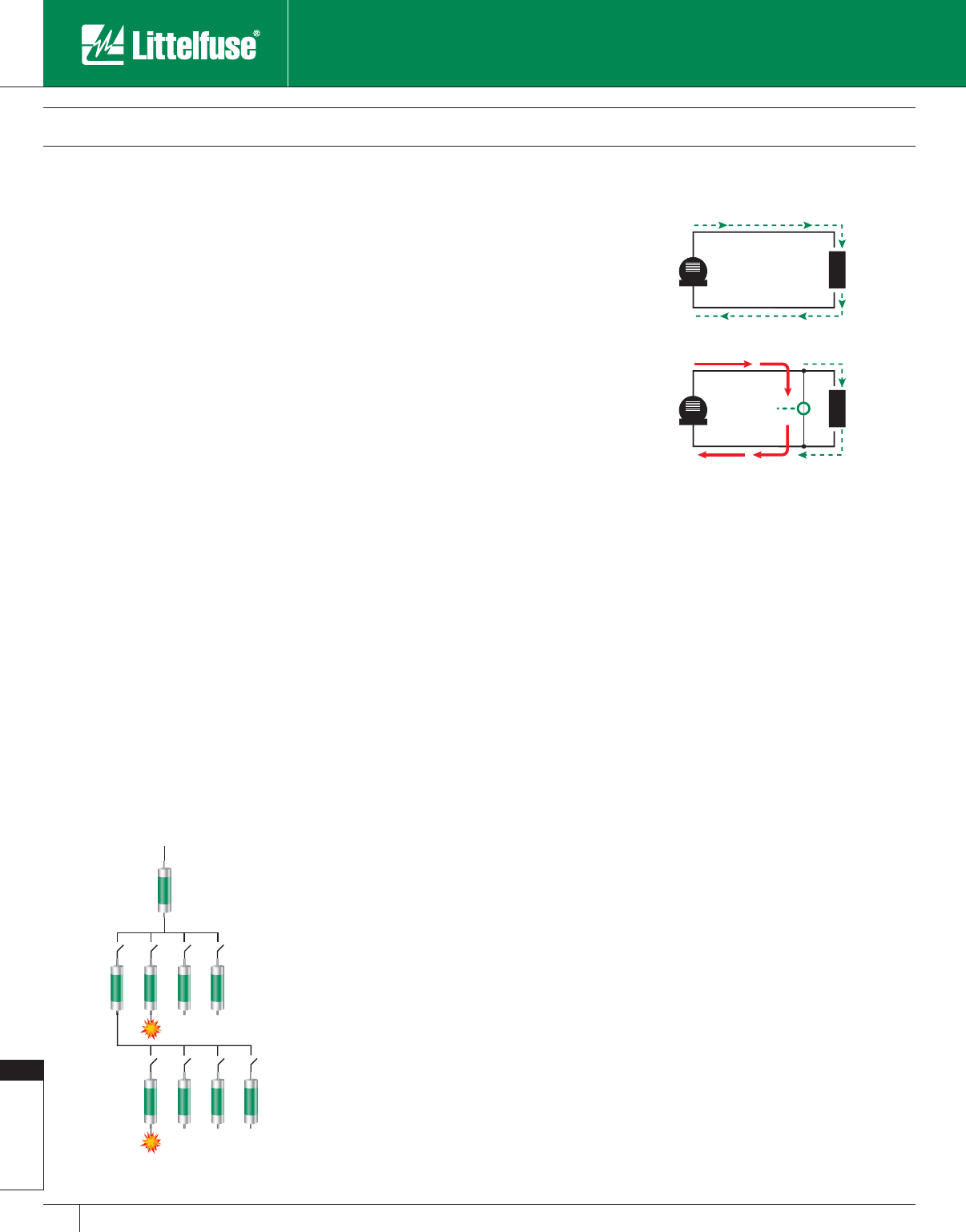
Fuseology
180 www.littelfuse.com
Fuseology
© 2005 Littelfuse • POWR-GARD™ Products Catalog
with interrupting ratings exceeding 10,000 amperes are required to have
a power factor of 20% or less. Since the power factor of test circuits
tends to vary during test procedures, actual test circuits are usually set
to a 15% power factor. The resulting asym met ri cal current has an rms
value of 1.33 times the available symmetrical rms. The instantaneous
peak current of the first peak after the fault is 2.309 times the available
symmetrical rms.
Prospective Current
See Available Short-Circuit Current.
Rating
A designated limit of operating characteristics based on definite
conditions such as current rating, voltage rating and interrupting rating.
Rectifier Fuse
See Semi con duc tor Fuse.
Rejection Feature
The physical characteristics of a fuse block or fuseholder that prevents
the insertion of a fuse unless it has mating characteristics. This may
be done through the use of slots, grooves, projections, or the actual
physical dimensions of the fuse. This feature prevents the substitution
of fuses of a Class or size other than the Class and size intended.
Renewable Element (also Renewable Link)
A renewable fuse current-carrying part that is replaced to restore the
fuse to a functional condition after the link opens due to an overcurrent
condition.
Renewable Fuse
A fuse that may be readily restored to service by replacing the
renewable element after operation.
Selective Coordination (See Figure 5)
In a selectively coordinated system, only the protective device
immediately on the line side of an overcurrent opens. Upstream
protective devices remain closed. All other equipment remains in
service, which simplifies the identification and location of overloaded
equipment or short-circuits. For additional information, refer to the Fuse
Coordination pages of this Fuseology section.
Semiconductor Fuse
A fuse specifically designed to protect semiconductors such as silicon
rectifiers, silicon-controlled rectifiers, thyristers, transistors, and similar
components. For additional information, refer to the Semiconductor
Section of this catalog.
Short-Circuit (See Figure 6)
A current flowing outside its normal path. It is caused by a breakdown of
insulation or by faulty equipment con nec tions. In a short-circuit, current
bypasses the normal load. Current is determined by the system impedance
(AC resistance) rather than the load impedance. Short-circuit currents may
vary from fractions of an ampere to 200,000 amperes or more.
Short-Circuit Rating
The maximum RMS symmetrical short-circuit current at which a given
piece of equipment has been tested under specified conditions, and
which, at the end of the test is in essentially the same condition as prior
to the test. Short-circuit ratings (also called withstand ratings) apply to
equipment that will be subjected to fault currents, but which are not
required to interrupt them. This includes switches, busway (bus duct),
switchgear and switchboard structures, motor control centers and
transformers.
Most short-circuit ratings are based on tests which last three complete
electrical cycles (0.05 seconds). However, if the equipment is protected
during the test by fuses, or by a circuit breaker with instantaneous trips,
the test duration is the time required for the overcurrent protective
device to open the circuit.
When so protected during testing, the equipment in struc tions and labels
must indicate that the equipment shall be protected by a given fuse
class and rating or by a specific make, type, and rating of circuit breaker.
Figure 5
C
URRENT FL
O
W
GEN.
LOAD
Accidental
connection
creates fault
GEN.
LOAD
In a "normal" circuit,
current is determined by
load IMPEDANCE
(Heavy lines indicate
increased current)
In a short-circuit, current is limited
only by impedance of fault path.
Current may increase to many times
load current.
In a selective system:
For a fault at "X" only fuse "C" will open.
For a fault at "Y" only fuse "F" will open.
X
BCDE
A
FGHJ
Y
Figure 6
Fuse Application Guide
Definitions
Fuseology
181
www.littelfuse.com
Fuseology
© 2005 Littelfuse • POWR-GARD™ Products Catalog
Circuit breakers equipped with short-delay trip elements instead of
instantaneous trip elements have withstand (short-circuit) ratings
in addition to their interrupting rating. The breaker must be able to
withstand the available fault current during the time that opening is
delayed.
Symmetrical Current
The terms “Symmetrical Current” and “Asymmetrical Current” describe
an AC wave symmetry around the zero axis. The current is symmetrical
when the peak currents above and below the zero axis are equal in
value, as shown in Figure 7. If the peak currents are not equal, as
shown in Figure 8, the current is asymmetrical.
The degree of asymmetry during a fault is determined by the change
in power factor (X/R) and the point in the voltage wave when the fault
occurs. See definition of Power Factor. In general, lower short-circuit
power factors increase the degree of asymmetry.
Threshold Current
The minimum current for a given fuse size and type at which the
fuse becomes current-limiting. It is the lowest value of available rms
symmetrical current that will cause the device to begin opening within
the first 1/4 cycle (90 electrical degrees) and completely clear the circuit
within 1/2 cycle (180 electrical degrees). The approximate thresh old
current can be determined from the fuse’s peak let-through charts.
See Figure 9.
Threshold Ratio
The threshold current divided by the ampere rating of a specific type or
class overcurrent device. A fuse with a threshold ratio of 15 becomes
current-limiting at 15 times its current rating.
Time-Delay Fuse
Fuses that have an intentional, built-in delay in opening. When compared
to fast-opening fuses, time-delay fuses have an increased opening
time for overcurrents between approximately 200% and 600% of
the fuse’s current rating. Time-delay is indicated on the fuse label by
“Time-Delay”, “T-D”, “D”, or other suitable marking. Time-delay in the
overload range (200%-600% of the fuse rating) permits the fuse to
withstand system switching surges, motor starting currents, and other
harmless temporary over cur rents.
UL Standards require time-delay Class H, K, RK1, RK5, and J fuses to
hold 500% of their normal current rating for a minimum of 10 seconds.
They must also pass the same opening time tests (135% and 200% of
current rating) as fast acting fuses.
Time-delay Class CC, CD, G, Plug, and Miscellaneous fuses have
different requirements. See the corresponding descriptions given in the
Product Information Section.
For the UL Standard, Class L fuses have no standard time-delay. The
time-delay varies from type to type for a given manufacturer, as well
as from manufacturer to manufacturer. For reference, Littelfuse KLPC
series POWR-PRO® fuses do hold 500% of rated current for a minimum
of ten seconds.
Voltage Rating
The maximum rms AC voltage and/or the maximum DC voltage at
which the fuse is designed to operate. For example, fuses rated 600
volts and below may be applied at any voltage less than their rating.
There is no rule for applying AC fuses in DC circuits such as applying the
fuse at half its AC voltage rating. Fuses used on DC circuits must
have DC ratings.
Withstand Rating
See Short-Circuit.
1000
4000
A
B
Fuse approximate
threshold current = 4000A
Peak let-through current
Available Fault Current Symmetrical RMS Amperes
Peak Let-Through in Amperes
Equal
Peaks
Zero Axis
Fuse Application Guide
Definitions
Figure 7
Symmetrical Current
Figure 8
Asymmetrical Current
Figure 9
Unequal
Peaks
Zero Axis

Fuseology
182 www.littelfuse.com
Fuseology
© 2005 Littelfuse • POWR-GARD™ Products Catalog
Electrical Safety Guide
Electrical safety is an important issue for employers and employees
alike. Unfortunately there are still about 30,000 electrical accidents
occurring each year, each of them potentially costing up to $15 million,
and the number is increasing.
OSHA requires all employers to perform a hazard assessment of their
facilities and train their employees to become qualified to perform a
specific task. Being aware, following safety regulations, codes and
standards, and using protective devices will minimize hazards and help
establish safer work practices.
OSHA Standard 29 CFR Part 1910 Subpart S (electrical)
generally addresses safety standards, work practices, and maintenance
requirements.
NFPA 70E Standard for Electrical Safety in the Workplace
concentrates on safety requirements to protect employees. OSHA
commonly is referred to as the “Shall” and NFPA 70E as the “How”
with regards to electrical safety.
Both OSHA and NFPA 70E reinforce the need for Electrical
Hazard Analysis.
The analysis should address all potential electrical hazards including
shock, Arc-Flash, Arc-Blast, and burns. NFPA 70E Article 110.8(B)(1)
specifically requires Electrical Hazard Analysis within all areas of the
electrical system that operate at 50 volts or greater. The results of the
Electrical Hazard Analysis will determine the work practices, protection
boundaries, personal protective equipment to be used, and other
procedures to protect employees from an Arc-Flash or contact with live
conductors.
Implementing and following a well designed Electrical Safety
Program will protect employees and employers against:
• Injury to personnel
• Increased insurance and workman compensation
• Lost or unusable materials
• Unplanned equipment repair or replacement
• OSHA citations and fines
• Multi-million dollar lawsuits
• Possible bankruptcy
Electrical Safety is not an option; it is absolutely necessary for
both workers and employers.
FACTS
• There are approximately 30,000 electrical shock accidents every year.
• Over 3600 disabling electrical contact injuries occur annually.
• Over 2000 workers are sent to burn centers each year with severe Arc-Flash burns.
• Over 1000 electrical workers die each year from workplace accidents.
• 60% of workplace accident deaths are caused by burn injuries.
• Electrocutions are the 4th leading cause of traumatic occupational fatalities.
• Estimates show that 10 Arc-Flash incidents occur every day in the U.S.
• 97% of all electricians have been shocked or injured on the job.
• Medical costs per person can exceed $4 million for severe electrical burns.
• Total costs per electrical incident can exceed $15 million.
• In the year 2002, work injuries cost Americans $146.6 billion.
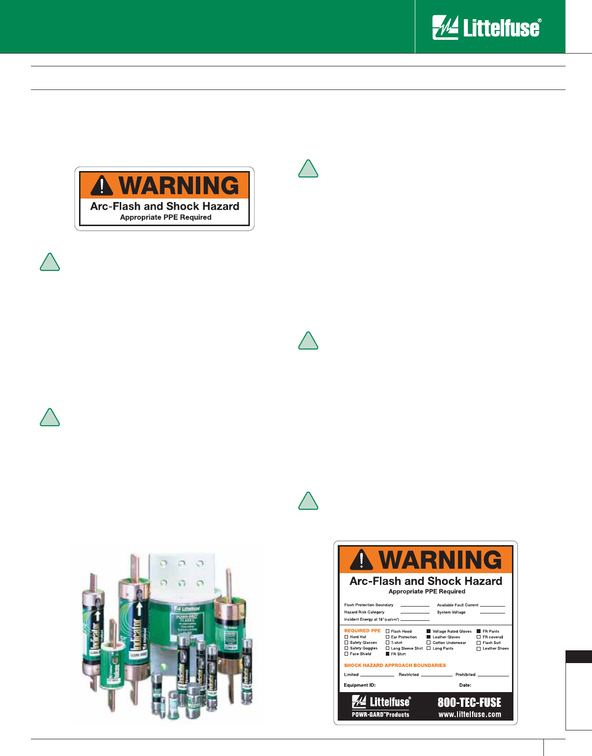
Fuseology
183
www.littelfuse.com
Fuseology
© 2005 Littelfuse • POWR-GARD™ Products Catalog
The following is a brief overview of requirements for working on electrical equipment.
NOTE: Only the complete standards constitute the law or regulation and all parts must be followed where applicable.
Understand and follow NFPA and OSHA
guidelines
Allow only “Qualified” individuals to perform work. Qualified
workers must be knowledgeable on the equipment and the
hazards that exist and receive documented training. For more
information refer to OSHA 1910.332 and NFPA 70E Article
110 .6 ( D ) (1) .
Establish a “Safe Work Condition” and work on system
components de-energized whenever possible. Consult NFPA
70E Article 120.1 for establishing an Electrically Safe Work
Condition.
Develop an Electrical Safety Program
Determine available fault currents and hazard risks at points
where there is the potential for contact with an energized
part. In many cases, this requires a complete Hazard Risk
Assessment. As a result, the entire electrical system is
analyzed and the one-line diagram for the facility is reviewed
and updated. The outcome is used to determine the Hazard
Risk Category (0 to 4), required level of PPE, Protection
Boundaries and equipment that requires warning labels. Refer
to OSHA 1910.132(d) and NFPA 70E Article 110.8(B)(1) for
more information on Electrical Hazard Analysis.
Establish an Electrical Safety Program.
It should control and re-engineer the processes in the
workplace to insure Electrical Safety including: hazard
assessments, labeling of equipment, training programs,
energized work permits and using current-limiting devices to
minimize hazards. Refer to NFPA 70E Article 110.7 for more
information on establishing an Electrical Safety Program.
Develop formal training for equipment operators, service
technicians and any other employees that might come in
contact with the identified hazard. “Qualify” them for hazard
preparations and contingencies (preparations prior to servicing
electrical systems or coming within boundaries of electrical
hazards). For more information refer to OSHA 1910.332 and
NFPA 70E Article 110.6.
Communicate the hazards to employees
Train your employees.
Label equipment and service entrances of the “Hazards
Assessed.” Refer to NEC Article 110.16 for Warning Label
Requirements.
Create a safety culture and support safety processes and
awareness such as: Deenergize and Verify, “Test Before
Touch”, Lockout / Tagout, the proper use of PPE and insulated
tools, providing barriers to warn and restrict access to
unqualified personnel, etc.
Select the safest circuit protection
devices to minimize electrical hazards
!
Electrical Safety Guide
!
!
!
!
Bus: SERVICE4 05/12/05
42 inches 12 inches 1 inch
1 480 VAC
35 kA
32 inches
2.77 cal/cm2

Fuseology
184 www.littelfuse.com
Fuseology
© 2005 Littelfuse • POWR-GARD™ Products Catalog
Fuse Application Guide
Overcurrent Protection Fundamentals
Introduction
An important part of developing quality overcurrent protection is an
understanding of system needs and overcurrent protective device
fundamentals. This section discusses these topics with special attention
to the application of fuses. If you have additional questions, call our
Technical Support and Engineering Services Group at 1-800-TEC-FUSE
(1-800-832-3873). Definitions of terms used in this section are located
in the preceding section.
INDEX Page
Why Overcurrent Protection? ..................................................184
What is Quality Overcurrent Protection? .............................184
Overcurrents, Types and Effects .............................................184
Overloads ..............................................................................184
Short-Circuits ......................................................................185
Fuse Characteristics (600 volts and below) .............................185
Voltage Rating ..................................................................... 18 5
Interrupting Rating ............................................................185-186
300,000 AIC Fuses ........................................................186
Time Current Characteristics ...................................................186
Overloads ..............................................................................186
Fast-Acting Fuses ..........................................................186
Time-Delay (Dual-Element) Fuses ...............................186
Very Fast-Acting Fuses .................................................187
Short Circuits .......................................................................187
Current-Limiting Fuses ..................................................187
Fast-Acting Fuses ..........................................................187
Dual-Element (Time-Delay) Fuses ...............................187
Very Fast-Acting Fuses .................................................187
Time-current Curves .........................................................187
Peak Let-through Charts............................................................187
Using the Peak Let-through Charts
(“up-over-and-down”) ............................................................188-189
Fuse Ampere (current) Ratings ...............................................189
Fuse Dimensions .........................................................................189
Fuse Coordination, Selective Systems .................................190-191
Component Short-circuit Protecting Ability .......................190
UL/CSA Fuse Classes and Their Applications ....................192-193
Why Overcurrent Protection?
All electrical systems eventually experience overcurrents. Unless
removed in time, even moderate overcurrents quickly overheat system
components, damaging insulation, conductors, and equipment. Large
overcurrents may melt conductors and vaporize insulation. Very high
currents produce magnetic forces that bend and twist bus bars. They
can pull cables from their terminals and crack insulators and spacers.
Too frequently, fires, explosions, poisonous fumes and panic accompany
uncontrolled overcurrents. They not only damage electrical systems and
equipment, but may cause injury or death to personnel.
To reduce these hazards, the National Electrical Code® (NEC®), OSHA
regulations, and other applicable design and in stal la tion standards require
overcurrent protection that will disconnect overloaded or faulted equipment.
Industry and governmental organizations have developed performance
standards for overcurrent devices and testing pro ce dures that show
compliance with the standards and with the NEC. These organizations
include: the American National Stan dards Institute (ANSI), National
Electrical Man u fac tur ers Association (NEMA), and the National Fire
Protec tion Association (NFPA) working with Nationally Recognized
Testing Laboratories (NRTL) such as Un der writ ers Lab o ra to ries (UL).
Electrical systems must meet applicable code re quire ments including
those for overcurrent protection before electric util i ties can provide
electric power to a facility.
What is Quality Overcurrent Protection?
A system with quality overcurrent protection has the following
characteristics:
1. Meets all legal requirements, such as NEC, OSHA, local codes, etc.
2. Provides maximum safety for personnel, ex ceed ing minimum code
requirements as necessary.
3. Minimizes overcurrent damage to property, equipment, and electrical
systems.
4. Provides coordinated protection. Only the protective device
immediately on the line side of an overcurrent opens to protect the
system.
5. Is cost effective. Provides reserve interrupting capacity for
future growth. Not subject to obsolescence. Re quires minimum
maintenance that can be done by regular maintenance personnel
using readily available tools and equipment.
Overcurrent Types and Effects
An overcurrent is any current that exceeds the ampere rat ing of
conductors, equipment, or devices under con di tions of use. The term
“overcurrent” includes both over loads and short-circuits.
Overloads
An overload is an overcurrent that is confined to normal current paths.
There is no insulation breakdown.
Sustained overloads are commonly caused by installing excessive
equipment such as additional lighting fixtures. They are also caused by
overloading mechanical equipment and by equipment breakdown such
as failed bear ings. If not disconnected within established time limits,
sustained overloads eventually overheat circuit com po nents causing
thermal damage to insulation and other system components.
Overcurrent protective devices must disconnect circuits and equipment
experiencing continuous or sustained overloads before overheating
occurs. Even moderate insulation overheating seriously reduces its life.
For example, motors overloaded by only 15% may have less than 50%
insulation life.
Temporar y overloads occur frequently. They may be caused by
temporary equipment overloads such as a machine tool taking too deep
of a cut, or may result from starting inductive loads, such as motors.
Since temporary overloads are, by definition, harmless, over cur rent
protective devices should not open the circuit.
Fuses selected must have sufficient time-delay to allow motors to start
Overcurrent Protection Fun da men tals (Fuses and How They Work)

Fuseology
185
www.littelfuse.com
Fuseology
© 2005 Littelfuse • POWR-GARD™ Products Catalog
and temporary overloads to subside. However, should the overcurrent
continue, fuses must open before system components are damaged.
Littelfuse POWR-PRO® and POWR-GARDTM time-delay fuses are
designed to meet these needs. They hold 500% current for a minimum
of ten seconds, yet open quickly on higher values of current. Even
though government mandated high efficiency motors and NEMA
design E motors have much higher locked rotor currents, POWR-PRO
time-delay fuses such as the FLSR_ID, LLSRK_ID, or IDSR series
have sufficient time-delay to permit motors to start when the fuses are
properly selected in accordance with the NEC.
Short-Circuits
Types of Short- Circuits
Short-circuits are divided into bolted faults, arcing faults
and ground faults. Each are defined in the Definition section.
Causes of Short-Circuits
A short-circuit is current flowing outside of its normal path. It is caused
by an insulation breakdown or faulty connection. During a circuit’s
normal operation, the connected load determines current. During a
short-circuit, the current bypasses load and the current takes a “shorter
path,” hence: short-circuit. Since there is no load impedance, only the
total distribution system’s impedance from the utility’s generators to
the fault will limit current flow. See Figure 6.
Many elec tri cal sys tems have single-phase impedance of 0.005 ohms
or less. Ap ply ing Ohm’s Law (I = E/Z for AC systems), a 480 volt single-
phase circuit with a ten ohm load impedance would draw 48 amperes
(480/10 = 48). If, when the load is shorted, the same circuit has a 0.005
ohm system impedance, the available fault current would be 96,000
amperes (480/0.005 = 96,000). Short-circuits are currents out of their
normal path and regardless of their value, they must be removed
quickly.
Effects of Short-Circuit Currents
If not removed quickly, the large currents associated with short-circuits
may have three profound effects on an electrical system: heating,
magnetic stress, and arcing.
Heating. Current passing through an electrical system heats every
part of it. When overcurrents are large enough, heating is practically
instantaneous. The energy in such overcurrents is measured in ampere-
squared seconds (I2t). An overcurrent of 10,000 amperes that lasts for
0.01 seconds has an I2t of 1,000,000. If the current could be reduced
to 1,000 amperes for the same period of time, I2t would be reduced
to 10,000 — only one percent of the original value. If the current in a
conductor increases 10 times, the I2t increases 100 times. A current
of only 7,500 amperes can melt a #8 AWG copper wire in 0.1 second.
Within eight milliseconds (0.008 seconds or one-half cycle), a current
of 6,500 amperes can raise the temperature of #12 AWG THHN
thermoplastic insulated copper wire from its operating temperature of
75°C to its maximum short-circuit tem per a ture of 150°C.
Currents larger than this may immediately vaporize organic insulations.
Arcs at the point of fault or from mechanical switching such as
automatic transfer switches or circuit breakers may ignite the vapors
causing violent explosions and electrical flash.
Magnetic stress. Magnetic stress (or force) is a function of the peak
current squared. Fault currents of 100,000 amperes can exert forces
of more than 7,000 lb. per foot of bus bar. These stresses may injure
insulation, pull con duc tors from terminals, and stress equipment
terminals sufficiently to cause damage.
Arcing. Arcing at the point of fault melts and vaporizes the conductors
and com po nents involved in the fault. The arcs often burn through
raceways and equipment enclosures show er ing the area with molten
metal that quickly starts fires and/or injures personnel in the area.
Additional short-circuits are often created when vaporized material is
deposited on insulators and other surfaces. Sustained arcing-faults
vaporize organic insulation. These vapors may explode or burn.
Fuse characteristics (600 volts and below)
Since overcurrent protection is crucial to reliable electrical system
operation and safety, overcurrent device selection and application should
be carefully considered. When selecting fuses, the following parameters
need to be evaluated:
Voltage Rating
Fuse voltage ratings must equal or exceed the circuit voltage where the
fuses will be installed, and fuses used in DC circuits must be rated for DC.
Exceeding the voltage ratings or using an AC only fuse in a DC circuit could
result in violent destruction of the fuse. Standard 600 volt and below fuses
may be applied at any voltage less than their rating. For example, a 600
volt fuse may be used in a 277 volt or even a 32 volt system.
NOTE: This does not apply to semiconductor fuses and medium
voltage fuses. See the semiconductor and medium voltage fuse
application data later in this section for voltage limitations of these fuses.
UL Listed low-voltage power fuses are available with AC voltage ratings
of 125, 250, 300, 480, and 600 volts, and DC voltage ratings of 60, 125,
160, 250, 300, 400, 500, and 600 volts. Fuses may be rated for AC
only or DC only, or they may have both an AC and a DC voltage rating.
Supplementary fuses have voltage ratings from 32 to 1,000 volts AC
and/or DC.
300 volt Class T fuses (Littelfuse JLLN series) may only be used for
single-phase to neutral loads where the voltage does not exceed 300
volts to ground. They may not be used in three-phase, four wire, 480/277
volt, wye systems or in 480 volt corner-grounded delta systems.
Interrupting Rating
A fuse’s interrupting rating is the highest available sym met ri cal rms
alternating current that the fuse is required to safely interrupt at rated
voltage under standardized test conditions without being damaged. A
fuse must interrupt all overcurrents up to its interrupting rating. Fuses
are available with interrupting ratings of 10,000A, 50,000A, 100,000A,
200,000A, and 300,000A.
NEC Article 110.9 requires all equipment intended to break current at
fault levels to have an interrupting rating sufficient for system voltage
and current available at the equipment’s line terminals. Refer to Figure
10. Select fuses with interrupting ratings which equal or exceed the avail-
able fault current.
Standardizing on fuses with at least a 200,000 ampere interrupting
capacity (AIR) ensures that all fuses have an adequate interrupting
Fuse Application Guide
Overcurrent Protection Fundamentals
Fuseology
186 www.littelfuse.com
Fuseology
© 2005 Littelfuse • POWR-GARD™ Products Catalog
rating, and provides reserve in ter rupt ing capacity for future increases in
available fault current.
300,000 AIC Fuses
Littelfuse POWR-PRO® fuse series have a Littelfuse Self-Certified
interrupting rating of 300,000 amperes rms symmetrical. The 300,000
ampere testing was performed in a Nationally Recognized Testing Lab-
o ra to ry, and the tests were UL witnessed. UL has ruled that fuses with
a UL interrupting rating greater than 200,000 amperes must be marked
as “Special Purpose Fuses” and may not be labeled as UL Listed Class
RK5, RK1, L, etc.
Littelfuse feels that the “Special Purpose Fuse” clas si fi ca tion adds
confusion to specification writing for both fuses and switches and
com pli cates fuse pro cure ment. Since only a very small number of
installations have a real need for fuses with interrupting ratings in excess
of 200,000 amperes, Littelfuse will continue to UL List their fuses by
UL standard fuse classes that have in ter rupt ing ratings up to 200,000
amperes. Littelfuse fuses which have passed the 300,000 ampere tests
are marked on the label: “300kA (Self certified by Littelfuse)”. UL listing
cards showing 300,000 AIC and the special purpose classification are
available on request. Refer to the product section of this catalog for
information on specific fuse classes.
Time Current Characteristics
Time current characteristics determine how fast a fuse responds to
overcurrents. All fuses have inverse time characteristics; that is, the fuse
opening time de creas es as the value of overcurrent increases. When
properly rated in ac cor dance with NEC re quire ments, fuses provide
both overload and short-circuit protection to system con duc tors and
components. However, in some instances such as when fuses are used
to backup circuit breakers or to provide motor branch circuit short-circuit
and ground fault pro tec tion, fuses provide only short-circuit protection.
A fuse’s response to over cur rents is divided into overloads and short-
circuits.
Overloads
While fuses must disconnect overloaded conductors and equipment
before the conductors and components are se ri ous ly overheated,
they should not disconnect harmless temporary over loads. To provide
overload protection for system conductors, UL has established
maximum fuse opening times at 135% and 200% of a fuse’s current
rating. All UL Listed fuses for application in accordance with the National
Electrical Code® (NEC®) must meet these limits whether they are fast-
acting or time-delay fuses.
Fast-Acting (Normal-Opening) Fuses
Fastoacting fuses (sometimes called “Normal-opening fuses”) have no
in ten tion al time-delay. Typical opening times at 500% of the fuse ampere
rating range from 0.05 to approximately 2 seconds. Fast-Acting fuses
are suitable for non-inductive loads, such as in can des cent lighting and
general-purpose feeders, or branch circuits with little or no motor load.
When protecting motors and other inductive loads, fast-acting fuses
must be rated at 200-300% of load currents to prevent nuisance opening
on in-rush currents. Fuses with such increased ratings no longer furnish
adequate protection from overloads. They provide only short-circuit pro-
tec tion. Over load relays or other overload protection must be provided to
protect con duc tors and equipment from overload conditions.
Time-Delay (Dual El e ment) Fuses
UL Classes CC, CD, G, H, L, RK5 and RK1 fuses, plus some of the
UL Listed Miscellaneous fuses, may have time-delay. If so, they are
identified on the fuse label with “Time-Delay”, “T-D”, “D”, or some
other suitable marking. Minimum time-delay varies with the fuse class,
and to some degree with the fuse ampere rating. UL standards for
POWR-GARDTM Fuses Products series IDSR, FLNR_ID, and FLSR_ID
(UL Class RK5), LLNRK, LLSRK, LLSRK_ID (UL Class RK1), and JTD,
JTD_ID (UL Class J) fuses require them to carry 500% rated current for
a minimum of 10 seconds. Standards for CCMR and KLDR (UL Class
CC and CD) and SLC (UL Class G) require them to carry 200% rated
current for a minimum of 12 seconds.
Although there is no UL Classification for time-delay Class L fuses, they
may be marked “Time-Delay.” The amount of time-delay is determined
by the man u fac tur er. POWR-PRO® KLPC series and POWR-GARD
KLLU series fuses will hold 500% current for 10 seconds or more.
In addition to providing time-delay for surges and short time overloads,
time-delay fuses meet all UL requirements for sustained overload
protection. On higher values of current, time-delay fuses are current-
limiting meaning they remove large overcurrents in less than one-half
cycle (0.008 seconds). Time-delay fuses provide the best overall
protection for both motor and general purpose circuits, and eliminate
nuisance fuse opening and most downtime.
Compared to fast-acting fuses, time-delay fuses can be selected with
ratings much closer to a circuit’s operating current. For example, on
most motor circuits, RK5 and RK1 fuses can be rated at 125-150% of
a motor’s full load current (FLA). This provides superior overload and
short-circuit protection, and often permits using smaller, less expensive
switches. Time-delay fuses have gradually replaced most one-time and
re new able fuses. Today, more than 50% of all fuses sold by electrical
distributors are time-delay fuses such as Littelfuse POWR-PRO LLSRK_ID
series fuses.
Fuse Application Guide
Overcurrent Protection Fundamentals
Main Switchboard
Available fault
Current = 125,000A
Available fault
Current = 85,000A
All fuses in main switchboard
must have an A.I.R. of at least
125,000A. Next higher standard
rating is 200,000A.
Fuses in panel must have at
least an 85,000 A.I.C. Next higher
standard rating is 100,000A., but
best choice is time-delay fuses
with 200,000 A.I.R.
Figure 10
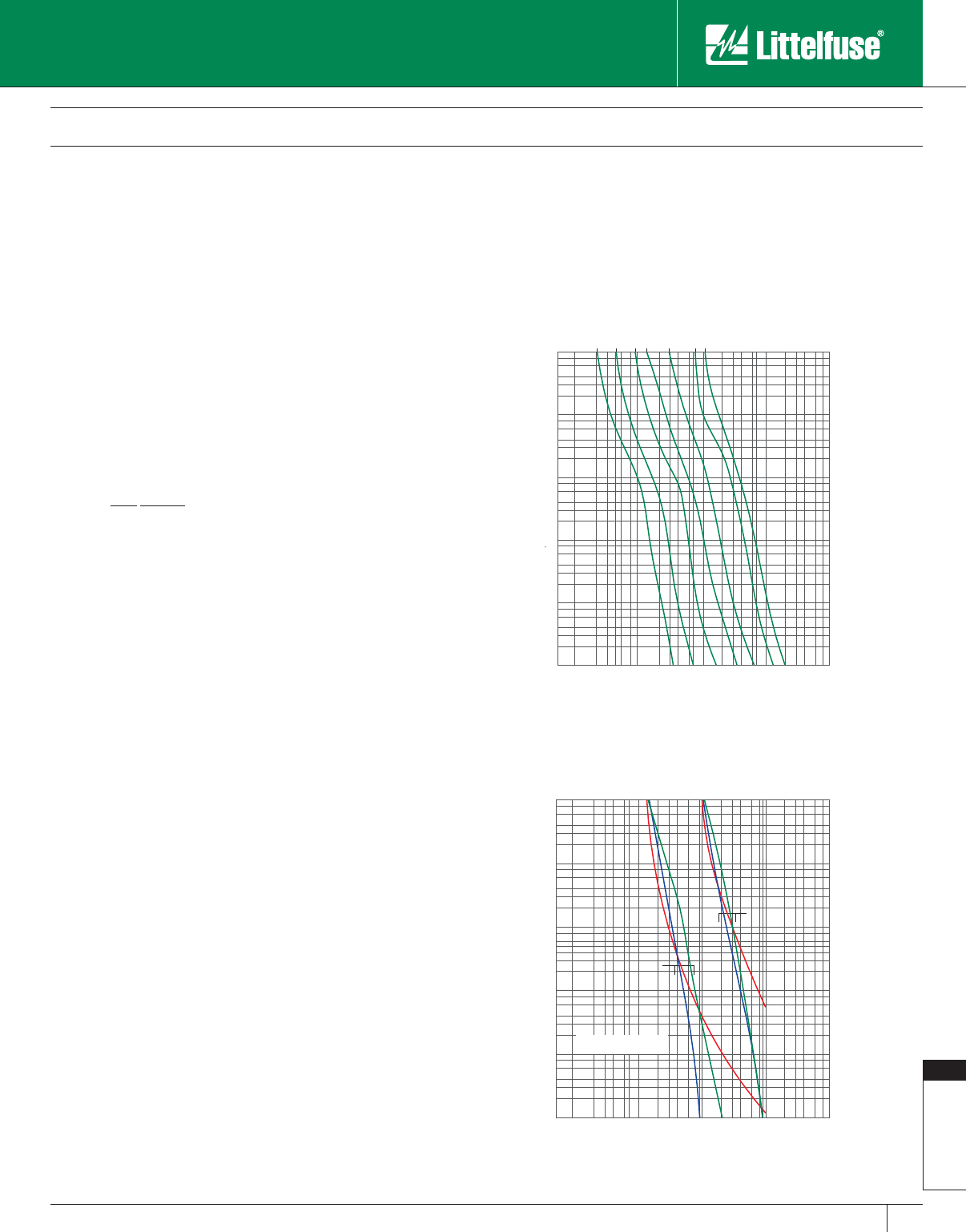
Fuseology
187
www.littelfuse.com
Fuseology
© 2005 Littelfuse • POWR-GARD™ Products Catalog
Very Fast-Acting Fuses
The principle use of very fast acting fuses is to protect solid-state
electronic components, such as semi con ductors. Their special
characteristics, including quick overload response, very low I2t, Ipeak
and peak transient voltages provide protection for components that
cannot withstand line surges, low value overloads, or short-circuit
currents.
Short-Circuits
A fuse’s short-circuit response is its opening time on higher-value
currents. For power fuses, that is generally over 500 – 600% of
the fuse’s rating. As stated earlier, all fuses have inverse time
characteristics: the higher the current, the faster the opening time. Since
short-circuits should be removed quickly, inverse time is especially
important for short-circuit protection.
Current-limiting Fuses
Current-limiting fuses must have the following character istics:
1. Limit peak currents to values less than those which would occur
if the fuses were replaced with solid conductors of the same
impedance. This reduced peak current is referred to as a fuse’s “Peak
Let-through Current.”
2. When the fault current exceeds the fuse threshold current, the fuse
must open the circuit in less than 180 electrical degrees (1/2 cycle)
after the start of the fault.
3. Matching fuse holders and/or fuse blocks must reject non-current-
limiting fuses and accept only current-limiting fuses of the stated
UL Class.
Fast-Acting (Normal Opening) Fuses
All fast-acting fuses provide fast short-circuit response within their
interrupting rating. Some are current-limiting, such as Class T and J.
Others are non-current-limiting, such as Class H.
Dual Element (Time-delay) Fuses
Littelfuse time-delay IDSR, FLNR_ID/FLSR_ID Class RK5, and LLNRK/
LLSRK_ID Class RK1 series fuses have true dual-element construction.
Time-delay elements are used for overload protection, and separate fast
acting fuse links are used to provide current-limiting short-circuit protection.
Very Fast-Acting Fuses
Very fast-acting fuses are designed for very fast response to overloads
and short-circuits. They are very current-limiting.
Understanding Time-current Curves
Time-current curves for Littelfuse POWR-GARD™ fuses are shown in
each product section. They show the average melting times for that
fuse series at any current. In order to make the curves more readable,
they are presented on log-log paper. The overcurrent values appear
at the bottom, and increase from left to right. Average melting times
appear on the left-hand side of the curve and increase from bottom to
top. The amperage ratings of the individual fuses for a given series are
listed at the top and increase from left to right. Figure 11 shows the
average melting time curves for a typical time-delay fuse series.
Figure 12 compares the average melting times for 100 and 600 amp
ratings of three fuse types: Littelfuse POWR-GARD dual-element, time-
delay LLSRK series RK1 fuses; Littelfuse normal opening NLS series
fuses and Littelfuse very fast acting L60S series semiconductor fuses.
Table 1 com pares the opening times for these fuses.
Peak Let-through Charts
Fuses that are current-limiting open severe short-circuits within the
first half-cycle (180 electrical degrees) after the fault occurs. They also
reduce the peak current of the available fault current to a value less than
would occur without the fuse. This is shown in Figure 13.
1000
800
600
400
300
200
100
80
60
40
30
20
10
8
6
4
3
2
1
.8
.6
.4
.3
.2
.1
.08
.06
.04
.03
.02
.01
200
300
400
600
800
1000
2000
3000
4000
6000
8000
10000
20000
30000
40000
60000
80000
100000
10
20
30
40
60
80
100
15A
30A
60A
100A
200A
400A
600A
TIME IN SECONDS
CURRENT IN AMPERES
1000
800
600
400
300
200
100
80
60
40
30
20
10
8
6
4
3
2
1
.8
.6
.4
.3
.2
.1
.08
.06
.04
.03
.02
.01
200
300
400
600
800
1000
2000
3000
4000
6000
8000
10000
20000
30000
40000
60000
80000
100000
10
20
30
40
60
80
100
100 AMP
600 AMP
GREEN = TIME-DELAY FUSE
RED = NORMAL OPENING FUSE
BLUE = VERY-FAST ACTING FUSE
TIME IN SECONDS
CURRENT IN AMPERES
Figure 11
Figure 12
Fuse Application Guide
Overcurrent Protection Fundamentals
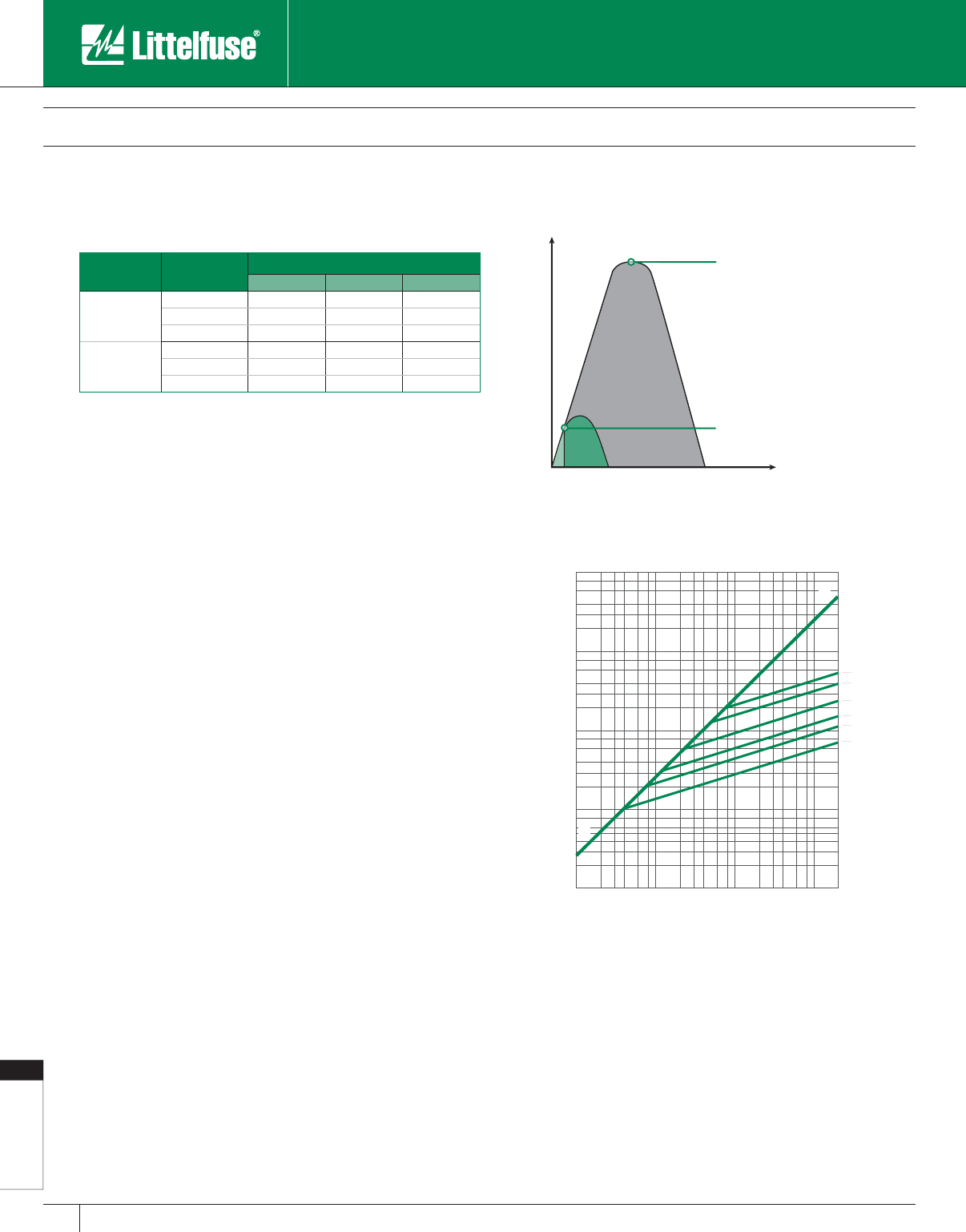
Fuseology
188 www.littelfuse.com
Fuseology
© 2005 Littelfuse • POWR-GARD™ Products Catalog
A fuse current-limiting effects are shown graphically on Peak Let-
through charts such as the one in Figure 14. The values across the
chart’s bottom represent the available (also referred to as potential or
prospective) rms sym met ri cal fault current. The values on the chart’s
left side represent the instantaneous available peak current
and the peak let-through current for various fuse ratings.
As an example, enter the chart on the bottom at 100,000 rms sym met-
ri cal amperes and read upwards to line A-B. From this point, read hor i-
zon tal ly to the left and read an instantaneous peak current of 230,000
amperes. In a circuit with a 15% short-circuit power factor, the in stan-
ta neous peak of the available current approximates 2.3 times the rms
symmetrical value. Line A-B on the chart has a 2.3:1 slope.
The curves that branch off line A-B show the current-limiting effects
of different fuse ampere ratings. Enter the chart in Figure 14 on the
bottom at 100,000 rms sym met ri cal amperes and read upwards to
the in ter sec tion of the 200 ampere fuse curve. Read horizontally to the
left from this point and read approximately 20,000 amperes. The 200
ampere fuse has reduced the peak current during the fault from 230,000
amperes to 20,000 amperes. 20,000 am peres is less than one-tenth of
the available current. Magnetic force created by current flow is a function
of the peak current squared. If the peak let-through current of a current-
limiting fuse is one-tenth of the available peak, the magnetic force is
reduced to less than 1/100 of what would occur without the fuse.
Using the Peak Let-through Charts (“Up-Over-and-Down”)
Peak Let-through Charts for Littelfuse POWR-GARD™ fuses are shown in
each product section of this catalog. These charts are useful in determining
whether a given fuse can protect a specific piece of equipment.
For example, with an available fault-current of 100,000 rms symmetrical
amperes, determine whether 600 amp 250 volt time-delay Class RK1
fuses can protect equip ment with a 22,000 amp short-circuit rating.
Refer to Figure 15.
Locate 100,000A available fault-current on the bottom of the chart
(Point A) and follow this value upwards to the in ter sec tion with the
600A fuse curve (Point B). Follow this point horizontally to the left to
intersect with Line A-B (Point C). Read down to the bottom of the chart
(Point D) and read approximately 18,000 amps.
The POWR-PRO® LLNRK 600 ampere RK1 current-limiting fuses
have reduced the 100,000 amperes available current to an apparent or
equivalent 18,000 amps. When protected by 600 amp LLNRK RK1 fuses,
equip ment with short-circuit ratings of 22,000 amps may be safely con-
nect ed to a system having 100,000 available rms sym met ri cal am peres.
This method, sometimes referred to as the “Up-Over- and-Down”
method, may be used to:
1. Provide back-up short-circuit protection to large air power circuit
breakers.
2. Enable non-interrupting equipment such as bus duct to be installed in
systems with available short-circuit currents greater than their short-
circuit (withstand) ratings.
Table 1
Comparative Opening Times for Time-Delay,
Fast-Acting, and Very Fast-Acting Fuses
Ampere Rating Fuse Type Opening Time in Seconds
500% Rating 800% Rating 1200% Rating
100
Time-Delay 12 secs. 0.9 secs. 0.14 secs.
Normal Opening 2 secs. 0.7 secs. 0.3 secs.
Very Fast-Acting 1.3 secs. 0.02 secs. >0.01 secs.
600
Time-Delay 14 secs. 0.7 secs. 0.045 secs.
Normal Opening 10 secs. 3 secs. 1.1 secs.
Very Fast-Acting 2 secs. 0.05 secs. >0.01 secs.
100
1000000
200000
300000
400000
600000
800000
100000
20000
30000
40000
60000
80000
10000
2000
3000
4000
6000
8000
1000
200
300
400
600
800
100
200
300
400
600
800
1000
2000
3000
4000
6000
8000
10000
20000
30000
40000
60000
80000
100000
200000
FUSE
AMPERE
RATING
600
400
200
100
60
30
A
B
AVAILABLE FAULT CURRENT
SYMMETRICAL R.M.S. AMPERES
PEAK LET-THRU IN AMPERES
Peak Let-through Current
Peak Current which would occur
without current limitation
Current
Time
Figure 13
Current limiting effect of fuses
Figure 14
Peak Let-through Charts
Fuse Application Guide
Overcurrent Protection Fundamentals
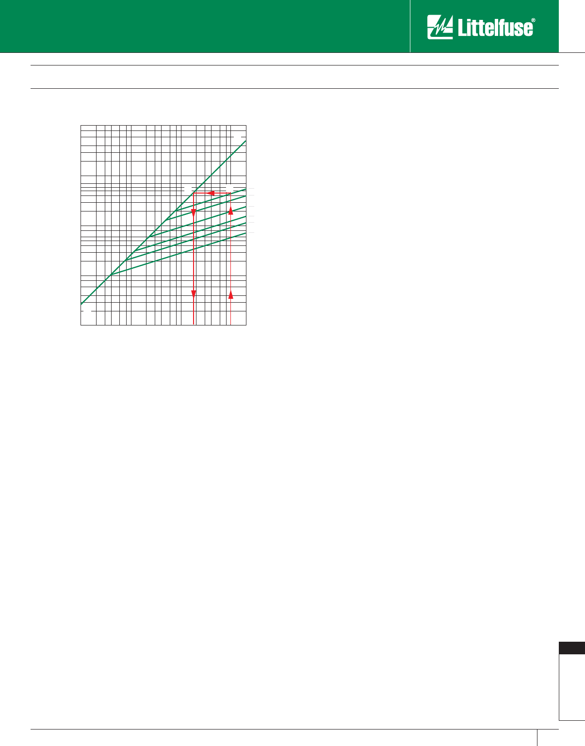
Fuseology
189
www.littelfuse.com
Fuseology
© 2005 Littelfuse • POWR-GARD™ Products Catalog
This method may not be used to select fuses for backup protection of
molded case or intermediate frame circuit breakers. National Electrical
Code® (NEC®) Article 240.86 states:
“Where a circuit breaker is used on a circuit having an available fault
current higher than its marked interrupting rating by being connected on
the load side of an acceptable overcurrent protective device having the
higher rating, 240.86(A) and (B) shall apply.
(A) Marking. The additional series combination interrupting rating shall be
marked on the end use equipment, such as switchboards and panelboards.”
NEC Article 110.22 states:
“Where circuit breakers or fuses are applied in compliance with the series
combination ratings marked on the equip ment by the manufacturer, the
equipment enclosure(s) shall be legibly marked in the field to indicate
the equip ment has been applied with a series combination rating. The
marking shall be readily visible and state the following:
CAUTION - SERIES COMBINATION SYSTEM RATED ________
____ AMPERES. IDENTIFIED REPLACEMENT COMPONENTS
REQUIRED.
UL Listed fuse-to-circuit breaker series ratings are now available from
most national loadcenter and panelboard manufacturers. The Listings
are shown in their product digests and catalogs. Many local builders
have also obtained fuse-to-circuit breaker series ratings. For ad di tion al
information on this subject contact the Littelfuse Technical Support and
Engineering Services Group at 1-800-TEC-FUSE (1-800-832-3873).
Ampere (Current) Rating
A fuse ampere rating is the AC or DC current that the fuse can
continuously carry under specified conditions. Fuses selected for a
circuit must have ampere ratings that meet NEC requirements. These
NEC requirements establish maximum ratings and, in some cases,
minimum ratings. NEC Articles 240 and 430 contain specific re quire-
ments.
Fuse Dimensions
There is a trend toward miniaturization in almost ev ery thing, and
electrical equipment is no exception. While saving space may be an
important factor when selecting the proper fuses, other considerations
should not be overlooked. Some of these are:
a) Does the smallest fuse have the most desirable characteristics for
the application?
b) Does the equipment in which the fuse will be installed provide
adequate space for maintenance?
c) Do smaller fuses coordinate well with the sys tem’s other overcurrent
protection?
General Fusing Recommendations
Fuse Ratings from 1/10 through 600 amperes
When available fault currents are less than 100,000 amperes and when
equipment does not require the more current-limiting characteristics of
RK1 fuses, POWR-PRO FLSR_ID series Indicating Class RK5 current-
limiting fuses provide superior time-delay and cycling characteristics
along with all the benefits of an indicating fuse at lower cost than
RK1 fuses. FLSR_ID series fuses tell you when they have protected
your circuit and need to be replaced. If available fault currents exceed
100,000 amperes, equipment may need the additional current-limitation
capabilities of the POWR-PRO LLNRK/LLSRK/LLSRK_ID series Class
RK1 fuses.
Fast-acting JLLN/JLLS series Class T fuses possess space-saving
features that make them especially suitable for protection of molded
case circuit breakers, meter banks, and similar limited-space ap pli ca-
tions.
Time-delay JTD_ID/JTD series Class J fuses are used in OEM motor
control center applications as well as other MRO motor and transformer
applications requiring space-saving IEC Type 2 protection.
Class CC and Class CD series fuses are used in control circuits and
control panels where space is at a premium. Choose Littelfuse POWR-
PRO CCMR series fuses for protection of small motors. They are now
available with ampere ratings up to 60 amperes. Choose Littelfuse
KLDR series fuses for the protection of control power transformers and
similar devices.
Should you have any questions concerning product applications, call our
Technical Support Group at 800 TEC FUSE.
Fuses with ampere ratings from 601 through 6,000 amperes
For superior protection of most general-purpose and motor circuits, we
recommend POWR-PRO KLPC series Class L fuses.
Fuse Application Guide
Overcurrent Protection Fundamentals
100
1000000
200000
300000
400000
600000
800000
100000
20000
30000
40000
60000
80000
10000
2000
3000
4000
6000
8000
1000
200
300
400
600
800
100
200
300
400
600
800
1000
2000
3000
4000
6000
8000
10000
20000
30000
40000
60000
80000
100000
200000
FUSE
AMPERE
RATING
600
400
200
100
60
30
A
B
D A
B
C
AVAILABLE FAULT CURRENT
SYMMETRICAL R.M.S. AMPERES
PEAK LET-THRU IN AMPERES
Figure 15
Peak Let-through Chart for POWR-PRO®
LLNRK Class RK1 Dual-Element Fuses.
Using the Up-Over-and-Down Method.
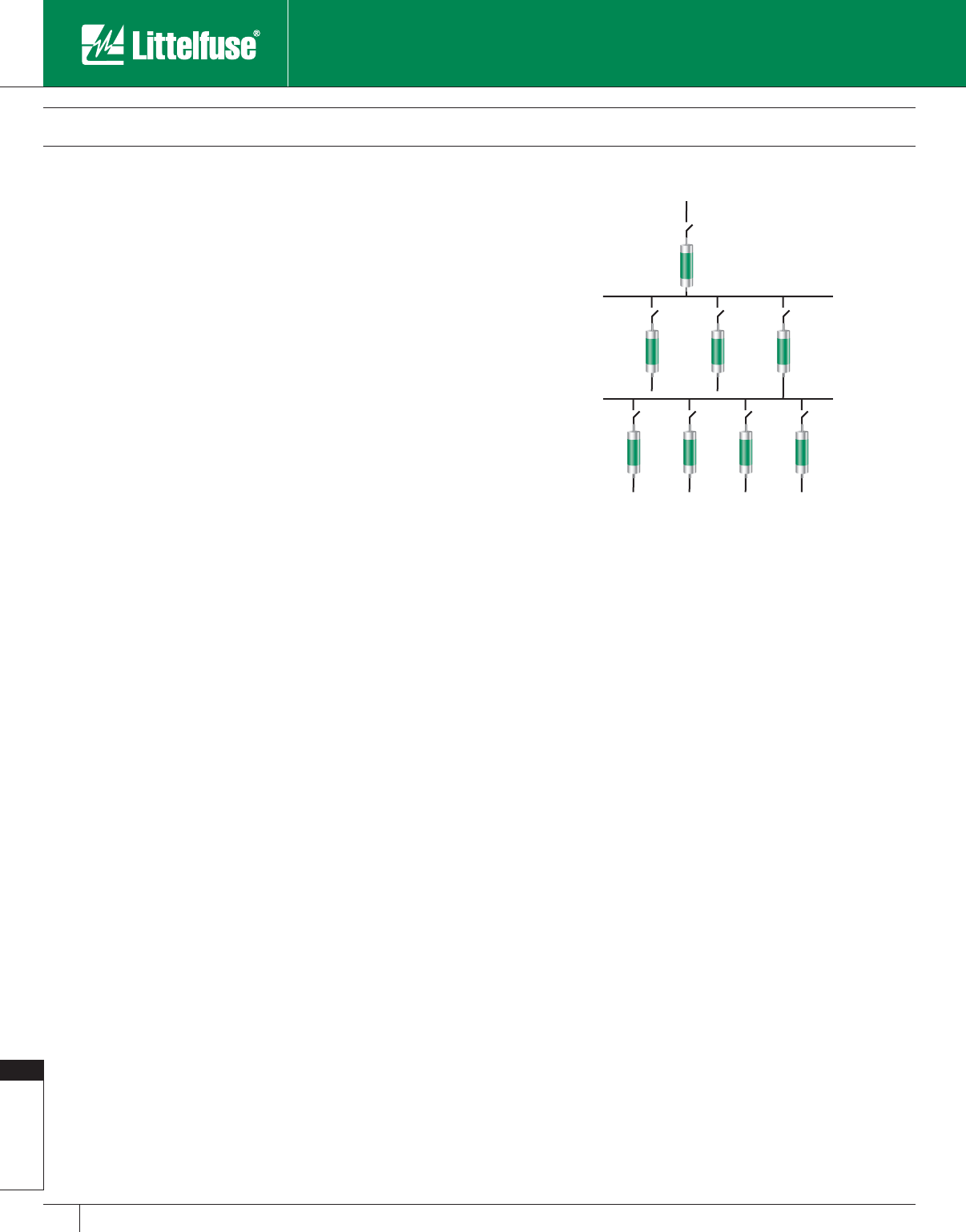
Fuseology
190 www.littelfuse.com
Fuseology
© 2005 Littelfuse • POWR-GARD™ Products Catalog
Coordinated (Selective) Systems
A “coordinated” or “selective” system is a system whose overcurrent
protective devices have been carefully chosen and their time-current
characteristics coordinated. Only the overcurrent device immediately on
the line side of an overcurrent will open for any overload or short-circuit
condition.
See definition of Selective Coordination in Definitions, and refer to
Figure 5 for a graphical example.
When a system is not coordinated, a fault at X might cause Fuse
B to open. This increases the amount of equipment out of service,
and makes it more difficult to locate the problem, thereby increasing
downtime.
Since the advent of electrical and electronic equipment, businesses
have become entirely dependent on the continuous availability of
electric energy. Loss of power halts all production. Customer service is
interrupted; order pro cess ing ceases; yet expenses continue.
Even many UPS systems become unintentionally non-se lec tive, causing
power loss to computers and other critical equipment. Non-selectivity
may defeat otherwise well-en gi neered UPS systems.
In a selective system, none of this occurs. Overloads and faults are
disconnected by the overcurrent protective device immediately on the
line side of the problem. Minimum equip ment is removed from service,
the faulted or overloaded cir cuit is easy to locate, and minimum time is
required to re store full service.
For these and many other reasons, selectivity is the stan dard by which
many systems are judged.
Fuse Selectivity
Refer to Figure 11 which shows typical average melting time curves
for one class of fuses. Note that the curves are roughly parallel, and that
for a given overcurrent the smaller fuse ratings respond quicker than the
larger ratings. The heat energy required to open a fuse is divided into
melting I2t and arcing I2t (see definition of Ampere-Squared-Seconds).
The sum of these is the total clearing I2t.
For a system to be coordinated, the smaller fuse total clear ing I2t
must be less than the larger fuse melting I2t. Put another way, if the
downstream (branch) fuse opens the cir cuit before the overcurrent
affects the upstream (feeder) fuse element, the system will be
selective. This can be determined from curves showing melting and
total clearing I2t, or from minimum melting and maximum clearing time-
current curves.
The simplest method of coordinating low voltage power fus es is by use
of a Coordination Table such as the one shown in Table 2. This table is
only applicable for the Littelfuse POWR-PRO® and POWR-GARD™ fuse
series listed. Tables such as this one great ly reduce design time. For
example, the coordination table shows that POWR-PRO KLPC Class L
fuses co or di nate at a two-to-one ratio with other Class L fuses, and
with POWR-PRO LLNRK/LLSRK/LLSRK_ID series Class RK1 and
POWR-PRO JTD/JTD_ID series Class J fuses.
In the system shown in Figure 16, the 3000 amp Class L main fuses
are at least twice the ratings of the 1500, 1200, and 1000 amp Class L
feeder fuses, therefore they will co or di nate. The Coordination Table also
shows that the LLSRK series time-delay RK1 feeder and branch circuit
fus es coordinate at a two-to-one ratio with the Class L feeder fuses, so
the entire system in Figure 16 would be 100% coordinated.
Circuit Breaker Coordination
Because of the many types of circuit breakers and circuit breaker trip
units, developing a coordinated circuit breaker system or coordinating
circuit breakers with fuses is beyond the scope of this Guide. If you have
questions concerning these subjects contact the Littelfuse Technical
Support Group. For more information on fuses and circuit breakers
request Littelfuse Tech Topics Volume 2 – Fuses Vs. Breakers (PF327).
Component Short-Circuit Protecting Ability
NEC requires equipment protection to be coordinated with overcurrent
protective devices and available fault current to prevent extensive
damage to equipment. See Figure 17. Essentially, this means
that electrical equipment must be capable of withstanding heavy
overcurrents without damage or that they are protected by overcurrent
pro tec tive devices that will limit damage.
When a severe fault occurs in an unprotected circuit, current
immediately increases to a very high value. This is the available or
prospective fault current. Some fuses respond so quickly to the
increasing current that they interrupt current within the first half-cycle;
before the current reaches its first peak. See Figure 13. Such fuses are
termed “current-limiting fuses.” Current-limiting fuses stop damaging
current faster than any other protective device. Current-limiting fuses
greatly reduce or totally prevent component damage from high fault
currents. This helps meet the NEC® Article 110.10 requirements shown
in Figure 17.
Fuse Application Guide
Overcurrent Protection Fundamentals
Figure 16
A Co or di nat ed (selective) Fused System
KLPC
3000
KLPC
1500
KLPC
1200
KLPC
1000
LLSRK
200
LLSRK
200
LLSRK
400
LLSRK
400
Fuseology
191
www.littelfuse.com
Fuseology
© 2005 Littelfuse • POWR-GARD™ Products Catalog
Fuse Application Guide
Overcurrent Protection Fundamentals
Table 2
Fuse Coordination Table
Selecting the Correct Fuse Ampere Ratio to Maintain Selectively Coordinated Sys tems
Ratios are expressed as Line-Side Fuse to Load-Side Fuse
Line-Side Fuses Load-Side Fuses
Ampere
Range UL Class Littelfuse
Catalog No.
Time-Delay Fuses
Ampere Range, UL Class and Catalog No.
Fast-Acting Fuses
Ampere Range, UL Class and Catalog No.
601-6000 601-4000 30-600 30-600 30-600 30-600 30-1200 30-600 1-60
L L RK1 J RK5 RK1 T J G
KLPC
LDC KLLU LLNRK
LLSRK_ID
JTD_ID
JTD
FLNR_ID
FLSR_ID
IDSR
KLNR
KLSR
JLLN
JLLS JLS SLC
601-6000 L KLPC 2:1 2:1 2:1 2:1 4:1 2:1 2:1 2:1 N/A
601-4000 L KLLU 2:1 2:1 2:1 2:1 4:1 2:1 2:1 2:1 N/A
601-2000 L LDC 2:1 2:1 2:1 2:1 4:1 2:1 2:1 2:1 N/A
30-600 RK1 LLNRK N/A N/A 2:1 2:1 8:1 3:1 3:1 3:1 4:1
30-600 RK1 LLSRK_ID N/A N/A 2:1 2:1 8:1 3:1 3:1 3:1 4:1
30-600 J JTD_ID N/A N/A 2:1 2:1 8:1 3:1 3:1 3:1 4:1
30-600 RK5 IDSR N/A N/A 1.5:1 1.5:1 2:1 1.5:1 1.5:1 1.5:1 1.5:1
30-600 RK5 FLNR_ID N/A N/A 1.5:1 1.5:1 2:1 1.5:1 1.5:1 1.5:1 1.5:1
30-600 RK5 FLSR_ID N/A N/A 1.5:1 1.5:1 2:1 1.5:1 1.5:1 1.5:1 1.5:1
30-600 RK1 KLNR N/A N/A 3:1 3:1 8:1 3:1 3:1 3:1 4:1
30-600 RK1 KLSR N/A N/A 3:1 3:1 8:1 3:1 3:1 3:1 4:1
30-1200 T JLLN N/A N/A 3:1 3:1 8:1 3:1 3:1 3:1 4:1
30-1200 T JLLS N/A N/A 3:1 3:1 8:1 3:1 3:1 3:1 4:1
30-600 J JLS N/A N/A 3:1 3:1 8:1 3:1 3:1 3:1 4:1
1-60 G SLC N/A N/A 3:1 3:1 4:1 2:1 2:1 2:1 2:1
Figure 17
National Electrical Code Requires Effective Overcurrent Protection
NATIONAL ELECTRICAL CODE®
ARTICLE 110 – REQUIREMENTS FOR ELECTRICAL IN STAL LA TIONS
A. General
110-3. Examination, Identification, Installation, and Use of Equipment.
(A) Examination. In judging equipment, considerations such as the following shall be evaluated:
(5) Heating effects under normal conditions of use and also under abnormal conditions likely to arise in service.
(6) Arcing effects.
(B) Installation and Use. Listed or labeled equipment shall be used or installed in accordance with any instructions included in the listing or
labeling.
110.9 Interrupting Rating. Equipment intended to interrupt current at fault levels shall have an interrupting rating sufficient for the nominal
circuit voltage and the current that is available at the line terminals of the equipment.
Equipment intended to interrupt current at other than fault levels shall have an interrupting rating at nominal circuit voltage sufficient for the
current that must be interrupted.
110.10 Circuit Impedance and Other Characteristics. The overcurrent protective devices, the total impedance, the component short-
circuit current ratings, and other characteristics of the circuit to be protected shall be selected and coordinated to permit the circuit-protective
devices used to clear a fault to do so without extensive damage to the electrical components of the circuit. This fault shall be assumed to
be either between two or more of the circuit conductors or between any circuit conductor and the grounding conductor or enclosing metal
raceway. Listed products applied in accordance with their listing shall be considered to meet the requirements of this section.
ARTICLE 240 – OVERCURRENT PROTECTION
240.1 Scope. Parts I through VII of this article provide the general requirements for overcurrent protection and overcurrent protective devices
not more than 600 volts, nominal. Part VIII covers overcurrent protection for those portions of supervised industrial installations operating at
voltages of not more than 600 volts, nominal. Part IX covers overcurrent protection over 600 volts, nominal.
(FPN): Overcurrent protection for conductors and equipment is provided to open the circuit if the current reaches a value that will cause an
excessive or dangerous temperature in conductors or con ductor insulation. See also Sections 110.9 for requirements for interrupting ratings and
110.10 for require ments for protection against fault currents.
(Reproduced by permission of NFPA)

Fuseology
192 www.littelfuse.com
Fuseology
© 2005 Littelfuse • POWR-GARD™ Products Catalog
Fuse Application Guide
UL/CSA Fuse Charts
Non-Current Lim it ing
Fuses for overcurrent and short-circuit protection of
power and lighting feeders and/or branch circuits Current Lim it ing
Fuses for Supplementary Overcurrent Protection
Standards: UL Standard 248-14 (formerly 198F); CSA Standard C22.2,
No. 59-1. Three Classifications covered:
Note: Fuses may be rated for AC and/or DC when suitable for such use.
(1) Micro fuses
Voltage ratings: UL, 125 volts; CSA, 0-250 volts
Current ratings: UL, 0-10 amps; CSA, 0-60 amps
Interrupting rating: 50 amps rms symmetrical
(2) Miniature fuses
(CSA classifies these as Supplemental Fuses)
Voltage ratings: UL, 125 or 250 volts; CSA, 0-600 volts
Current ratings: UL, 0-30 amps; CSA, 0-60 amps
Interrupting rating: 10,000 amps rms symmetrical
(3) Miscellaneous Cartridge fuses
(CSA classifies these as Sup ple men tal Fuses)
Voltage ratings: UL, 125 to 600 volts; CSA, 0-600 volts
Current ratings: UL, 0-30 amps; CSA 0-60 amps
Interrupting ratings: 10,000, 50,0000, or 100,000 amps rms sym met ri cal
Time delay (Optional); Minimum delay at 200% fuse rating:
5 seconds for fuses rated 3 amps or less
12 seconds for fuses rated more than 3 amps
LF Series: BLF, BLN, BLS, FLA, FLM, FLQ, KLK, KLKD (600 Volts DC)
NOTE: Littelfuse electronic fuses are also covered by these stan dards; see electronic
section of this catalog, or request Electronic Designer's Guide
(Publication No. EC101) for complete listing.
Special Purpose Fuses
There are no UL Standards covering this category of fuses. These fuses have special
char ac ter is tics designed to protect special types of electrical or electronic equipment
such as diodes, SCR, tran sis tors, thyristers, capacitors, integrally fused circuit break-
ers, parallel cable runs, etc. Fuses may be UL Recognized for use as a component in UL
Listed equipment. UL Recognized fuses are tested for char ac ter is tics such as published
interrupting capacity. They are also covered by UL re-ex am i na tion service.
Non-renewable
Voltage ratings: to 1000 volts AC and/or DC
Ampere ratings: to 6000 amperes
Interrupting ratings: to 200,000 amperes
Dimensions vary widely depending on ap pli ca tion, voltage and current ratings.
Many of these fuses are extremely current limiting. When considering application of
these fuses, or if you have special re quire ments, contact Littelfuse Technical Support
Group for assistance.
LF Series: KLC, LA15QS, LA30QS, LA50QS, LA60QS, LA60X, LA70QS, LA100P,
LA120X, LA070URD, LA130URD, L15S, L25S, L50S, L60S, L70S, JLLS 900 amp through
1200 amp
Plug Fuses
Standards: UL Standard 248-11 (formerly 198F),
CSA Standard C22.2, No. 59.1
Voltage ratings: 125 volts AC only
Current ratings: 0-30 amps
Interrupting ratings: 10,000 amps rms symmetrical. In ter rupt ing rating need not
be marked on fuse.
Two types: Edison-base and Type S
Edison-base: Base is same as standard light bulb. All amp ratings interchangeable.
NEC permits Edison-base plug fuses to be used only as replacements for existing
fuses, and only when there is no evidence of tampering or overfusing.
Type S: Not interchangeable with Edison-base fuses unless non-removable type S
fuse adapter is installed in Edison-base fuse socket.
To prevent overfusing, adapters have three ampere ratings: 10-15, 16-20,
and 21-30 amps.
Time delay: Fuses may be time delay, if so, they are required to hold 200% of rating for
12 seconds minimum.
Time delay plug fuses are marked T, TD, o r Time Delay
NOTE: Plug fuses may be used where there is not more than 125 volts between conduc-
tors or more than 150 volts from any conductor to ground. This permits their use in
120/240 volts grounded, single-phase circuits.
LF Series: Edison-base: TOO, TLO
Type S: SOO, SLO
Type S Adapters: SAO
CLASS H
Standards: UL Standard 248-6 (formerly 198B),
CSA Standard C22.2, No. 59.1
Also known as NEMA Class H, and sometimes referred to as “NEC” or “Code” fuses
Voltage ratings: 250 and 600 volts, AC
Current ratings: 0-600 amps
Interrupting ratings: 10,000 amps rms symmetrical
Two types: one-time and renewable
Physically interchangeable with UL Classes K1 & K5;
Fits UL Class H fuseholders which will also accept K1, K5, RK5, and RK1 fuses.
Manufacturers are upgrading Class H One-time fuses to Class K5 per UL Standard 198D,
See Class K fuses.
ONE-TIME FUSES
(NON-RE NEW ABLE)
Time delay: Optional
Time-delay fuses must hold 500%
current rating for a minimum of ten
seconds
LF Series: NLKP
RENEWABLE FUSES
Only Class H fuses may be renewable.
While time delay is optional, no
renewable fuses meet re quire -ments
for time delay.
Some renewable fuses have a
moderate amount of time delay,
referred to as “time lag” to
differentiate from true time delay.
LF Series: RLN, RLS
Replaceable links Series: LKN, LKS

Fuseology
193
www.littelfuse.com
Fuseology
© 2005 Littelfuse • POWR-GARD™ Products Catalog
Fuse Application Guide
UL/CSA Fuse Charts
CLASS T
Standards: UL Standard 248-15 (formerly 198H),
CSA Standard C22.2, No. 106, classified as HRCI-T
Voltage ratings: 300 and 600 volts AC, 125 and 300 volts DC
Current ratings: 0-1200 amps
900 to 1200 amps UL Rec og nized for 600V version
Interrupting rating: 200,000 amps rms symmetrical
Non-renewable
Fast-Acting fuses. High degree of current limitation
Very small fuses; space-saving and non-interchangeable with any other fuse class.
LF Series: JLLN/JLLS
CLASS CC/CD
Standards: UL Standard 248-4 (formerly 198C),
CSA Standard C22.2, No. 106, classified as HRCI Misc.
Voltage rating: 600 volts, AC
Current ratings: UL Class CC; 0-30 amps
UL Class CD: 35-60 amps
Interrupting ratings: 200,000 amps rms symmetrical
Non-renewable
Fuseholders: Fit UL Class CC and CD fuseholders which reject non Class CC fuses.
Time delay optional: Minimum of 12 seconds at 200% current rating.
LF Series: KLKR (Fast-Acting)
KLDR (Time-Delay for Transformers)
CCMR (Time-Delay for Motors)
CLASS K
Standards: UL Standard 248-9 (formerly
198D), No CSA Standard
Voltage ratings: 250 and 600 volts, AC
Current ratings: 0-600 amps
Interrupting ratings: Three permitted:
50,000, 100,000, and 200,000 amps rms sym
Non-renewable
Time delay is optional for Class K fuses.
Fuses marked “Time Delay”, “D” or “TD” are
required to hold 500% current rating for a
minimum of ten seconds.
Same Dimensions and Physically
Interchangeable with UL Class H fuses
Fits UL Class H fuseholders
Class K fuses are not permitted to be labeled
Current Limiting because there is no rejection
feature as required by NEC Article 240-60 (B).
CLASS K1
Same prescribed degree of
current limitation as RK1 fuses
when tested at 50,000 or
100,000 amps rms symmetrical.
LF Series:
Time Delay – Use LLNRK/LLSRK
Fast-Acting – Use KLNR/KLSR
CLASS K5
Same prescribed degree of
current limitation as RK5 fuses
when tested at 50,000 or
100,000 amps rms sym met ri cal.
LF Series: NLN/NLS
CLASS RK5
Moderate degree of current limitation, adequate for most applications.
Time Delay optional
FLNR_ID, FLSR_ID and IDSR series provides visual indication of blown fuse.
LF Series: FLNR_ID, FLSR_ID and IDSR
CLASS RK1
High degree of current limitation.
Provides IEC Type 2 (no damage) protection for motor starters and control components
Time Delay optional LLSRK_ID Series provides visual indication of blown fuse
LF Series: Time Delay: LLNRK, LLSRK, LLSRK_ID
Fast-Acting: KLNR, KLSR
CURRENT LIMITING FUSE LABELING
Fuses which meet the requirements for current limiting fuses are required to be labeled
“Cur rent Limiting”. Fuse labels must include: UL/CSA fuse class, Manufacturer's name or
trademark, Current Rating, AC and/or DC voltage rating, and AC and/or DC interrupting
rating. The words “Time Delay” or equivalent may also be included on the label when
the fuse complies with time delay requirements of its class.
CLASS G
Standards: UL Standard 248-5 (formerly 198C),
CSA Standard C22.2, No. 106, classified as HRC1 Misc.
Voltage rating: 480 volts, AC
Current ratings: 0-60 amps
Interrupting rating: 100,000 amps rms symmetrical
Not interchangeable with any other UL fuse class.
Time delay optional: Minimum of 12 seconds at 200% current rating.
LF Series: SLC
CLASS J
Standards: UL Standard 248-8 (formerly 198C),
CSA Standard C22.2, No. 106, classified as HRCI-J
Voltage rating: 600 volts, AC
Current ratings: 0-600 amps
Interrupting rating: 200,000 amps rms symmetrical
Not interchangeable with any other UL fuse class
Time delay optional: Minimum of 10 seconds at 500% current rating.
LF Series: Time-Delay: JTD_ID, JTD
Fast-Acting: JLS
CLASS L
Standards: UL Standard 248-10 (formerly 198C),
CSA Standard C22.2, No. 106, classified as HRCI-L
Voltage rating: 600 volts, AC and/or DC
Current ratings: 601-6000 amps
KLPC also available 200-600A; LDC also available 150-600A
Interrupting rating: AC: 200,000 amps rms symmetrical
DC: 50,000, 100,000, or 200,000 amps
Not interchangeable with any other UL fuse class
Time delay: Class L fuses may be marked “Time-Delay” although UL does not investigate
time-delay characteristics of Class L fuses.
KLPC & KLLU: 10 seconds at 500% current rating.
LDC: 4 seconds at 500% current rating
LF Series: KLPC, KLLU, LDC
CLASS R
Standards: UL Standard 248-12 (formerly 198E),
CSA Standard C22.2, No. 106, classified as HRCI-R
Voltage ratings: 250 and 600 volts, AC; 125 and 300 volts DC
Current ratings: 0-600 amps
Interrupting rating: 200,000 amps rms symmetrical
Two classes: RK1 & RK5
Non-renewable
Time delay is optional for Class R fuses.
Fuses marked “Time Delay”, “D”, “TD”, or similar indications of time delay are required
to hold 500% current rating for a minimum of ten seconds.
Same Dimensions as UL Class H fuses, terminals modified to provide rejection feature.
Fits UL Class R fuseholders which reject non Class R fuses.
Physically interchangeable with UL Class H, NEMA Class H, and UL Classes K1 & K5
when equipment has Class H fuseholders.

Fuseology
194 www.littelfuse.com
Fuseology
© 2005 Littelfuse • POWR-GARD™ Products Catalog
Fuse Application Guide
Applying Fuses for Specific Applications
Fuses for Specific Applications (600 volts and Below)
IN DEX Page
Protecting Service Entrance and Feeder Conductors ..... 194
Motor Protection ........................................................................ 194-198
Motor Overload Protection (running overcurrent) ............... 195-196
Motor Feeder (100% motor Load) over 600A. ................... 197
Motor Branch Circuit Protection over 600A. ....................... 197
Motor Controller (Starter) Protection over 600A. ............... 197
Control Circuit Protection ...................................................... 197
Control Transformer Protection ............................................ 197-198
Protecting Branch Circuits ....................................................... 198
Transformer Protection ............................................................. 198
Primary Fusing only ............................................................... 198
Primary Fusing With Secondary Fusing .............................. 198
Secondary Fusing of Transformers ...................................... 198
Fusing Capacitors ....................................................................... 198
Lighting Fixture Protection ...................................................... 198
Street Lighting and Other Weatherproof
........ Overcurrent Protection ................................................. 198
Cable Short-Circuit Protection (Cable Limiter Application) .199
Semiconductor and Solid-state Device Protection .......... 199
Medium Voltage Protection ..................................................200-203
Protecting Service Entrance and Feeder Conductors
601 through 6000 amperes
Select POWR-PRO® KLPC series Class L fuses for AC circuits from 601
through 6000 amperes. The construction and operating characteristics
of KLPC series fuses meet the toughest project specifications for Class
L fuses:
• They provide maximum time-delay and current-limitation.
• They have a 300,000 amp interrupting rating.
• They have an “O-ring” seal to improve short-circuit performance.
• The fuse links are 99% pure silver.
If the system has DC circuits, another choice is the POWR-PRO LDC
series Class L fuses for AC and DC circuits available from 601 through
2000 amperes. LDC series fuses are the only Class L fuses which are
UL Listed at both 600 Volts AC and DC. When facilities have a mix of
large AC and DC circuits, standardizing on LDC series for all Class L
fuses should be considered. This reduces inventory and elim i nates the
possibility that an AC-only fuse will be used in a DC circuit.
When conductors are selected in accordance with the NEC®,
recommended fuse ratings for mains and feeders with combined motor
and non-motor loads are:
• 150% of the largest motor full load current plus,
• 100% of all other motors full load currents plus,
• 125% of the continuous1 non-motor load plus,
• 100% of non-continuous, non-motor load.
If the largest motor has a long acceleration time requiring branch circuit
protection to be increased to 175-225% of FLA, it may be necessary
to increase main and feeder fuse ratings to 175-225% of the largest
motor FLA plus the other current values as indicated above. However,
if conductor ampacity has been increased to provide spare capacity
for future loads, fuse ratings may be increased to the ampacity of the
conductors.
When standard fuse ratings do not match conductor ampacities, the
next larger standard fuse ratings may be used only if they are rated
less than 800 amperes. If fuse ratings are over 800 amperes, the next
smaller ratings must be used. In addition to all standard ampere ratings,
KLPC and LDC series fuses have many additional ampere ratings. The
additional ratings permit minimum downsizing of fuses, saving valuable
conductor ampacity.
Main Services and Feeders 600 amps and less
Several fuse series may be used for main services and feeders under
600 amperes. Choices should be made on the needs of the particular
facility. Some of the needs to be considered are discussed below, with
recommendations for fuses that meet those needs.
The vast majority of electrical systems, especially those 600 amps and
smaller, have available short-circuit currents less than 100,000 amperes.
Class RK5 fuses have provided excellent protection for such circuits
for many years. When fault currents exceed 100,000 amperes at the
service entrance, a study should be made to determine if the additional
current limitation provided by Class RK1 or Class J fuses is required.
POWR-PRO Class RK5, 600 Volt FLSR_ID series Indicator® fuses
provide superior time-delay plus substantially better current limitation
than required by UL Class RK5 standards. In addition, the patented
indicating window on the fuse immediately shows which fuses are
blown. This can significantly reduce downtime.
POWR-PRO Class RK1, 250/600 Volt LLNRK/LLSRK/LLSRK_ID series
time-delay fuses are the fuse of choice for circuits where fault currents
exceed 100,000 amperes. The LLSRK advanced design reduces short-
circuit damage to full-size NEMA and sensitive IEC motor controllers, and
is capable of providing Type 2 “No Damage” protection to NEMA size
motor starters. Together with the KLPC series fuses, the LLNRK/ LLSRK
series form the foundation of the POWR-PRO Fuse system of overcurrent
protection. And, the patented indicating window on the LLSRK_ID series
provides the same benefits of blown fuse indication for the user.
POWR-PRO Class J 600 Volt JTD_ID series time-delay fuses provide
the amount of time-delay necessary for most applications and are
substantially smaller than RK5 or RK1 fuses with current-limitation equal
to the RK1 fuse. JTD_ID series fuses provide IEC Type 2 “No Damage”
protection to both NEMA and IEC control components and motor
controllers. When time-delay is required and space is the determining
factor, JTD_ID time-delay Class J fuses provide the answer.
1 See Definitions for “Continuous Load.”

Fuseology
195
www.littelfuse.com
Fuseology
© 2005 Littelfuse • POWR-GARD™ Products Catalog
Fuse Application Guide
Applying Fuses for Specific Applications
When conductors are selected in accordance with the NEC®,
recommended fuse ratings for mains and feeders rated 1 to 600A with
combined motor and non-motor loads are:
• 150% of the largest motor full load current plus,
• 100% of all other motors full load currents plus,
• 125% of the continuous1 non-motor load plus,
• 100% of non-continuous, non-motor load.
Motor Protection
The importance of effective motor and motor circuit protection cannot
be over emphasized. Motors are consistently the largest single cause of
in dus tri al and commercial fires.
In today’s highly automated commercial and industrial facilities, the
failure of even one relatively minor motor may shut down an entire
installation.
Motor Characteristics
Motors discussed herein are standard characteristic AC induction
motors, which cover about 80-85% of all motors. Special purpose
motors are beyond the scope of this publication. Specific application
information and protection requirements for these special purpose
motors should be obtained from the motor manufacturers.
Horsepower Ratings
A motor’s assigned horsepower rating indicates the work that it can
do under standard test conditions. It is the maximum horsepower load
the motor can drive over a long period without exceeding its rated
temperature rise. However, a motor can develop far more horsepower
than its rating, and if the overload does not last long enough to overheat
the motor, no damage occurs.
A motor tries to rotate any load attached to it. If the load is too large,
the motor will not be able to rotate and will overheat and fail within a
very short period. However, if the motor is able to start and run with
an overload, excess heat will be generated. If the motor is not stopped
or the overload removed, the excess heat will gradually de te ri o rate the
insulation, and the motor will prematurely fail.
Motor RPM
The motor nameplate shows the rated speed of the motor in revolutions
per minute (RPM) with rated full load attached. The no-load speed of
the motor is somewhat higher. The no-load (synchronous) speed of a
motor is a function of its design and the number of poles (windings).
Table 3 shows the relationship between the number of poles, no-load
speed, and full load speed shown on the motor nameplate.
All non-synchronous induction motors begin to slow down as the load
increases. This is commonly referred to as “slip.” As load increases, the
motor current and slip increase.
Motor Running Current
Full Load Amperes (FLA or F.L.A.): A motor’s rated full load amps
(full load current) is the motor’s running current when connected to a
load equal to its horsepower rating. If load exceeds the horsepower
rating, current will exceed the FLA and the motor may overheat. The
vast majority of motors are only partially loaded. As load decreases,
motor current decreases.
Partially Loaded Motors: If a motor is not connected to any external
load, it still requires a certain amount of current to turn the rotor. This
is defined as the “no-load amps” or “no-load current.” No-load current
is a constant for any given motor and does not change with load.
However, no-load current varies widely for different motor designs and
horsepower ratings.
A motor’s actual running current is the sum of no-load current and load
current. For all practical purposes, load current increases directly as the
load increases. If a motor is loaded to only 50% of rated horsepower,
then the actual load current will be approximately 50% of the full
potential load current.
If a given motor’s no-load current is 30% of FLA, load current is 70%
FLA (100% - 30% = 70%). At 50% rated load, the load current would
be about 35% FLA (one-half of 70%). Added to no-load current of 30%,
motor running current at 50% load will be about 65% FLA (30 + 35 =
65%). If the same motor were 75% loaded, the motor running current
would be about 83% FLA (0.70 X 0.75 + 0.30 = 0.83).
Motor starting currents: When a motor is first energized, a great
deal of energy (torque) is required to overcome the inertia of the motor
and the load. Once the load is moving, it requires much less energy to
keep it moving.
At the instant a motor is energized, motor current peaks at about 12-
15 times the nameplate FLA. This is the current required to magnetize
the motor windings. Within 1/2 to 3/4 cycles (0.008-0.0125 seconds)
the full magnetic field is developed, and current decreases from 12 to
15 times FLA to roughly 4.5 to 8 times FLA. This is called the motor
starting current, and is also the current the motor will draw if it stops
while energized. This is why it is also referred to as the locked-rotor
amps (LRA).
The exact value of LRA is determined by motor design, and is shown
on the motor nameplate by the NEMA design letter. Motors designed
to start only low inertia loads have the lowest starting current. Motors
with the same horse pow er ratings but designed to start very high
inertia loads such as large flywheels, hammer mills, etc., will have much
higher starting currents. Table 4 shows the starting current for various
designs.
As the motor speed increases from zero, current remains high until
the motor reaches about 85-90% full speed. Current then begins to
decrease, and when the motor reaches full speed for the attached load,
current decreases to normal running current.
Table 3
Synchronous (No Load) Speed of Induction Motors vs Full Load Speed
Number of Poles Synchronous (No Load)
Speed (RPM)
Typical Full Load
Speed Range (RPM)
2 3600 3450 – 3500
4 1800 1710 – 1760
8900855 – 880
12 600 520 – 610
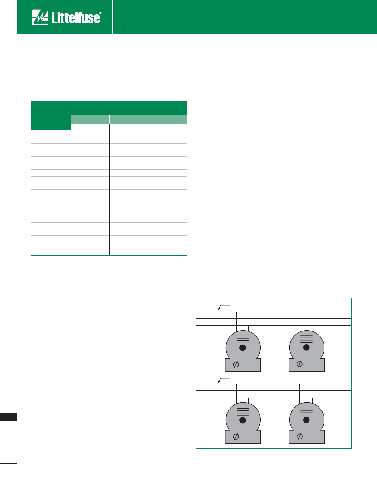
Fuseology
196 www.littelfuse.com
Fuseology
© 2005 Littelfuse • POWR-GARD™ Products Catalog
Single-phasing of three-phase motors
Three phase motors are designed to operate with three balanced
phases. When one phase is missing, severe damage may occur if
the motor is not rapidly de-energized. This may be due to an open
wire in a motor junction box, an open motor winding, a blown fuse, a
burned contact in a motor controller, a defective circuit breaker, or other
conditions. What happens when single-phasing occurs depends on
the nature of the circuit. There are several possibilities which must be
examined to fully understand the problem:
When there is only one motor on a circuit which is single-
phased
If the motor is not running at the time, and then tries to start while
single-phased, it will not have sufficient avail able energy to overcome
starting inertia, and will stay in a locked rotor condition. The motor will
draw full locked rotor current, and most overcurrent protection devices
will open the circuit quick enough to prevent serious motor damage.
If the motor is running at the time it is single-phased, current in the
remaining legs theoretically increases to 1.73 times the current being
drawn when the single-phasing occurs. Single-phased motors, however,
do not have the capability of developing full horsepower and torque, so
the motors may begin to slow down (increased slip) depending on the
amount of load. The motor is designed to operate at full speed, so the
current increases as the slip increases.
A motor that is more than 80% fully loaded at the time of single-phasing
will slow down quite rapidly and stop. Current increases to locked rotor
values, and the running overcurrent protection will de-energize the
circuit in sufficient time to protect the motor from significant damage.
A motor that is loaded to less than 50-60% load will not slow down
significantly while the current increases to 173% of the current being
drawn just prior to single-phasing. Since this is less than FLA, ordinary
running overcurrent protection will not sense this as an abnormal
condition and the motor will continue to run. When it stops, it will
obviously not restart again until the source of the single-phasing is
eliminated. Fortunately, the extra heat gen er at ed under these single-
phase conditions can usually be dissipated by the motor. Little damage
is done, unless the single-phasing continues for an extended period of
time. For added protection to large, expensive motors, (es pe cial ly those
over 600 volts), consideration should be given to installation of single-
phase detection or voltage im bal ance relays.
It is the group of motors loaded from 55-60% through 80% that
present the greatest challenge. When these motors are single-phased,
they slow down but continue to rotate. Current in the energized legs
increases to approximately 200-220% of current being drawn at the
time the motor was single-phased. This is a combination of the increase
due to single-phasing (173%) plus that due to slow down (slip increase).
Since this may vary from slightly less than FLA, up to as much as 200%
FLA, standard overcurrent protection may not provide adequate protection
when sized in accordance with rated full load amps of the motor.
The voltage imbalance in the circuit may also result in extra heat. This
additional heat produces damage in excess of that produced by current
alone.
The best way of reducing this type of damage is to measure the actual
current drawn by the motor under normal conditions, determine if
there may be temporary overloads that need to be considered, and
size overcurrent protection just large enough to permit the motor to run
under normal conditions.
Fuse Application Guide
Applying Fuses for Specific Applications
Table 4
Starting Current (Amperes) for Various Types of Motor Designs
NEMA
Code
Letter
Locked
Rotor
KVA Per
Hrspwr.
Maximum Locked Rotor Amps
for NEMA Code Letter Motors
Single Phase Three Phase
115V 230V 200V 230V 460V 575V
A 3.14 27.3 13.7 9.1 7.9 4.0 3.1
B 3.54 30.8 15.4 10.2 8.9 4.5 3.5
C 3.99 34.7 17.4 11.5 10.0 5.0 4.0
D 4.49 39.1 19.5 13.0 11.3 5.7 4.5
E4.9943.421.714.412.56.35.0
F 5.59 48.6 24.3 16.2 14.0 7.0 5.6
G6.2954.727.418.215.87.96.3
H 7.09 61.7 30.8 20.5 17.8 8.9 7.1
J 7.99 69.5 34.8 23.1 20.1 10.1 8.0
K 8.99 78.2 39.1 26.0 22.6 11.3 9.0
L 9.99 86.9 43.5 28.9 25.1 12.6 10.0
M 11.19 97.4 48.7 32.3 28.1 14.1 11.2
N 12.49 108.7 54.3 36.1 31.3 15.7 12.5
P 13.99 121.7 60.9 40.4 35.1 17.6 14.0
R 15.99 139.1 69.6 46.2 40.1 20.1 16.0
S 17.99 156.5 78.3 52.0 45.2 22.7 18.0
T 19.99 173.9 87.0 57.8 50.2 25.2 20.0
U 22.39 194.8 97.4 64.7 56.2 28.2 22.4
V 24.00 208.8 104.4 69.4 60.2 30.2 24.0
Figure 18
3 motor 1 motor
3 motor 3 motor
Open circuit
Open circuit
10 HP 1 HP

Fuseology
197
www.littelfuse.com
Fuseology
© 2005 Littelfuse • POWR-GARD™ Products Catalog
Fuse Application Guide
Applying Fuses for Specific Applications
Several motors single-phased on one circuit
When there is more than one motor on a circuit that is single-phased,
the effects on motor current depend on the relative size of the motors,
and whether they are all three-phase, or whether there is a mix of three-
phase and single-phase motors.
Figure 18 presents two such cases. In the circuit with a three-phase
and a single-phase motor, the three-phase motor was loaded to 70% of
full load. The feeder was then single-phased as shown. The currents in
the three-phase motor increased to 52%, 120%, and 36% of full load
current in the three phases. At 120% current, it is ques tion able whether
standard running overcurrent protection sized at 115% of rated FLA could
provide protection from damage due to overload and voltage imbalance.
When the circuit with the ten horsepower and one horse pow er three-
phase motors was single-phased, the smaller motor did little to affect
the currents in the larger motor, but the one horsepower motor was
in serious trouble. One of the currents was 140% of normal, while
the other two currents were only slightly above the standard rating of
running overcurrent protection.
When the ampere rating of a motor’s running overcurrent protection
is based on the motor’s actual running current, adequate protection
may be provided for such conditions. However, as is usually the case,
if the ampere rating of a motor’s running overcurrent protection is
based on nameplate FLA and the motor is only partially loaded, the
protective devices (overload relays and fuses) may not open in time
to protect the motor because the current will not increase enough to
operate the relays.
For these reasons, and many others, it is strongly rec om mend ed that
Littelfuse POWR-GARD™ dual-element fuses be properly sized per the
recommended guidelines.
Protection required by motors
Since mains and feeders usually serve a mix of inductive and resistive
loads, time-delay fuses provide significant advantages. Even when there
is no motor load, time-delay fuses reduce other nuisance outages caused
by temporary overloads or switching surges. Available short-circuit current
is generally highest at the main service disconnect so that adequate
interrupting capacity and maximum current limitation are also desirable.
Motor Branch Circuits
Most motor circuits contain motor controllers (starters) which start and
stop the motor, overload relays to provide motor running protection, and
in some cases other relays to provide other types of protection.
Time-delay fuses should be considered a must for motor branch circuits.
Motor starting currents and the possibility of temporary overloads
and/or voltage surges would require oversizing of non-time delay fuses
— often as much as 300%. In such cases, only short-circuit protection
is provided, and because of the oversizing necessary, larger switches
and enclosures are required. This is true of MCCs as well. Properly
selected, time-delay fuses also provide back-up protection to the motor
controllers for such conditions as single-phasing and contact welding.
Recommended ratings of RK1 and RK5 time-delay fuses for motor branch
circuits containing motor controllers with overload relays are as follows:
For general purpose motors with 1.15 service factor or 40° C rise, the
fuses may generally be rated at 125% of motor’s FLA. When fuse
ratings do not match the motor’s FLA, use the next larger standard
fuse rating, but do not exceed the NEC® limitation of 175% of motor’s
FLA as given in NEC Tables 430.248 through 430.250. Following these
guidelines will provide optimum pro tec tion to the circuit.
High efficiency motors and NEMA Design E motors have much higher
efficiencies, and also require higher locked rotor currents in relation
to FLA. They will require careful selection of both fuses and overload
relays. In these circuits, we recommend sizing fuses at 150% of FLA, or
the next smaller rating.
These recommendations will cover about 90% of all motor applications.
For those motors with especially severe starting duty and long
acceleration times, Table 430.52 of the NEC permits time-delay fuses to
be sized up to 175% of motor FLA.
If 175% of FLA will not permit the motor to start, fuse rating may be
increased to a maximum of 225% of motor FLA.
Pages 204 – 206 contain Motor Protection Tables that simplify the
selection of Littelfuse RK5, RK1, J and CC fuses for motor running
protection and motor branch short-circuit and ground fault protection.
Motor Feeders Over 600A With 100% Motor Load
Recommended fuses are POWR-PRO® KLPC series.
Recommended fuse ratings when conductors are selected in
accordance with the NEC are 150% of largest motor’s full load current
plus the full load current of the other motors. If required rating does not
correspond with a KLPC ampere rating, use the next larger rating.
Fuses for Mains and Feeders With No Motor Loads
Minimum fuse rating is 125% of the continuous load plus 100% of the
non-continuous load.
Fusing Motor Control Centers (MCCs)
The same general considerations apply to protecting MCCs as they do
to mains and feeders. Use time-delay current-limiting fuses as described
above to provide protection to the entire MCC including buses and
internal construction.
Feeders serving MCC are sized the same as general-purpose mains
and feeders since many MCC have both motor and non-motor loads.
Non-motor loads may include fused switches that serve dry-type
power transformers used for lighting panels or feeders to distribution
panels. MCC ampere ratings based on the MCC main buses usually
exceed the load connected to the MCC. Therefore, fuses feeding
the MCC or located in a main switch in the MCC may be rated to
protect the MCC buses, as long as they meet the minimum size as
determined above.
Fusing Control Transformers
With one exception, control transformers are protected the same as
regular transformers as discussed below. Control transformers with
primary current less than 2 amperes and which are part of a Listed
motor controller may have primary fusing not greater than 500% of
rated primary current.
Fuseology
198 www.littelfuse.com
Fuseology
© 2005 Littelfuse • POWR-GARD™ Products Catalog
Protecting Branch Circuits
Multi-outlet branch circuits must be protected in accordance with the
ampere rating of the overcurrent protective device. Ratings shall be 15,
20, 30, 40, and 50 amperes, although non-lighting loads in industrial
facilities with adequate main te nance may have branch circuits larger than
50 amperes.
Special purpose branch circuits must have adequate capacity for the
load to be served. Refer to NEC® Article 210.2 for a listing of Articles and
Sections covering requirements for specific equipment not covered in this
section.
Transformer Protection
Transformers over 600 volts
The basic rule for trans form ers rated over 600 volts requires them to
have primary and secondary pro tec tion in accordance with Table 5.
Transformers rated 600 volts and less
UL Industrial Control Standards (No. 508) and Motor Control Center
Standards (No. 845) specify control power transformer protection
corresponding to NEC 430.72(C). In addition, UL requires the primary
of control power trans form ers used in controllers having short-circuit
ratings in excess of 10,000 amperes to be protected by UL Class CC,
J, R, or T fuses. For maximum fuse ratings permitted by the NEC,
refer to Table 6 for sizing of primary fusing and Table 7 for sizing of
secondary fusing.
Fusing Capacitors
Capacitors installed on the load side of motor running overcurrent
protection are required to have individual protection. All other capacitors
are required to have an individual fuse in each ungrounded conductor.
NEC Article 460.8(B) requires that the fuse rating be as small as
possible. Use POWR-PRO® dual-element time-delay fuses rated at
150% to 175% of capacitor rated current.
Lighting Fixture Ballasts
Ballasts for all types of discharge lighting should be protected with
individual fuses. Even the newer electronic ballasts with internal fusing
benefit from fusing of the fixture. Individual fusing helps prevent loss of
an entire lighting circuit when one ballast or fixture fails. This prevents
loss of production. When only one fixture is removed from service, the
user can now identify the fixture in trouble and eliminate the need to
test all the fixtures to locate the problem. UL Listed Class P ballasts
are only tested at 200 amps fault current, and the test circuit has a fuse
ahead of the ballast. With available currents continuing to increase,
individual fixture fusing reduces the possibility of the ballast failing
in such a way that the fixture is damaged. Since ballast designs and
characteristics vary so much, recommendations for ballast fusing should
be obtained directly from the ballast manufacturer.
Fusing of Outdoor Lighting Standards
Whether the lighting fixtures are being used for highway lighting,
street lighting, or for parking lots, each fixture should be fused using a
Littelfuse Class CC or midget fuse installed in a LEB or LEC weather
proof fuseholder. These fuseholders were designed to fit in the base
of lighting standards. They withstand wet and corrosive con di tions,
including those caused by snow-melting chemicals. Fusing each fixture
eliminates having to test the entire circuit for the faulted fixture when
only one fails. In industrial plants where outdoor lighting provides safety
and security, this is particularly important.
Fuse Application Guide
Applying Fuses for Specific Applications
Table 5
Fuses for Transformers over 600 volts
Transformer
Rated
Impedance
Maximum Fuse Rating in Percent
of Transformer Rated Current
Primary
Fuse Rating
Over 600
Volts
Secondary Fuse Rating
Over
600 volts in
all locations
600 volts
or less in
unsupervised
locations
600 volts
or less in
supervised
locations
Not more than
6% 300% 250% 125% 250%
More than 6%
and not more
than 10%
300% 225% 125% 250%
Notes to Table 5
1. Littelfuse IDSR, LLNRK/LLSRK/LLSRK_ID, FLNR_ID/FLSR_ID, and JTD_ID series
time-delay fuses may be rated at 125% of transformer secondary current.
2. Where the required fuse rating does not cor re spond to a standard fuse rating, the
next higher standard rating is permitted.
3. An individual primary fuse is not required if the primary circuit fuse is not greater
than 300% of transformer primary current.
Table 6
Maximum Acceptable Rating of Primary Overcurrent Device
Rated Primary
Current Amperes
Maximum Rating of Overcurrent Protective Device
% of Transformer Primary Current Rating
No secondary
fusing provided
Secondary fusing provided in
accordance with Table 7
Less than 2 30012501
2 to less than 9 167 250
9 or more 1252250
Table 7
Maximum Acceptable Rating of Secondary Overcurrent Device
Rated Secondary
Current Amperes
Maximum Rating of Overcurrent Protective Device
% of Transformer Secondary Current Rating
less than 9 167
9 or more 1252
Notes to Tables 6 & 7
1. 500% for Motor Circuit Control Power Transformers.
2. If 125% does not correspond to a standard fuse rating, the next higher standard
rating may be used.
Reference NEC 430.72 (c) Exception No. 2: 450.3 (b) 1 and 2 UL 508 32.7: 845 11.16
and 11.17.
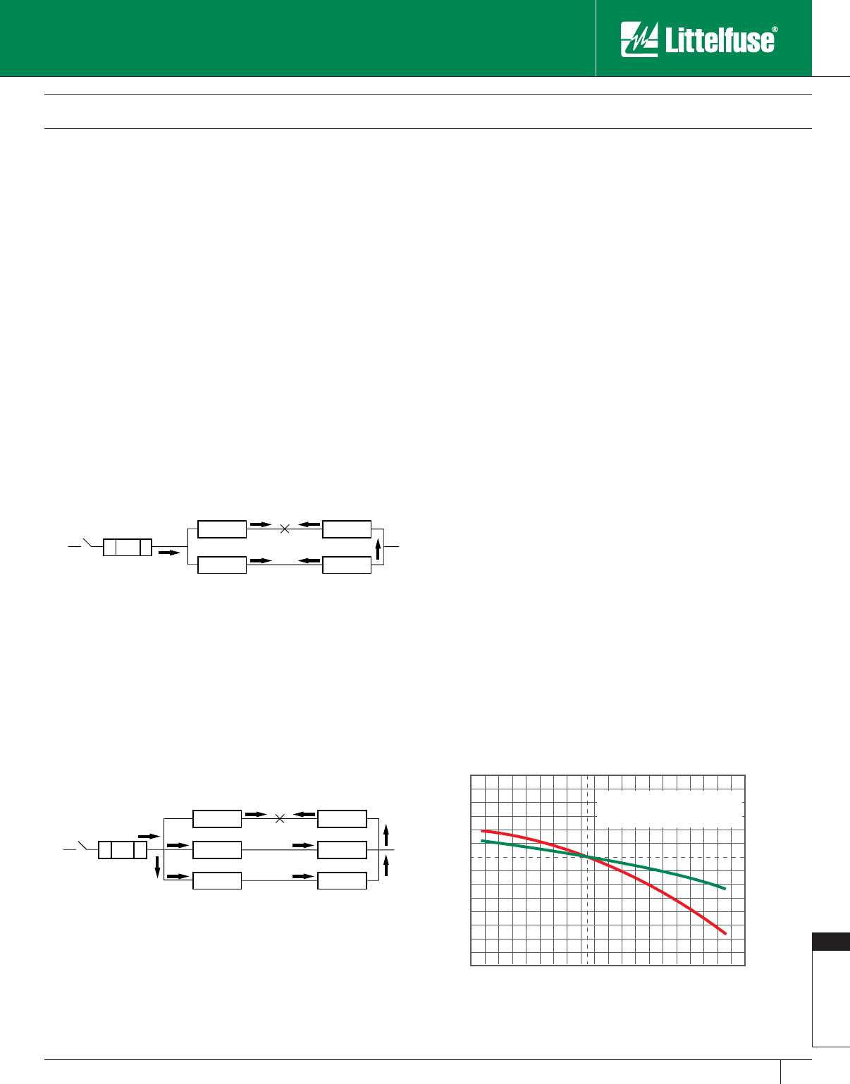
Fuseology
199
www.littelfuse.com
Fuseology
© 2005 Littelfuse • POWR-GARD™ Products Catalog
Fuse Application Guide
Applying Fuses for Specific Applications
Cable Short-Circuit Protection
(application of cable limiters)
Cable limiters are fusible devices that provide very fast short-circuit
protection, primarily to faulted cables, but also to other conductors such as
busway. Cable limiters do not have an ampere rating, and cannot be used
to provide overload protection. Cable limiters are selected by cable size; for
example, a 500 kcmil cable requires a 500 kcmil cable limiter. Their main
use is to isolate faulted cables in circuits containing three or more parallel
con duc tors per phase and may be installed on the line side of the main
service to provide short-circuit protection to the service conductors. This is
especially important when service conductors are tapped from large low
voltage networks or from large low impedance transformers.
The principle involved is illustrated in Figures 19 and 20. The first
example has two cables per phase, as shown in Figure 19. When a
fault occurs in either cable as illustrated by the “X”, most of the fault
current will flow directly to the fault through limiter L-1. L-1 will open, and
all the fault current will back feed the fault via limiters L-3, L-4, and L-2.
Since all of the limiters have the same rating, they will all open resulting
in the entire circuit being shut down.
However, when a fault occurs and there are three or more cables per
phase, this problem can be avoided. This scenario is illustrated in Figure
20. When a fault occurs at point “X”, current will flow directly to the
fault opening limiter L-1. The fault current will back feed the fault, but
when there are three or more conductors in parallel, it divides between
the re main ing cables. When there are three conductors in parallel as
shown in Figure 20, one half of the fault current will flow through
limiters L-3 and L-4, and one-half will flow through limiters L-5 and L-6.
All of the fault current will flow through limiter L-2 causing it to open
before the other limiters. As a result, only the one cable is removed
from service.
By isolating faulted cables quickly, cable limiters prevent damage
to conductor insulation caused by the heating effects of large fault
currents. For example, if the cable run shown in Figure 20 passed
through pull boxes or manholes, and one section of the cable faulted,
only the faulted section would require replacement instead of one or
more entire lengths.
Cable limiters have terminals which permit them to be installed in a
variety of equipment. The most common configuration is the offset
blade on one end and the crimp terminal on the other end. This permits
the limiter to replace a cable terminal (lug).
Applications
Service entrance conductors.
Between transformer or network bus and busway terminal boxes.
Large feeders with three or more conductors per phase.
Features/Benefits
• Fast-acting current-limiting characteristics provide pro tec tion to
conductor insulation and reduce damage when faults occur.
• Properly applied cable limiters may permit the use of equipment with
reduced withstand ratings.
• Wide variety of terminations and cable ratings permit use in almost
every situation.
Semiconductors and Solid-State Device Protection
Semiconductors generally are very sensitive to low value overloads and
to short-circuit currents. As a result, they require fuses referred to as
“very fast-acting” fuses. Littelfuse Semiconductor fuses are designed
specifically to protect power electronics equipment. For application
information refer to Littelfuse Semiconductor Application Guide PF336
or the Semiconductor fuse section of this catalog.
Effect Of Ambient Temperature On Fuses
The current carrying capacity of fuses is 110% of the fuse rating when
installed in a standard UL test circuit and tested in open air at 25°C
ambient. This allows for derating to 100% of rating in an enclosure at
40°C ambient. At higher ambient temperatures, the continuous current
carrying capacity will be decreased as shown in the chart below. This
closely follows the derating tables for all electrical equipment, and
can help reduce equipment burnout due to high ambient conditions.
Littelfuse SLO-BLO® or Time-Delay fuses derate quicker in higher
ambient conditions, so they in effect, act as “self-protecting” devices
and maintain their integrity until opening.
L-1
L-3
L-2
L-4
L-3
L-5
L-4
L-6
L-1 L-2
Figure 19
One Line Diagram of Circuit with Two Conductors Per Phase
Figure 20
One Line Diagram of Circuit with Three or More Conductors Per Phase
A
A
B
B
0 0
20
40
60
20
40
60
AMBIENT TEMPERATURE
PERCENT OF UPRATING
PERCENT OF DOWNRATING
KEY TO CHART:
Curve A - Slo-Blo® Fuse
Curve B - Medium and Fast-Acting Fuses
-60°C
-76°F
-40°C
-40°F
-20°C
-4°F
0°C
32°F
20°C
68°F
40°C
104°F
60°C
140°F
80°C
176°F
100°C
212°F
120°C
248°F
140°C
264°F
Fuse Rerating Curve
Fuseology
200 www.littelfuse.com
Fuseology
© 2005 Littelfuse • POWR-GARD™ Products Catalog
Fuse Application Guide
Applying Fuses for Specific Applications/Applying Medium Voltage Fuses
Medium voltage fuses are applied quite differently than fuses rated 600
volts and less. The biggest difference is: medium voltage fuses are not
intended to provide overload protection. They should only be applied
where they will not be required to open small overcurrents. Another
major difference is the wide range of system voltages which results in a
correspondingly large number of fuse voltage ratings.
Descriptions and ratings of Littelfuse medium voltage fuses are located
in the medium voltage fuse section of this catalog, which also contains
some application data. The following is a more detailed discussion of
factors which must be considered.
Littelfuse medium voltage fuses are silver-sand, non-expulsion, current-
limiting type. When properly applied, they are designed to carry their
nominal current rating continuously without “fatigue failure.” This means
that the fuse will not age, become brittle, or deteriorate under the most
severe duty cycling.
There are two basic types of current-limiting, medium voltage fuses:
general purpose and back-up. General purpose fuses have the ability
to interrupt both large and small short-circuits down to currents which
would cause the fuse to open within one hour. General purpose fuses
are used to provide short-circuit protection for trans form ers, switchgear,
and similar equipment.
Back-up fuses are designed to only protect against high fault currents
and must be used in series with equipment which provides the circuit’s
required overload and low value short-circuit protection.
Medium Voltage “E” rated fuses are general purpose fuses. Their
mounting dimensions permit them to be installed in a wide variety of
medium voltage switches, in pad-mounted transformers, and other
similar locations. “R” rated MV fuses are specifically designed to
provide short-circuit protection for medium voltage motor con trol lers
and associated equip ment.
Selecting Medium Voltage Fuses
Four factors must be considered when applying MV fuses: voltage
rating, interrupting rating, current rating, and coordination with other
overcurrent protective devices.
Voltage Rating
In common with fuses rated 600 volts and less, MV fuses minimum
voltage ratings must be equal to or greater than the maximum recovery
voltage which the fuse will ex pe ri ence under the worst possible conditions.
Normally, this requires the fuse voltage rating to be greater than the
system’s maximum line-to-line voltage. However, when fusing single-phase
loads which are connected from line-to-neutral on an effectively grounded
four wire wye system, a fuse maximum design voltage only needs to be
greater than the system’s maximum line-to-neutral voltage. When fuses
are selected on this basis, it must be impossible for the fuse to experience
line-to-line voltage. Therefore, if more than one phase is extended beyond
the fuse location, it is best to use fuses with a voltage rating greater than the
maximum line-to-line voltage.
While not required for low voltage fuses, MV fuses maximum voltage
rating must also be considered. For a fuse to be current-limiting, it must
interrupt the circuit withing 180 electrical degrees (one-half cycle) after
the fault occurs. It does this by producing an arc voltage across the fuse
which is greater than the system voltage. This forces current to zero
before the available short-circuit current reaches its first peak.
Arc voltages are created in the fuse by the melting of the fuse links. This
produces a number of high resistance arcs (gaps) in series, and there is
a voltage drop across each gap. When the total voltage drop exceeds
system voltage, current flow stops. As this occurs, a transient voltage
spike is gen er at ed in the system, (see Figure 21). Care must be taken
to see that this voltage is not greater than the system’s basic insulation
level (BIL). If the fuse maximum design voltage rating does not exceed
140% of the electrical system’s voltage, arc (transient) voltage will not
usually be a problem.
However, higher voltage fuses may be used if certain conditions are
met. When tested at nominal voltage rating and rated interrupting
current, Littelfuse MV fuses are designed so that the peak arc voltage
does not exceed three times the fuse nominal voltage. If the electrical
system being protected has a basic insulation level (BIL) greater than
three times the fuse maximum design voltage, the higher voltage fuses
may be used. See the following example:
Given: System nominal voltage = 4,800 volts
System BIL = 50 kV
Can a POWR-GARD™ 15NLE-80E fuse, rated 14,400 volts
nominal and 15,500 volts max. be used in this system?
Maximum peak voltage produced by this fuse =
3 X 14,400 = 43,200 volts.
43,200 volts is less than the BIL of 50 kV, so the 15NLE-80E fuse
may be used.
Medium Voltage Fuses Used With Lightning Arresters
When MV fuses are in the same circuit with lightning arresters, some
precautions must be taken to insure that the transient voltage spike,
which occurs when the fuse is interrupting a fault, does not cause
lightning arresters to spark over. When checking the BIL of the system,
INSTANTANEOUS ARC VOLTAGE
183% OF CYCLEPEAK
RESTORED VOLTAGE
PEAK
Figure 21
Medium Voltage (MV) Fuse Ap pli ca tion
(2,400 - 38,000 Volts AC)

Fuseology
201
www.littelfuse.com
Fuseology
© 2005 Littelfuse • POWR-GARD™ Products Catalog
Medium Voltage Fuses Used With Lightning Arresters
(continued from previous page)
lightning arresters are the first things that should be investigated. The
lightning arrester spark-over voltage must be higher than the transient
voltages which can be produced by the MV fuses. If arc voltages
produced by the fuses cause light ning arresters to spark over, a
relatively high current will be shunted into the arresters. However, they
are not designed to interrupt such currents.
If the fuses have a voltage rating higher than the arrester and are installed
on the arrester’s load side, the arrester may spark over when the fuse
is interrupting a large fault. If the system has only distribution class
arresters, there will seldom be a problem because distribution class
arresters have sufficient impedance to prevent large amounts of current
from passing through them. However, intermediate, line, and station type
arresters have low impedance, and if they spark over, sufficient current
may flow in an arrester to damage it severely. Intermediate, line, and
station type arresters should not be applied on the line side or in parallel
with current-limiting MV fuses unless the arresters’ spark over voltages
are greater than the arc voltages the fuses can produce. If the lightning
arresters and the fuses have the same voltage rating, arc voltages will be
within desired limits, and the problem is eliminated.
Another approach is to locate the fuses on the line side of the arresters.
However, in many cases this impossible. Utilities prefer to locate fuses
on the load side of lightning arresters to prevent lightning from damaging
the fuses. In still other cases, fuses may be mounted on the primary
transformer bushings or within pad-mounted transformer enclosures so
that lightning arresters will be on the line side of the fuses.
Machine protection lightning arresters, such as those used to protect
large motors and motor control, have very low spark over values and
may be easily damaged if they are located on the fuses line side.
However, arresters should always be mounted directly on the machine
terminals placing them on the load side of the fuses.
Interrupting Ratings
Maximum rms symmetrical AC component and maximum asymmetrical
current interrupting ratings for Littelfuse MV power fuses are shown in
the medium voltage fuse section of this catalog. MV fuses are tested
with a short-circuit X/R ratio of 25:1 which produces an rms asymmetrical
mul ti pli er of 1.6 times the symmetrical component 1/2 cycle after the fault
occurs. It also produces an instantaneous asymmetrical peak current 2.66
times the rms symmetrical component. The interrupting ratings indicate
the maximum symmetrical and asymmetrical fault current permitted at the
point where the fuse is installed.
Short-circuit kVA Ratings
It is common to state the short-circuit ratings of MV breakers and other
equipment such as switchgear in terms of short-circuit kVA. It must be
remembered that MV power fuses are not constant kVA devices. For
example, if the voltage is half of the fuse rating, the interrupting capacity
does not double. MV fuse interrupting ratings are given in symmetrical
and asymmetrical amperes. These values must not be exceeded at any
voltage.
When the short-circuit kVA is known, the rms symmetrical AC
component may be de ter mined from the formula:
I
SC = RMS sym met ri cal short-cir cuit current
kVA = Three phase short-circuit kVA
E = System line-to-line voltage
Effect of Frequency and Altitude
Interrupting ratings of MV fuses shown in the Product section are
valid for 50 and 60 Hertz systems. For 25 Hertz systems, multiply the
interrupting ratings shown by a factor of 0.74.
The continuous current ratings and interrupting ratings of MV fuses shown
in the Product section are valid up to 3,000 feet. Since the density of air
and its dielectric strength decreases as altitude increases, continuous
current ratings and interrupting ratings are affected at altitudes exceeding
3,000 feet. Table 8 provides altitude correction factors.
Continuous Current Ratings
Available current ratings of “E-rated” and “R-rated” MV fuses are
shown in the MV fuse section of this catalog. The current ratings
for MV fuses carry a different meaning than ratings for 600 volt and
below fuses. MV fuses are not intended to provide protection against
overloads or other overcurrents less than two times their continuous
current rating. If MV fuses are exposed to currents only slightly over
their continuous current rating, a large amount of heat is generated
within the fuse. The heat may cause the fuse tube to char and weaken,
and the time-current char ac ter is tics may be changed. If circuits can
produce sustained currents that are 100% to 200% of MV fuses current
ratings, other overcurrent devices must be in series with the fuses to
provide overload protection.,
MV fuses are designed to carry their rated current without exceeding
the temperature rise permitted by NEMA and ANSI standards. The “E”
and “R” ratings help define the operating characteristics of the fuses:
NEMA Standards for “E-rated” MV power fuses require that fuses rated
100E or less open within 300 seconds (5 minutes) when subjected to
an rms current of 200-240% of the fuse’s continuous current rating.
Fuses with an “E” rating larger than 100E must open within 600
seconds (10 minutes) when subjected to an RMS current of 220-264%
of the fuse continuous current rating.
Fuse Application Guide
Applying Medium Voltage Fuses
Table 8
Altitude Correction Factors per ANSI C37.40-2.3
Altitude Above Sea Level Continuous
Current Multiplier
Interrupting Rating
Multiplier
Feet Meters
4000 1200 .99 .98
6000 1800 .98 .92
8000 2400 .97 .86
10000 3000 .96 .80
12000 3600 .95 .75
14000 4300 .93 .70
16000 4900 .92 .65
18000 5500 .91 .61
20000 6100 .90 .56
ISC = kVA x 1000
1.732 x E
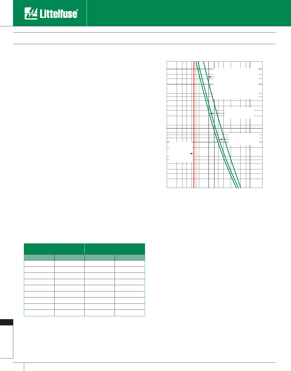
Fuseology
202 www.littelfuse.com
Fuseology
© 2005 Littelfuse • POWR-GARD™ Products Catalog
NEMA Standards for “R-rated” MV power fuses require that they open
within 15-35 seconds when subjected to an rms current 100 times the
“R” rating.
These values establish one point on the fuses time-current curves
and help define the characteristics of E-and R-rated fuses. Since all E
and R-rated fuses must meet these re quire ments, the time-current
characteristics of E-rated and R-rated fuses of different manufactures
will have a certain similarity, although they are not necessarily identical.
A long-standing rule of thumb for applying MV fuses states that the
minimum fuse rating should be at least 1.4 times the circuit’s full load
current. This generally insures that MV fuses will not be required to
open overloads. If the nature of the load is such that load currents will
never exceed the rating of the fuse, MV fuses may be rated as close as
1.1 times full load current.
Motor Protection
To properly select MV fuses for motor protection, several factors
should be considered. R Rated fuses are only intended for short-circuit
protection and should be applied in conjunction with motor overload
relays. An R Rated fuse does not have an ampere rating and the “R”
rating refers to the opening time of the fuse. R Rated fuses are designed
to safely interrupt any current between their minimum and maximum
interrupting rating. When applying R Rated fuses, it is recommended
to follow the fuse sizing guidelines established by the motor starter
manufacturer.
When engineering a system, time-current characteristic curves of the
fuse and overload relay should be compared to insure the overload relay
opens before the fuse during overload conditions. The following table is
provided as a guideline for sizing R Rated fuses.
Transformer Protection
A principle use of MV fuses is to provide primary short-circuit protection
for transformers. When selecting MV fuses to protect transformers,
the following factors must be considered in descending order of
importance:
1. As explained above, the fuses voltage and in ter rupt ing ratings must
equal or exceed system requirements at the point where fuses will
be applied.
2. The fuse continuous current rating must be large enough to
withstand transformer magnetizing (in-rush) current. (Minimum Fuse
Rating).
3. The fuse continuous current rating must be able to withstand
transformer overloading and emergency operation, and meet NEC
requirements. (Maximum Fuse Rating).
4. Fuses must protect the system on the line side of the fuse from the
effects of short circuits on the load side of the fuses. (Utility System
Coordination).
5. Fuses must coordinate with the transformer secondary protection
where and whenever possible. (Facility System Co or di na tion).
6. Fuses must protect transformer against sec ond ary bolted faults.
7. Where and whenever possible, fuses should protect the transformer
against higher impedance secondary faults.
Transformer magnetizing or inrush current depends on several factors
such as transformer design, residual flux in the core at the instant
the transformer is energized, the point on the voltage wave at which
the switch is closed, and the characteristics of the electrical system
powering the transformer. Power transformers in-rush current
approximates 12 times the transformer full load current, and distribution
transformers 25 to 40 times full load current. The current generally lasts
less than 1/10 second.
Fuse Application Guide
Applying Medium Voltage Fuses
1000
200
300
400
600
100
20
30
40
60
80
10
2
3
4
6
8
1
.1
.2
.3
.4
.6
.8
1
2
3
4
6
8
10
20
30
40
60
80
100
200
300
400
1000
TIME IN SECONDS
Fuse Maximum
Clearing Curve
Fuse Minimum
Melting Curve
Typical transformer
damage curve for
3- phase faults on
3- phase transformers
and single-phase faults
on 1-phase transformers
CURRENT IN AMPERES
Maximum
Transformer
Overload
Current
Figure 22
R-Rated Fuse Sizing Table
For Motors with an
Acceleration of 10 Seconds
For Motors with an
Acceleration of 3 Seconds
Max.Motor FLA R Rated Fuse Max.Motor FLA R Rated Fuse
28A 2R 32A 2R
40A 3R 45A 3R
55A 4R 65A 4R
80A 6R 95A 6R
125A 9R 140A 9R
165A 12R 190A 12R
250A 18R 280A 18R
330A 24R 360A 24R
500A 36R 550A 36R
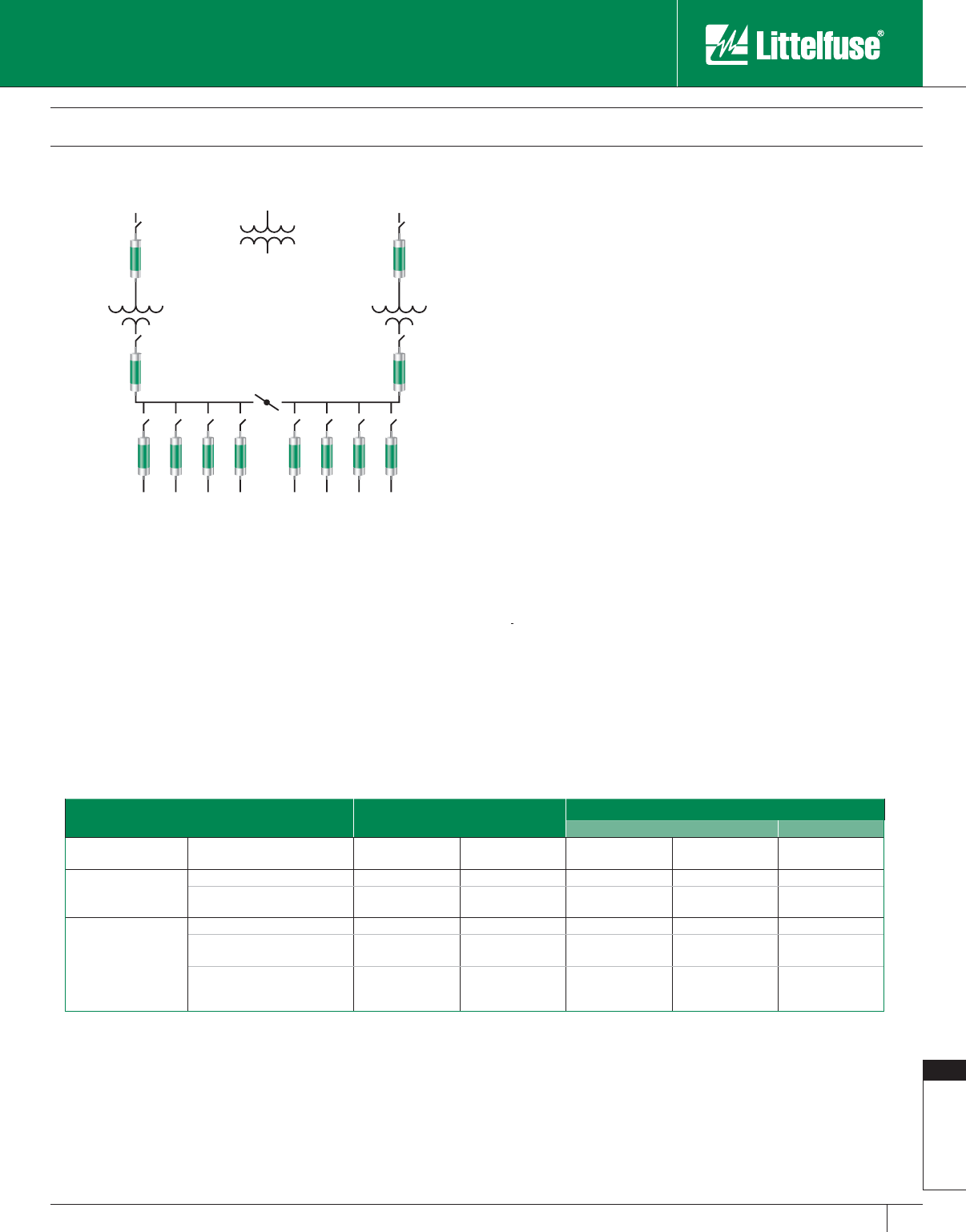
Fuseology
203
www.littelfuse.com
Fuseology
© 2005 Littelfuse • POWR-GARD™ Products Catalog
To determine the minimum size fuse which will hold the in-rush current,
obtain the in-rush current from the trans form er manufacturer and mark
the current on the fuses minimum melting time-current curves at
0.10 second as shown in Figure 22. The minimum fuse rating is the
fuse whose minimum melting curve is just to the right and above the
transformer inrush point.
When the in-rush current is not greater than 12 times transformer
full load current, MV fuses with current ratings that equal or exceed
a transformer’s self-cooled, full load current will usually meet this
requirement. However, transformers are generally operated at
close to full load current on a continuous basis, and are overloaded
under emergency conditions. A typical example is a double-ended
loadcenter operated with a normally open bus tie. See Figure 23.
Each transformer is rated to carry 150% of the load on its half of the
loadcenter. With loss of service to one transformer, the main switch
for that line is opened, and the bus tie switch is closed shifting all load
to the remaining transformer. The system is operated overloaded until
the other line is back in service. If the outage will continue for a long
period of time, manual load shedding can be used to control transformer
overloading.
Other similar operating schemes also result in transformer overloading.
As a result, MV fuses usually have continuous current ratings larger than
required to withstand transformer in-rush current.
NEC® Article 450 covers transformer installations and establishes
the maximum ratings of transformer overcurrent protective devices.
Regarding medium voltage fuses, Article 450.3 states in part:
Overcurrent Protection of transformers shall comply with NEC Article
450.3(A) – Transformers Over 600 Volts, Nominal, and shall be provided
in accordance with Table 9.
NOTE: In this section, the word transformer shall mean a transformer or polyphase bank of
two or more single-phase transformers operating as a single unit.
Table 9
(Based on NEC Table 450.3(A) – Maximum Rating or Setting of Overcurrent Protection
for Transformers Over 600 Volts (as a Percentage of Transformer-Rated Current))
Primary Protection Over
600 Volts
Secondary Protection (See Note 2)
Over 600 Volts 600 Volts or Less
Location Limitations Transformer Rated
Impedance
Circuit Breaker
(see Note 4) Fuse Rating Circuit Breaker
(see Note 4) Fuse Rating Circuit Breaker or
Fuse Rating
Any Location
Not more than 6% (see Note 1) 600% 300% 300% 250% 125%
More than 6% but not more than
10% (see Note 1) 400% 300% 250% 225% 125%
Supervised
Locations Only (see
Note 3)
Any (see Note 1) 300% 250% Not Required Not Required Not Required
Not more than 6% (see Note 5 for
Secondary Protection) 600% 300% 300% 250% 250%
More than 6% but not more than
10% (see Note 5 for Secondary
Protection)
400% 300% 250% 225% 250%
Note 1 – If the required fuse rating or breaker setting does not correspond to standard ratings/settings, the next higher rating/setting may be used.
Note 2 – If secondary overcurrent protection is required, no more than six breakers or sets of fuses may be grouped in any one location. When multiple overcurrent devices
are used, the sum of all device ratings shall not exceed the allowed value of any single device. If both breakers and fuses are used, the total of device ratings shall
not exceed that if using only fuses.
Note 3 – A “supervised location” is one where maintenance and supervision conditions ensure that only qualified persons are allowed to monitor and perform installation
service on the transformer.
Note 4 – Electronically actuated fuses set to open at a specific current shall be set and calibrated in accordance with the corresponding settings of the circuit breakers
involved.
Note 5 – Separate secondary protection is not necessary if the transformer is equipped with a coordinated thermal overload protection provided by the manufacturer.
Transformers
look like this
Figure 23
Fuse Application Guide
Applying Medium Voltage Fuses
Fuseology
204 www.littelfuse.com
Fuseology
© 2005 Littelfuse • POWR-GARD™ Products Catalog
Using AC Motor Protection Tables to Select Fuse Ratings
Time-delay RK1 and RK5 fuse ratings selected in accordance with
the following recommendations also meet NEC® requirements for
Motor Branch circuit and Short-Circuit Protection.
Selecting Fuses for Motor Running Protection
Based on Motor Horsepower
Motor horsepower and motor Full Load Amperes (FLA) shown are
taken from NEC Tables 430.248 through 430.250 covering standard
speed AC motors with normal torque characteristics. Fuse ratings
for motors with special characteristics may need to vary from given
values.
If motor running protection will be provided by the fuses, select
fuse ratings for correct type of motor from Motor Protection Table
Columns headed, “Without Overload Relays.”
If overload relays will provide principal motor running protection,
select fuse ratings for correct type of motor from Motor Protection
Table Columns headed, “Back-up Running Protection” or “With
Overload Relays.” Fuse ratings selected from these columns
coordinate with most UL Class 10 and 20 overload relays which
covers over 90% of motor applications.
Selecting Fuses for Motor Running Protection
Based on Motor Actual Full Load Currents
Better protection is achieved when fuse ratings are based on
motor actual FLA obtained from motor nameplates. Locate motor
nameplate FLA in the column appropriate for the type of motor and
type of protection required. Then select the corresponding ampere
rating from the first column of that line.
Time Delay UL
Class RK1 or
RK5 Fuse
Ampere Rating
Motor Running Protection
(Used Without Properly Sized Overload
Relays) Motor Full-Load Amps
Back-up Motor Running Protection
(Used With Properly Sized Overload
Relays) Motor Full-Load Amps
Motor Service
Factor of 1.15 or
Greater or With
Temp. Rise Not
over 40°C.
Motor Service
Factor Less Than
1.15 or with Temp.
Rise Greater
Than 40°C.
Motor Service
Factor of 1.15 or
Greater or With
Temp. Rise Not
Over 40°C.
Motor Service
Factor Less Than
1.15 or with Temp.
Rise Greater
Than 40°C
1⁄10 0.08-0.09 0.09-0.10 0-0.08 0-0.09
1⁄80.10-0.11 0.11- 0.125 0.09 -0.10 0.10-0.11
15 ⁄100 0.12-0.15 0.14-0.15 0.11-0.12 0.12-0.13
2⁄10 0.16-0.19 0.18 -0.20 0.13-0.16 0.14-0.17
1⁄40.20-0.23 0.22-0.25 0.17-0.20 0.18-0.22
3⁄10 0.24-0.30 0.27-0.30 0.21-0.24 0.23-0.26
4⁄10 0.32-0.39 0.35-0.40 0.25-0.32 0.27-0.35
1⁄20.40-0.47 0.44-0.50 0.33-0.40 0.36-0.43
6⁄10 0.48-0.60 0.53-0.60 0.41-0.48 0.44-0.52
8⁄10 0.64-0.79 0.70-0.80 0.49-0.64 0.53-0.70
1 0.80-0.89 0.87-0.97 0.65-0.80 0.71-0.87
11⁄80.90-0.99 0.98-1.08 0.81-0.90 0.88-0.98
11⁄41.00-1.11 1.09-1.21 0.91-1.00 0.99-1.09
14⁄10 1.12-1.19 1.22-1.30 1.01-1.12 1.10-1.22
11⁄21.20-1.27 1.31-1.39 1.13-1.20 1.23-1.30
16⁄10 1.28-1.43 1.40-1.56 1.21-1.28 1.31-1.39
18⁄10 1.44-1.59 1.57-1.73 1.29-1.44 1.40-1.57
2 1.60-1.79 1.74-1.95 1.45-1.60 1.58-1.74
21⁄41.80-1.99 1.96-2.17 1.61-1.80 1.75-1.96
21⁄22.00-2.23 2.18-2.43 1.81-2.00 1.97-2.17
28⁄10 2.24-2.39 2.44-2.60 2.01-2.24 2.18-2.43
3 2.40-2.55 2.61-2.78 2.25-2.40 2.44-2.60
32⁄10 2.56-2.79 2.79-3.04 2.41-2.56 2.61-2.78
31⁄22.80-3.19 3.05-3.47 2.57-2.80 2.79-3.04
4 3.20-3.59 3.48-3.91 2.81-3.20 3.05-3.48
41⁄23.60-3.99 3.92-4.34 3.21-3.60 3.49-3.91
5 4.00-4.47 4.35-4.86 3.61-4.00 3.92-4.35
56⁄10 4.48-4.79 4.87-5.21 4.01-4.48 4.36-4.87
6 4.80-4.99 5.22-5.43 4.49-4.80 4.88-5.22
61⁄45.00-5.59 5.44-6.08 4.81-5.00 5.23-5.43
7 5.60-5.99 6.09-6.52 5.01-5.60 5.44-6.09
71⁄26.00-6.39 6.53-6.95 5.61-6.00 6.10-6.52
8 6.40-7.19 6.96-7.82 6.01-6.40 6.53-6.96
9 7.20 -7.99 7.83- 8.69 6.41-7. 20 6.9 7-7.8 3
10 8.00-9.59 8.70-10.00 7.21-8.00 7.84-8.70
12 9.60-11.99 10.44-12.00 8.01-9.60 8.71-10.43
15 12.00-13.99 13.05-15.00 9.61-12.00 10.44-13.04
171⁄214.00-15.99 15.22-17.39 12.01-14.00 13.05- 15.21
20 16.00-19.99 17.40-20.00 14.01-16.00 15.22-17.39
25 20.00-23.99 21.74-25.00 16.01-20.00 17.40-21.74
30 24.00-27.99 26.09-30.00 20.01-24.00 21.75-26.09
35 28.00-31.99 30.44-34.78 24.01-28.00 26.10-30.43
40 32.00-35.99 34.79-39.12 28.01-32.00 30.44-37.78
45 36.00-39.99 39.13-43.47 32.01-36.00 37.79-39.13
50 40.00-47.99 43.48-50.00 36.01-40.00 39.14-43.48
60 48.00-55.99 52.17-60.00 40.01-48.00 43.49-52.17
70 56.00-59.99 60.87-65.21 48.01-56.00 52.18-60.87
75 60.00-63.99 65.22-69.56 56.01-60.00 60.88-65.22
80 64.00-71.99 69.57-78.25 60.01-64.00 65.23-69.57
90 72.00-79.99 78.26-86.95 64.01-72.00 69.58-78.26
100 80.00-87.99 86.96-95.64 72.01-80.00 78.27-86.96
110 88.00-99.99 95.65-108.69 80.01-88.00 86.97-95.65
125 100.00-119.99 108.70-125.00 88.01-100.00 95.66-108.70
150 120.00-139.99 131.30-150.00 100.01-120.00 108.71-130.43
175 140.00-159.99 152.17-173.90 120.01-140.00 130.44-152.17
200 160.00-179.99 173.91-195.64 140.01-160.00 152.18-173.91
225 180.00-199.99 195.65-217.38 160.01-180.00 173.92-195.62
250 200.00-239.99 217.39-250.00 180.01-200.00 195.63-217.39
300 240.00-279.99 260.87-300.00 200.01-240.00 217.40-260.87
350 280.00-319.99 304.35-347.82 240.01-280.00 260.88-304.35
400 320.00-359.99 347.83-391.29 280.01-320.00 304.36-347.83
450 360.00-399.99 391.30-434.77 320.01-360.00 347.84-391.30
500 400.00-479.99 434.78-500.00 360.01-400.00 391.31-434.78
600 480.00-600.00 521.74-600.00 400.01-480.00 434.79-521.74
Motor Protection Tables
Selection of Class RK5 (FLNR_ID/FLSR_ID & IDSR Series) or POWR-PRO® Class RK1 (LLNRK/LLSRK/LLSRK_ID Series) Fuses Based
on Motor Full Load Amps
Fuseology
205
www.littelfuse.com
Fuseology
© 2005 Littelfuse • POWR-GARD™ Products Catalog
Motor Protection Tables
Motor HP Full Load
Amps
Without Overload Relays With Overload Relays
Switch or
Fuse Clip
Rating
S.F. = 1.15 Or
More, Temp
Rise Not Over
40
°
C
S.F. = Less
Than 1.15 Or
Temp Rise
More Than
40
°
C
S.F. = 1.15 Or
More, Temp
Rise Not Over
40
°
C
S.F. = Less
Than 1.15 Or
Temp Rise
More Than
40
°
C
460 VOLT 3-PHASE MOTORS (480V CIRCUIT)
1⁄21.1 14⁄10 11⁄414⁄10 14⁄10 30
3⁄41.6 2 18⁄10 2230
12.12
1⁄221⁄428⁄10 21⁄230
11⁄23.0 31⁄232⁄10 43
1⁄230
23.4 4 3
1⁄241⁄2430
34.85
6⁄10 565
6⁄10 30
57.6 9 8 10 9 30
71⁄211 12 12 15 15 30
10 14 171⁄215 171⁄2171⁄230
15 21 25 20 30 25 30
20 27 30* 30* 35 35 60
25 34 40 35 45 40 60
30 40 50 45 50 50 60
40 54 60* 60* 70 60* 100
50 65 80 70 90 75 100
60 77 90 80 100 90 100
75 96 110 110 125 125 200
100 124 150 125 175 150 200
125 156 175 175 200 200 200
150180 225200*225 225 400
200 240 300 250 300 300 400
575 VOLT 3-PHASE MOTORS (600V CIRCUIT)
1⁄20.9 11⁄811
1⁄811⁄830
3⁄41.3 16⁄10 14⁄10 16⁄10 16⁄10 30
11.7 2 1
8⁄10 21⁄4230
11⁄22.4 3 21⁄23330
22.73
2⁄10 28⁄10 31⁄232⁄10 30
33.94
1⁄2454
1⁄230
56.17
1⁄2787
1⁄230
71⁄291010121230
10 11 12 12 15 15 30
15 17 20 171⁄225 20 30
20 22 25 25 30 30 30
25 27 30* 30* 35 35 60
30 32 40 35 40 40 60
40 41 50 45 60 50 60
50 52 60 60 70† 60 60
60 62 75 70 80 75 100
75 77 90 80 100 90 100
100 99 110 110 125 125 200
125 125 150 125 175 150 200
150 144 175 150 200 175 200
200 192 225 200* 250 225 400
NOTES
S.F. = Motor Service Factor
* Fuse Reducers Required
† 100 Amp Switch Required
Selection of Class RK5 (FLNR_ID/FLSR_ID & IDSR Series) or POWR-PRO® Class RK1 (LLNRK/LLSRK/LLSRK_ID Series) Fuses
Based on Motor Horsepower
Motor HP Full Load
Amps
Without Overload Relays With Overload Relays
Switch or
Fuse Clip
Rating
S.F. = 1.15 Or
More, Temp
Rise Not Over
40
°
C
S.F. = Less
Than 1.15 Or
Temp Rise
More Than
40
°
C
S.F. = 1.15 Or
More, Temp
Rise Not Over
40
°
C
S.F. = Less
Than 1.15 Or
Temp Rise
More Than
40
°
C
120 VOLT 1-PHASE MOTORS (120V CIRCUIT)
1⁄64.4 5 5 56⁄10 56⁄10 30
1⁄45.8 7 61⁄471⁄2730
1⁄37.2989930
1⁄29.8 12 10 15 12 30
3⁄413.8 15 15 171⁄2171⁄230
116 2017
1⁄220 20 30
11⁄220 25 20 25 25 30
224 30 25 30 30 30
230 VOLT 1-PHASE MOTORS (240V CIRCUIT)
1⁄62.2 21⁄221⁄228⁄10 28⁄10 30
1⁄42.9 31⁄232⁄10 43
1⁄230
1⁄33.6 41⁄244
1⁄241⁄230
1⁄24.9 56⁄10 56⁄10 61⁄4630
3⁄46.9 8 71⁄29830
18 10 9 101030
11⁄210 12 10 15 12 30
2121512151530
317 2017
1⁄225 20 30
5 28 35 30* 35 35 60
71⁄240 50 45 50 50 60
10 50 60 50 70 60 60
200 VOLT 3-PHASE MOTORS (208V CIRCUIT)
1⁄22.5 3 28⁄10 32⁄10 330
3⁄43.7 41⁄2454
1⁄230
14.8 6 5
6⁄10 61⁄4630
11⁄26.9 8 71⁄271⁄2830
27.8 9 8 10 9 30
311 12 12 15 15 30
517.5 20 20 25 25 30
71⁄225.3 30* 25* 35 30* 60
10 32.2 40 35 45 40 60
15 48.3 60 50 70† 60 60
20 62.1 75 70 80 75 100
25 78.2 90 80 100 90 100
30 92 110 100* 125 110 200
40 120 150 125 150 150 200
50 150 175 150 200 175 200
60 177 200* 200* 225 225 400
75 221 250 250 300 300 400
100 285 350 300 400 350 400
125 359 400* 400* 450 450 600
150 414 500 450 600 500 600
230 VOLT 3-PHASE MOTORS (240V CIRCUIT)
1⁄22.2 28⁄10 21⁄228⁄10 28⁄10 30
3⁄43.2 4 31⁄24430
14.2 5 4
1⁄256⁄10 530
11⁄26.0 71⁄261⁄471⁄271⁄230
26.8 8 7
1⁄29830
3 9.6 12 10 12 12 30
515.217
1⁄2171⁄220 171⁄230
71⁄222 25 25 30 30 30
10 28 35 30* 35 35 60
15 42 50 45 60 50 60
20 54 60* 60* 70 70 100
25 68 80 75 90 80 100
30 80 100 90 100 100 100
40 104 125 110 150 125 200
50 130 150 150 175 150 200
60 154 175 175 200 200 200
75 192 225 200* 250 225 400
100 248 300 250 350 300 400
125 312 350 350 400 400 400
150 360 450 400* 450 450 600
200 480 600 500 600 600 600
Fuseology
206 www.littelfuse.com
Fuseology
© 2005 Littelfuse • POWR-GARD™ Products Catalog
Motor F.L.A. JTD_ID/JTD
Ampere Rating Motor F.L.A. JTD_ID/JTD
Ampere Rating Motor F.L.A. JTD_ID/JTD
Ampere Rating
0.00 – 0.60 8⁄10 12.1 – 14.5 17 1/276.1 – 84.0 110
0.61 – 0.80 1 14.6 – 17.0 20 84.1 – 90.0 125
0.81 – 1.00 11⁄417.1 – 21.0 25 90.1 – 102 150
1.01 – 1.20 11⁄221.1 – 25.0 30 103 – 125 175
1.21 – 1.65 2 25.1 – 28.5 35 126 – 144 200
1.66 – 2.00 21⁄228.6 – 34.0 40 145 – 162 225
2.01 – 2.40 3 34.1 – 37.0 45 163 – 180 250
2.41 – 3.30 4 37.1 – 41.0 50 181 – 204 300
3.31 – 4.10 5 41.1 – 48.0 60 205 – 240 350
4.11 – 4.90 6 48.1 – 52.0 70 241 – 288 400
4.91 – 6.40 8 52.1 – 59.0 80 289 – 312 450
6.41 – 8.00 10 59.1 – 66.0 90 313 – 360 500
8.01 – 9.80 12 66.1 – 76.0 100 361 – 432 600
9.81 – 12.0 15
NOTE: For severe motor starting conditions, fuses may be sized up to 225% motor F.L.A. (See NEC Article 430.52 for Exceptions)
Selection of POWR-PRO® Class J (JTD_ID/JTD Series) Fuses
Based on Motor Full Load Amps
Motor Full Load Current (F.L.A.)
CCMR
Ampere Rating
For Motors With An Acceleration
Time Of 2 Seconds Or Less
For Motors With An Acceleration
Time Of 5 Seconds Or Less
For Motors With An Acceleration
Time Of 8 Seconds Or Less
Min. F.L.A. (1) Max F.L.A. (3) Min. F.L.A. (1) Max F.L.A. (3) Min F.L.A. (2) Max F.L.A. (3)
0.2 0.2 0.2 0.2 0.2 0.2 3⁄10
0.3 0.4 0.3 0.4 0.3 0.3 1⁄2
0.4 0.6 0.4 0.5 0.4 0.5 8⁄10
0.5 0.7 0.5 0.6 0.5 0.6 1
0.6 1.0 0.6 0.9 0.6 0.8 11⁄4
0.8 1.1 0.8 1.0 0.7 0.9 11⁄2
0.9 1.3 0.9 1.1 0.8 1.0 18⁄10
1.1 1.4 1.1 1.2 0.9 1.1 2
1.2 2.1 1.2 2.1 1.2 1.8 21⁄2
1.5 2.6 1.5 2.6 1.4 2.3 3
1.8 3.0 1.8 3.0 1.6 2.6 3 1⁄2
2.1 3.4 2.1 3.2 1.8 2.8 4
2.3 3.9 2.3 3.3 2.0 2.8 41⁄2
2.6 4.3 2.6 3.4 2.3 2.8 5
2.9 4.8 2.9 3.7 2.5 3.1 56⁄10
3.3 5.2 3.3 4.0 2.7 3.4 6
3.5 5.4 3.5 4.1 2.8 3.5 61⁄4
3.6 5.7 3.6 4.2 3.2 3.7 7
4.1 5.8 4.1 4.3 3.4 3.8 71⁄2
4.3 6.2 4.3 4.6 3.6 4.2 8
4.6 6.9 4.6 5.2 4.0 4.5 9
5.2 7.7 5.2 5.8 4.5 4.9 10
5.8 8.9 5.8 6.6 5.4 5.5 12
6.9 10.0 6.9 7.7 6.7 6.7 15
8.9 13.5 8.9 10.0 6.8 9.0 20
11.5 15.8 11.2 (2) 11.8 9.0 11.0 25
14.3 17.8 13.4 (2) 13.4 10.0 15.0 30
20.7 23.3 16.1 17.9 15.6 15.9 35
23.7 26.7 18.4 20.5 17.8 18.2 40
26.6 30.0 20.7 23.1 20.0 20.4 45
30.0 33.3 23.0 25.6 22.3 22.7 50
35.5 40.0 27.6 30.1 26.7 27.3 60
1 Based on NEC requirement limiting the rating of time-delay fuses to 175% of motor F.L.A., or next
higher rating.
2 Based on NEC exception permitting fuse rating to be increased, but not to exceed, 225% motor
F.L.A., however per NEC Article 430.52 Class CC (0-30) fuses can now be sized up to 300% of
motor F.L.A.
3 Based on Littelfuse CCMR time-delay characteristics.
Selection of CCMR Time-Delay Fuses Based on Motor Full Load Amps
NOTE: These values were calculated for motors with Locked Rotor
Current (LRA), not exceeding the following values:
Motor F.L.A. *LRA
0.00 – 1.00 850%
1.01 – 2.00 750%
2.01 – 10.0 650%
10.1 – 17.8 600%
*If motor LRA varies from these values, contact Littelfuse.
Motor Protection Tables

Fuseology
207
www.littelfuse.com
Fuseology
© 2005 Littelfuse • POWR-GARD™ Products Catalog
Condensed Cross Reference
Power/Electronic Fuses
This cross reference covers most popular fuses for which there is a similar Littelfuse standard item. Furnished for your con ve nience, it is meant to
serve as a guide only for product selection. We suggest you check all applicable specifications before making substitutions. For special applications,
consult the factory.
For more complete information, and for fuse block and medium voltage fuse cross referencing, send for Cross Reference Booklet EC501
or call 1-800-TEC-FUSE (1-800-832-3873).
Competition Littelfuse Competition Littelfuse Competition Littelfuse Competition Littelfuse
10KOTN NLN CLL KLLU or KLPC JHC JTD_ID NCLR KLNR
10KOTS NLS CLU KLLU or KLPC JJN JLLN NON NLN
50KOTN NLN CM BLF JJS JLLS NOS NLS
50KOTS NLS CMF BLN JKS JLS NRN NLN
A251 CNM FLM KAA L15S NRN (15-60A) NLKP
A013F L15S CNQ FLQ KAB L25S NRS NLS
A015F L15S CRN-R FLNR_ID (note 3) KAC KLC OT NLN
A015R L15S CRS-R FLSR_ID KBH L50S OTM BLF or BLN
A025F L25S CSF13X L15S KLM KLKD OTN NLN
A050F L50S CSF25X L25S (AC only) KLMR CCMR OTS NLS
A060F L60S CSF50P L50S KLU KLLU or KLPC REN RLN
A060URL KLK CSF60C KLC (AC only) KN KLNR RES RLS
A070F L70S CSF60X L60S (AC only) KON NLN RF RLN
A13X L15S CSF70P L70S KOS NLS RFA L15S
A25X L25S (AC only) CTN-R KLNR KRPC (SP) KLPC RFC KLC
A2D-R LLNRK CTS-R KLSR KRPC-L KLPC RFL (750V) L70S (700V)
A2K-R KLNR EBS BLS KS KLSR RFN (Ferraz) RLN
A3T JLLN ECNR FLNR_ID (note 3) KTK KLK RFS (Ferraz) RLS
A4BQ KLPC ECSR FLSR_ID KTKR KLKR RFV L50S
A4BT KLLU or KLPC ELN LKN KTNR KLNR RHN KLNR
A4BY KLPC or KLLU ELS LKS KTSR KLSR RHS KLSR
A4J JLS ERN RLN KTU KLPC RLN (Ferraz) LKN
A50P (type 1 & 4) L50S ERS RLS LKLLU or KLPC RLS (Ferraz) LKS
A60X L60S FNA FLA LCL KLPC or KLLU SSOO
A6D-R LLSRK_ID FNB 235 LCU KLPC or KLLU SA SAO
A6K-R KLSR FNM FLM LENRK LLNRK SC SLC
A6T JLLS FNQ FLQ LESRK LLSRK_ID SCLR KLSR
A70P L70S FNQ-R KLDR LKN LKN SEC SLC
ACK CCK FRN-R FLNR_ID (note 3) LKS LKS SF13X L15S
AG SLC FRS-R FLSR_ID LKU KLLU SF25X L25S
AGA AGA FWA (note 2) L15S LONRK LLNRK SF50P L50S
AGC 312 FWH (note 2) L50S LOSRK LLSRK_ID SF60X L60S
AGU (1-30A) BLN FWP (note 1) L70S LPCC CCMR SF70P L70S
AGW AGW FWX (note 1) L25S LPJ (SP) JTD_ID SFE SFE
AJT JTD_ID GDA 216 LPNRK (SP) LLNRK SL SLO
ANL CNL GDB 217 LPSRK (SP) LLSRK_ID TTOO
ANN CNN GDC 218 MCL KLK TJN JLLN
ATC ATO (257) GDL 313 MDA 326 TJS JLLS
AT-DE FLNR_ID (note 3) GEB LEB MDL 313 TL TLO
ATDR CCMR GEBN LET MDQ 313 TR FLNR_ID (note 3)
ATM KLK GFA 251 MDV 315 TRM FLM
ATMR KLKR GFN FLA MDX 313 TRN-R FLNR_ID (note 3)
ATQ FLQ GGC 312 MEN FLM TRS FLSR_ID
ATQR KLDR GGM 235 MEQ FLQ TRS-R FLSR_ID
AX 481 GLR LGR MID FLA XL25X L25S
AXRAD 252 GMT 481 MOF BLN XL50F L50S (note 1)
BAF BLF HCLR KLKR MOL BLF XL70F L70S (note 1)
BAN BLN HCTR KLDR MTH 312
BBS BLS HEB LEB 1) Check specific mounting dimensions before substituting.
2) Check fuse characteristics and mounting dimensions for specific application before substituting.
3) For 1/10 - 30 amperes, order non-indicating FLNR series fuses.
Remember a fuse may be used in circuits where the fuse’s voltage rating is equal to or greater than
the circuit voltage, unless otherwise stated on the fuse. For example, the FLSR_ID indicating fuse
has a voltage rating of 75-600 volts. This fuse can be used on 600 volts, 480 volts, 250 volts, 125
volts, or 75 volts. Never use a fuse in a circuit having higher rated voltage than the fuse.
CGL (2-100A) 2CO HET LET
CGL (125-600A) 2CC HLR LHR
CJ JLS JJLS
CJS JLS JDL JTD_ID
CLF KLPC or KLLU JFL JLS
Fuseology
208 www.littelfuse.com
Fuseology
© 2005 Littelfuse • POWR-GARD™ Products Catalog
Alphanumeric Index of Catalog Numbers
Arc-Flash 177
ATO series 60
BLF series 51
BLN series 51
BLS series 52
Box Cover Units 158-159
CablePro®62
CBO series 107
CCK series 107
CCL series 107
CCMR series 20-21, 45-47
Class CC 20-21, 45-47
Class CD 20-21, 45-47
Class G 44
Class H 38
Class J 17-19, 39-40
Class K5 36-37
Class L 8-10, 23-24,
26-28
Class RK1 11-16, 34-35
Class RK5 22, 29-33
Class T 41-43
CNL series 107
CNN series 107
CYHP001 128, 168
Cylindrical Fuses 168
Diazed Fuses 166-167
Definitions 177-181
Distribution Blocks 137-144
Electrical Safety 182-183
Electronic Fuses 55-59
E-Rated Fuses 69-74
European Fuses 161-169
FBDIN1 127
FDR001PG 160
FLA series 52
FLM series 50
FLNR series 33
FLNR_ID series 29-32
FLQ series 51
FLSR series 33
FLSR_ID series 29-32
FLU series 53
Fuse Blocks 126
Fuseology 172-206
Fuse Reducers 157
GFP 131
IDSR series 22
ILS series 135-136
Inline Fuseholders 145-150
JCASE series 62
JLLN series 41-43
JLLS series 41-43
JLS series 39-40
JTD_ID series 17-19
KLC series 85, 87
KLDR series 45-47
KLK series 50
KLKD series 50
KLKR series 45-47
KLLU series 26-28
KLNR series 34-35
KLPC series 8-10
KLQ series 53
KLSR series 34-35
L15S series 85-86
L17T series 77
L25S series 85-86
L30030G series 124
L50S series 85-86
L60030C series 125-126
L60030M series 125-126
L60060C series 125-126
L60S series 85, 87
L70S series 85, 87
LA15QS 88-89
LA30QS 90-91
LA50QS 92-93
LA60QS 94
LA60X 95
LA70QS 96-98
LA100P 99-100
LA120X 101
LA070URD 102-104
LA130URD 102, 105-106
LCC series 131
LD series 137-144
LDC series 23-24
LEB series 145-150
LEC series 145-150
LET series 145-150
LEX series 145-150
LEY series 145-150
LFCL series 108
LFDS series 156
LFFB001 133
LFFS030CC 156
LG300 series 124
LgD series 5, 162
LGR series 109
Live Parts 75
LH250 series 112-116
LH250-PC series 130
LH600 series 112-116
LH600-PC series 130
LHFB 133
LHR series 108
LJ600 series 117-119
LJ600-PC series 130
LKN series 38
LKS series 38
LLNRK series 14-16
LLSRK series 14-16
LLSRK_ID series 11-13
LMF series 109
LNNB 53
LPFP 131
LPBC series 138
LPMP series 154-155
LPS1 152-153
LPS2 152-153
LPS3 152-153
LPS4 152-153
LPS6 152-153
LPSC series 128
LPSG series 163
LPSJ series 129
LPSM series 128
LR250 series 112-116
LR600 series 112-116
LRU series 157
LS series 137-144
LSCR series 134
LSCY 158-159
LSFC 160
LSKA 158-159
LSOU 158-159
LSOW 158-159
LSOX 158-159
LSOY 158-159
LSOY-B 158-159
LSRU 158-159
LSRW 158-159
LSRX 158-159
LSRY 158-159
LSSU 158-159
LSSW 158-159
LSSX 158-159
LSSY-L 158-159
LSSY-RL 158-159
LST Y 158-159
LT300 series 120-123
LT600 series 120-123
LTFD series 81-82
LVSP series 174
MAX series 60
Medium Voltage 63-75
MEGA series 61
MFP 131
MIDI series 61
MIN series 60
MOV 173
MROplus 6
Neozed Fuses 166-167
NH Fuse Links 164-165
NLKP series 36-37
NLN series 36-37
NLS series 36-37
Overvoltage 170-174
Plug Fuses 48
PT Fuses 74
RLN series 38
RLS series 38
R-Rated Fuses 65-68
SAO series 48
Semiconductor Fuses 83-106
SFE series 60
SLC series 44
SLO series 48
SOO series 48
SPL001 127
Splicer Blocks 137-144
Suppression 170-174
Telecom Fuses 76-80
TLN series 78
TLO series 48
TLS series 79
TMOV 173
TOO series 48
US3J series 129
US6J series 129
WPB series 147
094324PG 160
215 series 57
216 series 57
217 series 57
218 series 57
224 series 58
225 series 58
229 series 56
230 series 56
235 series 58
239 series 58
251 series 59
252 series 59
257 series see ATO
272 series 59
273 series 59
278 series 59
279 series 59
297 series see MIN
299 series see MAX
2CC series 169
2CM series 169
2CO series 169
312 series 55
313 series 55
313_ID series 56
314 series 55
315 series 55
318 series 55
324 series 55
325 series 55
326 series 55
334 series 56
473 series 59
481 series 80
496 series 62
498 series 61
571 series 132
572 series 132
70 series 80
700 series 75
Catalog Number Page Number Catalog Number Page Number Catalog Number Page Number Catalog Number Page Number
Littelfuse®
POWR-GARD™ Products
Littelfuse provides our customers with a comprehensive range of
electrical products used to protect:
• Industrial motors and drives
• Pumps and compressors
• Power distribution circuits and wiring devices
• Medium voltage power distribution grids
• Lighting circuits
At Littelfuse we are committed to partnering with our
customers. That means not only providing the right circuit
protection solution, but also offering services that will
continually add value to your initiatives:
MROplusTM : (Material Reduction
Opportunity plus, the industry’s
best indicating fuse line)
Improve performance while lowering operational costs – for free.
When you use our MROplus program, our technical service
professionals will run a free comprehensive fuse analysis,
evaluating your current purchases and complete fuse inventory,
including identification of duplicate and obsolete fuses. After
the analysis you will receive a detailed report with streamlining
recommendations, annual cost savings estimates and ways to
improve safety and decrease downtime.
Techline
800-TEC-FUSE ( 800-832-3873 )
Our technical hotline is available 8:00 a.m. – 4:30 p.m. CST.
The Littelfuse technical specialists are there to answer questions,
assist in cross-references and provide application expertise.
Littelfuse®
POWR-GARD™ Services Designed to Add Value
www.littelfuse.com
© 2005 Littelfuse • POWR-GARD™ Products Catalog
TM
Littelfuse
Safety Program
Did you know that 97% of all electricians have been shocked
or injured on the job? To help you increase safety in your facility
Littelfuse offers the following:
• Current-Limiting Fuses and Accessories
• Electrical Safety Literature and Arc-Flash Calculators
• Electrical Safety Video
• Training Seminars and Presentations
• MROplus Fuse Inventory Analysis
• Technical Support and Engineering Services
Littelfuse safety experts are here to help you stay safe on the job.
We can assist you in developing an Electrical Safety Program in
your own facility.
24-Hour Emergency Fuse Service
847-824-1188
Our Emergency Fuse Service is available 24 hours a day, seven
days a week — even on holidays. Just call our emergency fuse
service number and one of our trained service agents will be
happy to help you.
When looking for the right solutions, companies around the
world count on the expertise of Littelfuse – the global leader
in circuit protection.

22
FORM NO. PF101-11
© October 2005, Littelfuse Inc. Printed in U.S.A.
Specifications descriptions and illustrative material in this literature are as accurate as known at the time
of publication, but are subject to changes without notice. Visit www.littelfuse.com for the most up-to-date
technical information. Littelfuse reserves the right to change the design or construction of any product
without notice.
International Sales,
Distribution and
Engineering Facilities:
North America
• Des Plaines, Illinois USA
and Irving, Texas USA
Technical Assistance
Phone: 800 TEC FUSE
847 824 1188
Fax: 217 268 5094
Europe
• Dünsen, Germany
Phone: +49 4244 8190
Fax: +49 4244 819 139
• Eltville, Germany
Phone: +49 6129 460
Fax: +49 6129 46222
• Kaposvár, Hungary
Phone: +36 8250 8335
Fax: +36 8241 7529
• Munich, Germany
Phone: +49 8955 27660
Fax: +49 8955 276 699
• Utrecht, The Netherlands
Phone: +31 30 299 9900
Fax: +31 30 299 9800
• Swindon, United Kingdom
Phone: +44 179 372 0400
Fax: +44 179 372 0401
Asia/Pacifi c
• Hong Kong, China
Phone: +852 2810 5099
Fax: +852 2810 5500
• Beijing, China
Phone: +86 10 8454 9408
Fax: +86 10 8454 9409
• Shanghai, China
Phone: +86 21 5383 8016
Fax: +86 21 5383 7476
• Shenzhen, China
Phone: +86 755 8207 0760
Fax: +86 755 8207 0759
• Singapore
Phone: +65 6885 9111
Fax: +65 6885 9113
• Shin-Yokohama, Japan
Phone: +81 45 478 1088
Fax: +81 45 478 1089
• Seoul, Korea
Phone: +82 2 6000 8600
Fax: +82 2 6000 8655
• Taipei, Taiwan
Phone: +886 2 8751 1234
Fax: +886 2 8751 1177
Central and South America
• São Paulo, Brasil
Phone: +55 113 835 3780
Fax: +55 113 645 0612
Research and
Manufacturing Facilities:
• Arcola, Illinois USA
• Des Plaines, Illinois USA
• Dongguan, China
• Dundalk, Ireland
• Dünsen, Germany
• Eltville, Germany
• Grenchen, Switzerland
• Irving, Texas USA
• Lipa City, Philippines
• Matamoros, Mexico
• Piedras Negras, Mexico
• Siemianowice Slaskie, Poland
• Suzhou, China
• Swindon, United Kingdom
• Uebigau, Germany
• Witten, Germany
Other Catalogs Available
• Electronic Designer’s Guide
• Teccor® Power Thyristor Databook
• Automotive OEM Catalog
• Automotive Aftermarket Catalog
World Headquarters
Littelfuse, Inc.
800 E. Northwest Highway
Des Plaines, IL 60016 USA
www.littelfuse.com
