Kindorf Catalog 100458
2016-07-29
: Pdf 100458-Catalog 100458-Catalog B2 unilog
Open the PDF directly: View PDF ![]() .
.
Page Count: 160 [warning: Documents this large are best viewed by clicking the View PDF Link!]
- Kindorf ®- Table of Contents
- Back to Main Contents
- Features, Finishes and Materials
- Channels, Fittings and Bantam Channels
- Conduit, Cable and Pipe Supports
- Concrete Inserts
- Beam Clamps & Hanger Rod Supports
- Support Brackets
- Surface Raceway & Lighting Support Systems
- Hardware and Threaded Components
- Cable and Mounting Systems
- Channels – Aluminum & Stainless Steel
- Pipe Supports – Aluminum
- Beam Clamps for Hanging Rod - Stainless Steel
- PVC Coated Steel Kindorf ®
- Metallic Engineering Data & Specifications
- Nonmetallic Channels & Accessories
- Right Angle Slotted Angle
Features, Finishes and Materials . . . . . . . . . . K2-K8
Channels, Fittings and Bantam
Channels . . . . . . . . . . . . . . . . . . . . . . . . . . . . K9-K36
Conduit, Cable and Pipe
Supports . . . . . . . . . . . . . . . . . . . . . . . . . . . K37-K49
Concrete Inserts . . . . . . . . . . . . . . . . . . . . . K50-K54
Beam Clamps and Hanger
Rod Supports . . . . . . . . . . . . . . . . . . . . . . . K55-K66
Support Brackets. . . . . . . . . . . . . . . . . . . . . K67-K70
Surface Raceway and Lighting
Support Systems . . . . . . . . . . . . . . . . . . . . . K71-K99
Hardware and Threaded
Components . . . . . . . . . . . . . . . . . . . . . . K100-K107
Cable and Mounting Systems . . . . . . . . . K108-K117
Channels – Aluminum and
Stainless Steel . . . . . . . . . . . . . . . . . . . K118-K121
Pipe Supports – Aluminum . . . . . . . . . . . . . . . . K122
Beam Clamps for Hanging Rod –
Stainless Steel . . . . . . . . . . . . . . . . . . . . . . . . K123
PVC Coated Steel Kindorf. . . . . . . . . . . . K124-K127
Metallic Engineering Data and
Specifications . . . . . . . . . . . . . . . . . . . . K128-K141
Nonmetallic Channels and
Accessories . . . . . . . . . . . . . . . . . . . . . . . K142-K150
Right Angle Slotted Angle . . . . . . . . . . . . K151-K160
K
412034.K01 KINDORF 5/1 5/7/03 3:16 PM Page K1
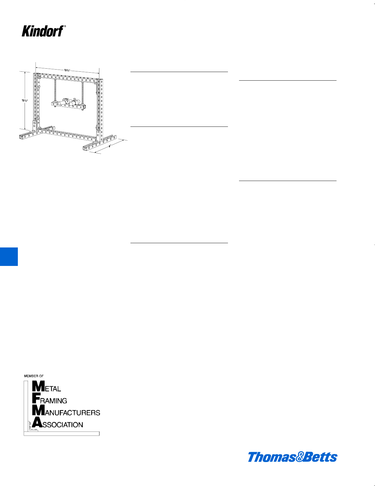
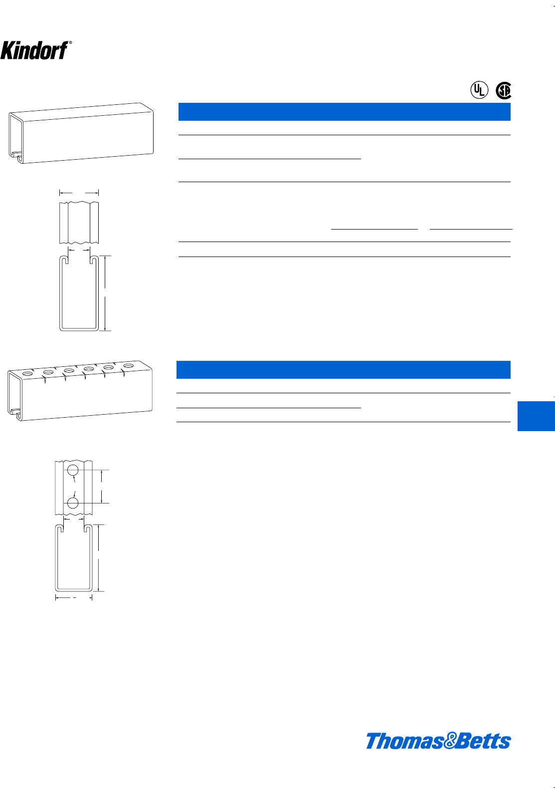
Features
11⁄2" wide x 11⁄2" deep
7⁄8" continuous open slot
10 ft. and 20 ft. lengths
Kindorf Channel
The Kindorf Channel System is
designed so that the maximum number
of support and framing applications
can be constructed with a minimum
amount of labor and pieces.
Uniqueness in Design
The 1d" dimension in the channel, hole
spacing and fittings means all parts fit
together, no matter where they’re used,
or at what angle. This modular dimen-
sion provides maximum flexibility in
field applications, and results in saving
inventory and labor dollars. The
Kindorf exclusive Galv-Kr¯om finish pro-
vides superior corrosion protection for
all threaded components, channel and
fittings. Through a two-part process,
the coating is applied on all finished
parts after fabrication – there is no
exposed surface where corrosion can
start.
Strength
Even though Kindorf’s Channel is
slightly smaller in dimensions, it sup-
ports the same weight as1e" channel.
Compatibility with 15⁄8"
Strut
The Kindorf System is designed so that
most accessories are compatible with
1e" strut. Conduit and pipe straps will
work equally well with 1e" and 1d"
strut. In addition, 98% of 1e" acces-
sories are interchangeable in Kindorf
Channel. Angle fittings can adapt easi-
ly to the open side of any 1e" strut and
the unique parallelogram nuts provide
secure attachment to both types of
strut.
Full Line of Support
Products
Kindorf’s many advantages are
extended into a broad product offering
including beam clamps, concrete
inserts, lighting supports, cable cleats
and a variety of threaded components.
This system is available in the largest
selection of finishes and materials
including green coated, aluminum,
stainless steel and nonmetallic. This
combined with a nationwide network of
distributors and service centers makes
Kindorf a single source for supported
metal framing needs.
K2 © 2003 Thomas & Betts Corporation. Specifications are subject to change without notice. www.tnb.com
K
Kindorf ®
412034.K01 KINDORF 5/1 5/7/03 3:16 PM Page K2
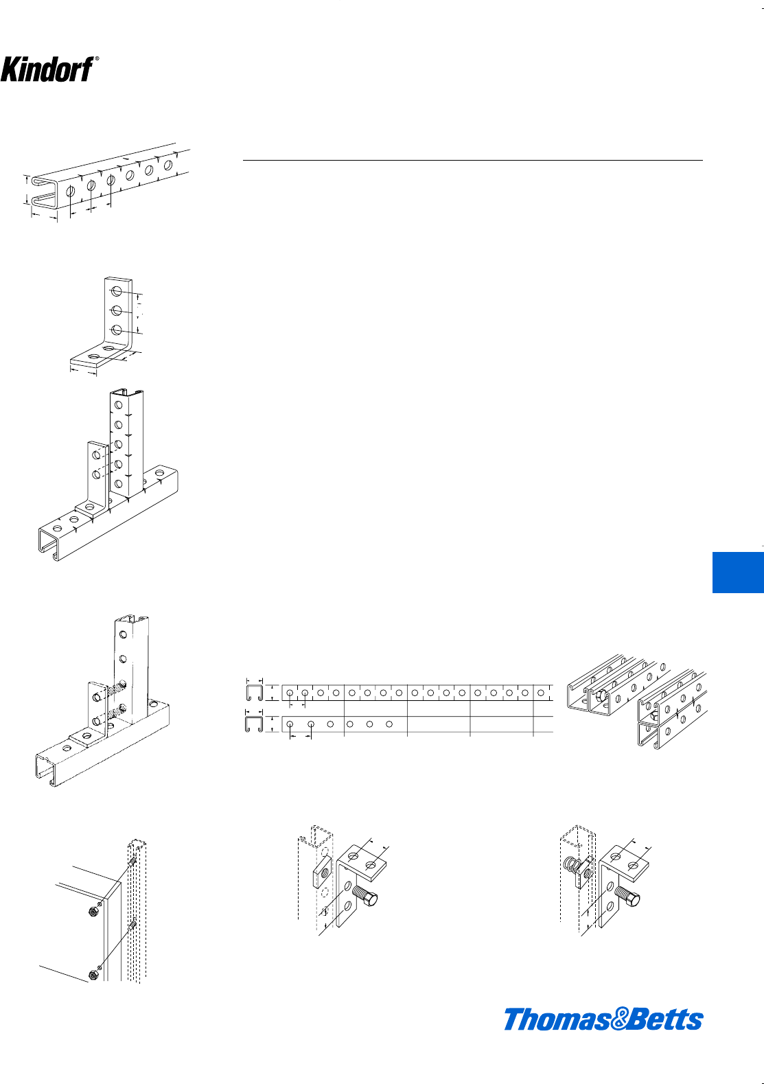
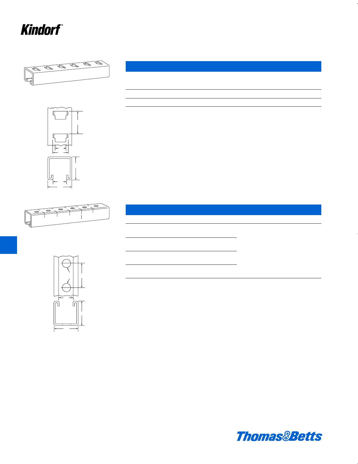
Features
Channel with bolt holes
9⁄16" dia. holes on 11⁄2" centers for 11⁄2" bolts.
Kindorf’s 11⁄2" is Much More Than A Cross
Section Dimension
The 1d" with Kindorf is truly a Modular
Dimension. The channel height, width,
and prepunched hole spacings are all
1d". The angle fittings and the bolt
holes in the angle fittings are all 1d"
dimensions. Scribe marks are located
at 1d" intervals to mark the midpoint
between holes and every 6" on the side
for easy measurement.
Job site adaptability and structural
integrity are the key factors in making
strut channel an economical solution to
metal framing needs. Kindorf, with its
1d" modular dimensions allows the
installer to do more work with fewer
pieces and less labor dollars.
Here’s What The Modular Dimension Can
Do For You
Using a 1e" channel with hole spac-
ings on 1g" centers requires numerous
fittings and in many cases limits the
joint fastening to the open side of the
channel. Field drilling and welding,
plus extra fittings become the rule
rather than the exception. With con-
stant 1d" dimensions throughout the
system many structural joints can be
made with a minimum of fittings.
Consider the following:
1. The Entire Section Can be Used
You are not limited to using only the
open slot side. Because holes line up
on channel and fittings. Using the
scribe marks ensures the fittings will
work, and a straight cut is made.
2. Considerable Field Drilling and Welding
Eliminated
The holes are already there and they
are usable. Back to back; side to back;
side to side – all combinations that can
be made using B-995 Kindorf channel.
3. Field Cutting And Layout Made Simple
8 scribe marks = 1 ft. Simply count the
marks and cut. Position of holes
ensures balanced support for trapezes
on every piece, thus keeping waste to
an absolute minimum.
4. Modular Fittings Fasten To Bolt Side or
Slot Side – Unique Stud Nut
Kindorf framing fittings are engineered
for versatile use – to meet the greatest
number of framing combinations with
maximum rigidity and security. Fittings
may be fastened to the channel on
either the bolt hole side or the slot side.
The matching 1d" dimensions of chan-
nel bolt holes and fitting bolt holes pro-
vide a fast alignment and quick bolting.
Fastening on the slot side provides infi-
nite placement of the nut to match bolt-
ing requirements. Either way results in
simple “building block” erection and
permits multiple application of fittings.
With the B-911SN Stud Nut, blind fasten-
ing of angles and fixtures is eliminated.
1
2
1
1
2
1
1
2
1
1
2
1
1
2
1
1
2
1
1
2
1
1
2
1
11⁄2
11⁄2
11⁄2
11⁄2
11⁄2
11⁄2
11⁄2
11⁄2
Kindorf 11⁄2"
All holes line up – all the time.
15⁄8" Strut
7⁄8" holes cause misalignment.
© 2003 Thomas & Betts Corporation. Specifications are subject to change without notice. www.tnb.com K3
Why Kindorf 11⁄2" Channel Saves You Labor Dollars
Holes in fittings also line up.
Cuts come where they should
Fastening on bolt hole side Fastening on slot side.
Clamping nut or hex head nut may be used for
attachment and security of fittings to either side
of channel.
Spring nut holds in position without support.
Inserts easily in channel and sets automati-
cally – cannot rotate.
Stud nut saves time, reduces labor – like
having an extra pair of hands.
1
2
1
2
1
1
5
8
1
5
8
1
1
2
1
7
8
1
5
8
1Strut
Kindorf 1'
6" 12" 18" 24"
1'
1
2
1
1
2
1
1
2
1
1
2
1
11⁄2
11⁄2
11⁄2
17⁄8
11⁄2
6"
15⁄8
15⁄8
12" 18" 24"
1
"
1
"
11⁄2
11⁄2
11⁄2
11⁄2
K
Kindorf ®
412034.K01 KINDORF 5/1 5/7/03 3:16 PM Page K3
Features
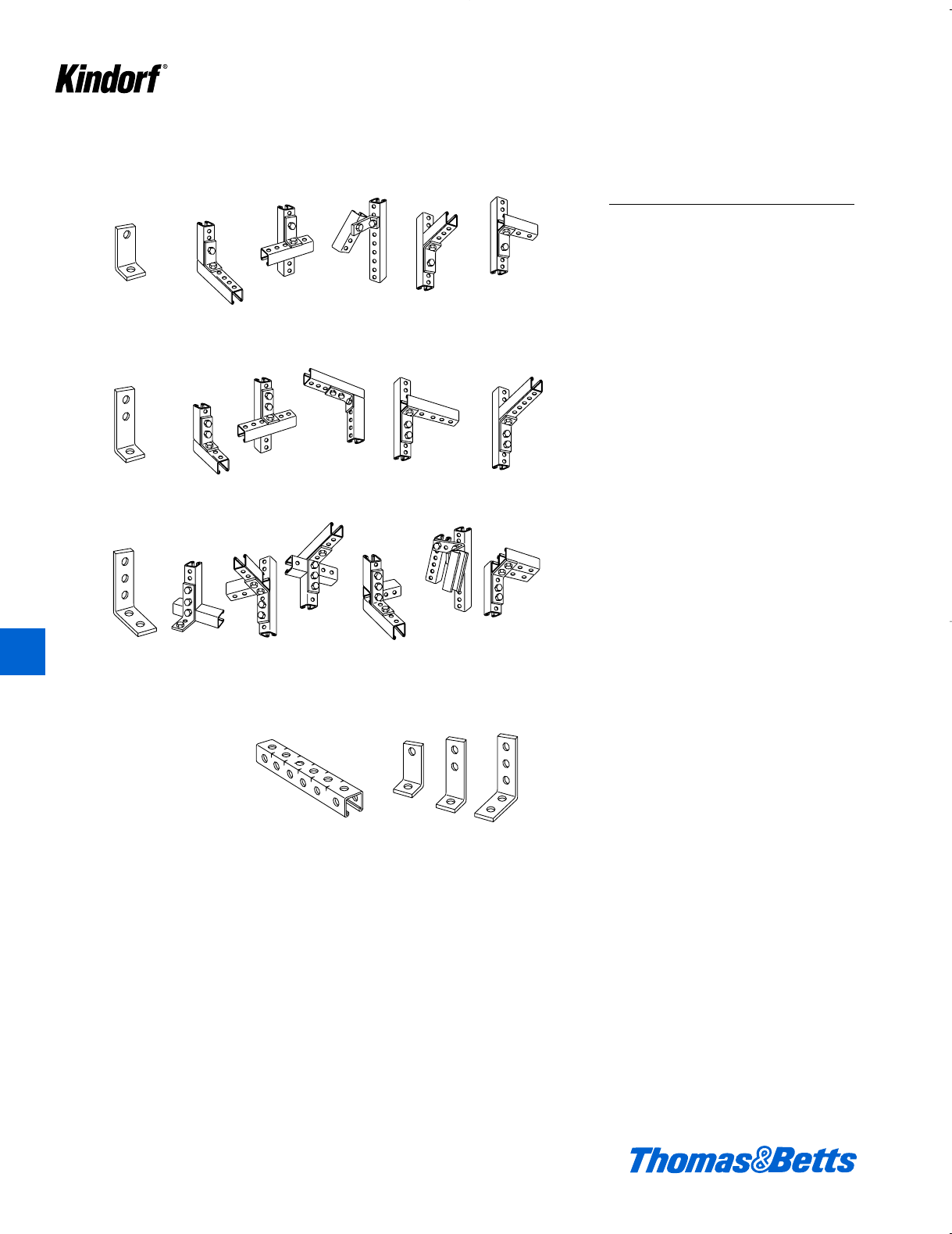
One Kindorf B-915
Two-Hole Connector Will Do
One Kindorf B-916
Three-Hole Connector Will Do
One Kindorf B-917
Five-Hole Connector Will Do
By simply stocking B-995
pre-punched channel and
three angle fittings, a great
number of joints can be
made.
Why Kindorf 11⁄2" Saves
You Inventory Dollars
Fewer Pieces Do More Work
By making equal use of the back of
the channel, the sides of the channel
(B-995 see page K5) and the open
slot, your options are increased.
Combine this with three simple fittings
that are 1d" wide and have 1d" hole
layout, and you have the simplest and
most versatile Channel System on the
market today.
By stocking a single channel system
and only 3 angle fittings, a multitude of
jobs can be done.
With fewer pieces doing more work,
ordering efficiency is increased and
investment dollars are decreased.
Any way you look at it – Kindorf can save
you money.
Let the modular 11⁄2" dimension work for you in saving labor and inventory dollars.
K4 © 2003 Thomas & Betts Corporation. Specifications are subject to change without notice. www.tnb.com
K
Kindorf ®
412034.K01 KINDORF 5/1 5/7/03 3:16 PM Page K4
© 2003 Thomas & Betts Corporation. Specifications are subject to change without notice. www.tnb.com K5
Galv-Kr¯om®
ASTM Spec. For Finish: B-633-85
Galv-Kr¯om protects the steel
against rust and corrosion. Kindorf
channels, fittings and accessories,
including all threaded parts, are Galv-
Kr¯om finish. Channel and fittings with
bolt holes are finished after holes are
punched so that it has complete Galv-
Kr¯om protection.
Galv-Kr¯om is a combination of a .5
mil of electrogalvanizing on steel and
gold zinc chromate. The base zinc
thickness is in compliance with ASTM
B633-85 Type LS coating. Zinc, unlike
organic coatings, is a sacrificial type
plating protecting the base steel from
corrosion even though it is exposed at
cut edges or scratches. The additional
gold zinc chromate film provides a
passivating nonporous barrier against
moisture and other corrosive elements.
The Galv-Kr¯om®Superior
Finish
Galv-Kr¯om is the time-tested and
proved metal finish that provides
Kindorf with an outstanding measure
of product value. It is not a paint –
won’t chip or peel. Stands up under
rough handling.
Galv-Kr¯om is a superior galvanized
finish, plus zinc chromate, resulting in
an attractive bronze lustre that needs
no painting for protection or appear-
ance. The finish is smooth, clean and
remarkably tough. When colorizing is
necessary for coding, you’ll find Galv-
Kr¯om an excellent bond for the paint of
your choice. The surface does not
require an acid wash preparation and
is non-porous and non-crystalline.
Unlike paint or enamel this surface
also offers a minimum of electrical
resistance so that electrical applica-
tions are easily grounded as required
under most electrical codes.
Finishes
Roll Formed
Carbon Steel
Electro
Plated Zinc
Coating
Yellow
Dichromate
Conversion
Coat
Tank 1 Tank 2 Tank 3 Tank 4 Tank 5 Tank 6 Tank 7
Tank 8 Tank 9 Tank 10 Tank 11 Tank 12
“Soak Degreasing”
Chemical solution
removes bulk of oil
and grease buildup.
“Electro Cleaner”
The metal is nega-
tively charged to
remove minute sur-
face particles.
“Rinse”
Live, clear water
rinse.
“Sulfuric Acid Bath”
Prepares the metal
by etching the sur-
face for the zinc
application.
“Rinse”
Live, clear water
rinse.
“Zinc Tank”
Electrically applies
the zinc metal coat-
ing.
“Rinse”
Chemically treated
rinse water.
“Rinse”
Live, clear water
rinse.
“Rinse”
Live, clear water
rinse.
“Chromate Dip”
A yellow dichro-
mate conversion
coat is applied to
the zinc.
“Rinse”
Live, clear water
rinse.
“Dryer”
Forced hot air is
circulated around
the strut until dry.
K
Kindorf ®
412034.K01 KINDORF 5/1 5/7/03 3:16 PM Page K5

Finishes
K6 © 2003 Thomas & Betts Corporation. Specifications are subject to change without notice. www.tnb.com
K
Kindorf ®
ASTM B 117 Test
Information and
Specifications
The B117 salt spray (fog) test is
applicable to organic and inorganic
finishes such as a paint versus plating
comparison and is highly recognized
for both industrial and military produc-
tion as a qualifying procedure. It’s use-
ful in estimating the relative behavior of
closely related material such as low
carbon steel since it simulates the
basic conditions with some accelera-
tion due to either wetness or tempera-
ture or both. The 5% salt solution is the
dissolving of 5+/-1 parts of sodium
chloride in 95 parts of water conform-
ing to Type IV water in ASTM Sped C
1193. The salt is free of nickel and
copper, containing not more than 0.1%
sodium iodide or more than 0.3% total
impurities. Temperature must be at
95F +2/-3F recorded twice daily. The
apparatus consists of a fog chamber,
reservoir, compressed air, atomizing
nozzles, specimen supports, heat
source and controls.
About the Channel
Finish Test
Performed and certified by an inde-
pendent testing laboratory, randomly
chosen channel samples were placed
in the same chamber and exposed to
a continuous salt spray. Channel ends
were sealed so that exposed cuts
were not subjected, thus measuring
the true finish resistance. The channel
sections were also suspended vertical-
ly with no other contact and positioned
to permit the free settling of fog.
During the test time cycles, the chan-
nel sections were thoroughly inspect-
ed for signs and indications of damag-
ing red rust. The Kindorf Zinc and
Gold Dichromate finish dramatically
outperformed all other tested finishes
as shown above.
Metal Framing Channel finish (Unscribed) Independent Laboratory Salt Spray
Corrosion Resistant Test ASTM B-117
Kindorf
Zinc w/Gold
Dichromate
Industry
Pre-Galvanized
(G90)
Epoxy
Green
Enamel
Green
Hours to Red Rust
700 ____________________________________________________________________________
600 ____________________________________________________________________________
500 ____________________________________________________________________________
400 ____________________________________________________________________________
300 ____________________________________________________________________________
200 ____________________________________________________________________________
100 ____________________________________________________________________________
0 ____________________________________________________________________________
412034.K01 KINDORF 5/1 5/7/03 3:16 PM Page K6

© 2003 Thomas & Betts Corporation. Specifications are subject to change without notice. www.tnb.com K7
K
Kindorf ®
Finishes and Materials
Finishes
1. Green Coated. (Suffix GR)
Green urethane powder resins are
applied electrostatically to the steel
after fabrication. Once the material is
completely covered with the pow-
dered-form urethane, it proceeds
through a 400° baking process for ten
minutes, creating a chemical bond.
This results in a minimum of 1.5 mil
thickness of urethane coating provid-
ing excellent resistance to chipping or
peeling.
2. Pregalvanized Steel. (Suffix PG)
In addition to the standard Galv-Kr¯om®
finish, all Kindorf®channels are avail-
able in pregalvanized steel. This mate-
rial is identical to the standard steel
except for its ASTM G-90 zinc coating.
This coating is applied at the steel mill
prior to the channel fabrication.
3. Electrogalvanized (Suffix EG)
Often referred to as “zinc plated” or
“electroplated zinc,” the steel and .5
mils of zinc are bonded by an electrol-
ysis process. This is the identical
process used in the Kindorf Galv-Kr¯om
finish without the numerous benefits of
the gold colored dichromate conver-
sion coat (see Galv-Kr¯om finish for
more information). Electrogalvanizing is
most commonly applied to small fit-
tings, hardware and threaded products.
4. Hot-Dipped Galvanized (Suffix HD)
The material is zinc coated after fabri-
cation providing total product protec-
tion on all surfaces. The fabricated
channel or fitting is suspended and
then dipped into tanks of hot zinc for a
prolonged period, creating a coherent
bond. The result is superior corrosion
resistance as compared to pregalva-
nized material. Hot-dipped galvanizing
is not recommended for threaded
6063 Aluminum and heat treated to a
T-6 specification.
3. Nonmetallic. (Suffix N)
Kindorf®channels are also available in
fiberglass reinforce polyester and vinyl
ester. These products are pultruded
into shapes similar to steel channels.
They offer a high degree of corrosion
protection and are very lightweight.
4. Stainless Steel. (Suffix SS)
For the most corrosive environments,
Kindorf®offers Type 304 Stainless
Steel channel sections and acces-
sories. Type 316 stainless available
upon request. Contact your local sales
rep. These products are identical to
their carbon steel counterparts except
for a much greater corrosion resis-
tance.
Warning
Load tables, charts, and design crite-
ria provided in this catalog are intend-
ed as guides only. Selection of proper
product, installation intervals, erection,
and placement are the responsibility of
the user.
Pipe hanger products when improp-
erly used as tools of erection have
occasionally failed. The user is cau-
tioned to use the product only as it
was intended, to avoid an accident.
We reserve the right to change
material and finish specifications with-
out notice, to improve our products.
products, considering the zinc coating
thickness will often disrupt the threads.
Kindorf hot-dipped galvanized is in
conformance with ASTM Specifications
A-123 (formerly A-386) and A-153.
Kindorf channels maintain a mini-
mum 1.5 ounces of zinc per square
foot of steel or 2.5 mils (ASTM A-123,
Thickness Grade 65). This finish is
also referred to as “Hot-dipped galva-
nized after fabrication.”
5. PVC Coated (Prefix P)
A polyvinyl chloride (PVC) plastic coat-
ing is fused to the channel, fitting or
accessory after fabrication by immers-
ing the part in fluidized PVC tanks. The
fused-melt mixed powder PVC coating
thickness is 15 mils (.015") plus or
minus five mils. PVC material is a ther-
moplastic and will soften in high tem-
peratures. An inherent weakness with
PVC coatings occurs when field alter-
ations are applied, such as cutting or
drilling. These acts disrupt the sealed
PVC product and warrant field touch-
up. Kindorf cannot be held responsible
for field-altered PVC coated products.
Materials
1. Standard Steel.
The standard Kindorf®Channel is
made from high quality carbon steel
sheet. These sections are cold formed
into a unique and modular profile by
an efficient roll forming process.
Additionally, the process”cold works”
the steel is to give it greater mechani-
cal properties.
2. Extruded Aluminum. (Suffix AL)
For more corrosive environments,
Kindorf®also offers extruded aluminum
channel sections. These section are
nearly identical to their steel counter-
ports. Aluminum channel is made from
412034.K01 KINDORF 5/1 5/7/03 3:16 PM Page K7
Finishes
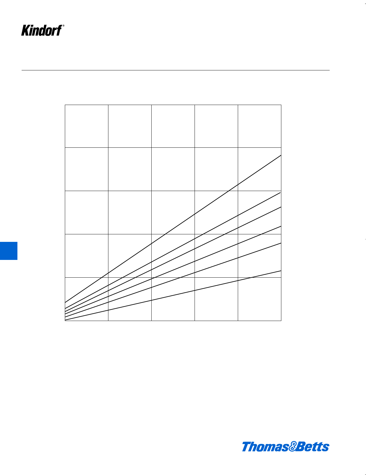
Life of Protection vs. Thickness of Zinc and Type of Atmosphere
50
40
30
20
10
Service Life, Years*
Rural
Tropical Marine
Suburban
Moderately Industrial
Heavy Industrial
Temperate Marine
Oz. of Zinc/Sq. Ft. of Surface
.25 .50 .75 1.00 1.25 1.50
Thickness of Zinc in Mils
0.4 0.8 1.3 1.7 2.1 2.6
K8 © 2003 Thomas & Betts Corporation. Specifications are subject to change without notice. www.tnb.com
* Service Life is defined as the time to 5% rusting of the steel surface.
Courtesy of American Galvanizers Assoc.
K
Kindorf ®
412034.K01 KINDORF 5/1 5/7/03 3:16 PM Page K8
© 2003 Thomas & Betts Corporation. Specifications are subject to change without notice. www.tnb.com K9
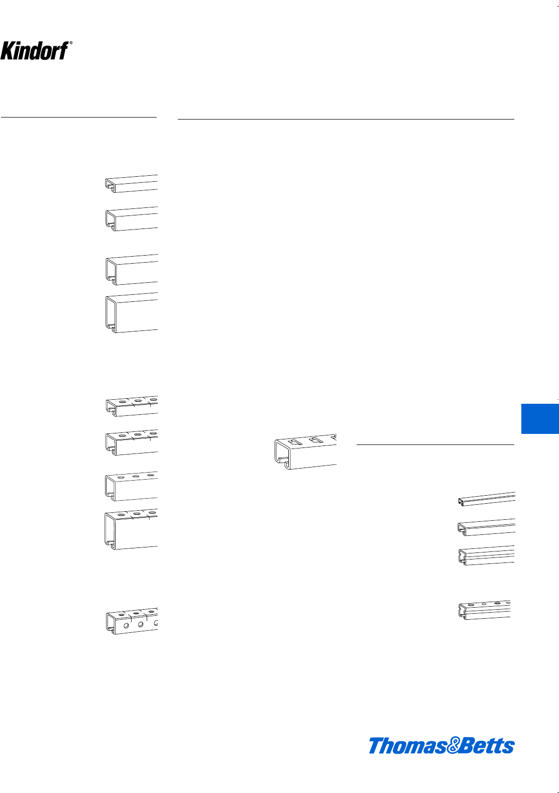
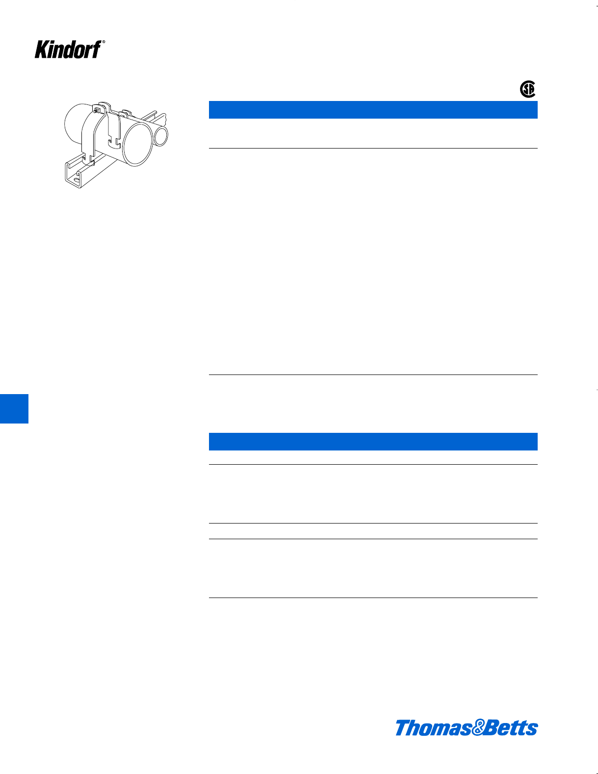
Channels
Bantam Channels –
Pre-Galvanized Steel
10 Ft. Lengths
Solid Base
6014
j" x d" Nom. x 18 ga.
6013
c" x e" Nom. x 20 ga.
6029
d" x f" Nom. x 16 ga.
Bolt Hole Base
6029
d" x f" Nom. x 16 ga.
Steel Channels
Galv-Kr¯om Finish
10 ft. and 20 ft. Lengths
Solid Base
B-906
1d" x f" x 14 ga.
B-900 (12 ga.)
B-900-M (14 ga.)
1d" x 1d"
B-901
1d" x 1g" x 12 ga.
B-902
1d" x 3" x 12 ga.
l" Dia. Bolt Holes On 1d" Centers
f" From End
B-907
1d" x f" x 14 ga.
B-905 (12 ga.)
B-905-M (14 ga.)
1d" x 1d"
B-909
1d" x 1g" x 12 ga.
B-903
1d" x 3" x 12 ga.
Bolt Holes 3 Sides
l" Dia. On 1d" Centers
f" From End
B-995 (12 ga.)
B-995-M (14 ga.)
1d" x 1d"
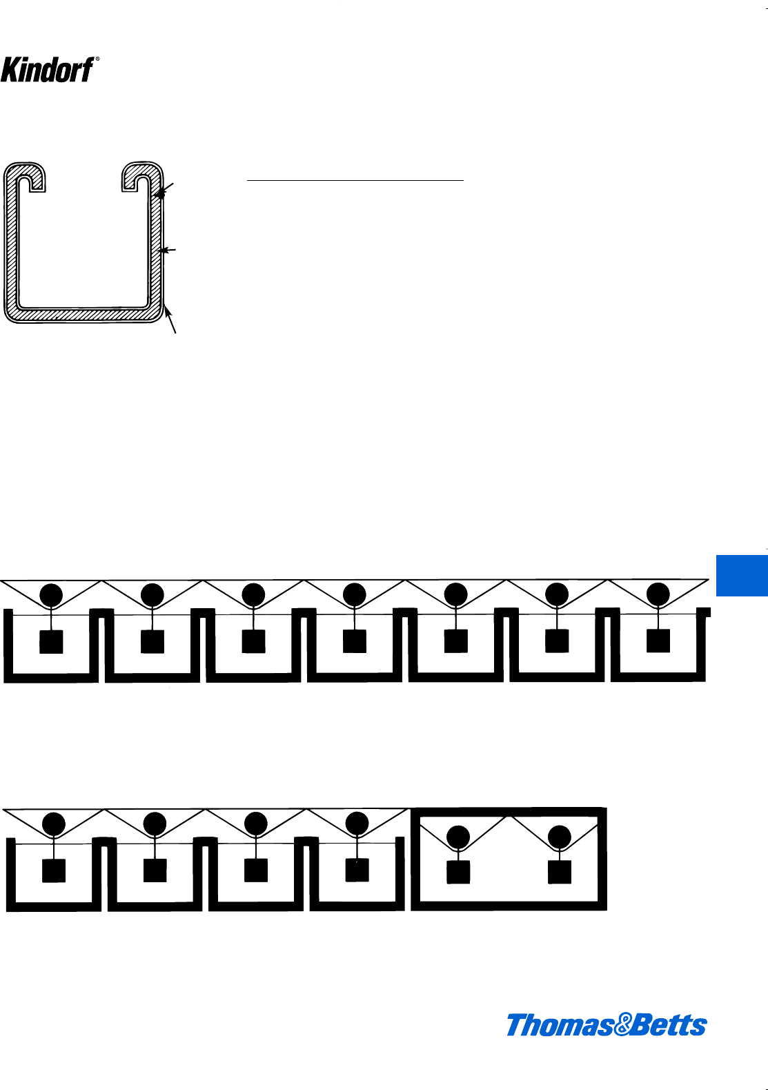
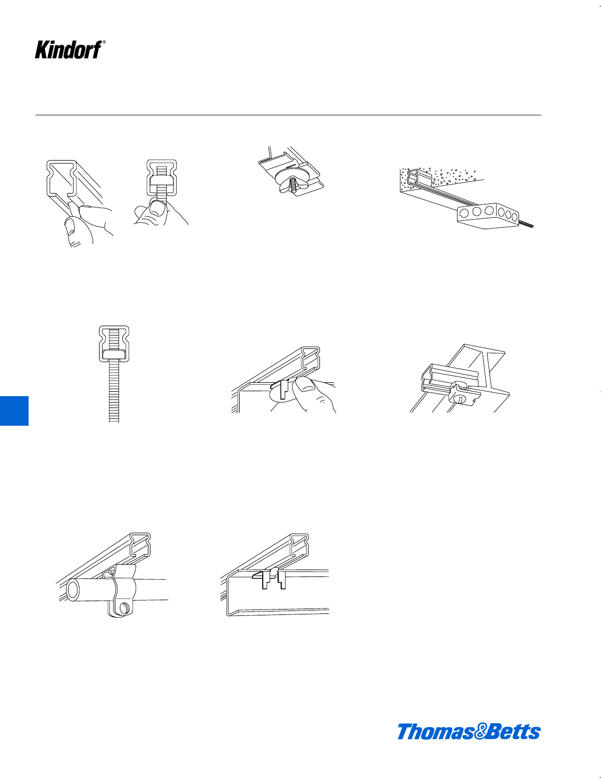
Channels, Fittings and Bantam Channels
T-Slot Base
B-904
1d" x 1d" x 12 ga.
Kindorf is a rugged heavy gage struc-
tural quality steel channel preformed in
a “U” shape with a continuous open
slot the entire length. The turned-in
edges serve as retaining points for the
nuts and bolts assembly of fittings to
the channel. The shape of the channel
permits infinite adjustability of the
clamping nut … simply by gliding it
along the channel to the desired posi-
tion. Spring-tensioned nuts are gener-
ally used for positioning overhead or in
vertical channel installations. A stud
nut (with spring) is provided for easy
mounting of cabinets and equipment.
Channel Nuts are specially shaped as
parallelograms with biting edges so
that when tightened, with normal pres-
sure on the bolt, the nut clamps the
sides of the channel together in a
secure connection which reinforces the
rigidity of the channel itself. The nut
rests on the ‘lips’ of the channel slot.
Continuous-slot channel framing, with
its sliding nut and bolt attachment fea-
ture, offers substantial installation
economy since no pre-measuring,
punching, drilling or welding are
required. Erection of structural framing
provides a basic system for the sup-
port of practically all electrical, industri-
al and mechanical services. The appli-
cation versatility of Kindorf eliminates
the need for individual service support
systems and results in lower over-all
installation costs for framing and sup-
ports.
An important consideration for stan-
dardizing on the Kindorf System is its
flexibility of purpose for metal framing
requirements. A supply of channel and
a select group of fittings will take care
of a majority of metal framing require-
ments. It is easy to stock – stacked like
conduit, 1000 ft. of channel takes up
less than one square foot of floor
space. Fittings and channels are
reusable – short sections are saved
and become valuable for spot arrange-
ments, which means there is no waste
in a Kindorf System.
K
Kindorf ®
412034.K01 KINDORF 5/1 5/7/03 3:16 PM Page K9
K10 © 2003 Thomas & Betts Corporation. Specifications are subject to change without notice. www.tnb.com
Channels
Connection by means of continuous slot.
B-900 Channel – 1d" x 1d"
Cat. No. Description Joiner End Caps
B-900 12 ga. Galv-Kro
-m
B-900-M 14 ga. Galv-Kro
-m
B-900-10GR Green Powder Coated
B-900-20GR Green Powder Coated G978
B-900-10PG Pregalvanized G978A G967
B-900-20PG Pregalvanized G1503S
B-900-10HD Hot Dipped Galvanized
B-900-20HD Hot Dipped Galvanized
Use H-113-B bolts and B-910-1/2 or B-911-1/2 steel nuts for mounting fittings. B-900, 162#/C ft. B-900-M, 107#/C ft.
Properties of Section
Sectional Material X-X Axis Y-Y Axis
Cat. No. Area Thickness lbs/ft. ISRISR
B-900 0.345 0.104 1.206 0.101 0.123 0.535 0.129 0.175 0.603
B-900M 0.217 0.074 0.74 0.018 0.041 0.272 0.077 0.105 0.559
For heavier load requirements. Connection by
means of continuous slot.
1
2
1
1
2
1
7
8
1
2
1
7
8
1
7
8
g"
1d"
1d"
g"
1d"
1g"
®
®
®
®
B-901 Channel – 1d" x 1g"
Cat. No. Description Joiner End Caps
B-901 12 ga. Galv-Kro
-mG978C G-966
B-901HD Hot Dipped Galvanized
Use H-113-B bolts and B-910-1/2 or B-911-1/2 steel nuts for mounting fittings. 196#/C ft.
Properties of Section
Sectional Material X-X Axis Y-Y Axis
Cat. No. Area Thickness lbs/ft. ISRISR
B-901 0.595 0.104 2.028 0.263 0.251 0.665 0.238 0.309 0.632
K
Kindorf ®
412034.K01 KINDORF 5/1 5/7/03 3:16 PM Page K10
© 2003 Thomas & Betts Corporation. Specifications are subject to change without notice. www.tnb.com K11
Channels
Connection by means of continuous slot.
B-902 Channel 1d" x 3"
Cat. No. Description Joiner End Cap
B-902-10 12 ga. Galv-Kro
-m
B-902-20 12 ga. Galv-Kro
-mG978-D G957
B-902-10HD Hot Dipped Galvanized G-3003S
B-902-20HD Hot Dipped Galvanized
Use H-113-B bolts and B-910-1/2 steel nuts for mounting fittings. 285#/C ft.
Properties of Section
Sectional Material X-X Axis Y-Y Axis
Cat. No. Area Thickness lbs/ft. ISRISR
B-902 0.837 0.104 2.825 0.909 0.552 1.042 0.363 0.471 0.658
Connection by means of continuous slot or 9⁄16"
holes on 11⁄2" centers.
1
2
1
3
7
8
1
2
1
7
8
1
2
1
2
9
16
3"
11⁄2"
7⁄8"
11⁄2"
7⁄8"
11⁄2"
9⁄16"
3"
®
®
B-903 Channel 1d" x 3"
Cat. No. Description Joiner End Cap
B-903 12 ga. Galv-Kro
-mG978-D
B-903HD Hot Dipped Galvanized G3003S
Use H-113-B bolts and B-910-1/2 steel nuts for mounting fittings. 277#/C ft.
K
Kindorf ®
412034.K01 KINDORF 5/1 5/7/03 3:16 PM Page K11
Channels
Connections by means of continuous slot or 9⁄16"
holes on 11⁄2" centers which match holes in B-
900 series fittings.
1
2
1
1
2
1
1
2
1
7
8
9
16
11⁄2"
7⁄8"
11⁄2"
9⁄16"
11⁄2"
K12 © 2003 Thomas & Betts Corporation. Specifications are subject to change without notice. www.tnb.com
B-905 Channel 1d" x 1d"
Cat. No. Description Joiner End Cap
B-905 12 ga. Galv-Kro
-m
B-905-M 14 ga. Galv-Kro
-m
B-905-10GR Green Coated
B-905-20GR Green Coated
B-905-10PG Pregalvanized B941
B-905-20PG Pregalvanized
B-905-10HD Hot Dipped Galvanized
B-905-20HD Hot Dipped Galvanized
Use H-113-B bolts and B-910-1/2 or B-911-1/2 steel nuts for mounting fittings. Scribe marks designate mid-point
between holes for accurate field cutting. B-905, 158#/C ft. B-905-M, 102#/C ft.
Connection by means of continuous slot or T-
slots on 11⁄2" centers in base side of channel.
B-904 Channel 1d" x 1d"
T-Slot Base
Cat. No. Description
B-904 12 ga. Galv-Kro
-m
B-904HD Hot Dipped Galvanized
For attachment to continuous slot use H-113-B bolts and B-910-1/2 steel nuts. For attachment to T-slots use F-739
brackets 155#/C ft.
1
2
1
1
1
1
7
8
1
2
1
2
3
4
11⁄2"
7⁄8"
11⁄2"
3⁄4"
1"
11⁄2"
K
Kindorf ®
412034.K01 KINDORF 5/1 5/7/03 3:16 PM Page K12
© 2003 Thomas & Betts Corporation. Specifications are subject to change without notice. www.tnb.com K13
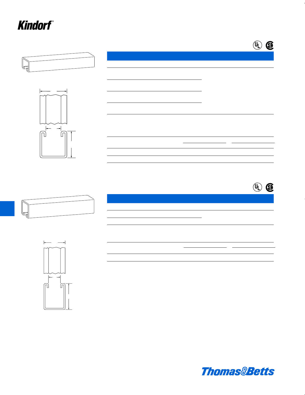
Channels
Connection by means of continuous slot.
B-906 Channel 1d" x f"
Connection by means of continuous slot.
Cat. No. Description Joiner End Cap
B-906 14 ga. Galv-Kro
-m G978-AL
G978-L G-968
Use H-113-A bolts and B-910-1/2 or B-912-1/2 steel nuts for mounting fittings.
Steel 75#/C ft.
1
12
7
8
3
4
11⁄2"
7⁄8"
3⁄4"
®
®
Properties of Sections
Sectional Material X-X Axis Y-Y Axis
Area Thickness lbs./ft. I S R I S R
0.521 0.104 1.776 0.155 0.179 0.545 0.2 0.259 0.619
B-907 Channel 1d" x f"
Cat. No. Description Joiner
B-907 14 ga. Galv-Kro
-m
B-907-10GR Green Coated
B-907-20GR Green Coated
B-907-10PG Pregalvanized B948
B-907-20PG Pregalvanized
B-907-10HD Hot Dipped Galvanized
B-907-20HD Hot Dipped Galvanized
Use H-113-A bolts and B-910-1/2 or B-912-1/2 steel nuts for mounting fittings. Holes on B-900 series fittings match
channel holes. Scribe marks on steel channel designate midpoint between holes for accurate field cutting. Steel
71#/C. ft.
Connection by means of continuous slot or 9⁄16"
holes on 11⁄2" centers.
1
2
1
9
16
9⁄16"11⁄2"
7⁄8"
11⁄2"
For heavier load requirements. Connection by
means of continuous slot or 9⁄16" holes on 11⁄2"
centers.
1
2
1
7
8
1
1
2
1
7
8
9
16
7⁄8"
11⁄2"
17⁄8"
9⁄16"11⁄2"
B-909 Channel 1d" x 1g"
Cat. No. Description Joiner
B-909 12 ga. Galv-Kro
-m
B-909HD Hot Dipped Galvanized G978-C
Use H-113-B bolts and B-910-1/2 or B-911-1/2 steel nuts for mounting fittings. 118#/C. ft.
K
Kindorf ®
412034.K01 KINDORF 5/1 5/7/03 3:16 PM Page K13
Channels
K14 © 2003 Thomas & Betts Corporation. Specifications are subject to change without notice. www.tnb.com
B-995 Channel 1d" x 1d"
Cat. No. Description Joiner
B-995-10 12 ga. Galv-Kro
-m
B-995-20 12 ga. Galv-Kro
-m
B-995-10M 14 ga. Galv-Kro
-mB941
B-995-20M 14 ga. Galv-Kro
-m
Use H-113-B bolts and B-910-1/2 or B-911-1/2 steel nuts for mounting fittings. 150#/C ft. Scribe marks designate mid-
point between holes for accurate field cutting.
Standard 10 ft. lengths
Kindorf Channels – Welded Combinations
All Kindorf channels are available in a variety of combinations – some are shown below.
10 and 20 ft. lengths – steel Special lengths may be ordered.
How To Order
Add the suffix designation of the desired combination to the regular channel catalog number.
(Example: Two B-900 channels back to back are ordered as B-900-2A.)
Connection by means of continuous slot or 9⁄16"
holes on 11⁄2" centers on three sides which
match holes in B-900 series fittings.
1
2
1
1
2
1
1
2
1
7
8
9
16
2A 2B 2C 2D 3A
3C 3D
11⁄2"
7⁄8"
11⁄2"
11⁄2"
9⁄15"
K
Kindorf ®
412034.K01 KINDORF 5/1 5/7/03 3:16 PM Page K14
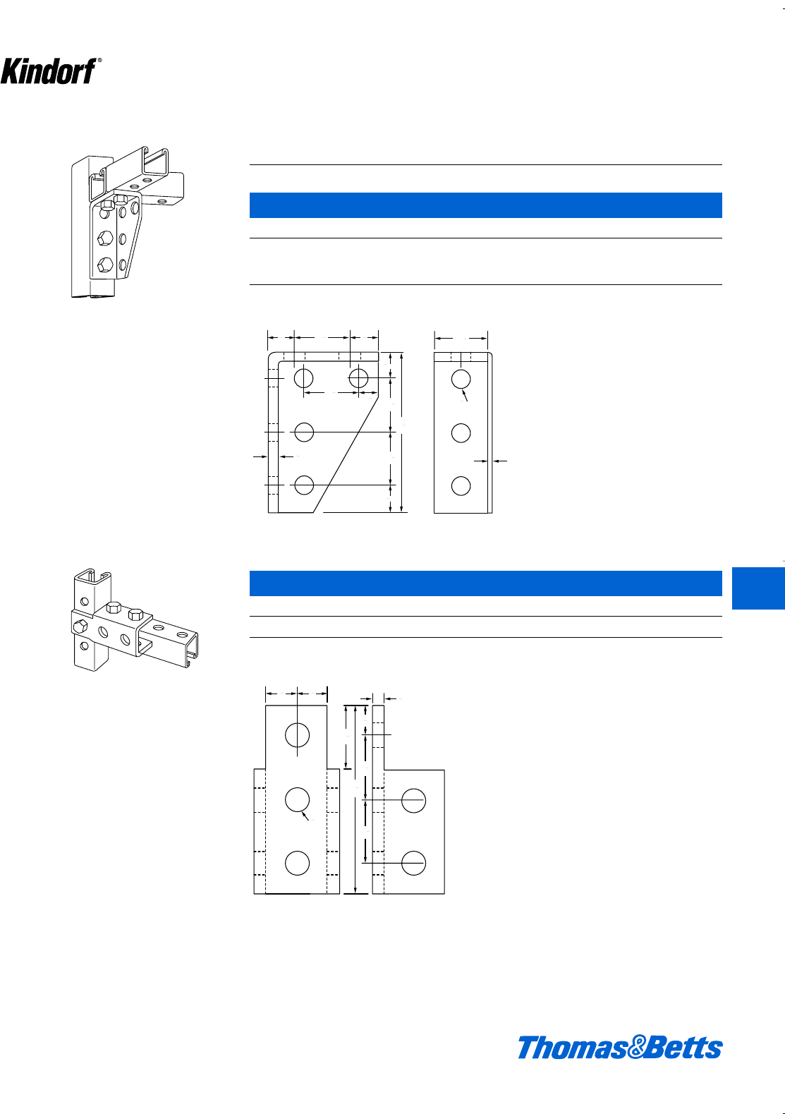
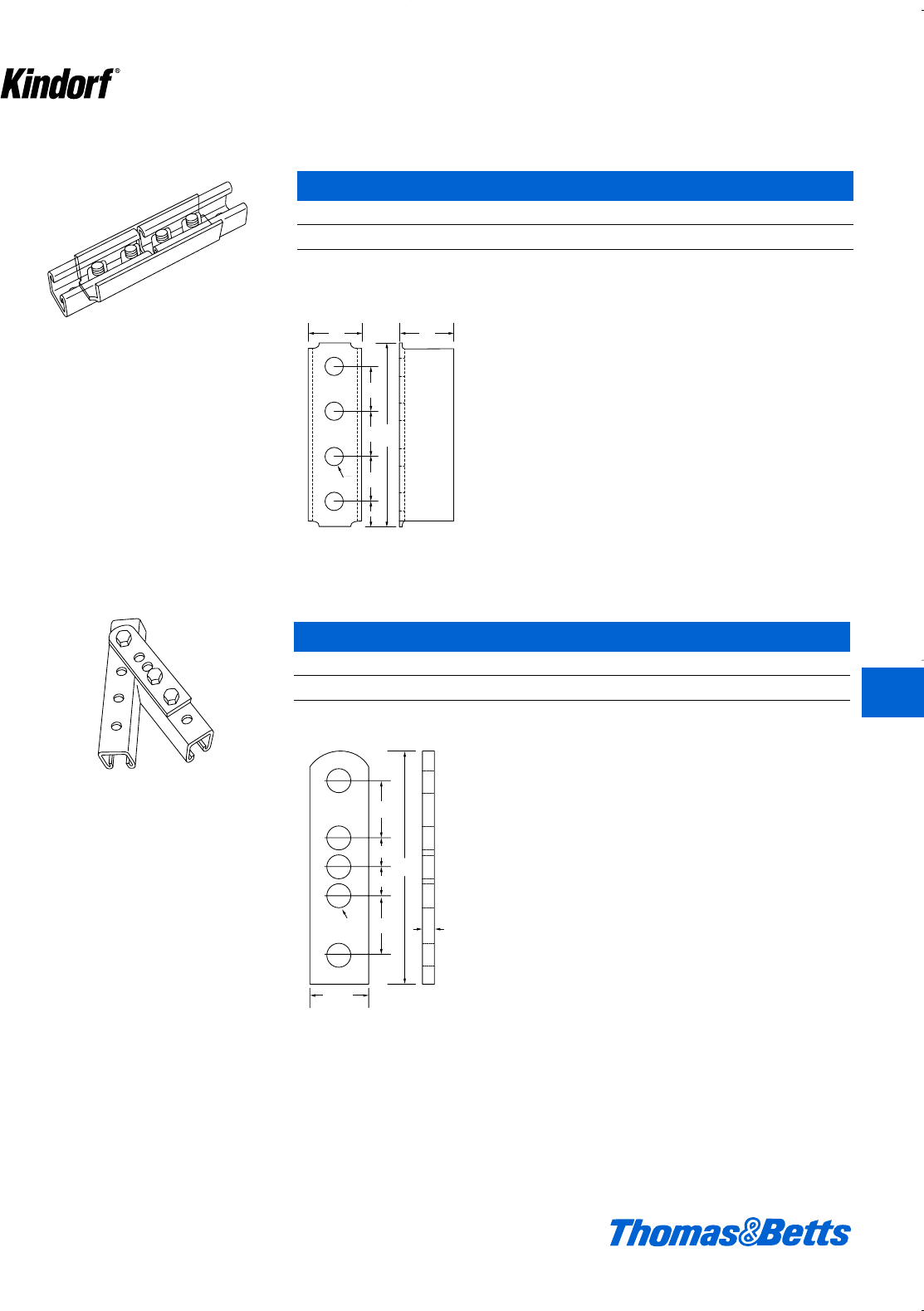
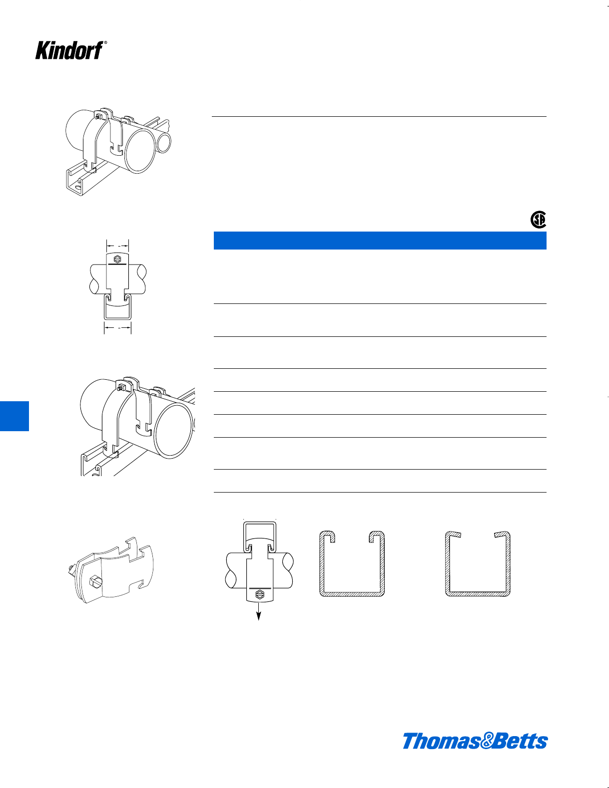
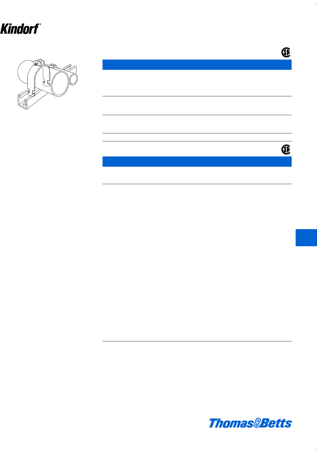
Fittings
For use with all Kindorf channels
Channel Nuts
Standard Finish: Galv-Kr¯om
B-910 Series
Wt.
Cat. No. Size Thickness lbs./C
B-9100-1/4 1⁄4- 20 3⁄16 7.5
B-910-5/16 5⁄16 - 18 5⁄16 7.3
B-910-3/8 3⁄8- 16 5⁄16 9.15
B-910-1/2 1⁄2- 13 3⁄89.9
B-911 Series
Wt.
Cat. No. Size Thickness lbs./C
B-911-1/4 1⁄4- 20 3⁄16 8
B-911-5/16 5⁄16 - 18 5⁄16 8.25
B-911-3/8 3⁄8- 16 5⁄16 10
B-911-D-3/8* 3⁄8- 16 5⁄16 12
B-911-1/2 1⁄2- 13 3⁄810
B-911-D-1/2* 1⁄2- 13 7⁄813
* For clamping nuts with spring for 3" deep channels add suffix D to catalog number.
B-911-SN Series
Wt.
Cat. No. Size Thickness lbs./C
B-911-3/8-SN1†3⁄8- 16 3⁄16 12.5
B-911-3/8-SN2†3⁄8- 16 5⁄16 13.0
B-911-1/2-SN1†1⁄2- 13 5⁄16 16.0
B-911-1/2-SN2†1⁄2- 13 3⁄817.0
† B-911-3/8-SN1, Stud: cDia., 1" Long. Accepts Kindorf Nuts H-114C (hex), H-116-C (square).
B-911-3/8-SN2, Stud: cDia., 1b" Long. Accepts Kindorf Nuts H-114C (hex), H-116-C (square).
B-911-1/2-SN1, Stud: dDia., 1" Long. Accepts Kindorf Nuts H-114D (hex), H-116-D (square).
B-911-1/2-SN2, Stud: dDia., 1b" Long. Accepts Kindorf Nuts H-114D (hex), H-116-D (square).
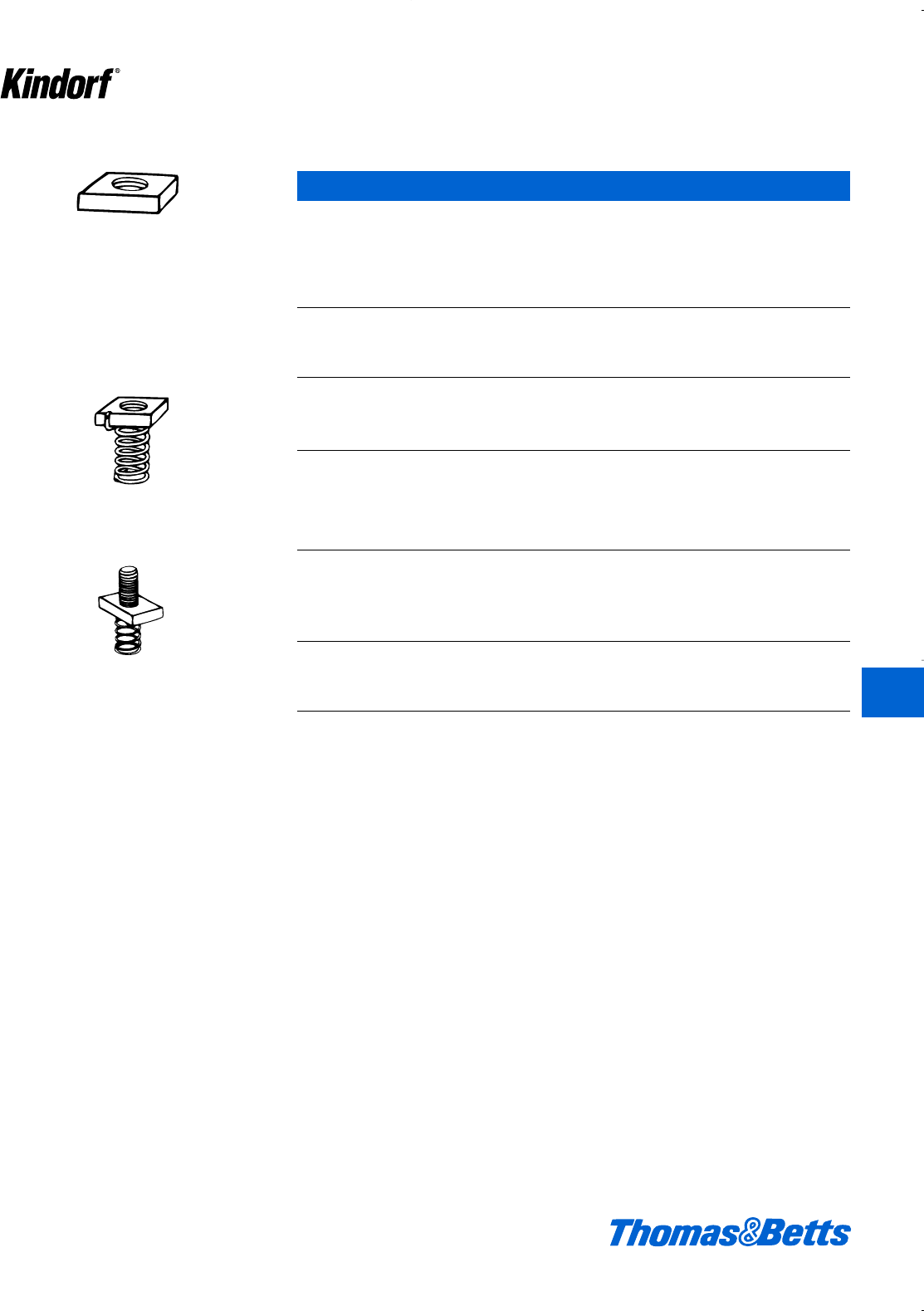
Load Ratings of Steel Channel and Insert Nuts
(B-910-1/2 or B-911-1/2) when used in slot of 12 ga. Kindorf channel and tightened to a torque of 50 ft. Pounds are as
follows:
Withdrawal resistance to pull out safe load rating = 1600 lbs. Slip resistance safe loading
rating = 400 lbs.
(B-910-1/2 or B-912-1/2) when used in slot of 14 ga. Kindorf channel and tightened to a torque of 50 ft. Pounds are as
follows:
Withdrawal resistance to pull out safe load rating = 1300 lbs. Slip resistance safe load rating = 400 lbs.
Load ratings are based on safety factor of 3.
Self-holding clamping nut with spring attached.
For use with 11⁄2" deep channels.
Stud nut self-holding clamping nut with spring
attached.
© 2003 Thomas & Betts Corporation. Specifications are subject to change without notice. www.tnb.com K15
K
Kindorf ®
412034.K01 KINDORF 5/1 5/7/03 3:16 PM Page K15
Fittings
Channel Nuts – continued
B-912 Series
Wt.
Cat. No. Size Thickness lbs./C
B-912-1/4 b- 20 i8.0
B-912-5/16 j- 18 j7.5
B-912-3/8 c- 16 j9.5
B-912-1/2 d- 13 j9.8
Standard finish: Galv-Kro
-m
B-914 Series
Wt.
Cat. No. Size Thickness lbs./C
B-914-1/4 b- 20 i10.50
B-914-3/8 c- 16 j13.25
B-914-1/2 d- 13 c14.00
B-914-5/8 e- 11 c14.00
B-914-3/4 f- 10 c12.00
B-914-7/8 g- 9 c10.50
B-914-3/8P c- 18** c12.00
B-914-1/2P d- 14** c11.00
** Standard Pipe Threads.
Standard finish: Galv-Kro
-m
Load Ratings of Steel Channel and Insert Nuts
(B-910-1/2 or B-911-1/2) when used in slot of 12 ga. Kindorf channel and tightened to a torque of 50 ft. Pounds are as
follows:
Withdrawal resistance to pull out safe load rating = 1600 lbs. Slip resistance safe loading
rating = 400 lbs.
(B-910-1/2 or B-912-1/2) when used in slot of 14 ga. Kindorf channel and tightened to a torque of 50 ft. Pounds are as
follows:
Withdrawal resistance to pull out safe load rating = 1300 lbs. Slip resistance safe load rating = 400 lbs.
Load ratings are based on safety factor of 3.
Self-holding clamping nut with spring attached.
For use with 3⁄4" deep channels.
Square nuts for use with channel and spot-type
concrete inserts.
11⁄4" sq.
K16 © 2003 Thomas & Betts Corporation. Specifications are subject to change without notice. www.tnb.com
K
Kindorf ®
412034.K01 KINDORF 5/1 5/7/03 3:16 PM Page K16
© 2003 Thomas & Betts Corporation. Specifications are subject to change without notice. www.tnb.com K17
K
Kindorf ®
Fittings
Connectors
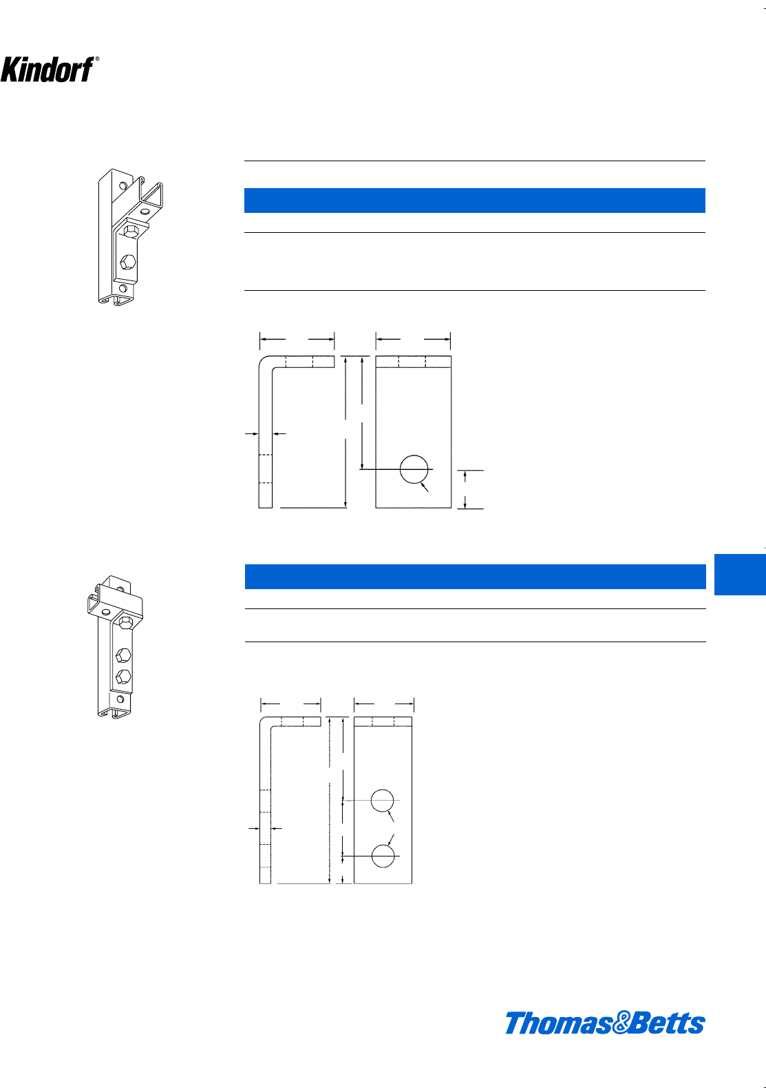
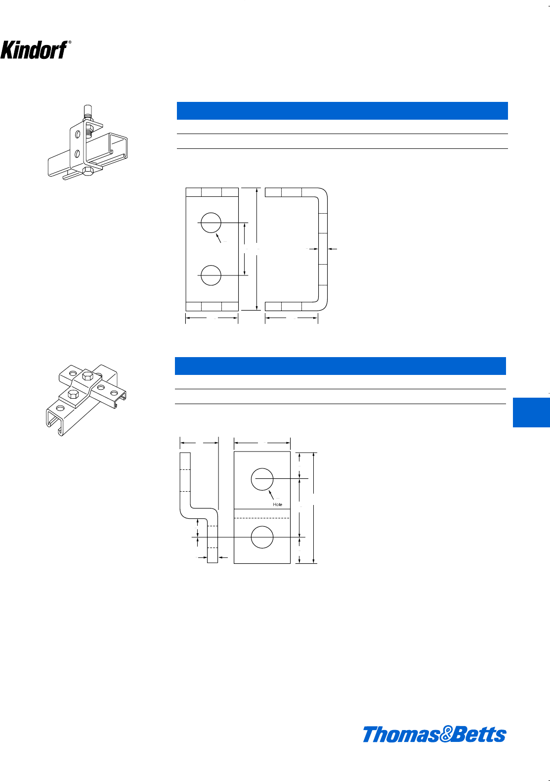
B-915 Two Hole Angle Connector
Cat. No. Finish
B-915 Galv-Kro
-m
B-915GR Green Coated
B-915EG Electro-Galvanized Finish
B-915HD Hot Dipped Galvanized
b" steel. 39#/C.
Can also be used as side beam connector to
suspend 1
⁄2" hanger rod.
Can also be used as side beam connector to
suspend 11
⁄2" hanger rod.
b
1d
3
2b
1d
f
l
b
1d
4d
1d
l
2b
f
1d
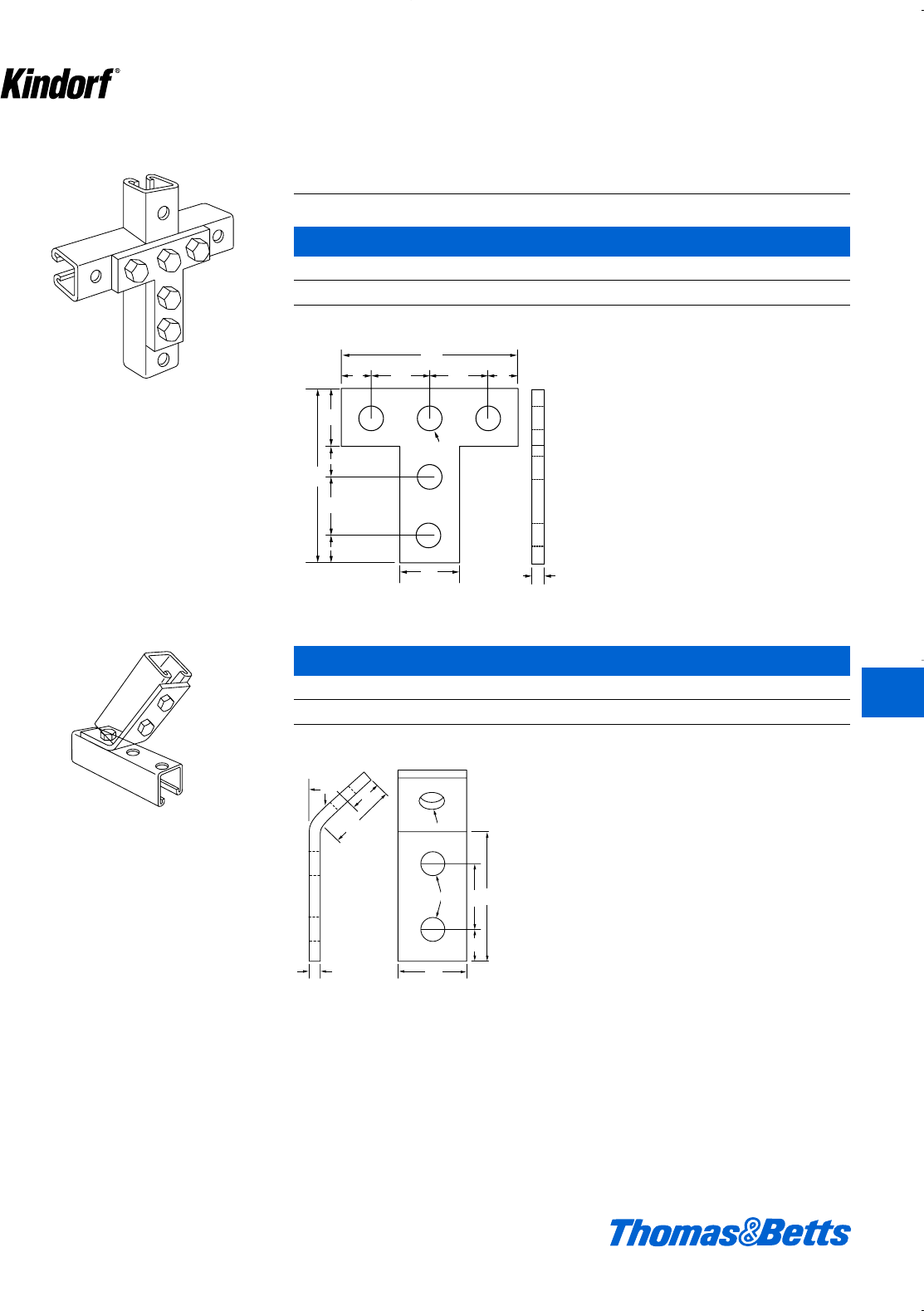
B-916 Three Hole Angle Connector
Cat. No. Finish
B-916 Galv-Kro
-m
B-916HD Hot Dipped Galvanized
b" steel. 46#/C.
412034.K01 KINDORF 5/1 5/7/03 3:16 PM Page K17
K18 © 2003 Thomas & Betts Corporation. Specifications are subject to change without notice. www.tnb.com
K
Kindorf ®
Fittings
Connectors – (Continued)
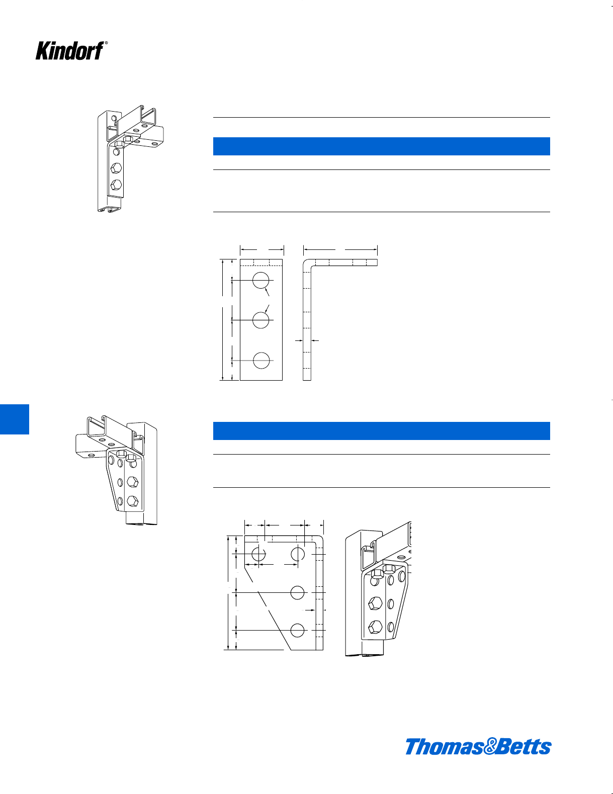
B-917 Five Hole Angle Connector
Cat. No. Finish
B-917 Galv-Kro
-m
B-917GR Green Coated
B-917EG Electro-Galvanized Finish
B-917HD Hot Dipped Galvanized
b" steel. 68#/C.
3
1
2
1
9
16
1
4
1
2
1
3
4
1
2
41
2
1
3
4
1
2
1
1
4
1
2
4
1
2
1
3
4
3
4
1
2
1
1
2
3
4
3
4
1
2
1
1d"
f"
b"
1d"
1d"
l"
4d"
3"
f"
1d"
f"
b"
1d"
1d"
4d"
1d"f"
f"
f"
B-918 Left Hand Gusset Connector
Cat. No. Finish
B-918 Galv-Kro
-m
B-918GR Green Coated
B-918EG Electro-Galvanized
12 Ga. and b" steel. 102#/C.
412034.K01 KINDORF 5/1 5/7/03 3:16 PM Page K18
© 2003 Thomas & Betts Corporation. Specifications are subject to change without notice. www.tnb.com K19
K
Kindorf ®
Fittings
Connectors – (Continued)
B-919 Right Hand Gusset Connector
Cat. No. Finish
B-919 Galv-Kro
-m
B-919GR Green Coated
B-919EG Electro-Galvanized
12 Ga. and b" steel. 102#/C.
3
4
3
4
9
16
1
2
1
3
4
1
2
1
3
16
1
2
1
1
2
4
12 ga.
1
2
1
1
2
19
16
1
4
1
2
4
1
2
13
4
3
4
1
2
11
2
3
4
1
2
1
3
4
B-920 End Connector
Cat. No. Finish
B-920 Galv-Kro
-m
i" steel. 80#/C.
412034.K01 KINDORF 5/1 5/7/03 3:16 PM Page K19
K20 © 2003 Thomas & Betts Corporation. Specifications are subject to change without notice. www.tnb.com
K
Kindorf ®
Fittings
Connectors – (Continued)
B-921 Two Side Corner Connector
Cat. No. Finish
B-921 Galv-Kro
-m
i" steel. 101#/C.
1
2
1
1
2
1
1
2
4
9
16
3
4
1
2
1
3
4
1
2
1
1
2
4
3
16
1
2
4
3
4
1
2
1
1
4
2
1
2
1
1
2
1
3
1
2
4
3
4
3
4
19
16
2
2
1
1
4
3
9
16
3
4
1
2
1
1
2
1
3
4
4
3
4
3
3
16
1d"
1d"
1d"i"
4d"
f"
4d"
l"
1d"
1d"
f"
f"
1d"
4d"
1d"
1d"
1d"
i"
f"
l"
1d"
1d"
f"
f"
4d"
f"
f"
f"f"
l"
2"
3"
B-922 Opposite Side Angle Connector
Cat. No. Finish
B-922 Galv-Kro
-m
i" steel. 124#/C.
412034.K01 KINDORF 5/1 5/7/03 3:16 PM Page K20
© 2003 Thomas & Betts Corporation. Specifications are subject to change without notice. www.tnb.com K21
K
Kindorf ®
Fittings
Connectors – (Continued)
B-923 Three Side Angle Connector
Cat. No. Finish
B-923 Galv-Kro
-m
i" steel. 137#/C.
3
1
2
4
3
4
3
4
11
2
2
1
1
4
3
3
4
9
16
3
4
9
16
1
3
16
9
16
1 6
3
4
6
6
6
3
4
1
25
32
3
16
25
32
1
2
1
3
16
3
3
16
3
4
B-924 Post Base Connector
Cat. No. Finish
B-924 Galv-Kro
-m
B-924-GR Green Coated
B-924-EG Electro-Galvanized
i" steel 250#/C.
For use with 1d" x 1d" channels.
412034.K01 KINDORF 5/1 5/7/03 3:16 PM Page K21
K22 © 2003 Thomas & Betts Corporation. Specifications are subject to change without notice. www.tnb.com
K
Kindorf ®
Fittings
Supports
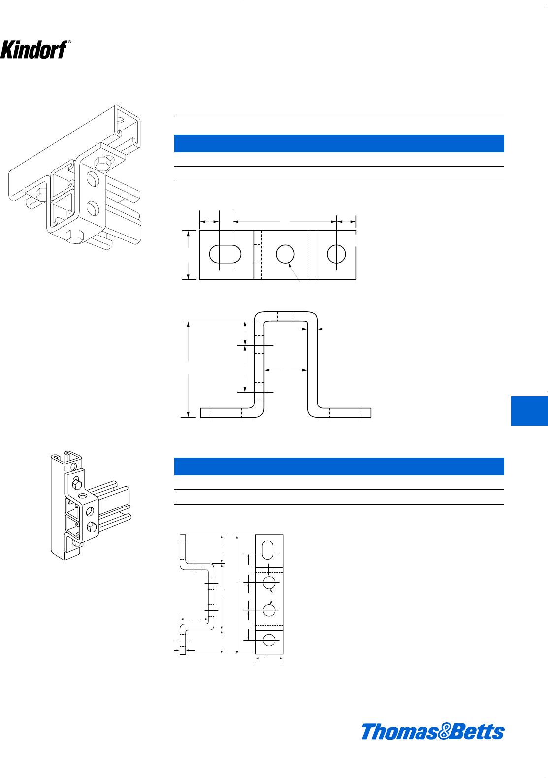
B-926 Z Support
Cat. No. Finish
B-926 Galv-Kro
-m
b" steel. 42#/C.
For use with 1d" x 1d" channels.
1
21
1
2
1
3
3
4
3
4
3
4
3
4
9
16
11
2
1
2
1
11
2
1
4
11
16
5
16 33
4
3
4
1
1
2
1
9
16
9
16
1
3
16
25
16
B-927 U Support
Cat. No. Finish
B-927 Galv-Kro
-m
B-927GR Green Coated
B-927EG Electro-Galvanized
i" steel. 57#/C.
For use with 1d" x 1d" channels.
412034.K01 KINDORF 5/1 5/7/03 3:16 PM Page K22
© 2003 Thomas & Betts Corporation. Specifications are subject to change without notice. www.tnb.com K23
K
Kindorf ®
Fittings
Supports – (Continued)
B-928 Deep U Support
Cat. No. Finish
B-928 Galv-Kro
-m
i" steel. 77#/C.
1
1
2
1
3
4
11
16 5
16
9
16
1
16
3
3
4
9
16
19
16
1
3
16
1
2
1
9
16
1
2
3
1
4
1
3
16
9
16
1
1
2
1
15
32
1
9
16
1
15
32
1
1
4
6
1d
1l
3h
W
1b
1d
f
i
f
1l
1
j
l
i
1l
3d
1d
1v
6b
1v
1ll
B-929 Wide U Support
Cat. No. Finish
B-929 Galv-Kro
-m
i" steel. 63#/C.
412034.K01 KINDORF 5/1 5/7/03 3:16 PM Page K23
K24 © 2003 Thomas & Betts Corporation. Specifications are subject to change without notice. www.tnb.com
K
Kindorf ®
Fittings
Supports – (Continued)
B-930 Angle Support
Cat. No. Finish
B-930 Galv-Kro
-m
b" steel. 70#/C.
3
1
4
9
16
11
2
3
4
3
4
3
4
11
2
3
4
3
3
4
3
4
3
4
3
4
3
16
47
16
3
4
9
16
1
2
1
2
1
1
2
1
3
4
3
4
1
2
11
2
17
16
3
4
3
4
41
2
Connectors
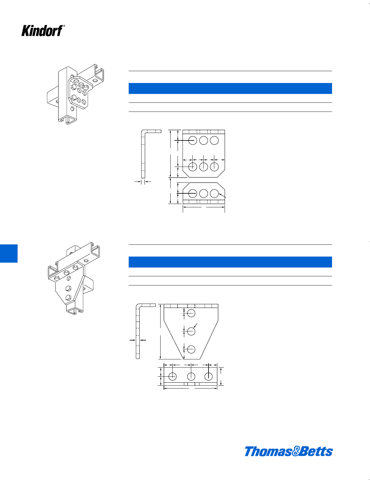
B-932 Heavy Angle Connector
Cat. No. Finish
B-932 Galv-Kro
-m
i" steel. 136#/C.
412034.K01 KINDORF 5/1 5/7/03 3:16 PM Page K24
© 2003 Thomas & Betts Corporation. Specifications are subject to change without notice. www.tnb.com K25
K
Kindorf ®
Fittings
Connectors – (Continued)
B-933 Five Hole Joint Connector
Cat. No. Finish
B-933 Galv-Kro
-m
b" steel. 96#/C.
1
4
1
2
1
2
1
3
4
3
4
3
1
3
4
3
4
3
1
2
1
9
16
1
2
1
1
2
1
9
16
3
4
3
4
4
3
4
1
3
4
1
4
1
2
1
1
l
1
1d
4f
b
l
f
f
3
3
1d
f
f
1d
b
1f
1d
1d
1d
f
f
B-934 Outside Corner Connector
Cat. No. Finish
B-934 Galv-Kro
-m
b" steel. 57#/C.
412034.K01 KINDORF 5/1 5/7/03 3:16 PM Page K25
K26 © 2003 Thomas & Betts Corporation. Specifications are subject to change without notice. www.tnb.com
K
Kindorf ®
Fittings
Connectors – (Continued)
B-935 Three Hole Plate Connector
Cat. No. Finish
B-935 Galv-Kro
-m
B-935-GR Green Coated
B-935-EG Electro-Galvanized
i" steel. 32#/C.
1
2
1
9
16
1
2
11
2
1
1
2
4
1
2
4
3
9
16
1
2
1
1
2
1
1
2
1
3
1
2
1
l
1d
i
1d
4d
1d
l
1d
1d
4d
1d
1d
3
3
B-936 Angle Plate Connector
Cat. No. Finish
B-936 Galv-Kro
-m
B-936GR Green Coated
B-936EG Electro-Galvanized
i" steel. 42#/C.
412034.K01 KINDORF 5/1 5/7/03 3:16 PM Page K26
© 2003 Thomas & Betts Corporation. Specifications are subject to change without notice. www.tnb.com K27
K
Kindorf ®
Fittings
Connectors – (Continued)
B-937 T-Plate Connector
Cat. No. Finish
B-937 Galv-Kro
-m
i" steel. 53#/C.
4
3
4
4
1
2
11
13
4
9
16
1
2
1
1
2
3
4
1
2
1
3
4
1
2
13
16
11
2
9
16
3
11
2
3
4
9
16
1
4
45
11
2
3
4
1d
i
1d1d
4
41⁄2
f
l
1d
f
f
1d
f
11⁄2
3
45°
9⁄16
11⁄2
3⁄4
1⁄4
9⁄16
11⁄2
3⁄4
B-938 Open Angle Connector
Cat. No. Finish
B-938 Galv-Kro
-m
b" steel. 42#/C.
412034.K01 KINDORF 5/1 5/7/03 3:16 PM Page K27
K28 © 2003 Thomas & Betts Corporation. Specifications are subject to change without notice. www.tnb.com
K
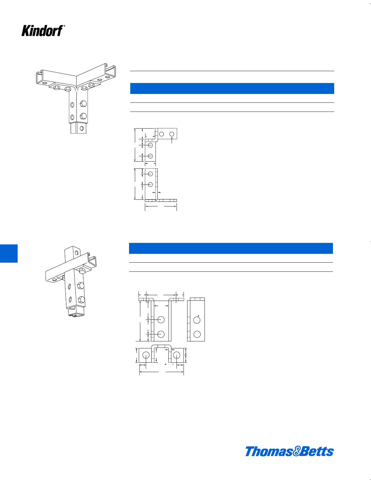
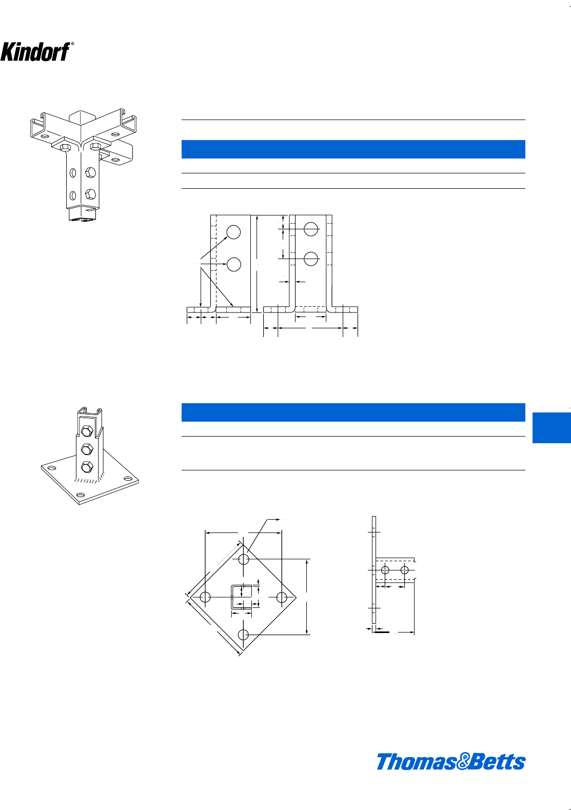
Kindorf ®
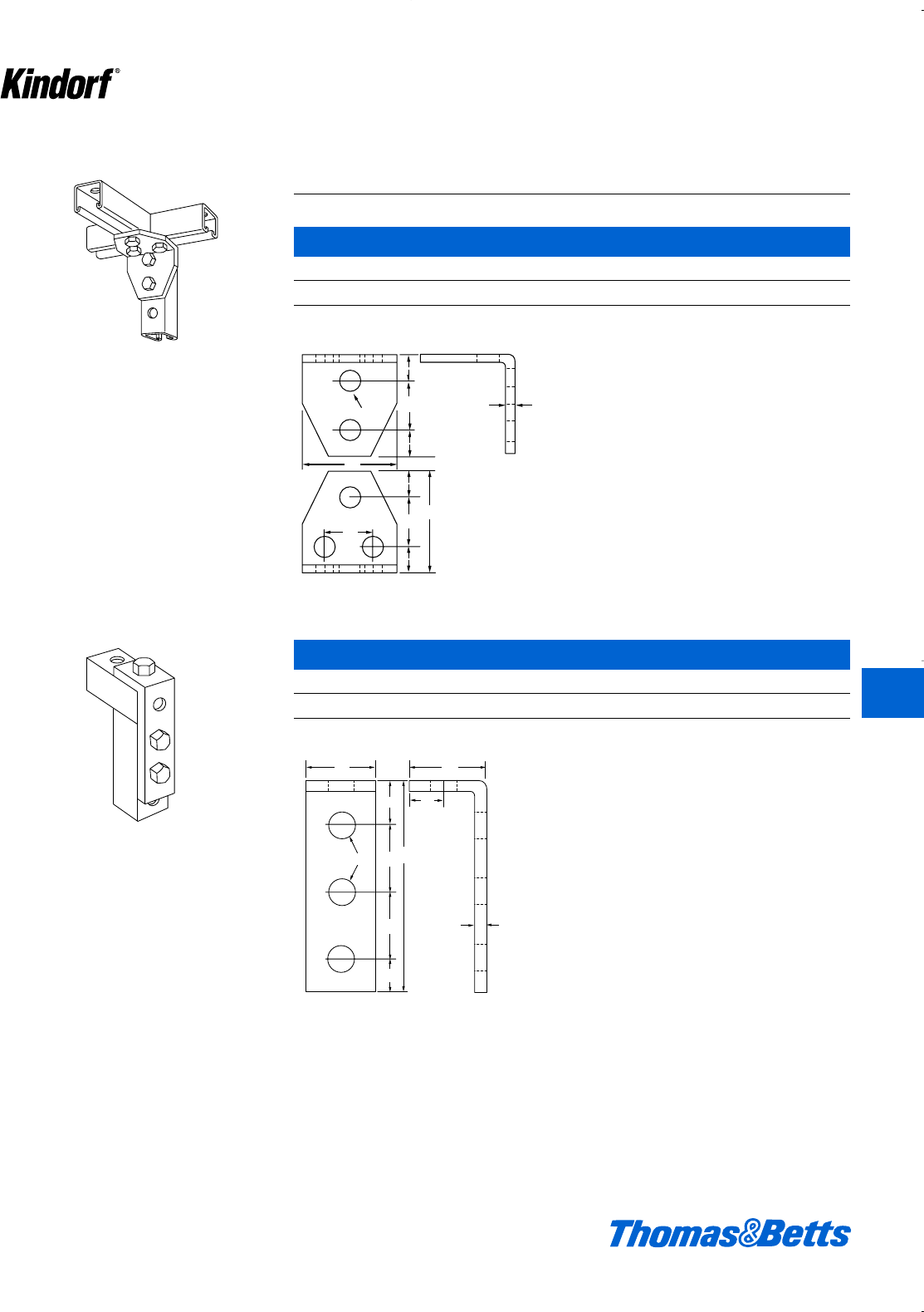
B-940 Corner Braces
Dimension Wt. in
Cat. No. A B C lbs./C
B-940-1 7d 6f 8a 115
B-940-2 13d 12f 16e 212
B-940-3 19d 18f 25a 305
b" steel, Galv-Kro
-m
Fittings
Connectors – (Continued)
B-939 Closed Angle Connector
Cat. No. Finish
B-939 Galv-Kro
-m
b" steel. 50#/C.
All sizes match hole structure of the B-905
channel at 90°.
11
2
9
16
11
2
3
4
1
4
45
3
4
23
8
11
2
1
2
1
A
B
11
2
B
1
4
3
4
3
4
9
16
45
C
45°
l
1d
b
1d
f
45°
l
1d
b
f
1d
B
B
A
1d
f
2c
f
412034.K01 KINDORF 5/1 5/7/03 3:16 PM Page K28
© 2003 Thomas & Betts Corporation. Specifications are subject to change without notice. www.tnb.com K29
K
Kindorf ®
Fittings
B-941 Joiner for B-905 Channel
Cat. No. Finish
B-941 Galv-Kro
-m
Order four B-910-1⁄2 nuts and four H-113-A cap screws separately.
12 ga. steel 80#/C.
11
2
6
9
16 11
2
11
2
11
2
3
4
11
2
7
8
5
1
2
1
1
2
1
9
16
1
2
1
3
4
3
4
1d
1d
f
1d
1d
1d
6
l
1d
11⁄2
5g
1di
f
f
Swivel Plate
Cat. No. Finish
B-942 Galv-Kro
-m
i" steel. 40#/C.
412034.K01 KINDORF 5/1 5/7/03 3:16 PM Page K29
K30 © 2003 Thomas & Betts Corporation. Specifications are subject to change without notice. www.tnb.com
K
Kindorf ®
Fittings
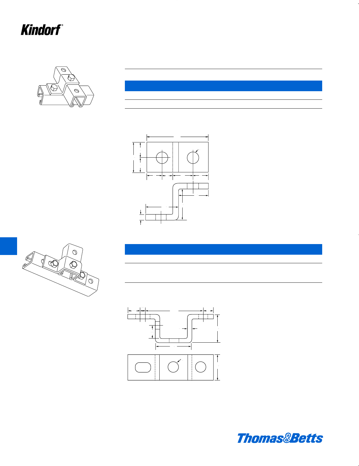
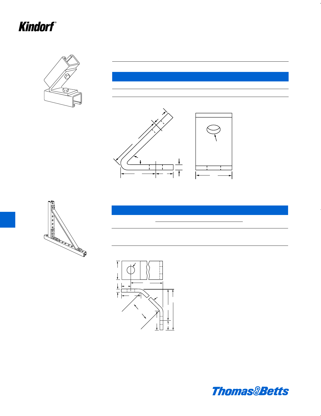
B-943 Brace Connectors
Cat. No. Finish
B-943 Galv-Kro
-m
b" steel. 66#/C.
5
16
2
1
2
1
3
4
1
9
16
1
3
9
16
1
4
1
2
1
3
4
1
1
2
1
3
3
16
1
2
15
8
11
2
1
2
11
2
1
3
4
3
4
9
16
1d
b
2j
19⁄16
3
1f
1d
1d
1d
i
3
1e
f
1d
f1d1df
l
l
Hole
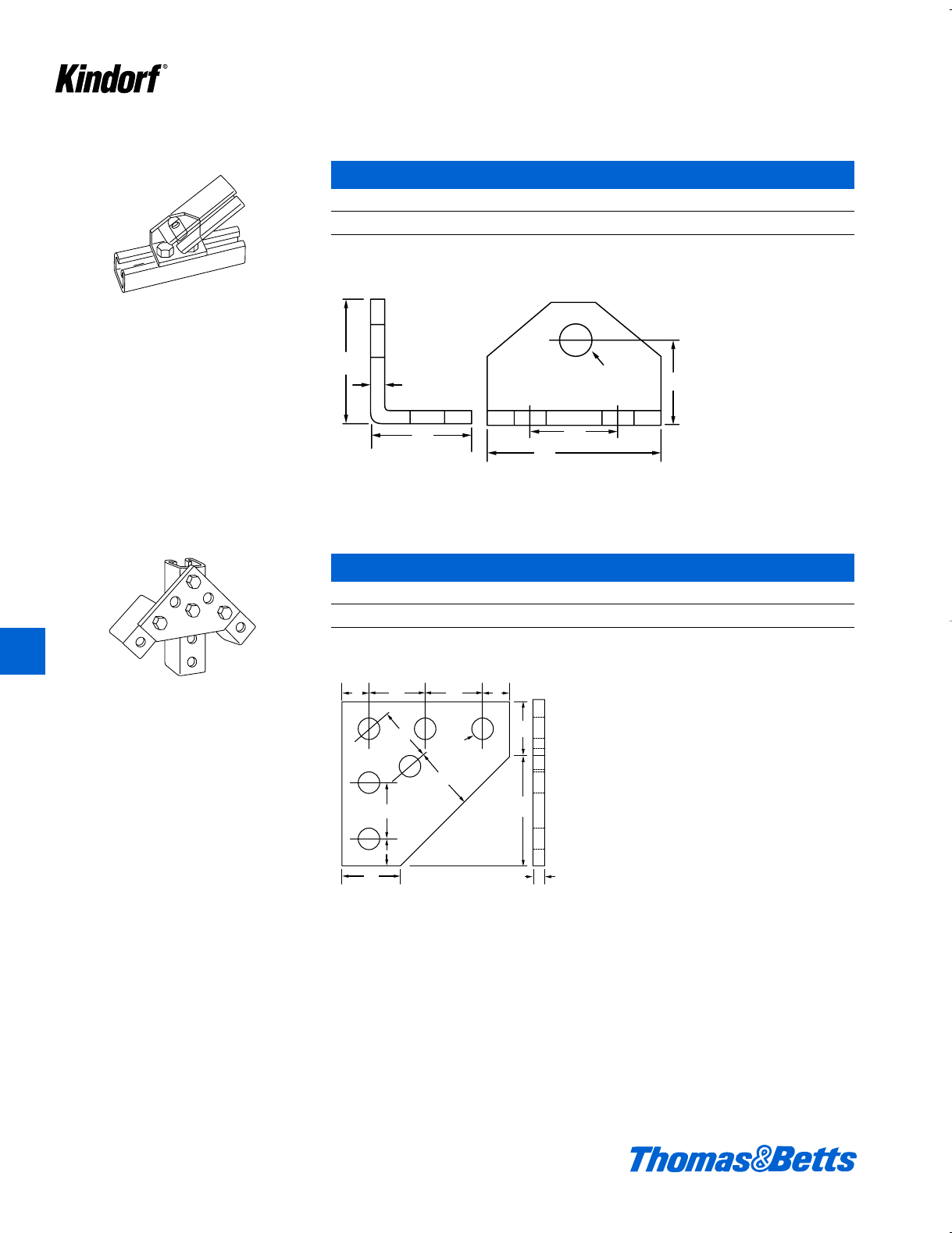
B-944 Double Brace Connector
Cat. No. Finish
B-944 Galv-Kro
-m
i" steel. 75#/C.
412034.K01 KINDORF 5/1 5/7/03 3:16 PM Page K30
© 2003 Thomas & Betts Corporation. Specifications are subject to change without notice. www.tnb.com K31
K
Kindorf ®
Fittings
Rod Connector
Cat. No. Finish
B-945 Galv-Kro
-m
b" steel. 61#/C.
1
2
1
1
2
1
1
2
1
5
8
31
4
9
16
For use with B-906 or B-907 channel only.
1
2
1
3
4
1
1
2
1
3
4
3
1
4
1
2
9
16
Z Support
Cat. No. Finish
B-946 Galv-Kro
-m
b" steel. 34#/C.
412034.K01 KINDORF 5/1 5/7/03 3:16 PM Page K31

K32 © 2003 Thomas & Betts Corporation. Specifications are subject to change without notice. www.tnb.com
K
Kindorf ®
Fittings
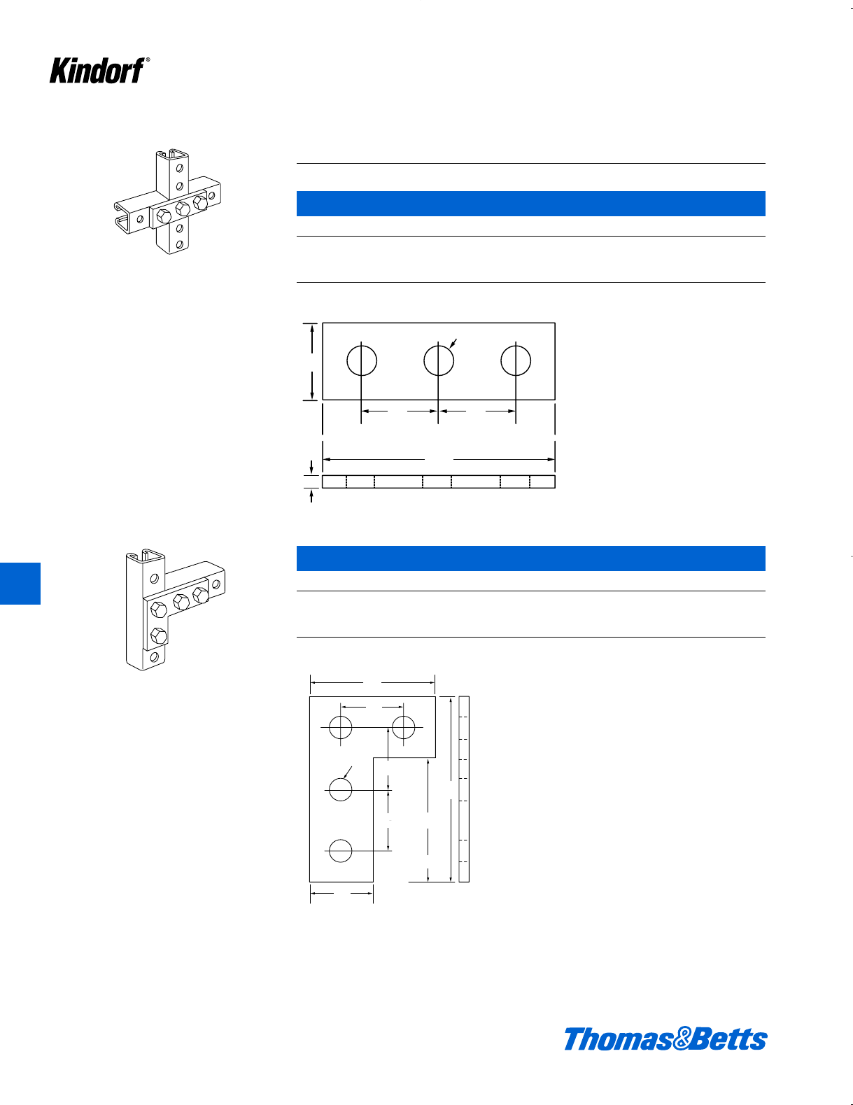
Cross Plate Connector
Cat. No. Finish
B-947 Galv-Kro
-m
i" steel. 55#/C.
41
2
3
4
9
16 holes
3
4
3
4
11
211
2
11
2
19
16
6
9
16 11
2
11
2
11
2
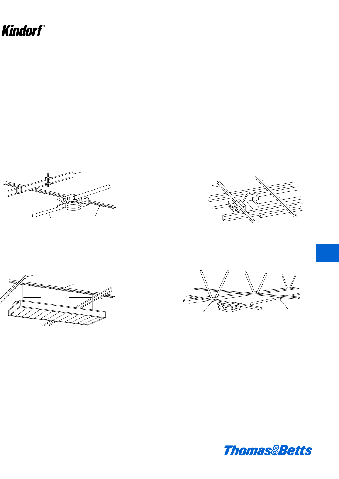
Joiner for B-907 Channel
Cat. No. Finish
B-948 Galv-Kro
-m
Order four B-910-1/2 nuts and four H-113-A cap screws separately.
12 ga. steel. 51#/C.
412034.K01 KINDORF 5/1 5/7/03 3:16 PM Page K32
© 2003 Thomas & Betts Corporation. Specifications are subject to change without notice. www.tnb.com K33
K
Kindorf ®
Lathers Channel
Suspended Fixture
Bantam Channel
Hanger Rods
6025 Fastener
Bantam Channel
Box mounted on
Bantam Channel to
feed fixtures
Bantam Channels
Lathers Channel
Bantam Channel
Hanger Rods
6025 Fastener
Bantam Channel Conduit Hanger
Bantam Channels
Conduit
Adapting conduit
runs through flush mounted device boxes
Bantam Channel
Box mounted on Bantam Channel to feed fixtures.
Typical mounting on bar joists
Lathers Channel
Bantam Channel
Conduit
Adapting conduit runs
through flush mounted
device boxes
Lathers Channel
Bantam Channel
Conduit
Bantam Channel Conduit Hanger
Suspended Fixture
For the support of light and medium
weight equipment in electrical and
mechanical applications.
Bantam Channels simplify the support
of overhead fixtures, conduits, pipes
and boxes in suspended ceiling instal-
lations where they can be supported on
runs of lathers channel or directly from
bar joists or ceiling beams. Ribbed
channels may also be mounted on con-
crete forms and used as low-cost con-
tinuous slot concrete inserts.
Installed slot down the open slot
accommodates and allows easy posi-
tioning of accessory fittings or b" hang-
er rod to support light or medium weight
equipment.
The use of Kindorf Channel Bar provides
a ready made system of bars and acces-
sories designed to eliminate costly and
time consuming on-the-job improvising.
412034.K01 KINDORF 5/1 5/7/03 3:16 PM Page K33
K34 © 2003 Thomas & Betts Corporation. Specifications are subject to change without notice. www.tnb.com
K
Kindorf ®
Ribbed Channels (extra strength)
Cat. Wt.
No. Description lbs./C ft.
6029-H 16 gauge (.060") Ribbed Channel with holes 30
6029 16 gauge (.060") Ribbed Channel 45
Channels are produced in 10 ft. lengths. Pre-galvanized steel.
6013
Single
Bantam Channel
Bantam Channels
6029-H
Holes for binch threaded rod and #12
sheet metal screw.
.266 dia. holes
clearance for b"
threaded rod
.177 dia. holes for
#12 Sheet Metal
Screw
6014
Single
Bantam Channel
.750"
.500"
.281"
1"
2
1
1"
4
.177 Dia holes for
#12 Sheet Metal
Screw.
6
Dia holes
a
rance for
aded rod.
3"
8
3"
4
.388
.263
.281
.281
.576
.451
c"
f"
1d"
Lightweight Channels
Cat. Wt.
No. Description lbs./C ft.
6013 20 gauge (.034") Lightweight Channel 17
6014 18 gauge (.044") Lightweight Channel 16
Channels are produced in 10 ft. lengths. Pre-galvanized steel.
412034.K01 KINDORF 5/1 5/7/03 3:16 PM Page K34
© 2003 Thomas & Betts Corporation. Specifications are subject to change without notice. www.tnb.com K35
K
Kindorf ®
Bantam Channels
6016
Bantam Channel Accessories
Cat. No. Description
6015 Fixture stud and carrier, (complete assembly) 7#/C.
6016 Fastener and carrier, (complete assembly) 6#/C.
6017 Channel carrier, 2#/C.
6018 Fixture stud, 5#/C.
6019 Fastener, 4#/C.
6024 Beam flange clip, pre-assembled – includes clip,
round head machine screw and square nut, 3d#/C.
6025 Channel fastener, 4⁄5#/C.
6026 Joiner, for ribbed channel, screws included, 41#/C.
6025
Secures channel bar to lathers channel or other
ceiling carrying channel.
6026
Fits over ends of ribbed channels for
continuous runs.
6075
Mounts electrical fixtures to exposed acoustical
ceilings. Fits n" or 1" bar face.
T-bar Clip
Cat. No. Description
6075 T-bar clip
Load rating: 50 lbs. Safety factor of 3. Furnished complete with cupped washer and wing nut. 8 lbs./C.
Fast, Easy Installation
1
Snap
Prong Side
Over
Tee-Bar
Edge
2
Reverse
Push-
Prongs
Lock
Clip in
Place
c-18 N.P.S.
c-18 N.P.S.
6017 6018 6019 6024
Fastens channel bar to I-beam, angle iron and bar joists with flanges not exceeding b" thickness.
6015
412034.K01 KINDORF 5/1 5/7/03 3:16 PM Page K35
K36 © 2003 Thomas & Betts Corporation. Specifications are subject to change without notice. www.tnb.com
K
Kindorf ®
Bantam Channels
Fast, Easy Hanging With
Standard Fittings
Low Cost Techniques for Bantam Channel
No. H-116-A-1⁄4"
square nut tips in anywhere.
Groove holds nut
squarely – nut won’t
rotate.
Insert rod full height of channel for rigidity.
IH-193-1/4
hanger rod.
Pipe Hanger
T-Bar Clip Bantam Channel for
Low-cost, Continuous-slot
Concrete Inserts
Beam Flange Clip
6075
Mounts electrical fixtures to exposed grid acousti-
cal ceilings. Fits n" or 1" bar face. Load Rating:
100 lbs. Safety factor of 4. Furnished complete
with cupped washer and wing nut.
Insert and turn in place – press on.
6029
Channel
bar
6025
Bar fastener
Hung ceiling carrying channel
6025
Secures channel to lathers channel or other
ceiling-carrying channels.
6029
Maximum recommended loads 200 lbs.
6024
Secures channel to I-beams, angle iron or bar
joists with flanges not exceeding b" thickness.
Channel Fastener
412034.K01 KINDORF 5/1 5/7/03 3:16 PM Page K36
© 2003 Thomas & Betts Corporation. Specifications are subject to change without notice. www.tnb.com K37
K
Kindorf ®
36"
5'
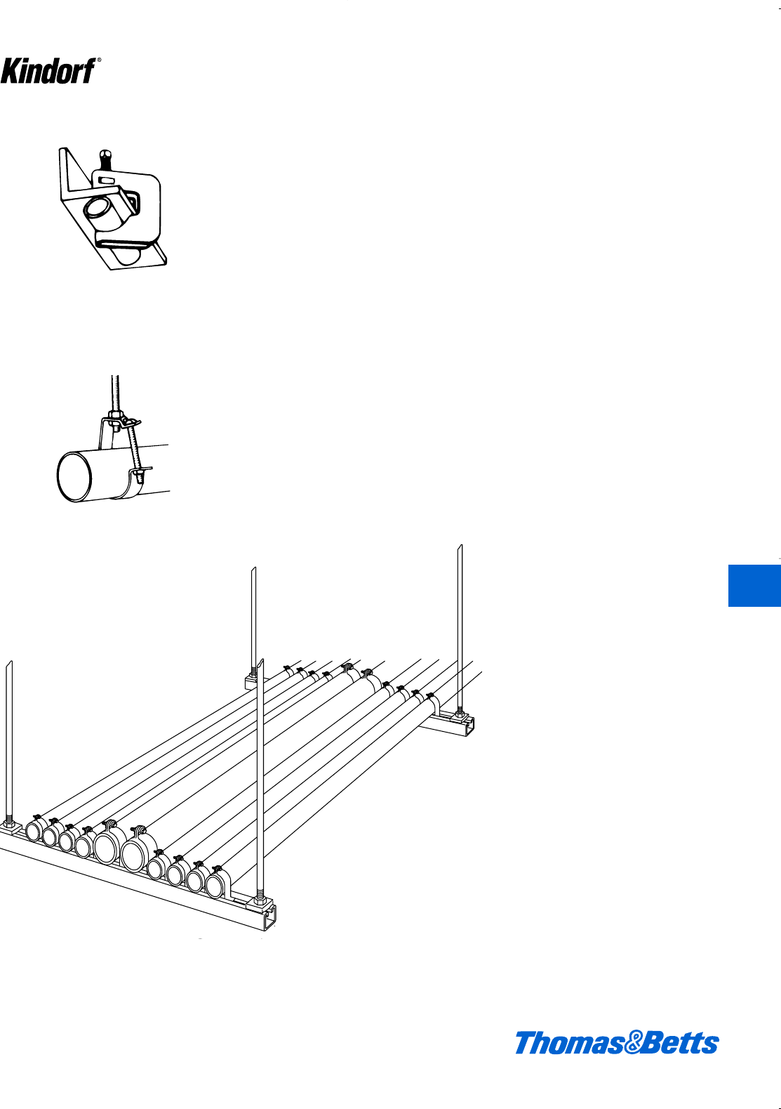
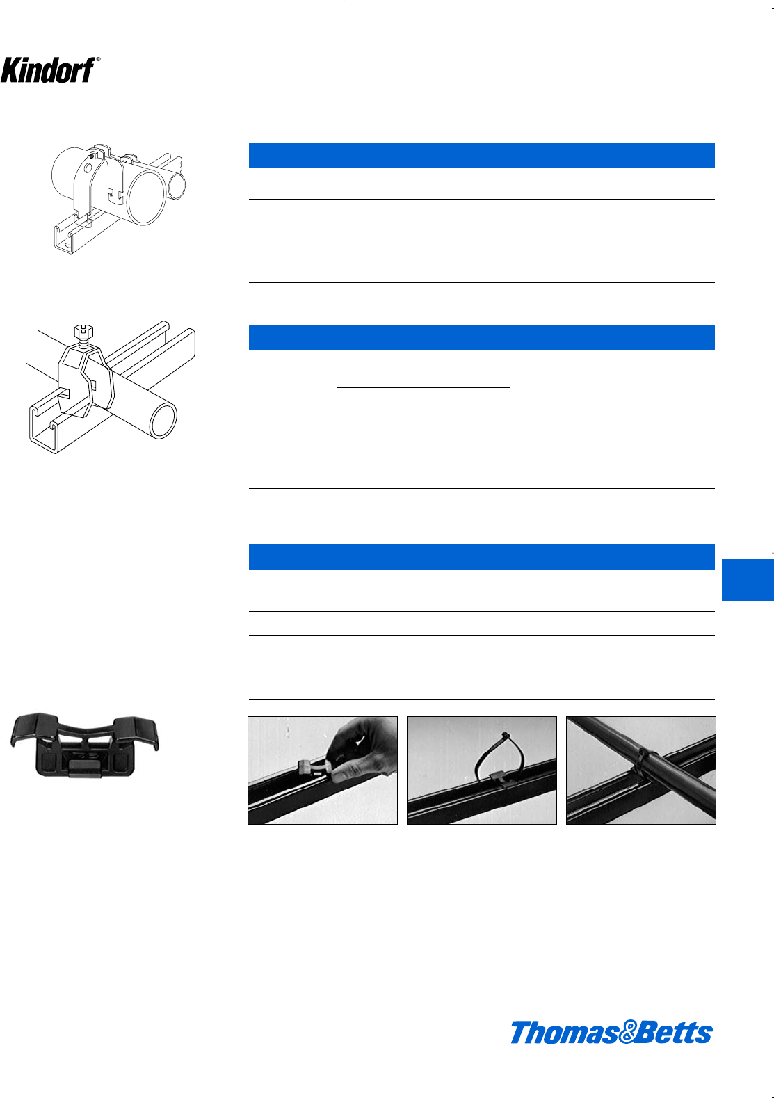
Conduit, Cable and Pipe Supports
Single or multiple runs of pipe and
cable are secured easily and economi-
cally by Kindorf supports. In the rack-
ing of multiple runs of pipe, for exam-
ple, C-105 Straps are quickly twist
inserted into a channel slot and the
pipe is installed by the tightening of a
single screw. There are no holes to drill
and position adjustment is made sim-
ple by sliding the strap along the chan-
nel slot. Runs of pipe or conduit can be
spaced with complete freedom, as
close as conduit couplings permit.
For single runs the C-149 Pipe Hanger
saves installation time by allowing the
conduit or pipe to be laid in place after
the hanger is mounted. The versatile
C-149 can be suspended from hanger
rod or bolted directly to the wall and
pipe insulation, when needed, can be
installed without removing the pipe
from the hanger.
These are but two examples of how
Kindorf products deliver lower installed
costs. Whether it be a problem of tight
spacing, adjustment, or alignment of
adequate spacing between hangers,
there’s a Kindorf support to solve it.
Kindorf pipe and cable supports are
engineered to provide safe and secure
installations. The majority of Kindorf
supports are protected by the exclu-
sive Galv-Kr¯om finish, including thread-
ed components.
There’s a wide range of Kindorf pipe
and cable supports to meet almost
every job condition, installed either in
combination with channel or individually
secured to the structure surface.
C-247 Beam clamp supports pipe.
Pipe supported by C-149 lay-in hanger.
Trapeze application supporting multiple conduit runs
412034.K01 KINDORF 5/1 5/7/03 3:16 PM Page K37
Pipe Supports
Interchangeable strap
fits both 11⁄2" and 15⁄8"
Kindorf Straps for Rigid Conduit, IMC and Pipe
Steel Straps – Galv-Kr¯om Finish
Rigid
Conduit Steel Design
or Pipe O.D. Strap Load Wt.
Cat. No. Size Size (In.) Thickness (lbs.) lbs./C
C-105-3/8 c" 0.675 14 ga. 750 12
C-105-1/2 d" 0.840 14 ga. 750 13
C-105-3/4 f" 1.050 14 ga. 750 15
C-105-1 1" 1.315 14 ga. 750 17
C-105-1-1/4 1b" 1.660 14 ga. 800 19
C-105-1-1/2 11⁄2" 1.900 12 ga. 800 28
C-105-2 2" 2.375 12 ga. 800 31
C-105-2-1/2 2d" 2.875 12 ga. 1000 36
C-105-3 3" 3.500 12 ga. 1650 42
C-105-3-1/2 3d" 4.000 11 ga. 1650 56
C-105-4 4" 4.500 11 ga. 1650 64
C-105-4-1/2 4d" 5.000 11 ga. 1650 72
C-105-5 5" 5.563 11 ga. 1650 76
C-105-6 6" 6.625 11 ga. 1650 89
C-105-8 8" 8.625 11 ga. 1650 114
C-105-10 10" 10.750 10 ga. 1650 160
C-105-12 12 12.750 10 ga. 1650 165
1
4
1
1
2
1
All Kindorf Straps are pre-assembled for easy
handling and sorting C105, C106 and C107 pipe straps are specifically designed to work
with all brands of channel that have a rolled lip design (figure 1).
Should you need to install pipe straps on old style Kindorf channel
(figure 2) see table on page K40 to determine the strap to use with
each diameter of conduit pipe.
Design Load
Figure 1 Figure 2
K38 © 2003 Thomas & Betts Corporation. Specifications are subject to change without notice. www.tnb.com
®
C-105 and C-106 Pipe Straps
Kindorf Pipe Straps are designed to be
twist inserted anywhere along the slot
side of the channel. Pipes can be
placed as closely as pipe couplings
permit.
Some unique features of the straps
include:
• Bolt head is combination slot and hex
head for flexibility of attachment.
• Square nut is captivated on the shoul-
der for easy one-handed tightening.
• Straps are interchangeable with 1e"
strut, for broader application.
• Straps are shipped assembled so
counting and sorting are easier.
• Pipe or conduit sizes are shown on
the strap for easy identification.
K
Kindorf ®
412034.K01 KINDORF 5/1 5/7/03 3:16 PM Page K38
Pipe Supports
Kindorf Straps for EMT
Steel – Galv-Kr¯om Finish
Steel Design
EMT O.D. Strap Load Wt.
Cat. No. Size Size (In.) Thickness (lbs.) lbs./C
C-106-3/8 c" 0.577 14 ga. 750 13
C-106-1/2 d" 0.706 14 ga. 750 14
C-106-3/4 f" 0.922 14 ga. 750 13
C-106-1 1" 1.163 14 ga. 750 16
C-106-1-1/4 1b" 1.510 14 ga. 750 19
C-106-1-1/2 1d" 1.740 12 ga. 800 20
C-106-2 2" 2.197 12 ga. 800 22
Kindorf Straps for O.D. Tubing
Design
Tubing Steel Load Wt.
Cat. No. O.D. Thickness (lbs.) lbs./C
C-107-1/4 b" 14 ga. 750 8
C-107-3/8 c" 14 ga. 750 8
C-107-1/2 d" 14 ga. 750 9
C-107-5/8 e" 14 ga. 750 10
C-107-3/4 f" 14 ga. 750 11
C-107-7/8 g" 14 ga. 750 12
C-107-1 1" 14 ga. 1000 12
C-107-1/8 1-a" 14 ga. 1000 12
C-107-1-1/4 1-b" 14 ga. 1000 13
C-107-1-3/8 1-c" 14 ga. 1000 14
C-107-1-1/2 1-d" 14 ga. 1000 14
C-107-1-5/8 1-e" 14 ga. 1000 15
C-107-1-3/4 1-f" 14 ga. 1000 28
C-107-1-7/8 1-g" 12 ga. 1000 29
C-107-2 2" 12 ga. 1000 31
C-107-2-1/8 2-a" 12 ga. 1300 32
C-107-2-1/4 2-b" 12 ga. 1300 33
C-107-2-3/8 2-c" 12 ga. 1300 34
C-107-2-1/2 2-d" 12 ga. 1300 35
C-107-2-5/8 2-e" 12 ga. 1300 37
C-107-2-3/4 2-f" 12 ga. 1300 38
C-107-2-7/8 2-g" 12 ga. 1300 40
C-107-3 3" 12 ga. 1300 41
C-107-3-1/8 3-a" 12 ga. 1300 43
C-107-3-1/4 3-b" 12 ga. 1300 45
C-107-3-3/8 3-c" 12 ga. 1300 46
C-107-3-1/2 3-d" 12 ga. 1300 47
C-107-3-5/8 3-e" 11 ga. 1650 56
C-107-3-3/4 3-f" 11 ga. 1650 58
C-107-3-7/8 3-g" 11 ga. 1650 60
C105, C106 and C107 pipe straps are specifically designed to work with all brands of channel that
have a rolled lip design (figure 1 page K38). Should you need to install pipe straps on old style
Kindorf channel (figure 2 page K38) see table on page K40 to determine the strap to use with each
diameter of conduit pipe.
© 2003 Thomas & Betts Corporation. Specifications are subject to change without notice. www.tnb.com K39
®
®
K
Kindorf ®
412034.K01 KINDORF 5/1 5/7/03 3:16 PM Page K39
Pipe Supports
Kindorf Straps for O.D. Tubing – Continued
Design
Tubing Steel Load Wt.
Cat. No. O.D. Thickness (lbs.) lbs./C
C-107-4 4" 11 ga. 1650 62
C-107-4-1/8 4-a" 11 ga. 1650 62
C-107-4-1/4 4-b" 11 ga. 1650 64
C-107-4-3/8 4-c" 11 ga. 1650 66
C-107-4-1/2 4-d" 11 ga. 1650 67
C-107-4-5/8 4-e" 11 ga. 1650 70
C-107-4-3/4 4-f" 11 ga. 1650 72
C-107-4-7/8 4-g" 11 ga. 1650 73
C-107-5 5" 11 ga. 1650 74
C-107-5-1/8 5-a" 11 ga. 1650 76
C-107-5-1/4 5-b" 11 ga. 1650 77
C-107-5-3/8 5-c" 11 ga. 1650 78
C-107-5-1/2 5-d" 11 ga. 1650 79
C-107-5-5/8 5-e" 10 ga. 1650 88
C-107-5-3/4 5-f" 10 ga. 1650 90
C-107-5-7/8 5-g" 10 ga. 1650 92
C-107-6 6" 10 ga. 1650 94
C-107-6-1/8 6-a" 10 ga. 1650 96
C-107-6-1/4 6-b" 10 ga. 1650 98
C-107-6-3/8 6-c" 10 ga. 1650 99
C-107-6-1/2 6-d" 10 ga. 1650 100
C-107-6-5/8 6-e" 10 ga. 1650 100
C-107-6-3/4 6-f" 10 ga. 1650 102
C-107-6-7/8 6-g" 10 ga. 1650 106
C-107-8 8" 10 ga. 1650 112
C105, C106 and C107 pipe straps are specifically designed to work with all brands of channel that
have a rolled lip design (figure 1 page K38). Should you need to install pipe straps on old style
Kindorf channel (figure 2 page K38) see table below to determine the strap to use with each diameter
of conduit pipe.
Conduit Strap Size Chart – Old Kindorf Strut
EMT Trade Size Strap
dC105-3/8
fC105-1/2
1C105-3/4
1b C105-1
1d C105-1-1/2
2C106-2
Rigid Conduit Size Strap
dC106-1/2
fC106-3/4
1C106-1
1b C106-1-1/4
1d C105-1 1/2
2C105-2
K40 © 2003 Thomas & Betts Corporation. Specifications are subject to change without notice. www.tnb.com
®
K
Kindorf ®
412034.K01 KINDORF 5/1 5/7/03 3:16 PM Page K40
© 2003 Thomas & Betts Corporation. Specifications are subject to change without notice. www.tnb.com K41
Pipe Supports
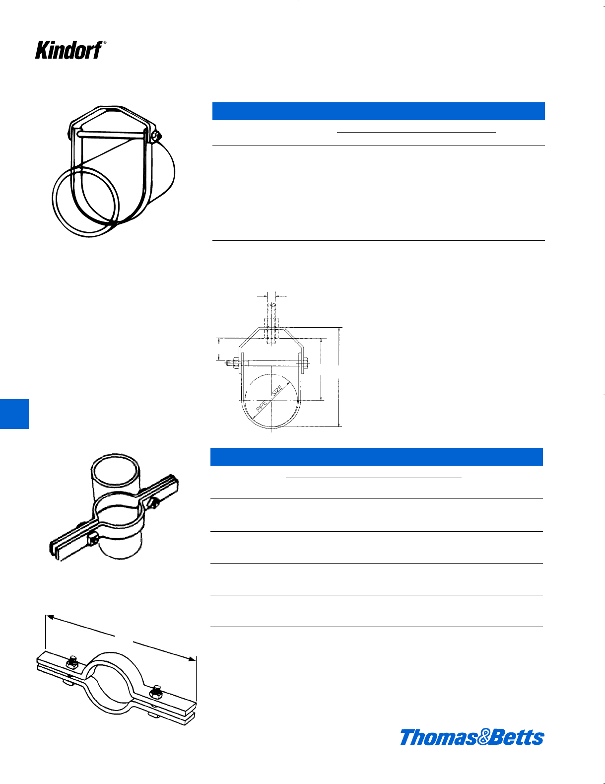
C-200 Universal Pipe Straps
EMT, IMC, Rigid Wt.
Cat. No. Pipe Size Pipe O.D. Range Strap Thickness lbs./C
C-200-1⁄2 d" .706 – .804 14 ga. 12
C-200-3⁄4 f" .922 – 1.060 14 ga. 13
C-200-1 1" 1.163 – 1.315 14 ga. 14
C-200-1-1⁄4 1b" 1.508 – 1.660 14 ga. 16
C-200-1-1⁄2 1d" 1.738 – 1.900 12 ga. 27
C-200-2 2" 2.196 – 2.375 12 ga. 31
Design load equal to C-105 straps.
EZ-Strap
The C-108 Universal Pipe Strap
Cat. No. Dimensions (in.) Thickness O.D. Wt.
& Size Conduit or Pipe Size Steel Size lbs./C
C-108-1⁄2 dEMT dIMC dRigid 16 ga. g8
C-108-3⁄4 fEMT fIMC fRigid 16 ga. 1z 10
C-108-1 1 EMT 1 IMC 1 Rigid 16 ga. 1X 10
C-108-1-1⁄4 1bEMT 1bIMC 1bRigid 14 ga. 1L 15
C-108-1-1⁄2 1dEMT 1dIMC 1dRigid 14 ga. 1n 16
C-108-2 2 EMT 2 IMC 2 Rigid 14 ga. 2u 19
• Fits E.M.T., I.M.C., rigid conduit.
• Size range 1
⁄2" thru 2".
• Can be used on 11
⁄2" or 15
⁄8" channel.
• Saves inventory dollars.
• Corrosion resistant Galv-Kr¯om finish.
• One piece construction means no assembly
required.
• Installs directly over conduit for easy instal-
lation.
• 50% reduction of installation time.
• No twisting required to install.
• Slotted hex head screw.
Framing Channel Clamp
Maximum
Cat. Channel Tie Width Unit Std.
No. Size Accom. Quan. Pkg.
TC5363X 1.5 & 1.625 .301 50 250
Mounting bases for heavy duty applications are made from high-impact weather-resistant nylon.
Ty-Rap ®Installation
• Installs with a push and twist. • Designed for indoor or outdoor use.
• Smooth design protects cable insulation. • Takes range of cable diameters.
When fastening wire bundles, cables, or hoses to framing channels, you can cut
costs considerably by using the TY-RAP®cable clamp. It is made of smooth,
weather-resistant nylon and designed to protect cable insulation and hoses from
wear or damage as can occur with metal clamps. The clamp may be used for both
indoor or outdoor applications. It installs in the framing channel with a simple push
and twist. It requires no screws, nuts or tools. The clamp fits all 1d" and 1e" chan-
nels regardless of channel depth.
K
Kindorf ®
412034.K01 KINDORF 5/1 5/7/03 3:16 PM Page K41
K42 © 2003 Thomas & Betts Corporation. Specifications are subject to change without notice. www.tnb.com
Pipe Supports
C-144 Two Hole Pipe Straps
Cat. No. Dimensions (in.) Wood Screw Thickness Wt.
& Size A & B C D E Size Req’d. Steel lbs./C
C-144-1⁄2 .840 23 fNo. 12 x 1 a10
C-144-3⁄4 1.050 2b 3b f No. 12 x 1 a11
C-144-1 1.315 2d 3d f No. 12 x 1 a13
C-144-1-1⁄4 1.660 3b 4b 1 No. 12 x 1 a20
C-144-1-1⁄2 1.900 3d 4d 1 No. 12 x 1 a23
C-144-2 2.375 4b 5b 1 No. 16 x 1da 30
C-144-2-1⁄2 2.875 56 1No. 16 x 1da 35
C-144-3 3.500 5f 6f 1 No. 16 x 2 a42
C-144-3-1⁄2 4.000 6d 7d 1 No. 16 x 2di 69
C-144-4 4.500 78 1No. 16 x 3 i78
Standard finish Galv-Kr¯om
Holds pipe tight against mounting surface.
X"
AB
C
D
E
K
Kindorf ®
412034.K01 KINDORF 5/1 5/7/03 3:16 PM Page K42
© 2003 Thomas & Betts Corporation. Specifications are subject to change without notice. www.tnb.com K43
Pipe Supports
C-149 Lay-in Pipe Hanger (J-Hanger)
Max.*
Recom.
Cat. No. Load Dimensions (in.) Wt.
& Size (lbs.) A B C D E F G lbs./C
C-149-1⁄2 700 .840 2d u k .104 fbx21b 18
C-149-3⁄4 700 1.050 2e u k .104 fbx2b 21
C-149-1 700 1.315 2n u k .104 fbx2f 22
C-149-1-1⁄4 700 1.660 3b u k .104 fbx3b 25
C-149-1-1⁄2 700 1.900 3d u k .104 fbx3d 27
C-149-2 700 2.375 3e u k .104 fbx429
C-149-2-1⁄2 875 2.875 4e l l .104 1b c x564
C-149-3 875 3.500 4k l l .104 1b c x572
C-149-3-1⁄2 965 4.000 4f l l .188 1b c x5d 84
C-149-4 965 4.500 5k l l .188 11b c x6138
C-149-5 965 5.563 6l L l .188 1b c x7162
C-149-6 1300 6.625 8Ll.188 1f c x8d 249
C-149-8 1300 8.625 9j n l .188 13f c x12 291
* Safety factor of three.
Standard finish: Galv-Kr¯om
Above dimensional information is general and not for critical measurements; please consult technical
services for additional dimensional requirements.
Saves installation time by allowing the conduit
or pipe to be laid in place after the hanger is
mounted. Fastening of side bolt can be delayed
until most convenient for job conditions.
Insulation can be installed without removing pipe
from hanger. The C-149 hanger can be suspend-
ed from hanger rod or can be bolted directly to a
wall. When used with hanger rod, assembly
requires two H-114 hex nuts.
Vertical adjustment of at least 11
⁄2inches after
pipe is laid in place. The lower nut adjusts pipe
lines to the proper pitch and the top nut when
locked into position prevents loosening due to
vibration. The square nut on the side bolt is kept
from loosening by the arrangement of hole and
up-turned lip.
Rest pipe in body of hanger. Fasten
side bolt when convenient.
K
Kindorf ®
412034.K01 KINDORF 5/1 5/7/03 3:16 PM Page K43
K44 © 2003 Thomas & Betts Corporation. Specifications are subject to change without notice. www.tnb.com
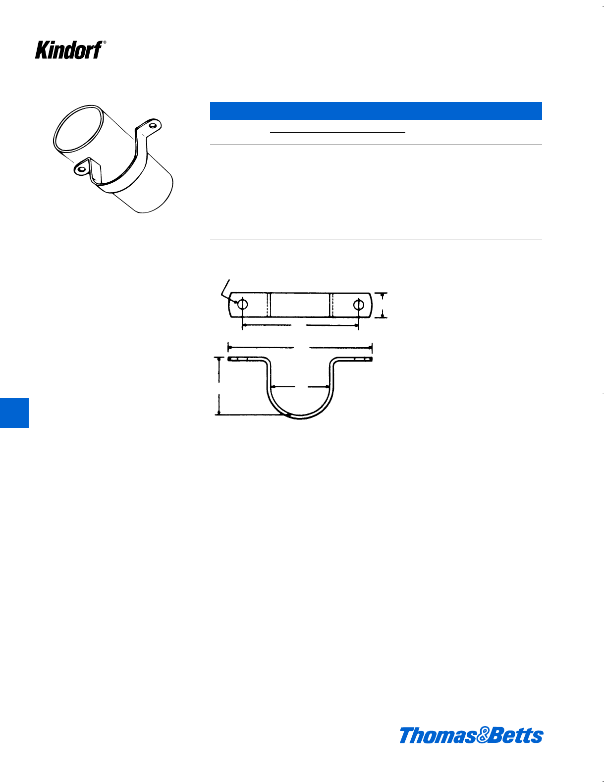
Pipe Supports
C-150 Clevis Hanger
Cat. No. Max. Recom.* Dimensions (in.) Wt.
& Size Load (lbs.) A B C D lbs./C
C-150-1⁄2 1000 2g" c" 1m" 1" 43
C-150-3⁄4 1000 3h" c" 1g" 1" 47
C-150-1 1000 3c" c" 2h" 1" 50
C-150-1-1⁄4 1000 3f" c" 2b" 1" 52
C-150-1-1⁄2 1000 4h" c" 2c" 1" 57
C-150-2 1000 4d" c" 2f" 1b" 63
C-150-2-1⁄2 1850 5d" d" 3b" 1b" 109
C-150-3 1850 6a" d" 3d" 1b" 117
C-150-3-1⁄2 1850 6f" d" 3f" 1b" 133
C-150-4 1850 7e" e" 4b" 1d" 204
* Safety factor of three.
Standard finish: Black
Above dimensional information is general and not for critical measurements; please consult technical
services for additional dimensional requirements.
Provides a vertical adjustment of approximate-
ly 11
⁄2inches after pipe is in place. The lower
nut adjusts pipe line to the proper pitch and the
top nut, when locked into position, prevents
loosening due to vibration. Assembly requires
two H-114 hex nuts along with hanger rod. B
D
CA
C-210 Riser Clamps
Dimensions (in.)
Cat. No. Stock Bolt Wt.
& Size A Size Size lbs./C
C-210-1⁄2 9b i x1b c x1d 138
C-210-3⁄4 9b i x1b c x1d 140
C-210-1 9l i x1b c x1d 150
C-210-1-1⁄4 9L i x1b c x1d 200
C-210-1-1⁄2 10c i x1b c x1d 205
C-210-2 10f i x1b c x1d 224
C-210-2-1⁄2 11c b x1b c x1d 241
C-210-3 12 b x1b c x1d 270
C-210-3-1⁄2 13 b x1b c x1d 335
C-210-4 13d b x1b d x1d 340
C-210-5-B 14d b x1d d x1d 510
C-210-6-B 15a b x2dx1d 560
Two bolts and nuts included. Sizes thru 4" are steel with Galv-Kr¯om finish. *Larger sizes are steel with black finish.
Above dimensional information is general and not for critical measurements; please consult technical
services for additional dimensional requirements.
Firmly grips vertically mounted pipe or conduit
and distributes the load over a larger area.
A
K
Kindorf ®
412034.K01 KINDORF 5/1 5/7/03 3:16 PM Page K44
© 2003 Thomas & Betts Corporation. Specifications are subject to change without notice. www.tnb.com K45
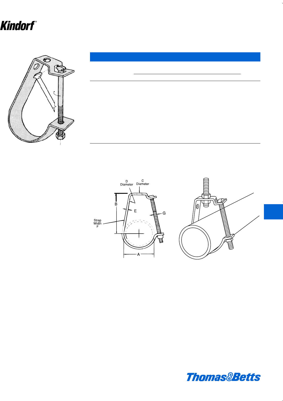
Conduit, Cable and Pipe Supports
A versatile clamp for attaching conduit to any
type of beam, channel, angle, or column.
Designed to hold the conduit snug against the
support with conduit either parallel or at right
angle to it. The case hardened set screw bites
into the structural member for maximum secu-
rity. 1
⁄8" steel.
Designed for use as intermediate supports for
3
⁄8" messenger cable. Grips cable when 5
⁄16"
screw is tightened. Provides easy vertical
adjustment. Design load 1000#. Safety factor
of 3.
1
4
1
17
32
3
5
16 X 1
1
8
hole
a
A
B
C
1b
3
r
hole
a
jx 1
D
C-247, C-248, & C-249 Steel Conduit Clamps
Conduit Maximum Beam Flange Thickness
Size C-247 C-248 C-249
de1
fkf1d
1d1b
1b 1
1d e
Dim A 2b 2l 3b
Dim B 1c 1f 2d
Dim C 2f 3 4
Dim D ll e
Per Carton 100 50 50
Wt. in lbs./C 33 36 59
Galv-Kr¯om Finish
C-708 Messenger Cable Support
Cat. No. Description
C-708 a" steel, 27#/C
Galv-Kr¯om Finish
K
Kindorf ®
412034.K01 KINDORF 5/1 5/7/03 3:16 PM Page K45
K46 © 2003 Thomas & Betts Corporation. Specifications are subject to change without notice. www.tnb.com
K
Kindorf ®
Conduit, Cable and Pipe Supports
C-750 Maple Cable Clamp
Cat. No. Dimensions (in.) Wt. in.
& Size O.D. of Cable A B lbs./C
C-750-1 0 – 0.99 43g 90
C-750-2 1.0 – 1.49 4d 4c 100
C-750-3 1.5 – 1.99 54g 120
C-750-4 2 – 2.49 5d 5c 140
C-750-5 2.5 – 2.99 65g 160
C-750-6 3 – 3.49 76g 200
C-750-7 3.5 – 3.99 87g 240
C-750-8 4 – 4.49 – – –
C-750-9 4.5 – 5.00 – – –
Size refers to over-all dimensions of maple cable clamp only. Hole will be bored to fit O.D. of cable.
Orders MUST specify exact O.D. of cable.
Special Order.
Maple blocks, impregnated with paraffin. 3
⁄8"
bolts with special nuts facilitate installation on
B-900 channel.
1
8
B
B
5
8
11
8
1e
B
a
e
B
412034.K01 KINDORF 5/1 5/7/03 3:16 PM Page K46
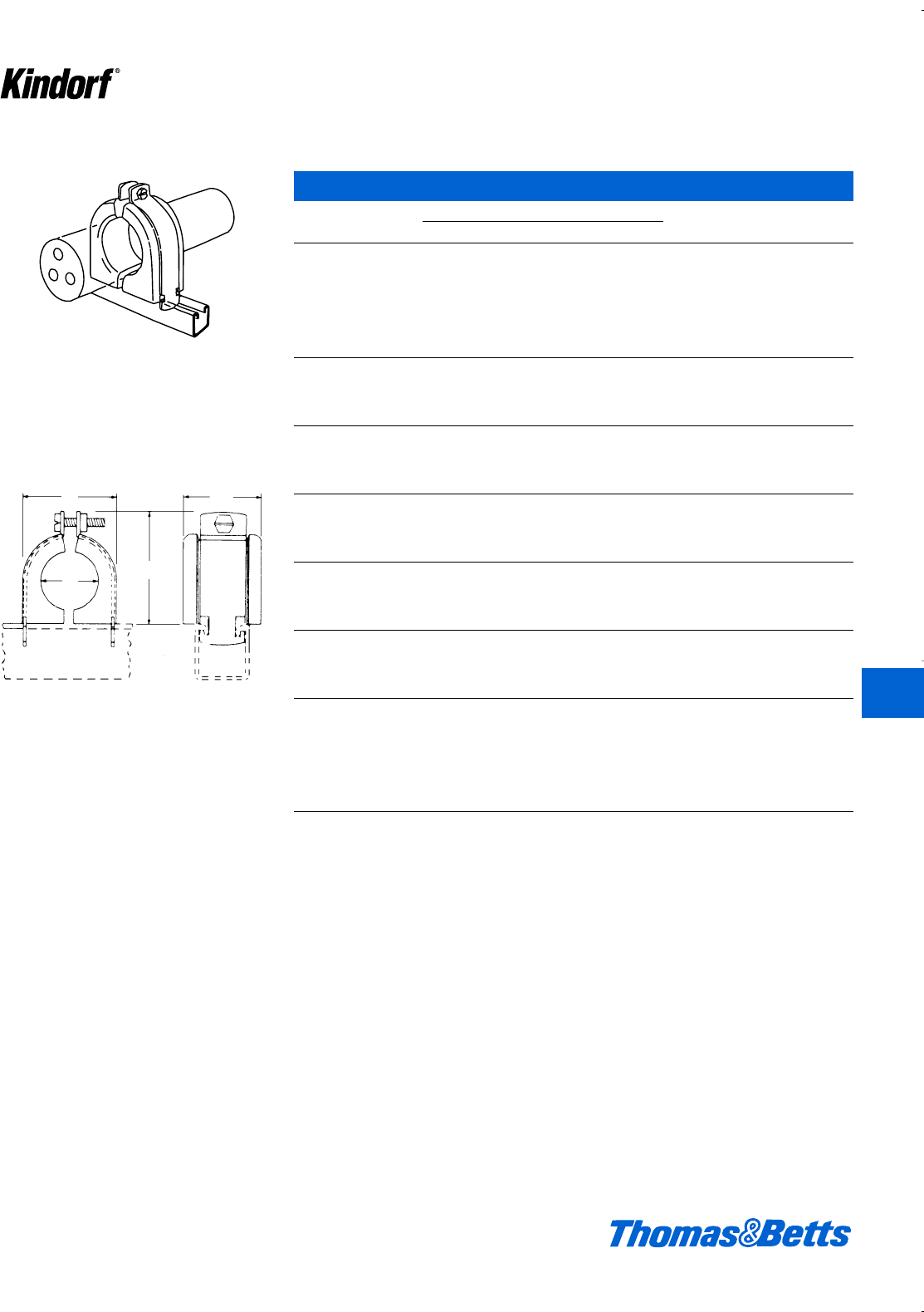
© 2003 Thomas & Betts Corporation. Specifications are subject to change without notice. www.tnb.com K47
K
Kindorf ®
Pipe Supports
C-755 Porcelain Insulator Clamp
Cat. No. Dimensions (in.) Strap Wt. in
& Size A B C C-105 lbs./C
C-755-1A c2h1l1"50
C-755-1B d2h1l1"50
C-755-1C e2h1l1"50
C-755-2 f 2y 2q 1d" 91
C-755-2A g 2y 2q 1d" 90
C-755-2B 12y2qd"85
C-755-2C 1a 2y 2q 1d" 82
C-755-3 1b 3a 2e 2" 114
C-755-3A 1c 3a 2e 2" 110
C-755-3B 1d 3a 2e 2" 105
C-755-3C 1e 3a 2e 2" 102
C-755-4 1f 4b 3f 3" 220
C-755-4A 1g 4b 3f 3" 214
C-755-4B 24b3f3"205
C-755-4C 2a 4b 3f 3" 200
C-755-5 2b 4f 4b 3d" 260
C-755-5A 2c 4f 4b 3d" 250
C-755-5B 2d 4f 4b 3d" 243
C-755-5C 2e 4f 4b 3d" 240
C-755-6 2f 5b 4f 4" 250
C-755-6A 2g 5b 4f 4" 240
C-755-6B 35b4f4"230
C-755-6C 3a 5b 4f 4" 220
C-755-7 3b 6j 5m 5" 340
C-755-7A 3c 6j 5m 5" 330
C-755-7B 3d 6j 5m 5" 318
C-755-7C 3e 6j 5m 5" 387
C-755-8 3f 7c 6g 6" 565
C-755-8A 3g 7c 6g 6" 550
C-755-8B 47c6g6"535
C-755-8C 4a 7c 6g 6" 520
C-755-8D 4b 7c 6g 6" 490
C-755-8E 4c 7c 6g 6" 475
C-755-8F 4d 7c 6g 6" 460
Dry process white glaze porcelain insulators
assembled in pairs to accept cables from 3
⁄8"
thru 41
⁄2" O.D. C-105 clamp with bronze slotted
hex head screw and nut furnished. Fits all
Kindorf channels
2a
A
B
C
412034.K01 KINDORF 5/1 5/7/03 3:16 PM Page K47
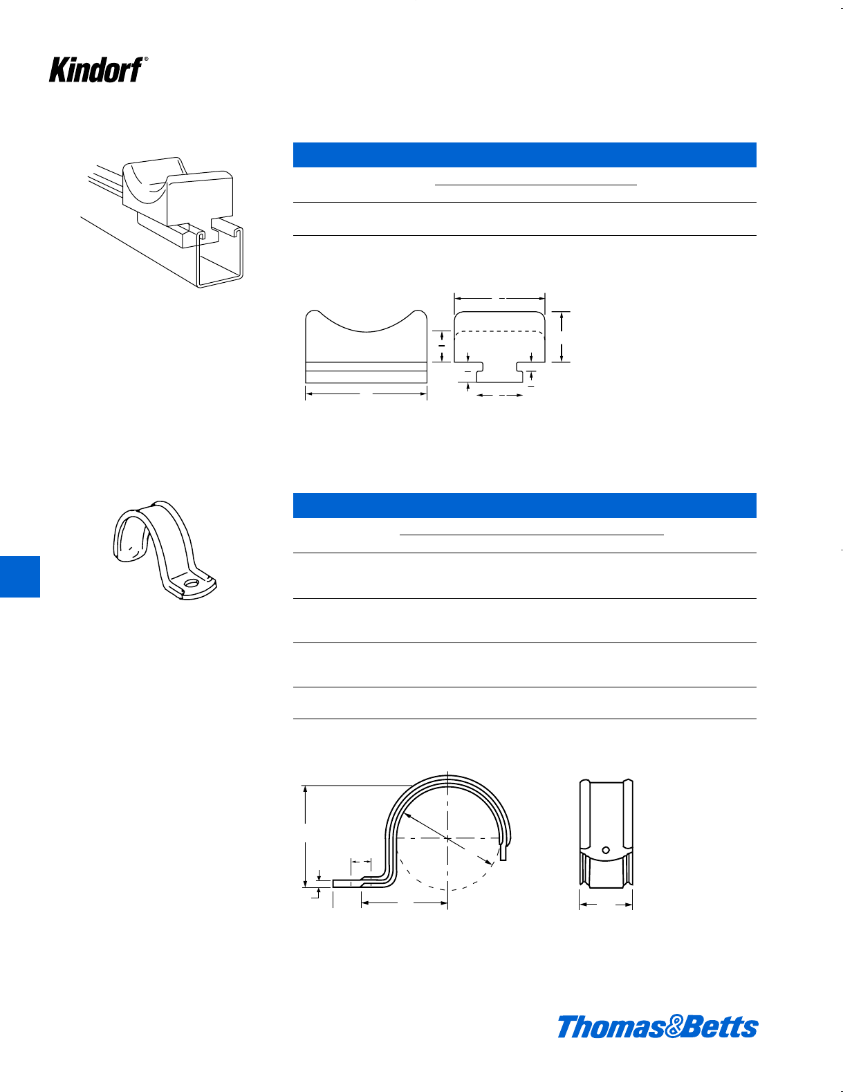
K48 © 2003 Thomas & Betts Corporation. Specifications are subject to change without notice. www.tnb.com
K
Kindorf ®
Pipe Supports
White glaze dry process porcelain cable rack
insulator. Fits all sizes of B-900 series channel
including B-906.
C-756-1 Porcelain Saddle / C-756-2 Porcelain Saddle
Dimensions (in.)
Cat. No. A B
C-756-1 3 13⁄16
C-756-2 4 17⁄32
C-756-1 is for cables up to 3" O.D. Weight 72#/C.
C-756-2 for cables up to 5" O.D. Weight 102#/C.
A
B
21
32
21
32
5
16
1
4
32
2
7
1
D
S
ECB
A
F
HS-100 One Hole Pipe Straps
Cat. Nom. Dimensions (in.) S Wt. in
No. Size A B C D E F Hole lbs./C
HS-100 c .718 .797 X .640 14 ga. Lb 3
HS-101 d .840 .900 k .780 16 ga. 1s 5
HS-102 f 1.050 1.000 k .990 16 ga. 1s 6
HS-103 1 1.315 1.187 u 1.215 13 ga. 1s10
HS-104 1b 1.660 1.490 e 1.562 13 ga. 1X14
HS-105 1d 1.900 1.667 e 1.770 13 ga. 1i u 16
HS-106 2 2.375 1.875 e 2.200 13 ga. 1i k 20
HS-107 2d 2.875 2.563 m 2.688 i 1b v 52
HS-108 3 3.500 3.000 m 3.328 b 1c w 84
HS-109 3d 4.000 3.250 m 3.938 b 1c w 92
HS-110 4 4.500 3.273 m 4.375 b 1c w 101
Galvanized finish.
412034.K01 KINDORF 5/1 5/7/03 3:16 PM Page K48
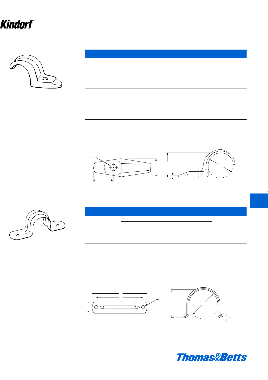
© 2003 Thomas & Betts Corporation. Specifications are subject to change without notice. www.tnb.com K49
K
Kindorf ®
Pipe Supports
HS-400 One Hole Pipe Straps
Dimensions (in.)
Cat. Nom. SWt. per
No. Size (in.) A C D E M Hole 100/pcs.
HS-400 c .680 { e p w s 4
HS-401 d .840 G J p e s 4
HS-402 f 1.050 K 1D p m j 7
HS-403 1 1.315 m 1b p n j 12
HS-404 1b 1.660 1o 1x a 1o c 21
HS-405 1d 1.900 1p 1B i 1a k 25
HS-406 2 2.375 1∫ 2∫ b 1j l 40
HS-407 2d 2.875 1G 2A j 1e L 99
HS-408 3 3.500 1g 3ç c 1g L 111
HS-409 3d 4.000 2q 3g k 2a L 218
HS-410 4 4.500 2c 4X d 2c L 295
HS-411 5 5.563 2c 53c d 2e L 400
Malleable iron – Galvanized finish.
C
D
E
A
M
S
HS-900 Two Hole Pipe Straps
Cat. Nom. Dimensions (in.) Thickness Wt. in
No. Size A B C D E F Steel lbs./C
HS-901 d.840 .850 1.812 2k f .188 20 ga. 2
HS-902 f1.050 1.050 2.062 2L f .188 20 ga. 3
HS-903 11.315 1.300 2.812 3k f .188 20 ga. 4
HS-904 1b 1.660 1.610 3.218 3B f .188 20 ga. 5
HS-905 1d 1.900 1.850 3.437 4h f .188 20 ga. 5
HS-906 22.375 2.350 3.812 4k f .188 20 ga. 7
HS-907 2d 2.875 2.750 5.250 5e 1 .252 16 ga. 18
HS-908 33.500 3.281 5.562 6i 1 .252 16 ga. 22
HS-909 3d 4.000 3.687 6.562 7i 1 .252 16 ga. 25
HS-910 4 4.500 4.375 8.062 8L 1 .252 16 ga. 28
Two-hole pipe straps for surface mounting
pipes and tubing. Formed steel for strength.
E
D
CF
B
A
cR
412034.K01 KINDORF 5/1 5/7/03 3:16 PM Page K49
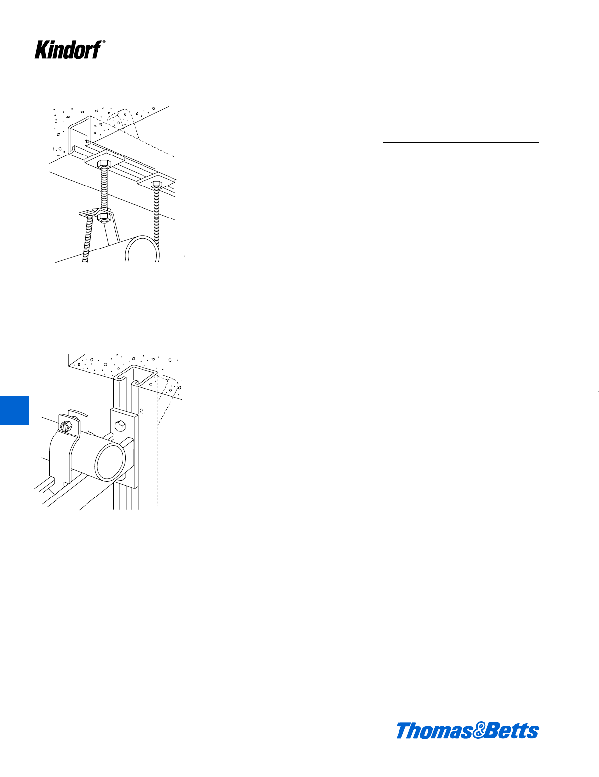
Concrete Inserts
Concrete Inserts
Buildings designed with concrete
inserts as an integral part of the ceiling
or wall construction realize many
economies, both in initial construction
and when up-
dating of the mechanical and electrical
system is required. The initial
economies of construction stem from
the ease with which pipe, air condition-
ing, lighting and other fixtures can be
attached to ceilings or walls.
Inserted by casting into the struc-
ture, Kindorf continuous-slot channels
will accept all the assembly parts and
fittings of the Kindorf system. This pro-
vides virtually limitless structural
arrangements – present and future.
Hanger attachments are made by
the standard Kindorf procedure of sim-
ply inserting a standard channel nut
which can be pre-started on the hang-
er rod or bolt. Placement or adjustment
of attachments can be made in infinite
increments at any time along the
length of the concrete insert. Future
flexibility means economies in terms of
future changes in equipment or its
placement.
Initial Installation of
Continuous-Slot Channel
Inserts Offers:
• An immediate savings in time and
labor by eliminating the need for pre-
cise calculation and measurement,
both in layout planning and actual
installation of attachment devices
• Additional savings in time and labor
because changes or additions can
be made readily to the existing chan-
nel at any time; the need for costly
drilling in concrete and other costly
procedures can be eliminated.
Companion to the channel inserts is
the spot-type insert for use where a
single hanger is required at a specific
location.
Pipe section hangs from D-990 concrete insert.
D-990 concrete insert supports conduit installa-
tion.
K50 © 2003 Thomas & Betts Corporation. Specifications are subject to change without notice. www.tnb.com
K
Kindorf ®
412034.K01 KINDORF 5/1 5/7/03 3:16 PM Page K50
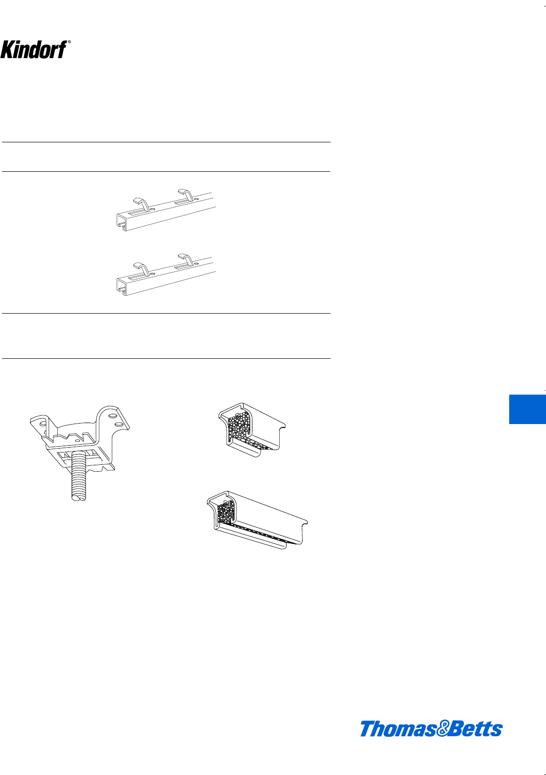
D-255 concrete inserts D-256-2 and D-256-5
D-256-2
Concrete Inserts
Two types of Continuous Insert Channels, Standard
lengths 10 and 20 feet. Special lengths available on
request.
D-990 Punched 11⁄2x 11⁄2x 12 ga. 2000
D-996 Punched 11⁄2x3⁄4x 14 ga. 1500
* Safety factor of 3. Based on uniformly distributed load.
Two types of Spot Inserts
Cat. Type Load Rating
No. Anchor Cross-Section Lbs. per Ft.*
© 2003 Thomas & Betts Corporation. Specifications are subject to change without notice. www.tnb.com K51
D-256-5
K
Kindorf ®
412034.K01 KINDORF 5/1 5/7/03 3:16 PM Page K51
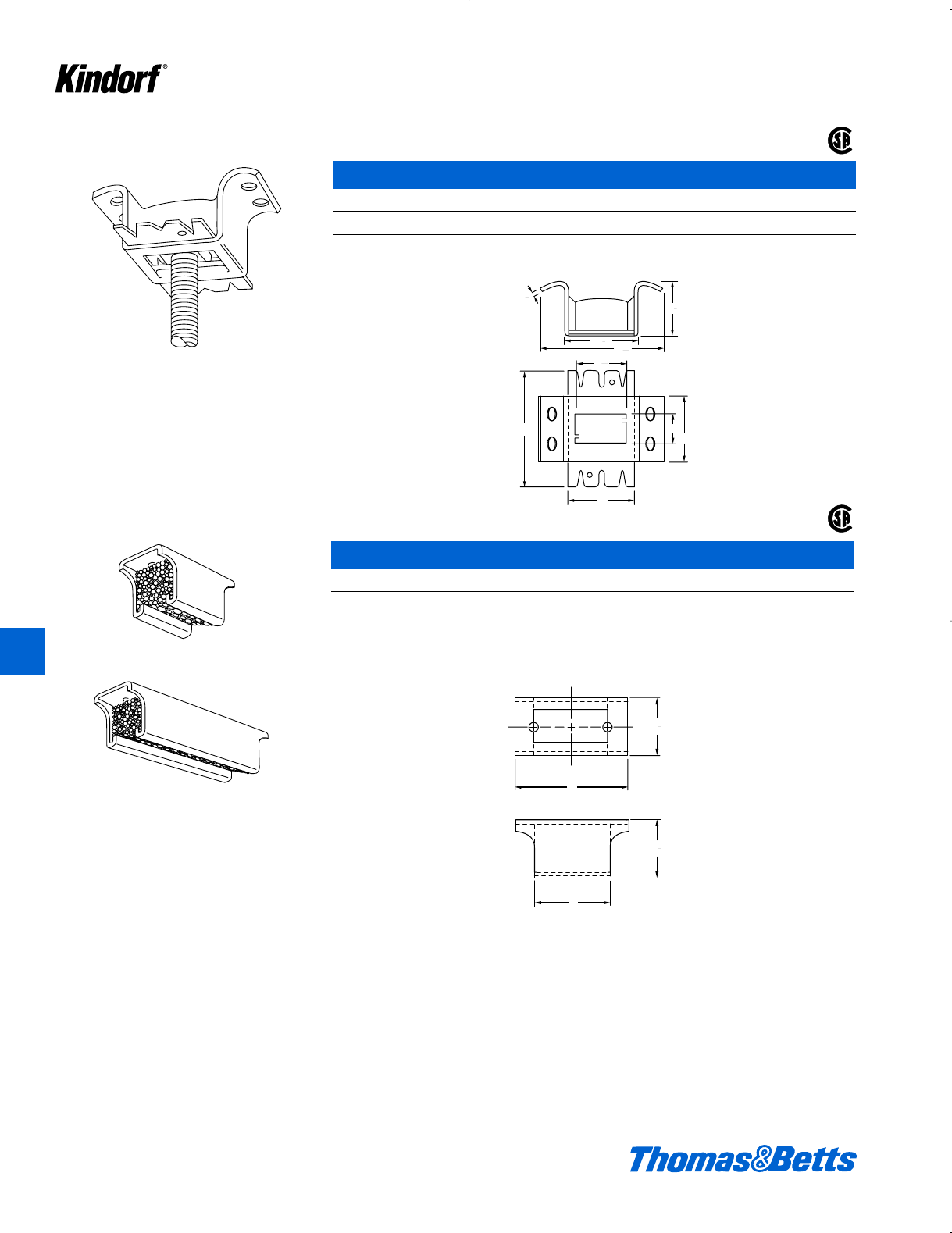
K52 © 2003 Thomas & Betts Corporation. Specifications are subject to change without notice. www.tnb.com
K
Kindorf ®
Concrete Inserts
D-255 Concrete Inserts
Cat. No. Description
D-255 For b" through g" hanger rod – b" through d" pipe
Standard finish: Galv-Kr¯om
D-256-2
D-256-5
An insert with a knockout saves covering the
slot or covering the opening. Load rating at
1300 lbs. with a safety factor of three.
Accommodates hanger rod sizes from 1⁄4" thru
7⁄8" by means of a B-914 insert nut. 1⁄8" steel.
52#/C.
This unique product reduces the “spot” con-
crete insert to its simplest possible components
with all the adjustability of the most expensive.
Its features include: two sizes – 2" and 5"
adjustability, takes standard insert nuts, uses
hanger rod sizes 1⁄4" thru 5⁄8" and has a load rat-
ing up to 1000 lbs. and a safety factor of 3
(hanger rod permitting).
5
8
1
3
8
1
1
8
1
4
217
32
3
19
32
1
2
2
3
4
3
35
64
1
T
35
64
1
N
®
®
D-256-2 and D-256-5 Concrete Insert
Cat. No. N T Wt. in lbs./C
D-256-2 2" 3" 34
D-256-5 5" 6" 76
Standard finish: Galv-Kr¯om
412034.K01 KINDORF 5/1 5/7/03 3:16 PM Page K52
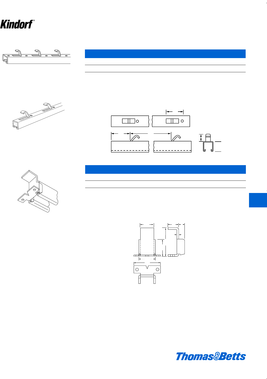
© 2003 Thomas & Betts Corporation. Specifications are subject to change without notice. www.tnb.com K53
K
Kindorf ®
Concrete Inserts
D-990
Cat. No. Description
B-990 Continuous slot and concrete insert
Use B-910 or B-914 steel nuts for assembly. Load rating 2000 lbs. per foot with a safety factor of three. Available in 10
and 20 foot lengths.
Galv-Kr¯om finish
D-982 Anchor End Cap
Cat. No. Description
B-982 Anchor end cap
Load rating of such an insert less than 1 foot long is 1000 lbs. with a safety factor of three. 1⁄8" steel. 19#/C.
Galv-Kr¯om finish
Insert is made of B-900 channel (12 ga.) with
anchors punched out of insert on 6" centers.
Polystyrene filled.
For capping the ends of D-990 continuous slot
concrete inserts. May be used on the job to
make up inserts of less than 1 foot lengths of B-
900 channel.
D-990 is provided with a rigid plastic closure
strip which prevents concrete from entering the
channel section. When the channel is in place,
the strip is easily removed.
1
8
2
2
2
5
16
1
7
16
1
1
8
5
16
1
2
5⁄6
21⁄2
1⁄8
21⁄8
17⁄16
15⁄16
2
11
32
1
63
3
11⁄2
6
3
3
111⁄32
412034.K01 KINDORF 5/1 5/7/03 3:16 PM Page K53
Concrete Inserts
D-996 Continuous Slot Concrete Insert
Cat. No. Description
B-996 Continuous slot and concrete insert
Use B-910 or B-914 steel nuts for assembly. Load rating 1500 lbs. per foot with a safety factor of three. Available in 10
and 20 foot lengths.
Galv-Kr¯om finish
D-988 Anchor End Cap
Cat. No. Description
D-988 Anchor end cap
Load rating of each insert less than 1 foot long is 600 lbs. with a safety factor of three. a" steel. 13#/C.
Galv-Kr¯om finish
Insert is made of B-906 channel (14 ga.) with
anchors punched out of insert on 6" centers.
Polystyrene filled.
For capping the ends of D-996 continuous slot
concrete inserts. May be used on the job to
make up inserts of less than 1 foot lengths of B-
906 channel.
D-996 is provided with a rigid plastic closure
strip which prevents concrete from entering
the channel section. When the channel is in
place, the strip is easily removed.
1
8
2
2
5
16
1
7
16
1
1
8
5
16
1
2
2
21⁄2
1⁄8
21⁄8
17⁄16
5⁄16
2
15⁄16
11
32
1
63
3
f
6
3
3
1X
K54 © 2003 Thomas & Betts Corporation. Specifications are subject to change without notice. www.tnb.com
K
Kindorf ®
412034.K01 KINDORF 5/1 5/7/03 3:16 PM Page K54
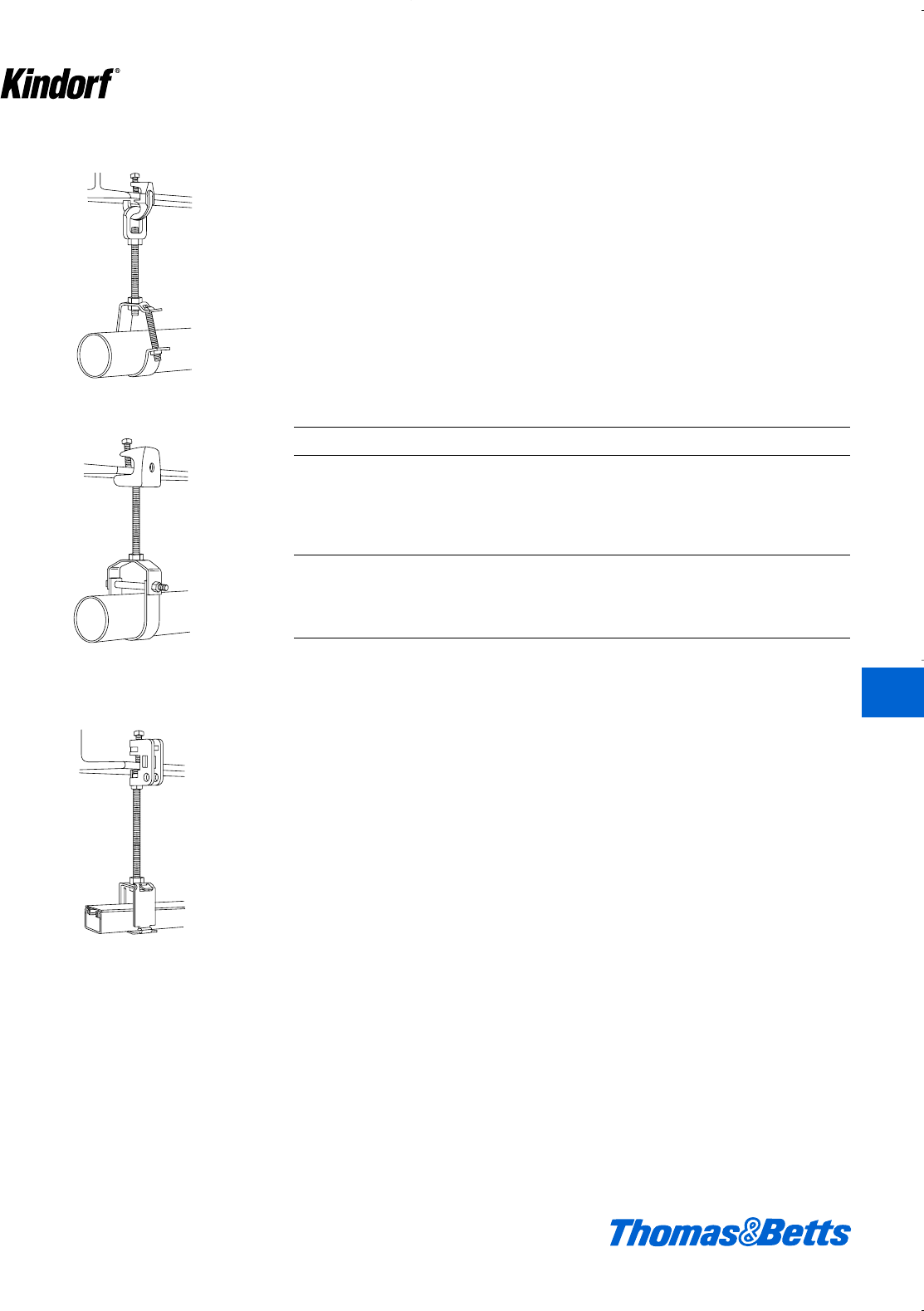
Beam Clamps and Hanger Rod Supports
H-550 Swivel beam clamp supports pipe with
C-149 hanger.
Kindorf devices for hanging the load
can deliver lower installed costs.
Hanger rod and conduit pipe supports
are attached to ceilings or to other
structural members such as beams,
columns, or purlins without drilling,
welding or fastening by means of
power actuated tools. A full selection of
beam clamps and hanger rod supports
are offered to meet a wide variety of
needs.
The flexibility of the Kindorf Series of
clamps affords a range of applications
from simple attachment of channel to
the suspending of supports from slop-
ing as well as horizontal beams.
Where high vibrations are expected
additional support can be attained by
gripping the beam on both sides. From
the simple job to the complex job with
special needs the Kindorf line of beam
clamps can fill the bill.
The following table may be used when
attaching hanger rod with Kindorf
beam clamps.
500 Series beam clamp supports pipe with
C-150 clevis hanger.
E-231 Beam clamp supports channel raceway
with G-1012 lay-in-hanger.
© 2003 Thomas & Betts Corporation. Specifications are subject to change without notice. www.tnb.com K55
Rod Size Beam Clamp Rod Size Beam Clamp
c" E-230, E-231-3/8, e" E-237-5⁄8
E-232-3/8 f" E-237-3⁄4
d" E-160-1/2, E-177, g" E-237-7⁄8
E-165-1/2, E-231-1/2,
E-232-1/2
507, 508
Channel to E-760-2
Beam E-760-3
E-761
E-763
E-767
For additional beam clamps see Steel City Hanger and Clamp Section.
K
Kindorf ®
412034.K01 KINDORF 5/1 5/7/03 3:16 PM Page K55
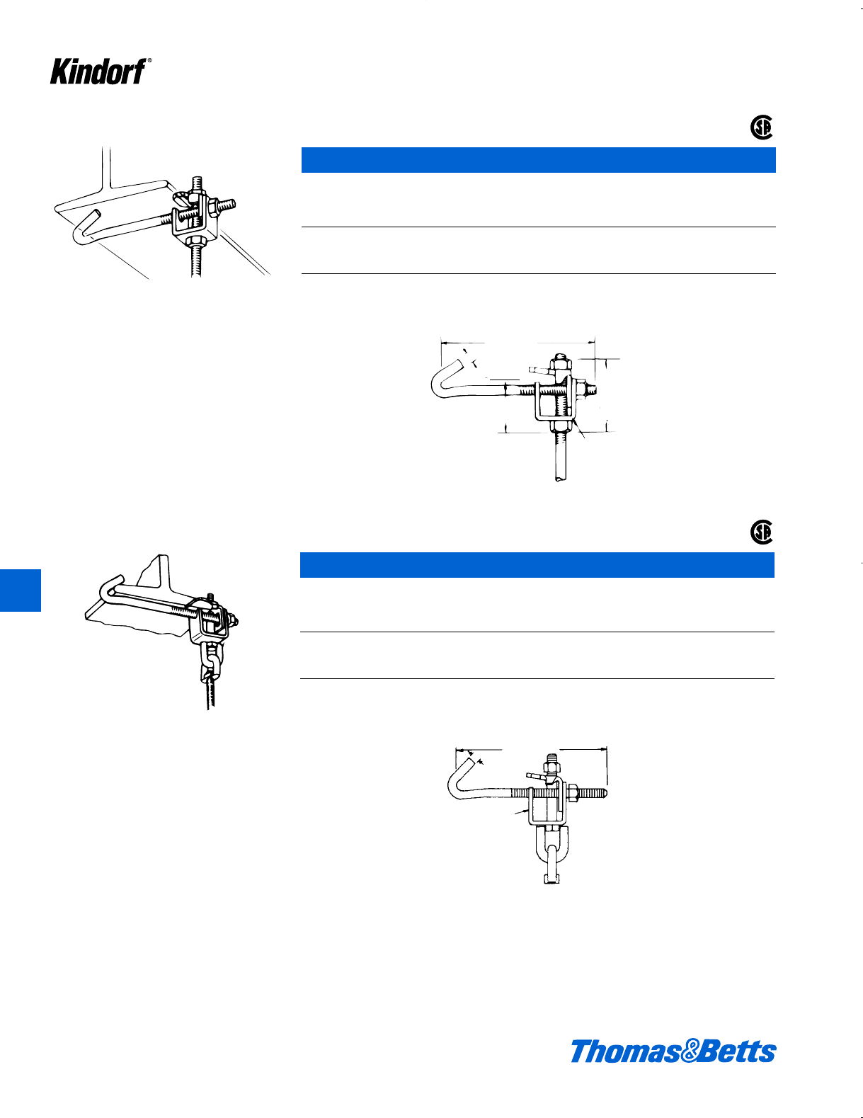
Beam Clamps and Hanger Rod Supports
Clamps to I-beams where edge of beam flange
does not exceed .8 inch thickness. Hook rod is
furnished in three lengths to fit beam flanges
up to 6, 9 or 12 inch widths.
E-160 Adjustable Beam Clamp
(d" rod)
Cat. No. For Beam Flange Wt.
for d" Hanger Rods width/in. lbs./C
E-160-1/2-6 2dto 6 115
E-160-1/2-9 5dto 9 125
E-160-1/2-12 8dto 12 154
Load rating 800 lbs. with a safety factor of three. Assembly requires hanger rod of the proper length and size plus two
H-114-D nuts. i" steel, d" hook rod.
Galv-Kr¯om finish
8, 11, or 14
1⁄2
21⁄8
3⁄16 x 11⁄2
3
min
35⁄8
max
1⁄2"
3⁄16 x 11⁄2
8", 11" or 14"
K56 © 2003 Thomas & Betts Corporation. Specifications are subject to change without notice. www.tnb.com
®
®
E-165 Adjustable Beam Clamp with Swing Connector
(d" rod)
Cat. No. For Beam Flange Wt.
for d" Hanger Rods width/in. lbs./C
E-165-1/2-6 2dto 6 210
E-165-1/2-9 51dto 9 227
E-165-1/2-12 81dto 12 245
Load rating of 1300 lbs. with a safety factor of three.
Assembly requires hanger rod of the proper length and size. i" steel, d" hook rod.
Galv-Kr¯om finish
Similar to E-160 with swing connector added.
K
Kindorf ®
412034.K01 KINDORF 5/1 5/7/03 3:16 PM Page K56
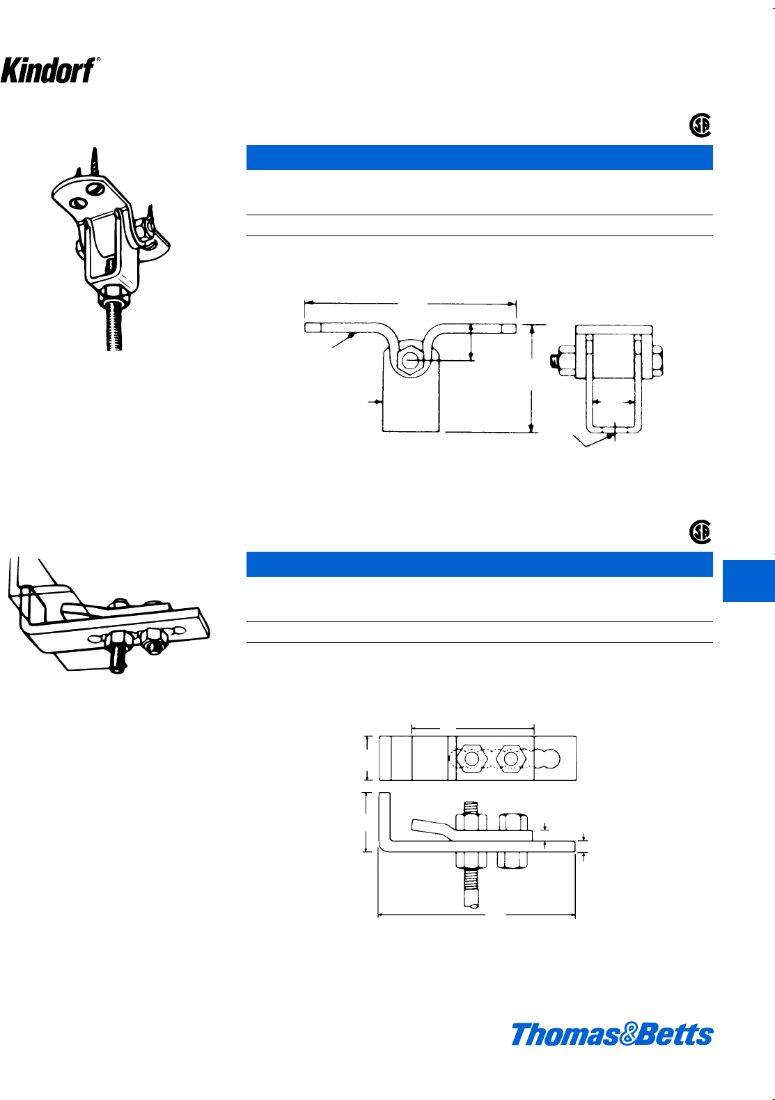
Beam Clamps and Hanger Rod Supports
Adjustable to fit all structural channels up to a
maximum flange width of 31⁄4" inches, and all
structural angles with leg up to 3 inches long
and not more than 3⁄8inch thick.
E-170 Adjustable Swinging Hanger Flange
(c" or d" rod)
Wt.
Cat. No. lbs./C
E-170 100
Assembly requires c" or d" hanger rod of proper length plus two H-114-C or H-114-D nuts. i" steel. Flange has u"
diameter holes for connection to ceiling.
Galv-Kr¯om finish
Flange has 13⁄32" holes for connection to ceiling.
3⁄16 x 11⁄4
3⁄16 x 2
5
7⁄8
23⁄4
17⁄32
15⁄16
3⁄83⁄8
63⁄8
2
11⁄2
4
© 2003 Thomas & Betts Corporation. Specifications are subject to change without notice. www.tnb.com K57
®
®
E-177 Adjustable Channel Clamp
(d" rod)
Wt.
Cat. No. lbs./C
E-177 183
Load rating is 800 lbs. with a safety factor of three. Assembly requires d" hanger rod of the proper length plus two
H-114-D nuts. c" steel.
Galv-Kr¯om finish
K
Kindorf ®
412034.K01 KINDORF 5/1 5/7/03 3:16 PM Page K57
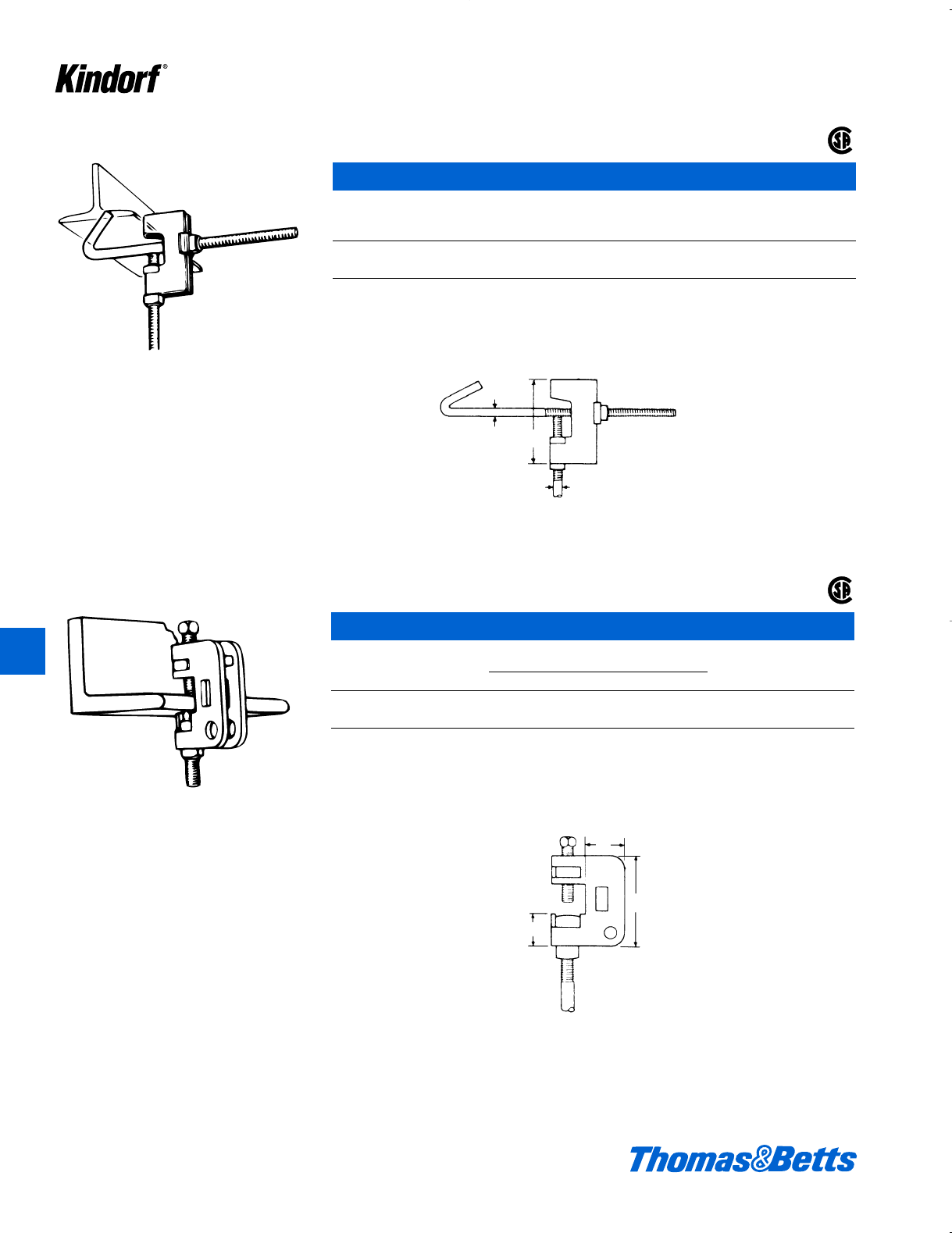
Beam Clamps and Hanger Rod Supports
Clamps to I-beams where edge of beam flange
does not exceed .8 inch. Hook rod is furnished
to fit beam flanges from 21⁄2through 10 inch
widths.
E-230 I-Beam Clamp
(c" rod)
For Beam Flange Wt.
Cat. No. width/in. lbs./C
E-230-6 2dto 6 60
E-230-10 5dto 10 72
Load rating 800 lbs. with a safety factor of three. Assembly requires c" hanger rod of the proper length plus two
H-116-C square nuts.
Galv-Kr¯om finish
Clamps to I-beams, channels, angles and col-
umn. Two sizes are available, one for 3⁄8inch
and the other for 1⁄2inch hanger rod. Each takes
flanges up to .8 inch thickness.
12 Ga.
3⁄8
22⁄8
3⁄8
B
A
C
K58 © 2003 Thomas & Betts Corporation. Specifications are subject to change without notice. www.tnb.com
®
®
E-231 Structural Steel Clamp
(c" or d" rod) Dimensions (in.) Wt.
Cat. No. A B C lbs./C
E-231-3/8 * 2d1g31
E-231-1/2** 31sn 53
Assembly requires two H-116-C (c") or two H-116-D (d") square nuts to attach hanger rod. a" steel.
* Load rating of 500 lbs. with a safety factor of three.
** Load rating of 800 lbs. with a safety factor of three.
Galv-Kr¯om finish
K
Kindorf ®
412034.K01 KINDORF 5/1 5/7/03 3:16 PM Page K58
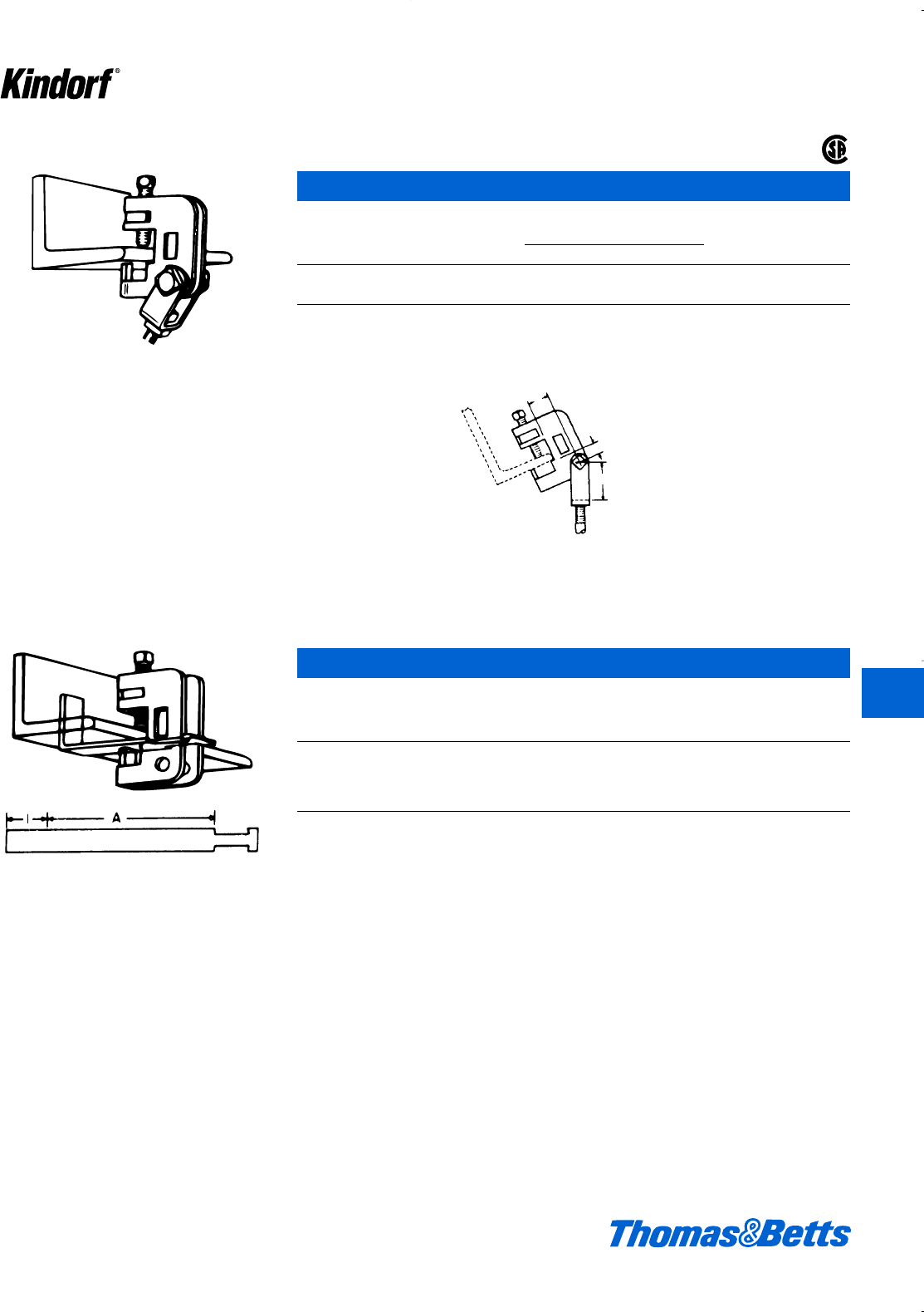
Beam Clamps and Hanger Rod Supports
For use with E-231 and E-232 clamps when
hanger rod is not in straight through position.
E-232 Clamp with Swing Connector
(c" or d" rod)
Cat. Diameter Dimensions (in.) Wt.
No. for Rod A B C lbs./C
E-232-3/8* c"lk148
E-232-1/2** d"gS1e76
* Load rating of 400 lbs. with a safety factor of three.
** Load rating of 550 lbs. with a safety factor of three.
Galv-Kr¯om finish
E-231 clamp with swing connector. Affords a
convenient method of attaching to angled
beams.
A
B
C
© 2003 Thomas & Betts Corporation. Specifications are subject to change without notice. www.tnb.com K59
®
E-233 Anchor Clip
Max.
Beam
Cat. Rod Width For use Wt.
No. Size “A” With lbs./C
E-233-3/8-6 c6" E-231-3/8 or 20
E-233-3/8-10 c10" E-232-3/8 33
E-233-1/2-6 d6" E-231-1/2 or 26
E-233-1/2-10 d10" E-232-1/2 37
Anchor Clips should be used when clamps are subject to excessive vibration. To obtain the correct size clips add 1 inch
to the flange width. If length required is not standard, order next largest standard length.
Galv-Kr¯om finish
K
Kindorf ®
412034.K01 KINDORF 5/1 5/7/03 3:16 PM Page K59
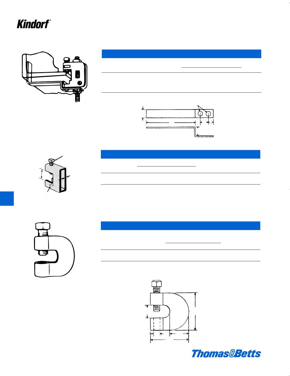
For beam flange thicknesses up to .3⁄4".
Hardened cup pointed set screw secures clamp
to flange.
E-237 Beam Clamps
(e", f" or g" rod)
Max. Set Approx.
Cat. Load Steel Dimensions (in.) Screw Weight
No. lbs.* Size B C D E F Size per 100
E-237-5/8 900 ie2b2j1fex 1d65
E-237-3/4 900 if2b2b1ffx 1d68
* Load rating based on safety factor of three.
Standard finish: black.
D
C
B
F
E
Beam Clamps and Hanger Rod Supports
E-234 Anchor Clip
Max. Dimensions
Cat. Rod Beam For Use (in.) Wt.
No. Size Width With ABCDEF
lbs./C
E-234-3/8-6 c6" E-231-3/8 or f6ag g e k 20
E-234-3/8-10 c10" E-232-3/8 f10ag g e k 33
E-234-1/2-6 d6" E-231-1/2 or 1 6an 1Ll 32
E-234-1/2-10 d10" E-232-1/2 1 10an 1Ll 45
Galv-Kr¯om finish
Set screw C included
Tapped
hole
size
A
D
C
B
F
E
121⁄32"
A
B
K60 © 2003 Thomas & Betts Corporation. Specifications are subject to change without notice. www.tnb.com
K
Kindorf ®
E-235 Heavy Duty Beam Clamp
Design
Cat. Dimensions Wt. Load
No. A B C lbs./C lbs.
E-235-3/8-HD cacx 2f109 1300
E-235-1/2-HD dbdx 2f201 3150
Finish: Hot-Dipped Galvanized
412034.K01 KINDORF 5/1 5/7/03 3:16 PM Page K60
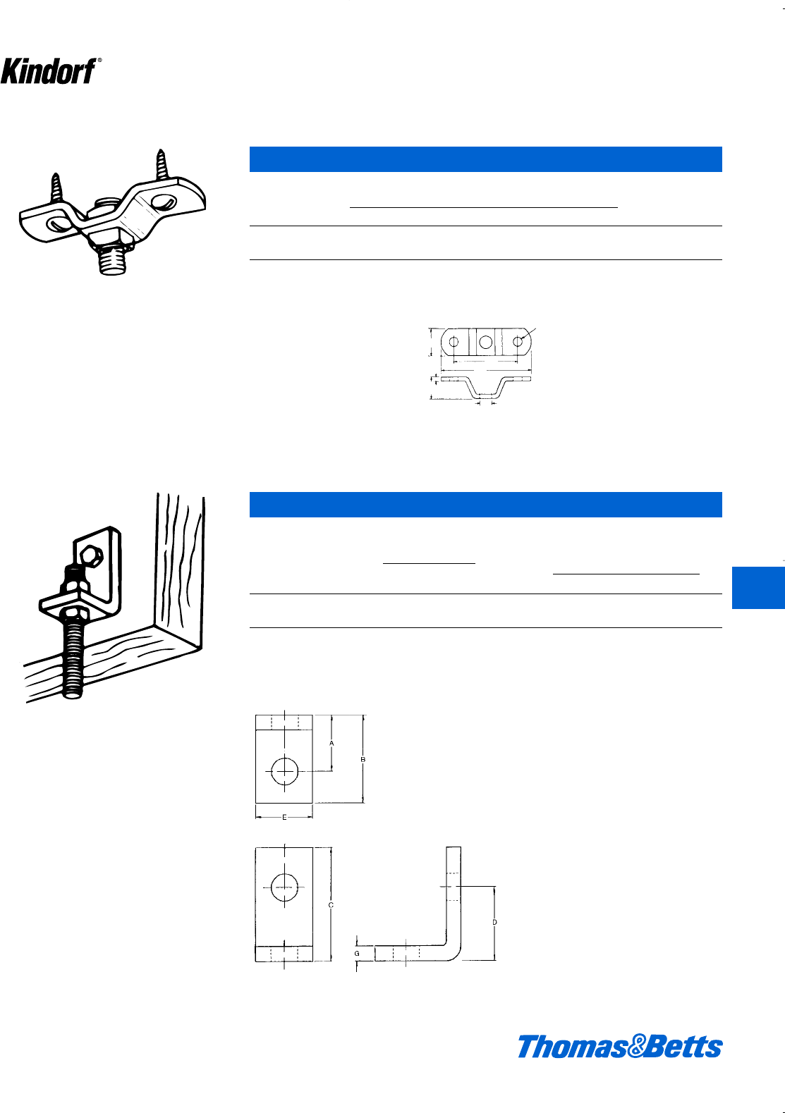
© 2003 Thomas & Betts Corporation. Specifications are subject to change without notice. www.tnb.com K61
K
Kindorf ®
Beam Clamps and Hanger Rod Supports
Secures hanger rod to the side of beams and
joists.
E-243 Ceiling Flange
(c" or d" rod)
Cat. Dimension (in.)
No. A B C D E Weight
E-243-3/8 3ke 2b1crod 18
E-243-1/2 4b13a1bdrod 31
Assembly requires two H-116-C (c") or two H-116-D (d") square nuts for the hanger rod. Also requires screws or bolts
for fastening to the ceiling. i" steel. 18#/C.
Galv-Kr¯om finish
For suspending hanger rods from the ceiling.
13⁄32
hole
C
A
E
B
D
3⁄16
E-244 Side Beam Connector
(c", e" rod)
Max. Recom.
Cat. No. Load (lbs.)
and Rod Hole Lag Bolt to Wt. Dimension (in.)
Size Size Screw Steel lbs./C A B C D E G
E-244-3/8 k" 390 580 20 1" 1l"1g"1c"1" b"
E-244-5/8 L" 760 1,500 70 1k"2b"2g"1g"1d"c"
For d" rod use B-915 or B-916 connectors.
Assembly requires hanger rod of proper size and two hex nuts, plus screw or bolt for fastening to beam or joist. Cat. No.
E-244-3⁄8 has Galv-Kr¯om finish. Larger sizes: Black.
412034.K01 KINDORF 5/1 5/7/03 3:16 PM Page K61
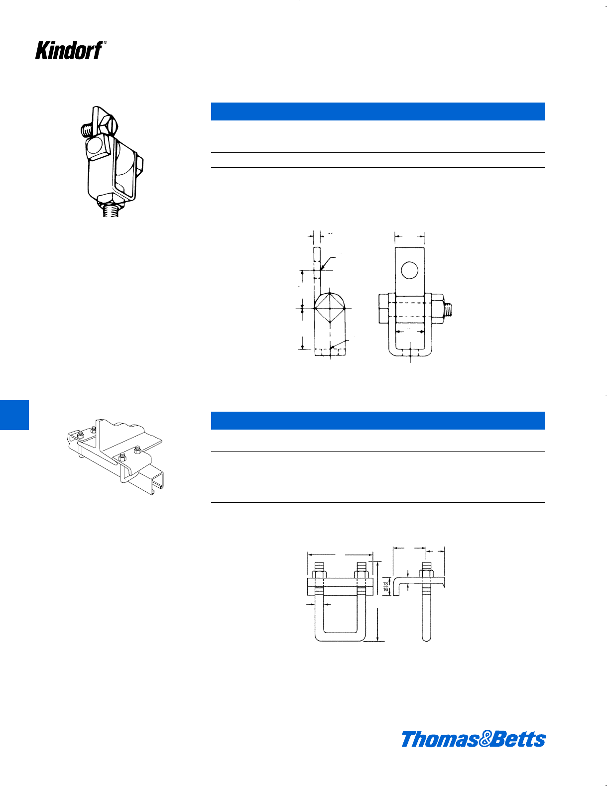
Beam Clamps and Hanger Rod Supports
Used to secure a 3⁄8-inch hanger rod to the side
or bottom of beam or ceiling.
E-245 Swing Connector
(c" rod)
Wt.
Cat. No. lbs./C
E-245 28
Assembly requires two H-116-C (c") square nuts. Also screw or bolt for fastening to beam or ceiling. a" steel.
Load rating of 700 lbs. with a safety factor of three.
Galv-Kr¯om finish
Hardened points bite into beam flange. Fits all
I-beams where edge of beam flange does not
exceed .8 inch thickness.
1⁄8
13⁄32 hole
11⁄8
13⁄32 hole
11⁄8
3⁄4
13⁄16
3⁄8
7⁄8
1⁄4
3
A
11⁄2
K62 © 2003 Thomas & Betts Corporation. Specifications are subject to change without notice. www.tnb.com
E-760 Channel to Beam Clamp
For Structor Dimension A Wt.
Cat. No. Channel (in.) lbs./C
E-760-2* B-900, B-905, 3b76
B-906, B-907
E-760-2SS Stainless Steel
E-760-3 B-901, B-900-2A, 4f88
B-902, B-903
* Load rating of 2,200 lbs. with a safety factor of three.
b" steel, c-inch U-bolt.
Standard finish: Galv-Kr¯om
K
Kindorf ®
412034.K01 KINDORF 5/1 5/7/03 3:16 PM Page K62
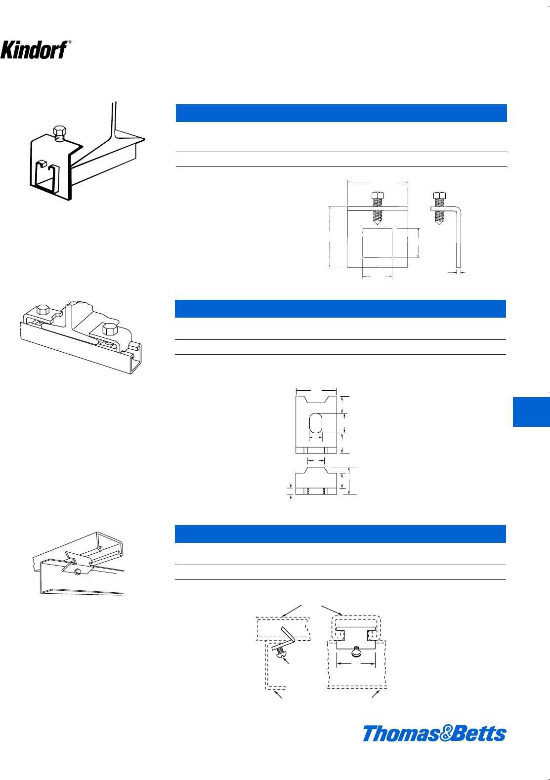
© 2003 Thomas & Betts Corporation. Specifications are subject to change without notice. www.tnb.com K63
Beam Clamps and Hanger Rod Supports
Secures all sizes of Kindorf channel to beams
where flange edge does not exceed .8" thick-
ness.
E-761 Channel to Beam Clamp
Design
Load Channel Wt.
Cat. No. lbs./ea. Series lbs./C
E-761 800 B-900, B-905, B-995 108
d" x 1d" set screw included
Galv-Kr¯om finish
Complete with set screw. For clipping a length
of channel slot-side down and across the run-
ner bars of a dropped ceiling installation.
1
2
1
5
8
3
4
3
4
9
16
5
8
1
2
1
1
4
Runner bar for dropped ceiling
set
screw
channel
11
4
11⁄8
5⁄8
3⁄4
3⁄4
9⁄16
5⁄8
1⁄2
1⁄4
31⁄2
111⁄16
111⁄16
31⁄2
1⁄4
E-763 Channel to Beam Clamp
Design Wt.
Cat. No. Load lbs./C
E-763 500 lbs. 25
Load rating each clamp 800 lbs. with a safety factor of 3. b" steel. Assembly requires one H-113-E bolt and one
B-910-1⁄2 steel nut per clamp – order separately.
Galv-Kr¯om finish
E-764 Channel Clip
Wt.
Cat. No. lbs./C
E-764 4
At least two required per each such application.
Galv-Kr¯om finish
K
Kindorf ®
412034.K01 KINDORF 5/1 5/7/03 3:16 PM Page K63
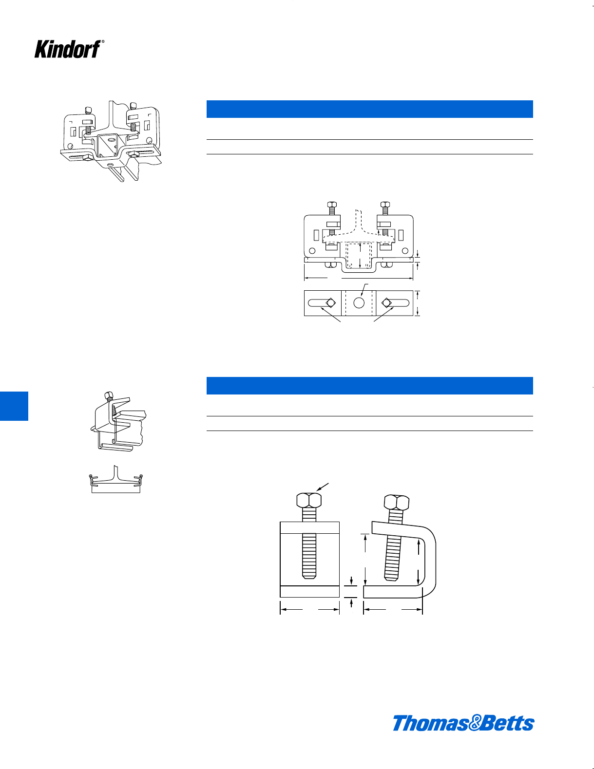
K
Kindorf ®
K64 © 2002 Thomas & Betts Corporation. Specifications are subject to change without notice. www.tnb.com
Beam Clamps and Hanger Rod Supports
Supports any size Kindorf channel. Clamps to
I-beam where flange edge does not exceed .8"
thickness.
E-765 Center Beam Clamp
Wt.
Cat. No. Load Rating lbs./C
E-765 800 lbs. 112
Load rating is 800 lbs. with a safety factor of 3. Furnished assembled. a" steel clamps, i" steel strap.
Galv-Kr¯om finish
0.8
11
2
3
16
61
4
11
2
15
8
9
16
13
32 xslot
8
1
4
11
41
11
4
set screw
11
4
13⁄32 x 15⁄8slot
3⁄16
9⁄16
1⁄4
61⁄4
11⁄2
11⁄2
.08
3⁄8set screw
11⁄411⁄4
11⁄41
Clamps 11⁄2" x 11⁄2" Kindorf channel to beams
where beam flange does not exceed 3⁄4" thick-
ness and 4" to 63⁄4" wide.
E-767 Channel Support
Wt.
Cat. No. Load Rating lbs./C
E-767 800 lbs. 44
Load rating is 800 lbs. with a safety factor of 3. b" steel.
Galv-Kr¯om finish
412034.K01 KINDORF 5/1 5/7/03 3:16 PM Page K64
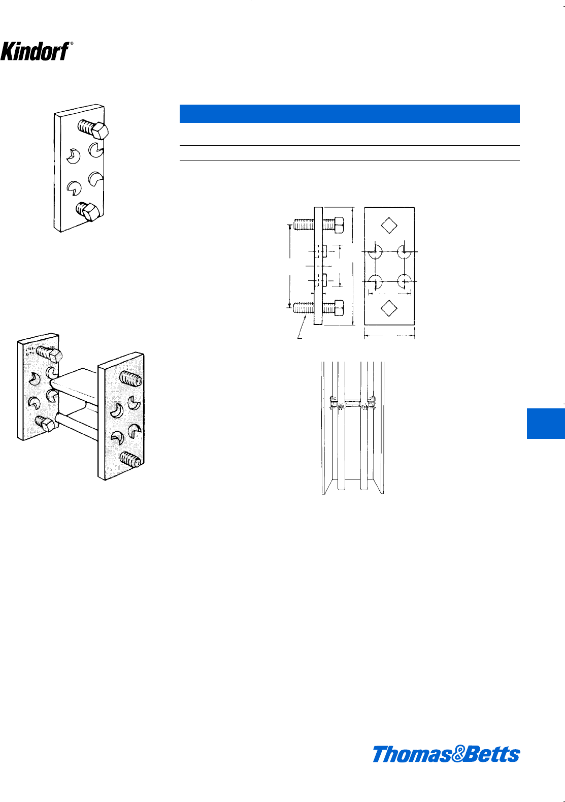
K
Kindorf ®
© 2002 Thomas & Betts Corporation. Specifications are subject to change without notice. www.tnb.com K65
Beam Clamps and Hanger Rod Supports
For use with 11⁄2" x 11⁄2" channel. Provides a
rigid support between ‘H’ beam flanges for
mounting pipe, conduit, outlet boxes, panel
boards.
E-768 Column Mount Support
Wt.
Cat. No. Load Rating lbs./C
E-768 800 lbs. 50
Two E-768’s required for installation. Use C-105, C-106 or C-107 straps for mounting d" to 8" pipe on channel section.
Load rating of 800# – safety factor of three.
Galv-Kr¯om finish
Use 11⁄2" x 11⁄2" size
Kindorf Channel.
STEEL
CITY
C-768
5⁄16 x 11⁄4bolts
1⁄4
31⁄2
11⁄4
21⁄2
11⁄2
11⁄4
412034.K01 KINDORF 5/1 5/7/03 3:16 PM Page K65
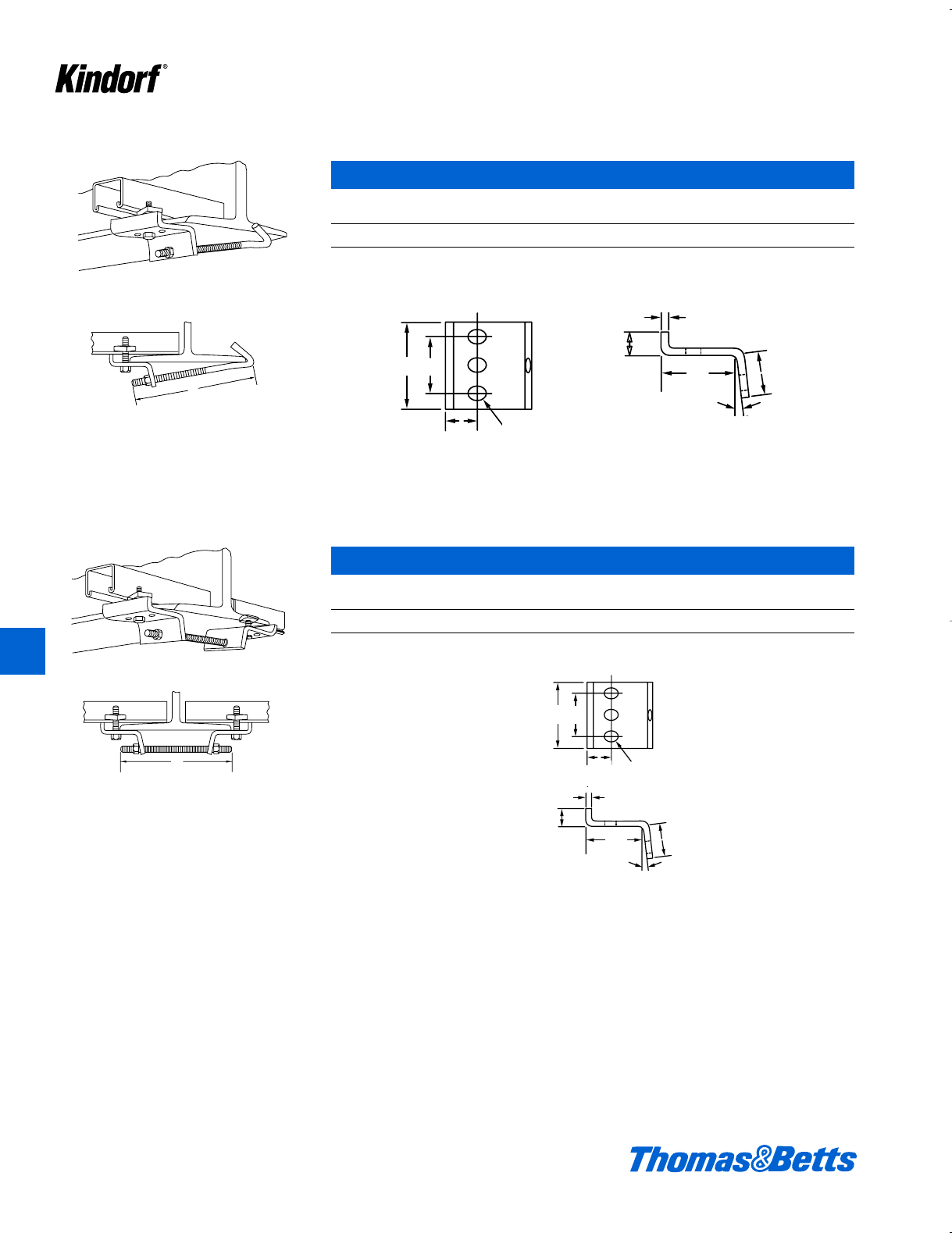
Beam Clamps and Hanger Rod Supports
For use in attaching channel on both sides of a
beam flange with slot side down. Members are
shipped assembled for easy installation.
E-781 Single Beam Clamp
Wt.
Cat. No. lbs./C
E-781 133
Galv-Kr¯om finish
1
2
2
32
1
16
17
16 x9
16 slot total (3)
3
16
1
7
1
2
2
32
1
16
17
16 x9
16 slot t
o
1
4
3
1
6
1
2
1
8
7
7⁄16 x9⁄16 slot total (3)
3⁄16
1⁄4
3
11⁄2
211⁄2
7°
3⁄16
11⁄16
21⁄2
7⁄16 x9⁄16 slot total (3)
1⁄4
32
7°
11⁄16
21⁄2
For use in attaching channel on top of beam
flange with slot side down. Members are
shipped assembled for easy installation.
K66 © 2003 Thomas & Betts Corporation. Specifications are subject to change without notice. www.tnb.com
E-782 Double Beam Clamp
Wt.
Cat. No. lbs./C
E-782 235
Galv-Kr¯om finish
K
Kindorf ®
412034.K01 KINDORF 5/1 5/7/03 3:16 PM Page K66
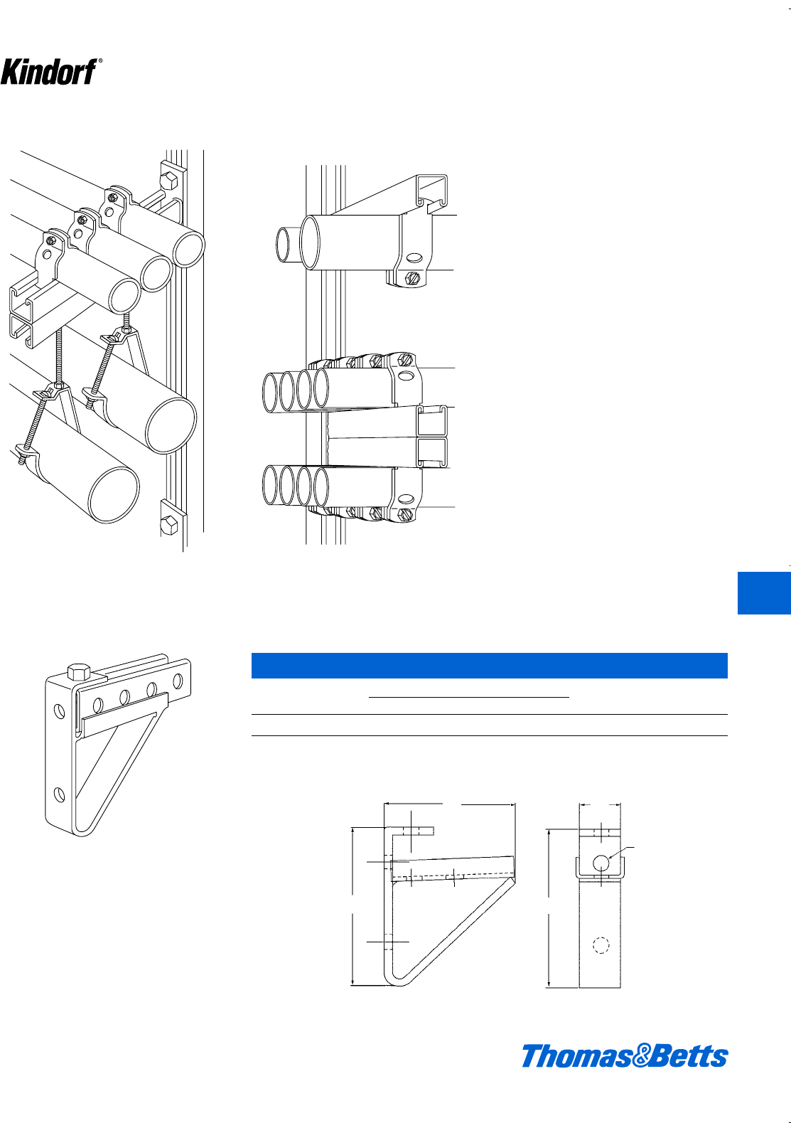
© 2003 Thomas & Betts Corporation. Specifications are subject to change without notice. www.tnb.com K67
Support Brackets
F-721 Wall bracket hangs and supports pipe
runs.
Kindorf Wall brackets provide a ready-
made shelving arrangement that can
be attached quickly to the supporting
channels.
Utilizing the built-in advantages of the
Kindorf Channel, the support bracket
members allow a great deal of flexibility
in meeting the structural framing needs.
Axle supports and a variety of wall
brackets all adapt to the standard
Kindorf channel and allow additional
flexibility in the support of cables, con-
duit, pipe and other equipment.
The application of axle supports and
bracket members can be made on
either the continuous slot of the chan-
nel or the prepunched hole side.
Utilizing the 1d" hole spacing, greater
adaptability is attained with a minimum
of fittings.
Conduit installations supported above and
below by F-721 wall bracket.
Mounts on Kindorf channel or directly to wall.
F-715 bracket supports 11⁄2" or 15⁄8" channels.
Brackets allow for a variety of support channel
lengths. The continuous tray on brackets pre-
vent lateral movement of supported channels.
Support channels can be fastened from top,
bottom or both.
F-715 Wall Bracket
Cat. Dimensions (in.) Wt.
No. AB C lbs./C.
F-715 5B4e1d163
Galv-Kr¯om finish
9⁄16 Dia. Holes
AA
BC
K
Kindorf ®
412034.K01 KINDORF 5/1 5/7/03 3:16 PM Page K67
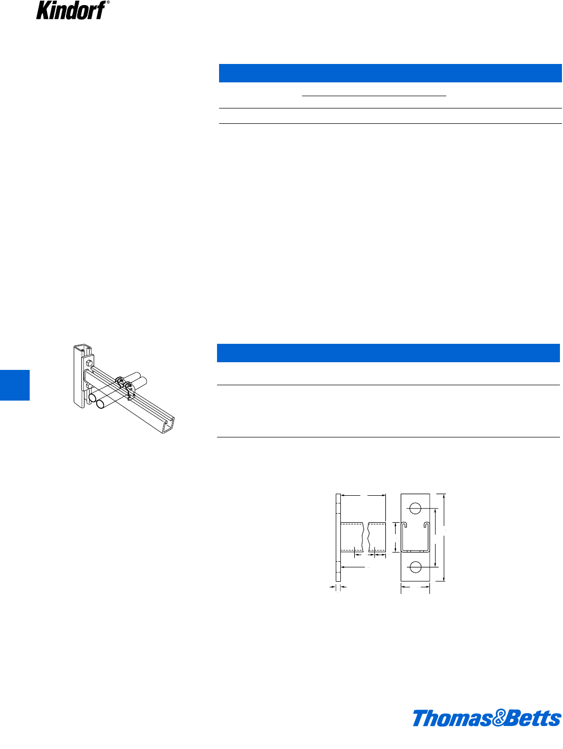
Mounts on Kindorf channel, concrete inserts or
directly to wall. Continuous-slot accepts C-105,
C-106 and C-107 series pipe straps. Bracket is
12 gage steel, 11⁄2" x 11⁄2" channel welded to a 1⁄4"
back plate. May be attached to either the con-
tinuous slot side or prepunched holes in back
or side of Kindorf channel.
F-720 Wall Bracket
Cat. Dim. A End Load Wt.
No. (in.) Rating lbs.* lbs./C
F-720-6** 6 600 132
F-720-9** 9 450 155
F-720-12** 12 300 200
F-720-18 18 200 275
F-720-24** 24 150 350
* Safety factor of 3.
** This product available in green & hot-dipped galvanized.
Standard finish: Galv-Kr¯om
1
2
1
1
2
1
1
4
9
16 hole
3
4
A
1
2
1
3
1
2
4
Support Brackets
K68 © 2003 Thomas & Betts Corporation. Specifications are subject to change without notice. www.tnb.com
K
Kindorf ®
Mounts on Kindorf channel or directly to wall.
F-716-3 bracket supports 3" deep or back to
back channels. Brackets allow for a variety of
support channel lengths. The continuous tray
on brackets prevent lateral movement of sup-
ported channels. Support channels can be fas-
tened from top, bottom or both.
F-716-3 Wall Bracket
Cat. Dimensions (in.) Wt.
No. AB C lbs./C.
F-716-3 7X4e1d179
Galv-Kr¯om finish
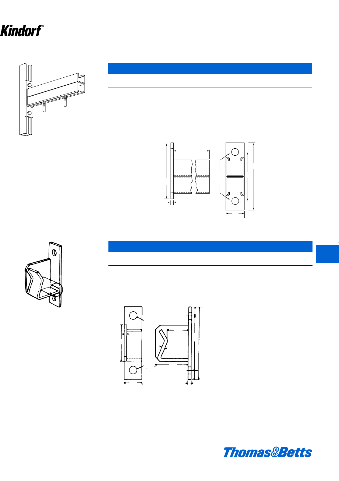
Support Brackets
Double channel to provide continuous-slot for
both top and bottom mounting. 12 ga. steel, 1⁄4
inch back plate. May be attached to either the
continuous slot side or prepunched holes in
back or side of Kindorf channel.
1
4
9
16
holes
A
1
2
1
3
1
2
4
6
© 2003 Thomas & Betts Corporation. Specifications are subject to change without notice. www.tnb.com K69
K
Kindorf ®
F-721 Wall Bracket
Cat. Dim. A End Load Wt.
No. (in.) Rating lbs.* lbs./C.
F-721-18 18 300 568
F-721-24 24 225 736
F-721-30 30 180 904
F-721-36 36 150 1072
* Safety factor of 3.
Standard finish: Galv-Kr¯om
For use on storage racks constructed on Kindorf
channel. Supports reels of electrical cables,
wire rope, chain and other materials. Left hand
axle support illustrated. F-736 identical except
right hand.
May be attached to either the continuous slot
side or prepunched holes in back or side of
Kindorf channel.
F-735 and F-736 Axle Supports
Wt.
Cat No. Description lbs./C
F-735 Left hand 165
F-736 Right hand 165
Assembly requires two B-910-1/2 steel nuts and two H-113-B bolts. Accepts up to 1b" steel bar or pipe for axle.
Galv-Kr¯om finish
3
1⁄4
9⁄16
9⁄16
11⁄21⁄4
6
41⁄2
3⁄4
113⁄16
23⁄4
1⁄4
3⁄4
412034.K01 KINDORF 5/1 5/7/03 3:16 PM Page K69

To be used as center support for tandem reel
assembly.
F-737 Double Axle Support
Wt.
Cat. No. lbs./C
F-737 335
Assembly requires four B-910-1⁄2 steel nuts and four H-113-B bolts. To be used with F-735 and F-736. b" steel.
Galv-Kr¯om finish
Typical Kindorf Space-Saver reel rack. Kindorf
reel racks are easy to build, exceptionally
strong and economical. Racks adjust easily to
accommodate a variety of reel sizes.
No special tools needed.
113⁄16
1⁄4
1⁄4
31⁄4
3⁄4
3⁄4
11⁄2
39
3⁄4
11⁄2
3⁄4
23⁄4
9⁄16
Support Brackets
K70 © 2003 Thomas & Betts Corporation. Specifications are subject to change without notice. www.tnb.com
K
Kindorf ®
Cantilever type cable hooks fit into ‘T’ slot on
B-904 channel for rigid, non-slip support. Fast
mounting, no hardware to tighten.
F-739 Telephone Cable Hook
Cat. Dimension A Wt.
No. (in.) lbs./C
F-739-4-1/2 41⁄281
F-739-7-1/2 71⁄2122
F-739-10-1/2 101⁄2162
F-739-13-1/2 131⁄2198
F-739-18 18 278
Has l" diameter holes on 1d" centers to allow for easy tie banding of cables. Galv-Kr¯om 12 ga. steel.
11
2
A
11
2
11⁄2
11⁄2
A
412034.K01 KINDORF 5/1 5/7/03 3:16 PM Page K70
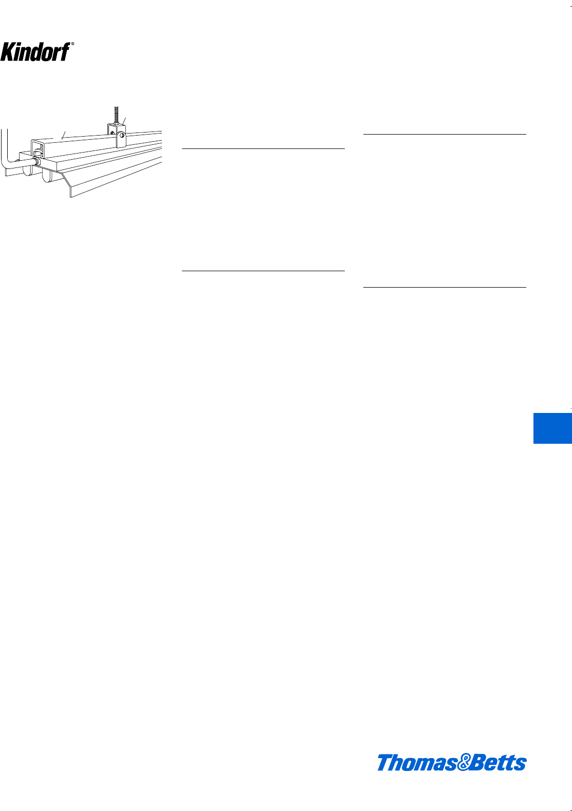
© 2003 Thomas & Betts Corporation. Specifications are subject to change without notice. www.tnb.com K71
K
Kindorf ®
Channel raceway system supports and feeds
fluorescent lighting fixtures.
Surface Raceway and
Lighting Support
Systems
The Kindorf Lighting Support System
consists of high quality construction
materials that afford definite installation
advantages to those most concerned
with lighting installations. When used
as a Surface Metal Raceway it is U.L.
Listed and complies with National
Electrical Code Article 352.
To The Owner
A flexible installation requiring fewer
attachments to the building structure
with built-in provisions for easy mainte-
nance and future modifications when
lighting fixtures must be added, delet-
ed or relocated. Kindorf channel and
fittings form a strong, economical and
attractive support and wiring system
for fixtures and other equipment.
To The Architect and
Engineer
A system of construction least
demanding on general design condi-
tions and readily adaptable to all spac-
ing of pillars, purlins and other structur-
al components. Supply will not delay a
job because Kindorf is stocked at
many locations throughout the country.
The Kindorf System saves planning
time because it is designed for fast
and easy installation by the contractor
with little or no detailing.
To the Contractor
The Kindorf System consists of time
saving materials that will simultaneous-
ly provide for the electrical feed and
the mechanical support of lighting and
other equipment. Kindorf affords a
means of making fewer attachments to
the structure at wider spacing. It
insures true and rigid alignment and
lends itself to systematic preassembly
methods which economize on labor.
No special tools for installation and no
painting is required. Kindorf speeds all
jobs because a complete line of fittings
assures easy solution of many installa-
tion problems as they arise in the field.
B-900
G-962
G-962
B-900
Surface Raceway and Lighting Support Systems
412034.K01 KINDORF 5/1 5/7/03 3:16 PM Page K71
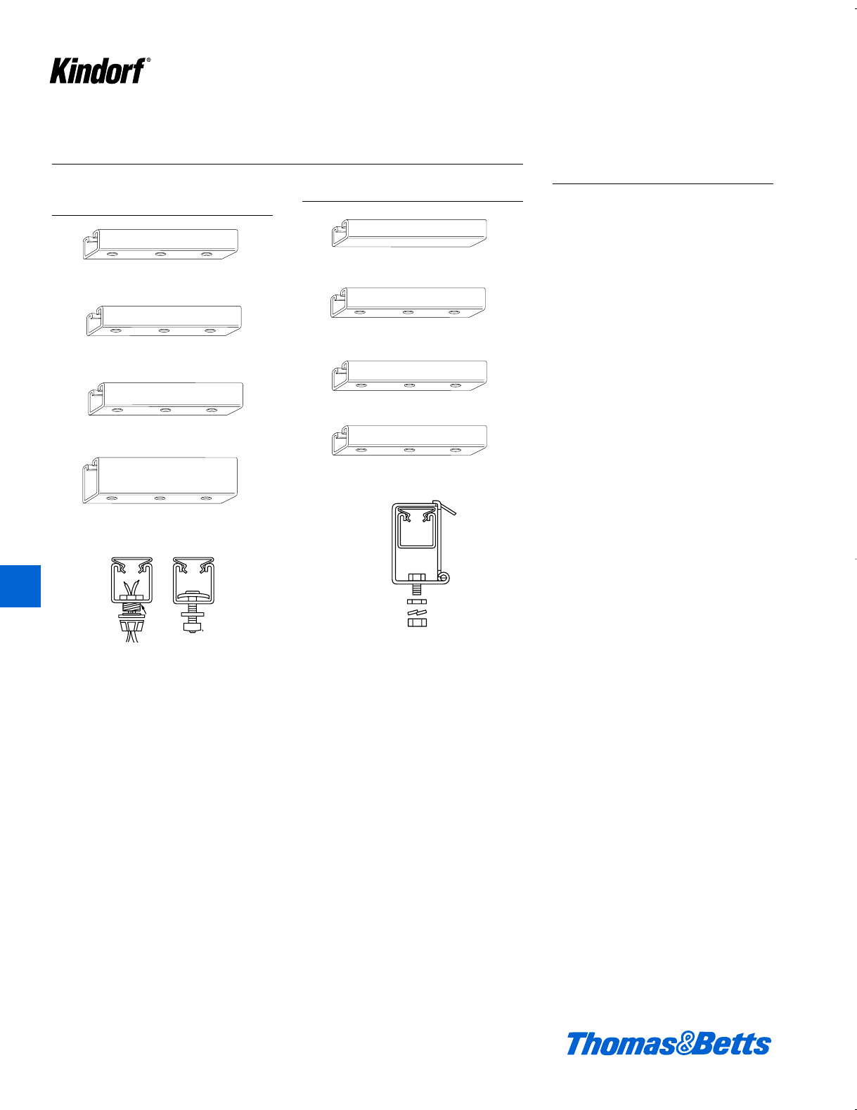
K72 © 2003 Thomas & Betts Corporation. Specifications are subject to change without notice. www.tnb.com
K
Kindorf ®
Surface Raceway and Lighting Support Systems
Knock-out type
by means of 1⁄2" channel knockouts
on 6" centers
Electrical Conductors
“Lay-In” the Channel
Kindorf Surface Raceway channels
provide a central wiring distribution
system with conductor capacity that
exceeds requirements of any lighting
layout and with ‘power to spare’ for
other uses. Channel adapts to any
interval of structural support – may be
dropped to any level where it
becomes a rigid platform for fixture
attachment. Lighting fixtures may be
spaced and fastened anywhere along
the channel system with “plug-in” or
direct feed electrical connection.
Branch lighting circuit conductors
are completely enclosed in channel
from panel to fixture eliminating the
ordinary “clutter” of external conduc-
tors and protecting the wires from
physical damage.
Listed by Underwriters’ Laborato-
ries, Inc.
Plug-in type
by means of sliding fixture hanger
Surface Raceway Channel Systems
1
2
1xx 14 ga.
1
2
1
1
2
1xx 12 ga.
1
2
1
1
2
1xx 12 ga.
7
8
1
1
2
1xx 12 ga.
3
1
2
1xx 14 ga.
1
2
1
1
2
1xx 14 ga.
1
2
1
1
2
1xx 14 ga.
1
2
1
1
2
1xx 14 ga.
1
2
1
G-1012 hangar wit
h
H-115-A bolt and s
q
G-1016 and H-118
-
1
G 974 1
G-975-M
G-975
G-965
G-955
G-972-1/2 G-974-1-1/4
Nipple
Lock nut and
bushing
B-900-M
B-900
B-901
B-906
G-1012
Hanger with H-115-A bolt and
square nut plus
G-1016 and H-118-C washers
11⁄2x 11⁄2x 14 ga.
11⁄2x 11⁄2x 12 ga.
11⁄2x7⁄8x 12 ga.
11⁄2x 3 x 12 ga.
11⁄2x 11⁄2x 14 ga.
11⁄2x 11⁄2x 12 ga.
11⁄2x7⁄8x 12 ga.
11⁄2x3⁄4x 14 ga.
412034.K01 KINDORF 5/1 5/7/03 3:16 PM Page K72
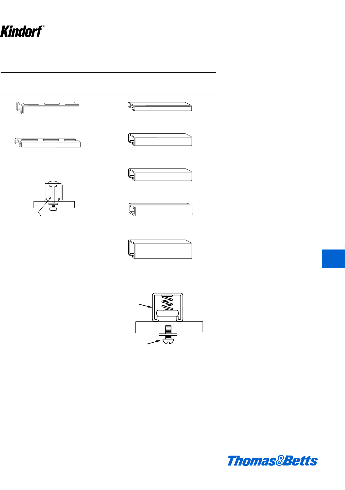
© 2003 Thomas & Betts Corporation. Specifications are subject to change without notice. www.tnb.com K73
K
Kindorf ®
Kindorf channels, installed slot-side
down, are designed to provide fixture
support only. A range of accessory fit-
tings permit fixture attachment to the
channel safely and securely in an
approved manner. Channels with solid
base or with slots are generally used
for simple channel support systems.
Channel support systems combine
economy of investment with maximum
strength and rigidity. The continuous-
slot channel provides complete flexi-
bility of lighting layout with fixture
spacing continuous or intermittent.
Fixtures may be added or relocated to
meet changing requirements without
disturbing the basic support system.
The rigid channels maintain fixture
alignment, adapt to any interval of
structural support.
Channel Support Lighting Systems
Shoulder bolt type Spring-nut type
by means of special shoulder bolt by means of spring-nut and bolt combination
13⁄32" x 3" slots on 4" centers
1
2
1xx 12 ga.
1
2
11
2
1xx 14 ga.
3
4
1
2
1xx 14 ga.
1
2
1
1
2
1xx 12 ga.
1
2
1
1
2
1xx 12 ga.
7
8
1
1
1xx 12 ga.
3
2
-B
1
4
1
2
1xx 14 ga.
1
2
B-911-1⁄4
H-111-B
G-953
G-956
G-973-2-1⁄4
B-906
B-900-M
B-900
B-901
B-902
11⁄2x 11⁄2x 12 ga.
11⁄2x 11⁄2x 12 ga.
11⁄2x3⁄4x 14 ga.
11⁄2x 11⁄2x 14 ga.
11⁄2x 11⁄2x 12 ga.
11⁄2x 17⁄8x 12 ga.
11⁄2x 3 x 12 ga.
Surface Raceway and Lighting Support Systems
412034.K01 KINDORF 5/1 5/7/03 3:16 PM Page K73
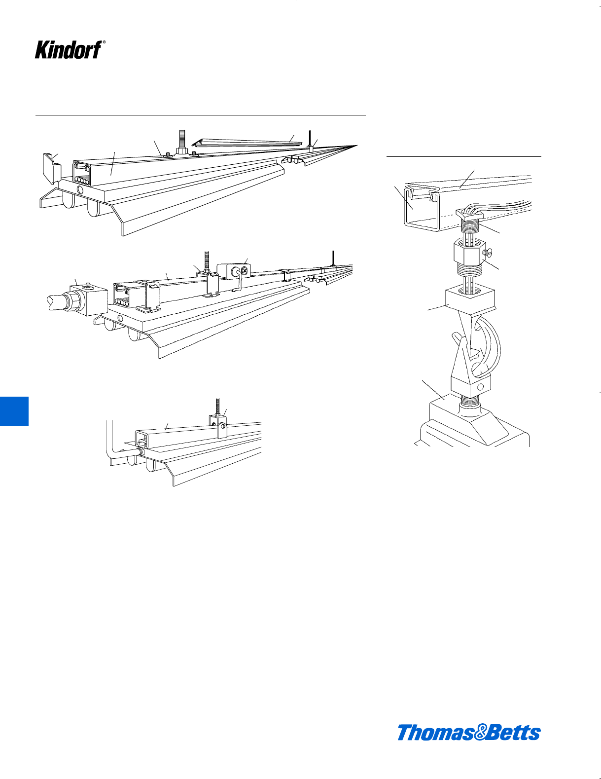
K74 © 2003 Thomas & Betts Corporation. Specifications are subject to change without notice. www.tnb.com
For mounting or sus-
pending high intensity
lighting fixtures in high
bay installations.
Maximum Number of Wires in Raceway
See page K138 and K139 for maximum number of wires in raceway.
Other mechanical details
G-967 G-975
G-1032 G-969
G-1012
B-900
G-962
G-972-1⁄2
Nipple
G-972-HB-1⁄2&3⁄4
Fixture Hanger
Adapter
Fixture Hanger
Fixture Box
and Fixture
G-969A or G-969AP Closure Strip
G-975
G-967 G-975
G-1032 G-969A G-1012
G-1020
G-1012
G-969A
G-1038
G-962
B-900
Surface Raceway and Lighting Support Systems
K
Kindorf ®
412034.K01 KINDORF 5/1 5/7/03 3:16 PM Page K74
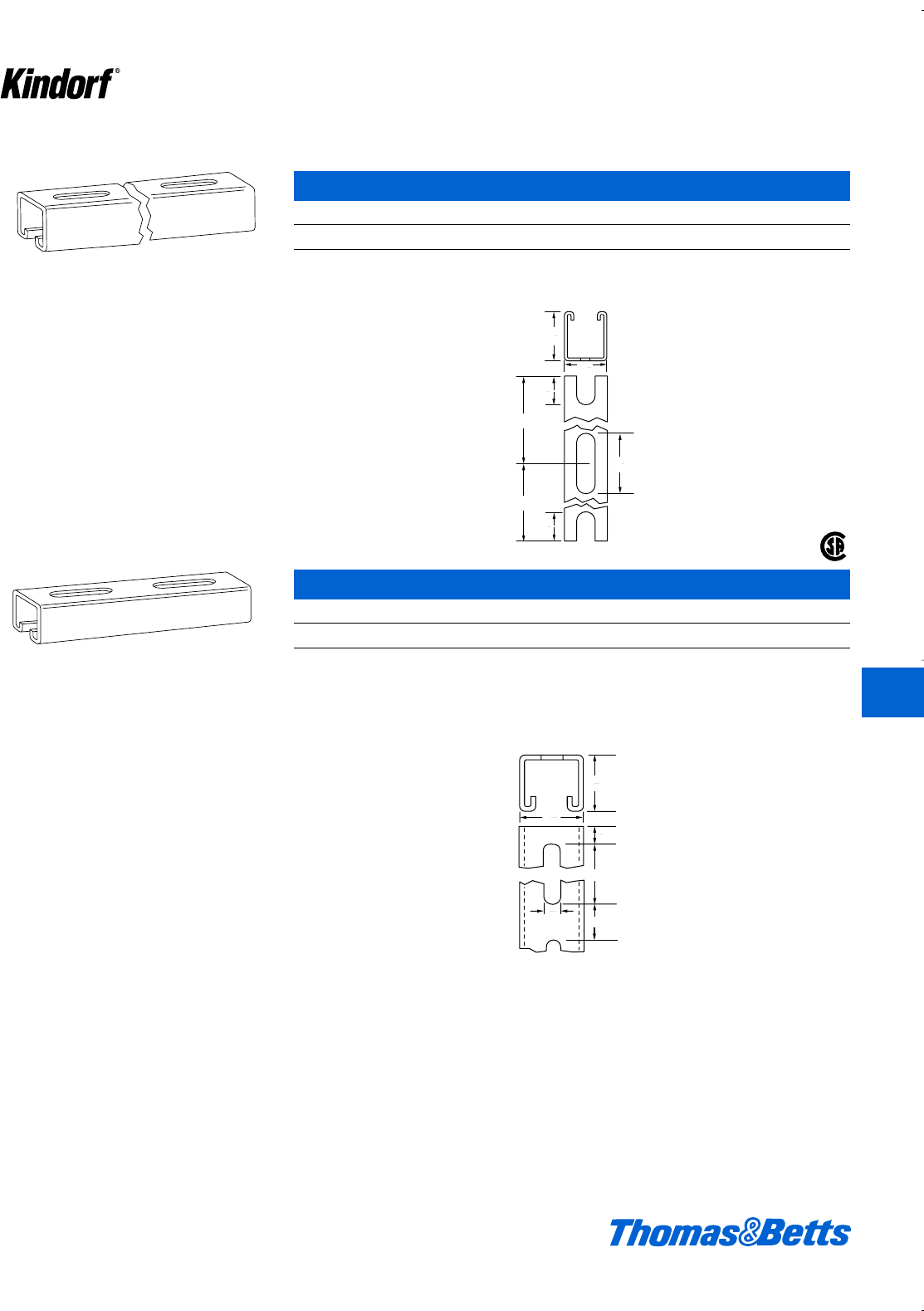
© 2003 Thomas & Betts Corporation. Specifications are subject to change without notice. www.tnb.com K75
G-950 Fixture Hanging Channel
Cat. No. Description Joiner
G-950 1d" x 1g" x 12 ga. G-978C
L" x 2b" slots on 4 foot centers
20 ft. lengths only 194#/C ft.
Standard finish: Galv-Kr¯om
1
2
1
1
4
2
7
8
1
1
8
1
1
8
1
4 ft.
4 ft.
1
2
3
1
2
1
13
32
1
1
2
1
Surface Raceway and Lighting Support Systems
®
G-953 Fixture Hanging Channel
Cat. No. Description Joiner
G-953 1d" x 1d" x 12 ga. G-958
Fixtures attached to channel of G-973-2-1⁄4 shoulder bolts. 154#/C ft.
u" x 3" slots on 4" centers
Standard finish: Galv-Kr¯om K
Kindorf ®
412034.K01 KINDORF 5/1 5/7/03 3:16 PM Page K75
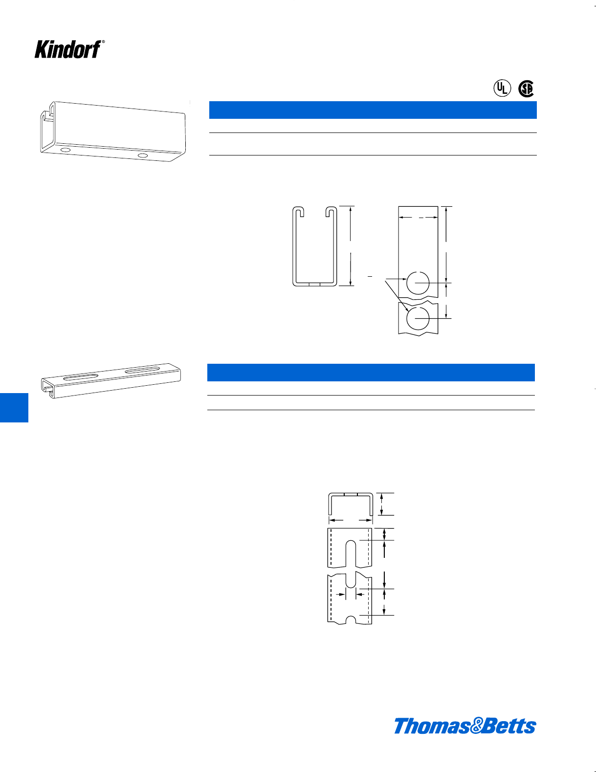
K76 © 2003 Thomas & Betts Corporation. Specifications are subject to change without notice. www.tnb.com
To be used in place of G-975 channel when
heavy fixtures are used or supports are on
wider spacing.
G-955 Fixture Hanging Channel
Cat. No. Description Joiner End Cap
G-955 1d" x 3" x 12 ga. G-978-D G-957
G-959
270#/C ft. UL Listed for raceway.
d" KO’s on 6" centers
Standard finish: Galv-Kr¯om
Similar to G-953 channel except it is lighter
gauge and only 3⁄4" deep.
3
6
KO
3
1
2
1
1
2
1
2
3
1
2
1
13
32
3
4
1
11⁄2
3⁄4
1⁄2
3
1
13⁄32
Surface Raceway and Lighting Support Systems
®
®
G-956 Fixture Hanging Channel
Cat. No. Description Joiner
G-956 1d" x f" x 14 ga. G-960
Fixtures attached to channel by means of G-973-1-1/2 shoulder bolts or G-973-2-1⁄4 fixture bolts. 80#/C ft.
u" x 3" slots on 4" centers
Standard finish: Galv-Kr¯om
K
Kindorf ®
412034.K01 KINDORF 5/1 5/7/03 3:16 PM Page K76
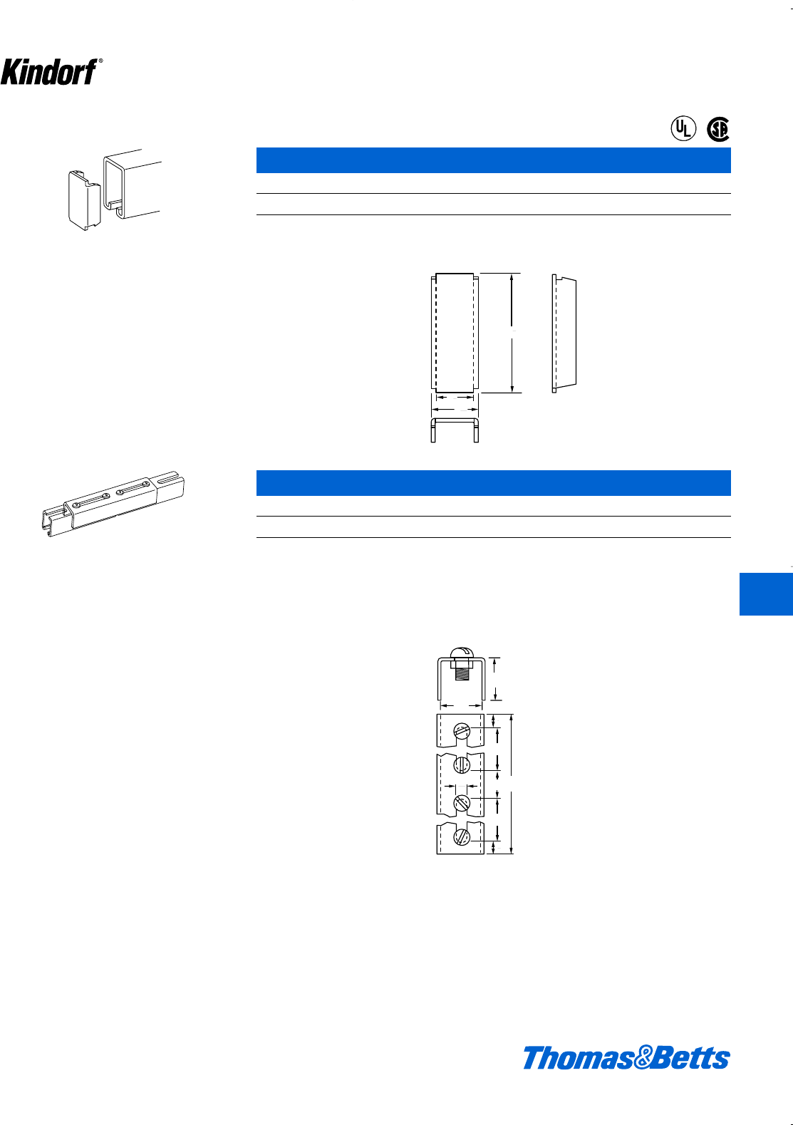
© 2003 Thomas & Betts Corporation. Specifications are subject to change without notice. www.tnb.com K77
Blank end cap for use with G-955 and B-902
channel.
For 11⁄2" deep slotted channel G-953.
5
16
1
1
8
1
1
8
3
1
1
1
3
Bolts and Nuts
17⁄16
19⁄16
1⁄2
3
3
81
13⁄32
1⁄2
Surface Raceway and Lighting Support Systems
®
®
G-957 End Cap
Cat. No. Wt. lbs./C
G-957 14
14 ga. steel.
U.L. Listed for raceway.
Galv-Kr¯om finish
G-958 Channel Joiner
Cat. No. Wt. lbs./C
G-958 92
Four c" x f" bolts and nuts are furnished with the joiner. 14 ga. steel.
Galv-Kr¯om finish
K
Kindorf ®
412034.K01 KINDORF 5/1 5/7/03 3:16 PM Page K77
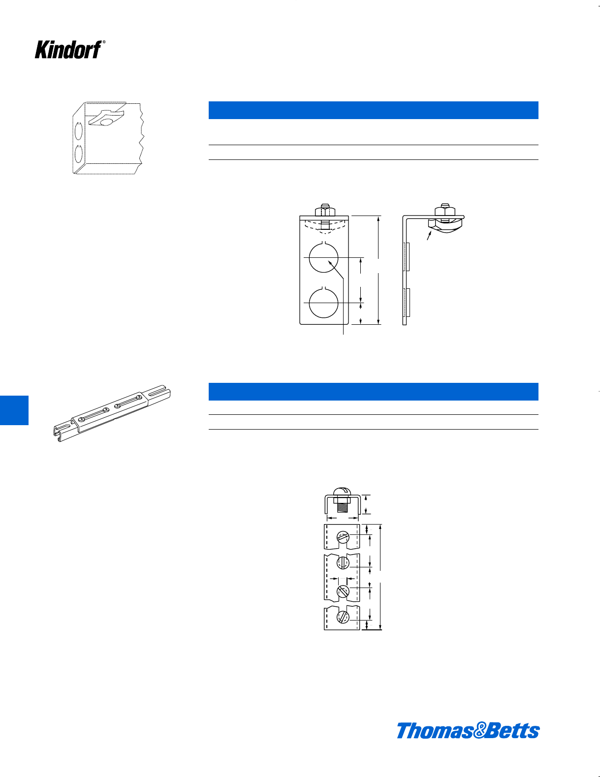
K78 © 2003 Thomas & Betts Corporation. Specifications are subject to change without notice. www.tnb.com
K
Kindorf ®
For use with G-955 and B-902 channel.
G-959 End Cap
With Two dinch Knockouts
Cat. No. Wt. lbs./C
G-959 31
12 ga. steel.
U.L. Listed for raceway.
Galv-Kr¯om finish
For 3⁄4" deep slotted channel G-956.
11
16
1
1
2
5
52
3
3
8
KO
1
2
stud nut G-974 -
3
8
1
1
3
35⁄552
13⁄8
11⁄16
1⁄2KO
3⁄8stud nut G-974 - 1⁄2
Bolts and Nuts
19⁄16
1⁄2
3
3
8
1
13⁄32
1⁄2
3⁄4
Surface Raceway and Lighting Support Systems
G-960 Channel Joiner
Cat. No. Wt. lbs./C
G-960 70
Four c" x f" bolts and nuts are furnished with the joiner. 14 ga. steel.
Galv-Kr¯om finish
412034.K01 KINDORF 5/1 5/7/03 3:16 PM Page K78
© 2003 Thomas & Betts Corporation. Specifications are subject to change without notice. www.tnb.com K79
K
Kindorf ®
G-962 fits around 11⁄2" or 17⁄8" deep channel.
G-962-D series hangers for 3" deep channel.
G-962 and G-962-D Channel Hangers
Cat. Wt. Cat. Wt. Dim. A
No. lbs./C No. lbs./C Hanger Size (in.) (in.)
G-962-1 40 G-962-D-1 47 band crod 13⁄32
G-962-2 42 G-962-D-2 47 drod and bpipe 9⁄16
G-962-3 39 G-962-D-3 47 cpipe and erod 11⁄16
G-962-4* 47 G-962-D-4** 47 dpipe 7⁄8
* Load rating of 600 lbs. with a safety factor of three.
** Load rating of 700 lbs. with a safety factor of three.
“B” dimension for G-962:21⁄2"; for G-962-D:4". U.L. Listed for raceway. ‘C’ dimension for G-962, 1F", for G-962-D,
3ƒ".
Galv-Kr¯om finish
For use with G-953 or G-956 channel. Does not
interfere with fluorescent fixtures.
1
4
1
1
2
1
B
A
C
5
16
16 Ga
3
16
1
1
2
1
A
3
32
1
13
32
37
64
1
G
a
1 x
1
8
3
816
A
16 Ga
C
5⁄16
11⁄4
11⁄2
A
12 Ga
137⁄64
11⁄2
1⁄8
13⁄16
13⁄32
13⁄32 1 x 3⁄8- 16
B
Surface Raceway and Lighting Support Systems
G-963 Channel Hanger
Cat. No. Hanger Size (in.) Dim. A (in.)
G-963-1 band crod 13⁄32
G-963-2 drod and bpipe 9⁄16
Load rating of 900 lbs. with a safety factor of three.
48#/C.
Galv-Kr¯om finish
412034.K01 KINDORF 5/1 5/7/03 3:16 PM Page K79
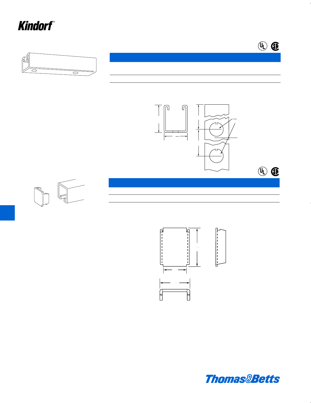
K80 © 2003 Thomas & Betts Corporation. Specifications are subject to change without notice. www.tnb.com
K
Kindorf ®
G-965 Fixture Hanging Channel
1d" x 1g"
Cat. No. Description Joiner End Cap
G-965 12 ga., 190#/C ft. G-978-C 6959
U.L. Listed for raceway.
d" knockouts on 6" centers
Standard finish: Galv-Kr¯om
Provides a combination fixture support and
surface raceway.
For 17⁄8" deep channel.
1
12
6
3
1
1
KO
1
2
7
8
1
2
5
16
1
1
8
1
57
64
1
Surface Raceway and Lighting Support Systems
®
®
®
®
G-966 Blank End Cap
Cat. No. Wt. lbs./C
G-966 8
U.L. Listed for raceway.
Galv-Kr¯om finish
412034.K01 KINDORF 5/1 5/7/03 3:16 PM Page K80
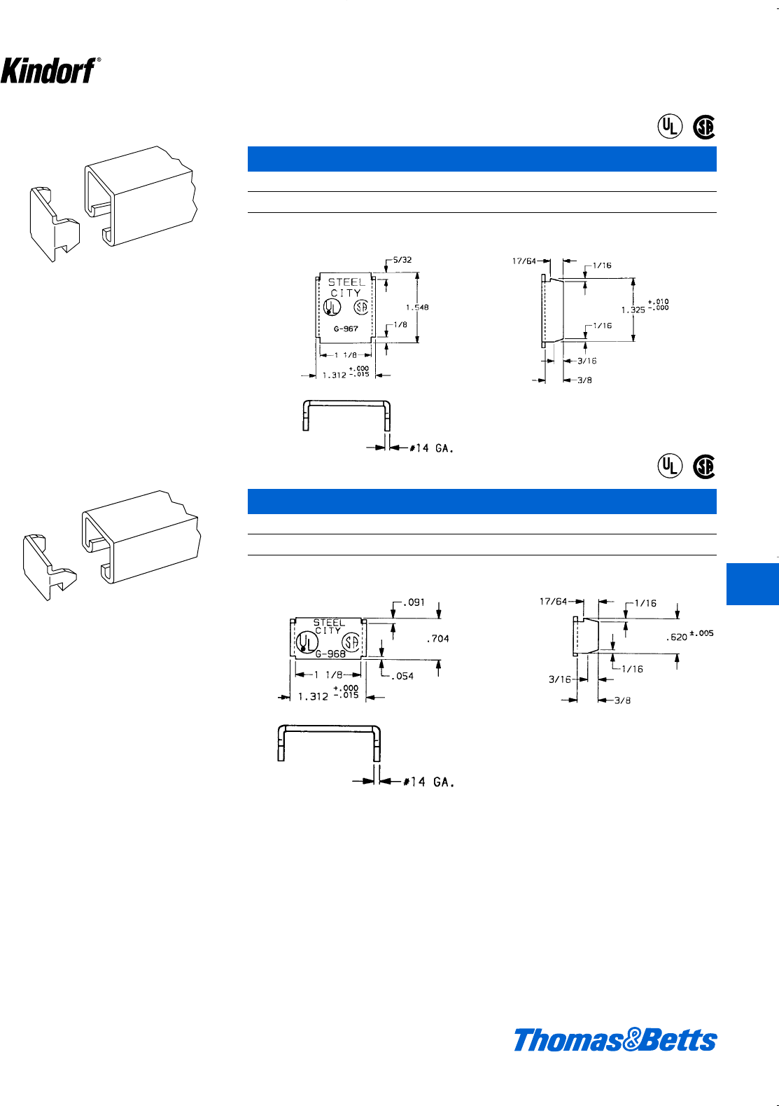
© 2003 Thomas & Betts Corporation. Specifications are subject to change without notice. www.tnb.com K81
K
Kindorf ®
For use with 11⁄2" deep channel.
G-967 Blank End Cap
Cat. No. Wt. lbs./C
G-967 6
U.L. Listed for raceway.
Galv-Kr¯om finish
For 3⁄4" deep channel.
Surface Raceway and Lighting Support Systems
®
®
®
®
G-968 Blank End Cap
Cat. No. Wt. lbs./C
G-968 3
U.L. Listed for raceway.
Galv-Kr¯om finish
412034.K01 KINDORF 5/1 5/7/03 3:16 PM Page K81

K82 © 2003 Thomas & Betts Corporation. Specifications are subject to change without notice. www.tnb.com
K
Kindorf ®
The 1⁄2" size can nipple fixtures through channel
knockouts. All sizes can be fastened to the
open slot of all Kindorf channels. Locknut sup-
plied with nipple.
G-972 Nipple Malleable Iron
Cat. No. A B C Wt. in lbs./C
G-972-1/2 d" Pipe Size g"1b"7
G-972-3/4 f" Pipe Size g"1b"11
G-972-L-1/2 d" Pipe Size 2" 1b"9
The extra length of the G-972-L-1/2 permits its use as a spacing nipple when locked into knockout or continuous slot.
Load rating 750#, with a safety factor of 3.
Galv-Kr¯om finish
C
A
B
A
B
C
G-969A Closure Strip for New Style Kindorf Channel
Cat. No. Description
G-969A Steel Closure Strip – Galv-Kro
-m finish
G-969AP Plastic Closure Strip – Gold
19 ga. steel. 35#/C. U.L. Listed for raceway.
For use with all channel series to complete
enclosure.
G-969A G-969AP
17⁄32
113⁄32
Surface Raceway and Lighting Support Systems
412034.K01 KINDORF 5/1 5/7/03 3:16 PM Page K82
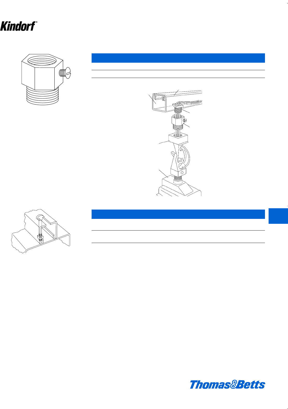
© 2003 Thomas & Betts Corporation. Specifications are subject to change without notice. www.tnb.com K83
K
Kindorf ®
The Fixture Hanger Adapter extends the flexi-
bility of the Kindorf System by easily adapting
the 3⁄4" hanger size of high intensity fixtures to
channel mounting.
The hanger adapter securely mounts the fixture
hanger or box to the channel through the 1⁄2" KO
in the base. No special tools are needed for
installation of fittings and fixtures.
Kindorf channels, with 1⁄2" KO’s every 6", hangs
and feeds the fixtures – thus simplifying instal-
lation.
G-972-HB-1/2 Steel Fixture Hanger Adapter
Cat. No. Wt. lbs./C
G-972-HB-1/2 Galv-Kro
-m finish 17
For use in fastening fixtures to slotted chan-
nels. Permits the preassembly of hardware to
the fixture. The head of the G-973 is simply
inserted into the channel slot and twisted 90° to
seat. The fixture is secured tightly when the nut
is run home.
G-972-1⁄2
Nipple
G-972-HB-1⁄2&3⁄4
Fixture Hanger
Adapter
Fixture Hanger
Fixture Box
and Fixture
G-969 or G-969P Closure Strip
G-975
Surface Raceway and Lighting Support Systems
G-973 Shoulder Type Fixture Bolt and Nut
Used with
Cat. No. Channel Size Wt. lbs./C
G-973-1-1/2 G-956 cx 1d7
G-973-2-1/4 G-953 cx 2b10
Galv-Kr¯om finish
412034.K01 KINDORF 5/1 5/7/03 3:16 PM Page K83
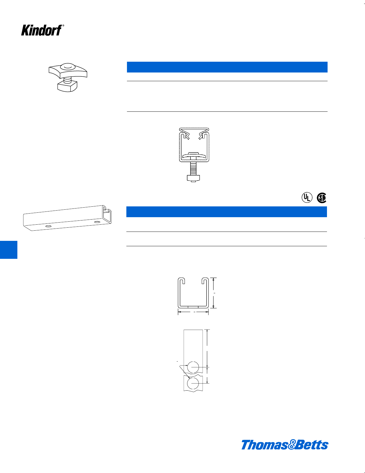
K84 © 2003 Thomas & Betts Corporation. Specifications are subject to change without notice. www.tnb.com
Will fasten fluorescent fixtures to G-975 thru
knockouts or to the open slot of all Kindorf
channels when installed slot down.
G-974 Fastener
Cat. No. Size Wt. lbs./C
G-974-1/2 bxd8
G-974-3/4 bxf8d
G-974-1 bx 1 9
G-974-1-1/4 bx 1b10
G-974-1-1/2 bx 1d11
Galv-Kr¯om finish
Designed to provide a combination fixture sup-
port and surface raceway. Fixture attaches to
KO’s by G-972-1⁄2nipple for wiring, or a G-974
stud nut where wiring is not required.
1
2
1
1
2
1
1
2
1
3
6
KO
1
2
Surface Raceway and Lighting Support Systems
®
®
G-975 Fixture Hanging Channel
1d" x 1d"
Cat. No. Description Joiner End Cap
G-975 12 ga. G978A G967
G-975-M 14 ga. G1503-S G979
G-975: 160#/C ft. G-975-M: 107#/C ft. U.L. Listed for raceway.
d" knockout’s on 6" centers
Standard finish: Galv-Kr¯om
K
Kindorf ®
412034.K01 KINDORF 5/1 5/7/03 3:16 PM Page K84
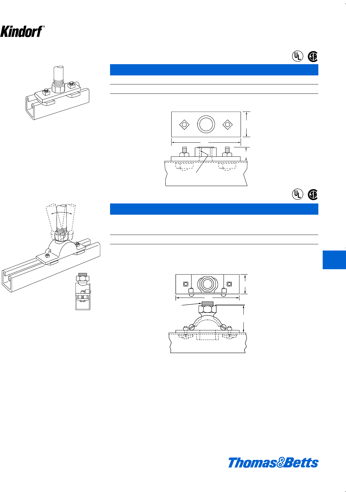
© 2003 Thomas & Betts Corporation. Specifications are subject to change without notice. www.tnb.com K85
Accepts either 1⁄2" or 3⁄4" conduit to feed control
channel when used as a combination raceway
and lighting fixture support. Includes two stud
nuts. Malleable iron.
G-976 Connector
Cat. No. Wt. lbs./C
G-976 Galv-Kro
-m finish 54
Load rating 1000# with a safety factor of 3. U.L. Listed for raceway.
Provides a 15° swing in either direction to the
channel run. Accepts 1⁄2" or 3⁄4" conduit, or may
be adapted for use with 3⁄8" fixture stem when
specified.
1
2
1
4
11
16
3
4conduit thd. in main unit
1
2
1
5
5
32
2
3
4conduit thd. in main unit
11⁄2
4
11⁄16
3⁄4conduit thd. in main unit
11⁄2
5
25⁄32
3⁄4conduit thd. in main unit
Surface Raceway and Lighting Support Systems
®
®
®
®
G-977 Swing Connector
Channel feed hanger
Cat. No. Wt. lbs./C
G-977 Galv-Kro
-m finish 130
Includes two stud nuts. Malleable iron.
U.L. Listed for raceway. Load rating of 1300 lbs. with a safety factor of three. K
Kindorf ®
412034.K01 KINDORF 5/1 5/7/03 3:16 PM Page K85
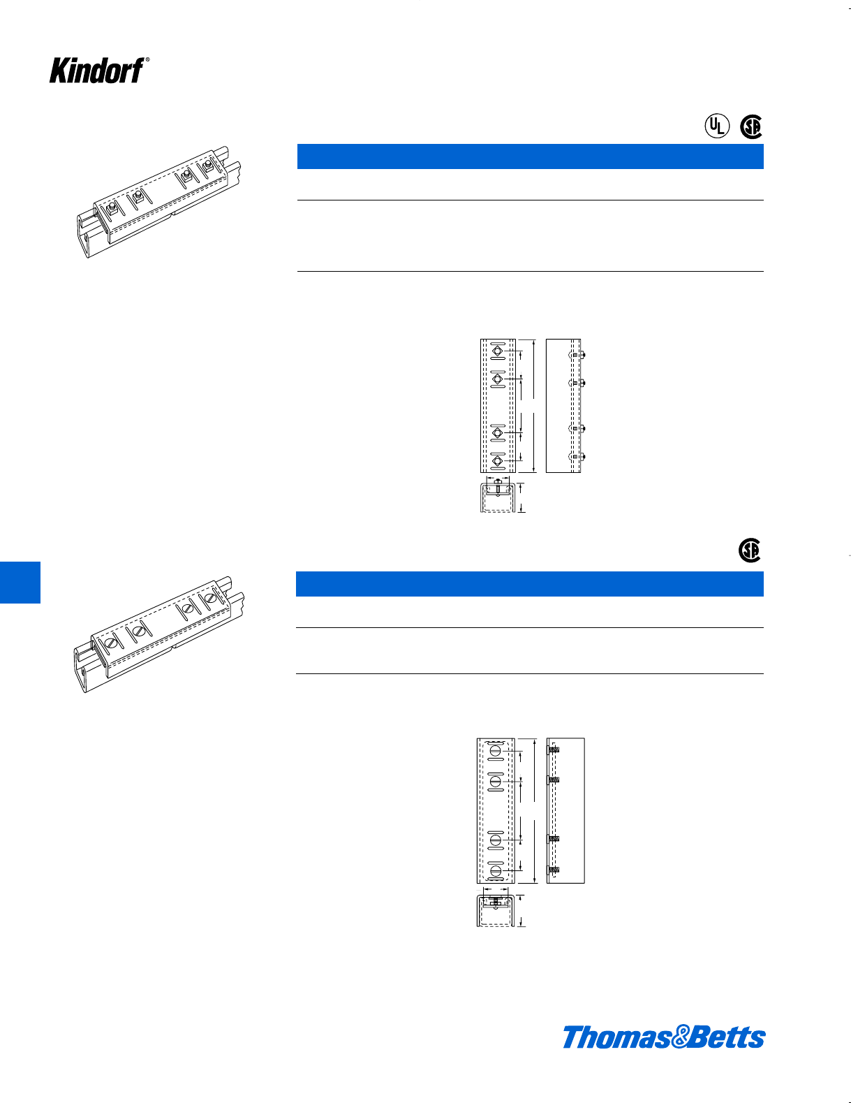
K86 © 2003 Thomas & Betts Corporation. Specifications are subject to change without notice. www.tnb.com
To splice lengths of raceway channel. Installed
by tightening nuts on 1⁄4" studs which are perma-
nently attached to a smooth inner plate.
G-978 Joiners
Dim. A Wt.
Cat. No. Type of Channel Applicable (in.) lbs./C
G-978 Use with G-975, G-975-M and 1d107
B-900, B-900-M
G-978-L Use with B-906 f87
G-978-D Use with G-955 and B-902 3 137
G-978-C Use with B-901, G-950 and G-965 1g122
Nuts included. 14 ga. steel.
U.L. Listed for raceway.
Galv-Kr¯om finish
For installations where fixtures are mounted
flush to slot-down channels. Fastening is
accomplished by tightening flat head machine
screws.
A
1
2
1
1
2
1
371
2
1
4
1
71⁄2
3
11⁄2
11⁄2
11⁄4
A
71⁄2
3
11⁄2
11⁄2
A
11⁄4
Surface Raceway and Lighting Support Systems
®
®
®
G-978-A Joiners
Dim. A Wt.
Cat. No. Type of Channel Applicable (in.) lbs./C
G-978-A Use with G-975, G-975-M and
B-900, B-900-M 1d103
G-978-AL Use with B-906 f83
14 ga. steel.
Galv-Kr¯om finish
K
Kindorf ®
412034.K01 KINDORF 5/1 5/7/03 3:16 PM Page K86
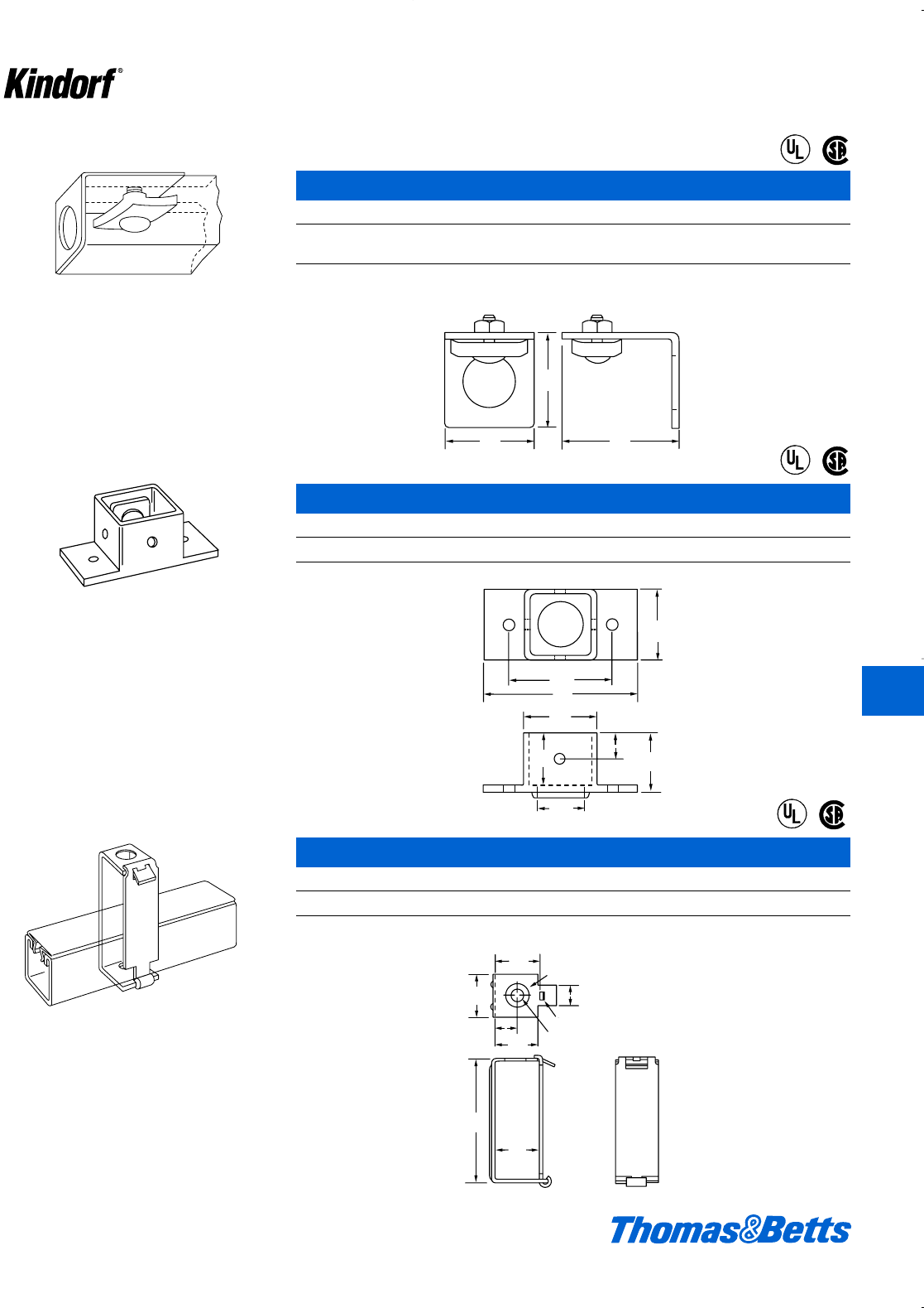
© 2003 Thomas & Betts Corporation. Specifications are subject to change without notice. www.tnb.com K87
Use with G-975 or B-900 channel to provide
conduit entrance.
G-979 End Cap
Cat. No. Description Wt. lbs./C
G-979-1/2 For g" hole, d" conduit 25
G-979-3/4 For 1p" hole, f" conduit 25
Furnished with stud nut. 12 ga. steel. U.L. Listed for raceway.
Galv-Kr¯om finish
Mounts 11⁄2" x 11⁄2" raceway channel to panel
board.
1
2
1
5
8
1
7
8
1
11
16
2
7
8
1
9
16
1
7
8
1
1
4
1
4
11
16
3
8
1
15⁄8
17⁄811⁄2
17⁄8
211⁄16
4
17⁄8
19⁄16
11⁄4
11⁄16
13⁄8
Surface Raceway and Lighting Support Systems
®
®
®
®
G-1007 Panel Adapter
Cat. No. Wt. lbs./C
G-1007 36
Complete with stud nuts.
U.L. Listed for raceway.
Galv-Kr¯om finish
Hinged channel hanger for raceway channel.
G-1012 “Lay-In” Channel Hanger
Cat. No. Wt. lbs./C
G-1012 Galv-Kro
-m finish 33
14 ga. steel. U.L. Listed for raceway. Load rating of 500 lbs. with a safety factor of three.
3
4
9
32
13
32
35
64
1
19
32
113
16
1
2
1
long x 1
8wide slot
dia. hole total - 1
51
64 dia. hole total - 1
5
8
1
1
8
3
15⁄8
31⁄8
135⁄64
51⁄64
11⁄2
119⁄32
13⁄16 dia. hole total -1
3⁄4
9⁄32 long x 1⁄8wide slot
13⁄32 dia. hole total -1
®
®
K
Kindorf ®
412034.K01 KINDORF 5/1 5/7/03 3:16 PM Page K87
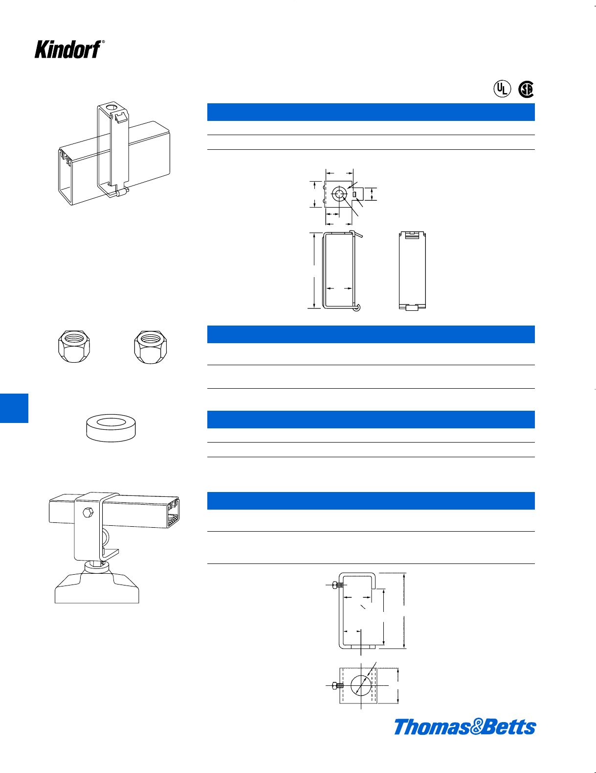
K88 © 2003 Thomas & Betts Corporation. Specifications are subject to change without notice. www.tnb.com
K
Kindorf ®
Hinged channel hanger for 3" deep raceway
channel.
3
4
9
32
13
32
35
64
1
19
32
113
16
1
2
1
long x 1
8wide slot
dia. hole total - 1
51
64 dia. hole total - 1
5
8
1
3
16
4
15⁄8
43⁄16
135⁄64
51⁄64
11⁄2
119⁄32
13⁄16 dia. hole total -1
3⁄4
9⁄32 long x 1⁄8wide slot
13⁄32 dia. hole total -1
Surface Raceway and Lighting Support Systems
®
®
G-1012-D “Lay-In” Channel Hanger
Cat. No. Wt. lbs./C
G-1012-D Galv-Kro
-m finish 40
14 ga. steel. U.L. Listed for raceway. Load rating of 450 lbs. with a safety factor of three.
Two required for each G-1012 channel hanger
to provide swivel action.
G-1013 Hex Swivel Nuts
Wt.
Cat. No. Description lbs./C
G-1013-3/8 For c" hanger rod 7
G-1013-1/2 For d" hanger rod 7
Use with G-1012 fixture hanger as cushion
between fixture and hanger.
To support high or low bay mercury vapor or
heavy incandescent fixtures from raceway
channels. Permits plug-in connections with G-
1038 raceway outlets.
121⁄32
33⁄16
41⁄4
1
11⁄8dia. hole
C2
G-1016 Rubber Washer
Cat. No. Wt. lbs./C
G-1016 1
Washers are 1" diameter, b" thick with j" hole.
G-1017 Mercury Vapor Hanger
Cat. Used with Depth Wt.
No. Channel Size lbs./C
B-900, B-901
G-1017 G-975 41⁄4"76
G-965
Galv-Kr¯om finish
412034.K01 KINDORF 5/1 5/7/03 3:17 PM Page K88
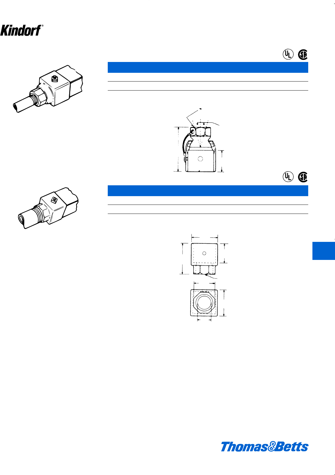
Mounts to 11⁄2" x 11⁄2" raceway channel.
Threaded for 3⁄4" conduit or fitting. Swivel
action, adapter for 1⁄2" conduit furnished.
G-1020 End Swivel Joint
Cat. No. Wt. lbs./C
G-1020 Galv-Kro
-m finish 40
U.L. Listed for raceway.
Mounts to 11⁄2" x 11⁄2" raceway channel.
Threaded for 1" conduit or fitting. No swivel
action.
13⁄8
213⁄16
15°
3⁄4- 14 N P S Thread
with 3⁄4to 1⁄2Reducer
213⁄16
17⁄8
13⁄8
1" Pipe Thread
11⁄2
17⁄8
1" I.D.
Surface Raceway and Lighting Support Systems
®
®
®
®
G-1021 Threaded End Fitting
Cat. No. Wt. lbs./C
G-1021 Galv-Kro
-m finish 32
U.L. Listed for raceway.
© 2003 Thomas & Betts Corporation. Specifications are subject to change without notice. www.tnb.com K89
K
Kindorf ®
412034.K01 KINDORF 5/1 5/7/03 3:17 PM Page K89

Provides a 15° swivel action (to offset possible
movement) for connection of 1⁄2" or 3⁄4" conduit to
raceway channels. May be accepted for use
with 3⁄8" fixture stem when specified. Order two
G-974-3⁄4" fasteners for channel mounting.
G-1032 Channel Swivel Joint
Cat. No. Wt. lbs./C
G-1032 Galv-Kro
-m finish 25
Load rating 500# with a safety factor of 3. U.L. Listed for raceway.
Cover for G-2000 through G-2004 junction
boxes. Use with 3⁄4" or 1⁄2" conduit. Swivel action.
11
16
2
1
2
1
4
9
32 dia. holes
Total 2
3
8
1
3
16
15
Pipe thread
to 1
2
3
4
with
reducer
3
4
4
3
15" 3⁄4Pipe Thread
with 3⁄4to 1⁄2
Reducer
13⁄32
3⁄6
K90 © 2003 Thomas & Betts Corporation. Specifications are subject to change without notice. www.tnb.com
K
Kindorf ®
Surface Raceway and Lighting Support Systems
®
®
®
®
G-1033 4 Inch Diameter Swivel Cover
Cat. No. Wt. lbs./C
G-1033 Galv-Kro
-m finish 35
Load rating 400# with a safety factor of three. U.L. Listed for raceway.
412034.K01 KINDORF 5/1 5/7/03 3:17 PM Page K90
© 2003 Thomas & Betts Corporation. Specifications are subject to change without notice. www.tnb.com K91
K
Kindorf ®
Complete unit including housing, single, 3-
wire, 15 amp. 277 volt-twistlock receptacle and
cover plate.
G-1038 Raceway Outlet
Cat. No. Wt. lbs./C
G-1038 Gold finish 55
U.L. Listed for raceway.
G-1038-A Raceway Outlet
Cat. No. Wt. lbs./C
G-1038A Gold finish 50
U.L. Listed for raceway.
G-1038-D Raceway Outlet
Cat. No. Wt. lbs./C
G-1038-D Gold finish 60
U.L. Listed for raceway.
G-1038-E Raceway Outlet
Cat. No. Wt. lbs./C
G-1038-E Gold finish 50
U.L. Listed for raceway.
Complete unit including housing, duplex, 3-
wire, 15 amp. 277 volt-twistlock receptacle and
cover plate.
Complete unit including housing, standard
duplex 3-wire, 15 amp. 125 volt NEMA ground
receptacle and cover plate.
Complete unit including housing, standard sin-
gle 3-wire, 15 amp. 125 volt NEMA ground
receptacle and cover plate.
Surface Raceway and Lighting Support Systems
®
®
®
®
®
®
®
®
412034.K01 KINDORF 5/1 5/7/03 3:17 PM Page K91
G-1038-B Housing Only
Cat. No. Wt. lbs./C
G-1038-B Gold finish 25
G-1038-C Duplex Cover Plate
Cat. No. Wt. lbs./C
G-1038-C Gold finish 12
G-1038-CA Single Cover Plate
Cat. No. Wt. lbs./C
G-1038-CA Gold finish 14
Size of opening: 1.391 diameter
G-1038-CX Blank Cover Plate
Cat. No. Wt. lbs./C
G-1038-CX Gold finish 15
G-1060 Nylon Bushing
Cat. No. Wt. lbs./C
G-1060 2
Strain relief bushing to protect lead from fluorescent fixture.
K92 © 2003 Thomas & Betts Corporation. Specifications are subject to change without notice. www.tnb.com
K
Kindorf ®
Surface Raceway and Lighting Support Systems
412034.K01 KINDORF 5/1 5/7/03 3:17 PM Page K92
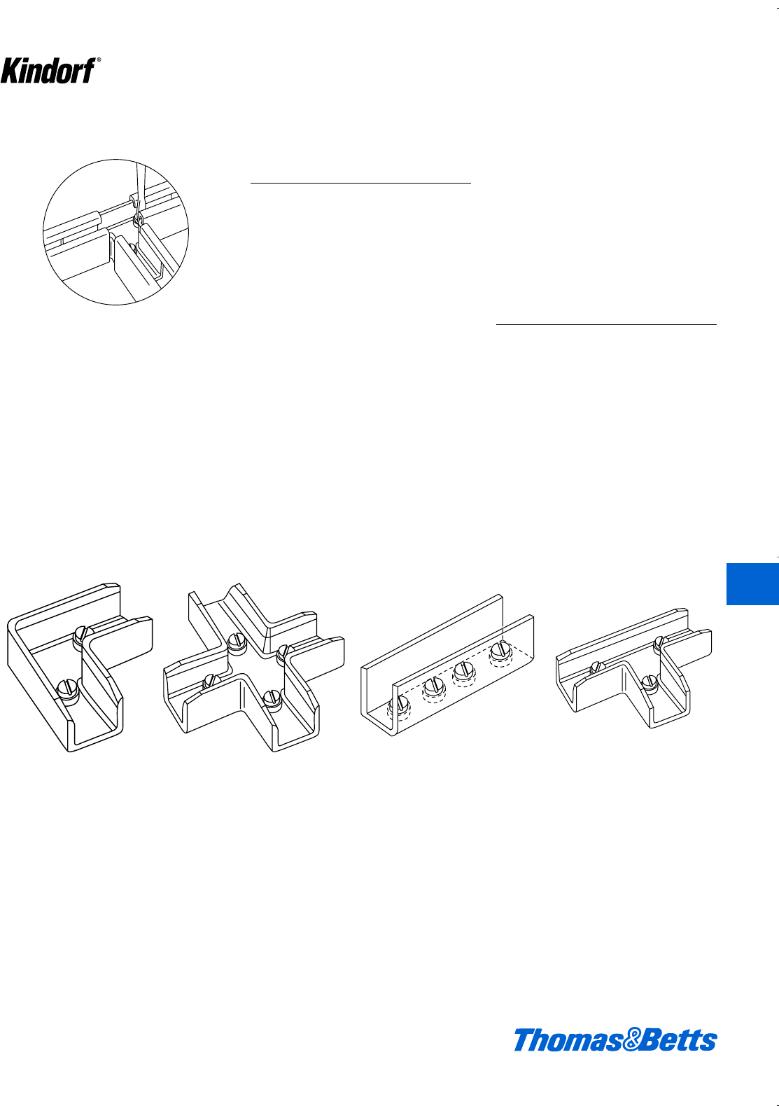
© 2003 Thomas & Betts Corporation. Specifications are subject to change without notice. www.tnb.com K93
K
Kindorf ®
Channel should be supported a minimum of 12"
from joiner.
Channel Joiners for
Lay-In Wiring
The direction-change joiner fittings for
Kindorf Channels expand to three the
number of channel depths available
for complete raceway wiring systems.
Joiner Fittings are made for 11⁄2", 17⁄8"
and 3" depths of 11⁄2" wide channels.
These three systems provide raceway
conductor fill capacities for any light-
ing layout and with erected strength to
spare for lighting fixture support.
The Joiner Fitting rests inside the
channel without obstructing the chan-
nel, nor the lay-in of electrical conduc-
tors. No time-consuming “fishing” of
conductors at the elbows, tee and
crosses.
Installation is fast, simply insert the
fitting into the end of the channel and
turn the captive set-screw. This “jack-
screws” the fitting sidewalls beneath
the channel lips for snug, strong joints.
Standard Kindorf Channel Closure
Strip is used for a completely enclosed
raceway.
Listed by Underwriters’
Laboratories, Inc.
G-1500, G-1870 and
G-3000 Series Direction
Change Joiner
Assemblies
Direction change joiners for 11⁄2", 17⁄8"
and 3" deep raceway channels com-
plete with screws and washers.
Joiners fit into end of channel. When
screws are tightened, joiner is forced
up against channel lips for secure
installation. Conductors can be laid in,
no pulling required. No need for junc-
tion boxes. Available in X, T, L and S
configurations. Support required within
12" of each joiner.
Surface Raceway and Lighting Support Systems
Elbow Cross Straight Tee
412034.K01 KINDORF 5/1 5/7/03 3:17 PM Page K93
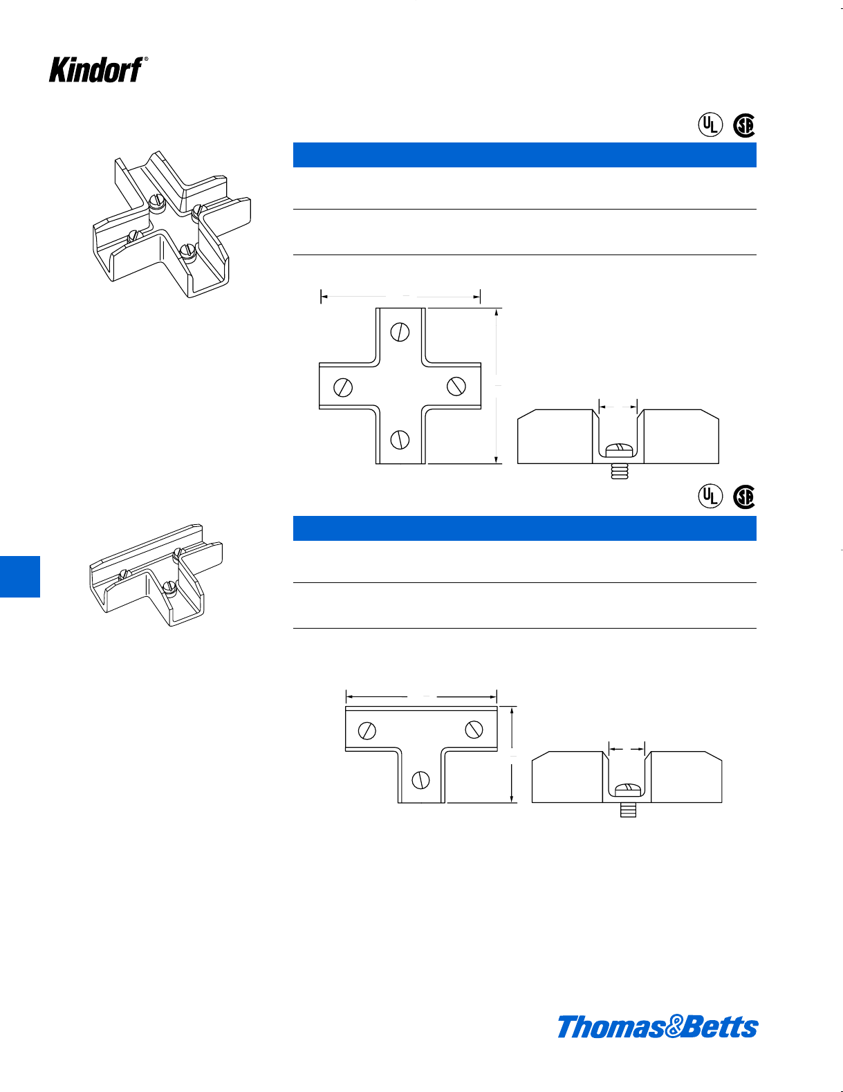
K94 © 2003 Thomas & Betts Corporation. Specifications are subject to change without notice. www.tnb.com
K
Kindorf ®
X-style – G-1500X, G-1870X and G-3000X
Cast Aluminum
Cat. No. For Use with Channel No. Wt. lbs./C
G-1500X B-900 & G-975 44
G-1870X B-901 & G-965 51
G-3000X B-902 & G-955 79
Galv-Kr¯om finish
9
32
4
1
9
32
4
9
32
4
1
49
64
2
Surface Raceway and Lighting Support Systems
®
®
®
®
T-style – G-1501T, G-1871T and G-3001T
Cast Aluminum
Cat. No. For Use with Channel No. Wt. lbs./C
G-1501T B-900 & G-975 34
G-1871T B-901 & G-965 45
G-3001T B-902 & G-955 66
Galv-Kr¯om finish
412034.K01 KINDORF 5/1 5/7/03 3:17 PM Page K94
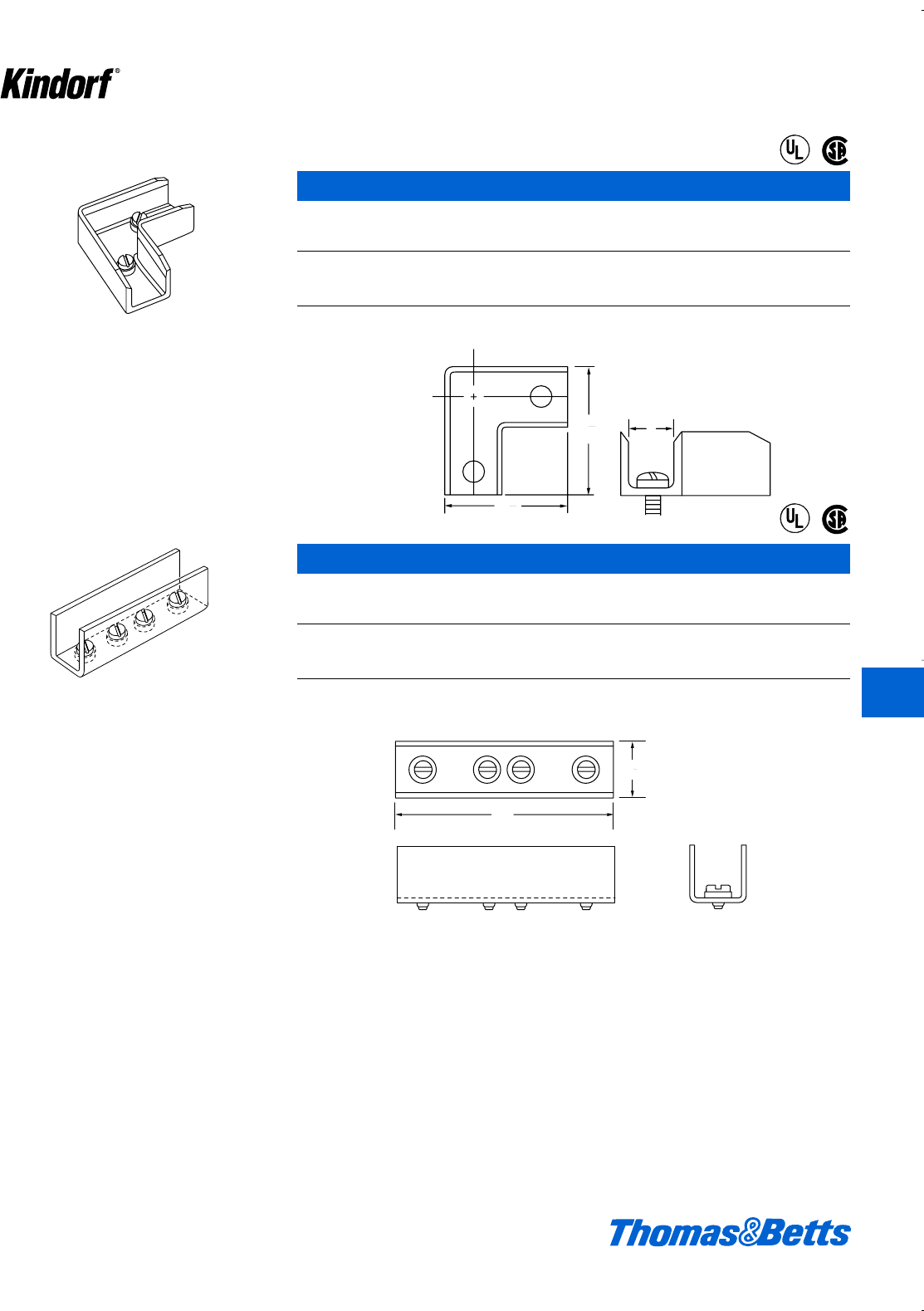
© 2003 Thomas & Betts Corporation. Specifications are subject to change without notice. www.tnb.com K95
K
Kindorf ®
L-style – G-1502L, G-1872L and G-3002L
Cast Aluminum
Cat. No. For Use with Channel No. Wt. lbs./C
G-1502L B-900 & G-975 25
G-1872L B-901 & G-965 32
G-3002L B-902 & G-955 51
Galv-Kr¯om finish
49
64
2
1
49
64
2
5
1
8
1
Surface Raceway and Lighting Support Systems
®
®
®
®
S-style – G-1503S, G-1873S and G-3003S
Steel
Cat. No. For Use with Channel No. Wt. lbs./C
G-1503S B-900 & G-975 21
G-1873S B-901 & G-965 25
G-3003S B-902 & G-955 36
Galv-Kr¯om finish
412034.K01 KINDORF 5/1 5/7/03 3:17 PM Page K95
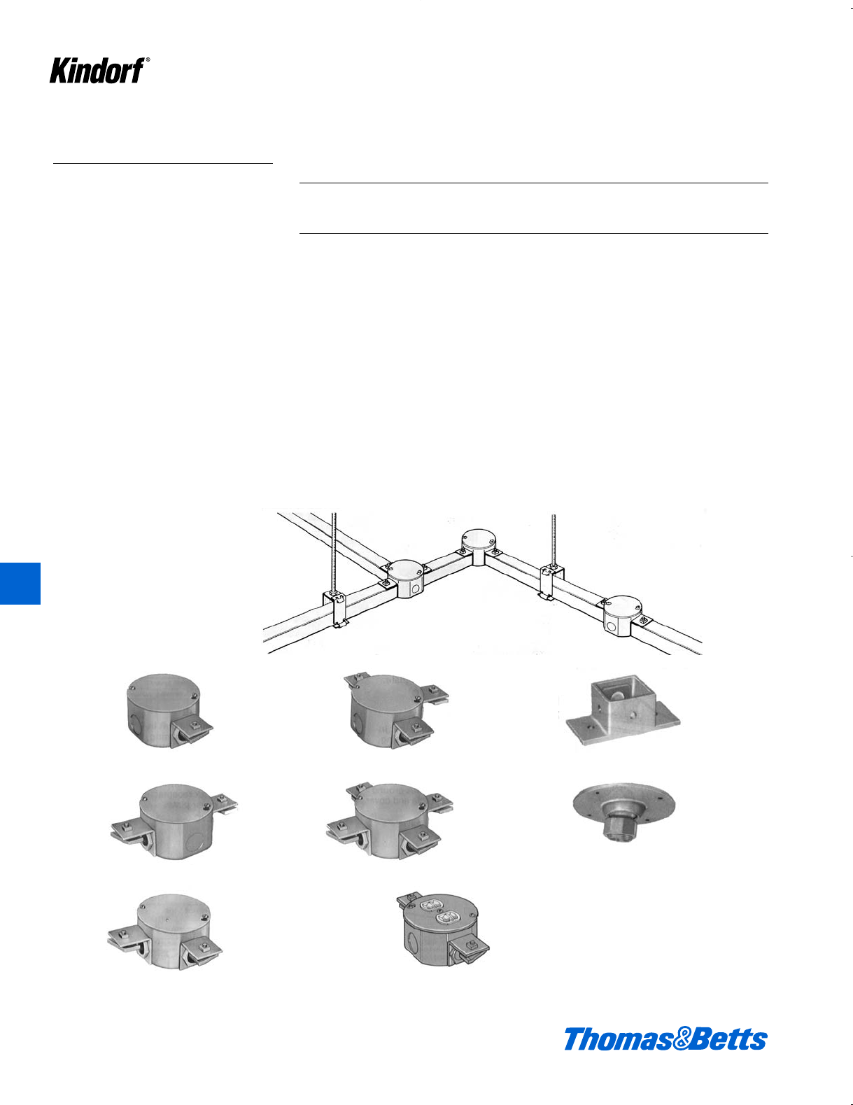
K96 © 2003 Thomas & Betts Corporation. Specifications are subject to change without notice. www.tnb.com
Surface Raceway and Lighting Support Systems
Raceway Junction Boxes
Kindorf Raceway System Fittings for
1d" x 1d" Channel Systems
The Kindorf Channel system serves
both as a raceway for electrical con-
ductors and a support system for the
electrical outlets or tap-offs.
Kindorf is a complete wiring and sup-
port system with fittings and acces-
sories for the design and installation of
your electrical system.
A full line of direction change junction
boxes are provided for use with the
Kindorf raceway system. These are
made up of a standard Steel City octa-
gon box, box cover and attachment fit-
tings. Assemblies as shown are avail-
able complete, or members can be
purchased separately to make up a
junction.
Junction Boxes for 11
/2" x 11
/2" Raceway Channels
Galv-Kr¯om Finish
The assembly consists of the following components:
Item Quantity
Octagon Box 1
Box Cover 1
Locknuts 1, 2, 3, or 4
(as required)
Nipples 1, 2, 3, or 4
(as required)
End Caps 1, 2, 3, or 4
(as required)
When purchased as an assembly, the octagon box and cover are Galv-Kr¯om finish
to match the channel and end cap and all parts are factory fabricated.
G-2000
Type ‘E’
100 lbs./C
Raceway Junction Boxes
Kindorf Raceway System Fittings for
1d" x 1d" Channel Systems
G-2003
Type ‘T’
140 lbs./C
G-1007
36 lbs./C
G-1033
For d" or f"
conduit feed
from outlet box
35 lbs./C
G-2001
Junction Box with No.
5402-LR outlet box
cover and field-mount-
ed duplex receptacle.
G-2004
Type ‘X’
150 lbs./C
G-2001
Type ‘C’
121 lbs./C
G-2002
Type ‘L’
90°
K
Kindorf ®
412034.K01 KINDORF 5/1 5/7/03 3:17 PM Page K96
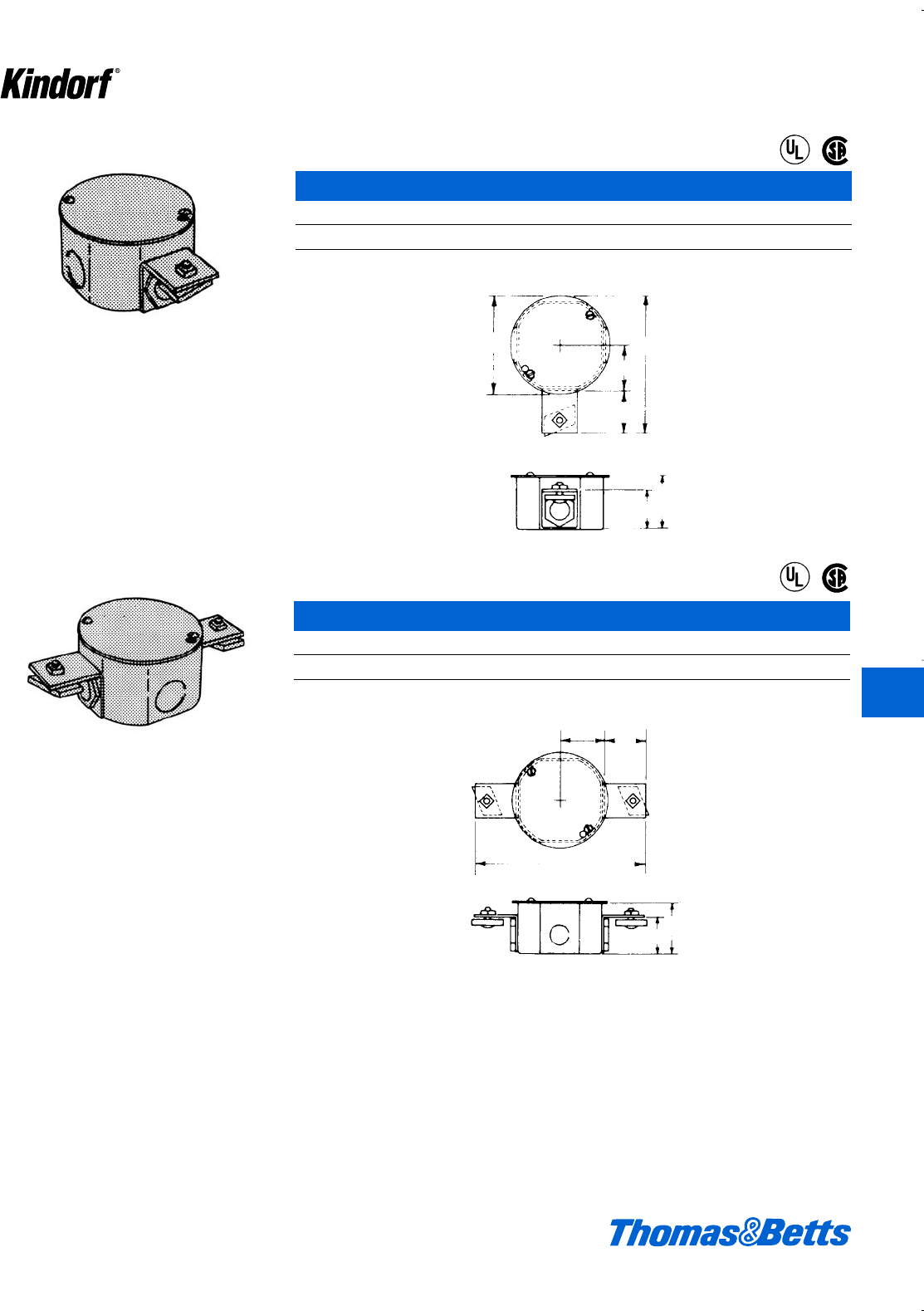
© 2003 Thomas & Betts Corporation. Specifications are subject to change without notice. www.tnb.com K97
Type ‘E’ dead-end junction box for raceway
channel. Accepts standard devices and covers
for 4" octagon outlet boxes.
G-2000 Junction Box
Cat. No. Wt. lbs./C
G-2000 Galv-Kro
-m finish 123
Complete with cover, locknuts, nipples and end caps.
Type ‘C’ straight-through junction box for two
raceway channels. Accepts standard devices
and covers for 4" octagon outlet boxes.
41⁄865⁄8
113⁄16
13⁄4
119⁄32
23⁄16
113⁄16
13⁄4
119⁄32
23⁄16
17⁄8
Surface Raceway and Lighting Support Systems
®
®
®
®
G-2001 Junction Box
Cat. No. Wt. lbs./C
G-2001 Galv-Kro
-m finish 147
Complete with cover, locknuts, nipples, and end caps. K
Kindorf ®
412034.K01 KINDORF 5/1 5/7/03 3:17 PM Page K97
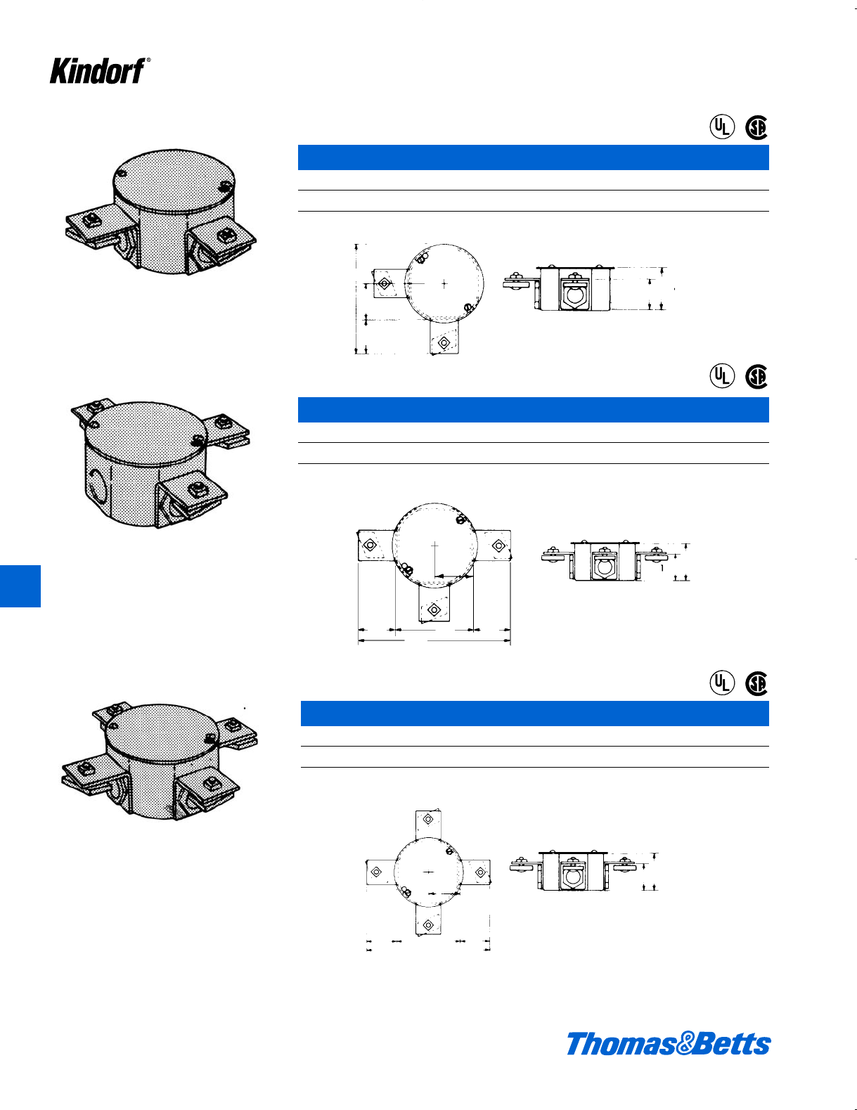
G-2002 Junction Box
Cat. No. Wt. lbs./C
G-2002 Galv-Kro
-m finish 120
Complete with cover, locknuts, nipples, and end caps.
Type ‘L’ 90° junction box for two raceway chan-
nels. Accepts standard devices and covers for
4" octagon outlet boxes.
Type ‘T’ junction box for three raceway chan-
nels. Accepts standard devices and covers for
4" octagon outlet boxes.
71⁄8
65⁄8
113⁄16
13⁄4
119⁄32
23⁄16
113⁄16
13⁄413⁄4
35⁄8
119⁄32
23⁄16
K98 © 2003 Thomas & Betts Corporation. Specifications are subject to change without notice. www.tnb.com
Surface Raceway and Lighting Support Systems
®
®
®
®
G-2003 Junction Box
Cat. No. Wt. lbs./C
G-2003 Galv-Kro
-m finish 140
Complete with cover, locknuts, nipples and end caps.
Type ‘X’ junction box for four raceway chan-
nels. Accepts standard devices and covers for
4" octagon outlet boxes.
G-2004 Junction Box
Cat. No. Wt. lbs./C
G-2004 Galv-Kro
-m finish 150
Complete with cover, locknuts, nipples and end caps.
71⁄8
113⁄16
13⁄413⁄4
35⁄8
119⁄32
23⁄16
®
®
K
Kindorf ®
412034.K01 KINDORF 5/1 5/7/03 3:17 PM Page K98
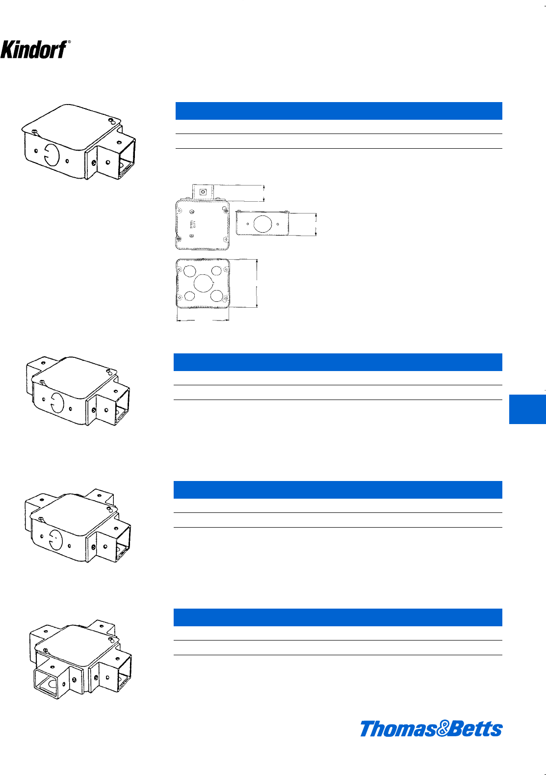
© 2003 Thomas & Betts Corporation. Specifications are subject to change without notice. www.tnb.com K99
19⁄16
21⁄8
411⁄16
411⁄16
Surface Raceway and Lighting Support Systems
G-2005 Junction Box
Cat. No. Wt. lbs./C
G-2005 Galv-Kro
-m finish 189
G-2006 Junction Box
Cat. No. Wt. lbs./C
G-2006 Galv-Kro
-m finish 225
G-2007 Junction Box
Cat. No. Wt. lbs./C
G-2007 Galv-Kro
-m finish 261
G-2008 Junction Box
Cat. No. Wt. lbs./C
G-2008 Galv-Kro
-m finish 290
K
Kindorf ®
412034.K01 KINDORF 5/1 5/7/03 3:17 PM Page K99
K100 © 2003 Thomas & Betts Corporation. Specifications are subject to change without notice. www.tnb.com
K
Kindorf ®
Hardware and Threaded Components
H-193 Hanger Rod supports conduit from
G-962-D hanger.
ASTM Class 2
“Threads” are an integral part of erec-
tor systems because nearly everything
hangs by – or is secured by threaded
fasteners. Kindorf threaded hardware
includes continuous rolled-thread
hanger rod, and special and standard
screws and nuts designed with the
necessary holding power to serve the
requirements of framing and hanging
installations.
It is vital that each thread be fully pro-
tected against rust and corrosion
because they are usually exposed to
corrosive atmospheres. Kindorf
threaded hardware and accessories
are completely protected by the same
Galv-Kr¯om finish that protects Kindorf
channel and fittings. Kindorf extra-
quality threads are always:
• Free-running – clean, uniform
• Corrosion resistant – no paint
required
• Burr-free – smooth finish
Trouble-free threaded hardware is an
investment in fast installation and low
maintenance. Free-running threads
are a time saving asset on every job –
saving fingers and tempers, and elimi-
nating delays that result when threads
must be specially treated before use.
Threaded rod is packed in tubes to
prevent damage during shipment.
Kindorf threaded hardware is pro-
duced from high tensile strength car-
bon steel with Unified National Coarse
(U.N.C.) threads. Galv-Kr¯om finish is
standard.
412034.K01 KINDORF 5/1 5/7/03 3:17 PM Page K100
© 2003 Thomas & Betts Corporation. Specifications are subject to change without notice. www.tnb.com K101
K
Kindorf ®
Hardware and Threaded Components
H-111 Round Head Machine Screw – Less Nut
Cat. Sizes Wt.
No. (in.) lbs./C
H-111-A b-20 x d1.00
H-111-B b-20 x f1.25
H-111-C b-20 x 1b1.76
H-111-D b-20 x 2 2.54
H-111-E c-16 x f3.45
H-111-F d-13 x f6.40
H-111-G d-13 x 1 7.50
H-111-H d-13 x 1b8.50
Standard finish: Galv-Kr¯om unless otherwise specified.
H-113 Hex Head Cap Screw – Less Nut
Cat. Sizes Wt.
No. (in.) lbs./C
H-113-A d-13 x f7.0
H-113-B d-13 x 1 9.0
H-113-BSH d-13 x 1 9.0
H-113-C d-13 x 1b9.0
H-113-D d-13 x 1d10.0
H-113-E d-13 x 1f13.0
H-113-F d-13 x 2 14.0
H-113-G d-13 x 2b16.0
H-113-H d-13 x 2d16.0
H-113-I d-13 x 3 20.0
H-113-J d-13 x 3d23.0
H-113-K d-13 x 4 25.0
H-113-N c-16 x f3.0
H-113-O c-16 x 1 4.0
H-113-P c-13 x 1b4.0
H-113-Q c-16 x 1d5.0
H-113-R c-16 x 1f6.0
H-113-S c-16 x 2 7.0
H-113-T c-16 x 2b7.0
H-113-U c-16 x 2d8.0
H-113-V c-16 x 2f9.0
H-113-W c-16 x 3 10.0
H-113-X c-16 x 3d11.0
H-113-Y c-16 x 4 13.0
H-113-ZA bxf1.0
H-113-ZB bx 1 1.0
H-113-ZC bx 1b1.5
H-113-ZD bx 1d2.0
Standard finish: Galv-Kr¯om unless otherwise specified.
412034.K01 KINDORF 5/1 5/7/03 3:17 PM Page K101
K102 © 2003 Thomas & Betts Corporation. Specifications are subject to change without notice. www.tnb.com
K
Kindorf ®
Hardware and Threaded Components
H-114 Hex Nut
Cat. Sizes Wt.
No. (in.) lbs./C
H-114-A b-20 1.2
H-114-B j-18 2.0
H-114-C c-16 3.2
H-114-D d-13 5.0
H-114-E e-11 9.0
H-114-F f-10 13.0
Standard finish: Galv-Kr¯om unless otherwise specified.
H-115 Square Head Machine Bolt with Square Nut
Cat. Sizes Wt.
No. (in.) lbs./C
H-115-A c-16 x 1 7.39
H-115-B c-16 x 1b8.15
H-115-C c-16 x 1d8.83
H-115-D d-13 x 1 16.00
H-115-E d-13 x 1b16.70
H-115-F d-13 x 1d18.00
Standard finish: Galv-Kr¯om unless otherwise specified.
H-116 Square Nut
Cat. Sizes Wt.
No. (in.) lbs./C
H-116-A b-20 1.00
H-116-B j-18 2.40
H-116-C c-16 2.37
H-116-D d-13 6.00
H-116-E e-11 11.00
H-116-F f-10 15.00
Standard finish: Galv-Kr¯om unless otherwise specified.
H-117 Flat Steel Washer
Cat. Sizes Wt.
No. (in.) lbs./C
H-117-A b.67
H-117-B j1.20
H-117-C c2.00
H-117-D d3.85
H-117-E e7.70
H-117-F f9.00
Standard finish: Galv-Kr¯om unless otherwise specified.
412034.K01 KINDORF 5/1 5/7/03 3:17 PM Page K102
© 2003 Thomas & Betts Corporation. Specifications are subject to change without notice. www.tnb.com K103
K
Kindorf ®
Hardware and Threaded Components
H-118 Lock Washer
Cat. Sizes Wt.
No. (in.) lbs./C
H-118-A b.259
H-118-B j.550
H-118-C c.630
H-118-D d1.436
H-118-E e2.587
H-118-F f4.293
Standard finish: Galv-Kr¯om unless otherwise specified.
H-119 Square Washer
Cat. Dimensions (in.) Wt.
No. Size Thickness lbs./C
H-119-A ba8.10
H-119-B ja8.00
H-119-C ci11.50
H-119-D db14.36
H-119-E eb13.50
H-119-F fb12.50
H-119-G gb13.00
Standard finish: Galv-Kr¯om unless otherwise specified.
H-120 Saddle Type Washer
Cat. No. Wt. lbs./C
H-120 7
Standard finish: Galv-Kr¯om unless otherwise specified.
For rigid attachment of rod to channel. For use
with either 3⁄8" or 1⁄2" hanger rod.
1d
11⁄2
A5⁄8"-18 x 2" galvanized steel nipple in assem-
bly with four jam nuts. This feed attachment
provides spacing between lighting fixtures and
raceway channels.
H-133-N Nipple Assembly
Cat. No. Wt. lbs./C
H-133-N 27
Approved for G.S.A. installations.
H-134-S Spacer Assembly
Cat. No. Wt. lbs./C
H-134-S 21
Approved for G.S.A. installations.
Used for attaching fixture to channel with a uni-
form 1" clearance between fixture and support-
ing channel. Assembly includes a 1" spacer, a
5⁄8"-18 x 11⁄2" bolt and jam nut, all galvanized.
412034.K01 KINDORF 5/1 5/7/03 3:17 PM Page K103
K104 © 2003 Thomas & Betts Corporation. Specifications are subject to change without notice. www.tnb.com
K
Kindorf ®
Hardware and Threaded Components
Six, ten and twelve foot lengths continuous
thread.
H-193 Hanger Rod, Continuous Thread-Galv-Kr¯om
Wt./lbs.
Cat. No. Size per 100 pcs.
H-193-1/4-6 ft. 73
H-193-1/4-10 ft. b"-20 124
H-193-1/4-12 ft. 148
H-193-3/8-6 ft. 172
H-193-3/8-10 ft. c"-16 293
H-193-3/8-12 ft. 348
H-193-1/2-6 ft. 313
H-193-1/2-10 ft. d"-13 530
H-193-1/2-12 ft. 648
H-193-5/8-6 ft. 510
H-193-5/8-10 ft. e"-11 850
H-193-5/8-12 ft. 1020
Suffix indicates rod size and length.
R-Series Continuous Thread Rod – Electro-Galvanized
Wt./lbs.
Cat. No. Size per 100 pcs.
R628-6 ft. b"-20 74
R1028-10 ft. 120
R638-6 ft. c"-16 174
R1038-10 ft. 290
R648-6 ft. d"-13 324
R1048-10 ft. 530
Suffix indicates rod size and length.
National Coarse Thread
Threads Lbs./ Design Load
Size per inch 100 ft. lbs.
b20 12.5 150
c16 29.0 610
d13 53.5 1130
e11 85.0 1810
f10 123.0 2710
g9 130.0 3770
1 8 214.0 4960
Grade ASTM A-510
®
412034.K01 KINDORF 5/1 5/7/03 3:17 PM Page K104
© 2003 Thomas & Betts Corporation. Specifications are subject to change without notice. www.tnb.com K105
K
Kindorf ®
H-261 Swivel Joint with Stud
Cat. Dimensions (in.) Load Wt.
No. A B C Rating lbs./C
H-261-A c-16 1c2f1000 25
H-261-B d-13 1d3 1800 52
Safety factor of three.
Galv-Kr¯om finish
Same as H-260, but with a 3⁄8" or 1⁄2" stud on one
end.
A
C
I
A
1
C
Hardware and Threaded Components
For coupling lengths of H-193 hanger rod.
Right-hand threaded. Threads tapered to lock
rods in place.
H-195 Steel Rod Coupling
Cat. Dimensions (in.) Load Rating Wt.
No. Threads A B (lbs.) lbs./C
H-195-1/4 b-20 gc240 2
H-195-3/8 c-16 1a d 610 4
H-195-1/2 d-13 1b e 1130 5
H-195-5/8 e-11 1g m 1810 10
Galv-Kr¯om finish
Permits hanger rod to swing freely in any
direction.
BA
A
B
C
D
H-260 Swivel Joint
Cat. Dimensions (in.) Load Wt.
No. A B C Rating lbs./C
H-260-A c-16 1c 2f 1000 28
H-260-B d-13 1d 3 1800 48
Safety factor of three.
Galv-Kr¯om finish
®
412034.K01 KINDORF 5/1 5/7/03 3:17 PM Page K105
K106 © 2003 Thomas & Betts Corporation. Specifications are subject to change without notice. www.tnb.com
K
Kindorf ®
H-262 Eyelet with d" or c" Stud
Cat. Dimensions (in.) Load Wt.
No. A B C D Rating lbs./C
H-262-A-3/8 c-16 1c1fd 1000 23
H-262-B-1/2 d-13 1d2f1800 28
Safety factor of three.
Galv-Kr¯om finish
Hardware and Threaded Components
For bolting to a supporting member to furnish
suspension for rope, chain or cable.
H-272 Swivel Eye
Cat. Dimensions (in.) Load Wt.
No. A B C D E Rating lbs./C
H-272-3/8 c-16 2f 1d 1i g 2000 19
H-272-1/2 d-13 2f 1d 1i g 2000 19
Safety factor of three.
H-272 swivel eye has 3⁄8" or 1⁄2" tapped hole for
hanger rod applications.
H-272
E
DB
A
C
412034.K01 KINDORF 5/1 5/7/03 3:17 PM Page K106
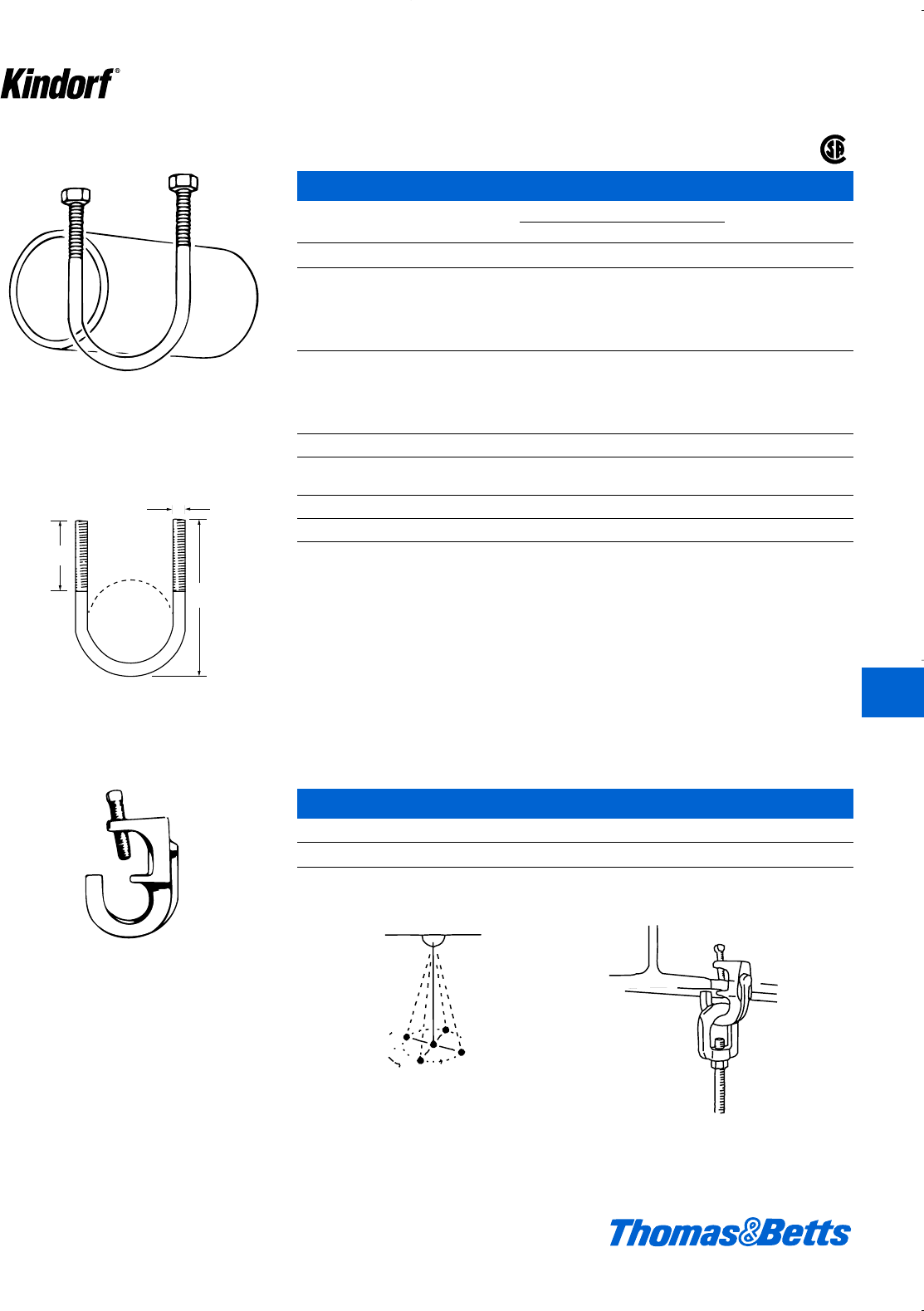
© 2003 Thomas & Betts Corporation. Specifications are subject to change without notice. www.tnb.com K107
K
Kindorf ®
Hardware and Threaded Components
“U” bolt to support, anchor or guide pipe lines.
Sizes through 4" are furnished with one hex nut
per leg in Galv-Kr¯om. H-286 sizes 5" and above
are furnished with two hex nuts per leg in
black.
One piece malleable iron casting. Attaches to
beam flanges up to 3⁄4" thickness.
B
A
C
360
®
H-286 U-Bolts
Cat. No. and Rec. Max. Dimensions (in.) Wt. in
Pipe Size Load (lbs.) A B C lbs./C
H-286-3/8 1500 2j 1j b 7
H-286-1/2 1500 2f 1f j 13
H-286-3/4 2000 3h 1f j 15
H-286-1 2500 3j 1g j 16
H-286-1-1/4 2500 3d 1f j 17
H-286-1-1/2 2500 3f 1f j 18
H-286-2 3300 4L 2h c 32
H-286-2-1/2 4000 5a 2h c 34
H-286-3 4000 5L 2 c 38
H-286-3-1/2 4000 6i 2 c 40
H-286-4 4000 6n 2b c 46
H-286-5 4000 8q 2b d 128
H-286-6 4000 9f 2e e 239
H-286-8 4000 11f 2e e 283
H-286-10 5400 14a 2f f 479
H-286-12 7500 16d 3 g 764
Complies with Fed. Spec. WW-H-171E and MSS SP-69 Type 24
H-550 Swivel Beam Clamp
Cat. No. Description
H-550 Max. load rating 500 lbs. with a safety factor of 3.33#C.
Galv-Kr¯om finish
412034.K01 KINDORF 5/1 5/7/03 3:17 PM Page K107
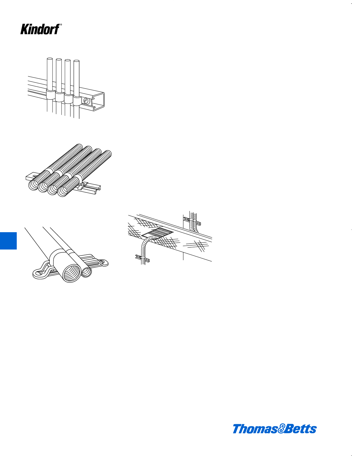
K108 © 2003 Thomas & Betts Corporation. Specifications are subject to change without notice. www.tnb.com
K
Kindorf ®
Cable and Mounting Systems
Copper Tubing
Flexible Tubing
Armored Cable
(Take-off from Cable Tray)
Shipboard Cables
Designed originally to eliminate costly
and time-consuming methods of
installing cables aboard ships, the
Kindorf J-800 series of straps, hangers
and brackets has found ever-widening
applications by mechanical and elec-
trical contractors in general construc-
tion. The J-800 system has proven to
be a work-saver when used to install
tubing or cable. Tubing and cable of
various construction and fabrication
can be racked efficiently with built-in
provisions for making additions or
changes at a later date. They can be
secured in all combinations and
sequences of sizes. A variety of hangers
and brackets secures multiple runs as
well as single branch take-offs.
Installation of J-800 straps on Kindorf
supports is simple, requiring only a
screwdriver or small wrench. Each run
is gripped individually on a hanger and
all runs are secured by tightening a
single locking device. Loosening the
locking device permits fast access to
the runs … making it easy to add,
remove or adjust them at any time.
J-800 installations have withstood the
severe conditions of service at sea for
many years. In countless installations
they have proven their ability to with-
stand the effects of salt air, moisture,
shock and vibration.
J-800 racking is well known for its fast,
yet precise installation methods. A
proven method that results in labor
economy and neat, workmanlike
installation.
412034.K01 KINDORF 5/1 5/7/03 3:17 PM Page K108
© 2003 Thomas & Betts Corporation. Specifications are subject to change without notice. www.tnb.com K109
K
Kindorf ®
Cable and Mounting Systems
4. Apply second cable strap, hooking strap
tongue under pin of first strap.
6. Drive locking device tight against cable
strap. Tighten locking device screw.
5. Apply locking device and tighten screw
moderately.
Installation Steps
1. Insert pin of strap in slot of hanger. 3. Push strap and cable to end of hanger slot so
tongue of strap hooks below slot.
2. Close Kindorf cable strap down over cable.
412034.K01 KINDORF 5/1 5/7/03 3:17 PM Page K109
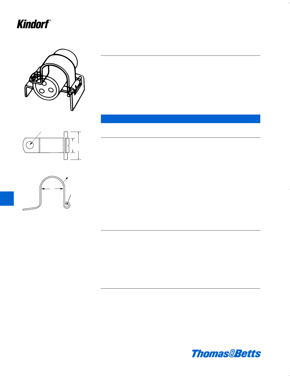
K110 © 2003 Thomas & Betts Corporation. Specifications are subject to change without notice. www.tnb.com
Cable and Mounting Systems
Straps are steel, and have Galv-Kr¯om finish.
eb
1
Xhole
D
1
A
D
A
10 ga. steel
pin
11⁄32 hole
11⁄4
5⁄8
J-800 Interlocking Straps
J-800 Interlocking Straps
Dimensions Use In Use In Use In
Cat. No. Strap A (in.) Wt. New Kindorf Old Kindorf J Series
& Size Size Gauge D max. lbs./C Channel Channel Mountings
J-800-8 8 18 .2500 2.50 – 0.250 0.250
J-800-10 10 18 .3124 2.60 – 0.313 0.313
J-800-12 12 18 .3750 2.75 0.250 0.375 0.375
J-800-14 14 18 .4375 2.90 0.313 0.438 0.438
J-800-16 16 18 .5000 2.75 0.375 0.500 0.500
J-800-18 18 18 .5625 2.90 0.438 0.563 0.563
J-800-20 20 18 .6250 3.35 0.500 0.625 0.625
J-800-22 22 18 .6875 3.50 0.563 0.688 0.688
J-800-24 24 18 .7500 3.65 0.625 0.750 0.750
J-800-26 26 18 .8125 3.80 0.688 0.813 0.813
J-800-28 28 18 .8750 3.95 0.750 0.875 0.875
J-800-30 30 18 .9375 4.10 0.813 0.938 0.938
J-800-32 32 18 1.0000 4.25 0.875 1.000 1.000
J-800-34 34 18 1.0625 4.40 0.938 1.063 1.063
J-800-36 36 18 1.1250 4.55 1.000 1.125 1.125
J-800-38 38 18 1.1875 4.70 1.063 1.188 1.188
J-800-40 40 18 1.2500 4.85 1.125 1.250 1.250
J-800-42 42 18 1.3125 5.00 1.188 1.313 1.313
J-800-44 44 18 1.3750 5.15 1.250 1.375 1.375
J-800-46 46 18 1.4375 5.30 1.313 1.438 1.438
J-800-48 48 18 1.5000 5.45 1.375 1.500 1.500
J-800-50 50 16 1.5625 6.38 1.438 1.563 1.563
J-800-52 52 16 1.6250 6.55 1.500 1.625 1.625
J-800-54 54 16 1.6875 6.73 1.563 1.688 1.688
J-800-56 56 16 1.7500 6.90 1.625 1.750 1.750
J-800-58 58 16 1.8125 7.08 1.688 1.813 1.813
J-800-60 60 16 1.8750 7.25 1.750 1.875 1.875
J-800-62 62 16 1.9375 7.43 1.813 1.938 1.938
J-800-64 64 16 2.0000 7.6 1.875 2.000 2.000
J-800-68 68 16 2.1250 7.95 1.938 2.063 2.063
J-800-72 72 16 2.2500 8.30 2.000 2.250 2.250
J-800-76 76 16 2.3750 8.65 2.125 2.375 2.375
J-800-80 80 16 2.5000 9.00 2.250 2.500 2.500
J-800-84 84 16 2.6250 9.35 2.375 2.625 2.625
Separate strap sizes rack b" through 2e" dia. rounds in h" increments.
One J-800 strap of the proper diameter
is used to secure each run. All straps
have a 1b" pin. In multiple runs the pin
is simply twist inserted into the sup-
porting Kindorf hanger, bracket or
channel slot; the strap closed over the
cable or tube to lock the strap tongue
under the pin of the adjacent strap.
The same procedure is used for single
runs except the strap tongue is
secured directly to the hanger. When
all multiple runs have been assembled,
they are secured by a single locking
device.
J-800 straps can be installed along the
continuous slot of any Kindorf channel.
This increases their versatility and
extends their possible applications.
K
Kindorf ®
412034.K01 KINDORF 5/1 5/7/03 3:17 PM Page K110
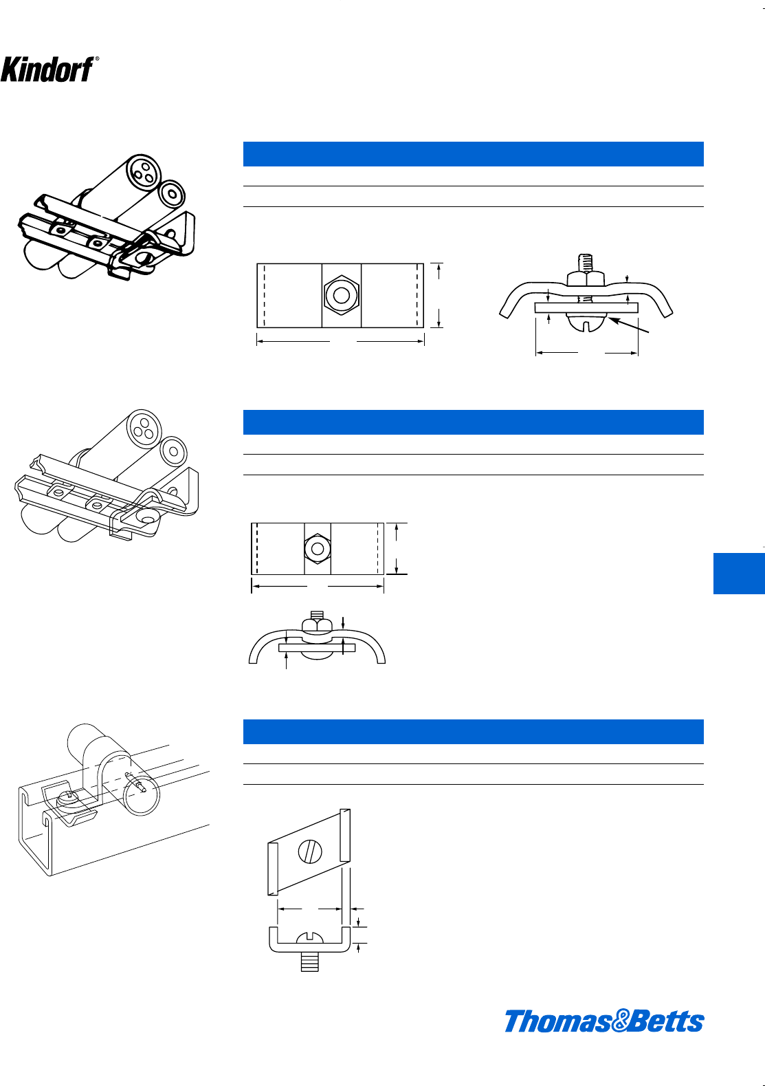
© 2003 Thomas & Betts Corporation. Specifications are subject to change without notice. www.tnb.com K111
Cable and Mounting Systems
Secures single or multiple interlocked assemblies
on bar hangers, mounting brackets and continuous
slot channel. For installations not subject to
severe shock.
J-850 Locking Device
Cat. No. Description
J-850 Steel, Galv-Kr¯om finish, 11#/C
Includes b" screw, nut and lock washer.
Secures single or multiple interlocked assemblies
on bar hangers, mounting brackets and continuous
slot channels. Similar to J-850 except stud
replaces screw for easier assembly.
1g
f
3
4
59
64
1
12 ga.
1b
12 ga.
12 ga. Lock Washer
1g
f
1b
12 ga.
f
1∂
12 ga.
12 ga.
12 ga.
J-851 Locking Device
Cat. No. Description
J-851 Steel, Galv-Kr¯om finish, 11#/C
Includes b" screw, nut and lock washer.
Secures single or multiple interlocked assem-
blies on bar hangers, mounting brackets and
continuous slot channels. Designed for use
with B-900 Kindorf channels.
J-852 Locking Device
Cat. No. Description
J-852 Steel, Galv-Kr¯om finish, 5#/C
1
4
1
8
1
i
1a
K
Kindorf ®
412034.K01 KINDORF 5/1 5/7/03 3:17 PM Page K111
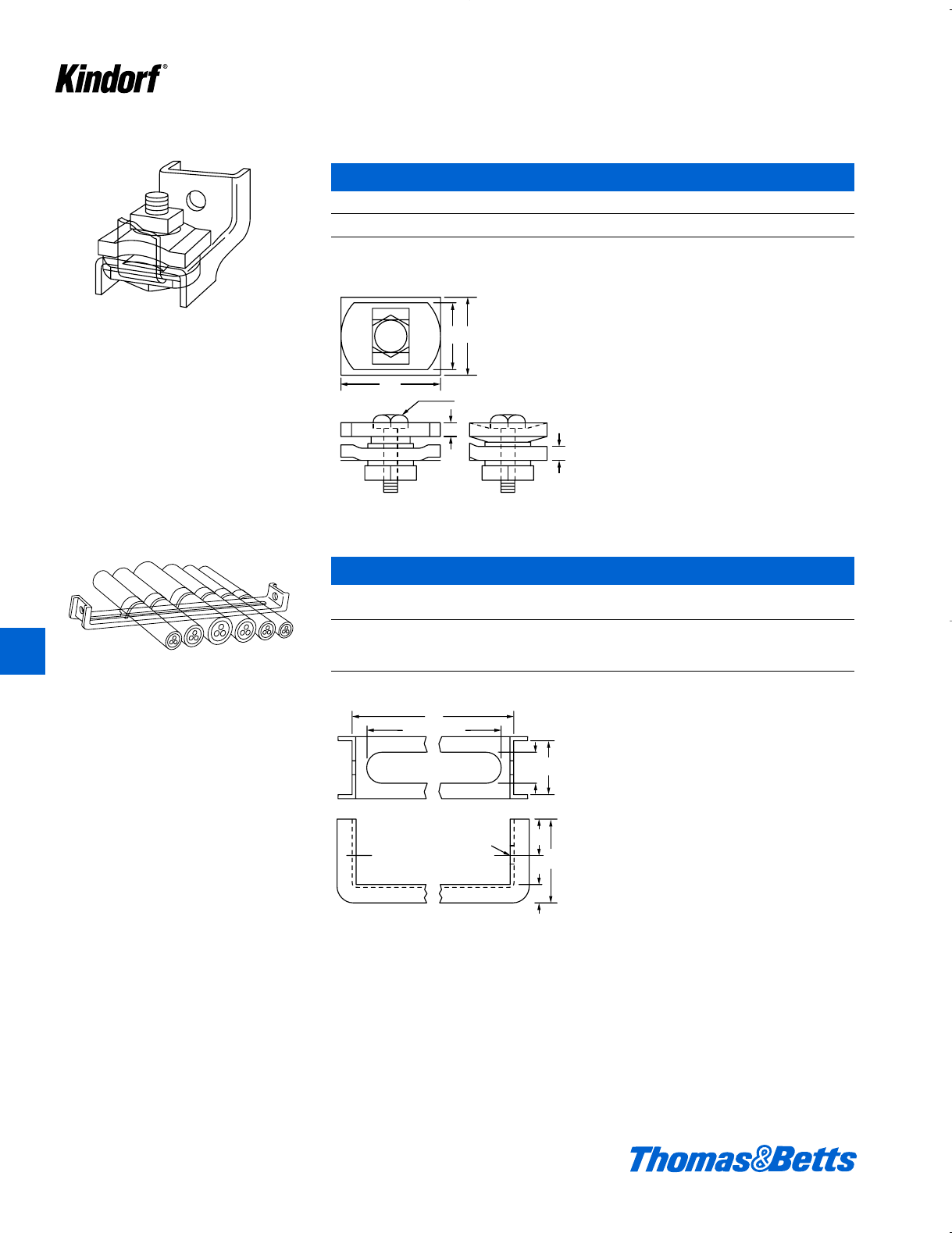
K112 © 2003 Thomas & Betts Corporation. Specifications are subject to change without notice. www.tnb.com
K
Kindorf ®
Cable and Mounting Systems
For use with channel-type hangers in installa-
tions subject to extreme shock.
3
16
1
4
5
16 x 1 bolt, nut and washer
1
1
3
16
1b
jx 1 bolt, nut and washer
1
i
i
J-855 Locking Device – Heavy Duty
Cat. No. Description
J-855 Steel, Galv-Kr¯om finish, 15#/C
Includes j" bolt, nut and washer.
U-style channel, 12 ga. steel, with Galv-Kr¯om
finish, 3⁄8" turned edge. Three sizes.
J-860 Mounting Brackets
Cat. Dimensions Wt.
No. L (in.) lbs./C
J-860-6 642
J-860-9 948
J-860-12 12 59
9
32
21
32
3
4
3
8
1
3
4
1
hole
L minus I
L
13
32
y1s
uhole f
c
1f
412034.K01 KINDORF 5/1 5/7/03 3:17 PM Page K112
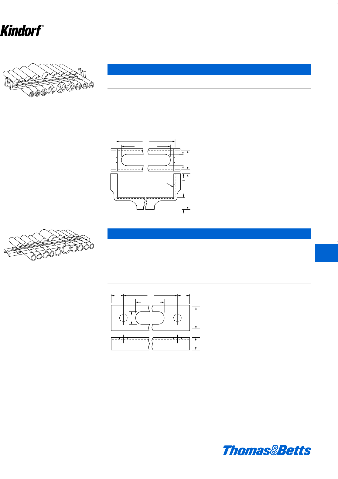
© 2003 Thomas & Betts Corporation. Specifications are subject to change without notice. www.tnb.com K113
K
Kindorf ®
Cable and Mounting Systems
U-style channel, 12 ga. steel, with Galv-Kr¯om
finish, 5⁄8" turned edge. Six sizes.
9
32
21
32
3
4
5
8
1
2
hole
L minus I
L
13
32
uhole
y1s
f
e
2
J-861 Mounting Brackets
Cat. Dimensions Wt.
No. L (in.) lbs./C
J-861-10 10 64
J-861-12 12 73
J-861-14 14 86
J-861-15 15 89
J-861-16 16 96
J-861-18 18 100
Straight, heavy duty channel. 12 ga. steel, with
Galv-Kr¯om finish. Five sizes.
J-863 Mounting Brackets
Cat. Dimensions Wt.
No. L (in.) lbs./C
J-863-6 642
J-863-9 957
J-863-12 12 73
J-863-15 15 85
J-863-18 18 106
5
8
21
32
5
8
5
8
9
32
1
L minus I
L
y
ee
e
1s
412034.K01 KINDORF 5/1 5/7/03 3:17 PM Page K113
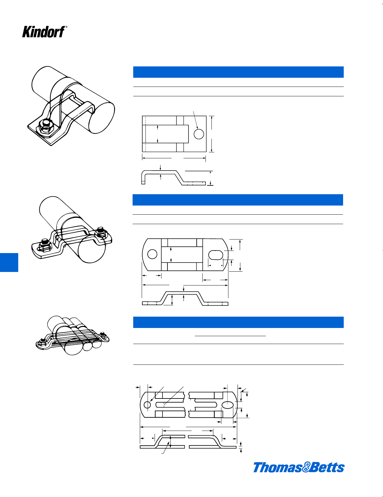
K114 © 2003 Thomas & Betts Corporation. Specifications are subject to change without notice. www.tnb.com
Cable and Mounting Systems
Supports one cable or tube up to 11⁄16" O.D. Only
one stud or screw necessary for mounting.
12 ga.
d
2b
y
X
1b
X
y 1b
2b
12 ga.
d
J-865 Bar Hanger
Cat. No. Description
J-865 Steel, Galv-Kr¯om finish, 6.7#/C
J-867 Bar Hanger
Cat. No. Dimensions (in.) Wt.
& Size A B lbs./C
J-867-1 5a 2g 15
J-867-2 7a 4g 20
J-867-3 9a 6g 27
Steel, Galv-Kr¯om finish.
Supports one large or two small cables or tubes
up to a total of 15⁄16" O.D.
J-866 Bar Hanger
Cat. No. Description
J-866 Steel, Galv-Kr¯om finish, 9#/C
Cable or tube assembly locks in place with one
short 1⁄4" screw and nut. Use two studs, welding
pads or bolts to mount.
y
f
d
1b
X
x
12 ga.
12
ga.
X
e
l
1b
v
y
s
c
X
e
e
AB
X1b
s
c
12 ga.
d
3d
16⁄32
y
f
X
1b
vo
l
e
e
e
16⁄32
y
A
B
K
Kindorf ®
412034.K01 KINDORF 5/1 5/7/03 3:17 PM Page K114
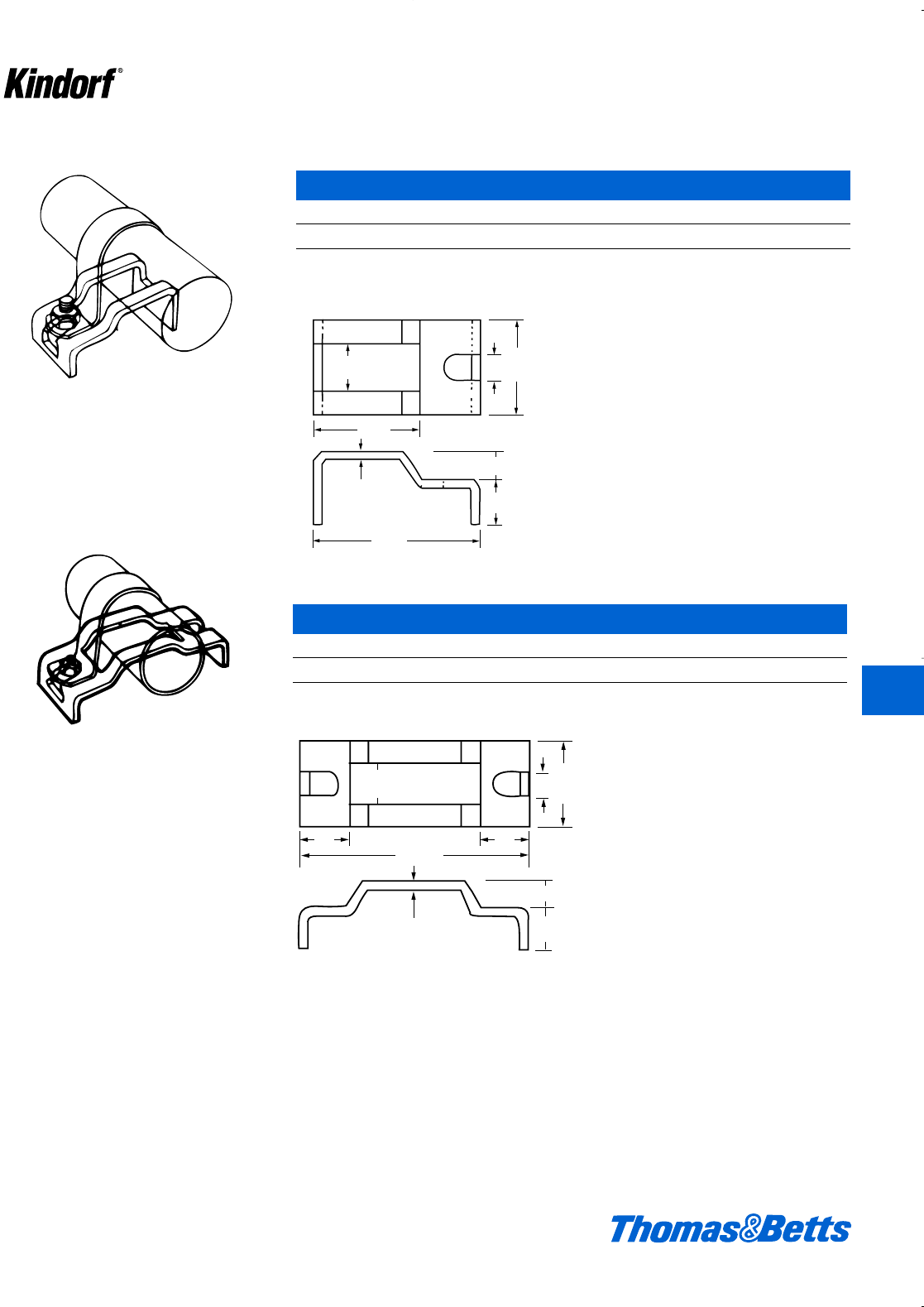
Cable and Mounting Systems
Supports one cable or tube up to 11
/16" O.D.
Strap fastens to hanger by short machine screw
and nut.
J-868 Bar Hanger
Cat. No. Description
J-868 Steel, Galv-Kr¯om finish, 8.3#/C
Use one stud or weld to mount.
Supports one large or two small cables or tubes
up to a total of 15⁄16" O.D. Both ends of hanger
have nut engaging slot.
12 ga.
2b
1l
yX1b
c
e
y
f
3c
f
X1b
c
e
12 ga.
X1b
c
12 ga.
2b
f
y
l
e
e
X
c
12 ga.
3c
1b
f
y
J-869 Bar Hanger
Cat. No. Description
J-869 Steel, Galv-Kr¯om finish, 11.2#/C
© 2003 Thomas & Betts Corporation. Specifications are subject to change without notice. www.tnb.com K115
K
Kindorf ®
412034.K01 KINDORF 5/1 5/7/03 3:17 PM Page K115
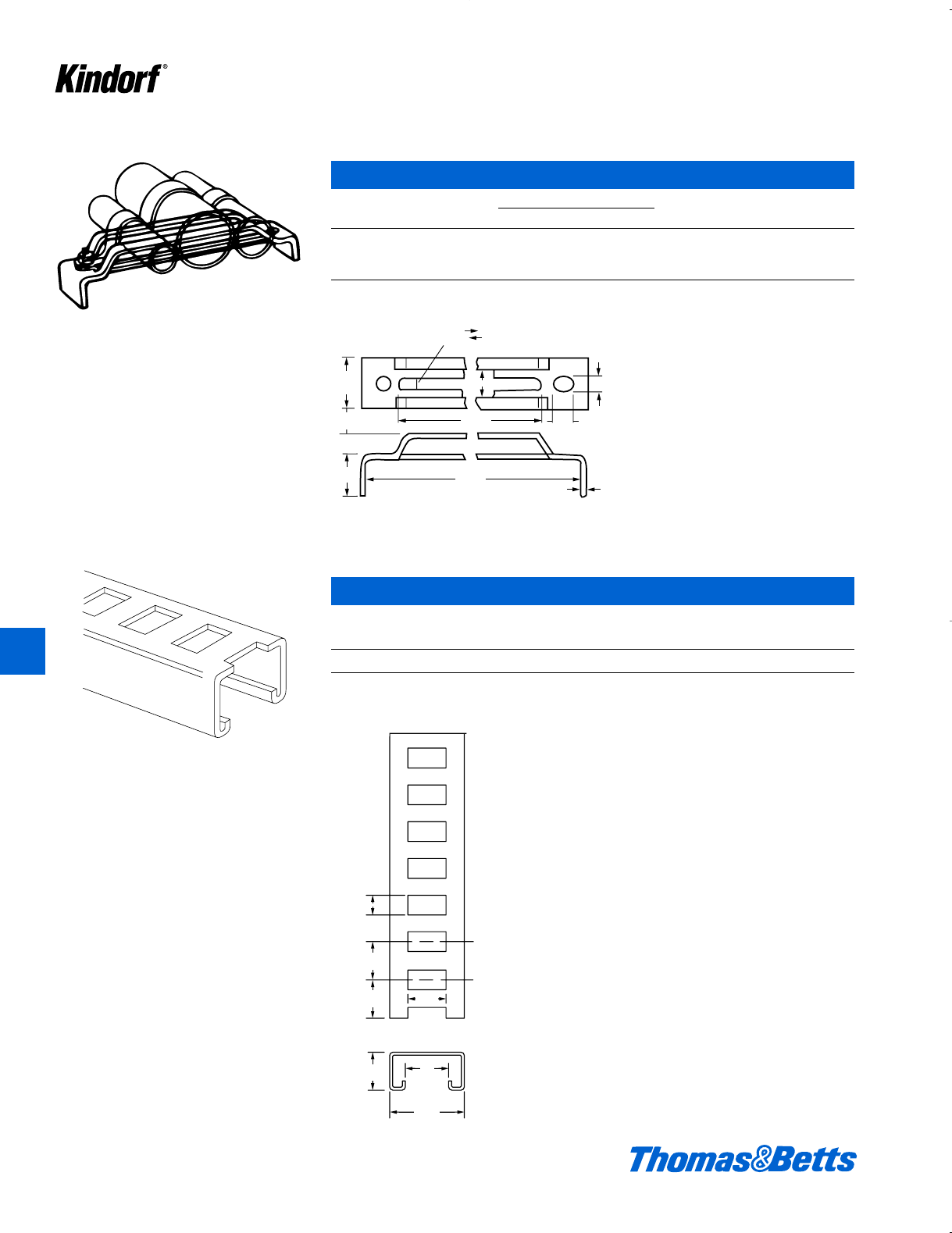
K116 © 2003 Thomas & Betts Corporation. Specifications are subject to change without notice. www.tnb.com
Cable and Mounting Systems
Supports cable or tube assembly, locked in
place with one short 1⁄4" screw and nut. Mount
by welding.
J-870 Bar Hanger
Cat. No. Dimensions (in.) Wt.
& Size A B lbs./C
J-870-1 5a 3k 22.5
J-870-2 7a 5k 28.0
J-870-3 9a 7k 33.3
Steel, Galv-Kr¯om finish
10' length slotted channel provides “cut to
length” versatility. For use with standard
marine steel banding. Uniformly spaced slot
size 13⁄32" x 3⁄4" spaced on 3⁄4" centers. Cut any-
where along entire length.
12
ga.
X
s
l
1b
d
1
B
A
3
4
3
4
3
4
3
32
1
1
2
1
7
8
3
4
X
1p
s
12
ga.
d
1b
l
f
1d
g
f
f
f
J-864 Slotted Channel
Mount, Band or Support at any Slot
Cat. No. Description Wt. lbs./C
J-864 10' length f" deep Kindorf slotted channel 65
For applications see page K117.
Galv-Kr¯om finish
K
Kindorf ®
412034.K01 KINDORF 5/1 5/7/03 3:17 PM Page K116
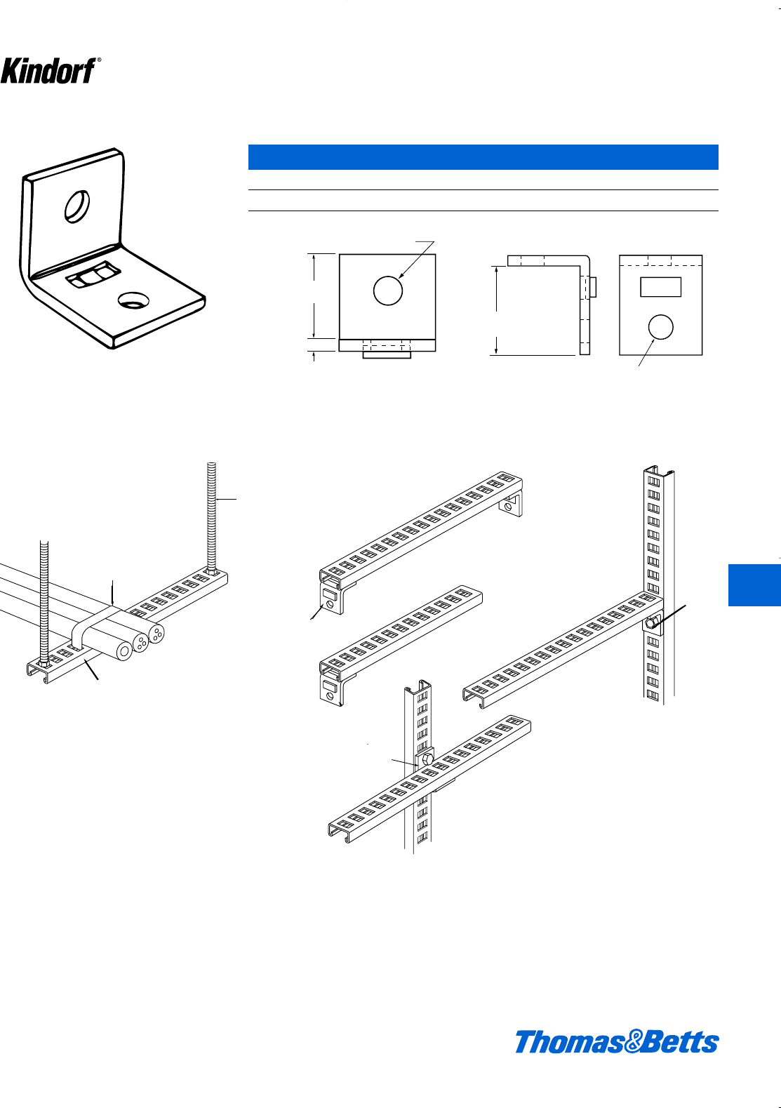
© 2003 Thomas & Betts Corporation. Specifications are subject to change without notice. www.tnb.com K117
Cable and Mounting Systems
Integral pilot, prevent twist.
J-844 Channel Angle Connector
Cat. No. Description
J-844 Galv-Kr¯om finish
dia. Hole
u"
i
j
1
e
e
1
i
udia. hole
1j
udia. hole
1e
Slotted Channel Installation Applications Angle Connector Provides “On The Job” Versatility for Cable Racking and Mounting.
J-844
J-8
J-844
Standard
Steel Band
Kindorf J-864 Channel Support
Field-Cut to length required
H-193
3/8" dia
Kindorf
Steel H
Standard
Steel Band
H-193-3/8
c" diameter
Kindorf
threaded Steel
Hanger Rod
Kindorf J-864 Channel Support
Field-Cut to length required
J-844
J-844
J-844
K
Kindorf ®
412034.K01 KINDORF 5/1 5/7/03 3:17 PM Page K117
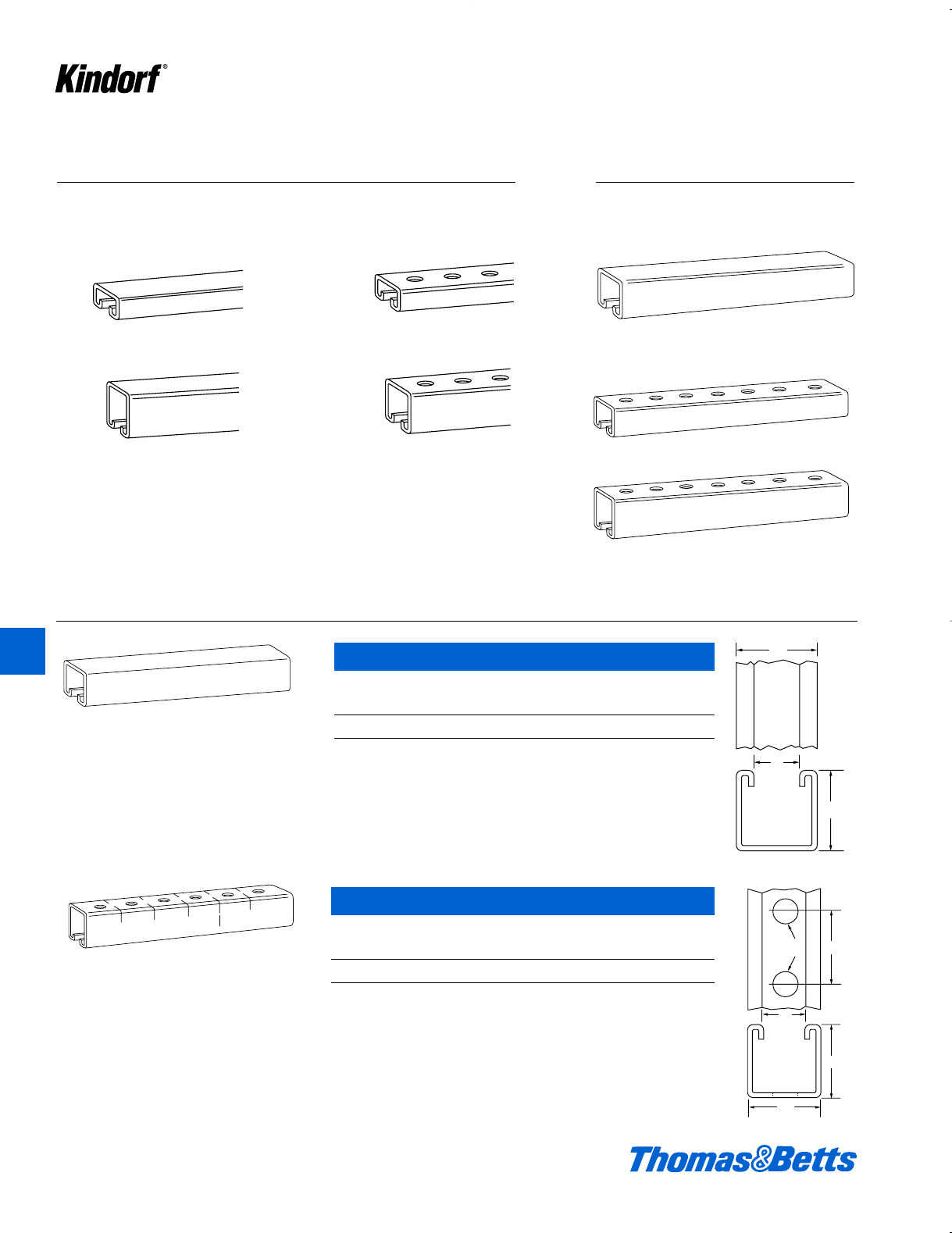
K118 © 2003 Thomas & Betts Corporation. Specifications are subject to change without notice. www.tnb.com
B-905-AL Channel
Aluminum (extruded 6063-T6)
Cat. No. Description
B-905-AL 1d" x 1d" x .1046; 56#/C ft.
Use H-113-B bolts and B-910-1/2 or B-911-1/2 steel nuts for mounting fittings.
10 ft. lengths only
Solid Base
Stainless Steel – Type 304
10 and 20 foot lengths
Channels – Aluminum and Stainless Steel
Connection by means of continuous slot.
B-900-AL Channel
Aluminum (extruded 6063-T6)
Cat. No. Description
B-900-AL 1d" x 1d" x .1046; 58#/C ft.
Use H-113-B bolts and B-910-1/2, B-911--1/2 or B-911-1/2-TL steel nuts for mount-
ing fittings.
10 ft. lengths only
9⁄16" holes on 11⁄2" centers punched in channel
base. Connection also by means of continuous
slot.
1
2
1
1
2
1
7
8
1
2
1
1
2
1
1
2
1
7
8
9
16
Aluminum • Extruded 6063-T6 Aluminum Alloy
10 and 20 foot lengths
Bolt Hole Base
1d
1d
1d
1d
1d
g
g
l
Aluminum
Solid Base
B-900-AL
1d" x 1d" x .104"
B-906-AL
1d" x f" x .104"
B-907-AL
1d" x f" x .104"
B-905-AL
1d" x 1d" x .104"
B-900-SS
1d" x 1d" x 13 gage
Bolt Hole Base
B-907-SS
1d" x f" x 14 gage
B-905-SS
1d" x 1d" x 13 gage
K
Kindorf ®
412034.K01 KINDORF 5/1 5/7/03 3:17 PM Page K118
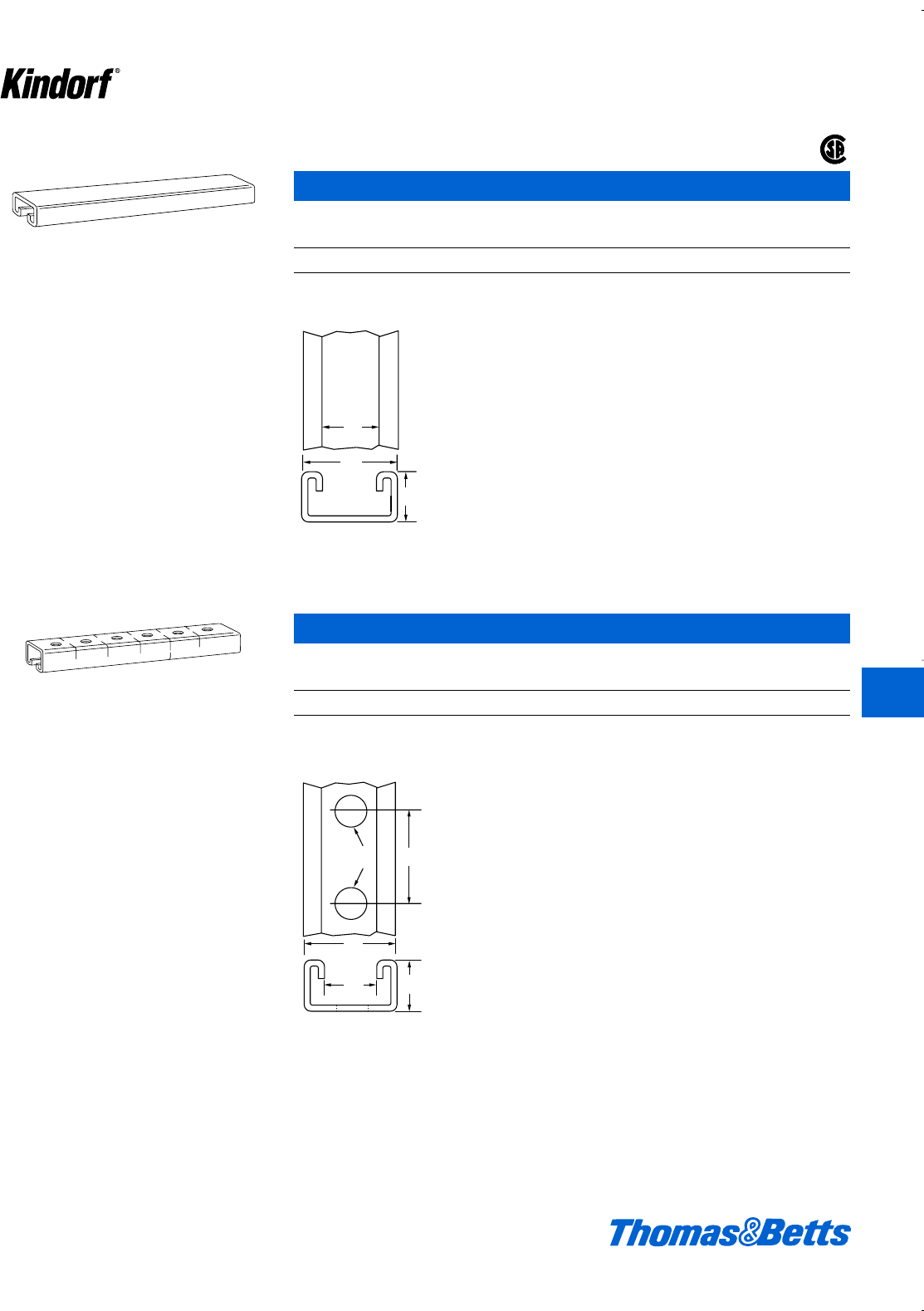
© 2003 Thomas & Betts Corporation. Specifications are subject to change without notice. www.tnb.com K119
®
Channels – Aluminum
B-906-AL Channel
Aluminum (extruded 6063-T6)
Cat. No. Description
B-906-AL 1d" x f" x .1046; 40#/C ft.
Use H-113-A bolts and B-910-1/2 or B-912-1/2 steel nuts for mounting fittings.
Connection by means of continuous slot.
Connection by means of continuous slot or 9⁄16"
holes on 11⁄2" centers.
1
12
7
8
3
4
2
1
3
4
1
2
1
17
32
1
7
8
®
B-907-AL Channel
Aluminum (extruded 6063-T6)
Cat. No. Description
B-907-AL 1d" x f" x .1046; .37#/C ft.
Use H-113-A bolts and B-910-1/2 or B-912-1/2 steel nuts for mounting fittings. Holes on B-900 series fittings match
channel holes.
1d
g
f
1d
1d
gf
w
K
Kindorf ®
412034.K01 KINDORF 5/1 5/7/03 3:17 PM Page K119
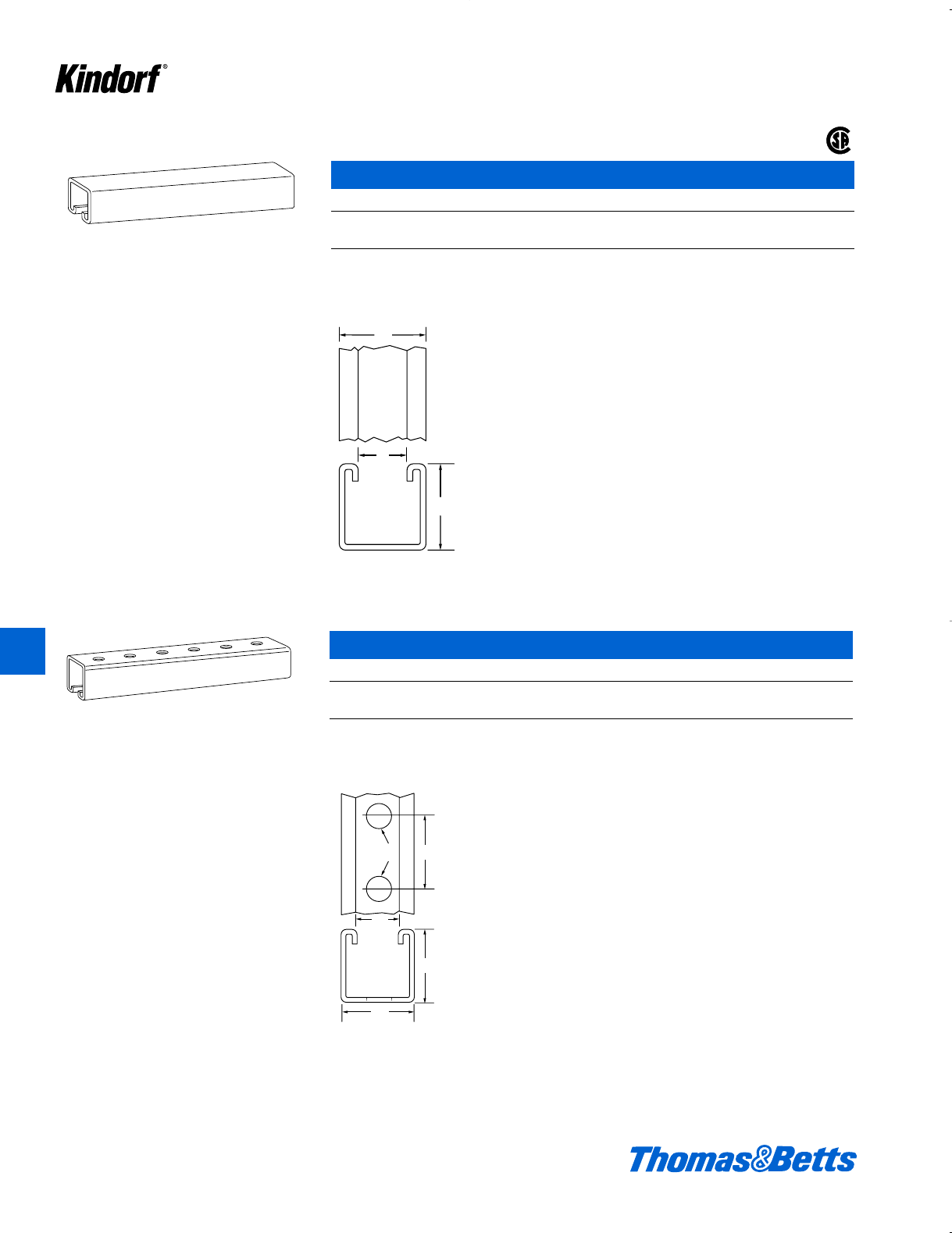
K120 © 2003 Thomas & Betts Corporation. Specifications are subject to change without notice. www.tnb.com
Channels – Stainless Steel
Connection by means of continuous slot.
B-900 Channel – Stainless Steel – 1d" x 1d"
Cat. No. Description
B-900-10SS Type 304
B-900-20SS Type 304
Use H-113-B bolts and B-910-1/2 or B-911-1/2 stainless steel nuts for mounting fittings.
Connections by means of continuous slot or 9⁄16"
holes on 11⁄2" centers which match holes in
B-900 series fittings.
1
2
1
1
2
1
7
8
1
2
1
1
2
1
1
2
1
7
8
9
16
1d
1d
g
®
B-905 Channel – Stainless Steel – 1d" x 1d"
Cat. No. Description
B-905-10SS Type 304
B-905-20SS Type 304
Use H-113-B bolts and B-910-1/2 or B-911-1/2 stainless steel nuts for mounting fittings. Scribe marks designate mid-
point between holes for accurate field cutting.
1d
1d
1d
g
l
K
Kindorf ®
412034.K01 KINDORF 5/1 5/7/03 3:17 PM Page K120
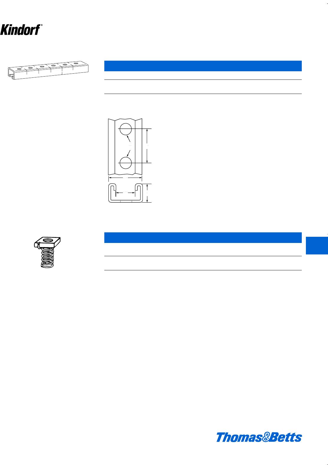
© 2003 Thomas & Betts Corporation. Specifications are subject to change without notice. www.tnb.com K121
Channels – Stainless Steel
Connection by means of continuous slot or 9⁄16"
holes on 11⁄2" centers.
B-907 Channel – Stainless Steel
Cat. No. Description
B-907-10SS Type 304
B-907-20SS Type 304
Use H-113-A bolts and B-910-1/2 or B-912-1/2 steel nuts for mounting fittings. Holes on B-900 series fittings match
channel holes.
2
1
3
4
1
2
1
17
32
1
7
8
B-911 Channel – Stainless Steel
Wt.
Cat. No. Size Thickness lbs./C
B-911-3/8-SS†c- 16 i12.5
B-911-1/2-SS†d- 13 j16.0
† B-911-3/8-SS, Stud: cDia., 1" Long. Accepts Kindorf Nuts H-114C (hex), H-116-C (square).
B-911-1/2-SS, Stud: dDia., 1" Long. Accepts Kindorf Nuts H-114D (hex), H-116-D (square).
Stud nut self-holding clamping nut with spring
attached.
K
Kindorf ®
412034.K01 KINDORF 5/1 5/7/03 3:17 PM Page K121
K122 © 2003 Thomas & Betts Corporation. Specifications are subject to change without notice. www.tnb.com
K
Kindorf ®
Pipe Supports – Aluminum
Steel beam mounting application.
Aluminum straps with stainless steel hardware.
Frame assembly carries multiple conduit runs.
Kindorf Straps for Rigid Conduit and Pipe – Aluminum
Cat. Rigid Conduit Aluminum Strap Wt.
No. or Pipe Size Material Thickness lbs./C
C-105AL-1/2 d"14 7
C-105AL-3/4 f"14 8
C-105AL-1 1" 14 9
C-105AL-1-1/4 1b"14 10
C-105AL-1-1/2 1d"12 12
C-105AL-2 2" 12 14
C-105AL-2-1/2 2d"12 16
C-105AL-3 3" 12 18
C-105AL-3-1/2 3d"a"22
C-105AL-4 4" a"24
Kindorf Straps for Rigid Conduit and Pipe – Type 304
Cat. Rigid Conduit
No. or Pipe Size
C-105-1/2SS d"
C-105-3/4SS f"
C-105-1SS 1"
C-105-1-1/4SS 1b"
C-105-1-1/2SS 1d"
C-105-2SS 2"
C-105-2-1/2SS 2d"
C-105-3SS 3"
C-105-3-1/2SS 3d"
C-105-4SS 4"
Pipe Supports – Stainless Steel
Kindorf Straps for EMT – Aluminum
Cat. Rigid Conduit Aluminum Strap Wt.
No. or Pipe Size Material Thickness lbs./C
C-106AL-1/2 d"14 7
C-106AL-3/4 f"14 8
C-106AL-1 1" 14 9
C-106AL-1-1/4 1b"14 10
C-106AL-1-1/2 1d"12 12
C-106AL-2 2" 12 14
Kindorf Straps for EMT – Type 304
Cat. Rigid Conduit
No. or Pipe Size
C-106-1/2SS d"
C-106-3/4SS f"
C-106-1SS 1"
C-106-1-1/4SS 1b"
C-106-1-1/2SS 1d"
C-106-2SS 2"
412034.K01 KINDORF 5/1 5/7/03 3:17 PM Page K122
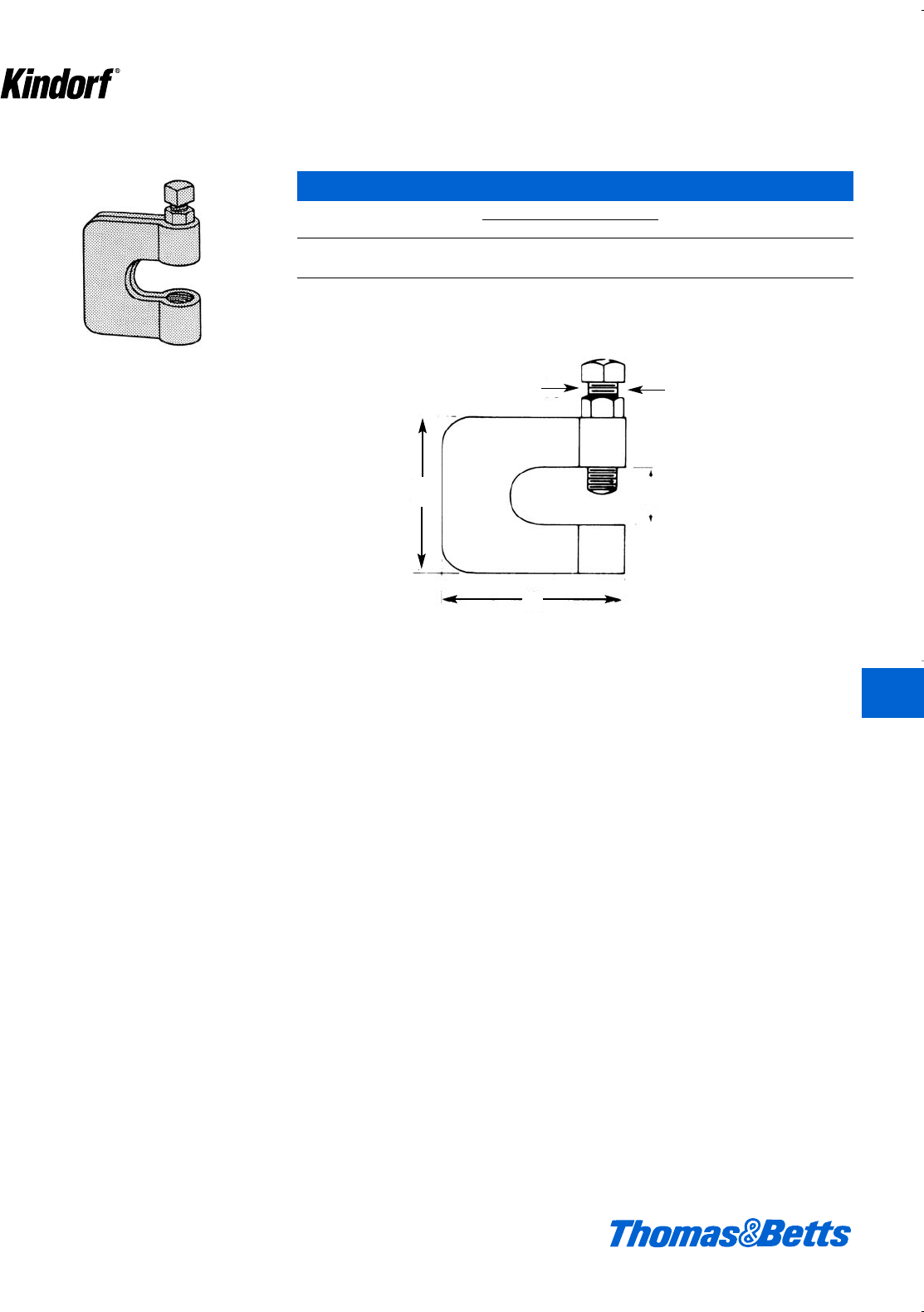
© 2003 Thomas & Betts Corporation. Specifications are subject to change without notice. www.tnb.com K123
K
Kindorf ®
Beam Clamps for Hanging Rod – Stainless Steel
E-236 Clamp with Lock Nut – Type 304
Cat. Rod Dimensions (in.) Wt./C Design
No. Size ABCD
C-775-L Load (lbs.)
E-236-3/8SS ccc2b2b35 550
E-236-1/2SS ddf2b2b41 600
A
DB
C
412034.K01 KINDORF 5/1 5/7/03 3:17 PM Page K123

PVC Coated Steel
Channel and Fittings for
High Corrosive
Atmospheres
The complete and lasting corrosion
protection of conduit with polyvinyl
chloride coating is now extended to
the supporting system. No longer will
installers be faced with the problem of
installing PVC coated conduit or other
corrosion resistant material only to
have the support system require con-
stant maintenance or replacement.
PVC coated Kindorf channel and fit-
tings complement other corrosion
resistant services installed in chemical
plants, foundries, meat packing plants,
oil refineries, paper mills, sewage treat-
ment plants and other locations.
PVC Plastic-Coated
Kindorf Channel Support
System for Installations
in Severely Corrosive
Atmospheres
PVC Coating
The coating is a polyvinyl chloride
(PVC) plastic coating that is perma-
nently fused to the Kindorf Galv-Kr¯om
galvanized steel channels, fittings and
accessories. The fused-melt mixed
powder (PVC) coating is 15 mils.
(.015") ±5 mils thickness.
The physical properties of the PVC
coating material are as follows:
Hardness 90+ Shore A
Durometer
Dielectric Strength 1100
(volts/mil @
60 cycles
Flammability Self-extinguishing
Tensile strength 2000 p.s.i.
Percent elongation 180%
Aging 14,000 hours
Atlas Weatherometer
The material is a thermoplastic and will
soften in high temperatures. Service
life will be decreased if the normal
operating temperature of the support
system is in excess of 225°F.
The service life expectancy is 20
years in normal weathering, with no
indication of hardening, softening or
other physical change.
The Kindorf plastic coated support
system has excellent resistance to the
corrosive atmospheres created in
modern processing industries which
materially reduce the life of standard
products and cause high maintenance
costs. The fused-on coating of PVC
plastic to a pre-galvanized steel effec-
tively bars corrosive action by eliminat-
ing “undercreep” or “corrosion travel”.
There is practically no maintenance.
No special tools are required for instal-
lation of the Kindorf PVC system.
The Kindorf PVC coated support
system, combining the strength of steel
and the corrosion resistance of plastic,
is designed for mechanical support of
plastic and plastic-coated conduits
and pipes. PVC Kindorf meets the
requirements for corrosion-resistance
in those environments generally found
in chemical processing plants, oil
refineries, steel mills, foundries, meat
packing and other food processing
plants, fertilizer plants, textile and
paper processing industries.
PVC Coated Steel Kindorf
K124 © 2003 Thomas & Betts Corporation. Specifications are subject to change without notice. www.tnb.com
K
Kindorf ®
412034.K01 KINDORF 5/1 5/7/03 3:17 PM Page K124
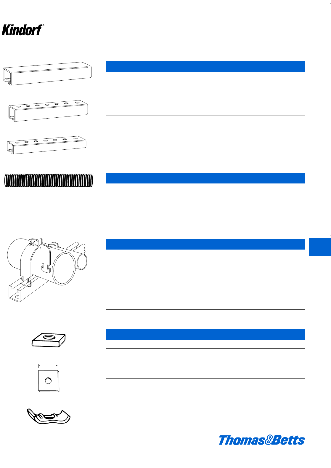
PVC Coated Steel Kindorf
© 2003 Thomas & Betts Corporation. Specifications are subject to change without notice. www.tnb.com K125
PB-900-10
PVC Coated Steel Channel
Cat. No. Description Wt. lbs./C
PB-900-10 1d" x 1d" x 12 ga. 168
Solid Base
PB-905-10 1d" x 1d" x 12 ga. 160
l" Holes on 1d" Centers
PB-907-10 1d" x f" x 14 ga. 82
l" Holes on 11⁄2" Centers
Standard 10 ft. lengths
PBH-193
PVC Coated Steel Hanger Rod
Cat. No. & Size Description Wt. lbs./C
PBH-193-3/8-6 c" x 6' 174
PBH-193-3/8-10 f" x 10' 290
PBH-193-1/2-6 d" x 6' 324
PBH-193-1/2-10 d" x 10' 540
PB-905-10
PB-907-10
PBC-105
PVC Coated Steel Conduit Straps
Cat. No. & Size Description Wt. lbs./C
PBC-105-3/4 f" 16
PBC-105-1 1" 18
PBC-105-1-1/4 1b" 20
PBC-105-1-1/2 1d" 29
PBC-105-2 2" 33
PBC-105-2-1/2 2d" 38
PBC-105-3 3" 45
PBC-105-3-1/2 3d" 58
PBC-105-4 4" 64
1d
1d
PVC Coated Hardware
Cat. No. & Size Description Wt. lbs./C
PB-910-3/8 c-16 Steel Nut 9
PB-910-1/2 d-13 Steel Nut 10
PBH-119C-3/8 1d" Square Washer with k" hole 12
PBH-119D-1/2 1d" Square Washer with B" hole 14
PBH-120 Saddle Washer for c" or d" rod 7
PB-910
PBH-119
PBH-120
K
Kindorf ®
412034.K01 KINDORF 5/1 5/7/03 3:17 PM Page K125
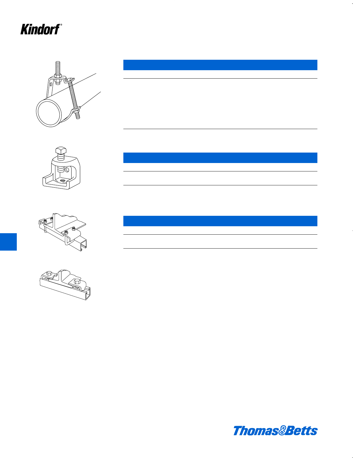
PVC Coated Steel Kindorf
K126 © 2003 Thomas & Betts Corporation. Specifications are subject to change without notice. www.tnb.com
K
Kindorf ®
PBC-149
PVC Coated Single Run Conduit Supports
Cat. No. & Size Description Wt. lbs./C
PBC-149-3/4 f" 19
PBC-149-1 1" 22
PBC-149-1-1/4 1b" 26
PBC-149-1-1/2 1d" 26
PBC-149-2 2" 31
PBC-149-2-1/2 2d" 66
PBC-149-3 3" 72
PBC-149-3-1/2 3d" 84
PBC-149-4 4" 178
PVC Coated Beam Clamps
Cat. No. & Size Description Wt. lbs./C
PB-502 2" – g" Jaw Tapped c-16 95
PB-508 2d" – 2" Jaw Tapped d-13 182
PVC Coated Beam Clamps
Cat. No. & Size For Use With Wt. lbs./C
PBE-760-2 PB-900, PB-905, PB-906 or PB-907 80
PBE-763 All Channels 25
PB-500 Series
PBE-760
PBE-763
412034.K01 KINDORF 5/1 5/7/03 3:17 PM Page K126
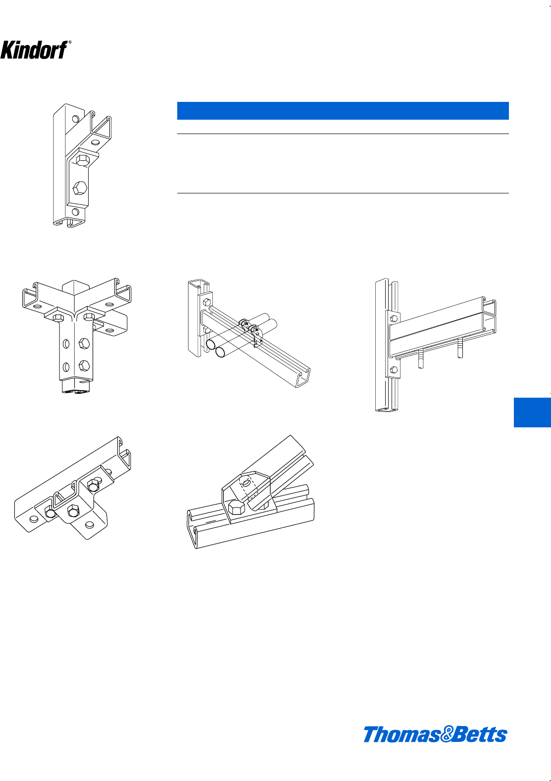
© 2003 Thomas & Betts Corporation. Specifications are subject to change without notice. www.tnb.com K127
K
Kindorf ®
PB-915
PVC Coated Framing Fittings
Cat. No. & Size Description Wt. lbs./C
PB-915 2-Hole Angle Connector 40
PB-923 3-Side Angle Connector 137
PB-927 U Support 53
PB-943 Double Brace Connector 66
PBF-720-18 Single Channel Wall Bracket – 18" 275
PBF-721-18 Double Channel Wall Bracket – 18" 568
PB-923
PB-927
PBF-721
PBF-720
PB-943
PVC Coated Steel Kindorf
412034.K01 KINDORF 5/1 5/7/03 3:17 PM Page K127
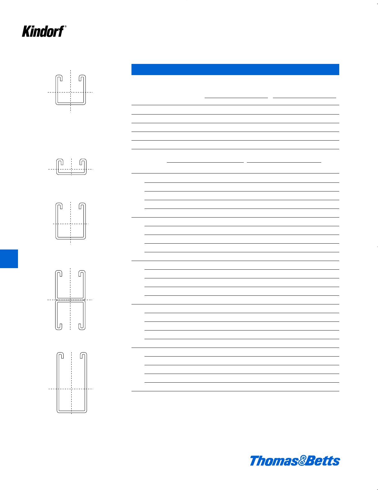
Metallic Engineering Data and Specifications
B-900
11⁄2" x 11⁄2" x 12 ga. steel
B-900-M
11⁄2" x 11⁄2" x 14 ga. steel
B-900-AL
11⁄2" x 11⁄2" x .1046
aluminum
Channel Load Data
Steel Section Properties
Material Properties f=30,000 E=30,000,000
X-X Axis Y-Y Axis
Channel Area lbs/ft. I S r I S r
B-906 0.217 0.740 0.018 0.041 0.272 0.077 0.105 0.559
B-900 0.521 1.776 0.155 0.179 0.545 0.200 0.259 0.619
B-900-M 0.354 1.206 0.101 0.123 0.535 0.129 0.175 0.603
B-901 0.595 2.028 0.263 0.251 0.665 0.238 0.309 0.632
B-902 0.837 2.852 0.909 0.552 1.042 0.363 0.471 0.658
Simple Beam Simple Beam
Span Channel Uniformly Distributed Load Concentrated Center Load Column
Max 1⁄240 Span Design Max 1⁄240 Span Design Load
Load Deflection Load Load Load Deflection Load Load For K=1
B-906 820 0.034 1200 820 410 0.027 750 410 7337
B-900 3580 0.017 10333 3580 1790 0.014 6458 1790 7628
12˝ B-900-M 2460 0.018 6733 2460 1230 0.015 4208 1230 7625
B-901 5020 0.014 17533 5020 2510 0.011 10958 2510 7660
B-902 11040 0.009 60600 11040 5520 0.007 37875 5520 7699
B-906 547 0.077 533 533 273 0.062 333 273 6852
B-900 2387 0.039 4593 2387 1193 0.031 2870 1193 7507
18˝ B-900-M 1640 0.041 2993 1640 820 0.033 1870 820 7499
B-901 3347 0.032 7793 3347 1673 0.026 4870 1673 7579
B-902 7360 0.020 26933 7360 3680 0.016 16833 3680 7665
B-906 410 0.137 300 300 205 0.109 188 188 6172
B-900 1790 0.069 2583 1790 895 0.055 1615 895 7338
24˝ B-900-M 1230 0.073 1683 1230 615 0.058 1052 615 7324
B-901 2510 0.057 4383 2510 1255 0.046 2740 1255 7465
B-902 5520 0.036 15150 5520 2760 0.029 9469 2760 7619
B-906 328 0.214 192 192 164 0.171 120 120 5299
B-900 1432 0.108 1653 1432 716 0.067 1033 716 7121
30˝ B-900-M 984 0.114 1077 984 492 0.091 673 492 7098
B-901 2008 0.089 2805 2008 1004 0.072 1753 1004 7319
B-902 4416 0.057 9696 4416 2208 0.046 6060 2208 7560
B-906 273 0.308 133 133 137 0.246 83 83 4231
B-900 1193 0.156 1148 1148 597 0.125 718 597 6855
36˝ B-900-M 820 0.164 748 748 410 0.132 468 410 6822
B-901 1673 0.129 1948 1673 837 0.103 1218 837 7140
B-902 3680 0.082 6733 3680 1840 0.066 4208 1840 7487
For channel with holes in bottom, multiply load by 0.95.
For channel with holes in bottom and sides, multiply load by 0.90.
For extruded aluminum channel, multiply load by .33
Column loads calculated in accordance with AISI Light Gauge Cold-Formed Steel Design Manual, Section 3.6.
y
y
xx
x
x
xx
y
xx
x
xx
x
x
y
y
xx
K128 © 2003 Thomas & Betts Corporation. Specifications are subject to change without notice. www.tnb.com
K
Kindorf ®
B-900-2A
11⁄2" x 3" x 12 ga. steel
B-906
11⁄2" x 3⁄4" x 14 ga. steel
B-901
17⁄8" x 11⁄2" x 12 ga. steel
B-902
11⁄2" x 3" x 12 ga. steel
412034.K01 KINDORF 5/1 5/7/03 3:17 PM Page K128

© 2003 Thomas & Betts Corporation. Specifications are subject to change without notice. www.tnb.com K129
K
Kindorf ®
Metallic Engineering Data and Specifications
Channel Load Data – continued
Simple Beam Simple Beam
Span Channel Uniformly Distributed Load Concentrated Center Load Column
Max 1⁄240 Span Design Max 1⁄240 Span Design Load
Load Deflection Load Load Load Deflection Load Load For K=1
B-906 234 0.419 98 98 117 0.335 61 61 3125
B-900 1023 0.212 844 844 511 0.170 527 511 6541
42˝ B-900-M 703 0.224 550 550 351 0.179 344 344 6496
B-901 1434 0.175 1431 1431 717 0.140 895 717 6929
B-902 3154 0.112 4947 3154 1577 0.089 3092 1577 7401
B-906 205 0.547 75 75 103 0.437 47 47 2392
B-900 895 0.277 646 646 448 0.222 404 404 6178
48˝ B-900-M 615 0.292 421 421 308 0.234 263 263 6120
B-901 1255 0.229 1096 1096 628 0.183 685 628 6686
B-902 2760 0.146 3788 2760 1380 0.117 2367 1380 7302
B-906 182 0.692 59 59 91 0.554 37 37 1890
B-900 796 0.351 510 510 398 0.281 319 319 5767
54˝ B-900-M 547 0.370 333 333 273 0.296 208 208 5693
B-901 1116 0.290 866 866 558 0.232 541 541 6410
B-902 2453 0.184 2993 2453 1227 0.148 1870 1227 7189
B-906 164 0.854 48 48 82 0.683 30 30 1531
B-900 716 0.433 413 413 358 0.346 258 258 5308
60˝ B-900-M 492 0.457 269 269 246 0.365 168 168 5216
B-901 1004 0.358 701 701 502 0.286 438 438 6101
B-902 2208 0.228 2424 2208 1104 0.182 1515 1104 7064
B-906 137 1.230 33 33 68 0.984 21 21 1063
B-900 597 0.624 287 287 298 0.499 179 179 4244
72˝ B-900-M 410 0.658 187 187 205 0.526 117 117 4113
B-901 837 0.515 487 487 418 0.412 304 304 5387
B-902 1840 0.328 1683 1683 920 0.262 1052 920 6773
B-906 117 1.674 24 24 59 1.339 15 15 781
B-900 511 0.849 211 211 256 0.679 132 132 3136
84˝ B-900-M 351 0.895 137 137 176 0.716 86 86 3022
B-901 717 0.701 358 358 359 0.561 224 224 4543
B-902 1577 0.446 1237 1237 789 0.357 773 773 6429
For channel with holes in bottom, multiply load by 0.95.
For channel with holes in bottom and sides, multiply load by 0.90.
For extruded aluminum channel, multiply load by .33
Column loads calculated in accordance with AISI Light Gauge Cold-Formed Steel Design
Manual, Section 3.6.
412034.K01 KINDORF 5/1 5/7/03 3:17 PM Page K129

Metallic Engineering Data and Specifications
Channel Load Data – continued
Simple Beam Simple Beam
Span Channel Uniformly Distributed Load Concentrated Center Load Column
Max 1⁄240 Span Design Max 1⁄240 Span Design Load
Load Deflection Load Load Load Deflection Load Load For K=1
B-906 103 2.187 19 19 51 1.749 12 12 598
B-900 448 1.109 161 161 224 0.887 101 101 2401
96˝ B-900-M 308 1.169 105 105 154 0.935 66 66 2314
B-901 628 0.916 274 274 314 0.733 171 171 3575
B-902 1380 0.583 947 947 690 0.466 592 592 6032
B-906 91 2.768 15 15 46 2.214 9 9 473
B-900 398 1.403 128 128 199 1.123 80 80 1897
108˝ B-900-M 273 1.480 83 83 137 1.184 52 52 1828
B-901 558 1.160 216 216 279 0.928 135 135 2825
B-902 1227 0.738 748 748 613 0.590 468 468 5582
B-906 82 3.417 12 12 41 2.733 8 8 383
B-900 358 1.732 103 103 179 1.386 65 65 1537
120˝ B-900-M 246 1.827 67 67 123 1.461 42 42 1481
B-901 502 1.432 175 175 251 1.145 110 110 2288
B-902 1104 0.911 606 606 552 0.729 379 379 5080
For channel with holes in bottom, multiply load by 0.95.
For channel with holes in bottom and sides, multiply load by 0.90.
For extruded aluminum channel, multiply load by .33
Column loads calculated in accordance with AISI Light Gauge Cold-Formed Steel Design
Manual, Section 3.6.
K130 © 2003 Thomas & Betts Corporation. Specifications are subject to change without notice. www.tnb.com
K
Kindorf ®
412034.K01 KINDORF 5/1 5/7/03 3:17 PM Page K130
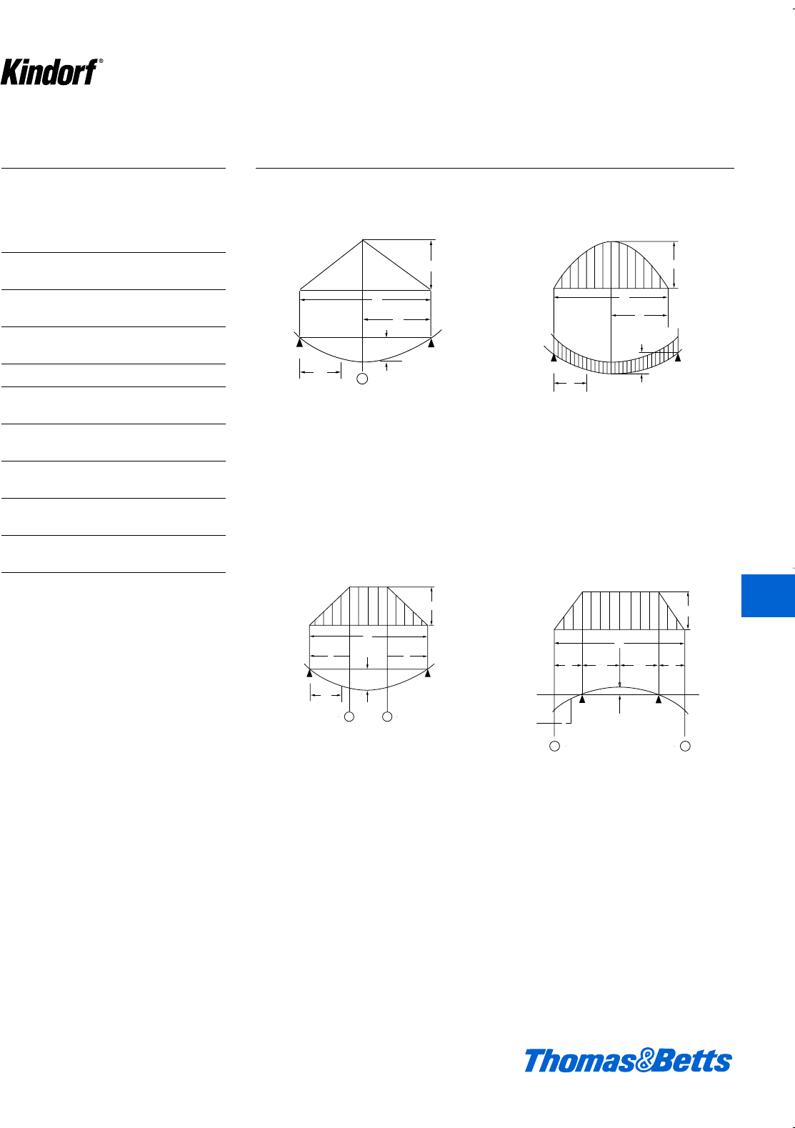
© 2003 Thomas & Betts Corporation. Specifications are subject to change without notice. www.tnb.com K131
Metallic Engineering Data and Specifications
Steel and Aluminum
Modulus of Elasticity (E)
Steel – 29,500,000 pounds per square inch
Aluminum – 10,000,000 pounds per square inch
Maximum Fiber Stress (f)
Steel – 30,000 pounds per square inch
Aluminum – 10,000 pounds per square inch
Beam supported at ends
Concentrated load at center
W max. = 4fS/L
D max. = WL3/48El
Beam supported at ends
Uniformly distributed load
W max. = 8fS/L
D max. = 5WL3/384El
Beam continuous over two supports
Two exterior symmetrical loads
W max. = 2fS/a
D, distance a = Wa(3aL-4a2)/12EI
D1, distance L/2 - a = Wa(2-2a)2/16EI
Beam supported at ends
Two symmetrical concentrated loads
W max. = 2fS/a
D max. = Wa/12El (3⁄4L2- a2)
L
1
2
X
R1
R
W
D
M
WD
L
M
1
2
X
R1
R
L
M
W
2
W
2
00
X
D
L
M
R
1
R
W
2
W
X
D
2
D
1
0 0
0
1
20
1
2
Beam Formula
For calculating deflection and maxi-
mum safe load (Beams of uniform
cross section)
I= Moment of inertia, in position of load, in
inches4.
S= Section modulus – in position of load l/n,
in inches3.
f= Bending stress in extreme fiber, in
pounds per square inch.
E= Modulus of elasticity, in pounds per
square inch.
L= Length of section, in inches.
W= Superimposed loads supported by
beam, in pounds.
W Max.= Maximum safe load at point
given, in pounds.
M= Maximum bending moment, in inch
pounds.
D,D1= Deflections at points given, in inch-
es.
D Max.= Maximum deflection at point
given, in inches.
K
Kindorf ®
412034.K01 KINDORF 5/1 5/7/03 3:17 PM Page K131
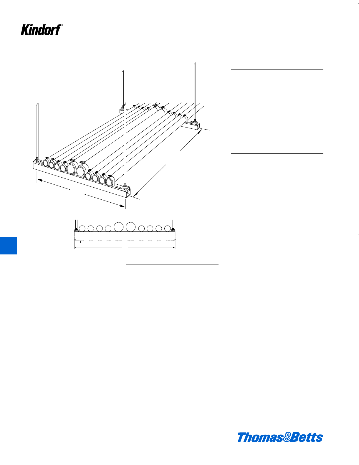
Weight per Hanger Equals
2" rigid steel conduit with heaviest conductor combination = 6.625 lbs. per foot.
3" rigid steel conduit with heaviest conductor combination = 13.415 lbs. per foot.
8 x 6.625 x 5 = 265 lbs. = weight of 2" conduits per hanger
2 x 13.415 x 5 = 134 lbs. = weight of 3" conduits per hanger
Total = 399 lbs. = weight of conduits per hanger
Metallic Engineering Data and Specifications
Conclusion
Referring to the load span tables on
page K128 for B-905 channel, a 36-
inch span has a uniformly distributed
load rating of 1133 lbs., which is greater
than the 390 lb. load calculated
above, and is therefore satisfactory.
On longer spans or spans with
greater loads, use B-901, B-900-2A or
B-905-2A channel or provide an inter-
mediate support
Note on Conduit Support
The 1987 edition of the National
Electrical Code states the rigid metal
conduit, intermediate metal conduit,
and electrical metallic tubing shall be
supported at least every 10 feet. See
Article 346, Section 346-12 for excep-
tions for rigid-metal conduit.
Problem
Design trapeze to support 8-2" rigid
steel conduits and 2-3" rigid steel con-
duits on a No. B-905 channel span
with hangers spaced five (5) feet
apart.
36"
5'
36"
2"2"2"2"
3"3"
2"2"2"2"
17
32
1
3
16
1
1
8
317
32
1
3
16
1
1
8
31
8
31
8
31
8
31
8
3
3
4
33
4
3
5
16
4
2˝2˝ 2˝2˝ 2˝2˝ 2˝2˝
3˝
3˝
13⁄16
117⁄32
117⁄32
13⁄16
36˝
31⁄8
31⁄831⁄8
31⁄8
33⁄4
31⁄831⁄8
33⁄445⁄16
K132 © 2003 Thomas & Betts Corporation. Specifications are subject to change without notice. www.tnb.com
K
Kindorf ®
412034.K01 KINDORF 5/1 5/7/03 3:17 PM Page K132

© 2003 Thomas & Betts Corporation. Specifications are subject to change without notice. www.tnb.com K133
Metallic Engineering Data and Specifications
Conduit Spacings
Spacings in inches between centers of conduits.
The light face figures are the minimum dimensions to provide clearance between locknuts.
The more liberal spacings printed in bold face type should be used whenever possible.
Size 1⁄23⁄411
1⁄411⁄222
1⁄233
1⁄244
1⁄256
1⁄213⁄16 – – – – – – – – – – – –
13⁄8– – – – – – – – – – – –
3⁄415⁄16 17⁄16 – – – – – – – – – – –
11⁄215⁄8– – – – – – – – – – –
11
1⁄215⁄813⁄4– – – – – – – – – –
13⁄417⁄82 – – – – – – – – – –
11⁄413⁄417⁄822
1⁄4– – – – – – – – –
22
1⁄821⁄421⁄2– – – – – – – – –
11⁄2115⁄16 21⁄16 23⁄16 27⁄16 29⁄16 – – – – – – – –
21⁄821⁄423⁄825⁄823⁄4– – – – – – – –
22
3⁄16 25⁄16 21⁄223⁄427⁄831⁄8– – – – – – –
23⁄821⁄223⁄433
1⁄833⁄8– – – – – – –
21⁄227⁄16 29⁄16 23⁄433
1⁄833⁄835⁄8– – – – – –
25⁄823⁄433
1⁄433⁄835⁄84 – – – – – –
32
13⁄16 215⁄16 31⁄16 35⁄16 37⁄16 33⁄444
5⁄16 – – – – –
33
1⁄833⁄835⁄833⁄444
3⁄843⁄4– – – – –
31⁄231⁄831⁄433⁄835⁄833⁄441⁄16 45⁄16 45⁄8415⁄16 – – – –
33⁄831⁄235⁄837⁄844
3⁄845⁄855
3⁄8– – – –
43
7⁄16 39⁄16 311⁄16 315⁄16 41⁄16 43⁄845⁄8415⁄16 51⁄459⁄16 – – –
33⁄437⁄844
1⁄443⁄843⁄455
3⁄855⁄86 – – –
41⁄233⁄437⁄844
1⁄443⁄845⁄847⁄851⁄459⁄16 57⁄861⁄8– –
44
1⁄841⁄441⁄243⁄455
1⁄455⁄866
1⁄461⁄2– –
54
1⁄841⁄443⁄845⁄843⁄455
1⁄459⁄16 57⁄863⁄16 61⁄2613⁄16 –
43⁄841⁄245⁄847⁄855
3⁄855⁄866
1⁄465⁄877
1⁄4–
64
3⁄447⁄855
1⁄453⁄855⁄857⁄863⁄16 61⁄2613⁄16 71⁄877⁄16 81⁄8
55
1⁄851⁄451⁄255⁄866
1⁄465⁄877
1⁄475⁄888
5⁄8
K
Kindorf ®
412034.K01 KINDORF 5/1 5/7/03 3:17 PM Page K133
K134 © 2003 Thomas & Betts Corporation. Specifications are subject to change without notice. www.tnb.com
K
Kindorf ®
Metallic Engineering Data and Specifications
Pipe Data
Rigid Conduit – Aluminum and Steel
Nominal Outside Max. Weight
Outside Diameter Weight of of Conduit and
Trade Diameter of Coupling Conduit Conductor (lbs. per foot)
Size (in. per UL-6) (in. per UL-6) (lbs. per ft.) Not Lead Covered
steel alum. steel alum. steel alum. steel alum.
1⁄20.840 0.840 1.010 1.078 0.790 0.274 1.040 .524
3⁄41.050 1.050 1.250 1.328 1.050 0.364 1.760 1.074
1 1.315 1.315 1.525 1.563 1.530 0.530 2.695 1.695
11⁄41.660 1.660 1.869 1.953 2.010 0.696 3.975 2.661
11⁄21.900 1.900 2.155 2.219 2.490 0.822 5.000 3.332
2 2.375 2.375 2.650 2.750 3.320 1.157 6.625 4.462
21⁄22.875 2.875 3.250 3.281 5.270 1.825 9.460 6.015
3 3.500 3.500 3.870 3.812 6.830 2.389 13.415 8.974
31⁄24.000 4.000 4.500 4.438 8.310 2.877 16.690 11.257
4 4.500 4.500 4.875 5.000 9.720 3.400 20.410 14.090
5 5.563 5.563 6.000 6.219 13.140 4.654 29.350 20.864
6 6.625 6.625 7.200 7.313 17.450 6.120 41.910 30.580
Pipe Data – continued
Thinwall Conduit (EMT)
Intermediate Metal Conduit (IMC) Per UL-797
Nominal Outside Max. Weight Nominal Max. Weight
Outside Diameter Weight of of Conduit and Outside Weight of of EMT and
Trade Diameter of Coupling Conduit Conductor Diameter EMT Conductor
Size (in. per UL) (in. per UL) (lbs. per foot) (lbs. per ft.) (in.) (lbs. per ft.) (lbs. per ft.)
1⁄20.815 1.010 .6 0.850 0.706 0.285 0.538
3⁄41.029 1.250 .8 1.530 0.922 0.435 1.160
1 1.290 1.525 1.1 2.325 1.163 0.640 1.825
11⁄41.638 1.869 1.5 3.465 1.510 0.950 2.950
11⁄21.883 2.155 1.8 4.330 1.740 1.100 3.674
2 2.360 2.650 2.4 5.725 2.197 1.400 4.436
21⁄22.857 3.250 4.2 8.470 2.875 2.050 6.400
3 3.476 3.870 5.2 11.845 3.500 2.500 9.262
31⁄23.971 4.500 6.1 14.500 4.000 3.400 12.100
4 4.466 4.875 6.8 17.510 4.500 3.700 15.355
412034.K01 KINDORF 5/1 5/7/03 3:17 PM Page K134

© 2003 Thomas & Betts Corporation. Specifications are subject to change without notice. www.tnb.com K135
K
Kindorf ®
Metallic Engineering Data and Specifications
Column Loading-structor Channel
Maximum Load in Pounds – Column Loading
Max.
Column Type Column Number of Tiers or Braces
Height of Loading per Column
(ft.) Channel (lbs.) 1 2 3 4 5
B-900 8,625 2590
1 B-900-2A 17,400 4450
B-906 4,170 1280
B-906-2A 8,570 2160
B-900 7,900 2520 2000
2 B-900-2A 16,500 4400 3650
B-906 3,450 1200 980
B-906-2A 7,840 2100 1720
B-900 6,960 2420 1960 1780
3 B-900-2A 15,000 4300 3520 2960
B-906 2,250 1015 950 795
B-906-2A 6,680 2020 1700 1435
B-900 5,970 2280 1910 1640 1360
4 B-900-2A 13,095 4100 3480 2930 2520
B-906 1,270 755 895 775 670
B-906-2A 4,980 1830 1660 1420 1230
B-900 5,055 2140 1850 1560 1340 1180
5 B-900-2A 11,490 3950 3420 2900 2500 2210
B-906 830 745 650 575
B-906-2A 3,340 1550 1610 1400 1215 1075
Max.
Column Type Column
Height of Loading Number of Tiers or Braces per Column
(ft.) Channel (lbs.) 1 2 3 4 5678 910
B-900 4,275 1990 1790 1540 1325 1150 1035
6 B-900-2A 9,990 3750 3340 2870 2480 2190 1960
B-906 700 710 635 565 505
B-906-2A 2,170 1240 1550 1370 1205 1065 955
B-900 3,645 1840 1720 1490 1310 1140 1025 925
7 B-900-2A 8,715 3550 3240 2820 2470 2170 1945 1760
B-906 520 635 610 550 495 450
B-906-2A 1450 1330 1180 1050 945 860
B-900 3,045 1670 1650 1460 1290 1130 1015 920 835
8 B-900-2A 7,395 3180 3140 2780 2450 2160 1930 1750 1600
B-906 470 605 590 535 490 445 410
B-906-2A 1330 1290 1160 1040 935 850 780
B-900 2,580 1520 1570 1430 1260 1120 1000 905 825 760
9 B-900-2A 6,190 3030 3040 2730 2420 2140 1920 1745 1595 1465
B-906 130 535 555 525 485 435 400 370
B-906-2A 1200 1250 1150 1020 930 840 775 715
B-900 2,100 1340 1500 1380 1230 1110 990 900 820 755 700
10 B-900-2A 5,580 2900 2940 2665 2380 2135 1910 1730 1580 1460 1350
B-906 470 520 500 465 430 395 365 340
B-906-2A 1160 1190 1120 1010 915 835 770 710 660
This table recognizes eccentricity on the column caused by usual connections.
412034.K01 KINDORF 5/1 5/7/03 3:17 PM Page K135

Metallic Engineering Data and Specifications
Examples for Using the Continuous Run Load Chart
for Channel
Example Number 1
A total load of 500 lbs. is to be supported in an evenly distributed manner over a
distance of 28 feet with the maximum deflection being not greater than 1⁄240 of the
span between the supports.
Which Kindorf channel should be used and how many supports are needed? On
the chart, find the point of intersection for a total load of 500 lbs. and a total run of
28 feet.
Pick the next graph line vertically above this point. This B-900 or G-975 with 4
supports (4B) evenly spaced. By reading horizontally to the left from this point, it
can be seen that up to 565 lbs. can be supported on B-900, (G-975) under these
conditions and still maintain a deflection of 1/240 of the span.
Example Number 2
Four foot fixtures weighing 30 lbs. each are to be attached to a channel suspended
from a ceiling in a continuous 20-foot run and maintain a deflection of less than
1/240 of the span between the supports.
Which Kindorf channel should be used and how many supports are needed?
Number of fixtures = 20 ft.
4 ft./fixture = 5 fixtures
Total Load = 5 fixtures x 30 lbs.
fixture = 150 lbs.
On the chart, find the point of intersection for a total load of 150 lbs. and a total run
of 20 feet.
Pick the next graph line vertically above this point. This is B-900-M (G-975-M)
with 3 supports (3A) – one support on each end and one in the center of the run.
Example Number 3
A 20-foot run of B-901 or G-965 is supported by 3 hangers, one on each end and
one in the center. How much evenly distributed weight can this system support
and maintain a maximum deflection of 1/240 of the span between the supports?
On the chart, find the point of the intersection for a total run of 20 feet and the
graph line for B-901 (G-965) with 3 supports (3C).
From this point, read horizontally to the left to find the total uniform load of 690
lbs. on the vertical scale.
K136 © 2003 Thomas & Betts Corporation. Specifications are subject to change without notice. www.tnb.com
K
Kindorf ®
412034.K01 KINDORF 5/1 5/7/03 3:17 PM Page K136
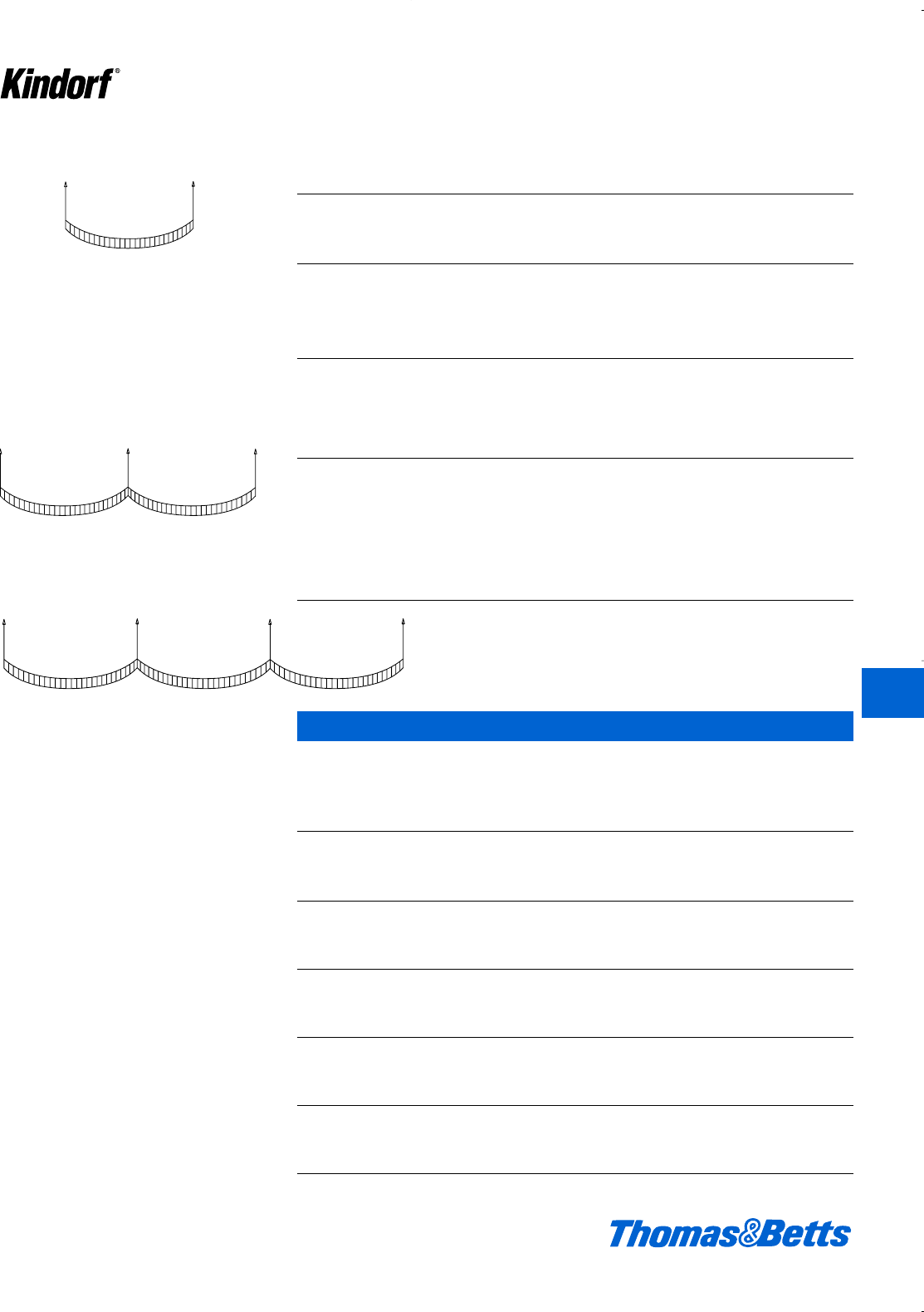
© 2003 Thomas & Betts Corporation. Specifications are subject to change without notice. www.tnb.com K137
K
Kindorf ®
Selection of Hanger Rods
Use H-193-3/8 Use H-193-1/2
or ‘R’ series or ‘R’ series
hanger rod if the total hanger rod if the total uniform
for uniform load is: for load is between
2 supports 1220 lbs. or less 2 supports 1220 lbs. and 2260 lbs.
3 supports 975 lbs. or less 3 supports 975 lbs. and 1810 lbs.
4 supports 1665 lbs. or less 4 supports 1665 lbs. and 3080 lbs.
Load distribution on hanger rods – 2 Supports
Example – If the total uniformly distributed load W is 1,000 lbs., each hanger must
be capable of supporting half of the load or 500 lbs. Therefore, H-193-3/8 or c‘R’
series hanger rod would be sufficient to support this load.
3 Supports
Example – If the total uniformly distributed load W is 1,000 lbs., the load is distrib-
uted to each support in the following manner: 187dlbs. to each end support and
625 lbs. to the center support. In this case, the maximum load to be supported is
625 lbs., which exceeds the recommended safe load of 610 lbs. for H-193-3/8
hanger rod., therefore H-193-1/2, or d‘R’ series supports should be used.
Metallic Engineering Data and Specifications
Total Uniform Load W lbs.
Maximum Safe Load - H-193-3/8 or ‘R’ Series - 610 lbs.
per hanger rod H-193-1/2 or ‘R’ Series - 1130 lbs.
5
8
Total uniform loads - W lbs.
W
Total uniform load - W lbs.
W⁄2W⁄2
Total uniform load - W lbs.
3⁄16 W5⁄8W
Total Uniform
3⁄16 W
Load W lbs.
4 Supports
Example – If the total uniformly distributed load W is 1,000
lbs., the load is distributed to each support in the following
manner: 133 lbs. to each end support and 367 lbs. to each
inner support. Therefore, H-193-3/8, or c‘R’ series hanger
rod would be sufficient to support this load.
Kindorf Channel Bars – Load Deflection Charts
Concentrated Center Loads
Load at Deflection Load at Max.
Beam 25,000 at 25,000 Deflection of
Cat. Span psi Stress psi Stress 1⁄240 Span
No. (in.) (lbs.) (in.) (lbs.)
6013 55 .038 55
6014 12 34 .048 34
6029 180 .023 180
6029-H 175 .024 175
6013 27 .153 18
6014 24 17 .192 9
6029 89 .093 89
6029-H 87 .095 87
6013 18 .345 8
6014 36 11 .433 4
6029 59 .208 42
6029-H 57 .213 40
6013 13 .615 4
6014 48 8 .773 2
6029 43 .367 23
6029-H 42 .375 22
6013 11 .963 2
6014 60 6 1.216 1
6029 34 .550 14
6029-H 33 .581 13
Loads for lengths greater than 60" spans are available on request.
11
30
Total loads - W lbs.
WW
uniform
11
30
2
15
W
Total Uniform
2⁄15 W11⁄30 W2⁄15 W
11⁄30 W
Loads W lbs.
412034.K01 KINDORF 5/1 5/7/03 3:17 PM Page K137

K138 © 2003 Thomas & Betts Corporation. Specifications are subject to change without notice. www.tnb.com
K
Kindorf ®
Metallic Engineering Data and Specifications
Kindorf Channel Bars – Load Deflection Charts – continued
Uniformly Distributed Loads
Load at Deflection Load at Max.
Beam 25,000 at 25,000 Deflection of
Cat. Span psi Stress psi Stress 1⁄240 Span
No. (in.) (lbs.) (lbs.) (lbs.)
6013 110 .049 110
6014 12 68 .060 57
6029 361 .029 361
6029-H 350 .030 350
6013 55 .194 28
6014 24 34 .238 14
6029 180 .117 154
6029-H 174 .119 146
6013 36 .437 12
6014 36 22 .536 6
6029 119 .263 67
6029-H 115 .268 64
6013 27 .776 6
6014 48 16 .953 3
6029 88 .467 37
6029-H 86 .477 35
6013 21 1.213 4
6014 60 13 1.490 1
6029 70 .729 22
6029-H 68 .746 21
Loads are rounded off to the nearest pound in all cases.
RJBT March 21, 1980
Surface Metal Raceways
Kindorf Channel Systems E55273 (N)
(K-cont. from J card)
For use with not more than the number of wires of sizes and types indicated in
the following tables when used solely as a surface metal raceway or when also
used for the support of light fixtures and the fixtures over 1⁄2in. from raceway.
Raceway Raceway Raceway Raceway
Cat. No. Cat. No. Cat. No. Cat. No.
B-900, B-900M, B-901, G965 B-906 B-902
Wire Size AWG G-975, G-975M G-955
Type insulation AVB, RH, RHH, RHW
14 21 25 10 44
12 17 20 8 35
10 14 16 7 29
89 10 418
65 6 210
Type Insulation FEP, FEPB, THHN, THWN
14 79 94 39 165
12 58 69 29 121
Replaces E55273K dated Feb. 17, 1978. (Cont. on L card)
466409002 Underwriters Laboratories Inc.®F110059784
412034.K01 KINDORF 5/1 5/7/03 3:17 PM Page K138

© 2003 Thomas & Betts Corporation. Specifications are subject to change without notice. www.tnb.com K139
K
Kindorf ®
Metallic Engineering Data and Specifications
RJBT March 21, 1980
Surface Metal Raceways
Kindorf Channel Systems E55273 (N)
(L-cont. from K card)
Raceway Raceway Raceway Raceway
Cat. No. Cat. No. Cat. No. Cat. No.
B-900, B-900M, B-901, G965 B-906 B-902
Wire Size AWG G-975, G-975M G-955
10 37 44 18 77
821 251044
6910418
Type Insulation RUH, RUW, T, TW, XHHW
14 51 61 25 107
12 40 48 20 84
10 30 36 15 63
816 19 833
68 9416
Type insulation THW
14 33 39 16 69
12 27 32 13 56
10 22 26 11 46
813 15 627
68 9416
Replaces E55273L dated Feb. 21, 1978. (Cont. on M card)
466409002 Underwriters Laboratories Inc.®F110059785
RJBT January 31, 1984
Surface Metal Raceways
Kindorf Channel Systems E55273 (N)
(M-cont. from L card)
Note A is suitable for number of wires in table below when installed to support and
supply electric discharge lighting fixtures mounted flush to the underside of the
raceway and when raceway wiring is suitable for at least 75 C, except wire suitable
for 60 C may be used when clearance between fixtures and raceway is at least 1⁄2
in. In all cases, closure strip G-969 or G-969-AL is required to complete raceway
enclosure
Raceway Raceway Raceway
Cat. No. Cat. No. Cat. No.
B-900, B-900M, B-906 B-902,
B-901, G-965, G-955
Wire Size AWG G-975, G-975M
Type Insulation. AVB, FEP, FEPB, RH, RHH, RHW, RUH, RUW, T, THHN, THW, THWN, TW,
XHHW
14 10 4 10
12 10 3 10
10 5 – 8
84 – 6
64 – 4
Look For Listing Mark on Product
(Cont. on N card)
466409002 Underwriters Laboratories Inc.®F110059786
412034.K01 KINDORF 5/1 5/7/03 3:17 PM Page K139
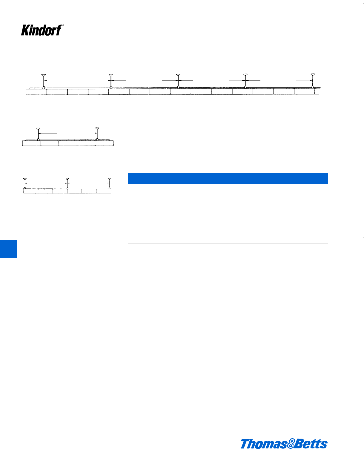
K140 © 2003 Thomas & Betts Corporation. Specifications are subject to change without notice. www.tnb.com
K
Kindorf ®
To Select Proper Channel
The hanger spacing is often determined by the type of building construction. The
deflection then will determine the proper channel since this deflection should not
exceed 1/240 of the span.
To estimate the deflection at the center of an intermediate span in long continu-
ous runs (Fig. 1), multiply the weight of a single fixture times the applicable deflec-
tion constant (from table). This deflection also applies to the end span in Figure 1
and the single span in Figure 2 if the dimension “C” is between 1⁄4and 1⁄3of the
length of the span. If a cantilever does not exist as in the double span (Figure 3),
the deflection of end spans (Figure 3) will be doubled.
Deflection Constants for Continuous Run, 4-Foot Fixtures*
Span B-906 B-900-M B-900 B-901 B-902
feet G-956 G-975-M G-953 G-975 G-950, G-965 B-900-2A G-955
6 .004 .000 .000 .000 .000 .000 .000
8 .009 .002 .001 .000 .000 .000 .000
10 .005 .004 .003 .001 .000 .000
12 .010 .007 .006 .004 .001 .001
14 .012 .007 .002 .002
16 .020 .011 .004 .004
18 .018 .007 .006
20 .010 .009
* For 8-foot fixtures reduce the deflection constant by 50%. This table is for normal weight fix-
tures – the constant “.000” infers negligible deflection.
A long, continuous run of 30# 4-foot fixtures on G-975 channel is supported on 12' centers.
The deflection at the center of an intermediate span will be the deflection constant (.006)
times the fixture weight (30#) or 0.18 inches.
Figure 1 – long continuous run
Metallic Engineering Data and Specifications
Figure 2 – single span
Figure 3
double span
intermediate span intermediate span intermediate spanend span
single span
end span end span
end span end span
412034.K01 KINDORF 5/1 5/7/03 3:17 PM Page K140

© 2003 Thomas & Betts Corporation. Specifications are subject to change without notice. www.tnb.com K141
K
Kindorf ®
Metallic Engineering Data and Specifications
Suggested Kindorf Specifications
I. For purposes of designating type and
quality for work in this section, drawings
and specifications are based upon prod-
ucts of standard Kindorf product draw-
ings. Whenever substitute products are
to be considered, supporting technical
literature, samples, drawings, and certi-
fied performance data must be submit-
ted in order to make a valid comparison
of products involved.
II. Materials
Steel channel sections shall be rolled
from AISI 1008 commercial grade steel
and be in conformance with ASTM
A569-72.
Aluminum channel sections shall be
extruded from 6063-T6 aluminum alloy
and be in conformance with ASTM-
B221-80.
III. Construction
A. Channel and Accessories for Support
Systems.
The cross sectional width dimension of
the channel shall be a minimum of 1d".
The depth will be as required to satisfy
the load requirements. Channel with 1d"
depth or greater shall be rolled from
Manufacturing Std. 12 gauge steel.
Channel smaller than 1d" may be
Manufacturing Std. 14 gauge.
Attachment holes, when required, shall
be factory punched on hole centers
equal to the channel cross sectional
width dimension and shall be a maxi-
mum of l" in diameter.
Channel attachment nuts shall be
designed to prelocate in the channel
and provide a bearing surface on the
turned down lips while making positive
contact with the side walls of the chan-
nel.
Straps for the support of conduit shall
be designed such that the attachment
nut is captivated on the shoulder of the
strap when tightened, and the attach-
ment bolt will allow tightening by either
a slot-head screwdriver or wrench.
All nuts, bolts, straps, threaded rod and
edges of punched holes shall be pro-
tected with the same finish as the chan-
nel as described in the FINISH section
of this specification.
B. Channel and Accessories for Surface
Raceway Systems.
Fluorescent fixtures, as designated on
the drawings and according to the fix-
ture schedule, shall be supported and
supplied through a combination race-
way and support system.
The cross sectional width dimension of
the channel shall be a minimum of 1d".
The depth will be as required to satisfy
the load and wire carrying require-
ments.
The supporting channel shall have d"
diameter knockouts on 6" centers to
accommodate d" conduit fittings, and
be listed by Underwriters’ Laboratories
Inc. as complying with Std. UL-5 for use
as surface raceway and support for
electric discharge type lighting fixture.
The channel must also provide for
ground continuity.
The combination raceway and support
system shall be complete with channel
joiners, end caps, closure strips, hang-
ers, wiring entrance and all necessary
fittings for electrical and mechanical
connections.
When splicing or joining raceway chan-
nel at 90 degree angles, the joiners
shall be designed such that they are
concealed and fastened to the inside
surface of the channel. Joiners shall be
listed by Underwriters’ Laboratories Inc.
and allow wires to be directly laid in
place.
All channel and fittings, including
threaded components, shall be protect-
ed against corrosion as outlined in the
finish section of this specification.
Installation of the system shall be in
accordance with the National Electrical
Code, NFPA 70 and ANSI C1.
IV. Galv-Kr¯om Zinc Dichromate Finish
The finish on steel components shall
consist of a combination of .0005 inch
electrogalvanizing on steel in accor-
dance with ASTM B633-78 Type LS
coating and a gold zinc dichromate
barrier formed on the zinc. This coating
shall be applied after factory fabrication
of the material.
When tested in accordance with ASTM
B117-73 procedure, there shall be no
sign of red rust after 1,000 hours of test-
ing. Certified test results to support this
must be submitted upon request.
412034.K01 KINDORF 5/1 5/7/03 3:17 PM Page K141
K142 © 2003 Thomas & Betts Corporation. Specifications are subject to change without notice. www.tnb.com
Nonmetallic Channels and Accessories
Kindorf strut is a complete corrosion-
proof system, with a comprehensive
selection of channels and accessories.
Cost-efficient, extremely durable, easy
to use, and made of the strongest non-
metallic materials available.
Kindorf: Demanding products for demand-
ing environments.
• Can’t rust under the worst of conditions
• Cost-effective
• Maintenance-free
• Easy to use, cut and drill
• Ideal for a wide variety of applications
• Unsurpassed reliability
Channels
Lbs.
Cat. No. Description Material Color Wt./100 ft.
NB-900-10-P 1d” x 1d” x 10’ Single Channel Polyester Gray 55
NB-900-10-V 1d” x 1d” x 10’ Single Channel Vinylester Beige 55
NB-900-2A-10-P 3” x 1d” x 10’ Back to Back Channel Polyester Gray 110
NB-900-2A-10-V 3” x 1d” x 10’ Back to Back Channel Vinylester Beige 110
Channel Closure Strip
Lbs.
Cat. No. Description Material Color Wt./100 ft.
NG-969-5 Standard length 5’ Rigid PVC Dark Gray 20
NB-900
NB-900-2A
NG-969-5
K
Kindorf ®
412034.K01 KINDORF 5/1 5/7/03 3:17 PM Page K142
© 2003 Thomas & Betts Corporation. Specifications are subject to change without notice. www.tnb.com K143
Nonmetallic Channels and Accessories
Channel Simple Beam Loading Table
Max Uniform Max Column
Beam Load 1⁄360 Span Load
Cat. No. lbs. Def (in.) lbs. Def (in.) lbs.
12 inches
NB-900-10-P 1430 0.066 723 0.033 3439
NB-900-10-V 1430 0.066 723 0.033 3439
NB-900-2A-10-P 4231 0.036 3940 0.033 7007
NB-900-2A-10-V 4231 0.036 3940 0.033 7007
18 inches
NB-900-10-P 953 0.148 321 0.050 3136
NB-900-10-V 953 0.148 321 0.050 3136
NB-900-2A-10-P 2821 0.081 1751 0.050 6501
NB-900-2A-10-V 2821 0.081 1751 0.050 6501
24 inches
NB-900-10-P 715 0.264 180 0.067 2778
NB-900-10-V 715 0.264 180 0.067 2778
NB-900-2A-10-P 2115 0.143 985 0.067 5909
NB-900-2A-10-V 2115 0.143 985 0.067 5909
30 inches
NB-900-10-P 572 0.412 115 0.083 2369
NB-900-10-V 572 0.412 115 0.083 2369
NB-900-2A-10-P 1692 0.224 630 0.083 5236
NB-900-2A-10-V 1692 0.224 630 0.083 5236
36 inches
NB-900-10-P 476 0.593 80 0.100 1906
NB-900-10-V 476 0.593 80 0.100 1906
NB-900-2A-10-P 1410 0.322 437 0.100 4482
NB-900-2A-10-V 1410 0.322 437 0.100 4482
48 inches
NB-900-10-P 357 1.055 45 0.133 1091
NB-900-10-V 357 1.055 45 0.133 1091
NB-900-2A-10-P 1057 0.573 246 0.133 2809
NB-900-2A-10-V 1057 0.573 246 0.133 2809
60 inches
NB-900-10-P 286 1.648 28 0.167 698
NB-900-10-V 286 1.648 28 0.167 698
NB-900-2A-10-P 846 0.895 157 0.167 1798
NB-900-2A-10-V 846 0.895 157 0.167 1798
72 inches
NB-900-10-P 238 2.373 20 0.200 485
NB-900-10-V 238 2.373 20 0.200 485
NB-900-2A-10-P 705 1.289 109 0.200 1248
NB-900-2A-10-V 705 1.289 109 0.200 1248
Deflection in excess of 3.00 inches; midspan support is recommended.
Table lists the total allowable load for various simple spans based on a minimum safety factor of 3:1.
All beams should be supported in a manner to prevent rotation at supports.
For beams longer than 72 inches, contact manufacturer’s engineering department.
Recommend sealing ends of channel with sealant after cutting (see page K148).
NB-900
NB-900-2A
K
Kindorf ®
412034.K01 KINDORF 5/1 5/7/03 3:17 PM Page K143
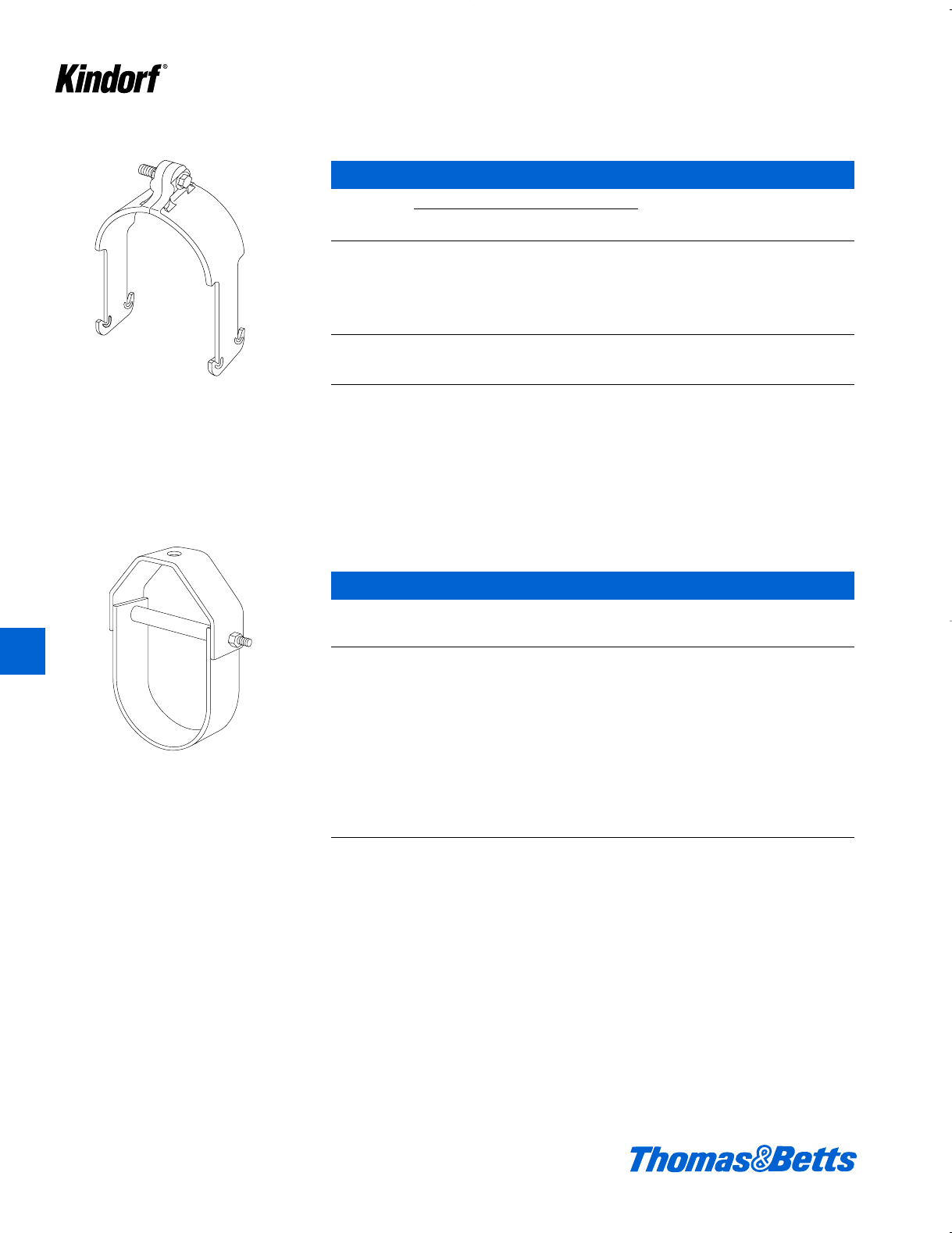
Nonmetallic Channels and Accessories
Pipe Clamps
Conduit/Pipe Style Recommended
Nominal PVC PVC Coated Torque Design Wt.
Cat. No. in. Sch. 80 Rigid Metal (Typ.) in lbs. Load* lbs./100
NC-105-1/2 d.840 .840 .920 5 100 4
NC-105-3/4 f1.050 1.050 1.130 5 100 4
NC-105-1 1 1.315 1.315 1.395 5 200 4.8
NC-105-1 1/4 – – – – – – –
NC-105-1 1/2 1d1.900 1.900 1.980 5 200 6.4
NC-105-2 2 2.375 2.375 2.455 5 200 8
NC-105-3 3 3.500 3.500 3.580 20 300 10
NC-105-4 4 4.500 4.500 4.580 20 300 10
NC-105-6 6 6.625 6.625 6.705 20 300 16.3
* Design load is based on pullout values with a 3:1 factor of safety.
Material: Polyurethane
Color: Gray
Clevis Hangers
(A) (B) (C)
Nominal Max Dimension Hanger Maximum Wt.
Cat. No. Diameter Pipe OD Height Rod Size Load lbs./100
NC-149-1 11d2fd 60 20.8
NC-149-1 1/2 1d 2 3d d 60 24
NC-149-2 22e4fd 90 38
NC-149-2 1/2 2d 3b 5d d 120 40
NC-149-3 33g7 e160 62.5
NC-149-4 45a8de250 88
NC-149-6 6 7a 10g e 400 170
NC-149-8 89b14 e450 250
NC-149-10 10 11c 18 e 500 400
NC-149-12 12 13d 21d e 600 550
NC-149-14 14 15f 24d f 700 700
NC-149-16 16 18 27c f 800 1150
NC-149-19 19 21 34b f 900 1700
Design loads given are in pounds at 70°F with a 3:1 factor of safety.
Insulate hangers from pipe at higher temperatures
Material: Polyester
Color: Yellow and Gray
K144 © 2003 Thomas & Betts Corporation. Specifications are subject to change without notice. www.tnb.com
K
Kindorf ®
412034.K01 KINDORF 5/1 5/7/03 3:17 PM Page K144
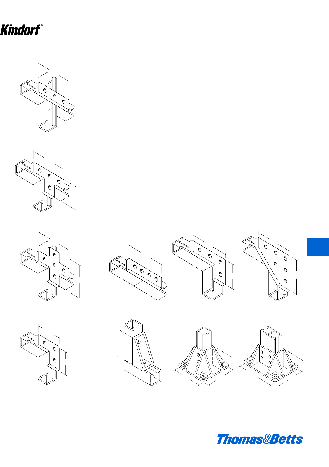
© 2003 Thomas & Betts Corporation. Specifications are subject to change without notice. www.tnb.com K145
K
Kindorf ®
Nonmetallic Channels and Accessories
4 7/8"
Fittings
NB-935-P
NB-935-V
NB-937-P
NB-937-V
NB-947
NB-925NB-924
NB-931 NB-918
NB-944NB-949-P
NB-949-V
NB-936-P
NB-936-V
4 7/8"
3 1/4"
4 7/8"
4 7/8"
3 1/4"
3 1/4"
4 7/8"
4 7/8"
6 1/2"
4 7/8"
3 1/4"
6 5/8"
5"
3"
5"
5"
3"
4"
4g"
4g"
3b"
6d"
4g"
5"
6e"
3b"
4g"
3b" 4"
3b" 4g"
3"
5"
3"
5"
4 7/8"
4g"
Wt
Cat. No. Material Color lbs./100
NB-935-P Polyester Gray 13
NB-935-V Vinylester Beige 13
NB-931 Polyurethane Gray 14
NB-947 Polyurethane Gray 24
NB-949-P Polyester Gray 22
NB-949-V Vinylester Beige 22
NB-936-P Polyester Gray 28
NB-936-V Vinylester Beige 28
NB-937-P Polyester Gray 20
NB-937-V Vinylester Beige 20
NB-924 Polyurethane Gray 56
NB-944 Polyurethane Gray 34
NB-925 Polyurethane Gray 70
NB-918 Polyurethane Gray 4.6
• Polyester and Vinylester Kindorf fit-
tings are suited for use with all 1d"
and 1e" channels.
• Kindorf fittings are manufactured
from i" flat material.
• Consult the Chemical Compatibility
Chart to ensure material will with-
stand the specific chemical environ-
ment.
• All holes in Kindorf fittings are u" in
diameter.
412034.K01 KINDORF 5/1 5/7/03 3:17 PM Page K145
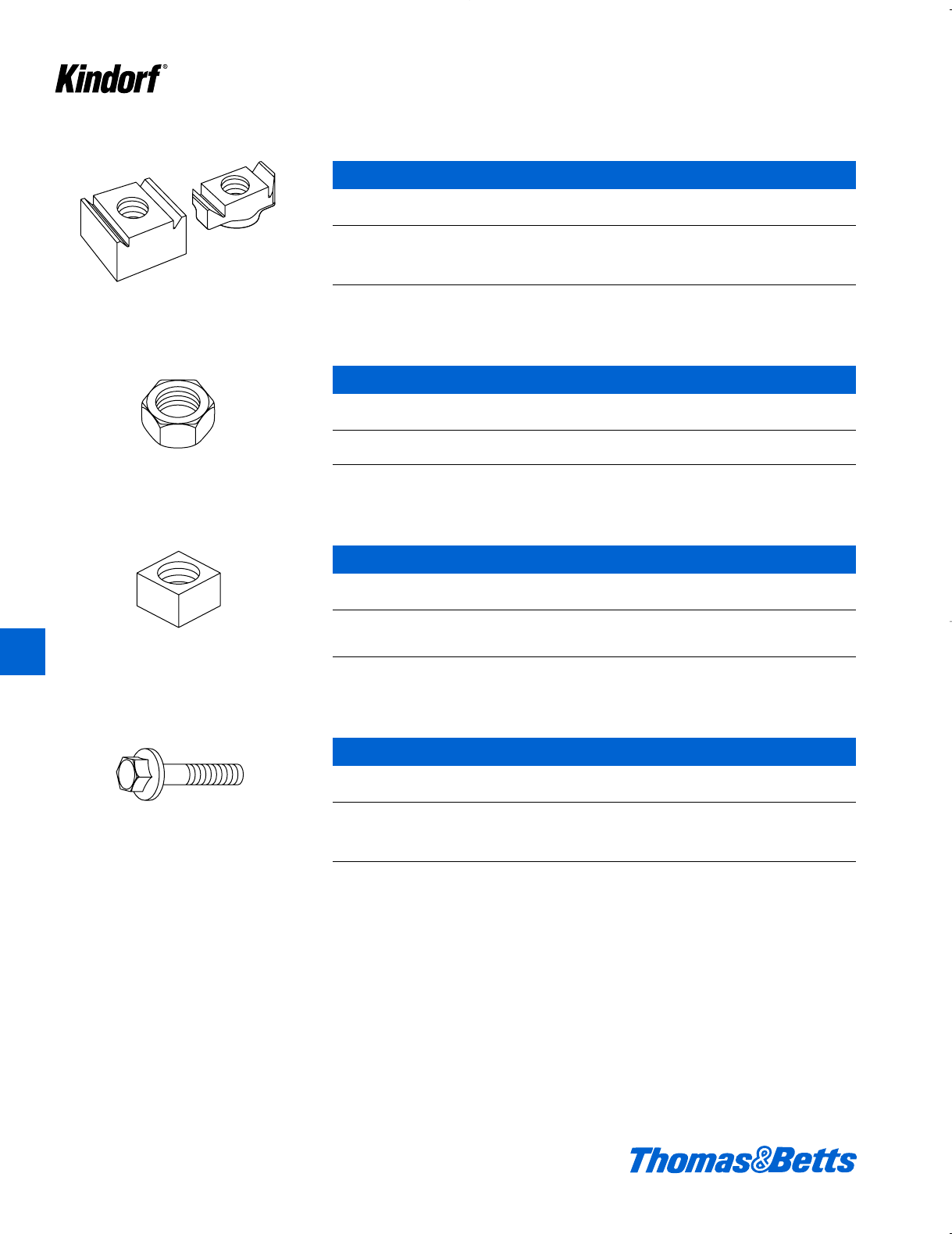
Nonmetallic Channels and Accessories
K146 © 2003 Thomas & Betts Corporation. Specifications are subject to change without notice. www.tnb.com
K
Kindorf ®
Channel Nuts
Maximum Maximum Wt.
Cat. No. Thread Size Load/lbs. Torque/lbs. lbs./100
NB-910-3/8 c"450 35 1.8
NB-910-3/8 HD c"1,370 100 2.6
NB-910-1/2 d"450 40 1.8
NB-910-1/2 HD d"1,500 130 5.2
3:1 Factor of Safety
Material: Glass Fiber Reinforced Polyurethane
Color: Gray
Hex Nuts
Maximum Maximum Wt.
Cat. No. Size Load/lbs. Torque/lbs. lbs./100
NH-114-C c"465 50 .33
NH-114-D d"830 125 .8
3:1 Factor of Safety
Material: Glass Fiber Reinforced Polyurethane
Color: Gray
Square Nuts
Thread Max. Wt.
Cat. No. Size Shear/lbs. Torque/lbs. lbs./100
NH-116-C c"1,300 125 1.8
NH-116-D d"1,600 200 2.8
NH-116-E e"1,600 200 5.6
3:1 Factor of Safety
Material: Vinylester
Color: Gray
Hex Head Bolts
Maximum Maximum Wt.
Cat. No. Size Load/lbs. Torque/lbs. lbs./100
NH-113-P c"x 1b"360 30 1.4
NH-113-U c"x 2d"360 30 2
NH-113-C* d"x 1b"600 90 1.4
NH-113-H* d"x 2d"600 90 2
3:1 Factor of Safety
Material: Glass Fiber Reinforced Polyurethane
Color: Gray
* With molded washer
412034.K01 KINDORF 5/1 5/7/03 3:17 PM Page K146
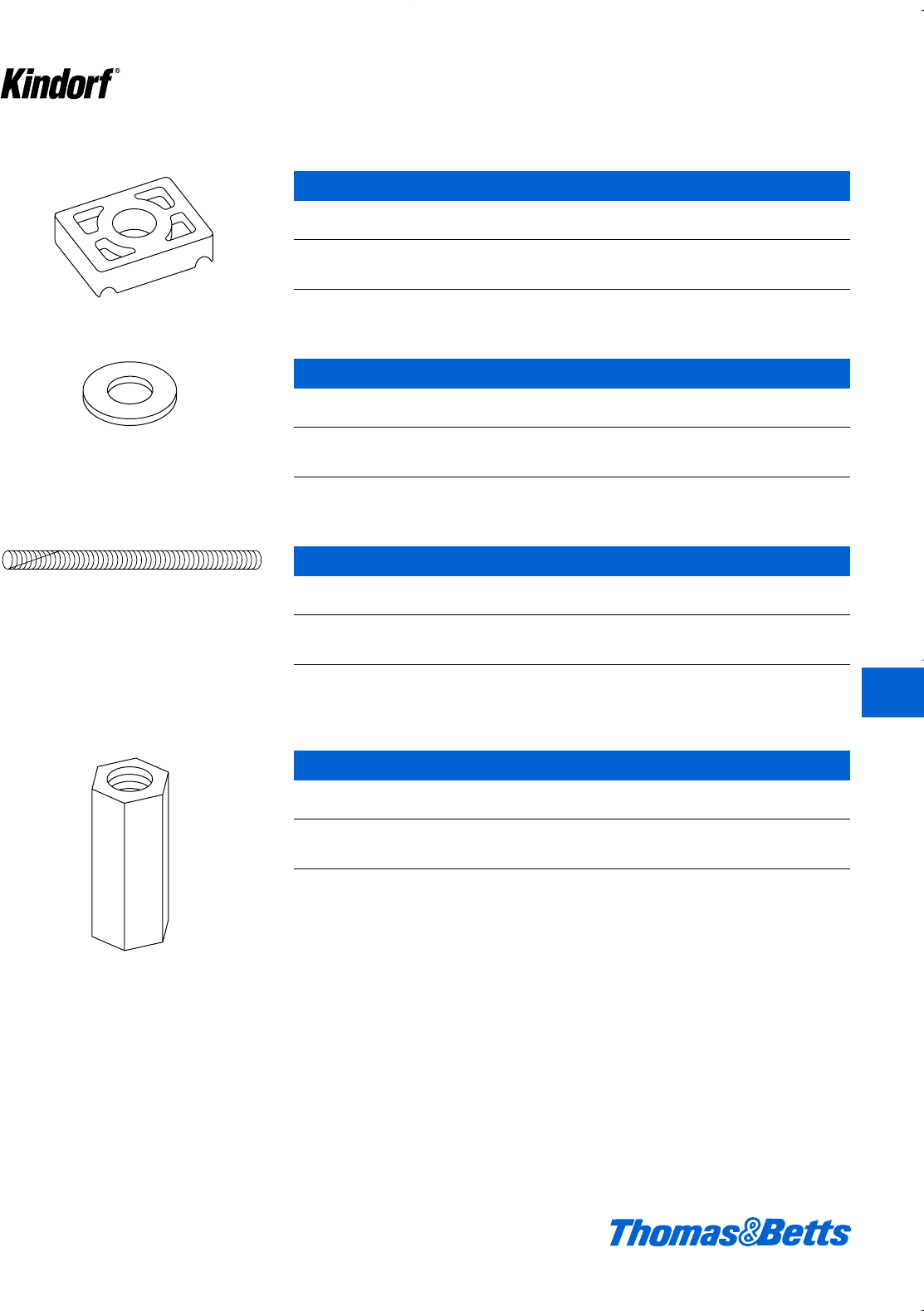
© 2003 Thomas & Betts Corporation. Specifications are subject to change without notice. www.tnb.com K147
K
Kindorf ®
Nonmetallic Channels and Accessories
Channel Washers
Wt.
Cat. No. Hole Size lbs./100
NH-119-C c"4
NH-119-D d"3.6
NH-119-E e"3.6
Material: Glass Fiber Reinforced Polyurethane
Color: Gray
Flat Washers
Wt.
Cat. No. Size lbs./100
NH-117-C c".6
NH-117-D d".6
NH-117-E e".8
Material: Rigid PVC
Color: Gray
Threaded Rod
Thread Maximum Wt.
Cat. No. Size Shear/lbs. Torque/lbs. lbs./100
NH-193-3/8-4 c"x 4'300 30 7.0
NH-193-1/2-4 d"x 4'510 80 12
NH-193-5/8-4 e"x 4'1,600 200 18
3:1 Factor of Safety
Material: Vinylester
Color: Gray
Rod Couplers
Maximum Wt.
Cat. No. Size Load/lbs. lbs./100
NH-195-3/8 c"880 6.4
NH-195-1/2 d"1,000 6.4
NH-195-5/8 e"1,700 13.2
3:1 Factor of Safety
Material: Glass Fiber Reinforced Polyurethane
Color: Gray
412034.K01 KINDORF 5/1 5/7/03 3:17 PM Page K147
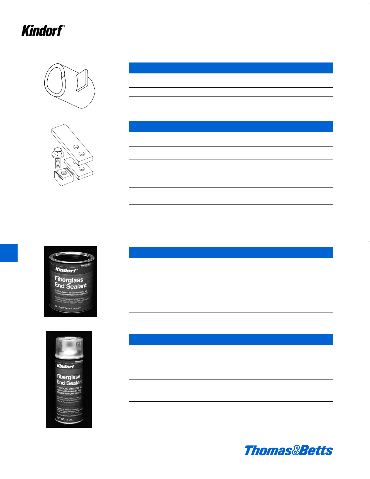
Nonmetallic Channels and Accessories
K148 © 2003 Thomas & Betts Corporation. Specifications are subject to change without notice. www.tnb.com
K
Kindorf ®
Channel Reinforcement Spacer
Wt.
Cat. No. Hole Size lbs./100
NB-950 c" – d" 1.6
Material: Polyurethane
Color: Gray
Channel to Beam Clamp Assembly
Maximum
Cat. No. Weight Load/lbs.
NE-763-3/8 110 200
NE-763-1/2 120 200
Kit Consists Of:
Description Qty. Material Color
Channel Nuts 4 Polyurethane Gray
Clips(set) 2 Vinylester Beige
Bolts 4 Polyurethane Gray
Kindorf Brush-On Fiberglass End Sealant
When fabricating Type “P” or “V” Series materials, Kindorf Fiberglass End Sealant
should be used. After cutting or drilling the channel, interior glass fibers may fray
and lose strength due to exposure to the environment. Kindorf sealant protects the
exposed glass fibers and prevents deterioration. Kindorf sealant exceeds
Vinylester (V) material in corrosion resistance.
Wt.
Cat. No. Description Size lbs./100
NH-600 Brush-On Sealant 1 qt. 220
Kindorf Spray-On Fiberglass End Sealant
Kindorf Spray-On Fiberglass End Sealant provides a quick and easy corrosion-
resistant coating when applied to fiberglass channel and accessories. Kindorf
Spray-On Fiberglass End Sealant is a rubberized spray which is supplied in a 12
oz. pressurized can.
Wt.
Cat. No. Description Size lbs./100
NH-601 Spray-On Sealant 12 oz. 100
412034.K01 KINDORF 5/1 5/7/03 3:17 PM Page K148

© 2003 Thomas & Betts Corporation. Specifications are subject to change without notice. www.tnb.com K149
K
Kindorf ®
Nonmetallic Channels and Accessories
Chemical Resistance
Polyester Vinylester Rigid PVC Polyurethane
Chemical 70°F 160°F 70°F 160°F 70°F 160°F 70°F 160°F
Acetic Acid, <50% • • • • † † • –
Acetone, <10% † † † † – – – –
Aluminum Hydroxide • • • • – – – –
Ammonium Hydroxide, <20% † † • 150° • • • –
Ammonium Nitrate • • • • – – – –
Ammonium Phosphate • • • • – – – –
Benzene • • † † – – – –
Benzoic Acid • • • • • • • –
Bromine, Wet Gas † † • 100° • † – –
Butylene Glycol • • • • – – – –
Butyric Acid, <50% • • • • – – – –
Chlorine, Dry Gas • • • • – – – –
Chlorine, Wet Gas † † • • – – – –
Chlorine, Liquid † † † † – – – –
Chlorine, Water • • • • • • • –
Chromic Acid, <5% † † • • – – – –
Copper Chloride • • • • • • • –
Copper Cyanide • • • • • • • –
Copper Nitrate • • • • – – – –
Copper Sulfate • • • • • • • –
Esters, Fatty Acids • • • • – – – –
Ferric Chloride • • • • • • – –
Ferrous Chloride • • • • – – – –
Fluoboric Acid • 120° • • • • • –
Fluosilicic Acid, <32% † † • 100° – – – –
Formic Acid, <50% † † • 100° † † • –
Gasoline, Aviation • † • • – – – –
Hydrochloric Acid, <37% • † • • • • • –
• Recommended for use
° Recommended up to temperature indicated
† Not recommended for use
– No information available at this time
Note: The guidelines presented in this table assume the typical application of Kindorf products where exposure is limited to fumes, vapors, and occasional splashes from chemicals.
This information is intended as a guideline and does not guarantee product performance for the applications listed. In special situations where chemical resistance is critical, the factory
should be consulted. Some applications may require a screening test of samples in the chemical environment of interest. The user is advised to determine suitability of the product for
its particular use.
Class I fire rated per ASTM E-84 and are UL-94 V-0.
Type operating ranges for;
Polyester -30°F – 150°F
Vinylester -35°F – 200°F
Polyurethane -40°F – 130°F
Nylon -20°F – 150°F
412034.K01 KINDORF 5/1 5/7/03 3:17 PM Page K149
Nonmetallic Channels and Accessories
Chemical Resistance – continued
Polyester Vinylester Rigid PVC Polyurethane
Chemical 70°F 160°F 70°F 160°F 70°F 160°F 70°F 160°F
Hydroflouric Acid, <20% † † • 100° • † – –
Hydrogen Chloride, Wet Gas • † • • – – – –
Hydrogen Sulfide, Wet Gas • † • • • • – –
Lactic Acid • † • • • • • –
Nickel Sulfate, low pH † † • • – – – –
Nickel Sulfate, high pH † † • • – – – –
Nitric Acid, <35% † † • 120° • • • –
Perchloric Acid, <10% † † • 150° – – – –
Phosphoric Acid • • • • • • • –
Potassium Chloride • • • • • • • –
Potassium Nitrate • • • • – – – –
Potassium Persulfate † † • • – – – –
Sodium Hydroxide, <50% † † • 180° • • • –
Sodium Hypochlorite, <15% † † • 150° • • • –
Sodium Nitrate • • • • – – – –
Sodium Sulfate • † • • – – – –
Sodium Sulfide † † • • • • • –
Sulfuric Acid, <70% † † • • • • • –
Sulfuric Acid >70% † † • 102° † † – –
Trisodium Phosphate † † • • • • • –
Urea • † • 150° – – – –
Vegetable Oils • • • • – – – –
Vinegar • • • • – – – –
White Liquor – – • • • • • –
• Recommended for use
° Recommended up to temperature indicated
† Not recommended for use
– No information available at this time
Note: The guidelines presented in this table assume the typical application of Kindorf products where exposure is limited to fumes, vapors, and occasional splashes from chemicals.
This information is intended as a guideline and does not guarantee product performance for the applications listed. In special situations where chemical resistance is critical, the factory
should be consulted. Some applications may require a screening test of samples in the chemical environment of interest. The user is advised to determine suitability of the product for
its particular use.
Class I fire rated per ASTM E-84 and are UL-94 V-0.
Type operating ranges for;
Polyester -30°F – 150°F
Vinylester -35°F – 200°F
Polyurethane -40°F – 130°F
Nylon -20°F – 150°F
K150 © 2003 Thomas & Betts Corporation. Specifications are subject to change without notice. www.tnb.com
K
Kindorf ®
412034.K01 KINDORF 5/1 5/7/03 3:17 PM Page K150
© 2003 Thomas & Betts Corporation. Specifications are subject to change without notice. www.tnb.com K151
Right Angle Slotted Angle
With Right Angle you get
Flexibility – Simplicity –
Economy
Create the support framing you need
Right Angle is manufactured from com-
mercial quality steel in three different
sizes. The small sizes are 14 ga. steel,
the larger size is 12 ga. steel. With this
offering, an endless variety of metal
framing requirements can be met, from
lightweight supporting needs to larger
shelving for inventory storage.
One of the legs on all sizes is 1e"
wide, while the other is either 1e", 2c"
or 3a" long. Depending on the frame
requirements, a single size can be uti-
lized throughout, or the sizes can be
interchanged to get the most efficient
usage from the material.
This book will serve as a guide to
plan and build your structure.
Installation time is reduced – inventory
space is minimal.
Scribe marks are placed every f"
which saves planning, layout and cut-
ting time and assures accuracy. The
exclusive slot and hole pattern, repeat-
ed every 3", is scientifically designed
for ease of assembly and rigidity. No
welding is necessary, no holes to drill.
Al" wrench is the only tool required
for assembly. The proper nuts and
bolts are included with the material to
ensure fast and easy erection.
Right Angle Metal Framing is pack-
aged in 10' and 12' lengths to minimize
cut offs and ensure maximum use of
material.
120 feet, 10, 12 foot lengths of Right
Angle takes up the same amount of
space as one 2 x 4. A standard pack-
age includes five pieces to a bundle,
therefore handling and storage space
are significantly reduced.
The importance of cutting Right
Angle easily, quickly and accurately is
the key to time saving assembly. The
Steel City Portable Cutter provides
these advantages and make layout
and erection of any structure a “light-
work” job.
Steel City Right Angle
comes standard with our
Galv-Kr¯om Finish, which
assures a long-lasting,
durable installation.
Galv-Kr¯om is a two-part finishing
process that protects the entire sys-
tem, including all nuts and bolts. The
first part of the finish is electrogalva-
nized zinc that covers the bare steel.
The second part is a gold zinc dichro-
mate that is applied over the zinc
base.
Three aspects of the Galv-Kr¯om
Process are worthy of note:
1. Zinc Coating – In the first part of
the Galv-Kr¯om process, a .5 mil coat-
ing of zinc is placed on the bare steel.
This assures the sacrificial quality of
any galvanizing and becomes a work-
ing finish. The zinc literally sacrifices
itself over bare steel and protects cut
edges or scratches which may occur
during construction.
Galv-Kr¯om is in compliance with
ASTM B633-78 Type II coating.
2. Electrogalvanizing – Because
the zinc is applied through a tempera-
ture-controlled electrolytic process, a
cohesive bond with the steel is
assured. This prohibits chipping or
peeling. It also distributes the zinc
evenly so all components – including
threads – can be equally protected.
3. Zinc Dichromate Barrier – The
second part of the Galv-Kr¯om finish is a
gold zinc dichromate that is applied
over the zinc base. This second layer
of plating forms a non-porous barrier
which protects the underlying zinc and
adds additional resistance to corro-
sion. In addition, the gold zinc dichro-
mate covering provides an excellent
base if the surface is to be painted.
K
Kindorf ®
412034.K01 KINDORF 5/1 5/7/03 3:17 PM Page K151
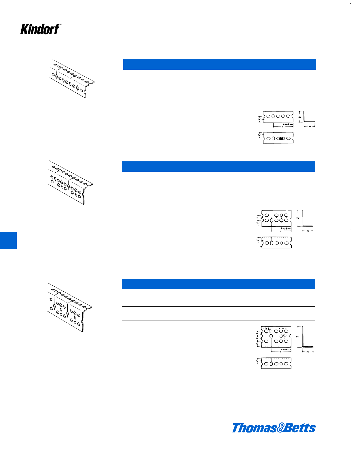
Right Angle Slotted Angle
Type RA-160
•1
5⁄8" x 15⁄8" x .080" (14 gauge)
• Designed for light duty applications where
extra strength is not a requirement
• Ideal material for light racking and shelving
• Packaged in five 10-ft. or 12-ft. lengths com-
plete with thirty-six 3⁄8" x 5⁄8" long hex head
bolts and nuts
• Standard package 10' lengths – 39 lbs., 12'
lengths – 48 lbs
Type RA-160 Slotted Angle Metal Framing
Ft. Wt.
Cat. per per 100
No. Length Pkg. Ft.
RA-160-10 10 ft. 50 75 lbs.
RA-160-12 12 ft. 60 75 lbs.
Type RA-225
•2
3⁄8" x 15⁄8" x .080" (14 gauge)
• Wide range versatility for nearly every type
of framing
• Well suited for electrical applications
• Slot-and-hole pattern provides ready-made
anchoring points for panel-board framing
and fixtures of all kinds
• Packaged in five 10-ft. or 12-ft. lengths com-
plete with thirty-six 3⁄8" x 5⁄8" long hex head
bolts and nuts
• Standard package 10' lengths – 48 lbs.,
12' lengths – 56 lbs
Type RA-300
•3
1⁄8" x 15⁄8" x .104" (12 gauge)
• Used where heavy loads are involved
• Racks and shelving for heavy material and
large structures such as ramps and balconies
are typical uses
• Packaged in five 10-ft. or 12-ft. lengths com-
plete with thirty-six 3⁄8" x 3⁄4" long hex head
bolts and nuts
• Standard package 10' lengths – 72 lbs.,
12' lengths – 84 lbs
K152 © 2003 Thomas & Betts Corporation. Specifications are subject to change without notice. www.tnb.com
K
Kindorf ®
Type RA-225 – For Heavy Duty
Ft. Wt.
Cat. per per 100
No. Length Pkg. Ft.
RA-225-10 10 ft. 50 93 lbs.
RA-225-12 12 ft. 60 93 lbs.
Type RA-300 – For Extra Heavy Duty
Ft. Wt.
Cat. per per 100
No. Length Pkg. Ft.
RA-300-10 10 ft. 50 135 lbs.
RA-300-12 12 ft. 60 135 lbs.
412034.K01 KINDORF 5/1 5/7/03 3:17 PM Page K152
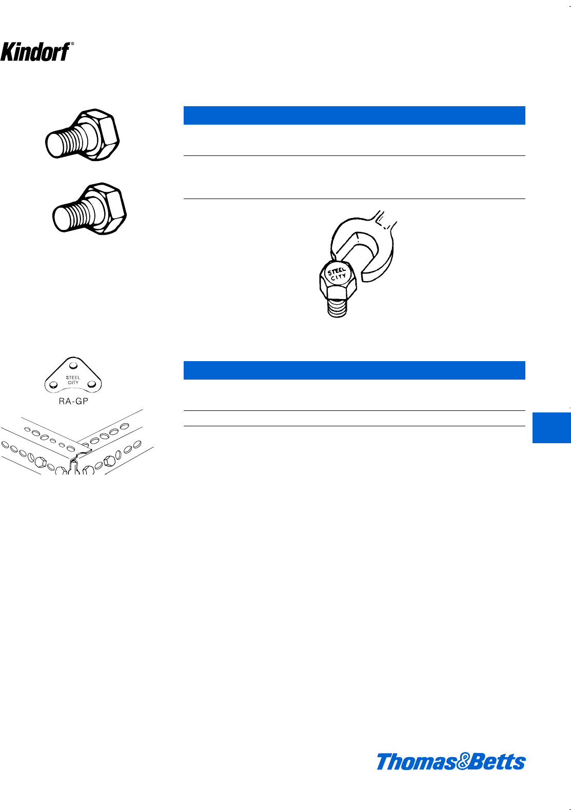
© 2003 Thomas & Betts Corporation. Specifications are subject to change without notice. www.tnb.com K153
K
Kindorf ®
Right Angle Slotted Angle
3⁄8"-16 x 5⁄8"
Nuts Serrated for Self-Locking
Weight
Cat. Standard per 100
No. Package Sets
RA-BN-5/8 100 4 lbs.
c"-16 x e"
RA-BN-3/4 100 5 lbs.
c"-16 x f"
A9/16" wrench is only tool needed for assembly.
Gusset Plate
Weight
Cat. Standard per 100
No. Package Sets
RA-GP 25 10
For proper assembly, insert plate between the angle flanges for 3-bolt connection.
• 100 sets per package
• No. RA-BN-5⁄8,3⁄8"-16 x 5⁄8" long for RA-160 and
RA-225
• No. RA-BN-3⁄4,3⁄8"-16 x 3⁄4" long for RA-300
• A 9⁄16" wrench is only tool needed for assembly
3⁄8"-16 x 3⁄4"
RA-GP
• Three hole connector for extra rigid angle
assembly
• For use with all three types of Right Angle
• Galvanized steel
412034.K01 KINDORF 5/1 5/7/03 3:17 PM Page K153
K154 © 2003 Thomas & Betts Corporation. Specifications are subject to change without notice. www.tnb.com
Right Angle Slotted Angle
Portable Cutter
Cat. Standard Weight
No. Package Each
RA-C 117
Rigid and Swivel Casters
Cat. Standard Weight
No. Package Each
RA-RC 22
RA-SC 23
RA-C
• Designed for use with all three types of
Slotted Angle.
• Cuts with single stroke of handle.
• Produces clean, burr free cuts.
RA-RC
Rigid Center
RA-SC
Swivel Caster
• Hard rubber composition.
• 31⁄2" diameter with load rating of 225 lbs. per
wheel.
• Plate has 13⁄32" diameter holes for mounting on
all three types of Slotted Angle.
K
Kindorf ®
412034.K01 KINDORF 5/1 5/7/03 3:17 PM Page K154
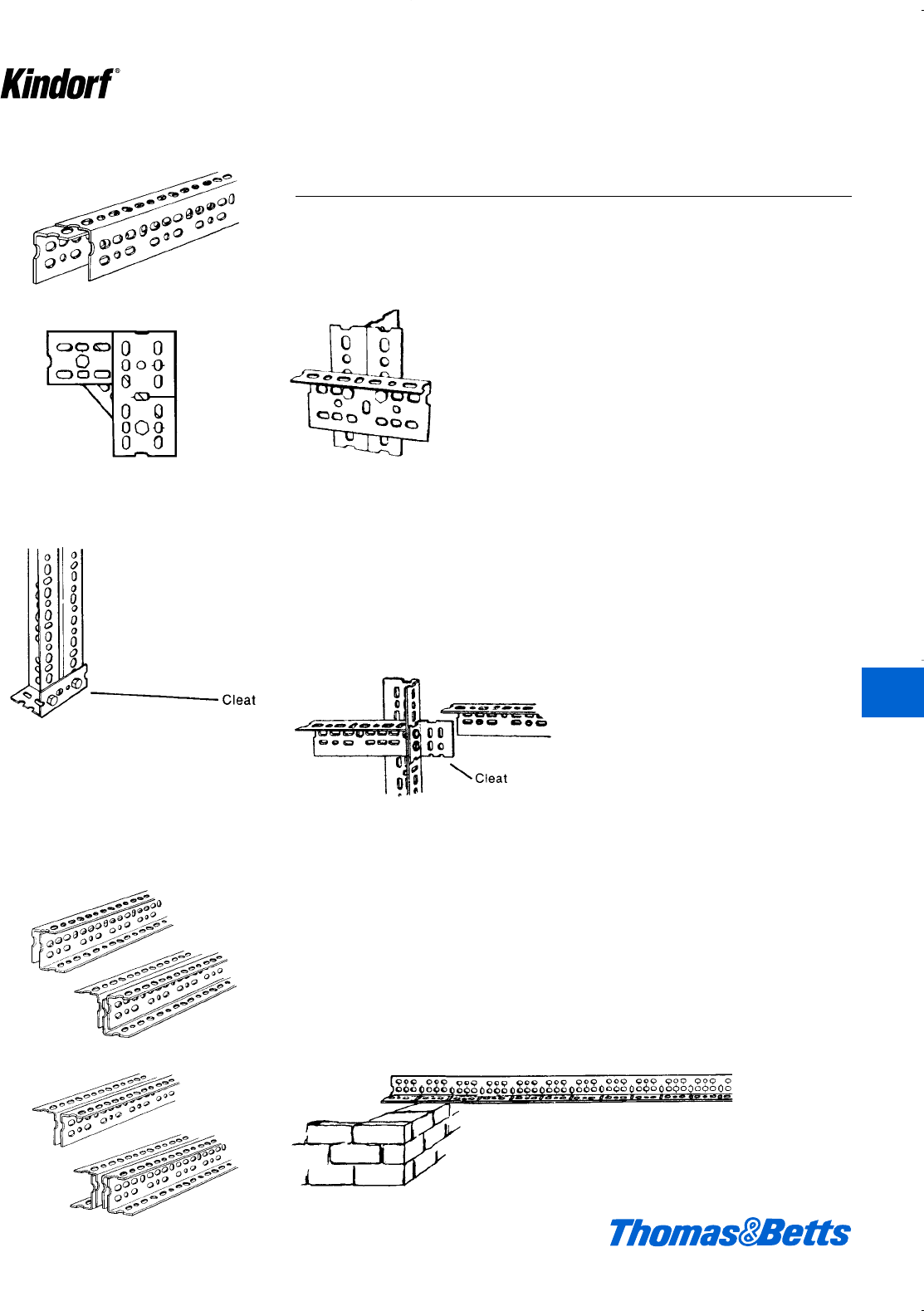
© 2003 Thomas & Betts Corporation. Specifications are subject to change without notice. www.tnb.com K155
Right Angle Slotted Angle
Nesting
Cleat
Cleat
Cross Beams
Triangulation
Helpful Hints to Maximize Right Angle Erection
Cleat Sections
Cut Off Cleats are small sections of
Right Angle used to reinforce joints or
used as feet to support vertical
columns. These feet prevent damage
to floor surfaces or can be used to bolt
a structure to the floor.
Additional joints can be made using
cut off cleats. Simply butt the cleat
against a column and behind a right
side beam, as shown in the illustration.
Slot and Hole Pattern
The Right Angle hole pattern is simple
and flexible. It is repeated every 3"
along the entire length of the Right
Angle. An extended line marks the 3"
increments, (vertical slots), while short-
er lines mark every f" increment. With
this hole pattern, nesting, triangulation,
cross beams and many additional
combinations are possible.
When a beam rests on a ledge of other
material (such as a wall) the long flange
should extend upward. Right Angle
beams are at their strongest when
assembled with long flange downward.
Vertical columns may be in either direc-
tion. Place short flange of vertical col-
umn in front for shelving to permit wider
opening for handling material.
Variety of Combinations to Meet
Needs
Greater strength is obtained by joining
sections of Right Angle in various com-
binations for beams and columns. See
the load chart on page K159 for the
combination that best suits your need.
K
Kindorf ®
412034.K01 KINDORF 5/1 5/7/03 3:17 PM Page K155
Right Angle Slotted Angle
K156 © 2003 Thomas & Betts Corporation. Specifications are subject to change without notice. www.tnb.com
K
Kindorf ®
Plan Flange Direction
Right Angle beams are at their
strongest position with the long flange
downward. Vertical uprights may be in
either direction for equal strength. Be
sure to measure the material to be
shelved to allow space for handling.
Your sketch will also be used as a cut-
ting and assembly plan.
Plan View
Erect vertical frames into bays.Bolt bays together.
Procedure for Laying Out Structure
12'-0"
12"
4'-10"
4'-6"
9'-4"
24" 15'-0"
3´
3´
3´
3´
3´
4´
Measure the Space
Right Angle structures may be built to
the size of the space available.
Measure the space and make a sketch
of the area.
Sketch the Planned Structure
Sketch the structure you plan to build
listing all vital dimensions. Include
length, width and height of all sections
so that load limits can be calculated
safely.
Assembling the Structure
Follow your plan for cutting sections
and for layout. Assemble the structure
as a series of frames, or bays and bolt
together as units. Use as many bolts
as possible and turn nuts up finger-
tight. Square-up and level the entire
structure. Proceed to tighten bolts with
wrench … starting with corners to
assure permanent squareness. Use
diagonal bracing, if necessary. Add
shelves. Your Right Angle structure is
ready for a useful lifetime.
412034.K01 KINDORF 5/1 5/7/03 3:17 PM Page K156
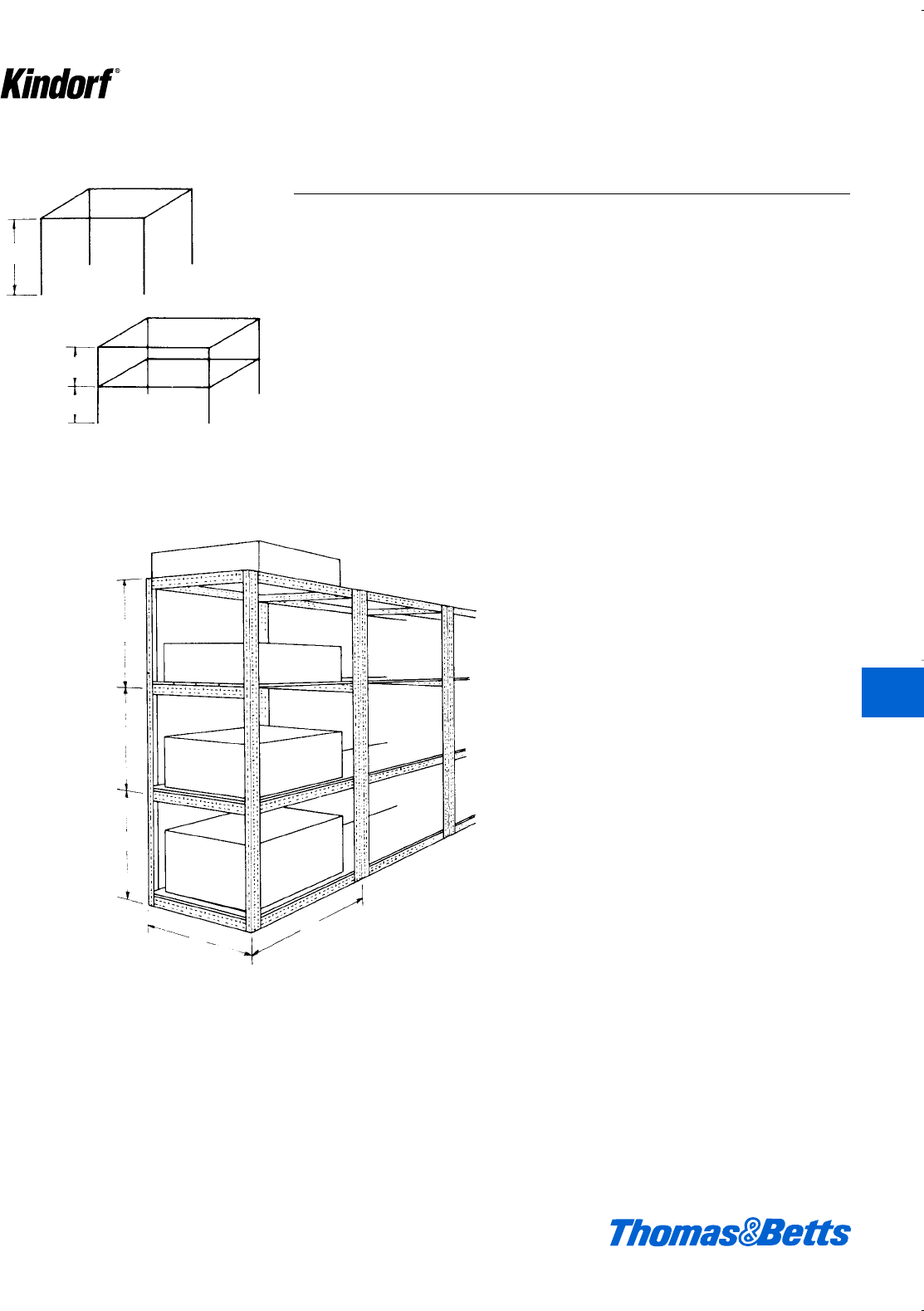
© 2003 Thomas & Betts Corporation. Specifications are subject to change without notice. www.tnb.com K157
K
Kindorf ®
Right Angle Slotted Angle
Multiple Bay Shelving
A
A
B
B
C
6 ft.
3 ft.
3 ft.
A
B
C
D
3´
3´
3´
3´
4´
Load F
Load E
Load G
Load H
400 lbs.
600 lbs.
800 lbs.
1000 lbs.
Figure the load your structure must
bear – on each level or shelf. This is
necessary to determine the sections
required to carry the load safely.
The load tables will enable you to
determine the Right Angle gauge and
section combination needed.
Load Limit Example For Evenly Distributed
Loads
Using the sketch shown and the load
tables, calculate the weight support-
able by a structure with two or more
shelves. A 6-ft. high single shelf struc-
ture AB will support a load of 5200 lbs.
using RA-225 Right Angle
(4 single uprights x 1100 lbs. each)
from table.
When an additional shelf is framed at
C, columns become the same as two
3-ft. uprights, AC and CB, and the total
safe load is 10200 lbs. on columns CB
(4 x 2550 lbs.). This load can be divid-
ed between the shelves in any conve-
nient way, so long as the total load on
columns CB does not exceed 10200
lbs. If shelf loads are unequal, the
heavier load should go on the lower
shelf to avoid top-heavy instability.
Use the same method of calculating
for three or more shelves with the load
tables as reference.
Figure Load Limits
412034.K01 KINDORF 5/1 5/7/03 3:17 PM Page K157
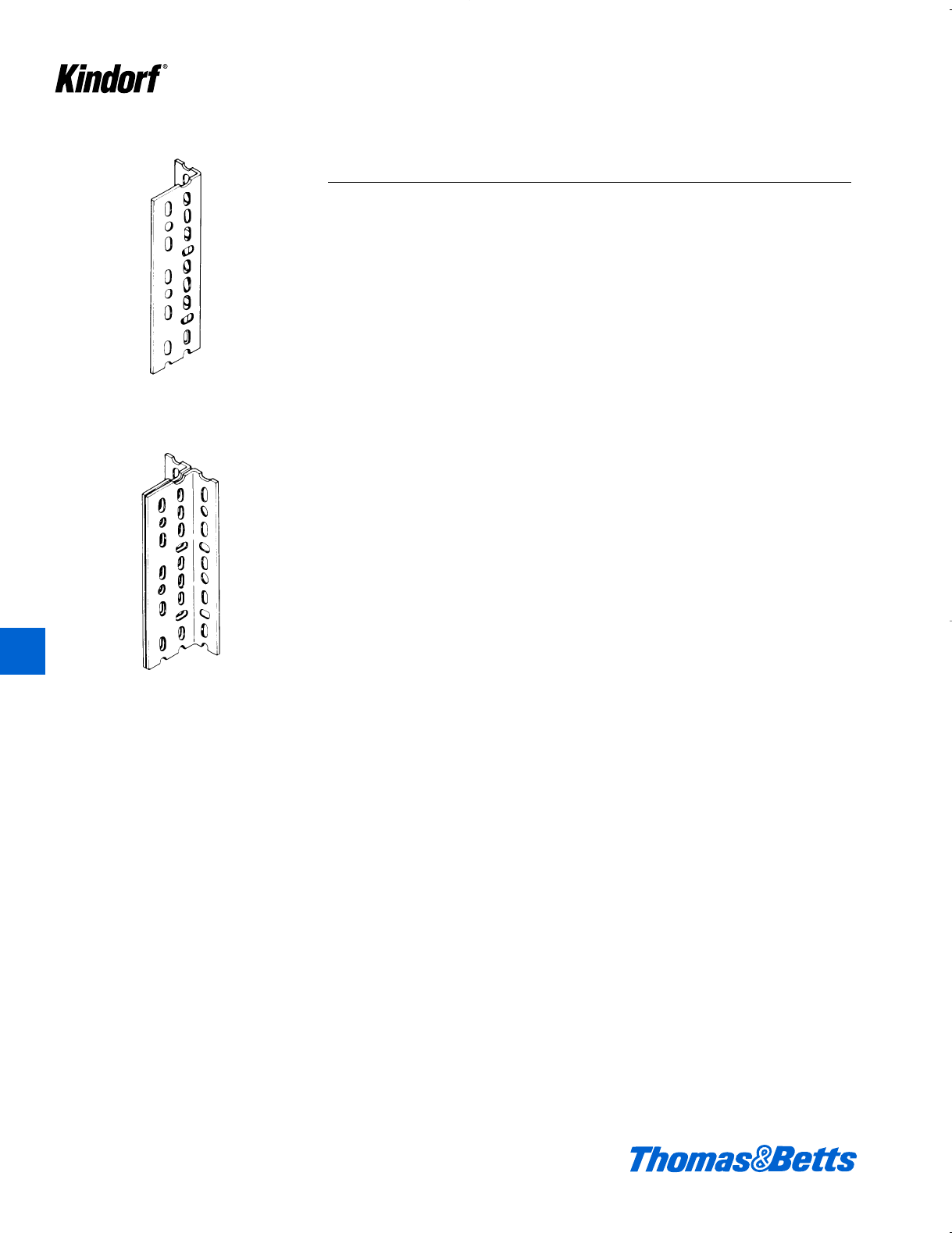
Right Angle Slotted Angle
Single Section
T-Section
K158 © 2003 Thomas & Betts Corporation. Specifications are subject to change without notice. www.tnb.com
How to Determine Weight to be Supported
Multiple-bay shelving is typical of many
Right Angle weight-bearing structures.
Load tables are your guide to the
weights supportable by RA-160, RA-225
and RA-300. Strengths are increased
where needed by combining sections
for beams or columns, and by adding
braces.
Example for Checking Load Safety
This structure is erected as 3 separate
bays and bolted together, using RA-225.
Beam Load Bearing
Load E = 400 lbs. evenly distributed on
two 4' beams. Refer to beam load
tables for RA-225: Two 4' beams will
support 1090 lbs. – Safe load.
Load F = 600 lbs. on solid shelf evenly
distributes weight to two 3' beams. Refer
to beam load tables: Two 3' beams will
support 1560 lbs. – Safe load.
Load G = 800 lbs. on shelf supported
by two 3' beams and two 4' beams.
Add the 4 sections: 3 + 3 + 4 + 4 = 14
ft. Divide total load G by 14, i.e., 800 ÷
14 = 57 lbs. per ft.
Compute wt. on longest beam – two 4'
sections, or 8 ft. Multiply 8' x 57 lbs.
per ft. load = 456 lbs. supported by the
two 4' beam. Refer to load tables: Two
4' beams support 1090 lbs. – Safe
load. Since the 3' beams are stronger,
they are also safe for the load. Load H,
any load on shelf supported by beams
at floor level – considered safe.
The example illustrates methods of fig-
uring loads on three different types of
shelf construction. It is not a typical bay.
It should be remembered that a safe
beam load does not assure a safe
structure – column load safety must
also be computed.
Column Load Bearing
Four columns support load equally.
Column section AB = bload E, or
100 lbs.
Column section BC = bload F, or
150 lbs., PLUS bload E, 100 lbs. or
250 lbs.
Column section CD = bload G, or 200
lbs. PLUS 150 lbs., bload F, PLUS 100
lbs., bload E, for a total load on sec-
tion CD of 450 lbs. Load H is at floor
level, does not count.
Assuming a 9' high structure, the 9'
column is supported at 3' intervals by
ties for shelving, the 3' column section
data is used. Refer to column load
tables: 3 column (vertical) supports
2550 lbs. – Safe for the load.
Figures are for a free-standing,
unbraced structure. Common uprights
in two or more bay structures carry a
double load.
See page K159 for load tables.
K
Kindorf ®
412034.K01 KINDORF 5/1 5/7/03 3:17 PM Page K158
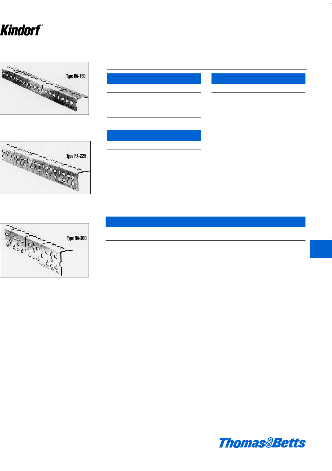
© 2003 Thomas & Betts Corporation. Specifications are subject to change without notice. www.tnb.com K159
Right Angle Slotted Angle
Narrow Channel
Single Section
Broad Channels
Beam Loads
Broad Narrow Single
Channel Channel Section
3' 2550 1490 770
4' 1780 1040 530
5' 1330 770 400
6' 1030 600 310
7' 820 470 240
8' 590 380 –
9' 420 310 –
10' 310 230 –
3' 4110 3050 1560
4' 2870 2130 1090
5' 2140 1580 810
6' 1660 1230 630
7' 1330 980 500
8' 1080 790 410
9' 890 650 330
10' 720 540 280
3' 7570 6300 3220
4' 5290 4400 2250
5' 3950 3280 1680
6' 3060 2540 1300
7' 2440 2020 1040
8' 1990 1650 840
9' 1650 1360 690
10' 1380 1140 580
Notes: Values shown are for a pair of beams supporting an evenly distributed load
(lbs.). For a concentrated load these values should be halved. Min. safety factor
1.4. Multiple angle beams should be bolted every 6 in. with bolts staggered in
alternate rows. To increase load capacity tie angles can be cut to size and bolted
between beams.
Column Loads
RA 160 – 14 ga. x 1e" x 1e"
T-Section Single Section
3' 3880 1500
4' 3500 1200
5' 3000 950
6' 2500 750
RA 225 – 14 ga. x 2c" x 1e"
T-Section Single Section
3' 5550 2550
4' 5050 1900
5' 4400 1550
6' 3850 1300
7' 3400 970
8' 3000 –
9' 2650 –
10' 2300 –
RA 300 – 12 ga. x 3a" x 1e"
T-Section Single Section
3' 8000 3500
4' 7100 2900
5' 6300 2400
6' 5550 1800
7' 4750 1300
8' 4000 1000
9' 3200 –
10' 2400 –
Notes: Values shown are static loads (lbs.) applied verti-
cally to an unbraced column. Min. safety factor 2.1. To
increase load capacity columns can be reinforced with
side braces cut to size.
K
Kindorf ®
412034.K01 KINDORF 5/1 5/7/03 3:17 PM Page K159

Total wire
management
solutions!
Reconfiguring electrical wiring and communica-
tions networks for building retrofits or additions?
Specify Thomas & Betts Surface Raceway
Systems to get the flexibility,
functionality and compatibility
you need for every
connectivity application.
Our comprehensive line of
wire management solutions
includes metallic, non-metallic,
and aluminum surface
raceways, power poles,
in-floor and undercarpet systems, and
complete structured cabling systems.
Custom-engineered systems available.
For integrated connectivity, ease of installation,
and the convenience of single-source purchasing
and support, see your
Thomas & Betts
distributor. Or for
Technical Services,
call 888-862-3289.
Single-source convenience for every connectivity application!
Decorative
Cove Molding
Raceway, ideal for
executive offices and
conference rooms.
Steel City®• Superstrut®• Union®• Bowers®• Kindorf®
3-channel metal raceway.
A Thomas & Betts exclusive!
412034.K01 KINDORF 5/1 5/7/03 3:17 PM Page K160
