100505 Catalog
2014-09-05
: Pdf 100505-Catalog 100505-Catalog 702316 Batch7 unilog
Open the PDF directly: View PDF ![]() .
.
Page Count: 196 [warning: Documents this large are best viewed by clicking the View PDF Link!]

Power-Strut and the Power-Strut logo are registered trademarks of Allied Tube & Conduit.
©Copyright 2004, Allied Tube & Conduit. All Rights Reserved.
ATC-L-1376-6 [web download]
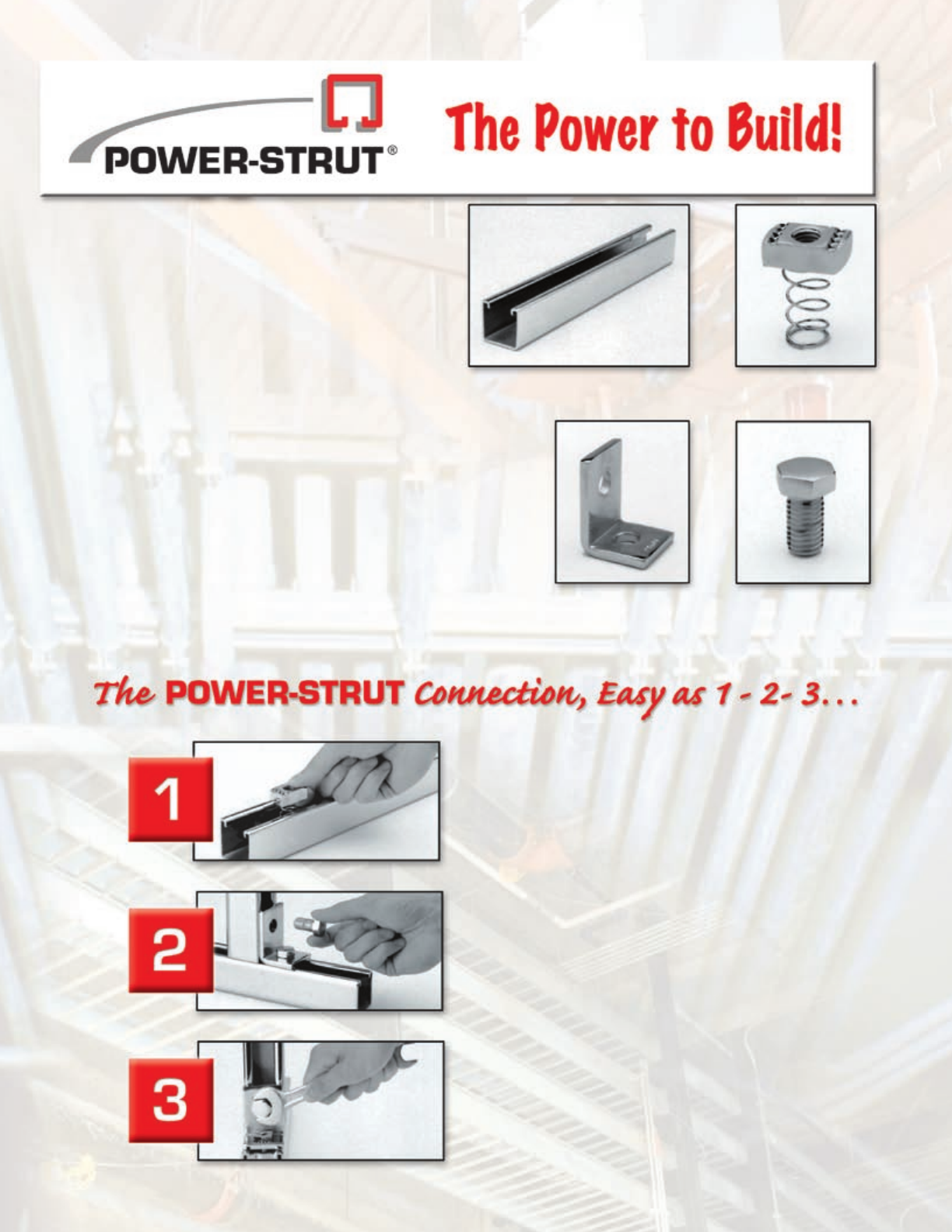
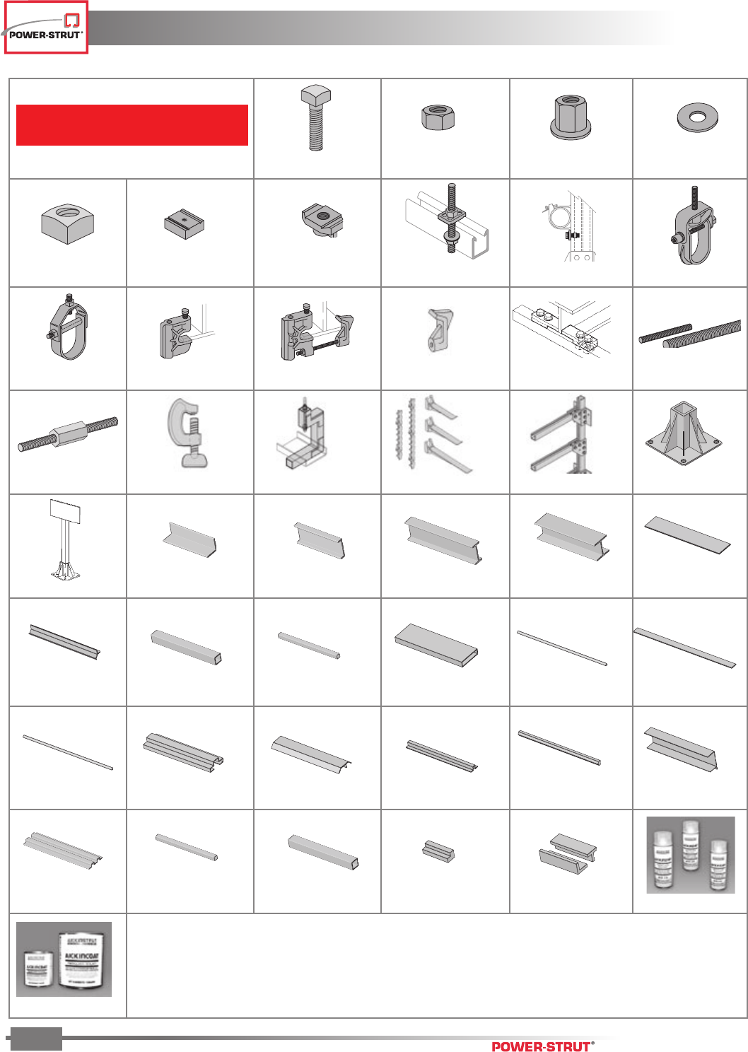
Insert the clamping nut anywhere along the continu-
ous slot channel. A 90° clockwise turn positions the
grooves and teeth in the nut with the inturned edges
of the channel.
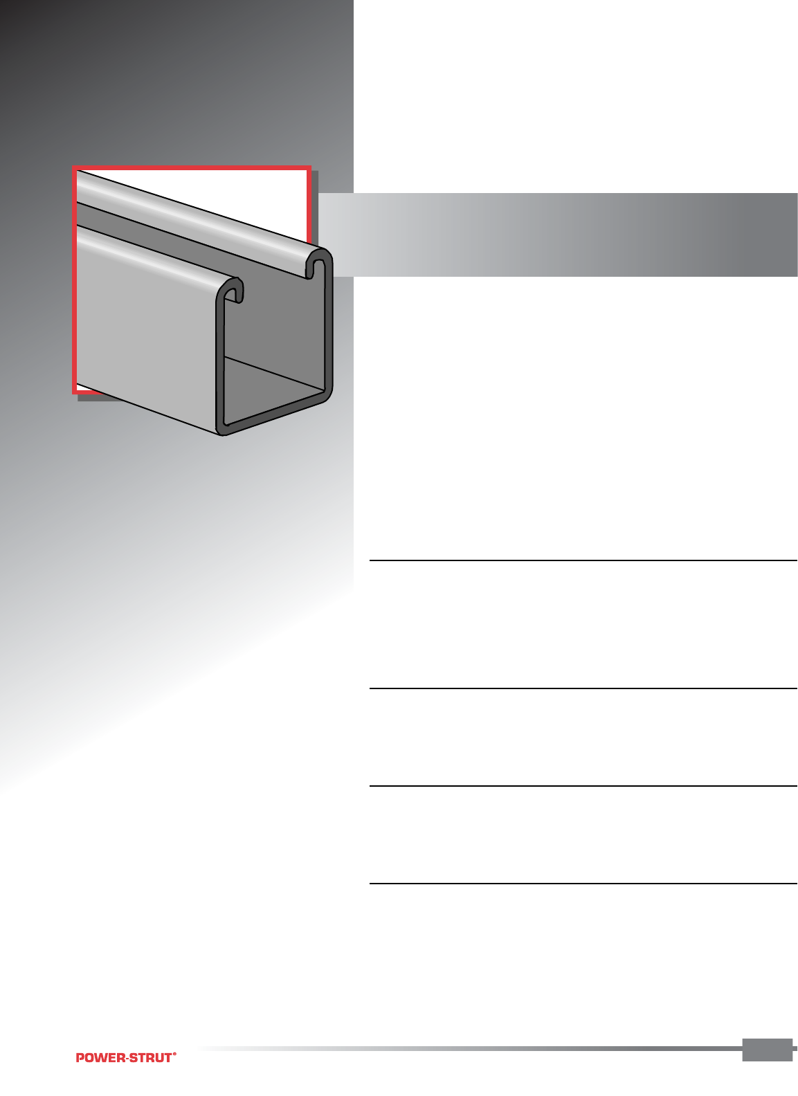
The present line of Power-Strut continuous slot
metal framing is the result of over one half cen-
tury of experience in metal framing. This complete
line includes channels, fittings and accessories of
American manufacture for any framing or support
problem… large or small, heavy or light.
Power-Strut is proud of the exacting standards of
research, design, engineering and manufacturing
that go into production of the Power-Strut system.
Maximum recommended load ratings for chan-
nels have been established through testing and
are based on allowable stresses applicable to the
Power-Strut Material Specification. Many Power-
Strut products are listed by the Underwriters’
Laboratories, Inc. and certified by the Canadian
Standards Association.
CONNECTION
FITTING
CLAMPING NUT
BOLT
CHANNEL
The Power–Strut fitting provides the connection
of channels.
Tighten the bolt(s) to secure the connection.
3
3
TABLE OF CONTENTS
TABLE OF CONTENTS
ENGINEERING CATALOG
3
General Information .......................................Page 2
Channel .....................................................Page 19
Fasteners ...................................................Page 55
Fittings ......................................................Page 61
Pipe & Conduit Clamps .................................Page 85
Brackets ....................................................Page 93
Rollers .......................................................Page 97
Beam Clamps ...........................................Page 101
Electrical ..................................................Page 109
Concrete Inserts .......................................Page 127
Junior Channel ..........................................Page 133
Power-Angle® ...........................................Page 139
Fiberglass ................................................Page 145
Technical Data ..........................................Page 175
Product Index ...........................................Page 193
WARNING: Power-Strut products are carefully designed and manufactured to the listed standards, as applicable.
However, Power-Strut reserves the right to revise product design without notification. Power-Strut products included in
this catalog are intended for installation and service only as described or specified herein. Care should be exercised by
installers and end-users to install, use and maintain these products properly to avoid any possible on-the-job accidents.
1"
3⁄8"
1⁄2"
1⁄2"
THE POWER TO BUILD
THE POWER TO BUILD
ENGINEERING CATALOG
4
■ More Than 8,000 Quality Products
The Power–Strut metal framing system can be regarded as a basic build-
ing material. Our metal framing system is an erector set concept, using
channel and fittings to solve many applications. You can conceal metal
framing in the basic structure of a building or run it along the surface of
walls, ceilings and floors. An endless array of fittings provide freedom to
work at virtually any angle along any surface to shape a support system
that fits your exact needs.
Available finishes include hot–dipped galvanized, pregalvanized,
electro–galvanized and painted, along with material choices of steel,
stainless steel and aluminum.
Beyond its versatility as a basic building material, metal framing is popu-
lar for more exotic applications such as clean rooms, satellite dish sup-
ports, x–ray supports, storage racks, theater screens, tunnel stanchions
and offshore platform catwalks. While the uses of metal framing are truly
unlimited, they fall into three major categories.
■ Electrical Systems
Versatile metal framing is widely used by electrical contractors to support
conduit, panel boxes, raceway systems and other electrical components.
In addition, Power–Strut channel can be used as a wiring raceway. Prod-
ucts marked with the UL symbol in this catalog are listed by Underwriter’s
Laboratories for use in raceway applications.
Channel raceways or support systems can be attached to ceilings, wood
or steel beams, inside columns or imbedded in concrete. Trapeze systems
can support conduit from either the top or bottom.
As a lighting support system, metal framing helps assure proper align-
ment over long spans. As a raceway system, channel offers an oppor-
tunity to reduce construction costs through more efficient use of installa-
tion labor. The exceptional versatility of channel gives contractors more
flexibility in solving miscellaneous problems which may arise at the
job site.
■ Mechanical Systems That Reduce Costs
For mechanical support of HVAC, plumbing and fire protection systems,
A Broad and Versatile Metal Framing Line Backed
THE POWER TO BUILD
THE POWER TO BUILD
ENGINEERING CATALOG
5
the versatility of metal framing systems is unmatched. It is by far the
most popular framing system with contractors because the wide variety
of fittings and support devices available help solve virtually any support
problem without expensive welding.
Piping stanchions, ceiling and wall-mounted supports and tunnel sup-
ports are common metal framing applications. Concrete insert, shelf
bracket, wall and ceiling-mounted systems provide flexible solutions to
any piping support applications.
In addition, pipe support products such as Power-Wrap and cushioned
clamps provide insulation to prevent potential damage from noise,
vibration, temperature variations and metal-to-metal contact.
■ OEM Components And Maintenance
Metal Framing systems provide convenient solutions for maintenance
and retrofit requirements in processing and manufacturing facilities.
Also, Power-Strut products can be used as cost-effective components
in OEM applications. For example, channel can be used as conveyor
stands and side rails or provide framing for panel cabinetry products, or
for generator, motor and pump supports.
The complete line of products and leading reputation for quality and ser-
vice make Power-Strut your practical choice for metal framing. Contact
your local Power-Strut representative for additional information.
by a Leading Reputation for Quality and Service.
EXAMPLE APPLICATIONS
EXAMPLE APPLICATIONS
ENGINEERING CATALOG
6
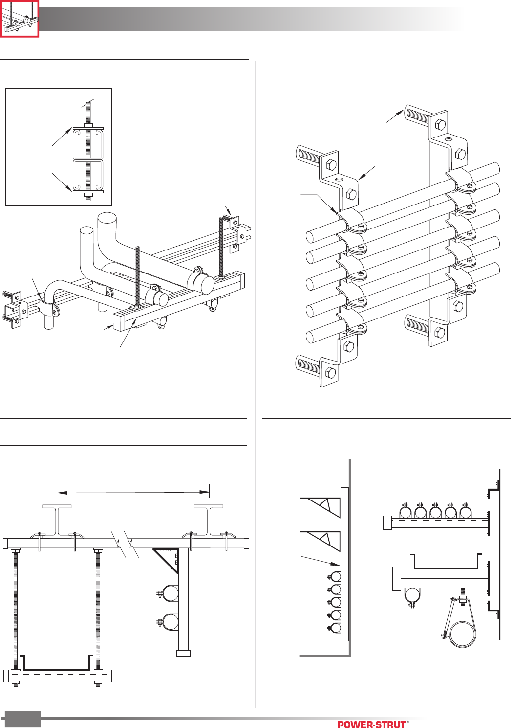
Pipe clamp fittings
PS 1100 (typical)
Standard back-to-back
combination channel
Plastic End Cap
(typical)
Anchor
(suitable for wall material)
Square Washer
PS 619 w/Hex Nut
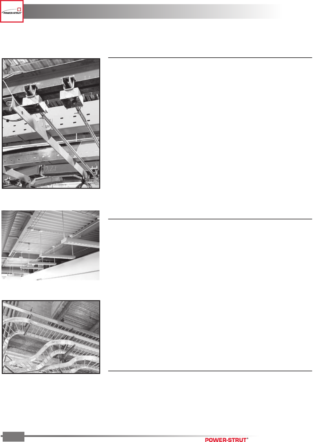
■ Overhead Support Vertical to Horizontal Shelf or Utility Support
Pipe clamp
fittings
(typical)
Versatile Power-Strut installation
of utility piping means that
expansion is just a matter of
inserting another pipe clamp!
PS 611
(typical)
Anchor
(suitable for wall material)
Check span for allowable load
Pipe Rack
Trapeze Support
■ Overhead Multi-Use Support Systems
Using Channel Attached to “I” Beams
■ Wall Mount Organize & Control Multi-
Stock brackets are
available in lengths
from 6" to 36"
■ Wall Mounted Brackets
Wall-mounted
channel
EXAMPLE APPLICATIONS
EXAMPLE APPLICATIONS
ENGINEERING CATALOG
7
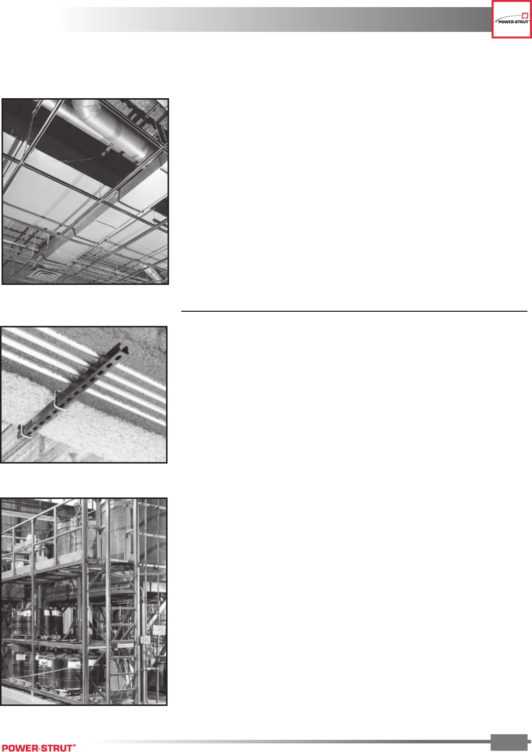
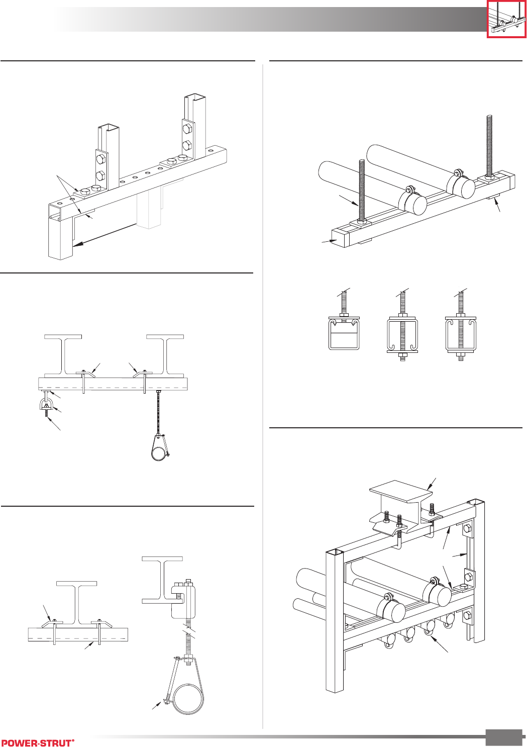
■ Standard Channel and Fitting Assembly
The factory punched holes
in “H” series channel allow
fittings to be attached to
either side.
Just loosen the
nuts to easily
adjust position
■ Trapeze Support System
Power-Strut metal framing is ideal for electrical
and mechanical pipe support applications.
Plastic
End Cap
(For safety)
Pre-slotted channel allow
through channel connections
Square
Washer
PS 619
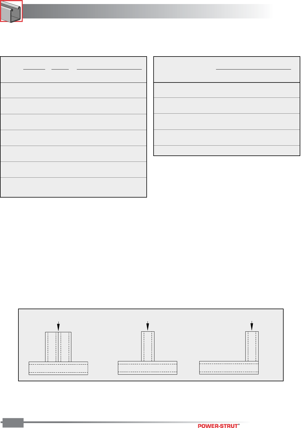
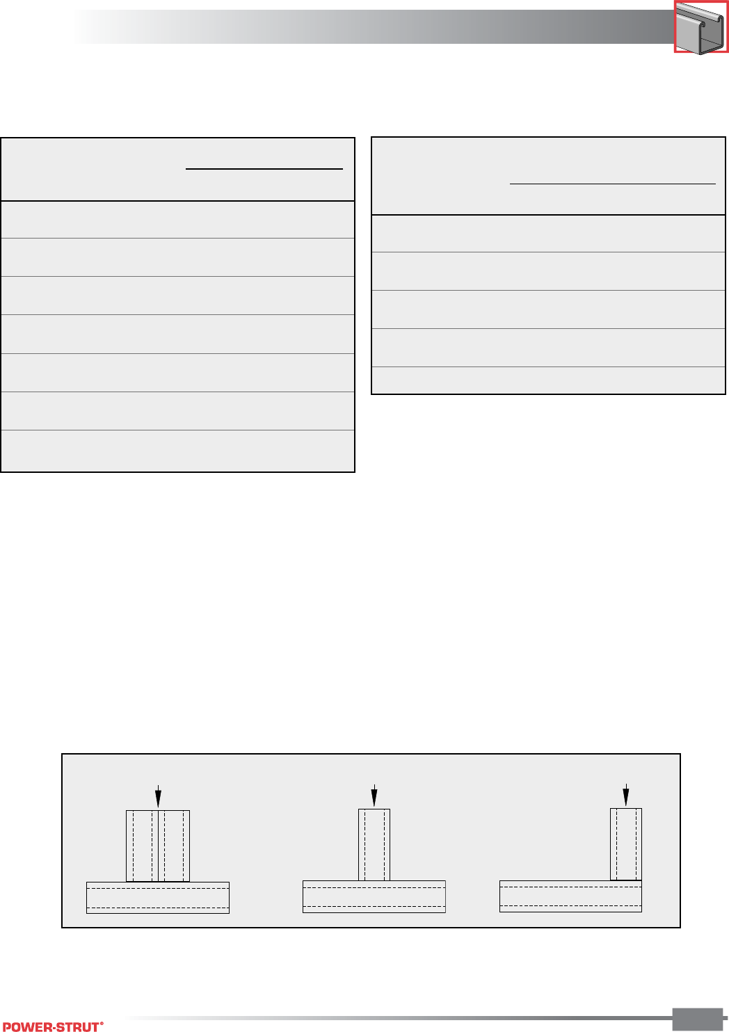
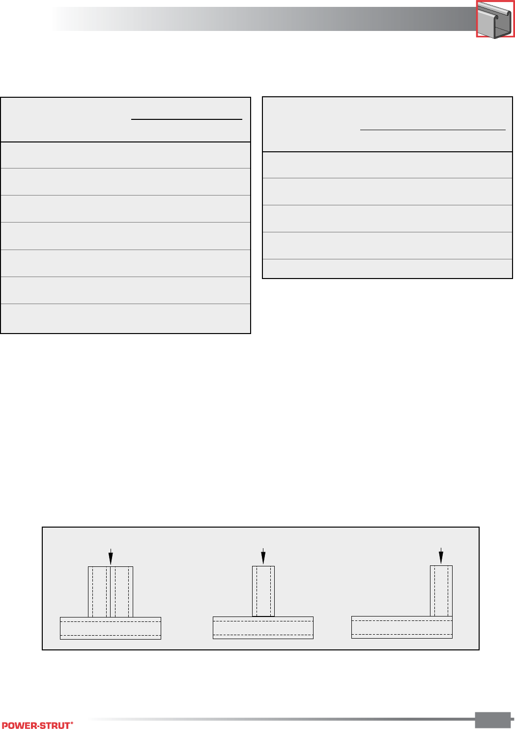
Acceptable Methods to Hang Channels
Threaded Rod
■ Supports for Threaded Rod Attachments
Between Beams
Use Beam Clamps in pairs
Select channel size based on load requirements
PS 203 for 3/8" Rod
(eyelet link)
Threaded Rod
PS RS 3/8" (channel nut)
w/PS 619 3/8" (sq. washer)
Pipe Hanger
■ Ganged Pipe Support
■ Supports for Threaded Rod Attachments
to Single Beams
Standard “I” beam
Standard channel
Pipe clamps
Use Beam Clamps
in pairs
Hanger support
Select channel size based
on load requirements
THE POWER TO BUILD
THE POWER TO BUILD
ENGINEERING CATALOG
8
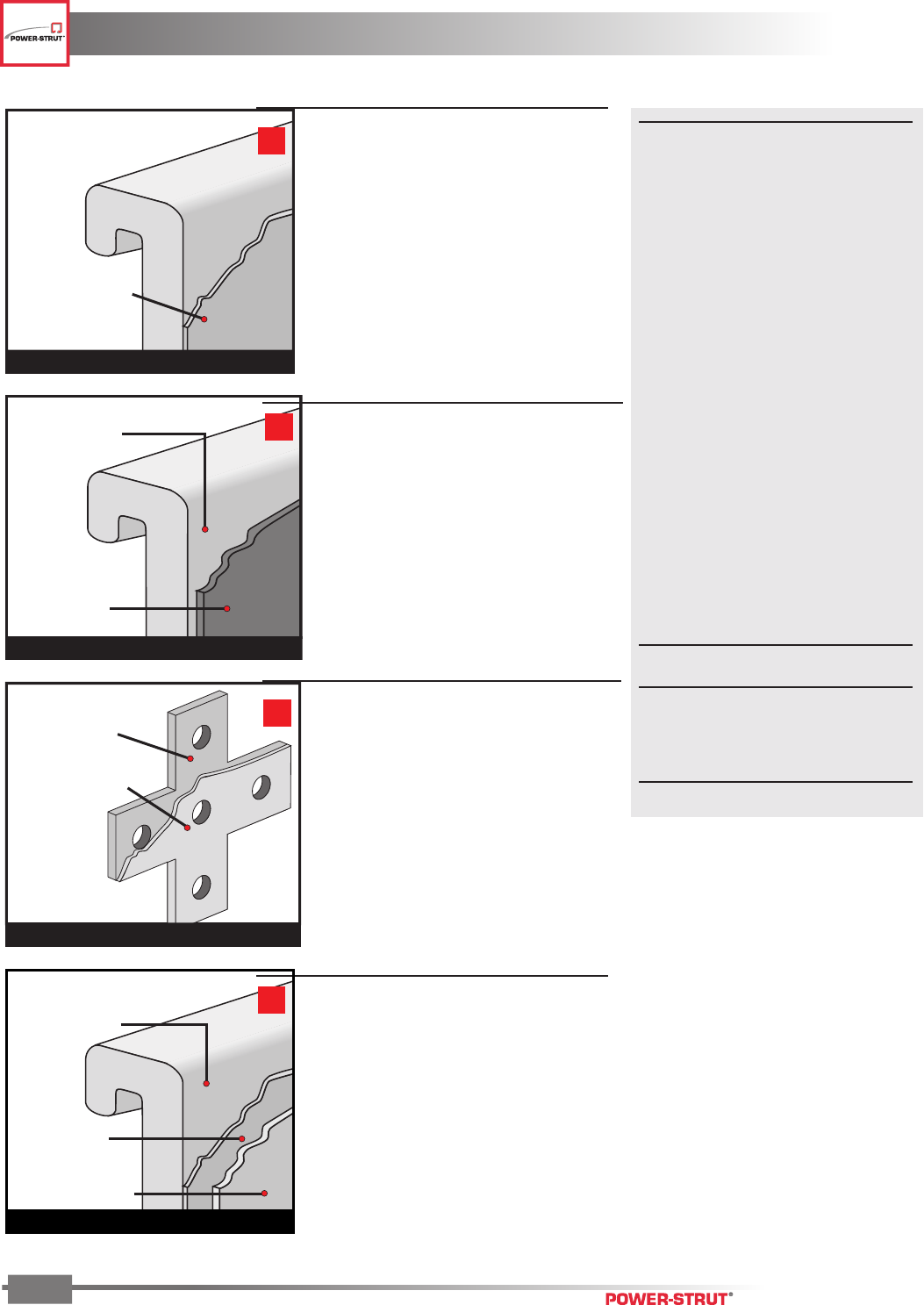
■ ZINC COATING
Power-Strut products are available in
four types of zinc coatings:
• electroplated (EG)
• pregalvanized (PG)
• hot dip galvanized (HG)
• yellow dichromate (ZD)
Zinc coatings offer two types of protec-
tion:
1. Barrier: The zinc coating protects the
steel substrate from direct contact with
the environment.
2. Sacrificial: The zinc coating will pro-
tect scratches, cut edges, etc. through
an anodic sacrificial process.
The service life of zinc coating is directly
related to the zinc coating thickness as
shown below.
COMPARISON OF ZINC
GALVANIZED FINISHES
Finish Zinc
Thickness
Hot Dip Galvanized 2.6 MIL
Pregalvanized .75 MIL
Electro-Galvanized .2 to .5 MIL
Power-Gold .5 MIL
Zinc Coating
Prepared Steel
Channel, Closures, Clamps & Fittings
HOT-DIPPED GALVANIZED (HG)
Material is coated with zinc after being roll-
formed or after all manufacturing operations
are completed, conforming to ASTM speci-
fication No. A123 or A153.
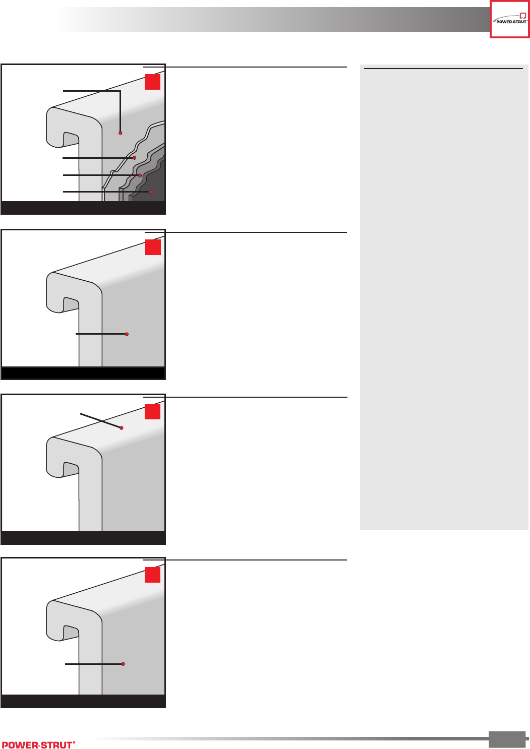
Electro-Galvanized
Zinc Coating
Prepared Steel
Bolts, Nuts, Clamps & Fittings
ELECTRO-GALVANIZED (EG)
Fittings and hardware are electrolytically
coated with zinc to commercial standards
(ASTM-B633 Type III C1).
POWER-GOLD (ZD)
A .5 mil Electro-galvanized zinc plate is
applied with a cohesive molecular bond to
the steel base metal, in compliance with the
ASTM B633 standard. Yellow Dichromate
is applied over the zinc and results in a
gold appearance which acts as a non-
porous barrier sealant.
Electro-Plated
Zinc Coating
Yellow Dichromate
Conversion Coat
Prepared Steel
Channel & Fittings
Pre-galvanized
steel
Channel & Closures
PREGALVANIZED (PG)
Material (steel strip) is coated with zinc
by hot-dip process prior to roll-forming or
press operations.
The zinc coating conforms to
ASTM A–653, Grade 90 General
Requirement for Steel Sheet, Zinc–Coated
(Galvanized) by Hot Dip Process.
THE POWER TO BUILD
THE POWER TO BUILD
ENGINEERING CATALOG
9
■ POWER-GREEN®
TECHNICAL DATA
STEEL SUBSTRATE PREPARATION
Eight stage continuous cleaning, phos-
phate process.
Substrate after “prep”: sealed iron phos-
phate conversion coating.
COATING
Thermoset acrylic
Color: Green Federal STD. 595A,
Color No. 14109, Dark Limit V-.
Hardness: 2H.
Coating Process: Anodic Electrodepo-
sition.
PERFORMANCE
Salt Spray:
Scribed: exceeds 400 hrs per
ASTM B117.
Unscribed: exceeds 600 hrs per
ASTM B117.
Chalk: nominal at 1,000 hrs per weath-
erometer G-23 test.
Checking: None at 1,000 hrs per weath-
erometer G-23 test.
Fade: Less than 50% compared to stan-
dard epoxy E.C. coatings.
ENVIRONMENTAL ISSUES
Formulated as a “heavy metal”-free coat-
ing (trace elements only).
Outgassing in service: essentially none
at 350°F for 24 hrs.
Type 304 or
Type 316
Stainless Steel
Channel, Closures & Fittings
STAINLESS STEEL (SS)
Material in accordance with ASTM A 240
(Type 304 or type 316).
Extruded Aluminum
Channel, Closures & Fittings
ALUMINUM (AL)
Channel is extruded aluminum in accor-
dance with ASTM B221 Type 6063-T6.
Steel (oiled surface)
Channel, Closures & Fittings
PLAIN (PL)
Plain finish designation means that the
channel retains the oiled surface applied to
the raw steel during the rolling process. The
fittings have the original oiled surface of
the bar-stock material.
POWER-GREEN® (GR)
Channel and parts are cleaned and phos-
phated. Immediately afterward, a uniform
coat of rust-inhibiting acrylic enamel paint
is applied by electro-deposition and thor-
oughly baked.
Prepared Steel
Sealer
Iron Phosphate
E-Coat
Channel, Closures & Fittings
THE POWER TO BUILD
THE POWER TO BUILD
ENGINEERING CATALOG
10
* Channel referenced is 15⁄8" wide, fittings referenced are for 15⁄8" channel.
† Some 1⁄4" fittings are produced from A-36 Structural Steel.
■ MATERIALS:
Channel* & Closures – Pregalvanized
ASTM A653 Grade 33, Steel Sheet Zinc Coated by
Hot Dip Process
Channel* – Plain, Painted or Hot Dip Galvanized
ASTM A–1011 Grade 33, Hot Rolled Carbon Steel
Sheet and Strip, Structural Quality
Channel* – Stainless Steel
ASTM A–240, Type 304, Heat Resisting Chromium
and Chromium–Nickel Stainless Steel Plate, Sheet,
Strip for Pressure Vessel
Channel* – Aluminum
ASTM B–221, Type 6063 T6, Aluminum Alloy
Extruded Bar, Rod, Wire, Shape and Tube
Closures – Plain, Painted or Hot Dip Galvanized
ASTM A1008, Steel, Strip, Carbon, Cold–Rolled
Fittings* – Steel
• 1⁄4" Nominal Thickness – ASTM A–575 and A576†
• 3⁄8" Nominal Thickness – A36 (Structural Steel)
Fittings* – Aluminum
ASTM B–209
Accessories – Steel
• Less than 1⁄4" Nominal Thickness – ASTM A–569,
1008–1010 Grade, or (when Pre–Galvanized) ASTM
A–527/Coating Designation G90
Pipe Clamps – Steel
A–1011SS Grade 33
Pipe Clamps – Stainless Steel
ASTM A–240, Type 304
Pipe Clamps – Aluminum
ASTM B-209, 5052, H32 Grade, Sheet and Plate
Channel Nuts
ASTM (3⁄8" & 1⁄2") A-576 Grade 1015M, A–675 (1⁄4")
Grade 60, Case Hardened to RC25 min.
Hex Nuts and Bolts
ASTM A–563, Grade A and ASTM A–307, Grade A
Threaded Rod
ASTM A–510, Hot Rolled, 1008–1010 Grade
■ FINISHES (Ordering):
When ordering, add the finish to the part number.
Examples: PS 200-10 PG
PS 200-10 ZD
PS 200-10 GR
PS 200-10 HG
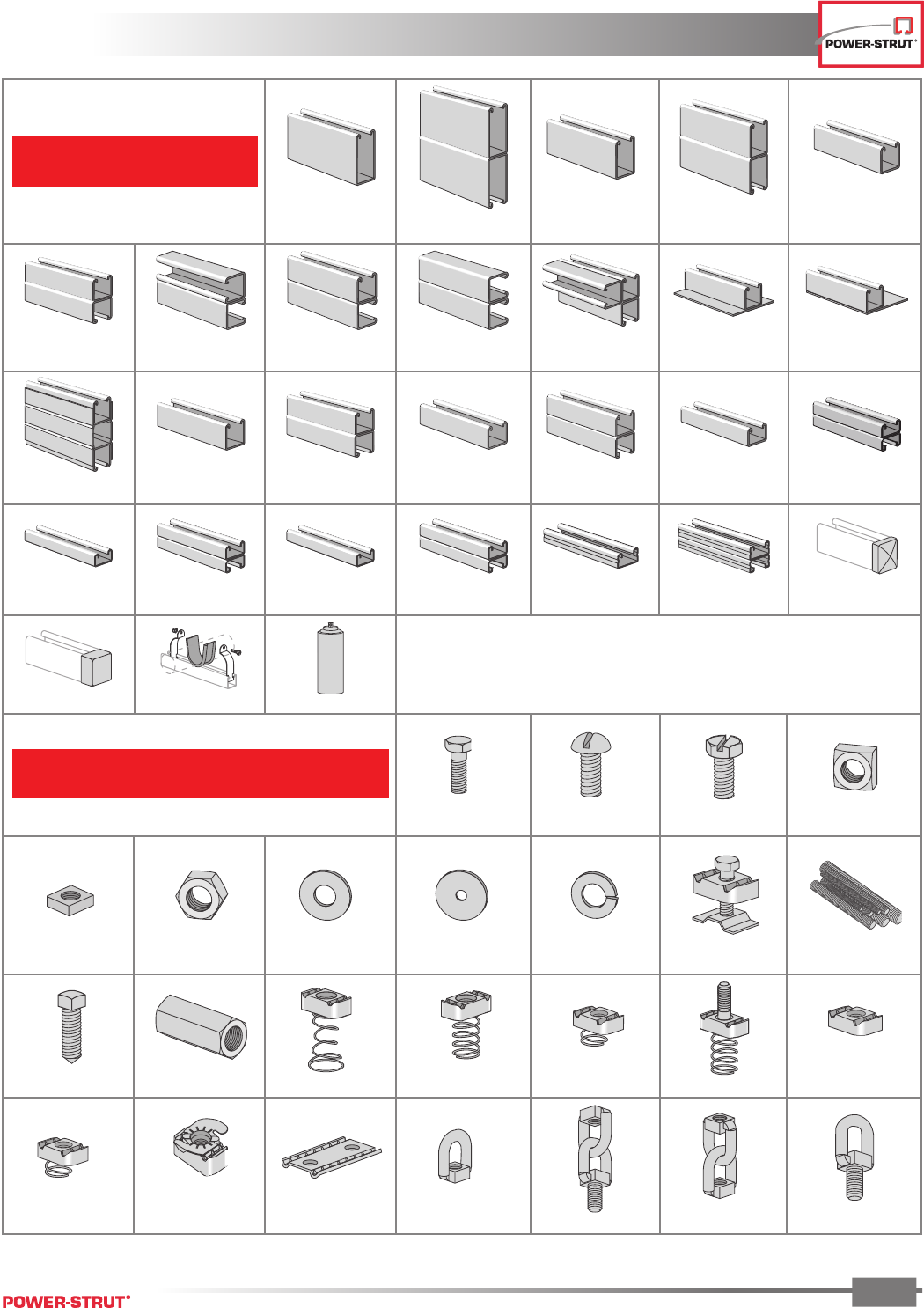
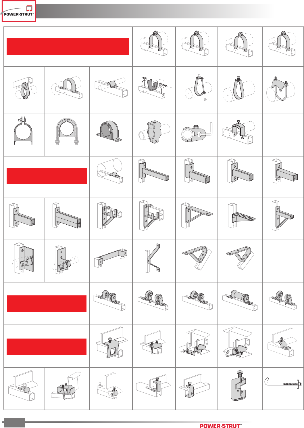
PICTORIAL INDEX
PICTORIAL INDEX
ENGINEERING CATALOG
11
Channel
Fasteners
PS 6112 .............. p.57
15⁄8” x 31⁄4” x 12Ga.
PS 100 .....................p.22 15⁄8” x 61⁄2” x 12Ga.
PS 100 2T3 ...............p.24
15⁄8” x 27⁄16” x 12Ga.
PS 150 .....................p.25
15⁄8” x 47⁄8” x 12Ga.
PS 150 2T3 ...............p.27
15⁄8” x 15⁄8” x 12Ga.
PS 200 .....................p.28
15⁄8” x 31⁄4” x 12Ga.
PS 200 2T3 ...............p.30
15⁄8” x 31⁄4” x 12Ga.
PS 200 2T2 ...............p.31
15⁄8” x 31⁄4” x 12Ga.
PS 200 2T4 ...............p.31
15⁄8” x 31⁄4” x 12Ga.
PS 200 2T5 ...............p.31
31⁄4” x 31⁄4” x 12Ga.
PS 200 3T6 ...............p.31
15⁄8” x 15⁄8” x 12Ga.
w/Plate
PS 200 PLA ...............p.34
15⁄8” x 15⁄8” x 12Ga.
w/Plate
PS 200 PLB ................p.34
15⁄8” x 47⁄8” x 12Ga.
PS 200 PLC ...............p.34
15⁄8” x 15⁄8” x 14Ga.
PS 210 .....................p.36
15⁄8” x 31⁄4” x 14Ga.
PS 210 2T3 ...............p.38
15⁄8” x 13⁄8” x 12Ga.
PS 300 .....................p.39
15⁄8” x 23⁄4” x 12Ga.
PS 300 2T3 ...............p.41
15⁄8” x 1” x 12Ga.
PS 400 .....................p.42
15⁄8” x 2” x 12Ga.
PS 400 2T3 ...............p.44
15⁄8” x 13⁄16” x 14Ga.
PS 500 .....................p.45
15⁄8” x 15⁄8” x 14Ga.
PS 500 2T3 ...............p.47
15⁄8” x 13⁄16” x 12Ga.
PS 520 .....................p.48
15⁄8” x 15⁄8” x 12Ga.
PS 520 2T3 ...............p.50
15⁄8” x 13⁄16” x 16Ga.
PS 560 .....................p.51
15⁄8” x 15⁄8” x 16Ga.
PS 560 2T3 ...............p.53 PS 6152 ...................p.54
PS 6153 ...................p.54 PS 3792 ....................p.54 PS 9050 ...................p.54
PS 6024 ...................p.57 PS 6072 ...................p.57 PS 6075 ...................p.57 PS 6108 ....................p.58
PS 83 .......................p.58 PS 209 .....................p.58 PS 230 .....................p.58 PS 211 .....................p.58 PS 3500 ...................p.58 PS 146 .....................p.58
PS 6064 ...................p.58 PS 135 .....................p.58 PS LS .......................p.59 PS RS .......................p.59 PS SS .......................p.59 PS 517 .....................p.59 PS NS .......................p.59
PS NS S ....................p.59 PS TG .......................p.60 PS 3281 ...................p.60 PS 202 .....................p.60 PS 203 .....................p.60 PS 204 ......................p.60 PS 205 .....................p.60
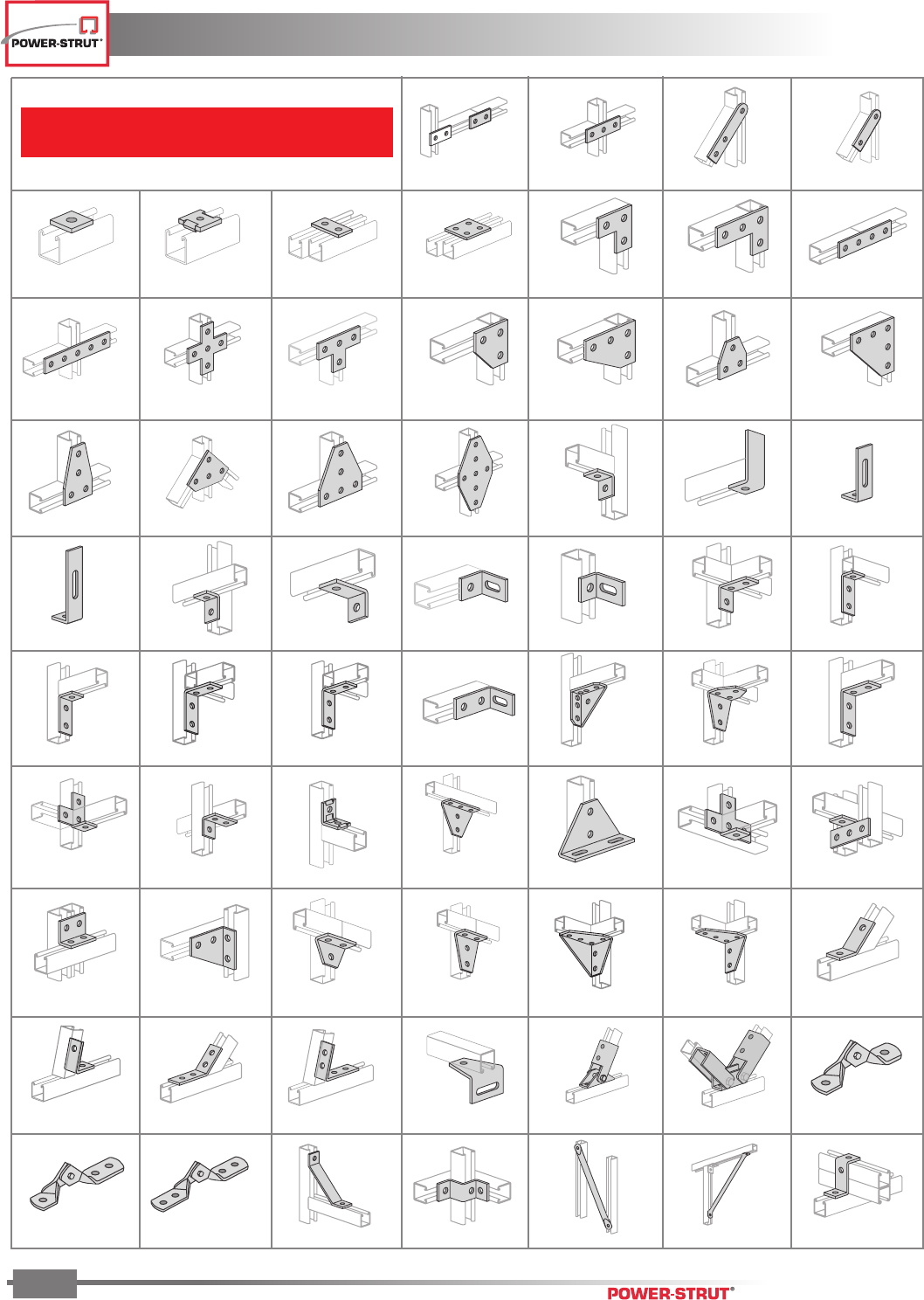
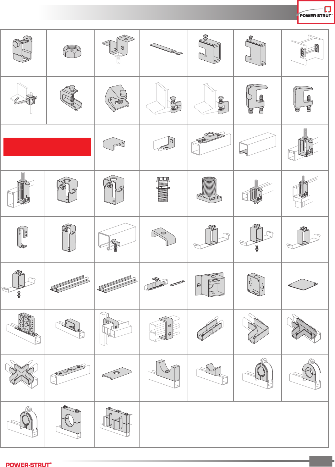
PICTORIAL INDEX
PICTORIAL INDEX
ENGINEERING CATALOG
12
Fittings
PS 618 .....................p.62
PS 3373 ...................p.68
PS 689 A ...................p.69 PS 713 .....................p.69PS 927 .....................p.69
PS 622 .....................p.69 PS 746 .....................p.70 PS 748 .....................p.70
PS 781 .....................p.71 PS 793 .....................p.71 PS 2113 ...................p.71 PS 9400 ...................p.71
PS 9404 ...................p.72 PS 810 .....................p.73 PS 812 .....................p.73PS 926 .....................p.72
PS 712 .....................p.64 PS 714 .....................p.64 PS 744 .....................p.64
PS 747 .....................p.65 PS 822 .....................p.65 PS 854 .....................p.65 PS 2112 ...................p.65
PS 764 .....................p.66
PS 921 .....................p.65
PS 2144 ...................p.66 PS 605 .....................p.67
PS 806 .....................p.66 PS 2520 ...................p.66
PS 2545 ...................p.67 PS 607 .....................p.67
PS 750 .....................p.64 PS 925 .....................p.64 PS 2190 ...................p.64
PS 603 .....................p.65
PS 604 .....................p.66
PS 763 .....................p.66
PS 606 .....................p.67
PS 745 .....................p.67
PS 660 .....................p.68
PS 614 .....................p.68 PS 615 .....................p.68PS 3049 ...................p.67
PS 715 .....................p.69PS 716 R or L .............p.68 PS 720 R or L .............p.68
PS 752 R or L .............p.69 PS 2007 R or L ...........p.70 PS 633 .....................p.70
PS 9401 ...................p.71 PS 9402 ...................p.72
PS 9403 ...................p.72 PS 2054 ...................p.72 PS 756 .....................p.73
PS 602 .....................p.62 PS 617 .....................p.62
PS 619 .....................p.62 PS 2504 ...................p.62 PS 620 .....................p.63 PS 621 .....................p.63 PS 718 .....................p.63 PS 719 .....................p.63 PS 888 .....................p.63
PS 889 .....................p.63
PS 601 .....................p.62
PS 3326 ...................p.70
PS 624 .....................p.70
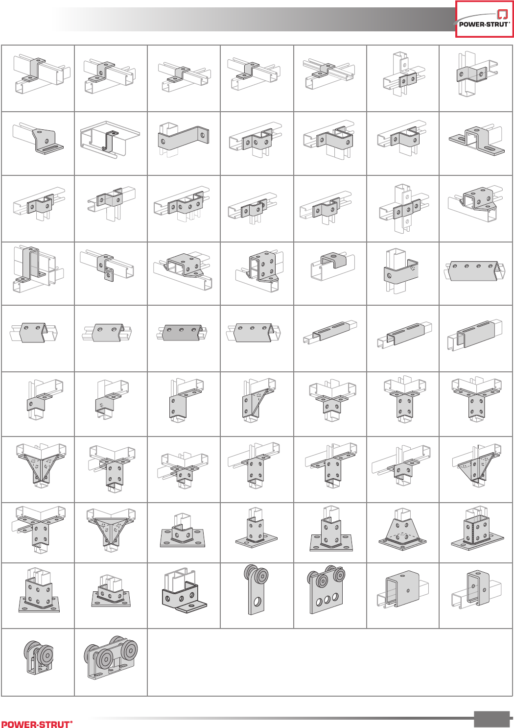
PICTORIAL INDEX
PICTORIAL INDEX
ENGINEERING CATALOG
13
PS 623 ................ p.78
PS 2532 ...................p.75 PS 3060 ...................p.75 PS 613 .....................p.75 PS 679 .....................p.75
PS 2119 ...................p.76
PS 2648 ...................p.75
PS 677 .....................p.77
PS 929 .....................p.76
PS 978 .....................p.76
PS 709 .....................p.77 PS 734 .....................p.77
PS 735 .....................p.77
PS 645 .....................p.78 PS 804 .....................p.79 PS 629 .....................p.78 PS 922 R or L .............p.79 PS 2117 R or L ...........p.79
PS 2128 R or L ...........p.80 PS 2129 R or L ...........p.80 PS 943 .....................p.80 PS 821 .....................p.81
PS 913 .....................p.81 PS 923 .....................p.81
PS 670 .....................p.81
PS 2514 ...................p.82
PS 3013 ...................p.82
PS 3025 ...................p.82 PS 3040 ...................p.82
PS 2064 ...................p.83
PS 3029 ...................p.83 PS 3041 ...................p.83
PS 2528-1 ................p.84 PS 2528 ...................p.84 PS 2524 ...................p.84 PS 2525 ...................p.84
PS 611 .....................p.74 PS 612 .....................p.74 PS 647 .....................p.74
PS 692 .....................p.75
PS 711 .....................p.74 PS 928 ....................... 74PS 2601 ...................p.73 PS 609 .....................p.74
PS 687 A ...................p.76
PS 710 .....................p.76
PS 678 .....................p.77
PS 721 .....................p.76 PS 733 .....................p.77
PS 993 .....................p.78 PS 616 .....................p.78 PS 631 .....................p.78
PS 644 .....................p.78
PS 704 .....................p.79
PS 1004 ...................p.79
PS 665 .....................p.80 PS 666 .....................p.80 PS 667 .....................p.80
PS 945 .....................p.81 PS 668 .....................p.81 PS 669 .....................p.82
PS 3033 ...................p.82 PS 3064 ...................p.83
PS 2521 ...................p.83 PS 2522 ....................p.83 PS 3282 ...................p.95
PICTORIAL INDEX
PICTORIAL INDEX
ENGINEERING CATALOG
14
Brackets
Rollers
Beam Clamps
PS 004T-106N ...........p.90
PS 51 .......................p.89PS 69 .......................p.89PS 67 .......................p.89PS 3792 ...................p.88
PS 1200 ...................p.87
PS 1300 ...................p.86
PS 1000 ...................p.86
PS 808 T1 ................p.94
PS 685 ...................p.103
PS 2653 .................p.103 PS 684 ...................p.104
PS 1100 ...................p.86
Pipe & Conduit
PS 3138 ...................p.88 PS 3126 ...................p.88 PS 1450 ...................p.88
PS UB1/2-UB 10 .......p.91 PS 004M-038 M .........p.91 PS 3101 thru 3115 ....p.92PS 270 .....................p.92 PS 52 E .....................p.92
PS 626 .....................p.94 PS 661 T1 .................p.94 PS 661 T2 .................p.94 PS 808 T2 .................p.94
PS 651 .....................p.94 PS 809 .....................p.94 PS 3164 ...................p.95 PS 732 .....................p.95 PS 838 R or L .............p.95
PS 825 R or L .............p.95 PS 826 .....................p.95 PS 2401 thru 2403 ....p.96 PS 2404 thru 2408 ....p.96 PS 2422 ...................p.91 PS 2421 ...................p.96
PS 1901 ...................p.98 PS 815 .....................p.98 PS 1902 ...................p.99 PS 1911 .................p.100 PS 816 ...................p.100
PS 855 ...................p.102 PS 2651 .................p.102 PS 2657 .................p.102 PS 2656 .................p.102
PS 686 ...................p.103 PS 907 ...................p.103 PS 916 ...................p.104 PS 2622 .................p.104 PS 736 ...................p.104
PS 708 .....................p.94
PICTORIAL INDEX
PICTORIAL INDEX
ENGINEERING CATALOG
15
PS 858 ...................p.106 PS 865 ...................p.106
PS 2626 .................p.106
PS 2654 .................p.106
PS 85 ................ p.107 PS 95 ................ p.107 PS 86 ................ p.107 PS 93 ................ p.108 PS 94 ................ p.108
Electrical
PS 655 .............. p.115 PS 2511 ............ p.115 PS 2560 ............ p.115 PS 2640 ............ p.115 PS 2632 ............ p.116
PS 2632 D ......... p.116 PS 659 .............. p.116 PS 658 .............. p.116 PS 803 .............. p.116 PS 2625 ............ p.116 PS 2631 ............ p.117 PS 2631D .......... p.117
PS 3301 ............ p.117 PS 807 .............. p.117 PS 2636 ............ p.118 PS 2637 ............ p.118 PS 702 .............. p.118 PS 703 .............. p.118 PS 702 D ........... p.119
PS 703 D ........... p.119 PS 707 .............. p.119 PS 707 .............. p.119 PS 649 .............. p.120 PS 2662 A ......... p.120 PS 2660 ............ p.120 PS 2661 ............ p.120
PS 3201 .................p.105 PS 2624 .................p.105 PS 871 ..................... 105PS 2623 .................p.105
PS 135 X ................... 107
PS 1610 ............ p.126 PS 1801 ............ p.126 PS 1850 ............ p.126
PS 2094-4” ....... p.121 PS 2639 ............ p.121 PS 760 .............. p.121 PS 671 .............. p.121 PS 2800 ............ p.122 PS 2802 ............ p.122 PS 2801 ............ p.122
PS 2803 ............ p.122 PS 791 .............. p.123 PS 2627 ............ p.123 PS 1510 ............ p.123 PS 1500 ............ p.123 PS 723 .............. p.124 PS 722 .............. p.125
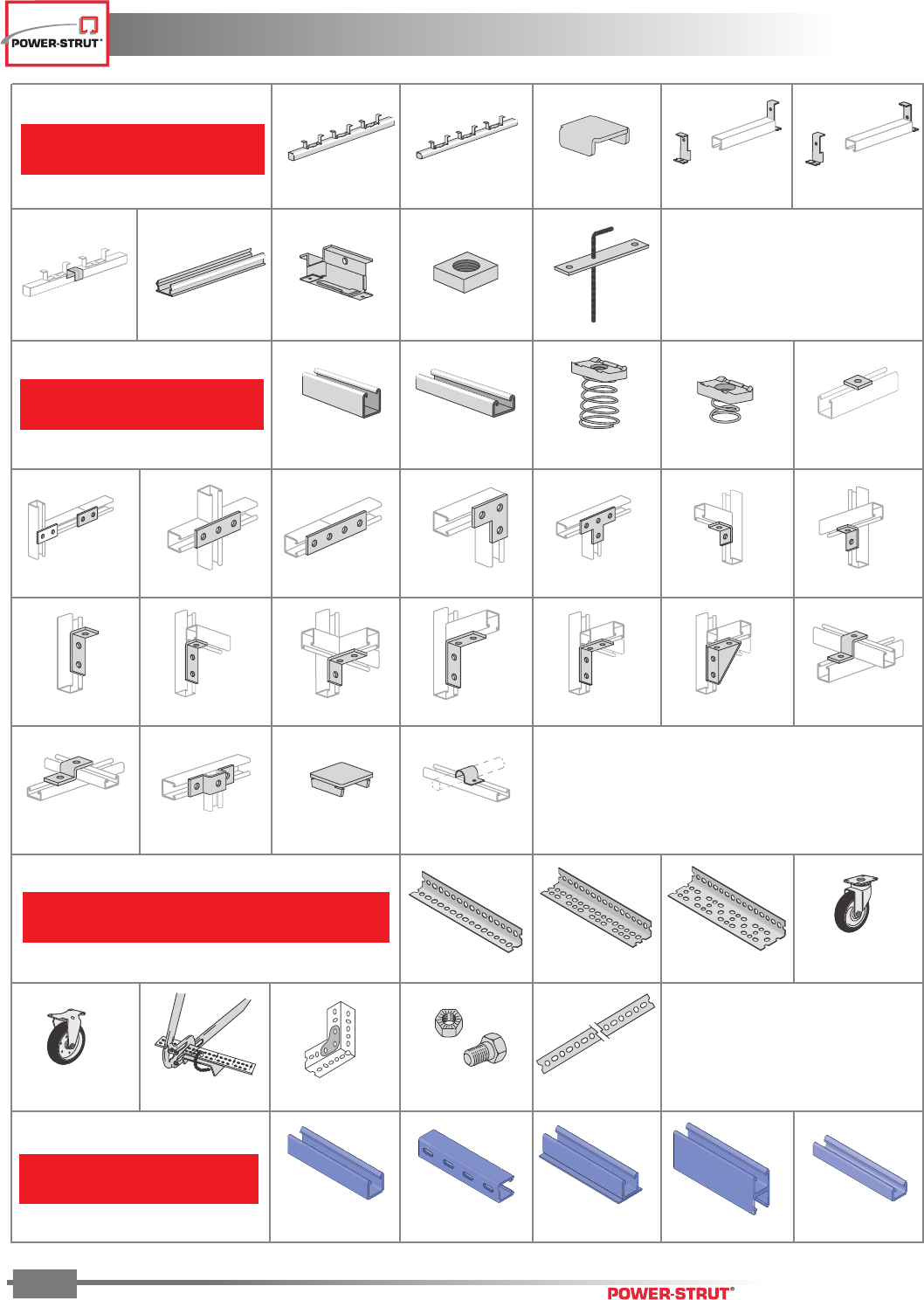
PICTORIAL INDEX
PICTORIAL INDEX
ENGINEERING CATALOG
16
Concrete Insert
PS 349 .............. p.128 PS 449 .............. p.129 PS 656 .............. p.130 PS 653 .............. p.130 PS 654 .............. p.130
PS 1154 ............ p.130 PS 6151 ............ p.130 PS 285 .............. p.131 PS 285 N ........... p.131 PS 680 .............. p.132
Junior Channel
PS 600J ............ p.134 PS 700J ............ p.135 PS 3017 ............ p.136 PS 4017 ............ p.136 PS 2013 ............ p.136
PS 2014 ............ p.136 PS 2015 ............ p.136 PS 2016 ............ p.136 PS 2033 ............ p.136 PS 2034 ............ p.136 PS 2008 ............ p.137 PS 2017 ............ p.137
PS 2018 ............ p.137 PS 2025 ............ p.137 PS 2037 ............ p.137 PS 2019 ............ p.137 PS 2024 ............ p.137 PS 2023 Ror L .... p.137 PS 2010 ............ p.138
PS 2026 ............ p.138 PS 2011 ............ p.138 PS 2029 ............ p.138 PS 2041 ............ p.138
Power-Angle®
PA158 ............... p.140 PA 238 .............. p.140 PA 318 .............. p.140 PA 1SC .............. p.140
PA 1RC .............. p.140 PA 1HDC ...............140 PA 1GP .................140 PA 1SNB ...............140 PA 1RP .................140
20P-2200, 20V-2200,
20E-2200 .......... p.151
20P-2300, 20V-2300,
20E-2200 .......... p.151
20P-2100,
20V-2100 .......... p.151 20P-1500,
20V-1500 .......... p.151
Fiberglass
20P-2000, 20V-2000,
20E-2000 .......... p.151
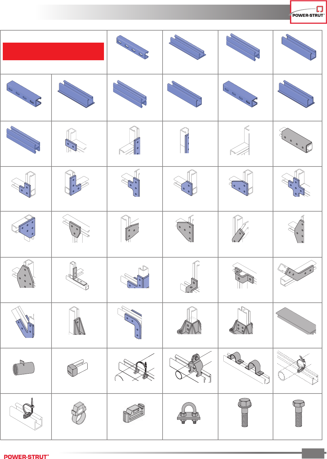
PICTORIAL INDEX
PICTORIAL INDEX
ENGINEERING CATALOG
17
Fiberglass (cont.)
20P-1000, 20V-1000,
20E-1000 ................. p.151
20P-1200, 20V-1200,
20E-1200 ................. p.151
20P-1300, 20V-1300,
20E-1300 ................. p.151
20P-2100-SST,
20V-2100-SST ..................p.151
20P-2504, 20V-2504
20P-2804, 20V-2804 .......p.154
20P-2502, 20V-2502
20P-2802, 20V-2802 .......p.154
20P-2500, 20V-2500
20P-2800, 20V-2800 .......p.154
20P-2528, 20V-2528
20P-2828, 20V-2828 ........p.156
20P/V-2510, 20P/V-2810R,
20 P/V-2810L, ................p.155
20P-2512, 20V-2512,
20P-2812, 20V-212 ..........p.155
20P-2514, 20V-2514,
20P-2814, 20V-2814 ........p.155
20P/V-2516, 20P/V-2816R,
20P/V2816L ....................p.155
20P-2524, 20V-2524,
20P-2824, 20V-2824 ........p.155
20P-2526, 20V-2526,
20P2826, 20V-2826 .........p.155
20P-2530, 20V-2530,
20P2830, 20V-2830 .........p.156
50PU-2611 ............. p.156 50PU-2613 ............. p.156
50PU-1508,
50PU-2008 ............. p.156
50PU-2045 ............. p.157
20P-1700, 20V-1700 p.151 20P-1800, 20V-1800 p.151 20P-1600, 20V-1600 p.151
20P-2000-SST,
20V-2000-SST ..................p.151
20P-2200-SST,
20V-2200-SST .......... p.151
20P-2300-SST,
20V-2300-SST ..................p.151
20P-2506, 20V-2506
20P-2806, 20V-2806 .......p.154
50PU-2616 ............. p.154
20P-2508, 20V-2508
20P-2808, 20V-2808 .......p.154
20P-2518, 20V-2518,
20-2818, 20V-2818 ..........p.155
20P-2520, 20V-220,
20P-2820, 20v-2820 ........p.155
20P-2522, 20V-2522,
20P-2822, 20V-2822 ........p.155
20P-2534, 20V-2534,
20P-2834, 20V-2834 ........p.156
20P-2541, 20V-2541 p.156
20P-2540, 20V-2540,
20P-2840, 20V-2840 ........p.156
20P-1100, 20V-1100 ........p.151
50PU-2636, 50PU-2636A,
50PU-3636B .....................p.157
50PU-2090 ............. p.157
20PU-5853, 20PU-5854, 20PU-5855,
20 PP-5853, 20PP-5854, 20PP-5855 ..p.157
20PU-5903, 20PU-5904, 20PU-5905,
20PU-5903, 20PP-5904, 20PP-5905 ..... p.157
20E-5000 .........................p.157
50PU-500SP ........... p.157
200-3100 to 200-3140 .....p.158
Rigid Pipe Clamps ..... p.159 Two-Hole Pipe Straps p.159AIC-EC ..................... p.157 200-4101 .............. p.160
Insert w/Cable Tie ... p.160 200-3101 .............. p.160 Nonmetallic U-Bolts .. p.160 Hex Flange Bolts ...... p.161 Hex Bolts ................ p.161200-4101 .............. p.160
PICTORIAL INDEX
PICTORIAL INDEX
ENGINEERING CATALOG
18
Fiberglass (cont.)
Hex Flange Nuts ...... p.162Hex Nuts ............ p.162 Flat Washers ............ p.162
Vinyl Ester Square
Head Bolts .............. p.161
Vinyl Ester Square
Head Bolts .............. p.162
Heavy Duty
Channel Nuts ........... p.163 Saddle Clips ............. p.163
Stop-Lock Assemblies ..........p.163 Molded Clevis Hanger .........p.164
Hand Lay-Up Clevis
Hangers .................. p.164
Molded Beam Clamps .........p.165 Cope-Glas Beam Clamps ......p.165
Threaded Rod .......... p.166
Standard Duty
Channel Nuts ........... p.163
Beam Clip ............... p.165 Fabricated Beam Clamps .....p.165
Rod Couplers ........... p.166 Duraclamp ............... p.166 Channel Hangers ...... p.166 Power-Rack Stanchions .....p.167 Heavy Duty Post Base ....p.168
Wall Brackets ..................p.167
Stands .........................p.168 Equal Leg Angle ....... p.169 Channel .................. p.169 I-Beam ...........................p.169 Flat Sheet .......................p.170
Wide Flange I-Beam .........p.169
Embedment Angle .........p.170 Square Tube ............ p.170 Square Bar .............. p.170 Rectangular Tube ..............p.170 Flat Strip ........................p.171Round Rod ......................p.170
Round Tube ..................p.171 Door Frame ............. p.171 Threshold ................ p.171 Hat Section .....................p.171 Flight Channel .................p.171Hex Bar (solid) ................p.171
Toe Plate .....................p.172 Square Bar (flat) ...... p.172 Square Tube (flat) .... p.172 Fixed Connector ...............p.172 Aickinzap ........................p.173Handrail Connectors ..........p.172
Aickincoat ....................p.173
19
CHANNEL
CHANNEL
ENGINEERING CATALOG
19
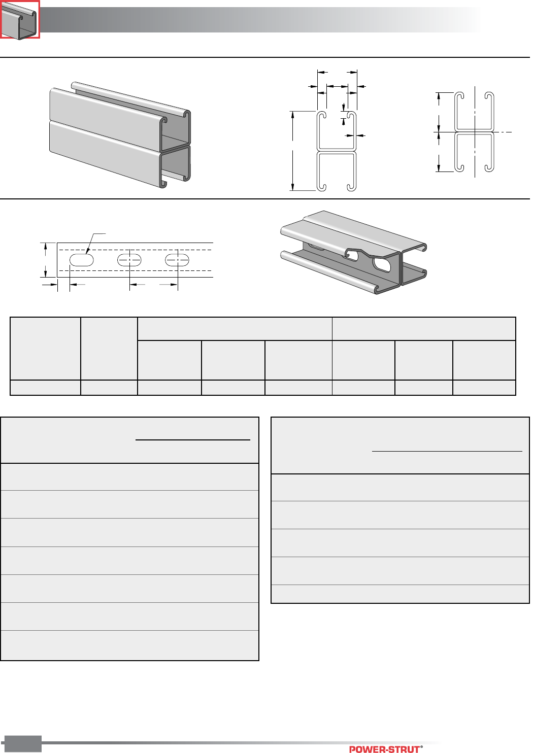
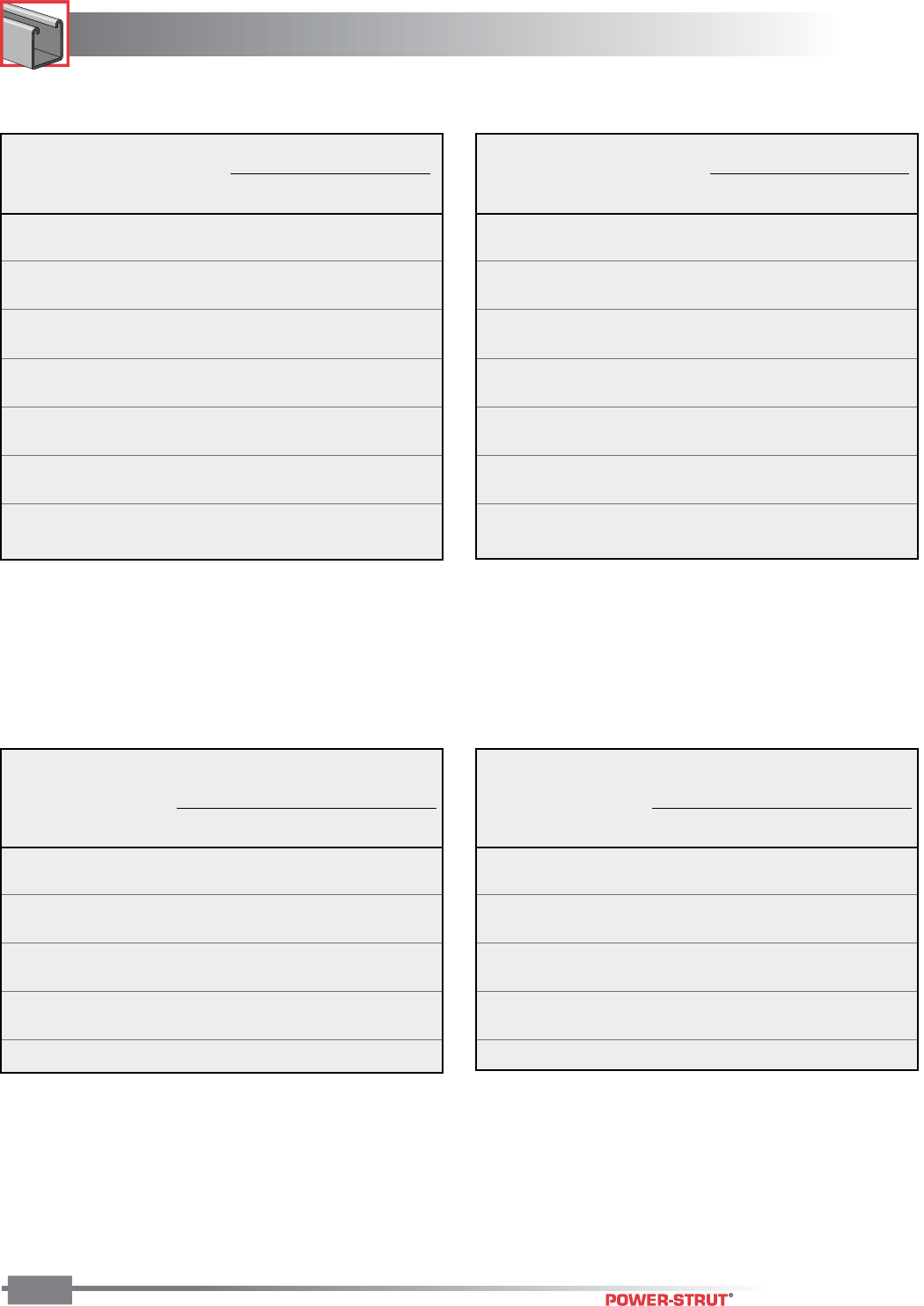
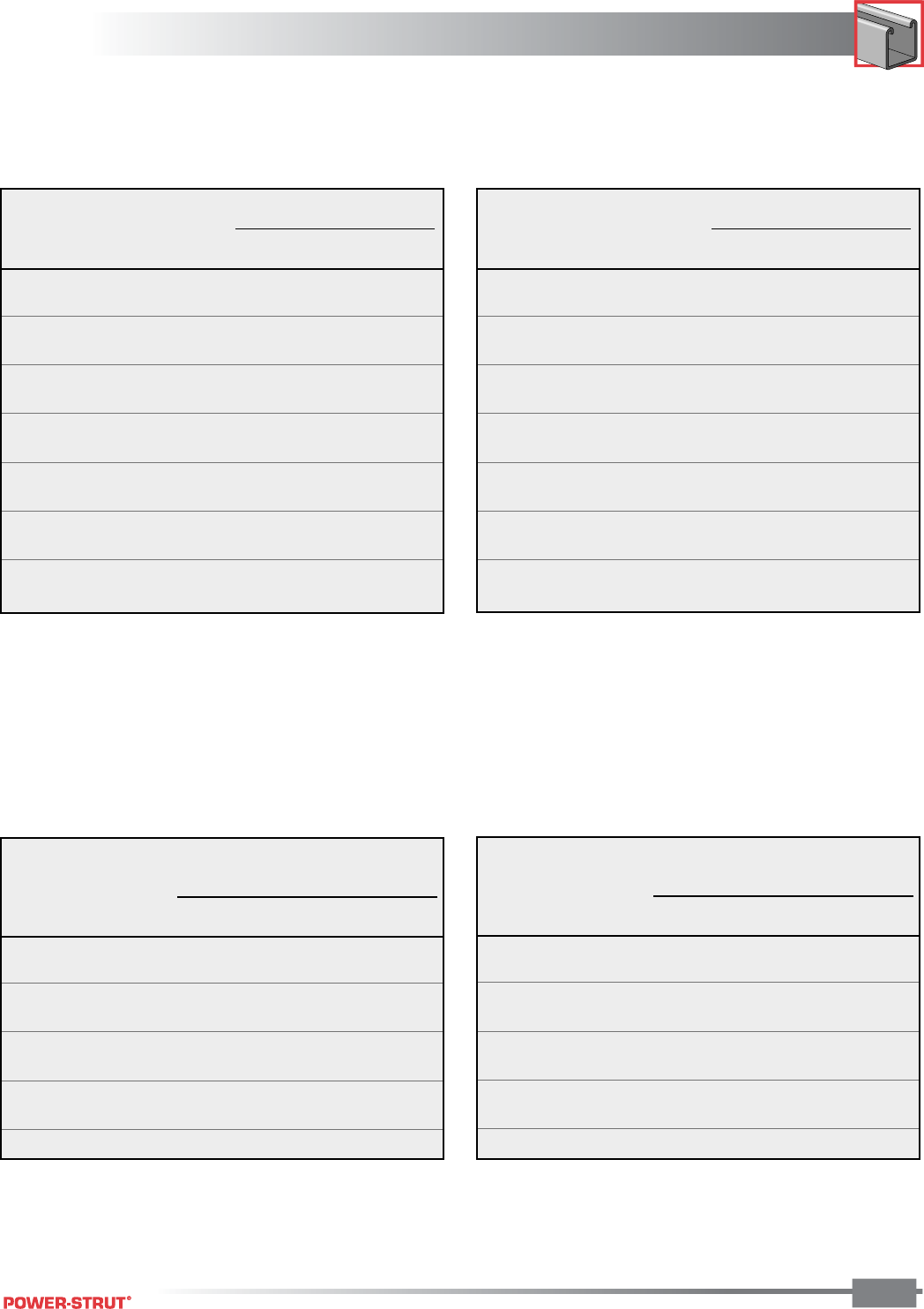
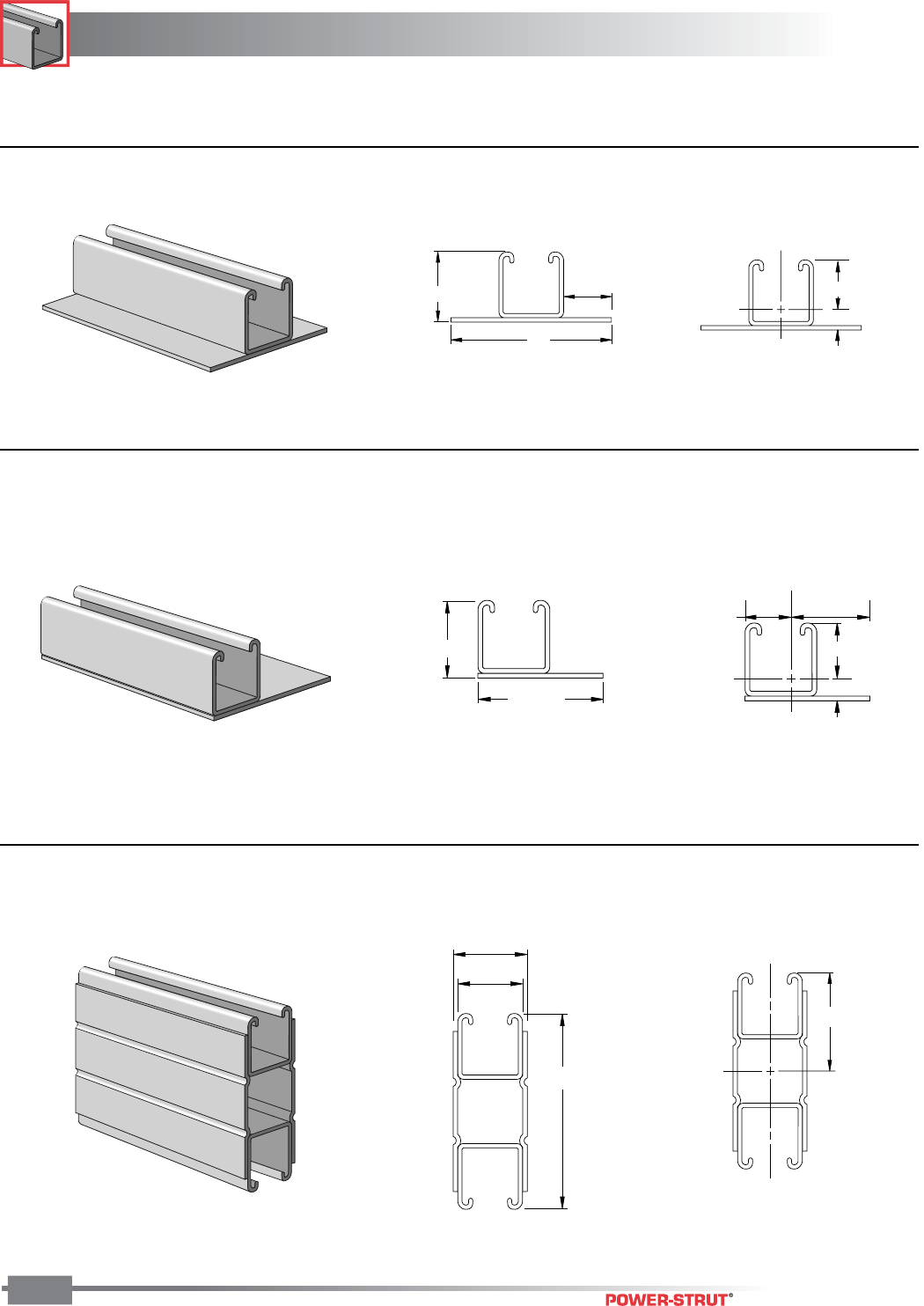
Power-Strut channel sections are
produced by multiple sets of forming
rolls which cold-work strip steel into
the channel configuration. This type of
roll forming produces a uniform
channel section held to the
specifications of MFMA-3.
■ MATERIALS:
Plain and painted green channels are formed from structural quality
strip steel which conforms to the requirements of ASTM A-1011 SS
Grade 33. Pre-galvanized channel conforms to the requirements of
ASTM A-653 Grade 33.
■ STANDARD LENGTHS:
Stock lengths are 10 and 20 feet. Special lengths are available
upon request.
■ STANDARD FINISHES:
Standard Power-Strut channel is available in plain, painted green,
zinc dichromate or pre-galvanized finishes.
■ ORDERING INFORMATION:
When ordering, add the length or size and finish to the part number.
See page 8 - 10 for finish abbreviations and an example.
CHANNEL
CHANNEL
ENGINEERING CATALOG
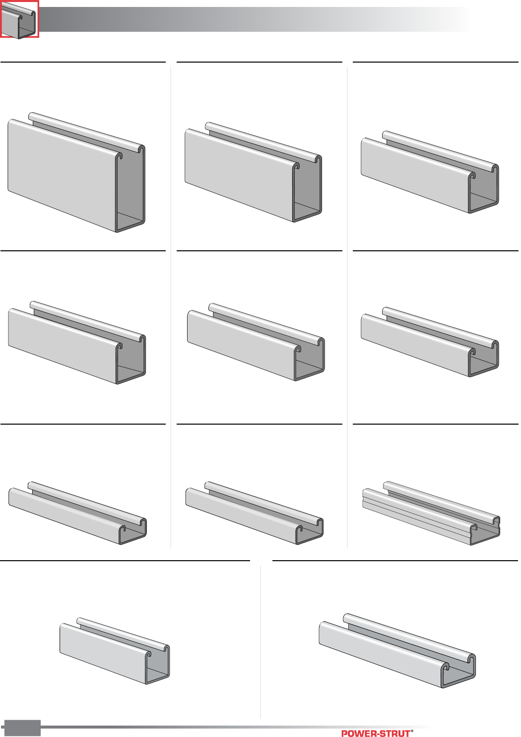
20
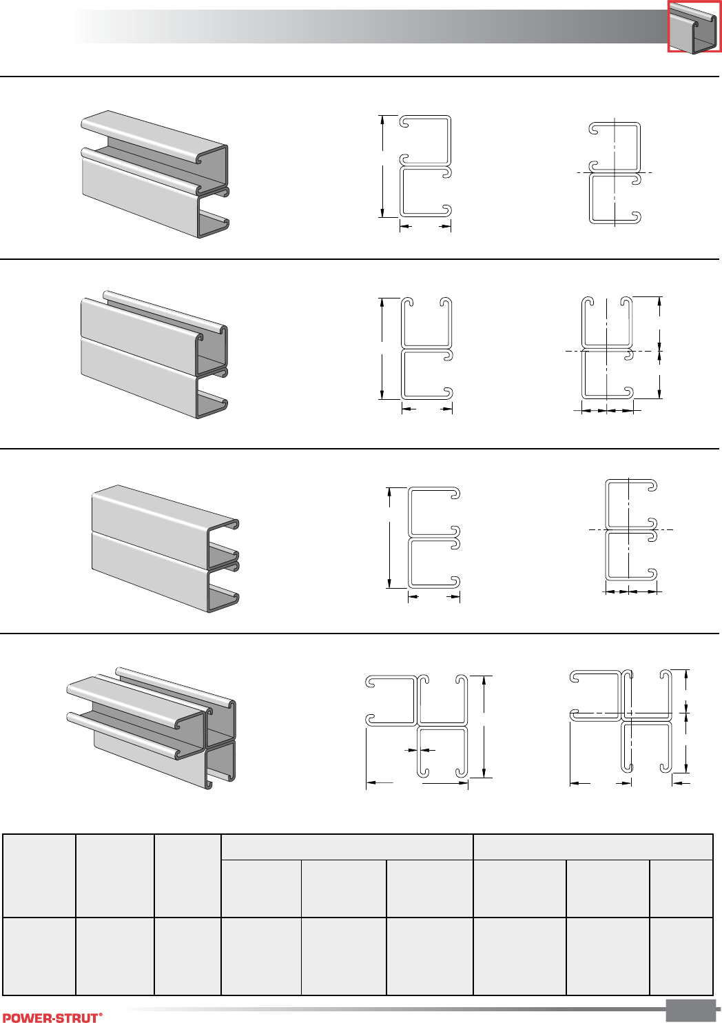
■PS 100 15⁄8" x 31⁄4" x 12 ga.
See Pages 22-24
■PS 150 15⁄8" x 27⁄16" x 12 ga.
See Pages 25-27
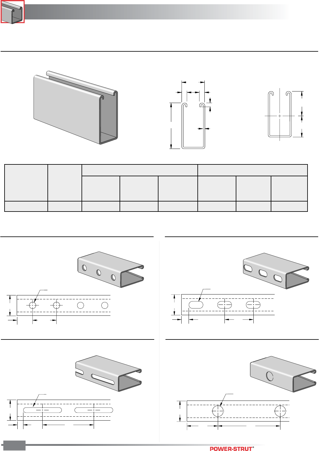
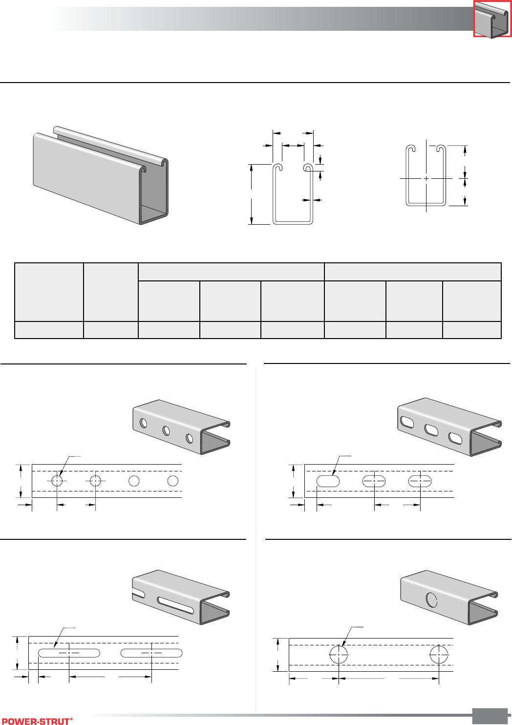
■PS 200 15⁄8" x 15⁄8" x 12 ga.
See Pages 28-35
■PS 500 15⁄8" x 13⁄16" x 14 ga.
See Pages 45-47
■PS 520 15⁄8" x 13⁄16" x 12 ga.
See Pages 48-50
■PS 560 15⁄8" x 13⁄16" x 16 ga.
See Pages 51-53
■PS 400 15⁄8" x 1" x 12 ga.
See Pages 42-44
■PS 300 15⁄8" x 13⁄8" x 12 ga.
See Pages 39-41
■PS 210 15⁄8" x 15⁄8" x 14 ga.
See Pages 36-38
■PS 600J 13⁄16" x 13⁄16" x 19 ga.
See Junior Channel
Page 134
■PS 700J 13⁄16" x 13⁄32" x 19 ga.
See Junior Channel
Page 135
CHANNEL
CHANNEL
ENGINEERING CATALOG
21
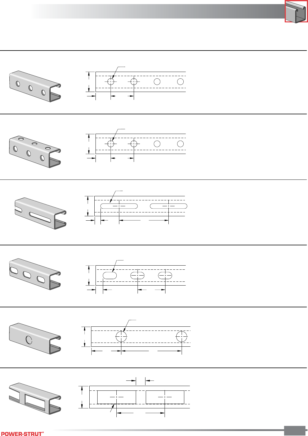
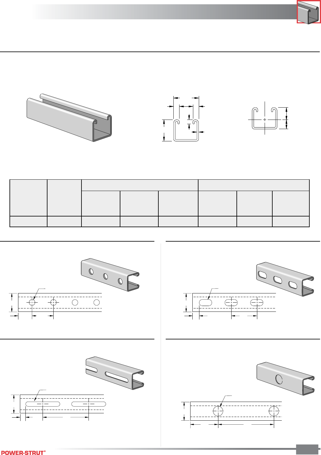
1 5⁄8"
1⁄2"4"
13⁄32" x 3" Slot
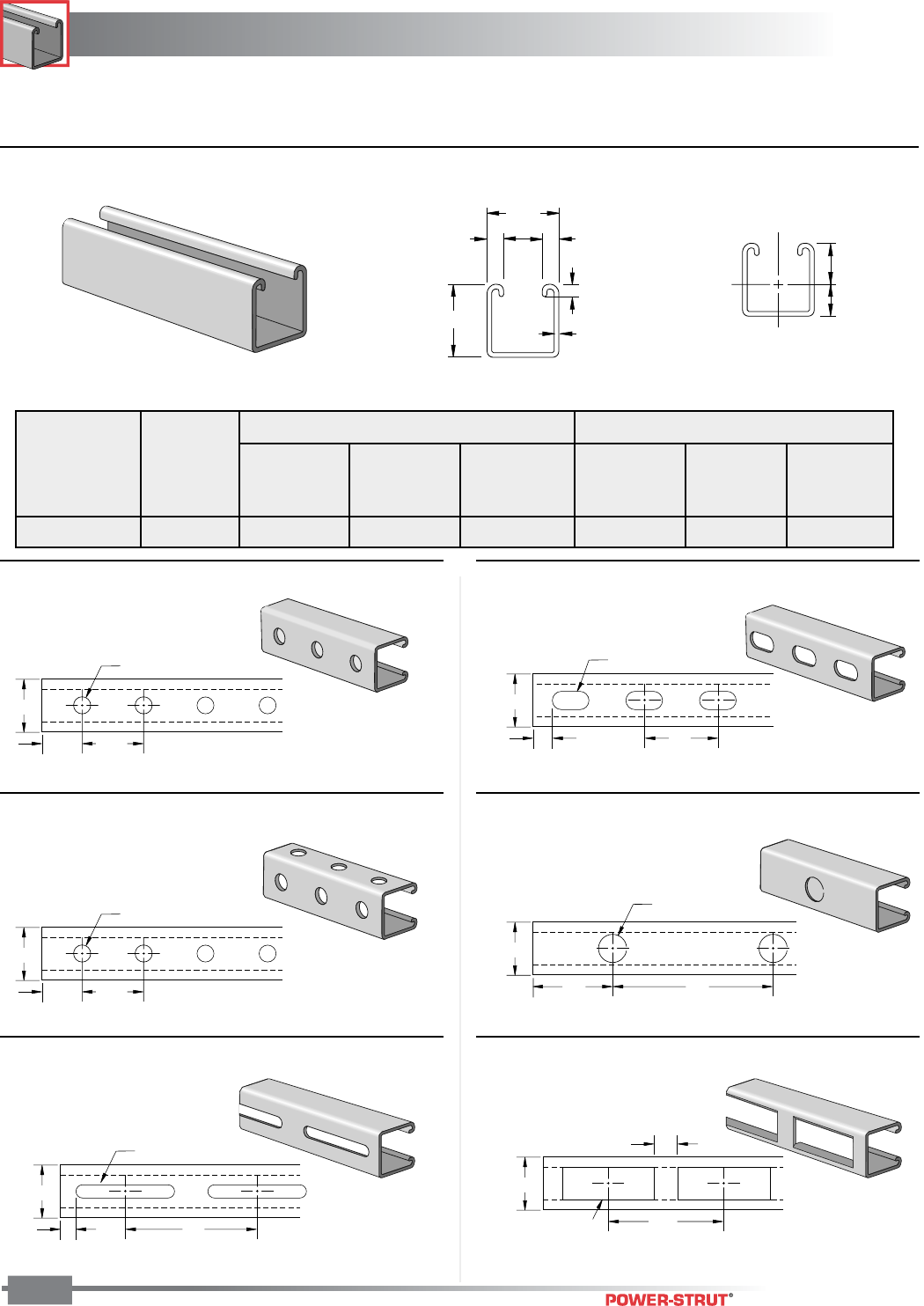
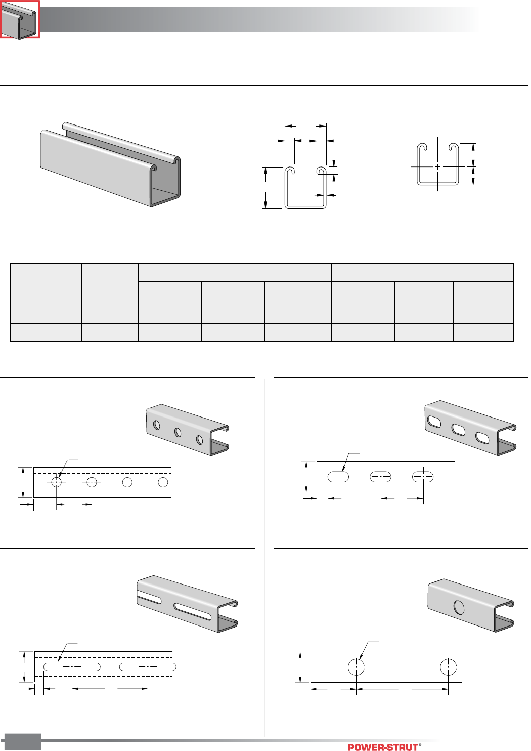
■Channel with Holes
1
5
⁄
8
"
13
⁄
16
"1
7
⁄
8
"
(typ.)
9
⁄
16
" Dia. Holes
■Channel with Elongated Holes
■Channel with Slots
■Channel with Holes on Three Sides
1 5⁄8"
13⁄16"1 7⁄8"
(typ.)
9⁄16" Dia. Holes
1
5
⁄
8
"
5
⁄
8
"2"
9
⁄
16
" x 1
1
⁄
8
" Dia. Holes
1 5⁄8"
6"
7⁄8" Dia. Knockouts
3"
■Channel with Slotted Back
■Channel with Knockouts
1 5⁄8"
3⁄4"
41⁄2"
7⁄8" x 3 1⁄2" Slot
PS 100, PS 150, PS 200,
PS 210, PS 300, PS 400,
PS 500, PS 520, PS 560
PS 100, PS 150, PS 200,
PS 210, PS 300, PS 400
PS 100, PS 150, PS 200,
PS 200 2T3, PS 210,
PS 300, PS 400, PS 500,
PS 520, PS 560
PS 100, PS 150, PS 200,
PS 210, PS 300, PS 400,
PS 500, PS 520, PS560
PS 200 Only
PS 200 Only
CHANNEL
CHANNEL
ENGINEERING CATALOG
22
Weight: 300 lbs./100 ft. Weight: 300 lbs./100 ft.
Weight: 300 lbs./100 ft. Weight: 305 lbs./100 ft.
3 1⁄4"12 Ga.
1 5⁄8"
3⁄8"3⁄8"
7⁄8"
9⁄32"
1
5
⁄
8
"
5
⁄
8
"2"
9
⁄
16
" x 1
1
⁄
8
" Dia. Holes
1
5
⁄
8
"
6"
7
⁄
8
" Dia. Knockouts
3"
XX
1.750"
1.500"
Y
Y
1
5
⁄
8
"
1
⁄
2
"4"
13
⁄
32
" x 3" Slot
1 5⁄8"
13⁄16"1 7⁄8"
(typ.)
9⁄16" Dia. Holes
Finish: Plain, Painted Green, or Pregalvanized Order By: No., Length and Finish
■PS 100 H - Channel with Holes ■PS 100 EH – Channel with Elongated Holes
■PS 100 S - Channel with Slots ■PS 100 K06 – Channel with Knockouts
■PS 100 - Steel Channel (15⁄8" x 31⁄4" x 12 ga.)
ELEMENTS OF SECTION
X-X Axis Y-Y Axis
Area of Moment Section Radius of Moment Section Radius of
Weight Section of Inertia Modulus Gyration of Inertia Modulus Gyration
(lbs./100 ft.) (Inch2) (Inch4) (Inch3) (Inch) (Inch4) (Inch3) (Inch)
305 0.897 1.099 0.628 1.107 0.359 0.442 0.695
CHANNEL
CHANNEL
ENGINEERING CATALOG
23
For Pierced Channels, reduce beam load values as follows:
PS-100-EH 15% PS-100-S 15%
PS-100-H 10% PS-100-KO6 5%
* Bearing load may govern capacity.
Resistance to Slip – 1,500 lbs. per bolt when 1⁄2" PS NS channel nuts are used.
Pull Out Strength – 2,000 lbs. per bolt when 1⁄2" PS NS channel nuts are used.
BEAM LOADING – PS 100
Column loads are for allowable axial loads and must be reduced for eccentric loading.
Finish: Plain, Painted Green, or Pregalvanized Order By: No., Length and Finish
For concentrated load at center of span, divide uniform load by 2 and multiply
corresponding deflection by 0.8. This load table is based on a solid channel section.
5,500 Lbs. 4,000 Lbs. 2,000 Lbs.
PS 100 – Crush Loads
Max Defl. at
Allowable Uniform Uniform Loading at Deflection
Span Uniform Load Load Span/180 Span/240Span/360
In Lbs In Lbs Lbs Lbs
24 5,260 0.03 5,260 5,260 5,260
36 3,510 0.07 3,510 3,510 3,510
48 2,630 0.12 2,630 2,630 2,630
60 2,110 0.18 2,110 2,110 1,920
72 1,750 0.26 1,750 1,750 1,330
84 1,500 0.36 1,500 1,470 980
96 1,320 0.47 1,320 1,130 750
108 1,170 0.59 1,170 890 590
120 1,050 0.73 960 720 480
144 880 1.05 670 500 330
168 750 1.43 490 370 250
192 660 1.87 380 280 190
216 580 2.37 300 220 150
240 530 2.92 240 180 120
COLUMN LOADING – PS 100
Maximum
Unbraced Allowable Load Maximum Column Load Applied at C.G.
Height at Slot Face K = 0.65 K = 0.80 K =1.0 K = 1.2
In Lbs Lbs Lbs Lbs Lbs
24 4,430 13,050 12,000 11,180 9,590
36 4,030 11,380 9,590 7,390 5,560
48 3,400 8,830 6,730 4,700 3,560
60 2,780 6,580 4,700 3,360 2,620
72 2,330 4,890 3,560 2,620 2,090
84 2,010 3,860 2,870 2,160 1,750
96 1,770 3,180 2,410 1,850 1,510
108 1,590 2,710 2,090 1,620 1,330
120 1,440 2,370 1,850 1,450 **
CHANNEL
CHANNEL
ENGINEERING CATALOG
24
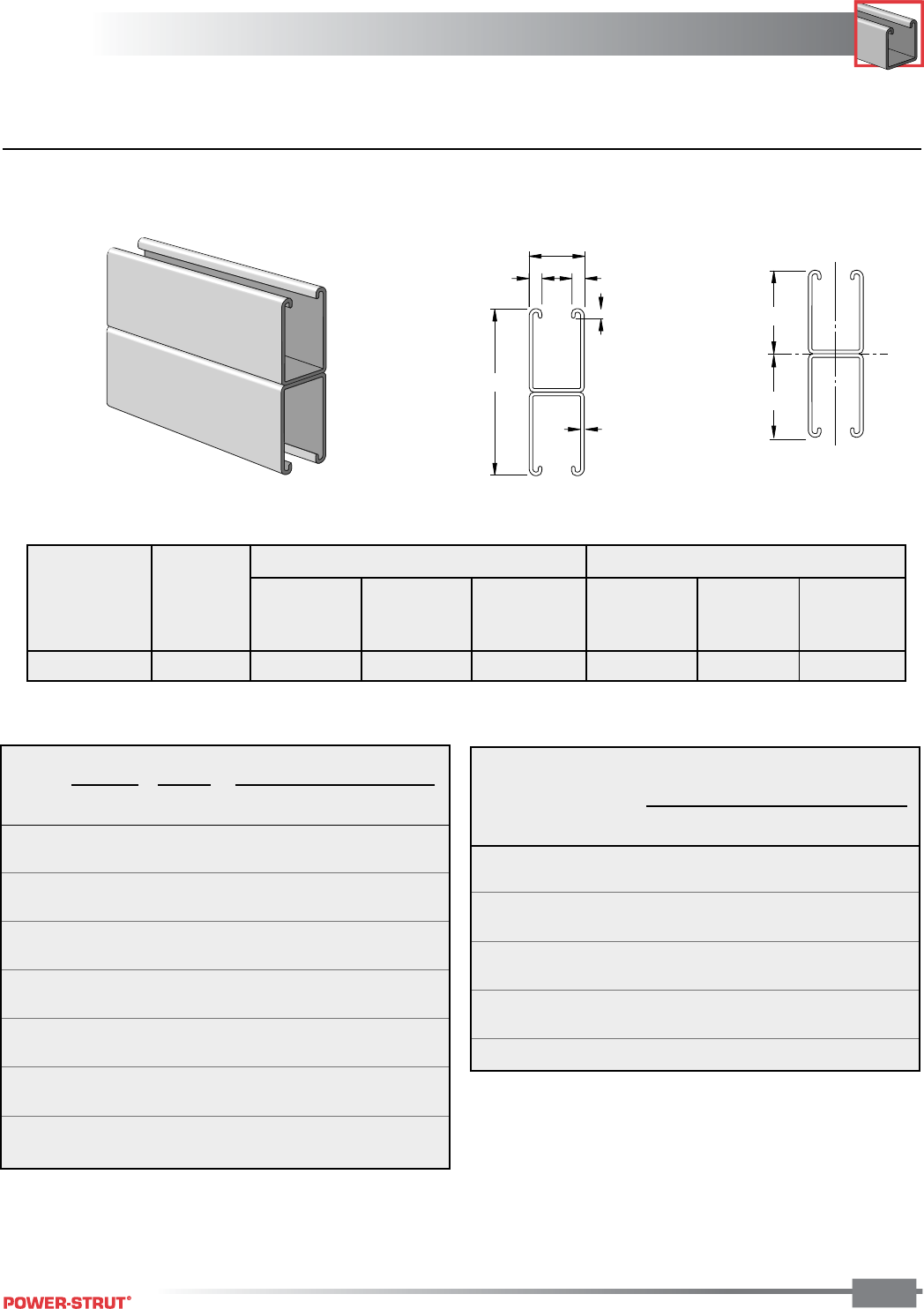
■ PS 100 2T3 – Steel Channel (15⁄8" x 61⁄2" x 12 ga.)
3.250"
Y
Y
XX
3.250"
6
1
⁄
2
"
12 Ga.
1
5
⁄
8
"
3
⁄
8
"
3
⁄
8
"
7
⁄
8
"
9
⁄
32
"
Column loads are for allowable axial loads and must be reduced for eccentric loading.
COLUMN LOADING – PS 100 2T3
For concentrated load at center of span, divide uniform load by 2 and multiply
corresponding deflection by 0.8.
* Load limited by spot weld shear.
† Bearing load may govern capacity.
Finish: Plain, Painted Green, or Pregalvanized Order By: No., Length and Finish
X-X Axis Y-Y Axis
Area of Moment Section Radius of Moment Section Radius of
Weight Section of Inertia Modulus Gyration of Inertia Modulus Gyration
(lbs./100 ft.) (Inch2) (Inch4) (Inch3) (Inch) (Inch4) (Inch3) (Inch)
610 1.794 5.578 1.716 1.864 0.719 0.884 0.695
ELEMENTS OF SECTION
Maximum
Unbraced Allowable Load Maximum Column Load Applied at C.G.
Height at Slot Face K = 0.65 K = 0.80 K =1.0 K = 1.2
In Lbs Lbs Lbs Lbs Lbs
24 8,360 30,190 29,820 29,220 28,500
36 8,230 29,300 28,500 27,220 25,740
48 8,050 28,100 26,750 24,660 22,320
60 7,810 26,630 24,660 23,090 19,770
72 7,530 24,930 22,320 19,770 15,800
84 7,340 23,070 21,110 16,450 12,100
96 6,950 22,440 18,430 13,300 9,260
108 6,510 20,270 15,800 10,540 7,320
120 6,010 18,100 13,300 8,540 **
Max Defl. at
Allowable Uniform Uniform Loading at Deflection
Span Uniform Load Load Span/180 Span/240 Span/360
In Lbs In Lbs Lbs Lbs
24 6,170 * 0.01 6,170 * 6,170 * 6,170 *
36 6,170 * 0.03 6,170 * 6,170 * 6,170 *
48 5,650 0.05 5,650 5,650 5,650
60 4,520 0.08 4,520 4,520 4,520
72 3,770 0.11 3,770 3,770 3,770
84 3,230 0.15 3,230 3,230 3,230
96 2,830 0.20 2,830 2,830 2,830
108 2,510 0.25 2,510 2,510 2,510
120 2,260 0.31 2,260 2,260 2,260
144 1,880 0.45 1,880 1,880 1,690
168 1,610 0.61 1,610 1,610 1,240
192 1,410 0.79 1,410 1,410 950
216 1,260 1.00 1,260 1,130 750
240 1,130 1.24 1,130 910 610
BEAM LOADING – PS 100 2T3
CHANNEL
CHANNEL
ENGINEERING CATALOG
25
Weight: 242 lbs./100 ft.
Weight: 247 lbs./100 ft.
1
5
⁄
8
"
6"
7
⁄
8
" Dia. Knockouts
3"
1
5
⁄
8
"
5
⁄
8
"2"
9
⁄
16
" x 1
1
⁄
8
" Dia. Holes
2
7
⁄
16
"
9
⁄
32
"
1
5
⁄
8
"
3
⁄
8
"
3
⁄
8
"
7
⁄
8
"
12 Ga.
XX
1.103"
1.336"
Y
Y
1
5
⁄
8
"
13
⁄
16
"1
7
⁄
8
"
(typ.)
9
⁄
16
" Dia. Holes
Weight: 242 lbs./100 ft.
Weight: 242 lbs./100 ft.
1 5⁄8"
1⁄2"4"
13⁄32" x 3" Slot
Finish: Plain, Painted Green, or Pregalvanized Order By: No., Length and Finish
■ PS 150 – Steel Channel (15⁄8" x 27⁄16" x 12 ga.)
■ PS 150 H - Channel with Holes ■ PS 150 EH – Channel with Elongated Holes
■ PS 150 S - Channel with Slots ■ PS 150 K06 – Channel with Knockouts
X-X Axis Y-Y Axis
Area of Moment Section Radius of Moment Section Radius of
Weight Section of Inertia Modulus Gyration of Inertia Modulus Gyration
(lbs./100 ft.) (Inch2) (Inch4) (Inch3) (Inch) (Inch4) (Inch3) (Inch)
247 0.726 0.523 0.391 0.848 0.335 0.412 0.679
ELEMENTS OF SECTION
CHANNEL
CHANNEL
ENGINEERING CATALOG
26
Resistance to Slip – 1,500 lbs. per bolt when 1⁄2" PS NS channel nuts are used.
Pull Out Strength – 2,000 lbs. per bolt when 1⁄2" PS NS channel nuts are used.
BEAM LOADING – PS 150
Max Defl. at
Allowable Uniform Uniform Loading at Deflection
Span Uniform Load Load Span/180 Span/240 Span/360
In Lbs In Lbs Lbs Lbs
24 3,280 0.04 3,280 3,280 3,280
36 2,190 0.09 2,190 2,190 2,190
48 1,640 0.15 1,640 1,640 1,430
60 1,310 0.24 1,310 1,310 910
72 1,090 0.34 1,090 950 630
84 940 0.47 930 700 470
96 820 0.61 710 540 360
108 730 0.77 560 420 280
120 660 0.96 460 340 230
144 550 1.38 320 240 160
168 470 1.87 230 170 120
192 410 2.45 180 130 90
216 360 3.10 140 110 70
240 330 3.82 110 90 60
COLUMN LOADING – PS 150
Maximum
Unbraced Allowed Load Max. Column Load Applied at C.G.
Height at Slot Face K = 0.65 K = 0.80 K =1.0 K = 1.2
In Lbs Lbs Lbs Lbs Lbs
24 4,580 13,860 12,610 10,910 9,300
36 4,010 11,120 9,300 7,190 5,550
48 3,370 8,550 6,580 4,800 3,800
60 2,810 6,430 4,800 3,610 2,920
72 2,410 4,970 3,800 2,920 2,390
84 2,120 4,060 3,160 2,460 2,020
96 1,900 3,450 2,720 2,130 1,740
108 1,720 3,000 2,390 1,870 1,520
120 1,570 2,670 2,130 1,660 **
* Bearing load may govern capacity.
This load table is based on a solid channel section.
For concentrated load at center of span, divide uniform load by 2 and multiply
corresponding deflection by 0.8.
Finish: Plain, Painted Green, or Pregalvanized Order By: No., Length and Finish
Column loads are for allowable axial loads and must be reduced for eccentric loading.
8,000 Lbs. 5,000 Lbs. 3,500 Lbs.
PS 150 – Crush Loads
For Pierced Channels, reduce beam load values as follows:
PS-150-EH 15%
PS-150-S 15%
PS-150-H 10%
PS-150-KO6 5%
CHANNEL
CHANNEL
ENGINEERING CATALOG
27
4
7
⁄
8
"
12 Ga.
1
5
⁄
8
"
3
⁄
8
"
3
⁄
8
"
7
⁄
8
"
9
⁄
32
"
2.437"
2.437"
Y
Y
XX
Column loads are for allowable axial loads and must be reduced for eccentric loading.
■ PS 150 2T3 – Steel Channel (15⁄8" x 47⁄8" x 12 ga.)
BEAM LOADING – PS 150 2T3
Max Defl. at
Allowable Uniform Uniform Loading at Deflection
Span Uniform Load Load Span/180 Span/240 Span/360
In Lbs In Lbs Lbs Lbs
24 4,680 * 0.02 4,680 * 4,680 * 4,680 *
36 4,680 * 0.05 4,680 * 4,680 * 4,680 *
48 4,680 * 0.08 4,680 * 4,680 * 4,680 *
60 3,870 0.13 3,870 3,870 3,870
72 3,220 0.19 3,220 3,220 3,220
84 2,760 0.26 2,760 2,760 2,510
96 2,420 0.34 2,420 2,420 1,920
108 2,150 0.42 2,150 2,150 1,520
120 1,930 0.52 1,930 1,840 1,230
144 1,610 0.76 1,610 1,280 850
168 1,380 1.03 1,250 940 630
192 1,210 1.34 960 720 480
216 1,070 1.70 760 570 380
240 970 2.10 610 460 310
COLUMN LOADING – PS 150 2T3
Maximum
Allowable
Unbraced Load Maximum Column Load Applied at C.G.
Height at Slot Face K = 0.65 K = 0.80 K =1.0 K = 1.2
In Lbs Lbs Lbs Lbs Lbs
24 8,650 32,840 32,310 31,440 30,410
36 8,450 31,560 30,410 28,610 26,550
48 8,180 29,850 27,950 25,070 21,960
60 7,830 27,780 25,070 21,160 17,200
72 7,420 25,450 21,960 17,200 12,730
84 6,940 22,950 18,770 13,460 9,350
96 6,410 20,360 15,660 10,310 7,160
108 5,810 17,780 12,730 8,150 5,660
120 5,220 15,280 10,310 6,600 **
*Load limited by spot weld shear.
For concentrated load at center of span, divide uniform load by 2 and multiply
corresponding deflection by 0.8.
Finish: Plain, Painted Green, or Pregalvanized Order By: No., Length and Finish
X-X Axis Y-Y Axis
Area of Moment Section Radius of Moment Section Radius of
Weight Section of Inertia Modulus Gyration of Inertia Modulus Gyration
(lbs./100 ft.) (Inch2) (Inch4) (Inch3) (Inch) (Inch4) (Inch3) (Inch)
494 1.453 2.811 1.153 1.391 0.669 0.824 0.679
ELEMENTS OF SECTION
CHANNEL
CHANNEL
ENGINEERING CATALOG
28
ELEMENTS OF SECTION
■ PS 200 – Steel Channel (15⁄8" x 15⁄8" x 12 ga.)
Weight: 185 lbs./100 ft.
1
5
⁄
8
"
1
⁄
2
"4"
13
⁄
32
" x 3" Slot
1 5⁄8"
3⁄8"
3⁄8"
1 5⁄8"
7⁄8"
9⁄32"
12 Ga.
.915"
.710"
Y
Y
XX
1 5⁄8"
13⁄16"1 7⁄8"
(typ.)
9⁄16" Dia. Holes
Weight: 186 lbs./100 ft.
1 5⁄8"
13⁄16"1 7⁄8"
(typ.)
9⁄16" Dia. Holes
1
5
⁄
8
"
5
⁄
8
"2"
9
⁄
16
" x 1
1
⁄
8
" Dia. Holes
1 5⁄8"
6"
7⁄8" Dia. Knockouts
3"
Weight: 189 lbs./100 ft.
Weight: 173 lbs./100 ft.
1 5⁄8"
3⁄4"
41⁄2"
7⁄8" x 3 1⁄2" Slot
Weight: 175 lbs./100 ft.
Weight: 185 lbs./100 ft.
Finish: Plain, Painted Green, or Pregalvanized Order By: No., Length and Finish
■ PS 200 H - Channel with Holes ■ PS 200 EH – Channel with Elongated Holes
■ PS 200 H3 - Channel with Holes ■ PS 200 K06 – Channel with Knockouts
■ PS 200 S - Channel with Slots ■ PS 200 SB – Channel with Slotted Back
X-X Axis Y-Y Axis
Area of Moment Section Radius of Moment Section Radius of
Weight Section of Inertia Modulus Gyration of Inertia Modulus Gyration
(lbs./100 ft.) (Inch2) (Inch4) (Inch3) (Inch) (Inch4) (Inch3) (Inch)
189 0.556 0.185 0.202 0.577 0.236 0.290 0.651
CHANNEL
CHANNEL
ENGINEERING CATALOG
29
Column loads are for allowable axial loads and must be reduced for eccentric loading.
For Pierced Channels, reduce beam load values as follows:
PS-200-EH 15% PS-200-S 15%
PS-200-H 10% PS-200-KO6 5%
PS-200-SB 30%
For Extruded Aluminum Channels, reduce beam load values 38%.
Resistance to Slip – 1,500 lbs. per bolt when 1⁄2" PS NS channel nuts are used.
Pull Out Strength – 2,000 lbs. per bolt when 1⁄2" PS NS channel nuts are used.
Maximum
Allowable
Unbraced Load Maximum Column Load Applied at C.G.
Height at Slot Face K = 0.65 K = 0.80 K =1.0 K = 1.2
In Lbs Lbs Lbs Lbs Lbs
24 3,450 10,750 9,900 8,770 7,730
36 3,050 8,910 7,730 6,370 5,280
48 2,660 7,250 5,980 4,660 3,770
60 2,290 5,890 4,660 3,600 2,940
72 2,000 4,800 3,770 2,940 2,380
84 1,760 4,010 3,170 2,460 1,970
96 1,570 3,450 2,730 2,090 1,650
108 1,410 3,020 2,380 1,800 **
120 1,270 2,680 2,090 ** **
BEAM LOADING – PS 200
Max Defl. at
Allowable Uniform Uniform Loading at Deflection
Span Uniform Load Load Span/180 Span/240 Span/360
In Lbs In Lbs Lbs Lbs
24 1,690 0.06 1,690 1,690 1,690
36 1,130 0.13 1,130 1,130 900
48 850 0.22 850 760 510
60 680 0.35 650 490 320
72 560 0.50 450 340 220
84 480 0.68 330 250 170
96 420 0.89 250 190 130
108 380 1.13 200 150 100
120 340 1.40 160 120 80
144 280 2.01 110 80 60
168 240 2.74 80 60 40
192 210 3.57 60 50 NR
216 190 4.52 50 40 NR
240 170 5.58 40 NR NR
COLUMN LOADING – PS 200
This load table is based on a solid channel section.
For concentrated load at center of span, divide uniform load by 2 and multiply
corresponding deflection by 0.8.
Finish: Plain, Painted Green, or Pregalvanized Order By: No., Length and Finish
8,000 Lbs. 5,000 Lbs. 3,500 Lbs.
PS 200 – Crush Loads
CHANNEL
CHANNEL
ENGINEERING CATALOG
30
Maximum
Allowable
Unbraced Load Maximum Column Load Applied at C.G.
Height at Slot Face K = 0.65 K = 0.80 K =1.0 K = 1.2
In Lbs Lbs Lbs Lbs Lbs
24 6,430 25,060 24,620 23,900 23,050
36 6,230 24,000 23,050 21,570 19,890
48 5,950 22,590 21,030 18,690 16,170
60 5,620 20,890 18,690 15,540 12,400
72 5,240 18,990 16,170 12,400 8,960
84 4,830 16,970 13,640 9,470 6,580
96 4,390 14,900 11,200 7,250 5,040
108 3,930 12,860 8,960 5,730 3,980
120 3,510 10,910 7,250 4,640 **
Max Defl. at
Allowable Uniform Uniform Loading at Deflection
Span Uniform Load Load Span/180 Span/240 Span/360
In Lbs In Lbs Lbs Lbs
24 3,130 * 0.03 3,130 * 3,130 * 3,130 *
36 3,130 * 0.07 3,130 * 3,130 * 3,130 *
48 2,400 0.13 2,400 2,400 2,400
60 1,920 0.20 1,920 1,920 1,630
72 1,600 0.28 1,600 1,600 1,130
84 1,370 0.39 1,370 1,240 830
96 1,200 0.50 1,200 950 640
108 1,070 0.64 1,000 750 500
120 960 0.79 810 610 410
144 800 1.13 560 420 280
168 690 1.54 410 310 210
192 600 2.01 320 240 160
216 530 2.55 250 190 130
240 480 3.15 200 150 100
■ PS 200 2T3 – Steel Channel (15⁄8" x 31⁄4" x 12 ga.)
3 1⁄4"
9⁄32"
1 5⁄8"
3⁄8"
3⁄8"7⁄8"
12 Ga.
Y
Y
1.625"
XX
1.625"
Column loads are for allowable axial loads and must be reduced for eccentric loading.
■ PS 200 EH 2T3 – Channel with Elongated Holes
1
5
⁄
8
"
5
⁄
8
"2"
9
⁄
16
" x 1
1
⁄
8
" Dia. Holes
Weight:
370 lbs./100 ft.
BEAM LOADING – PS 200 2T3 COLUMN LOADING – PS 200 2T3
*Load limited by spot weld shear.
For concentrated load at center of span, divide uniform load by 2 and multiply
corresponding deflection by 0.8. This load table is based on a solid channel section.
For pierced section, PS200 EH 2T3, reduce beam load values by 15%.
Finish: Plain, Painted Green, or Pregalvanized Order By: No., Length and Finish
X-X Axis Y-Y Axis
Area of Moment Section Radius of Moment Section Radius of
Weight Section of Inertia Modulus Gyration of Inertia Modulus Gyration
(lbs./100 ft.) (Inch2) (Inch4) (Inch3) (Inch) (Inch4) (Inch3) (Inch)
378 1.112 0.930 0.572 0.915 0.472 0.580 0.651
ELEMENTS OF SECTION
CHANNEL
CHANNEL
ENGINEERING CATALOG
31
1
5
⁄
8
"
3
1
⁄
4
"
1
5
⁄
8
"
3
1
⁄
4
"
1
5
⁄
8
"
3
1
⁄
4
"
Y
Y
XX
Y
Y
XX
1.677"
1.574"
.761" .864"
Y
Y
XX
.915".710"
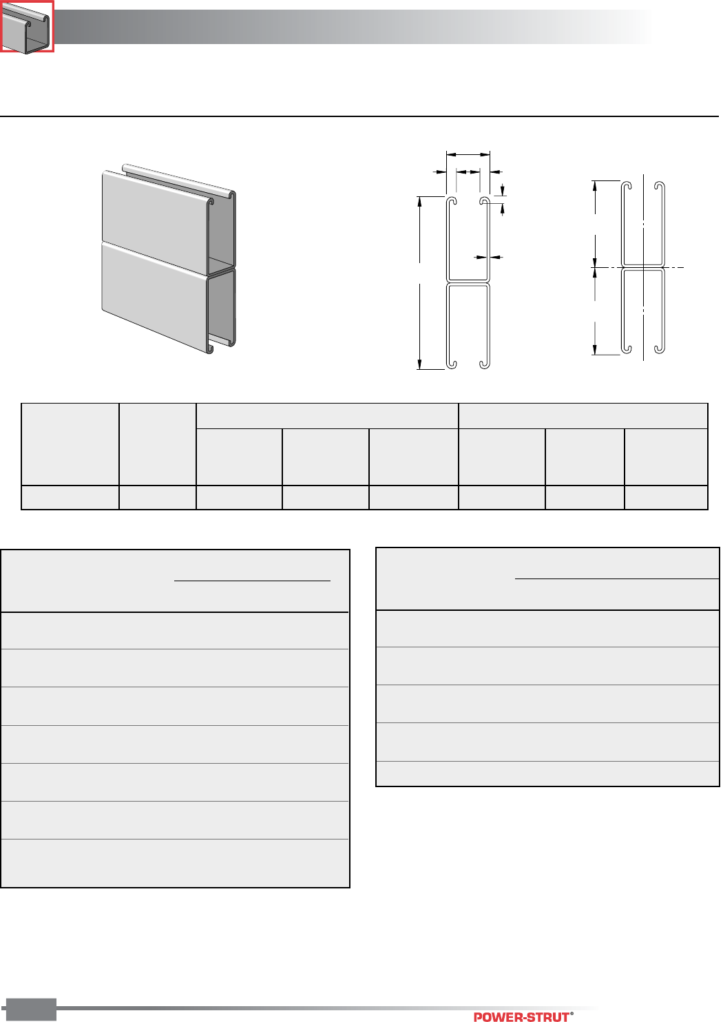
■ PS 200 2T4 – Welded Steel Channel (15⁄8" x 31⁄4" x 12 ga.)
■ PS 200 2T5 – Welded Steel Channel (15⁄8" x 31⁄4" x 12 ga.)
■ PS 200 3T6 – Welded Steel Channel (31⁄4" x 31⁄4" x 12 ga.)
■ PS 200 2T2 – Welded Steel Channel (15⁄8" x 31⁄4" x 12 ga.)
3
1
⁄
4
"
3
1
⁄
4
"
12 Ga.
1.896
1.354
1.323"
1.927"
XX
Y
Y
Finish: Plain, Painted Green, or Pregalvanized Order By: No., Length and Finish
ELEMENTS OF SECTION
X-X Axis Y-Y Axis
Area of Moment Section Radius of Moment Section Radius of
Weight Section of Inertia Modulus Gyration of Inertia Modulus Gyration
(lbs./100 ft.) (Inch2) (Inch4) (Inch3) (Inch) (Inch4) (Inch3) (Inch)
378 1.112 1.206 0.742 1.042 0.382 0.470 0.586
378 1.112 1.065 0.635 0.979 0.424 0.491 0.617
378 1.112 1.206 0.742 1.042 0.370 0.404 0.577
567 1.667 1.410 0.744 0.920 1.515 0.785 0.953
PS 200 2T2
PS 200 2T4
PS 200 2T5
PS 200 3T6
Part No.
CHANNEL
CHANNEL
ENGINEERING CATALOG
32
Finish: Plain, Painted Green, or Pregalvanized Order By: No., Length and Finish
Column loads are for allowable axial loads and must be reduced for eccentric loading.
*Load limited by spot weld shear.
This load table is based on a solid channel section.
For concentrated load at center of span, divide uniform load by 2 and multiply
corresponding deflection by 0.8.
Maximum
Allowable
Unbraced Load Maximum Column Load Applied at C.G.
Height at Slot Face K = 0.65 K = 0.80 K =1.0 K = 1.2
In Lbs Lbs Lbs Lbs Lbs
24 6,650 23,830 22,880 21,460 19,940
36 6,300 21,640 19,940 17,650 15,440
48 5,880 19,180 16,900 14,060 11,520
60 5,410 16,710 14,060 10,940 8,340
72 4,910 14,400 11,520 8,340 6,270
84 4,400 12,280 9,270 6,560 4,880
96 3,920 10,370 7,550 5,290 3,900
108 3,510 8,670 6,270 4,350 **
120 3,150 7,370 5,290 3,630 **
COLUMN LOADING – PS 200 2T4
BEAM LOADING – PS 200 2T4
Max Defl. at
Allowable Uniform Uniform Loading at Deflection
Span Uniform Load Load Span/180 Span/240 Span/360
In Lbs In Lbs Lbs Lbs
24 3,350 * 0.03 3,350 * 3,350 * 3,350 *
36 3,350 * 0.07 3,350 * 3,350 * 3,350 *
48 2,660 0.12 2,660 2,660 2,660
60 2,130 0.19 2,130 2,130 1,860
72 1,770 0.27 1,770 1,770 1,290
84 1,520 0.37 1,520 1,420 950
96 1,330 0.49 1,330 1,090 730
108 1,180 0.62 1,150 860 570
120 1,060 0.76 930 700 470
144 890 1.10 650 480 320
168 760 1.49 470 360 240
192 670 1.95 360 270 180
216 590 2.47 290 220 140
240 530 3.05 230 170 120
BEAM LOADING – PS 200 2T2
Max Defl. at
Allowable Uniform Uniform Loading at Deflection
Span Uniform Load Load Span/180 Span/240Span/360
In Lbs In Lbs Lbs Lbs
24 3,560 * 0.03 3,560 * 3,560 * 3,560 *
36 3,560 * 0.07 3,560 * 3,560 * 3,560 *
48 3,110 0.13 3,110 3,110 3,110
60 2,490 0.20 2,490 2,490 2,110
72 2,070 0.28 2,070 2,070 1,460
84 1,780 0.39 1,780 1,610 1,080
96 1,560 0.50 1,560 1,240 820
108 1,380 0.64 1,300 980 650
120 1,240 0.79 1,050 790 530
144 1,040 1.13 730 550 370
168 890 1.54 540 400 270
192 780 2.01 410 310 210
216 690 2.55 330 240 160
240 620 3.15 260 200 130
Maximum
Allowable
Unbraced Load Maximum Column Load Applied at C.G.
Height at Slot Face K = 0.65 K = 0.80 K =1.0 K = 1.2
In Lbs Lbs Lbs Lbs Lbs
24 11,670 24,860 24,320 23,450 22,430
36 11,060 23,570 22,430 20,660 18,690
48 10,270 21,870 20,020 17,300 14,480
60 9,330 19,860 17,300 13,780 10,430
72 8,310 17,650 14,480 10,430 7,260
84 7,230 15,360 11,730 7,680 5,330
96 6,130 13,080 9,180 5,880 4,080
108 5,180 10,910 7,260 4,640 **
120 4,420 8,900 5,880 ** **
COLUMN LOADING – PS 200 2T2
CHANNEL
CHANNEL
ENGINEERING CATALOG
33
Finish: Plain, Painted Green, or Pregalvanized Order By: No., Length and Finish
BEAM LOADING – PS 200 2T5
Max Defl. at
Allowable Uniform Uniform Loading at Deflection
Span Uniform Load Load Span/180 Span/240 Span/360
In Lbs In Lbs Lbs Lbs
24 3,560 * 0.03 3,560 * 3,560 * 3,560 *
36 3,560 * 0.07 3,560 * 3,560 * 3,560 *
48 3,110 0.13 3,110 3,110 3,110
60 2,490 0.20 2,490 2,490 2,110
72 2,070 0.28 2,070 2,070 1,460
84 1,780 0.39 1,780 1,610 1,080
96 1,560 0.50 1,560 1,240 820
108 1,380 0.64 1,300 980 650
120 1,240 0.79 1,050 790 530
144 1,040 1.13 730 550 370
168 890 1.54 540 400 270
192 780 2.01 410 310 210
216 690 2.55 330 240 160
240 620 3.15 260 200 130
Maximum
Allowable
Unbraced Load Maximum Column Load Applied at C.G.
Height at Slot Face K = 0.65 K = 0.80 K =1.0 K = 1.2
In Lbs Lbs Lbs Lbs Lbs
24 10,230 22,450 20,960 18,850 16,730
36 9,020 19,110 16,730 13,750 11,170
48 7,680 15,700 12,850 9,660 7,450
60 6,380 12,630 9,660 7,040 5,490
72 5,310 10,030 7,450 5,490 4,280
84 4,520 8,030 6,030 4,450 3,440
96 3,920 6,670 5,030 3,690 2,830
108 3,440 5,680 4,280 3,120 **
120 3,040 4,920 3,690 ** **
COLUMN LOADING – PS 200 2T5
BEAM LOADING – PS 200 3T6
Max Defl. at
Allowable Uniform Uniform Loading at Deflection
Span Uniform Load Load Span/180 Span/240 Span/360
In Lbs In Lbs Lbs Lbs
24 4,740 * 0.03 4,740 * 4,740 * 4,740 *
36 4,160 0.06 4,160 4,160 4,160
48 3,120 0.11 3,120 3,120 3,120
60 2,490 0.17 2,490 2,490 2,460
72 2,080 0.24 2,080 2,080 1,710
84 1,780 0.33 1,780 1,780 1,260
96 1,560 0.43 1,560 1,440 960
108 1,390 0.55 1,390 1,140 760
120 1,250 0.67 1,230 920 620
144 1,040 0.97 860 640 430
168 890 1.32 630 470 310
192 780 1.73 480 360 240
216 690 2.19 380 290 190
240 620 2.70 310 230 150
Maximum
Allowable
Unbraced Load Maximum Column Load Applied at C.G.
Height at Slot Face K = 0.65 K = 0.80 K =1.0 K = 1.2
In Lbs Lbs Lbs Lbs Lbs
24 7,440 34,950 33,390 31,270 29,250
36 7,130 31,530 29,250 26,590 24,410
48 6,800 28,310 25,810 23,180 21,170
60 6,490 25,630 23,180 20,740 18,860
72 6,200 23,470 21,170 18,860 16,860
84 5,920 21,750 19,570 17,190 14,800
96 5,640 20,330 18,180 15,520 12,680
108 5,370 19,120 16,860 13,720 10,760
120 5,090 18,010 15,520 12,010 9,120
COLUMN LOADING – PS 200 3T6
Column loads are for allowable axial loads and must be reduced for eccentric loading.
*Load limited by spot weld shear.
This load table is based on a solid channel section.
For concentrated load at center of span, divide uniform load by 2 and multiply
corresponding deflection by 0.8.
CHANNEL
CHANNEL
ENGINEERING CATALOG
34
■ PS 200 PLA – Welded Steel Channel and Plate
1 3⁄16"
1.730"
4"
Y
Y
XX
.494"
1.236"
4
7
⁄
8
"
1 5⁄8"
1.834"
1.730"
2
13
⁄
16
"
■ PS 200 PLB – Welded Steel Channel and Plate
■ PS 200 PLC – Welded Steel Channel and Plate
Y
Y
X
X
.551"
1.179"
1.017" 1.796"
2.437"
Y
Y
XX
Finish: Plain, Painted Green, or Pregalvanized Order By: No., Length and Finish
CHANNEL
CHANNEL
ENGINEERING CATALOG
35
*Load limited by spot weld shear.
† Bearing load may govern capacity.
For concentrated load at center of span, divide uniform load by 2 and multiply
corresponding deflection by 0.8.
This load table is based on a solid channel section.
Column loads are for allowable axial loads and must be reduced for eccentric loading.
Finish: Plain, Painted Green, or Pregalvanized Order By: No., Length and Finish
Max Defl. at
Allowable Uniform Uniform Loading at Deflection
Span Uniform Load Load Span/180 Span/240 Span/360
In Lbs In Lbs Lbs Lbs
24 9350 * 0.02 9350 * 9350 * 9350 *
36 9350 0.05 9350 9350 9350
48 7010 0.08 7010 7010 7010
60 5610 0.13 5610 5610 5610
72 4680 0.19 4680 4680 4680
84 4010 0.26 4010 4010 3640
96 3510 0.34 3510 3510 2790
108 3120 0.42 3120 3120 2200
120 2810 0.52 2810 2670 1780
132 2550 0.63 2550 2210 1470
144 2340 0.76 2340 1860 1240
156 2160 0.89 2110 1580 1050
168 2000 1.03 1820 1360 910
180 1870 1.18 1580 1190 790
BEAM LOADING – PS 200 PLC
Maximum
Allowable
Unbraced Load Maximum Column Load Applied at C.G.
Height at Slot Face K = 0.65 K = 0.80 K =1.0 K = 1.2
In Lbs Lbs Lbs Lbs Lbs
24 11,390 36,960 33,980 30,430 27,500
36 10,510 30,840 27,500 24,180 21,870
48 9,780 26,260 23,320 20,720 19,070
60 9,240 23,120 20,720 18,750 17,540
72 8,830 20,980 19,070 17,540 16,660
84 8,520 19,510 17,970 16,770 15,660
96 8,260 18,470 17,190 16,280 11,990
108 8,050 17,690 16,660 13,640 9,470
120 7,870 17,110 16,280 11,050 7,670
COLUMN LOADING – PS 200 PLC
PS 200 PLA
PS 200 PLB
PS 200 PLC
Part No.
X-X Axis Y-Y Axis
Area of Moment Section Radius of Moment Section Radius of
Weight Section of Inertia Modulus Gyration of Inertia Modulus Gyration
(lbs./100 ft.) (Inch2) (Inch4) (Inch3) (Inch) (Inch4) (Inch3) (Inch)
332 0.976 0.324 0.261 0.577 0.796 0.398 0.903
291 0.851 0.293 0.249 0.587 0.495 0.276 0.763
672 1.978 4.079 1.673 1.436 1.121 1.204 0.753
ELEMENTS OF SECTION
CHANNEL
CHANNEL
ENGINEERING CATALOG
36
■ PS 210 – Steel Channel (15⁄8" x 15⁄8" x 14 ga.)
Weight: 137 lbs./100 ft. Weight: 141 lbs./100 ft.
1 5⁄8"
13⁄16"1 7⁄8"
(typ.)
9⁄16" Dia. Holes
1
5
⁄
8
"
5
⁄
8
"2"
9
⁄
16
" x 1
1
⁄
8
" Dia. Holes
1
5
⁄
8
"
1
⁄
2
"4"
13
⁄
32
" x 3" Slot
1
5
⁄
8
"
6"
7
⁄
8
" Dia. Knockouts
3"
1 5⁄8"
3⁄8"
3⁄8"
1 5⁄8"
7⁄8"
9⁄32"
14 Ga.
.896"
.729"
Y
Y
XX
Weight: 137 lbs./100 ft. Weight: 137 lbs./100 ft.
Finish: Plain, Painted Green, or Pregalvanized Order By: No., Length and Finish
■ PS 210 H - Channel with Holes ■ PS 210 EH – Channel with Elongated Holes
■ PS 210 S - Channel with Slots ■ PS 210 K06 – Channel with Knockouts
ELEMENTS OF SECTION
X-X Axis Y-Y Axis
Area of Moment Section Radius of Moment Section Radius of
Weight Section of Inertia Modulus Gyration of Inertia Modulus Gyration
(lbs./100 ft.) (Inch2) (Inch4) (Inch3) (Inch) (Inch4) (Inch3) (Inch)
142 0.417 0.149 0.166 0.597 0.183 0.225 0.662

CHANNEL
CHANNEL
ENGINEERING CATALOG
37
This load table is based on a solid channel section.
For concentrated load at center of span, divide uniform load by 2 and multiply
corresponding deflection by 0.8.
For Pierced Channels, reduce beam load values as follows:
PS-210-EH 15%
PS-210-S 15%
PS-210-H 10%
PS-210-KO6 5%
Resistance to Slip – 1,000 lbs. per bolt when 1⁄2" PS NS channel nuts are used.
Pull Out Strength – 1,400 lbs. per bolt when 1⁄2" PS NS channel nuts are used.
Column loads are for allowable axial loads and must be reduced for eccentric loading.
Finish: Plain, Painted Green, or Pregalvanized Order By: No., Length and Finish
Max Defl. at
Allowable Uniform Uniform Loading at Deflection
Span Uniform Load Load Span/180 Span/240 Span/360
In Lbs In Lbs Lbs Lbs
24 1,390 0.06 1,390 1,390 1,390
36 930 0.13 930 930 720
48 700 0.23 700 610 410
60 560 0.36 520 390 260
72 460 0.51 360 270 180
84 400 0.70 270 200 130
96 350 0.91 200 150 100
108 310 1.15 160 120 80
120 280 1.42 130 100 70
144 230 2.05 90 70 50
168 200 2.79 70 50 30
192 170 3.65 50 40 30
216 150 4.62 40 30 NR
240 140 5.70 30 NR NR
BEAM LOADING – PS 210
Maximum
Allowable
Unbraced Load Maximum Column Load Applied at C.G.
Height at Slot Face K = 0.65 K = 0.80 K =1.0 K = 1.2
In Lbs Lbs Lbs Lbs Lbs
24 2,770 8,120 7,450 6,540 5,660
36 2,410 6,650 5,660 4,480 3,520
48 2,040 5,240 4,140 3,040 2,390
60 1,690 4,050 3,040 2,270 1,830
72 1,440 3,140 2,390 1,830 1,480
84 1,260 2,560 1,980 1,530 1,240
96 1,120 2,170 1,700 1,310 1,060
108 1,000 1,880 1,480 1,140 **
120 910 1,670 1,310 ** *
COLUMN LOADING – PS 210
5,500 Lbs. 3,500 Lbs. 2,500 Lbs.
PS 210 – Crush Loads
CHANNEL
CHANNEL
ENGINEERING CATALOG
38
■ PS 210 2T3 – Steel Channel (15⁄8" x 31⁄4" x 14 ga.)
3 1⁄4"
9⁄32"
1 5⁄8"
3⁄8"
3⁄8"7⁄8"
14 Ga.
Y
Y
1.625"
XX
1.625"
*Load limited by spot weld shear.
For concentrated load at center of span, divide uniform load by 2 and multiply
corresponding deflection by 0.8.
Column loads are for allowable axial loads and must be reduced for eccentric loading.
Finish: Plain, Painted Green, or Pregalvanized Order By: No., Length and Finish
ELEMENTS OF SECTION
X-X Axis Y-Y Axis
Area of Moment Section Radius of Moment Section Radius of
Weight Section of Inertia Modulus Gyration of Inertia Modulus Gyration
(lbs./100 ft.) (Inch2) (Inch4) (Inch3) (Inch) (Inch4) (Inch3) (Inch)
284 0.834 0.741 0.456 0.942 0.366 0.451 0.662
Max Defl. at
Allowable Uniform Uniform Loading at Deflection
Span Uniform Load Load Span/180 Span/240 Span/360
In Lbs In Lbs Lbs Lbs
24 1,850 * 0.03 1,850 * 1,850 * 1,850 *
36 1,850 * 0.07 1,850 * 1,850 * 1,850 *
48 1,850 * 0.13 1,850 * 1,850 * 1,850 *
60 1,530 0.20 1,530 1,530 1,300
72 1,270 0.28 1,270 1,270 900
84 1,090 0.39 1,090 990 660
96 960 0.50 960 760 510
108 850 0.64 800 600 400
120 760 0.79 650 490 320
144 640 1.13 450 340 220
168 550 1.54 330 250 170
192 480 2.01 250 190 130
216 420 2.55 200 150 100
240 380 3.15 160 120 80
BEAM LOADING – PS 210 2T3
Maximum
Allowable
Unbraced Load Maximum Column Load Applied at C.G.
Height at Slot Face K = 0.65 K = 0.80 K =1.0 K = 1.2
In Lbs Lbs Lbs Lbs Lbs
24 5,050 18,820 18,500 17,980 17,360
36 4,890 18,050 17,360 16,280 15,050
48 4,670 17,020 15,880 14,170 12,320
60 4,420 15,780 14,170 11,850 9,530
72 4,120 14,390 12,320 9,530 6,950
84 3,800 12,910 10,450 7,350 5,100
96 3,460 11,380 8,630 5,630 3,910
108 3,100 9,870 6,950 4,450 3,090
120 2,770 8,420 5,630 3,600 **
COLUMN LOADING – PS 210 2T3
CHANNEL
CHANNEL
ENGINEERING CATALOG
39
■ PS 300 – Steel Channel (15⁄8" x 13⁄8" x 12 ga.)
Weight: 165 lbs./100 ft.
Weight: 165 lbs./100 ft.
1
3
⁄
8
"
9
⁄
32
"
1
5
⁄
8
"
7
⁄
8
"
3
⁄
8
"
3
⁄
8
"
12 Ga.
1 5⁄8"
13⁄16"1 7⁄8"
(typ.)
9⁄16" Dia. Holes
1
5
⁄
8
"
5
⁄
8
"2"
9
⁄
16
" x 1
1
⁄
8
" Dia. Holes
1
5
⁄
8
"
1
⁄
2
"4"
13
⁄
32
" x 3" Slot
1
5
⁄
8
"
6"
7
⁄
8
" Dia. Knockouts
3"
.784"
Y
Y
XX
.591"
Weight: 170 lbs./100 ft.
Weight: 165 lbs./100 ft.
Finish: Plain, Painted Green, or Pregalvanized Order By: No., Length and Finish
■ PS 300 H - Channel with Holes ■ PS 300 EH – Channel with Elongated Holes
■ PS 300 S - Channel with Slots ■ PS 300 K06 – Channel with Knockouts
X-X Axis Y-Y Axis
Area of Moment Section Radius of Moment Section Radius of
Weight Section of Inertia Modulus Gyration of Inertia Modulus Gyration
(lbs./100 ft.) (Inch2) (Inch4) (Inch3) (Inch) (Inch4) (Inch3) (Inch)
171 0.503 0.121 0.154 0.490 0.205 0.253 0.639
ELEMENTS OF SECTION
CHANNEL
CHANNEL
ENGINEERING CATALOG
40
This load table is based on a solid channel section.
For concentrated load at center of span, divide uniform load by 2 and multiply
corresponding deflection by 0.8.
For Pierced Channels, reduce beam load values as follows:
PS-300-EH 15%
PS-300-S 15%
PS-300-H 10%
PS-300-KO6 5%
Resistance to Slip – 1,500 lbs. per bolt when 1⁄2" PS NS channel nuts are used.
Pull Out Strength – 2,000 lbs. per bolt when 1⁄2" PS NS channel nuts are used.
Column loads are for allowable axial loads and must be reduced for eccentric loading.
Finish: Plain, Painted Green, or Pregalvanized Order By: No., Length and Finish
Max Defl. at
Allowable Uniform Uniform Loading at Deflection
Span Uniform Load Load Span/180 Span/240 Span/360
In Lbs In Lbs Lbs Lbs
24 1,290 0.07 1,290 1,290 1,290
36 860 0.15 860 860 590
48 650 0.26 650 500 330
60 520 0.41 420 320 210
72 430 0.59 290 220 150
84 370 0.80 220 160 110
96 320 1.04 170 120 80
108 290 1.32 130 100 70
120 260 1.63 110 80 50
144 220 2.34 70 60 40
168 180 3.19 50 40 30
192 160 4.17 40 30 NR
216 140 5.27 NR NR NR
240 130 6.51 NR NR NR
BEAM LOADING – PS 300
Maximum
Allowable
Unbraced Load Maximum Column Load Applied at C.G.
Height at Slot Face K = 0.65 K = 0.80 K =1.0 K = 1.2
In Lbs Lbs Lbs Lbs Lbs
24 3,070 9,790 9,090 8,190 7,370
36 2,730 8,300 7,370 6,320 5,440
48 2,400 7,000 6,010 4,930 4,050
60 2,090 5,930 4,930 3,860 3,120
72 1,820 5,060 4,050 3,120 2,290
84 1,590 4,300 3,390 2,430 **
96 1,400 3,690 2,880 1,860 **
108 1,200 3,220 2,290 ** **
120 1,040 2,820 1,860 ** **
COLUMN LOADING – PS 300
8,000 Lbs. 5,000 Lbs. 3,500 Lbs.
PS 300 – Crush Loads
CHANNEL
CHANNEL
ENGINEERING CATALOG
41
■ PS 300 2T3 – Steel Channel (15⁄8" x 23⁄4" x 12 ga.)
2 3⁄4"
1 5⁄8"
2
12 Ga.
1.375"
1.375"
Y
Y
XX
*Load limited by spot weld shear.
For concentrated load at center of span, divide uniform load by 2 and multiply
corresponding deflection by 0.8.
Column loads are for allowable axial loads and must be reduced for eccentric loading.
Finish: Plain, Painted Green, or Pregalvanized Order By: No., Length and Finish
ELEMENTS OF SECTION
X-X Axis Y-Y Axis
Area of Moment Section Radius of Moment Section Radius of
Weight Section of Inertia Modulus Gyration of Inertia Modulus Gyration
(lbs./100 ft.) (Inch2) (Inch4) (Inch3) (Inch) (Inch4) (Inch3) (Inch)
342 1.007 0.593 0.431 0.767 0.411 0.506 0.639
Maximum
Allowable
Unbraced Load Maximum Column Load Applied at C.G.
Height at Slot Face K = 0.65 K = 0.80 K =1.0 K = 1.2
In Lbs Lbs Lbs Lbs Lbs
24 5,720 22,670 22,250 21,580 20,780
36 5,500 21,670 20,780 19,400 17,830
48 5,220 20,350 18,890 16,710 14,390
60 4,880 18,760 16,710 13,800 10,920
72 4,510 17,000 14,390 10,920 7,810
84 4,120 15,120 12,050 8,270 5,740
96 3,710 13,210 9,820 6,330 4,400
108 3,300 11,340 7,810 5,000 **
120 2,940 9,560 6,330 4,050 **
COLUMN LOADING – P300 2T3
Max Defl. at
Allowable Uniform Uniform Loading at Deflection
Span Uniform Load Load Span/180 Span/240 Span/360
In Lbs In Lbs Lbs Lbs
24 2,660 * 0.04 2,660 * 2,660 * 2,660 *
36 2,410 0.08 2,410 2,410 2,410
48 1,810 0.15 1,810 1,810 1,620
60 1,450 0.23 1,450 1,450 1,040
72 1,200 0.33 1,200 1,080 720
84 1,030 0.46 1,030 790 530
96 900 0.59 810 610 400
108 800 0.75 640 480 320
120 720 0.93 520 390 260
144 600 1.34 360 270 180
168 520 1.82 260 200 130
192 450 2.38 200 150 100
216 400 3.01 160 120 80
240 360 3.72 130 100 60
BEAM LOADING – P300 2T3
CHANNEL
CHANNEL
ENGINEERING CATALOG
42
■ PS 400 – Steel Channel (15⁄8" x 1" x 12 ga.)
Weight: 136 lbs./100 ft. Weight: 136 lbs./100 ft.
Weight: 136 lbs./100 ft. Weight: 140 lbs./100 ft.
1 5⁄8"
13⁄16"1 7⁄8"
(typ.)
9⁄16" Dia. Holes
1
5
⁄
8
"
5
⁄
8
"2"
9
⁄
16
" x 1
1
⁄
8
" Dia. Holes
1
5
⁄
8
"
1
⁄
2
"4"
13
⁄
32
" x 3" Slot
1
5
⁄
8
"
6"
7
⁄
8
" Dia. Knockouts
3"
1"
9
⁄
32
"
1
5
⁄
8
"
3
⁄
8
"
3
⁄
8
"
7
⁄
8
"
12 Ga.
X
X
0.404"
0.596"
Y
Y
Finish: Plain, Painted Green, or Pregalvanized Order By: No., Length and Finish
■ PS 400 H - Channel with Holes ■ PS 400 EH – Channel with Elongated Holes
■ PS 400 S - Channel with Slots ■ PS 400 K06 – Channel with Knockouts
X-X Axis Y-Y Axis
Area of Moment Section Radius of Moment Section Radius of
Weight Section of Inertia Modulus Gyration of Inertia Modulus Gyration
(lbs./100 ft.) (Inch2) (Inch4) (Inch3) (Inch) (Inch4) (Inch3) (Inch)
140 0.411 0.051 0.086 0.353 0.158 0.194 0.619
ELEMENTS OF SECTION
CHANNEL
CHANNEL
ENGINEERING CATALOG
43
This load table is based on a solid channel section.
For concentrated load at center of span, divide uniform load by 2 and multiply
corresponding deflection by 0.8.
For Pierced Channels, reduce beam load values as follows:
PS-400-EH 15%
PS-400-S 15%
PS-400-H 10%
PS-400-KO6 5%
Resistance to Slip – 1,500 lbs. per bolt when 1⁄2" PS NS channel nuts are used.
Pull Out Strength – 2,000 lbs. per bolt when 1⁄2" PS NS channel nuts are used.
Column loads are for allowable axial loads and must be reduced for eccentric loading.
Finish: Plain, Painted Green, or Pregalvanized Order By: No., Length and Finish
Max Defl. at
Allowable Uniform Uniform Loading at Deflection
Span Uniform Load Load Span/180 Span/240 Span/360
In Lbs In Lbs Lbs Lbs
24 720 0.09 720 720 560
36 480 0.19 480 370 250
48 360 0.35 280 210 140
60 290 0.54 180 130 90
72 240 0.78 120 90 60
84 210 1.06 90 70 50
96 180 1.38 70 50 30
108 160 1.75 60 40 30
120 140 2.16 40 30 20
132 130 2.61 40 30 20
144 120 3.11 30 20 20
156 110 3.64 30 20 NR
168 100 4.23 20 20 NR
180 100 4.85 NR NR NR
BEAM LOADING – PS 400
Maximum
Allowable
Unbraced Load Maximum Column Load Applied at C.G.
Height at Slot Face K = 0.65 K = 0.80 K =1.0 K = 1.2
In Lbs Lbs Lbs Lbs Lbs
24 2,245 7,830 7,305 6,685 6,160
36 1,960 6,760 6,160 5,120 3,880
48 1,630 5,920 4,690 3,150 2,190
60 1,300 4,590 3,150 2,020 **
72 1,050 3,320 2,190 ** **
84 850 2,440 1,610 ** **
96 KL/r>200 1,870 ** ** **
108 KL/r>200 1,470 ** ** **
120 KL/r>200 ** ** ** **
COLUMN LOADING – PS 400
8,000 Lbs. 5,000 Lbs. 3,500 Lbs.
PS 400 – Crush Loads
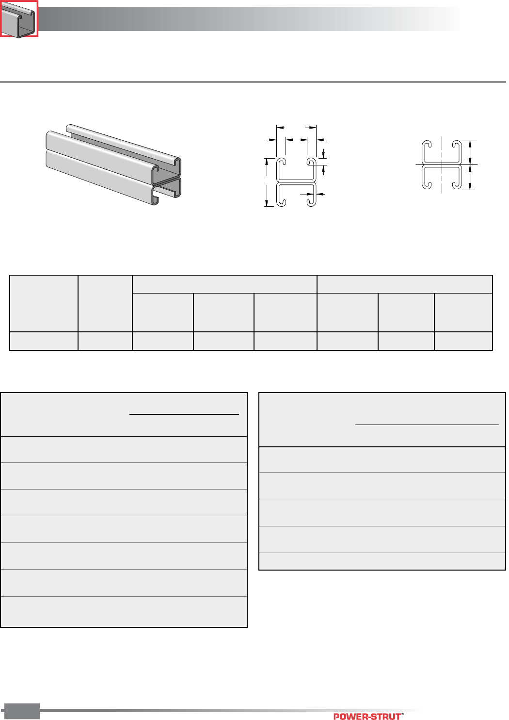
CHANNEL
CHANNEL
ENGINEERING CATALOG
44
■ PS 400 2T3 – Steel Channel (15⁄8" x 2" x 12 ga.)
2"
9
⁄
32
"
1
5
⁄
8
"
3
⁄
8
"
3
⁄
8
"
7
⁄
8
"
12 Ga.
X
X
1"
1"
Y
Y
*Load limited by spot weld shear.
For concentrated load at center of span, divide uniform load by 2 and multiply
corresponding deflection by 0.8.
Column loads are for allowable axial loads and must be reduced for eccentric loading.
Finish: Plain, Painted Green, or Pregalvanized Order By: No., Length and Finish
X-X Axis Y-Y Axis
Area of Moment Section Radius of Moment Section Radius of
Weight Section of Inertia Modulus Gyration of Inertia Modulus Gyration
(lbs./100 ft.) (Inch2) (Inch4) (Inch3) (Inch) (Inch4) (Inch3) (Inch)
279 0.822 0.237 0.237 0.537 0.315 0.388 0.619
ELEMENTS OF SECTION
Max Defl. at
Allowable Uniform Uniform Loading at Deflection
Span Uniform Load Load Span/180 Span/240 Span/360
In Lbs In Lbs Lbs Lbs
24 1,920 * 0.05 1,920 * 1,920 * 1,920 *
36 1,320 0.12 1,320 1,320 1,150
48 990 0.20 990 970 650
60 790 0.32 790 620 410
72 660 0.46 580 430 290
84 570 0.63 420 320 210
96 500 0.82 320 240 160
108 440 1.04 260 190 130
120 400 1.28 210 160 100
132 360 1.55 170 130 90
144 330 1.84 140 110 70
156 310 2.16 120 90 60
168 280 2.51 110 80 50
180 260 2.88 90 70 50
BEAM LOADING – PS 400 2T3
Maximum
Allowable
Unbraced Load Maximum Column Load Applied at C.G.
Height at Slot Face K = 0.65 K = 0.80 K =1.0 K = 1.2
In Lbs Lbs Lbs Lbs Lbs
24 4,280 17,670 17,220 16,690 16,120
36 4,050 16,750 16,120 14,620 12,980
48 3,720 15,640 14,090 11,840 9,580
60 3,350 13,950 11,840 9,030 6,490
72 2,980 12,130 9,580 6,490 4,500
84 2,610 10,270 7,450 4,770 3,310
96 2,260 8,490 5,700 3,650 **
108 1,970 6,820 4,500 ** **
120 1,740 5,530 3,650 ** **
COLUMN LOADING – PS 400 2T3
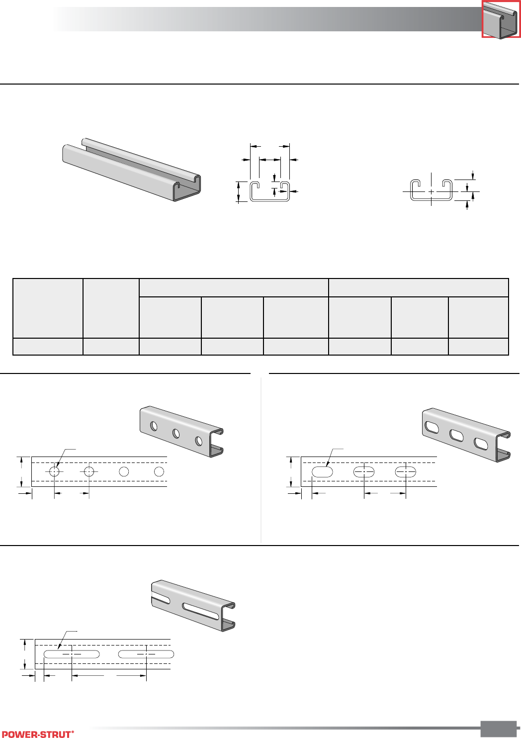
CHANNEL
CHANNEL
ENGINEERING CATALOG
45
■ PS 500 – Steel Channel (15⁄8" x 13⁄16" x 14 ga.)
Weight: 87 lbs./100 ft.
Weight: 87 lbs./100 ft.
7⁄8"
13⁄16"
1 5⁄8"
3⁄8"3⁄8"
1⁄4"
14 Ga.
.333"
.480"
Y
Y
XX
1 5⁄8"
13⁄16"1 7⁄8"
(typ.)
9⁄16" Dia. Holes
1
5
⁄
8
"
5
⁄
8
"2"
9
⁄
16
" x 1
1
⁄
8
" Dia. Holes
1
5
⁄
8
"
1
⁄
2
"4"
13
⁄
32
" x 3" Slot
ELEMENTS OF SECTION
Weight: 87 lbs./100 ft.
Finish: Plain, Painted Green, or Pregalvanized Order By: No., Length and Finish
X-X Axis Y-Y Axis
Area of Moment Section Radius of Moment Section Radius of
Weight Section of Inertia Modulus Gyration of Inertia Modulus Gyration
(lbs./100 ft.) (Inch2) (Inch4) (Inch3) (Inch) (Inch4) (Inch3) (Inch)
98 0.287 0.025 0.053 0.298 0.106 0.131 0.609
■ PS 500 H - Channel with Holes ■ PS 500 EH – Channel with Elongated Holes
■PS 500 S - Channel with Slots
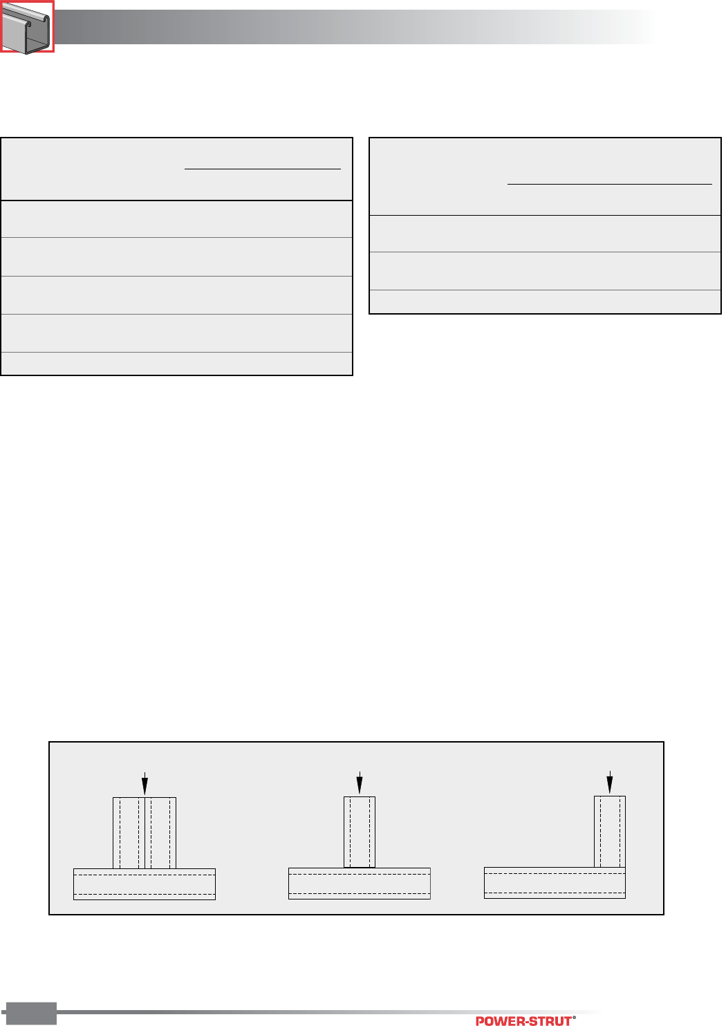
CHANNEL
CHANNEL
ENGINEERING CATALOG
46
This load table is based on a solid channel section.
For concentrated load at center of span, divide uniform load by 2 and multiply
corresponding deflection by 0.8.
For Pierced Channels, reduce beam load values as follows:
PS-500-EH 15%
PS-500-S 15%
PS-500-H 10%
Resistance to Slip – 1,000 lbs. per bolt when 1⁄2" PS NS channel nuts are used.
Pull Out Strength – 1,400 lbs. per bolt when 1⁄2" PS NS channel nuts are used.
Column loads are for allowable axial loads and must be reduced for eccentric loading
Finish: Plain, Painted Green, or Pregalvanized Order By: No., Length and Finish
Max Defl. at
Allowable Uniform Uniform Loading at Deflection
Span Uniform Load Load Span/180 Span/240 Span/360
In Lbs In Lbs Lbs Lbs
24 440 0.11 440 410 270
36 300 0.24 240 180 120
48 220 0.43 140 100 70
60 180 0.68 90 70 40
72 150 0.98 60 50 30
84 130 1.33 40 30 20
96 110 1.74 30 30 20
108 100 2.20 30 20 10
120 90 2.71 20 20 10
Maximum
Allowable
Unbraced Load Maximum Column Load Applied at C.G.
Height at Slot Face K = 0.65 K = 0.80 K =1.0 K = 1.2
In Lbs Lbs Lbs Lbs Lbs
24 1,620 5,670 5,210 4,530 3,810
36 1,300 4,620 3,810 2,770 1,940
48 1,000 3,450 2,450 1,570 1,090
60 760 2,380 1,570 ** **
72 600 1,650 1,090 ** **
BEAM LOADING – PS 500 COLUMN LOADING – PS 500
4,800 Lbs. 3,400 Lbs. 2,600 Lbs.
PS 500 – Crush Loads
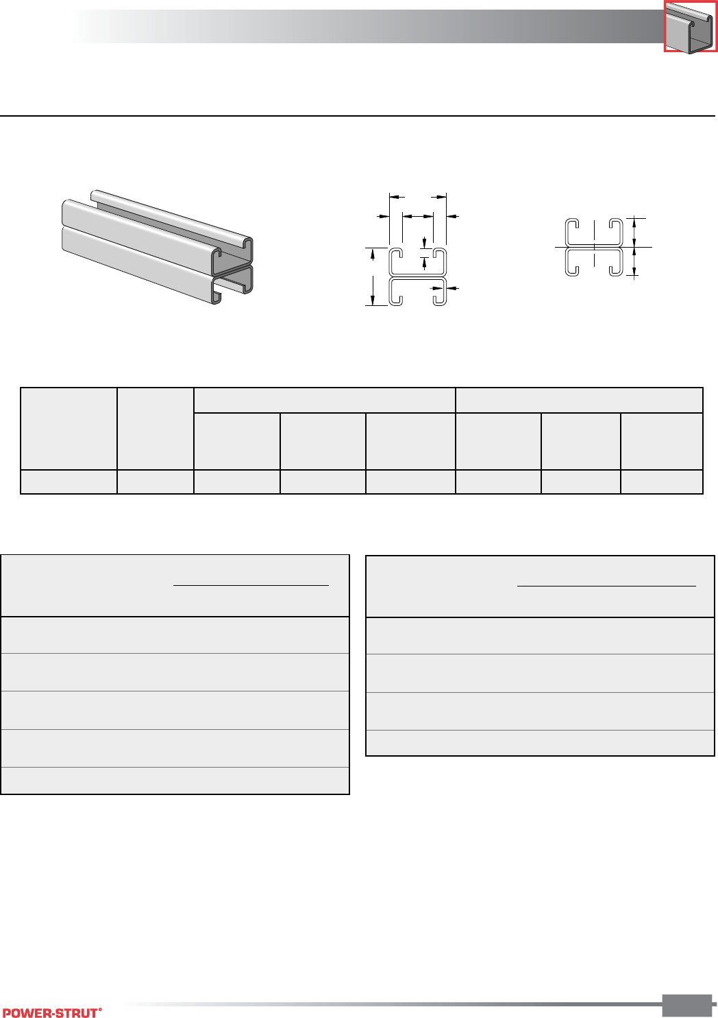
CHANNEL
CHANNEL
ENGINEERING CATALOG
47
■ PS 500 2T3 – Steel Channel (15⁄8" x 15⁄8" x 14 ga.)
*Load limited by spot weld shear.
For concentrated load at center of span, divide uniform load by 2 and multiply
corresponding deflection by 0.8.
.812"
.812"
Y
Y
XX
1
5
⁄
8
"
7
⁄
8
"
1
5
⁄
8
"
3
⁄
8
"
3
⁄
8
"
1
⁄
4
"
14 Ga.
Column loads are for allowable axial loads and must be reduced for eccentric loading.
Finish: Plain, Painted Green, or Pregalvanized Order By: No., Length and Finish
ELEMENTS OF SECTION
X-X Axis Y-Y Axis
Area of Moment Section Radius of Moment Section Radius of
Weight Section of Inertia Modulus Gyration of Inertia Modulus Gyration
(lbs./100 ft.) (Inch2) (Inch4) (Inch3) (Inch) (Inch4) (Inch3) (Inch)
195 0.574 0.114 0.141 0.447 0.212 0.261 0.609
Maximum
Unbraced Allowable Load Max. Column Load Applied at C.G.
Height at Slot Face K = 0.65 K = 0.80 K =1.0 K = 1.2
In Lbs Lbs Lbs Lbs Lbs
24 3,040 12,440 11,980 11,250 10,420
36 2,780 11,350 10,420 9,050 7,620
48 2,460 9,980 8,580 6,680 4,900
60 2,130 8,460 6,680 4,520 3,140
72 1,800 6,910 4,900 3,140 2,180
84 1,520 5,440 3,600 2,310 **
96 1,290 4,180 2,760 ** **
COLUMN LOADING – PS 500 2T3
Max Defl. at
Allowable Uniform Uniform Loading at Deflection
Span Uniform Load Load Span/180 Span/240 Span/360
In Lbs In Lbs Lbs Lbs
24 910 * 0.06 910 * 910* 910*
36 790 0.14 790 790 550
48 590 0.25 590 470 310
60 470 0.40 400 300 200
72 390 0.57 280 210 140
84 340 0.77 200 150 100
96 300 1.01 160 120 80
108 260 1.28 120 90 60
120 240 1.58 100 70 50
BEAM LOADING – PS 500 2T3
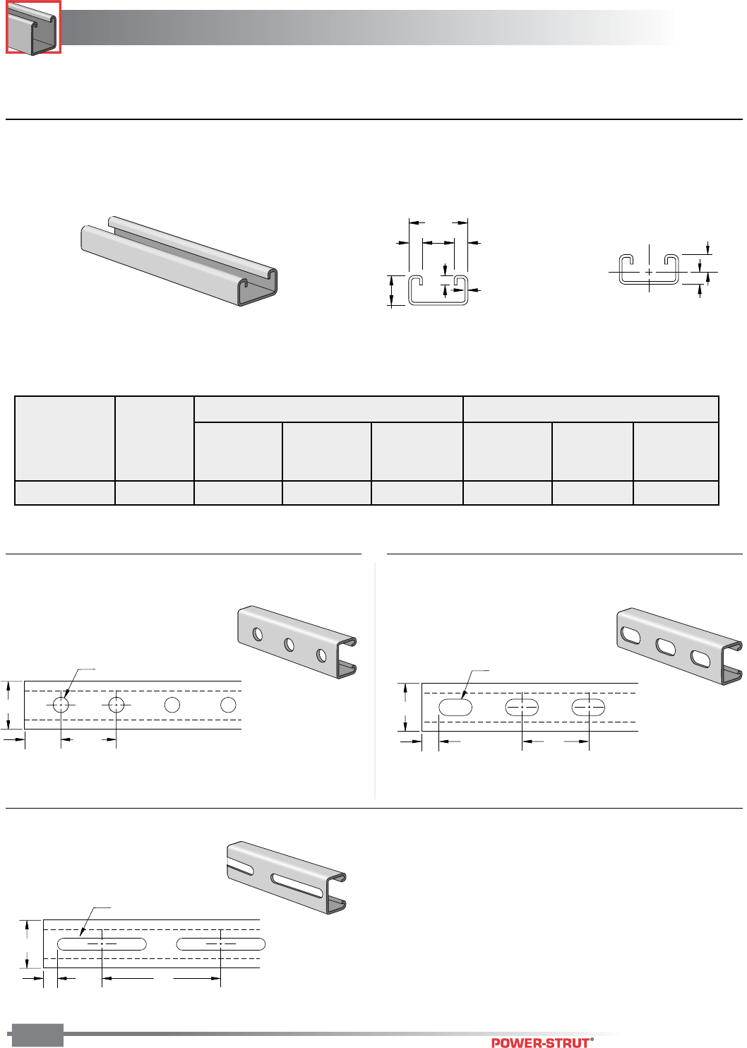
CHANNEL
CHANNEL
ENGINEERING CATALOG
48
■ PS 520 – Steel Channel (15⁄8" x 13⁄16" x 12 ga.)
Weight: 120 lbs./100 ft. Weight: 120 lbs./100 ft.
Weight: 118 lbs./100 ft.
1
5
⁄
8
"
13
⁄
16
"1
7
⁄
8
"
(typ.)
9
⁄
16
" Dia. Holes
1
5
⁄
8
"
5
⁄
8
"2"
9
⁄
16
" x 1
1
⁄
8
" Dia. Holes
1
5
⁄
8
"
1
⁄
2
"4"
13
⁄
32
" x 3" Slot
7⁄8"
13⁄16"
1 5⁄8"
3⁄8"3⁄8"
9⁄32"
12 Ga.
.321"
.492"
Y
Y
XX
Finish: Plain, Painted Green, or Pregalvanized Order By: No., Length and Finish
■ PS 520 H - Channel with Holes ■ PS 520 EH – Channel with Elongated Holes
■PS 520 S - Channel with Slots
X-X Axis Y-Y Axis
Area of Moment Section Radius of Moment Section Radius of
Weight Section of Inertia Modulus Gyration of Inertia Modulus Gyration
(lbs./100 ft.) (Inch2) (Inch4) (Inch3) (Inch) (Inch4) (Inch3) (Inch)
126 0.371 0.030 0.061 0.284 0.135 0.166 0.602
ELEMENTS OF SECTION

CHANNEL
CHANNEL
ENGINEERING CATALOG
49
Column loads are for allowable axial loads and must be reduced for eccentric loading.
Resistance to Slip – 1,500 lbs. per bolt when 1⁄2" PS NS channel nuts are used.
Pull Out Strength –1,500 lbs. per bolt when 1⁄2" PS NS channel nuts are used.
This load table is based on a solid channel section.
For concentrated load at center of span, divide uniform load by 2 and multiply
corresponding deflection by 0.8.
For Pierced Channels, reduce beam load values as follows:
PS-520-EH 15%
PS-520-S 15%
PS-520-H 10%
Finish: Plain, Painted Green, or Pregalvanized Order By: No., Length and Finish
Max Defl. at
Allowable Uniform Uniform Loading at Deflection
Span Uniform Load Load Span/180 Span/240 Span/360
In Lbs In Lbs Lbs Lbs
24 510 0.10 510 490 330
36 340 0.23 290 220 150
48 260 0.42 160 120 80
60 200 0.65 100 80 50
72 170 0.94 70 50 40
84 150 1.27 50 40 30
96 130 1.66 40 30 20
108 110 2.11 30 20 20
120 100 2.60 30 20 NR
132 90 3.15 20 20 NR
144 90 3.74 20 NR NR
156 80 4.39 20 NR NR
168 70 5.10 NR NR NR
180 70 5.85 NR NR NR
BEAM LOADING – PS 520
Maximum
Allowable
Unbraced Load Maximum Column Load Applied at C.G.
Height at Slot Face K = 0.65 K = 0.80 K =1.0 K = 1.2
In Lbs Lbs Lbs Lbs Lbs
24 1,880 7,170 6,570 5,620 4,650
36 1,520 5,750 4,650 3,280 2,270
48 1,160 4,160 2,870 1,830 **
60 890 2,790 1,840 ** **
72 KL/r>200 1,940 ** ** **
84 KL/r>200 1,420 ** ** **
96 KL/r>200 ** ** ** **
108 KL/r>200 ** ** ** **
120 KL/r>200 ** ** ** **
COLUMN LOADING – PS 520
9,000 Lbs. 6,000 Lbs. 4,000 Lbs.
PS 520 – Crush Loads
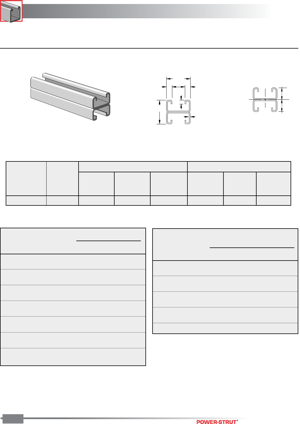
CHANNEL
CHANNEL
ENGINEERING CATALOG
50
■ PS 520 2T3 – Steel Channel (15⁄8" x 15⁄8" x 12 ga.)
1
5
⁄
8
"
7
⁄
8
"
1
5
⁄
8
"
3
⁄
8
"
3
⁄
8
"
9
⁄
32
"
12 Ga.
.812"
.812"
Y
Y
XX
Column loads are for allowable axial loads and must be reduced for eccentric loading.
For concentrated load at center of span, divide uniform load by 2 and multiply
corresponding deflection by 0.8.
Finish: Plain, Painted Green, or Pregalvanized Order By: No., Length and Finish
X-X Axis Y-Y Axis
Area of Moment Section Radius of Moment Section Radius of
Weight Section of Inertia Modulus Gyration of Inertia Modulus Gyration
(lbs./100 ft.) (Inch2) (Inch4) (Inch3) (Inch) (Inch4) (Inch3) (Inch)
252 0.742 0.136 0.168 0.428 0.270 0.331 0.602
ELEMENTS OF SECTION
Max Defl. at
Allowable Uniform Uniform Loading at Deflection
Span Uniform Load Load Span/180 Span/240 Span/360
In Lbs In Lbs Lbs Lbs
24 1,410 0.06 1,410 1,410 1,410
36 940 0.14 940 940 660
48 700 0.25 700 560 370
60 560 0.39 480 360 240
72 470 0.57 330 250 170
84 400 0.77 240 180 120
96 350 1.01 190 140 90
108 310 1.28 150 110 70
120 280 1.58 120 90 60
132 260 1.91 100 70 50
144 230 2.27 80 60 40
156 220 2.67 70 50 40
168 200 3.10 60 50 nr
180 190 3.55 50 40 nr
BEAM LOADING – PS 520 2T3
Maximum
Allowable
Unbraced Load Maximum Column Load Applied at C.G.
Height at Slot Face K = 0.65 K = 0.80 K =1.0 K = 1.2
In Lbs Lbs Lbs Lbs Lbs
24 3,690 15,910 15,350 14,340 13,190
36 3,360 14,470 13,190 11,310 9,370
48 2,960 12,560 10,640 8,090 5,800
60 2,550 10,500 8,110 5,360 3,720
72 2,150 8,420 5,820 3,720 **
84 1,810 6,480 4,280 2,740 **
96 1,540 4,960 3,270 ** **
108 KL/r>200 3,920 ** ** **
120 KL/r>200 3,170 ** ** **
COLUMN LOADING – PS 520 2T3
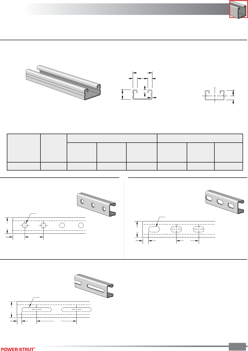
CHANNEL
CHANNEL
ENGINEERING CATALOG
51
■ PS 560 – Steel Channel (15⁄8" x 13⁄16" x 16 ga.)
Weight: 79 lbs./100 ft.
1
5
⁄
8
"
5
⁄
8
"2"
9
⁄
16
" x 1
1
⁄
8
" Dia. Holes
Weight: 79 lbs./100 ft.
1
5
⁄
8
"
13
⁄
16
"1
7
⁄
8
"
(typ.)
9
⁄
16
" Dia. Holes
Weight: 79 lbs./100 ft.
1
5
⁄
8
"
1
⁄
2
"4"
13
⁄
32
" x 3" Slot
.343"
2
1
.470"
13⁄16"
1 5⁄8"
3⁄8"
3⁄8"7⁄8"
1⁄4"
16 Ga.
Finish: Plain, Painted Green, or Pregalvanized Order By: No., Length and Finish
■ PS 560 H - Channel with Holes ■ PS 560 EH – Channel with Elongated Holes
■PS 560 S - Channel with Slots
ELEMENTS OF SECTION
X-X Axis Y-Y Axis
Area of Moment Section Radius of Moment Section Radius of
Weight Section of Inertia Modulus Gyration of Inertia Modulus Gyration
(lbs./100 ft.) (Inch2) (Inch4) (Inch3) (Inch) (Inch4) (Inch3) (Inch)
81 0.239 0.023 0.048 0.308 0.091 0.112 0.617
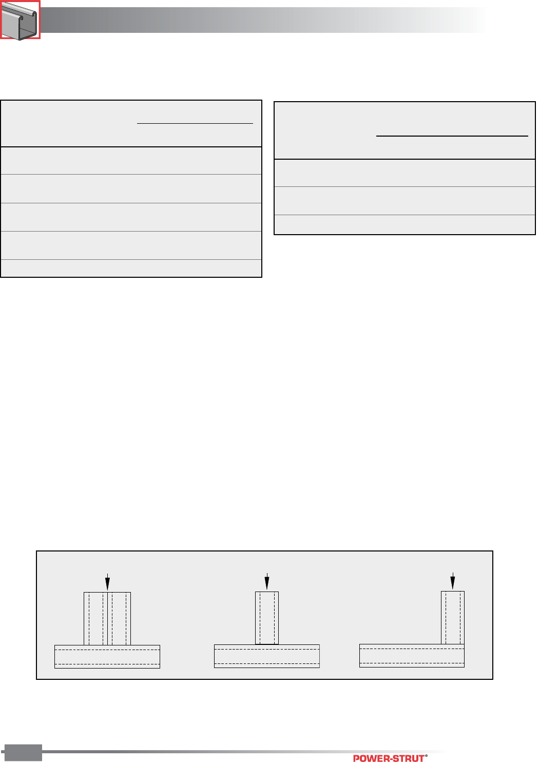
CHANNEL
CHANNEL
ENGINEERING CATALOG
52
For concentrated load at center of span, divide uniform load by 2 and multiply
corresponding deflection by 0.8.
For Pierced Channels, reduce beam load values as follows:
PS-520-EH 15%
PS-520-S 15%
PS-520-H 10%
Resistance to Slip – 1,000 lbs. per bolt when 1⁄2" PS NS channel nuts are used.
Pull Out Strength – 1,000 lbs. per bolt when 1⁄2" PS NS channel nuts are used.
Column loads are for allowable axial loads and must be reduced for eccentric loading.
Finish: Plain, Painted Green, or Pregalvanized Order By: No., Length and Finish
Max Defl. at
Allowable Uniform Uniform Loading at Deflection
Span Uniform Load Load Span/180 Span/240 Span/360
In Lbs In Lbs Lbs Lbs
24 400 0.11 400 380 250
36 270 0.24 220 170 110
48 200 0.43 130 90 60
60 160 0.67 80 60 40
72 130 0.96 60 40 30
84 110 1.31 40 30 20
96 100 1.71 30 20 20
108 90 2.16 20 20 10
120 80 2.67 20 20 10
BEAM LOADING – PS 560
Maximum
Allowable
Unbraced Load Maximum Column Load Applied at C.G.
Height at Slot Face K = 0.65 K = 0.80 K =1.0 K = 1.2
In Lbs Lbs Lbs Lbs Lbs
24 1,420 4,480 4,000 3,320 2,640
36 1,110 3,410 2,640 1,760 1,220
48 810 2,320 1,540 990 690
60 600 1,500 990 630 **
72 470 1,040 690 ** **
COLUMN LOADING – PS 560
3,500 Lbs. 2,200 Lbs. 1,700 Lbs.
PS560 – Crush Loads

CHANNEL
CHANNEL
ENGINEERING CATALOG
53
■ PS 560 2T3 – Steel Channel (15⁄8" x 15⁄8" x 16 ga.)
*Load limited by spot weld shear.
For concentrated load at center of span, divide uniform load by 2 and multiply
corresponding deflection by 0.8.
1 5⁄8"
7⁄8"
1 5⁄8"
3⁄8"3⁄8"
9⁄32"
16 Ga.
.812"
.812"
Y
Y
XX
Column loads are for allowable axial loads and must be reduced for eccentric loading.
Finish: Plain, Painted Green, or Pregalvanized Order By: No., Length and Finish
X-X Axis Y-Y Axis
Area of Moment Section Radius of Moment Section Radius of
Weight Section of Inertia Modulus Gyration of Inertia Modulus Gyration
(lbs./100 ft.) (Inch2) (Inch4) (Inch3) (Inch) (Inch4) (Inch3) (Inch)
163 0.478 0.101 0.125 0.460 0.182 0.224 0.617
ELEMENTS OF SECTION
Max Defl. at
Allowable Uniform Uniform Loading at Deflection
Span Uniform Load Load Span/180 Span/240 Span/360
In Lbs In Lbs Lbs Lbs
24 690 * 0.06 690 * 690 * 690 *
36 690 * 0.14 690 * 690 * 490
48 520 0.25 520 410 280
60 420 0.40 350 260 180
72 350 0.57 250 180 120
84 300 0.78 180 140 90
96 260 1.01 140 100 70
108 230 1.28 110 80 50
120 210 1.58 90 70 40
BEAM LOADING – PS 560 2T3
Maximum
Allowable
Unbraced Load Maximum Column Load Applied at C.G.
Height at Slot Face K = 0.65 K = 0.80 K =1.0 K = 1.2
In Lbs Lbs Lbs Lbs Lbs
24 2660 10270 9950 9460 8800
36 2430 9540 8800 7710 6550
48 2160 8450 7320 5780 4320
60 1880 7230 5780 3990 2770
72 1600 5970 4320 2770 1920
84 1350 4760 3180 2030 **
96 1150 3680 2430 ** **
108 980 2910 1920 ** **
COLUMN LOADING – PS 560 2T3
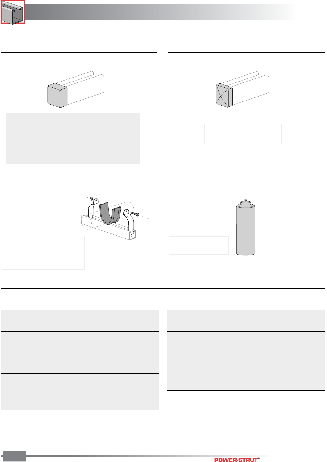
CHANNEL
CHANNEL
ENGINEERING CATALOG
54
Material: Red Colored PVC
■ PS 6153 - Strut Safety End Cap ■ PS 6152 – Decorative End Cap
(For OSHA Req'd End of Hand Rail)
■ PS 3792 - Power Wrap™ ■ PS 9050 – Green Touch-up Spray Paint
Finish: Electro-galvanized
Use With: PS-200, PS-210
Material: EPDM
Stock Thickness: 1⁄8"
Stock Length: 25 ft./box
Service Temp: -70° to 350°F
Wt./
Part No. Use With 100 pcs.
PS-6153-1 PS-100, PS200 2T3 5.0
PS-6153-2 PS-200,PS-210 2.8
PS-6153-3 PS-300 2.5
PS-6153-5 PS-500, PS-520, PS560 2.0
Weight: 10 lbs./100 pcs.
Weight: 253 lbs./100 boxesWeight: 253 lbs./100 boxes
Allowable
Channel Nut Gauge Pull-Out Resistance Torque
Size-Thread Channel Strength (Lbs.) to Slip (Lbs.) Ft.-Lbs.
3⁄4"-10 2,500 1,700 *125
5⁄8"-11 12 Gauge 2,500 1,500 *100
1⁄2"-13 PS 100 2,000 1,500 50
7⁄16"-14 PS 150 1,400 1,000 35
3⁄8"-16 PS 200 1,000 800 19
5⁄16"-18 PS 300 800 500 11
1⁄4"-20 600 300 6
1⁄2"-13 12 Gauge 1,500 1,500 50
3⁄8"-16 PS 400 1,000 800 19
5⁄16"-18 PS 520 800 500 11
1⁄4"-20 600 300 6
* May require 3⁄8" or 1⁄2 thick fitting.
Nut design loads include a minimum safety factor of 3.
Note: Refer to the Channel Nut Selection Chart on page 56 for the part number
Allowable
Channel Nut Gauge Pull-Out Resistance Torque
Size-Thread Channel Strength (Lbs.) to Slip (Lbs.) Ft.-Lbs.
1⁄2"-13 14 Gauge 1,400 1,000 50
3⁄8"-16 PS 210 1,000 750 19
5⁄16"-18 PS 520 800 400 11
1⁄4"-20 600 300 6
1⁄2"-13 16 Gauge 1,000 1,000 50
3⁄8"-16 PS 560 1,000 750 19
5⁄16"-18 800 400 11
1⁄4"-20 600 300 6
■ Maximum Allowable Pull-Out and Slip Loads
Aerosol can may be subject to
shipping restrictions
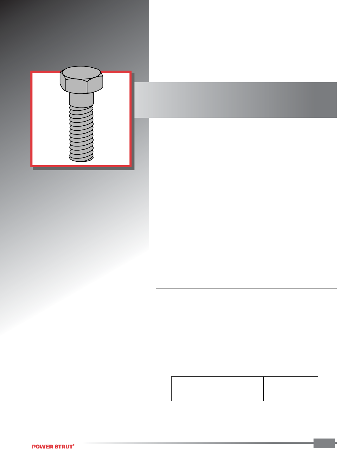
FASTENERS
FASTENERS
ENGINEERING CATALOG
55
Power-Strut Clamping Nuts are cold
formed, with two grooves, each with
six sharp teeth and then case
hardened. These sharp hardened teeth
bite into the inturned edges of the
Power-Strut channel forming a strong
vise-like connection giving greater
strength and resistance to slippage.
■ MATERIAL:
Channel clamping nuts meet ASTM A576 GR1015M, and are case
hardened. Hex head bolts meet SAE J429 GR 2 and ASTM A307.
Square and hex nuts meet ASTM A563 GR A.
■ SCREW THREADS DATA:
All Power-Strut nuts and bolts are manufactured to meet the Unified
Screw Threads standard, ANSI B1.1, Coarse Series UNC, class 2.
Continuous Threaded Rod: Meets ASTM A-510.
■ STANDARD FINISH:
All fasteners have an electro-galvanized finish.
■ RECOMMENDED TORQUE:
Bolt Size 1⁄4"–20 5⁄16"–18 3⁄8"–16 1⁄2"–13
Foot Pounds 6 11 19 50
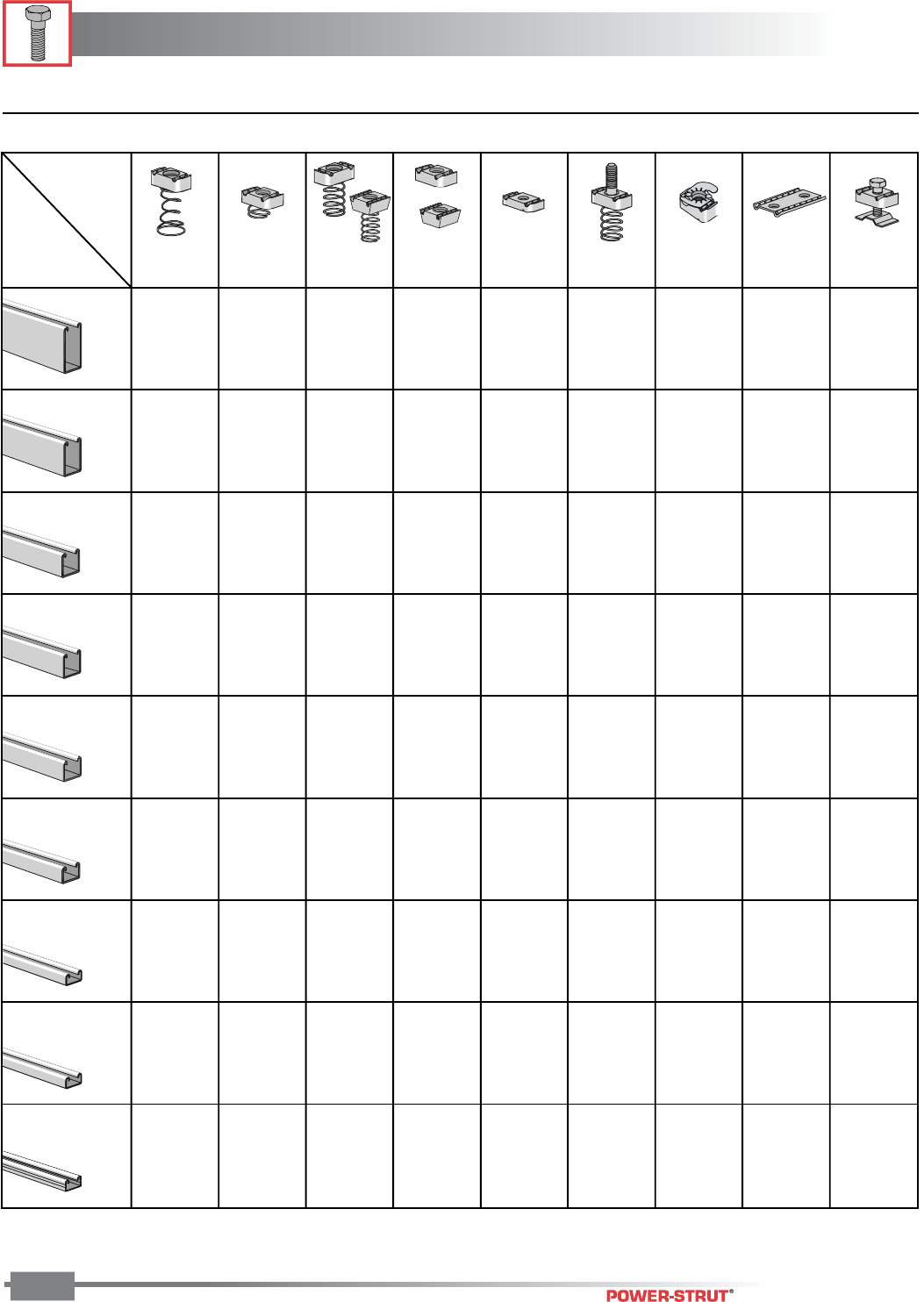
FASTENERS
FASTENERS
ENGINEERING CATALOG
56
✓
Indicates Nuts To Be Used With The Channel
3⁄8" or smaller
■Channel Nut Selection Chart
PS100
CHANNEL
PS 150
PS 200
PS 210
PS 300
PS 400
PS 500
PS 520
PS 560
PS NS
PS LS PS SS PS RS PS NS S PS 517 PS TG PS 3281 PS 3500
NUTS
*
✓
✓✓
✓
✓✓
✓✓
✓✓ ✓✓✓✓
✓✓✓
✓✓
✓
✓✓
✓✓
✓✓
✓✓
✓
✓✓*✓
✓*✓✓
✓*✓✓
✓✓
✓✓
✓✓
✓✓
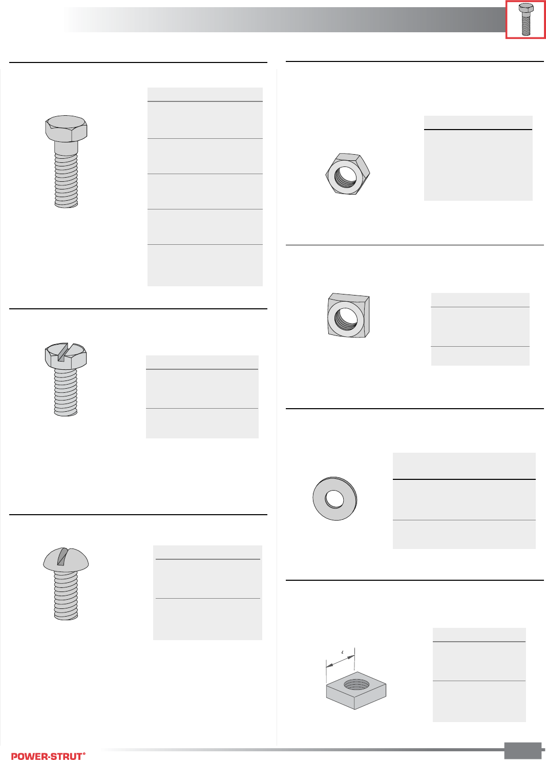
FASTENERS
FASTENERS
ENGINEERING CATALOG
57
■PS 6024 – Hex Head Cap Screw
■PS 6072 – Round Head Machine Screw
■PS 6108 – Square Nut
■PS 6075 – Slotted Hex Head Machine Screw
■PS 83 – Hexagon Nut
■PS 209 – Flat Washer
Finish: Electro-galvanized Order By: No. and Size and Finish
Size Wt./100 pcs
1⁄4x 3⁄4"1.7
5⁄16 x 1" 2.6
5⁄16 x 11⁄4"3.0
5⁄16 x 11⁄2"3.4
3⁄8x 11⁄4"5.3
Size Wt./100 pcs
1⁄4x 3⁄4"1.5
1⁄4x 1" 1.8
1⁄4x 11⁄4"2.1
1⁄4x 11⁄2"2.4
3⁄8x 3⁄4"3.6
3⁄8x 1" 4.2
3⁄8x 11⁄4"4.9
3⁄8x 11⁄2"5.6
3⁄8x 2" 7.2
1⁄2x 3⁄4"8.1
1⁄2x 1" 9.2
1⁄2x 11⁄4" 10.4
1⁄2x 11⁄2" 11.6
1⁄2x 13⁄4" 13.0
1⁄2x 2" 14.4
Size Wt./100 pcs
1⁄4".9
5⁄16"1.6
3⁄8"2.6
1⁄2"5.8
Size Wt./100 pcs
1⁄4x 3⁄4"1.3
1⁄4x 1" 1.6
1⁄4x 11⁄4"1.9
3⁄8x 1" 4.4
3⁄8x 11⁄4"5.0
3⁄8x 11⁄2"5.6
Size Wt./100 pcs
1⁄4"0.7
3⁄8"1.6
1⁄2"3.8
5⁄8"7.3
3⁄4" 11.9
Outside
Size Diameter Wt./ 100 pcs
1⁄4"3⁄4"0.7
3⁄8"1" 1.5
1⁄2"1
3⁄8"3.9
5⁄8"1
3⁄4"7.7
3⁄4"2" 11
■PS 6112 - Oversize Square Nut
1
1
⁄
1
4
⁄
⁄
"
Size Wt./100 pcs
1⁄4"-20 13
3⁄8"-16 14
1⁄2"-13 14
5⁄8"-11 12
3⁄4"-16 11
7⁄8"-11 10
FASTENERS
FASTENERS
ENGINEERING CATALOG
58
Finish: Plain or Electro-galvanized
Standard Length: 6' or 10'; Other lengths available
Hanger rod stiffener assembly for 3⁄8" thru 5⁄8" threaded rod.
■PS 230 – Fender Washer ■PS 211 – Lock Washer
■PS 6064 – Square Head Cone Point Set Screw
■PS 146 – Continuous Thread Rod■PS 3500 3⁄8" - 5⁄8" – Seismic Rod Stiffener
■PS 135 – Rod Coupling
Finish: Electro-galvanized Order By: No. and Size and Finish
Size Wt./100 pcs
1⁄4"3.3
3⁄8"3
1⁄2"2.8
Size Wt./ 100 pcs
1⁄4"0.3
3⁄8"0.7
1⁄2"1.5
Part No. Wt./100 pcs
PS 3500 3⁄8"–5⁄8"16
Wt./100 pcs.
Max Load 6' 10'
Rod Size Lbs. Lengths Lengths
1⁄4" 240 73 121
3⁄8" 610 175 292
1⁄2" 1,130 319 531
5⁄8" 1,810 504 840
3⁄4" 2,710 740 1,234
Size Wt./100 pcs
3⁄8 x 11⁄2"4.5
3⁄8 x 2" 6.1
1⁄2 x 11⁄2"8.5
1⁄2 x 2" 11.4
Rod Max Load
Size lbs. Wt./ 100 pcs.
1⁄4" 240 2
3⁄8" 610 9
1⁄2" 1,130 10
5⁄8" 1,810 18
3⁄4" 2,710 28
FASTENERS
FASTENERS
ENGINEERING CATALOG
59
Use With: PS 200, PS 210 and PS 300 Channel.
Use With: PS 100 and PS 150 Channel.
■PS LS – Clamping Nut with Long Spring ■PS RS – Clamping Nut with Long Spring
Use With: PS 400, PS 500 and PS 520 channel.
*PS SS 1⁄2" and PS SS 5⁄8" nuts have 3⁄8" body thickness.
PS SS – Clamping Nut with Short Spring
Use With: PS 200, PS 210 and PS 300 channel.
■PS 517 – Channel Nut with Stud
■PS NS – Clamping Nut without Spring ■PS NS S – Shallow Clamping Nut without Spring
Use With: PS 100, PS 150, PS 200, PS 210 and PS 300 channel.
*Can be used with PS 400, PS 500, PS 520 and PS 560 channel.
Use With: PS 500 and PS 520 channel.
Finish: Electro-galvanized Order By: No. and Size and Finish
Size Threads Wt./100 pcs
1⁄4"20 7.5
3⁄8" 16 10.2
1⁄2" 13 12.3
5⁄8" 11 15.8
3⁄4" 10 14.1
Size Threads Wt./100 pcs
5⁄8" 11 15.5
3⁄4" 10 13.8
7⁄8" 9 14.3
Size Threads Wt./100 pcs
#10-24 24 7.2
#10-32 32 7.2
1⁄4"207.1
5⁄16"18 7.0
3⁄8"169.9
1⁄2" 13 11.9
Size Wt./100 pcs
1⁄4" x 1" 8.1
1⁄4"x 1
1⁄4"8.3
1⁄4"x 1
1⁄2"8.6
1⁄4" x 2" 9.1
3⁄8" x 1" 13.0
3⁄8"x 1
1⁄4" 14.0
3⁄8"x 1
1⁄2" 14.0
3⁄8" x 2" 15.0
1⁄2" x 1" 15.0
1⁄2"x 1
1⁄4" 16.0
1⁄2"x 1
1⁄2" 17.0
1⁄2" x 2" 19.0
Size Threads Wt./100 pcs
#8-32 32 7.0
#10-24 24 7.0
#10-32 32 7.0
1⁄4"20 6.9
5⁄16"18 6.7
3⁄8"16 9.6
1⁄2" 13* 8.8
5⁄8" 11* 11.5
3⁄4" 10* 10.0
Size Threads Wt./100 pcs
1⁄2"13 6.9
5⁄8"11 9.7
3⁄4"10 8.4
Size Threads Wt./100 pcs
#8-32 32* 8.0
#10-32 32* 6.6
#10-24 24* 6.7
1⁄4" 20* 6.6
5⁄16" 18* 6.4
3⁄8" 16* 9.3
1⁄2" 13 11.4
Size Threads Wt./100 pcs
5⁄8" 11 15.2
3⁄4" 10 13.0
7⁄8" 9 14.0
FASTENERS
FASTENERS
ENGINEERING CATALOG
60
1"
A
A
A
A
A
A
1"
■PS TG – Top Grip™ Nut ■PS 3281 – Double Conveyor Adjusting Nut
■PS 202 – Eyelet ■PS 205 – Eyelet with Stud
■PS 204 – Linked Eyelets ■PS 203 – Linked Eyelet with Stud
Finish: Electro-galvanized Order By: No. and Size and Finish
Part No. Size Threads Wt./100 pcs
PSTG 1⁄4 1⁄4"20 7
PSTG 3⁄83⁄8"16 10
PSTG 1⁄2*1⁄2"13 8
Size Threads Wt./100 pcs
3⁄8" 16 17.5
Stock Max. Load Wt./
Rod Size A Dia. lbs. 100 pcs
3⁄8"1
3⁄4"3⁄8" 610 15
1⁄2"1
3⁄4"3⁄8" 610 18
Max. Load Wt./
Rod Size A Stock Dia. lbs. 100 pcs
3⁄8"1
13⁄16"3⁄8" 610 16
1⁄2"1
3⁄4"3⁄8" 610 20
Max. Load Wt./
Rod Size A Stock Dia. lbs. 100 pcs
3⁄8"1
7⁄16"3⁄8" 610 23
1⁄2"1
3⁄8"3⁄8" 610 32
Max. Load Wt./
Rod Size A Stock Dia. lbs. 100 pcs
3⁄8"1
7⁄16"3⁄8" 610 27
1⁄2"1
3⁄8"3⁄8" 610 45
Use With: All 15⁄8" Channel.
*PS TG 1⁄2" nut has a 3⁄8" body thickness Use With: All 15⁄8" channel.

FITTINGS
FITTINGS
ENGINEERING CATALOG
61
Power–Strut has a wide variety of
fittings to meet all of your application
requirements
■ MATERIAL:
All Power-Strut fittings are formed in punch press dies from mild, pickled
and oiled, bar or strip steel. Plain or electro-galvanized fittings meet the
requirements for ASTM A575 and A-576, or ASTM A-36.
■ STANDARD DIMENSIONS:
Standard dimensions on all fittings are as follows except where
otherwise indicated:
Fitting Thickness: 1⁄4"
Fitting Width: 15⁄8"
Hole Diameter: 9⁄16"
Hole Spacing: 17⁄8" on centers and 13⁄16" from ends.
■ STANDARD FINISH:
All Power-Strut fittings are available in painted green or electro-
galvanized finish.
■ ORDERING INFORMATION:
When ordering, add the length or size and finish to the part number.
See pages 8-10 for finish abbreviations and an example.
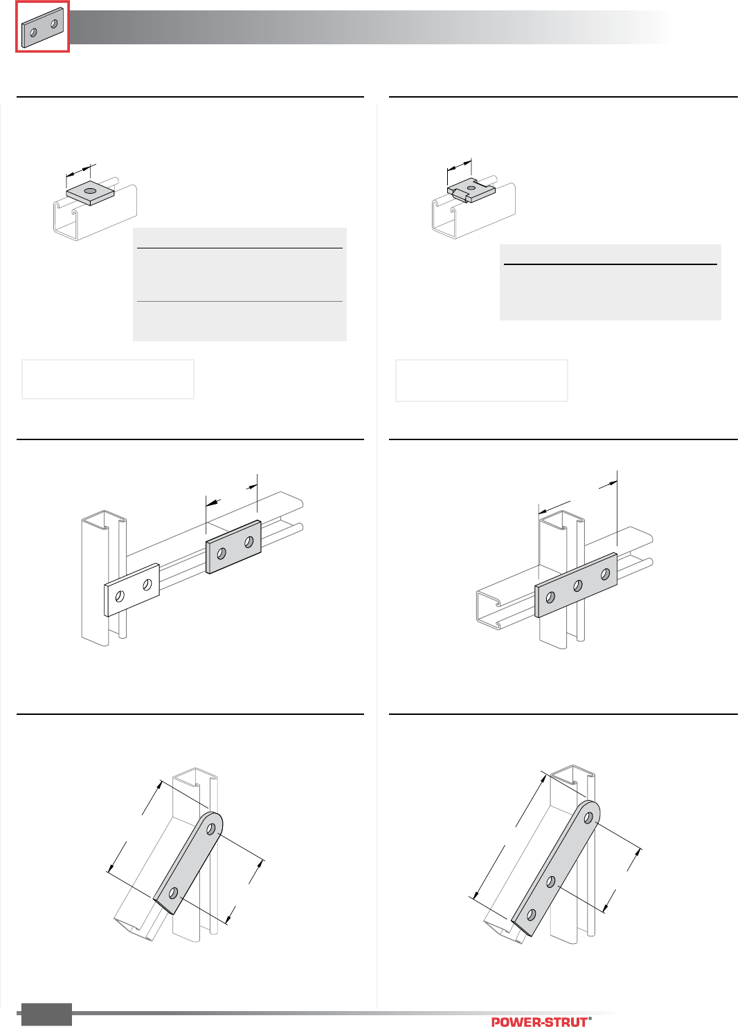
FITTINGS
FITTINGS
ENGINEERING CATALOG
62
Finish: Painted Green or Electro-galvanized Order By: No., Size and Finish
Weight/100 pcs: 38 lbs. Weight/100 pcs: 50 lbs.
Weight/100 pcs: 55 lbs. Weight/100 pcs: 75 lbs.
31⁄2"
5
1
⁄
4
"
3
5
⁄
8
"
7
1
⁄
8
"
3
5
⁄
8
"
1
5
⁄
8
"
5
3
⁄
8
"
1
5
⁄
8
"
■PS 601 – Two-Hole Splice Plate
■PS 619 – Square Washer ■PS 2504 – Guided Square Washer
■PS 602 – Three-Hole Splice Plate
Rod Size Hole Size Wt./ 100 pcs
1⁄4"11⁄32"18
3⁄8"7⁄16"18
1⁄2"9⁄16"17
5⁄8"11⁄16"16
3⁄4"13⁄16"15
Rod Size Hole Size Wt./ 100 pcs
1⁄4"11⁄32"18
3⁄8"7⁄16"18
1⁄2"9⁄16"17
■PS 618 – Two-Hole Swivel Plate ■PS 617 – Three-Hole Swivel Plate
Note: Indicate rod size when ordering.
For example, PS 619 1⁄2.
Note: Indicate rod size when ordering.
For example, PS 2504 1⁄2.
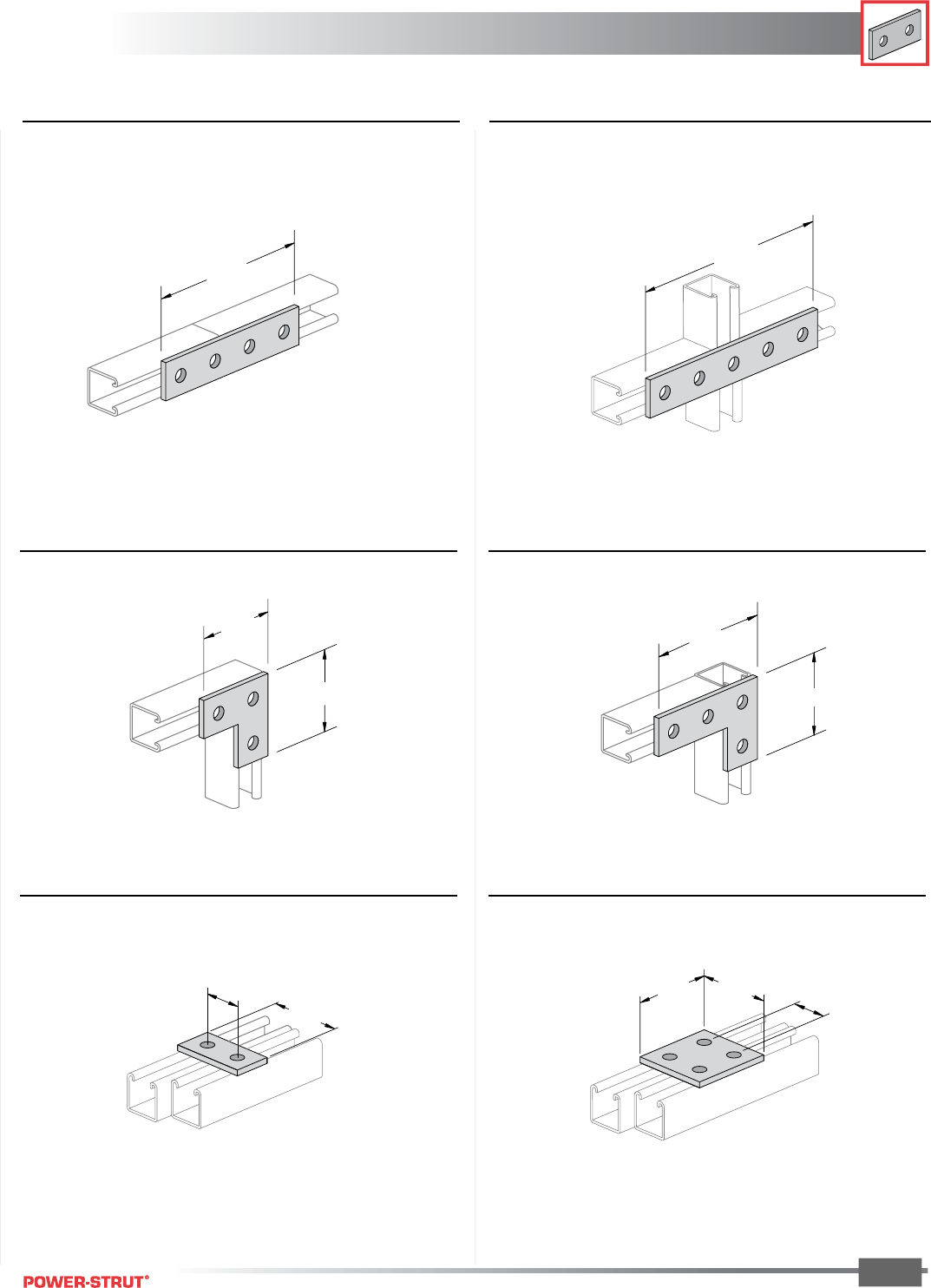
FITTINGS
FITTINGS
ENGINEERING CATALOG
63
Finish: Painted Green or Electro-galvanized Order By: No., Size and Finish
Weight/100 pcs: 78 lbs. Weight/100 pcs: 94 lbs.
Weight/100 pcs: 58 lbs. Weight/100 pcs: 80 lbs.
Weight/100 pcs: 35 lbs. Weight/100 pcs: 73 lbs.
71⁄4"
91⁄8"
3
1
⁄
2
"
3
1
⁄
2
"
5
3
⁄
8
"
3
1
⁄
2
"
15⁄8"
31⁄4"
31⁄2"31⁄4"
15⁄8"
■PS 888 – Four-Hole Splice plate ■PS 889 – Five-Hole Splice Plate
■PS 718 – Flat Angle Plate ■PS 719 – Flat Angle Plate
■PS 620 – Two-Hole Connecting Plate ■PS 621 – Four-Hole Connecting Plate

FITTINGS
FITTINGS
ENGINEERING CATALOG
64
Finish: Painted Green or Electro-galvanized Order By: No., Size and Finish
Weight/100 pcs: 80 lbs. Weight/100 pcs: 105 lbs.
Weight/100 pcs: 70 lbs. Weight/100 pcs: 105 lbs.
Weight/100 pcs: 150 lbs. Weight/100 pcs: 70 lbs.
5 3⁄8"
5 3⁄8"
3
1
⁄
2
"
3
1
⁄
2
"5
3
⁄
8
"
3
1
⁄
2
"
53⁄8"
53⁄8"
31⁄2"
31⁄2"
53⁄8"
31⁄2"
■PS 744 – Flat Corner Connector
■PS 714 – Tee Plate ■PS 712 – Cross Plate
■PS 750 – Four-Hole Corner Connector
■PS 2190 – Flat Corner Connector ■PS 925 – Three-Hole Joint Connector
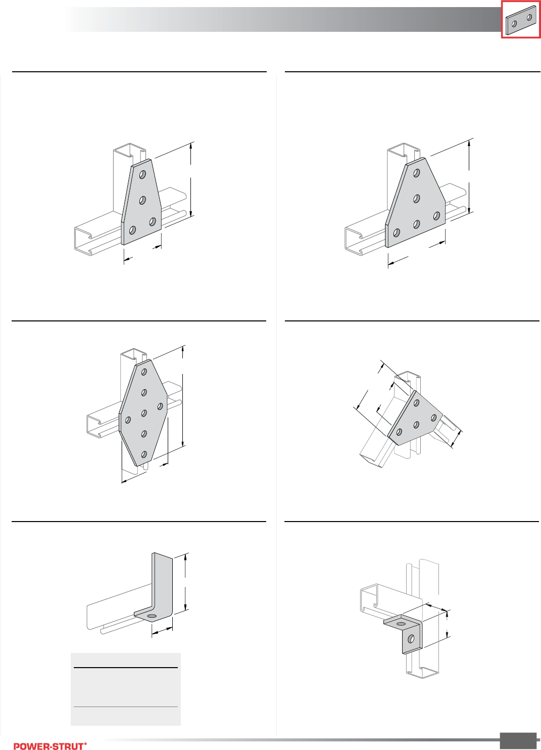
FITTINGS
FITTINGS
ENGINEERING CATALOG
65
Finish: Painted Green or Electro-galvanized Order By: No., Size and Finish
Weight/100 pcs: 105 lbs. Weight/100 pcs: 148 lbs.
Weight/100 pcs: 240 lbs. Weight/100 pcs: 112 lbs.
53⁄8"
31⁄2"
53⁄8"
53⁄8"
5
3
⁄
8
"
9
1
⁄
8
"
41⁄2"
27⁄8"
15⁄8"
■PS 2112 – Cross Connector
■PS 747 – Symmetrical Four-Hole Connector ■PS 854 – Flat Connector
■PS 822 – Double 45° Connector
■PS 921 – One-Hole Angle ■PS 603 – Two-Hole End Angle
Weight/100 pcs: 38 lbs.
1
7
⁄
8
"
2"
A
1
7
⁄
8
"
A Wt./100 pcs
37⁄8"61
57⁄8"84
77⁄8" 107
97⁄8" 130
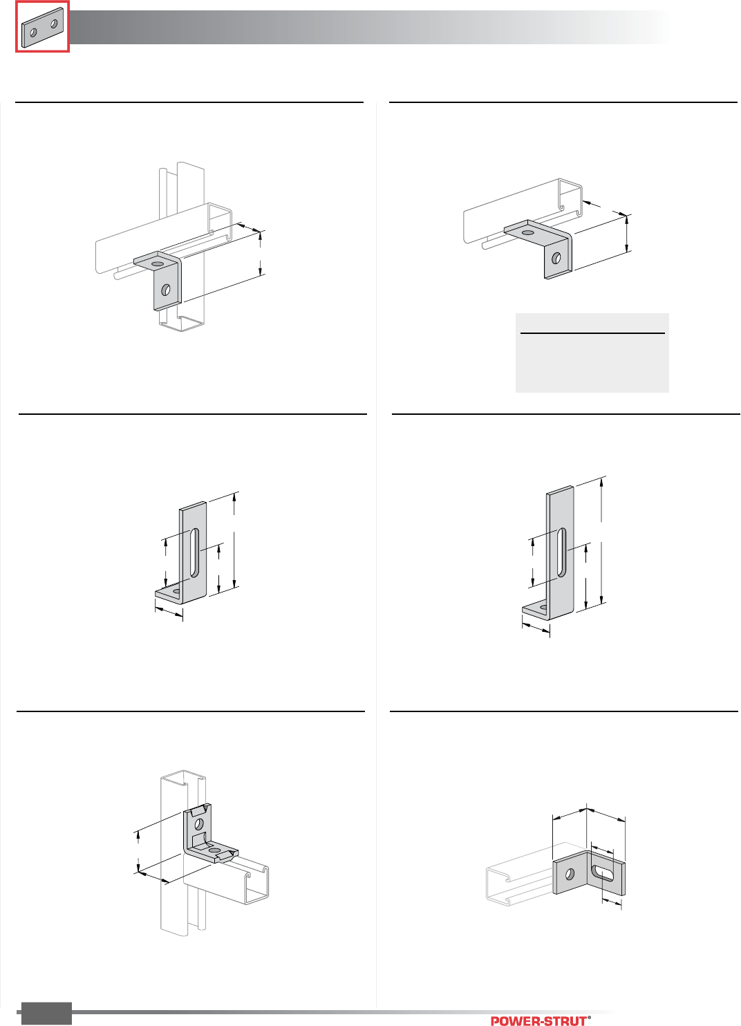
FITTINGS
FITTINGS
ENGINEERING CATALOG
66
Finish: Painted Green or Electro-galvanized Order By: No., Size and Finish
■PS 2520 – Slotted 90˚ Angle■PS 806 – Self-Aligning Two-Hole Angle
Weight/100 pcs: 40 lbs. Weight/100 pcs: 42 lbs.
21⁄8"
21⁄8"
2
5
⁄
8
"
2"
1
5
⁄
16
"
1
1
⁄
2
"
■PS 604 – Two-Hole Corner Angle
Weight/100 pcs: 38 lbs.
■PS 2144 – Corner Angle
■PS 763 – Slotted Adjustment Angle
Weight/100 pcs: 65 lbs.
■PS 764 – Slotted Adjustment Angle
Weight/100 pcs: 85 lbs.
15⁄8"
21⁄4"
2
1
⁄
2
"4
1
⁄
2
"
6
7
⁄
8
"
1
7
⁄
8
"
1
7
⁄
8
"
A
2
1
⁄
2
"2
1
⁄
2
"
4
7
⁄
8
"
1
7
⁄
8
"
A Wt./100 pcs
3" 49
31⁄2"54
4" 61
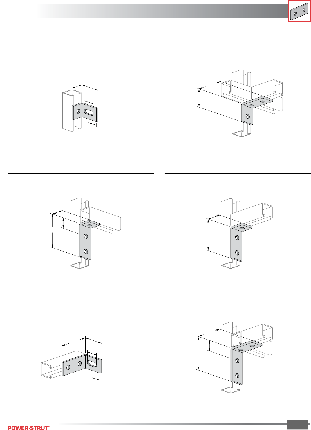
FITTINGS
FITTINGS
ENGINEERING CATALOG
67
Finish: Painted Green or Electro-galvanized Order By: No., Size and Finish
■PS 606 – Three-Hole Corner Angle
■PS 605 – Three-Hole Corner Angle■PS 2545 – Slotted 90˚ Angle
Weight/100 pcs: 38 lbs. Weight/100 pcs: 58 lbs.
Weight/100 pcs: 58 lbs.
■PS 745 – Three-Hole Corner Angle
Weight/100 pcs: 58 lbs.
2
5
⁄
8
"
1
5
⁄
8
"
1
5
⁄
16
"
1
1
⁄
2
"
41⁄8"17⁄16"
15⁄8"
37⁄8"
17⁄8"
21⁄4"
31⁄2"
■PS 607 – Four-Hole Corner Angle■PS 3049 – Two-Hole Slotted 90˚ Angle
Weight/100 pcs: 66 lbs. Weight/100 pcs: 78 lbs.
37⁄8"
11⁄2"
15⁄16"
25⁄8"
41⁄8"
31⁄2"
17⁄16"
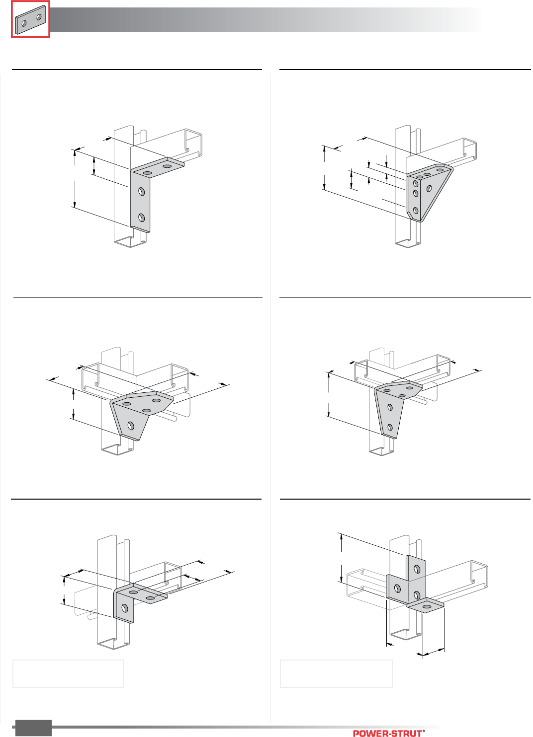
FITTINGS
FITTINGS
ENGINEERING CATALOG
68
Finish: Painted Green or Electro-galvanized Order By: No., Size and Finish
■PS 716 R OR L – Angle Tee Plate■PS 720 R OR L – Angle Plate Connector
3
1
⁄
4
"
1
5
⁄
8
"
1
7
⁄
8
"
2"
3
1
⁄
2
"
3
1
⁄
2
"2"
■PS 615 – Five-Hole Joint Angle Connector■PS 614 – Four-Hole Joint Angle Connector
■PS 3373 – Universal Corner Connector■PS 660 – Four-Hole Corner Angle
Weight/100 pcs: 78 lbs. Weight/100 pcs: 134 lbs.
Weight/100 pcs: 103 lbs. Weight/100 pcs: 135 lbs.
13⁄16"
4"
7⁄8"
19⁄16"
4"
4
1
⁄
8
"
3
1
⁄
2
"3
1
⁄
2
"
31⁄2"
21⁄4"
31⁄2"
37⁄8"
313⁄16"
11⁄2"
NOTE: Specify R (Right) or L (Left)
Right Hand Illustrated
Weight/100 pcs: 55 lbs. Weight/100 pcs: 80 lbs.
NOTE: Specify R (Right) or L (Left)
Right Hand Illustrated
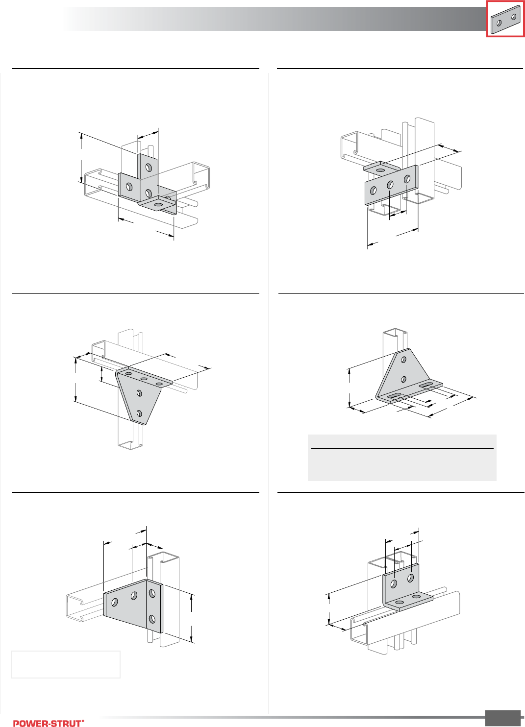
FITTINGS
FITTINGS
ENGINEERING CATALOG
69
Finish: Painted Green or Electro-galvanized Order By: No., Size and Finish
■PS 689A, PS 689B – Double-Slotted
Corner Connector
■PS 927 – Five-Hole Corner Connector
■PS 715 – Tee Plate 90˚ Angle■PS 713 – Cross Plate Angle
Weight/100 pcs: 105 lbs. Weight/100 pcs: 71 lbs.
Weight/100 pcs: 154 lbs.
41⁄8"
15⁄8"
17⁄16"
53⁄8"
2"
53⁄8"
31⁄2"
2"
47⁄8"
15⁄8"
1
7
⁄
8
"
3
3
⁄
4
"
A
1
1
⁄
2
"
B
Part No. A B Wt./100 pcs
PS 689 A 65⁄8" 4" 190
PS 689 B 85⁄8" 6" 242
■PS 622 – Four-Hole Corner Connector
Weight/100 pcs: 75 lbs.
1
5
⁄
8
"
3
1
⁄
4
"
1
5
⁄
8
"
2
1
⁄
4
"
■PS 752 R OR L – Four-Hole Corner Connector
4
1
⁄
8
"
1
7
⁄
16
"
1
5
⁄
8
"
3
1
⁄
2
"
Weight/100 pcs: 105 lbs.
NOTE: Specify R (Right) or L (Left)
Right Hand Illustrated
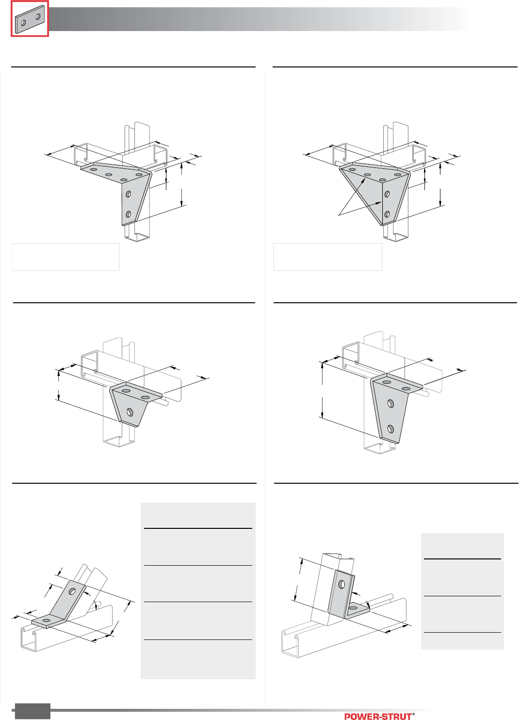
FITTINGS
FITTINGS
ENGINEERING CATALOG
70
Finish: Painted Green or Electro-galvanized Order By: No., Size and Finish
■PS 633 – Two-Hole Open Angle Connector ■PS 624 – Two-Hole Closed Angle Connector
B
21⁄2"
A
Weight/100 pcs: 58 lbs. Weight/100 pcs: 58 lbs.
1
1
⁄
16
"
1
1
⁄
16
"
A
B
C
■PS 748 – Four-Hole Corner Joint Connector ■PS 746 – Three-Hole Corner Joint Connector
Weight/100 pcs: 70 lbs. Weight/100 pcs: 105 lbs.
3
1
⁄
2
"
2
1
⁄
4
"
1
5
⁄
8
"
1
5
⁄
8
"
4
1
⁄
8
"
3
1
⁄
2
"
■PS 2007 R OR L – Six-Hole Corner Connector
13
⁄
16
"
5
3
⁄
8
"
3
1
⁄
2
"
1
7
⁄
16
"
4
1
⁄
8
"
■PS 3326 R OR L– Six-Hole Gussetted Corner
Connector
13
⁄
16
"
5
3
⁄
8
"
3
1
⁄
2
"
1
7
⁄
16
"
4
1
⁄
8
"
Continuous
Weld
"A" "B" "C"
Degree In. In.
821⁄2°39⁄16 111⁄16
75°39⁄16 111⁄16
671⁄2°31⁄213⁄4
60°33⁄817⁄8
521⁄2°31⁄421⁄16
45°32
5⁄16
371⁄2°211⁄16 25⁄8
30°31⁄421⁄16
221⁄2°35⁄16 21⁄16
15°35⁄16 21⁄16
71⁄2°35⁄16 21⁄16
"B" "A"
In. Angle
3" 371⁄2°
31⁄8"45°
31⁄16"52
1⁄2°
31⁄8"60°
31⁄8"67
1⁄2°
33⁄16"75°
33⁄16"82
1⁄2°
Weight/100 pcs: 230 lbs.Weight/100 pcs: 160 lbs.
NOTE: Specify R (Right) or L (Left)
Right Hand Illustrated
NOTE: Specify R (Right) or L (Left)
Right Hand Illustrated
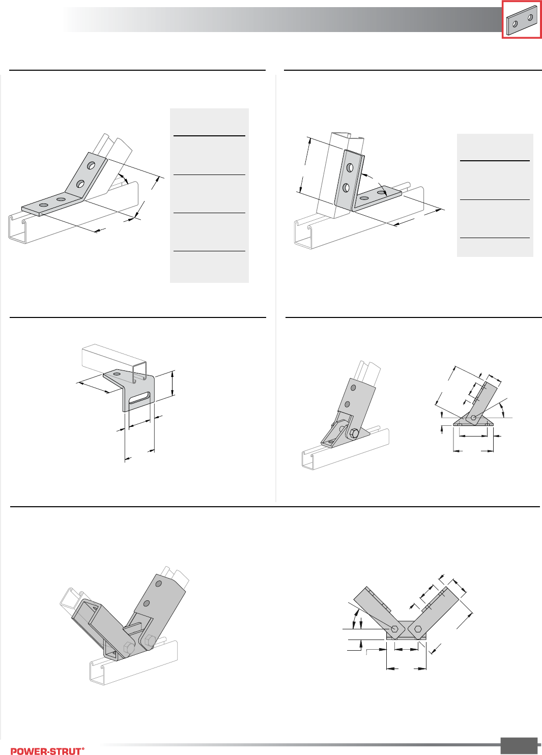
FITTINGS
FITTINGS
ENGINEERING CATALOG
71
■PS 781 – Four-Hole Open Angle Connector ■PS 793 – Four-Hole Closed Angle Connector
A
B
3
1
⁄
2
"
Weight/100 pcs: 78 lbs. Weight/100 pcs: 100 lbs.
■PS 9400 – Adjustable Brace
Weight/100 pcs: 307 lbs.
■PS 2113 – Slotted Corner Connector
Weight/100 pcs: 97 lbs.
A
B
4
3
⁄
8
"
"A" "B"
Angle In.
71⁄2°33⁄4"
15°33⁄4"
221⁄2°33⁄4"
30°311⁄16"
371⁄2°311⁄16"
45°311⁄16"
521⁄2°311⁄16"
60°311⁄16"
671⁄2°35⁄8"
75°35⁄8"
821⁄2°35⁄8"
"A" "B"
Angle In.
371⁄2°-4
7⁄8"
45°-4
15/16"
521⁄2°-4
15/16"
60° -5"
671⁄2°51/16"
75°51/16"
821⁄2°51/16"
■PS 9401 – Double Adjustable Brace
Weight/100 pcs: 497 lbs.
2
1
⁄
2
"
1
⁄
2
"
3
1
⁄
2
"
3
1
⁄
2
"
2
1
⁄
4
"
1
⁄
2
"
53⁄8"
33⁄4"13⁄16"
11⁄16"
57⁄8"
1
7⁄8"
13
⁄
16
"
13
⁄
16"
30°
17⁄8"
57⁄8"
17⁄8"
13⁄16"
13⁄16"
13⁄16"4"
11⁄16"23⁄8"
30°
17⁄8"
Finish: Painted Green or Electro-galvanized Order By: No., Size and Finish
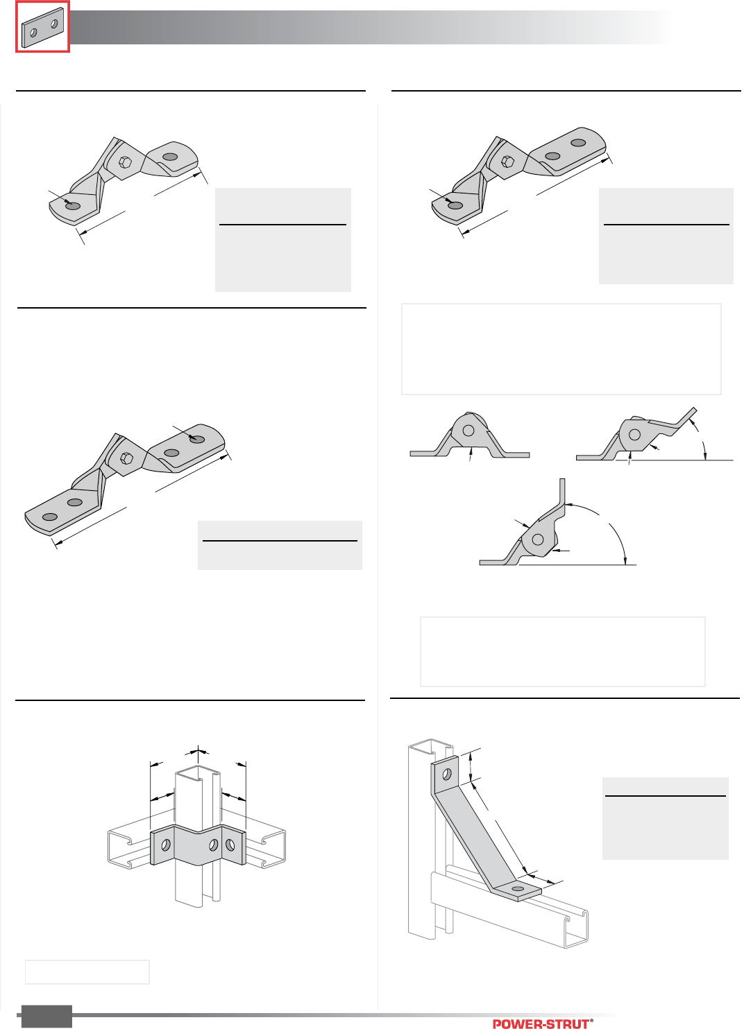
FITTINGS
FITTINGS
ENGINEERING CATALOG
72
Finish: Painted Green or Electro-galvanized Order By: No., Size and Finish
■PS 2054 – Corner Connector ■PS 926 – Strut Brace
1
7
⁄
8
"
3
1
⁄
2
"
3
1
⁄
2
"
1
7
⁄
8
"
17⁄8"
17⁄8"
A
■PS 9404 – Four-Hole Hinge Connector
9
3
⁄
4
"
1
⁄
2
" Bolt Size
Alignment
45°
Alignment
90°
Alignment
Alignment
■PS 9402 – Two-Hole Hinge Connector
6 "
B
Hinge Connector Auto-Alignment Guides -
The unique edges of the two hinges have been
designed to provide an alignment guide for 0°, 45° and 90° as shown in the
drawings below.
This eliminates the need for measuring gages.
Part No. Wt./100 pcs
PS 9404-1⁄2" 126
"B" Wt./
Bolt Size 100 pcs
1⁄2"90
5⁄8"88
3⁄4"86
• Each half of the hinge is formed and welded for maximum strength.
• Hinged with Grade 5 bolt for superior strength.
• The nylon insert locknut prevents loosening of the hinge.
A Size Wt./100 pcs
12" 160
18" 218
24" 280
■PS 9403 – Three-Hole Hinge Connector
77⁄8"
B
"B" Wt./
Bolt Size 100 pcs
1⁄2" 108
5⁄8" 107
3⁄4" 106
Weight/100 pcs: 66 lbs.
Use With: PS 200, PS 210
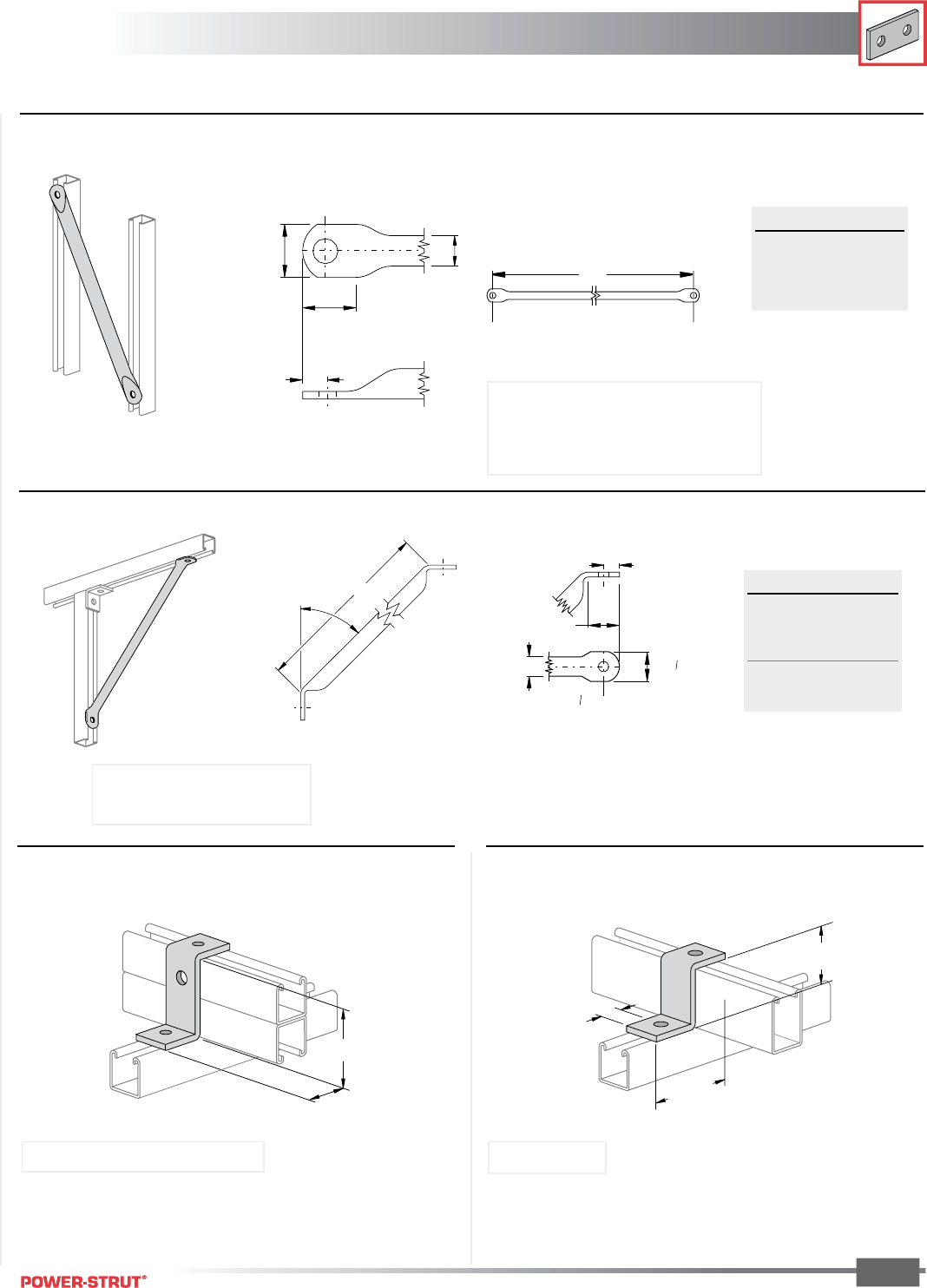
FITTINGS
FITTINGS
ENGINEERING CATALOG
73
■PS 810 – Diagonal Tube Brace
■PS 812 – 45˚ Diagonal Tube Brace
A
13⁄16"
1 5⁄8"
1 "
1"
Dia Hole
17 32
"
17 32
45°
A
1"
13
⁄
16
"
1
5
⁄
8
"
1
17
⁄
32
"
1
7
⁄
32
"
Dia. Hole
A Size Wt./100 pcs
3'–0" 205
3'–6" 237
4'–0" 270
Note: 30° to 60° angle between the brace
and channel is recommended for maximum effect.
Material: 1" dia. electric welded tubing
Stock Thickness: (.075) 14 ga.
Material: 1" dia. electric welded tubing
Stock Thickness: (.075) 14 ga.
A Size Wt./100 pcs
12" 88
18" 116
24" 149
30" 181
36" 214
■PS 756 – Zee Support ■PS 2601 – Zee Support
31⁄4"
17⁄8"
27⁄16"
11⁄16"
33⁄4"
Use With: PS 100, PS 200 2T3, PS 210 2T3
Weight/100 pcs: 70 lbs.
Use With: PS 150
Weight/100 pcs: 70 lbs.
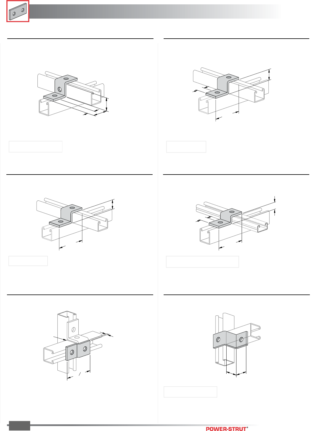
FITTINGS
FITTINGS
ENGINEERING CATALOG
74
Finish: Painted Green or Electro-galvanized Order By: No., Size and Finish
■PS 647 – 17⁄8" Offset Zee Connector■PS 609 – Two-Hole Offset Plate Connector
Weight/100 pcs: 55 lbs.
1
5
⁄
8
"
1
5
⁄
8
"
Offset
1
⁄
4
"
3 "
32
15
Splice
Weight/100 pcs: 38 lbs.
■PS 611 – Zee Support ■PS 711 – Zee Support
■PS 612 – Zee Support ■PS 928 – Zee Support
1
1
⁄
16
"2
1
⁄
8
"
1
5
⁄
8
"
13
⁄
16
"
1
1
⁄
16
"
3
3
⁄
4
"
1
3
⁄
8
"
1
1
⁄
16
"
3
3
⁄
4
"
1"
31⁄2"
Use With: PS 200, PS 210 Use With: PS 300
Use With: PS 500, PS 520 and PS 560
Weight/100 pcs: 55 lbs. Weight/100 pcs: 53 lbs.
Weight/100 pcs: 47 lbs.
Use With: PS 400
Weight/100 pcs: 47 lbs.
Use With: PS 200, PS 210
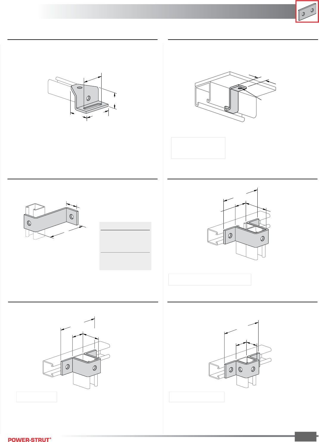
FITTINGS
FITTINGS
ENGINEERING CATALOG
75
Finish: Painted Green or Electro-galvanized Order By: No., Size and Finish
■PS 2532 – Shelf Attachment Zee■PS 692 – 15⁄8" Offset Zee Connector
Weight/100 pcs: 102 lbs.
■PS 3060 – Offset Connector
A
1
5
⁄
8
"
3
7
⁄
8
"3
1
⁄
2
"
2
1
⁄
2
"
1
7
⁄
8
"
13
⁄
16
"
9
⁄
32
"
Hole
1
⁄
8
"
Thick
Weight/100 pcs: 9 lbs.
A Wt./100 pcs
4" 81
5" 92
6" 104
7" 115
8" 127
Stock Thickness: 1⁄8"
Use With: PS 200, PS 210
■PS 679 – "U" Support
31⁄4"
121⁄32"
53⁄8"
Use With: PS 100, PS 200 2T3, PS 210 2T3
■PS 2648 – "U" Support ■PS 613 – "U" Support
Weight/100 pcs: 108 lbs. Weight/100 pcs: 88 lbs.
1
5
⁄
8
"
1
21
⁄
32
"
53⁄8"
27⁄16"
121⁄32"
53⁄8"
PS 150
Use With: PS 150 Use With: PS 200, PS 210
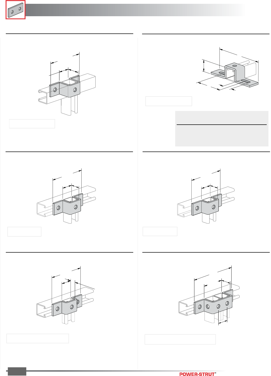
FITTINGS
FITTINGS
ENGINEERING CATALOG
76
Finish: Painted Green or Electro-galvanized Order By: No., Size and Finish
■PS 978 – "U" Support
■PS 721 – "U" Support
Weight/100 pcs: 71 lbs.
■PS 929 – "U" Support
5
13
⁄
16
"
1
21
⁄
32
"
1"
53⁄8"
13⁄16"
121⁄32"
7"
3
9
⁄
32
"
1
5
⁄
8
"
1
5
⁄
8
"
■PS 2119 – "U" Support ■PS 687A, PS 687B & PS 687C –
Slotted "U" Support
Weight/100 pcs: 84 lbs.
■PS 710 – "U" Support
15⁄8"
B
11⁄2"
A
53⁄8"
13⁄8"
121⁄32"
5
3
⁄
8
"
1
7
⁄
8
"
1
21
⁄
32
"
Order ‘A’ ‘B’ Wt./
No. Length Length 100 pcs
PS 687A 71⁄4"4
1⁄8" 105
PS 687B 81⁄2"5
3⁄8" 120
PS 687C 103⁄8"7
1⁄4" 130
Use With: PS 500, PS 520 and PS 560
Weight/100 pcs: 71 lbs.
Use With: PS 100, PS 200 2T3, PS 210 2T3
Weight/100 pcs: 105 lbs.
Use With: PS 200, PS 210
Weight/100 pcs: 95 lbs.
Use With: PS 200, PS 210
Use With: PS 300 Use With: PS 400
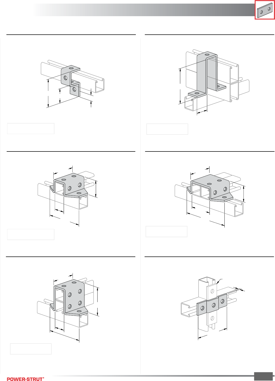
FITTINGS
FITTINGS
ENGINEERING CATALOG
77
Finish: Painted Green or Electro-galvanized Order By: No., Size and Finish
■PS 678 – Three-Hole "U" Support■PS 677 – Cup Support for Standard Single Strut
■PS 733 – Six-Hole "U" Support
Weight/100 pcs: 171 lbs.
4
1
⁄
32
"1
7
⁄
8
"1
5
⁄
64
"
1
7
⁄
8
"
4
7
⁄
8
"
53⁄8"
121⁄32"
31⁄2"
17⁄8"
■PS 734 – Eight-Hole "U" Support
Weight/100 pcs: 209 lbs.
3
9
⁄
32
"
7"
3
1
⁄
2
"
1
7
⁄
8
"
Weight/100 pcs: 76 lbs.
Use With: PS 200, PS 210
Weight/100 pcs: 197 lbs.
Use With: PS 150 2T3
Use With: PS 200, PS 210 Use With: PS 200 2T3
■PS 709 – Three-Hole Offset Plate Connection■PS 735 – Eight-Hole "U" Support
5
5
⁄
16
"
1
⁄
4
"
Offset
1
⁄
4
"
Plate
31⁄2"
5
3
⁄
8
"
3
1
⁄
2
"
121⁄32"
Weight/100 pcs: 58 lbs.Weight/100 pcs: 257 lbs.
Use With: PS 200 2T3
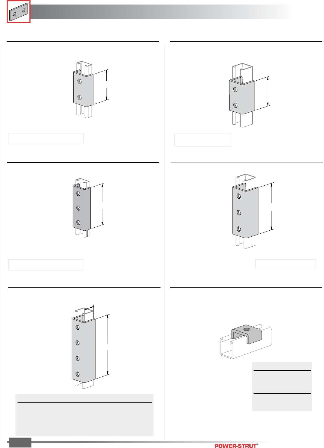
FITTINGS
FITTINGS
ENGINEERING CATALOG
78
Finish: Painted Green or Electro-galvanized Order By: No., Size and Finish
■PS 631 – Two-Hole Splice Clevis■PS 644 – Two-Hole Splice Clevis
■PS 645 – Three-Hole Splice Clevis
Weight/100 pcs: 128 lbs.
■PS 616, PS 646 – Four-Hole Splice Clevis
Weight/100 pcs: 265 lbs.
3
1
⁄
2
"
3
1
⁄
2
"
7
1
⁄
4
"
A
5
3
⁄
8
"
■PS 629 – Three-Hole Splice Clevis
5
3
⁄
8
"
Use With: PS 200, PS 210
Weight/100 pcs: 85 lbs.
Use With: PS 500, PS 520 and PS 560
Weight/100 pcs: 130 lbs.
Use With: PS 500, PS 520 and PS 560
Weight/100 pcs: 197 lbs.
Use With: PS 200 and PS 210
■PS 623 – Saddle Washer
Part No. A For Use With Wt./100 pcs
PS 616 19⁄16" PS 200, PS 210 265
PS 646 13⁄16" PS 500, PS 560 176
PS 616-100 33⁄16" PS 100 390
PS 616-150 23⁄8" PS 150 390
Bolt Size Wt./100 pcs
1⁄4"14
3⁄8"14
1⁄2"13
5⁄7"13
3⁄4"13
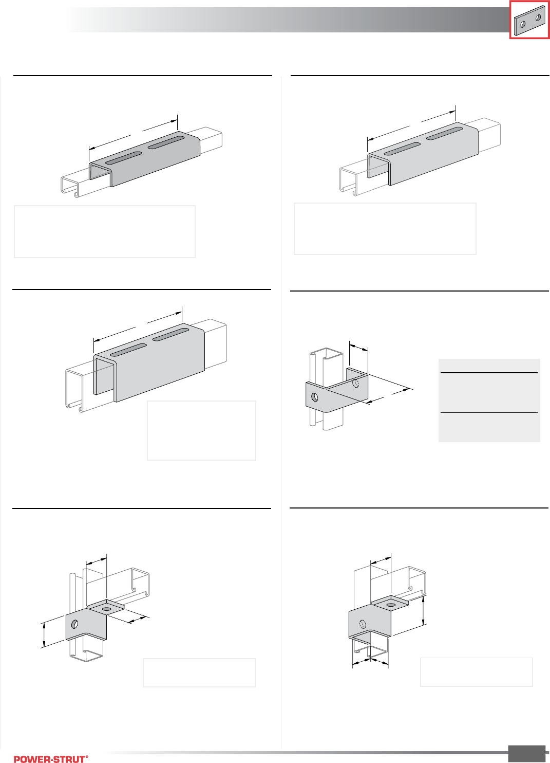
FITTINGS
FITTINGS
ENGINEERING CATALOG
79
Finish: Painted Green or Electro-galvanized Order By: No., Size and Finish
■PS 804 – Slotted Joiner
8"
■PS 704 – Slotted Joiner
8"
8"
■PS 1004 – Slotted Joiner
Weight/100 pcs: 80 lbs.
Stock Thickness: (.105)
Use With: PS 400S, PS 500S, PS 520S and PS 560S
NOTE: Order PS 6072 screws & PS 6108 nuts separately.
Weight/100 pcs: 197 lbs.
Stock Thickness: (.105)
Use With: PS 200S, PS 210S
NOTE: Order PS 6072 screws & PS 6108 nuts separately.
Weight/100 pcs: 140 lbs.
Stock Thickness: (.105)
Use With: PS 150S
NOTE: Order PS 6072 screws &
PS 6108 nuts separately.
■PS 922 R OR L – Two-Hole Corner Connector
15⁄8"
111⁄16"
17⁄8"
Weight/100 pcs: 60 lbs.
NOTE: Specify R (Right) or L (Left)
Right Hand Illustrated
■PS 993 – Inside Clevis Hanger
A
17⁄8"
A Size Wt./100 pcs
4" 78
5" 89
6" 101
7" 112
8" 124
■PS 2117 R OR L – Wrap-Around Corner
Connector
Weight/100 pcs: 75 lbs.
NOTE: Specify R (Right) or L (Left)
Right Hand Illustrated
2"
15⁄8"
17⁄8"
121⁄32"
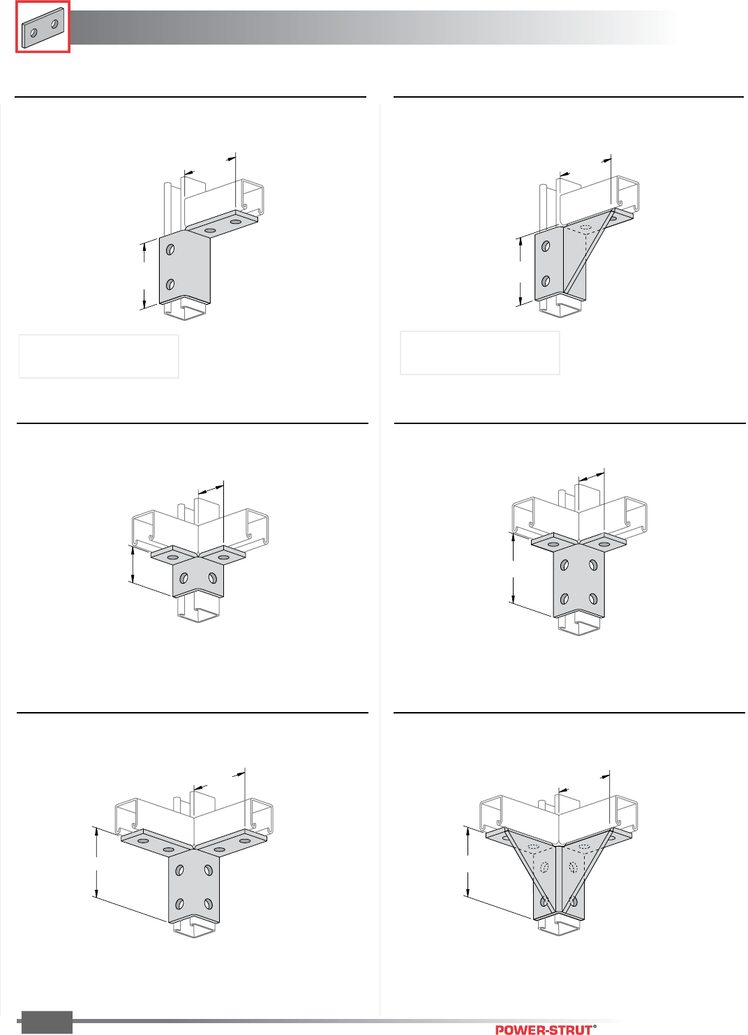
FITTINGS
FITTINGS
ENGINEERING CATALOG
80
Finish: Painted Green or Electro-galvanized Order By: No., Size and Finish
Weight/100 pcs: 115 lbs.
37⁄8"
17⁄8"
■PS 666 – Six-Hole Double Corner Connector
■PS 667 – Eight-Hole Double Corner Connector
3
7
⁄
8
"
3
3
⁄
4
"
■PS 943 – Eight-Hole Gussetted Double
Corner Connector
Weight/100 pcs: 217 lbs.
37⁄8"
33⁄4"
Weight/100 pcs: 155 lbs.
■PS 2128 R OR L – Four-Hole Corner Connector
3
1
⁄
2
"
3
3
⁄
4
"
Weight/100 pcs: 176 lbs.
3
7
⁄
8
"
3
3
⁄
4
"
■PS 2129 R OR L – Single Corner Gussetted
Connector
■PS 665 – Four-Hole Double Corner Connector
Weight/100 pcs: 76 lbs.
2"
1
7
⁄
8
"
Weight/100 pcs: 119 lbs.
NOTE: Specify R (Right) or L (Left)
Right Hand Illustrated
NOTE: Specify R (Right) or L (Left)
Right Hand Illustrated
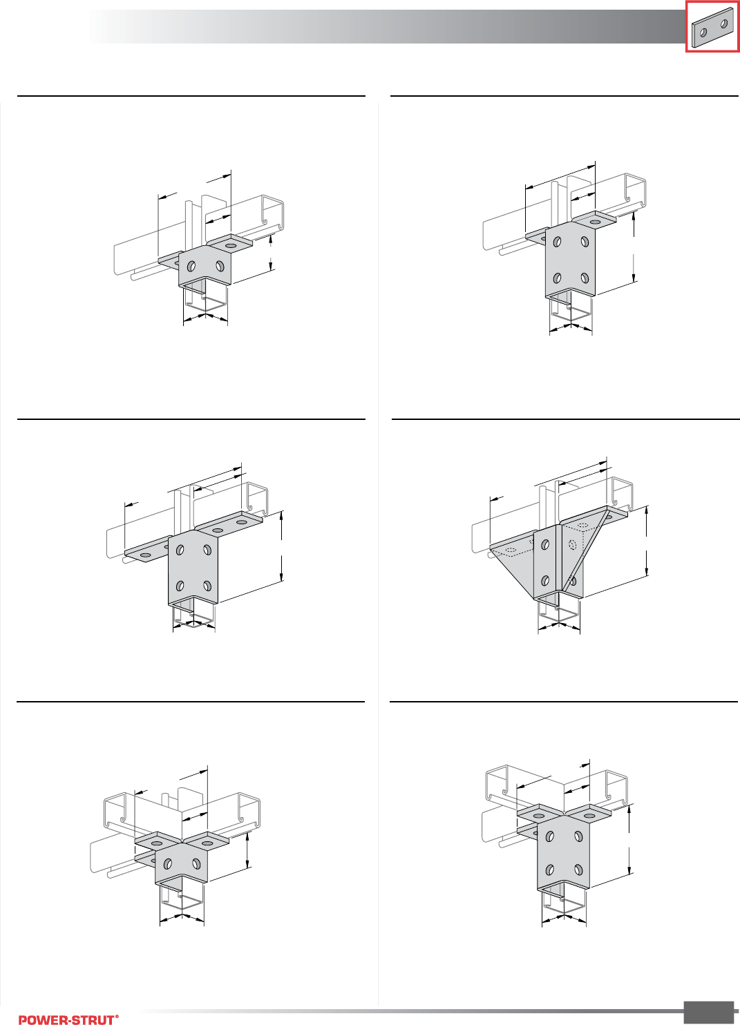
FITTINGS
FITTINGS
ENGINEERING CATALOG
81
Finish: Painted Green or Electro-galvanized Order By: No., Size and Finish
■PS 923 – Five-Hole Double Wing Connector
Weight/100 pcs: 93 lbs.
2"
1
7
⁄
8
"
1
5
⁄
8
"
1
21
⁄
32
"
5
13
⁄
32
"
■PS 821 – Eight-Hole Double Wing Connector
Weight/100 pcs: 150 lbs.
3
7
⁄
8
"
17⁄8"
15⁄8"
5
13
⁄
32
"
1
21
⁄
32
"
■PS 913 – Ten-Hole Double Wing Connector
Weight/100 pcs: 193 lbs.
15⁄8"
37⁄8"
9
5
⁄
32
"
33⁄4"
1
21
⁄
32
"
■PS 945 – Ten-Hole Gussetted Double Wing
Connector
Weight/100 pcs: 274 lbs.
9
5
⁄
32
"
1
5
⁄
8
"
3
7
⁄
8
"
3
3
⁄
4
"
121⁄32"
■PS 668 – Six-Hole Triple Wing Connector
Weight/100 pcs: 113 lbs.
2"
1
7
⁄
8
"
1
5
⁄
8
"
5
13
⁄
32
"
1
21
⁄
32
"
■PS 670 – Nine-Hole Triple Wing Connector
Weight/100 pcs: 177 lbs.
1
7
⁄
8
"
3
7
⁄
8
"
1
5
⁄
8
"
5
13
⁄
32
"
1
21
⁄
32
"
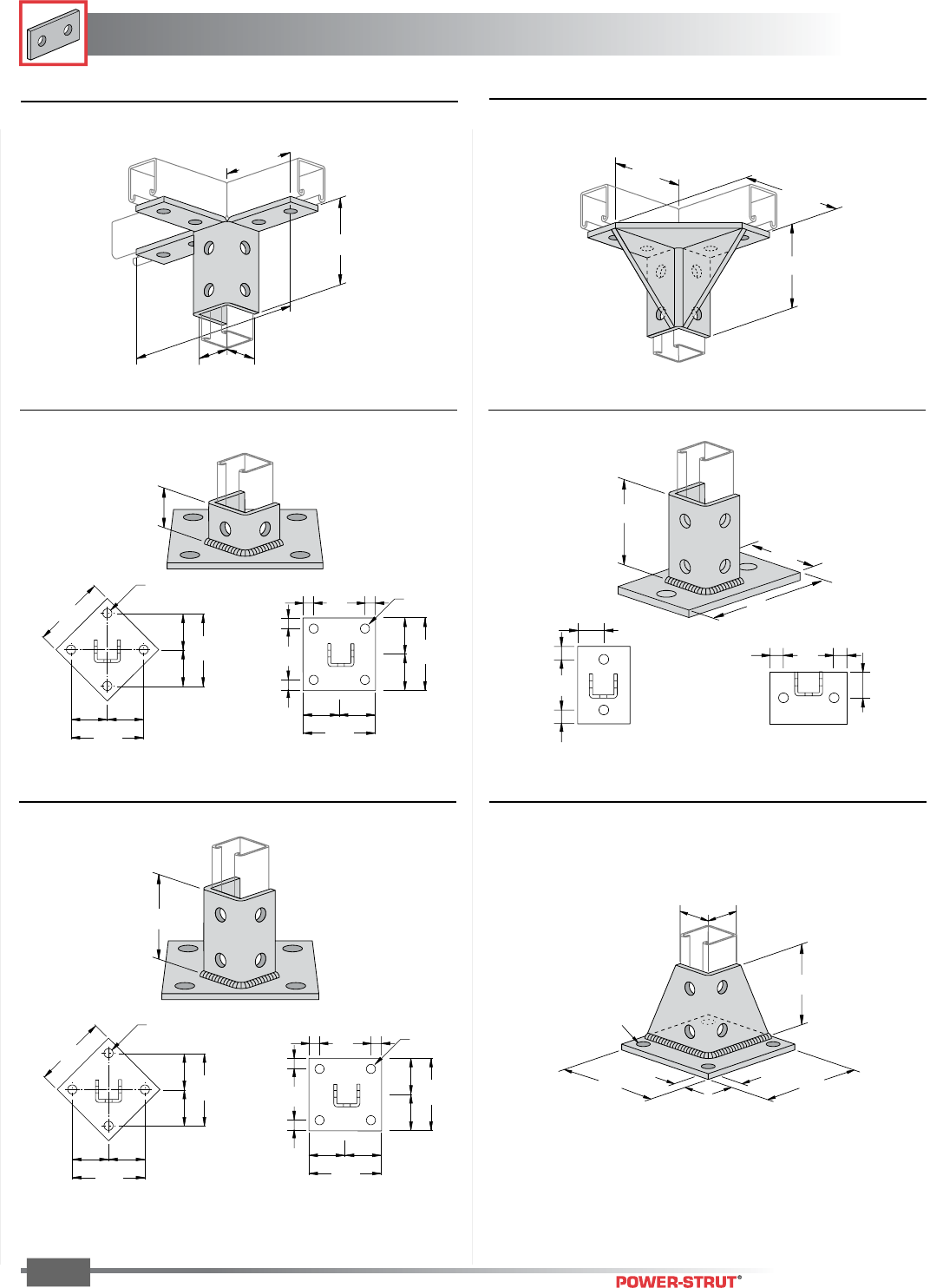
FITTINGS
FITTINGS
ENGINEERING CATALOG
82
Finish: Painted Green or Electro-galvanized Order By: No., Size and Finish
■PS 3013, PS 3013 SQ – Post Base ■PS 3025, PS 3025 FL – Post Base
Weight/100 pcs: 307 lbs. Weight/100 pcs: 358 lbs.
■PS 3033, PS 3033 SQ – Post Base
Weight/100 pcs: 373 lbs.
■PS 3040 – Post Base
Weight/100 pcs: 297 lbs.
1
5
⁄
8
"
1
5
⁄
8
"
5"
5"
5
⁄
8
"
5
⁄
8
"
3
1
⁄
2
"
4
Holes
7
⁄
16
"
Dia.
1
5
⁄
8
"
6"
3" 3"
6"
3"
3"
6"
4 Holes
3
⁄
4
"
Dia.
6"
3"
7
⁄
8
"
7
⁄
8
"
7
⁄
8
"
7
⁄
8
"
3"
3"
3"
6"
4 Holes
3
⁄
4
" Dia.
(PS 3013 SQ)
3
1
⁄
2
"
6"
3" 3"
6"
3"
3"
6"
4 Holes
3
⁄
4
"
Dia.
6"
3"
7⁄8"
7⁄8"
7⁄8"
7⁄8"
3"
3"
3"
6"
4 Holes
3⁄4"
Dia.
(PS 3033 SQ)
3
1
⁄
2
"
6"
4"
2"
1"
1"
2"
1" 1"
(PS 3025) (PS 3025 FL)
(PS 3013)
(PS 3033)
■PS 669 – Twelve-Hole Triple Wing Connector
Weight/100 pcs: 230 lbs.
1
5
⁄
8
"
95⁄32"
3
7
⁄
8
"
3
3
⁄
4
"
1
21
⁄
32
"
■PS 2514 – Eight-Hole Gussetted Double
Corner Connector
Weight/100 pcs: 315 lbs.
33⁄4"
53⁄8"
33⁄4"
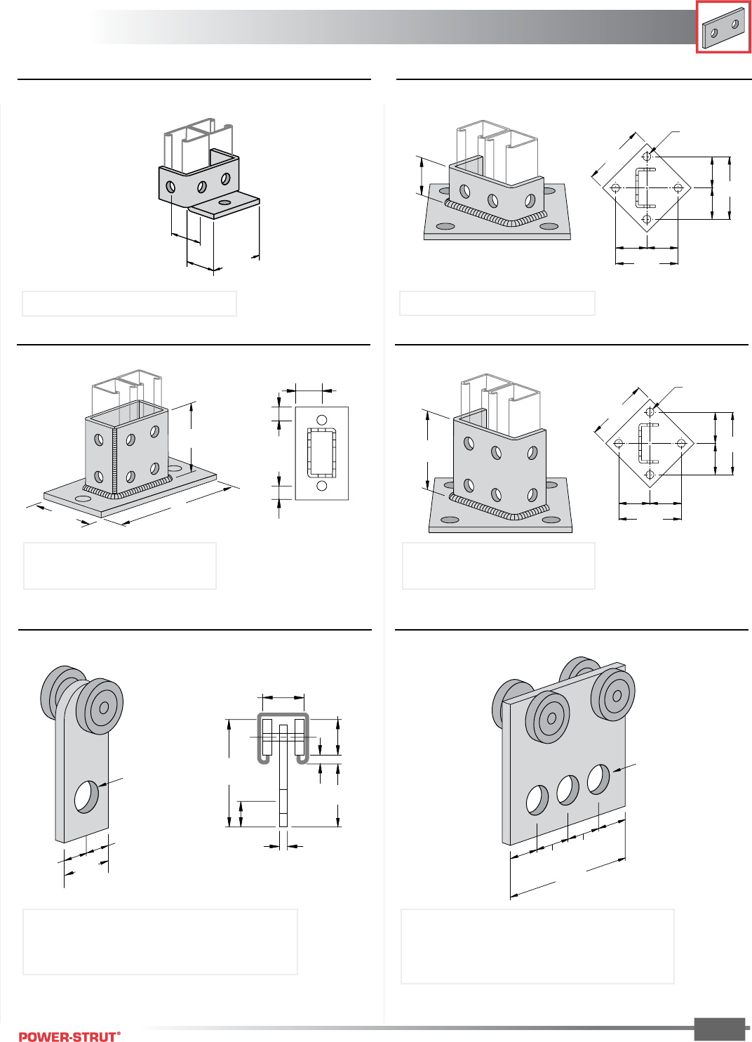
FITTINGS
FITTINGS
ENGINEERING CATALOG
83
Finish: Painted Green or Electro-galvanized Order By: No., Size and Finish
■PS 3041 – Double-Column Post Base ■PS 3029 – Double-Column Post Base
15⁄8"
6"
3" 3"
6"
3"
3"
6"
4 Holes
3⁄4" Dia.
111⁄16"
115⁄16"
31⁄8"
■PS 2064 – Double-Column Post Base ■PS 3064 – Double-Column Post Base
3
1
⁄
2
"
31⁄2"
7"
4"
6"
3" 3"
6"
3"
3"
6"
4 Holes
3
⁄
4
" Dia.
2"
3⁄4"
3⁄4"
Weight/100 pcs: 311 lbs. Weight/100 pcs: 408 lbs.
Use With: PS 100, PS 200 2T2, PS 200 2T3,
PS 200 2T4 and PS 200 2T5
Weight/100 pcs: 116 lbs Weight/100 pcs: 325 lbs.
Use With: PS 100, PS 200 2T3, and PS 210 2T3. Use With: PS 100, PS 200 2T3, PS 210 2T3
Use With: PS 100, PS 200 2T2, PS 200 2T3,
PS 200 2T4 and PS 200 2T5
■PS 2521 – Two-Wheel Trolley ■PS 2522 – Four-Wheel Trolley
1
1
⁄
4
"
5
⁄
8
"
5
⁄
8
"
Hole
9
⁄
16
"
Dia.
1
15
⁄
16
"
1
5
⁄
16
"
9
⁄
32
"
1
3
⁄
16
"
13
⁄
16
"
3
13
⁄
32
"
1
⁄
4
"
3
1
⁄
2
"
13
⁄
16
"
15
⁄
16
"
15
⁄
16
"
13
⁄
16
"
3 Holes
9
⁄
16
"
Dia.
Weight/100 pcs: 46 lbs.
Material: Carbon Steel Wheels have stainless steel ball bearings
Finish: Electro-Galvanized
Use With: PS 200 Load Rating: 300 lbs.
Weight/100 pcs: 110 lbs.
Material: Carbon Steel Wheels have stainless steel ball bearings
Finish: Electro-Galvanized
Use With: PS 200 Load Rating: 600 lbs.
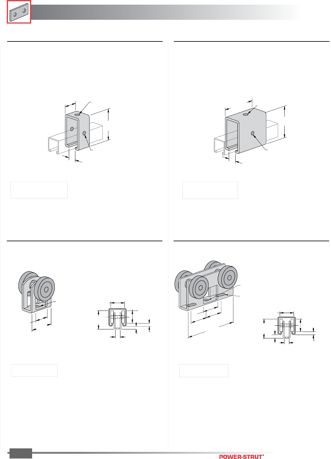
FITTINGS
FITTINGS
ENGINEERING CATALOG
84
Finish: Painted Green or Electro-galvanized Order By: No., Size and Finish
■PS 2524 – Two-Bearing Light Duty Trolley ■PS 2525 – Four-Bearing Light Duty Trolley
11⁄4"
3⁄4"
9⁄32" Dia. Hole
13⁄16"
123⁄32"
11⁄4"
1⁄4"7⁄16"
9⁄32"
7⁄16"
1
21
⁄32"
3⁄16"9⁄32"
13⁄16"
11⁄4"
■PS 2528 – Trolley Beam Standard Support ■PS 2528 - 1 – Trolley Beam Heavy Support
and Track Joiner
3
3
⁄
4
"
3
1
⁄
2
"
1"
2 Holes
7
⁄
16
"
Dia.
1 Hole
9
⁄
16
"
Dia.
33⁄4"
15⁄8"
2 Holes
7⁄16" Dia.
1 Hole
9⁄16" Dia.
1"
Weight/100 pcs: 220 lbs.
Use With: PS 200, PS 210
Load Rating: 2,500 lbs.
Use With: PS 200, PS 210
Load Rating: 600 lbs.
Weight/100 pcs: 102 lbs.
Weight/100 pcs: 55 lbs.Weight/100 pcs: 21 lbs.
Load Rating: 50 lbs. Load Rating: 100 lbs.
1"
1"
1"
9
⁄
32
" Dia. Hole
9
⁄
16
"x
9
⁄
32
" Slots
3
1
⁄
8
"
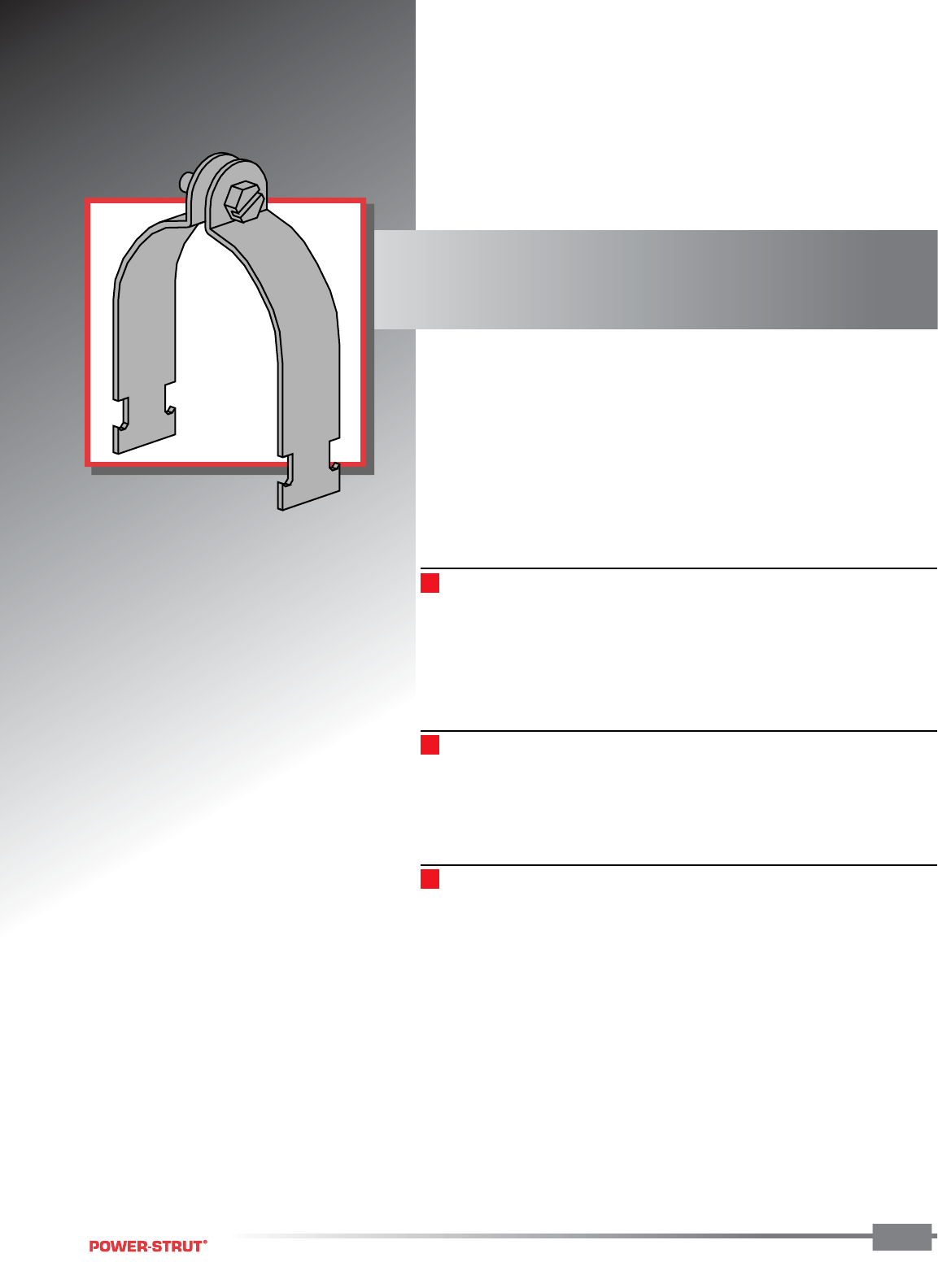
PIPE & CONDUIT CLAMPS
PIPE & CONDUIT CLAMPS
ENGINEERING CATALOG
85
Power-Strut pipe, conduit and O.D.
tubing clamps are formed in punch
press dies in a wide selection of sizes to
meet every requirement.
MATERIAL:
Power-Strut pipe, conduit and O.D. tubing clamps are made on punch
press dies from hot rolled, pickled and oiled steel which conforms to the
ASTM A-1008, A-1011 SS, A-575 and A-576 standards. Select sizes of
O.D. tubing clamps are available in stainless steel or aluminum.
STANDARD FINISH:
All steel clamps are electro-galvanized. Select sizes of O.D. tubing clamps
are available in copper plated finish. PVC coatings are available upon
special request.
ORDERING INFORMATION:
When ordering, add the length or size and finish to the part number.
See pages 8-10 for finish abbreviations and an example.
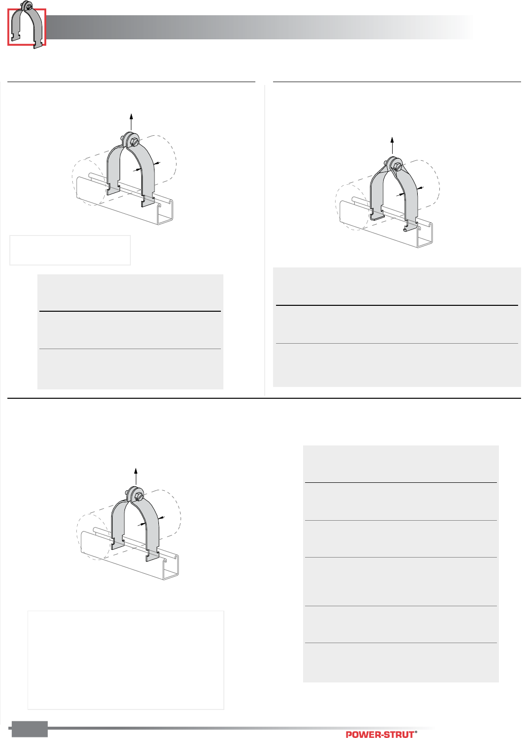
PIPE & CONDUIT CLAMPS
PIPE & CONDUIT CLAMPS
ENGINEERING CATALOG
86
Finish: Electro-galvanized Order By: No. and Finish
■PS 1000 – EMT Conduit Clamp ■PS 1300 – Universal Clamp for EMT,
IMC & GRC
11⁄4"
Design Load
11⁄4"
Design Load
■PS 1100, PS 1116, PS 1117 – Standard Pipe Clamp
(GRC, IMC and SCH 40/SCH 80 steel pipe)
1
1⁄4"
Design Load
Hanging
EMT Stock Load Wt./
Size Thickness Rating/lbs. 100 pcs
1⁄2" .060 400 11
3⁄4" .060 400 12
1" .075 600 15
11⁄4" .075 600 18
11⁄2" .105 800 29
2" .105 800 33
Hanging
Nom Fits Stock Load Wt./
Size O.D. Thickness Rating/lbs. 100 pcs
1⁄2" .706-.840 .060 250 10
3⁄4" .922-1.050 .060 400 11
1" 1.163-1.315 .060 400 12
11⁄4" 1.510-1.660 .075 400 18
11⁄2" 1.740-1.900 .075 500 20
2" 2.197-2.375 .075 500 22
Material and finish are specified as:
1100 ALM .. Alum. clamp, EG fasteners
1100 HDG .. HDG Clamp, Stainless Steel fasteners
1116 .......... Alum. clamp and fasteners
1117 .......... Alum. clamp, Stainless Steel fasteners
1100SS ...... Stainless Steel clamp and fasteners
Hanging
Pipe Stock Load Wt./
Size Thickness Rating/lbs. 100 pcs
3⁄8" .060 400 10
1⁄2" .060 400 11
3⁄4" .075 600 15
1" .075 600 17
11⁄4" .075 600 19
11⁄2" .105 800 29
2" .105 800 34
21⁄2" .105 800 40
3" .105 800 47
31⁄2" .125 1,000 62
4" .125 1,000 67
5" .125 1,000 80
6" .135 1,000 102
8" .135 1,000 130
10" .135 1,000 143
12" .135 1,000 174
NOTE: For EMT larger than
2" use PS 1100
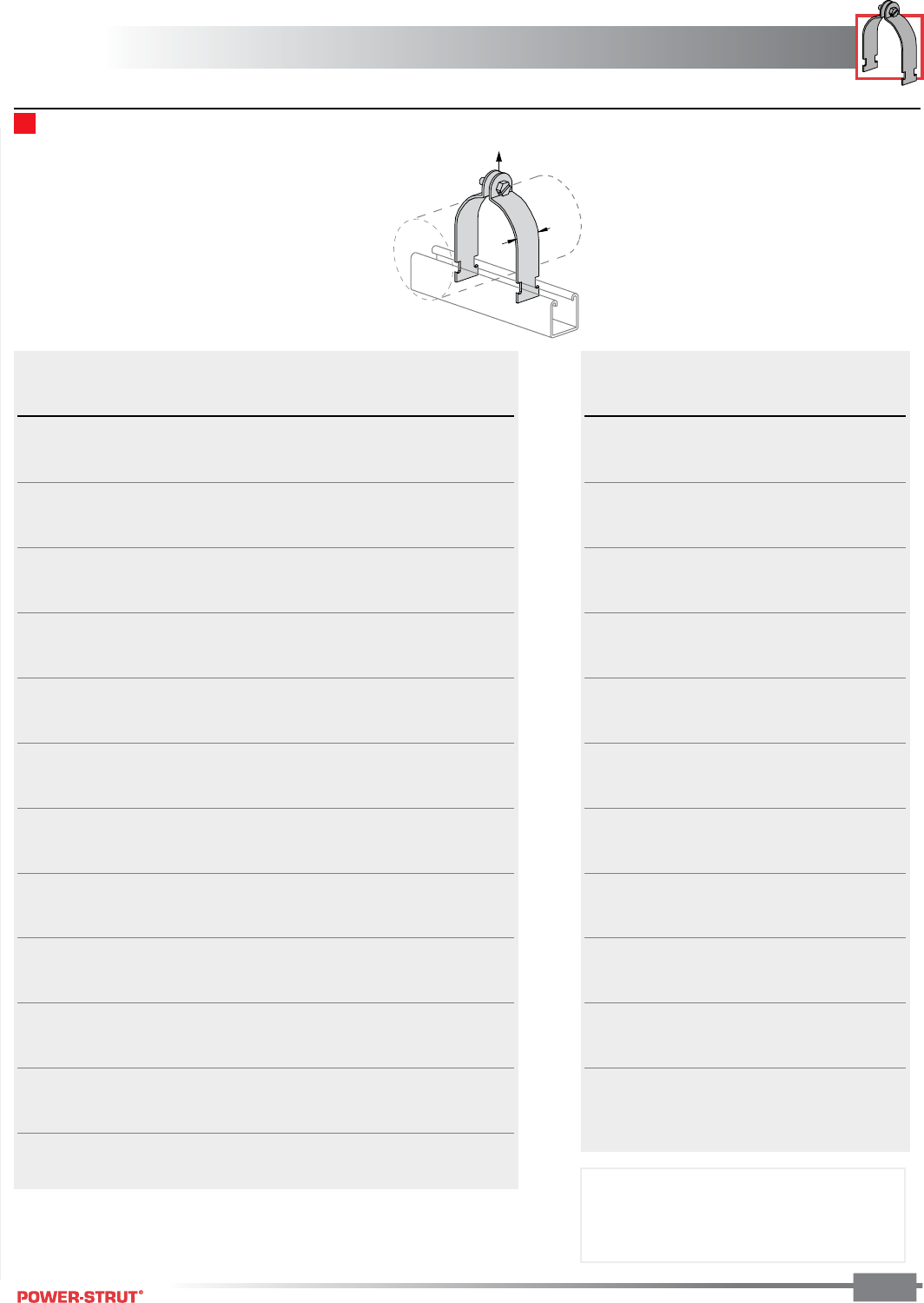
PIPE & CONDUIT CLAMPS
PIPE & CONDUIT CLAMPS
ENGINEERING CATALOG
87
Finish: Electro-galvanized Order By: No. and Size
■PS 1200 – O.D. Tubing Clamp
11⁄4"
Design Load
Hanging
O.D. Stock Load Wt./ Other Finishes
Size Thickness Rating/lbs. 100 pcs Available
1⁄4" .060 400 8
3⁄8" .060 400 8 CPLT
1⁄2" .060 400 9 CPLT
5⁄8" .060 400 10 CPLT
3⁄4" .060 400 11
7⁄8" .060 400 12 CPLT
1" .075 600 14
11⁄8" .075 600 15 SS CPLT
11⁄4" .075 600 16 SS
13⁄8" .075 600 17 SS CPLT
11⁄2" .075 600 18 SS
15⁄8" .075 600 19 SS CPLT
13⁄4" .105 800 29 SS
17⁄8" .105 800 28 SS
2" .105 800 31 SS
21⁄8" .105 800 32 SS CPLT
21⁄4" .105 800 33 SS
23⁄8" .105 800 34 SS
21⁄2" .105 800 35 SS
25⁄8" .105 800 37 SS CPLT
23⁄4" .105 800 38 SS
27⁄8" .105 800 40 SS
3" .105 800 41 SS
31⁄8" .105 800 43 SS CPLT
31⁄4" .105 800 45 SS
33⁄8" .105 800 46 SS
31⁄2" .105 800 47 SS
35⁄8" .105 800 56 SS CPLT
33⁄4" .105 800 58 SS
37⁄8" .125 1,000 60 SS
4" .125 1,000 62 SS
41⁄8" .125 1,000 62 SS CPLT
41⁄4" .125 1,000 64 SS
43⁄8" .125 1,000 66 SS
41⁄2" .125 1,000 67 SS
Hanging
O.D. Stock Load Wt./
Size Thickness Rating/lbs. 100 pcs
45⁄8" .125 1,000 70
43⁄4" .125 1,000 72
47⁄8" .125 1,000 73
5" .125 1,000 74
51⁄8" .125 1,000 76
51⁄4" .125 1,000 77
53⁄8" .125 1,000 78
51⁄2" .125 1,000 79
55⁄8" .135 1,000 88
53⁄4" .135 1,000 90
57⁄8" .135 1,000 92
6" .135 1,000 94
61⁄8" .135 1,000 96
61⁄4" .135 1,000 98
63⁄8" .135 1,000 99
61⁄2" .135 1,000 100
65⁄8" .135 1,000 102
63⁄4" .135 1,000 104
67⁄8" .135 1,000 106
7" .135 1,000 108
71⁄8" .135 1,000 110
71⁄4" .135 1,000 112
73⁄8" .135 1,000 114
71⁄2" .135 1,000 116
75⁄8" .135 1,000 117
73⁄4" .135 1,000 119
77⁄8" .135 1,000 121
8" .135 1,000 123
81⁄8" .135 1,000 125
81⁄4" .135 1,000 126
83⁄8" .135 1,000 128
81⁄2" .135 1,000 129
85⁄8" .135 1,000 130
Please contact factory for sizes not shown.
NOTE: SS - Stainless Steel
CPLT - Copper Plated
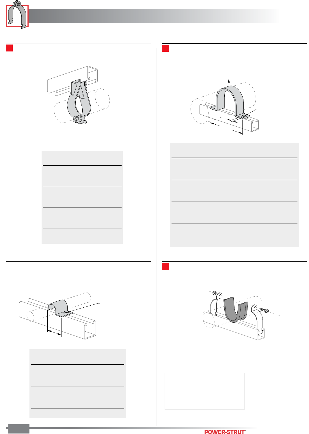
PIPE & CONDUIT CLAMPS
PIPE & CONDUIT CLAMPS
ENGINEERING CATALOG
88
Finish: Electro-galvanized Order By: No. and Finish
■PS 3138 – Parallel Run Pipe Clamp ■PS 3126 – One-Piece Pipe Strap
■PS 1450 – One-Hole Clamp for O.D. Tubing ■PS 3792 – Power-Wrap™
A ±
1
⁄
8
"
C
Hole Size B
Design Load
Hole Size –
9⁄32"
1⁄4" X 3⁄4"
Round Head
Machine Screw
and Channel Nut
Not Included
A
Pipe Load Wt./
Size Rating 100 pcs
3⁄8" 300 27
1⁄2" 300 29
3⁄4" 300 30
1" 400 31
11⁄4" 400 38
11⁄2" 500 40
2" 500 47
21⁄2" 500 66
3" 500 78
31⁄2" 500 87
4" 500 90
Pipe Design Wt./
Size A B C Load 100 pcs
1⁄2"2
7⁄8"9⁄32"7⁄16" 500 23
3⁄4"3
1⁄8"9⁄32"7⁄16" 500 26
1" 33⁄8"9⁄32"7⁄16" 500 31
11⁄4"3
3⁄4"9⁄32"7⁄16" 500 35
11⁄2"3
7⁄8"9⁄32"7⁄16" 500 39
2" 53⁄4"7⁄16"11⁄16" 1,000 94
21⁄2"6
1⁄4"7⁄16"11⁄16" 1,000 114
3" 67⁄8"7⁄16"11⁄16" 1,000 133
31⁄2"7
3⁄8"7⁄16"11⁄16" 1,000 152
4" 77⁄8"7⁄16"11⁄16" 1,000 176
5" 9" 7⁄16"11⁄16" 1,000 198
6" 10" 7⁄16"11⁄16" 1,000 225
O.D. Thickness Wt./
Size A Gages 100 pcs
1⁄4"1
3⁄16"16 4
3⁄8"1
5⁄16"16 5
1⁄2"1
7⁄16"16 6
5⁄8"1
5⁄8"14 8
3⁄4"1
3⁄4"14 9
7⁄8"1
7⁄8"14 10
1" 2" 14 11
Material: EPDM
Stock Thickness: 1⁄8"
Stock Length: 25 ft./box
Service Temp: -70˚ to 350˚ F
Weight/100 boxes: 253 lbs.
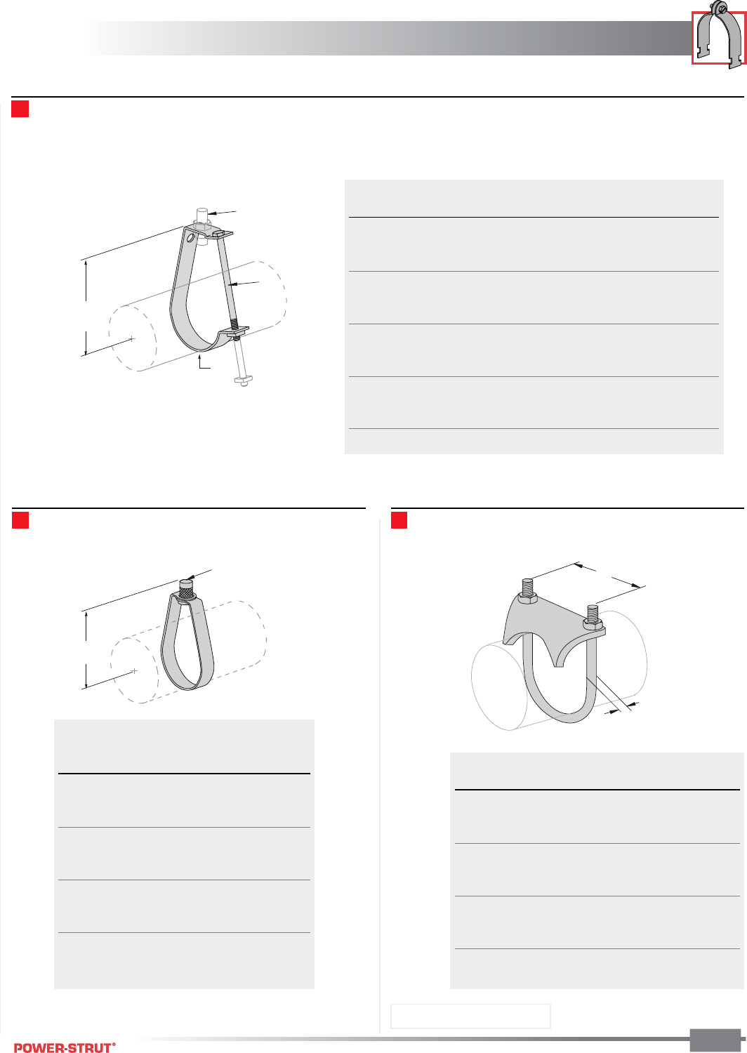
PIPE & CONDUIT CLAMPS
PIPE & CONDUIT CLAMPS
ENGINEERING CATALOG
89
Finish: Electro-galvanized Order By: No. and Size
■PS 67 – Pipe or Conduit Hanger
■PS 69 – E-Z Grip Hanger
Rod Size A
Listed
B
Rod Size A
Listed
C
B
D
■PS 51 – Right Angle Pipe or Conduit Clamp
B
A
Conduit A Load Wt./
Size Rod Size B C D Rating 100 pcs
1⁄2"3⁄8"1
3⁄4"1⁄4 x 21⁄4"1⁄8 x 3⁄4" 300 20
3⁄4"3⁄8"1
7⁄8"1⁄4 x 21⁄4"1⁄8 x 3⁄4" 300 21
1" 3⁄8"2
1⁄4"1⁄4 x 23⁄4"1⁄8 x 3⁄4" 300 24
11⁄4"3⁄8"2
3⁄4"1⁄4 x 31⁄4"1⁄8 x 3⁄4" 300 27
11⁄2"3⁄8"3"
1⁄4 x 31⁄2"1⁄8 x 3⁄4" 300 29
2" 3⁄8"3
3⁄8"1⁄4 x 4" 1⁄8 x 3⁄4" 300 33
21⁄2"1⁄2"4"
3⁄8 x 41⁄2"1⁄8 x 11⁄4" 500 71
3" 1⁄2"4
1⁄4"3⁄8 x 5" 1⁄8 x 11⁄4" 500 78
31⁄2"1⁄2"4
3⁄4"3⁄8 x 51⁄2"1⁄8 x 11⁄4" 500 85
4" 5⁄8"5
1⁄2"3⁄8 x 61⁄2"1⁄4 x 11⁄4" 600 178
5" 5⁄8"6"
3⁄8 x 71⁄2"1⁄4 x 11⁄4" 600 199
6" 3⁄4"7"
3⁄8 x 81⁄2"1⁄4 x 11⁄4" 600 231
8" 7⁄8"10"
3⁄8 x 12" 1⁄4 x 2" 700 449
Load
A Rating Wt./
Size Rod Size B Lbs/650 100 pcs
1⁄2"3⁄8"2
1⁄4" 300 9
3⁄4"3⁄8"2
5⁄16" 300 9
1" 3⁄8"2
7⁄16" 300 10
11⁄4"3⁄8"2
5⁄8" 300 10
11⁄2"3⁄8"2
3⁄4" 300 110
2" 3⁄8"3
1⁄4" 300 11
21⁄2"3⁄8" 4" 525 25
3" 3⁄8"4
3⁄8" 525 27
4" 3⁄8"4
11⁄16" 600 48
5" 1⁄2"5
5⁄16" 1000 53
6" 1⁄2"6
7⁄16" 1000 100
7" 1⁄2" 8" 1000 100
A Wt./
Size Diameter B 100 pcs
3⁄8"5⁄16"15⁄16"25
1⁄2"5⁄16"1
3⁄16"41
3⁄4"5⁄16"1
7⁄16"42
1" 5⁄16"1
11⁄16"47
11⁄4"5⁄16"2" 54
11⁄2"5⁄16"2
5⁄16"57
2" 3⁄8"2
3⁄16"85
21⁄2"3⁄8"3
3⁄8" 106
3" 3⁄8"4
1⁄8" 110
31⁄2"3⁄8"4
5⁄8" 128
4" 3⁄8"5
1⁄8" 140
Material: Malleable Iron
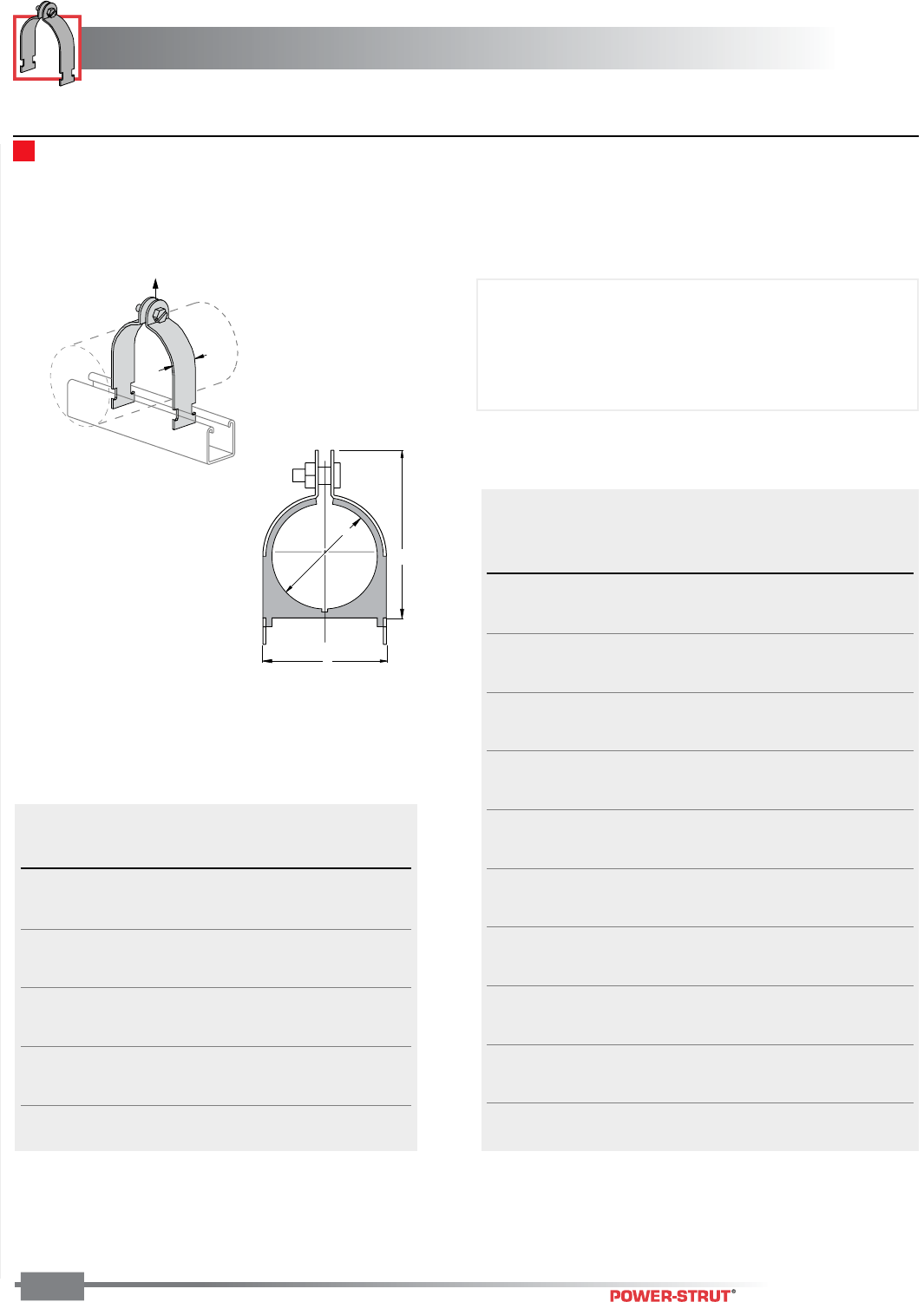
PIPE & CONDUIT CLAMPS
PIPE & CONDUIT CLAMPS
ENGINEERING CATALOG
90
Finish: Electro-galvanized Order By: No. and Finish
1
1
⁄
4
"
Design Load
A
B
C
■PS 004T – PS 106N – Cush-a-Clamp® Assembly Pipe & Tube Series
Pipe Series
Pipe Size Dimensions Wt./
Part No. (Nominal) A B C 100
PS 009N 1⁄4" 0.54 0.98 1.34 13
PS 011N 3⁄8" 0.67 1.13 1.54 14
PS 014N 1⁄2" 0.84 1.29 1.82 15
PS 017N 3⁄4" 1.05 1.50 2.08 17
PS 021N 1" 1.31 1.76 2.34 19
PS 027N 11⁄4" 1.66 2.17 2.73 35
PS 030N 11⁄2" 1.90 2.35 2.86 41
PS 038N 2" 2.37 2.82 3.67 49
PS 046N 21⁄2" 2.87 3.32 4.17 57
PS 056N 3" 3.50 3.95 4.79 55
PS 064N 31⁄2" 4.00 4.45 5.42 88
PS 072N 4" 4.50 4.95 5.92 110
PS 089N 5" 5.56 6.01 6.92 130
PS 106N 6" 6.62 7.07 8.23 140
Tube Series
Copper & Copper
Steel Tube Water Pipe Dimensions Wt./
Part No. O. D. Size (Nominal) A B C 100
PS 004T 1⁄4" 0.25 0.62 0.98 10
PS 006T 3⁄8"1⁄4" 0.37 0.82 1.13 11
PS 008T 1⁄2"3⁄8" 0.50 0.94 1.34 13
PS 010T 5⁄8"1⁄2" 0.62 1.06 1.54 14
PS 012T 3⁄4"5⁄8" 0.75 1.2 1.68 14
PS 014T 7⁄8"3⁄4" 0.87 1.31 1.82 15
PS 016T 1" 1.00 1.44 1.95 17
PS 018T 11⁄8" 1" 1.12 1.57 2.08 18
PS 020T 11⁄4" 1.25 1.70 2.21 18
PS 022T 13⁄8"1
1⁄4" 1.37 1.82 2.34 20
PS 024N 11⁄2" 1.50 1.95 2.47 33
PS 026N 15⁄8"1
1⁄2" 1.62 2.07 2.60 35
PS 028N 13⁄4" 1.75 2.20 2.73 37
PS 030N 17⁄8" 1.87 2.32 2.86 39
PS 032N 2" 2.00 2.45 3.04 41
PS 034N 21⁄8" 2.12 2.57 3.23 46
PS 038N 23⁄8" 2.37 2.82 3.67 47
PS 040N 21⁄2" 2.50 2.94 3.79 49
PS 042N 25⁄8" 2.62 3.07 3.92 51
PS 046N 27⁄8" 2.87 3.32 4.17 55
PS 048N 3" 3.00 3.57 4.42 57
PS 050N 31⁄8" 3.12 3.57 4.42 60
PS 056N 31⁄2" 3.50 3.95 4.79 55
PS 058N 35⁄8" 3.62 4.2 5.11 70
PS 064N 4" 4.00 4.45 5.42 88
PS 066N 41⁄8" 4.12 4.57 5.54 94
PS 072N 41⁄2" 4.50 4.95 5.92 110
PS 082N 51⁄8" 5.12 5.57 6.54 125
PS 098N 61⁄8" 6.12 6.57 7.54 130
Clamp: Electro-galvanized or stainless steel
Cushion: Thermoplastic elastomer resistant to the effects of
most oils, chemicals and industrial cleaning
compounds in temperatures from -50°F to 275°F.
Includes: Cushion, Clamp and Hardware
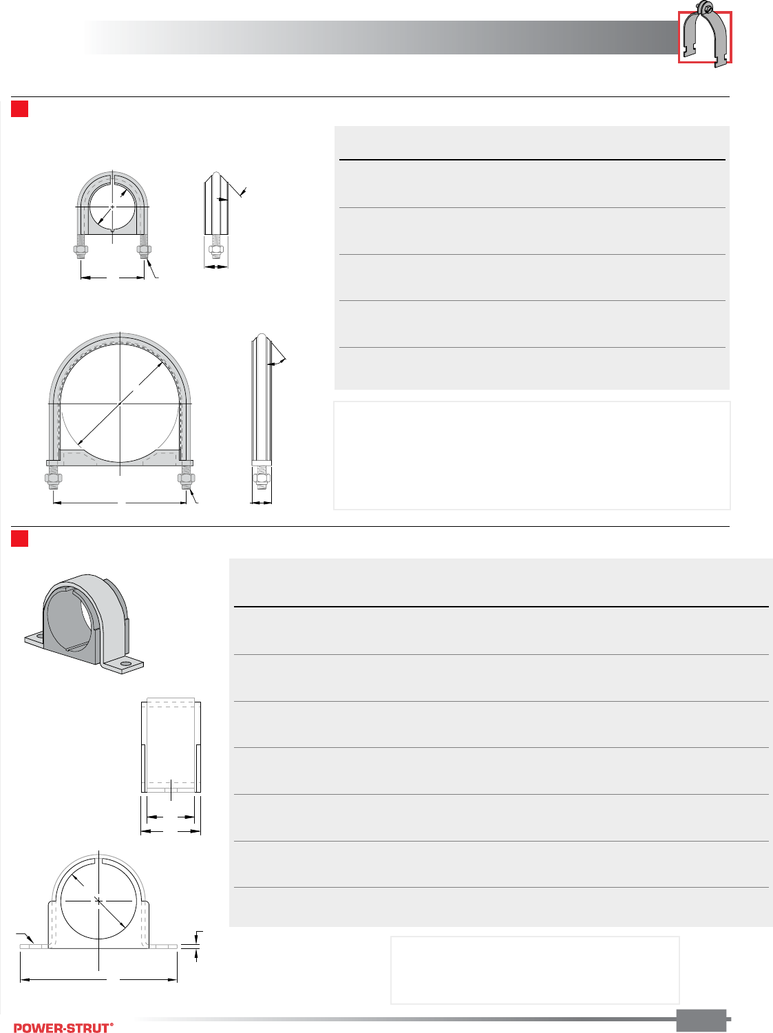
PIPE & CONDUIT CLAMPS
PIPE & CONDUIT CLAMPS
ENGINEERING CATALOG
91
Finish: Electro-galvanized Order By: No. and Size
■PS 004M – PS 038M – Cush-a-Clamp® Assembly Omega Series
■PS UB 1/2 – PS UB 10 – Cush-a-Clamp® Assembly U–Bolt Series
A
C
D
B
30¡
(0.17„)
A
BD
30¡
(0.17
„)
C
F
D
PIPE Dimensions Wt./
PART NO. SIZE A B C D 100 Pcs
PS UB 1⁄21⁄2" 0.84 1.60 0.68 1⁄4-20 UNC-2B 9
PS UB 3⁄43⁄4" 1.05 1.80 0.68 1⁄4-20 UNC-2B 10
PS UB 1 1" 1.31 2.05 0.68 1⁄4-20 UNC-2B 12
PS UB 11⁄411⁄4" 1.66 2.55 1.24 3⁄8-16 UNC-2B 32
PS UB 11⁄211⁄2" 1.90 2.80 1.24 3⁄8-16 UNC-2B 36
PS UB 2 2" 2.37 3.35 1.24 3⁄8-16 UNC-2B 42
PS UB 21⁄221⁄2" 2.87 3.90 1.24 1⁄2-13 UNC-2B 72
PS UB 3 3" 3.50 4.55 1.24 1⁄2-13 UNC-2B 84
PS UB 31⁄231⁄2" 4.00 5.05 1.24 1⁄2-13 UNC-2B 93
PS UB 4 4" 4.50 5.50 1.24 1⁄2-13 UNC-2B 102
PS UB 5 5" 5.56 6.56 1.24 1⁄2-13 UNC-2B 123
PS UB 6 6" 6.62 7.75 1.44 5⁄8-11 UNC-2B 243
PS UB 8 8" 8.62 9.82 1.44 5⁄8-11 UNC-2B 293
PS UB 10 10" 10.75 12.16 1.65 3⁄4-10 UNC-2B 492
Copper
Tubing Water Pipe Pipe Size Dimensions Wt./
PART NO. O.D. SIZE (Nominal) (Nominal) ABCDEF100 Pcs
PS 004M 1⁄4" 0.25 1.81 0.06 0.62 0.20 0.78 3.4
PS 006M 3⁄8"1⁄40.37 1.90 0.06 0.62 0.20 0.81 4.0
PS 008M 1⁄2"3⁄81⁄4" 0.50 2.20 0.06 0.75 0.26 0.98 5.5
PS 010M 5⁄8"1⁄23⁄8" 0.62 2.32 0.06 0.75 0.26 0.98 6.0
PS 012M 3⁄4"5⁄80.75 2.41 0.06 0.75 0.26 0.98 6.5
PS 014M 7⁄8"3⁄41⁄2" 0.87 2.56 0.06 0.75 0.26 0.98 7.1
PS 016M 1" 1.00 2.68 0.06 0.75 0.26 0.98 7.8
PS 018M20 3⁄4" 1.05 2.68 0.06 0.75 0.26 0.98 8.1
PS 018M21 11⁄8" 1 1.12 2.82 0.06 0.75 0.26 0.98 8.4
PS 020M 11⁄4" 1.25 3.00 0.08 1.25 0.26 1.56 17
PS 021M 1" 1.31 3.12 0.08 1.25 0.26 1.56 20
PS 022M 13⁄8"1
1⁄41.37 3.12 0.08 1.25 0.26 1.56 19
PS 024M 11⁄2" 1.50 3.65 0.08 1.25 0.26 1.56 20
PS 026M 15⁄8"1
1⁄21.62 3.77 0.08 1.25 0.26 1.56 23
PS 027M 11⁄4" 1.66 3.90 0.10 1.25 0.33 1.56 32
PS 028M 13⁄4" 1.75 3.90 0.10 1.25 0.33 1.56 32
PS 030M 17⁄8"1
1⁄2" 1.87 4.02 0.10 1.25 0.33 1.56 34
PS 032M 2" 2.00 4.15 0.10 1.25 0.33 1.56 36
PS 034M 21⁄8" 2.12 4.40 0.10 1.25 0.33 1.56 41
PS 038M 2" 2.37 4.71 0.10 1.25 0.33 1.56 44
Includes U-bolt, cushion, and hardware.
Materials: U-Bolt: Electrogalvanized finish or Type 316 SS
Cushion: Thermoplastic elastomer
Note: Not intended for use with metal framing components
due to the length of the thread.
Includes clamp and cushion.
Materials: Clamp: ZD or Stainless Steel
Cushion: Thermoplastic elastomer
A
B
C
E
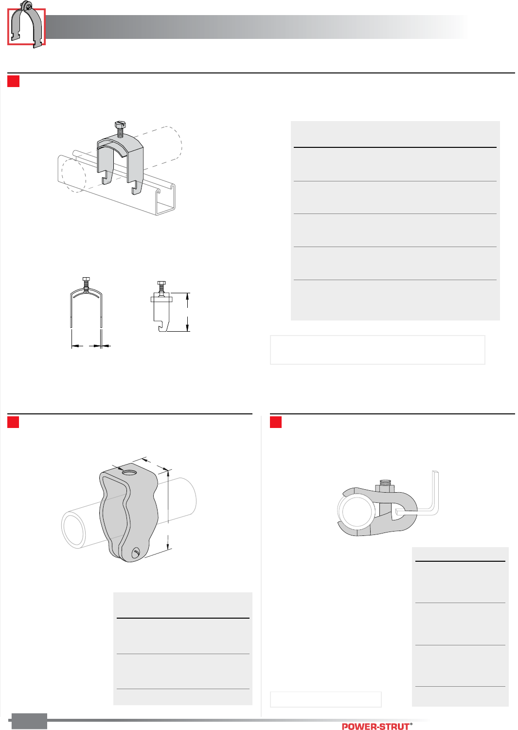
PIPE & CONDUIT CLAMPS
PIPE & CONDUIT CLAMPS
ENGINEERING CATALOG
92
Finish: Electro-galvanized Order By: No. and Finish
■PS 270 – Conduit Clamp ■PS 52E – Parallel Pipe and Conduit Clamp
1"
A
2
5
⁄
8
"
■PS 3101 thru PS 3115 – One-Piece cable & Conduit Clamp
CA
B
Max Wt/
Part No. O.D. Size A B C 100 pcs
PS 3101 3⁄8"7⁄16"1
5⁄8"14 6
PS 3102 1⁄2"9⁄16"1
3⁄4"14 7
PS 3103 3⁄4"13⁄16"2"14 12
PS 3104 1" 11⁄16"2
1⁄4"14 15
PS 3105 11⁄4"1
5⁄16"2
1⁄2"14 19
PS 3106 11⁄2"1
9⁄16"2
3⁄4"14 20
PS 3107 13⁄4"1
13⁄16"3" 12 25
PS 3108 2" 21⁄16"3
1⁄4"12 35
PS 3109 23⁄8"2
7⁄16"3
5⁄8"12 41
PS 3110 23⁄4"2
13⁄16"4" 12 60
PS 3111 31⁄4"3
5⁄16"4
1⁄2"12 74
PS 3112 33⁄4"3
13⁄16"5" 12 91
PS 3113 4" 41⁄16"5
1⁄4" 12 100
PS 3114 43⁄8"4
7⁄16"5
5⁄8" 12 115
PS 3115 43⁄4"4
13⁄16" 6" 12 125
Size Wt./100 pcs
1⁄2"59
3⁄4"64
1" 70
11⁄4"72
11⁄2"93
2" 128
21⁄2" 135
3" 155
31⁄2" 190
4" 205
A Wt./
Size Diameter 100 pcs
3⁄8"1⁄4"6
1⁄2"1⁄4"6
3⁄4"1⁄4"8
1" 1⁄4"9
11⁄4"1⁄4"11
11⁄2"1⁄4"19
2" 1⁄4"27 Material: Malleable Iron
Note: Available in Electro-galvanized steel, Type 304
Stainless Steel or Aluminum
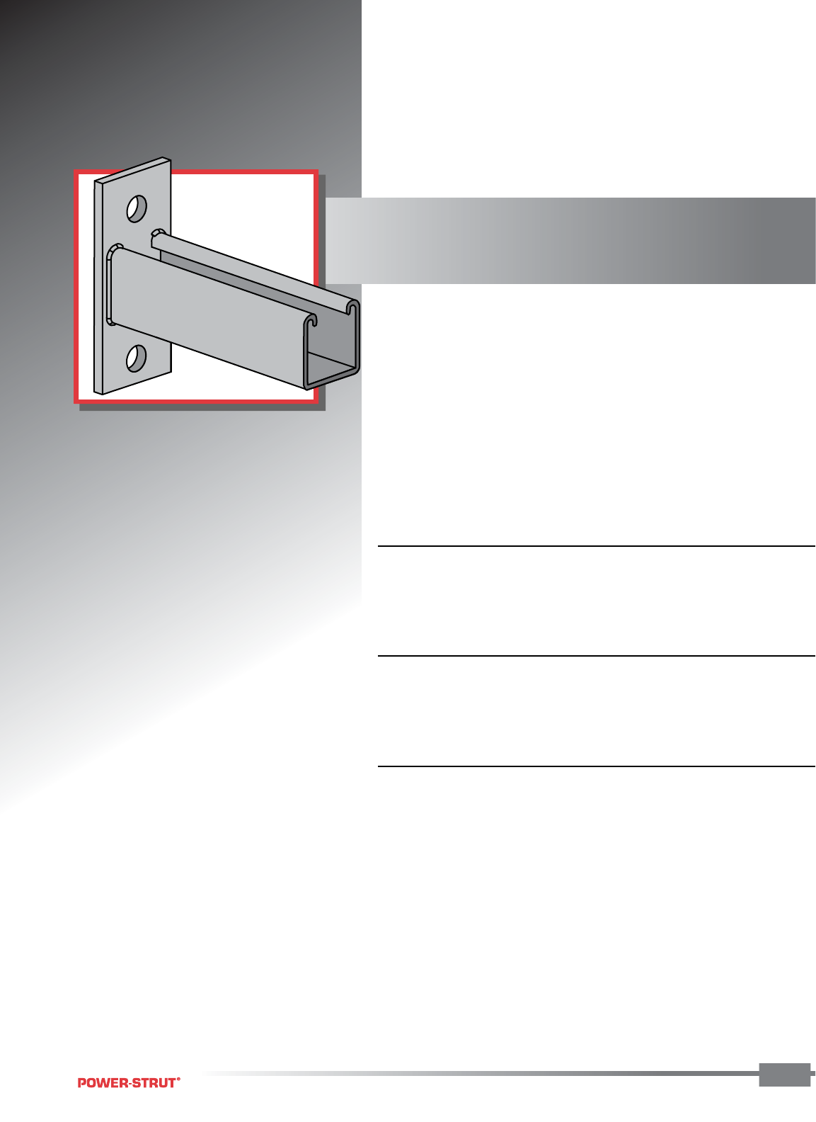
BRACKETS
BRACKETS
ENGINEERING CATALOG 93
Power-Strut channel brackets feature a
combination fitting and channel to
eliminate field fabrication and speed
installation. Shelf, pipe and stair
brackets are also available in a variety
of sizes.
■ MATERIAL:
Power-Strut brackets are made by punch press and roll form operations
from hot rolled, mild steel.
■ STANDARD FINISH:
Power-Strut brackets are available in painted green or electro-galva-
nized finishes.
■ ORDERING INFORMATION:
When ordering, add the length or size and finish to the part number.
See pages 8-10 for finish abbreviations and an example.
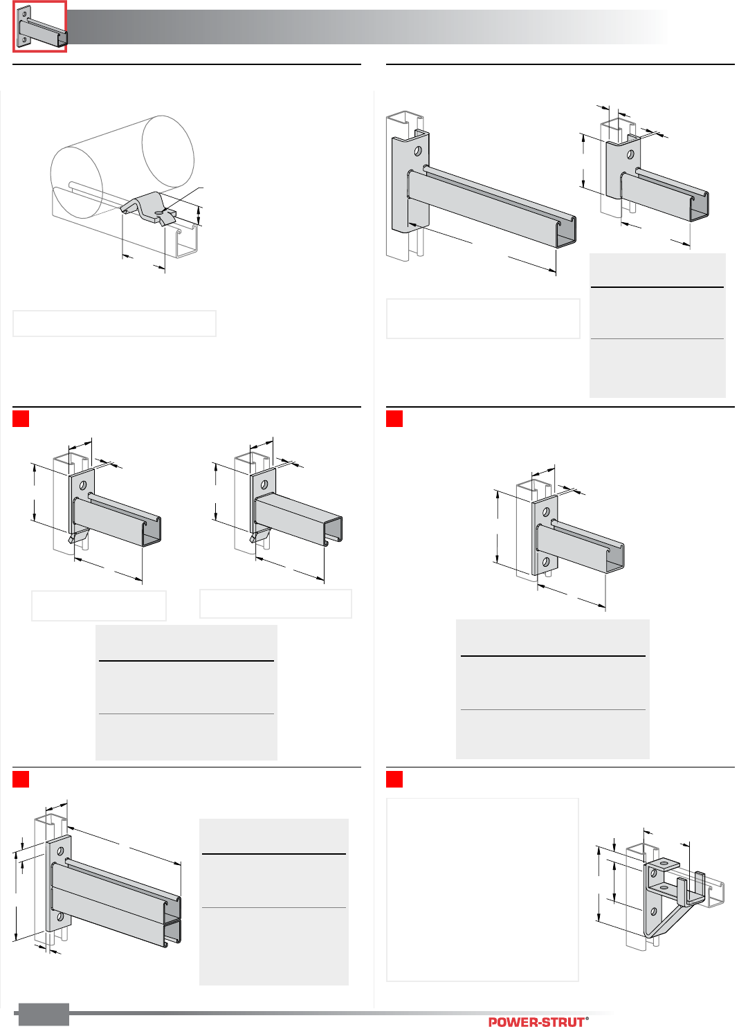
BRACKETS
BRACKETS
ENGINEERING CATALOG
94
Finish: Painted Green or Electro-galvanized Order By: No., Size and Finish
■PS 708 – Single Channel Bracket Support■PS 809 – Double Channel Bracket
3⁄8"
13⁄16"
61⁄4"
A
2"
■PS 626 – Pipe Stop ■PS 661 T1, PS 661 T2 – Wrap-Around
Channel Bracket
■
PS 808 T1, PS 808 T2 – Interlocking Channel Bracket
■PS 651 – Reversible Channel Bracket
Hole Size 7
⁄
16
"
3"
1"
Clamp Requires bolt and
channel nut sold seperately.
3
3
⁄
4
"
1
⁄
4
"
A
2"
4
7
⁄
8
"
3
⁄
8
"
A
2"
18" or 24"
31⁄2"
13⁄16"
1⁄4"
6 or 12
4
3
⁄
4
"
5
7
⁄
8
"
3"
1
1
⁄
16
"
3
3
⁄
4
"
1
⁄
4
"
A
2"
Uniform Wt./
Size Load* 100 pcs
6" 1,600 191
12" 800 292
18" 600 436
24" 450 536
*Mounted on 12 Ga.
Channel
Uniform Wt./
A Size Load* 100 pcs
6" 1,200 185
12" 600 293
18" 400 401
24" 300 509
*Mounted on 12 Ga. Channel
Uniform Wt./
A Size Load* 100 pcs
6" 1,200 161
12" 600 261
18" 400 361
24" 300 461
*Mounted on 12 Ga. Channel
Uniform Wt./
A Size Load* 100 pcs
12" 2,000 502
18" 1,300 692
24" 1,000 882
30" 800 1,072
36" 650 1,262
*Mounted on 12 Ga.
Channel
Weight/100 pcs: 40 lbs.
NOTE: For use with 2" to 8" Pipe
NOTE: PS 661 T1 (Slot up) illustrated
PS 661 T2 (Slot down) not shown
(PS 808 T1 Slot Up) (PS 808 T2 Slot Down)
Weight/100 pcs: 235 lbs.
Use With: PS 200, PS 210,
PS 500 2T3
Design Moment on Upright
Channel:
16 ga. channel 3,200 in.-lbs.,
14 ga. channel 4,400 in.-lbs.
12 ga. channel 5,100 in.-lbs.
NOTE: Moment is for fitting only.
Channel may determine overall
capacity.
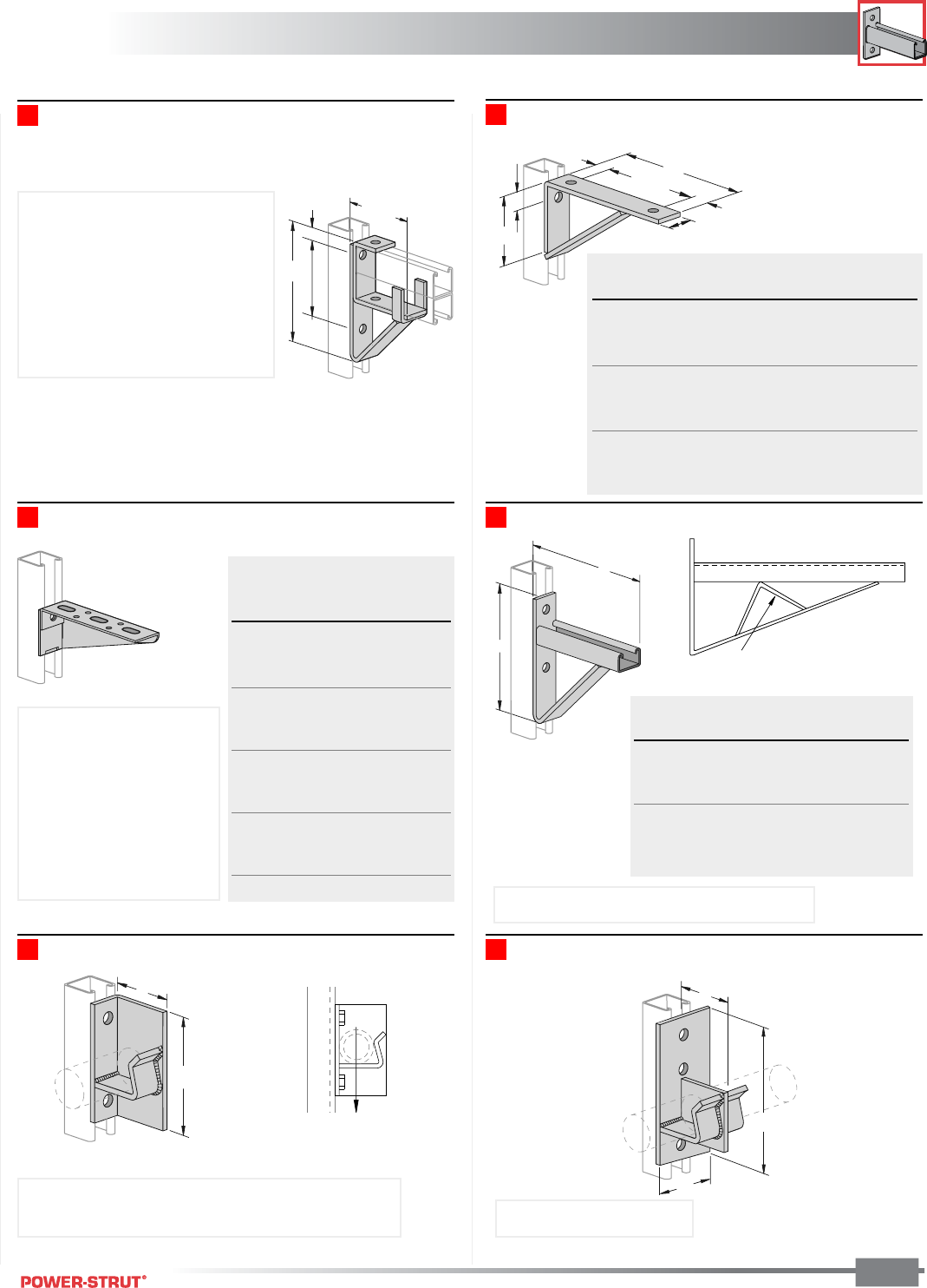
BRACKETS
BRACKETS
ENGINEERING CATALOG
95
Finish: Painted Green or Electro-galvanized Order By: No., Size and Finish
■PS 3164 – Double Channel Bracket Support ■PS 732 – Shelf Bracket
6
1
⁄
8
"
1
3
⁄
16
"
1
3
⁄
16
"
1
1
⁄
16
"
B1
5
⁄
8
"
A
4
3
⁄
4
"
7
1
⁄
2
"
4
5
⁄
8
"
1
1
⁄
16
"
Uniform Wt./
Size A B Load* 100 pcs
8" 81⁄2" 4" 800 168
10" 101⁄2" 4" 800 202
12" 121⁄2" 6" 900 258
14" 141⁄2" 6" 900 292
16" 161⁄2" 6" 1,200 381
18" 181⁄2" 6" 1,200 416
20" 201⁄2" 6" 1,000 461
*Mounted on 12 ga. channel
Use With: PS 200 2T3, PS 210 2T3
Design Moment on Upright Channel:
16 ga. channel 6,500 in.-lbs.
14 ga. channel 9,100 in.-lbs.
12 ga. channel 13,000 in.-lbs.
NOTE: Moment is for fitting only.
Channel may determine overall
capacity.
Weight/100 pcs: 273 lbs.
■PS 3282 – Cable Tray Strut Bracket■PS 838 R OR L – Shelf Bracket
■PS 825 R OR L – Single Pipe Axle Support ■PS 826 – Double Pipe Axle Support
5
3
⁄
8
"
3"
7
5
⁄
8
"
3"
3"
Load
Right Hand Illustrated
B
A
PS 400
Support brace on
24", 30" and 36" only.
Uniform Wt./
A B Load* 100 pcs
12" 83⁄4" 1,900 388
18" 83⁄4" 1,000 506
24" 83⁄4" 1,000 763
30" 111⁄4" 900 1,012
36" 111⁄4" 800 1,083
*Mounted on 12 ga. channel.
Stock Thickness: .105
NOTE: Specify
R (Right) or L (Left)
when ordering.
Right Hand Illustrated
Uniform Load Rating:
275 Lbs. when mounted
on 12 ga. channel.
NOTE: PS 400 channel welded to 1⁄4" stock
Load Rating: 4,000 lbs.
Weight/100 pcs.: 310 lbs.
Load Rating: 2,000 lbs.
NOTE: Specify R (Right) or L (Left) when ordering.
Weight/100 pcs.: 220 lbs.
Stamped
A Ident. Wt./
Size No. B 100 pcs
6" 121892 115⁄16"58
8" 121893 27⁄16"83
10" 121894 215⁄16" 114
12" 121895 37⁄16"49
14" 121896 315⁄16" 174
16" 121897 47⁄16" 225
18" 121898 415⁄16" 255
20" 121899 57⁄16" 295
22" 121900 515⁄16" 361
24" 121901 67⁄16" 396
26" 121902 615⁄16" 456
28" 121903 77⁄16" 479
30" 121904 715⁄16" 544
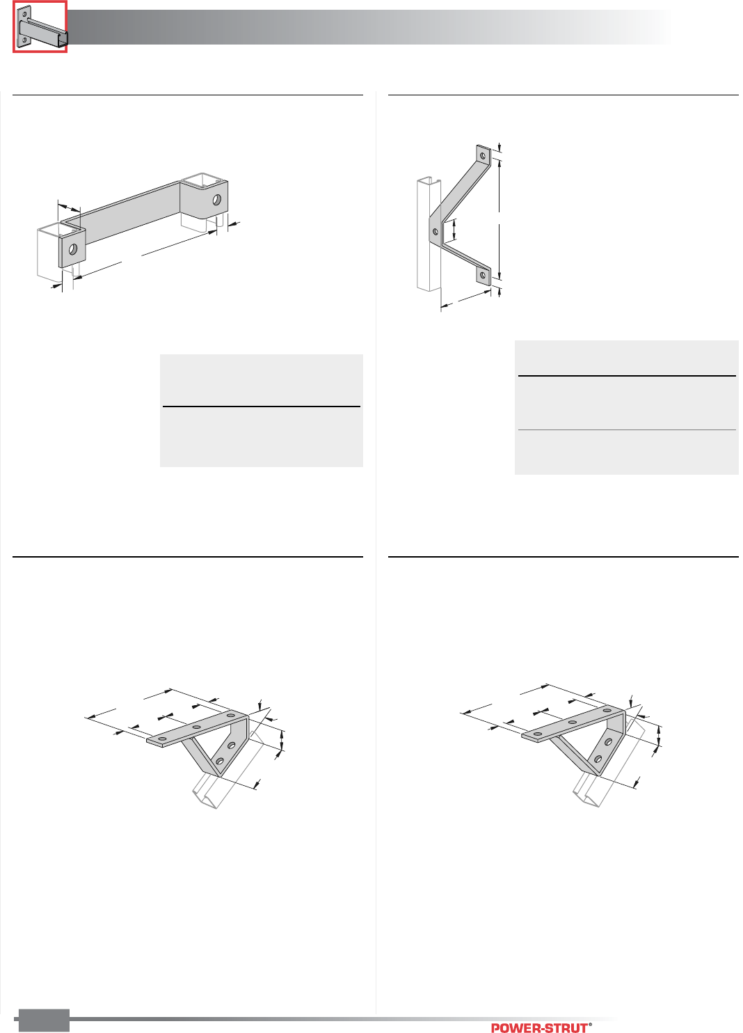
BRACKETS
BRACKETS
ENGINEERING CATALOG
96
Finish: Painted Green or Electro-galvanized Order By: No., Size and Finish
■PS 2401 thru PS 2403 – Ladder Rung ■PS 2404 thru PS 2408 – Wall Ladder
Bracket
B
13⁄16"
2"
A
13⁄16"
1
5
⁄
8
"
13
⁄
16
"
A
13
⁄
16
"
Part Wt./
No. A B 100 pcs
PS 2404 23⁄8" 6" 113
PS 2405 43⁄8" 8" 164
PS 2406 63⁄8" 10" 216
PS 2407 83⁄8" 12" 267
PS 2408 103⁄8" 14" 318
"A"
Part Hole to Wt./
No. Hole 100 pcs
PS 2401 12" 186
PS 2402 15" 221
PS 2403 18" 254
■PS 2422 – 371⁄2° Degree Stair Tread
Support
■PS 2421 – 45° Degree Stair Tread Support
Weight/100 pcs: 213 lbs.
11⁄16"
31⁄2"
31⁄2"
13⁄16"
87⁄8"
33⁄4"
371⁄2°
17⁄8"
Weight/100 pcs: 220 lbs.
45°
3
3
⁄
4
"
1
7
⁄
8
"
1
1
⁄
16
"
3
1
⁄
2
"
3
1
⁄
2
"
13
⁄
16
"
8
7
⁄
8
"
ROLLERS
ROLLERS
ENGINEERING CATALOG
97
Power-Strut rollers feature cast iron
rollers and steel brackets formed by
punch press dies. The brackets have
holes for attachment to channel
with a standard channel nut and bolt.
■ MATERIAL:
Power-Strut pipe rollers consist of cast iron rollers and steel brackets.
The steel brackets are punched from hot rolled, pickled and oiled
mild steel.
■ STANDARD FINISH:
Standard finish for the roller is plain while brackets are painted green
or electro–galvanized.
■ ORDERING INFORMATION:
When ordering, add the length or size and finish to the part number.
See pages 8-10 for finish abbreviations and an example.
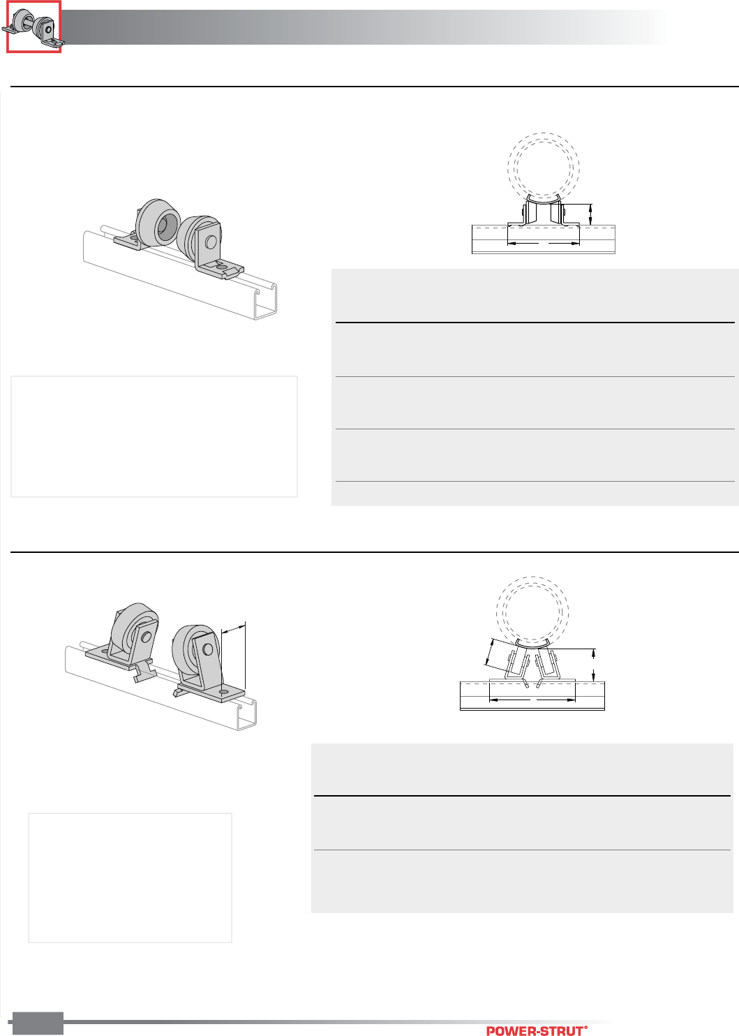
ROLLERS
ROLLERS
ENGINEERING CATALOG
98
Order By: No. and Finish
■PS 1901 – Two-Piece Pipe Roller
A
2
1
⁄
2
"
■PS 815 – Two-Piece, Heavy Duty Pipe Roller
A
3
1
⁄
2
"3
3
⁄
4
"
TO
3"
2"
Chart for Dimension A
Pipe No Insulation Thickness
Size Insulation 1" 11⁄2"2"2
1⁄2"3" 4"
1⁄2"6
1⁄2"6
1⁄2"
3⁄4"6
1⁄2"6
1⁄2"6
5⁄8"6
7⁄8"
1" 61⁄2"6
1⁄2"6
5⁄8"6
7⁄8"
11⁄4"6
1⁄2"6
1⁄2"6
7⁄8"7
1⁄8"7
3⁄8"
11⁄2"6
1⁄2"6
1⁄2"6
7⁄8"7
1⁄8"7
3⁄8"
2" 61⁄2"6
5⁄8"7
1⁄8"7
3⁄8"7
1⁄2"8"
21⁄2"6
1⁄2"6
5⁄8"7
1⁄8"7
3⁄8"7
1⁄2"8"
3" 61⁄2"7"7
1⁄2"7
3⁄4"7
7⁄8"8
1⁄8"
31⁄2"6
1⁄2"7"7
1⁄2"7
3⁄4"7
7⁄8"8
1⁄8"
4" 65⁄8"7
1⁄4"7
5⁄8"7
7⁄8"8"8
3⁄8"9"
Chart for Dimension A
Pipe No Insulation Thickness
Size Insulation 1" 11⁄2"2"2
1⁄2"3" 4"
6" 91⁄2"10
1⁄4"10
1⁄2"10
3⁄4"11"11
3⁄8"11
7⁄8"
8" 101⁄8"11"11
3⁄8"11
3⁄4"12"12
1⁄2"
10" 103⁄4"11
5⁄8"12"12
1⁄4"12
1⁄2"13"
12" 111⁄4"12
1⁄8"12
1⁄2"12
3⁄4"13"13
1⁄2"
14" 115⁄8"12
1⁄2"12
7⁄8"13"13
3⁄8"14"
16" 121⁄8"13"13
3⁄8"13
7⁄8"14"14
1⁄2"
Weight/100 pair: 268 lbs.
Use With: 1/2"-4" pipe
Load Rating: 500 lbs.
Material: Bracket - steel;
Roller - cast iron (or aluminum)
Finish: Green or galvanized;
Roller - plain
Weight/100 pair: 680 lbs.
Use With: 6-16" pipe
Material: Bracket - steel;
Roller - cast iron
Finish: Green or galvanized;
Roller - plain
Load Rating: 1500 lbs.
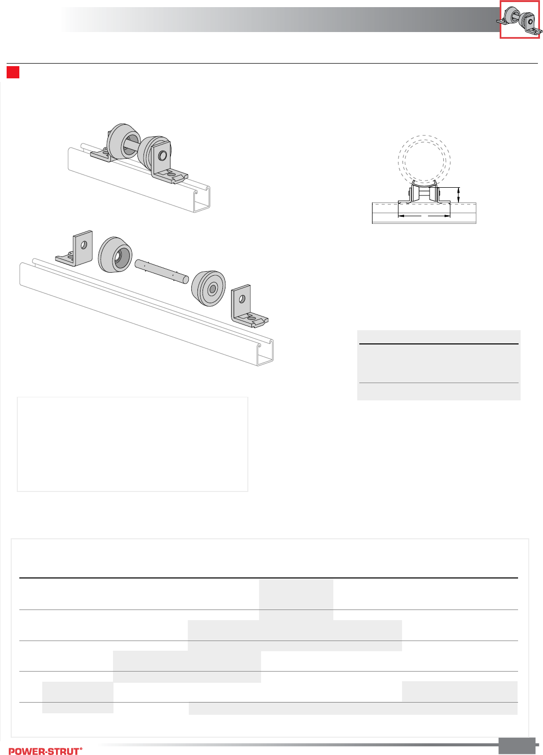
ROLLERS
ROLLERS
ENGINEERING CATALOG
99
Order By: No. and Size
PS 1902 – Pipe-Roller Assembly
A
2
1
⁄
2
"
Part Number A Wt./100 pcs.
PS 1902 - 1"-2" 63⁄4299
PS 1902 - 21⁄2"-31⁄2"7
1⁄2304
PS 1902 - 4"-6" 81⁄2311
PS 1902 - 8" 99⁄16 319
Pipe No Insulation Thickness
Size Insulation 1" 11⁄2" 2" 21⁄2" 3" 4"
1⁄2" PS 1902 - 1"-2" PS 1902 - 1"-2" PS 1902 - 1"-2" PS 1902 - 21⁄2"-31⁄2"
3⁄4" PS 1902 - 1"-2" PS 1902 - 1"-2" PS 1902 - 1"-2" PS 1902 - 21⁄2"-31⁄2"
1" PS 1902 - 1"-2" PS 1902 - 1"-2" PS 1902 - 1"-2" PS 1902 - 21⁄2"-31⁄2"
11⁄4" PS 1902 - 1"-2" PS 1902 - 1"-2" PS 1902 - 1"-2" PS 1902 - 21⁄2"-31⁄2"
11⁄2" PS 1902 - 1"-2" PS 1902 - 1"-2" PS 1902 - 21⁄2"-31⁄2" PS 1902 - 21⁄2"-31⁄2" PS 1902 - 21⁄2"-31⁄2"
2" PS 1902 - 1"-2" PS 1902 - 1"-2" PS 1902 - 21⁄2"-31⁄2" PS 1902 - 21⁄2"-31⁄2" PS 1902 - 21⁄2"-31⁄2"
21⁄2" PS 1902 - 1"-2" PS 1902 - 1"-2" PS 1902 - 21⁄2"-31⁄2" PS 1902 - 21⁄2"-31⁄2" PS 1902 - 21⁄2"-31⁄2"
3" PS 1902 - 1"-2" PS 1902 - 21⁄2"-31⁄2" PS 1902 - 21⁄2"-31⁄2" PS 1902 - 4"-6" PS 1902 - 4"-6" PS 1902 - 4"-6"
31⁄2" PS 1902 - 1"-2" PS 1902 - 21⁄2"-31⁄2" PS 1902 - 21⁄2"-31⁄2" PS 1902 - 4"-6" PS 1902 - 4"-6" PS 1902 - 4"-6"
4" PS 1902 - 1"-2" PS 1902 - 21⁄2"-31⁄2" PS 1902 - 21⁄2"-31⁄2" PS 1902 - 4"-6" PS 1902 - 4"-6" PS 1902 - 4"-6"
5" PS 1902 - 21⁄2"-31⁄2" PS 1902 - 4"-6" PS 1902 - 4"-6" PS 1902 - 4"-6" PS 1902 - 4"-6" PS 1902 - 8" PS 1902 - 8"
6" PS 1902 - 21⁄2"-31⁄2" PS 1902 - 4"-6" PS 1902 - 4"-6" PS 1902 - 4"-6" PS 1902 - 4"-6" PS 1902 - 8" PS 1902 - 8"
8" PS 1902 - 21⁄2"-31⁄2" PS 1902 - 4"-6" PS 1902 - 8" PS 1902 - 8" PS 1902 - 8" PS 1902 - 8" PS 1902 - 8"
Material: Brackets and shaft - steel;
Rollers - cast iron
Finish: Brackets - painted green or galvanized;
Shaft - electro-galvanized;
Rollers - plain
Load Rating: 750 lbs.
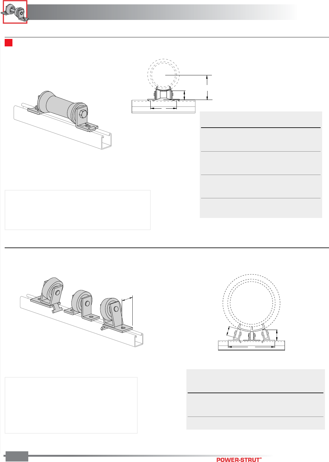
ROLLERS
ROLLERS
ENGINEERING CATALOG
100
Order By: No. and Finish
■PS 1911 – Pipe Roller
A
21⁄2"B
■PS 816 – Three Piece, Heavy Duty Pipe Roller
2"
A
31⁄4"
3"
Fits Wt./
Size Pipe Size A B 100 pcs
2 – 31⁄2" 2" 5" 3" 160
21⁄2"5"3
1⁄4"
3" 5" 35⁄8"
31⁄2"5"3
7⁄8"
4 – 6" 4" 57⁄8"4
5⁄16" 215
5" 57⁄8"4
7⁄8"
6" 57⁄8"5
7⁄16"
8 – 10" 8" 85⁄16"7
1⁄8" 525
10" 85⁄16"8
1⁄4"
12 – 14" 12" 107⁄8"9
7⁄8" 1,025
14" 107⁄8"10
1⁄2"
Chart for Dimension A
Pipe Insulation Thickness
Size 11⁄2"2"2
1⁄2"3" 4"
16" 137⁄8" 14" 141⁄2"
18" 135⁄8" 14" 141⁄8"14
1⁄2" 15"
20" 141⁄8"14
1⁄2"14
3⁄4" 15" 151⁄2"
24" 151⁄4"15
1⁄2"15
7⁄8"16
1⁄8"16
5⁄8"
Material: Brackets and shaft - steel; Rollers - cast iron
Finish: Brackets - painted green or galvanized;
Shaft - electro-galvanized; Rollers - plain
Load Rating: 950 lbs.
Weight/100 units: 1,046 lbs.
Use With: 16-24" pipe
Material: Brackets - steel; Roller - cast iron
Finish: Brackets - painted green or galvanized;
Roller - plain
Load Rating: 2,000 lbs.
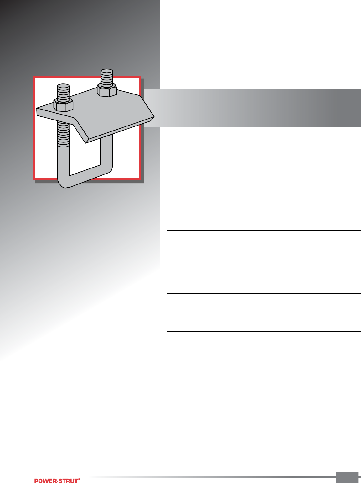
BEAM CLAMPS
BEAM CLAMPS
ENGINEERING CATALOG
Power-Strut offers beam clamps
designed for every loading condition
from light to heavy duty. Styles are
available to attach to nearly every
type of support beam.
■ MATERIAL:
Power-Strut beam clamps are cold formed from hot rolled, pickled and
oiled steel. Square head, cone point set screws are furnished where
noted. Cast beam clamps are made from high quality
malleable iron.
■ STANDARD FINISH:
Standard finish is plain or electro-galvanized.
■ ORDERING INFORMATION:
When ordering, add the length or size and finish to the part number.
See pages 8-10 for finish abbreviations and an example.
101
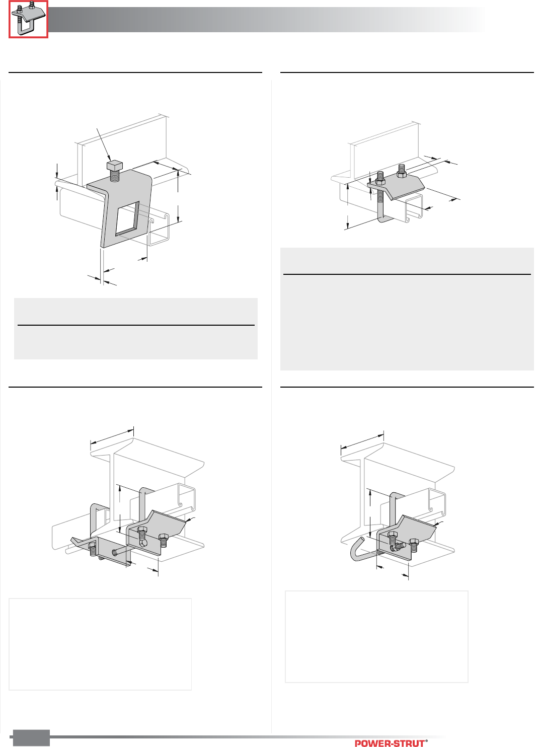
BEAM CLAMPS
BEAM CLAMPS
ENGINEERING CATALOG
102
Finish: Painted Green or Electro-galvanized Order By: No. and Finish Note: Use in pairs or with other support
■PS 855 – Angular “I” Beam Clamp ■PS 2651 – Beam Clamp
■PS 2656 – U Bolt Beam Clamp With Hook■PS 2657 – Double U Beam Clamp
Up to 6"
3"
33⁄8"
1⁄4"
Thick
Up to 6"
3"
3
3
⁄
8
"
1
⁄
4
"
Thick
1
⁄
4
"
3"
7
⁄
8
"
3
⁄
8
"
Hex Nuts and
"U" Bolt Included
A
13⁄4"
7⁄8"
1⁄4"
31⁄2"
1⁄2" - 13 X 11⁄2"
Set Screw Included
A
Load Wt./
Part No. Use With A Rating 100 pcs.
PS 2651 T1
PS 200, PS 210 33⁄8" 1,000 83
PS 300, PS 400
PS 500, PS 520
PS 2651 T2
PS 100, PS 150 5" 1,000 92
PS 200 2T3
PS 2651 T3 PS 150 2T3 8 1⁄4” 1,000 112
PS 100 2T3
Load Wt./
Part No. Use With A Rating 100 pcs.
PS 855–1 PS 200, PS 210 31⁄2" 500 107
PS 855–2 PS 500 211⁄16" 500 98
Weight/100 pcs: 280 lbs. Weight/100 pcs: 143 lbs.
Specify 6" or 12" max. flange width
(Example: PS 2657 T1-6")
T1 Use with PS 200, PS 210, PS 300,
PS 400, PS 500, PS 520
T2 Use with PS 100, PS 150, PS 200 2T3
T3 Use with PS 150 2T3, PS 100 2T3
Specify 6" or 12" max. flange width
(Example: PS 2656 T1-6")
T1 Use with PS 200, PS 210, PS 300,
PS 400, PS 500, PS 520
T2 Use with PS 100, PS 150, PS 200 2T3
T3 Use with PS 150 2T3, PS 100 2T3
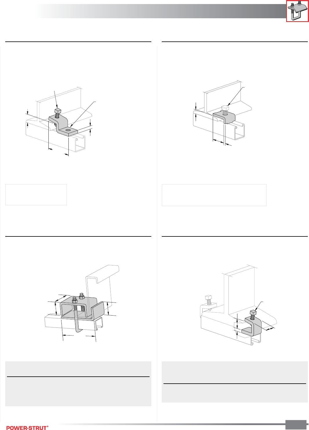
BEAM CLAMPS
BEAM CLAMPS
ENGINEERING CATALOG
103
Finish: Painted Green or Electro-galvanized Order By: No. and Finish Note: Use in pairs or with other support
■PS 685 – Beam Clamp ■PS 686 – Beam Clamp
■PS 2653 – Purlin Clamp ■PS 907, PS 998 – “I” Beam Clamp
B
A1
1
⁄
4
"
1
3
⁄
16
"
1
1
⁄
4
"
5
1
⁄
8
"
3"
1
1
⁄
4
"
31⁄4"
1"
3⁄8"
1⁄2" - 13 X 11⁄2"
Set Screw Included
Clamp Requires
1⁄2" x 15⁄16"
Hex Head Cap Screw
and
1⁄2"
Channel
Nut Not Included.
17⁄8"
1⁄4"
1⁄2"
Clamp Requires
1⁄2" - 13 X 11⁄2"
Hex Head Cap Screw
and
1⁄2"
Channel
Nut Not Included.
Load Wt./
Part No. Use With Rating 100 pcs.
PS 2653 T1 PS 200, PS 210, PS 300 1,200 175
PS 2653 T2 PS 100, PS 150, PS 200 2T3 1,200 179
PS 2653 T3 PS 100 2T3 1,200 179
Load
Stock Set Rating Wt./
Part # Thickness Screw lbs. 100 pcs.
PS 907 1⁄4"
3⁄8450 26
PS 998 3⁄8"
1⁄2900 64
Weight/100 pcs: 63 lbs.
Stock Thickness: 3⁄8"
Load Rating: 450 lbs.
Load Rating: 600 lbs. with 12 ga. channel
500 lbs. with 14 ga. channel
Weight/100 pcs: 26 lbs.
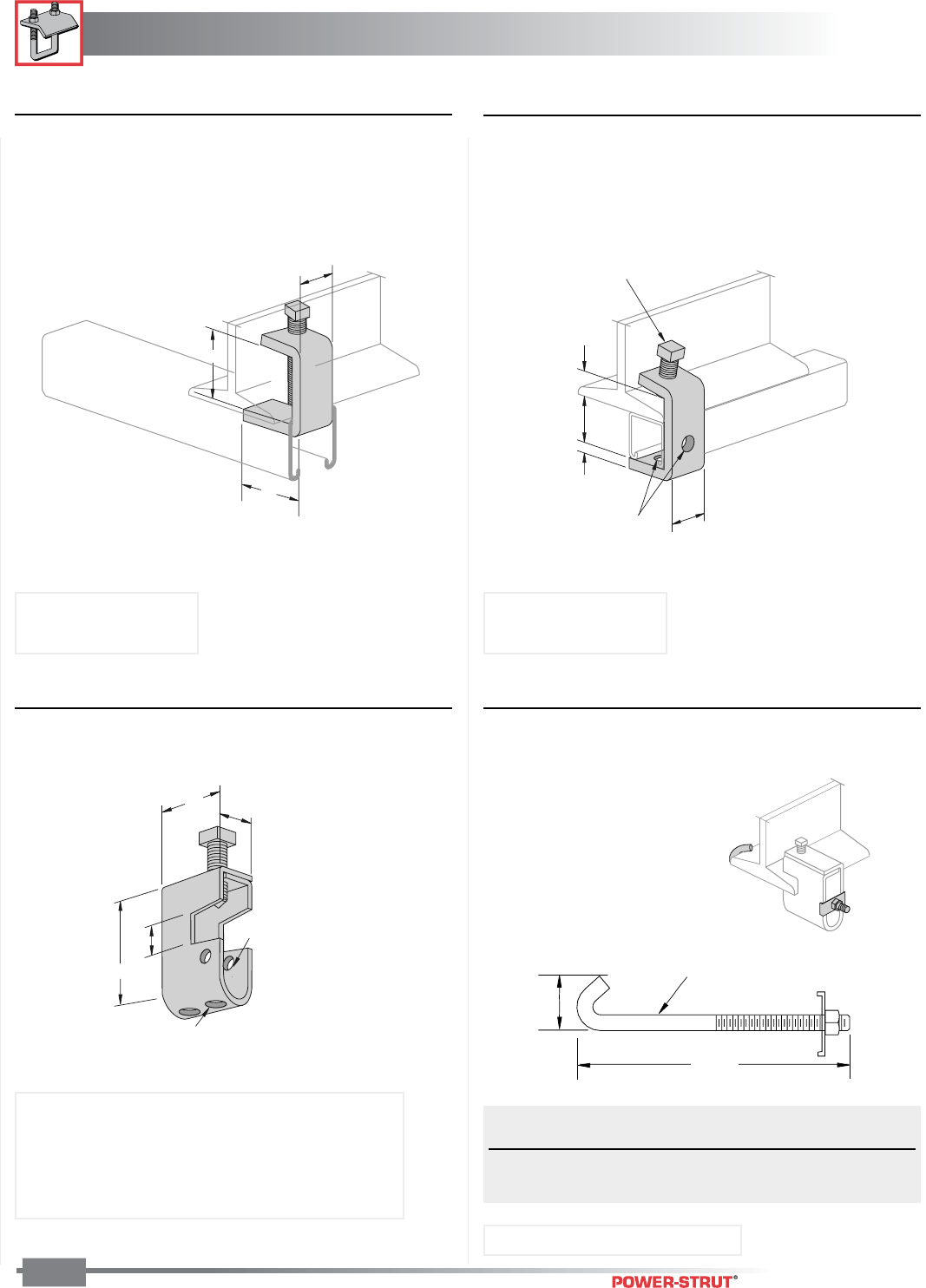
BEAM CLAMPS
BEAM CLAMPS
ENGINEERING CATALOG
104
Finish: Painted Green or Electro-galvanized Order By: No. and Finish Note: Use in pairs or with other support
■PS 916 – “I” Beam Clamp ■PS 684 – “I” Beam Clamp
■PS 2622 – Beam Clamp ■PS 736 – Hook Rod Assembly
3
⁄
8
"
7
⁄
8
"
1
5
⁄
8
"
1
1
⁄
2
"
1
⁄
2
" - 13 X 1
1
⁄
2
"
Set Screw Included
2 Holes
9
⁄
16
" Dia.
2"
2"
11⁄8"
2 Holes
17
⁄
32
"
Dia.
3"
2 Holes
13
⁄
32
"
Dia.
2" 1
1
⁄
16
"
3
⁄
4
"
3
⁄
4
"
3
⁄
8
" Dia.
A
Flange Width A Wt./
Part No. Max Min Size 100 pcs
PS 736 J6 7" 3" 85⁄8"24
PS 736 J10 11" 7" 125⁄8"33
Weight/100 pcs: 72 lbs.
Stock Thickness: 3⁄8"
Load Rating: 900 lbs.
Stock Thickness: 3⁄8"
Load Rating: 500 lbs.
Weight/100 pcs: 94 lbs.
Load Rating: 300 lbs.
Assembly including PS 736 also available.
Order PS 2622/J6 or PS 2622/J10
NOTE: Adaptable for 1⁄4", 3⁄8" & 1⁄2" rod with PS 3201.
Weight/100 pcs: 41 lbs. Use With: PS 2622 Beam Clamp
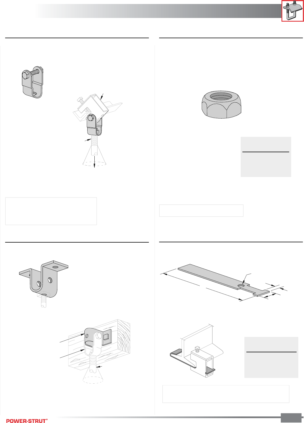
BEAM CLAMPS
BEAM CLAMPS
ENGINEERING CATALOG
105
Finish: Painted Green or Electro-galvanized Order By: No. and Finish Note: Use in pairs or with other support
■PS 2623 – Swivel Adaptor ■PS 3201 – Swivel Nut
■PS 2624 – Wood Beam Hanger
Weight/100 pcs: 22 lbs.
■PS 871 – Safety Anchor Strap
Rod Size
up to
1
⁄
2
"
Rod Swivel 15°
All Directions
PS 2622
Rod Size
up to
1
⁄
2
"
Rod Swivel 15
°
All Directions
PS 2624
PS 2623
1
⁄
2
"
A
17
⁄
32
"
Hole
1
3
⁄
8
"
"A" Wt./
Length 100 pcs
9" 33
12" 45
15" 57
Weight/100 pcs: 31 lbs.
Rod Wt./
Size 100 pcs
1⁄4"4
3⁄8"4
1⁄2"3
Use With: PS 2622 Beam Clamp or
PS 2624 Wood Beam Hanger
Load Rating: 300 lbs.
Use with: PS 858, PS 865 (Cannot be used with 5⁄8"
rod size beam clamps and larger)
Use With: PS 2622 Beam Clamp
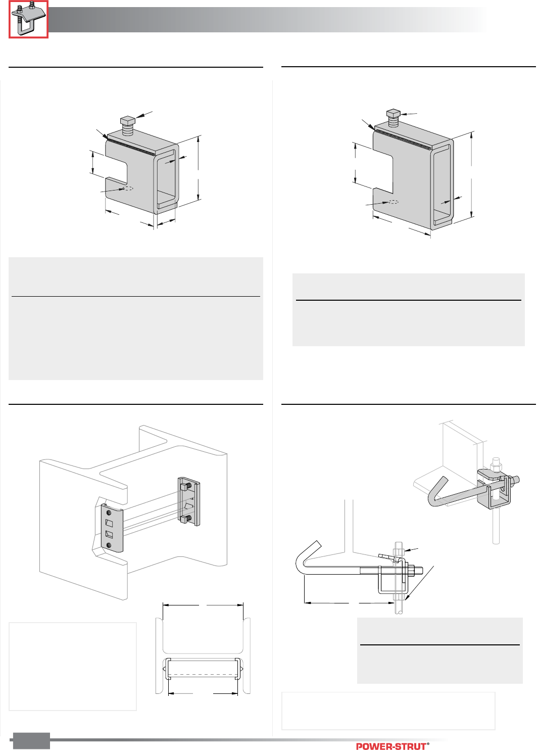
BEAM CLAMPS
BEAM CLAMPS
ENGINEERING CATALOG
106
Finish: Painted Green or Electro-galvanized Order By: No. and Finish Note: Use in pairs or with other support
■PS 858 – Heavy Duty Beam Clamp ■PS 865 – Wide Throat Heavy Duty Beam Clamp
B
3
5
⁄
8
"
3
1
⁄
4
"
Set Screw
Size C Included
Tapped Hole
Size A
D
Continuous
Weld
■PS 2654 & PS 2654A – Column Attachment ■PS 2626 – Beam Clamp
A - 1"
A
Set Screw
Size C
Included
Continuous
Weld
7⁄8"
21⁄2"
21⁄2"
Tapped Hole
Size A
B
D
Clamp Requires
1⁄2"
Diameter Rod and
2 Hex Nuts Sold Seperately
A
"A"
Part Rod Load Wt./
Number Size B C D Ratings 100 pcs
PS 858 1⁄41⁄4"- 20 1⁄8"3⁄8" x 11⁄27⁄8" 650 67
PS 858 5⁄16 5⁄16"- 18 1⁄8"3⁄8" x 11⁄27⁄8" 650 67
PS 858 3⁄83⁄8"- 16 3⁄16"1⁄2" x 11⁄215⁄16" 1,100 100
PS 858 1⁄21⁄2"- 13 1⁄4"1⁄2" x 11⁄215⁄16" 1,600 130
PS 858 5⁄85⁄8"- 11 5⁄16"5⁄8" x 11⁄215⁄16" 2,400 160
PS 858 3⁄43⁄4"- 10 5⁄16"5⁄8" x 11⁄215⁄16" 2,400 160
Rod Load Wt./
Size B C D Ratings 100 pcs
3⁄8"3⁄16"1⁄2"1
11⁄16" 1,100 151
1⁄2"1⁄4"1⁄2"1
11⁄16" 1,600 195
5⁄8"5⁄16"5⁄8"1
11⁄16" 2,400 225
Part "A" Wt./
Number Range 100 Pcs
PS 2626 6 21⁄2- 6" 125
PS 2626 9 51⁄2-9" 140
PS 2626 12 81⁄2-12" 171
Weight/100 pcs: 41 lbs.
PS 2654 Use with PS 200
PS 2654A Use with PS 500
Slip Rating: 800 lbs.
NOTE: Column attachment
can only be used in pairs. Finish: Plain, painted green or electro-galvanized
Load Rating: 500 lbs.
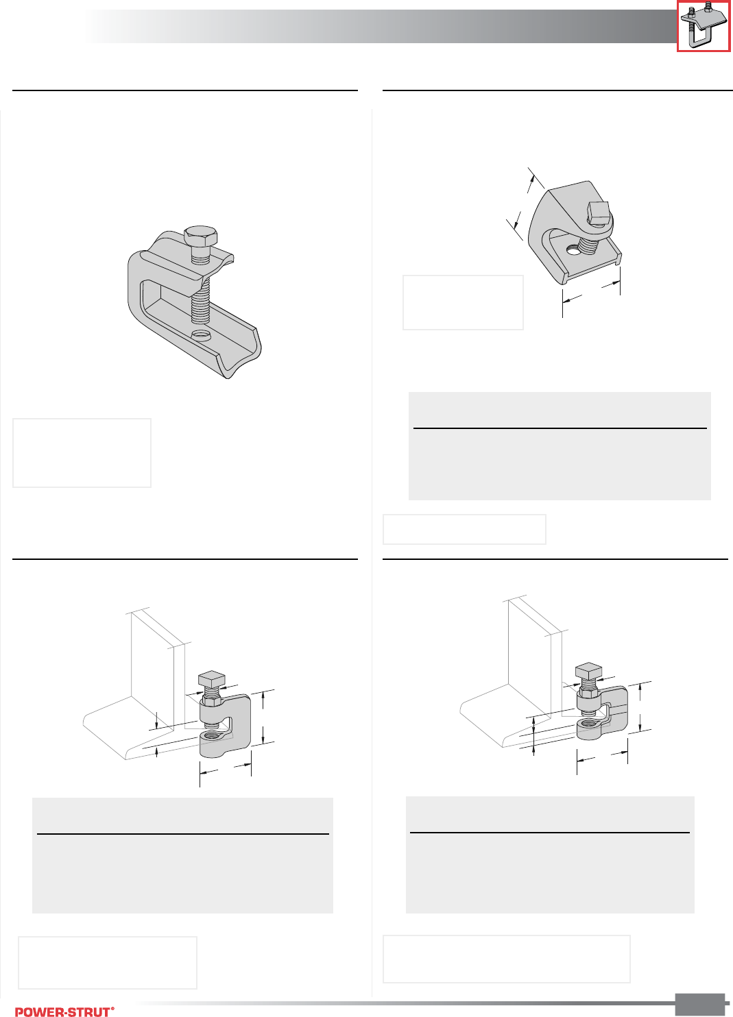
BEAM CLAMPS
BEAM CLAMPS
ENGINEERING CATALOG
107
Finish: Painted Green or Electro-galvanized Order By: No. and Finish Note: Use in pairs or with other support
■PS 135X – Light Duty Beam Clamp ■PS 85 – Rod or Insulator Support
■PS 95 – “C" Clamp ■PS 86 – “C” Clamp
3
⁄
4
"
1
⁄
2
"
3
⁄
8
"
A
B
3
⁄
4
"
2
1
⁄
4
"
A
B
A
B
Rod Load Wt./
Size A B Ratings 100 pcs
1⁄4"1
1⁄8"1
1⁄4" 150 23
3⁄8" 2" 2" 350 95
1⁄2"2
5⁄8"2
1⁄2" 400 195
Rod Load Wt./
Size A B Rating 100 pcs
3⁄8"1
11⁄16"1
3⁄4" 400 38
1⁄2"1
23⁄32"1
3⁄4" 400 52
5⁄8"1
15⁄16" 2" 450 68
3⁄4"2
1⁄32" 2" 600 128
Rod Load Wt./
Size A B Rating 100 pcs
3⁄8"2
5⁄16"3⁄8" 330 35
1⁄2"2
1⁄4"1⁄2" 380 41
5⁄8"2
3⁄8"5⁄8" 450 67
3⁄4"2
1⁄4"1⁄2" 500 72
Weight/100 pcs: 14 lbs.
Material: Steel
Use With: 1⁄4" rod
Load Rating: 75 lbs.
Material: Steel
NOTE: UL Listed for 3⁄8" rod.
Material: Malleable Iron, Steel Set Screw
NOTE: UL Listed for 3⁄8" rod.
Material: Malleable Iron
7⁄8" Maximum
Flange Thickness
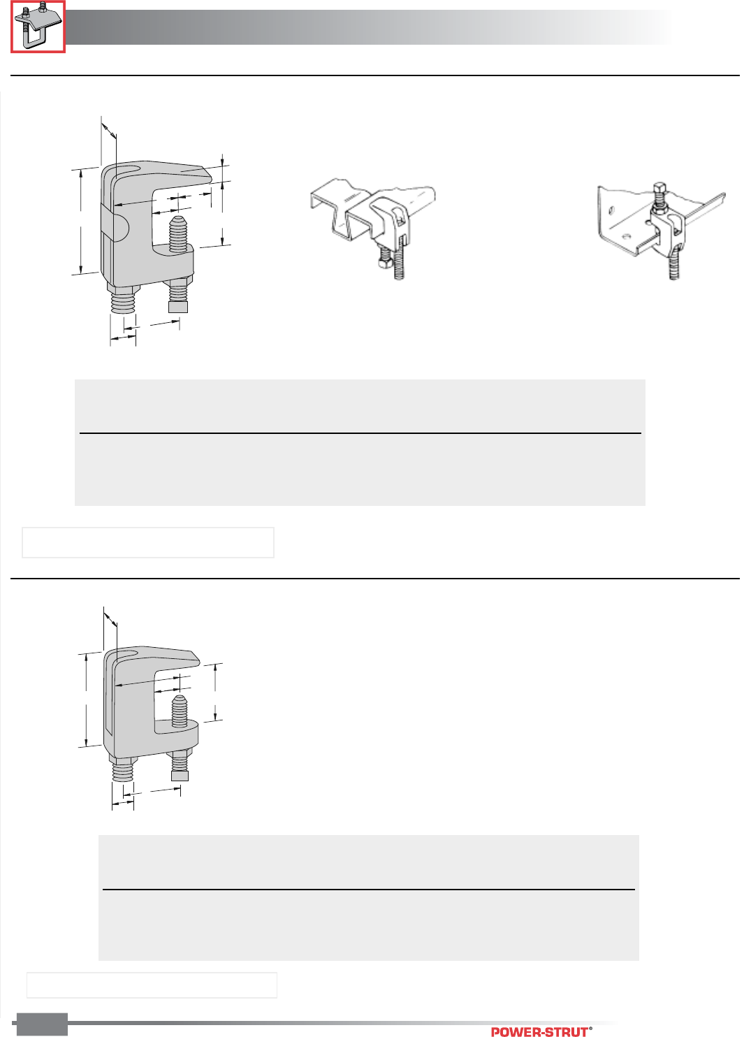
BEAM CLAMPS
BEAM CLAMPS
ENGINEERING CATALOG
108
Finish: Painted Green or Electro-galvanized; Order By: No. and Finish; Note: Use in pairs or with other support
■PS 93 – Universal “C” Clamp
■PS 94 – Wide Throat Top Beam “C” Clamp
At least one full
thread must be exposed
Rod DIMENSIONS (Inches) Max. Max.
Size Pipe Load Wt/
A B C D E F G Size (Lbs.) 100 pcs
3⁄815⁄16 23⁄47⁄8 3⁄8 5⁄84 400 41
1⁄213⁄823⁄47⁄8 7⁄16 13⁄16 8 500 75
• Maximum temperature of 450˚ F
Rod DIMENSIONS (Inches) Max
Size Pipe Max. Wt/
A B C D E F Size Load (Lbs.) 100 pcs
5⁄813⁄421⁄43⁄411⁄41 10 600 66
3⁄417⁄823⁄83⁄413⁄813⁄16 12 800 83
• Maximum temperature of 450˚ F
Material: Malleable Iron, Steel Set Screw
Material: Malleable Iron, Steel Set Screw
A
1"
BG
F
E
D
C11⁄4"
A
E
B
F
D
C15⁄16"
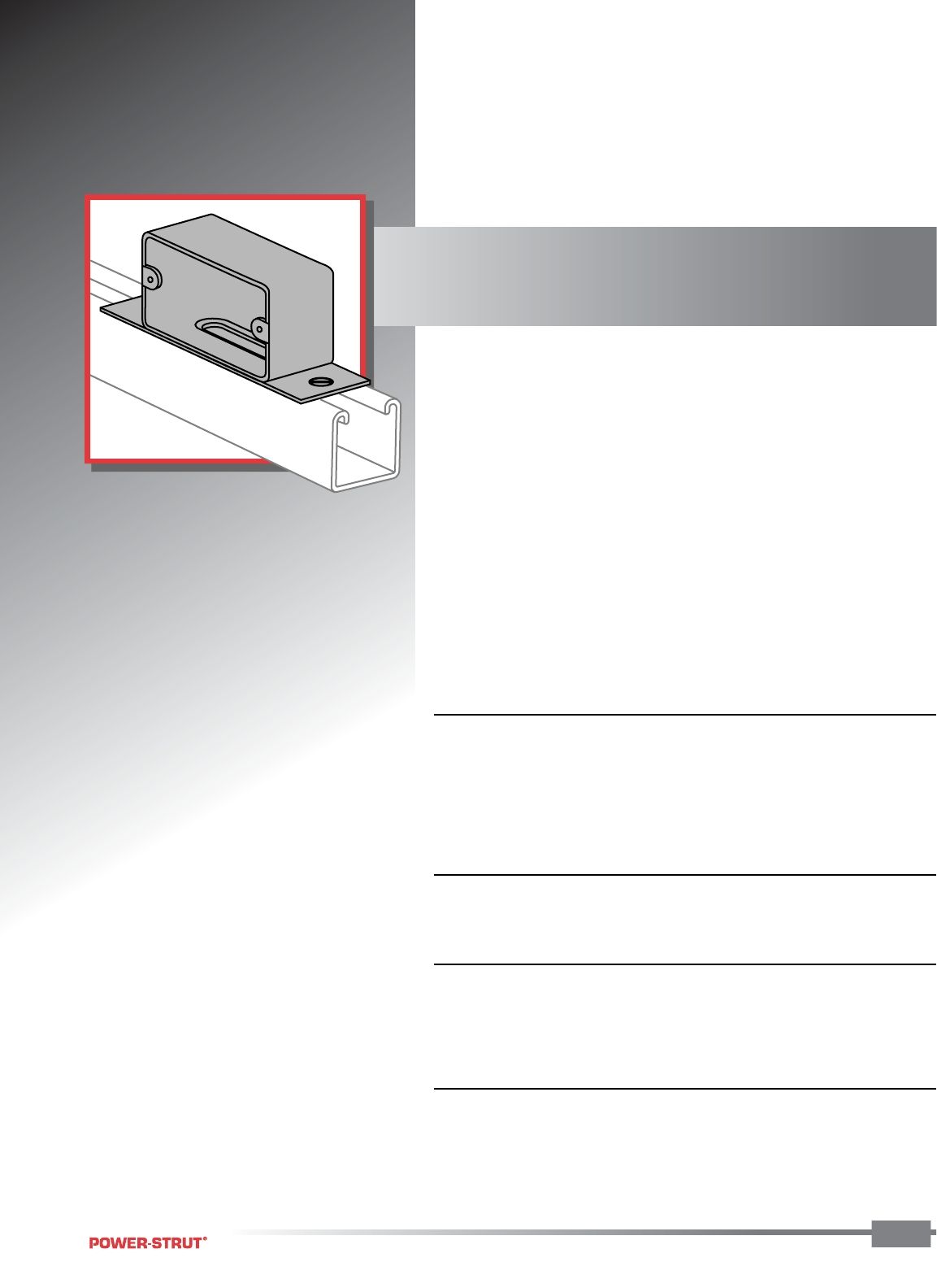
ELECTRICAL
ELECTRICAL
ENGINEERING CATALOG
Power-Strut offers a versatile means of
supporting lighting, conduits, cable
and other portions of an electrical
system. Power-Strut is listed as an
electrical raceway by Underwriters
laboratories as specified by the
National Electric Code (Article 352),
and CSA approved in accordance with
the Canadian Electrical Code (Part 1).
■ MATERIAL:
Power-Strut electrical raceways are cold formed from low carbon steel
and meet the requirements of ASTM A-1011 Grade 33 in painted green
or ASTM A-653 Grade 33 in pre-galvanized material. Plain or electro-
galvanized fittings conform to the ASTM A-635 or ASTM A-36 stan-
dards while pre-galvanized fittings meet the requirements of ASTM
A-653 Grade 33.
■ STANDARD LENGTHS:
Standard lengths of electrical raceway are 10 and 20 feet.
The Power-Strut closure strips are available only in 10 feet lengths.
■ STANDARD FINISH:
Electrical raceway channel is available in a painted green or
pre-galvanized finish. All Power-Strut fittings are available in painted
green or electro-galvanized finish. Many fittings are available in
pre-galvanized.
■ ORDERING INFORMATION:
When ordering, add the length or size and finish to the part number.
See pages 8-10 for finish abbreviations and an example.
109
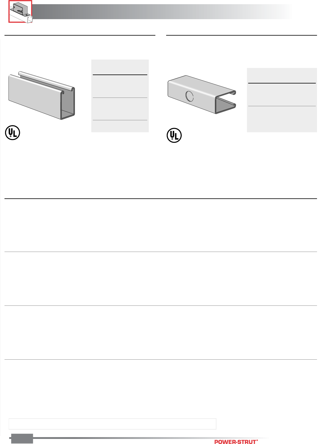
ELECTRICAL
ELECTRICAL
ENGINEERING CATALOG
110
Finish: Painted Green or Pregalvanized Stock Length: 10 feet & 20 feet Order By: No. and Size
■Knock-Out Raceway*
Maximum Number of Wires Types
AVB, FEP, FEBP, RH, RHH, RHW, RUH, RUW, T, TW,
THHN, THWN, THW, XHHW
■Solid Raceway*
Section
Part No. Height
PS 100 31⁄4"
PS 150 27⁄16"
PS 200 15⁄8"
PS 210 15⁄8"
PS 300 13⁄8"
PS 400 1"
PS 500 13⁄16"
Section
Part No. Height
PS 100 KO6 31⁄4"
PS 150 KO6 27⁄16"
PS 200 KO6 15⁄8"
PS 210 KO6 15⁄8"
PS 300 KO6 13⁄8"
PS 400 KO6 1"
Height
Raceway Part Wt./ of Section
Numbers 100 Ft. Inches 14 12 10 8 6
PS 100, PS 100 K06 305 31⁄4"1010864
PS 150, PS 150 K06 247 27⁄16"1010864
PS 200, PS 200 K06 190 15⁄8"66542
PS 210, PS 210 K06 141 15⁄8"66542
PS 300, PS 300 K06 170 13⁄8"54432
PS 400, PS 400 K06 146 1" 4 3 0 0 0
PS 500 97 13⁄16"43000
PS 100, PS 100 K06 305 31⁄4"10101096
PS 150, PS 150 K06 247 27⁄16"10101086
PS 200, PS 200 K06 190 15⁄8"1010863
PS 210, PS 210 K06 141 15⁄8"1010863
PS 300, PS 300 K06 170 13⁄8"1010642
PS 400, PS 400 K06 146 1" 6 6 0 0 0
PS 500 97 13⁄16"66000
PS 100, PS 100 K06 305 31⁄4"5042352013
PS 150, PS 150 K06 247 27⁄16"362925149
PS 200, PS 200 K06 190 15⁄8"22181595
PS 210, PS 210 K06 141 15⁄8"242017106
PS 300, PS 300 K06 170 13⁄8"18151375
PS 400, PS 400 K06 146 1" 11 9 7 4 3
PS 500 97 13⁄16"97642
PS 100, PS 100 K06 305 31⁄4"1010864
PS 150, PS 150 K06 247 27⁄16"1010864
PS 200, PS 200 K06 190 15⁄8"88543
PS 210, PS 210 K06 141 15⁄8"88543
PS 300, PS 300 K06 170 13⁄8"86532
PS 400, PS 400 K06 146 1" 4 3 0 0 0
PS 500 97 13⁄16"43000
Wire Size AWG*
Table C – CSA Certified
Maximum number of wires
Types R, RW, RWU, T, TW
Table C – Maximum number of conductors
when raceway is not employed with
fixtures OR where the clearance between
the raceway and fixtures is greater than
1⁄2 inch.
Table B – Maximum number of conductors
when raceway is installed to support and
supply electric discharge type lighting
fixtures when raceway wiring is suitable for
at least 75 C and clearance between raceway
and fixtures is at least 1⁄8 inch.
Table A – Maximum number of conductors
when raceway is installed to support and
supply electric discharge type lighting
fixtures when raceway wiring is suitable for
at least 75 C. EXCEPTION: Wire suitable for
60 C may be used when clearance between
raceway and fixtures is at least 1⁄2 inch.
*In all cases, the snap-in-cover, P
S
707, is required to complete raceway enclosures.
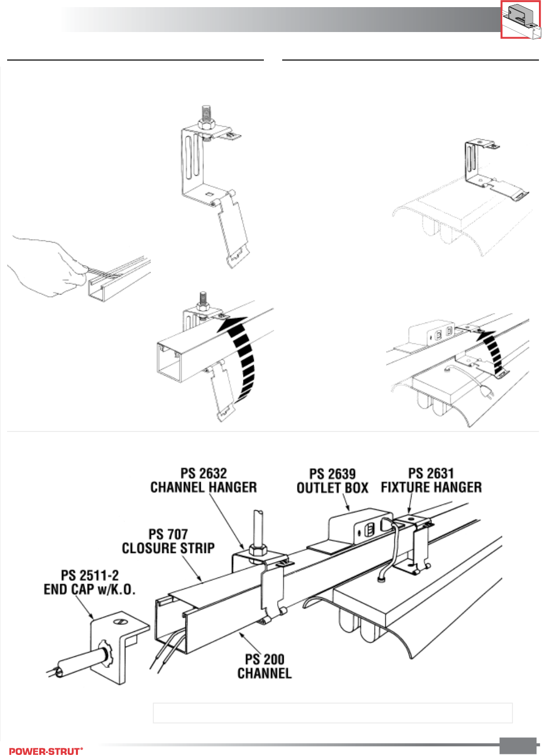
ELECTRICAL
ELECTRICAL
ENGINEERING CATALOG 111
Finish: Painted Green or Pregalvanized Stock Length: 10 feet & 20 feet Order By: No. and Size
■To Install Channel ■To Install Fluorescent Fixture
1. Suspend and align PS-2632
Channel hanger from threaded
rod at pre-determined level.
2. At floor working level install
wiring in channel raceway and
add a channel closure strip.
3. Lay raceway into pre-hung
channel hanger. Close snap
fastening door which securely
locks raceway into position.
Complete installation in minutes. No screw, bolts or cotter pins to lose.
1. Attach PS2631 Fixture Hanger to
fixture with quick assembly
wing-nut leaving door open.
2. Hook fixture over raceway. Close
snap fastening door which
securely locks fixture into
position. Plug in fixture.
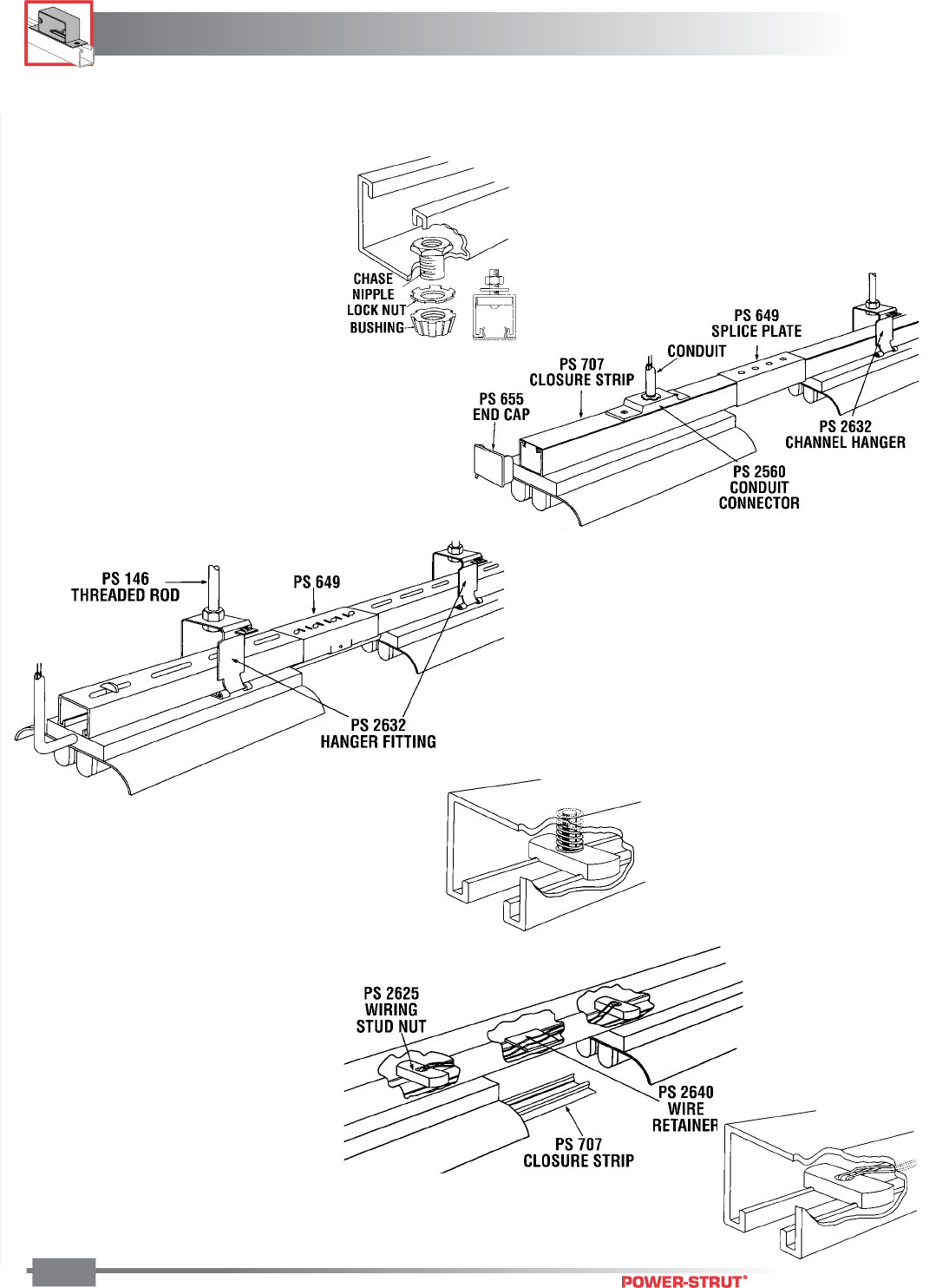
ELECTRICAL
ELECTRICAL
ENGINEERING CATALOG
112
Finish: Painted Green or Pregalvanized Stock Length: 10 feet & 20 feet Order By: No. and Size
ECONOMY RACEWAY
SYSTEM FLUORESCENT
In this slot-down system the circuits run
through the fixtures and only enter the
channel where there is a break in the fixture
run. At that point the fiber wire retainer
holds wires in place and snap-in closure strip
covers the area.
KNOCK-OUT FLUORESCENT
RACEWAY SYSTEM
Listed by Underwriter's Laboratories, Inc.
Fixture is attached to slot-up channel with
chase nipple, locknut and bushing through
knock-outs in bottom of channel. Conduit
connector fitting PS-2560 holds channel and
fixture to pipe or rod.
BASIC FLUORESCENT
SUPPORT SYSTEM
Slot-down channel holds fixture
firmly in place with spring nut and
bolt. Fixtures may be added or
relocated without changing the basic
assembly.
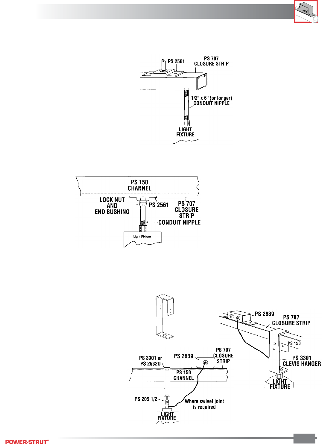
ELECTRICAL
ELECTRICAL
ENGINEERING CATALOG 113
Finish: Painted Green or Pregalvanized Stock Length: 10 feet & 20 feet Order By: No. and Size
SLOT DOWN MERCURY
VAPOR SYSTEM
In this slot down system the mercury
vapor ballast is wired directly to the
system.
KNOCK-OUT MERCURY
VAPOR RACEWAY SYSTEM
Listed by Underwriter's Laboratories, Inc.
Fixture is attached to slot-up channel with
chase nipple, locknut and bushing through
knock-outs in bottom of channel. Conduit
connector fitting PS-2561 holds channel
and fixture to pipe or rod.
BASIC MERCURY VAPOR
SUPPORT SYSTEM – PS-3301
CLEVIS HANGER FOR USE
WITH PS-150, PS-200
In this slot up or down system, the fixture is
supported by PS-3301 clevis hanger which is
designed for use with both 15⁄8" and 27⁄16" deep
channels.
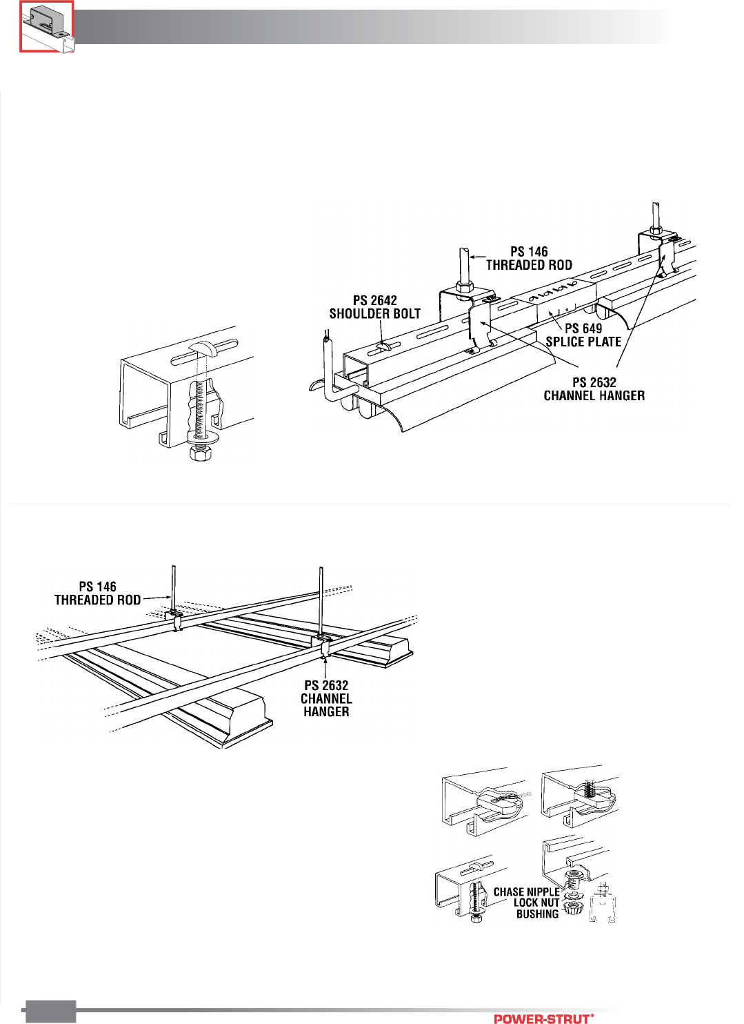
ELECTRICAL
ELECTRICAL
ENGINEERING CATALOG
114
Finish: Painted Green or Pregalvanized Stock Length: 10 feet & 20 feet Order By: No. and Size
SLOTTED SUPPORT
SYSTEM
This system is designed for
maximum ease of attaching
fixture through slotted channel
with shoulder bolt and provides
positive alignment.
GRID SYSTEM
This system is used where fixtures are hung at
right angles to Power-Strut raceways and support
channels. Any of the features of the above
systems can be adapted to this system. Ideal for
egg-crate type drop ceiling installations.
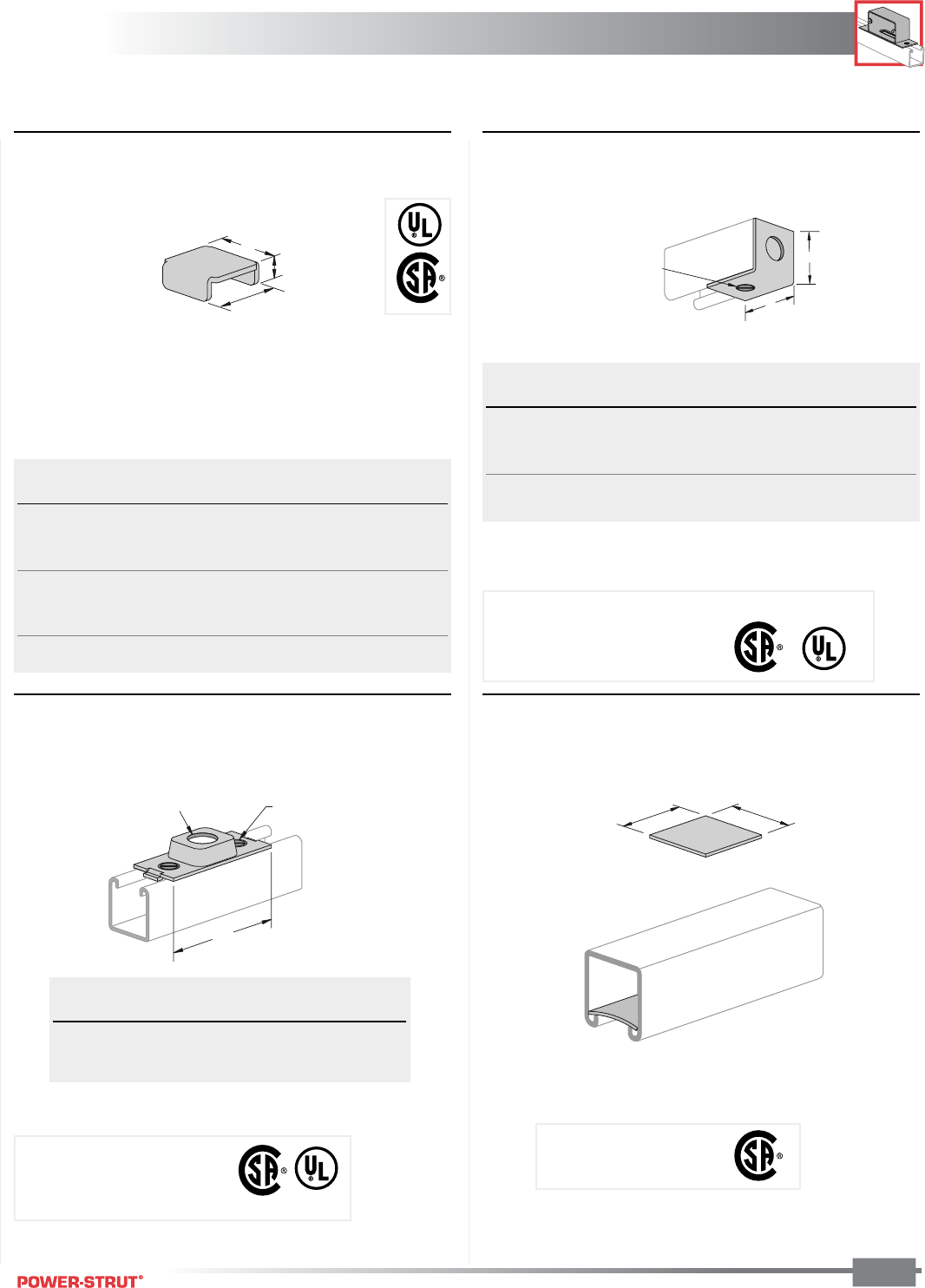
ELECTRICAL
ELECTRICAL
ENGINEERING CATALOG 115
Finish: Painted Green or Pregalvanized Stock Length: 10 feet & 20 feet Order By: No. and Size
■PS 2560, PS 2561 – Conduit Connector
Fitting
■PS 2640 – Wire Retainer
■PS 655, PS 656, PS 901, PS 902,
PS 930, PS 2580, PS 2585 – Raceway
End Caps
■PS 2511, PS 2581 – End Cap With
Knock-Out
7
⁄
8
" Dia.
A
1
⁄
4
" X
5
⁄
8
" Flat Head
Machine Screws and
Nuts Included
A
1
27
⁄
64
"
1
⁄
2
"
B
A
1
⁄
4
" X
5
⁄
8
" Flat Head
Machine Screw and
Nut Included
1
1
⁄
2
"
1
1
⁄
2
"
Wt./
Part No. Use With A Hole 100 pcs
PS 2560 1⁄2 Conduit" 4" 7⁄8"36
PS 2561 3⁄4 Conduit" 51⁄8"1
3⁄32"36
Wt./
Part No. Use With Finish A 100 pcs
PS 902 PS 100 EG 31⁄4"22
PS 2580 PS 150 EG 27⁄16"18
PS 655 PS 200 EG 15⁄8"11
PS 2585 PS 210 EG 15⁄8"12
PS 656 PS 300 EG 13⁄8"15
PS 901 PS 400 EG 1" 11
PS 930 PS 500 EG 13⁄16"5
Wt./
Part No. Use With Finish A B 100 pcs
PS 2511–1 PS 100 EG 31⁄4"1
3⁄4" 3.1
PS 2511–2 PS 200, PS 210 EG 15⁄8"1
3⁄4" 2.7
PS 2511–3 PS 300 EG 13⁄8"1
3⁄4" 2.6
PS 2581 PS 150 EG 27⁄16" 2" 3.0
ASSEMBLY: End Cap Part, 1 Machine Screw, 1 Nut
Specify 1⁄2" or 3⁄4" knock-out
Material: Polypropylene
Stock Size: (.060)
Assembly: Connector Fitting,
2 Nuts, 2 Bolts
Weight/100 pcs: .30 lbs.
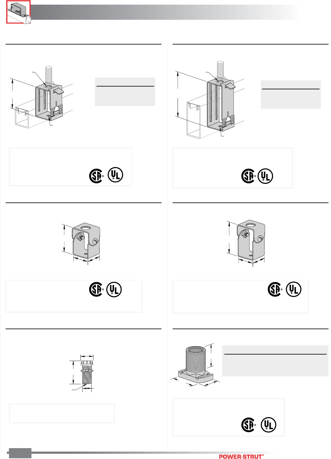
ELECTRICAL
ELECTRICAL
ENGINEERING CATALOG
116
Finish: Painted Green or Pregalvanized Stock Length: 10 feet & 20 feet Order By: No. and Size
■PS 2632 – Swing Gate Channel Hanger ■PS 2632D – Swing Gate Channel Hanger
■PS 659 – Channel Hanger ■PS 658 – Channel Hanger
9
⁄
32
"
Sq. Hole
2
3
⁄
4
"
A
■PS 2625 – Wiring Stud Nut■PS 803 – Fixture Wiring Nipple
3
1
⁄
8
"
1
11
⁄
16
"1
5
⁄
8
"
2
5
⁄
8
"
1
11
⁄
16
"1
5
⁄
8
"
A
13
⁄
8
"
3
⁄
4
"
5"
A
9⁄32"
Sq. Hole
2
1
⁄
8
"
1.100"
.800"
Hole
.600" Dia.
A Dia. Use With
9⁄16"1⁄2" Rod
7⁄8"1⁄2" Conduit
A Dia. Use With
9⁄16"1⁄2" Rod
7⁄8"1⁄2" Conduit
Weight/100 pcs: 25 lbs. Weight/100 pcs: 34 lbs.
Finish: Electro-galvanized
Use With: PS 100, PS 150, PS 200 2T3,
and PS 210 2T3
Load Rating: 90 lbs.
Weight/100 pcs: 28 lbs. Weight/100 pcs: 30 lbs.
Use With: PS 400, PS 500
Load Rating: 150 lbs.
NOTE: Washers supplied to adapt to 3⁄8" or 1⁄2" rod
Use With: PS 200, PS 210, PS 300
Load Rating: 150 lbs.
NOTE: Washers supplied to adapt to 3⁄8" or 1⁄2" rod
Weight/100 pcs: 14 lbs. Weight/100 pcs: 10 lbs.
Material: Sintered Iron
Size: 1⁄2" - 14 Amer. Std, conduit thread
Assembly: 1⁄2" x 2" rigid conduit nipple
Bushing Locknut
Finish: Electro-galvanized
Use With: PS 200, PS 210, PS 300, PS 400
and PS 500
Load Rating: 90 lbs.
Part No. A Indentification No.
PS 2625-1⁄215⁄64" 121961
PS 2625-2-5⁄85⁄8" 121960

ELECTRICAL
ELECTRICAL
ENGINEERING CATALOG 117
Finish: Painted Green or Pregalvanized Stock Length: 10 feet & 20 feet Order By: No. and Size
■PS 3301 – Mercury Vapor Fixture Hanger
■PS 2631 – Swing Gate Fixture Hanger ■PS 2631D – Swing Gate Fixture Hanger
5"
9⁄16"
■PS 807 – Channel Hanger
5"
111⁄16"15⁄8"
3
1
⁄
8
"
9
⁄
16
"
6
3
⁄
4
"Hole Size
1
1
⁄
16
"
Weight/100 pcs: 27 lbs.
Use With: PS 100, PS 150
Load Rating: 150 lbs.
NOTE: Washers supplied to adapt to 3⁄8" or 1⁄2" rod
Use With: PS 200, PS 210, PS 300, PS 400 and PS 500
Load Rating: 90 lbs.
NOTE: Includes Bolt and Wing Nut for connection to
fluorescent fixtures.
Finish: Electro-galvanized
Stock Size: 1⁄4"
Use With: PS 150, PS 200, PS 210
NOTE: Supports fixture in slot up or down system.
Use With: PS 100, PS 150, PS 200 2T3, PS 210 2T3
Load Rating: 90 lbs.
NOTE: Includes Bolt and Wing Nut for connection to
fluorescent fixtures.
Weight/100 pcs: 36 lbs.
Weight/100 pcs: 154 lbs. Weight/100 pcs: 35 lbs.
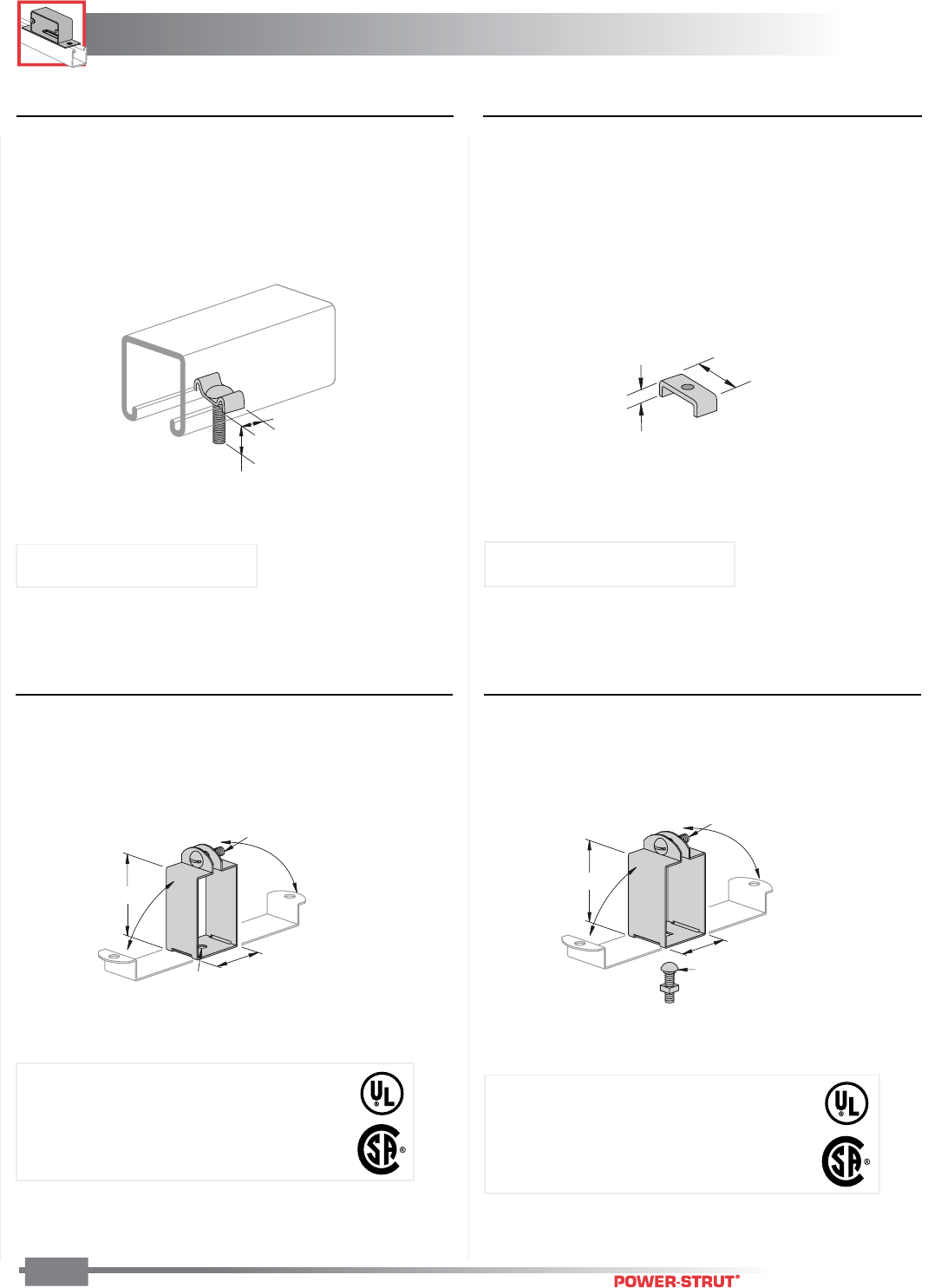
ELECTRICAL
ELECTRICAL
ENGINEERING CATALOG
118
Finish: Painted Green or Pregalvanized Stock Length: 10 feet & 20 feet Order By: No. and Size
■PS 2636 – Fixture Stud Nut ■PS 2637 – Fixture Nut
1
1
⁄
8
"
1
⁄
2
"
■PS 702 – Fluorescent Fixture Hanger ■PS 703 – Fluorescent Fixture Hanger
1
⁄
4
" X 1"
RHMS and
Sq. Nut Included
1
5
⁄
8
"
2
7
⁄
16
"
9
⁄
32
"
Dia. Hole
1
5
⁄
8
"
1
3
⁄
4
"
1
⁄
4
" X
3
⁄
4
"
Carriage Bolt
and Sq. Nut Included
1
⁄
4
" X 1"
RHMS and
Sq. Nut Included
5
⁄
16
"1
7
⁄
16
"
Weight/100 pcs: 5 lbs.
Size: 1⁄4" x 20 thread, 11⁄4" long Size: Tapped for 1⁄4" - 20 thread
Weight/100 pcs: 2 lbs.
Weight/100 pcs: 17 lbs.
Weight/100 pcs: 19 lbs.
Hanger provides more than 1⁄8" space between
channel and fixtures.
Use hanger for PS 200 & PS 210.
Load Rating: 120 lbs.
Hanger provides more than 1⁄2" space between
channel and fixtures.
Use hanger for PS 200, PS 210 & PS 300.
Load Rating: 120 lbs.
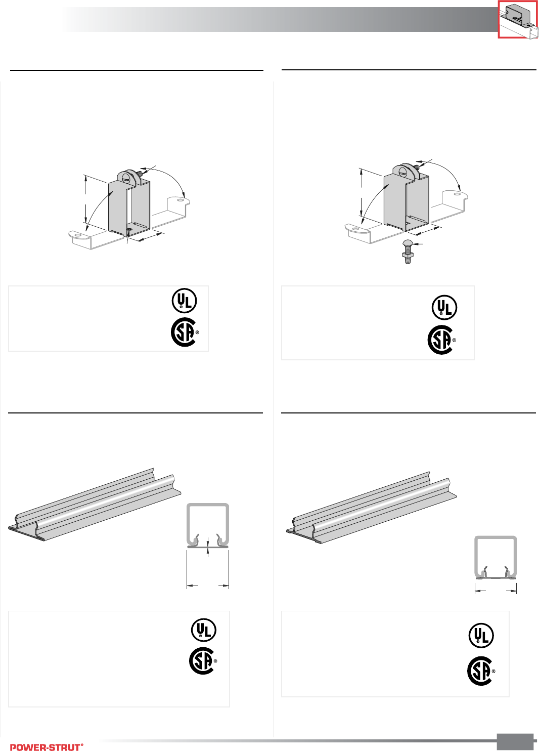
ELECTRICAL
ELECTRICAL
ENGINEERING CATALOG 119
Finish: Painted Green or Pregalvanized Stock Length: 10 feet & 20 feet Order By: No. and Size
■PS 702 D – Fluorescent Fixture Hanger ■PS 703 D – Fluorescent Fixture Hanger
1
⁄
4
" X 1" RHMS and
Sq. Nut Included
1
5
⁄
8
"
3
1
⁄
4
"
9
⁄
32
" Dia. Hole
1
5
⁄
8
"
2
9
⁄
16
"
1
⁄
4
" X
3
⁄
4
"
Carriage Bolt
and Sq. Nut Included
1
⁄
4
" X 1" RHMS and
Sq. Nut Included
■PS 707, PS 707 P – Raceway Closure
Strip
■PS 707 – Aluminum Raceway Closure Strip
1
5
⁄
8
"
.040"
15⁄8"
Hanger provides more than 1⁄2" space
between channel and fixtures.
Use hanger for PS 150.
Load Rating: 120 lbs.
Weight/100 pcs: 20 lbs. Weight/100 pcs: 18 lbs.
Weight 47 Lbs./ ft. Weight 21 Lbs./ ft.
Material/Finish:
PS 707 - Painted green and pre-galvanized
PS 707 P - Green and gray
Stock Size: (.040) GRN, (.040) PGAL
Stock Length: 10 ft.
Use With: All 15⁄8" wide channel.
Hanger provides more than 1⁄8" space
between channel and fixtures.
Use hanger for PS 150.
Load Rating: 120 lbs.
Material:
6063-T6 Aluminum, Copper Free, Extruded
Stock Size: (.051)
Stock Length: 10 ft.
Use With: All 15⁄8" wide channel
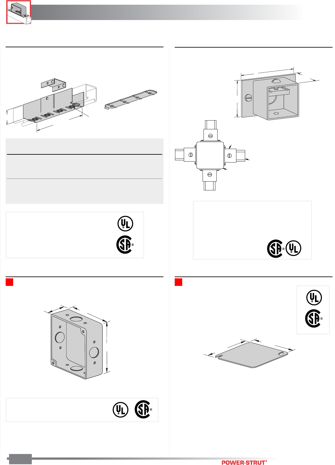
ELECTRICAL
ELECTRICAL
ENGINEERING CATALOG
120
Finish: Painted Green or Pregalvanized Stock Length: 10 feet & 20 feet Order By: No. and Size
■PS 649, PS 693, PS 694, PS 805, PS
942, PS 2582 – Electrical Joiner
PS 2660 – Junction Box
■PS 2662 - A – Hub Assembly
1
11
⁄
16
"
3"
2"
PS 2661 – Junction Box Cover
Weight/100 pcs: 30 lbs.
43⁄16"
43⁄16"
2
1
⁄
4
"4"
4"
63⁄4"
A1⁄4" X 5⁄8" Flat Head Machine Screws
and 4 Hole Splice Plate Nut Included
14 Gage
Threaded
Plate Nut
Wt./
Part No. A Use With Finish 100 pcs
PS 805 15⁄8" PS 100 EG, GRN 106
PS 2582 15⁄8" PS 150 EG 103
PS 649 15⁄8" PS 200, PS 210 EG, GRN 100
PS 694 13⁄8" PS 300 EG, GRN 97
PS 693 11⁄16" PS 400 EG, GRN 97
PS 942 13⁄16" PS 500, PS 520 EG, GRN 80
Use With: PS 200, PS 210
Assembly: 1 Hub, 2 Screws, 1 Bolt, 1 Nut
NOTE: Add hub assemblies to the basic PS
2660 unit assembly to make 1, 2, 3 ot 4-way
junction box.
Identification No. 122022
NOTE: Add hub assemblies PS 2662-A
to make 1, 2, 3 or 4-way junction box.
Weight/100 pcs: 27 lbs.
Weight/100 pcs: PS 2660 113 lbs.
Stock Size: (.060)
Assembly: 1 Splice Plate Clevis (GRN),
1 Tapped Plate (EG), 1 Backplate (GRN),
4 Flat Head Machine Screws (EG).
PS 2660
Junction Box
PS 2662 A, Hub
PS 200
Channel
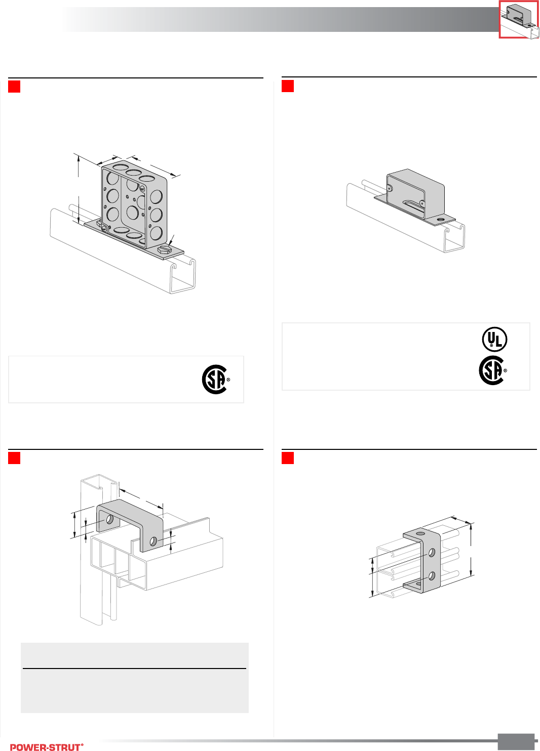
ELECTRICAL
ELECTRICAL
ENGINEERING CATALOG 121
Finish: Painted Green or Pregalvanized Stock Length: 10 feet & 20 feet Order By: No. and Size
PS 2094 – 4" Receptacle Box With Knock-outs PS 2639 – Outlet Box
PS 760 – Bus Duct Connection Clevis PS 671 – Strut Suspension Member
1
7
⁄
8
"
1
1
⁄
16
"
1
21
⁄
32
"
3
25
⁄
32
"
Weight/100 pcs: 70 lbs.
11⁄2"
41⁄8"
2 Screws and
Channel Nuts
4"
A
1
7
⁄
8
"
1
⁄
2
"
13
⁄
16
"
Outside Inside Wt./
Part No. Width Width 100 pcs
PS 760–1 213⁄32"1
29⁄32"57
PS 760–2 325⁄32"3
9⁄32"73
PS 760–3 43⁄4"4
1⁄4"84
Weight/100 pcs: 88 lbs.
Weight/100 pcs: 93 lbs.
Stock Size: (.075)
Assembly: 1 Box, 2 Screws, 2 Channel Nuts
Stock Size: (.075)
Assembly: 1 Box, 2 Screws, 2 Channel Nuts
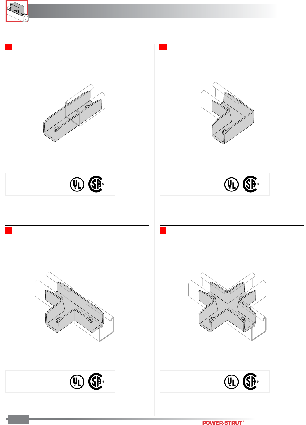
ELECTRICAL
ELECTRICAL
ENGINEERING CATALOG
122
Finish: Painted Green or Pregalvanized Stock Length: 10 feet & 20 feet Order By: No. and Size
PS 2800 – Inside Strut Joiner ■PS 2802 – “Elbow” Inside Strut Joiner
■PS 2801 – “T” Inside Strut Joiner ■PS 2803 – “Cross” Inside Strut Joiner
Weight/100 pcs: 20 lbs. Weight/100 pcs: 27 lbs.
Weight/100 pcs: 35 lbs. Weight/100 pcs: 45 lbs.
Material: Cast aluminum
Jam screws included
Material: Cast aluminum
Jam screws included
Material: Cast aluminum
Jam screws included
Material: Cast aluminum
Jam screws included
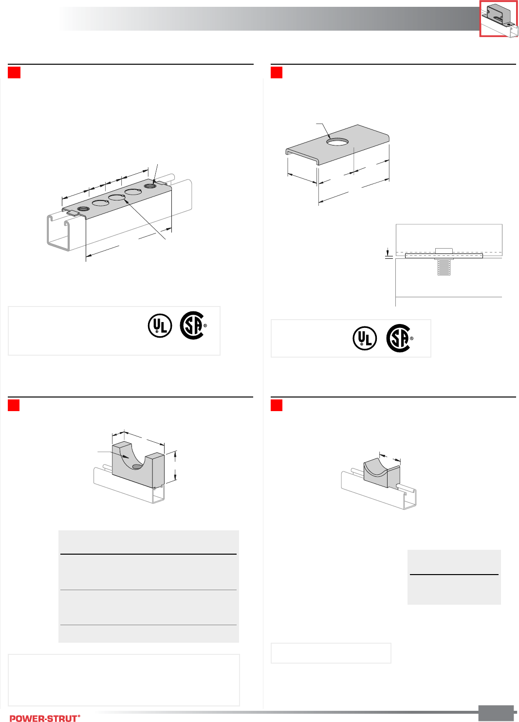
ELECTRICAL
ELECTRICAL
ENGINEERING CATALOG 123
Finish: Painted Green or Pregalvanized Stock Length: 10 feet & 20 feet Order By: No. and Size
■PS 1500 – Porcelain Cable Rack Insulators
A
1
5
⁄
8
"
B
Hole Size
■PS 1510 – Maple Cable Saddle
A
■PS 791 – Electrical Box Adapter Plate ■PS 2627 – Spacer Clevis
2"
1
2
1
⁄
32
"
7
⁄
8
"
DIA.
2"
4"
6
1
⁄
4
"
3 Knockouts
7
⁄
8
"
Dia
.
1
15
⁄
16
"
1
3
⁄
16
"
1
3
⁄
16
"
1
15
⁄
16
"
1
⁄
4
" X
5
⁄
8
"
Flat Head
Machine Screws and
Nuts Included
1
⁄
8
"
Flourescent Fixture
Cable Wt./
Size A B 100 pcs
0"– 1" 3" 13⁄4"31
1" – 11⁄2"3
1⁄2"2"38
11⁄2"– 2" 4" 21⁄4"47
2"– 21⁄2"4
1⁄2"2
1⁄2"57
21⁄2" – 3" 5" 23⁄4"68
3"– 31⁄2"5
1⁄2"3"80
31⁄2" – 4" 6" 31⁄4"94
Cable Wt./
Dia. A 100 pcs
3" 3" 75
41⁄2"4" 95
Weight/100 pcs: 24 lbs.Weight/100 pcs: 35 lbs.
Stock Size: (.060)
Assembly: 1 Plate, 2 Screws,
2 Channel Nuts
Material:12 gage
Use With: All 15⁄8" channel
Use With: All 15⁄8" Channel
Assembly: Maple Part, 1 Spring Nut, 1 Flat Head Screw
NOTE: Specify Cable Diameter
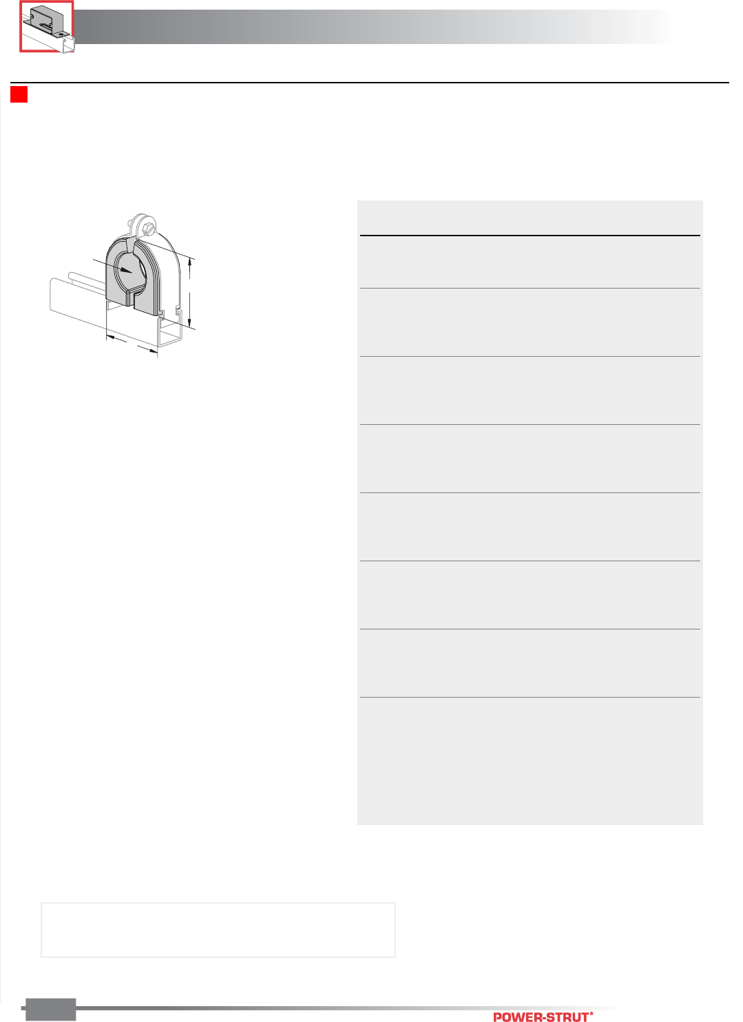
ELECTRICAL
ELECTRICAL
ENGINEERING CATALOG
124
Finish: Painted Green or Pregalvanized Stock Length: 10 feet & 20 feet Order By: No. and Size
■PS 723 – Porcelain Cable Clamp
Hole Size
A
B
Part Hole PS 1100 Wt./
Number Size Size A B 100 pcs
PS723 3⁄8"3⁄8"1"1
7⁄8"1
15⁄32"51
PS723 1⁄2"
1⁄2"47
PS723 5⁄8"
5⁄8"46
PS723 3⁄4"
3⁄4"1
1⁄2"2
3⁄8"2
1⁄32"85
PS723 7⁄8"
7⁄8"84
PS723 1" 1" 83
PS723 11⁄8"1
1⁄8"76
PS723 11⁄4"1
1⁄4"2"2
7⁄8"2
17⁄32" 116
PS723 13⁄8"1
3⁄8" 115
PS723 11⁄2"1
1⁄2" 108
PS723 15⁄8"1
5⁄8" 100
PS723 13⁄4"1
3⁄4"3" 4"3
5⁄8" 228
PS723 17⁄8"1
7⁄8" 224
PS723 2" 2" 204
PS723 21⁄8"2
1⁄8" 184
PS723 21⁄4"2
1⁄4"3
1⁄2"4
1⁄2"4
1⁄8" 255
PS723 23⁄8"2
3⁄8" 255
PS723 21⁄2"2
1⁄2" 250
PS723 25⁄8"2
5⁄8" 245
PS723 23⁄4"2
3⁄4"4"5
1⁄8"4
5⁄8" 322
PS723 27⁄8"2
7⁄8" 301
PS723 3" 3" 301
PS723 31⁄8"3
1⁄8" 296
PS723 31⁄4"3
1⁄4"5"6
1⁄8"5
11⁄32" 460
PS723 33⁄8"3
3⁄8" 440
PS723 31⁄2"3
1⁄2" 433
PS723 35⁄8"3
5⁄8" 423
PS723 33⁄4"3
3⁄4"6"7
1⁄4"6
3⁄4" 698
PS723 37⁄8"3
7⁄8" 678
PS723 4" 4" 648
PS723 41⁄8"4
1⁄8" 638
PS723 41⁄4"4
1⁄4" 648
PS723 43⁄8"4
3⁄8" 598
PS723 41⁄2"4
1⁄2" 588
Strap Material: Electro-galvanized steel or stainless steel
Use With: All 15⁄8" channel. EG includes Everdur hardware
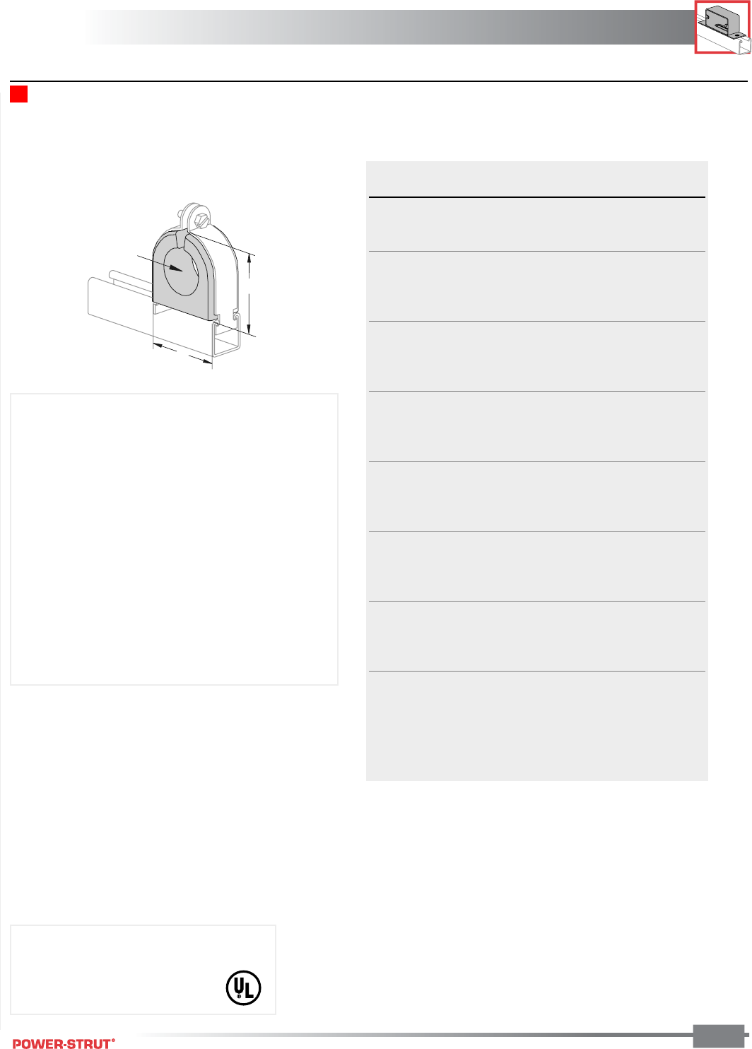
ELECTRICAL
ELECTRICAL
ENGINEERING CATALOG 125
Finish: Painted Green or Pregalvanized Stock Length: 10 feet & 20 feet Order By: No. and Size
■PS 722 – Porce -A- Clamp™
Hole Size
A
B
Part Hole Wt./
Number Size A B 100 pcs
PS722 3⁄8"3⁄8"1
7⁄8"1
15⁄32"25
PS722 1⁄2"
1⁄2"
PS722 5⁄8"
5⁄8"
PS722 3⁄4"
3⁄4"2
3⁄8"2
1⁄32"37
PS722 7⁄8"
7⁄8"
PS722 1" 1"
PS722 11⁄8"1
1⁄8"
PS722 11⁄4"1
1⁄4"2
7⁄8"2
17⁄32"58
PS722 13⁄8"1
3⁄8"
PS722 11⁄2"1
1⁄2"
PS722 15⁄8"1
5⁄8"
PS722 13⁄4"1
3⁄4"4"3
5⁄8"76
PS722 17⁄8"1
7⁄8"
PS722 2" 2"
PS722 21⁄8"2
1⁄8"
PS722 21⁄4"2
1⁄4"4
1⁄2"4
1⁄8"90
PS722 23⁄8"2
3⁄8"
PS722 21⁄2"2
1⁄2"
PS722 25⁄8"2
5⁄8"
PS722 23⁄4"2
3⁄4"5
1⁄8"4
5⁄8" 109
PS722 27⁄8"2
7⁄8"
PS722 3" 3"
PS722 31⁄8"3
1⁄8"
PS722 31⁄4"3
1⁄4"6
1⁄8"5
11⁄32" 130
PS722 33⁄8"3
3⁄8"
PS722 31⁄2"3
1⁄2"
PS722 35⁄8"3
5⁄8"
PS722 33⁄4"3
3⁄4"7
1⁄4"6
3⁄4" 160
PS722 37⁄8"3
7⁄8"
PS722 4" 4"
PS722 41⁄8"4
1⁄8"
PS722 41⁄4"4
1⁄4"
PS722 43⁄8"4
3⁄8"
Patents Pending
Strap Material: Electro-galvanized steel or
stainless steel
Use With: All 15⁄8" channel
Porce –A– Clamp™
• Non-Breakable TPE Material
• U.V. Resistant
• U.L. Listed
• Electro-galvanized or Stainless Steel Clamps
• Tapered Flange to Protect Cable
• Dielectric Strength 525 Volts Per Mil.
• One Piece
• Replaces Porcelain & Maple Cable Clamp
• For use in accordance with National Electrical Code
ANSI/NFPA 70.
Replaces the two piece PS 723 Porcelain Cable Clamp
Includes Everdur Hardware
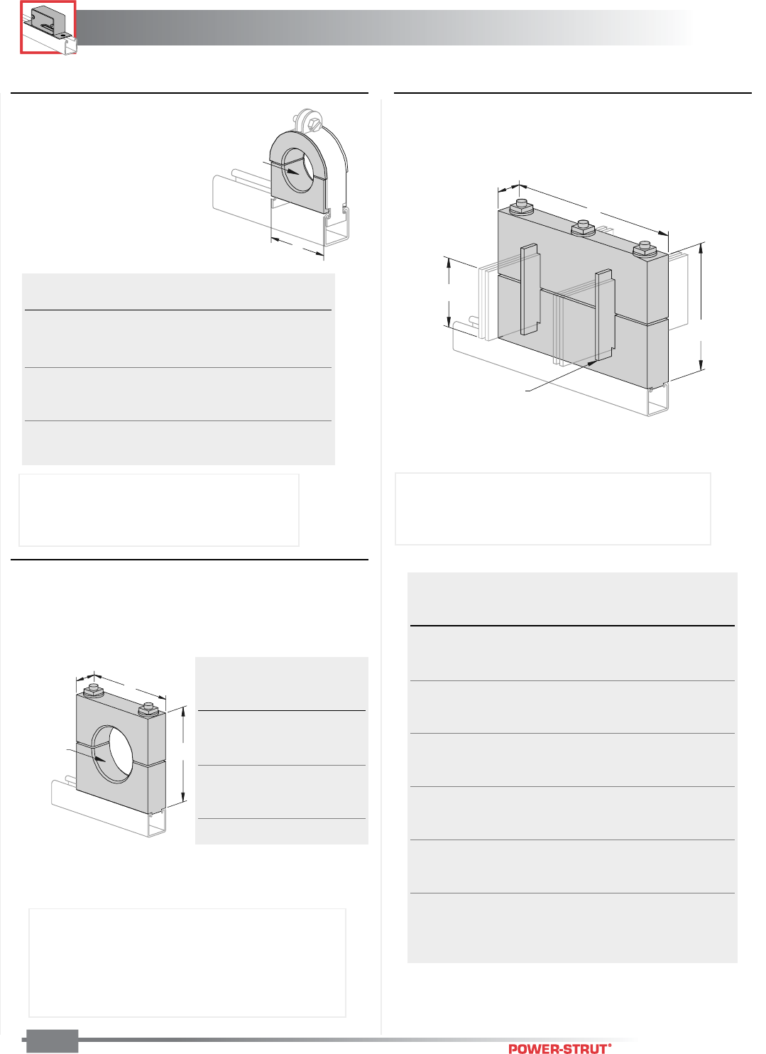
ELECTRICAL
ELECTRICAL
ENGINEERING CATALOG
126
Finish: Painted Green or Pregalvanized Stock Length: 10 feet & 20 feet Order By: No. and Size
■PS 1801 – Square Maple Cable Clamps
Hole Size
A
1
5
⁄
8
"
B
■PS 1610 – Maple Cable Clamp
Hole Size
A
■PS 1850 – Maple Bus Bar Clamp
15⁄8"
A
4"
1⁄4" Maple
Separator
B
Inside PS 1100 Wt./
Diameter A Size 100 pcs
0 to 5⁄8"1
5⁄16"1" 24
1⁄2 to 1" 115⁄16"1
1⁄2"42
3⁄4 to 11⁄2"2
3⁄8"2" 54
11⁄4 to 13⁄4"3
1⁄2"3" 65
11⁄2 to 21⁄4"4" 3
1⁄2"84
2 to 21⁄2"4
1⁄2" 4" 107
21⁄4 to 3" 59⁄16" 5" 123
3 to 4" 65⁄8" 6" 163
Inside
Diameter Wt./
Size A & B 100 pcs
0"– 1" 31⁄2"84
1"– 11⁄2" 4" 102
11⁄2"– 2" 41⁄2" 121
2"– 21⁄2"5
1⁄2" 165
21⁄2" – 3" 6" 189
3"– 31⁄2"6
1⁄2" 215
31⁄2"– 4" 7" 243
Bus # of
Bar Separa- Wt./
Type Size A B tors 100 pcs
11⁄4 x 2" 81⁄2"5
3⁄8" 0 360
21⁄4 x 2" 91⁄2"5
3⁄8" 2 400
31⁄4 x 2" 101⁄2"5
3⁄8" 4 430
41⁄4 x 2" 111⁄2"5
3⁄8" 6 460
51⁄4 x 2" 121⁄2"5
3⁄8" 8 490
61⁄4 x 2" 131⁄2"5
3⁄8" 10 520
11⁄4 x 4" 81⁄2"7
3⁄8" 0 421
21⁄4 x 4" 91⁄2"7
3⁄8" 2 465
31⁄4 x 4" 101⁄2"7
3⁄8" 4 509
41⁄4 x 4" 111⁄2"7
3⁄8" 6 553
51⁄4 x 4" 121⁄2"7
3⁄8" 8 597
61⁄4 x 4" 131⁄2"7
3⁄8" 10 631
11⁄4 x 6" 81⁄2"9
3⁄8" 0 567
21⁄4 x 6" 91⁄2"9
3⁄8" 2 628
31⁄4 x 6" 101⁄2"9
3⁄8" 4 689
41⁄4 x 6" 111⁄2"9
3⁄8" 6 750
51⁄4 x 6" 121⁄2"9
3⁄8" 8 811
61⁄4 x 6" 131⁄2"9
3⁄8" 10 872
Use With: All 15⁄8" Wide Channel
Assembly: Maple Part, Pipe Clamp Assembly
NOTE: Specify Cable Diameter
Use With: All 15⁄8" Channels.
Assembly: Maple Part, 3 Stud Bolts, 3 Spring Nuts,
3 Square Nuts, 3 Washers
Use With: All 15⁄8" Wide Channels.
Assembly: Maple Part, 2 Stud Bolts, 2 Washers,
2 Spring Nuts, 2 Square Nuts
NOTE: Special maple clamps can be made to order.
Specify Cable Diameter.
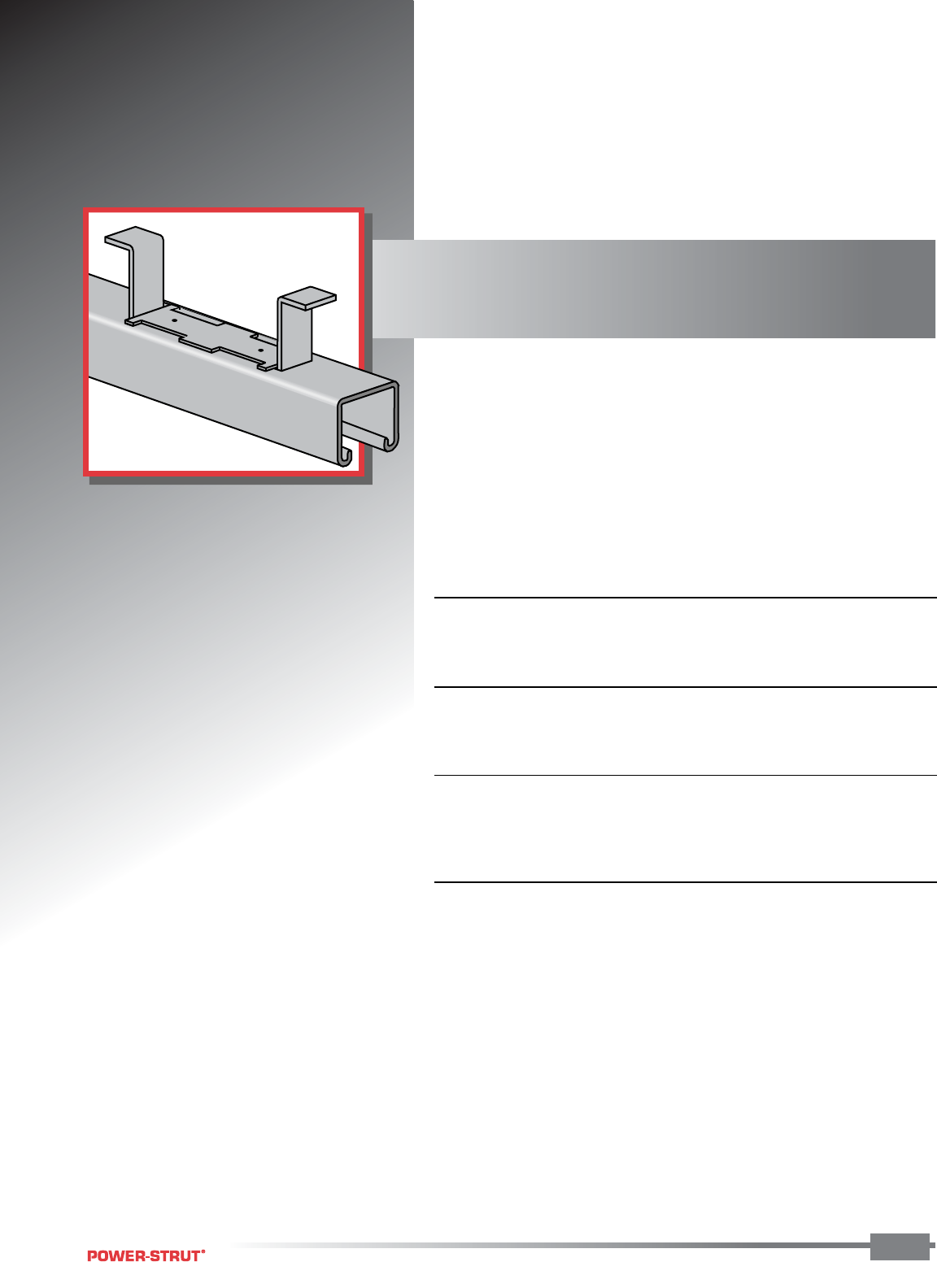
CONCRETE INSERTS
CONCRETE INSERTS
ENGINEERING CATALOG 127
A selection of heavy-duty to light-duty
“continuous” and “spot” concrete
inserts is available for use in pre-cast,
pre-stressed or poured-in-place concrete
floors, walls or ceilings.
■ MATERIAL:
Power-Strut continuous slotted concrete inserts are cold formed from
structural quality strip steel.
■ STANDARD LENGTHS:
Standard lengths are 10 or 20 feet. Non-standard lengths from 3 inches
to 20 feet are also available.
■ STANDARD FINISH:
Power-Strut continuous-slotted concrete inserts are available in plain or
pre-galvanized finishes. Closure strips (CS) are made of plastic and end
caps (EC) are pre-galvanized.
■ ORDERING INFORMATION:
When ordering, add the length or size and finish to the part number.
See pages 8-10 for finish abbreviations and an example.
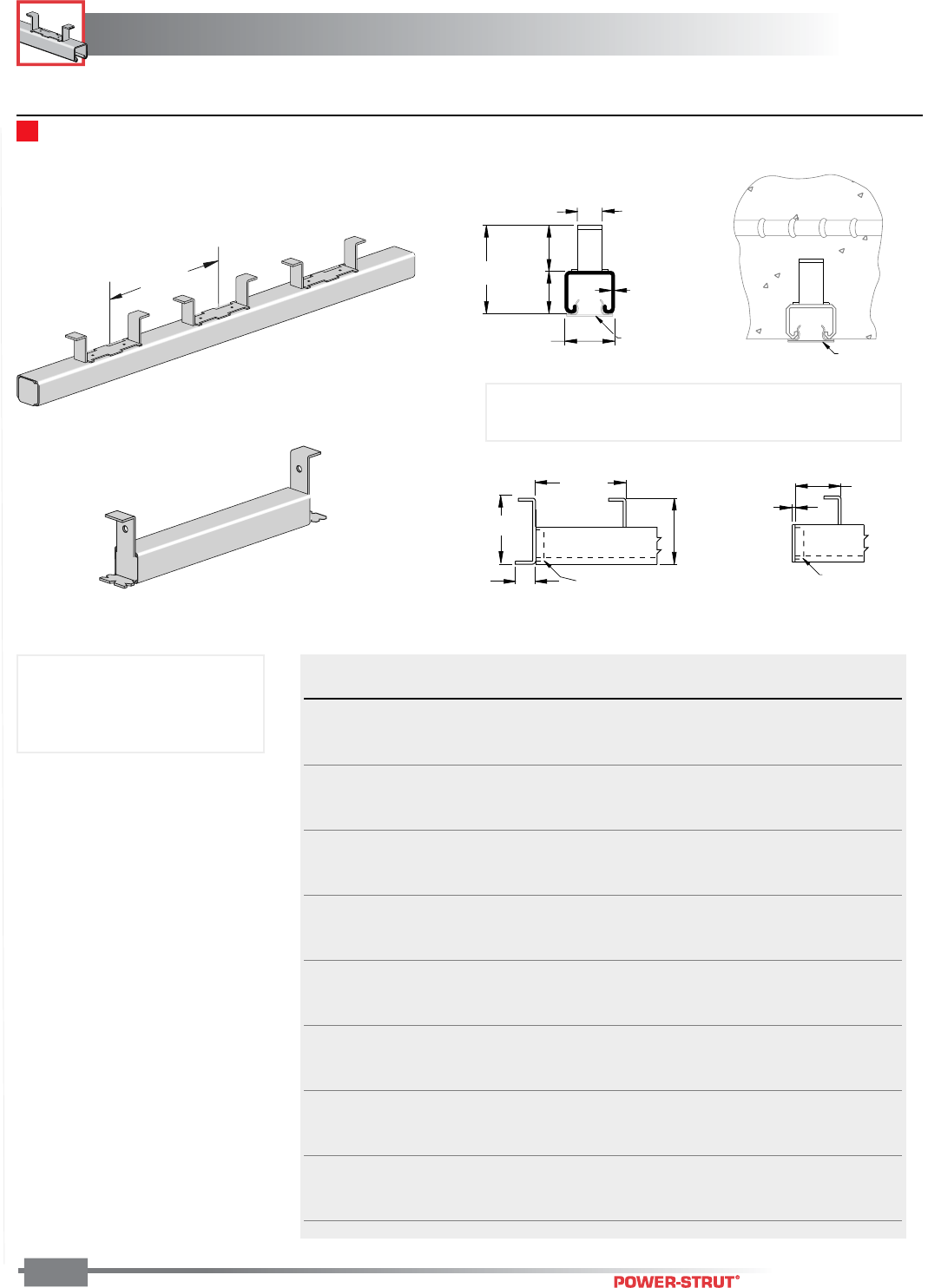
CONCRETE INSERTS
CONCRETE INSERTS
ENGINEERING CATALOG
128
Finish: Plain, Pregalvanized or Hot-Dipped Galvanized Stock Thickness: .105 (12 ga.) Stock Length: 20 feet
Other lengths made to order Order By: No. and Size
PS 349 – Continuous Concrete Insert (15⁄8" x 13⁄8")
8"
PS 6151
2 7⁄8"
1 1⁄2"
1 5⁄8"
12 Ga.
13⁄16"
PS 6151
1 3⁄8"
≤2"
1
⁄
8
"
PS 656
3"
>2"
2 7⁄8"
(73.0)
PS 653
1"
Furnished with steel end caps and plastic closure strips installed
Wt./100 pcs
Part No. End Cap PLN Load Data*
PS 349 3" CS/EC PS 653 72 500 lbs
PS 349 4" CS/EC PS 653 87 800 lbs.
PS 349 6" CS/EC PS 653 117 1,000 lbs.
PS 349 8" CS/EC PS 653 147 1,200 lbs.
PS 349 1' CS/EC PS 653 194 2,000 lbs.
PS 349 1'4" CS/EC PS 656 253 2,000 lbs./ft.
PS 349 1'8" CS/EC PS 653 312 2,000 lbs./ft.
PS 349 2' CS/EC PS 656 371 2,000 lbs./ft.
PS 349 2'8" CS/EC PS 656 490 2,000 lbs./ft.
PS 349 3' CS/EC PS 653 549 2,000 lbs./ft.
PS 349 4' CS/EC PS 656 727 2,000 lbs./ft.
PS 349 5' CS/EC PS 653 905 2,000 lbs./ft.
PS 349 6' CS/EC PS 656 1,082 2,000 lbs./ft.
PS 349 7' CS/EC PS 653 1,260 2,000 lbs./ft.
PS 349 8' CS/EC PS 656 1,438 2,000 lbs./ft.
PS 349 9' CS/EC PS 653 1,615 2,000 lbs./ft.
PS 349 10' CS/EC PS 656 1,793 2,000 lbs./ft.
PS 349 12' CS/EC PS 656 2,148 2,000 lbs./ft.
PS 349 14' CS/EC PS 656 2,504 2,000 lbs./ft.
PS 349 16' CS/EC PS 656 2,859 2,000 lbs./ft.
PS 349 18' CS/EC PS 656 3,215 2,000 lbs./ft.
PS 349 20' CS/EC PS 656 3,570 2,000 lbs./ft.
PS 349 10' W/O Insert Only 1,777
PS 349 20' W/O Insert Only 3,554
*uniform recommended loading
on inserts in 3,000 psi concrete.
Choice of end cap is based on the distance from the end
of the insert to the first anchor as shown below.
• Use channel nuts designed for
PS 300 Channel.
• Nail or anchor the inserts to
forms every 16" to 24"
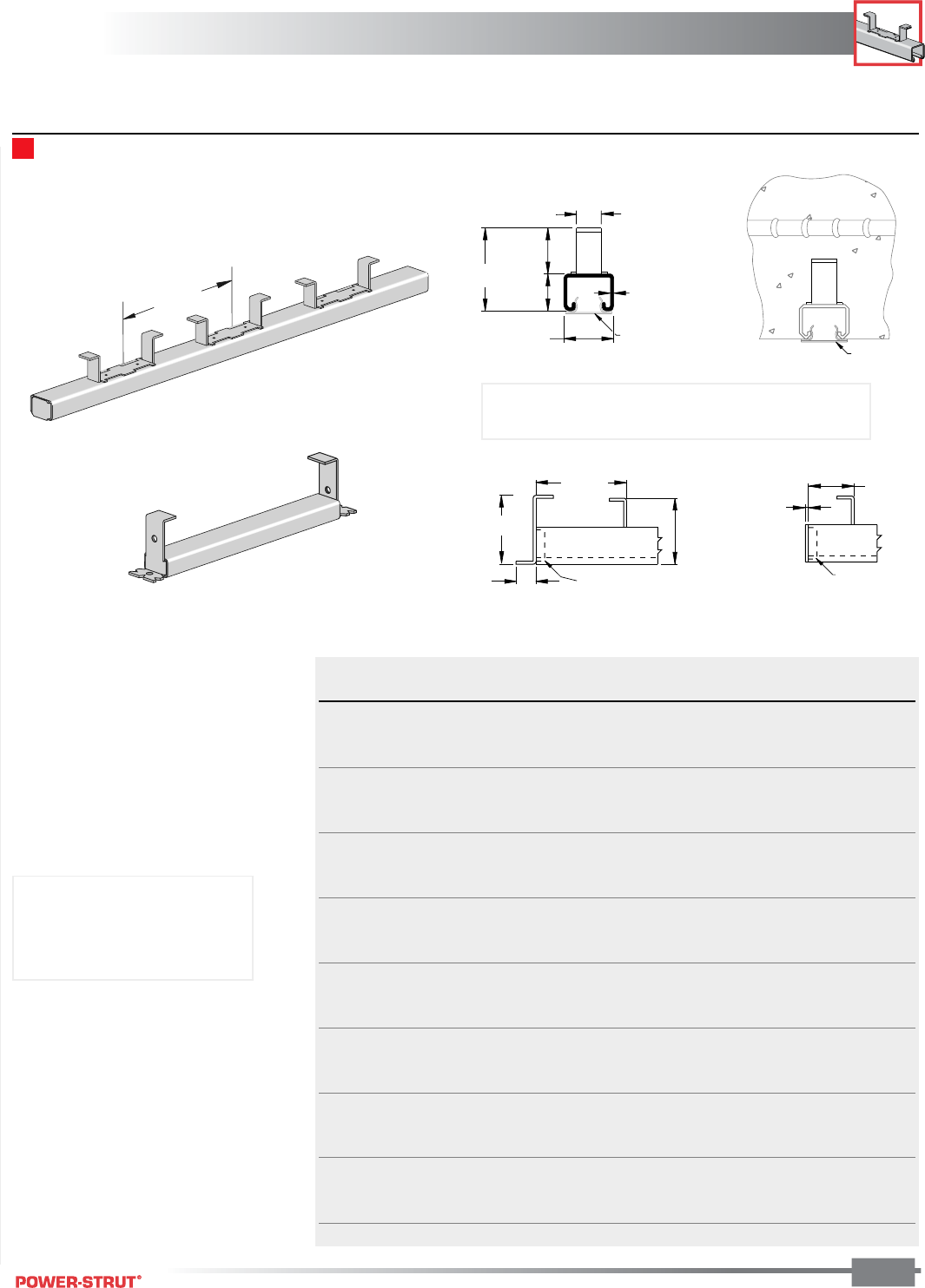
CONCRETE INSERTS
CONCRETE INSERTS
ENGINEERING CATALOG
129
Finish: Plain, Pregalvanized or Hot-Dipped Galvanized Stock Length: 20 feet Other lengths made to order
Order By: No. and Size
PS 449 – Continuous Concrete Insert (15⁄8" x 1")
≤2"
1
⁄
8
"
PS 901
2
7
⁄
8
"
>2"
2
1
⁄
4
"
PS 654
1"
PS 6151
2
1
⁄
2
"
1
1
⁄
2
"
1
5
⁄
8
"
12 Ga.
13
⁄
16
"
PS 6151
1"
8"
Furnished with steel end caps and plastic closure strips installed
Wt./100 pcs
Part No. End Cap PLN Load Data*
PS 449 3" CS/EC PS 654 62 500 lbs
PS 449 4" CS/EC PS 654 74 600 lbs.
PS 449 6" CS/EC PS 654 99 800 lbs.
PS 449 8" CS/EC PS 654 124 1,000 lbs.
PS 449 1' CS/EC PS 654 163 1,600 lbs./ft.
PS 449 1'4" CS/EC PS 901 213 1,600 lbs./ft.
PS 449 1'8" CS/EC PS 654 263 1,600 lbs./ft.
PS 449 2' CS/EC PS 901 313 1,600 lbs./ft.
PS 449 2'8" CS/EC PS 901 414 1,600 lbs./ft.
PS 449 3' CS/EC PS 654 464 1,600 lbs./ft.
PS 449 4' CS/EC PS 901 615 1,600 lbs./ft.
PS 449 5' CS/EC PS 654 766 1,600 lbs./ft.
PS 449 6' CS/EC PS 901 916 1,600 lbs./ft.
PS 449 7' CS/EC PS 654 1,079 1,600 lbs./ft.
PS 449 8' CS/EC PS 901 1,218 1,600 lbs./ft.
PS 449 9' CS/EC PS 654 1,368 1,600 lbs./ft.
PS 449 10' CS/EC PS 901 1,519 1,600 lbs./ft.
PS 449 12' CS/EC PS 901 1,820 1,600 lbs./ft.
PS 449 14' CS/EC PS 901 2,122 1,600 lbs./ft.
PS 449 16' CS/EC PS 901 2,423 1,600 lbs./ft.
PS 449 18' CS/EC PS 901 2,725 1,600 lbs./ft.
PS 449 20' CS/EC PS 901 3,026 1,600 lbs./ft.
PS 449 10' W/O Insert Only 1,507
PS 449 20' W/O Insert Only 3,014
*uniform recommended loading
on inserts in 3,000 psi concrete.
• Use channel nuts designed
for PS 400 Channel.
• Nail or anchor the inserts to
forms every 16" to 24"
Choice of end cap is based on the distance from the
end of the insert to the first anchor as shown below.
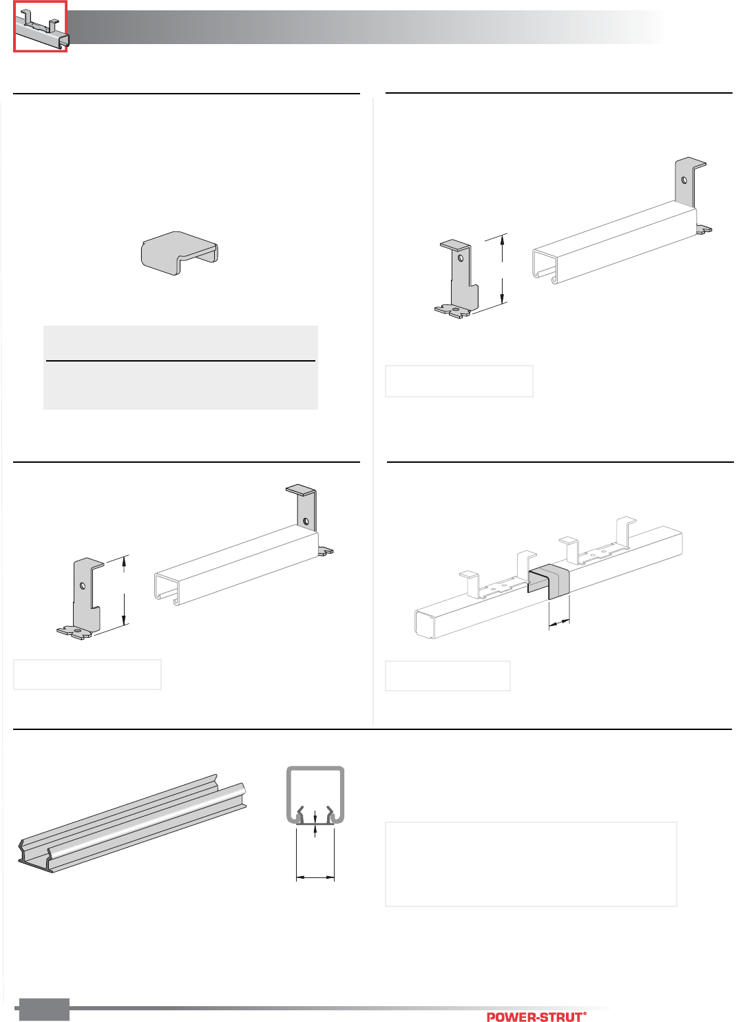
CONCRETE INSERTS
CONCRETE INSERTS
ENGINEERING CATALOG
130
■PS 656, PS 901 – Type 'A' End Cap
■PS 654 – Type 'B' End Cap
■PS 653 – Type 'B' End Cap
2
7
⁄
8
"
PS 400, PS 449
3"
PS 300, PS 349
■PS 1154 – Splice Connection
1
5
⁄
8
"
■PS 6151 – Plastic Closure Strip
.040"
1
1
⁄
16
"
Use With Wt./
Part No. Insert Finish 100 pcs
PS 656 PS 349 PGAL 8
PS 901 PS 449 PGAL 6
Weight/100 pcs: 14 lbs.
Finish: Pre-galvanized
Weight/100 pcs: 10 lbs.
Material: Plastic
Stock Length: 10 ft.
Use With: All 15⁄8" channel and inserts to prevent
concrete seepage
Use With: PS 349
Finish: Pre-galvanized
Weight/100 pcs: 12 lbs.
Weight/100 pcs: 47 lbs.
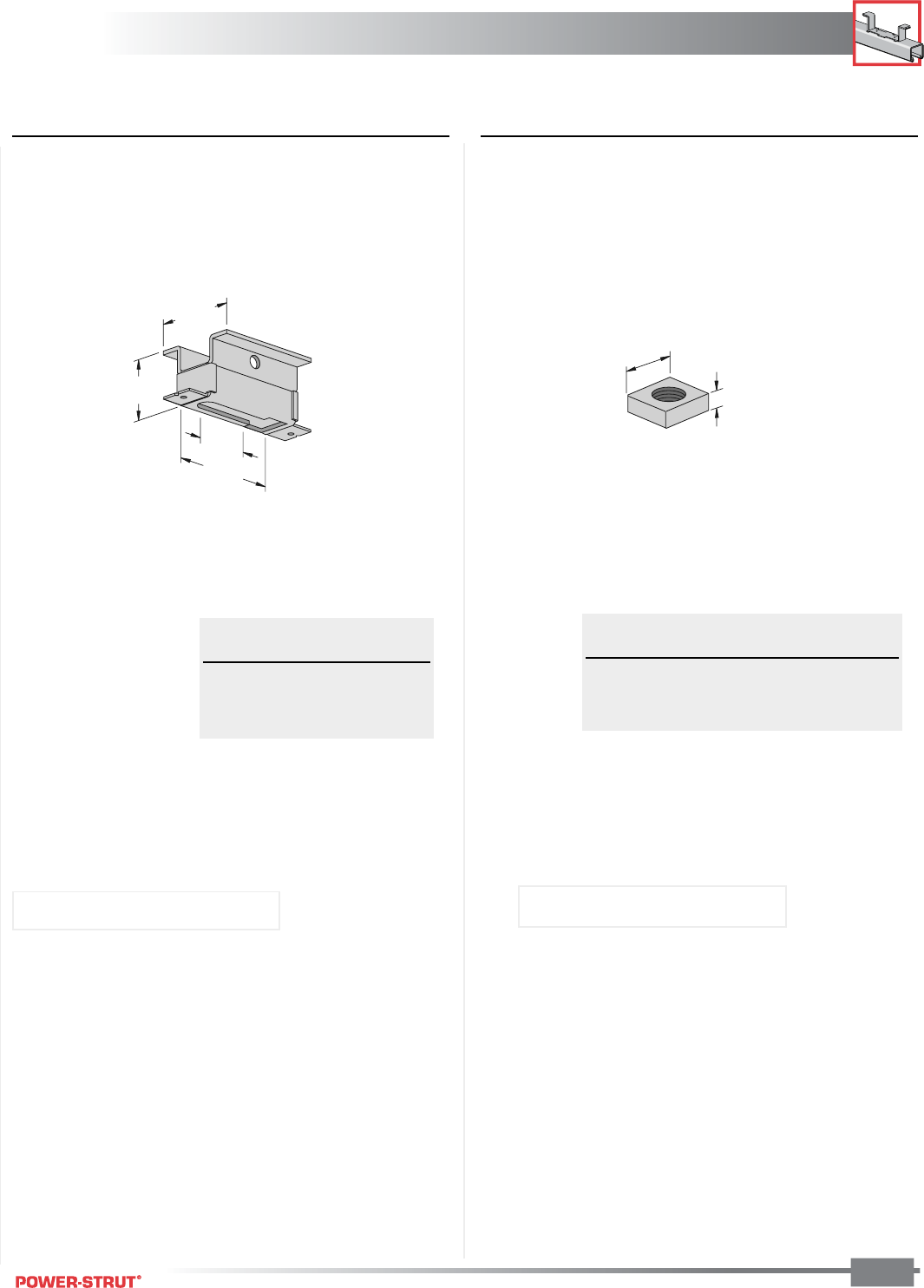
CONCRETE INSERTS
CONCRETE INSERTS
ENGINEERING CATALOG
131
■PS 285 – Light Weight Concrete Insert ■PS 285 N – Concrete Insert Nut
(for use with PS 285)
13
⁄
16
"
A"
2"
2
1
⁄
4
"
3"
1
5
⁄
8
"
Rod Wt./
Part No. Size A 100 pcs
PS 285 1⁄4"5⁄16"6
PS 285 3⁄8"5⁄16"5
PS 285 1⁄2"7⁄16"6
Rod Load Wt./
Size Rating 100 pcs
1⁄4" 230 46
3⁄8" 400 49
1⁄2" 400 49
Finish: Plain or Electro-galvanized
Finish: Plain or Electro-galvanized
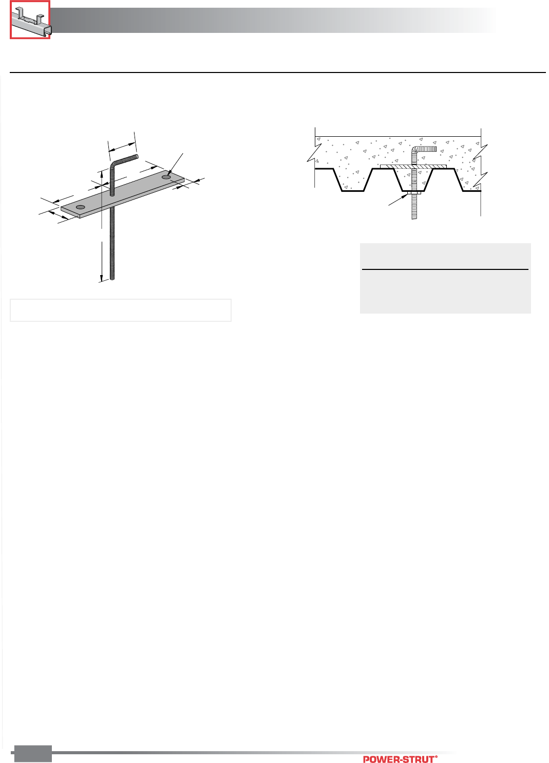
CONCRETE INSERTS
CONCRETE INSERTS
ENGINEERING CATALOG
132
■PS 680 – Concrete Deck Insert
Jam Nut
Recommended
Wt./ Load
Part No. 100 pcs Rating
PS 680–3⁄8" 86 610
PS 680–1⁄2" 105 1,130
PS 680–5⁄8"130 1,810
Note: Rod is electro-galvanized and plate is plain.
4"
6"
8"
1 1
⁄
2"
9
⁄
16"
13
⁄
32" Hole
1
1
⁄
4
"
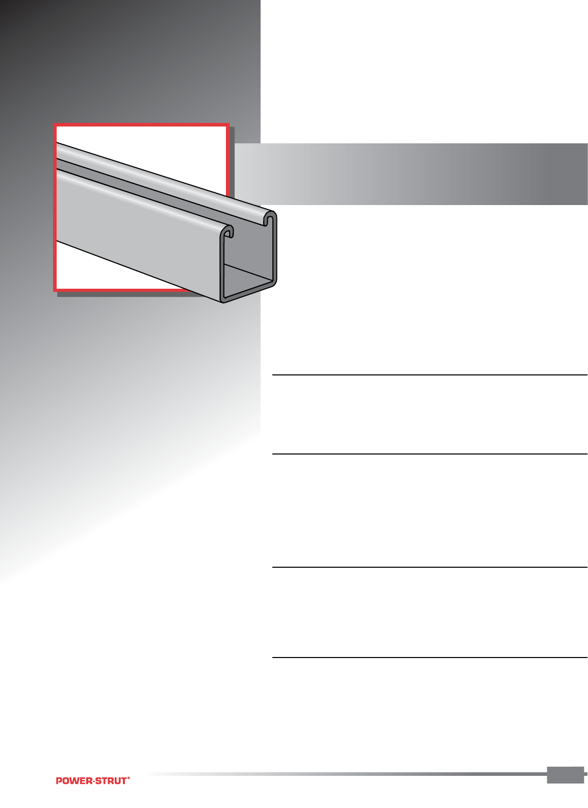
JUNIOR CHANNEL
JUNIOR CHANNEL
ENGINEERING CATALOG
133
Power-Strut junior channel sections
are cold formed from prime quality
cold rolled steel. Junior channel fittings
are punched from hot rolled,
pickled and oiled steel.
■ STANDARD LENGTHS:
Standard length is 10 feet at a tolerance of ±1⁄16 inches. Shorter lengths
are available for a small cutting charge.
■ STANDARD DIMENSIONS FOR FITTINGS:
Fitting Thickness: 1⁄8"
Fitting Width: 13⁄16"
Hole Diameter: 9⁄32"
Hole Spacing: 11⁄16" on centers and 13⁄32" from end.
■ STANDARD FINISH:
PS 600J and PS 700J junior channels are available in a galvanized or
painted green finish. All junior channel fittings are available in electro-
galvanized finish.
■ ORDERING INFORMATION:
When ordering, add the length or size and finish to the part number.
See pages 8-10 for finish abbreviations and an example.
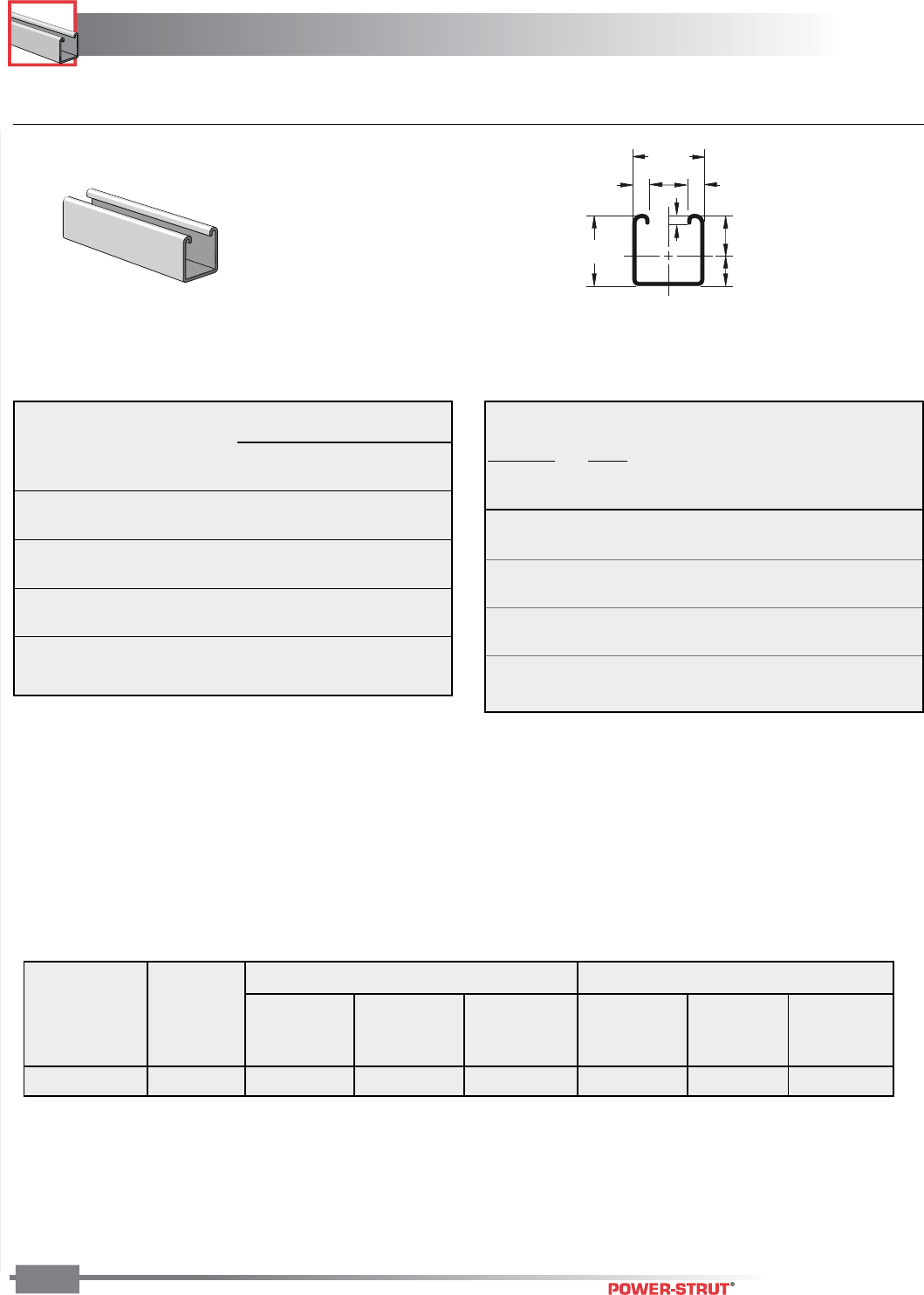
JUNIOR CHANNEL
JUNIOR CHANNEL
ENGINEERING CATALOG
134
Finish: Electro-galvanized Stock Width: 13⁄16” Stock Thickness: 1⁄8” Stock Length: 10 feet Order By: Part No. and Size
Hole Spacing: 13⁄32” from end, 11⁄16” on center Hole Diameter: 9⁄32”
Max Defl. at
Allowable Uniform Uniform Loading at Deflection
Span Uniform Load Load Span/180 Span/240 Span/360
In Lbs In Lbs Lbs Lbs
18 220 0.06 220 220 170
24 170 0.11 170 150 100
30 130 0.18 130 90 60
36 110 0.26 90 70 40
42 100 0.35 60 50 30
48 80 0.45 50 40 20
54 70 0.58 40 30 20
60 70 0.71 30 20 20
Maximum
Allowable
Unbraced Load Maximum Column Load Applied at C.G.
Height at Slot Face K = 0.65 K = 0.80 K =1.0 K = 1.2
In Lbs Lbs Lbs Lbs Lbs
18 570 1,650 1,340 960 670
24 450 1,210 840 540 370
30 340 820 540 350 240
36 270 570 370 240 170
42 210 420 280 180 120
48 170 320 210 130 90
54 140 250 170 110 **
60 120 200 130 ** **
■PS 600J – Channel (13⁄16" x 13⁄16" x 19 ga.)
Y
X
7
⁄
16
"
3
⁄
16
"
3
⁄
16
"
13
⁄
16
"
13
⁄
16
"
3
⁄
32
".463"
.350"
Column loads are for allowable axial loads and must be reduced for eccentric loading. For concentrated load at center
of span, divide uniform load by 2 and multiply corresponding deflection by 0.8. This load table is based on a solid
channel section.
BEAM LOADING DATA – PS 600J CHANNEL COLUMN LOADING DATA – PS 600J CHANNEL
X-X Axis Y-Y Axis
Area of Moment Section Radius of Moment Section Radius of
Weight Section of Inertia Modulus Gyration of Inertia Modulus Gyration
(lbs./100 ft.) (Inch2) (Inch4) (Inch3) (Inch) (Inch4) (Inch3) (Inch)
35 0.103 .009 .020 .294 .012 .028 .333
ELEMENTS OF SECTION
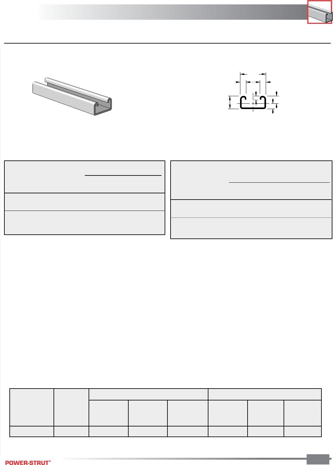
JUNIOR CHANNEL
JUNIOR CHANNEL
ENGINEERING CATALOG
135
Finish: Electro-galvanized Stock Width: 13⁄16” Stock Thickness: 1⁄8” Stock Length: 10 feet Order By: Part No. and Size
Hole Spacing: 13⁄32” from end, 11⁄16” on center Hole Diameter: 9⁄32”
Maximum
Allowable
Unbraced Load Maximum Column Load Applied at C.G.
Height at Slot Face K = 0.65 K = 0.80 K =1.0 K = 1.2
In Lbs Lbs Lbs Lbs Lbs
18 320 970 720 470 330
24 230 620 410 260 180
30 170 400 260 ** **
36 130 280 180 ** **
Max Defl. at
Allowable Uniform Uniform Loading at Deflection
Span Uniform Load Load Span/180 Span/240 Span/360
In Lbs In Lbs Lbs Lbs
18 80 0.10 80 60 40
24 60 0.18 40 30 20
30 50 0.28 30 20 10
36 40 0.40 20 10 10
■PS 700J – Channel (13⁄16" x 13⁄32" x 19 ga.)
7
⁄
16
"
3
⁄
16
"
13
⁄
16
"
3
⁄
16
"
3
⁄
32
"
.243"
.163"
1
3
⁄
32
"
X
Y
Column loads are for allowable axial loads and must be reduced for eccentric loading. For concentrated load at center
of span, divide uniform load by 2 and multiply corresponding deflection by 0.8. This load table is based on a solid
channel section.
X-X Axis Y-Y Axis
Area of Moment Section Radius of Moment Section Radius of
Weight Section of Inertia Modulus Gyration of Inertia Modulus Gyration
(lbs./100 ft.) (Inch2) (Inch4) (Inch3) (Inch) (Inch4) (Inch3) (Inch)
24 0.072 0.002 0.007 0.148 0.007 0.017 0.306
ELEMENTS OF SECTION
COLUMN LOADING DATA – PS 700J CHANNEL
BEAM LOADING DATA – PS 700J CHANNEL
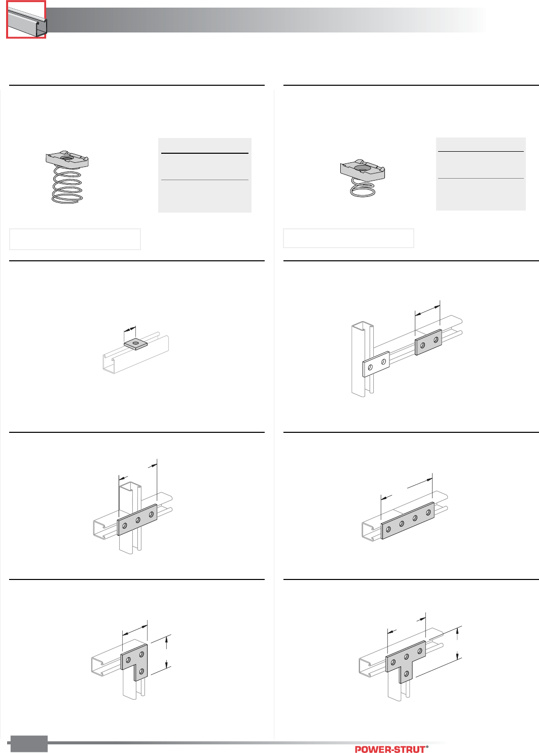
JUNIOR CHANNEL
JUNIOR CHANNEL
ENGINEERING CATALOG
136
Finish: Electro-galvanized Stock Width: 13⁄16” Stock Thickness: 1⁄8” Stock Length: 10 feet Order By: Part No. and Size
Hole Spacing: 13⁄32” from end, 11⁄16” on center Hole Diameter: 9⁄32”
■PS 2033 – Flat Angle Plate ■PS 2034 – Tee Plate
Weight/100 pcs: 8 lbs. Weight/100 pcs: 11 lbs.
17⁄8"
17⁄8"
1
7
⁄
8
"
2
15
⁄
16
"
■PS 2015 – Three-Hole Splice Plate
■PS 2013 – Square Washer
■PS 4017 – Junior Channel Nuts■PS 3017 – Junior Channel Nuts
■PS 2014 – Two-Hole Splice Plate
■PS 2016 – Four-Hole Splice Plate
Weight/100 pcs: 2 lbs. Weight/100 pcs: 5 lbs.
Weight/100 pcs: 8 lbs. Weight/100 pcs: 11 lbs.
13
⁄
16
"
4"
215⁄16"
17
⁄
8
"
Size Wt./100 pcs
8-32 1
10-32 1
10-24 1
1⁄4"1
Size Wt./100 pcs
8-32 1
10-32 1
10-24 1
1⁄4"1
Use With: PS 600J channel Use With: PS 700J channel
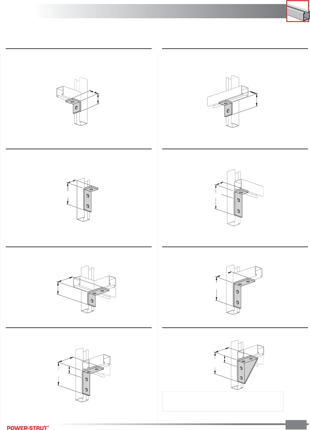
JUNIOR CHANNEL
JUNIOR CHANNEL
ENGINEERING CATALOG
137
Finish: Electro-galvanized Stock Width: 13⁄16” Stock Thickness: 1⁄8” Stock Length: 10 feet Order By: Part No. and Size
Hole Spacing: 13⁄32” from end, 11⁄16” on center Hole Diameter: 9⁄32”
■PS 2008 – Two-Hole Corner Angle ■PS 2017 – Two-Hole Corner Angle
■PS 2018 – Three-Hole Corner Angle
Weight/100 pcs: 8 lbs.
■PS 2025 – Three-Hole Corner Angle
Weight/100 pcs: 5 lbs. Weight/100 pcs: 5 lbs.
Weight/100 pcs: 8 lbs.
2"
1
1
⁄
8
"
13⁄16"
11⁄4"
15
⁄
16
"
1
1
⁄
8
"
25⁄16"
27⁄32"
■PS 2024 – Four-Hole Corner Angle
■PS 2019 –Four-Hole Corner Angle■PS 2037 – Three-Hole Corner Angle
■PS 2023 R or L – Four-Hole Shelf Bracket
Weight/100 pcs: 8 lbs. Weight/100 pcs: 11 lbs.
1
1
⁄
4
"
1
7
⁄
8
"
2
5
⁄
16
"
1
7
⁄
8
"
27
⁄
32
"
25⁄16"
17⁄8"
27⁄32"
23⁄16"
2
Weight/100 pcs: 11 lbs. Weight/100 pcs: 19 lbs.
Note: Specify R (right) or L (left) when ordering
Right Hand Illustrated
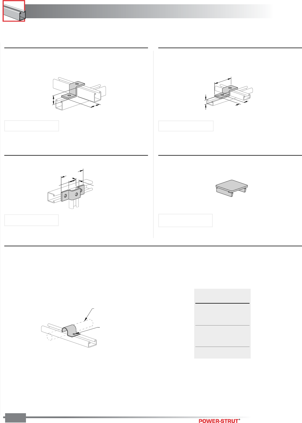
JUNIOR CHANNEL
JUNIOR CHANNEL
ENGINEERING CATALOG
138
Finish: Electro-galvanized Stock Width: 13⁄16” Stock Thickness: 1⁄8” Stock Length: 10 feet Order By: Part No. and Size
Hole Spacing: 13⁄32” from end, 11⁄16” on center Hole Diameter: 9⁄32”
■PS 2011 – "U" Support ■PS 2029 – End Cap
■PS 2041 – Tubing Clamps
27
⁄
32
"
215⁄16"
13⁄16"
9
⁄
32
"
Dia. Hole
Tubing Size
PS 700J
■PS 2026 –Zee Support■PS 2010 – Zee Support
1
3⁄32"
1
3⁄32"
17⁄8"
1
1
⁄
16
"
13
⁄
16
"
Size Wt./
Tubing O.D. 100 pcs
1⁄4"2
3⁄8"2
1⁄2"2
5⁄8"2
3⁄4"3
7⁄8"3
1" 3
Weight/100 pcs: 7 lbs
Use With: PS 600J Use With: PS 700J
Use With: PS 600J Use With: PS 600J
Weight/100 pcs: 6 lbs.
Weight/100 pcs: 12 lbs. Weight/100 pcs: 2 lbs.
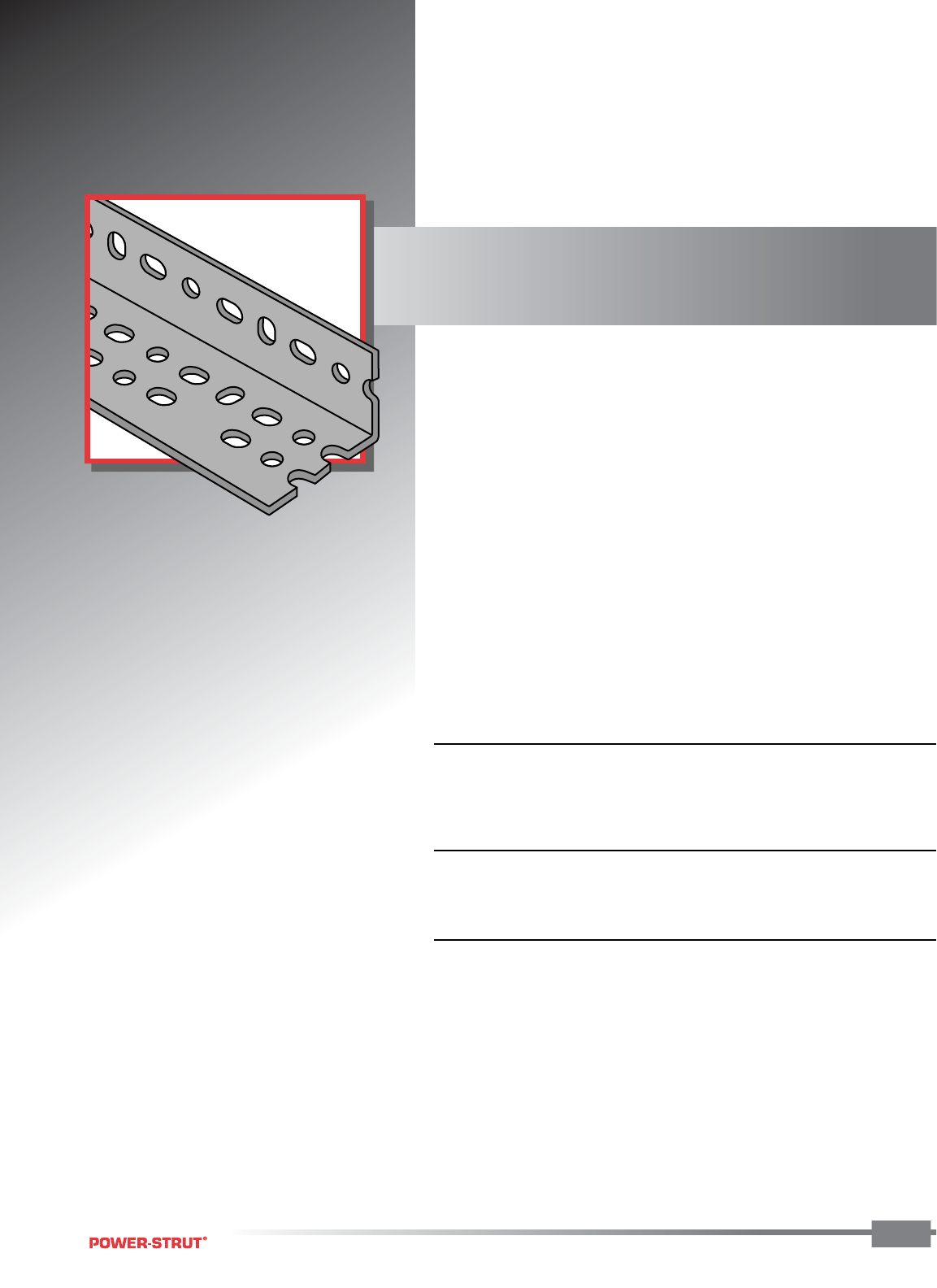
POWER-ANGLE
®
POWER-ANGLE
®
ENGINEERING CATALOG
139139
139
A complete support system that's
versatile, economical and easy to use.
• No drilling, welding or
special tools necessary
• Fast, efficient bolt-together
construction
• Easy to change and adjust
■ STANDARD LENGTHS:
Standard lengths are 10' and 12'. Slotted angle is shipped in ten-piece
bundles complete with 75 pieces of 3⁄8" - 16 x 3⁄4" hex head bolts and
3⁄8" nuts.
■ STANDARD FINISH:
Available in two durable, long-lasting finishes;
pre-galvanized or Power–Green™.
■ ORDERING INFORMATION:
When ordering, add the length or size and finish to the part number.
See pages 8-10 for finish abbreviations and an example.
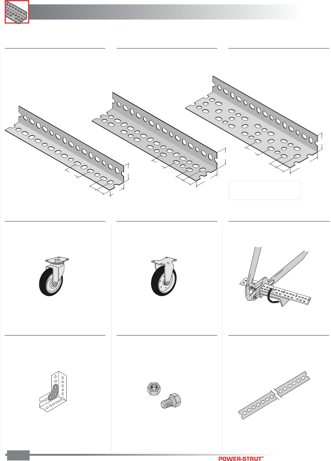
POWER-ANGLE
®
POWER-ANGLE
®
ENGINEERING CATALOG
140
Finish: Pregalvanized or Acrylic Green Stock Thickness: .075 (14 ga.) Stock Length: 10 and 12 feet
Order By: No., Size and Finish
■PA 158 – Light Duty
(15⁄8" x 15⁄8" x 14 ga.)
■PA 238 – Medium Duty
(15⁄8" x 23⁄8" x 14 ga.)
1
5
⁄
8"
1
5
⁄
8"
1
1
⁄
2"
3
⁄
4"
3
⁄
4"
2
3
⁄
8
"
1
5
⁄
8
"
1
1
⁄
2
"
3
⁄
4
"
3
⁄
4
"
31⁄8"
15⁄8"
11⁄2"
3⁄4"
3⁄4"
■PA 318 – Heavy Duty
(15⁄8" x 31⁄8" x 12 ga.)
■PA 1GP – Gusset Plate
■PA 1Sc – Swivel Caster ■PA 1RC – Rigid Caster
■PA 1SNB – Serrated Nuts
and Bolts (Package of 75
nuts and 75 bolts)
■PA 1HDC –
Portable Cutter
Weight/each: 17 lbs.
■PA 1RP – Slotted Strap
Weight/100 pcs: 9 lbs.
Weight/100 pcs: 170 lbs.
Weight/100 pcs: 7 lbs.
Weight/100 pcs: 110 lbs.
Weight/100 pcs: 35 lbs.
Weight/100 ft.: 66 lbs. Weight/100 ft.: 80 lbs. Weight/100 ft.: 130 lbs.
Note: Includes Serrated
Nuts & Bolts
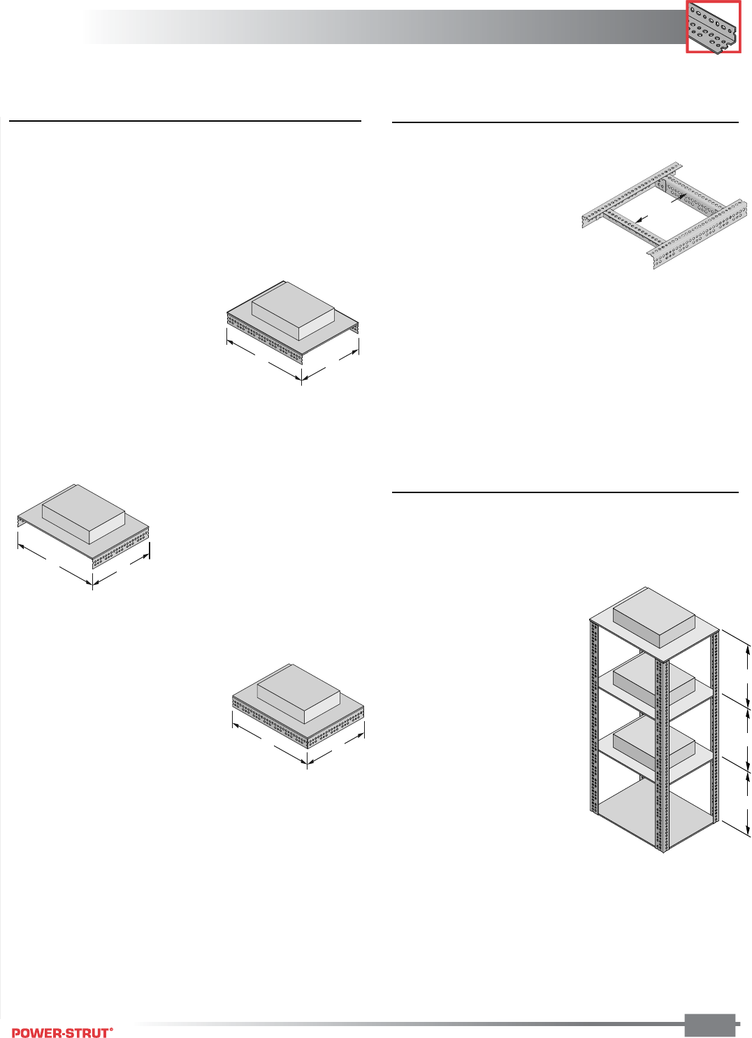
POWER-ANGLE
®
ENGINEERING CATALOG
POWER-ANGLE
®
141
3'-6''
Max.
■Beam Load Calculations
The beam loading depends on which slotted angle is used and
the manner in which the beam is constructed. The diagrams on
the next page show how individual slotted angle components
can be combined to form a beam. The loading for each beam
configuration is shown in the beam loading tables on the
following pages.
Example - Load “A”
Load “A” is supported by two 48"
sections of PA-238 (15⁄8" x 23⁄8").
The 48" row of Table 2 (page
143) indicates what each beam
configuration will support. Since
the columns are sorted from
lowest to highest load, the first
configuration that satisfies the
requirement is "J" which will
support 1,110 lbs.
Example - Load “B”
Load “B” is supported by two 36"
sections of PA-238 (15⁄8" x 23⁄8").
The 36" row of Table 2 (Page 143)
indicates what each beam
configuration will support. Since
the columns are sorted from
lowest to highest load, the first
configuration that satisfies the
requirement is "I" which will
support 1,100 lbs.
Example - Load “C”
Load “C” is supported by all four
beam sections. The load is distrib-
uted uniformly on two 3' and two 4'
beams which total 14' of supporting
beam length. Dividing the 1,000 lb.
load by 14-feet equals 72 lbs. per
foot. Using the two longest (weakest) lengths, calculate the
total weight as follows:
2 (beams) x 4' (length) x 72 lbs./ft. = 576 lbs. total weight
The 36" row of Table 2 (Page 143) indicates what each
beam configuration will support. Since the columns are
sorted from lowest to highest load, the first configuration that
satisfies the requirement is "H" which will support 680 lbs.
and is adequate for this requirement. The 3-foot beams
configured in the same manner will support the load because
they are shorter and stronger.
4'
1,000 LBS.
A
3'
4' 3'
1,000 LBS.
B
4'
1,000 LBS.
C
3'
■Transverse Stiffeners
When supporting concentrated loads, the
capacity of a pair of slotted-angle
beams can be increased by the
addition of transverse stiffen-
ers. These should be placed
immediately under the load
bearing point. The slotted-angle
segment used as the stiffener is bolted
into place using a metal connector at each
junction.
Beams that are 6' long or less require only one stiffener in the
center of the span. Seven-foot beams need two stiffeners
placed 2' from each end. Eight-ffot beams require two
stiffeners 2'6" from the ends. For beams with a nine-foot
span, it is necessary to have three stiffeners at 2'3" intervals.
Ten-foot beams need three stiffeners with 2'6" spacings.
For maximum effectiveness, transverse stiffeners should
never be spaced more than 3'6" apart.
Note: All loads based on actual physical testing. Documenta-
tion available on request.
■Column Load Calculations
Column sections are calculated as described in the following
example: (Assumes use of PA-238 15⁄8" x 23⁄8", material.)
Since all load areas are supported equally by the 4-columns,
the calculations are based on
a single-column section.
Section MN is one-fourth of
“X”, or 250 pounds. Column
section NP supports one-
fourth of “Y” (250 pounds)
plus the load supported by
MN, or a total of 500 pounds.
Section PQ supports one-
fourth of “Z” (250 pounds)
plus the 500 pound load on
section NP, or a total of 750
pounds.
Column loads are based on
free and unbraced column
lengths. Since MN, NP and
PQ are each 3' long, the load
requirement is for a 36"
section that will bear 750 pounds safely. A reference to Table
5 (Page 144) indicates that all sections designated “A” will
support 2,280 lbs. and meet the necessary requirements.
Note: To simplify assembly, we recommend using the same
size material as for the horizontal members. This would be
found in Table 2 to match the 14 gauge 15⁄8" x 23⁄8" material
selected for the beams of this structure.
X
1,000 LBS.
Y
1,000 LBS.
Z
1,000 LBS.
M
N
P
Q
3'
3'
3'
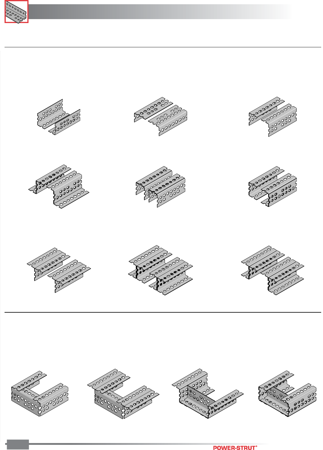
POWER-ANGLE
®
POWER-ANGLE
®
ENGINEERING CATALOG
142
Finish: Pregalvanized or Acrylic Green Stock Thickness: .075 (14 ga.) Stock Length: 10 and 12 feet
Order By: No., Size and Finish
■Beam Configurations (See corresponding letters in table on following page for load data)
G – Two Single Pieces (Up)
■Beam Configurations With Stiffeners (See corresponding letters in table on
following page for load data)
R – I-Sections w/StiffenerP – Single Pieces w/Stiffner Q – T-Sections w/Stiffener R – Z-Sections w/Stiffener
H – Two Single Pieces (Level) I – Two Single Pieces (Down)
J – Two Z-Sections K – Two Narrow Channels L – Two Broad Channels
M – Two T-Sections N – Two I-Section O – Two J-Sections
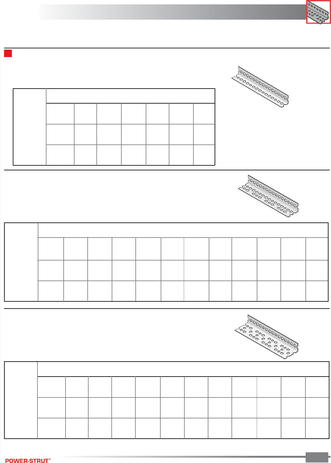
POWER-ANGLE
®
ENGINEERING CATALOG
POWER-ANGLE
®
143
Finish: Pregalvanized or Acrylic Green Stock Thickness: .075 (14 ga.) Stock Length: 10 and 12 feet
Order By: No., Size and Finish
* Based on simple beam condition with uniform loads on parallel beams.
To determine concentrated load capacity at mid-span, multiply uniform load by 0.5.
Beam Loads PA 158 – Light Duty (15⁄8" x 15⁄8" x 14 ga.)
■Beam Loads PA 238 – Medium Duty (15⁄8" x 23⁄8" x 14 ga.)
■Beam Loads PA 318 – Heavy Duty (15⁄8" x 31⁄8" x 12 ga.)
Beam Load in Pounds*
Beam Configuration (See Previous Page)
GH I P J LRMKQON
24 700 1,020 1,660 1,740 2,220 3,170 3,230 3,490 3,590 3,630 6,060 7,560
36 460 680 1,100 1,160 1,480 2,110 2,150 2,320 2,390 2,420 4,040 5,040
48 350 510 830 870 1,110 1,580 1,620 1,740 1,800 1,810 3,030 3,780
60 280 410 660 700 890 1,270 1,290 1,390 1,440 1,450 2,420 3,020
72 230 340 550 580 740 1,060 1,080 1,160 1,200 1,210 2,020 2,520
84 • 290 470 500 630 910 920 1,000 1,030 1,040 1,730 2,160
96 • 260 410 440 550 790 810 870 900 910 1,520 1,890
108 • • • • 490 700 720 770 800 810 1,350 1,680
120 • • • • 440 630 650 700 720 730 1,210 1,510
Beam Span (Inches)
Beam Load in Pounds*
Beam Configuration (See Previous Page)
GH I P J LRMKQON
24 1,790 1,610 4,300 4,960 6,520 7,910 8,070 9,920 9,990 10,170 14,600 16,120
36 1,200 1,070 2,870 3,310 4,350 5,270 5,380 6,610 6,660 6,780 9,730 10,750
48 900 810 2,150 2,480 3,260 3,950 4,030 4,960 4,990 5,080 7,300 8,060
60 720 640 1,720 1,980 2,610 3,160 3,230 3,970 4,000 4,070 5,840 6,450
72 600 540 1,430 1,650 2,170 2,640 2,690 3,310 3,330 3,390 4,870 5,370
84 • 460 1,230 1,420 1,860 2,260 2,300 2,830 2,850 2,910 4,170 4,610
96 • 400 1,080 1,240 1,630 1,980 2,020 2,480 2,500 2,540 3,650 4,030
108 • • • 1,100 1,450 1,760 1,790 2,200 2,220 2,260 3,240 3,580
120 • • • 990 1,300 1,580 1,610 1,980 2,000 2,030 2,920 3,220
Beam Span (Inches)
Beam Span (Inches)
Beam Load in Pounds*
Beam Configuration (See Previous Page)
GH I PLRM
24 550 830 830 920 1,600 1,700 1,840
36 370 560 560 610 1,070 1,130 1,230
48 280 420 420 460 800 850 920
60 220 330 330 370 640 680 740
72 180 280 280 310 530 570 610
84 • 240 240 260 460 490 530
96 • 210 210 230 400 430 460
108••••360380410
120••••320340370
TABLE 1
TABLE 2
TABLE 3
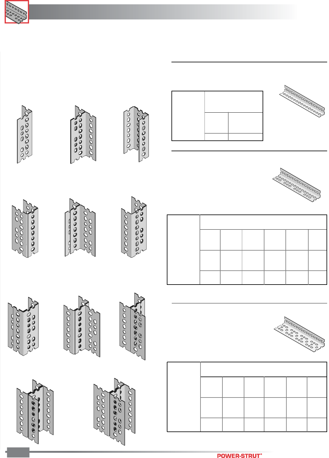
POWER-ANGLE
®
POWER-ANGLE
®
ENGINEERING CATALOG
144
Finish: Pregalvanized or Acrylic Green Stock Thickness: .075 (14 ga.) Stock Length: 10 and 12 feet
Order By: No., Size and Finish
COLUMN SECTIONS
(See corresponding letters in table on following page for
load data)
A – Single Piece
D – Dual
Channel Section
B – T-Section B – Broad
Channel Section
B – Narrow
Channel Section
C – Uneven
T-Section
C – Uneven
Channel Section
D – T-Channel
Section
D – T-Channel
Section
E – I-Section F – Uneven I-Section
■PA 158 – Light Duty (15⁄8" x 15⁄8" x 14 ga.)
■PA 238 – Medium Duty (15⁄8" x 23⁄8" x 14 ga.)
■PA 318 – Heavy Duty (15⁄8" x 31⁄8" x 12 ga.)
COLUMN LOAD
Column Load in Pounds*
Column Sections
(See Left Side of Page)
AB
36" 1,450 3,850
48" 1,150 3,500
60" 950 3,000
72" 750 2,500
Column Height
(Inches)
Column Load in Pounds*
Column Sections (See Left Side of Page)
ABCDEF
36" 2,280 4,760 4,940 7,270 9,520 9,865
48" 1,970 4,490 4,680 6,920 8,970 9,330
60" 1,520 3,995 4,310 6,370 7,990 8,620
72" 1,070 3,140 3,870 5,840 6,280 7,715
84" 660 2,340 3,665 4,930 4,660 6,740
96" • 1,750 2,700 3,850 3,500 5,365
108" • • 2,060 2,870 • 4,115
120" • • 1,610 2,690 • 3,210
Column Height (Inches)
* Column Loads are concentric without intermediate lateral support.
Column Load in Pounds*
Column Sections (See Left Side of Page)
ABCDEF
36" 3,470 7,970 8,770 12,560 15,940 17,550
48" 2,870 7,360 8,580 11,970 14,750 17,150
60" 1,970 6,570 8,180 11,360 13,160 16,360
72" 1,280 5,270 7,690 10,480 10,560 15,360
84" • 3,670 6,970 9,470 7,370 13,970
96" • 2,580 6,260 8,370 5,170 12,570
108" • • 5,460 6,880 • 10,970
120" • • 4,460 5,370 • 8,960
Column Height (Inches)
TABLE 4
TABLE 5
TABLE 6
FIBERGLASS
FIBERGLASS
ENGINEERING CATALOG
145
The installation of fiberglass channel and
accessories is similar to the installation of
metallic channel and accessories. All
standard installation practices and
procedures apply. In general, special
handling is not required. Fabrication of
Aickinstrut components requires just three
simple operations; cutting, drilling and
sealing.
FIBERGLASS
FIBERGLASS
ENGINEERING CATALOG
146
Fabrication
Cutting – Cutting can be accomplished with a wide variety of
saws. Hand held saws, such as hack saws (24 to 32 teeth per
inch) are suitable when a few number of cuts are required. For
frequent cutting, a circular power saw with a carbide-tipped
masonry blade yields the best results and the greatest
number of cuts. When using a power saw, dust filter masks,
gloves and long sleeve clothing should be worn.
Drilling – Any standard twist bit, even when used with battery-
powered drills will work well. Carbide-tipped drill bits are
recommended.
Sealing – To protect against future migration of corrosive
elements into the cut sections, all cuts and holes should be
properly sealed using Aickincoat or Aickinzap.
Material
Aickinstrut components utilize a combination of materials from
the following resin families covering distinct temperature
ranges:
Material Low/High
Code Temperature Material
E -25°F/130°F PVC (extruded)
P -35°F/200°F Polyester (pultruded)
V -35°F/200°F Vinyl ester (pultruded)
PU -40°F/140°F Polyurethane (injection molded)
PP -30°F/150°F Polypropylene (injection molded)
N -20°F/150°F Nylon (injection molded)
The temperature ranges indicated are meant to be used only
as a general guideline. Continual exposure to elevated
temperatures reduces the strength properties of plastics and
glass reinforced fiberglass. Actual resin test data confirms that
a 50% reduction in strength occurs at the extreme high
temperature levels.
Chemical Resistance
Each resin family has its own specifications regarding its
performance against corrosion resistance. Use the following
chart to determine which Aickinstrut material system will
provide the best performance for your particular application.
The results in the chart are based upon immersion for a 24
hour period. This is typically the “worst case” exposure to
corrosion. Less severe contact such as spills, splashes and
vapor condensate will exceed the performance results listed in
the table.
Loading
Channel loading is defined on pages 152 to 153. Additional
loading and design limitations for fittings and accessories are
described in the appropriate section for that part.

147
FIBERGLASS
FIBERGLASS
ENGINEERING CATALOG
147
Legend:“NR” indicates “Not Recommended” for use;
“R” indicates “Recommended”;
“–” indicates no information available
Chemical Compatibility Table
Series E Series P Series V Series K Series PU Series N
(Rigid PVC) (Poly/Glass) (Vinyl/Glass) (PVDF) (Polyurethane) (Nylon)
Chemical 70°-160°F70°-160°F70°-160°F70°-160°F70°-160°F70°-160°F
Acetic Acid, Up to 10% R R R R R R R R R – NR NR
Acetic Acid, Up to 50% R R R R R R R R R – NR NR
Acetone, Up to 10% NR NR NR NR NR NR NR NR R – R R
Aluminum Hydroxide R R R R R R R R R – NR NR
Ammonium Hydroxide (Aqueous Ammonia), Up to 5% R R NR NR R R R R R – – –
Ammonium Hydroxide, Up to 10% R R NR NR R 150°RR R– – –
Ammonium Hydroxide, Up to 20% R R NR NR R 150°RR R– – –
Ammonium Nitrate R NR R R R R R R R – – –
Ammonium Phosphate R R R NR R R R R R – – –
Ammenium Sulfide, saturated R R NR NR R 120°RR R– – –
Aqua Regia, fumes NR NR NR NR R 150°RR NR– – –
Benzene NR NR NR NR NR NR NR R R R – R R
Benzoic Acid R R R R R R R R R – – –
Bromine, wet gas R NR NR NR R 100°RR –– ––
Butylene Glycol, Up to 100% R R R R R R R R R – R R
Butyric Acid, Up to 50% NR NR R R R R R R R – – –
Calcium Hydroxide R R R NR R R R R R – – –
Calcium Hypochlorite R R R NR R R R R R – NR NR
Chlorine, Dry Gas NR NR NR NR R R R R – – – –
Chlorine, Wet Gas NR NR NR NR R R R R – – – –
Chlorine, Liquid NR NR NR NR NR NR R R – – – –
Chlorine, Water NR NR R R R R R R R – NR NR
Chromic Acid, Up to 5% R R NR NR R R R R – – R R
Copper Chloride R R R R R R R R R – – –
Copper Cyanide R R R NR R R R R R – – –
Copper Fluoride R R R NR R R R R R – – –
Copper Nitrate R R R R R R R R R – –
Copper Sulfate R R R R R R R R R – – –
Dechlorinated Brine Storage R R – – R R R R R – – –
Esters, Fatty Acid NR NR R R R R R R R – – –
Ferric Chloride R R R R R R R R R – – –
Ferrous Chloride R R R R R R R R R – – –
Fluoboric Acid R R R 120°RR RR –– – –
Fluosilicic Acid, Up to 10% NR NR NR NR R R R R – – NR NR
Fluosilicic Acid, Up to 32% NR NR NR NR R 100°RR –– ––
Formic Acid, Up to 10% R R NR NR R R R R R – NR NR
Formic Acid, Up to 50% R R NR NR R 100°RR R– – –
Gasoline, Aviation R NR R NR R R R R R – – –
Green Liquor, Pulp Mill R R – – R R R R – – – –
Hydrochloric Acid Up to 15% R R R NR R R R R R – – –
Hydrochloric Acid Up to 37% R R R NR R R R R R – – –
Hydrofluoric Acid, Up to 10% R R NR NR R 150°RR –– ––
Hydrofluoric Acid, Up to 20% R NR NR NR R 100°RR –– ––
Hydrogen Chloride, Wet Gas NR NR R NR R R R R NR – – –
Hydrogen Sulfide, Wet Gas R R R NR R R R R R – – –
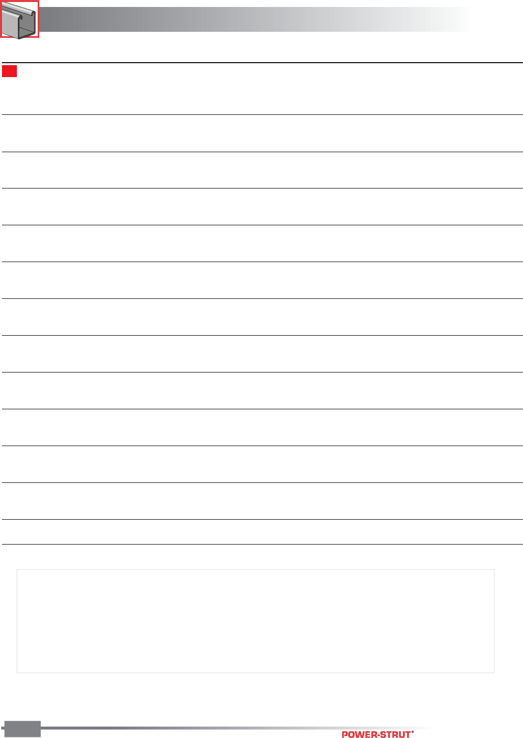
FIBERGLASS
FIBERGLASS
ENGINEERING CATALOG
148
Note: The recommendations contained in this table are made without guarantee of representation as to results. Since
the actual use by others is beyond our control, no guarantee, expressed or implied, is made by T.J. Cope, Inc. as to
effects of such use or results to be obtained nor does T.J. Cope, Inc. assume any liability arising out of the use by
others of the products referenced in this table. Nor is the information herein to be construed as absolutely complete
since additional information may be needed or desirable when particular or exceptional conditions or circumstances
exist or because of applicable laws or government regulations. We suggest that you evaluate these recommendations
and suggestions in your own laboratory prior to use. Our responsibility for claims arising from breach of warranty,
negligence, or otherwise is limited to the purchase price of the material.
Legend:“NR” indicates “Not Recommended” for use;
“R” indicates “Recommended”;
“–” indicates no information available
Chemical Compatibility Table
Series E Series P Series V Series K Series PU Series N
(Rigid PVC) (Poly/Glass) (Vinyl/Glass) (PVDF) (Polyurethane) (Nylon)
Chemical 70°-160°F70°-160°F70°-160°F70°-160°F70°-160°F70°-160°F
Lactic Acid R R R NR R R R R R – – –
Lead Nitrate R R – – R R R R R – – –
Magnesium Hydroxide R R NR NR R R R R R – R R
Nickel Sulfate, Low pH R R NR NR R R R R R – – –
Nickel Sulfate, High pH R R NR NR R R R R R – – –
Nitric Acid, Up to 5% R R NR NR R 150°RR R– ––
Nitric Acid, Up to 35% R R NR NR R 150°RR R– ––
Nitric Acid, Vapor R R NR NR R R R R – – – –
Perchloric Acid, Up to 10% NR NR NR NR R 150°R R – – NR NR
Pickling Liquids, 3-5% H2S04 R R R R R R R R R – – –
Phosphoric Acid R R NR NR R R R R R – NR NR
Phosphoric Acid, Super or Poly (115%, P20%) R R NR NR R R R R – – – –
Phosphoric Acid Vapor or Condensate R R NR NR R R R R – – – –
Potassium Chloride R R R R R R R R R – – –
Potassium Nitrate R R R R R R R R R – – –
Potassium Persulfate R R NR NR R R R R R – – –
Silver Cyanide, Up to 5% R R NR NR R R R R R – – –
Sodium Hydroxide, Up to 25% R R NR NR R 150°RR R– ––
Sodium Hydroxide, up to 50% R R NR NR R 180°RR –– RR
Sodium Hypochlorite, Up to 15% R R NR NR R 150°R R R – NR NR
Sodium Nitrate R R R R R R R R R – – –
Sodium Sulfate R R R NR R R R R R – – –
Sodium Sulfide R R NR NR R R R R R – – –
Sulfuric Acid, Up to 25% R R R R R R R R R – NR NR
Sulfuric Acid, Up to 50% R R NR NR R R R R R – – –
Sulfuric Acid, Up to 70% R R NR NR R R R R R – NR NR
Sulfuric Acid, Up to 75% NR NR NR NR R 120°R R – – NR NR
Sulfuric Acid, Up to 80% NR NR NR NR NR NR NR NR – – NR NR
Sulfuric Acid, Vapor R R R NR R R R R – – – –
Trichlorethylene, Fumes NR NR NR NR R 120°RR NR– – –
Trisodium Phosphate R R R NR R R R R R – – –
Urea R R R NR R 150°RR R– RR
Vegetable Oils R R R R R R R R R – R R
Vinegar R R R R R R R R R R R R
White Liquor, Pulp Mill R R – – R R R R – – – –

149
FIBERGLASS
FIBERGLASS
ENGINEERING CATALOG
149
4.5 Universal Pipe Clamps shall have full interlocking
contact with interior channel flanges to maxi-
mize pull-out resistance and be adjustable to
accommodate a minimum 3⁄4" variance in piping
or conduit O.D. sizes.
5.0 STANDARDS
5.1 Glass reinforced and PVC channels covered in
this specification shall have a flame spread rating
of 25 or less when tested per ASTM E84 and meet
the requirements of UL 94V0 thereby qualifying
them as Class 1 material in the Uniform Building
Code.
5.2 Glass reinforced channels covered in this specifi-
cation shall comply with the requirements of
ASTM D 3917 and ASTM D 4385 which govern
the dimensional tolerance and visual defects of
pultruded shapes.
6.0 GENERAL
6.1 Aickinstrut Nonmetallic Channel Framing shall be
furnished as a system which includes all the
necessary fasteners, channel splice plates,
brackets, sealants, hangers, pipe clamps, etc.
6.2 Nonmetallic fasteners shall be manufactured
from long glass fiber reinforced polyurethane to
ensure maximum strength and corrosion resis-
tance.
6.3 All components of the Aickinstrut Channel
Framing System shall be nonmetallic except
where type 316 stainless steel hardware is used
as part of the assembly.
6.4 Aickinstrut is manufactured by Aickinstrut, a
subsidiary of T. J. Cope, Philadelphia, Pennsylva-
nia, 1-800-426-4293.
6.5 The manufacturer shall not have had less than 10
years experience in manufacturing strut systems.
6.6 All products are manufactured in the United
States of America.
■Aickinstrut Specifications
1.0 SCOPE
1.1 This specification covers the requirements for
the Aickinstrut Nonmetallic Channel Framing
System.
2.0 MATERIAL
2.1 FRP channel shall be of pultruded glass rein-
forced polyester or vinyl ester resin having the
physical property values listed in this catalog.
2.2 PVC channel shall be of extruded polyvinyl
chloride having the physical property values
listed in this catalog.
2.3 Some accessories shall be of injection molded,
40% long glass fiber reinforced polyurethane,
polypropylene or nylon.
3.0 COMPOSITION
3.1 Glass reinforced channel shall have a synthetic
surfacing veil applied on exterior surfaces to
improve weatherability and inhibit ultraviolet
degradation. An ultraviolet stabilizer shall be
incorporated in the resin formulation to further
inhibit ultraviolet degradation.
3.2 PVC channel shall be manufactured from a U.V.
stabilized resin and incorporate dark gray pig-
ment to improve weatherability and inhibit
ultraviolet degradation.
4.0 STRUCTURAL DESIGN
4.1 Channel shall incorporate Aickinstrut's patented
flange profile design which allows full and
positive interlocking contact of channel accesso-
ries and prohibits premature flange failure from
torqued accessories.
4.2 Channel profile dimensions shall be:
15⁄8" x 15⁄8" x 1⁄4",
11⁄2" x 11⁄2" x 1⁄8" and
11⁄2" x 11⁄8" x 1⁄8".
4.3 All 15⁄8" x 15⁄8" channel profiles shall have a
minimum pull out resistance of 1,000 pounds
when load is applied over a 3⁄8" long section of
the inside flanges.
4.4 Channel section lengths shall be supplied in 10'
or 20' lengths (±1⁄8").
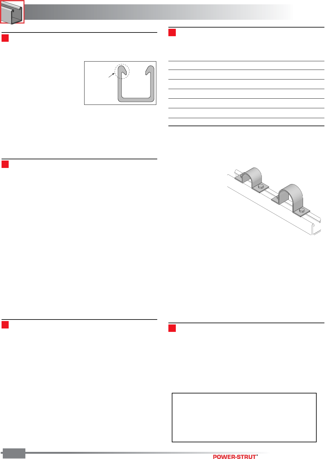
FIBERGLASS
FIBERGLASS
ENGINEERING CATALOG
150
NOTE: Aickinstrut SST Channel is not compatible
with the Aickinstrut pipe clamps and channel nuts
shown in this catalog. Please contact Aickinstrut
for information on a complete line of compatible
clamps and channel nuts.
Aickinstrut
Patented
Flange
Channel Framing
All Aickinstrut channels, except the SST series, incorporate a
patented flange design which provides reliable fastening and
interlocking of Aickinstrut
components and accessories.
Channels are provided in
standard lengths of 10' with
longer lengths available upon
request. Aickinstrut single
channels come packaged in
boxes of 100' while the double
channels are packaged in boxes containing 40'.
Aickinstrut channel is available in the following three materials:
• Polyester (P material),
• Vinyl Ester (V material) and
• PVC (E material)
Polyester and Vinyl Ester Materials
The polyester and vinyl ester channels are manufactured from
the pultrusion process. In this process, the component is
made by reinforcing a polymer resin (polyester or vinyl ester)
with multiple strands of glass filament, alternating layers of
glass mat and U.V. resistant surfacing veils. The glass is
drawn through the liquid resin, which coats and saturates the
fibers. The combination of resin, glass and veil is then
continuously guided and pulled (pultruded) through a heated
die that determines the shape of the component.
In the die, the resin is cured to form a permanent, reinforced
part which can be cut to a specific length. Since the hardened
fiberglass pultrusion is reinforced with and internal arrange-
ment of permanently bonded continuous glass fibers, it
possesses great strength.
In addition, pultruded fiberglass components exhibit excep-
tional corrosion and fire resistance. These attributes make
fiberglass the material of choice for many harsh industrial
applications.
The polyester and vinyl ester channels are color coded.
Polyester channels are colored gray and the vinyl ester
channels are colored beige.
PVC Materials
The PVC channels are manufactured from the extrusion
process. In this process, the component is made by a PVC
resin mixture being continuously fed through a heated die that
determines the shape of the component.
In the die, the resin is cured to form a permanent, extruded
part that can be cut to a specific length. Unlike pultruded
components, extruded components do not incorporate glass-
reinforcement; consequently, they do not exhibit the same
beam strength as their pultruded counterparts. PVC compo-
nents, however; exhibit exceptional corrosion and fire resis-
tance. These features make PVC channels an excellent
alternative when excessive beam strength is not required.
PVC channels are color coded dark gray.
Channel Availability Chart
The following chart illustrates the availability of materials in the
different channel profiles.
Channel Profile Polyester(P) Vinyl Ester(V) PVC(E)
Series 2000, 2200, 2300 X X X
Series 1500, 1700, 1800 X X N/A
Series 1000, 1200, 1300 X X X
Series 2100 X X N/A
Series 1600 X X N/A
Series 1100 X X N/A
■Concrete Embedment Channel
Part No. 20E-2300
In certain applications, it is necessary to embed a corrosion
resistant channel into a new pouring of concrete. For these
applications, Aickinstrut concrete embedment channel is
recommended.
Aickinstrut embed-
ment channel is
available in three
material types; PVC,
polyester and vinyl ester.
The PVC embedment
channel is extruded as
one piece while the
polyester and vinyl ester embed-
ment channel is a two piece bonded
type design. The PVC embedment
channel is available in the 15⁄8" and 11⁄8" profiles while polyester
and vinyl ester embedment channels are available in all three
profiles (15⁄8", 11⁄2" & 11⁄8").
The embedment channel utilizes two continuous protruding
flanges in the profile base to retain the channel in the concrete.
Mounting the embedment channel flush with the concrete
surface is a convenient way to secure piping, conduits or
electrical enclosures to a wall or ceiling. The PVC embedment
channel is extremely high in strength. When embedded in
3,000 PSI concrete, the concrete will fail before the channel is
pulled out.
Aickinstrut SST Channel
Aickinstrut SST Fiberglass Channel incorporates a standard
channel profile that will accommodate metallic pipe straps and
clamps. SST channel is available in polyester or vinyl ester
resin. All standard styles (solid, slotted, concrete insert and
back-to-back) are also available. Please contact the factory for
loading information for the SST Channel.
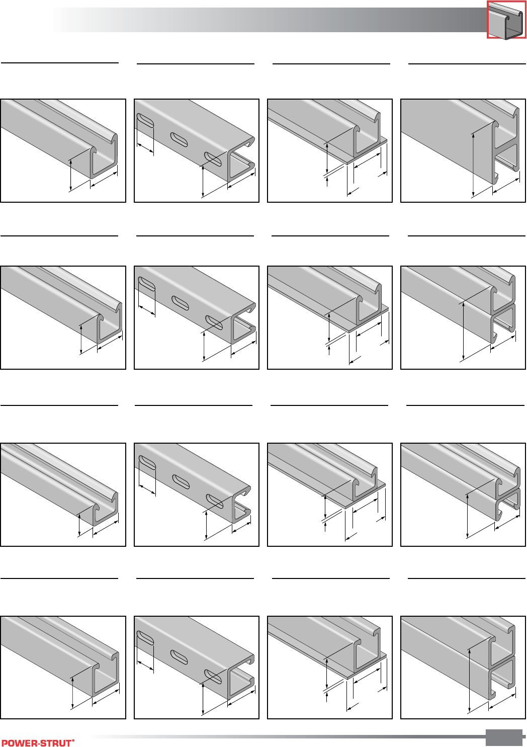
151
FIBERGLASS
FIBERGLASS
ENGINEERING CATALOG
151
■20P-2000, 20V-2000,
20E-2000
■20P-2200, 20V-2200,
20E-2200
■20P-2300, 20V-2300,
20E-2200
■20P-2100, 20V-2100
■20P-1500, 20V-1500 ■20P-1700, 20V-1700 ■20P-1800, 20V-1800 ■20P-1600, 20V-1600
■20P-1000, 20V-1000,
20E-1000
■20P-1200, 20V-1200,
20E-1200
■20P-1300, 20V-1300,
20E-1300
■20P-1100, 20V-1100
■20P-2000-SST,
20V-2000-SST
■20P-2200-SST,
20V-2200-SST
■20P-2300-SST,
20V-2300-SST
■20P-2100-SST,
20V-2100-SST
HEAVY DUTY CHANNEL – AICKINSTRUT PROFILE
MEDIUM DUTY CHANNEL – AICKINSTRUT PROFILE
LIGHT DUTY CHANNEL – AICKINSTRUT PROFILE
HEAVY DUTY CHANNEL – STANDARD PROFILE
1
5
⁄
8"
1
5
⁄
8"
1
5
⁄
8"
1
5
⁄
8"
1
"
1
5
⁄
8"
1
⁄
4"
1
5
⁄
8"
2
3
⁄
8"
1
5
⁄
8"
3
1
⁄
4"
1
1
⁄
2"
1
1
⁄
2"
1
1
⁄
2"
1
1
⁄
2"
1
"
1
1
⁄
2"
1
⁄
4"
2
3
⁄
8"
1
1
⁄
2"
1
1
⁄
8"
1
1
⁄
2"
1
"
1
1
⁄
2"
1
1
⁄
8"
1
1
⁄
8"
1
⁄
4"
1
1
⁄
2"
2
3
⁄
8"
1
5
⁄
8"
1
5
⁄
8"
1
"
1
5
⁄
8"
1
⁄
4"
1
5
⁄
8"
2
3
⁄
8"
1
5
⁄
8"
1
5
⁄
8"
1
5
⁄
8"
3
1
⁄
4"
3
"
1
1
⁄
2"
2
1
⁄
4"
1
1
⁄
2"
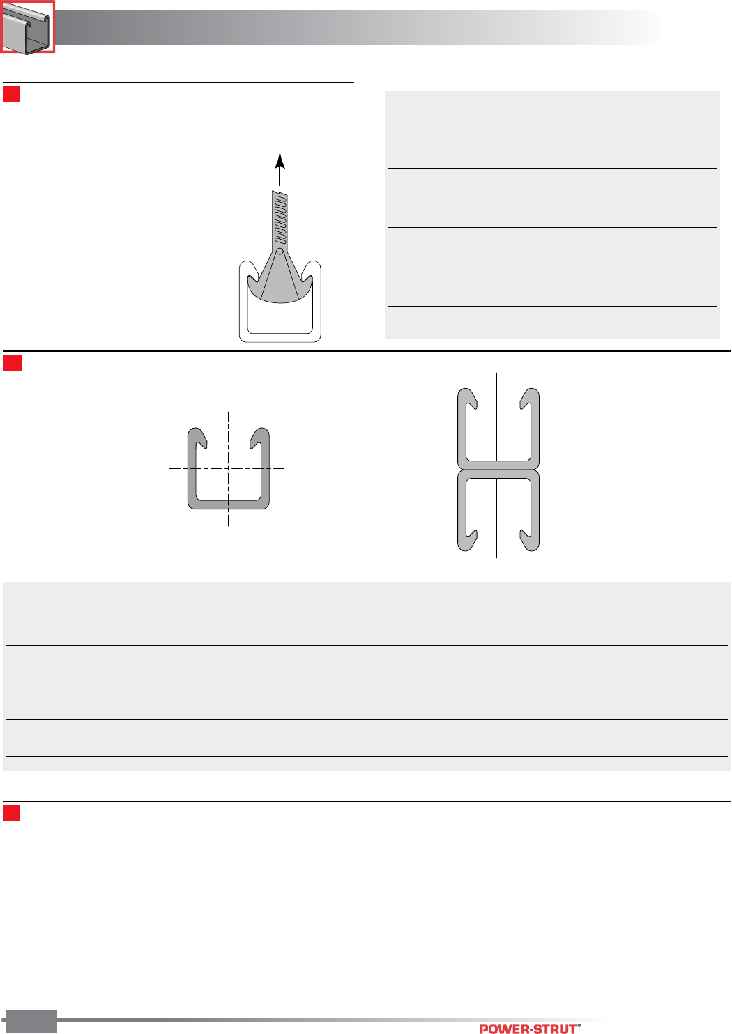
FIBERGLASS
FIBERGLASS
ENGINEERING CATALOG
152
FLANGE
LOAD
XX
Y
Y
XX
Y
Y
................. X - X Axis ............... .........Y - Y Axis ..........
Section Height Width Weight Area I R C1C2IRC
Number (in.) (in.) (lbs./ft.) (in.2) (in.4) (in.) (in.) (in.) (in.4) (in.) (in.)
2000 1.63 1.63 0.82 1.06 0.31 0.54 0.70 0.93 0.42 0.63 0.82
2100 3.26 1.63 1.64 2.12 1.77 0.91 1.63 1.63 0.85 0.63 0.82
1500 1.50 1.50 0.55 0.71 0.19 0.52 0.62 0.88 0.25 0.59 0.75
1600 3.00 1.50 1.10 1.42 1.02 0.85 1.50 1.50 0.49 0.59 0.75
1000 1.13 1.50 0.47 0.61 0.10 0.40 0.51 0.62 0.22 0.60 0.75
1100 2.25 1.50 0.94 1.22 0.42 0.59 1.13 1.13 0.44 0.60 0.75
Section Properties
Beam Loading – PVC
Heavy Duty Channel Pull-Out Strength*
20V-2000 449
20P-2000 360
20E-2000 260
Medium Duty Channel Pull-Out Strength*
20V-1500 229
20P-1500 219
Light Duty Channel Pull-Out Strength*
20E-1000 239
20P-1000 213
20V-1000 213
*Values shown represent a 3:1 safety factor
Pull-out strength is the channel's
resistance to a clamp or fastener
inserted under the flange and put
under tension. For additional
information concerning specific
channels, materials and their pull-
out strengths, refer to the channel
flange pull-out chart on the right.
■Flange Loading
The data listed in the Beam Loading Chart reflects testing
conducted on Polyester (Type P) and vinyl ester (Type V)
channels. PVC (Type E) material will differ from the Polyester/
Vinyl ester Beam Loading Chart. To obtain the beam loading for
PVC channel, reduce the load as follows:
(Polyester/Vinyl Ester Beam Load)
PVC Beam Load = ––––––––––––––––––––––––––––
4
NOTE: PVC is not recommended for lengths over 24"
153
FIBERGLASS
FIBERGLASS
ENGINEERING CATALOG
153
Polyester/Vinyl Ester Beam Loading Chart
Max. Uniform Beam Load Uniform Load at Maximum
(Safety Factor - 3:1) Defl. of 1/360 Span Column
Span Part Number Load (lbs.) Deflection (in.) Load (lbs.) Deflection (in.) Load (lbs.)
20P/V-2100 5,559 0.028 5,559 0.033 9,454
20P/V-1600 4,836 0.043 3,778 0.033 7,007
20P/V-1100 3,804 0.082 1,556 0.033 5,961
20P/V-2000 3,561 0.102 1,159 0.033 5,160
20P/V-1500 1,950 0.093 700 0.033 3,439
20P/V-1000 1,629 0.151 359 0.033 2,759
20P/V-2100 3,706 0.064 2,914 0.050 8,866
20P/V-1600 3,224 0.096 1,697 0.050 6,501
20P/V-1100 2,536 0.183 691 0.050 5,509
20P/V-2000 2,374 0.230 515 0.050 4,704
20P/V-1500 1,300 0.209 311 0.050 3,136
20P/V-1000 1,086 0.340 160 0.050 2,351
20P/V-2100 2,780 0.113 1,639 0.067 8,181
20P/V-1600 2,418 0.171 944 0.067 5,909
20P/V-1100 1,902 0.326 389 0.067 4,979
20P/V-2000 1,781 0.410 290 0.067 4,168
20P/V-1500 975 0.371 175 0.067 2,778
20P/V-1000 815 0.605 90 0.067 1,862
20P/V-2100 2,224 0.177 1,049 0.083 7,405
20P/V-1600 1,934 0.267 604 0.083 5,236
20P/V-1100 1,522 0.509 249 0.083 4,375
20P/V-2000 1,424 0.640 185 0.083 3,553
20P/V-1500 780 0.580 112 0.083 2,369
20P/V-1000 652 0.945 57 0.083 1,298
20P/V-2100 1,853 0.254 730 0.100 6,451
20P/V-1600 1,612 0.384 420 0.100 4,482
20P/V-1100 1,268 0.734 173 0.100 3,698
20P/V-2000 1,187 0.922 129 0.100 2,859
20P/V-1500 650 0.836 78 0.100 1,906
20P/V-1000 543 1.360 40 0.100 901
20P/V-2100 1,390 0.452 410 0.133 4,534
20P/V-1600 1,209 0.683 236 0.133 2,809
20P/V-1100 951 1.304 97 0.133 2,254
20P/V-2000 890 1.638 72 0.133 1,636
20P/V-1500 488 1.486 44 0.133 1,091
20P/V-1000 407 2.418 22 0.133 507
20P/V-2100 1,112 0.707 262 0.167 2,902
20P/V-1600 967 1.067 151 0.167 1,798
20P/V-1100 761 2.038 62 0.167 1,442
20P/V-2000 712 2.560 46 0.167 1,047
20P/V-1500 390 2.321 28 0.167 698
20P/V-1000 326 3.779 14 0.167 324
20P/V-2100 927 1.018 182 0.200 2,015
20P/V-1600 806 1.536 105 0.200 1,248
20P/V-1100 634 2.935 43 0.200 1,001
20P/V-2000 594 3.686 32 0.200 727
20P/V-1500 325 3.343 19 0.200 485
20P/V-1000 272 5.441 10 0.200 225
12"
Span
18"
Span
24"
Span
30"
Span
36"
Span
48"
Span
60"
Span
72"
Span
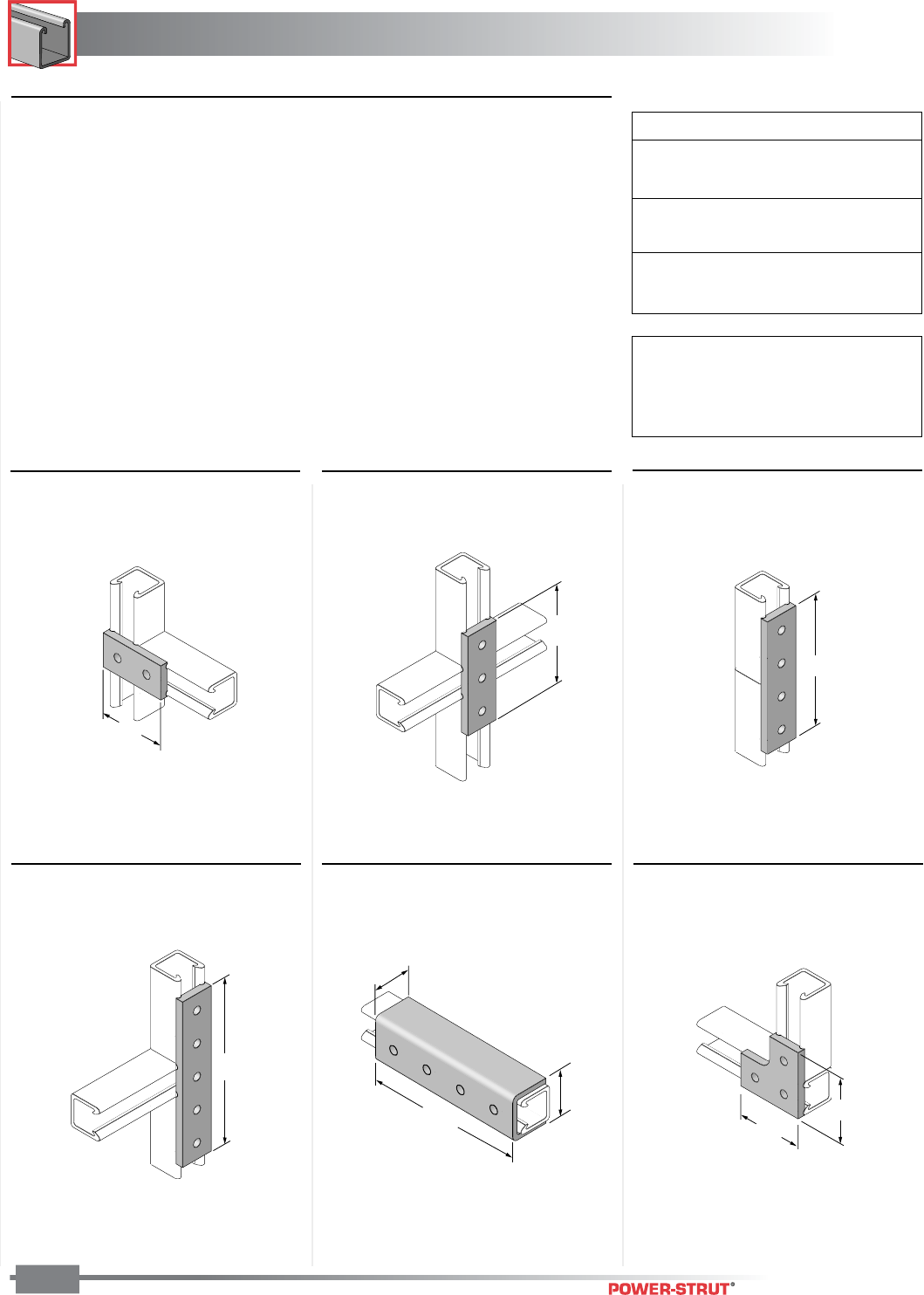
FIBERGLASS
FIBERGLASS
ENGINEERING CATALOG
154
Legend
R = Right Hand
L = Left Hand
P Series Fittings are Grey
V Series Fittings are Beige
2500 Series - Flat
2800 Series - Grooved
NOTE
Illustrations depict
grooved channel fittings.
■20P-2500, 20V-2500 (Flat)
20P-2800, 20V-2800 (Grooved)
■20P-2506, 20V-2506 (Flat)
20P-2806, 20V-2806 (Grooved)
■20P-2502, 20V-2502 (Flat)
20P-2802, 20V-2802 (Grooved)
■20P-2504, 20V-2504 (Flat)
20P-2804, 20V-2804 (Grooved)
■50PU-2616 ■20P-2508, 20V-2508 (Flat)
20P-2808, 20V-2808 (Grooved)
3
1
⁄
4
"
47⁄8
"
61⁄2"
81⁄8
"
1
7
⁄
8"
7
1
⁄
4"
2
5
⁄
32"
3
1
⁄
4
"
3
1
⁄
4
"
■Channel Fittings
Aickinstrut Channel Fittings are required
to fabricate an Aickinstrut structure and
are easily attached to Aickinstrut Chan-
nels with channel nuts and polyurethane
fasteners. The fittings are offered in two
types; fabricated (cut from flat stock) or
molded. Fabricated fittings are made
from either polyester or vinyl ester
material. All molded fittings with the
exception of the post bases are molded
in polyurethane. Post bases are also
offered in polypropylene.
The 2500 Series Fittings are manufac-
tured from 3⁄8" flat material. The 2800
Series Fittings are manufactured from 3⁄8"
flat material and feature grooves which
stabilize the fittings when mounted to the
open side of the channel. All channel
fittings are provided with 13⁄32" holes
which accommodate 3⁄8" hardware.
Larger diameter holes can be provided
upon special request.
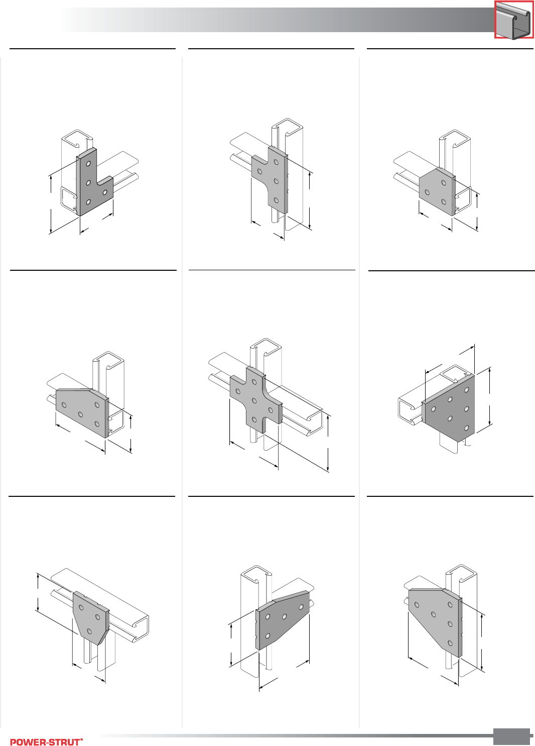
155
FIBERGLASS
FIBERGLASS
ENGINEERING CATALOG
155
■20P-2510, 20V-2510 (Flat)
20P-2810R, 20V-2810R (Grooved)
20P-2810L, 20V-2810L (Grooved)
■20P-2516, 20V-2516 (Flat)
20P-2816R, 20V-2816R (Grooved)
20P-2816L, 20V-2816L (Grooved)
■20P-2512, 20V-2512 (Flat)
20P-2812, 20V-2812 (Grooved)
■20P-2514, 20V-2514 (Flat)
20P-2814, 20V-2814 (Grooved)
■20P-2518, 20V-2518 (Flat)
20P-2818, 20V-2818 (Grooved)
■20P-2520, 20V-2520 (Flat)
20P-2820, 20V-2820 (Grooved)
■20P-2522, 20V-2522 (Flat)
20P-2822, 20V-2822 (Grooved)
■20P-2524, 20V-2524 (Flat)
20P-2824, 20V-2824 (Grooved)
■20P-2526, 20V-2526 (Flat)
20P-2826, 20V-2826 (Grooved)
47⁄8"
31⁄4"
4
7
⁄
8
"
3
1
⁄
4
"
3
1
⁄
4"
3
1
⁄
4"
3
1
⁄
4
"
4
7
⁄
8
"
47⁄8
"
47⁄8
"
47⁄8
"
47⁄8
"
3
1
⁄
4
"
3
1
⁄
4
"
31⁄4
"
47⁄8
"
4
7
⁄
8
"
4
7
⁄
8
"
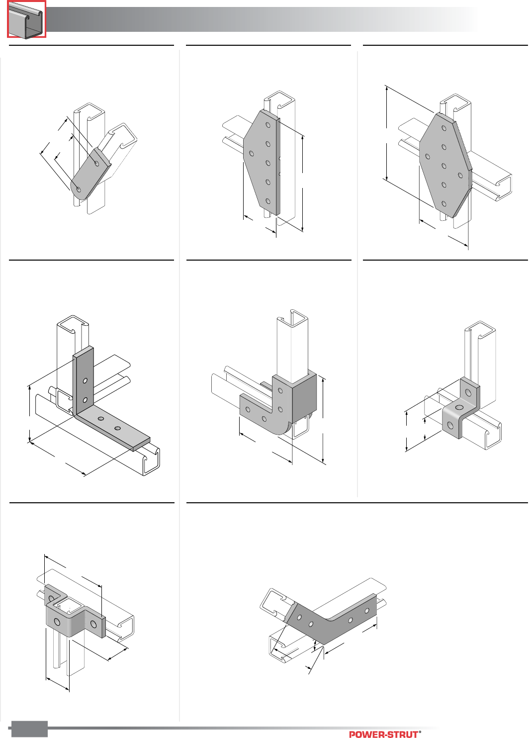
FIBERGLASS
FIBERGLASS
ENGINEERING CATALOG
156
■20P-2528, 20V-2528 (Flat)
20P-2828, 20V-2828 (Grooved)
■20P-2530, 20V-2530 (Flat)
20P-2830, 20V-2830 (Grooved)
■20P-2534, 20V-2534 (Flat)
20P-2834, 20V-2834 (Grooved)
■20P-2541 (Flat)
20V-2541 (Grooved)
■20P-2540, 20V-2540 (Flat)
20P-2840, 20V-2840 (Grooved)
■50PU-2611 (Flat)
■50PU-2613 (Flat)
■50PU-1508 (11⁄2") 50PU-2008 (15⁄8")
5
1
⁄
4
"
3
5
⁄
8
"
8
1
⁄
8"
3
1
⁄
4"
81⁄8
"
47⁄8
"
17⁄8"
31⁄2"
17⁄8"
513⁄32"
25⁄32"
47⁄8"
47⁄8"
51⁄4
"
51⁄4
"
45
°
3
1
⁄
2
"
4"
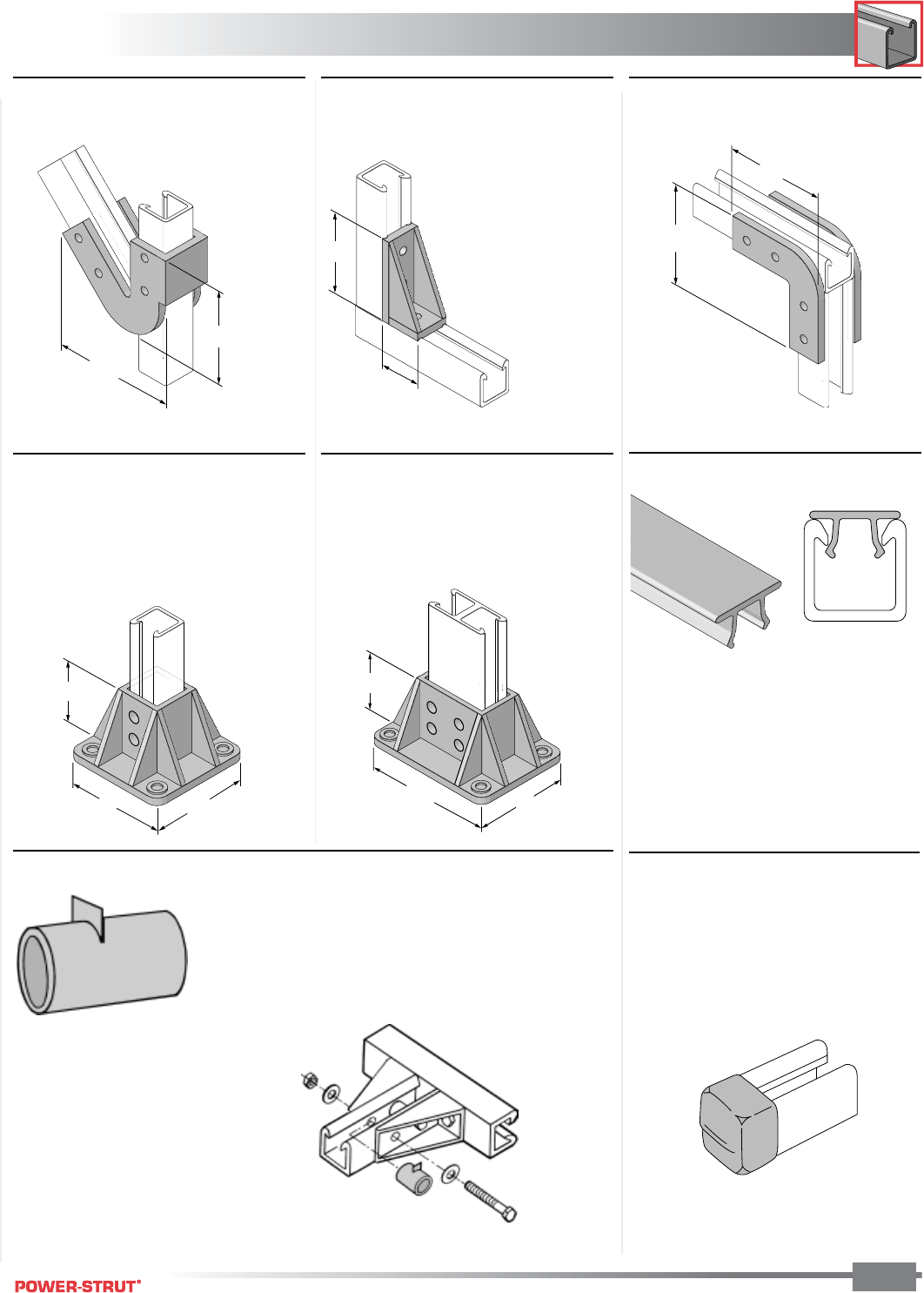
157
FIBERGLASS
FIBERGLASS
ENGINEERING CATALOG
157
■50PU-2045 (1
5
⁄
8
")
■20PU-5853(1
5
⁄
8
"), 20PU-5854(1
1
⁄
2
"),
20PU-5855(1"), 20PP-5853(1
5
⁄
8
"),
20PP-5854(1
1
⁄
2
"), 20PP-5855(1")
■50PU-2636
1
, 50PU-2636A
2
50PU-2636B
3
■50PU-2090 (1
5
⁄
8
")
■20PU-5903(1
5
⁄
8
"), 20PU-5904(1
1
⁄
2
"),
20PU-5905 (1"), 20PP-5903 (1
5
⁄
8
"),
20PP-5904 (1
1
⁄
2
"), 20PP-5905 (1")
■Channel Spacers 50PU-500SP
1) 50PU-2636 – Flat,
without splines
2) 50PU-2636A – Splines
on long side only
3) 50PU-2636B – Splines
on short side only
41⁄2
"
51⁄2
"
4"
15⁄8"
47⁄8"
47⁄8"
3"
5"5"
3"
5"
6 5⁄8"
Supplied in 10
foot lengths
■Channel Capping Strip 20E-5000
Channel spacers are designed to prevent wall compression
under heavy loading conditions. Such loading occurs during
the torquing of hardware for channel fittings. The spacers
are molded from polyurethane and will accommodate 3⁄8"
and 1⁄2" bolts. The spacers are designed to be used only
with 15⁄8" and 11⁄2" channels.
Channel Capping Strip is made from PVC
and installs simply by pressing it onto the
channel opening. It is designed to be
used when a cover is desired for the
channel opening (such as concrete
embedment channel).
■Channel End Cap AIC-EC
The Aickin-End Cap is made from red
PVC and designed for 15⁄8" channel. End
caps are desired when the ends of the
channel need to be enclosed. The Aickin-
End Cap easily installs by pressing it onto
the end of the channel opening.
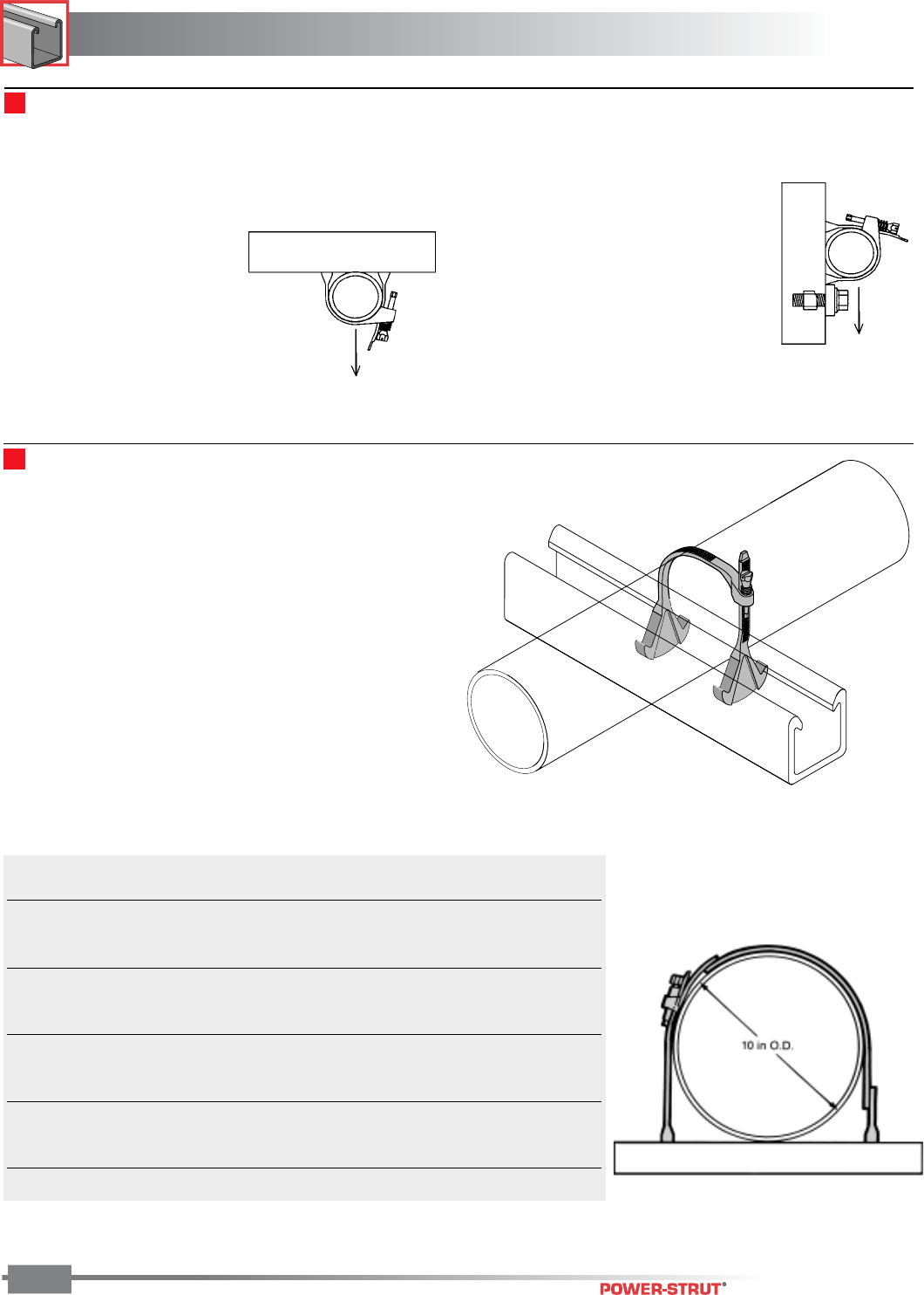
FIBERGLASS
FIBERGLASS
ENGINEERING CATALOG
158
200-3100 to 200-3140
200-3150 to 200-3210
There are two types of piping system loadings, overhead (Type
1) and vertical (Type 2) as described below. All Aickinstrut pipe
straps and clamps show the recommended loading for both
types of loading.
Type 1 Design Load
The design load shown represents
pipes supported below the strut.
The design loads shown are based
on a minimum ultimate failure safety
factor of 3:1
Type 2 Design Load
The design loading shown can be
achieved with the addition of a vertical
stop lock assembly (Part #200-4219)
installed directly beneath the pipe
clamp. The adjacent illustration shows
how the vertical stop lock assembly
provides additional support for pipe and
how it can be used to achieve full Type
2 design loads.
Design loads are based on a minimum
clamp slip safety factor or 3:1. It is
recommended that stop lock assem-
blies be used for all vertical pipe support applications.
Aickinstrut Adjustable Pipe Clamps are manufactured from
glass-reinforced polyurethane and are adjustable to accommo-
date a wide range of outside diameters. They can be utilized
with a variety of piping systems including: PVC, fiberglass,
copper, rigid steel conduit and PVC coated rigid steel conduit.
Aickinclamps sized 61⁄2" – 20" are to be used only in non-load
bearing applications. These are applications where the weight
of the pipe is being supported by Aickinstrut structural members
(see figure on right). Aickinclamps can safely be used in
temperatures up to 160°F. For operating temperatures of 160-
230°F, it is recommended to use PVDF clamps. PVDF clamps
are available as a special order. Contact the factory for pricing
and availability. Care should be taken not to exceed 3 ft./lbs. of
torque on the adjustable pipe straps.
■Adjustable Pipe Clamps
Part O.D. Pipe Design Load (lbs.)* Torque
Number Size (in.) Type 1 Type 2 (ft./lbs.)
200-3100 1⁄2–1
1⁄2135 65 10 in./lbs.
200-3110 11⁄2–2
1⁄4135 65 3
200-3120 21⁄4–3
1⁄4145 70 3
200-3130 3 – 4 215 70 3
200-3140 4 – 61⁄2215 70 3
200-3150 61⁄2– 8 Non-Load Bearing 3
200-3160 8 – 10 Non-Load Bearing 3
200-3170 10 – 12 Non-Load Bearing 3
200-3180 12 – 14 Non-Load Bearing 3
200-3190 14 – 16 Non-Load Bearing 3
200-3200 16 – 18 Non-Load Bearing 3
200-3210 18 – 20 Non-Load Bearing 3
*Design loads shown represent a 3:1 safety factor.
Pipe Clamps (Design Load Information)
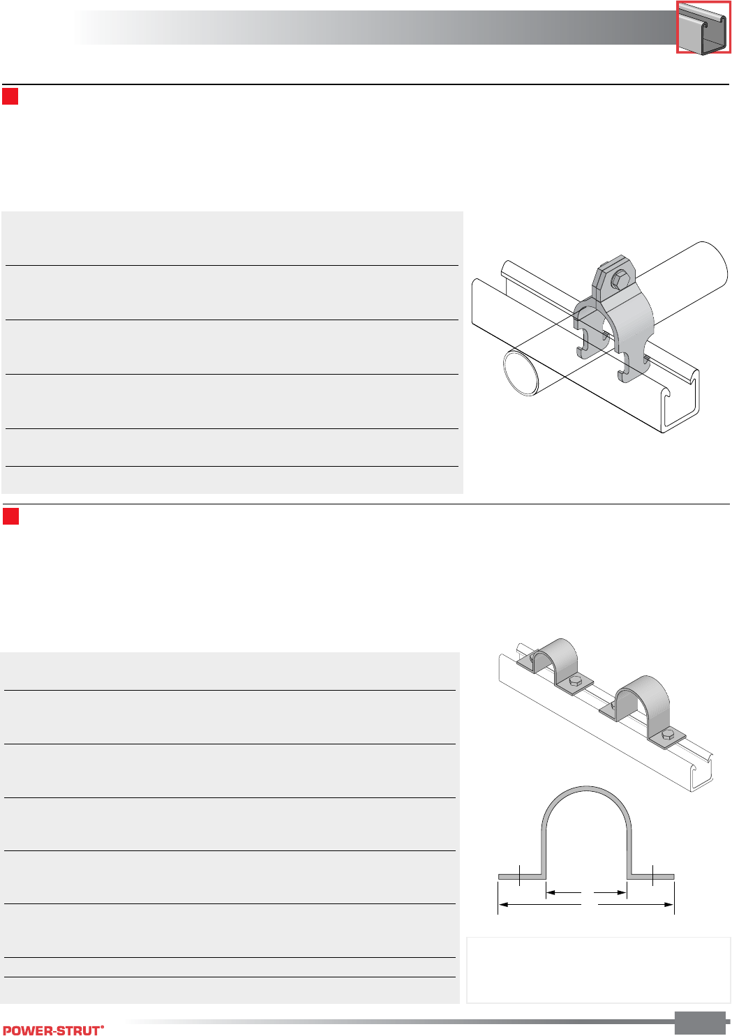
159
FIBERGLASS
FIBERGLASS
ENGINEERING CATALOG
159
■Two Hole Pipe Straps
Aickinstrut Two Hole Pipe Straps are designed for use in
securing pipe, conduit and ducts to Aickinstrut Channel. Two
hole fiberglass straps can also be used independently from the
channel for surface mounting. All sizes of the straps are
suitable for load bearing applications.
The two hole pipe straps are manufactured from a fire-retar-
A
B
Aickinstrut Rigid Pipe Clamps resemble the more traditional
style of pipe clamps. These clamps are made from glass-
reinforced polyurethane and are sized based on the pipe inside
diameter or nominal size.
Polyurethane clamps are recommended for applications up to
160°F. For high temperature applications (up to 230°F), PVDF
clamps are available as a special order. Contact the factory for
pricing and availability.
Care should be taken not to exceed the recommended torque
values of the rigid pipe clamps.
dant, glass reinforced polyester resin. For extreme chemical
environments, the straps can be manufactured from vinyl ester
resin. Larger diameter straps for special applications are also
available. Contact the factory for pricing and availability of vinyl
ester and large diameter straps. Two hole pipe straps should
not be torqued above recommended values.
■Rigid Pipe Clamps
PVC Design FRP Bolt
Part Nominal Sch. 80 and Loads (lbs.)* FRP Bolt Torque
Number Size (in.) Rigid Metal Type 1 Type 2 Size (in.) (ft./lbs.)
PCR-050 1⁄20.840 225 90 3⁄8 x 11⁄43
PCR-075 3⁄41.050 225 90 3⁄8 x 11⁄43
PCR-100 1 1.315 225 90 3⁄8 x 11⁄43
PCR-125 11⁄41.660 225 90 3⁄8 x 11⁄43
PCR-150 11⁄21.900 225 90 3⁄8 x 11⁄43
PCR-200 2 2.375 225 90 3⁄8 x 11⁄43
PCR-250 21⁄22.875 225 90 3⁄8 x 11⁄43
PCR-300 3 3.500 225 90 3⁄8 x 11⁄43
PCR-400 4 4.500 300 125 3⁄8 x 11⁄43
PCR-600 6 6.625 300 125 3⁄8 x 11⁄43
PCR-800 8 8.625 300 125 3⁄8 x 11⁄43
*Design loads shown represent a 3:1 safety factor.
Notes: Bolts and channel nuts are sold separately.
When bolting onto 15⁄8" or 11⁄2" channel
a 11⁄4" long bolt is required.
Part Dimension Bolt Size Material Design Load (lbs)* Torque
No. A (in.) B (in.) (in.) Size (in.) Type 1 Type2 (ft./lbs.)
PS050 0.840 4.840 1⁄21⁄4x1
5⁄8135 50 4
PS075 1.050 5.050 1⁄21⁄4x1
5⁄8135 50 4
PS100 1.315 5.315 1⁄21⁄4x1
5⁄8135 50 4
PS200 2.375 6.375 1⁄21⁄4x1
5⁄8135 50 4
PS250 2.875 6.875 1⁄21⁄4x1
5⁄8135 50 4
PS300 3.500 7.500 1⁄21⁄4x1
5⁄8135 50 4
PS350 4.000 8.000 1⁄21⁄4x1
5⁄8135 50 4
PS400 4.500 8.500 1⁄21⁄4x1
5⁄8175 60 4
PS500 5.563 9.563 1⁄21⁄4x1
5⁄8175 60 4
PS600 6.625 10.625 1⁄21⁄4x1
5⁄8175 60 4
PS800 8.625 12.625 1⁄21⁄4x1
5⁄8225 125 4
PS1000 10.750 15.750 5⁄81⁄4x1
5⁄8225 125 10
PS1200 12.750 16.250 5⁄81⁄4x1
5⁄8225 125 10
PS1400 14.000 18.000 5⁄83⁄8x1
5⁄8250 150 10
PS1600 16.000 20.000 5⁄83⁄8x1
5⁄8250 150 10
PS1800 18.000 23.000 5⁄83⁄8x1
5⁄8250 150 10
*Design loads shown represent a 3:1 safety factor.
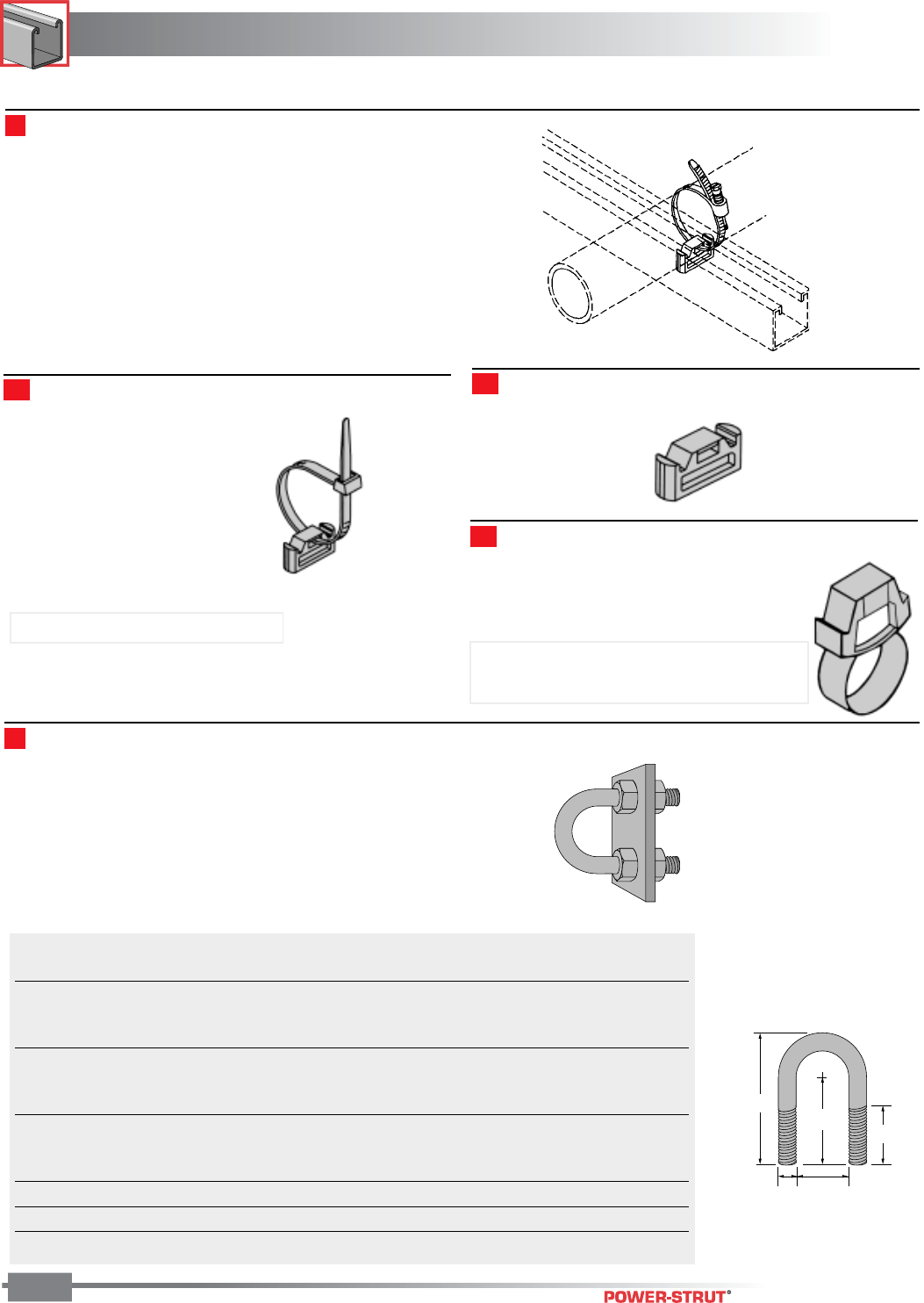
FIBERGLASS
FIBERGLASS
ENGINEERING CATALOG
160
C
BA
TL
D
■Unisert Channel Insert
Part Load Torque
Number Size (in.) “A” Dim. “B” Dim. “C” Dim. “D” Dim.“TL” Dim. (lbs.)* (in./lbs.)*
UB-050 1⁄20.937 0.375 1.568 2.412 1.25 135 40
UB-075 3⁄41.125 0.375 1.662 2.600 1.25 135 40
UB-100 1 1.375 0.375 1.787 2.850 1.25 135 40
UB-125 11⁄41.687 0.375 1.943 3.162 1.25 135 40
UB-150 11⁄22.000 0.375 2.100 3.475 1.25 135 40
UB-200 2 2.437 0.500 2.468 4.187 1.50 135 80
UB-250 21⁄22.937 0.500 2.718 4.687 1.50 135 80
UB-300 3 3.562 0.500 3.031 5.312 1.50 135 80
UB-350 31⁄24.062 0.500 3.281 5.812 1.50 135 80
UB-400 4 4.562 0.500 3.531 6.312 1.50 135 80
UB-600 6 6.750 0.625 5.750 9.875 3.25 135 120
*Torque and load values shown represent a 3:1 safety factor.
Unisert is a polyurethane nonmetallic insert which can be used
with standard cable ties for securing tubing, conduit and cables
to standard metal channels. The Unisert works with all 1 5⁄8"
channel that are 13⁄16" deep or more. One size fits 12, 14 and 16
metal gauge channels. The 200-4101 is used only with metallic
channel. Insert 200-3101 is to be used with Aickinstrut profile
channel.
■Unisert Channel Insert - Part No. 200-4101
Note: For use with metallic channel.
Note: For use with Aickinstrut 2000-1500
series profile channel only.
■Unisert Channel Insert - Part No. 200-3101
■Unisert Channel Insert - with Cable Tie
Aickinstrut Nonmetallic U-Bolts provide a corrosion resistant
alternative to traditional metallic U-Bolts. made from glass-
reinforced polyurethane, these bolts will outlast stainless steel
in most corrosive applications. Nonmetallic U-Bolts have
oversized diameters which allow them to hold steel condiut and
plastic pipe.
Each U-Bolt comes with two polyurethane hex nuts. Additional
nuts and washers cabe purchased separately.
Nonmetallic U-Bolts
The U-Bolts can also be
installed to allow for thermal
expansion and contraction of
plastic pipe as shown here.
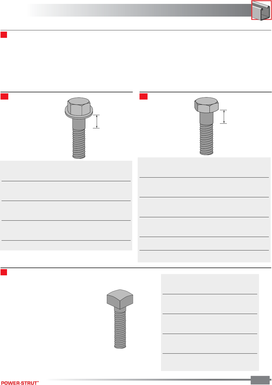
161
FIBERGLASS
FIBERGLASS
ENGINEERING CATALOG
161
Shoulder
Length
Shoulder
Length
Fiberfast bolts are provided in two styles and four diameters
(1⁄4", 3⁄8", 1⁄2" and 5⁄8") and range in length from 11⁄4" to 31⁄2". The
flanged style incorporates a molded washer collar which
eliminates the need for a washer. The flange style is provided
for 1⁄4" and 1⁄2" diameter bolts. Flanged bolts are available in 3⁄8"
diameter as a special order item. The hex head style is
provided for all 3⁄8" and 5⁄8" diameter bolts. All Fiberfast bolts are
Thread Shank Shoulder
Part Size Shear Shear Length Torque
Number (in.) (lbs.)* (lbs.)* (in.) (ft./lbs.)
250PU-075 1⁄4x 3⁄4110 210 Full Thread 10 In./lbs.
250PU-100 1⁄4x 1 110 210 Full Thread 10 In./lbs.
250PU-150 1⁄4x 11⁄2110 210 1⁄210 In./lbs.
500PU-125 1⁄2x 11⁄4450 870 Full Thread 8
500PU-150 1⁄2x 11⁄2450 870 Full Thread 8
500PU-200 1⁄2x 2 450 870 3⁄48
500PU-250 1⁄2x 21⁄2450 870 3⁄48
500PU-300 1⁄2x 3 450 870 1 8
500PU-350 1⁄2x 31⁄2450 870 23⁄16 8
*Thread shear values shown represent a 3:1 safety factor.
Thread Shank Shoulder
Part Size Shear Shear Length Torque
Number (in.) (lbs.)* (lbs.)* (in.) (ft./lbs.)
375PU-125 3⁄8x 11⁄4250 470 Full Thread 3
375PU-150 3⁄8x 11⁄2250 470 1⁄43
375PU-200 3⁄8x 2 250 470 1⁄23
375PU-250 3⁄8x 21⁄2250 470 3⁄43
375PU-300 3⁄8x 3 250 470 1 3
625PU-125 5⁄8x 11⁄4700 1,360 1⁄412
625PU-150 5⁄8x 11⁄2700 1,360 1⁄412
625PU-200 5⁄8x 2 700 1,360 1⁄412
625PU-250 5⁄8x 21⁄2700 1,360 1⁄412
625PU-300 5⁄8x 3 700 1,360 1⁄412
625PU-350 5⁄8x 31⁄2700 1,360 11⁄412
*Thread shear values shown represent a 3:1 safety factor.
Fiberfast Bolts
not fully threaded, therefore, shoulder length (nonthreaded
portion) dimensions have been provided. Fiberfast bolts are
ideal for mechanical connections that requrie a high degree of
corrosion resistance. The 3⁄8" diameter fasteners are recom-
mended for all channel fitting mechanical connections. All
Fiberfast bolts are manufactured from glass-reinforced polyure-
thane and are packaged in bags containing 25 pieces.
Hex Flange Bolts Hex Bolts
Thread
Part Size Shear Torque
Number (in.) (lbs.)* (ft./lbs.)*
375V-100 3⁄8x 1 250 10
375V-125 3⁄8x 11⁄4250 10
375V-150 3⁄8x 11⁄2250 10
375V-175 3⁄8x 13⁄4250 10
375V-200 3⁄8x 2 250 10
375V-250 3⁄8x 21⁄2250 10
375V-300 3⁄8x 3 250 10
375V-350 3⁄8x 31⁄2250 10
375V-400 3⁄8x 4 250 10
*Thread shear values shown represent a 3:1 safety
factor.
Vinyl Ester Square Head Bolts
Vinyl ester square bolts are used for
concrete mounting and general purpose
fastening applications. The square head
bolts are constructed from vinyl ester all-
thread rod and vinyl ester square nuts. The
units are bonded together with a durable two
part urethane adhesive. The square head
bolts are offered in 3⁄8" diameter but can be
supplied in other diameters as a special
order. Contact the factory for pricing and
availability of special diameter square head
bolts.
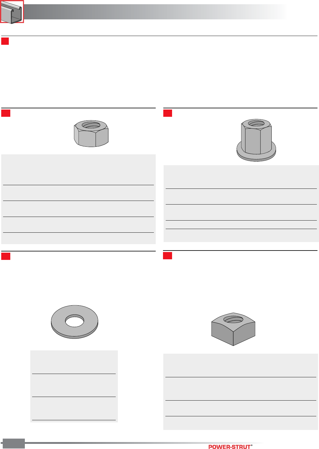
FIBERGLASS
FIBERGLASS
ENGINEERING CATALOG
162
Thread
Part Size Shear Height Torque
Number (in.) (lbs.)* (in.) (ft./lbs.)
250PU-000 1⁄4-20 150 0.218 10 in./lbs.
375PU-000 3⁄8-16 460 0.328 3
500PU-000 1⁄2-13 800 0.437 8
625PU-000 5⁄8-11 1,000 0.546 12
750PU-000 3-10 1,000 0.640 15
1000PU-000 1-8 1,100 0.859 17
*Thread shear values shown represent a 3:1 safety factor.
Fiberfast Hex Nuts
The Aickinstrut hex nut is similar in design to the conventional
hex nut and is preferred for channel fitting connections.
All nuts are manufactured from glass-reinforced polyurethane
and are packaged in bags containing 25 pieces. Available in
PVDF and Polypropylene and metric sizes as a special order.
Contact the factory for pricing and availability.
The Aickinstrut hex flange nut is preferred for applications that
require additional thread engagement (such as with all-thread
rod) or maximum thread shear strength.
All nuts are manufactured from glass-reinforced polyurethane
and are packaged in bags containing 25 pieces. Available in
PVDF and Polypropylene and metric sizes as a special order.
Contact the factory for pricing and availability.
Flat Washers Vinyl Ester Square Nuts
Hex Nuts Hex Flange Nuts
Thread
Part Size Shear Height Torque
Number (in.) (lbs.)* (In.) (ft./lbs.)
375PU-FN-000 3⁄8-16 500 0.750 3
500PU-FN-000 1⁄2-13 1,200 0.855 8
625PU-FN-000 5⁄8-11 2,200 1.220 12
750PU-FN-000 3⁄4-10 2,900 1.590 15
1000PU-FN-000 1-8 2900 1.75 17
*Thread shear values shown represent a 3:1 safety factor.
Outside
Part Size Diameter
Number (in.) (in.)
250E-999 1⁄40.49
375E-999 3⁄81.00
500E-999 1⁄21.25
625E-999 5⁄81.50
750E-999 3⁄41.50
1000E-999 1 2.25
Thread
Part Size Shear Height Torque
Number (in.) (lbs.)* (In.) (ft./lbs.)
375V-000 3⁄8-16 1,300 0.437 10
500V-000 1⁄2-13 1,700 0.562 10
625V-000 5⁄8-11 1,700 0.687 10
750V-000 3⁄4-10 1,700 0.812 10
1000V-000 1-8 1,700 0.937 10
*Thread shear values shown represent a 3:1 safety factor.
Flat Washers are made from PVC and are available for 1⁄4"
diameter through 1". PVC washers are recommended for
connections that utilize hex nuts and bolts. PVC washers are
packaged in bags containing 25 pieces.
Square nuts are manufactured from pultruded vinyl ester
square stock. They are recommended for applications that
require high thread shear values. Square nuts are packaged in
bags containing 25 pieces.
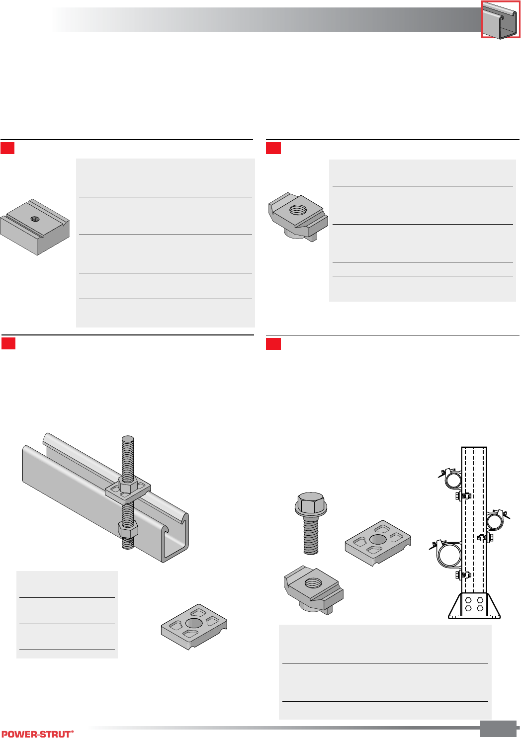
163
FIBERGLASS
FIBERGLASS
ENGINEERING CATALOG
163
Standard Duty channel nuts are designed for light duty applica-
tions that do not require high thread shear values. Standard
duty channel nuts can be used with all sizes of Aickinstrut
Channel.
All channel nuts are manufactured from glass-reinforced
polyurethane and are packaged in bags containing 50 pieces.
Available in PVDF as a special order. Contact the factory for
pricing and availability.
Heavy duty channel nuts are designed to be used where high
thread shear values or spring nuts are required. Heavy duty
channel nuts can not be used with Series 1000 Channel (light
duty).
All channel nuts are manufactured from glass-reinforced
polyurethane and are packaged in bags containing 50 pieces.
Available in PVDF as a special order. Contact the factory for
pricing and availability.
Heavy Duty Channel Nuts Standard Duty Channel Nuts
Thread
Part Size Shear Torque
Number (in.) (lbs.)* (ft./lbs.)
375PU-CNHD 3⁄8-16 1,400 8
500PU-CNHD 1⁄2-13 1,400 8
625PU-CNHD 5⁄8-11 1,400 10
750PU-CNHD 3⁄4-10 1,400 10
10PU-CNMHD 10 mm 1,400 8
12PU-CNMHD 12 mm 1,400 8
16PU-CNMHD 16 mm 1,400 10
20PU-CNMHD 20 mm 1,400 10
*Thread shear values shown represent a 3:1
safety factor.
Part Size Thread Shear Torque
Number (in.) (lbs.)* (ft./lbs.)
250PU-CN 1⁄4-20 460 2
312PU-CN 5⁄16-18 460 2
375PU-CN 3⁄8-16 460 3
500PU-CN 1⁄2-13 460 3
10PU-CN 10 mm 460 3
12PU-CN 12 mm 460 3
10PU-CNS #10 Screw 460 N/A
*Thread shear values shown represent a 3:1 safety factor.
Saddle Clips
Aickinstrut Saddle Clips make fastening through Aickinstrut
channel much easier. The clips mate with the exterior of the
channel flanges and are secured with threaded rods and nuts.
The saddle clips are manufactured from glass reinforced
polyurethane and are supplied in bags of 50 pieces.
Stop-Lock Assemblies
Aickinstrut Stop-Lock Assemblies reduce the chance of pipe
slippage when running supports vertically. Stop-Locks are
recommended for applications that are subject to vibration,
have regular contact with fluids or are vertically mounted (Type
2). The Stop-Locks fit all three sizes of channel. Stop-Locks
are offered with a 3⁄8", 1⁄2" and 5⁄8" bolt size. The 5⁄8" Stop-Lock
Assembly is supplied with a heavy duty channel nut (the 5⁄8"
Stop-Lock Assembly will not work with the
1000 Series Channel).
The Stop-Lock Assemblies' components
are manufactured from glass-reinforced
polyurethane.
Part Size
Number (In.)
200-4226 3⁄8
200-4217 1⁄2
200-4341 5⁄8
200-4342 3⁄4
Force
Part Size Resistance Torque
Number (in.) (lbs.)* (ft./lbs.)
200-4227 3⁄8200 7
200-4219 1⁄2220 12
200-4343 5⁄8250 15
*Force resistance values shown represents a 3:1 safety factor.
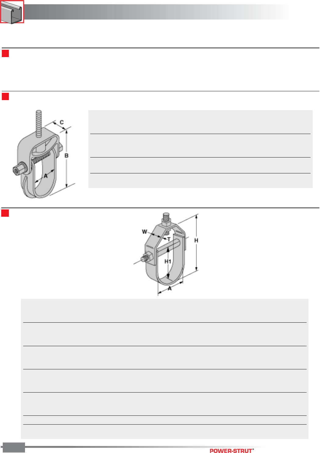
FIBERGLASS
FIBERGLASS
ENGINEERING CATALOG
164
Clevis Hangers
Clevis hangers are available in two styles; molded and hand
lay-up. The molded clevis hangers are manufactured from
glass-reinforced polyurethane and are available for sizes 1⁄2"
through 6". The hand lay-up clevis hangers are manufactured
from glass-reinforced polyester resin and are available for sizes
1" through 21". Vinyl ester resin clevis hangers are available as
a special order. Contact the factory for pricing and
availability.
Molded Clevis Hangers
Nominal Max. Hanger
Part Diameter Pipe O.D. Rod Load
Number (in.) (in.) “A” Dim. “B” Dim. “C” Dim. (in.) (lbs.)*
CVHPU-100 1⁄21 1.500 4.25 1.25 1⁄2670
CVHPU-150 11⁄411⁄22.000 5.14 1.25 1⁄2670
CVHPU-200 11⁄22 2.500 6.52 1.25 1⁄2730
CVHPU-400 21⁄24 5.125 10.00 1.50 1⁄21,150
CVHPU-600 41⁄26 6.750 12.33 1.50 1⁄21,170
*Design load values shown represent a 3:1 safety factor.
Hand Lay-Up Clevis Hangers
Hanger Trans Spreader
Part Size Range (In.) Dimensions (in.) Rod Rod Rod O.D. Loads
Number A T H H1 W (in.) (in.) (in.) (lbs.)*
100-1500 1 – 11⁄21⁄823⁄417⁄811⁄21⁄23⁄81⁄260
100-1501 11⁄2–2 1⁄831⁄223⁄811⁄21⁄23⁄81⁄260
100-1502 2 – 25⁄81⁄843⁄432
1⁄23⁄81⁄290
100-1503 21⁄2–3
1⁄41⁄851⁄235⁄821⁄23⁄81⁄2120
100-1504 3 – 37⁄81⁄874
1⁄425⁄83⁄81⁄2160
100-1505 4 – 51⁄83⁄16 81⁄255⁄825⁄83⁄81⁄2250
100-1506 6 – 71⁄83⁄16 107⁄871⁄235⁄83⁄81⁄2300
100-1507 8 – 91⁄41⁄414 93⁄435⁄83⁄81⁄2350
100-1508 10 – 113⁄81⁄418 12 4 5⁄81⁄23⁄4450
100-1509 12 – 131⁄21⁄4211⁄2141⁄855⁄81⁄23⁄4600
100-1510 14 – 153⁄41⁄4241⁄2161⁄253⁄41⁄23⁄4700
100-1511 16 – 18 3⁄8273⁄8191⁄263⁄43⁄41 750
100-1512 19 – 21 3⁄8341⁄2221⁄263⁄43⁄41 800
*Design load values shown represent a 3:1 safety factor.
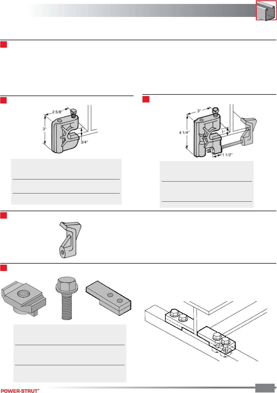
165
FIBERGLASS
FIBERGLASS
ENGINEERING CATALOG
165
Beam Clamps
Aickinstrut beam clamps are available in two styles; molded and
fabricated. The molded beam clamps are manufactured from
glass-reinforced polyurethane and can accomodate 3⁄8", 1⁄2", 5⁄8"
hanger rod sizes. the molded beam clamps utilize the tradi-
tional "C" clamp style design. The fabrication beam clamps are
manufactured from vinyl ester flat stock and utilize polyurethane
bolts and channel nuts for clamping. Fabricated beam clamps
are available for attaching to 1⁄4", 3⁄8" and 1⁄2" thick beam flanges.
Each fabricated beam clamp assembly includes four (4) 1⁄2"
Polyurethanej bolts and two (2) attachment clips.
All Aickinstrut beam clamps allow easy attachment of threaded
rod to "I" beams or other structural assemblies.
Molded Beam Clamps
Thread
Part Size Shear Torque
Number (in.) (lbs.)* (ft./lbs.)
375PU-BC 3⁄8400 10
500PU-BC 1⁄2400 10
*Design load values shown represent a 3:1 safety factor.
Cope-Glas Beam Clamps
Thread
Part Size Shear Torque
Number (in.) (lbs.)* (ft./lbs.)
RGBC-1 3⁄8500 10
RGBC-2 1⁄2500 10
RGBC-3 5⁄8500 10
Beam Clip - 375PU-BCCLP (3⁄8")
Flange Thread
Part Thickness Shear Torque
Number (in.) (lbs.)* (ft./lbs.)
20V-2BC-25 1⁄4600 10
20V-2BC-37 3⁄8600 10
20V-2BC-50 1⁄2600 10
*Design load values shown represent a 3:1 safety factor.
Bolts and channel nuts are 1⁄2" diameter.
Fabricated Beam Clamps
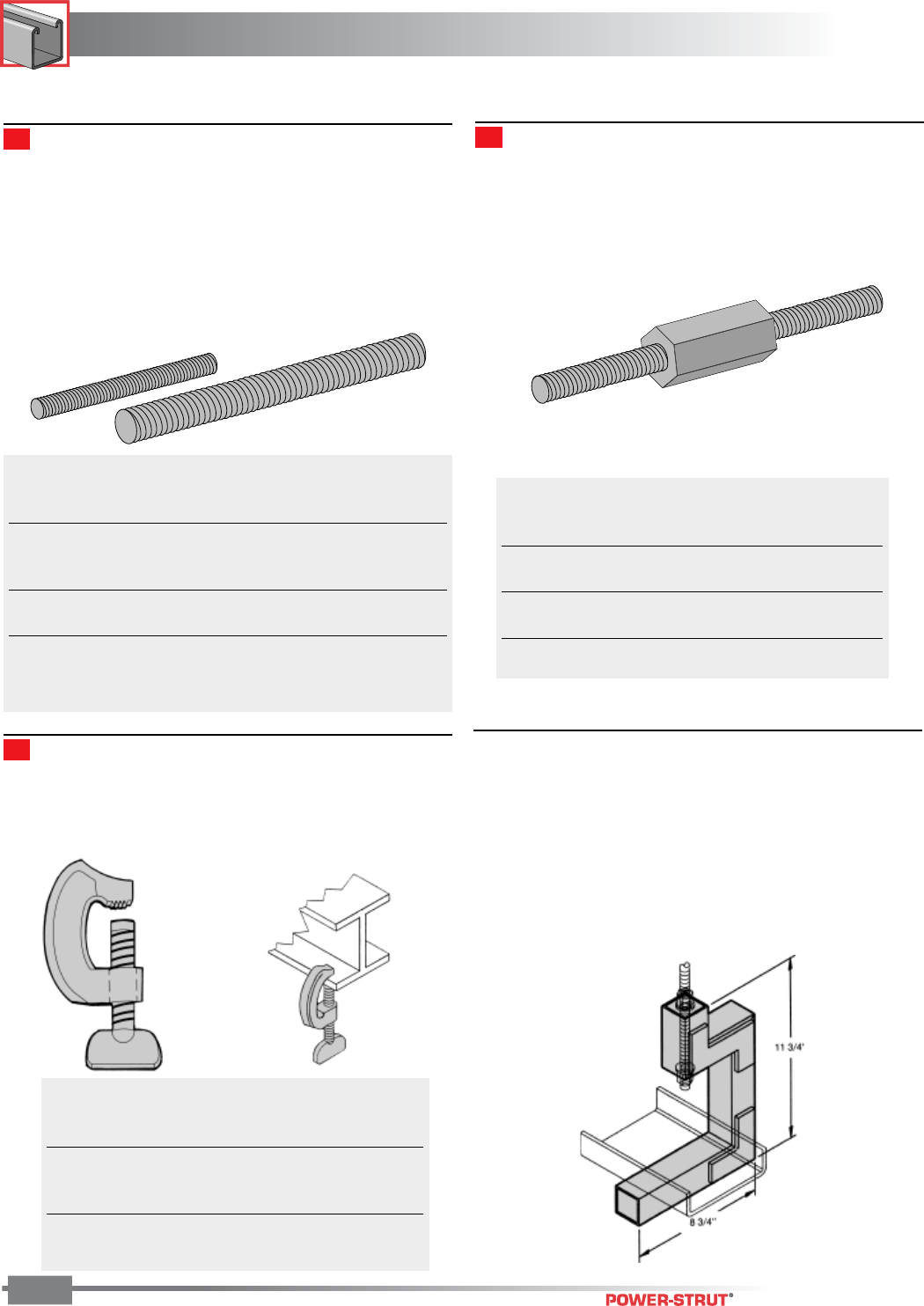
FIBERGLASS
FIBERGLASS
ENGINEERING CATALOG
166
A-Konnectors provide an excellent means for extending
Aickinstrut FRP all-thread rods beyond their standard lengths.
A-Konnectors are manufactured from glass-reinforced polyure-
thane and are colored gray. A-Konnectors are packaged in
bags containing 50 pieces.
The Aickin-Channel Hanger is designed to support fiberglass
structural “C” channel that is being used as a raceway system
for cables, tubing or small diameter piping. The Aickin-Channel
Hanger is available in either polyester or vinyl ester resin and is
simply supported from a 1⁄2" FRP all-thread rod and beam clamp
(not provided). The Channel Hanger will accommodate “C”
channel width sizes 2" through 8".
Threaded Rod
Pultruded threaded rods are an excellent choice for hanging
and fastening Aickinstrut Channel. These rods can also be
used with either the Aickinstrut vinyl ester square nuts, polyure-
thane hex nuts, hex flange nuts and Aickinstrut channel nuts.
All FRP threaded rod is manufactured from pultruded vinyl ester
resin and is gray in color.
The standard rod lengths are 4' and 8'. Special lengths and
threading are also available. Contact the factory for pricing and
availability.
Thread
Part Size Weight Shear Torque
Number (in.) (lbs.) (lbs.)* (ft./lbs.)
200-3827 3⁄8-16 0.07 470 5
200-3828 1⁄2-13 0.12 570 10
200-3829 5⁄8-11 0.18 1,600 40
200-3830 3⁄4-10 0.28 1,700 50
200-3831 1-8 0.50 3,000 60
* Thread shear values shown represent a 3:1 safety factor.
* To order eight foot lengths, add suffix “-96” to part number
(EX: 200-3827-96)
A-Konnector Rod Couplers
Thread
Part Size Length Shear
Number (in.) (ln.) (lbs.)*
200-3840 3⁄8-16 21⁄4800
200-3841 1⁄2-13 21⁄4870
200-3842 5⁄8-11 21⁄41,500
200-3843 3⁄4-10 21⁄41,500
* Thread shear values shown represent a 3:1 safety factor.
Duraclamp C-Clamps
Duraclamp are glass-reinforced polyurethane clamps that are
designed to replace steel C-Clamps in areas where corrosion is
a problem. The individual Duraclamp components can also be
purchased separately.
■
Channel Hangers
AIC-CH-P (Polyester) AIC-CH-V (Vinyl Ester)
Thread
Part Shear Torque
Number Description (lbs.)* (ft./lbs.)
390N-150 “C”-Clamp 25 17
390N-BLT Bolt N/A 17
390N-CLP “C” 25 N/A
*Design load values shown represent a 3:1 safety factor.
Note: Bolt Dimension is 5⁄8" x 21⁄2"
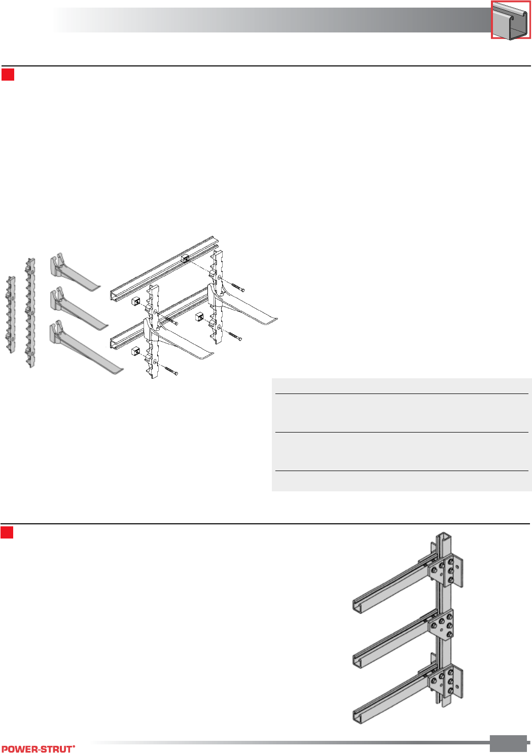
167
FIBERGLASS
FIBERGLASS
ENGINEERING CATALOG
167
Wall Brackets
Aickin-Brackets are available in a wide variety of sizes and
configurations. These wall brackets are made entirely from
Aickinstrut material and are specifically designed to meet the
customers requirements. They are ideal for customizing the
support of piping, cables, tubing, conduits or cable trays. These
brackets are available in either polyester or vinyl ester resin
types and will work with all the Aickinstrut accessory items.
Consult the factory for design, pricing and availability informa-
tion.
Power-Rack Stanchions
The Power-Rack Stanchion is the new alternative to traditional
iron cable stanchions used for utility and industrial cable
supports. Made entirely from glass-reinforced nylon, these
stanchions out-perform metallic supports against corrosion.
The extended life-span of the Power-Rack Stanchion makes
them the logical choice over metallic cable supprts. The
Power-Rack Stanchion is available in two different lengths and
four different arm lengths. The unique interlocking design
allows the arm to "lock" into nine different levels on the 141⁄4"
stanchions and fourteen on the 171⁄2" stanchion. Glass-
reinforced polyurethane standchions are available as a special
order. Contact the factory for pricing and availability.
Dimensions - The stanchion back is designed with 9⁄16" wide x
15⁄16" long holes to accept fasteners for mounting. There are two
mounting holes in the 21 3⁄8" long stanchion and three mounting
holes in the 33 5⁄16" long stanchion. Thickness at the slotted
mounting holes is 1 7⁄8". The mounting holes are spaced on 12"
centers and require 1⁄2" diameter features.
Installation - The Power-Rack Stanchions can be anchored into
existing concrete structures using any good qualitiy industrial
anchoring system. For new concrete structures, the Power-
Rack Stanchions can be mounted to Aickinstrut concrete
embedment channel and attached with 1⁄2" channel nuts and 1⁄2"
x 3" Fiberfast Bolts.
Fire Retardance - Power-Rack materials meet or exceed the
requirements of UL94 HB.
Loading - The recommended allowable loads on Power-Rack
Stanchions vary depending upon the position of the arm.
Following the guidelines listed below will ensure a safe, reliable
installation.
• Total load on any one arm should not exceed 800 lbs.
• The sumof the loads on any arm multiplied by their
distances to the wall stanchion should not exceed
1200 in./lbs.
Example - A cable weighing 200 lbs. is positioned on an arm at
a distance of 5" from the wall stanchion.
If the total load is less than 800 lbs and the sum of the load
multiplied by their distances to the wall stanchion does not
exceed 1200 in./lbs., then the system is adequate. In this case,
Total load (200<800 lbs) = OK
Total moment (200x5 in. = 1000<1200 in./lbs.) = OK
Part No. Description Weight (lbs.) Load (lbs.)*
20N-ARM08 8" Arm 1.00 800
20N-ARM14 141⁄4" Arm 1.16 800
20N-ARM17 171⁄2" Arm 1.45 800
20N-ARM23 237⁄8" Arm 1.86 800
20N-STA21 213⁄8" Stanchion 1.49 N/A
20N-STA33 335⁄16" Stanchion 2.31 N/A
*Design load values shown represent a 3:1 safety factor.
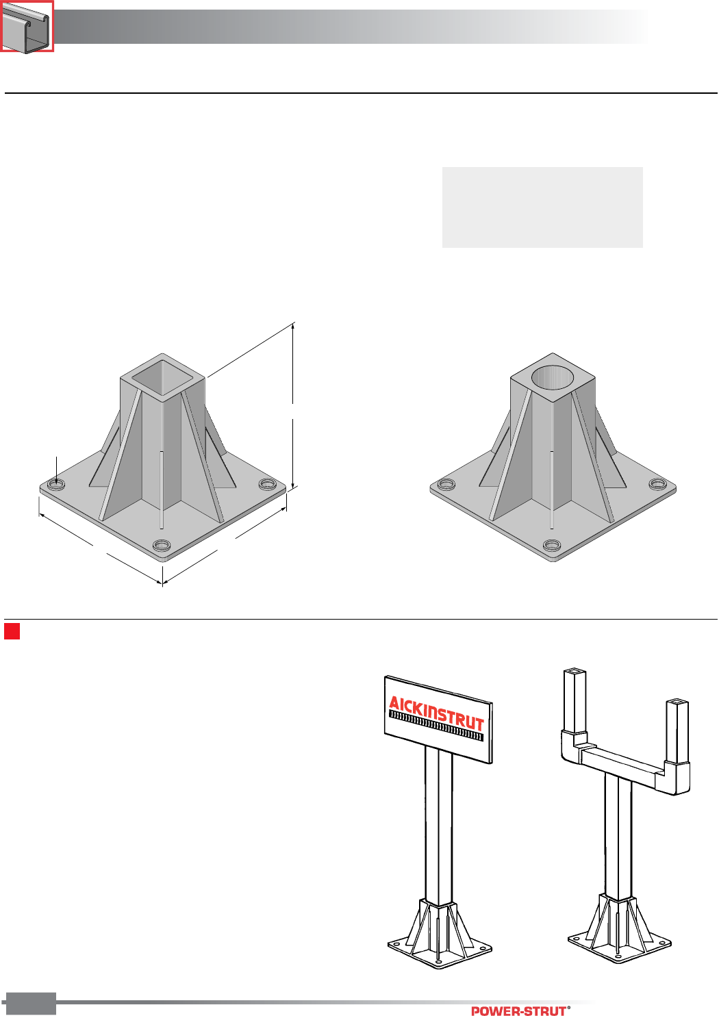
FIBERGLASS
FIBERGLASS
ENGINEERING CATALOG
168
Instrument & Pipe Stands
■Heavy Duty Post Base
The Aickinstrut heavy duty post base is designed for applica-
tions that require a stronger base attachment than the standard
Aickinstrut post base. Made from polyurethane, the heavy duty
post base is available with four different openings: 11⁄2", 15⁄8", 2"
square and 2" Schedule 80 round. The heavy duty post base
is ideal for mounting fiberglass channel, handrails and instru-
ment stands in corrosive environments. The standard color is
gray, but special colors are available upon request.
8"8"
Dia.
Hole (4)
19⁄32"
61⁄4"
Instrument & Pipe Stands
Aickin-Instrument and Pipe Stands are available in polyester or
vinyl ester resin types and are designed to meet specific
customer requirements. These stands are ideal for supporting
instruments and enclosures in corrosive environments. The
stands utilize the Aickinstrut Heavy Duty Post Base and either
2" x 2" x 1/4" square tube or 2" Schedule 80 pipe to support the
instruments or enclosures. These stands can be designed or
configured to meet any application. Consult the factory for
design, pricing and availability information.
20PU-5852 2" Square
20PU-5852 RD 2" Round
20PU-5853 HD 15⁄8" Sq
20PU-5854 HD 11⁄2" Sq
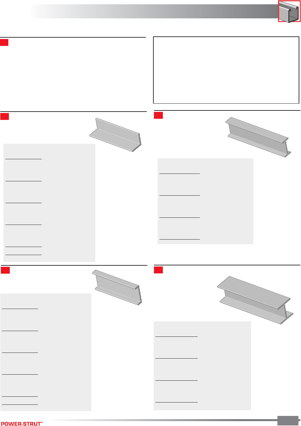
169
FIBERGLASS
FIBERGLASS
ENGINEERING CATALOG
169
General purpose pultruded structural shapes can be used as a
complement to Aickinstrut Channel Framing projects. The
shapes are ideal for structural bracing, handrails, handrail
kickplates and shims. Structural shapes are available in either
polyester or vinyl ester resin and are provided in ten foot
lengths. Additional structural shapes not listed in this catalog
are available. Contact the factory for pricing and availability.
NOTES
ST - Standard Isophthalic Polyester Resin
(Olive Green)
FR - Isophthalic Polyester Fire Retardant Resin
(Light Gray)
VE - Vinyl Ester Fire Retardant Resin (Beige)
* Stock Item
† Stocked in Yellow
Structural Shapes
Equal Leg Angle
Size Resin
(In.) ST FR VE #/Lin. Ft.
1 x 1⁄8* * * 0.21
11⁄4 x 1⁄8– – – 0.23
11⁄2 x 3⁄16 * – – 0.37
11⁄2 x 1⁄4* * * 0.51
2 x 1⁄4* * * 0.68
3 x 1⁄4* * * 1.04
3 x 3⁄8* * * 1.65
3 x 1⁄2– – – 2.15
4 x 1⁄4* * * 1.41
4 x 3⁄8* * * 2.23
4 x 1⁄2* * * 2.92
6 x 3⁄8– – – 3.44
6 x 1⁄2* * * 4.50
I–Beam
Size Resin
(In.) ST FR VE #/Lin. Ft.
3 x 3 x 1⁄4* * * 1.69
4 x 4 x 1⁄4* * * 2.10
6 x 6 x 1⁄4* * * 3.41
6 x 6 x 3⁄8* * * 5.05
8 x 8 x 3⁄8* * * 6.49
8 x 8 x 1⁄2– – – 8.70
10 x 10 x 3⁄8– – – 8.74
10 x 10 x 1⁄2– – – 10.90
12 x 12 x 1⁄2– – – 13.20
Channel Wide Flange I-Beam
Size Resin
(In.) ST FR VE #/Lin. Ft.
1 x 5⁄8 x 5⁄8 x 1⁄8– – – 0.32
2 x 9⁄16 x 1⁄8* * – 0.25
3 x 13⁄16 x 1⁄8– – – 0.48
3 x 7⁄8 x 1⁄4* – – 0.77
3 x 1 x 1⁄4* * * 0.87
3 x 11⁄2 x 1⁄4– – – 1.07
3 x 1⁄2 x 13⁄16 x 1⁄8– – – 0.65
4 x 11⁄8 x 1⁄4* * * 1.11
4 x 13⁄8 x 3⁄16 – – – 0.86
6 x 15⁄8 x 1⁄4* * * 1.64
6 x 111⁄16 x 3⁄8* * * 2.52
8 x 23⁄16 x 3⁄8* * * 3.40
10 x 23⁄4 x 1⁄2* * * 5.65
Size Resin
(In.) ST FR VE #/Lin. Ft.
3 x 3 x 1⁄4* * * 1.69
4 x 4 x 1⁄4* * * 2.10
6 x 6 x 1⁄4* * * 3.41
6 x 6 x 3⁄8* * * 5.05
8 x 8 x 3⁄8* * * 6.49
8 x 8 x 1⁄2– – – 8.70
10 x 10 x 3⁄8– – – 8.74
10 x 10 x 1⁄2– – – 10.90
12 x 12 x 1⁄2– – – 13.20
FIBERGLASS
FIBERGLASS
ENGINEERING CATALOG
170
Size Resin
(In.) ST FR VE #/Lin. Ft.
1⁄8 x 48 x 96 * * * 1.14
3⁄16 x 48 x 96 * * * 1.71
1⁄4 x 48 x 96 * * * 2.34
3⁄8 x 48 x 96 * * * 3.54
1⁄2 x 48 x 96 * * * 4.68
5⁄8 x 48 x 96 – – – 5.79
3⁄4 x 48 x 96 – – – 6.94
1 x 48 x 96 – – – 9.27
Flat Sheet
Embedment Angle
Size Resin
(In.) ST FR VE #/Lin. Ft.
1 x 11⁄2 x 1⁄4– – * 1.00
11⁄2 x 11⁄2 x 1⁄4– – * 1.10
2 x 11⁄2 x 1⁄4– – * 1.20
Square Tube
Size Resin
(In.) ST FR VE #/Lin. Ft.
1 x 1⁄8* * * 0.32
11⁄8 x 1⁄8– – – 0.37
11⁄4 x 1⁄8– – – 0.41
11⁄4 x 1⁄4– *† *† 0.68
11⁄2 x 1⁄8* *† *† 0.54
11⁄2 x 1⁄4– – * 0.98
13⁄4 x 1⁄8– *† *† 0.63
13⁄4 x 1⁄4– *† *† 1.10
2 x 1⁄8* *† *† 0.69
2 x 1⁄4* *† *† 1.40
21⁄8 x 3⁄16 – *† – 1.14
21⁄4 x 1⁄8– *† – 0.83
21⁄2 x 1⁄4– *† – 1.79
3 x 1⁄8– – – 1.12
3 x 1⁄4* * * 2.15
4 x 1⁄4* * * 2.93
4 x 3⁄8* – – 4.24
Toe Plate
4 x 5⁄8 x 1⁄8– *† – 0.49
Square Bar
Size Resin
(In.) ST FR VE #/Lin. Ft.
1 x 1 * – – 0.87
11⁄4 x 11⁄4– *† – 1.31
11⁄2 x 11⁄2– *† – 1.98
2 x 2 – – – 3.12
Rectangular Tube
Size Resin
(In.) ST FR VE #/Lin. Ft.
4 x 1 x 1⁄8– – – 0.85
4 x 1⁄8 x 2 x 1⁄4– – – 1.52
43⁄8 x 13⁄8 x 1⁄8 x 3⁄16 – – – 1.18
41⁄2 x 13⁄8 x 1⁄8 x 3⁄16 – – – 1.29
5 x 2 x 1⁄8– – – 1.32
51⁄8 x 21⁄8 x 3⁄16 – – – 1.32
61⁄2 x 1⁄4 x 2 x 1⁄2– – – 3.77
Round Rod
Size Resin
(In.) ST FR VE #/Lin. Ft.
1⁄8* – – 0.01
3⁄16 * – – 0.02
1⁄4* – – 0.04
0.3 – – – 0.06
5⁄16 * – – 0.07
0.35 – – – 0.08
3⁄8* – * 0.09
7⁄16 – – – 0.13
1⁄2* – * 0.17
5⁄8* – * 0.27
3⁄4* – * 0.39
13⁄16 – – – 0.46
1 * – * 0.66
11⁄8– – – 0.87
11⁄4* – – 1.08
11⁄2* – – 1.56
13⁄4– – – 2.10
2 – – – 2.56
171
FIBERGLASS
FIBERGLASS
ENGINEERING CATALOG
171
Flat Strip Special Shapes
Size Resin
(In.) ST FR VE #/Lin. Ft.
5⁄8 x 1⁄4* – – 0.11
3⁄4 x 1⁄4* – – 0.14
1 x 1⁄8– – – 0.11
11⁄4 x 3⁄16 – – – 0.19
11⁄2 x 3⁄8– – – 0.50
11⁄2 x 1 – – – 1.32
13⁄4 x 3⁄16 – – – 0.28
13⁄4 x 1⁄4* – – 0.38
2 x 1⁄2– – – 0.88
2 x 1 – – – 1.76
21⁄2 x 3⁄16 – – – 0.34
3 x 1⁄4– – – 0.66
3 x 3⁄8– – – 0.99
3 x 1⁄2– – – 1.32
4 x 1⁄8– – – 0.44
6 x 1⁄4– – – 1.32
6 x 1⁄2– – – 2.16
Round Tube
Size Resin
(In.) ST FR VE #/Lin. Ft.
5⁄8 Core – – – 0.18
3⁄4 Core – – – 0.21
1 x .100 – – – 0.22
1 x 1⁄4* * – 0.25
11⁄4 Core – – – 0.31
11⁄4 x 3⁄32 – – – 0.27
11⁄4 x 1⁄8– – – 0.32
11⁄4 x 1⁄4– – – 0.60
11⁄2 x 1⁄8* * – 0.45
11⁄2 x 1⁄4– * – 0.79
13⁄4 x 1⁄8– – – 0.47
13⁄4 x 1⁄4– – – 0.94
2 x 1⁄4* * * 1.12
3 x.100 – – – 0.89
3 x 1⁄4– – – 1.68
3 x 1⁄2* – – 2.98
4 x .100 – – – 1.23
4 x 1⁄4– – – 2.36
4.89 x 1⁄8– – – 2.32
4.89 x 3⁄16 – – – 2.97
Resin
Profile/Size ST FR VE #/Lin. Ft.
Door Frame
53⁄4 x 25⁄8 x 3⁄16 – – – 1.60
Threshold
51⁄2 x 1⁄4– – – 1.05
Hex Bar (solid)
7⁄8– – – 0.60
13⁄16 – – – 1.00
Hat Section
2 x 7⁄8 x .140 – – – 0.34
Flight Channel
3 x 6 x 1⁄8 x 3⁄16 * – – 1.31
3 x 8 x 1⁄8 x 3⁄16 * – – 1.43
FIBERGLASS
FIBERGLASS
ENGINEERING CATALOG
172
Size
(In.) #/Lin. Ft.
Toe Plate†
4 x 5⁄8 x 1⁄80.49
Flat Strip
Square Bar†#/Lin. Ft.
11⁄4 x 11⁄41.31
11⁄2 x 11⁄21.98
Square Tube†#/Lin. Ft.
11⁄4 x 1⁄40.68
11⁄2 x 1⁄80.54
13⁄4 x 1⁄80.63
13⁄4 x 1⁄41.10
2 x 1⁄80.69
2 x 1⁄41.40
21⁄8 x 3⁄16 1.12
21⁄4 x 1⁄80.83
21⁄2 x 1⁄41.69
Fixed Connector†#/Ea.
41⁄4 x 11⁄40.87
41⁄2 x 11⁄21.32
Handrail Connectors
Size Resin
(In.) ST FR VE #/Ea.
Fixed 90°
11⁄4– *† – 0.87
11⁄2– *† – 1.32
Adjustable 90°
11⁄4–––
11⁄2–––
Fixed “T”
11⁄4–––
11⁄2–––
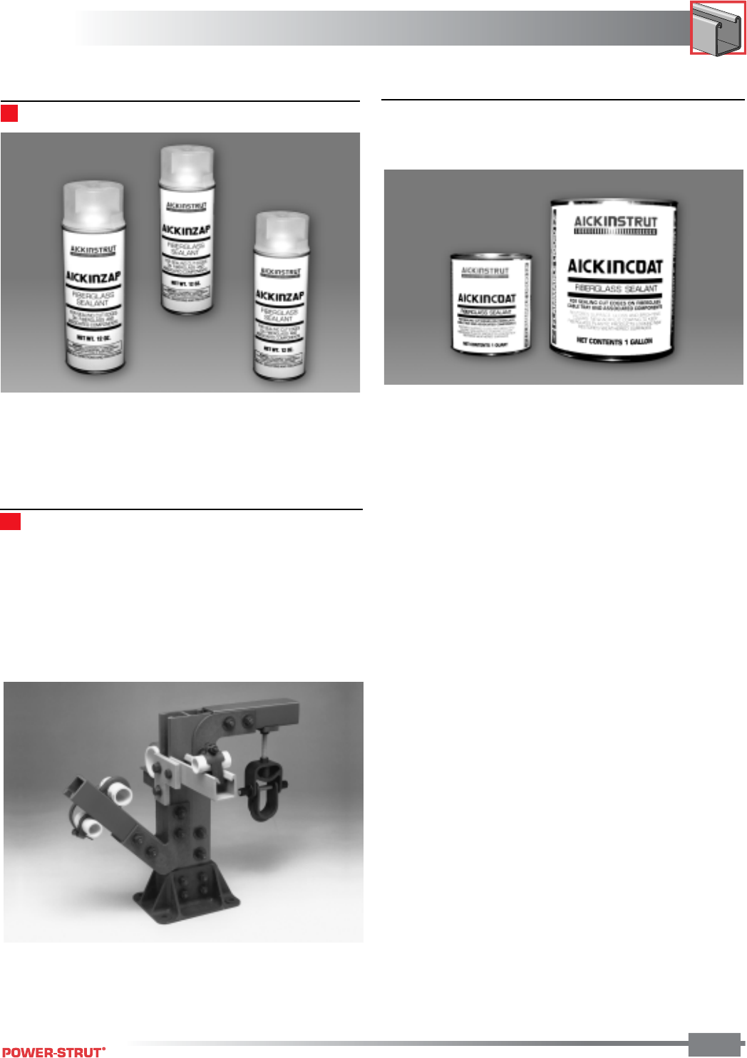
173
FIBERGLASS
FIBERGLASS
ENGINEERING CATALOG
173
Aickinzap 600-2200
Aickinzap is an acrylic spray that provides a corrosion resistant
coating when applied to cut sections of Aickinstrut. Aickinzap is
supplied in a 12 oz. can and is recommended for use as a
sealant for Aickinstrut polyester and vinyl ester materials after
cutting or drilling. Aickinzap is the quickest, most convenient
method for sealing after fabrication.
AICK-DIST-DISP
The Aickin Distributor Display is a counter top display for
stocking distributors. This display features multiple channel
sizes and materials, adjustable and rigid pipe straps, U-bolts,
molded and fabricated channel fittings, post bases, clevis
hangers and fasteners. All of these materials are then as-
sembled to form a comprehensive, compact display which
becomes an excellent sales tool.
■Aickincoat 600-1500 (Quart), 600-1600
(Gallon)
Aickincoat is a “brush-on” corrosion resistant sealant that
should be applied to all cut or drilled surfaces of fiberglass to
seal exposed areas from corrosion. Aickincoat dries into a
clear, hard, glossy coating that restores weathered fiberglass
surfaces and provides an excellent barrier from ultraviolet
degradation. It is available in quart and gallon cans.
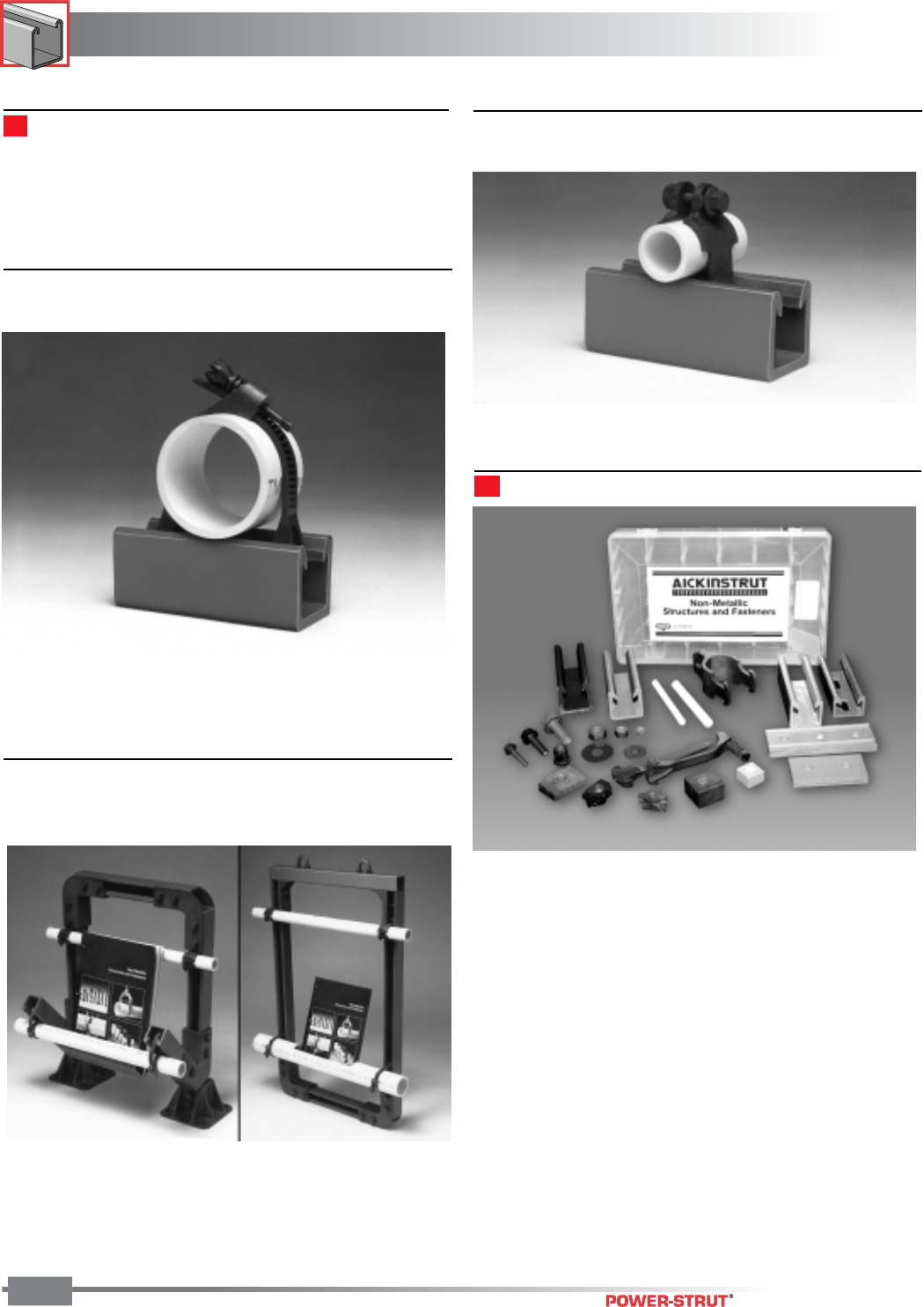
FIBERGLASS
FIBERGLASS
ENGINEERING CATALOG
174
■Aickin Adjustable Pipe Clamp Sample
AJPSS2
The Aickin Adjustable Pipe Clamp Sample is a desk top sample
that displays the Aickin Adjustable Pipe Strap clamping a piece
of PVC pipe onto a section of Aickinstrut Channel.
■Aickin Distributor Literature Displays
(Hanging) AICK-LIT-DISP (Counter Stand)
AICK-LIT-DISP-CS
The Aickin Distributor Literature Display is offered in two
designs; wall hanging and counter standing. The wall hanging
design is meant to be hung from the two top U-bolts while the
counter standing design is a free standing counter display.
Both displays incorporate Aickinstrut channel in their design
and utilize the PVC display pipe as the literature container.
■Aickin Rigid Pipe Clamp Sample
ARPS2
The Aickin Rigid Pipe Clamp Sample is a desk top sample that
displays the rigid pipe strap clamping a piece of PVC pipe onto
a section of Aickinstrut Channel.
Aickin Sample Box AICK-SAMP-CART
The Aickin Sample Box is a convenient plastic carrying case
with a complete sampling of the Aickinstrut product line.
Each Sample Box includes:
• PVC strut sample (20E-2000)
• Polyester strut sample (20P-2000)
• Polyester slotted strut sample (20P-1100)
• Vinyl ester strut sample (20V-1500)
• Polyester solid channel fitting (20V-2500)
• Vinyl ester grooved channel fitting (20V-2802)
• Saddle Clip (200-4226)
• Fiberfast bolts (250PU-000, 375PU-125 & 500PU-000)
• Fiberfast nuts (250PU-000, 375PU-125 & 500PU-CN)
• Square nut (500V-000)
• PVC washers (375E-999 & 500E-999)
• Standard duty channel nuts (375PU-CN & 500PU-CN)
• Heavy duty channel nut (500PU-CNHD)
• Adjustable pipe clamp (200-3110)
• Rigid pipe clamp (PCR-125)
• FRP threaded rod samples (200-3827 & 200-3828)
Promotional Materials
Promotional materials are available for select individuals,
including stocking distributors, end users, OEM's, contractors,
specifying engineers, consultants and sales representatives.
Please contact the factory for availability.
TECHNICAL DATA
TECHNICAL DATA
ENGINEERING CATALOG
1"
3⁄8"
1⁄2"
1⁄2"
175
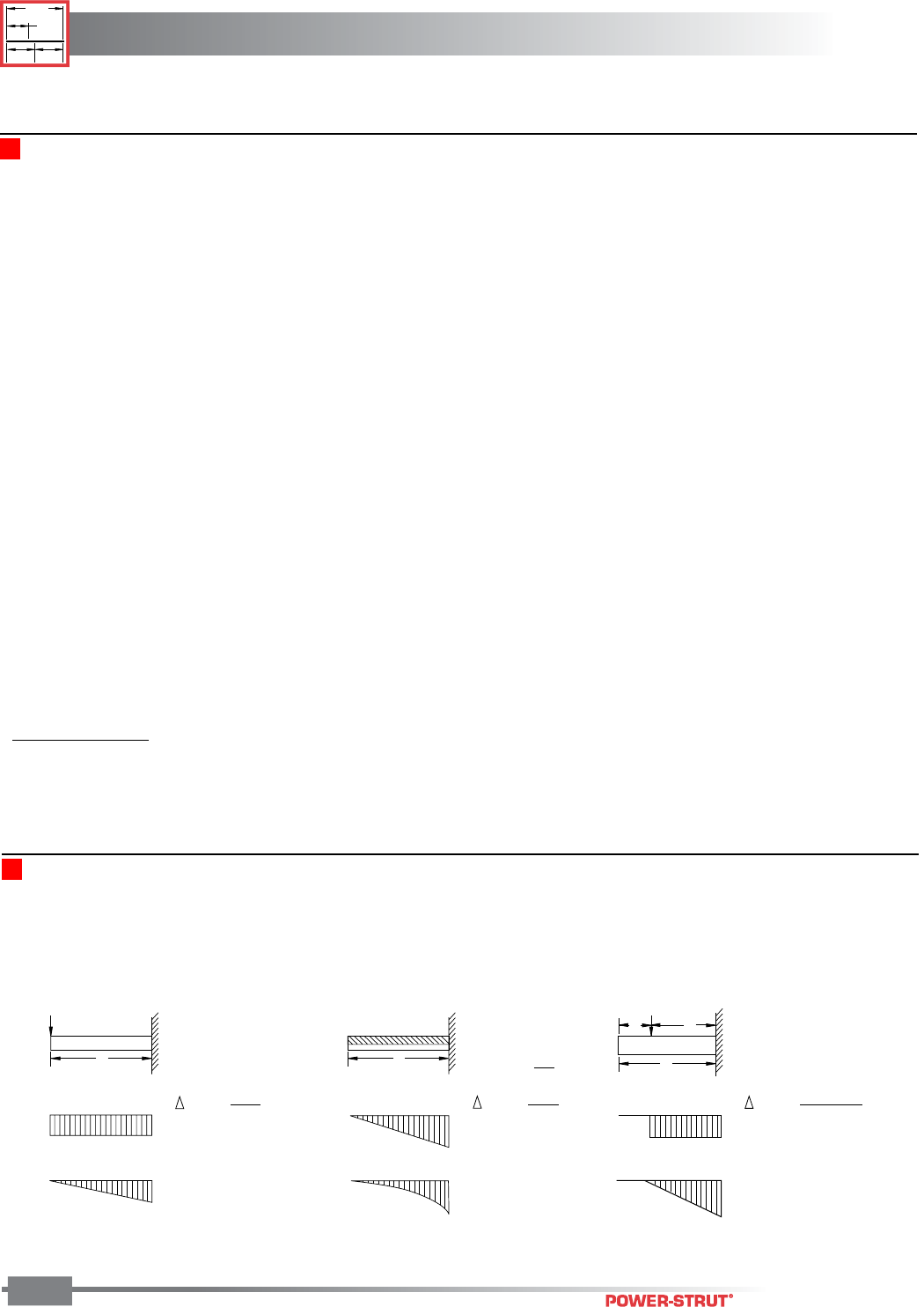
TECHNICAL DATA
TECHNICAL DATA
ENGINEERING CATALOG
1"
3
⁄
8
"
1
⁄
2
"
1
⁄
2
"
176
The information presented below is a
direct reproduction from portions of the
8th Edition of THE MANUAL OF STEEL CONSTRUCTION
by express permission of the American Institute of Steel Construction.
BEAM DIAGRAMS AND FORMULAS (Nomenclature)
E Modulus of Elasticity of steel at 29,000 ksi.
I Moment of Inertia of Beam (inch4).
Mmax Maximum Moment (kip inch)
M1 Maximum moment in left section of beam (kip inch)
M2 Maximum moment in right section of beam (kip inch)
Mx Moment at distance x from end of beam (kip inch)
P Concentrated Load (kips)
R End beam reaction for any condition of symmetrical loading (kips)
R1 Left end beam reaction (kips)
R2 Right end or intermediate beam reaction (kips)
V Maximum vertical shear for any condition of symmetrical loading (kips)
V1 Maximum vertical shear in left section of beam (kips)
V2 Vertical shear ar right reaction point, or to left of intermediate reaction point of beam (kips)
Vx Vertical shear at distance x from end of beam(kips)
a Measured distance along beam (inch)
b Measured distance along beam which may be greater or less that “a” (inch)
L Total length of beam between reaction points (inch)
W Uniformly distributed load per unit of length (kips per in.)
x Any distance measured along beam from left reaction (inch)
x1 Any distance measured along overhang section of beam from nearest reaction point(in).
∆max Maximum deflection (inch)
∆a Deflection at point of load (inch)
∆x Deflection at point x distance from left reaction (inch)
Beam Diagrams and Formulas (Cantilever Beams)
P
L
V
M
L
ab
P
M
V
M
V
V max. = P
M max. = PL
max. = PL3
3EI
V max. = W
max. = WL3
8EI
WL
2
M max. =
V max. = P
max. = Pb2(3L-b)
6EI
M max. = Pb
L
CANTILEVER BEAMS
LATERAL BRACING
Long spanning strut, when loaded, has a tendency to twist or bend laterally. This occurrence results in reductions in the allowable beam loads
shown in the tables. it's recommended that long spans be laterally braced properly. Many systems inherently provide such bracing. Pipes,
conduits, and cable tray do so when attached to the strut with straps, clamps and other fittings. Direct all questions regarding laterally bracing
issues to the factory.
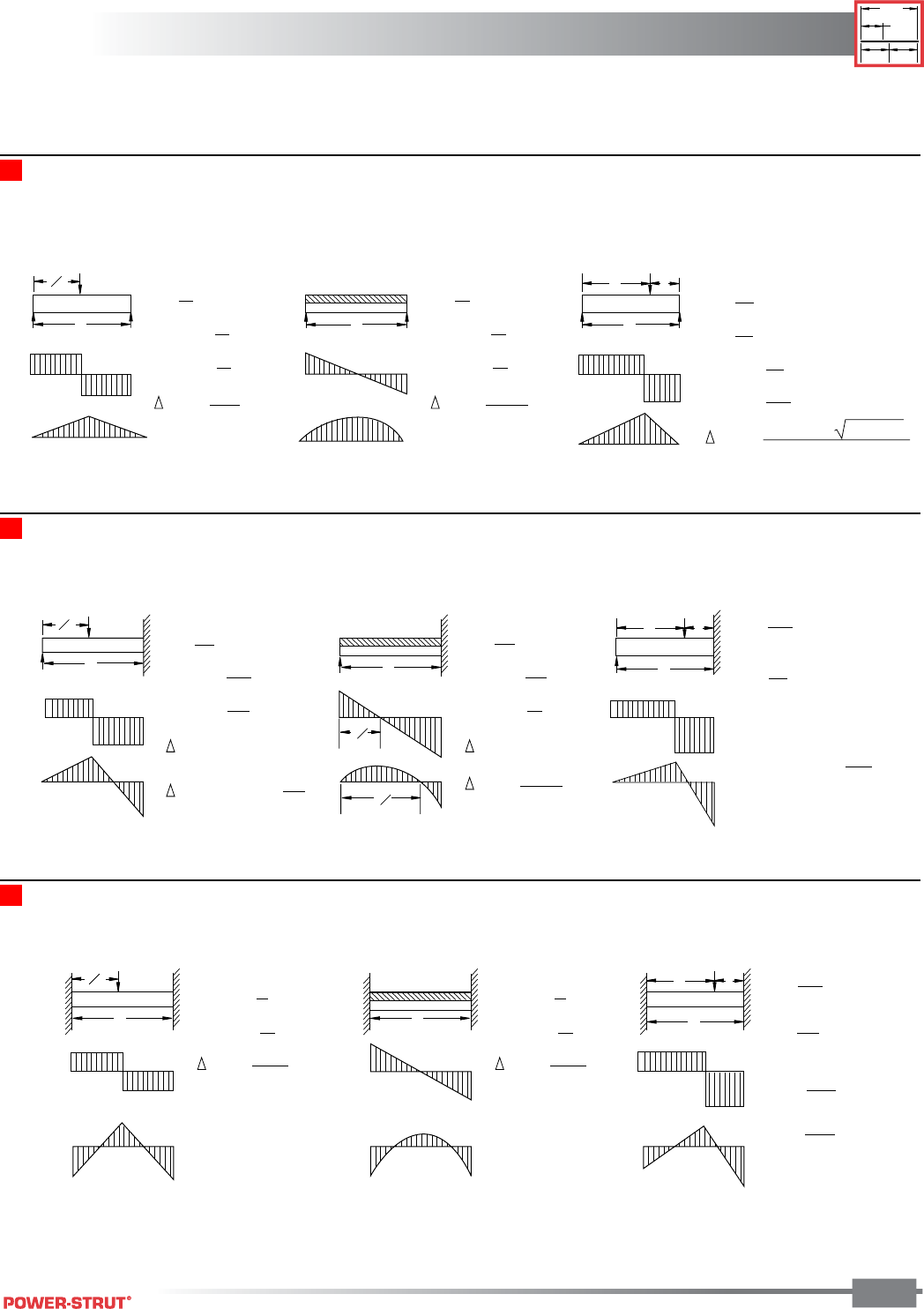
TECHNICAL DATA
TECHNICAL DATA
ENGINEERING CATALOG
1"
3⁄8"
1⁄2"
1⁄2"
177
Beam Diagrams and Formulas (Simple Beams)
The information presented below is a direct
reproduction from portions of the 8th Edition of
THE MANUAL OF STEEL CONSTRUCTION by
express permission of the American Institute of Steel Construction.
M
V
L
P
L2
RR
M
V
L
RR L
R
1
R
2
M
V
ab
P
R=
V max. =
M max. =
max. = PL
3
48EI
P
2
P
2
PL
4
R=
V max. =
M max. =
max. = 5WL
3
384EI
W
2
W
2
WL
8
R
2
=
V max. =
M max. =
Pb
L
R
1
=
Pa
L
Pa
L
Pab
L
Pab(a+2b) 3a(a+2b)
27EIL
max. =
L
R
1
R
2
ab
P
V
M
L
R
1
P
L2
V
M
L
V
M
3L
8
3L
4
R
2
=
M at point of load = R
1
a
M at fixed end =
Pb
2
2L
3
R
1
=
Pa
2L
3
(a+2L)
(3L2-a2)
Pab
2L
3
(a+L)
R
1
=
V max. =
M max. =
max. at x = 0.447L
5P
16
11P
16
3PL
16
max. = 0.009317
PL
3
EI
R
1
=
V max. =
M max. =
max. at x = 0.4215L
3W
8
5W
8
WL
8
max. = WL
3
185EI
R
1
V
M2
L
R1R2
ab
P
V
M
L
P
L2
V
M
L
M1
R2=
M1 =
M2 =
Pb2
L3
R1=
Pa2
L3
(3a+b)
(a+3b)
Pab2
L2
Pa2b
L2
V max. =
M max. =
max. = PL3
192EI
P
2
PL
8
V max. =
M max. =
max. = WL3
384EI
W
2
WL
12
Beam Digrams and Formulas (Beams fixed at one end, supported at other)
Beam Diagrams (Beams fixed at both ends)
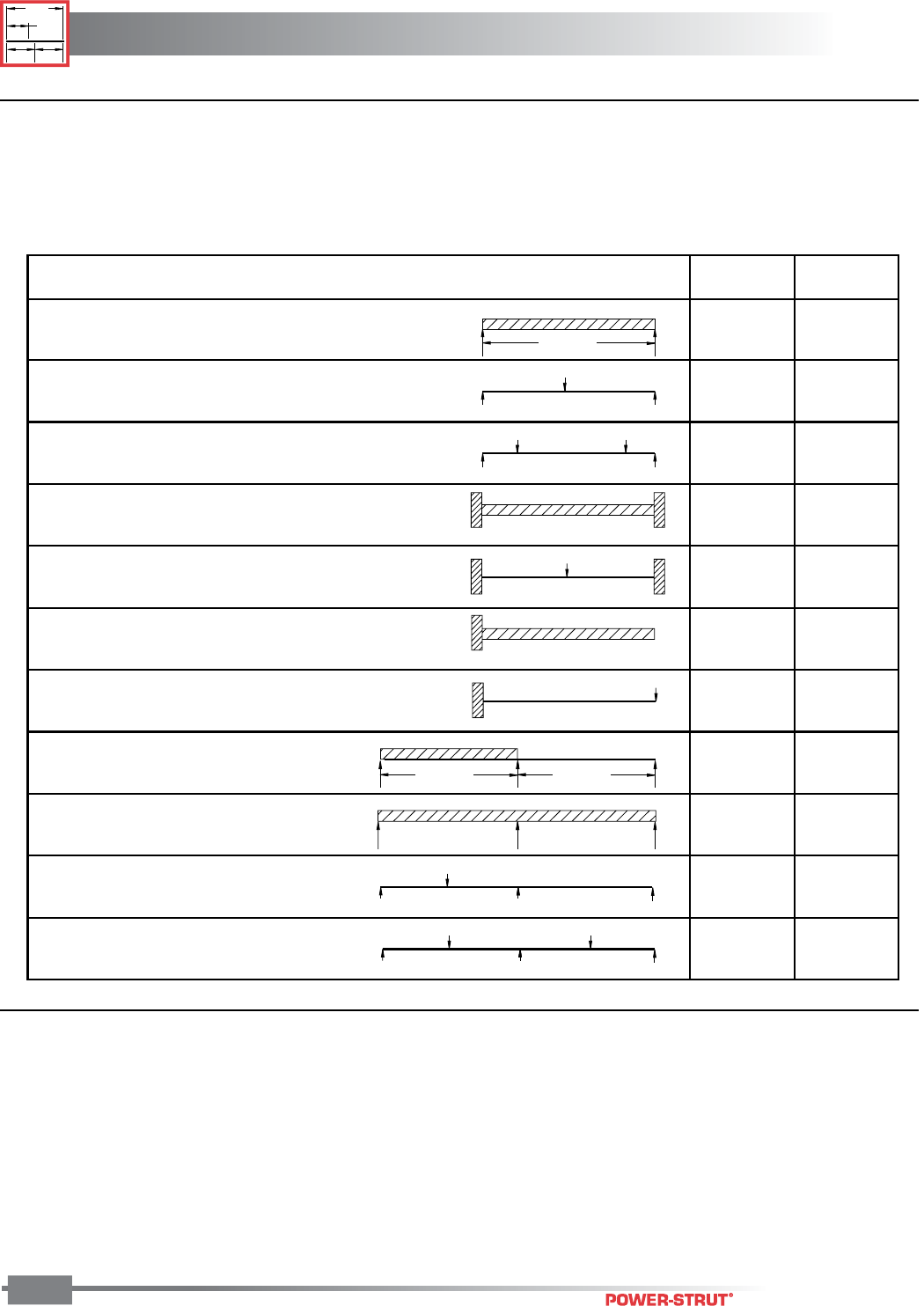
TECHNICAL DATA
TECHNICAL DATA
ENGINEERING CATALOG
1"
3
⁄
8
"
1
⁄
2
"
1
⁄
2
"
178
Power-Strut beam loads shown for varoius channels throughout this catalog are for single span, simple beams, with uniform
loads. Loading or other support conditions can be calculated by multiplying the channel beam load by the appropriate
factor listed below.
■ Beam Load (Static) Conversion Factors
1.) To determine the load and deflection of a PS-200
simple beam 72" long, with a concentrated load
at the center of span:
From the PS-200 Beam Load Chart (page 29), the
maximum uniform load for a 72" span is 560# with a
deflection of .50".
Multiply the above factors: Load = 560 x .50 = 280#
Defl. = .50 x .80 = .40"
Example solutions
Continuous Beam, Two Equal Spans,
Concentrated Load at Center of Each Span 0.67 0.48
DEFLECTION
FACTOR
LOAD
FACTOR
LOAD AND SUPPORT CONDITION
SPAN
1.00
1.00
0.50
0.25
1.50
1.00
1.00
0.12
1.30
0.62
1.10
1.00
0.80
2.40
0.30
0.40
0.42
3.20
0.92
0.71
1. Simple Beam,
Uniform Load
2. Simple Beam,
Concentrated Load at Center
3. Simple Beam,
Two Equal Concentrated Loadcs at 1/4 pts
4. Beam Fixed at Both Ends,
Uniform Load
5. Beam Fixed at Both Ends,
Concentrated Load at Center
6. Cantilever Beam,
Uniform Load
7. Cantilever Beam,
Concentrated Load at End
8. Continuous Beam, Two Equal Spans,
Uniform Load on One Span
9. Continuous Beam, Two Equal Spans,
Uniform Load on Both Ends
10. Continuous Beam, Two Equal Spans,
Concentrated Load at Center of One Span
11.
SPAN SPAN
2.) To determine the load and deflection of a PS-200-2T3
cantilever beam 24" long with a concetrated load at end:
From the PS-200-2T3 Beam Load Chart (page 30), the
maximum uniform load for a 24" span is 3130# with a
deflection of .03".
Multiply the above factors: Load = 3130# x .12 = 376#
Defl. = .03 x 3.20 = .096"
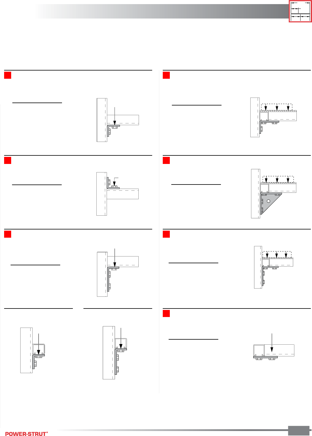
TECHNICAL DATA
TECHNICAL DATA
ENGINEERING CATALOG
1"
3⁄8"
1⁄2"
1⁄2"
179
DESIGN LOAD DATA FOR POWER-STRUT CHANNEL CONNECTIONS
PS 603 –PS-200 1500#, PS-2101000#
PS 603 –PS-200 1000#, PS-210 650#
PS 607 –PS-200 2000#, PS-210 2000#
■PS-601 PS-210 1000#, PS-210 800#
Both Ends Supported Both Ends Supported
PS 605 –PS-2001500, #PS-210 1000#
Both Ends Supported Both Ends Supported
PS 3373 –PS-200 3000#, PS-210 2000#
Both Ends Supported Both Ends Supported
PS 745 –PS-200 2000#, PS-210 1500#
Both Ends Supported
LOAD
LOAD
LOAD
LOAD
LOAD
LOAD
LOAD
LOAD
LOAD
■PS 604 – 500# ■PS 606 – 500#
1.) Safety Factor = 2-1⁄2 based on ultimate strength of connection.
2.) Load Diagrams indicate design loads for 12 ga. (listed as PS-200) and for 14 ga. (listed as PS-210) channels.
Channel Load (lbs)
PS 200 1,500
PS 210 1,000
Channel Load (lbs)
PS 200 1,500
PS 210 1,000
Channel Load (lbs)
PS 200 1,000
PS 210 650
Channel Load (lbs)
PS 200 3,000
PS 210 2,000
Channel Load (lbs)
PS 200 2,000
PS 210 1,500
Channel Load (lbs)
PS 200 2,000
PS 210 2,000
Channel Load (lbs)
PS 200 1,000
PS 210 800
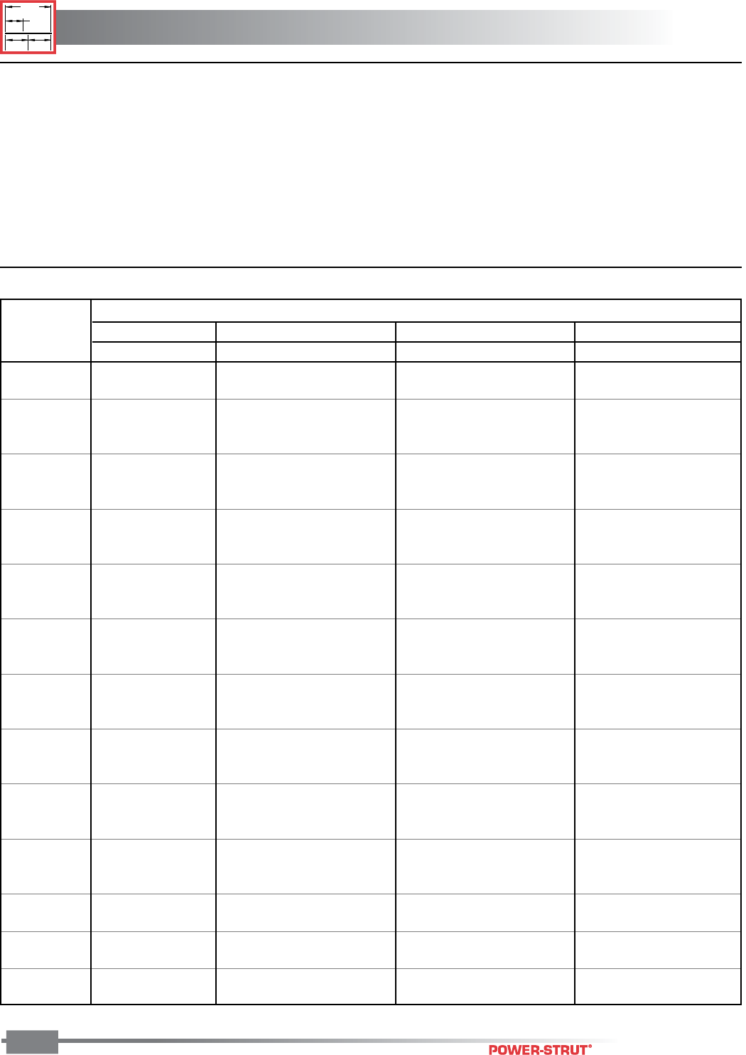
TECHNICAL DATA
TECHNICAL DATA
ENGINEERING CATALOG
1"
3
⁄
8
"
1
⁄
2
"
1
⁄
2
"
180
■ Tables of Pipe Spacing
This chart, developed by Julius Getlan of Seelye Stevenson Value & Knect, consulting engineers, New York City, enables one to quickly
determine the centerline-to-centerline dimension between any two size pipes on a rack. Select the smaller pipe size at top and select the other
at the side of the table. Where the appropriate columns intersect, the dimension is given.
These factors are included in the dimensions given:
• O.D. of flanges and fittings.
• 1" insulation over flanges and fittings.
• All fractional dimensions less than 1⁄4" were increased to the
next larger 1⁄4".
T – denotes threaded IPS pipe. F – denotes flanged fittings on pipe. S – denotes soldered or brazed tubing.
Centerline to Centerline Dimensions, Inches
• Clear space between fittings as follows:
1. 1" between piping 3" and smaller.
2. 11⁄2" between a pipe 3" and smaller and a pipe 4" or larger.
3. 2" between piping 4" and larger.
Normal Pipe Diameter, Inches
Normal 3⁄4"1" 1
1⁄4"1
1⁄2"
Pipe Dia.(In.) T S T F S T F S T F S
3⁄4T4
3⁄4––––––––––
S4
1⁄241⁄4–– – ––– –––
1T 5 4
3⁄451⁄4– – –– – – ––
F65
3⁄461⁄471⁄4–––– –––
S4
3⁄441⁄2564
1⁄2–– – – ––
11⁄4T5
1⁄455
1⁄261⁄255
1⁄2–– –––
F6
1⁄466
1⁄271⁄261⁄463⁄473⁄4––––
S4
3⁄441⁄2564
1⁄251⁄461⁄443⁄4–––
11⁄2T5
1⁄455
1⁄261⁄251⁄453⁄463⁄451⁄453⁄4––
F6
1⁄261⁄463⁄473⁄461⁄463⁄486
1⁄278–
S54
3⁄451⁄461⁄443⁄451⁄465 5
1⁄261⁄25
2T 5
3⁄451⁄2675
1⁄267
1⁄453⁄461⁄471⁄453⁄4
F76
3⁄471⁄481⁄463⁄471⁄481⁄277
1⁄281⁄27
S5
1⁄455
1⁄261⁄255
1⁄263⁄451⁄453⁄463⁄451⁄4
21⁄2T65
3⁄461⁄471⁄466
1⁄271⁄266
1⁄273⁄461⁄4
F7
1⁄271⁄473⁄483⁄471⁄473⁄497
1⁄2897
1⁄2
S5
1⁄251⁄453⁄463⁄451⁄453⁄475
1⁄2675
1⁄2
3T 6
1⁄466
1⁄271⁄261⁄463⁄473⁄461⁄463⁄486
1⁄2
F7
3⁄471⁄2897
1⁄289
1⁄473⁄481⁄491⁄473⁄4
S5
3⁄451⁄2675
1⁄267
1⁄453⁄461⁄471⁄453⁄4
4T 7
1⁄271⁄473⁄483⁄471⁄473⁄497
1⁄2897
1⁄2
F98
3⁄491⁄4101⁄483⁄491⁄4101⁄299
1⁄2101⁄29
S6
3⁄461⁄2786
1⁄278
1⁄463⁄471⁄481⁄463⁄4
5T 8 7
3⁄481⁄491⁄473⁄481⁄491⁄288
1⁄291⁄28
F9
1⁄291⁄493⁄4103⁄491⁄493⁄411 91⁄210 11 91⁄2
S7
1⁄477
1⁄281⁄477
1⁄283⁄471⁄473⁄483⁄471⁄4
6T 8
3⁄481⁄29108
1⁄2910
1⁄483⁄491⁄4101⁄483⁄4
F109
3⁄4101⁄4111⁄493⁄4101⁄4111⁄210 101⁄2111⁄210
S7
3⁄471⁄2897
1⁄289
1⁄473⁄481⁄491⁄473⁄4
8T 8
3⁄491⁄210 11 93⁄4101⁄2111⁄493⁄4101⁄4111⁄210
F11
1⁄411 111⁄2121⁄211 111⁄2123⁄4111⁄4113⁄4123⁄4111⁄4
10 T 111⁄411 111⁄2121⁄211 111⁄2123⁄4111⁄4113⁄4123⁄4111⁄4
F12
1⁄2121⁄4123⁄4133⁄4121⁄4123⁄414 121⁄213 14 121⁄2
12 T 121⁄412 121⁄2131⁄212 121⁄2133⁄4121⁄4123⁄4133⁄4121⁄4
F1413
3⁄4141⁄4151⁄4133⁄4141⁄4151⁄214 141⁄2151⁄214
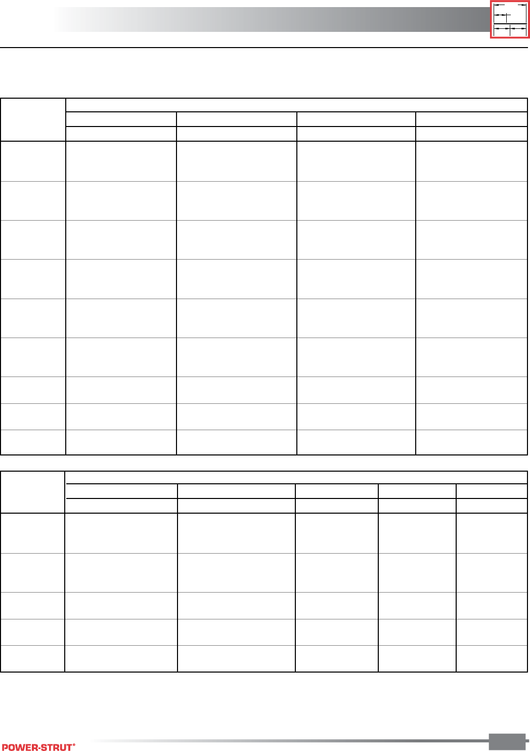
TECHNICAL DATA
TECHNICAL DATA
ENGINEERING CATALOG
1"
3⁄8"
1⁄2"
1⁄2"
181
■ Centerline to Centerline Dimensions, Inches
T – denotes threaded IPS pipe. F – denotes flanged fittings on pipe.
S – denotes soldered or brazed tubing.
Nominal Pipe Diameter, Inches
Nominal 5" 6" 8" 10" 12"
Pipe Dia. (In.) T F S T F S T F T F T F
5T11––––– ––––––
F12
1⁄214– – –– –– –– ––
S10
1⁄4113⁄491⁄2––– ––––––
6T 11
3⁄4131⁄411 121⁄2–– –– –– ––
F1314
1⁄2121⁄4131⁄415– ––––––
S10
3⁄4121⁄410 111⁄2123⁄4101⁄2–– –– ––
8T 13 14
1⁄2121⁄4133⁄415 123⁄4143⁄4–––––
F14
1⁄4153⁄4131⁄215 161⁄414 161⁄417 1⁄2–– ––
10 T 141⁄4153⁄4131⁄215 161⁄414 161⁄4171⁄2171⁄2–––
F15
1⁄217 143⁄4161⁄4171⁄2151⁄4171⁄2183⁄4183⁄420 – –
12 T 151⁄4163⁄4141⁄216 171⁄415 171⁄4181⁄2181⁄2193⁄4191⁄2–
F1718
1⁄4161⁄4173⁄419 163⁄414 201⁄4201⁄4211⁄2211⁄429
Nominal Pipe Diameter, Inches
Nominal 2" 21⁄2"3" 4"
Pipe Dia. (In.) T F S T F S T F S T F S
2T 6
1⁄2–– – – – – –– – ––
F7
3⁄49– – – – – –– – ––
S67
1⁄451⁄2––– ––– –––
21⁄2T78
1⁄461⁄271⁄4–– – –– –––
F8
1⁄491⁄273⁄483⁄410 – – – – – – –
S6
1⁄471⁄253⁄463⁄486 – –– –––
3T 7
1⁄481⁄263⁄471⁄297 7
3⁄4–– – ––
F8
1⁄293⁄48910
1⁄481⁄491⁄4101⁄2––––
S6
1⁄273⁄4678
1⁄461⁄471⁄481⁄261⁄2–––
4T 8
1⁄491⁄273⁄483⁄410 8 9 101⁄481⁄410 – –
F9
3⁄411 91⁄4101⁄4111⁄291⁄2101⁄2113⁄493⁄4111⁄213 –
S7
1⁄283⁄4789
1⁄471⁄481⁄491⁄271⁄291⁄4103⁄481⁄2
5T 8
3⁄410 81⁄491⁄4101⁄281⁄291⁄2103⁄483⁄4101⁄412 93⁄4
F10
1⁄4111⁄293⁄4103⁄412 10 11 121⁄4101⁄412 131⁄2111⁄4
S89
1⁄471⁄281⁄293⁄473⁄483⁄410 8 93⁄4111⁄49
6T 9
1⁄2103⁄491011
1⁄491⁄4101⁄4111⁄291⁄2111⁄4123⁄4101⁄2
F10
3⁄412 101⁄4111⁄4121⁄2101⁄2111⁄2121⁄4103⁄4121⁄214 113⁄4
S8
1⁄293⁄48910
1⁄481⁄491⁄4101⁄281⁄2101⁄4113⁄491⁄2
8T 10
3⁄412 101⁄211 121⁄2101⁄2111⁄4123⁄4103⁄4121⁄214 113⁄4
F1213
1⁄4111⁄2121⁄2133⁄4113⁄4123⁄414 12 133⁄4151⁄413
10 T 12 131⁄4111⁄2121⁄2133⁄4113⁄4123⁄414 12 133⁄4151⁄413
F13
1⁄4141⁄2123⁄4133⁄415 13 14 151⁄4131⁄415 161⁄2141⁄4
12 T 13 141⁄4121⁄2131⁄2143⁄4123⁄4133⁄415 13 143⁄4161⁄414
F14
3⁄416 141⁄4151⁄4161⁄2141⁄2151⁄2163⁄4143⁄4161⁄218 153⁄4
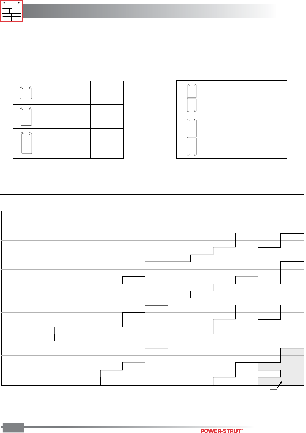
TECHNICAL DATA
TECHNICAL DATA
ENGINEERING CATALOG
1"
3
⁄
8
"
1
⁄
2
"
1
⁄
2
"
182
■ Minimum Size Power-Strut Channel - To Comply with NFPA 13 Table 2-6.1 5(a) 1996 Edition
Top values are for Schedule 10 pipe; bottom values are for Schedule 40 Pipe.
Pipe Size
Exceeds Section Modulus for
Channel Shown Above
Span of
Trapeze 1" 11⁄4"1
1⁄2"2"2
1⁄2"3" 3
1⁄2"4"5"6"8"10"
1 ft. 6 in. 0.08 0.09 0.09 0.09 0.10 0.11 0.12 0.13 0.15 0.18 0.24 0.32
0.08 0.09 0.09 0.10 0.11 0.12 0.13 0.15 0.18 0.22 0.30 0.41
2 ft. 0 in. 0.11 0.12 0.12 0.13 0.13 0.15 0.16 0.17 0.20 0.24 0.32 0.43
0.11 0.12 0.12 0.13 0.15 0.16 0.18 0.20 0.24 0.29 0.40 0.55
2 ft. 6 in. 0.14 0.14 0.15 0.16 0.17 0.18 0.20 0.21 0.25 0.30 0.40 0.54
0.14 0.15 0.15 0.16 0.18 0.21 0.22 0.25 0.30 0.36 0.50 0.68
3 ft. 0 in. 0.17 0.17 0.18 0.19 0.20 0.22 0.24 0.26 0.31 0.36 0.48 0.65
0.17 0.18 0.18 0.20 0.22 0.25 0.27 0.30 0.36 0.43 0.60 0.82
4 ft. 0 in. 0.22 0.23 0.24 0.25 0.27 0.29 0.32 0.34 0.41 0.48 0.64 0.87
0.22 0.24 0.24 0.26 0.29 0.33 0.36 0.40 0.48 0.58 0.80 1.09
5 ft. 0 in. 0.28 0.29 0.30 0.31 0.34 0.37 0.40 0.43 0.51 0.59 0.80 1.08
0.28 0.29 0.30 0.33 0.37 0.41 0.45 0.49 0.60 0.72 1.00 1.37
6 ft. 0 in. 0.33 0.35 0.36 0.38 0.41 0.44 0.48 0.51 0.61 0.71 0.97 1.30
0.34 0.35 0.36 0.39 0.44 0.49 0.54 0.59 0.72 0.87 1.20 1.64
7 ft. 0 in. 0.39 0.40 0.41 0.44 0.47 0.52 0.55 0.60 0.71 0.83 1.13 1.52
0.39 0.41 0.43 0.46 0.51 0.58 0.63 0.69 0.84 1.01 1.41 1.92
8 ft. 0 in. 0.44 0.46 0.47 0.50 0.54 0.59 0.63 0.68 0.81 0.95 1.29 1.73
0.45 0.47 0.49 0.52 0.59 0.66 0.72 0.79 0.96 1.16 1.61 2.19
9 ft. 0 in. 0.50 0.52 0.53 0.56 0.61 0.66 0.71 0.77 0.92 1.07 1.45 1.95
0.50 0.53 0.55 0.59 0.66 0.74 0.81 0.89 1.08 1.30 1.81 2.46
10 ft. 0 in. 0.56 0.58 0.59 0.63 0.68 0.74 0.79 0.85 1.02 1.19 1.61 2.17
0.56 0.59 0.61 0.65 0.74 0.82 0.90 0.99 1.20 1.44 2.01 2.74
■ Section Modulus Required for Trapeze Members (in.3)
Channel Size
PS-200
15⁄8" x 15⁄8" x 12 ga.
PS-150
15⁄8" x 27⁄16" x 12 ga.
PS-100
15⁄8" x 31⁄4" x 12 ga.
Sect.
Mod. (in3)
.202
.391
.628
Channel Size
Sect.
Mod. (in3)
1.153
1.716
PS-150 2T3
15⁄8" x 47⁄8" x 12 ga.
PS-100 2T3
15⁄8" x 61⁄2" x 12 ga.
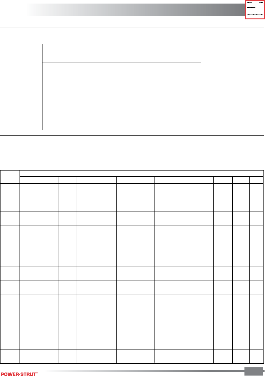
TECHNICAL DATA
TECHNICAL DATA
ENGINEERING CATALOG
1"
3⁄8"
1⁄2"
1⁄2"
183
■ Electrical Metallic Tubing Data
■ Application Engineering Data – Conduit Spacings
Spacings in inches between centers of conduits. The light face figures are the minimum dimensions to provide clearance between
locknuts. The more liberal spacings printed in bold face type should be used whenever possible.
Nom. Size Approx. Max Wt. (lbs.ft.)
EMT OD Conduit Wt. Conduit and Conductor
Conduit Conduit lbs./ft Not Lead Covered
1⁄20.706 0.29 0.54
3⁄40.922 0.45 1.16
1 1.163 0.65 1.83
11⁄41.510 0.96 2.96
11⁄21.740 1.11 3.68
2 2.197 1.41 4.45
21⁄22.875 2.15 6.41
3 3.500 2.60 9.30
31⁄24.000 3.25 12.15
4 4.500 3.90 15.40
Size
Size 1⁄2"
3⁄4"1" 1
1⁄4"1
1⁄2"2" 2
1⁄2"3"3
1⁄2"4"4
1⁄2"5"6"
1⁄2"1
3⁄16 –– –––– –– ––––
13⁄8–– –––– –– ––––
3⁄4"1
5⁄16 17⁄16 –––––––––––
11⁄215⁄8–––––––––––
1" 11⁄215⁄813⁄4–––– –– ––––
13⁄417⁄82––––––––––
11⁄4"1
3⁄417⁄822
1⁄4–– – – – –– ––
21
1⁄821⁄421⁄2–– – – – –– ––
11⁄2"1
15⁄16 21⁄16 23⁄16 27⁄16 29⁄16 –– –– ––––
21⁄821⁄423⁄825⁄823⁄4–– –– ––––
2" 23⁄16 25⁄16 21⁄223⁄427⁄831⁄8–––––––
23⁄821⁄223⁄433
1⁄833⁄8–––––––
21⁄2"2
7⁄16 29⁄16 23⁄433
1⁄833⁄835⁄8–– ––––
25⁄823⁄433
1⁄433⁄835⁄84––––––
3" 213⁄16 215⁄16 31⁄16 35⁄16 37⁄16 33⁄444
5⁄16 –––––
33
1⁄833⁄835⁄833⁄444
3⁄843⁄4–––––
31⁄2"3
1⁄831⁄433⁄835⁄833⁄441⁄16 45⁄16 45⁄8415⁄16 –– ––
33⁄831⁄235⁄837⁄844
3⁄845⁄855
3⁄8–– ––
4" 37⁄16 39⁄16 311⁄16 315⁄16 41⁄16 43⁄845⁄8415⁄16 51⁄459⁄16 –––
33⁄437⁄844
1⁄443⁄843⁄455
3⁄855⁄86– ––
41⁄2"3
3⁄437⁄844
1⁄443⁄845⁄847⁄851⁄459⁄16 57⁄861⁄8––
44
1⁄841⁄441⁄243⁄455
1⁄455⁄866
1⁄461⁄2––
5" 41⁄841⁄443⁄845⁄843⁄455
1⁄459⁄16 57⁄863⁄16 61⁄2613⁄16 –
43⁄841⁄245⁄847⁄855
3⁄855⁄866
1⁄465⁄877
1⁄4–
6" 43⁄447⁄855
1⁄453⁄855⁄857⁄863⁄16 61⁄2613⁄16 71⁄877⁄16 81⁄8
55
1⁄851⁄451⁄255⁄866
1⁄465⁄877
1⁄475⁄888
5⁄8
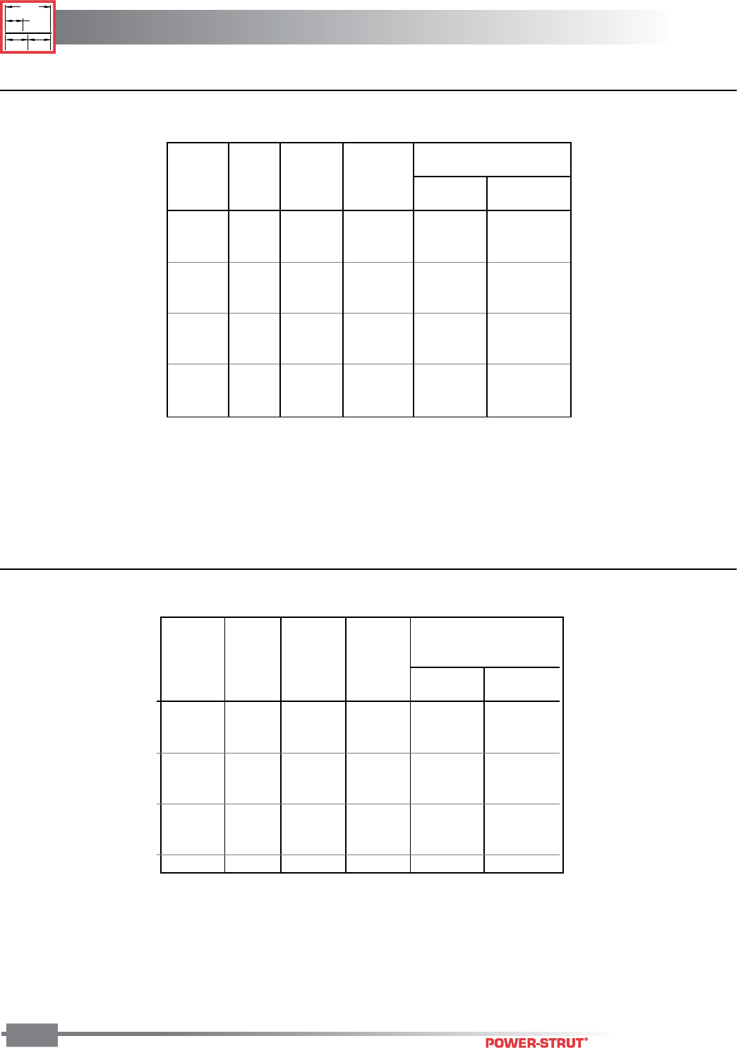
TECHNICAL DATA
TECHNICAL DATA
ENGINEERING CATALOG
1"
3
⁄
8
"
1
⁄
2
"
1
⁄
2
"
184
Approx. Max Wt.(lbs./ft.)
Nom. Size Wt. Conduit Conduit and Conductor
Rigid OD OD W/C Pkg. Lead Not Lead
Conduit Conduit Coupling lbs./ft Covered Covered
1⁄2" 0.840 1.010 0.80 1.17 1.04
3⁄4" 1.050 1.250 1.09 1.75 1.40
1" 1.315 1.525 1.65 2.62 2.35
11⁄4" 1.660 1.869 2.15 4.31 3.58
11⁄2" 1.900 2.155 2.58 5.89 4.55
2" 2.375 2.650 3.52 8.53 7.21
21⁄2" 2.875 3.250 5.67 11.51 10.22
3" 3.500 3.870 7.14 16.51 14.51
31⁄2" 4.000 4.500 8.60 19.05 17.49
4" 4.500 4.875 10.00 24.75 21.48
5" 5.563 6.000 13.20 35.87 30.83
6" 6.625 7.200 17.85 50.69 43.43
1 Cubic ft. of water weighs 62.35 lbs.
1 Gallon US weighs 8.335 lbs.
■ Steel Rigid Conduit Data
■ Intermediate Metal Conduit Data
Maximum weight equals weight of rigid conduit plus weight of heaviest
conductor combination as specified by the 1996 edition of the
"National Electric Code Handbook."
Approx. Max Wt.
Weight (lbs./ft.)
Nom. Size Conduit Conduit and Conductor
Rigid OD OD W/C Pkg. Lead Not Lead
Conduit Conduit Coupling lbs./ft Covered Covered
1⁄2" 0.815 1.010 0.60 0.97 0.84
3⁄4" 1.029 1.250 0.82 1.48 1.13
1" 1.290 1.525 1.16 2.13 1.86
11⁄4" 1.638 1.869 1.50 3.66 2.93
11⁄2" 1.883 2.115 1.82 5.13 3.79
2" 2.360 2.650 2.42 7.43 6.11
21⁄2" 2.857 3.250 4.28 10.12 8.83
3" 3.476 3.870 5.26 14.63 12.63
31⁄2" 3.971 4.500 6.12 16.57 15.01
4" 4.466 4.875 6.82 21.57 18.30
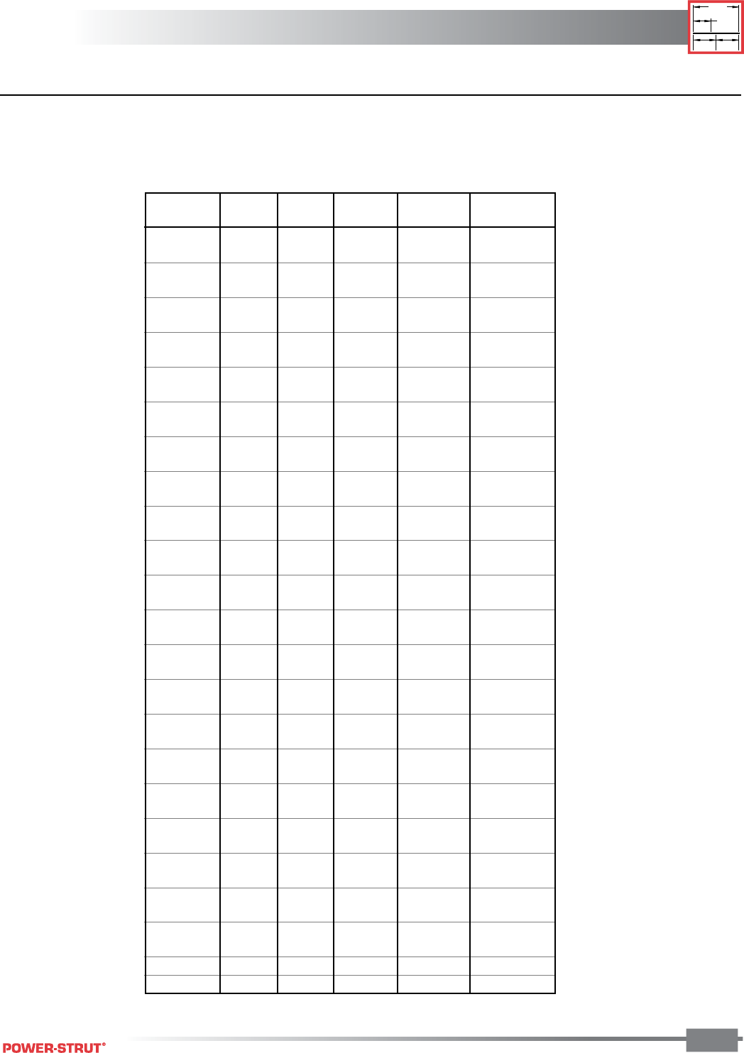
TECHNICAL DATA
TECHNICAL DATA
ENGINEERING CATALOG
1"
3⁄8"
1⁄2"
1⁄2"
185
■ Steel Pipe Data – Schedule 40 & 80
Nominal Sch. Wall Wt. of
Pipe Size No. O.D. Thick Wt./Ft. Water/Ft
3⁄8" 40 0.675 0.091 0.567 0.083
80 0.126 0.738 0.061
1⁄2" 40 0.840 0.109 0.850 0.132
80 0.147 1.087 0.101
3⁄4" 40 1.050 0.133 1.130 0.230
80 0.154 1.473 0.186
1" 40 1.315 0.133 1.678 0.374
80 0.179 2.171 0.311
11⁄4" 40 1.660 0.140 2.272 0.647
80 0.199 2.996 0.555
11⁄2" 40 1.900 0.145 2.717 0.882
80 0.200 3.631 0.765
2" 40 2.375 0.154 3.652 1.452
80 0.218 5.022 1.279
21⁄2" 40 2.875 0.203 5.790 2.072
80 0.276 7.660 1.834
3" 40 3.500 0.216 7.570 3.200
80 0.300 10.250 2.860
31⁄2" 40 4.000 0.226 9.110 4.280
80 0.318 12.510 3.850
4" 40 4.500 0.237 10.790 5.510
80 0.337 14.980 4.980
5" 40 5.563 0.258 14.620 8.660
80 0.375 20.780 7.870
6" 40 6.625 0.280 18.970 12.510
80 0.432 28.570 11.290
8" 40 8.625 0.322 28.550 21.600
80 0.500 43.390 19.800
10" 40 10.750 0.365 40.480 34.100
80 0.593 64.400 31.100
12" 40 12.750 0.406 53.600 48.500
80 0.687 88.600 44.000
14" 40 14.000 0.437 63.000 58.500
80 0.750 107.000 51.200
16" 40 16.000 0.500 83.000 76.500
80 0.843 137.000 69.700
18" 40 18.000 0.563 105.000 97.200
80 0.937 171.000 88.500
20" 40 20.000 0.593 123.000 120.400
80 1.031 209.000 109.400
24" 40 24.000 0.687 171.000 174.200
80 1.218 297.000 158.200
30" 20 30.000 0.500 158.000 286.000
36" API 36.000 0.500 190.000 417.000
TECHNICAL DATA
TECHNICAL DATA
ENGINEERING CATALOG
1"
3
⁄
8
"
1
⁄
2
"
1
⁄
2
"
186
Nom. Wt. of
Tube O.D. Wall Wt./Ft. Water/Ft.
Size Tubing O.D. Thick Lbs. Lbs.
1⁄4"3⁄8" 0.375 0.035 0.145 0.032
3⁄8"1⁄2" 0.500 0.005 0.269 0.055
1⁄2"5⁄8" 0.625 0.049 0.344 0.094
5⁄8"3⁄4" 0.750 0.049 0.418 0.144
3⁄4"7⁄8" 0.875 0.065 0.641 0.188
1" 11⁄8" 1.125 0.065 0.839 0.337
11⁄4"1
3⁄8" 1.375 0.065 1.040 0.527
11⁄2"1
5⁄8" 1.625 0.072 1.360 0.743
2" 21⁄8" 2.125 0.083 2.060 1.310
21⁄2"2
5⁄8" 2.625 0.095 2.920 2.000
3" 31⁄8" 3.125 0.109 4.000 2.960
31⁄2"3
5⁄8" 3.625 0.120 5.120 3.900
4" 41⁄8" 4.125 0.134 6.510 5.060
5" 51⁄8" 5.125 0.160 9.670 8.000
6" 61⁄8" 6.125 0.192 13.870 11.200
8" 81⁄8" 8.125 0.271 25.900 19.500
10" 101⁄8" 10.125 0.338 40.300 30.423
12" 121⁄8" 12.125 0.405 57.800 43.675
■ Copper Tube Data
Type K
Nom. Wt. of
Tube O.D. Wall Wt./Ft. Water/Ft
Size Tubing O.D. Thick Lbs. Lbs.
1⁄4"3⁄8" 0.375 0.030 0.126 0.034
3⁄8"1⁄2" 0.500 0.035 0.198 0.062
1⁄2"5⁄8" 0.625 0.040 0.285 0.100
5⁄8"3⁄4" 0.750 0.042 0.362 0.151
3⁄4"7⁄8" 0.875 0.045 0.455 0.209
1" 11⁄8" 1.125 0.050 0.655 0.357
11⁄4"1
3⁄8" 1.375 0.055 0.884 0.546
11⁄2"1
5⁄8" 1.625 0.060 1.140 0.767
2" 21⁄8" 2.125 0.070 1.750 1.341
21⁄2"2
5⁄8" 2.625 0.080 2.480 2.064
3" 31⁄8" 3.125 0.090 3.330 2.949
31⁄2"3
5⁄8" 3.625 0.100 4.290 3.989
4" 41⁄8" 4.125 0.110 5.380 5.188
5" 51⁄8" 5.125 0.125 7.610 8.081
6" 61⁄8" 6.125 0.140 10.200 11.616
8" 81⁄8" 8.125 0.200 19.290 20.289
10" 101⁄8" 10.125 0.250 30.100 31.590
12" 121⁄8" 12.125 0.280 40.400 45.426
Type L
TECHNICAL DATA
TECHNICAL DATA
ENGINEERING CATALOG
1"
3⁄8"
1⁄2"
1⁄2"
187
■ Spacing of Hangers for Steel Pipe
The above spacing and capacities are based on pipe filled with water.
Additional valves and fittings increase the load and therefore closer hanger spacing is required.
* Many codes and specifications state “pipe hangers must be spaced every 10 ft., regardless of size”.
Follow local specifications.
■ Spacing of Hangers for Copper Tubing
Tubing Size
1⁄2 3⁄411
1⁄411⁄222
1⁄233
1⁄245681012
Span in Ft. 6 8 8 101010121212121214141819
Nominal Pipe
Size, Inches 1⁄23⁄411
1⁄411⁄222
1⁄233
1⁄24 5 6 8 10 12 14 16 18 20 24
Maximum
Span, Ft.* 5 6 7 7 9 10 11 12 13 14 16 17 19 2 23 25 27 28 30 32
Recommended
Hanger 3⁄83⁄83⁄83⁄83⁄83⁄81⁄21⁄21⁄25⁄85⁄83⁄47⁄87⁄87⁄8111
1⁄411⁄2
Rod Sizes or Trapeze
TECHNICAL DATA
TECHNICAL DATA
ENGINEERING CATALOG
1"
3
⁄
8
"
1
⁄
2
"
1
⁄
2
"
188
■ PVC Plastic Pipe Data – Schedule 40 & 80
■ Spacing of Hangers for PMC Plastic Pipe
Nom. Wt. of
Tube Schedule Wall Wt./Ft. Water/Ft.
Size No. O.D. Thick Lbs. Lbs.
1⁄8" 40 0.405 0.068 0.043 0.025
80 0.095 0.055 0.016
1⁄4" 40 0.540 0.088 0.074 0.045
80 0.119 0.094 0.031
3⁄8" 40 0.675 0.091 0.100 0.083
80 0.126 0.129 0.061
1⁄2" 40 0.840 0.109 0.150 0.132
80 0.147 0.150 0.101
3⁄4" 40 1.050 0.113 0.199 0.230
80 0.154 0.259 0.186
1" 40 1.315 0.133 0.295 0.374
80 0.179 0.382 0.311
11⁄4" 40 1.660 0.140 0.400 0.647
80 0.191 0.527 0.555
11⁄2" 40 1.990 0.145 0.478 0.882
80 0.200 0.639 0.765
2" 40 2.375 0.154 0.643 1.452
80 0.218 0.884 1.279
Nom. Wt. of
Tube Schedule Wall Wt./Ft. Water/Ft.
Size No. O.D. Thick Lbs. Lbs.
21⁄2" 40 2.875 0.203 1.020 2.072
80 0.276 1.350 1.834
3" 40 3.500 0.216 1.333 3.200
80 0.300 1.804 2.860
31⁄2" 40 4.000 0.226 1.598 4.280
80 0.318 2.195 3.850
4" 40 4.500 0.237 1.899 5.510
80 0.337 2.636 4.980
5" 40 5.563 0.258 2.770 8.660
80 0.375 4.126 7.870
6" 40 6.625 0.280 3.339 12.150
80 0.432 5.028 11.290
8" 40 8.625 0.322 5.280 21.600
80 0.500 8.023 19.800
10" 40 10.750 0.366 7.505 34.100
80 0.593 11.894 31.100
12" 40 12.750 0.406 10.023 48.500
80 0.687 16.365 44.000
Sch. 40 Support Spacings in Feet at Temperatures Shown Above
Pipe Size 20°F40°F60°F80°F 100°F 110°F 120°F 130°F 140°F 150°F
1⁄2"– 3⁄4" 5.00 4.75 4.50 4.25 4.00 3.75 3.33 3.00 2.66 2.00
1"– 11⁄4" 5.50 5.25 5.00 4.66 4.33 4.00 3.75 3.33 2.80 2.25
11⁄2" – 2" 5.80 5.50 5.25 5.00 4.66 4.33 3.80 3.50 3.00 2.50
21⁄2" 6.66 6.33 6.00 5.50 5.25 4.80 4.50 4.00 3.50 2.80
3" 6.80 6.50 6.25 5.80 5.50 5.25 4.75 4.25 3.66 3.00
4" 7.33 7.00 6.50 6.25 5.80 5.50 5.00 4.50 3.80 3.25
6" 7.80 7.50 7.00 6.80 6.33 5.80 5.33 4.80 4.25 3.50
Sch. 40 Support Spacings in Feet at Temperatures Shown Above
Pipe Size 20°F40°F60°F80°F 100°F 110°F 120°F 130°F 140°F 150°F
1⁄2" – 3⁄4" 5.75 5.50 5.25 4.80 4.50 4.33 3.80 3.50 3.00 2.50
1" 6.33 6.00 5.75 5.33 5.00 4.60 4.33 3.80 3.33 2.75
11⁄4" – 11⁄2" 6.66 6.33 6.00 5.66 5.25 4.80 4.50 4.00 3.50 3.00
2" 7.00 6.50 6.25 6.00 5.50 5.12 4.75 4.33 3.66 3.12
21⁄2" 7.80 7.50 7.00 6.66 6.33 5.80 5.33 4.75 4.25 3.33
3" 8.20 7.75 7.33 7.00 6.50 6.00 5.50 5.00 4.33 3.50
4" 8.66 8.25 7.80 7.33 6.80 6.33 5.80 5.25 4.66 3.75
6" 9.80 9.33 8.80 8.33 7.80 7.33 6.50 6.00 5.12 4.25
TECHNICAL DATA
TECHNICAL DATA
ENGINEERING CATALOG
1"
3⁄8"
1⁄2"
1⁄2"
189
■ Cast Iron Pipe Data
Mechanical Joint Pipe Class 150. Approximately same weight
for Bell & Spigot. Flange cast iron pipe add weight of flanges.
Spacing of Hangers for glass pipe support every 8-10 ft. Pad
all hangers. Use only clevis or trapeze, do not tie down pipe.
■ Load Carrying Capacities of Threaded Hot Rolled Steel Rod
Nom. Wt. of
Tube Wall Wt./ Water
Size Class O.D. Thick Ft. Ft. Lbs.
3" 150 3.96 0.32 12.20 3.73
4" 150 4.80 0.35 16.40 5.72
6" 150 6.90 0.38 25.70 12.80
8" 150 9.05 0.41 36.70 23.10
10" 150 11.10 0.44 48.70 35.50
12" 150 13.20 0.48 62.90 51.00
14" 150 15.30 0.51 78.80 69.30
16" 150 17.40 0.54 95.00 90.30
18" 150 19.50 0.58 114.70 114.00
20" 150 21.60 0.62 135.90 141.50
24" 150 25.80 0.73 190.40 201.00
30" 150 32.00 0.85 277.30 312.00
36" 150 38.30 0.94 368.90 449.00
42" 150 44.50 1.05 479.10 612.00
48" 150 50.80 1.14 595.20 803.00
Nom. Wt. of
Pipe Wall Wt./Ft. Water/Ft.
Size O.D. Thick Lbs. lbs.
11⁄2" 1.84 0.12 0.64 0.89
2" 2.34 0.14 0.94 1.45
3" 3.41 0.17 1.60 3.19
4" 4.53 0.20 2.60 5.79
6" 6.66 0.24 4.70 12.78
Heavy Schedule
1" 1.31 0.16 0.60 0.35
11⁄2" 1.84 0.17 0.87 0.76
2" 2.34 0.17 1.10 1.36
3" 3.41 0.20 2.00 3.06
4" 4.53 0.26 3.40 5.44
6" 6.66 0.33 6.30 12.42
Nominal Root Area Maximum Safe Load, Pounds
Rod Dia. Sq. (In.) 650°750°
1⁄4" 0.027 240 210
3⁄8" 0.068 610 540
1⁄2" 0.126 1,130 1,010
5⁄8" 0.202 1,810 1,610
3⁄4" 0.302 2,710 2,420
7⁄8" 0.419 3,770 3,030
1" 0.552 4,960 4,420
11⁄8" 0.693 6,230 5,560
11⁄4" 0.889 8,000 7,140
11⁄2" 1.293 11,630 10,370
13⁄4" 1.744 15,700 14,000
2" 2.300 20,700 18,460
21⁄4" 3.023 27,200 24,260
21⁄2" 3.719 33,500 29,880
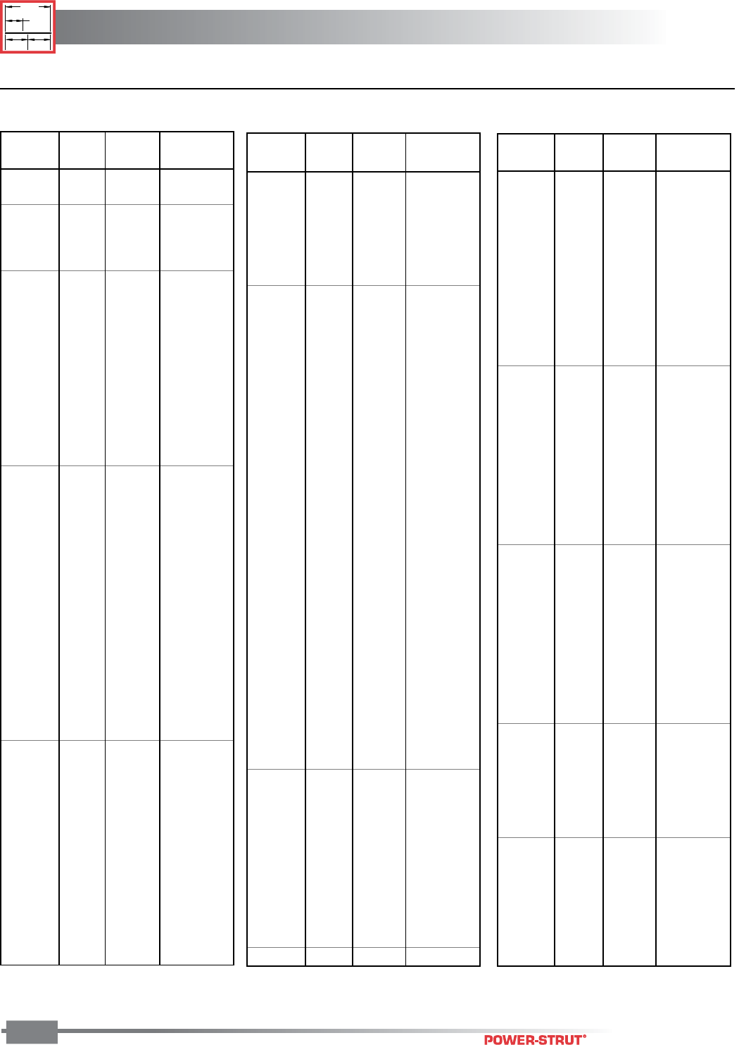
TECHNICAL DATA
TECHNICAL DATA
ENGINEERING CATALOG
1"
3
⁄
8
"
1
⁄
2
"
1
⁄
2
"
190
■ Wide Flange Beams
18" 40 0.525"
46 0.605"
50 71⁄2" 0.570"
55 0.630"
60 0.695"
65 75⁄8" 0.750"
71 0.810"
76 11" 0.680"
86 111⁄8" 0.770"
97 0.870"
106 111⁄4" 0.940"
119 1.060"
21" 44 61⁄2" 0.450"
50 0.535"
57 0.650"
62 81⁄4" 0.615"
68 0.685"
73 0.740"
83 83⁄8" 0.835"
93 0.930"
111 123⁄8" 0.875"
122 0.960"
147 121⁄2" 1.150"
24" 55 7" 0.505"
62 0.590"
68 9" 0.585"
76 0.680"
84 0.770"
94 91⁄8" 0.875"
104 123⁄4" 0.750"
117 0.850"
131 127⁄8" 0.960"
146 1.090"
162 13" 1.220"
27" 84 10" 0.640"
94 0.745"
102 0.830"
114 101⁄8" 0.930"
146 14" 0.975"
161 1.080"
178 141⁄8" 1.190"
30" 99 101⁄2" 0.670"
108 0.760"
116 0.850"
124 0.930"
132 1.000"
173 15" 1.065"
191 1.185"
Depth of Wt/ Flange Avg. Flange
Section Foot Width Thickness
12" 87 0.810"
96 0.900"
106 121⁄4" 0.990"
120 123⁄8" 1.105"
136 1.250"
152 121⁄2" 1.400"
190 125⁄8" 1.735"
14" 22 5" 0.335"
26 0.420"
30 63⁄4" 0.385"
34 0.455"
38 0.515"
43 8" 0.530"
48 0.595"
53 0.660"
61 10" 0.645"
68 0.720"
74 101⁄8" 0.785"
82 0.855"
90 141⁄2" 0.710"
99 145⁄8" 0.780"
109 0.860"
120 0.940"
132 143⁄4" 1.030"
145 151⁄2" 1.090"
159 155⁄8" 1.190"
176 1.310"
193 153⁄4" 1.440"
211 1.560"
233 157⁄8" 1.720"
257 16" 1.890"
283 161⁄8" 2.070"
311 161⁄4" 2.260"
342 163⁄8" 2.470"
370 161⁄2" 2.660"
398 165⁄8" 2.845"
426 163⁄4" 3.035"
16" 26 51⁄2" 0.345"
31 0.440"
36 7" 0.430"
40 0.505"
45 0.565"
50 71⁄8" 0.630"
57 0.715"
67 101⁄4" 0.665"
77 0.760"
89 103⁄8" 0.875"
100 0.985"
18" 35 6" 0.425"
Depth of Wt/ Flange Avg. Flange
Section Foot Width Thickness
Depth of Wt/ Flange Avg. Flange
Section Foot Width Thickness
5" 16 5" 0.360"
19 0.430"
6" 12 4" 0.280"
16 4" 0.405"
20 6" 0.365"
25 0.455"
8" 13 4" 0.255"
15 0.315"
18 51⁄4" 0.330"
21 0.400"
24 61⁄2" 0.400"
28 0.465"
31 8" 0.435"
35 0.495"
40 81⁄8" 0.560"
48 0.685"
58 81⁄4" 0.810"
67 0.935"
10" 15 4" 0.270"
17 0.330"
19 0.395"
22 53⁄4" 0.360"
26 0.440"
30 0.510"
33 8" 0.435"
39 0.530"
45 0.620"
49 10" 0.560"
54 0.615"
60 101⁄8" 0.680"
68 0.770"
77 101⁄4" 0.870"
88 0.990"
100 103⁄8" 1.120"
112 1.250"
12" 16 4" 0.265"
19 0.350"
22 0.425"
26 61⁄2" 0.380"
30 0.440"
35 65⁄8" 0.520"
40 8" 0.515"
45 0.575"
50 81⁄8" 0.640"
53 10" 0.575"
58 0.640"
65 12" 0.605"
72 0.670"
79 121⁄8" 0.735"
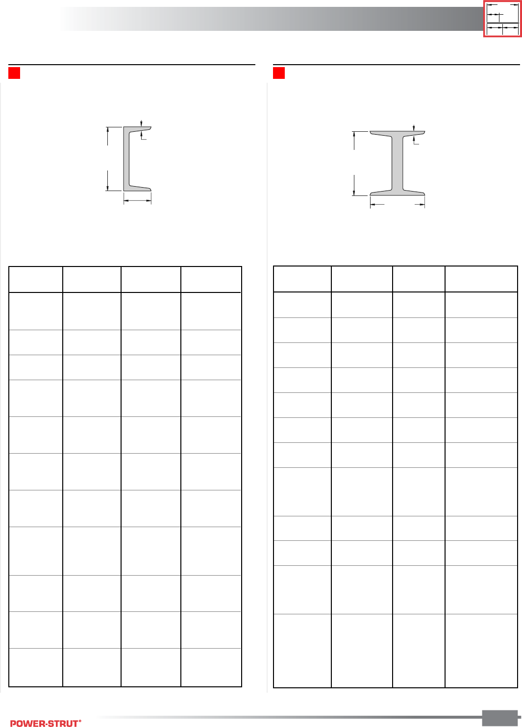
TECHNICAL DATA
TECHNICAL DATA
ENGINEERING CATALOG
1"
3⁄8"
1⁄2"
1⁄2"
191
Channels – American Standard I-beams – American Standard
DEPTH
OF
SECTION
AVERAGE
THICKNESS
OF FLANGE
FLANGE
WIDTH
DEPTH
OF
SECTION
AVERAGE
THICKNESS
OF FLANGE
FLANGE
WIDTH
Depth of Weight/ Flange Avg. Flange
Section Foot Width Thickness
3" 5.70 23⁄8" 0.260"
7.50 21⁄2"
4" 7.70 25⁄8" 0.293"
9.50 23⁄4"
5" 10.00 3" 0.326"
14.75 31⁄4"
6" 12.50 33⁄8" 0.359"
17.25 35⁄8"
7" 15.30 35⁄8" 0.392"
20.00 37⁄8"
8" 18.40 4" 0.426"
23.00 41⁄8"
10" 25.40 45⁄8" 0.491"
35.00 5"
12" 31.80 5" 0.544"
35.00 51⁄8"
40.80 51⁄4" 0.659"
50.00 51⁄2"
15" 42.90 51⁄2" 0.622"
50.00 55⁄8"
18" 54.70 6" 0.691
70.00 61⁄4"
20" 66.00 61⁄4" 0.795
75.00 63⁄8"
86.00 7" 0.920
96.00 71⁄4"
24" 80.00 7" 0.871
90.00 71⁄8"
100.00 71⁄4"
106.00 77⁄8" 1.090
Depth of Weight/ Flange Avg. Flange
Section Foot Width Thickness
3" 4.10 13⁄8" 0.273"
5.00 11⁄2"
6.00 15⁄8
4" 5.40 15⁄8" 0.296"
7.25 13⁄4"
5" 6.70 13⁄4" 0.320"
9.00 17⁄8"
6" 8.20 17⁄8" 0.343"
10.50 2"
13.00 21⁄8
7" 9.80 21⁄8" 0.366"
12.25 21⁄4"
14.75 21⁄4"
8" 11.50 21⁄4" 0.390"
13.75 23⁄8"
18.75 21⁄2"
9" 13.40 23⁄8" 0.413"
15.00 21⁄2"
20.00 25⁄8"
10" 15.30 25⁄8" 0.436"
20.00 23⁄4"
25.00 27⁄8"
30.00 3"
12" 20.70 3" 0.501"
25.00 3"
30.00 31⁄8"
15" 33.90 33⁄8" 0.650"
40.00 31⁄2"
50.00 33⁄4"
18" 42.70 4"
45.80 4" 0.625"
51.90 41⁄8"
TECHNICAL DATA
TECHNICAL DATA
ENGINEERING CATALOG
1"
3
⁄
8
"
1
⁄
2
"
1
⁄
2
"
192
To Convert Multiply To Convert Multiply
From To By From To By
Length
Inch [in] Millimeter [mm] 25.400 000 Millimeter [mm] Inch [in] 0.039 370
Foot [ft] Meter [m] 0.304 800 Meter [m] Foot [ft] 3.280 840
Yard [yd] Meter [m] 0.914 400 Meter [m] Yard [yd] 1.093 613
Mile (U.S. Statute) [mi] Kilometer [km] 1.609 347 Kilometer [km] Mile (U.S. Statute) [mi] 0.621 370
Area
Square Inch [in2] Square Millimeter [mm2] 645.16 Square Millimeter [mm2] Square Inch [in2] 0.001550
Square Foot [ft2] Square Meter [m2] 0.092 903 Square Meter [m2] Square Foot [ft2] 10.763 915
Square Yard [yd2] Sqare Meter [m2] 0.836 127 Sqare Meter [m2] Square Yard [yd2] 1.195 991
Square Mile [mi2] Square Kilometer [km2] 2.589 998 Square Kilometer [km2] Square Mile [mi2] 0.386 101
(U.S. Statute) (U.S. Statute)
Acre Square Meter [m2] 4046.873 Square Meter [m2] Acre 0.000 247
Acre Hectare 0.404 687 Hectare Acre 2.471 046
Volume
Cubic Inch [in3] Cubic Millimeter [mm3] 16387.06 Cubic Millimeter [mm3] Cubic Inch [in3] 0.000061
Cubic Foot [ft3] Cubic Meter [m3] 0.028 317 Cubic Meter [m3] Cubic Foot [ft3] 35.314 662
Cubic Yard [yd3] Cubic Meter [m3] 0.764 555 Cubic Meter [m3] Cubic Yard [yd3] 1.307 950
Gallon (U.S. Liquid) [gal] Litre [l] 3.785 412 Litre [l] Gallon (U.S. Liquid) [gal] 0.264 172
Quart (U.S. Liquid) [qt] Litre [l] 0.946 353 Litre [l] Quart (U.S. Liquid) [qt] 1.056 688
Mass
Ounce (Avoirdupois) [oz] Gram [g] 28.349 520 Gram [g] Ounce (Avoirdupois) [oz] 0.035 274
Pound (Avoirdupois) [lb] Kilogram [kg] 0.453 592 Kilogram [kg] Pound (Avoirdupois) [lb] 2.204 624
Short Ton Kilogram [kg] 907.185 Kilogram [kg] Short Ton 0.00110
Force
Ounce-Force Newton [N] 0.278 014 Newton [N] Ounce-Force 3.596 941
Pound-Force [lbf] Newton [N] 4.448 222 Newton [N] Pound-Force [lbf] 0.224 809
Bending Moment
Pound-Force-Inch [lbf-in] Netwon-Meter [N-m] 0.112 985 Netwon-Meter [N-m] Pound-Force-Inch [lbf-in] 8.850 732
Pound-Force-Foot [lbf-ft] Newton-Meter [N-m] 1.355 818 Newton-Meter [N-m] Pound-Force-Foot [lbf-ft] 0.737 562
Pressure, Stress
Pound-Force per Kilopascal [kPa] 6.894 757 Kilopascal [kPa] Pound-Force per 0.145 038
Square Inch [lbf/in2] Square Inch [lbf/in2]
Foot of Water (39.2 F) Kilopascal [kPa] 2.988 980 Kilopascal [kPa] Foot of Water (39.2 F) 0.334 562
Inch of Mercury (32 F) Kilopascal [kPa] 3.386 380 Kilopascal [kPa] Inch of Mercury (32 F) 0.295 301
Energy, Work, Heat
Foot-Pound-Force [ft-lbf] Joule [J] 1.355 818 Joule [J] Foot-Pound-Force [ft-lbf] 0.737 562
British Thermal Unit [Btu] Joule [J] 1055.056 Joule [J] British Thermal Unit [Btu] 0.000948
Calorie [cal] Joule [J] 4.186 800 Joule [J] Calorie [cal] 0.238 846
Kilowatt Hour [kW-h] Joule [J] 3600000 Joule [J] Kilowatt Hour [kW-h] 2.78-7
Power
Foot-Pound-Force Watt [W] 1.355 818 Watt [W] Foot-Pound-Force 0.737 562
/Second [ft-lbs/s] /Second [ft-lbs/s]
British Thermal Unit Watt [W] 0.293 071 Watt [W] British Thermal Unit 3.412 142
/Hour [Btu/h] /Hour [Btu/h]
Horsepower Kilowatt [kW] 0.745 700 Kilowatt [kW] Horsepower 1.341 022
(550 Ft. Lbf/s) [hp] (550 Ft. Lbf/s) [hp]
Angle
Degree Radian [rad] 0.017 453 Radian [rad] Degree 57.295 788
Temperature
Degree Fahrenheit [F] Degree Celsius [C] (F° -32)/1.8 Degree Celsius [C] Degree Fahrenheit [F] 1.8xC°+32

TECHNICAL DATA
TECHNICAL DATA
ENGINEERING CATALOG
1"
3⁄8"
1⁄2"
1⁄2"
193
PS 993 ........................ 79
PS 998 ...................... 103
PS 1000 ...................... 86
PS 1004 ...................... 79
PS 1100 ...................... 86
PS 1116 ...................... 86
PS 1117 ...................... 86
PS 1154 .................... 130
PS 1200 ...................... 87
PS 1300 ...................... 86
PS 1450 ...................... 88
PS 1500 .................... 123
PS 1510 .................... 123
PS 1610 .................... 126
PS 1801 .................... 126
PS 1850 .................... 126
PS 1901 ...................... 98
PS 1902 ...................... 99
PS 1911 .................... 100
PS 2007 R or L ........... 70
PS 2008 .................... 137
PS 2010 .................... 138
PS 2011 .................... 138
PS 2013 .................... 136
PS 2014 .................... 136
PS 2015 .................... 136
PS 2016 .................... 136
PS 2017 .................... 137
PS 2018 .................... 137
PS 2019 .................... 137
PS 2023 R or L ......... 137
PS 2024 .................... 137
PS 2025 .................... 137
PS 2026 .................... 138
PS 2029 .................... 138
PS 2033 .................... 136
PS 2034 .................... 136
PS 2037 .................... 137
PS 2041 .................... 138
PS 2054 ...................... 72
PS 2064 ...................... 83
PS 2094 .................... 121
PS 2112 ...................... 65
PS 2113 ...................... 71
PS 2117 R or L ........... 79
PS 2119 ...................... 76
PS 2128 R or L ........... 80
PS 2129 R or L ........... 80
PS 2144 ...................... 66
PS 2190 ...................... 64
PS 2401 thru 2403 ..... 96
PS 2404 thru 2408 ..... 96
PS 2421 ...................... 96
PS 2422 ...................... 96
PS 2504 ...................... 62
PS 2511 .................... 115
PS 2514 ...................... 82
PS 2520 ...................... 66
PS 2521 ...................... 83
PS 2522 ...................... 83
PA 158 ...................... 140
PA 238 ...................... 140
PA 318 ...................... 140
PA 1GP ..................... 140
PA 1HDC .................. 140
PA 1RC ..................... 140
PA 1RP ..................... 140
PA 1SC ..................... 140
PA 1SNB ................... 140
PS 51 .......................... 89
PS 52 E ....................... 92
PS 67 .......................... 89
PS 69 .......................... 89
PS 83 .......................... 57
PS 85 ........................ 107
PS 86 ........................ 107
PS 93 ........................ 108
PS 94 ........................ 108
PS 95 ........................ 107
PS 100 ........................ 22
PS 100 2T3 ................. 24
PS 100 EH .................. 22
PS 100 H .................... 22
PS 100 K06 ................ 22
PS 100 S .................... 22
PS 135 ........................ 58
PS 135 X .................. 107
PS 146 ........................ 58
PS 150 ........................ 25
PS 150 2T3 ................. 27
PS 150 EH .................. 25
PS 150 H .................... 25
PS 150 KO6 ................ 25
PS 150 S .................... 25
PS 200 ........................ 28
PS 200 2T2 ................. 31
PS 200 2T3 ................. 30
PS 200 2T4 ................. 31
PS 200 2T5 ................. 31
PS 200 3T6 ................. 31
PS 200 EH .................. 28
PS 200 EH 2T3 ........... 30
PS 200 H .................... 28
PS 200 H3 .................. 28
PS 200 KO6 ................ 28
PS 200 PLA ................ 34
PS 200 PLB ................ 34
PS 200 PLC ................ 34
PS 200 S .................... 28
PS 200 SB .................. 28
PS 202 ........................ 60
PS 203 ........................ 60
PS 204 ........................ 60
PS 205 ........................ 60
PS 209 ........................ 57
PS 210 ........................ 36
PS 210 2T3 ................. 38
PS 210 EH .................. 36
PS 210 H .................... 36
PS 210 KO6 ................ 36
PS 210 S .................... 36
PS 211 ........................ 58
PS 230 ........................ 58
PS 270 ........................ 92
PS 285 ...................... 131
PS 300 ........................ 39
PS 300 2T3 ................. 41
PS 300 EH .................. 39
PS 300 H .................... 39
PS 300 KO6 ................ 39
PS 300 S .................... 39
PS 349 ...................... 128
PS 400 ........................ 42
PS 400 2T3 ................. 44
PS 400 EH .................. 42
PS 400 H .................... 42
PS 400 KO6 ................ 42
PS 400 S .................... 42
PS 449 ...................... 129
PS 500 ........................ 45
PS 500 2T3 ................. 47
PS 500 EH .................. 45
PS 500 H .................... 45
PS 500 S .................... 45
PS 517 ........................ 59
PS 520 ........................ 48
PS 520 2T3 ................. 50
PS 520 EH .................. 48
PS 520 H .................... 48
PS 520 S .................... 48
PS 560 ........................ 51
PS 560 2T3 ................. 53
PS 560 EH .................. 51
PS 560 H .................... 51
PS 560 S .................... 51
PS 600 J ................... 134
PS 601 ........................ 62
PS 602 ........................ 62
PS 603 ........................ 65
PS 604 ........................ 66
PS 605 ........................ 67
PS 606 ........................ 67
PS 607 ........................ 68
PS 609 ........................ 74
PS 611 ........................ 74
PS 612 ........................ 74
PS 613 ........................ 75
PS 614 ........................ 68
PS 615 ........................ 68
PS 616 ........................ 78
PS 617 ........................ 62
PS 618 ........................ 62
PS 619 ........................ 62
PS 620 ........................ 63
PS 621 ........................ 63
PS 622 ........................ 69
PS 623 ........................ 78
PS 624 ........................ 70
PS 626 ........................ 94
PS 629 ........................ 78
PS 631 ........................ 78
PS 633 ........................ 70
PS 644 ........................ 78
PS 645 ........................ 78
PS 646 ........................ 78
PS 647 ........................ 74
PS 649 ...................... 120
PS 651 ........................ 94
PS 653 ...................... 130
PS 654 ...................... 130
PS 655 ...................... 115
PS 656 .............. 115, 130
PS 658 ...................... 116
PS 659 ...................... 116
PS 660 ........................ 68
PS 661 T1 ................... 94
PS 661 T2 ................... 94
PS 665 ........................ 80
PS 666 ........................ 80
PS 667 ........................ 80
PS 668 ........................ 81
PS 669 ........................ 82
PS 670 ........................ 81
PS 671 ...................... 121
PS 677 ........................ 77
PS 678 ........................ 77
PS 679 ........................ 75
PS 680 ...................... 132
PS 684 ...................... 104
PS 685 ...................... 103
PS 686 ...................... 103
PS 687 ........................ 76
PS 689 ........................ 69
PS 692 ........................ 75
PS 693 ...................... 120
PS 694 ...................... 120
PS 700 J ................... 135
PS 702 ...................... 118
PS 702 D .................. 119
PS 703 ...................... 118
PS 703 D .................. 119
PS 704 ........................ 79
PS 707 ...................... 119
PS 707 P .................. 119
PS 708 ........................ 94
PS 709 ........................ 77
PS 710 ........................ 76
PS 711 ........................ 74
PS 712 ........................ 64
PS 713 ........................ 69
PS 714 ........................ 64
PS 715 ........................ 69
PS 716 R or L ............. 68
PS 718 ........................ 63
PS 719 ........................ 63
PS 720 R or L ............. 68
PS 721 ........................ 76
PS 722 ...................... 125
PS 723 ...................... 124
PS 732 ........................ 95
PS 733 ........................ 77
PS 734 ........................ 77
PS 735 ........................ 77
PS 736 ...................... 104
PS 744 ........................ 64
PS 745 ........................ 67
PS 746 ........................ 70
PS 747 ........................ 65
PS 748 ........................ 70
PS 750 ........................ 64
PS 752 R or L ............. 69
PS 756 ........................ 73
PS 760 ...................... 121
PS 763 ........................ 66
PS 764 ........................ 66
PS 781 ........................ 71
PS 791 ...................... 123
PS 793 ........................ 71
PS 803 ...................... 116
PS 804 ........................ 79
PS 805 ...................... 120
PS 806 ........................ 66
PS 807 ...................... 117
PS 808 T1 ................... 94
PS 808 T2 ................... 94
PS 809 ........................ 94
PS 810 ........................ 73
PS 812 ........................ 73
PS 815 ........................ 98
PS 816 ...................... 100
PS 821 ........................ 81
PS 822 ........................ 65
PS 825 R or L ............. 95
PS 826 ........................ 95
PS 838 R or L ............. 95
PS 854 ........................ 65
PS 855 ...................... 102
PS 858 ...................... 106
PS 865 ...................... 106
PS 871 ...................... 105
PS 888 ........................ 63
PS 889 ........................ 63
PS 901 .............. 115, 130
PS 902 ...................... 115
PS 907 ...................... 103
PS 913 ........................ 81
PS 916 ...................... 104
PS 921 ........................ 65
PS 922 R or L ............. 79
PS 923 ........................ 81
PS 925 ........................ 64
PS 926 ........................ 72
PS 927 ........................ 69
PS 928 ........................ 74
PS 929 ........................ 76
PS 930 ...................... 115
PS 942 ...................... 120
PS 943 ........................ 80
PS 945 ........................ 81
PS 978 ........................ 76
■ Metal Framing
TECHNICAL DATA
TECHNICAL DATA
ENGINEERING CATALOG
1"
3
⁄
8
"
1
⁄
2
"
1
⁄
2
"
194
PS 2524 ...................... 84
PS 2525 ...................... 84
PS 2528 ...................... 84
PS 2528 -1 ................. 84
PS 2532 ...................... 75
PS 2545 ...................... 67
PS 2560 .................... 115
PS 2561 .................... 115
PS 2580 .................... 115
PS 2581 .................... 115
PS 2582 .................... 120
PS 2585 .................... 115
PS 2601 ...................... 73
PS 2622 .................... 104
PS 2623 .................... 105
PS 2624 .................... 105
PS 2625 .................... 116
PS 2626 .................... 106
PS 2627 .................... 123
PS 2631 .................... 117
PS 2631 D ................ 117
PS 2632 .................... 116
PS 2632 D ................ 116
PS 2636 .................... 118
PS 2637 .................... 118
PS 2639 .................... 121
PS 2640 .................... 115
PS 2648 ...................... 75
PS 2651 .................... 102
PS 2653 .................... 103
PS 2654 .................... 106
PS 2654 A ................ 106
PS 2656 .................... 102
PS 2657 .................... 102
PS 2660 .................... 120
PS 2661 .................... 120
PS 2662 - A .............. 120
PS 2800 .................... 122
100-1500 thru 100-1512 ................. 164
200-3101 ......................................... 160
200-4101 ......................................... 160
200-3100 thru 200-3210 ................. 158
200-3827 thru 200-3381 ................. 166
200-3840 thru 200-3843 ................. 166
200-4100N
200-4226 thru 200-4342 ................. 163
200-4227 thru 200-4343 ................. 163
1000E .............................................. 162
1000V .............................................. 162
10PU-CNS thru 250PU-CN .............. 163
20E-1000 thru 20E-2300 ................. 151
20E-5000 ......................................... 157
20N-ARM08 .................................... 167
20N-ARM14 .................................... 167
20N-ARM17 .................................... 167
20N-ARM23 .................................... 167
20N-STA21 ...................................... 167
20N-STA33 ...................................... 167
20P-1000 thru 20P-2300 ................ 151
20P/V-2500 thru 20P/V-2508 .......... 154
20P/V-2510 thru 20P/V-2526 .......... 155
20P/V-2528 thru 20P/V-2541 .......... 156
20P/V-2800 thru 20P/V-2808 .......... 154
20P/V-2812 thru 20P/V-2826 .......... 155
20P/V-2828 thru 20P/V-2840 .......... 156
20P/V-2810L/R ................................ 155
20P/V-2816L/R ................................ 155
20PP-5903 ...................................... 157
20PP-5904 ...................................... 157
20PP-5905 ...................................... 157
20PU-CNMHD thru 375PU-CNHD ... 163
20PU/PP-5853 ................................ 157
20PU/PP-5854 ................................ 157
20PU/PP-5855 ................................ 157
20V-1000 thru 20V-2300-SST ......... 151
20V-2BC-25 ..................................... 165
PS 2801 .................... 122
PS 2802 .................... 122
PS 2803 .................... 122
PS 3013 ...................... 82
PS 3013 SQ ................ 82
PS 3017 .................... 136
PS 3025 ...................... 82
PS 3025 FL ................. 82
PS 3029 ...................... 83
PS 3033 ...................... 82
PS 3033 SQ ................ 82
PS 3040 ...................... 82
PS 3041 ...................... 83
PS 3049 ...................... 67
PS 3060 ...................... 75
PS 3064 ...................... 83
PS 3101 thru 3115 ..... 92
PS 3126 ...................... 88
PS 3138 ...................... 88
PS 3164 ...................... 95
PS 3201 .................... 105
PS 3281 ...................... 60
PS 3282 ...................... 95
PS 3301 .................... 117
PS 3326 R or L ........... 70
PS 3373 ...................... 68
PS 3500 ...................... 58
PS 3792 ................. 54,88
PS 4017 .................... 136
PS 6024 ...................... 57
PS 6064 ...................... 58
PS 6072 ...................... 57
PS 6075 ...................... 57
PS 6108 ...................... 57
PS 6112 ...................... 57
PS 6151 .................... 130
PS 6152 ...................... 54
PS 6153 ...................... 54
PS 9050 ...................... 54
PS 9400 ...................... 71
PS 9401 ...................... 71
PS 9402 ...................... 72
PS 9403 ...................... 72
PS 9404 ...................... 72
PS 004M-038 M ......... 91
PS 004T-106N ............ 90
PS 285N ................... 131
PS LS ......................... 59
PS NS ......................... 59
PS NS S ...................... 59
PS RS ......................... 59
PS SS ......................... 59
PS TG ......................... 60
PS UB1/2-UB 10 ......... 91
20V-2BC-37 ..................................... 165
20V-2BC-50 ..................................... 165
250E ................................................ 162
250PU ............................................. 161
250PU ............................................. 161
375E ................................................ 162
375PU-BC ........................................ 165
375PU ............................................. 161
375V ................................................ 161
390N-150 ........................................ 166
390N-BLT ........................................ 166
390N-CLP ........................................ 166
500E ................................................ 162
500PU-BC ........................................ 165
500PU ............................................. 161
500V ................................................ 162
50PU-1508 ...................................... 156
50PU-2045 ...................................... 157
50PU-2090 ...................................... 157
50PU-2536 ...................................... 157
50PU-2611 ...................................... 156
50PU-2613 ...................................... 156
50PU-2616 ...................................... 154
50PU-2636 ...................................... 157
50PU-500SP .................................... 157
625E ................................................ 162
625PU ............................................. 161
625V ................................................ 162
750E ................................................ 162
750V ................................................ 162
AIC-EC ............................................. 157
CVHPU-100 thru CVHPU-600 .......... 164
PCR-050 thru PCR-080 ................... 159
PS050 thru PS1800 ......................... 159
RGBC-1 ........................................... 165
RGBC-2 ........................................... 165
RGBC-3 ........................................... 165
UB-050 thru UB-600 ........................ 160
Design Load - Channel Connections ............................ 146
Beam Diagrams and Formulas .............................. 147-148
Beam Load Conversion Factors ................................... 149
Section Modulus Required for Trapeze Members ........ 150
American Standard Beam Tables .......................... 151-152
Tables of Pipe Spacing ......................................... 153-154
Conduit Spacings ........................................................ 155
Electrical Metallic Tubing Data ..................................... 155
Intermediate Metal Conduit Data ................................. 156
Steel Rigid Conduit Data .............................................. 156
Steel Pipe Data – Schedule 40 & 80 ............................ 157
Copper Tube Data ........................................................ 158
Spacing of Hangers for Copper Tubing........................ 159
Spacing of Hangers for Steel Pipe ............................... 159
PVC Plastic Pipe Data – Schedule 40 & 80 .................. 160
Spacing of Hangers for PVC Plastic Pipe ..................... 160
Cast Iron Pipe Data ...................................................... 161
Load Capacities of Threaded Rod ................................ 161
Table of Conversions ................................................... 162
Fractions and Decimal Equivalents .............................. 163
General Applications ............................................. 164-167
■ Metal Framing
■ Fiberglass Framing ■ Technical Data

Power-Strut and the Power-Strut logo are registered trademarks of Allied Tube & Conduit.
©Copyright 2004, Allied Tube & Conduit. All Rights Reserved.
ATC-L-1376-6 [web download]
