382068 EU EN V4.0 Installation Directions
2014-07-05
: Pdf 101359-Installationsheet 101359-InstallationSheet 793950 Batch5 unilog
Open the PDF directly: View PDF ![]() .
.
Page Count: 20
User's Manual
Datalogging AC/DC Power Clamp-on Meter
Model 382068

382068-EU-EN-V4.0 12/11
2
Table of Contents
Specifications
General Specifications …………………………………………………………. 3
Range Specifications……………………………………………………………. 3
Safety Information ……………………………………………….………………. 5
Meter and Display Descriptions………………………………..……….……… 6
Measurements
AC/DC Power Measurements………………………………………………….. 7
AC/DC Voltage Measurements………………………………………………… 16
AC/DC Current Measurements………………………………………….……… 17
Resistance and Continuity Measurements…………………………….……… 18
Diode Tests …………………….…………….……………………………..…… 19
Min/Max Mode ………………………………….……………………………..…… 19
Peak Detector ………………………………….……………………………..…… 19
Data Hold .………………………………….…………………………………..…… 19
Datalogging …………………………………….……………………………...…... 20
Maintenance
Battery Replacement..………………………………….…………………..…… 21
Cleaning ………………………………….……………………………..……….. 21
Repair and Calibration Services ………………………………………….……. 21
Tech Support Hotlines..………………………………….………………………. 21
Introduction
Congratulations on your purchase of the Extech 382065/382068 Datalogging AC/DC Power Clamp-
on Meter. Measurements include DC and AC True Power, Apparent Power, Power Factor, and True
RMS Voltage, Current, & Watts. Status indication for Lead/Lag and PF is included as well as dual
displays of KW + PF, KVA + PF, V + A, A + Hz, and V + Hz. The frequency of Voltage and Current
measurements can be displayed also. Datalogger and PC interface features are built into the meter.
The Datalogger/Data Acquisition Software package is for exclusive use with the Model
382065/382068 Clamp on Power Datalogger. Windows® XP, Vista, Window’s 7-32 bit, and 7-64 bit
operating systems are supported. Users can download readings stored in the datalogger to a PC,
program sample rates for datalogging, remotely monitor readings, and save readings to ASCII files
for export to spreadsheet and other programs. Careful use will provide years of reliable service.
382068-EU-EN-V4.0 12/11
3
Specifications
General Specifications
Main display 4-digit (10,000 count) multi-function LCD
Bargraph display 40-segment bargraph
Datalogger 4000 data point continuous logging (25 point manual logging)
with MIN / MAX and Peak detect recording
Peak hold Built-in detector captures positive and negative peaks to .1ms
Maximum voltage 600Vrms between any terminal and earth ground
Meter power 9V battery
Battery life 30 hours (approx.)
Low battery indication Battery icon is displayed
Auto power off After 30 minutes (approx.)
Display update rate 2 times per second (Bargraph); 5 times per second (Digits),
(once every 6 seconds for the KW function)
Jaw opening For Cables φ 1.8” (46mm)
Operating temperature 32 to 122oF (0 to 50oC)
Operating Humidity R.H. < 80% non-condensing.
Storage temperature 14o to 140oF (-10 to 60oC)
Storage Humidity RH < 70% non-condensing
Dimensions/Weight 10.24 x 3.66 x 1.77" (260 x 93 x 45mm) / 1 lb. (450g)
Accessories Carrying case, test leads, and 9V battery
Range Specifications
Accuracy specs are ± (reading + no. of digits) at 64o to 82oF (18o to 28o C) and RH to 80%
True power & Apparent power measurements (600KW Max.)
Input Resolution Accuracy
Frequency
range
Overload
protection
V<130V, A<150A
V>130V, A<150A
V<130V, A>150A
0.01
±
(2%+5)
V>130V, A>150A 0.1
±
(2%+1)
45Hz to 500Hz 600V/1100A
Power Factor
Range* Resolution Accuracy Frequency Range Sensitivity
0.30 to 1.00 ± (4% + 10d)
0.00 to 0.30
0.001
Not specified
10Hz to 5KHz >100V / 10A
*Minimum voltage: 100V AC, Minimum Current: 20A AC
DCA
Range Resolution Accuracy Overload protection
2 to 1000A 0.1A ±(1.5% + 5) 1100A
382068-EU-EN-V4.0 12/11
4
ACA
Range Resolution Accuracy Frequency range Overload
protection
2 to 1000A 0.1A ±(1.5% + 5) 45Hz to 500Hz 1100A
Crest factor < 3 for stated accuracy
DCV
Range Resolution Accuracy Input impedance Overload
protection
2 to 600V 0.1V ±(0.5% + 5) 1MΩ 600V
ACV
Range Resolution Accuracy Input
impedance
Frequency
range
Overload
protection
2 to 600V 0.1V
±
(0.5%+5)
1MΩ 45Hz to 500Hz 600Vrms
Crest factor < 3 for stated accuracy
Peak indication
Range Resolution Accuracy Overload protection
20A~80A 0.1A ±(10% + 10) 1100A
80A~1000A 0.1A ±(6% + 10) 1100A
Peak detect acquisition time .1ms
Peak indication
Range Resolution Accuracy Overload protection
20V~80V 0.1V ±(10% + 10) 600Vrms
80V~600V 0.1V ±(6% + 10) 600Vrms
Peak detect acquisition time .1ms
Audible continuity
Range Continuity
beeper Open circuit voltage Overload
protection
< 50 Ω 3.2V 600Vrms
Resistance ( Ω )
Range Resolution Accuracy Open circuit
voltage
Overload
protection
10KΩ 1
Ω ±(1% + 5) 3.2 V 600Vrms
Diode test
Range Resolution Overload protection
0.001V 600Vrms
Frequency (Hz)
Range Resolution Accuracy Voltage
sensitivity
Overload
protection
1KHz 0.1Hz
5KHz 10 Hz
±(0.5% + 5) 10V or 10A 600V / 1100A
382068-EU-EN-V4.0 12/11
5
Safety Information
1. Read the following safety information carefully before attempting to operate or service the
meter.
2. Read all operating instructions before use.
3. To avoid damage to the instrument do not exceed the published input limits.
4. Do not use the meter or test leads if they appear damaged. Use extreme caution when working
around bare conductors or bus bars. Accidental contact with a conductor could result in electric
shock.
5. Use the meter only as specified in this manual otherwise the protection provided by the meter
may be impaired.
6. Use caution when working with voltages above 60VDC or 30VAC RMS. Such voltages pose a
shock hazard.
7. Before taking resistance or continuity measurements, disconnect the circuit from the main power
supply and disconnect all loads from the circuit.
8. Safety Specifications:
• Installation categories III
• Pollution degree 2
• Altitude: 2000m max
• Indoor use only
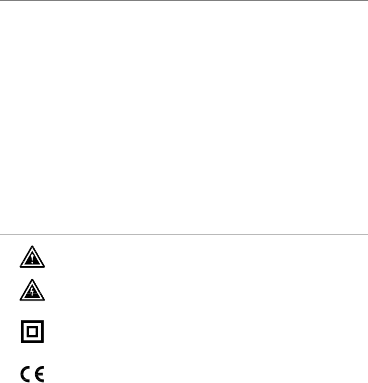
Safety symbols
Caution: Refer to this manual before using the meter.
Dangerous voltages.
Meter is protected throughout by double insulation or reinforced insulation.
When servicing, use only specified replacement parts.
Complies with EN-61010-1, IEC 1010-2-32
382068-EU-EN-V4.0 12/11
6
KW
K
KVA
P P-
3 3W
MEM
PF lead l ag
WL12 3 READ
3 4W Hz
KVA
MINMAX HOLD -
RECORD
HOLD
Hz
1000A
OFF
V
3 4W
3 3W
KW
600V CATMAX
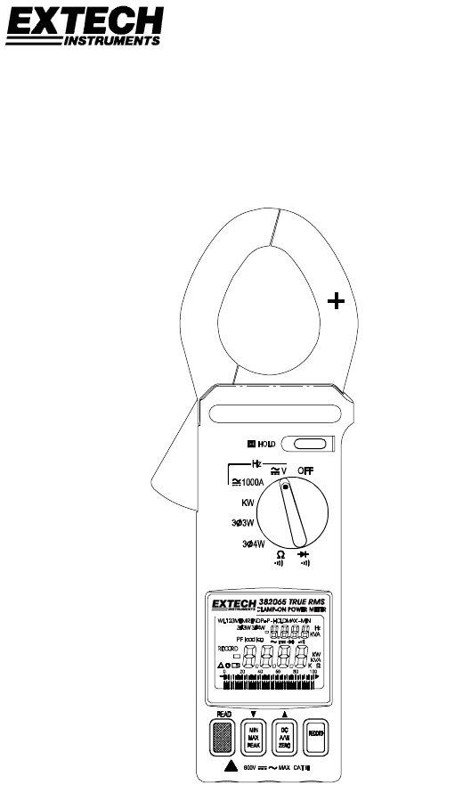
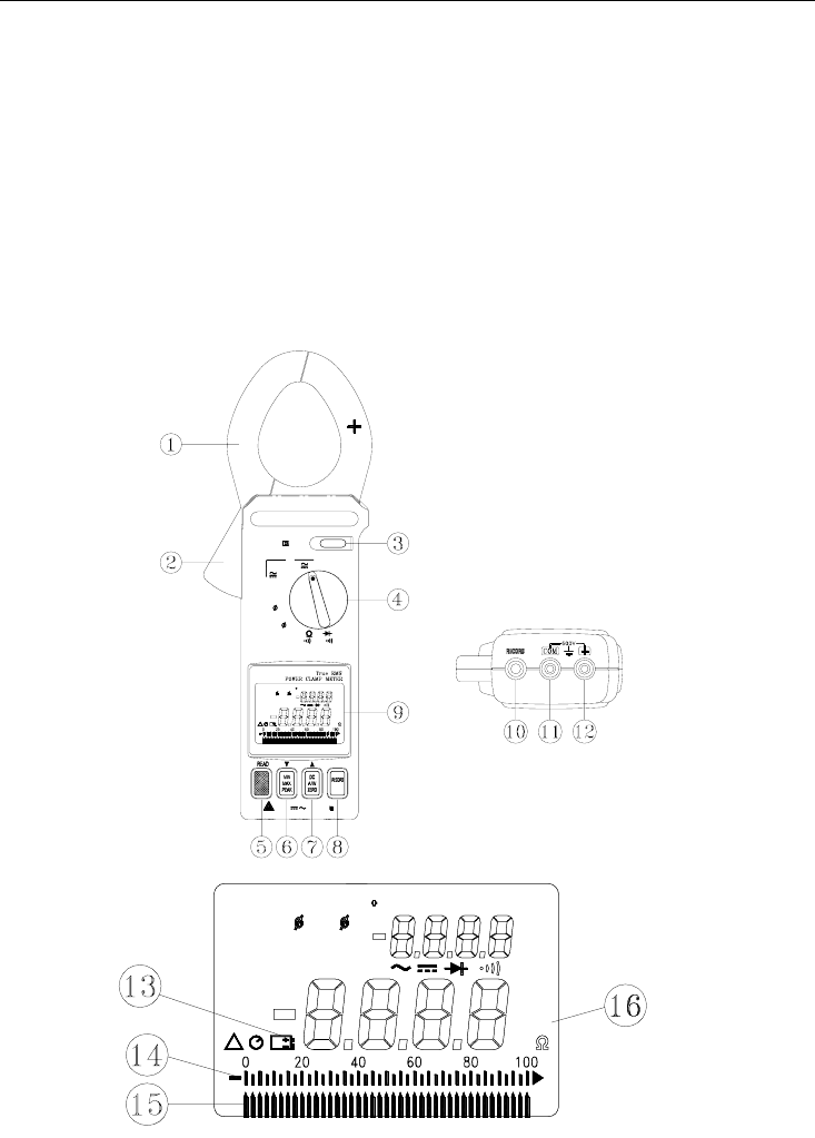
Meter Description
1. Transformer jaws
2. Jaw trigger
3. Data Hold button
4. Function selector
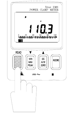
5. Peak Detector READ button
6. MIN/MAX/PEAK function button
7. DC A/W ZERO button
8. RECORD button
9. LCD display
10. PC Interface Jack
11. COM terminal
12. VΩHz terminal
13. Low battery indication
14. Analog Display
15. Bargraph Display
16. Units Symbols
Figure 1
Figure 2
KW
K
KVA
P P-
3 3W
MEM
PF lead lag
WL123 READ
3 4W Hz
KVA
MINMAX
HOLD -
RECORD
READ
3 4W
PF lead lag
WL123
RECORD
3 3W
MEM
KVA
KW
Hz
KVA
K
MAX
P P-HOLD MIN-
382068-EU-EN-V4.0 12/11
7
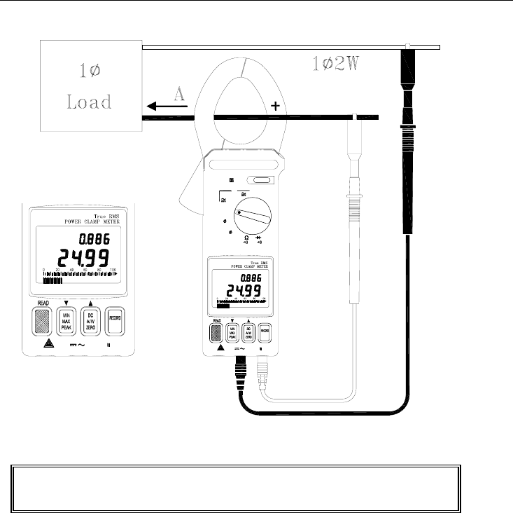
AC/DC Power Measurements
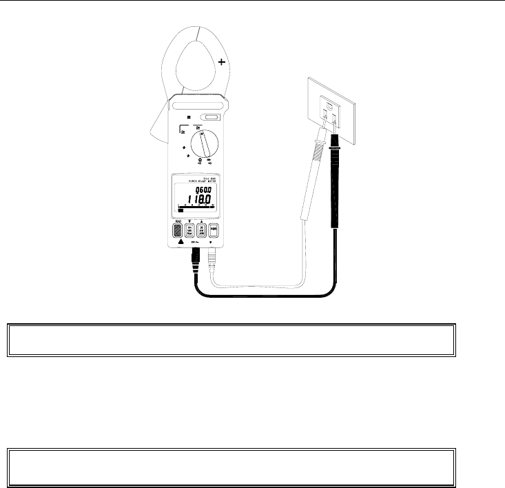
AC/DC 1φ2W Power (W) and Power Factor (PF) Measurements
KW
PF l ag
HOLD
Hz
1000A
OFF
V
3 4W
3 3W
KW
600V CATMAX
600V MAX CAT
PF lag
KW
Figure 3
1. With the clamp jaws empty, turn the clamp meter on by setting the rotary switch to the KW position
(refer to figure 3).
2. Insert the test leads into the input terminals (black lead to COM and red lead to '+').
3. Connect the probe end of the black test lead to the neutral line.
4. Connect the probe end of the red lead to the power line.
5. Clamp the meter onto the conductor where the red test lead is connected.
6. The power clamp will automatically select the appropriate range.
7. Read the Watt (middle of display) and PF (top display) values on the LCD.
8. Press the READ button to scroll through the dual displays of KW + PF, A + V, and KVA + PF.
WARNING
Do not clamp on to a conductor when zeroing the jaw's
residual magnetic field until the LCD reads zero.
382068-EU-EN-V4.0 12/11
8
Note: When calculating KVAR, the KVAR accuracy greatly depends on V, A and KW measurement
accuracy (especially when PF is very close to 1). To get a more accurate value when PF is greater
than 0.91 (φ < 25°), use the following equation for a pure sine wave
KVA
KW
PF = KVA (Apparent Power): KVA = 1000
*AV
KVAR (Reactive Power): KVAR= 22 (KW)(KVA) −
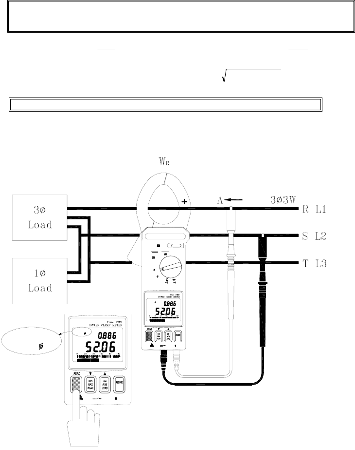
3φ3W AC/DC Power Measurement
Figure 4
Note: The "+" sign printed on the jaw must face the power source.
KW
600V MAX CAT
WL12
3 3W
3 3W
PF lag
WL12
KW
MAX600V CAT
WL1 2
PF lag
3 3W
3 4W
KW
3 3W
V
1000A
Hz
HOLD
OFF

382068-EU-EN-V4.0 12/11
9
A.
With the Clamp jaws empty, turn the meter on
by
setting the rotary switch to the 3φ3W position.
WL12 will appear on the upper left side of the LCD prompting the user to take a
WRS (L2 L1) measurement.
1. Insert the test leads into the input terminals (black to COM terminal and red to '+').
2. Select one phase (eg. S or L2) as COM and connect the probe end of the black lead to that
phase (eg. S or L2).
3. Connect the probe end of the red test lead to the second phase (eg. R or L1).
4. Clamp the meter onto the same phase as the red test lead (eg. R or L1).
5. The meter will automatically select the proper range.
6. Wait until the reading is stable (about 6 seconds), and then press the READ button. WL23 will
appear prompting the user to take a measurement of
W
TS
(WL3 L2).
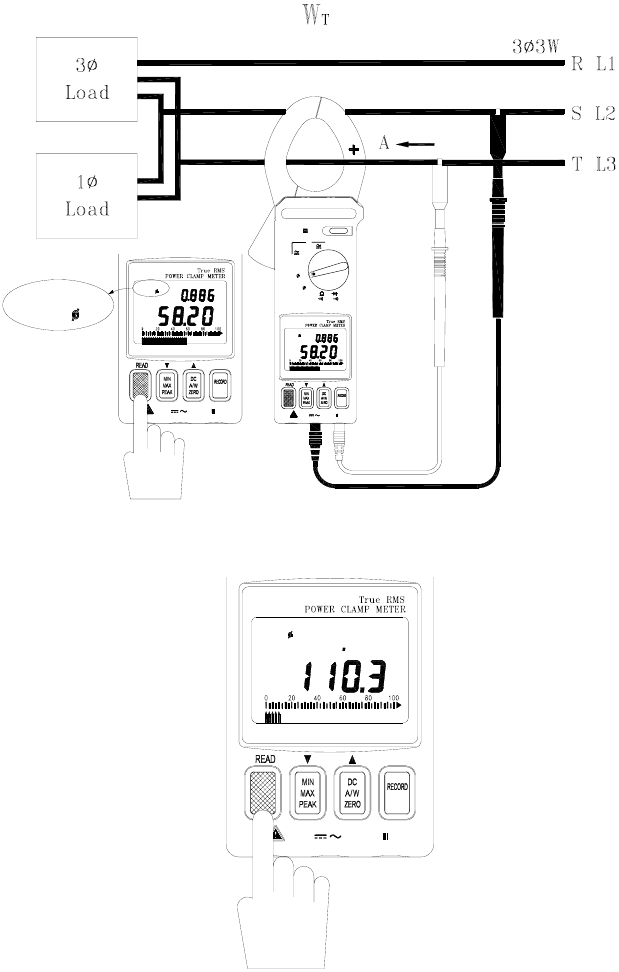
B. Measure W
TS (L3 L2)
(refer to figure 5).
1. Disconnect the red test lead from the phase where the clamp is connected.
2. Connect the red test lead to the third phase (eg. T or L3).
3. Clamp onto the third phase (where the red test lead is connected; eg. T or L3).
4. The meter will automatically select the proper range.
5. Wait until the reading is stable (about 6 seconds) and then press the READ button.
C. The power clamp will process these measurements
and display the result.
WL123
appears in the upper left corner of the LCD and the 3
φ
3W power measurement is
displayed in watts (this value is now stored in meter memory). The following equations are
provided for your information.
W3
φ
3W = WRS(L1L2) + WTS(L3L2)
WWW KVAR
W
KKVA 33
2
33
2
33
φφφ
+=
W
W
WKVA
KW
PF
33
33
33
φ
φ
φ
=
Notes:
1. Once a phase is designated as common (COM) it should remain as such in all
subsequent measurements. For example, if the S (or L2) phase is selected, S
(or L2) phase is connected to COM during the measurements of WRS (or
WL1L2) and WTS (or WL3L2) in 3φ 3W unbalanced power.
2. The "+" sign printed on the jaw must face the power source.
3. In 3φ3W unbalanced power measurements, if either WRS or WTS is negative
(connection error) ensure that all test lead and clamp connections are correct.
382068-EU-EN-V4.0 12/11
10
600V
PF lag
3 3W
WL1 23
KW
MAX CAT
HOLD
Figure 5
Figure 6
600V CATMAX
WL 23
PF lag
3 3W
KW
MAX CAT600V
WL 23
PF lag
3 3W
KW
3 4W
V
KW
3 3W
1000A
Hz
OFF
HOLD
WL 23
3 3W
382068-EU-EN-V4.0 12/11
11
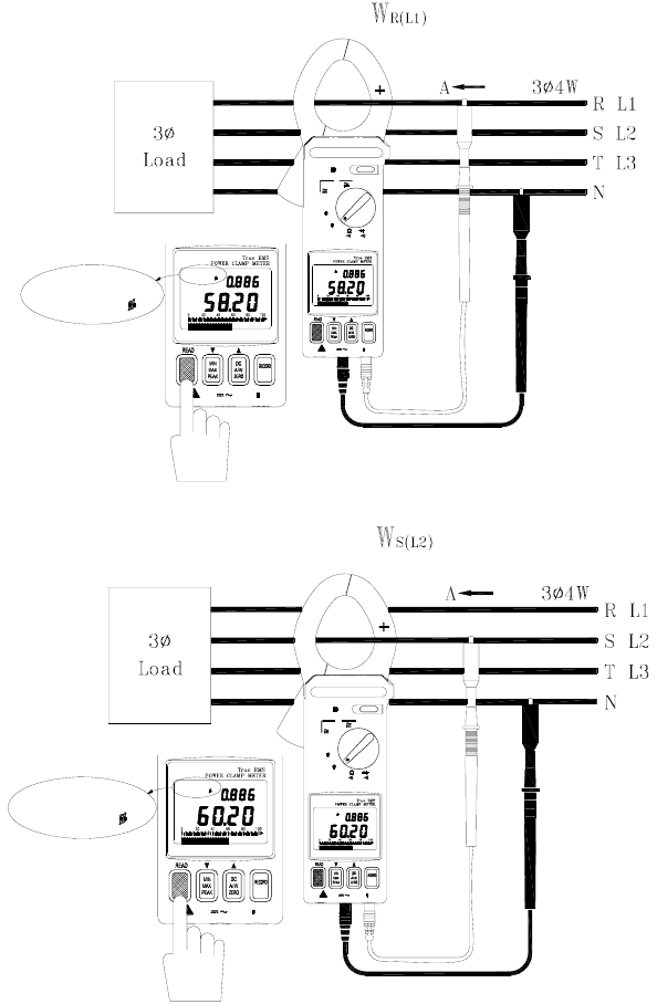
3φ4W AC/DC Power Measurement
KW
600V MAX CAT
PF lag
WL1
3 4W
MAX600V CAT
WL1
3 4W
PF lag
KW
3 4W
3 3W
V
1000A
KW
Hz
HOLD
OFF
WL1
3 4W
Figure 7
HOLD
CAT600V MAX
WL 2
PF lag
KW
3 4W
600V CATMAX
PF lag
WL 2
3 4W
KW
KW
3 3W
3 4W
1000A
OFF
Hz
V
WL 2
3 4W
Figure 8
382068-EU-EN-V4.0 12/11
12
600V CATMAX
PF lag
KW
WL 3
3 4W
MAX600V CAT
3 4W
WL 3
3 4W
PF lag
KW
OFF
Hz
V
KW
3 3W
1000A
HOLD
WL 3
3 4W
Figure 9
600V
PF lag
WL123
KW
MAX CAT
HOLD
3 4W
Figure 10
382068-EU-EN-V4.0 12/11
13
A. Measure W
R (L1)
/ P
FR (L1)
(refer to figure 6).
1. With the jaw enclosure empty, turn the meter on by setting the rotary switch to the 3φ4W position.
2. Insert the test leads into the input terminals (black lead to the COM terminal and red to '+').
3. Connect the black lead's probe end to the neutral line.
4. Connect the red lead's probe end to the first phase (eg. R or L1).
5. Clamp on to the same phase as the red test lead (eg. R or L1).
6. The meter will automatically select the proper range.
7. Wait until the reading is stable (about 6 seconds) then press the READ button. WL1 will disappear
and WL2 will appear prompting the user to take a WS (L2) / PFS (L2) measurement.
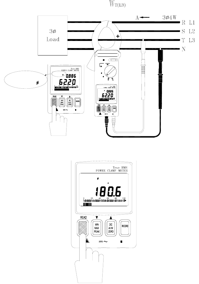
B.
Measure WS (L2)/PFS (L2) (refer to figure 7)
1. Disconnect the red test lead from the phase where the jaws are clamped.
2. Connect the red test lead to the second phase (eg. S or L2).
3. Clamp onto the phase where the red test lead is connected (eg. S or L2 phase)
4. The meter will automatically select the proper range.
5. Wait until the reading is stable (about 6 seconds) then press the READ button. WL2 will disappear
and WL3 will appear prompting the user to take a WT (L3) / PFT (L3) measurement.
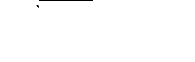
C. Measure W
T (L3)
/P
FT (L3)
(refer to figure 8)
1. Disconnect the red test lead from the phase where the meter's jaws are clamped.
2. Connect the red test lead to the third phase (eg. T or L3 phase).
3. Clamp onto the phase where the red test lead is now connected (eg. T or L3).
4. The meter will automatically select the proper range.
5. Wait until the reading is stable (about 6 seconds) and then press the READ button. WL3 will
disappear from the upper left hand area of the LCD.
6. The meter will process these three sets of data (refer to figure 9) and display the 3φ4W power
measurement (WL123 will be displayed). The 3φ4W measurement will then be stored in
memory. The following equations are provided for your information.
W3
φ
4W = WR(L1) + WS(L2) WT(L3)
WWW KVAR
W
KKVA 43
2
43
2
43
φφφ
+=
W
W
WKVA
KW
PF
43
43
43
φ
φ
φ
=
Notes:
1. The "+" sign printed on jaw must face the power source.
2. For 3φ4W power measurements, WR or WS and WT must be positive. If any are
negative, check the test lead and clamp connections for polarity errors.
382068-EU-EN-V4.0 12/11
14
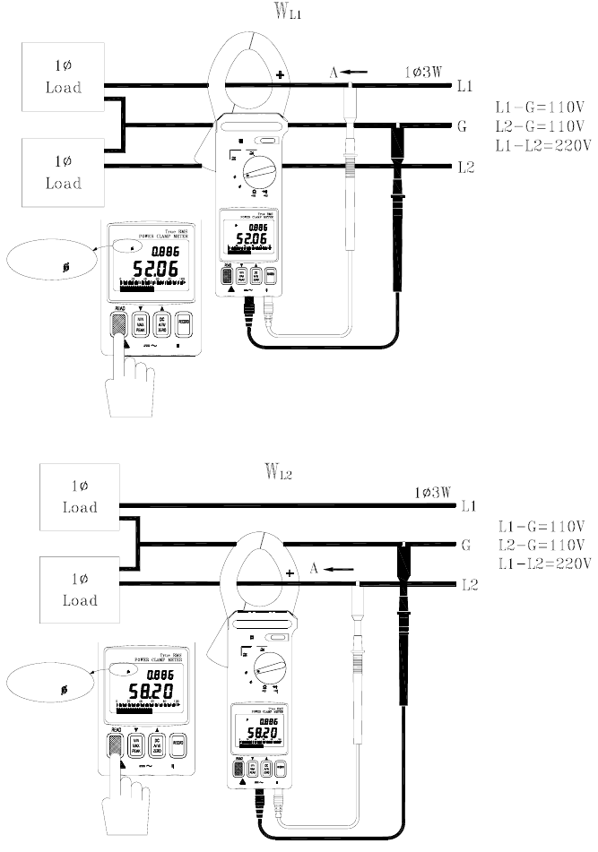
1φ3W Power Measurement
MAX600V CAT
PF lag
WL12
3 3W
KW
KW
MAX600V CAT
WL12
PF l ag
3 3W
3 4W
KW
3 3W
V
1000A
Hz
HOLD
OFF
WL12
3 3W
Figure 11
600V CATMAX
PF lag
3 3W
WL 2 3
KW
MAX CAT600V
WL 23
PF lag
3 3W
KW
3 4W
V
KW
3 3W
1000A
Hz
OFF
HOLD
WL 23
3 3W
Figure 12
382068-EU-EN-V4.0 12/11
15
1
φ3W power measurements are similar to 3φ3W
unbalanced power measurement except for the
nomenclature. Two measurements are required: WRS
(L1G) and WTS (L2G).
A. Measure W
RS (L1G)
(refer to figure 11).
1. With the Clamp jaws empty, turn the meter on by
setting the rotary switch to the 3φ3W position.
2. Insert the test leads into the input terminals.
3. Connect the probe end of the black lead to
ground.
4. Connect the probe end of the red lead to the
second phase (eg. L1).
5. Clamp onto the second phase (eg. L1).
6. The meter will automatically select the proper
range.
7. Wait until the reading is stable (about 6 seconds)
and then press the READ button.
8. WL23 will appear prompting the user to take the
WTS (L2G) measurement.
Figure 13
B. Measure W
TS
or W
L2G
(refer to figure 12).
1. Disconnect the red test lead from the phase where the jaws are clamped.
2. Connect the red test lead to the L2 line.
3. Clamp onto the L2 line (where the red test lead is connected).
4. The meter will automatically select the proper range.
5. Wait until the reading is stable (about 6 seconds) and then press the READ button.
C. The power clamp sums the
two values
, displays the result, and stores the 1φ3W power
measurement in memory. Note the following equation:
W1φ3W = WRST = WRS(L1G) + WTS(L2G)
600V
PF lag
3 3W
WL123
KW
MAX CAT
HOLD
382068-EU-EN-V4.0 12/11
16
Current and Voltage Measurements
AC, DC, and AC+DC Voltage Measurements
Hz
HOLD
Hz
1000A
OFF
V
3 4W
3 3W
KW
600V CATMAX
V
Figure 14
Warning: The maximum input is 600V. Do not attempt to take voltage measurements
that exceed this limit; electrical shock and damage to the clamp meter can result.
1. Set the rotary switch to the 'V' position (refer to figure 14).
2. Insert the test leads into the input terminals (black lead to COM and red to '+').
3. Connect the probe ends of the test leads in PARALLEL to the circuit to be measured.
4. The meter will automatically select the appropriate range and units (AC or DC).
5. Read the voltage and frequency values displayed on the LCD.
Note: The sensitivity for frequency measurements is 10V. The frequency range is 45 –
500Hz. If the frequency is less than 45 Hz, the LCD will display "------".
382068-EU-EN-V4.0 12/11
17
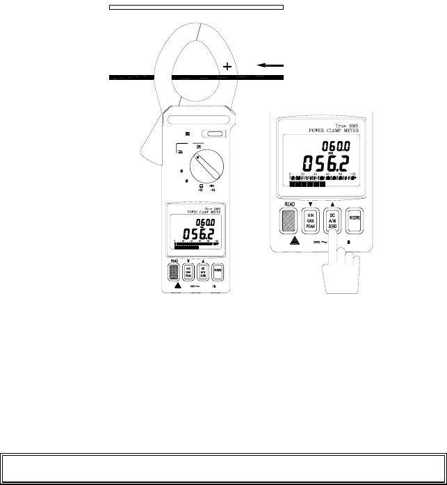
AC, DC, and AC+DC Current Measurements
Hz
HOLD
Hz
1000A
OFF
V
3 4W
3 3W
KW
600V CATMAX
A
CAT600V
A
Hz
A
Figure 15
1. Set the rotary switch to the '1000A' position (refer to figure 15).
2. For DC, press and hold the ZERO button until a beep is heard to zero the reading; the LCD will
display “- - - -” while zeroing.
3. Press the trigger to open the jaw.
4. Fully enclose the conductor to be measured. Do not allow a gap between the two jaw halves
when measuring.
5. The clamp will automatically select the appropriate range.
6. Read the current and frequency values displayed on the LCD.
Note: The current sensitivity for frequency measurements is 10A. The frequency range
is 45 - 500Hz. If the frequency is less than 45 Hz, the LCD will display "------"
382068-EU-EN-V4.0 12/11
18
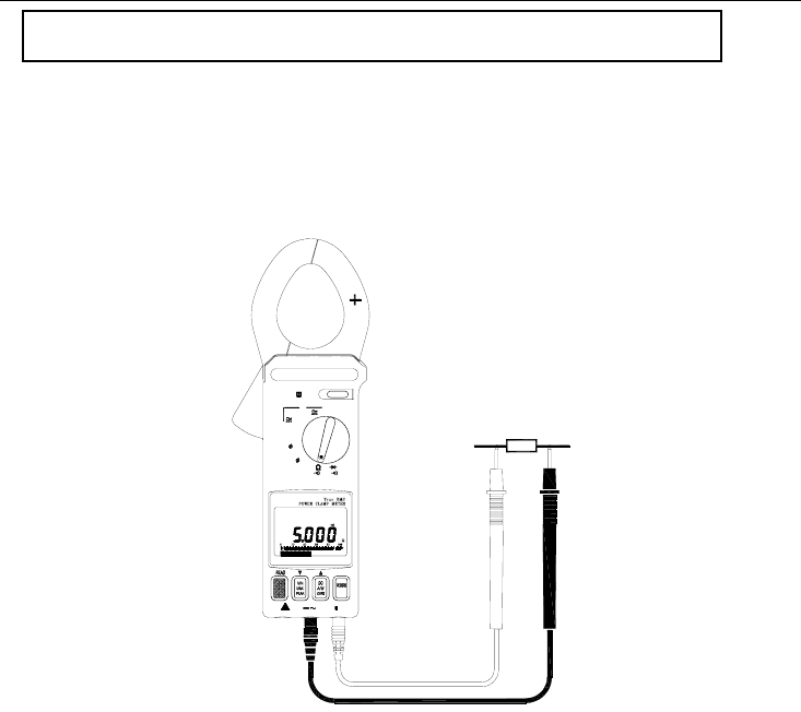
Resistance and Continuity Measurements
Warning: Before taking any in-circuit resistance measurements, remove
power from the circuit under test and discharge all capacitors.
1. Set the function switch to the Ω position for both resistance and continuity measurements.
2. Connect the black test lead to the COM terminal and the red test lead to the '+' terminal.
3. Connect the test leads to the circuit being measured and read the displayed resistance value.
Refer to Figure 16.
4. For Continuity measurements, an audible tone will sound when the reading is below 50Ω.
K
HOLD
Hz
1000A
OFF
V
3 4W
3 3W
KW
600V CATMAX
Figure 16

382068-EU-EN-V4.0 12/11
19
Diode and Continuity Measurements
1. Connect red test lead to the "+" terminal and black test lead to the "COM" terminal.
2. Set the range switch to the diode test position " ".
3. Connect the red test lead to the anode side and black test lead to the cathode side of the
diode being tested.
4. Read the forward voltage value on LCD. The value for a good diode is 0.3VDC for
germanium diodes and 0.7VDC for silicon diodes.
5. If the test lead connection is reversed, the digital reading should reflect an open circuit
condition if the diode is good.
6. Continuity measurement: When the reading is below 50mV an audible tone will sound.
MIN/MAX Recording
1. Set the Function Switch to the Voltage or Current position.
2. To record and view MIN and MAX values while taking measurements, press the MIN MAX
button.
3. Now while measurements are being taken, the display only the MIN or the MAX reading. Use
the MIN MAX button to toggle between MIN and MAX readings. The LCD will display MIN or
MAX as selected.
4. To exit this mode, press and hold the MIN MAX button until the MIN and MAX display icons
disappear from the LCD.
Peak Detection
Peak Detect mode is used to capture fast transients signals (to 0.1ms) such as those caused by
motor startup surges or arc welding equipment switching.
1. Set the Function Switch to the Current or Voltage position.
2. Engage the Peak detector by pressing and holding the READ button until a short beep is heard.
(Note that if the button is held longer, a longer beep will sound and the meter will be in the
datalogging view mode; refer to the datalogging section for more info).
3. The LCD will display 'P-P+' when the Peak Detect mode is accessed correctly. Use the PEAK
button to toggle between ' P+ Max' (captures positive polarity peaks) and 'P- MIN' (captures
negative polarity peaks).
4. To exit the Peak mode, press and hold the PEAK button for two seconds (until the P- and P+
icons disappear).
5. Take a Voltage or Current measurement on a transient signal and the display will show the peak
of the pulse. The fastest surge the meter can detect is 0.1ms.
Data Hold
1. To freeze a displayed reading, press the HOLD key.
2. The HOLD icon will appear on the top of the LCD to let the user know that the meter is in the
Data Hold mode.
3. To return the meter to the normal operation mode, press the HOLD key again. The HOLD icon
will extinguish.
382068-EU-EN-V4.0 12/11
20
Datalogging
Single mode
1. Single mode datalogging records one reading at a time.
2. To record one reading, press the RECORD key until one beep heard. (Note that if the button is
held longer, 2 beeps will sound and the meter will be in continuous mode; see below). The
record number (1 through 25 or FULL) will briefly appear on the LCD.
3. The meter can store up to 25 readings. When the memory is full, FULL will display.
4. To view the readings, press and hold the READ button until two tones are heard. The second
tone is longer and louder than the first.
5. Now use the yellow and keys to scroll through the recorded readings.
Continuous mode (for use with PC interface only)
1. In continuous mode the meter records one reading after another automatically. Up to 4000
records can be recorded.
2. Press and hold the RECORD until two tones are heard (not available in 3φ3W and 3φ4W
function positions). The meter will begin recording data and the RECORD icon will appear on
the LCD.
3. To exit the Record mode, press and hold the RECORD button until the RECORD display icon
disappears.
4. Readings can only be transferred to a PC with optional Windows® software and interface cable.
Instructions for use are provided with optional software/hardware kit.
Clearing Datalog Data
1. Turn the meter off and hold down the RECORD button while turning the meter on.
2. Release the RECORD key when CLR appears. The datalog memory is now clear.
Maintenance
Battery Replacement
Warning: To prevent electrical hazard or shock, turn off the clamp meter
and disconnect the test leads before removing the back cover.
When the 9V battery expires, the LCD will display the battery icon. To replace the battery:
1. Set the Range switch to the OFF position.
2. Remove the meter's three rear screws and carefully open the meter housing.
3. Replace the 9V battery and re-assemble the meter housing.
Cleaning
Periodically wipe the case with a dry cloth; do not use abrasives or solvents.
Copyright © 2011 Extech Instruments Corporation
All rights reserved including the right of reproduction in whole or in part in any form.
