101787 Catalog
2014-09-27
: Pdf 101787-Catalog 101787-Catalog 786683 Batch8 unilog
Open the PDF directly: View PDF ![]() .
.
Page Count: 34
August 2006
CA08101001E For more information visit:
www.EatonElectrical.com
Contents
Busway Products 17-1
17
Busway Products
Description Page
Low Voltage Busway
Pow-R-Way
III
Busway
Product Description. . . . . . . . . . . . . . . . . . . . . . . . . . . . . . . . . . . . . . . . .
17-2
Features, Benefits and Functions. . . . . . . . . . . . . . . . . . . . . . . . . . . . . .
17-4
Product Offering . . . . . . . . . . . . . . . . . . . . . . . . . . . . . . . . . . . . . . . . .
17-4
Standards and Certifications . . . . . . . . . . . . . . . . . . . . . . . . . . . . . . . . .
17-4
Product Specifications . . . . . . . . . . . . . . . . . . . . . . . . . . . . . . . . . . . . . .
17-5
Technical Data and Specifications . . . . . . . . . . . . . . . . . . . . . . . . . . . . .
17-7
Dimensions . . . . . . . . . . . . . . . . . . . . . . . . . . . . . . . . . . . . . . . . . . . . .
17-7
Product Selection and Pricing . . . . . . . . . . . . . . . . . . . . . . . . . . . . . . . .
17-10
Pow-R-Way Busway
Product Description. . . . . . . . . . . . . . . . . . . . . . . . . . . . . . . . . . . . . . . . .
17-21
Standards and Certifications . . . . . . . . . . . . . . . . . . . . . . . . . . . . . . . . .
17-21
Product Specifications . . . . . . . . . . . . . . . . . . . . . . . . . . . . . . . . . . . . . .
17-21
Product Selection and Pricing . . . . . . . . . . . . . . . . . . . . . . . . . . . . . . . .
17-22
Technical Data and Specifications . . . . . . . . . . . . . . . . . . . . . . . . . . . . .
17-27
100 Ampere Busway
Product Description and Application Description . . . . . . . . . . . . . . . .
17-28
Options and Accessories . . . . . . . . . . . . . . . . . . . . . . . . . . . . . . . . . . . .
17-28
Technical Data and Specifications . . . . . . . . . . . . . . . . . . . . . . . . . . . . .
17-28
Product Specifications . . . . . . . . . . . . . . . . . . . . . . . . . . . . . . . . . . . . . .
17-29
Product Selection . . . . . . . . . . . . . . . . . . . . . . . . . . . . . . . . . . . . . . . . . .
17-29
Medium Voltage Busway — Non-Segregated Phase Bus
Application Description . . . . . . . . . . . . . . . . . . . . . . . . . . . . . . . . . . . . .
17-30
Features, Benefits and Functions. . . . . . . . . . . . . . . . . . . . . . . . . . . . . .
17-30
Standards and Certifications . . . . . . . . . . . . . . . . . . . . . . . . . . . . . . . . .
17-30
Technical Data and Specifications . . . . . . . . . . . . . . . . . . . . . . . . . . . . .
17-31
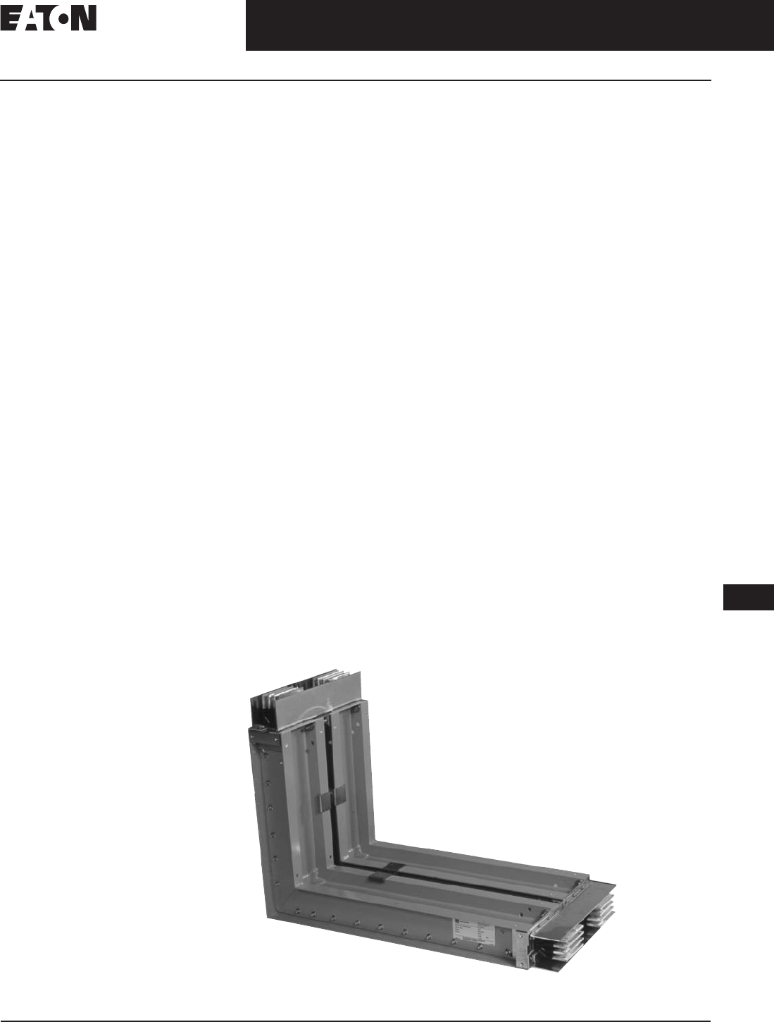
Pow-R-Way III Upward Elbow
August 2006
17-2
For more information visit:
www.EatonElectrical.com
CA08101001E
Busway Products
17
Low Voltage Busway
Pow-R-Way
III
Busway
Product Description
Superior Housing Design and a
True Sandwich Design Maximize
Busway Performance
Cutler-Hammer
Pow-R-Way
III
by
Eaton Corporation is constructed with
a lightweight and durable, two-piece,
aluminum-extruded housing. The non-
ventilated housing design excludes
potential points of penetration by
moisture or dust. Bus bars for plug-in
applications have full-sized conductor
tabs welded by a fully automated
state-of-the-art welding process. This
design extends the contact surfaces
outside of the busway housing and
into the plug-in outlet. The benefits
of the true sandwich design for both
plug-in and feeder busway include
improved coordination and heat
dissipation, better bracing, and the
elimination of the ˝chimney effect.”
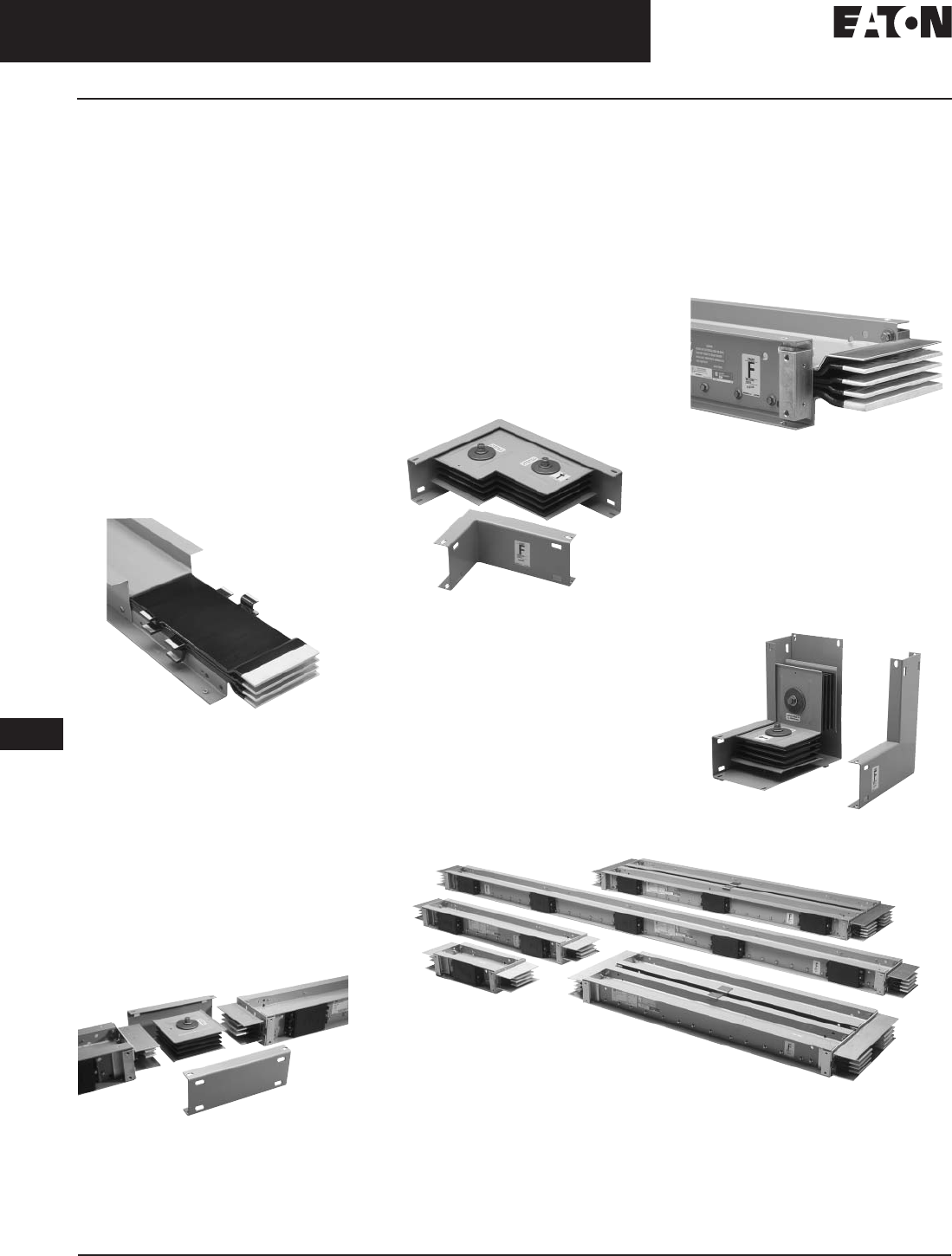
Cut-Away Section of Plug-in Busway
Epoxy Insulation Provides Exceptional
Performance
The phase and neutral bars are
insulated with Class B, 130°C, epoxy
insulation applied by an automated
fluidized bed process. This application
insulates the conductors in a precise
and controlled manner to ensure
smooth, continuous, high quality
protection. Following the epoxy insu-
lation process, all contact surfaces
are silver-plated to provide an
extremely durable connection.
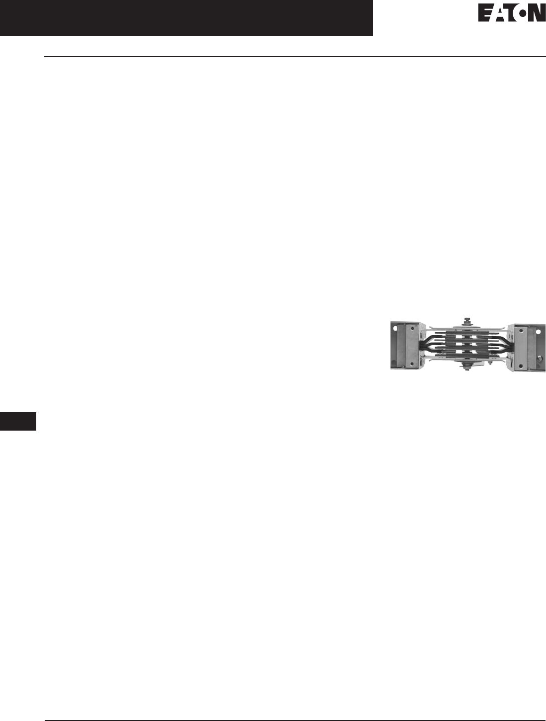
Indoor Joint Assembly
Pow-R-Way
III
Bridge Joint Reduces
Installation Time and Provides Flexibility
for Future Modifications
Pow-R-Way
III
joint connections are
made with the rugged Pow-R-Bridge
joint package. A Pow-R-Bridge is
installed on each section of busway
prior to shipment. Job site connections
are made quickly by releasing the bridge
joint bolt, moving the next section into
place, and re-tightening the bolt. Torque-
indicating, double-headed bolts with
fall-away instruction tags are provided
to ensure that proper installation torque
is achieved. The Pow-R-Bridge provides
an adjustment in section length of up
to ±0.5-inch (12.7 mm) at each joint.
Forward Corner Joint
Pow-R-Way
III
Offers Grounding
and Neutral Options to Meet Every
Customer Preference and Need
The aluminum housing is UL
listed
as a 50% integral ground path and is
provided as a standard, economical
ground system. A 50% internal ground
bar is also available. In certain indus-
trial applications, a ground path
greater than 50% may be required.
Pow-R-Way
III
can solve this problem
in a cost-efficient manner through
combining the 50% integral housing
ground with the 50% internal ground.
To meet the growing demand for
grounding isolation, Pow-R-Way
III
also offers a 50% isolated ground bar.
When customers are concerned about
harmonics and overheating generated
by nonlinear loads, Pow-R-Way
III
provides a solution through a fully
rated 200% capacity neutral bar.
Joint End
A Space-Saving Innovation —
The Corner Joint Elbow
The Pow-R-Way
III
Corner Joint com-
bines the features of the Pow-R-Bridge
with reduced elbow leg lengths.
Due to its compact design, the corner
joint allows for layouts that provide
optimum utilization of space and
increases available plug-in openings.
Upward Corner Joint
Straight Lengths
August 2006
CA08101001E For more information visit:
www.EatonElectrical.com
17-3
Busway Products
17
Low Voltage Busway
Pow-R-Way
III
Busway
A Complete Line of Fittings for Indoor
and Outdoor Applications
Pow-R-Way
III
offers an extensive
range of fittings to meet every applica-
tion need. Flanges, elbows, end cable
tap boxes and end closers are used
in basic busway routing. For more
complex layouts, combination elbows
and offsets can be utilized along with
transformer throats, vault flanges,
reducers and expansion joints.
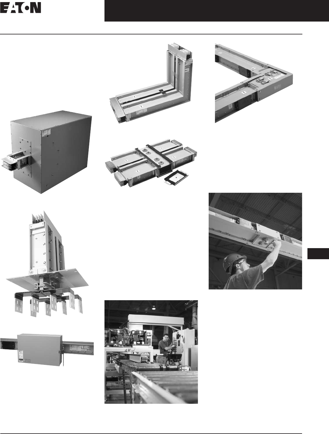
End Cable Tap Box
Standard Switchboard Flange
Plug-in Unit
Upward Elbow
Outdoor Joint Assembly
Enhanced Bus Plug Design Facilitates
Installation and Improves Safety
Pow-R-Way
III
plug-in protective
devices are available in circuit breaker
and fusible switch designs. Standard
features include: oversized enclosures,
extended ground and neutral bars,
line side barriers, bus plug alignment
pin, busway interlock, and improved
clamp and guides.
Advanced bus plugs provide
protection, communication and
coordination capabilities using the
Visor
Series (TVSS), Energy Sentinel
,
Digitrip
OPTIM
, and Advantage
Motor Control components.
Final Busway Assembly
Rearward Corner Joint Assembly
High 6-Cycle Short-Circuit Ratings
Optimize Coordination between
Busway and Power Equipment and
Meet High Quality Standards
All ratings of Pow-R-Way
III
have been
tested to 6-cycle standards and have
achieved a minimum rating of 85 kA
and a maximum rating of 200 kA rms
symmetrical.
Typical Busway Installation
(Torque Indicating Bolt)
August 2006
17-4
For more information visit:
www.EatonElectrical.com
CA08101001E
Busway Products
17
Low Voltage Busway
Pow-R-Way
III
Busway
Features, Benefits
and Functions
Pow-R-Way
III
Offers a Full Line of
Low Voltage Busway to Meet the
Needs of the Global Marketplace
Eaton Corporation has combined the
requirements of NEMA
, UL, CSA
and
IEC into one design to present a world-
class product in the Cutler-Hammer
Pow-R-Way
III
. With standard features
that include a two-piece aluminum
housing, finger-safe plug-in outlets, an
integral ground path and high 6-cycle
short-circuit withstand ratings, Pow-R-
Way
III
provides a busway system that
can be utilized over a broad spectrum
of industrial, commercial and institu-
tional applications worldwide.
Product Offering
■
Plug-in Busway
225 to 5000 amperes copper and
225 to 4000 amperes aluminum
straight sections of plug-in busway
are available in 2-foot (.6 m) incre-
mental lengths from a 2-foot (.6 m)
minimum to 10-foot (3 m) maximum.
Plug-in busway is also available as
sprinkler-proof.
■
Feeder Busway
225 to 5000 amperes copper and 225
to 4000 amperes aluminum straight
sections of indoor and outdoor feeder
busway available in any length in
1/8-inch (3.2 mm) increments from a
16-inch (406 mm) minimum to a 10-
foot (3 m) maximum. A wide range
of fittings are available in indoor or
outdoor feeder busway.
■
Plug-in Units
A full family of busway plug-in units
is available. Standard plug-in units
include fusible or circuit breaker
protection. Advanced plug-in units
include Visor Series surge suppres-
sion, communicating IQ Energy
Sentinel and OPTIM Circuit Breakers,
and Advantage combination contac-
tors and starters.
Product Features and Benefits
■
The all-aluminum two-piece
housing provides durability
and product integrity.
■
The lightweight and compact design
results in easy installation.
■
The housing combined with a true
sandwich design in both plug-in
and feeder busway contributes to
improve coordination and high
short-circuit ratings.
■
An epoxy insulation process
ensures optimum conductor and
system protection.
■
Silver-plated joint and contact
surfaces provide high-quality
connections.
■
Highly automated manufacturing
processes result in a superior
product.
■
The Pow-R-Bridge joint package
and torque indicating bolt gives a
rugged, yet flexible and easy-to-
install connection.
■
Corner Joint Elbows contribute to
successful layouts and minimize
space limitations.
■
High 6-cycle short-circuit ratings
optimize coordination between
busway and power equipment.
■
This world-class product design and
manufacturing meets the require-
ments of NEMA, CSA, Seismic
and ISO
.
■
Plug-in busway design and an
enhanced bus plug-in unit facilitates
installation and improves safety.
■
Flexible ground and neutral options
provide solutions for any applica-
tion problem.
■
A full family of plug-in units is
available for every power need.
■
Advanced bus plugs provide
protection, communication and
coordination capabilities.
Busway Capabilities
■
The busway manufacturing plant in
Greenwood, SC is able to meet your
emergency or quick ship require-
ments with quick ship lead-times
from 3 days to 2 weeks.
■
Customer approval drawings can be
available in
2 weeks or less
to meet
your project requirements.
■
Eaton’s Cutler-Hammer Final Field
Fit program ensures accurate lay-
out and allows for minor last-minute
modifications during installation.
■
Advanced system tools including
the Bid Manager
and Pow-R–
Designer
programs provide quick
and accurate product information.
Product Support
■
Busway product and application
support is available from a
professional team of Eaton employees
that includes Field Sales Engineers,
Application Engineers, Engineering
Service Systems and the Greenwood
Busway Product Engineering Services.
Additional Pow-R-Way
III
Information
Technical Data: TD01701001E
ABCs of Busway: IM01701002E
Brochure: BR01701001E
Busway vs. Cable
and Conduit: SA01701003E
Final Field Fit
Program: SA01701004E
Selling Policy: 25-000
Discount Symbol: CE3-LV Busway
CE4-LV Busway
Devices
Bridge Joint Assembly
Standards and Certifications
■
Pow-R-Way
III
meets the require-
ments of NEMA, UL 857, CSA
C22.2 No. 27-94, IEEE, ANSI,
IEC 439-1 & 2, IEC 529 and is
manufactured in an ISO 9001
certified facility.
■
Pow-R-Way
III
meets the International
Building Code standards and is cer-
tified in the Uniform Building Code
and the California Building Code to
exceed Zone 4 requirements.

August 2006
CA08101001E For more information visit:
www.EatonElectrical.com
17-5
Busway Products
17
Low Voltage Busway
Pow-R-Way III — Product Specifications
Product Specifications
Ratings
B. The busway shall be
Cutler-Hammer type Pow-R-Way III
by Eaton Corporation:
[3-phase, 3-wire]
[3-phase, 3-wire with 50%
housing ground and/or 50%
internal ground]
[3-phase, 3-wire with 50%
housing ground and/or 50%
isolated ground]
[3-phase, 4-wire with 100% neutral]
[3-phase, 4-wire with 100% neutral,
50% housing and/or 50%
internal ground]
[3-phase, 4-wire with 100%
neutral, 50% housing and/or
50% isolated ground]
[3-phase, 4-wire with 200% neutral]
[3-phase, 4-wire with 200% neutral,
50% housing ground, and/or
50% internal ground]
[3-phase, 4-wire with 200% neutral,
50% housing ground, and/or
50% isolated ground]
with voltage and current ratings
as indicated on the contract
drawings.
C. The busway shall have a minimum
of 6-cycle short-circuit rating of
85 kA rms symmetrical for ratings
through 800 amperes, 100 kA rms
symmetrical for ratings through
1350 amperes, 125 kA rms sym-
metrical for ratings through 1600
amperes, 150 kA rms symmetrical
for ratings through 2500 amperes,
and 200 kA rms symmetrical for
ratings through 5000 amperes.
Construction
A. The busway and associated
fittings shall consist of [aluminum]
[copper] conductors totally
enclosed in a two-piece extruded
aluminum housing. Outdoor
feeder, indoor feeder and indoor
plug-in busway shall be inter-
changeable at the same rating
without the use of adapters or
special splice plates. Fittings —
such as elbows, tees, flanges, etc.
— shall be identical for use with
both the plug-in and feeder types
of busway. The busway shall be
capable of being mounted
flatwise, edgewise, or vertically
without derating. The busway
shall consist of standard 10-foot
(3 m) sections with special sec-
tions and fittings provided to suit
the installation. Horizontal runs
shall be suitable for hanging on
10-foot (3 m) maximum centers.
Vertical runs shall be suitable
for mounting on 16-foot (4 m)
maximum centers. Provide one
hanger for every 10 feet
(3 m) of horizontally mounted
duct. On vertical runs provide
one adjustable hanger per floor.
Bus
A. Bus bars shall be fabricated from
high strength, [55% conductivity
aluminum] [98% conductivity
copper] and suitably plated at all
electrical contact surfaces.
B. Bus bars shall be insulated over
their entire length, except at joints
and contact surfaces, with a UL
listed insulating material consist-
ing of epoxy applied by fluidized
bed process. Tape or heat-shrink
sleeve insulation, or any other
method of insulation which can
allow air-gaps or insulation break-
down, shall not be acceptable.
C. The busway shall be capable of
carrying rated current continuously
without exceeding a temperature
rise of 55ºC based on a 40ºC ambient.
Bus Joints
A. Each busway section shall be
furnished complete with joint
hardware and covers. The busway
joints shall be a single-bolt, non-
rotating, removable bridge design.
All bridge joints shall be furnished
with torque-indicating double
head joint bolts and Belleville
washers. The bridge joint shall
utilize a captive nut retainer on
the opposite side of the torque
indicating bolt. The bridge joint
design shall ensure proper instal-
lation without the use of a torque
wrench, and provide visual indica-
tion that the joint is properly
torqued. Each busway joint
shall allow for a minimum
length adjustment of ± 0.5 inches
(12.7 mm). De-energization of
busway shall not be required for
safe testing of joint tightness.
Housing
A. The busway housing shall be
a two-piece design fabricated from
extruded aluminum. The two-piece
housing shall be bolted together
along the bottom flange. The
busway enclosure finish shall
be ANSI 61 gray baked epoxy
powder paint applied by an
electrostatic process.
B. Outdoor feeder busway housing
shall be identical to indoor feeder
busway housings, and shall be
UL listed for outdoor use.

August 2006
17-6
For more information visit: www.EatonElectrical.com CA08101001E
Busway Products
17
Low Voltage Busway
Pow-R-Way III Busway — Product Specifications
Plug-in Busway
A. Where required, busway shall
be of the plug-in type. Plug-in
busway shall be available in
standard 2-, 4-, 6-, 8- and 10-foot
lengths, with plug-in openings
provided on both sides of the
busway sections on 2-foot (.6 m)
centers. Plug-in covers shall pre-
vent dirt and debris from entering
contact plug-in openings in the
busway. The design shall allow
for 10 hinged cover outlets per 10
feet (3 m) of plug-in length. Covers
for plug-in openings shall have a
positive screw close feature and
provisions for the installation of
power company seals. The contact
surfaces for bus plug stabs shall
be silver-plated of the same
material, thickness, and rating
as the stab bars. The tabs shall be
welded to the bus bars. A standard
housing ground connection shall be
supplied in each plug-in opening.
Positive mechanical guides for
plug-in units shall be provided at
each plug-in opening to facilitate
unit alignment and prevent
improper installation.
B. Where required, plug-in units of
the types and ratings indicated on
the plans and specifications shall
be supplied. Plug-in units shall be
mechanically interlocked with the
busway housing to prevent their
installation or removal when the
switch is in the ON position. The
enclosure of any plug-in unit shall
make positive ground connection
to the duct housing before the
stabs make contact with the bus
bars. All plug-in units shall be
equipped with a defeatable inter-
lock to prevent the cover from
being opened while the switch is
in the ON position and prevent
accidental closing of the switch
while the cover is open. The plugs
shall be provided with a means for
padlocking the cover closed and
padlocking the disconnect device
in the OFF position. The operating
handle and mechanism shall
remain in control of the discon-
nect device at all times, permitting
its easy operation from the floor
by means of a hookstick or chain.
For safety reasons, no projections
shall extend into the busway
housing other than the plug-in
stabs. All plug-in units shall be
interchangeable without alteration
or moderation of plug-in duct.
C. Fusible-type plugs shall have a
quick-make/quick-break discon-
nect switch and positive pressure
fuse clips
— OR —
C. Circuit-breaker-type plugs
shall have an interrupting rating of
not less than — symmetrical rms
amperes or be series-rated as
otherwise shown in the contract
document and shall meet all
requirements of UL Standard 489.
It shall be possible to increase the
interrupting rating of a breaker
plug-in device having ampere
ratings through 400 amperes up to
100 kAIC at 480 Vac and 200 kAIC
at 240 Vac by changing out the
circuit breaker only and leaving
the enclosure intact. All breaker
plug-in devices shall be
Cutler-Hammer type Series C.
Transient Voltage Surge Suppression
A. Provide transient voltage surge
suppression as specified in
Section 16671.
For a complete product
specification in CSI format,
see the Cutler-Hammer Product
Specification Guide. . . . . . . . . . . . . Section 16466

August 2006
CA08101001E For more information visit: www.EatonElectrical.com
17-7
Busway Products
17
Low Voltage Busway
Pow-R-Way III Busway — Technical Data and Specifications
Technical Data and Specifications
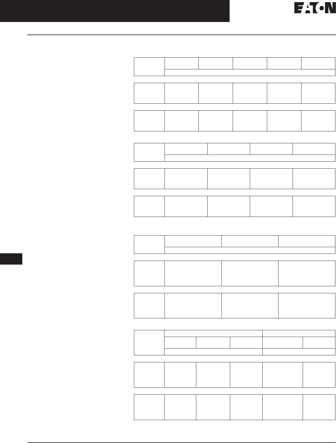
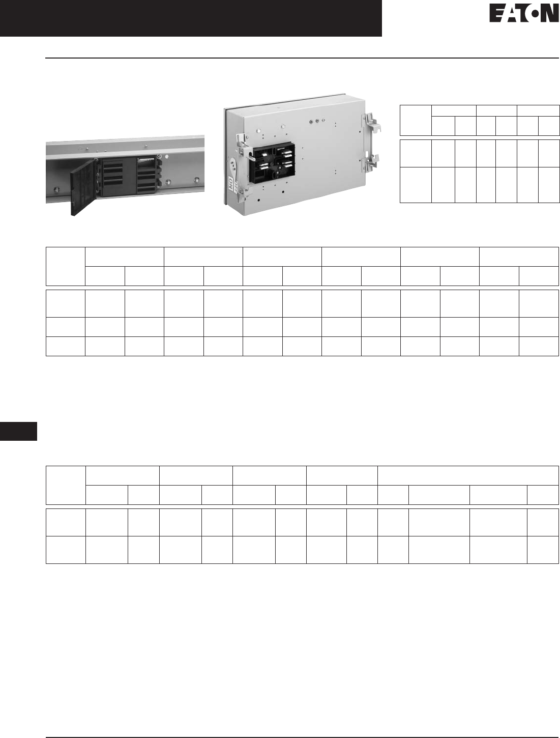
Dimensions — Bus Bar and Housing
Table 17-1. 3-Wire with No Neutral
Note: Refer to Figure 17-1 on Page 17-8.
Table 17-2. 4-Wire with 100% Neutral
Note: Refer to Figure 17-1 on Page 17-8.
Ampere Rating Phase Bar Size
(Depth and Width)
Inches (mm)
Bar
Per
Phase
Wire Designation and Housing Size (Width x Height) Inches (mm) Figure
Cu Al 50% Integral Housing
Ground 3WH 50% Internal Ground
Bus 3WHG 50% Internal Isolated
Ground 3WI
225
400
600
800
225
400
—
600
.25 x 1.62 (6.4 x 41.1)
.25 x 1.62 (6.4 x 41.1)
.25 x 1.62 (6.4 x 41.1)
.25 x 1.62 (6.4 x 41.1)
1
1
1
1
4.75 x 4.38 (120.7 x 111.3)
4.75 x 4.38 (120.7 x 111.3)
4.75 x 4.38 (120.7 x 111.3)
4.75 x 4.38 (120.7 x 111.3)
4.75 x 4.50 (120.7 x 114.3)
4.75 x 4.50 (120.7 x 114.3)
4.75 x 4.50 (120.7 x 114.3)
4.75 x 4.50 (120.7 x 114.3)
4.75 x 4.55 (120.7 x 115.6)
4.75 x 4.55 (120.7 x 115.6)
4.75 x 4.55 (120.7 x 115.6)
4.75 x 4.55 (120.7 x 115.6)
A
A
A
A
1000
1200
1350
1600
—
800
1000
1200
.25 x 2.25 (6.4 x 57.2)
.25 x 2.75 (6.4 x 70.0)
.25 x 3.25 (6.4 x 82.3)
.25 x 4.25 (6.4 x 108.0)
1
1
1
1
5.38 x 4.38 (136.7 x 111.3)
5.88 x 4.38 (149.4 x 111.3)
6.38 x 4.38 (162.1 x 111.3)
7.38 x 4.38 (187.5 x 111.3)
5.38 x 4.50 (136.7 x 114.3)
5.88 x 4.50 (149.4 x 114.3)
6.38 x 4.50 (162.1 x 114.3)
7.38 x 4.50 (187.5 x 114.3)
5.38 x 4.55 (136.7 x 115.6)
5.88 x 4.55 (149.4 x 115.6)
6.38 x 4.55 (162.1 x 115.6)
7.38 x 4.55 (187.5 x 115.6)
A
A
A
A
2000
—
2500
3200
1350
1600
2000
—
.25 x 5.50 (6.4 x 139.7)
.25 x 6.25 (6.4 x 158.8)
.25 x 8.00 (6.4 x 203.2)
.25 x 4.25 (6.4 x 108.0)
1
1
1
2
8.64 x 4.38 (219.5 x 111.3)
9.40 x 4.38 (238.8 x 111.3)
11.17 x 4.38 (283.7 x 111.3)
16.14 x 4.38 (410.0 x 111.3)
8.64 x 4.50 (219.5 x 114.3)
9.40 x 4.50 (238.8 x 114.3)
11.17 x 4.50 (283.7 x 114.3)
16.14 x 4.50 (410.0 x 114.3)
8.64 x 4.55 (219.5 x 115.6)
9.40 x 4.55 (238.8 x 115.6)
11.17 x 4.55 (283.7 x 115.6)
16.14 x 4.55 (410.0 x 115.6)
A
A
A
B
4000
—
5000
2500
3200
4000
.25 x 5.50 (6.4 x 139.7)
.25 x 6.25 (6.4 x 158.8)
.25 x 8.00 (6.4 x 203.2)
2
2
2
18.64 x 4.38 (473.5 x 111.3)
20.16 x 4.38 (512.0 x 111.3)
23.70 x 4.38 (602.0 x 111.3)
18.64 x 4.50 (473.5 x 114.3)
20.16 x 4.50 (512.0 x 114.3)
23.70 x 4.50 (602.0 x 114.3)
18.64 x 4.55 (473.5 x 115.6)
20.16 x 4.55 (512.0 x 115.6)
23.70 x 4.55 (602.0 x 115.6)
B
B
B
Ampere Rating Phase and Neutral
Bar Size
(Depth and Width)
Inches (mm)
Bar
Per
Phase
Wire Designation and Housing Size (Width x Height) Inches (mm) Figure
Cu Al 50% Integral Housing
Ground 4WH 50% Internal Ground
4WHG 50% Internal Isolated
Ground 4WI
225
400
600
800
225
400
—
600
.25 x 1.62 (6.4 x 41.1)
.25 x 1.62 (6.4 x 41.1)
.25 x 1.62 (6.4 x 41.1)
.25 x 1.62 (6.4 x 41.1)
1
1
1
1
4.75 x 4.38 (120.7 x 111.3)
4.75 x 4.38 (120.7 x 111.3)
4.75 x 4.38 (120.7 x 111.3)
4.75 x 4.38 (120.7 x 111.3)
4.75 x 4.50 (120.7 x 114.3)
4.75 x 4.50 (120.7 x 114.3)
4.75 x 4.50 (120.7 x 114.3)
4.75 x 4.50 (120.7 x 114.3)
4.75 x 4.55 (120.7 x 115.6)
4.75 x 4.55 (120.7 x 115.6)
4.75 x 4.55 (120.7 x 115.6)
4.75 x 4.55 (120.7 x 115.6)
A
A
A
A
1000
1200
1350
1600
—
800
1000
1200
.25 x 2.25 (6.4 x 57.2)
.25 x 2.75 (6.4 x 70.0)
.25 x 3.25 (6.4 x 82.3)
.25 x 4.25 (6.4 x 108.0)
1
1
1
1
5.38 x 4.38 (136.7 x 111.3)
5.88 x 4.38 (149.4 x 111.3)
6.38 x 4.38 (162.1 x 111.3)
7.38 x 4.38 (187.5 x 111.3)
5.38 x 4.50 (136.7 x 114.3)
5.88 x 4.50 (149.4 x 114.3)
6.38 x 4.50 (162.1 x 114.3)
7.38 x 4.50 (187.5 x 114.3)
5.38 x 4.55 (136.7 x 115.6)
5.88 x 4.55 (149.4 x 115.6)
6.38 x 4.55 (162.1 x 115.6)
7.38 x 4.55 (187.5 x 115.6)
A
A
A
A
2000
—
2500
3200
1350
1600
2000
—
.25 x 5.50 (6.4 x 139.7)
.25 x 6.25 (6.4 x 158.8)
.25 x 8.00 (6.4 x 203.2)
.25 x 4.25 (6.4 x 108.0)
1
1
1
2
8.64 x 4.38 (219.5 x 111.3)
9.40 x 4.38 (238.8 x 111.3)
11.17 x 4.38 (283.7 x 111.3)
16.14 x 4.38 (410.0 x 111.3)
8.64 x 4.50 (219.5 x 114.3)
9.40 x 4.50 (238.8 x 114.3)
11.17 x 4.50 (283.7 x 114.3)
16.14 x 4.50 (410.0 x 114.3)
8.64 x 4.55 (219.5 x 115.6)
9.40 x 4.55 (238.8 x 115.6)
11.17 x 4.55 (283.7 x 115.6)
16.14 x 4.55 (410.0 x 115.6)
A
A
A
B
4000
—
5000
2500
3200
4000
.25 x 5.50 (6.4 x 139.7)
.25 x 6.25 (6.4 x 158.8)
.25 x 8.00 (6.4 x 203.2)
2
2
2
18.64 x 4.38 (473.5 x 111.3)
20.16 x 4.38 (512.0 x 111.3)
23.70 x 4.38 (602.0 x 111.3)
18.64 x 4.50 (473.5 x 114.3)
20.16 x 4.50 (512.0 x 114.3)
23.70 x 4.50 (602.0 x 114.3)
18.64 x 4.55 (473.5 x 115.6)
20.16 x 4.55 (512.0 x 115.6)
23.70 x 4.55 (602.0 x 115.6)
B
B
B

August 2006
17-8
For more information visit: www.EatonElectrical.com CA08101001E
Busway Products
17
Low Voltage Busway
Pow-R-Way III Busway — Technical Data and Specifications
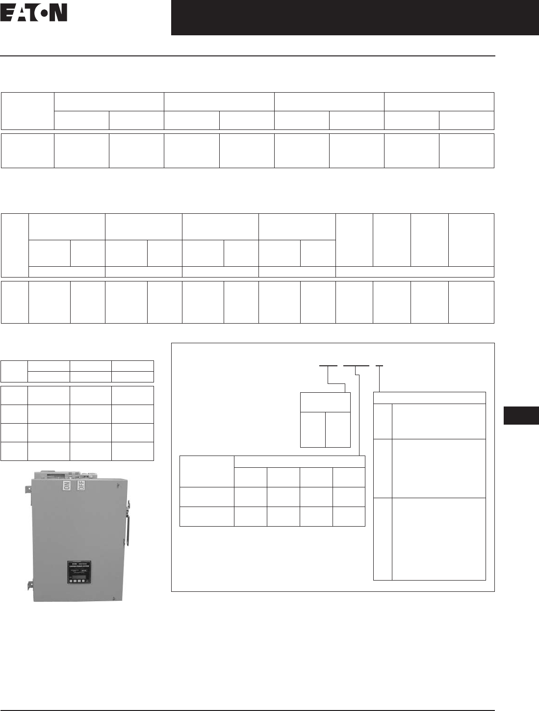
Dimensions — Bus Bar and Housing
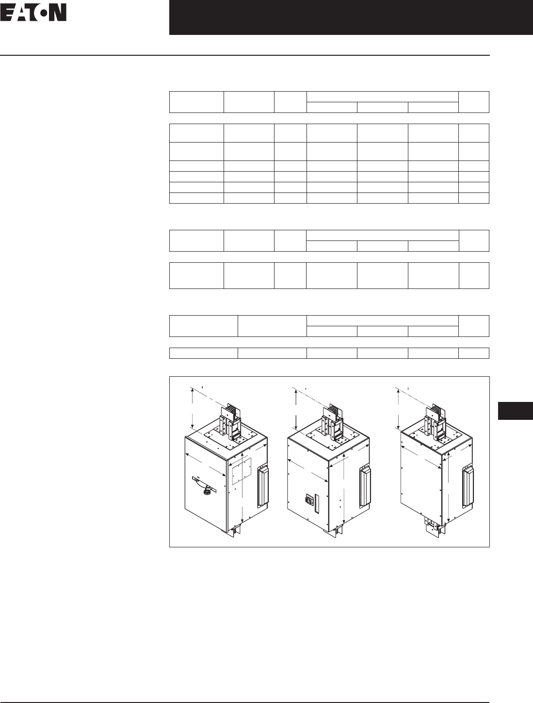
Table 17-3. 4-Wire with 200% Neutral
Note: Refer to Figure 17-1 below.
Figure 17-1. Single and Double Module Cross-Sections
Ampere Rating Phase Bar Size
(Depth and Width)
Inches (mm)
Neutral Bar is 0.5 (12.7)
x Width Shown
Bar
Per
Phase
Wire Designation and Housing Size (Width x Height) Inches (mm) Figure
Cu Al 50% Integral Housing
Ground 4WNH 50% Internal Ground
Bus 4WNG 50% Internal Isolated
Ground 4WNI
225
400
600
800
225
400
—
600
.25 x 1.62 (6.4 x 41.1)
.25 x 1.62 (6.4 x 41.1)
.25 x 1.62 (6.4 x 41.1)
.25 x 1.62 (6.4 x 41.1)
1
1
1
1
4.75 x 4.92 (120.7 x 125.0)
4.75 x 4.92 (120.7 x 125.0)
4.75 x 4.92 (120.7 x 125.0)
4.75 x 4.92 (120.7 x 125.0)
4.75 x 5.05 (120.7 x 128.3)
4.75 x 5.05 (120.7 x 128.3)
4.75 x 5.05 (120.7 x 128.3)
4.75 x 5.05 (120.7 x 128.3)
4.75 x 5.10 (120.7 x 129.5)
4.75 x 5.10 (120.7 x 129.5)
4.75 x 5.10 (120.7 x 129.5)
4.75 x 5.10 (120.7 x 129.5)
A
A
A
A
1000
1200
1350
1600
—
800
1000
1200
.25 x 2.25 (6.4 x 57.2)
.25 x 2.75 (6.4 x 70.0)
.25 x 3.25 (6.4 x 82.3)
.25 x 4.25 (6.4 x 108.0)
1
1
1
1
5.38 x 4.92 (136.7 x 125.0)
5.88 x 4.92 (149.4 x 125.0)
6.38 x 4.92 (162.1 x 125.0)
7.38 x 4.92 (187.5 x 125.0)
5.38 x 5.05 (136.7 x 128.3)
5.88 x 5.05 (149.4 x 128.3)
6.38 x 5.05 (162.1 x 128.3)
7.38 x 5.05 (187.5 x 128.3)
5.38 x 5.10 (136.7 x 129.5)
5.88 x 5.10 (149.4 x 129.5)
6.38 x 5.10 (162.1 x 129.5)
7.38 x 5.10 (187.5 x 129.5)
A
A
A
A
2000
—
2500
3200
1350
1600
2000
—
.25 x 5.50 (6.4 x 139.7)
.25 x 6.25 (6.4 x 158.8)
.25 x 8.00 (6.4 x 203.2)
.25 x 4.25 (6.4 x 108.0)
1
1
1
2
8.64 x 4.92 (219.5 x 125.0)
9.40 x 4.92 (238.8 x 125.0)
11.17 x 4.92 (283.7 x 125.0)
16.14 x 4.92 (410.0 x 125.0)
8.64 x 5.05 (219.5 x 128.3)
9.40 x 5.05 (238.8 x 128.3)
11.17 x 5.05 (283.7 x 128.3)
16.14 x 5.05 (410.0 x 128.3)
8.64 x 5.10 (219.5 x 129.5)
9.40 x 5.10 (238.8 x 129.5)
11.17 x 5.10 (283.7 x 129.5)
16.14 x 5.10 (410.0 x 129.5)
A
A
A
B
4000
—
5000
2500
3200
4000
.25 x 5.50 (6.4 x 139.7)
.25 x 6.25 (6.4 x 158.8)
.25 x 8.00 (6.4 x 203.2)
2
2
2
18.64 x 4.92 (473.5 x 125.0)
20.16 x 4.92 (512.0 x 125.0)
23.70 x 4.92 (602.0 x 125.0)
18.64 x 5.05 (473.5 x 128.3)
20.16 x 5.05 (512.0 x 128.3)
23.70 x 5.05 (602.0 x 128.3)
18.64 x 5.10 (473.5 x 129.5)
20.16 x 5.10 (512.0 x 129.5)
23.70 x 5.10 (602.0 x 129.5)
B
B
B
225 to 2000 Am
p
ere Aluminu
m
225 to 2500 Am
p
ere Co
pp
e
r
2500 to 4000 Am
p
ere Aluminu
m
3200 to 5000 Am
p
ere Co
ppe
r
Wi
dth
Hei
g
h
t
Figure
A
Figure
B
A
B
C
N
A
B
C
N
A
B
C
N
Hei
g
h
t
W
i
dth

August 2006
CA08101001E For more information visit: www.EatonElectrical.com
17-9
Busway Products
17
Low Voltage Busway
Pow-R-Way III Busway — Catalog Numbering System
Pow-R-Way III Catalog Numbering System
The Pow-R-Way III Catalog Numbering System was created
using the logic of Lean Manufacturing. With the use of a
single catalog number, the customer will be able to order
everything from a standard straight piece of busway, to
a variety of accessory fittings in all configurations and
materials. Using this process will assist in standardizing
the Pow-R-Way III product line and allow manufacturing
to reduce lead-times.
The Catalog Numbering System below represents the initial
offering available. The numbering system has been loaded
into Bid Manager, and soon standard busway pieces can be
ordered with the ease of one number. Additional offerings in
the future will include straight busway pieces down to 1-inch
(25.4 mm) increments and will include all of the standard
accessory fittings available today. Busway items not covered
in this numbering system will be entered as they are today
and will be engineered at the plant.
Table 17-4. Pow-R-Way III Catalog Numbering System
Copper only.
System Configuration
3H = 3-Phase, 3-Wire,
50% Integral Housing Ground Only
3G= 3-Phase, 3-Wire,
50% Internal Ground
3I = 3-Phase, 3-Wire,
50% Isolated Internal Ground
4H = 3-Phase, 4-Wire,
50% Integral Housing Ground Only, 100%
Neutral
4G= 3-Phase, 4-Wire,
50% Internal Ground, 100% Neutral
4I = 3-Phase, 4-Wire,
50% Isolated Internal Ground, 100% Neutral
Busway Style and Voltage
B1 = Pow-R-Way III 120/208 V
B2 = Pow-R-Way III 277/480 V
B3 = Pow-R-Way III 347/600 V
B6 = Pow-R-Way III 600 V
Amperes
02 = 225
04 = 400
06 = 600
08 = 800
10 = 1000
12 = 1200
13 = 1350
16 = 1600
20 = 2000
25 = 2500
30 = 3000
32 = 3200
40 = 4000
50 = 5000
Material
C= Copper
A= Aluminum
Busway Type
F= Feeder Duct
P= Plug-in Duct
A= Accessory Fitting
(see description codes)
O= Offset Fitting
Rating Description
I= Indoor
O= Outdoor
(feeder & fittings only)
S= Sprinkler-Proof
(plug-in duct only)
Accessory Fittings
120 = 10" Feeder or Plug-in Duct
UPE = Upward Elbow (12" x 12")
DWE = Downward Elbow (12" x 12")
FWE = Forward Elbow (24" x 24")
RWE = Rearward Elbow (24" x 24")
FCJ = Forward Corner Joint
RCJ = Rearward Corner Joint
UCJ = Upward Corner Joint
DCJ = Downward Corner Joint
LFT = Flush Flange Left Top (15")
LFB = Flush Flange Left Bottom (15")
RFT = Flush Flange Right Top (15")
RFB = Flush Flange Right Bottom (15")
SFL = Standard Flange — Left (12")
SFR = Standard Flange — Right (12")
ETL = End Tap Box — Left (50")
ETR = End Tap Box — Right (50")
ECL = End Closer
B2 16 C 4G A UPE I

August 2006
17-10
For more information visit: www.EatonElectrical.com CA08101001E
Busway Products
17
Low Voltage Busway
Pow-R-Way III Busway — Product Selection
Product Selection
General Information
■Determine the total footage, all
fittings, and accessories for entire
busway run. Price the total footage by
type and system requirements. Round
footage up to the nearest foot. Add the
fabrication charge for the fittings. Add
any additional accessories required
for the total price of the busway run.
Plug-in
■Straight sections of plug-in
busway are available in 2-foot (.6 m)
increments from 2-foot (.6 m)
minimum to 10-foot (3 m) maximum.
Pow-R-Bridge joint is included.
Sprinkler-proof Plug-in
■For sprinkler-proof plug-in,
multiply the plug-in price by 1.15
and use outdoor pricing for the
feeder busway.
Feeder
■Straight sections of feeder busway
are available in 1/8-inch (3.2 mm)
increments from 16 inches (406 mm)
minimum to 10-foot (3 m) maximum.
Pow-R-Bridge joint is included.
Busway must carry at least a 50%
load in all outdoor applications.
Hangers/Pow-R-Bridge
■The busway price includes one
horizontal hanger per 10 feet (3 m)
of busway and one Pow-R-Bridge
joint per connection. All vertical
hangers and any additional
horizontal hangers should be
added to the total price.
Ground
■A 50% integral housing ground is
provided as standard. The housing
ground can be used in combination
with the internal ground or the
isolated ground to achieve a
100% ground rating.
Table 17-5. Short-Circuit Withstand Ratings
— rms Symmetrical Amperes for Copper
Pow-R-Way III Plug-in and Feeder Busway
Ampere Rating 6-Cycle Copper
225
400
600
800
85,000
85,000
85,000
85,000
1000
1200
1350
1600
100,000
100,000
100,000
125,000
2000
2500
3200
4000
5000
150,000
150,000
200,000
200,000
200,000
Pricing — Copper Busway
Table 17-6. Busway (Copper) — Copper Straight Lengths
Table 17-7. Fabrication Adders for Common Fittings — Cable Tap Boxes and End Closures
General Information
■When pricing a cable tap box or a
weatherhead, include the price of
4-feet (1.2 m) of feeder busway to
the fabrication charge.
■Cable tap boxes include 1/0 to 600
kcmil lugs. For additional lugs, larger
lugs, or compression type lugs, refer
to Eaton’s Cutler-Hammer Busway.
■Additional fittings on Page 17-12.
Table 17-8. Accessories and Renewal Parts
Specify the ampere rating and system requirements when ordering as renewal parts.
Ampere
Rating Plug-in Indoor
Feeder Outdoor
Feeder 50% Internal
Ground 50% Isolated
Ground 200%
Neutral
Price U.S. $ Per Foot, Busway Only Price U.S. $ Per Adder Per Foot
3-Phase, 3-Wire, 600 Volts with Integral Housing Ground
225
400
600
—
—
—
800
1000
1200
—
—
—
1350
1600
2000
—
—
—
2500
3200
4000
5000
—
—
—
—
3-Phase, 4-Wire, Full Neutral, 277/480 Volts or 347/600 Volts with Integral Housing Ground
225
400
600
800
1000
1200
1350
1600
2000
2500
3200
4000
5000
Ampere
Rating End or Center
Cable Tap Box Outdoor Cable
Tap Box Weatherhead End Closure
Price U.S. $
3-Phase, 3-Wire, 600 Volts
225 – 600
800 – 1200
1350 – 2500
3200 – 5000
3-Phase, 4-Wire, 277/480 Volts or 367/600 Volts
225 – 600
800 – 1200
1350 – 2500
3200 – 5000
Description Catalog Number Price U.S. $
Wall/Floor Flange
Vertical Hanger
Extra Horizontal Hanger
Roof Flange (Required when Outdoor Busway Penetrates a Roof)
Indoor Joint Cover
Outdoor Joint Cover
Hookstick Kit — 8 – 14 Foot (2.4 – 4.3 m)
Joint Puller
HS8-14
PWJP
Discount Symbol . . . . . . . . . . . . . . . . . . . . . . . . . . CE3

August 2006
CA08101001E For more information visit: www.EatonElectrical.com
17-11
Busway Products
17
Low Voltage Busway
Pow-R-Way III Busway — Product Selection
General Information
■Determine the total footage, all
fittings, and accessories for entire
busway run. Price the total footage
by type and system requirements.
Round footage up to the nearest
foot. Add the fabrication charge
for the fittings. Add any additional
accessories required for the total
price of the busway run.
Plug-in
■Straight sections of plug-in
busway are available in 2-foot (.6 m)
increments from 2-foot (.6 m)
minimum to 10-foot (3 m) maximum.
Pow-R-Bridge joint is included.
Sprinkler-proof Plug-in
■For sprinkler-proof plug-in,
multiply the plug-in price by 1.15
and use outdoor pricing for the
feeder busway.
Feeder
■Straight sections of feeder busway
are available in 1/8-inch (3.2 mm)
increments from 16 inches (406 mm)
minimum to 10-foot (3 m) maximum.
Pow-R-Bridge joint is included.
Busway must carry at least a 50%
load in all outdoor applications.
Hangers/Pow-R-Bridge
■The busway price includes one
horizontal hanger per 10 feet (3 m)
of busway and one Pow-R-Bridge
joint per connection. All vertical
hangers and any additional
horizontal hangers should be
added to the total price.
Ground
■A 50% integral housing ground is
provided as standard. The housing
ground can be used in combination
with the internal ground or the
isolated ground to achieve a 100%
ground rating.
Table 17-9. Short-Circuit Withstand Ratings
— rms Symmetrical Amperes for Aluminum
Pow-R-Way III Plug-in and Feeder Busway
Ampere
Rating 6-Cycle
Aluminum
225
400
600
800
85,000
85,000
85,000
100,000
1000
1200
1350
1600
100,000
125,000
150,000
150,000
2000
2500
3200
4000
5000
150,000
200,000
200,000
200,000
—
Pricing — Aluminum Busway
Table 17-10. Busway (Aluminum) — Aluminum Straight Lengths
Table 17-11. Fabrication Adders for Common Fittings — Cable Tap Boxes and End Closures
General Information
■When pricing a cable tap box or a
weatherhead, include the price of
4 feet (1.2 m) of feeder busway to
the fabrication charge.
■Cable tap boxes include 1/0 to 600
kcmil lugs. For additional lugs, larger
lugs, or compression type lugs, refer
to Eaton’s Cutler-Hammer Busway.
■Additional Fittings on Page 17-12.
Table 17-12. Accessories and Renewal Parts
Specify the ampere rating and system requirements when ordering as renewal parts.
Ampere
Rating Plug-in Indoor
Feeder Outdoor
Feeder 50% Internal
Ground 50% Isolated
Ground 200%
Neutral
Price U.S. $ Per Foot, Busway Only Price U.S. $ Per Adder Per Foot
3-Phase, 3-Wire, 600 Volts with Integral Housing Ground
225
400
600
—
—
—
800
1000
1200
—
—
—
1350
1600
2000
—
—
—
2500
3200
4000
5000 —————
—
—
—
—
3-Phase, 4-Wire, Full Neutral, 277/480 Volts or 347/600 Volts with Integral Housing Ground
225
400
600
800
1000
1200
1350
1600
2000
2500
3200
4000
5000 ——————
Ampere
Rating End or Center
Cable Tap Box Outdoor Cable
Tap Box Weatherhead End Closure
Price U.S. $
3-Phase, 3-Wire, 600 Volts
225 – 600
800 – 1200
1350 – 2500
3200 – 5000
3-Phase, 4-Wire, 277/480 Volts or 367/600 Volts
225 – 600
800 – 1200
1350 – 2500
3200 – 5000
Description Catalog Number Price U.S. $
Wall/Floor Flange
Vertical Hanger
Extra Horizontal Hanger
Roof Flange (Required when Outdoor Busway Penetrates a Roof)
Indoor Joint Cover
Outdoor Joint Cover
Hookstick Kit — 8 – 14 Foot (2.4 – 4.3 m)
Joint Puller
HS8-14
PWJP
Discount Symbol . . . . . . . . . . . . . . . . . . . . . . . . CE3
August 2006
17-12
For more information visit: www.EatonElectrical.com CA08101001E
Busway Products
17
Low Voltage Busway
Pow-R-Way III Busway — Product Selection
General Information
■For a complete price on these fittings,
add the price of the footage through
the fitting to the fabrication charge.
See Page 17-10 for copper or Page
17-11 for aluminum per foot prices.
■A standard flange is used to connect
to Eaton’s Cutler-Hammer equipment.
General Information
■For a complete price on these fittings,
add the price of the footage through
the fitting to the fabrication charge.
See Page 17-10 for copper or Page
17-11 for aluminum per foot prices.
■A Corner Joint Elbow is an exclusive
Pow-R-Way III feature that provides
minimum elbow leg lengths to
maximize plug-in usage. Used
for indoor applications only.
■For a special degree elbow,
double the traditional elbow
fabrication charge.
General Information
■See NEC 364-11 for Reducer
Application.
■Price fabrication charge at the lower
busway rating.
■For a complete price on these fittings,
add the price of the footage through
the fitting to the fabrication charge.
See Page 17-10 for copper or Page
17-11 for aluminum per foot prices.
■Fusible reducers are 600 volt
maximum. Fuses are not included.
General Information
Transformer connections:
■Transformer tap bus extensions do
not include drilling or lugs.
■Transformer throats include
flexible connectors.
■Add the price of the footage through
the fitting to the fabrication charge.
See Page 17-10 for copper or Page
17-11 for aluminum per foot prices.
Power take-offs:
■To completely price a power take-
off, include a power take-off from
this table at the busway ampere
rating, footage through the fitting,
and a bolt-on circuit breaker or
fusible unit at the required rating.
Pricing — Fabrication Adders for Fittings
Table 17-13. Flanges and Expansion Joints
Table 17-14. Elbows, Tees and Crosses
For indoor use only.
Table 17-15. Reducers
Table 17-16. Transformer Connections and Power Take-offs
Ampere
Rating Standard
Flange Flush
Flange Special
Flange Vault
Flange Expansion
Joint
Price U.S. $
3-Phase, 3-Wire, 600 Volts
225 – 600
800 – 1200
1350 – 2500
3200 – 5000
3-Phase, 4-Wire, 277/480 Volts or 347/600 Volts
225 – 600
800 – 1200
1350 – 2500
3200 – 5000
Ampere
Rating Traditional
Elbow Corner Joint
Elbow Tee Cross
Price U.S. $
3-Phase, 3-Wire, 600 Volts
225 – 600
800 – 1200
1350 – 2500
3200 – 5000
3-Phase, 4-Wire, 277/480 Volts or 347/600 Volts
225 – 600
800 – 1200
1350 – 2500
3200 – 5000
Ampere
Rating No Overcurrent
Protection Reducer Circuit Breaker
Protection Reducer Fusible
Protection Reducer
Price U.S. $
3-Phase, 3-Wire, 600 Volts
225 – 600
800 – 1200
1350 – 2000
2500 – 3200
4000 – 5000 — —
3-Phase, 4-Wire, 277/480 Volts or 347/600 Volts
225 – 600
800 – 1200
1350 – 2000
2500 – 3200
4000 – 5000 — —
Ampere
Rating Transformer Connections Power Take-offs
One
3-Phase Tap Three
1-Phase Taps Transformer
Throat Built into
Straight Length For Use at
Bridge Joint
Price U.S. $ Price U.S. $
3-Phase, 3-Wire, 600 Volts
225 – 600
800
1000 – 1200
1350 – 2500
3200 – 5000
3-Phase, 4-Wire, 277/480 Volts or 347/600 Volts
225 – 600
800
1000 – 1200
1350 – 2500
3200 – 5000
Discount Symbol . . . . . . . . . . . . . . . . . . . . . . . . . CE3
August 2006
CA08101001E For more information visit: www.EatonElectrical.com
17-13
Busway Products
17
Low Voltage Busway
Pow-R-Way III Busway — Product Selection
General Information
■For a complete price on these fit-
tings, add the price of the footage
through the fitting to the fabrication
charge. See Page 17-10 or 17-11.
■For use with 33MM, 37MM and
37SS meter stack modules. Order
separately.
■Main breaker units include circuit
breaker and trip units.
■1200 A or greater main devices must
be center fed when installing 800
ampere residential meter sockets
and 1200 ampere commercial meter
sockets.
■Spacer kit 3MMBSK may be
required when stacks are mounted
on right-hand side in EUSERC areas.
See Page 5-40.
■Class T fuse clips only; fuses not
included.
■Compatible with indoor corner
elbow accessory 3MMEB12 and
3MMEB16. See Page 5-41.
■In-line metering PTO with no over-
currrent protection should only be
used with six meter sockets/tenant
main circuit breakers or less, or
applied per local code.
Pricing — Fabrication Adders for Fittings
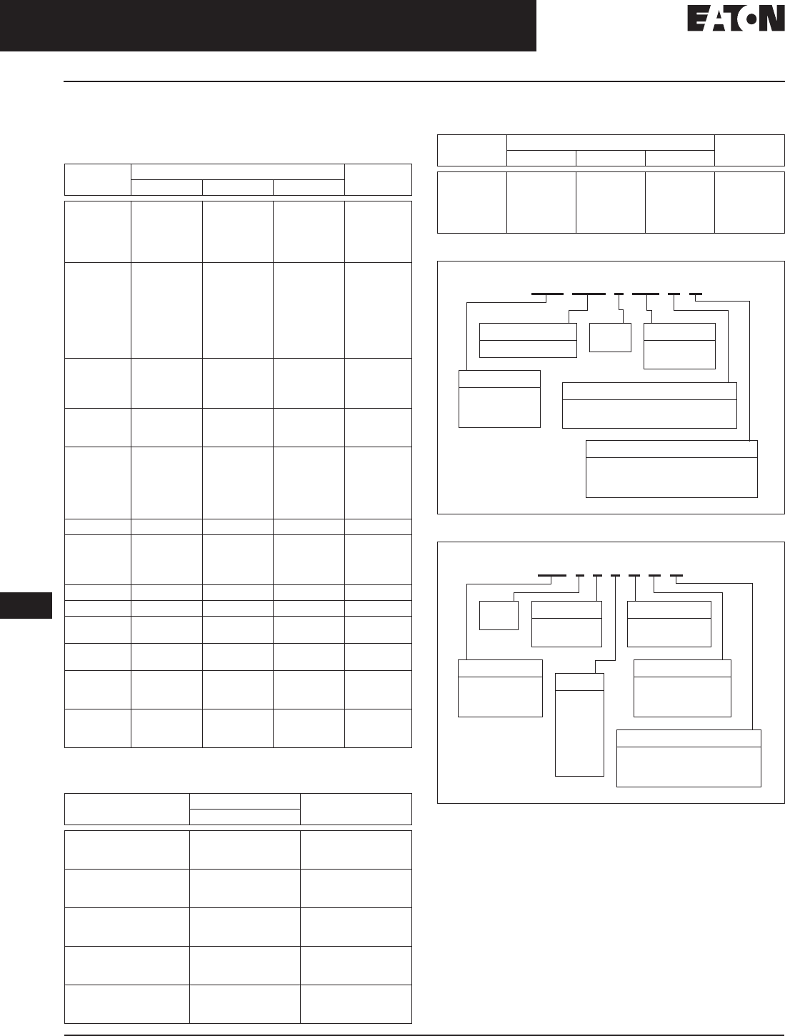
Table 17-17. Circuit Breaker In-line Metering PTO
20-inch (508 mm) width for one bar per phase; 33-inch (838 mm) width for two bars per phase.
Table 17-18. Fusible In-line Metering PTO
20-inch (508 mm) width for one bar per phase; 33-inch (838 mm) width for two bars per phase.
Table 17-19. In-line Metering PTO (No Overcurrent Protection)
20-inch (508 mm) width for one bar per phase, 33-inch (838 mm) width for two bars per phase.
Figure 17-2. Metering PTO
Main Circuit
Breaker Type Main Ampere
Rating kAIC Dimensions in Inches (mm) Price
U.S. $
Width (A) Depth Height
3-Phase, 4-Wire, 120/208 Volts
LD 300 – 400
500 – 600 65
20.00 (508.0)
20.00 (508.0) 30.00 (762.0)
30.00 (762.0)
HLD 300 – 400
500 – 600 100
20.00 (508.0)
20.00 (508.0) 30.00 (762.0)
30.00 (762.0)
MDL 700 – 800 65 20.00 (508.0) 30.00 (762.0)
HMDL 700 – 800 100 20.00 (508.0) 30.00 (762.0)
ND 900 – 1200 65 20.00 (508.0) 30.00 (762.0)
HND 900 – 1200 100 20.00 (508.0) 30.00 (762.0)
Main Ampere
Rating Class Fuse
Clips kAIC Dimensions in Inches (mm) Price
U.S. $
Width (A) Depth Height
3-Phase, 4-Wire, 120/208 Volts
400
600
800
T200
20.00 (508.0)
20.00 (508.0)
20.00 (508.0)
30.00 (762.0)
30.00 (762.0)
30.00 (762.0)
Cross Bus
Ampere Rating kAIC Dimensions in Inches (mm) Price
U.S. $
Width (A) Depth Height
3-Phase, 4-Wire, 120/208 Volts
1200 100 15.00 (381.0) 30.00 (762.0)
Brid
ge
J
o
in
t
C
L
CC
12.
00
A
2
0
.
00
30
.
00
Brid
ge
J
o
in
t
C
L
CC
12.
00
A
2
0
.
00
30
.
00
Brid
ge
J
o
in
t
C
L
C
C
12.
00
1
5
.
00
30
.
00
A
Discount Symbol . . . . . . . . . . . . . . . . . . . . . . . . . . CE3
August 2006
17-14
For more information visit: www.EatonElectrical.com CA08101001E
Busway Products
17
Low Voltage Busway
Pow-R-Way III Busway — Product Selection
Pricing — Circuit Breaker Plug-in Units
Table 17-20. Circuit Breakers
100% rated breakers are not available for use in bus plugs.
Contact Product Line for guidance.
Table 17-21. Branch Devices Earth Leakage Ground Fault Circuit Breakers
(Adjustable pickup from 30 mA to 30 amperes)
Table 17-22. Integrally Fused, Current Limiting Circuit Breaker
Table 17-23. Breaker Unit Catalog Numbering System
Table 17-24. Fusible Unit Catalog Numbering System
Note: “H” clips are standard for PRW and Old Line unless specified
by adding “R” in catalog number.
Note: Please call Greenwood Low Voltage Busway department
for help in assigning a catalog number for a specific application.
Note: Do not leave spaces between characters.
Example: P3BFD3100N; ITAP361N.
Note: All plug-in units come fully assembled.
Ampere
Rating Interrupting Rating (kA Symmetrical) Breaker
Type
240 Vac 480 Vac 600 Vac
15 – 60
70 – 100
15 – 60
70 – 100
110 – 150
18
18
18
18
18
14
14
14
14
14
—
—
14
14
14
EHD
EHD
FDB
FDB
FDB
15 – 60
70 – 100
110 – 150
175 – 225
15 – 60
70 – 100
110 – 150
175 – 225
65
65
65
65
100
100
100
100
25
25
25
25
65
65
65
65
18
18
18
18
25
25
25
25
FD
FD
FD
FD
HFD
HFD
HFD
HFD
15 – 60
70 – 100
110 – 225
15 – 100
200
200
200
200
100
100
100
150
35
35
35
—
FDC
FDC
FDC
FCL
100 – 225
100 – 225
100 – 225
65
100
200
—
—
—
—
—
—
ED
EDH
EDC
70 – 225
250
70 – 225
250
70 – 225
250
65
65
100
100
200
200
35
35
65
65
100
100
18
18
25
25
35
35
JD, JDB
JD, JDB
HJD
HJD
JDC
JDC
125 – 250 200 200 — LCL
250 – 400
100 – 400
100 – 400
100 – 400
65
65
100
200
—
35
65
100
—
25
35
50
DK
KD, KDB
HKD
KDC
200 – 400 200 200 — LCL
300 – 600 65 35 25 LD, LDB
300 – 600
300 – 600 100
200 65
100 35
50 HLD
LDC
400 – 800
400 – 800 65
100 50
65 25
35 MDL
HMDL
400 – 800
400 – 800
400 – 800
65
100
200
50
65
100
25
35
50
ND
HND
NDC
600 – 1200
600 – 1200
600 – 1200
65
100
200
50
65
100
25
35
50
ND
HND
NDC
Ampere
Rating kAIC (symmetrical) Breaker
Type
480 Vac
35 – 60
70 – 100
110 – 150
25
25
25
ELFD
ELFD
ELFD
35 – 60
70 – 100
110 – 150
65
65
65
ELHFD
ELHFD
ELHFD
35 – 60
70 – 100
110 – 150
100
100
100
ELFDC
ELFDC
ELFDC
100 – 250
100 – 250
100 – 250
35
65
100
ELJD
ELHJD
ELJDC
200 – 400
200 – 400
200 – 400
35
65
100
ELKD
ELHKD
ELKDC
Ampere
Rating Interrupting Rating (kA Symmetrical) Breaker
Type
240 Vac 480 Vac 600 Vac
15 – 100
125 – 225
250 – 400
400 – 600
700 – 800
200
200
200
200
200
200
200
200
200
200
200
200
200
200
200
FB-P
LA-P
LA-P
NB-P
NB-P
P3B HFD 3 015 G N
Bus Style
P3B = PRWIII
IBP = PRW
BP = Old Line
Breaker Frame
(Ex. FD, JDC, KDB)
3-Pole
Only Trip Rating
(Ex. 015, 060,
150, 400)
Ground Option
G= 50% Internal
I= Isolated Ground (PRWIII Only)
Neutral Option
N= 100% Neutral
N2 = 200% Neutral (PRWIII Only)
ZN = Low Z (Old Line Only)
P3F 3 6 4 R G N
Bus Style
P3B = PRWIII
ITAP = PRW
TAP = Old Line
3-Pole
Only Voltage
6= 600 Volt
2= 240 Volt
Fuse Clips
H, J, or R ≤ 600 A
T or L for 800 A
Ground Option
G= 50%
I= Isolated
(PRWIII Only)
Amp
1= 30
2= 60
3= 100
4= 200
5= 400
6= 600
7= 800
Neutral Options
N= 100%
N2 = 200% (PRWIII Only)
ZN = Low Z (Old Line Only)
August 2006
CA08101001E For more information visit: www.EatonElectrical.com
17-15
Busway Products
17
Low Voltage Busway
Pow-R-Way III Busway — Product Selection
Pricing — Circuit Breaker Plug-in Units
Horizontal Install (Front View) Horizontal Install (Rear View) Circuit Breaker Plug
Table 17-25. Circuit Breaker Plug-in Units
Note: See Page 17-14 for Plug Assembled Style Number Configuration.
■Refer to Page 17-14 for breaker
data. For reference only.
■The enclosure, circuit breaker,
neutral and ground are ordered
and shipped assembled.
■Housing ground connection
supplied as standard at no
additional charge.
■The adder for sprinkler-proof is 15%.
Table 17-26. Advanced Circuit Breaker Plug-ins
■The P3BFD, P3BJD and P3BKD
plug-in units can be modified to
accept breaker mounted IQ Energy
Sentinels. See above for pricing.
■The IQ Energy Sentinel and the
OPTIM breaker plug-in units permit
multiple meters, remote monitoring,
and interconnection with program-
mable logic controllers and building
management systems. Applications
may range from revenue metering
for tenant billing to a full power man-
agement system. Consult with an
Eaton Application Engineer or the
Busway Product Line for assistance.
■Refer to SA.73A.01.T.E and the
IQ Energy Sentinel prices.
■The adder for sprinkler-proof is 15%.
Breaker
Frame Ampere
Rating Plug-in
Enclosure 100% Neutral
Stab 50% Internal
Ground Stab 50% Isolated
Ground Stab 200% Neutral
Stab
Catalog
Number Price
U.S. $ Catalog
Number Price
U.S. $ Catalog
Number Price
U.S. $ Catalog
Number Price
U.S. $ Catalog
Number Price
U.S. $
ED, EDH, EHD, EDC,
FDB, FD, HFD, FDC 10 – 225 P3BFD P3FDN100
P3FDN225 P3FG100
——P3FDI100
P3FDI225 P3FD2N100
P3FD2N225
JDB, JD,
HJD, JDC 70 – 250 P3BJD P3JDN150
P3JDN250 —
P3JDG250 —P3JDI150
P3JDI250 P3JD2N150
P3JD2N250
KDB, KD, DK,
HKD, KDC 100 – 400 P3BKD P3KDN400 P3KDG400 P3KDI400 P3KD2N400
LDB, LD, HLD, LDC 300 – 600 P3BLD P3MDN800 P3MDG800 P3MDI800 — —
MDL, HMDL 400 – 800 P3BMD P3MDN800 P3MDG800 P3MDI800 — —
ND, HND, NDC 400 – 800 P3BND P3NDN800 P3NDG800 P3NDI800 — —
FB TRI-PAC 15 – 100 P3BFBP P3FBPN100 P3FBPG100 P3BFBPI100 — —
LA TRI-PAC 75 – 400 P3BLAP P3LAPN400 P3LAPG400 P3LAPI400 — —
NB TRI-PAC 500 – 800 P3BNBP P3NBPN800 P3NBPG800 P3BNBPI800 — —
Digitrip
OPTIM Ampere
Rating Plug-In Enclosure 100% Neutral 50% Internal Ground 50% Isolated Ground
Catalog
Number Price
U.S. $ Catalog
Number Price
U.S. $ Catalog
Number Price
U.S. $ Catalog
Number Price
U.S. $
L-Frame 70 – 600 P3BORPL P3BORPLN600 P3BORPLG600 P3BORPLI600
Discount Symbol . . . . . . . . . . . . . . . . . . . . . . . . . . CE4
August 2006
17-16
For more information visit: www.EatonElectrical.com CA08101001E
Busway Products
17
Low Voltage Busway
Pow-R-Way III Busway — Product Selection
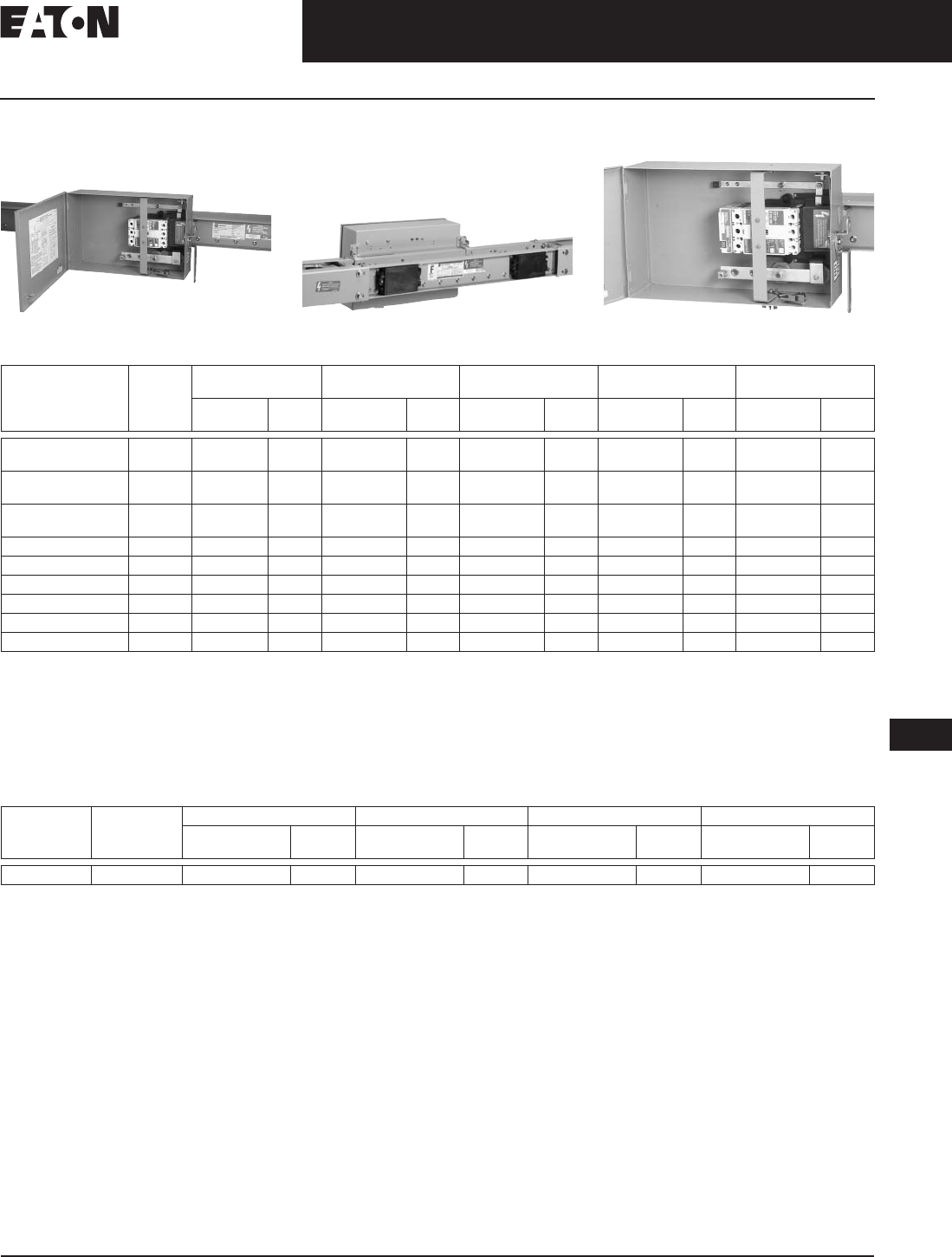
Pricing — Fusible Plug-in Units
Pow-R-Way III Plug-In Opening Pow-R-Way III Plug (Rear View)
Table 17-27. Fusible Switch
Horsepower Ratings
Table 17-28. Fusible Plug-in Units
■Fuses are not included.
■Mechanical lugs are provided.
If compression lugs are required,
the cable size must be specified.
■Plug-in unit, neutral, and ground are
ordered and shipped assembled.
Note: See Page 17-14 for Plug
Assembled Style Number Configuration.
■Housing ground connection supplied
as standard at no additional charge.
■R-Fuse clips are supplied as
standard.
■If J-Fuse clips are required, replace
“R” in the catalog number with
a “J” (30 through 600 ampere;
600 volt only).
■800 ampere 600 volt also available
with L-Fuse clips; replace “T” in
the catalog number with “L.”
■The adder for sprinkler-proof is 15%.
Table 17-29. Special Industry Fusible Plug-in Units
Grounds and neutrals must be factory assembled. Order by description. See Page 17-14.
■Fuses are not included.
■Housing ground connection supplied
as standard at no additional charge.
■Grounding compression lug included
on 200 ampere and above. Lugs
are ordered and shipped separately.
Fuses are not included.
■H-Fuse clips are supplied
as standard.
■If J- or R-Fuse clips are required,
order by description.
Ampere
Rating 240 Volts 480 Volts 600 Volts
NEC
Std. Max. NEC
Std. Max. NEC
Std. Max.
30
60
100
3
7.5
15
7.5
15
30
5
15
25
15
30
60
7.5
15
30
20
50
75
200
400
600
800
25
50
75
100
60
125
200
250
50
100
150
200
125
250
400
500
60
125
200
250
150
350
500
500
Ampere
Rating Enclosure
600 Volt Enclosure
240 Volt 100% Neutral
Stab 50% Internal
Ground Stab 50% Isolated
Ground Stab 200% Neutral
Stab
Catalog
Number Price
U.S. $ Catalog
Number Price
U.S. $ Catalog
Number Price
U.S. $ Catalog
Number Price
U.S. $ Catalog
Number Price
U.S. $ Catalog
Number Price
U.S. $
30
60
100
P3F361R
P3F362R
P3F363R
P3F321R
P3F322R
P3F323R
P3FN100
P3FN100
P3FN100
P3FG100
P3FG100
P3FG100
P3FI100
P3FI100
P3FI100
P3F2N100
P3F2N100
P3F2N100
200
400 P3F364R
P3F365R P3F324R
P3F325R P3FN200
P3FN400 P3FG200
P3FG400 P3FI200
P3FI400 P3F2N200
——
600
800 P3F366R
P3F367T P3F326R
P3F327T P3FN600
P3FN800 P3FG800
P3FG800 P3FI800
P3FI800 —
——
—
Ampere
Rating Enclosure
600 Volt 100% Neutral
Stab 50% Internal
Ground Stab 50% Isolated
Ground Stab Terminal Kit
Compression Lugs
Catalog
Number Price
U.S. $ Catalog
Number Price
U.S. $ Catalog
Number Price
U.S. $ Catalog
Number Price
U.S. $ # Per
Phase Wire
Size Catalog
Number Price
U.S. $
30
60
100
P3F361H
P3F362H
P3F363H
1
1
1
1 – #12 to #10
1 – #8
1 – #4
CTK30SC
CTK60SC
CTK100SC
200
400
600
P3F364H
P3F365H
P3F366H
1
1
2
1 – 2/0
1 – 750 kcmil
2 – 500 kcmil
CTK200BSC
CTK400SPW
CTK600DPM
Discount Symbol . . . . . . . . . . . . . . . . . . . . . . . . . CB-2
Discount Symbol . . . . . . . . . . . . . . . . . . . . . . . . . CE4
August 2006
CA08101001E For more information visit: www.EatonElectrical.com
17-17
Busway Products
17
Low Voltage Busway
Pow-R-Way III Busway — Product Selection
Pricing — Special Plug-in Units
Table 17-32. Advanced Plug-in Units —
Visor Series Bus Plug Prices —
TVSS Transient Voltage Surge Suppressor
Visor Series Bus Plug
kA
Rating AdVisor SuperVisor NetVisor
Price U.S. $ Price U.S. $ Price U.S. $
100
120
160
200
250
300
400
500
Table 17-30. Plug-in Cable Tap Box Units
■The adder for sprinkler proof is 15%.
■Mechanical lugs are provided. If compression lugs are required, the cable size must be specified.
Table 17-31. Plug-in Combination Starters and Contactors (Non-Reversing, 3-Pole)
Ampere
Rating Plug-in Cable Tap Box
600 Volt Enclosure 100% Neutral
Stab 50% Internal
Ground Stab 50% Isolated
Ground Stab
Catalog
Number Price
U.S. $ Catalog
Number Price
U.S. $ Catalog
Number Price
U.S. $ Catalog
Number Price
U.S. $
200
400
600
800
P3PTB200
P3PTB400
P3PTB600
P3PTB800
P3PTBN200
P3PTBN400
P3PTBN600
P3PTBN800
P3PTBG200
P3PTBG400
P3PTBG600
P3PTBG800
P3PTBI200
P3PTBI400
P3PTBI600
P3PTBI800
NEMA
Size Freedom
Combination
Starters
Freedom
Combination
Contactors
Advantage
Combination
Starters
Advantage
Combination
Contactors
100%
Neutral
Stab
50%
Internal
Ground
Stab
50%
Isolated
Ground
Stab
Fuse
120 Volt
Control
Transformer
Fusible
Disconnect Circuit
Breaker
or HMCP
Fusible
Disconnect Circuit
Breaker
or HMCP
Fusible
Disconnect Circuit
Breaker
or HMCP
Fusible
Disconnect Circuit
Breaker
or HMCP
Price U.S. $ Price U.S. $ Price U.S. $ Price U.S. $ Price U.S. $
0
1
2
3
4
Table 17-33. Visor Series Bus Plug Catalog Numbering System
Surge Rating
(kA/Phase)
100
120
160
200
250
300
400
500
Diagnostics Package
A AdVisor complete with sta-
tus indicator lights on each
phase, Form C. Audible
Alarm — Enable/Disable.
S SuperVisor complete with
status indicator lights on
each phase, Form C.
Audible Alarm — Enable/
Disable, Transient Counter,
Push-to-Test, PQ Meter
(no date stamp).
N NetVisor complete with
status indicator lights on
each phase, Form C.
Audible Alarm — Enable/
Disable, Transient Counter,
Push-to-Test, PQ Meter (no
date stamp). Modbus and
Ethernet Communications
Port, % Life Remaining, %
Voltage THD.
P3BCPS 250 480Y S A
Voltage
Code Voltage Requirements
120/208
240 V 230/400
400 V 277/480
480 V 347/600
600 V
3-Phase Wye
(4W+G)
208Y 400Y 480Y 600Y
3-Phase Delta
(4W+G)
240D —480D 600D
Discount Symbol. . . . . . . . . . . . . . . . . . . . . . . . . . CE4

August 2006
17-18
For more information visit: www.EatonElectrical.com CA08101001E
Busway Products
17
Low Voltage Busway
Pow-R-Way III Busway — Product Selection
Pricing — Bolt-on Units
Table 17-34. Circuit Breaker Bolt-on Units
■Factory assembled, Refer to Eaton’s
Cutler-Hammer Busway for delivery.
■Refer to Page 17-14 for breaker data.
For reference only.
■Bolt-on units require a Power
Take-off at the rating of the busway.
Price from Page 17-12.
■Housing ground connection supplied
as standard at no additional charge.
■The adder for sprinkler-proof is 15%.
Table 17-35. Fusible Bolt-on Units
■Factory assembled. Refer to Eaton’s
Cutler-Hammer Busway for delivery.
■Bolt-on units require a Power
Take-off at the rating of the busway.
Price from Page 17-12.
■If neutral and ground are required,
order by description with bolt-on unit.
■Housing ground connection supplied
as standard at no additional charge.
■The adder for sprinkler-proof is 15%.
Table 17-36. Ground Detector Neutralizer
Plug (3-Wire)
Breaker
Frame Ampere
Rating Bolt-on Enclosure 100% Neutral Stab 50% Internal Ground Stab 50% Isolated Ground Stab
Catalog
Number Price
U.S. $ Catalog
Number Price
U.S. $ Catalog
Number Price
U.S. $ Catalog
Number Price
U.S. $
EHD, FDB, FD, HFD, FDC
JDB, JD, HJD, JDC
KDB, KD, HKD, KDC
15 – 225
70 – 250
250 – 400
P3BFDBO
P3BJDBO
P3BKDBO
P3FDNBO
P3FJDNBO
P3KDNBO
P3FDGBO
P3JDGBO
P3KDGBO
P3FDIBO
P3JDIBO
P3KDIBO
LDB, LD, HLD, LDC
MDL, HMDL
ND, HND
300 – 600
500 – 800
900 – 1200
P3BLDBO
P3BMDBO
P3BNDBO
P3LDNBO
P3MDNBO
P3NDNBO
P3LDGBO
P3MDGBO
P3NDGBO
P3LDIBO
P3MDIBO
P3NDIBO
Ampere
Rating Enclosure 600 Volt 100% Neutral Stab 50% Internal Ground Stab 50% Isolated Ground Stab
Catalog
Number Price
U.S. $ Catalog
Number Price
U.S. $ Catalog
Number Price
U.S. $ Catalog
Number Price
U.S. $
30
60
100
P3F361BO
P3F362BO
P3F363BO
P3FN100BO
P3FN100BO
P3FN100BO
P3FG100BO
P3FG100BO
P3FG100BO
P3FI100BO
P3FI100BO
P3FI100BO
200
400
600
P3F364BO
P3F365BO
P3F366BO
P3FN250BO
P3FN400BO
P3FN600BO
P3FG250BO
P3FG400BO
P3FG600BO
P3FI250BO
P3FI400BO
P3FI600BO
800
1200 P3F367BO
P3F369BO P3FN800BO
P3FN1200BO P3FG800BO
P3FG1200BO P3FI800BO
P3FI1200BO
Maximum
Voltage Catalog
Number Price
U.S. $
600 P3GND
Discount Symbol . . . . . . . . . . . . . . . . . . . . . . . . . . CE4
August 2006
CA08101001E For more information visit: www.EatonElectrical.com
17-19
Busway Products
17
Low Voltage Busway
Pow-R-Way III Busway — Product Selection
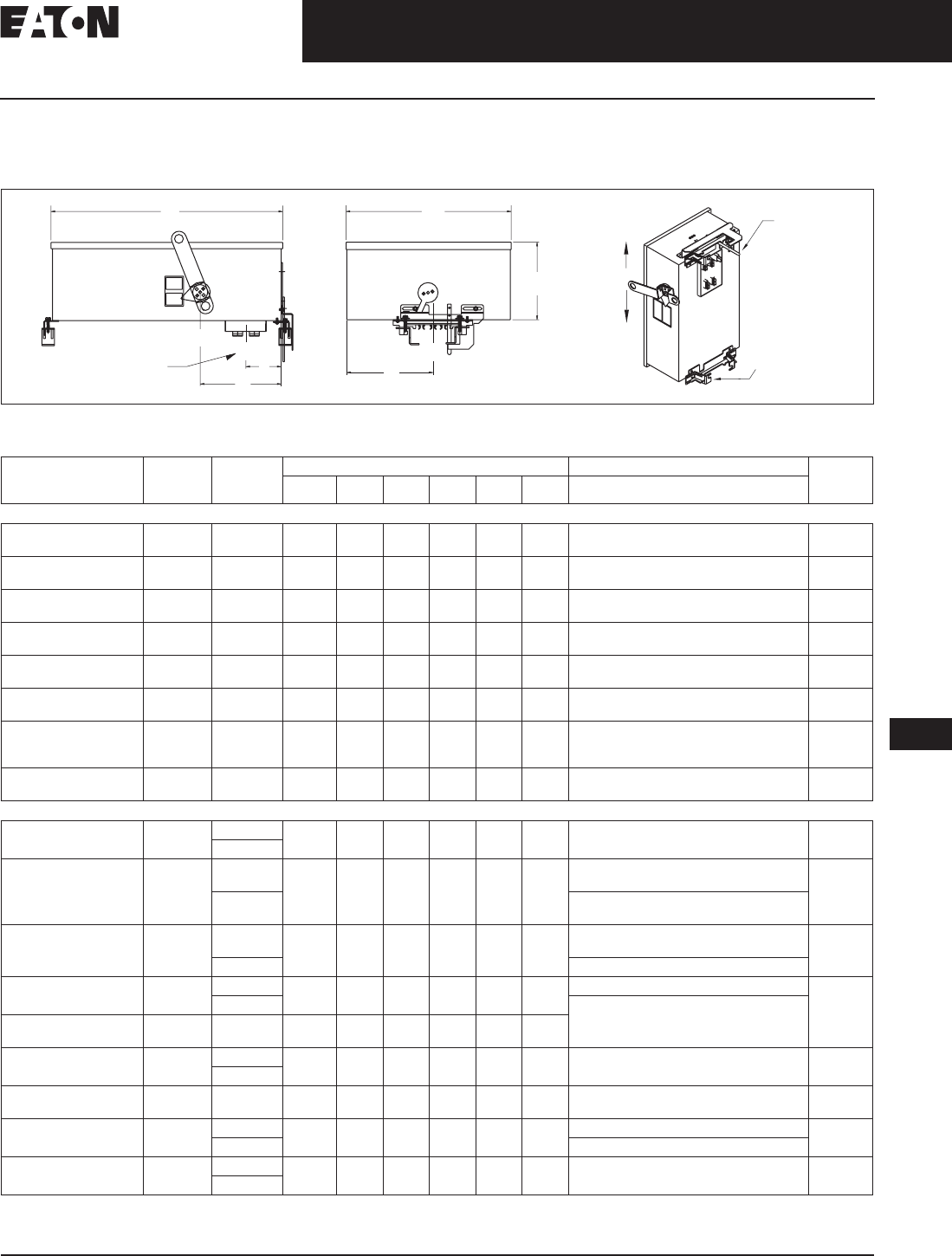
Dimensions — Plug-in Units
Physical Data
Figure 17-3. Bus Plugs
Table 17-37. Plug-in Units
The Clamp and Guide mechanism adds 2.50 inches (63.5 mm) to the overall length of the unit.
Plug-in
Unit Maximum
Amperes Maximum
ac Volts Dimensions in Inches (mm) Mechanical Terminal Approx.
Weights
Lbs. (kgs)
(A) (B) (C) (D) (E) (F) Wire Range Per Phase (mm2)
Circuit Breaker Plug-in Units
P3BFD
(E- & F-Frame Breakers) 225 600 19.26
(489.2) 12.36
(314.0) 5.43
(138.0) 6.25
(158.8) 4.00
(101.6) 6.06
(153.7) 100 A – (1) #14 – 1/0 (2.5 – 50)
150 A – (1) #4 – 4/0 (25 – 95) 25
(11.3)
P3BJD
(J-Frame Breakers) 250 600 21.33
(541.8) 12.36
(314.0) 6.97
(177.0) 10.44
(265.2) 4.00
(101.6) 6.06
(153.7) 250 A – (1) #14 – 350 kcmil (25 – 185)
225 A – (1) 3 – 350 kcmil (35 – 185) 47
(21.3)
P3BKD
(K-Frame Breakers) 400 600 32.50
(825.5) 13.29
(337.6) 7.79
(197.9) 12.56
(319.0) 4.00
(101.6) 6.64
(168.7) 350 A – (1) 250 – 500 kcmil (120 – 240)
400 A – (2) 3/0 – 250 kcmil (45 – 120) 53
(24.0)
P3BLD
(L-Frame Breakers) 600 600 44.03
(1118.4) 19.65
(499.1) 10.15
(257.8) 17.38
(441.5) 4.00
(101.6) 9.83
(249.7) 400 A – (1) 4/0 – 600 kcmil (120 – 300)
600 A – (2) 400 – 500 kcmil (185 – 240) 75
(34.0)
P3BMD
(M-Frame Breakers) 800 600 44.03
(1118.4) 19.65
(499.1) 10.15
(257.8) 17.38
(441.5) 4.00
(101.6) 9.83
(249.7) 600 A – (2) #1 – 500 kcmil (50 – 240)
800 A – (2) 500 – 750 kcmil (300 – 400) 136
(61.7)
P3BND
(N-Fame Breakers) 800 600 44.03
(1118.4) 19.65
(499.1) 10.15
(257.8) 17.38
(441.5) 4.00
(101.6) 9.83
(249.7) 700 A – (2) # 1 – 500 kcmil (50 – 240)
800 A – (3) 3/0 – 400 kcmil (95 – 185) 138
(62.6)
P3BLAP
(TRI-PAC) 400 600 44.03
(1118.4) 19.65
(499.1) 10.15
(257.8) 13.80
(350.5) 4.00
(101.6) 9.83
(249.7) 225 A – (1) #6 – 350 kcmil (16 – 185)
400 A – (1) #4 – 250 kcmil and (1) 3/0 – 600
kcmil (25 – 120 and 95 – 300)
96
(43.5)
P3BLCL 400 600 40.00
(1016.0) 19.65
(499.1) 10.15
(257.8) 13.80
(350.5) 4.00
(101.6) 9.83
(249.7) (1) #4 – 250 kcmil (25 – 120) and
(1) 3/0 – 600 kcmil (95 – 300) 88
(39.9)
Fusible Plug-in Units
P3F321R 30 240 20.85
(529.6) 12.36
(314.0) 5.43
(138.0) 7.88
(200.2) 4.00
(101.6) 6.06
(153.9) Cu – (1) #14 – #3, (2.5 – 35)
Al – (1) #12 – #2 (3.2 – 35) 22
(10.0)
P3F361R and P3F361H 600
P3F322R 60 240 20.85
(529.6) 12.36
(314.0) 5.43
(138.0) 7.88
(200.2) 4.00
(101.6) 6.06
(153.9) Cu – (1) #14 – #3, (2.5 – 35)
Al – (1) #12 – #2 (3.2 – 38) 24
(10.9)
P3F362R and
P3F362H 600 Cu – (1) #14 – 1/0, (2.5 – 50)
Al – (1) #12 – 1/0 (3.2 – 50)
P3F323R and 100 240 20.85
(529.6) 12.36
(314.0) 5.43
(138.0) 7.88
(200.2) 4.00
(101.6) 6.06
(153.9) Cu – (1) #14 – 1/0, (2.5 – 50)
Al – (1) #12 – 1/0 (3.2 – 50) 24
(10.9)
P3F363R and P3F363H 600 (1) # 4 – 250 kcmil Cu/Al (25 – 120)
P3F324R and 200 240 23.52
(597.4) 15.56
(395.2) 7.19
(182.6) 7.98
(202.7) 4.00
(101.6) 7.63
(193.8) (1) # 4 – 250 kcmil Cu/Al (25 – 120) 47
(21.3)
P3F364R 600 (1) #4 – 600 kcmil Cu/Al (25 – 300)
or (2) 250 kcmil (120)
P3F364H 200 600 21.75
(552.5) 15.56
(395.2) 9.66
(245.4) 6.28
(159.5) 4.00
(101.6) 7.63
(193.8)
P3F325R and 400 240 46.94
(1192.3) 21.22
(539.0) 10.07
(255.8) 12.67
(321.8) 4.00
(101.6) 10.69
(271.5) (1) 250 – 750 kcmil Cu/Al (127 – 380)
(2) 3/0 – 250 kcmil Cu/Al (85 – 127) 77
(34.9)
P3F365R 600
P3F365H 400 600 21.67
(550.4) 21.22
(539.0) 21.00
(533.4) 12.67
(321.8) 4.00
(101.6) 10.69
(271.5) (1) 250 – 750 kcmil Cu/Al (127 – 380)
(2) 3/0 – 250 kcmil Cu/Al (85 – 127) 81
(36.7)
P3F326R and 600 240 46.94
(1192.3) 26.31
(668.3) 10.59
(270.0) 14.26
(362.2) 4.00
(101.6) 13.16
(334.3) (2) #2 – 600 kcmil Cu/Al (35 – 300) 82
(37.1)
P3F366R 600 (3) #4 – 600 kcmil Cu/Al (25 – 300)
P3F327R and 800 240 46.94
(1192.3) 26.31
(668.3) 10.59
(270.0) 14.26
(362.2) 4.00
(101.6) 13.16
(334.3) (3) #4 – 600 kcmil Cu/Al (25 – 300) 108
(49.0)
P3F367R 600
Plug-in Opening
and B ©
Handle
Plug-in
Opening
OFF
ON
E
D
A
C
B
F
C
LC
LC
L
Guide Pin
Clam
p
a
n
d
Gu
i
de
OF
F
ON
OFF
ON
August 2006
17-20
For more information visit: www.EatonElectrical.com CA08101001E
Busway Products
17
Low Voltage Busway
Pow-R-Way III Busway — Pricing
Pricing — Examples
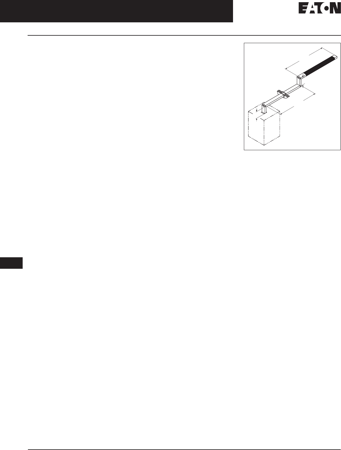
How to Price an End Cable Tap Box
System configuration:
2500 ampere indoor 3-phase, 4-wire
copper with internal ground.
Fitting fabrication charge for
end cable tap box. . . . . . . . $ 2,344.
4-foot (1.2 m) indoor feeder at
$1,331 per foot . . . . . . . . . . . . 5,324.
4-foot (1.2 m) 50% internal ground
at $161 per foot . . . . . . . . . . . . . 644.
Total Price $ 8,312.
How to Price a 90° Traditional Elbow
(2’6” x 2’6”)
System Configuration:
1600 ampere indoor 3-phase, 3-wire
aluminum with integral housing
ground and 50% internal ground.
Fitting fabrication charge for
90° elbow . . . . . . . . . . . . . . . $ 1,047.
5-foot (1.5 m) indoor
feeder at $433 per foot
(Includes integral
housing ground). . . . . . . . . . . 2,165.
5-foot (1.5 m) 50% internal
ground at $54 per foot . . . . . . . . 270.
Total Price $ 3,482.
How to Price a Corner Joint Elbow (1’ x 1’)
System Configuration:
1200 ampere indoor 3-phase, 3-wire
copper with integral housing ground
and 50% internal ground.
Fitting fabrication charge for
corner joint . . . . . . . . . . . . . . $ 851.
2-foot (.6 m) indoor feeder
at $470 per foot (includes
integral housing ground). . . . . . 940.
2-foot (.6 m) 50% internal
ground at $73 per foot . . . . . . . . 146.
Total Price $ 1,937.
How to Price a Complete Bus Run
System configuration:
1200 ampere indoor 3-phase, 4-wire
copper with 50% internal ground.
Include quantity 4 – 30 ampere,
600 volt fusible plug-in units.
Note: Price footage through entire bus run,
add fabrication charges for fittings.
14-foot (4 m) indoor feeder at
$645 per foot . . . . . . . . . . . . $ 9,030.
150-foot (45 m) plug-in at
$663 per foot . . . . . . . . . . . . . 99,450.
164-foot (50 m) 50% internal
ground at $73 per foot . . . . . 11,972.
Quantity 1 — standard flange . . 1,348.
Quantity 3 — 90° traditional
elbows at $1,135 per each . . . 3,405.
Quantity 2 — wall flanges at
$136 per each . . . . . . . . . . . . . . . 272.
Quantity 1 — end closures . . . . . . .273.
Total List – Busway $ 125,750.
Quantity 4 — P3F361R at
$466 per each . . . . . . . . . . . $ 1,864.
Quantity 4 — P3FN100 at
$61 per each . . . . . . . . . . . . . . . . 244.
Quantity 4 — P3FG100 internal
ground stabs at $61 per each. . . 244.
Total Price — Plug-in Units $ 2,352.
Figure 17-4. Shaded Sections Indicate
Plug-in Busway — Dimensions in Feet (m)
2.0
(.61)
2.0 (.61)
10.0
(3.0)
150.0 (45.7)

August 2006
CA08101001E For more information visit: www.EatonElectrical.com
17-21
Busway Products
17
Low Voltage Busway
Pow-R-Way Busway
Product Description
Plug-in Busway:
■Pow-R-Way II Plug-in Busway
225 to 400 Ampere Copper
225 to 400 Ampere Aluminum
■Pow-R-Way Plug-in Busway
600 to 4000 Ampere Copper
600 to 4000 Ampere Aluminum
Straight sections of plug-in busway are
available in 2-foot (.6 m) incremental
lengths from a 2-foot (.6 m) minimum
to a 10-foot (3 m) maximum.
Feeder Busway:
■Pow-R-Way II Indoor Feeder Busway
225 to 400 Ampere Copper
225 to 400 Ampere Aluminum
■Pow-R-Way Indoor or Outdoor
Feeder Busway
600 to 5000 Ampere Copper
600 to 4000 Ampere Aluminum
Straight sections of indoor and out-
door feeder busway are available in
1/8-inch (3.2 mm) increments from
an 18-inch (457 mm) minimum to
10-foot (3 m) maximum.
Plug-in Units:
A full family of busway plug-in units
are available. Standard plug-in units
include fusible or circuit breaker
protection.
Pow-R-Way (Single Bolt per Joint, 600 – 5000 Amperes and
Pow-R-Way II (Single Bolt per Bus Bar, 225 – 400 Amperes)
Typical Pow-R-Way Plug-in Straight Length
Typical Pow-R-Way Feeder Straight Length
Standards and Certifications
Pow-R-Way and Pow-R-Way II busway
meet the requirements of UL, CSA
and NEMA.
Additional Pow-R-Way Information:
■Technical Data: AD30-560.
Product Specifications
The following systems are
available:
■3-phase, 3-wire.
■3-phase, 3-wire, with 50% internal
ground.
■3-phase, 4-wire (100% neutral).
■3-phase, 4-wire (100% neutral)
with 50% internal ground.
■All 3-wire systems have a maximum
voltage rating of 600 volts and all
4-wire systems have a maximum
of 347/600 volts.
Note: The Pow-R-Way bus housing is NOT
suitable for use as ground.
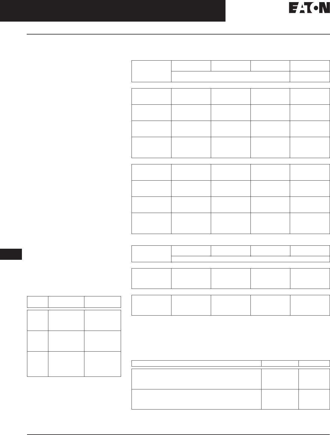
August 2006
17-22
For more information visit: www.EatonElectrical.com CA08101001E
Busway Products
17
Low Voltage Busway
Pow-R-Way Busway — Product Selection
Product Selection
Pricing — Copper Busway
General Information
■Determine the total footage, all
fittings, and accessories for entire
busway run. Price the total footage
by type and system requirements.
Round footage up to the nearest
foot. Add the fabrication charge
for the fittings. Add any additional
accessories required for the total
price of the busway run.
Plug-in
■Straight sections of plug-in busway
are available in 2-foot (.6 m) incre-
ments from a 2-foot (.6 m) minimum
to a 10-foot (3 m) maximum.
Sprinkler-proof Plug-in
■For sprinkler-proof plug-in multiply
the plug-in price by 1.25 and use
outdoor pricing for the feeder
busway.
Feeder
■Straight sections of feeder busway
are available in 1/8-inch (3.2 mm)
increments from 16 inches (406 mm)
minimum to 10-foot (3 m) maximum.
Busway must carry at least a 50%
load in all outdoor applications.
Hangers
■The busway price includes one
horizontal hanger per 10 feet (3 m)
of busway. All vertical hangers and
any additional horizontal hangers
should be added to the total price.
Table 17-38. Short-Circuit Withstand Ratings
— rms Symmetrical Amperes for Copper
Pow-R-Way Plug-in and Feeder Busway
Ampere
Rating 3-Cycle
Copper Plug-in 3-Cycle
Copper Feeder
225
400
600
800
18,000
25,000
50,000
50,000
18,000
25,000
75,000
75,000
1000
1200
1350
1600
100,000
100,000
100,000
100,000
100,000
100,000
100,000
100,000
2000
2500
3000
4000
5000
100,000
150,000
150,000
200,000
—
100,000
150,000
150,000
200,000
200,000
Table 17-39. Busway — Copper Straight Lengths
Table 17-40. Fabrication Adders for Common Fittings — Cable Tap Boxes and End Closures
General Information
■When pricing a cable tap box or
a Weatherhead, include the price
of 4 feet (1.2 m) of feeder busway
to the fabrication charge.
■Cable tap boxes include 1/0 to 600
kcmil lugs. For additional lugs, larger
lugs, or compression type lugs, refer
to Eaton’s Cutler-Hammer busway.
■Additional Fittings on Page 17-24.
Table 17-41. Accessories and Renewal Parts
Specify the ampere rating and system requirements when ordering as renewal parts.
Ampere
Rating Plug-in Indoor Feeder Outdoor Feeder 50% Internal
Ground
Price U.S. $
Per Foot, Busway Only Price U.S. $
Adder Per Foot
3-Phase, 3-Wire, 600 Volts
225
400
600
—
——
—
800
1000
1200
1350
1600
2000
2500
3000
4000
5000 —
3-Phase, 4-Wire, Full Neutral, 277/480 Volts or 347/600 Volts
225
400
600
—
——
—
800
1000
1200
1350
1600
2000
2500
3000
4000
5000 —
Ampere
Rating End or Center
Cable Tap Box Outdoor Cable
Tap Box Weatherhead End Closure
Price U.S. $
3-Phase, 3-Wire, 600 Volts
225 – 600
800 – 1200
1350 – 2500
3000 – 5000
3-Phase, 4-Wire, 277/480 Volts or 347/600 Volts
225 – 600
800 – 1200
1350 – 2500
3000 – 5000
Description Catalog Number Price U.S. $
Wall/Floor Flange
Vertical Hanger
Extra Horizontal Hanger
Roof Flange (Required when Outdoor Busway Penetrates a Roof)
Indoor Joint Cover
Outdoor Joint Cover
Hookstick Kit — 8 – 14 Foot (2.4 – 4.3 m)
Joint Puller
PWIJC
PWOJC
HS8-14
PWJP
Discount Symbol . . . . . . . . . . . . . . . . . . . . . . . . . . CE3
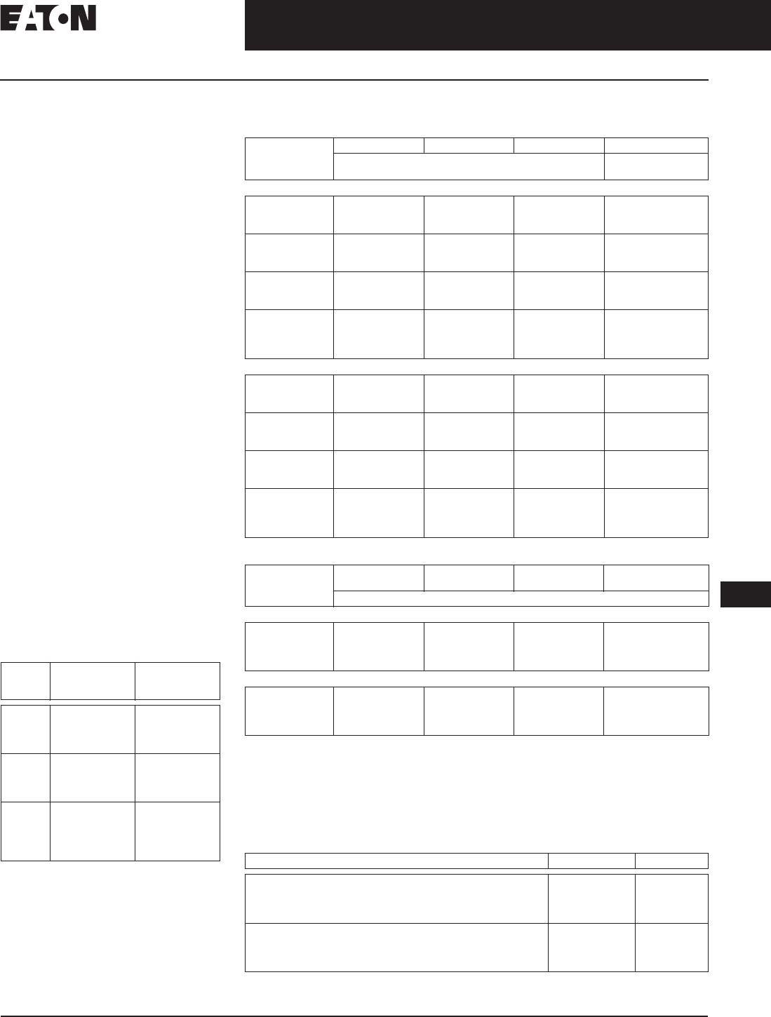
August 2006
CA08101001E For more information visit: www.EatonElectrical.com
17-23
Busway Products
17
Low Voltage Busway
Pow-R-Way Busway — Aluminum
Pricing — Aluminum Busway
General Information
■Determine the total footage, all
fittings, and accessories for entire
busway run. Price the total footage
by type and system requirements.
Round footage up to the nearest
foot. Add the fabrication charge
for the fittings. Add any additional
accessories required for the total
price of the busway run.
Plug-in
■Straight sections of plug-in busway
are available in 2-foot (.6 m) incre-
ments from a 2-foot (.6 m) minimum
to a 10-foot (3 m) maximum.
Sprinkler-proof Plug-in
■For sprinkler-proof plug-in multiply
the plug-in price by 1.25 and use
outdoor pricing for the feeder
busway.
Feeder
■Straight sections of feeder busway
are available in 1/8-inch (3.2 mm)
increments from 16 inches (406 mm)
minimum to 10-foot (3 m) maximum.
Busway must carry a least a 50%
load in all outdoor applications.
Hangers/Pow-R-Bridge
■The busway price includes one
horizontal hanger per 10 feet (3 m)
of busway. All vertical hangers and
any additional horizontal hangers
should be added to the total price.
Table 17-42. Short-Circuit Withstand Rating
— rms Symmetrical Amperes for Aluminum
Pow-R-Way Plug-in and Feeder Busway
Ampere
Rating 3-Cycle
Aluminum
Plug-in
3-Cycle
Aluminum
Feeder
225
400
600
800
18,000
25,000
50,000
100,000
18,000
25,000
75,000
100,000
1000
1200
1350
1600
100,000
100,000
100,000
100,000
100,000
100,000
100,000
100,000
2000
2500
3000
4000
5000
100,000
150,000
150,000
200,000
—
100,000
150,000
150,000
270,000
—
Table 17-43. Busway — Aluminum Straight Lengths
Table 17-44. Fabrication Adders for Common Fittings — Cable Tap Boxes and End Closures
General Information
■When pricing a cable tap box or a
weatherhead, include the price of
4-feet (1.2 m) of feeder busway to
the fabrication charge.
■Cable tap boxes include 1/0 to
600 kcmil lugs. For additional lugs,
larger lugs, or compression type lugs,
refer to Eaton’s Cutler-Hammer
busway.
■Additional fittings on Page 17-24.
Table 17-45. Accessories and Renewal Parts
Specify the ampere rating and system requirements when ordering as renewal parts.
Ampere
Rating Plug-in Indoor Feeder Outdoor Feeder 50% Internal Ground
Price U.S. $
Per Foot, Busway Only Price U.S. $
Adder Per Foot
3-Phase, 3-Wire, 600 Volts
225
400
600
——
—
800
1000
1200
1350
1600
2000
2500
3000
4000
5000 ——— —
3-Phase, 4-Wire, Full Neutral, 277/480 Volts or 347/600 Volts
225
400
600
—
——
—
800
1000
1200
1350
1600
2000
2500
3000
4000
5000 ——— —
Ampere
Rating End or Center
Cable Tap Box Outdoor Cable
Tap Box Weatherhead End Closure
Price U.S. $
3-Phase, 3-Wire, 600 Volts
225 – 600
800 – 1200
1350 – 2500
3000 – 5000
3-Phase, 4-Wire, 277/480 Volts or 347/600 Volts
225 – 600
800 – 1200
1350 – 2500
3000 – 5000
Description Catalog Number Price U.S. $
Wall/Floor Flange
Vertical Hanger
Extra Horizontal Hanger
Roof Flange (Required when Outdoor Busway Penetrates a Roof)
Indoor Joint Cover
Outdoor Joint Cover
Hookstick Kit — 8 – 14 Foot (2.4 – 4.3 m)
Joint Puller
PWIJC
PWOJC
HS8-14
PWJP
Discount Symbol. . . . . . . . . . . . . . . . . . . . . . . . . . CE3

August 2006
17-24
For more information visit: www.EatonElectrical.com
Busway Products
17
Low Voltage Busway
Pow-R-Way Busway — Fittings
Pricing — Fabrication Adders for Fittings
Table 17-46. Flanges and Expansion Joints
Table 17-47. Elbows, Tees and Crosses
Table 17-48. Reducers
Table 17-49. Transformer Connections and Power Take-offs
Ampere
Rating Standard Flange Flush Flange Special Flange Vault Flange Expansion Joint
Price U.S. $
3-Phase, 3-Wire, 600 Volts
225 – 600
800 – 1200
1350 – 2500
3000 – 5000
3-Phase, 4-Wire, 277/480 Volts or 347/600 Volts
225 – 600
800 – 1200
1350 – 2500
3000 – 5000
Ampere
Rating Traditional Elbow Tee Cross
Price U.S. $
3-Phase, 3-Wire, 600 Volts
225 – 600
800 – 1200
1350 – 2500
3000 – 5000
3-Phase, 4-Wire, 277/480 Volts or 347/600 Volts
225 – 600
800 – 1200
1350 – 2500
3000 – 5000
Ampere
Rating No Overcurrent
Protection Reducer Circuit Breaker
Protection Reducer Fusible
Protection Reducer
Price U.S. $
3-Phase, 3-Wire, 600 Volts
225 – 600
800 – 1200
1350 – 2000
2500 – 3000
4000 – 5000 — —
3-Phase, 4-Wire, 277/480 Volts or 347/600 Volts
225 – 600
800 – 1200
1350 – 2000
2500 – 3000
4000 – 5000 — —
Ampere
Rating Transformer Connections Power Take-offs
One
3-Phase Tap Three
1-Phase Taps Transformer
Throat Built into
Straight Length For Use at
Plug-in Opening
Price U.S. $ Price U.S. $
3-Phase, 3-Wire, 600 Volts
600
800
1000 – 1200
1350 – 2500
3000 – 5000
3-Phase, 4-Wire, 277/480 Volts or 347/600 Volts
600
800
1000 – 1200
1350 – 2500
3000 – 5000
General Information
■For a complete price on these
fittings, add the price of the footage
through the fitting to the fabrication
charge. See Page 17-22 for copper
or Page 17-23 for aluminum per
foot prices.
■A standard flange is used to connect
to Eaton’s Cutler-Hammer equipment.
General Information
■For a complete price on these
fittings, add the price of the footage
through the fitting to the fabrication
charge. See Page 17-22 for copper
or Page 17-23 for aluminum per
foot prices.
■For a special degree elbow, double the
traditional elbow fabrication charge.
General Information
■See NEC 364-11 for Reducer
Application.
■Price fabrication charge at the lower
busway rating.
■For a complete price on these
fittings, add the price of the footage
through the fitting to the fabrication
charge. See Page 17-22 for copper
or Page 17-23 for aluminum per
foot prices.
■Fusible reducers are 600 volt
maximum. Fuses are not included.
General Information
Transformer connections:
■Transformer tap bus extensions
do not include drilling or lugs.
■Transformer throats include
flexible connectors.
■Add the price of the footage
through the fitting to the fabrication
charge. See Page 17-22 for copper
or Page 17-23 for aluminum per
foot prices.
Power take-offs:
■To completely price a power take-
off, include a power take-off from
this table at the busway ampere
rating, footage through the fitting,
and a bolt-on circuit breaker or
fusible unit at the required rating.
Discount Symbol . . . . . . . . . . . . . . . . . . . . . . . . . . CE4
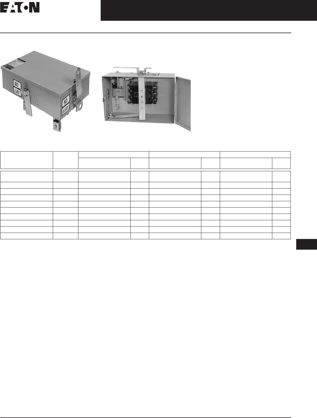
August 2006
CA08101001E For more information visit: www.EatonElectrical.com
17-25
Busway Products
17
Low Voltage Busway
Pow-R-Way Busway — Circuit Breaker Plug-in Units
Pricing — Circuit Breaker Plug-in Units
Pow-R-Way Bus Plug Pow-R-Way Bus Plug (Open View)
Table 17-50. Circuit Breaker Plug-in Units
■Refer to Page 17-14 for breaker data.
For reference only.
Note: The enclosure, circuit breaker,
neutral, and ground are ordered and
shipped assembled. See Page 17-14 for Plug
Assembled Style Number Configuration.
■If a Bolt-on Unit is required, double
the price of a plug-in unit and order
by description. Bolt-on units are fac-
tory assembled. Refer to Eaton’s
Cutler-Hammer busway for delivery.
Bolt-on units require a Power Take-off
at the rating of the busway. Prices
from Page 17-24.
■The adder for sprinkler-proof is 15%.
Breaker
Frame Ampere
Rating Plug-in Enclosure 100% Neutral Stab 50% Internal Ground Stab
Catalog
Number Price
U.S. $ Catalog
Number Price
U.S. $ Catalog
Number Price
U.S. $
ED, EHD, FDB, FD,
HFD, FDC, EDH, EDC 15 – 150 IBPFD PWN110 (15 – 110 A)
PWN150 (125 – 250 A) PIGS104
JDB, JD, HJD, JDC 70 – 250 IBPJD PWN250 (125 – 250 A) PIGS104
KDB, KD, HKD, KDC 100 – 400 IBPKD PWN400 (150 – 400 A) PIGS104
LDB, LD, HLD, LDC 300 – 600 IBPLD PWN600 (300 – 600 A) PIGS208
MDL, HMDL 400 – 800 IBPMD PWN800 (400 – 800 A) PIGS608
FB TRI-PAC 15 – 100 IBPFBP PWN110 (15 – 100 A) PIGS104
LA TRI-PAC 125 – 400 IBPLAP PWN400 (125 – 400 A) PIGS104
NB TRI-PAC 500 – 800 IBPNBP PWN800 (500 – 800 A) PIGS208
FCL Current Limit-R 15 – 100 IBPFCL PWN110 (15 – 110 A) PIGS104
LCL Current Limit-R 125 – 400 IBPLCL PWN400 (125 – 400 A) ——
Discount Symbol . . . . . . . . . . . . . . . . . . . . . . . . . . CE4
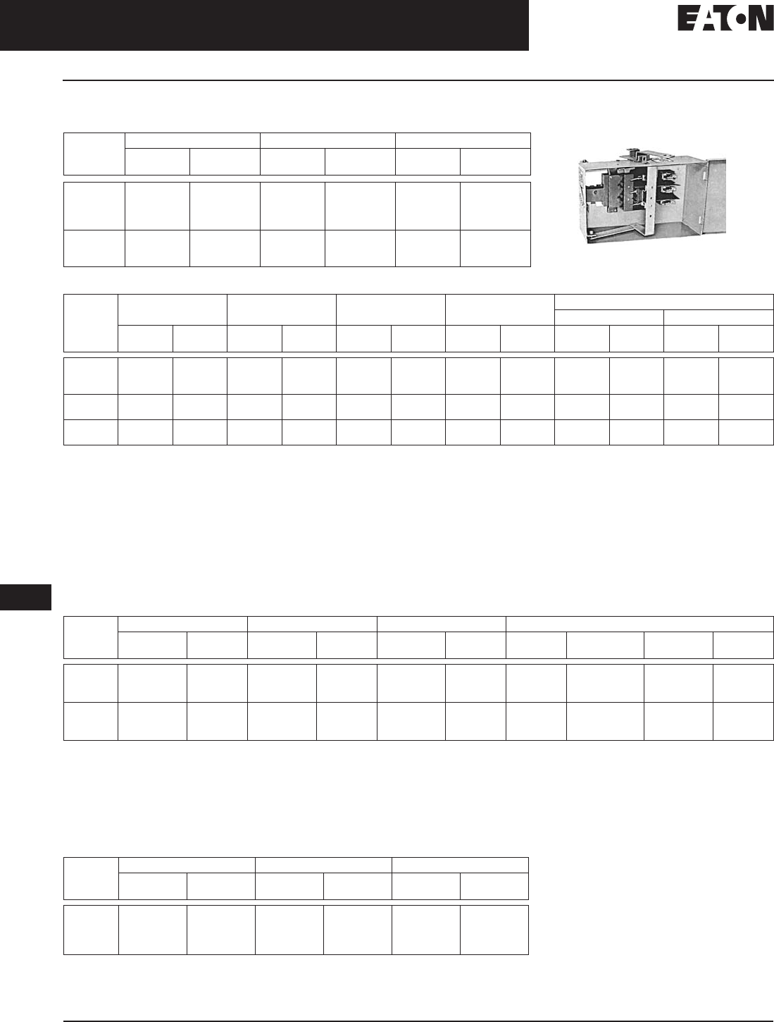
August 2006
17-26
For more information visit: www.EatonElectrical.com CA08101001E
Busway Products
17
Low Voltage Busway
Pow-R-Way Busway — Fusible Plug-in Units
Pricing — Fusible Plug-in Units
Table 17-51. Fusible Switch Horsepower Ratings
Table 17-52. Fusible Plug-in Units
■Fuses are not included.
■Mechanical lugs are provided.
If compression lugs are required,
the size must be specified.
■Plug-in unit, neutral, and ground are
ordered and shipped assembled.
Note: See Page 17-14 for Plug Assembled
Style Number Configuration.
■H-Fuse clips are supplied as
standard.
■If a bolt-on unit is required, double
the price of a plug-in unit and
order by description. Bolt-on units
are factory assembled. Refer to
Eaton’s Cutler-Hammer busway for
delivery. Bolt-on units require a
power take-off at the rating of the
busway. Prices from Page 17-24.
■If R-Fuse clips are required, add an
“R” to the end of the catalog num-
ber (30 through 600 amperes only).
■The adder for sprinkler-proof is 15%.
Table 17-53. Special Industry Fusible Plug-in Units
Grounds and neutrals must be factory assembled. Order by description. See Page 17-14.
■Fuses are not included.
■Grounding compression lug included
on 200 ampere and above. Lugs
are ordered and shipped separately.
Fuses are not included.
■H-Fuse Clips are supplied as standard.
■If J- or R-Fuse clips are required,
order by description.
■The adder for sprinkler-proof is 15%.
Table 17-54. Pow-R-Way Plug-in Cable Tap Box Units
Discount Symbol . . . . . . . . . . . . . . . . . . . . . . . . CB-15
Discount Symbol . . . . . . . . . . . . . . . . . . . . . . . . CE4
Ampere
Rating 240 Volts 480 Volts 600 Volts
Fusible ITAP
NEC
Standard Maximum NEC
Standard Maximum NEC
Standard Maximum
30
60
100
200
3
7-1/2
15
25
7-1/2
15
30
60
5
15
25
50
15
30
60
125
7-1/2
15
30
60
20
50
75
150
400
600
800
50
75
100
125
200
250
100
150
200
250
400
500
125
200
250
350
500
500
Ampere
Rating Enclosure
600 Volts Enclosure
240 Volts 100% Neutral
Stab 50% Internal
Ground Stab Class R Fuse Clips (If Required)
600 Volts 240 Volts
Catalog
Number Price
U.S. $ Catalog
Number Price
U.S. $ Catalog
Number Price
U.S. $ Catalog
Number Price
U.S. $ Catalog
Number Price
U.S. $ Catalog
Number Price
U.S. $
30
60
100
ITAP361
ITAP362
ITAP363
ITAP321
ITAP322
ITAP323
PWN110
PWN110
PWN110
PIGS104
PIGS104
PIGS104
RFK161
RFK262
RFK464
RFK121
RFK222
RFK464
200
400 ITAP364
ITAP365 ITAP324
ITAP325 PWNF250
PWN400 PIGS208
PIGS208 RFK464
RFK666 RFK464
RFK666
600
800 ITAP366
ITAP367 ITAP326
ITAP327 PWN600
PWN800 PIGS208
PIGS208 RFK666
——RFK666
——
Ampere
Rating Enclosure 600 Volts 100% Neutral Stab 50% Internal Ground Stab Terminal Kit Compression Lugs
Catalog
Number Price
U.S. $ Catalog
Number Price
U.S. $ Catalog
Number Price
U.S. $ # Per
Phase Wire
Size Catalog
Number Price
U.S. $
30
60
100
ITAP361H
ITAP362H
ITAP363H
1
1
1
1 – #12 to #10
1 – #8
1 – #4
CTK30SC
CTK60SC
CTK100SC
200
400
600
ITAP364H
ITAP365H
ITAP366H
1
1
2
1 – 2/0
1 – 750 kcmil
2 – 500 kcmil
CTK200BSC
CTK400SPW
CTK600DPM
Ampere
Rating Enclosure 600 Volts 100% Neutral Stab 50% Internal Ground Stab
Catalog
Number Price
U.S. $ Catalog
Number Price
U.S. $ Catalog
Number Price
U.S. $
225
400
600
1000
IPTB225
IPTB400
IPTB600
IPTB1000
PWN225
PWN400
PWN600
PWN1000
PIGS208
PIGS208
PIGS208
PIGS208
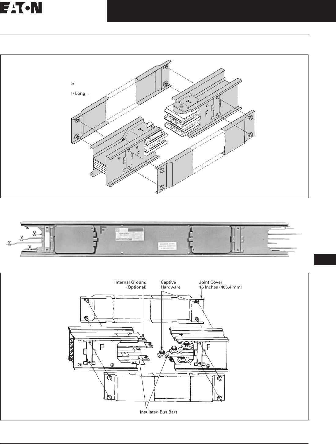
August 2006
CA08101001E For more information visit: www.EatonElectrical.com
17-27
Busway Products
17
Low Voltage Busway
Pow-R-Way Busway — Technical Data and Specifications
Technical Data and Specifications
Figure 17-5. Typical Pow-R-Way Joint
(Single Bolt Construction, 1 Bar per Phase, See AD 30-560)
Typical Pow-R-Way II Plug-in Straight Length
Figure 17-6. Typical Pow-R-Way II Joint
(Single Bolt per Bus Bar, Pow-R-Way II)
J
o
in
t
Co
v
e
1
6
in
c
h
es
(406.4 m
m
)
Lon
g
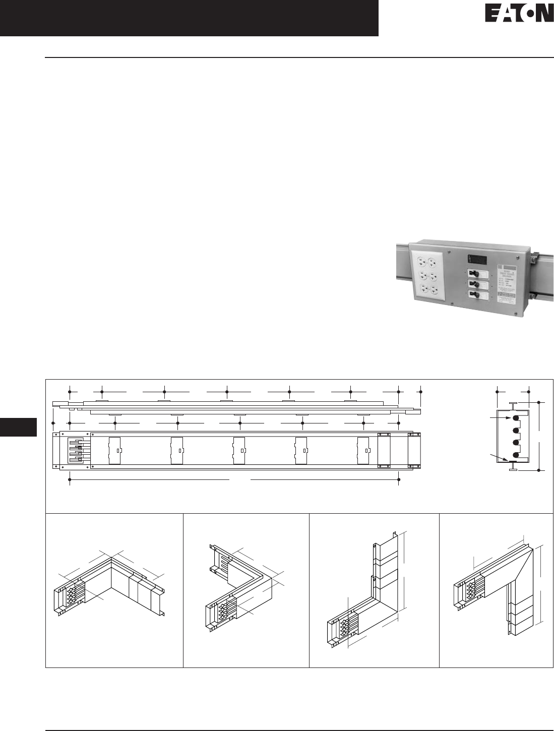
August 2006
17-28
For more information visit: www.EatonElectrical.com CA08101001E
Busway Products
17
Low Voltage Busway
100 Ampere Busway
Product Description
Plug-in Busway
■100 ampere copper.
■Straight sections of plug-in busway.
■3-phase 3-wire, 3-phase 4-wire,
and 1-phase 3-wire applications.
Application Description
The Cutler-Hammer 100 ampere
busway by Eaton Corporation is an
alternative to cable in supplying small
blocks of power for the normal com-
mercial and industrial power systems.
100 ampere busway is practical for
small shops, laboratories, classrooms,
and light manufacturing.
Options and Accessories
100 Ampere Busway Plug-in Units
Plug-in units for 100 ampere busway are
available with or without overcurrent
protection. All plug-in units include a
neutral stab and are suitable for 3-phase,
3-wire, and 3-phase, 4-wire applications.
The PINQP circuit breaker enclosures
and the LCNQP and LCNFD receptacle
enclosures are all suitable for 1-phase,
3-wire applications. Ground stabs are
available for field installation.
Fusible Units
Fusible units are available for 30,
60 and 100 ampere service for 240 or
600 volts.
Circuit Breaker Units
If you are using circuit breaker
units, the load must be distributed
evenly among A, B and C phases. To
accomplish this, distribute the load
evenly among 1-, 2- and 3-pole
breakers. Available are QUICKLAG
“HQP” circuit breaker units for 50 A –
240 V maximum service, “EHD,
FDB and FD” circuit breakers for
100 A – 600 V maximum service.
External Handle Operating Mechanism
An external operating mechanism is
attached on top of the breaker switch
for hookstick or chain operation. This
is available for all circuit breakers.
Receptacle Enclosures
The receptacle enclosures (loadcenters)
include space for three breaker poles
and provisions for 1, 2 or 3 conven-
tional, single-gang outlets, and blank
covers to fill unused spaces. Include
neutral stab. Do not include breakers,
outlets or wiring.
The enclosure, circuit breaker (if
required) and ground are ordered
separately and shipped unassembled.
If the unit is to be factory assembled,
please indicate on the order, add 15%
to the total price, and allow additional
time for shipment. For circuit breaker
selection and pricing, see Page 17-14.
Bus Plug Receptacle
Technical Data and Specifications
Figure 17-7. 100 Ampere Busway and Fittings
10"
10"
10"
10"
C
L Joint
C
L Joint
10"
10"
C
L Joint
10"
10"
C
L Joint
FRONT
C
L C
L
120.00
(3048.0)
Joint Joint
50% Internal Ground
Neutral
Bus Bar Size:
.281 (7.1) Dia.
26.25
(666.8)
26.25
(666.8)
26.25
(666.8)
26.25
(666.8)
26.25
(666.8)
26.25
(666.8)
26.25
(666.8)
6.00
(152.4)
6.00
(152.4)
3.50
(88.9)
3.50
(88.9)
9.00
(228.6)
26.25
(666.8)
9.00
(228.6)
1.75
(44.4)
5.37
(136.5)
Typical 100 Ampere Busway, Straight Length Typical Cross-Section
10.00 (254.0) x 10.00 (254.0) 10.00 (254.0) x 10.00 (254.0) 10.00 (254.0) x 10.00 (254.0) 10.00 (254.0) x 10.00 (254.0)
Forward Elbow Rearward Elbow Upward Elbow Downward Elbow
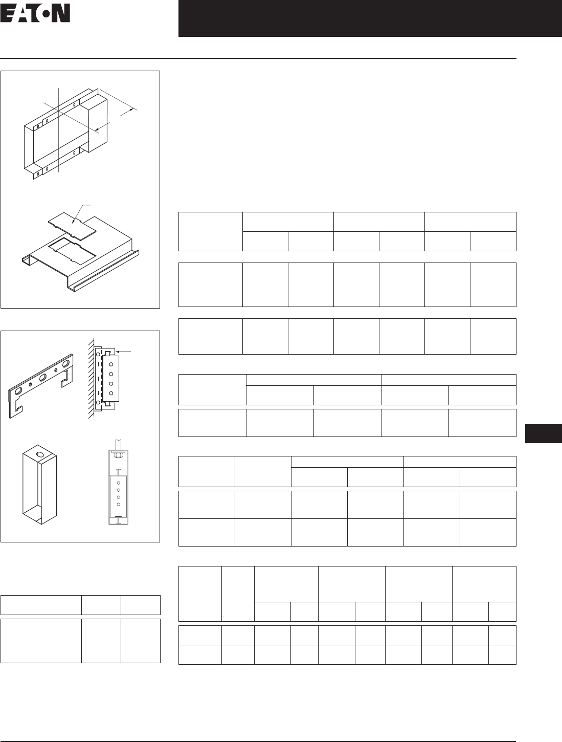
August 2006
CA08101001E For more information visit: www.EatonElectrical.com
17-29
Busway Products
17
Low Voltage Busway
100 Ampere Busway — Product Selection
Figure 17-8. Accessories
Figure 17-9. Hangers
Note: The busway price does not
include hangers.
Table 17-55. Accessories
Note: The above items can be used with
or without ground, 3-wire or 4-wire.
Item Catalog
Number Price
U.S. $
End Closer
Outlet Cover
Edgewise Hanger
“C” Clamp Hanger
Slip-on Wall Flange
EC1
OC1
EH1
FH1
WF1
C
LJoint
4.00
(101.6)
Outlet Cover
End Closers — EC1
Replacement Outlet Cover — OC1
Angle
Iron
“C” Clamp — FH1 Wall Mounted
Edgewise — EH1 Edge Mounted
Product Specifications
Electrical conductors are silver-plated
round copper rods. A 50% internal
ground bar is supplied as standard.
Busway with ground will match existing
busway without ground. The housing is
formed from two channels of 20-gauge
steel riveted together in a solid
assembly and painted ANSI 61.
Conductor joints are made by means
of boltless pressure clips that require
no assembly or adjustment by the
installer. The bus bars are firmly
supported by molded insulators on
the alternate side of the busway.
Product Selection
Table 17-56. Busway
Table 17-57. Cable Tap Boxes
Table 17-58. Fusible Plug-in Units
Table 17-59. Circuit Breakers for Plug-in Units
Description 3-Phase, 3-Wire
600 Volts Maximum 3-Phase, 4-Wire
FN 277/480 Volts 1-Phase, 3-Wire
120/240 Volts
Catalog
Number Price
U.S. $ Catalog
Number Price
U.S. $ Catalog
Number Price
U.S. $
Copper (Includes 50% Internal Ground Bar)
10-ft. (3048 m)
5-ft. (1524 m)
3-ft. (914.4 m)
2-ft. (609.6 m)
1-ft. (304.8 m)
CST13G
CST135G
CST133G
CST132G
CST131G
CST14G
CST145G
CST143G
CST142G
CST141G
CST13NG
CST13N5G
CST13N3G
CST13N2G
CST13N1G
Elbows 10-inch x 10-inch (254.0 mm x 254.0 mm)
Forward
Rearward
Upward
Downward
CFE13G
CRE13G
CUE13G
CDE13G
CFE14G
CRE14G
CUE14G
CDE14G
CFE13NG
CRE13NG
CUE13NG
CDE13NG
Type 3- or 4-Wire Ground (If Required)
Catalog
Number Price
U.S. $ Catalog
Number Price
U.S. $
Plug-in
End (R or L)
Center
PIB14
EB14
CBIB14G
PIGS100
GL100
Included —
Voltage
Rating Ampere
Rating Fusible Enclosure Ground (If Required)
Catalog
Number Price
U.S. $ Catalog
Number Price
U.S. $
240 30
60
100
FAN321
FAN322
FAN323
PIGS100
PIGS100
PIGS100
600 30
60
100
FAN361
FAN362
FAN363
PIGS100
PIGS100
PIGS100
Breaker
Frame Ampere
Rating Circuit Breaker
Enclosure Receptacle
Enclosure Ground
(If Required) External Handle
(Required for
Hook-Stick
Operation)
Catalog
Number Price
U.S. $ Catalog
Number Price
U.S. $ Catalog
Number Price
U.S. $ Catalog
Number Price
U.S. $
QUICKLAG
HQP 15 – 50 PINQP LCNQP PIGS100 HMQP
FD, EHD,
FDB 15 – 100 PINFD LCNFD PIGS100 HMFD
Discount Symbol . . . . . . . . . . . . . . . . . . . . . . . . . . CE3
Discount Symbol . . . . . . . . . . . . . . . . . . . . . . . . . . CE4

August 2006
17-30
For more information visit: www.EatonElectrical.com CA08101001E
Busway Products
17
Medium Voltage Non-Segregated Phase Bus
Application Description
Non-Segregated Bus Duct
Non-Segregated Phase 600 Volt, 10 kV BIL – 5 kV, 60 kV BIL – 15 kV, 95 kV BIL – 38 kV, 170 kV BIL
Typical 5/15 kV Bus Run Section End View
Application Description
Eaton’s Cutler-Hammer non-segregated
phase bus runs are designed for use
on circuits whose importance requires
greater reliability than power cables pro-
vide. Typical of such applications are the
connections from transformers to
switchgear assemblies in unit substa-
tions, connections from switchgear
assemblies to rotating apparatus, and
tie connections between switchgear
assemblies. Non-segregated phase
bus is an assembly of bus conductors
with associated connections, joints,
and insulating supports confined within
a metal enclosure without interphase
barriers. The conductors are adequately
separated and insulated from each other
and ground by insulating bus supports.
Each conductor for 2400 volt service and
above is insulated with a fluidized bed
epoxy coating throughout which
reduces the possibility of corona and
electrical tracking.
Features, Benefits
and Functions
Ease of Installation
Because of its compact dimensions,
relative light weight, and user-friendly
design, non-segregated phase bus is
easily installed. The inherent rigidity
of the design permits hanging rods
to be spaced approximately every 4
feet (1.2 m) for indoor bus runs, and
allows supporting frames to be spaced
approximately every 8 feet (2.4 m)
for outdoor runs. Standard length
of bus run sections is 100 inches
(2540 mm) or less.
Short Circuit Force Withstand Ability
Non-segregated phase bus runs in
600 volt, 5 kV and 15 kV are designed
to withstand 3-phase and phase-to-
ground short-circuit current of 78 kA
rms asymmetrical (132 kA peak) for
10 cycles and 50 kA rms symmetrical
for 2 seconds. Momentary 4-cycle
withstand ratings up to 158 kA peak
(98.8 kA rms asymmetrical) are also
available. For 27 kV non-segregated
phase bus runs, short-circuit withstand
ratings of 64 kA rms asymmetrical
(108 kA peak) for 10 cycles and
40 kA rms symmetrical for 2 seconds
are standard.
Construction
Enclosures are fabricated from 11
gauge steel or aluminum, and are
welded for maximum rigidity. Remov-
able covers are secured with bolts for
ease of access when making joints and
subsequent and periodic inspection.
Enclosures are painted with a baked-
on polyester powder coat paint system
resulting in a very durable finish with
uniform thickness and gloss. This cos-
metically pleasing finish minimizes
the risk of problems in harsh environ-
ments. The standard color is ANSI-61
light gray, and special paint colors
are available upon request.
Expansion joints are supplied in all
straight bus runs at approximately
50 foot (15.2 m) intervals to allow for
the expected expansion when the
conductors are energized and are
carrying rated current.
A variety of terminations is available
to accommodate most termination
requirements. Bus runs can be termi-
nated with flexible shunts, potheads,
porcelain bushings, or conductor stub
ends for connection to riser bars in
switchgear assemblies.
Conductors
All conductors are 100% conductivity
copper bars. Bus joints are made by
solidly bolting the bus bars together
with splice plates on each side. All joint
surfaces are silver-plated to ensure
maximum conductivity through the
joint. After bolting, each standard joint
is covered by a preformed, flame
retardant insulating boot, providing full
insulation for bus conductors. These
boots are easily removable for inspec-
tion of the joints at any future time.
Temperature Rise
The bus will be capable of carrying
rated current continuously without
exceeding a conductor temperature
rise of 65°C above an outside ambient
temperature of 40°C, as required by
ANSI Standard C37.23.
Standards and Certifications
The metal-enclosed bus runs are design-
ed for 600 volt, 5 kV, 15 kV, 27 kV and
38 kV service in accordance with ANSI
C37.23. 600V, 5 kV and 15 kV bus is avail-
able with continuous current ratings of
1200, 2000, 3000, 3200 or 4000 amperes.
27 kV and 38 kV bus is available in 1200
and 2000 amperes continuous ratings.
Tests
The design of non-segregated bus
runs has been tested per ANSI C37.23.
Certification of momentary current
testing, impulse testing, and heat
rise are available upon request.
Seismic Application
Bus run assemblies are designed to
meet Uniform Building Code (UBC)
and California Code Title 24 for Seismic
Zones 4, 3, 2A, 2B, 1 and 0. Complete
guidelines for proper supports are pro-
vided on each seismic specified order.
Further Information:
Technical Data . . . . . . . . . . . . . . . . . . . TD01702001E
Brochure . . . . . . . . . . . . . . . . . . . . . . . . BR01702001E
Final Fit Program . . . . . . . . . . . . . . . . . SA01702001E
Consulting Application
Guide, 13th Edition. . . . . . . . . . . . . . . . CA08104001E

August 2006
CA08101001E For more information visit: www.EatonElectrical.com
17-31
Busway Products
17
Medium Voltage Non-Segregated Phase Bus
Technical Data and Specifications
Technical Data and Specifications
Table 17-60. Available Non-Segregated Bus Ratings per ANSI/IEEE Standard C37.23-1987
Refer to Section 22 Tables 22-4 – 22-7 for available CSA and UL listings.
This is a value calculated from 2 second short-circuit current withstand rating based on relationship l2t = constant.
For 600 volt application, 4-cycle momentary current withstand rating up to 158 kA peak (98.8 kA rms asymmetrical) is also available.
Rated
Maximum
Voltage
kV rms
Rated Power
Frequency Hz Power Frequency
Withstand 1 min.
Dry kV rms
Impulse Withstand
(1.2 x 50 microsec)
kV Peak
Rated
Continuous
Current
Amperes
Rated Short-Time
Short Circuit
Withstand Current
(kA rms Symmetrical)
Rated Momentary
Short Circuit
Withstand Current
2 Sec. 1 Sec. 10 Cycle
kA Peak kA rms
Asym.
0.635 60 2.2 10 1200
2000
3000
4000
5000
49 69 132 78
0.635 60 2.2 10 1200
2000
3000
63 89 170 100.8
4.76 60 19 60 1200
2000
3000
4000
5000
49 — 132 78
4.76 60 19 60 1200
2000
3000
63 — 170 100.8
8.25 60 36 95 1200
2000
3000
4000
5000
41 — 111 66
8.25 60 36 95 1200
2000
3000
63 — 170 100.8
15 60 36 95 1200
2000
3000
4000
5000
48 — 130 77
15 60 36 95 1200
2000
3000
63 — 170 100.8
27 60 60 125 1200
2000 40 — 108 64
38 60 80 170 1200
2000 40 — 104 64
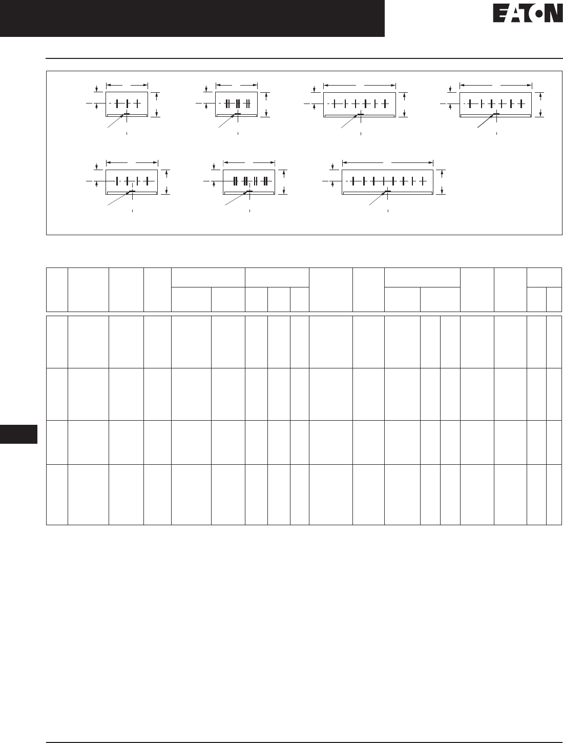
August 2006
17-32
For more information visit: www.EatonElectrical.com CA08101001E
Busway Products
17
Medium Voltage Non-Segregated Phase Bus
Technical Data and Specifications
Figure 17-10. Dimensional Data for 635 Volt/5 kV/15 kV Non-Segregated Phase Bus — Standard Configurations
Table 17-61. Dimensional Data for 635 Volt/5 kV/15 kV Bus Rated up to 132 kA Peak Momentary, 49 kA rms Symmetrical 2 Second
All bus bars for applications above 600 volts are fully insulated with fluidized epoxy coating for the rated maximum voltage.
All bus bars for applications at 600 volts or below are bare. Epoxy coating at 600 volts and below is available as an option.
Check with Eaton for availability.
Add 3 lbs. to the weights shown when using Poly/Porcelain or Epoxy insulating supports in place of Glass Polyester.
Glass Polyester.
Polyester/Porcelain.
Epoxy.
Note: For dimensions in mm, multiply inches by 25.4.
Wire
Type Rated
Maximum
Voltage kV
Rated
Cont-
inuous
Current
Amperes
Layout
No. Enclosure
Material Enclosure
Size (Inches) No. of Bars
Ph and
Size, Cu
(inches)
Ph-Ph
Bus
Spacing
(Inches)
Insulating
Supports Optional
Ground
Bus, Cu
(Inches)
Approx.
Average
Weight
per Foot
(Lbs.)
Listing
Standard Optional W H C Standard Optional
CSA UL
3 0.635/5/15
0.635/5/15
0.635/5/15
0.635
0.635/5/15
0.635/5/15
1200
2000
3000
3200
4000
5000
1
1
1
2
3
4
Aluminum
Aluminum
Aluminum
Aluminum
Aluminum
Aluminum
—
—
—
—
—
—
20.00
20.00
20.00
20.00
35.75
35.75
17.38
17.38
17.38
17.38
17.38
17.38
8.13
8.13
8.13
8.13
8.13
8.13
(1) 0.50 x 3
(1) 0.38 x 6
(1) 0.50 x 8
(2) 0.38 x 6
(2) 0.50 x 6
(2) 0.50 x 6
5.38
5.38
5.38
5.38
5.38
5.38
—
—
0.25 x 2
0.25 x 2
0.25 x 2
0.25 x 2
0.25 x 2
0.25 x 2
38
47
68
68
101
101
Yes
Yes
Yes
Yes
Yes
Yes
No
No
No
No
No
No
30.635/5/15
0.635/5/15
0.635/5/15
0.635
0.635/5/15
0.635/5/15
1200
2000
3000
3200
4000
5000
1
1
3
3
3
4
—
—
—
—
—
—
Steel
Steel
Steel
Steel
Steel
Steel
20.00
20.00
35.75
35.75
35.75
35.75
17.38
17.38
17.38
17.38
17.38
17.38
8.13
8.13
8.13
8.13
8.13
8.13
(1) 0.50 x 3
(1) 0.38 x 6
(2) 0.50 x 4
(2) 0.50 x 6
(2) 0.50 x 8
(2) 0.50 x 8
5.38
5.38
5.38
5.38
5.38
5.38
—
—
0.25 x 2
0.25 x 2
0.25 x 2
0.25 x 2
0.25 x 2
0.25 x 2
58
67
106
130
154
154
No
No
No
No
No
No
No
No
No
No
No
No
40.635/5/15
0.635/5/15
0.635/5/15
0.635
0.635
1200
2000
3000
3200
4000
5
5
5
6
7
Aluminum
Aluminum
Aluminum
Aluminum
Aluminum
—
—
—
—
—
26.00
26.00
26.00
26.00
35.75
17.38
17.38
17.38
17.38
17.38
8.13
8.13
8.13
8.13
8.13
(1) 0.50 x 3
(1) 0.38 x 6
(1) 0.50 x 8
(2) 0.38 x 6
(2) 0.50 x 6
5.38
5.38
5.38
5.38
4.00
—
—
—
—
0.25 x 2
0.25 x 2
0.25 x 2
0.25 x 2
0.25 x 2
48
60
88
88
127
No
No
No
No
No
No
No
No
No
No
40.635/5/15
0.635/5/15
0.635
0.635
0.635
5/15
5/15
1200
2000
3000
3200
4000
3000
4000
5
5
7
7
7
—
—
—
—
—
—
—
—
—
Steel
Steel
Steel
Steel
Steel
Steel
Steel
26.00
26.00
35.75
35.75
35.75
NA
NA
17.38
17.38
17.38
17.38
17.38
NA
NA
8.13
8.13
8.13
8.13
8.13
—
—
(1) 0.50 x 3
(1) 0.38 x 6
(2) 0.50 x 4
(2) 0.50 x 6
(2) 0.50 x 8
—
—
5.38
5.38
4.00
4.00
4.00
—
—
—
—
—
—
—
—
—
—
—
—
—
—
0.25 x 2
0.25 x 2
0.25 x 2
0.25 x 2
0.25 x 2
—
—
72
84
124
156
188
—
—
No
No
No
No
No
—
—
No
No
No
No
No
—
—
Bus
Optional
Ground Bus
Optional
Ground Bus Optional
Ground Bus
Layout 1
C
W
H
123
W W
Bus
Layout 2
123
Bus
Layout 5
123NBus
Layout 6
123
N
Bus
Layout 3
11 2233
Bus
Layout 7
11 2233N
N
Bus
Layout 4
12 1332
C
L
C
C
LC
C
L
HH
C
LOptional
Ground Bus Optional
Ground Bus Optional
Ground Bus
Optional
Ground Bus
C
W
C
L
C
LC
L
C
LC
C
L
HH
W
C
L
C
C
L
W
C
L
H
W
H
C
L
C
C
L
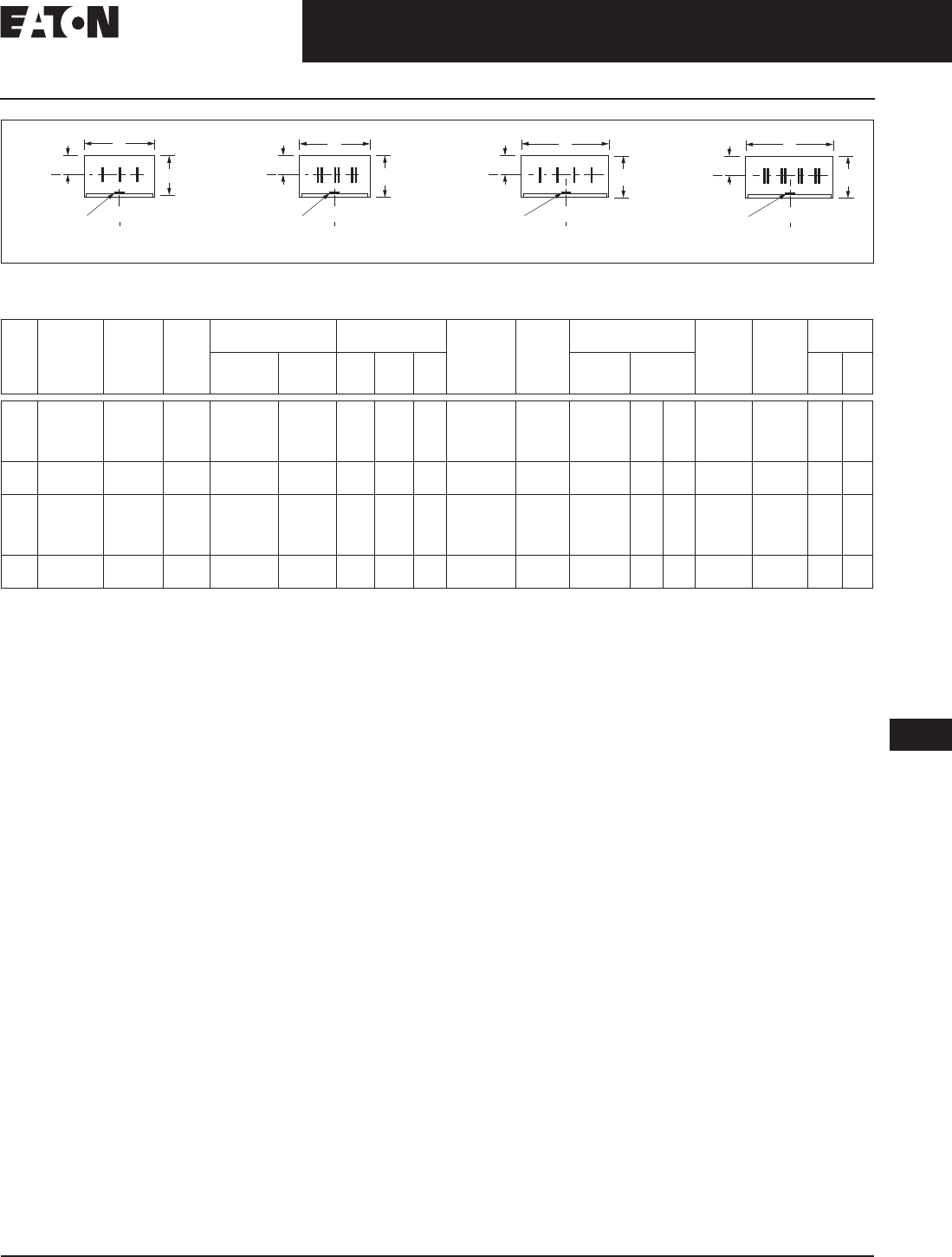
August 2006
CA08101001E For more information visit: www.EatonElectrical.com
17-33
Busway Products
17
Medium Voltage Non-Segregated Phase Bus
Technical Data and Specifications
Figure 17-11. Dimensional Data for 635 Volt/5 kV/15 kV Non-Segregated Phase Bus — 63 kA Configurations
Table 17-62. Dimensional Data for 635 Volt/5 kV/15 kV Bus Rated up to 170 kA Momentary, 63 kA rms Symmetrical 2 Second
All bus bars for applications above 600 volts are fully insulated with fluidized epoxy coating for the rated maximum voltage.
All bus bars for applications at 600 volts or below are bare. Epoxy coating at 600 volts and below is available as an option.
Check with Eaton for availability.
Add 3 lbs. to the weights shown when using Poly/Porcelain or Epoxy insulating supports in place of Glass Polyester.
Glass Polyester.
Polyester/Porcelain.
Epoxy.
Note: For dimensions in mm, multiply inches by 25.4.
Wire
Type Rated
Maximum
Voltage
kV
Rated
Cont-
inuous
Current
Amperes
Layout
No. Enclosure
Material Enclosure
Size (Inches) No. of Bars
Ph and
Size, Cu
(Inches)
Ph-Ph
Bus
Spacing
(Inches)
Insulating
Supports Optional
Ground
Bus, Cu
(Inches)
Approx.
Average
Weight
per Foot
(Lbs.)
Listing
Standard Optional W H C Standard Optional
CSA UL
3 0.635/5/15
0.635/5/15
0.635/5/15
0.635
1200
2000
3000
3200
8
8
9
9
Aluminum
Aluminum
Aluminum
Aluminum
—
—
—
—
20.00
20.00
20.00
20.00
17.38
17.38
17.38
17.38
8.13
8.13
8.13
8.13
(1) 0.38 x 6
(1) 0.38 x 6
(2) 0.38 x 6
(2) 0.38 x 6
5.38
5.38
5.38
5.38
—
—
—
0.25 x 3
0.25 x 3
0.25 x 3
0.25 x 3
48
48
78
78
Yes
Yes
Yes
No
No
No
No
No
3 0.635/5/15
0.635/5/15 1200
2000 8
8 —
—Steel
Steel 20.00
20.00 17.38
17.38 8.13
8.13 (1) 0.38 x 6
(1) 0.38 x 6 5.38
5.38
0.25 x 3
0.25 x 3 68
68 No
No No
No
40.635/5/15
0.635/5/15
0.635/5/15
0.635
1200
2000
3000
3200
10
10
11
11
Aluminum
Aluminum
Aluminum
Aluminum
—
—
—
—
26.00
26.00
26.00
26.00
17.38
17.38
17.38
17.38
8.13
8.13
8.13
8.13
(1) 0.38 x 6
(1) 0.38 x 6
(2) 0.38 x 6
(2) 0.38 x 6
5.38
5.38
5.38
5.38
—
—
—
0.25 x 3
0.25 x 3
0.25 x 3
0.25 x 3
61
61
101
101
No
No
No
No
No
No
No
No
40.635/5/15
0.635/5/15 1200
2000 10
10 —
—Steel
Steel 26.00
26.00 17.38
17.38 8.13
8.13 (1) 0.38 x 6
(1) 0.38 x 6 5.38
5.38
0.25 x 3
0.25 x 3 85
85 No
No No
No
Ground Bus
Layout 10
123
N
Ground Bus
Layout 11
123
N
Ground Bus
Layout 8
W
123
Ground Bus
Layout 9
123
Bus C
C
LH
C
L
W
Bus C
C
L
C
L
H
W
HH
C
L
Bus C
C
LBus C
C
L
W
C
L
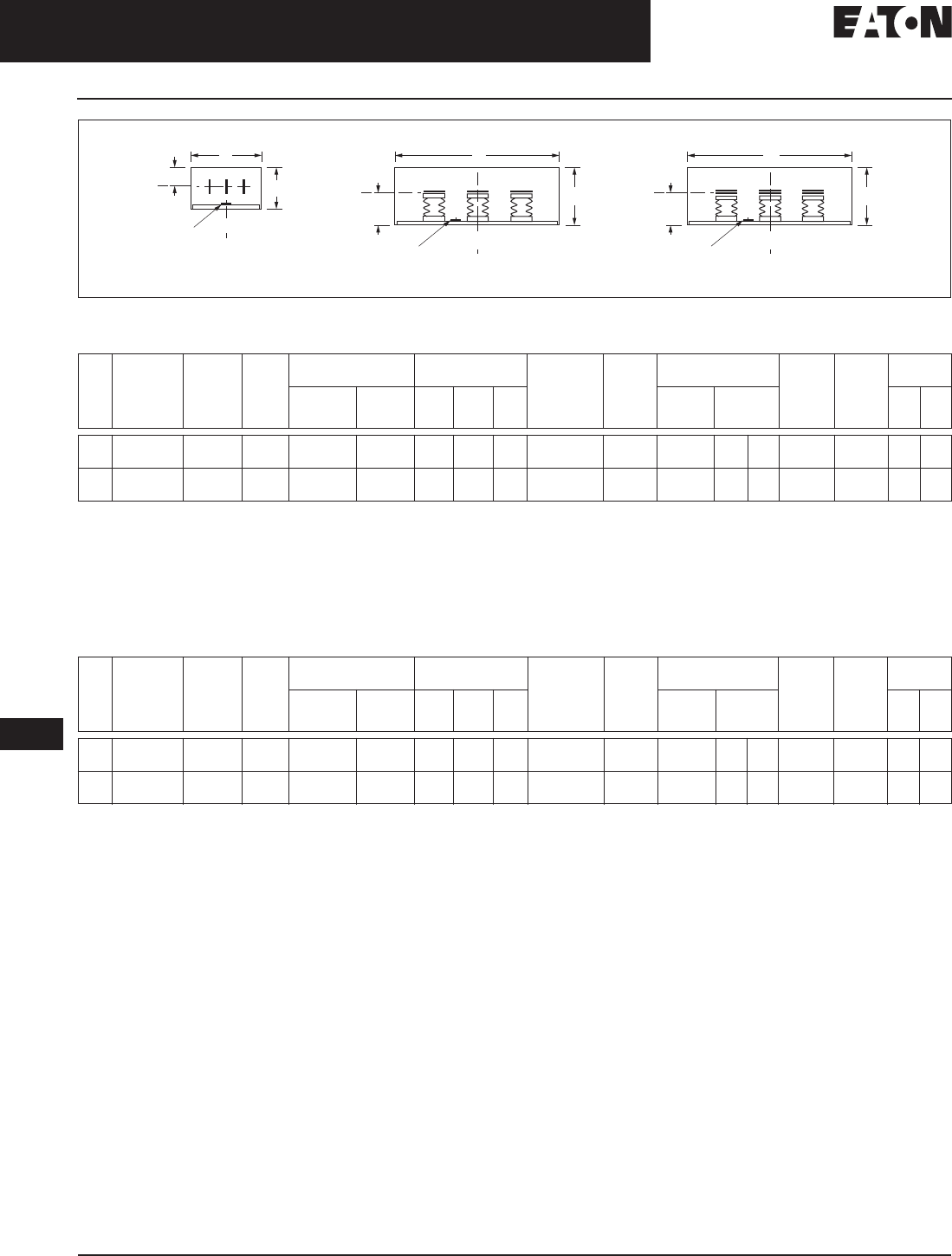
August 2006
17-34
For more information visit: www.EatonElectrical.com CA08101001E
Busway Products
17
Medium Voltage Non-Segregated Phase Bus
Technical Data and Specifications
Figure 17-12. Dimensional Data for 27 kV/38 kV Non-Segregated Phase Bus — Standard Configurations.
Table 17-63. Dimensional Data for 27 kV Bus Rated up to 108 kA Peak Momentary, 40 kA rms Symmetrical 2 Second
All bus bars for applications above 600 volts are fully insulated with fluidized epoxy coating for the rated maximum voltage.
Check with Eaton for availability.
Add 3 lbs. to the weights shown when using Poly/Porcelain or Epoxy insulating supports in place of Glass Polyester.
Glass Polyester.
Polyester/Porcelain.
Epoxy.
Note: For dimensions in mm, multiply inches by 25.4.
Table 17-64. Dimensional Data for 38 kV Bus Rated up to 104 kA Peak Momentary, 40 kA rms Symmetrical 2 Second
All bus bars for applications above 600 volts are fully insulated with fluidized epoxy coating for the rated maximum voltage.
Note: For dimensions in mm, multiply inches by 25.4.
Cutler-Hammer is a federally registered trademark of
Eaton Corporation. NEMA is the registered trademark
and service mark of the National Electrical Manufactur-
ers Association. CSA is a registered trademark of the
Canadian Standards Association. ISO is the registered
trademark and sole property of the International Orga-
nization for Standardization. Uniform Building Code
(UBC) is a trademark of the International Conference of
Building Officials (ICBO). National Electrical Code and
NEC are registered trademarks of the National Fire Pro-
tection Association, Quincy, Mass. UL is a registered
trademark of the Underwriters Laboratories Inc.
Wire
Type Rated
Maximum
Voltage kV
Rated
Cont-
inuous
Current
Amperes
Layout
No. Enclosure
Material Enclosure
Size (Inches) No. of Bars
Ph and
Size, Cu
(Inches)
Ph-Ph
Bus
Spacing
(Inches)
Insulating
Supports Optional
Ground
Bus, Cu
(Inches)
Approx.
Average
Weight
per Foot
(Lbs.)
Listing
Standard Optional W HC Standard Optional CSA UL
3 27
27 1200
2000 12
12 Aluminum
Aluminum —
—30.00
30.00 21.00
21.00 9.88
9.88 (1) 0.25 x 4
(1) 0.50 x 4 7.00
7.00
0.25 x 2
0.25 x 2 37
49 Yes
Yes No
No
3 27
27 1200
2000 12
12 —
—Steel
Steel 30.00
30.00 21.00
21.00 9.88
9.88 (1) 0.25 x 4
(1) 0.50 x 4 7.00
7.00
0.25 x 2
0.25 x 2 37
49 Yes
Yes No
No
Wire
Type Rated
Maximum
Voltage kV
Rated
Cont-
inuous
Current
Amperes
Layout
No. Enclosure
Material Enclosure
Size (Inches) No. of Bars
Ph and
Size, Cu
(Inches)
Ph-Ph
Bus
Spacing
(Inches)
Insulating
Supports Optional
Ground
Bus, Cu
(Inches)
Approx.
Average
Weight
per Foot
(Lbs.)
Listing
Standard Optional W H C Standard Optional CSA UL
3 38
38 1200
2000 13
14 Aluminum
Aluminum —
—40.25
40.25 21.50
21.50 10.23
10.64 (1) 0.25 x 4
(1) 0.38 x 4 10.50
10.50 Epoxy
Epoxy —
——
—0.25 x 2
0.25 x 2 61
89 Yes
Yes No
No
3 38
38 1200
2000 13
14 —
—Steel
Steel 40.25
40.25 21.50
21.50 10.23
10.64 (1) 0.25 x 4
(1) 0.38 x 4 10.50
10.50 Epoxy
Epoxy —
——
—0.25 x 2
0.25 x 2 88
116 No
No No
No
Ground Bus
Layout 12 Layout 13
123
Ground Bus
123
Layout 14
Ground Bus
123
W
Bus C
C
LHH H
C
LC
L
Bus
D
C
L
WW
Bus
D
C
L
C
L
