Modicon TM5 Expansion Modules Configuration Programming Guide 04/2012 101842 Catalog
120997-Catalog 120997-Catalog 120997-Catalog B5 unilog cesco-content
2016-09-04
: Pdf 101842-Catalog 101842-Catalog B4 unilog
Open the PDF directly: View PDF ![]() .
.
Page Count: 198 [warning: Documents this large are best viewed by clicking the View PDF Link!]
- Modicon TM5
- Table of Contents
- Safety Information
- About the Book
- I/O Configuration General Information
- TM5 Compact I/O Modules
- TM5 Digital I/O Electronic Modules
- TM5 Analog I/O Electronic Modules
- TM5 Expert I/O Electronic Modules
- TM5 Transmitter - Receiver Electronic Modules
- TM5 Power Supply Electronic Modules
- TM5 Common Distribution Electronic Modules
- Glossary
- Index
EIO0000000420.04
www.schneider-electric.com
Modicon T M5
EIO0000000420 04/2012
Modicon TM5
Expansion Modules Configuration
Programming Guide
04/2012

2EIO0000000420 04/2012
The information provided in this documentation contains general descriptions and/or
technical characteristics of the performance of the products contained herein. This
documentation is not intended as a substitute for and is not to be used for
determining suitability or reliability of these products for specific user applications. It
is the duty of any such user or integrator to perform the appropriate and complete
risk analysis, evaluation and testing of the products with respect to the relevant
specific application or use thereof. Neither Schneider Electric nor any of its affiliates
or subsidiaries shall be responsible or liable for misuse of the information contained
herein. If you have any suggestions for improvements or amendments or have found
errors in this publication, please notify us.
No part of this document may be reproduced in any form or by any means, electronic
or mechanical, including photocopying, without express written permission of
Schneider Electric.
All pertinent state, regional, and local safety regulations must be observed when
installing and using this product. For reasons of safety and to help ensure
compliance with documented system data, only the manufacturer should perform
repairs to components.
When devices are used for applications with technical safety requirements, the
relevant instructions must be followed.
Failure to use Schneider Electric software or approved software with our hardware
products may result in injury, harm, or improper operating results.
Failure to observe this information can result in injury or equipment damage.
© 2012 Schneider Electric. All rights reserved.

EIO0000000420 04/2012 3
Table of Contents
Safety Information . . . . . . . . . . . . . . . . . . . . . . . . . . . . . . 5
About the Book . . . . . . . . . . . . . . . . . . . . . . . . . . . . . . . . . 7
Chapter 1 I/O Configuration General Information . . . . . . . . . . . . . . 11
General Description. . . . . . . . . . . . . . . . . . . . . . . . . . . . . . . . . . . . . . . . . . 12
TM5 Manager Configuration . . . . . . . . . . . . . . . . . . . . . . . . . . . . . . . . . . . 18
Adding an Expansion Module . . . . . . . . . . . . . . . . . . . . . . . . . . . . . . . . . . 21
Chapter 2 TM5 Compact I/O Modules. . . . . . . . . . . . . . . . . . . . . . . . 27
2.1 TM5 Compact I/O Modules . . . . . . . . . . . . . . . . . . . . . . . . . . . . . . . . . . . . 28
TM5C24D18T . . . . . . . . . . . . . . . . . . . . . . . . . . . . . . . . . . . . . . . . . . . . . . 29
TM5C12D8T . . . . . . . . . . . . . . . . . . . . . . . . . . . . . . . . . . . . . . . . . . . . . . . 32
TM5C12D6T6L . . . . . . . . . . . . . . . . . . . . . . . . . . . . . . . . . . . . . . . . . . . . . 36
TM5C24D12R . . . . . . . . . . . . . . . . . . . . . . . . . . . . . . . . . . . . . . . . . . . . . . 40
TM5CAI8O8VL . . . . . . . . . . . . . . . . . . . . . . . . . . . . . . . . . . . . . . . . . . . . . 43
TM5CAI8O8CL . . . . . . . . . . . . . . . . . . . . . . . . . . . . . . . . . . . . . . . . . . . . . 46
TM5CAI8O8CVL . . . . . . . . . . . . . . . . . . . . . . . . . . . . . . . . . . . . . . . . . . . . 49
2.2 Integrated Electronic Modules. . . . . . . . . . . . . . . . . . . . . . . . . . . . . . . . . . 52
Digital Input 4In . . . . . . . . . . . . . . . . . . . . . . . . . . . . . . . . . . . . . . . . . . . . . 53
Digital Input 6In . . . . . . . . . . . . . . . . . . . . . . . . . . . . . . . . . . . . . . . . . . . . . 54
Digital Input 12In . . . . . . . . . . . . . . . . . . . . . . . . . . . . . . . . . . . . . . . . . . . . 55
Digital Output 4Out . . . . . . . . . . . . . . . . . . . . . . . . . . . . . . . . . . . . . . . . . . 56
Digital Output 6Out . . . . . . . . . . . . . . . . . . . . . . . . . . . . . . . . . . . . . . . . . . 57
Digital Output Relay 6Rel . . . . . . . . . . . . . . . . . . . . . . . . . . . . . . . . . . . . . 58
Analog Input 4AI ±10 V . . . . . . . . . . . . . . . . . . . . . . . . . . . . . . . . . . . . . . . 59
Analog Input 4AI 0-20 mA / 4-20 mA . . . . . . . . . . . . . . . . . . . . . . . . . . . . 60
Analog Input 4AI ±10 V / 0-20 mA / 4-20 mA . . . . . . . . . . . . . . . . . . . . . . 62
Analog Output 4AO ±10 V. . . . . . . . . . . . . . . . . . . . . . . . . . . . . . . . . . . . . 68
Analog Output 4AO 0-20 mA. . . . . . . . . . . . . . . . . . . . . . . . . . . . . . . . . . . 69
Analog Output 2AO ±10 V / 0-20 mA . . . . . . . . . . . . . . . . . . . . . . . . . . . . 70
Chapter 3 TM5 Digital I/O Electronic Modules. . . . . . . . . . . . . . . . . 71
TM5SDI2D, TM5SDI4D and TM5SDI6D. . . . . . . . . . . . . . . . . . . . . . . . . . 72
TM5SDI2A, TM5SDI4A and TM5SDI6U . . . . . . . . . . . . . . . . . . . . . . . . . . 75
TM5SDI12D. . . . . . . . . . . . . . . . . . . . . . . . . . . . . . . . . . . . . . . . . . . . . . . . 77
TM5SDO2T, TM5SDO4T, TM5SDO6T and TM5SDO12T . . . . . . . . . . . . 80

4EIO0000000420 04/2012
TM5SDO4TA and TM5SDO8TA . . . . . . . . . . . . . . . . . . . . . . . . . . . . . . . 83
TM5SDO2R and TM5SDO4R . . . . . . . . . . . . . . . . . . . . . . . . . . . . . . . . . 86
TM5SDO2S . . . . . . . . . . . . . . . . . . . . . . . . . . . . . . . . . . . . . . . . . . . . . . . 88
TM5SDM12DT. . . . . . . . . . . . . . . . . . . . . . . . . . . . . . . . . . . . . . . . . . . . . 90
TM5SMM6D2L. . . . . . . . . . . . . . . . . . . . . . . . . . . . . . . . . . . . . . . . . . . . . 92
Chapter 4 TM5 Analog I/O Electronic Modules. . . . . . . . . . . . . . . . . 101
TM5SAI2H and TM5SAI4H . . . . . . . . . . . . . . . . . . . . . . . . . . . . . . . . . . . 102
TM5SAI2L and TM5SAI4L. . . . . . . . . . . . . . . . . . . . . . . . . . . . . . . . . . . . 109
TM5SAI2PH and TM5SAI4PH. . . . . . . . . . . . . . . . . . . . . . . . . . . . . . . . . 118
TM5SAI2TH and TM5SAI6TH . . . . . . . . . . . . . . . . . . . . . . . . . . . . . . . . . 123
TM5SEAISG . . . . . . . . . . . . . . . . . . . . . . . . . . . . . . . . . . . . . . . . . . . . . . 129
TM5SAO2H and TM5SAO2L. . . . . . . . . . . . . . . . . . . . . . . . . . . . . . . . . . 130
TM5SAO4H and TM5SAO4L. . . . . . . . . . . . . . . . . . . . . . . . . . . . . . . . . . 132
Chapter 5 TM5 Expert I/O Electronic Modules . . . . . . . . . . . . . . . . . 135
TM5SE1IC02505 . . . . . . . . . . . . . . . . . . . . . . . . . . . . . . . . . . . . . . . . . . . 136
TM5SE1IC01024 . . . . . . . . . . . . . . . . . . . . . . . . . . . . . . . . . . . . . . . . . . . 140
TM5SE2IC01024 . . . . . . . . . . . . . . . . . . . . . . . . . . . . . . . . . . . . . . . . . . . 144
TM5SE1SC10005 . . . . . . . . . . . . . . . . . . . . . . . . . . . . . . . . . . . . . . . . . . 148
TM5SDI2DF. . . . . . . . . . . . . . . . . . . . . . . . . . . . . . . . . . . . . . . . . . . . . . . 152
Chapter 6 TM5 Transmitter - Receiver Electronic Modules. . . . . . . 157
TM5SBET1 . . . . . . . . . . . . . . . . . . . . . . . . . . . . . . . . . . . . . . . . . . . . . . . 158
TM5SBET7 . . . . . . . . . . . . . . . . . . . . . . . . . . . . . . . . . . . . . . . . . . . . . . . 160
TM5SBER2 . . . . . . . . . . . . . . . . . . . . . . . . . . . . . . . . . . . . . . . . . . . . . . . 162
Chapter 7 TM5 Power Supply Electronic Modules . . . . . . . . . . . . . . 165
TM5SPS1 . . . . . . . . . . . . . . . . . . . . . . . . . . . . . . . . . . . . . . . . . . . . . . . . 166
TM5SPS1F . . . . . . . . . . . . . . . . . . . . . . . . . . . . . . . . . . . . . . . . . . . . . . . 168
TM5SPS2 . . . . . . . . . . . . . . . . . . . . . . . . . . . . . . . . . . . . . . . . . . . . . . . . 170
TM5SPS2F . . . . . . . . . . . . . . . . . . . . . . . . . . . . . . . . . . . . . . . . . . . . . . . 172
Chapter 8 TM5 Common Distribution Electronic Modules . . . . . . . 175
TM5SPDG12F . . . . . . . . . . . . . . . . . . . . . . . . . . . . . . . . . . . . . . . . . . . . . 176
TM5SPDD12F . . . . . . . . . . . . . . . . . . . . . . . . . . . . . . . . . . . . . . . . . . . . . 178
TM5SPDG5D4F. . . . . . . . . . . . . . . . . . . . . . . . . . . . . . . . . . . . . . . . . . . . 180
TM5SPDG6D6F. . . . . . . . . . . . . . . . . . . . . . . . . . . . . . . . . . . . . . . . . . . . 182
TM5SD000. . . . . . . . . . . . . . . . . . . . . . . . . . . . . . . . . . . . . . . . . . . . . . . . 184
Glossary . . . . . . . . . . . . . . . . . . . . . . . . . . . . . . . . . . . . . . . . . . . 185
Index . . . . . . . . . . . . . . . . . . . . . . . . . . . . . . . . . . . . . . . . . . . 195
EIO0000000420 04/2012 5
§
Safety Information
Important Information
NOTICE
Read these instructions carefully, and look at the equipment to become familiar with
the device before trying to install, operate, or maintain it. The following special
messages may appear throughout this documentation or on the equipment to warn
of potential hazards or to call attention to information that clarifies or simplifies a
procedure.

6EIO0000000420 04/2012
PLEASE NOTE
Electrical equipment should be installed, operated, serviced, and maintained only by
qualified personnel. No responsibility is assumed by Schneider Electric for any
consequences arising out of the use of this material.
A qualified person is one who has skills and knowledge related to the construction
and operation of electrical equipment and its installation, and has received safety
training to recognize and avoid the hazards involved.

EIO0000000420 04/2012 7
About the Book
At a Glance
Document Scope
This manual describes the configuration of the Modicon TM5 Input/Output
expansion modules. For further information, refer to the separate documents
provided in the SoMachine online help.
Validity Note
This document has been updated with the release of SoMachine V3.1.
Related Documents
Title of Documentation Reference Number
Modicon M258 Logic Controller Programming Guide EIO0000000402 (Eng);
EIO0000000403 (Fre);
EIO0000000404 (Ger);
EIO0000000405 (Spa);
EIO0000000406 (Ita);
EIO0000000407 (Chs)
Modicon LMC058 Motion Controller Programming Guide EIO0000000408 (Eng);
EIO0000000409 (Fre);
EIO0000000410 (Ger);
EIO0000000411 (Spa);
EIO0000000412 (Ita);
EIO0000000413 (Chs)
Modicon TM5 IoDrvTM5SEAISG Strain Gauge Library Guide EIO0000001185 (Eng),
EIO0000001186 (Fre),
EIO0000001187 (Ger),
EIO0000001188 (Spa),
EIO0000001189 (Ita),
EIO0000001190 (Chs)

8EIO0000000420 04/2012
You can download these technical publications and other technical information from
our website at www.schneider-electric.com.
Modicon TM5 Compact I/O Modules Hardware Guide EIO0000000456 (Eng);
EIO0000000457 (Fre);
EIO0000000458 (Ger);
EIO0000000459 (Spa);
EIO0000000460 (Ita);
EIO0000000461 (Chs)
Modicon TM5 Digital I/O Modules Hardware Guide EIO0000000444 (Eng);
EIO0000000445 (Fre);
EIO0000000446 (Ger);
EIO0000000447 (Spa);
EIO0000000448 (Ita);
EIO0000000449 (Chs)
Modicon TM5 Analog I/O Modules Hardware Guide EIO0000000450 (Eng);
EIO0000000451 (Fre);
EIO0000000452 (Ger);
EIO0000000453 (Spa);
EIO0000000454 (Ita);
EIO0000000455 (Chs)
Modicon TM5 Expert (High Speed Counter) Modules
Hardware Guide
EIO0000000462 (Eng);
EIO0000000463 (Fre);
EIO0000000464 (Ger);
EIO0000000465 (Spa);
EIO0000000466 (Ita);
EIO0000000467 (Chs)
Modicon TM5 Transmitter and Receiver Modules Hardware
Guide
EIO0000000468 (Eng);
EIO0000000469 (Fre);
EIO0000000470 (Ger);
EIO0000000471 (Spa);
EIO0000000472 (Ita);
EIO0000000473 (Chs)
EIO0000000420 04/2012 9
Product Related Information
1 For additional information, refer to NEMA ICS 1.1 (latest edition), "Safety
Guidelines for the Application, Installation, and Maintenance of Solid State Control"
and to NEMA ICS 7.1 (latest edition), "Safety Standards for Construction and Guide
for Selection, Installation and Operation of Adjustable-Speed Drive Systems" or their
equivalent governing your particular location.
User Comments
We welcome your comments about this document. You can reach us by e-mail at
techcomm@schneider-electric.com.
WARNING
LOSS OF CONTROL
zThe designer of any control scheme must consider the potential failure modes
of control paths and, for certain critical control functions, provide a means to
achieve a safe state during and after a path failure. Examples of critical control
functions are emergency stop and overtravel stop, power outage and restart.
zSeparate or redundant control paths must be provided for critical control
functions.
zSystem control paths may include communication links. Consideration must be
given to the implications of unanticipated transmission delays or failures of the
link.
zObserve all accident prevention regulations and local safety guidelines.1
zEach implementation of this equipment must be individually and thoroughly
tested for proper operation before being placed into service.
Failure to follow these instructions can result in death, serious injury, or
equipment damage.
WARNING
UNINTENDED EQUIPMENT OPERATION
zOnly use software approved by Schneider Electric for use with this equipment.
zUpdate your application program every time you change the physical hardware
configuration.
Failure to follow these instructions can result in death, serious injury, or
equipment damage.

10 EIO0000000420 04/2012
EIO0000000420 04/2012 11
1
Modicon TM5
I/O Configu ration Gener al Informati on
EIO0000000420 04/2012
I/O Configuration General
Information
Introduction
This chapter provides general considerations to configure I/O expansion modules.
What’s in this Chapter?
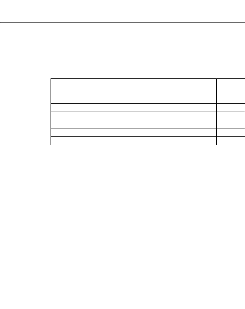
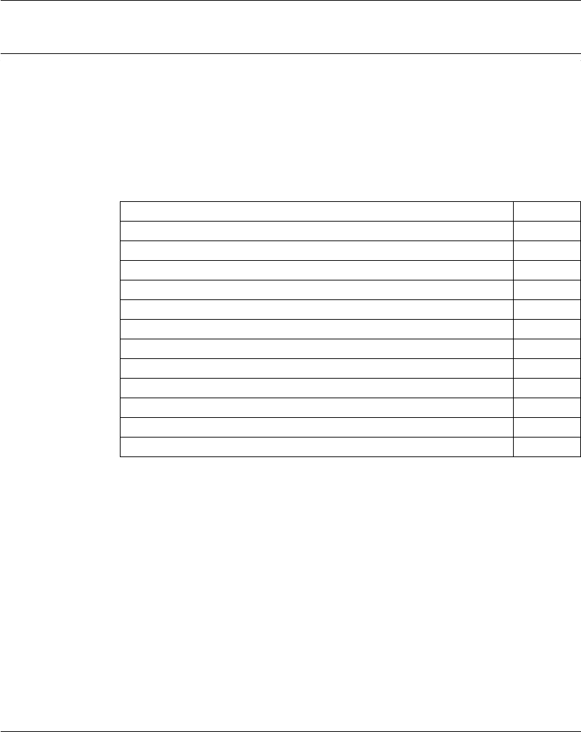
This chapter contains the following topics:
Topic Page
General Description 12
TM5 Manager Configuration 18
Adding an Expansion Module 21

I/O Configuration General Information
12 EIO0000000420 04/2012
General Description
Introduction
The range of expansion I/O includes:
zTM5 Compact I/O modules with integrated modules
zTM5 Digital I/O modules
zTM5 Analog I/O modules
zTM5 Expert I/O modules
zTM5 Transmitter - Receiver modules
zTM5 Power distribution modules
zTM5 Common distribution modules
zTM5 Dummy modules
Compact, digital or analog input modules convert measured values (voltages,
currents) into numerical values which can be processed by the controller.
Compact, digital or analog output modules convert controller internal numerical
values into voltages or currents.
Expert modules are used for counting. They use either a Synchronous Serial
Interface (SSI) encoder, incremental encoder (ABR) or event counting.
The data transmitter and receiver modules handle the communication between
remote module via expansion bus cables.
Power Distribution modules are used to manage the power supply for the various
I/O modules.
The common distribution modules provide 0 Vdc and/or 24 Vdc terminal
connections for the 24 Vdc I/O power segment(s) integrated into the bus bases,
which expand the wiring possibilities for sensors and actuators.
The dummy module is a non-functional module. This module is used to separate
modules which has specific thermal or EMC requirements, or as a place holder for
later system expansion.
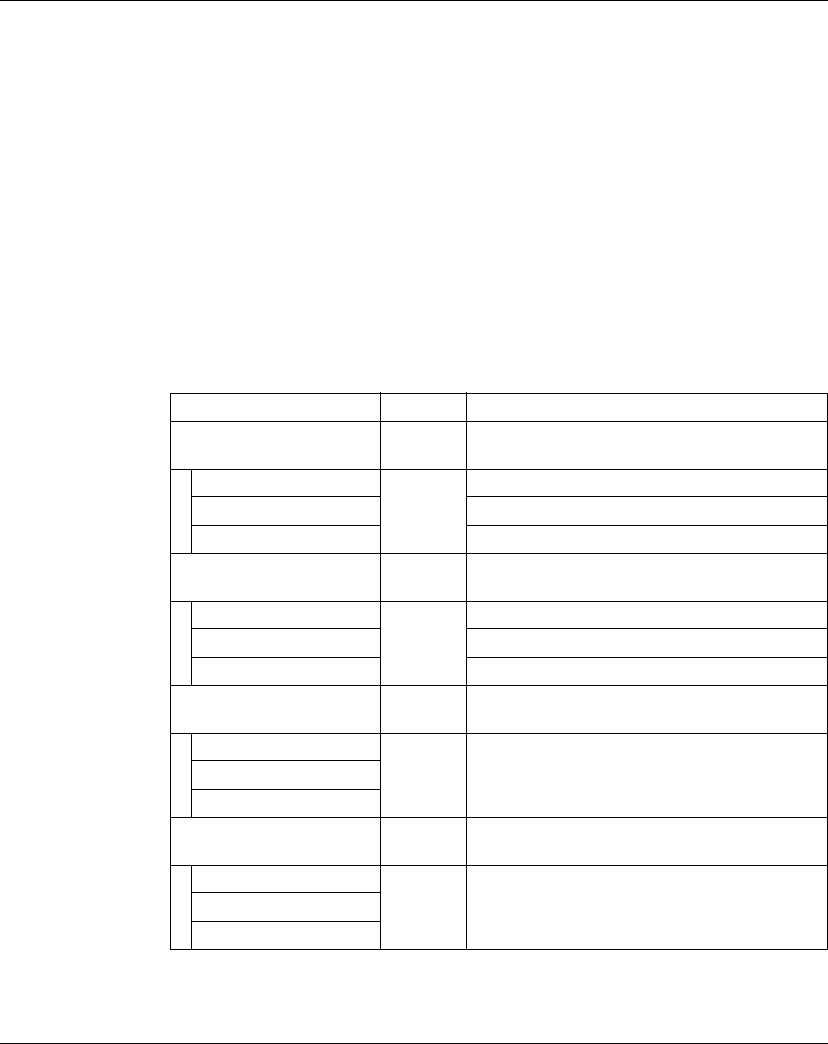
Compact I/O Expansion Features
Reference Number of
Channels
Voltage/Current
TM5C24D18T
(see page 29)
24 digital inputs 24 Vdc / 3.75 mA
18 digital outputs 24 Vdc / 0.5 A
TM5C12D8T
(see page 32)
12 digital inputs 24 Vdc / 3.75 mA
8 digital outputs 24 Vdc / 0.5 A

I/O Configuration General Information
EIO0000000420 04/2012 13
Digital I/O Expansion Features
TM5C24D12R
(see page 40)
24 inputs 24 Vdc / 3.75 mA
12 relays 24 Vdc / 230 Vac
2A
NO
TM5CAI8O8VL
(see page 43)
8 analog inputs -10...+10 Vdc
8 analog outputs -10...+10 Vdc
TM5CAI8O8CL
(see page 46)
8 analog inputs 0...20 mA / 4...20 mA
8 analog outputs 0...20 mA
TM5CAI8O8CVL
(see page 49)
4 analog inputs -10...+10 Vdc
4 analog inputs 0...20 mA / 4...20 mA
4 analog outputs -10...+10 Vdc
4 analog outputs 0...20 mA
TM5C12D6T6L
(see page 36)
12 digital inputs 24 Vdc / 3.75 mA
6 digital outputs 24 Vdc / 0.5 A
4 analog inputs -10...+10 Vdc
0...20 mA/4...20 mA
2 analog outputs -10...+10 Vdc
0...20 mA
Reference Number of
Channels
Voltage/Current
Reference Number of
Channels
Voltage/Current
TM5SDI2D
(see page 72)
2 inputs 24 Vdc / 3.75 mA
TM5SDI4D
(see page 72)
4 inputs 24 Vdc / 3.75 mA
TM5SDI6D
(see page 72)
6 inputs 24 Vdc / 3.75 mA
TM5SDI12D
(see page 77)
12 inputs 24 Vdc / 3.75 mA
TM5SDI2A
(see page 75)
2 inputs 100...240 Vac
TM5SDI4A
(see page 75)
4 inputs 100...240 Vac
TM5SDI6U
(see page 75)
6 inputs 100...120 Vac

I/O Configuration General Information
14 EIO0000000420 04/2012
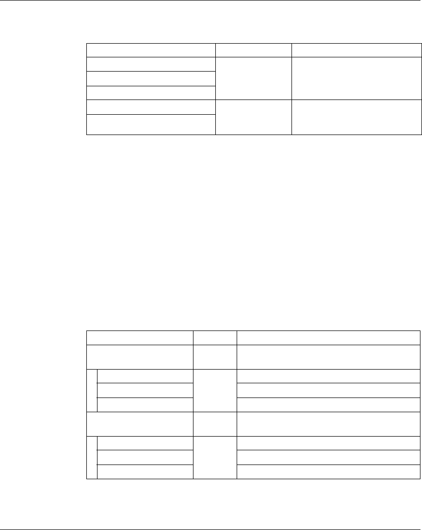
Analog I/O Expansion Features
TM5SDO2T
(see page 80)
2 outputs 24 Vdc / 0.5 A
TM5SDO4T
(see page 80)
4 outputs 24 Vdc / 0.5 A
TM5SDO6T
(see page 80)
6 outputs 24 Vdc / 0.5 A
TM5SDO12T
(see page 80)
12 outputs 24 Vdc / 0.5 A
TM5SDO4TA
(see page 83)
4 outputs 24 Vdc / 2 A
TM5SDO8TA
(see page 83)
8 outputs 24 Vdc / 2 A
TM5SDO2R
(see page 86)
2 outputs 30 Vdc / 230 Vac 5 A C/O
TM5SDO4R
(see page 86)
4 outputs 30 Vdc / 230 Vac 5 A NO
TM5SDO2S
(see page 88)
2 outputs 230 Vac / 1 A
TM5SDM12DT
(see page 90)
8 inputs
4 outputs
24 Vdc / 7 mA
24 Vdc / 0.5 A
TM5SMM6D2L
(see page 92)
4 digital inputs 24 Vdc / 3.3 mA
2 digital outputs 24 Vdc / 0.5 A
1 analog input -10...+10 Vdc
0...20 mA / 4...20 mA
1 analog output -10...+10 Vdc
0...20 mA
Reference Number of
Channels
Voltage/Current
Reference Number of
Channels
Voltage/Current
TM5SAI2L
(see page 109)
2 inputs -10...+10 Vdc
0...20 mA / 4...20 mA
TM5SAI4L
(see page 109)
4 inputs -10...+10 Vdc
0...20 mA / 4...20 mA
TM5SAI2H
(see page 102)
2 inputs -10...+10 Vdc
0...20 mA
TM5SAI4H
(see page 102)
4 inputs -10...+10 Vdc
0...20 mA

I/O Configuration General Information
EIO0000000420 04/2012 15
Temperature Analog Expansion Features
Analog Strain Gauge Input Electronic Modules Features
Expert Expansion Features
TM5SAO2L
(see page 130)
2 outputs -10...+10 Vdc
0...20 mA
TM5SAO2H
(see page 130)
2 outputs -10...+10 Vdc
0...20 mA
TM5SAO4L
(see page 132)
4 outputs -10...+10 Vdc
0...20 mA
TM5SAO4H
(see page 132)
4 outputs -10...+10 Vdc
0...20 mA
Reference Number of
Channels
Voltage/Current
Reference Number of
Channels
Sensor Type
TM5SAI2PH
(see page 118)
2 inputs PT100/1000
TM5SAI4PH
(see page 118)
4 inputs PT100/1000
TM5SAI2TH
(see page 123)
2 inputs Thermocouple J, K, N, S
TM5SAI6TH
(see page 123)
6 inputs Thermocouple J, K, N, S
Reference Number of
Channels
Sensor Type
TM5SEAISG
(see page 129)
1 input Full-bridge strain gauge
Reference Number of
Channels
Encoder Inputs
TM5SE1IC02505
(see page 136)
1 5 Vdc Symmetrical
TM5SE1IC01024
(see page 140)
1 24 Vdc Asymmetrical
TM5SE2IC01024
(see page 144)
2 24 Vdc Asymmetrical

I/O Configuration General Information
16 EIO0000000420 04/2012
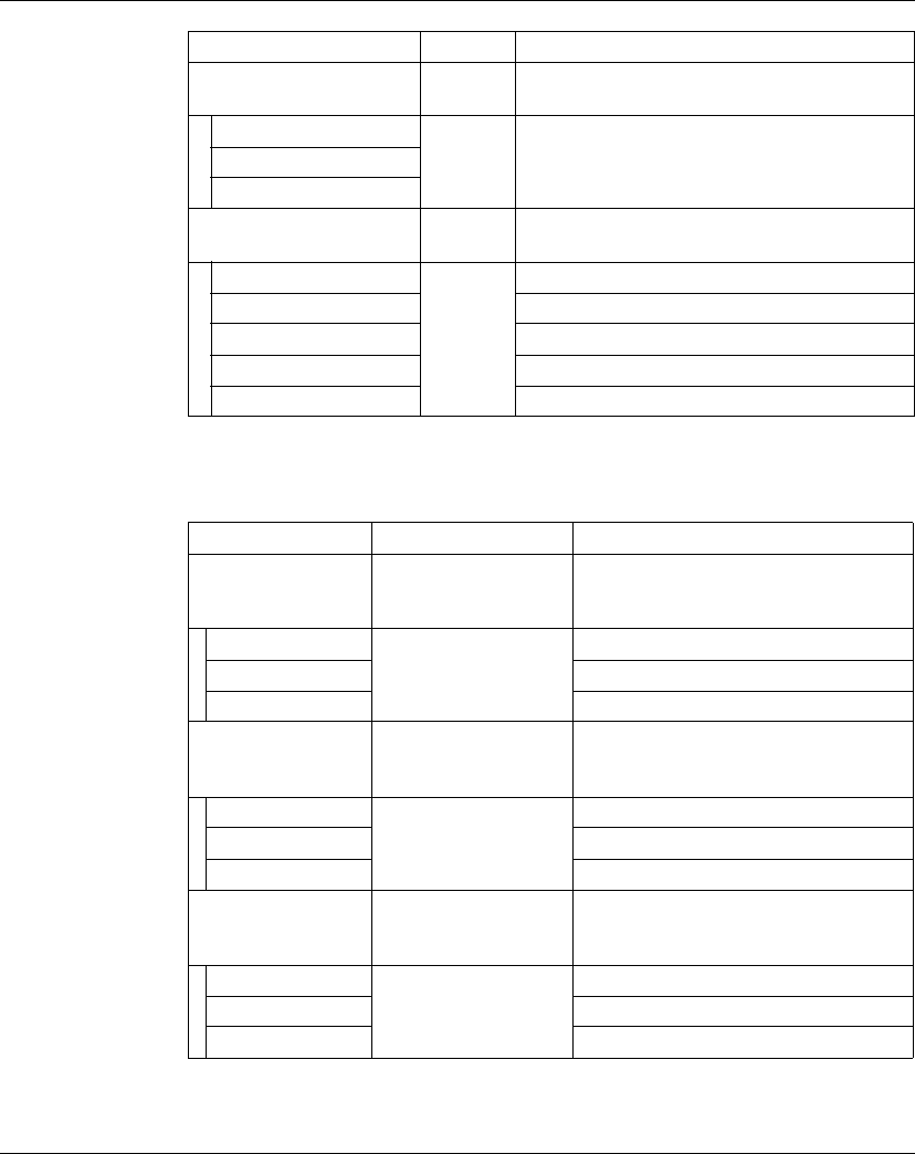
Transmitter-Receiver Expansion Features
Power Distribution Expansion Features
Common Distribution Expansion Features
TM5SE1SC10005
(see page 148)
1 5 Vdc Symmetrical
TM5SDI2DF
(see page 152)
2 Event counting, gate measurement
Reference Number of
Channels
Encoder Inputs
Reference Modules Description
TM5SBET1
(see page 158)
TM5 data transmitter electronic module.
TM5SBET7
(see page 160)
TM5 data transmitter electronic module.
It also distributes power to the TM7 bus.
TM5SBER2
(see page 162)
TM5 data receiver electronic module.
It also distributes power to the TM5 bus and to the 24 Vdc I/O
power segment.
Reference Modules Description
TM5SPS1
(see page 166)
24 Vdc I/O power segment supply
TM5SPS1F
(see page 168)
24 Vdc I/O power segment supply with integrated fuse
TM5SPS2
(see page 170)
24 Vdc I/O power segment supply and TM5 bus supply
TM5SPS2F
(see page 172)
24 Vdc I/O power segment supply with integrated fuse and TM5
bus supply
Reference Number of Channels Voltage
TM5SPDG12F
(see page 176)
12 24 Vdc
TM5SPDD12F
(see page 178)
12 24 Vdc
TM5SPDG5D4F
(see page 180)
2 x 5 0 Vdc - 24 Vdc
TM5SPDG6D6F
(see page 182)
2 x 6 0 Vdc - 24 Vdc
I/O Configuration General Information
EIO0000000420 04/2012 17
Dummy Expansion Features
Match Software and Hardware Configuration
The I/O that may be embedded in your controller is independent of the I/O that you
may have added in the form of I/O expansion. It is important that the logical I/O
configuration within your program matches the physical I/O configuration of your
installation. If you add or remove any physical I/O to or from the I/O expansion bus,
it is imperative that you update your application configuration (this is also true for any
field bus devices you may have in your installation). Otherwise, there is the potential
that the expansion bus or field bus will no longer function while the embedded I/O
that may be present in your controller will continue to operate.
To verify if the hardware and software configuration match, use the GVL
TM5_Module_R function regularly to monitor the expansion bus status.
Reference Number of channels Voltage
TM5SD000
(see page 184)
––
WARNING
UNINTENDED EQUIPMENT OPERATION
Update the configuration of your program each time you add or delete an I/O
expansion, or you add or delete any devices on your field bus.
Failure to follow these instructions can result in death, serious injury, or
equipment damage.
I/O Configuration General Information
18 EIO0000000420 04/2012
TM5 Manager Configuration
TM5 Manager Configuration
To configure the TM5 Manager, proceed as follows:
Parameters of the TM5 Manager:
NOTE: For more information about the maximum capacities of your system, refer
to the TM5 / TM7 System Planning and Installation Guide.
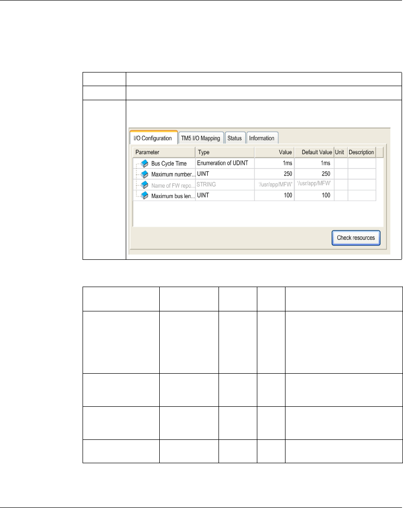
Step Action
1 Select the Configuration tab and double-click the controller.
2 Click the TM5 → TM5_Manager entry on the left-hand side.
Result: The TM5 Manager configuration window is displayed:
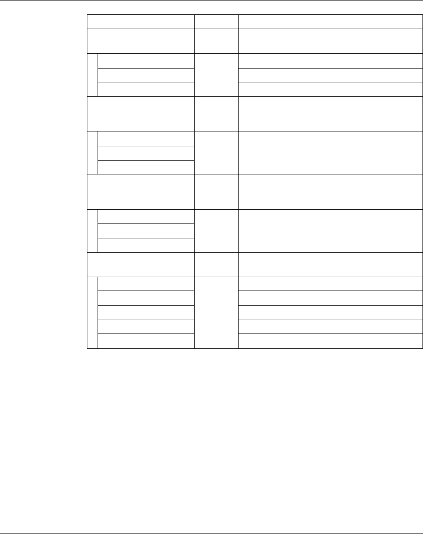
Parameter Value Default
Value
Unit Description
Bus Cycle Time 0.5 ms
1 ms
2 ms
3 ms
4 ms
5 ms
1 ms ms Expansion Bus Cycle Time
Maximum number of
physical slots
Number of
Embedded
modules...250
250 - Maximum number of modules on
the expansion bus.
Name of FW
repository
Not
configurable
- - This parameter indicates the
Flash memory repository for the
modules firmware.
Maximum bus length
in meters (feet)
1...2500
(3.28...8202)
100
(328)
m Total cable length used on the
expansion bus.

I/O Configuration General Information
EIO0000000420 04/2012 19
Bus Cycle Time
Bus Cycle Time can be configured from 0.5 to 5 ms. Very fast cycles reduce the idle
time for handling monitoring, diagnostics and acyclic commands.
The Bus Cycle Time follows 2 rules:
zThe Bus Cycle Time must be longer than the greatest Minimum Cycle Time of
any expansion module or block in the configuration.
zThe Bus Cycle Time must be long enough to permit the data exchange with all
the modules and the blocks. The calculation of this minimum Bus Cycle time is
made by the function Check Resources (see page 20).
Minimum Cycle Time
The Minimum Cycle Time of a module or of a block is the time needed by the module
or the block to perform I/O management. If the Bus Cycle Time is shorter than this
minimum value, the module will not operate properly.
Minimum I/O Update Time
The Minimum I/O Update Time of a module or block is the time needed by the
module or block to update I/O on the bus. If the Bus Cycle Time is shorter than this
minimum value, the I/O will be updated on the bus at the next Bus Cycle Time.
I/O Management
At the beginning of each task, the %I memory variable for the inputs used in the task
is updated with the physical state of the input.
At the end of each task, the used %Q memory variable value for the outputs is
updated.
On the next bus cycle after the end of the task configured as the Bus cycle task,
the physical output is updated from the %Q memory variable value.
For more details on Bus cycle task, refer to Logic Controller PLC Settings
(see Modicon M258 Logic Controller, Programming Guide) or Motion Controller PLC
Settings. (see Modicon M258 Logic Controller, Programming Guide)
I/O Configuration General Information
20 EIO0000000420 04/2012
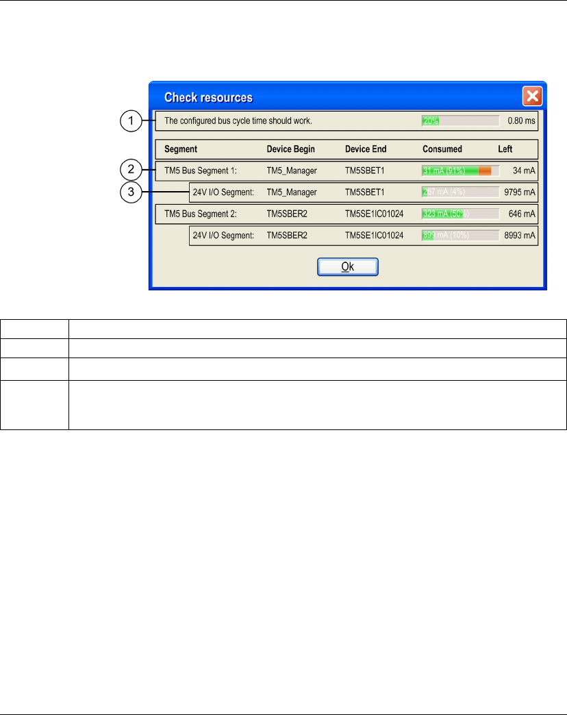
Check Resources
You can check if the Bus Cycle Time is valid and the power supply of the expansion
modules and blocks.
To check resources of the expansion modules, proceed as follows:
(1) A segment is a group of I/O modules that are supplied by the same Power
Distribution Module.
NOTE: The current consumption figures presented by the Check Resources
function are based on assumed values, and not on actual current measurements.
The assumed values for the outputs are based on classic loads but can be adjusted
using the 24 Vdc I/O segment external current setting in the I/O Configuration
(see page 22) tab of each module. The assumptions for input signals are based on
known internal loads and are therefore not modifiable. While the use of the Check
Resources function to test the power budget is required, it is no substitute for actual
and complete system testing and commissioning, refer to the TM5 / TM7 System
Planning and Installation Guide.
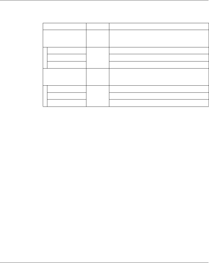
Legend Description
1 Indicates if the configured bus cycle time should work or should be increased.
2Provides the consumption status on the TM5 Bus segment (1)
3Provides a consumption status on the 24 Vdc I/O power segment (1). This value depends on the 24
Vdc I/O segment external current on TM5 power supply bus parameter available in the I/O
Configuration tab. This parameter is not necessarily available with all electronic modules.
I/O Configuration General Information
EIO0000000420 04/2012 21
Adding an Expansion Module
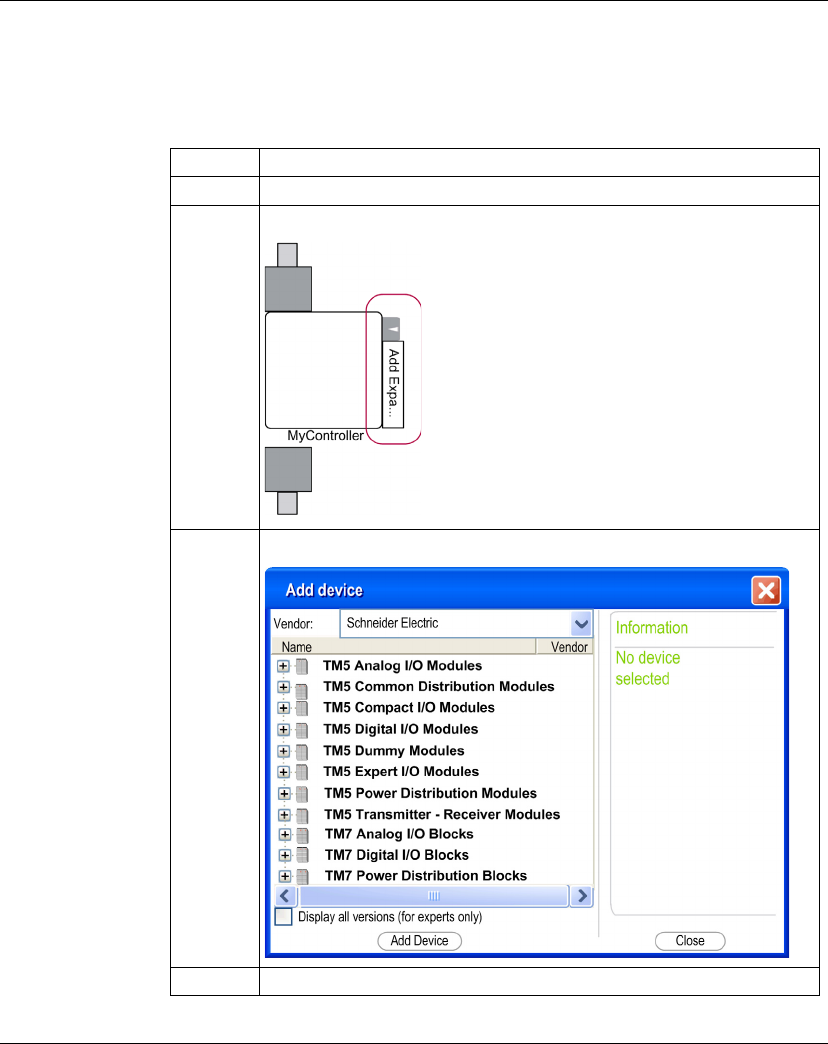
Procedure
The table below describes how to add an expansion module to the controller:
Step Action
1 Select the Configuration tab.
2In the Graphical Configuration Editor, click Add Expansion:
3In the Add Device window, select one expansion module to add:
4 Click Add and Close.
I/O Configuration General Information
22 EIO0000000420 04/2012
I/O Configuration
To configure TM5 expansion modules, proceed as follows:
I/O Configuration Tab Description
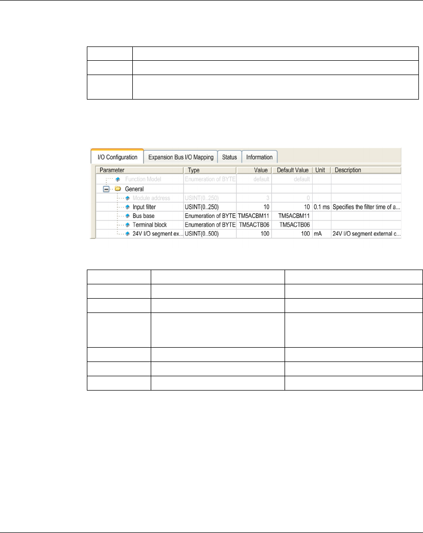
Set the parameters of the expansion module using the I/O Configuration tab:
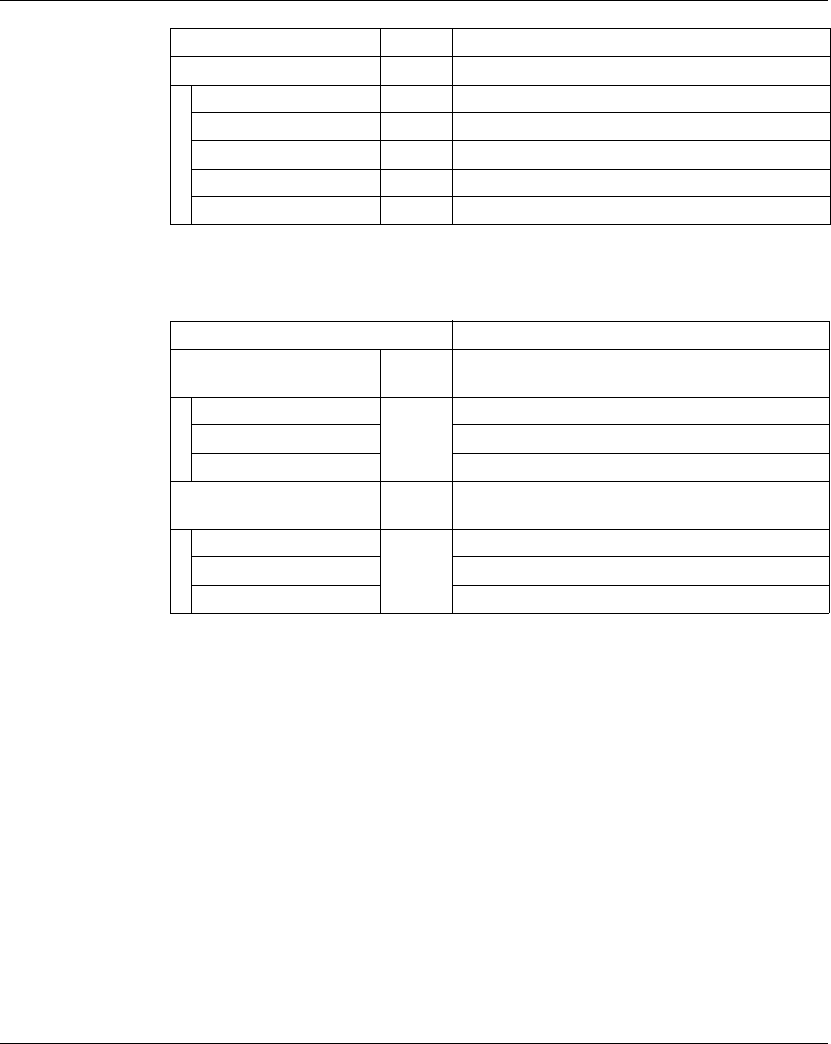
The I/O Configuration tab contains the following columns:
Step Action
1 Select the Configuration tab.
2 Double-click the expansion module.
Result: The I/O Configuration tab of the module appears.
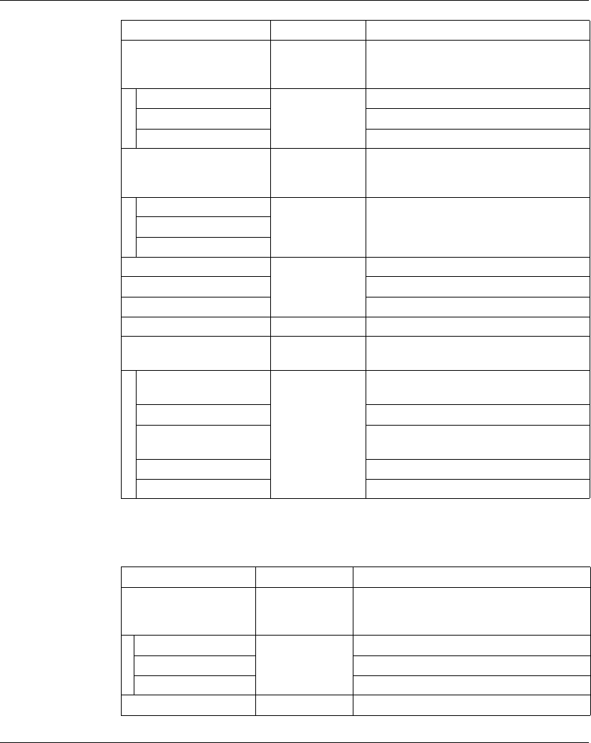
Column Description Editable
Parameter Parameter name No
Type Parameter data type No
Value Value of the parameter If the parameter is editable, an edit
frame can be opened by double-
clicking.
Default Value Default parameter value No
Unit Unit value of the parameter No
Description Short description of the parameter No
I/O Configuration General Information
EIO0000000420 04/2012 23
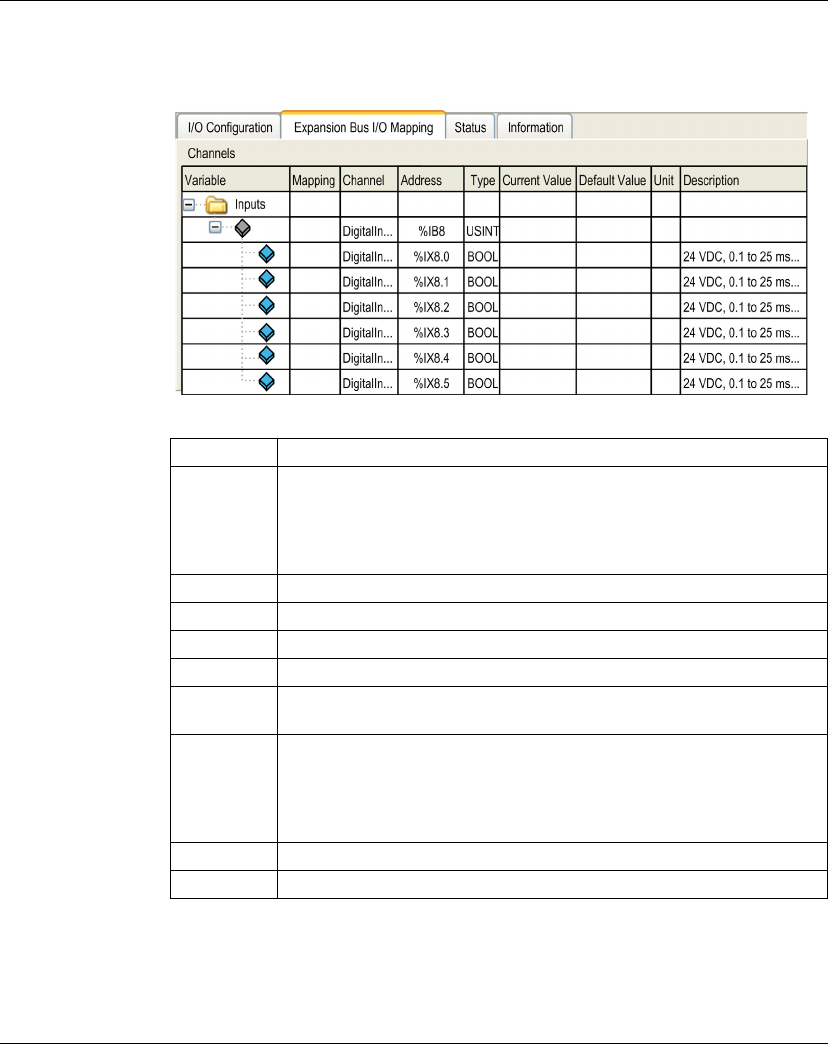
Expansion Bus I/O Mapping Tab Description
Variables can be defined and named in the Expansion Bus I/O Mapping tab.
Additional information such as topological addressing is also provided in this tab:
The Expansion Bus I/O Mapping tab contains the following columns:
NOTE: %I value is updated from physical information at the beginning of each task
using the %I.
Physical output level is updated from memory variable for the outputs value within
the task configured by Bus cycle task configuration.
Column Description
Variable Lets you map the channel on a variable.
Double-click the icon to enter the variable name.
If it is a new variable, the variable is created.
It is also possible to map an existing variable with the variables Input
Assistant by clicking the... button.
Mapping Indicates if the channel is mapped on a new variable or an existing variable.
Channel Name of the channel of the device
Address Address of the channel
Type Data type of the channel
Current
Value
Current value of the channel, displayed in online mode
Default Value Value taken by the Output when the controller is in a STOPPED or HALT
state. For more details, refer to Logic Controller PLC Settings (see Modicon
M258 Logic Controller, Programming Guide) or Motion Controller PLC
Settings (see Modicon LMC058 Motion Controller, Programming Guide).
Double-click to change the default value.
Unit Unit of the channel value
Description Description of the channel
I/O Configuration General Information
24 EIO0000000420 04/2012
For more details on Bus cycle task, refer to Logic Controller PLC Settings
(see Modicon M258 Logic Controller, Programming Guide) or Motion Controller PLC
Settings (see Modicon LMC058 Motion Controller, Programming Guide).
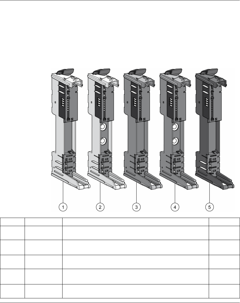
TM5 Bus Bases
Set the TM5 bus base in the I/O Configuration tab to be consistent with your
hardware configuration. Note that this does not apply to compact I/O modules.
The following figure shows the TM5 bus bases:
Number Reference Description Color
1 TM5ACBM11 Bus base 24 Vdc
24 Vdc I/O power segment pass-through
White
2 TM5ACBM15 Bus base 24 Vdc
24 Vdc I/O power segment pass-through with address setting (1)
White
3 TM5ACBM01R Bus base 24 Vdc
24 Vdc I/O power segment left isolated
Gray
4 TM5ACBM05R Bus base 24 Vdc
24 Vdc I/O power segment left isolated with address setting (1)
Gray
5 TM5ACBM12 Bus base 240 Vac
24 Vdc I/O power segment pass-through isolated from the 240 Vac
Black

I/O Configuration General Information
EIO0000000420 04/2012 25
(1) In certain cases, it is necessary to define specific slices or potential groups at a
fixed address, regardless of the preceding modules in the backplane. For this
purpose, there are bus bases in the TM5 System with address setting rotary
switches, that allow you to set the address setting number of the slice. All
subsequent slices refer to this offset and are addressed thereafter automatically.
Set the physical address of the TM5ACBM15 and TM5ACBM05R using the Module
address parameter available from the I/O Configuration tab of the module. This
parameter becomes editable only when the TM5ACBM15 and TM5ACBM05R are
selected in the Bus base parameter. The value of the module address set in the I/O
Configuration tab must be identical to the address set on your hardware.
For further information, refer to TM5 Addressing (see Modicon TM5 / TM7 Flexible
System, System Planning and Installation Guide).
I/O Configuration General Information
26 EIO0000000420 04/2012
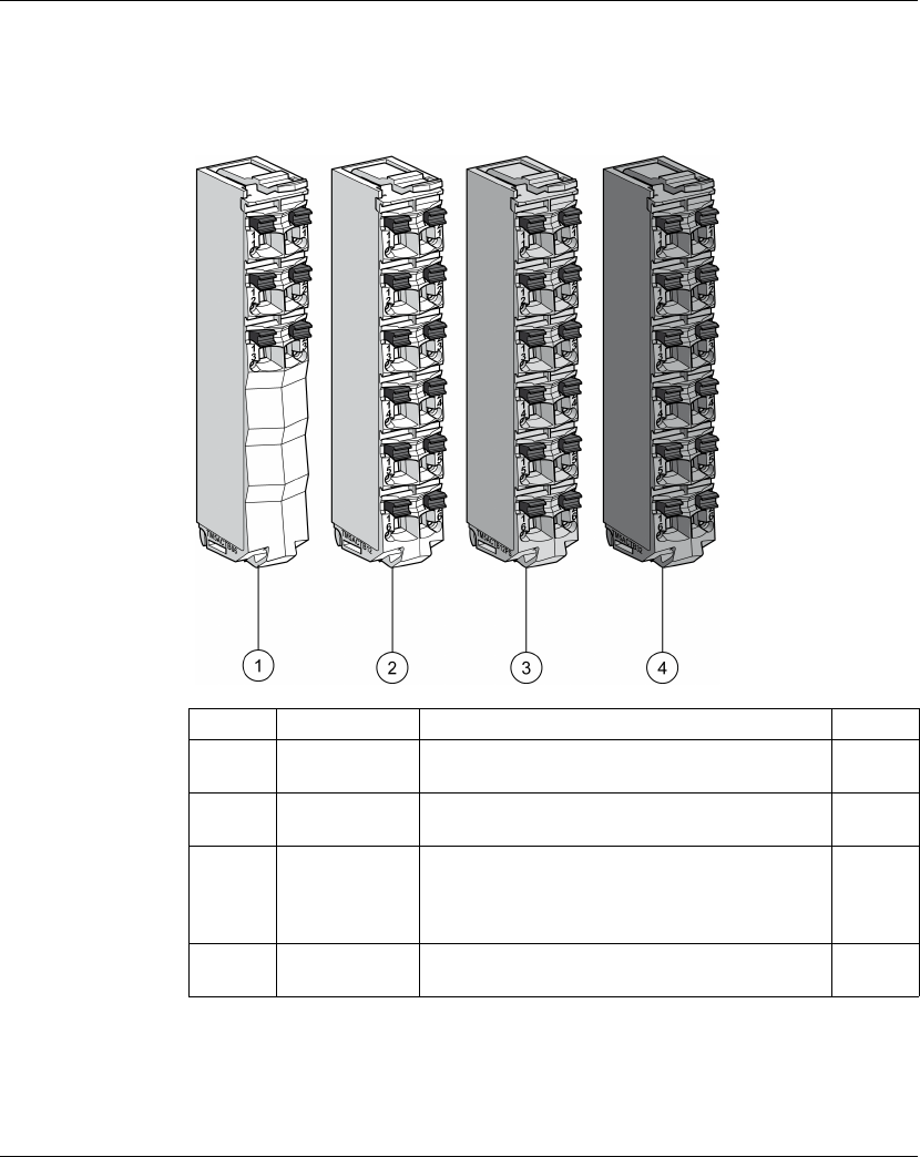
TM5 Terminal Blocks
Set the TM5 terminal block in the I/O Configuration tab to be consistent with your
hardware configuration.
The following figure shows the TM5 terminal blocks:
Number Reference Description Color
1 TM5ACTB06 6-pin terminal block designed for 24 Vdc I/O
modules
White
2 TM5ACTB12 12-pin terminal block designed for 24 Vdc I/O
modules
White
3 TM5ACTB12PS 12-pin terminal block designed for 24 Vdc Power
Distribution Modules (PDM), Interface Power
Distribution Modules (IPDM) and receiver
electronic module (TM5SBER2)
Gray
4 TM5ACTB32 12-pin terminal block designed for 240 Vac I/O
modules
Black

EIO0000000420 04/2012 27
2
Modicon TM5
TM5 Compa ct I/O Module s
EIO0000000420 04/2012
TM5 Compact I/O Modules
Introduction
This chapter provides information to configure compact I/O and their integrated
electronic modules:
zTM5C24D18T with the 12In and 6Out electronic modules,
zTM5C12D8T with the 4In and 4Out electronic modules,
zTM5C24D12R with the 12In and 6Rel electronic modules,
zTM5CAI8O8VL with the 4AI ±10 V and 4AO ±10 V electronic modules,
zTM5CAI8O8CL with the 4AI 0-20 mA / 4-20 mA and 4AO 0-20 mA electronic
modules,
zTM5CAI8O8CVL with the 4AI ±10 V, 4AI 0-20 mA / 4-20 mA, 4AO ±10 V and
4AO 0-20 mA electronic modules,
zTM5C12D6T6L with the 6In, 6Out, 4AI ±10 V / 0-20 mA / 4-20 mA and 2AO ±10
V / 0-20 mA electronic modules.
To add the expansion electronic modules contained in the compact I/O modules,
and to access the configuration screens, refer to Adding an expansion electronic
module (see page 21).
What’s in this Chapter?
This chapter contains the following sections:
Section Topic Page
2.1 TM5 Compact I/O Modules 28
2.2 Integrated Electronic Modules 52
TM5 Compact I/O Modules
28 EIO0000000420 04/2012
2.1 TM5 Compact I/O Modules
Introduction
This section shows you how to configure the compact I/O modules.
What’s in this Section?
This section contains the following topics:
Topic Page
TM5C24D18T 29
TM5C12D8T 32
TM5C12D6T6L 36
TM5C24D12R 40
TM5CAI8O8VL 43
TM5CAI8O8CL 46
TM5CAI8O8CVL 49

TM5 Compact I/O Modules
EIO0000000420 04/2012 29
TM5C24D18T
Introduction
The TM5C24D18T compact I/O module is a set of five TM5 24 Vdc input and output
electronic modules assembled together.
This set includes:
ztwo digital input electronic modules
zthree digital output electronic modules
For further information, refer to the TM5C24D18T General Description
(see Modicon TM5, Compact I/O Modules, Hardware Guide).
I/O Configuration Tab
To configure the TM5C24D18T compact I/O module, select the I/O Configuration
tab.
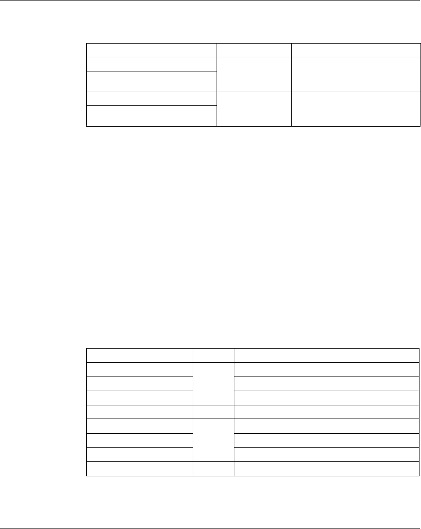
The table below describes the General parameters of the TM5C24D18T compact
I/O module:
Set each of the I/O electronic modules individually using the Pos.xx - SDEM (SDEM
= Short Description of the Electronic Module, like 12In, 6Out, 4AI ±10 V / 0-20 mA /
4-20 mA etc.) folders available.
NOTE:
zPos. stands for the position of the electronic module within the compact I/O
module.
zxx is the index number of the electronic module position (from 00 to 04).
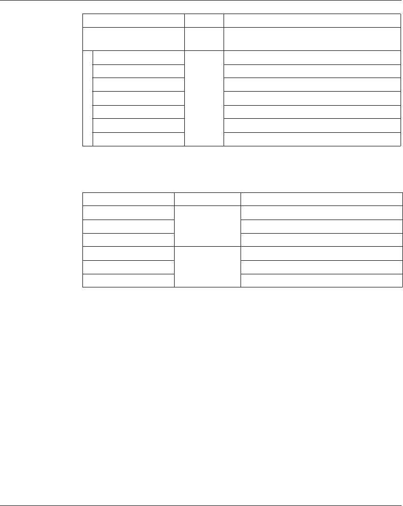
The table below provides the I/O electronic module type associated with the
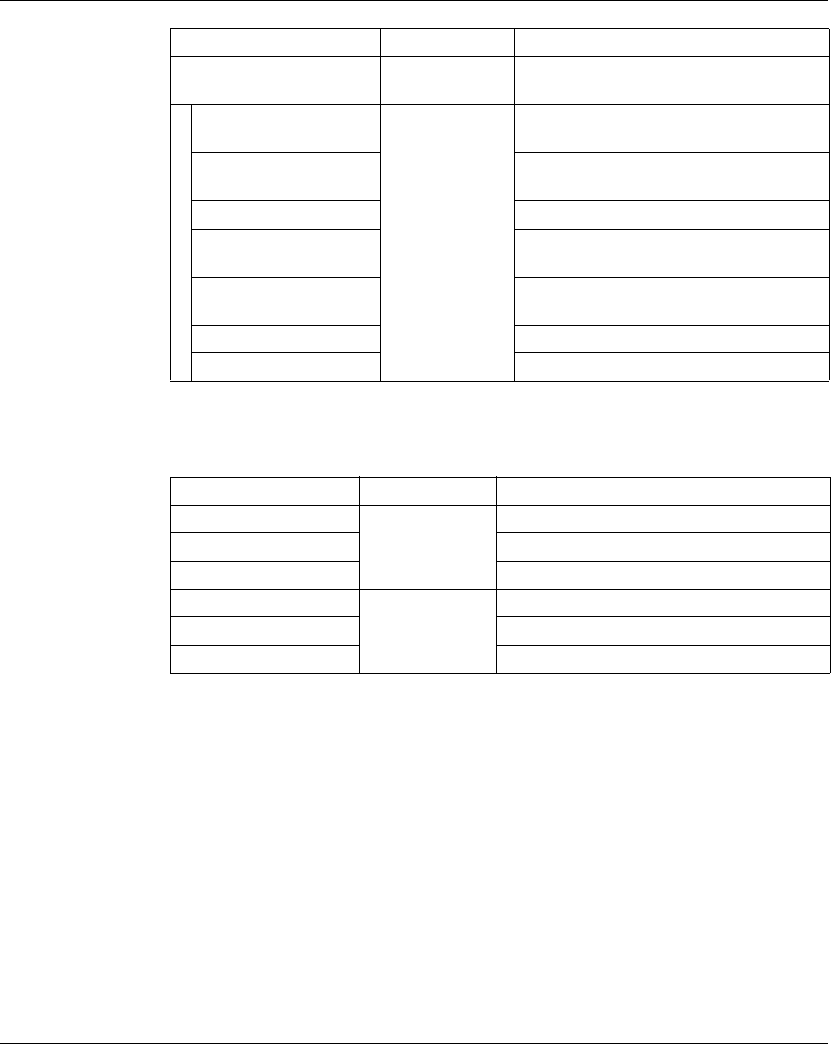
positions 0 to 4 (Pos.00 to Pos.04) on the TM5C24D18T compact I/O module:
Parameter Value Default Value Description
Module
address
0...250 0 The address is automatically set when adding
the compact I/O modules. The address value
depends on the order of adding the module in
the SoMachine tree.
The compact I/O module do not support the
possibility to change the address.
I/O Electronic Module Position Type Refer to
Pos.00 12 digital inputs Configuration of the digital input 12In
electronic modules (see page 55).
Pos.01
Pos.02 6 digital outputs Configuration of the digital output
6Out electronic modules
(see page 57).
Pos.03
Pos.04
TM5 Compact I/O Modules
30 EIO0000000420 04/2012
For further generic descriptions, refer to I/O Configuration Tab Description
(see page 22).
Expansion Bus I/O Mapping Tab
Variables can be defined and named in the Expansion Bus I/O Mapping tab.
Additional information such as topological addressing is also provided in this tab.
Refer to the following paragraphs:
zInput Mapping (see page 30), for the input parameters configuration details.
zOutput Mapping (see page 31), for the output parameters configuration details.
For further generic descriptions, refer to Expansion Bus I/O Mapping Tab
Description (see page 22).
Input Mapping
The table below describes the TM5C24D18T input mapping configuration:
Channel Type Description
Pos0_DigitalInputs00 UINT State of all inputs (bits 12-15 = 0, not used) for the
integrated electronic module located at Pos.00
DigitalInput00 BOOL State of input 0
... ...
DigitalInput11 State of input 11
Pos1_DigitalInputs00 UINT State of all inputs (bits 12-15 = 0, not used) for the
integrated electronic module located at Pos.01
DigitalInput00 BOOL State of input 0
... ...
DigitalInput11 State of input 11
Pos2_StatusDigitalOutputs USINT Status word of all outputs for the integrated
electronic module located at Pos.02
StatusDigitalOutput00 BOOL Status bit associated to each output:
z0: Ok
z1: detected error
...
StatusDigitalOutput05
Pos3_StatusDigitalOutputs USINT Status word of all outputs for the integrated
electronic module located at Pos.03
StatusDigitalOutput00 BOOL Status bit associated to each output:
z0: Ok
z1: detected error
...
StatusDigitalOutput05
TM5 Compact I/O Modules
EIO0000000420 04/2012 31
Output Mapping
The table below describes the TM5C24D18T output mapping configuration:
Pos4_StatusDigitalOutputs USINT Status word of all outputs for the integrated
electronic module located at Pos.04
StatusDigitalOutput00 BOOL Status bit associated to each output:
z0: Ok
z1: detected error
...
StatusDigitalOutput05
GlobalModuleStatusInputs UINT State of the compact IO and the electronic
modules
StatusPos00 BOOL State of the electronic module in position 0 (OK=1)
... ...
StatusPos04 State of the electronic module in position 4 (OK=1)
Not Used Bit not used
GlobalModuleStatus State of the compact IO (OK=0)
Channel Type Description
Channel Type Description
Pos2_DigitalOutputs USINT Command word of all outputs for the
integrated electronic module located at
Pos.02
DigitalOutput00 BOOL Command bit of output 0
... ...
DigitalOutput05 Command bit of output 5
Pos3_DigitalOutputs USINT Command word of all outputs for the
integrated electronic module located at
Pos.03
DigitalOutput00 BOOL Command bit of output 0
... ...
DigitalOutput05 Command bit of output 5
Pos4_DigitalOutputs USINT Command word of all outputs for the
integrated electronic module located at
Pos.04
DigitalOutput00 BOOL Command bit of output 0
... ...
DigitalOutput05 Command bit of output 5

TM5 Compact I/O Modules
32 EIO0000000420 04/2012
TM5C12D8T
Introduction
The TM5C12D8T compact I/O module is a set of five TM5 24 Vdc input and output
electronic modules assembled together.
This set includes:
zthree digital input electronic modules
ztwo digital output electronic modules
For further information, refer to the TM5C12D8T General Description (see Modicon
TM5, Compact I/O Modules, Hardware Guide).
I/O Configuration Tab
To configure the TM5C12D8T compact I/O module, select the I/O Configuration
tab.
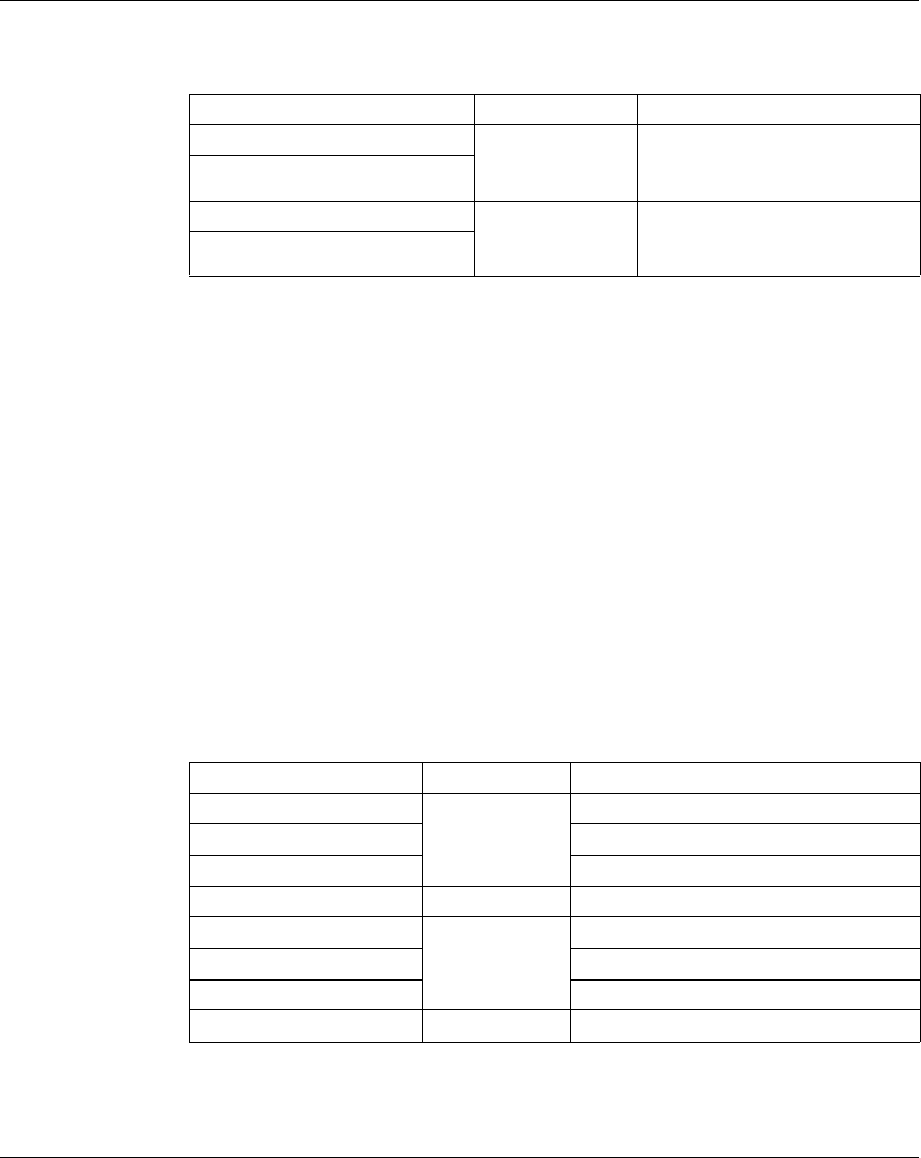
The table below describes the General parameters of the TM5C12D8T compact I/O
module:
Set each of the I/O electronic modules individually using the Pos.xx - SDEM (SDEM
= Short Description of the Electronic Module, like 12In, 6Out, 4AI ±10 V / 0-20 mA /
4-20 mA etc.) folders available.
NOTE:
zPos. stands for the position of the electronic module within the compact I/O
module.
zxx is the index number of the electronic module position (from 00 to 04).
Parameter Value Default Value Description
Module
address
0...250 0 The address is automatically set when adding
the compact I/O modules. The address value
depends on the order of adding the module in
the SoMachine tree.
The compact I/O module do not support the
possibility to change the address.
TM5 Compact I/O Modules
EIO0000000420 04/2012 33
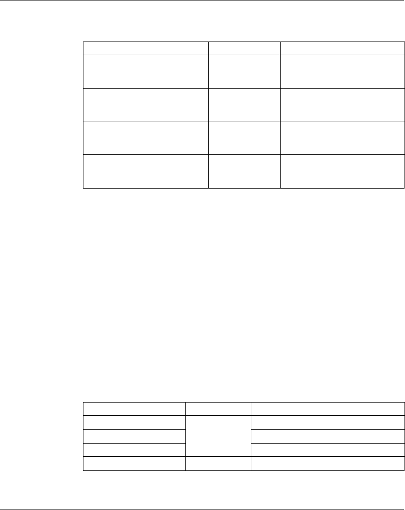
The table below provides the I/O electronic module type associated with the
positions 0 to 4 (Pos.00 to Pos.04) on the TM5C12D8T compact I/O module:
For further generic descriptions, refer to I/O Configuration Tab Description
(see page 22).
Expansion Bus I/O Mapping Tab
Variables can be defined and named in the Expansion Bus I/O Mapping tab.
Additional information such as topological addressing is also provided in this tab.
Refer to the following paragraphs:
zInput Mapping (see page 33), for the input parameters configuration details.
zOutput Mapping (see page 35), for the output parameters configuration details.
For further generic descriptions, refer to Expansion Bus I/O Mapping Tab
Description (see page 22).
Input Mapping
The table below describes the TM5C12D8T input mapping configuration:
I/O Electronic Module Position Type Refer to
Pos.00 4 digital inputs Configuration of the digital input
4In electronic modules
(see page 53)
Pos.01
Pos.02
Pos.03 4 digital outputs Configuration of the digital output
4Out electronic modules
(see page 56)
Pos.04
Channel Type Description
Pos0_DigitalInputs USINT State of all inputs (bits 4-7 = 0, not used) for the
integrated electronic module located at Pos.00
DigitalInput00 BOOL State of input 0
... ...
DigitalInput03 State of input 03
Pos1_DigitalInputs USINT State of all inputs (bits 4-7 = 0, not used) for the
integrated electronic module located at Pos.01
DigitalInput00 BOOL State of input 0
... ...
DigitalInput03 State of input 3
TM5 Compact I/O Modules
34 EIO0000000420 04/2012
Pos2_DigitalInputs USINT State of all inputs (bits 4-7 = 0, not used) for the
integrated electronic module located at Pos.02
DigitalInput00 BOOL State of input 0
... ...
DigitalInput03 State of input 3
Pos3_StatusDigitalOutputs USINT Status word of all outputs for the integrated
electronic module located at Pos.03
(bits 4...7: not used).
StatusDigitalOutput00 BOOL Status bit associated to each output:
z0: Ok
z1: detected error
...
StatusDigitalOutput03
Pos4_StatusDigitalOutputs USINT Status word of all outputs for the integrated
electronic module located at Pos.04
(bits 4...7: not used).
StatusDigitalOutput00 BOOL Status bit associated to each output:
z0: Ok
z1: detected error
...
StatusDigitalOutput03
GlobalModuleStatusInputs UINT State of the compact IO and the electronic
modules
StatusPos00 BOOL State of the electronic module in position 0 (OK=1)
... ...
StatusPos04 State of the electronic module in position 4 (OK=1)
Not used Bit not used
GlobalModuleStatus State of the compact IO (OK=0)
Channel Type Description
TM5 Compact I/O Modules
EIO0000000420 04/2012 35
Output Mapping
The table below describes the TM5C12D8T output mapping configuration:
Channel Type Description
Pos3_DigitalOutputs USINT Command word of all outputs for the integrated
electronic module located at Pos.03
(bits 4...7: not used).
DigitalOutput00 BOOL Command bit of output 0
... ...
DigitalOutput03 Command bit of output 3
Pos4_DigitalOutputs USINT Command word of all outputs for the integrated
electronic module located at Pos.04
(bits 4...7: not used).
DigitalOutput00 BOOL Command bit of output 0
... ...
DigitalOutput03 Command bit of output 3

TM5 Compact I/O Modules
36 EIO0000000420 04/2012
TM5C12D6T6L
Introduction
The TM5C12D6T6L compact I/O module is a set of five TM5 24 Vdc input and
output electronic modules assembled together.
This set includes:
ztwo digital input electronic modules
zone digital output electronic module
zone analog input electronic module
zone analog output electronic module
For further information, refer to the TM5C12D6T6L General Description
(see Modicon TM5, Compact I/O Modules, Hardware Guide).
I/O Configuration Tab
To configure the TM5C12D6T6L compact I/O module, select the I/O Configuration
tab.
The table below describes the General parameters of the TM5C12D6T6L compact
I/O module:
Set each of the I/O electronic modules individually using the Pos.xx - SDEM (SDEM
= Short Description of the Electronic Module, like 12In, 6Out, 4AI ±10 V / 0-20 mA /
4-20 mA etc.) folders available.
NOTE:
zPos. stands for the position of the electronic module on the compact I/O
electronic module.
zxx is the index number of the electronic module position (from 00 to 04).
Parameter Value Default Value Description
Module
address
0...250 0 The address is automatically set when adding
the compact I/O modules. The address value
depends on the order of adding the module in
the SoMachine tree.
The compact I/O module do not support the
possibility to change the address.

TM5 Compact I/O Modules
EIO0000000420 04/2012 37
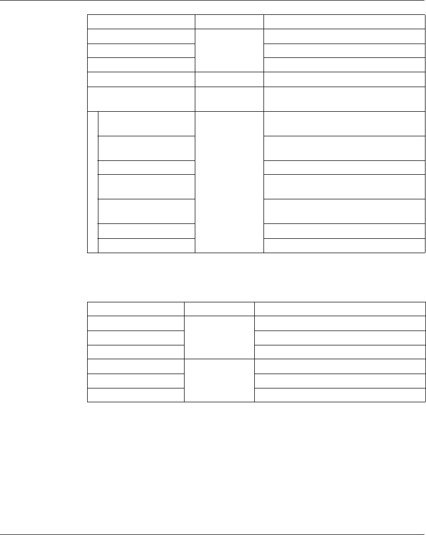
The table below provides the I/O electronic module type associated with the
positions 0 to 4 (Pos.00 to Pos.04) on the TM5C12D6T6L compact I/O module:
For further generic descriptions, refer to I/O Configuration Tab Description
(see page 22).
Expansion Bus I/O Mapping Tab
Variables can be defined and named in the Expansion Bus I/O Mapping tab.
Additional information such as topological addressing is also provided in this tab.
Refer to the following paragraphs:
zInput Mapping (see page 37), for the input parameters configuration details.
zOutput Mapping (see page 38), for the output parameters configuration details.
For further generic descriptions, refer to Expansion Bus I/O Mapping Tab
Description (see page 22).
Input Mapping
The table below describes the TM5C12D6T6L input mapping configuration:
I/O Electronic Module Position Type Refer to
Pos.00 6 digital inputs Configuration of the digital input
6In electronic modules
(see page 54)
Pos.01
Pos.02 6 digital outputs Configuration of the digital output
6Out electronic module
(see page 57)
Pos.03 4 analog inputs Configuration of the analog input
4AI ±10 V / 0-20 mA / 4-20 mA
electronic module (see page 62)
Pos.04 2 analog outputs Configuration of the analog output
2AO ±10 V / 0-20 mA electronic
module (see page 70)
Channel Type Description
Pos0_DigitalInputs USINT State of all inputs (bits 6-7 = 0, not used) for
the integrated electronic module located at
Pos.00
DigitalInput00 BOOL State of input 0
... ...
DigitalInput05 State of input5
TM5 Compact I/O Modules
38 EIO0000000420 04/2012
Output Mapping
The table below describes the TM5C12D6T6L output mapping configuration:
Pos1_DigitalInputs USINT State of all inputs (bits 6-7 = 0, not used) for
the integrated electronic module located at
Pos.01
DigitalInput00 BOOL State of input 0
... ...
DigitalInput05 State of input 5
Pos2_StatusDigitalOutputs USINT Status word of all outputs for the integrated
electronic module located at Pos.02
(bits 6...7: not used).
DigitalInput00 BOOL Status bit associated to each output:
z0: Ok
z1: detected error
...
DigitalInput05
Pos3_AnalogInput00 INT Current value of input 0
... ...
Pos3_AnalogInput03 Current value of input 3
Pos3_StatusInput USINT State of all inputs
GlobalModuleStatusInputs UINT State of the compact IO and the electronic
modules
StatusPos00 BOOL State of the electronic module in position 0
(OK=1)
... ...
StatusPos04 State of the electronic module in position 4
(OK=1)
Not used Bit not used
GlobalModuleStatus State of the compact IO (OK=0)
Channel Type Description
Channel Type Description
Pos2_DigitalOutputs USINT Command word of all outputs for the
integrated electronic module located at
Pos.02 (bits 6...7: not used).
DigitalOutput00 BOOL Command bit of output 0
... ...
DigitalOutput05 Command bit of output 5
Pos4_AnalogOutput00 INT Command word of the output 0

TM5 Compact I/O Modules
EIO0000000420 04/2012 39
Pos4_AnalogOutput01 INT Command word of the output 1
Channel Type Description

TM5 Compact I/O Modules
40 EIO0000000420 04/2012
TM5C24D12R
Introduction
The TM5C24D12R compact I/O module is a set of five TM5 24 Vdc input and output
electronic modules assembled together.
This set includes:
ztwo digital input electronic modules
ztwo relay electronic modules
zone dummy module (see Modicon TM5, Compact I/O Modules,
Hardware Guide).
For further information, refer to the TM5C24D12R General Description
(see Modicon TM5, Compact I/O Modules, Hardware Guide).
I/O Configuration Tab
To configure the TM5C24D12R compact I/O module, select the I/O Configuration
tab.
The table below describes the General parameters of the TM5C24D12R compact
I/O module:
Set each of the I/O electronic modules individually using the Pos.xx - SDEM (SDEM
= Short Description of the Electronic Module, like 12In, 6Out, 4AI ±10 V / 0-20 mA /
4-20 mA etc.) folders available.
NOTE:
zPos. stands for the position of the electronic module within the compact I/O
module.
zxx is the index number of the electronic module position (from 00 to 04).
Parameter Value Default Value Description
Module
address
0...250 0 The address is automatically set when adding
the compact I/O modules. The address value
depends on the order of adding the module in
the SoMachine tree.
The compact I/O module do not support the
possibility to change the address.
TM5 Compact I/O Modules
EIO0000000420 04/2012 41
The table below provides the I/O electronic module type associated with the
positions 0 to 4 (Pos.00 to Pos.04) on the TM5C24D12R compact I/O module:
NOTE: Pos.03 does not appear in the I/O Configuration tab as this is the dummy
module that cannot be configured.
For further generic descriptions, refer to I/O Configuration Tab Description
(see page 22).
Expansion Bus I/O Mapping Tab
Variables can be defined and named in the Expansion Bus I/O Mapping tab.
Additional information such as topological addressing is also provided in this tab.
Refer to the following paragraphs:
zInput Mapping (see page 41), for the input parameters configuration details.
zOutput Mapping (see page 42), for the output parameters configuration details.
For further generic descriptions, refer to Expansion Bus I/O Mapping Tab
Description (see page 22).
Input Mapping
The table below describes the TM5C24D12R I/O Mapping configuration:
I/O Electronic Module Position Type Refer to
Pos.00 12 digital inputs Configuration of the digital input
12In electronic modules
(see page 55)
Pos.01
Pos.02 6 relay outputs Configuration of the digital output
relay 6Rel electronic modules
(see page 58)
Pos.04
Channel Type Description
Pos0_DigitalInput UINT State of all inputs (bits 12-15 = 0, not used) for the
integrated electronic module located at Pos.00
DigitalInput00 BOOL State of input 0
... ...
DigitalInput11 State of input 11
Pos1_DigitalInputs00 UINT State of all inputs (bits 12-15 = 0, not used) for the
integrated electronic module located at Pos.01
DigitalInput00 BOOL State of input 0
... ...
DigitalInput11 State of input 11
TM5 Compact I/O Modules
42 EIO0000000420 04/2012
Output Mapping
The table below describes the TM5C24D12R I/O Mapping configuration:
GlobalModuleStatusInputs UINT State of the compact IO and the electronic modules
StatusPos00 BOOL State of the electronic module in position 0 (OK=1)
... ...
StatusPos04 State of the electronic module in position 4 (OK=1)
Not used Bit not used
GlobalModuleStatus State of the compact IO (OK=0)
Channel Type Description
Channel Description
Pos2_DigitalOutputs UINT Command word of all outputs for the integrated
electronic module located at Pos.02
DigitalOutput00 BOOL Command bit of output 0
... ...
DigitalOutput05 Command bit of output 5
Pos4_DigitalOutputs UINT Command word of all outputs for the integrated
electronic module located at Pos.04
DigitalOuput00 BOOL Command bit of output 0
... ...
DigitalOutput05 Command bit of output 5

TM5 Compact I/O Modules
EIO0000000420 04/2012 43
TM5CAI8O8VL
Introduction
The TM5CAI8O8VL compact I/O module is a set of four TM5 24 Vdc input and
output electronic modules assembled together.
This set includes:
z2 analog input electronic module
zone dummy module (see Modicon TM5, Compact I/O Modules, Hardware Guide)
z2 analog output electronic module
For further information, refer to the TM5CAI8O8VL General Description
(see Modicon TM5, Compact I/O Modules, Hardware Guide).
I/O Configuration Tab
To configure the TM5CAI8O8VL compact I/O module, select the I/O Configuration
tab.
The table describes the General parameters of the TM5CAI8O8VL compact I/O
module:
Set each of the I/O electronic modules individually using the Pos.xx - SDEM (SDEM
= Short Description of the Electronic Module, like 12In, 6Out, 4AI ±10 V / 0-20 mA /
4-20 mA etc.) folders available.
NOTE:
zPos. stands for the position of the electronic module on the compact I/O
electronic module.
zxx is the index number of the electronic module position (from 00 to 04).
Parameter Value Default Value Description
Module
address
0...250 0 The address is automatically set when adding
the compact I/O modules. The address value
depends on the order of adding the module in
the SoMachine tree.
The compact I/O modules do not support the
possibility to change the address.
TM5 Compact I/O Modules
44 EIO0000000420 04/2012
The table provides the I/O electronic module type associated with the positions 0 to
4 (Pos.00 to Pos.04) on the TM5CAI8O8VL compact I/O module:
NOTE: Pos.02 does not appear in the I/O Configuration tab as this is the dummy
module that cannot be configured.
For further generic descriptions, refer to I/O Configuration Tab Description
(see page 22).
Expansion Bus I/O Mapping Tab
Variables can be defined and named in the Expansion Bus I/O Mapping tab.
Additional information such as topological addressing is also provided in this tab.
Refer to the following paragraphs:
zInput Mapping (see page 44), for the input parameters configuration details.
zOutput Mapping (see page 45), for the output parameters configuration details.
For further generic descriptions, refer to Expansion Bus I/O Mapping Tab
Description (see page 22).
Input Mapping
The table describes the TM5CAI8O8VL input mapping configuration:
I/O Electronic Module Position Type Refer to
Pos.00 4 analog inputs Configuration of the analog input
4AI ±10 V electronic modules
(see page 59)
Pos.01
Pos.03 4 analog outputs Configuration of the analog output
4AO ±10 V electronic module
(see page 68)
Pos.04
Channel Type Description
Pos0_AnalogInput00 INT Current value of input 0
... ...
Pos0_AnalogInput03 Current value of input 3
Pos0_StatusInput USINT Status of the analog inputs
Pos1_AnalogInput00 INT Current value of input 0
... ...
Pos1_AnalogInput03 Current value of input 3
Pos1_StatusInput USINT Status of the analog inputs
TM5 Compact I/O Modules
EIO0000000420 04/2012 45
Output Mapping
The table describes the TM5CAI8O8VL output mapping configuration:
GlobalModuleStatusInputs UINT State of the compact IO and the electronic
modules
StatusPos00 BOOL State of the electronic module in position 0 (OK=1)
StatusPos01 State of the electronic module in position 1 (OK=1)
Not Used Bit not used
StatusPos03 State of the electronic module in position 3 (OK=1)
StatusPos04 State of the electronic module in position 4 (OK=1)
Not used Bit not used
GlobalModuleStatus State of the compact IO (OK=0)
Channel Type Description
Channel Type Description
Pos3_AnalogOutput00 INT Command word of the output 0
... ...
Pos3_AnalogOutput03 Command word of the output 3
Pos4_AnalogOutput00 INT Command word of the output 0
... ...
Pos4_AnalogOutput03 Command word of the output 3

TM5 Compact I/O Modules
46 EIO0000000420 04/2012
TM5CAI8O8CL
Introduction
The TM5CAI8O8CL compact I/O module is a set of four TM5 24 Vdc input and
output electronic modules assembled together.
This set includes:
z2 analog input electronic modules
zone dummy module (see Modicon TM5, Compact I/O Modules, Hardware Guide)
z2 analog output electronic modules
For further information, refer to the TM5CAI8O8CL General Description
(see Modicon TM5, Compact I/O Modules, Hardware Guide).
I/O Configuration Tab
To configure the TM5CAI8O8CL compact I/O module, select the I/O Configuration
tab.
The table describes the General parameters of the TM5CAI8O8CL compact I/O
module:
Set each of the I/O electronic modules individually using the Pos.xx - SDEM (SDEM
= Short Description of the Electronic Module, like 12In, 6Out, 4AI ±10 V / 0-20 mA /
4-20 mA etc.) folders available.
NOTE:
zPos. stands for the position of the electronic module on the compact I/O
electronic module.
zxx is the index number of the electronic module position (from 00 to 04).
Parameter Value Default Value Description
Module
address
0...250 0 The address is automatically set when adding
the compact I/O modules. The address value
depends on the order of adding the module in
the SoMachine tree.
The compact I/O modules do not support the
possibility to change the address.
TM5 Compact I/O Modules
EIO0000000420 04/2012 47
The table provides the I/O electronic module type associated with the positions 0 to
4 (Pos.00 to Pos.04) on the TM5CAI8O8CL compact I/O module:
NOTE: Pos.02 does not appear in the I/O Configuration tab as this is the dummy
module that cannot be configured.
For further generic descriptions, refer to I/O Configuration Tab Description
(see page 22).
Expansion Bus I/O Mapping Tab
Variables can be defined and named in the Expansion Bus I/O Mapping tab.
Additional information such as topological addressing is also provided in this tab.
Refer to the following paragraphs:
zInput Mapping for the input parameters configuration details.
zOutput Mapping, for the output parameters configuration details.
For further generic descriptions, refer to Expansion Bus I/O Mapping Tab
Description (see page 22).
Input Mapping
The table describes the TM5CAI8O8CL input mapping configuration:
I/O Electronic Module Position Type Refer to
Pos.00 4 analog inputs Configuration of the analog input
4AI 0-20 mA / 4-20 mA electronic
modules (see page 60)
Pos.01
Pos.03 4 analog outputs Configuration of the analog output
4AO 0-20 mA electronic module
(see page 69)
Pos.04
Channel Type Description
Pos0_AnalogInput00 INT Current value of input 0
... ...
Pos0_AnalogInput03 Current value of input 3
Pos0_StatusInput USINT State of all inputs
Pos1_AnalogInput00 INT Current value of input 0
... ...
Pos1_AnalogInput03 Current value of input 3
Pos1_StatusInput USINT State of all inputs
TM5 Compact I/O Modules
48 EIO0000000420 04/2012
Output Mapping
The table describes the TM5CAI8O8CL output mapping configuration:
GlobalModuleStatusInputs UINT State of the compact IO and the electronic
modules
StatusPos00 BOOL State of the electronic module in position 0
(OK=1)
StatusPos01 State of the electronic module in position 1
(OK=1)
Not Used Bit not used
StatusPos03 State of the electronic module in position 3
(OK=1)
StatusPos04 State of the electronic module in position 4
(OK=1)
Not used Bit not used
GlobalModuleStatus State of the compact IO (OK=0)
Channel Type Description
Channel Type Description
Pos3_AnalogOutput00 INT Command word of the output 0
... ...
Pos3_AnalogOutput03 Command word of the output 3
Pos4_AnalogOutput00 INT Command word of the output 0
... ...
Pos4_AnalogOutput03 Command word of the output 3

TM5 Compact I/O Modules
EIO0000000420 04/2012 49
TM5CAI8O8CVL
Introduction
The TM5CAI8O8CVL compact I/O module is a set of four TM5 24 Vdc input and
output electronic modules assembled together.
This set includes:
z2 analog input electronic modules
zone dummy module (see Modicon TM5, Compact I/O Modules, Hardware Guide)
z2 analog output electronic modules
For further information, refer to the TM5CAI8O8CVL General Description
(see Modicon TM5, Compact I/O Modules, Hardware Guide).
I/O Configuration Tab
To configure the TM5CAI8O8CVL compact I/O module, select the I/O
Configuration tab.
The table describes the General parameters of the TM5CAI8O8CVL compact I/O
module:
Set each of the I/O electronic modules individually using the Pos.xx - SDEM (SDEM
= Short Description of the Electronic Module, like 12In, 6Out, 4AI ±10 V / 0-20 mA /
4-20 mA etc.) folders available.
NOTE:
zPos. stands for the position of the electronic module on the compact I/O
electronic module.
zxx is the index number of the electronic module position (from 00 to 04).
Parameter Value Default Value Description
Module
address
0...250 0 The address is automatically set when adding
the compact I/O modules. The address value
depends on the order of adding the module in
the SoMachine tree.
The compact I/O modules do not support the
possibility to change the address.
TM5 Compact I/O Modules
50 EIO0000000420 04/2012
The table provides the I/O electronic module type associated with the positions 0 to
4 (Pos.00 to Pos.04) on the TM5CAI8O8CVL compact I/O module:
NOTE: Pos.02 does not appear in the I/O Configuration tab as this is the dummy
module that cannot be configured.
For further generic descriptions, refer to I/O Configuration Tab Description
(see page 22).
Expansion Bus I/O Mapping Tab
Variables can be defined and named in the Expansion Bus I/O Mapping tab.
Additional information such as topological addressing is also provided in this tab.
Refer to the following paragraphs:
zInput Mapping for the input parameters configuration details.
zOutput Mapping, for the output parameters configuration details.
For further generic descriptions, refer to Expansion Bus I/O Mapping Tab
Description (see page 22).
Input Mapping
The table describes the TM5CAI8O8CVL input mapping configuration:
I/O Electronic Module Position Type Refer to
Pos.00 4 analog inputs Configuration of the analog input
4AI ±10 V electronic modules
(see page 59)
Pos.01 4 analog inputs Configuration of the analog input
4AI 0-20 mA / 4-20 mA electronic
modules (see page 60)
Pos.03 4 analog outputs Configuration of the analog output
4AO ±10 V electronic module
(see page 68)
Pos.04 4 analog outputs Configuration of the analog output
4AO 0-20 mA electronic module
(see page 69)
Channel Type Description
Pos0_AnalogInput00 INT Current value of input 0
... ...
Pos0_AnalogInput03 Current value of input 3
Pos0_StatusInput USINT State of all inputs
TM5 Compact I/O Modules
EIO0000000420 04/2012 51
Output Mapping
The table describes the TM5CAI8O8CVL output mapping configuration:
Pos1_AnalogInput00 INT Current value of input 0
... ...
Pos1_AnalogInput03 Current value of input 3
Pos1_StatusInput USINT State of all inputs
GlobalModuleStatusInputs UINT State of the compact IO and the electronic
modules
StatusPos00 BOOL State of the electronic module in position 0
(OK=1)
StatusPos01 State of the electronic module in position 1
(OK=1)
Not Used Bit not used
StatusPos03 State of the electronic module in position 3
(OK=1)
StatusPos04 State of the electronic module in position 4
(OK=1)
Not used Bit not used
GlobalModuleStatus State of the compact IO (OK=0)
Channel Type Description
Channel Type Description
Pos3_AnalogOutput00 INT Command word of the output 0
... ...
Pos3_AnalogOutput03 Command word of the output 3
Pos4_AnalogOutput00 INT Command word of the output 0
... ...
Pos4_AnalogOutput03 Command word of the output 3
TM5 Compact I/O Modules
52 EIO0000000420 04/2012
2.2 Integrated Electronic Modules
Introduction
This section provides the electronic modules parameters available in order to
configure the compact I/O modules.
What’s in this Section?
This section contains the following topics:
Topic Page
Digital Input 4In 53
Digital Input 6In 54
Digital Input 12In 55
Digital Output 4Out 56
Digital Output 6Out 57
Digital Output Relay 6Rel 58
Analog Input 4AI ±10 V 59
Analog Input 4AI 0-20 mA / 4-20 mA 60
Analog Input 4AI ±10 V / 0-20 mA / 4-20 mA 62
Analog Output 4AO ±10 V 68
Analog Output 4AO 0-20 mA 69
Analog Output 2AO ±10 V / 0-20 mA 70

TM5 Compact I/O Modules
EIO0000000420 04/2012 53
Digital Input 4In
Overview
The Digital Input 4In electronic module is a 24 Vdc electronic module with 4 inputs.
For further information, refer to the description of this electronic module in the
Compact I/O Modules Hardware Guide (see Modicon TM5, Compact I/O Modules,
Hardware Guide).
I/O Configuration
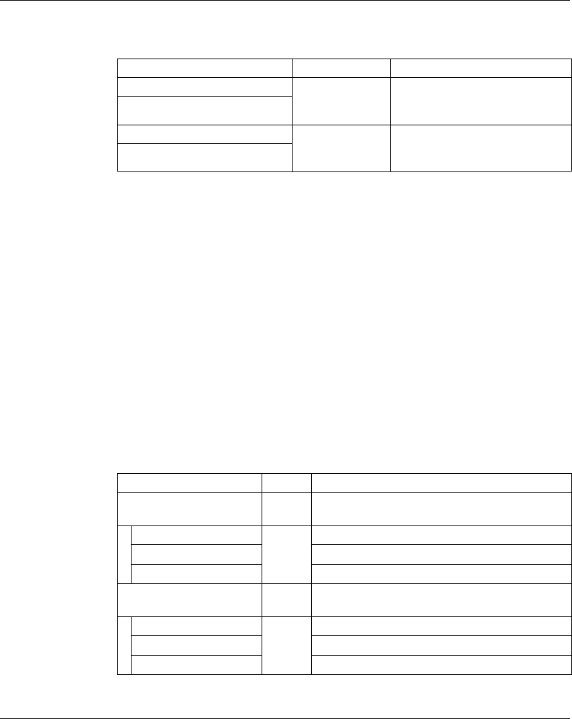
The table below describes the 4In electronic module parameters configuration:
Cycle Time and I/O Update Time
The table below gives the module characteristics allowing the TM5 Bus Cycle Time
configuration:
For further information, refer to TM5 Manager Configuration (see page 18).
Parameter Value Default
Value
Description
Input filter 0...250 10 Specifies the filter time of all digital
inputs in the range 0...250 (0...25 ms).
24V I/O segment
external current
0...500 mA 200 mA Current derived from the 24 Vdc I/O
power segment to supply the sensors
connected to the module. This value is
used to balance current consumption on
the 24Vdc I/O power segment
(see Modicon TM5 / TM7 Flexible
System, System Planning and
Installation Guide). This value is used
exclusively in the calculation of the
Check Resources function.
Characteristic Value (μs)
Without filter With filter
Minimum cycle time 100 150
Minimum I/O update time 100 200

TM5 Compact I/O Modules
54 EIO0000000420 04/2012
Digital Input 6In
Overview
The Digital Input 6In electronic module is a 24 Vdc electronic module with 6 inputs.
For further information, refer to the description of this electronic module in the
Compact I/O Modules Hardware Guide (see Modicon TM5, Compact I/O Modules,
Hardware Guide).
I/O Configuration
The table below describes the 6In electronic module parameters configuration:
Cycle Time and I/O Update Time
The table below gives the module characteristics allowing the TM5 Bus Cycle Time
configuration:
For further information, refer to TM5 Manager Configuration (see page 18).
Parameter Value Default
Value
Description
Input filter 0...250 10 Specifies the filter time of all digital
inputs in the range 0...250 (0...25 ms).
Characteristic Value (μs)
Without filter With filter
Minimum cycle time 100 150
Minimum I/O update time 100 200

TM5 Compact I/O Modules
EIO0000000420 04/2012 55
Digital Input 12In
Overview
The Digital Input 12In electronic module is a 24 Vdc electronic module with
12 inputs.
For further information, refer to the description of this electronic module in the
Compact I/O Modules Hardware Guide (see Modicon TM5, Compact I/O Modules,
Hardware Guide).
I/O Configuration
The table below describes the 12In electronic module parameters configuration:
Cycle Time and I/O Update Time
The table below gives the module characteristics allowing the TM5 Bus Cycle TIme
configuration:
For further information, refer to TM5 Manager Configuration (see page 18).
Parameter Value Default
Value
Description
Input filter 0...250 10 Specifies the filter time of all digital
inputs in the range 0...250 (0...25 ms).
Characteristic Value (μs)
Without filter With filter
Minimum cycle time 100 150
Minimum I/O update time 100 200

TM5 Compact I/O Modules
56 EIO0000000420 04/2012
Digital Output 4Out
Overview
The Digital Output 4Out electronic module is a 24 Vdc electronic module with
4 outputs.
For further information, refer to the description of this electronic module in the
Compact I/O Modules Hardware Guide (see Modicon TM5, Compact I/O Modules,
Hardware Guide).
I/O Configuration
The table below describes the 4Out electronic module parameters configuration:
Cycle Time and I/O Update Time
The table below gives the module characteristics allowing the TM5 Bus Cycle Time
configuration:
For further information, refer to TM5 Manager Configuration (see page 18).
Parameter Value Default
Value
Description
Output status
information
off
on
on Enable or disable the output status
reading function. When the value is set
to ON, the status is displayed in the
Expansion Bus I/O Mapping tab.
Status bit associated to each output:
z0: Ok
z1: detected error, overload or short
circuit
24V I/O segment
external current
0...2500 mA 1200 mA This value includes the current to supply
actuators and the sum of the current for
all outputs simultaneously activated. It is
used to balance current consumption on
the 24 Vdc I/O power segment
(see Modicon TM5 / TM7 Flexible
System, System Planning and
Installation Guide). This value is used
exclusively in the calculation of the
Check Resources function.
Characteristic Value (μs)
Minimum cycle time 100
Minimum I/O update time 100

TM5 Compact I/O Modules
EIO0000000420 04/2012 57
Digital Output 6Out
Overview
The Digital Output 6Out electronic module is a 24 Vdc electronic module with
6outputs.
For further information, refer to the description of this electronic module in the
Compact I/O Modules Hardware Guide (see Modicon TM5, Compact I/O Modules,
Hardware Guide).
I/O Configuration
The table below describes the 6Out electronic module parameters configuration:
Cycle Time and I/O Update Time
The table below gives the module characteristics allowing the TM5 Bus Cycle Time
configuration:
For further information, refer to TM5 Manager Configuration (see page 18).
Parameter Value Default
Value
Description
Output status
information
off
on
on Enable or disable the output status
reading function. When the value is set
to ON, the status is displayed in the
Expansion Bus I/O Mapping tab.
Status bit associated to each output:
z0: Ok
z1: detected error, overload or short
circuit
24V I/O segment
external current
0...3000 mA 2000 mA Current derived from the 24 Vdc I/O
power segment. The value to set is the
sum of current of all outputs simulta-
neously activated. It is used to balance
current consumption on the 24 Vdc I/O
power segment (see Modicon
TM5 / TM7 Flexible System, System
Planning and Installation Guide). This
value is used exclusively in the calcula-
tion of the Check Resources function.
Characteristic Value (μs)
Minimum cycle time 100
Minimum I/O update time 100

TM5 Compact I/O Modules
58 EIO0000000420 04/2012
Digital Output Relay 6Rel
Overview
The Digital Output Relay 6Rel electronic module is equipped with 6 relay outputs.
For further information, refer to the description of this electronic module in the
Compact I/O Modules Hardware Guide (see Modicon TM5, Compact I/O Modules,
Hardware Guide).
I/O Configuration
The 6Rel electronic module does not have any I/O configuration parameter settings.
TM5 Compact I/O Modules
EIO0000000420 04/2012 59
Analog Input 4AI ±10 V
Overview
The Analog Input 4AI ±10 V electronic module is equipped with 4 12-bit inputs.
For further information, refer to the description of this electronic module in the
Compact I/O Modules Hardware Guide (see Modicon TM5, Compact I/O Modules,
Hardware Guide).
I/O Configuration
No parameter settings are required in the I/O Configuration tab for the Analog Input
4AI ±10 V electronic module.
Status Input Register
The Posx_StatusInput (where x is the analog input electronic module position) byte
describes the status of each input channel:
Cycle Time and I/O Update Time
The table gives the module characteristics allowing the TM5 Bus Cycle Time
configuration:
For further information, refer to TM5 Manager Configuration (see page 18).
Bit Description Bits value
0-1 Channel 00 status 00: No detected error
11: Wire break
2-3 Channel 01 status
4-5 Channel 02 status
6-7 Channel 03 status
Characteristic Value (μs)
Minimum cycle time 250
Minimum I/O update time < 300

TM5 Compact I/O Modules
60 EIO0000000420 04/2012
Analog Input 4AI 0-20 mA / 4-20 mA
Overview
The Analog Input 4AI 0-20 mA / 4-20 mA electronic module is equipped with 4 12-
bit inputs.
For further information, refer to the description of this electronic module in the
Compact I/O Modules Hardware Guide (see Modicon TM5, Compact I/O Modules,
Hardware Guide).
I/O Configuration
The table below describes the 4AI 0-20 mA / 4-20 mA electronic module parameters
configuration:
Status Input Register
The Posx_StatusInput (where x is the analog input electronic module position) byte
describes the status of each input channel:
Parameter Value Default Value Description
Channel 00 0 to 20 mA
4 to 20 mA
0 to 20 mA Specifies the channel type.
Channel 01 0 to 20 mA
4 to 20 mA
0 to 20 mA
Channel 02 0 to 20 mA
4 to 20 mA
0 to 20 mA
Channel 03 0 to 20 mA
4 to 20 mA
0 to 20 mA
Bit Description Bits value
0-1 Channel 00 status 00: No detected error
11: Wire break
2-3 Channel 01 status
4-5 Channel 02 status
6-7 Channel 03 status

TM5 Compact I/O Modules
EIO0000000420 04/2012 61
Cycle Time and I/O Update Time
The table below gives the module characteristics allowing the TM5 Bus Cycle Time
configuration:
For further information, refer to TM5 Manager Configuration (see page 18).
Characteristic Value (μs)
Without filter With filter
Minimum cycle time 100 500
Minimum I/O update time 300 1000

TM5 Compact I/O Modules
62 EIO0000000420 04/2012
Analog Input 4AI ±10 V / 0-20 mA / 4-20 mA
Overview
The Analog Input 4AI ±10 V / 0-20 mA / 4-20 mA electronic module is equipped with
4 12-bit inputs.
For further information, refer to the description of this electronic module in the
Compact I/O Modules Hardware Guide (see Modicon TM5, Compact I/O Modules,
Hardware Guide).
I/O Configuration
The table below describes the 4AI ±10 V / 0-20 mA / 4-20 mA electronic module
parameters configuration:
Parameter Value Default Value Description
Lower limit (Minimum
value)
-32768...32767 -32768 Specifies the lower
measurement limit
(see page 63).
Upper limit (Maximum
value)
-32768...32767 32767 Specifies the upper
measurement limit
(see page 63).
Input filter off
on
off Enables / Disables the input
filter (see page 64).
Input limitation off
16383
8191
4095
2047
1023
511
255
off Defines the input ramp
limitation (see page 66).
NOTE: This Input limitation
parameter is only accessible
when the Input filter
parameter is activated.
Channel 00 Channel
type
± 10 V
0 to 20 mA
4 to 20 mA
± 10 V Specifies the channel type.
Channel 01 Channel
type
± 10 V
0 to 20 mA
4 to 20 mA
± 10 V Specifies the channel type.
Channel 02 Channel
type
± 10 V
0 to 20 mA
4 to 20 mA
± 10 V Specifies the channel type.
Channel 03 Channel
type
± 10 V
0 to 20 mA
4 to 20 mA
± 10 V Specifies the channel type.

TM5 Compact I/O Modules
EIO0000000420 04/2012 63
Analog Inputs
The input status is registered with a fixed offset with respect to the network cycle and
is transferred in the same cycle.
Input Cycle
The electronic module is equipped with a configurable Input cycle. Filtering is
deactivated for shorter cycle times.
If the Input cycle is active, then the channels are scanned in ms cycles. The time
offset between the channels is 200 µs. The conversion takes place asynchronously
to the network cycle. Refer to Cycle time and I/O update time (see page 67).
Limit values
You can define 2 different type of limits:
zLower limit
zUpper limit
The Lower limit value range is between -32768 to 32767. This value is applied on
every channel of the module being configured.
NOTE: the Lower limit cannot be greater than the Upper limit.
Channel
Configuration
Digital Value
Behavior
Comments
± 10V -10 V = -32768
+10 V = +32767
If the Lower limit value is configured between -32768
and +32767, the digital value is limited to the Lower
limit value.
0 to 20 mA 0 mA = 0
20 mA = +32767
If the Lower limit value is configured between -32768
and 0, the digital value is limited to 0.
If the Lower limit value is configured between 0 and
32 767, the digital value is limited to the Lower limit
value.
4 to 20 mA 0 mA = -8192
4mA = 0
20 mA = +32767
If the Lower limit is configured between -32768 and
-8192, the digital value is limited to -8192.
If the Lower limit is configured between -8192 and
32767, the digital value is limited to the Lower limit
value.

TM5 Compact I/O Modules
64 EIO0000000420 04/2012
The Upper limit value range is between -32768 to 32767. This value is applied on
every channel of the module being configured.
NOTE: The Upper limit value cannot be less than the Lower limit value.
Filter Level
The input value is evaluated according to the filter level. An input ramp limitation can
then be applied using this evaluation.
Formula for the evaluation of the input value:
The following examples show the function of the input ramp limitation based on an
input jump and a disturbance.
Channel
Configuration
Digital Value
Behavior
Comments
± 10V -10 V = -32768
+10 V = +32767
If the Upper limit value is configured between -32768
and +32767, the digital value is limited to the Upper
limit value.
0 to 20 mA 0 mA = 0
20 mA = +32767
If the Upper limit value is configured between -32768
and 0, the digital value stays at 0, hence, the Upper
limit value must be set to a positive value.
If the Upper limit value is configured between 1 and
+32767, the digital value is limited to the Upper limit
value.
4 to 20 mA 0 mA = -8192
4mA = 0
20 mA = +32767
If the Upper limit value is configured between -32768
and -8192, the digital value is limited to -8192.
If the Upper limit value is configured between -8192
and 32767, the digital value is limited to the Upper
limit value.
old
new old
Inputvalue
Value
Value Value Filterlevel Filterlevel
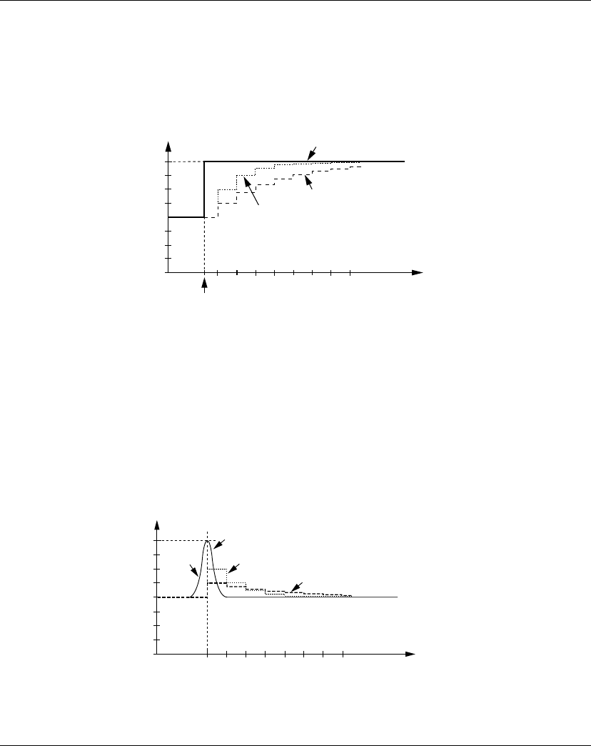
TM5 Compact I/O Modules
EIO0000000420 04/2012 65
Example 1: The input value makes a jump from 8,000 to 16,000. The diagram
displays the evaluated value with the following settings:
Input ramp limitation = 0
Filter level = 2 or 4
1 Input value
2 Evaluated value: Filter level 2
3 Evaluated value: Filter level 4
4 Input jump
Example 2: A disturbance is imposed on the input value. The diagram shows the
evaluated value with the following settings:
Input ramp limitation = 0
Filter level = 2 or 4
1 Input value.
2 Evaluated value: Filter level 2
3 Evaluated value: Filter level 4
4 Disturbance (Spike)
W>PV@
W>PV@
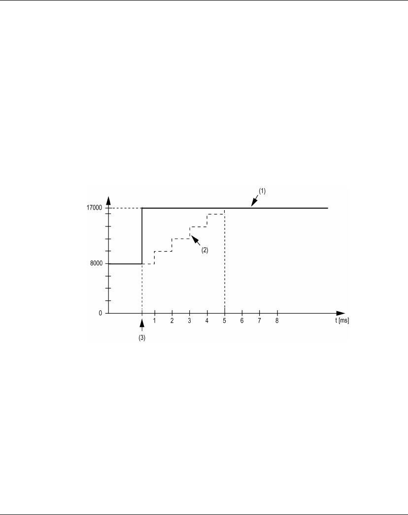
TM5 Compact I/O Modules
66 EIO0000000420 04/2012
Input Ramp Limitation
Input ramp limitation can only take place when a filter is used. Input ramp limitation
is executed before filtering takes place.
The amount of the change in the input value is checked to make sure the specified
limits are not exceeded. If the values are exceeded, the adjusted input value is equal
to the old value ± the limit value.
The input ramp limitation is well suited for suppressing disturbances (spikes). The
following examples show the function of the input ramp limitation based on an input
jump and a disturbance.
Example 1: The input value makes a jump from 8,000 to 17,000. The diagram
displays the adjusted input value for the following settings:
Input ramp limitation = 2047
Filter level = 2
1 Input value
2 Internal adjusted input value before filter
3 Input jump
Example 2: A disturbance is imposed on the input value. The diagram shows the
adjusted input value with the following settings:
Input ramp limitation = 2047
Filter level = 2
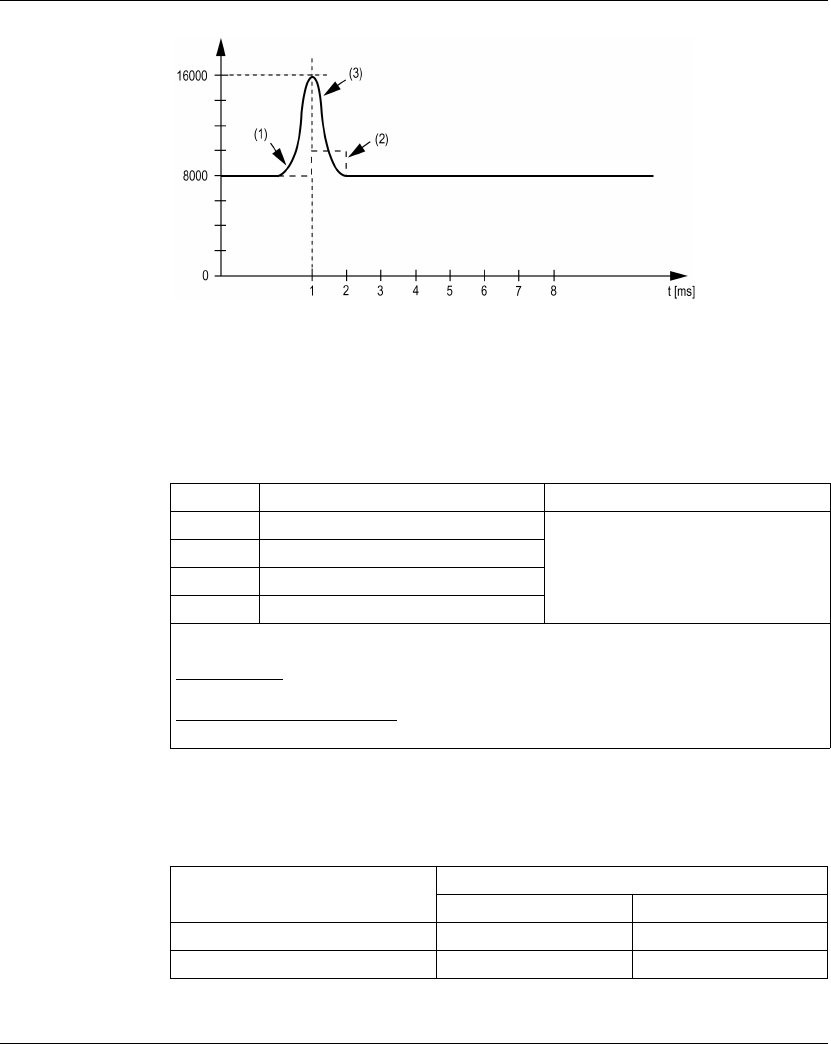
TM5 Compact I/O Modules
EIO0000000420 04/2012 67
1 Input value
2 Internal adjusted input value before filter
3 Disturbance (Spike)
Status Input Register
The Posx_StatusInput (where x is the analog input electronic module position) byte
describes the status of each input channel:
Cycle Time and I/O Update Time
The table below gives the module characteristics allowing the TM5 Bus Cycle Time
configuration:
For further information, refer to TM5 Manager Configuration (see page 18).
Bit Description Bits value
0-1 Channel 00 status 00: No detected error
01: Below lower limit value1
10: Above upper limit value
11: Wire break
2-3 Channel 01 status
4-5 Channel 02 status
6-7 Channel 03 status
1
Current signal 0...20 mA
Default setting: The input value has a lower limit. Underflow monitoring is, therefore, not
necessary.
After lower limit value changes: The input value is limited to the set value. The status bit is
set when the lower limit value is passed.
Characteristic Value (μs)
Without filter With filter
Minimum cycle time 100 500
Minimum I/O update time 300 1000
TM5 Compact I/O Modules
68 EIO0000000420 04/2012
Analog Output 4AO ±10 V
Overview
The Analog Output 4AO ±10 V electronic module is equipped with 4 12-bit outputs.
For further information, refer to the description of this electronic module in the
Compact I/O Modules Hardware Guide (see Modicon TM5, Compact I/O Modules,
Hardware Guide).
I/O Configuration
No parameter settings are required in the I/O Configuration tab for the Analog
Output 4AO ±10 V electronic module.
Cycle Time and I/O Update Time
The table gives the module characteristics allowing the TM5 Bus Cycle Time
configuration:
For further information, refer to TM5 Manager Configuration (see page 18).
Characteristic Value (μs)
Minimum cycle time 250
Minimum I/O update time < 300

TM5 Compact I/O Modules
EIO0000000420 04/2012 69
Analog Output 4AO 0-20 mA
Overview
The Analog Output 4AO 0-20 mA electronic module is equipped with 4 12-bit
outputs.
For further information, refer to the description of this electronic module in the
Compact I/O Modules Hardware Guide (see Modicon TM5, Compact I/O Modules,
Hardware Guide).
I/O Configuration
No parameter settings are required in the I/O Configuration tab for the Analog
Output 4AO 0-20 mA electronic module.
Cycle Time and I/O Update Time
The table gives the module characteristics allowing the TM5 Bus Cycle Time
configuration:
For further information, refer to TM5 Manager Configuration (see page 18).
Characteristic Value (μs)
Minimum cycle time 250
Minimum I/O update time < 300

TM5 Compact I/O Modules
70 EIO0000000420 04/2012
Analog Output 2AO ±10 V / 0-20 mA
Overview
The Analog Output 2AO ±10 V / 0-20 mA electronic module is equipped with 2 12-
bit outputs.
For further information, refer to the description of this electronic module in the
Compact I/O Modules Hardware Guide (see Modicon TM5, Compact I/O Modules,
Hardware Guide).
I/O Configuration
The table below describes the 2AO ±10 V / 0-20 mA electronic module parameters
configuration:
Cycle Time and I/O Update Time
The table below gives the module characteristics allowing the TM5 Bus Cycle Time
configuration:
For further information, refer to TM5 Manager Configuration (see page 18).
Parameter Value Default Value Description
Channel 00 Channel type ± 10V
0 to 20mA
± 10V Specifies the channel
type.
Channel 01 Channel type ± 10V
0 to 20mA
± 10V Specifies the channel
type.
Characteristic Value (μs)
Minimum cycle time 250
Minimum I/O update time < 300
EIO0000000420 04/2012 71
3
Modicon TM5
TM5 Digital I/O Electronic Modules
EIO0000000420 04/2012
TM5 Digital I/O Electronic Modules
Introduction
This chapter provides information to configure digital I/O expansion electronic
modules.
To add expansion electronic modules, and to access the configuration screens,
refer to Adding an expansion electronic module (see page 21).
What’s in this Chapter?
This chapter contains the following topics:
Topic Page
TM5SDI2D, TM5SDI4D and TM5SDI6D 72
TM5SDI2A, TM5SDI4A and TM5SDI6U 75
TM5SDI12D 77
TM5SDO2T, TM5SDO4T, TM5SDO6T and TM5SDO12T 80
TM5SDO4TA and TM5SDO8TA 83
TM5SDO2R and TM5SDO4R 86
TM5SDO2S 88
TM5SDM12DT 90
TM5SMM6D2L 92

TM5 Digital I/O Electronic Modules
72 EIO0000000420 04/2012
TM5SDI2D, TM5SDI4D and TM5SDI6D
Introduction
The TM5SDI2D, TM5SDI4D and TM5SDI6D expansion electronic modules are
24 Vdc Digital Input electronic modules with 2, 4 and 6 inputs respectively.
For further information, refer to the Hardware Guide:
I/O Configuration Tab
To configure the TM5SDI2D, TM5SDI4D and TM5SDI6D electronic modules, select
the I/O configuration tab.
The table below describes the modules parameters configuration:
Reference Refer to
TM5SDI2D TM5SDI2D Electronic Module 2DI 24 Vdc Sink 3 Wires (see Modicon TM5,
Digital I/O Modules, Hardware Guide)
TM5SDI4D TM5SDI4D Electronic Module 4DI 24 Vdc Sink 3 Wires (see Modicon TM5,
Digital I/O Modules, Hardware Guide)
TM5SDI6D TM5SDI6D Electronic Module 6DI 24 Vdc Sink 2 Wires (see Modicon TM5,
Digital I/O Modules, Hardware Guide)
Parameter Value Default Value Unit Description
Module address 0...250 Depends on the
configuration
- The address is
automatically set
when adding the
modules. The
address value
depends on the
order of adding the
module in the
SoMachine tree. The
TM5ACBM15
supports the
possibility to change
the address.
Input filter 0...250 10 (1 ms) 0.1 ms Specifies the filter
time of all digital
inputs in the range
0...250 (0...25 ms).
Bus base TM5ACBM15
TM5ACBM11
TM5ACBM11 - Specifies the bus
base associated with
the electronic
module.
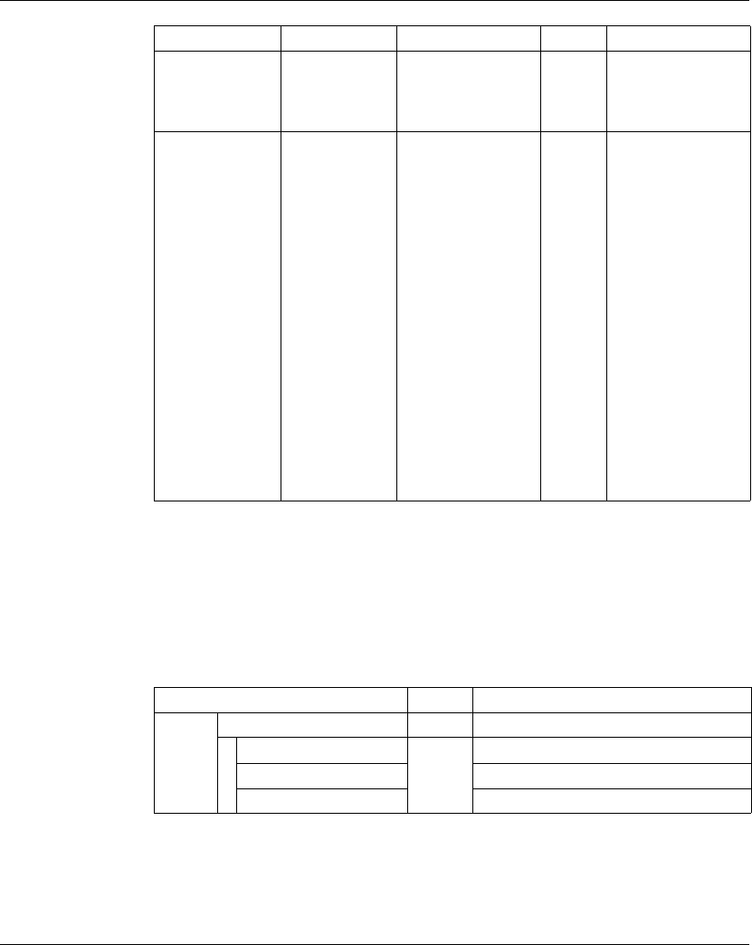
TM5 Digital I/O Electronic Modules
EIO0000000420 04/2012 73
For further generic descriptions, refer to I/O Configuration Tab Description
(see page 22).
Expansion Bus I/O Mapping Tab
Variables can be defined and named in the Expansion Bus I/O Mapping tab.
Additional information such as topological addressing is also provided in this tab.
The table below describes the Expansion Bus I/O Mapping configuration:
* The number of DigitalInput bit is equal to the module input number.
For further generic descriptions, refer to Expansion Bus I/O Mapping Tab
Description (see page 22).
Terminal block TM5ACTB06
(not for
TM5SDI4D)
TM5ACTB12
TM5ACTB06
(TM5ACTB12 for
TM5SDI4D)
- Specifies the
terminal block
associated with the
electronic module.
24 V I/O segment
external current
(Only for
TM5SDI2D and
TM5SDI4D)
0...500 100 mA (for
TM5SDI2D)
200 mA (for
TM5SDI4D)
- Current derived from
the 24 Vdc I/O power
segment to supply
the sensors
connected to the
module. This value is
used to balance
current consumption
on the 24Vdc I/O
power segment
(see Modicon
TM5 / TM7 Flexible
System, System
Planning and
Installation Guide).
This value is used
exclusively in the
calculation of the
Check Resources
function.
Parameter Value Default Value Unit Description
Channel Type Description
Inputs DigitalInputs USINT State of all inputs (bits 6-7 = 0, not used)
DigitalInput00 BOOL State of input 0
... ...
DigitalInput05 * State of input 5

TM5 Digital I/O Electronic Modules
74 EIO0000000420 04/2012
Cycle Time and I/O Update Time
The table below gives the module characteristics allowing the TM5 Bus Cycle Time
configuration:
For further information, refer to TM5 Manager Configuration (see page 18).
Characteristic Value (μs)
Without filter With filter
Minimum cycle time 100 150
Minimum I/O update time 100 200

TM5 Digital I/O Electronic Modules
EIO0000000420 04/2012 75
TM5SDI2A, TM5SDI4A and TM5SDI6U
Introduction
The TM5SDI2A, TM5SDI4A and TM5SDI6U expansion electronic modules are 100-
240 Vac Input electronic modules with 2, 4 and 6 inputs respectively.
For further information, refer to the Hardware Guide:
I/O Configuration Tab
To configure the TM5SDI2A, TM5SDI4A and TM5SDI6U electronic modules, select
the I/O configuration tab.
The table below describes the modules parameters configuration:
For further generic descriptions, refer to I/O Configuration Tab Description
(see page 22).
Reference Refer to
TM5SDI2A TM5SDI2A Electronic Module 2DI 100 ... 240 Vac 3 Wires (see Modicon
TM5, Digital I/O Modules, Hardware Guide)
TM5SDI4A TM5SDI4A Electronic Module 4DI 100 ... 240 Vac 2 Wires (see Modicon
TM5, Digital I/O Modules, Hardware Guide)
TM5SDI6U TM5SDI6U Electronic Module 6DI 100 ... 120 Vac 1 Wire (see Modicon
TM5, Digital I/O Modules, Hardware Guide)
Parameter Value Default Value Unit Description
Input filter 0...250 10 ( 1 ms) 0.1 ms Specifies the filter time of
all digital inputs in the
range 0...250 (0...25 ms).
Bus base TM5ACBM12 TM5ACBM12 - Specifies the bus base
associated with the
electronic module.
Terminal block TM5ACTB32 TM5ACTB32 - Specifies the terminal
block associated with the
electronic module.
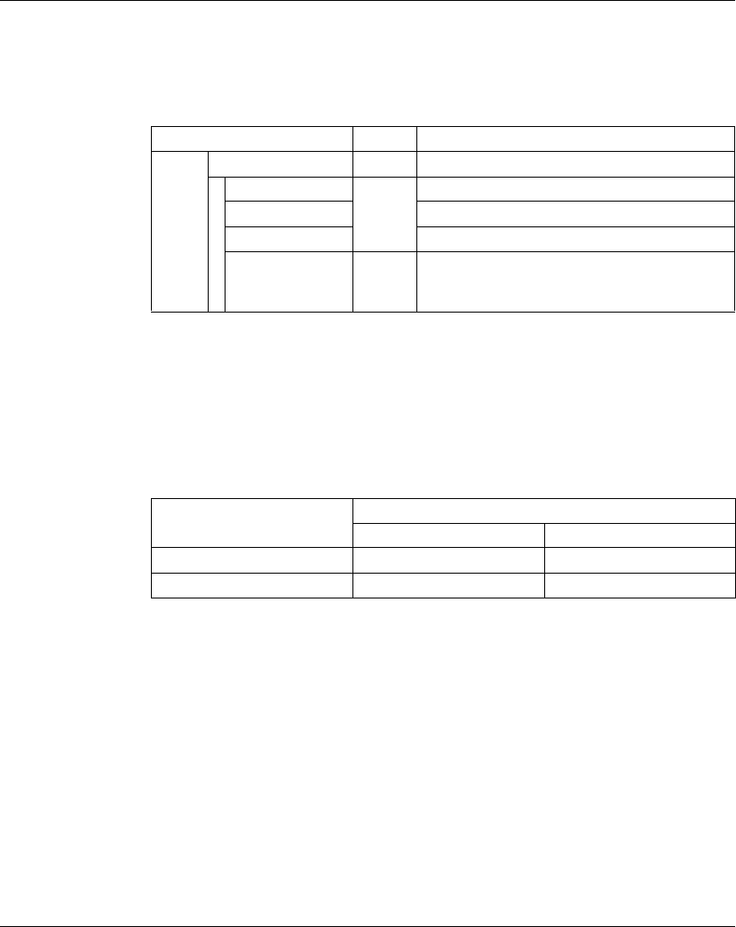
TM5 Digital I/O Electronic Modules
76 EIO0000000420 04/2012
Expansion Bus I/O Mapping Tab
Variables can be defined and named in the I/O Configuration tab. Additional
information such as topological addressing is also provided in this tab.
The table below describes the Expansion Bus I/O Mapping configuration:
* The number of DigitalInput bit is equal to the module input number.
For further generic descriptions, refer to Expansion Bus I/O Mapping Tab
Description (see page 22).
Cycle Time and I/O Update Time
The table below gives the module characteristics allowing the TM5 Bus Cycle Time
configuration:
For further information, refer to TM5 Manager Configuration (see page 18).
Channel Type Description
Inputs DigitalInputs USINT State of all inputs
DigitalInput00 BOOL State of input 0
... ...
DigitalInput05 * State of input 5
PowerSupply BOOL Status bit associated to external power supply:
z0: no AC external power supply or < 85 Vac
z1: AC external power supply OK
Characteristic Value (μs)
Without filter With filter
Minimum cycle time 100 150
Minimum I/O update time 100 200

TM5 Digital I/O Electronic Modules
EIO0000000420 04/2012 77
TM5SDI12D
Introduction
The TM5SDI12D expansion electronic module is a 24 Vdc Digital Inputs electronic
module with 12 inputs.
For further information, refer to TM5SDI12D Electronic Module 12DI 24 Vdc Sink 1
Wire (see Modicon TM5, Digital I/O Modules, Hardware Guide).
I/O Configuration Tab
To configure the TM5SDI12D electronic module, select the I/O Configuration tab.
The table below describes the modules parameters configuration:
Parameter Value Default Value Unit Description
Module address 0...250 Depends on the
configuration
- The address is
automatically set when
adding the modules. The
address value depends
on the order of adding
the module in the
SoMachine tree. The
TM5ACBM15 supports
the possibility to change
the address.
Input filter 0...250 10 (1 ms) 0.1 ms Specifies the filter time
of all digital inputs in the
range 0...250
(0...25 ms).
Bus base TM5ACBM15
TM5ACBM11
TM5ACBM11 - Specifies the bus base
associated with the
electronic module.
Terminal block TM5ACTB12 TM5ACTB12 - Specifies the terminal
block associated with
the electronic module.
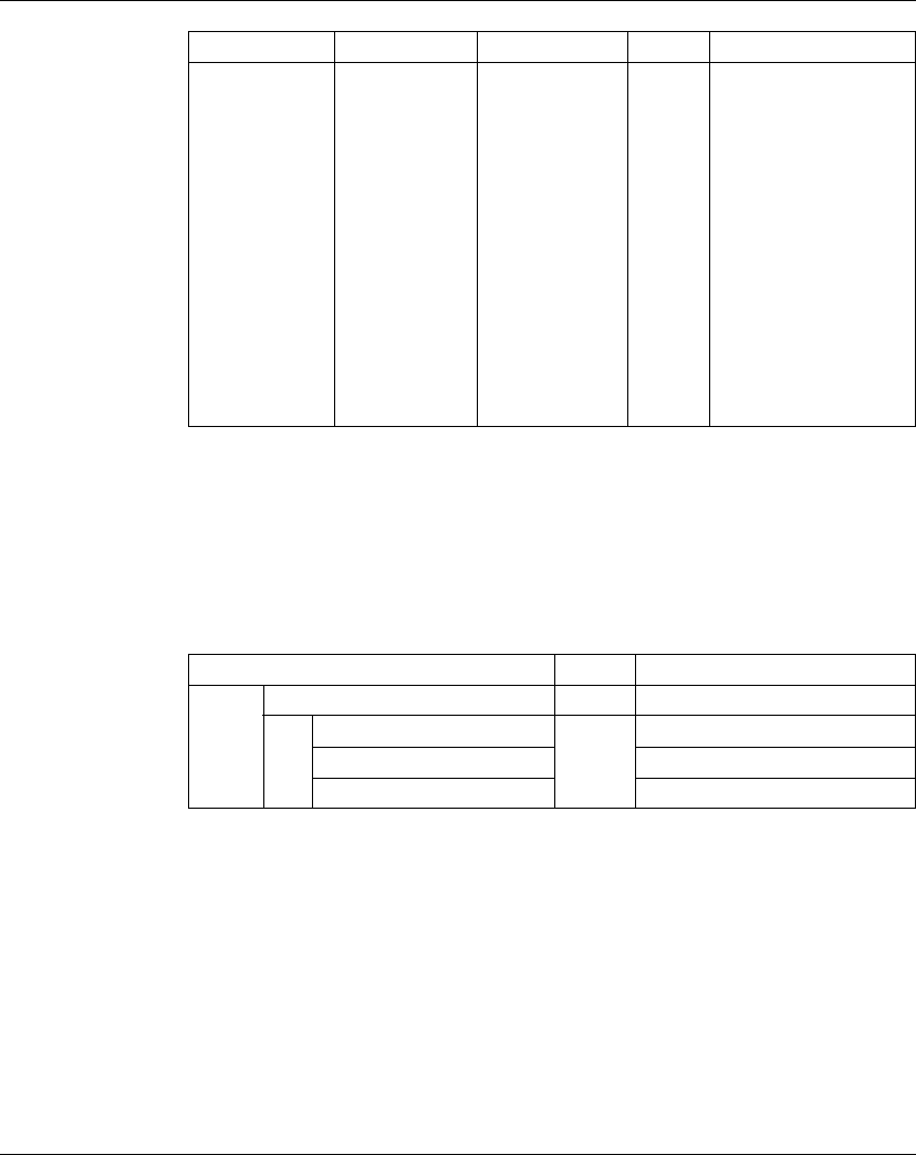
TM5 Digital I/O Electronic Modules
78 EIO0000000420 04/2012
For further generic descriptions, refer to I/O Configuration Tab Description
(see page 22).
Expansion Bus I/O Mapping Tab
Variables can be defined and named in the Expansion Bus I/O Mapping tab.
Additional information such as topological addressing is also provided in this tab.
The table below describes the Expansion Bus I/O Mapping configuration:
For further generic descriptions, refer to Expansion Bus I/O Mapping Tab
Description (see page 22).
24 V I/O
segment
external current
0...500 100 mA - Current derived from the
24 Vdc I/O power
segment to supply the
sensors connected to
the module. This value is
used to balance current
consumption on the
24Vdc I/O power
segment (see Modicon
TM5 / TM7 Flexible
System, System
Planning and Installation
Guide). This value is
used exclusively in the
calculation of the Check
Resources function.
Parameter Value Default Value Unit Description
Channel Type Description
Inputs DigitalInputs USINT State of all inputs
DigitalInput00 BOOL State of input 0
... ...
DigitalInput11 State of input 11

TM5 Digital I/O Electronic Modules
EIO0000000420 04/2012 79
Cycle Time and I/O Update Time
The table below gives the module characteristics allowing the TM5 Bus Cycle TIme
configuration:
For further information, refer to TM5 Manager Configuration (see page 18).
Characteristic Value (μs)
Without filter With filter
Minimum cycle time 100 150
Minimum I/O update time 100 200

TM5 Digital I/O Electronic Modules
80 EIO0000000420 04/2012
TM5SDO2T, TM5SDO4T, TM5SDO6T and TM5SDO12T
Introduction
The TM5SDO2T, TM5SDO4T, TM5SDO6T and TM5SDO12T expansion electronic
modules are 24 Vdc Digital Outputs electronic modules with 2, 4, 6 or 12 outputs
respectively.
For further information, refer to the Hardware Guide:
I/O Configuration Tab
To configure the TM5SDO2T, TM5SDO4T, TM5SDO6T and TM5SDO12T
electronic modules, select the I/O Configuration tab.
The table below describes the modules parameters configuration:
Reference Refer to
TM5SDO2T TM5SDO2T Electronic Module 2DO 24 Vdc Tr 0.5 A 3 Wires (see Modicon
TM5, Digital I/O Modules, Hardware Guide)
TM5SDO4T TM5SDO4T Electronic Module 4DO 24 Vdc Tr 0.5 A 3 wires (see Modicon
TM5, Digital I/O Modules, Hardware Guide)
TM5SDO6T TM5SDO6T Electronic Module 6DO 24 Vdc Tr 0.5 A 2 wires (see Modicon
TM5, Digital I/O Modules, Hardware Guide)
TM5SDO12T TM5SDO12T Electronic Module 12DO 24 Vdc Tr 0.5 A 1 wire
(see Modicon TM5, Digital I/O Modules, Hardware Guide)
Parameter Value Default Value Description
Module
address
0...250 Depends on the
configuration
The address is automatically set when
adding the modules. The address
value depends on the order of adding
the module in the SoMachine tree.
The TM5ACBM15 supports the
possibility to change the address.
Output
status
information
On
Off
On Enable/Disable read of the output
status.
On: the StatusDigitalOutputs word is
added to the Expansion Bus I/O
Mapping tab.
Bus base TM5ACBM15
TM5ACBM11
TM5ACBM11 Specifies the bus base associated
with the electronic module.
Terminal
block
TM5ACTB06
TM5ACTB12
TM5ACTB06
TM5ACTB12
(for TM5SDO6T
and TM5SDO12T)
Specifies the terminal block
associated with the electronic module.
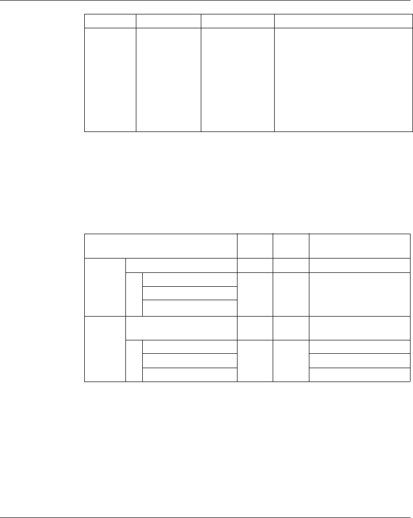
TM5 Digital I/O Electronic Modules
EIO0000000420 04/2012 81
For further generic descriptions, refer to I/O Configuration Tab Description
(see page 22).
Expansion Bus I/O Mapping Tab
Variables can be defined and named in the Expansion Bus I/O Mapping tab.
Additional information such as topological addressing is also provided in this tab.
The table below describes the Expansion Bus I/O Mapping configuration:
* The number of DigitalOuput bit is equal to the module output number.
For further generic descriptions, refer to Expansion Bus I/O Mapping Tab
Description (see page 22).
24 V I/O
segment
external
current
0...1500 700 mA Current derived from the 24 Vdc I/O
power segment to supply the sensors
connected to the module. This value is
used to balance current consumption
on the 24Vdc I/O power segment
(see Modicon TM5 / TM7 Flexible
System, System Planning and
Installation Guide). This value is used
exclusively in the calculation of the
Check Resources function.
Parameter Value Default Value Description
Channel Type Default
value
Description
Inputs StatusDigitalOutputs USINT - Status word of all outputs
StatusDigitalOutput00 BOOL - Status bit associated to
each output:
z0: Ok
z1: detected error
...
StatusDigitalOutput11 *
Outputs DigitalOuputs USINT - Command word of all
outputs
DigitalOuput00 BOOL None
TRUE
FALSE
Command bit of output 0
... ...
DigitalOuput11 * Command bit of output 11

TM5 Digital I/O Electronic Modules
82 EIO0000000420 04/2012
Cycle Time and I/O Update Time
The table below gives the module characteristics allowing the TM5 Bus Cycle Time
configuration:
For further information, refer to TM5 Manager Configuration (see page 18).
Characteristic Value (μs)
Minimum cycle time 100
Minimum I/O update time 100

TM5 Digital I/O Electronic Modules
EIO0000000420 04/2012 83
TM5SDO4TA and TM5SDO8TA
Introduction
The TM5SDO4TA and TM5SDO8TA expansion electronic modules are 24 Vdc
Digital Output electronic modules with 4 and 8 outputs respectively.
For further information, refer to the Hardware Guide:
I/O Configuration Tab
To configure the TM5SDO4TA and TM5SDO8TA electronic modules, select the I/O
Configuration tab.
The table below describes the modules parameters configuration:
Reference Refer to
TM5SDO4TA TM5SDO4TA Electronic Module 4DO 24 Vdc Tr 2 A 3 Wires (see Modicon
TM5, Digital I/O Modules, Hardware Guide)
TM5SDO8TA TM5SDO8TA Electronic Module 8DO 24 Vdc Tr 2 A 1 Wire (see Modicon
TM5, Digital I/O Modules, Hardware Guide)
Parameter Value Default Value Description
Module address 0...250 Depends on the
configuration
The address is automatically set when
adding the modules. The address
value depends on the order of adding
the module in the SoMachine tree. The
TM5ACBM15 supports the possibility
to change the address.
Output status
information
On
Off
On Enable/Disable read of the output
status.
On: the StatusDigitalOutputs word is
added to the Expansion Bus I/O
Mapping tab
Bus base TM5ACBM15
TM5ACBM11
TM5ACBM11 Specifies the bus base associated with
the electronic module.
Terminal block TM5ACTB12 TM5ACTB12 Specifies the terminal block associated
with the electronic module.
Power supply
(Only for
TM5SDO8TA)
On
Off
Off Enable/Disable read of the power
supply status.
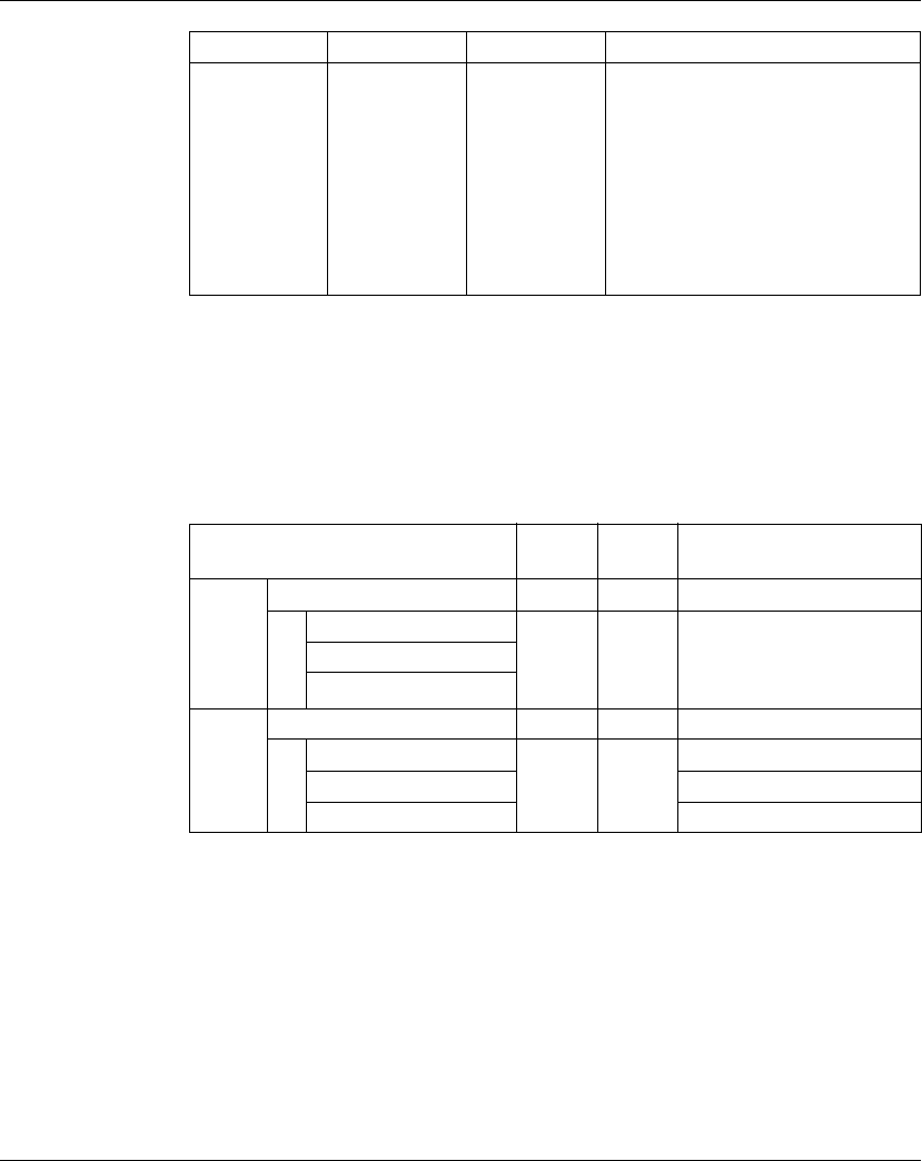
TM5 Digital I/O Electronic Modules
84 EIO0000000420 04/2012
For further generic descriptions, refer to I/O Configuration Tab Description
(see page 22).
Expansion Bus I/O Mapping Tab
Variables can be defined and named in the Expansion Bus I/O Mapping tab.
Additional information such as topological addressing is also provided in this tab.
The table below describes the Expansion Bus I/O Mapping configuration:
* The number of DigitalOuput bit is equal to the module output number.
For further generic descriptions, refer to Expansion Bus I/O Mapping Tab
Description (see page 22).
24 V I/O
segment
external current
(Only for
TM5SDO4TA)
0...4500 2200 mA Current derived from the 24 Vdc I/O
power segment to supply the sensors
connected to the module. This value is
used to balance current consumption
on the 24Vdc I/O power segment
(see Modicon TM5 / TM7 Flexible
System, System Planning and
Installation Guide). This value is used
exclusively in the calculation of the
Check Resources function.
Parameter Value Default Value Description
Channel Type Default
value
Description
Inputs StatusDigitalOutputs USINT - Status word of all outputs
StatusDigitalOutput00 BOOL - Status bit associated to each
output:
z0: Ok
z1: detected error
...
StatusDigitalOutput07 *
Outputs DigitalOuputs USINT - Command word of all outputs
DigitalOuput00 BOOL None
TRUE
FALSE
Command bit of output 0
... ...
DigitalOuput07 * Command bit of output 7

TM5 Digital I/O Electronic Modules
EIO0000000420 04/2012 85
Cycle Time and I/O Update Time
The table below gives the module characteristics allowing the TM5 Bus Cycle Time
configuration:
For further information, refer to TM5 Manager Configuration (see page 18).
Characteristic Value (μs)
Minimum cycle time 100
Minimum I/O update time 100

TM5 Digital I/O Electronic Modules
86 EIO0000000420 04/2012
TM5SDO2R and TM5SDO4R
Introduction
The TM5SDO2R and TM5SDO4R expansion electronic modules are 30 Vdc Digital
Outputs electronic modules with 2 and 4 outputs respectively.
For further information, refer to the Hardware Guide:
I/O Configuration Tab
To configure the TM5SDO2R and TM5SDO4R electronic modules, select the I/O
Configuration tab.
The table below describes the modules parameters configuration:
For further generic descriptions, refer to I/O Configuration Tab Description
(see page 22).
Reference Refer to
TM5SDO2R TM5SDO2R Electronic Module 2DO 30 Vdc/230 Vac 5A Relay C/O
(see Modicon TM5, Digital I/O Modules, Hardware Guide)
TM5SDO4R TM5SDO4R Electronic Module 4DO 30 Vdc / 230 Vac 5 A Relay N/O
(see Modicon TM5, Digital I/O Modules, Hardware Guide)
Parameter Value Default Value Description
Module
address
0...250 Depends on the
configuration
The address is automatically set when
adding the modules. The address value
depends on the order of adding the
module in the SoMachine tree. The
TM5ACBM15 supports the possibility to
change the address.
Bus base TM5ACBM15
TM5ACBM11
TM5ACBM11 Specifies the bus base associated with
the electronic module.
Terminal
block
TM5ACTB12 TM5ACTB12 Specifies the terminal block associated
with the electronic module.
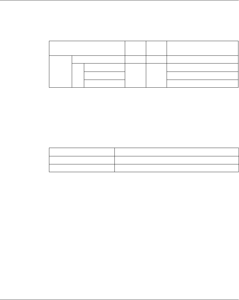
TM5 Digital I/O Electronic Modules
EIO0000000420 04/2012 87
Expansion Bus I/O Mapping Tab
Variables can be defined and named in the Expansion Bus I/O Mapping tab.
Additional information such as topological addressing is also provided in this tab.
The table below describes the Expansion Bus I/O Mapping configuration:
* The number of DigitalOuput bit is equal to the module output number.
For further generic descriptions, refer to Expansion Bus I/O Mapping Tab
Description (see page 22).
Cycle Time and I/O Update Time
The table below gives the module characteristics allowing the TM5 Bus Cycle Time
configuration:
For further information, refer to TM5 Manager Configuration (see page 18).
Channel Type Default
value
Description
Outputs DigitalOuputs USINT - Command word of all outputs
DigitalOuput00 BOOL None
TRUE
FALSE
Command bit of output 0
... ...
DigitalOuput07 * Command bit of output 7
Characteristic Value (μs)
Minimum cycle time 100
Minimum I/O update time 100

TM5 Digital I/O Electronic Modules
88 EIO0000000420 04/2012
TM5SDO2S
Introduction
The TM5SDO2S expansion electronic module is a 240 Vac Digital Outputs
electronic module with 2 outputs.
For further information, refer to TM5SDO2S Electronic Module 2DO 240 Vac 1 A
3 wires (see Modicon TM5, Digital I/O Modules, Hardware Guide).
I/O Configuration Tab
To configure the TM5SDO2S electronic module, select the I/O Configuration tab.
The table below describes the modules parameters configuration:
For further generic descriptions, refer to I/O Configuration Tab Description
(see page 22).
Parameter Value Default Value Description
Module address 0...250 Depends on the
configuration
The address is automatically set when
adding the modules. The address
value depends on the order of adding
the module in the SoMachine tree.
Bus base TM5ACBM12 TM5ACBM12 Specifies the bus base associated with
the electronic module.
Terminal block TM5ACTB32 TM5ACTB32 Specifies the terminal block associated
with the electronic module.
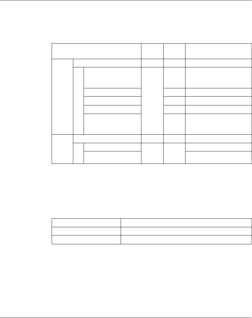
TM5 Digital I/O Electronic Modules
EIO0000000420 04/2012 89
Expansion Bus I/O Mapping Tab
Variables can be defined and named in the Expansion Bus I/O Mapping tab.
Additional information such as topological addressing is also provided in this tab.
The table below describes the Expansion Bus I/O Mapping configuration:
For further generic descriptions, refer to Expansion Bus I/O Mapping Tab
Description (see page 22).
Cycle Time and I/O Update Time
The table below gives the module characteristics allowing the TM5 Bus Cycle Time
configuration:
For further information, refer to TM5 Manager Configuration (see page 18).
Channel Type Default
value
Description
Inputs ZeroCrossing USINT – Status zero crossing
ZeroCrossingInput BOOL – Zero cross detection signal:
z0: negative half wave
z1: positive half wave
Not used – –
Not used – –
Not used – –
ZeroCrossingStatus – Status zero cross detection:
z0: Ok
z1: detected error
Outputs DigitalOuputs USINT – Command word of all outputs
DigitalOuput00 BOOL None
TRUE
FALSE
Command bit of output 0
DigitalOuput01 Command bit of output 1
Characteristic Value (μs)
Minimum cycle time 100
Minimum I/O update time 100

TM5 Digital I/O Electronic Modules
90 EIO0000000420 04/2012
TM5SDM12DT
Introduction
The TM5SDM12DT expansion electronic module is a 24 Vdc Digital Inputs
electronic module with 8 inputs and 4 outputs.
For further information, refer to TM5SDM12DT Electronic Module 8DI/4DO Tr 1 Wire
(see Modicon TM5, Digital I/O Modules, Hardware Guide).
I/O Configuration Tab
To configure the TM5SDM12DT electronic module, select the I/O configuration
tab.
The table below describes the modules parameters configuration:
For further generic descriptions, refer to I/O Configuration Tab Description
(see page 22).
Parameter Value Default Value Unit Description
Module address 0...250 Depends on the
configuration
- The address is
automatically set when
adding the modules. The
address value depends
on the order of adding the
module in the SoMachine
tree. The TM5ACBM15
supports the possibility to
change the address.
Input filter 0...250 10 (1 ms) 0.1 ms Specifies the filter time of
all digital inputs in the
range 0...250 (0...25 ms).
Output status
information
On
Off
On - Enable/Disable read of
the output status.
On: the
StatusDigitalOutputs
word is added to the
Expansion Bus I/O
Mapping tab.
Bus base TM5ACBM11
TM5ACBM15
TM5ACBM11 - Specifies the bus base
associated with the
electronic module.
Terminal block TM5ACTB12 TM5ACTB12 - Specifies the terminal
block associated with the
electronic module.
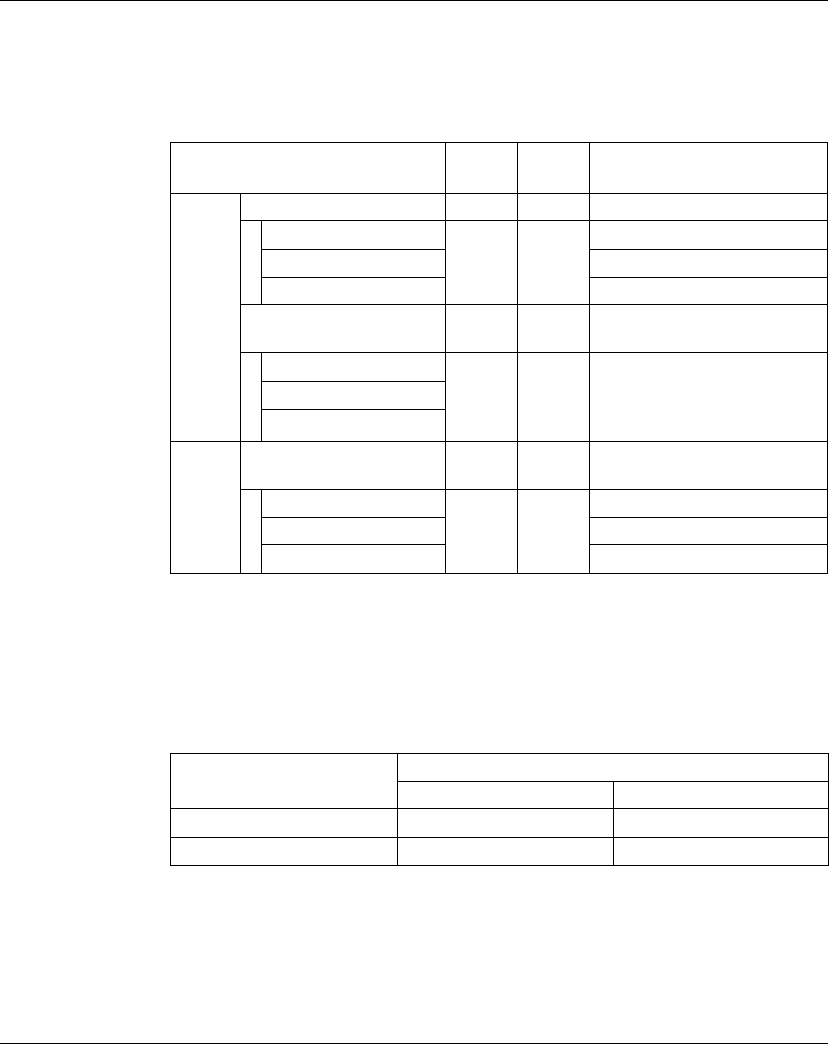
TM5 Digital I/O Electronic Modules
EIO0000000420 04/2012 91
Expansion Bus I/O Mapping Tab
Variables can be defined and named in the Expansion Bus I/O Mapping tab.
Additional information such as topological addressing is also provided in this tab.
The table below describes the Expansion Bus I/O Mapping configuration:
For further generic descriptions, refer to Expansion Bus I/O Mapping Tab
Description (see page 22).
Cycle Time and I/O Update Time
The table below gives the module characteristics allowing the TM5 Bus Cycle Time
configuration:
For further information, refer to TM5 Manager Configuration (see page 18).
Channel Type Default
value
Description
Inputs DigitalInputs USINT - State of all inputs
DigitalInput00 BOOL - State of input 0
...
DigitalInput07 State of input 7
StatusDigitalOutputs USINT - Status word of all outputs (bits
4...7: not used)
StatusDigitalOutput00 BOOL - Status bit associated to each
output:
z0: Ok
z1: detected error
...
StatusDigitalOutput03
Outputs DigitalOuputs USINT - Command word of all outputs
(bits 4...7: not used)
DigitalOuput00 BOOL None
TRUE
FALSE
Command bit of output 0
... ...
DigitalOuput03 Command bit of output 3
Characteristic Value (μs)
Without filter With filter
Minimum cycle time 100 150
Minimum I/O update time 100 200

TM5 Digital I/O Electronic Modules
92 EIO0000000420 04/2012
TM5SMM6D2L
Introduction
The TM5SMM6D2L expansion electronic modules is a mixed module with 4 digital
inputs, 2 digital outputs, 1 analog input, and 1 analog output.
If you have wired your input for a voltage measurement, and you configure
SoMachine for a current type of configuration, you may permanently damage the
electronic module.
For further information, refer to TM5SMM6D2L Electronic Module 4DI/2DO 24Vdc
Tr 0.5A / 1AI/1AO ±10V/0-20mA 12 Bits 1 Wire (see Modicon TM5, Digital I/O
Modules, Hardware Guide).
I/O Configuration Tab
To configure the TM5SMM6D2L electronic module, select the I/O Configuration
tab.
The table describes the modules parameters configuration:
NOTICE
INOPERABLE EQUIPMENT
Be sure that the physical wiring of the module is compatible with the software
configuration for the module.
Failure to follow these instructions can result in equipment damage.
Parameter Value Default Value Description
General Module address 0...250 0 The address is automatically set when adding
the modules. The address value depends on
the order of adding the module in the
SoMachine tree. The TM5ACBM15 supports
the possibility to change the address.
Bus base TM5ACBM11
TM5ACBM15
TM5ACBM11 Specifies the bus base associated with the
electronic module.
Terminal block TM5ACTB12 TM5ACTB12 Specifies the terminal block associated with the
electronic module.
Digital
Inputs
Input filter 0...250 10 Specifies the filter time of all digital inputs in the
range 0...250 (0...25 ms).
Input latch on
off
off This parameter allows to activate (when value
is on) or deactivate (when value is off) the input
latch.

TM5 Digital I/O Electronic Modules
EIO0000000420 04/2012 93
For further generic descriptions, refer to I/O Configuration Tab Description
(see page 22).
Analog Inputs
The input status is registered with a fixed offset with respect to the network cycle and
is transferred in the same cycle.
Input Cycle
The electronic module is equipped with a configurable Input cycle. Filtering is
deactivated for shorter cycle times.
If the Input cycle is active, then the channels are scanned in ms cycles. The time
offset between the channels is 200 µs. The conversion takes place asynchronously
to the network cycle. Refer to Cycle time and I/O update time (see page 99)
Analog
Inputs
Lower limit
(Minimum value)
-32768...32767 -32768 Specifies the lower measurement limit
(see page 94).
Upper limit
(Maximum
value)
-32768...32767 32767 Specifies the upper measurement limit
(see page 94).
Channel type ±10 V
0 to 20 mA
4 to 20 mA
±10 V Specifies the channel type.
Input filter off
level 2
level 4
level 8
level 16
level 32
level 64
level 128
off Definition of the filter level (see page 95).
Input limitation off
16383
8191
4095
2047
1023
511
255
off Specifies the limitation of input ramp
(see page 96).
NOTE: Parameter available if an input filter is
selected.
Digital
Outputs
Output status
information
on
off
on Enable/Disable read of the output status.
on: The StatusDigitalOutputs word is added
to the Expansion Bus I/O Mapping tab.
Analog
Outputs
Channel type ±10 V
0 to 20 mA
±10 V Specifies the channel type.
Parameter Value Default Value Description

TM5 Digital I/O Electronic Modules
94 EIO0000000420 04/2012
Limit Values
You can define 2 different types of limits:
zLower limit
zUpper limit
The Lower limit value range is between -32768 and 32767. This value is applied on
every channel of the module being configured.
NOTE: the Lower limit cannot be greater than the Upper limit.
The Upper limit value range is between -32768 and 32767. This value is applied on
every channel of the module being configured.
NOTE: The Upper limit value cannot be less than the Lower limit value.
Channel
Configuration
Digital Value
Behavior
Comments
± 10V -10 V = -32768
+10 V = +32767
If the Lower limit value is configured between -32768
and +32767, the digital value is limited to the Lower
limit value.
0...20 mA 0 mA = 0
20 mA = +32767
If the Lower limit value is configured between -32768
and 0, the digital value is limited to 0.
If the Lower limit value is configured between 0 and
32767, the digital value is limited to the Lower limit
value.
4...20 mA 0 mA = -8192
4mA = 0
20 mA = +32767
If the Lower limit is configured between -32768 and
-8192, the digital value is limited to -8192.
If the Lower limit is configured between -8192 and
32767, the digital value is limited to the Lower limit
value.
Channel
Configuration
Digital Value
Behavior
Comments
± 10V -10 V = -32768
+10 V = +32767
If the Upper limit value is configured between -32768
and +32767, the digital value is limited to the Upper
limit value.
0...20 mA 0 mA = 0
20 mA = +32767
If the Upper limit value is configured between -32768
and 0, the digital value stays at 0, hence, the Upper
limit value must be set to a positive value.
If the Upper limit value is configured between 1 and
+32767, the digital value is limited to the Upper limit
value.
4...20 mA 0 mA = -8192
4mA = 0
20 mA = +32767
If the Upper limit value is configured between -32768
and -8192, the digital value is limited to -8192.
If the Upper limit value is configured between -8192
and 32767, the digital value is limited to the Upper
limit value.

TM5 Digital I/O Electronic Modules
EIO0000000420 04/2012 95
Filter Level
The input value is evaluated according to the filter level. An input ramp limitation can
then be applied using this evaluation.
Formula for the evaluation of the input value:
The following examples show the function of the input ramp limitation based on an
input jump and a disturbance.
Example 1: The input value makes a jump from 8000 to 16000. The diagram
displays the evaluated value with the following settings:
Input ramp limitation = 0
Filter level = 2 or 4
1 Input value.
2 Evaluated value: Filter level 2
3 Evaluated value: Filter level 4
4 Input jump
old
new old
Inputvalue
Value
Value Value Filterlevel Filterlevel
W>PV@
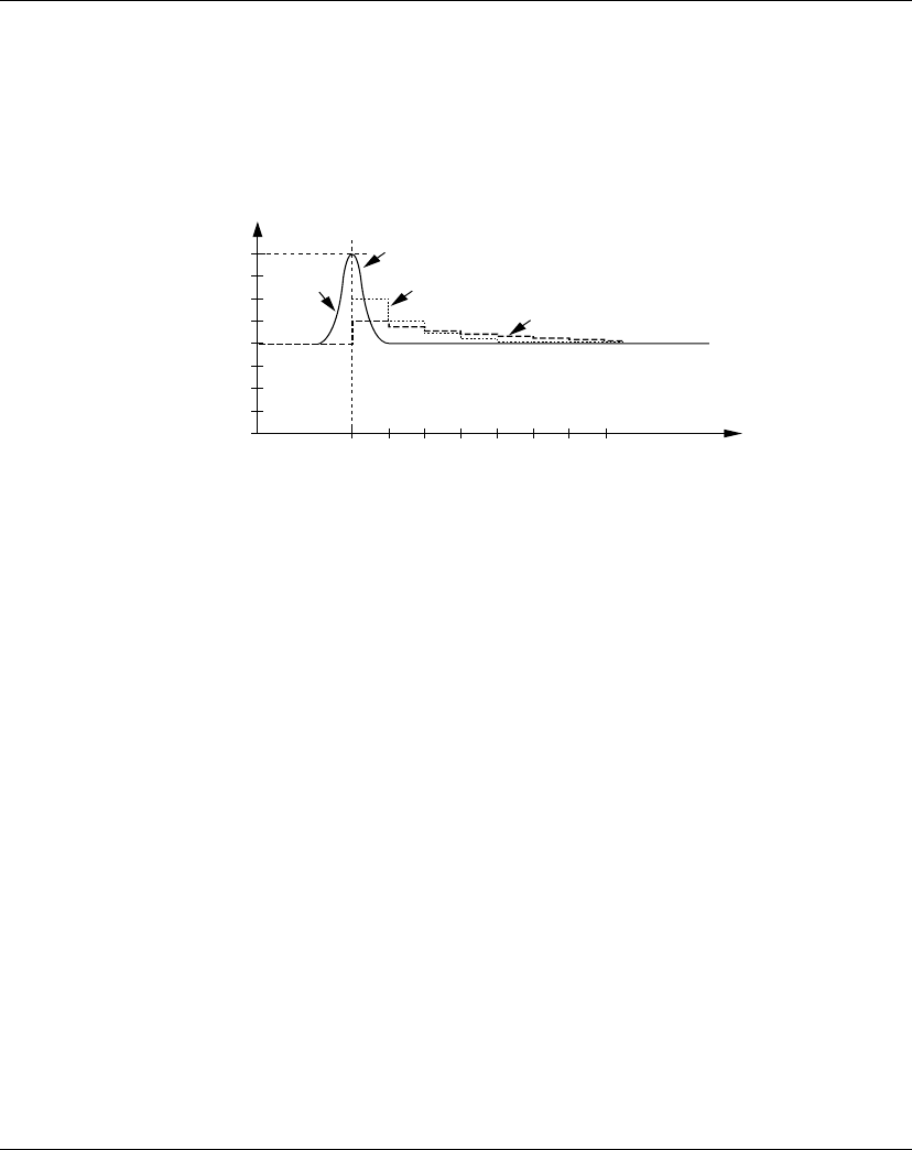
TM5 Digital I/O Electronic Modules
96 EIO0000000420 04/2012
Example 2: A disturbance is imposed on the input value. The diagram shows the
evaluated value with the following settings:
Input ramp limitation = 0
Filter level = 2 or 4
1 Input value
2 Evaluated value: Filter level 2
3 Evaluated value: Filter level 4
4 Disturbance (Spike)
Input Ramp Limitation
Input ramp limitation can only take place when a filter is used. Input ramp limitation
is executed before filtering takes place.
The amount of the change in the input value is checked to make sure the specified
limits are not exceeded. If the values are exceeded, the adjusted input value is equal
to the old value ± the limit value.
The input ramp limitation is well suited for suppressing disturbances (spikes). The
following examples show the function of the input ramp limitation based on an input
jump and a disturbance.
W>PV@

TM5 Digital I/O Electronic Modules
EIO0000000420 04/2012 97
Example 1: The input value makes a jump from 8,000 to 17,000. The diagram
displays the adjusted input value for the following settings:
Input ramp limitation = 2047
Filter level = 2
1 Input value
2 Internal adjusted input value before filter
3 Input jump
Example 2: A disturbance is imposed on the input value. The diagram shows the
adjusted input value with the following settings:
Input ramp limitation = 2047
Filter level = 2
1 Input value
2 Internal adjusted input value before filter
3 Disturbance (Spike)
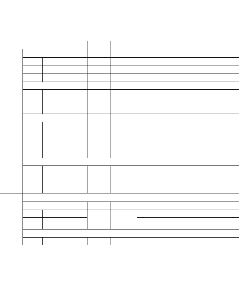
TM5 Digital I/O Electronic Modules
98 EIO0000000420 04/2012
Expansion Bus I/O Mapping Tab
Variables can be defined and named in the Expansion Bus I/O Mapping tab.
Additional information such as topological addressing is also provided in this tab.
The table describes the Expansion Bus I/O Mapping configuration:
For further generic descriptions, refer to Expansion Bus I/O Mapping Tab
Description (see page 22).
Channel Type Value Description
Inputs Digital Inputs USINT - State of all inputs.
DigitalInput00 BOOL - State of input 0.
... ...
DigitalInput03 State of input 3.
DigitalInputLatch USINT - Positive edge latched state of the inputs.
DigitalInput00Latch BOOL - Positive edge latched state of input 00.
... ...
DigitalInput03Latch Positive edge latched state of input 03.
DigitalInputLatchQuit USINT - Acknowledge latch state of the inputs.
DigitalInput00Latch
Quit
BOOL - Acknowledge latch state of input 00.
... ...
DigitalInput03Latch
Quit
Acknowledge latch state of input 03.
Analog Inputs
AnalogInput00 INT - Current value of the input 0.
StatusInput00 USINT - Status of analog input channel (see description in
the Status Input Register section of this chapter
(see page 99)).
Outputs Digital Outputs
DigitalOutputs USINT - Command word of the outputs.
DigitalOutput00 BOOL None
TRUE
FALSE
Command bit of output 0.
DigitalOutput01 Command bit of output 1.
Analog Outputs
AnalogOutput00 INT - Command word of the output 0.
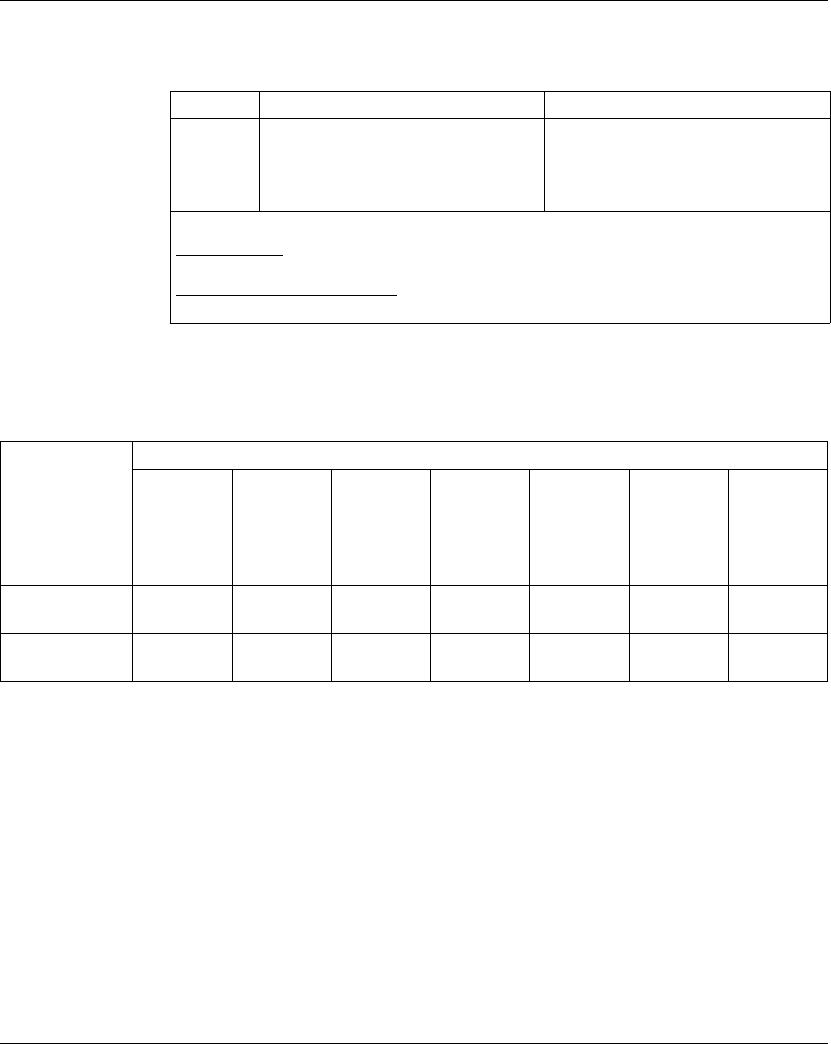
TM5 Digital I/O Electronic Modules
EIO0000000420 04/2012 99
Status Input Register
The StatusInput00 byte describes the status of the analog input channel:
Cycle Time and I/O Update Time
The table gives the module characteristics allowing the TM5 Bus Cycle Time
configuration:
For further information, refer to TM5 Manager Configuration (see page 18).
Bit Description Bits value
0-1 Channel 00 status 00: No detected error
01: Below lower limit value1
10: Above upper limit value
11: Wire break
1 Current signal 0...20 mA
Default setting: The input value has a lower limit. Underflow monitoring is, therefore, not
necessary.
After lower limit value changes: The input value is limited to the set value. The status bit is
set when the lower limit value is passed.
Characteristic Value (μs)
Without
filter on
analog
input
channels
With filter
on analog
input
channels
Without
filter on
digital
input
channels
With filter
on digital
input
channels
TM5SAO2H TM5SAO2L On digital
output
channels
Minimum cycle
time
100 500 100 150 200 250 100
Minimum I/O
update time
300 1000 100 200 200 < 300 100

TM5 Digital I/O Electronic Modules
100 EIO0000000420 04/2012
EIO0000000420 04/2012 101
4
Modicon TM5
TM5 Anal og I/O Ele ctronic M odules
EIO0000000420 04/2012
TM5 Analog I/O Electronic
Modules
Introduction
This chapter provides information to configure analog I/O expansion electronic
modules.
To add expansion electronic modules and access to the configuration screens, refer
to Adding an expansion electronic module (see page 21).
What’s in this Chapter?
This chapter contains the following topics:
Topic Page
TM5SAI2H and TM5SAI4H 102
TM5SAI2L and TM5SAI4L 109
TM5SAI2PH and TM5SAI4PH 118
TM5SAI2TH and TM5SAI6TH 123
TM5SEAISG 129
TM5SAO2H and TM5SAO2L 130
TM5SAO4H and TM5SAO4L 132

TM5 Analog I/O Electronic Modules
102 EIO0000000420 04/2012
TM5SAI2H and TM5SAI4H
Introduction
The TM5SAI2H and TM5SAI4H expansion electronic modules are 10 Vdc Analog
Input electronic modules with 2 and 4 inputs respectively.
If you have wired your input for a voltage measurement, and you configure
SoMachine for a current type of configuration, you may permanently damage the
electronic module.
For further information, refer to the Hardware Guide:
NOTICE
INOPERABLE EQUIPMENT
Be sure that the physical wiring of the module is compatible with the software
configuration for the module.
Failure to follow these instructions can result in equipment damage.
Reference Refer to
TM5SAI2H TM5SAI2H Electronic Module 2AI ±10V/0-20mA 16 Bits (see Modicon
TM5, Analog I/O Modules, Hardware Guide)
TM5SAI4H TM5SAI4H Electronic Module 4AI ±10V/0-20mA 16 Bits (see Modicon
TM5, Analog I/O Modules, Hardware Guide)

TM5 Analog I/O Electronic Modules
EIO0000000420 04/2012 103
I/O Configuration Tab
To configure the TM5SAI2H and TM5SAI4H electronic modules, select the I/O
Configuration tab.
The table below describes the modules parameters configuration:
Parameter Parameter Value Default Value Description
General Module address 0...250 Depends on the
configuration
The address is automatically set when
adding the modules. The address value
depends on the order of adding the module
in the SoMachine tree. The TM5ACBM15
support the possibility to change the
address.
Sample time 50...10000 100 µs Time during which all inputs are updated.
Channel status
information
On
Off
On Enable/Disable read of the channel status
information
On: the Status00 word is added to the
Expansion Bus I/O Mapping tab.
Extended channel
status information
On
Off
Off Enable/Disable read of the extended
channel status information
On: the Status01 and Status02 words are
added to the Expansion Bus I/O Mapping
tab.
Bus base TM5ACBM11
TM5ACBM15
TM5ACBM11 Specifies the bus base associated with the
electronic module.
Terminal block TM5ACTB06 (only
for TM5SAI2H)
TM5ACTB12
TM5ACTB06
(for TM5SAI2H)
TM5ACTB12
(for TM5SAI4H)
Specifies the terminal block associated
with the electronic module.

TM5 Analog I/O Electronic Modules
104 EIO0000000420 04/2012
For further generic descriptions, refer to I/O Configuration Tab Description
(see page 22).
The same Channel00 parameters are also available for:
zChannel01 (for the TM5SAI2H)
zChannel01...03 (for the TM5SAI4H)
Limit Values
The user can specify an upper and lower limit value for each individual channel.
When activated, the input signals are monitored to see if the limit values are
exceeded. The defined limit values are used for this. If the analog value goes
beyond the defined range, then it is limited to the upper or lower limit value.
The result of the signal check is displayed in a corresponding status bit. If necessary,
the counters are incremented by one if the value falls outside the range.
Channel 00 Channel on/off On
Off
On Enable/disable the channel.
Off: The other parameters are fixed to
default value in the Expansion Bus I/O
Mapping tab.
Off: All the channel bit associated to the
input 0 are removed in the Expansion Bus
I/O Mapping tab.
Minimum value -32768...32767 -32768 Limitation minimum value (see page 104)
Maximum value -32768...32767 32767 Limitation maximum value (see page 104)
Gain -2147483648...
2147483647
65536 Refer to Scaling (see page 105).
1.0 corresponds with 10000 hex.
Offset -2147483648...
2147483647
0
Channel type ±10 V
0...20 mA
±10 V Specifies the channel type.
Error check On
Off
On This checks if there is an error on the
system.
Minimum/maximum
value check
Off
Positive
Negative
Positive/Negative
Off Activate minimum and maximum input
values (see page 105).
Other than Off: the Status03 and
Status04 words are added to
theExpansion Bus I/O Mapping tab.
Filter On
Off
Off Enable/disable the input filter.
Filter order 1...4 1 Refer to Input Cycle (see page 106).
NOTE: Parameter only available if an input
filter is selected.
Filter cut off
frequency
1...65535 500 Hz
Parameter Parameter Value Default Value Description
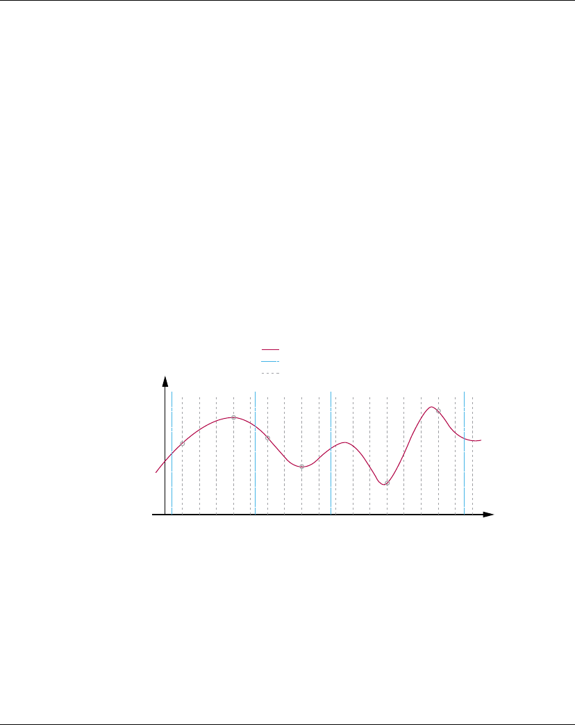
TM5 Analog I/O Electronic Modules
EIO0000000420 04/2012 105
Scaling
The raw A/D converter data and the filtered A/D converter data are compared. The
system measure and the user measure are grouped internally as a k/d pair to
optimize the execution time. Gain and offset can be specified for each individual
channel.
Minimum and Maximum Input Values
The system stores the minimum and maximum values between two trigger events.
The function is started by the corresponding trigger edge. The following edges are
evaluated depending on the configuration:
zPositive edge
zNegative edge
zPositive and negative edge
The trigger counter counts valid trigger events. In the event that trigger events occur
faster than the sampling cycle, the triggering becomes invalid (trigger detected error
counter is incremented).
The following example shows how the minimum and maximum input values are
recorded:
Input value
Trigger (triggered by user)
Scanning of value
Signal
Trigger
a
Trigger
b
Trigger
c
Trigger
d
Min
1
Min
2
Max
1
Max
2
Min
3
Max
3
t

TM5 Analog I/O Electronic Modules
106 EIO0000000420 04/2012
Input Cycle
The electronic module has an Input cycle that can be configured separately for each
individual channel. The order and cut-off frequency can be specified for each
individual channel:
zFilter Order: 1...4 (default: 1)
zFilter Cut-off frequency: 1...65535 Hz (default: 500 Hz)
Expansion Bus I/O Mapping Tab
Variables can be defined and named in the Expansion Bus I/O Mapping tab.
Additional information such as topological addressing is also provided in this tab.
Trigger
Event
Description
Trigger a The function is started. The system notes the minimum and maximum value of
the input signal. The Min./Max values registered by the status bit must be
ignored after the initial start.
Trigger b The minimum value (Min1) and the maximum value (Max1) between Trigger a
and Trigger b are given to the register and the new cycle is started. A status bit
informs the user as soon as the values are valid.
Trigger c The minimum value (Min2) and the maximum value (Max2) between Trigger b
and Trigger c are given to the register and the new cycle is started. A status bit
informs the user as soon as the values are valid.
Trigger d The minimum value (Min3) and the maximum value (Max3) between Trigger c
and Trigger d are given to the register and the new cycle is started. A status bit
informs the user as soon as the values are valid.
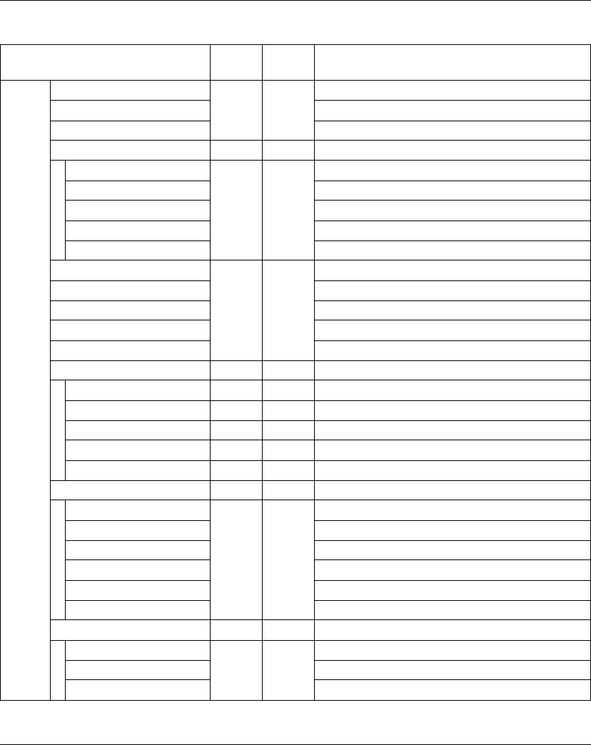
TM5 Analog I/O Electronic Modules
EIO0000000420 04/2012 107
The table below describes the Expansion Bus I/O Mapping configuration:
Channel Type Default
value
Description
Inputs AnalogInput00 INT - Current value of input 0
... ...
AnalogInput03 Current value of input 3
Status04 USINT - State of all inputs (Bits 0...3 not used)
Not used BOOL - -
... ...
MinMaxStart00Readback Readback MinMax Start of input 0
... ...
MinMaxStart03Readback Readback MinMax Start of input 3
MinInput00 INT - Minimum value of input 0
MaxInput00 Maximum value of input 0
... ...
MinInput03 Minimum value of input 3
MaxInput03 Maximum value of input 3
Status00 USINT - State of all inputs (Bits 5...7 not used)
Channel00OK BOOL - State of input 0 (0=OK)
... ...
Channel03OK State of input 3 (0=OK)
Not used -
ConvertionCycle Status convertion cycle bit (0=OK)
Status01 USINT - State of all inputs
Channel00underflow BOOL - Input 0 underflow (0=OK)
... ...
Channel03underflow Input 3 underflow (0=OK)
Channel00overflow Input 0 overflow (0=OK)
... ...
Channel03overflow Input 3 overflow (0=OK)
Status02 USINT - Out of range status of all inputs (Bits 5...7 not used)
Channel00outofrange BOOL - Input 0 out of range (0=OK)
... ...
Channel03outofrange Input 3 out of range (0=OK)
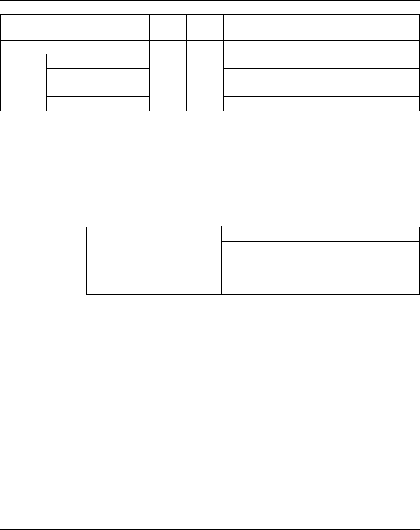
TM5 Analog I/O Electronic Modules
108 EIO0000000420 04/2012
For further generic descriptions, refer to Expansion Bus I/O Mapping Tab
Description (see page 22).
NOTE: All the bits dedicated to channel 2 and channel 3 are not used (bit=0) for the
TM5SAI2H.
Cycle Time and I/O Update Time
The table below gives the module characteristics allowing the TM5 Bus Cycle Time
configuration:
For further information, refer to TM5 Manager Configuration (see page 18).
Outputs Status03 USINT - Command word of all outputs (Bits 0...3: not used)
... BOOL None
TRUE
FALSE
...
MinMaxStart00 Command bit of Start Min/Max of input 0 (1 = Start)
... ...
MinMaxStart03 Command bit of Start Min/Max of input 3 (1 = Start)
Channel Type Default
value
Description
Characteristic Value (μs)
Default priority High priority with trace
function
Minimum cycle time 200 μs 300 μs
Minimum I/O update time No limitation on Bus cycle time

TM5 Analog I/O Electronic Modules
EIO0000000420 04/2012 109
TM5SAI2L and TM5SAI4L
Introduction
The TM5SAI2L and TM5SAI4L expansion electronic modules are 10 Vdc Analog
Input electronic modules with 2 and 4 inputs respectively.
If you have wired your input for a voltage measurement, and you configure
SoMachine for a current type of configuration, you may permanently damage the
electronic module.
For further information, refer to the Hardware Guide:
NOTICE
INOPERABLE EQUIPMENT
Be sure that the physical wiring of the module is compatible with the software
configuration for the module.
Failure to follow these instructions can result in equipment damage.
Reference Refer to
TM5SAI2L TM5SAI2L Electronic Module 2AI ±10V/0-20mA/4-20mA 12 Bits
(see Modicon TM5, Analog I/O Modules, Hardware Guide)
TM5SAI4L TM5SAI4L Electronic Module 4AI ±10V/0-20mA/4-20mA 12 Bits
(see Modicon TM5, Analog I/O Modules, Hardware Guide)

TM5 Analog I/O Electronic Modules
110 EIO0000000420 04/2012
I/O Configuration Tab
To configure the TM5SAI2L and TM5SAI4L electronic modules, select the I/O
Configuration tab.
The table below describes the modules parameters configuration:
Parameter Value Default Value Description
General Module address 0...250 Depends on the
configuration
The address is automatically set when adding
the modules. The address value depends on
the order of adding the module in the
SoMachine tree. The TM5ACBM15 support the
possibility to change the address.
Lower limit -32768...32767 -32767 Specifies the lower measurement limit
(see page 112).
Upper limit -32768...32767 32767 Specifies the upper measurement limit
(see page 112).
Input filter Off
level 2
level 4
level 8
level 16
level 32
level 64
level 128
Off Definition of the filter level (see page 113).
Input limitation Off
16383
8191
4095
2047
1023
511
255
Off Specifies the limitation of input ramp
(see page 114).
NOTE: Parameter available if an input filter is
selected.
Bus base TM5ACBM11
TM5ACBM15
TM5ACBM11 Specifies the bus base associated with the
electronic module.
Terminal block TM5ACTB06
(only for
TM5SAI2L)
TM5ACTB12
TM5ACTB06
(for TM5SAI2L)
TM5ACTB12
(for TM5SAI4L)
Specifies the terminal block associated with the
electronic module.
Channel 00 Channel type ±10 V
0...20 mA
4...20 mA
±10 V Specifies the channel type.
Channel 01 Channel type ±10 V
0...20 mA
4...20 mA
±10 V Specifies the channel type.

TM5 Analog I/O Electronic Modules
EIO0000000420 04/2012 111
For further generic descriptions, refer to I/O Configuration Tab Description
(see page 22).
NOTE: The channel 02 and channel 03 parameters are not available for the
TM5SAI2L.
Analog Inputs
The input status is registered with a fixed offset with respect to the network cycle and
is transferred in the same cycle.
Input Cycle
The electronic module is equipped with a configurable Input cycle. Filtering is
deactivated for shorter cycle times.
If the Input cycle is active, then the channels are scanned in ms cycles. The time
offset between the channels is 200 µs. The conversion takes place asynchronously
to the network cycle. Refer to Cycle time and I/O update time (see page 117)
Channel 02 Channel type ±10 V
0...20 mA
4...20 mA
±10 V Specifies the channel type.
Channel 03 Channel type ±10 V
0...20 mA
4...20 mA
±10 V Specifies the channel type.
Parameter Value Default Value Description

TM5 Analog I/O Electronic Modules
112 EIO0000000420 04/2012
Limit values
You can define 2 different type of limits:
zLower limit
zUpper limit
The Lower limit value range is between -32768 to 32767. This value is applied on
every channel of the module being configured.
NOTE: the Lower limit cannot be greater than the Upper limit.
The Upper limit value range is between -32768 to 32767. This value is applied on
every channel of the module being configured.
NOTE: The Upper limit value cannot be less than the Lower limit value.
Channel
Configuration
Digital Value
Behavior
Comments
± 10V -10 V = -32768
+10 V = +32767
If the Lower limit value is configured between -32768
and +32767, the digital value is limited to the Lower
limit value.
0...20 mA 0 mA = 0
20 mA = +32767
If the Lower limit value is configured between -32768
and 0, the digital value is limited to 0.
If the Lower limit value is configured between 0 and
32 767, the digital value is limited to the Lower limit
value.
4...20 mA 0 mA = -8192
4mA = 0
20 mA = +32767
If the Lower limit is configured between -32768 and
-8192, the digital value is limited to -8192.
If the Lower limit is configured between -8192 and
32767, the digital value is limited to the Lower limit
value.
Channel
Configuration
Digital Value
Behavior
Comments
± 10V -10 V = -32768
+10 V = +32767
If the Upper limit value is configured between -32768
and +32767, the digital value is limited to the Upper
limit value.
0...20 mA 0 mA = 0
20 mA = +32767
If the Upper limit value is configured between -32768
and 0, the digital value stays at 0, hence, the Upper
limit value must be set to a positive value.
If the Upper limit value is configured between 1 and
+32767, the digital value is limited to the Upper limit
value.
4...20 mA 0 mA = -8192
4mA = 0
20 mA = +32767
If the Upper limit value is configured between -32768
and -8192, the digital value is limited to -8192.
If the Upper limit value is configured between -8192
and 32767, the digital value is limited to the Upper
limit value.
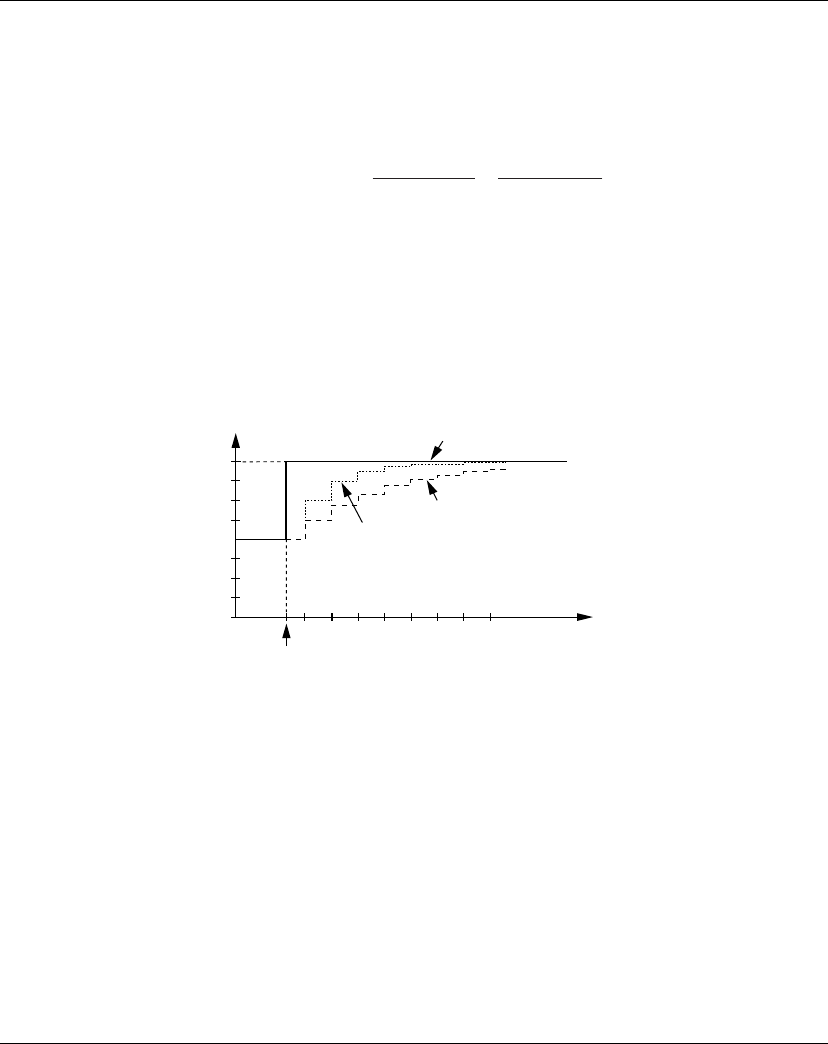
TM5 Analog I/O Electronic Modules
EIO0000000420 04/2012 113
Filter Level
The input value is evaluated according to the filter level. An input ramp limitation can
then be applied using this evaluation.
Formula for the evaluation of the input value:
The following examples show the function of the input ramp limitation based on an
input jump and a disturbance.
Example 1: The input value makes a jump from 8000 to 16000. The diagram
displays the evaluated value with the following settings:
Input ramp limitation = 0
Filter level = 2 or 4
1 Input value.
2 Evaluated value: Filter level 2
3 Evaluated value: Filter level 4
4 Input jump
old
new old
Inputvalue
Value
Value Value Filterlevel Filterlevel
W>PV@

TM5 Analog I/O Electronic Modules
114 EIO0000000420 04/2012
Example 2: A disturbance is imposed on the input value. The diagram shows the
evaluated value with the following settings:
Input ramp limitation = 0
Filter level = 2 or 4
1 Input value
2 Evaluated value: Filter level 2
3 Evaluated value: Filter level 4
4 Disturbance (Spike)
Input Ramp Limitation
Input ramp limitation can only take place when a filter is used. Input ramp limitation
is executed before filtering takes place.
The amount of the change in the input value is checked to make sure the specified
limits are not exceeded. If the values are exceeded, the adjusted input value is equal
to the old value ± the limit value.
The input ramp limitation is well suited for suppressing disturbances (spikes). The
following examples show the function of the input ramp limitation based on an input
jump and a disturbance.
W>PV@
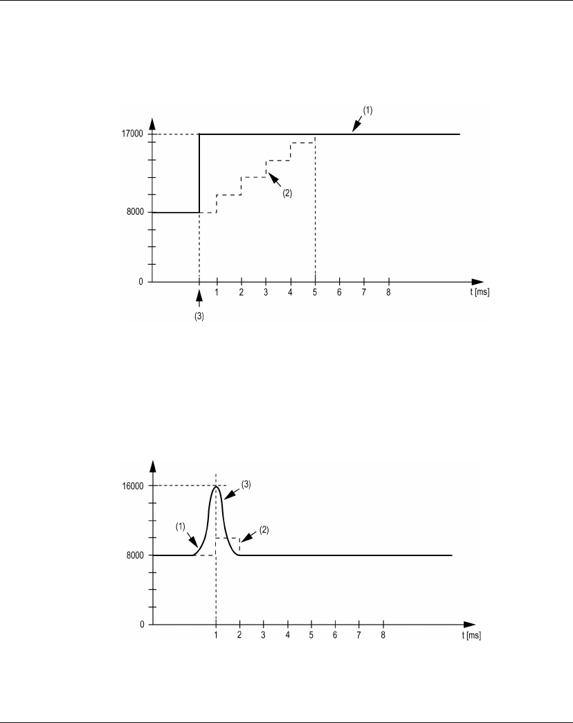
TM5 Analog I/O Electronic Modules
EIO0000000420 04/2012 115
Example 1: The input value makes a jump from 8,000 to 17,000. The diagram
displays the adjusted input value for the following settings:
Input ramp limitation = 2047
Filter level = 2
1 Input value
2 Internal adjusted input value before filter
3 Input jump
Example 2: A disturbance is imposed on the input value. The diagram shows the
adjusted input value with the following settings:
Input ramp limitation = 2047
Filter level = 2
1 Input value
2 Internal adjusted input value before filter
3 Disturbance (Spike)
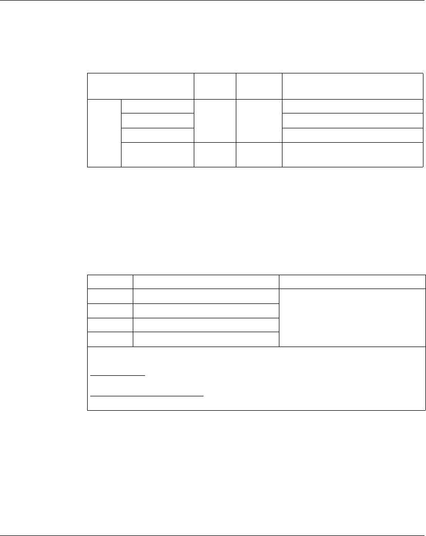
TM5 Analog I/O Electronic Modules
116 EIO0000000420 04/2012
Expansion Bus I/O Mapping Tab
Variables can be defined and named in the Expansion Bus I/O Mapping tab.
Additional information such as topological addressing is also provided in this tab.
The table below describes the Expansion Bus I/O Mapping configuration:
For further generic descriptions, refer to Expansion Bus I/O Mapping Tab
Description (see page 22).
NOTE: The bytes dedicated to channel 2 and channel 3 are not available for the
TM5SAI2L.
Status Input Register
The StatusInput00 byte describes the status of each input channel:
NOTE: The bit dedicated to channel 2 and channel 3 are not used (bit=0) for the
TM5SAI2L.
Channel Type Default
value
Description
Inputs AnalogInput00 INT - Current value of the input 0
... ...
AnalogInput03 Current value of the input 3
StatusInput00 USINT - Status of analog input channels (see
description below)
Bit Description Bits value
0-1 Channel 00 status 00: No detected error
01: Below lower limit value1
10: Above upper limit value
11: Wire break
2-3 Channel 01 status
4-5 Channel 02 status
6-7 Channel 03 status
1
Current signal 0...20 mA
Default setting: The input value has a lower limit. Underflow monitoring is, therefore, not
necessary.
After lower limit value changes: The input value is limited to the set value. The status bit is
set when the lower limit value is passed.

TM5 Analog I/O Electronic Modules
EIO0000000420 04/2012 117
Cycle Time and I/O Update Time
The table below gives the module characteristics allowing the TM5 Bus Cycle Time
configuration:
For further information, refer to TM5 Manager Configuration (see page 18).
Characteristic Value (μs)
Without filter With filter
Minimum cycle time 100 500
Minimum I/O update time 300 1000
TM5 Analog I/O Electronic Modules
118 EIO0000000420 04/2012
TM5SAI2PH and TM5SAI4PH
Introduction
The TM5SAI2PH and TM5SAI4PH expansion electronic modules are Analog
Resistor Temperature electronic modules with 2 and 4 Inputs respectively.
For further information, refer to the Hardware Guide:
I/O Configuration Tab
To configure the TM5SAI2PH and TM5SAI4PH electronic modules, select the I/O
Configuration tab.
The table below describes the modules parameters configuration:
NOTICE
INOPERABLE EQUIPMENT
Be sure that the physical wiring of the module is compatible with the software
configuration for the module.
Failure to follow these instructions can result in equipment damage.
Reference Refer to
TM5SAI2PH TM5SAI2PH Electronic Module 2AI PT100/PT1000 16 Bits (see Modicon
TM5, Analog I/O Modules, Hardware Guide)
TM5SAI4PH TM5SAI4PH Electronic Module 4AI PT100/PT1000 16 Bits (see Modicon
TM5, Analog I/O Modules, Hardware Guide)
Parameter Parameter Value Default Value Description
Function model 3 wire connection
2 wire connection
3 wire
connection
Specifies 3 wire connection or 2 wire
connection.

TM5 Analog I/O Electronic Modules
EIO0000000420 04/2012 119
General Module address 0...250 Depends on
the
configuration
The address is automatically set when
adding the modules. The address value
depends on the order of adding the module
in the SoMachine tree. The TM5ACBM15
support the possibility to change the
address.
I/O cycle counter Off
On
Off Enable or disable I/O cycle counter.
On: the IOCycleCounter word is added in
the Expansion Bus I/O Mapping tab.
Input filter 66.7
40
33.3
20
16.7
10
2
1
20 ms Specifies the filter time on the module.
Bus base TM5ACBM11
TM5ACBM15
TM5ACBM11 Specifies the bus base associated with the
electronic module.
Terminal block TM5ACTB06 (only for
TM5SAI2PH)
TM5ACTB12
TM5ACTB06
(for
TM5SAI2PH)
TM5ACTB12
(for
TM5SAI4PH)
Specifies the terminal block associated with
the electronic module.
Channel 00 Sensor type PT100
PT1000
0.1...4500 ohm, 0.1
ohm/bit,
0.05...2250 ohm,
0.05 ohm/bit
off
PT100 Specifies the sensor type (see page 121).
Off: the Temperature00 channel is
removed from the Expansion Bus I/O
Mapping tab.
Channel 01 Sensor type PT100
PT1000
0.1...4500 ohm, 0.1
ohm/bit,
0.05...2250 ohm,
0.05 ohm/bit
off
PT100 Specifies the sensor type (see page 121).
Off: the Temperature01 channel is
removed from the Expansion Bus I/O
Mapping tab.
Parameter Parameter Value Default Value Description

TM5 Analog I/O Electronic Modules
120 EIO0000000420 04/2012
For further generic descriptions, refer to I/O Configuration Tab Description
(see page 22).
NOTE: The channel 02 and channel03 parameters are not available for the
TM5SAI2PH.
NOTE: To economize cycle time, do not activate a channel when there is no sensor
connected.
Analog Inputs
The converted analog values are output by the electronic module in the registers.
Different resistance or temperature measurements result in different value ranges
and data types.
Timing Setting
The timing setting for data acquisition is made using the converter hardware. All
activated inputs are converted during each conversion cycle.
Conversion Time
The conversion time for the channels depends on their use. For the formulas listed
in the table, ’n’ corresponds to the number of channels that are agitated.
Channel 02 Sensor type PT100
PT1000
0.1...4500 ohm, 0.1
ohm/bit,
0.05...2250 ohm,
0.05 ohm/bit
off
PT100 Specifies the sensor type (see page 121).
Off: the Temperature02 channel is
removed from the Expansion Bus I/O
Mapping tab.
Channel 03 Sensor type PT100
PT1000
0.1...4500 ohm, 0.1
ohm/bit,
0.05...2250 ohm,
0.05 ohm/bit
off
PT100 Specifies the sensor type (see page 121).
Off: the Temperature03 channel is
removed from the Expansion Bus I/O
Mapping tab.
Parameter Parameter Value Default Value Description
Channel uses Conversion time
1 channel 1 x Input Filter time
n channels with the same sensor type n x (Input Filter time + 20 ms)
n channels with different sensor types n x (2 x Input Filter time + 20 ms)
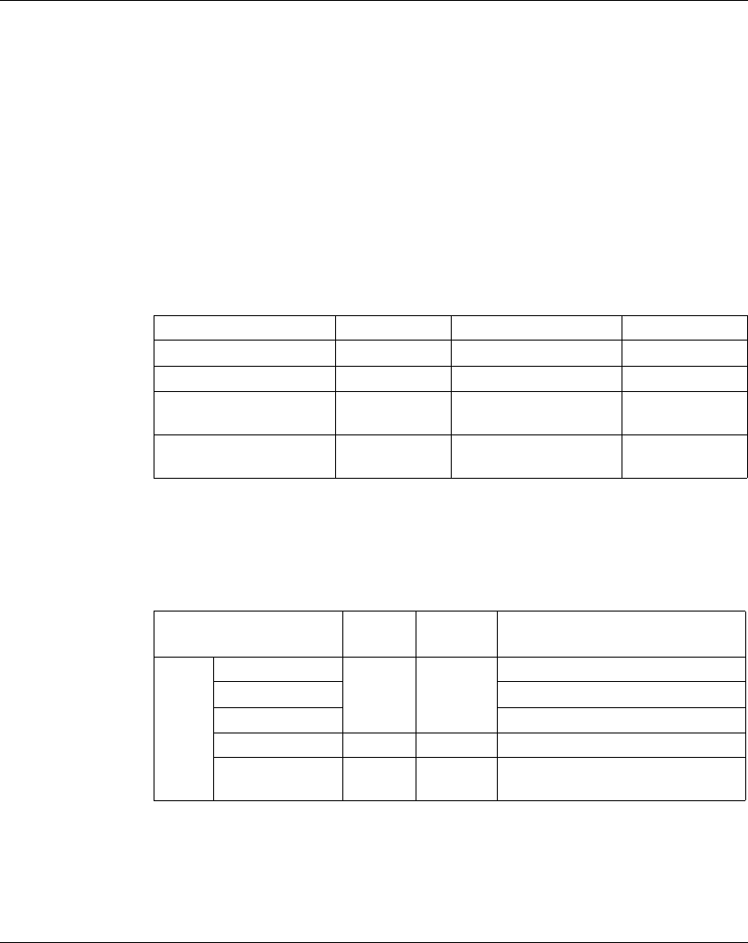
TM5 Analog I/O Electronic Modules
EIO0000000420 04/2012 121
Reduce Conversion Time
If an input is not necessary, it can be deactivated by setting the sensor type to Off,
thereby reducing the refresh time.
The time saved is: Timesaving = 2 x 20 ms + Input Filter time
The Input Filter time is the conversion time for the remaining channels.
Sensor Type and Channel Deactivation
The electronic module is designed for temperature and resistance measurement.
The sensor type must be specified because of the different adjustment values for
temperature and resistance. To save time, individual channels can be deactivated
by setting the sensor type to Off.
The table below shows the sensor types:
Expansion Bus I/O Mapping Tab
Variables can be defined and named in the Expansion Bus I/O Mapping tab.
Additional information such as topological addressing is also provided in this tab.
The table below describes the Expansion Bus I/O Mapping configuration:
For further generic descriptions, refer to Expansion Bus I/O Mapping Tab
Description (see page 22).
NOTE: The bytes dedicated to channel 2 and channel 3 are not available for the
TM5SAI2PH.
Sensor Types Digital value Temperature °C (°F) Resolution
Sensor type PT100 -2000...8500 -200...850 (-328...1562) 0.1°C(0.18°F)
Sensor type PT1000 -2000...8500 -200...850 (-328...1562) 0.1°C (0.18°F)
Resistance measurement
0.1...4500 Ohm
1...45000 – 0.1 Ohm
Resistance measurement
0.05...2250 Ohm
1...45000 – 0.05 Ohm
Channel Type Default
value
Description
Inputs Temperature00 INT - Current value of the input 0
... ...
Temperature03 Current value of the input 3
IOCycleCounter USINT - I/O cycle counter
StatusInput00 USINT - Status of analog input channels
(see description below)
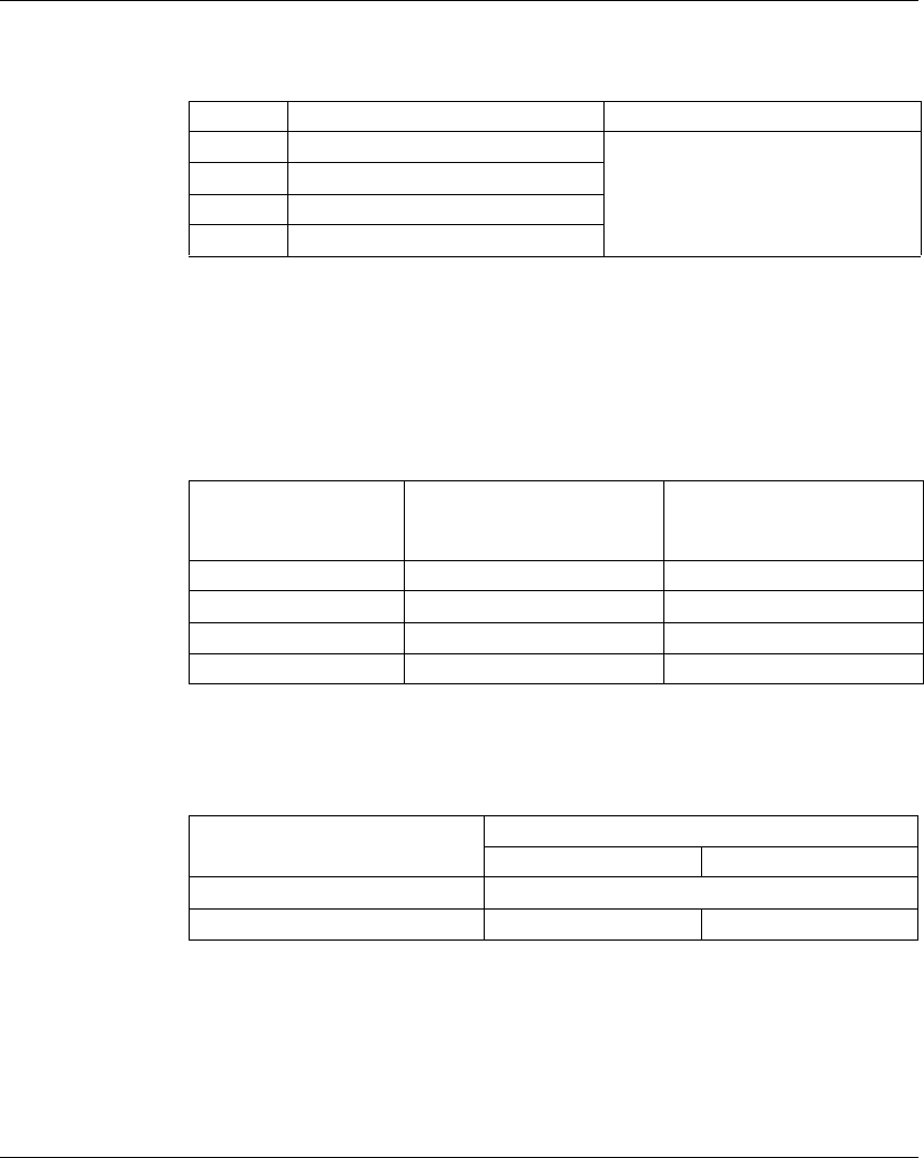
TM5 Analog I/O Electronic Modules
122 EIO0000000420 04/2012
Status Input Register
The StatusInput byte describes the status of each input channel:
NOTE: The bit dedicated to channel 2 and channel 3 are not used (bit=0) for the
TM5SAI2PH.
Limit Analog Value
In addition to the status information, the analog value is set to the values listed
below, by default, when an detected error occurs. The analog value is limited to the
new values if the limit values were changed.
Cycle Time and I/O Update Time
The table below gives the module characteristics allowing the TM5 Bus Cycle Time
configuration:
For further information, refer to TM5 Manager Configuration (see page 18).
Bit Description Bits value
0-1 Channel 00 status 00: No detected error
01: Below minimum value
10: Above maximum value
11: Broken wire detected
2-3 Channel 01 status
4-5 Channel 02 status
6-7 Channel 03 status
Detected error type Temperature measurement
Digital value for detected
error
Resistance measurement
Digital value for detected
error
Wire break +32767 (7FFF hex) 65535 (FFFF hex)
Above upper limit value +32767 (7FFF hex) 65535 (FFFF hex)
Below lower limit value -32767 (8001 hex) 0 (0 hex)
Invalid value -32768 (8000 hex) 65535 (FFFF hex)
Characteristic Value (μs)
1 input n inputs
Minimum cycle time 100
Minimum I/O update time Equal to the filter time n * (200 ms + filter time)

TM5 Analog I/O Electronic Modules
EIO0000000420 04/2012 123
TM5SAI2TH and TM5SAI6TH
Introduction
The TM5SAI2TH and TM5SAI6TH expansion electronic modules are Analog
Temperature Sensor with 2 and 6 Inputs respectively.
For further information, refer to the Hardware Guide:
I/O Configuration Tab
To configure the TM5SAI2TH and TM5SAI6TH electronic modules, select the I/O
Configuration tab.
The table below describes the modules parameters configuration:
NOTICE
INOPERABLE EQUIPMENT
Be sure that the physical wiring of the module is compatible with the software
configuration for the module.
Failure to follow these instructions can result in equipment damage.
Reference Refer to
TM5SAI2TH TM5SAI2TH Electronic Module 2AI Thermocouple J/K/N/S 16 Bits
(see Modicon TM5, Analog I/O Modules, Hardware Guide)
TM5SAI6TH TM5SAI6TH Electronic Module 6AI Thermocouple J/K/N/S 16 Bits
(see Modicon TM5, Analog I/O Modules, Hardware Guide)
Parameter Value Default Value Description
Function model Internal
compensation
temperature
External
compensation
temperature
Internal
compensation
temperature
Refer to External Compensation
Temperature (see page 125).

TM5 Analog I/O Electronic Modules
124 EIO0000000420 04/2012
For further generic descriptions, refer to I/O Configuration Tab Description
(see page 22).
NOTE: The channel 02... channel05 parameters are not available for the
TM5SAI2TH.
NOTE: To economize cycle time, do not activate a channel when there is no sensor
connected.
General Module address 0...250 Depends on
the
configuration
The address is automatically set when
adding the modules. The address value
depends on the order of adding the module
in the SoMachine tree. The TM5ACBM15
support the possibility to change the
address.
I/O cycle counter Off
On
Off Enable/disable I/O cycle counter.
On: the IOCycleCounter word is added to
the Expansion Bus I/O Mapping tab.
Input filter 66.7
40
33.3
20
16.7
10
2
1
20 ms Specifies the filter time on the module.
Sensor type J
K
N
S
±32767 µV, 1 µV/bit
±65534 µV, 2 µV/bit
J Specifies the sensor type (see page 126).
Enable channel
00
On
Off
On Selectively enabling of not used channels
reduces the electronic module cycle time.
Off: the Temperature00 word is removed
from the Expansion Bus I/O Mapping tab.
...
Enable channel
05
On
Off
On Selectively enabling of not used channels
reduces the electronic module cycle time.
Off: the Temperature05 word is removed
from the Expansion Bus I/O Mapping tab.
Bus base TM5ACBM11
TM5ACBM15
TM5ACBM11 Specifies the bus base associated with the
electronic module.
Terminal block TM5ACTB06
TM5ACTB12
TM5ACTB06 Specifies the terminal block associated with
the electronic module.
Parameter Value Default Value Description

TM5 Analog I/O Electronic Modules
EIO0000000420 04/2012 125
Analog Inputs
The converted analog values are output by the electronic module in the registers.
The sensor type configured affects the value ranges.
Raw Value Measurement
If a sensor type other than J, K, N, or S is used, the terminal temperature must be
measured on at least one input. Based on this value, the user must perform a
terminal temperature compensation.
Timing Setting
The timing setting for data acquisition is made using the converter hardware. All
switched on inputs are converted during each conversion cycle. A terminal
temperature measurement also takes place.
If an input is not necessary, it can be deactivated by setting the channel to Off,
thereby reducing the refresh time. The measurement of the terminal temperature is
deactivated.
Conversion Time
The conversion time depends on the number of channels used. For the formulas
listed in the table, ’n’ corresponds to the number of channels that are activated.
Terminal Temperature (Cold Junction) Compensation
General information
When using thermocouples, it is necessary to measure the temperature at the
terminal connections of the TM5SAIxTH in order to calculate an accurate absolute
temperature at the measuring point of the thermocouple.
NOTE: At least one terminal temperature sensor is required to determine the
temperature measured by the connected thermocouples. Otherwise, a value of
7FFF hex is calculated for all the connected thermocouples.
The accuracy of the temperature measurement of the connected thermocouples is
a function of the number of terminal temperature sensors connected to the block.
A terminal temperature compensation junction is useful for the following
applications:
zWhen there is a large distance between the controller and point of measurement.
zTo increase precision.
Channel uses Conversion time
n channels (n x (2 x Input Filter time + 200 µs)
1 channel Corresponds to the Input Filter time

TM5 Analog I/O Electronic Modules
126 EIO0000000420 04/2012
Bridging large distances
When there is a large distance between the controller and the point of measurement,
a terminal temperature compensation junction is recommended. The thermocouple
voltage is supplied via copper cable from the terminal temperature compensation
junction to the terminal on the TM5SAIxTH. The temperature measured at the
terminal temperature compensation junction is stored in the I/O area of the
TM5SAIxTH electronic module. The TM5SAIxTH electronic module calculates the
thermocouple temperature internally from the measured voltage and the reference
junction temperature value (per channel).
Increased precision
To increase the precision, a terminal temperature compensation junction is
recommended. The construction of the terminal temperature compensation junction
is the same as described above. The installation of a terminal temperature
compensation junction is especially helpful in the following cases:
zThere is a slice next to the TM5SAIxTH that requires more than 1 W.
zThere is no slice next to the TM5SAIxTH.
zWith strongly fluctuating ambient conditions (draft, temperature).
NOTE: If the J, K, N and S types are used, you must select the external
compensation.
Sensor Type and Channel Deactivation
The electronic module is designed for various sensor types. The sensor type must
be specified because of the different adjustment values. The default setting for all
channels is ON. To save time, individual channels can be deactivated.
The table below shows the code corresponding sensor types:
Sensor Types
Sensor type J
Sensor type K
Sensor type N
Sensor type S
Raw value without linearization and terminal temperature compensation.
Resolution 1 µV for a measurement range of ±32.767 mV.
Raw value without linearization and terminal temperature compensation.
Resolution 2 µV for a measurement range of ±65.534 mV.
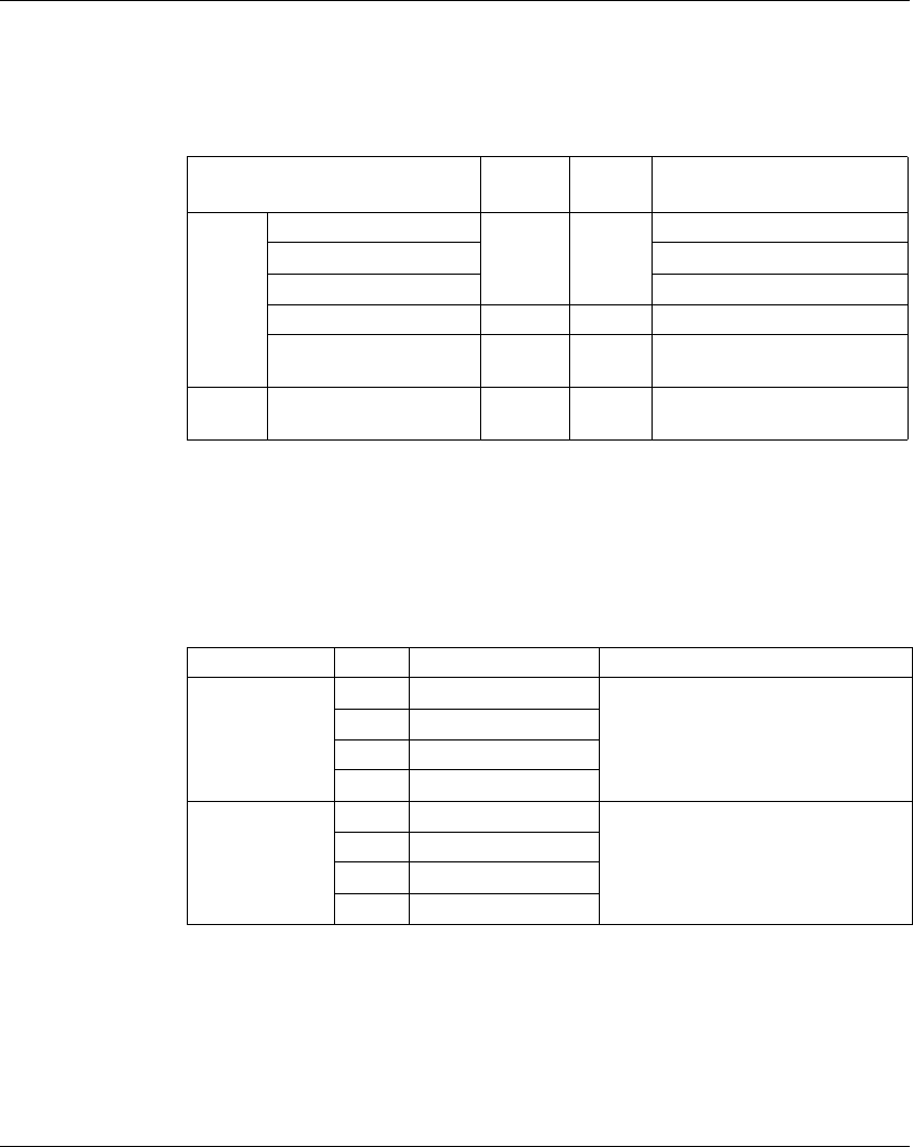
TM5 Analog I/O Electronic Modules
EIO0000000420 04/2012 127
Expansion Bus I/O Mapping Tab
Variables can be defined and named in the Expansion Bus I/O Mapping tab.
Additional information such as topological addressing is also provided in this tab.
The table below describes the I/O Mapping configuration:
For further generic descriptions, refer to Expansion Bus I/O Mapping Tab
Description (see page 22).
NOTE: The channel 2...5 parameters are not available for the TM5SAI2TH.
Status Input Register
The status byte describes the status of each input channel:
NOTE: The bit dedicated to channel 2...5 are not used (bit=0) for the TM5SAI2TH.
The Statusinput01 byte is not available for the TM5SAI2TH.
Channel Type Default
value
Description
Inputs Temperature00 INT - Current value of the input 0
... ...
Temperature05 Current value of the input 5
IOCycleCounter USINT - IO cycle counter
StatusInput00 USINT - Status of analog input channels
(see description below)
Outputs ExternalCompensation
Temperature
INT - External compensation
temperature
Status Bit Description Bits value
StatusInput00 0-1 Channel 00 status 00: No detected error
01: Below lower limit value
10: Above upper limit value
11: Broken wire detected
2-3 Channel 01 status
4-5 Channel 02 status
6-7 Channel 03 status
StatusInput01 0-1 Channel 04 status 00: No detected error
01: Below minimum value
10: Above maximum value
11: Broken wire detected
2-3 Channel 05 status
4-5 Not used
6-7 Not used

TM5 Analog I/O Electronic Modules
128 EIO0000000420 04/2012
Cycle Time and I/O Update Time
The table below gives the module characteristics allowing the TM5 Bus Cycle Time
configuration:
For further information, refer to TM5 Manager Configuration (see page 18).
Characteristic Value (μs)
1 input n inputs
Minimum cycle time 150
Minimum I/O update time Equal to the filter time n * (2 * filter time + 200 ms)

TM5 Analog I/O Electronic Modules
EIO0000000420 04/2012 129
TM5SEAISG
Introduction
The TM5SEAISG is an analog electronic module which allows to convert the output
of a 4-wire or 6-wire full-bridge strain gauge to a numeric value.
For further information, refer to the TM5SEAISG Analog Strain Gauge Input
Electronic Module (see Modicon TM5, Analog I/O Modules, Hardware Guide) and
the TM5 IoDrvTM5SEAISG Strain Gauge Library Guide. (see Modicon TM5,
IoDrvTM5SEAISG Strain Gauge, Library Guide)

TM5 Analog I/O Electronic Modules
130 EIO0000000420 04/2012
TM5SAO2H and TM5SAO2L
Introduction
The TM5SAO2H and TM5SAO2L expansion electronic modules are analog output
electronic modules with 2 outputs, ±10 Vdc / 0 to 20 mA.
If you have wired your output for a voltage measurement, and you configure
SoMachine for a current type of configuration, you may permanently damage the
electronic module.
For further information, refer to the Hardware Guide:
I/O Configuration Tab
To configure the TM5SAO2H and TM5SAO2L electronic modules, select the I/O
Configuration tab.
The table below describes the modules parameters configuration:
NOTICE
INOPERABLE EQUIPMENT
Be sure that the physical wiring of the module is compatible with the software
configuration for the module.
Failure to follow these instructions can result in equipment damage.
Reference Refer to
TM5SAO2H TM5SAO2H Electronic Module 2AO ±10V/0-20mA 16 Bits (see Modicon
TM5, Analog I/O Modules, Hardware Guide)
TM5SAO2L TM5SAO2L Electronic Module 2AO ±10V/0-20mA 12 Bits (see Modicon
TM5, Analog I/O Modules, Hardware Guide)
Parameter Parameter Value Default Value Description
General Module address 0...250 Depends on
the
configuration
The address is automatically set when
adding the modules. The address value
depends on the order of adding the module
in the SoMachine tree. The TM5ACBM15
support the possibility to change the
address.
Bus base TM5ACBM11
TM5ACBM15
TM5ACBM11 Specifies the bus base associated with the
electronic module.
Terminal block TM5ACTB06
TM5ACTB12
TM5ACTB06 Specifies the terminal block associated with
the electronic module.
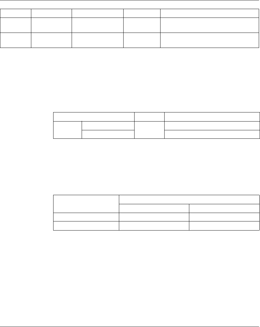
TM5 Analog I/O Electronic Modules
EIO0000000420 04/2012 131
For further generic descriptions, refer to I/O Configuration Tab Description
(see page 22).
Expansion Bus I/O Mapping Tab
Variables can be defined and named in the Expansion Bus I/O Mapping tab.
Additional information such as topological addressing is also provided in this tab.
The table below describes the Expansion Bus I/O Mapping configuration:
For further generic descriptions, refer to Expansion Bus I/O Mapping Tab
Description (see page 22).
Cycle Time and I/O Update Time
The table below gives the module characteristics allowing the TM5 Bus Cycle Time
configuration:
For further information, refer to TM5 Manager Configuration (see page 18).
Channel00 Channel type ±10 V
0...20 mA
±10 V Specifies the channel type.
Channel01 Channel type ±10 V
0...20 mA
±10 V Specifies the channel type.
Parameter Parameter Value Default Value Description
Channel Type Description
Outputs AnalogOutput00 INT Command word of the output 0
AnalogOutput01 Command word of the output 1
Characteristic Value (μs)
TM5SAO2H TM5SAO2L
Minimum cycle time 200 250
Minimum I/O update time 200 < 300

TM5 Analog I/O Electronic Modules
132 EIO0000000420 04/2012
TM5SAO4H and TM5SAO4L
Introduction
The TM5SAO4H and TM5SAO4L electronic modules are analog outputs electronic
modules with 4 outputs, ±10 Vdc / 0 to 20 mA.
If you have wired your output for a voltage measurement, and you configure
SoMachine a current type of configuration, you may permanently damage the
electronic module.
For further information, refer to the Hardware Guide:
I/O Configuration Tab
To configure the TM5SAO4H and TM5SAO4L electronic modules, select the I/O
Configuration tab.
The table below describes the modules parameters configuration:
NOTICE
INOPERABLE EQUIPMENT
Be sure that the physical wiring of the module is compatible with the software
configuration for the module.
Failure to follow these instructions can result in equipment damage.
Reference Refer to
TM5SAO4H TM5SAO4H Electronic Module 4AO ±10V/0-20mA 16 Bits (see Modicon
TM5, Analog I/O Modules, Hardware Guide)
TM5SAO4L TM5SAO4L Electronic Module 4AO ±10V/0-20mA 12 Bits (see Modicon
TM5, Analog I/O Modules, Hardware Guide)
Parameter Parameter Value Default Value Description
General Module address 0...250 Depends on
the
configuration
The address is automatically set when
adding the modules. The address value
depends on the order of adding the module
in the SoMachine tree. The TM5ACBM15)
support the possibility to change the
address.
Bus base TM5ACBM11
TM5ACBM15
TM5ACBM11 Specifies the bus base associated with the
electronic module.
Terminal block
(not available for
TM5SAO4L)
TM5ACTB12 TM5ACTB06 Specifies the terminal block associated with
the electronic module.
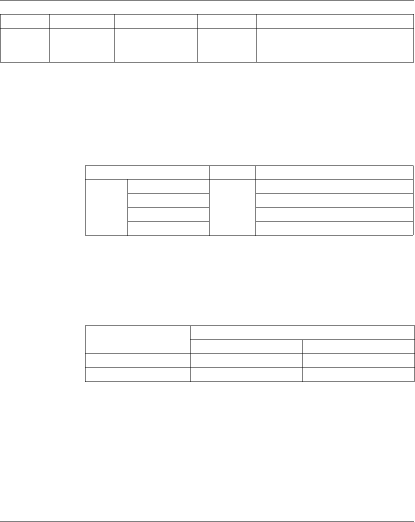
TM5 Analog I/O Electronic Modules
EIO0000000420 04/2012 133
For further generic descriptions, refer to I/O Configuration Tab Description
(see page 22).
Expansion Bus I/O Mapping Tab
Variables can be defined and named in the Expansion Bus I/O Mapping tab.
Additional information such as topological addressing is also provided in this tab.
The table below describes the Expansion Bus I/O Mapping configuration:
For further generic descriptions, refer to Expansion Bus I/O Mapping Tab
Description (see page 22).
Cycle Time and I/O Update Time
The table below gives the module characteristics allowing the TM5 Bus Cycle Time
configuration:
For further information, refer to TM5 Manager Configuration (see page 18).
Channel00
...
Channel03
Channel type ±10 V
0...20 mA
±10 V Specifies the channel type.
Parameter Parameter Value Default Value Description
Channel Type Description
Outputs AnalogOutptu00 INT Command word of the output 0
AnalogOutptu01 Command word of the output 1
AnalogOutptu02 Command word of the output 2
AnalogOutptu03 Command word of the output 3
Characteristic Value (μs)
TM5SAO4H TM5SAO4L
Minimum cycle time 200 250
Minimum I/O update time 200 < 400

TM5 Analog I/O Electronic Modules
134 EIO0000000420 04/2012
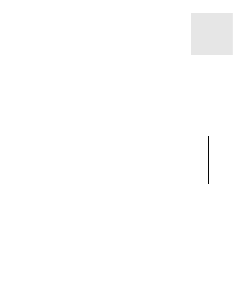
EIO0000000420 04/2012 135
5
Modicon TM5
TM5 Expert I/O Electronic Module
EIO0000000420 04/2012
TM5 Expert I/O Electronic Modules
Introduction
This chapter provides information to configure expert I/O expansion electronic
modules.
To add expansion electronic modules and access to the configuration screens, refer
to Adding an expansion electronic module (see page 21).
What’s in this Chapter?
This chapter contains the following topics:
Topic Page
TM5SE1IC02505 136
TM5SE1IC01024 140
TM5SE2IC01024 144
TM5SE1SC10005 148
TM5SDI2DF 152
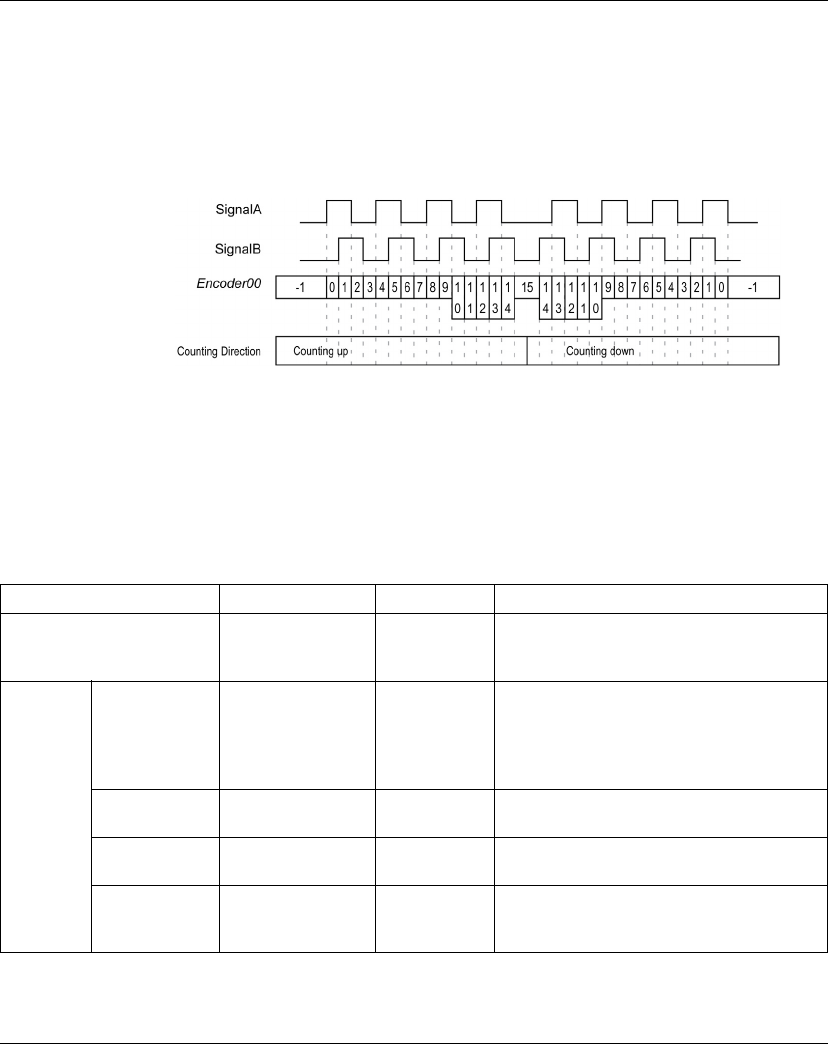
TM5 Expert I/O Electronic Module
136 EIO0000000420 04/2012
TM5SE1IC02505
Introduction
The TM5SE1IC02505 expansion electronic module is a 5 Vdc or 24 Vdc Expert
Inputs electronic module with 1 input channel for ABR incremental encoder.
The encoder signal is counted as shown below:
For further information, refer to TM5SE1IC02505 Electronic Module 1 HSC INC 250
kHz 5 Vdc (see Modicon TM5, Expert (High Speed Counter) Modules, Hardware
Guide).
I/O Configuration Tab
To configure the TM5SE1IC02505 electronic module, select the I/O Configuration
tab.
The table below describes the module parameters configuration:
Parameter Value Default Value Description
Function model 16-bit counter
32-bit counter
16-bit counter Define the counter value range:
z16-bit: -32768...+32767
z32-bit: -2147483648...+2147483647
General Module address 0...250 Depends on
configuration
The address is automatically set when adding
the modules. The address value depends on
the order of adding the module in the
SoMachine tree. TheTM5ACBM15 supports
the possibility to change the address.
Bus base TM5ACBM11
TM5ACBM15
TM5ACBM11 Specifies the bus base associated with the
electronic module.
Terminal block TM5ACTB12 TM5ACTB12 Specifies the terminal block associated with
the electronic module.
24 V I/O
segment
external current
0...300 mA 300 mA 24 V I/O segment external current on TM5
power supply bus. Refer to System Planning
and Installation Guide.
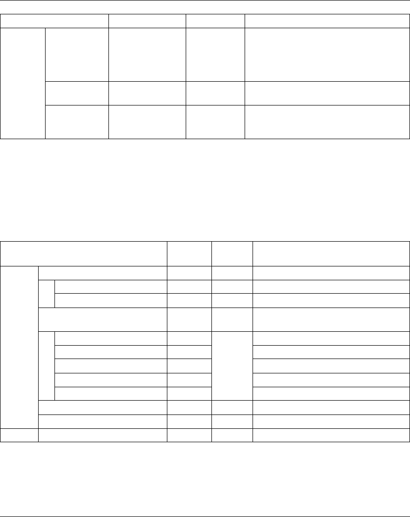
TM5 Expert I/O Electronic Module
EIO0000000420 04/2012 137
For further generic descriptions, refer to I/O Configuration Tab Description
(see page 22).
Expansion Bus I/O Mapping Tab
Variables can be defined and named in the Expansion Bus I/O Mapping tab.
Additional information such as topological addressing is also provided in this tab.
The table below describes the Expansion Bus I/O Mapping configuration:
For further generic descriptions, refer to Expansion Bus I/O Mapping Tab
Description (see page 22).
Counter00 Preset value -32768...32767 (16-
bit)
-
2147483648...2147
483647 (32-bit)
0 Homing preset value for counter, the value set
here is applied to the counter value upon
completion of the referencing process.
Reference pulse Negative edge
Positive edge
Negative edge Select edge of reference pulse for homing.
Reference
enable switch
Off
On (active low)
On (active high)
Off Digital input 00 used as reference enable
switch.
Parameter Value Default Value Description
Channel Type Default
value
Description
Inputs PowerSupply USINT - Status encoder supply (bits 2...7: not used)
PowerSupply00 BOOL - Status encoder supply 24 Vdc (0=OK)
PowerSupply01 Status encoder supply 5 Vdc (0=OK)
DigitalInput USINT - State of all digital inputs (bits 6...7: not
used)
SignalA BOOL - Encoder Signal A
SignalB BOOL Encoder Signal B
SignalR BOOL Encoder Reference Impulse
DigitalInput00 BOOL State of digital input 0
DigitalInput01 BOOL State of digital input 1
Encoder00 INT - Incremental encoder
StatusInput00 USINT - Status incremental encoder 00 (see below)
Outputs ReferenceModeEncoder00 USINT - Reference mode incremental encoder 00

TM5 Expert I/O Electronic Module
138 EIO0000000420 04/2012
StatusInput00 Register
This register contains information regarding whether the referencing process is off,
active, or complete.
The following table describes the StatusInput00 register:
Example:
ReferenceModeEncoder00 Register
This register determines the encoder reference mode.
The following table describes the ReferenceModeEncoder00 register:
Bit Description
0-1 Always 0
2 When the referencing is ON, bit is always 1 after the first reference impulse.
When the referencing is OFF, bit is always 0.
3 When the referencing is ON, toggle after each completed reference. When
the referencing is OFF, bit is always 0.
4 Bit is always 1 after the first reference impulse
5...7 Free-running counter, increased with each reference impulse
Register value Description
00000000 bin 00 hex Referencing off or already in progress
00111100 bin 3C hex First reference complete, reference value applied in the
Encoder00 register
xxx11100 bin xB hex Bits 5...7 are changed sequentially with each reference
impulse
xxx1x100 bin xx hex Bits changed continuously with the setting continuous
referencing. With every reference impulse, the reference
value is applied to the Encoder00 register.
Bit Value Description
0-1 00 Referencing OFF
01 One-time reference (single shot)
11 Continuous referencing
2...5 0000 Bit permanently set = 0
6-7 00 Referencing OFF
11 Bit permanently set = 1
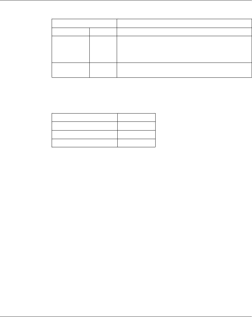
TM5 Expert I/O Electronic Module
EIO0000000420 04/2012 139
Example:
Cycle Time and I/O Update Time
The table below gives the module characteristics allowing the TM5 Bus Cycle Time
configuration:
For further information, refer to TM5 Manager Configuration (see page 18).
Register value Description
00000000 bin 00 hex Referencing OFF
11000001 bin C1 hex One-time reference (single shot)
When starting over after the referencing process is complete,
the value 00 hex must be written. Then wait until the
StatusInput00 also takes on the value x0 hex.
11000011 bin C3 hex Continuous referencing, referencing occurs at every reference
pulse.
Characteristic Value
Minimum cycle time 128 μs
Maximum cycle time 16 ms
Minimum I/O update time 128 μs

TM5 Expert I/O Electronic Module
140 EIO0000000420 04/2012
TM5SE1IC01024
Introduction
The TM5SE1IC01024 expansion electronic module is a 24 Vdc Expert input
electronic module with 1 input channel for ABR incremental encoder.
For further information, refer to TM5SE1IC01024 Electronic Module 1 HSC INC 100
kHz 24 Vdc (see Modicon TM5, Expert (High Speed Counter) Modules, Hardware
Guide).
I/O Configuration Tab
To configure the TM5SE1IC01024 electronic module, select the I/O Configuration
tab.
The table below describes the module parameters configuration:
Parameter Value Default Value Description
Function model 16-bit counter
32-bit counter
16-bit counter Define the counter value range:
z16-bit: -32768...+32767
z32-bit: -2147483648...+2147483647
General Module address 0...250 Depends on
configuration
The address is automatically set when adding
the modules. The address value depends on
the order of adding the module in the
SoMachine tree. The TM5ACBM15 supports
the possibility to change the address.
Bus base TM5ACBM11
TM5ACBM15
TM5ACBM11 Specifies the bus base associated with the
electronic module.
Terminal block TM5ACTB12 TM5ACTB12 Specifies the terminal block associated with
the electronic module.
24 V I/O segment
external current
0...300 mA 300 mA 24 V I/O segment external current on TM5
power supply bus. Refer to System Planning
and Installation Guide.
Counter00 Preset value -32768...32767
(16-bit)
-
2147483648...2
147483647
(32-bit)
0 Homing preset value for counter, the value set
here is applied to the counter value upon
completion of the referencing process.
Reference pulse Negative edge
Positive edge
Negative edge Select edge of reference pulse for homing.
Reference
enable switch
Off
On (active low)
On (active high)
Off Digital input 01 used as reference enable
switch.
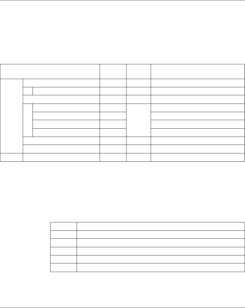
TM5 Expert I/O Electronic Module
EIO0000000420 04/2012 141
For further generic descriptions, refer to I/O Configuration Tab Description
(see page 22).
Expansion Bus I/O Mapping Tab
Variables can be defined and named in the Expansion Bus I/O Mapping tab.
Additional information such as topological addressing is also provided in this tab.
The table below describes the Expansion Bus I/O Mapping configuration:
For further generic descriptions, refer to Expansion Bus I/O Mapping Tab
Description (see page 22).
StatusInput00 Register
This register contains information regarding whether the referencing process is off,
active, or complete.
The following table describes the StatusInput00 register:
Channel Type Default
value
Description
Inputs PowerSupply USINT - Status encoder supply (bits 1...7: not used)
PowerSupply00 BOOL - Status encoder supply (0=OK)
DigitalInput USINT - State of all digital inputs
SignalA BOOL - Encoder Signal A
SignalB BOOL Encoder Signal B
SignalR BOOL Encoder Signal R
DigitalInput00 BOOL State of digital input 0
Encoder00 INT - Incremental encoder
StatusInput00 USINT - Status incremental encoder 00 (see below)
Outputs ReferenceModeEncoder00 USINT - Reference mode incremental encoder 00
Bit Description
0-1 Always 0
2 Bit is always 1 after the first reference impulse
3 Toggle after each completed reference
4 Bit is always 1 after the first reference impulse
5...7 Free-running counter, increased with each reference impulse

TM5 Expert I/O Electronic Module
142 EIO0000000420 04/2012
Example:
ReferenceModeEncoder00 Register
This register determines the encoder reference mode.
The following table describes the ReferenceModeEncoder00 register:
Example:
Register value Description
00000000 bin 00 hex Referencing off or already in progress
00111100 bin 3C hex First reference complete, reference value applied in the
Encoder00 register
xxx11100 bin xB hex Bits 5...7 are changed sequentially with each reference
impulse
xxx1x100 bin xx hex Bits changed continuously with the setting continuous
referencing. With every reference impulse, the reference
value is applied to the Encoder00 register.
Bit Value Description
0-1 00 Referencing OFF
01 One-time reference (single shot)
11 Continuous referencing
2...5 0000 Bit permanently set = 0
6-7 00 Referencing OFF
11 Bit permanently set = 1
Register value Description
00000000 bin 00 hex Referencing OFF
11000001 bin C1 hex One-time reference (single shot)
When starting over after the referencing process is complete,
the value 00 hex must be written. Then wait until the
StatusInput00 also takes on the value 00 hex. Only then can
the value C1 hex be written.
11000011 bin C3 hex Continuous referencing, referencing occurs at every reference
pulse.

TM5 Expert I/O Electronic Module
EIO0000000420 04/2012 143
Cycle Time and I/O Update Time
The table below gives the module characteristics allowing the TM5 Bus Cycle Time
configuration:
For further information, refer to TM5 Manager Configuration (see page 18).
Characteristic Value
Minimum cycle time 128 μs
Maximum cycle time 16 ms
Minimum I/O update time 128 μs

TM5 Expert I/O Electronic Module
144 EIO0000000420 04/2012
TM5SE2IC01024
Introduction
The TM5SE2IC01024 expansion electronic module is a 24 Vdc Expert input
electronic module with 2 input channels for ABR incremental encoder.
For further information, refer to TM5SE2IC01024 Electronic Module 2 HSC INC 100
kHz 24 Vdc (see Modicon TM5, Expert (High Speed Counter) Modules, Hardware
Guide).
I/O Configuration Tab
To configure the TM5SE2IC01024 electronic module, select the I/O Configuration
tab.
The table below describes the module parameters configuration:
Parameter Value Default Value Description
Function model 16-bit counter
32-bit counter
16-bit counter Define the counter value range:
z16-bit: -32768...+32767
z32-bit: -2147483648...+2147483647
General Module address 0...250 Depends on
configuration
The address is automatically set when adding
the modules. The address value depends on
the order of adding the module in the
SoMachine tree. The TM5ACBM15 supports
the possibility to change the address.
Bus base TM5ACBM11
TM5ACBM15
TM5ACBM11 Specifies the bus base associated with the
electronic module.
Terminal block TM5ACTB12 TM5ACTB12 Specifies the terminal block associated with
the electronic module.
24 V I/O segment
external current
0...600 mA 600 mA 24 V I/O segment external current on TM5
power supply bus. Refer to System Planning
and Installation Guide.
Counter00 Preset value -32768...32767
(16-bit)
-
2147483648...2
147483647
(32-bit)
0 Homing preset value for counter, the value set
here is applied to the counter value upon
completion of the referencing process.
Reference pulse Negative edge
Positive edge
Negative edge Select edge of reference pulse for homing.
Reference
enable switch
Off
On (active low)
On (active high)
Off Digital input 00 used as reference enable
switch.
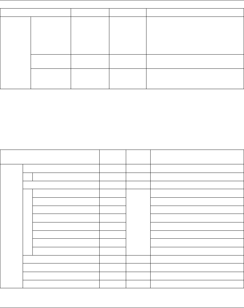
TM5 Expert I/O Electronic Module
EIO0000000420 04/2012 145
For further generic descriptions, refer to I/O Configuration Tab Description
(see page 22).
Expansion Bus I/O Mapping Tab
Variables can be defined and named in the Expansion Bus I/O Mapping tab.
Additional information such as topological addressing is also provided in this tab.
The table below describes the Expansion Bus I/O Mapping configuration:
Counter01 Preset value -32768...32767
(16-bit)
-
2147483648...2
147483647
(32-bit)
0 Homing preset value for counter, the value set
here is applied to the counter value upon
completion of the referencing process.
Reference pulse Negative edge
Positive edge
Negative edge Select edge of reference pulse.
Reference
enable switch
Off
On (active low)
On (active high)
Off Digital input 01 used as reference enable
switch.
Parameter Value Default Value Description
Channel Type Default
value
Description
Inputs PowerSupply USINT - Status encoder supply (bits 1...7: not used)
PowerSupply00 BOOL - Status encoder supply (0=OK)
DigitalInput USINT - State of all digital inputs
SignalA BOOL - Encoder Signal A
SignalB BOOL Encoder Signal B
SignalR BOOL Encoder Signal R
DigitalInput00 BOOL State of digital input 0
SignalA BOOL Encoder Signal A
SignalB BOOL Encoder Signal B
SignalR BOOL Encoder Signal R
DigitalInput01 BOOL State of digital input 1
Encoder00 INT - Incremental encoder
StatusInput00 USINT - Status incremental encoder 00 (see below)
Encoder01 INT - Incremental encoder
StatusInput01 USINT - Status incremental encoder 01 (see below)
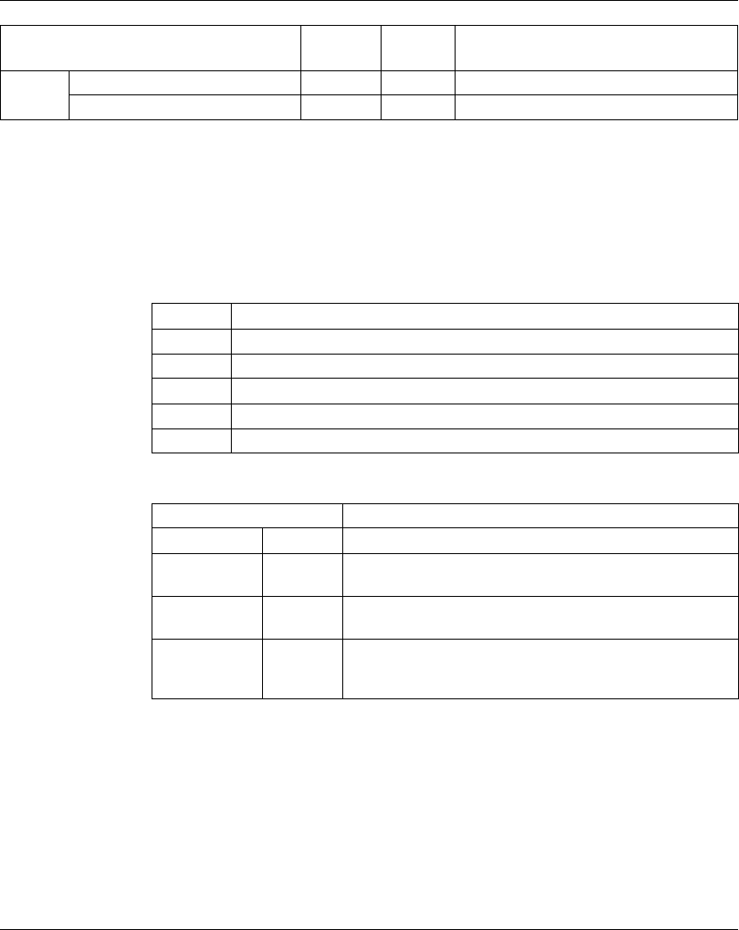
TM5 Expert I/O Electronic Module
146 EIO0000000420 04/2012
For further generic descriptions, refer to Expansion Bus I/O Mapping Tab
Description (see page 22).
StatusInput0x Register
This register contains information regarding whether the referencing process is off,
active, or complete.
The following table describes the StatusInput0x register:
Example:
Outputs ReferenceModeEncoder00 USINT - Reference mode incremental encoder 00
ReferenceModeEncoder01 USINT - Reference mode incremental encoder 01
Channel Type Default
value
Description
Bit Description
0-1 Always 0
2 Bit is always 1 after the first reference impulse
3 Toggle after each completed reference
4 Bit is always 1 after the first reference impulse
5...7 Free-running counter, increased with each reference impulse
Register value Description
00000000 bin 00 hex Referencing off or already in progress.
00111100 bin 3C hex First reference complete, reference value applied in the
Encoder0x register.
xxx11100 bin xB hex Bits 5...7 are changed sequentially with each reference
impulse.
xxx1x100 bin xx hex Bits changed continuously with the setting continuous
referencing. With every reference impulse, the reference
value is applied to the Encoder0x register.
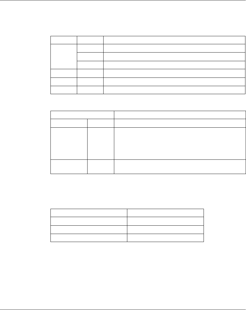
TM5 Expert I/O Electronic Module
EIO0000000420 04/2012 147
ReferenceModeEncoder0x Register
This register determines the encoder reference mode.
The following table describes the ReferenceModeEncoder0x register:
Example:
Cycle Time and I/O Update Time
The table below gives the module characteristics allowing the TM5 Bus Cycle Time
configuration:
For further information, refer to TM5 Manager Configuration (see page 18).
Bit Value Description
0-1 00 Referencing OFF
01 One-time reference (single shot)
11 Continuous referencing
2...5 0000 Bit permanently set = 0
6-7 00 Referencing OFF
11 Bit permanently set = 1
Register value Description
00000000 bin 00 hex Referencing OFF
11000001 bin C1 hex One-time reference (single shot)
When starting over after the referencing process is complete,
the value 00 hex must be written. Then wait until the
StatusInput0x also takes on the value 00 hex. Only then can
the value C1 hex be written.
11000011 bin C3 hex Continuous referencing, referencing occurs at every reference
pulse.
Characteristic Value
Minimum cycle time 128 μs
Maximum cycle time 16 ms
Minimum I/O update time 128 μs

TM5 Expert I/O Electronic Module
148 EIO0000000420 04/2012
TM5SE1SC10005
Introduction
The TM5SE1SC10005 expansion electronic module is a 5 Vdc or 24 Vdc Expert
Inputs electronic module with 1 input channel for SSI absolute encoder.
For further information, refer to TM5SE1SC10005 Electronic Module 1 HSC SSI 1
Mb 5 Vdc (see Modicon TM5, Expert (High Speed Counter) Modules, Hardware
Guide).
I/O Configuration Tab
To configure the TM5SE1SC10005 electronic module, select the I/O Configuration
tab.
The table below describes the module parameters configuration:
Parameter Value Default Value Description
General Module
address
0...250 Depends on
configuration
The address is automatically set when
adding the modules. The address value
depends on the order of adding the module
in the SoMachine tree. The TM5ACBM15
supports the possibility to change the
address.
Bus base TM5ACBM11
TM5ACBM15
TM5ACBM11 Specifies the bus base associated with the
electronic module.
Terminal block TM5ACTB12 TM5ACTB12 Specifies the terminal block associated with
the electronic module.
24 V I/O
segment
external
current
0...300 mA 300 mA 24 V I/O segment external current on TM5
power supply bus. Refer to System Planning
and Installation Guide.
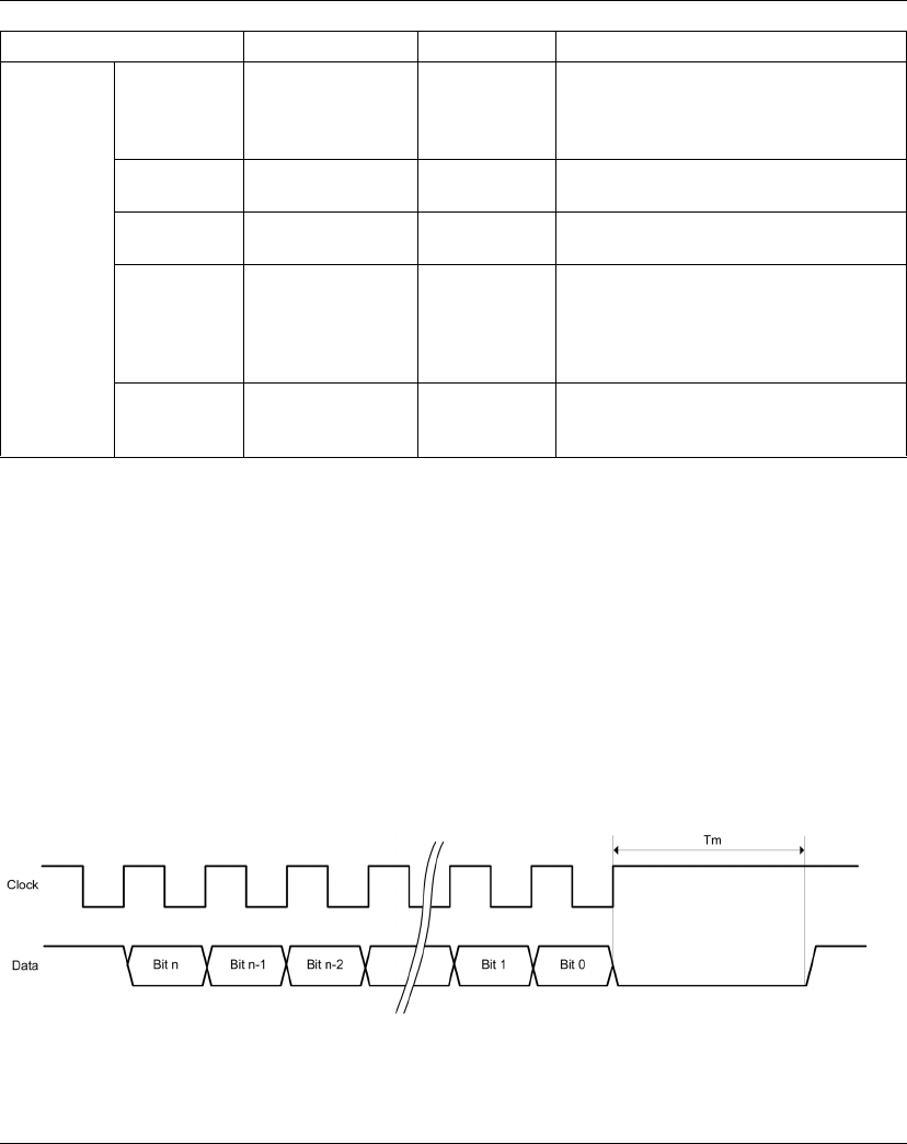
TM5 Expert I/O Electronic Module
EIO0000000420 04/2012 149
For further generic descriptions, refer to I/O Configuration Tab Description
(see page 22).
Monoflop Check Parameter
The Monoflop check parameter is used to test the data line level before starting
data transmission: the clock starts only if the data line level is equal to the specified
level.
This level is programmable, you can choose to perform the test or not.
If you test the level, you can select its value (0 or 1) via the interface.
The data line level is checked from Tm after the last rising edge of the clock line
In the example 1, the Monoflop check parameter must be configured to high level.
This ensures that the clock generation is postponed until the data line goes high.
Counter 00 Clock rate 1 MHz
500 kHz
250 kHz
125 kHz
1 MHz Define the clock rate.
Data format Binary
Gray
Binary Data format of SSI encoder.
Total SSI bit
length
0...32 8 Number of bits sent by the SSI encoder per
frame.
Valid SSI bit
length
0...32 8 Significant part of the SSI encoder frame.
Only the least significant part of the total SSI
encoder frame is valid. The complementary
most significant part of the frame is ignored
and read as 0.
Monoflop
check
High level
Low level
Ignore
High level Data line level checked before starting data
emission (see description below).
Parameter Value Default Value Description
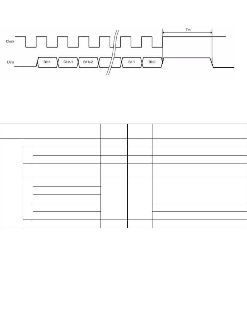
TM5 Expert I/O Electronic Module
150 EIO0000000420 04/2012
In the example 2 the Monoflop check parameter must be configured to low level.
This ensures that the clock generation is postponed until the data line goes low.
Expansion Bus I/O Mapping Tab
Variables can be defined and named in the Expansion Bus I/O Mapping tab.
Additional information such as topological addressing is also provided in this tab.
The table below describes the Expansion Bus I/O Mapping configuration:
For further generic descriptions, refer to Expansion Bus I/O Mapping Tab
Description (see page 22).
Channel Type Default
value
Description
Inputs PowerSupply USINT - Status encoder supply (bits 2...7: not used)
PowerSupply00 BOOL - Status encoder supply 24 Vdc (0=OK)
PowerSupply01 BOOL - Status encoder supply 5 Vdc (0=OK)
DigitalInput USINT - State of all digital inputs (bits 0...3, 6-7: not
used)
Reserved BOOL - Not used
...
Reserved
DigitalInput00 State of digital input 0
DigitalInput01 State of digital input 1
Encoder00 UDINT - Encoder position value

TM5 Expert I/O Electronic Module
EIO0000000420 04/2012 151
Cycle Time and I/O Update Time
The table below gives the module characteristics allowing the TM5 Bus Cycle Time
configuration:
For further information, refer to TM5 Manager Configuration (see page 18).
Characteristic Value
Minimum cycle time 128 μs
Maximum cycle time 16 ms
Minimum I/O update time 128 μs

TM5 Expert I/O Electronic Module
152 EIO0000000420 04/2012
TM5SDI2DF
Introduction
The TM5SDI2DF expansion electronic module is a 24 Vdc Input electronic module
with 2 inputs.
For further information, refer to TM5SDI2DF Electronic Module 2DI 24 Vdc Sink 3-
Wire (see Modicon TM5, Expert (High Speed Counter) Modules, Hardware Guide).
I/O Configuration Tab
To configure the TM5SDI2DF electronic module, select the I/O Configuration tab.
The table below describes the module parameters configuration:
Parameter Value Default Value Unit Description
Function model Default
Additional function
input latch
Default - Additional function input latch:
the Status00...Status03 are
added to the Expansion Bus I/O
Mapping tab.
General Module address 0...250 Depends on
configuration
- The address is automatically set
when adding the modules. The
address value depends on the
order of adding the module in the
SoMachine tree. The
TM5ACBM15 supports the
possibility to change the address.
Input filter 0...250 10 (1 ms) 0.1 ms Specifies the filter time of all
digital inputs.
Bus base TM5ACBM11
TM5ACBM15
TM5ACBM11 - Specifies the bus base
associated with the electronic
module.
Terminal block TM5ACTB06
TM5ACTB12
TM5ACTB06 - Specifies the terminal block
associated with the electronic
module.
24 V I/O segment
external current
0...500 100 mA 24 V I/O segment external
current on TM5 power supply
bus. Refer to System Planning
and Installation Guide.
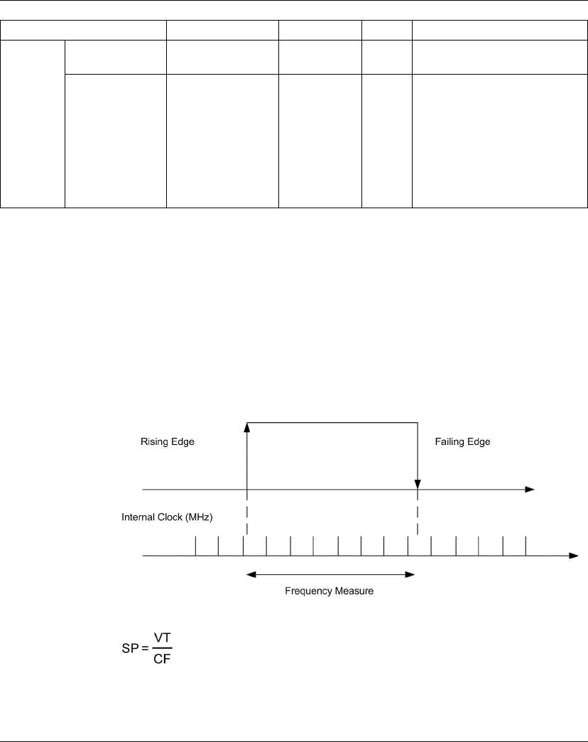
TM5 Expert I/O Electronic Module
EIO0000000420 04/2012 153
For further generic descriptions, refer to I/O Configuration Tab Description
(see page 22).
Counter Mode
Two counter modes can be used with the TM5SDI2DF electronic module:
Event counter operation consists to transfer the counter status, registered with a
fixed offset with respect to the bus cycle and is transferred in the same cycle.
NOTE: The rising edges are registered on the counter input.
Gate measurement consists to use an internal frequency to register the necessary
time to reach the gate input.
The following figure describes the Gate measuring principle:
The TM5SDI2DF value is defined by the following equation:
Where:
SP = Size of Pulse to be measured.
VT = Value of TM5SDI2DF.
CF = Count Frequency.
Counter00
Counter01
Counter mode Event counter
Gate measurement
Event counter - Counter mode (see page 153)
Count frequency 48
24
12
6
3
1.5
0.750
0.375
0.1875
48 MHz Count frequency
(Gate measurement mode only)
Parameter Value Default Value Unit Description
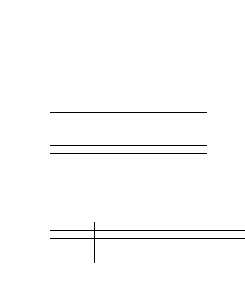
TM5 Expert I/O Electronic Module
154 EIO0000000420 04/2012
For example: For a Count Frequency at 3 Mhz and a Size of Pulse to be
measured = 15 ms, the Value of TM5SDI2DF is near 46000.
NOTE:
zThe recovery time between measurements must be > 100 µs.
zThe measurement result is transferred with the falling edge to the result memory.
The following table gives the maximun Size of Pulse to be measured depending
on the Count Frequency parameter:
For example: For a Count Frequency at 48 Mhz, the maximum Size of Pulse to be
measured = 13 ms.
Additional function input latch
Using this function, the positive edges of the input signal can be latched with a
resolution of 200 µs. With the “Acknowledge - input latch” function, the input latch is
either reset or prevented from latching.
It works in the same way as a dominant reset RS flip-flop:
Maximum Size of
Pulse
Count Frequency
13.653125 ms 48 MHz
27.30625 ms 24 MHz
54.6125 ms 12 MHz
109.225 ms 6 MHz
218.45 ms 3 MHz
436.9 ms 1.5 MHz
873.8 ms 0.75 MHz
1747.6 ms 0.375 MHz
3542.432432 ms 0.185 MHz
R: Status03 S: Status02 Q Status
0 0 x Do not change
01 1 Set
1 0 0 Reset
1 1 0 Reset
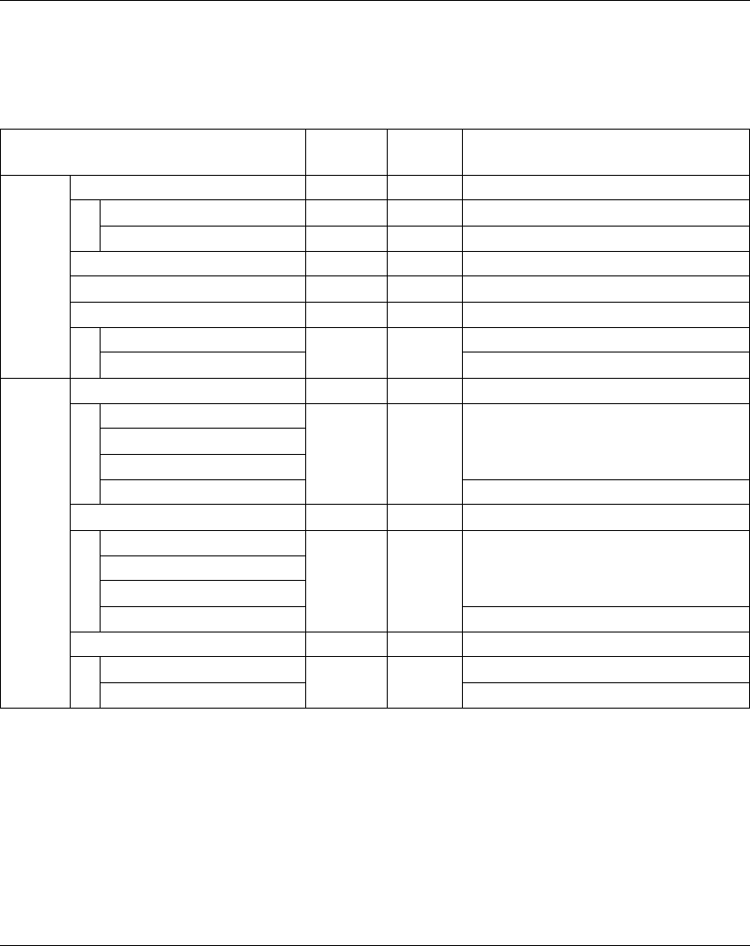
TM5 Expert I/O Electronic Module
EIO0000000420 04/2012 155
Expansion Bus I/O Mapping Tab
Variables can be defined and named in the Expansion Bus I/O Mapping tab.
Additional information such as topological addressing is also provided in this tab.
The table below describes the Expansion Bus I/O Mapping configuration:
For further generic descriptions, refer to Expansion Bus I/O Mapping Tab
Description (see page 22).
Channel Type Default
value
Description
Inputs DigitalInput USINT - State of digital inputs (bits 2...7: not used)
DigitalInput00 BOOL - State of digital input 0
DigitalInput01 BOOL - State of digital input 1
Counter00 UINT - Counter 0 value
Counter01 UINT - Counter 1 value
Status02 USINT -
DigitalInput00Latch BOOL - Positive edge latched state of input 0
DigitalInput01Latch Positive edge latched state of input 1
Outputs Status00 USINT -
Not used BOOL - Not used
...
Not used
ResetCounter00 Reset event counter 00 on rising edge
Status01 USINT -
Not used BOOL - Not used
...
Not used
ResetCounter01 Reset event counter 01 on rising edge
Status03 USINT -
DigitalInput00LatchQuitt BOOL - Acknowledge latch state input 0
DigitalInput01LatchQuitt Acknowledge latch state input 1

TM5 Expert I/O Electronic Module
156 EIO0000000420 04/2012
Cycle Time and I/O Update Time
The table below gives the module characteristics allowing the TM5 Bus Cycle Time
configuration:
For further information, refer to TM5 Manager Configuration (see page 18).
Characteristic Value
Minimum cycle time 100 μs
Minimum I/O update time 100 μs
EIO0000000420 04/2012 157
6
Modicon TM5
TM5 Transm itter - Re ceiver Ele ctronic Mo dules
EIO0000000420 04/2012
TM5 Transmitter - Receiver
Electronic Modules
Introduction
This chapter provides information to configure transmitter - receiver expansion
electronic modules.
To add expansion electronic modules and access to the configuration screens, refer
to Adding an expansion electronic module (see page 21).
What’s in this Chapter?
This chapter contains the following topics:
Topic Page
TM5SBET1 158
TM5SBET7 160
TM5SBER2 162

TM5 Transmitter - Receiver Electronic Modules
158 EIO0000000420 04/2012
TM5SBET1
Introduction
The TM5SBET1 expansion electronic module is a Transmitter electronic module
which transmits the TM5 data bus
For further information, refer to TM5SBET1 Transmitter Electronic Module
(see Modicon TM5, Transmitter and Receiver Modules, Hardware Guide).
I/O Configuration Tab
To configure the TM5SBET1 electronic module, select the I/O configuration tab.
The table below describes the modules parameters configuration:
For further generic descriptions, refer to I/O Configuration Tab Description
(see page 22).
Parameter Parameter Value Default Value Description
General Module address 0...250 Depends on
the
configuration
The address is automatically set when adding
the modules. The address value depends on
the order of adding the module in the
SoMachine tree. The TM5ACBM15 supports
the possibility to change the address.
Module status
information
On
Off
On Enable/Disable read of the module information
On: the StatusInputs word is added to the
Expansion Bus I/O Mapping tab.
Voltage
information
Off
On
Off Enable/Disable read of the additional
current/voltage information
On: the SupplyVoltage word is added to the
Expansion Bus I/O Mapping tab.
Bus base TM5ACBM11
TM5ACBM15
TM5ACBM11 Specifies the bus base associated with the
electronic module.
Terminal block TM5ACTB06
TM5ACTB12
TM5ACTB06 Specifies the terminal block associated with the
electronic module.

TM5 Transmitter - Receiver Electronic Modules
EIO0000000420 04/2012 159
Expansion Bus I/O Mapping Tab
Variables can be defined and named in the Expansion Bus I/O Mapping tab.
Additional information such as topological addressing is also provided in this tab.
The table below describes the Expansion Bus I/O Mapping configuration:
For further generic descriptions, refer to Expansion Bus I/O Mapping Tab
Description (see page 22).
Cycle Time and I/O Update Time
The table below gives the module characteristics allowing the TM5 Bus Cycle Time
configuration:
For further information, refer to TM5 Manager Configuration (see page 18).
Channel Type Default
value
Description
Inputs StatusInputs USINT - Status of the module (bits 2...7: not used)
StatusInput00 BOOL - Bus power supply warning:
z0 = OK
z1 = low voltage <4.7 V
Not used Not used (bit=0)
StatusInput01 I/O power supply warning:
z0 = OK
z1 = I/O power supply < 20.4 V
Supply/Voltage USINT - Bus voltage with a resolution of 0.1 V
Characteristic Value (μs)
Minimum cycle time 100
Minimum I/O update time 2000

TM5 Transmitter - Receiver Electronic Modules
160 EIO0000000420 04/2012
TM5SBET7
Introduction
The TM5SBET7 expansion electronic module is a Transmitter electronic module
which transmits the TM7 data bus and provides the TM7 power bus to the TM7
expansion I/O blocks.
For further information, refer to TM5SBET7 Transmitter Electronic Module
(see Modicon TM5, Transmitter and Receiver Modules, Hardware Guide).
I/O Configuration Tab
To configure the TM5SBET7 electronic module, select the I/O configuration tab.
The table below describes the modules parameters configuration:
For further generic descriptions, refer to I/O Configuration Tab Description
(see page 22).
Parameter Parameter Value Default Value Description
General Module address 0...250 0 The address is automatically set when adding
the modules. The address value depends on
the order of adding the module in the
SoMachine tree. The TM5ACBM15 supports
the possibility to change the address.
Module status
information
On
Off
On Enable/Disable read of the module information
On: the StatusInputs word is added to the
Expansion Bus I/O Mapping tab.
Current/Voltage
information
Off
On
Off Enable/Disable read of the additional
current/voltage information
On: the SupplyVoltage and SupplyCurrent
words are added to the Expansion Bus I/O
Mapping tab.
Bus base TM5ACBM11
TM5ACBM15
TM5ACBM11 Specifies the bus base associated with the
electronic module.
Terminal block TM5ACTB12 TM5ACTB12 Specifies the terminal block associated with the
electronic module.

TM5 Transmitter - Receiver Electronic Modules
EIO0000000420 04/2012 161
Expansion Bus I/O Mapping Tab
Variables can be defined and named in the Expansion Bus I/O Mapping tab.
Additional information such as topological addressing is also provided in this tab.
The table below describes the Expansion Bus I/O Mapping configuration:
For further generic descriptions, refer to Expansion Bus I/O Mapping Tab
Description (see page 22).
Cycle Time and I/O Update Time
The table below gives the module characteristics allowing the TM5 Bus Cycle Time
configuration:
For further information, refer to TM5 Manager Configuration (see page 18).
Channel Type Default
value
Description
Inputs StatusInputs USINT – Status of the module (bits 2...7: not used)
StatusInput00 BOOL – Bus power supply warning:
z0 = OK
z1 = over current > 0.4 A or low voltage <18 V
Not used Not used (bit=0)
StatusInput01 I/O power supply warning:
z0 = OK
z1 = I/O power supply < 20.4 V
SupplyCurrent USINT - Bus current with a resolution of 0.01 A
SupplyVoltage USINT - Bus voltage with a resolution of 0.1 V
Characteristic Value (μs)
Minimum cycle time 100
Minimum I/O update time 2000

TM5 Transmitter - Receiver Electronic Modules
162 EIO0000000420 04/2012
TM5SBER2
Introduction
The TM5SBER2 expansion electronic module is a Receiver electronic module which
receives the TM5 data bus.
For further information, refer to TM5SBER2 Receiver Electronic Module
(see Modicon TM5, Transmitter and Receiver Modules, Hardware Guide).
I/O Configuration Tab
To configure the TM5SBER2 electronic module, select the I/O configuration tab.
The table below describes the modules parameters configuration:
For further generic descriptions, refer to I/O Configuration Tab Description
(see page 22).
Parameter Parameter Value Default Value Description
General Module address 0...250 Depends on the
configuration
The address is automatically set when adding
the modules. The address value depends on
the order of adding the module in the
SoMachine tree. The TM5ACBM15 supports
the possibility to change the address.
Module status
information
On
Off
On Enable/Disable read of the module information
On: the StatusInputs word is added to the
Expansion Bus I/O Mapping tab.
Current/Voltage
information
Off
On
Off Enable/Disable read of the additional
current/voltage information
On: the SupplyCurrent and SupplyVoltage
words are added to the Expansion Bus I/O
Mapping tab.
Bus base TM5ACBM01R
TM5ACBM05R
TM5ACBM01R Specifies the bus base associated with the
electronic module.
Terminal block TM5ACTB12PS TM5ACTB12PS Specifies the terminal block associated with the
electronic module.
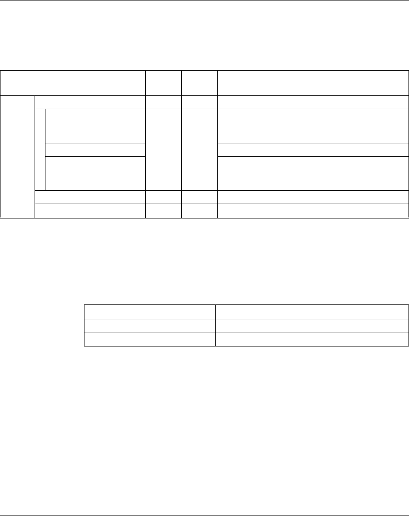
TM5 Transmitter - Receiver Electronic Modules
EIO0000000420 04/2012 163
Expansion Bus I/O Mapping Tab
Variables can be defined and named in the Expansion Bus I/O Mapping tab.
Additional information such as topological addressing is also provided in this tab.
The table below describes the Expansion Bus I/O Mapping configuration:
For further generic descriptions, refer to Expansion Bus I/O Mapping Tab
Description (see page 22).
Cycle Time and I/O Update Time
The table below gives the module characteristics allowing the TM5 Bus Cycle Time
configuration:
For further information, refer to TM5 Manager Configuration (see page 18).
Channel Type Default
value
Description
Inputs StatusInputs USINT - Status of the module (bits 3...7: not used)
StatusInput00 BOOL - Bus power supply warning:
z0 = OK
z1 = over current >2.3 A or low voltage <4.7 V
Not used Not used (bit=0)
StatusInput01 I/O power supply warning:
z0 = OK
z1 = I/O power supply < 20.4 V
SupplyCurrent USINT - Bus current with a resolution of 0.1 A
Supply/Voltage USINT - Bus voltage with a resolution of 0.1 V
Characteristic Value (μs)
Minimum cycle time 100
Minimum I/O update time 2000

TM5 Transmitter - Receiver Electronic Modules
164 EIO0000000420 04/2012
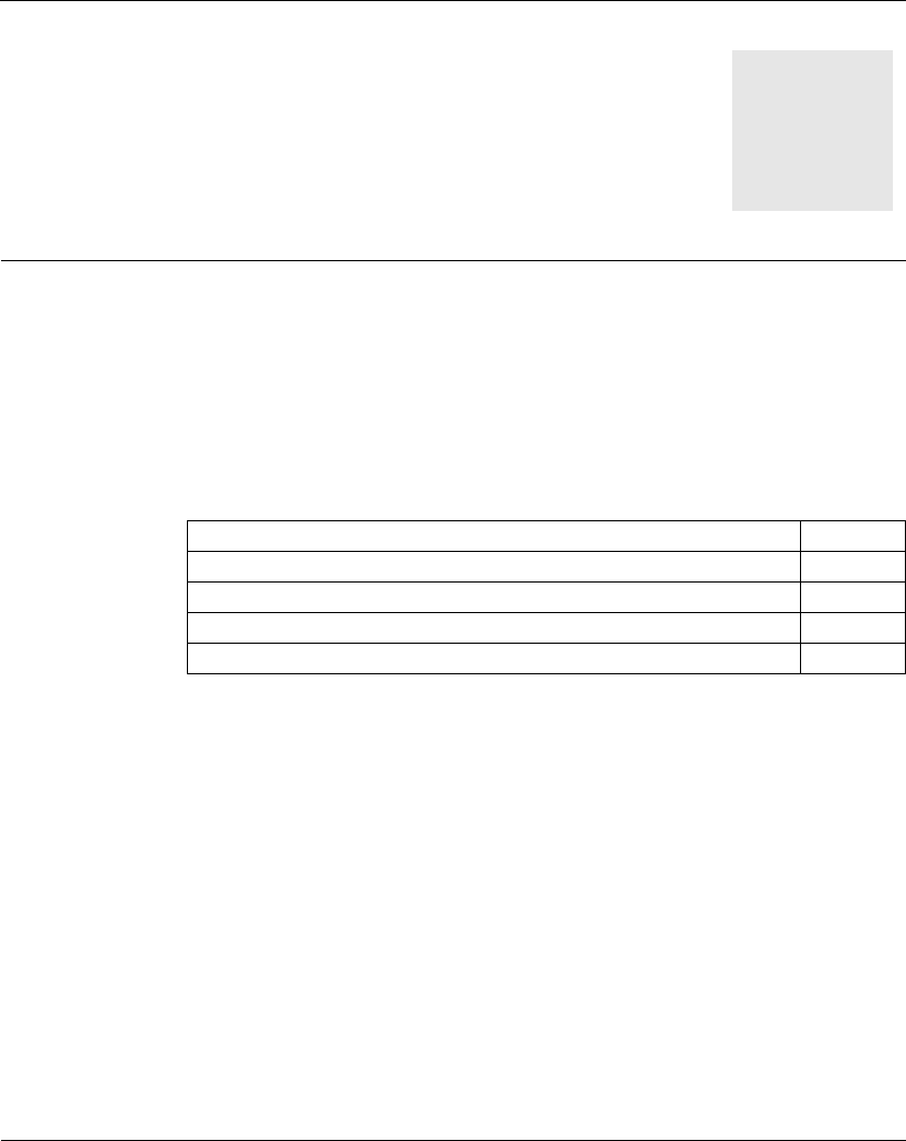
EIO0000000420 04/2012 165
7
Modicon TM5
TM5 Power Supply Electronic Modules
EIO0000000420 04/2012
TM5 Power Supply Electronic
Modules
Introduction
This chapter provides information to configure power supply expansion electronic
modules.
To add expansion electronic modules and access to the configuration screens, refer
to Adding an expansion electronic module (see page 21).
What’s in this Chapter?
This chapter contains the following topics:
Topic Page
TM5SPS1 166
TM5SPS1F 168
TM5SPS2 170
TM5SPS2F 172

TM5 Power Supply Electronic Modules
166 EIO0000000420 04/2012
TM5SPS1
Introduction
The TM5SPS1 expansion electronic module is a 24 Vdc power supply electronic
module for internal I/O supply.
I/O Configuration Tab
To configure the TM5SPS1 electronic module, select the I/O configuration tab.
The table below describes the modules parameters configuration:
For further generic descriptions, refer to I/O Configuration Tab Description
(see page 22).
Parameter Parameter Value Default Value Description
General Module address 0...250 Depends on the
configuration.
Specifies the electronic module address (only
with TM5ACBM05R).
Module status
information
On
Off
On Additional status information
On: the StatusInputs word is added to the
Expansion Bus I/O Mapping tab.
Voltage
information
Off
On
Off Additional current/voltage information
On: the SupplyVoltage word is added to the
Expansion Bus I/O Mapping tab.
Bus base TM5ACBM01R
TM5ACBM05R
TM5ACBM01R Specifies the bus base associated with the
electronic module.
Terminal block TM5ACTB12PS TM5ACTB12PS Specifies the terminal block associated with the
electronic module.
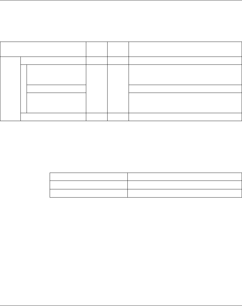
TM5 Power Supply Electronic Modules
EIO0000000420 04/2012 167
Expansion Bus I/O Mapping Tab
Variables can be defined and named in the Expansion Bus I/O Mapping tab.
Additional information such as topological addressing is also provided in this tab.
The table below describes the Expansion Bus I/O Mapping configuration:
For further generic descriptions, refer to Expansion Bus I/O Mapping Tab
Description (see page 22).
Cycle Time and I/O Update Time
The table below gives the module characteristics allowing the TM5 Bus Cycle Time
configuration:
For further information, refer to TM5 Manager Configuration (see page 18).
Channel Type Default
value
Description
Inputs StatusInputs USINT - Status of the module (bits 3...7: not used)
StatusInput00 BOOL - Bus power supply warning:
z0 = OK
z1 = low voltage <4.7 V
Not used Not used (bit=0)
StatusInput01 I/O power supply warning:
z0 = OK
z1 = I/O power supply < 20.4 V
SupplyVoltage USINT - Bus voltage with a resolution of 0.1 V
Characteristic Value (μs)
Minimum Cycle Time 100
Minimum I/O update time 2000

TM5 Power Supply Electronic Modules
168 EIO0000000420 04/2012
TM5SPS1F
Introduction
The TM5SPS1F expansion electronic module is a 24 Vdc power supply electronic
module for internal I/O supply with a fuse.
I/O Configuration Tab
To configure the TM5SPS1F electronic module, select the I/O configuration tab.
The table below describes the modules parameters configuration:
For further generic descriptions, refer to I/O Configuration Tab Description
(see page 22).
Parameter Parameter Value Default Value Description
General Module address 0...250 Depends on the
configuration
Specifies the electronic module address
(only with TM5ACBM05R).
Module status
information
On
Off
On Additional status information
On: the StatusInputs word is added to the
Expansion Bus I/O Mapping tab.
Voltage
information
Off
On
Off Additional voltage information
On: the SupplyVoltage word is added to the
Expansion Bus I/O Mapping tab.
Bus base TM5ACBM01R
TM5ACBM05R
TM5ACBM01R Specifies the bus base associated with the
electronic module.
Terminal block TM5ACTB12PS TM5ACTB12PS Specifies the terminal block associated with
the electronic module.
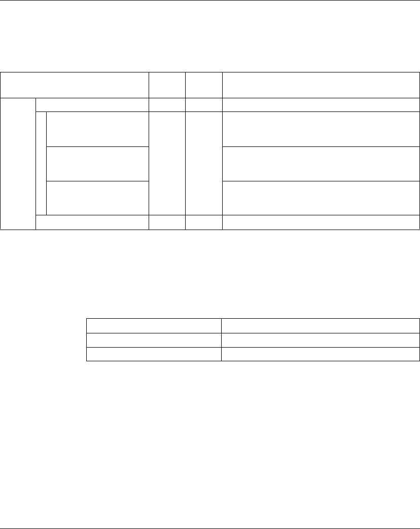
TM5 Power Supply Electronic Modules
EIO0000000420 04/2012 169
Expansion Bus I/O Mapping Tab
Variables can be defined and named in the Expansion Bus I/O Mapping tab.
Additional information such as topological addressing is also provided in this tab.
The table below describes the Expansion Bus I/O Mapping configuration:
For further generic descriptions, refer to Expansion Bus I/O Mapping Tab
Description (see page 22).
Cycle Time and I/O Update Time
The table below gives the module characteristics allowing the TM5 Bus Cycle Time
configuration:
For further information, refer to TM5 Manager Configuration (see page 18).
Channel Type Default
value
Description
Inputs StatusInputs USINT - Status of the module (bits 3...7: not used)
StatusInput00 BOOL - Bus power supply warning:
z0 = OK
z1 = low voltage <4.7 V
StatusInput01 Fuse status:
z0 = OK
z1 = fuse is blown or missing
StatusInput02 I/O power supply warning:
z0 = OK
z1 = I/O power supply < 20.4 V
SupplyVoltage USINT - Bus voltage with a resolution of 0.1 V
Characteristic Value (μs)
Minimum Cycle Time 100
Minimum I/O update time 2000

TM5 Power Supply Electronic Modules
170 EIO0000000420 04/2012
TM5SPS2
Introduction
The TM5SPS2 expansion electronic module is a 24 Vdc power supply electronic
module for internal I/O supply.
I/O Configuration Tab
To configure the TM5SPS2 electronic module, select the I/O configuration tab.
The table below describes the modules parameters configuration:
For further generic descriptions, refer to I/O Configuration Tab Description
(see page 22).
Parameter Parameter Value Default Value Description
General Module address 0...250 Depends on the
configuration
Specifies the electronic module address
(only with TM5ACBM05R).
Module status
information
On
Off
On Additional status information
On: the StatusInputs word is added to the
Expansion Bus I/O Mapping tab.
Current/voltage
information
Off
On
Off Additional current/voltage information
On: the SupplyCurrent and SupplyVoltage
words are added to the Expansion Bus I/O
Mapping tab.
Bus base TM5ACBM01R
TM5ACBM05R
TM5ACBM01R Specifies the bus base associated with the
electronic module.
Terminal block TM5ACTB12PS TM5ACTB12PS Specifies the terminal block associated with
the electronic module.
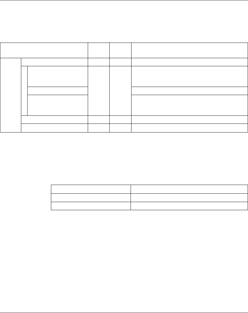
TM5 Power Supply Electronic Modules
EIO0000000420 04/2012 171
Expansion Bus I/O Mapping Tab
Variables can be defined and named in the Expansion Bus I/O Mapping tab.
Additional information such as topological addressing is also provided in this tab.
The table below describes the Expansion Bus I/O Mapping configuration:
For further generic descriptions, refer to Expansion Bus I/O Mapping Tab
Description (see page 22).
Cycle Time and I/O Update Time
The table below gives the module characteristics allowing the TM5 Bus Cycle Time
configuration:
For further information, refer to TM5 Manager Configuration (see page 18).
Channel Type Default
value
Description
Inputs StatusInputs USINT - Status of the module (bits 3...7: not used)
StatusInput00 BOOL - Bus power supply warning:
z0 = OK
z1 = over current > 2.3 A or low voltage < 4.7 V
Not used -
StatusInput01 I/O power supply warning:
z0 = OK
z1 = I/O power supply < 20.4 V
SupplyCurrent USINT - Bus current with a resolution of 0.1 A
SupplyVoltage USINT - Bus voltage with a resolution of 0.1 V
Characteristic Value (μs)
Minimum cycle time 100
Minimum I/O update time 2000

TM5 Power Supply Electronic Modules
172 EIO0000000420 04/2012
TM5SPS2F
Introduction
The TM5SPS2F expansion electronic module is a 24 Vdc power supply electronic
module for internal I/O supply with a fuse.
I/O Configuration Tab
To configure the TM5SPS2F electronic module, select the I/O configuration tab.
The table below describes the modules parameters configuration:
For further generic descriptions, refer to I/O Configuration Tab Description
(see page 22).
Parameter Parameter Value Default Value Description
General Module address 0...250 Depends on the
configuration
Specifies the electronic module address
(only with TM5ACBM05R).
Module status
information
On
Off
On Additional status information
On: the StatusInputs word is added to the
Expansion Bus I/O Mapping tab.
Current/voltage
information
Off
On
Off Additional current/voltage information
On: the SupplyCurrent and SupplyVoltage
words are added to the Expansion Bus I/O
Mapping tab.
Bus base TM5ACBM01R
TM5ACBM05R
TM5ACBM01R Specifies the bus base associated with the
electronic module.
Terminal block TM5ACTB12PS TM5ACTB12PS Specifies the terminal block associated with
the electronic module.

TM5 Power Supply Electronic Modules
EIO0000000420 04/2012 173
Expansion Bus I/O Mapping Tab
Variables can be defined and named in the Expansion Bus I/O Mapping tab.
Additional information such as topological addressing is also provided in this tab.
The table below describes the Expansion Bus I/O Mapping configuration:
For further generic descriptions, refer to Expansion Bus I/O Mapping Tab
Description (see page 22).
Cycle Time and I/O Update Time
The table below gives the module characteristics allowing the TM5 Bus Cycle Time
configuration:
For further information, refer to TM5 Manager Configuration (see page 18).
Channel Type Default
value
Description
Inputs StatusInputs USINT - Status of the module (bits 3...7: not used)
StatusInput00 BOOL - Bus power supply warning:
z0 = OK
z1 = over current > 2.3 A or low voltage < 4.7 V
Not used -
StatusInput01 I/O power supply warning:
z0 = OK
z1 = I/O power supply < 20.4 V
SupplyCurrent USINT - Bus current with a resolution of 0.1 A
SupplyVoltage USINT - Bus voltage with a resolution of 0.1 V
Characteristic Value (μs)
Minimum cycle time 100
Minimum I/O update time 2000

TM5 Power Supply Electronic Modules
174 EIO0000000420 04/2012

EIO0000000420 04/2012 175
8
Modicon TM5
TM5 Common Distribution Electronic Modules
EIO0000000420 04/2012
TM5 Common Distribution
Electronic Modules
Introduction
This chapter provides information to configure common distribution expansion
electronic modules.
To add expansion electronic modules and access to the configuration screens, refer
to Adding an expansion electronic module (see page 21).
What’s in this Chapter?
This chapter contains the following topics:
Topic Page
TM5SPDG12F 176
TM5SPDD12F 178
TM5SPDG5D4F 180
TM5SPDG6D6F 182
TM5SD000 184
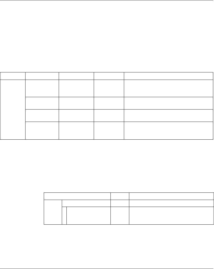
TM5 Common Distribution Electronic Modules
176 EIO0000000420 04/2012
TM5SPDG12F
Introduction
The TM5SPDG12F expansion electronic module is a 12 x Ground potential
distribution electronic module with a fuse.
I/O Configuration Tab
To configure the TM5SPDG12F electronic module, select the I/O configuration tab.
The table below describes the modules parameters configuration:
For further generic descriptions, refer to I/O Configuration Tab Description
(see page 22).
Expansion Bus I/O Mapping Tab
Variables can be defined and named in the Expansion Bus I/O Mapping tab.
Additional information such as topological addressing is also provided in this tab.
The table below describes the Expansion Bus I/O Mapping configuration:
For further generic descriptions, refer to Expansion Bus I/O Mapping Tab
Description (see page 22).
Parameter Parameter Value Default Value Description
General Module address 0...250 Depends on
the
configuration
Specifies the electronic module address
(only with TM5ACBM15).
Bus base TM5ACBM11
TM5ACBM15
TM5ACBM11 Specifies the bus base associated with the
electronic module.
Terminal block TM5ACTB12 TM5ACTB12 Specifies the terminal block associated with the
electronic module.
24 V I/O
segment
external current
0...6300 0 mA 24 V I/O segment external current on TM5
power supply bus. Refer to System Planning
and Installation Guide.
Channel Type Description
Inputs StatusInputs USINT Status of the module (bits 1...7: not used)
StatusFuse BOOL Fuse status:
z0 = OK
z1 = fuse is blown or missing

TM5 Common Distribution Electronic Modules
EIO0000000420 04/2012 177
Cycle Time and I/O Update Time
The table below gives the module characteristics allowing the TM5 Bus Cycle Time
configuration:
For further information, refer to TM5 Manager Configuration (see page 18).
Characteristic Value (μs)
Minimum cycle time 100
Minimum I/O update time 100
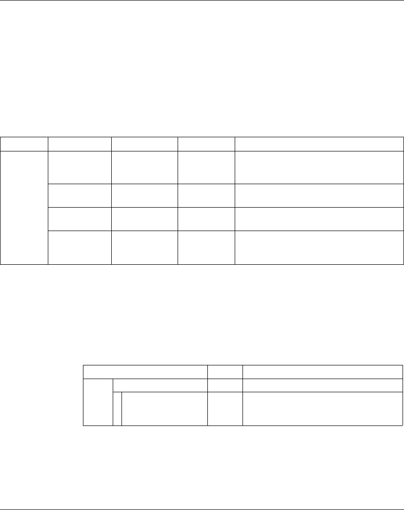
TM5 Common Distribution Electronic Modules
178 EIO0000000420 04/2012
TM5SPDD12F
Introduction
The TM5SPDD12F expansion electronic module is a 12 x 24 Vdc potential
distribution electronic module with a fuse.
I/O Configuration Tab
To configure the TM5SPDD12F electronic module, select the I/O configuration tab.
The table below describes the modules parameters configuration:
For further generic descriptions, refer to I/O Configuration Tab Description
(see page 22).
Expansion Bus I/O Mapping Tab
Variables can be defined and named in the Expansion Bus I/O Mapping tab.
Additional information such as topological addressing is also provided in this tab.
The table below describes the Expansion Bus I/O Mapping configuration:
For further generic descriptions, refer to Expansion Bus I/O Mapping Tab
Description (see page 22).
Parameter Parameter Value Default Value Description
General Module address 0...250 Depends on
the
configuration
Specifies the electronic module address
(only with TM5ACBM15).
Bus base TM5ACBM11
TM5ACBM15
TM5ACBM11 Specifies the bus base associated with the
electronic module.
Terminal block TM5ACTB12 TM5ACTB12 Specifies the terminal block associated with the
electronic module.
24 V I/O
segment
external current
0...6300 0 mA 24 V I/O segment external current on TM5
power supply bus. Refer to System Planning
and Installation Guide.
Channel Type Description
Inputs StatusInputs USINT Status of the module (bits 1...7: not used)
StatusFuse BOOL Fuse status:
z0 = OK
z1 = fuse is blown or missing

TM5 Common Distribution Electronic Modules
EIO0000000420 04/2012 179
Cycle Time and I/O Update Time
The table below gives the module characteristics allowing the TM5 Bus Cycle Time
configuration:
For further information, refer to TM5 Manager Configuration (see page 18).
Characteristic Value (μs)
Minimum cycle time 100
Minimum I/O update time 100

TM5 Common Distribution Electronic Modules
180 EIO0000000420 04/2012
TM5SPDG5D4F
Introduction
The TM5SPDG5D4F expansion electronic module is a 12 x 24 Vdc potential
distribution electronic module with a fuse.
I/O Configuration Tab
To configure the TM5SPDG5D4F electronic module, select the I/O configuration
tab.
The table below describes the modules parameters configuration:
For further generic descriptions, refer to I/O Configuration Tab Description
(see page 22).
Parameter Parameter Value Default Value Description
General Module address 0...250 Depends on
the
configuration
Specifies the electronic module address
(only with TM5ACBM15).
Edge counter Off
On
Off Falling edge counter for power supply
On: the Counter00 word is added to the
Expansion Bus I/O Mapping tab.
Bus base TM5ACBM11
TM5ACBM15
TM5ACBM11 Specifies the bus base associated with the
electronic module.
Terminal block TM5ACTB12 TM5ACTB12 Specifies the terminal block associated with the
electronic module.
24 V I/O
segment
external current
0...6300 0 mA 24 V I/O segment external current on TM5
power supply bus. Refer to System Planning
and Installation Guide.
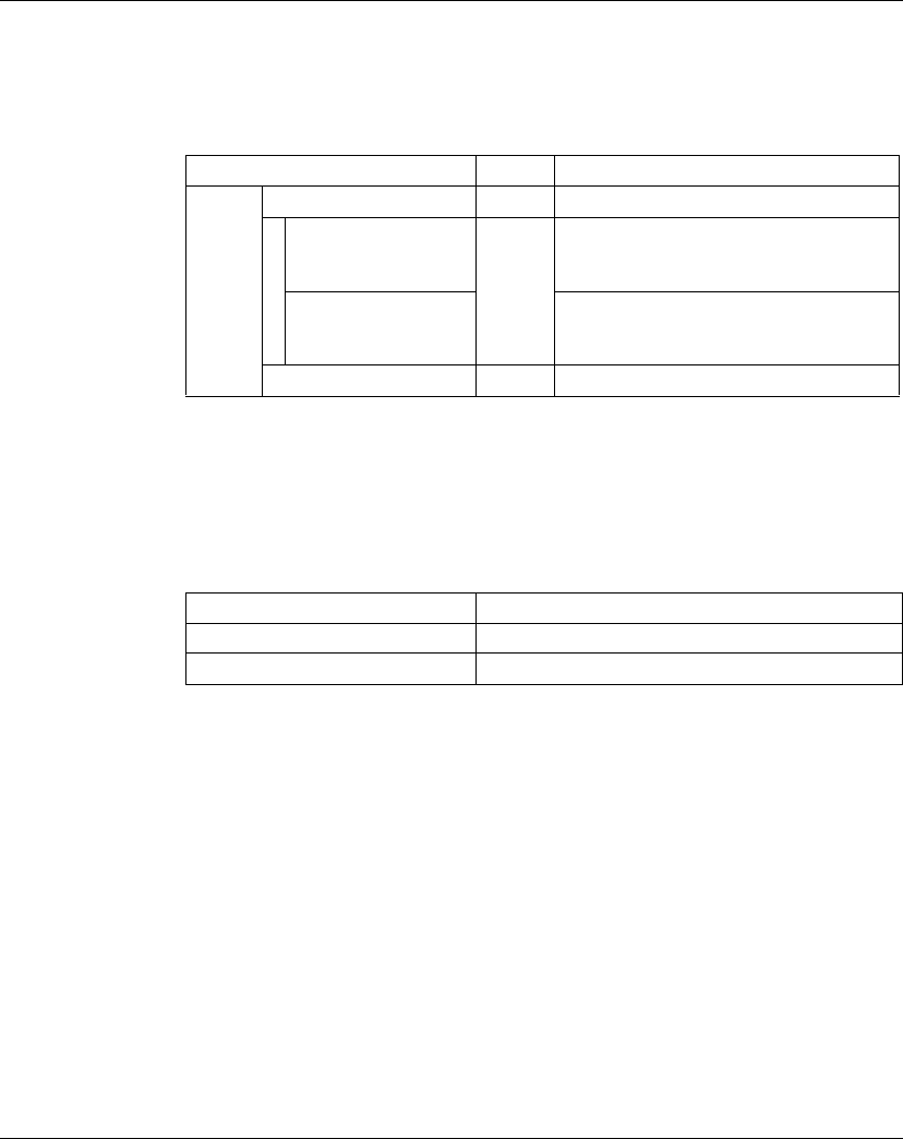
TM5 Common Distribution Electronic Modules
EIO0000000420 04/2012 181
Expansion Bus I/O Mapping Tab
Variables can be defined and named in the Expansion Bus I/O Mapping tab.
Additional information such as topological addressing is also provided in this tab.
The table below describes the Expansion Bus I/O Mapping configuration:
For further generic descriptions, refer to Expansion Bus I/O Mapping Tab
Description (see page 22).
Cycle Time and I/O Update Time
The table below gives the module characteristics allowing the TM5 Bus Cycle Time
configuration:
For further information, refer to TM5 Manager Configuration (see page 18).
Channel Type Description
Inputs StatusInputs USINT Status of the module (bits 2...7: not used)
StatusFuse BOOL Fuse status:
z0 = OK
z1 = fuse is blown or missing
StatusPowerSupply I/O power supply warning:
z0 = OK
z1 = I/O power supply < 20.4 V
Counter00 USINT Number of falling edges of power supply
Characteristic Value (μs)
Minimum Cycle Time 100
Minimum I/O update time 100

TM5 Common Distribution Electronic Modules
182 EIO0000000420 04/2012
TM5SPDG6D6F
Introduction
The TM5SPDG6D6F expansion electronic module is a 6 x Ground and 6 x 24 Vdc
potential distribution electronic module with a fuse.
I/O Configuration Tab
To configure the TM5SPDG6D6F electronic module, select the I/O configuration
tab.
The table below describes the modules parameters configuration:
For further generic descriptions, refer to I/O Configuration Tab Description
(see page 22).
Parameter Parameter Value Default Value Description
General Module address 0...250 Depends on
the
configuration
Specifies the electronic module address
(only with TM5ACBM15).
Edge counter Off
On
Off Falling edge counter for power supply
On: the Counter00 word is added to the
Expansion Bus I/O Mapping tab.
Bus base TM5ACBM11
TM5ACBM15
TM5ACBM11 Specifies the bus base associated with the
electronic module.
Terminal block TM5ACTB12 TM5ACTB12 Specifies the terminal block associated with the
electronic module.
24 V I/O
segment
external current
0...6300 0 mA 24 V I/O segment external current on TM5
power supply bus. Refer to System Planning
and Installation Guide.

TM5 Common Distribution Electronic Modules
EIO0000000420 04/2012 183
Expansion Bus I/O Mapping Tab
Variables can be defined and named in the Expansion Bus I/O Mapping tab.
Additional information such as topological addressing is also provided in this tab.
The table below describes the Expansion Bus I/O Mapping configuration:
For further generic descriptions, refer to Expansion Bus I/O Mapping Tab
Description (see page 22).
Cycle Time and I/O Update Time
The table below gives the module characteristics allowing the TM5 Bus Cycle Time
configuration:
For further information, refer to TM5 Manager Configuration (see page 18).
Channel Type Description
Inputs StatusInputs USINT Status of the module (bits 2...7: not used)
StatusFuse BOOL Fuse status:
z0 = OK
z1 = fuse is blown or missing
StatusPowerSupply I/O power supply warning:
z0 = OK
z1 = I/O power supply < 20.4 V
Counter00 USINT Number of falling edges of power supply
Characteristic Value (μs)
Minimum cycle time 100
Minimum I/O update time 100

TM5 Common Distribution Electronic Modules
184 EIO0000000420 04/2012
TM5SD000
Introduction
The TM5SD000 expansion electronic module is a dummy electronic module.
I/O Configuration Tab
To configure the TM5SD000 electronic module, select the I/O configuration tab.
The table below describes the modules parameters configuration:
For further generic descriptions, refer to I/O Configuration Tab Description
(see page 22).
Parameter Parameter Value Default Value Description
General Module address 0...250 Depends on
the
configuration
Specifies the electronic module address
(only with TM5ACBM15).
Bus base TM5ACBM11
TM5ACBM12
TM5ACBM15
TM5ACBM11 Specifies the bus base associated with the
electronic module.
Terminal block TM5ACTB06
TM5ACTB12
TM5ACTB32
TM5ACTB06 Specifies the terminal block associated with the
electronic module.

EIO0000000420 04/2012 185
Modicon TM5
Glossary
EIO00000 00420 04/2012
Glossary
A
analog input
An analog input module contains circuits that convert an analog DC input signal to
a digital value that can be manipulated by the processor. By implication, the analog
input is usually direct. That means a data table value directly reflects the analog
signal value.
analog output
An analog output module contains circuits that transmit an analog DC signal
proportional to a digital value input to the module from the processor. By implication,
these analog outputs are usually direct. That means a data table value directly
controls the analog signal value.
AWG
The american wire gauge standard specifies wire gauges in North America.
B
bus base
A bus base is a mounting device that is designed to seat an electronic module on a
DIN rail and connect it to the TM5 bus for M258 and LMC058 controllers. Each base
bus extends the TM5 data and to the power buses and the 24 Vdc I/O power
segment. The electronic modules are added to the TM5 system through their
insertion on the base bus. The base bus also supplies the articulation point for the
terminal blocks.

Glossary
186 EIO0000000420 04/2012
C
CAN
The controller area network protocol (ISO 11898) for serial bus networks is designed
for the interconnection of smart devices (from multiple manufacturers) in smart
systems for real-time industrial applications. CAN multi-master systems ensure high
data integrity through the implementation of broadcast messaging and advanced
diagnostic mechanisms. Originally developed for use in automobiles, CAN is now
used in a variety of industrial automation control environments.
CANmotion
CANmotion is a CANopen-based motion bus with an additional mechanism that
provides synchronization between the motion controller and the drives.
CANopen
CANopen is an open industry-standard communication protocol and device profile
specification.
configuration
The configuration includes the arrangement and interconnection of hardware
components within a system and the hardware and software selections that
determine the operating characteristics of the system.
controller
A controller (or “programmable logic controller,” or “programmable controller”) is
used to automate industrial processes.
CPDM
controller power distribution module

Glossary
EIO0000000420 04/2012 187
D
Derating
Derating describes a reduction in an operating specification. For devices in general
it is usually a specified reduction in nominal power to facilitate operation at increased
ambient conditions like higher temperatures or higher altitudes.
digital I/O
A digital input or output has an individual circuit connection at the electronic module
that corresponds directly to a data table bit that holds the value of the signal at that
I/O circuit. It gives the control logic digital access to I/O values.
DIN
Deutsches Institut für Normung is a German institution that sets engineering and
dimensional standards.
DIN
Deutsches Institut für Normung is a German institution that sets engineering and
dimensional standards.
E
electronic module
In a programmable controller system, most electronic modules directly interface to
the sensors, actuators, and external devices of the machine/process. This electronic
module is the component that mounts in a bus base and provides electrical
connections between the controller and the field devices. Electronic modules are
offered in a variety of signal levels and capacities. (Some electronic modules are not
I/O interfaces, including power distribution modules and transmitter/receiver
modules.)
encoder
An encoder is a device for length or angular measurement (linear or rotary
encoders).
Ethernet
Ethernet is a physical and data link layer technology for LANs, also known as
IEE 802.3.

Glossary
188 EIO0000000420 04/2012
EtherNet/IP
The ethernet industrial protocol is an open communications protocol for
manufacturing automation solutions in industrial systems. EtherNet/IP is in a family
of networks that implements Common Industrial Protocol at its upper layers. The
supporting organization (ODVA) specifies EtherNet/IP to accomplish global
adaptability and media independence.
expansion bus
The expansion bus is an electronic communication bus between expansion modules
and a CPU.
expansion I/O module
An expansion input or output module is either a digital or analog module that adds
additional I/O to the base controller.
expert I/O
Expert I/Os are dedicated modules or channels for advanced features. These
features are generally embedded in the module in order to not use the ressources
of the PLC Controller and to allow a fast response time, depending of the feature.
Regarding the function, it could be considered as a “stand alone” module, because
the function is independant of the Controller processing cycle, it just exchanges
some information with the Controller CPU.
F
FAST I/O
FAST I/Os are specific I/Os with some electrical features (response time, for
example) but the treatment of these channels is done by the Controller CPU.
FE
Functional ground is the point of a system or device that must be grounded to help
prevent equipment damage.
Flash memory
Flash memory is nonvolatile memory that can be overwritten. It is stored on a special
EEPROM that can be erased and reprogrammed.

Glossary
EIO0000000420 04/2012 189
H
HMI
A human-machine interface is an operator interface (usually graphical) for industrial
equipment.
hot swapping
Hot swapping is the replacement of a component with a like component while the
system remains operational. The replacement component begins to function
automatically after it is installed.
HSC
high-speed counter
I
I/O
input/output
IEC
The international electrotechnical commission is a non-profit and non-governmental
international standards organization that prepares and publishes international
standards for all electrical, electronic, and related technologies.
IEEE
The institute of electrical and electronics engineers is a non-profit international
standards and conformity assessment body for advances in all fields of
electrotechnology.
input filter
An input filter is a special function that rejects input noises. It is useful for helping to
minimize input noises and chatter in limit switches. All inputs provide a level of input
filtering using the hardware. Additional filtering with software is also configurable
through the programing or the configuration software.

Glossary
190 EIO0000000420 04/2012
IP 20
Ingress protection rating according to IEC 60529. IP20 modules are protected
against ingress and contact of objects larger than 12.5 mm. The module is not
protected against harmful ingress of water.
L
LAN
A local area network local area network is a short-distance communications network
that is implemented in a home, office, or institutional environment.
LED
A light emitting diode is an indicator that lights up when electricity passes through it.
LSB
The least significant bit (or least significant byte) is the part of a number, address, or
field that is written as the right-most single value in conventional hexadecimal or
binary notation.
M
minimum I/O update time
The minimum I/O update time is the minimum time it takes for the bus cycle to shut
down to force an I/O update at each cycle.
Modbus
The Modbus communication protocol allows communications between many
devices connected to the same network.
MSB
The most significant bit (or most significant byte) is the part of a number, address,
or field that is written as the left-most single value in conventional hexadecimal or
binary notation.

Glossary
EIO0000000420 04/2012 191
N
NEC
The national electric code standard dictates the safe installation of electrical wiring
and equipment.
P
PCI
A peripheral component interconnect is an industry-standard bus for attaching
peripherals.
PDM
A power distribution module distributes either AC or DC field power to a cluster of
I/O modules.
PE
Protective ground is a return line across the bus for fault currents generated at a
sensor or actuator device in the control system.
PLC
The programmable logic controller is the “brain” of an industrial manufacturing
process. It automates a process, used instead of relay control systems. PLCs are
computers suited to survive the harsh conditions of the industrial environment.
Profibus DP
Profibus Decentralised Peripheral is a linear bus with a centralized access
procedure of the Master/Slave type. Only Master stations, also known as active
stations, have access rights to the bus. The Slave or passive stations can only
respond to prompts.The physical connection is a single shielded twisted pair, but
fiber optic interfaces are available to create tree, star, or ring structures. Compared
to the ISO model, only layers 1, 2 are implemented, since access from the user
interface is made directly to the link layer via simple mapping of variables.
PWM
Pulse width modulation is used for regulation processes (e.g. actuators for
temperature control) where a pulse signal is modulated in its length. For these kind
of signals, transistor outputs are used.

Glossary
192 EIO0000000420 04/2012
R
RS-232
RS-232 (also known as EIA RS-232C or V.24) is a standard type of serial
communication bus, based on three wires.
RS-485
RS-485 (also known as EIA RS-485) is a standard type of serial communication bus,
based on two wires.
S
SEL-V
A system that follows IEC 61140 guidelines for safety extra low voltage is protected
in such a way that voltage between any 2 accessible parts (or between 1 accessible
part and the PE terminal for Class 1 equipment) does not exceed a specified value
under normal conditions or under single-fault conditions.
sink input
A sink input is a wiring arrangement in which the device provides current to the input
electronic module. A sink input is referenced to 0 Vdc.
Source output
A source output is a wiring arrangement in which the output electronic module
provides current to the device. A source output is referenced to +24 Vdc.
T
terminal block
The terminal block is the component that mounts in an electronic module and
provides electrical connections between the controller and the field devices.

Glossary
EIO0000000420 04/2012 193
U
UL
Underwriters laboratories, US organization for product testing and safety
certification.

Glossary
194 EIO0000000420 04/2012

EIO0000000420 04/2012 195
C
B
A
Modicon T M5
Index
EIO0000000420 04/2012
Index
0-9
12In, 11
2AO ±10 V / 0-20 mA, 11
4AI ±10 V, 11
4AI ±10 V / 0-20 mA / 4-20 mA, 11
4AI 0-20 mA / 4-20 mA, 11
4AO ±10 V, 11
4AO 0-20 mA, 11
4In, 11
4Out, 11
6In, 11
6Out, 11
6Rel, 11
A
analog I/O module
TM5SAI2H, 102
TM5SAI2L, 109
TM5SAI2PH, 118
TM5SAI2TH, 123
TM5SAI4H, 102
TM5SAI4L, 109
TM5SAI4PH, 118
TM5SAI6TH, 123
TM5SAO2H, 130
TM5SAO2L, 130
TM5SAO4H, 132
TM5SAO4L, 132
TM5SEAISG, 129
C
common distribution module
TM5SD000, 184
TM5SPDD12F, 178
TM5SPDG12F, 176
TM5SPDG5D4F, 180
TM5SPDG6D6F, 182
compact electronic module
analog input 4AI, 62
analog input 4AI ±10 V, 59
analog input 4AI 0-20 mA / 4-20 mA, 60
analog output 2AO, 70
analog output 4AO ±10 V, 68
analog output 4AO 0-20 mA, 69
digital input 12In, 55
digital input 4In, 53
digital input 6In, 54
digital output 4Out, 56
digital output 6Out, 57
digital output relay 6Rel, 58
compact I/O module
TM5C12D6T6L, 36
TM5C12D8T, 32
TM5C2418T, 29
TM5C24D12R, 40
TM5CAI8O8VL, 43

Index
196 EIO0000000420 04/2012
D
digital I/O module
TM5SDI12D, 77
TM5SDI2A, 75
TM5SDI2D, 72
TM5SDI4A, 75
TM5SDI4D, 72
TM5SDI6D, 72
TM5SDI6U, 75
TM5SDM12DT, 90
TM5SDO12T, 80
TM5SDO2R, 86
TM5SDO2S, 88
TM5SDO2T, 80
TM5SDO4R, 86
TM5SDO4T, 80
TM5SDO4TA, 83
TM5SDO6T, 80
TM5SDO8TA, 83
E
expansion modules
add, 21
general description, 12
expansion modules and blocks
check resources, 18
TM5 manager, 18
expert I/O module
TM5SDI2DF, 152
TM5SE1IC01024, 140
TM5SE1IC02505, 136
TM5SE1SC10005, 148
TM5SE2IC01024, 144
M
mixed I/O module
TM5SMM6D2L, 92
P
power supply module
TM5SPS1, 166
TM5SPS1F, 168
TM5SPS2, 170
TM5SPS2F, 172
T
TM5, 11
TM5 analog, 11
TM5 common distribution, 11
TM5 compact, 11
TM5 digital, 11
TM5 expert, 11
TM5 power distribution, 11
TM5 receiver, 11
TM5 transmitter, 11
TM5C12D6T6L, 11
TM5C12D8T, 11
TM5C24D12R, 11
TM5C24D18T, 11
TM5CAI8O8CL, 11
TM5CAI8O8CVL, 11
TM5CAI8O8VL, 11
TM5SAI2H, 11
TM5SAI2L, 11
TM5SAI2PH, 11
TM5SAI2TH, 11
TM5SAI4H, 11
TM5SAI4L, 11
TM5SAI4PH, 11
TM5SAI6TH, 11
TM5SAO2H, 11
TM5SAO2L, 11
TM5SAO4H, 11
TM5SAO4L, 11
TM5SBER2, 11
TM5SBET1, 11
TM5SBET7, 11
TM5SD000, 11
TM5SDI12D, 11
TM5SDI2A, 11
TM5SDI2D, 11
TM5SDI2DF, 11

Index
EIO0000000420 04/2012 197
TM5SDI4A, 11
TM5SDI4D, 11
TM5SDI6D, 11
TM5SDI6U, 11
TM5SDM12DT, 11
TM5SDO12T, 11
TM5SDO2R, 11
TM5SDO2S, 11
TM5SDO2T, 11
TM5SDO4R, 11
TM5SDO4T, 11
TM5SDO4TA, 11
TM5SDO6T, 11
TM5SDO8TA, 11
TM5SE1IC01024, 11
TM5SE1IC02505, 11
TM5SE1SC10005, 11
TM5SEAISG, 11
TM5SMM6D2L, 11
TM5SPDD12F, 11
TM5SPDG12F, 11
TM5SPDG5D4F, 11
TM5SPDG6D6F, 11
TM5SPS1, 11
TM5SPS1F, 11
TM5SPS2, 11
TM5SPS2F, 11
transmitter/receiver module
TM5SBER2, 162
TM5SBET1, 158
TM5SBET7, 160

Index
198 EIO0000000420 04/2012
