101974 Catalog
2014-09-05
: Pdf 101974-Catalog 101974-Catalog 785901 Batch7 unilog
Open the PDF directly: View PDF ![]() .
.
Page Count: 22
24-1
© 2012 Schneider Electric
All Rights Reserved
24 TERMINAL BLOCKS
Table of Contents
Section 24
Terminal Blocks
NSYTRV, p. 24-7 NSYTRR, p. 24-3
NSYTRP, p. 24-11 9080GR6, p. 24-15
GB2, p. 24-17 9080GCB, p. 24-17
9080LB, p. 24-18 9080GF6, p. 24-14
9080FB, p. 24-19
DZ5, p. 24-20
Product Panorama
Ter m ina l B l o cks 24-2
Track-Mounting Terminal Blocks and Prewired Connectors
Advantys TELEFAST™ 2 ABE7 Connection
Systems
24-22
NEMA Style Class 9080 Type G 24-13
IEC Style Linergy TR 24-3
Direct-Mounting Terminal Blocks
NEMA Style Class 9080 Type GK 24-13
Circuit Protectors
Class 9080 Type GCB 24-17
GB2 24-17
Power Distribution Blocks (Splitter Blocks)
Class 9080 Type LB 24-18
Fuseholders
Panel Mounting Class 9080 Type FB 24-19
NEMA Style Class 9080 Type GF6 24-14
IEC Style AB1FU, AB1SF 24-8
AB1AASF 24-10
AB1RRNSF 24-4
DF 24-8
Cable Ends (Ferrules, Wire Markers)
DZ5 24-20
AZ5 24-20
AR1 24-21
AT 1 24-21
Mounting Track
9080GH (Square D) 24-16
9080MH (DIN) 24-12
www.schneider-electric.us
24 TERMINAL BLOCKS
24-2 © 2012 Schneider Electric
All Rights Reserved
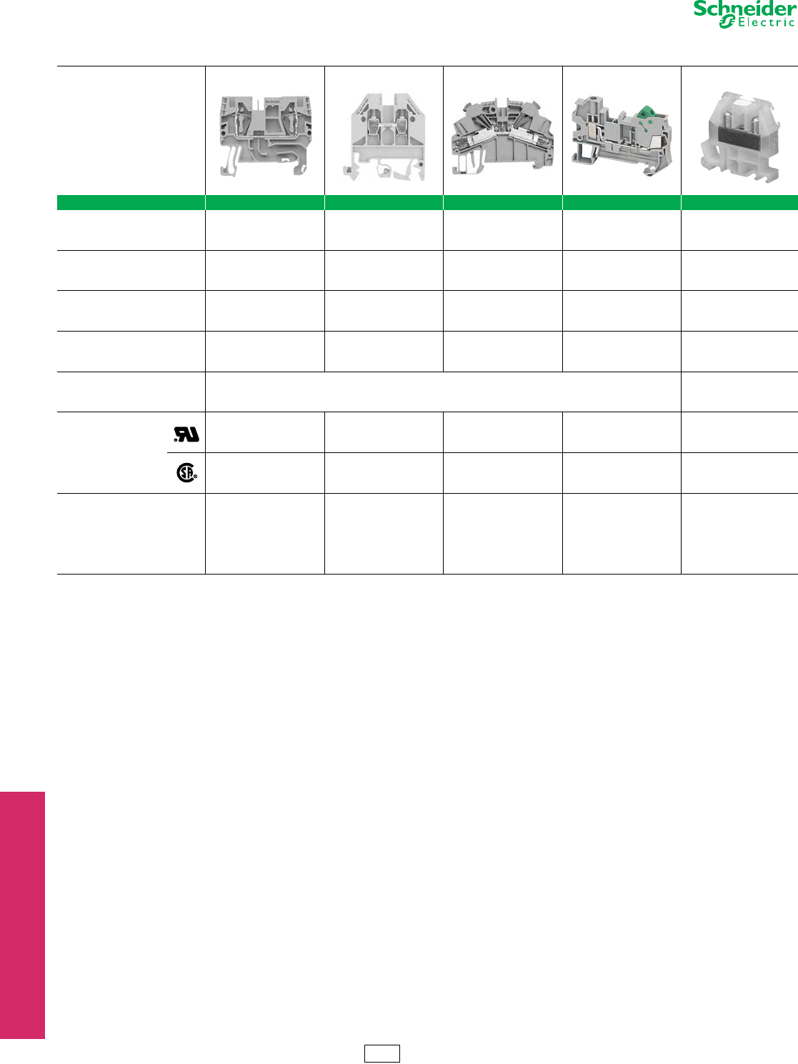
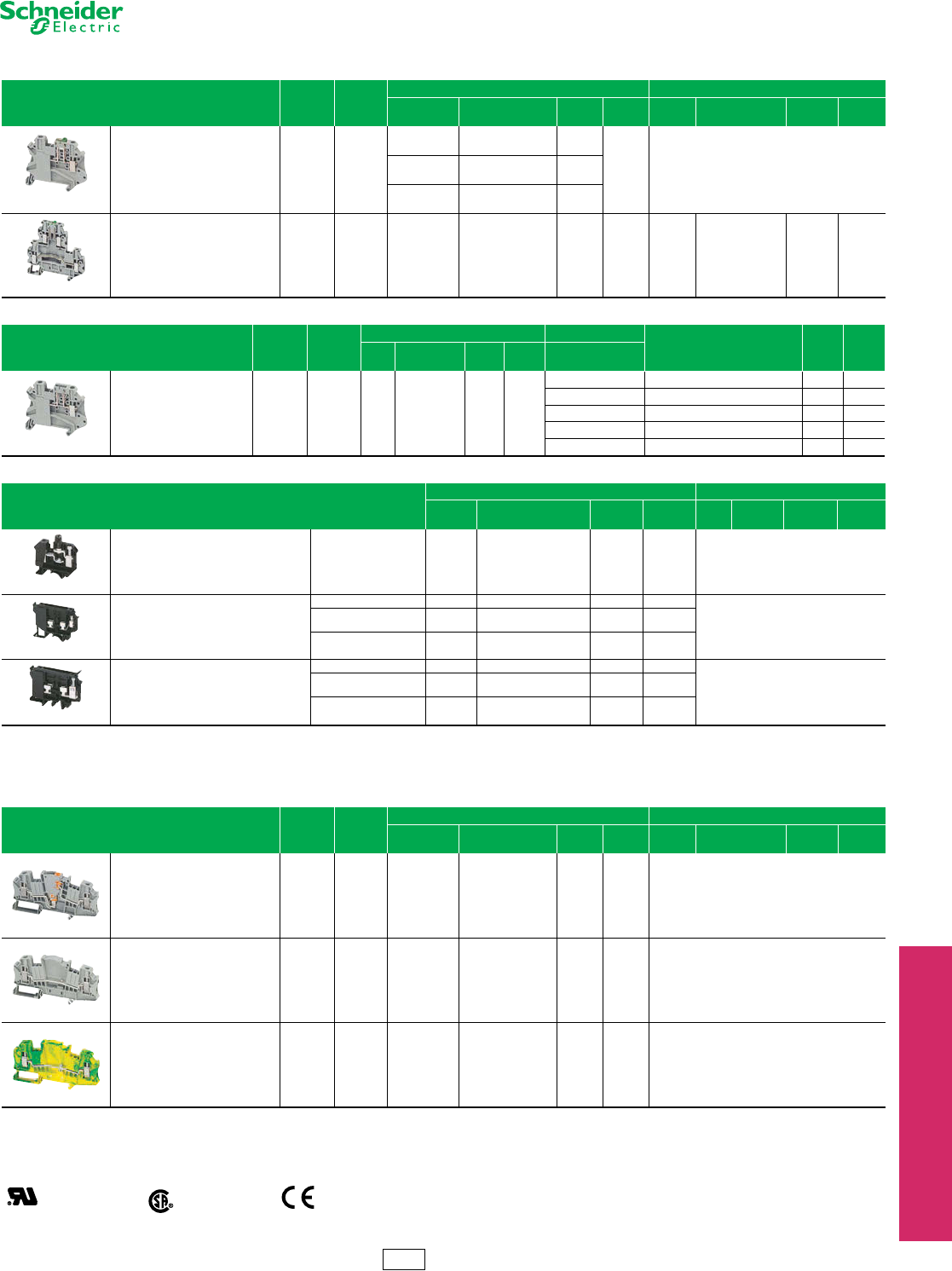
Selection Guide Terminal Blocks
Refer to Catalog 9080CT1301 and 9080CT9601
Product Family NSYTRV NSYTRR NSYTRP NSYTRH 9080G
Type of product IEC screw technology IEC spring technology IEC push-in technology
IEC hybrid
(screw and insulation
displacement connection)
NEMA screw technology
Mounting DIN 3 DIN 3 DIN 3 DIN 3 DIN 3 and Square D track a
Maximum rated voltage (V) 600 600 600 600 600 b
Maximum rated current per UL (A) 285853015255
Ambient air temperature -40 to +266 °F (-40 to 130 °C) -40 to +257 °F (-40 to 125 °C)
Approvals c
UL File E87739
CCN XCFR2
UL File E87739
CCN XCFR2
UL File E87729
CCN XCFR2
UL File E87729
CCN XCFR2
UL File E60616
CCN XCFR2
CSA File 25644
Class 6228-01
CSA File 25644
Class 6228-01
CSA File 25644
Class 6228-01
CSA File 25644
Class 6228-01
CSA File 025490
Class 3211 07
Color
Gray
Blue
Orange
Red
Green
White
Black
Green/Yellow
Gray
Blue
Orange
Green/Yellow
Gray
Blue
Orange
Green/Yellow
Gray
Green/Yellow
Natural (White)
Black
Blue
Green
Gray
Orange
Red
Yellow
Brown
a9080GK6 can be mounted directly to a panel or on Square D track.
b9080GT6 is 120 V.
cRefer to catalogs 9080CT9901R7/07 and 9080CT9601 for a complete list of certifications.
CP5 Discount
Schedule
www.schneider-electric.us
24 TERMINAL BLOCKS
© 2012 Schneider Electric
All Rights Reserved 24-3
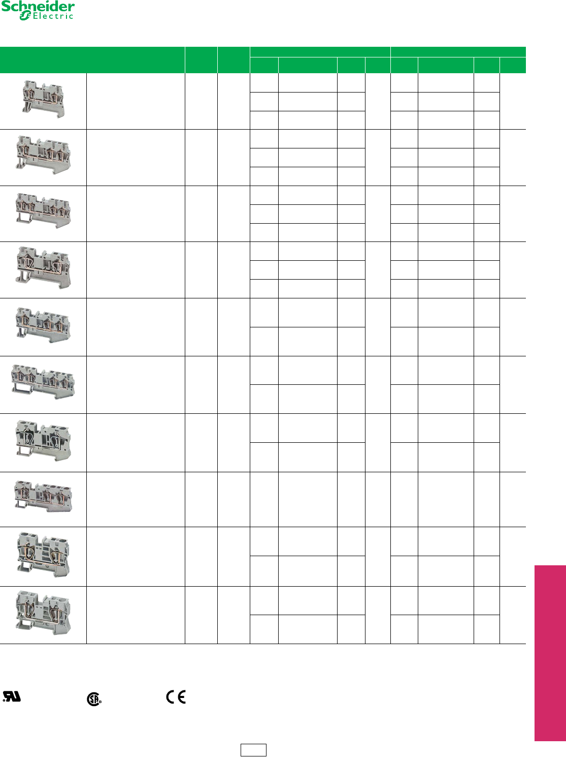
IEC Style Terminal Blocks Spring Clip Passthrough Blocks
Refer to Catalog 9080CT1301
For track and accessories, see page 24-16.
Table 24.1: Spring Clip Passthrough
Description Maximum
Vol tage
Maximum
Current
b
Block End Barrierc
Color Catalog Number $ Price
ea.
Std.
PackaColor Catalog Number $ Price
ea.
Std.
Packa
5.2 mm (0.21 in.) wide
Two Ter m in a l s
Solid or Stranded Copper Wire
28–12 AWG
600 V 20 A
Grey NSYTRR22 1.40
50
Grey NSYTRACR22 0.60
50Blue NSYTRR22BL 1.40 Blue NSYTRACR22BL 0.60
Orange NSYTRR22AR 1.40 Grey NSYTRACR22 0.60
5.2 mm (0.21 in.) wide
Three Terminals
Solid or Stranded Copper Wire
28–12 AWG
600 V 20 A
Grey NSYTRR23 1.80
50
Grey NSYTRACR23 0.60
50Blue NSYTRR23BL 1.80 Blue NSYTRACR23BL 0.60
Orange NSYTRR23AR 1.80 Grey NSYTRACR23 0.60
5.2 mm (0.21 in.) wide
Four Terminals
Solid or Stranded Copper Wire
28–12 AWG
600 V 20 A
Grey NSYTRR24 2.30
50
Grey NSYTRACR24 0.60
50Blue NSYTRR24BL 2.30 Blue NSYTRACR24BL 0.60
Orange NSYTRR24AR 2.30 Grey NSYTRACR24 0.60
6.2 mm (0.24 in.) wide
Two Terminals
Solid or Stranded Copper Wire
28–10 AWG
600 V 30 A
Grey NSYTRR42 1.50
50
Grey NSYTRACR42 0.63
50Blue NSYTRR42BL 1.50 Grey NSYTRACR42 0.63
Orange NSYTRR42AR 1.50 Grey NSYTRACR42 0.63
6.2 mm (0.24 in.) wide
Three Terminals
Solid or Stranded Copper Wire
28–10 AWG
600 V 30 A
Grey NSYTRR43 2.30
50
Grey NSYTRACR43 0.78
50
Blue NSYTRR43BL 2.30 Grey NSYTRACR43 0.78
6.2 mm (0.24 in.) wide
Four Terminals
Solid or Stranded Copper Wire
28–10 AWG
600 V 30 A
Grey NSYTRR44 2.90
50
Grey NSYTRACR44 0.83
50
Blue NSYTRR44BL 2.90 Grey NSYTRACR44 0.83
8.2 mm (0.32 in.) wide
Two Terminals
Solid or Stranded Copper Wire
28–8 AWG
600 V 50 A
Grey NSYTRR62 2.10
50
Grey NSYTRACR62 0.83
50
Blue NSYTRR62BL 2.10 Grey NSYTRACR62 0.83
8.2 mm (0.32 in.) wide
Three Terminals
Solid or Stranded Copper Wire
24–8 AWG
600 V 50 A Grey NSYTRR63 3.60 50 Grey NSYTRACR63 0.83 50
10.2 mm (0.40 in.) wide
Two Terminals
Solid or Stranded Copper Wire
16–6 AWG
600 V 66 A
Grey NSYTRR102 2.70
50
Grey NSYTRACRR102 0.90
50
Blue NSYTRR102BL 2.70 Grey NSYTRACRR102 0.90
12.2 mm (0.48 in.) wide
Two Terminals
Solid or Stranded Copper Wire
16–4 AWG
600 V 85 A
Grey NSYTRR162 5.60
50
Grey NSYTRACR162 1.20
50
Blue NSYTRR162BL 5.60 Grey NSYTRACR162 1.20
aOrders must specify the standard package quantity (Std. Pack) or multiples of that quantity.
bThese maximum current values assume the use of insulated copper conductors with 75oC temperature rating and are calculated based on NEC Article 310, Table 310-16. In most cases this
value is the maximum ampacity of the wire which has the greatest current carrying capacity. The actual allowable current for a particular application depends on the size, insulation class, and
other characteristics of the wire used. The UL ratings are shown. The CSA rating may be higher or lower. Refer to the catalog for CSA ratings.
cOne end-barrier is required for each assembly of like blocks.
File
CCN
E87739
XCFR2
File
Class
256444
6228-1
RoHS
Compliant
CP5 Discount
Schedule
www.schneider-electric.us
24 TERMINAL BLOCKS
24-4 © 2012 Schneider Electric
All Rights Reserved
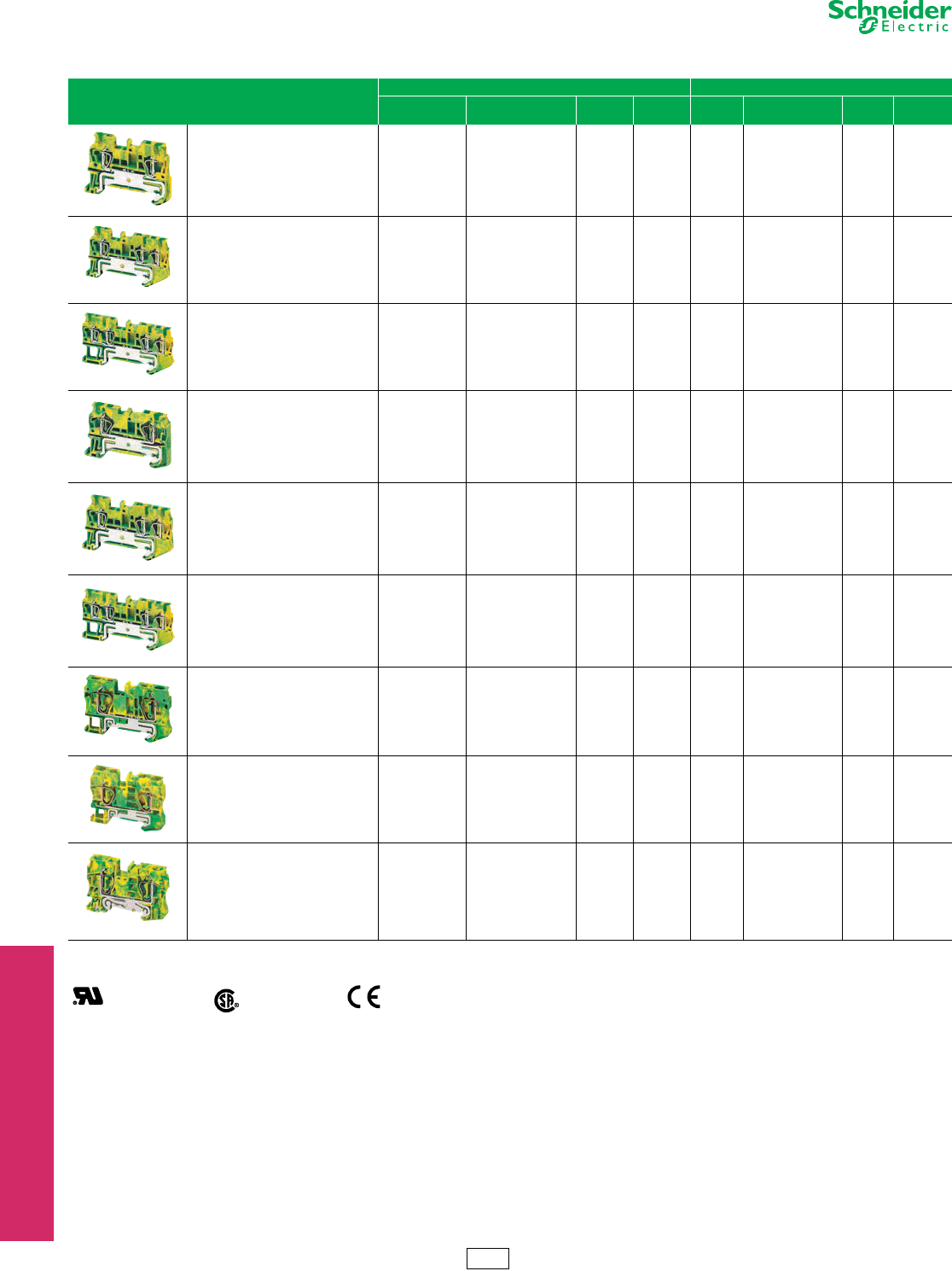
IEC Style
Terminal Blocks
Spring Clip Grounding Blocks
Refer to Catalog 9080CT1301
Table 24.2: Spring Clip Grounding Blocks
Description
Block End Barrier b
Color Catalog
Number
$ Price
ea.
Std. Pack
aColor Catalog
Number
$ Price
ea.
Std. Pack
a
5.2 mm (0.21 in.) wide
Grounding Block
Two Ter m i n a l s
Solid or Stranded Copper Wire
28–12 AWG
Green / Yellow NSYTRR22PE 5.10 50 Grey NSYTRACR22 0.60 50
5.2 mm (0.21 in.) wide
Grounding Block
Three Terminals
Solid or Stranded Copper Wire
28–12 AWG
Green /Yellow NSYTRR23PE 6.30 50 Grey NSYTRACR23 0.68 50
5.2 mm (0.21 in.) wide
Grounding Block
Four Terminals
Solid or Stranded Copper Wire
28–12 AWG
Green /Yellow NSYTRR24PE 7.50 50 Grey NSYTRACR24 0.75 50
6.2 mm (0.24 in.) wide
Grounding Block
Two Ter m i n a l s
Solid or Stranded Copper Wire
28–10 AWG
Green /Yellow NSYTRR42PE 6.20 50 Grey NSYTRACR42 0.63 50
6.2 mm (0.24 in.) wide
Grounding Block
Three Terminals
Solid or Stranded Copper Wire
28–10 AWG
Green /Yellow NSYTRR43PE 7.50 50 Grey NSYTRACR43 0.78 50
6.2 mm (0.24 in.) wide
Grounding Block
Four Terminals
Solid or Stranded Copper Wire
28–10 AWG
Green /Yellow NSYTRR44PE 9.00 50 Grey NSYTRACR44 0.83 50
8.2 mm (0.32 in.) wide
Grounding Block
Two Ter m i n a l s
Solid or Stranded Copper Wire
24–8 AWG
Green / Yellow NSYTRR62PE 6.90 50 Grey NSYTRACR62 0.83 50
10.2 mm (0.40 in.) wide
Grounding Block
Two Ter m i n a l s
Solid or Stranded Copper Wire
16–6 AWG
Green /Yellow NSYTRR102PE 7.80 50 Grey NSYTRACR102 0.90 50
12.2 mm (0.48 in.) wide
Grounding Block
Two Ter m i n a l s
Solid or Stranded Copper Wire
16–4 AWG
Green /Yellow NSYTRR162PE 9.30 50 Grey NSYTRACR162 1.20 10
aOrders must specify the standard package quantity (Std. Pack) or multiples of that quantity.
bOne end-barrier is required for each assembly of like blocks.
File
CCN
E87739
XCFR2
File
Class
256444
6228-1
RoHS
Compliant
For track and accessories, see page 24-16.
CP5 Discount
Schedule
www.schneider-electric.us
24 TERMINAL BLOCKS
© 2012 Schneider Electric
All Rights Reserved 24-5
IEC Style
Terminal Blocks
Spring Clip Double Deck, Blade Isolator, Component Carrier
Refer to Catalog 9080CT1301
aOrders must specify the standard package quantity (Std. Pack) or multiples of that quantity.
bThese maximum current values assume the use of insulated copper conductors with 75oC temperature rating and are calculated based on NEC Article 310, Table 310-16. In most cases this
value is the maximum ampacity of the wire which has the greatest current carrying capacity. The actual allowable current for a particular application depends on the size, insulation class,
and other characteristics of the wire used. The UL rating are shown. The CSA rating may be higher or lower. Refer to the catalog for CSA ratings.
cOne end-barrier is required for each assembly of like blocks.
Table 24.3: Spring Clip Double Deck Passthrough
Description Maximum
Voltag e
Maximum
Current
b
Block End Barrier c
Color Catalog Number $ Price
ea.
Std.
Pack aColor Catalog Number $ Price
ea.
Std.
Pack a
5.2 mm (0.21 in.) wide
Double Deck Block Four Terminals
Solid or Stranded Copper Wire
28–12 AWG
600 V 20 A
Grey NSYTRR24D 2.90
50
Grey NSYTRACRE24 0.90
50
Blue NSYTRR24DBL 2.90 Grey NSYTRACRE24 0.90
6.2 mm (0.24 in.) wide
Double Deck Block Four Terminals
Solid or Stranded Copper Wire
28–10 AWG
600 V 30 A
Grey NSYTRR44D 4.20
50
Grey NSYTRACRE44 0.90
50
Blue NSYTRR44DBL 4.20 Grey NSYTRACRE44 0.90
5.2 mm (0.21 in.) wide
Double Deck Block Six Terminals
Solid or Stranded Copper Wire
28–12 AWG
600 V 20 A
Grey NSYTRR26T 4.70
50
Grey NSYTRACRE26 0.90
50
Blue NSYTRR26TBL 4.70 Grey NSYTRACRE26 0.90
Table 24.4: Spring Clip Grounding Double Deck
Description
Block End Barrier c
Color Catalog Number $ Price
ea.
Std.
Pack aColor Catalog Number $ Price
ea.
Std.
Pack a
5.2 mm (0.21 in.) wide
Grounding Block
Four Terminals
Solid or Stranded Copper Wire
28–12 AWG
Green/Yellow NSYTRR24DPE 7.50 50 Grey NSYTRACRE24 0.83 50
6.2 mm (0.24 in.) wide
Grounding Block
Four Terminals
Solid or Stranded Copper Wire
28–10 AWG
Green/Yellow NSYTRR44DPE 9.80 50 Grey NSYTRACRE44 0.90 50
Table 24.5: Spring Clip Blade Isolator and Component
Description Maximum
Voltag e
Maximum
Current
b
Block End Barrier c
Color Catalog Number $ Price
ea.
Std.
Pack aColor Catalog Number $ Price
ea.
Std.
Pack a
5.2 mm (0.21 in.) wide
Blade Isolator
Two Ter m in a l s
Solid or Stranded Copper Wire
28–12 AWG
600 V 16 A
Grey NSYTRR22SC 4.40
50
Grey NSYTRACR23 0.68
50
Orange NSYTRR22SCAR 4.40 Grey NSYTRAC23 0.68
5.2 mm (0.21 in.) wide
Blade Isolator
Three Terminals
Solid or Stranded Copper Wire
28–12 AWG
600 V 16 A
Grey NSYTRR23SC 5.00
50
Grey NSYTRACR24 0.75
50
Orange NSYTRR23SCAR 5.00 Grey NSYTRAC24 0.75
5.2 mm (0.21 in.) wide
Component Carrier
Two Ter m in a l s
Solid or Stranded Copper Wire
28–12 AWG
300 V 16 A Grey NSYTRR22TB 4.10 50 Grey NSYTRACR23 0.68 50
5.2 mm (0.21 in.) wide
Component Carrier
Three Terminals
Solid or Stranded Copper Wire
28–12 AWG
300 V 16 A Grey NSYTRR23TB 4.50 50 Grey NSYTRACR24 0.75 50
5.2 mm (0.21 in.) wide
Blade Isolator
Four Terminals
Solid or Stranded Copper Wire
28–12 AWG
300 V 10 A Grey NSYTRR24SCD 11.60 50 Not required for this block.
File
CCN
E87739
XCFR2
File
Class
256444
6228-1
RoHS
Compliant For track and accessories, see page 24-16.
CP5 Discount
Schedule
www.schneider-electric.us
24 TERMINAL BLOCKS
24-6 © 2012 Schneider Electric
All Rights Reserved
IEC Style
Terminal Blocks
Spring Clip Miniature Passthrough and Grounding Type
Refer to Catalog 9080CT1301
aOrders must specify the standard package quantity (Std. Pack) or multiples of that quantity.
bThese maximum current values assume the use of insulated copper conductors with 75oC temperature rating and are calculated based on NEC Article 310, Table 310-16. In most cases this
value is the maximum ampacity of the wire which has the greatest current carrying capacity. The actual allowable current for a particular application depends on the size, insulation class,
and other characteristics of the wire used. The UL rating are shown. The CSA rating may be higher or lower. Refer to the catalog for CSA ratings.
cOne end-barrier is required for each assembly of like blocks.
dCan only be used at the end of a group of terminals.
For track and accessories, see page 24-16.
eFor additional blocks and information, refer to Catalog 9080CT0801.
fWith blown-fuse indicator.
Table 24.6: Miniature Spring Clip Passthrough DIN Rail Mounting
Description Maximum
Voltag e
Maximum
Current
b
Block End Barrier c
Color Catalog Number $ Price
ea.
Std.
Pack aColor Catalog Number $ Price
ea.
Std.
Pack a
5.2 mm (0.21 in.) wide
Two Ter m in a l s
Solid or Stranded Copper Wire
28–12 AWG
600 V 20 A
Grey NSYTRR22M 1.10
50
Grey NSYTRACRM22 0.50
50
Blue NSYTRR22MBL 1.10 Grey NSYTRACRM22 0.50
10.4 mm (0.41 in.) wide
Four Terminals
Solid or Stranded Copper Wire
28–12 AWG
600 V 20 A
Grey NSYTRR24M 1.70
50
Grey NSYTRACRM22 0.50
50
Blue NSYTRR24MBL 1.70 Grey NSYTRACRM22 0.50
Table 24.7: Miniature Spring Clip Grounding Type
Description
Block End Barrier c
Color Catalog Number $ Price
ea.
Std.
Pack aColor Catalog Number $ Price
ea.
Std.
Pack a
5.2 mm (0.21 in.) wide
Grounding Block
Solid or Stranded Copper Wire
28–12 AWG
Green/Yellow NSYTRR22MPE 3.00 50 Grey NSYTRACRM22 0.50 50
Table 24.8: Miniature Spring Clip Passthrough Direct Mounting and for Micro-Perforated Mounting Plates
Description Maximum
Voltag e
Maximum
Current
b
Block End Barrier c
Color Catalog Number $ Price
ea.
Std.
Pack aColor Catalog Number $ Price
ea.
Std.
Pack a
5.2 mm (0.21 in.) wide
Direct Mounting (Flange)
Two Ter m in a l s
Solid or Stranded Copper Wire
28–12 AWG
600 V 20 A
Grey NSYTRR22MF 1.60
50
Grey NSYTRACRM22 0.50
50Blue NSYTRR22MFBL 1.60 Grey NSYTRACRM22 0.50
Grey with
FlangedNSYTRR22MFF 1.00 Grey with
FlangedNSYTRACRMF22 0.50
10.4 mm (0.41 in.) wide
Direct Mounting (Flange)
Four Terminals
Solid or Stranded Copper Wire
28–12 AWG
600 V 20 A
Grey NSYTRR24MF 1.60
50
Grey NSYTRACRM22 0.50
50Blue NSYTRR24MFBL 1.60 Grey NSYTRACRM22 0.50
Grey with
FlangedNSYTRR24MFF 1.00 Grey with
FlangedNSYTRACRMF22 0.50
5.2 mm (0.21 in.) wide
For Micro-Perforated Mounting Plates
Two Ter m in a l s
Solid or Stranded Copper Wire
28–12 AWG
600 V 20 A
Grey NSYTRR22MP 1.00
50
Grey NSYTRACRM22 0.50
50
Blue NSYTRR22MPBL 1.00 Grey NSYTRACRM22 0.50
10.4 mm (0.41 in.) wide
For Micro-Perforated Mounting Plates
Four Terminals
Solid or Stranded Copper Wire
28–12 AWG
600 V 20 A
Grey NSYTRR24MP 1.00
50
Grey NSYTRACRM22 0.50
50
Blue NSYTRR24MBL 1.00 Grey NSYTRACRM22 0.50
File
CCN
E87739
XCFR2
File
Class
256444
6228-1
RoHS
Compliant
Table 24.9: Modular Fuse Holders, DFe
Rated Thermal Current Type of Fuse Composition Standard Pack Quantity Catalog Number $ Price ea.
DFCC1V DFCC3V
30 A Class CC
1 Pole 12 DFCC1 18.00
2 Poles 6 DFCC2 36.00
3 Poles 4 DFCC3 54.00
1 Pole f12 DFCC1V 22.50
2 Poles f6DFCC2V 45.00
3 Poles f 4DFCC3V 68.00
File
CCN
E310269
IZLT
CP5 Discount
Schedule
www.schneider-electric.us
24 TERMINAL BLOCKS
© 2012 Schneider Electric
All Rights Reserved 24-7
IEC Style
Terminal Blocks
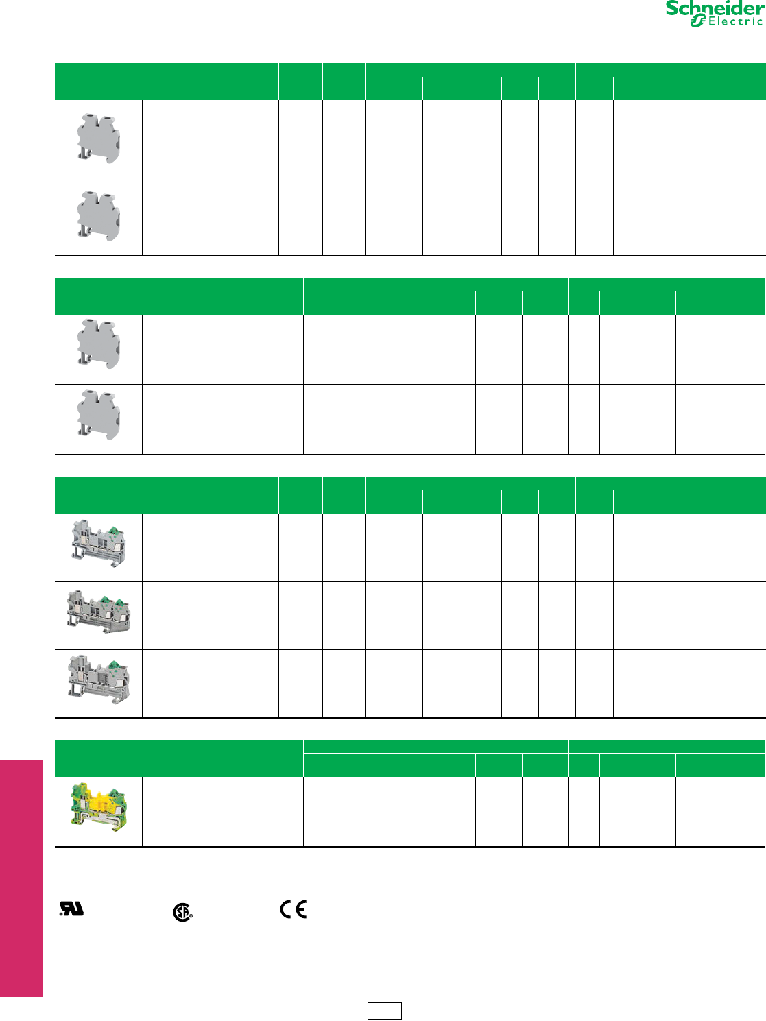
Screw Type Passthrough Blocks, Grounding Blocks
Refer to Catalog 9080CT1301
aOrders must specify the standard package quantity (Std. Pack) or multiples of that quantity.
bThese maximum current values assume the use of insulated copper conductors with 75oC temperature rating and are calculated based on NEC Article 310, Table 310-16. In most cases this
value is the maximum ampacity of the wire which has the greatest current carrying capacity. The actual allowable current for a particular application depends on the size, insulation class,
and other characteristics of the wire used. The UL ratings are shown. The CSA rating may be higher or lower. Refer to the catalog for CSA ratings.
cOne end-barrier is required for each assembly of like blocks.
Table 24.10: Screw Type Passthrough
Description Maximum
Voltag e
Maximum
Current
b
Block End Barrier c
Color Catalog Number $ Price
ea.
Std.
Pack aColor Catalog Number $ Price
ea.
Std.
Pack a
5.2 mm (0.21 in.) wide
Two Ter m in a l s
Solid or Stranded Copper Wire
26–12 AWG
600 V 20 A
Grey NSYTRV22 1.40
50
Grey NSYTRAC22 0.62
50Blue NSYTRV22BL 1.40 Blue NSYTRAC22BL 0.62
Orange NSYTRV22AR 1.40 Grey NSYTRAC22 0.62
6.2 mm (0.24 in.) wide
Two Ter m in a l s
Solid or Stranded Copper Wire
26–10 AWG
600 V 00 A
Grey NSYTRV42 1.50
50
Grey NSYTRAC22 0.62
50
Blue NSYTRV42BL 1.50 Blue NSYTRAC22BL 0.62
Orange NSYTRV42AR 1.50 Grey NSYTRAC22 0.62
Red NSYTRV42RD 1.50 Grey NSYTRAC22 0.62
Green NSYTRV42GN 1.50 Grey NSYTRAC22 0.62
White NSYTRV42WH 1.50 Grey NSYTRAC22 0.62
Black NSYTRV42BK 1.50 Grey NSYTRAC22 0.62
8.2 mm (0.32 in.) wide
Two Ter m in a l s
Solid or Stranded Copper Wire
24–8 AWG
600 V 50 A
Grey NSYTRV62 2.10
50
Grey NSYTRAC22 0.62
50
Blue NSYTRV62BL 2.10 Blue NSYTRAC22BL 0.62
10.2 mm (0.40 in.) wide
Two Ter m in a l s
Solid or Stranded Copper Wire
20–6 AWG
600 V 65 A
Grey NSYTRV102 2.70
50
Grey NSYTRAC22 0.62
50
Blue NSYTRV102BL 2.70 Blue NSYTRAC22BL 0.62
12.2 mm (0.48 in.) wide
Two Ter m in a l s
Solid or Stranded Copper Wire
16–4 AWG
600 V 85 A
Grey NSYTRV162 5.40
50
Grey NSYTRAC162 0.93
50
Blue NSYTRV162BL 5.40 Grey NSYTRAC162 0.93
16 mm (0.63 in.) wide
Two Ter m in a l s
Solid or Stranded Copper Wire
14–1/0 AWG
600 V 150 A
Grey NSYTRV352 7.70
50 Not required for these blocks.
Blue NSYTRV352BL 7.70
20 mm (0.79 in.) wide
Two Ter m in a l s
Solid or Stranded Copper Wire
6–1/0 AWG
600 V 150 A
Grey NSYTRV502 18.80
50 Not required for these blocks.
Blue NSYTRV502BL 18.80
Table 24.11: Grounding
Description
Block End Barrier c
Color Catalog Number $ Price
ea.
Std.
Pack aColor Catalog Number $ Price
ea.
Std.
Pack a
5.2 mm (0.21 in.) wide
Grounding Block
Solid or Stranded Copper Wire
26–12 AWG
Green/Yellow NSYTRV22PE 5.30 50 Grey NSYTRAC22 0.62 50
6.2 mm (0.24 in.) wide
Grounding Block
Solid or Stranded Copper Wire
26–10 AWG
Green/Yellow NSYTRV42PE 6.20 50 Grey NSYTRAC22 0.62 50
8.2 mm (0.32 in.) wide
Grounding Block
Solid or Stranded Copper Wire
24–8 AWG
Green/Yellow NSYTRV62PE 6.90 50 Grey NSYTRAC22 0.62 50
10.2 mm (0.40 in.) wide
Grounding Block
Solid or Stranded Copper Wire
20–6 AWG
Green/Yellow NSYTRV102PE 7.80 50 Grey NSYTRAC22 0.62 50
0.63 mm (0.16 in.) wide
Grounding Block
Solid or Stranded Copper Wire
16–4 AWG
Green/Yellow NSYTRV162PE 9.30 50 Grey NSYTRAC162 0.93 50
16 mm (0.63 in.) wide
Grounding Block
Solid or Stranded Copper Wire
14–1/0 AWG
Green/Yellow NSYTRV352PE 13.20 50 Not required for this block.
20 mm (0.79 in.) wide
Grounding Block
Solid or Stranded Copper Wire
6–1/0 AWG
Green/Yellow NSYTRV502PE 55.00 50 Not required for this block.
File
CCN
E87739
XCFR2
File
Class
702070
256444
RoHS
Compliant For track and accessories, see page 24-16.
CP5 Discount
Schedule
www.schneider-electric.us
24 TERMINAL BLOCKS
24-8 © 2012 Schneider Electric
All Rights Reserved
IEC Style
Terminal Blocks
Screw Type Lug/Lug, Double Deck Passthrough and Grounding Blocks
Refer to Catalog 9080CT1301
aOrders must specify the standard package quantity (Std. Pack) or multiples of that quantity.
bThese maximum current values assume the use of insulated copper conductors with 75oC temperature rating and are calculated based on NEC Article 310, Table 310-16. In most cases this
value is the maximum ampacity of the wire which has the greatest current carrying capacity. The actual allowable current for a particular application depends on the size, insulation class,
and other characteristics of the wire used. The UL ratings are shown. The CSA rating may be higher or lower. Refer to the catalog for CSA ratings.
cOne end-barrier is required for each assembly of like blocks.
Table 24.12: Passthrough, Lug/Lug and Lug/Clamp
Description
Block Partition Cover
Maximum
CurrentbColor Catalog Number $ Price
ea.
Std.
Pack aColor Catalog Number $ Price
ea.
Std.
Pack a
20.3 mm (0.80 in.) wide
Passthrough
Solid or Stranded Copper Wire
4–3/0 AWG
Screw thread M8
Maximum
Voltage–600 V
192 A Grey NSYTRV702 27.90 10 Not required for this block.
40 mm (1.58 in.) wide
Lug to Lug
Solid or Stranded Copper Wire
2–4/0 AWG
Screw thread M12
Maximum
Voltage–600 V
230 A Grey NSYTRV952BB 21.30 10 Grey NSYTRACP1 13.40 10
40 mm (1.58 in.) wide
Solid or Stranded Copper Wire
2–4/0 AWG
Screw thread M12
Maximum
Voltage–600 V
230 A Grey NSYTRV952BC 31.10 10 Grey NSYTRACP1 13.40 10
46 mm (1.81 in.) wide
Lug to Lug
Solid or Stranded Copper Wire
2–300 AWG/kcmil
Screw thread M12
Maximum
Voltage–600 V
285 A Grey NSYTRV1052BB 54.00 10 Grey NSYTRACP2 14.50 10
Table 24.13: Screw Type Double Deck Passthrough
Description Maximum
Voltage
Maximum
Currentb
Block End Barrier c
Color Catalog Number $ Price ea. Std. Pack aColor Catalog Number $ Price ea. Std. Pack a
6.2 mm (0.24 in.) wide
Double Deck, One Pole, Three
Connections
Solid or Stranded Copper Wire
26–10 AWG
150 V 30 A
Grey NSYTRV43 3.60
50
Grey NSYTRAC23 1.10
50
Blue NSYTRV43BL 3.60 Grey NSYTRAC23 1.10
6.2 mm (0.24 in.) wide
Double Deck, One Pole, Four
Connections
Solid or Stranded Copper Wire
26–10 AWG
150 V 30 A
Grey NSYTRV44 5.10
50
Grey NSYTRAC24 1.20
50
Blue NSYTRV44BL 5.10 Grey NSYTRAC24 1.20
5.2 mm (0.21 in.) wide
Double Deck, Two Poles, Four
Connections
Solid or Stranded Copper Wire
26–12 AWG
600 V 20 A
Grey NSYTRV24D 3.20
50
Grey NSYTRACE24 1.20
50
Blue NSYTRV24DBL 3.20 Grey NSYTRACE24 1.20
6.2 mm (0.24 in.) wide
Double Deck, Two Poles, Four
Connections
Solid or Stranded Copper Wire
26–10 AWG
600 V 30 A
Grey NSYTRV44D 5.10
50
Grey NSYTRACE24 1.20
50
Blue NSYTRV44DBL 5.10 Grey NSYTRACE24 1.20
5.2 mm (0.21 in.) wide
Triple Deck, Three Poles, Six
Connections
Solid or Stranded Copper Wire
26–10 AWG
600 V 20 A Grey NSYTRV26T 8.60 50 Grey NSYTRACE26 1.20 50
Table 24.14: Screw Type Grounding Double Deck
Description Block End Barrier c
Color Catalog Number $ Price ea. Std. Pack aColor Catalog Number $ Price ea. Std. Pack a
6.2 mm (0.24 in.) wide
Grounding Block, One Pole, Three Connections
Solid or Stranded Copper Wire
26–12 AWG
Green/Yellow NSYTRV43PE 7.50 50 Grey NSYTRAC23 0.83 50
6.2 mm (0.24 in.) wide
Grounding Block, One Pole, Four Connections
Solid or Stranded Copper Wire
26–12 AWG
Green/Yellow NSYTRV44PE 12.20 50 Grey NSYTRAC24 1.20 50
5.2 mm (0.21 in.) wide
Grounding Block, One Pole, Four Connections
Solid or Stranded Copper Wire
26–12 AWG
Green/Yellow NSYTRV24DPE 14.00 50 Grey NSYTRACE24 1.20 50
6.2 mm (0.24 in.) wide
Grounding Block, One Pole, Four Connections
Solid or Stranded Copper Wire
26–10 AWG
Green/Yellow NSYTRV44DPE 18.60 50 Grey NSYTRACE24 1.20 50
File
CCN
E87739
XCFR2
File
Class
256444
6228-1
RoHS
Compliant
CP5 Discount
Schedule
www.schneider-electric.us
24 TERMINAL BLOCKS
© 2012 Schneider Electric
All Rights Reserved 24-9
IEC Style
Terminal Blocks
Screw Type Blade Isolator, Fused, Measuring Blocks
Refer to Catalog 9080CT1301
These measuring transducer terminal blocks with screw connection technology are characterized by easy operation and clarity. All switching
statuses are clearly visible. Due to the extensive range of flexible accessories, costs and time are saved when executing transducer test circuit
tasks.
aOrders must specify the standard package quantity (Std. Pack) or multiples of that quantity.
bThese maximum current values assume the use of insulated copper conductors with 75oC temperature rating and are calculated based on NEC Article 310, Table 310-16. In most cases this
value is the maximum ampacity of the wire which has the greatest current carrying capacity. The actual allowable current for a particular application depends on the size, insulation class,
and other characteristics of the wire used. The UL rating are shown. The CSA rating may be higher or lower. Refer to the catalog for CSA ratings.
cOne end-barrier is required for each assembly of like blocks.
dWhen voltage is applied within the minimum and maximum limites, the LED will illuminate.
For track and accessories, see page 24-16.
Table 24.15: Screw Type Blade Isolator
Description Maximum
Vol tage
Maximum
Current
b
Block End Barrier c
Color Catalog Number $ Price
ea.
Std.
Pack aColor Catalog Number $ Price
ea.
Std.
Pack a
6.2 mm (0.24 in.) wide
Blade Isolator
Two Ter m in a l s
Solid or Stranded Copper Wire
26–10 AWG
600 V 16 A
Grey NSYTRV42SC 7.10
50 Not required for this block.
Grey with
Te s t Po in ts NSYTRV42ST 7.10
Orange with
Te s t Po in ts NSYTRV42STAR 7.10
6.2 mm (0.24 in.) wide
Blade Isolator Double Deck
Four Terminals
Solid or Stranded Copper Wire
26–10 AWG
300 V 30 A Grey NSYTRV42SCD 9.20 50 Grey NSYTRACRE24 0.83 50
Table 24.16: Screw Type Component Carrier
Description Maximum
Voltage
Maximum
Current
b
Block Removable Carriers
Description $ Price
ea.
Std.
Pack a
Color Catalog
Number
$ Price
ea.
Std.
Pack aCatalog Number
6.2 mm (0.24 in.) wide
Component Carrier
Two Ter m in a l s
Solid or Stranded Copper Wire
26–10 AWG
600 V 16 A Grey NSYTRV42TB 3.90 50
NSYTRASF520 For fuse 5x2 mm 5.50 10
NSYTRASF520M For fuse 5x20 mm 110–250 V LED 20.30 10
NSYTRASF520B For fuse 5x20 mm 12–30 V LED 20.30 10
NSYTRASV1 For component 6.20 10
NSYTRASV2 With 1N4007 Diode 15.60 10
Table 24.17: Fused Terminal Blocks
Description
Block End Barrier c
Color Catalog Number $ Price
ea.
Std.
Pack aColor Catalog
Number
$ Price
ea.
Std.
Pack a
12 mm (0.47 in.) wide
Fuse Block
For G-fuse cartridge 5x20 mm
Solid or Stranded Copper Wire 26–12 AWG
Maximum Voltage 300 V
Maximum Current 20 Ab
Without Indicator Lamp Black NSYTRV162SF 10.80 50 Not required for this block.
8.2 mm (0.32 in.) wide
Lever-Type Fuse
For G-fuse cartridge 5x20 mm
Solid or Stranded Copper Wire 26–10 AWG
Maximum Voltage 600 V
Maximum Current 12 Ab
Without Indicator Lamp Black NSYTRV42SF5 7.80 50
Not required for this block.
With Light Indicator,
12–30 V AC/DCdBlack NSYTRV42SF5LD 16.10 50
With Light Indicator,
110–250 V AC/DCdBlack NSYTRV42SF5LA 16.10 50
10.2 mm (0.40 in.) wide
Lever-Type Fuse
For G-fuse cartridge 6.3x32 mm
Solid or Stranded Copper Wire 26–8 AWG
Maximum Voltage 600 V
Maximum Current 10 Ab
Without Indicator Lamp Black NSYTRV42SF6 14.40 50
Not required for this block.
With Light Indicator,
12–30 V AC/DCdBlack NSYTRV42SF6LD 18.60 50
With Light Indicator,
110–250 V AC/DCdBlack NSYTRV42SF6LA 18.60 50
Table 24.18: Measuring and Grounding Terminal Blocks
Description Maximum
Vol tage
Maximum
Current
b
Block End Barrier c
Color Catalog Number $ Price
ea.
Std.
Pack aColor Catalog Number $ Price
ea.
Std.
Pack a
8.2 mm (0.32 in.) wide
Blade Isolator Double Deck
Solid or Stranded Copper Wire
24–8 AWG
600 V 30 A Grey NSYTRV62TTD 13.00 50 NSYTRACT22
8.2 mm (0.32 in.) wide
Passthrough
Solid or Stranded Copper Wire
24–8 AWG
600 V 30 A Grey NSYTRV62TT 13.00 50 NSYTRACT22
8.2 mm (0.32 in.) wide
Grounding Block
Solid or Stranded Copper Wire
24–8 AWG
N/A N/A Green/Yellow NSYTRV62TTPE 19.00 50 NSYTRACT22
File
CCN
E87739
XCFR2
File
Class
256444
6228-1
RoHS
Compliant
CP5 Discount
Schedule
www.schneider-electric.us
24 TERMINAL BLOCKS
24-10 © 2012 Schneider Electric
All Rights Reserved
IEC Terminal Blocks Screw Type Miniature Passthrough and Hybrid Passthrough
Refer to Catalog 9080CT1301
aOrders must specify the standard package quantity (Std. Pack) or multiples of that quantity.
bThese maximum current values assume the use of insulated copper conductors with 75oC temperature rating and are calculated based on NEC Article 310, Table 310-16. In most cases this
value is the maximum ampacity of the wire which has the greatest current carrying capacity. The actual allowable current for a particular application depends on the size, insulation class,
and other characteristics of the wire used. The UL rating are shown. The CSA rating may be higher or lower. Refer to the catalog for CSA ratings.
cOne end-barrier is required for each assembly of like blocks.
For track and accessories, see page 24-16.
Table 24.19: Screw Type Miniature Passthrough
Description Maximum
Vol tage
Maximum
Current
b
Block End Barrier c
Color Catalog Number $ Price
ea.
Std.
Pack aColor Catalog Number $ Price
ea.
Std.
Pack a
5.2 mm (0.21 in.) wide
Two Ter m in a l s
Solid or Stranded Copper Wire
24–12 AWG
600 V 20 A
Grey NSYTRV22M 1.50
50
Grey NSYTRACM22 0.65
50
Blue NSYTRV22MBL 1.50 Grey NSYTRACM22 0.65
6.2 mm (0.24 in.) wide
Two Ter m in a l s
Solid or Stranded Copper Wire
24–10 AWG
600 V 30 A
Grey NSYTRV42M 1.70
50
Grey NSYTRACM22 0.65
50
Blue NSYTRV42MBL 1.70 Grey NSYTRACM22 0.65
Table 24.20: Fused Terminal Blocks
Description
Block End Barrier c
Color Catalog Number $ Price
ea.
Std.
Pack aColor Catalog Number $ Price
ea.
Std.
Pack a
5.2 mm (0.21 in.) wide
Grounding Block
Two Ter m in a l s
Solid or Stranded Copper Wire
24–12 AWG
Green/Yellow NSYTRV22MPE 4.40 50 Grey NSYTRACM22 0.65 50
6.2 mm (0.24 in.) wide
Grounding Block
Two Ter m in a l s
Solid or Stranded Copper Wire
24–10 AWG
Green/Yellow NSYTRV42MPE 5.00 50 Grey NSYTRACM22 0.65 50
Table 24.21: Hybrid Blocks—Screw and IDC Passthrough
Description Maximum
Vol tage
Maximum
Current
b
Block End Barrier c
Color Catalog Number $ Price
ea.
Std.
Pack aColor Catalog Number $ Price
ea.
Std.
Pack a
5.2 mm (0.21 in.) wide
Two Ter m in a l s
Solid or Stranded Copper Wire
24–16 AWG
600 V 10 A Grey NSYTRH12 1.50 50 Grey NSYTRACH12 0.65 50
5.2 mm (0.21 in.) wide
Three Terminals
Solid or Stranded Copper Wire
24–16 AWG
600 V 10 A Grey NSYTRH13 1.80 50 Grey NSYTRACH13 0.70 50
6.2 mm (0.24 in.) wide
Three Terminals
Solid or Stranded Copper Wire
20–14 AWG
600 V 15 A Grey NSYTRH22 1.60 50 Grey NSYTRACH22 0.80 50
Table 24.22: Hybrid Grounding Block—Screw and IDC Passthrough
Description
Block End Barrier c
Color Catalog Number $ Price
ea.
Std.
Pack aColor Catalog Number $ Price
ea.
Std.
Pack a
5.2 mm (0.21 in.) wide
Grounding Block
Solid or Stranded Copper Wire
24–16 AWG
Green/Yellow NSYTRH12PE 5.30 50 Grey NSYTRACH12 0.65 50
File
CCN
E87739
XCFR2
File
Class
256444
6228-1
RoHS
Compliant
CP5 Discount
Schedule
www.schneider-electric.us
24 TERMINAL BLOCKS
© 2012 Schneider Electric
All Rights Reserved 24-11
IEC Style
Terminal Blocks
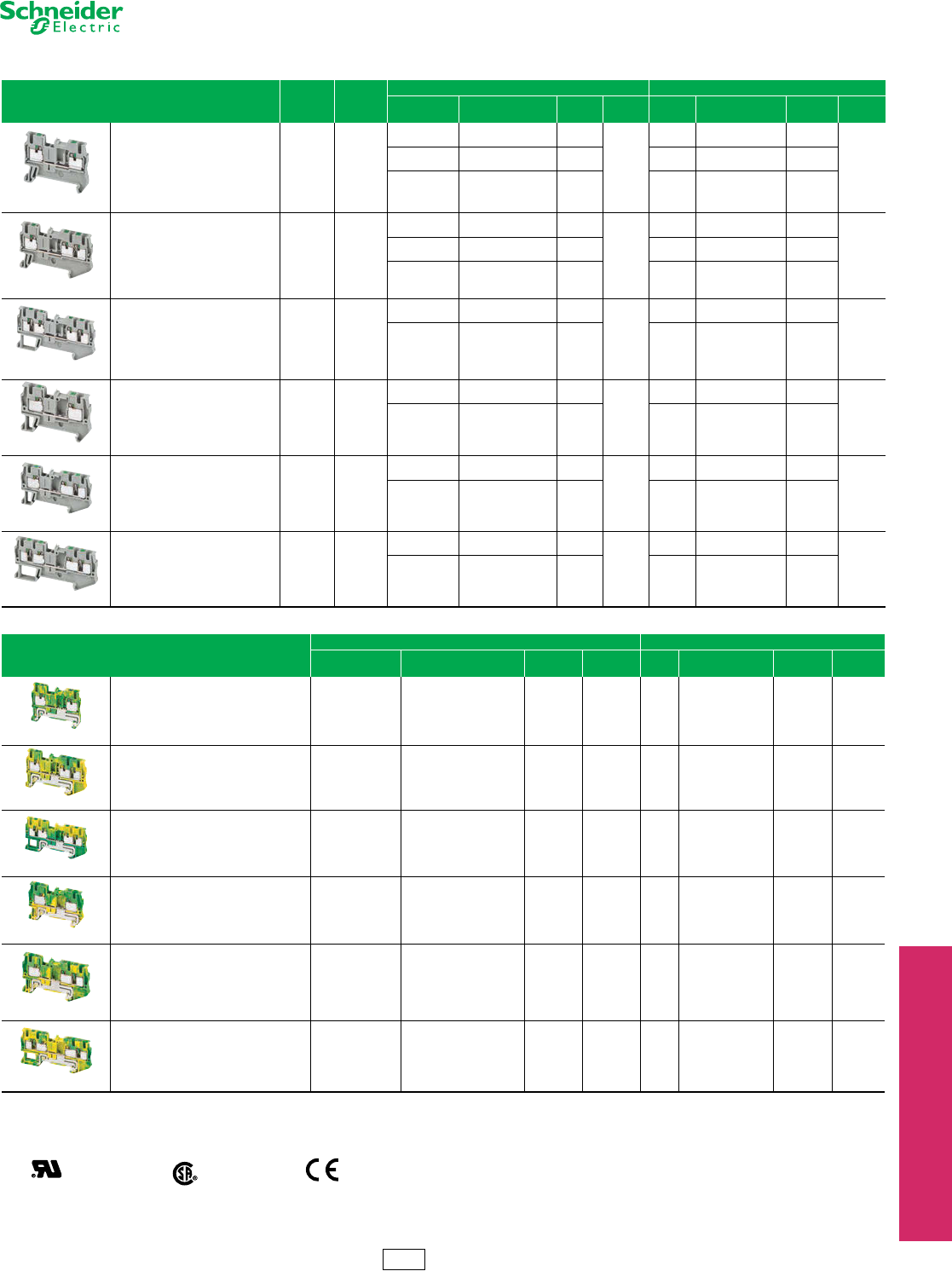
Push-in Passthrough and Grounding Blocks
Refer to Catalog 9080CT1301
aOrders must specify the standard package quantity (Std. Pack) or multiples of that quantity.
bThese maximum current values assume the use of insulated copper conductors with 75oC temperature rating and are calculated based on NEC Article 310, Table 310-16. In most cases this
value is the maximum ampacity of the wire which has the greatest current carrying capacity. The actual allowable current for a particular application depends on the size, insulation class,
and other characteristics of the wire used. The UL ratings are shown. The CSA rating may be higher or lower. Refer to the catalog for CSA ratings.
cOne end-barrier is required for each assembly of like blocks.
Table 24.23: Push-in Passthrough Blocks
Description Maximum
Vol tage
Maximum
Current
b
Block End Barrier c
Color Catalog Number $ Price
ea.
Std.
Pack aColor Catalog Number $ Price
ea.
Std.
Pack a
5.2 mm (0.21 in.) wide
Two Ter m in a l s
Solid or Stranded Copper Wire
24–12 AWG
600 V 20 A
Grey NSYTRP22 1.60
50
Grey NSYTRACR22 0.60
50
Blue NSYTRP22BL 1.60 Blue NSYTRACR22BL 0.60
Orange NSYTRP22AR 1.60 Grey NSYTRACR22 0.60
5.2 mm (0.21 in.) wide
Three Terminals
Solid or Stranded Copper Wire
24–12 AWG
600 V 20 A
Grey NSYTRP23 1.80
50
Grey NSYTRACR23 0.68
50
Blue NSYTRP23BL 1.80 Blue NSYTRACR23 0.68
Orange NSYTRP23AR 1.80 Grey NSYTRACR23 0.68
5.2 mm (0.21 in.) wide
Four Terminals
Solid or Stranded Copper Wire
24–12 AWG
600 V 20 A
Grey NSYTRP24 2.50
50
Grey NSYTRACR24 0.75
50
Blue NSYTRP24BL 2.70 Grey NSYTRACR24BL 0.75
6.2 mm (0.24 in.) wide
Two Ter m in a l s
Solid or Stranded Copper Wire
24–10 AWG
600 V 30 A
Grey NSYTRP42 1.80
50
Grey NSYTRACR42 0.63
50
Blue NSYTRP42BL 1.80 Grey NSYTRACR42 0.63
6.2 mm (0.24 in.) wide
Three Terminals
Solid or Stranded Copper Wire
24–10 AWG
600 V 30 A
Grey NSYTRP43 2.10
50
Grey NSYTRACP43 0.60
50
Blue NSYTRP43BL 2.10 Grey NSYTRACP43 0.60
6.2 mm (0.24 in.) wide
Four Terminals
Solid or Stranded Copper Wire
24–10 AWG
600 V 30 A
Grey NSYTRP44 2.70
50
Grey NSYTRACP44 0.63
50
Blue NSYTRP44BL 2.70 Grey NSYTRACP44 0.63
Table 24.24: Push-in Grounding Blocks
Description
Block End Barrier c
Color Catalog Number $ Price
ea.
Std.
Pack aColor Catalog Number $ Price
ea.
Std.
Pack a
5.2 mm (0.21 in.) wide
Grounding Block
Two Ter m in a l s
Solid or Stranded Copper Wire 24–12 AWG
Green/Yellow NSYTRP22PE 0.63 50 Grey NSYTRACR22 0.60 50
5.2 mm (0.21 in.) wide
Grounding Block
Three Terminals
Solid or Stranded Copper Wire 24–12 AWG
Green/Yellow NSYTRP23PE 6.00 50 Grey NSYTRACR23 0.68 50
5.2 mm (0.21 in.) wide
Grounding Block
Four Terminals
Solid or Stranded Copper Wire 24–12 AWG
Green/Yellow NSYTRP24PE 7.70 50 Grey NSYTRACR24 0.68 50
6.2 mm (0.24 in.) wide
Grounding Block
Two Ter m in a l s
Solid or Stranded Copper Wire 24–10 AWG
Green/Yellow NSYTRP42PE 5.80 50 Grey NSYTRACR42 0.63 50
6.2 mm (0.24 in.) wide
Grounding Block
Three Terminals
Solid or Stranded Copper Wire 24–10 AWG
Green/Yellow NSYTRP43PE 6.30 50 Grey NSYTRACP43 0.60 50
6.2 mm (0.24 in.) wide
Grounding Block
Four Terminals
Solid or Stranded Copper Wire 24–10 AWG
Green/Yellow NSYTRP44PE 8.00 50 Grey NSYTRACP44 0.63 50
File
CCN
E164359
XCFR2
File
Class
702070
6228 01
RoHS
Compliant For track and accessories, see page 24-16.
CP5 Discount
Schedule
www.schneider-electric.us
24 TERMINAL BLOCKS
24-12 © 2012 Schneider Electric
All Rights Reserved
IEC Style Terminal
Blocks
Push-in Double Deck Passthrough Terminal Blocks
Refer to Catalog 9080CT2301
aOrders must specify the standard package quantity (Std. Pack) or multiples of that quantity.
bThese maximum current values assume the use of insulated copper conductors with 75oC temperature rating and are calculated based on NEC Article 310, Table 310-16. In most cases this
value is the maximum ampacity of the wire which has the greatest current carrying capacity. The actual allowable current for a particular application depends on the size, insulation class,
and other characteristics of the wire used. The UL rating are shown. The CSA rating may be higher or lower. Refer to the catalog for CSA ratings.
cOne end-barrier is required for each assembly of like blocks.
For track and accessories, see page 24-16.
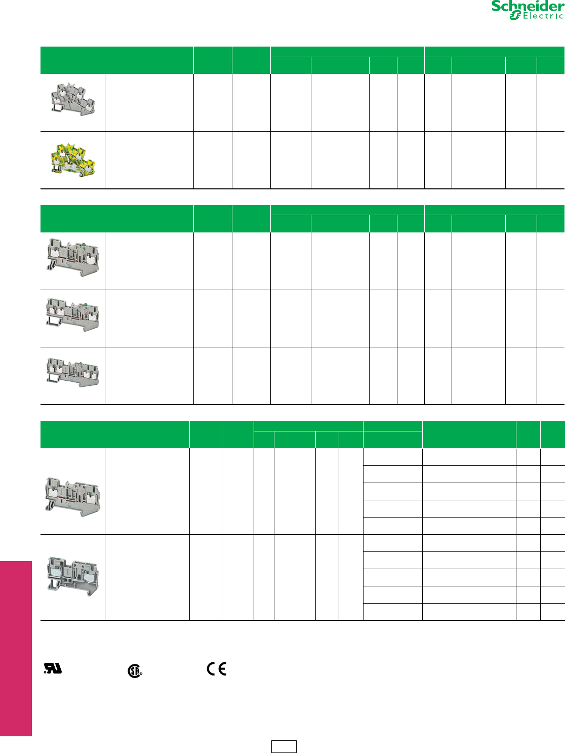
Table 24.25: Push-in Double Deck Passthrough and Grounding Terminal Blocks
Description Maximum
Vol tage
Maximum
Current
b
Block End Barrier c
Color Catalog Number $ Price
ea.
Std.
Pack aColor Catalog Number $ Price
ea.
Std.
Pack a
5.2 mm (0.21 in.) wide
Double Deck Passthrough
Four Terminals
Solid or Stranded Copper Wire
26–12 AWG
600 V 20 A Grey NSYTRP24D 6.50 50 Grey NSYTRACRE24 0.83 50
5.2 mm (0.21 in.) wide
Double Deck Grounding Block
Four Terminals
Solid or Stranded Copper Wire
26–12 AWG
N/A N/A Green/Yellow NSYTRP24DPE 10.70 50 Grey NSYTRACRE24 0.83 50
Table 24.26: Push-in Blade Isolator
Description Maximum
Vol tage
Maximum
Current
b
Block End Barrier c
Color Catalog Number $ Price
ea.
Std.
Pack aColor Catalog Number $ Price
ea.
Std.
Pack a
5.2 mm (0.21 in.) wide
Blade Isolator
Two Ter m in a l s
Solid or Stranded Copper Wire
26–12 AWG
300 V 20 A Grey NSYTRP22SC 4.70 50 Grey NSYTRACPK22 0.80 50
5.2 mm (0.21 in.) wide
Blade Isolator
Three Terminals
Solid or Stranded Copper Wire
26–12 AWG
300 V 20 A Grey NSYTRP23SC 5.30 50 Grey NSYTRACPK23 0.84 50
5.2 mm (0.21 in.) wide
Blade Isolator
Four Terminals
Solid or Stranded Copper Wire
26–12 AWG
300 V 20 A Grey NSYTRP24SC 6.30 50 Grey NSYTRACPK24 0.84 50
Table 24.27: Push-in Component Carrier
Description Maximum
Voltage
Maximum
Current
b
Block Removable Carriers
Description $ Price
ea.
Std.
Pack a
Color Catalog
Number
$ Price
ea.
Std.
Pack aCatalog Number
5.2 mm (0.21 in.) wide
Component Carrier
Two Ter m in a l s
Solid or Stranded Copper Wire
26–12 AWG
300 V 20 A Grey NSYTRP22TB 3.10 50
NSYTRASF520 For fuse 5x2 mm 5.50 10
NSYTRASF520M For fuse 5x20 mm 110–250 V LED 20.30 10
NSYTRASF520B For fuse 5x20 mm 12–30 V LED 20.30 10
NSYTRASV1 For component 6.20 10
NSYTRASV2 With 1N4007 Diode 15.60 10
6.2 mm (0.24 in.) wide
Component Carrier
Two Ter m in a l s
Solid or Stranded Copper Wire
24–12 AWG
300 V 20 A Grey NSYTRP42TB 3.20 50
NSYTRASF520 For fuse 5x2 mm 5.50 10
NSYTRASF520M For fuse 5x20 mm 110–250 V LED 20.30 10
NSYTRASF520B For fuse 5x20 mm 12–30 V LED 20.30 10
NSYTRASV1 For component 6.20 10
NSYTRASV2 With 1N4007 Diode 15.60 10
File
CCN
E87739
XCFR2
File
Class
256444
6228-1
RoHS
Compliant
CP5 Discount
Schedule
24 TERMINAL BLOCKS
© 2012 Schneider Electric
All Rights Reserved 24-13
www.schneider-electric.us
IEC Style
Terminal Blocks
Linergy Marking Accessories
Refer to Catalog 9080CT1301
aFor blocks 12.2 mm (0.48 in.) or wider, the strip must be broken and the individual marking
characters used.
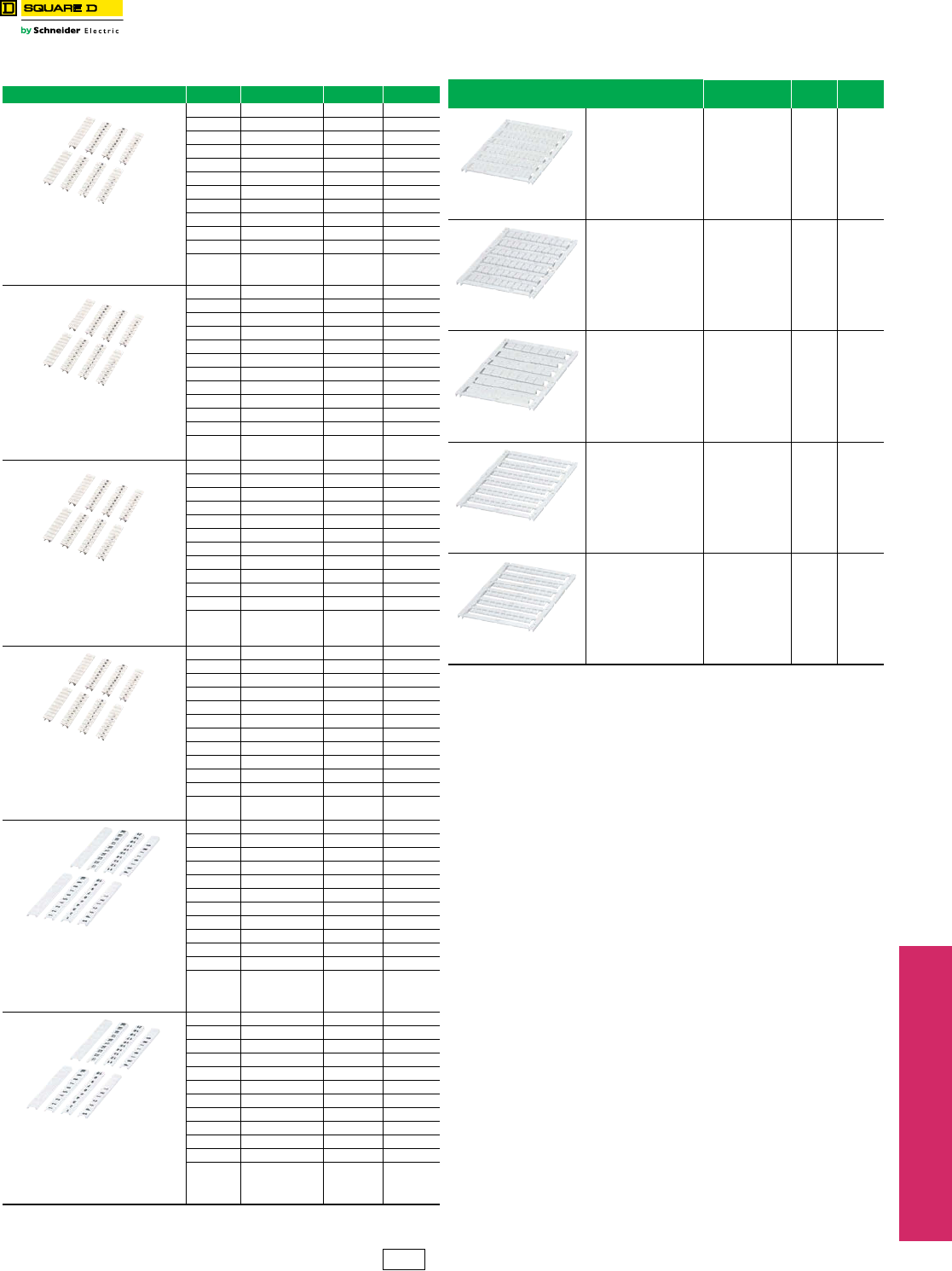
Table 24.28: Markers
Description Marking Catalog Number $ Price ea. Std Packa
Black horizontal markings on white
background
For 5.2 mm (0.21 in.) wide blocks
Lateral sides for NSYTRV terminal
blocks
Central shaft for NSYTRR / NSYTRP /
NSYTRH terminal blocks
1 to 10 NSYTRAB510 0.82 10
11 to 20 NSYTRAB520 0.82 10
21 to 30 NSYTRAB530 0.82 10
31 to 40 NSYTRAB540 0.82 10
41 to 50 NSYTRAB550 0.82 10
51 to 60 NSYTRAB560 0.82 10
61 to 70 NSYTRAB570 0.82 10
71 to 80 NSYTRAB580 0.82 10
81 to 90 NSYTRAB590 0.82 10
91 to 100 NSYTRAB5100 0.82 10
1 to 100 NSYTRAB51100 8.20 1
L1, L2,
L3, N,PE NSYTRAB5L1N 1.90 10
Black horizontal markings on white
background
For 6.2 mm (0.24 in.) wide blocks
Lateral sides for NSYTRV terminal blocks
Central shaft for NSYTRR / NSYTRP /
NSYTRH terminal blocks
1 to 10 NSYTRAB610 0.85 10
11 to 20 NSYTRAB620 0.85 10
21 to 30 NSYTRAB630 0.85 10
31 to 40 NSYTRAB640 0.85 10
41 to 50 NSYTRAB650 0.85 10
51 to 60 NSYTRAB660 0.85 10
61 to 70 NSYTRAB670 0.85 10
71 to 80 NSYTRAB680 0.85 10
81 to 90 NSYTRAB690 0.85 10
91 to 100 NSYTRAB6100 0.85 10
1 to 100 NSYTRAB61100 8.50 1
L1, L2,
L3, N,PE NSYTRAB6L1N 3.00 10
Black horizontal markings on white
background
For 8.2 mm (0.32 in.) wide blocks
Lateral sides for NSYTRV terminal
blocks
Central shaft for NSYTRR / NSYTRP /
NSYTRH terminal blocks
1 to 10 NSYTRAB810 0.85 10
11 to 20 NSYTRAB820 0.85 10
21 to 30 NSYTRAB830 0.85 10
31 to 40 NSYTRAB840 0.85 10
41 to 50 NSYTRAB850 0.85 10
51 to 60 NSYTRAB860 0.85 10
61 to 70 NSYTRAB870 0.85 10
71 to 80 NSYTRAB880 0.85 10
81 to 90 NSYTRAB890 0.85 10
91 to 100 NSYTRAB8100 0.85 10
1 to 100 — — —
L1, L2,
L3, N,PE ———
Flat markers
Black horizontal markings on white
background
For >=10.2 mm (0.40 in.) wide blocksa
Lateral sides for NSYTRV terminal blocks
Central shaft for NSYTRR / NSYTRP /
NSYTRH terminal block
1 to 10 NSYTRAB1010 0.92 10
11 to 20 NSYTRAB1020 0.92 10
21 to 30 NSYTRAB1030 0.92 10
31 to 40 NSYTRAB1040 0.92 10
41 to 50 NSYTRAB1050 0.92 10
51 to 60 NSYTRAB1060 0.92 10
61 to 70 NSYTRAB1070 0.92 10
71 to 80 NSYTRAB1080 0.92 10
81 to 90 NSYTRAB1090 0.92 10
91 to 100 NSYTRAB10100 0.92 10
1 to 100 — — —
L1, L2,
L3, N,PE ———
Flat markers
Black horizontal markings on white
background
For 5.2 mm (0.21 in.) wide blocks
Lateral sides for NSYTRV terminal
blocks
Central shaft for NSYTRR / NSYTRP /
NSYTRH terminal blocks
1 to 10 NSYTRABF510 0.85 10
11 to 20 NSYTRABF520 0.85 10
21 to 30 NSYTRABF530 0.85 10
31 to 40 NSYTRABF540 0.85 10
41 to 50 NSYTRABF550 0.85 10
51 to 60 — — —
61 to 70 — — —
71 to 80 — — —
81 to 90 — — —
91 to 100 — — —
1 to 100 — — —
L1, L2,
L3, N,PE ———
Flat markers
Black horizontal markings on white
background
For 6.2 mm (0.24 in.) wide blocks
Lateral sides for NSYTRV terminal
blocks
Central shaft for NSYTRR / NSYTRP /
NSYTRH terminal block
1 to 10 NSYTRABF610 0.89 10
11 to 20 NSYTRABF620 0.85 10
21 to 30 NSYTRABF630 0.85 10
31 to 40 NSYTRABF640 0.85 10
41 to 50 NSYTRABF650 0.85 10
51 to 60 — — —
61 to 70 — — —
71 to 80 — — —
81 to 90 — — —
91 to 100 — — —
1 to 100 — — —
L1, L2,
L3, N,PE ———
Table 24.29: Blank Markers
Description Catalog Number $ Price
ea.
Std.
Pack
Blank marking cards for
5.2 mm (0.21 in.) wide blocks
72 characters (6 strips) NSYTRABPV5 5.60 10
Blank marking cards for
6.2 mm (0.24 in.) wide blocks
60 characters (6 strips) NSYTRABPV6 4.70 10
Blank marking cards for
8.2 mm (0.32 in.) wide blocksa
42 characters (6 strips) NSYTRABPV8 3.30 10
Blank flat marking cards for
5.2 mm (0.21 in.) wide blocks
60 characters (6 strips) NSYTRABFPV5 5.60 10
Blank flat marking cards for
6.2 mm (0.24 in.) wide blocks
60 characters (6 strips) NSYTRABFPV6 4.70 10
RoHS
Compliant
CP5 Discount
Schedule
www.schneider-electric.us
24 TERMINAL BLOCKS
24-14 © 2012 Schneider Electric
All Rights Reserved
IEC Style
Terminal Blocks
Mounting Track and End Clamps
Class 9080 / Refer to Catalog 9080CT1301
aOrders must specify the standard package quantity (Std. Pack) or multiples of that
quantity.
aOrders must specify the standard package quantity (Std. Pack) or multiples of that
quantity.
bCan only be used at the end of a group of terminals.
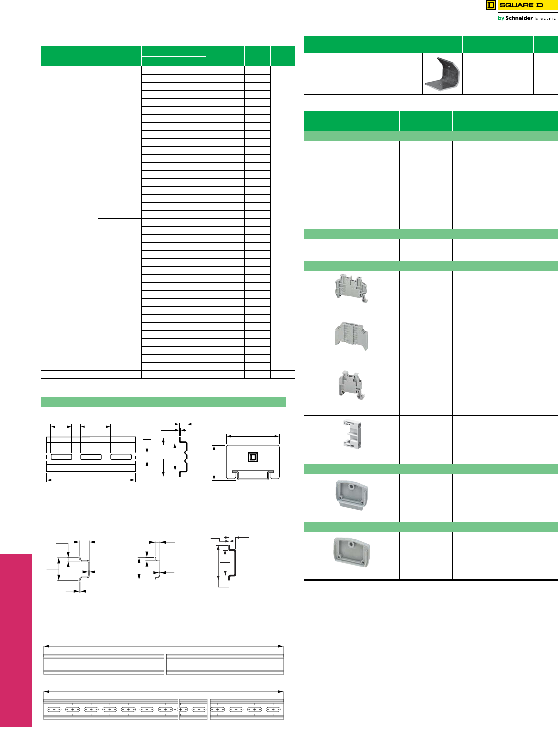
Table 24.30: DIN 3 Track – Various Lengths
Description Length Class 9080
Type
$ Price
ea.
Std.a
Pack
IN mm
Symmetrical
rail 35 x 7.5
mm
(1.38 in. x 0.295
in.) in
compliance with
EN 50022
standard (DIN
46277-3).
Galvanized
steel,
no mounting
holes
3 0.08 MH203 3.20
10
4 0.10 MH204 3.60
5 0.13 MH205 4.10
6 0.15 MH206 4.70
7 0.18 MH207 5.10
8 0.20 MH208 5.60
9 0.23 MH209 6.20
10 0.25 MH210 6.80
11 0.28 MH211 7.20
12 0.30 MH212 7.80
13 0.33 MH213 8.30
14 0.36 MH214 8.70
15 0.38 MH215 9.30
16 0.41 MH216 9.80
17 0.42 MH217 10.20
18 0.46 MH218 10.80
19.68 500 MH220 11.60
39.37 1000 MH239 19.70
78.74 2000 MH279 29.60
Galvanized
steel,
prepunched
3 0.08 MH303 3.50
4 0.10 MH304 3.90
5 0.13 MH305 4.70
6 0.15 MH306 5.10
7 0.18 MH307 5.70
8 0.20 MH308 6.20
9 0.23 MH309 6.90
10 0.25 MH310 7.40
11 0.28 MH311 8.10
12 0.30 MH312 8.60
13 0.33 MH313 9.20
14 0.36 MH314 9.60
15 0.38 MH315 10.20
16 0.41 MH316 10.80
17 0.42 MH317 11.60
18 0.46 MH318 12.00
19.68 500 MH320 13.10
39.37 1000 MH339 23.00
78.74 2000 MH379 32.70
High rise track Aluminum 39.37 1000 MH439 27.90 2
Dimensions
.25
6
A
.30
8
.04
1
.98
25
1.38
35
9080MH3**
.71
18
.98
25
1.80
46
1.17
30
9080MHA10
Dual Dimensions:
Millimeters
Inches
2000 (78.7)
2000 (78.7)
15
0.6
1.5
0.06
1
0.04
1
0.04
5
0.2
35
1.4
7.2
0.3
35
1.4
5.5
0.2
5
.20
1
.04
8.5
.34
15
.59
NSYSDR200D
and NSYSDR200
NSYSDR200BD
and NSYSDR200B
NSYSTRAD155
Angle bracket kit Catalog
Number
$ Price
ea.
Std.a
Pack
For mounting 9080GH or MH track to a panel
at 45o angle. Includes 2 brackets and
hardware for mounting the track to the
brackets.
9080MH82c7.20 1
Table 24.31: DIN 3 Track—2 meter length
Description Length Catalog Number $ Price
ea.
Std.
Pack a
IN mm
DIN 3
Symmetrical rail 35x15 mm depth
1.5 mm thick galvanized steel
Prepunched
78.74 2000 NSYSDR200D 11.16 20
Symmetrical rail 35x15 mm depth
1.5 mm thick galvanized steel
No mounting holes
78.74 2000 NSYSDR200 11.16 20
Symmetrical rail 35x7.2 mm depth
1 mm thick galvanized steel
Prepunched
78.74 2000 NSYSDR200BD 7.52 20
Symmetrical rail 35x7.2 mm depth
1 mm thick galvanized steel
No mounting holes
78.74 2000 NSYSDR200B 7.52 20
DIN 2
Symmetrical rail 15x5 mm depth
1 mm thick galvanized steel
Prepunched
78.74 2000 NSYTRADR155 15.00 5
End Clamps
Plastic clip-on end clamp for
35 mm DIN 3 track
0.21 5.2 NSYTRAAB35 1.50 50
Plastic clip-on end clamp with screw
for 35 mm DIN 3 track
0.37 9.5 NSYTRAABV35 2.40 50
Plastic clip-on end clamp for
15 mm DIN 2 track
0.21 5.2 NSYTRAAB15 1.50 50
Polycarbonate end clamp for
35 mm DIN 3 track
0.31 8 9080MHA10 2.40 50
End Plate for Direct Mounting Miniature Blocks
Plastic end plateb
0.09 2.2 NSYTRACRM22 0.50 50
End Plate for Direct Mounting Miniature Blocks with Flange
Plastic end plate with flangeb
0.09 2.2 NSYTRACRMF22 0.50 50
RoHS
Compliant
www.schneider-electric.us
24 TERMINAL BLOCKS
© 2012 Schneider Electric
All Rights Reserved 24-15
NEMA Style
Terminal Blocks
Type G
Class 9080 / Refer to Catalog 9080CT9601
Standard Terminal Block Assemblies
The assemblies listed in the table below consist of 6 ft
(two 3 ft lengths packaged together) of terminal blocks.
The terminal blocks are mounted on snap-off mounting
track, which can be easily broken every 5/16 in. Every
tenth terminal block is marked to aid in counting off the
proper number of terminal blocks. After adding the proper
end barrier and a slip-in end clamp to the blocks that were
broken off, the custom assembly is ready for installation.
Custom Terminal Block Assemblies
Order an assembly built as required for the application.
As standard, custom assemblies use 9080GH mounting
track with screw on end clamps. Other options are
available from the table below.
One terminal block type: The number of blocks in the
assembly is added to the end of the catalog number of
the desired block. Example: an assembly of 25 9080GR6
blocks would be 9080GR625.
More than one terminal block type in an assembly: A
detailed drawing or sketch of the desired assembly must
accompany the order. aThe 9080GH10 screw-on end clamp is not recommended for use with
snap-off channel. It is recommended that the 9080GH11 slip-in end
clamp be used. Therefore, when the suffix B is used, it should be
followed by the suffix C.
Table 24.32: Standard Terminal Block Assemblies
Description Type $ Price
Assembly of 188 Type GA6 GA6188BC 530.00
Assembly of 204 Type GR6 GR6204BC 674.00
Assembly of 94 Type GF6 GF694BC 1311.00
Assembly of 296 Type GM6 GM6296BC 830.00
Assembly of 188 Type GP6 GP6188BC 653.00
Table 24.33: Custom Assembly Pricing
Block Type $ Price Per
Block/Terminal Block Type $ Price Per
Block/Terminal
GA6 2.80 GK6 channel mounted 3.30
GC6 6.10 GK6 direct mounted 2.70
GCB01–15 68.00 GM6 2.90
GCB20–150 84.00 GP6 3.50
GD6 12.20 GR6 3.30
GE6 31.80 GR6T 3.80
GF6 14.00 GS6 3.80
GG6 14.60 Blank vinyl marking strip 0.05
Pre-numbered (1-25 only) 0.24
Table 24.34: Custom Terminal Block Assemblies
Option Suffix Example
Substitute slip-in end clamps C9080GR625C
Substitute snap-off channel B9080GR625BC a
For direct mount assembly of 9080GK6 blocks D9080GK67D
Add a blank vinyl marking strip M9080GR625M
Add pre-marked (1–25 only) marking strip MPO 9080GR625MPO
Mount on 35 mm DIN 3 track instead of
9080GH track T9080GR625T
Price per block from Table 24.33
Number of blocks in the assembly x
Subtotal (multiply # of blocks by price of blocks)
Initial Charge for factory assemblies
All except 9080GK6 direct mount ($7.00)
OR for 9080GK6 direct mount ($3.60)
Vinyl Marking Strips
Adder for Suffix M—$0.05 per block
OR adder for Suffix MPO—$0.24 per block
Deduct for Suffix C—$2.40
Total everything from Subtotal down
Apply the following rounding rules to the total obtained:
$1.00 through $50.00 Round to the nearest dime
over $50.00 Round to the nearest dollar
Table 24.35: How to Order
To Order Specify Catalog Number
•Class Number
•Type Number
Class Type
9080 GA612
CP5 Discount
Schedule
www.schneider-electric.us
24 TERMINAL BLOCKS
24-16 © 2012 Schneider Electric
All Rights Reserved
NEMA Style
Terminal Blocks
Type G
Class 9080 / Refer to Catalog 9080CT9601
Note: For additional track and appropriate end clamps, see page 24-12.
aOrders must specify the standard package quantity or multiples of
that quantity.
Table 24.36: 3/4 in. Mounting Track
Style Length
(in.) Type $ Price
ea.
Std.
Packa
Standard
Tr a c k
3GH103 2.40 5
4GH104 2.40 5
5GH105 2.60 5
6GH106 2.60 5
7GH107 2.60 5
8GH108 3.00 5
9GH109 3.00 5
10 GH110 3.30 5
11 GH111 3.30 5
12 GH112 3.50 5
13 GH113 3.50 5
14 GH114 3.80 5
15 GH115 3.90 5
16 GH116 4.20 5
17 GH117 4.40 5
18 GH118 4.80 5
36 GH136 11.70 5
48 GH148 15.20 5
72 GH172 22.70 5
Snap-Off
Track
36 GH236 11.70 20
48 GH248 15.20 20
72 GH272 22.70 20
High Rise 36 GH336 29.00 2
Table 24.37: Accessories
Description Type $ Price
ea.
Std.
Pack a
End Clamps
Screw-on End Clamp
(Not recommended for use
on snap-off mounting track)
GH10 2.40 50
Slip-in End Clamp
(Not for use with 9080
GE6, GK6 blocks)
GH11 .63 50
Jumpers
2-pole jumper for GM6 GH700 .59 20
6-pole jumper for GM6 GH710 1.20 10
2-pole jumper for GK6, GR6 GH72 .62 20
6-pole jumper for GK6, GR6 GH73 1.80 10
2-pole jumper for GC6 GH74 2.30 10
6-pole jumper for GC6 GH75 4.30 10
2-pole jumper for GD6 GH76 3.20 10
6-pole jumper for GD6 GH77 8.70 10
2-pole jumper for GA6, GP6 GH78 1.20 10
6-pole jumper for GA6, GP6 GH79 2.00 10
Fanning Strip
Snap-together fanning
strip section for GA6 blocks GH51 3.00 10
Snap-together fanning strip
section for GK6, GR6 blocks GH52 3.30 10
Standard
Track
Snap-Off
Track
High Rise
Table 24.38: Marking and Additional Accessories
Description Type $ Price
ea.
Std.
Pack a
25 ft blank vinyl marking
strip GH220 11.90 1
For GK6, GR6 GH21 4.40 5
For GA6, GP6 GH22 4.40 5
For GM6 GH230 4.40 5
Blank pin-feed marking
tabs—6 x 20
(total 120) marking tabs
for GD6, GR6,
and GT6 blocks
GH200 1.70 20
Pre-marked 01 to 50
(2 sets) plus 20
Various marking tabs
(total 120 marking tabs)
for GD6, GR6, and
GT6 blocks
GH210 13.10 5
Marking pen with
permanent, fine line
black ink
GH40 8.00 12
Marking strip end plug
for GK6, GR6, GM6,
GA6, GP6, GC6, GD6,
GE6, and GT6 blocks
GH60 .39 50
Transition barrier
between GK6 and
all other G or K blocks
GH61 .98 50
Cover for GR6 or GR6T
blocks GH62 .98 50
Banana test plug for
GR6T block GH90 7.40 10
Test plug adapter for
GR6T block
(included as standard
with GR6T)
GH91 1.20 50
Angle bracket kit—for
mounting
9080GH or MH track
to panel at 45° angle.
Includes 2 brackets
and hardware for
mounting the track to
the brackets
MH82 7.20 1
Polycarbonate end
clamp for 35 mm
DIN 3 track, 8 mm
(0.31 in.) wide
MHA10 2.40 50
Table 24.39: How to Order
To Order Specify Catalog Number
•Class Number Class Type
•Type Number 9080 GH10
Vinyl marking strip
numbered 1-25
CP5 Discount
Schedule
www.schneider-electric.us
24 TERMINAL BLOCKS
© 2012 Schneider Electric
All Rights Reserved 24-17
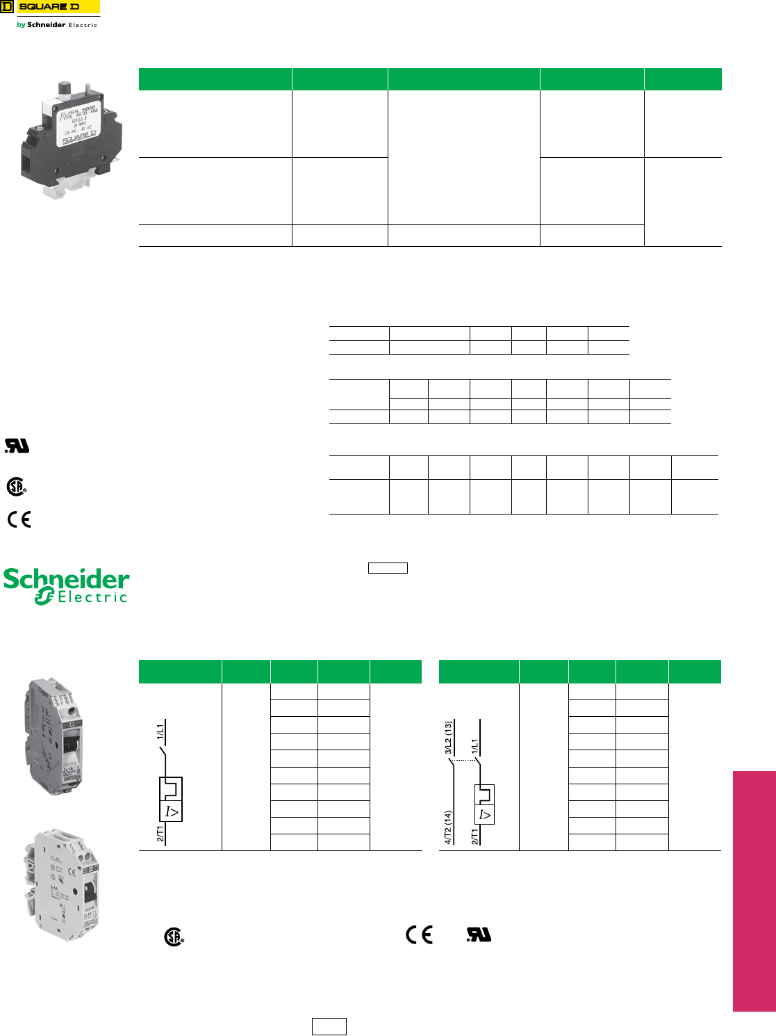
Thermal-Magnetic Circuit
Protectors
Type GCB
Class 9080 / Refer to Catalog 9080CT9901
aThese maximum current values assume the use of insulated copper conductors with 75oC temperature rating, and are calculated based on NEC Article
310, Table 310-16. In most cases this value is the maximum ampacity of that wire or combination of wires (as listed in the above table) which has the
greatest current carrying capacity. The actual allowable current for a particular application depends on the number, size, insulation class, and other
characteristics of the wires used.
bDiscount schedule CP5.
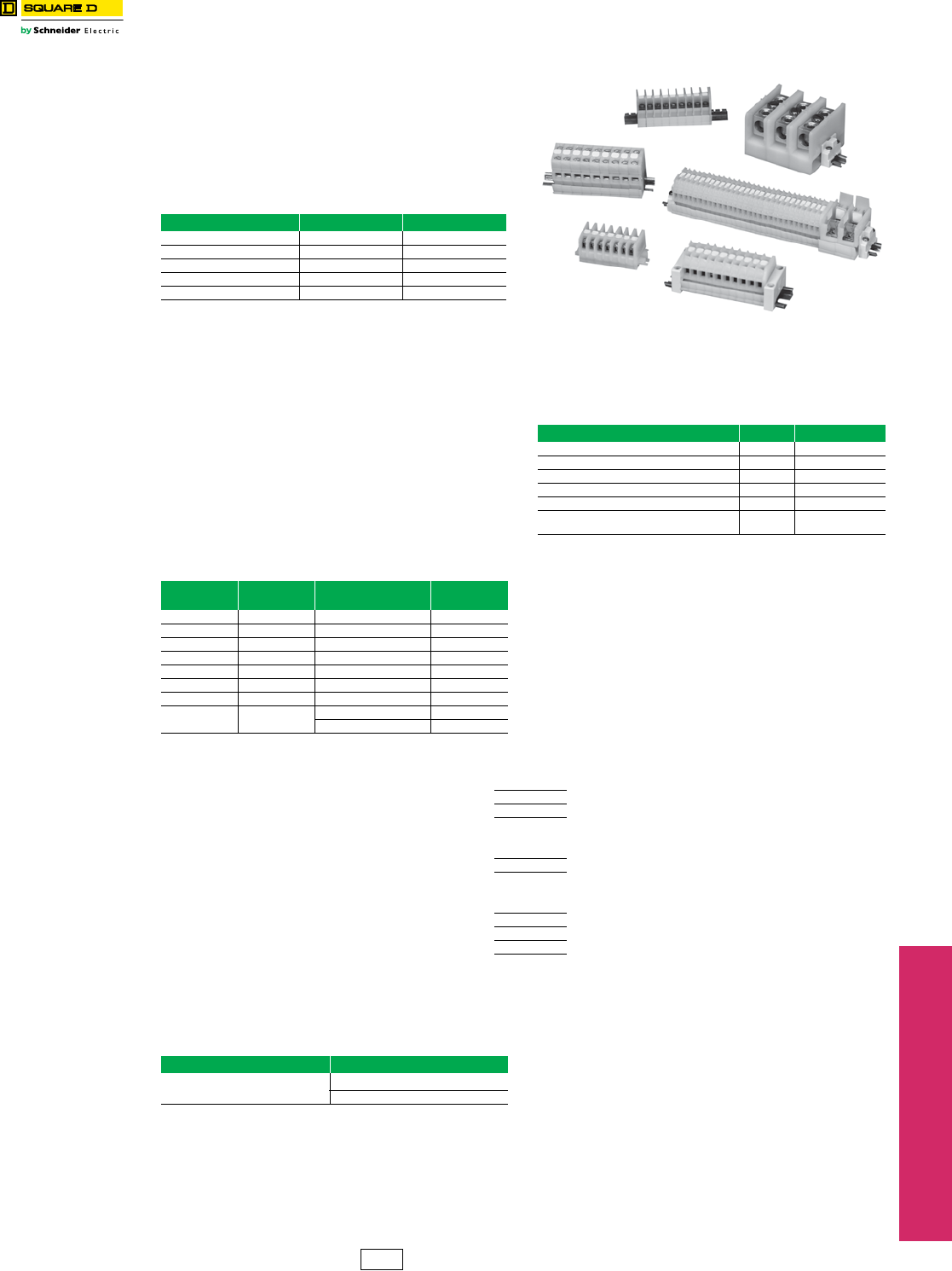
Thermal-Magnetic Circuit Protectors
Type GB2
www.schneider-electric.us
GCB100
Table 24.40: 9080GCB Thermal-Magnetic Circuit Protectorsb
Maximum Current (A) Internal Resistance
¾Maximum Voltage Catalog Numbera$ Price
0.1 133
250 Vac
65 Vdc
GCB01
66.00
0.5 6.6 GCB05
0.8 2.55 GCB08
1.0 1.97 GCB10
1.2 1.22 GCB12
1.5 0.86 GCB15
2.0 0.49 GCB20
72.00
2.5 0.31 GCB25
3.0 0.20 GCB30
4.0 0.10 GCB40
5.0 0.08 GCB50
7.0 0.03 GCB70
10.0 <0.02 125 Vac
65 Vdc
GCB100
15.0 <0.02 GCB150
Selection
To properly select a Class 9080 Type GCB circuit protector, follow these steps:
1. Determine the inrush correction factor from Table 24.41.
2. Determine the temperature correction factor from Table 24.42.
3. Determine the sealed current of the load that is being protected.
4. Multiply the sealed current by the two correction factors and choose
the closest circuit protector.
Note: Choosing a circuit protector with a value lower than the calculated value might
cause nuisance tripping, while choosing the larger might provide a protector
that will not properly protect the load.
Table 24.41: Table A—Inrush Ratio Correction Table
Note: For resistive loads, use inrush correction factor of 1.0.
Inrush Ratio 1:1 to 1:4 1:5 1:6 1:7 1:8
Factor 1.3 1.4 1.5 1.6 1.7
Table 24.42: Table B—Ambient Temperature Correction Table
Ambient
Temperature
70oF 100oF 120oF140
oF160
oF180
oF200oF
(21.1oC) (37.8oC) (48.9oC) (60oC) (71.1oC) (82.2oC) (93.3oC)
Factor 1.0 1.1 1.2 1.3 1.4 1.5 1.6
File
CCN
E152841
QVNU2 Example: Solenoid with sealed current of 0.75 A, an
inrush ratio of 1:6, and in an ambient temperature of
85oF: 0.75 x 1.5 x 1.05 = 1.18 Choose the 1.2 A
protector
Tripping Time: Tripping time of the circuit protector
is determined from Table 24.43. Divide the circuit
protector value by the temperature correction factor
from Table 24.42 to determine actual rated current
referenced in Table 24.43.
Table 24.43: Table C—Tripping Times in Seconds at 70oF (21.1oC)
(UL1077) Percent rated
current 100% 200% 300% 400% 500% 600% 1000% 2000% and
greater
File
Class
025490
3211 07 Tripping
Time (s) no trip 10–40 38 1.5–9 0.8–6 0.003–4 0.003–2 Max. 0.02
Note: When several protectors are channel mounted adjacent to each other, the “no trip” current will be
80% of rated current at 70oF.
CP5 Discount Schedule
Table 24.44: GB2 Thermal-Magnetic Circuit Protectorsc
Description Maximum
Voltage
Thermal
Rating
Catalog
Number $ Price ea.dDescription Maximum
Voltage
Thermal
Rating
Catalog
Number $ Price ea.d
One pole Thermal
Magnetic Circuit
Protector
300 Vac
0.5 A GB2CB05
43.60
Two pole Thermal
Magnetic Circuit
Protector
300 Vac
0.5 A GB2CD05
52.00
1 A GB2CB06 1 A GB2CD06
2 A GB2CB07 2 A GB2CD07
3 A GB2CB08 3 A GB2CD08
4 A GB2CB09 4 A GB2CD09
5 A GB2CB10 5 A GB2CD10
6 A GB2CB12 6 A GB2CD12
8 A GB2CB14 8 A GB2CD14
10 A GB2CB16 10 A GB2CD16
12 A GB2CB20 12 A GB2CD20
cDiscount schedule I.
dMust order in multiples of 6
Note: For markers, use AB1( )R and AB1( )G markers from page 24-16
File
Class
081630
3215 30
IEC 157-1
VDE 0660
File
CCN
E113720
QVNU2
GB2CB06
GB2CD
IDiscount
Schedule
www.schneider-electric.us
www.schneider-electric.us
24 TERMINAL BLOCKS
24-18 © 2012 Schneider Electric
All Rights Reserved
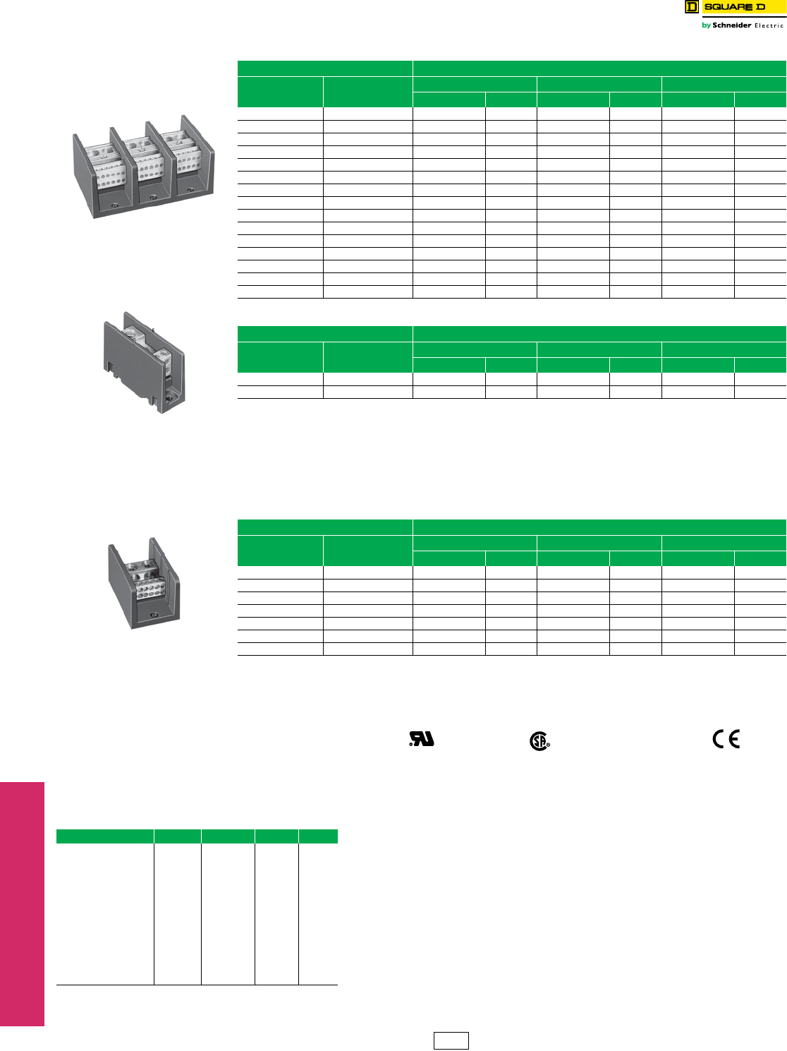
Table 24.45: Standard Power Distribution Blocks
Lug Wire RangeaAluminumb
Main Branch One Pole Two Pole Three Pole
Type $ Price Type $ Price Type $ Price
(1) #14–2/0 (1) #14–2/0 LBA162101 10.40 LBA262101 22.10 LBA362101 25.70
(1) #6–350 kcmil (1) #6–350 kcmil LBA163101 53.00 LBA263101 81.00 LBA363101 107.00
(1) #4–600 kcmil (1) #4–600 kcmil LBA164101 95.00 N/A — LBA364101 183.00
(2) #4–350 kcmil (2) #4–350 kcmil LBA165202 98.00 LBA265202 147.00 LBA365202 189.00
(2) #6–500 kcmil (2) #4–500 kcmil LBA1652021 135.00 LBA2652021 206.00 LBA3652021 243.00
(1) #14–2/0 (4) #14–4 LBA162104 30.50 LBA262104 45.80 LBA362104 68.00
(1) #14–2/0 (6) #14–4 N/A — N/A — LBA362106 131.00
(1) #6–400 kcmil (4) #14–2 LBA163104 56.00 LBA263104 84.00 LBA363104 113.00
(1) #6–400 kcmil (6) #14–2 LBA163106 59.00 LBA263106 89.00 LBA363106 122.00
(1) #6–400 kcmil (8) #14–2 LBA164108 77.00 LBA264108 116.00 LBA364108 161.00
(1) #4–500 kcmil (6) #14–2/0 LBA165106 126.00 LBA265106 189.00 LBA365106 233.00
(1) #4–500 kcmil (12) #14–2 LBA165112 134.00 LBA265112 201.00 LBA365112 261.00
(2) #14–2/0 (6) #14–4 LBA163206 60.00 LBA263206 90.00 LBA363206 122.00
(2) #6–500 kcmil (8) #14–2/0 LBA165208 126.00 LBA265208 189.00 LBA365208 251.00
(2) #6–500 kcmil (12) #14–4 LBA165212 135.00 LBA265212 206.00 LBA365212 261.00
Table 24.46: Miniature Power Distribution Blocks
Lug Wire RangeaAluminumb
Main Branch One Pole Two Pole Three Pole
Type $ Price Type $ Price Type $ Price
(1) #14–2 (1) #14–2 LBA161101 13.40 N/A — LBA361101 23.40
(1) #14–2 (4) #18–10 LBA161104 26.40 LBA261104 30.60 LBA361104 58.00
Table 24.47: Copper Power Distribution Blocks
Lug Wire RangeaCopperc
Main Branch One Pole Two Pole Three Pole
Type $ Price Type $ Price Type $ Price
(1) #18–1/0 (1) #18–1/0 LBC162101 99.00 N/A — LBC362101 201.00
(1) #6–250 kcmil (1) #6–250 kcmil LBC163101 125.00 N/A — LBC363101 233.00
(1) #14–2/0 (4) #14–4 LBC162104 99.00 LBC262104 147.00 LBC362104 248.00
(1) #4–500 kcmil (6) #14–2 LBC163106 153.00 LBC263106 228.00 LBC363106 354.00
(2) #14–2/0 (6) #14–4 LBC163206 134.00 LBC263206 201.00 LBC363206 269.00
(2) #4–500 kcmil (8) #14–2/0 LBC165208 297.00 N/A — LBC365208 593.00
(2) #6–500 kcmil (12) #14–2 LBC165212 284.00 N/A — LBC365212 567.00
aLugs suitable for use with 75oC conductors. (#) indicates number of conductors.
bAluminum blocks will accept either Al or Cu conductors.
cCu blocks will accept copper conductors only. Refer to catalog for dimensions.
Certifications File
Guide
E60616
XCFR2
File
Class
70361
6228-01 RoHS Compliant Marked
Table 24.48: Clear Plastic Covers (0.045 in. thick) Application Data
Voltage Rating—Class B & C—600 V
Blocks are rated based on NEC Table 310-16 using 75oC wire.
Aluminum blocks are tin plated high conductive aluminum.
Copper blocks are tin plated high conductive copper.
Housing material:
•Miniature Blocks are made from high impact thermoplastic rated at 125oC. max. & -40oC. min.
•Full Size Blocks are made from general purpose phenolic rated at 150oC. max. & -40oC. min.
All blocks have a flammability rating of UL 94V-0.
Most blocks have a short circuit current rating for UL508A up to 200 kA for branch
circuit applications. For the actual ratings, see catalog 9080CT9603R9/08.
Note: There are no covers for miniature blocks.
For LBA Type Type $ Price ea. dDim. A Dim. B
LBA162…, LBC162 LB21 11.30 1.062 2.750
LBA262…, LBC262 LB22 13.50 1.875 2.750
LBA362…, LBC362 eLB23 15.80 2.688 2.750
LBA163…, LBC163 LB31 12.50 1.782 3.813
LBA263…, LBC263 LB32 14.70 3.313 3.813
LBA363.… LBC363 LB33 17.00 4.844 3.813
LBA164… LB41 13.50 2.125 4.563
LBA264… LB42 15.80 4.000 4.563
LBA364… LB43 18.00 5.875 4.563
LBA165…, LBC165 LB51 14.70 2.719 5.313
LBA265…, LBC265 LB52 17.00 5.656 5.313
LBA365…, LBC365 LB53 19.20 8.375 5.313
dThese covers must be ordered in multiples of 5. Each cover comes with two self-tapping screws.
eWill not work on a 9080LBA362106 block.
Power Distribution Blocks Type LB
Class 9080 / Refer to Catalog 9080CT9603
CP1 Discount
Schedule
LBA365212
LBA161104
LBC165212
www.schneider-electric.us
24 TERMINAL BLOCKS
© 2012 Schneider Electric
All Rights Reserved 24-19
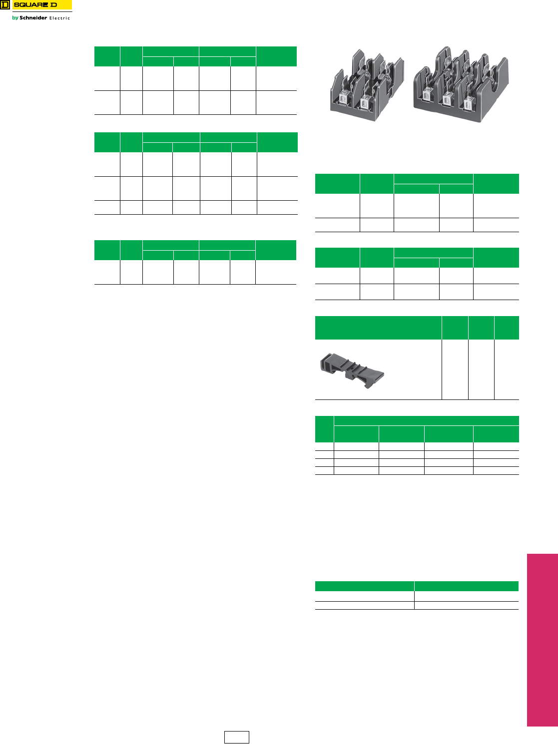
Fuseholders Type FB
Class 9080 / Refer to Catalog 9080CT9603
Application Information:
Base material:
aBase is high impact thermoplastic—
maximum operating temperature 125oC
bBase is general purpose phenolic—
maximum operating temperature 150oC
cBase is high impact polyester—
maximum operating temperature 130oC
Clip material:
•All 30 and 60 A fuse clips are copper alloy tin plated.
•All 100 and 200 A fuse clips are one piece aluminum with
copper spring tin plated.
•All Class H, R and J fuses are standard with reinforced fuse
clips.
Lug termination:
•All 30 A blocks have pressure wire connectors.
•All 60, 100 and 200 A blocks have box lug connectors.
Approvals:
•The Type M fuseholders are UL component recognized
(File E40747 CCN IZLT2).
•The Type H, R, J and CC are UL Listed (File E40747 CCN
IZLT).
•All fuseholders are CSA certified
(File 70360 Class 6225-01).
Flammability rating of all FB fuse blocks is UL 94V-0.
RoHS Compliant
dClass R and CC fuseholders accept current limiting Class R & CC
fuses only.
eNot in stock. Order point—Raleigh, NC.
fSpecified wire ranges are based on 75oC wire. Wires with
temperature ratings other than 75oC are approved while observing
NEC Article 310 wire tables for allowable ampacities of insulated
conductors.
Class R, J and CC fuse blocks are tested and approved for 200,000
AIC in accordance with UL 512.
gCan be mounted directly to a panel or on 35 mm DIN 3 track.
hOrders must specify the standard package quantity or multiples of that
quantity.
Table 24.49: 250 V—Classes H and R
Rating
(A) f
No. of
Poles
Class H Class Rd Lug
Wire Range
Type $ Price Type $ Price
30a
1FB1211 12.90 FB1211R 19.20 #14–10
Cu
2FB2211 21.90 FB2211R 28.40
3FB3211 31.10 FB3211R 37.20
60a
1FB1221R 28.40 #14–2
Cu or Al
2FB2221 39.20 FB2221R 45.80
3FB3221 55.00 FB3221R 61.00
Table 24.50: 600 V—Classes H and R
Rating
(A) f
No. of
Poles
Class H Class Rd Lug
Wire Range
Type $ Price Type $ Price
30b
1FB1611 24.30 FB1611R 30.60 #14–10
Cu
2FB2611 42.60 FB2611R 48.50
3FB3611 54.00 FB3611R 60.00
60b
1FB1621Re37.20 #14–2
Cu or Al
2FB2621 51.00
3FB3621 54.00 FB3621R 78.00
100b3FB3631 147.00 FB3631R 158.00 #6–2/0
Cu or Al
Table 24.51: 600 V Series—Miniature Fuse
Dimension (13/32 x 1-1/2 in.)
Rating
(A) f
No. of
Poles
Type M Class CCd Lug
Wire Range
Type $ Price Type $ Price
30a
1FB1611M 13.50 FB1611CC 13.50 #14–10
Cu
2FB2611M 19.80 FB2611CC 22.10
3FB3611M 24.30 FB3611CC 24.80
FB2221 FB3221R
Table 24.52: 600 V—Class H Only (Copper Only)
Rating
(A) f
No. of
Poles
Class H Lug
Wire Range
Type $ Price
30b
1FB1611 24.30 #14–10
Cu
2FB2611 42.60
3FB3611 54.00
100b3FB3631C 158.00 #6–2/0
Cu
Table 24.53: 600 V—Class J
Rating
(A) f
No. of
Poles
Class J Lug
Wire Range
Type $ Price
30b2FB2611J 45.50 #2–14 AWG
Cu—Al
3FB3611J 63.00
60b2FB2621Je54.00 #2–14
Cu—Al
3FB3621J 75.00
Table 24.54: Track Adapter
Description Type $ Price
ea.
Std.
Pack
h
35 mm DIN 3 Track
Adapter
For 9080 FB*211,
FB*211R,
FB*611M, and
FB*611CC
Fuseholders
FBDIN3
e4.10 100
Table 24.55: Fuse Sizes—(Diameter x Length)
A
Class of Fuse
Class H/R—
300 V
Class H/R—
600 V
Class M/CC—
600 V
Class J—
600 V
30 9/16 x 2 in. 13/16 x 5 in. 13/32 x 1-1/2 in. 13/16 x 2-1/4 in.
60 13/16 x 3 in. 1-1/16 x 5-1/2 in. N/A 1-1/16 x 2-3/8 in.
100 1 x 7-7/8 in. 1 x 7-7/8 in. N/A N/A
200 1-1/2 x 7-1/8 in. 1-3/4 x 9-5/8 in. N/A N/A
Table 24.56: How to Order
To Order Specify Catalog Number
•Class Number 9080
•Type Number FB1211
CP1 Discount
Schedule
www.schneider-electric.us
24 TERMINAL BLOCKS
24-20 © 2012 Schneider Electric
All Rights Reserved
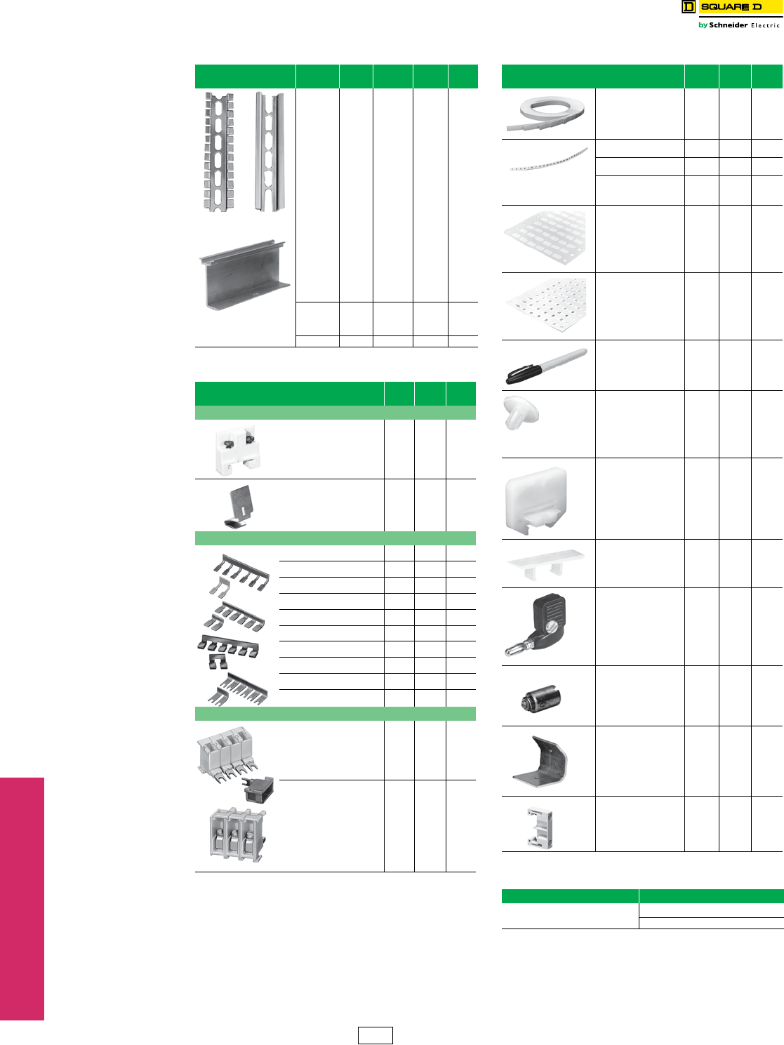
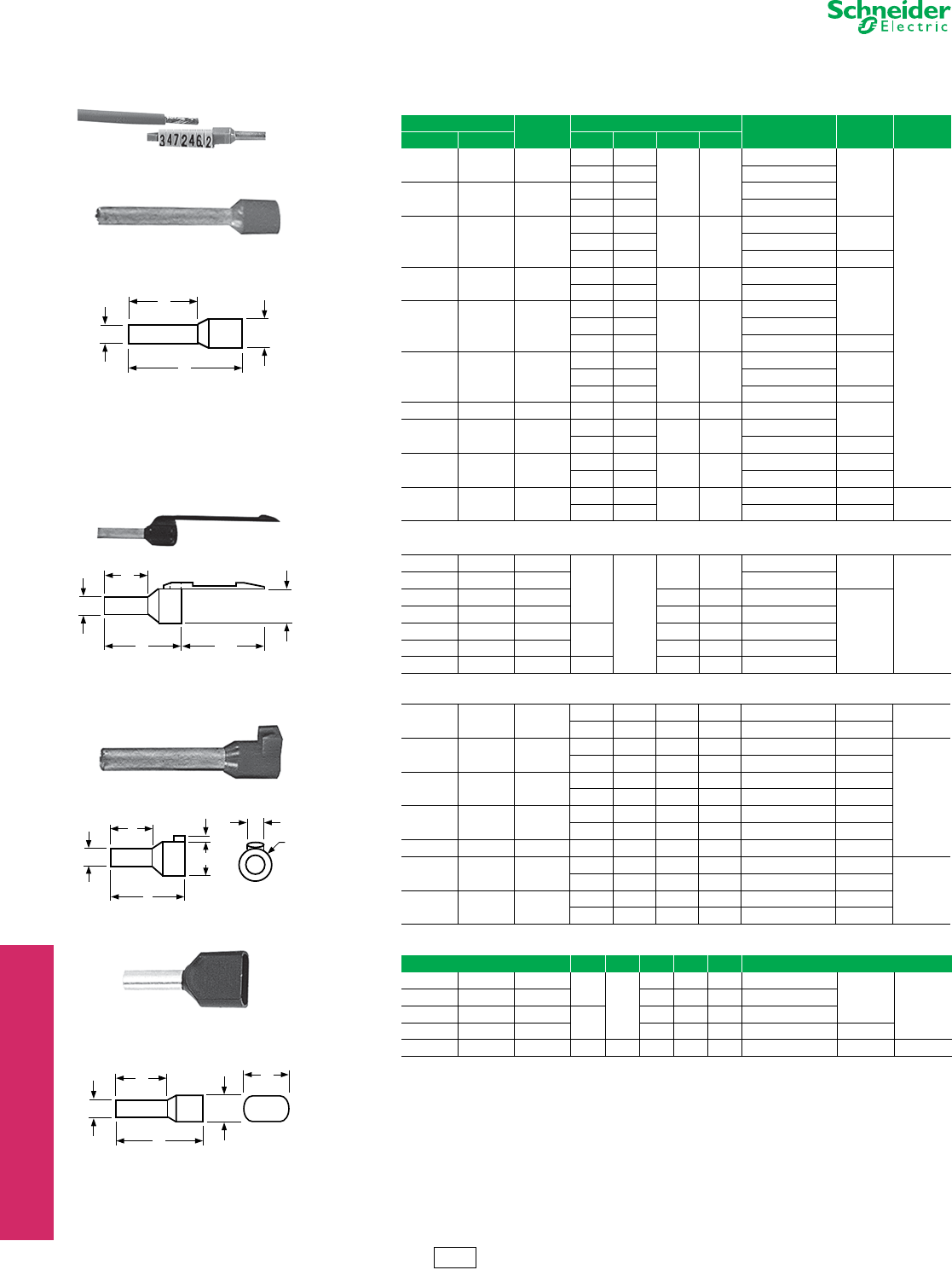
Cable Ends DZ5 and AZ5
Refer to Catalog 9080CT9701
aBold faced catalog numbers are stocked in the United States.
bThese catalog numbers are UL Component Recognized (File E164872 CCN ZMMT2) provided the AT1PA crimping
tool is used to crimp the cable end.
cCE Marked.
dOrder must specify the standard pack quantities or multiples of that quantity.
eWill accept an AR1SC03 cable marker from page 24-22.
RoHS
Compliant
Conform to NF C 63-023 Standard
Mark and terminate wires simultaneously
Strip the wire, insert it into the cable end and crimp it.
Up to 7 markers can be used.
Table 24.57: Without Marking Flag
Wire Size Sleeve
color
Dimensions (mm) Catalog Number
ac $ Price ea. Std. Pack
d
AWG mm2A B C D
26 0.25 Yellow 11 6.2
1.2 2.2
DZ5CE002L6
0.16
1000
13 8.2 DZ5CE002
24 0.34 Green 11 6.2 DZ5CE003L6
13 8.2 DZ5CE003
22 0.50 White
11 6.2
1.4 3
DZ5CE005L6b
0.18
13 8.2 DZ5CE005b
16.8 12 DZ5CE005L12 0.26
20 0.75 Blue 11 6.2 1.6 3.1 DZ5CE007L6b
0.18
13 8.2 DZ5CE007b
18 1.00 Red
11.5 6.2
1.8 3.4
DZ5CE010L6b
13.5 8.2 DZ5CE010b
16.8 12 DZ5CE010L12 0.28
16 1.50 Black
11.5 6.2
2.1 4
DZ5CE015L6b
0.22
13.5 8.2 DZ5CE015b
22.8 17.7 DZ5CE0153b0.42
14 2.00 Yellow 14.5 8.2 2.35 4.2 DZ5CE020 0.24
14 2.50 Gray 14.5 8.2 2.7 4.6 DZ5CE025b
24 17.7 DZ5CE0253b0.44
12 4.00 Orange 17.3 9.8 3.3 5.5 DZ5CE042b0.42
25.5 17.5 DZ5CE043b0.62
10 6.00 Green 20 11.5 3.95 7 DZ5CE062 0.48 100
26 17.5 DZ5CE063 0.66
Table 24.58: With Marking Flag
26 0.25 Yellow
13
8.2
1.2 2.2 DZ5CA002 0.26
1000
24 0.34 Green DZ5CA003
22 0.50 White 1.4 3 DZ5CA005b
0.32
20 0.75 Blue 1.6 3.1 DZ5CA007b
18 1.00 Red 13.5 1.8 3.4 DZ5CA010b
16 1.50 Black 2.1 4 DZ5CA015b
14 2.50 Gray 14.5 2.7 4.6 DZ5CA025b
Table 24.59: Marking Flag Optional e
12 4.00 Orange 19.5 11.5 3.3 5.5 DZ5CA042b0.38 1000
25.5 17.5 3.3 5.5 DZ5CA043b0.46
10 6.00 Green 20 11.5 3.95 7 DZ5CA062 0.62
100
26 17.5 3.95 7 DZ5CA063 0.64
8 10.00 Brown 21.5 12 4.95 8.4 DZ5CA102 0.72
27 17.5 4.95 8.4 DZ5CA103 0.78
616.00White
23.5 12 6.35 9.8 DZ5CA162 0.86
29 17.5 6.35 9.8 DZ5CA163 0.96
4 25.00 Black 30 17.5 8.15 12 DZ5CA253 1.10
235.00Red
30 16 9 13.5 DZ5CA352 1.30
20
39 25 9 13.5 DZ5CA353 1.50
0 50.00 Blue 36 20 11 15.7 DZ5CA502 1.50
41 25 11 15.7 DZ5CA503 1.70
Table 24.60: Dual Wire Cable Ends
A B C D E
22 0.50 White 13
8
1.4 2.5 4.7 AZ5DE005
0.24 500
20 0.75 Blue 1.6 2.8 5.0 AZ5DE007
18 1.00 Red 13.5 1.8 3.4 5.4 AZ5DE010
16 1.50 Black 2.1 3.6 6.6 AZ5DE015 0.26
14 2.50 Gray 24 10 2.7 4.2 7.8 AZ5DE025 0.32 250
B
A
CD
DZ5CE005
22
B
A
CD
DZ5CA007
C
A
D
D
4.5
B
2
DZ5CA042
BE
A
CD
AZ5DE010
IDiscount
Schedule
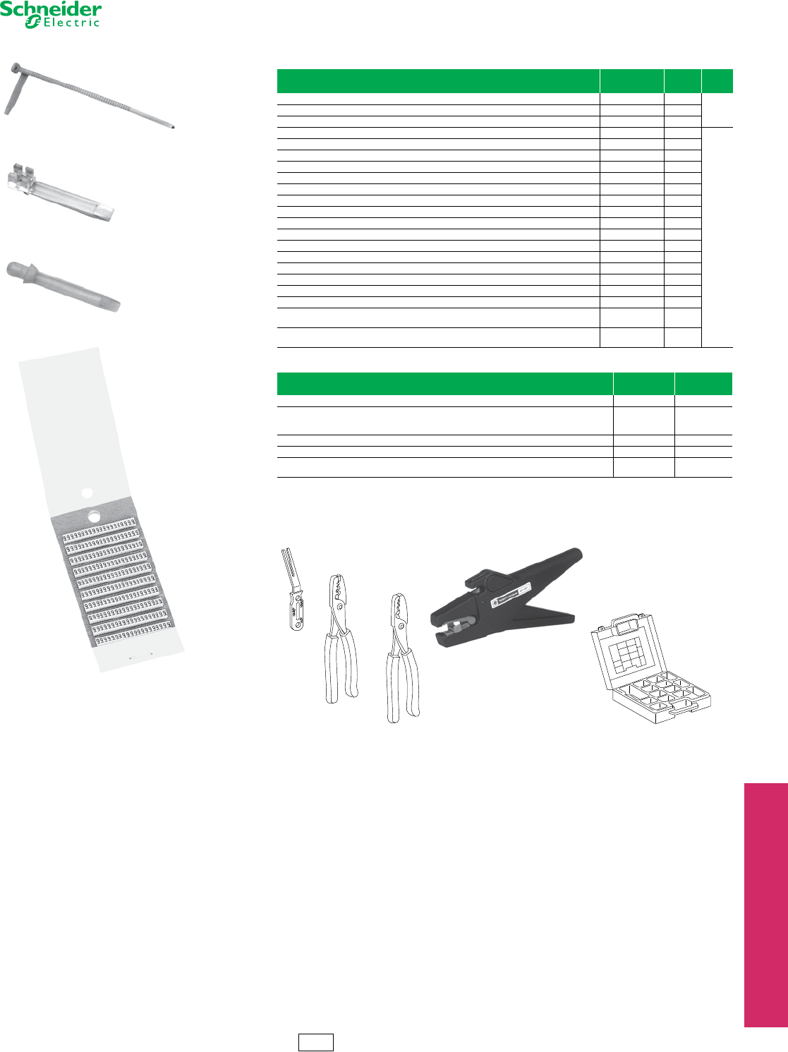
www.schneider-electric.us
24 TERMINAL BLOCKS
© 2012 Schneider Electric
All Rights Reserved 24-21
Cable Ends AR1 and AT1
Refer to Catalog 9080CT9701
Table 24.61: Cable End Markers & Accessories
Style Catalog
Number
$ Price
ea.
Std.
Packa
Adjustable collar type marker holder for #14 to #2 wire AR1SC01 0.42
100Clip-on marker holder for #18 to #16 wire (7 markers max.) AR1SC02 0.42
Cable end marker tags for DZ5CA042 to DZ5CA253 AR1SC03 0.12
Card of 200 yellow markers with black numeral 0 thru 9 AR1MA01b136.00
1
Card of 200 yellow markers with black letters A thru Z AR1MB01b300.00
Card of 200 black markers with a white 0 marked on them AR1MC010 13.60
Card of 200 brown markers with a white 1 marked on them AR1MC011 13.60
Card of 200 red markers with a black 2 marked on them AR1MC012 13.60
Card of 200 orange markers with a black 3 marked on them AR1MC013 13.60
Card of 200 yellow markers with a black 4 marked on them AR1MC014 13.60
Card of 200 green markers with a black 5 marked on them AR1MC015 13.60
Card of 200 blue markers with a black 6 marked on them AR1MC016 13.60
Card of 200 violet markers with a black 7 marked on them AR1MC017 13.60
Card of 200 gray markers with a black 8 marked on them AR1MC018 13.60
Card of 200 white markers with a black 9 marked on them AR1MC019 13.60
Card of 200 blank yellow markers AR1MA0196 12.20
Card of 200 blank green markers AR1MA0197 12.20
Card of 200 yellow markers with a black + marked on them AR1MA0198 12.20
Card of 200 yellow markers with a black—marked on them AR1MA0199 12.20
Complete set of numeral markers 0 thru 9, plus one card each of the “+” “-”, yellow blanks,
and green blanks/one AT1PA1 positioning tool. Each kit has 200 of each item. AR1MA01 136.00
Complete set of letter markers A thru Z, plus one card each of the “+” “-”, yellow blanks,
and green blanks/one AT1PA1 positioning tool. Each kit has 200 of each item. AR1MB01 300.00
Table 24.62: Cable End Tools
Description Catalog
Number $ Price
Cable end marker positioning tool AT 1 PA 1 30.20
Automatic stripping and cutting tool
for 0.8 mm to 4 mm cable,
adjustable stripping length
AT 1 PA 7 506.00
Crimping tool for cable ends 0.5 mm2 to 16 mm2AT 1 PA 2 246.00
Crimping tool for cable ends 10 mm2 to 35 mm2AT 1 PA 4 268.00
Organizing case for cable ends—holds
stripping tool and cable ends (not supplied) AT 1 H B 2 116.00
aOrder must specify the standard pack quantities or multiples of that quantity.
bComplete the catalog number by adding the number or letter desired.
Examples: AR1 MA015 is a card of 200 yellow markers with a black 5 marked on them.
R1 MB01T is a card of 200 yellow markers with a black T marked on them.
AR1SC01
AR1SC02
AR1SC03
AR1MA019
AT1PA1
AT1PA4
AT1PA2
AT1HB2
AT1PA7
IDiscount
Schedule
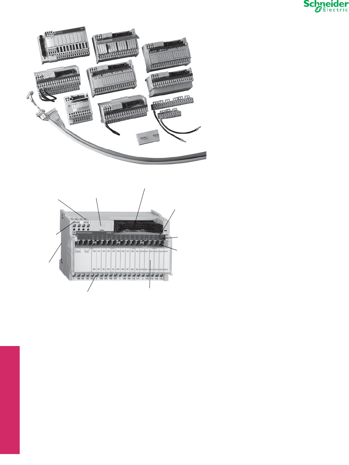
www.schneider-electric.us
24 TERMINAL BLOCKS
24-22 © 2012 Schneider Electric
All Rights Reserved
Advantys TELEFAST™ 2 Prewired Connection System
Refer to Catalog 8501CT9801
The TELEFAST 2 system is a set of products for the rapid
connection of I/O modules (24 Vdc discrete, analog and
counters) to Various control circuit components. These
components act as a substitute for screw terminal blocks,
remotely locating and partly eliminating the single wire
connections. The system connects only to channels with
HE10 and SUB-D connectors, or to standard terminal blocks
with a cabled connector.
Variations within the listing of modules include those with
and without relays (electromechanical and solid state),
analog and counter modules, and special function modules.
Pre-wired cables available allow you to connect directly to:
•Schneider Electric (Modicon™ family)
— TSX Premium™
— TSX Micro
— TSX Series 7
—Twido
— Quantum™
— Compact
— April S5000/7000
— NUM1020/1060
•Siemens
— S7 – 200/300/400
— S5 – 95U to 155U
•Allen-Bradley
— SLC500
In addition, other accessories include:
•I/O simulators
•Continuity blocks
•Label marking software
•Splitter bases (16, 23, and 32 channels)
•Mounting kits
•Detachable terminal strips
•Wiring pass-through connectors
•Fuses
Advantys TELEFAST 2 Product Features
NOTE: Not all features available on all modules.
LEDs Indicating
I/O State and
Blown Fuse
Custom Labeling of Channels (cover face)
and Wiring Diagram (under cover)
Blade Isolation
Switches per
Channel
Test Point for 2.3 mm PlugFuse Protection for
the Cable and
Power Supply
Power Supply
LED
Detachable
Terminal Blocks
(Screw Terminations)
35 mm
DIN-rail
Mounting
Fusing per
Channel
Blade Isolation Switch
on the 0 V terminal of
the Power Supply
