Catalog INTERFACE 2011 102233
2014-05-16
: Pdf 102233-Catalog 102233-Catalog 012596 Batch3 unilog
Open the PDF directly: View PDF ![]() .
.
Page Count: 141 [warning: Documents this large are best viewed by clicking the View PDF Link!]
198 PHOENIX CONTACT

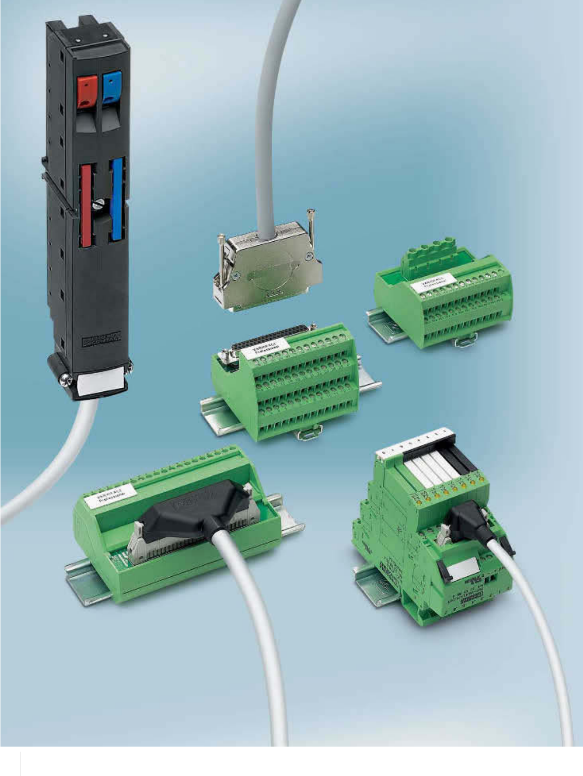
Wiring I/O modules with individual
wires is an extremely time-consuming
process. Wiring errors and tedious
troubleshooting cannot be ruled out.
Interface Cabling reduces assembly
costs by using plug-in components to carry
out wiring quickly, clearly, and without
errors.
The new interface modules in the VIP -
VARIOFACE Professional series, which
feature a modern housing design, offer the
following advantages over previous
solutions:
– They save space
– Vibration-resistant up to 5 g
thanks to metal feet
– Wide range of labeling options
VIP modules are available for both
product segments:
VARIOFACE system cabling is a
cabling concept that has been specially
developed to allow connection to the I/O
modules of a wide range of automation
devices.
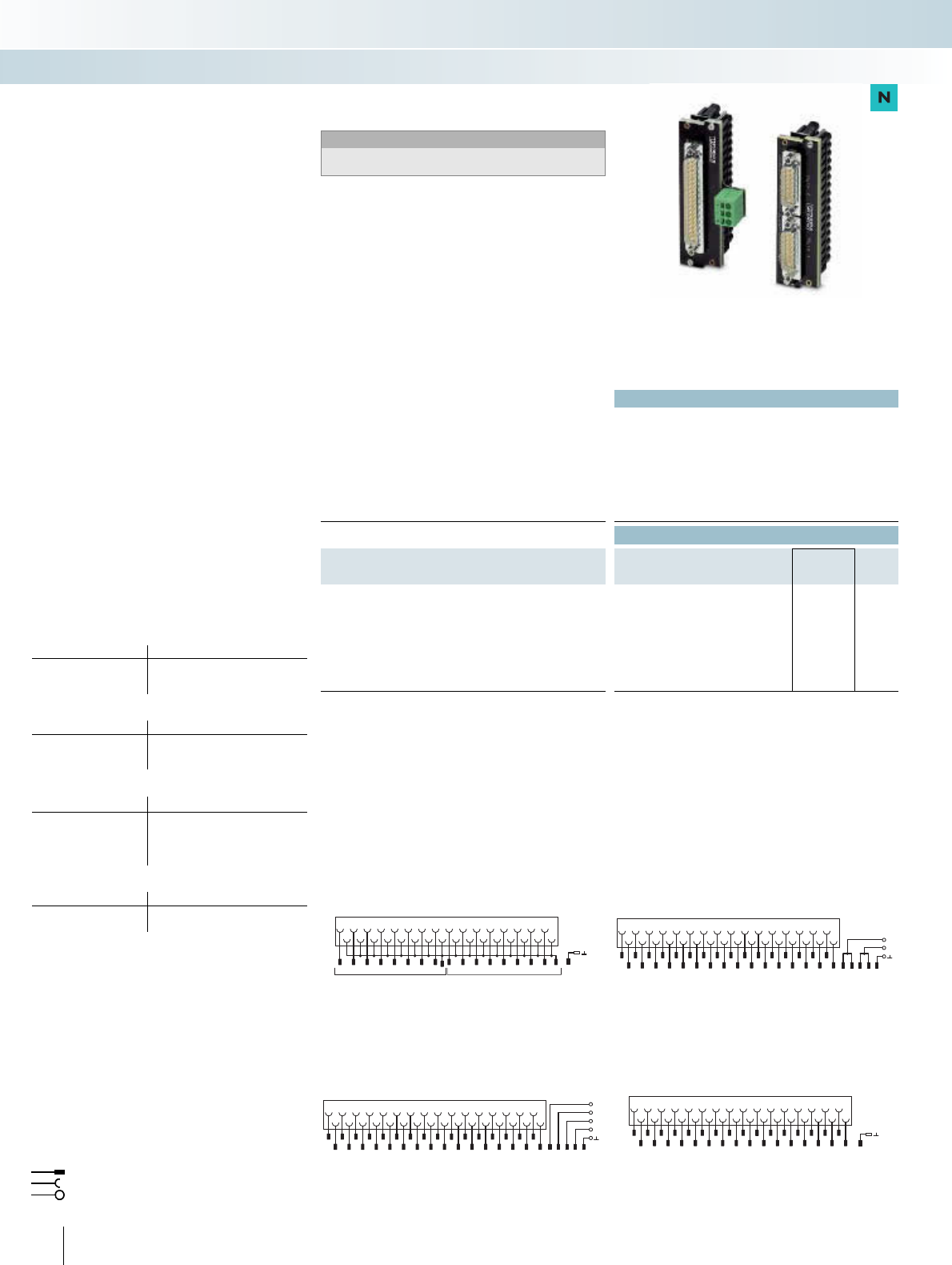
The VIP series is rounded off by new
front adapters with enclosed system cables
for the Simatic S7 300.
VARIOFACE wiring interfaces are
suitable for universal use. Various VIP -
VARIOFACE Professional modules with
a 1:1 connection from a high-pole
connector to a different connection
method are available. The enclosed system
cables provide an effective and efficient
means of establishing a connection to a
control device with protection against
polarity reversal.
A wide variety of potential distributors
are available for splitting the control and
operating voltage.
INTERFACE Cabling
System cabling and wiring interface
Product range overview
Introduction to VARIOFACE system cabling 200
Overview of VARIOFACE system cabling 202
Front adapter
For ABB S800 I/O 204
For Allen-Bradley, ControlLogix, PLC 5, and SLC 500 206
For Emerson DeltaV 214
For GE Fanuc RX3i and Series 90-30 218
For Honeywell C300 Series CI/O and PlantScape 220
For Mitsubishi A1S and Q 222
For Omron CJ1, CS1, and C200H 223
For Phoenix Contact Axioline and Inline 224
For Schneider Electric MODICON® 226
VIP front adapter for Siemens SIMATIC® S7-300 228
For Siemens SIMATIC® S7-300 and S7-400 230
For Siemens SIMATIC® S5-S7 conversion 237
For Yokogawa CS3000 R3 244
Termination boards
With passive transfer 248
With relay 268
PLC-INTERFACE via V8 adapter
V8 adapter 262
Feed-through terminal block 264
Relay/solid-state relay 80
Cross-reference list 266
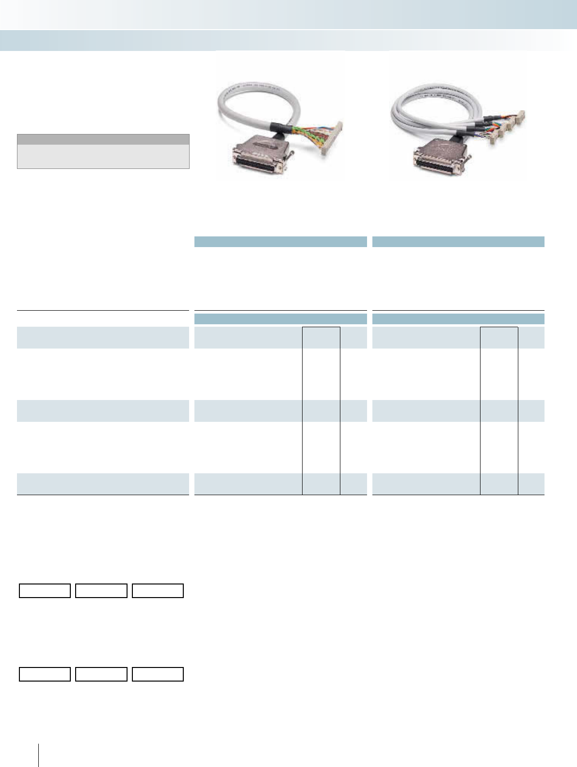
System cables
With flat-ribbon cable and D-SUB connectors 278
Introduction to VARIOFACE wiring interface 296
Overview of VIP - VARIOFACE Professional 298
Passive interface modules
VIP modules with flat-ribbon cable connectors 300
VIP modules with D-SUB connectors 306
VIP modules with high-density D-SUB connectors 313
With DIN strips 314
With ELCO connectors 316
With RJ45 connector 320
With COMBICON connection 321
VIP potential distributors 322
Active interface modules
For relay couplers/optocouplers 324
For solid-state relays 327
Accessories (relays, optocouplers) 328
199PHOENIX CONTACT
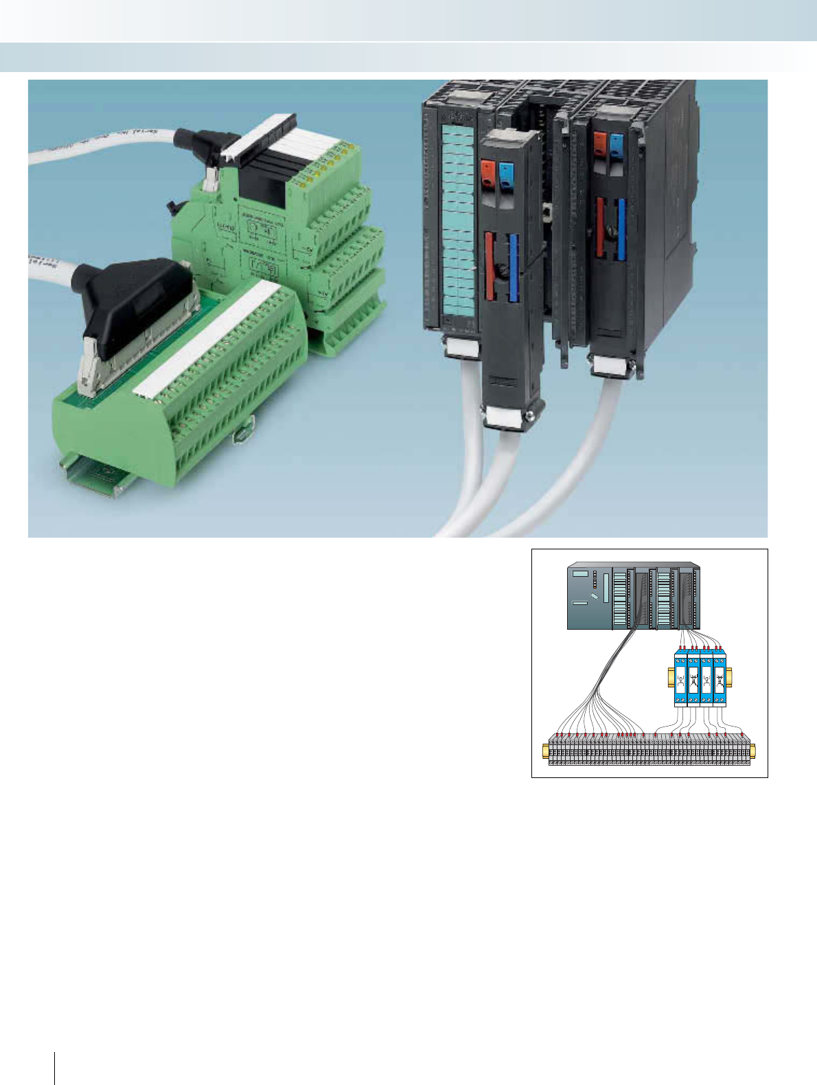
A large part of the costs incurred in
automation systems today results from the
cabling for the actuators and signaling units.
On top of this, machines and systems are
becoming more and more complex, which
means that the cabling costs for the input
and output stations are also steadily on the
increase. In addition to cabling material
costs, the costs associated with planning,
assembly, startup and documentation must
also be considered.
VARIOFACE PLC system cabling is
a system concept that reduces
manufacturing costs by allowing fast,
faultless, and uniform wiring of the
input and output signals of a PLC.
The system configuration comprises
three components:
–VARIOFACE front adapter
– VARIOFACE system cable
– VARIOFACE termination board
VARIOFACE system cabling is available
for controllers from:
–ABB
– Allen-Bradley
–Emerson
– Honeywell
– GE Fanuc
– Mitsubishi Electric
–OMRON
– Schneider Electric
– Siemens
–Yokogawa
– Phoenix Contact
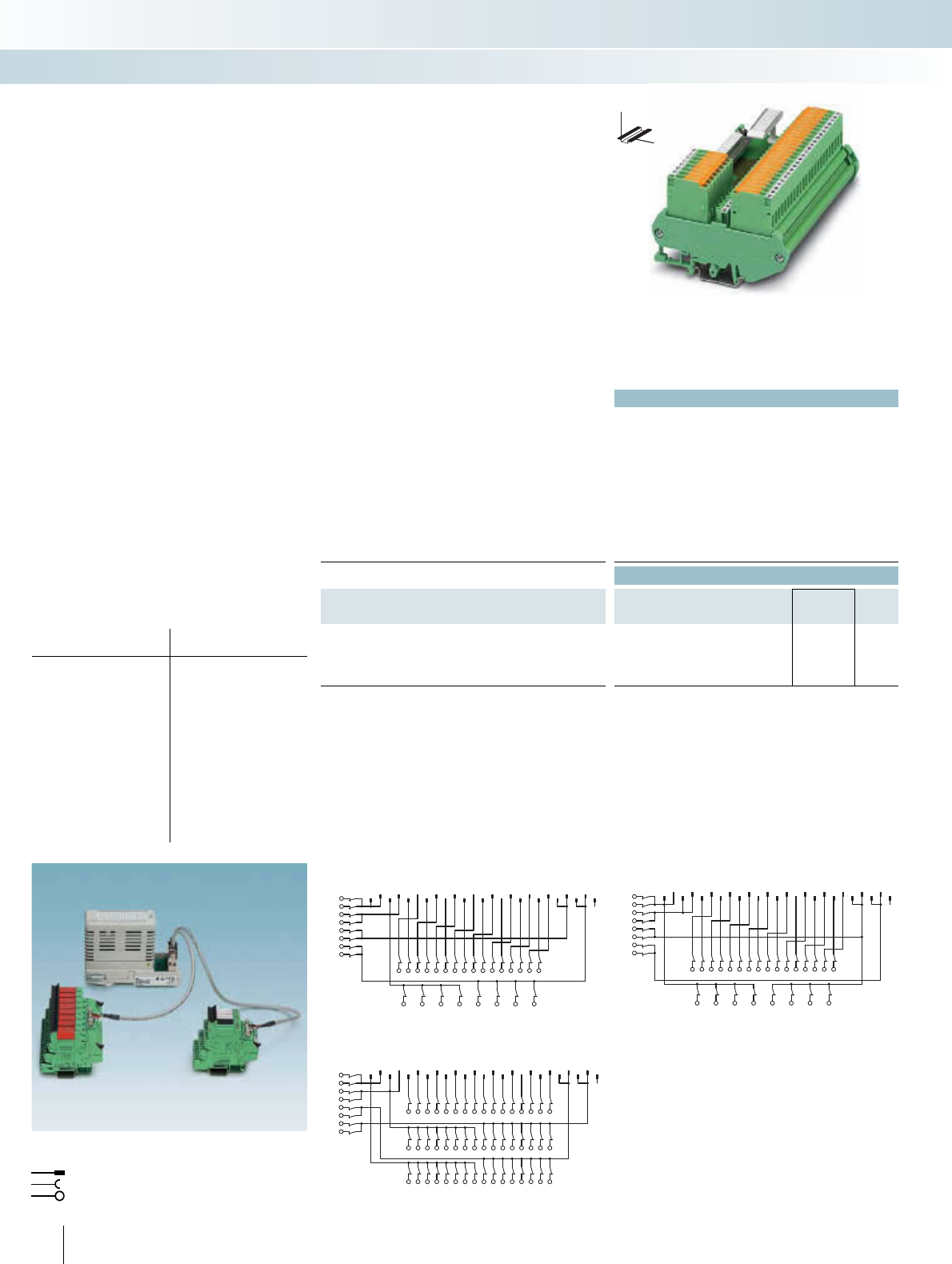
VIP - VARIOFACE Professional
The new front adapters with enclosed
system cables for the S7 300 and new
compact termination boards make the system
cabling even more robust. VARIOFACE
Professional means:
New front adapters
– Optimized housing concept
– Power supplied via PCB terminal
blocks
– Plug-in bridges for electrical
isolation
– Directly connected system cables
with enclosed connectors
New termination boards
–Space-saving
– Vibration-resistant up to 5 g
– Optional labeling
– New housing design
Figure 1: Example of control cabinet cabling with individual
signal lines
200 PHOENIX CONTACT
INTERFACE Cabling
VARIOFACE system cabling
The plug-in, standardized connection
method not only simplifies the actual
construction of the control cabinet and
system startup thanks to fast and faultless
wiring, but also planning and design.
The project planning cross-reference list
(a quick reference guide to the VARIOFACE
system components) is extremely useful when
selecting the required components. What's
more, matching components can be configured
using the INTERFACE search wizard. See
www.phoenixcontact.net/catalog.
VARIOFACE system cabling enables you
to achieve greater efficiency:
– Simple planning using the project
planning cross-reference list or
online selector
– Cost reductions thanks to time-
saving wiring
– Fault minimization through
protection against polarity reversal
and
– Easy maintenance thanks to
modular system components
Actuators and sensors from the field
level are connected to the termination
boards by means of screw or spring-cage
connections, or knife disconnect terminal
blocks. The termination boards are marked
on the field side according to application, so
that the signals can be clearly assigned.
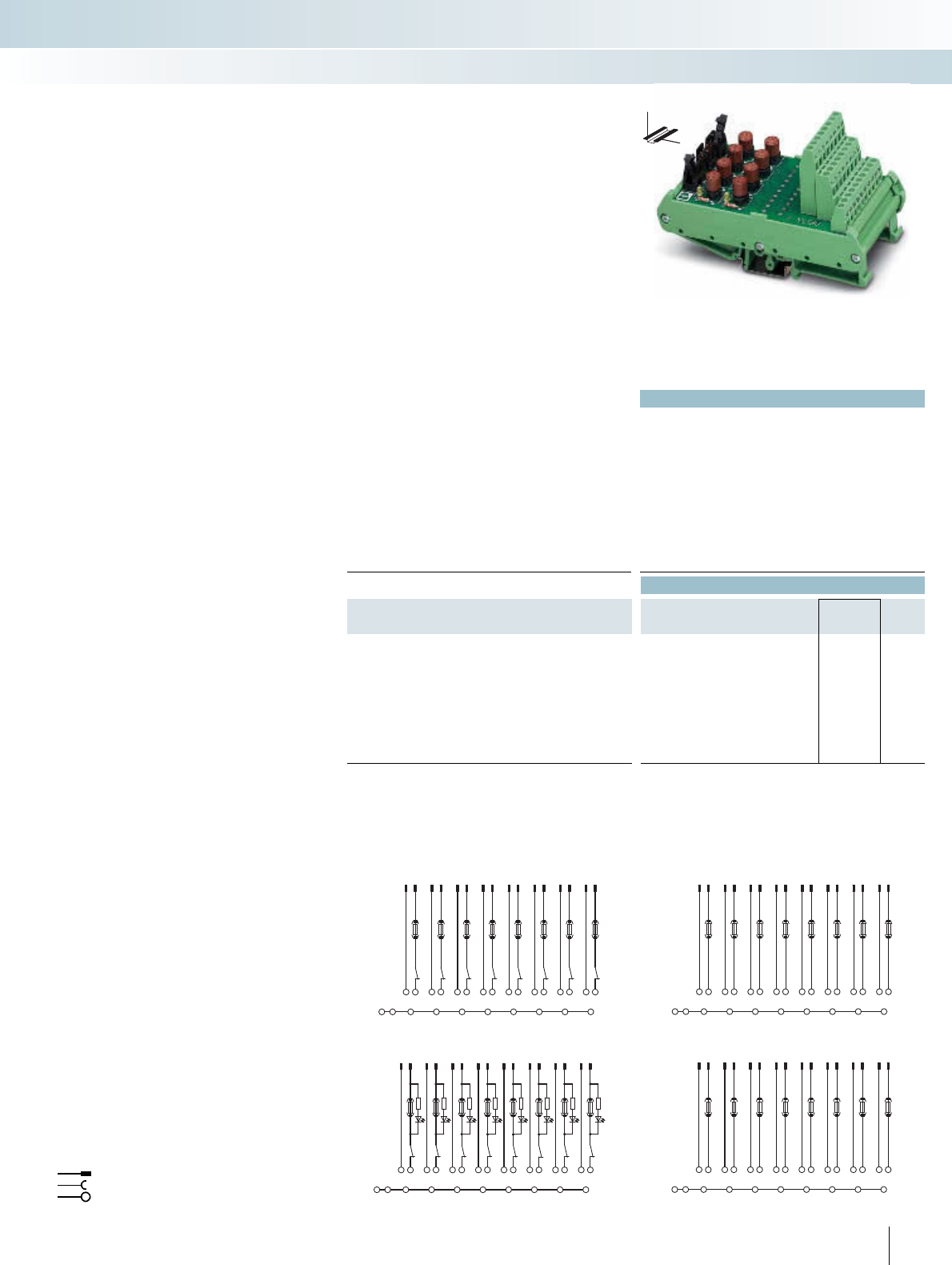
These termination boards are available
in a wide range of designs depending on the
application:
– Interface modules for 1:1 signal
transfer with or without LED
– Initiator modules for the
connection of PNP 3-wire
initiators
– Active output modules and
interfaces equipped with relays or
optocouplers for electrical
isolation, signal amplification or
level adaptation
– Input modules and interfaces for
various voltage ranges, feed-
through and jumper modules
The termination boards are connected
to the PLC front adapter using the high-pole
system round cables. The individual wires of
the system cable can each be subjected to a
load of 1 A.
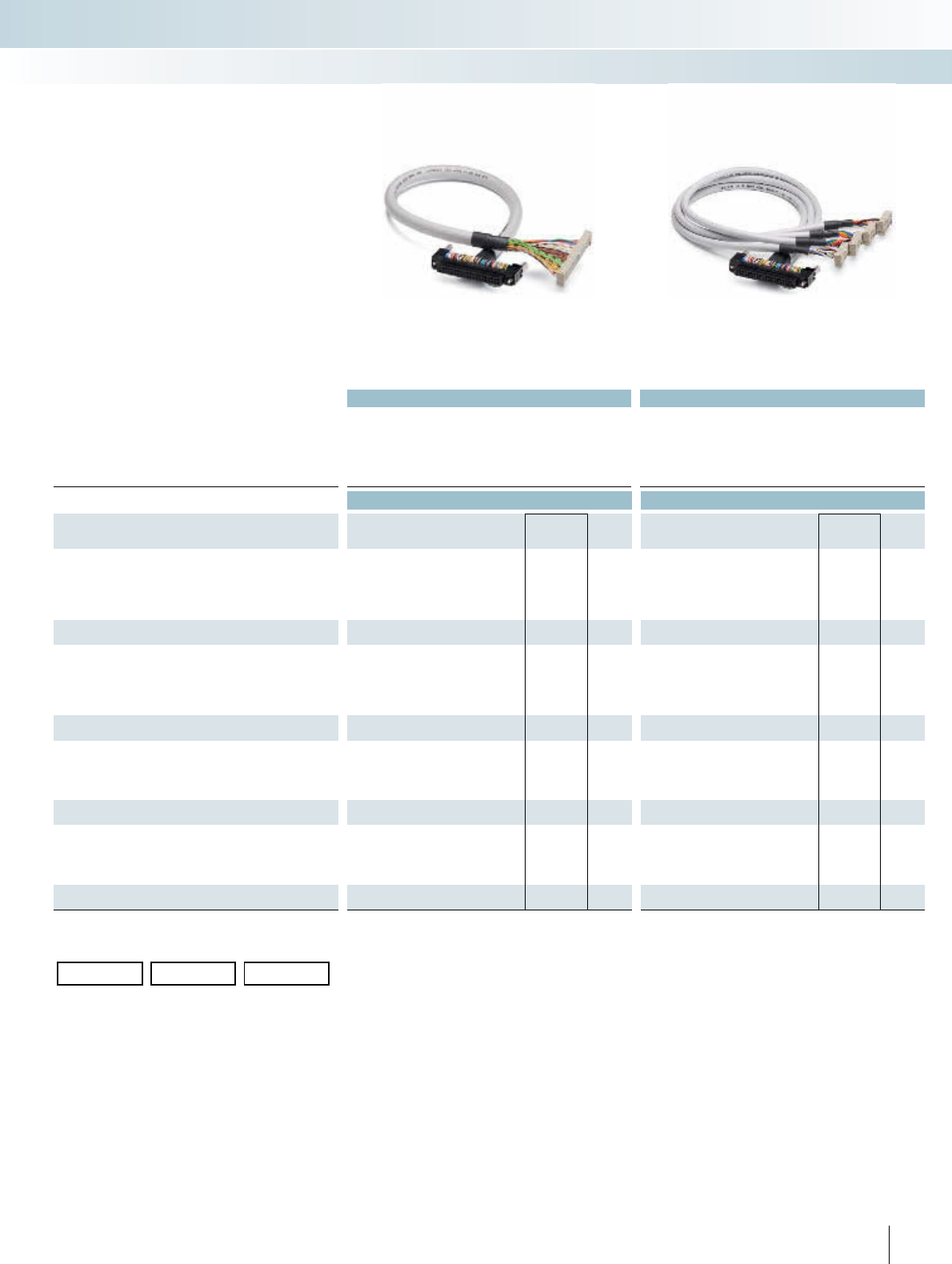
The signals from 32-channel input and
output cards (32 signals of 500 mA each)
can be transmitted using a 50-pole system
cable. Four single bytes are transmitted
separately using one 14-pole system cable
for each. The signals from 8-channel I/O
cards (8 signals of 500 mA each) are also
transmitted via a 14-pole system cable.
The supply voltage per byte is supplied
through several free cores in the cable. This
ensures that when 32 signals are transferred
via a 50-pole cable, a total current of 2 A
can flow.
If 8 signals are transmitted via a 14-pole
cable, the total current is 3 A per byte. If a
higher level of protection is required for the
I/O cards, separate power terminals are
available directly on the front adapter. The
system components allow distribution of
the coupling level even within a confined
space.
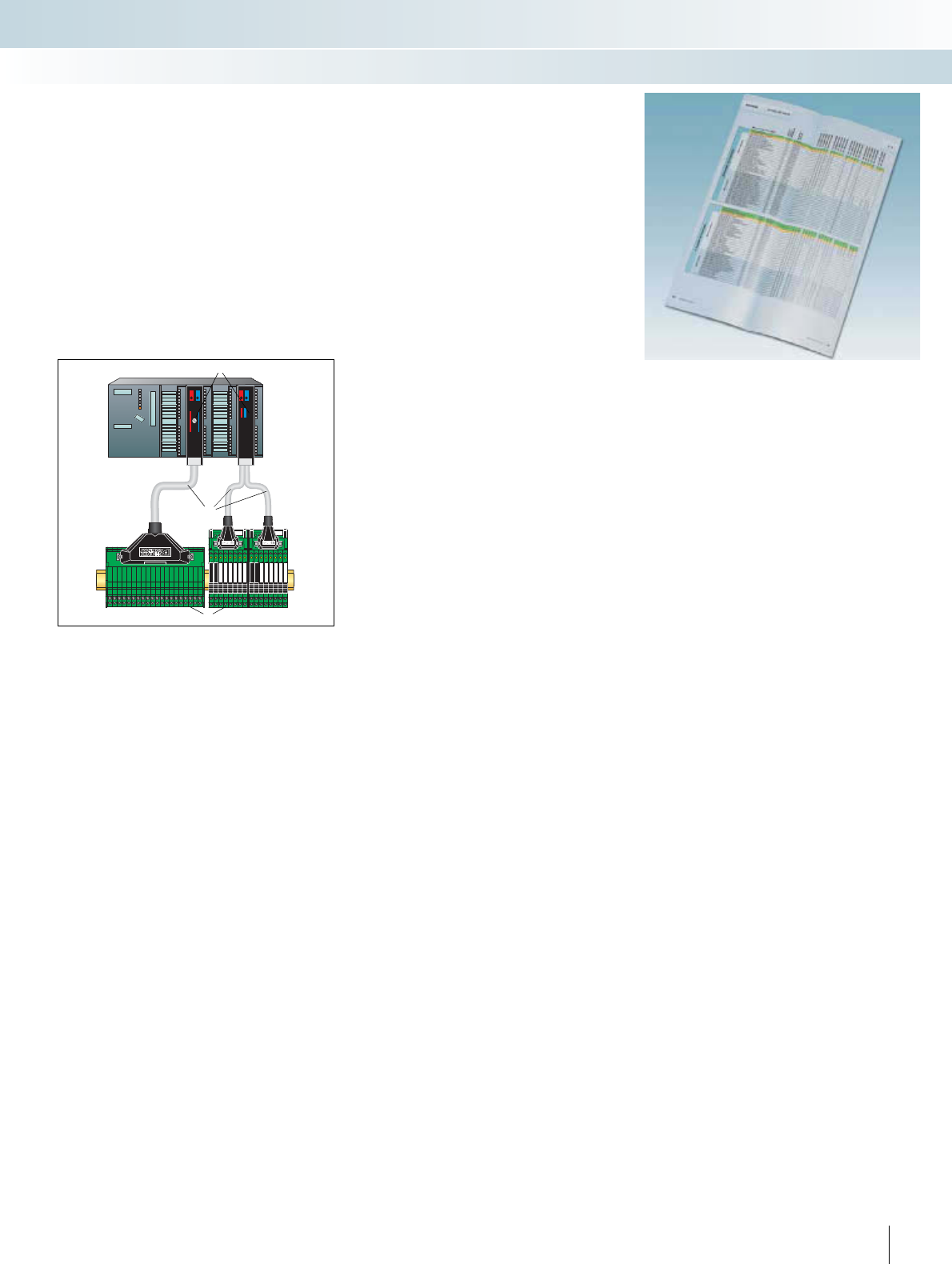
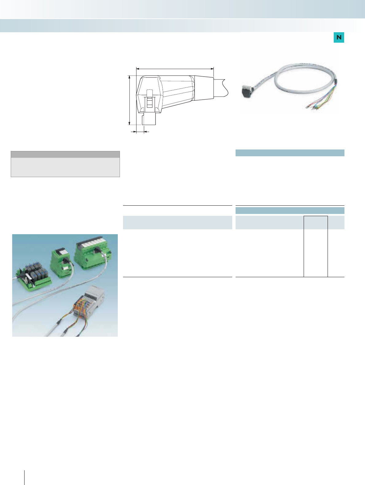
The conventional method of wiring the
input and output cards of programmable
logic controllers is extremely time-
consuming.
Signals are transmitted from the
controller to modular terminal blocks or
coupling modules such as relays or
optocouplers by means of single conductor
wiring (Figure 1).
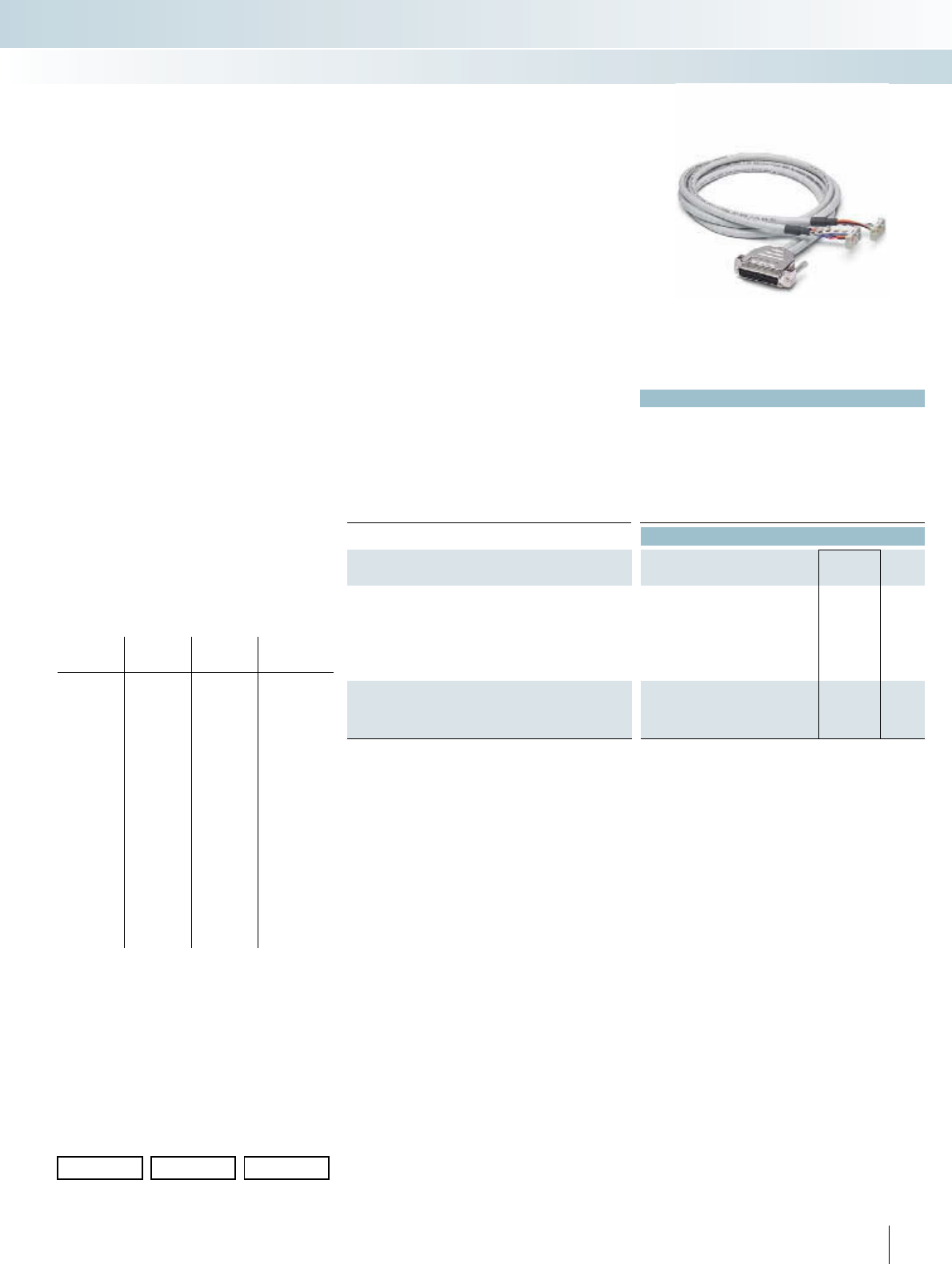
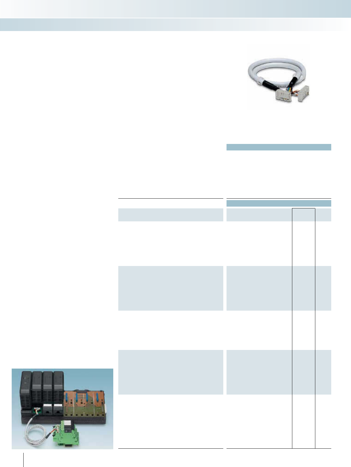
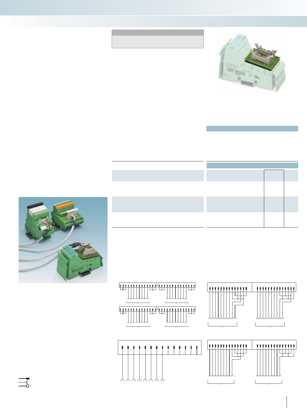
Figure 2: Example of control cabinet wiring with front adapters
1, pre-assembled system cables 2, and termination
boards 3
This requires a complex wiring process.
At the same time, wiring mistakes are
always possible with this connection
method. Errors in wiring are often only
noticed during system startup, resulting in
additional costs.
Wiring based on the system cabling
concept reduces assembly time considerably
and guarantees protection against polarity
reversal (Figure 2).
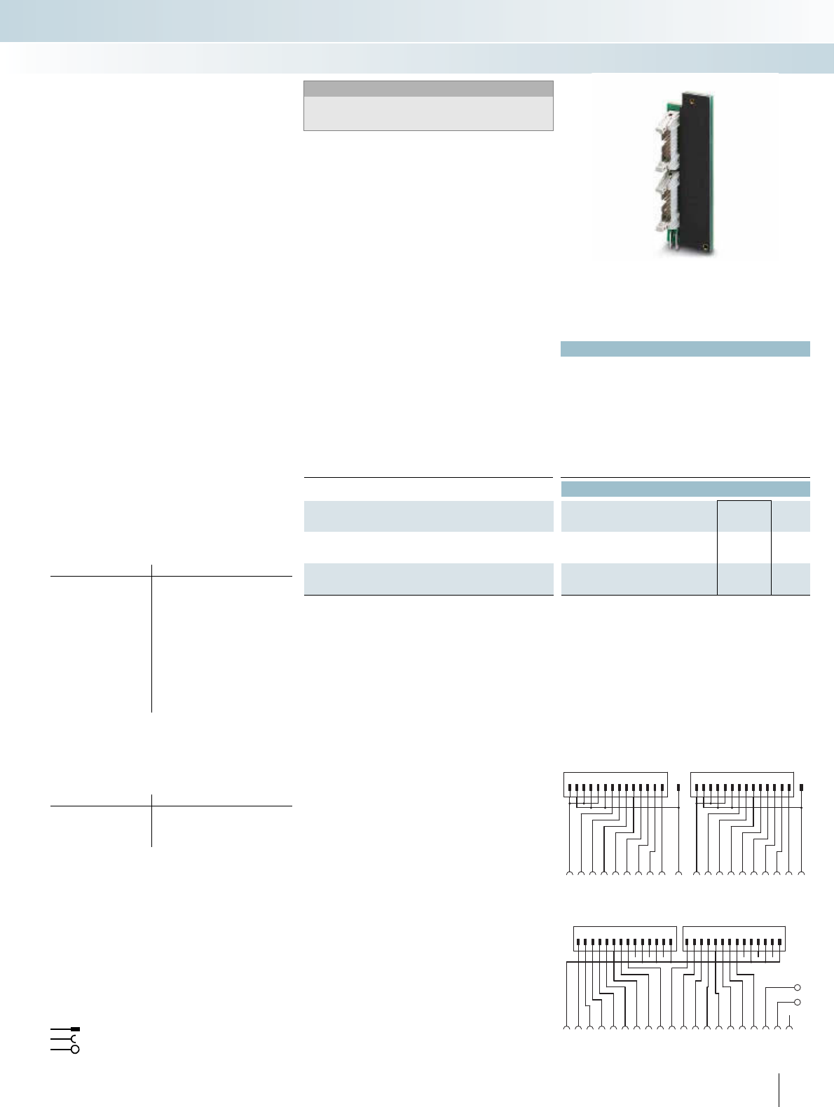
Front adapters with an integrated pin
strip (IEC 60603-13) are plugged onto
the PLC I/O cards. They replace connection
methods such as those involving a screw or
crimp connection.
The termination boards are simply
snapped onto the DIN rail instead of
modular terminal blocks or coupling
modules. They too have a high-pole pin strip
on the control side.
The termination boards are connected
to the front adapters using high-pole and
pre-assembled system cables that can
simply be plugged in.
201PHOENIX CONTACT
INTERFACE Cabling
VARIOFACE system cabling
11
A1+
A2-
24
V
14
12
11
A1+
A2-
24
V
14
12
11
A1+
A2-
24
V
14
12
11
A1+
A2-
24
V
14
12
11
A1+
A2-
24
V
14
12
11
A1+
A2-
24
V
14
12
11
A1+
A2-
24
V
14
12
11
A1+
A2-
24
V
14
12
11
A1+
A2-
24
V
14
12
11
A1+
A2-
24
V
14
12
11
A1+
A2-
24
V
14
12
11
A1+
A2-
24
V
14
12
11
A1+
A2-
24
V
14
12
11
A1+
A2-
24
V
14
12
11
A1+
A2-
24
V
14
12
11
A1+
A2-
24
V
14
12
1
3
2
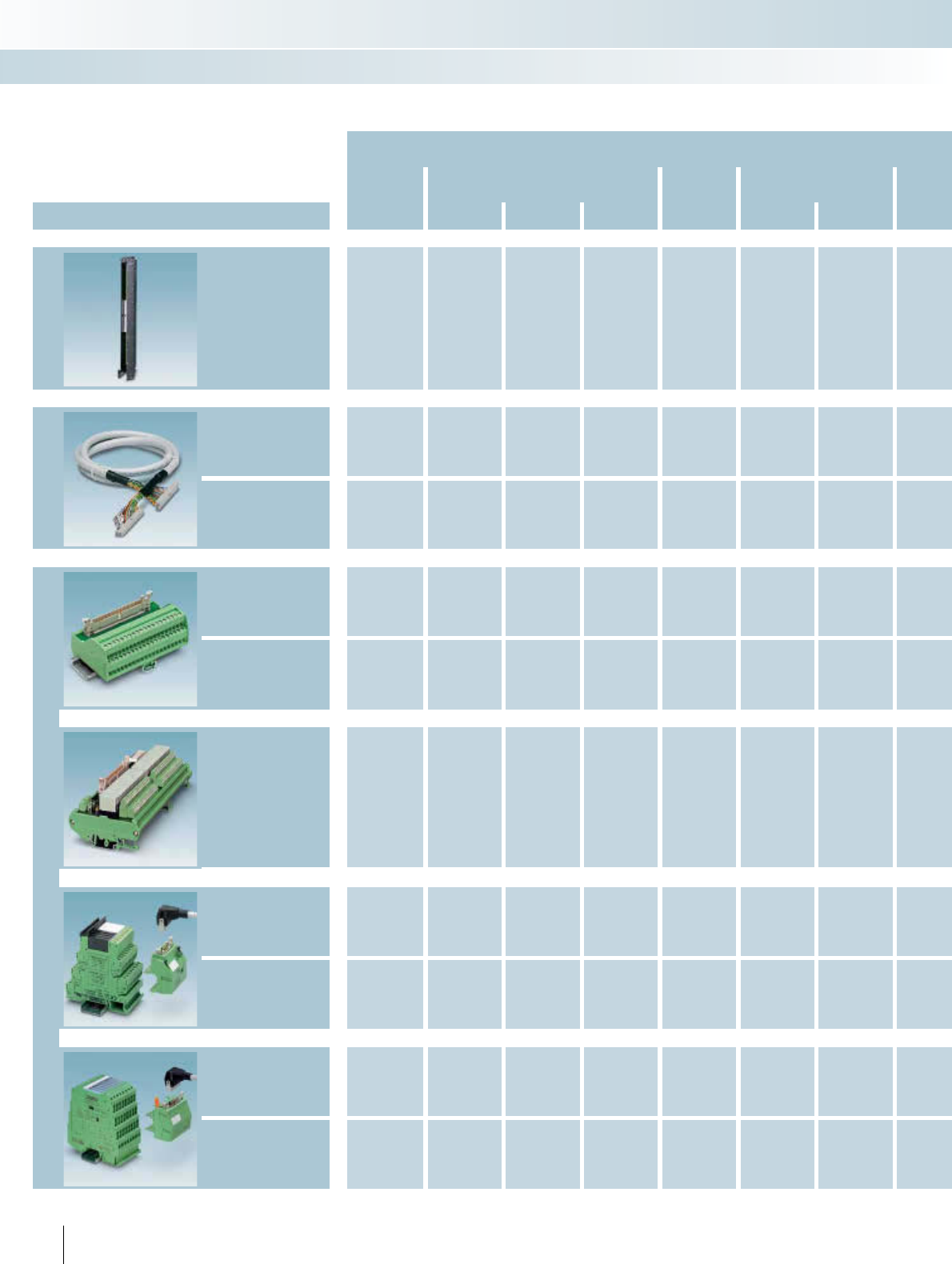
Product overview of VARIOFACE system cabling
Controller
ABB Allen-Bradley Emerson GE FANUC
System component Vers io n S800 I/O Control
Logix PLC 5 SLC 500 DeltaV RX3i 90-30
Page Page Page Page Page Page Page
Front adapter
Not required
206 208 210 Not required
218 219
System cables
Standard 290 282 282 282 284 282 282
Controller-specific 205 212 214
Termination boards
Passive, standard 248 248 248 248 248 248 248
Passive,
controller-specific 204 251 211 215
Active, standard 268 268 268 268 268 268 268
V8 adapter/
feed-through terminal
block
262 262 262 262 262 262 262
Relay/optocoupler 80 80 80 80 80 80 80
MINI Analog system
adapter
MINI Analog
202 PHOENIX CONTACT
INTERFACE Cabling
VARIOFACE system cabling
Honeywell Mitsubishi OMRON CJ1 Phoenix
Contact Schneider Siemens Yo k o g a w a
C300
Series CI/O PlantScape MELSEC
A, A1S, Q
CS1, CQM1,
C200H
Axioline
Inline
TSX
Qantum M340 S7 300 S7 400 S5 to S7
conversion
Centum
CS3000
Page Page Page Page Page Page Page Page Page Page Page
220 206 Not required
Not required
225 226 Not required
228 236 237 Not required
290 282 282 282 227 282 282
222 223 233 244
221 248 248 248 248 248 248 248 248
251 250 250 246
268 268 268 268 268 268 268 268 268
262 262 262 262 262 262 262 262 262 262
80 80 80 80 80 80 80 80 80 80
374 374
372 372
203PHOENIX CONTACT
INTERFACE Cabling
VARIOFACE system cabling
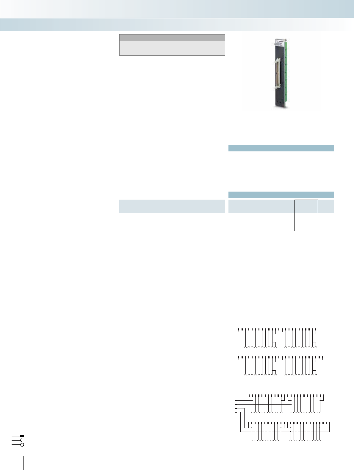
204 PHOENIX CONTACT
Technical data
Max. perm. operating voltage 50 V AC/DC
Max. perm. current (per branch) 2 A
Max. total current (voltage supply) 4 A (8 A L1-/L2-)
Rated surge voltage 1.4 kV
Ambient temperature (operation) -20°C ... 50°C
Mounting position Any
Standards / regulations DIN EN 50178, IEC 62103
Connection method Field level Screw connection with disconnect knife
Control system level D-SUB socket
Connection data solid / stranded / AWG 0.2 ... 4 mm² / 0.2 ... 2.5 mm² / 24 - 12
Dimensions H / D 90 mm / 61 mm
Ordering data
Description No. of
poles
Module width
WType Order No. Pcs. /
Pkt.
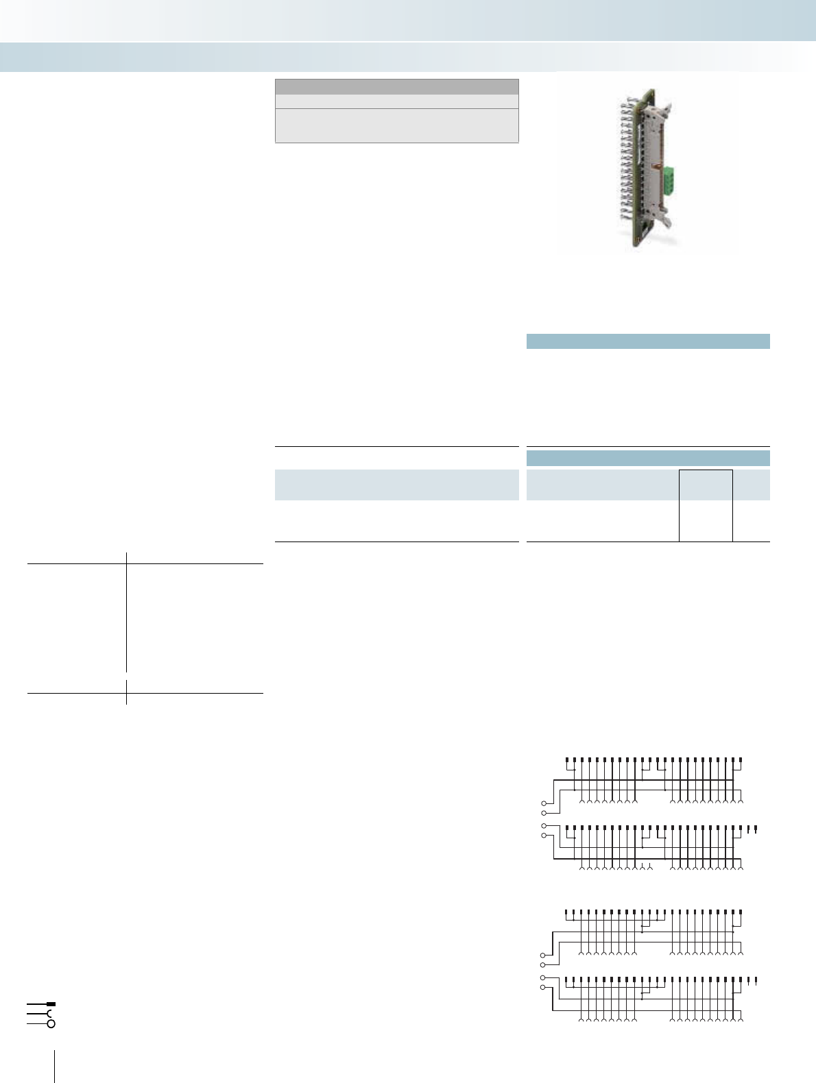
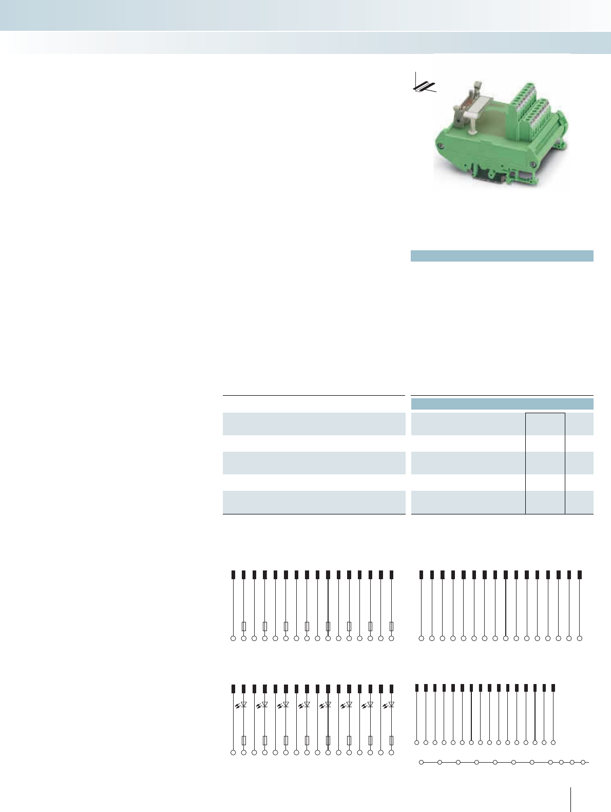
VARIOFACE module, with knife disconnect terminal blocks for:
- S800 I/O output modules 25 126.5 mm FLKM-D25 SUB/B/KDS3-MT/TU810 2304513 1
- S800 I/O input modules 25 126.5 mm FLKM-D25 SUB/B/KDS3-MT/TU810/P 2304539 1
- S800 I/O universal module 25 247.5 mm FLKM-D25 SUB/B/KDS3-MT/TU830 2304526 1
L1+
L1+
L1-
L1-
L2+
L2+
L2-
L2-
123456789
10 11 12 13
14 15 16 17 18 19 20 21 22 23 24 25
C1 C2 C3 C4 C5 C6 C7C8C9C10C11
C12C13
C14C15C16
A1 A2 A3 A4 A5 A6 A7A8A9A10A11
A12
A13
A14A15A16
B1 B2 B3 B4 B5 B6B7B8B9B10B11
B12B13
B14B15B16
FLKM-D25 SUB/B/KDS3-MT/TU830 connection scheme
L1+
L1+
L1-
L1-
L2+
L2+
L2-
L2-
123456789
10 11 12 13
25
2423
22
2110191817
16
1514
B1C1B2C2B3C3B4C4B5C5B6C6B7C7B8C8
A1 A2 A3 A4 A5 A6 A7 A8
FLKM-D25 SUB/B/KDS3-MT/TU810 connection scheme
L1+
L1+
L1-
L1-
L2+
L2+
L2-
L2-
123456789
10 11 12 13
14 15 16 17 18 19 20 21 22 23 24 25
B1C1B2C2B3C3B4C4B5C5B6C6B7C7B8C8
+1 +2 +3 +4 +5 +6 +7 +8
FLKM-D25 SUB/B/KDS3-MT/TU810/P connection scheme
Connectable I/O modules
Card type FLKM-D25SUB...
Digital input DI 810
DI 811
DI 814
DI 830
DI 831
DI 885
Digital output DO 810
DO 814
Analog input AI 810
AI 820
AI 830
AI 835
Analog output AO 810
AO 820
Flat-ribbon cable strip
Connection to I/O card
Screw terminal blocks for separate supply
Explanation:
The ABB S800 I/O system offers the pos-
sibility of realizing the process wiring with
D-SUB plug connectors. ABB TU 812 Com-
pact MTU are available for this purpose.
The FLKM-D25SUB/B/KDS3-MT/... mod-
ules are connected to the I/O modules using
assembled D-SUB cables (refer to chapter
System cables).
In addition to screw connection with
knife disconnection for every channel and
ABB S800-specific labeling, the modules
have the following features:
– Eight negative terminals with knife discon-
nection (TU810)
– Eight positive terminals with knife discon-
nection (TU810/P)
– For each channel, there is a positive and
negative terminal with knife disconnec-
tion (TU830)
Passive interface modules can also be
used for signal transmission
(e.g., VIP-3/SC/D25SUB/F, 2315188),
see page 307.
ABB S800 I/O
Termination boards with
knife disconnection
INTERFACE Cabling
VARIOFACE system cabling
DW
H
Interface module with
knife disconnect terminal blocks
For additional information, visit www.phoenixcontact.net/catalog 205PHOENIX CONTACT
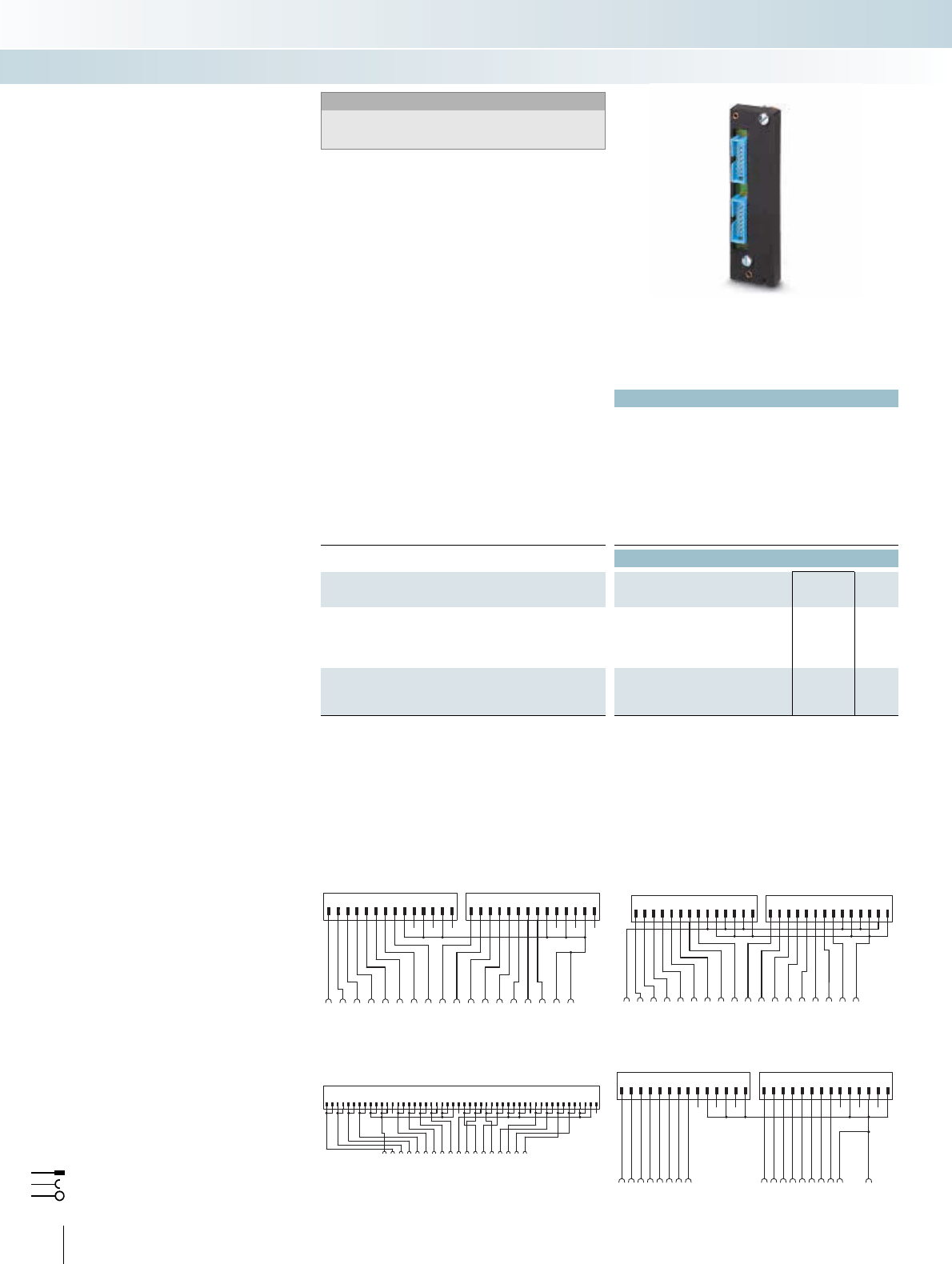
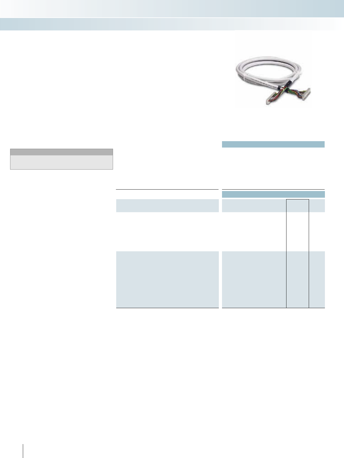
Technical data
Max. perm. operating voltage < 50 V AC / 60 V DC
Max. perm. current carrying capacitance per path 1 A
Ambient temperature (operation) -20°C ... 50°C
Assembly Insulation displacement, IEC 60352-4 / DIN EN 60352-4
Conductor cross section AWG - / 0.14 mm²
Conductor structure: stranded wires / material 7 / Cu tin-plated
Outside diameter
25-pole 6.3 mm
Ordering data
Description No. of
poles Cable length Type Order No. Pcs. /
Pkt.
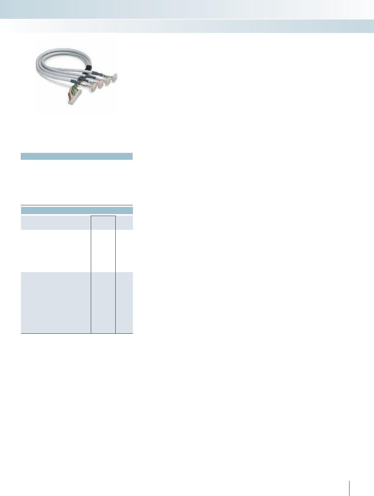
VARIOFACE system cable, for S800 I/O, with a 25-pole D-SUB
socket strip and two 14-pole flat-ribbon cable connectors, in stan-
dard lengths
25 1 m CABLE-D25SUB/B/2X14/100/TU812 2304649 1
25 2 m CABLE-D25SUB/B/2X14/200/TU812 2304652 1
25 3 m CABLE-D25SUB/B/2X14/300/TU812 2304665 1
25 5 m CABLE-D25SUB/B/2X14/500/TU812 2304678 1
VARIOFACE system cable for S800 I/O, with a 25-pole D-SUB
socket strip and two 14-pole flat-ribbon cable connectors, in vari-
able lengths
25 CABLE-D25SUB/B/2X14/TU812/... 2304681 1
Color code and pin assignment
CABLE-D25SUB/B/2X14...TU812
D-SUB
connector
25-pos.
FLK 14
1. Connector
FLK 14
2. Connector
Conductor
color
1
2
3
4
5
6
7
8
9
10
11
12
13
14
15
16
17
18
19
20
21
22
23
24
25
9
10
1
3
5
7
NC
11
12
2
4
6
8
1
3
5
7
9
10
NC
2
4
6
8
11
12
Gray
White
Black
Red
Yellow
Blue
Black
Red
Yellow
Blue
Orange
White
–
White-black
White-brown
Brown
Orange
Green
Violet
Brown
Orange
Green
Violet
White-black
White-brown
Ordering example for system cable:
– Cable for ABB S800, 12.75 m long
Quantity Order No. Length [m]1)
1 2304681 /12.75
1) min. 0.20 m
The ABB S800 I/O system offers the pos-
sibility of realizing the process wiring with
D-SUB plug connectors. ABB TU 812 Com-
pact MTU are available for this purpose.
The CABLE-D25SUB/B/2X14/.../TU812
system cables convert from a D-SUB socket
strip to two flat-ribbon cable connectors.
Therefore, all 8-channel controller boards
of the system cabling can be connected to
S800 I/O modules. Two controller boards
are used per module.
ABB S800 I/O
System cable
INTERFACE Cabling
VARIOFACE system cabling
System cable
206 PHOENIX CONTACT
Technical data
Max. perm. operating voltage < 50 V AC / 60 V DC
Max. permissible current 1 A (per path)
8 A (per connection, supply via separate power supply)
Ambient temperature (operation) -20°C ... 50°C
Ambient temperature (storage / transport) -20°C ... 70°C
Connection data solid / stranded / AWG 0.14 ... 1.5 mm² / 0.14 ... 1.5 mm² / 28 - 16
Standards / regulations IEC 60664 / DIN EN 50178 / IEC 62103
Ordering data
Description No. of poles Type Order No. Pcs. /
Pkt.
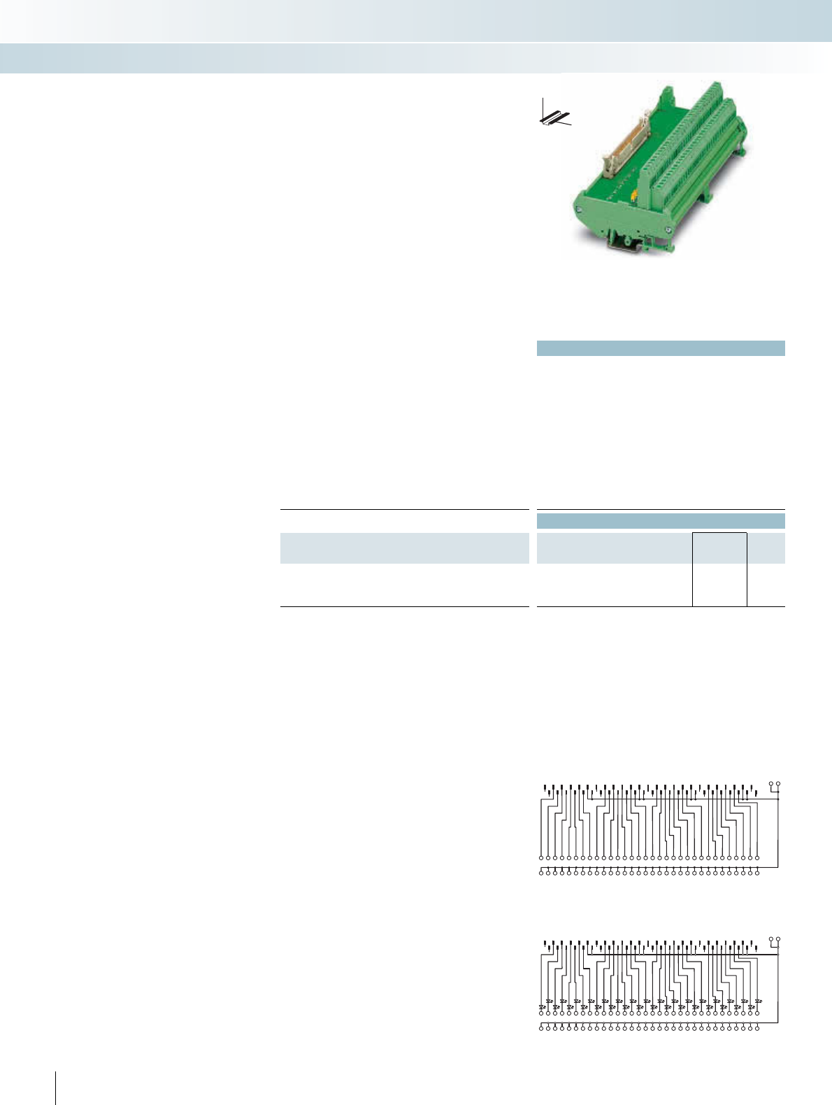
VARIOFACE front adapters, for ControlLogix:
- A maximum of 1 x 32 channels can be connected 50 FLKM 50-PA-AB/1756/EXTC 2302735 1
- IB 32 input board 50 FLKM 50-PA-AB/1756/IN/EXTC 2302748 1
0-
0-
1-
1-
123456789101112131415
161718192021222324
12345678 9101112131415
161718
2526272829303132333435363738394041424344454647484950
NCNC
1920212223242526 27282930313233343536
Connection scheme: FLKM 50-PA-AB/1756/IN/EXTC
0+
0-
1-
1+
12345678910
1112131415161718192021222324
12345678 910
1112131415161718
2526272829303132333435363738394041424344454647484950
NCNC
1920212223242526 27282930313233343536
Connection scheme: FLKM 50-PA-AB/1756/EXTC
Front adapter for I/O modules of
Allen Bradley ControlLogix and Honeywell PlantScape
automation devices
Card type FLKM 50-PA-AB/1756/EXTC
Digital input 1756-IA 16 I* or TC-TDK 161*
1756-IB 16 D* or TC-TDX 161*
1756-IB 16 I* or TC-TDJ 161*
1756-IH 16 I*
Digital output 1756-OB 32 or TC-ODD 321
Analog input 1756-IF 8*
1756-IF 16 I* or TC-IAH 161*
1756-IF 8H*
Counter 1756-HSC*
Servo 1756-M02 AE*
Card type FLKM 50-PA-AB/1756/IN/EXTC
Digital input 1756-IB 32 or TC-IDD 321
* Only in conjunction with
VIP-2/SC/FLK50/AB-1756, Order No.: 2322317.
There must be no voltage supply at the front adapter. Risk of short
circuit!
Flat-ribbon cable strip
Connection to I/O card
Screw terminal blocks for separate supply
Explanation:
I/O modules with 32 channels or with
this design
The front adapters are pushed into the
tall 1756-TBE covers (not supplied as stan-
dard, original accessories must be ordered
directly from manufacturer) of the control-
ler. 50-pole system cable can connect a
maximum of 32 channels to the field level.
Perfectly-fitting VARIOFACE termination
boards round off this system concept.
Allen-Bradley ControlLogix,
Honeywell PlantScape
Front adapter
INTERFACE Cabling
VARIOFACE system cabling
32-channel front adapter
with 50-pole FLK strip
Notes:
Front adapters can also be used without a cover.
Suitable system cabling components can be
configured in the INTERFACE search wizard.
See www.phoenixcontact.net/catalog.

For additional information, visit www.phoenixcontact.net/catalog
207
PHOENIX CONTACT
Technical data
Max. perm. operating voltage < 50 V AC / 60 V DC
Max. permissible current 1 A (per path)
8 A (per connection, supply via separate power supply)
Ambient temperature (operation) -20°C ... 50°C
Ambient temperature (storage / transport) -20°C ... 70°C
Connection data solid / stranded / AWG 0.14 ... 1.5 mm² / 0.14 ... 1.5 mm² / 28 - 16
Standards / regulations IEC 60664 / DIN EN 50178 / IEC 62103
Ordering data
Description No. of poles Type Order No. Pcs. /
Pkt.
VARIOFACE front adapters, for ControlLogix:
– Up to 2 x 8 channels can be connected 14 FLKM 14-PA-AB/1756/EXTC 2302861 1
– IA 16, IB 16, IC 16, IN 16 input card 14 FLKM 14-PA-AB/1756/IN/EXTC 2302874 1
- IF6 I input card (only suitable for measuring
current; no power terminals on adapter)
14 FLKM 14-PA-AB/1756/IF6I/EXTC 2901037 1
0-
0-
1-
1-
1 2 3 4 5 6 7 8 9 1011121314 1 2 3 4 5 6 7 8 9 1011121314
1 2 3 4 5 6 7 8 9 10 11121314151617181920
Connection scheme: FLKM 14-PA-AB/1756/IN/EXTC
12345678910
11
12
1314
12345678910 11121314151617181920
12345678910
11
12
1314
Connection scheme: FLKM 14-PA-AB/1756/IF6I/EXTC
0+
0-
1+
1-
12345678910
11121314 1 2 3 4 5 6 7 8 9 1011121314
1 2 3 4 5 6 7 8 9 10 11121314151617181 9 20
Connection scheme: FLKM 14-PA-AB/1756/EXTC
Front adapter for I/O modules of
Allen Bradley ControlLogix and Honeywell PlantScape
automation devices
Card type FLKM 14-PA-AB/1756/EXTC
Digital input 1756-IA 8 D** or TC-IDX 081**
Digital output 1756-OB 16 E
Analog input 1756-IF 6 CIS**
1756-IF 6 I** or TC-IAH 061**
1756-IR 6 I** or TC-IXR 061**
1756-IT 6 I** or TC-IXL 061**
Analog output 1756-OF 4 I**
1756-OF 6 CI** or TC-OAH 061**
1756-OF 6 VI** or TC-OAV 061**
1756-OF 8** or TC-OAV 081**
1756-OF 8 H**
Switch 1756-PLS**
Card type FLKM 14-PA-AB/1756/IN/EXTC
Digital input 1756-IN 16**
1756-IA 16 or TC-IDA 161**
1756-IB 16
1756-IC 16**
Card type FLKM 14-PA-AB/1756/IF6I/EXTC
Analog input IF6I**
** Only in conjunction with
VIP-2/SC/2FLK14/AB-1756, Order No.: 2322333.
There must be no voltage supply at the front adapter. Risk of short
circuit!!
Flat-ribbon cable strip
Connection to I/O card
Screw terminal blocks for separate supply
Explanation:
I/O modules with 16 channels or with
this design
The front adapters are pushed into the tall
1756-TBE covers (not supplied as standard,
original accessories must be ordered directly
from manufacturer) of the controller. Two
14-pole system cables are used to connect
up to 2 x 8 channels to the field level.
Perfectly-fitting VARIOFACE termination
boards round off this system concept.
Allen-Bradley ControlLogix,
Honeywell PlantScape
Front adapter
INTERFACE Cabling
VARIOFACE system cabling
16-channel front adapter
with two 14-pole FLK strips
Notes:
Front adapters can also be used without a cover.
Suitable system cabling components can be
configured in the INTERFACE search wizard.
See www.phoenixcontact.net/catalog.
|
208 PHOENIX CONTACT
Technical data
Max. perm. operating voltage < 50 V AC / 60 V DC
Max. permissible current 1 A (per path)
Max. perm. total current 2 A (per byte, for supply via connector)
Ambient temperature (operation) -20°C ... 50°C
Ambient temperature (storage / transport) -20°C ... 70°C
Standards / regulations IEC 60664 / DIN EN 50178 / IEC 62103
Ordering data
Description No. of poles Type Order No. Pcs. /
Pkt.
VARIOFACE front adapters, for Allen-Bradley PLC 5, 1771
- IBN 32 channels input 50 FLKM 50-PA-AB/IBN 2289816 2
- OBN 32 channels output 50 FLKM 50-PA-AB/OBN 2289829 2
21 3 4 5 6 7 8 9 101112131415161718192021222324
11121314151617181920
+-
21345678910
+-
2526272829303132333435363738394041424344454647484950
31323334353637383940
+-
252627282930
24232221
0+
1+
2+
3+
Connection scheme FLKM 50-PA-AB/OBN
12345678910111213
1415161718192021222324
NCNC NCNC
NCNC NCNC NCNC
12345678910
--
11121314151617181920
--
252627282930
31
32333435363738394041424344454647484950
21222324252627282930 31323334353637383940
Connection scheme FLKM 50-PA-AB/IBN
Flat-ribbon cable strip
Connection to I/O card
Screw terminal blocks for separate supply
Explanation:
The front adapters mean that pre-assem-
bled system cables can be directly connect-
ed to I/O modules.
Up to 32 channels are connected via
50-pole system cables.
Perfectly-fitting VARIOFACE termination
boards with a variety of functions and con-
nection possibilities round off this system
concept.
Allen-Bradley, PLC 5 series 1771
Front adapter
INTERFACE Cabling
VARIOFACE system cabling
Front adapter for Allen-Bradley PLC 5, 1771
Notes:
Suitable system cabling components can be
configured in the INTERFACE search wizard.
See www.phoenixcontact.net/catalog.

For additional information, visit www.phoenixcontact.net/catalog 209PHOENIX CONTACT
INTERFACE Cabling
VARIOFACE system cabling
|
210 PHOENIX CONTACT
Technical data
FLKM 14-PA... FLKM 50-PA...
Max. perm. operating voltage < 50 V AC / 60 V DC < 50 V AC / 60 V DC
Max. permissible current 1 A (per path) 2 A (per path)
Max. perm. total current 2 A (per byte, for supply via con-
nector)
7 A (per byte, for supply via con-
nector)
Ambient temperature (operation) -20°C ... 50°C -20°C ... 50°C
Ambient temperature (storage / transport) -20°C ... 70°C -20°C ... 70°C
Mounting position Any Any
Standards / regulations IEC 60664 / DIN EN 50178 / IEC
62103
IEC 60664 / DIN EN 50178 / IEC
62103
Ordering data
Description No. of poles Type Order No. Pcs. /
Pkt.
VARIOFACE front adapter, 2 x 8 channels can be connected for
Allen-Bradley SLC 500 for:
- 1746 OB16, OV16, OG16, and IG16 14 FLKM 14-PA-SLC500/OUT 2293459 1
- 1746 IA16, IB16, ITB16, and IN16 14 FLKM 14-PA-SLC500/IN 2293462 1
- 1746 IV16 and IVT16 14 FLKM 14-PA-SLC500/IN/M 2293475 1
VARIOFACE front adapter, 1 x 16 channels can be connected for
Allen-Bradley SLC 500 1746 OA16 and OW16
50 FLKM 50-PA-SLC500/OUT/2A 2293446 1
123579
4681012
14
11 13 15 17
16 18 20 22 24 26 28
19 21 23 25 27 29 31 33 35 37 39
30 32 34 36 38 40 42 44 4648 50
41 43 45 47 49
VAC1
01234567
VAC2
98
111013121514
Connection scheme FLKM 50-PA-SLC500/OUT/2A
X1
X2
123456789
1011121314 1 2 3 4 5 6 7 8 9 1011121314
01234567 89
10111213 14 15COM COM
Connection scheme FLKM 14-PA-SLC500/IN
X1 X2
123456789
1011 121314 12 3456789
1011 121314
012345678910
11 12 13 14 15 VDCVDC
Connection scheme FLKM 14-PA-SLC500/IN/M
X1 X2
12345678910
11121314 12345678910
11121314
VDC 0 123456789101112
13 14 15 COM
Connection scheme FLKM 14-PA-SLC500/OUT
Flat-ribbon cable strip
Connection to I/O card
Screw terminal blocks for separate supply
Explanation:
The front adapters mean that pre-assem-
bled system cables can be directly connect-
ed to I/O modules.
– The FLKM 14-PA-SLC500... adapters
connect max. 2 x 8 channels via two
14-pole system cables. Perfectly-fitting
VARIOFACE termination boards with a
variety of functions and connection possi-
bilities round off this system concept.
– With the FLKM50-PA-SLC500 OUT/2A
front adapters, the FLKM 50/16/SLC500
termination board and 50-pole system ca-
bles, the VARIOFACE system cabling can
also be coupled to the OA16 and OW16
power output cards.
Allen-Bradley SLC 500
Front adapter
INTERFACE Cabling
VARIOFACE system cabling
Front adapter for SLC 500 1746,
2 x 8 channels can be connected
Notes:
Suitable system cabling components can be
configured in the INTERFACE search wizard.
See www.phoenixcontact.net/catalog.
For additional information, visit www.phoenixcontact.net/catalog
211
PHOENIX CONTACT
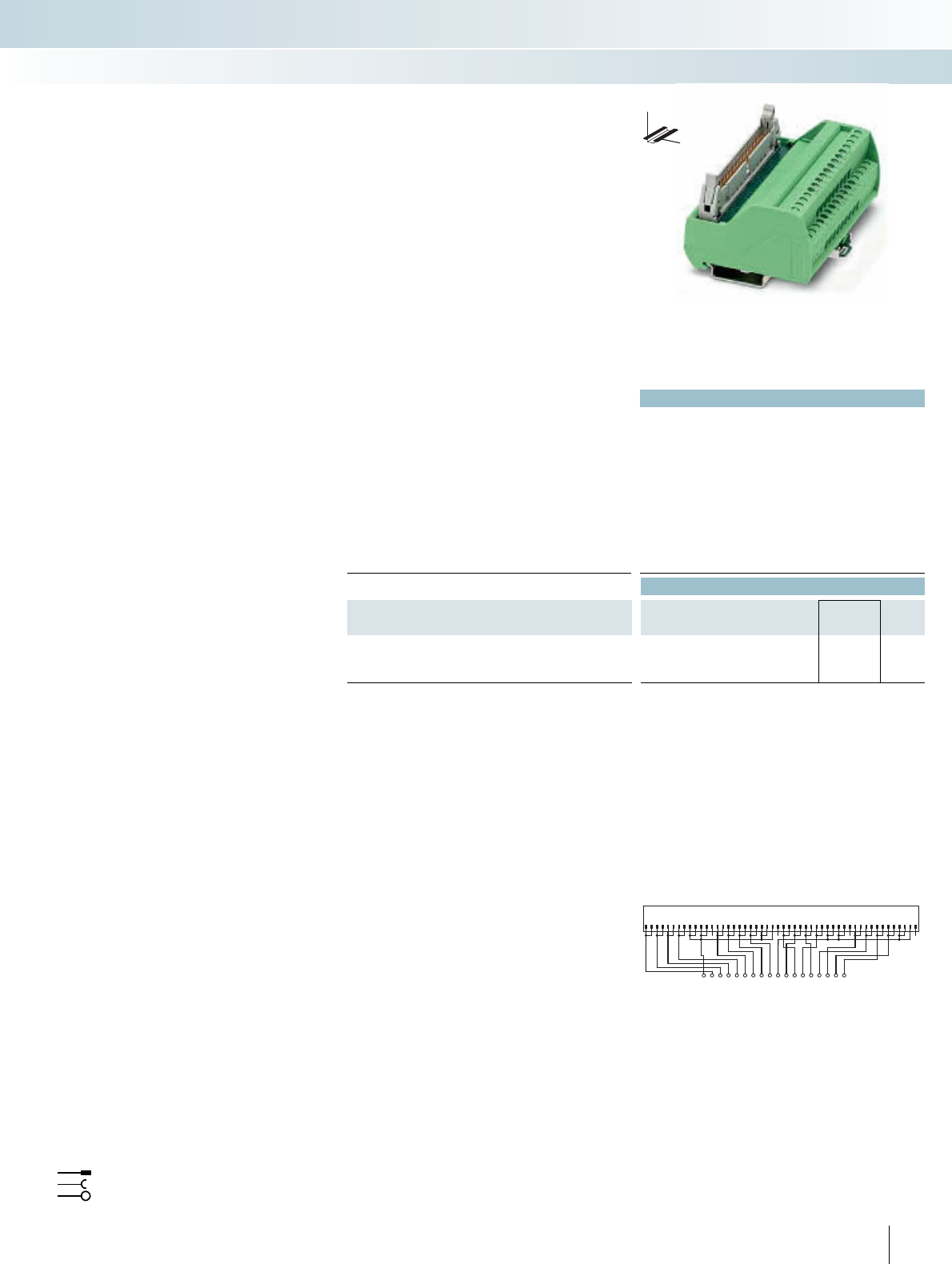
Technical data
Max. perm. operating voltage 120 V AC/DC
Max. perm. current (per branch) 1 A
Max. total current (voltage supply) 2 A (per channel)
Rated surge voltage -
Ambient temperature (operation) -20°C ... 50°C
Mounting position Any
Standards / regulations IEC 60664, DIN EN 50178, IEC 62103
Connection method Field level Screw connection
Control system level Flat-ribbon cable plug connector in acc. with IEC 60603-13
Connection data solid / stranded / AWG 0.2 ... 4 mm² / 0.2 ... 2.5 mm² / 24 - 12
Dimensions H / D 65.5 mm / 56 mm
Ordering data
Description No. of
poles
Module width
WType Order No. Pcs. /
Pkt.
VARIOFACE controller board, for transfer of max. 16 channels,
only in connection with FLKM 50-PA-SLC500 OUT/2A
90.8 mm VIP-2/SC/FLK50/16/SLC500 2322320 1
135
246810
7911
13 15 17 19 21
12 14 16 18 20 23 25 27 29 31 33
22 24 26 28 30 32 35 37 39 41 43 45
34 36 38 40 42 44 47 49
46 48 50
VAC1
012345679
VAC2
8111013121514
VIP-2/SC/FLK50/16/SLC500 connection scheme
Flat-ribbon cable strip
Connection to I/O card
Screw terminal blocks for separate supply
Explanation:
The VIP - VARIOFACE Professional mod-
ule VIP-2/SC/FLK50/16/SLC500 has been
specially designed for the output modules
OA16 and OW16. As regards the front
adapter FLKM 50-PA-SLC500/OUT/2A,
currents up to 2 A per channel can be trans-
ferred with the system cabling.
VIP termination board for
Allen-Bradley SLC 500,
2 A output cards
INTERFACE Cabling
VARIOFACE system cabling
DW
H
VARIOFACE controller board for 16 channels
|
212 PHOENIX CONTACT
Allen-Bradley SLC 500
System cable for 32 channels
The 32-channel I/O cards of the SLC 500
are connected using 40-pole connectors (al-
ready integrated into the I/O modules). Pas-
sive interface modules (-3/SC/FLK40, etc.)
are connected to the I/O cards using the
FLK 40/EZ-DR/.../SLC system cables.
32 channels are split into 4x8 channels us-
ing the FLK 40/4X14/EZ-DR/... system
cables.
The following 8-channel system cabling
modules can be coupled:
– OB32 and IB32
passive and active modules plus V8 adapter
–OV32 and IV32
passive modules without status indicator
Notes:
Suitable system cabling components can be
configured in the INTERFACE search wizard.
See www.phoenixcontact.net/catalog.
Technical data
Max. perm. operating voltage < 50 V AC / 60 V DC
Max. perm. current carrying capacitance per path 1 A
Ambient temperature (operation) -20°C ... 50°C
Assembly Insulation displacement, IEC 60352-4 / DIN EN 60352-4
Conductor cross section AWG 26 / 0.14 mm²
Conductor structure: stranded wires / material 7 / Cu tin-plated
Outside diameter
40-pole 10 mm
Ordering data
Description No. of
poles Cable length Type Order No. Pcs. /
Pkt.
Assembled round cables, with two 40-pole socket strips in fixed
lengths (50 cm steps) for connection with 32-channel I/O cards of
the SLC 500
40 0.5 m FLK 40/EZ-DR/ 50/SLC 2294610 1
40 1 m FLK 40/EZ-DR/ 100/SLC 2294623 1
40 1.5 m FLK 40/EZ-DR/ 150/SLC 2294636 1
40 2 m FLK 40/EZ-DR/ 200/SLC 2294649 1
40 3 m FLK 40/EZ-DR/ 300/SLC 2294652 1
Round cable sets, for connection to Allen-Bradley SLC500, OB32
and IB32, with one 40-pole female connector and four 14-pole
female connectors, for splitting max. 32 channels into 4 x 8 chan-
nels.
for OB32 40 0.5 m
40 1 m
40 2 m
40 3 m
for IB32 40 0.5 m
40 1 m
40 2 m
40 3 m
INTERFACE Cabling
VARIOFACE system cabling
System cable for 32-channel
I/O cards of the SLC 500
(OB32, OV32, IB32, IV32)
For additional information, visit www.phoenixcontact.net/catalog
|
213
PHOENIX CONTACT
Technical data
< 50 V AC / 60 V DC
1 A
-20°C ... 50°C
Insulation displacement, IEC 60352-4 / DIN EN 60352-4
AWG 26 / 0.14 mm²
7 / Cu tin-plated
7.8 mm
Ordering data
Type Order No. Pcs. /
Pkt.
FLK 40/4X14/EZ-DR/ 50/OB32 2296786 1
FLK 40/4X14/EZ-DR/ 100/OB32 2298483 1
FLK 40/4X14/EZ-DR/ 200/OB32 2298522 1
FLK 40/4X14/EZ-DR/ 300/OB32 2298535 1
FLK 40/4X14/EZ-DR/ 50/IB32 2296812 1
FLK 40/4X14/EZ-DR/ 100/IB32 2296825 1
FLK 40/4X14/EZ-DR/ 200/IB32 2296838 1
FLK 40/4X14/EZ-DR/ 300/IB32 2296841 1
INTERFACE Cabling
VARIOFACE system cabling
System cable for splitting
max. 32 channels into 4 x 8 channels
(OB32, IB32)
Technical data
Max. perm. operating voltage < 50 V AC / 60 V DC
Max. perm. current carrying capacitance per path 1 A
Max. conductor resistance 0.16 /m
Ambient temperature (operation) -20°C ... 50°C
Conductor cross section AWG 26 / 0.14 mm²
Outside diameter
16-pole 6.8 mm
20-pole 7.6 mm
24-pole 6.5 mm
20-pole 10.3 mm
Ordering data
Description No. of
poles Cable length Type Order No. Pcs. /
Pkt.
System cable, for 16-pos. "mass termination blocks" with a
16-pole and a 14-pole flat-ribbon cable connector for connection
with PLC-INTERFACE
16 0.3 m FLK 16/14/DV-OUT/ 30 2304348 1
16 0.5 m FLK 16/14/DV-OUT/ 50 2304351 1
16 1 m FLK 16/14/DV-OUT/100 2300575 1
16 2 m FLK 16/14/DV-OUT/200 2300588 1
16 3 m FLK 16/14/DV-OUT/300 2304364 1
Variable cable length 16 FLK 16-14-DV-OUT/... 2304377 1
System cable, for 16-pos. "mass termination blocks" with a
16-pole and a 14-pos. flat-ribbon cable connector for connection
with PLC-INTERFACE
16 0.5 m FLK 16/14/DV-IN/ 50 2304393 1
16 1 m FLK 16/14/DV-IN/100 2300559 1
16 2 m FLK 16/14/DV-IN/200 2300562 1
16 3 m FLK 16/14/DV-IN/300 2304403 1
16 4 m FLK 16/14/DV-IN/400 2305185 1
Variable cable length 16 FLK 16-14-DV-IN/... 2304416 1
System cable, for 40-pos. (2 x 20) "mass termination blocks"
with a 20-pole and two 14-pole flat-ribbon cable connectors for con-
nection with PLC-INTERFACE (two cables should be used per 32-
channel I/O card)
20 1 m FLK 20/2FLK14/EZ-DR/100/KONFEK 2298470 1
20 2 m FLK 20/2FLK14/EZ-DR/200/KONFEK 2298438 1
20 3 m FLK 20/2FLK14/EZ-DR/300/KONFEK 2300818 1
Variable cable length 20 FLK 20/2FLK14/EZ-DR/... 2304487 1
System cable, for 24-pos. "mass termination blocks" with a
24-pole and a 16-pos. flat-ribbon cable connector for connection
with UM-DELTAV/... modules
24 0.3 m FLK 16/24/DV-AI/EZ-DR/ 30 2304319 1
24 0.5 m FLK 16/24/DV-AI/EZ-DR/ 50 2304296 1
24 1 m FLK 16/24/DV-AI/EZ-DR/100 2301134 1
24 2 m FLK 16/24/DV-AI/EZ-DR/200 2301545 1
24 3 m FLK 16/24/DV-AI/EZ-DR/300 2304322 1
Variable cable length 24 FLK 16-24-DV-AI-EZ-DR/... 2304335 1
System cable, for 40-pos. "mass termination blocks" with two
20-pole and one 50-pole flat-ribbon cable plugs for connecting with
32-channel interface modules
20 0.5 m FLK 50/2FLK20/EZ-DR/ 50/DV 2304872 1
20 1 m FLK 50/2FLK20/EZ-DR/ 100/DV 2304898 1
20 2 m FLK 50/2FLK20/EZ-DR/ 200/DV 2304908 1
20 3 m FLK 50/2FLK20/EZ-DR/ 300/DV 2304911 1
20 6 m FLK 50/2FLK20/EZ-DR/ 600/DV 2304937 1
20 8 m FLK 50/2FLK20/EZ-DR/ 800/DV 2304940 1
20 10 m FLK 50/2FLK20/EZ-DR/1000/DV 2304953 1
Variable cable length 20 FLK 50-2FLK20-EZ-DR-DV/... 2304966 1
214 PHOENIX CONTACT
The DeltaV system allows you to install
the process wiring through "mass termina-
tion blocks" (MTB) using flat-ribbon cable
connectors. Besides the 10, 16, and 20-pole
system cables of system cabling (refer to the
System cables chapter), the following sys-
tem-specific lines are also available:
–FLK 16/14/DV-OUT/..., for digital as-
semblies with 16-pos. MTB for connec-
tion with PLC-INTERFACE
–FLK 16/14/DV-IN/..., for digital modules
with 16-pos. MTB for connection to
PLC-INTERFACE
–FLK 20/2FLK14/EZ-DR/..., for digital
assemblies with 40-pos. MTB for connec-
tion with PLC-INTERFACE
–FLK 16/24/DV-AI/EZ-DR/..., for analog
assemblies with 24-pos. MTB
–
FLK 50/2FLK20/EZ-DR/.../DV
system
cables are specifically designed for
32-channel I/O modules with 40-pin
MTB for the purpose of connecting
I/O modules with 32-channel VARIOFACE
interface modules
Emerson DeltaV
System cable
INTERFACE Cabling
VARIOFACE system cabling
System cable for DeltaV
For additional information, visit www.phoenixcontact.net/catalog 215PHOENIX CONTACT
Technical data
FLKM 16/.../DV FLKM 16/.../SI/.../DV
Max. perm. operating voltage < 50 V AC < 50 V AC
Max. perm. current (per branch) 1 A (per signal path) 50 mA (In delivered state, with
one 50 mA fuse, max. 1 A per-
mitted)
Rated surge voltage 0.8 kV 0.8 kV
Ambient temperature (operation) -20°C ... 50°C -20°C ... 50°C
Mounting position Any Any
Standards / regulations IEC 60664, DIN EN 50178, IEC 62103
Connection method Field level Screw connection Screw connection
Control system level Flat-ribbon cable plug connector
in acc. with IEC 60603-13
Flat-ribbon cable plug connector
in acc. with IEC 60603-13
Connection data solid / stranded / AWG 0.2 ... 4 mm² / 0.2 ... 2.5 mm² / 24 - 12
Dimensions H / D 90 mm / 68 mm
Ordering data
Description No. of
poles
Module width
WType Order No. Pcs. /
Pkt.
Interface module, with 1:1 connection
16 45 mm FLKM 16/DV 2304432 1
Interface module, with 1:1 connection and separate potential ter-
minal blocks per channel
16 57 mm FLKM 16/AI/DV 2304429 1
Interface module, with fuses per channel
16 90 mm FLKM 16/AO/SI/DV 2304445 1
Interface module, with LED and fuses per channel
16 90 mm FLKM 16/DI/SI/LA/DV 2304458 1
12468101214163579
11 13 15
CH1CH1CH2CH3CH4CH5CH6CH7CH8CH2CH3CH4CH5CH6CH7CH8
+--------+++++++
FLKM 16/DI/SI/LA/DV connection scheme
12468101214163579
11 13 15
CH1
COM COM COM COM COM COM COM COMCOMCOMCOM
CH1CH2CH3CH4CH5CH6CH7CH8CH2CH3CH4CH5CH6CH7CH8
+--------+++++++
FLKM 16/AI/DV connection scheme
12468101214163579
11 13 15
CH1CH1CH2CH3CH4CH5CH6CH7CH8CH2CH3CH4CH5CH6CH7CH8
+--------+++++++
FLKM 16/AO/SI/DV connection scheme
+--------+++++++
1234567 8910111213141516
Ch1 Ch1 Ch2 Ch2 Ch3 Ch3 Ch4 Ch4 Ch5Ch5 Ch6 Ch6 Ch7 Ch7 Ch8 Ch8
FLKM 16/DV connection scheme
These system-specific interface modules
for DeltaV assemblies are used in combina-
tion with the respective system cables. The
controller board is connected to 8-channel
modules through "mass termination blocks"
with flat-ribbon cable connection.
FLKM 16/DV
–Universal module
– 1:1 connection
FLKM 16/AI/DV
– 1:1 connection
– Separate equipotential terminals per
channel
FLKM 16/AO/SI/DV
– 1:1 connection
– Fuse 5 x 20, 50 mA T, IEC 60127-2/3 per
channel
FLKM 16/DI/SI/LA/DV
– 1:1 connection
– Fuse 5 x 20, 50 mA T, IEC 60127-2/3 per
channel
– LED status indicator per signal path
Emerson DeltaV
Controller board for eight channels
INTERFACE Cabling
VARIOFACE system cabling
DW
H
Interface module for 8 channels
216 PHOENIX CONTACT
Technical data
FLKM 50/32M/DV FLKM 50/32M/IN/LA/DV
Max. perm. operating voltage < 50 V AC 30 V DC
Max. perm. current (per branch) 1 A 1 A
Rated surge voltage 0.8 kV 0.8 kV
Ambient temperature (operation) -20°C ... 50°C -20°C ... 50°C
Mounting position Any Any
Standards / regulations IEC 60664, DIN EN 50178, IEC 62103
Connection method Field level Screw connection Screw connection
Control system level Flat-ribbon cable plug connector
in acc. with IEC 60603-13
Flat-ribbon cable plug connector
in acc. with IEC 60603-13
Connection data solid / stranded / AWG 0.2 ... 4 mm² / 0.2 ... 2.5 mm² / 24 - 12
Dimensions H / D 90 mm / 68 mm
Ordering data
Description No. of
poles
Module width
WType Order No. Pcs. /
Pkt.
VARIOFACE interface modules, for 32-channel I/O modules:
- Input/Output 50 169 mm FLKM 50/32M/DV 2304869 1
- Input with LED per signal 50 169 mm FLKM 50/32M/IN/LA/DV 2304856 1
1
1
--------------------------------
23456789101112131415161718192021222324
2526272829303132
35791113 15 17 19 21 23 25 27 29 31 33 35 37 39 41 43 45 47 49 --
2468101214161820222426283032343638404244464850
FLKM 50/32M/IN/LA/DV connection scheme
1
1
--------------------------------
23456789101112131415161718192021222324
2526272829303132
35791113 15 17 19 21 23 25 27 29 31 33 35 37 39 41 43 45 47 49 --
2468101214161820222426283032343638404244464850
FLKM 50/32M/DV connection scheme
These system-specific interface modules
for DeltaV assemblies are used in combina-
tion with the FLK 50/2FLK20/EZ-DR/.../DV
system cables. The controller board is con-
nected to 32-channel modules through
40-pos. "mass termination blocks" with flat-
ribbon cable connection.
FLKM 50/32M/DV
– Can be used for 32-channel input and out-
put modules
– Two-wire connection with a separate
negative terminal per channel
FLKM 50/32M/IN/LA/DV
– Can be used for 32-channel input mod-
ules
– LED status display per channel
– Two-wire connection with a
separate negative terminal per channel
(dry contact)
Emerson DeltaV
Controller board for 32 channels
INTERFACE Cabling
VARIOFACE system cabling
DW
H
Interface module with
two-wire connection method for DeltaV
For additional information, visit www.phoenixcontact.net/catalog
217
PHOENIX CONTACT
Technical data
Max. perm. operating voltage 24 V DC
Max. perm. current (per branch) 50 mA (in as-supplied state, with one 50 mAF fuse, max. 1 A permit-
ted)
Rated surge voltage -
Ambient temperature (operation) -20°C ... 50°C
Mounting position Any
Standards / regulations IEC 60664, DIN EN 50178, IEC 62103
Connection method Field level Screw connection
Control system level Flat-ribbon cable plug connector in acc. with IEC 60603-13
Connection data solid / stranded / AWG 0.2 ... 4 mm² / 0.2 ... 2.5 mm² / 24 - 12
Dimensions H / D 126 mm / 71 mm
Ordering data
Description No. of
poles
Module width
WType Order No. Pcs. /
Pkt.
Interface modules for 16-pos. and 24-pos. "mass termination
blocks" with:
- Fuses 16 61 mm UM-DELTA V/D/SI 5603255 1
– Fuses and knife disconnect terminal
blocks
16 61 mm UM-DELTA V/D/SI/BFI/TP 5603257 1
– Fuses and fuse failure display 16 61 mm UM-DELTA V/A/SI 5603256 1
- Fuses, fuse failure display, and knife
disconnect terminal blocks
16 61 mm UM-DELTA V/A/SI/BFI/TP 5603258 1
12 34 56 78 910 1112 1314 1516
1- 1+ 2- 2+ 3- 3+ 4- 4+ 5- 5+ 6- 6+ 7- 7+ 8- 8+
SHSHSHSHSHSHSHSHSHSH
Connection scheme UM-DELTAV/A/SI/BFI/TP
1 2 3 4 5 6 7 8 9 10 1112 1314 1516
1- 1+ 2- 2+ 3- 3+ 4- 4+ 5- 5+ 6- 6+ 7- 7+ 8- 8+
SHSHSHSHSHSHSHSHSHSH
Connection scheme UM-DELTAV/D/SI/BFI/TP
12 34 56 78 910 1112 1314 1516
1- 1+ 2- 2+ 3- 3+ 4- 4+ 5- 5+ 6- 6+ 7- 7+ 8- 8+
SHSHSHSHSHSHSHSHSHSH
Connection scheme UM-DELTAV/A/SI
1 2 3 4 5 6 7 8 9 10 1112 1314 1516
1- 1+ 2- 2+ 3- 3+ 4- 4+ 5- 5+ 6- 6+ 7- 7+ 8- 8+
SHSHSHSHSHSHSHSHSHSH
Connection scheme UM-DELTAV/D/SI
Flat-ribbon cable strip
Connection to I/O card
Screw terminal blocks for separate supply
Explanation:
These system-specific interface modules
for DeltaV assemblies are used in combina-
tion with the respective system cables. The
controller board is connected to 8-channel
modules through 16-pos. or 24-pos. "mass
termination blocks" with flat-ribbon cable
connection.
UM-DELTA V/D/SI
– Fuse per channel
– Separate equipotential terminals per channel
UM-DELTA V/D/SI
– Fuse per channel
– Separate equipotential terminals per channel
– Knife disconnection for each channel
UM-DELTA V/D/SI/BFI/TP
– Fuse and LED status indicator per channel
– Separate equipotential terminals per channel
UM-DELTA V/D/SI
– Fuse and LED status indicator per channel
– Separate equipotential terminals per
channel
– Knife disconnection for each channel
Emerson DeltaV
Controller boards with fuses for
8 channels
INTERFACE Cabling
VARIOFACE system cabling
DW
H
Interface module with fuses for
16-pos. and 24-pos. "mass termination blocks"

218 PHOENIX CONTACT
Technical data
Max. perm. operating voltage < 50 V AC / 60 V DC
Max. permissible current 1 A (per path)
8 A (per connection, supply via separate power supply)
Ambient temperature (operation) -20°C ... 50°C
Ambient temperature (storage / transport) -20°C ... 70°C
Mounting position Any
Standards / regulations IEC 60664 / DIN EN 50178 / IEC 62103
Ordering data
Description No. of poles Type Order No. Pcs. /
Pkt.
VARIOFACE front adapter, for PACSystems RX3i,
For digital output and analog modules 50 FLKM 50-PA-GE/TKFC/RXI 2321473 1
For digital input modules 50 FLKM 50-PA-GE/TKFC/RXI/IN 2321486 1
123456789101112131415161718192021222324
NCNC NCNC
NC
1–
2–
3–
A
4–
B
NC
123456789101112131415161718
252627282930
31
32333435363738394041424344454647484950
21
20
19 22232425262731
30
29
28 3233343536
Connection scheme for FLKM 50-PA-GE/TKFC/RXI/IN
0+
0–
1–
1+
123456789101112131415161718192021222324
123456789101112131415161718
2526272829303132333435363738394041424344454647484950
1920212223242526 27282930313233343536
A
B
Connection scheme for FLKM 50-PA-GE/TKFC/RXI
Front adapter for I/O modules of RX3i series
Card type FLKM 50-PA/GE/TKFC/RXI
Digital output IC 694 MDL 754
Analog IC 695 ALG 608*
IC 695 ALG 616*
IC 695 ALG 626*
IC 695 ALG 629*
IC 695 ALG 704*
IC 695 ALG 708*
IC 695 ALG 728*
Card type FLKM 50-PA/GE/TKFC/RXI/IN
Digital input IC 694 MDL 660
* Only in connection with VIP-3/SC/FLK50, Order No. 2315081.
No voltage may be supplied through the slip-on connections on
the front adapter.
Flat-ribbon cable strip
Connection to I/O card
Screw terminal blocks for separate supply
Explanation:
The front adapters mean that pre-assem-
bled system cables can be directly connect-
ed to I/O modules.
– Transfer of max. 32 channels over one
50-pole system cable
– Can be plugged onto I/O modules
– Connection via suitable VARIOFACE
termination boards
GE Fanuc/RX3i
Front adapters
INTERFACE Cabling
VARIOFACE system cabling
Front adapter for GE Fanuc
RX3i
Notes:
Suitable system cabling components can be
configured in the INTERFACE search wizard.
See www.phoenixcontact.net/catalog.
For additional information, visit www.phoenixcontact.net/catalog
|
219
PHOENIX CONTACT
Technical data
Max. perm. operating voltage < 50 V AC / 60 V DC
Max. permissible current 1 A (per path)
4 A (per connection, supply via separate power supply)
Max. perm. total current 3 A (per byte, for supply via connector)
Ambient temperature (operation) -20°C ... 50°C
Ambient temperature (storage / transport) -20°C ... 70°C
Mounting position Any
Standards / regulations IEC 60664 / DIN EN 50178 / IEC 62103
Ordering data
Description No. of poles Type Order No. Pcs. /
Pkt.
VARIOFACE front adapter, for 90-30 series, max. 2 x 8 channels
can be connected, digital output
14 FLKM 14-PA/GE/DO 2290009 2
VARIOFACE front adapter, for 90-30 series, max. 2 x 8 channels
can be connected, digital input
14 FLKM 14-PA/GE/DI 2290038 5
1
2
345678910
-
11 12 13 14 15 16 17 18 19 20
0V
+24 V
1234567891011
121314 1 2 3 4 5 6 7 8 9 1011121314
Connection scheme FLKM 14-PA/GE/DI
20 19 18 17 16 15 14 13 12 11
+-
1098765432 1
-+
1413121110 9 8 7 6 5 4 3 2 1 B1413121110 9 8 7 6 5 4 3 2 1 A
Connection scheme FLKM 14-PA/GE/DO
Front adapter for 90-30 series I/O modules
Card type FLKM 14-PA/GE/DO
Digital output IC 693 MDL 732
IC 693 MDL 733*
IC 693 MDL 740
IC 693 MDL 741*
IC 693 MDL 742
Analog IC 693 ALG 220*
IC 693 ALG 221*
IC 693 ALG 222*
IC 693 ALG 223*
IC 693 ALG 390*
IC 693 ALG 391*
IC 693 ALG 392*
IC 693 ALG 442*
Card type FLKM 14-PA/GE/DI
Digital input IC 693 MDL 241
IC 693 MDL 634
IC 693 MDL 645
IC 693 MDL 646
* Only in conjunction with VIP-2/SC/2FLK14(1-20)/S7, Order No.:
2315230 and UM 45-2FLK14/ZFKDS/S7, Order No.: 2965156.
All wire bridges (DR) on the adapter must be disconnected.
There must be no voltage supply at the front adapter (flowing via
the slip-on connections)!
Flat-ribbon cable strip
Connection to I/O card
Screw terminal blocks for separate supply
Explanation:
The front adapters mean that pre-assem-
bled system cables can be directly connect-
ed to I/O modules.
Up to 2 x 8 channels are connected via
two 14-pole system cables.
Perfectly-fitting VARIOFACE termination
boards with a variety of functions and con-
nection possibilities round off this system
concept.
GE-FANUC, series 90-30
Front adapter
INTERFACE Cabling
VARIOFACE system cabling
Front adapter for GE-FANUC
series 90-30
Notes:
Suitable system cabling components can be
configured in the INTERFACE search wizard.
See www.phoenixcontact.net/catalog.
220 PHOENIX CONTACT
Technical data
Max. perm. operating voltage < 50 V AC / 60 V DC
Max. permissible current 1 A (per path)
4 A (per connection, supply via separate power supply)
Ambient temperature (operation) -20°C ... 50°C
Ambient temperature (storage / transport) -20°C ... 70°C
Mounting position Any
Standards / regulations IEC 60664 / DIN EN 50178 / IEC 62103
Ordering data
Description No. of poles Type Order No. Pcs. /
Pkt.
VARIOFACE front adapter for series C I/O,
With D-SUB pin strip for digital I/O modules 37 FLKM-PA-D37/HW/C300 2322029 1
With D-SUB pin strip for redundant digital I/O modules
37 FLKM-PA-D37/HW/DIO/C300 2901423 1
With D-SUB pin strip for analog I/O modules
37 FLKM-PA-D37/HW/AN/C300 2900622 1
With two D-SUB pin strips for digital output modules
15 FLKM-PA-2D15/HW/DO/C300 2900924 1
2
20
1
1
3
2
5
3
7
4
9
5
11
6
13
7
15
8
17
9
19
10
21
11
23
12
25
13
27
14
29
15
31
16
4
21
6
22
8
23
10
24
12
25
14
26
16
27
18
28
20
29
22
30
24
31
26
32
28
33
30
34
32
35 17
1-
SP
18 36 37
Housing
2-
3-
4-
D-SUB
Connection scheme: FLKM-PA-D37/HW/AN/C300
2
20
1
1
3
2
5
3
7
4
9
5
11
6
13
7
15
8
17
9
19
10
21
11
23
12
25
13
27
14
29
15
31
16
4
21
6
22
8
23
10
24
12
25
14
26
16
27
18
28
20
29
22
30
24
31
26
32
28
33
30
34
32
35 Housing
D-SUB
Connection scheme: FLKM-PA-D37/HW/DIO/C300
2
1
1
3
2
5
3
7
4
9
5
11
6
13
7
15
8
17
1
19
2
21
3
23
4
25
5
27
6
29
7
31
8
46810 12 14 16
10
18 20 22 24 26 28 30 32
10 Housing
D-SUB
Byte 0Byte 1
Connection scheme: FLKM-PA-2D15/HW/DO/C300
2
20
1
1
3
2
5
3
7
4
9
5
11
6
13
7
15
8
17
9
19
10
21
11
23
12
25
13
27
14
29
15
31
16
4
21
6
22
8
23
10
24
12
25
14
26
16
27
18
28
20
29
22
30
24
31
26
32
28
33
30
34
32
35
+
-
SP
17 18 36 37
Housing
D-SUB
Connection scheme: FLKM-PA-D37/HW/C300
Front adapter for I/O modules of the C300 series, C I/O series
Card type FLKM-PA-D37/HW/C300
Digital input TDIL 01*
Digital output TDOB 01*
Card type FLKM-PA-D37/HW/DIO/C300
Digital input TDIL 11*
Digital output TDOB 11*
Card type FLKM-PA-D37/HW/AN/C300
Analog input TAIX 01**
TAIX 11**
Analog output TAOX 01**
TAOX 11**
Card type FLKM-PA-2D15/HW/DO/C300
Digital output TDOB 01*
TDOB 11*
* Two front adapters are required for each module.
** For three-wire operation (channels 13 - 16) of input modules:
Only in conjunction with VIP-3/SC/D37SUB/M/HW/C300, Order
No. 2900675.
Connector
Connection to I/O card
Screw terminal blocks for separate supply
Explanation:
The front adapters mean that pre-assem-
bled system cables can be directly connect-
ed to I/O modules.
FLKM-PA-D37/HW/C300
– Front adapter with D-SUB connector
– Connection of a maximum of 16 digital
channels
– Terminal blocks for power supply
– Not for redundant digital I/O cards
FLKM-PA-D37/HW/DIO/C300
– Front adapter with D-SUB connector
– Connection of a maximum of 16 digital
channels
– Specially designed for redundant digital
I/O cards
FLKM-PA-D37/HW/AN/C300
– Front adapter with D-SUB connector
– Connection of analog modules
FLKM-PA-2D15/HW/DO/C300
– Front adapter with two 15-pole D-SUB
connectors
– Connection of a maximum of 2 x 8 digital
outputs
Honeywell C300, series C I/O
Front adapters
INTERFACE Cabling
VARIOFACE system cabling
Honeywell C300 front adapter
– Specially designed for coupling PLC-
V8/D15.../OUT
Notes:
Matching system cable fitted with D-SUB female connector at both
ends, see page 291.

For additional information, visit www.phoenixcontact.net/catalog
221
PHOENIX CONTACT
Technical data
VIP-2/SC... VIP-3/SC...C300
Max. perm. operating voltage 125 V AC/DC 24 V DC
Max. perm. current (per branch) 2 A 2 A
Ambient temperature (operation) -20°C ... 50°C -20°C ... 50°C
Mounting position Any Any
Standards / regulations DIN EN 50178
Connection method PCB connection Screw connection Screw connection
D-SUB connection
Male connector; 4-40 UNC thread Male connector; 4-40 UNC thread
Connection data solid / stranded / AWG 0.2 ... 4 mm² / 0.2 ... 2.5 mm² / 24 - 12
Dimensions H / D 45.5 mm / 65.5 mm
Ordering data
Description No. of
poles
Module width
WType Order No. Pcs. /
Pkt.
VARIOFACE interface modules with D-SUB pin strip,
With universal labeling 37 101 mm VIP-2/SC/D37SUB/M 2900676 1
With system specific labeling 37 88 mm VIP-2/SC/D37SUB/M/SO 2900786 1
For analog input modules 37 88 mm VIP-3/SC/D37SUB/M/HW/C300 2900675 1
1
1+
20
2-
2
3+
21
4-
3
5+
22
6-
4
7+
23
8-
5
9+
24
10-
6
11+
25
12-
7
13+
26
14-
8
15+
27
16-
9
17+
28
18-
19
nc
10
19+
29
20-
11
21+
30
22-
12
23+
31
24- 25+
13 32
26-
14
27+
33
28-
15
29+
34
30-
16
31+
35
32-
17
+
36
-
18
+
37
-
GND
GND
VIP-2/SC/D37SUB/M/SO connection scheme
1 20 2 21 3 22 4 23 5 24 6 25 7 26 8 27 9 28
1+
C1
2+
C2
3+
C3
4+
C4
5+
C5
6+
C6
7+
C7
8+
C8
9+
C9
GND
GND
19
10 29 1130 1231
nc
10+
C10
11+
C11
12+
C12
13+
13321433 1534 1635 17 361837
C13
14+
C14
15+
C15
16+
C16
15-
13-
16-
14-
VIP-3/SC/D37SUB/M/HW/C300 connection scheme
123456789101112
12345678910
1112
3132 333435 36 37 GND
GND
3132333435 3637
VIP-2/SC/D37SUB/M connection scheme
These VARIOFACE modules are used in
combination with the respective front
adapters.
VIP-2/SC/D37SUB/M
– In conjunction with FLKM-PA-
D37/HW/C300 or FLKM-PA-
D37/HW/AN/C300 front adapter
–Universal module
– Field connection via double-level terminal
blocks
VIP-2/SC/D37SUB/M/SO
– In conjunction with FLKM-PA-
D37/HW/C300 front adapter
– System-specific labeling
– Field connection via double-level terminal
blocks
VIP-3/SC/D37SUB/M/HW/C300
– In conjunction with FLKM-PA-
D37/HW/AN/C300 front adapter
– System-specific labeling
– For TAIX01, TAIX11 analog input modules
– Field connection via three-level terminal
blocks
Honeywell C300, series C I/O
Interface modules
INTERFACE Cabling
VARIOFACE system cabling
DW
H
37 poles
with screw connection
Technical data Technical data
Max. perm. operating voltage < 50 V AC / 60 V DC < 50 V AC / 60 V DC
Max. perm. current carrying capacitance per path 1 A 1 A
Max. conductor resistance 0.16 /m 0.16 /m
Ambient temperature (operation) -20°C ... 50°C -20°C ... 50°C
Conductor cross section AWG 26 / 0.14 mm² AWG 26 / 0.14 mm²
Conductor structure: stranded wires / material 7 / Cu tin-plated 7 / Cu tin-plated
Outside diameter
37-pole 10.5 mm 6.3 mm
Ordering data Ordering data
Description No. of
poles Cable length Type Order No. Pcs. /
Pkt. Type Order No. Pcs. /
Pkt.
Round cable (connection of 1 x 32 channels), for MELSEC Q
Y81 P, MELSEC A1S Y81, and MELSEC A AY82EP, in standard
lengths
37 0.5 m FLK 50/EZ-DR/D37SUB/ 50/Y81P-O 2302599 1CABLE-D37-M2,5/4X14/ 50/Y81P-O 2302476 1
37 1 m FLK 50/EZ-DR/D37SUB/100/Y81P-O 2302609 1CABLE-D37-M2,5/4X14/100/Y81P-O 2302489 1
37 2 m FLK 50/EZ-DR/D37SUB/200/Y81P-O 2302612 1CABLE-D37-M2,5/4X14/200/Y81P-O 2302492 1
37 3 m FLK 50/EZ-DR/D37SUB/300/Y81P-O 2302638 1CABLE-D37-M2,5/4X14/300/Y81P-O 2302502 1
Round cable, same as before, however in variable lengths
37 FLK 50-EZ-DR-D37SUB-Y81P-O/... 2302625 1CABLE-D37-M2,5-4X14-Y81P-O/... 2302696 1
Round cable (connection of 4 x 8 channels), for MELSEC Q
Y81 P, MELSEC A1S Y81, and MELSEC A AY82EP, in standard
lengths
37 0.5 m FLK 50/EZ-DR/D37SUB/ 50/X81-I 2302641 1CABLE-D37-M2,5/4X14/ 50/X81-I 2302515 1
37 1 m FLK 50/EZ-DR/D37SUB/100/X81-I 2302654 1CABLE-D37-M2,5/4X14/100/X81-I 2302528 1
37 2 m FLK 50/EZ-DR/D37SUB/200/X81-I 2302667 1CABLE-D37-M2,5/4X14/200/X81-I 2302531 1
37 3 m FLK 50/EZ-DR/D37SUB/300/X81-I 2302670 1CABLE-D37-M2,5/4X14/300/X81-I 2302544 1
Round cable, same as before, however in variable lengths
37 FLK 50-EZ-DR-D37SUB-X81-I/... 2302683 1CABLE-D37-M2,5-4X14-X81-I/... 2302706 1
Ordering example for system cable:
– Cable for MELSEC Q Y81P, 12.75 m long
Quantity Order No. Length [m]1)
1 2302625 /12.75
1) min. 0.20 m
Ordering examples for splitting cable:
– Cable for MELSEC Q Y81P, 11.00 m long
Quantity Order No. Length [m]1)
1 2302696 /11.00
1) min. 0.20 m
222 PHOENIX CONTACT
INTERFACE Cabling
VARIOFACE system cabling
System cable,
D-SUB female connector on FLK,
number of poles: 37 on 50
Splitting cable,
D-SUB-female connector on FLK,
number of poles: 37 on 4 x 14
For 32-/64-channel I/O boards with
37-pole D-SUB connectors. System cables
are available for connecting 1 x 32 channels
or 4 x 8 channels.
Notes:
Suitable system cabling components can be
configured in the INTERFACE search wizard.
See www.phoenixcontact.net/catalog.
Mitsubishi Electric
MELSEC A, A1S, and Q
System cable
For additional information, visit www.phoenixcontact.net/catalog
Technical data Technical data
Max. perm. operating voltage < 50 V AC / 60 V DC < 50 V AC / 60 V DC
Max. perm. current carrying capacitance per path 1 A 1 A
Max. conductor resistance 0.16 /m 0.16 /m
Ambient temperature (operation) -20°C ... 50°C -20°C ... 50°C
Conductor cross section AWG 26 / 0.14 mm² AWG - / 0.14 mm²
Conductor structure: stranded wires / material 7 / Cu tin-plated 7 / Cu tin-plated
Ordering data Ordering data
Description No. of
poles Cable length Type Order No. Pcs. /
Pkt. Type Order No. Pcs. /
Pkt.
Round cable in variable lengths for
CJ1: OD231, OD261
CS1, C200H: OD218, OD219
CQM1: OD213
40 1 m FLK 50/EZ-DR/FCN40/100/OMR-OUT 2304144 1CABLE-FCN40/4X14/100/OMR-OUT 2304186 1
40 2 m FLK 50/EZ-DR/FCN40/200/OMR-OUT 2304157 1CABLE-FCN40/4X14/200/OMR-OUT 2304199 1
Round cable, same as before, however in variable lengths
40 FLK 50-EZ-DR-FCN40-OMR-OUT/... 2302829 1CABLE-FCN40-4X14-OMR-OUT/... 2302832 1
Round cable in variable lengths for
CJ1: ID231, ID261
CS1 and C200H: ID111, ID216, ID217,
CQM1: ID213; ID214;ID112
40 1 m FLK 50/EZ-DR/FCN40/100/OMR-IN 2304160 1CABLE-FCN40/4X14/100/OMR-IN 2304209 1
40 2 m FLK 50/EZ-DR/FCN40/200/OMR-IN 2304173 1CABLE-FCN40/4X14/200/OMR-IN 2304212 1
Round cable, same as before, however in variable lengths
40 FLK 50-EZ-DR-FCN40-OMR-IN/... 2302803 1CABLE-FCN40-4X14-OMR-IN/... 2302816 1
Round cable in variable lengths for
CS1, C200H: OD215, MD115 (only output),
MD215 (only output)
24 1 m CABLE-FCN24/2X14/100/OMR-OUT 2304225 1
24 2 m CABLE-FCN24/2X14/200/OMR-OUT 2304238 1
Round cable, same as before, however in variable lengths
24 CABLE-FCN24-2X14-OMR-OUT/... 2302858 1
Round cable in variable lengths for
CS1, C200H: ID215, MD115 (only input),
MD215 (only input)
24 1 m CABLE-FCN24/2X14/100/OMR-IN 2304241 1
24 2 m CABLE-FCN24/2X14/200/OMR-IN 2304254 1
Round cable, same as before, however in variable lengths
24 CABLE-FCN24-2X14-OMR-IN/... 2302845 1
Ordering example for system cable:
– Cable for OMRON CJ1, ID231, 12.75 m long
Quantity Order No. Length [m]1)
1 2302803 /12.75
1) min. 0.20 m
223PHOENIX CONTACT
INTERFACE Cabling
VARIOFACE system cabling
Connector Fujitsu FCN on flat-ribbon cable,
number of poles: 40 on 50
Connector Fujitsu FCN on flat-ribbon cable,
number of poles: 40 on 4 x 14 or 24 on 2 x 14
These system cables are plugged onto the
I/O cards that are connected using Fujitsu
connectors.
FLK 50/EZ-DR/...
– Signal transmission of 32 channels
CABLE-FCN40...
– Splitting up 32 channels into 4 x 8 channels
CABLE-FCN24...
– Splitting up 16 channels into 2 x 8 channels
OMRON CJ1, CS1, CQM1, and C200H
System cable
224 PHOENIX CONTACT
Technical data
Max. perm. operating voltage < 50 V AC / 60 V DC
Max. perm. current carrying capacitance per path 1 A
Max. conductor resistance 0.16 /m
Ambient temperature (operation) -20°C ... 50°C
Assembly Insulation displacement, IEC 60352-4 / DIN EN 60352-4
Conductor cross section AWG 26 / 0.14 mm²
Conductor structure: stranded wires / material 7 / Cu tin-plated
Outside diameter
14-pole 6.4 mm
Ordering data
Description No. of
poles Cable length Type Order No. Pcs. /
Pkt.
Round cable with an open end (8 individual wires)
14 0.5 m VIP-CAB-FLK14/AXIO/0,14/0,5M 2901604 1
14 1 m VIP-CAB-FLK14/AXIO/0,14/1,0M 2901605 1
14 1.5 m VIP-CAB-FLK14/AXIO/0,14/1,5M 2901606 1
14 2 m VIP-CAB-FLK14/AXIO/0,14/2,0M 2901607 1
14 2.5 m VIP-CAB-FLK14/AXIO/0,14/2,5M 2901608 1
14 3 m VIP-CAB-FLK14/AXIO/0,14/3,0M 2901609 1
14 4 m VIP-CAB-FLK14/AXIO/0,14/4,0M 2901610 1
14 6 m VIP-CAB-FLK14/AXIO/0,14/6,0M 2901611 1
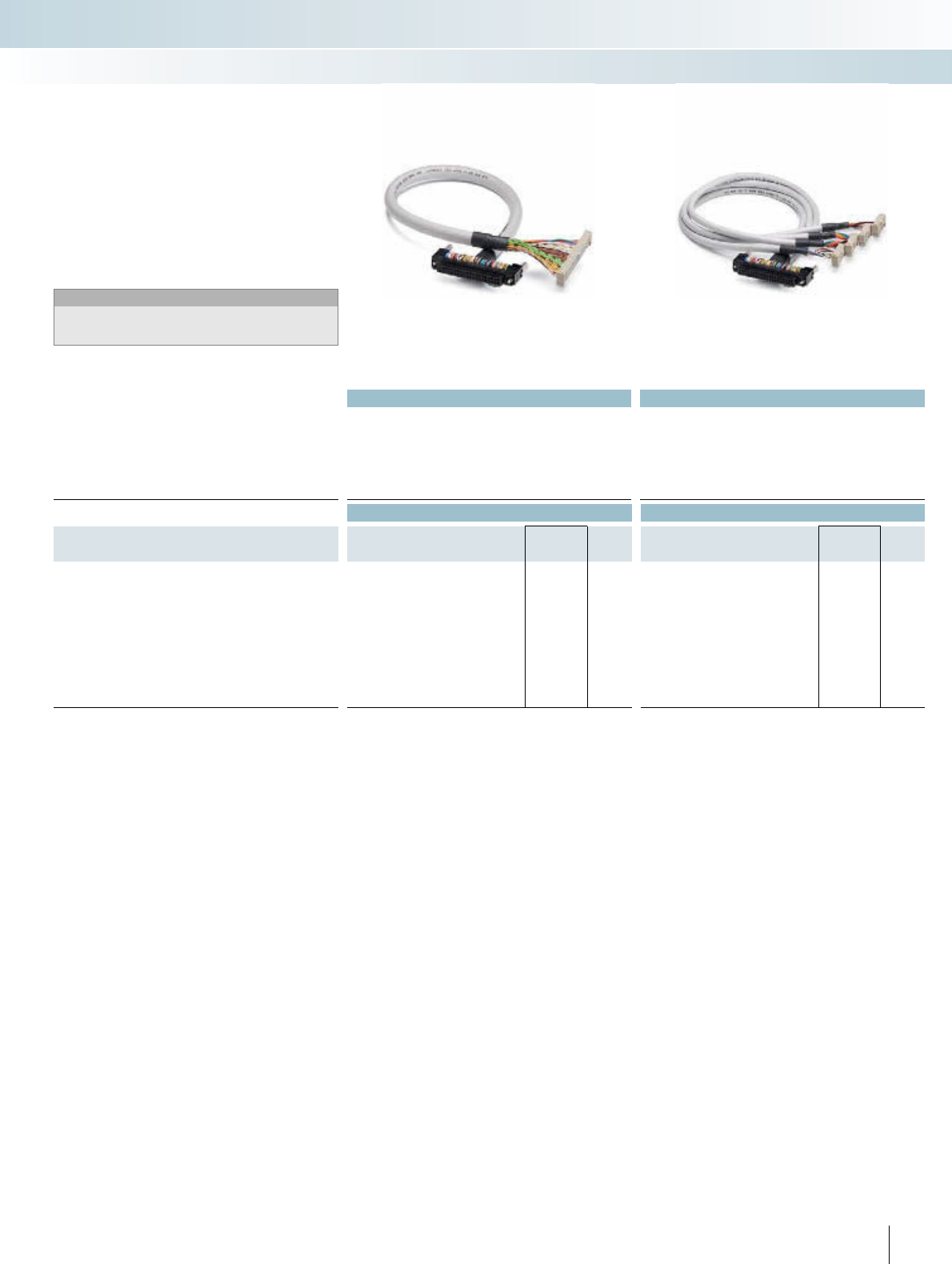
These cables have been specifically devel-
oped for connecting VARIOFACE termina-
tion boards to the Axioline realtime I/O sys-
tem. The push-in technology on the I/O
system ensures rapid connection.
The cables have the following features:
– 1:1 connection
– 14-pole connector, molded
– 8 pre-assembled open ends, for connec-
tion to the Axioline realtime I/O system
– Transmission of groups of 8 channels
– Labeling field on connector
Perfectly-fitting VARIOFACE termination
boards round off this system concept.
Notes:
The following modules cannot be coupled due to the larger outer
contour of the molded connectors:
UM 45-FLK14/ 8IM/ZFKDS/PLC, 2965211
UM 45- 8RM/MR-G24/1/PLC, 2962900
Phoenix Contact Axioline real-time I/O
System cables
INTERFACE Cabling
VARIOFACE system cabling
System cable for 8 channels
37
26,5
5
For additional information, visit www.phoenixcontact.net/catalog 225PHOENIX CONTACT
Technical data
Max. perm. operating voltage < 50 V AC / 60 V DC
Max. permissible current 1 A (per path)
Ambient temperature (operation) -20°C ... 50°C
Ambient temperature (storage / transport) -20°C ... 70°C
Mounting position Any
Standards / regulations IEC 60664 / DIN EN 50178 / IEC 62103
Ordering data
Description No. of poles Type Order No. Pcs. /
Pkt.
VARIOFACE front adapter, for 8-channel Inline modules
Input: IB IL 24 D I8/HD-PAC
Output: IB IL 24 DO 8/HD-PAC
FLKM 14-PA-INLINE/DIO8 2900889 1
VARIOFACE front adapter, for 16-channel Inline modules
Input: IB IL 24 DI 16 FLKM 14-PA-INLINE/IN16 2302751 1
Output: IB IL 24 DO 16 FLKM 14-PA-INLINE/OUT16 2302764 1
VARIOFACE front adapter, for 32-channel Inline modules
Input: IB IL 24 DI 32/HD and
Output: IB IL 24 DO 32/HD
FLKM 14-PA-INLINE/32 2302777 1
1.1
2.1
1.2
2.2
1.3
2.3
1.4
2.4
12345678910
11
12
13 14
NC
X1
Connection scheme for FLKM 14-PA-INLINE/DIO8
Byte 0
1.1
2.1
1.4
2.4
2.4
1.1
2.1
1.4
2.2
333344444
Byte 1
1.1
2.1
1.4
2.4
2.4
1.1
2.1
1.4
2.2
111122221
12345678910
11121314 12345678910
11121314
Connection scheme: FLKM 14-PA-INLINE/OUT16
X1
7.1
Byte 0
Byte 2
Byte 1
Byte 3
8.1
7.2
8.2
7.3
8.3
7.4
8.4
5.1
6.1
5.2
6.2
5.3
6.3
5.4
6.4
7.1
8.1
7.2
8.2
7.3
8.3
7.4
8.4
5.1
6.1
5.2
6.2
5.3
6.3
5.4
6.4
X3
X2
X4
91113 12345678
101214 91113 12345678
101214
91113 12345678
101214
91113 12345678
101214
Connection scheme: FLKM 14-PA-INLINE/32
Byte 0
1.1
2.1
1.4
2.4
1.1
2.1
1.4
2.4
2.3
2.2
3333
Byte 1
444444
1.1
2.1
1.4
2.4
1.1
2.1
1.4
2.4
2.3
2.2
1111222211
12345678910111213
1412345678910111213
14
Connection scheme: FLKM 14-PA-INLINE/IN16
Flat-ribbon cable strip
Connection to I/O card
Screw terminal blocks for separate supply
Explanation:
The front adapters are used to connect
pre-assembled system cables directly to In-
line. Front adapters are simply plugged into
the relevant Inline modules. Three connec-
tion options are available:
– Transfer of 8 channels via a 14-pole sys-
tem cable
– Transmission of 2 x 8 channels over two
14-pole system cables
– Transmission of 4 x 8 channels over four
14-pole system cables
Perfectly-fitting VARIOFACE termination
boards round off this system concept.
Phoenix Contact Inline
Front adapters
INTERFACE Cabling
VARIOFACE system cabling
Front adapters for Inline
Notes:
Suitable system cabling components can be
configured in the INTERFACE search wizard.
See www.phoenixcontact.net/catalog.

|
226 PHOENIX CONTACT
Technical data
Max. perm. operating voltage < 50 V AC / 60 V DC
Max. permissible current 1 A (per path)
4 A (per connection, supply via separate power supply)
Ambient temperature (operation) -20°C ... 50°C
Ambient temperature (storage / transport) -20°C ... 70°C
Mounting position Any
Standards / regulations IEC 60664 / DIN EN 50178 / IEC 62103
Ordering data
Description No. of poles Type Order No. Pcs. /
Pkt.
VARIOFACE front adapter, for MODICON® TSX Quantum,
1 x 32 channels can be connected
50 FLKM 50-PA-MODI-TSX/Q 2294306 1
VARIOFACE front adapter, for MODICON® TSX Quantum,
4 x 8 channels can be connected
14 FLKM 50/ 4-FLK14/PA-MODI-TSX/Q 2294416 1
X1 9X2
111312345678
101214 9111312345678
101214
1+
-
23456789 10 +
-
111213141516171819 20
X3 9111312345678
101214 X4
9111312345678
101214
21 +
-
2223242526272829 30 31 +
-
3233343536373839 40
0+
1+
2+
3+
Connection scheme FLKM 50/ 4-FLK14/PA-MODI-TSX/Q
123456789101112
1314151617
18
192021222324
12345678910
+-+-
11
121314151617181920
252627282930313233
34
353637
3839
40414243
44454647484950
21 -+-+
22232425262728
29
30 31323334353637383940
0+
1+
2+
3+
Connection scheme FLKM 50-PA-MODI-TSX/Q
Front adapters for
I/O modules of MODICON® TSX Quantum automation
devices
Card type FLKM 50-PA-MODI-TSX/Q
Digital input DDI 353
DDI 841*
DDI 853
DAI 340*
DAI 353**
DAI 440*
DAI 453**
Digital output DDO 353
Digital input/output DDM 390*
Analog input ACI 030*
ACI 040*
ATI 030*
ARI 030*
AVI 030*
Analog output ACO 020*
ACO 130*
AVO 020*
Analog input/output AMM 090*
Counter ECH 105*
EHC 202*
* Only in conjunction with VIP-2/SC/FLK50/MODI-TSX/Q,
Order No. 2322304.
** Only in conjunction with passive termination boards without LED.
Flat-ribbon cable strip
Connection to I/O card
Screw terminal blocks for separate supply
Explanation:
The front adapters mean that pre-assem-
bled system cables can be directly connect-
ed to I/O modules. There are two connec-
tion possibilities available:
– Transfer of max. 32 channels over one
50-pole system cable
– Transmission of 4 x 8 channels over four
14-pole system cables,
Perfectly-fitting VARIOFACE termination
boards with a variety of functions and con-
nection possibilities round off this system
concept.
Schneider Electric
MODICON® TSX Quantum
Front adapter
INTERFACE Cabling
VARIOFACE system cabling
Front adapter for
MODICON TSX Quantum
Notes:
Suitable system cabling components can be
configured in the INTERFACE search wizard.
See www.phoenixcontact.net/catalog.
For additional information, visit www.phoenixcontact.net/catalog
Technical data Technical data
Max. perm. operating voltage < 50 V AC / 60 V DC < 50 V AC / 60 V DC
Max. perm. current carrying capacitance per path 1 A 1 A
Max. conductor resistance 0.16 /m 0.16 /m
Ambient temperature (operation) -20°C ... 50°C -20°C ... 50°C
Conductor cross section AWG 26 / 0.14 mm² AWG 26 / 0.14 mm²
Conductor structure: stranded wires / material 7 / Cu tin-plated 7 / Cu tin-plated
Outside diameter 10.5 mm 6.3 mm
Ordering data Ordering data
Description No. of
poles Cable length Type Order No. Pcs. /
Pkt. Type Order No. Pcs. /
Pkt.
Round cable in variable lengths for
BMX DDI 3202K, BMX DDI 6402K,
BMX DD0 3202K, BMX DD0 6402K,
BMX DDM 3202K
40 0.5 m CABLE-FCN40/1X50/ 0,5M/M340 2321635 1CABLE-FCN40/4X14/ 0,5M/M340 2321716 1
40 1 m CABLE-FCN40/1X50/ 1,0M/M340 2321648 1CABLE-FCN40/4X14/ 1,0M/M340 2321729 1
40 2 m CABLE-FCN40/1X50/ 2,0M/M340 2321651 1CABLE-FCN40/4X14/ 2,0M/M340 2321732 1
40 3 m CABLE-FCN40/1X50/ 3,0M/M340 2321664 1CABLE-FCN40/4X14/ 3,0M/M340 2321745 1
40 4 m CABLE-FCN40/1X50/ 4,0M/M340 2321677 1CABLE-FCN40/4X14/ 4,0M/M340 2321758 1
40 6 m CABLE-FCN40/1X50/ 6,0M/M340 2321680 1CABLE-FCN40/4X14/ 6,0M/M340 2321761 1
40 8 m CABLE-FCN40/1X50/ 8,0M/M340 2321693 1CABLE-FCN40/4X14/ 8,0M/M340 2321774 1
40 10 m CABLE-FCN40/1X50/10,0M/M340 2321703 1CABLE-FCN40/4X14/10,0M/M340 2321787 1
227PHOENIX CONTACT
INTERFACE Cabling
VARIOFACE system cabling
Connector Fujitsu FCN on flat-ribbon cable,
number of poles: 40 on 50
Connector Fujitsu FCN on flat-ribbon cable,
number of poles: 40 on 4 x 14
These system cables are plugged onto the
I/O cards that are connected using Fujitsu
connectors.
CABLE-FCN40/1X50/Ê
– Signal transmission of 32 channels
CABLE-FCN40/4X14/Ê
– Splitting up 32 channels into 4 x 8 channels
Notes:
Suitable system cabling components can be
configured in the INTERFACE search wizard.
See www.phoenixcontact.net/catalog.
Schneider Electric
MODICON® M340
System cable
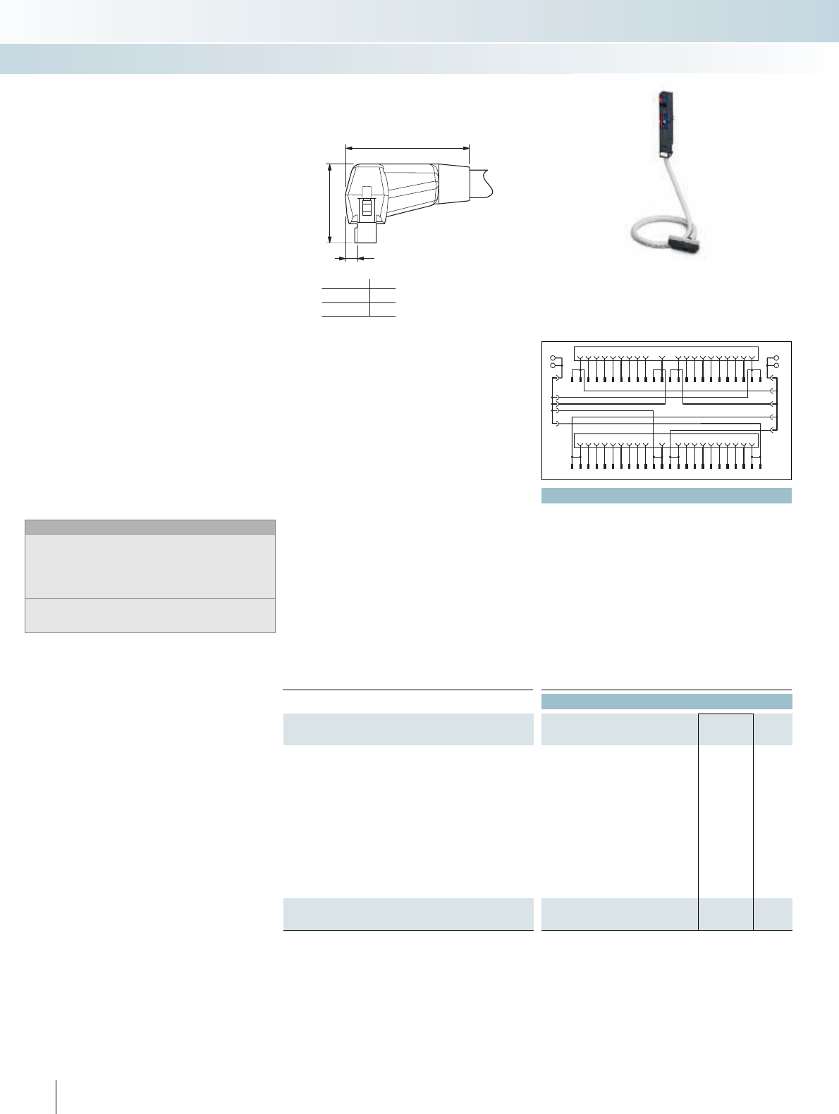
228 PHOENIX CONTACT
Three connection options are available:
– Transfer of max. 32 channels via two
50-pole system cables (32-channel cards
or this design)
– Transfer of 4 x 8 channels via two 14-pole
system cables (32-channel cards or their
type)
– Transfer of 2 x 8 channels via two 14-pole
system cables (16-channel cards or their
type)
The front adapters have the following
features:
– Can be screwed with I/O module
– Voltage supply via terminal blocks with
spring-cage double connection
– Encapsulated socket strips for module
side
Special lengths can be configured using
separate order numbers.
Ordering example:
A front adapter with a connected 50-pole
system cable (32-channel cards), 12.75 m in
length:
1 pcs. 2900885/12,75
Notes:
The following modules cannot be coupled due to the larger outer
contour of the molded connectors:
UM 45-FLK14/ 8IM/ZFKDS/PLC, 2965211
UM 45-FLK50/32IM/ZFKDS/PLC, 2965224
UM 45- 8RM/MR-G24/1/PLC, 2962900
UM 45-16RM/MR-G24/1/PLC, 2962913
Suitable system cabling components can be
configured in the INTERFACE search wizard.
See www.phoenixcontact.net/catalog.
VIP – VARIOFACE Professional
front adapters for SIMATIC S7-300
Technical data
Max. perm. operating voltage < 50 V AC / 60 V DC
Max. perm. current carrying capacitance per path 1 A (per path)
Max. perm. current (separate power supply) 8 A
Rated surge voltage 0.8 kV
Max. conductor resistance 0.16 /m
Conductor cross section AWG 26 / 0.14 mm²
Conductor structure: stranded wires / material 7 / Cu tin-plated
Outside diameter 10.3 mm
Ambient temperature range -20°C ... 50°C
Standards / regulations IEC 60664, IEC 62103, DIN EN 50178
Connection method Front adapter Can be plugged onto 40-pos. I/O modules / separate power supply
through terminal blocks with spring-cage double connection
System cable Flat-ribbon cable plug connector in acc. with IEC 60603-13
Connection data solid / stranded / AWG 0.2 ... 2.5 mm² / 0.2 ... 2.5 mm² / 24 - 14
Ordering data
Description Cable length Type Order No. Pcs. /
Pkt.
VIP VARIOFACE front adapter, with connected system cables for
SIMATIC S7 300
0.5 m VIP-PA-FLK50/ 0,5M/S7 2322443 1
1 m VIP-PA-FLK50/ 1,0M/S7 2322456 1
1.5 m VIP-PA-FLK50/ 1,5M/S7 2322469 1
2 m VIP-PA-FLK50/ 2,0M/S7 2321800 1
2.5 m VIP-PA-FLK50/ 2,5M/S7 2322472 1
3 m VIP-PA-FLK50/ 3,0M/S7 2322485 1
4 m VIP-PA-FLK50/ 4,0M/S7 2322498 1
5 m VIP-PA-FLK50/ 5,0M/S7 2322508 1
6 m VIP-PA-FLK50/ 6,0M/S7 2322511 1
7 m VIP-PA-FLK50/ 7,0M/S7 2322524 1
8 m VIP-PA-FLK50/ 8,0M/S7 2322537 1
10 m VIP-PA-FLK50/10,0M/S7 2322540 1
VIP VARIOFACE front adapter, as above, in variable lengths
VIP-PA-FLK50-S7/... 2900885 1
A
26,5
5
...FLK14...
...FLK50...
37
42
A
INTERFACE Cabling
VARIOFACE system cabling
BRbl
SP SP
BRrd
1
2
3
4
5
6
7
8
9
10
11
12
13
14
15
16
17
18
19
20
1
2
3
4
5
6
7
8
9
10
11
12
13
14
15
16
17
18
19
20
21
22
23
24
21
22
23
24
25
26
27
28
29
30
31
32
33
34
35
36
37
38
39
40
25
26
27
28
29
30
31
32
33
34
35
36
37
38
39
40
41
42
43
44
45
46
47
48
-+
-+
Front adapter with system cable
1 x 32 channels can be connected
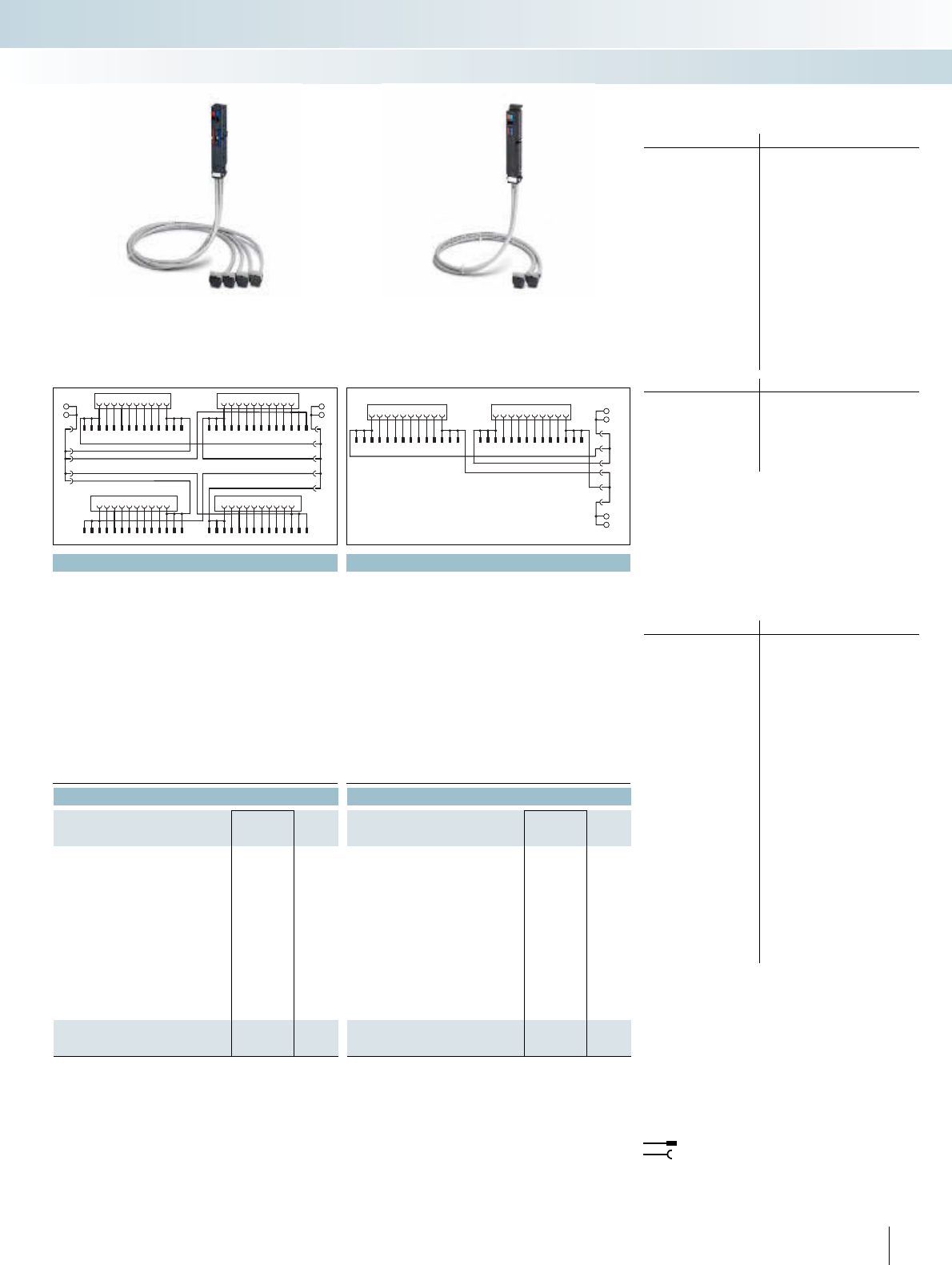
For additional information, visit www.phoenixcontact.net/catalog
229
PHOENIX CONTACT
Technical data Technical data
< 50 V AC / 60 V DC < 50 V AC / 60 V DC
1 A (per path) 1 A (per path)
8 A 8 A
0.8 kV 0.8 kV
0.16 /m 0.16 /m
AWG 26 / 0.14 mm² AWG 26 / 0.14 mm²
7 / Cu tin-plated 7 / Cu tin-plated
6.4 mm 6.4 mm
-20°C ... 50°C -20°C ... 50°C
IEC 60664, IEC 62103, DIN EN 50178 IEC 60664, IEC 62103, DIN EN 50178
Can be plugged onto 40-pos. I/O modules / separate power supply
through terminal blocks with spring-cage double connection
Can be plugged onto 20-pos. I/O modules / separate power supply
through terminal blocks with spring-cage double connection
Flat-ribbon cable plug connector in acc. with IEC 60603-13 Flat-ribbon cable plug connector in acc. with IEC 60603-13
0.2 ... 2.5 mm² / 0.2 ... 2.5 mm² / 24 - 14 0.2 ... 2.5 mm² / 0.2 ... 2.5 mm² / 24 - 14
Ordering data Ordering data
Type Order No. Pcs. /
Pkt. Type Order No. Pcs. /
Pkt.
VIP-PA-FLK50/4X14/ 0,5M/S7 2322553 1VIP-PA-FLK14/ 0,5M/S7 2322663 1
VIP-PA-FLK50/4X14/ 1,0M/S7 2322566 1VIP-PA-FLK14/ 1,0M/S7 2322676 1
VIP-PA-FLK50/4X14/ 1,5M/S7 2322579 1VIP-PA-FLK14/ 1,5M/S7 2322689 1
VIP-PA-FLK50/4X14/ 2,0M/S7 2321910 1VIP-PA-FLK14/ 2,0M/S7 2321790 1
VIP-PA-FLK50/4X14/ 2,5M/S7 2322582 1VIP-PA-FLK14/ 2,5M/S7 2322692 1
VIP-PA-FLK50/4X14/ 3,0M/S7 2322595 1VIP-PA-FLK14/ 3,0M/S7 2322702 1
VIP-PA-FLK50/4X14/ 4,0M/S7 2322605 1VIP-PA-FLK14/ 4,0M/S7 2322715 1
VIP-PA-FLK50/4X14/ 5,0M/S7 2322618 1VIP-PA-FLK14/ 5,0M/S7 2322728 1
VIP-PA-FLK50/4X14/ 6,0M/S7 2322621 1VIP-PA-FLK14/ 6,0M/S7 2322731 1
VIP-PA-FLK50/4X14/ 7,0M/S7 2322634 1VIP-PA-FLK14/ 7,0M/S7 2322744 1
VIP-PA-FLK50/4X14/ 8,0M/S7 2322647 1VIP-PA-FLK14/ 8,0M/S7 2322757 1
VIP-PA-FLK50/4X14/10,0M/S7 2322650 1VIP-PA-FLK14/10,0M/S7 2322760 1
VIP-PA-FLK50-4X14-S7/... 2900886 1VIP-PA-FLK14-S7/... 2900887 1
Front adapter for 32-channel cards of
SIMATIC® S7-300
Card type VIP-PA-FLK50/...M/S7
Digital input 6ES7 321-1BL00-0AA0
Digital output 6ES7 322-1BL00-0AA0
Digital input/output 6ES7 323-1BL00-0AA0
Analog input 6ES7 331-7PF01-0AB0*
6ES7 331-7PF11-0AB0*
6ES7 331-7NF00-0AB0*
6ES7 331-7NF10-0AB0*
6ES7 331-1KF01-0AB0*
Analog output 6ES7 332-5HF00-0AB0*
CPU 312C, 313C, 314C, 313C-2PtP
313C-2DP, 314C-2DP, 314C-2PtP
Other modules 6ES7 350-2AH01-0AE0*
6ES7 357-4AH01-0AE0*
Card type VIP-PA-FLK50/4X14/...M/S7
Digital input 6ES7 321-1BL00-0AA0
Digital output 6ES7 322-1BL00-0AA0
Digital input/output 6ES7 323-1BL00-0AA0
CPU 313C, 314C, 313C-2PtP
313C-2DP, 314C-2DP, 314C-2PtP
Front adapter for 16-channel cards of
SIMATIC® S7-300
Card type VIP-PA-FLK14/...M/S7
Digital input 6ES7 321-1BH02-0AA0
6ES7 321-1BH10-0AA0
6ES7 321-1BH50-0AA0*
6ES7 321-7BH01-0AB0*
Digital output 6ES7 322-1BH01-0AA0
6ES7 322-1BH10-0AA0
6ES7 322-8BF00-0AB0*
Digital input/output 6ES7 323-1BH01-0AA0
Analog input 6ES7 331-7KF02-0AB0*
6ES7 331-7HF01-0AB0*
6ES7 331-7KB02-0AB0*
6ES7 331-7TF01-0AB0*
Analog output 6ES7 332-5HD01-0AB0*
6ES7 332-5HB01-0AB0*
6ES7 332-7ND02-0AB0*
Analog input/output 6ES7 334-0CE01-0AA0*
6ES7 334-0KE00-0AB0*
6ES7 335-7HG01-0AB0*
Other modules 6ES7 338-4BC01-0AB0*
6ES7 350-1AH03-0AE0*
6ES7 351-1AH01-0AE0*
6ES7 352-1AH02-0AE0*
6ES7 353-1AH01-0AE0*
6ES7 354-1AH01-0AE0*
6ES7 355-0VH10-0AE0*
6ES7 355-1VH10-0AE0*
* Only in conjunction with
VIP-2/SC/FLK50 (1-40)/S7, Order No.: 2315243,
UM 45-FLK50/ZFKDS/S7-300, Order No.: 2968111,
FLKM 50/KDS3-MT/PPA/S7-300, Order No.: 2304490.
All bridges (BR) at the adapter must be removed!
* Only in conjunction with
IP-2/SC/2FLK14 (1-20)S7, Order No.: 2315230
UM 45-2FLK14/ZFKDS/S7, Order No.: 2965156
FLKM-2FLK14/KDS 3-MT/PPA/S7, Order No.: 2295062
All bridges (BR) on the adapter must be disconnected.
Note:
The front adapters are non-isolated on delivery.
Removal of the bridges can achieve electrical isolation
(in groups of 8).
Flat-ribbon cable strip
Connection to I/O card
Explanation:
SP: Separate power terminals
BRbl: Blue plug-in bridge
BRrd: Red plug-in bridge
INTERFACE Cabling
VARIOFACE system cabling
BRbl
SP SP
BRrd
-+
-+
1
2
3
4
5
6
7
8
9
10
11
12
13
14
15
16
17
18
19
20
9
11
13
1
2
3
4
5
6
7
8
10
12
14
9
11
13
1
2
3
4
5
6
7
8
10
12
14
21
22
23
24
25
26
27
28
29
30
31
32
33
34
35
36
37
38
39
40
9
11
13
1
2
3
4
5
6
7
8
10
12
14
9
11
13
1
2
3
4
5
6
7
8
10
12
14
1
11
2
12
3
13
4
14
5
15
6
16
7
17
8
18
9
19
10
20
Byte0Byte1
9
11
13
1
2
3
4
5
6
7
8
10
12
14
9
11
13
1
2
3
4
5
6
7
8
10
12
14
SP
SP
BRrd
BRbl
+
-
+
-
Front adapter with system cable
4 x 8 channels can be connected
Front adapter with system cable
2 x 8 channels can be connected
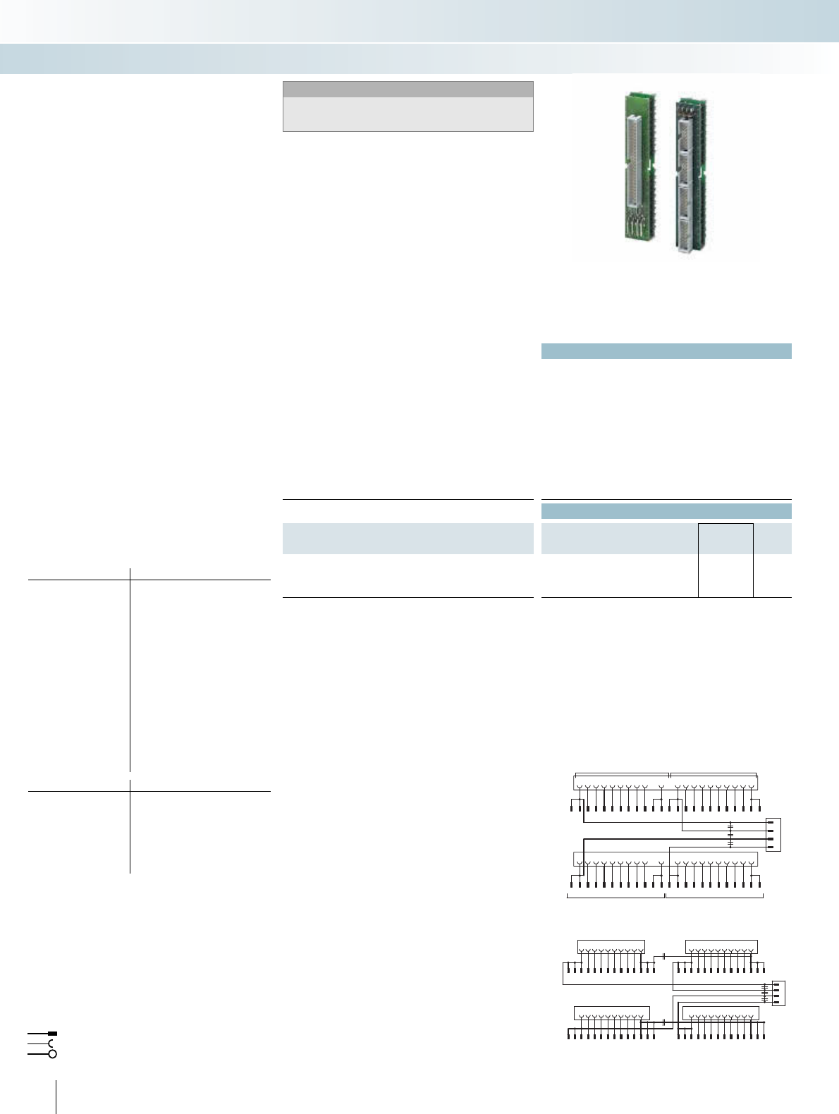
|
230 PHOENIX CONTACT
Technical data
Max. perm. operating voltage < 50 V AC / 60 V DC
Max. permissible current
1 A (per path)
8 A (per connection, supply via separate power supply (2.8 x 0.8 mm))
Max. perm. total current 2 A (per byte, for supply via connector)
8 A (during supply via a separate bridged power supply)
Ambient temperature (operation) -20°C ... 50°C
Ambient temperature (storage / transport) -20°C ... 70°C
Standards / regulations IEC 60664 / DIN EN 50178 / IEC 62103
Connection method Flat-ribbon cable plug connector in acc. with IEC 60603-13
Ordering data
Description No. of poles Type Order No. Pcs. /
Pkt.
VARIOFACE front adapters, for SIMATIC® S7-300
- 1 x 32 channels can be connected 50 FLKM 50-PA-S300 2294445 1
- 4 x 8 channels can be connected 14 FLKM 50/4-FLK14/PA-S300 2296281 1
Byte 0
Byte 2Byte 3
Byte 1
12345678910 111213141516
17181920
9111312345678101214 9111312345678101214
0
1
2
3
FS
DR
DR
DR
21222324252627282930 31323334353637383940
911
1312345678
101214 911
1312345678
101214
Connection scheme FLKM 50/4-FLK14/PA-S300
Byte 0Byte 1
Byte 2Byte 3
123456789 10 11121314151617181920
123456789
1011121314 15161718
19
2021222324
0
1
2
3
FS
DR
DR
DR
212223242526272829 30 31 323334353637383940
2526272829303132
33
343536 3738394041424344 45464748
Connection scheme FLKM 50-PA-S300
Front adapter for 32-channel cards of
SIMATIC® S7-300
Card type FLKM 50-PA-S300
Digital input 6ES7 321-1BL00-0AA0
Digital output 6ES7 322-1BL00-0AA0
Digital input/output 6ES7 323-1BL00-0AA0
Analog input 6ES7 331-7PF01-0AB0*
6ES7 331-7PF11-0AB0*
6ES7 331-7NF00-0AB0*
6ES7 331-7NF10-0AB0*
6ES7 331-1KF01-0AB0*
Analog output 6ES7 332-5HF00-0AB0*
CPU 312C, 313C, 314C, 313C-2PtP
313C-2DP, 314C-2DP, 314C-2PtP
Other modules 6ES7 350-2AH01-0AE0*
6ES7 357-4AH01-0AE0*
Card type FLKM 50/4-FLK14/PA-S300
Digital input 6ES7 321-1BL00-0AA0
Digital output 6ES7 322-1BL00-0AA0
Digital input/output 6ES7 323-1BL00-0AA0
CPU 313C, 314C, 313C-2PtP
313C-2DP, 314C-2DP, 314C-2Pt
*O
n
l
y
i
n con
j
unct
i
on w
i
t
h
VIP-2/SC/FLK50 (1-40)/S7, Order No.:2315243,
UM 45-FLK50/ZFKDS/S7-300, Order No.: 2968111,
FLKM 50/KDS3-MT/PPA/S7-300, Order No.: 2304490.
All wire bridges (DR) on the adapter must be disconnected!
There must be no voltage supply at the front adapter (flowing via
the slip-on connections)!
Note:
The front adapters are non-isolated on delivery.
Removal of the bridges can achieve electrical isolation
(in groups of 8).
Flat-ribbon cable strip
Connection to I/O card
Screw terminal blocks for separate supply
Explanation:
I/O modules with 32 channels or with
this design
There are two connection possibilities
available:
– Transfer of max. 32 channels over one
50-pole system cable
– Transmission of 4 x 8 channels over four
14-pole system cables,
Perfectly-fitting VARIOFACE termination
boards with a variety of functions and con-
nection possibilities round off this system
concept.
Siemens-SIMATIC® S7-300
Front adapter
INTERFACE Cabling
VARIOFACE system cabling
Front adapter for SIMATIC® S7-300,
I/O cards with max. 32 channels
Notes:
Suitable system cabling components can be
configured in the INTERFACE search wizard.
See www.phoenixcontact.net/catalog.
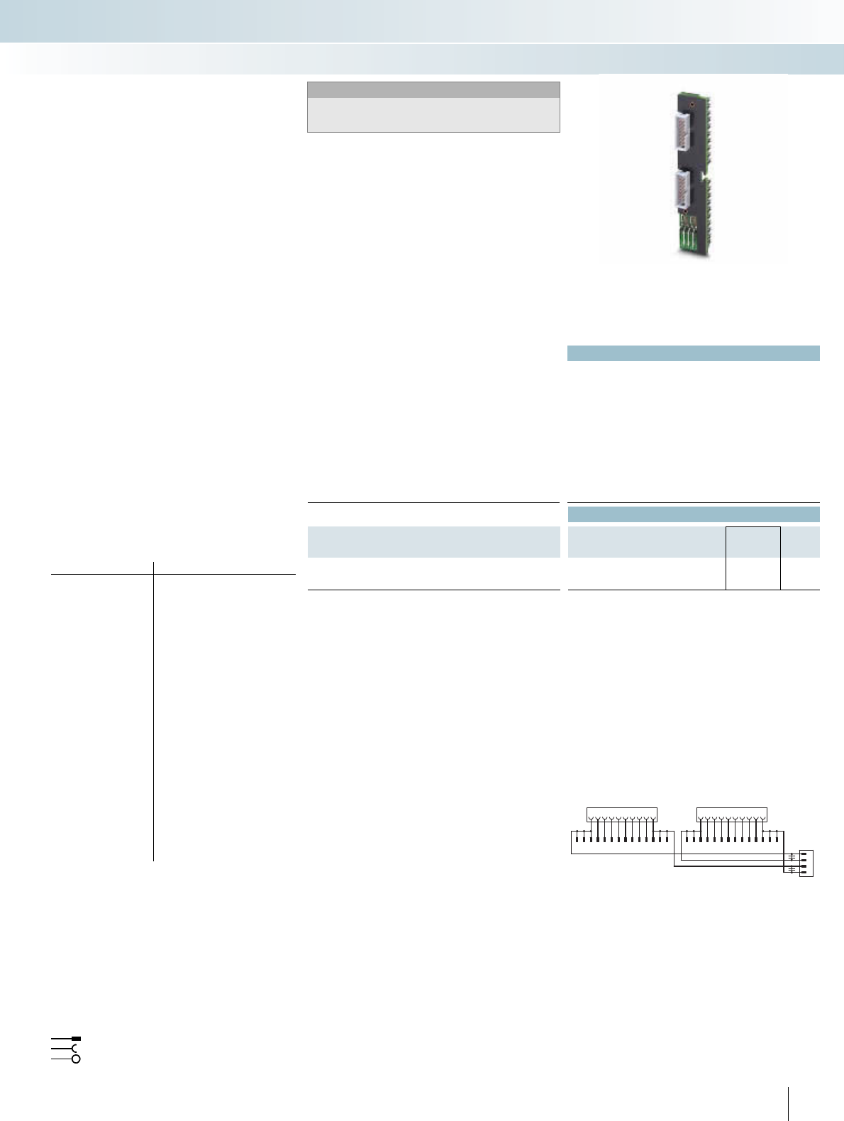
For additional information, visit www.phoenixcontact.net/catalog
|
231
PHOENIX CONTACT
Technical data
Max. perm. operating voltage < 50 V AC / 60 V DC
Max. permissible current 1 A (per path)
8 A (per connection, supply via separate power supply (2.8 x 0.8
mm))
Max. perm. total current 2 A (per byte, for supply via connector)
8 A (during supply via a separate bridged power supply)
Ambient temperature (operation) -20°C ... 50°C
Ambient temperature (storage / transport) -20°C ... 70°C
Standards / regulations IEC 60664 / DIN EN 50178 / IEC 62103
Connection method Flat-ribbon cable plug connector in acc. with IEC 60603-13
Ordering data
Description No. of poles Type Order No. Pcs. /
Pkt.
VARIOFACE front adapters, for SIMATIC® S7-300
- 2 x 8 channels can be connected 14 FLKM 14-PA-S300 2299770 1
1
11
2
12
3
13
4
14
5
15
6
16
7
17
8
18
9
19
10
20
0+
1+
0
1-
Byte0Byte1
DR FS
9111312345678101214 9111312345678101214
Connection scheme FLKM 14-PA-S300
Front adapter for 16-channel cards of
SIMATIC® S7-300
Card type FLKM 14-PA-S300
Digital input 6ES7 321-1BH02-0AA0
6ES7 321-1BH10-0AA0
6ES7 321-1BH50-0AA0*
6ES7 321-7BH01-0AB0*
Digital output 6ES7 322-1BH01-0AA0
6ES7 322-1BH10-0AA0
6ES7 322-8BF00-0AB0*
Digital input/output 6ES7 323-1BH01-0AA0
Analog input 6ES7 331-7KF02-0AB0*
6ES7 331-7HF01-0AB0*
6ES7 331-7KB02-0AB0*
6ES7 331-7TF01-0AB0*
Analog output 6ES7 332-5HD01-0AB0*
6ES7 332-5HB01-0AB0*
6ES7 332-7ND02-0AB0*
Analog input/output 6ES7 334-0CE01-0AA0*
6ES7 334-0KE00-0AB0*
6ES7 335-7HG01-0AB0*
Other modules 6ES7 338-4BC01-0AB0*
6ES7 350-1AH03-0AE0*
6ES7 351-1AH01-0AE0*
6ES7 352-1AH02-0AE0*
6ES7 353-1AH01-0AE0*
6ES7 354-1AH01-0AE0*
6ES7 355-0VH10-0AE0*
6ES7 355-1VH10-0AE0*
* Only in conjunction with
VIP-2/SC/2FLK14 (1-20)/S7, Order No.: 2315230
UM 45-2FLK14/ZFKDS/S7, Order No.: 2965156
FLKM-2FLK14/KDS 3-MT/PPA/S7, Order No.: 2295062
All wire bridges (DR) on the adapter must be disconnected.
There must be no voltage supply at the front adapter (flowing via
the slip-on connections)!
Note:
The front adapters are non-isolated on delivery.
Removal of the bridges can achieve electrical isolation
(in groups of 8).
Flat-ribbon cable strip
Connection to I/O card
Screw terminal blocks for separate supply
Explanation:
I/O modules with 16 channels or with
this design
– Up to 2 x 8 channels are connected via
two 14-pole system cables
Perfectly-fitting VARIOFACE termination
boards with a variety of functions and con-
nection possibilities round off this system
concept.
Siemens-SIMATIC® S7-300
Front adapter
INTERFACE Cabling
VARIOFACE system cabling
Front adapter for SIMATIC® S7-300,
I/O cards with max. 16 channels
Notes:
Suitable system cabling components can be
configured in the INTERFACE search wizard.
See www.phoenixcontact.net/catalog.
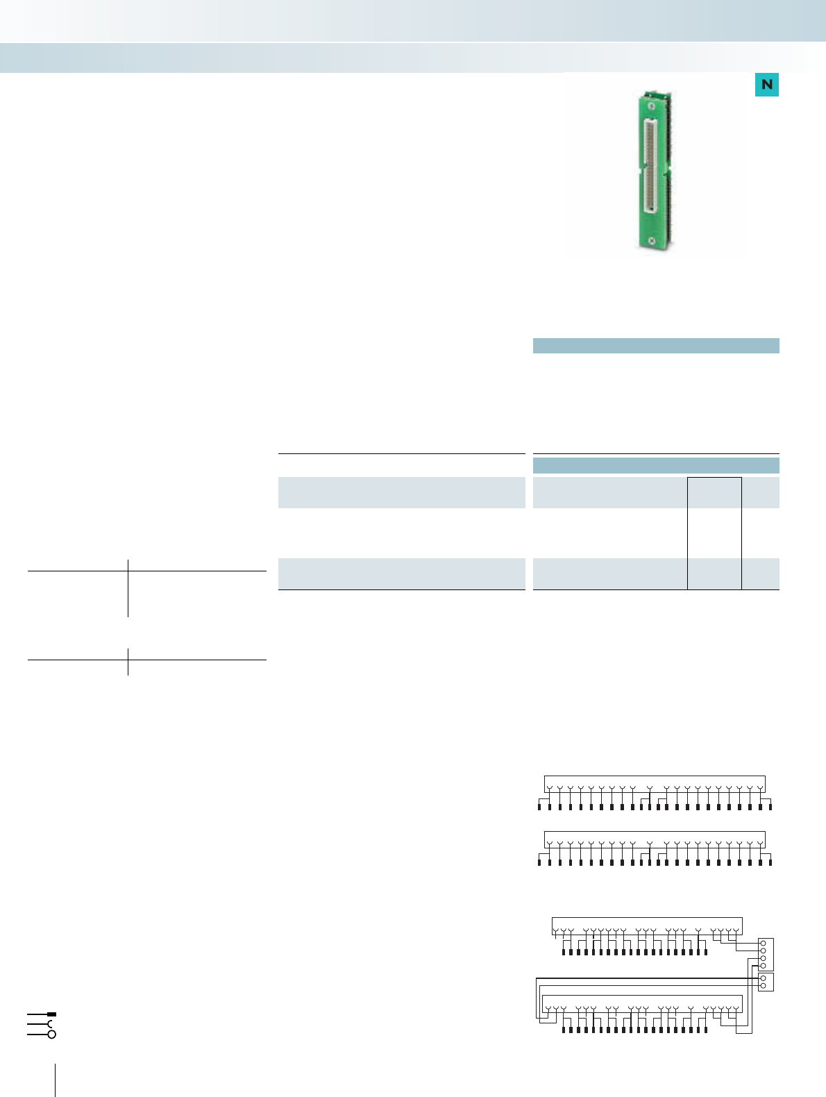
232 PHOENIX CONTACT
Technical data
Max. perm. operating voltage 30 V DC
Max. permissible current 1 A (per path)
Max. perm. total current 2 A
Ambient temperature (operation) -20°C ... 50°C
Ambient temperature (storage / transport) -20°C ... 70°C
Standards / regulations EN 50178
Connection method Flat-ribbon cable plug connector in acc. with IEC 60603-13
Ordering data
Description No. of poles Type Order No. Pcs. /
Pkt.
VARIOFACE front adapter for failsafe I/O cards
6ES7 326-1BK02-0AB0
6ES7 326-1RF00-0AB0
6ES7 336-1HE00-0AB0
50 FLKM 50-PA-S300/SO167 2307662 1
VARIOFACE front adapter for failsafe I/O cards
6ES7 326-2BF01-0AB0 50 FLKM 50-PA/DO326/S7-300 2321952 1
3468 11 14 18 20257
9101213151617
19
1
2346
78910 11 12 13 14 15 16 17 18 19 20
15
2+
2M
3+
3M
1+
1M
22 23 24 26 27 28 29 30 31 32 33 34 35 36 37 38 39 40
21 25
23 24 26 27 30 33 37 39
22 25 28 29 31 32 34 35 36 38
21 40
Connection scheme FLKM 50-PA/DO326/S7-300
1 2 3 4 5 6 7 8 9 10 11 12 13 14 15 16 17 18 19 20
123456789101112131415161718192021222324
21 22 23 24 25 26 27 28 29 30 31 32 33 34 35 36 37 38 39 40
25 26 27 28 29 30 31 32 33 34 35 36 37 38 39 40 41 42 43 44 45 46 47 48
Connection scheme FLKM 50-PA-S300/SO167
Front adapter for I/O modules of
SIMATIC® S7-300
Card type FLKM 50-PA-S300/SO167
Digital input 6ES7 326-1BK02-0AB0*
6ES7 326-1RF00-0AB0*1)
Analog input 6ES7 336-1HE00-0AB0*
Card type FLKM 50-PA/DO326/S7-S300
Digital output 6ES7 326-2BF01-0AB0**
*O
n
l
y
i
n con
j
unct
i
on w
i
t
h
VIP-2/SC/FLK50 (1-40)/S7, Order No.:2315243,
UM 45-FLK50/ZFKDS/S7-300, Order No.: 2968111,
FLKM 50/KDS3-MT/PPA/S7-300, Order No.: 2304490.
** Only in conjunction with
FLKM 50/DO326/S7-300, Order No.: 2312952.
1) Not suitable for signals from the Ex area.
Flat-ribbon cable strip
Connection to I/O card
Screw terminal blocks for separate supply
Explanation:
The front adapters are coupled using
50-pole system cables and convert the sig-
nals for passive modules.
Siemens SIMATIC® S7-300
Front adapter for failsafe modules
INTERFACE Cabling
VARIOFACE system cabling
Siemens SIMATIC S7-300 front adapter
for failsafe I/O cards
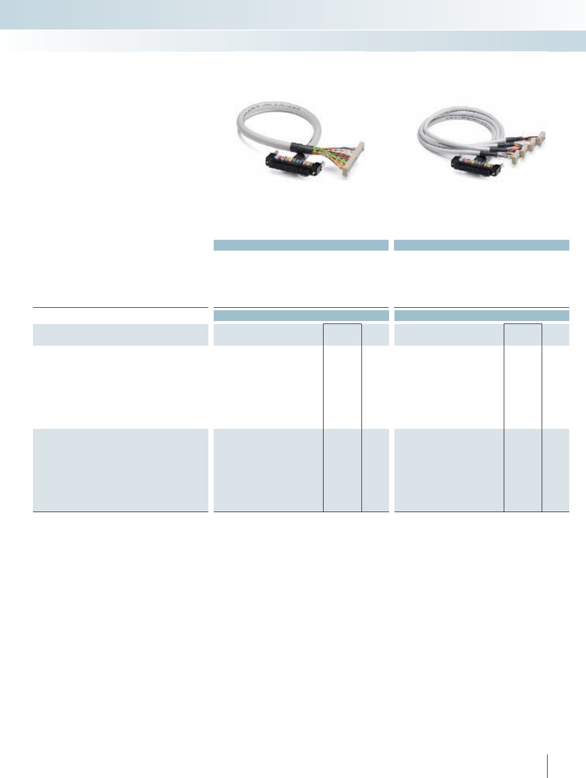
For additional information, visit www.phoenixcontact.net/catalog
Technical data Technical data
Max. perm. operating voltage < 50 V AC / 60 V DC < 50 V AC / 60 V DC
Max. perm. current carrying capacitance per path 1 A 1 A
Max. conductor resistance 0.16 /m 0.16 /m
Ambient temperature (operation) -20°C ... 50°C -20°C ... 50°C
Conductor cross section AWG 26 / 0.14 mm² AWG 26 / 0.14 mm²
Conductor structure: stranded wires / material 7 / Cu tin-plated 7 / Cu tin-plated
Outside diameter 10 mm 6.3 mm
Ordering data Ordering data
Description No. of
poles Cable length Type Order No. Pcs. /
Pkt. Type Order No. Pcs. /
Pkt.
Round cable, for output module 6ES7 322-1BP00-0AA0 and
6ES7 322-1BP50-0AA0 (two cables per module)
40 0.5 m CABLE-FCN40/1X50/ 0,5M/S7-OUT 2321017 1CABLE-FCN40/4X14/ 0,5M/S7-OUT 2321172 1
40 1 m CABLE-FCN40/1X50/ 1,0M/S7-OUT 2321020 1CABLE-FCN40/4X14/ 1,0M/S7-OUT 2321185 1
40 2 m CABLE-FCN40/1X50/ 2,0M/S7-OUT 2321033 1CABLE-FCN40/4X14/ 2,0M/S7-OUT 2321198 1
40 3 m CABLE-FCN40/1X50/ 3,0M/S7-OUT 2321046 1CABLE-FCN40/4X14/ 3,0M/S7-OUT 2321208 1
40 4 m CABLE-FCN40/1X50/ 4,0M/S7-OUT 2321059 1CABLE-FCN40/4X14/ 4,0M/S7-OUT 2321211 1
40 6 m CABLE-FCN40/1X50/ 6,0M/S7-OUT 2321062 1CABLE-FCN40/4X14/ 6,0M/S7-OUT 2321224 1
40 8 m CABLE-FCN40/1X50/ 8,0M/S7-OUT 2321075 1CABLE-FCN40/4X14/ 8,0M/S7-OUT 2321237 1
40 10 m CABLE-FCN40/1X50/10,0M/S7-OUT 2321088 1CABLE-FCN40/4X14/10,0M/S7-OUT 2321240 1
Round cable, for input module 6ES7 321-1BP00-0AA0 (two
cables per module). Plus-reading operation (sinking mode) of the
module
40 0.5 m CABLE-FCN40/1X50/ 0,5M/S7-IN 2321091 1CABLE-FCN40/4X14/ 0,5M/S7-IN 2321253 1
40 1 m CABLE-FCN40/1X50/ 1,0M/S7-IN 2321101 1CABLE-FCN40/4X14/ 1,0M/S7-IN 2321266 1
40 2 m CABLE-FCN40/1X50/ 2,0M/S7-IN 2321114 1CABLE-FCN40/4X14/ 2,0M/S7-IN 2321279 1
40 3 m CABLE-FCN40/1X50/ 3,0M/S7-IN 2321127 1CABLE-FCN40/4X14/ 3,0M/S7-IN 2321282 1
40 4 m CABLE-FCN40/1X50/ 4,0M/S7-IN 2321130 1CABLE-FCN40/4X14/ 4,0M/S7-IN 2321295 1
40 6 m CABLE-FCN40/1X50/ 6,0M/S7-IN 2321143 1CABLE-FCN40/4X14/ 6,0M/S7-IN 2321305 1
40 8 m CABLE-FCN40/1X50/ 8,0M/S7-IN 2321156 1CABLE-FCN40/4X14/ 8,0M/S7-IN 2321318 1
40 10 m CABLE-FCN40/1X50/10,0M/S7-IN 2321169 1CABLE-FCN40/4X14/10,0M/S7-IN 2321321 1
233PHOENIX CONTACT
INTERFACE Cabling
VARIOFACE system cabling
System cable Splitting cable
These system cables are plugged onto the
64-channel (2x32) I/O cards that are direct-
ly connected using connectors.
CABLE-FCN40/1X50/Ê
– Signal transmission of 1x32 channels
– System cable: 40-pole connector on
50-pole flat-ribbon cable strip
CABLE-FCN40/4X14/Ê
– Signal transmission of 4x8 channels
– Splitting cable: 40-pole connector on four
14-pole flat-ribbon cable strips
Siemens SIMATIC S7 -300
System cables for 64-channel I/O cards
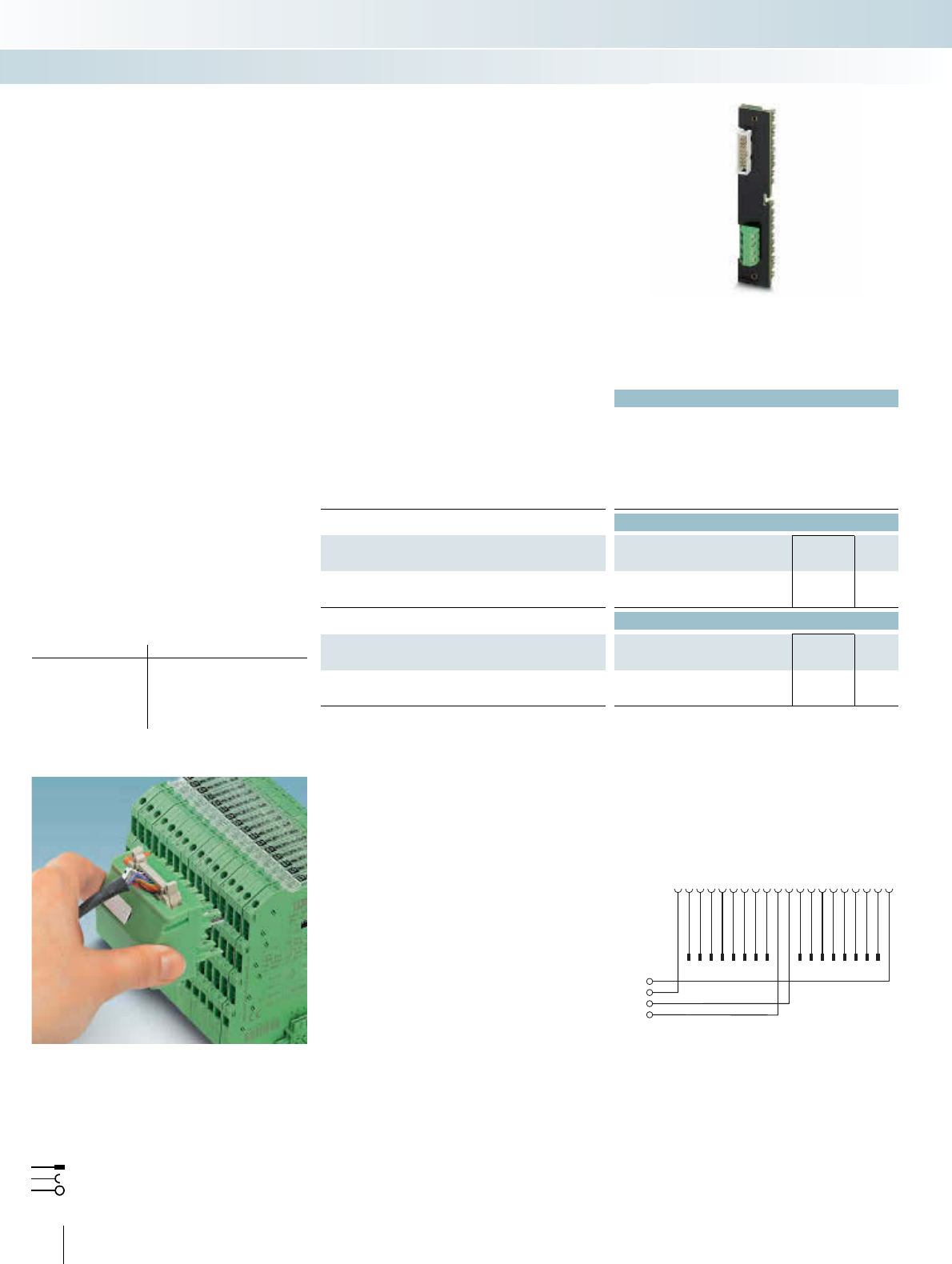
234 PHOENIX CONTACT
Technical data
FLKM 16-PA-S300/MINI-MCR
Max. perm. operating voltage 30 V AC/DC
Max. permissible current 50 mA (per path)
500 mA (per connection, supply via separate power supply)
Ambient temperature (operation) -20°C ... 60°C
Ambient temperature (storage / transport) -20°C ... 70°C
Standards / regulations DIN EN 50178 / IEC 62103
Ordering data
Description No. of poles Type Order No. Pcs. /
Pkt.
VARIOFACE front adapter, for SIMATIC® S7-300, only in con-
nection with MINI MCR-SL-V8-FLK 16-A
16 FLKM 16-PA-S300/MINI-MCR 2314749 1
Accessories
Assembled round cable, with two 16-pole socket strips
FLK 16/EZ-DR/ 300/KONFEK 2299330 1
System adapter, for MINI Analog modules with screw connection
MINI MCR-SL-V8-FLK 16-A 2811268 1
20 19 18 17 16 15 14 13 12 11
L+
M
10987654321
141516 13 12 11 10 9 87654321
Comp.-
Comp.+
FLKM 16-PA-S300/MINI-MCR connection scheme
Front adapter for analog cards of
SIMATIC® S7-300
Card type FLKM 16-PA-S300/MINI-MCR
Analog input 6ES7 331-7KF02-0AB0
6ES7 331-7KB02-0AB0
6ES7 331-7KB81-0AB0
6ES7 331-7TF00-0AB0
Analog output 6ES7 332-8TF01-0AB0
Flat-ribbon cable strip
Connection to I/O card
Screw terminal blocks for separate supply
Explanation:
This front adapter helps only in coupling
the MINI MCR-SL-V8-FLK 16 A adapter.
Changed analog standard signals can be
transmitted with the help of these compo-
nents.
Suitable isolators can be seen from page
352 on.
For suitable 16-pole system cable
(FLK 16/EZ-DR/...), refer to page 284.
Siemens SIMATIC® S7-300
Front adapter for MINI MCR
INTERFACE Cabling
VARIOFACE system cabling
Front adapter for SIMATIC® S7-300,
20-pos. analog I/O boards
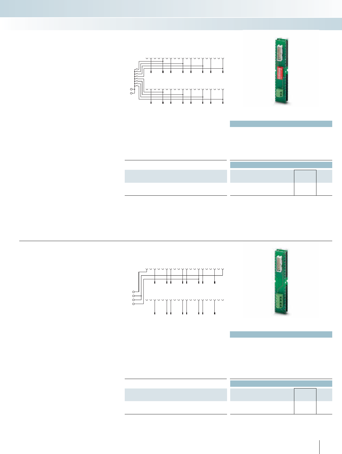
For additional information, visit www.phoenixcontact.net/catalog
Technical data
Max. perm. operating voltage 30 V AC/DC
Max. permissible current 50 mA (per path)
Rated surge voltage / insulation 0.5 kV / basic insulation
Ambient temperature (operation) -20°C ... 60°C
Ambient temperature (storage / transport) -20°C ... 70°C
Standards / regulations DIN EN 50178 / IEC 62103
Ordering data
Description No. of poles Type Order No. Pcs. /
Pkt.
VARIOFACE front adapter, for SIMATIC® S7-300, only in con-
nection with MINI MCR-SL-V8-FLK 16-A
16 FLKM 16-PA- 331-1KF/I/MINI-MCR 2318237 1
M–
M– 21
1
22
2
23
3
24
4
25
5
26
6
27
7
28
8
29
9
30
10
31
11
32
12
33
13
34
14
35
15
36
16
37
17
38
18
39
19
40
20
9
1
10
2
11
3
12
4
13
5
14
6
15
7
16
8
0
1
2
3
4
5
6
7
FLKM 16-PA-331-1KF/I/MINI-MCR connection scheme
The FLKM 16-PA-331-1KF/I/MINI-MCR
front adapter helps in system cabling in con-
junction with the MINI Analog system
adapter and a 16-pole system cable
FLK 16/EZ-DR/.../KONFEK, refer to
page 284.
Instead of the conventional front connec-
tor, screw terminal blocks are used to snap
this component on to the analog module.
The DIP switches can be used to connect
"M-" connections to each other and to the
central ground of the system.
The front adapter supports only current
signals.
The front adapter is suitable for the fol-
lowing analog input card:
– 6ES7 331-1KF02-0AB0
Siemens SIMATIC® S7-300
Front adapter for MINI Analog
system cabling
INTERFACE Cabling
VARIOFACE system cabling
Front adapter for SIMATIC® S7-300,
6ES7 331-1KF02-0AB0 analog I/O board
Technical data
Max. perm. operating voltage 30 V AC/DC
Max. permissible current 50 mA (per path)
500 mA (per connection, supply via separate power supply)
Rated surge voltage / insulation 0.5 kV / basic insulation
Ambient temperature (operation) -20°C ... 60°C
Ambient temperature (storage / transport) -20°C ... 70°C
Standards / regulations DIN EN 50178 / IEC 62103
Ordering data
Description No. of poles Type Order No. Pcs. /
Pkt.
VARIOFACE front adapter, for SIMATIC® S7-300, only in con-
nection with MINI MCR-SL-V8-FLK 16-A
16 FLKM 16-PA- 332-5HF/I/MINI-MCR 2318240 1
235
PHOENIX CONTACT
MANA
M–
M–
L+
21
1
22
2
23
3
24
4
25
5
26
6
27
7
28
8
29
9
30
10
31
11
32
12
33
13
34
14
35
15
36
16
37
17
38
18
39
19
40
20
9
1
10
2
11
3
12
4
13
5
14
6
15
7
16
8
FLKM 16-PA-332-5HF/I/MINI-MCR connection scheme
The FLKM 16-PA-332-5HF/I/MINI-MCR
front adapter helps in system cabling in con-
junction with the MINI Analog system
adapter and a 16-pole system cable FLK
16/EZ-DR/.../KONFEK, refer to page 284.
Instead of the conventional front connec-
tor, screw terminal blocks are used to snap
this component on to the analog module.
The front adapter supports only current
signals.
The front adapter is suitable for the fol-
lowing analog output cards:
– 6ES7 332-5HF00-0AB0
Siemens SIMATIC® S7-300
Front adapter for MINI Analog
system cabling
Front adapter for SIMATIC® S7-300,
6ES7 332-5HF00-0AB0 analog I/O board
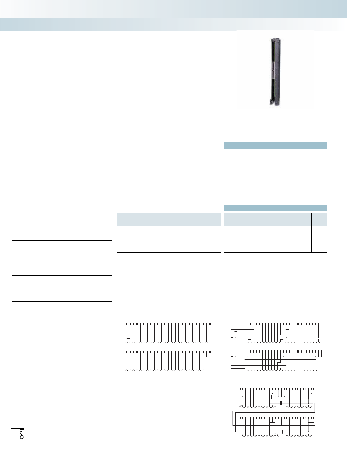
|
236 PHOENIX CONTACT
Technical data
Max. perm. operating voltage < 50 V AC / 60 V DC
Max. permissible current 1 A (per path)
8 A (per connection, supply via separate power supply)
Max. perm. total current 2 A (per byte, for supply via connector)
8 A (during supply via a separate bridged power supply)
Ambient temperature (operation) -20°C ... 50°C
Ambient temperature (storage / transport) -20°C ... 70°C
Mounting position Any
Standards / regulations IEC 60664 / DIN EN 50178 / IEC 62103
Ordering data
Description No. of poles Type Order No. Pcs. /
Pkt.
VARIOFACE front adapter, for
- SIMATIC
®
S7-400, 1 x 32 channels can be connected
50 FLKM 50-PA-S400 2294500 2
- SIMATIC
®
S7-400, 4 x 8 channels can be connected
14 FLKM 50/ 4-FLK14/PA-S400 2294429 2
- SIMATIC® S7-400, only analog 50 FLKM 50-PA-S400(3-48) 2294908 2
87
5
469
11 15 16 17 18 19 20 21 22 23
14
321 10 12 13 24
5421131193 141210678 5421131193 141210678
5421131193 141210678 5421131193 141210678
302928272625 31 32 33 34 35 36 37 38 4039 41 42 43 44 45 46 47 48
DR1
DR4
DR2
DR5
L
M
DR3
DR6
Connection scheme: FLKM 50/4-FLK14/PA-S400
12345678910
11121314 15 161718 19 20 2122 232425
12345678910
11121314 15 161718 19 20 2122 232425
26272829 3031 32333435 3637 383940 41424344 4546 47484950
26272829 3031 32333435 3637 383940 41424344 4546 4748
Connection scheme FLKM 50-PA-S400 (3-48)
12 34567891011
12131415161718192021222324
1234567891011
12 131415161718192021222324
2526272829303132333435363738394041424344454647484950
252627282930313233343536373839404142434445464748
DR1
DR2
DR3
0+
1+
2+
3+
–
Connection scheme FLKM 50-PA-S400
Front adapter for I/O modules of the Siemens automation
equipment SIMATIC® S7-400
Card type FLKM 50-PA-S400
Digital input 6ES7 421-1BL01-0AA0
6ES7 421-7BH01-0AB0*
6ES7 421-7DH00-0AB0*
Digital output 6ES7 422-1BL00-0AA0
6ES7 422-7BL00-0AB0
Card type FLKM 50/4-FLK14/PA-S400
Digital input 6ES7 421-1BL01-0AA0
Digital output 6ES7 422-1BL00-0AA0
6ES7 422-7BL00-0AB0
Card type FLKM 50-PA-S400 (3-48)
Analog input 6ES7 431-0HH00-0AB0**
6ES7 431-1KF00-0AB0**
6ES7 431-1KF10-0AB0**
6ES7 431-1KF20-0AB0**
6ES7 431-7KF00-0AB0**
6ES7 431-7KF10-0AB0**
6ES7 431-7QH00-0AB0**
Analog output 6ES7 432-1HF00-0AB0**
* Only in connection with
VIP-2/SC/FLK50/S7/A-S400, Order No.: 2322359
All wire bridges (DR) on the adapter must be disconnected.
** Only in connection with
VIP-3/SC/FLK50, Order No.: 2315081
UM 45-FLK 50/ZFKDS, Order No.: 2293585
UM 45-FLKS 50/ZFKDS, Order No.: 2968470
FLKM 50/KDS 3-MT/PPA/AN/PLC, Order No.: 2291587
Flat-ribbon cable strip
Connection to I/O card
Screw terminal blocks for separate supply
Explanation:
The front adapters mean that pre-assem-
bled system cables can be directly connect-
ed to I/O modules.
FLKM 50-PA-S400
– Transmission of max. 32 digital channels
over one 50-pole system cable
FLKM 50/4-FLK14/PA-S400
– Transmission of max. 32 digital channels
via one 14-pole system cable
Perfectly-fitting VARIOFACE termination
boards with a variety of functions and con-
nection possibilities round off this system
concept.
FLKM 50-PA-S400 (3-48)
– Analog channels are connected via a
50-pole system cable
The 1:1 connection of the adapter means
that corresponding 1:1 interface modules
are connected here.
Siemens SIMATIC® S7-400
Front adapter
INTERFACE Cabling
VARIOFACE system cabling
Front adapter for
SIMATIC® S7-400
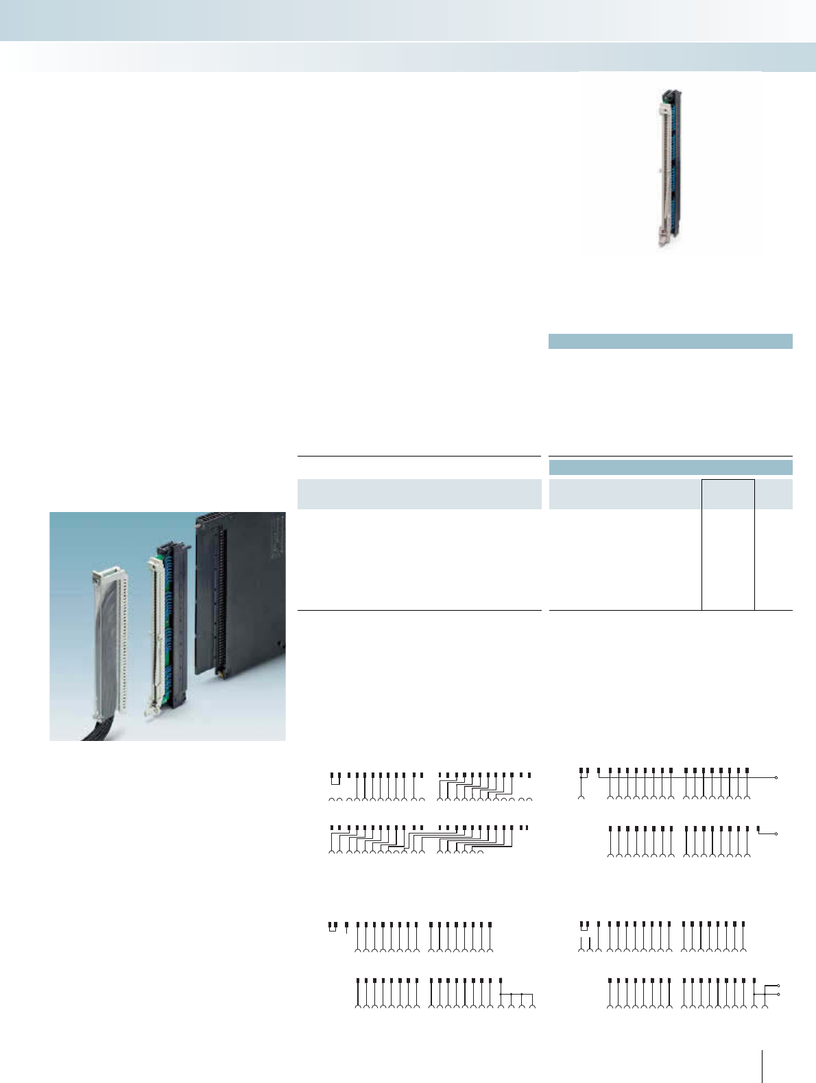
For additional information, visit www.phoenixcontact.net/catalog 237PHOENIX CONTACT
Technical data
¤¥¦§
Max. perm. operating voltage 24 V AC/DC 60 V DC 24 V DC 24 V AC/DC
Max. permissible current 4 A (per path) 2 A (per path) 4 A (per path) 4 A (per path)
Test voltage (contact / contact) 500 V (50 Hz,
1 min.)
1.25 kV (50 Hz,
1 min.)
1.25 kV (50 Hz,
1 min.)
1.25 kV (50 Hz,
1 min.)
Ambient temperature (operation) -20°C ... 50°C -20°C ... 50°C -20°C ... 50°C -20°C ... 50°C
Mounting position Any Any Any Any
Standards / regulations DIN EN 50178 / IEC 62103
Ordering data
Description No. of poles Type Order No. Pcs. /
Pkt.
Digital IN 24 V from S5-135/155 to S7-400
6ES5 420-4UA14 on 6ES7 421-1BL01-0AA0 ¤FLKM S135/S400/SO120 2301723 1
6ES5 430-4UA14 on 6ES7 421-1BL01-0AA0 ¥FLKM S135/S400/SO121 2301736 1
6ES5 431-4UA12 to 6ES7 421-7DH00-0AB0 ¦FLKM S135-431-4UA/S400 2314846 1
6ES5 432-4UA12 on 6ES7 421-1BL01-0AA0 §FLKM S135/S400/SO122 2301749 1
S7-400 31 41
32 4233 43 4534 44 46 48
2728 29 3930 40
M
S5-135 56789
10 19
11 20
1513 1614 1718
44
S5-135 29 36
30 3731 38 4041 21 42 12 3332 39
2526 27 3428 35
S7-400 12 3 56789
10 21
11 22
41516 1718 1920
L+
Connection scheme: FLKM S135/S400/SO122
S7-400 31 41
32 4233 43 4534 44 46 48
2728 29 3930 40
M
M
S5-135 12 56789
10 19
11 20
1513 1614 1718
434
S5-135 29 36
30 3731 38 40 41 21 4232 39
2526 27 3428 35
S7-400 12 3 56789
10 21
11 22
41516 17 181920
Connection scheme: FLKM S135/S400/SO121
S7-400
S7-400
S5-135
S5-135
1
13
23
123
2
21412 24
35
5
6
6
7
7
8
8
9
9
10 21
31
31
41
41
10 19
11 22
32
32
42
42
33
33
43 4534
34
35
35
36
36
44 46 4748
11 202122
415
1513
16
161412 24
17
27
27
26
26
25
25
17
18
28
28
18
19
29
29
39
39
38
38
37
37
20
30
30
40
40
434
FLKM S135-431-UA/S400 connection scheme
S7-400
M
L+
S5-135 29 36
30 3731 38 40 4132 39
25 26 27 3428 35
S5-135 156789
10 19
11 20
1513 1614 17 18
44
S7-400 31 41
32 4233 43 4534 44 46 48
27 28 29 3930 40
12 3 56789
10 21
11 22
415 16 17 18 19 20
Connection scheme: FLKM S135/S400/SO120
The FLKM S135/... adapters connect a
SIMATIC® S5 connector wired with individ-
ual conductors directly with the
SIMATIC® S7-400 basic card.
The SIMATIC® S5 connector is plugged
directly onto an S7-400 I/O card with the
help of an FLKM S135/... intermediate
adapter.
A new SIMATIC® S7-400 is installed in
place of the SIMATIC® S5. The existing field
wiring remains intact.
Attention:
The LEDs of the S7-400 module are hid-
den.
Siemens SIMATIC® S7-400
Adapter for conversion from
S5-135/155 to S7-400
INTERFACE Cabling
VARIOFACE system cabling
Adapter for Siemens SIMATIC® S5-135/S7-400
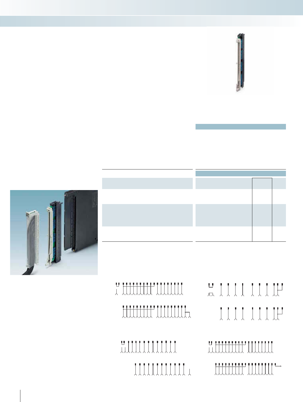
238 PHOENIX CONTACT
Technical data
¤¥¦§
Max. perm. operating voltage 230 V AC/DC 24 V AC/DC 24 V DC 24 V DC
Max. permissible current 4 A (per path) 4 A (per path) 4 A (per path) 4 A (per path)
Test voltage (contact / contact) 1.5 kV (50 Hz,
1 min.)
500 V (50 Hz, 1
min.)
1.25 kV (50 Hz,
1 min.)
500 V (50 Hz,
1 min.)
Ambient temperature (operation) -20°C ... 50°C -20°C ... 50°C -20°C ... 50°C -20°C ... 50°C
Mounting position Any Any Any Any
Standards / regulations DIN EN 50178 / IEC 62103
Ordering data
Description No. of poles Type Order No. Pcs. /
Pkt.
Digital IN 120/230 V UC from S5-135/155 to S7-400
6ES5 436-4UA12 to 6ES7 421-1FH20-0AA0 ¤FLKM S135/S400/SO123 2301752 1
Digital OUT 24 V from S5-135/155 to S7-400
6ES5 441-4UA12 to 6ES7 422-1BL00-0AA0 ¥FLKM S135/S400/SO125 2301778 1
6ES5 451-4UA14 to 6ES7 422-1BL00-0AA0 ¦FLKM S135/S400/SO126 2301781 1
Digital OUT 24 V DC / 2 A from S5-135/155 to S7-400
6ES5 453-4UA12 to 6ES7 422-1HH00-0AA0 §FLKM S135/S400/SO127 2301794 1
S5-135 39
30 41
32 27 36 40 2131
26 28 35 37
S7-400 12 11 4 5 9 10 17 22
615 16 20
S7-400
S5-135 110 5 7 9
44
11 15
32
45
33 29 4134 46
19
14 16
27 28
18 20
39
21
40
63
Connection scheme: FLKM S135/S400/SO127
S7-400 31 41
38
32 4233 43 4534 44 46 48
2726 28 29 3930 40
M
S5-135 12 56789
10 19
11 20
1513 1614 17 18
434
S5-135 29 36
30 3731 38 40 4132 39
2524 26 27 3428 35
S7-400 12 3 56789
10 21
11 14 22
415 16 17 18 19 20
Connection scheme: FLKM S135/S400/SO125
S7-400
S7-400
S5-135 156789
31 41
10 19
38
32 4233 43 4534 44 46 48
11 20
1513 1614
2726
17
28
18
29 3930 40
434
48
1L+
S5-135 29 36
30 3731 38 40 4132 39
2524 26 27 3428 35
M2L+
221
12 3 56789
10 21
1114 22
415 16 17 18 19 20
Connection scheme: FLKM S135/S400/SO126
S5-135 31 37
33 39 4125
27 29 35
S7-400 31 41
33 43 4536 48
27 29 39
S7-400 12 68
10 21 13
415 17 19 24
S5-135 810
12 20 4
1614 18
621
Connection scheme: FLKM S135/S400/SO123
The FLKM S135/... adapters connect a
SIMATIC® S5 connector wired with individ-
ual conductors directly with the
SIMATIC® S7-400 basic card.
The SIMATIC® S5 connector is plugged
directly onto an S7-400 I/O card with the
help of an FLKM S135/... intermediate
adapter.
A new SIMATIC® S7-400 is installed in
place of the SIMATIC® S5. The existing field
wiring remains intact.
Attention:
The LEDs of the S7-400 module are hid-
den.
Siemens SIMATIC® S7-400
Adapter for conversion from
S5-135/155 to S7-400
INTERFACE Cabling
VARIOFACE system cabling
Front adapter for SIMATIC S5-135/S7-400
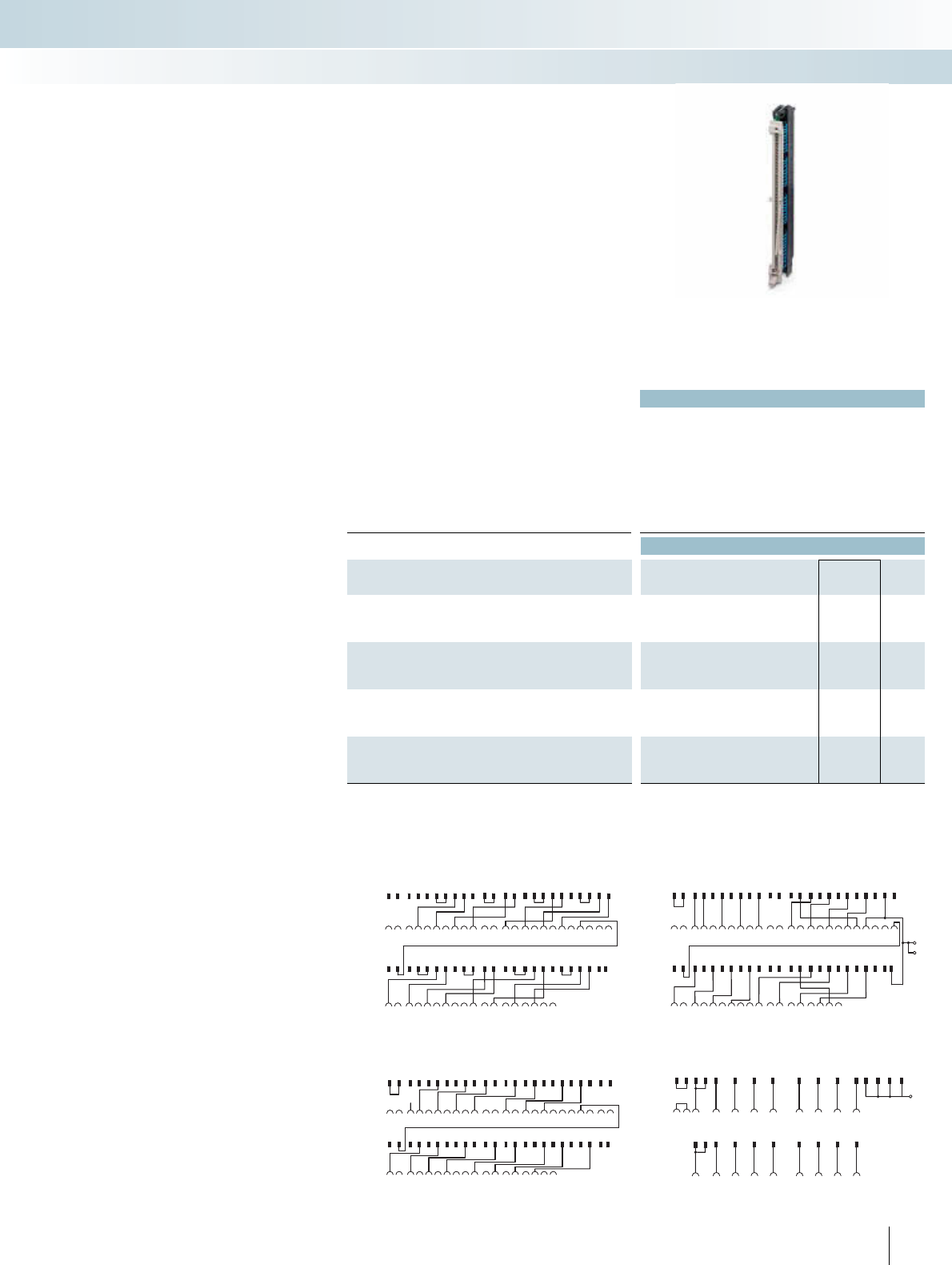
For additional information, visit www.phoenixcontact.net/catalog 239PHOENIX CONTACT
Technical data
¤¥¦§
Max. perm. operating voltage 24 V DC 230 V AC 24 V DC 24 V DC
Max. permissible current 4 A (per path) 4 A (per path) 4 A (per path) 4 A (per path)
Test voltage (contact / contact) 1.25 kV (50 Hz,
1 min.)
1.5 kV (50 Hz,
1 min.)
500 V (50 Hz,
1 min.)
500 V (50 Hz,
1 min.)
Ambient temperature (operation) -20°C ... 50°C -20°C ... 50°C -20°C ... 50°C -20°C ... 50°C
Mounting position Vertical Vertical Vertical Vertical
Standards / regulations DIN EN 50178 / IEC 62103
Ordering data
Description No. of poles Type Order No. Pcs. /
Pkt.
Digital OUT 24 V DC / 2 A from S5-135/155 to S7-400
6ES5 454-4UA14 to 6ES7 422-1BH11-0AA0 ¤FLKM S135-454-4UA/S400 2314859 1
Digital OUT 230 V UC / 2 A from S5-135/155 to S7-400
6ES5 456-4UA12 to 6ES7 422-1FH00-0AA0 ¥FLKM S135/S400/SO124 2301765 1
Analog IN (only current measurement) from S5-135/155 to S7-400
6ES5 460-4UA13 to 6ES7 431-1KF00-0AB0 ¦FLKM S135-460-4UA/I/S400 2314613 1
Analog IN (only voltage measurement) from S5-135/155 to S7-400
6ES5 460-4UA13 to 6ES7 431-1KF00-0AB0 §FLKM S135-460-4UA/U/S400 2314862 1
S7-400
S7-400
S5-135
S5-135
1
13
23
123
2
21412 24
35
5
6
6
7
7
8
8
9
9
10 21
31
31
41
41
10 19
11 22
32
32
42
42
33
33
43 4534
34
35
35
36
36
44 46 4748
11 202122
415
1513
16
161412 24
17
27
27
26
26
25
25
17
18
28
28
18
19
29
29
39
39
38
38
37
37
20
30
30
40
40
434
Connection scheme: FLKM S135-460-4UA/U/S400
N
S7-400
S7-400
S5-135
S5-135
111
34
222
46
6
8
8
10
10 21
31 41
12 20
31 37
13
33 43 45
33 39 41
415
16
27
14
17
27
18
29 35
19
29 39
24 36 48
6214
25
Connection scheme: FLKM S135/S400/SO124
S7-400
S7-400
S5-135
S5-135
1
13
23
123
2
21412 24
35
5
6
6
7
7
8
8
9
9
10 21
31
31
41
41
10 19
11 22
32
32
42
42
33
33
43 4534
34
35
35
36
36
44 46 4748
11 202122
415
1513
16
161412 24
17
27
27
26
26
25
25
17
18
28
28
18
19
29
29
39
39
38
38
37
37
20
30
30
40
40
434
FLKM S135-460-4UA/I/S400 connection scheme
S7-400
S7-400
S5-135
S5-135
1
13
23
123
2
21412 24
35
5
6
6
7
7
8
8
9
9
10 21
31
31
41
41
10 19
11 22
32
32
42
42
33
33
43 4534
34
35
35
36
36
44 46 4748
11 202122
415
1513
16
161412 24
17
27
27
26
26
25
25
17
18
28
28
18
19
29
29
39
39
38
38
37
37
20
30
30
40
40
434 L-
L-
FLKM S135-454-4UA/S400 connection scheme
The FLKM S135/... adapters connect a
SIMATIC® S5 connector wired with individ-
ual conductors directly with the
SIMATIC® S7-400 basic card.
The SIMATIC® S5 connector is plugged
directly onto an S7-400 I/O card with the
help of an FLKM S135/... intermediate
adapter.
A new SIMATIC® S7-400 is installed in
place of the SIMATIC® S5. The existing field
wiring remains intact.
Attention:
The LEDs of the S7-400 module are hid-
den.
Siemens SIMATIC® S7-400
Adapter for conversion from
S5-135/155 to S7-400
INTERFACE Cabling
VARIOFACE system cabling
Adapter for Siemens SIMATIC® S5-135/S7-400
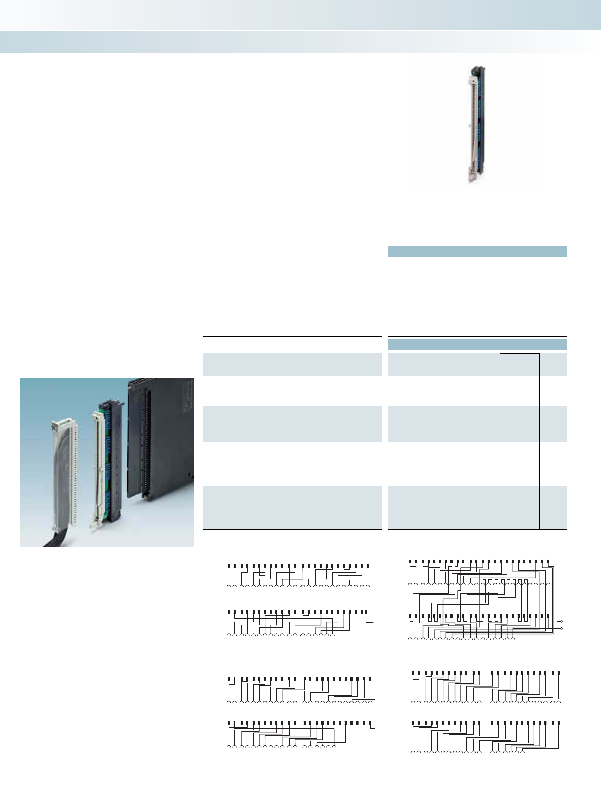
240 PHOENIX CONTACT
Technical data
¤¥¦§
Max. perm. operating voltage 24 V DC 24 V DC 24 V DC 24 V DC
Max. permissible current 2 A (per path) 4 A (per path) 4 A (per path) 4 A (per path)
Test voltage (contact / contact) 500 V (50 Hz,
1 min.)
500 V (50 Hz,
1 min.)
500 V (50 Hz,
1 min.)
500 V (50 Hz,
1 min.)
Ambient temperature (operation) -20°C ... 50°C -20°C ... 50°C -20°C ... 50°C -20°C ... 50°C
Mounting position Any Any Any Any
Standards / regulations DIN EN 50178 / IEC 62103
Ordering data
Description No. of poles Type Order No. Pcs. /
Pkt.
Analog IN (only Pt 100) from S5-135/155 to S7-400
6ES5 465-4UA13 to 6ES7 431-7KF10-0AB0 ¤FLKM S135-465-4UA/T/S400 2314875 1
Analog IN (only current and voltage measurement) from S5-
135/155 to S7-400
6ES5 465-4UA13 to 6ES7 431-0HH00-0AB0
6ES5 465-4UA13 to 6ES7 431-7QH00-0AB0
¥FLKM S135-465-4UA/UI/S400 2314888 1
Analog OUT (only current output) from S5-135/155 to S7-400
6ES5 470-4UA13 to 6ES7 432-1HF00-0AB0
6ES5 470-4UC13 to 6ES7 432-1HF00-0AB0
¦FLKM S135-470-4UC/I/S400 2314626 1
Analog OUT (only voltage output) from S5-135/155 to S7-400
6ES5 470-4UA13 to 6ES7 432-1HF00-0AB0
6ES5 470-4UB13 to 6ES7 432-1HF00-0AB0
6ES5 470-4UC13 to 6ES7 432-1HF00-0AB0
§FLKM S135-470-4UC/U/S400 2314891 1
S7-400
S7-400
S5-135
S5-135
1
13
23
123
2
21412 24
35
5
6
6
7
7
8
8
9
9
10 21
31
31
41
41
10 19
11 22
32
32
42
42
33
33
43 4534
34
35
35
36
36
44 46 4748
11 202122
415
1513
16
161412 24
17
27
27
26
26
25
25
17
18
28
28
18
19
29
29
39
39
38
38
37
37
20
30
30
40
40
434
Connection scheme FLKM S135-470-4UC/U/S400
S7-400
S7-400
S5-135
S5-135
1
13
23
123
2
21412 24
35
5
6
6
7
7
8
8
9
9
10 21
31
31
41
41
10 19
11 22
32
32
42
42
33
33
43 4534
34
35
35
36
36
44 46 4748
11 202122
415
1513
16
161412 24
17
27
27
26
26
25
25
17
18
28
28
18
19
29
29
39
39
38
38
37
37
20
30
30
40
40
434
FLKM S135-465-4UA/UI/S400 connection scheme
S7-400
S7-400
S5-135
S5-135
1
13
23
123
2
21412 24
35
5
6
6
7
7
8
8
9
9
10 21
31
31
41
41
10 19
11 22
32
32
42
42
33
33
43 4534
34
35
35
36
36
44 46 4748
11 202122
415
1513
16
161412 24
17
27
27
26
26
25
25
17
18
28
28
18
19
29
29
39
39
38
38
37
37
20
30
30
40
40
434
Connection scheme FLKM S135-470-4UC/I/S400
S7-400
S7-400
S5-135
S5-135
1
13
23
123
2
21412 24
35
5
6
6
7
7
8
8
9
9
10 21
31
31
41
41
10 19
11 22
32
32
42
42
33
33
43 4534
34
35
35
36
36
44 4647 48
11 202122
415
1513
16
161412 24
17
27
27
26
26
25
25
17
18
28
28
18
19
29
29
39
39
38
38
37
37
20
30
30
40
40
434
L-
L-
FLKM S135-465-4UA/T/S400 connection scheme
The FLKM S135/... adapters connect a
SIMATIC® S5 connector wired with individ-
ual conductors directly with the
SIMATIC® S7-400 basic card.
The SIMATIC® S5 connector is plugged
directly onto an S7-400 I/O card with the
help of an FLKM S135/... intermediate
adapter.
A new SIMATIC® S7-400 is installed in
place of the SIMATIC® S5. The existing field
wiring remains intact.
Attention:
The LEDs of the S7-400 module are hid-
den.
Siemens SIMATIC® S7-400
Adapter for conversion from
S5-135/155 to S7-400
INTERFACE Cabling
VARIOFACE system cabling
Adapter for Siemens SIMATIC® S5-135/S7-400
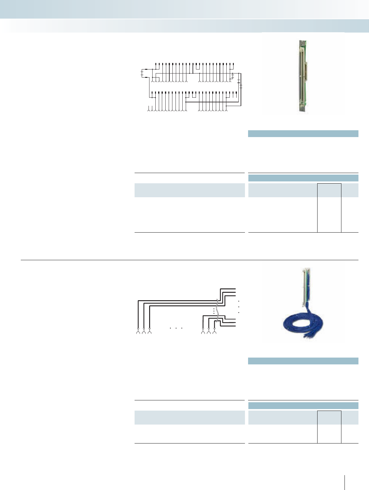
For additional information, visit www.phoenixcontact.net/catalog
Technical data
Max. perm. operating voltage 50 V AC/DC
Max. permissible current 1 A (per path)
Ambient temperature (operation) -20°C ... 50°C
Ambient temperature (storage / transport) -20°C ... 70°C
Mounting position Any
Standards / regulations DIN EN 50178 / IEC 62103
Ordering data
Description Type Order No. Pcs. /
Pkt.
Digital IN or OUT 24 V DC from S5-135 to S7-300
IN
6ES5 420-4UA14 to 6ES7 321-1BL00-0AA0
6ES5 430-4UA14 to 6ES7 321-1BL00-0AA0
OUT
6ES5 441-4UA14 to 6ES7 322-1BL00-0AA0
6ES5 451-4UA14 to 6ES7 322-1BL00-0AA0
FLKM S135/S7/FLK50/PLC 2314736 1
2322 343332
31
3029 40 4239 4138372425262728 3536
28272625 4140393837363534 494847464544 50
2930313233 4243
32
1141312
1110
92021
191817
45678 1516
L+
L-
L2+
DR1
DR3
DR4
DR2
43211716151413121110 242322212056789 1819
FLK50
S5-135
FLK50
S5-135
FLKM S135/S7/FLK50/PLC connection scheme
S5-S7 adapters connect the S5-135 front
adapters wired with individual wires to the
I/O modules of the S7.
With the help of the FLKM
S135/S7/FLK50 converter module, the sig-
nals of the S5-135 front adapter can be con-
verted to a 50-pole strip. A 50-pole system
cable FLK 50/EZ-DR/.../KONFEK and a
front adapter for the SIMATIC® S7
(FLKM 50-PA-S300) now connect the sig-
nals with the I/O module.
Siemens SIMATIC® S7-300
Adapter for conversion from
S5-135/155 to S7-300
INTERFACE Cabling
VARIOFACE system cabling
Converter for Siemens SIMATIC® S5-135 to
50-pole FLK strip
Technical data
Max. perm. operating voltage 250 V AC/DC
Max. permissible current 6 A (per path)
Ambient temperature (operation) -20°C ... 50°C
Ambient temperature (storage / transport) -20°C ... 80°C
Mounting position Any
Standards / regulations EN 60664-1
Ordering data
Description Type Order No. Pcs. /
Pkt.
Connection of all S5-135 connections (1 to 42) at the open
cable end
FLKM S135/42X0,75/3,0M/OE 2315007 1
FLKM S135/42X0,75/5,0M/OE 2318017 1
241
PHOENIX CONTACT
1
40
2
41
3
42
1
1
40
40
2
2
41
41
3
3
42
42
S5-135
All signals of the existing S5-135 wiring
3 or 5 are extended with the help of the
universal commissioning adapters. The open
cable end can be connected to various con-
trollers such as S7-400 or S7-300. There-
fore, the existing field wiring of S5-135 can
communicate with the new controller for
test purposes. Since the new control unit is
temporarily arranged before the control
cabinet, the original status of the system can
be restored if required.
If the system functions with the new con-
troller without problems, the S5-135 can
now be replaced.
Startup adapter for extending the
existing S5-135/155 field wiring
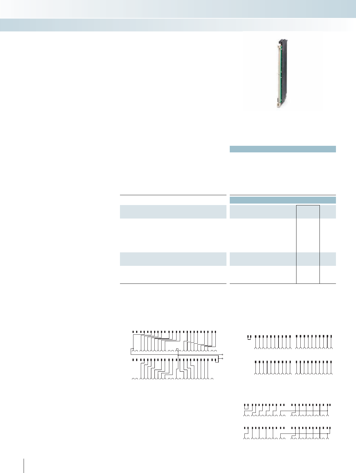
242 PHOENIX CONTACT
Technical data
Max. perm. operating voltage 24 V AC/DC
Max. permissible current 4 A (per path)
4 A (per connection, supply via separate power supply)
Ambient temperature (operation) -20°C ... 50°C
Ambient temperature (storage / transport) -20°C ... 70°C
Mounting position Vertical
Standards / regulations DIN EN 50178 / IEC 62103
Ordering data
Description Type Order No. Pcs. /
Pkt.
Digital IN or OUT 24 V DC from S5-115 to S7-400
IN
6ES5 420-7LA11 on 6ES7 421-1BL01-0AA0
6ES5 430-7LA11 on 6ES7 421-1BL01-0AA0
OUT
6ES5 441-7LA11 on 6ES7 422-1BL01-0AA0
6ES5 451-7LA11 on 6ES7 422-1BL01-0AA0
FLKM S115/S400/SO155 2307248 1
Digital OUT 24 V DC from S5-115 to S7-400
6ES5 454-7LA12 to 6ES7 422-1BH11-0AA0 FLKM S115-454-7LA/S400 2314901 1
Analog IN (only current and voltage measurement) from
S5-115 to S7-400
6ES5 465-7LA13 to 6ES7 431-0HH00-0AB0
6ES5 465-7LA13 to 6ES7 431-7QH00-0AB0
FLKM S115-465-7LA/UI/S400 2314914 1
S7-400
S7-400
S5-115
S5-115
1
13
23
123
2
21412 24
35
5
6
6
7
7
8
8
9
9
10 21
31
31
41
41
10 19
11 22
32
32
42
42
33
33
43
43
45
45
34
34
35
35
36
36
44
44
46
46
47
47
48
11 202122
415
1513
16
161412
17
27
27
26
26
25
25
17
18
28
28
18
19
29
29
39
39
38
38
37
37
20
30
30
40
40
434
FLKM S115-454-7LA/S400 connection scheme
S7-400
S7-400
S5-115
S5-135
1
13
23
123
2
21412 24
35
5
6
6
7
7
8
8
9
9
10 21
31
31
41
41
10 19
11 22
32
32
42
424344
45
46 47
33
33
43 4534
34
35
35
36
36
44 46 4748
11 202122
415
1513
16
161412 24
17
27
27
26
26
25
25
17
18
28
28
18
19
29
29
39
39
38
38
37
37
20
30
30
40
40
434
L-
L+
FLKM S115-465-7LA/UI/S400 connection scheme
S7-400
S7-400
S5-115
S5-115
12 3 5
5
6
6
7
7
8
8
9
9
10 21
31
31
31
31 41
41
10 21
11 12 22 23
32
32
32
32 42
42
33
33
33
33 43
43
45
45
34 35
34 35
34
34 44
44
46
46
48
47
11 22 23
41513
17
1513
16
1816
17
27
27
27
27
25
25
25
25
19
37
18
28
28
28
28
20
19
29
29
29
29 39
39
37
20
30
30
30
30 40
40
4314
Connection scheme: FLKM S115/S400/SO155
The FLKM S115/... adapters connect a
SIMATIC® S5 connector wired with individ-
ual conductors directly with the
SIMATIC® S7-400 basic card.
The SIMATIC® S5 connector is plugged
directly onto an S7-400 I/O card with the
help of an FLKM S115/... intermediate
adapter.
A new SIMATIC® S7-400 is installed in
place of the SIMATIC® S5. The existing field
wiring remains intact.
Attention:
Due to the geometry, it is only possible to
use every second slot. The LEDs of the
S7-400 module are hidden by the S5-115
adapter.
Siemens SIMATIC® S7-400
Adapter for conversion from
S5-115 to S7-400
INTERFACE Cabling
VARIOFACE system cabling
Adapter for Siemens SIMATIC® S5-115/S7-400
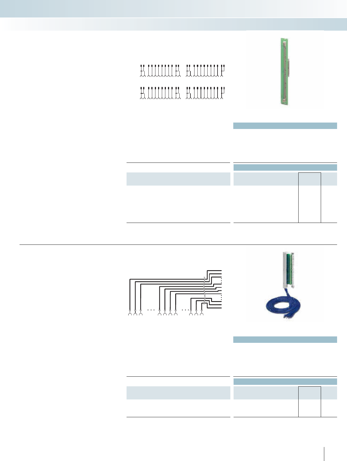
For additional information, visit www.phoenixcontact.net/catalog
Technical data
Max. perm. operating voltage 24 V AC/DC
Max. permissible current 1 A (per path)
Max. perm. total current 2 A (per byte)
Ambient temperature (operation) -20°C ... 50°C
Ambient temperature (storage / transport) -20°C ... 70°C
Standards / regulations DIN EN 50178 / IEC 62103
Ordering data
Description Type Order No. Pcs. /
Pkt.
Digital IN or OUT 24 V DC from S5-115 through converters,
system cables and front adapters to S7-300
IN
6ES5 420-7LA11 on 6ES7 321-1BL00-0AA0
6ES5 430-7LA11 on 6ES7 321-1BL00-0AA0
OUT
6ES5 441-7LA11 on 6ES7 322-1BL00-0AA0
6ES5 451-7LA11 on 6ES7 322-1BL00-0AA0
FLKM S115/S7/FLK50/PLC/SO137 2306294 1
FLK50
FLK50
S5-115
S5-115
1
13
23
123
2
21412 24
35
5
6
6
7
7
8
8
9
9
10 21
31
31
41
41
10 19
11 22
32
32
42
42
33
33
43
43
45
45
34
34
35
35
36
36
44
44
46
46
47
47
48
11 202122
415
1513
16
161412
17
27
27
26
26
25
25
17
18
28
28
18
19
29
29
39
39
38
38
37
37
20
30
30
40
40
434
Connection scheme: FLKM S115/S7/FLK50/PLC/SO137
S5-S7 adapters connect the S5-115 front
adapters wired with individual wires to the
I/O modules of S7-300.
With the aid of the FLKM
S115/S7/FLK50/SO137 converter module,
the signals of the S5-115 front adapter can
be converted to a 50-pole strip. A 50-pole
system cable FLK 50/EZ-DR/.../KONFEK
and a front adapter for the SIMATIC® S7
(FLKM 50-PA-S300) now connect the sig-
nals with the I/O module.
Siemens SIMATIC® S7-300
Adapter for conversion from
S5-115 to S7-300
INTERFACE Cabling
VARIOFACE system cabling
Converter for Siemens SIMATIC® S5-115 to
50-pole FLK strip
Technical data
Max. perm. operating voltage 250 V AC/DC
Max. permissible current 6 A (per path)
Ambient temperature (operation) -20°C ... 50°C
Ambient temperature (storage / transport) -20°C ... 80°C
Mounting position Any
Standards / regulations EN 60664-1
Ordering data
Description Type Order No. Pcs. /
Pkt.
Connection of all S5-115 connections (1 to 23, 25 to 47) at the
open cable end
FLKM S115/47X0,75/3,0M/OE 2314985 1
FLKM S115/47X0,75/5,0M/OE 2314998 1
243
PHOENIX CONTACT
1
45
22
2
46
23
3
47
25
26
122
122
45
45
223
223
46
46
32526
32526
47
47
S5-115
All signals of the existing S5-115 wiring
3 or 5 are extended with the help of the
universal commissioning adapters. The open
cable end can be connected to various con-
trollers such as S7-400 or S7-300. There-
fore, the existing field wiring of S5-115 can
communicate with the new controller for
test purposes. Since the new control unit is
temporarily arranged before the control
cabinet, the original status of the system can
be restored if required.
If the system functions with the new con-
troller without problems, the S5-115 can
now be replaced.
Commissioning adapters for extending
the existing S5-115 field wiring
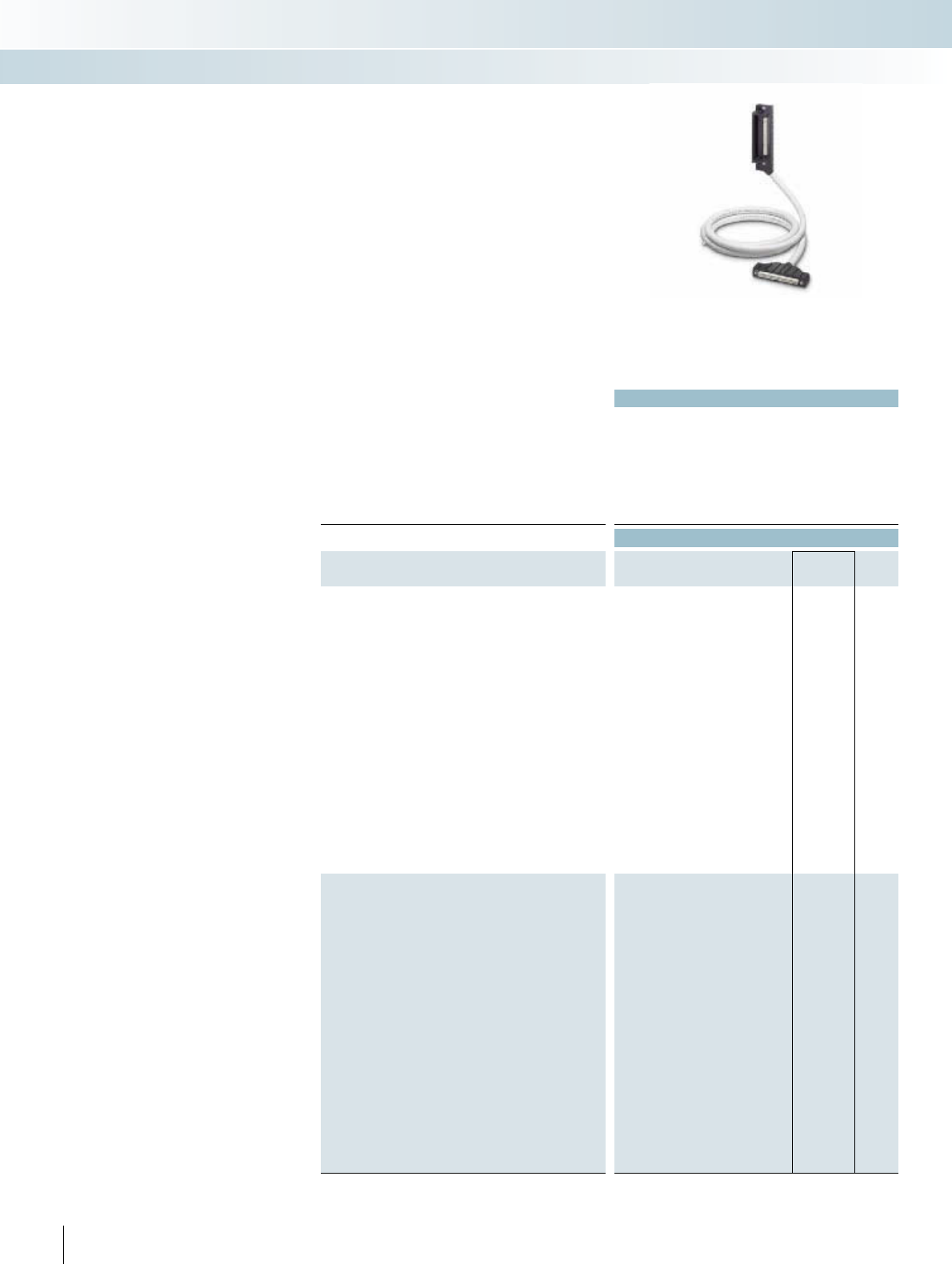
Technical data
Max. perm. operating voltage 30 V DC
Max. perm. current carrying capacitance per path 500 mA
Max. conductor resistance 0.16 /m
Ambient temperature (operation) -20°C ... 50°C
Conductor cross section AWG 26 / 0.14 mm²
Conductor structure: stranded wires / material 7 / Cu tin-plated
Outside diameter
50-pole 11 mm
40-pole 11 mm
Ordering data
Description No. of
poles Cable length Type Order No. Pcs. /
Pkt.
50-pole YUC cables, for digital I/O modules
50 2 m FLK 50-PA/EZ-DR/KS/ 200/YUC 2314299 1
50 3 m FLK 50-PA/EZ-DR/KS/ 300/YUC 2314309 1
50 4 m FLK 50-PA/EZ-DR/KS/ 400/YUC 2314312 1
50 5 m FLK 50-PA/EZ-DR/KS/ 500/YUC 2321499 1
50 6 m FLK 50-PA/EZ-DR/KS/ 600/YUC 2314927 1
50 7 m FLK 50-PA/EZ-DR/KS/ 700/YUC 2321509 1
50 8 m FLK 50-PA/EZ-DR/KS/ 800/YUC 2314930 1
50 9 m FLK 50-PA/EZ-DR/KS/ 900/YUC 2321512 1
50 10 m FLK 50-PA/EZ-DR/KS/1000/YUC 2314325 1
50 11 m FLK 50-PA/EZ-DR/KS/1100/YUC 2321389 1
50 12 m FLK 50-PA/EZ-DR/KS/1200/YUC 2321525 1
50 13 m FLK 50-PA/EZ-DR/KS/1300/YUC 2321392 1
50 14 m FLK 50-PA/EZ-DR/KS/1400/YUC 2321402 1
50 15 m FLK 50-PA/EZ-DR/KS/1500/YUC 2314338 1
50 16 m FLK 50-PA/EZ-DR/KS/1600/YUC 2321538 1
50 17 m FLK 50-PA/EZ-DR/KS/1700/YUC 2321541 1
50 18 m FLK 50-PA/EZ-DR/KS/1800/YUC 2321554 1
50 19 m FLK 50-PA/EZ-DR/KS/1900/YUC 2321567 1
50 20 m FLK 50-PA/EZ-DR/KS/2000/YUC 2314503 1
50 25 m FLK 50-PA/EZ-DR/KS/2500/YUC 2314516 1
50 30 m FLK 50-PA/EZ-DR/KS/3000/YUC 2314529 1
40-pole YUC cables, for analog I/O modules
40 1 m FLK 40-PA/EZ-DR/KS/ 100/YUC 2322786 1
40 2 m FLK 40-PA/EZ-DR/KS/ 200/YUC 2314341 1
40 3 m FLK 40-PA/EZ-DR/KS/ 300/YUC 2314354 1
40 4 m FLK 40-PA/EZ-DR/KS/ 400/YUC 2314367 1
40 5 m FLK 40-PA/EZ-DR/KS/ 500/YUC 2321570 1
40 6 m FLK 40-PA/EZ-DR/KS/ 600/YUC 2314943 1
40 7 m FLK 40-PA/EZ-DR/KS/ 700/YUC 2321583 1
40 8 m FLK 40-PA/EZ-DR/KS/ 800/YUC 2314956 1
40 9 m FLK 40-PA/EZ-DR/KS/ 900/YUC 2321415 1
40 10 m FLK 40-PA/EZ-DR/KS/1000/YUC 2314370 1
40 11 m FLK 40-PA/EZ-DR/KS/1100/YUC 2321428 1
40 12 m FLK 40-PA/EZ-DR/KS/1200/YUC 2321431 1
40 13 m FLK 40-PA/EZ-DR/KS/1300/YUC 2321444 1
40 14 m FLK 40-PA/EZ-DR/KS/1400/YUC 2321457 1
40 15 m FLK 40-PA/EZ-DR/KS/1500/YUC 2314383 1
40 16 m FLK 40-PA/EZ-DR/KS/1600/YUC 2321596 1
40 17 m FLK 40-PA/EZ-DR/KS/1700/YUC 2321606 1
40 18 m FLK 40-PA/EZ-DR/KS/1800/YUC 2321619 1
40 19 m FLK 40-PA/EZ-DR/KS/1900/YUC 2321622 1
40 20 m FLK 40-PA/EZ-DR/KS/2000/YUC 2314532 1
40 25 m FLK 40-PA/EZ-DR/KS/2500/YUC 2314545 1
40 30 m FLK 40-PA/EZ-DR/KS/3000/YUC 2314558 1
244 PHOENIX CONTACT
These shielded system cables for digital
(50-pole) and analog (40-pole) I/O modules
are connected directly to the modules. An
intermediate adapter is not required. Fea-
tures:
– Molded plug connector
– Can be screwed
– Lateral cable outlet of the I/O module
– KS/AKB-compatible plug connectors on
the module side
YOKOGAWA Centum CS3000 R3
System cable
INTERFACE Cabling
VARIOFACE system cabling
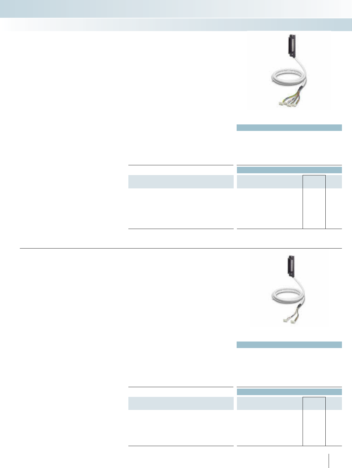
For additional information, visit www.phoenixcontact.net/catalog
Technical data
Max. perm. operating voltage 30 V DC
Max. perm. current carrying capacitance per path 500 mA
Max. conductor resistance 0.16 /m
Ambient temperature (operation) -20°C ... 50°C
Conductor cross section AWG 26 / 0.14 mm²
Outside diameter
50-pole 11 mm
Ordering data
Description No. of
poles Cable length Type Order No. Pcs. /
Pkt.
System cable for digital I/O modules for coupling four 8-channel
VARIOFACE modules
50 2 m CABLE-50/4FLK14/ 2,0M/YUC 2314655 1
50 4 m CABLE-50/4FLK14/ 4,0M/YUC 2314671 1
50 6 m CABLE-50/4FLK14/ 6,0M/YUC 2318978 1
50 10 m CABLE-50/4FLK14/10,0M/YUC 2314684 1
50 15 m CABLE-50/4FLK14/15,0M/YUC 2322773 1
50 20 m CABLE-50/4FLK14/20,0M/YUC 2314778 1
These system cables for digital I/O mod-
ules are connected directly to the modules.
An intermediate adapter is not required.
Features:
– Lateral cable outlet of the I/O module
– Four 14-pole plug connectors on the
module side for connection of four
8-channel VARIOFACE modules of the
system cabling
YOKOGAWA Centum CS3000 R3
System cable
INTERFACE Cabling
VARIOFACE system cabling
Technical data
Max. perm. operating voltage 30 V DC
Max. perm. current carrying capacitance per path 500 mA
Max. conductor resistance 0.16 /m
Ambient temperature (operation) -20°C ... 50°C
Conductor cross section AWG 26 / 0.14 mm²
Conductor structure: stranded wires / material 7 / Cu tin-plated
Outside diameter
40-pole 11 mm
Ordering data
Description No. of
poles Cable length Type Order No. Pcs. /
Pkt.
System cable, for analog I/O modules for coupling two 8-channel
MINI Analog system adapters
40 2 m CABLE-40/2FLK16/ 2,0M/YUC 2321334 1
40 4 m CABLE-40/2FLK16/ 4,0M/YUC 2321347 1
40 10 m CABLE-40/2FLK16/10,0M/YUC 2321350 1
40 15 m CABLE-40/2FLK16/15,0M/YUC 2321376 1
40 20 m CABLE-40/2FLK16/20,0M/YUC 2321363 1
245
PHOENIX CONTACT
The Yokogawa system cable CABLE-
40/2FLK16/.../YUC makes it possible to
connect 16 MINI Analog modules to a Yok-
ogawa control system. In conjunction with
two MINI Analog system adapters
MINI MCR-SL-V8-FLK-16-A, the Yokogawa
system cable provides a simple and econom-
ical "Plug and Play" solution.
The system cable is plugged directly at the
Yokogawa module. Two 16-pole flat-ribbon
cable connectors are provided for connect-
ing the module to the MINI Analog system
adapters.
The system cable in conjunction with
4-wire measuring transducers is suit-
able for the following analog cards:
– AAI 141
– AAI 143
YOKOGAWA Centum CS3000 R3
System cable for MINI Analog
system cabling
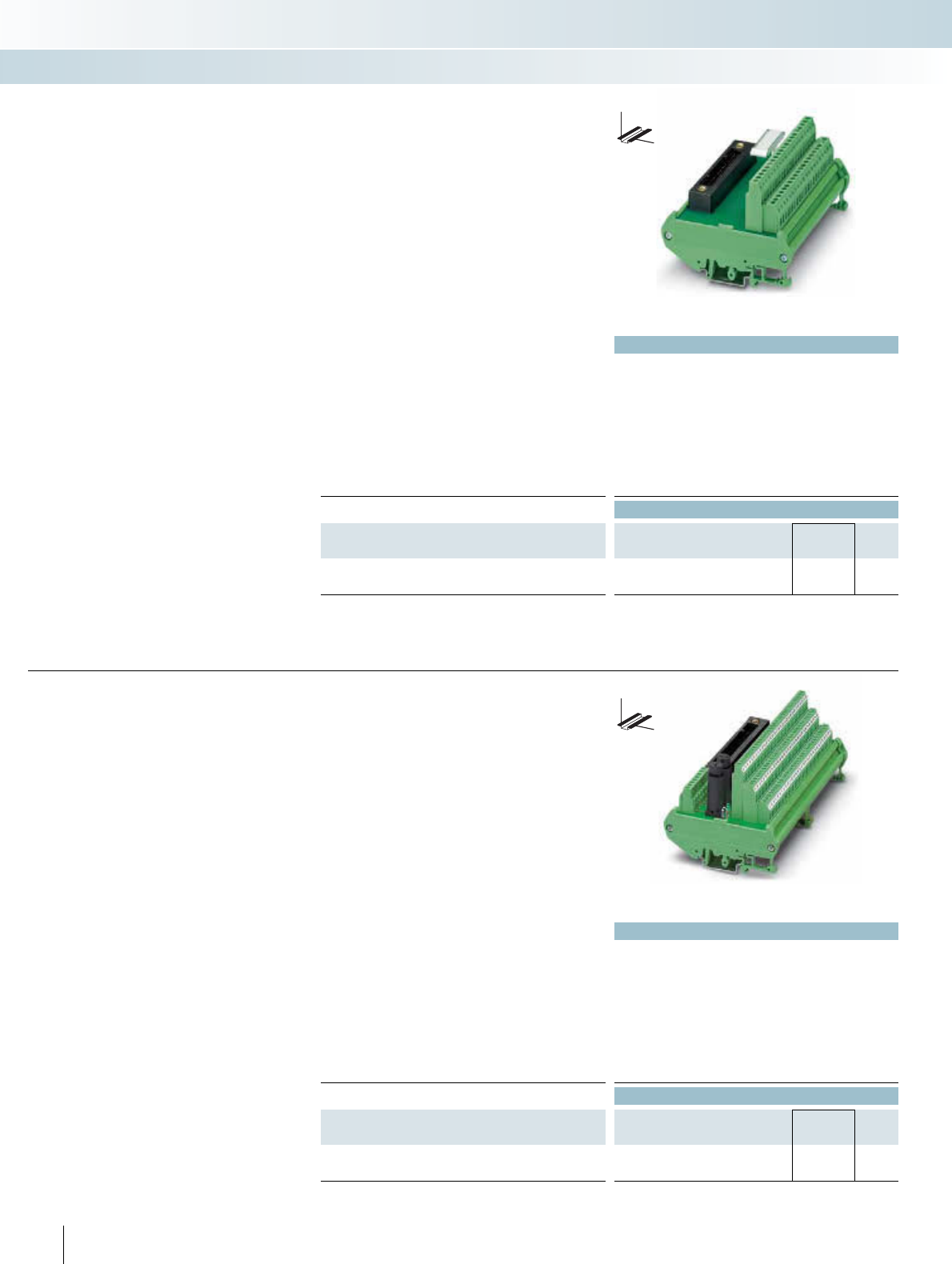
Technical data
Max. perm. operating voltage 24 V AC/DC ±10%
Max. perm. current (per branch) 1 A
Test voltage (contact / contact) 500 V (50 Hz, 1 min.)
Ambient temperature (operation) -20°C ... 50°C
Mounting position Any
Standards / regulations DIN EN 50178
Connection method Field level Screw connection
Control system level Yokogawa KS-compatible
Connection data solid / stranded / AWG 0.2 ... 4 mm² / 0.2 ... 2.5 mm² / 24 - 12
Dimensions H / D 90 mm / 68 mm
Ordering data
Description No. of
poles
Module width
WType Order No. Pcs. /
Pkt.
Controller board, for analog I/O modules
40 112 mm FLKM-KS40/YCS 2314642 1
DW
H
These modules are connected to the I/O
modules through the YUC system cable.
FLKM-KS40/YCS:
– For analog modules
– Universal interface module with 40 con-
necting terminal blocks
For more cabling solutions for Yokogawa:
www.phoenixcontact.com
YOKOGAWA Centum CS3000 R3
Controller boards
INTERFACE Cabling
VARIOFACE system cabling
Passive interface modules
Technical data
Max. perm. operating voltage 24 V AC/DC ±10%
Max. perm. current (per branch) 1 A
Test voltage (contact / contact) 500 V (50 Hz, 1 min.)
Ambient temperature (operation) -20°C ... 50°C
Mounting position Any
Standards / regulations DIN EN 50178
Connection method Field level Screw connection
Control system level Yokogawa KS-compatible
Connection data solid / stranded / AWG 0.2 ... 4 mm² / 0.2 ... 2.5 mm² / 24 - 12
Dimensions H / D 90 mm / 81 mm
Ordering data
Description No. of
poles
Module width
WType Order No. Pcs. /
Pkt.
Controller board, for digital I/O modules ADV 151 and ADV 551
50 174 mm FLKMS-KS50/32IM/YCS 2314451 1
246 PHOENIX CONTACT
DW
H
These modules are connected to the I/O
modules through the YUC system cable.
FLKMS-KS50/32IM/YCS:
– For digital modules ADV 151 and
ADV 551
– Three-wire connection
(signal, plus, minus)
– Redundant voltage supply
(fuse IEC 127-2, 5 x 20, 2 A)
For more cabling solutions for Yokogawa:
www.phoenixcontact.com
YOKOGAWA Centum CS3000 R3
Controller boards
Passive interface modules

For additional information, visit www.phoenixcontact.net/catalog
Technical data
Max. perm. operating voltage 24 V DC ±10%
Max. perm. current (per branch) 100 mA
Test voltage (contact / contact) 500 V (50 Hz, 1 min.)
Ambient temperature (operation) -20°C ... 50°C
Mounting position Any
Standards / regulations DIN EN 50178
Connection method Field level Screw connection
Control system level Yokogawa KS-compatible
Connection data solid / stranded / AWG 0.2 ... 4 mm² / 0.2 ... 2.5 mm² / 24 - 12
Dimensions H / D 126 mm / 68 mm
Ordering data
Description No. of
poles
Module width
WType Order No. Pcs. /
Pkt.
Controller board, for analog output modules AAI 543
40 108 mm FLKM-KS40/AO16/YCS 2314260 1
Controller board, with fuses and LED, for analog input modules
AAI 141 and AAI 143
40 214 mm FLKMS-KS40/SI/AI16/YCS 2314273 1
Controller board, for analog input modules AAI 141 and AAI 143,
without fuses and LED
40 214 mm FLKMS-KS40/AI/YCS 2314286 1
247PHOENIX CONTACT
These modules are connected to the ana-
log I/O modules through the 40-pole YUC
system cable.
The modules are designed for redundant
signal transmission (two plug connectors in
parallel). A separate connection to the
HART multiplexer is possible.
FLKM-KS40/AO16/YCS
– For analog module AAI 543
FLKMS-KS40/SI/AI16/YCS
– For analog modules AAI 141 and AAI 143
(operation of modules in the 4-wire mode)
– Transfer of 16 channels with separate
positive and negative connections
– 16 pluggable fuses (IEC 127-2, 5 x 20, 0.1 A)
per positive supply and LED status indica-
tor
– Redundant voltage supply
(fuse IEC 127-2, 5 x 20, 2 A)
FLKMS-KS40/AI/YCS
– For analog modules AAI 141 and AAI 143
(operation of modules in the 4-wire mode)
– Transfer of 16 channels with separate
positive and negative connections
– Redundant voltage supply
(fuse IEC 127-2, 5 x 20, 2 A)
For more cabling solutions for Yokogawa:
www.phoenixcontact.com
YOKOGAWA Centum CS3000 R3
Controller boards
INTERFACE Cabling
VARIOFACE system cabling
DW
H
Interface modules for analog I/O modules
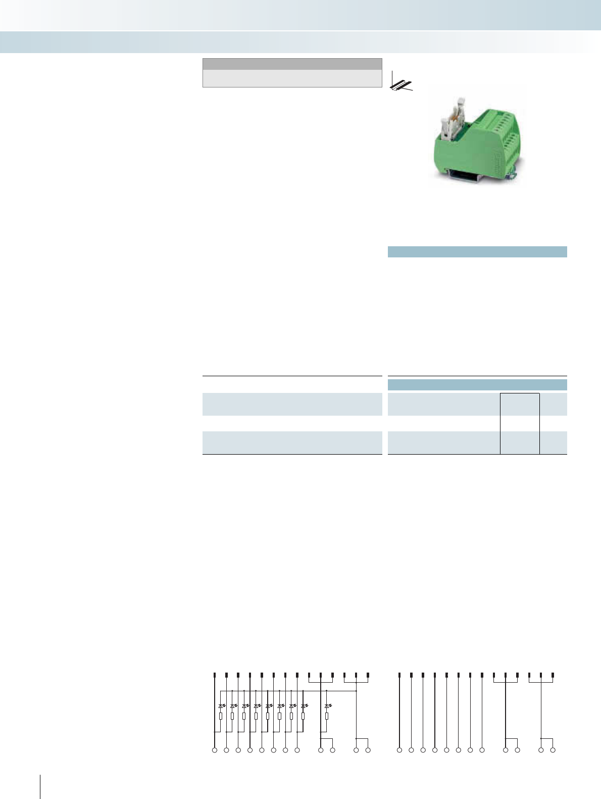
p
Technical data
VIP-2/SC/FLK14/PLC VIP-2/SC/FLK14/LED/PLC
Max. perm. operating voltage 60 V AC/DC 20 V DC (up to 26.5 V DC)
Max. perm. current (per branch) 1 A 1 A
Max. total current (voltage supply) 3 A 3 A
Rated surge voltage 0.6 kV -
Ambient temperature (operation) -20°C ... 50°C -20°C ... 50°C
Mounting position Any Any
Standards / regulations IEC 60664, DIN EN 50178, IEC 62103
Connection method Field level Screw connection Screw connection
Control system level Flat-ribbon cable plug connector
in acc. with IEC 60603-13
Flat-ribbon cable plug connector
in acc. with IEC 60603-13
Connection data solid / stranded / AWG 0.2 ... 4 mm² / 0.2 ... 2.5 mm² / 24 - 12
Dimensions H / D 65.5 mm / 56 mm
Ordering data
Description No. of
poles
Module width
WType Order No. Pcs. /
Pkt.
VARIOFACE interface module, for
- eight channels 14 39.8 mm VIP-2/SC/FLK14/PLC 2315214 1
VARIOFACE interface module, with light indicator for:
- eight channels 14 39.8 mm VIP-2/SC/FLK14/LED/PLC 2322249 1
248 PHOENIX CONTACT
123456789
11 13 10 12 14
01234567 ++ - -
VIP-2/SC/FLK14/LED/PLC connection scheme
1234567891113101214
1234567
0++--
VIP-2/SC/FLK14/PLC connection scheme
These VIP VARIOFACE Professional
modules are used in combination with the
respective front adapters.
Similar to the front adapters, the modules
are connected through 14-pole system ca-
bles. The following module types are avail-
able:
VIP-2/SC/FLK14/PLC
VIP-2/SC/FLK14/LED/PLC
– Byte-wise labeling
– Can be used for digital I/O modules
– Optionally with LED
VIP termination boards
INTERFACE Cabling
VARIOFACE system cabling
DW
H
Passive interface modules for
input/output of 8 channels
Notes:
For marking systems and mounting material, see
CLIPLINE catalog, part 2.
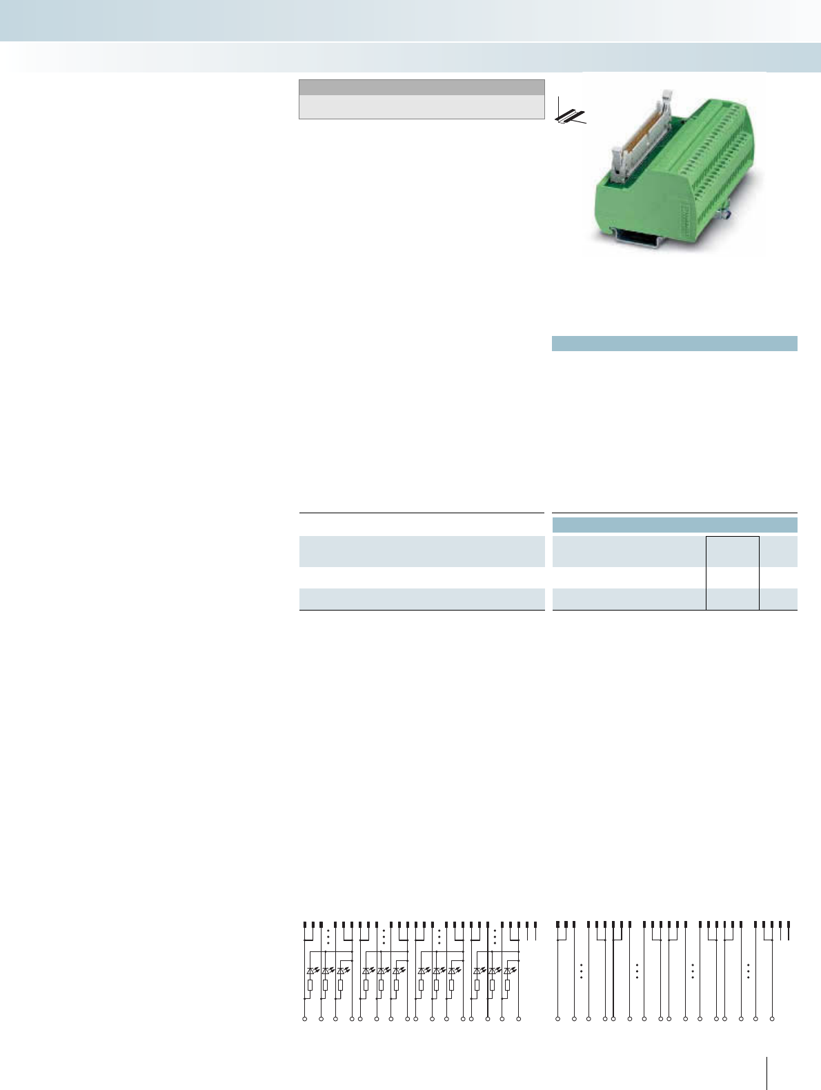
For additional information, visit www.phoenixcontact.net/catalog
p
Technical data
VIP-2/SC/FLK50/PLC VIP-2/SC/FLK50/LED/PLC
Max. perm. operating voltage 60 V AC/DC 20 V DC (up to 26.5 V DC)
Max. perm. current (per branch) 1 A 1 A
Max. total current (voltage supply) 2 A 2 A (per byte)
Rated surge voltage 0.6 kV -
Ambient temperature (operation) -20°C ... 50°C -20°C ... 50°C
Mounting position Any Any
Standards / regulations IEC 60664, DIN EN 50178, IEC 62103
Connection method Field level Screw connection Screw connection
Control system level Flat-ribbon cable plug connector
in acc. with IEC 60603-13
Flat-ribbon cable plug connector
in acc. with IEC 60603-13
Connection data solid / stranded / AWG 0.2 ... 4 mm² / 0.2 ... 2.5 mm² / 24 - 12
Dimensions H / D 65.5 mm / 56 mm
Ordering data
Description No. of
poles
Module width
WType Order No. Pcs. /
Pkt.
VARIOFACE interface module, for
- 32 channels 50 106.1 mm VIP-2/SC/FLK50/PLC 2315227 1
VARIOFACE interface module, for
- 32 channels 50 106.1 mm VIP-2/SC/FLK50/LED/PLC 2322252 1
249PHOENIX CONTACT
123 1011121314 15 2223 24252627 343536373839 46474849 50
B0.0
+B0.7+-B1.0 B1.7 +- B2.0 B2.7 +- B3.0 B3.7 -
VIP-2/SC/FLK50/LED/PLC connection scheme
123 1011121314 15 222324252627 343536 373839 4647484950
+B0.0 B0.7 +- B1.0 B1.7 +- B2.0 B2.7 +- B3.0 B3.7 -
VIP-2/SC/FLK50/PLC connection scheme
These VIP VARIOFACE Professional
modules are used in combination with the
respective front adapters.
Similarly to the front adapters, the mod-
ules are connected through 50-pole system
cables. The following module types are
available:
VIP-2/SC/FLK50/PLC
VIP-2/SC/FLK50/LED/PLC
– Byte-wise labeling
– Can be used for digital I/O modules
– Optionally with LED.
VIP termination boards
INTERFACE Cabling
VARIOFACE system cabling
DW
H
Passive interface modules for
input/output of 32 channels
Notes:
For marking systems and mounting material, see
CLIPLINE catalog, part 2.
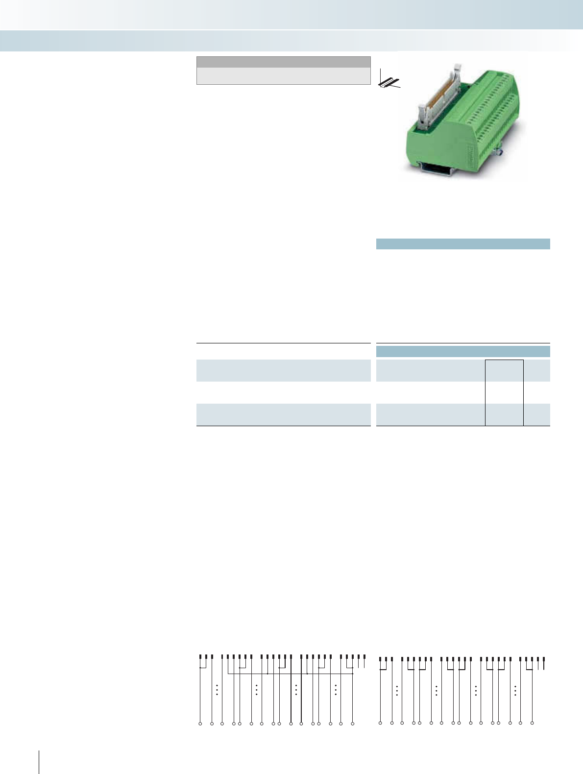
p
Technical data
Max. perm. operating voltage 60 V AC/DC
Max. perm. current (per branch) 1 A
Rated surge voltage 0.6 kV
Ambient temperature (operation) -20°C ... 50°C
Mounting position Any
Standards / regulations IEC 60664, DIN EN 50178, IEC 62103
Connection method Field level Screw connection
Control system level Flat-ribbon cable plug connector in acc. with IEC 60603-13
Connection data solid / stranded / AWG 0.2 ... 4 mm² / 0.2 ... 2.5 mm² / 24 - 12
Dimensions H / D 65.5 mm / 56 mm
Ordering data
Description No. of
poles
Module width
WType Order No. Pcs. /
Pkt.
VARIOFACE interface module, for SIMATIC®S7-300, with
SIMATIC®-specific labeling
50 106.1 mm VIP-2/SC/FLK50 (1-40) /S7 2315243 1
VARIOFACE interface module, for SIMATIC®S7-400, with
SIMATIC®-specific labeling
50 106.1 mm VIP-2/SC/FLK50/S7/A-S400 2322359 1
250 PHOENIX CONTACT
123 10 111213 1415 22 2324252627 343536373839 4647484950
34111213
15 22 23 26 27 34 35 38 39 46 48
VIP-2/SC/FLK50/S7/A-S400 connecction scheme
123 10
1112131415 22 23242526 27 34 3536 373839 4647 484950
12910111219
20 21 22 29 3031 32 39 40
VIP-2/SC/FLK50 (1-40) /S7 connecction scheme
These VIP VARIOFACE Professional
modules are used in combination with the
respective front adapters for SIMATIC® S7.
Similarly to the front adapters, the mod-
ules are connected through 50-pole system
cables. The following module types are
available:
VIP-2/SC/FLK50 (1-40)/S7
– Numerical labeling (1-40)
– Specially for S7 300
VIP-2/SC/FLK50/S7/A-S400
– Numerical labeling (3-48)
– Specially for S7 400
VIP termination boards for
SIMATIC® S7
INTERFACE Cabling
VARIOFACE system cabling
DW
H
Passive interface modules for
input/output of 32 channels,
with SIMATIC®-specific labeling
Notes:
For marking systems and mounting material, see
CLIPLINE catalog, part 2.
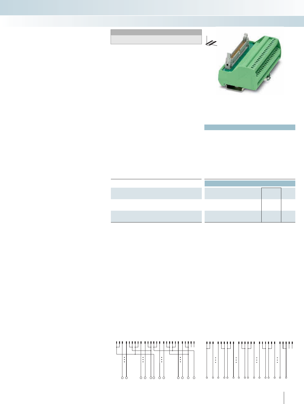
For additional information, visit www.phoenixcontact.net/catalog
Technical data
Max. perm. operating voltage 60 V DC
Max. perm. current (per branch) 1 A
Rated surge voltage -
Ambient temperature (operation) -20°C ... 50°C
Mounting position Any
Standards / regulations IEC 60664, DIN EN 50178, IEC 62103
Connection method Field level Screw connection
Control system level Flat-ribbon cable plug connector in acc. with IEC 60603-13
Connection data solid / stranded / AWG 0.2 ... 4 mm² / 0.2 ... 2.5 mm² / 24 - 12
Dimensions H / D 65.5 mm / 56 mm
Ordering data
Description No. of
poles
Module width
WType Order No. Pcs. /
Pkt.
VARIOFACE interface module, for MODICON® TSX Quantum,
with MODICON®-specific labeling
50 106.1 mm VIP-2/SC/FLK50/MODI-TSX/Q 2322304 1
VARIOFACE interface module for Allen-Bradley, with
ControlLogix-specific labeling
50 95.9 mm VIP-2/SC/FLK50/AB-1756 2322317 1
251PHOENIX CONTACT
19 271982616 34173518 36
12315 392710 3411 3523 4712 3624 4813 3725 4914 3826 5022 46
VIP-2/SC/FLK50/AB-1756 connecction scheme
123 1011
1213 1415 22 23242526 27 343536373839 4647484950
10 1 8 9 20 11 18 19 30 21 28 29 40 31 38 39
VIP-2/SC/FLK50/MODI-TSX/Q connecction scheme
These VIP VARIOFACE Professional
modules are used in combination with
the respective front adapters for
MODICON® TSX Quantum.
Similar to the front adapters, the modules
are connected through 50-pole system ca-
bles.
VIP-2/SC/FLK50/MODI-TSX/Q
– Numerical labeling (1-40)
– Specially for MODICON TSX Quantum
VIP-2/SC/FLK50/AB-1756
– Numerical labeling (1-36)
– Specially for ControlLogix
VIP termination boards for
MODICON® TSX Quantum and
Allen-Bradley ControlLogix
INTERFACE Cabling
VARIOFACE system cabling
DW
H
Passive interface modules for
input/output of 32 channels
Notes:
For marking systems and mounting material, see
CLIPLINE catalog, part 2.
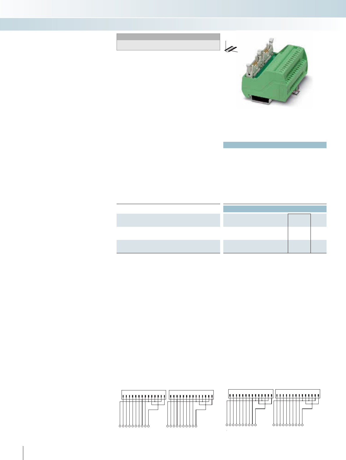
p
Technical data
Max. perm. operating voltage 60 V AC/DC
Max. perm. current (per branch) 1 A
Rated surge voltage 0.6 kV
Ambient temperature (operation) -20°C ... 50°C
Mounting position Any
Standards / regulations IEC 60664, DIN EN 50178, IEC 62103
Connection method Field level Screw connection
Control system level Flat-ribbon cable plug connector in acc. with IEC 60603-13
Connection data solid / stranded / AWG 0.2 ... 4 mm² / 0.2 ... 2.5 mm² / 24 - 12
Dimensions H / D 65.5 mm / 56 mm
Ordering data
Description No. of
poles
Module width
WType Order No. Pcs. /
Pkt.
VARIOFACE interface module, for SIMATIC®S7-300, with
SIMATIC®-specific labeling
With screw connection 14 80.6 mm VIP-2/SC/2FLK14 (1-20) /S7 2315230 1
VARIOFACE interface module for Allen-Bradley, with
ControlLogix-specific labeling
With screw connection 14 80.6 mm VIP-2/SC/2FLK14/AB-1756 2322333 1
252 PHOENIX CONTACT
X2X1 1234567891011121314 1234567891011121314
123456789
10 20111213141516171819
VIP-2/SC/2FLK14/AB-1756 connection scheme
X1 X2
1 2 3 4 5 6 7 8 9 1011121314 1 2 3 4 5 6 7 8 9 1011121314
1 2 3 4 5 6 7 8 9 10 11121314151617181920
VIP-2/SC/2FLK14 (1-20) /S7 and UM 45-2FLK14/ZFKDS/S7
These VIP VARIOFACE Professional
modules are used in combination with the
respective front adapters for Siemens
SIMATIC® S7-300 and Allen-Bradley. The
following modules are available:
VIP-2/SC/2FLK14 (1-20) /S7
– Screw or spring-cage connection
– Numerical labeling (1-20)
– Specially for S7 300.
VIP-2/SC/2FLK14/AB-1756
– Screw connection
– Numerical labeling (1-20)
– Specially for ControlLogix
VIP termination boards for
Siemens SIMATIC® S7-300 and
Allen-Bradley
INTERFACE Cabling
VARIOFACE system cabling
DW
H
Passive interface modules for SIMATIC S7 300
and Allen-Bradley ControlLogix
Notes:
For marking systems and mounting material, see
CLIPLINE catalog, part 2.
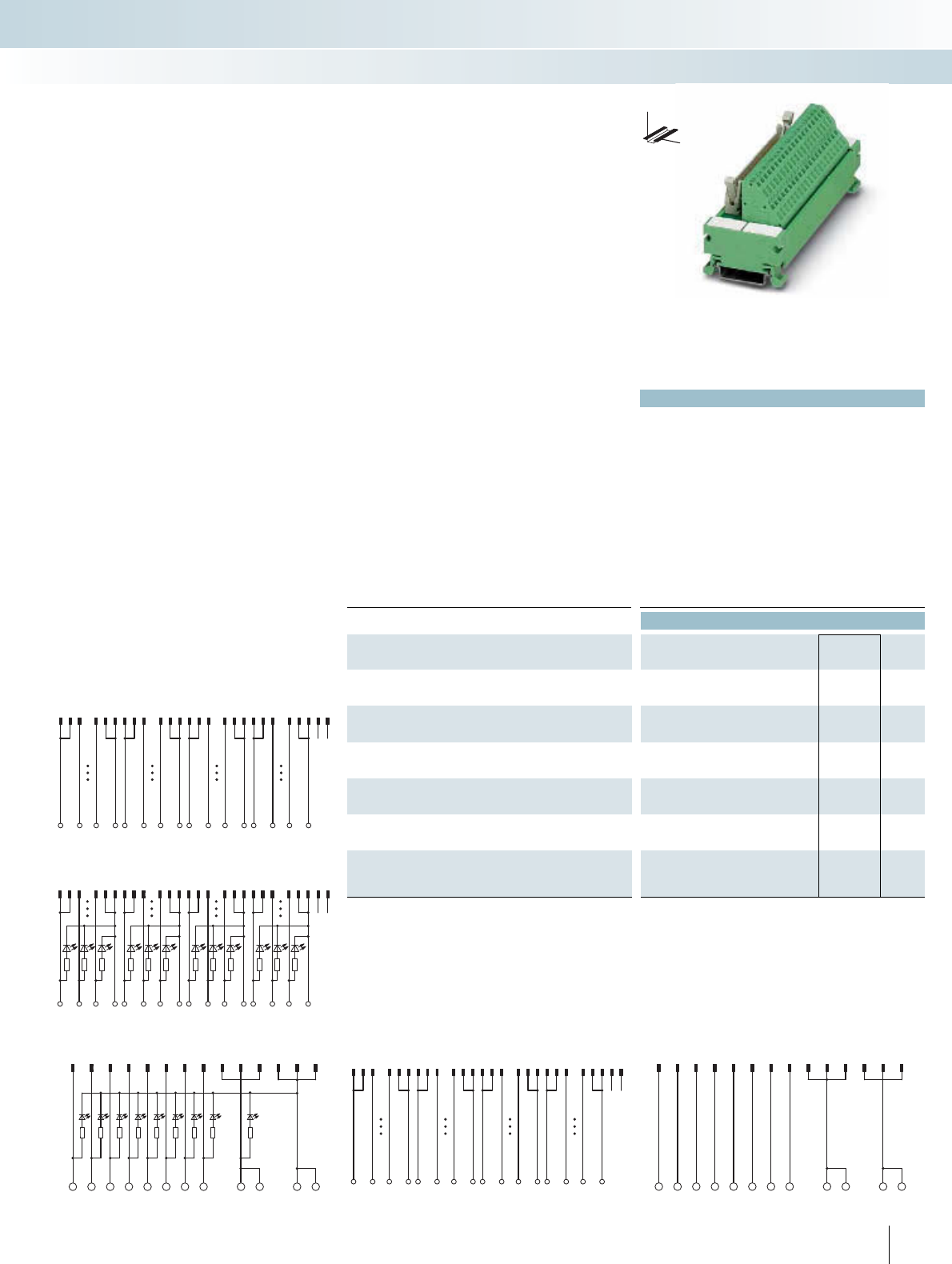
For additional information, visit www.phoenixcontact.net/catalog
|
Technical data
... 14/PLC ... 50/PLC ... 14/LA/PLC ... 50/LA/PLC
Max. perm. operating voltage 60 V DC 60 V DC 20 V DC (up to
30 V DC)
20 V DC (up to
30 V DC)
Max. perm. current (per branch) 1 A 1 A 1 A 1 A
Max. total current (voltage supply) 3 A 2 A (per byte) 3 A 2 A (per byte)
Status indication No No LED LED
Rated surge voltage 0.8 kV 0.8 kV 0.8 kV 0.8 kV
Ambient temperature (operation) -20°C ... 50°C
Mounting position Any
Standards / regulations IEC 60664, DIN EN 50178, IEC 62103
Connection method Field level Spring-cage connection
Control system level Flat-ribbon cable plug connector in acc. with IEC 60603-13
Connection data solid / stranded / AWG 0.2 ... 2.5 mm² / 0.2 ... 1.5 mm² / 24 - 14
Dimensions H / D 45 mm / 50 mm
Ordering data
Description No. of
poles
Module width
WType Order No. Pcs. /
Pkt.
VARIOFACE interface module for eight channels
14 59 mm UM 45-FLK14/ZFKDS/PLC 2965172 1
VARIOFACE interface module for 32 channels
50 126 mm UM 45-FLK50/ZFKDS/PLC 2965198 1
VARIOFACE interface module for eight channels, with light indi-
cator
14 59 mm UM 45-FLK14/LA/ZFKDS/PLC 2965334 1
VARIOFACE interface module for 32 channels, with light indica-
tor
50 138 mm UM 45-FLK50/LA/ZFKDS/PLC 2965347 1
VARIOFACE interface module, for SIMATIC®S7-300, with
SIMATIC®-specific labeling
50 126 mm UM 45-FLK50/ZFKDS/S7-300 2968111 1
VARIOFACE interface module, for SIMATIC® S7-300, with
SIMATIC®-specific labeling and 2 FLK connectors
14 98 mm UM 45- 2FLK14/ZFKDS/S7 2965156 1
253PHOENIX CONTACT
123 1011121314 15 222324252627 343536 373839 4647484950
+B0.0 B0.7 +- B1.0 B1.7 +- B2.0 B2.7 +- B3.0 B3.7 -
UM 45-FLK50/ZFKDS/PLC connection scheme
1234567891113101214
1234567
0++--
UM 45-FLK14/ZFKDS/PLC connection scheme
123456789
11 13 10 12 14
01234567 ++ - -
UM 45-FLK14/LA/ZFKDS/PLC connection scheme
123 1011121314 15 2223 24252627 343536373839 46474849 50
B0.0
+ B0.7 +- B1.0 B1.7 +- B2.0 B2.7 +- B3.0 B3.7 -
45-FLK50/LA/ZFKDS/PLC connection scheme
123 10
1112131415 22 23242526 27 34 3536 373839 4647 484950
12910111219
20 21 22 29 3031 32 39 40
UM 45-FLK50/ZFKDS/S7-300 connection scheme
These VARIOFACE modules are used in
combination with the respective front
adapters. Like the front adapters, the mod-
ules are connected via 14-pole or 50-pole
system cables. The following Compact-Line
modules are available:
UM 45-FLK14.../PLC (for 8 channels)
UM 45-FLK50.../PLC (for 32 channels)
– Byte-wise labeling
– Can be used for digital I/O modules
– Optionally with LED.
UM 45-FLK50/.../S7-300
– Numerical labeling (1-40)
– Specially for S7 300
UM 45-2FLK14/ZFKDS/S7
– Numerical labeling (1-20)
– Specially for S7 300
– Connection via two 14-pole system cables
COMPACT-LINE
Controller boards with spring-cage
connection
INTERFACE Cabling
VARIOFACE system cabling
DW
H
Passive interface module for eight or
32 channels with a spring-cage connection
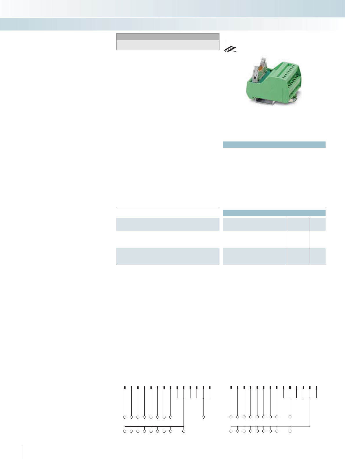
Technical data
Max. perm. operating voltage 60 V DC
Max. perm. current (per branch) 1 A
Max. total current (voltage supply) 3 A (per byte)
Rated surge voltage -
Ambient temperature (operation) -20°C ... 50°C
Mounting position Any
Standards / regulations IEC 60664, DIN EN 50178, IEC 62103
Connection method Field level Screw connection
Control system level Flat-ribbon cable plug connector in acc. with IEC 60603-13
Connection data solid / stranded / AWG 0.2 ... 4 mm² / 0.2 ... 2.5 mm² / 24 - 12
Dimensions H / D 65.5 mm / 56 mm
Ordering data
Description No. of
poles
Module width
WType Order No. Pcs. /
Pkt.
VARIOFACE interface module, for eight channels, each with an
additional terminal block per signal for a common minus potential
14 50 mm VIP-2/SC/FLK14/8M/PLC 2322281 1
VARIOFACE interface module, for eight channels, each with an
additional terminal block per signal for a common plus potential
14 50 mm VIP-2/SC/FLK14/8P/PLC 2322294 1
254 PHOENIX CONTACT
12345678911
13 10 12 14
12345670
++++++++ +
-
VIP-2/SC/FLK14/8P/PLC connection scheme
12345678911
13 10 12 14
12345670+
---------
VIP-2/SC/FLK14/8M/PLC connection scheme
These VIP VARIOFACE modules are used
in combination with the respective front
adapters.
Similar to the front adapters, the modules
are connected through 14-pole system ca-
bles. The following module types with the
2-wire connection method are available:
VIP-2/SC/FLK14/8M/PLC
– Byte-wise labeling
– Can be used for digital I/O modules
– Negative connection for each signal
VIP-2/SC/FLK14/8P/PLC
– Byte-wise labeling
– Can be used for digital I/O modules
– Positive connection per signal
VIP termination boards in
2-wire connection method
INTERFACE Cabling
VARIOFACE system cabling
DW
H
Passive interface modules for 8 channels
Notes:
For marking systems and mounting material, see
CLIPLINE catalog, part 2.
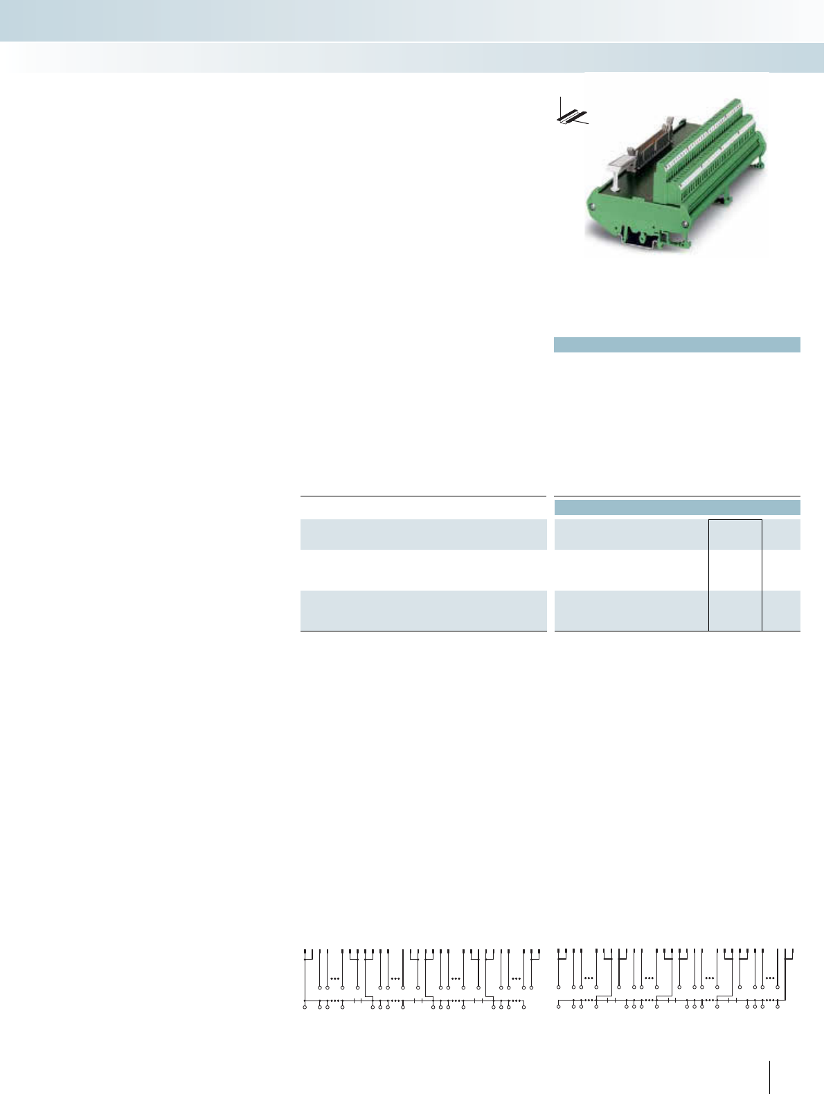
For additional information, visit www.phoenixcontact.net/catalog
|
Technical data
Max. perm. operating voltage 60 V DC
Max. perm. current (per branch) 1 A
Max. total current (voltage supply) 8 A (per byte)
Rated surge voltage 0.8 kV
Ambient temperature (operation) -20°C ... 50°C
Mounting position Any
Standards / regulations IEC 60664, DIN EN 50178, IEC 62103
Connection method Field level Screw connection
Control system level Flat-ribbon cable plug connector in acc. with IEC 60603-13
Connection data solid / stranded / AWG 0.2 ... 4 mm² / 0.2 ... 2.5 mm² / 24 - 12
Dimensions H / D 90 mm / 68 mm
Ordering data
Description No. of
poles
Module width
WType Order No. Pcs. /
Pkt.
VARIOFACE interface module, for 32 channels, each with an
additional terminal block per signal for a common minus potential
50 192 mm FLKM 50/32M/PLC 2289719 1
VARIOFACE interface module, for 32 channels, each with an
additional terminal block per signal for a common plus potential
50 192 mm FLKM 50/32P/PLC 2291121 1
255PHOENIX CONTACT
1234 10
111213141516 22232425262728 34353637383940 464748
B3.0B3.1B3.7--
B2.0B2.1 B2.7-
B1.0B1.1 B1.7-
B0.0B0.1 B0.7
+++ + +++ + +++ + +++ +
DR3
DR2
DR1
Connection scheme: FLKM 50/32P/PLC
1234 10
111213141516 22232425262728 34353637383940 464748
B3.0B3.1 B3.7+B2.0B2.1 B2.7+
B1.0B1.1 B1.7+
B0.0B0.1 B0.7+
---- ---- ---- ----
DR3
DR2
DR1
Connection scheme: FLKM 50/32M/PLC
These VARIOFACE modules are used in
combination with the respective front
adapters.
Similar to the front adapters, the modules
are connected through 50-pole system ca-
bles. The following module types with the
2-wire connection method are available:
FLKM 50/32M/PLC (for 32 channels)
– Byte-wise labeling
– Can be used for digital I/O modules
– Negative connection for each signal
FLKM50/32P/PLC (for 32 channels)
– Byte-wise labeling
– Can be used for all digital I/O modules
– Positive connection per signal
Termination boards in
2-wire connection method
INTERFACE Cabling
VARIOFACE system cabling
DW
H
Passive interface modules for 32 channels
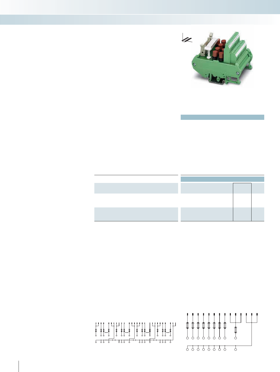
|
Technical data
FLKM 14/8M/SI/PLC FLKM 50/32M/PLC
Max. perm. operating voltage 60 V DC 60 V DC
Max. perm. current (per branch) 1 A 1 A
Max. total current (voltage supply) 2 A 2 A (per byte)
Rated surge voltage 0.8 kV 0.8 kV
Ambient temperature (operation) -20°C ... 50°C -20°C ... 50°C
Mounting position Any Any
Standards / regulations IEC 60664, DIN EN 50178, IEC 62103
Connection method Field level Screw connection Screw connection
Control system level Flat-ribbon cable plug connector
in acc. with IEC 60603-13
Flat-ribbon cable plug connector
in acc. with IEC 60603-13
Connection data solid / stranded / AWG 0.2 ... 4 mm² / 0.2 ... 2.5 mm² / 24 - 12
Dimensions H / D 90 mm / 68 mm
Ordering data
Description No. of
poles
Module width
WType Order No. Pcs. /
Pkt.
VARIOFACE module, for eight channels, each with an additional
terminal block and fuse per signal (common minus potential)
14 57 mm FLKM 14/8M/SI/PLC 2294487 1
VARIOFACE module, for 32 channels, each with an additional ter-
minal block and fuse per signal (common minus potential)
50 192 mm FLKM 50/32M/SI/PLC 2294490 1
256 PHOENIX CONTACT
1234 10
111213141516 22232425262728 34353637383940 464748
F1F1 F1F2F1 F1 F1F2F1F1 F1F2
F1F1 F1F2
B3.0B3.1 B3.7
+
B2.0B2.1 B2.7
+
B1.0B1.1 B1.7
+
B0.0B0.1 B0.7
+
---- ---- ---- ----
DR3DR2DR1
Connection scheme: FLKM 50/32M/SI/PLC
1234567 891113
10 12 14
F2
F1 F1 F1 F1 F1 F1 F1 F1
12345670+
-------- -
Connection scheme: FLKM 14/8M/SI/PLC
These VARIOFACE modules are used in
combination with the respective front
adapters.
Like the front adapters, the modules are
connected via 14-pole or 50-pole system
cables. The following module types with fus-
es in the 2-wire and 4-wire connection
method are available:
FLKM 14/8M/SI/PLC (for 8 channels)
FLKM 50/32M/SI/PLC (for 32 channels)
– Byte-wise labeling
– Can be used for digital I/O modules
– Pluggable fuse (IEC 127-3, 1AF) per signal
path (F1)
– Pluggable fuse (IEC 127-3, 2AF) per volt-
age supply (F2)
– Negative connection for each signal
Termination boards with fuses in
2-wire connection method
INTERFACE Cabling
VARIOFACE system cabling
DW
H
Passive fuse modules for 8 or 32 channels
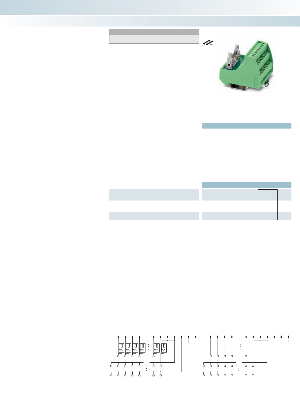
For additional information, visit www.phoenixcontact.net/catalog
Technical data
Max. perm. operating voltage 60 V DC
Max. perm. current (per branch) 1 A
Max. total current (voltage supply) 3 A
Rated surge voltage -
Ambient temperature (operation) -20°C ... 50°C
Mounting position Any
Standards / regulations IEC 60664, DIN EN 50178, IEC 62103
Connection method Field level Screw connection
Control system level Flat-ribbon cable plug connector in acc. with IEC 60603-13
Connection data solid / stranded / AWG 0.2 ... 4 mm² / 0.2 ... 2.5 mm² / 24 - 12
Dimensions H / D 69 mm / 62 mm
Ordering data
Description No. of
poles
Module width
WType Order No. Pcs. /
Pkt.
VARIOFACE initiator module
, for connection of eight PNP initiators
14 52.3 mm VIP-3/SC/FLK14/8IM/PLC 2322278 1
14 52.3 mm VIP-3/SC/FLK14/8IM/LED/PLC 2322265 1
257PHOENIX CONTACT
1 2 3 4 8 9 11 13 10 12 14
12307
+++++++
----- --
VIP-3/SC/FLK14/8IM/LED/PLC connection scheme
1 2 3 4 8 9 11 13 10 12 14
12307
+++++++
----- --
VIP-3/SC/FLK14/8IM/PLC connection scheme
These VIP VARIOFACE Professional
modules are used in combination with the
respective front adapters.
Similar to the front adapters, the modules
are connected through 14-pole system ca-
bles. The following VIP initiator modules are
available:
VIP-3/SC/FLK14/8IM/...
(for 8 channels)
– Byte-wise labeling
– Can be used for digital I/O modules
– Positive and negative connection per signal
– Optionally with LED.
VIP initiator modules
INTERFACE Cabling
VARIOFACE system cabling
DW
H
Sensor modules for 8 channels
Notes:
For marking systems and mounting material, see
CLIPLINE catalog, part 2.
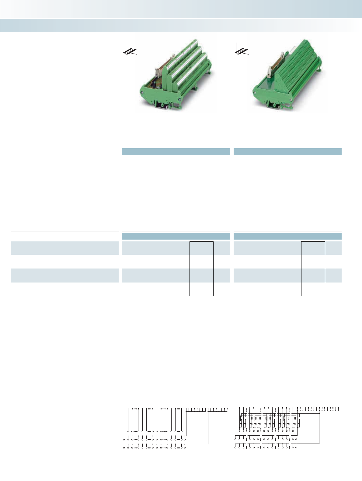
|
Technical data Technical data
... 50/32 IM ... 50/32 IM/LA
Max. perm. operating voltage 60 V DC 20 V DC (up to 30 V DC) 60 V DC
Max. perm. current (per branch) 1 A 1 A 1 A
Max. total current (voltage supply) 2 A (per byte) 2 A (per byte) 2 A (per byte)
Status indication No LED -
Rated surge voltage 0.8 kV 0.8 kV 0.6 kV
Ambient temperature (operation) -20°C ... 50°C -20°C ... 50°C -20°C ... 50°C
Mounting position Any Any Any
Standards / regulations IEC 60664, DIN EN 50178, IEC 62103 DIN EN 50178
Connection method Field level Screw connection Screw connection Spring-cage connection
Control system level Flat-ribbon cable plug connector
in acc. with IEC 60603-13
Flat-ribbon cable plug connector
in acc. with IEC 60603-13
Flat-ribbon cable plug connector in acc. with IEC 60603-13
Connection data solid / stranded / AWG 0.2 ... 4 mm² / 0.2 ... 2.5 mm² / 24 - 12 0.2 ... 2.5 mm² / 0.2 ... 1.5 mm² / 24 - 12
Dimensions H / D 90 mm / 81 mm 90 mm / 73.5 mm
Ordering data Ordering data
Description No. of
poles
Module width
WType Order No. Pcs. /
Pkt. Type Order No. Pcs. /
Pkt.
VARIOFACE initiator module, for connection of 32 PNP initiators
50 180 mm FLKMS 50/32IM/PLC 2284523 1
VARIOFACE initiator module, same as before, however with light
indicator
50 180 mm FLKMS 50/32IM/LA/PLC 2284510 1
VARIOFACE initiator module, for connection of 32 PNP initiators
FLKMS 50/32IM/ZFKDS/PLC 2901389 1
34 10 15 16 22 27 28 34 39 40 46 1 213
14
25
26
37
3811
12
23
2435
36
47
48
B0.0B0.1B0.7B1.0B1.1B1.7B2.0B2.1B2.7B3.0B3.1B3.7
+++ +++ +++ +++ ++
--------------
Connection scheme: FLKMS 50/32IM/PLC,
...50/32IM/ZFKDS/PLC
-
-------------
48
47
36
35
2324
1112
3738
2526
1314
12
46
403934
2827
22
161534 10
B2.7 B3.0 B3.1 B3.7
B2.1B2.0B1.7B1.1B1.0B0.7
B0.1
B0.0
+
-
+
-
+
-
+
-
+
-
+
-
+
-
+
-
+
-
+
-
+
-
+
-
+
-
+
-
FLKMS 50/32IM/LA/PLC connection scheme
258 PHOENIX CONTACT
INTERFACE Cabling
VARIOFACE system cabling
Initiator modules for 32 channels,
with screw connection
Initiator modules for 32 channels,
with spring-cage connection
These VARIOFACE modules are used in
combination with the respective front
adapters for digital I/O modules.
– For 32 channels
– Byte-wise labeling
– Positive and negative connection per signal
– Screw or spring-cage connection
– Optionally with LED
DW
H
DW
H
Sensor modules
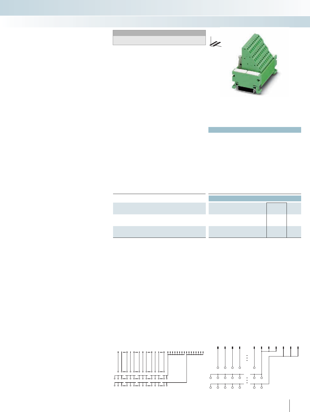
For additional information, visit www.phoenixcontact.net/catalog
|
Technical data
UM 45-FLK 14/.../PLC UM 45-FLK 50/.../PLC
Max. perm. operating voltage 60 V DC 60 V DC
Max. perm. current (per branch) 1 A 1 A
Max. total current (voltage supply) 3 A 2 A (per byte)
Rated surge voltage 0.8 kV 0.8 kV
Ambient temperature (operation) -20°C ... 50°C -20°C ... 50°C
Mounting position Any Any
Standards / regulations IEC 60664, DIN EN 50178, IEC 62103
Connection method Field level Spring-cage connection Spring-cage connection
Control system level Flat-ribbon cable plug connector
in acc. with IEC 60603-13
Flat-ribbon cable plug connector
in acc. with IEC 60603-13
Connection data solid / stranded / AWG 0.2 ... 2.5 mm² / 0.2 ... 1.5 mm² / 24 - 14
Dimensions H / D 45 mm / 61 mm
Ordering data
Description No. of
poles
Module width
WType Order No. Pcs. /
Pkt.
VARIOFACE-COMPACT-LINE initiator module, for connection
of eight PNP initiators
14 75 mm UM 45-FLK14/ 8IM/ZFKDS/PLC 2965211 1
VARIOFACE-COMPACT-LINE initiator module, for connection
of 32 PNP initiators
50 197 mm UM 45-FLK50/32IM/ZFKDS/PLC 2965224 1
259PHOENIX CONTACT
34 10 15 16 22 27 28 34 39 40 46 1 213
14
25
26
37
3811
12
23
2435
36
47
48
B0.0B0.1B0.7B1.0B1.1B1.7B2.0B2.1B2.7B3.0B3.1B3.7
+++ +++ +++ +++ ++
--------------
UM 45-FLK50/32IM/ZFKDS/PLC connection scheme
1234 89
11 13 10 12 14
123
07
+
-
++++
-- -- -
++
-
UM 45-FLK14/8IM/ZFKDS/PLC connection scheme
These VARIOFACE modules are used in
combination with the respective front
adapters.
Like the front adapters, the modules are
connected via 14-pole or 50-pole system
cables. The following Compact-Line sensor
modules are available:
UM 45-FLK14/8IM/.../PLC
(for 8 channels)
UM 45-FLK 50/32IM/.../PLC
(for 32 channels)
– Byte-wise labeling
– Can be used for digital I/O modules
– Positive and negative connection for ev-
ery signal
COMPACT-LINE initiator modules
with spring-cage connection
INTERFACE Cabling
VARIOFACE system cabling
DW
H
Sensor modules for 8 or 32 channels
With spring-cage connection
Notes:
Due to the geometry, it is not possible to couple any molded FLK
connectors (e.g., VIP-PA...S7).
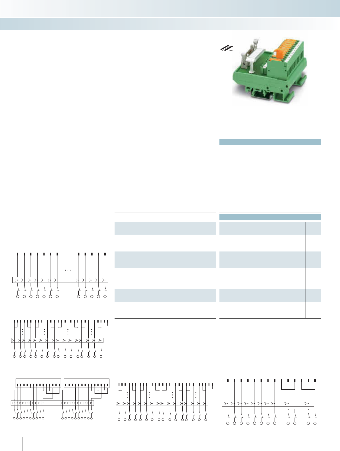
|
Technical data
FLKM...14/KDS 3-MT... FLKM 50/KDS 3-MT...
Max. perm. operating voltage 60 V DC 60 V DC
Max. perm. current (per branch) 1 A 1 A
Max. total current (voltage supply) 3 A 2 A (per byte)
Rated surge voltage 0.8 kV 0.8 kV
Ambient temperature (operation) -20°C ... 50°C -20°C ... 50°C
Mounting position Any Any
Standards / regulations IEC 60664, DIN EN 50178, IEC 62103
Connection method Field level Screw connection with discon-
nect knife
Screw connection with discon-
nect knife
Control system level Flat-ribbon cable plug connector
in acc. with IEC 60603-13
Flat-ribbon cable plug connector
in acc. with IEC 60603-13
Connection data solid / stranded / AWG 0.2 ... 4 mm² / 0.2 ... 2.5 mm² / 24 - 12
Dimensions H / D 77 mm / 61 mm
Ordering data
Description No. of
poles
Module width
WType Order No. Pcs. /
Pkt.
VARIOFACE interface module, for eight channels, with knife dis-
connect terminal blocks and test sockets to the field and the system
14 67 mm FLKM 14/KDS3-MT/PPA/PLC 2290423 1
VARIOFACE interface module, for 32 channels, with knife dis-
connect terminal blocks and test sockets to the field and the system
50 214 mm FLKM 50/KDS3-MT/PPA/PLC 2290614 1
VARIOFACE interface module, for SIMATIC S7-300 with
SIMATIC-specific labeling (1-20), knife disconnect terminal blocks
and test sockets to the field and the system
14 113 mm FLKM-2FLK14/KDS3-MT/PPA/S7 2295062 1
VARIOFACE interface module, same as before, however, with
SIMATIC-specific labeling (1-40)
50 214 mm FLKM 50/KDS3-MT/PPA/S7-300 2304490 1
VARIOFACE interface module, same as before, however, for
SIMATIC S7-400 with SIMATIC-specific labeling (3-48)
50 259 mm FLKM 50/KDS3-MT/PPA/AN/PLC 2291587 1
260 PHOENIX CONTACT
123 101112 131415 22 23 24 2526 27 34 3536 373839 4647484950
+B0.0
B0.7 -+ B1.0 B1.7 -+B2.0 B2.7 -+B3.0 B3.7 -
FLKM 50/KDS3-MT/PPA/PLC connection scheme
12345678911
13 10 12 14
1234567
0++--
FLKM 14/KDS3-MT/PPA/PLC connection scheme
1234567891011121314 1234567891011121314
12345678910 11
121314151617181920
FLKM-2FLK14/KDS3-MT/PPA/S7 connection scheme
123101112 131415 22 2324 25 26 27 3435363738 39 4647484950
1 29 1011121920212229303132
39 40
FLKM 50/KDS3-MT/PPA/S7-300 connection scheme
1234567 4647
48 49 50
1234567 46 47 48 49 50
FLKM 50/KDS3-MT/PPA/AN/PLC connection scheme
These VARIOFACE modules with knife
disconnection and test connection for each
signal (2 or 2.3 mm Ø test plug) are used in
combination with the respective front
adapters.
FLKM14/KDS3-MT/PPA/PLC
(for 8 channels)
FLKM 50/KDS3-MT/PPA/PLC
(for 32 channels)
– Byte-wise labeling
– Can be used for digital I/O modules
FLKM-2FLK14/KDS3-MT/PPA/S7
– Numerical labeling (1-20)
– Specially for S7-300 (in conjunction with
the front adapter FLKM 14-PA-S300,
Order No.: 2299770)
FLKM 50/KDS3-MT/PPA/7-300
– Numerical labeling (1-40)
– Specially for S7-300 (in conjunction with
the front adapter FLKM 50-PA-S300,
Order No.: 2294445)
FLKM 50/KDS3-MT/PPA/AN/PLC
– Numerical labeling (1-50)
– Specially for S7-400 (in conjunction with
the front adapter FLKM 50-PA-S400 (3-48)
Order No. 2294908)
Controller boards with knife disconnect
terminal blocks
INTERFACE Cabling
VARIOFACE system cabling
DW
H
Passive interface modules for eight or 32
channels with knife disconnect terminal
blocks
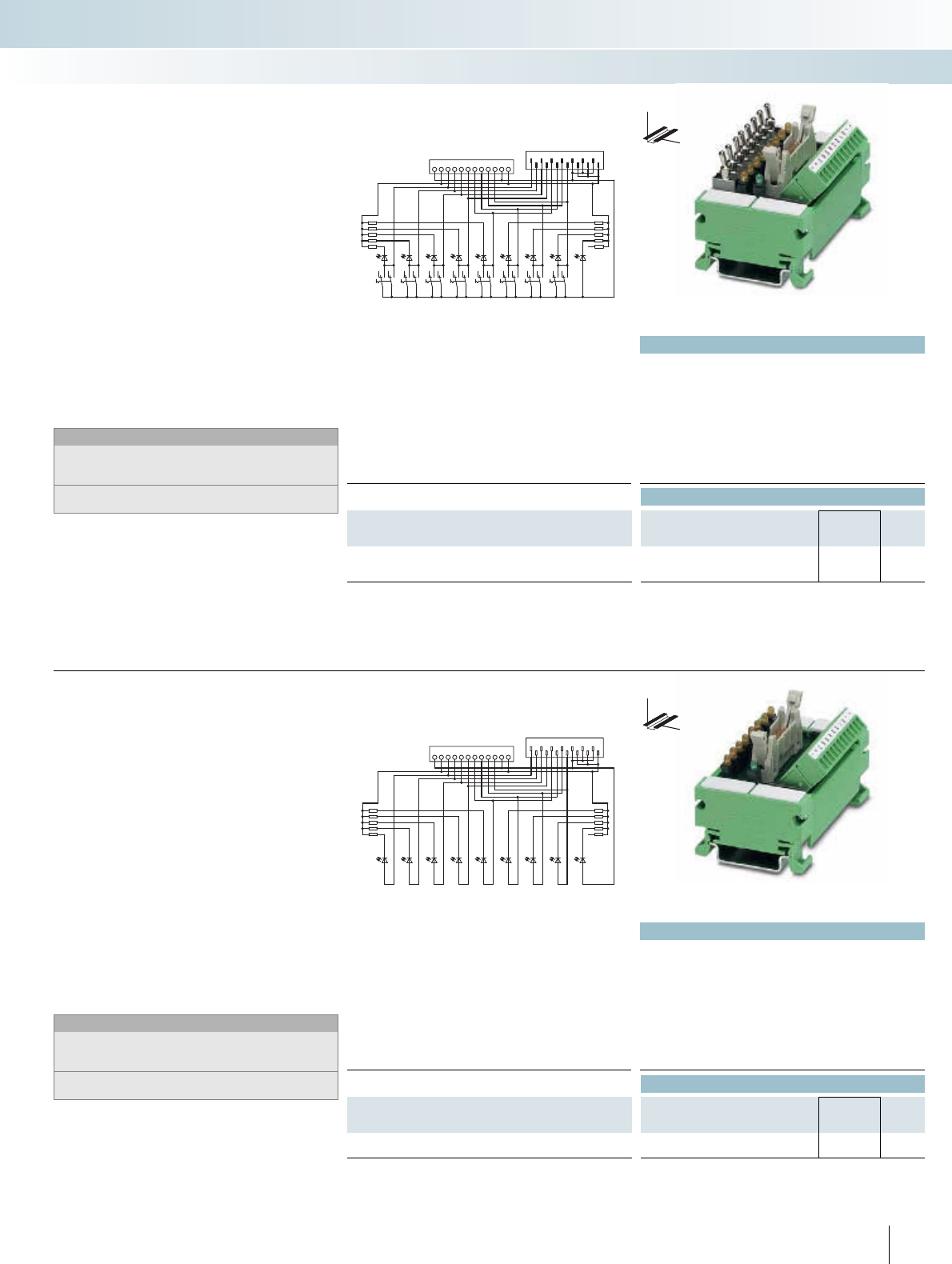
For additional information, visit www.phoenixcontact.net/catalog
Technical data
Max. perm. operating voltage 24 V DC
Max. perm. current (per branch) 1 A
Max. total current (voltage supply) 8 A (+, - terminal block)
Rated surge voltage 0.8 kV
Ambient temperature (operation) -20°C ... 50°C
Mounting position Any
Standards / regulations IEC 60664, DIN EN 50178, IEC 62103
Connection data solid / stranded / AWG 0.14 ... 1.5 mm² / 0.14 ... 1.5 mm² / 28 - 16
Dimensions H / D 45 mm / 51 mm
Ordering data
Description No. of
poles
Module width
WType Order No. Pcs. /
Pkt.
VARIOFACE switch module, for simulation
75 mm UM 45-DI/DO/S/LA/SIM8 2968205 1
01234567-+ -+SMC 1,5
FLK 14 12346810
12 14
5791113
DW
H
These VARIOFACE modules enable sim-
ple simulation of the control and peripheral
hardware for 8 signals.
The UM 45-DI/DO/S/LA/SIM8 switch
module is assembled for signal transmission
with COMBICON screw connector for sin-
gle-wire wiring. Alternatively, connection to
the PLC system cabling is established
through a 14-pole flat-ribbon cable pin strip.
Connection to the front adapters of the
PLC system cabling is established through
14-pole system cables with socket strips.
Each signal path is allocated an LED which
signals the "high active" signal state. The
supply voltage to the modules is signaled via
a green LED.
Notes:
Type of housing:
Terminal blocks: Polyamide PA non-reinforced, color: Green.
Housing: PVC
For marking systems and mounting material, see
CLIPLINE catalog, part 2.
Simulation module with switches
INTERFACE Cabling
VARIOFACE system cabling
Switch module
Technical data
Max. perm. operating voltage 24 V DC
Max. perm. current (per branch) 1 A
Max. total current (voltage supply) 8 A (+, - terminal block)
Rated surge voltage 0.8 kV
Ambient temperature (operation) -20°C ... 50°C
Mounting position Any
Standards / regulations IEC 60664, DIN EN 50178, IEC 62103
Connection data solid / stranded / AWG 0.14 ... 1.5 mm² / 0.14 ... 1.5 mm² / 28 - 16
Dimensions H / D 45 mm / 51 mm
Ordering data
Description No. of
poles
Module width
WType Order No. Pcs. /
Pkt.
VARIOFACE display module, for simulation
75 mm UM 45-DO/LA/SIM8 2968195 1
261
PHOENIX CONTACT
SCM 1,5
FLK 14
+-01234567+-
12468
10 12 14
3 4 7 9 11 13
DW
H
These VARIOFACE modules enable sim-
ple simulation of the control and peripheral
hardware for 8 signals.
The UM 45-DO/LA/SIM8 display module
is assembled for signal transmission with
COMBICON screw connector for single-
wire wiring. Alternatively, connection to the
PLC system cabling is established through a
14-pole flat-ribbon cable pin strip. Connec-
tion to the front adapters of the PLC system
cabling is established through 14-pole sys-
tem cables with socket strips.
Each signal path is allocated an LED which
signals the "high active" signal state. The
supply voltage to the modules is signaled via
a green LED.
Notes:
Type of housing:
Terminal blocks: Polyamide PA non-reinforced, color: Green.
Housing: PVC
For marking systems and mounting material, see
CLIPLINE catalog, part 2.
Simulation module for display
Indicator module
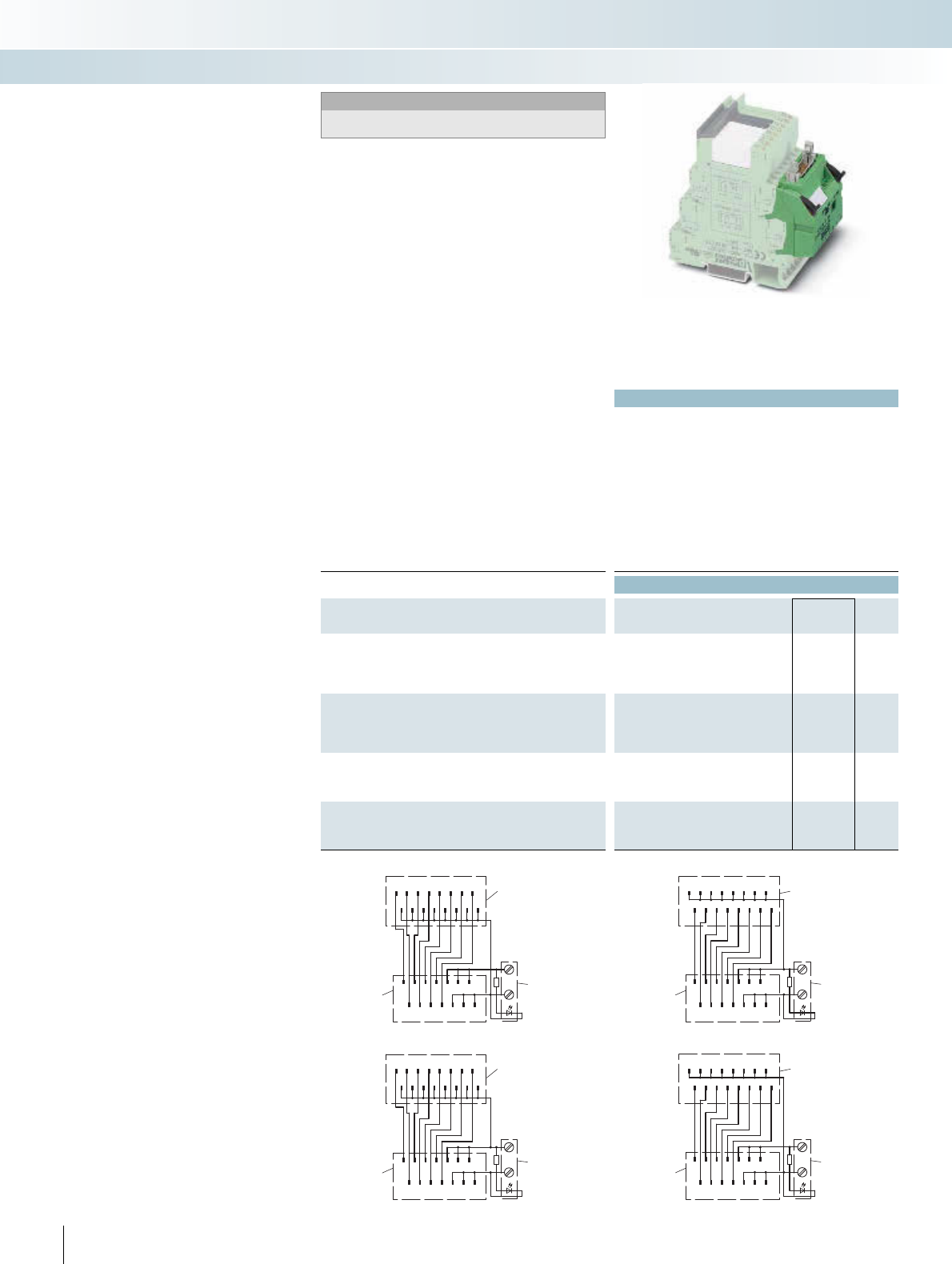
| £
262 PHOENIX CONTACT
Technical data
Max. perm. operating voltage 24 V DC ±25%
Max. perm. current (per branch) 1 A (per signal path)
Max. total current (voltage supply) 3 A
Rated surge voltage 0.8 kV
Ambient temperature (operation) -40°C ... 70°C
Standards / regulations IEC 60664, DIN EN 50178, IEC 62103
Connection method Power supply Screw connection
Signal level Flat-ribbon cable connector, in acc. with IEC 60603-13 (engage-
ment catches based on IEC 60603-13)
Connection data solid / stranded / AWG 0.2 ... 4 mm² / 0.2 ... 2.5 mm² / 24 - 12
Dimensions H / D 100 mm / 94 mm
Ordering data
Description No. of
poles
Module width
WType Order No. Pcs. /
Pkt.
V8 adapter, for 8 PLC interfaces (6.2 mm), with FLK connection,
for PLC system cabling, positive switching
OUTPUT 14 49.6 mm PLC-V8/FLK14/OUT 2295554 1
INPUT 14 49.6 mm PLC-V8/FLK14/IN 2296553 1
V8 adapter, for 8 PLC interfaces (6.2 mm), with FLK connection,
for PLC system cabling, negative switching
OUTPUT 14 49.6 mm PLC-V8/FLK14/OUT/M 2304102 1
INPUT 14 49.6 mm PLC-V8/FLK14/IN/M 2304115 1
V8 output adapter, for 8 PLC interfaces (6.2 mm), with 15-pole
D-SUB connection
Pin strip 15 49.6 mm PLC-V8/D15S/OUT 2296058 1
Socket strip 15 49.6 mm PLC-V8/D15B/OUT 2296061 1
V8 input adapter, for 8 PLC interfaces (6.2 mm), with 15-pole
D-SUB connection
Pin strip 15 49.6 mm PLC-V8/D15S/IN 2296074 1
Socket strip 15 49.6 mm PLC-V8/D15B/IN 2296087 1
1/1
135791113
2468101214
+
-
2/1
1/2
2/2
1/3
2/3
1/4
2/4
1/5
2/5
1/6
2/6
1/7
2/7
1/8
2/8
Contacting
PLC terminal blocks
Power
terminals
FLK14
Connection scheme: PLC-V8/FLK14/IN
1/1
135791113
2468101214
+
-
2/1
1/2
2/2
1/3
2/3
1/4
2/4
1/5
2/5
1/6
2/6
1/7
2/7
1/8
2/8
Contacting
PLC terminal blocks
Power
terminals
FLK14
Connection scheme: PLC-V8/FLK14/IN/M
1/1
135791113
2468101214
+
-
2/1
1/2
2/2
1/3
2/3
1/4
2/4
1/5
2/5
1/6
2/6
1/7
2/7
1/8
2/8
Contacting
PLC terminal blocks
Power
terminals
FLK14
PLC-V8/FLK14/OUT connection scheme
1/1
135791113
2468101214
+
-
2/1
1/2
2/2
1/3
2/3
1/4
2/4
1/5
2/5
1/6
2/6
1/7
2/7
1/8
2/8
Contacting
PLC terminal blocks
Power
terminals
FLK14
PLC-V8/FLK14/OUT/M connection scheme
PLC-V8/... are the VARIOFACE adapters
connecting the eight slim 6.2 mm PLC-IN-
TERFACE modules to the VARIOFACE sys-
tem cabling:
– Can be plugged into the bridge shafts of
eight aligned PLC-INTERFACE modules
– Freely definable configuration with relays,
optocouplers and passive feed-through
terminal blocks
– With D-SUB connection as an option for
universal connections
Adapter for PLC-INTERFACE
(6.2 mm)
INTERFACE Cabling
VARIOFACE system cabling
VARIOFACE adapter for 6.2 mm
PLC-INTERFACE
Notes:
Cross-reference list with matching PLC-INTERFACE modules,
see page 266.
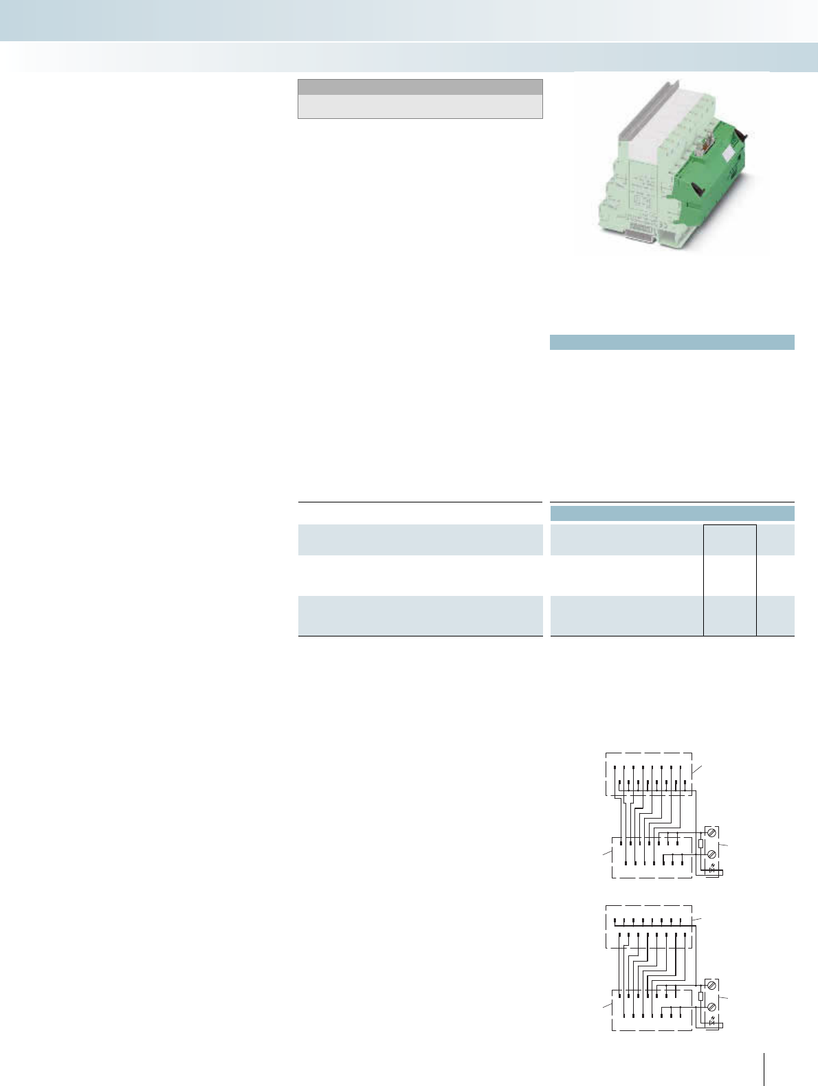
For additional information, visit www.phoenixcontact.net/catalog
| £
Applied for: UL / CUL
263PHOENIX CONTACT
Technical data
Max. perm. operating voltage 24 V DC ±25%
Max. perm. current (per branch) 1 A (per signal path)
Max. total current (voltage supply) 3 A
Rated surge voltage 0.8 kV
Ambient temperature (operation) -40°C ... 70°C
Mounting position Any
Standards / regulations IEC 60664, DIN EN 50178, IEC 62103
Connection method Power supply Screw connection
Signal level Flat-ribbon cable connector, in acc. with IEC 60603-13 (engage-
ment catches based on IEC 60603-13)
Connection data solid / stranded / AWG 0.2 ... 4 mm² / 0.2 ... 2.5 mm² / 24 - 12
Dimensions H / D 100 mm / 94 mm
Ordering data
Description No. of
poles
Module width
WType Order No. Pcs. /
Pkt.
V8 adapter, for 8 PLC interfaces (14 mm), with FLK connection, for
PLC system cabling, positive switching
14 112.3 mm PLC-V8L/FLK14/OUT 2299660 1
V8 adapter, for 8 PLC interfaces (14 mm), with FLK connection, for
PLC system cabling, negative switching
14 112.3 mm PLC-V8L/FLK14/OUT/M 2304306 1
1/1
135791113
2468101214
+
-
2/1
1/2
2/2
1/3
2/3
1/4
2/4
1/5
2/5
1/6
2/6
1/7
2/7
1/8
2/8
Contacting
PLC terminal blocks
Power
terminals
FLK14
PLC-V8L/FLK14/OUT/M connection scheme
1/1
135791113
2468101214
+
-
2/1
1/2
2/2
1/3
2/3
1/4
2/4
1/5
2/5
1/6
2/6
1/7
2/7
1/8
2/8
Contacting
PLC terminal blocks
Power
terminals
FLK14
PLC-V8L/FLK14/OUT connection scheme
PLC-V8L/... are the VARIOFACE adapt-
ers connecting the eight 14 mm PLC-IN-
TERFACE modules (2 PDT, HC, and IC
types) to the system cabling:
– Can be plugged into the bridge shafts of
eight aligned PLC-INTERFACE modules
– Freely selectable assembly with relays or
optocouplers
Adapter for PLC-INTERFACE
(14 mm)
INTERFACE Cabling
VARIOFACE system cabling
VARIOFACE adapter for 14 mm
PLC-INTERFACE
Notes:
Cross-reference list with matching PLC-INTERFACE modules,
see page 266.
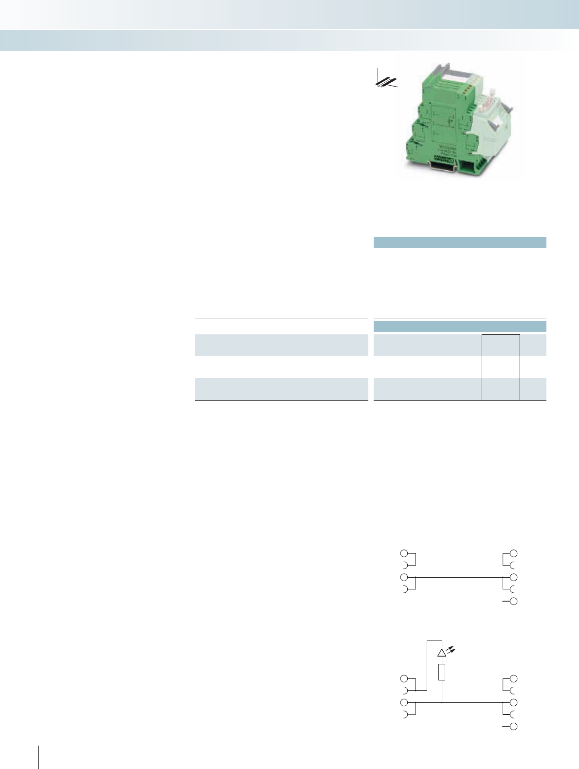
| £
264 PHOENIX CONTACT
Technical data
PLC-VT PLC-VT/LA
Max. perm. operating voltage Max. 250 V AC/DC 24 V DC
Max. perm. current (per branch) 6 A (per signal conductor) 6 A (per signal conductor)
Ambient temperature (operation) -40°C ... 70°C -40°C ... 70°C
Mounting position Any Any
Standards / regulations DIN EN 50178, IEC 62103
Connection data solid / stranded / AWG 0.2 ... 4 mm² / 0.2 ... 2.5 mm² / 24 - 12
Dimensions H / D 80 mm / 94 mm
Ordering data
Description No. of
poles
Module width
WType Order No. Pcs. /
Pkt.
VARIOFACE feed-through terminal block (two-wire connec-
tion), for PLC-INTERFACE universal series
6.2 mm PLC-VT 2296870 10
VARIOFACE feed-through terminal block, same as before, how-
ever, with 24 V DC light indicator
6.2 mm PLC-VT/LA 2296854 10
2
1
3
4
5
NC
PLC-VT/LA connection scheme
2
1
3
4
5
NC
PLC-VT connection scheme
The VARIOFACE PLC-VT terminals are
passive feed-through terminal blocks, with
the same shape as the 6.2 mm slim relay and
optocoupler interfaces PLC-INTERFACE. It
is therefore possible to implement 8-chan-
nel interface blocks for the system cabling,
which can be adapted to a bit for the partic-
ular application. For individual require-
ments, the relay, optocoupler or the PLC-
VT terminal blocks for passive signal trans-
mission can be combined as needed.
PLC-VT
PLC-VT/LA
– Can be combined with PLC-INTERFACE
universal series
– Signal path with additional potential level
for free assignment (two-wire connec-
tion)
– Optionally with LED
Feed-through terminal blocks for
PLC-INTERFACE
INTERFACE Cabling
VARIOFACE system cabling
DW
H
VARIOFACE feed-through terminal blocks for
PLC-INTERFACE universal series
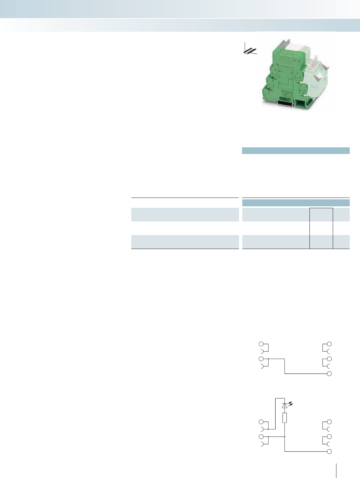
For additional information, visit www.phoenixcontact.net/catalog
| £
265
PHOENIX CONTACT
Technical data
PLC-VT/AKT PLC-VT/AKT/LA
Max. perm. operating voltage Max. 250 V AC/DC 24 V DC
Max. perm. current (per branch) 6 A (per signal conductor) 6 A (per signal conductor)
Ambient temperature (operation) -40°C ... 70°C -40°C ... 70°C
Mounting position Any Any
Standards / regulations DIN EN 50178, IEC 62103
Connection data solid / stranded / AWG 0.2 ... 4 mm² / 0.2 ... 2.5 mm² / 24 - 12
Dimensions H / D 80 mm / 94 mm
Ordering data
Description No. of
poles
Module width
WType Order No. Pcs. /
Pkt.
VARIOFACE feed-through terminal block (three-wire connec-
tion), for PLC-INTERFACE actuator series
6.2 mm PLC-VT/ACT 2295567 10
VARIOFACE feed-through terminal block, same as before, how-
ever, with 24 V DC light indicator
6.2 mm PLC-VT/ACT/LA 2296867 10
2
1
3
4
5
PLC-VT/ACT/LA connection scheme
2
1
3
4
5
PLC-VT/ACT connection scheme
The VARIOFACE PLC-VT terminals are
passive feed-through terminal blocks, with
the same shape as the 6.2 mm slim relay and
optocoupler interfaces PLC-INTERFACE. It
is therefore possible to implement 8-chan-
nel interface blocks for the system cabling,
which can be adapted to a bit for the partic-
ular application. For individual require-
ments, the relay, optocoupler or the PLC-
VT terminal blocks for passive signal trans-
mission can be combined as needed.
PLC-VT/ACT
PLC-VT/ACT/LA
– Can be combined with PLC-INTERFACE
actuator series
– Signal path with two additional potential
levels for free assignment (three-wire
connection)
– Optionally with LED
The system connection is made via the
PLC-V8 adapter.
Feed-through terminal blocks for
PLC-INTERFACE
INTERFACE Cabling
VARIOFACE system cabling
DW
H
VARIOFACE feed-through terminal blocks for
PLC-INTERFACE actuator series
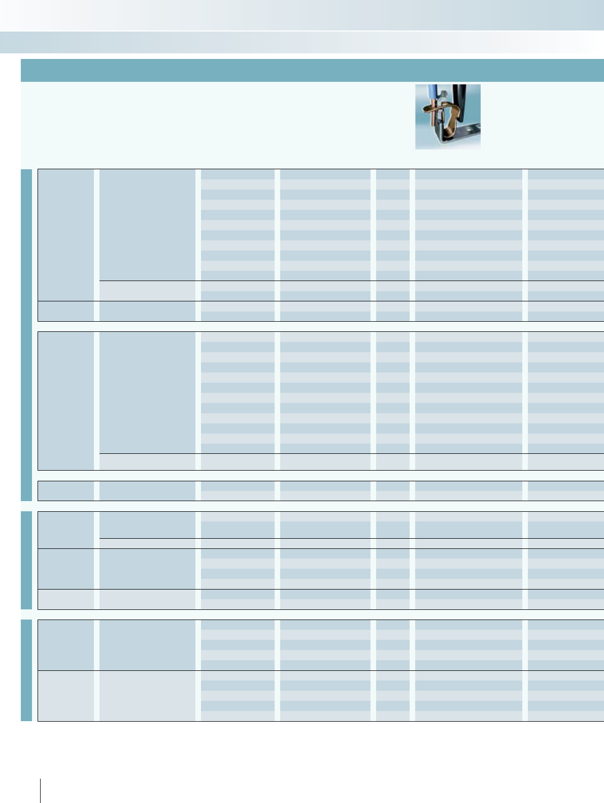
INTERFACE Cabling
VARIOFACE system cabling
1) Plug-in miniature relay insert: REL-MR-60DC/21AU, 2961134
2) Plug-in solid-state relay insert: OPT-60DC/48DC/100, 2966621
3) PLC-...SO46 is supplied as a basic terminal block with filter, but without relay or solid-state relay.
4) Cannot be combined with the universal series (within a byte)
Cross-reference list for PLC-V8 adapters with matching PLC-INTERFACE modules
Series
Function Contact Input Output Page Spring-cage connection Order No.:
Universal
Relay
1 PDT
24 V DC 250 V AC/DC / 6 A 82 PLC-RSP-24DC/21 2966472
24 V DC 250 V AC/DC / 10 A 93 PLC-RSP-24DC/21HC 2912277
12 V DC 30 V AC/36 V DC / 50 mA 83 PLC-RSP-12DC/21AU 2967442
24 V DC 30 V AC/36 V DC / 50 mA 83 PLC-RSP-24DC/21AU 2966540
24 V AC/DC 30 V AC/36 V DC / 50 mA 83 PLC-RSP-24UC/21AU 2966553
48 V DC 30 V AC/36 V DC / 50 mA 83 PLC-RSP-48DC/21AU 2966566
60 V DC 30 V AC/36 V DC / 50 mA 83 PLC-RSP-60DC/21AU 2966579
120 V AC/DC 30 V AC/36 V DC / 50 mA 83 PLC-RSP-120UC/21AU 2966582
230 V AC/DC 30 V AC/36 V DC / 50 mA 83 PLC-RSP-230UC/21AU 2966647
120 V AC 30 V AC/36 V DC / 50 mA1) 94 PLC-BSP-120UC/21/SO46 29803513)
230 V AC 30 V AC/36 V DC / 50 mA1) 94 PLC-BSP-230UC/21/SO46 29803773)
2 PDT 24 V DC 250 V AC/DC / 6 A 83 PLC-RSP-24DC/21-21 2912507
24 V DC 30 V AC/DC / 50 mA 83 PLC-RSP-24DC/21-21AU 2912578
Relay switch 1 N/O contact 24 V AC/DC 250 V AC/DC / 6 A 110 PLC-RSP-24UC/1/S/H 2982249
24 V AC/DC 250 V AC/DC / 6 A 110 PLC-RSP-24UC/1/S/L 2834889
Optocoupler
1 N/O contact, electronic
24 V DC 24 V DC / 3 A 85 PLC-OSP-24DC/24DC/2 2967471
24 V DC 24 V DC / 10 A 113 PLC-OSP-24DC/24DC/10/R 2982715
24 V DC 250 V AC / 0.75 A 85 PLC-OSP-24DC/230AC/1 2967895
24 V DC 300 V DC / 1 A 112 PLC-OSP-24DC/300DC/1 2980830
24 V DC 48 V DC / 100 mA 84 PLC-OSP-24DC/48DC/100 2967549
48 V DC 48 V DC / 100 mA 84 PLC-OSP-48DC/48DC/100 2967743
60 V DC 48 V DC / 100 mA 84 PLC-OSP-60DC/48DC/100 2967756
120 V AC/DC 48 V DC / 100 mA 84 PLC-OSP-120UC/48DC/100 2967552
230 V AC/DC 48 V DC / 100 mA 84 PLC-OSP-230UC/48DC/100 2967565
NAMUR 24 V DC / 50 mA 122 PLC-SP-EIK 1-SVN 24P/P 2982676
120 V AC 48 V DC / 100 mA2) 94 PLC-BSP-120UC/21/SO46 29803513)
230 V AC 48 V DC / 100 mA2) 94 PLC-BSP-230UC/21/SO46 29803773)
1 PDT, electronic 24 V DC 48 V DC / 0.5 A 113 PLC-OSP-24DC/48DC/500/W 2980649
Feed-through –250 V AC/DC 250 V AC/DC 264 –
24 V DC 24 V DC 264 –
Actuator
Relay 1 N/O contact
24 V DC 250 V AC/DC / 6 A 86 PLC-RSP-24DC/1/ACT 2967345
24 V DC 250 V AC/DC / 10 A
(80 A; 20 ms) 92 PLC-RSP-24DC/1IC/ACT 2912413
2 N/O contacts 24 V DC 250 V AC/DC / 6 A 87 –
Optocoupler 1 N/O contact, electronic
24 V DC 24 V DC / 3 A 87 PLC-OSP-24DC/24DC/2/ACT 2967507
24 V DC 24 V DC / 5 A 88 –
24 V DC 250 V AC / 0.75 A 87 –
24 V DC 250 V AC / 2 A 88 –
Feed-through –250 V AC/DC 250 V AC/DC 265 –
24 V DC 24 V DC 265 –
Sensor4)
Relay 1 N/O contact
24 V DC 30 V AC/36 V DC / 50 mA 90 PLC-RSP-24DC/1AU/SEN 2967374
120 V AC/DC 30 V AC/36 V DC / 50 mA 90 PLC-RSP-120UC/1AU/SEN 2967390
230 V AC/DC 30 V AC/36 V DC / 50 mA 90 PLC-RSP-230UC/1AU/SEN 2967413
120 V AC 30 V AC/36 V DC / 50 mA1) 95 PLC-BSP-120UC/1/SEN/SO46 29803643)
230 V AC 30 V AC/36 V DC / 50 mA1) 95 PLC-BSP-230UC/1/SEN/SO46 29803803)
Optocoupler 1 N/O contact, electronic
24 V DC 48 V DC / 100 mA 91
PLC-OSP-24DC/48DC/100/SEN
2967578
120 V AC/DC 48 V DC / 100 mA 91
PLC-OSP-120UC/48DC/100/SEN
2967581
230 V AC/DC 48 V DC / 100 mA 91
PLC-OSP-230UC/48DC/100/SEN
2967594
120 V AC 48 V DC / 100 mA2) 95 PLC-BSP-120UC/1/SEN/SO46 29803643)
230 V AC 48 V DC / 100 mA2) 95 PLC-BSP-230UC/1/SEN/SO46 29803803)
266 PHOENIX CONTACT
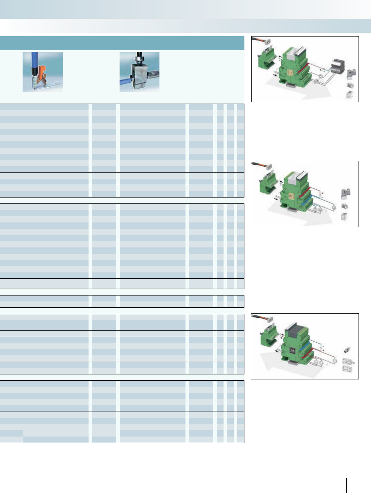
INTERFACE Cabling
VARIOFACE system cabling
PLC universal series
The universal series of products can be
used as either input or output interfaces.
Each product consists of a basic terminal
block with a plug-in miniature relay
(PDT contact) or a plug-in solid-state relay.
PLC actuator series
In applications involving an interface
between the PLC and actuators (e.g.,
motors, contactors or solenoid valves)
often only an N/O function is required. In
such cases, the PLC...ACT output interface
is used. All actuator connections, including
the load return line, are connected directly.
This eliminates the need for additional
output terminal blocks.
PLC sensor series
In applications involving an interface
between the PLC and sensors (e.g.,
proximity switches, limit switches or
auxiliary contacts), an N/O function is often
required. In such cases, the PLC…SEN
input interface is used. All sensor
connections, including the supply voltage
for the sensors/switches, are connected
directly. This eliminates the need for
additional modular terminal blocks.
PLC-V8…OUT(/M)
PLC-V8…IN(/M)
PLC-V8L…OUT
Push-in connection Order No.: Screw connection Order No.:
PLC-RPT-24DC/21 2900299 PLC-RSC-24DC/21 2966171 X
PLC-RPT-24DC/21HC 2900291 PLC-RSC-24DC/21HC 2967620 X
PLC-RPT-12DC/21AU 2900317 PLC-RSC-12DC/21AU 2966919 X
PLC-RPT-24DC/21AU 2900306 PLC-RSC-24DC/21AU 2966265 X X
PLC-RPT-24UC/21AU 2900307 PLC-RSC-24UC/21AU 2966278 X X
PLC-RPT-48DC/21AU 2900308 PLC-RSC-48DC/21AU 2966126 X
PLC-RPT-60DC/21AU 2900309 PLC-RSC-60DC/21AU 2966142 X
PLC-RPT-120UC/21AU 2900310 PLC-RSC-120UC/21AU 2966281 X
PLC-RPT-230UC/21AU 2900311 PLC-RSC-230UC/21AU 2966294 X
PLC-RPT-120UC/21/SO46 29004533)PLC-BSC-120UC/21/SO46 29803193)X
PLC-RPT-230UC/21/SO46 29004553)PLC-BSC-230UC/21/SO46 29803353)X
PLC-RPT-24DC/21-21 2900330 PLC-RSC-24DC/21-21 2967060 X
PLC-RPT-24DC/21-21AU 2900338 PLC-RSC-24DC/21-21AU 2967125 X
PLC-RPT-24UC/1/S/H 2900328 PLC-RSC-24UC/1/S/H 2982236 X
PLC-RPT-24UC/1/S/L 2900327 PLC-RSC-24UC/1/S/L 2834876 X
PLC-OPT-24DC/24DC/2 2900364 PLC-OSC-24DC/24DC/2 2966634 X
PLC-OPT-24DC/24DC/10/R 2900398 PLC-OSC-24DC/24DC/10/R 2982702 X
PLC-OPT-24DC/230AC/1 2900369 PLC-OSC-24DC/230AC/1 2967840 X
PLC-OPT-24DC/300DC/1 2900383 PLC-OSC-24DC/300DC/1 2980678 X
PLC-OPT-24DC/48DC/100 2900352 PLC-OSC-24DC/48DC/100 2966728 X X
PLC-OPT-48DC/48DC/100 2900353 PLC-OSC-48DC/48DC/100 2966993 X
PLC-OPT-60DC/48DC/100 2900354 PLC-OSC-60DC/48DC/100 2967455 X
PLC-OPT-120UC/48DC/100 2900355 PLC-OSC-120UC/48DC/100 2966744 X
PLC-OPT-230UC/48DC/100 2900356 PLC-OSC-230UC/48DC/100 2966757 X
PLC-PT-EIK 1-SVN 24P/P 2900397 PLC-SC-EIK 1-SVN 24P/P 2982663 X
PLC-BPT-120UC/21/SO46 29004533)PLC-BSC-120UC/21/SO46 29803193)X
PLC-BPT-230UC/21/SO46 29004553)PLC-BSC-230UC/21/SO46 29803353)X
PLC-OPT-24DC/48DC/500/W 2900378 PLC-OSC-24DC/48DC/500/W 2980636 X
–PLC-VT 2296870 X X
–PLC-VT/LA 2296854 X X
PLC-RPT-24DC/1/ACT 2900312 PLC-RSC-24DC/1/ACT 2966210 X
PLC-RPT-24DC/1IC/ACT 2900298 PLC-RSC-24DC/1IC/ACT 2967604 X
–PLC-RSC-24DC/1-1/ACT 2967109 X
PLC-OPT-24DC/24DC/2/ACT 2900376 PLC-OSC-24DC/24DC/2/ACT 2966676 X
–PLC-OSC-24DC/24DC/5/ACT 2982786 X
–PLC-OSC-24DC/230AC/1/ACT 2967947 X
–PLC-OSC-24DC/230AC/2/ACT 2982760 X
–PLC-VT/AKT 2295567 X
–PLC-VT/AKT/LA 2296867 X
PLC-RPT-24DC/1AU/SEN 2900313 PLC-RSC-24DC/1AU/SEN 2966317 X
PLC-RPT-120UC/1AU/SEN 2900314 PLC-RSC-120UC/1AU/SEN 2966320 X
PLC-RPT-230UC/1AU/SEN 2900315 PLC-RSC-230UC/1AU/SEN 2966333 X
PLC-BPT-120UC/1/SEN/SO46 29004563)PLC-BSC-120UC/1/SEN/SO46 29803223)X
PLC-BPT-230UC/1/SEN/SO46 29004573)PLC-BSC-230UC/1/SEN/SO46 29803483)X
PLC-OPT-24DC/48DC/100/SEN
2900358
PLC-OSC-24DC/48DC/100/SEN
2966773 X
PLC-OPT-120UC/48DC/100/SEN
2900359
PLC-OSC-120UC/48DC/100/SEN
2966799 X
PLC-OPT-230UC/48DC/100/SEN
2900361
PLC-OSC-230UC/48DC/100/SEN
2966809 X
PLC-BPT-120UC/1/SEN/SO46 29004563)PLC-BSC-120UC/1/SEN/SO46 29803223)X
PLC-BPT-230UC/1/SEN/SO46 29004573)PLC-BSC-230UC/1/SEN/SO46 29803483)X
267PHOENIX CONTACT
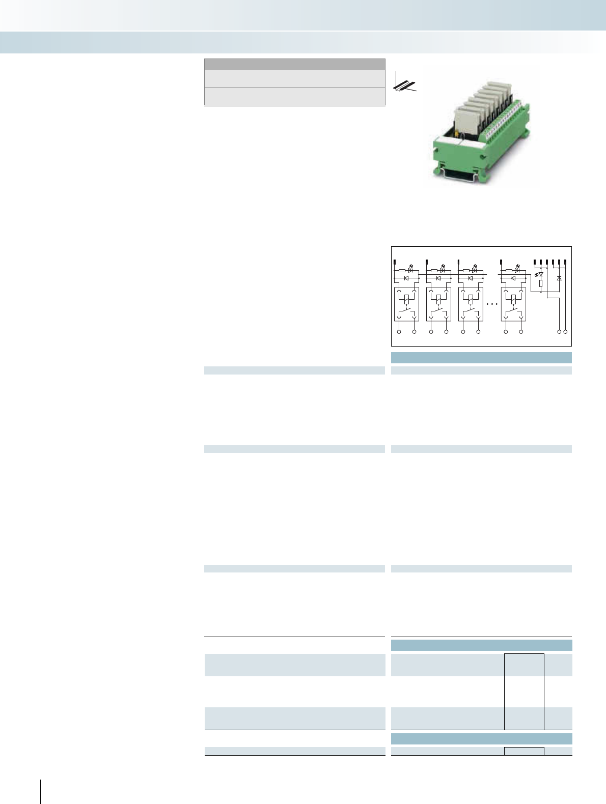
|
Technical data
Coil side
Operating voltage UN24 V DC
Typ. input current at UN6.5 mA
Typ. response time at UN5 ms
Typ. release time at UN15 ms
Input circuit Free-wheeling diode, protection against polarity reversal
Status display/channel Yellow LED
Connection method Flat-ribbon cable plug connector in acc. with IEC 60603-13
No. of poles 14
Contact side
Contact type 1 N/O contact (double contact)
Contact material AgNi, 5 μm hard gold-plated
Max. switching voltage 250 V AC / 125 V DC
Min. switching voltage 5 V
Max. inrush current 5 A
Limiting continuous current 3 A
Min. switching current 1 mA
Max. interrupting rating: 24 V DC 72 W
48 V DC 60 W
60 V DC 50 W
110 V DC 50 W
250 V AC 750 VA
Connection method Screw connection
Connection data solid / stranded / AWG 0.14 ... 1.5 mm² / 0.14 ... 1.5 mm² / 26 - 14
General data
Test voltage 2 kV AC (50 Hz, 1 min.)
Ambient temperature (operation) -20°C ... 50°C
Nominal operating mode 100% operating factor
Mechanical service life 2 x 10⁷ cycles
Standards / regulations IEC 60664, DIN EN 50178, IEC 62103
Mounting position Any
Mounting In rows with zero spacing
Dimensions H / D 45 mm / 50 mm
Ordering data
Description Module width
WType Order No. Pcs. /
Pkt.
VARIOFACE COMPACT LINE output module, for
24 V DC (including relays)
- With 8 miniature relays 103 UM 45- 8RM/MR-G24/1/PLC 2962900 1
- With 16 miniature relays 215
VARIOFACE COMPACT LINE output expansion module, for
24 V DC (including relays)
- With 16 miniature relays 200
Accessories
Pluggable miniature relays REL-MR-G 24/1 2961037 8
268 PHOENIX CONTACT
123 89
1113101214
1238
14 13 24 23 34 33 84 83 + -
COMPACT-LINE output modules
with relays, one N/O contact
These VARIOFACE Compact Line output
modules are used in combination with the
respective front adapters.
Like the front adapters, the modules are
connected via 14-pole or 50-pole system
cables. The following features characterize
these relay modules:
– Pluggable miniature relays, each with an
N/O contact
– Universal applications from 1 mA to 3 A
continuous current through 2-layer dou-
ble contact with hard gold plating
– Low construction height of only 45 mm
– LED status display for each signal path and
supply voltage
– Free-wheeling and reverse polarity pro-
tection diode for each signal path
With the 32-channel version, the system
cable is connected to the 16-channel base
module UM 45-16RM/MR-G24/1/PLC. The
output expansion module UM 45-
16RM/MR-G24/1/E/PLC with a further
16 channels is coupled to the base module
via a 20-pole flat-ribbon cable
(length: 10 cm).
INTERFACE Cabling
VARIOFACE system cabling
DW
H
Notes:
The connecting cable between the base and the extension mod-
ules is delivered with the extension unit.
Due to the geometry, it is not possible to couple any molded FLK
connectors (e.g., VIP-PA...S7).
Output module with eight miniature relays,
one N/O contact
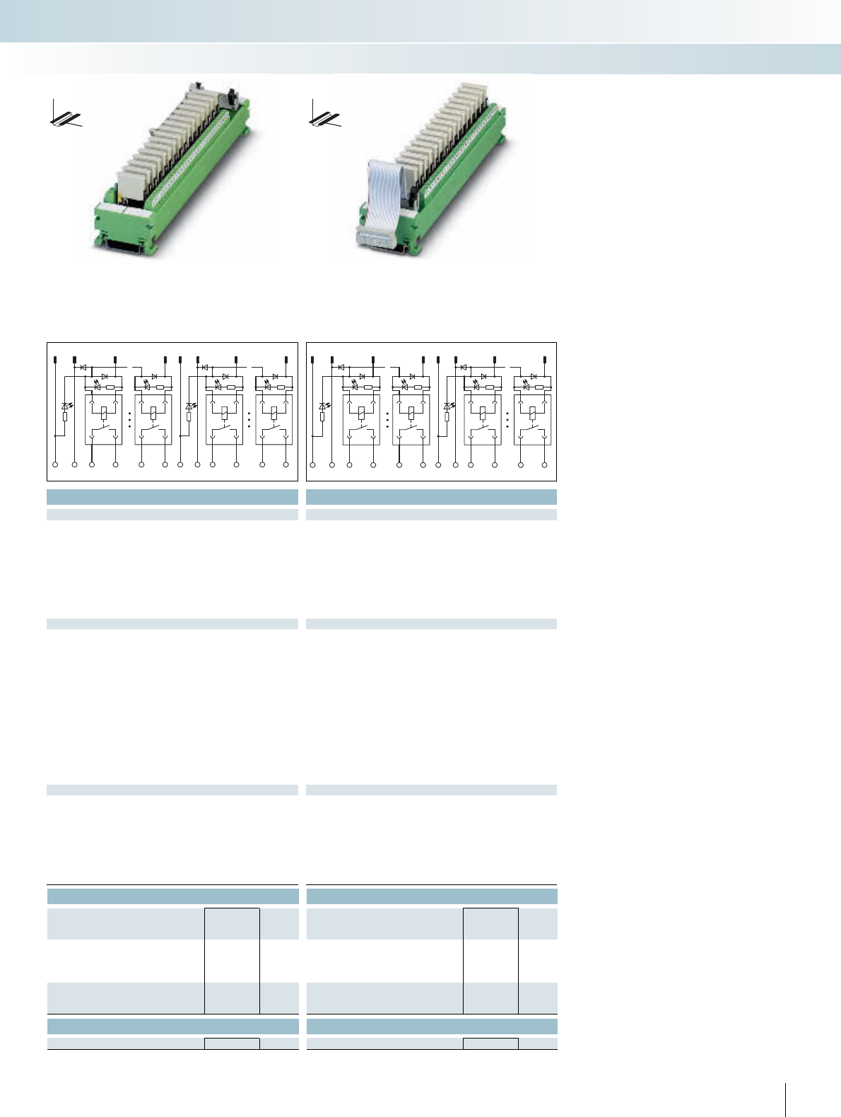
For additional information, visit www.phoenixcontact.net/catalog
||
Technical data Technical data
24 V DC 24 V DC
6.5 mA 6.5 mA
5 ms 5 ms
15 ms 15 ms
Free-wheeling diode, protection against polarity reversal Free-wheeling diode, protection against polarity reversal
Yellow LED Yellow LED
Flat-ribbon cable plug connector in acc. with IEC 60603-13 Flat-ribbon cable plug connector in acc. with IEC 60603-13
50 20
1 N/O contact (double contact) 1 N/O contact (double contact)
AgNi, 5 μm hard gold-plated AgNi, 5 μm hard gold-plated
250 V AC / 125 V DC 250 V AC / 125 V DC
5 V 5 V
5 A 5 A
3 A 3 A
1 mA 1 mA
72 W 72 W
60 W 60 W
50 W 50 W
50 W 50 W
750 VA 750 VA
Screw connection Screw connection
0.14 ... 1.5 mm² / 0.14 ... 1.5 mm² / 26 - 14 0.14 ... 1.5 mm² / 0.14 ... 1.5 mm² / 26 - 14
2 kV (50 Hz, 1 min.) 2 kV (50 Hz, 1 min.)
-20°C ... 50°C -20°C ... 50°C
100% operating factor 100% operating factor
2 x 10⁷ cycles 2 x 10⁷ cycles
IEC 60664, DIN EN 50178, IEC 62103 IEC 60664, DIN EN 50178, IEC 62103
Any Any
In rows with zero spacing In rows with zero spacing
45 mm / 50 mm 45 mm / 50 mm
Ordering data Ordering data
Type Order No. Pcs. /
Pkt. Type Order No. Pcs. /
Pkt.
UM 45-16RM/MR-G24/1/PLC 2962913 1
UM 45-16RM/MR-G24/1/E/PLC 2962926 1
Accessories Accessories
REL-MR-G 24/1 2961037 8REL-MR-G 24/1 2961037 8
269PHOENIX CONTACT
1,2 11,12 310 13,14 23,24 15 22
18 916
B0
+-
B0 14 13 84 83
+-
B1 B1 94 93 164 163
220 17 121
19 9 4
322524
17
B2 B2
+-
174 173 244 243 B3 B3 254 253 324 323
+-
INTERFACE Cabling
VARIOFACE system cabling
DW
H
DW
H
Output base module with 16 miniature relays,
one N/O contact
Output extension module with 16 miniature relays,
one N/O contact
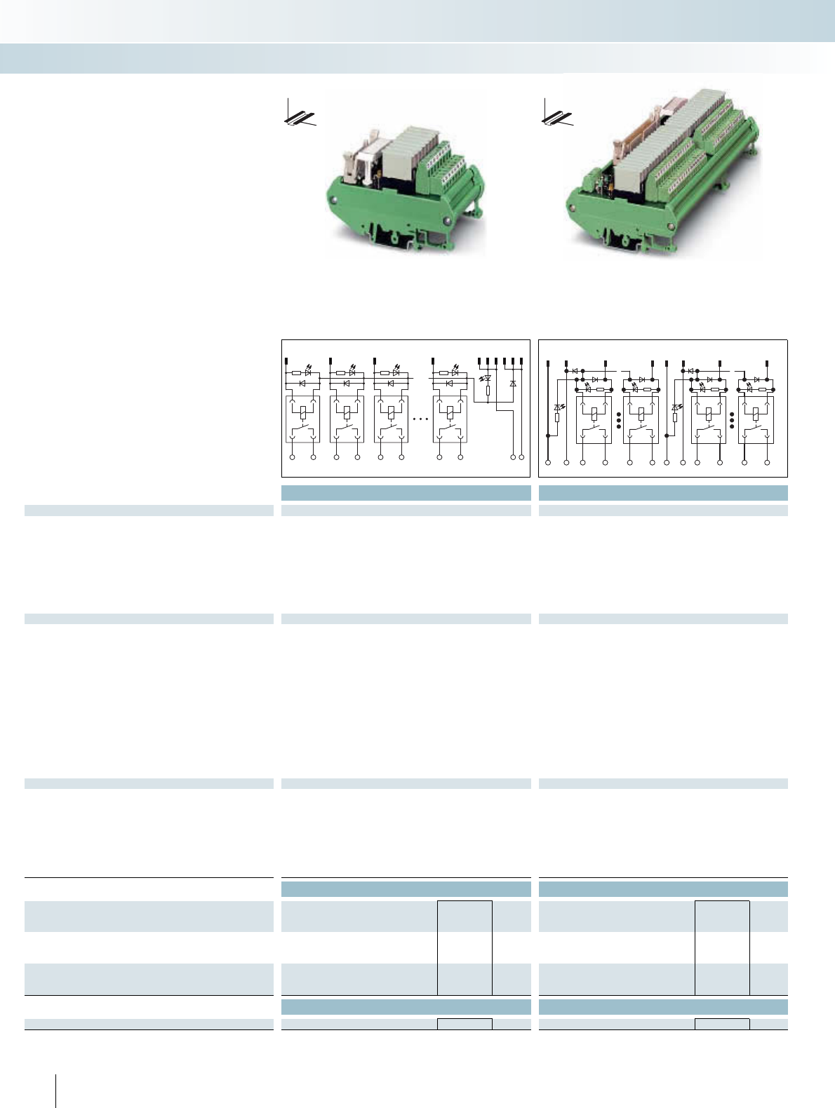
| |
Technical data Technical data
Coil side
Operating voltage UN24 V DC 24 V DC
Typ. input current at UN6.5 mA 6.5 mA
Typ. response time at UN5 ms 5 ms
Typ. release time at UN15 ms 15 ms
Input circuit Free-wheeling diode, protection against polarity reversal Free-wheeling diode, protection against polarity reversal
Status display/channel Yellow LED Yellow LED
Connection method Flat-ribbon cable plug connector in acc. with IEC 60603-13 Flat-ribbon cable plug connector in acc. with IEC 60603-13
No. of poles 14 50
Contact side
Contact type 1 N/O contact (double contact) 1 N/O contact (double contact)
Contact material AgNi, 5 μm hard gold-plated AgNi, 5 μm hard gold-plated
Max. switching voltage 250 V AC / 125 V DC 250 V AC / 125 V DC
Min. switching voltage 5 V 5 V
Max. inrush current 5 A 5 A
Limiting continuous current 3 A 3 A
Min. switching current 1 mA 1 mA
Max. interrupting rating: 24 V DC 72 W 72 W
48 V DC 60 W 60 W
60 V DC 50 W 50 W
110 V DC 50 W 50 W
250 V AC 750 VA 750 VA
Connection method Screw connection Screw connection
Connection data solid / stranded / AWG 0.14 ... 1.5 mm² / 0.14 ... 1.5 mm² / 26 - 14 0.14 ... 1.5 mm² / 0.14 ... 1.5 mm² / 26 - 16
General data
Test voltage 3 kV AC 3 kV AC
Ambient temperature (operation) -20°C ... 50°C -20°C ... 50°C
Nominal operating mode 100% operating factor 100% operating factor
Mechanical service life 2 x 10⁷ cycles 2 x 10⁷ cycles
Standards / regulations IEC 60664, DIN EN 50178, IEC 62103 IEC 60664, DIN EN 50178, IEC 62103
Mounting position Any Any
Mounting In rows with zero spacing In rows with zero spacing
Dimensions H / D 90 mm / 58 mm 90 mm / 58 mm
Ordering data Ordering data
Description Module width
WType Order No. Pcs. /
Pkt. Type Order No. Pcs. /
Pkt.
VARIOFACE output module, with eight miniature relays, plugged,
for 24 V DC (incl. relays)
56 UMK- 8 RM/MR-G24/ 1/PLC 2979469 1
VARIOFACE output module, with 32 miniature relays, plugged in,
for 24 V DC (including relays)
202 UMK-32 RM/MR-G24/1/PLC 2979472 1
Accessories Accessories
Pluggable miniature relays REL-MR-G 24/1 2961037 8REL-MR-G 24/1 2961037 8
270 PHOENIX CONTACT
These VARIOFACE output modules are
used in combination with the respective
front adapters.
– Pluggable miniature relays, each with an
N/O contact
– Universal applications from 1 mA to 3 A
continuous current through 2-layer dou-
ble contact with hard gold plating
– Slim construction widths of only 55 mm
(8 channels) or 202 mm (32 channels)
– LED status display for each signal path and
supply voltage
– Free-wheeling and reverse polarity pro-
tection diode for each signal path
DW
H
DW
H
Output modules with relays,
one N/O contact
INTERFACE Cabling
VARIOFACE system cabling
123 89
1113101214
1238
14 13 24 23 34 33 84 83 + -
1,211,12 310
13,14
23,24 15 46
32981
B0
+-
B0 14 13 84 83
+-
B1 B1 94 93 324 323
Output module with eight miniature relays,
one N/O contact
Output modules with 32 miniature relays,
one N/O contact
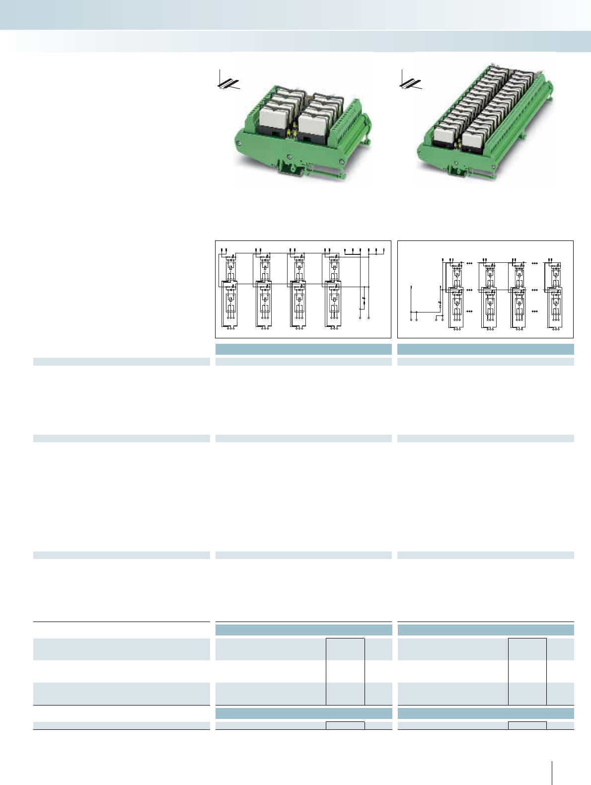
For additional information, visit www.phoenixcontact.net/catalog
Technical data Technical data
Coil side
Operating voltage UN24 V DC 24 V DC
Typ. input current at UN18 mA 18 mA
Typ. response time at UN8 ms 8 ms
Typ. release time at UN10 ms 10 ms
Input circuit Free-wheeling diode Free-wheeling diode
Status display/channel Yellow LED Yellow LED
Connection method Flat-ribbon cable plug connector in acc. with IEC 60603-13 Flat-ribbon cable plug connector in acc. with IEC 60603-13
No. of poles 14 50
Contact side
Contact type Single contact, 1 PDT Single contact, 1 PDT
Contact material AgNi AgNi
Max. switching voltage 250 V AC/DC 250 V AC/DC
Min. switching voltage 12 V AC/DC 12 V AC/DC
Limiting continuous current 5 A 5 A
Min. switching current 100 mA 100 mA
Max. interrupting rating: 24 V DC 120 W 120 W
48 V DC 58 W 58 W
60 V DC 48 W 48 W
110 V DC 50 W 50 W
220 V DC 80 W 80 W
250 V AC 1250 VA 1250 VA
Connection method Screw connection Screw connection
Connection data solid / stranded / AWG 0.2 ... 4 mm² / 0.2 ... 2.5 mm² / 24 - 12 0.2 ... 4 mm² / 0.2 ... 2.5 mm² / 24 - 12
General data
Test voltage 2.5 kV (50 Hz, 1 min.) 2.5 kV (50 Hz, 1 min.)
Ambient temperature (operation) -20°C ... 50°C -20°C ... 50°C
Nominal operating mode 100% operating factor 100% operating factor
Mechanical service life 3 x 10⁷ cycles 3 x 10⁷ cycles
Standards / regulations IEC 60664, DIN EN 50178, IEC 62103 IEC 60664, DIN EN 50178, IEC 62103
Mounting position Any Any
Mounting In rows with zero spacing In rows with zero spacing
Dimensions H / D 123 mm / 68 mm 123 mm / 68 mm
Ordering data Ordering data
Description Module width
WType Order No. Pcs. /
Pkt. Type Order No. Pcs. /
Pkt.
VARIOFACE output module, with eight miniature relays, plugged,
for 24 V DC (incl. relays)
80 UM- 8 RM/RT-G24/21/PLC 2968386 1
VARIOFACE output module, with 32 miniature relays, plugged in,
for 24 V DC (including relays)
271 UM-32 RM/RT-G24/21/PLC 2968373 1
Accessories Accessories
Pluggable miniature relays REL-MR- 24DC/21HC 2961312 10 REL-MR- 24DC/21HC 2961312 10
271PHOENIX CONTACT
These VARIOFACE output modules are
used in combination with the respective
front adapters.
Like the front adapters, the modules are
connected via 14-pole or 50-pole system
cables. The following features characterize
these relay modules:
– Pluggable miniature relays, each with a
PDT contact
– Slim construction widths of only 80 mm
(8 channels) or 271 mm (32 channels)
– LED status display for each signal path and
supply voltage
– Free-wheeling diode for each signal path
DW
H
DW
H
Output modules with relay, 1 PDT
INTERFACE Cabling
VARIOFACE system cabling
12 34 56 78911 13 10 12 14
24 6 8
75
31
22
21
24
12
11
14
32
31
34
42
41
44
52
51
54
62
61
64
72
71
74
82
81
84
+-
1,2,13,14,25,26,37,38
11,12,23,24,35,36,47,48
3
4
9
10
15
16
45
46
17
28
9
10
31
32
22
21
24
12
11
14
+
+
--
82
81
84
72
71
74
102
101
104
92
91
94
312
311
314
322
321
324
Output module with eight miniature relays,
1 PDT
Output module with 32 miniature relays,
1 PDT

Technical data
Coil side
Operating voltage UN24 V DC ±10%
Input circuit Free-wheeling diode, protection against polarity reversal
Operating voltage display Green LED
Status display/channel Yellow LED
Connection method Flat-ribbon cable plug connector in acc. with IEC 60603-13
No. of poles 14
Contact side
Contact type 1 PDT
Max. switching voltage 250 V AC/DC
Limiting continuous current 5 A
Connection method Screw connection
Connection data solid / stranded / AWG 0.2 ... 4 mm² / 0.2 ... 2.5 mm² / 24 - 12
General data
Test voltage 2.5 kV (50 Hz, 1 min.)
Ambient temperature (operation) -20°C ... 50°C
Standards / regulations IEC 60664, DIN EN 50178, IEC 62103
Mounting position Any
Mounting In rows with zero spacing
Dimensions H / D 90 mm / 68 mm
Ordering data
Description Module width
WType Order No. Pcs. /
Pkt.
VARIOFACE output module, with eight miniature relays, plugged,
for 24 V DC (incl. relays)
135 UMK- 8 RM/KSR-G 24/21/PLC 2979485 1
VARIOFACE output module, with plug-in bases for eight minia-
ture relays, for 24 V DC (without relays)
135 UMK- 8 RELS/KSR-G24/21/PLC 2974914 1
VARIOFACE output module, with 16 miniature relays, plugged,
for 24 V DC (base module, including relays)
259
VARIOFACE output module, with plug-in bases for 16 miniature
relays, for 24 V DC (base module, without relays)
259
VARIOFACE output extension module, with 16 miniature relays,
plugged, for 24 V DC (including relays)
259
VARIOFACE output extension module, with plug-in bases for
16 miniature relays, for 24 V DC (without relays)
259
Accessories
Pluggable miniature relays REL-MR- 24DC/21HC 2961312 10
272 PHOENIX CONTACT
123 8911
13101214
83
21
12 11 14 22 21 24 32 31 34 82 81 84 +-
Output modules with relay, 1 PDT
These VARIOFACE output modules are
used in combination with the respective
front adapters.
Like the front adapters, the modules are
connected via 14-pole or 50-pole system
cables. The following features characterize
these relay modules:
– Plug-in miniature relays with one PDT
each
– LED status display for each signal path and
supply voltage
– Free-wheeling and reverse polarity pro-
tection diode for each signal path
With the 32-channel version, the system
cable is connected to the base module with
16 channels UMK-16R.../KSR-G24/21/PLC.
The output expansion module
UMK-16R.../ KSR-G24/21/E/PLC with a
further 16 channels is coupled to the base
module via a 20-pole flat-ribbon cable
(length: 10 cm).
INTERFACE Cabling
VARIOFACE system cabling
DW
H
Notes:
The connecting cable between the base and the extension mod-
ules is delivered with the extension unit.
Output module with eight miniature relays,
1 PDT
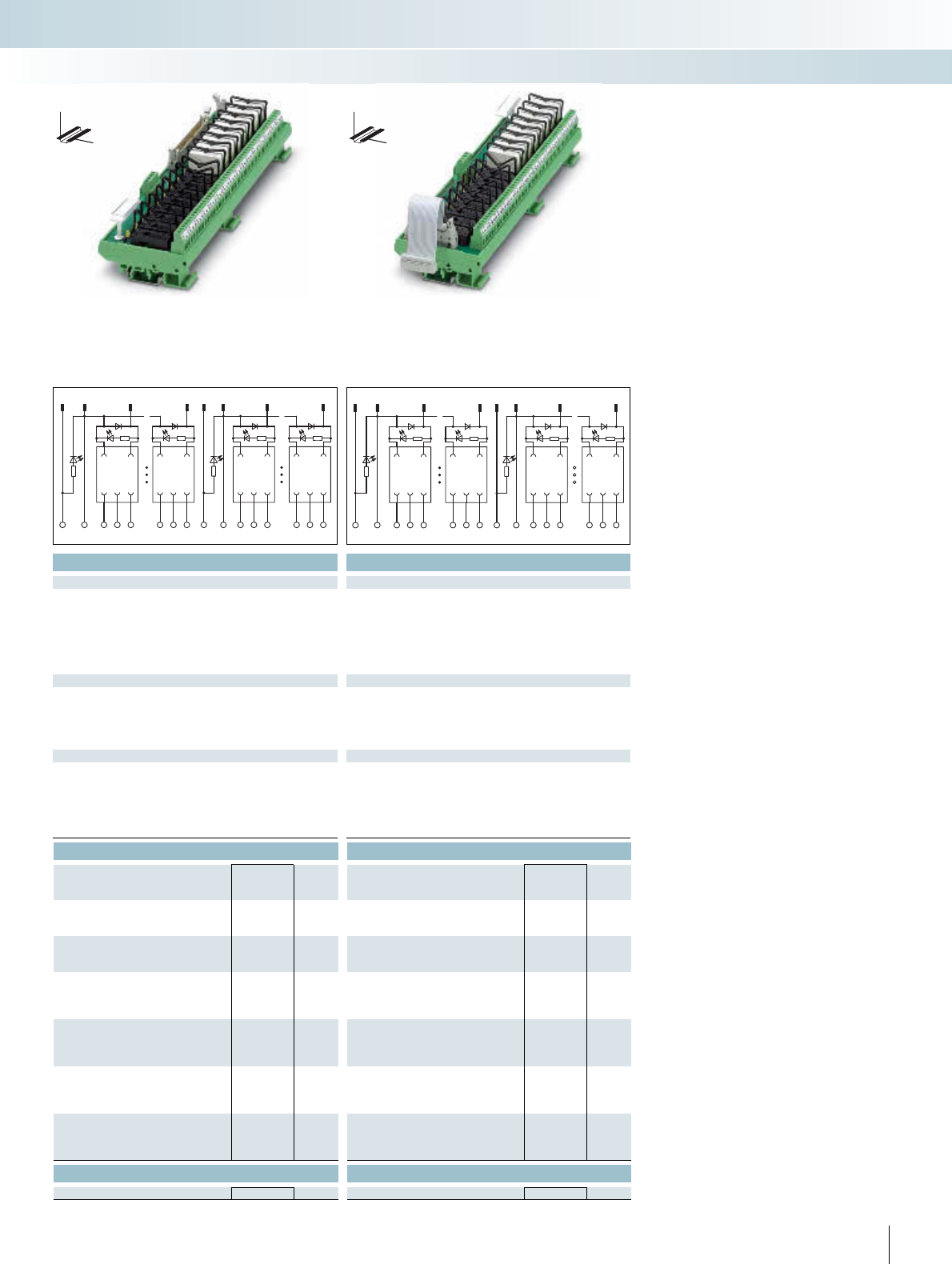
For additional information, visit www.phoenixcontact.net/catalog
Technical data Technical data
24 V DC ±10% 24 V DC ±10%
Free-wheeling diode, protection against polarity reversal Free-wheeling diode, protection against polarity reversal
Green LED Green LED
Yellow LED Yellow LED
Flat-ribbon cable plug connector in acc. with IEC 60603-13 Flat-ribbon cable plug connector in acc. with IEC 60603-13
50 20
1 PDT 1 PDT
250 V AC/DC 250 V AC/DC
5 A 5 A
Screw connection Screw connection
0.2 ... 4 mm² / 0.2 ... 2.5 mm² / 24 - 12 0.2 ... 4 mm² / 0.2 ... 2.5 mm² / 24 - 12
2.5 kV (50 Hz, 1 min.) 2.5 kV (50 Hz, 1 min.)
-20°C ... 50°C -20°C ... 50°C
IEC 60664, DIN EN 50178, IEC 62103 IEC 60664, DIN EN 50178, IEC 62103
Any Any
In rows with zero spacing In rows with zero spacing
90 mm / 68 mm 90 mm / 68 mm
Ordering data Ordering data
Type Order No. Pcs. /
Pkt. Type Order No. Pcs. /
Pkt.
UMK-16 RM/KSR-G 24/21/PLC 2979498 1
UMK-16 RELS/KSR-G24/21/PLC 2974901 1
UMK-16 RM/KSR-G 24/21/E/PLC 2979508 1
UMK-16 RELS/KSR-G24/21/E/PLC 2974891 1
Accessories Accessories
REL-MR- 24DC/21HC 2961312 10 REL-MR- 24DC/21HC 2961312 10
273PHOENIX CONTACT
1,2 11,12 310
13,1423,24 15 22
16
981
B0 B0
+-
11 14 12 81 84 82 B1 B1
+-
91 94 92 161164162
220 17 12119 94
3225
2417
B2 B2
+- +-
171 174 172 241244 242 B3 B3 251254 252 321 324 322
INTERFACE Cabling
VARIOFACE system cabling
DW
H
DW
H
Output base module with 16 miniature relays,
1 PDT
Output extension module with 16 miniature relays,
1 PDT
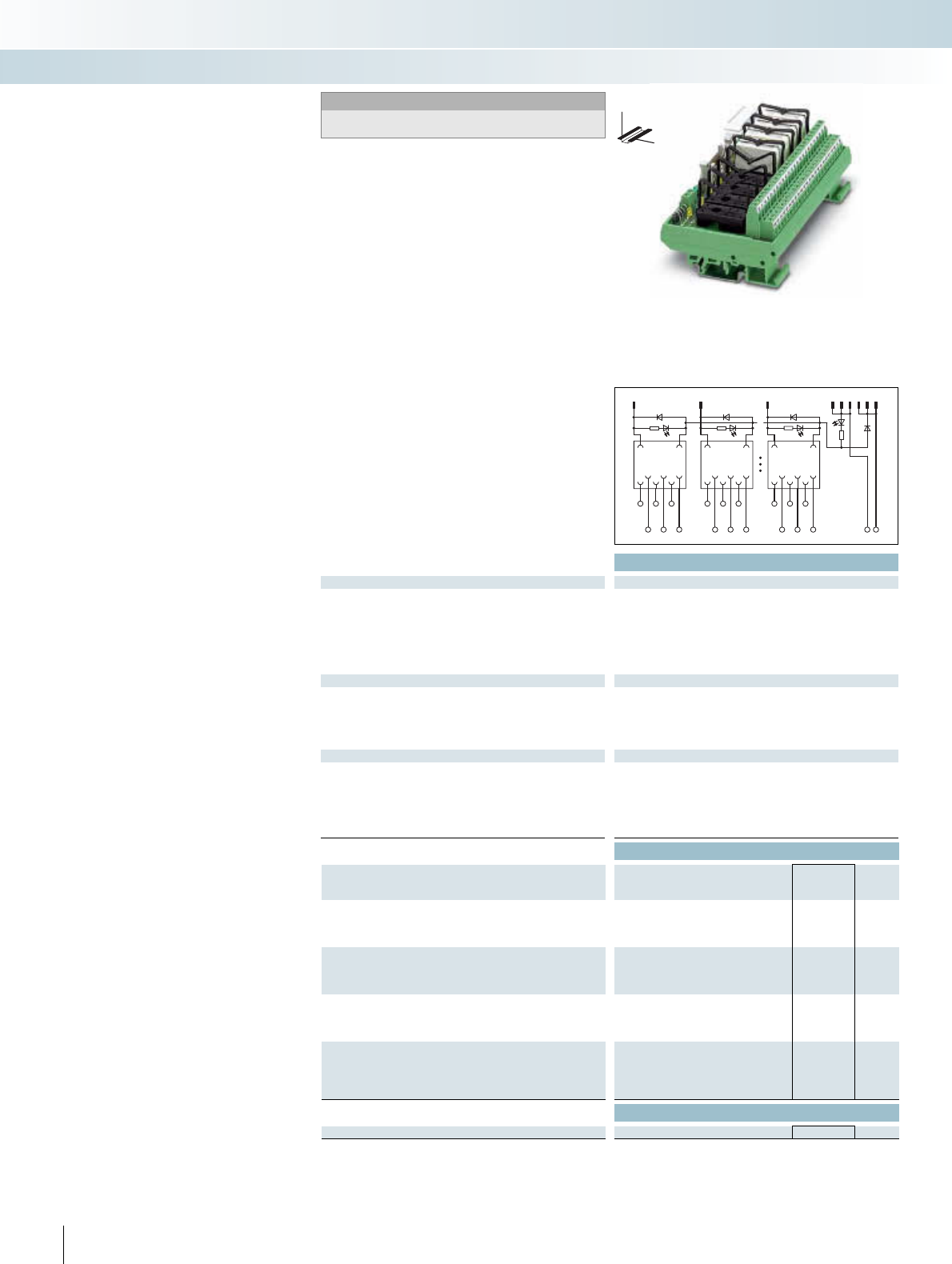
|
Technical data
Coil side
Operating voltage UN24 V DC
Input circuit Free-wheeling diode
Operating voltage display Green LED
Status display/channel Yellow LED
Connection method Flat-ribbon cable plug connector in acc. with IEC 60603-13
No. of poles 14
Contact side
Contact type 2 PDT
Max. switching voltage 250 V AC/DC
Limiting continuous current 3 A
Connection method Screw connection
Connection data solid / stranded / AWG 0.14 ... 1.5 mm² / 0.14 ... 1.5 mm² / 26 - 14
General data
Test voltage 2.5 kV AC
Ambient temperature (operation) -20°C ... 50°C
Standards / regulations IEC 60664, DIN EN 50178, IEC 62103
Mounting position Any
Mounting In rows with zero spacing
Dimensions H / D 90 mm / 68 mm
Ordering data
Description Module width
WType Order No. Pcs. /
Pkt.
VARIOFACE output module, with plug-in bases for eight minia-
ture relays, for 24 V DC, each with two PDTs (without relays)
135 UMK- 8 RELS/KSR-G24/21-21/PLC 2976187 1
VARIOFACE output module, with plug-in bases for 8 miniature
relays, for 24 V DC and knife disconnect terminal blocks, each with
1 PDT (without relays)
145
VARIOFACE output module, with plug-in bases for 16 miniature
relays, for 24 V DC and knife disconnect terminal blocks, each with
1 PDT (without relays)
285
VARIOFACE output extension module, with plug-in bases for 16
miniature relays, for 24 V DC and knife disconnect terminal blocks,
each with 1 PDT (without relays)
285
Accessories
Pluggable miniature relays REL-MR- 24DC/21-21 2961192 10
274 PHOENIX CONTACT
+
-
128
911
13101214
8
21
12 11 14 22 21 24 82 81 84
112 111 114 122 121 124 182 181 184
Output module for relays
- 2 PDTs
- 1 PDT with disconnect terminal blocks
These VARIOFACE output modules are
used in combination with the respective
front adapters.
8 channels are controlled via 14-pole ca-
bles. All modules feature the following:
– Plug-in miniature relays
– LED status indicator and free-wheeling
diode per signal path
– Supply voltage indicator (LED)
– Polarity protection diode
With the 32-channel version (1 PDT with
knife disconnect terminal blocks), the
50-pole system cable is connected to the
base module with 16 channels.
The output expansion module with a fur-
ther 16 channels is coupled to the base
module via a 20-pole flat-ribbon cable
(length: 10 cm).
INTERFACE Cabling
VARIOFACE system cabling
DW
H
Notes:
The connecting cable between the base and the extension mod-
ules is delivered with the extension unit.
Output module for 8 miniature relays,
2 PDTs
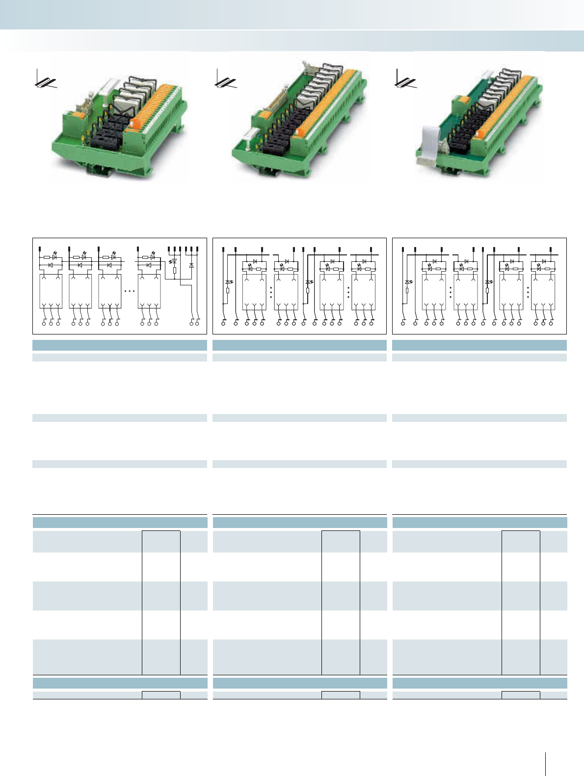
For additional information, visit www.phoenixcontact.net/catalog
|||
Technical data Technical data Technical data
24 V DC 24 V DC 24 V DC
Free-wheeling diode, protection against polarity reversal Free-wheeling diode Free-wheeling diode
Green LED Green LED Green LED
Yellow LED Yellow LED Yellow LED
Flat-ribbon cable plug connector in acc. with IEC 60603-13 Flat-ribbon cable plug connector in acc. with IEC 60603-13 Flat-ribbon cable plug connector in acc. with IEC 60603-13
14 50 20
1 PDT 1 PDT 1 PDT
250 V AC/DC 250 V AC/DC 250 V AC/DC
5 A 5 A 5 A
Screw connection with disconnect knife Screw connection with disconnect knife Screw connection with disconnect knife
0.2 ... 4 mm² / 0.2 ... 2.5 mm² / 24 - 12 0.2 ... 4 mm² / 0.2 ... 2.5 mm² / 24 - 12 0.2 ... 4 mm² / 0.2 ... 2.5 mm² / 24 - 12
2.5 kV (50 Hz, 1 min.) 2.5 kV (50 Hz, 1 min.) 2.5 kV (50 Hz, 1 min.)
-20°C ... 50°C -20°C ... 50°C -20°C ... 50°C
IEC 60664, DIN EN 50178, IEC 62103 IEC 60664, DIN EN 50178, IEC 62103 IEC 60664, DIN EN 50178, IEC 62103
Any Any Any
In rows with zero spacing In rows with zero spacing In rows with zero spacing
111.5 mm / 59 mm 111.5 mm / 59 mm 111.5 mm / 59 mm
Ordering data Ordering data Ordering data
Type Order No. Pcs. /
Pkt. Type Order No. Pcs. /
Pkt. Type Order No. Pcs. /
Pkt.
UM- 8 RELS/KSR-G24/21/MT/PLC 2962463 1
UM-16 RELS/KSR-G24/21/MT/PLC 2962382 1
UM-16 RELS/KSR-G24/21/E/MT/PLC 2962379 1
Accessories Accessories Accessories
REL-MR- 24DC/21-21 2961192 10 REL-MR- 24DC/21-21 2961192 10 REL-MR- 24DC/21-21 2961192 10
275PHOENIX CONTACT
123 8911
13101214
8321
12 11 14 22 21 24 32 31 34 82 81 84 + -
B1B1
84 8281 94 9291 164 162161
+
-
14 1211
B0 B0
+
-
1,2
3
11,12 22
10
18
13,14
15
23,24
916
B3B3
244 242241 254 252251 324 322321
+
-
174 172171
B2 B2
+
-
2
17
20 4
12
17 24
1
9
19
25 32
INTERFACE Cabling
VARIOFACE system cabling
DW
H
DW
H
DW
H
Output module for 8 miniature relays with
knife/disconnect terminal blocks,
1 PDT
Output module for 16 miniature relays with
knife/disconnect terminal blocks,
1 PDT
Output extension module for 16 miniature relays with
knife/disconnect terminal blocks,
1 PDT
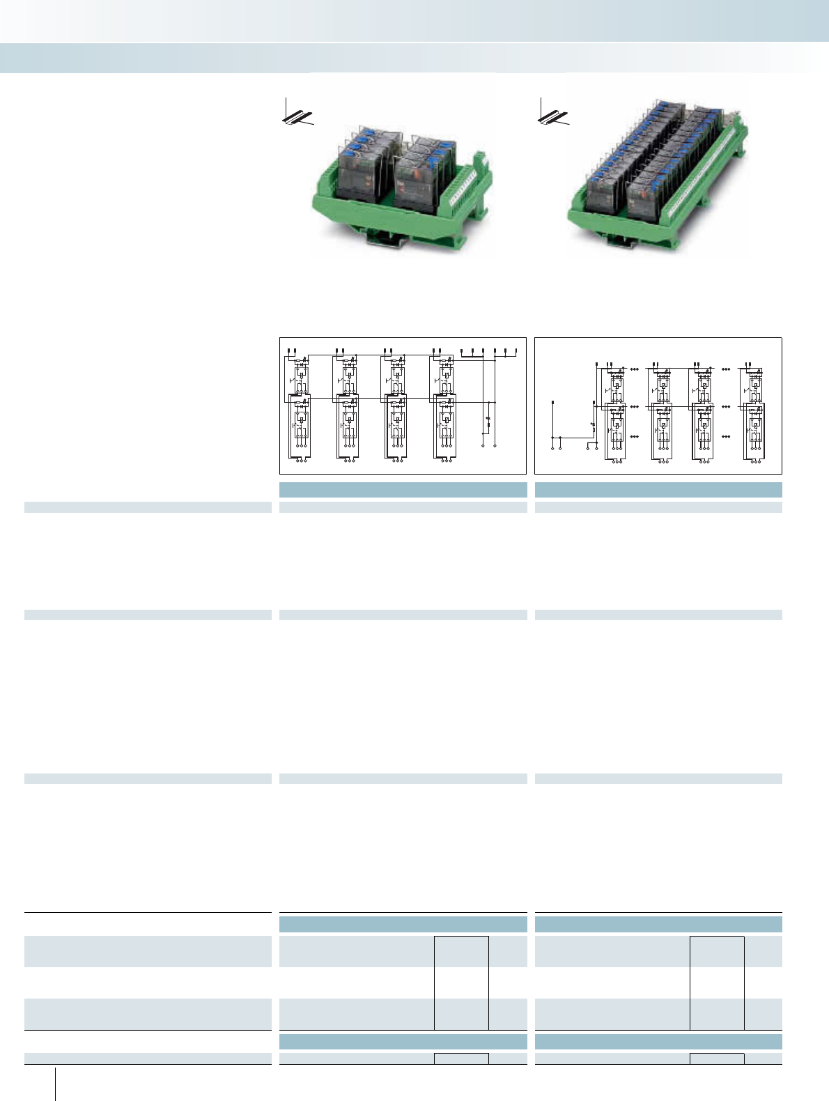
Technical data Technical data
Coil side
Operating voltage UN24 V DC 24 V DC
Typ. input current at UN18 mA 18 mA
Typ. response time at UN9 ms 9 ms
Typ. release time at UN6 ms 6 ms
Input circuit Free-wheeling diode (integrated in relay) Free-wheeling diode (integrated in relay)
Status display/channel Yellow LED (integrated in relay) Yellow LED (integrated in relay)
Connection method Flat-ribbon cable plug connector in acc. with IEC 60603-13 Flat-ribbon cable plug connector in acc. with IEC 60603-13
No. of poles 14 50
Contact side
Contact type Single contact, 1 PDT Single contact, 1 PDT
Contact material AgNi AgNi
Max. switching voltage 250 V AC/DC 250 V AC/DC
Min. switching voltage 12 V AC/DC 12 V AC/DC
Limiting continuous current 5 A 5 A
Min. switching current 100 mA 100 mA
Max. interrupting rating: 24 V DC 120 W 120 W
48 V DC 62 W 62 W
60 V DC 42 W 42 W
110 V DC 55 W 55 W
220 V DC 66 W 66 W
250 V AC 1250 VA 1250 VA
Connection method Screw connection Screw connection
Connection data solid / stranded / AWG 0.2 ... 4 mm² / 0.2 ... 2.5 mm² / 24 - 12 0.2 ... 4 mm² / 0.2 ... 2.5 mm² / 24 - 12
General data
Rated insulation voltage 260 V AC 260 V AC
Rated surge voltage 4 kV (basic insulation (safe isolation, reinforced insulation, and 6 kV
between input and output))
4 kV (basic insulation (safe isolation, reinforced insulation, and 6 kV
between input and output))
Pollution degree / surge voltage category 2 / III 2 / III
Ambient temperature (operation) -20°C ... 50°C -20°C ... 50°C
Nominal operating mode 100% operating factor 100% operating factor
Mechanical service life 5 x 10⁶ cycles 5 x 10⁶ cycles
Standards / regulations DIN EN 50178 DIN EN 50178
Mounting position Any Any
Mounting In rows with zero spacing In rows with zero spacing
Dimensions H / D 111 mm / 64 mm 111 mm / 64 mm
Ordering data Ordering data
Description Module width
WType Order No. Pcs. /
Pkt. Type Order No. Pcs. /
Pkt.
VARIOFACE output module, with 8 miniature relays, plugged in,
for 24 V DC (including relays)
92 UM- 8RM/KSR-G24/21/MS/PLC 2900890 1
VARIOFACE output module, with 32 miniature relays, plugged in,
for 24 V DC (including relays)
285 UM-32RM/KSR-G24/21/MS/PLC 2900891 1
Accessories Accessories
Miniature relay with manual checking function REL-MR- 24DC/21HC/MS 2987888 10 REL-MR- 24DC/21HC/MS 2987888 10
276 PHOENIX CONTACT
These VARIOFACE output modules are
used in combination with the respective
front adapters.
The modules are connected via 14 or
50-pole system cable. These relay modules
offer the following features:
– Plug-in miniature relays each with a PDT
contact and detectable manual operation
– Slim design width of just 92 mm (8 chan-
nels) or 285 mm (32 channels)
– LED status indicator and free-wheeling
diode per signal path (integrated in relay)
– Supply voltage indicator (LED)
DW
H
DW
H
Output modules with relays, 1 PDT
with detectable manual operation
INTERFACE Cabling
VARIOFACE system cabling
911 13 10 12 14
+-
12
2
1
22
21
24
12
11
14
34
4
3
32
31
34
42
41
44
56
6
5
52
51
54
62
61
64
78
8
7
72
71
74
82
81
84
1,2,13,14,25,26,37,38
11,12,23,24,35,36,47,48
3
4
9
10
15
16
45
46
17
28
9
10
31
32
22
21
24
12
11
14
+
+
--
82
81
84
72
71
74
102
101
104
92
91
94
312
311
314
322
321
324
Output module with 8 miniature relays,
1 PDT with detectable manual operation
Output module with 32 miniature relays,
1 PDT with detectable manual operation
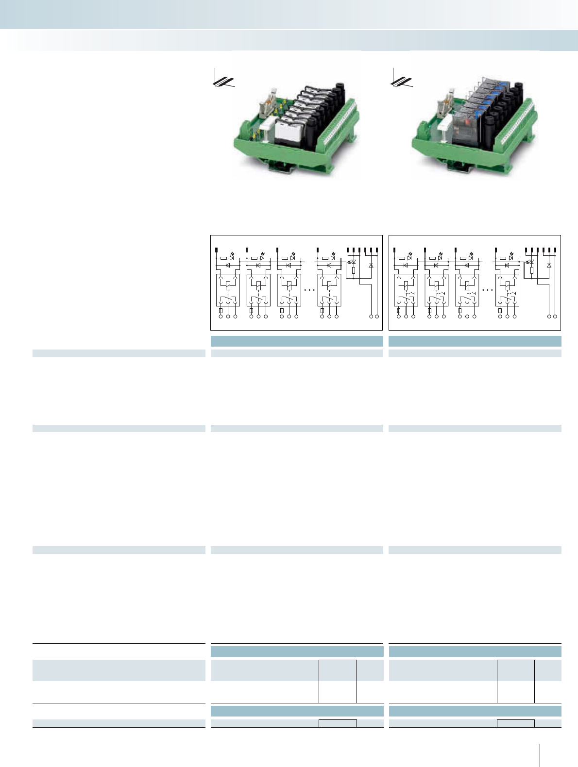
For additional information, visit www.phoenixcontact.net/catalog
Technical data Technical data
Coil side
Operating voltage UN24 V DC 24 V DC
Typ. input current at UN17 mA 18 mA
Typ. response time at UN8 ms 9 ms
Typ. release time at UN10 ms 6 ms
Input circuit Free-wheeling diode Free-wheeling diode (integrated in relay)
Status display/channel Yellow LED Yellow LED (integrated in relay)
Connection method Flat-ribbon cable plug connector in acc. with IEC 60603-13 Flat-ribbon cable plug connector in acc. with IEC 60603-13
No. of poles 14 14
Contact side
Contact type Single contact, 1 PDT Single contact, 1 PDT
Contact material AgNi AgNi
Max. switching voltage 250 V AC/DC 250 V AC/DC
Min. switching voltage 12 V AC/DC 12 V AC/DC
Output fuse 4 A 5x20 fuse (slow-blow) 4 A 5x20 fuse (slow-blow)
Limiting continuous current 3.9 A (observe derating) 3.9 A (observe derating)
Min. switching current 100 mA 100 mA
Max. interrupting rating: 24 V DC 93 W 93 W
48 V DC 58 W 62 W
60 V DC 48 W 42 W
110 V DC 50 W 55 W
220 V DC 80 W 66 W
250 V AC 975 VA 975 VA
Connection method Screw connection Screw connection
Connection data solid / stranded / AWG 0.2 ... 4 mm² / 0.2 ... 2.5 mm² / 24 - 12 0.2 ... 4 mm² / 0.2 ... 2.5 mm² / 24 - 12
General data
Rated insulation voltage 260 V AC 260 V AC
Rated surge voltage 4 kV (basic insulation (safe isolation, reinforced insulation, and 6 kV
between input and output))
4 kV (basic insulation (safe isolation, reinforced insulation, and 6 kV
between input and output))
Pollution degree / surge voltage category 2 / III 2 / III
Ambient temperature (operation) -20°C ... 50°C -20°C ... 50°C
Nominal operating mode 100% operating factor 100% operating factor
Mechanical service life 3 x 10⁷ cycles 5 x 10⁶ cycles
Standards / regulations DIN EN 50178 DIN EN 50178
Mounting position Any Any
Mounting In rows with zero spacing In rows with zero spacing
Dimensions H / D 111 mm / 60 mm 111 mm / 64 mm
Ordering data Ordering data
Description Module width
WType Order No. Pcs. /
Pkt. Type Order No. Pcs. /
Pkt.
VARIOFACE output module, with 8 miniature relays, plugged in,
for 24 V DC (including relays)
127 UM- 8RM/KSR-G24/21/SI/PLC 2900892 1UM- 8RM/KSR-G24/21/MS/SI/PLC 2900893 1
Accessories Accessories
Pluggable miniature relays REL-MR- 24DC/21HC 2961312 10 REL-MR- 24DC/21HC/MS 2987888 10
277PHOENIX CONTACT
These VARIOFACE output modules are
used in combination with the respective
front adapters.
The modules are connected via 14-pole
system cable. These relay modules offer the
following features:
– Plug-in miniature relays each with a PDT
contact with or without manual opera-
tion
– Fuse per output circuit as short-circuit
protection
– Slim design width of just 127 mm
– LED status indicator and free-wheeling
diode per signal path
– Supply voltage indicator (LED)
– Polarity protection diode
DW
H
DW
H
Output modules with relays, 1 PDT
with or without manual operation and
fuses
INTERFACE Cabling
VARIOFACE system cabling
123 89
11
13
10
12
14
1238
11 14 21 24 31 34 81 84 +-
12 22 32 82
F2F3F8F1
123 89
11
13
10
12
14
1238
11 14 21 24 31 34 81 84 +-
12 22 32 82
F2F3F8F1
Output module with 8 miniature relays,
1 PDT and fuse per output circuit
Output module with 8 miniature relays,
1 PDT with detectable manual operation
and fuse per output circuit
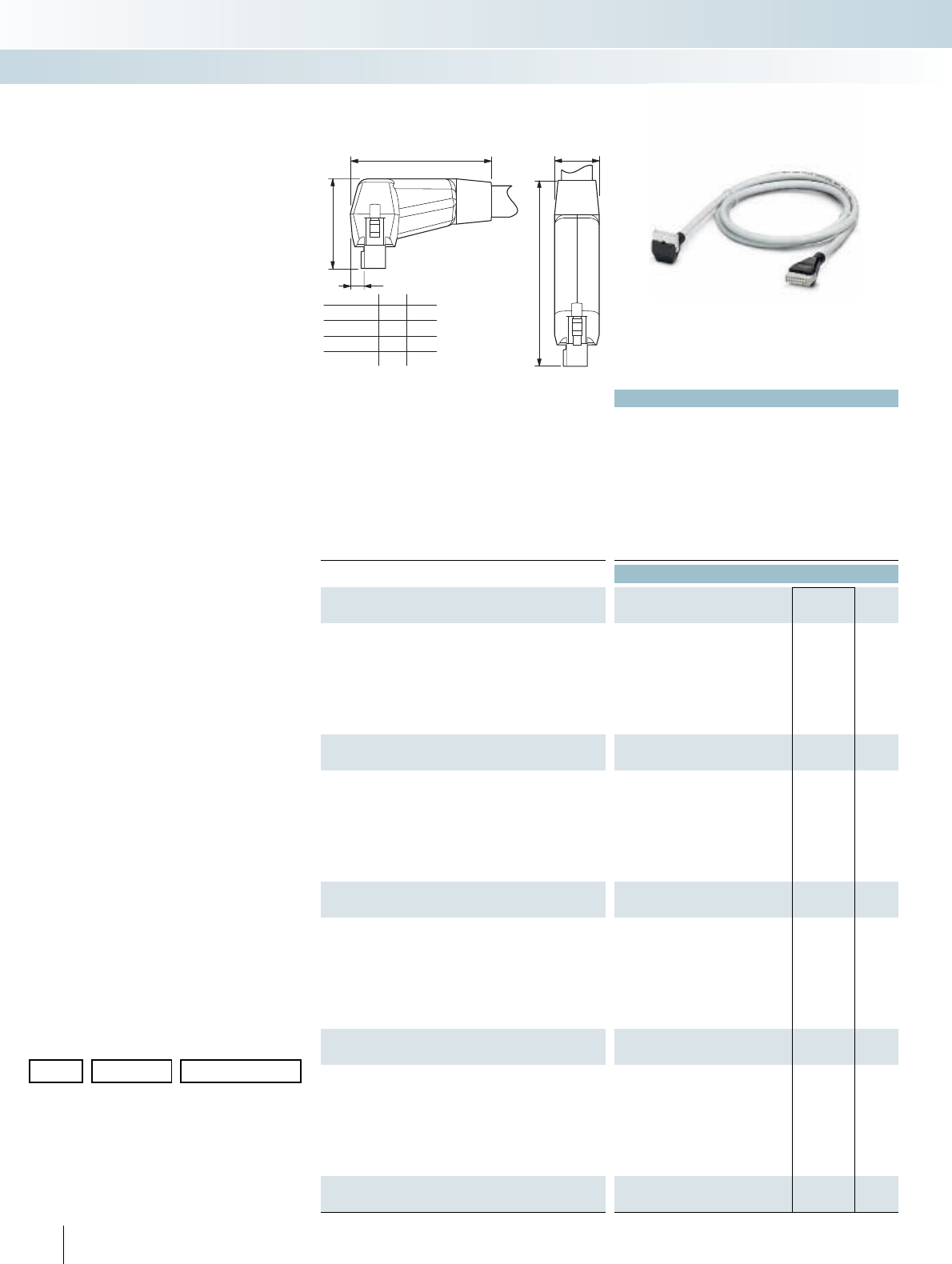
Technical data
Max. perm. operating voltage < 50 V AC / 60 V DC
Max. perm. current carrying capacitance per path 1 A
Max. conductor resistance 0.16 /m
Ambient temperature (operation) -20°C ... 50°C
Assembly Insulation displacement, IEC 60352-4 / DIN EN 60352-4
Conductor cross section AWG 26 / 0.14 mm²
Outside diameter
10-pole 6.1 mm
14-pole 6.4 mm
16-pole 6.8 mm
20-pole 7.6 mm
Ordering data
Description No. of
poles Cable length Type Order No. Pcs. /
Pkt.
Round cable, with two molded socket strips
10 0.5 m VIP-CAB-FLK10/0,14/0,5M 2318305 1
10 1 m VIP-CAB-FLK10/0,14/1,0M 2318318 1
10 1.5 m VIP-CAB-FLK10/0,14/1,5M 2318321 1
10 2 m VIP-CAB-FLK10/0,14/2,0M 2318334 1
10 3 m VIP-CAB-FLK10/0,14/3,0M 2318347 1
10 4 m VIP-CAB-FLK10/0,14/4,0M 2318350 1
10 6 m VIP-CAB-FLK10/0,14/6,0M 2318363 1
Round cable, same as before, in variable lengths (minimum order-
ing quantity five pieces)
10 VIP-CAB-FLK10-0,14/... 2318376 1
Round cable, with two molded socket strips
14 0.5 m VIP-CAB-FLK14/0,14/0,5M 2318389 1
14 1 m VIP-CAB-FLK14/0,14/1,0M 2318392 1
14 1.5 m VIP-CAB-FLK14/0,14/1,5M 2318402 1
14 2 m VIP-CAB-FLK14/0,14/2,0M 2318415 1
14 3 m VIP-CAB-FLK14/0,14/3,0M 2318428 1
14 4 m VIP-CAB-FLK14/0,14/4,0M 2318431 1
14 6 m VIP-CAB-FLK14/0,14/6,0M 2318444 1
Round cable, same as before, in variable lengths (minimum order-
ing quantity five pieces)
14 VIP-CAB-FLK14-0,14/... 2318457 1
Round cable, with two molded socket strips
16 0.5 m VIP-CAB-FLK16/0,14/0,5M 2318460 1
16 1 m VIP-CAB-FLK16/0,14/1,0M 2318473 1
16 1.5 m VIP-CAB-FLK16/0,14/1,5M 2318486 1
16 2 m VIP-CAB-FLK16/0,14/2,0M 2318499 1
16 3 m VIP-CAB-FLK16/0,14/3,0M 2318509 1
16 4 m VIP-CAB-FLK16/0,14/4,0M 2318512 1
16 6 m VIP-CAB-FLK16/0,14/6,0M 2318525 1
Round cable, same as before, in variable lengths (minimum order-
ing quantity five pieces)
16 VIP-CAB-FLK16-0,14/... 2318538 1
Round cable, with two molded socket strips
20 0.5 m VIP-CAB-FLK20/0,14/0,5M 2318541 1
20 1 m VIP-CAB-FLK20/0,14/1,0M 2318554 1
20 1.5 m VIP-CAB-FLK20/0,14/1,5M 2318567 1
20 2 m VIP-CAB-FLK20/0,14/2,0M 2318570 1
20 3 m VIP-CAB-FLK20/0,14/3,0M 2318583 1
20 4 m VIP-CAB-FLK20/0,14/4,0M 2318596 1
20 6 m VIP-CAB-FLK20/0,14/6,0M 2318606 1
Round cable, same as before, in variable lengths (minimum order-
ing quantity five pieces)
20 VIP-CAB-FLK20-0,14/... 2318619 1
278 PHOENIX CONTACT
– 1:1 connection
– 10 to 20-pole
– Connectors as per IEC 60603-13
– In the desired lengths
– Individual serial number
Note:
Due to the enlarged outer contour of the
molded connectors, module types with
UM45 profile and three-level terminal
blocks cannot be connected with the
VIP-CAB-FLK... system cable.
The following module types
(10 to 50-pole) can be connected.
For example, for 20 poles:
–VIP-2/SC/FLK 20
–VIP-2/SC/FLK20/LED
– FLKM 20/ZFKDS
– UM45-FLK 20/ZFKDS
(double-level connection)
The VIP-CAB-FLK... system cables are
not suitable for front adapters
(see the dimensional drawing).
VIP – VARIOFACE Professional
system cables with
flat-ribbon connectors
Ordering example for system cable:
– 10-pos. cable, 7.6 m long
Quantity Order No. Length [m]
1 2318376 /7.6
Min.
Max.
Step width
0.5 m
100.0 m
0.1 m
INTERFACE Cabling
VARIOFACE system cabling
Not shielded
...FLK10...
...FLK14...
...FLK16...
...FLK20...
A
26,5
B
13,5
5
34
51
49
49
46
37
37
39
AB
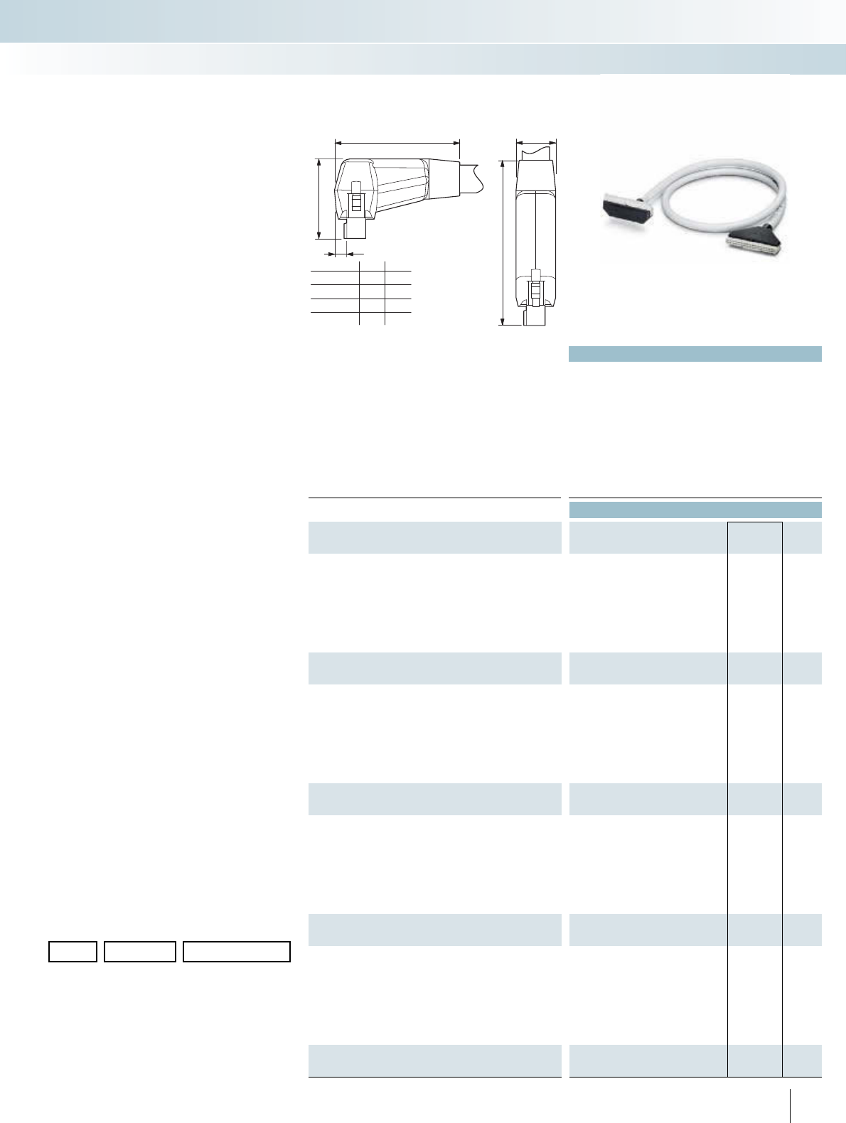
For additional information, visit www.phoenixcontact.net/catalog
Technical data
Max. perm. operating voltage < 50 V AC / 60 V DC
Max. perm. current carrying capacitance per path 1 A
Max. conductor resistance 0.16 /m
Ambient temperature (operation) -20°C ... 50°C
Assembly Insulation displacement, IEC 60352-4 / DIN EN 60352-4
Conductor cross section AWG 26 / 0.14 mm²
Outside diameter
26-pole 8.3 mm
34-pole 8.7 mm
40-pole 9.9 mm
50-pole 10.3 mm
Ordering data
Description No. of
poles Cable length Type Order No. Pcs. /
Pkt.
Round cable, with two molded socket strips
26 0.5 m VIP-CAB-FLK26/0,14/0,5M 2318622 1
26 1 m VIP-CAB-FLK26/0,14/1,0M 2318635 1
26 1.5 m VIP-CAB-FLK26/0,14/1,5M 2318648 1
26 2 m VIP-CAB-FLK26/0,14/2,0M 2318651 1
26 3 m VIP-CAB-FLK26/0,14/3,0M 2318664 1
26 4 m VIP-CAB-FLK26/0,14/4,0M 2318677 1
26 6 m VIP-CAB-FLK26/0,14/6,0M 2318680 1
Round cable, same as before, in variable lengths (minimum order-
ing quantity five pieces)
26 VIP-CAB-FLK26-0,14/... 2318693 1
Round cable, with two molded socket strips
34 0.5 m VIP-CAB-FLK34/0,14/0,5M 2318703 1
34 1 m VIP-CAB-FLK34/0,14/1,0M 2318716 1
34 1.5 m VIP-CAB-FLK34/0,14/1,5M 2318729 1
34 2 m VIP-CAB-FLK34/0,14/2,0M 2318732 1
34 3 m VIP-CAB-FLK34/0,14/3,0M 2318745 1
34 4 m VIP-CAB-FLK34/0,14/4,0M 2318758 1
34 6 m VIP-CAB-FLK34/0,14/6,0M 2318761 1
Round cable, same as before, in variable lengths (minimum order-
ing quantity five pieces)
34 VIP-CAB-FLK34-0,14/... 2318774 1
Round cable, with two molded socket strips
40 0.5 m VIP-CAB-FLK40/0,14/0,5M 2318787 1
40 1 m VIP-CAB-FLK40/0,14/1,0M 2318790 1
40 1.5 m VIP-CAB-FLK40/0,14/1,5M 2318800 1
40 2 m VIP-CAB-FLK40/0,14/2,0M 2318813 1
40 3 m VIP-CAB-FLK40/0,14/3,0M 2318826 1
40 4 m VIP-CAB-FLK40/0,14/4,0M 2318839 1
40 6 m VIP-CAB-FLK40/0,14/6,0M 2318842 1
Round cable, same as before, in variable lengths (minimum order-
ing quantity five pieces)
40 VIP-CAB-FLK40-0,14/... 2318855 1
Round cable, with two molded socket strips
50 0.5 m VIP-CAB-FLK50/0,14/0,5M 2318868 1
50 1 m VIP-CAB-FLK50/0,14/1,0M 2318871 1
50 1.5 m VIP-CAB-FLK50/0,14/1,5M 2318884 1
50 2 m VIP-CAB-FLK50/0,14/2,0M 2318897 1
50 3 m VIP-CAB-FLK50/0,14/3,0M 2318907 1
50 4 m VIP-CAB-FLK50/0,14/4,0M 2318910 1
50 6 m VIP-CAB-FLK50/0,14/6,0M 2318923 1
Round cable, same as before, in variable lengths (minimum order-
ing quantity five pieces)
50 VIP-CAB-FLK50-0,14/... 2318936 1
279PHOENIX CONTACT
– 1:1 connection
– 26 to 50-pole
– Connectors as per IEC 60603-13
– In the desired lengths
– Individual serial number
Note:
Due to the enlarged outer contour of the
molded connectors, module types with
UM45 profile and three-level terminal
blocks cannot be connected with the
VIP-CAB-FLK... system cable.
The following module types (10 to 50-pole)
can be connected.
For example, for 20 poles:
–VIP-2/SC/FLK 20
–VIP-2/SC/FLK20/LED
– FLKM 20/ZFKDS
– UM45-FLK 20/ZFKDS
(double-level connection)
The VIP-CAB-FLK... system cables are
not suitable for front adapters (see the di-
mensional drawing).
VIP – VARIOFACE Professional
system cables with
flat-ribbon connectors
Ordering example for system cable:
– 26-pos. cable, 12.6 m long
Quantity Order No. Length [m]
1 2318693 /12.6
Min.
Max.
Step width
0.5 m
100.0 m
0.1 m
INTERFACE Cabling
VARIOFACE system cabling
Not shielded
...FLK26...
...FLK34...
...FLK40...
...FLK50...
A
26,5
B
13,5
5
39
55
52
52
51
40
40
42
AB
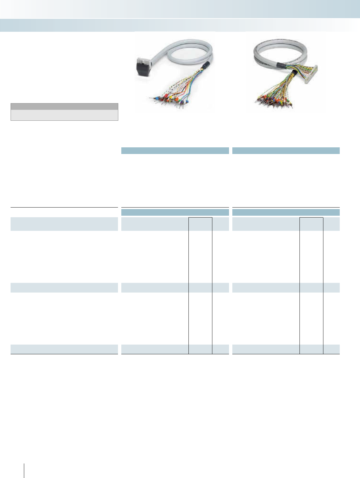
Technical data Technical data
Max. perm. operating voltage < 50 V AC / 60 V DC < 50 V AC / 60 V DC
Max. perm. current carrying capacitance per path 1 A 1 A
Max. conductor resistance 0.16 /m 0.16 /m
Ambient temperature (operation) -20°C ... 50°C -20°C ... 50°C
Assembly Insulation displacement, IEC 60352-4 / DIN EN 60352-4 Insulation displacement, IEC 60352-4 / DIN EN 60352-4
Conductor cross section AWG 26 / 0.14 mm² AWG 26 / 0.14 mm²
Conductor structure: stranded wires / material 7 / Cu tin-plated 7 / Cu tin-plated
Outside diameter
14-pole 6.4 mm 6.4 mm
16-pole 6.5 mm 6.5 mm
Ordering data Ordering data
Description No. of
poles Cable length Type Order No. Pcs. /
Pkt. Type Order No. Pcs. /
Pkt.
Round cable with an open end
14 0.5 m VIP-CAB-FLK14/FR/OE/0,14/0,5M 2900122 1CABLE-FLK14/OE/0,14/ 50 2305761 1
14 1 m VIP-CAB-FLK14/FR/OE/0,14/1,0M 2900123 1CABLE-FLK14/OE/0,14/ 100 2305253 1
14 1.5 m VIP-CAB-FLK14/FR/OE/0,14/1,5M 2900125 1CABLE-FLK14/OE/0,14/ 150 2305266 1
14 2 m VIP-CAB-FLK14/FR/OE/0,14/2,0M 2900126 1CABLE-FLK14/OE/0,14/ 200 2305279 1
14 2.5 m CABLE-FLK14/OE/0,14/ 250 2305282 1
14 3 m VIP-CAB-FLK14/FR/OE/0,14/3,0M 2900127 1CABLE-FLK14/OE/0,14/ 300 2305295 1
14 4 m VIP-CAB-FLK14/FR/OE/0,14/4,0M 2900128 1CABLE-FLK14/OE/0,14/ 400 2305774 1
14 6 m VIP-CAB-FLK14/FR/OE/0,14/6,0M 2900129 1CABLE-FLK14/OE/0,14/ 600 2305787 1
14 8 m CABLE-FLK14/OE/0,14/ 800 2305790 1
14 10 m CABLE-FLK14/OE/0,14/1000 2305800 1
Round cable, same as before, however in variable lengths
14 CABLE-FLK14/OE/0,14/... 2305732 1
Round cable with an open end
16 0.5 m VIP-CAB-FLK16/FR/OE/0,14/0,5M 2900130 1CABLE-FLK16/OE/0,14/ 0,5M 2318127 1
16 1 m VIP-CAB-FLK16/FR/OE/0,14/1,0M 2900131 1CABLE-FLK16/OE/0,14/ 1,0M 2318130 1
16 1.5 m VIP-CAB-FLK16/FR/OE/0,14/1,5M 2900132 1CABLE-FLK16/OE/0,14/ 1,5M 2318143 1
16 2 m VIP-CAB-FLK16/FR/OE/0,14/2,0M 2900133 1CABLE-FLK16/OE/0,14/ 2,0M 2318156 1
16 2.5 m CABLE-FLK16/OE/0,14/ 2,5M 2318169 1
16 3 m VIP-CAB-FLK16/FR/OE/0,14/3,0M 2900134 1CABLE-FLK16/OE/0,14/ 3,0M 2318172 1
16 4 m VIP-CAB-FLK16/FR/OE/0,14/4,0M 2900135 1CABLE-FLK16/OE/0,14/ 4,0M 2318185 1
16 6 m VIP-CAB-FLK16/FR/OE/0,14/6,0M 2900136 1CABLE-FLK16/OE/0,14/ 6,0M 2318198 1
16 8 m CABLE-FLK16/OE/0,14/ 8,0M 2318208 1
16 10 m CABLE-FLK16/OE/0,14/10,0M 2318211 1
Round cable, same as before, however in variable lengths
16 CABLE-FLK16/OE/0,14/... 2318224 1
280 PHOENIX CONTACT
INTERFACE Cabling
VARIOFACE system cabling
Molded connectors, not shielded Not shielded
– 1:1 connection
– 14- and 16-pole
– Connectors as per IEC 60603-13
– Open end at the other end
The individual wires at the open end are
labeled (1, 2, 3, 4, ...) and equipped with a
ferrule.
Notes:
In the case of molded connectors, please observe the dimensional
drawing and note, see page 278.
System cable with a flat-ribbon cable
connector and an open end
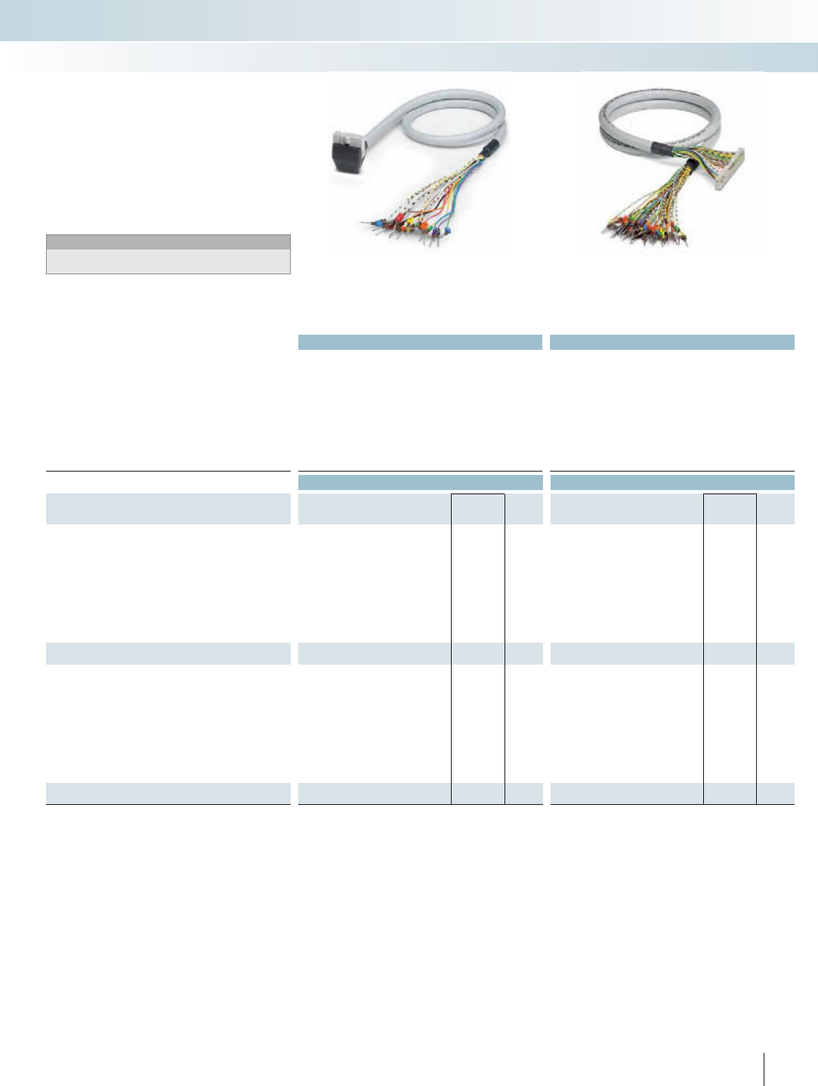
For additional information, visit www.phoenixcontact.net/catalog
Technical data Technical data
Max. perm. operating voltage < 50 V AC / 60 V DC < 50 V AC / 60 V DC
Max. perm. current carrying capacitance per path 1 A 1 A
Max. conductor resistance 0.16 /m 0.16 /m
Ambient temperature (operation) -20°C ... 50°C -20°C ... 50°C
Assembly Insulation displacement, IEC 60352-4 / DIN EN 60352-4 Insulation displacement, IEC 60352-4 / DIN EN 60352-4
Conductor cross section AWG 26 / 0.14 mm² AWG 26 / 0.14 mm²
Conductor structure: stranded wires / material 7 / Cu tin-plated 7 / Cu tin-plated
Outside diameter
20-pole 7.6 mm 7.6 mm
50-pole 10.3 mm 10.3 mm
Ordering data Ordering data
Description No. of
poles Cable length Type Order No. Pcs. /
Pkt. Type Order No. Pcs. /
Pkt.
Round cable with an open end
20 0.5 m VIP-CAB-FLK20/FR/OE/0,14/0,5M 2900138 1CABLE-FLK20/OE/0,14/ 50 2305826 1
20 1 m VIP-CAB-FLK20/FR/OE/0,14/1,0M 2900139 1CABLE-FLK20/OE/0,14/ 100 2305305 1
20 1.5 m VIP-CAB-FLK20/FR/OE/0,14/1,5M 2900141 1CABLE-FLK20/OE/0,14/ 150 2305318 1
20 2 m VIP-CAB-FLK20/FR/OE/0,14/2,0M 2900142 1CABLE-FLK20/OE/0,14/ 200 2305321 1
20 2.5 m CABLE-FLK20/OE/0,14/ 250 2305334 1
20 3 m VIP-CAB-FLK20/FR/OE/0,14/3,0M 2900143 1CABLE-FLK20/OE/0,14/ 300 2305347 1
20 4 m VIP-CAB-FLK20/FR/OE/0,14/4,0M 2900144 1CABLE-FLK20/OE/0,14/ 400 2305839 1
20 6 m VIP-CAB-FLK20/FR/OE/0,14/6,0M 2900145 1CABLE-FLK20/OE/0,14/ 600 2305842 1
20 8 m CABLE-FLK20/OE/0,14/ 800 2305855 1
20 10 m CABLE-FLK20/OE/0,14/1000 2305868 1
Round cable, same as before, however in variable lengths
20 CABLE-FLK20/OE/0,14/... 2305745 1
Round cable with an open end
50 0.5 m VIP-CAB-FLK50/FR/OE/0,14/0,5M 2900146 1CABLE-FLK50/OE/0,14/ 50 2305871 1
50 1 m VIP-CAB-FLK50/FR/OE/0,14/1,0M 2900147 1CABLE-FLK50/OE/0,14/ 100 2305350 1
50 1.5 m VIP-CAB-FLK50/FR/OE/0,14/1,5M 2900148 1CABLE-FLK50/OE/0,14/ 150 2305363 1
50 2 m VIP-CAB-FLK50/FR/OE/0,14/2,0M 2900149 1CABLE-FLK50/OE/0,14/ 200 2305376 1
50 2.5 m CABLE-FLK50/OE/0,14/ 250 2305389 1
50 3 m VIP-CAB-FLK50/FR/OE/0,14/3,0M 2900150 1CABLE-FLK50/OE/0,14/ 300 2305392 1
50 4 m VIP-CAB-FLK50/FR/OE/0,14/4,0M 2900151 1CABLE-FLK50/OE/0,14/ 400 2305884 1
50 6 m VIP-CAB-FLK50/FR/OE/0,14/6,0M 2900152 1CABLE-FLK50/OE/0,14/ 600 2305897 1
50 8 m CABLE-FLK50/OE/0,14/ 800 2305907 1
50 10 m CABLE-FLK50/OE/0,14/1000 2305910 1
Round cable, same as before, however in variable lengths
50 CABLE-FLK50/OE/0,14/... 2305758 1
281PHOENIX CONTACT
INTERFACE Cabling
VARIOFACE system cabling
Molded connectors, not shielded Not shielded
– 1:1 connection
– 20- and 50-pole
– Connectors as per IEC 60603-13
– Open end at the other end
The individual wires at the open end are
labeled (1, 2, 3, 4, ...) and equipped with a
ferrule.
Notes:
In the case of molded connectors, please observe the dimensional
drawing and note, see page 278.
System cable with a flat-ribbon cable
connector and an open end
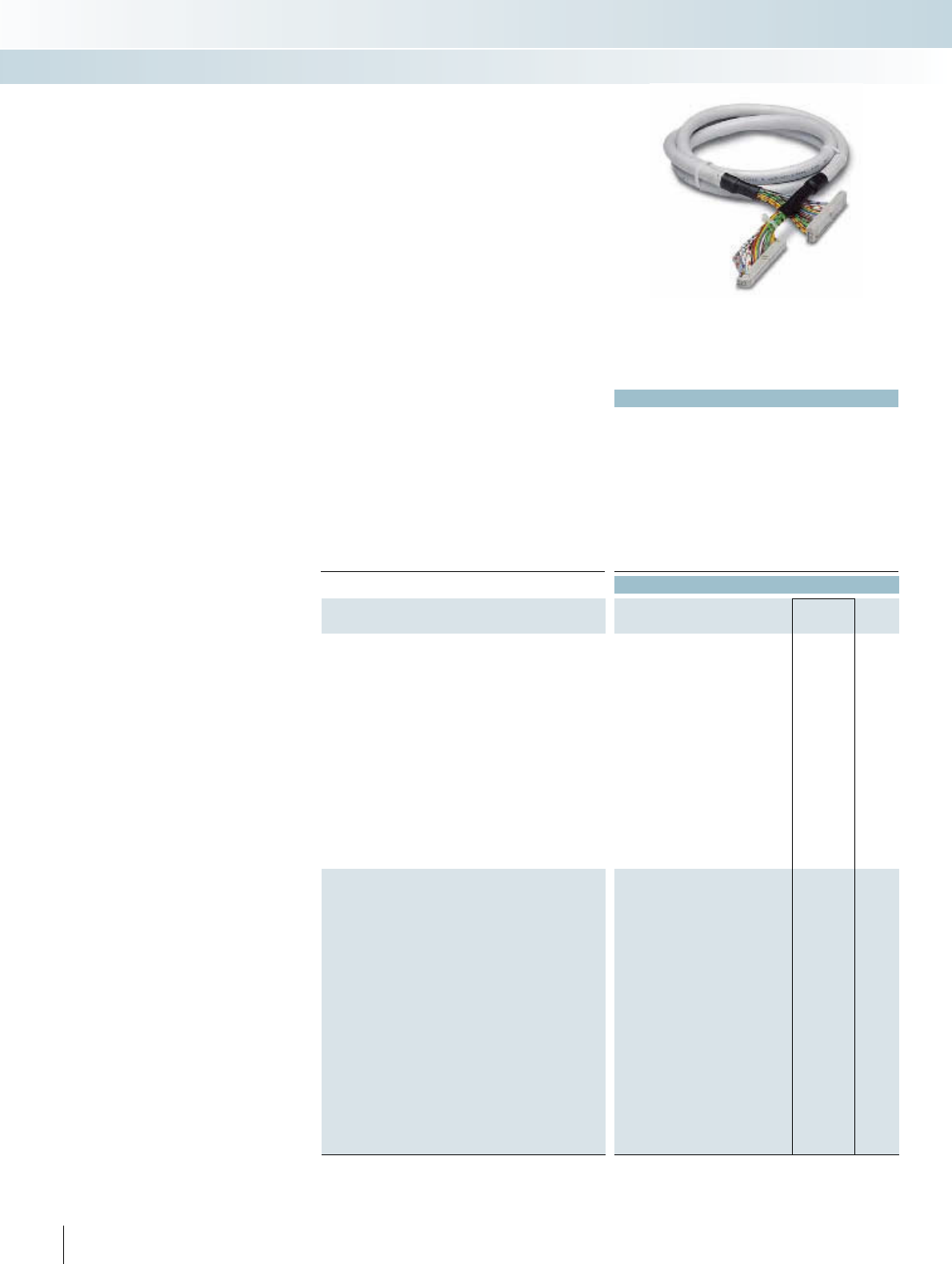
|
282 PHOENIX CONTACT
Standard lengths
Round cable sets are used to connect the
PLC front adapters to the corresponding
VARIOFACE controller boards.
The following versions are available with
14 and 50 poles:
– Not shielded
–Shielded
–Halogen-free
Connector strips are fitted on both
sides of the cables in accordance with
IEC 60603-13/DIN 41651 (1:1 connection).
In case of shielded cables, a cable end with
a ferrule is additionally provided as a shield
connection (length: approx. 0.5 m; cable
H05V-K 1 mm2, black).
Special lengths are defined using an order
key, refer to page 288.
System cable with flat-ribbon cable
connector
Technical data
Max. perm. operating voltage < 50 V AC / 60 V DC
Max. perm. current carrying capacitance per path 1 A
Max. conductor resistance 0.16 /m
Ambient temperature (operation) -20°C ... 50°C
Shield -
Assembly Insulation displacement, IEC 60352-4 / DIN EN 60352-4
Conductor cross section AWG 26 / 0.14 mm²
Conductor structure: stranded wires / material 7 / Cu tin-plated
Outside diameter
14-pole 6.4 mm
50-pole 10.3 mm
Ordering data
Description No. of
poles Cable length Type Order No. Pcs. /
Pkt.
Assembled round cables1), with two 14-pole socket strips in fixed
lengths, for transfer of eight channels among other things
14 0.3 m FLK 14/EZ-DR/ 30/KONFEK 2295729 5
14 0.5 m FLK 14/EZ-DR/ 50/KONFEK 2288901 5
14 1 m FLK 14/EZ-DR/ 100/KONFEK 2288914 1
14 1.5 m FLK 14/EZ-DR/ 150/KONFEK 2288927 1
14 2 m FLK 14/EZ-DR/ 200/KONFEK 2288930 1
14 2.5 m FLK 14/EZ-DR/ 250/KONFEK 2288943 1
14 3 m FLK 14/EZ-DR/ 300/KONFEK 2288956 1
14 3.5 m FLK 14/EZ-DR/ 350/KONFEK 2288969 1
14 4 m FLK 14/EZ-DR/ 400/KONFEK 2288972 1
14 4.5 m FLK 14/EZ-DR/ 450/KONFEK 2290847 1
14 5 m FLK 14/EZ-DR/ 500/KONFEK 2290834 1
14 5.5 m FLK 14/EZ-DR/ 550/KONFEK 2290850 1
14 6 m FLK 14/EZ-DR/ 600/KONFEK 2290863 1
14 7 m
14 8 m FLK 14/EZ-DR/ 800/KONFEK 2299563 1
14 10 m FLK 14/EZ-DR/1000/KONFEK 2299576 1
Assembled round cables2), with two 50-pole socket strips in fixed
lengths, for transfer of 32 channels among other things
50 0.5 m FLK 50/EZ-DR/ 50/KONFEK 2289065 5
50 1 m FLK 50/EZ-DR/ 100/KONFEK 2289078 1
50 1.5 m FLK 50/EZ-DR/ 150/KONFEK 2289081 1
50 2 m FLK 50/EZ-DR/ 200/KONFEK 2289094 1
50 2.5 m FLK 50/EZ-DR/ 250/KONFEK 2289104 1
50 3 m FLK 50/EZ-DR/ 300/KONFEK 2289117 1
50 3.5 m FLK 50/EZ-DR/ 350/KONFEK 2289120 1
50 4 m FLK 50/EZ-DR/ 400/KONFEK 2289133 1
50 4.5 m FLK 50/EZ-DR/ 450/KONFEK 2289573 1
50 5 m FLK 50/EZ-DR/ 500/KONFEK 2289586 1
50 5.5 m FLK 50/EZ-DR/ 550/KONFEK 2289599 1
50 6 m FLK 50/EZ-DR/ 600/KONFEK 2289609 1
50 6.5 m FLK 50/EZ-DR/ 650/KONFEK 2289612 1
50 7 m FLK 50/EZ-DR/ 700/KONFEK 2289625 1
50 7.5 m FLK 50/EZ-DR/ 750/KONFEK 2289638 1
50 8 m FLK 50/EZ-DR/ 800/KONFEK 2289641 1
50 8.5 m FLK 50/EZ-DR/ 850/KONFEK 2289654 1
50 9 m FLK 50/EZ-DR/ 900/KONFEK 2289667 1
50 9.5 m FLK 50/EZ-DR/ 950/KONFEK 2289670 1
50 10 m FLK 50/EZ-DR/1000/KONFEK 2289683 1
INTERFACE Cabling
VARIOFACE system cabling
Not shielded
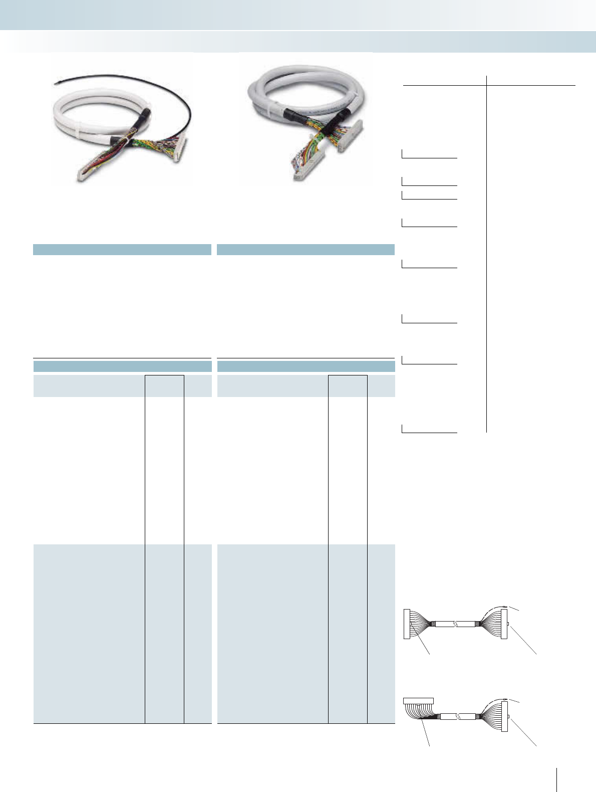
For additional information, visit www.phoenixcontact.net/catalog
1) straight socket strips fitted at both ends.
Polarity protection lug
Shield connection
(for shielded
cables)
Polarity protection lug
2) Socket strips fitted, straight at one end and angled at the
other.
Polarity protection lug Polarity protection lug
Shield connection
(for shielded cables)
No. of cores PIN Core color
1black
2brown
3red
4orange
5 yellow
6 green
7blue
8 violet
9gray
10-pos. 10 white
11 white-black
12 white-brown
13 white-red
14-pos. 14 white-orange
15 white-yellow
16-pos. 16 white-green
17 white-blue
18 white-violet
19 white-gray
20-pos. 20 brown-black
21 brown-red
22 brown-orange
23 brown-yellow
24 brown-green
25 brown-blue
26-pos. 26 brown-violet
27 brown-gray
28 brown-white
29 green-black
30 green-brown
31 green-red
32 green-orange
33 green-blue
34-pos. 34 green-violet
35 green-gray
36 green-white
37 yellow-black
38 yellow-brown
39 yellow-red
40-pos. 40 yellow-orange
41 yellow-blue
42 yellow-violet
43 yellow-gray
44 yellow-white
45 gray-black
46 gray-brown
39 gray-red
48 gray-orange
49 gray-yellow
50-pos. 50 gray-green
Color code of the system cables
|
Applied for: UL / CUL
283PHOENIX CONTACT
Technical data Technical data
< 50 V AC / 60 V DC < 50 V AC / 60 V DC
1 A 1 A
0.16 /m 0.16 /m
-20°C ... 50°C -20°C ... 50°C
Tinned copper-braided shield, approx. 85% covering -
Insulation displacement, IEC 60352-4 / DIN EN 60352-4 Insulation displacement, IEC 60352-4 / DIN EN 60352-4
AWG 26 / 0.14 mm² AWG 26 / 0.14 mm²
7 / Cu tin-plated 7 / Cu tin-plated
6.7 mm 6.4 mm
11 mm 10.3 mm
Ordering data Ordering data
Type Order No. Pcs. /
Pkt. Type Order No. Pcs. /
Pkt.
FLK 14/EZ-DR/ 50/KONFEK/S 2296977 1FLK 14/EZ-DR/HF/ 50/KONFEK 2305952 1
FLK 14/EZ-DR/ 100/KONFEK/S 2296980 1FLK 14/EZ-DR/HF/ 100/KONFEK 2305965 1
FLK 14/EZ-DR/ 150/KONFEK/S 2296993 1FLK 14/EZ-DR/HF/ 150/KONFEK 2305978 1
FLK 14/EZ-DR/ 200/KONFEK/S 2297002 1FLK 14/EZ-DR/HF/ 200/KONFEK 2305981 1
FLK 14/EZ-DR/HF/ 250/KONFEK 2305994 1
FLK 14/EZ-DR/ 300/KONFEK/S 2299013 1FLK 14/EZ-DR/HF/ 300/KONFEK 2304759 1
FLK 14/EZ-DR/ 400/KONFEK/S 2299026 1FLK 14/EZ-DR/HF/ 400/KONFEK 2304762 1
FLK 14/EZ-DR/HF/ 500/KONFEK 2304717 1
FLK 14/EZ-DR/ 600/KONFEK/S 2299039 1FLK 14/EZ-DR/HF/ 600/KONFEK 2306003 1
FLK 14/EZ-DR/HF/ 700/KONFEK 2314011 1
FLK 14/EZ-DR/ 800/KONFEK/S 2299042 1FLK 14/EZ-DR/HF/ 800/KONFEK 2314024 1
FLK 14/EZ-DR/1000/KONFEK/S 2299055 1FLK 14/EZ-DR/HF/1000/KONFEK 2314037 1
FLK 50/EZ-DR/ 50/KONFEK/S 2299097 1CABLE-FLK50/0,14/HF/ 0,5M 2314134 1
FLK 50/EZ-DR/ 100/KONFEK/S 2299107 1CABLE-FLK50/0,14/HF/ 1,0M 2314147 1
FLK 50/EZ-DR/ 150/KONFEK/S 2299110 1CABLE-FLK50/0,14/HF/ 1,5M 2314150 1
FLK 50/EZ-DR/ 200/KONFEK/S 2299123 1CABLE-FLK50/0,14/HF/ 2,0M 2314163 1
CABLE-FLK50/0,14/HF/ 2,5M 2314176 1
FLK 50/EZ-DR/ 300/KONFEK/S 2299136 1CABLE-FLK50/0,14/HF/ 3,0M 2314189 1
FLK 50/EZ-DR/ 400/KONFEK/S 2299149 1CABLE-FLK50/0,14/HF/ 4,0M 2314192 1
CABLE-FLK50/0,14/HF/ 5,0M 2314202 1
FLK 50/EZ-DR/ 600/KONFEK/S 2299152 1CABLE-FLK50/0,14/HF/ 6,0M 2314215 1
CABLE-FLK50/0,14/HF/ 7,0M 2314228 1
FLK 50/EZ-DR/ 800/KONFEK/S 2299165 1CABLE-FLK50/0,14/HF/ 8,0M 2314231 1
FLK 50/EZ-DR/1000/KONFEK/S 2299178 1CABLE-FLK50/0,14/HF/10,0M 2314244 1
INTERFACE Cabling
VARIOFACE system cabling
Shielded Halogen-free
(only the cable)
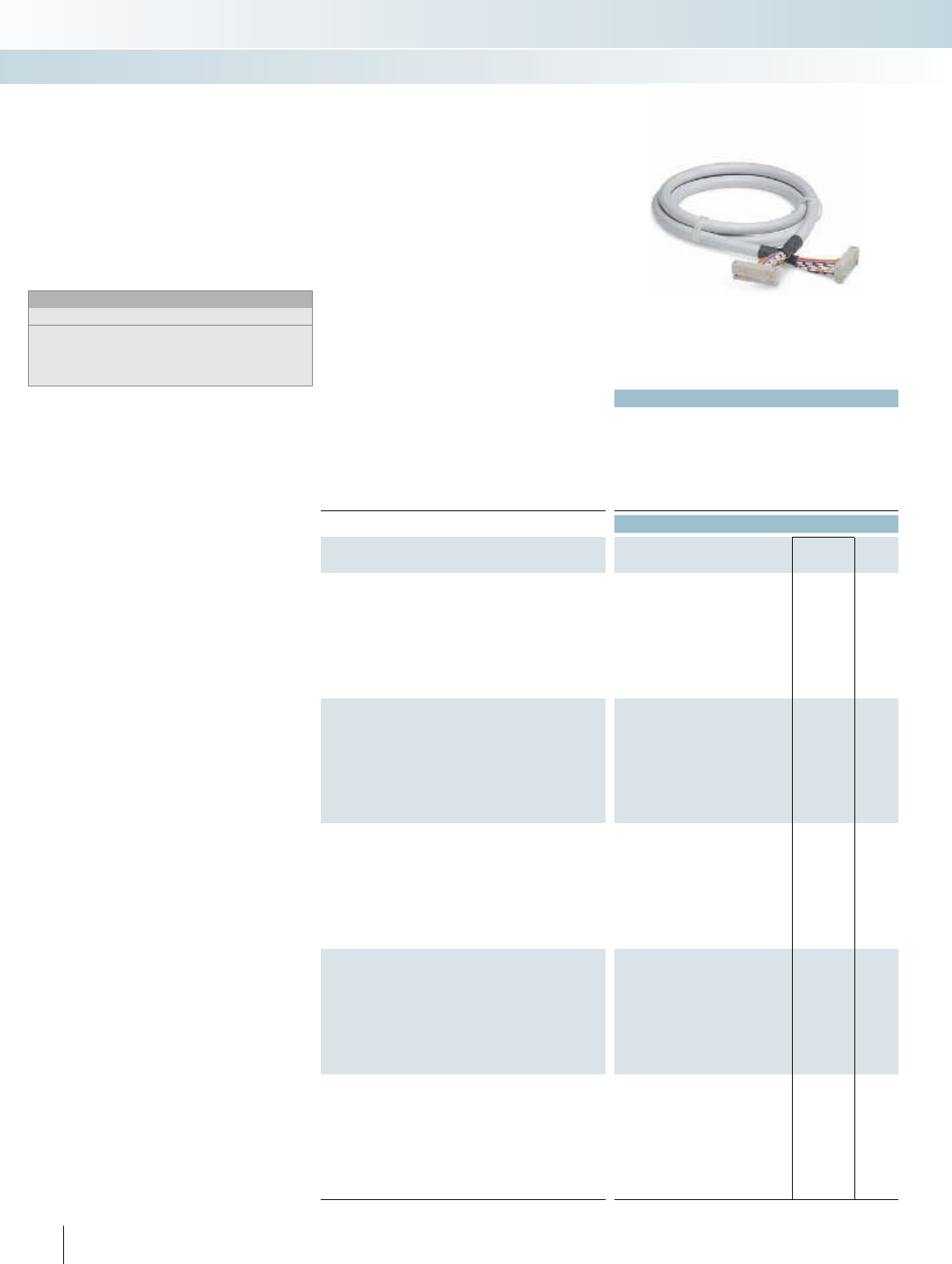
|
Applied for: UL / CUL
Technical data
Max. perm. operating voltage < 50 V AC / 60 V DC
Max. perm. current carrying capacitance per path 1 A
Max. conductor resistance 0.16 /m
Ambient temperature (operation) -20°C ... 50°C
Assembly Insulation displacement, IEC 60352-4 / DIN EN 60352-4
Conductor cross section AWG 26 / 0.14 mm²
Conductor structure: stranded wires / material 7 / Cu tin-plated
Ordering data
Description No. of
poles Cable length Type Order No. Pcs. /
Pkt.
Round cable1), with two socket strips
10 0.5 m FLK 10/EZ-DR/ 50/KONFEK 2299204 1
10 1 m FLK 10/EZ-DR/ 100/KONFEK 2299217 1
10 1.5 m FLK 10/EZ-DR/ 150/KONFEK 2299220 1
10 2 m FLK 10/EZ-DR/ 200/KONFEK 2299233 1
10 3 m FLK 10/EZ-DR/ 300/KONFEK 2299246 1
10 4 m FLK 10/EZ-DR/ 400/KONFEK 2299259 1
10 6 m FLK 10/EZ-DR/ 600/KONFEK 2299262 1
10 8 m FLK 10/EZ-DR/ 800/KONFEK 2299275 1
10 10 m FLK 10/EZ-DR/1000/KONFEK 2299288 1
Round cable1), with two socket strips
16 0.5 m FLK 16/EZ-DR/ 50/KONFEK 2299291 1
16 1 m FLK 16/EZ-DR/ 100/KONFEK 2299301 1
16 1.5 m FLK 16/EZ-DR/ 150/KONFEK 2299314 1
16 2 m FLK 16/EZ-DR/ 200/KONFEK 2299327 1
16 3 m FLK 16/EZ-DR/ 300/KONFEK 2299330 1
16 4 m FLK 16/EZ-DR/ 400/KONFEK 2299343 1
16 6 m FLK 16/EZ-DR/ 600/KONFEK 2299356 1
16 8 m FLK 16/EZ-DR/ 800/KONFEK 2299369 1
16 10 m FLK 16/EZ-DR/1000/KONFEK 2299372 1
Round cable1), with two socket strips
20 0.5 m FLK 20/EZ-DR/ 50KONFEK 2296391 1
20 1 m FLK 20/EZ-DR/ 100KONFEK 2296401 1
20 1.5 m FLK 20/EZ-DR/ 150KONFEK 2296472 1
20 2 m FLK 20/EZ-DR/ 200KONFEK 2296485 1
20 3 m FLK 20/EZ-DR/ 300KONFEK 2296498 1
20 4 m FLK 20/EZ-DR/ 400KONFEK 2296508 1
20 6 m FLK 20/EZ-DR/ 600KONFEK 2296511 1
20 8 m FLK 20/EZ-DR/ 800KONFEK 2296524 1
20 10 m FLK 20/EZ-DR/1000KONFEK 2296537 1
Round cable1), with two socket strips
26 0.5 m FLK 26/EZ-DR/ 50/KONFEK 2299385 1
26 1 m FLK 26/EZ-DR/ 100/KONFEK 2299398 1
26 1.5 m FLK 26/EZ-DR/ 150/KONFEK 2299408 1
26 2 m FLK 26/EZ-DR/ 200/KONFEK 2299411 1
26 3 m FLK 26/EZ-DR/ 300/KONFEK 2299424 1
26 4 m FLK 26/EZ-DR/ 400/KONFEK 2299437 1
26 6 m FLK 26/EZ-DR/ 600/KONFEK 2299440 1
26 8 m FLK 26/EZ-DR/ 800/KONFEK 2299453 1
26 10 m FLK 26/EZ-DR/1000/KONFEK 2299466 1
Round cable1), with two socket strips
34 0.5 m FLK 34/EZ-DR/ 50/KONFEK 2299479 1
34 1 m FLK 34/EZ-DR/ 100/KONFEK 2299482 1
34 1.5 m FLK 34/EZ-DR/ 150/KONFEK 2299495 1
34 2 m FLK 34/EZ-DR/ 200/KONFEK 2299505 1
34 3 m FLK 34/EZ-DR/ 300/KONFEK 2299518 1
34 4 m FLK 34/EZ-DR/ 400/KONFEK 2299521 1
34 6 m FLK 34/EZ-DR/ 600/KONFEK 2299534 1
34 8 m FLK 34/EZ-DR/ 800/KONFEK 2299547 1
34 10 m FLK 34/EZ-DR/1000/KONFEK 2299550 1
284 PHOENIX CONTACT
Standard lengths
Pre-assembled round cables to couple the
VARIOFACE interface modules.
Connector strips are fitted on both sides
of the cables in accordance with
IEC 60603-13/DIN 41651 (1:1 connection).
Special lengths are defined using an order
key, refer to page 288.
Notes:
Outside diameter of the cable
10-pole: 6 mm
16-pole: 6.5 mm
20-pole: 7.6 mm
26-pole: 7.8 mm
34-pole: 10 mm
System cable with flat-ribbon cable
connector
INTERFACE Cabling
VARIOFACE system cabling
Not shielded
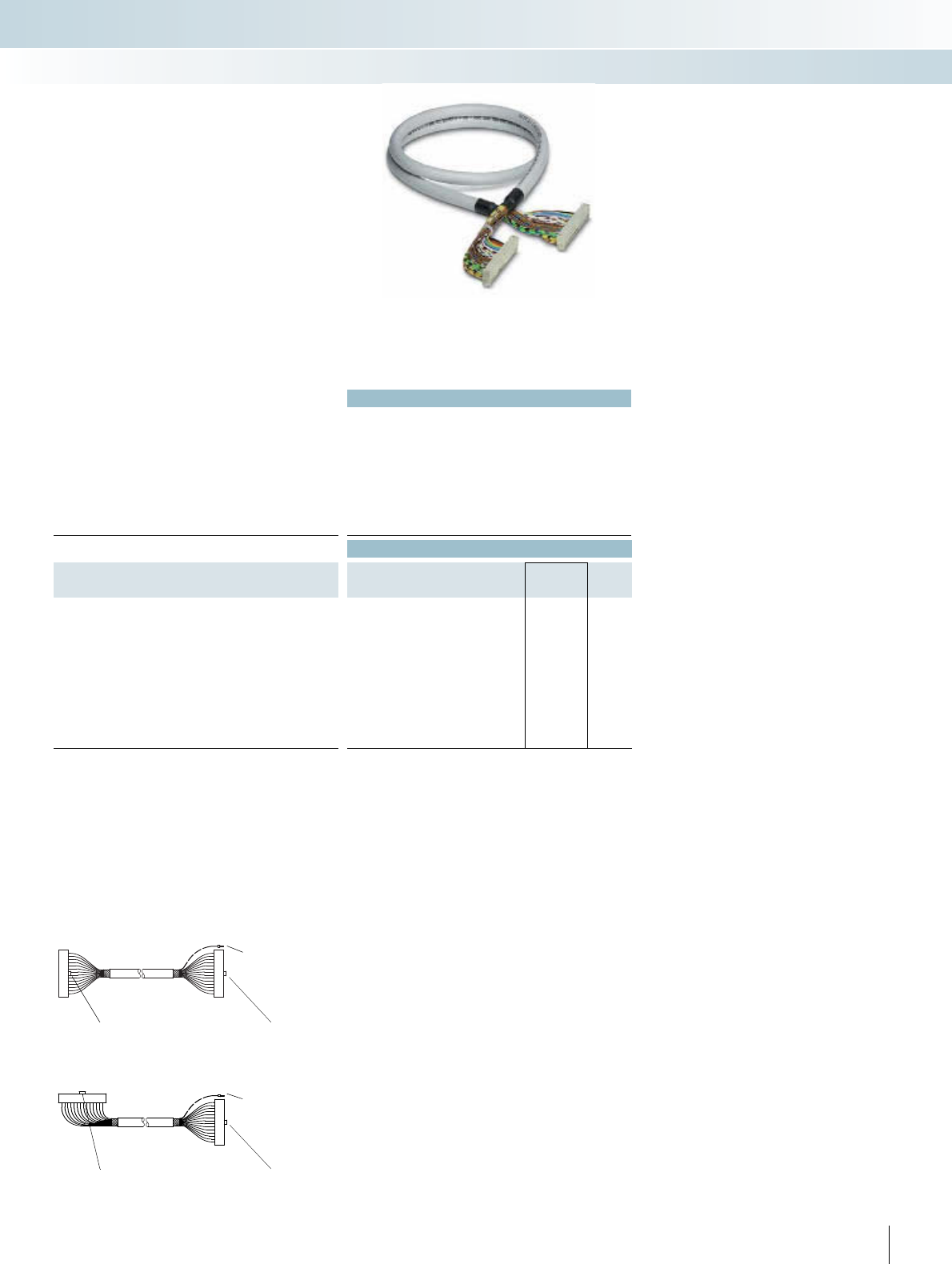
For additional information, visit www.phoenixcontact.net/catalog
|
Technical data
Max. perm. operating voltage < 50 V AC / 60 V DC
Max. perm. current carrying capacitance per path 1 A
Max. conductor resistance 0.16 /m
Ambient temperature (operation) -20°C ... 50°C
Assembly Insulation displacement, IEC 60352-4 / DIN EN 60352-4
Conductor cross section AWG 26 / 0.14 mm²
Conductor structure: stranded wires / material 7 / Cu tin-plated
Outside diameter
40-pole 9.9 mm
Ordering data
Description No. of
poles Cable length Type Order No. Pcs. /
Pkt.
Round cable2), with two socket strips
40 0.5 m FLK 40/EZ-DR/ 50/KONFEK 2288985 5
40 1 m FLK 40/EZ-DR/ 100/KONFEK 2288998 1
40 1.5 m FLK 40/EZ-DR/ 150/KONFEK 2289007 1
40 2 m FLK 40/EZ-DR/ 200/KONFEK 2289010 1
40 2.5 m FLK 40/EZ-DR/ 250/KONFEK 2289023 1
40 3 m FLK 40/EZ-DR/ 300/KONFEK 2289036 1
40 3.5 m FLK 40/EZ-DR/ 350/KONFEK 2289049 1
40 4 m FLK 40/EZ-DR/ 400/KONFEK 2289052 1
40 6 m FLK 40/EZ-DR/ 600/KONFEK 2299589 1
40 8 m FLK 40/EZ-DR/ 800/KONFEK 2299592 1
40 10 m FLK 40/EZ-DR/1000/KONFEK 2299602 1
1) Straight socket strips fitted at both ends.
Polarity protection lug
2) Socket strips fitted, straight at one end and angled at the
other.
Polarity protection lug Polarity protection lug
Shield connection
(for shielded
cables)
Shield connection
(for shielded
cables)
Polarity protection lug
285PHOENIX CONTACT
INTERFACE Cabling
VARIOFACE system cabling
Not shielded
Standard lengths
Round cable sets are used to connect the
PLC front adapters to the corresponding
VARIOFACE controller boards.
Connector strips are fitted on both sides
of the cables in accordance with
IEC 60603-13/DIN 41651 (1:1 connection).
Special lengths are defined using an order
key, refer to page 288.
System cable with flat-ribbon cable
connector

|
Technical data Technical data
Max. perm. operating voltage < 50 V AC / 60 V DC < 50 V AC / 60 V DC
Max. perm. current carrying capacitance per path 1 A 1 A
Max. conductor resistance 0.16 /m 0.16 /m
Ambient temperature (operation) -20°C ... 50°C -20°C ... 50°C
Shield - Tinned copper-braided shield, approx. 85% covering
Assembly Insulation displacement, IEC 60352-4 / DIN EN 60352-4 Insulation displacement, IEC 60352-4 / DIN EN 60352-4
Conductor cross section AWG 26 / 0.14 mm² AWG 26 / 0.14 mm²
Conductor structure: stranded wires / material 7 / Cu tin-plated 7 / Cu tin-plated
Number of connectors on the module side 4 4
Outside diameter
50-pole 6.3 mm 6.3 mm
Ordering data Ordering data
Description No. of
poles Cable length Type Order No. Pcs. /
Pkt. Type Order No. Pcs. /
Pkt.
Round cable sets, for connection to the VARIOFACE system
cabling, with a 50-pole female connector and four 14-pole female
connectors, for splitting max. 32 channels into 4 x 8 channels.
50 0.5 m FLK 50/4X14/EZ-DR/ 50/KONFEK 2296689 1
50 1 m FLK 50/4X14/EZ-DR/ 100/KONFEK 2296692 1
50 1.5 m FLK 50/4X14/EZ-DR/ 150/KONFEK 2296702 1
50 2 m FLK 50/4X14/EZ-DR/ 200/KONFEK 2296715 1
50 2.5 m FLK 50/4X14/EZ-DR/ 250/KONFEK 2305402 1
50 3 m FLK 50/4X14/EZ-DR/ 300/KONFEK 2296728 1
50 4 m FLK 50/4X14/EZ-DR/ 400/KONFEK 2296731 1
50 6 m FLK 50/4X14/EZ-DR/ 600/KONFEK 2296744 1
50 8 m FLK 50/4X14/EZ-DR/ 800/KONFEK 2296757 1
50 10 m FLK 50/4X14/EZ-DR/1000/KONFEK 2296773 1
Assembled round cables, same as before, however in variable
lengths
50 FLK50-4X14-EZ-DR ... 2302405 1
Assembled round cables, same as before, however shielded and
in variable lengths
50 FLK50-4X14-EZ-DR-S ... 2302447 1
Ordering example for system cable:
– Unshielded splitting cable 12.75 m long
Quantity Order No. Length [m]1)
1 2302405 /12.75
1) min. 0.30 m
– Shielded splitting cable 11.00 m long
Quantity Order No. Length [m]1)
12302447 /11.00
1) min. 0.30 m
286 PHOENIX CONTACT
INTERFACE Cabling
VARIOFACE system cabling
Splitting cable unshielded
50 poles on 4 x 14
Splitting cable shielded
50 poles on 4 x 14
The FLK 50... types are plugged onto the
VARIOFACE front adapters for 32 channels
and make it possible to split the channels into
4 x 8 channels. All 8-channel VARIOFACE
modules and the PLC-V8 adapters for
PLC-INTERFACE can therefore be connect-
ed.
In case of shielded cables, a cable end with
a ferrule is additionally provided as a shield
connection (length: approx. 0.5 m; cable
H05V-K 1 mm2, black).
System cable with flat-ribbon cable
connector

For additional information, visit www.phoenixcontact.net/catalog 287PHOENIX CONTACT
INTERFACE Cabling
VARIOFACE system cabling
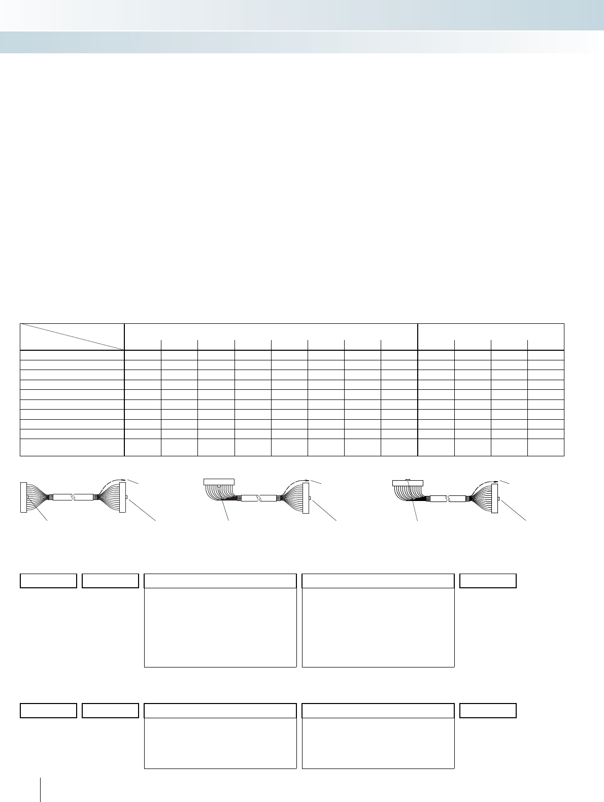
288 PHOENIX CONTACT
S
ystem ca
bl
e w
i
t
h
fl
at-r
ibb
on ca
bl
e
connector
Cable type Non-shielded round cables
FLK EZ-DR.../.../...
Shielded round cables
FLK EZ-DR-S.../.../...
Assembly 10-pos. 14-pos. 16-pos. 20-pos. 26-pos. 34-pos. 40-pos. 50-pos. 14-pos. 16-pos. 40-pos. 50-pos.
no assembly 10U/C00/... 14U/C00/... 16U/C00/... 20U/C00/... 26U/C00/... 34U/C00/... 40U/C00/... 50U/C00/... 14S/C00/... 16S/C00/.... 40S/C00/... 50S/C00/...
socket strip at both ends, 10-pos. 10U/C55/...1)
socket strip at both ends, 14-pos. 14U/C23/...1)14S/C23/...1)
socket strip at both ends, 16-pos. 16U/C58/...1)16S/C58/...1)
socket strip at both ends, 20-pos. 20U/C61/...1)
socket strip at both ends, 26-pos. 26U/C63/...1)
socket strip at both ends, 34-pos. 34U/C65/...1)
socket strip at both ends, 40-pos. 40U/C30/...3)40S/C30/...3)
socket strip at both ends, 50-pos. 50U/C38/...2)50S/C38/...2)
socket strip at one end, 14-pos.;
socket strip at one end, 16-pos. 14U/C52/...1)14S/C52/...1)
Features of permissible assemblies:
1) straight socket strips fitted at both ends.
Polarity protection lug
2) Socket strips fitted, straight at one end and angled at the
other.
Polarity protection lug Polarity protection lug
Shield connection
(for shielded
cables)
Shield connection
(for shielded cables)
Polarity protection lug
Sample order for round cable unshielded:
– Unshielded 50-position round cable sets with two 50-pos. socket strips and a length of 11.5 m
Quantity Order No. Cable type Assembly Length [m]4)
1 2295059 /50U /C38 /11.50
10U 10-pos. unshielded
14U 14-pos. unshielded
16U 16-pos. unshielded
20U 20-pos. unshielded
26U 26-pos. unshielded
34U 34-pos. unshielded
40U 40-pos. unshielded
50U 50-pos. unshielded
C00 no assembly
C55 10-pos. socket strip at both ends
C23 14-pos. socket strip at both ends
C52 14-pos. socket strip at one end
16-pos. socket strip at one end (for S7)
C58 16-pos. socket strip at both ends
C61 20-pos. socket strip at both ends
C63 26-pos. socket strip at both ends
C65 34-pos. socket strip at both ends
C30 40-pos. socket strip at both ends
C38 50-pos. socket strip at both ends
4) min. 0.20 m
Sample orders for round cable shielded:
– Shielded 14-position round cable sets with two 14-pos. socket strips and a length of 12.75 m
Quantity Order No. Cable type Assembly Length [m]4)
1 2295046 /14S /C23 /12.75
14S 14-pos. shielded
16S 16-pos. shielded
40S 40-pos. shielded
50S 50-pos. shielded
C00 no assembly
C23 14-pos. socket strip at both ends
C52 14-pos. socket strip at one end
16-pos. socket strip at one end (for S7)
C58 16-pos. socket strip at both ends
C30 40-pos. socket strip at both ends
C38 50-pos. socket strip at both ends
4) min. 0.20 m
Special lengths
Pre-assembled round cables are used
to connect the PLC front adapters to the
corresponding VARIOFACE termination
boards. Connector strips are fitted on both
ends of the cables in accordance with
IEC 60603-13/DIN 41651. In case of
shielded cables, a cable end with a ferrule is
additionally provided as a shield connection
(length: Approx. 0.5 m; cable H05V-K
1mm
2, black).
The order key for special lengths is
defined by three features.
The features in the appropriate
sequence are:
–Cable type
–Assembly,
– Length in meters.
There are two order keys, one for the
non-shielded round cable FLK EZ-
DR/.../.../... and one for the shielded round
cable FLK EZ-DR-S/.../.../.... The features
necessary for clear identification of an order
are described below:
Cable type
– The number of individual conductors of
the cable is defined here.
Assembly
–None,
the cable is not assembled at either end;
– socket strip at both ends, 10-pos.,
the cable is fitted at both ends with
10-pos. connectors (1:1 connection);
– socket strip at both ends, 14-pos.,
the cable is fitted at both ends with
14-pos. connectors (1:1 connection);
– socket strip at both ends, 50-pos.,
the cable is fitted at both ends with
50-pos. connectors (1:1 connection);
– socket strip at one end, 14-pos.,
socket strip at one end, 16-pos.,
the cable is fitted with a 14-pos.
connector at one end and with a 16-pos.
connector at the other (for SIMATIC S7;
no 1:1 connection).
3) Socket strips fitted, straight at one end and angled at the
other.
Polarity protection lug Polarity protection lug
Shield connection
(for shielded
cables)
INTERFACE Cabling
VARIOFACE system cabling
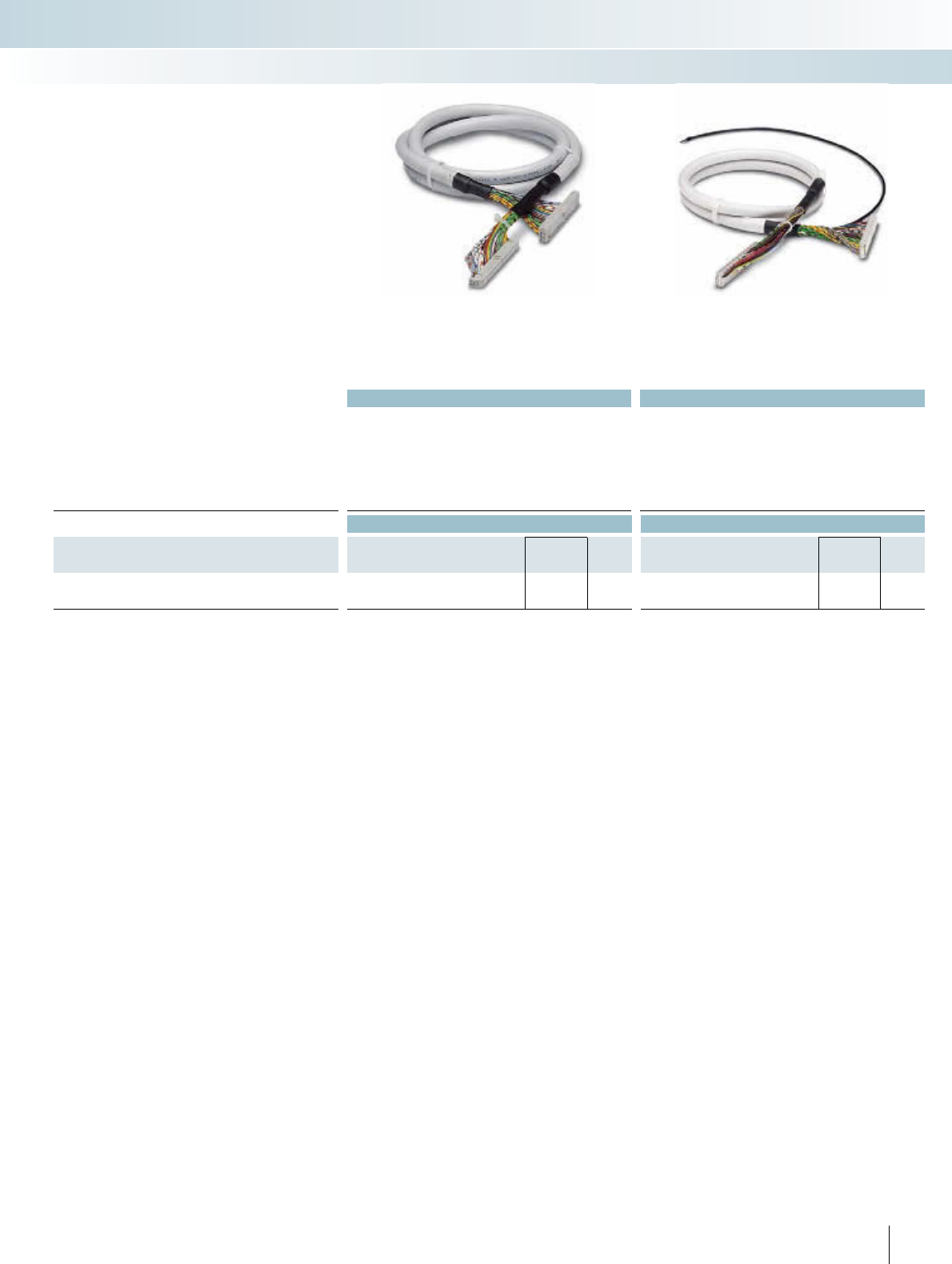
For additional information, visit www.phoenixcontact.net/catalog
|
Technical data Technical data
Max. perm. operating voltage < 50 V AC / 60 V DC < 50 V AC / 60 V DC
Max. perm. current carrying capacitance per path 1 A 1 A
Max. conductor resistance 0.16 /m 0.16 /m
Ambient temperature (operation) -20°C ... 50°C -20°C ... 50°C
Shield - Tinned copper-braided shield, approx. 85% covering
Conductor cross section AWG 26 / 0.14 mm² AWG 26 / 0.14 mm²
Conductor structure: stranded wires / material 7 / Cu tin-plated 7 / Cu tin-plated
Ordering data Ordering data
Description No. of
poles Cable length Type Order No. Pcs. /
Pkt. Type Order No. Pcs. /
Pkt.
Assembled round cables, with socket strips in variable lengths
FLK EZ-DR.../.../... 2295059 1FLK EZ-DR-S.../.../... 2295046 1
289PHOENIX CONTACT
INTERFACE Cabling
VARIOFACE system cabling
Not shielded Shielded
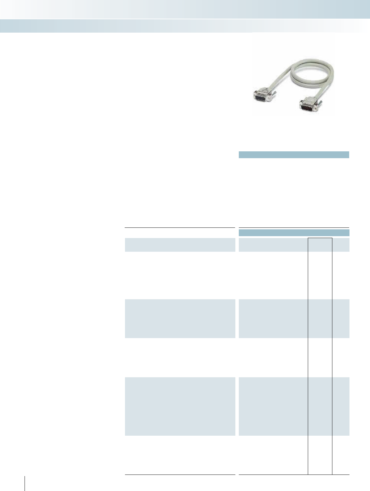
|
290 PHOENIX CONTACT
Standard lengths
Shielded round cable sets to connect the
control level with the corresponding
VARIOFACE interface modules.
Assembly with D-SUB strips as per
IEC 60807-2/DIN 41652, (1:1 connection).
– D-SUB socket strip on one side and
D-SUB pin strip on the other
– D-SUB socket strips on both sides
– D-SUB pin strips on both sides
– Cable exit: Straight
– Screw connection: 2 UNC 4-40 screws
Special lengths and assembly versions are
defined using an order key, refer to page 292.
System cable with D-SUB socket and
pin strip
Technical data
Max. perm. operating voltage 125 V AC/DC
Max. perm. current carrying capacitance per path 2 A
Max. conductor resistance 0.09 /m
Ambient temperature (operation) -20°C ... 50°C
Shield Tinned copper-braided shield, approx. 85% covering
Insertion/withdrawal cycles > 200
Conductor cross section AWG 24 / 0.25 mm²
Outside diameter
9-pole 7.5 mm
15-pole 9 mm
25-pole 10.5 mm
37-pole 12.5 mm
50-pole 13.5 mm
Ordering data
Description No. of
poles Cable length Type Order No. Pcs. /
Pkt.
Shielded round cable, fitted with two D-SUB strips, various num-
bers of poles and lengths
90.5 mCABLE-D 9SUB/B/S/ 50/KONFEK/S 2299987 1
91 mCABLE-D 9SUB/B/S/100/KONFEK/S 2299990 1
91.5 mCABLE-D 9SUB/B/S/150/KONFEK/S 2300009 1
92 mCABLE-D 9SUB/B/S/200/KONFEK/S 2302010 1
93 mCABLE-D 9SUB/B/S/300/KONFEK/S 2302023 1
94 mCABLE-D 9SUB/B/S/400/KONFEK/S 2302036 1
96 mCABLE-D 9SUB/B/S/600/KONFEK/S 2302049 1
15 0.5 m CABLE-D15SUB/B/S/ 50/KONFEK/S 2302052 1
15 1 m CABLE-D15SUB/B/S/100/KONFEK/S 2302065 1
15 1.5 m CABLE-D15SUB/B/S/150/KONFEK/S 2302078 1
15 2 m CABLE-D15SUB/B/S/200/KONFEK/S 2302081 1
15 3 m CABLE-D15SUB/B/S/300/KONFEK/S 2302094 1
15 4 m CABLE-D15SUB/B/S/400/KONFEK/S 2302104 1
15 6 m CABLE-D15SUB/B/S/600/KONFEK/S 2302117 1
25 0.5 m CABLE-D25SUB/B/S/ 50/KONFEK/S 2302120 1
25 1 m CABLE-D25SUB/B/S/100/KONFEK/S 2302133 1
25 1.5 m CABLE-D25SUB/B/S/150/KONFEK/S 2302146 1
25 2 m CABLE-D25SUB/B/S/200/KONFEK/S 2302159 1
25 3 m CABLE-D25SUB/B/S/300/KONFEK/S 2302162 1
25 4 m CABLE-D25SUB/B/S/400/KONFEK/S 2302175 1
25 6 m CABLE-D25SUB/B/S/600/KONFEK/S 2302188 1
37 0.5 m CABLE-D37SUB/B/S/ 50/KONFEK/S 2302191 1
37 1 m CABLE-D37SUB/B/S/100/KONFEK/S 2302201 1
37 1.5 m CABLE-D37SUB/B/S/150/KONFEK/S 2302214 1
37 2 m CABLE-D37SUB/B/S/200/KONFEK/S 2302227 1
37 3 m CABLE-D37SUB/B/S/300/KONFEK/S 2302230 1
37 4 m CABLE-D37SUB/B/S/400/KONFEK/S 2302243 1
37 6 m CABLE-D37SUB/B/S/600/KONFEK/S 2302256 1
37 8 m
37 10 m
37 15 m
37 20 m
50 0.5 m CABLE-D50SUB/B/S/ 50/KONFEK/S 2302269 1
50 1 m CABLE-D50SUB/B/S/100/KONFEK/S 2302272 1
50 1.5 m CABLE-D50SUB/B/S/150/KONFEK/S 2302285 1
50 2 m CABLE-D50SUB/B/S/200/KONFEK/S 2302298 1
50 3 m CABLE-D50SUB/B/S/300/KONFEK/S 2302308 1
50 4 m CABLE-D50SUB/B/S/400/KONFEK/S 2302311 1
50 6 m CABLE-D50SUB/B/S/600/KONFEK/S 2302324 1
INTERFACE Cabling
VARIOFACE system cabling
Socket at one end and pin strip at the other
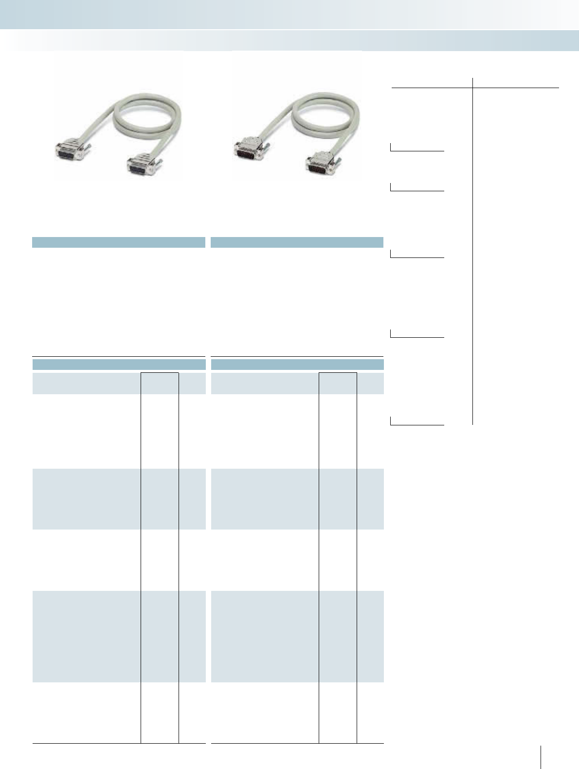
For additional information, visit www.phoenixcontact.net/catalog
No. of cores PIN Core color
1white
2brown
3 green
4 yellow
5gray
6pink
7blue
8red
9-pos. 9 black
10 violet
11 gray-pink
12 red-blue
13 white-green
14 brown-green
15-pos. 15 white-yellow
16 yellow-brown
17 white-gray
18 gray-brown
19 white-pink
20 pink-brown
21 white-blue
22 brown-blue
23 white-red
24 brown-red
25-pos. 25 white-black
26 brown-black
27 gray-green
28 yellow-gray
29 pink-green
30 yellow-pink
31 green-blue
32 yellow-blue
33 green-red
34 yellow-red
35 green-black
36 yellow-black
37-pos. 37 gray-blue
38 pink-blue
39 gray-red
40 pink-red
41 gray-black
42 pink-black
43 blue-black
44 red-black
45 white-brown-black
46 yellow-green-black
47 gray-pink-black
48 blue-red-black
49 white-green-black
50-pos. 50 green-brown-black
Color code of the system cables
CABLE-D...SUB/...
291
PHOENIX CONTACT
Technical data Technical data
125 V AC/DC 125 V AC/DC
2 A 2 A
0.09 /m 0.09 /m
-20°C ... 50°C -20°C ... 50°C
Tinned copper-braided shield, approx. 85% covering Tinned copper-braided shield, approx. 85% covering
> 200 > 200
AWG 24 / 0.25 mm² AWG 24 / 0.25 mm²
7.5 mm 7.5 mm
9 mm 9 mm
10.5 mm 10.5 mm
12 mm 12 mm
13.5 mm 13.5 mm
Ordering data Ordering data
Type Order No. Pcs. /
Pkt. Type Order No. Pcs. /
Pkt.
CABLE-D 9SUB/B/B/100/KONFEK/S 2305415 1CABLE-D 9SUB/S/S/100/KONFEK/S 2305570 1
CABLE-D 9SUB/B/B/200/KONFEK/S 2305428 1CABLE-D 9SUB/S/S/200/KONFEK/S 2305583 1
CABLE-D 9SUB/B/B/300/KONFEK/S 2305431 1CABLE-D 9SUB/S/S/300/KONFEK/S 2305596 1
CABLE-D15SUB/B/B/100/KONFEK/S 2305444 1CABLE-D15SUB/S/S/100/KONFEK/S 2305606 1
CABLE-D15SUB/B/B/200/KONFEK/S 2305457 1CABLE-D15SUB/S/S/200/KONFEK/S 2305619 1
CABLE-D15SUB/B/B/300/KONFEK/S 2305460 1CABLE-D15SUB/S/S/300/KONFEK/S 2305622 1
CABLE-D25SUB/B/B/100/KONFEK/S 2305473 1CABLE-D25SUB/S/S/100/KONFEK/S 2305635 1
CABLE-D25SUB/B/B/200/KONFEK/S 2305486 1CABLE-D25SUB/S/S/200/KONFEK/S 2305648 1
CABLE-D25SUB/B/B/300/KONFEK/S 2305499 1CABLE-D25SUB/S/S/300/KONFEK/S 2305651 1
CABLE-D37SUB/B/B/ 100/KONFEK/S 2305509 1CABLE-D37SUB/S/S/100/KONFEK/S 2305664 1
CABLE-D37SUB/B/B/ 200/KONFEK/S 2305512 1CABLE-D37SUB/S/S/200/KONFEK/S 2305677 1
CABLE-D37SUB/B/B/ 300/KONFEK/S 2305525 1CABLE-D37SUB/S/S/300/KONFEK/S 2305680 1
CABLE-D37SUB/B/B/ 400/KONFEK/S 2900759 1
CABLE-D37SUB/B/B/ 600/KONFEK/S 2900760 1
CABLE-D37SUB/B/B/ 800/KONFEK/S 2900761 1
CABLE-D37SUB/B/B/1000/KONFEK/S 2900762 1
CABLE-D37SUB/B/B/1500/KONFEK/S 2900763 1
CABLE-D37SUB/B/B/2000/KONFEK/S 2900764 1
CABLE-D50SUB/B/B/100/KONFEK/S 2305541 1CABLE-D50SUB/S/S/100/KONFEK/S 2305693 1
CABLE-D50SUB/B/B/200/KONFEK/S 2305554 1CABLE-D50SUB/S/S/200/KONFEK/S 2305703 1
CABLE-D50SUB/B/B/300/KONFEK/S 2305567 1CABLE-D50SUB/S/S/300/KONFEK/S 2305716 1
INTERFACE Cabling
VARIOFACE system cabling
Socket strip at both ends Male connector at both ends
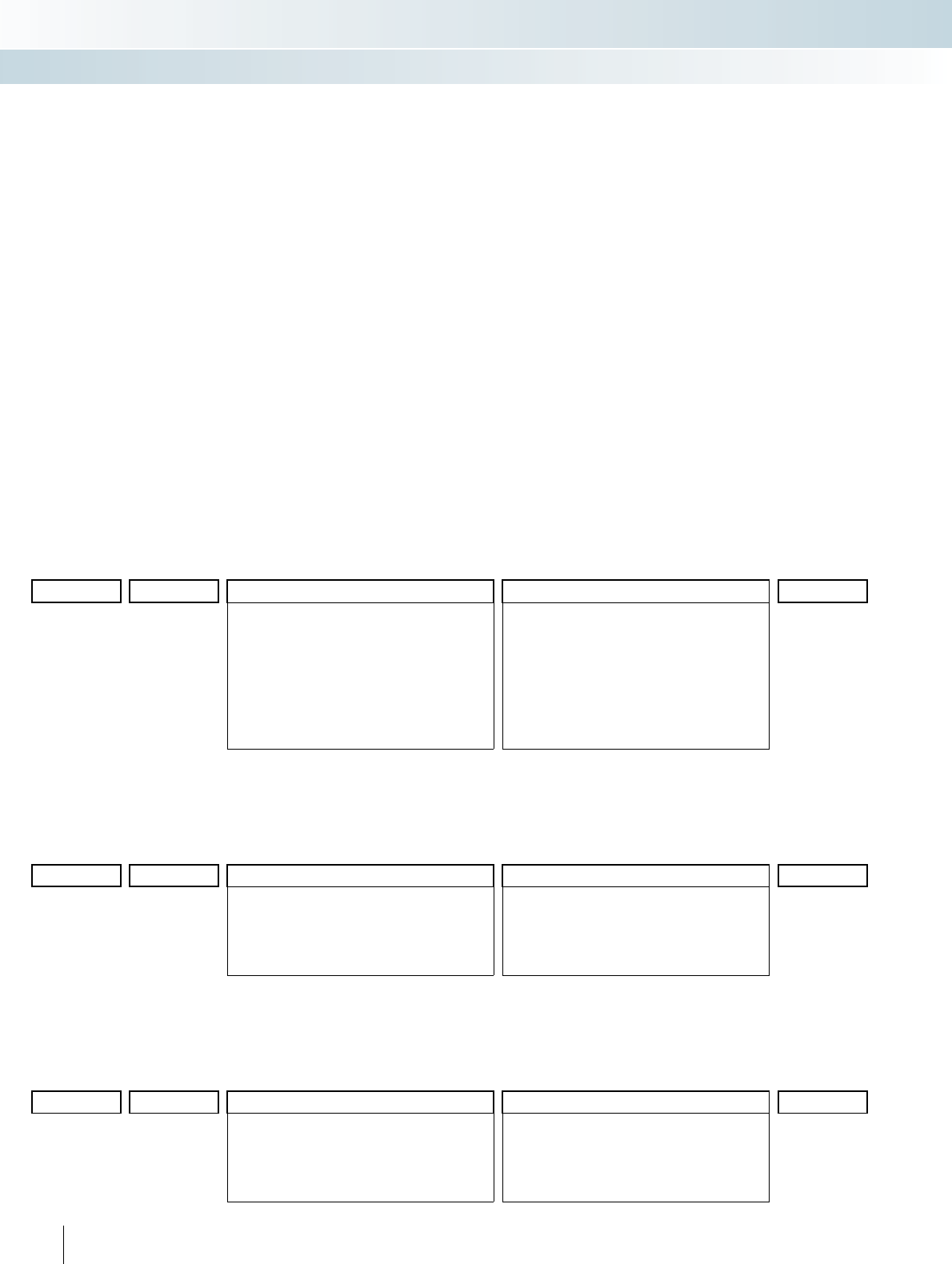
292 PHOENIX CONTACT
S
ystem ca
bl
e w
i
t
h
D
-
SUB
soc
k
ets an
d
pin strip
Special lengths
Preassembled shielded round cables
for connecting VARIOFACE termination
boards. The cables are assembled with
D-SUB strips in accordance with
IEC 60807-2/DIN 41652.
The order key is defined by three
features.
The features in the appropriate
sequence are:
–Cable type
–Assembly
–Length in meters
There are three assembly variants of the
shielded round cable:
– CABLE D-SUB-S/.../.../...
D-SUB socket strip on one end and
D-SUB pin strip on the other
– CABLE D-SUB-B-B-S/.../.../... D-SUB
socket strip at both ends
– CABLE D-SUB-S-S-S/.../.../... D-SUB pin
strip at both ends
The features necessary for clear
identification of an order are described
below:
Cable type
– The number of individual conductors of
the cable is defined here.
Assembly
– (example for CABLE D-SUB-S/.../.../...)
–None,
the cable is not assembled at either ends
– 9-pos. D-SUB socket strip at one end
9-pos. D-SUB pin strip at one end
the cable connects (1:1) a 9-pos. D-SUB
socket and pin strip
– 15-pos. D-SUB socket strip at one end
15-pos. D-SUB pin strip at one end
the cable connects (1:1) a 15-pos.
D-SUB socket and pin strip; or up to
– 50-pos. D-SUB socket strip at one end
50-pos. D-SUB pin strip at one end
the cable connects (1:1) a 50-pos.
D-SUB socket and pin strip.
Sample order for round cable set assembled with pin strip on one side and socket strip on one side
– unshielded 25-position round cable set, assembled with one 25-pos. D-SUB socket strip and one 25-pos. D-SUB pin strip, 11.5 mm long
Quantity Order No. Cable type Assembly Length [m]1)
1 2302340 /25S /C36 /11.50
09S 9-pos. shielded
15S 15-pos. shielded
25S 25-pos. shielded
37S 37-pos. shielded
50S 50-pos. shielded
C00 no assembly
C01 9-pos. D-SUB socket strip at one end
9-pos. D-SUB pin strip at one end
C28 15-pos. D-SUB socket strip at one end
15-pos. D-SUB pin strip at one end
C36 25-pos. D-SUB socket strip at one end
25-pos. D-SUB pin strip at one end
C43 37-pos. D-SUB socket strip at one end
37-pos. D-SUB pin strip at one end
C49 50-pos. D-SUB socket strip at one end
50-pos. D-SUB pin strip at one end
1) min. 0.20 m
Sample order for round cable set assembled with socket strip at both ends
– Shielded 37-pos. round cable, assembled with two 37-pos. D-SUB socket strips, 12.75 m long
Quantity Order No. Cable type Assembly Length [m]1)
1 2302421 /37S /C44 /12.75
09S 9-pos. shielded
15S 15-pos. shielded
25S 25-pos. shielded
37S 37-pos. shielded
50S 50-pos. shielded
C00 no assembly
C22 9-pos. D-SUB socket strip at both ends
C29 15-pos. D-SUB socket strip at both ends
C37 25-pos. D-SUB socket strip at both ends
C44 37-pos. D-SUB socket strip at both ends
C50 50-pos. D-SUB socket strip at both ends
1) min. 0.20 m
Sample order for round cable set assembled with pin strip at both ends
– Shielded 15-pos. round cable, assembled with two 15-pos. D-SUB pin strips, 8.5 m long
Quantity Order No. Cable type Assembly Length [m]1)
1 2302434 /15S /C71 /8.50
09S 9-pos. shielded
15S 15-pos. shielded
25S 25-pos. shielded
37S 37-pos. shielded
50S 50-pos. shielded
C00 no assembly
C70 9-pos. D-SUB pin strip at both ends
C71 15-pos. D-SUB pin strip at both ends
C72 25-pos. D-SUB pin strip at both ends
C73 37-pos. D-SUB pin strip at both ends
C74 50-pos. D-SUB pin strip at both ends
1) min. 0.20 m
INTERFACE Cabling
VARIOFACE system cabling
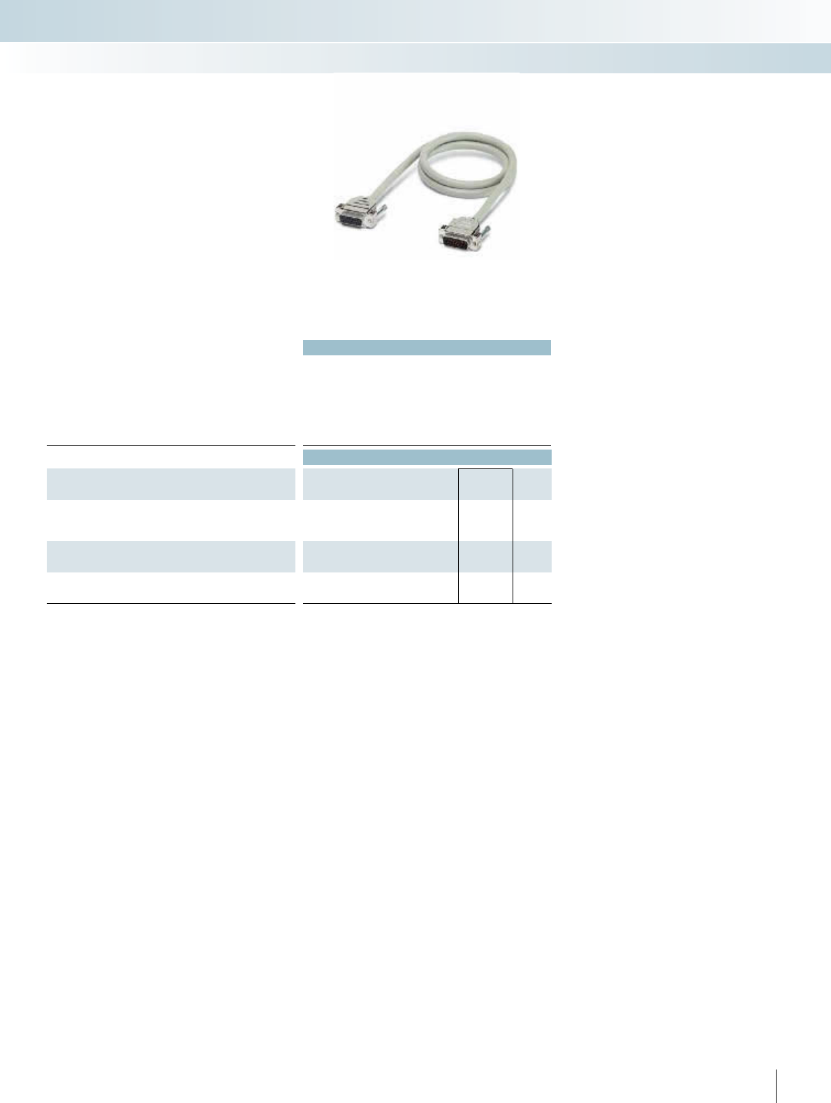
For additional information, visit www.phoenixcontact.net/catalog
|
Technical data
Max. perm. operating voltage 125 V AC/DC
Max. perm. current carrying capacitance per path 2 A
Max. conductor resistance 0.09 /m
Ambient temperature (operation) -20°C ... 50°C
Shield Tinned copper-braided shield, approx. 85% covering
Insertion/withdrawal cycles > 200
Conductor cross section AWG 24 / 0.25 mm²
Ordering data
Description No. of
poles Cable length Type Order No. Pcs. /
Pkt.
Assembled round cables, in variable lengths, pin strip on one
side and socket strip on one side
CABLE D-SUB-S/.../.../... 2302340 1
Assembled round cables, in variable lengths, socket strip on
both sides
CABLE D-SUB-B-B-S/.../.../... 2302421 1
Assembled round cables, in variable lengths, pin strip on both
sides
CABLE D-SUB-S-S-S/.../.../... 2302434 1
293PHOENIX CONTACT
INTERFACE Cabling
VARIOFACE system cabling
Shielded
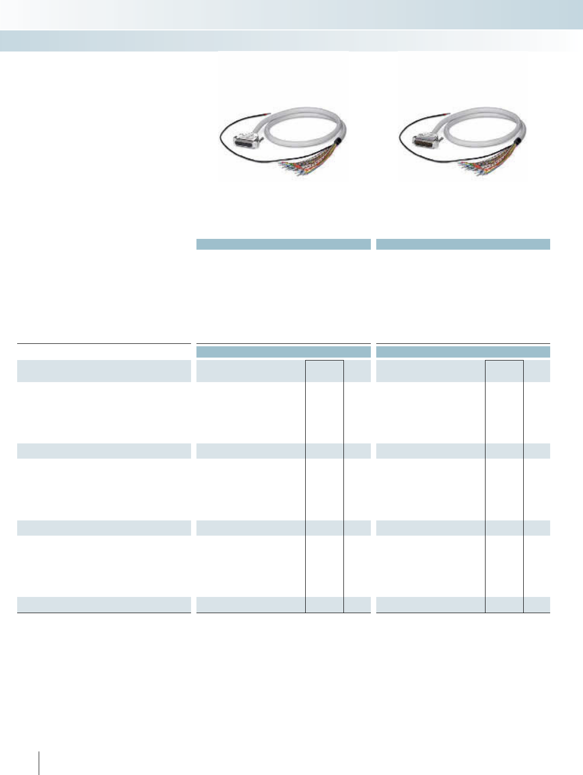
Technical data Technical data
Max. perm. operating voltage 125 V AC/DC 125 V AC/DC
Max. perm. current carrying capacitance per path 2 A 2 A
Max. conductor resistance 0.09 /m 0.09 /m
Ambient temperature (operation) -20°C ... 50°C -20°C ... 50°C
Shield Tinned copper-braided shield, approx. 85% covering Tinned copper-braided shield, approx. 85% covering
Insertion/withdrawal cycles > 200 > 200
Conductor cross section AWG 24 / 0.25 mm² AWG 24 / 0.25 mm²
Outside diameter
9-pole 7.5 mm 7.5 mm
15-pole 9 mm 9 mm
25-pole 10.5 mm 10.5 mm
Ordering data Ordering data
Description No. of
poles Cable length Type Order No. Pcs. /
Pkt. Type Order No. Pcs. /
Pkt.
Round cable with an open end
90.5 mCABLE-D- 9SUB/F/OE/0,25/S/0,5M 2926014 1CABLE-D- 9SUB/M/OE/0,25/S/0,5M 2926360 1
91 mCABLE-D- 9SUB/F/OE/0,25/S/1,0M 2926027 1CABLE-D- 9SUB/M/OE/0,25/S/1,0M 2926373 1
91.5 mCABLE-D- 9SUB/F/OE/0,25/S/1,5M 2926030 1CABLE-D- 9SUB/M/OE/0,25/S/1,5M 2926386 1
92 mCABLE-D- 9SUB/F/OE/0,25/S/2,0M 2926043 1CABLE-D- 9SUB/M/OE/0,25/S/2,0M 2926399 1
93 mCABLE-D- 9SUB/F/OE/0,25/S/3,0M 2926056 1CABLE-D- 9SUB/M/OE/0,25/S/3,0M 2926409 1
94 mCABLE-D- 9SUB/F/OE/0,25/S/4,0M 2926069 1CABLE-D- 9SUB/M/OE/0,25/S/4,0M 2926412 1
96 mCABLE-D- 9SUB/F/OE/0,25/S/6,0M 2926072 1CABLE-D- 9SUB/M/OE/0,25/S/6,0M 2926425 1
Round cable, same as before, however in variable lengths
CABLE-D- 9SUB-F-OE-0,25-S/... 2900903 1CABLE-D- 9SUB-M-OE-0,25-S/... 2900909 1
Round cable with an open end
15 0.5 m CABLE-D-15SUB/F/OE/0,25/S/0,5M 2926085 1CABLE-D-15SUB/M/OE/0,25/S/0,5M 2926438 1
15 1 m CABLE-D-15SUB/F/OE/0,25/S/1,0M 2926098 1CABLE-D-15SUB/M/OE/0,25/S/1,0M 2926441 1
15 1.5 m CABLE-D-15SUB/F/OE/0,25/S/1,5M 2926108 1CABLE-D-15SUB/M/OE/0,25/S/1,5M 2926454 1
15 2 m CABLE-D-15SUB/F/OE/0,25/S/2,0M 2926111 1CABLE-D-15SUB/M/OE/0,25/S/2,0M 2926467 1
15 3 m CABLE-D-15SUB/F/OE/0,25/S/3,0M 2926124 1CABLE-D-15SUB/M/OE/0,25/S/3,0M 2926470 1
15 4 m CABLE-D-15SUB/F/OE/0,25/S/4,0M 2926137 1CABLE-D-15SUB/M/OE/0,25/S/4,0M 2926483 1
15 6 m CABLE-D-15SUB/F/OE/0,25/S/6,0M 2926140 1CABLE-D-15SUB/M/OE/0,25/S/6,0M 2926496 1
Round cable, same as before, however in variable lengths
CABLE-D-15SUB-F-OE-0,25-S/... 2900905 1CABLE-D-15SUB-M-OE-0,25-S/... 2900910 1
Round cable with an open end
25 0.5 m CABLE-D-25SUB/F/OE/0,25/S/0,5M 2926153 1CABLE-D-25SUB/M/OE/0,25/S/0,5M 2926506 1
25 1 m CABLE-D-25SUB/F/OE/0,25/S/1,0M 2926166 1CABLE-D-25SUB/M/OE/0,25/S/1,0M 2926519 1
25 1.5 m CABLE-D-25SUB/F/OE/0,25/S/1,5M 2926179 1CABLE-D-25SUB/M/OE/0,25/S/1,5M 2926522 1
25 2 m CABLE-D-25SUB/F/OE/0,25/S/2,0M 2926182 1CABLE-D-25SUB/M/OE/0,25/S/2,0M 2926535 1
25 3 m CABLE-D-25SUB/F/OE/0,25/S/3,0M 2926195 1CABLE-D-25SUB/M/OE/0,25/S/3,0M 2926548 1
25 4 m CABLE-D-25SUB/F/OE/0,25/S/4,0M 2926205 1CABLE-D-25SUB/M/OE/0,25/S/4,0M 2926551 1
25 6 m CABLE-D-25SUB/F/OE/0,25/S/6,0M 2926218 1CABLE-D-25SUB/M/OE/0,25/S/6,0M 2926564 1
Round cable, same as before, however in variable lengths
CABLE-D-25SUB-F-OE-0,25-S/... 2900906 1CABLE-D-25SUB-M-OE-0,25-S/... 2900911 1
294 PHOENIX CONTACT
INTERFACE Cabling
VARIOFACE system cabling
Female connector at one end and
open end at the other end
Pin strip at one end and
open end at the other end
– 1:1 connection
– D-SUB female connector or pin strip at
one end
– Connector according to
IEC 60807-2/DIN 41652
– Gland: 2 UNC 4-40 screws
– Open end at the other end
– Individual wire marking: 1, 2, 3, 4, etc.
– Individual wires fitted with ferrules
– Shield connection: H05V-K 1 mm2 cable,
black, 0.5 m in length
System cable with D-SUB female con-
nector or pin strip and one open end
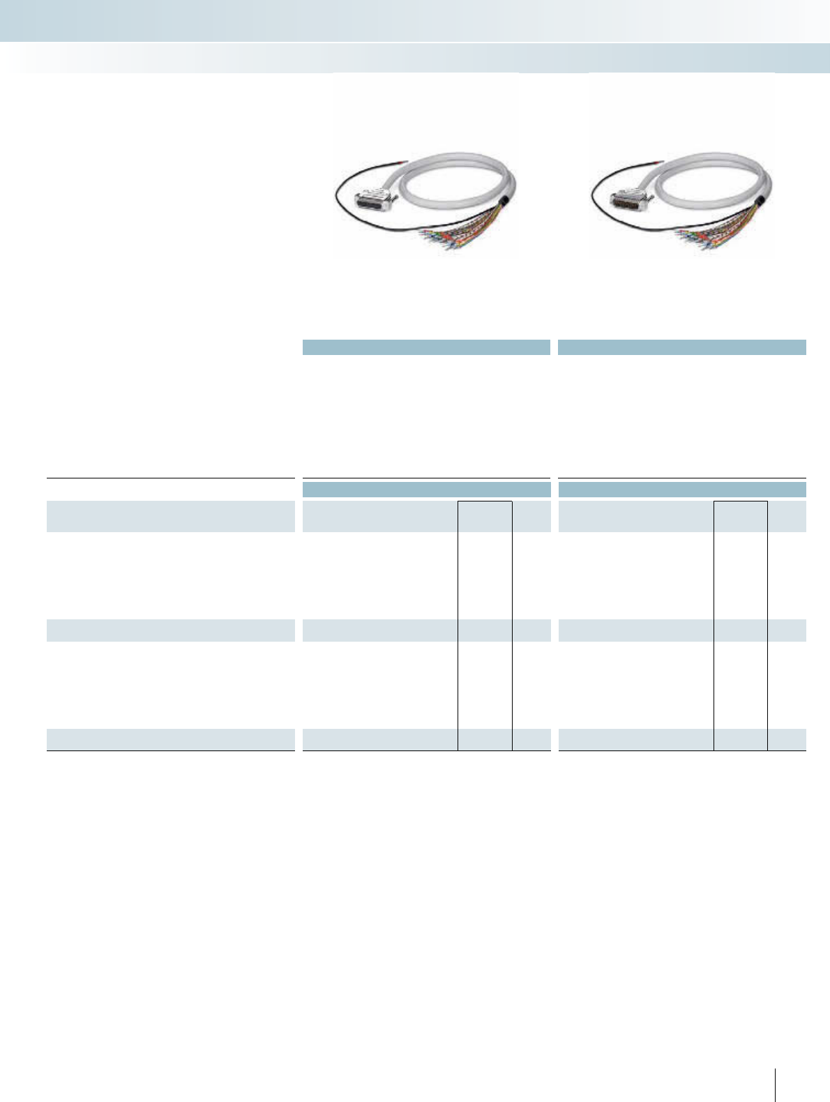
For additional information, visit www.phoenixcontact.net/catalog
Technical data Technical data
Max. perm. operating voltage 125 V AC/DC 125 V AC/DC
Max. perm. current carrying capacitance per path 2 A 2 A
Max. conductor resistance 0.09 /m 0.09 /m
Ambient temperature (operation) -20°C ... 50°C -20°C ... 50°C
Shield Tinned copper-braided shield, approx. 85% covering Tinned copper-braided shield, approx. 85% covering
Insertion/withdrawal cycles > 200 > 200
Conductor cross section AWG 24 / 0.25 mm² AWG 24 / 0.25 mm²
Outside diameter
37-pole 12 mm 12 mm
50-pole 13.5 mm 13.5 mm
Ordering data Ordering data
Description No. of
poles Cable length Type Order No. Pcs. /
Pkt. Type Order No. Pcs. /
Pkt.
Round cable with an open end
37 0.5 m CABLE-D-37SUB/F/OE/0,25/S/0,5M 2926221 1CABLE-D-37SUB/M/OE/0,25/S/0,5M 2926577 1
37 1 m CABLE-D-37SUB/F/OE/0,25/S/1,0M 2926234 1CABLE-D-37SUB/M/OE/0,25/S/1,0M 2926580 1
37 1.5 m CABLE-D-37SUB/F/OE/0,25/S/1,5M 2926247 1CABLE-D-37SUB/M/OE/0,25/S/1,5M 2926593 1
37 2 m CABLE-D-37SUB/F/OE/0,25/S/2,0M 2926250 1CABLE-D-37SUB/M/OE/0,25/S/2,0M 2926603 1
37 3 m CABLE-D-37SUB/F/OE/0,25/S/3,0M 2926263 1CABLE-D-37SUB/M/OE/0,25/S/3,0M 2926616 1
37 4 m CABLE-D-37SUB/F/OE/0,25/S/4,0M 2926276 1CABLE-D-37SUB/M/OE/0,25/S/4,0M 2926629 1
37 6 m CABLE-D-37SUB/F/OE/0,25/S/6,0M 2926289 1CABLE-D-37SUB/M/OE/0,25/S/6,0M 2926632 1
Round cable, same as before, however in variable lengths
CABLE-D-37SUB-F-OE-0,25-S/... 2900907 1CABLE-D-37SUB-M-OE-0,25-S/... 2900912 1
Round cable with an open end
50 0.5 m CABLE-D-50SUB/F/OE/0,25/S/0,5M 2926292 1CABLE-D-50SUB/M/OE/0,25/S/0,5M 2926645 1
50 1 m CABLE-D-50SUB/F/OE/0,25/S/1,0M 2926302 1CABLE-D-50SUB/M/OE/0,25/S/1,0M 2926658 1
50 1.5 m CABLE-D-50SUB/F/OE/0,25/S/1,5M 2926315 1CABLE-D-50SUB/M/OE/0,25/S/1,5M 2926661 1
50 2 m CABLE-D-50SUB/F/OE/0,25/S/2,0M 2926328 1CABLE-D-50SUB/M/OE/0,25/S/2,0M 2926674 1
50 3 m CABLE-D-50SUB/F/OE/0,25/S/3,0M 2926331 1CABLE-D-50SUB/M/OE/0,25/S/3,0M 2926687 1
50 4 m CABLE-D-50SUB/F/OE/0,25/S/4,0M 2926344 1CABLE-D-50SUB/M/OE/0,25/S/4,0M 2926690 1
50 6 m CABLE-D-50SUB/F/OE/0,25/S/6,0M 2926357 1CABLE-D-50SUB/M/OE/0,25/S/6,0M 2926700 1
Round cable, same as before, however in variable lengths
CABLE-D-50SUB-F-OE-0,25-S/... 2900908 1CABLE-D-50SUB-M-OE-0,25-S/... 2900913 1
295PHOENIX CONTACT
INTERFACE Cabling
VARIOFACE system cabling
Female connector at one end and
open end at the other end
Pin strip at one end and
open end at the other end
Special lengths of D-SUB cable with open
ends can be configured using separate order
numbers.
Ordering example:
One system cable assembled with a
37-pole D-SUB female connector and one
open end, 12.75 m in length:
1 pcs. 2900907/12,75
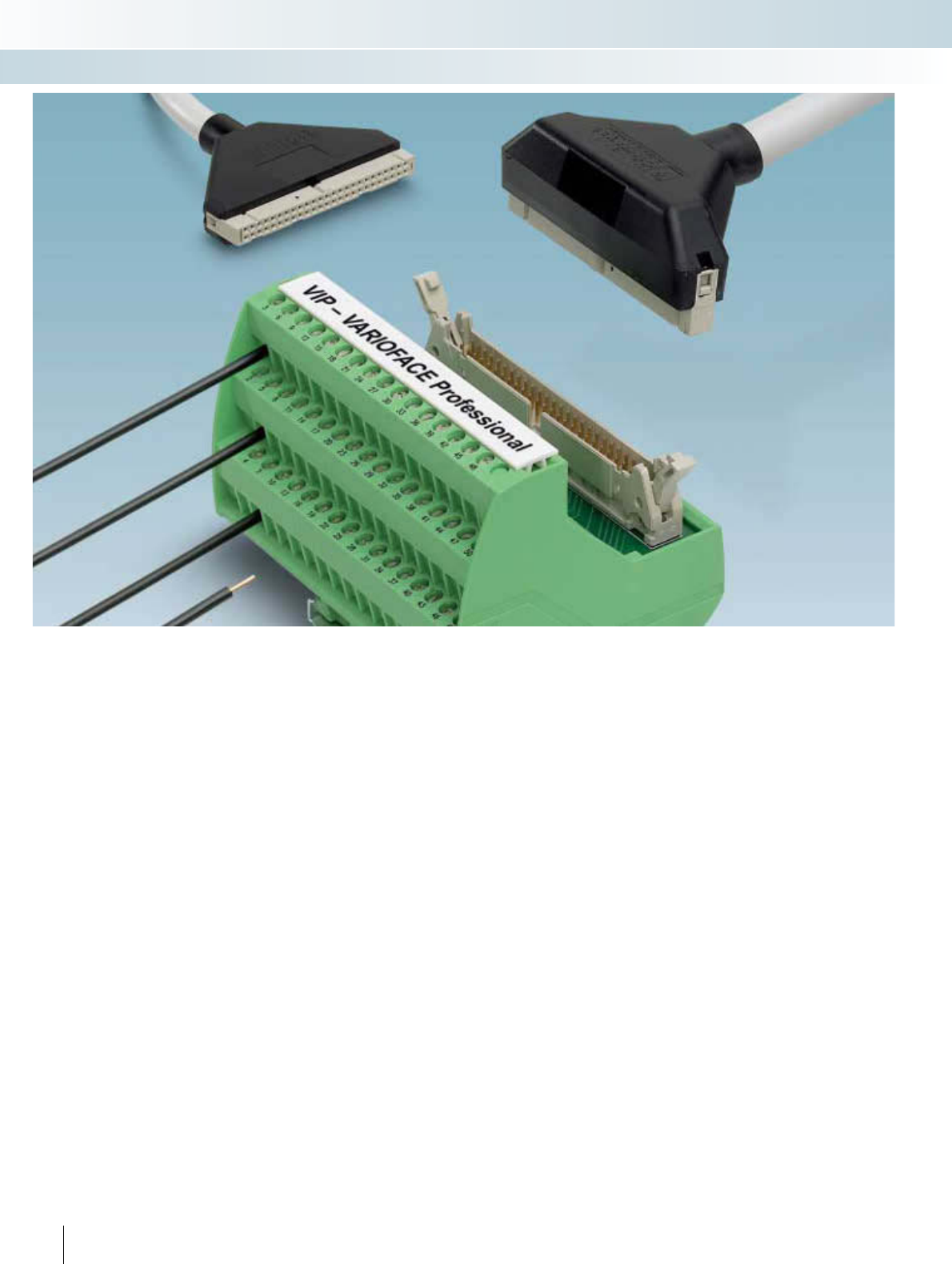
VIP – VARIOFACE Professional –
Secure and reliable connections in
even the tightest of spaces
Switch cabinet space is extremely
valuable. That is why the I/Os of automation
devices feature high-pole connectors. To
enable the individual wires of the sensor/
actuator level to be connected to the
automation interface in accordance with
industry requirements, Phoenix Contact is
now able to offer new interface modules
and new system cables inside a professional
and compact housing. Thanks to the
enclosed system cables, the control and
process levels can be connected securely
and reliably within harsh industrial
environments.
To allow all components to be supplied
with power, potential distributors are
available with the same housing design.
VARIOFACE Professional means:
New modules:
– Space-saving
– Vibration-resistant thanks to metal foot
– Optional labeling
– New housing design
New FLK system cables:
– Enclosed FLK connectors
– Professional strain relief
– Rugged design
296 PHOENIX CONTACT
INTERFACE Cabling
VARIOFACE wiring interface
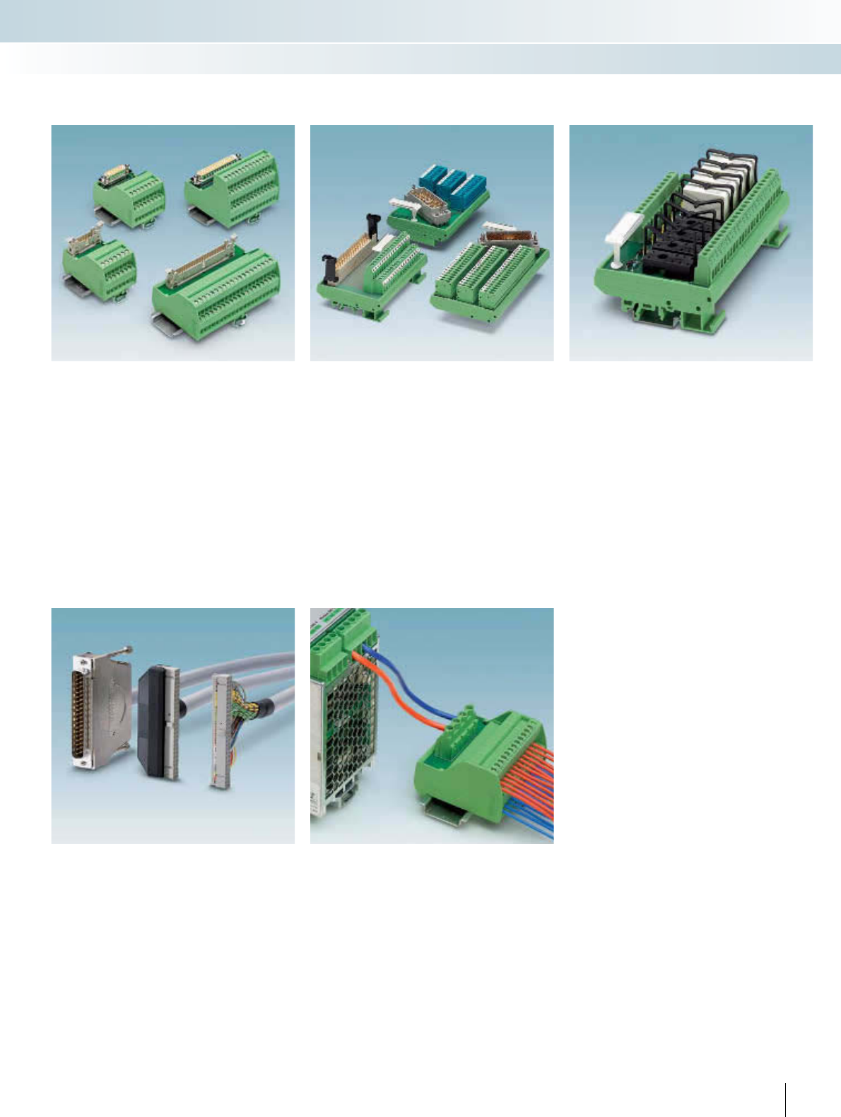
VIP - VARIOFACE Professional
potential distributors
System cables with enclosed
FLK or D-SUB connectors
Interface modules with various
connection methods and designs are
available for the widely used FLK, D-SUB,
and high-density D-SUB connectors.
Modules with a status indicator can be
selected for operation monitoring
purposes.
Modules with ELCO connectors are
available for tough environments or where
increased safety requirements apply.
Interface modules are also available for
DIN strip types C, D, E, and F.
The active modules are configured as a
4-channel, 8-channel or 16-channel
interface. There is a choice of multi-channel
modules for relays and signal/power
optocouplers. This means that functions
such as signal conditioning, electrical
isolation, and power amplification can be
supported.
Designed for up to 250 V/30 V, the
potential distributors are suitable for
universal use – for both operating voltage
and control voltage distribution. The screw
or spring-cage connection method can be
selected as required for the application
concerned.
Ready-assembled FLK and D-SUB cables
ensure a reliable connection between the
automation equipment and the module. 1 A
(FLK cable) and 2 A (D-SUB cable) currents
can be transmitted on each signal path
thanks to the large conductor cross
sections.
Interface modules with
ELCO or DIN connectors
VIP - VARIOFACE Professional
interface modules
Relay/solid-state relay modules
297PHOENIX CONTACT
INTERFACE Cabling
VARIOFACE wiring interface
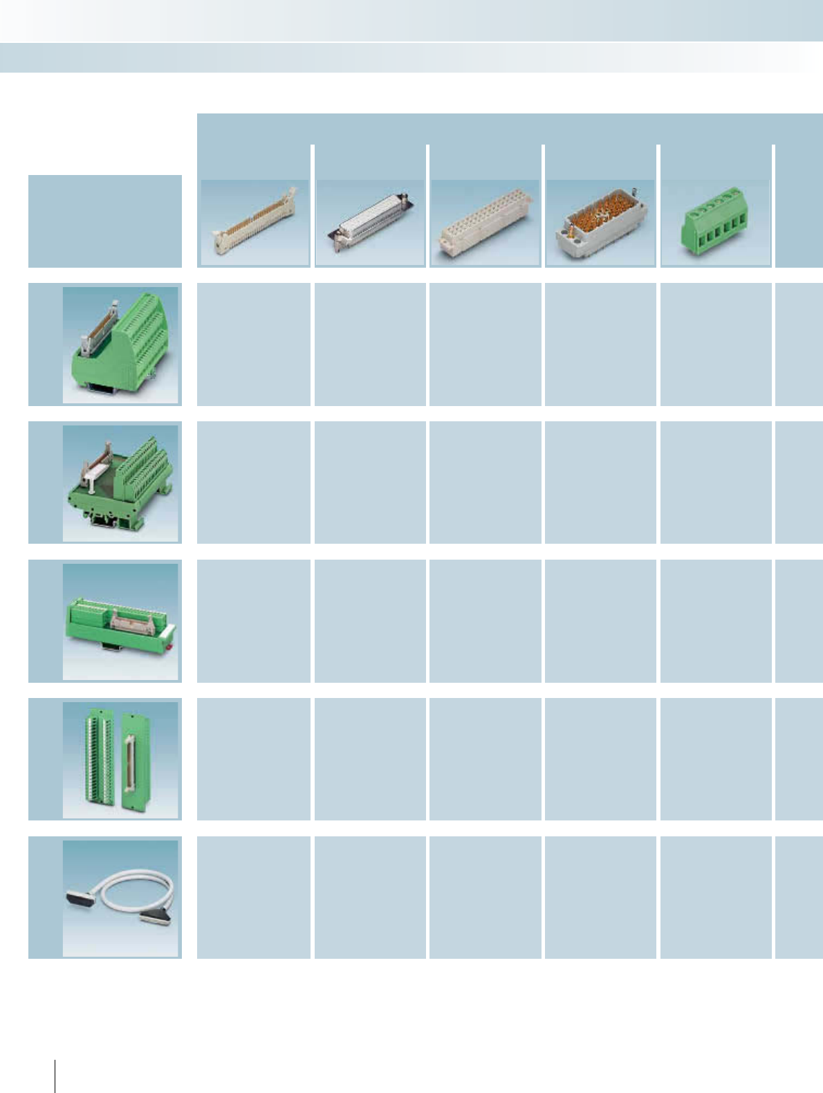
VIP - VARIOFACE Professional product overview
Passive modules (connection method)
Flat-ribbon cable
strip D-SUB strip DIN strip ELCO strip
Potential distributor
Device series
Page Page Page Page Page
VIP Line
300 306
313 322
Standard Line
314 318
Slim Line
304 309
Feed-through
modules
305 310
Cables
278 290
298 PHOENIX CONTACT
INTERFACE Cabling
VARIOFACE wiring interface
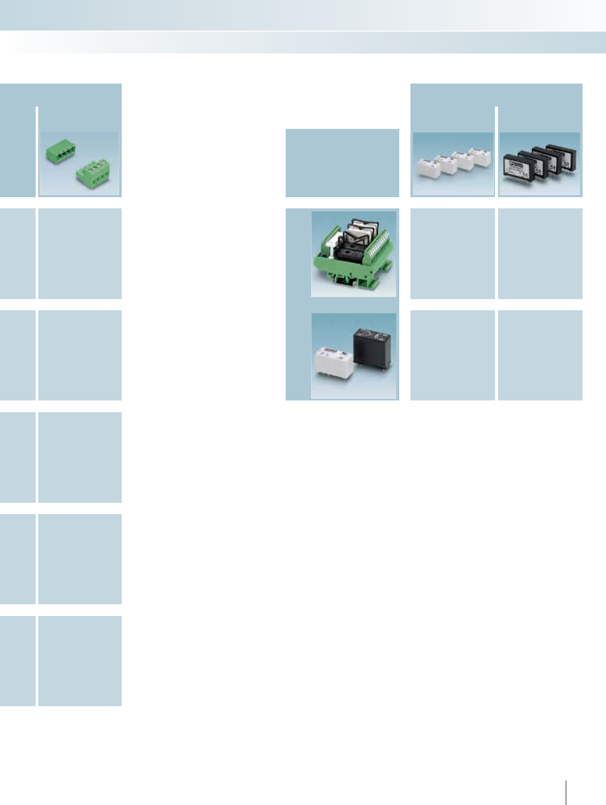
COMBICON
Page
321
321
Active modules (function)
Relays/solid-state
relays Solid-state relays
Device series
Page Page
Standard Line
324 327
Accessories
328 332
299PHOENIX CONTACT
INTERFACE Cabling
VARIOFACE wiring interface
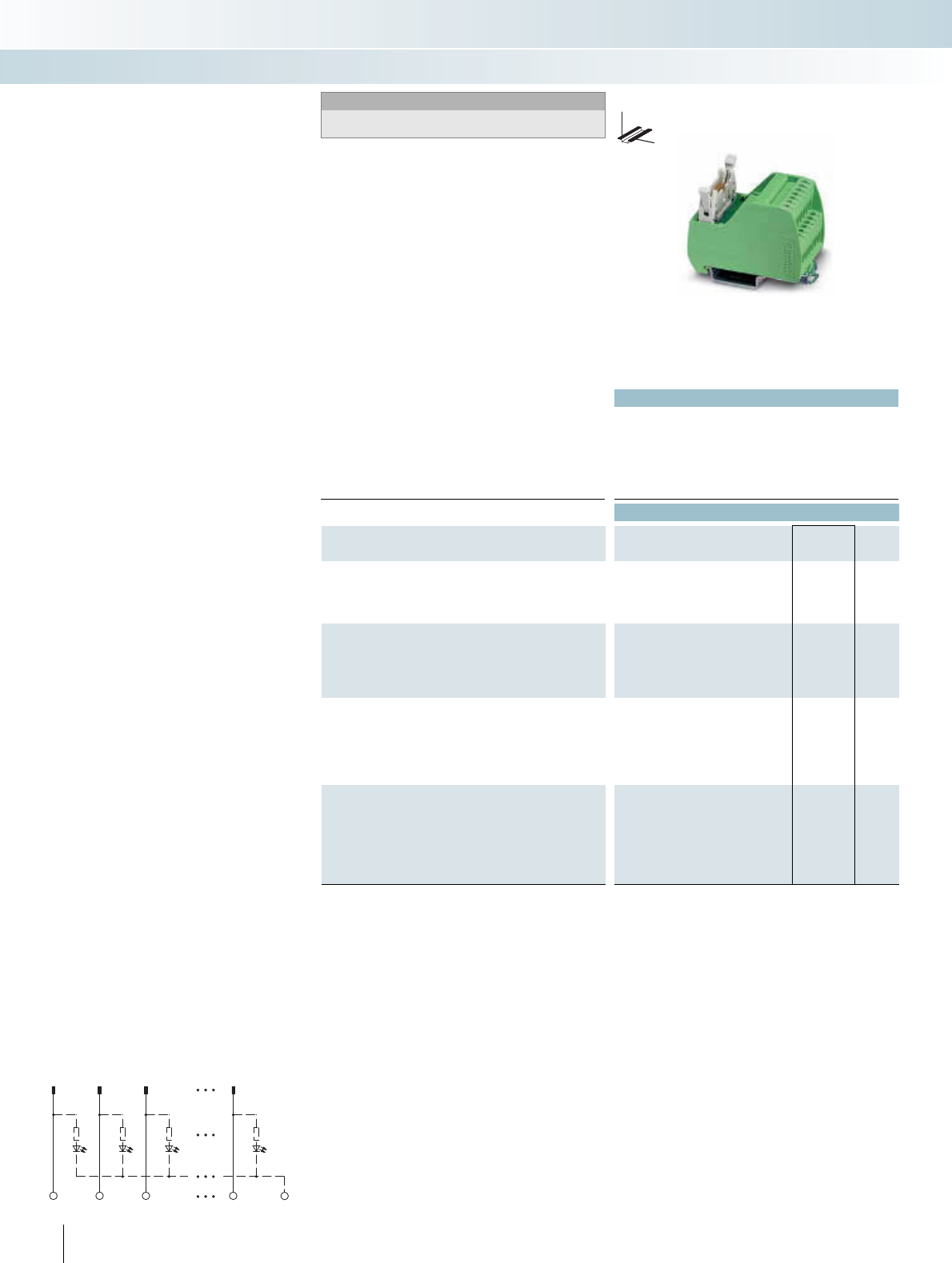
p
Technical data
Operating voltage 60 V AC/DC
Max. perm. current (per branch) 1 A
Ambient temperature (operation) -20°C ... 50°C
Mounting position Any
Standards / regulations IEC 60664, DIN EN 50178, IEC 62103
Connection data solid / stranded / AWG 0.2 - 4 mm² / 0.2 - 2.5 mm² / 24 - 12
Dimensions H / D 65.5 mm / 56 mm
Ordering data
Description No. of
poles
Module width
WType Order No. Pcs. /
Pkt.
VARIOFACE module, with pin strip
10 34.70 VIP-2/SC/FLK10 2315010 1
14 39.80 VIP-2/SC/FLK14 2315023 1
16 45.00 VIP-2/SC/FLK16 2315036 1
20 55.10 VIP-2/SC/FLK20 2315049 1
VARIOFACE module, with pin strip and light indicator
10 34.70
14 44.90
16 50.00
20 60.20
VARIOFACE module, with pin strip
26 57.10
34 67.30
40 77.40
50 92.70
60 108.00
64 118.00
VARIOFACE module, with pin strip and light indicator
26 57.40
34 67.60
40 77.80
50 93.10
60 113.50
64 118.60
300 PHOENIX CONTACT
DW
H
VIP – VARIOFACE Professional
Modules with flat-ribbon cable connectors
Notes:
For marking systems and mounting material, see
CLIPLINE catalog, part 2.
1
1
2
2
3
3
n
n
-
– 1:1 connection
– 10 to 64-pos.
– Screw connection
– Metal foot
– As per IEC 60603-13
– Optional with status indicator
Low and high engagement latches are sup-
plied with all modules.
INTERFACE Cabling
VARIOFACE wiring interface
10 to 20 positions
with screw connection
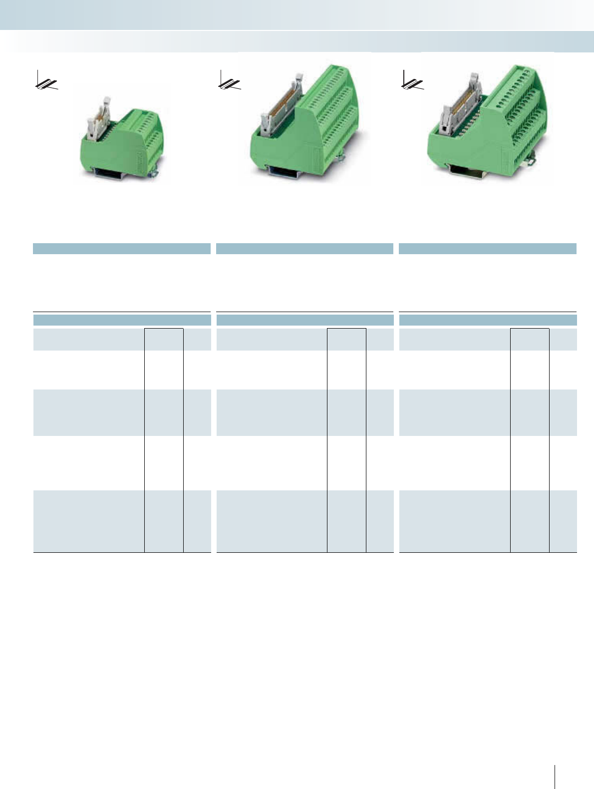
For additional information, visit www.phoenixcontact.net/catalog
p
Technical data Technical data Technical data
24 V DC 60 V AC/DC 24 V DC
1 A 1 A 1 A
-20°C ... 50°C -20°C ... 50°C -20°C ... 50°C
Any Any Any
IEC 60664, DIN EN 50178, IEC 62103 IEC 60664, DIN EN 50178, IEC 62103 IEC 60664, DIN EN 50178, IEC 62103
0.2 - 4 mm² / 0.2 - 2.5 mm² / 24 - 12 0.2 - 4 mm² / 0.2 - 2.5 mm² / 24 - 12 0.2 - 4 mm² / 0.2 - 2.5 mm² / 24 - 12
65.5 mm / 56 mm 69 mm / 62 mm 69 mm / 62 mm
Ordering data Ordering data Ordering data
Type Order No. Pcs. /
Pkt. Type Order No. Pcs. /
Pkt. Type Order No. Pcs. /
Pkt.
VIP-2/SC/FLK10/LED 2322045 1
VIP-2/SC/FLK14/LED 2322058 1
VIP-2/SC/FLK16/LED 2322061 1
VIP-2/SC/FLK20/LED 2322074 1
VIP-3/SC/FLK26 2315052 1
VIP-3/SC/FLK34 2315065 1
VIP-3/SC/FLK40 2315078 1
VIP-3/SC/FLK50 2315081 1
VIP-3/SC/FLK60 2315094 1
VIP-3/SC/FLK64 2315104 1
VIP-3/SC/FLK26/LED 2322087 1
VIP-3/SC/FLK34/LED 2322090 1
VIP-3/SC/FLK40/LED 2322100 1
VIP-3/SC/FLK50/LED 2322113 1
VIP-3/SC/FLK60/LED 2322126 1
VIP-3/SC/FLK64/LED 2322139 1
301PHOENIX CONTACT
DW
H
DW
H
DW
H
INTERFACE Cabling
VARIOFACE wiring interface
10 to 20 positions
with screw connection and light indicator
26 to 64 positions
with screw connection
26 to 64 positions
with screw connection and light indicator
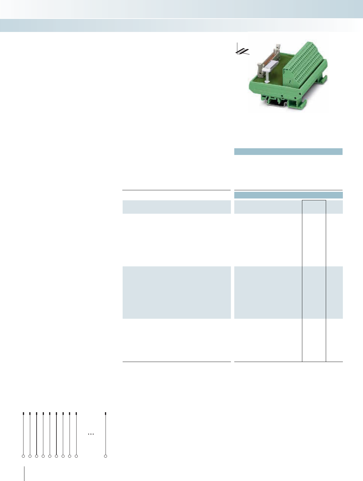
Technical data
Operating voltage < 50 V AC / 60 V DC
Max. perm. current (per branch) 1 A
Ambient temperature (operation) -20°C ... 50°C
Mounting position Any
Standards / regulations IEC 60664, DIN EN 50178, IEC 62103
Connection data solid / stranded / AWG 0.2 - 4 mm² / 0.2 - 2.5 mm² / 24 - 12
Dimensions H / D 77 mm / 51 mm
Ordering data
Description No. of
poles
Module width
WType Order No. Pcs. /
Pkt.
VARIOFACE module, with pin strip
10 34.00 FLKM 10/ZFKDS 2302887 1
14 45.00 FLKM 14/ZFKDS 2302890 1
16 45.00 FLKM 16/ZFKDS 2302900 1
20 57.00 FLKM 20/ZFKDS 2302913 1
26 79.00 FLKM 26/ZFKDS 2302926 1
34 90.00 FLKM 34/ZFKDS 2302939 1
40 113.00 FLKM 40/ZFKDS 2302942 1
50 135.00 FLKM 50/ZFKDS 2302955 1
60 158.00 FLKM 60/ZFKDS 2302968 1
64 169.00 FLKM 64/ZFKDS 2302971 1
VARIOFACE module, with pin strip
10 54.00
14 59.00
16 64.00
20 75.00
26 90.00
34 110.00
40 126.00
50 151.00
60 176.00
64 186.00
VARIOFACE module, with pin strip
16 61.00
20 66.00
26 74.00
34 86.00
40 96.00
50 111.00
60 126.00
64 136.00
302 PHOENIX CONTACT
DW
H
Modules with flat-ribbon cable connectors
1
1
2
2
3
3
4
4
5
5
6
6
7
7
8
8
9n
9n
The following VARIOFACE modules
(1:1 connection) for flat-ribbon cable plug
connectors (in accordance with
IEC 60603-13/DIN 41651) are available
with spring-cage connection:
– FLK modules with double-level terminal
blocks with 10 to 64 positions
– UM 45-FLK... modules with double-level
terminal blocks with 10 to 64 positions
– UM 45-FLKS... modules with double-level
terminal blocks with 10 to 64 positions
Low and high engagement latches are sup-
plied with all modules.
INTERFACE Cabling
VARIOFACE wiring interface
10 to 64 positions
with spring-cage connection
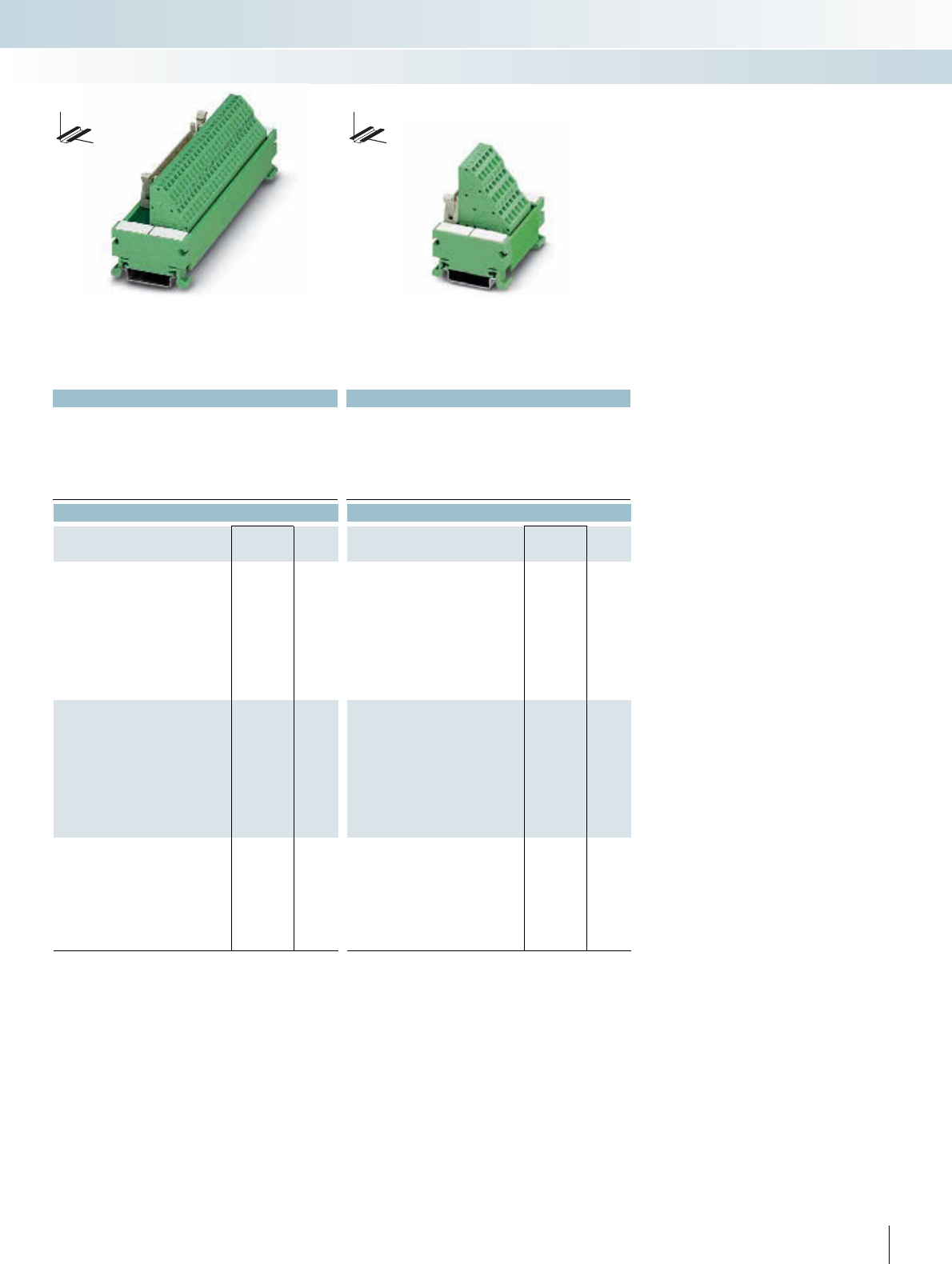
For additional information, visit www.phoenixcontact.net/catalog
|
Technical data Technical data
< 50 V AC / 60 V DC < 50 V AC / 60 V DC
1 A 1 A
-20°C ... 50°C -20°C ... 50°C
Any Any
IEC 60664, DIN EN 50178, IEC 62103 IEC 60664, DIN EN 50178, IEC 62103
0.2 - 2.5 mm² / 0.2 - 1.5 mm² / 24 - 14 0.2 - 2.5 mm² / 0.2 - 1.5 mm² / 24 - 14
45 mm / 50 mm 45 mm / 61 mm
Ordering data Ordering data
Type Order No. Pcs. /
Pkt. Type Order No. Pcs. /
Pkt.
UM 45-FLK10/ZFKDS 2293514 1
UM 45-FLK14/ZFKDS 2293527 1
UM 45-FLK16/ZFKDS 2293530 1
UM 45-FLK20/ZFKDS 2293543 1
UM 45-FLK26/ZFKDS 2293556 1
UM 45-FLK34/ZFKDS 2293569 1
UM 45-FLK40/ZFKDS 2293572 1
UM 45-FLK50/ZFKDS 2293585 1
UM 45-FLK60/ZFKDS 2293598 1
UM 45-FLK64/ZFKDS 2293608 1
UM 45-FLKS16/ZFKDS 2968399 1
UM 45-FLKS20/ZFKDS 2968409 1
UM 45-FLKS26/ZFKDS 2968412 1
UM 45-FLKS34/ZFKDS 2968425 1
UM 45-FLKS40/ZFKDS 2968438 1
UM 45-FLKS50/ZFKDS 2968470 1
UM 45-FLKS60/ZFKDS 2968441 1
UM 45-FLKS64/ZFKDS 2968454 1
303PHOENIX CONTACT
DW
H
DW
H
INTERFACE Cabling
VARIOFACE wiring interface
10 to 64 positions
with spring-cage connection
16 to 64 positions
with spring-cage connection
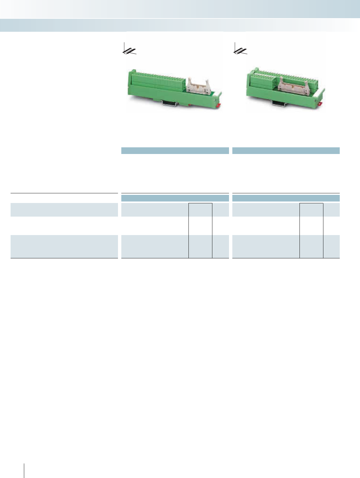
||
Technical data Technical data
Operating voltage < 50 V AC / 60 V DC < 50 V AC / 60 V DC
Max. perm. current (per branch) 0.8 A (data valid for 100% coincidence factor) 1 A (data valid for 100% coincidence factor)
Ambient temperature (operation) -10°C ... 50°C -10°C ... 50°C
Mounting position Any Any
Standards / regulations IEC 60664, DIN EN 50178, IEC 62103 IEC 60664, DIN EN 50178, IEC 62103
Screw connection solid / stranded / AWG 0.2 ... 4 mm² / 0.2 ... 2.5 mm² / 24 - 12 0.2 ... 4 mm² / 0.2 ... 2.5 mm² / 24 - 12
Dimensions D / W 45 mm / 25 mm 45 mm / 45 mm
Ordering data Ordering data
Description No. of
poles
Module height
HType Order No. Pcs. /
Pkt. Type Order No. Pcs. /
Pkt.
VARIOFACE-SLIM-LINE module, with pin strip
20 177.00 UM 25-FLK20/FRONT/Q 2959515 1
26 217.00 UM-25 FLK26/FRONT/Q 2959528 1
VARIOFACE-SLIM-LINE module, with pin strip
34 147.00 UM 45-FLK34/FRONT/Q 2959531 1
40 167.00 UM 45-FLK40/FRONT/Q 2959544 1
50 197.00 UM 45-FLK50/FRONT/Q 2959557 1
304 PHOENIX CONTACT
INTERFACE Cabling
VARIOFACE wiring interface
20 and 26-pos.
with screw connection
34 to 50 positions
with screw connection
VARIOFACE SLIM-LINE modules con-
nect flat-ribbon cable plug connectors in ac-
cordance with IEC 60603-13/DIN 41651 to
front connecting terminal blocks.
The modules are provided with low and
high engagement catches to protect the flat-
ribbon cable connector against being acci-
dentally released.
DW
H
DW
H
SLIM-LINE modules for
flat-ribbon cable connectors
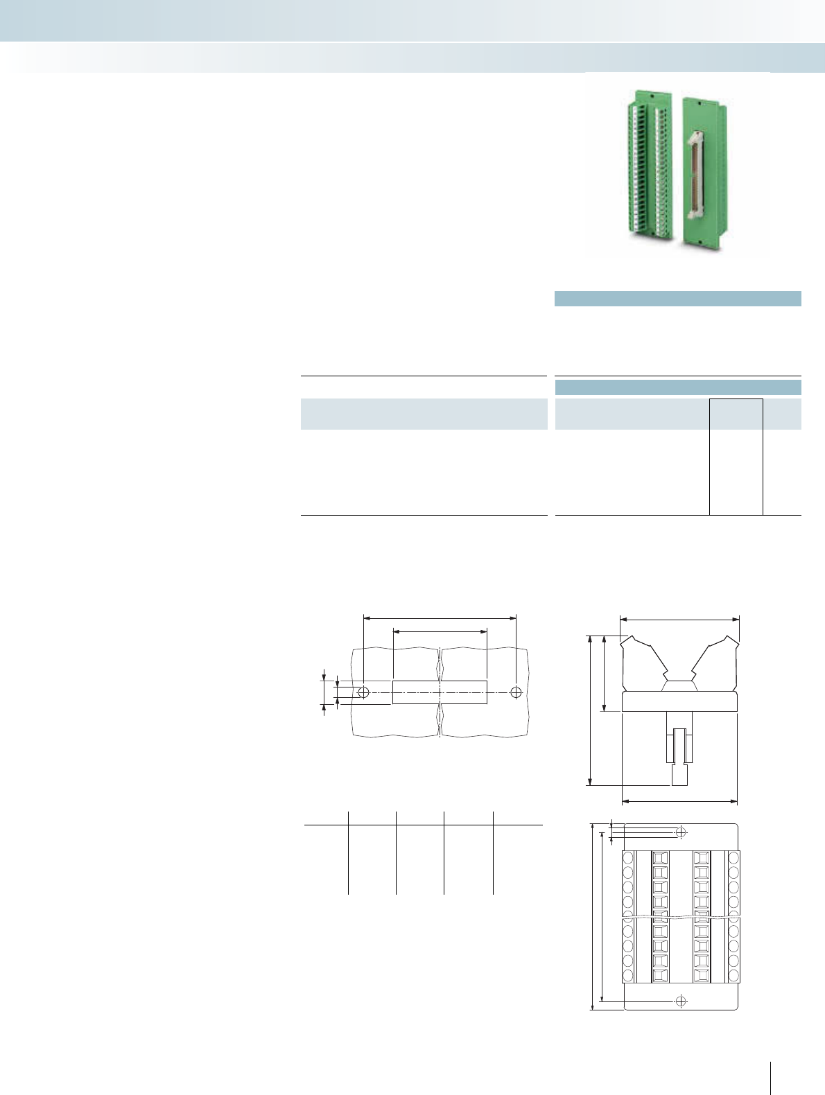
For additional information, visit www.phoenixcontact.net/catalog
Technical data
Operating voltage < 50 V AC / 60 V DC
Max. perm. current (per branch) 1 A
Ambient temperature (operation) -20°C ... 45°C
Mounting position Any
Standards / regulations IEC 60664, DIN EN 50178, IEC 62103
Connection data solid / stranded / AWG 0.2 - 4 mm² / 0.2 - 2.5 mm² / 24 - 12
Ordering data
Description No. of
poles
Module width
WType Order No. Pcs. /
Pkt.
VARIOFACE feed-through module, with pin strip
16 39.00 DFLK 16 2280239 5
20 39.00 DFLK 20 2280242 5
26 39.00 DFLK 26 2280255 5
34 39.00 DFLK 34 2280268 5
40 39.00 DFLK 40 2280271 5
50 39.00 DFLK 50 2280284 5
VARIOFACE panel feed-through modules
DFLK... connect the flat-ribbon cable
connectors in accordance with
IEC 60603-13/DIN 41651 to the screw
connection terminal blocks.
These modules are suitable for mounting
on a side panel with an appropriate housing
cutout (see dimensioning table).
The modules are provided with low and
high engagement catches to protect the flat-
ribbon cable connector against being acci-
dentally released.
Panel feed-through modules for
flat-ribbon cable connectors
INTERFACE Cabling
VARIOFACE wiring interface
16 to 50 positions
with screw connection
Dimensioning of the housing cutout Dimensional drawing DFLK:
Type a b c d
DFLK 16 58.4 52.5 40.1 + 0.2 9 + 0.2
DFLK 20 68.4 62.5 45.2 + 0.2 9 + 0.2
DFLK 26 83.4 77.5 52.8 + 0.2 9 + 0.2
DFLK 34 103.4 97.5 63.0 + 0.2 9 + 0.2
DFLK 40 128.4 122.5 70.6 + 0.2 9 + 0.2
DFLK 50 143.4 137.5 83.3 + 0.2 9 + 0.2
b
c+0,2
d+0,2
4
39
38
49
24,3
a
b
3,2
305
PHOENIX CONTACT
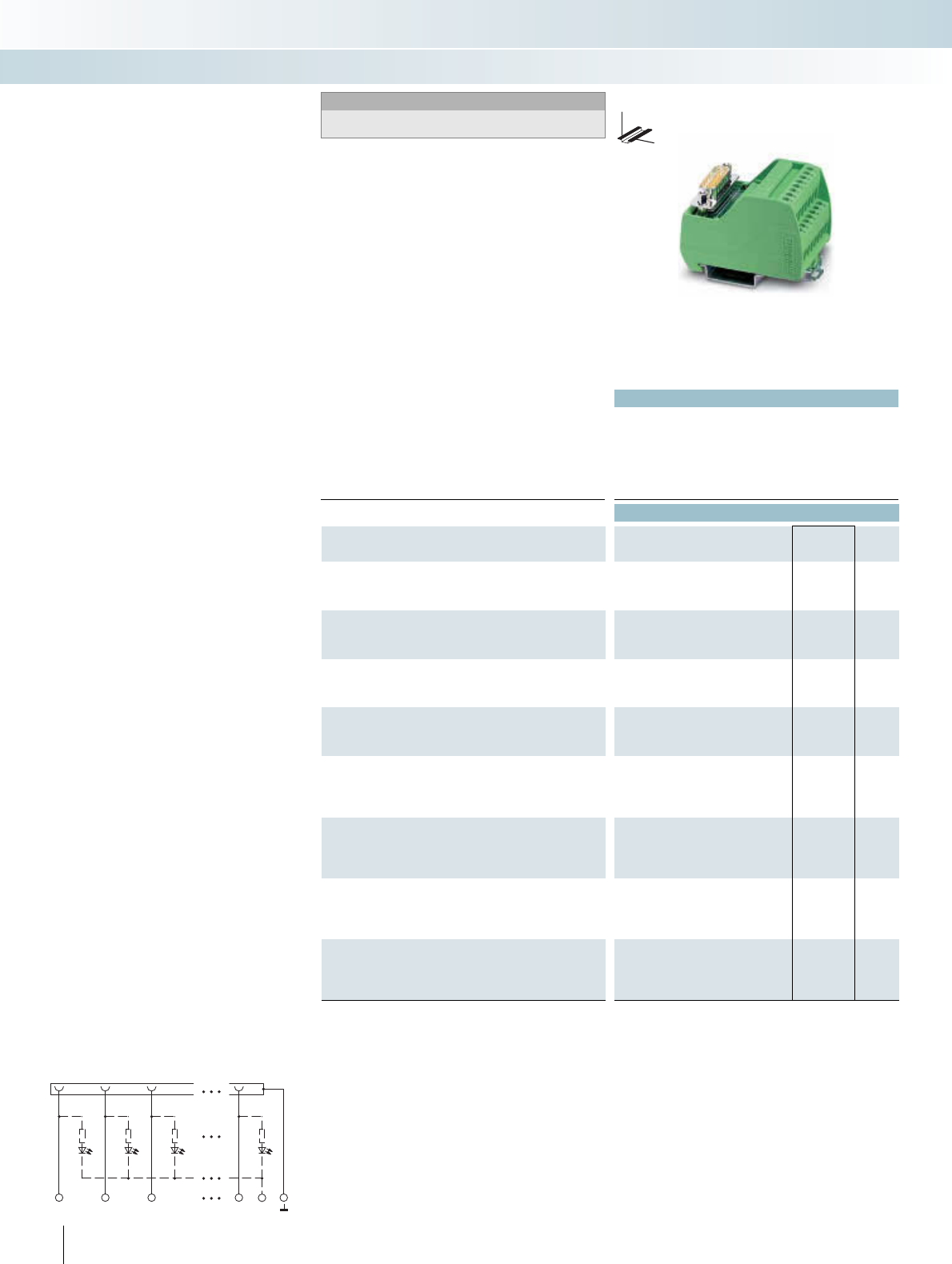
p
Technical data
Operating voltage 125 V AC/DC
Max. perm. current (per branch) 2 A
Ambient temperature (operation) -20°C ... 50°C
Mounting position Any
Standards / regulations IEC 60664, DIN EN 50178, IEC 62103
Connection data solid / stranded / AWG 0.2 - 4 mm² / 0.2 - 2.5 mm² / 24 - 12
Dimensions H / D 65.5 mm / 45.1 mm
Ordering data
Description No. of
poles
Module width
WType Order No. Pcs. /
Pkt.
VARIOFACE module, with D-Subminiature pin strip
934.70VIP-2/SC/D 9SUB/M 2315117 1
15 45.00 VIP-2/SC/D15SUB/M 2315120 1
VARIOFACE module, with D-Subminiature pin strip and light indi-
cator
934.70
15 50.00
VARIOFACE module, with D-Subminiature socket
934.70VIP-2/SC/D 9SUB/F 2315162 1
15 45.00 VIP-2/SC/D15SUB/F 2315175 1
VARIOFACE module, with D-Subminiature socket and light indica-
tor
934.70
15 50.00
VARIOFACE module, with D-Subminiature pin strip
25 57.40
37 72.70
50 98.20
VARIOFACE module, with D-Subminiature pin strip and light indi-
cator
25 57.40
37 72.70
50 98.20
VARIOFACE module, with D-Subminiature socket
25 57.40
37 72.70
50 98.20
VARIOFACE module, with D-Subminiature socket and light indica-
tor
25 57.40
37 72.70
50 98.20
306 PHOENIX CONTACT
DW
H
VIP – VARIOFACE Professional
Modules with D-SUB connectors
Notes:
For marking systems and mounting material, see
CLIPLINE catalog, part 2.
1
1
2
2
3
3
n
n
-
– 1:1 connection
– 9 to 50-pos.
– Screw connection
– Metal foot
– As per IEC 60807-2
– Optional with status indicator
The D-SUB-4-40 UNC threads are led on
to a connecting terminal block directly.
INTERFACE Cabling
VARIOFACE wiring interface
9 to 15 positions
with screw connection
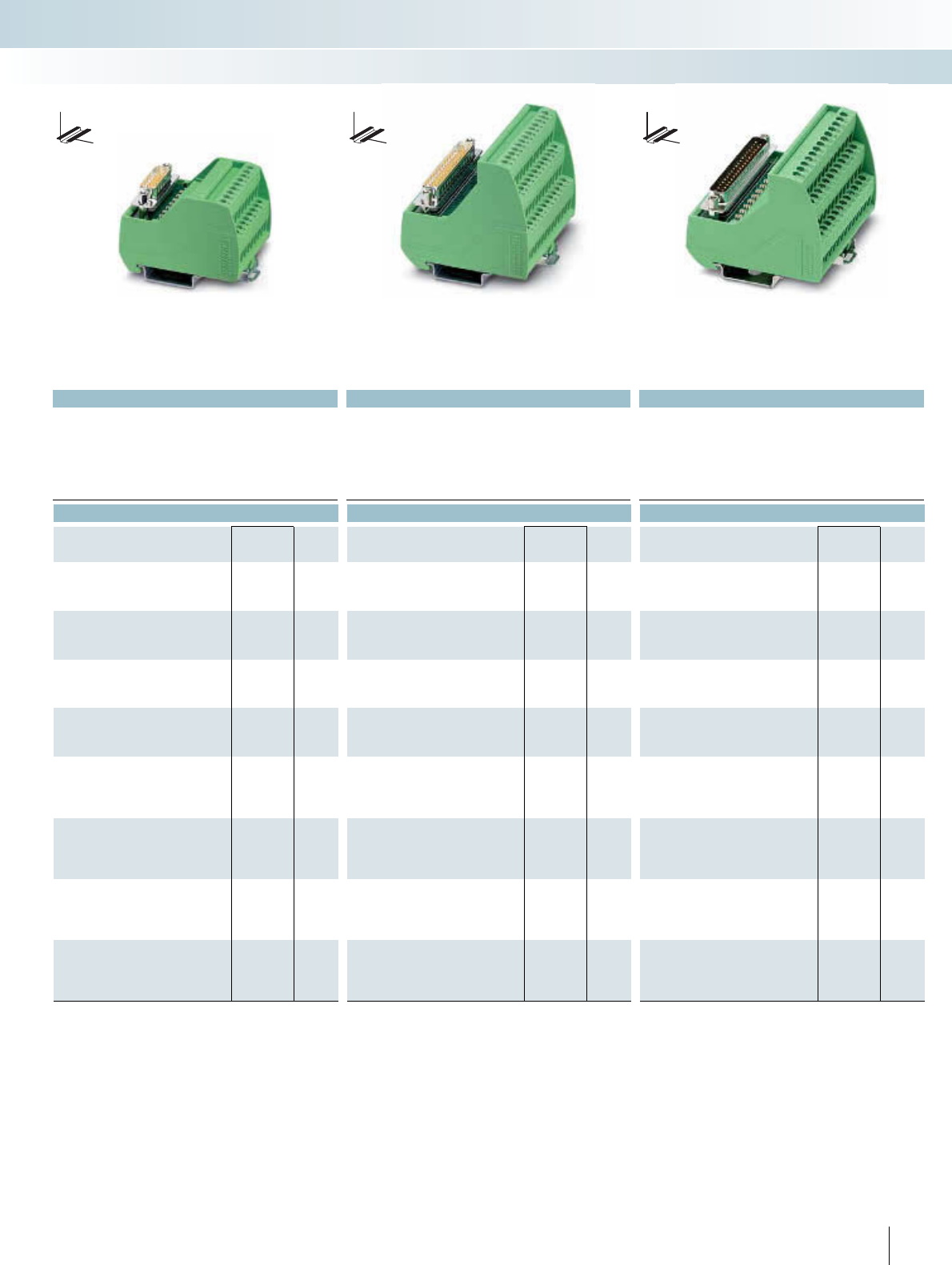
For additional information, visit www.phoenixcontact.net/catalog
p
Technical data Technical data Technical data
24 V DC 125 V AC/DC 24 V DC
2.5 A 2 A 2.5 A
-20°C ... 50°C -20°C ... 50°C -20°C ... 50°C
Any Any Any
IEC 60664, DIN EN 50178, IEC 62103 IEC 60664, DIN EN 50178, IEC 62103 IEC 60664, DIN EN 50178, IEC 62103
0.2 - 4 mm² / 0.2 - 2.5 mm² / 24 - 12 0.2 - 4 mm² / 0.2 - 2.5 mm² / 24 - 12 0.2 - 4 mm² / 0.2 - 2.5 mm² / 24 - 12
65.5 mm / 45.1 mm 69 mm / 62 mm 69 mm / 62 mm
Ordering data Ordering data Ordering data
Type Order No. Pcs. /
Pkt. Type Order No. Pcs. /
Pkt. Type Order No. Pcs. /
Pkt.
VIP-2/SC/D 9SUB/M/LED 2322142 1
VIP-2/SC/D15SUB/M/LED 2322155 1
VIP-2/SC/D 9SUB/F/LED 2322197 1
VIP-2/SC/D15SUB/F/LED 2322207 1
VIP-3/SC/D25SUB/M 2315133 1
VIP-3/SC/D37SUB/M 2315146 1
VIP-3/SC/D50SUB/M 2315159 1
VIP-3/SC/D25SUB/M/LED 2322168 1
VIP-3/SC/D37SUB/M/LED 2322171 1
VIP-3/SC/D50SUB/M/LED 2322184 1
VIP-3/SC/D25SUB/F 2315188 1
VIP-3/SC/D37SUB/F 2315191 1
VIP-3/SC/D50SUB/F 2315201 1
VIP-3/SC/D25SUB/F/LED 2322210 1
VIP-3/SC/D37SUB/F/LED 2322223 1
VIP-3/SC/D50SUB/F/LED 2322236 1
307PHOENIX CONTACT
DW
H
DW
H
DW
H
INTERFACE Cabling
VARIOFACE wiring interface
9 to 15 positions
with screw connection and light indicator
25 to 50 positions
with screw connection
25 to 50 positions
with screw connection and light indicator
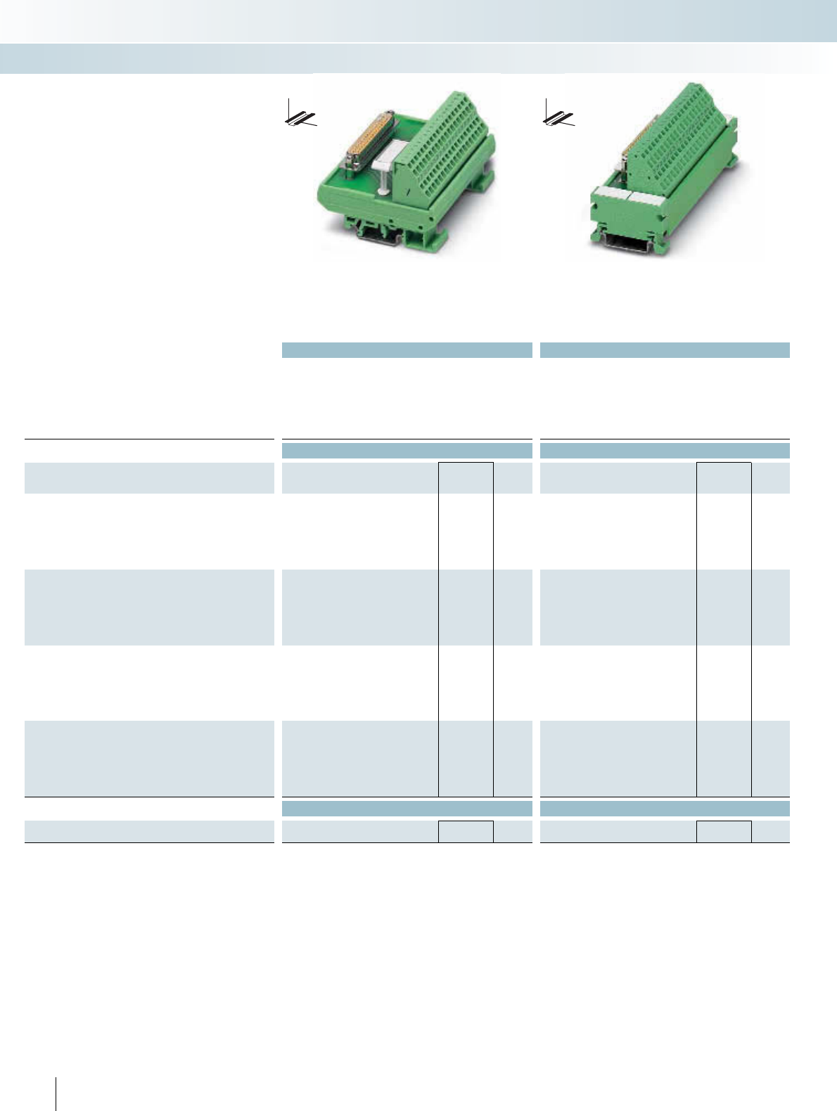
|
Technical data Technical data
Operating voltage 125 V AC/DC 125 V AC/DC
Max. perm. current (per branch) 2.5 A 2.5 A
Ambient temperature (operation) -20°C ... 50°C -20°C ... 50°C
Mounting position Any Any
Standards / regulations IEC 60664, DIN EN 50178, IEC 62103 IEC 60664, DIN EN 50178, IEC 62103
Connection data solid / stranded / AWG 0.2 - 4 mm² / 0.2 - 2.5 mm² / 24 - 12 0.2 - 2.5 mm² / 0.2 - 1.5 mm² / 24 - 14
Dimensions H / D 77 mm / 52 mm 45 mm / 50 mm
Ordering data Ordering data
Description No. of
poles
Module width
WType Order No. Pcs. /
Pkt. Type Order No. Pcs. /
Pkt.
VARIOFACE module, with D-Subminiature pin strip
9 33.80 FLKM-D 9 SUB/S/ZFKDS 2302984 1
15 45.00 FLKM-D15 SUB/S/ZFKDS 2302997 1
25 78.80 FLKM-D25 SUB/S/ZFKDS 2303006 1
37 101.30 FLKM-D37 SUB/S/ZFKDS 2304018 1
50 146.30 FLKM-D50 SUB/S/ZFKDS 2304021 1
VARIOFACE module, with D-Subminiature socket
933.80 FLKM-D 9 SUB/B/ZFKDS 2304034 1
15 45.00 FLKM-D15 SUB/B/ZFKDS 2304047 1
25 78.80 FLKM-D25 SUB/B/ZFKDS 2304050 1
37 101.30 FLKM-D37 SUB/B/ZFKDS 2304063 1
50 146.30 FLKM-D50 SUB/B/ZFKDS 2304076 1
VARIOFACE COMPACT-LINE module, with D-Subminiature pin
strip
9 54.00 UM 45-D 9SUB/S/ZFKDS 2293611 1
15 65.00 UM 45-D15SUB/S/ZFKDS 2293624 1
25 90.00 UM 45-D25SUB/S/ZFKDS 2293637 1
37 121.00 UM 45-D37SUB/S/ZFKDS 2293640 1
50 156.00 UM 45-D50SUB/S/ZFKDS 2293653 1
VARIOFACE COMPACT-LINE module, with D-Subminiature
socket
954.00 UM 45-D 9SUB/B/ZFKDS 2293666 1
15 65.00 UM 45-D15SUB/B/ZFKDS 2293679 1
25 90.00 UM 45-D25SUB/B/ZFKDS 2293682 1
37 121.00 UM 45-D37SUB/B/ZFKDS 2293695 1
50 156.00 UM 45-D50SUB/B/ZFKDS 2293705 1
Accessories Accessories
Screwdriver
Blade: 0,4x2.5x75mm, length: 156mm SZF 0-0,4X2,5 1204504 10 SZF 0-0,4X2,5 1204504 10
308 PHOENIX CONTACT
INTERFACE Cabling
VARIOFACE wiring interface
9 to 50 positions
with spring-cage connection
9 to 50 positions
with spring-cage connection
– 1:1 connection
– 9 to 50-pos.
– Spring-cage connection method
– As per IEC 60807-2
The D-SUB-4-40 UNC threads are led on
to a connecting terminal block directly.
DW
H
DW
H
Modules for D-subminiature connectors
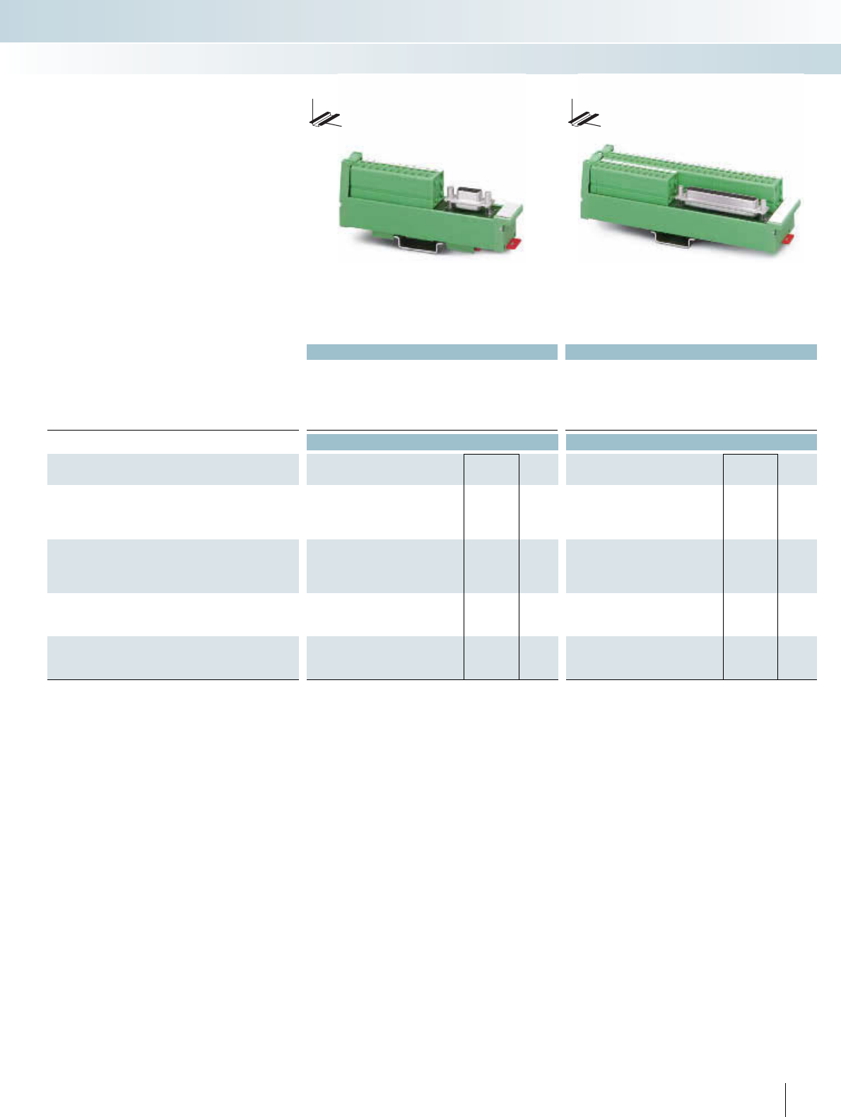
For additional information, visit www.phoenixcontact.net/catalog
||
Technical data Technical data
Operating voltage 125 V AC/DC 125 V AC/DC
Max. perm. current (per branch) 2.5 A 2.5 A
Ambient temperature (operation) -10°C ... 50°C -10°C ... 50°C
Mounting position Any Any
Standards / regulations IEC 60664, IEC 60664 A, DIN VDE 0110, DIN VDE 0160 (in parts) IEC 60664, DIN EN 50178, IEC 62103
Dimensions D / W 45 mm / 25 mm 45 mm / 45 mm
Ordering data Ordering data
Description No. of
poles
Module height
HType Order No. Pcs. /
Pkt. Type Order No. Pcs. /
Pkt.
VARIOFACE-SLIM-LINE module, with D-Subminiature pin strip
9 117.00 UM 25-D 9SUB/S/FRONT/Q 2959573 1
15 147.00 UM 25-D15SUB/S/FRONT/Q 2959599 1
25 217.00 UM 25-D25SUB/S/FRONT/Q 2959612 1
VARIOFACE-SLIM-LINE module, with D-Subminiature socket
strip
9117.00 UM 25-D 9SUB/B/FRONT/Q 2959560 1
15 147.00 UM 25-D15SUB/B/FRONT/Q 2959586 1
25 217.00 UM 25-D25SUB/B/FRONT/Q 2959609 1
VARIOFACE-SLIM-LINE module, with D-Subminiature pin strip
37 UM 45-D37SUB/S/FRONT/Q 2959638 1
50 UM 45-D50SUB/S/FRONT/Q 2959654 1
VARIOFACE-SLIM-LINE module, with D-Subminiature socket
strip
37 UM 45-D37SUB/B/FRONT/Q 2959625 1
50 UM 45-D50SUB/B/FRONT/Q 2959641 1
309PHOENIX CONTACT
INTERFACE Cabling
VARIOFACE wiring interface
9 to 25 positions
with screw connection
37 to 50 positions
with screw connection
These VARIOFACE modules connect
D-Sub strips with front connection terminal
blocks in accordance with
IEC 60807-2/DIN 41652.
To make the ground connection, the me-
tallic plug shell (4-40 UNC thread) makes
contact with a connecting terminal block.
DW
H
DW
H
SLIM-LINE modules for
D-subminiature connectors
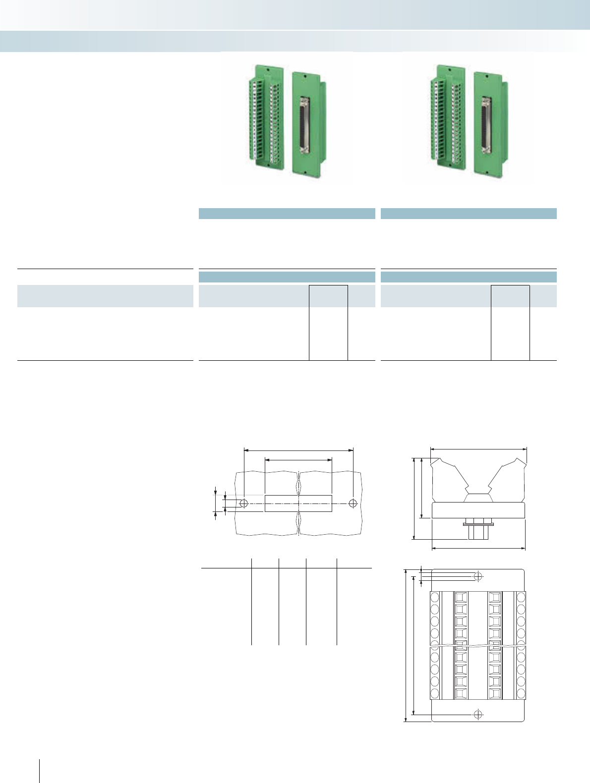
Technical data Technical data
Operating voltage 125 V AC/DC 125 V AC/DC
Max. perm. current (per branch) 2.5 A 2.5 A
Ambient temperature (operation) -20°C ... 50°C -20°C ... 50°C
Mounting position Any Any
Standards / regulations DIN EN 50178
Connection data solid / stranded / AWG 0.2 - 4 mm² / 0.2 - 2.5 mm² / 24 - 12 0.2 - 4 mm² / 0.2 - 2.5 mm² / 24 - 12
Ordering data Ordering data
Description No. of
poles
Module width
WType Order No. Pcs. /
Pkt. Type Order No. Pcs. /
Pkt.
VARIOFACE feed-through module, with D-subminiature male
connector
9 39.00 DFLK-D 9 SUB/S 2283870 5DFLK-D 9 SUB/B 2287135 5
15 39.00 DFLK-D15 SUB/S 2280297 5DFLK-D15 SUB/B 2280307 5
25 39.00 DFLK-D25 SUB/S 2280310 5DFLK-D25 SUB/B 2280323 5
37 39.00 DFLK-D37 SUB/S 2280336 5DFLK-D37 SUB/B 2280349 5
50 39.00 DFLK-D50 SUB/S 2291286 5DFLK-D50 SUB/B 2287669 5
– 1:1 connection
– 9 to 50-pos.
– Screw connection
– As per IEC 60807-2
– D-SUB 4-40 UNC thread
– 9- to 37-pos.: Separate ground tap
– 50-pos.: No ground tap
Panel feed-through modules for
D-subminiature connectors
INTERFACE Cabling
VARIOFACE wiring interface
With D-subminiature male connector With D-subminiature female connector
Dimensioning of the housing cutout Dimensional drawing: DFLK-D...SUB:
Type a b c d
DFLK-D 9 SUB/S 58.4 52.5 40.2 + 0.2 13 + 0.2
DFLK-D 15 SUB/S 58.4 52.5 40.2 + 0.2 13 + 0.2
DFLK-D 25 SUB/S 83.4 77.5 54.2 + 0.2 13 + 0.2
DFLK-D 37 SUB/S 128.4 122.5 70.6 + 0.2 13 + 0.2
DFLK-D 50 SUB/S 143.4 137.5 67.8 + 0.2 15.8 + 0.2
DFLK-D 9 SUB/B 58.4 52.5 40.2 + 0.2 13 + 0.2
DFLK-D 15 SUB/B 58.4 52.5 40.2 + 0.2 13 + 0.2
DFLK-D 25 SUB/B 83.4 77.5 54.2 + 0.2 13 + 0.2
DFLK-D 37 SUB/B 128.4 122.5 70.6 + 0.2 13 + 0.2
DFLK-D 50 SUB/B 143.4 137.5 67.8 + 0.2 15.8 + 0.2
b
c+0,2
d+0,2
4
39
38
33
24,3
a
b
3,2
310 PHOENIX CONTACT
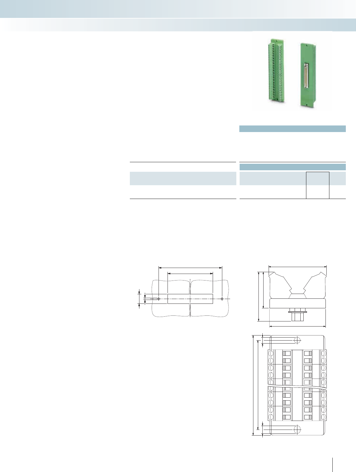
For additional information, visit www.phoenixcontact.net/catalog
Technical data
Operating voltage 48 V AC/DC
Max. perm. current (per branch) 0.5 A
Ambient temperature (operation) -20°C ... 50°C
Mounting position Any
Standards / regulations DIN EN 50178
Connection data solid / stranded / AWG 0.2 - 4 mm² / 0.2 - 2.5 mm² / 24 - 12
Ordering data
Description No. of
poles
Module width
WType Order No. Pcs. /
Pkt.
VARIOFACE feed-through module, with D-subminiature pin strip
62 40.40 DFLK-D62 SUBH/S 2300863 10
– 1:1 connection
– 62-pole pin strip
– Screw connection
– As per IEC 60807-2
– D-SUB 4-40 UNC thread
Feed-through module for high-density
D-subminiature male connector with
screw connection
INTERFACE Cabling
VARIOFACE wiring interface
With high-density D-subminiature pin strip
Dimensioning of the housing cutout Dimensional drawing DFLK-D62 SUBH/S
172,6
Ø5
15
±0,5
72±0,5
40,4
38
33,9
24,5
5,4
172,6
180
Ø4,2
311
PHOENIX CONTACT
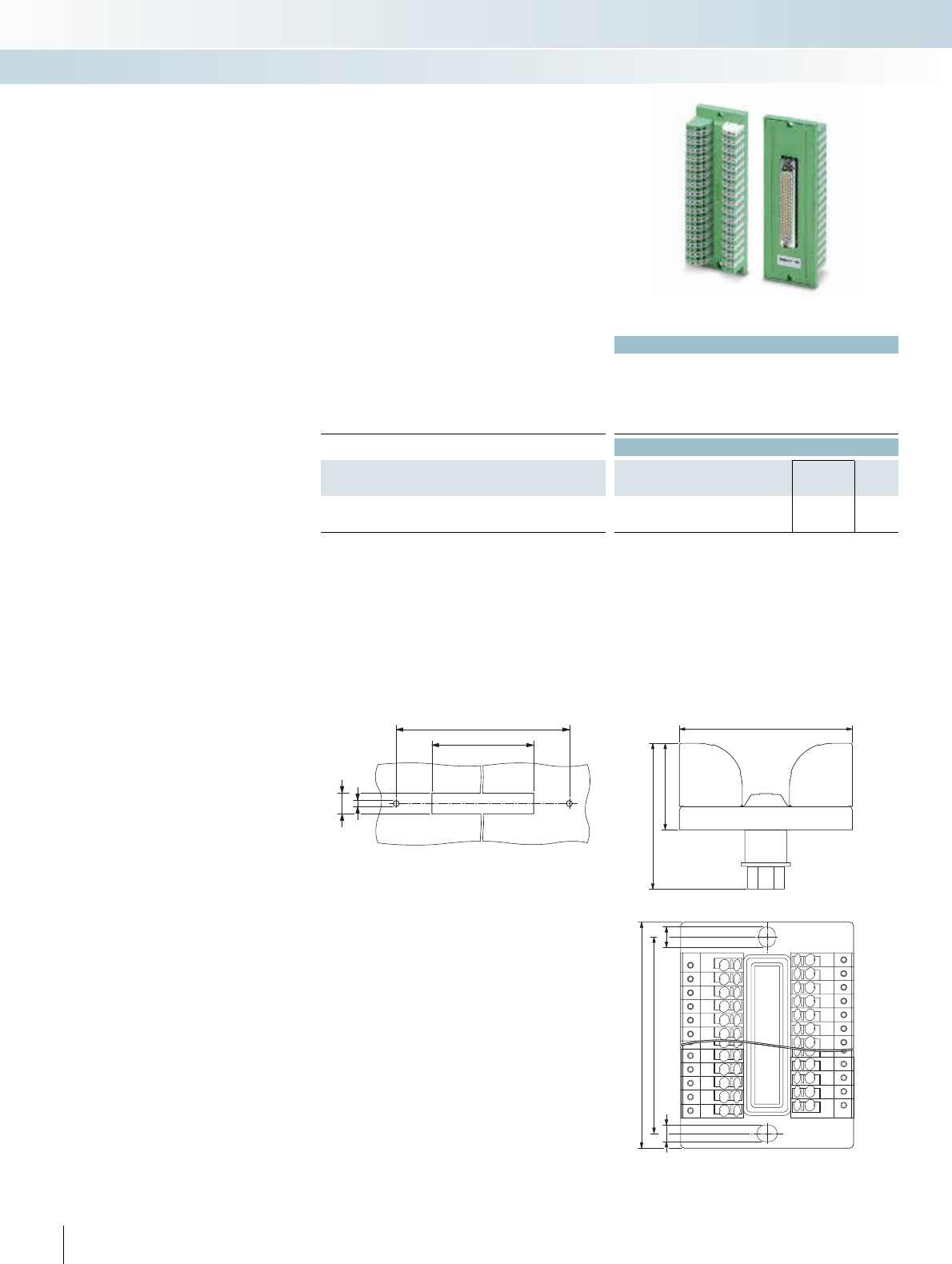
Technical data
Operating voltage 48 V DC
Max. perm. current (per branch) 0.5 A
Ambient temperature (operation) -20°C ... 50°C
Mounting position Any
Standards / regulations DIN EN 50178, basic insulation
Connection data solid / stranded / AWG 0.2 - 1.5 mm² / 0.2 - 1.5 mm² / 24 - 16
Ordering data
Description No. of
poles
Module width
WType Order No. Pcs. /
Pkt.
VARIOFACE feed-through module, with D-subminiature pin strip
62 DFLK-HD62SUB/M/PTDA-1,5 2900472 1
– 1:1 connection
– 62-pole pin strip
– Spring-cage connection with direct plug-
in method
– As per IEC 60807-2
– D-SUB 4-40 UNC thread
Feed-through module for high-density
D-subminiature male connector with
spring-cage connection
INTERFACE Cabling
VARIOFACE wiring interface
With high-density D-subminiature pin strip
Dimensioning of the housing cutout Dimensional drawing DFLK-HD62SUB/M/PTDA-1,5
71,4
121,5
5
14,5
44
22
37,1
4,2 5,2
121,45
129
312 PHOENIX CONTACT
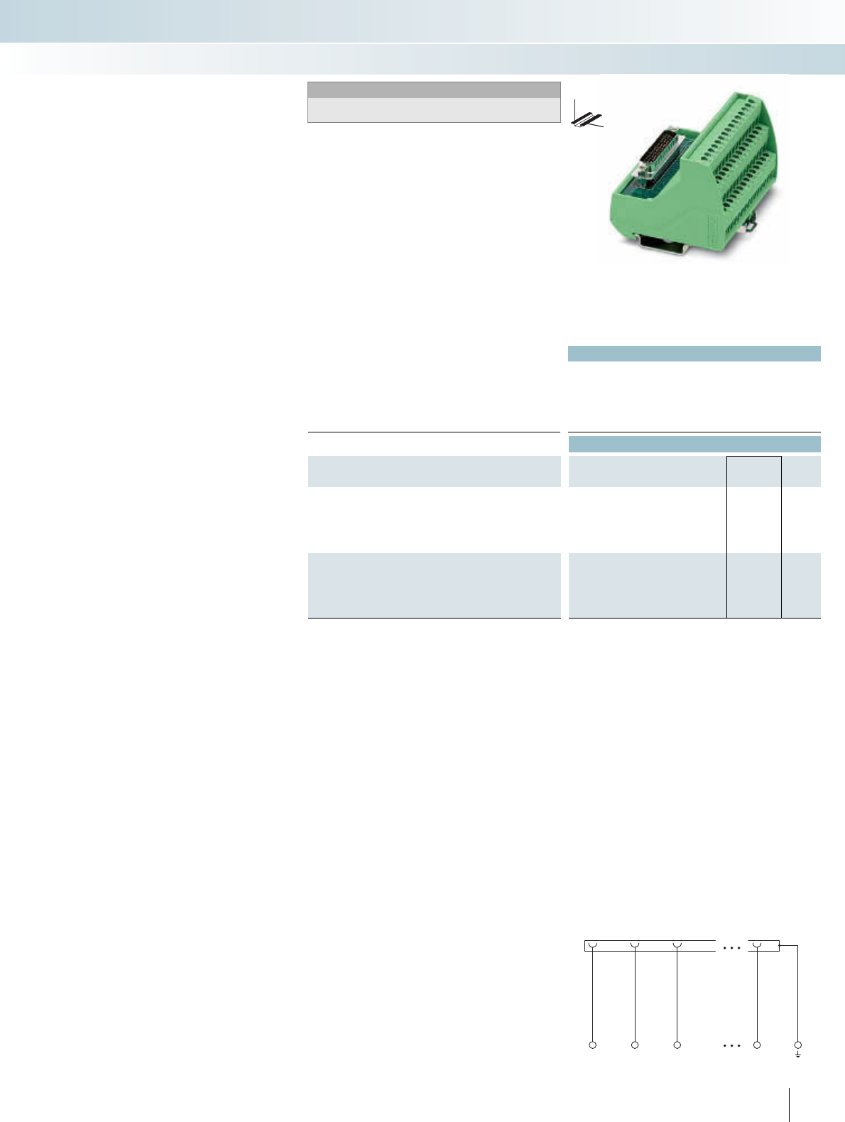
For additional information, visit www.phoenixcontact.net/catalog
313
PHOENIX CONTACT
1
1
2
2
3
3
n
n
Technical data
Operating voltage 125 V
Max. perm. current (per branch) 1 A
Ambient temperature (operation) -20°C ... 50°C
Mounting position Any
Connection data solid / stranded / AWG 0.2 - 4 mm² / 0.2 - 2.5 mm² / 24 - 12
Dimensions H / D 69 mm / 62 mm
Ordering data
Description No. of
poles
Module width
WType Order No. Pcs. /
Pkt.
VARIOFACE module, with D-Subminiature pin strip
Three-level terminal blocks 15 44.90 VIP-2/SC/HD15SUB/M 2322326 1
Three-level terminal blocks 26 52.30 VIP-3/SC/HD26SUB/M 2322375 1
Three-level terminal blocks 44 82.90 VIP-3/SC/HD44SUB/M 2322388 1
Three-level terminal blocks 62 113.50 VIP-3/SC/HD62SUB/M 2322391 1
VARIOFACE module, with D-Subminiature socket
Three-level terminal blocks 15 44.90 VIP-2/SC/HD15SUB/F 2322401 1
Three-level terminal blocks 26 52.30 VIP-3/SC/HD26SUB/F 2322414 1
Three-level terminal blocks 44 82.90 VIP-3/SC/HD44SUB/F 2322427 1
Three-level terminal blocks 62 113.50 VIP-3/SC/HD62SUB/F 2322430 1
These modules connect D subminiature
male or female connectors with screw ter-
minal blocks.
To make the ground connection, the me-
tallic plug shell (4-40 UNC thread) makes
contact with a connecting terminal block.
VIP – VARIOFACE Professional
modules for high-density
D-Subminiature plug connectors
INTERFACE Cabling
VARIOFACE wiring interface
DW
H
15 to 62 positions
with screw connection
Notes:
For marking systems and mounting material, see
CLIPLINE catalog, part 2.
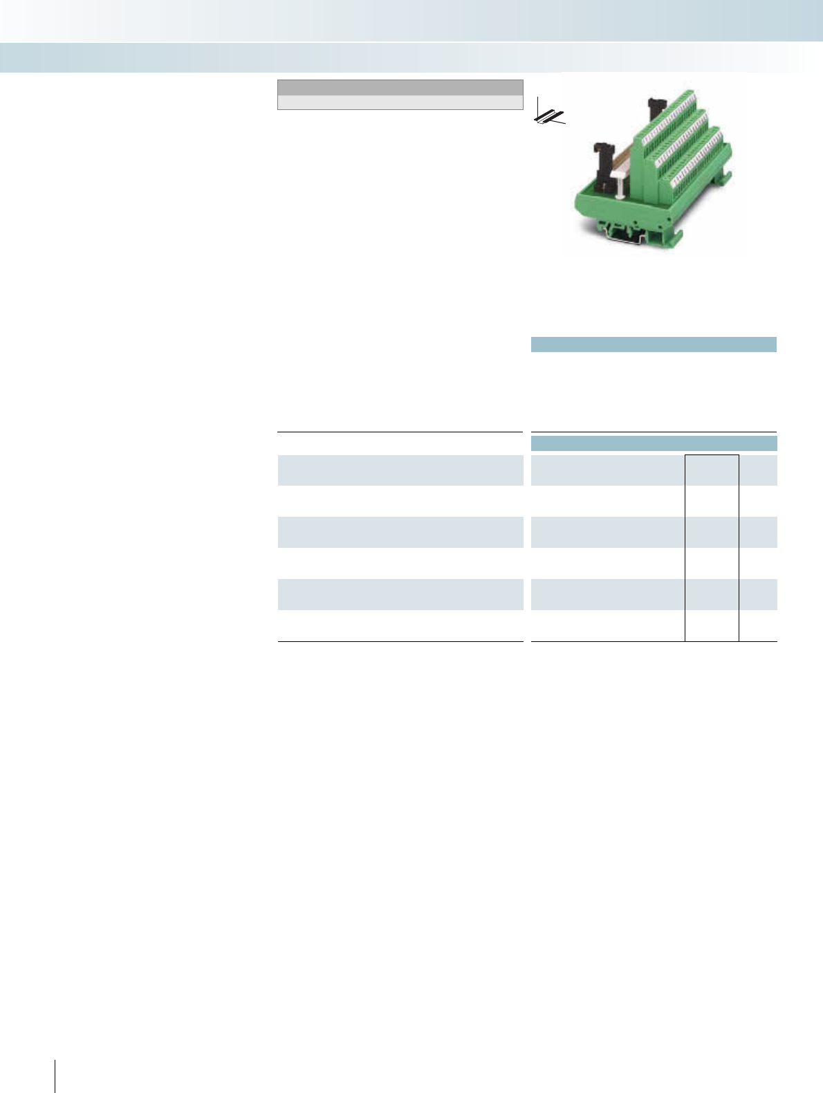
|
Technical data
Operating voltage 125 V AC/DC
Max. perm. current (per branch) 1 A
Ambient temperature (operation) -20°C ... 50°C
Mounting position Any
Standards / regulations IEC 60664, DIN EN 50178, IEC 62103
Connection data solid / stranded / AWG 0.2 - 4 mm² / 0.2 - 2.5 mm² / 24 - 12
Dimensions H / D 77 mm / 72 mm
Ordering data
Description No. of
poles
Module width
WType Order No. Pcs. /
Pkt.
VARIOFACE module, C 64-pos., screw-on cable housing, with:
- Male connector 64 135.00 UMKS- C64M-VS 2970565 1
VARIOFACE module, E 48-pos., screw-on cable housing, with:
- Male connector 48 123.80
VARIOFACE module, F 48-pos., screw-on cable housing, with:
- Male connector 48 112.50
VARIOFACE module, F 48-pos., snap-on cable housing, with:
- Male connector 48 112.50
VARIOFACE module, D 32-pos., screw-on cable housing, with:
- Male connector 32 135.00
314 PHOENIX CONTACT
DW
H
Modules for connectors
IEC 60603/DIN 41612
Notes:
Suitable cable housings, see the table on page 336
These VARIOFACE interface modules
connect high-pole plug connectors in acc.
with IEC 60603/DIN 41612 to screw con-
nection terminal blocks.
The following VARIOFACE modules are
available:
–UMK modules with double-level con-
necting terminal blocks
–UMKS modules with three-level con-
necting terminal blocks
INTERFACE Cabling
VARIOFACE wiring interface
Design C, 64-position, a, c assembled
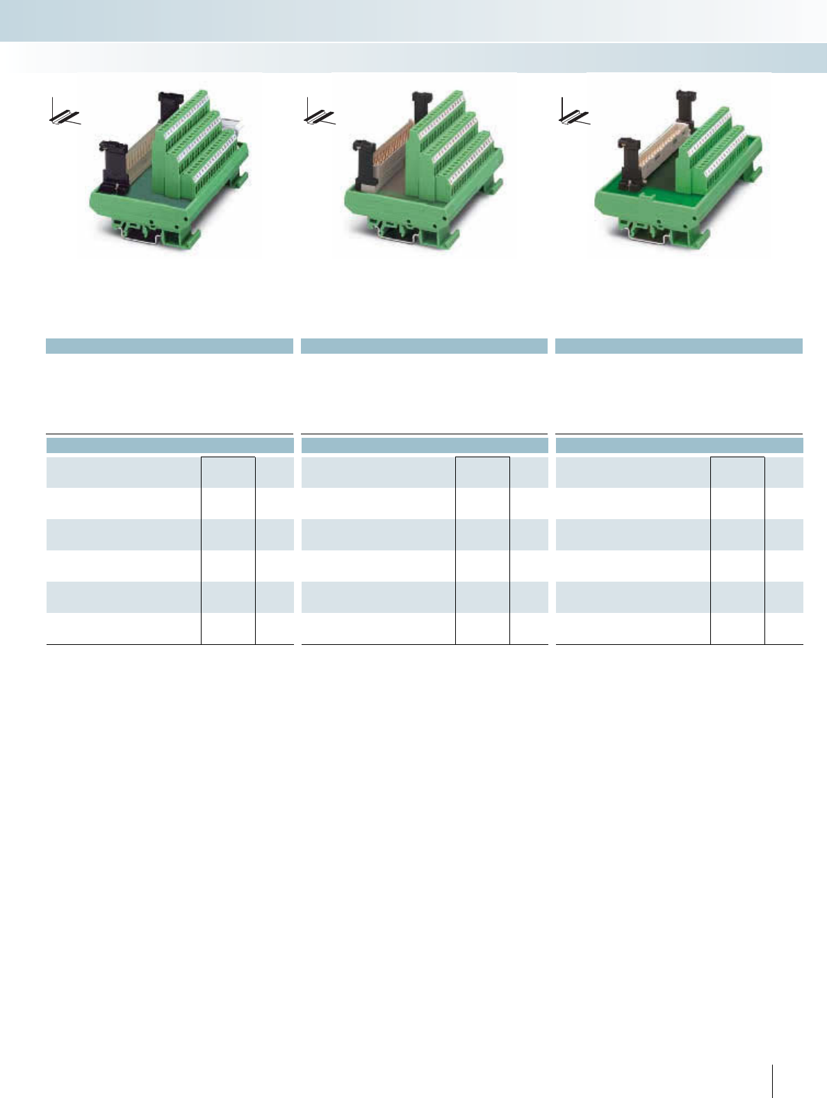
For additional information, visit www.phoenixcontact.net/catalog
|||
Technical data Technical data Technical data
125 V AC/DC 250 V AC 250 V AC/DC
4 A 4 A 2 A
-20°C ... 50°C -20°C ... 45°C -20°C ... 50°C
Any Any Any
IEC 60664, DIN EN 50178, IEC 62103 IEC 60664, DIN EN 50178, IEC 62103 IEC 60664, DIN EN 50178, IEC 62103
0.2 - 4 mm² / 0.2 - 2.5 mm² / 24 - 12 0.2 - 4 mm² / 0.2 - 2.5 mm² / 24 - 12 0.2 - 4 mm² / 0.2 - 2.5 mm² / 24 - 12
77 mm / 72 mm 77 mm / 72 mm 77 mm / 62.5 mm
Ordering data Ordering data Ordering data
Type Order No. Pcs. /
Pkt. Type Order No. Pcs. /
Pkt. Type Order No. Pcs. /
Pkt.
UMKS- E48M-VS 2970154 1
UMKS- F48M-VS 2970714 1
UMKS- F48M-VR 2970167 1
UMK- D32M-VS 2970060 1
315PHOENIX CONTACT
DW
H
DW
H
DW
H
INTERFACE Cabling
VARIOFACE wiring interface
Design E, 48-position, a, c, e assembled Design F, 48-position, z, b, d assembled Design D, 32-position, a, c assembled
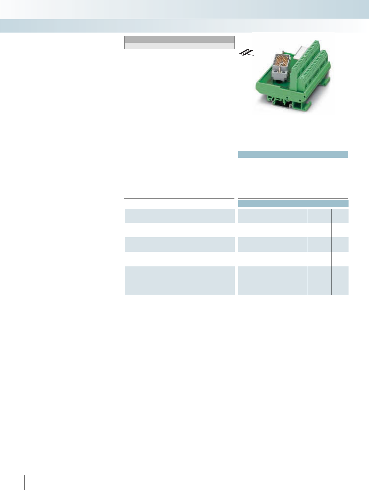
|
Technical data
Operating voltage 25 V AC / 60 V DC
Max. perm. current (per branch) 1.5 A
Total current 19 A (38 branches with 0.5 A each)
Ambient temperature (operation) -20°C ... 40°C
Mounting position Any
Standards / regulations IEC 60664, DIN EN 50178, IEC 62103
Connection data solid / stranded / AWG 0.2 - 4 mm² / 0.2 - 2.5 mm² / 24 - 12
Dimensions H / D 77 mm / 58.5 mm
Ordering data
Description No. of
poles
Module width
WType Order No. Pcs. /
Pkt.
VARIOFACE module, with:
- Pin strip 8016 right 38 101.50 UMK- EC38/38-XOR 2976297 1
- Pin strip 8016 left 38 101.50 UMK- EC38/38-XOL 2976284 1
VARIOFACE module, with:
- Pin strip 8016 right 56 157.50
- Pin strip 8016 left 56 157.50
VARIOFACE module, with:
- Pin strip 8016 right 56 77.00
- Pin strip 8016 left 56 77.00
VARIOFACE module, with:
- Pin strip 8016 right above 32 101.30
- Pin strip 8016 right below 32 101.30
- Pin strip 8016 left above 32 101.30
- Pin strip 8016 left below 32 101.30
316 PHOENIX CONTACT
DW
H
Modules for ELCO connectors Notes:
Dimensional drawings and pin assignments, see page 336.
These modules can be used to connect
ELCO plug connectors of the 8016 series to
screw connection terminal blocks.
The diagonal position of the ELCO plug
connector means that the wires leading out
of the cable housing at the side can be led
away without restricting neighboring mod-
ules.
INTERFACE Cabling
VARIOFACE wiring interface
38-pos.
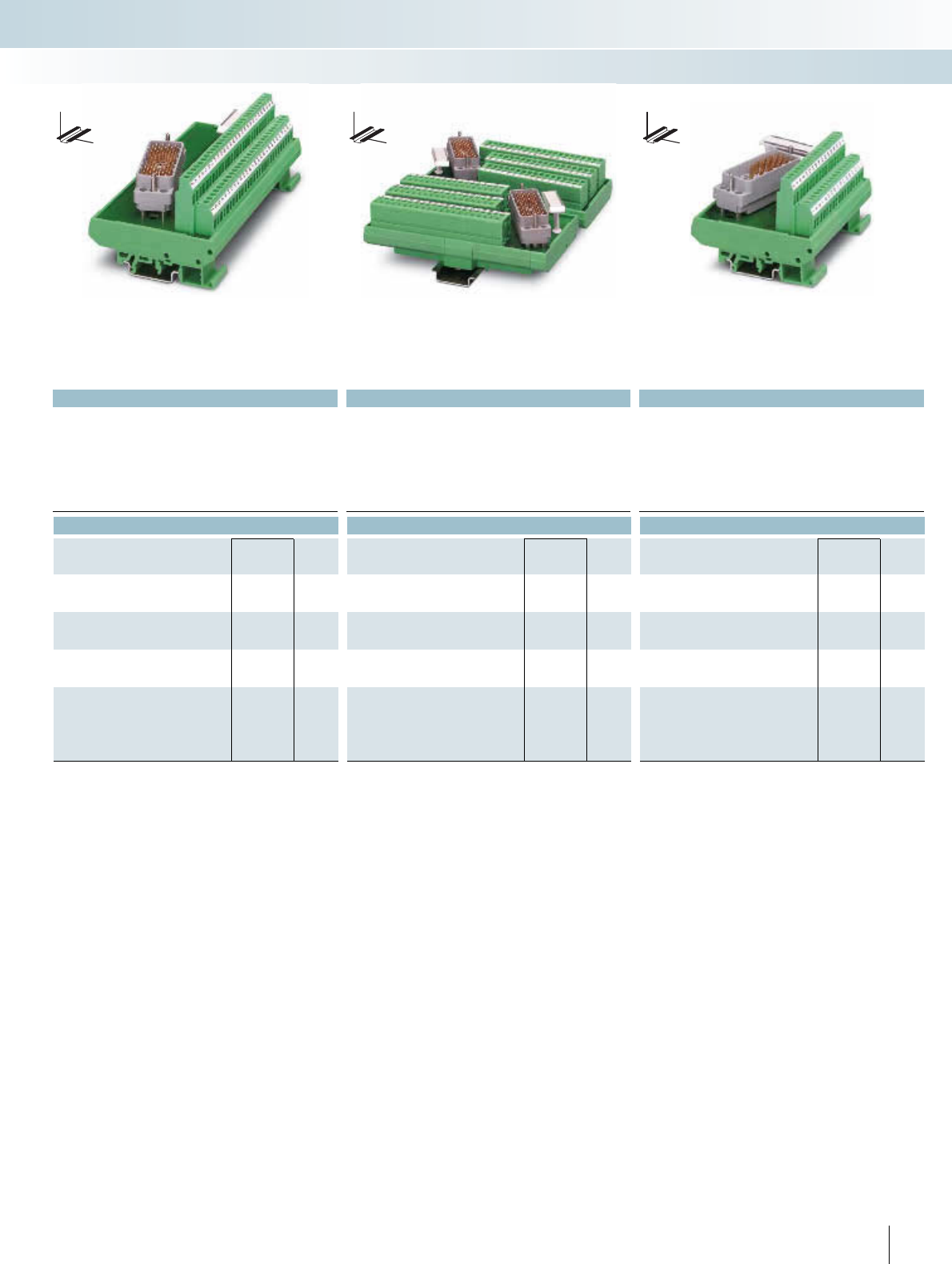
For additional information, visit www.phoenixcontact.net/catalog
|||
Technical data Technical data Technical data
125 V AC/DC < 25 V AC / 30 V DC 25 V AC / 60 V DC
1.5 A1.5 A2 A
28 A (56 branches with 0.5 A each) 28 A (56 branches with 0.5 A each) 32 A (32 branches with 1 A each)
-20°C ... 50°C -20°C ... 50°C -20°C ... 40°C
Any Any Any
IEC 60664, DIN EN 50178, IEC 62103 IEC 60664, DIN EN 50178, IEC 62103 IEC 60664, DIN EN 50178, IEC 62103
0.2 - 4 mm² / 0.2 - 2.5 mm² / 24 - 12 0.2 - 2.5 mm² / 0.2 - 1.5 mm² / 26 - 16 0.2 - 4 mm² / 0.2 - 2.5 mm² / 24 - 12
77 mm / 58.5 mm 146.3 mm / 47.5 mm 77 mm / 58.5 mm
Ordering data Ordering data Ordering data
Type Order No. Pcs. /
Pkt. Type Order No. Pcs. /
Pkt. Type Order No. Pcs. /
Pkt.
UMK- EC56/56-XOR 2975900 1
UMK- EC56/56-XOL 2975890 1
UMK- EC56/FRONT 2,5V/R 2976161 1
UMK- EC56/FRONT 2,5V/L 2976158 1
UMK- EC56/32-XOR 2975858 1
UMK- EC56/32-XUR 2975777 1
UMK- EC56/32-XOL 2975764 1
UMK- EC56/32-XUL 2975780 1
317PHOENIX CONTACT
DW
H
DW
H
DW
H
INTERFACE Cabling
VARIOFACE wiring interface
56-pos. 56-pos.,
with front connection terminal blocks
32-pos.
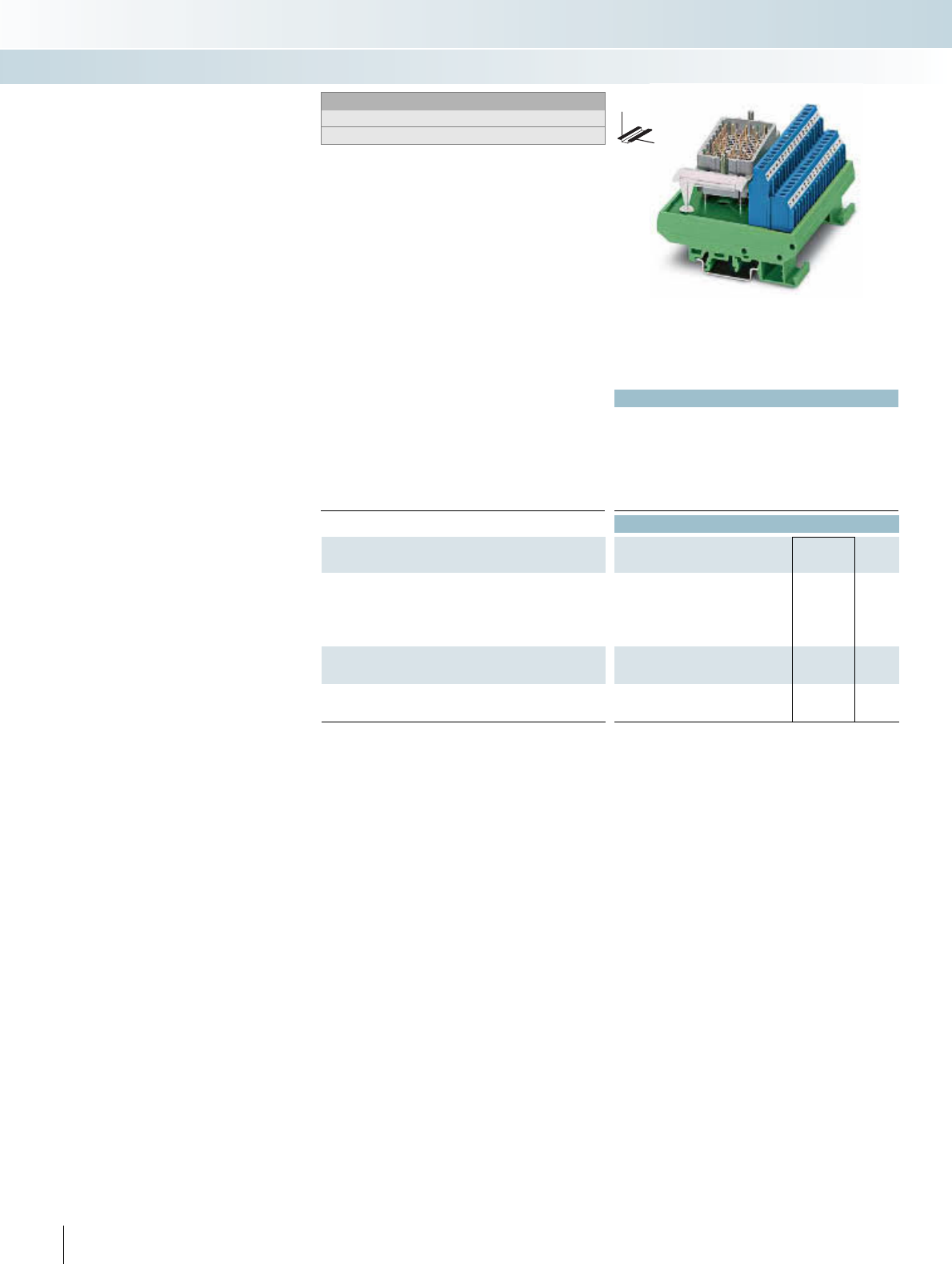
Technical data
Operating voltage Max. 30 V DC (max. voltage between two intrinsically safe circuits:
60 V DC)
Max. perm. current (per branch) 500 mA
Ambient temperature (operation) -20°C ... 50°C
Mounting position Any
Standards / regulations
Connection data solid / stranded / AWG 0.2 - 4 mm² / 0.2 - 2.5 mm² / 24 - 12
Dimensions H / D 77 mm / 58.5 mm
Ordering data
Description No. of
poles
Module width
WType Order No. Pcs. /
Pkt.
VARIOFACE module, with:
- Pin strip 8016 right above 32 101.30 UMK- EC90/32/EX-XOR 2900109 1
- Pin strip 8016 right below 32 101.30 UMK- EC90/32/EX-XUR 2969068 1
- Pin strip 8016 left above 32 101.30 UMK- EC90/32/EX-XOL 2900110 1
- Pin strip 8016 left above 32 101.30 UMK- EC90/32/EX-XUL 2969071 1
VARIOFACE module, with:
- Pin strip 8016 right 25 78.80
- Pin strip 8016 left 25 78.80
VARIOFACE module, with:
- Pin strip 8016 right 25 77.00
- Pin strip 8016 left 25 77.00
318 PHOENIX CONTACT
DW
H
Modules for ELCO connectors for
use in Ex i circuits
Notes:
Dimensional drawings and pin assignments, see page 337.
Facts about explosion protection, see page 432.
The VARIOFACE modules connect ELCO
connectors of the 8016 series to screw con-
nection terminal blocks. The modules for
ELCO connectors can be used as simple
electrical equipment for applications in in-
trinsically safe circuits as per EN 60079-14.
They fulfill the requirements of the intrinsic
safety as per EN 60079-11 (EN 50020) and
can be used for various intrinsically safe cir-
cuits taking into account the pin configura-
tion.
The voltage of an intrinsically safe circuit
may not exceed 30 V. The voltage difference
between two intrinsically safe circuits can
be up to 60 V.
The modules are equipped with blue
screw connection terminal blocks in order
to clearly label intrinsically safe circuits.
The arrangement of angled ELCO con-
nectors makes it possible to lead the lines
led out from the cable housing away from
the adjacent modules without any negative
effects.
For the disconnection of intrinsically safe
and non-intrinsically safe circuits, a distance
of at least 50 mm should be kept between
the connection points using partition plates
or spaces.
INTERFACE Cabling
VARIOFACE wiring interface
32-pos.
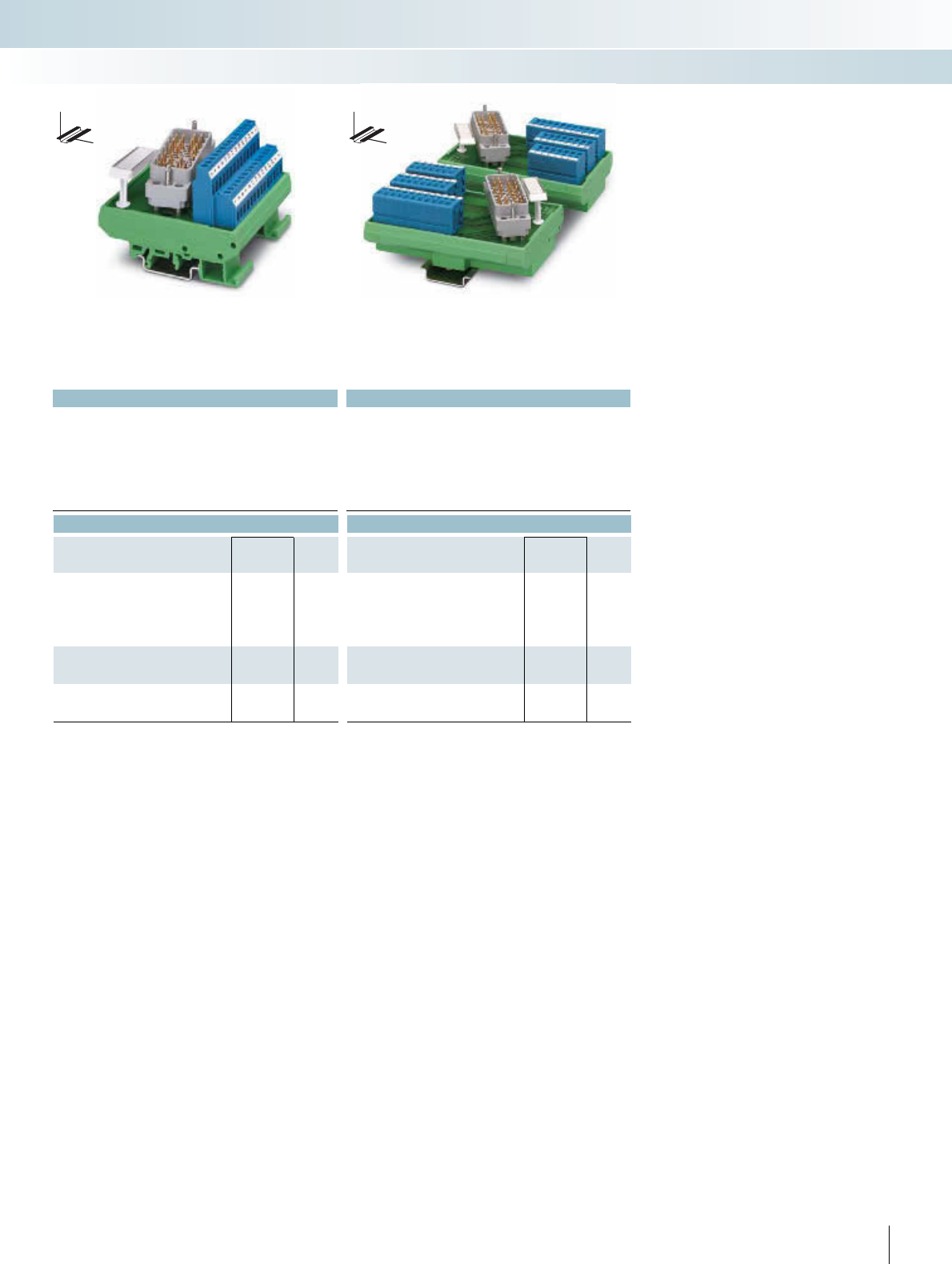
For additional information, visit www.phoenixcontact.net/catalog
Technical data Technical data
Max. 30 V DC (max. voltage between two intrinsically safe circuits:
60 V DC)
Max. 30 V DC (max. voltage between two intrinsically safe circuits:
60 V DC)
500 mA 500 mA
-20°C ... 50°C -20°C ... 50°C
Any Any
0.2 - 4 mm² / 0.2 - 2.5 mm² / 24 - 12 0.2 - 2.5 mm² / 0.2 - 2.5 mm² / 24 - 14
77 mm / 58.5 mm 112.5 mm / 52.5 mm
Ordering data Ordering data
Type Order No. Pcs. /
Pkt. Type Order No. Pcs. /
Pkt.
UMK- EC56/25/EX -R 2900112 1
UMK- EC56/25/EX -L 2900113 1
UMK- EC56/25/EX -FRONT 2,5V/R 2900114 1
UMK- EC56/25/EX -FRONT 2,5V/L 2900115 1
319PHOENIX CONTACT
DW
H
DW
H
INTERFACE Cabling
VARIOFACE wiring interface
25-pos. 25-pos.,
with front connection terminal blocks
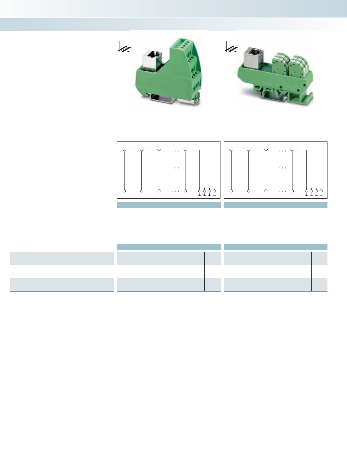
Technical data Technical data
Operating voltage 48 V AC/DC 48 V AC/DC
Max. perm. current (per branch) 1 A 1 A
Ambient temperature (operation) -20°C ... 50°C -20°C ... 50°C
Mounting position Any Any
Standards / regulations DIN EN 50178 DIN EN 50178
Connection data solid / stranded / AWG 0.2 - 4 mm² / 0.2 - 2.5 mm² / 24 - 12 0.2 - 1.5 mm² / 0.2 - 1.5 mm² / 24 - 16
Dimensions H / D 62 mm / 69 mm 91 mm / 51 mm
Ordering data Ordering data
Description No. of
poles
Module width
WType Order No. Pcs. /
Pkt. Type Order No. Pcs. /
Pkt.
VARIOFACE module, with RJ45 connector and screw connection
terminal blocks
RJ45 8 26.90 VIP-3/SC/RJ45 2900701 1
VARIOFACE module, with RJ45 connector and spring-cage con-
nection (direct plug-in method)
825.00 UMK-RJ45/S/8PTDA 2900682 1
320 PHOENIX CONTACT
– 1:1 connection
– 8 positions, RJ45 connector
– Screw or spring-cage connection
(direct plug-in method)
– Connector housing led to separate
connection terminal blocks
DW
H
DW
H
Modules with RJ45 connector
INTERFACE Cabling
VARIOFACE wiring interface
1
1
2
2
3
3
8
8
1
1
2
2
3
3
8
8
8 positions
with screw connection
8 positions
with spring-cage connection
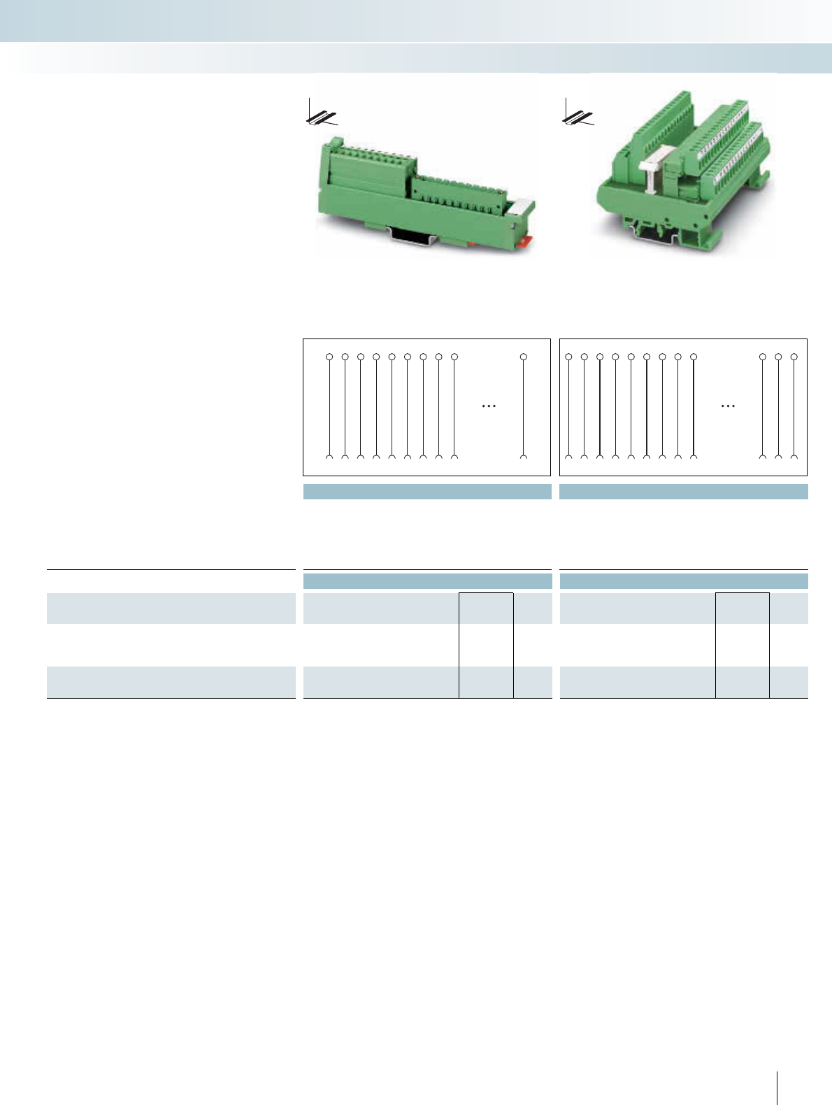
For additional information, visit www.phoenixcontact.net/catalog
||
Technical data Technical data
Operating voltage 250 V AC/DC 250 V AC/DC
Max. perm. current (per branch) 2.5 A 3 A
Ambient temperature (operation) -10°C ... 50°C -20°C ... 50°C
Mounting position Any Any
Standards / regulations IEC 60664, DIN EN 50178, IEC 62103 IEC 60664, DIN EN 50178, IEC 62103
Dimensions D / W 45 mm / 25 mm 58.5 mm / 112.5 mm
Ordering data Ordering data
Description No. of
poles
Module height
HType Order No. Pcs. /
Pkt. Type Order No. Pcs. /
Pkt.
VARIOFACE-SLIM-LINE module, with a COMBICON header
(without a COMBICON connector)
10 137.00 UM 25-10 MSTB/FRONT/Q 2959803 1
18 217.00 UM 25-18 MSTB/FRONT/Q 2959502 1
VARIOFACE module,with COMBICON plug connector, coded
32 77.00 UMK-32 MDSTB/MKKDS3/R 2970196 1
321PHOENIX CONTACT
– The slim 10 and 18-pos. VARIOFACE
SLIM-LINE modules connect the front
connection terminal blocks to a
COMBICON header. The corresponding
COMBICON connectors (5.0 mm pitch)
can be found in the COMBICON catalog
PCB Connection Technique.
– The 32-pos. module
UMK-32 MDSTB/MKKDS 3/R connects
screw connection terminal blocks with
coded COMBICON plug-in screw con-
nectors.
DW
H
DW
H
Modules with COMBICON connection
INTERFACE Cabling
VARIOFACE wiring interface
1
1
2
2
3
3
4
4
5
5
6
6
7
7
8
8
9n
9n
1
1
2
2
3
3
4
4
5
5
6
6
7
7
8
8
9303132
9303132
10 and 18-pos.
with screw connection
32-pos.
with screw connection
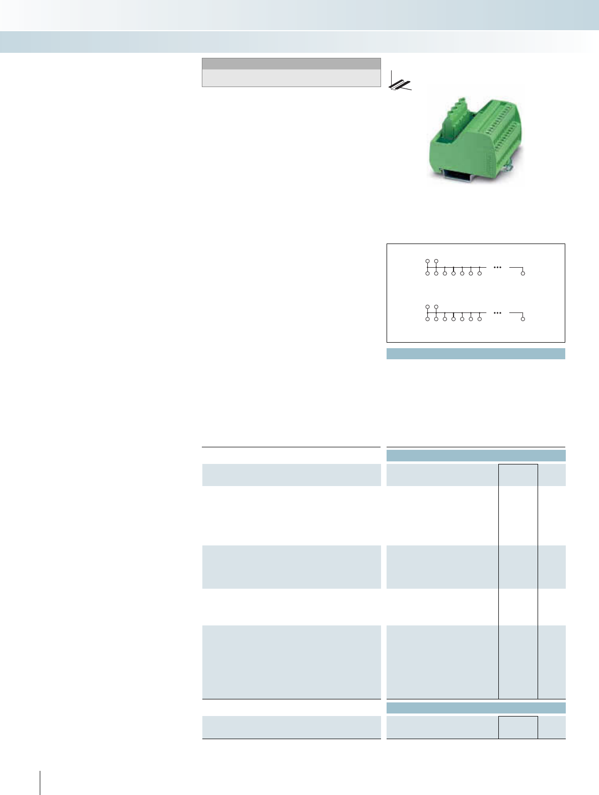
p
Technical data
Operating voltage 250 V AC/DC
Max. perm. current (per branch) 15 A
Total current 30 A (per potential)
Ambient temperature (operation) -20°C ... 50°C
Mounting position Any
Standards / regulations IEC 60664, DIN EN 50178, IEC 62103
Supply connection data solid / stranded / AWG 0.2 - 6 mm² / 0.2 - 4 mm² / 24 - 10
Distribution connection data solid / stranded / AWG 0.2 - 4 mm² / 0.2 - 2.5 mm² / 24 - 12
Dimensions H / D 65.5 mm / 50 mm
Ordering data
Description No. of
poles
Module width
WType Order No. Pcs. /
Pkt.
VARIOFACE module, with two busbars (P1, P2) for potential dis-
tribution, per potential:
2 power terminal blocks/8 distributor terminal blocks
50.00 VIP-2/SC/PDM-2/16 2315256 1
2 power terminal blocks/12 distributor terminal blocks
70.40 VIP-2/SC/PDM-2/24 2315269 1
2 power terminal blocks/16 distributor terminal blocks
90.80 VIP-2/SC/PDM-2/32 2315272 1
VARIOFACE module, with three busbars (+, -, PE) for potential
distribution, per potential:
(+) two power terminal blocks/48 distributor terminal blocks
(-) two power terminal blocks/24 distributor terminal blocks
(PE) 2 power/72 distributor terminal blocks
168.80
VARIOFACE module, with six busbars (P1 to P6) for potential dis-
tribution, per potential:
2 power terminal blocks/12 distributor terminal blocks
123.80
VARIOFACE module, with two busbars (P1, P2) for potential dis-
tribution, per potential:
2 power terminal blocks/8 distributor terminal blocks
45.00
2 power terminal blocks/12 distributor terminal blocks
67.50
2 power terminal blocks/16 distributor terminal blocks
90.00
2 power terminal blocks/24 distributor terminal blocks
135.00
Accessories
Screwdriver
Blade: 0,6x3.5x100mm, length: 181mm
322 PHOENIX CONTACT
P2
P1
P2
P1
P2
P1
P2
P1
P2
P1
P2
P1
P2
P1
P2
P1
P2
P1
P2
P1
.1 .2 .3 .4 .5 .6 .7 .n
.1 .2 .3 .4 .5 .6 .7 .n
Modules as compact potential
distributors
The VIP-2/SC/PDM... modules have the
following features:
– Two potential levels
– Separate supply
– Consecutive labeling
The modules UMK-PVB and UMK-PVB 6
have three or six potential levels.
The modules UMK-PVB 2/.../ZFKDS are
available as a variant with spring-cage con-
nection.
INTERFACE Cabling
VARIOFACE wiring interface
DW
H
Notes:
For marking systems and mounting material, see
CLIPLINE catalog, part 2.
With screw connection and 2 potential levels
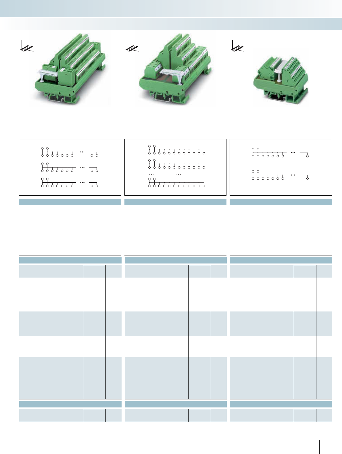
For additional information, visit www.phoenixcontact.net/catalog
|| |
Technical data Technical data Technical data
250 V AC/DC 250 V AC/DC 250 V AC/DC
16 A16 A17 A
16 A (per potential) 16 A (per potential) 32 A (per potential)
-20°C ... 50°C -20°C ... 50°C -20°C ... 50°C
Any Any Any
IEC 60664, DIN EN 50178, IEC 62103 IEC 60664, DIN EN 50178, IEC 62103
0.5 - 6 mm² / 0.5 - 4 mm² / 20 - 10 0.2 - 6 mm² / 0.2 - 4 mm² / 24 - 10 0.2 - 6 mm² / 0.2 - 4 mm² / 24 - 10
0.2 - 4 mm² / 0.2 - 2.5 mm² / 24 - 12 0.2 - 4 mm² / 0.2 - 2.5 mm² / 24 - 12 0.2 - 4 mm² / 0.2 - 2.5 mm² / 24 - 12
77 mm / 72 mm 77 mm / 72 mm 77 mm / 52 mm
Ordering data Ordering data Ordering data
Type Order No. Pcs. /
Pkt. Type Order No. Pcs. /
Pkt. Type Order No. Pcs. /
Pkt.
UMK- PVB 2971302 1
UMK- PVB 6 2972136 1
UMK- PVB 2/16/ZFKDS 2302353 1
UMK- PVB 2/24/ZFKDS 2302366 1
UMK- PVB 2/32/ZFKDS 2302379 1
UMK- PVB 2/48/ZFKDS 2302382 1
Accessories Accessories Accessories
SZF 1-0,6X3,5 1204517 10
323PHOENIX CONTACT
++
++++++ +++
--
------ ---
PE PE
PE PE PE PE PE PE PEPE PE
P1 P1
P1 P1 P1 P1 P1 P1 P1 P1 P1 P1 P1 P1
P2 P2
P2 P2 P2 P2 P2 P2 P2 P2 P2 P2 P2 P2
P6 P6
P6 P6 P6 P6 P6 P6 P6 P6 P6 P6 P6 P6
P2
P1
P2
P1
P2
.1
P1
P2
.2
P1
P2
.3
P1
P2
.4
P1
P2
.5
P1
P2
.6
P1
P2
.7
P1
P2
.n
P1
INTERFACE Cabling
VARIOFACE wiring interface
DW
H
DW
H
DW
H
With screw connection and 3 potential levels With screw connection and 6 potential levels
With spring-cage connection and 2 potential levels
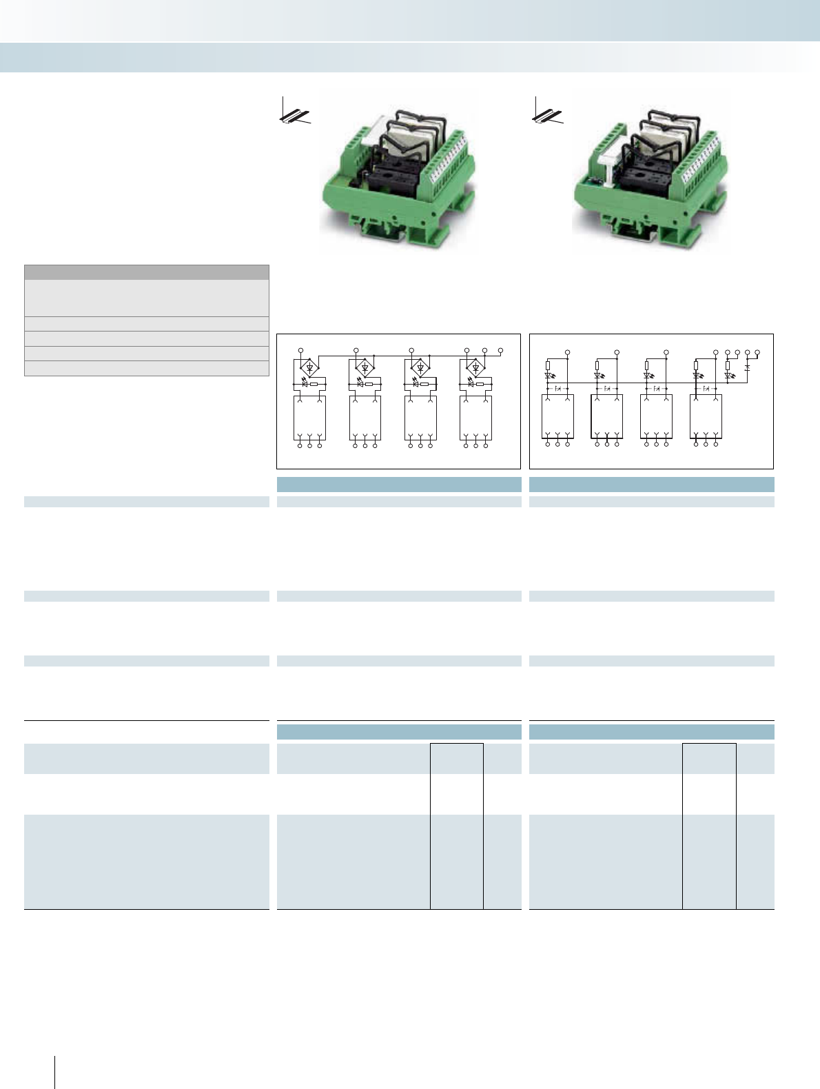
||
Technical data Technical data
Coil side
Tolerance of the input voltage ±10% ±10%
Input circuit Bridge rectifier Free-wheeling diode, protection against polarity reversal
Operating voltage display - Yellow LED1)
Status display/channel Yellow LED Yellow LED2)
Connection method Screw connection Screw connection
Connection data solid / stranded / AWG 0.2 ... 4 mm² / 0.2 ... 2.5 mm² / 24 - 12 0.2 ... 4 mm² / 0.2 ... 2.5 mm² / 24 - 24
Contact side
Contact type 1 PDT 1 PDT
Max. switching voltage 250 V AC/DC 250 V AC/DC
Limiting continuous current 6 A 5 A (optocoupler-dependent)
Connection method Screw connection Screw connection
Connection data solid / stranded / AWG 0.2 ... 4 mm² / 0.2 ... 2.5 mm² / 24 - 12 0.2 ... 4 mm² / 0.2 ... 2.5 mm² / 24 - 12
General data
Test voltage 2.5 kV (50 Hz, 1 min.) 2.5 kV (50 Hz, 1 min.)
Ambient temperature (operation) -20°C ... 50°C -20°C ... 50°C
Standards / regulations DIN VDE 0110 DIN VDE 0110
Mounting position Any Any
Dimensions W / H / D 67.5 mm / 77 mm / 59 mm 67.5 mm / 77 mm / 59 mm
Ordering data Ordering data
Description Input voltage Type Order No. Pcs. /
Pkt. Type Order No. Pcs. /
Pkt.
VARIOFACE module, for four pluggable miniature relays or minia-
ture solid-state relays, with light indicator (without relays)
24 V AC/DC UMK- 4 RM 24 2971344 1
VARIOFACE module, for pluggable miniature relays or miniature
solid-state relays, with light indicator (without relay)
5 V DC UMK- 4 RM 5DC 2972819 1
12 V DC UMK- 4 RM 12DC 2972822 1
24 V DC UMK- 4 RM 24DC 2972835 1
48 V DC UMK- 4 RM 60DC 2972851 1
110 V DC UMK- 4 RM110DC 2972864 1
230 V AC UMK- 4 RM230AC 2972880 1
324 PHOENIX CONTACT
1234
0234
NN
12 22 32 42
0000
11 21 31 41
++++
14 24 34 44
AAAA
1234
1234+-+-
12 22 32 42
0000
11 21 31 41
++++
14 24 34 44
AAAA
The 4, 8, and 16-way relay and solid-state
relay interfaces UMK-... RM provide four,
eight or 16 slots for commercially available
electromechanical relays (REL-MR...) or op-
toelectronic relays (SIM-EI...). The connec-
tions between the I/O module and the elec-
tronics, as well as the process cabling, are
implemented via screw connection terminal
blocks.
Notes:
For the protection of relay coils and contacts, inductive loads must
be dampened with an efficient protective circuit.
Other input voltages on request.
1) Not with 230 V AC.
2) With 230 V AC glow lamp.
3) With 100 V DC and 230 V AC glow lamp.
VARIOFACE modules for
pluggable miniature relays and/or
miniature solid-state relays
INTERFACE Cabling
VARIOFACE wiring interface
4-channel with bridge rectifier 4-channel for relays with a PDT contact
DW
H
DW
H
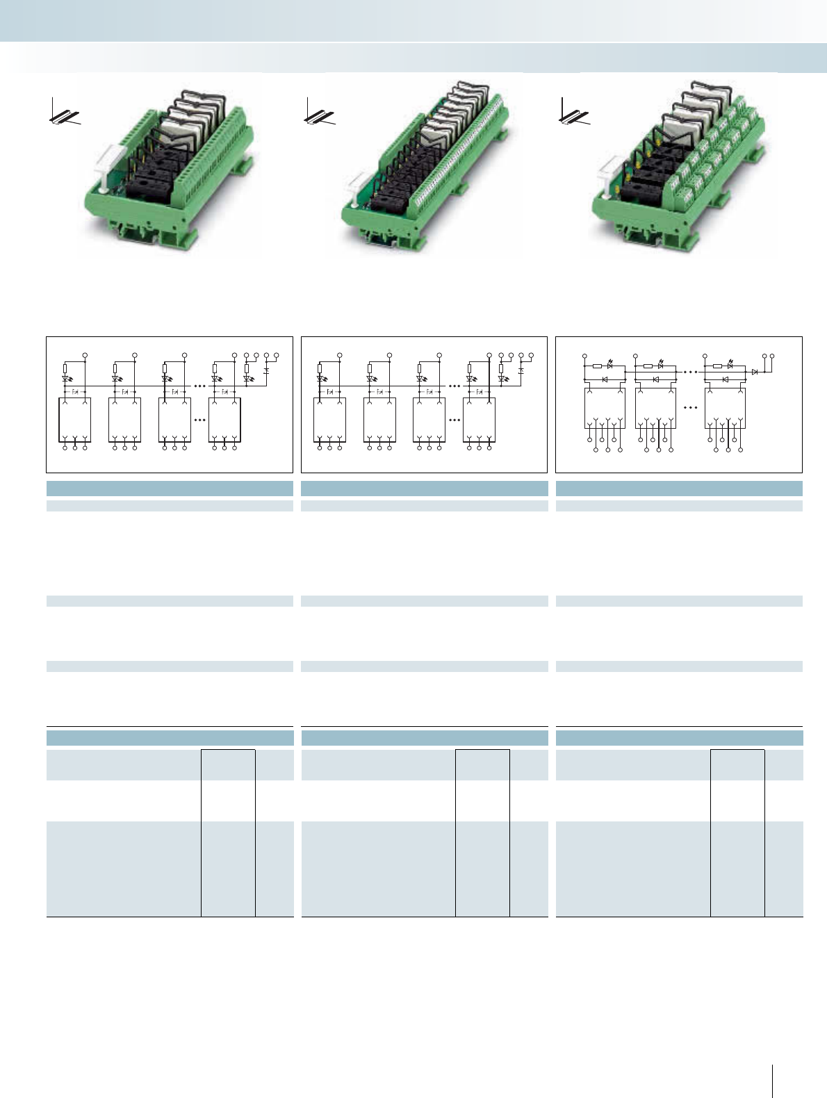
For additional information, visit www.phoenixcontact.net/catalog
|||
Technical data Technical data Technical data
±10% ±10% ±10%
Free-wheeling diode, protection against polarity reversal Free-wheeling diode, protection against polarity reversal Free-wheeling diode, protection against polarity reversal
Yellow LED3)Yellow LED
2)-
Yellow LED3)Yellow LED
2)Yellow LED
Screw connection Screw connection Screw connection
0.2 ... 4 mm² / 0.2 ... 2.5 mm² / 24 - 24 0.2 ... 4 mm² / 0.2 ... 2.5 mm² / 24 - 24 0.14 ... 1.5 mm² / 0.14 ... 1.5 mm² / 26 - 26
1 PDT 1 PDT 2 PDT
250 V AC 250 V AC 250 V AC
5 A5 A5 A
Screw connection Screw connection Screw connection
0.2 ... 4 mm² / 0.2 ... 2.5 mm² / 24 - 12 0.2 ... 4 mm² / 0.2 ... 2.5 mm² / 24 - 12 0.14 ... 1.5 mm² / 0.14 ... 1.5 mm² / 26 - 14
2.5 kV (50 Hz, 1 min.) 2.5 kV (50 Hz, 1 min.) 2.5 kV (50 Hz, 1 min.)
-20°C ... 50°C -20°C ... 50°C -20°C ... 50°C
DIN VDE 0110 DIN VDE 0110 DIN VDE 0110
Any Any Any
135 mm / 77 mm / 59 mm 259 mm / 77 mm / 59 mm 168.8 mm / 77 mm / 59 mm
Ordering data Ordering data Ordering data
Type Order No. Pcs. /
Pkt. Type Order No. Pcs. /
Pkt. Type Order No. Pcs. /
Pkt.
UMK- 8 RM 5DC/MKDS 2972893 1UMK-16 RM 5DC/MKDS 2972974 1
UMK- 8 RM 12DC/MKDS 2972903 1UMK-16 RM 12DC/MKDS 2972987 1
UMK- 8 RM24DC/MKDS 2972916 1UMK-16 RM 24DC/MKDS 2972990 1UMK- 8 RELS/KSR-24/21/21 2975722 1
UMK- 8 RM 60DC/MKDS 2972932 1UMK-16 RM 60DC/MKDS 2973038 1
UMK- 8 RM110DC/MKDS 2972945 1UMK-16 RM110DC/MKDS 2973041 1
UMK- 8 RM230AC/MKDS 2972961 1UMK-16 RM230AC/MKDS 2973067 1
325PHOENIX CONTACT
1238
1238+-+-
12 22 32 82
0000
11 21 31 81
++++
14 24 34 84
AAAA
12316
12316+-+-
12 22 32 162
0000
11 21 31 161
++++
14 24 34 164
AAAA
12 8 --
12 8
11
21
81
111
121
181
12
22
82
14
24
84
112
122
182
114
124
184
INTERFACE Cabling
VARIOFACE wiring interface
DW
H
8-channel for relays with a PDT contact 16-channel for relays with a PDT contact 8-channel for relays with two PDT contacts
DW
H
DW
H
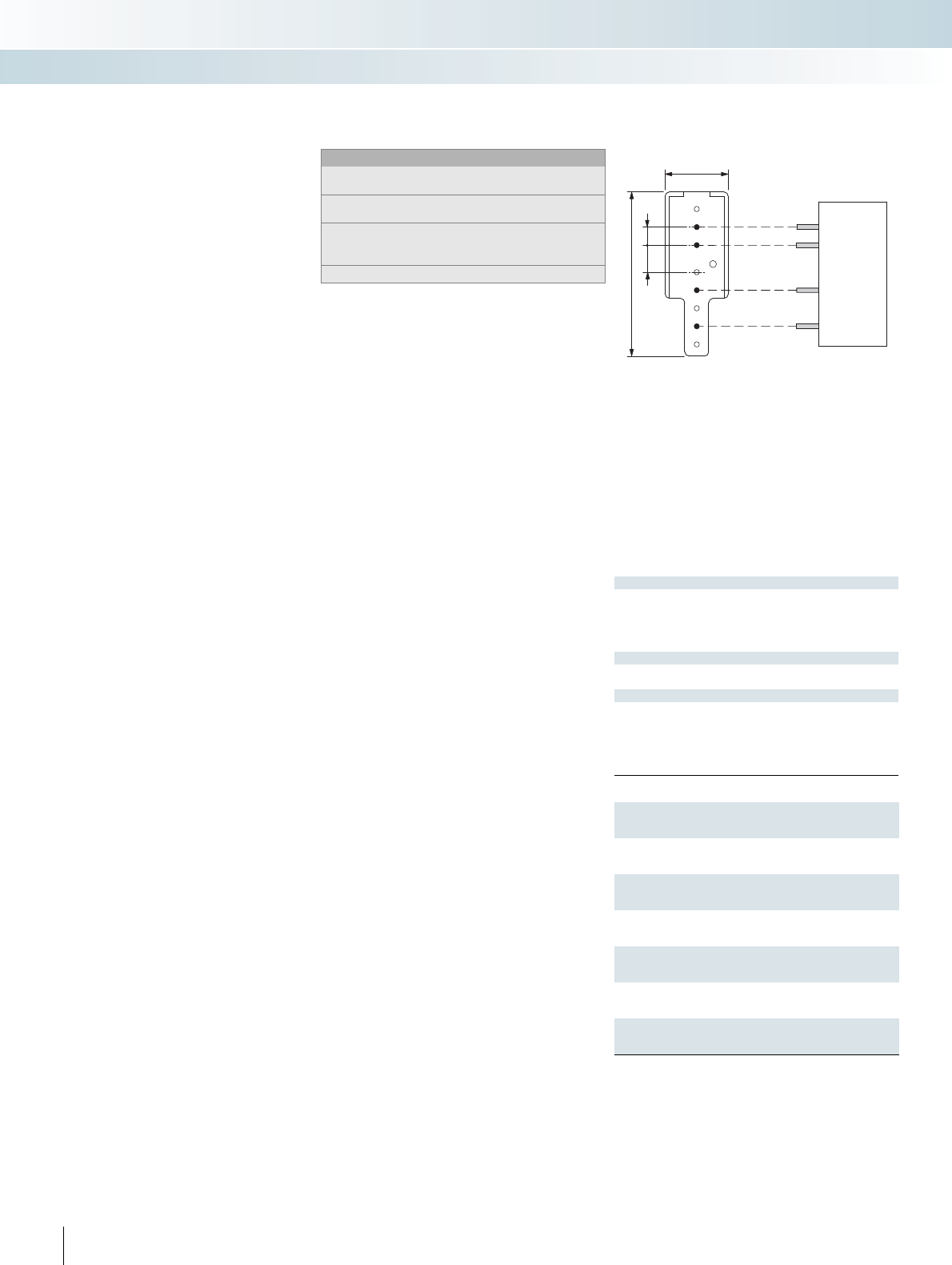
Input data
Input voltage range
Input circuit
Status display/channel
Connection method
Connection data solid / stranded / AWG
Output data
Connection method
Connection data solid / stranded / AWG
General data
Ambient temperature (operation)
Standards / regulations
Mounting position
Mounting
Dimensions H / D
Description Module width
W
Interface module, with plug-in base for one solid-state relay, with
locking clip
22.5
Interface module, with plug-in base for four solid-state relays, with
locking clip
Microfuse: 250 V, 4 A 90
Interface module, with plug-in base for eight digital I/O modules.
Microfuse: 250 V, 4 A 180
Interface module, with plug-in base for eight solid-state relays,
with locking clip
Microfuse: 250 V, 4 A 180
Interface module, with plug-in base for 16 digital I/O modules.
Microfuse: 250 V, 4 A 326.5
Interface module, with plug-in base for 16 solid-state relays, with
locking clip
Microfuse: 250 V, 4 A 326.5
326 PHOENIX CONTACT
The 1, 4, 8 or 16-time INTERFACE mod-
ules are the wiring interface and the cou-
pling level in one unit. The connection to
the interface module is established using
screw connection technology.
Properties of the single interface:
–Status indicator
– Protection against polarity reversal in in-
put
– Surge protection in input
– Assembly option with solid-state relay for
loads up to 350 V DC/1 A or 480 V AC/5 A
Properties of the 4, 8, and 16-time in-
terfaces:
–Status indicator
– Integrated fuse for line protection
– Assembly option with solid-state relay or
I/O modules
Notes:
Type of housing:
Polyamide PA non-reinforced, color: Green.
For marking systems and mounting material, see
CLIPLINE catalog, part 2.
For the protection of relay coils and contacts, inductive loads must
be dampened with an efficient protective circuit.
Solid-state relays, see page 332.
A
B
INPUT OUTPUT
2431(+)
18,8
46,7
7,5 5
A = without metal
B = with metal
VARIOFACE modules as interface for
pluggable solid-state relays or
digital I/O modules
INTERFACE Cabling
VARIOFACE wiring interface
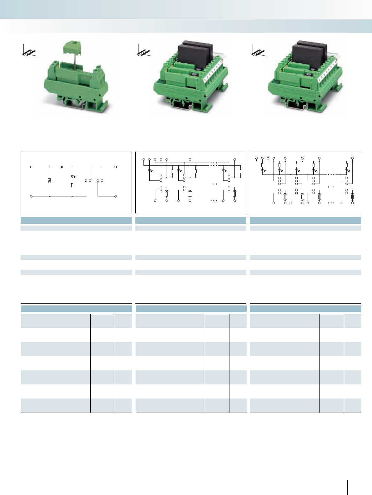
For additional information, visit www.phoenixcontact.net/catalog
| |
Technical data Technical data Technical data
4 V ... 32 V 4 V ... 32 V 4 V ... 32 V
Protection against polarity reversal, surge protection
Yellow LED Yellow LED Yellow LED
Screw connection Screw connection Screw connection
0.2 ... 4 mm² / 0.2 ... 2.5 mm² / 24 - 12 0.2 ... 4 mm² / 0.2 ... 2.5 mm² / 24 - 24 0.2 ... 4 mm² / 0.2 ... 2.5 mm² / 24 - 24
Screw connection Screw connection Screw connection
0.2 ... 6 mm² / 0.2 ... 4 mm² / 24 - 10 0.2 ... 6 mm² / 0.2 ... 4 mm² / 24 - 10 0.2 ... 6 mm² / 0.2 ... 4 mm² / 24 - 10
-20°C ... 60°C -20°C ... 55°C -20°C ... 55°C
DIN EN 50178 DIN VDE 0110b, Gr. C for 250 V DC, DIN VDE 0160 (in relevant
parts)
DIN VDE 0110b, Gr. C for 250 V DC, DIN VDE 0160 (in relevant
parts)
Any Any Any
In rows with zero spacing In rows with zero spacing In rows with zero spacing
77 mm / 72 mm 77 mm / 72 mm 77 mm / 72 mm
Ordering data Ordering data Ordering data
Type Order No. Pcs. /
Pkt. Type Order No. Pcs. /
Pkt. Type Order No. Pcs. /
Pkt.
UMK- 1 OM-R/AMS 2983002 1
UMK- 4 OM-R/MF 2970882 1UMK- 4 OM-R/MF/P 2972673 1
UMK- 8 OM/MF/MKDS 2972712 1
UMK- 8 OM-R/MF/MKDS 2972738 1UMK- 8 OM-R/MF/MKDS/P 2972699 1
UMK-16 OM/MF/MKDS 2972754 1
UMK-16 OM-R/MF/MKDS 2972770 1UMK-16 OM-R/MF/MKDS/P 2972796 1
327PHOENIX CONTACT
A1
A2
13(+)
14
+Vcc -GND 0
0
1
1
15
15
14 24 16413 23 163
(+) (+) (+)
+Vcc -GND 0
0
12
12
15
15
14 24 16413 23 34 33 163
(+) (+) (+) (+)
INTERFACE Cabling
VARIOFACE wiring interface
With light indicator With light indicator and fuse,
control logic negative switching
With light indicator and fuse,
control logic positive switching
DW
H
DW
H
DW
H
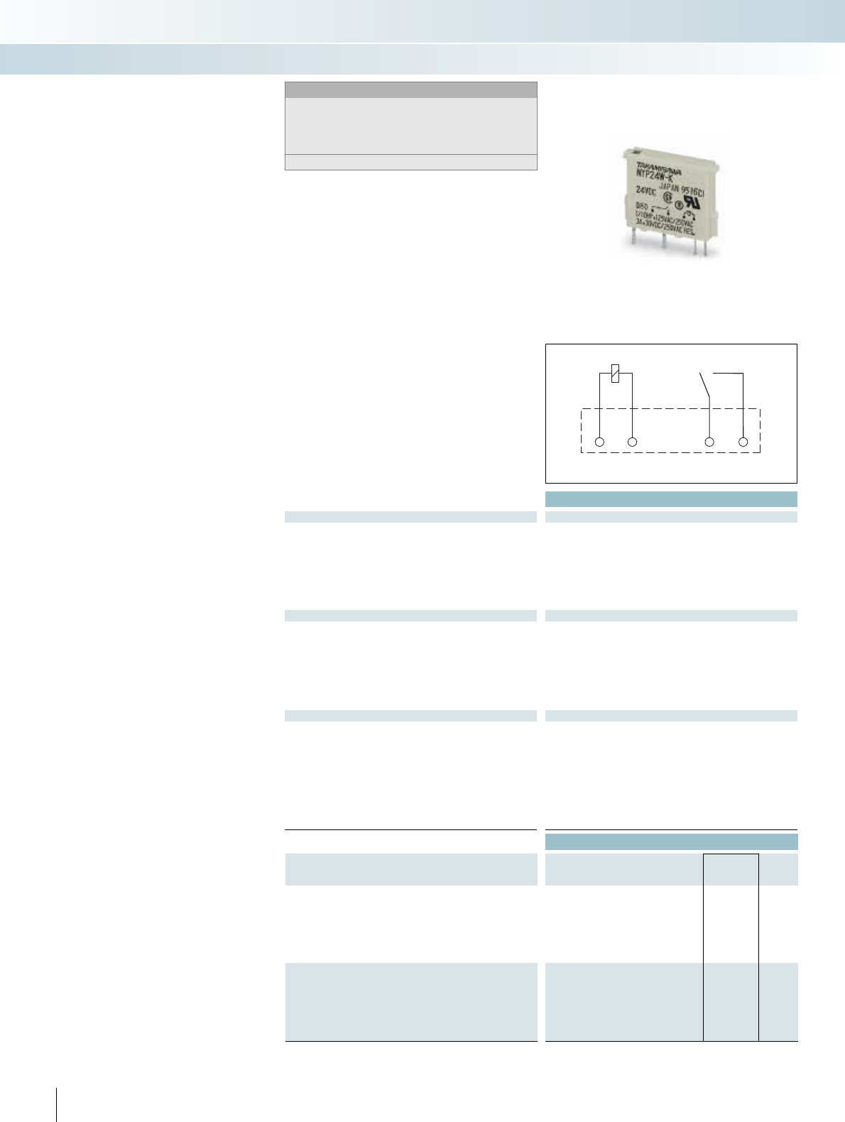
|
Technical data
Input data ¥
Permissible range (with reference to UN)-
Permissible range (with reference to UN)0.8 -
1.1
Typ. input current at UN[mA] 5
Typ. response time at UN[ms] 5
Typ. response time at U
N
( depending on phase relation )
[ms]
Typ. release time at UN[ms] 2
Typ. release time at U
N
( depending on phase relation )
[ms]
Output data
Contact type Double contact, 1 N/O contact
Contact material AgNi 90/10, + 5 μm hard gold-plated
Max. switching voltage 250 V AC / 125 V DC
Min. switching voltage 5 V DC
Limiting continuous current 3 A
Max. inrush current 5 A
Max. interrupting rating, ohmic load
250 V AC -
General data
Test voltage (winding / contact) 2 kV AC (50 Hz, 1 min.)
Test voltage (contact / contact) -
Ambient temperature (operation) -40°C ... 85°C
Nominal operating mode 100% operating factor
Mechanical service life Approx. 2 x 10⁷ cycles
Standards / regulations DIN VDE 0110, IEC 255 / DIN VDE 0435 (in relevant parts)
Mounting position / mounting Any
Dimensions W / H / D 5 mm / 23 mm / 17 mm
Ordering data
Description Input voltage
UN
Type Order No. Pcs. /
Pkt.
Pluggable miniature relays
with power contact ¤12 V DC
with power contact ¥24 V DC REL-MR-G 24/1 2961037 8
with power contact ¦48 V DC
with power contact §60 V DC
with power contact ¨110 V DC
with power contact ©230 V AC
Pluggable miniature relays
with gold contact ¤12 V DC
with gold contact ¥24 V DC
with gold contact ¦48 V DC
with gold contact §60 V DC
with gold contact ¨110 V DC
with gold contact ©230 V AC
328 PHOENIX CONTACT
A2 A1 11 12
Miniature relay REL-MR
The robust relays are used as interface re-
lays throughout process and production en-
gineering.
The main features of these relays are their
compact design, reliable electrical isolation,
and compliance with the most important
standards, as well as the number of variants.
INTERFACE Cabling
VARIOFACE wiring interface
Notes:
If the specified maximum values for multi-layer contact relays are
exceeded, the gold plating is destroyed. The maximum values of
the power contact relay are then valid. This can result in a shorter
service life than with a pure power contact.
For diagrams of operating voltage ranges, see page 104.
Pluggable miniature relay
1 N/O contact (1)
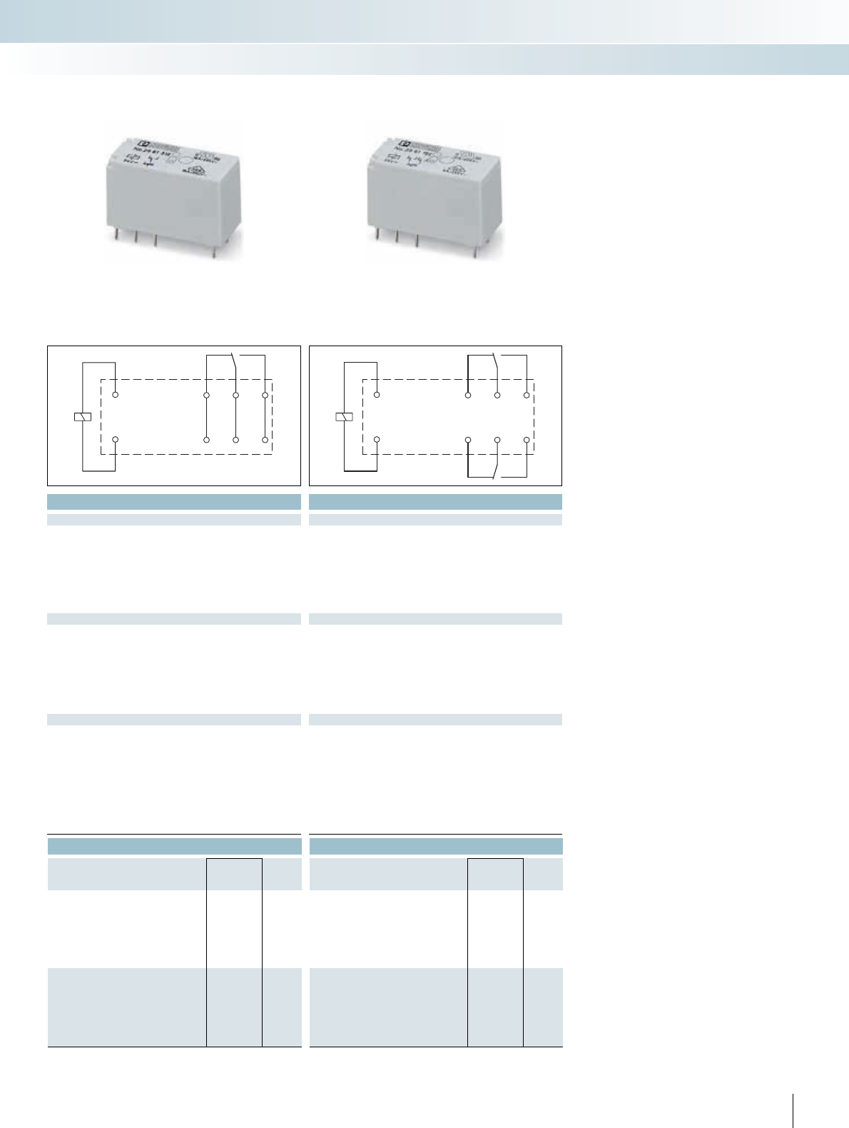
For additional information, visit www.phoenixcontact.net/catalog
| £ | £
Technical data Technical data
¤ ¥ ¦ § ¨ © ¤ ¥ ¦ § ¨ ©
Refer to the diagram Refer to the diagram
33 17 8.7 8.2 4.1 3 33 17 8.7 8.2 4.1 3
77777 77777
3 - 12 3 - 12
33333 33333
2 - 9 2 - 9
Single contact, 1 PDT Single contact, 1 PDT Single contact, 2 PDT Single contact, 2 PDT
AgNi AgNi, hard gold-plated AgNi AgNi, hard gold-plated
250 V AC/DC 30 V AC / 36 V DC 250 V AC/DC 30 V AC / 36 V DC
12 V (at 10 mA) 100 mV (at 10 mA) 5 V (at 10 mA) 100 mV (at 10 mA)
16 A 50 mA 8 A 50 mA
30 A (300 ms) 50 mA 15 A (300 ms) 50 mA
4000 VA - 2000 VA -
5 kV AC (50 Hz, 1 min.) 5 kV AC (50 Hz, 1 min.)
- 2.5 kV AC (50 Hz, 1 min.)
-40°C ... 85°C -40°C ... 85°C
100% operating factor 100% operating factor
3 x 10⁷ cycles 3 x 10⁷ cycles
IEC 60664, EN 50178, IEC 62103 IEC 60664, EN 50178, IEC 62103
Any / can be aligned without spacing (> 70°C 2.5 mm) Any / can be aligned without spacing (> 70°C 2.5 mm)
12.7 mm / 29 mm / 15.7 mm 12.7 mm / 29 mm / 15.7 mm
Ordering data Ordering data
Type Order No. Pcs. /
Pkt. Type Order No. Pcs. /
Pkt.
REL-MR- 12DC/21HC 2961309 10 REL-MR- 12DC/21-21 2961257 10
REL-MR- 24DC/21HC 2961312 10 REL-MR- 24DC/21-21 2961192 10
REL-MR- 48DC/21HC 2834821 10 REL-MR- 48DC/21-21 2834834 10
REL-MR- 60DC/21HC 2961325 10 REL-MR- 60DC/21-21 2961273 10
REL-MR-110DC/21HC 2961338 10 REL-MR-110DC/21-21 2961202 10
REL-MR-230AC/21HC 2961422 10 REL-MR-230AC/21-21 2961451 10
REL-MR- 12DC/21HC AU 2961532 10 REL-MR- 12DC/21-21AU 2961299 10
REL-MR- 24DC/21HC AU 2961545 10 REL-MR- 24DC/21-21AU 2961215 10
REL-MR- 48DC/21-21AU 2834847 10
REL-MR- 60DC/21-21AU 2961286 10
REL-MR-110DC/21HC AU 2961561 10 REL-MR-110DC/21-21AU 2961228 10
REL-MR-230AC/21HC AU 2961529 10 REL-MR-230AC/21-21AU 2961480 10
329PHOENIX CONTACT
14
A1
1112
A2
24
14
A1
21
11
22
12
A2
INTERFACE Cabling
VARIOFACE wiring interface
1 PDT, for high continuous currents 2 PDT
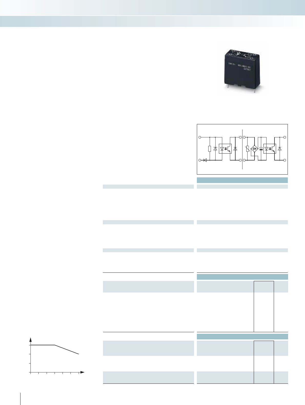
|
Technical data
Input data ¤ ¥ ¦ § ¨ © ª «
Permissible range (with reference to UN)0.9 -
1.1
0.9 -
1.1
0.9 -
1.1
0.9 -
1.1
0.9 -
1.1
0.9 -
1.1
0.9 -
1.1
0.9 -
1.1
Switching level with reference to UN1 signal ("H") 0.8 0.8 0.8 0.8 0.8 0.8 0.8 0.8
0 signal ("L") 0.35 0.4 0.4 0.25 0.4 0.4 0.4 0.4
Typ. input current at UN[mA]5.45.75.16.82.42.62.12.1
Transmission frequency flimit [Hz] 600 600 600 600 300 300 3 3
Input circuit AC Protection against polarity reversal, surge protection
Input circuit DC Protection against polarity reversal
Output data
Operating voltage range 8 V DC ... 48 V DC
Limiting continuous current 100 mA
Residual voltage drop at "H" 1 V
Max. inrush current -
Output circuit 2-wire, floating
Output protection Protection against polarity reversal
General data
Test voltage input/output 2.5 kV (50 Hz, 1 min.)
Ambient temperature (operation) -20°C ... 50°C
Standards / regulations DIN VDE 0110
Mounting position / mounting Any / can be aligned with 2 mm spacing
Dimensions W / H / D 13 mm / 29 mm / 25 mm
Ordering data
Description Input voltage
UN
Type Order No. Pcs. /
Pkt.
Solid-state relay, with protective circuit in the input and output cir-
cuit
¤5 V DC SIM-EI- 5DC/48DC/100 2271057 10
¥12 V DC SIM-EI- 12DC/48DC/100 2271060 10
¦24 V DC SIM-EI- 24DC/48DC/100 2271073 10
48 V DC ... 60 V DC §60 V DC SIM-EI- 60DC/48DC/100 2271086 10
¨110 V DC SIM-EI-110DC/48DC/100 2271099 10
©220 V DC SIM-EI-220DC/48DC/100 2271109 10
ª120 V AC SIM-EI-120AC/48DC/100 2271112 10
«230 V AC SIM-EI-230AC/48DC/100 2271125 10
Accessories
Plug-in base, for plug-in miniature relays or miniature solid-state
relays, for soldering onto the printed circuit board.
SIM-ERSN 2271484 100
Retaining bracket, for miniature solid-state relay
- Plastic SIM-ERSN-HB-KSR 2271468 10
- Metal SIM-ERSN-HB-KSR/MET 2271497 10
Retaining bracket, for miniature relay
- Plastic SIM-ERSN-HB-MR 2271471 10
- Metal SIM-ERSN-HB-MR/MET 2271510 10
330 PHOENIX CONTACT
Miniature solid-state relay SIM-EI
The SIM-EI miniature solid-state relays
have connections compatible with commer-
cially available miniature switching relays and
are of the same shape.
The modules are used for floating condi-
tioning of process signals as an alternative to
electromechanical relays. Substituting me-
chanical relays for solid-state ones opens
new possibilities for solving interface prob-
lems in a user-friendly way. The compatibili-
ty of the pins with the mechanical relay per-
mits use of solid-state relays without any
changes in the layout. The output of the sol-
id-state relay is "high active" and designed as
a 2 or 3-wire output.
Ambient temperature [°C]
Load current [A]
0
1
2
3
0 102030405060
Derating curve for SIM-EI-OV-24 DC/24 DC/3
INTERFACE Cabling
VARIOFACE wiring interface
A1 +
A2 A
AC
A1 +
A2 A
-
+
DC
With DC voltage output,
max. = 100 mA
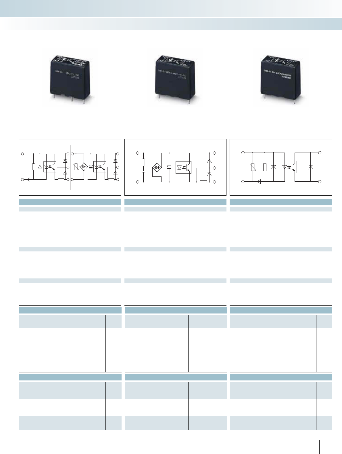
For additional information, visit www.phoenixcontact.net/catalog
|||
Technical data Technical data Technical data
¤ ¥ ¦ § ¨ © ª « ª « ¦
0.9 -
1.1
0.9 -
1.1
0.9 -
1.1
0.9 -
1.1
0.9 -
1.1
0.9 -
1.1
0.9 -
1.1
0.9 -
1.1
0.9 -
1.1
0.9 -
1.1
0.8 -
1.2
0.8 0.8 0.8 0.8 0.8 0.8 0.8 0.8 0.8 0.8 0.8
0.35 0.4 0.4 0.25 0.4 0.4 0.4 0.4 0.4 0.4 0.4
5.4 5.7 5.1 4.7 2.4 2.6 2.1 2.1 2.2 2.5 7
4000 4000 4000 4000 1000 1000 3 3 3 3 300
Protection against polarity reversal, surge protection RC element
Protection against polarity reversal Protection against polarity reversal, surge protection
3 V DC ... 5.25 V DC 8 V DC ... 48 V DC 3 V DC ... 33 V DC
100 mA 100 mA 3 A (see derating curve)
0.3 V 1 V 200 mV
- - 15 A (10 ms)
3-wire, ground-referenced 2-wire, floating 2-wire, floating
Protection against polarity reversal, free running Protection against polarity reversal Protection against polarity reversal, surge protection
2.5 kV (50 Hz, 1 min.) 2.5 kV (50 Hz, 1 min.) 2.5 kV (50 Hz, 1 min.)
-20°C ... 50°C -20°C ... 50°C -20°C ... 60°C
DIN VDE 0110 DIN VDE 0110 DIN VDE 0110
Any / can be aligned with 2 mm spacing Any / can be aligned with 2 mm spacing Any / can be aligned with 2 mm spacing
13 mm / 29 mm / 25 mm 13 mm / 29 mm / 25 mm 13 mm / 29 mm / 25 mm
Ordering data Ordering data Ordering data
Type Order No. Pcs. /
Pkt. Type Order No. Pcs. /
Pkt. Type Order No. Pcs. /
Pkt.
SIM-EI- 5DC/TTL/100 2271138 10
SIM-EI- 12DC/TTL/100 2271141 10
SIM-EI- 24DC/TTL/100 2271154 10 SIM-EI-OV- 24DC/ 24DC/3 2300096 10
SIM-EI- 60DC/TTL/100 2271167 10
SIM-EI-110DC/TTL/100 2271170 10
SIM-EI-220DC/TTL/100 2271183 10
SIM-EI-120AC/TTL/100 2271196 10 SIM-EI-120AC/48DC/100/RC 2271439 10
SIM-EI-230AC/TTL/100 2271206 10 SIM-EI-230AC/48DC/100/RC 2271426 10
Accessories Accessories Accessories
SIM-ERSN 2271484 100 SIM-ERSN 2271484 100 SIM-ERSN 2271484 100
SIM-ERSN-HB-KSR 2271468 10 SIM-ERSN-HB-KSR 2271468 10 SIM-ERSN-HB-KSR 2271468 10
SIM-ERSN-HB-KSR/MET 2271497 10 SIM-ERSN-HB-KSR/MET 2271497 10 SIM-ERSN-HB-KSR/MET 2271497 10
SIM-ERSN-HB-MR 2271471 10 SIM-ERSN-HB-MR 2271471 10 SIM-ERSN-HB-MR 2271471 10
SIM-ERSN-HB-MR/MET 2271510 10 SIM-ERSN-HB-MR/MET 2271510 10 SIM-ERSN-HB-MR/MET 2271510 10
331PHOENIX CONTACT
INTERFACE Cabling
VARIOFACE wiring interface
A1 +
A2 0
A
AC
A1 +
A2 0
A
-
+
DC
A1 +
A2 0
A
A1 +
A2 A
-
+
With TTL logic level output,
max. = 100 mA
With DC voltage output,
max. = 100 mA, RC element in input
With DC voltage output,
max. = 3 A
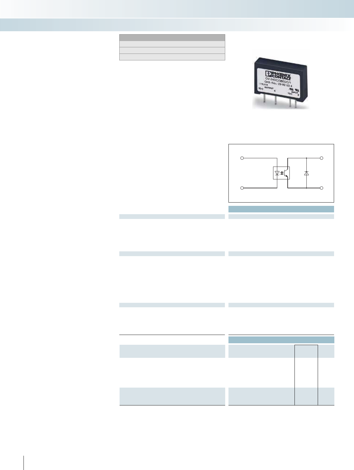
Technical data
Input data ¤
Input voltage range 4.25 V DC ... 32 V DC
Switching level 1 signal ("H") [V DC] 3.3
0 signal ("L") [V DC] 1
Typ. input current at UN[mA] 15
Typ. switch-on time at UN[μs] 100
Typ. switch-off time at UN[μs] 250
Transmission frequency flimit [Hz] 100
Output data
Operating voltage range 1 V DC ... 350 V DC
Periodic peak reverse voltage -
Limiting continuous current 1 A (see derating curve)
Min. load current 1 mA
Surge current 20 A (tp = 1 s)
Residual voltage drop at "H" 0.5 V
Leakage current in off state 100 μA
Phase angle (cos ) -
Max. load value -
Output protection Protection against polarity reversal
General data
Test voltage input/output 4 kV (50 Hz, 1 min.)
Ambient temperature (operation) -20°C ... 80°C
Standards / regulations EN 61000-4-2, EN 61000-4-3, EN 61000-4-4, EN 55011
Mounting position / mounting Any / can be aligned with > 9 mm spacing
Dimensions W / H / D 10.5 mm / 43 mm / 25.4 mm
Ordering data
Description Input voltage
UN
Type Order No. Pcs. /
Pkt.
Solid-state relay for signal amplification and electrical isolation of
the control and load circuits, pluggable in the solder-in plug-in base
SIM-AMS or with PCB connection for direct mounting onto the PCB
Input: DC voltage
Output: DC voltage
¤24 V DC OV-24DC/350DC/1 2982634 10
Solid-state relay, same as before, however
Input: DC voltage
Output: AC voltage
¤24 V DC
332 PHOENIX CONTACT
1 3
2 4
-
+ +
Solid-state relay OV
Solid-state relays for electrical isolation
can be mounted directly on the printed cir-
cuit board as interfaces or plugged in using
the solder-in socket SIM-AMS.
The solid-state relays are suitable for
switching ohmic, capacitive or inductive
loads. Relays for switching AC circuits have
a zero voltage switch to switch the load on
in the zero voltage crossing. It is switched
off in the zero current crossing. The inte-
grated RC element permits operation up to
cos φ = 0.5.
Inductive DC loads must be equipped
with a fast-acting free-wheeling diode for
semiconductor relay protection.
– Switching capacity up to 350 V DC/1 A,
60 V DC/4 A or 480 V AC/5 A
– No wear and tear, even with high switch-
ing frequencies
– No contact bounce – no movable parts
– No electromagnetic interference
– Electrically insulated housings
– Small dimensions
– High test voltage of 4 kV between control
and load circuits
INTERFACE Cabling
VARIOFACE wiring interface
Notes:
For derating curves see page 338.
For suitable bases, see page 334.
1) Turn-on/off time at UN: Max. ½ period
With DC voltage output,
max. = 1 A
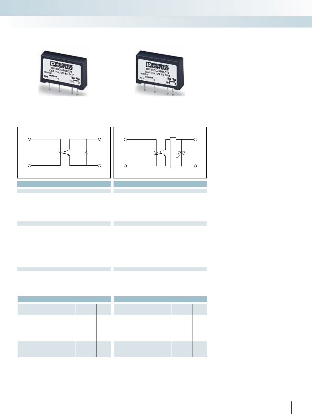
For additional information, visit www.phoenixcontact.net/catalog
Technical data Technical data
¤ ¤
4.25 V DC ... 32 V DC 4 V DC ... 32 V DC
3.3 3.5
11.2
15 10
100 1)
250 1)
100 25
1 V DC ... 60 V DC 12 V AC ... 530 V AC (45/65 Hz)
- 1000 V
4 A (see derating curve) 5 A (see derating curve)
1 mA 20 mA
25 A (tp = 1 s) 80 A (tp = 20 ms)
0.5 V 1.2 V
100 μA < 1 mA
-0.5
-50 A
2s
Protection against polarity reversal -
4 kV (50 Hz, 1 min.) 4 kV (50 Hz, 1 min.)
-20°C ... 80°C -20°C ... 70°C
EN 61000-4-2, EN 61000-4-3, EN 61000-4-4, EN 55011 EN 61000-4-2, EN 61000-4-3, EN 61000-4-4, EN 61000-4-5,
EN 61000-4-6
Any / can be aligned with > 20 mm spacing Any / can be aligned with > 20 mm spacing
10.5 mm / 43 mm / 25.4 mm 10.5 mm / 43 mm / 25.4 mm
Ordering data Ordering data
Type Order No. Pcs. /
Pkt. Type Order No. Pcs. /
Pkt.
OV-24DC/ 60DC/4 2982647 10
OV-24DC/480AC/5 2982650 10
333PHOENIX CONTACT
1 3
2 4
-
+ +
13
24
--
+ -
A
INTERFACE Cabling
VARIOFACE wiring interface
With DC voltage output,
max. = 4 A
With alternating voltage output,
max. = 5 A
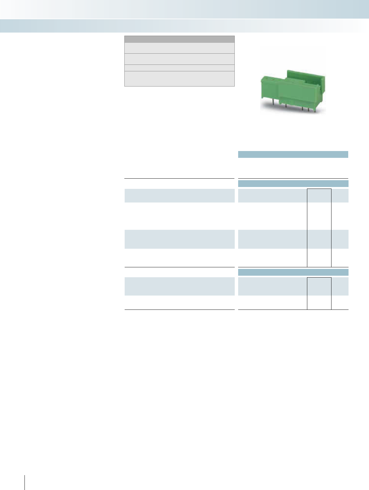
n p |
Technical data
Operating voltage 250 V AC / 380 V AC1)
Nominal current 5 A
Standards / regulations DIN VDE 0110b, Gr. C for 250 V DC
Ordering data
Description No. of
poles
Module width
WType Order No. Pcs. /
Pkt.
Plug-in base, for solid-state relay and I/O modules, with different
numbers of contacts, can be labeled with marker pins BN or BNB
Partial assembly SIM-AMS 1 2271015 10
Complete assembly SIM-AMS 2 2271028 10
Plug-in base, as above, however, with locking clips for fastening
Partial assembly
Complete assembly
Plug-in base, for standard I/O modules of generation 4 of the com-
pany Opto 22, can be labeled using marker pins BN or BNB
Accessories
Marker pin, made of white plastic, lettering area 7.5 x 4 mm,
unprinted for self-marking with B-STIFT
BN-TRK 2701404 100
Marker pen, not refillable,
for manual labeling, line thickness 0.5 mm
B-STIFT 1051993 10
334 PHOENIX CONTACT
Solder-in socket for solid-state relays
and I/O modules
Modern interface solutions for computer
and electronic controls are increasingly be-
ing designed as I/O systems which are sys-
tem independent and individually mount-
able. Electrical isolation and signal
conditioning are carried out using standard
I/O modules. These are produced by vari-
ous manufacturers in pin-compatible ver-
sions for different functions. The I/O mod-
ules are either soldered directly into the
PCB or plugged into component sockets for
quick interchanging.
SIM sockets facilitate the plugging of I/O
modules considerably. All standard I/O
modules and solid-state relays with up to
eight connections can be plugged into the
solder-in plug-in socket.
The I/O modules are securely fixed to the
socket using fastening screws which are spe-
cific to the module. They are thereby pro-
tected against being accidentally released.
Optocouplers, now also available in plugga-
ble versions, are secured using the latch
which is attached to the socket and which
can be labeled. For better identification,
each module plug position has its own
marking panel on the socket.
The SIM socket has been designed so that
it can be used on existing printed circuit
boards without any layout modifications.
Peripheral components such as LEDs or
fuse resistors remain accessible to the user.
INTERFACE Cabling
VARIOFACE wiring interface
Notes:
Type of housing:
Polyamide PA non-reinforced, color: Green.
For marking systems and mounting material, see
CLIPLINE catalog, part 2.
For dimensional drawings and pin assignments, see page 338.
1) Applies only to the sockets SIM-AMS 1, SIM-AMS 1-R, and SIM-
AMSC in connection with the standard I/O modules with the corre-
sponding AC voltage output.
Plug-in base for solid-state relays
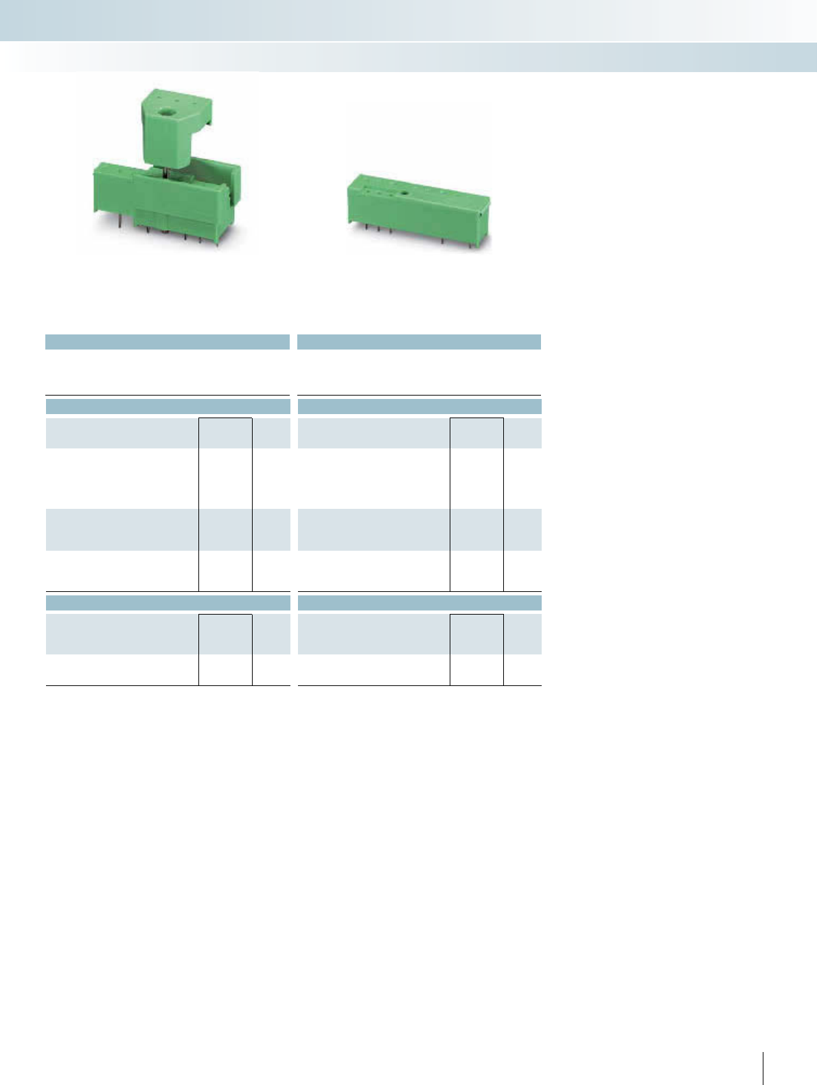
For additional information, visit www.phoenixcontact.net/catalog
n p |n |
Technical data Technical data
250 V AC / 380 V AC1) 250 V AC / 380 V AC1)
5 A 5 A
DIN VDE 0110b, Gr. C for 250 V DC DIN VDE 0110b, Gr. C for 250 V DC
Ordering data Ordering data
Type Order No. Pcs. /
Pkt. Type Order No. Pcs. /
Pkt.
SIM-AMS 1-R 2271031 10
SIM-AMS 2-R 2271044 10
SIM-AMSC1 2271390 50
Accessories Accessories
BN-TRK 2701404 100 BN-TRK 2701404 100
B-STIFT 1051993 10 B-STIFT 1051993 10
335PHOENIX CONTACT
INTERFACE Cabling
VARIOFACE wiring interface
Plug-in base for solid-state relays with
locking clip
Plug-in base for I/O modules
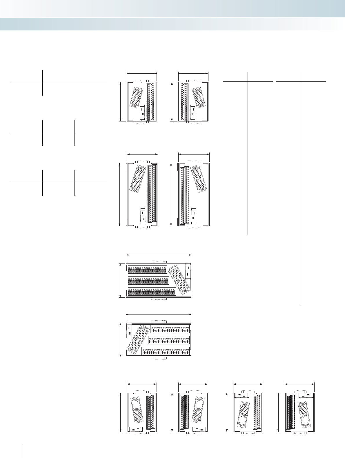
77
101,3
77
101,3
77
101,3
77
101,3
146,3
77
146,3
77
77
157
,
5
A
NN
1
3
5
7
9
11
13
15
17
19
21
23
25
27
29
31
3335
37
39
41
4345
47
49
51
53
Y
Z
2
4
6
810
12
14
16
18
20
22
24
26
28
30
32
34
36
38
40
42
44
46
48
50
52 54
X11
X10 X5
X9 X7 X3
X6
X8 X4 X2
77
157
,
5
A
NN
1
3
5
7
9
11
13
15
17
19
21
23
25
27
29
31
3335
37
39
41
4345
47
49
51
53
Y
Z
2
4
6
8
10
12
14
16
1820
22
24
262830
32
34
3638
40
42
44
46
4850
52 54
X11
X10
X5 X9
X7
X3 X6 X8
X4X2
77
101,3
77
101,3
Modules for ELCO connectorsModules for IEC 60603/DIN 41612
connectors
Cable housings suitable for screw locking:
Manufacturer Type
C, 64-pos.
Type
D, 32-pos.
ERNI
AMP
KSG 173...
826196-1
KSG 173...
826196-1
Cable housings suitable for screw locking:
Manufacturer Type
E, 48-pos.
Type
F, 32- and 48-pos.
ERNI
AMP
KSG 173...
–
KSG 203...
826198-1
Cable housings suitable for snap-lock mechanism:
Manufacturer
Type F, 32- and 48-pos.
HARTING Types "B" and "D"
Dimensional drawing for
UMK-EC38/38-XOL
Dimensional drawing for
UMK-EC38/38-XOR
Dimensional drawing for
UMK-EC56/32-XOL
Dimensional drawing for
UMK-EC56/32-XOR
Dimensional drawing for UMK-EC56/FRONT 2,5V/R
Dimensional drawing for UMK-EC56/FRONT 2,5V/L
Dimensional drawing for
UMK-EC56/32-XUL
Dimensional drawing for
UMK-EC56/32-XUR
Dimensional drawing for
UMK-EC56/56-XOL
Dimensional drawing for
UMK-EC56/56-XOR
336 PHOENIX CONTACT
Pin assignment
UMK-EC38/38...
Terminal Pin strip
1
2
3
4
5
6
7
8
9
10
11
12
13
14
15
16
17
18
19
20
21
22
23
24
25
26
27
28
29
30
31
32
33
34
35
36
37
CC
A
B
C
D
E
F
H
J
K
L
M
N
P
R
S
T
U
V
W
X
Y
Z
AA
BB
DD
EE
FF
HH
JJ
KK
LL
MM
NN
PP
RR
SS
TT
CC
Pin assignment
UMK-EC56/56...
Terminal Pin strip
Z
1
2
3
4
5
6
7
8
9
10
11
12
13
14
15
16
17
18
19
20
21
22
23
24
25
26
27
28
29
30
31
32
33
34
35
36
37
38
39
40
41
42
43
44
45
46
47
48
49
50
51
52
53
54
Y
Z
A
B
C
D
E
F
H
J
K
L
M
N
P
R
S
T
U
V
W
X
a
b
c
d
e
f
h
j
k
l
m
n
p
r
s
t
u
v
w
x
y
z
AA
BB
CC
DD
EE
FF
HH
JJ
KK
LL
MM
NN
Y (shield)
INTERFACE Cabling
VARIOFACE wiring interface
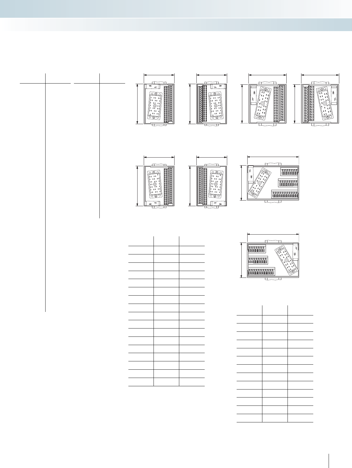
112,5
77
112,5
77
77
101,3
77
101,3
77
101,3
77
101,3
77
78,8
77
78,8
Modules for ELCO connectors with
Ex i protection type
Dimensional drawing for UMK-EC 56/25/EX/FRONT 2,5 V/L
Dimensional drawing for UMK-EC 56/25/EX/FRONT 2,5 V/R
Dimensional drawing for
UMK-EC90/32/EX-XUL
Dimensional drawing for
UMK-EC90/32/EX-XUR
Dimensional drawing for
UMK-EC90/32/EX-XOL
Dimensional drawing for
UMK-EC90/32/EX-XOR
Dimensional drawing for
UMK-EC56/25/EX-L
Dimensional drawing for
UMK-EC56/25/EX-R
337PHOENIX CONTACT
Pin assignment
UMK-EC56/FRONT 2,5V/...
Terminal ELCO
connector
X
1
2
3
4
5
6
7
8
9
10
11
12
13
14
15
16
17
18
19
20
21
22
23
24
25
26
27
28
29
30
31
32
33
34
35
36
37
38
39
40
41
42
43
44
45
46
47
48
49
50
51
52
53
54
Y
N.C.
A
B
C
D
E
F
H
J
K
L
M
N
P
R
S
T
U
V
W
X
a
b
c
d
e
f
h
j
k
l
m
n
p
r
s
t
u
v
w
x
y
z
AA
BB
CC
DD
EE
FF
HH
JJ
KK
LL
MM
NN
Y (shield)
Pin assignment
UMK-EC56/32-...
Terminal ELCO
connector
1
2
3
4
5
6
7
8
9
10
11
12
13
14
15
16
17
18
19
20
21
22
23
24
25
26
27
28
29
30
31
32
Y
A
B
C
D
E
F
H
J
K
L
M
N
P
R
S
T
U
V
W
X
Z
a
b
c
d
e
f
h
j
k
l
m
NN + Y
Pin assignment
UMK-EC90/32/EX...
Terminal Pin strip Channel
1
2
H
J1
3
4
L
M2
5
6
P
X3
7
8
Z
AA 4
9
10
AC
AD 5
11
12
AM
AN 6
13
14
AR
AS 7
15
16
AU
BC 8
17
18
AZ
BA 9
19
20
BJ
BK 10
21
22
BM
BN 11
23
24
BR
BY 12
25
26
CA
CB 13
27
28
CD
CE 14
29
30
CN
CP 15
31
32
CS
CT 16
YDB
Pin assignment
UMK-EC 56/25/EX/...
Terminal Pin strip Channel
1
2
C
D1
3
4
E
F2
5
6
N
P3
7
8
R
S4
9
10
a
b5
11
12
d
j6
13
14
k
l7
15
16
s
t8
17
18
u
v9
19
20
BB
CC 10
21
22
DD
EE 11
23
24
MM
NN 12
YY
INTERFACE Cabling
VARIOFACE wiring interface
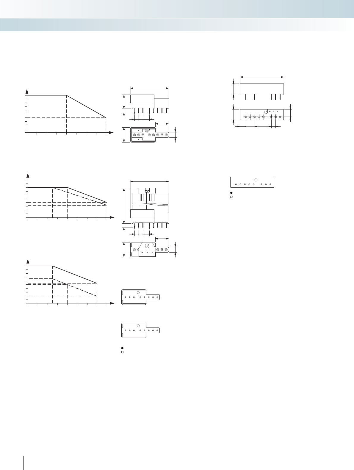
50
13,212,5
8,79
19,0210,16
6,46 5,08
45,7
16
7,624,7
5,08
18,5
6,9
max. 455
45,7
16
7,624,7
5,08
18,5 5
6,9
17,5
0
4
4,5
5
3,5
3
2,5
2
1,5
1
0,5
070605040302010
0
4
4,5
5
3,5
3
2,5
2
1,5
1
0,5
080
8070605040302010
0
0,9
1
0,8
0,7
0,6
0,5
0,4
0,3
0,2
0,1
08070605040302010
Contacts in the SIM-AMS plug-in base
1. Partial mounting for standard I/O modules
2. Complete mounting for analog I/O modules, for example
SIM-AMS 1
SIM-AMS 2
With metal
Without metal
Load current as a function of ambient temperature
Operating time: 100% OT
OV solid-state relays
Ambient temperature [°C]
OV-24DC/60DC/4
Load current [A]
Ambient temperature [°C]
OV-24DC/480AC/5
Load current [A]
20 mm spacing
9 mm spacing
20 mm spacing
9 mm spacing
Dimensional drawing for SIM-AMS:
With metal
Without metal
Note:
4th generation optocoupler, available from Opto 22.
Contacts in the SIM-AMSC plug-in base:
Dimensional drawing for SIM-AMSC:
Solder-in SIM-AMS plug-in bases for
solid-state relays and I/O modules
Dimensional drawing for SIM-AMS...R:
338 PHOENIX CONTACT
Ambient temperature [°C]
OV-24DC/350DC/1
Load current [A]
INTERFACE Cabling
VARIOFACE wiring interface
