9632.pmd Installation Directions
2014-09-04
: Pdf 102257-Installationsheet 102257-InstallationSheet 686334 Batch7 unilog
Open the PDF directly: View PDF ![]() .
.
Page Count: 51

Four position weld nuts supplied in case top and back
for field mounting by threaded rods or eye bolt with chain.
(Hardware supplied by others).
Optional radial or anemostat diffusers lending air pattern
versatility when mounted vertically.
Modular control kits for field installation. Disconnect
switch, thermostat, summer fan switch, heat recovery
thermostat. All kits with spade terminals (Except
disconnect switch).
Single point terminal board wiring of integral control kits.
24 volt low voltage control circuit standard on all
contactor and transformer models.
Roomy control box with access door locked into position
by two (2) 1/4 turn fasteners for ease of installation.
Revised 10/09
ECO 1-6174
Form 9632
ATTENTION: Read carefully before attempting to install,
operate or service the TaskMaster Unit Heater. Retain
these installation instructions for future use.
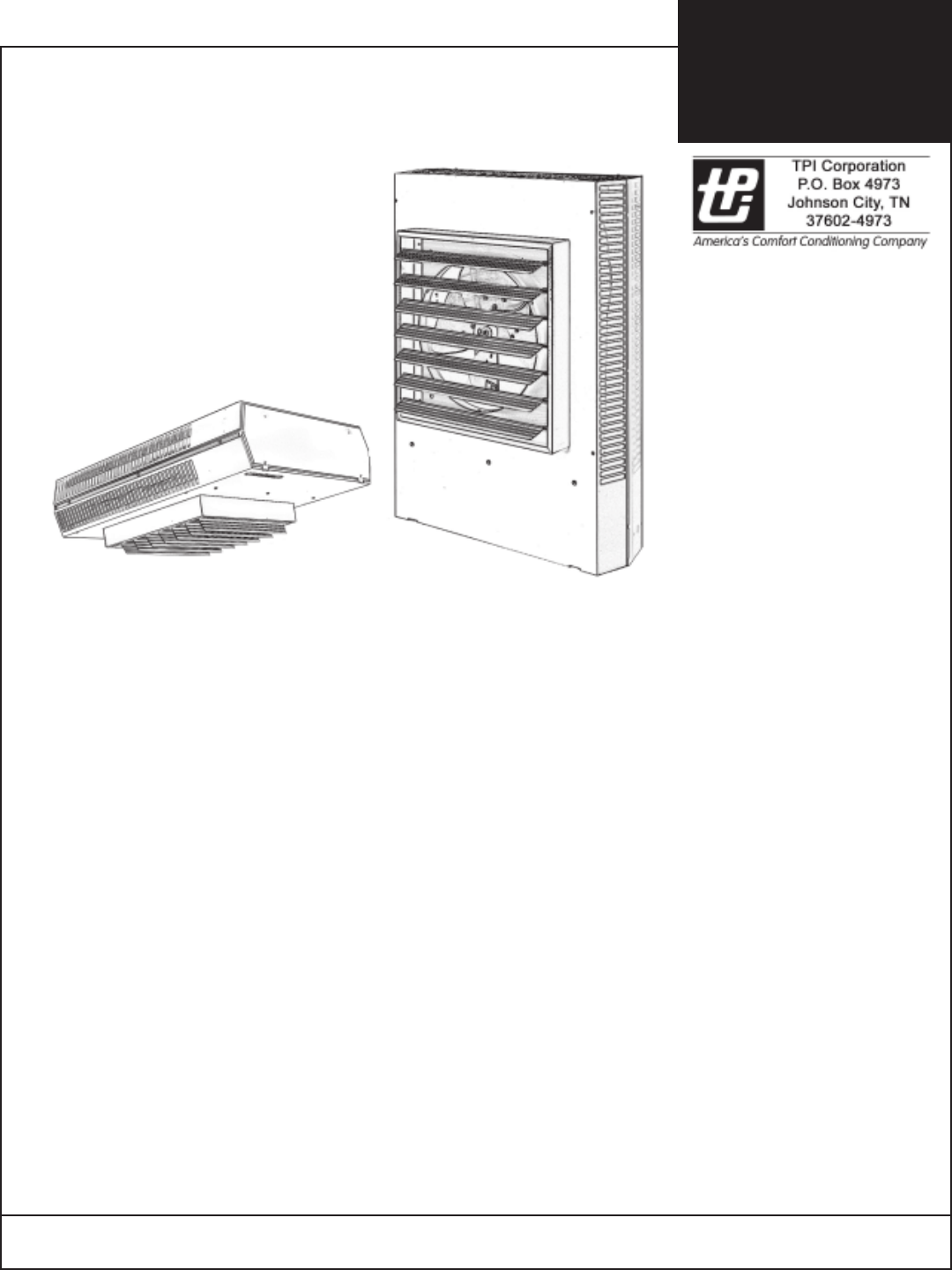
TASKMASTER
5100 SERIES
Horizontal or Vertical Mounting
Industrial / Commercial
Unit Heater
PRODUCT FEATURES
Forced air electric unit heater available in 208, 240/208,
227, 480, 550 or 600 volt as standard.
Ten standard heating capacities of 3.3 KW/11,260 BTUH
thru 50.0 KW/170, 600 BTUH.
208 and 240/208 volt models are single phase field
convertible to three phase on 3.3 thru 10.0 KW Models.
(Single phase only available on 3.3, 5.0, 7.5 and 10 KW
277 volt models.
Specially designed inlet louver allows the fan to pull cool
air evenly across the high mass all-steel element.
Outward drawn venturi and adjustable louver assembly
further directs the outlet air in a uniform pattern to meet
specific air pattern requirements in either the horizontal
or vertical mounting position.
Optional wall/ceiling or vertical mounting brackets (as
required).
INSTALLATION
INSTRUCTIONS
& PARTS LIST
IMPORTANT: OWNER SHOULD RETAIN THESE INSTRUCTIONS FOR FUTURE REFERENCE
PROPER LOCATION INSTRUCTIONS
Once the total heating load is calculated, the quantity and
capacity of the unit heaters must be determined. because a
large number of low-capacity heaters provides more uniform
heat distribution. This approach is recommended when the
area will be occupied by a relatively large number of seden-
tary personnel, (i.e. working on production lines and at
benches.)
A large number of smaller capacity unit heaters tends to
prevent hot drafts, reduces noise levels, and increases
diversity of load to help reduce electrical demand and
operating costs.
In warehouses where even heat distribution and constant
temperatures are less important, a smaller number of high
capacity units can be used -- in many cases reducing
installation cost. To maintain reasonable heat distribution
and reduce severe stratification even in lower bay areas, the
total air volume of the space should pass through the unit
heaters about three times per hour. (Take total cubic feet
and divide by 20 in order to determine proper total heater
CFM rating.)
It is important that the rated voltage of the heating equip-
ment match the supply voltage. Supply voltage in excess of
the heater rated voltage can damage equipment. Supply
voltage lower than the rated heater voltage will decrease
heater output as well as run the risk of damaging some
components.
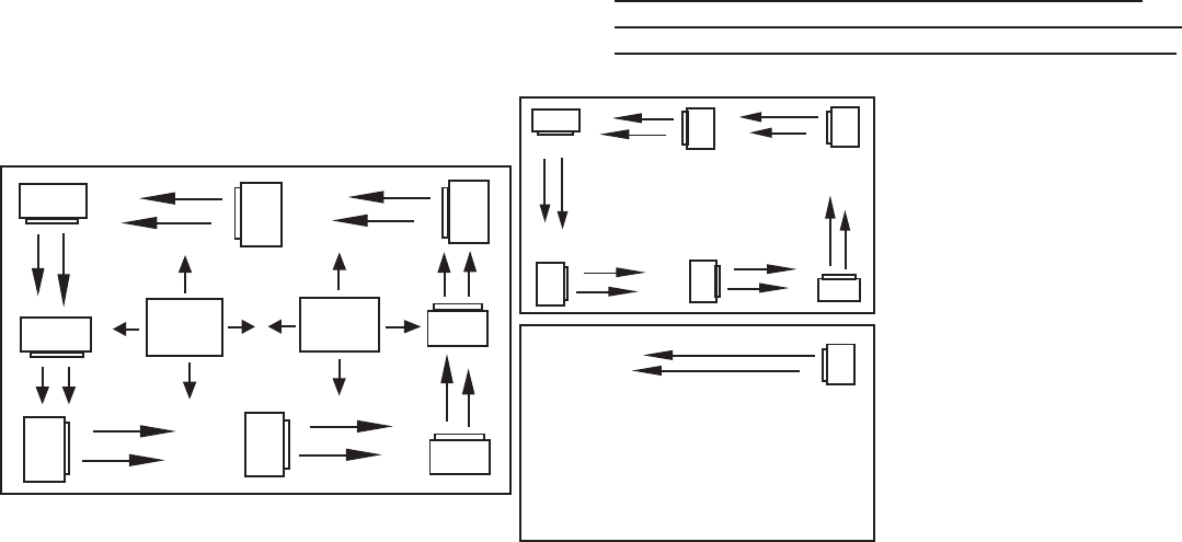
Horizontal unit heaters are recommended in low bay areas
with maximum 15 to 18 foot ceilings. These should be
concentrated along outside wall or other areas of greatest
heat loss; spaced to set up a generally circular air move-
ment, each heater supporting the air stream of the other.
Additional vertical down below unit heaters with appropriate
accessory diffusers can be located to counteract ceiling
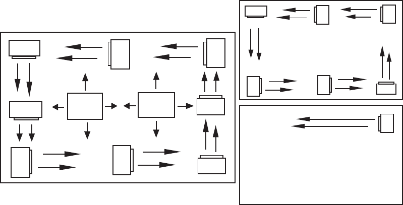
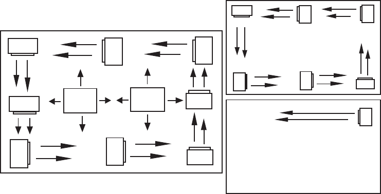
heat losses (see Figure 1 Location charts).
Figure 1 Location Instructions
GENERAL SAFETY INFORMATION / CAUTION:
Follow all local electrical and safety codes, as well as the
National Electrical Code (NEC) and the Occupational
Safety and Health Act (OSHA).
To avoid possible electrical shock, be sure the electrical
current is turned off at the main switch prior to wiring or
servicing of unit.
If the power disconnect is not integral and is out-of-sight,
lock it in the open position and tag to prevent unexpected
application of power prior to performing any service or
maintenance of the unit.
The unit when installed must be electrically grounded in
accordance with the National Electrical Code and stan-
dard industry practice.
Make certain that the power source conforms to the
requirements of your equipment. See Table 2 on page 6
for wire and circuit size
Check heater voltage and phase on rating label to confirm
that it matches the electric service supply.
Wiring diagrams of the heater and supply connections are
permanently attached to the inside of the heater access
door. All terminals are coded in accordance with the
wiring diagram. Accessory wiring are shown on the unit
wiring diagram and supporting literature.
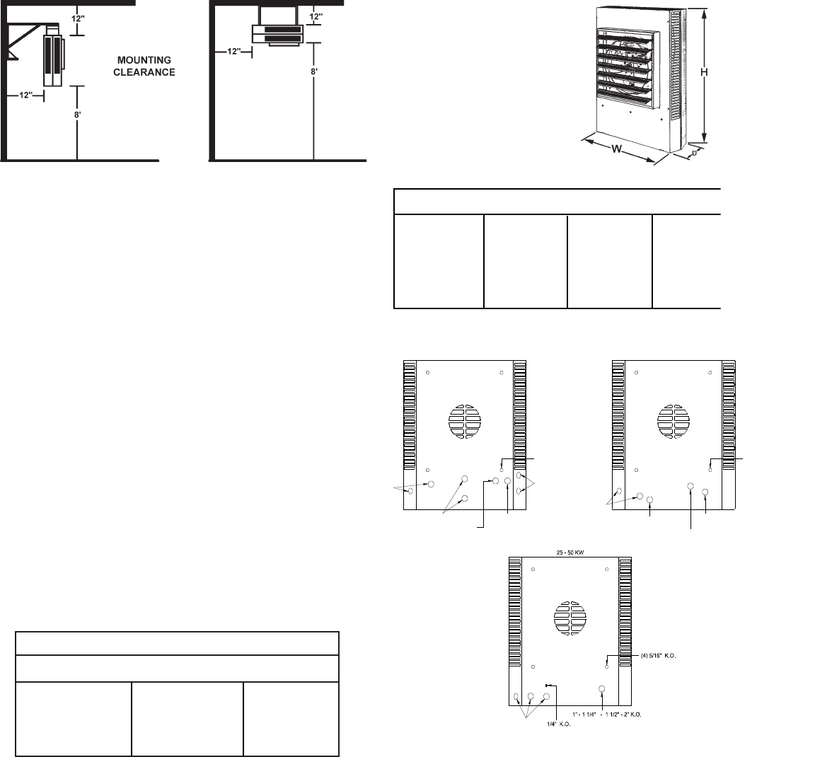
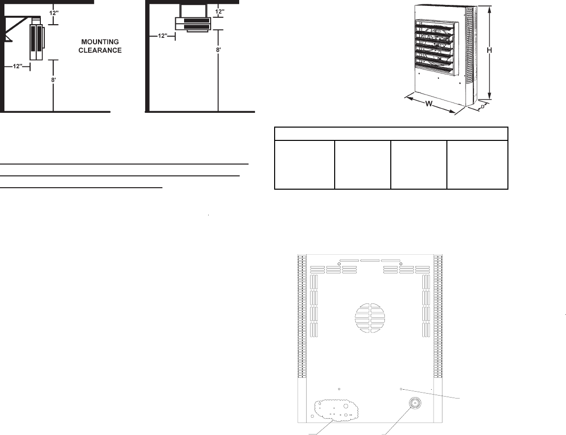
The heater must be mounted at least 7’ above the floor to
prevent accidental contact with the fan blade which could
cause injury. Install unit so there are no obstructions to the
intake or discharge. Maintain clearances as shown on
Table 1, 2, Fig. 1 & 2.
The wall/ceiling mounting structure and anchoring provi-
sions must be on sufficient strength to support the com-
bined weight of the heater and mounting bracket.
2
H
H
H
HH
H
H
H
VV
H
H
HH
H
H
H
EXPOSED
PRINCIPLES OF OPERATION
Upon a call for heat from the floor level or unit mounted
optional accessory thermostat, the unit fan motor and
heating elements shall be energized and remain ON until
temperature reaches setting of thermostat; at which time
the heating elements shall be deenergized.
The fan motor shall continue to run and purge heater
casing of residual heat until setting of fan override is
reached, then the fan motor shall be deenergized.
For those units with a factory installed two speed fan
switch (25-50KW), the unit as shipped from the factory is
set to “low” speed. Customer option to set to “high” speed.
For those units available with subdivided circuits, the
accessory two stage thermostat (optional) will, upon a call
for heat, energize fan motor and the first stage heating
element. Should temperature continue to fall, the thermo-
stat shall energize the second stage heating element.
Upon a rise in space conditions towards setting of the
thermostat, the two stages of heating elements shall be
deenergized in reverse sequence.
The fan motor shall continue to run and purge heater
casing of residual heat until setting of fan override is
reached, then the fan motor shall be deenergized.
The accessory unit mounted stratification thermostat will
energize the unit heater fan motor upon a rise in
temperature above its setting.
When the unit mounted stratification thermostat closes on
a temperature rise and at the same time the floor thermo-
stat calls for heat, the motor shall be energized immedi-
ately and the heating element shall be energized, as
previously described.
The automatic reset safety high limit shall deenergize the
heating elements and control circuits should the tempera-
ture exceed the setting of this device. The fan safety
override shall energize fan motor any time the setting of
this device is exceeded so as to purge heater casing of
excess residual heat.
When the accessory fan switch is placed in the ON position
(for summer air circulation), the unit heater fan motor shall
be energized.
NOTE: The wall thermostat is to be set to the OFF position
during this mode of operation (units with contactors).
For those accessory thermostats equipped with an integral
fan switch, place the switch in the HEAT, or AUTO position
for operation of the fan and elements which shall then be
under control of the thermostat as described above.
When switch is placed in the OFF position, the unit shall be
deenergized. When switch is placed in the FAN position,
elements shall be deenergized and fan shall be immedi-
ately energized.
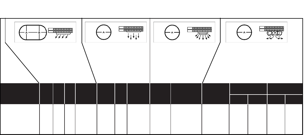
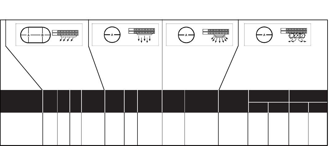
Optional diffusers lend added air pattern versatility to
individual vertical down blow installations as shown in
above illustations.
3
USED MAX A B STOCK MAX A MAX A STOCK STOCK MAX MTG HT. A
ON MTG NO. MTG MTG NO. NO.
HT. HT. HT. 45OOPEN 45OOPEN
3.3 & 5.0 KW 9 20 10 STD 9 15 -- -- N/A N/A -- -- -- --
7.5 & 10.0 KW 12 40 22 STD 12 30 10 30 AD5120 RD5120 0 14 36 30
15.0 & 20.0 KW 18 52 30 STD 18 40 15 38 AD5120 RD5120 14 21 42 35
25.0 & 30.0 KW 22 75 42 STD 22 55 17 50 AD5150 RD5150 20 30 62 44
40.0 & 50.0 KW 24 84 47 STD 24 64 20 60 AD5150 RD5150 18 28 68 54
STD = Standard N/A = Not Applicable
VERTICAL DISCHARGE UNITS - AIR PATTERNS
TABLE 1
Louver Diffuser (Standard) General Distribution
(No Diffuser) Anemostat Diffuser
(Optional) Radial Diffuser (Optional)
ATTENTION: READ INSTRUCTION CAREFULLY
All electric unit heaters are shipped fully assembled.
Installation includes hanging the unit, mounting the built-in
and remote accessories, wiring of optional control devices,
and electrical wiring to the unit.
To insure proper delivery of the heated air to desired areas,
follow the mounting height and air projection tables include
in these instructions. Follow Fig. 1 & 2 for minimum wall
and ceiling clearances.
The wall and/or ceiling structure must be sufficient to
support the combined weight of the heater and any mount-
ing bracket and accessories.
Be sure power source is deenergized before installing
heater. Check heater voltage and phase listed on heater
date tape on back of unit to make sure they are the same
as the electrical service supplied.
Certain units are convertable from single to three phase
service. Follow instructions noted on the unit wiring dia-
gram for this conversion. Units that carry a dual voltage
rating (HF) require specific wiring changes when converting
from 240 to 208 volt service supplied.
Open the access panel (2 1/4 turn fasteners).
Remove the desired knock-out(s) on back of the heater.
Install any optional accessories following their installation
instructions before mounting unit. Following the correct
unit/accessory wiring diagram, connect the power supply,
electrical ground and accessories to the correct terminals
or termination points using accepted practices.
NET JUNCTION BOX VOLUME
KW CUBIC INCHES CC
3.3 - 5 74.4 1219
7.5 - 10 198 3245
15.0 - 20 198 3245
25.0 - 50 341 5592
INSTALLATION INSTRUCTIONS
TASKMASTER -- 5100 SERIES UNIT HEATER
4
FIG. 1
HORIZONTAL DISCHARGE FIG. 2
VERTICAL DISCHARGE
Heaters may be mounted in the horizontal or vertical air
discharge configuration using factory optional supplied
accessory mounting equipment or using special hardware
facilities supplied by others.
After the installation is complete, replace the access panel.
Set the controls (thermostat, switch) at their desired
control point and apply power to the unit.
Check correct operation.
DIMENSIONS
DIMENSIONS (INCHES)
KW H W D
3.3 - 5.0 17-3/4 14-15/32 6-1/2
7.5 - 10.0 24-5/16 21-1/2 6-1/2
15.0 - 20.0 28-11/16 21-1/2 6-1/2
25.0 - 50.0 34 29-1/4 10-1/16
9/16" K.O.
1/2" K.O.
3/4" K.O.
3/4" - 1" K.O.
9/16" K.O.
(4) 5/16" K.O.
3.3 - 5.0 KW
9/16" K.O.
1/2" K.O.
9/16" K.O.
(4) 5/16" K.O.
7.5 - 20 KW
1/2" - 3/4" K.O.
9/16" K.O.
*For vertical discharge
mounting bracket
Diagrams not to scale
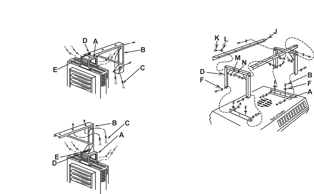
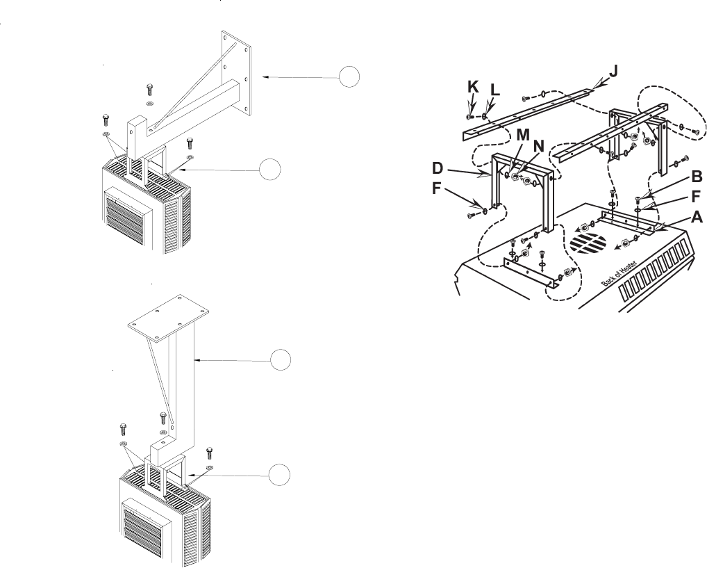
HORIZONTAL -- AIR DISCHARGE MOUNTING
SHOWN IN: FIGURE 5 & 6
Swivel hanger brackets may be used to suspend unit
heaters from either the wall (figure 5) or the ceiling
(figure 6). Attach hanger base “A” to top of heater with
the four 5/16 X 18 caps screws and lockwashers (pro-
vided in envelope).
Attach main hanger frame “B” to wall or ceiling in
desired location using lag screws “C” or other suitable
attachments (supplied by others).
Lift heater into position inserting stud “D” through hole
in main hanger frame and attach lock nut “provided in
envelope) “E” tightening to within two turns of being
tight.
Swivel heater to desired position, tighten lock nut.
5
VERTICAL -- AIR DISCHARGE MOUNTING
SHOWN IN: FIGURE 7
Attach short angle brackets “A” to back of heater with
four 5/16 X 18 capscrews “B”, lockwashers “F”. Be sure
vertical leg of angle brackets face top and bottom of
heater.
Attach inverted U frames “D” to short angle brackets
with four 5/16 X 18 capscrews “K”, washers “L”,
lockwashers “M” and nuts “N”.
Attach long angle brackets “J” to inverted frames “D”
with four 5/16 X 18 capscrews “K”, washers “L”,
lockwashers “M” and nuts “N”.
Attach heater and bracket assembly to ceiling in
desired location using customer supplied equipment
sufficient to support the assembly.
INSTALLATION INSTRUCTIONS
TASKMASTER -- 5100 SERIES UNIT HEATER (part 2)
Figure 5
WALL MOUNT
HORIZONTAL DISCHARGE
Figure 6
CEILING MOUNT
HORIZONTAL DISCHARGE
Figure 7
CEILING MOUNT
VERTICAL DISCHARGE
NOTE: When mounting heater using 5/16” all thread
rod (by others) do not screw the rod more than 1/2”
beyond the inside of the case.

5100 SERIES UNIT HEATER
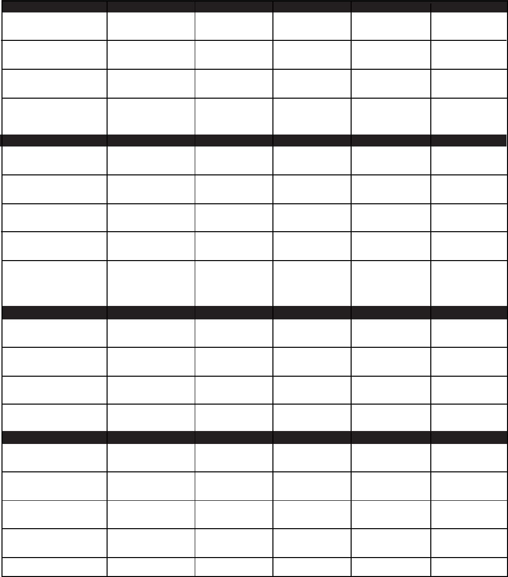
ELECTRICAL DATA (Table 2)
CATALOG KW BTU/HR HEATER / HEATER CONTROL AMPS BRANCH CIRCUIT SUPPLY WIRE
NUMBER RATING (000) MOTOR PHASE VOLTAGE PER PROTECTION SIZE 60o C
VOLTAGE PHASE SIZE(A) AWG **
F1F5130 3.3 11.2 208 1 208 15.9 20 12
F2F5130 3.3 11.2 208 1 208 15.9 20 12
208 3 208 9.2 15 14
HF1B5103 3.3/2.5 11.2/8.5 240/208 1 240/208 13.7/11.9 20/15 12/14
HF2B5103 3.3/2.5 11.2/8.5 240/208 1 240/208 13.7/11.9 20/15 12/14
240/208 3 240/208 7.9/6.9 10/10 14/14
G1G5103 3.3 11.2 277 1 277 11.9 15 14
P3P5103CA1 3.3 11.2 480 3 24 4 15 14
F1F5105 5.0 17.1 208 3 208 24.1 35 8
F2F5105 5.0 17.1 208 1 208 24.1 35 8
F2F5105 5.0 17.1 208 1 208 24.1 35 8
208 1 208 24. 35 8
HF1B5105 5.0/3.7 17.1/12.8 240/208 1 240/208 20.9/18.1 30/25 10/10
HF2B5105 5.0/3.7 17.1/12.8 240/208 1 240/208 20.9/18.1 30.25 10/10
240/208 3 240/208 12.1/10.4 20/15 12/14
G1G5105 5.0 17.1 277 1 277 18.1 25 10
P3P5105CA1 5.0 17.1 480 3 24 6.1 15 14
F2F5107CA1 7.5 25.6 208 1 24 36.1 50 6
208 3 24 20.8 30 10
HF2B5107CA1 7.5/5.6 25.6/19.2 240/208 1 24 31.3/27.1 40/35 8/8
240/208 3 24 18.1/15.6 25/20 10/12
G1G5107CA1 7.5 25.6 277 1 24 27.1 35 8
P3P5107CA1 7.5 25.6 480 3 24 9.1 15 14
208 3 24 27.8 35 8
HF2B5110CA1 10.0/7.5 34.1/25.6 240/208 1 24 41.6/36.1 60/50 4/6
240/208 3 24 24/20.8 30/30 8/10
G1G511OCA1 10.0 34.1 277 1 24 36.1 50 6
P3P5110CA1 10.0 34.1 480 3 24 12.1 20 12
F3F5115CA1 15.0 51.2 208 3 24 41.7 60 4
HF3B5115CA1 15.0/11.2 51.2/38.4 240/208 3 24 36.1/31/3 50/40 6/8
P3P5115CA1 15.0 51.2 480 3 24 18.1 25 10
HF3B5120CA1 19.5/14.6 67.2/50.5 240/208 3 24 47.8/41.1 60/60 4/6
P3P5120CA1 20.0 68.3 480 3 24 24.1 35 8
F3F5125CA1 25.0 83.3 208 3 24 69.5 90 2
HF3B512CA1 25.0/18.7 85.3/64.0 240/208 3 24 60.2/52.1 80/70 3/4
P3P5125 25.0 85.3 480 3 24 30.1 40 8
F3F5130CA1 30.0 102.4 208 3 24 83.4 110 2*
HB3B5130CA1 30.0/22.5 102.4/76.8 240/208 3 24 72.3/62.5 100/80 2/3
P3P5130CA1 30.0 102.4 480 3 24 36.2 50 6
F3F5140CA1 40.0 136.5 208 3 24 111.2 150 1/0*
HF3B5140CA1 40.0/30.0 136.5/102.4 240/208 3 24 96.4/83.4 124/110 1*/2*
P3P5140CA1 39.0 133.1 480 3 24 47 60 4
F3F5150CA1 49.6 169.9 208 3 24 139 175 2/0*
HF3BB5150CA1 50.0/37.5 170.6/128.0 240/208 3 24 120.5/104.3 175/150 2/0* 1/0*
P3P5150CA1 50.0 170.6 480 3 24 60.3 80 3
U3H5105CA4*** 5.0 17.1 600/240 3 240 5.1 15 14
U3H5107CA4 7.5 25.6 600/240 3 240 7.7 15 14
U3H5110CA4 10.0 34.1 600/240 3 240 10.2 15 14
U3H5115 15.0 51.2 600/240 3 240 15.5 20 12
U3H5120CA4 20.0 68.3 600/240 3 240 20.3 25 10
U3H5125CA4 25.0 85.3 600/240 3 240 24.5 35 8
U3H5130CA4 30.0 102.4 600/240 3 240 29.4 40 8
U3H5140CA4 40.0 136.5 600/240 3 240 39.8 50 6
U3H5150CA4 50.0 170.0 600/240 3 240 49.4 60 4
T3H5105CA4N 5.0 17.1 550/240 3 240 5.25 15 14
T3H5107CA4N 7.5 25.6 550/240 3 240 7.88 15 14
T3H5110CA4N 10.0 33.8 550/240 3 240 10.5 15 14
T3H5115CA4N 15.0 51.2 550/240 3 240 15.76 20 12
TEH5120CA4N 20.0 68.3 550/240 3 240 21.1 30 10
T3T5125CA1N 25.0 85.3 550 3 24 26.3 35 8
T3T5130CA1N 30.0 102.4 550 3 24 31.5 40 8
T3T5140CA1N 40.0 136.5 550 3 24 42 60 4
T3T5150CA1N 50.0 170.6 550 3 24 52.55 70 4
* Use 75 degree C Wire **Use Copper Conductors on all heaters ***This unit (only) built in 7.5 & 110KW case size.
6

7
5100 SERIES UNIT HEATER
AIR DELIVERY DATA FAN MOTOR DATA
CFM at FPM at TEMPETURE HP Motor MAX. MTG AIR WEIGHT
OUTLET OUTLET RISE RPM THROW LBS.
oF Horizontal Vertical
400 1030 26 1/125 1550 9 9 12 Ft. 25
400 1030 26 1/125 1550 9 9 12 Ft. 25
400 1030 26 1/125 1550 9 9 12 Ft. 25
400 1030 26 1/125 1550 9 9 12 Ft. 25
400 1030 26 1/125 1550 9 9 12 Ft. 25
400 1030 26 1/125 1550 9 9 12 Ft. 27
400 1030 40 1/125 1550 9 9 12 Ft. 25
400 1030 40 1/125 1550 9 9 12 Ft. 25
400 1030 40 1/125 1550 9 9 12 Ft. 25
400 1030 40 1/125 1550 9 9 12 Ft. 25
400 1030 40 1/125 1550 9 9 12 Ft. 25
400 1030 40 1/125 1550 9 9 12 Ft. 27
700 1000 34 1/50 1550 10 12 22 Ft. 50
700 1000 34 1/50 1550 10 12 22 Ft. 50
700 1000 34 1/50 1550 10 12 22 Ft. 50
700 1000 34 1/50 1550 10 12 22 Ft. 50
700 1000 45 1/50 1550 10 14 22 Ft. 50
700 1000 45 1/50 1550 10 14 22 Ft. 50
700 1000 45 1/50 1550 10 14 22 Ft. 50
700 1000 45 1/50 1550 10 14 22 Ft. 50
700 1000 45 1/50 1550 10 14 22 Ft. 50
1100 1580 43 1/20 1550 11 20 32 Ft. 65
1100 1580 43 1/20 1550 11 20 32 Ft. 65
1100 1580 43 1/20 1550 11 20 32 Ft. 65
1100 1580 57 1/20 1550 11 20 32 Ft. 65
1100 1580 57 1/20 1550 11 20 32 Ft. 65
2000/1800 1300/1100 40/44 1/12 1550/1250 12 22 45 Ft. 120
2000/1800 1300/1100 40/44 1/12 1550/1250 12 22 45 Ft. 120
2000/1800 1300/1100 40/44 1/15 1550/1250 12 22 45 Ft. 120
2000/1800 1300/1100 47/53 1/12 1550/1250 12 20 40 Ft. 120
2000/1800 1300/1100 47/53 1/12 1550/1250 12 20 40 Ft. 120
2000/1800 1300/1100 47/53 1/15 1550/1250 12 20 40 Ft. 120
3100/2800 2000/1800 40/45 1/4 1550/1310 15 25 55 Ft. 120
3100/2800 2000/1800 40/45 1/4 1550/1310 15 25 55 Ft. 120
3100/2800 2000/1800 40/45 1/4 1550/1310 15 25 55 Ft. 120
3100/2800 2000/1800 51/56 1/4 1550/1310 15 22 50 Ft. 120
3100/2800 2000/1800 51/56 1/4 1550/1310 15 22 50 Ft. 120
3100/2800 2000/1800 51/56 1/4 1550/1310 15 22 50 Ft. 120
558 929 30 1/125 1300 9 9 12 Ft. 50
700 1000 34 1/50 1550 10 12 22 Ft. 50
700 1000 45 1/50 1550 10 14 22 Ft. 50
1100 1580 43 1/20 1550 11 20 32 Ft. 65
1100 1580 43 1/20 1550 11 20 32 Ft. 65
2000/1800 1300/1100 40/44 1/12 1550/1250 12 22 45 Ft. 120
2000/1800 1300/1100 47/53 1/12 1550/1250 12 22 40 Ft. 120
3100/2800 2000/1800 40/45 1/4 1550/1310 15 25 55 Ft. 120
3100/2800 2000/1800 51/56 1/4 1550/1310 15 22 50 Ft. 120
680 971 25.1 1/125 1300 9 9 12 Ft. 50
680 971 37.6 1/50 1550 10 12 22 Ft. 50
680 971 50.2 1/50 1550 10 14 22 Ft. 50
1080 1542 47.4 ` 1/20 1550 11 20 32 Ft. 65
1080 1542 63.2 1/20 1550 12 18 37 Ft. 65
1980/1780 1290/1150 43/48 1/12 1550/125 12 22 45 Ft. 120
1980/1780 1290/1150 52/58 1/12 1550/125 12 20 40 Ft. 120
2900/2650 1870/1160 47/52 1/4 1550/131 15 25 55 Ft. 120
2900/2650 1870/1160 59/66 1/4 1550/131 15 22 50 120

8
5100 SERIES UNIT HEATER
TROUBLE SHOOTING GUIDE
SYMPTOM POSSIBLE CAUSE(S) CORRECTIVE ACTION
Thermostat calls for 1. Open (blown) fuse 1. Replace fuses, check for cause.
heat, but heater does (see Replacement Parts List for fuse size)
not function. 2. INCORRECT WIRING 2. CHECK WIRING CONNECTIONS
3. Thermal cut-out open,
deenergizing heater 3. Check for the following:
element and control --- Correct supply volts and phase
circuit. --- Correct control wiring (heater control
must be thru thermostat control wiring
section only).
--- Power interruption to heater during
heater operation.
--- Restriction of air around heater 1-5
minute fan purge after thermostat off.
Fan motor runs 1. Dust accumulation or 1. Clean fan motor and casing of grease
“HOT” excessive dirt on motor and oil accumulation.
2. Dirt accumulation 2. Clean louvers and between heating
elements.
3. Motor needs lubrication. 3. See Maintenance.
Fan motor runs, 1. Element contactor not 1. Check wiring for open circuit. Replace
but no heat. operating correctly. contactor if defective
2. Element fuse blown. 2. Replace fuses, check for cause. (see
Replacement Parts List for fuse size)
MAINTENANCE
CAUTION: Make certain that the power source is disconnected before attempting to service or disassemble any
componet. If the power disconnect is out of the line of sight, lock it in the OPEN position and tag to prevent the
application of power.
ELECTRICAL
Once a year inspect the control panel wiring to make certain insulation is intact and all connections are tight. Inspect
all heater and relay contacts. If the contacts appear badly pitted or burned, replace the contactor / relay.
CLEANING
Clean the unit casing, fan and motor once a year. A dirty motor will tend to run hot and eventually will be damaged
internally. Any rust spots on the casing should be cleaned and repainted.
LUBRICATION
All units up to 20KW have fan motors that are permanently lubricated so that only occasional cleaning is required.
Units above 20KW have fan motors lubricated for 5 years of continuous duty of 10 years of intermittent operations.
When required, remove the oil access plug on back of heater at motor intake grill, open oil cap, fill with S.A.E. No.
10 electric motor oil, replace plugs and access plug.
9
DIAGRAM MODEL CODE MODEL CODE
NO. PREFIX SIZE AND CONTROL SYSTEM
WD5101 FIF-GIG-HFIB 5103N 5105N
WD5104 GIG 5107CAIL 5110CAIL
WD5106 F2F-HF2B 5103N 5105N
WD5113 F2F 5107CAIL 5110CAIL
WD5114 HF2B 5107CAIL 5110CAIL
WD5138 P3P 5103CAIL 5105CAIN 5107CAIN
P3P 5110CAIN 5115CAIN 5120CAIN
WD5121 F3F 5115CAIL
WD5122 HF3B 5115CAIL 5120CAIL
WD5125 F3F 5125CAIL 5130CAIL 5140CAIL
F3F 5125CAIL
WD5126 HF3B 5125CAIL 5130CAIL 5140CAIL
HF3B 5150CAIL
WD5139 P3P, T3T 5125CAIN 5130CAIN
WD5140 P3P 5140CAIN
WD5141 P3P 5150CAIN
WD5142 U3H, T3H 5105CA4N 5107CA4N 5110CA4N
5115CA4N 5120CA4N
WD5143 U3H 5125CA4N 5130CA4N 5140CA4N
5150CA4N
WD5144 T3T 5140CAIN 5150CAIN
5100 SERIES UNIT HEATER
WIRING DIAGRAM SCHEDULE
10
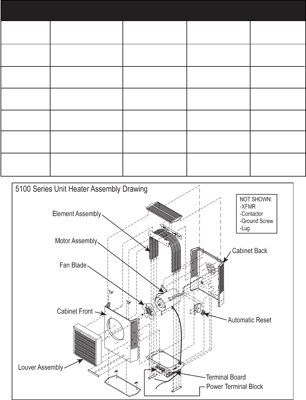
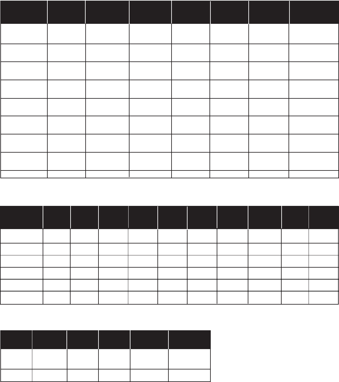
5100 SERIES UNIT HEATER
PARTS LIST - CATALOG NUMBERS
HEATER ELEMENT AUTOMATIC FAN XFMR CONTACTOR POWER
MODEL MOTOR ASSEMBLY RESET OVERRIDE TERMINAL
BLOCK
F1F5103N 56562-012 60715-001 57640-006 28163-005 56815-001
F25103N 56562-012 60715-011 57640-006 28163-005 56815-001
HF1B5103N 56562-017 60715-002 57604-006 28163-005 56815-001
HF2B5103N 56562-017 60715-012 57604-006 28163-005 56815-001
G1G5103N 56562-016 60715-007 57604-006 28163-005 56815-001
P3P5103CA1N 56562-018 60715-008 57604-006 56811-001 60719-006 58027-041 56815-001
F1F5105N 56562-012 60715-003 57604-006 28163-005 56815-001
F2F5105N 56562-012 60715-004 57604-006 28163-005 56815-001
HF1B5105N 56562-017 60715-005 57604-006 28163-005 56815-001
HF2B5105N 56562-017 60715-006 57604-006 28163-005 56815-001
G1G5105N 56562-016 60715-009 57604-006 28163-005 56815-001
P3P5105CA1N 56562-018 60715-010 57604-006 56811-001 60719-006 58027-041 56815-001
F2F5107CA1L 56823-011 56954-004 57604-003 56811-001 60719-001 58027-031 56815-001
HF2B5107CA1L 56823-012 56954-006 57604-003 56811-001 60719-001 58027-021 56816-001
G1G5107CA1L 56824-002 56954-001 57604-003 56811-001 60719-005 58027-021 56815-001
P3P5107CA1N 56824-011 56954-002 57604-003 56811-001 60719-006 58027-041 56815-001
F2F5110CA1L 56823-011 56954-003 57604-003 56811-001 60719-001 58027-036 56816-001
HF2B5110CA1L 56823-012 56954-004 57604-003 56811-001 60719-001 58027-036 56816-001
G1G5110CA1L 56824-002 56954-007 57604-003 56811-001 60719-005 58027-031 56816-001
P3P5110CA1N 56824-011 56954-008 57604-003 56811-001 60719-006 58027-041 56815-001
F3F5115CA1L 56825-001 56954-009 57604-004 56811-001 60719-001 58027-036 56816-001
HF3B5115CA1L 56825-002 56954-010 57604-004 56811-001 60719-001 58027-031 56816-001
P3P5115CA1N 56825-003 56954-011 57604-004 56811-001 60719-006 58027-041 56815-001
HF3B5120CA1L 56825-002 56954-012 57604-004 56811-003 60719-001 58027-036 56816-001
P3P5120CA1N 56825-003 56954-013 57604-004 56811-003 60719-006 58027-041 56815-001
Revised 3/91
HEATER MOTOR ELEMENT AUTO. FAN XFMR S.D. FUSE S.D. FUSE CONTACTOR POWER FAN
MODEL ASSY. RESET OVERRIDE 6 RQD 2 RQD 2 RQD TERMINAL
BLOCK
F3F5125CA1L 56943-001 56954-017 57640-005 56811-002 60719-009 50836-012 41280-002 50378-025 57097-001 57112-001
HF3B5125CA1L 56943-002 56954-018 57640-005 56811-002 60719-009 50836-012 41280-007 50378-025 57097-001 57112-001
P3P512CA1N 56944-001 56954-019 57640-005 56811-002 60719-012 50378-016 57098-001 57090-001
F3F5130CA1L 56943-001 56954-020 57640-005 56811-002 60719-009 50836-003 41280-008 50378-025 57097-001 57112-001
HF3B5130CA1L 56943-002 56954-021 57640-005 56811-002 60719-009 50836-012 41280-002 50378-025 57097-001 57112-001
P3P5130CA1N 56944-001 56954-022 57640-005 56811-002 60719-012 50378-016 57098-001 57090-001
F3F5140CA1L 56945-001 56954-023 57640-005 56811-002 60719-009 50836-003 41280-004 50378-025 57097-001 57112-001
HF3B5140CA1L 56945-002 56954-024 57640-005 56811-002 60719-009 50836-003 41280-003 50378-025 57097-001 57112-001
P3P5140CA1N 56946-001 56954-025 57640-005 56811-002 60719-012 50378-016 57098-001 57090-001
F3F5150CA1L 56945-001 56954-026 57640-005 56811-003 60719-009 50836-003 41280-005 50378-034 57097-001 57112-001
HF3B5150CA1L 56945-002 56954-027 57640-005 56811-003 60719-009 50836-003 41280-004 50378-025 57097-001 57112-001
P3P5150CA1N 56946-001 56954-028 57640-005 56811-003 60719-012 57110-001 57111-008 50378-016 57097-001 57090-001
KW FAN TERMIAL GROUND MOTOR LOUVER
BLADE BOARD CONN. CAPACITOR
3.3 - 5 56806-001 56809-001 1458 -- (5) 56986-001
7.5 - 10 50551-002 56809-001 1458 -- (7) 56986-003
15 - 20 56813-001 56809-001 1458 -- (7) 56986-003
25 - 30 57114-001 56809-001 3981 57100-001 (9) 56987-001
40 - 50 57115-001 56809-001 3981 57100-001 (9) 56987-001
11
U3H5105CA4N U3H5107CA4N U3H5110CA4N U3H5115CA4N U3H5120CA4N
MOTOR 56562-017 56823-012 56823-012 56825-002 56825-002
ELEMENT ASSY. 56954-029 56954-030 56954-031 56954-032 56954-035
AUTO RESET LIMIT 57640-003 57640-003 57640-003 57640-004 57640-004
FAN OVERRIDE 56811-001 56811-001 56811-001 56811-001 56811-003
XFMR 57641-003 (100VA) 57641-001 (150VA) 57641-001 57641-002 (300VA) 57641-002
CONTACTOR 58027-043 58027-043 58027-043 58027-043 58027-043
POWER TRML. BLOCK 56817-001 56815-001 56815-001 56815-001 56815-001
FAN BLADE 51554-002 51554-002 51554-002 56813-001 56813-001
TERMINAL BLOCK 56809-001 56809-001 56809-001 56809-001 56809-001
GROUND CONN. 1458 1458 1458 1458 1458
LOUVER 56986-003 (7) 56986-003 (7) 56986-003 (7) 56986-003 (7) 56986-003 (7)
U3H5125CA4N U3H5130CA4N U3H5140CA4N U3H5150CA4N
MOTOR 56943-002 56943-002 56943-002 56945-002
ELEMENT ASSY. 56954-003 56954-003 56954-036 56954-037
AUTO. RESET LIMIT 57640-005 57640-005 57640-005 57640-005
FAN OVERRIDE 56811-002 56811-002 56811-002 56811-003
XFMR 57641-001 57641-001 57641-004(350VA) 57641-004
CONTACTOR 58027-043 (2) 58027-043 (2) 58027-043 (2) 58027-043 (2)
POWER TRML. BLOCK 57098-001 57098-001 57098-001 57098-001
FAN BLADE 57114-001 57114-001 57115-001 57115-001
TERMINAL BOARD 56809-001 56809-001 56809-001 56809-001
GROUND CONN. 3981 3981 3981 3981
LOUVER 56986-004(9) 56896-004(9) 56986-004(9) 56986-004(9)
XFMR PRI FUSE BLOCK 57643-001 57643-001 57643-001 57643-001
XFMR PRI FUSE (2) 57644-001 (2) 57644-001 (2) 57644-001 (2) 57644-001 (2)
FAN SPEED SW 57112-001 57112-001 57112-001 57112-001
MOTOR CAPACITOR 57100-001 57100-001 57100-001 57100-001
T3H5105CA4N T3H5107CA4N T3H5110CA4N T3H5115CA4N T3H5120CA4N
MOTOR 56562-017 56823-012 56823-012 56815-002 56825-002
ELEMENT ASSY. 56954-061 56954-054 56954-055 56954-056 54929-006
FAN OVERRIDE 66811-001 56811-001 56811-001 56811-001 56811-001
XFMR 57641-003 57641-003 57641-001 57614-002 57641-002
CONTACTOR 58027-043 58027-043 58027-043 58027-043 58027-043
POWER TRML. BLOCK 56815-001 56815-001 56815-001 56815-001 56815-001
FAN BLADE 51554-002 51554-002 51554-002 56813-001 56813-001
TERMINAL BOARD 56809-001 56809-001 56809-001 56809-001 56809-001
GROUND CONN. 1458 1458 1458 1458 1458
LOUVER 56986-003(7) 56986-003(7) 56986-003(7) 56986-003(7) 56986-003(7)
T3T5125CA1N T3T5130CA1N T3T5140CA1N T3T5150CA1N
MOTOR 56943-002 56943-002 56945-002 56945-002
ELEMENT ASSY. 56954-057 56954-058 56954-059 56954-060
AUTO RESET LIMIT 57640-005 57640-005 57640-005 57640-005
FAN OVERRIDE 56811-002 56811-002 56811-002 56811-002
XFMR 60719-018 60719-018 60719-018 60719-018
CONTACTOR 58027-043 (2) 58027-043 (2) 58027-043 (2) 58027-043 (2)
POWER TRML. BLOCK 57098-001 57098-001 57098-001 57098-001
FAN BLADE 57114-001 57114-001 57114-001 57114-001
TERMINAL BOARD 56809-001 56809-001 56809-001 56809-001
GROUND CONN. 3981 3981 3981 3981
LOUVER 56986-004 (9) 56986-004 (9) 56986-004 (9) 56986-004 (9)
FAN SPEED SWITCH 57112-001 57112-001 57112-001 57112-001
MOTOR CAPACITOR 57100-001 57100-001 57100-001 57100-001
5100 SERIES UNIT HEATER
PARTS LIST - CATALOG NUMBERS - 600 VOLT MODELS
LIMITED WARRANTY
Products manufactured by TPI Corporation are warranted to the original consumer to be free from defects in
material and workmanship for twelve (12) months from the original purchase date.
The TPI limited warranty does not cover products that have been modified outside of our factory, damage or
failure caused by acts of God, abuse, misuse, connected to or placed on other than rated voltage, abnormal
usage, fault, installation, failure to follow suggested maintenance procedures enclosed with the product,
improper maintenance or any repairs other than those provided by an authorized TPI service center.
There are no obligations or liabilities on the part of the Corporation for consequential damages
arising out of or in connection with the use or performance of the product or other indirect damages
with respect to loss of property, revenues, profit, costs of removal installation, or reinstallation.
All implied warranties with respect to TPI products, including implied warranties for mechantability
and implied warranties for fitness, are limited in duration to twelve (12) months from original date of
purchase, except those products or parts of products which are warranted for long periods. On such
products or parts of products all implied warranties for merchantability and fitness are limited to the
duration of the extended warranty period thereon.
Some states do not allow the exclusions or limitation of incidental or consequential damages and some
states do not allow limitations on how long an implied warranty lasts. The above exclusions or limitations
may not apply to you.
During the warranty period, TPI Corporation will, at its sole option, repair or replace any defective parts or
products returned, freight prepaid, to the TPI Corporation factory or such other locations as TPI Corporation
may designate. Returned products must be packaged carefully and TPI Corporation shall not be responsible
for damage in transit.
When returning parts, the owner must provide the model number of the product and nature of difficulty being
experienced. This warranty does not obligate TPI Corporation to bear the cost of labor in replacing any
assembly, unit or componet part thereof, nor does the company assume any liability for secondary charges,
expenses for installing or removal, freight or damages. There will be charges rendered for product repairs
made after the warranty period has expired. Proof of purchase, including date, must accompany request for
in-warranty service. In any event, TPI Corporation’s maximum liability shall not in any case exceed the list
price for the product claimed to be defective. This warranty gives to you specific legal rights and you may
have other rights, which may vary from state to state. For the name of your nearest authorized TPI Corpora-
tion service center, please write to TPI Corporation, P.O. Box 4973, Johnson City, TN 37602.
Heating Products Warranty Coverage
Elements in 198 Series Portable Life of heater
Elements in Baseboards 10 Years
All Other Heating Products 1 Year
Thermostats and Controls 2 Years
Ventilation Products Warranty Coverage
Series HD or HDH Fans 5 Years
Series UHP of IHP Fans 3 Years
All other Ventilation Products 1 Year
INSTALLATION
INSTRUCTIONS
& PARTS LIST
ATTENTION: Lisez les instructions soigneusement avant de commencer
l’installation, la mise en marche ou l’entretien du radiateur taskmaster.
Gardez ces instructions pour utilisation ulterieure.
TASKMASTER
5100 SERIES
Montage horizontal ou vertical
radiateur industriel et commercial
INSTALLATION
INSTRUCTIONS
& PARTS LIST
CARACTERISTIQUES
Radiateur electrique ventilateur, disponible suivant les
tensions standards de 208, 240/208, 277, 480 ou de 600
volts.
Dix puissances de chauffage standard de 3.3 KW/11,260
BTUH jusqu’ a 50.0 KW/170, 600 BTUH.
Les modeles unipolaires de 3.3 jusqu a 10.0 Kw de 240/
208 volts peuvent se transformer sur le chantier en modele
tripolaire. (Les modeles uipolaires de 3.3, 5.0, 7.5 et 10
Kw de 277 volts ne peuvent etre transformes).
Le volet interieur specialement concu permet au ventilateur
d’appeler I’air uniformement a travers I’element massif en
acier.
Le diffuseur concu vers I’exterieur et les volets montes
dirigent plug encore uniformement la propulsion de I’air afin
de repondre aux exigences specifiques du montage
horizontal ou vertical de I’appareil.
Supports de montage mur/lafond ou verticaux en option.
(comme requis).
Quatre ecrous soudes sont disposes au dessus et a
I’arriere du boitier pour le montage de I’appareil au chantier
avec des tiges filetees ou des boulons aveu chaine.
(visserie fournie par d’autres).
Diffuseur anemostat ou radial (en option), donnant une
propultion d’air diversifiee lors du montage vertical de
l’appareil.
Instruments de controle varies pour installation sur le
chantier. Interrupteur, thermostat, interrupteur du
ventilateur pour la saison estivale, thermostat pour recu
peration de chaleur. Tous ont leurs conducteurs equippes
de serre-fils a lame. (a I’exception de I’interrupteur).
Tableau de branchement de la filerie de tous les instruments
de controle integres, en un seul endroit.
Circuit de controle standard basse tension de 24 volts sur
tous les modeles avec transformateur ou contracteur.
Boite de controle spacieuse ayant une porte d’acces fermee
a I’aide de deux attaches 1/4 de tour pour rendre I’intallation
facile.
INSTRUCTIONS D'ENDROIT NÉCESSAIRES
Dès que la charge totale de chauffage est calculée, la
quantité et la capacité des chauffages d'unité doivent être
déterminés. parce qu'un grand nombre de chauffages de
capacité basse fournit la distribution de chaleur plus
uniforme. Cette approche est recommandée quand la région
sera occupée par un relativement grand nombre de person-
nel sédentaire, (c'est-à-dire travaillant des chaînes de
fabrication et aux bancs.)
Un grand nombre de plus petits chauffages d'unité de
capacité a tendance à prévenir des brouillons chauds, réduit
des niveaux bruyants et augmente la diversité de charge
pour aider à réduire la demande électrique et les frais
d'exploitation.
Dans les magasins où chauffent même la distribution et les
températures constantes sont moins importants, un plus
petit nombre de hautes unités de capacité peut être utilisé -
dans beaucoup de cas réduisant le prix d'installation. Pour
maintenir la distribution de chaleur raisonnable et réduire la
stratification sévère même dans les régions de baie plus
basses, le volume aérien total de l'espace devrait traverser
les chauffages d'unité environ trois fois par heure. (Prenez
des pieds cubiques totaux et la division par 20 déterminent
afin du chauffage total nécessaire l'estimation de CFM.)
Il est important que le voltage évalué de l'équipement
chauffant correspond au voltage de réserves. Le voltage de
réserves plus du voltage estimé du chauffage peut nuire à
l'équipement. Le voltage de réserves plus bas que le voltage
de chauffage évalué diminuera la production de chauffage
aussi bien que courra le risque de nuire à quelques
composantes.
Les chauffages d'unité horizontaux sont recommandés dans
les régions de baie basses avec les plafonds de 15 à 18
pieds maximums. Ceux-ci devraient être concentrés le long
du mur extérieur ou d'autres régions de la plus grande perte
de chaleur; espacé monter un mouvement aérien
généralement circulaire, chaque chauffage soutenant le
courant atmosphérique de l'autre. Supplémentaire vertical en
bas au-dessous des chauffages d'unité avec diffusers
auxiliaire approprié peut être trouvé pour contrer des pertes
de chaleur de plafond (voir le chiffre 1 des graphiques
d'Endroit).
Instructions d'Endroit du chiffre 1
Général SAFETY INFORMATION / PRUDENCE :
Suivez tout l'habitant d'origine électrique et les codes de
sécurité, aussi bien que le Code Électrique national (NEC) et
l'acte de Santé et de Sécurité du Métier (OSHA).
Pour éviter le choc électrique possible, soyez sûrs que le
courant électrique est éteint au changement principal avant
de télégraphier ou assurer l'entretien de l'unité.
Si le pouvoir débranche n'est pas intrinsèque et est hors de
vue, la serrure cela dans la position ouverte et l'étiquette pour
prévenir l'application inattendue de pouvoir avant d'exécuter
n'importe quel service ou maintenance de l'unité.
L'unité quand installé doit être électriquement fondée
conformément à la pratique d'industrie Codée et standard
Électrique nationale
Vérifiez que la source de pouvoir conforme aux exigences de
votre équipement. Voir la Table 2 sur la page 6 pour la
grandeur de circuit et le fil
Vérifiez le voltage de chauffage et la phase en estimation de
l'étiquette pour confirmer qu'il correspond aux réserves de
service électriques.
Les schémas de connexions du chauffage et des
connexions de réserves sont attachés en permanence à
l'intérieur de la bouche d'accès de chauffage. Tous les
terminus sont codés conformément au schéma de
connexions. L'installation électrique auxiliaire est montrée
sur le schéma de connexions d'unité et la littérature de
soutien.
Le chauffage doit être monté au moins 7’ au-dessus de
l'étage pour prévenir le contact accidentel avec la lame de
fan qui pourrait provoquer la blessure. Installez l'unité ainsi il
n'y a aucune obstruction pour la consommation ou le renvoi.
Maintenez des déblayages comme montré sur la Table 1, 2,
la Figue 1 et 2.
Le mur/plafond montant la structure et ancrant des provi-
sions doit être sur la force suffisante pour soutenir le poids
combiné du chauffage et du support de fixation.
H
H
H
HH
H
H
H
VV
H
H
HH
H
H
H
EXPOSED
versatility when mounted vertically. (55 thru 75 kW only)
Modular control kits for field installation. Tthermostat,
summer fan switch, heat recovery thermostat. All kits with
spade terminals .
Single point terminal board wiring of integral control kits.
24 volt low voltage control circuit standard on all models.
Roomy control box with access door locked into position
by two (2) 1/4 turn fasteners for ease of installation.
Revised 03/07
Form XXXX
ATTENTION: Read carefully before attempting to install,
operate or service the TaskMaster Unit Heater. Retain
these installation instructions for future use.
TASKMASTER
5100 SERIES
Horizontal or Vertical Mounting
Industrial / Commercial
Unit Heater
PRODUCT FEATURES
Forced air electric unit heater available in 208, 240/208,
and 480 volt, 3 phase as standard.
Ten standard heating capacities of 55.0 KW/187,715 BTUH
thru 100.0 KW/341,300 BTUH.
Specially designed inlet louver allows the fan to pull cool
air evenly across the high mass all-steel element.
Outward drawn venturi and adjustable louver assembly
further directs the outlet air in a uniform pattern to meet
specific air pattern requirements in either the horizontal
or vertical mounting position.
Optional wall/ceiling or vertical mounting brackets (as
required).
Four position weld nuts supplied in case top and back
for field mounting by threaded rods or eye bolt with chain.
(Hardware supplied by others).
Optional radial or anemostat diffusers lending air pattern
INSTALLATION
INSTRUCTIONS
& PARTS LIST
IMPORTANT: OWNER SHOULD RETAIN THESE INSTRUCTIONS FOR FUTURE REFERENCE
55 THRU 100 kW MODELS
PROPER LOCATION INSTRUCTIONS
Once the total heating load is calculated, the quantity and
capacity of the unit heaters must be determined. because
a large number of low-capacity heaters provides more
uniform heat distribution. This approach is recommended
when the area will be occupied by a relatively large
number of sedentary personnel, (i.e. working on produc-
tion lines and at benches.)
A large number of smaller capacity unit heaters tends to
prevent hot drafts, reduces noise levels, and increases
diversity of load to help reduce electrical demand and
operating costs.
In warehouses where even heat distribution and constant
temperatures are less important, a smaller number of high
capacity units can be used -- in many cases reducing
installation cost. To maintain reasonable heat distribution
and reduce severe stratification even in lower bay areas, the
total air volume of the space should pass through the unit
heaters about three times per hour. (Take total cubic feet
and divide by 20 in order to determine proper total heater
CFM rating.)
It is important that the rated voltage of the heating equip-
ment match the supply voltage. Supply voltage in excess
of the heater rated voltage can damage equipment.
Supply voltage lower than the rated heater voltage will
decrease heater output as well as run the risk of damag-
ing some components.
Horizontal unit heaters are recommended in low bay
areas with maximum 15 to 18 foot ceilings. These should
be concentrated along outside wall or other areas of
greatest heat loss; spaced to set up a generally circular air
movement, each heater supporting the air stream of the
other. Additional vertical down below unit heaters with
appropriate accessory diffusers can be located to counter-
act ceiling heat losses (see Figure 1 Location charts).
Figure 1 Location Instructions
GENERAL SAFETY INFORMATION / CAUTION:
Follow all local electrical and safety codes, as well as the
National Electrical Code (NEC) and the Occupational
Safety and Health Act (OSHA).
To avoid possible electrical shock, be sure the electrical
current is turned off at the main switch prior to wiring or
servicing of unit.
If the power disconnect is not integral and is out-of-sight,
lock it in the open position and tag to prevent unexpected
application of power prior to performing any service or
maintenance of the unit.
The unit when installed must be electrically grounded in
accordance with the National Electrical Code and stan-
dard industry practice.
Make certain that the power source conforms to the
requirements of your equipment. See Table 2 on page 6
for wire and circuit size
Check heater voltage and phase on rating label to confirm
that it matches the electric service supply.
Wiring diagrams of the heater and supply connections are
permanently attached to the inside of the heater access
door. All terminals are coded in accordance with the
wiring diagram. Accessory wiring are shown on the unit
wiring diagram and supporting literature.
The heater must be mounted at least 7’ above the floor to
prevent accidental contact with the fan blade which could
cause injury. Install unit so there are no obstructions to the
intake or discharge. Maintain clearances as shown on
Table 1, 2, Fig. 1 & 2.
The wall/ceiling mounting structure and anchoring
provisions must be on sufficient strength to support the
combined weight of the heater and mounting bracket.
2
H
H
H
HH
H
H
H
VV
H
H
HH
H
H
H
EXPOSED
PRINCIPLES OF OPERATION
Upon a call for heat from the floor level or unit mounted
optional accessory thermostat, the unit fan motor and
heating elements shall be energized and remain ON until
temperature reaches setting of thermostat; at which time
the heating elements shall be deenergized.
The fan motor shall continue to run and purge heater
casing of residual heat until setting of fan override is
reached, then the fan motor shall be deenergized.
All units are supplied with a single speed motor .The 55-75
kW heaters are supplied with 3 stages of heat. The heater
can be wired as one stage, two stage or three stage. The
80 thru 100 kW models are supplied with four stages and
be operated as 1 thru 4 stages.The thermostat or step
controller(optional) will, upon a call for heat, energize fan
motor and the first stage heating element. Should tempera-
ture continue to fall, the thermostat shall energize the
remaining stages according to demand.
Upon a rise in space conditions towards setting of the
thermostat or step controller, the stages of heating ele-
ments shall be deenergized in reverse sequence.
The fan motor shall continue to run and purge heater
casing of residual heat until setting of fan override is
reached, then the fan motor shall be deenergized.
The accessory unit mounted stratification thermostat will
energize the unit heater fan motor upon a rise in
temperature above its setting.
When the unit mounted stratification thermostat closes on a
temperature rise and at the same time the floor thermostat
calls for heat, the motor shall be energized immediately and
the heating element shall be energized, as previously
described.
The manual reset safety high limit shall deenergize the
heating elements and control circuits should the temperature
exceed the setting of this device. The fan safety override
shall energize fan motor any time the setting of this device is
exceeded so as to purge heater casing of excess residual
heat.
When the accessory fan switch is placed in the ON position
(for summer air circulation), the unit heater fan motor shall
be energized.
NOTE: The wall thermostat is to be set to the OFF position
during this mode of operation (units with contactors).
For those accessory thermostats equipped with an integral
fan switch, place the switch in the HEAT, or AUTO position
for operation of the fan and elements which shall then be
under control of the thermostat as described above.
When switch is placed in the OFF position, the unit shall be
deenergized. When switch is placed in the FAN position,
elements shall be deenergized and fan shall be immedi-
ately energized.
Optional diffusers lend added air pattern versatility to
individual vertical down blow installations as shown in
above illustations.
3
USED MAX A B STOCK MAX A MAX A STOCK STOCK MAX MTG HT. A
ON MTG NO. MTG MTG NO. NO.
HT. HT. HT. 45OOPEN 45OOPEN
55 THRU 75 KW -- -- -- STD -- -- -- -- AD5175 RD 5175 -- -- -- --
80 THRU 100 kW -- -- -- STD -- -- -- -- N/A N/A -- -- -- --
STD = Standard N/A = Not Applicable
VERTICAL DISCHARGE UNITS - AIR PATTERNS
TABLE 1
Louver Diffuser (Standard) General Distribution
(No Diffuser)
Anemostat Diffuser
(Optional l)
Radial Diffuser (Optional)
55 thru 75kW only 55 thru 75kW only
ATTENTION: READ INSTRUCTION CAREFULLY
All electric unit heaters are shipped fully assembled.
Installation includes hanging the unit, mounting the built-in
and remote accessories, wiring of optional control devices,
and electrical wiring to the unit.
To insure proper delivery of the heated air to desired areas,
follow the mounting height and air projection tables include
in these instructions. Follow Fig. 1 & 2 for minimum wall
and ceiling clearances.
The wall and/or ceiling structure must be sufficient to
support the combined weight of the heater and any
mounting bracket and accessories.
Be sure power source is deenergized before installing
heater. Check heater voltage and phase listed on heater
date tape on back of unit to make sure they are the same
as the electrical service supplied.
Units that carry a dual voltage rating (HF) require specific
wiring changes when converting from 240 to 208 volt service
supplied.
Open the access panel (2 1/4 turn fasteners).
Remove the desired knock-out(s) on back of the heater.
Install any optional accessories following their installation
instructions before mounting unit. Following the correct
unit/accessory wiring diagram, connect the power supply,
electrical ground and accessories to the correct terminals
or termination points using accepted practices.
INSTALLATION INSTRUCTIONS
TASKMASTER -- 5100 SERIES UNIT HEATER
4
FIG. 1
HORIZONTAL DISCHARGE
FIG. 2
VERTICAL DISCHARGE
Heaters may be mounted in the horizontal or vertical air
discharge configuration using factory optional supplied
accessory mounting equipment or using special hardware
facilities supplied by others.
After the installation is complete, replace the access panel.
Set the controls (thermostat, switch) at their desired
control point and apply power to the unit.
Check correct operation.
DIMENSIONS
DIMENSIONS (INCHES)
KW H W D
55.0 - 75.0 35-1/2 30-1/2 14-1/2
80.0 - 100.0 39-1/2 37-5/8 18-1/2
ACCESSORY K.O.'S POWER K.O.'S
(4) 5/16"-18 MOUNTING POINTS
FOR ALL THREAD OR
OPTIONALFACTORY
CEILING HANGER
TYPICAL FOR
55 THRU 100 KW
REAR OF UNIT SHOWN
HORIZONTAL -- AIR DISCHARGE MOUNTING
SHOWN IN: FIGURE 5 & 6
Swivel hanger brackets may be used to suspend unit
heaters from either the wall (figure 5) or the ceiling
(figure 6). Attach hanger base “A” to top of heater with
the four 5/16 X 18 caps screws and lockwashers (pro-
vided in envelope).
Attach main hanger frame “B” to wall or ceiling in
desired location using appropriate hardware or welding.
Lift heater into position inserting 5/8” bolt with lockwasher
through hole in main hanger frame, tightening to welded
nut on hanger base within two turns of being tight.
Swivel heater to desired position, tighten bolt.
VERTICAL -- AIR DISCHARGE MOUNTING
SHOWN IN: FIGURE 7
5
Attach short angle brackets “A” to back of heater with
four 5/16 X 18 capscrews “B”, lockwashers “F”. Be sure
vertical leg of angle brackets face top and bottom of
heater.
Attach inverted U frames “D” to short angle brackets
with four 5/16 X 18 capscrews “K”, washers “L”,
lockwashers “M” and nuts “N”.
Attach long angle brackets “J” to inverted frames “D”
with four 5/16 X 18 capscrews “K”, washers “L”,
lockwashers “M” and nuts “N”.
Attach heater and bracket assembly to ceiling in
desired location using customer supplied equipment
sufficient to support the assembly.
INSTALLATION INSTRUCTIONS
TASKMASTER -- 5100 SERIES UNIT HEATER (part 2)
Figure 5
WALL MOUNT
HORIZONTAL DISCHARGE
NOTE: When mounting heater using 5/16” all thread
rod (by others) do not screw the rod more than 1/2”
beyond the inside of the case.
Figure 6
CEILING MOUNT
HORIZONTAL DISCHARGE
B
A
A
B
FIGURE 7
CEILING MOUNT VERTICAL DISCHARGE
V5150 SHOWN. SEE INSTALLATION INSTRUCTIONS
PROVIDED FOR V51100.

5100 SERIES UNIT HEATER
ELECTRICAL DATA (Table 2)
NUMBER RATING (000) MOTOR PHASE VOLTAGE PER PROTECTION SIZE 75o C
VOLTAGE PHASE SIZE-(A) AWG **
F3F5155CA1 55.0 187.7 208 3 24 152.8 200 2/0
HF3B5155CA1 55.0/41.25 187.7/140.8 240/208 3 24 132.5/114.6 175/150 1/0,1
P3P5155CA1 55.0 187.7 480 3 24 66.2 90 4
F3F5160CAI 60.0 204.7 208 3 24 166.7 225 2/0
HF3B5160CAI 60.0/45.0 204.7/153.6 240/208 3 24 144.6/125 200/175 1/0,1
P3P5160CA1 60.0 204.7 480 3 24 72.3 100 4
F3F5165CAI 65.0 221.8 208 3 24 180.6 250 3/0
HF3B5165CA1 65.0/48.75 221.8/166.4 240/208 3 24 156.6/135.4 200/175 2/0,2/0
P3P5165CA1 65.0 221.8 480 3 24 78.3 100 4
F3F5170CA1 70.0 238.9 208 3 24 194.4 250 3/0
HF3B5170CA1 70.0/52.5 238.9/179.2 240/208 3 24 168.7/145.8 225/200 2/0,1/0
P3P5170CA1 70.0 238.9 480 3 24 84.3 110 3
F3F5175CA1 75.0 256.0 208 3 24 208.3 300 4/0
HF3B5175CA1 75.0/56.25 256.0/192.0 240/208 3 24 180.7/156.3 250/200 3/0,2/0
P3P5175CA1 75.0 256.0 480 3 24 90.3 125 3
HF3B5180CA1 80.0/60.0 273.0/204.7 240/208 3 24 192.8/166.7 250/225 3/0,2/0
P3P5180CA1 80.0 273.0 480 3 24 96.3 125 3
HF3B5185CA1 85.0/63.75 290.0/217.5 240/208 3 24 204.8/177.1 300/225 4/0,3/0
P3P5185CA1 85.0 273.0 480 3 24 102.4 150 2
HF3B5190CA1 90.0/67.5 307.1/230.4 240/208 3 24 216.9/187.5 300/250 4/0,3/0
P3P5190CA1 90.0 307.1 480 3 24 108.4 150 2
HF3B5195CA1 95.0/71.25 324.2/243.1 240/208 3 24 229/198 300/250 250 MCM,3/0
P3P5195CA1 95.0 324.2 480 3 24 114.4 150 1
HF3B51100CA1 100.00/75.0 341.3/256.0 240/208 3 24 241/208.3 350/300 250MCM,4/0
P3P51100CA1 100.00 341.3 480 3 24 120.4 175 1
* Use 75 degree C Wire **Use Copper Conductors on all heaters
6
CATALOG KW BTU/HR HEATER / HEATER CONTROL AMPS BRANCH CIRCUIT SUPPLY WIRE
7
5100 SERIES UNIT HEATER
AIR DELIVERY DATA FAN MOTOR DATA
CFM at FPM at TEMPETURE HP Motor MAX. MTG AIR WEIGHT
OUTLET OUTLET RISE RPM THROW LBS.
oF Horizontal Vertical
3400 1485 55 1/3 1100
3400 1485 55/41 1/3 1100
3400 1485 55 1/3 1100
3400 1485 60 1/3 1100
3400 1485 60/45 1/3 1100
3400 1485 60 1/3 1100
3400 1485 65 1/3 1100
3400 1485 65/49 1/3 1100
3400 1485 65 1/3 1100
3400 1485 70 1/3 1100
3400 1485 70/53 1/3 1100
3400 1485 70 1/3 1100
3400 1485 75 1/3 1100
3400 1485 75/56 1/3 1100
3400 1485 75 1/3 1100
5000 1529 55/41 3/4 1100
5000 1529 55 3/4 1100
5000 1529 58/44 3/4 1100
5000 1529 58 3/4 1100
5000 1529 61/46 3/4 1100
5000 1529 61 3/4 1100
5000 1529 65/48 3/4 1100
5000 1529 65 3/4 1100
5000 1529 68/51 3/4 1100
5000 1529 68 3/4 1100

8
5100 SERIES UNIT HEATER
TROUBLE SHOOTING GUIDE
SYMPTOM POSSIBLE CAUSE(S) CORRECTIVE ACTION
Thermostat calls for 1. Open (blown) fuse 1. Replace fuses, check for cause.
heat, but heater does (see Replacement Parts List for fuse size)
not function. 2. INCORRECT WIRING
2. CHECK WIRING CONNECTIONS
3. Thermal cut-out open,
deenergizing heater 3. Check for the following:
element and control --- Correct supply volts and phase
circuit. Push reset button. --- Correct control wiring (heater control
must be thru thermostat control wiring
section only).
--- Power interruption to heater during
heater operation.
--- Restriction of air around heater 1-5
minute fan purge after thermostat off.
Fan motor runs 1. Dust accumulation or 1. Clean fan motor and casing of grease
“HOT” excessive dirt on motor and oil accumulation.
2. Dirt accumulation 2. Clean louvers and between heating
elements.
3. Motor needs lubrication. 3. See Maintenance.
Fan motor runs, 1. Element contactor not 1. Check wiring for open circuit. Replace
but no heat. operating correctly. contactor if defective
2. Element fuse blown. 2. Replace fuses, check for cause. (see
Replacement Parts List for fuse size)
MAINTENANCE
CAUTION: Make certain that the power source is disconnected before attempting to service or disassemble any
componet. If the power disconnect is out of the line of sight, lock it in the OPEN position and tag to prevent the
application of power.
ELECTRICAL
Once a year inspect the control panel wiring to make certain insulation is intact and all connections are tight. Inspect
all heater and relay contacts. If the contacts appear badly pitted or burned, replace the contactor / relay.
CLEANING
Clean the unit casing, fan and motor once a year. A dirty motor will tend to run hot and eventually will be damaged
internally. Any rust spots on the casing should be cleaned and repainted.
LUBRICATION
All units have fan motors that are permanently lubricated so that only occasional cleaning is required.
9
DIAGRAM MODELS
NO.
WD5160 F3F5155CA1,F3F5160CA1,F3F5165CA1,F3F5170CA1,F3F5175CA1
5100 SERIES UNIT HEATER
WIRING DIAGRAM SCHEDULE
WD5161 HF3B5155CA1,HF3B5160CA1,HF3B5165CA1,HF3B5170CA1,HF3B5175CA1
WD5162 P3P5155CA1,P3P5160CA1,P3P5165CA1,P3P5170CA1,P3P5175CA1
WD5163 HF3B5180CA1,HF3B5185CA1,HF3B5190CA1,HF3B5195CA1,HF3B51100CA1
WD5164 P3P5180CA1,P3P5185CA1,P3P5190CA1,P3P5195CA1,P3P51100CA1
SERIES 5100
TASKMASTER
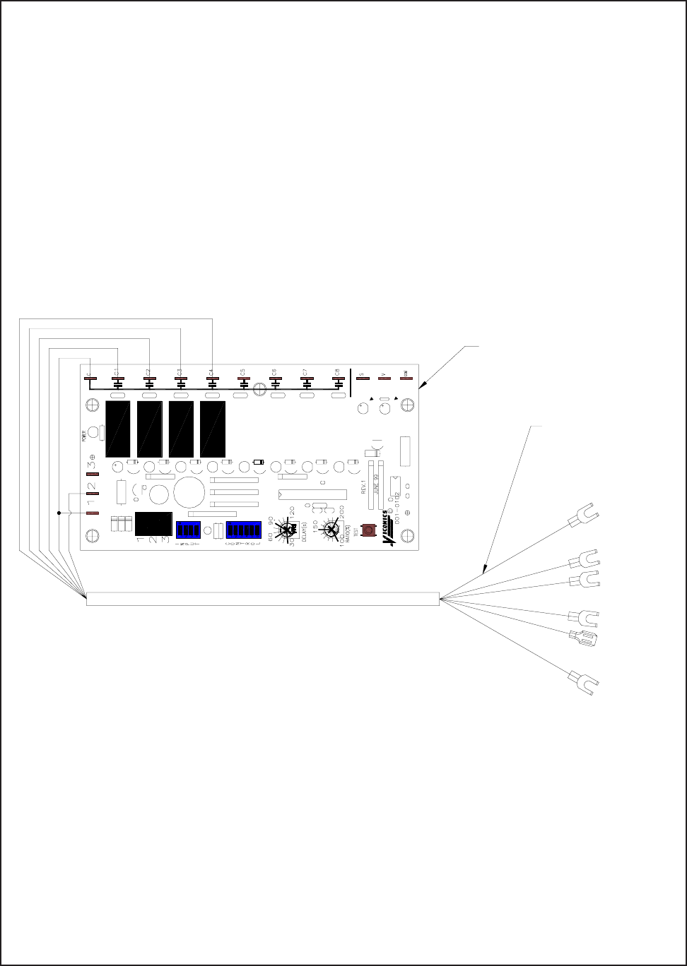
SC5100
Installation Instructions
FOR MODELS 5155 THRU 51100
READ THESE INSTRUCTIONS CAREFULLY BEFORE INSTALLING CONTROL. BE SURE TO
DE-ENERGIZE POWER SOURCE TO UNIT BEFORE INSTALLING CONTROL.
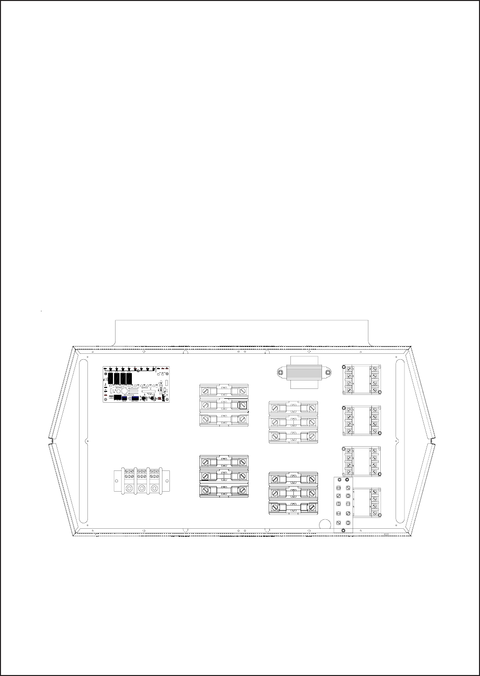
1.) Disconnect heater from power supply.
2.) Mount the controller in the control compartment as shown.
3.) Refer to page 2 for wiring.
FORM: 8987
ECO 1-5719
FORM: 8987
ECO 1-5719
WHITE
BLACK
RED
BLUE
BROWN
ORANGE
WHITE
BLACK
RED
BLUE
BROWN
ORANGE
CABLE ASSEMBLY
CONTROLLER
TERMINAL 4
TERMINAL 8
TERMINAL 5
TERMINAL 3
TERMINAL 10
TERMINAL 1
1) AFTER MOUNTING BOARD IN HEATER, PROCEED WITH WIRING AS SHOWN.
2) TERMINAL ARE IN REFERENCE TO THE TERMINAL BOARD LOCATED IN THE CONTROL
COMPARTMENT.
3) REFER TO MANUFACTURERS MANUAL FOR THERMOSTAT, 0-10VDC OR 4-20mA SIGNAL
CONNECTIONS AND SETTINGS. “DIP” SWITCHES MUST BE SET FOR INPUT AND
STAGING. SEQUENCING OPERATION MUST ALWAYS BE LAST IN FIRST OUT(LIFO)
WHICH IS THE FACTORY DEFAULT SETTING.
4) THE 5100 SERIES 55-75kW UNITS ARE CAPABLE OF 3 STAGES, THE 80-100kW ARE
CAPABLE OF 4 STAGES.
SERIES 5100
TASKMASTER
INSTALLATION INSTRUCTIONS
DCS202 POWER DISCONNECT SWITCH TASKMASTER SERIES
RATING - 2 POLE 20 AMP 277 VAC RESISTIVE
READ THESE INSTRUCTIONS THOROUGHLY BEFORE INSTALLING SWITCH. BE SURE TO DE-ENER-
GIZE POWER SOURCE TO UNIT BEFORE INSTALLING SWITCH. CHECK HEATER DATA LABEL TO IN-
SURE THAT HEATER ELECTRICAL RATING DOES NOT EXCEED THE POWER DISCONNECT ELECTRICAL
RATING.
SUPPLY WIRES MUST BE COPPER CONDUCTORS ONLY.
ALL WIRING TO BE IN ACCORDANCE WITH CSA, NEC AND LOCAL CODES. DO NOT REMOVE FISHPAPER
BARRIER FROM SWITCH ASSEMBLY. DO NOT INTERRUPT POWER TO HEATER WHILE THE UNIT IS
OPERATING IN ORDER TO PERFORM NORMAL MAINTENANCE SERVICE. ANY POWER INTERRUPTION
DURING NORMAL OPERATION WILL PREVENT THE FAN FROM PURGING THE UNIT OF RESIDUAL HEAT.
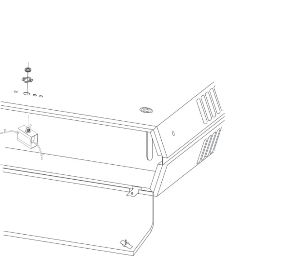
1.) Remove 1/2” (13mm) diameter knockout from heater back.
NOTE: 1/2” (13mm) diameter knockout is located on the heater back center approximately 3 1/2” (89mm)
from the bottom of heater. NOTE: DO NOT remove fishpaper barrier from switch assembly.
2.) Remove knurled nut and “ON-OFF” indicator ring from switch assembly.
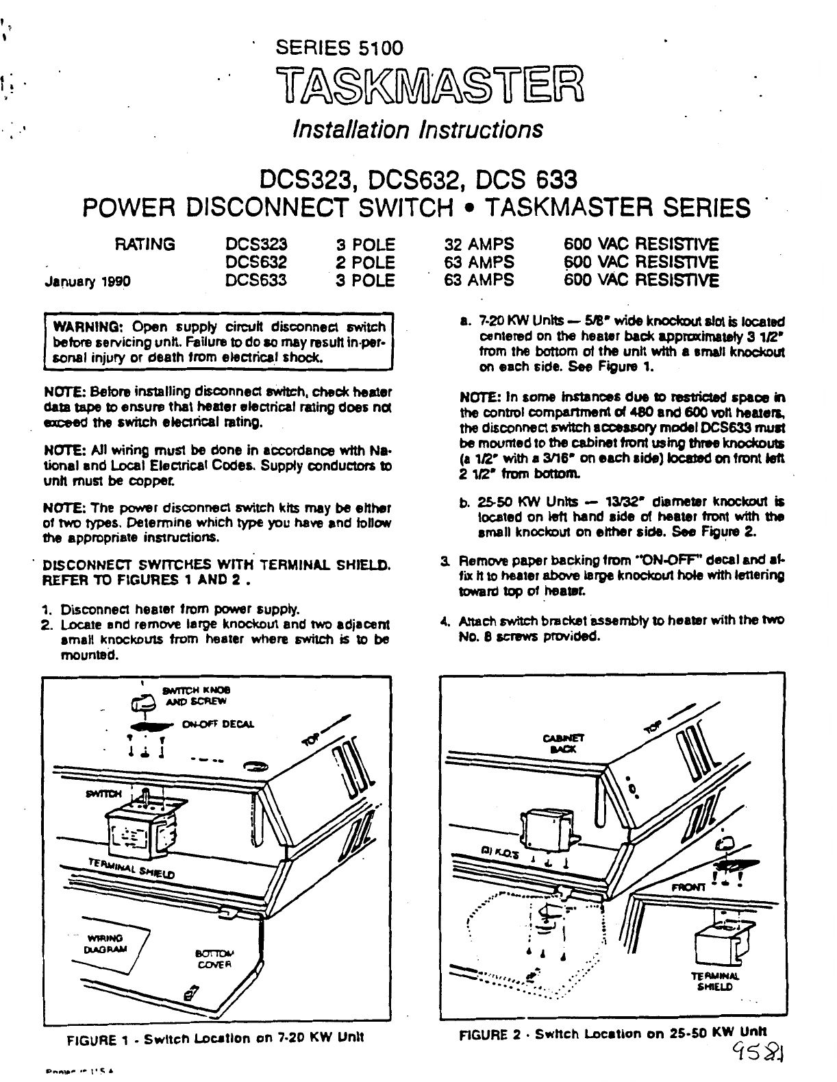
3.) Position switch assembly inside heater control compartment so the data label on switch assembly can be
visible from open side of compartment. Align flats on switch assembly with flats in heater back. Install
“ON-OFF” indicator ring. Secure switch assembly to heater back with knurled nut.
4.) Wire switch according to wiring diagram located on inside of bottom panel. Attach switch leads T1 and T2
to L1 and L2 of heater terminal block. Attach switch leads L1 and L2 to incoming supply conductors L1 and
L2 by suitable means.
5.) Restore power to unit and check for proper operation.
FORM: 8946
ECO 1-5148
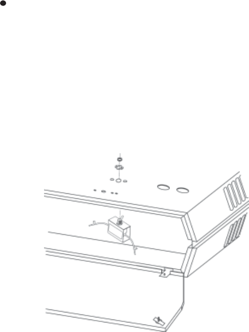
SERIES 5100
TASKMASTER
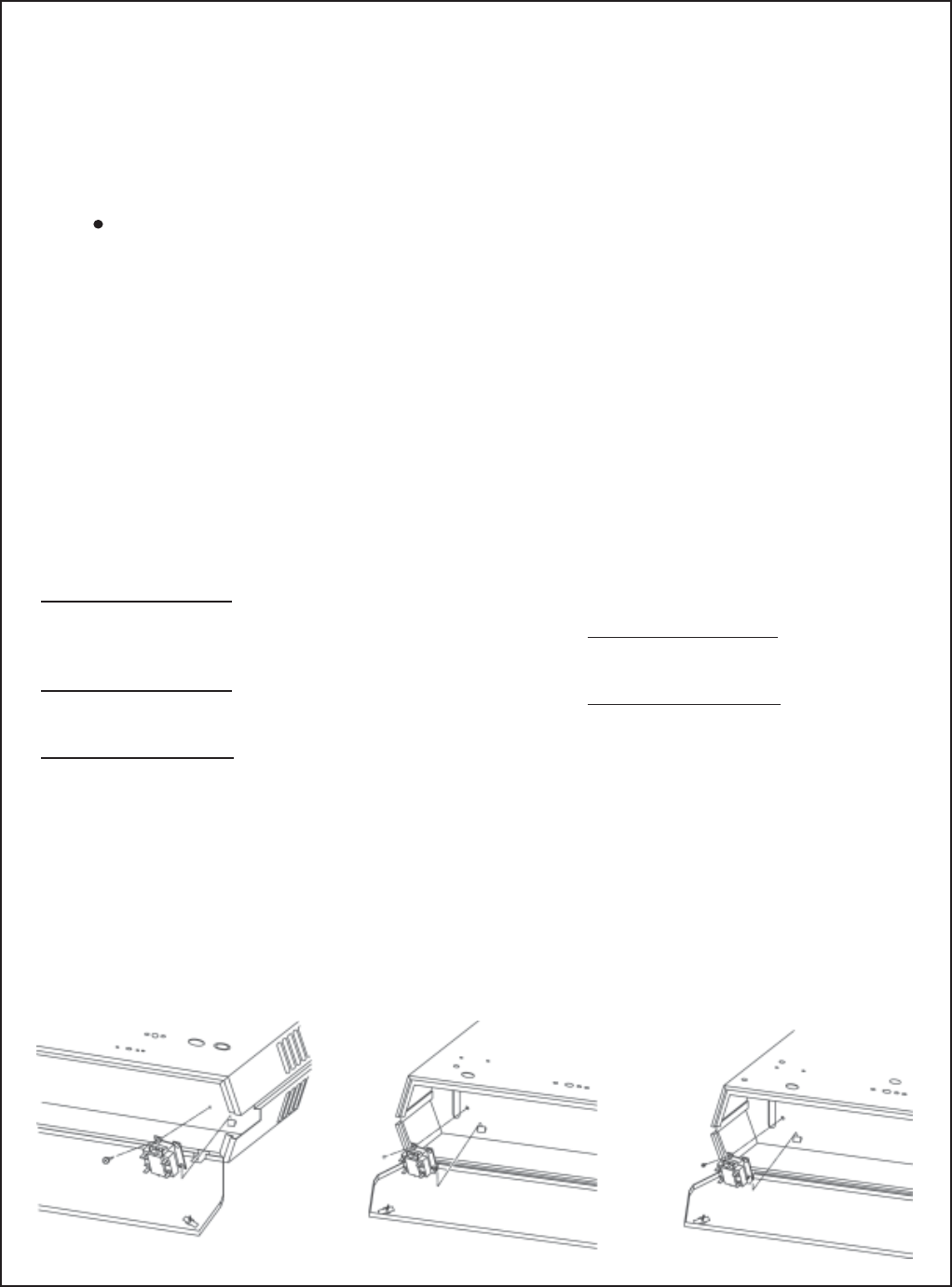
INSTALLATION INSTRUCTIONS
NOTE: Before installing disconnect switch, check heater data label
to ensure that heater electrical rating does not exceed the switch
electrical rating.
NOTE: All wiring must be done in accordance with National and
Local Electrical Codes. Supply conductors to unit must be copper.
1.) Disconnect heater from power supply.
2.) Locate and remove large knockout and two adjacent small
knockouts from heater where switch is to be mounted.
A.) 3-5KW - 1/2” diameter knockout is located centered on heater
back approximately 3 1/2” from bottom of the unit, with the two
slotted knockouts on each side.
B.) 7-50KW - 1/2” diameter knockout is located on left hand
side of heater front approximately 2 1/2” from bottom of
unit, with the two 3/16” slotted knockouts on each side.
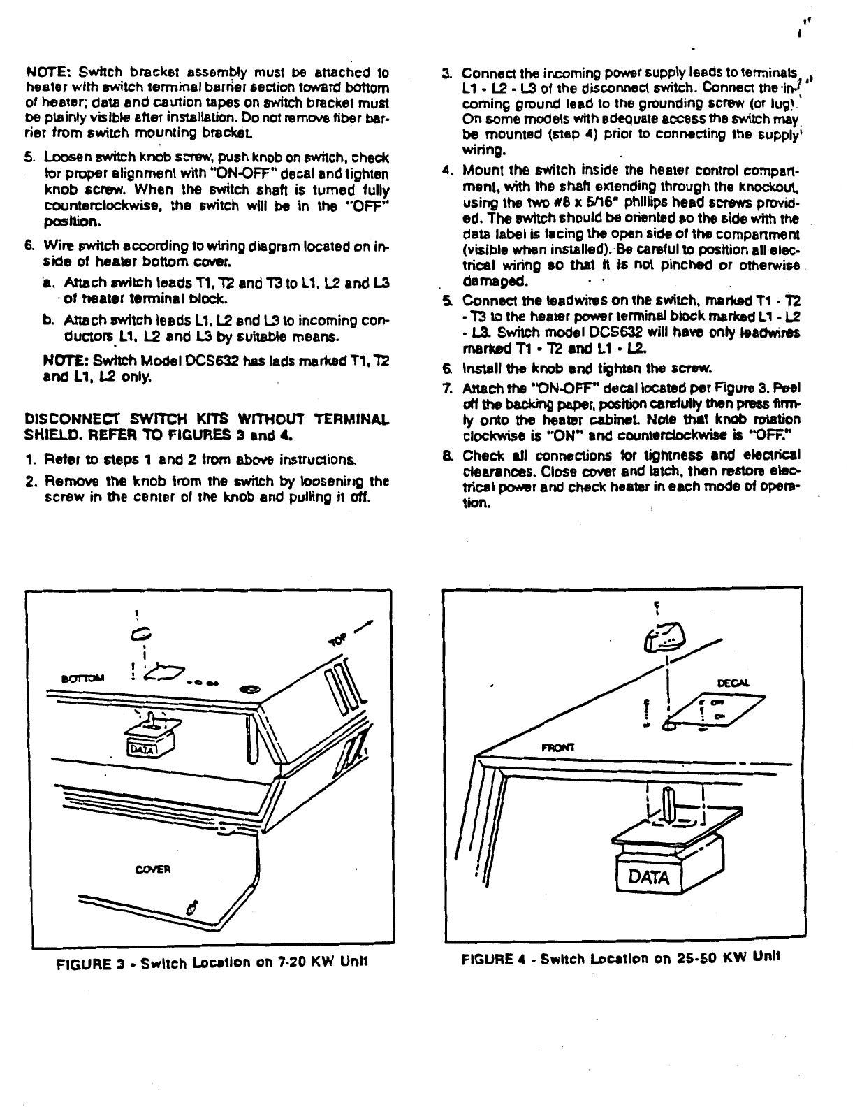
3.) Remove the knob and mounting plate from switch assembly.
Remove terminal shield.
(NOTE: Terminal shield must be installed on disconnect switch
after incoming supply wiring has been connected).
4.) Connect the incoming power supply leads to terminals
L1-L2-L3 of the disconnect switch. Connect the incoming
ground lead to the grounding screw (or lug). On some models
with adequate access the switch may be mounted (Step 5)
prior to connecting the supply wiring.
5.) Place the switch inside the heater control compartment with
the shaft extending through the 1/2” diameter knockout. The
switch must be oriented so the terminal shield is positioned
toward the left side of the heater. Data and caution labels
must be plainly visible from open end of compartment. Align
switch assembly and mounting plate with the 3/16” slotted
knockouts in unit and secure with the #6 or #8 screws
provided.
6.) Connect the leadwires on the switch, marked T1-T2-T3 to the
heater power terminal block marked L1-L2-L3 (Note: For single
phase units remove center leadwire marked T2).
7.) Attach the “On-Off” cover to the mounting plate. Install knob
and tighten screw.
8.) Check all connectors for tightness and electrical clearances.
Close cover and latch, then restore electrical power and check
heater in each mode of operation.
DCS403, DCS603, DCS1003
POWER DISCONNECT SWITCH TASK MASTER SERIES
RATING DCS403 3 POLE 40 AMPS 600 VAC RESISTIVE
DCS603 3 POLE 60 AMPS 600 VAC RESISTIVE
DCS1003 3 POLE 100 AMPS 600 VAC RESISTIVE
January 1990
WARNING: Open supply circuit disconnect switch
before servicing unit. Failure to do so may result in
personal injury or death from electrical shock.
FORM: 8947
ECO 1-5148
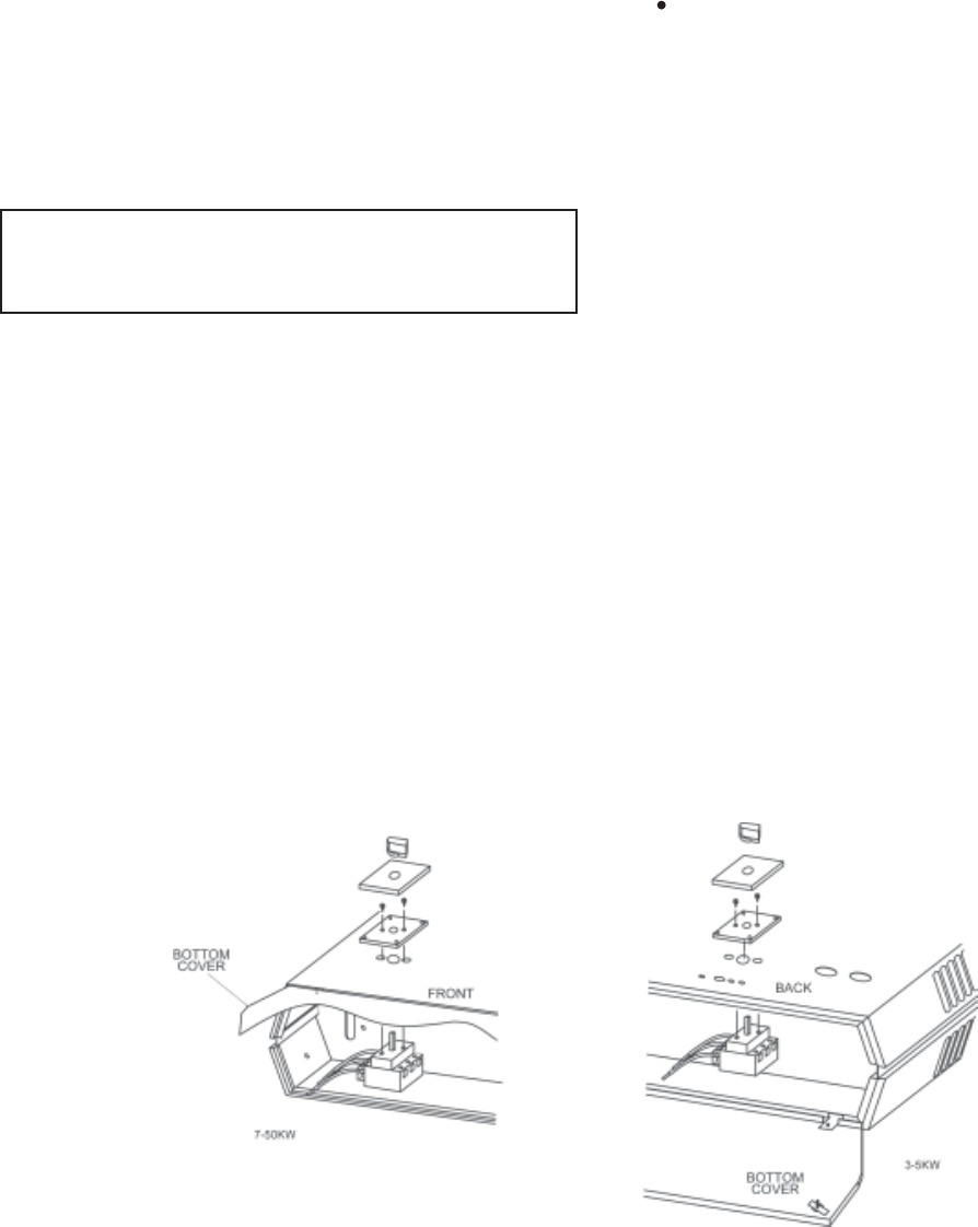
SERIES 5100
TASKMASTER
Installation Instructions
FS5101 TASKMASTER SERIES
UNIT MOUNTED LINE VOLTAGE SUMMER FAN SWITCH
FOR USE ON UNITS WITH 208, 240, 277 VOLT SUPPLY ONLY
READ THESE INSTRUCTIONS CAREFULLY BEFORE INSTALLING SWITCH. BE SURE TO DE-
ENERGIZE POWER SOURCE TO UNIT BEFORE INSTALLING SWITCH. BE SURE TO INSTALL
THE APPROPRIATE MODEL SWITCH ON THE CORRECT UNIT.
1.) Disconnect heater from power supply.
2.) Remove appropriate knockout for switch being used. Refer to Fig. 1.
Fig. 1
Models 5102 thru 5105 - Fig. 2
Knockout is located on heater back center
approximately 1 1/8” (29mm) from bottom of
heater.
Models 5107 thru 5120 - Fig. 3
Knockout is located on heater back approximately
3 1/4” (83mm) from bottom of heater with the 1/2”
(13mm) diameter knockout located approximately
3 3/4” (95mm) to the right of the back of center.
Models 5125 thru 51100 - Fig. 4
Knockout is located on heater back approximately
1 3/4” (44mm) from bottom of heater with the 1/2”
(13mm) diameter knockout located approximately
5” (127mm) to the left of the back center.
Fig. 2 Fig. 3
FORM: 8948
ECO 1-5719
Fig. 1
3.) Remove knurled nut and “On-Off” indicator ring from switch assembly.
4.) Align flats on switch with flats in knockout (Note position switch so data label will be visible from
open end of control compartment.
5.) Install “On-Off” indicator ring and secure switch assembly to heater with knurled nut.
6.) Wire switch according to wiring diagram located on inside of heater bottom panel. Attach switch
leads 7 & 9 to terminals 7 & 9 on terminal board.
7.) Remove paper backing from “Fan-Heat” decal and affix to unit with fan toward on and heat
toward off.
8.) After power is available to unit, check for proper operation.
NOTE: For summer fan operation only, thermostat must be in OFF position.
TPI CORPORATION
P.O. BOX 4973
JOHNSON CITY, TN 37602
(423) 477-4131
(423) 477-0064 FORM: 8948
ECO 1-5719
Fig. 4

SERIES 5100
TASKMASTER
FSW5111 TASKMASTER SERIES
REMOTE (WALL MOUNT) SUMMER FAN SWITCH
LINE VOLTAGE SWITCH FOR USE ONLY ON TASKMASTER HEATERS WITH A POWER
SUPPLY OF 208, 240 OR 277 VOLT SERVICE.
READ THESE INSTRUCTIONS CAREFULLY BEFORE INSTALLING SWITCH. DO NOT USE
THIS SWITCH ON UNITS WITH 480 OR 600 VOLT MOTOR CIRCUIT. BE SURE TO
DE-ENERGIZE POWER SOURCE TO UNIT BEFORE INSTALLING SWITCH. ALL
CONDUCTORS FROM SWITCH TO UNIT MUST BE COPPER (NEC) AND EXISTING LOCAL
CODE REQUIREMENTS.
1.) Disconnect heater from power supply.
2.) Remove 7/8” diameter knockout from heater back for control wiring from switch.
Models 5102 thru 5105
7/8” diameter knockouts located 2 1/2” to right of heater back center and 3 5/16” from bottom
of heater.
Models 5107 thru 5120
7/8” diameter knockouts located 5 1/2” to left of heater back center and 1 1/2” from bottom of
heater.
Models 5125 thru 5150
7/8” diameter knockouts located 5 1/16” to left of heater back center and 3 5/8” from bottom of
heater.
Models 5155 thru 5175
7/8” diameter knockouts located 5 1/16” to right of heater back center and 3 7/16” from bottom
of heater.
Models 5180 thru 51100
7/8” diameter knockouts located 5 1/16” to right of heater back center and 5” from bottom of
heater.
3.) Mount switch assembly in remotely located utility box.
4.) Wire switch according to wiring diagram located on inside of heater bottom panel. Attach leads
7 & 9 from switch to heater terminals 7 & 9 on heater terminal board.
5.) Remove paper backing from “Fan-Heat” decal and affix to utility box cover with fan toward on
and heat toward off.
6.) After installation is complete, restore power to heater and check for proper operation.
NOTE: For summer fan-operation only thermostat must be in OFF position.
FORM: 8949
ECO 1-5719
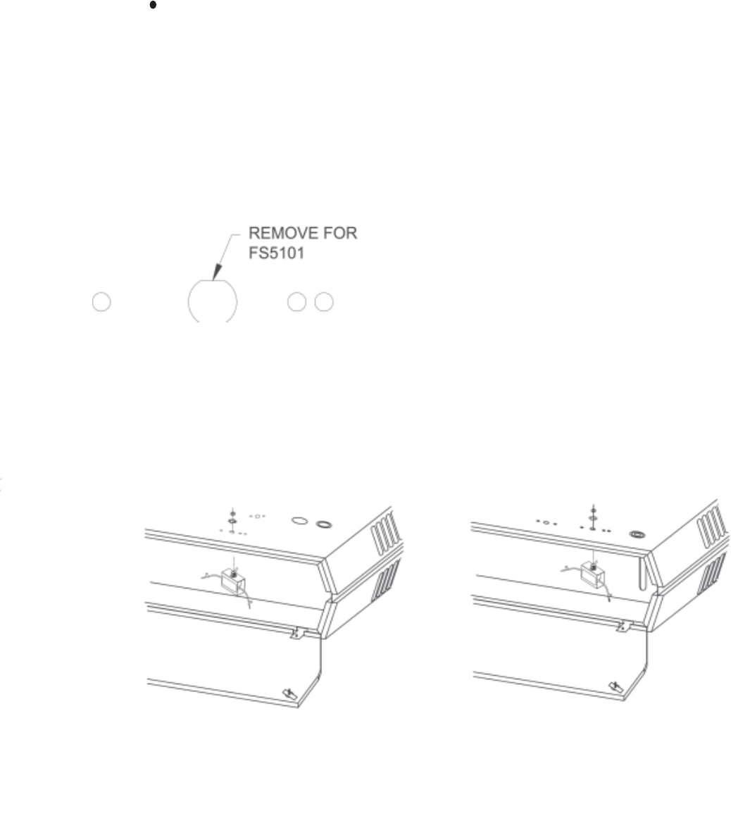
SERIES 5100
TASKMASTER
INSTALLATION INSTRUCTIONS
FSW5112 TASKMASTER SERIES
REMOTE (WALL MOUNT) LOW VOLTAGE SUMMER FAN SWITCH
LOW VOLTAGE SWITCH FOR USE ON TASKMASTER HEATERS WITH SUFFIX CODE “CA1” ONLY.
THIS ACCESSORY PACKAGE CONTAINS A REMOTE FAN SWITCH AND A LOW VOLTAGE RELAY FOR UNIT
MOUNTING.
READ THESE INSTRUCTIONS CAREFULLY BEFORE INSTALLING SWITCH. USE THIS SWITCH ONLY ON
UNITS WITH 24 VOLT CONTROL CIRCUITS. BE SURE TO DE-ENERGIZE POWER SOURCE TO UNIT BEFORE
INSTALLING SWITCH. ALL CONDUCTORS FROM SWITCH TO UNIT MUST BE COPPER. ALL WIRING TO BE
IN ACCORDANCE WITH THE NATIONAL ELECTRIC CODE (NEC) AND EXISTING LOCAL CODE
REQUIREMENTS.
1.) Disconnect heater from power supply.
2.) Remove 7/8” diameter knockout from heater back
for control wiring switch:
Models 5102 thru 5105
7/8” diameter knockout is located 2 1/2” to right of
heater back center and 3 5/16” from bottom of
heater.
Models 5107 thru 5120
7/8” diameter knockout is located 5 1/2” to left of
heater back center and 1 1/2” from bottom of heater.
Models 5125 thru 51100
7/8” diameter knockout is located 5 1/16” to left of
heater back center and 3 5/8” from bottom of heater.
3.) Mount switch assembly to remotely located utility
box.
4.) Wire switch according to wiring diagram located
on inside of heater bottom panel. Attach leads 2
and 4 from switch to heater terminals 2 and 4 on
heater terminal board.
5.) Fig. 1 Mount low voltage relay in wiring compartment-
Slip long leg of relay base under raised section of
control mounting plate and attach diagonally
opposite corner of relay base to control mounting
plate with the No. 8 sheet metal screw supplied.
NOTE: Models 5102 thru 5105
Relay is mounted next to heater power
terminal block.
Models 5107 thru 51100
Relay is mounted next to heater control
terminal board.
6.) Wire relay according to wiring diagram located on
inside of heater bottom panel. Attach relay leads
6, 8, 7 & 9 to terminals 6, 8, 7 & 9 on terminal
board.
7.) Remove paper backing from “Fan-Heat” decal and
affix to utility box cover with fan toward on and heat
toward off.
8.) After installation is complete, restore power to
heater and check for proper operation.
NOTE: For summer fan operation only thermostat
must be in OFF position.
2-5 kw 7-20 kw 25-50kw
FORM 8950
ECO 1-5719

SERIES 5100
TASKMASTER
INSTALLATION INSTRUCTIONS
TW1510, TW1512
REMOTE MOUNTING
LINE VOLTAGE THERMOSTAT
SINGLE STAGE
TW1510 (SPST)
TW1512 (DPST)
1) Disconnect heater from power supply.
2) Mount wall thermostat in desired location.
3) Wire the thermostat to the heater following the wiring diagram located on the heater. All wiring to be
in accordance with local and/or national codes.
4) Restore power to the heater.
5) Check for proper thermostat operation
INSTRUCTIONS D'INSTALLATION
THERMOSTAT À TENSION COMPOSÉE
TW1510, TW1512
INSTALLATION À DISTANCE
À UN ÉTAGE
TW1510 (SPST)
TW1512 (DPST)
1) Débranchez le radiateur de l'alimentation de courant.
2) Installez le thermostat mural à l'endroit désiré.
3) Connectez le thermostat au radiateur en suivant le schéma de filerie situé sur le radiateur.
Toute la filerie doit être en conformité avec les codes national et local.
4) Remettez le radiateur sous tension.
5) Vérifier au bon fonctionnement.
SERIES 5100
TASKMASTER
INSTALLATION INSTRUCTIONS
CEILING HANGER BRACKET -TASKMASTER SERIES
VERTICAL DISCHARGE AIR DELIVERY
MODEL V5105USE WITH 5102-5105 UNITS
MODEL V5120USE WITH 5107-5120 UNITS
MODEL V5150USE WITH 5125-5175 UNITS
MODEL V5105 IS FOR USE WITH 5102 THRU 5105 HEATERS.
MINIMUM MOUNTING DISTANCES FOR 5102 THRU 5105 HEATERS:
12” FROM CEILING AND ADJACENT SURFACES
7’ FROM FLOOR TO FRONT EDGE OF HEATER FRONT VENTURI
MODEL V5120 IS FOR USE WITH 5107 THRU 5120 HEATERS
MODEL V5150 IS FOR USE WITH 5125 THRU 5175 HEATERS
MINIMUM MOUNTING DISTANCES FOR 5107 THRU 5175 HEATERS:
18” FROM CEILING
24” FROM ADJACENT SURFACES
7’ FROM FLOOR TO FRONT EDGE OF HEATER FRONT VENTURI
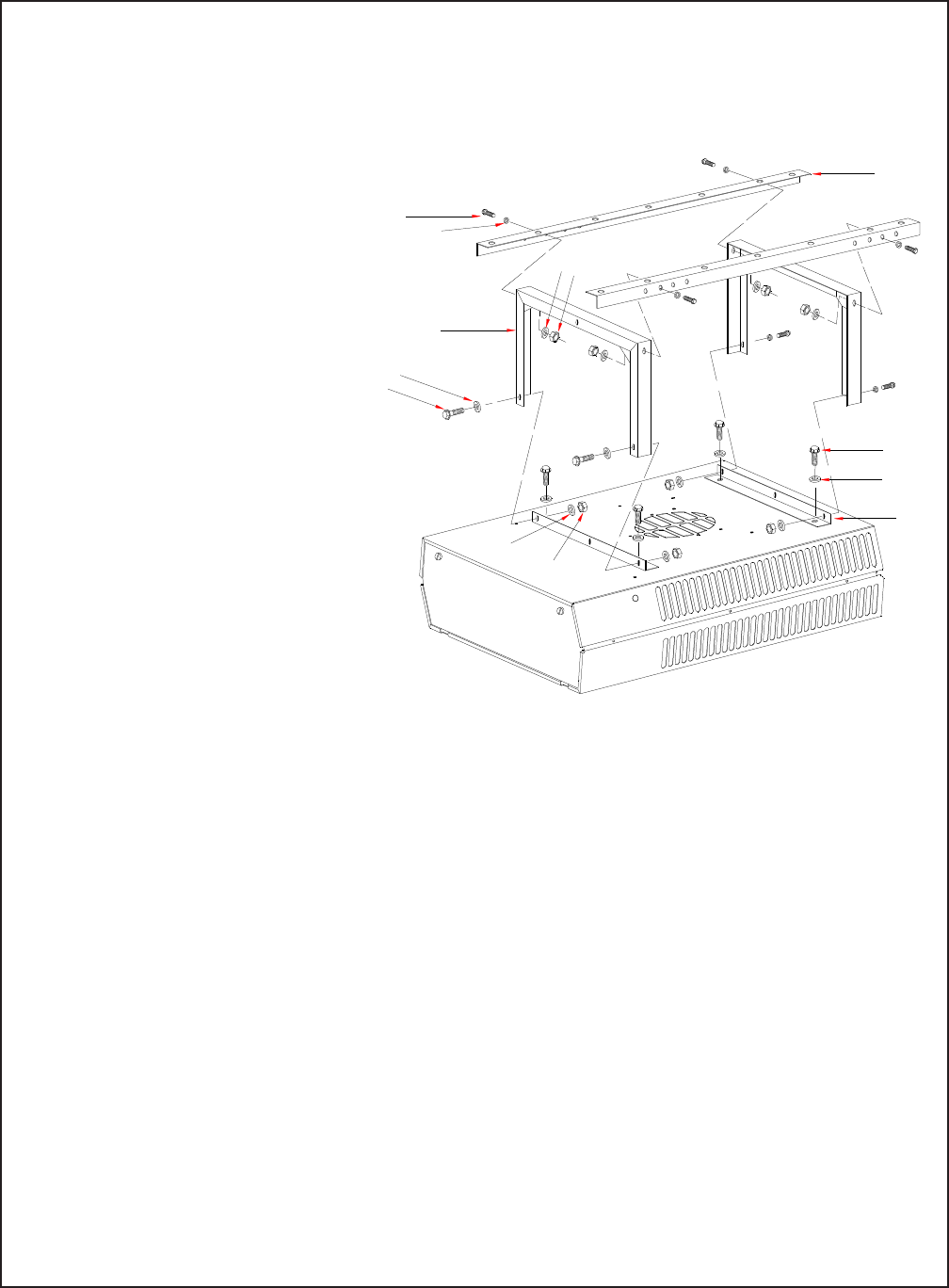
1) Attach short angle brackets “A” to back of heater with four 5/16-18 bolts “B”, lockwashers “F”.
Be sure vertical leg of angle brackets face top and bottom of heater.
2) Attach inverted U frames “D” to short angle brackets with four 5/16-18 bolts “E”, washers “F”, lockwashers
“G” and nuts “H”, oriented as shown.
3) Attach long angle brackets “J” to inverted U frames “D” with four 5/16-18 bolts “K”, washers “L”, lockwashers
“M” and nuts “N”.
4) Attach heater and bracket assembly to ceiling in desired location using customer supplied hardware
sufficient to support the assembly.
FORM: 56620-004
ECO 1-5719
D
F
E
K
L
MN
G
H
J
F
A
B

SERIES 5100
TASKMASTER
INSTALLATION INSTRUCTIONS
TW1510, TW1512
REMOTE MOUNTING
LINE VOLTAGE THERMOSTAT
SINGLE STAGE
TW1510 (SPST)
TW1512 (DPST)
1) Disconnect heater from power supply.
2) Mount wall thermostat in desired location.
3) Wire the thermostat to the heater following the wiring diagram located on the heater. All wiring to be
in accordance with local and/or national codes.
4) Restore power to the heater.
5) Check for proper thermostat operation
INSTRUCTIONS D'INSTALLATION
THERMOSTAT À TENSION COMPOSÉE
TW1510, TW1512
INSTALLATION À DISTANCE
À UN ÉTAGE
TW1510 (SPST)
TW1512 (DPST)
1) Débranchez le radiateur de l'alimentation de courant.
2) Installez le thermostat mural à l'endroit désiré.
3) Connectez le thermostat au radiateur en suivant le schéma de filerie situé sur le radiateur.
Toute la filerie doit être en conformité avec les codes national et local.
4) Remettez le radiateur sous tension.
5) Vérifier au bon fonctionnement.

SERIES 5100
TASKMASTER
Installation Instructions
TFS5102 -TASKMASTER SERIES
REMOTE MOUNTING
24 VOLT OPERATION
TWO STAGE CONTROL & INTEGRAL FAN SWITCH
1.) Disconnect heater from power supply.
2.) At the desired location, run the thermostat cable through the hole in the center of the thermostat
mounting sub-base. Leave about three inches of wire for connections. For the correct number of
wires, see appropriate heater or control package wiring diagram and instructions.
3.) Attach the sub-base directly to the wall or on a HORIZONTAL outlet box. Level the sub-base with
a spirit level.
4.) Connect the wires to the sub-base following the wiring diagram. complete installation of wiring on
the heater and/or control package. Plug the cable entrance hole to prevent drafts from affecting
thermostat operation.
5.) Remove the thermostat cover by pulling up the bottom edge until it snaps free of the locking
springs. Set the heat anticipator to correspond with the primary system control (relay, etc.). The
tabs along the top inside edge fit the sockets on the upper corners of the sub-base.
6.) Hang the thermostat on the sub-base and tighten the two captive screws on the thermostat base.
Replace cover by hooking cover tabs into the thermostat base and pushing down until the cover
snaps into the locking springs.
7.) Restore power to the heater and check for correct operation.
FAN SYSTEM
SWITCH SWITCH FUNCTION
On Off Fan on - heat off
On Auto Fan on - stat cycles
2 stages heat
Auto Off Fan off - heat off
Auto Auto Fan cycles with first stage heat-
stat cycles 2 stages heat
Honeywell
FORM: 56621-099
ECO 1-5719
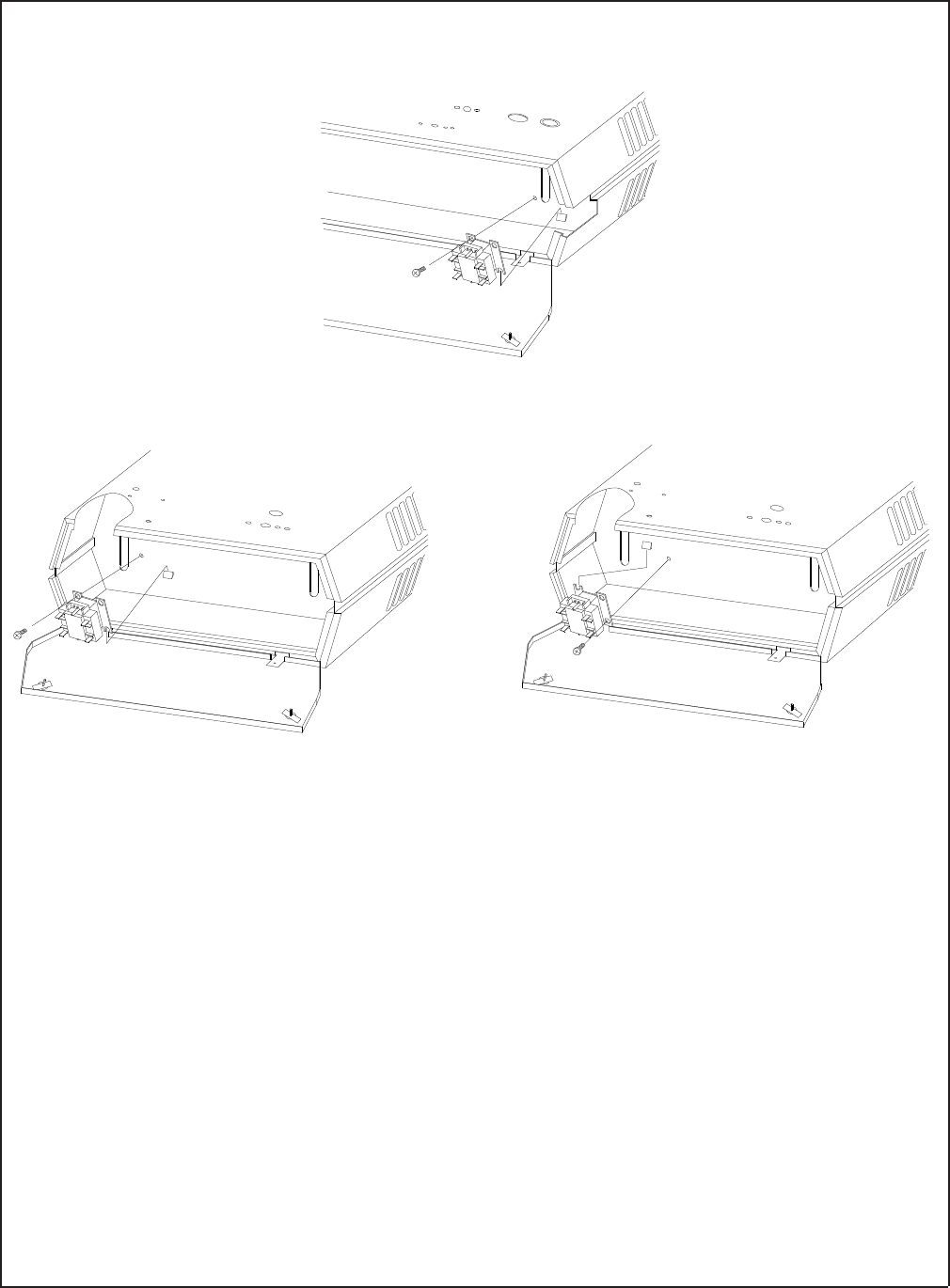
8.) Fig. 2 Mount low volt relay in wiring compartment. Slip long leg of relay base under raised section of control
mounting plate and attach diagonally opposite corner of relay base to control mounting plate with the No.
8 sheet metal screw supplied.
NOTE: Models 5102 thru 5105
Relay is mounted next to heater terminal block
Models 5107 thru 5150
Relay is mounted next to heater terminal board
9.) Wire relay according to wiring diagram located on inside of heater bottom panel. Attach relay leads 6, 8,
7 & 9 to terminals 6, 8, 7 & 9 on terminal board.
10.) After installation is complete, depress the reset button to insure continuity before applying power. After power
is available to unit, check for proper operation.
FORM: 56621-099
ECO 1-5719
2 - 5KW
FIG. 2
7 - 20KW
FIG. 2 25 - 50KW
FIG. 2
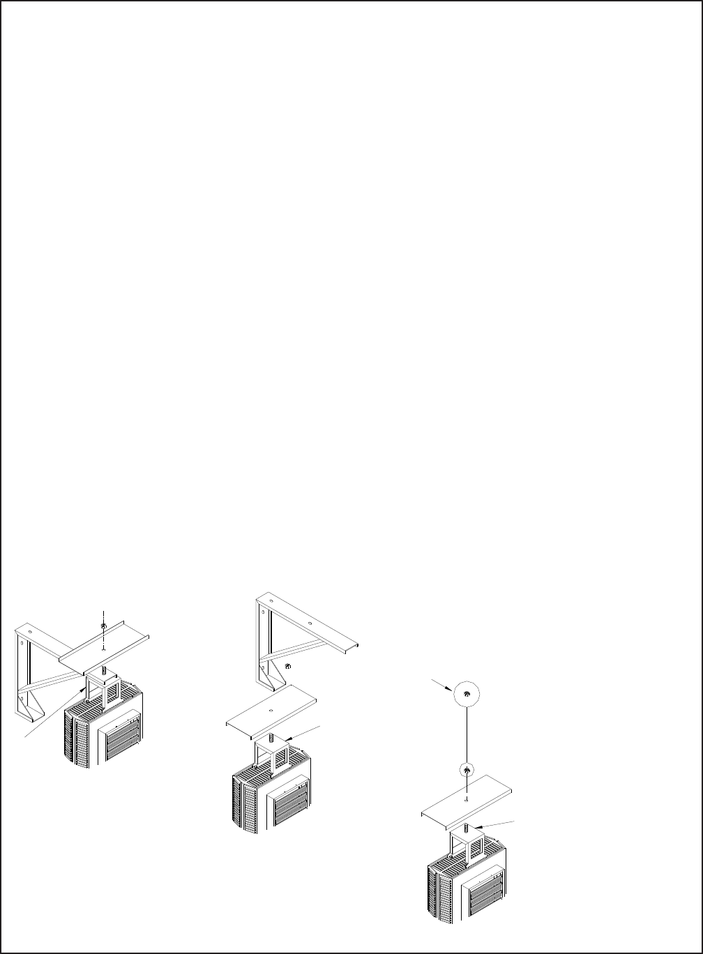
SERIES 5100
TASKMASTER
INSTALLATION INSTRUCTIONS
Dust Shield - Taskmaster Series
For Horizontal Air Delivery Units
Model DS5105 Use with 5102-5105 Units
Model DS5120 Use with 5107-5120 Units
Model DS5150 Use with 5125-5150 Units
1) Install the hanger base “A” on the heater following the instruction sheet packed with the
combination wall/ceiling bracket or the hanger base.
2) Attach the hanger bracket to the wall or ceiling as desired following instructions packed with
the bracket.
3) Following the correct illustration below:
Fig. A Wall Mounted Bracket
Fig. B Ceiling Mounted Bracket
Fig. C Customer Supplied Bracket or Direct Connection to Building Structural Member.
Position the dust shield as shown and insert the bolt of the hanger base “A” through the hole in
the dust shield, attach to the hanger bracket or structural member and attach the lock nut “E”
and complete installation as per the bracket installation sheet.
NOTE: The dust shield is to be positioned on the same axis as the heater.
"E"
"A"
"A"
"A"
Fig. A
Fig. B
Fig. C
FORM: 56621-101
ECO 1-5719

Honeywell
SERIES 5100
TASKMASTER
INSTALLATION INSTRUCTIONS
CAUTION: Models 5155 thru 5175 require that two circuits be wired to stage one and one circuit be
wired to stage two.
TW123 - TASKMASTER SERIES
REMOTE MOUNTING
24 VOLT OPERATION
TWO STAGE CONTROL
1. Disconnect heater from power supply.
2. At the desired location, run the thermostat cable through the hole in the center of the thermostat
mounting sub-base. Leave about three inches of wire for connections. For the correct number of
wires, see appropriate heater or control package wiring diagram and instructions.
3. Attach the sub-base directly to the wall or on a HORIZONTAL outlet box. Level the sub-base with a
spirit level.
4. Connect the wires to the sub-base following the wiring diagram. Complete installation of wiring on
the heater and/or control package. Plug the cable entrance hole to prevent drafts from affecting
thermostat operation.
5. Remove the thermostat cover by pulling up the bottom edge until it snaps free of the locking
springs. Set the heat anticipators to .25 amp. After usage, readjust as needed. The tabs along the
top inside edge fit the sockets on the upper corners of the sub-base.
6. Hang the thermostat on the sub-base and tighten the two captive screws on the thermostat base.
Replace cover by hooking cover tabs into the thermostat base and pushing down until the cover
snaps into the locking springs.
7. Restore power to heater and check for correct operation. The thermostat will, on a fall in space
temperature below its setting, energize the 2 stages of heating in sequence. On a rise in space
temperature towards the stat setting, the sequence is reversed.
FORM: 56621-104
ECO 1-5719
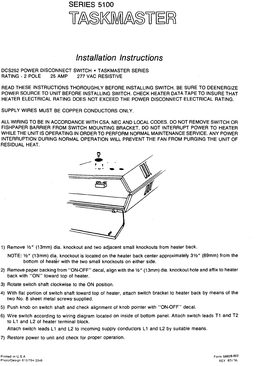
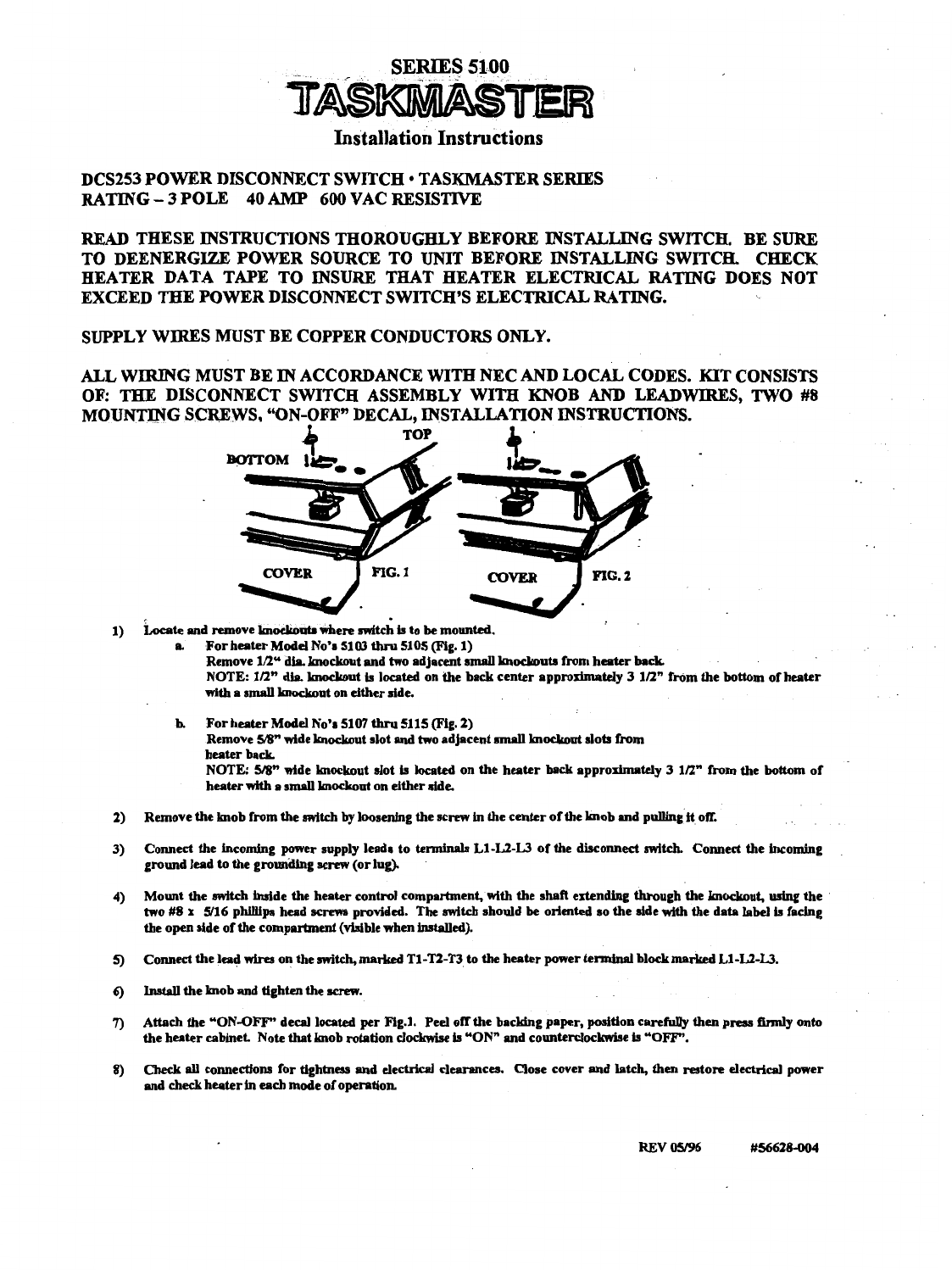

SERIES 5100
TASKMASTER
INSTALLATION INSTRUCTIONS
TASKMASTER SERIES
T5100, T5102, T5122, TC5102 AND TC5103 Built-in Thermostat Kits for Field installation in the 5100
Series Unit Heaters.
T5100 provides SPST line voltage control for single phase heaters up to 277V, 25a.
or
Pilot duty control (24-277 volt) for contactor equipped heaters.
T5102 provides double pole line voltage control breaking all ungrounded conductors for single phase
heaters up to 277V, 25 amperes.
or
Two pole line cycling control for 3 phase heaters up to 240 volts, 25 amps but does not break all
ungrounded conductors on 3 phase applications.
T5122 provides two stage low voltage (24V) control for two stage heaters. Two separate circuits are
controlled by the same sensing element. Switches controlling these circuits are calibrated to make
or break in sequence.
TC5102 is a thermostat and relay for use with 480 & 600 volt heaters to control the fan motor. It provides for
sensing of heat accumulation (strat-stat) near the ceiling and switches the fan motor on to recirculate
and recover this heat.
TC5103 provides control of the fan motor on 208, 240 & 277 volt heaters to recover and recirculate the
statified heat accumulated near the ceiling.
Please read each installation instruction carefully before beginning installation.
INSTALLATION INSTRUCTIONS T5100, T5102, T5122
1.) CAUTION:
To avoid possible electric shock, turn heater OFF at distribution panel. On heaters equipped with a
disconnect switch, rotate switch to the OFF position.
2.) Unlock the 2 screws on the control panel door and let door swing down. Some models have an
additional center door catch. Squeeze catch to open.
3.) Remove 1/2 (13mm) diameter thermostat bulb exit knockout from back of heater, Fig. 1. Feed
thermostat bulb and capillary tube thru knockout.
CAUTION: Keep capillary tubing away from internal electrical components.
4.) Remove 2 small thermostat bulb clip knockouts on the rear of the heater, see Fig. 1. Insert 2 bulb clips
(supplied). Snap thermostat bulb into clips.
5.) Remove the three stat mounting knockouts from side of control compartment: (1) 9/16 & (2) 3/16. Remove
backing from label (supplied). Align label with thermostat shaft hole and position as in Fig. 1. Press label
on heater side as shown.
6.) Note orientation of leg on thermostat bracket (see Fig. 1). Position only as shown. Install thermostat with
the (2) number 8 mounting screws provided. FORM: 56628-005
ECO 1-5719
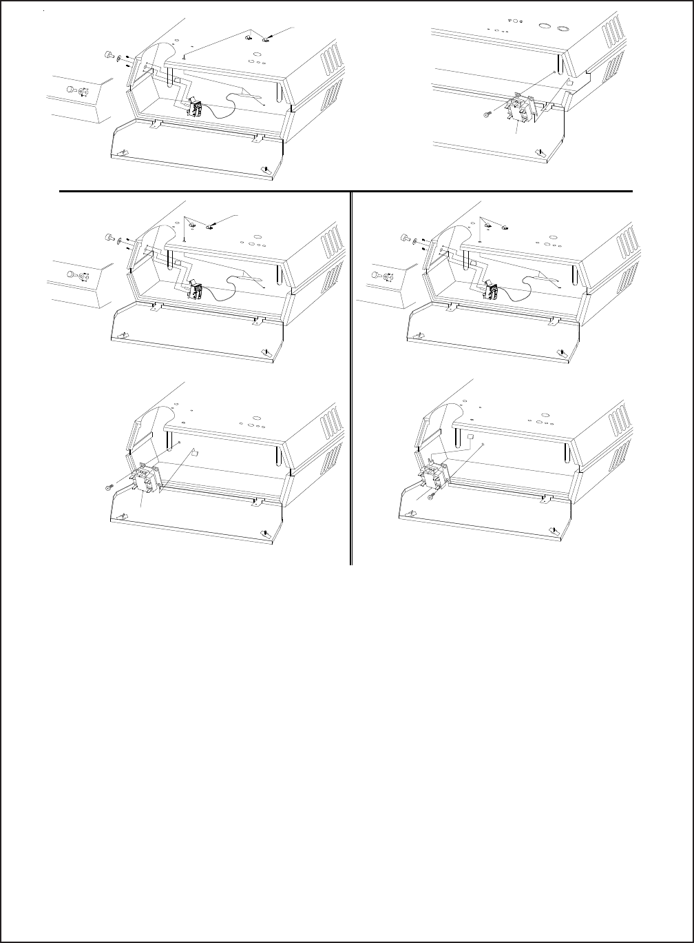
7.) Install knob by pushing onto thermostat shaft.
8.) Connect lead wires from the thermostat to the control terminal board as shown in the wiring diagrams
located on the inside of the control panel door.
9.) Set thermostat for desired turn on temperature. Rotate thermostat knob fully clockwise. When the room
temperature has reached the comfort level turn thermostat counterclockwise until it clicks off. The
thermostat may require one or two additional settings to maintain your desired comfort level.
HEAT RECOVERY THERMOSTAT TC5102 AND TC5103
10.) The TC5102 thermostat package requires a relay to operate the fan motor. Install the thermostat by
following steps 1 through 8.
11.) Install the relay by slipping extended relay leg under mounting lip on control panel. Mount relay with one
No. 8 screw as shown in Fig. 2. Each lead wire is marked for proper terminal location; connect lead wires
as indicated on teh wiring diagram located on the inside of the control panel door.
12.) Set the thermostat for desired turn on temperature for fan control.
SWITCH
RELAY
MOUNTING
SCREW
25 - 50KW
FIG. 1
BULB
25 - 50KW
FIG. 2
SWITCH
RELAY
MOUNTING
SCREW
BULB
3.3 - 5KW
FIG. 1
CLIPS
CLIPS
3.3 - 5KW
FIG. 2
7 - 20KW
FIG. 1
BULB
7 - 20KW
FIG. 2
SWITCH
RELAY
MOUNTING
SCREW
FORM: 56628-005
ECO 1-5719

`
`
`
`
`
`
SERIES TASKMASTER
`
`
Necessaires de thermostat incorpores T5100, T5102, T5122, TC5102 et TC5103 (pour etre installes sur place
les radiateurs de series 5100)
Le T5100, Unipolaire a une direction (SPST), controle la tension de ligne pour les radiateurs monophases jusqu' a
277V, 25A.
o u
veilleuse (24-277 volts) pour les radiateurs munis de contacteurs.
Le T5102, bipolaire controle la tension de ligne interrompant tous les conducteurs non mis a la terre pour les
radiateurs monophases jusqu' a 277V, 25A
o u
bipolaire a une direction pour les radiateurs tripolaires jusqu' a 240V, 25A mais n' interrompant pas tous
les conducteurs non mis a la terre pour les applications triphasees.
Le T5122, a un controle basse tension (24V) a 2 etages pour radiateur a 2 etages. Les deux circuits sont separes
et controles par le meme element sensitif. Les interrupteurs controlant ces circuits sont calibres pour
ouvrir et fermer en serie.
Le TC5102 est un relais/thermostat qui est utilise avec des radiateurs de 480 & 600 volts pour controler le moteur
du ventilateur. Il sert a detecter l arrivee de la chaleur (therm.de strat.) au plafond et a faire demarrer
le moteur du ventilateur pour faire recirculer accumulation de chaleur.
Le TC5103 sert a controler le moteur du ventilateur sur les radiateurs de 208, 240 & 277 volts pour faire recirculer
la chaleur stratifiee accumulee au plafond.
Lisez S.V.P. chaque instruction d'installation soigneusement avant de commencer l'installation.
1.) ATTENTION:
Afin d'eviter un choc electrique possible, mettez le radiateur a la position ARRET au niveau du panneau de
distribution. Sur les radiateurs equippes d'un interrupteur de courant, mettez l'interrupteur a la position ARRET.
2.) Desserez les deux vis situees sur la porte du panneau de controle et laissez celle-ci pendre. Quelques modeles
ont un dispositif d'arret supplementaire. Comprimez ce dispositif afin qu il s'ouvre.
3.) Enlevez la rondelle defoncable de dia. 1
2" (13mm) alimentant l'ampoule du thermostat Fig. 1 afin de connecter
celle-ci par le trou ainsi fait.
ATTENTION: Gardez le tube capillaire loin des dispositifs et des fils electriques internes.
4.) Enlevez lez 2 petites rondelles defoncables pour les attaches des ampoules du thermostat a l'arriere du radiateur,
(voir Fig. 1.) Inserez les deux attaches fournies. Agrafez les ampoules sur les attaches.
5.) Enlevez le papier du dos de l'etiquette (fournie). Alignez l'etiquette sur le trou de l'arbre du thermostat et
positionnez-la (voir Fig. 1.) Collez l'ettiquette sur le cote du radiateur comme montre.
6.) Notez l'orientation de la patte sur le support du thermostat. (voir Fig. 1). Positionnez-la comme montre seulement.
Installez le thermostat avec les 2 vis de montage No. 8 fournies.
Instructions d'Installation
INSTRUCTIONS D'INSTALLATION DES T5100, T5102 & T5122
`
``
``
`
`
` `
`
`
FORM: 56628-005
ECO 1-5719
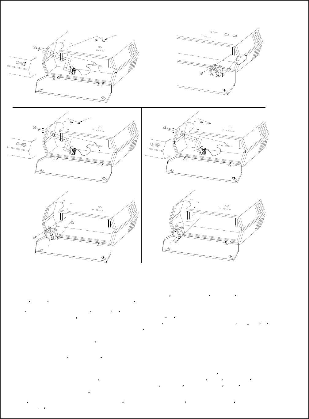
FIG. 1
`
`
`
`
``
`
`
`
25 - 50KW
FIG. 1
AMPOULE
7 - 20KW
FIG. 2
SWITCH
RELAY
MOUNTING
SCREW
25 - 50KW
FIG. 2
7.) Installez le bouton en le poussant sur l'arbre du themostat.
8.) Connectez les fils conducteurs du thermostat aux bornes de controle comme montre sur les shemas de filerie
situes a l'interieur de la porte du panneau de controle.
9.) Reglez le thermostat a la temperature desiree. Tournez le thermostat a fond dans le sens des auqulles d'une
montre. Lorsque la temperature de la piece a atteind le niveau desire tournez le thermostat dans le sens
contraire des auqulles d'une montre jusqu' a ce qu'il s'ouvre (declique). Le thermostat doit peut etre, etre regle
de noveau une a deux fois afin de maintenir une temperature comfortable.
10.) Le thermostat monte TC5102 doit etre muni d'un relais afin de faire fonctionner le moteur du ventilateur. Installez
le thermostat en suivant les paragraphes de 1 a 8.
11.) Installez le relais en glissant sa patte sous le rebord de montage du panneau de controle. Montez le relais
avec une vis No. 8 comme montre sur la Fig. 2. Chaque fil conducteur est marque pour etre connecte
correctement; Connectez les fils conducteurs comme indique sur le shema de filerie situe a l interieur de
la porte du panneau de controle.
12.) Reglez le thermostat de nouveau pour controler le ventilateur, si vous desirez une autre temperature que
celle reglee a la fabrique.
3.3 - 5KW
FIG. 2
7 - 20KW
3.3 - 5KW
FIG. 1
ATTACHES
ATTACHES
AMPOULE
THERMOSTAT A RECUPERATION DE CHALEUR TC5102 & TC5103
FORM: 56628-005
ECO 1-5719
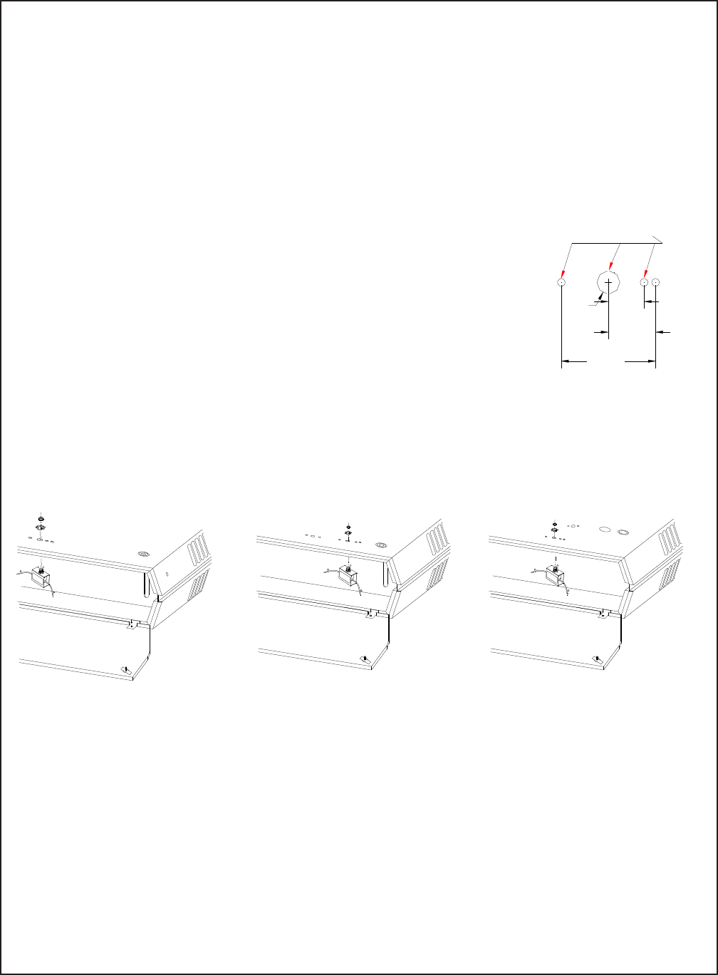
SERIES 5100
TASKMASTER
Installation Instructions
FS5102-TASKMASTER SERIES
UNIT MOUNTED LINE VOLTAGE SUMMER FAN SWITCH
FOR USE ON EITHER 480 OR 600 VOLT SUPPLY
READ THESE INSTRUCTIONS CAREFULLY BEFORE INSTALLING SWITCH. BE SURE TO DE-ENERGIZE
POWER SOURCE TO UNIT BEFORE INSTALLING SWITCH. BE SURE TO INSTALL THE APPROPRIATE
MODEL SWITCH ON THE CORRECT UNIT.
1.) Disconnect heater from supply.
2.) Remove appropriate knockouts for switch being used. Refer to Fig. 1.
Models 5102 thru 5105 - Fig. 2
Knockout group is located on heater back center approximately 1 1/8” (29mm)
from bottom of heater.
Models 5107 thru 5120 - Fig. 3
Knockout group is located on heater back approximately 3 1/4” (83mm) from bottom of heater with the 9/16”
(14mm) diameter knockout located approximately 3 3/4” (95mm) to the right of the back center.
Models 5125 thru 51100 - Fig. 4
Knockout group is located on heater back approximately 1 3/4” (44mm) from bottom of heater with the 9/16”
(14mm) diameter knockout located approximately 5” (127mm) to the left of the back center.
Fig. 2 Fig. 3 Fig. 4
3.) Remove paper backing from “Fan-Heat” decal, align with large knockout hole and affix to heater back with
“Heat” toward bottom of heater.
4.) Attach switch bracket assembly to heater back with the two No. 8 sheet metal screws supplied.
5.) Push knob on switch shaft and check alignment with decal.
6.) Wire switch according to wiring diagram located on inside of heater bottom panel. Attach switch leads 7 & 9
to terminals 7 & 9 on terminal board.
7.) After installation is complete, restore power and check for proper operation.
Note: For summer fan operation only, place thermostat in OFF position.
0.875
1.1565
2.3125
Ø0.5625 (22MM)
(29MM)
(59MM)
(14MM)
REMOVE FOR
FS5102
FIG. 1
Form 56628-008
ECO 1-5719
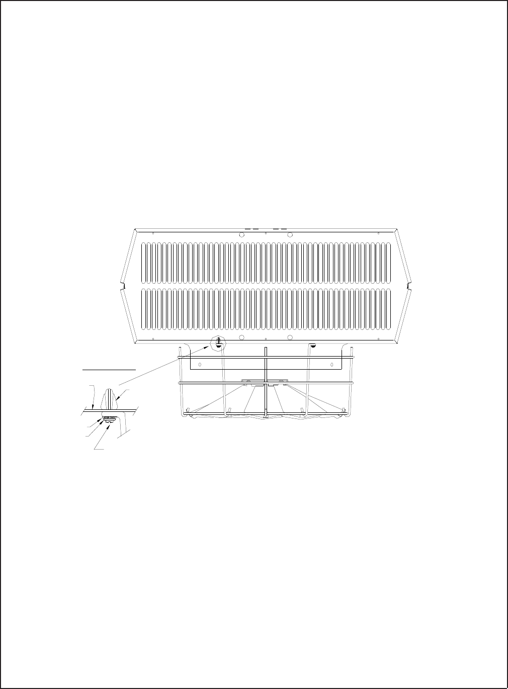
SERIES 5100
TASKMASTER
Installation Instructions
FOR RADIAL DIFFUSER
MODEL RD5120 USE WITH 5107-5120 UNITS
MODEL RD5150 USE WITH 5125-5150 UNITS
MODEL RD5175 USE WITH 5155-5175 UNITS
READ THESE INSTRUCTIONS CAREFULLY BEFORE INSTALLATION. BE SURE TO
DE-ENERGIZE POWER SOURCE TO UNIT BEFORE INSTALLING DIFFUSER. CHECK MODEL
NUMBER TO INSURE INSTALLATION ON PROPER SIZE UNIT.
1.) Disconnect heater from supply.
2.) Immerse nylon push nuts in water for at least 1/2 hour before installing.
3.) Remove louver frame assembly from front of heater and discard. (Louver frame assembly is
attached to the heater front with four sheet-metal screws.)
4.) Insert the four nylon push nuts provided into the square holes located around the venturi
opening on the heater front. A slight tap with a flat surface may be required to fully seat the
nylon push nuts into the square holes.
5.) Assemble the star washers and flat washers provided onto each of the mounting screws
as shown.
6.) Line up the diffuser mounting holes with the nylon push nuts mounted in the heater front
(step 2). Insert the mounting screws (step 3) through the diffuser mounting eyelets and
tighten screws.
7.) Adjust the diffuser vanes for desired air deflection.
8.) Restore power to place heater in operation.
MOUNTING BOLT DETAIL
MOUNTING
SCREW
FLAT WASHER
FRONT PANEL
OF UNIT
STARWASHER
NYLON
PUSH NUT
FORM: 56628-011
ECO 1-5719
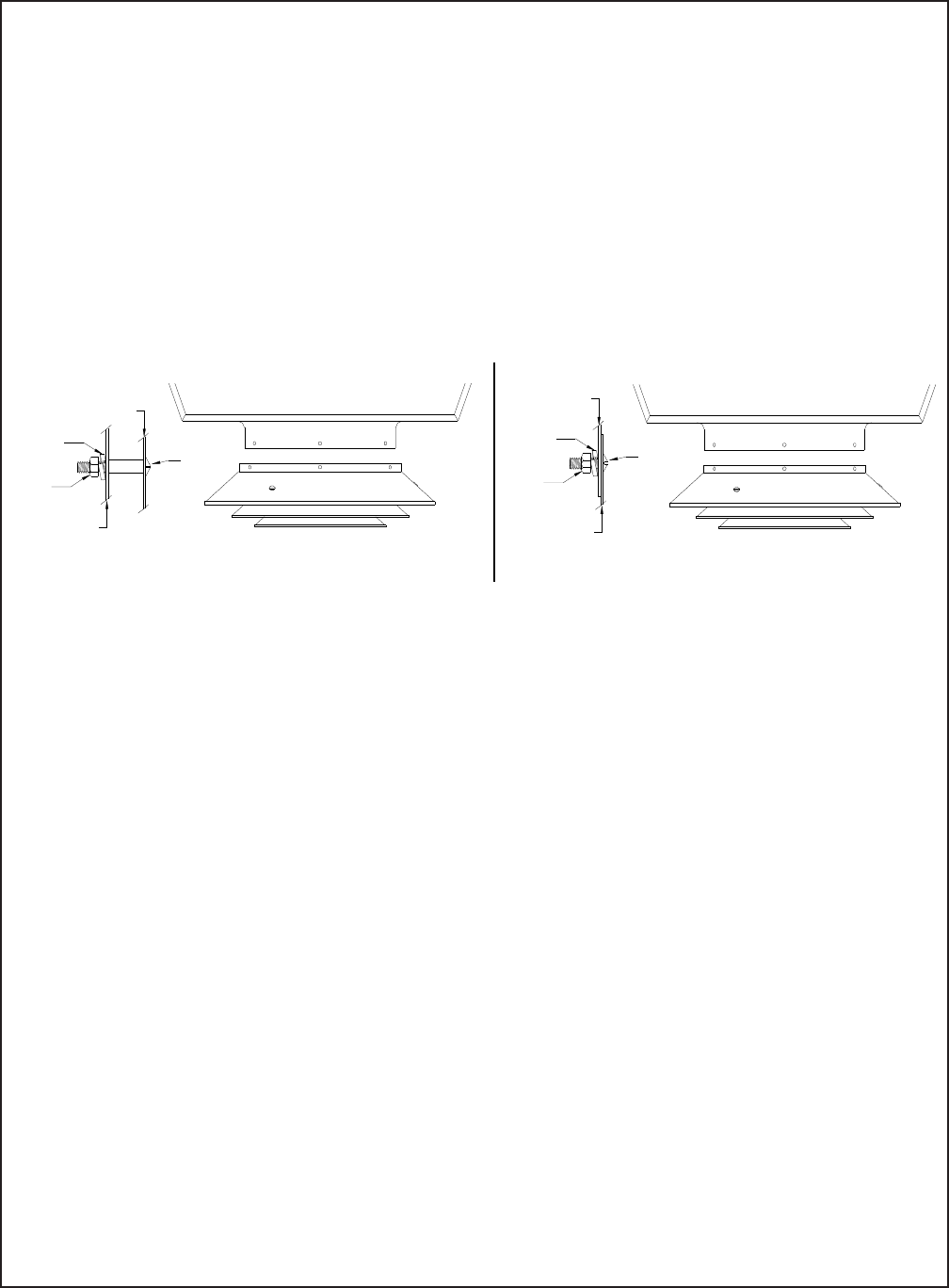
SERIES 5100
TASKMASTER
INSTALLATION INSTRUCTIONS
ANEMOSTAT DIFFUSER -TASKMASTER SERIES
MODEL AD5120 USE WITH 5107-5120 UNITS
MODEL AD5150 USE WITH 5125-5150 UNITS
MODEL AD5175 USE WITH 5155-5175 UNITS
READ THESE INSTRUCTIONS THOROUGHLY BEFORE INSTALLING DIFFUSER. BE SURE TO
DE-ENERGIZE POWER SOURCE TO UNIT BEFORE INSTALLING DIFFUSER. CHECK MODEL
NUMBER OF DIFFUSER TO INSURE INSTALLATION ON PROPER SIZE UNIT.
For Heaters 5107-5110 Use Diffuser AD5120 - See Fig. 1
For Heaters 5125-5150 Use Diffuser AD5150 - See Fig. 1
For Heaters 5155-5175 Use Diffuser AD5175 - See Fig. 1
1.) Discard 1/4-20 X 1/2” (13mm) long machine screws (bag assembly).
2.) Line up holes in diffuser and the venturi ring on the heater front.
3.) Insert the 1/4-20 x 1” (25mm) long machine screws through the venturi ring holes with the
machine screw head on the inside of the venturi (See Note Below).
4.) Slip the spacer (1/4”(6mm) for models 5155-5175 and 5/8”(16mm) for all others listed above)
over the machine screw. Insert the machine screw through the diffuser hole, install the
lockwasher, nut; then tighten. (See detail above). (Three places)
5.) Place heater in operation.
For Heaters 5112-5120 Only Use Diffuser AD5120 - See Fig. 2
1.) Discard 1/4-20 X 1” (25mm) long machine screws and 5/8” (16mm) long spacers.
2.) Line up holes in diffuser and venturi ring (heater front).
3.) Insert 1/4-20 x 1/2” (13mm) long machine screws through venturi ring and diffuser holes with the
machine screw head on the inside of the venturi (See Note Below).
4.) Attach the lockwasher, nut and tighten. (See detail above) (Three places).
5.) Place unit in operation.
NOTE
1.) Machine screw heads must be on the inside of the venturi ring.
2.) Caution must be exercised when mounting the diffuser so as not to damage the fan blade.
FORM: 56628-012
ECO 1-5719
NUT
MACHINE
SCREW
VENTURI
RING
DIFFUSER
LOCKWASHER
FIG. 1 FIG. 2
NUT
MACHINE
SCREW
VENTURI
RING
DIFFUSER
LOCKWASHER