14602 EZ Cover/intro 102651 Catalog
73535-Catalog 73535-Catalog 73535-Catalog 078477 Batch3 unilog cesco-content
2014-11-11
: Pdf 102651-Catalog 102651-Catalog 639889 Batch12 unilog
Open the PDF directly: View PDF ![]() .
.
Page Count: 465 [warning: Documents this large are best viewed by clicking the View PDF Link!]
- Electromate
- Industrial Solutions
- KL Junction Boxes
- Screw Cover Junction Boxes
- Lift-Off Hinge Cover Boxes
- EB Instrument Enclosures
- Continuous Hinge Cover Enclosures
- Continuous Hinge Quick Release Boxes
- Continuous Hinge Wing Turn Boxes
- Continuous Hinge Cover Boxes
- Clamp Cover Junction Enclosures
- Handy Box Enclosures
- Two Door Wallmount Enclosures
- Flush Mount Boxes
- Large Oil-Tight Boxes
- AE Wallmount Enclosures
- Legacy Series Enclosures
- One Door Wallmount Boxes
- One Door Wallmount Enclosures
- EL 3-Part Wallmount Enclosures
- Drawings KL Junction Boxes Without Gland Panels
- Drawings Screw Cover Junction Boxes
- Drawings Lift-Off Hinge Cover Boxes
- Drawings EB Instrument Enclosures
- Drawings Continuous Hinge Cover Enclosures
- Drawings EMI/RFI Continuous Hinge Cover Enclosures
- Drawings Continuous Hinge Quick Release Boxes
- Drawings Continuous Hinge Wing Turn Boxes
- Drawings Continuous Hinge Cover Boxes
- Drawings Clamp Cover Junction Enclosures
- Drawings Handy Box Enclosures
- Drawings Two Door Wallmount Enclosures
- Drawings Flush Mount Boxes
- Drawings Large Oil-Tight Boxes
- Drawings AE Wallmount Enclosures
- Drawings Legacy Series Enclosures
- Drawings One Door Wallmount Boxes
- Drawings EL 3-Part Wallmount Enclosures
- Notes
- Wireway
- FreeStanding Enclosures
- AK Freestanding Enclosures
- Door Freestanding Enclosures One
- One Door Modular Cabinets
- One/ Two Door Freestanding Cabinets
- Two Door Floormount Enclosures
- Multi-Door Freestanding Enclosures
- Drawings AK Freestanding Enclosures
- Drawings One Door Freestanding Enclosures
- Drawings One Door Modular Cabinets
- Drawings One Door Freestanding Cabinets
- Drawings Two Door Freestanding Cabinets
- Drawings Two Door Floormount Enclosures – NEMA 12
- Drawings Two Door Floormount Enclosures – NEMA 4
- Drawings Multi-Door Freestanding Enclosures
- FMD Enclosures
- Wallmount FMD Enclosures AE
- NEMA 4 Wallmount Boxes
- NEMA 12 Wallmount Boxes
- NEMA 12 Wallmount Enclosures
- Freestanding Heavy Duty Enclosures
- Floormount Freestanding Enclosures
- Drawings
- Drawings AE Wallmount FMD Enclosures
- Drawings NEMA 4 Wallmount Boxes
- Drawings NEMA 12 Wallmount Boxes
- Drawings NEMA 12 Wallmount Enclosures
- Drawings Freestanding Heavy Duty Enclosures
- Drawings Floormount Freestanding Enclosures
- AE Wallmount FMD Enclosures
- AE Wallmount FMD Enclosures
- NEMA 4/4X Wallmount Enclosures (HS)
- NEMA 12 Wallmount Boxes (SA)
- NEMA 4/4X And NEMA 12 Wallmount Enclosures
- NEMA 12 Wallmount Enclosures
- NEMA 4/4X And NEMA 12 Wallmount Enclosures
- NEMA 12 Wallmount Enclosures
- NEMA 4/4X And NEMA 12 Wallmount Enclosures
- NEMA 12 Wallmount Enclosures
- NEMA 4/4X And NEMA 12 Wallmount Enclosures
- NEMA 12 Wallmount Enclosures
- NEMA 4/4X And NEMA 12 Wallmount Enclosures
- Freestanding Heavy Duty Enclosures (XM)
- Freestanding Heavy Duty Enclosures (XM)
- Heavy Duty, Modular And Floormount Enclosures
- Notes
- Operator Interfaces
- Standard Boxes Pushbutton
- Slim Pushbutton Boxes
- Miniature Pushbutton Boxes
- Extra Large Pushbutton Boxes
- Extra Pushbutton Boxes Deep
- Sloping Front Pushbutton Boxes
- AP Desk Consoles
- Consoles, Pedestals and Bases
- Enclosures Series Operator
- Enclosures Computer PC
- Arm Enclosures CP Pendant
- CP Pendant Arm Systems
- Pendant Arm Systems CP
- CP- Vertical Pendant Arm Systems
- Technical Drawings
- Standard Pushbutton Boxes
- Slim Pushbutton Boxes
- Miniature Pushbutton Boxes
- Extra Large Pushbutton Boxes
- Extra Deep Pushbutton Boxes
- Sloping Front Pushbutton Boxes
- AP Desk Consoles, Bottom Section
- AP Desk Consoles, Center Section
- AP Desk Consoles, Top Section
- AP Desk Console Systems
- AP Universal Console Systems
- Consoles, Pedestals and Bases
- Series 9 Operator Enclosures
- Series 12 Operator Enclosures
- Series 14 Operator Enclosures
- PC Computer Enclosures
- CP Pendant Arm Enclosures
- CP-Vertical Pendant Arm Systems
- Noncorrosive Enclosures
- KL Junction Boxes
- Continuous Hinge Cover Enclosures
- Continuous Hinge Cover Enclosures
- Cover Continuous Hinge Boxes
- Enclosures Clamp Cover Junction
- Enclosures Clamp Cover Junction
- AE Wallmount Enclosures
- Legacy Series Enclosures
- One Door Wallmount Boxes
- One Door Wallmount Boxes
- Enclosures One Door Wallmount
- 4X Feed- Through Type Wireway
- One Door Freestanding Enclosures
- One/ Door Freestanding Cabinets Two
- Two Floormount Door Enclosures
- Two Door Floormount Enclosures
- NEMA Wallmount 4X Boxes
- Floormount Freestanding Enclosures
- Enclosures Freestanding Heavy Duty
- Pushbutton Standard Boxes
- Slim Pushbutton Boxes
- Pushbutton Miniature Boxes
- Extra Deep Pushbutton Boxes
- Consoles, and Pedestals Bases
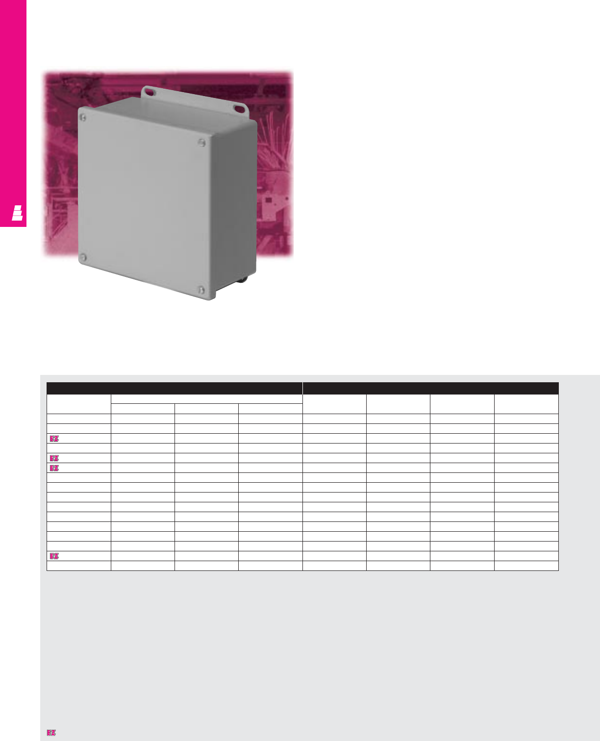
- KS Fiberglass Enclosures
- Screw Junction Cover Boxes
- Hinged Screw Cover Junction Boxes
- Lockable Quick Release Junction Boxes
- Flush Viewing Window Junction Boxes
- NEMA 4X Wallmount Boxes
- NEMA 3R Wallmount Boxes
- Fiberglass Wallmount Boxes
- NEMA 4X Freestanding Boxes
- 30/ 22 mm Pushbutton Enclosures
- Small Box Pushbutton Enclosures
- Technical Drawings
- KL Junction Boxes
- Continuous Hinge Cover Enclosures
- Clamp Cover Junction Enclosures
- AE Wallmount Enclosures
- Legacy Series Enclosures
- One Door Wallmount Boxes
- One Door Wallmount Enclosures
- Feed-Through Type 4X Wireway
- One Door Freestanding Enclosures
- One Door Freestanding Single Access Cabinets
- Two Door Freestanding Single Access Cabinets
- One Door Freestanding Dual Access Cabinets
- Two Door Freestanding Dual Access Cabinets
- Two Door Floormount Enclosures
- Two Door Floormount Enclosures
- NEMA 4X Wallmount Boxes
- Floormount Freestanding Enclosures
- Freestanding Heavy Duty Enclosures
- Standard Pushbutton Boxes
- Slim Pushbutton Boxes
- Miniature Pushbutton Boxes
- Extra Deep Pushbutton Boxes
- Consoles, Pedestals and Bases
- KS Fiberglass Enclosures
- Screw Cover Junction Boxes
- Hinged Screw Cover Junction Boxes
- Lockable Quick Release Junction Boxes
- Flush Viewing Window Junction Boxes
- Hinged Screw Cover Instrumentation Boxes
- Viewing Window Instrumentation Boxes
- Hinged Quick Release Instrumentation Boxes
- NEMA 4X Wallmount Boxes
- NEMA 3R Wallmount Boxes
- Fiberglass Wallmount Boxes
- NEMA 4X Freestanding Boxes
- NEMA 4X Freestanding Boxes
- 30/22mm Pushbutton Enclosures
- Small Box Pushbutton Enclosures
- Commercial Products
- Small Type 1 Wallmount Enclosures
- Large / Extra Large Type 1 Wallmount Enclosures
- Small Hinge Cover Boxes
- Large Hinge Cover Boxes
- Hinge Cover Enclosures
- Current Transformer Enclosures
- Lay- Type 1 In Wireway
- Screw Cover Pull Boxes
- Hinge Pull Boxes Cover
- Raintight Screw Cover Enclosures
- Raintight Wiring Trough
- Gasketed Screw Cover Boxes
- Technical Drawings
- Small Type 1 Wallmount Enclosures
- Large Type 1 Wallmount Enclosures
- Extra Large Type 1 Wallmount Enclosures
- Small Hinge Cover Boxes
- Large Hinge Cover Boxes
- Hinge Cover Enclosures
- Current Transformer Enclosures
- Lay-In Type 1 Carbon Steel Wireway
- Lay-In Type 1 Galvanized Steel Wireway
- Screw Cover Pull Boxes
- Hinge Cover Pull Boxes
- Raintight Screw Cover Enclosures
- Raintight Wiring Trough
- Gasketed Screw Cover Boxes
- Networking Solutions
- Outside Plant Products
- Climate Control Solutions
- Accessories
- Bases And Accessories
- Mounting Surfaces And Accessories
- Locking Systems
- Door System Accessories
- Cable Management
- Shelves And Accessories
- General Accessories
- Pole Mounting Kit
- Lids/ Covers For AP Consoles
- Pencil Ledge For AP Consoles
- Wall Brackets For KL/ EB/ AE/ KS Enclosures
- Grounding Straps
- Screws For Grounding Straps
- Quick Release Fastener
- Cover Hinge
- Threaded Insert Nuts For KS
- Enclosure Lights
- Connections Components With Cover
- Optical Components
- Light Bulbs
- Audible Components
- Mounting Components
- Laminated Copper Bars Rittal Flexibar “S”
- Interface Box
- Cable Flange For 24- pin Plug Wall Cutouts
- Rails 19"
- Compact Swing Frames For AE And AP 6 - 14 HU Packs Part No.
- Aluminum Front Panels
- Pedestal/ Platform
- Wireway Reinforcement
- Bracket
- Cable Tie Fastener
- Networking Accessories
- Vented Component
- Shelves
- Base
- Combination Cable
- Collecting Rails For
- QuickRack Frame width
- Rack Storage Drawer
- For BasicRacks
- Double Divider Shelf
- For BasicRacks
- Adjustable Monitor Shelf
- Divider Shelf
- Cable Management
- Sliding Extension Shelf
- For BasicRacks
- 19" Full Size Sliding
- Keyboard & Mouse Tray
- 19" Rails (482.6/ 485 mm)
- Combination Cable
- Collecting Rails For
- QuickBox
- 19" Cantilever Shelf
- Telescopic Slides For
- Component Shelves
- Outside Plant Accessories
- Climate Control Accessories
- Locking System Accessories/ Door System
- Mounting Surface Accessories
- Mounting Panels For Junction Boxes
- Mounting Panels For Type 1 And 3R Enclosures
- Mounting Panels For NEMA Style Boxes
- Mounting Panels For One Door Freestanding
- Mounting Panels For Two Door Freestanding
- Side- Mount Mounting Panels For Freestanding
- Enclosures
- Heavy Duty Mounting Panel Supports
- Center Mounting Panel Supports
- Mounting Panels
- For Legacy Enclosures
- Mounting Panels For
- Legacy Enclosures
- (Continued) White (NEMA Style) H W
- Dead Front Kits
- Dead Front Kits
- (Continued)
- Terminal Block Kits
- For JIC Enclosures
- Terminal Block Kits For
- Type 4, 4X, 12 And 13
- Enclosures parallel to straps length
- Drip Shield Kits For
- Type 12 Enclosures
- Drip Shield Kits For
- Type 4, 4X And Type 12
- Enclosures Part No. Part No. holes
- Wallmounting Bracket Kits
- Wall Brackets For
- Legacy Enclosures
- Relay Rack Angles
- For Freestanding
- Enclosures enclosure mounting
- Pedestals And Bases
- Accessories General
- Fiberglass Accessories
- Technical Information
- Certifications & Standards
- Enclosure Selection Guidelines
- Enclosure Materials
- Chemical Resistance
- Enclosure Paint Finishes
- Non-Metallic Properties
- Climate Control Heat Removal From Enclosures
- Climate Control General Information
- Climate Control Technical Information
- Advantages-At-A-Glance Air Conditioners
- Advantages-At-A-Glance Air/Air Heat Exchangers
- Advantages-At-A-Glance Air/Water Heat Exchangers
- Advantages-At-A-Glance Filter Fans
- Advantages-At-A-Glance Panel Heaters
- Index
In USA: Rittal Corporation • One Rittal Place • Springfield, OH 45504, USA • Phone: (937) 399-0500 • Toll Free: 1-800-477-4000
Fax: (937) 390-5599 • Email: rittal@rittal-corp.com • Internet: www.rittal-corp.com
Technical Hotline: 1-800-637-4425 • Technical Website: www.enclosureinfo.com
In Canada: Rittal Systems Ltd. • 7320 Pacific Circle • Mississauga, Ontario L5T 1V1, Canada
Phone: (905) 795-0777 • Fax: (905) 795-9548
In México: Rittal, S.A. de C.V. • Prolongación 5 de Mayo No. 29 • Parque Industrial Naucalpan
53489 Naucalpan, México • Phone: (525) 300-2570 • Fax: (525) 300-0495
HMC 14602 8/02 DBH 20M #9037.999
Industrial & Commercial
Enclosures & Climate
Control Products
14602-EZ Covers w/Spine.qx4 10/3/02 8:47 AM Page 1

E
SSENTIAL
E
NCLOSURE
S
OL
For over four
decades Rittal has
provided a steady
stream of solutions
to better meet the
needs of the markets
we serve. This
innovation-oriented
philosophy has set
the world standard
for products and categories that have
become the mainstays of the global mar-
ketplace. And to achieve this
accomplishment, Rittal has dedicated
itself to producing products that offer a
fine blend of
aesthetic design,
maximum
protection,
compatibility and
functionality —
for the utmost in
enclosure
packaging solutions. And nothing
exemplifies the essential
hard-working products you need
like the Rittal • Electromate
EnclosureZone program.
work on your next project.
Add to that the tough,
hard-working Electromate
NEMA-style products like
junction boxes, freestand-
ing cabinets, wireway/
trough and more, and you
have a world of solutions
with down-to-earth value in
every box.
1
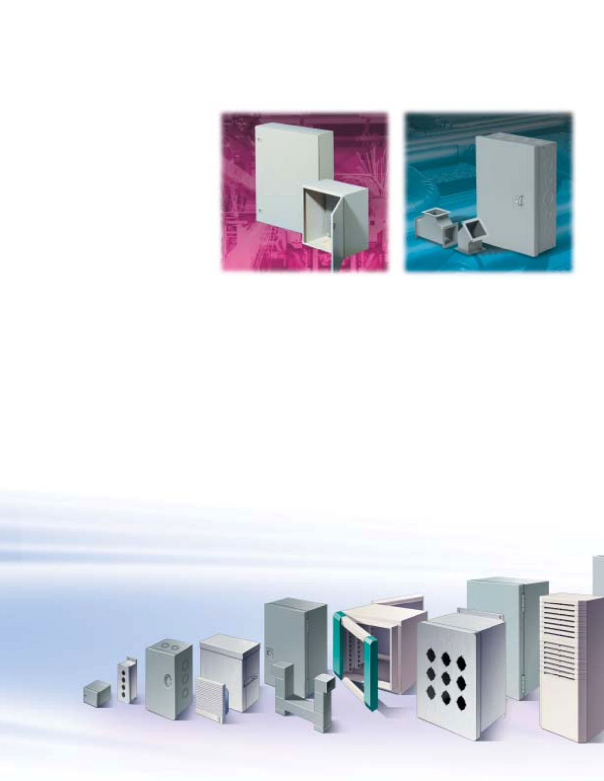
A World Of
Solutions.
Truly a world of solutions
has resulted between the
marriage of the Rittal and
Electromate product lines.
You see, Rittal offers a
comprehensive range of
enclosures for practically
any application. Big or
small, simple or complex, the Rittal EZ
products can provide just the right
products you need. From simple JIC
boxes to advanced climate control
products, outdoor packaging to
operator interface solutions,
our high-quality products
are waiting to go to
A powerful line-up — Rittal and
Electromate products provide you
with a complete range of quality
enclosure solutions.
Solid workmanship meets manufacturing
technology with Rittal's high quality
manufacturing processes.

UTIONS
F
ROM
R
ITTAL
.
INDUSTRIAL
Wallmount Enclosures ................pgs IND 1-58
Wireway/Trough ........................pgs IND 59-72
Freestanding Enclosures..........pgs IND 73-92
FMD Enclosures ....................pgs IND 93-142
Operator Interface ................pgs IND 143-198
Noncorrosive ........................pgs IND 199-299
COMMERCIAL
Type 1 Wallmount Enclosures ....pgs COM 1-2
Hinge Cover Boxes ....................pgs COM 3-5
Current Transformer Enclosures......pg COM 6
Lay-In Type 1 Wireway ..............pgs COM 7-8
Screw Cover Pull Boxes ..........pgs COM 9-10
Hinge Cover Pull Boxes ................pg COM 11
Raintight Screw Cover
Enclosures ....................................pg COM 12
Raintight Wiring Trough ................pg COM 13
Gasketed Screw Cover Boxes ......pg COM 14
Technical Drawings ................pgs COM 15-31
NETWORKING
QuickRack ValuePack
Enclosures ..................................pgs NET 1-2
QuickRack PowerPack
Enclosures ..................................pgs NET 3-4
BasicRacks ..................................pgs NET 5-6
QuickBox Enclosures ..................pgs NET 7-8
Technical Drawings....................pgs NET 9-11
OUTSIDE PLANT
Basic Aluminum Outdoor
Enclosures ..................................pgs OSP 1-2
Technical Drawings ..........................pg OSP 3
CLIMATE CONTROL
1S Filter Fans/Pagoda
Roof Fans ......................................pgs CLI 1-2
Air Conditioners ............................pgs CLI 3-4
Micro/Mini Air Conditioners ..........pgs CLI 5-6
Air/Air Heat Exchangers................pgs CLI 7-8
Enclosure Heaters..............................pg CLI 9
Air/Water Heat Exchangers..............pg CLI 10
Chillers ......................................pgs CLI 11-12
Vortex Kooler
Enclosure Coolers ....................pgs CLI 13-14
Technical Drawings ..................pgs CLI 15-30
ACCESSORIES
Rittal Accessories ....................pgs ACC 1-16
Electromate Accessories ........pgs ACC 17-31
TECHNICAL APPENDIX
Technical Information ................pgs TEC 1-30
TABLE OFCONTENTS
Essential
Enclosure
Quality.
The quality and
consistency of the EZ
product line is the direct
result of a careful blend
of skillful workmanship
combined with both
advanced manufacturing capabilities
and conventional skills that exist in all of
our Rittal operations facilities. In fact, the
pride of our well-trained
manufacturing team is
reflected in every
enclosure product we
make — from an
Electromate JIC box to
a Rittal PC industrial
enclosure. And this
dedication doesn't stop
there. Our team of responsive and
knowledgeable service and technical
experts strives to provide top-notch
service and support each and every day.
Altogether it is a total package coupled
with the utmost in enclosures — designed
to give you the essential enclosures
you need.
2
The Rittal team goes to work everyday to
ensure our customers and distributor partners
get precisely the enclosure they need.
Look for this notation that designates
an EZ item — EZ products are stocked,
quick ship items!
T
HE
P
ERFECT
E
NCLOSURE
F
Looking for tough enclosure products
for the most demanding industrial
applications? Then look to Rittal's line of
proven industrial packaging products, as
well as the Electromate family of NEMA-
style solutions. Choose from high quality,
high protection products like JIC/
wallmount boxes, pushbutton enclosures,
operator interface products, freestanding
enclosures, flange mount disconnect
products, wireway/trough and more.
Offered in a variety of materials, sizes
and protection ratings, these products
provide a smart solution for any
industrial installation.
INDUSTRIAL COMMERCIAL
Finding the perfect enclosure for a variety
of applications couldn't be easier with the
Rittal and Electromate EnclosureZone
program. Whether your application is in
a harsh industrial setting with dirt, dust
and heat, in an outdoor environment with
security considerations, or in a data
center filled with valuable networking
equipment, Rittal has the ideal packaging
and climate control solution for you.
Choose from a variety of solutions for
every zone that you operate in — from
industrial, commercial, networking,
outside plant and thermal management
— and you can be assured of a
top-quality, maximum protection solution
specifically for your next installation. Rittal
and Electromate — the perfect enclosure
for your application needs.
Designed for general purpose electrical
installations, Rittal’s line of commercial
Electromate products ensure basic
protection for Type 1 applications.
The line is comprised of Type 1/3R
small and medium enclosures, pull
boxes, hinge cover enclosures, as well
as industrial lay-in wireway. Top that
off with numerous raintight solutions
designed for indoor and outdoor
installations. For general industrial
jobs, choose from a host of sizes for
protection of sensitive components or
for easy wireway management.
3
OR
E
VERY
I
NSTALLATION
.
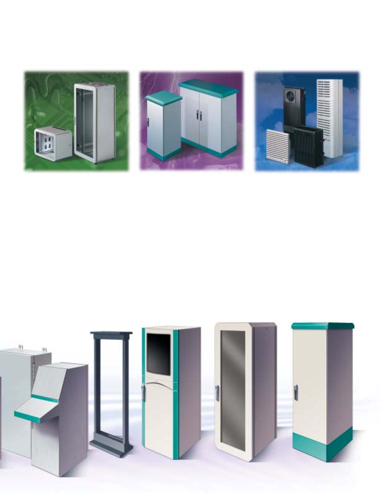
NETWORKING OUTSIDE PLANT CLIMATE CONTROL
Rittal’s family of indoor networking
enclosure products was developed to
offer a unique blend of style, quality,
advanced functionality and value, as well
as respond to the movement of network-
ing to the plant floor. The QuickRack line
of enclosure cabinets offers an attractive
design coupled with easy assembly.
Flexibility and cost efficiency are
highlighted with the QuickBox family of
wallmount boxes. And add to that the
economical 19” BasicRack. Altogether
Rittal's line-up of networking products can
satisfy virtually any indoor installation.
Weather the elements with Rittal’s CS
outdoor enclosure product offering.
For general utilities and traffic
management installations, Rittal’s
outdoor line of aluminum enclosures
provides top-notch solutions. Combine
Rittal's modular enclosure strength with
outdoor protection and the result is the
versatile CS Basic line of enclosures.
Choose from a variety of enclosure
sizes and accessories to complete
your outdoor plant installation.
From the simplest to the harshest
environments, Rittal has the ideal thermal
management solution for virtually any
enclosure installation. The Rittal thermal
management offering includes solutions
for low to high ambient temperatures —
from air conditioners and filter fans to
air/air and air/water heat exchangers,
chillers, heaters and Vortex Koolers.
Top that off with a range of applicable
accessories to complete the climate
control solution. So whether you need to
heat it up or cool it down, look to Rittal’s
extensive climate control family.
4
Real world applications demand real world
enclosure products. And no one offers an
extensive line-up of packaging products like
Rittal's EnclosureZone Program. Designed
for your typical installations like industrial
and commercial, the program provides
standard solutions for these applications.
Add to that a variety of solutions for zones
that are proliferating the marketplace like
networking and outside plant, and the offer-
ing is complete. The EZ family of products
has the real world solution you need for
your next real world application.
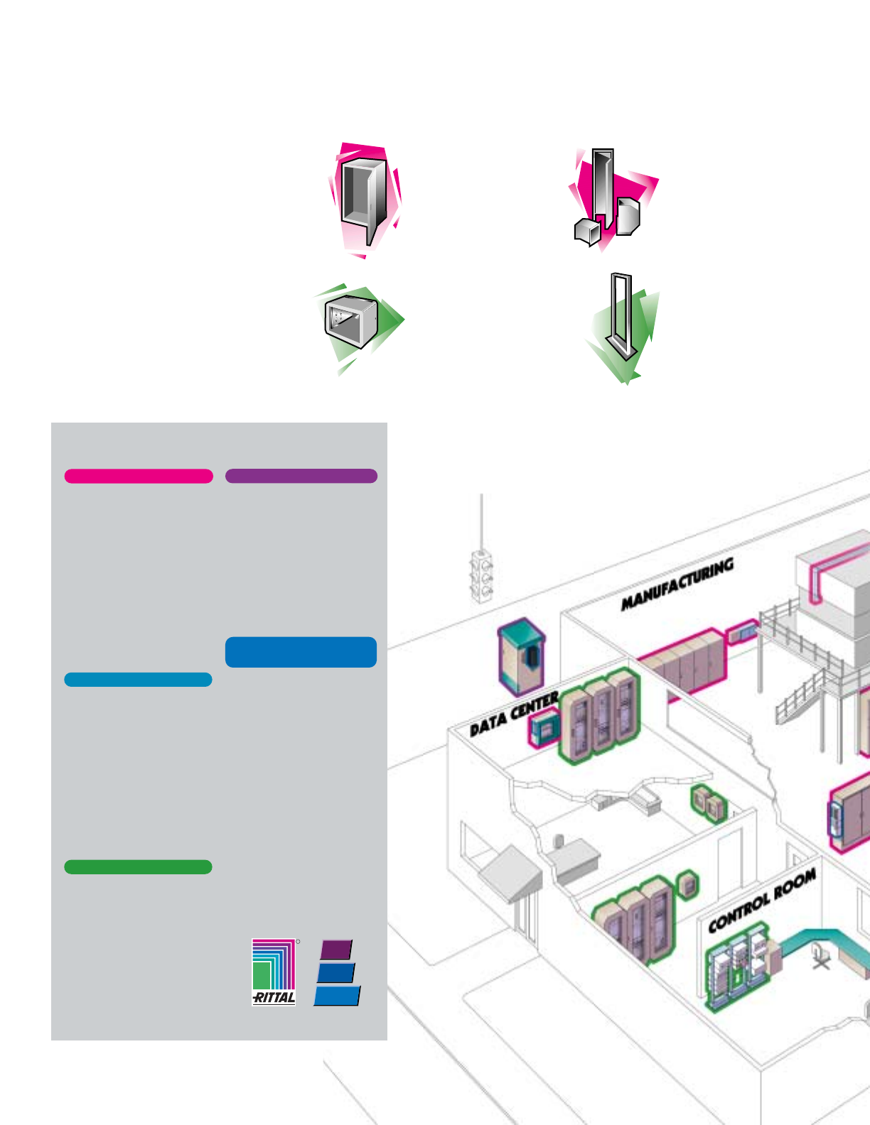
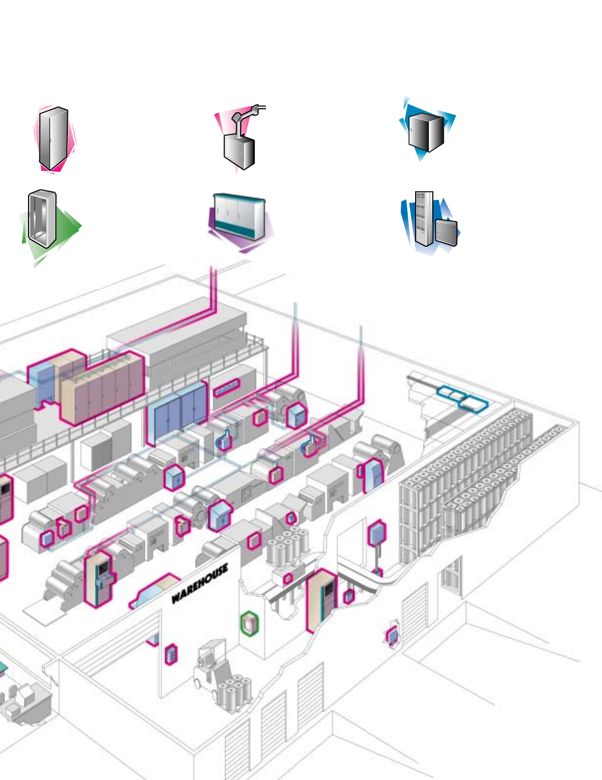
COMMERCIAL ZONE
The standard commercial
need can be found in
virtually any installation
setting. For both Type 1
and 3R applications, JIC,
wallmount, pull boxes and
trough are required to house
the wide variety of electrical
components.
INDUSTRIAL ZONE
The traditional zone, the
plant floor has numerous
opportunities for enclosure
solutions. From PLCs and
drives to pushbuttons,
controls and conduit, an
enclosure is needed at
just about every junction
throughout the manufactur-
ing environment.
NETWORKING ZONE
Networking is proliferating
many of the environments
as the use of servers, hubs,
routers and patch panels
increases. The flexibility to
hold various manufacturers'
equipment in a safe, secure
atmosphere is of the utmost
importance.
OUTSIDE PLANT ZONE
Many installations also
include the need for housings
to protect equipment for
utilities, traffic management
and outdoor applications.
This zone requires the highest
level of protection, security
and flexibility.
ENCLOSURE ZONES
To complement all of these
zone opportunities is the
thermal management line-up
of products. From harsh and
dirty ambient conditions to
clean rooms to outdoor
environments, climate control
products are needed in a
variety of settings.
THERMAL
MANAGEMENT ZONE
JIC/WALLMOUNT
SOLUTIONS
A wide range of wallmount
solutions including JIC, wall-
mount and pushbutton boxes,
are offered to protect sensitive
installed components.
NETWORK BOXES
These 2-part wallmount
boxes from Rittal are ideal
for termination and network-
ing equipment, as well as
patch fields.
OPEN RACKS
The relay rack solutions from
Rittal offer a complete equip-
ment management system for
a wide variety of 19" solutions.
WIREWAY SOLUTIONS
Wire management is simple
and easy with Rittal
Electromate’s line-up of
lay-in and feed-through wire-
way for industrial installations.
M
AXIMIZE
Y
OUR
Z
ONES
O
F
R
5
FREESTANDING
ENCLOSURES
Both freestanding cabinets
and floormount enclosures
provide the utmost in NEMA
protection for control center
equipment.
OUTSIDE PLANT PRODUCTS
For traffic management, utilities
and outside plant applications,
Rittal’s outdoor freestanding
enclosures provide a viable
solution with top-notch protec-
tion.
HMI PRODUCTS
Rittal operator interface solu-
tions encompass a variety of
products, from pendant arm
enclosures/systems and con-
soles to PC industrial enclo-
sures.
ENCLOSED CABINETS
Ideal for light commercial
and network/termination
equipment, Rittal’s enclosed
cabinets offer the utmost in
design and protection.
CLIMATE CONTROL
SOLUTIONS
Rittal’s family of thermal
management products is
comprised of air conditioners,
heat exchangers, filter fans,
heaters, Vortex koolers
and more.
COMMERCIAL PRODUCTS
Ideal for Type 1/3R applications,
the Rittal Electromate line-up
of commercial products
provides boxes, enclosures
and wireway.
O
PPORTUNITY
W
ITH
R
ITTAL
.
6

INDUSTRIAL SOLUTIONS
INDUSTRIAL SOLUTIONS

INDUSTRIAL SOLUTIONS
Wallmount Enclosures ....pgs IND 1-58
Wireway/Trough ............ pgs IND 59-72
Freestanding
Enclosures .................... pgs IND 73-92
FMD Enclosures ........ pgs IND 93-142
Operator Interface .... pgs IND 143-198
Noncorrosive ............ pgs IND 199-299
WALLMOUNT ENCLOSURES
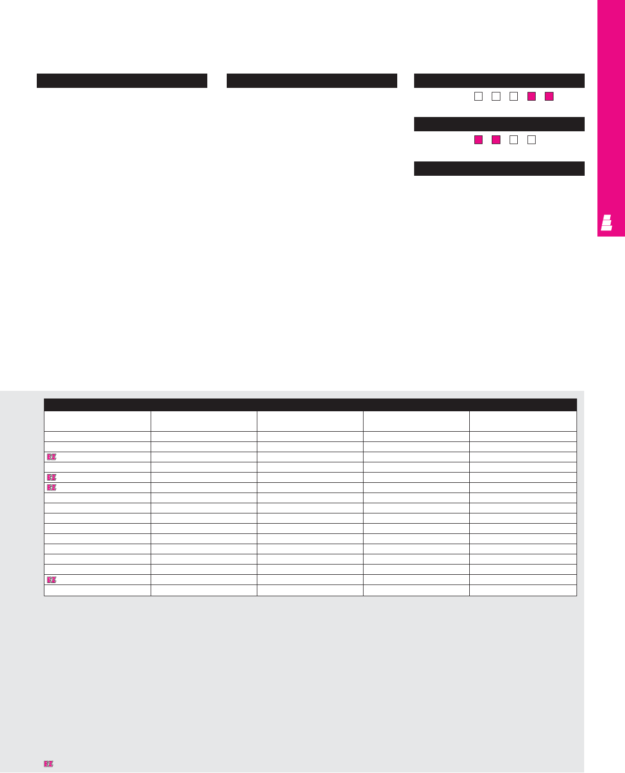
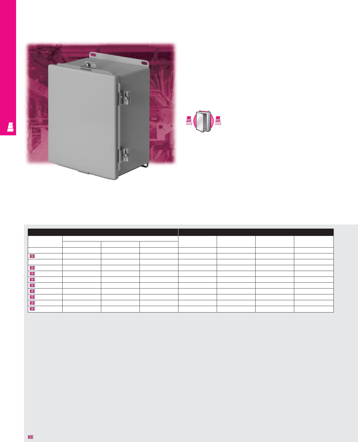
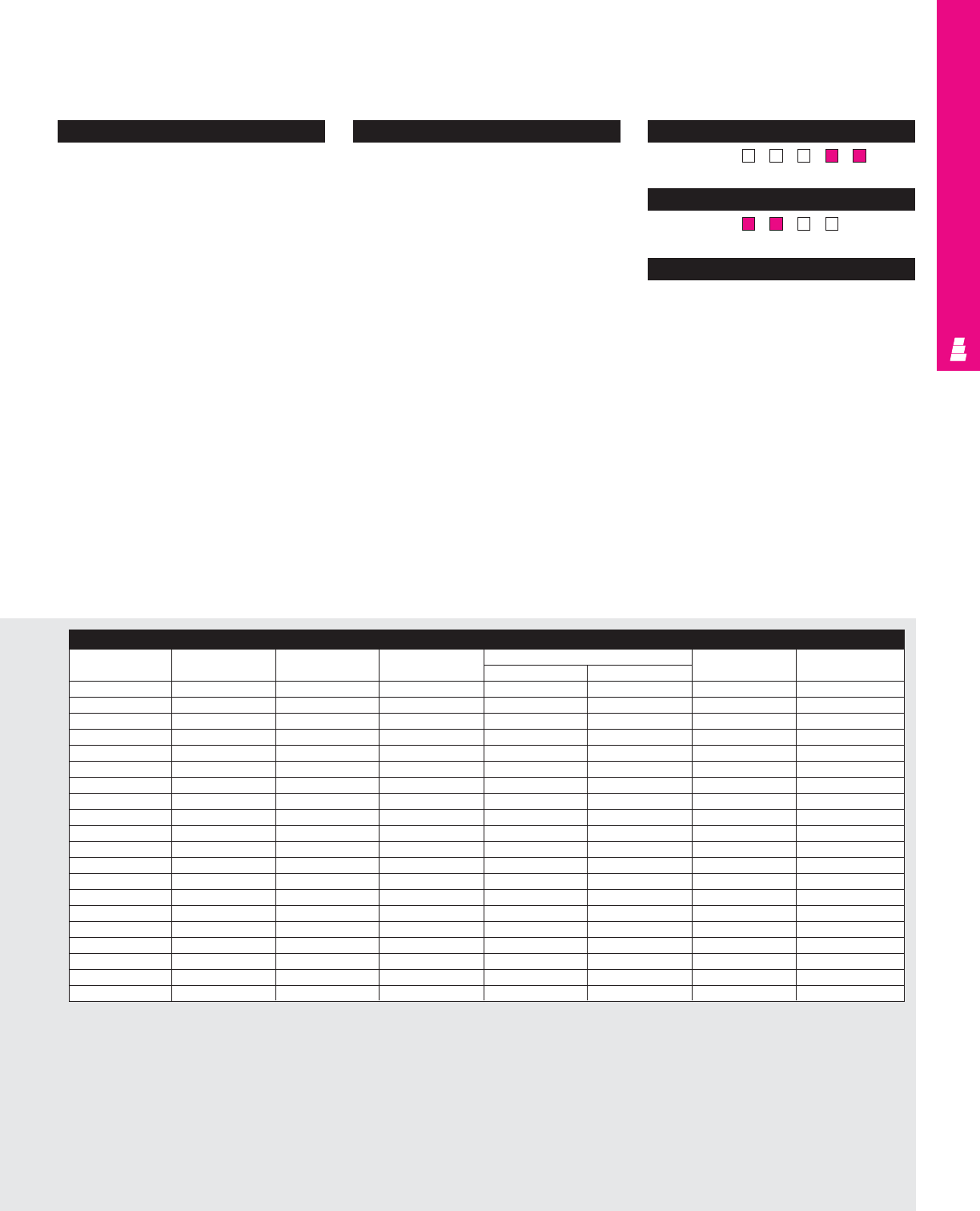
KL Junction Boxes
NEMA Rated Junction Boxes Without Gland Panels
Rittal’s KL Series NEMA rated junction boxes offer perfect
protection against harsh environments for delicate electrical
and electronic equipment. The knife-edge perimeter of the
enclosure prevents entry of dirt and liquids when the enclosure
is opened. Integrated mounting rails with holes inside the
enclosure offer flexible options for component installation. A
powder paint finish provides a durable, long lasting surface.
NEMA Rated Junction Boxes With Gland Panels
These junction boxes save both time and money with pre-cut
gland openings and covers for interconnecting multi-conductor
installations.
Enclosure Mounting Panel
Part No. Approx. NEMA No. of Exact outside dimensions Part No. Dimensions
outside rating gland
dimensions openings inches mm inches mm
H"xW"xD" H W D H W D H W H W
Junction Boxes Without Gland Panels
1514210 6x6x3 1, 4, 12 - 5.91 5.91 3.15 150 150 80 1560700 4.92 5.31 125 135
1515210 6x12x3 1, 4, 12 - 5.91 11.81 3.15 150 300 80 1561700 4.92 11.22 125 285
1517210 8x12x3 1, 4, 12 - 7.87 11.81 3.15 200 300 80 1563700 6.89 11.22 175 285
1500210 6x6x5 1, 4, 12 - 5.91 5.91 4.72 150 150 120 1560700 4.92 5.31 125 135
1501210 6x12x5 1, 4, 12 - 5.91 11.81 4.72 150 300 120 1561700 4.92 11.22 125 285
1502210 8x8x5 1, 4, 12 - 7.87 7.87 4.72 200 200 120 1562700 6.89 7.28 175 185
1503210 8x12x5 1, 4, 12 - 7.87 11.81 4.72 200 300 120 1563700 6.89 11.22 175 285
1504210 8x16x5 1, 4, 12 - 7.87 15.75 4.72 200 400 120 1564700 6.89 15.16 175 385
1505210 8x20x5 1, 4, 12 - 7.87 19.69 4.72 200 500 120 1565700 6.89 19.09 175 485
1507210 12x12x5 1, 4, 12 - 11.81 11.81 4.72 300 300 120 1567700 10.83 11.22 275 285
1508210 12x16x5 1, 4, 12 - 11.81 15.75 4.72 300 400 120 1568700 10.83 15.16 275 385
1509210 12x20x5 1, 4, 12 - 11.81 19.69 4.72 300 500 120 1569700 10.83 19.09 275 485
1511210 16x16x5 1, 4, 12 - 15.75 15.75 4.72 400 400 120 1571700 14.76 15.16 375 385
Junction Boxes With Gland Panels
1530210 6x12x5 1, 12 2 5.91 11.81 4.72 150 300 120 1561700 4.92 11.22 125 285
1531210 8x12x5 1, 12 2 7.87 11.81 4.72 200 300 120 1563700 6.89 11.22 175 285
IND 1
S
t
a
i
n
l
e
s
s
S
t
e
e
l
S
t
a
i
n
l
e
s
s
S
t
e
e
l
A
v
a
i
l
a
b
l
e
I
n
A
v
a
i
l
a
b
l
e
I
n
Page IND 199
Designates a product in the EnclosureZone program.
WALLMOUNT ENCLOSURES
Technical Specifications
Material:
•Housing: 17 ga/1.38 mm sheet steel
•Cover: 18 ga/1.25 mm sheet steel
Finish/color:
•Housing and cover: powder painted, RAL
7032 pebble grey
Configuration
• NEMA 1, 4, 12/IP 66, (without gland panels)
or NEMA 1, 12/IP 55, (with gland panels)
•UL/CSA/TÜV approvals
• Welded cold rolled steel body
• Foamed-on gaskets
• Integrated mounting rails
• Optional mounting panel
• Wide range of accessories
• Off-the-shelf availability
•Powder paint provides superior corrosion
protection
•Knife-edge design protects against
liquid entry
•Rear mounting holes allow direct
wallmounting or the use of optional
mounting feet
Pages . . . . . . . . . . . . . . . . . . . . . . . . . . IND 35-36
NEMA Type 144X1213
UL CUL CSA TÜV
Listings
Protection Ratings
Certifications/Approvals
Technical Drawings
IND 2
Accessories
Part No. Wallmounting Cover Quick release Ground strap Pole
bracket hinge fastener 7" long/11 AWG mounting kit
Junction Boxes Without Gland Panels
1514210 1590000 1592000 1593000 2564000 2584000
1515210 1590000 1592000 1593000 2564000 2584000
1517210 1590000 1592000 1593000 2564000 2584000
1500210 1590000 1592000 1593000 2564000 2584000
1501210 1590000 1592000 1593000 2564000 2584000
1502210 1590000 1592000 1593000 2564000 2584000
1503210 1590000 1592000 1593000 2564000 2584000
1504210 1590000 1592000 1593000 2564000 2584000
1505210 1590000 1592000 1593000 2564000 2584000
1507210 1590000 1592000 1593000 2564000 2584000
1508210 1590000 1592000 1593000 2564000 2584000
1509210 1590000 1592000 1593000 2564000 2584000
1511210 1590000 1592000 1593000 2564000 2584000
KL Junction Boxes With Gland Panels
1530210 1590000 1592000 1593000 2564000 2584000
1531210 1590000 1592000 1593000 2564000 2584000
Designates a product in the EnclosureZone program.
WALLMOUNT ENCLOSURES
IND 3
Screw Cover Junction Boxes
Carbon Steel NEMA Enclosures
These NEMA rated junction boxes are designed primarily for
indoor use to house pilot devices, such as limit switches, foot
switches, pushbuttons, selector switches, pilot lights, etc., and
to protect such equipment against dirt and dust, external
condensation, and spraying of water and oil.
Enclosure Mounting Panel
Part No. Outside dimensions (inches) Part No. HWUsable depth
HWD
E 404SC* 4.00 4.00 3.00 NONE ---
E 4044SC 4.00 4.00 4.00 NONE ---
E 604SC* 6.00 4.00 3.00 E 6P4 4.88 2.88 2.50
E 6044SC* 6.00 4.00 4.00 E 6P4 4.88 2.88 3.50
E 606SC* 6.00 6.00 4.00 E 6P6 4.88 4.88 3.50
E 806SC 8.00 6.00 3.50 E 8P6 6.88 4.88 3.00
E 8066SC 8.00 6.00 6.00 E 8P6 6.88 4.88 5.50
E 808SC 8.00 8.00 4.00 E 8P8 6.88 6.88 3.50
E 1008SC 10.00 8.00 4.00 E 10P8 8.88 6.88 3.50
E 1010SC 10.00 10.00 4.00 E 10P10 8.88 8.88 3.50
E 10106SC 10.00 8.00 6.00 E 10P10 8.88 8.88 5.50
E 10086SC 10.00 8.00 6.00 E 10P8 8.88 6.88 5.50
E 1210SC 12.00 10.00 5.00 E 12P10 10.88 8.88 4.50
E 1212SC 12.00 12.00 6.00 E 12P12 10.88 10.88 5.50
E 1412SC 14.00 12.00 6.00 E 14P12 12.88 10.88 5.50
E 1614SC 16.00 14.00 6.00 E 16P14 14.88 12.88 5.50
* 16 gauge
Designates a product in the EnclosureZone program.
WALLMOUNT ENCLOSURES
Configuration
•Continuously welded seams, finished
smooth
•Poron strip gasket
•Plated steel captive screws
•Lift-off cover
•External mounting brackets
•Mounting panel provisions installed
(except E 404SC and E 4044SC)
Technical Specifications
Material:
•Enclosure/cover: 14 or 16 gauge carbon
steel (see table)
Finish/color:
•Enclosure/cover: polyester-urethane
powder coat over phosphatized surfaces,
inside and outside – ANSI 61 grey
•Optional mounting panels: painted white Page . . . . . . . . . . . . . . . . . . . . . . . . . . . . . IND 37
NEMA Type 144X1213
UL CUL CSA TÜV
Listings
Protection Ratings
Certifications/Approvals
Technical Drawings
IND 4
Accessories
Part No. Terminal block kit Terminal rails Window kit Touch-up paint
E 404SC* -- -EL21
E 4044SC -- -EL21
E 604SC* -- -EL21
E 6044SC* -- -EL21
E 606SC* -- -EL21
E 806SC E 6JTMA E 8JS - E L21
E 8066SC E 6JTMA E 8JS - E L21
E 808SC E 8JTMA E 8JS E PWK53NF E L21
E 1008SC E 8JTMA E 10JS E PWK53NF E L21
E 1010SC E 10JTMAXD E 10JS E PWK53NF E L21
E 10106SC E 10JTMAXD E 10JS E PWK53NF E L21
E 10086SC E 8JTMA E 10JS E PWK53NF E L21
E 1210SC E 10JTMAXD E 12JS E PWK53NF E L21
E 1212SC E 12JTMA E 12JS E PWK95NF E L21
E 1412SC E 12JTMA E 14JS E PWK95NF E L21
E 1614SC E 14JTMA E 16JS E PWK95NF E L21
* 16 gauge
Designates a product in the EnclosureZone program.
WALLMOUNT ENCLOSURES
IND 5
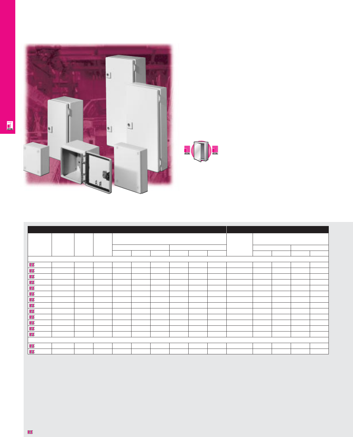
Lift-Off Hinge Cover Boxes
Carbon Steel Wallmount Enclosures
These NEMA rated junction boxes are designed to house pilot
devices, such as limit switches, foot switches, pushbuttons,
selector switches, pilot lights, etc., and to protect this
equipment against dirt and dust, spraying of water, oil
or coolant.
Enclosure Mounting Panel
Part No. Outside dimensions (inches) Part No. HWUsable depth
HWD
E 404LP* 4.00 4.00 3.00 NONE ---
E 4044LP 4.00 4.00 4.00 NONE ---
E 604LP* 6.00 4.00 3.00 E 6P4 4.88 2.88 2.50
E 6044LP* 6.00 4.00 4.00 E 6P4 4.88 2.88 3.50
E 606LP* 6.00 6.00 4.00 E 6P6 4.88 4.88 3.50
E 806LP 8.00 6.00 3.50 E 8P6 6.88 4.88 3.00
E 1008LP 10.00 8.00 4.00 E 10P8 8.88 6.88 3.50
E 1210LP 12.00 10.00 5.00 E 12P10 10.88 8.88 4.50
E 1412LP 14.00 12.00 6.00 E 14P12 12.88 10.88 5.50
E 1614LP 16.00 14.00 6.00 E 16P14 14.88 12.88 5.50
E 1816LP 18.00 16.00 6.00 E 18P16 16.88 14.88 5.50
* 16 gauge
Designates a product in the EnclosureZone program.
WALLMOUNT ENCLOSURES
IND 6
Configuration
•Continuously welded seams, finished
smooth
•Robotically applied urethane gasket
•Plated steel captive clamps, screws, chain
and clip
•Lift-off cover
•External mounting brackets
•Mounting panel provisions installed
(except E 404LP and E 4044LP)
Technical Specifications
Material:
•Enclosure/cover: 14 or 16 gauge carbon
steel (see table)
Finish/color:
•Enclosure/cover: polyester-urethane
powder coat over phosphatized surfaces,
inside and outside – ANSI 61 grey
•Optional mounting panels: painted white Page . . . . . . . . . . . . . . . . . . . . . . . . . . . . . IND 38
NEMA Type 144X1213
UL CUL CSA TÜV
Listings
Protection Ratings
Certifications/Approvals
Technical Drawings
Accessories
Part No. Terminal block kit Terminal rails Window kit Touch-up paint
E 404LP* ---E L21
E 4044LP ---E L21
E 604LP* ---E L21
E 6044LP* ---E L21
E 606LP* ---E L21
E 806LP E 6JTMA E 8JS - E L21
E 1008LP E 6JTMA E 10JS E PWK53NF E L21
E 1210LP E 10JTMAXD E 12JS E PWK53NF E L21
E 1412LP E 12JTMA E 14JS E PWK95NF E L21
E 1614LP E 14JTMA E 16JS E PWK95NF E L21
E 1816LP E 14JTMA E 16JS E PWK95NF E L21
* 16 gauge
Designates a product in the EnclosureZone program.
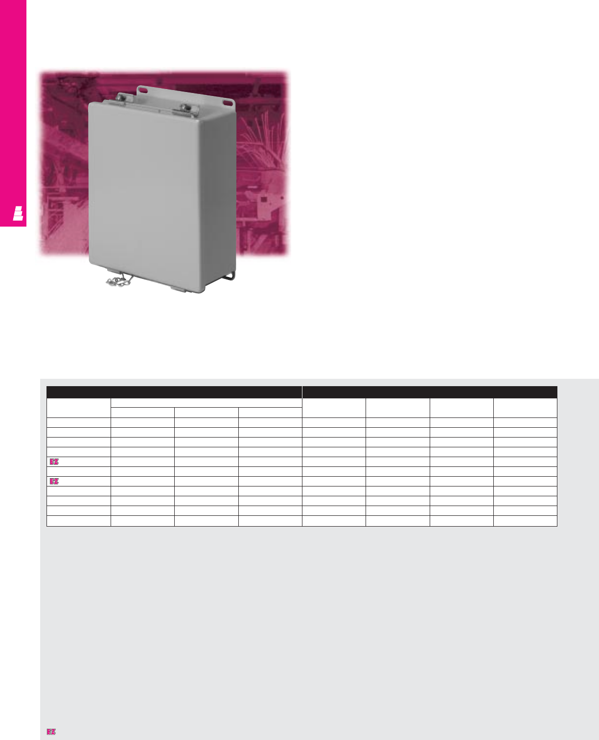
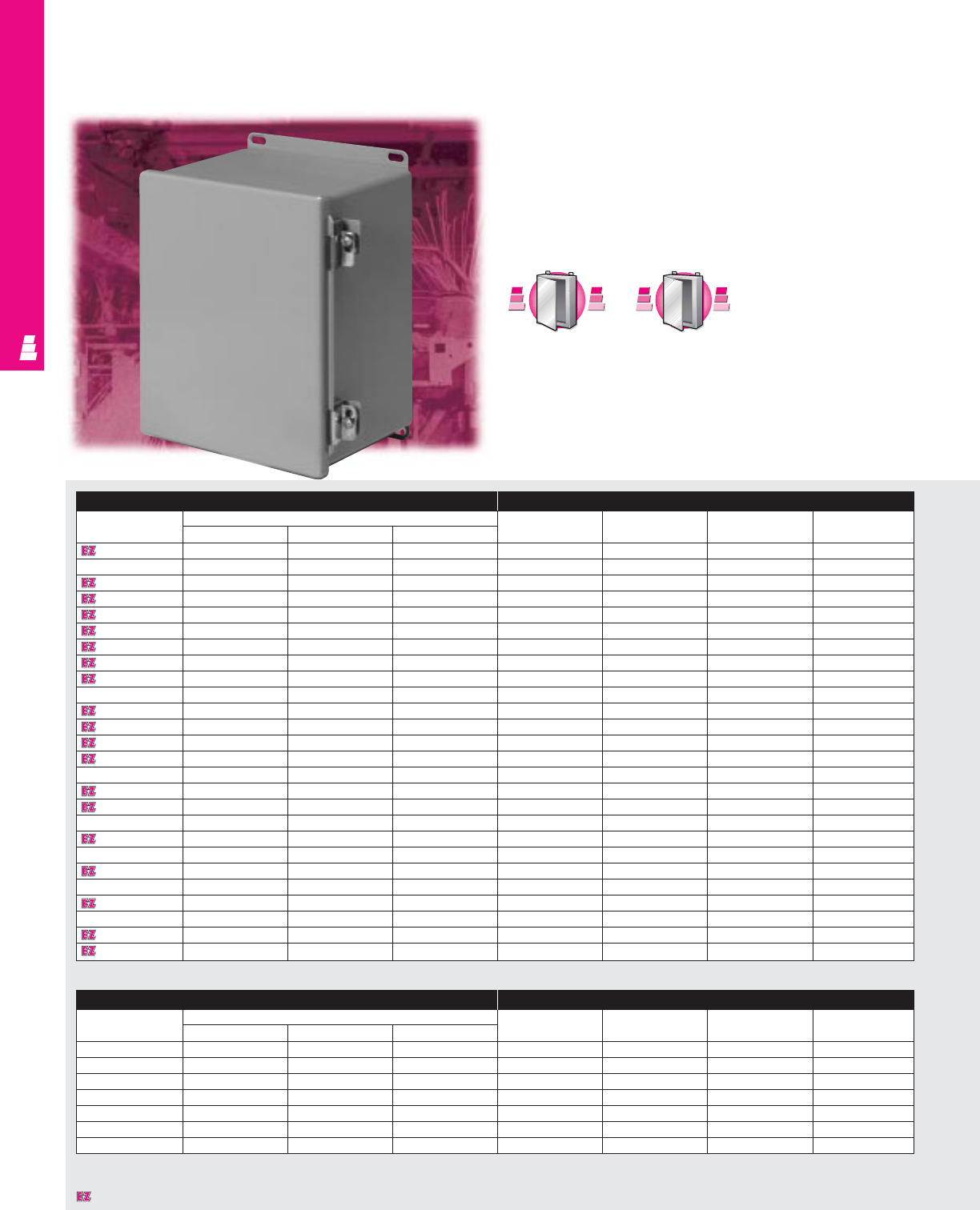
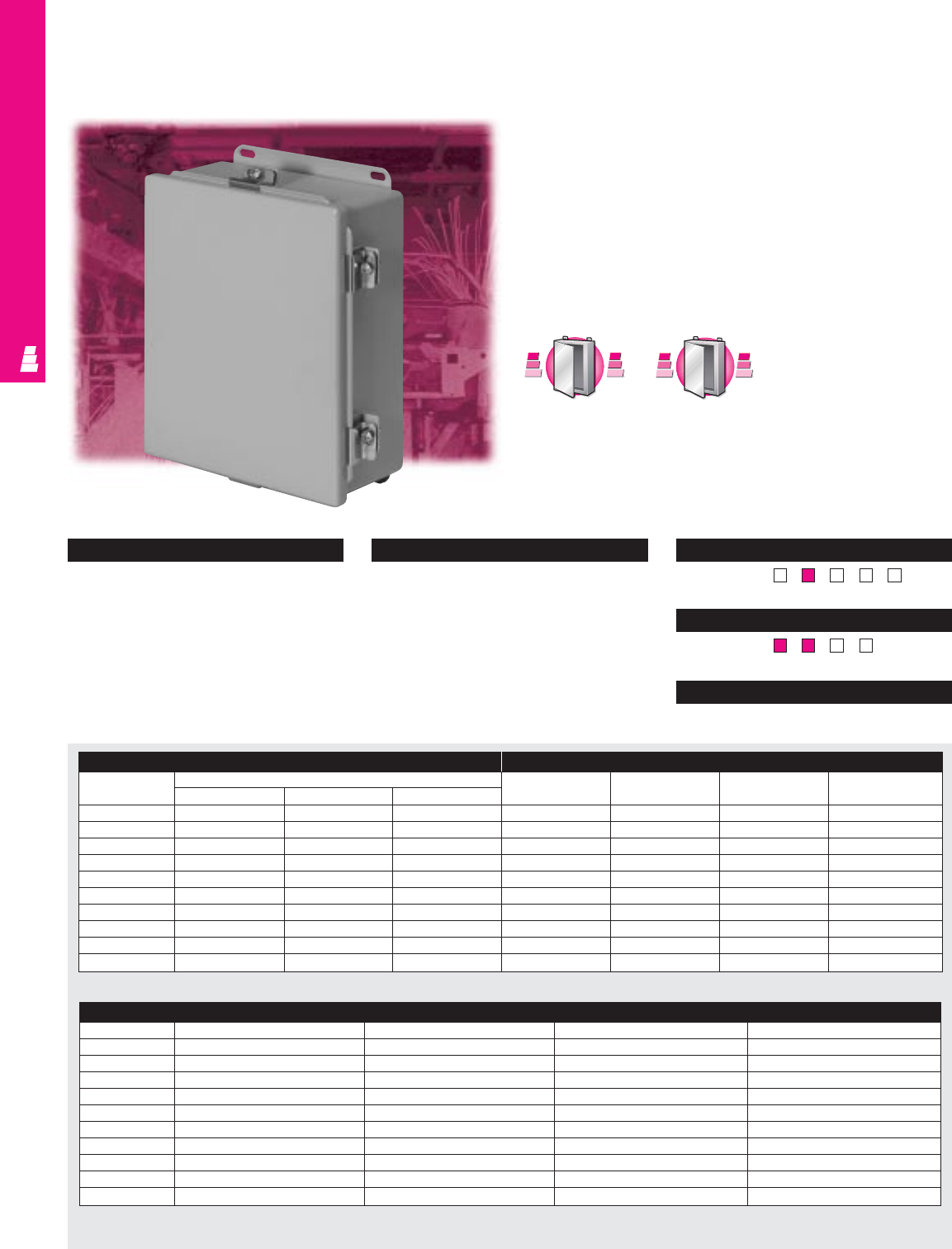
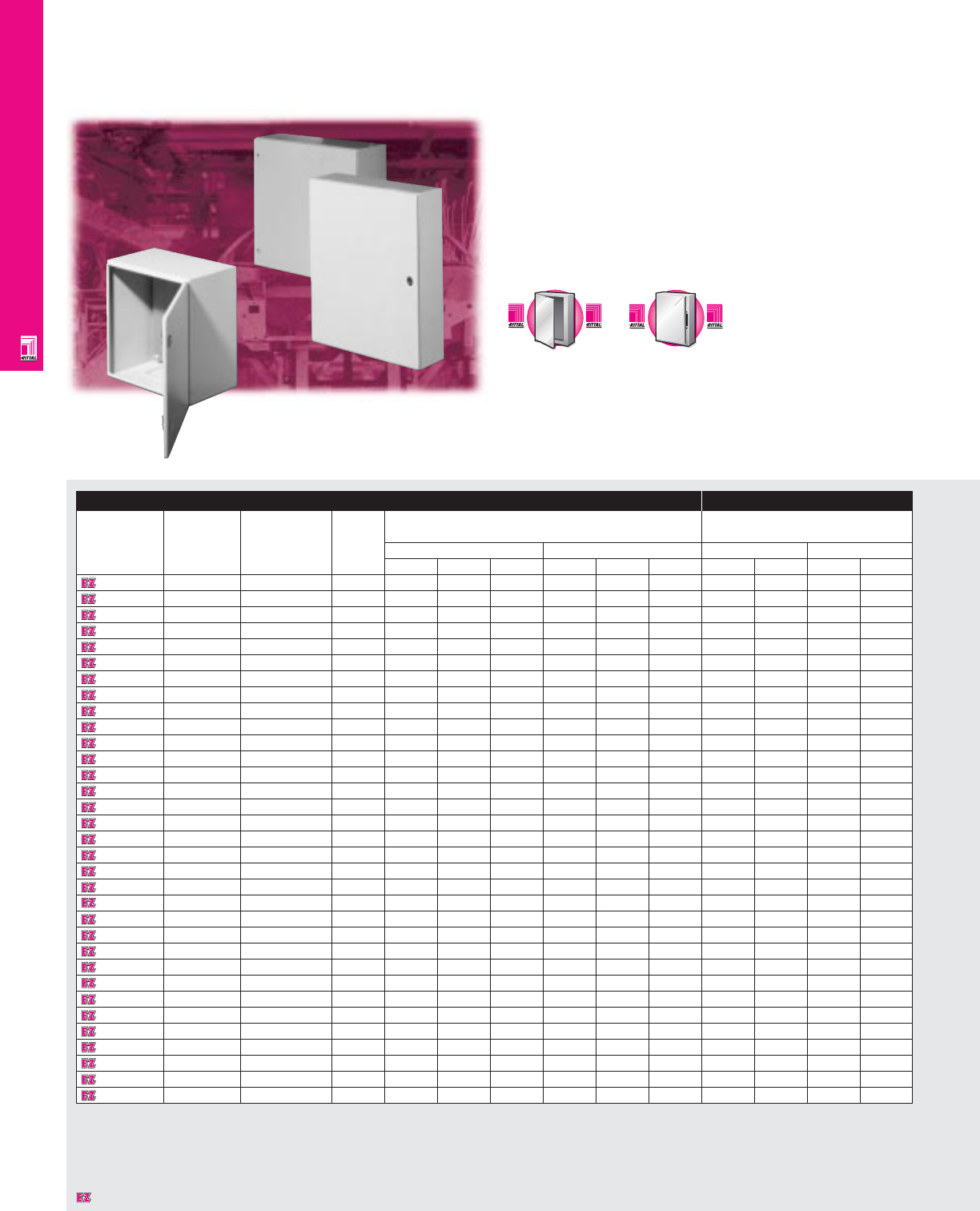
EB Instrument Enclosures
NEMA Rated Instrument Enclosures
Rittal’s EB Series instrument enclosures offer protection for
dense wiring and sensitive small instruments. These “JIC” type
boxes combine many of the advantages of Rittal's AE and KL
Series enclosures, at an economical cost.
Features include standard 180˚ hinges and locks with
double-bit inserts. A foamed-on gasket and knife-edge perimeter
ensure NEMA 4 protection.
Enclosure Mounting Panel
Part No.
Approximate
NEMA
Exact outside dimensions
Part No.
Dimensions
outside rating
dimensions inches mm inches mm
H"xW"xD" H W D H W D H W H W
1551600
6x6x3 1, 4, 12 5.91 5.91 3.15 150 150 80
included
5.31 4.92 135 125
1553600
6x6x5 1, 4, 12 5.91 5.91 4.72 150 150 120
included
5.31 4.92 135 125
1751600
8x6x5 1, 4, 12 7.87 5.91 4.72 200 150 120
included
7.28 4.92 185 125
1549600
8x8x5 1, 4, 12 7.87 7.87 4.72 200 200 120
included
7.28 6.89 185 175
1554600
12x8x5 1, 4, 12 11.81 7.87 4.72 300 200 120
included
11.22 6.89 285 175
1555600
12x12x5 1, 4, 12 11.81 11.81 4.72 300 300 120
included
11.22 10.83 285 275
1556600
16x12x5 1, 4, 12 15.75 11.81 4.72 400 300 120
included
15.16 10.83 385 275
1752600
10x8x6 1, 4, 12 9.84 7.87 6.10 250 200 155
included
9.25 6.89 235 175
1753600
12x10x6 1, 4, 12 11.81 9.84 6.10 300 250 155
included
11.22 8.86 285 225
1754600
14x12x6 1, 4, 12 13.78 11.81 6.10 350 300 155
included
13.19 10.83 335 275
1755600
16x14x6 1, 4, 12 15.75 13.78 6.10 400 350 155
included
15.16 12.80 385 325
1578600
24x12x6 1, 4, 12 23.62 11.81 6.10 600 300 155
included
23.03 10.83 585 275
WALLMOUNT ENCLOSURES
IND 7
Designates a product in the EnclosureZone program.

Configuration
• NEMA 1, 4, 12/IP 66 protection
• UL/CSA/TÜV approvals
•Permanent hinges, removable door
•Turnbuckle locks for easy access and
secure seal
•Mounting panel included
•Rear mounting holes allow direct wall
mounting or the use of optional
mounting feet
•Integrated grounding provisions
•One piece construction, continuously
welded seams
• Knife-edge design protects against
liquid entry
• Foamed-on gasket ensures perfect seal
•Off-the-shelf availability
•Powder paint provides superior corrosion
protection
Technical Specifications
Material:
•Housing: 17 ga/1.38 mm sheet steel
•Door: 18 ga/1.25 mm sheet steel
•Mounting panel: hot-dipped galvanized zinc
Finish/color:
•Housing and door: powder painted,
RAL 7032 pebble grey
•Mounting panel: Type M
Accessories
Part No. Wallmounting brackets Handles Ground strap
5/16" standoff 1-5/8" standoff Thumb turn T-handle 7" long/11 AWG
1551600 1590000 2503200 2576000 2575000 2564000
1553600 1590000 2503200 2576000 2575000 2564000
1751600 1590000 2503200 2576000 2575000 -
1549600 1590000 2503200 2576000 2575000 2564000
1554600 1590000 2503200 2576000 2575000 2564000
1555600 1590000 2503200 2576000 2575000 2564000
1556600 1590000 2503200 2576000 2575000 2564000
1752600 1590000 2503200 2576000 2575000 -
1753600 1590000 2503200 2576000 2575000 -
1754600 1590000 2503200 2576000 2575000 -
1755600 1590000 2503200 2576000 2575000 -
1578600 1590000 2503200 2576000 2575000 2564000
Page . . . . . . . . . . . . . . . . . . . . . . . . . . . . . IND 39
NEMA Type 144X1213
UL CUL CSA TÜV
Listings
Protection Ratings
Certifications/Approvals
Technical Drawings
WALLMOUNT ENCLOSURES
IND 8
Designates a product in the EnclosureZone program.
WALLMOUNT ENCLOSURES
IND 9
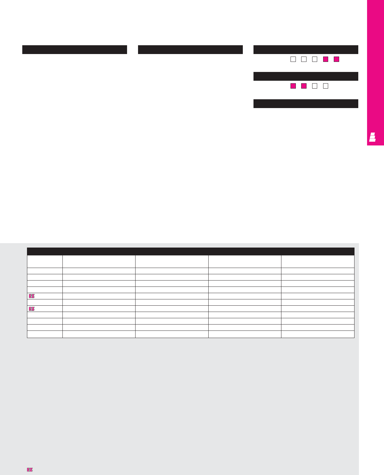
Continuous Hinge Cover Enclosures
Carbon Steel Junction Boxes
These NEMA rated junction boxes offer perfect protection for
delicate electrical and electronic equipment such as limit
switches, foot switches, pushbuttons, selector switches and
pilot lights. Installed equipment is protected against dirt, dust,
oil and water seepage.
Enclosure Mounting Panel
Part No. Outside dimensions (inches) Part No. HWUsable depth
HWD
E 404CH* 4.00 4.00 3.00 NONE ---
E 4044CH 4.00 4.00 4.00 NONE ---
E 604CH* 6.00 4.00 3.00 E 6P4 4.88 2.88 2.50
E 6044CH* 6.00 4.00 4.00 E 6P4 4.88 2.88 3.50
E 606CH* 6.00 6.00 4.00 E 6P6 4.88 4.88 3.50
E 806CH 8.00 6.00 3.50 E 8P6 6.88 4.88 3.00
E 8066CH 8.00 6.00 6.00 E 8P6 6.88 4.88 5.50
E 808CH 8.00 8.00 4.00 E 8P8 6.88 6.88 3.50
E 1008CH 10.00 8.00 4.00 E 10P8 8.88 6.88 3.50
E 1088CHS 10.00 8.00 4.00 E 10P8 8.88 6.88 3.50
E 10086CH 10.00 8.00 6.00 E 10P8 8.88 6.88 5.50
E 10106CH 10.00 10.00 6.00 E 10P10 8.88 8.88 5.50
E 12064CH 12.00 6.00 4.00 E 12P6 10.88 4.88 3.50
E 1210CH 12.00 10.00 5.00 E 12P10 10.88 8.88 4.50
E 1210CHS 12.00 10.00 5.00 E 10P10 10.88 8.88 4.50
E 12108CH 12.00 10.00 8.00 E 12P10 10.88 8.88 7.50
E 1212CH 12.00 12.00 6.00 E 12P12 10.88 10.88 5.50
E 14086CH 14.00 8.00 6.00 E 14P8 12.88 6.88 5.50
E 1412CH 14.00 12.00 6.00 E 14P12 12.88 10.88 5.50
E 1412CHS 14.00 12.00 6.00 E 14P12 12.88 10.88 5.50
E 14128CH 14.00 12.00 8.00 E 14P12 12.88 10.88 7.50
E 16106CH 16.00 10.00 6.00 E 16P10 14.88 8.88 5.50
E 1614CH 16.00 14.00 6.00 E 16P14 14.88 12.88 5.50
E 1614CHS 16.00 14.00 6.00 E 16P14 14.88 12.88 5.50
E 16148CH 16.00 14.00 8.00 E 16P14 14.88 12.88 7.50
E 161410CH 16.00 14.00 10.00 E 16P14 14.88 12.88 9.50
* 16 gauge
S
t
a
i
n
l
e
s
s
S
t
e
e
l
S
t
a
i
n
l
e
s
s
S
t
e
e
l
A
v
a
i
l
a
b
l
e
I
n
A
v
a
i
l
a
b
l
e
I
n
Page IND 201
A
l
u
m
i
n
u
m
A
v
a
i
l
a
b
l
e
I
n
A
v
a
i
l
a
b
l
e
I
n
A
l
u
m
i
n
u
m
Page IND 203
EMI/RFI Enclosure Mounting Panel
Part No. Outside dimensions (inches) Part No. HWUsable depth
HWD
E 604CHRFI* 6.00 4.00 3.00 E 6P4 4.88 2.88 2.50
E 606CHRFI 6.00 6.00 4.00 E 6P6 4.88 4.88 3.50
E 806CHRFI* 8.00 6.00 3.50 E 8P6 6.88 4.88 3.00
E 1008CHRFI 10.00 8.00 4.00 E 10P8 8.88 6.88 3.50
E 1210CHRFI 12.00 10.00 5.00 E 12P10 10.88 8.88 4.50
E 1412CHRFI 14.00 12.00 6.00 E 14P12 12.88 10.88 5.50
E 1614CHRFI 16.00 14.00 6.00 E 16P14 14.88 12.88 5.50
* 16 gauge
Designates a product in the EnclosureZone program.
WALLMOUNT ENCLOSURES
IND 10
Configuration
•Continuously welded seams, finished
smooth
•Robotically applied urethane gasket
•Continuous steel hinge
•Door removed by pulling steel hinge pin
•Plated steel cover clamps and
stainless screws
•External mounting brackets
•Mounting panel provisions installed
(except E 404CH and E 4044CH)
•Oil resistant gasket covered with a woven
plated steel mesh, attached with an oil
resistant adhesive (EMI/RFI enclosure only)
Technical Specifications
Material:
•Enclosure/door: 14 or 16 gauge carbon
steel (see table)
Finish/color:
•Enclosure/door: polyester-urethane powder
coat over phosphatized surfaces,
inside and outside – ANSI 61 grey
•Optional mounting panels: painted white Pages . . . . . . . . . . . . . . . . . . . . . . . . . . IND 40-41
NEMA Type 144X1213
UL CUL CSA TÜV
Listings
Protection Ratings
Certifications/Approvals
Technical Drawings
Accessories
Part No. Terminal block kit Terminal rails Window kit Touch-up paint
E 404CH* ---E L21
E 4044CH ---E L21
E 604CH* ---E L21
E 6044CH* ---E L21
E 606CH* ---E L21
E 806CH E 6JTMA E 8JS - E L21
E 8066CH E 6JTMA E 8JS - E L21
E 808CH E 8JTMA E 8JS - E L21
E 1008CH E 8JTMA E 10JS E PWK53NF E L21
E 1008CHS E 10JTMAXD E 8JS E PWK53NF E L21
E 10086CH E 8JTMA E 10JS E PWK53NF E L21
E 10106CH E 10JTMA E 10JS E PWK53NF E L21
E 12064CH E 6JTMA E 12JS - E L21
E 1210CH E 10JTMAXD E 12JS E PWK53NF E L21
E 1210CHS E 12JTMA E 10JS E PWK53NF E L21
E 12108CH E 10JTMAXD E 12JS E PWK53NF E L21
E 1212CH E 12JTMA E 12JS E PWK95NF E L21
E 14086CH E 8JTMA E 14JS E PWK95NF E L21
E 1412CH E 12JTMA E 14JS E PWK95NF E L21
E 1412CHS E 14JTMA E 12JS E PWK95NF E L21
E 14128CH E 12JTMA E 14JS E PWK95NF E L21
E 16106CH E 10JTMAXD E 16JS E PWK95NF E L21
E 1614CH E 14JTMA E 16JS E PWK95NF E L21
E 1614CHS E 16JTMA E 14JS E PWK95NF E L21
E 16148CH E 14JTMA E 16JS E PWK95NF E L21
E 161410CH E 14JTMA E 16JS E PWK95NF E L21
* 16 gauge
Accessories
Part No. Terminal block kit Terminal rails Window kit Touch-up paint
E 604CHRFI* ---E L21
E 606CHRFI ---E L21
E 806CHRFI* E 6JTMA E 8JS - E L21
E 1008CHRFI E 8JTMA E 10JS E PWK53NF E L21
E 1210CHRFI E 10JTMAXD E 12JS E PWK53NF E L21
E 1412CHRFI E 12JTMA E 14JS E PWK95NF E L21
E 1614CHRFI E 14JTMA E 16JS E PWK95NF E L21
* 16 gauge
Designates a product in the EnclosureZone program.
WALLMOUNT ENCLOSURES
IND 11
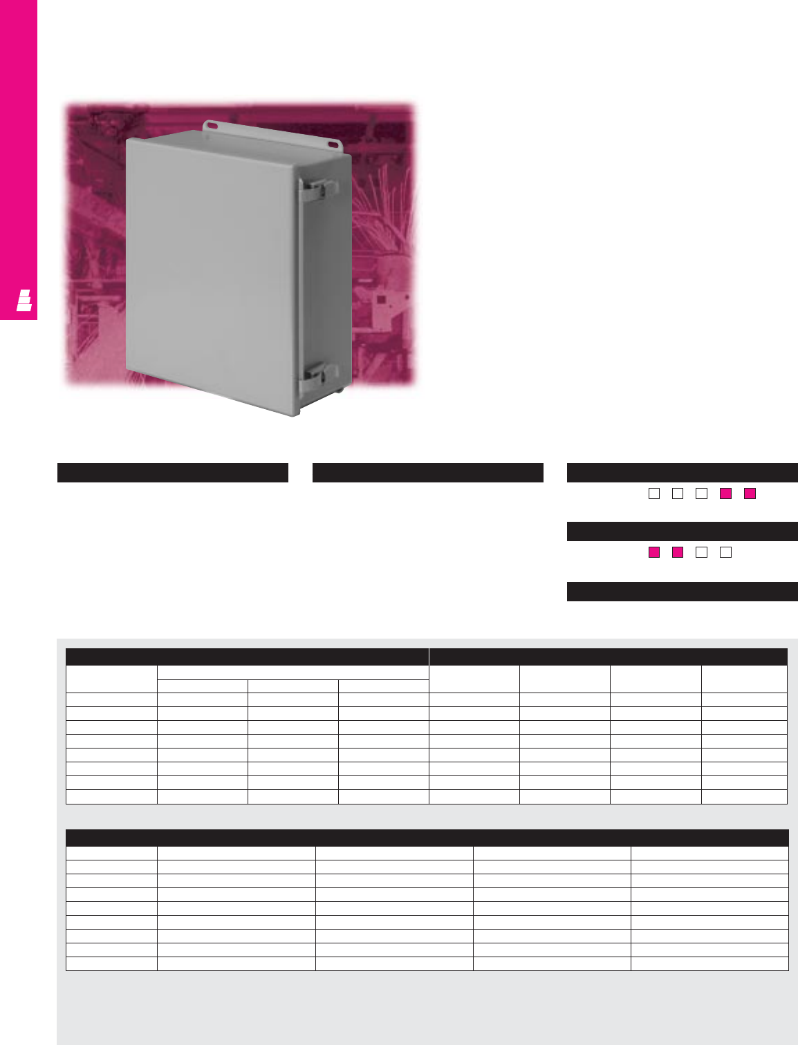
Continuous Hinge Quick Release Boxes
NEMA Rated Wallmount Enclosures
These NEMA rated junction boxes are designed primarily for
indoor use to house pilot devices, such as limit switches, foot
switches, pushbuttons, selector switches and pilot lights, and
to protect such equipment against splashing water, seepage of
water, falling or hose directed water, and spraying of water
and oil.
Configuration
•Continuously welded seams, finished
smooth
•Robotically applied urethane gasket
•Continuous steel hinge
•Door removed by pulling steel hinge pin
•Quick-release clamps
•External mounting brackets
•Mounting panel provisions installed
(except E 404CHQR)
Technical Specifications
Material:
•Enclosure/door: 14 or 16 gauge carbon steel
(see table)
Finish/color:
•Enclosure/door: polyester-urethane powder
coat over phosphatized surfaces,
inside and outside – ANSI 61 grey
•Optional mounting panels: painted white Page . . . . . . . . . . . . . . . . . . . . . . . . . . . . . IND 41
NEMA Type 144X1213
UL CUL CSA TÜV
Listings
Protection Ratings
Certifications/Approvals
Technical Drawings
Enclosure Mounting Panel
Part No. Outside dimensions (inches) Part No. HWUsable depth
HWD
E 404CHQR* 4.00 4.00 3.00 NONE ---
E 604CHQR* 6.00 4.00 3.00 E 6P4 4.88 2.88 2.50
E 606CHQR* 6.00 6.00 4.00 E 6P6 4.88 4.88 3.50
E 806CHQR 8.00 6.00 3.50 E 8P6 6.88 4.88 3.00
E 1008CHQR 10.00 8.00 4.00 E 10P8 8.88 6.88 3.50
E 1210CHQR 12.00 10.00 5.00 E 12P10 10.88 8.88 4.50
E 1412CHQR 14.00 12.00 6.00 E 14P12 12.88 10.88 5.50
E 1614CHQR 16.00 14.00 6.00 E 16P14 14.88 12.88 5.50
* 16 gauge
Accessories
Part No. Terminal block kit Terminal rails Window kit Touch-up paint
E 404CHQR* ---E L21
E 604CHQR* ---E L21
E 606CHQR* ---E L21
E 806CHQR E 6JTMA E 8JS - E L21
E 1008CHQR E 8JTMA E 10JS E PWK53NF E L21
E 1210CHQR E 10JTMAXD E 12JS E PWK53NF E L21
E 1412CHQR E 12JTMA E 14JS E PWK95NF E L21
E 1614CHQR E 14JTMA E 16JS E PWK95NF E L21
* 16 gauge
WALLMOUNT ENCLOSURES
IND 12
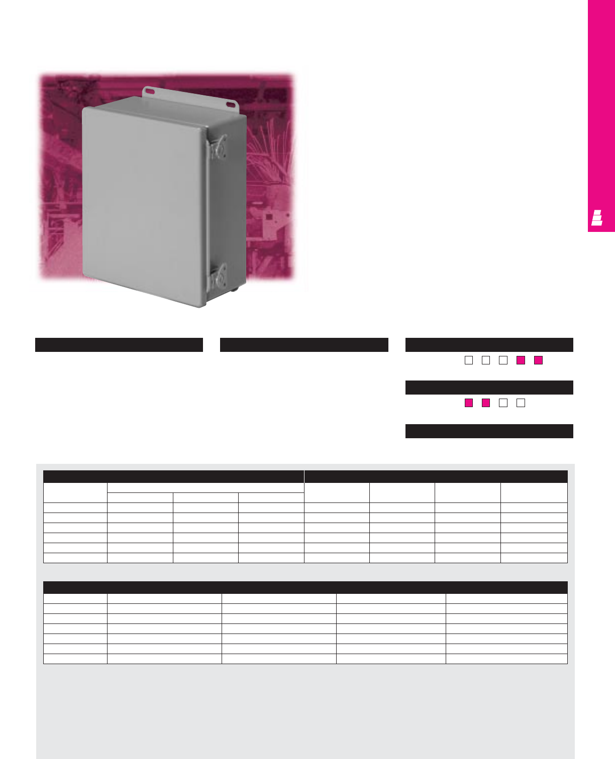
Configuration
•Continuously welded seams, finished
smooth
•Robotically applied urethane gasket
•Continuous steel hinge
•Door removed by pulling steel hinge pin
•Butterfly draw latch
•External mounting brackets
•Mounting panel provisions installed
Technical Specifications
Material:
•Enclosure/door: 14 or 16 gauge carbon
steel (see table)
Finish/color:
•Enclosure/door: polyester-urethane powder
coat over phosphatized surfaces, inside
and outside – ANSI 61 grey
•Optional mounting panels: painted white
Continuous Hinge Wing Turn Boxes
Electromate Wallmount Enclosures
These NEMA rated junction boxes are designed primarily for
indoor use to house pilot devices, such as limit switches, foot
switches, pushbuttons, selector switches, pilot lights, etc.,
and to protect these devices against dirt and dust, oil seepage,
external condensation, or coolant.
Page . . . . . . . . . . . . . . . . . . . . . . . . . . . . IND 42
NEMA Type 144X1213
UL CUL CSA TÜV
Listings
Protection Ratings
Certifications/Approvals
Technical Drawings
Accessories
Part No. Terminal block kit Terminal rails Window kit Touch-up paint
E 604CHWL* ---E L21
E 806CHWL E 6JTMA E 8JS - E L21
E 1008CHWL E 8JTMA E 10JS E PWK53NF E L21
E 1210CHWL E 10JTMAXD E 12JS E PWK53NF E L21
E 1412CHWL E 12JTMA E 14JS E PWK95NF E L21
E 1614CHWL E 14JTMA E 16JS E PWK95NF E L21
* 16 gauge
Enclosure Mounting Panel
Part No. Outside dimensions (inches) Part No. HWUsable depth
HWD
E 604CHWL* 6.00 4.00 4.48 E 6P4 4.88 2.88 4.04
E 806CHWL 8.00 6.00 4.48 E 8P6 6.88 4.88 4.04
E 1008CHWL 10.00 8.00 4.48 E 10P8 8.88 6.88 4.04
E 1210CHWL 12.00 10.00 5.48 E 12P10 10.88 8.88 5.04
E 1412CHWL 14.00 12.00 6.48 E 14P12 12.88 10.88 6.04
E 1614CHWL 16.00 14.00 6.48 E 16P14 14.88 12.88 6.04
* 16 gauge
WALLMOUNT ENCLOSURES
IND 13
Continuous Hinge Cover Boxes
NEMA 4 Carbon Steel Enclosures
These NEMA rated junction boxes offer perfect protection for
delicate electrical and electronic equipment. They are designed
to house pilot devices, such as limit switches, foot switches,
pushbuttons, selector switches and pilot lights. Installed
equipment is protected against splashing water, seepage of
water, falling or hose directed water, severe external
condensation and spraying of water, oil or coolant.
Enclosure Mounting Panel
Part No. Outside dimensions (inches) Part No. HWUsable depth
HWD
E 404CHNF* 4.00 4.00 3.00 NONE ---
E 604CHNF* 6.00 4.00 3.00 E 6P4 4.88 2.88 2.50
E 6044CHNF* 6.00 4.00 4.00 E 6P4 4.88 2.88 3.50
E 606CHNF* 6.00 6.00 4.00 E 6P6 4.88 4.88 3.50
E 806CHNF 8.00 6.00 3.50 E 8P6 6.88 4.88 3.00
E 1008CHNF 10.00 8.00 4.00 E 10P8 8.88 6.88 3.50
E 10086CHNF 10.00 8.00 6.00 E 10P8 8.88 6.88 5.50
E 1210CHNF 12.00 10.00 5.00 E 12P10 10.88 8.88 4.50
E 1212CHNF 12.00 12.00 6.00 E 12P12 10.88 10.88 5.50
E 1412CHNF 14.00 12.00 6.00 E 14P12 12.88 10.88 5.50
E 1614CHNF 16.00 14.00 6.00 E 16P14 14.88 12.88 5.50
* 16 gauge
S
t
a
i
n
l
e
s
s
S
t
e
e
l
S
t
a
i
n
l
e
s
s
S
t
e
e
l
A
v
a
i
l
a
b
l
e
I
n
A
v
a
i
l
a
b
l
e
I
n
Page IND 205
Designates a product in the EnclosureZone program.
WALLMOUNT ENCLOSURES
IND 14
Configuration
•Continuously welded seams, finished
smooth
•Robotically applied urethane gasket
•Continuous steel hinge
•Door removed by pulling steel hinge pin
•Stainless steel captive clamps and screws
•External mounting brackets
•Mounting panel provisions installed
(except E 404CHNF)
Technical Specifications
Material:
•Enclosure/door: 14 or 16 gauge carbon
steel (see table)
Finish/color:
•Enclosure/door: polyester-urethane powder
coat over phosphatized surfaces, inside
and outside - ANSI 61 grey
•Optional mounting panels: painted white Page . . . . . . . . . . . . . . . . . . . . . . . . . . . . . IND 43
NEMA Type 144X1213
UL CUL CSA TÜV
Listings
Protection Ratings
Certifications/Approvals
Technical Drawings
Accessories
Part No. Terminal block kit Terminal rails Window kit Touch-up paint
E 404CHNF* ---E L21
E 604CHNF* ---E L21
E 6044CHNF* ---E L21
E 606CHNF* ---E L21
E 806CHNF E 6JTMA E 8JS - E L21
E 1008CHNF E 8JTMA E 10JS E PWK53NF E L21
E 10086CHNF E 8JTMA E 10JS E PWK53NF E L21
E 1210CHNF E 10JTMA E 12JS E PWK53NF E L21
E 1212CHNF E 12JTMA E 12JS E PWK95NF E L21
E 1412CHNF E 12JTMA E 14JS E PWK95NF E L21
E 1614CHNF E 14JTMA E 16JS E PWK95NF E L21
* 16 gauge
Designates a product in the EnclosureZone program.
WALLMOUNT ENCLOSURES
IND 15
Configuration
•Continuously welded seams, finished
smooth
•Robotically applied urethane gasket
•Stainless steel cover clamps and screws
•External mounting brackets
•Mounting panel provisions installed
(except E 404NF)
Technical Specifications
Material:
•Enclosure/door: 14 or 16 gauge carbon
steel (see table)
Finish/color:
•Enclosure/door: polyester-urethane powder
coat over phosphatized surfaces, inside
and outside – ANSI 61 grey
•Optional mounting panels: painted white
Clamp Cover Junction Enclosures
NEMA Rated Carbon Steel Boxes
These NEMA rated junction boxes offer perfect protection for
delicate electrical and electronic equipment. They are designed
to house pilot devices, such as limit switches, foot switches,
pushbuttons, selector switches and pilot lights.
They can be used inside or outside to protect installed
equipment against splashing water, seepage of water, falling
or hose directed water, severe external condensation and
spraying of water, oil or coolants.
Page . . . . . . . . . . . . . . . . . . . . . . . . . . . . . IND 44
NEMA Type 144X1213
UL CUL CSA TÜV
Listings
Protection Ratings
Certifications/Approvals
Technical Drawings
Enclosure Mounting Panel
Part No. Outside dimensions (inches) Part No. HWUsable depth
HWD
E 404NF* 4.00 4.00 3.00 NONE ---
E 604NF* 6.00 4.00 3.00 E 6P4 4.88 2.88 2.50
E 6044NF* 6.00 4.00 4.00 E 6P4 4.88 2.88 3.50
E 606NF* 6.00 6.00 4.00 E 6P6 4.88 4.88 3.50
E 806NF 8.00 6.00 3.50 E 8P6 6.88 4.88 3.00
E 8064NF 8.00 6.00 4.00 E 8P6 6.88 4.88 3.50
E 1008NF 10.00 8.00 4.00 E 10P8 8.88 6.88 3.50
E 1210NF 12.00 10.00 5.00 E 12P10 10.88 8.88 4.50
E 1412NF 14.00 12.00 6.00 E 14P12 12.88 10.88 5.50
E 1614NF 16.00 14.00 6.00 E 16P14 14.88 12.88 5.50
* 16 gauge
Accessories
Part No. Terminal block kit Terminal rails Window kit Touch-up paint
E 404NF* ---E L21
E 604NF* ---E L21
E 6044NF* ---E L21
E 606NF* ---E L21
E 806NF E 6JTMA E 8JS - E L21
E 8064NF E 6JTMA E 8JS - E L21
E 1008NF E 8JTMA E 10JS E PWK53NF E L21
E 1210NF E 10JTMAXD E 12JS E PWK53NF E L21
E 1412NF E 12JTMA E 14JS E PWK95NF E L21
E 1614NF E 14JTMA E 16JS E PWK95NF E L21
* 16 gauge
S
t
a
i
n
l
e
s
s
S
t
e
e
l
S
t
a
i
n
l
e
s
s
S
t
e
e
l
A
v
a
i
l
a
b
l
e
I
n
A
v
a
i
l
a
b
l
e
I
n
Page IND 207
A
l
u
m
i
n
u
m
A
v
a
i
l
a
b
l
e
I
n
A
v
a
i
l
a
b
l
e
I
n
A
l
u
m
i
n
u
m
Page IND 209
WALLMOUNT ENCLOSURES
Configuration
•Continuously welded seams, finished
smooth
•Poron strip gasket
•Plated steel screws hold cover tight
•External mounting brackets
Technical Specifications
Material:
•Enclosure/cover: 16 gauge carbon steel
Finish/color:
•Enclosure/cover: polyester-urethane
powder coat over phosphatized surfaces,
inside and outside – ANSI 61 grey
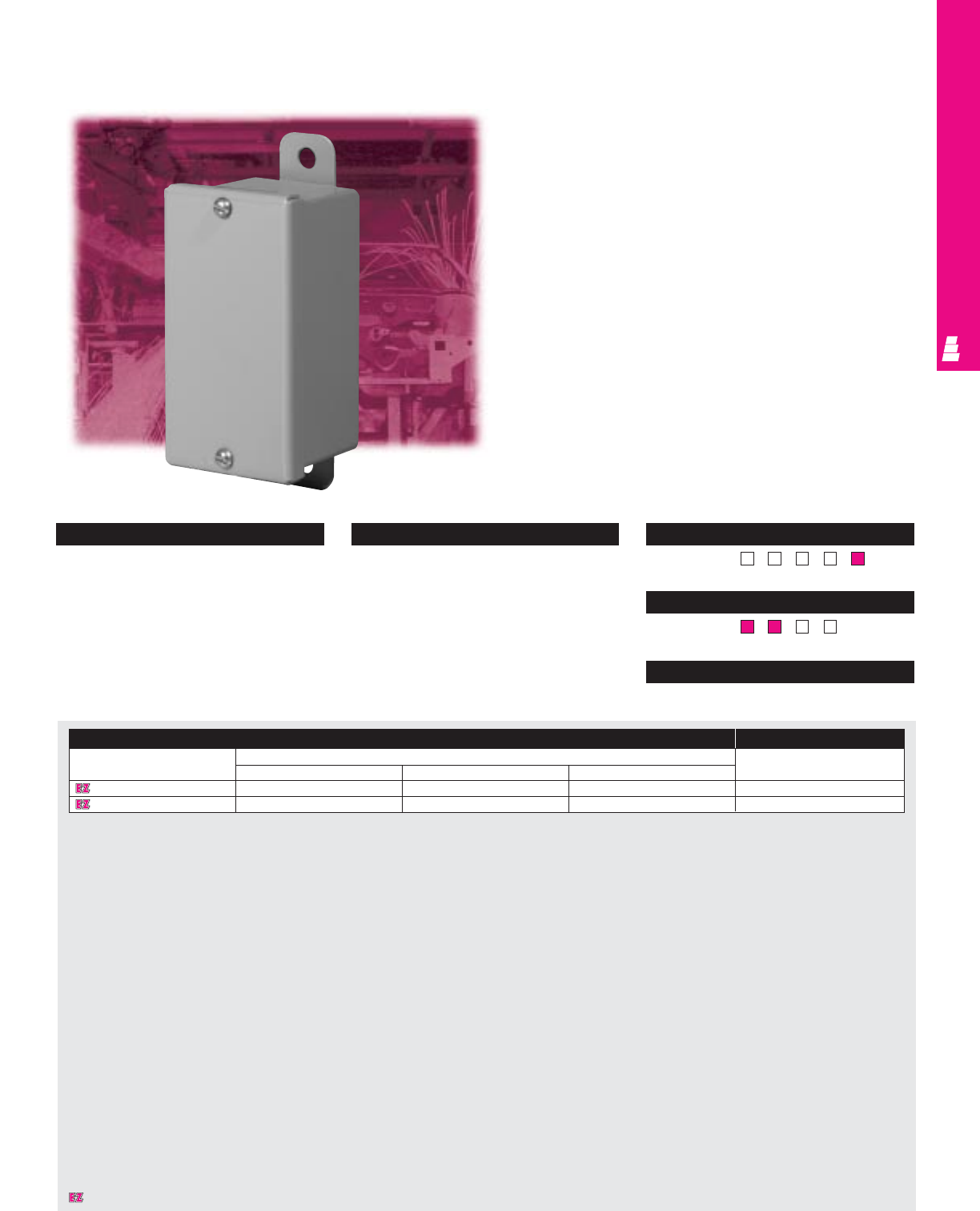
Handy Box Enclosures
Small Carbon Steel Boxes
These NEMA rated boxes are designed primarily for indoor use
to house pilot devices, such as limit switches, foot switches,
pushbuttons, selector switches, pilot lights, etc., and to protect
such equipment against dirt, dust, oil and water seepage.
Page . . . . . . . . . . . . . . . . . . . . . . . . . . . . . IND 45
NEMA Type 144X1213
UL CUL CSA TÜV
Listings
Protection Ratings
Certifications/Approvals
Technical Drawings
Enclosure Accessories
Part No. Outside dimensions (inches) Touch-up paint
HWD
E 4022HB 4.00 2.00 2.00 E L21
E 4033HB 4.25 2.88 2.63 E L21
IND 16
Designates a product in the EnclosureZone program.
WALLMOUNT ENCLOSURES
IND 17
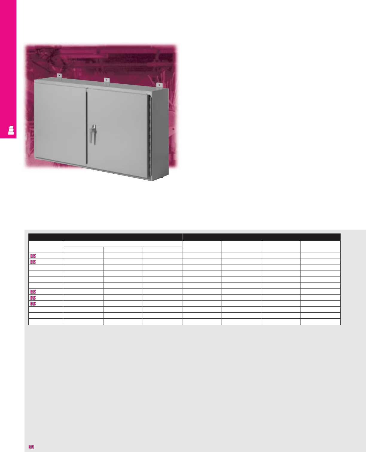
Two Door Wallmount Enclosures
Large Carbon Steel Boxes
These NEMA rated enclosures are designed for indoor use
to protect enclosed equipment against lint and dust, external
condensation, and spraying of water, oil or coolant.
Enclosure Mounting Panel
Part No. Outside dimensions Part No. HWUsable depth
HWD
E 244208WF 24.00 42.00 8.00 E 42P24 21.00 39.00 8.00
E 244808WF 24.00 48.00 8.00 E 48P24 21.00 45.00 8.00
E 304210WF 30.00 42.00 10.00 E 42P30 27.00 39.00 10.00
E 304810WF 30.00 48.00 10.00 E 48P30 27.00 45.00 10.00
E 306010WF 30.00 60.00 10.00 E 60P30 27.00 57.00 10.00
E 364212WF 36.00 42.00 12.00 E 42P36 33.00 39.00 12.00
E 364812WF 36.00 48.00 12.00 E 48P36 33.00 45.00 12.00
E 366012WF 36.00 60.00 12.00 E 60P36 33.00 57.00 11.37*
E 424212WF 42.00 42.00 12.00 E 42P42 39.00 39.00 12.00
E 424812WF 42.00 48.00 12.00 E 48P42 39.00 45.00 12.00
E 426012WFA 42.00 60.00 12.00 E 60WFP42 38.00 56.00 11.37*
E 484812WFA 48.00 48.00 12.00 E 48WFP48 44.00 44.00 12.00
* Usable depth reduced by .625” at door stiffener.
Designates a product in the EnclosureZone program.

WALLMOUNT ENCLOSURES
IND 18
Configuration
•Continuously welded seams, finished
smooth
•Neoprene strip gasket
•Continuous hinge with removable pin
•Gasketed overlapping doors
•3 point latch with key-locking handle
•Door and body stiffeners in larger sizes
•Mounting panel provisions installed
•External mounting brackets
•Print pocket included
Technical Specifications
Material:
•Enclosure/door: 14 gauge carbon steel
Finish/color:
•Enclosure/door: polyester-urethane powder
coat over phosphatized surfaces –
ANSI 61 grey outside and white inside
•Optional mounting panels: painted white
Page . . . . . . . . . . . . . . . . . . . . . . . . . . . . . IND 46
NEMA Type 144X1213
UL CUL CSA TÜV
Listings
Protection Ratings
Certifications/Approvals
Technical Drawings
Accessories
Part No. Door stop kit Drip shield kit Window kit Touch-up paint Light kit
E 244208WF E DSTOPK E DK42 E PWK1711NF E L21 See ACC 29
E 244808WF E DSTOPK E DK48 E PWK1711NF E L21 See ACC 29
E 304210WF E DSTOPK E DK42 E PWK2315NF E L21 See ACC 29
E 304810WF E DSTOPK E DK48 E PWK2315NF E L21 See ACC 29
E 306010WF E DSTOPK E DK60 E PWK2315NF E L21 See ACC 29
E 364212WF E DSTOPK E DK42 E PWK2919NF E L21 See ACC 29
E 364812WF E DSTOPK E DK48 E PWK2919NF E L21 See ACC 29
E 366012WF E DSTOPK E DK60 E PWK2919NF E L21 See ACC 29
E 424212WF E DSTOPK E DK42 E PWK2919NF E L21 See ACC 29
E 424812WF E DSTOPK E DK48 E PWK2919NF E L21 See ACC 29
E 426012WFA E DSTOPK E DK60 E PWK3523NF E L21 See ACC 29
E 484812WFA E DSTOPK E DK48 E PWK3523NF E L21 See ACC 29
Designates a product in the EnclosureZone program.
IND 19
Flush Mount Boxes
Flush Mount Carbon Steel Boxes
These NEMA rated enclosures can be mounted flush with the
wall and are designed for indoor use to protect enclosed
equipment against lint, dust, and spraying of water.
WALLMOUNT ENCLOSURES
Enclosure Mounting Panel
Part No. Outside dimensions Part No. HWUsable depth
HWD
E 161206FM 16.00 12.00 6.00 E 16P12 13.00 9.00 6.00
E 201606FM 20.00 16.00 6.00 E 20P16 17.00 13.00 6.00
E 202006FM 20.00 20.00 6.00 E 20P20 17.00 17.00 6.00
E 242006FM 24.00 20.00 6.00 E 24P20 21.00 17.00 6.00
E 242408FM 24.00 24.00 8.00 E 24P24 21.00 21.00 8.00
E 302408FM 30.00 24.00 8.00 E 30P24 27.00 21.00 8.00
IND 20
WALLMOUNT ENCLOSURES
Configuration
•Includes mounting frame for flush mount
•Continuously welded seams, finished smooth
•Urethane gasket
•Continuous hinge with removable hinge pin
•Slotted hex head captive screws secure door
•Hasp and staple for padlock
•Door and body stiffeners in larger sizes
•Mounting panel provisions installed
•Print pocket included
Technical Specifications
Material:
•Enclosure/door: 14 gauge carbon steel
•Mounting frame: 12 gauge carbon steel
Finish/color:
•Enclosure/door: polyester-urethane powder
coat over phosphatized surfaces – ANSI 61
grey outside and white inside
•Optional mounting panels: painted white Page . . . . . . . . . . . . . . . . . . . . . . . . . . . . . IND 47
NEMA Type 144X1213
UL CUL CSA TÜV
Listings
Protection Ratings
Certifications/Approvals
Technical Drawings
Accessories
Part No. Terminal block kit Terminal rails Window kit Light kit Dead front kit Touch-up paint
Panel Risers
E 161206FM E 12NTMA2 E 16NS E PWK95NF See ACC 29 - - E L21
E 201606FM E 16NTMA2 E 20NS E PWK138NF See ACC 29 E DF20P16 E DF6R4 E L21
E 202006FM E 20NTMA2 E 20NS E PWK138NF See ACC 29 E DF20P20 E DF6R4 E L21
E 242006FM E 20NTMA2 E 24NS E PWK1711NF See ACC 29 E DF24P20 E DF6R4 E L21
E 242408FM E 24NTMA3 E 24NS E PWK1711NF See ACC 29 E DF24P24 E DF8R4 E L21
E 302408FM E 24NTMA3 E 30NS E PWK2315NF See ACC 29 E DF30P24 E DF8R4 E L21
IND 21
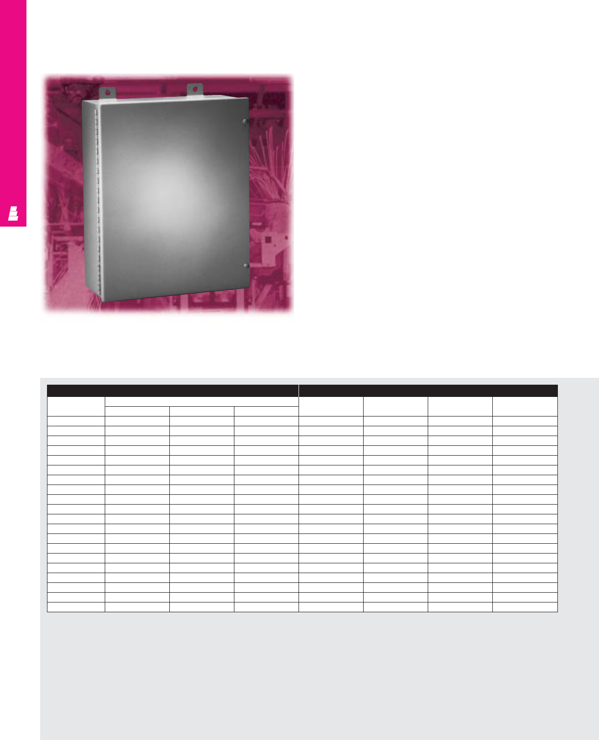
Large Oil-Tight Boxes
Large Oil Tight Carbon Steel Boxes
These NEMA rated enclosures are designed primarily for indoor
use to protect installed equipment against lint and dust, seepage,
and spraying of water, oil, or coolant.
WALLMOUNT ENCLOSURES
Enclosure Mounting Panel
Part No. Outside dimensions Part No. HWUsable depth
HWD
E 20C16A 20.00 16.00 7.00 E 20P16 17.00 13.00 6.00
E 20C16B 20.00 16.00 9.00 E 20P16 17.00 13.00 8.00
E 20C20A 20.00 20.00 7.00 E 20P20 17.00 17.00 6.00
E 20C20B 20.00 20.00 9.00 E 20P20 17.00 17.00 8.00
E 24C20A 24.00 20.00 7.00 E 24P20 21.00 17.00 6.00
E 24B20B 24.00 20.00 9.00 E 24P20 21.00 17.00 8.00
E 24C24A 24.00 24.00 7.00 E 24P24 21.00 21.00 6.00
E 24C24B 24.00 24.00 9.00 E 24P24 21.00 21.00 8.00
E 24C24C 24.00 24.00 11.00 E 24P24 21.00 21.00 10.00
E 30C20A 30.00 20.00 7.00 E 30P20 27.00 17.00 6.00
E 30C20B 30.00 20.00 9.00 E 30P20 27.00 17.00 8.00
E 30C24A 30.00 24.00 7.00 E 30P24 27.00 21.00 6.00
E 30C24B 30.00 24.00 9.00 E 30P24 27.00 21.00 8.00
E 30C24D 30.00 24.00 13.00 E 30P24 27.00 21.00 12.00
E 36C24A 36.00 24.00 7.00 E 36P24 33.00 21.00 6.00
E 36C24B 36.00 24.00 9.00 E 36P24 33.00 21.00 8.00
E 36C24C 36.00 24.00 11.00 E 36P24 33.00 21.00 10.00
E 36C30B 36.00 30.00 9.00 E 36P30 33.00 27.00 7.38*
E 36C30D 36.00 30.00 13.00 E 36P30 33.00 27.00 11.38*
E 48C36C 48.00 36.00 11.00 E 48P36 45.00 33.00 9.38*
* Usable depth reduced by .625" at door stiffener.
IND 22
WALLMOUNT ENCLOSURES
Configuration
•Continuously welded seams, finished smooth
•Urethane gasket
•Continuous hinge with removable pin
•Slotted pan head captive screws secure door
•Mounting panel provisions installed
•Print pocket included
•External mounting brackets
Technical Specifications
Material:
•Enclosure/door: 14 gauge carbon steel
Finish/color:
•Enclosure/door: polyester-urethane powder
coat over phosphatized surfaces – ANSI 61
grey inside and outside
•Optional mounting panels: painted white
Page . . . . . . . . . . . . . . . . . . . . . . . . . . . . . IND 48
NEMA Type 144X1213
UL CUL CSA TÜV
Listings
Protection Ratings
Certifications/Approvals
Technical Drawings
Accessories
Part No. Terminal kits Terminal rails Window kits Dead front kit Light kit Touch-up paint
Panel Risers
E 20C16A E 16NTMA2 E 20NS E PWK138NF E DF20P16 E DF6R4 See ACC 29 E L21
E 20C16B E 16NTMA2 E 20NS E PWK138NF E DF20P16 E DF8R4 See ACC 29 E L21
E 20C20A E 20NTMA2 E 20NS E PWK138NF E DF20P20 E DF6R4 See ACC 29 E L21
E 20C20B E 20NTMA2 E 20NS E PWK138NF E DF20P20 E DF8R4 See ACC 29 E L21
E 24C20A E 20NTMA2 E 24NS E PWK1711NF E DF24P20 E DF6R4 See ACC 29 E L21
E 24B20B E 20NTMA2 E 24NS E PWK1711NF E DF24P20 E DF8R4 See ACC 29 E L21
E 24C24A E 24NTMA3 E 24NS E PWK1711NF E DF24P24 E DF6R4 See ACC 29 E L21
E 24C24B E 24NTMA3 E 24NS E PWK1711NF E DF24P24 E DF8R4 See ACC 29 E L21
E 24C24C E 24NTMA3 E 24NS E PWK1711NF E DF24P24 E DF10R4 See ACC 29 E L21
E 30C20A E 20NTMA2 E 30NS E PWK2315NF - - See ACC 29 E L21
E 30C20B E 20NTMA2 E 30NS E PWK2315NF - - See ACC 29 E L21
E 30C24A E 24NTMA3 E 30NS E PWK2315NF E DF30P24 E DF6R4 See ACC 29 E L21
E 30C24B E 24NTMA3 E 30NS E PWK2315NF E DF30P24 E DF8R4 See ACC 29 E L21
E 30C24D E 24NTMA3 E 30NS E PWK2315NF E DF30P24 E DF12R4 See ACC 29 E L21
E 36C24A E 24NTMA3 E 36NS E PWK2919NF - - See ACC 29 E L21
E 36C24B E 24NTMA3 E 36NS E PWK2919NF E DF36P24 E DF8R5 See ACC 29 E L21
E 36C24C E 24NTMA3 E 36NS E PWK2919NF E DF36P24 E DF10R5 See ACC 29 E L21
E 36C30B E 30NTMA3 E 36NS E PWK2919NF E DF36P30 E DF8R5 See ACC 29 E L21
E 36C30D E 30NTMA3 E 36NS E PWK2919NF E DF36P30 E DF12R5 See ACC 29 E L21
E 48C36C E 30NTMA3 E 48NS E PWK3523NF E DF48P36 E DF10R6 See ACC 29 E L21
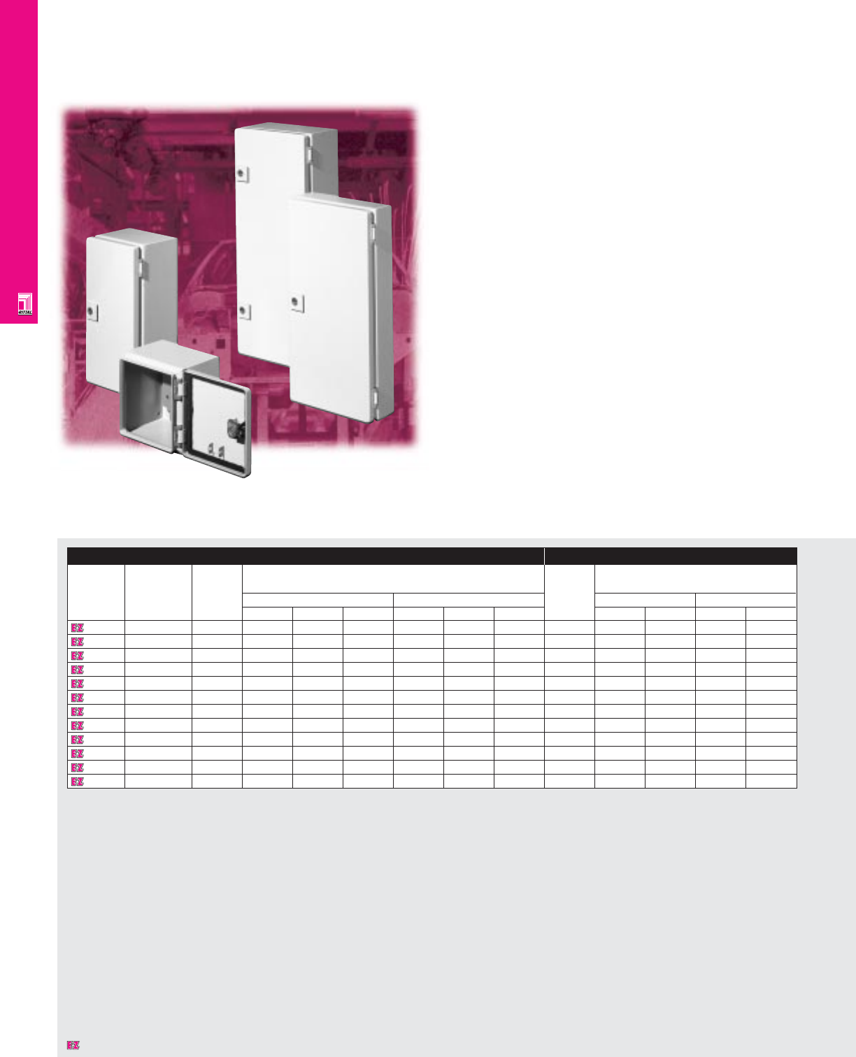
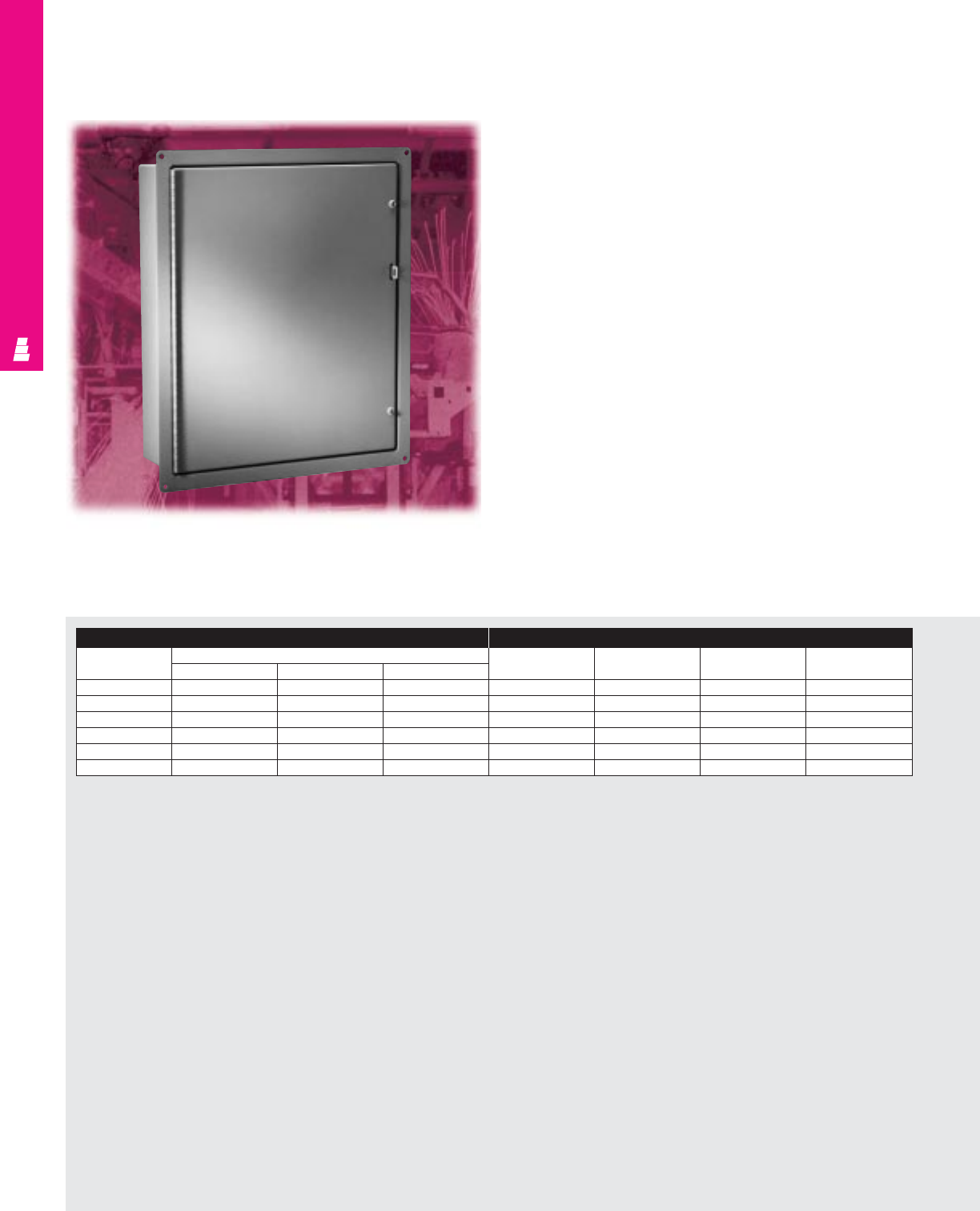
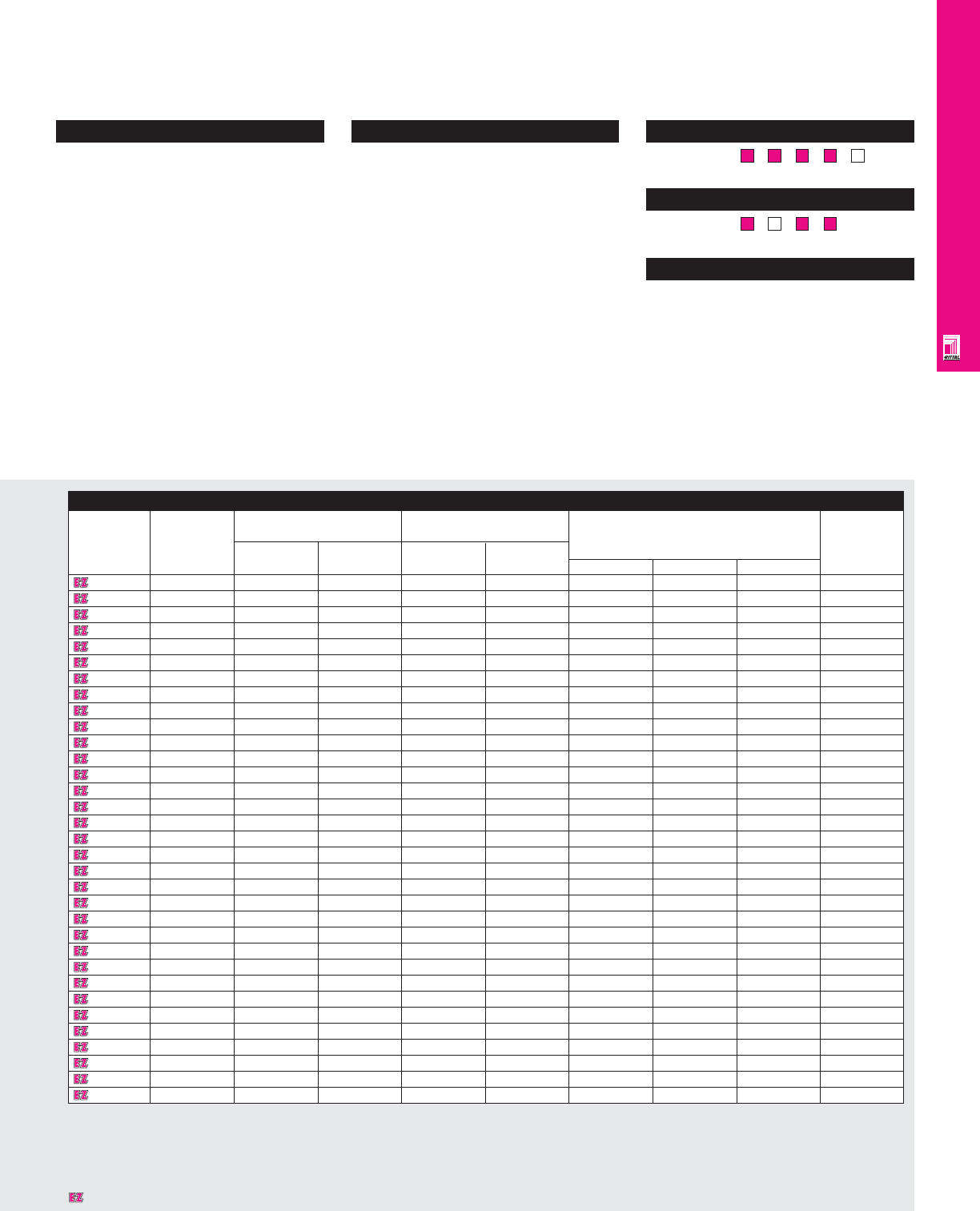
AE Wallmount Enclosures
NEMA Rated Wallmount Enclosures
Rittal’s AE compact enclosures can be used for many different
types of applications. Their NEMA 4 or NEMA 12 protection
rating is ensured through a secure locking system, foamed-on
gaskets, and knife-edge perimeter. They feature a body
constructed from cold rolled steel, steel doors, mounting panels,
and pre-installed cable entry panels.
Enclosure Mounting Panel
Part No. Approximate NEMA No. of Exact outside dimensions Dimensions
outside rating doors
dimensions inches mm inches mm
H"xW"xD" H W D H W D H W H W
1032600 12x8x5 1, 12 1 11.81 7.87 4.72 300 200 120 10.83 6.38 275 162
1035600 12x8x6 1, 12 1 11.81 7.87 6.10 300 200 155 10.83 6.38 275 162
1030600 12x15x6 1, 3R, 4, 12 1 11.81 14.96 6.10 300 380 155 10.83 13.15 275 334
1033600 12x12x8 1, 3R, 4, 12 1 11.81 11.81 8.27 300 300 210 10.83 10.00 275 254
1031600 12x15x8 1, 3R, 4, 12 1 11.81 14.96 8.27 300 380 210 10.83 13.15 275 334
1380600 15x15x8 1, 3R, 4, 12 1 14.96 14.96 8.27 380 380 210 13.98 13.15 355 334
1039600 15x24x8 1, 3R, 4, 12 1 14.96 23.62 8.27 380 600 210 13.98 21.61 355 549
1034600 16x12x8 1, 3R, 4, 12 1 15.75 11.81 8.27 400 300 210 14.76 10.00 375 254
1045600 20x16x8 1, 3R, 4, 12 1 19.69 15.75 8.27 500 400 210 18.70 13.94 475 354
1050600 20x20x8 1, 3R, 4, 12 1 19.69 19.69 8.27 500 500 210 18.50 17.68 470 449
1038600 24x15x8 1, 3R, 4, 12 1 23.62 14.96 8.27 600 380 210 22.44 13.15 570 334
1060600 24x24x8 1, 3R, 4, 12 1 23.62 23.62 8.27 600 600 210 22.44 21.61 570 549
1076600 30x24x8 1, 3R, 4, 12 1 29.92 23.62 8.27 760 600 210 28.74 21.61 730 549
1077600 30x30x8 1, 3R, 4, 12 1 29.92 29.92 8.27 760 760 210 28.74 27.72 730 704
1100600 30x40x8 1, 12 2 29.92 39.37 8.27 760 1000 210 28.74 37.17 730 944
1057600 27x20x10 1, 3R, 4, 12 1 27.50 19.68 9.84 700 500 250 26.38 17.68 670 449
1058600 32x24x10 1, 3R, 4, 12 1 31.50 23.62 9.84 800 600 250 30.31 21.61 770 549
1090600 40x24x10 1, 3R, 4, 12 1 39.37 23.62 9.84 1000 600 250 37.60 21.61 955 549
1350600 20x20x12 1, 3R, 4, 12 1 19.69 19.69 11.81 500 500 300 18.50 17.68 470 449
1073600 30x30x12 1, 3R, 4, 12 1 29.92 29.92 11.81 760 760 300 28.74 27.72 730 704
1130600 30x40x12 1, 12 2 29.92 39.37 11.81 760 1000 300 28.74 37.17 730 944
1097500 36x30x12 1, 3R, 4, 12 1 35.43 29.92 11.81 900 760 300 33.66 27.72 855 704
1180600 40x32x12 1, 3R, 4, 12 1 39.37 31.50 11.81 1000 800 300 37.60 29.09 955 739
1110600 40x40x12 1, 12 2 39.37 39.37 11.81 1000 1000 300 37.60 36.97 955 939
1260600 47x24x12 1, 3R, 4, 12 1 47.24 23.62 11.81 1200 600 300 45.47 21.26 1155 540
1280600 47x32x12 1, 3R, 4, 12 1 47.24 31.50 11.81 1200 800 300 45.47 29.13 1155 740
1097670 47x36x12 1, 3R, 4, 12 1 47.24 35.43 11.81 1200 900 300 45.47 33.07 1155 840
1213600 47x40x12 1, 12 2 47.24 39.37 11.81 1200 1000 300 45.47 37.00 1155 940
1114600 55x40x12 1, 12 2 55.12 39.37 11.81 1400 1000 300 53.35 37.00 1355 940
1339600 15x24x14 1, 3R, 4, 12 1 14.96 23.62 13.78 380 600 350 13.98 21.61 355 549
1338600 24x15x14 1, 3R, 4, 12 1 23.62 14.96 13.78 600 380 350 22.44 21.61 570 549
1360600 24x24x14 1, 3R, 4, 12 1 23.62 23.62 13.78 600 600 350 22.44 21.61 570 549
1376600 30x24x14 1, 3R, 4, 12 1 29.92 23.62 13.78 760 600 350 28.74 21.61 730 549
S
t
a
i
n
l
e
s
s
S
t
e
e
l
S
t
a
i
n
l
e
s
s
S
t
e
e
l
A
v
a
i
l
a
b
l
e
I
n
A
v
a
i
l
a
b
l
e
I
n
Page IND 211
F
M
D
F
M
D
A
v
a
i
l
a
b
l
e
I
n
A
v
a
i
l
a
b
l
e
I
n
Page IND 93
WALLMOUNT ENCLOSURES
IND 23
Designates a product in the EnclosureZone program.
Technical Specifications
Material:
•Sheet steel
•Housing: 16 ga/1.5 mm
•Door: 14 ga/2 mm (except AE 1032, 1035:
16 ga/1.5 mm)
•Mounting panel: 11 gauge hot-dipped
galvanized zinc
Finish/color:
•Housing and door: powder painted,
RAL 7032 pebble grey
•Mounting panel: Type M
Accessories
Part No. Swing frame Wallmounting Base Handles Plastic
(also order brackets print
EL 2093 screws 3/8" 1-5/8" 4" 8" pocket
& EL 2092 nuts) standoff standoff high high Ergoform-S Thumb turn T-handle
1032600 -2508200 2503200 - - - 2576000 2575000 -
1035600 -2508200 2503200 - - - 2576000 2575000 -
1030600 -2508200 2503200 - - - 2576000 2575000 -
1033600 -2508200 2503200 - - - 2576000 2575000 -
1031600 -2508200 2503200 - - - 2576000 2575000 -
1380600 -2508200 2503200 - - - 2576000 2575000 2514000
1039600 2026200 2508200 2503200 - - - 2576000 2575000 2514000
1034600 -2508200 2503200 - - - 2576000 2575000 2514000
1045600 -2508200 2503200 - - - 2576000 2575000 2514000
1050600 -2508200 2503200 - - - 2576000 2575000 2514000
1038600 -2508200 2503200 - - - 2576000 2575000 2514000
1060600 2027200 2508200 2503200 - - - 2576000 2575000 2514000
1076600 2034200 2508200 2503200 - - - 2576000 2575000 2514000
1077600 2034200 2508200 2503200 - - - 2576000 2575000 2514000
1100600 -2508200 2503200 - - - 2576000 2575000 2514000
1057600 -2508200 2503200 - - - 2576000 2575000 2514000
1058600 -2508200 2503200 - - - 2576000 2575000 2514000
1090600 -2508200 2503200 - - - 2576000 2575000 2514000
1350600 -2508200 2503200 - - - 2576000 2575000 2514000
1073600 2034200 2508200 2503200 - - - 2576000 2575000 2514000
1130600 -2508200 2503200 2801200 2802200 - 2576000 2575000 2514000
1097500 -2508200 2503200 - - - 2576000 2575000 2514000
1180600 -2508200 2503200 2818200 2828200 - 2576000 2575000 2514000
1110600 -2508200 2503200 2801200 2802200 - 2576000 2575000 2514000
1260600 -2508200 2503200 2816200 2826200 2450000 - - 2514000
1280600 -2508200 2503200 2818200 2828200 2450000 - - 2514000
1097670 -2508200 2503200 - - 2450000 2576000 2575000 2514000
1213600 -2508200 2503200 2801200 2802200 2450000 - - 2514000
1114600 -2508200 2503200 2801200 2802200 2450000 - - 2514000
1339600 2026200 2508200 2503200 - - - 2576000 2575000 2514000
1338600 -2508200 2503200 - - - 2576000 2575000 2514000
1360600 2027200 2508200 2503200 - - - 2576000 2575000 2514000
1376600 2034200 2508200 2503200 - - - 2576000 2575000 2514000
Configuration
• Vertical mounting rails on doors
• Right or left hand hinging on all single
door models
• Turnbuckle or rod type locks for easy
access and secure seal
•Rear mounting holes allow direct
wallmounting or the use of optional
mounting feet
•One piece body construction with
continuously welded seams
•Knife-edge design protects against
liquid entry
•Integrated grounding provisions
• Mounting panel included
• Powder paint provides superior corrosion
protection
• Foamed-on gaskets ensure perfect seal
• Wide range of accessories
Pages . . . . . . . . . . . . . . . . . . . . . . . . . IND 49-52
NEMA Type 13R41213
UL CUL CSA TÜV
Listings
Protection Ratings
Certifications/Approvals
Technical Drawings
WALLMOUNT ENCLOSURES
IND 24
Designates a product in the EnclosureZone program.
WALLMOUNT ENCLOSURES
IND 25
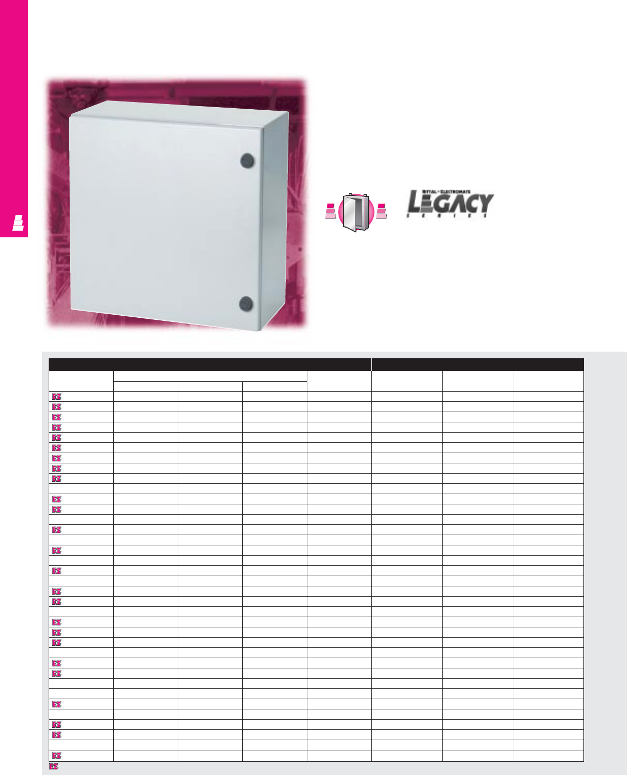
Legacy Series Enclosures
Carbon Steel Wallmount Boxes
Legacy Series instrument boxes offer protection for dense
wiring and sensitive small electronic and electrical equipment
controls and pilot devices, such as limit switches, foot switches,
pushbuttons, selector switches and pilot lights. Installed
equipment is protected against splashing water, seepage of
water, falling or hose directed water, severe external
condensation and spraying of water, oil or coolant.
Enclosure Mounting Panel
Part No. Outside dimensions (inches) Latch White (Full Size) Zinc (Full Size) White (NEMA Style)
HWDsystem Panel Part No. Panel Part No. Panel Part No.
L W120806 12.00 8.00 6.00 1 Qtr. Turn L W12P8W L W12P8 -
L W121206 12.00 12.00 6.00 1 Qtr. Turn L W12P12W L W12P12 -
L W121608 12.00 16.00 8.00 1 Qtr. Turn L W12P16W L W12P16 E 16P12
L W161206 16.00 12.00 6.00 1 Qtr. Turn L W16P12W L W16P12 E 16P12
L W161208 16.00 12.00 8.00 1 Qtr. Turn L W16P12W L W16P12 E 16P12
L W161606 16.00 16.00 6.00 1 Qtr. Turn L W16P16W L W16P16 E 16P16
L W161608 16.00 16.00 8.00 1 Qtr. Turn L W16P16W L W16P16 E 16P16
L W201606 20.00 16.00 6.00 2 Qtr. Turn L W20P16W L W20P16 E 20P16
L W201608 20.00 16.00 8.00 2 Qtr. Turn L W20P16W L W20P16 E 20P16
L W202006 20.00 20.00 6.00 2 Qtr. Turn L W20P20W L W20P20 E 20P20
L W202008 20.00 20.00 8.00 2 Qtr. Turn L W20P20W L W20P20 E 20P20
L W202012 20.00 20.00 12.00 2 Qtr. Turn L W20P20W L W20P20 E 20P20
L W202408 20.00 24.00 8.00 2 Qtr. Turn L W20P24W L W20P24 E 24P20
L W241608 24.00 16.00 8.00 2 Qtr. Turn L W24P16W L W24P16 E 24P16
L W242006 24.00 20.00 6.00 2 Qtr. Turn L W24P20W L W24P20 E 24P20
L W242008 24.00 20.00 8.00 2 Qtr. Turn L W24P20W L W24P20 E 24P20
L W242406 24.00 24.00 6.00 2 Qtr. Turn L W24P24W L W24P24 E 24P24
L W242408 24.00 24.00 8.00 2 Qtr. Turn L W24P24W L W24P24 E 24P24
L W242410 24.00 24.00 10.00 2 Qtr. Turn L W24P24W L W24P24 E 24P24
L W242412 24.00 24.00 12.00 2 Qtr. Turn L W24P24W L W24P24 E 24P24
L W242416 24.00 24.00 16.00 2 Qtr. Turn L W24P24W L W24P24 E 24P24
L W243008 24.00 30.00 8.00 2 Qtr. Turn L W24P30W L W24P30 E 30P24
L W302408 30.00 24.00 8.00 2 Qtr. Turn L W30P24W L W30P24 E 30P24
L W302412 30.00 24.00 12.00 2 Qtr. Turn L W30P24W L W30P24 E 30P24
L W303008 30.00 30.00 8.00 2 Qtr. Turn L W30P30W L W30P30 E 30P30
L W303010 30.00 30.00 10.00 2 Qtr. Turn L W30P30W L W30P30 E 30P30
L W303012 30.00 30.00 12.00 2 Qtr. Turn L W30P30W L W30P30 E 30P30
L W362408 36.00 24.00 8.00 2 Qtr. Turn L W36P24W L W36P24 E 36P24
L W362412 36.00 24.00 12.00 2 Qtr. Turn L W36P24W L W36P24 E 36P24
L W363008 36.00 30.00 8.00 2 Qtr. Turn L W36P30W L W36P30 E 36P30
L W363012 36.00 30.00 12.00 2 Qtr. Turn L W36P30W L W36P30 E 36P30
L W363612 36.00 36.00 12.00 2 Qtr. Turn L W36P36W L W36P36 E 36P36
L W423212 42.00 32.00 12.00 3 Point Lock System L W42P32W L W42P32 E 42P32
L W483612 48.00 36.00 12.00 3 Point Lock System L W48P36W L W48P36 E 48P36
L W483616 48.00 36.00 16.00 3 Point Lock System L W48P36W L W48P36 E 48P36
L W603612 60.00 36.00 12.00 3 Point Lock System L W60P36W L W60P36 E 60P36
S
t
a
i
n
l
e
s
s
S
t
e
e
l
S
t
a
i
n
l
e
s
s
S
t
e
e
l
A
v
a
i
l
a
b
l
e
I
n
A
v
a
i
l
a
b
l
e
I
n
Page IND 213
Designates a product in the EnclosureZone program.

WALLMOUNT ENCLOSURES
IND 26
Configuration
•Continuously welded seams, finished
smooth
•Robotically applied urethane gasket
•Door opens 130°
•Knife edge flange
•Easily removable stainless steel hinge pins
•Integral channel around door provides
additional stability and prevents entry of
water and dirt when enclosure is opened
•Quarter turn latching
•Screwdriver lock insert
•Mounting panel provisions installed
•Mounting panel available in both white
(NEMA and full size) and zinc (full
size) styles
•Grounding provisions on enclosure body
and door
•Print pocket included
Technical Specifications
Material:
•Enclosure/door: 14 gauge carbon steel
Finish/color:
•Enclosure/door: polyester-urethane powder
coat over phosphatized surfaces, inside
and outside - ANSI 61 grey
Page . . . . . . . . . . . . . . . . . . . . . . . . . . . . . IND 53
NEMA Type 144X1213
UL CUL CSA TÜV
Listings
Protection Ratings
Certifications/Approvals
Technical Drawings
Accessories
Part No. Terminal Terminal Latching Window Light Wallmounting Dead front kit Touch-up
block kit rails accessories kit kit brackets Panel Risers paint
L W120806 --See ACC 20 E PWK53NF See ACC 29 2508200 - - E L21
L W121206 --See ACC 20 E PWK53NF See ACC 29 2508200 L DF12P12 L DF6R4 E L21
L W121608 --See ACC 20 E PWK53NF See ACC 29 2508200 - - E L21
L W161206 E 12NTMA2 E 16NS See ACC 20 E PWK95NF See ACC 29 2508200 L DF16P12 L DF6R4 E L21
L W161208 E 12NTMA2 E 16NS See ACC 20 E PWK95NF See ACC 29 2508200 L DF16P12 L DF8R4 E L21
L W161606 E 16NTMA2 E 16NS See ACC 20 E PWK95NF See ACC 29 2508200 L DF16P16 L DF6R4 E L21
L W161608 E 16NTMA2 E 16NS See ACC 20 E PWK95NF See ACC 29 2508200 L DF16P16 L DF8R4 E L21
L W201606 E 16NTMA2 E 20NS See ACC 20 E PWK138NF See ACC 29 2508200 L DF20P16 L DF6R4 E L21
L W201608 E 16NTMA2 E 20NS See ACC 20 E PWK138NF See ACC 29 2508200 L DF20P16 L DF8R4 E L21
L W202006 E 20NTMA2 E 20NS See ACC 20 E PWK138NF See ACC 29 2508200 L DF20P20 L DF6R4 E L21
L W202008 E 20NTMA2 E 20NS See ACC 20 E PWK138NF See ACC 29 2508200 L DF20P20 L DF8R4 E L21
L W202012 E 20NTMA2 E 20NS See ACC 20 E PWK138NF See ACC 29 2508200 L DF20P20 L DF12R4 E L21
L W202408 E 24NTMA3 E 20NS See ACC 20 E PWK1711NF See ACC 29 2508200 - - E L21
L W241608 E 16NTMA2 E 24NS See ACC 20 E PWK175NF See ACC 29 2508200 L DF24P16 L DF8R4 E L21
L W242006 E 20NTMA2 E 24NS See ACC 20 E PWK1711NF See ACC 29 2508200 L DF24P20 L DF6R4 E L21
L W242008 E 20NTMA2 E 24NS See ACC 20 E PWK1711NF See ACC 29 2508200 L DF24P20 L DF8R4 E L21
L W242406 E 24NTMA3 E 24NS See ACC 20 E PWK1711NF See ACC 29 2508200 L DF24P24 L DF6R4 E L21
L W242408 E 24NTMA3 E 24NS See ACC 20 E PWK1711NF See ACC 29 2508200 L DF24P24 L DF8R4 E L21
L W242410 E 24NTMA3 E 24NS See ACC 20 E PWK1711NF See ACC 29 2508200 L DF24P24 L DF10R4 E L21
L W242412 E 24NTMA3 E 24NS See ACC 20 E PWK1711NF See ACC 29 2508200 L DF24P24 L DF12R4 E L21
L W242416 E 24NTMA3 E 24NS See ACC 20 E PWK1711NF See ACC 29 2508200 L DF24P24 L DF16R4 E L21
L W243008 E 30NTMA3 E 24NS See ACC 20 E PWK2315NF See ACC 29 2508200 - - E L21
L W302408 E 24NTMA3 E 30NS See ACC 20 E PWK2315NF See ACC 29 2508200 L DF30P24 L DF8R4 E L21
L W302412 E 24NTMA3 E 30NS See ACC 20 E PWK2315NF See ACC 29 2508200 L DF30P24 L DF12R4 E L21
L W303008 E 30NTMA3 E 30NS See ACC 20 E PWK2315NF See ACC 29 2508200 L DF30P30 L DF8R5 E L21
L W303010 E 30NTMA3 E 30NS See ACC 20 E PWK2315NF See ACC 29 2508200 L DF30P30 L DF10R5 E L21
L W303012 E 30NTMA3 E 30NS See ACC 20 E PWK2315NF See ACC 29 2508200 L DF30P30 L DF12R5 E L21
L W362408 E 24NTMA3 E 36NS See ACC 20 E PWK2919NF See ACC 29 2508200 L DF36P24 L DF8R5 E L21
L W362412 E 24NTMA3 E 36NS See ACC 20 E PWK2919NF See ACC 29 2508200 L DF36P24 L DF12R5 E L21
L W363008 E 30NTMA3 E 36NS See ACC 20 E PWK2919NF See ACC 29 2508200 L DF36P30 L DF8R5 E L21
L W363012 E 30NTMA3 E 36NS See ACC 20 E PWK2919NF See ACC 29 2508200 L DF36P30 L DF12R5 E L21
L W363612 E 36NTMA3 E 36NS See ACC 20 E PWK2919NF See ACC 29 2508200 L DF36P36 L DF12R6 E L21
L W423212 E 30NTMA3 E 42NS See ACC 20 E PWK3523NF See ACC 29 2508200 - - E L21
L W483612 E 36NTMA3 E 48NS See ACC 20 E PWK3523NF See ACC 29 2508200 - - E L21
L W483616 E 36NTMA3 E 48NS See ACC 20 E PWK3523NF See ACC 29 2508200 - - E L21
L W603612 E 36NTMA3 E 60NS See ACC 20 E PWK3523NF See ACC 29 2508200 - - E L21
Designates a product in the EnclosureZone program.

WALLMOUNT ENCLOSURES
One Door Wallmount Boxes
NEMA 4 Carbon Steel Enclosures
These NEMA 4 rated enclosures are designed for indoor or
outdoor use and can be used for many different applications.
They protect installed equipment against splashing water,
seepage of water, falling or hose directed water and severe
external condensation.
Enclosure Mounting Panel
Part No. Outside dimensions (inches) Part No. HWUsable depth
HWD
E 16H12A 16.00 12.00 6.00 E 16P12 13.00 9.00 6.00
E 16H12B 16.00 12.00 8.00 E 16P12 13.00 9.00 8.00
E 16H16A 16.00 16.00 6.00 E 16P16 13.00 13.00 6.00
E 16H20A 16.00 20.00 6.00 E 20P16 13.00 17.00 6.00
E 20H16A 20.00 16.00 6.00 E 20P16 17.00 13.00 6.00
E 20H16B 20.00 16.00 8.00 E 20P16 17.00 13.00 8.00
E 20H16C 20.00 16.00 10.00 E 20P16 17.00 13.00 10.00
E 20H20A 20.00 20.00 6.00 E 20P20 17.00 17.00 6.00
E 20H20B 20.00 20.00 8.00 E 20P20 17.00 17.00 8.00
E 20H24B 20.00 24.00 8.00 E 24P20 17.00 21.00 8.00
E 24H12A 24.00 12.00 6.00 E 24P12 21.00 9.00 6.00
E 24H16A 24.00 16.00 6.00 E 24P16 21.00 13.00 6.00
E 24H20A 24.00 20.00 6.00 E 24P20 21.00 17.00 6.00
E 24H20B 24.00 20.00 8.00 E 24P20 21.00 17.00 8.00
E 24H20C 24.00 20.00 10.00 E 24P20 21.00 17.00 10.00
E 24H24A 24.00 24.00 6.00 E 24P24 21.00 21.00 6.00
E 24H24B 24.00 24.00 8.00 E 24P24 21.00 21.00 8.00
E 24H30B 24.00 30.00 8.00 E 30P24 21.00 27.00 8.00
E 30H20A 30.00 20.00 6.00 E 30P20 27.00 17.00 6.00
E 30H20B 30.00 20.00 8.00 E 30P20 27.00 17.00 8.00
E 30H24A 30.00 24.00 6.00 E 30P24 27.00 21.00 6.00
E 30H24B 30.00 24.00 8.00 E 30P24 27.00 21.00 8.00
E 30H24C 30.00 24.00 10.00 E 30P24 27.00 21.00 10.00
E 30H24D 30.00 24.00 12.00 E 30P24 27.00 21.00 12.00
E 30H30B 30.00 30.00 8.00 E 30P30 27.00 27.00 8.00
E 36H24A 36.00 24.00 6.00 E 36P24 33.00 21.00 6.00
E 36H24B 36.00 24.00 8.00 E 36P24 33.00 21.00 8.00
E 36H30B 36.00 30.00 8.00 E 36P30 33.00 27.00 7.37*
E 36H30C 36.00 30.00 10.00 E 36P30 33.00 27.00 9.37*
E 36H30D 36.00 30.00 12.00 E 36P30 33.00 27.00 11.37*
E 36H30F 36.00 30.00 16.00 E 36P30 33.00 27.00 15.37*
E 42H30B 42.00 30.00 8.00 E 42P30 39.00 27.00 7.37*
E 42H36B 42.00 36.00 8.00 E 42P36 39.00 33.00 7.37*
E 48H30C 48.00 30.00 10.00 E 48P30 45.00 27.00 9.37*
E 48H36B 48.00 36.00 8.00 E 48P36 45.00 33.00 7.37*
E 48H36C 48.00 36.00 10.00 E 48P36 45.00 33.00 9.37*
E 48H36D 48.00 36.00 12.00 E 48P36 45.00 33.00 11.37*
E 48H36F 48.00 36.00 16.00 E 48P36 45.00 33.00 15.37*
E 60H36B 60.00 36.00 8.00 E 60P36 57.00 33.00 7.37*
E 60H36C 60.00 36.00 10.00 E 60P36 57.00 33.00 9.37*
E 60H36F 60.00 36.00 16.00 E 60P36 57.00 33.00 15.37*
IND 27
F
M
D
F
M
D
A
v
a
i
l
a
b
l
e
I
n
A
v
a
i
l
a
b
l
e
I
n
Page IND 95
S
t
a
i
n
l
e
s
s
S
t
e
e
l
S
t
a
i
n
l
e
s
s
S
t
e
e
l
A
v
a
i
l
a
b
l
e
I
n
A
v
a
i
l
a
b
l
e
I
n
Page IND 215
A
l
u
m
i
n
u
m
A
v
a
i
l
a
b
l
e
I
n
A
v
a
i
l
a
b
l
e
I
n
A
l
u
m
i
n
u
m
Page IND 219
* Usable depth reduced by .625" at door stiffener.
Designates a product in the EnclosureZone program.
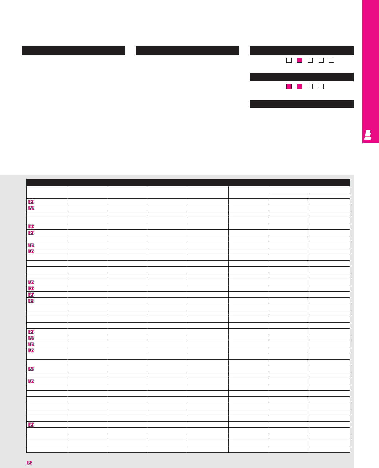
WALLMOUNT ENCLOSURES
Configuration
•Continuously welded seams, finished
smooth
•Robotically applied urethane gasket
•Continuous steel hinge
•Stainless steel captive clamps
•Hasp and staple provided for padlocking
•Door and body stiffeners on larger sizes
•Mounting panel provisions installed
•External mounting brackets
•Print pocket included
Technical Specifications
Material:
•Enclosure/door: 14 gauge carbon steel
Finish/color:
•Enclosure/door: polyester-urethane powder
coat over phosphatized surfaces,
inside and outside – ANSI 61 grey
•Optional mounting panels: painted white
Accessories
Part No. Drip shield kit Terminal block kit Terminal rails Light kit Window kit Dead front kit
Panel Risers
E 16H12A E DK12NF E 12NTMA2 E 16NS See ACC 29 E PWK95NF E DF16P12 E DF6R4
E 16H12B E DK12NF E 12NTMA2 E 16NS See ACC 29 E PWK138NF E DF16P12 E DF8R4
E 16H16A E DK16NF E 16NTMA2 E 16NS See ACC 29 E PWK138NF E DF16P16 E DF6R4
E 16H20A E DK20NF E 20NTMA2 E 16NS See ACC 29 E PWK138NF E DF20P16 E DF6R4
E 20H16A E DK16NF E 16NTMA2 E 20NS See ACC 29 E PWK138NF E DF20P16 E DF6R4
E 20H16B E DK16NF E 16NTMA2 E 20NS See ACC 29 E PWK138NF E DF20P16 E DF8R4
E 20H16C E DK16NF E 16NTMA2 E 20NS See ACC 29 E PWK138NF E DF20P16 E DF10R4
E 20H20A E DK20NF E 20NTMA2 E 20NS See ACC 29 E PWK138NF E DF20P20 E DF6R4
E 20H20B E DK20NF E 20NTMA2 E 20NS See ACC 29 E PWK138NF E DF20P20 E DF8R4
E 20H24B E DK24NF E 24NTMA3 E 20NS See ACC 29 E PWK1711NF E DF24P20 E DF8R4
E 24H12A E DK12NF E 12NTMA2 E 24NS See ACC 29 E PWK175NF - -
E 24H16A E DK16NF E 16NTMA2 E 24NS See ACC 29 E PWK175NF - -
E 24H20A E DK20NF E 20NTMA2 E 24NS See ACC 29 E PWK1711NF E DF24P20 E DF6R4
E 24H20B E DK20NF E 20NTMA2 E 24NS See ACC 29 E PWK1711NF E DF24P20 E DF8R4
E 24H20C E DK20NF E 20NTMA2 E 24NS See ACC 29 E PWK1711NF E DF24P20 E DF10R4
E 24H24A E DK24NF E 24NTMA3 E 24NS See ACC 29 E PWK1711NF E DF24P24 E DF6R4
E 24H24B E DK24NF E 24NTMA3 E 24NS See ACC 29 E PWK1711NF E DF24P24 E DF8R4
E 24H30B E DK30NF E 30NTMA3 E 24NS See ACC 29 E PWK2315NF E DF30P24 E DF8R4
E 30H20A E DK20NF E 20NTMA2 E 30NS See ACC 29 E PWK2315NF - -
E 30H20B E DK20NF E 20NTMA2 E 30NS See ACC 29 E PWK2315NF - -
E 30H24A E DK24NF E 24NTMA3 E 30NS See ACC 29 E PWK2315NF E DF30P24 E DF6R4
E 30H24B E DK24NF E 24NTMA3 E 30NS See ACC 29 E PWK2315NF E DF30P24 E DF8R4
E 30H24C E DK24NF E 24NTMA3 E 30NS See ACC 29 E PWK2315NF E DF30P24 E DF10R4
E 30H24D E DK24NF E 24NTMA3 E 30NS See ACC 29 E PWK2315NF E DF30P24 E DF12R4
E 30H30B E DK30NF E 30NTMA3 E 30NS See ACC 29 E PWK2315NF E DF30P30 E DF8R5
E 36H24A E DK24NF E 24NTMA3 E 36NS See ACC 29 E PWK2919NF - -
E 36H24B E DK24NF E 24NTMA3 E 36NS See ACC 29 E PWK2919NF E DF36P24 E DF8R5
E 36H30B E DK30NF E 30NTMA3 E 36NS See ACC 29 E PWK2919NF E DF36P30 E DF8R5
E 36H30C E DK30NF E 30NTMA3 E 36NS See ACC 29 E PWK2919NF E DF36P30 E DF10R5
E 36H30D E DK30NF E 30NTMA3 E 36NS See ACC 29 E PWK2919NF E DF36P30 E DF12R5
E 36H30F E DK30NF E 30NTMA3 E 36NS See ACC 29 E PWK2919NF E DF36P30 E DF16R5
E 42H30B E DK30NF E 30NTMA3 E 42NS See ACC 29 E PWK3523NF - -
E 42H36B E DK36NF E 36NTMA3 E 42NS See ACC 29 E PWK3523NF E DF42P36 E DF8R6
E 48H30C E DK30NF E 30NTMA3 E 48NS See ACC 29 E PWK3523NF - -
E 48H36B E DK36NF E 36NTMA3 E 48NS See ACC 29 E PWK3523NF E DF48P36 E DF8R6
E 48H36C E DK36NF E 36NTMA3 E 48NS See ACC 29 E PWK3523NF E DF48P36 E DF10R6
E 48H36D E DK36NF E 36NTMA3 E 48NS See ACC 29 E PWK3523NF E DF48P36 E DF12R6
E 48H36F E DK36NF E 36NTMA3 E 48NS See ACC 29 E PWK3523NF E DF48P36 E DF16R6
E 60H36B E DK36NF E 36NTMA3 E 60NS See ACC 29 E PWK3523NF - -
E 60H36C E DK36NF E 36NTMA3 E 60NS See ACC 29 E PWK3523NF - -
E 60H36F E DK36NF E 36NTMA3 E 60NS See ACC 29 E PWK3523NF - -
Page . . . . . . . . . . . . . . . . . . . . . . . . . . . . . IND 54
NEMA Type 144X1213
UL CUL CSA TÜV
Listings
Protection Ratings
Certifications/Approvals
Technical Drawings
IND 28
Designates a product in the EnclosureZone program.
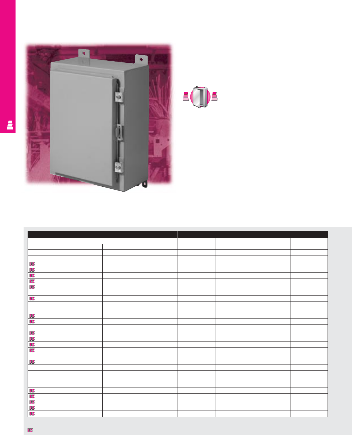
WALLMOUNT ENCLOSURES
IND 29
One Door Wallmount Enclosures
Carbon Steel Electromate Boxes
These NEMA rated enclosures are designed for indoor use
to protect enclosed equipment against lint and dust, external
condensation, and spraying of water, oil or coolant.
Enclosure Mounting Panel
Part No. Outside dimensions (inches) Part No. HWUsable
HWD depth
E 122406 12.00 24.00 6.00 E 12P24 9.00 21.00 6.00
E 122408 12.00 24.00 8.00 E 12P24 9.00 21.00 8.00
E 161206 16.00 12.00 6.00 E 16P12 13.00 9.00 6.00
E 161208 16.00 12.00 8.00 E 16P12 13.00 9.00 8.00
E 161210 16.00 12.00 10.00 E 16P12 13.00 9.00 10.00
E 161606 16.00 16.00 6.00 E 16P16 13.00 13.00 6.00
E 161608 16.00 16.00 8.00 E 16P16 13.00 13.00 8.00
E 162006 16.00 20.00 6.00 E 20P16 13.00 17.00 6.00
E 162008 16.00 20.00 8.00 E 20P16 13.00 17.00 8.00
E 201206 20.00 12.00 6.00 E 20P12 17.00 9.00 6.00
E 201208 20.00 12.00 8.00 E 20P12 17.00 9.00 8.00
E 201606 20.00 16.00 6.00 E 20P16 17.00 13.00 6.00
E 201608 20.00 16.00 8.00 E 20P16 17.00 13.00 8.00
E 201610 20.00 16.00 10.00 E 20P16 17.00 13.00 10.00
E 201612 20.00 16.00 12.00 E 20P16 17.00 13.00 12.00
E 202006 20.00 20.00 6.00 E 20P20 17.00 17.00 6.00
E 202008 20.00 20.00 8.00 E 20P20 17.00 17.00 8.00
E 202010 20.00 20.00 10.00 E 20P20 17.00 17.00 10.00
E 202406 20.00 24.00 6.00 E 24P20 17.00 21.00 6.00
E 202408 20.00 24.00 8.00 E 24P20 17.00 21.00 8.00
E 241206 24.00 12.00 6.00 E 24P12 21.00 9.00 6.00
E 241208 24.00 12.00 8.00 E 24P12 21.00 9.00 8.00
E 241210 24.00 12.00 10.00 E 24P12 21.00 9.00 10.00
E 241606 24.00 16.00 6.00 E 24P16 21.00 13.00 6.00
E 241608 24.00 16.00 8.00 E 24P16 21.00 13.00 8.00
E 242006 24.00 20.00 6.00 E 24P20 21.00 17.00 6.00
E 242008 24.00 20.00 8.00 E 24P20 21.00 17.00 8.00
E 242010 24.00 20.00 10.00 E 24P20 21.00 17.00 10.00
E 242012 24.00 20.00 12.00 E 24P20 21.00 17.00 12.00
* Usable depth reduced by .625" at door stiffener. (Chart continued on page IND 31).
Designates a product in the EnclosureZone program.
S
t
a
i
n
l
e
s
s
S
t
e
e
l
S
t
a
i
n
l
e
s
s
S
t
e
e
l
A
v
a
i
l
a
b
l
e
I
n
A
v
a
i
l
a
b
l
e
I
n
Page IND 221
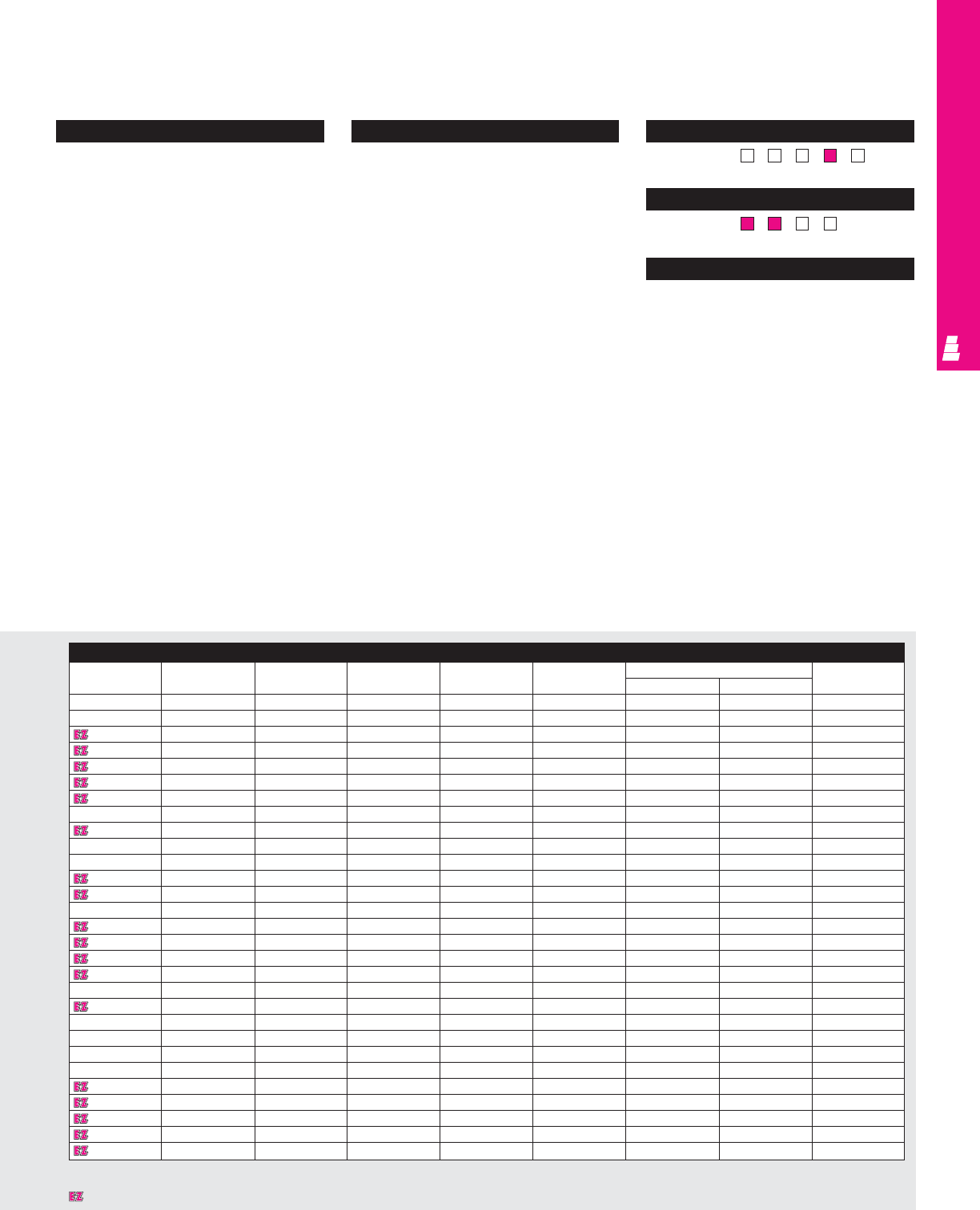
WALLMOUNT ENCLOSURES
IND 30
Configuration
•Continuously welded seams, finished
smooth
•Robotically applied urethane gasket
•Continuous hinge with removable pin
•Plated steel captive clamps
•Hasp and staple for padlocking
•Door and body stiffeners in larger sizes
•Mounting panel provisions installed
•External mounting brackets
•Print pocket included
Technical Specifications
Material:
•Enclosure/door: 14 gauge carbon steel
Finish/color:
•Enclosure/door: polyester-urethane powder
coat over phosphatized surfaces,
– inside: white
– outside: ANSI 61 grey
•Optional mounting panels: painted white Pages . . . . . . . . . . . . . . . . . . . . . . . . . . IND 55-56
NEMA Type 144X1213
UL CUL CSA TÜV
Listings
Protection Ratings
Certifications/Approvals
Technical Drawings
(Chart continued on page IND 32).
Accessories
Part No. Door stop kit Drip shield kit Terminal blocks Terminal rails Light kit Dead front kit Touch-up paint
Panel Risers
E 122406 E DSTOPK E DK24 - - See ACC 29 - - E L21
E 122408 E DSTOPK E DK24 - - See ACC 29 - - E L21
E 161206 -E DK12 E 12NTMA2 E 16NS See ACC 29 E DF16P12 E DF6R4 E L21
E 161208 -E DK12 E 12NTMA2 E 16NS See ACC 29 E DF16P12 E DF8R4 E L21
E 161210 -E DK12 E 12NTMA2 E 16NS See ACC 29 E DF16P12 E DF10R4 E L21
E 161606 -E DK16 E 16NTMA2 E 16NS See ACC 29 E DF16P16 E DF6R4 E L21
E 161608 -E DK16 E 16NTMA2 E 16NS See ACC 29 E DF16P16 E DF8R4 E L21
E 162006 -E DK20 E 20NTMA2 E 16NS See ACC 29 E DF20P16 E DF6R4 E L21
E 162008 -E DK20 E 20NTMA2 E 16NS See ACC 29 E DF20P16 E DF8R4 E L21
E 201206 -E DK12 E 12NTMA2 E 20NS See ACC 29 - - E L21
E 201208 -E DK12 E 12NTMA2 E 20NS See ACC 29 - - E L21
E 201606 -E DK16 E 16NTMA2 E 20NS See ACC 29 E DF20P16 E DF6R4 E L21
E 201608 -E DK16 E 16NTMA2 E 20NS See ACC 29 E DF20P16 E DF8R4 E L21
E 201610 -E DK16 E 16NTMA2 E 20NS See ACC 29 E DF20P16 E DF10R4 E L21
E 201612 -E DK16 E 16NTMA2 E 20NS See ACC 29 E DF20P16 E DF12R4 E L21
E 202006 -E DK20 E 20NTMA2 E 20NS See ACC 29 E DF20P20 E DF6R4 E L21
E 202008 -E DK20 E 20NTMA2 E 20NS See ACC 29 E DF20P20 E DF8R4 E L21
E 202010 -E DK20 E 20NTMA2 E 20NS See ACC 29 E DF20P20 E DF10R4 E L21
E 202406 E DSTOPK E DK24 E 24NTMA3 E 20NS See ACC 29 E DF24P20 E DF6R4 E L21
E 202408 E DSTOPK E DK24 E 24NTMA3 E 20NS See ACC 29 E DF24P20 E DF8R4 E L21
E 241206 -E DK12 E 12NTMA2 E 24NS See ACC 29 - - E L21
E 241208 -E DK12 E 12NTMA2 E 24NS See ACC 29 - - E L21
E 241210 -E DK12 E 12NTMA2 E 24NS See ACC 29 - - E L21
E 241606 -E DK16 E 16NTMA2 E 24NS See ACC 29 - - E L21
E 241608 -E DK16 E 16NTMA2 E 24NS See ACC 29 - - E L21
E 242006 -E DK20 E 20NTMA2 E 24NS See ACC 29 E DF24P20 E DF6R4 E L21
E 242008 -E DK20 E 20NTMA2 E 24NS See ACC 29 E DF24P20 E DF8R4 E L21
E 242010 -E DK20 E 20NTMA2 E 24NS See ACC 29 E DF24P20 E DF10R4 E L21
E 242012 -E DK20 E 20NTMA2 E 24NS See ACC 29 E DF24P20 E DF12R4 E L21
Designates a product in the EnclosureZone program.
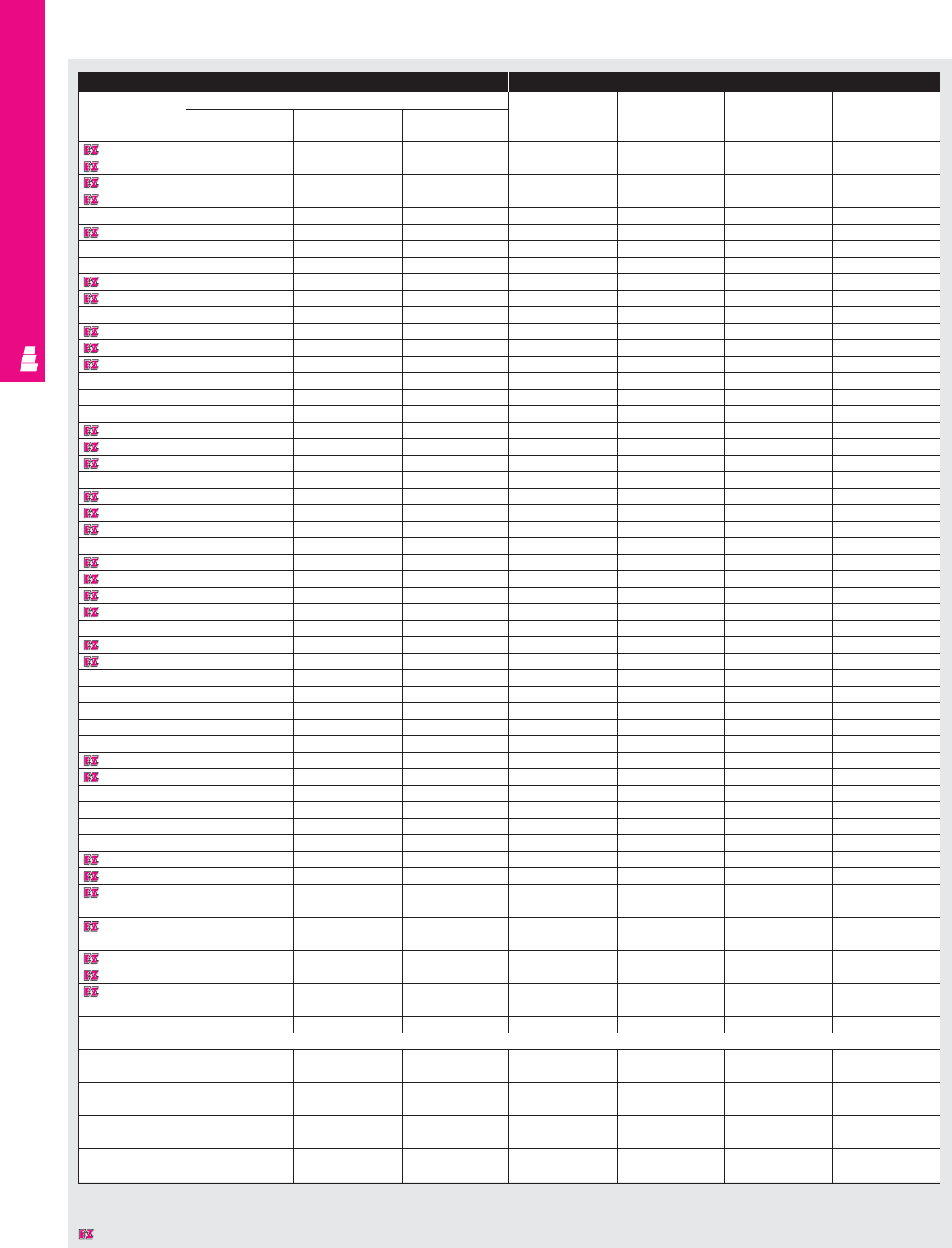
WALLMOUNT ENCLOSURES
IND 31
Enclosure (Continued) Mounting Panel (Continued)
Part No. Outside dimensions (inches) Part No. HWUsable
HWD depth
E 242016 24.00 20.00 16.00 E 24P20 21.00 17.00 16.00
E 242406 24.00 24.00 6.00 E 24P24 21.00 21.00 6.00
E 242408 24.00 24.00 8.00 E 24P24 21.00 21.00 8.00
E 242410 24.00 24.00 10.00 E 24P24 21.00 21.00 10.00
E 242412 24.00 24.00 12.00 E 24P24 21.00 21.00 12.00
E 242416 24.00 24.00 16.00 E 24P24 21.00 21.00 16.00
E 243008 24.00 30.00 8.00 E 30P24 21.00 27.00 8.00
E 301606 30.00 16.00 6.00 E 30P16 27.00 13.00 6.00
E 302006 30.00 20.00 6.00 E 30P20 27.00 17.00 6.00
E 302008 30.00 20.00 8.00 E 30P20 27.00 17.00 8.00
E 302010 30.00 20.00 10.00 E 30P20 27.00 17.00 10.00
E 302406 30.00 24.00 6.00 E 30P24 27.00 21.00 6.00
E 302408 30.00 24.00 8.00 E 30P24 27.00 21.00 8.00
E 302410 30.00 24.00 10.00 E 30P24 27.00 21.00 10.00
E 302412 30.00 24.00 12.00 E 30P24 27.00 21.00 12.00
E 302416 30.00 24.00 16.00 E 30P24 27.00 21.00 16.00
E 302420 30.00 24.00 20.00 E 30P24 27.00 21.00 20.00
E 302424 30.00 24.00 24.00 E 30P24 27.00 21.00 24.00
E 303008 30.00 30.00 8.00 E 30P30 27.00 27.00 8.00
E 303012 30.00 30.00 12.00 E 30P30 27.00 27.00 12.00
E 303608 30.00 36.00 8.00 E 36P30 27.00 33.00 8.00
E 362406 36.00 24.00 6.00 E 36P24 33.00 21.00 6.00
E 362408 36.00 24.00 8.00 E 36P24 33.00 21.00 8.00
E 362410 36.00 24.00 10.00 E 36P24 33.00 21.00 10.00
E 362412 36.00 24.00 12.00 E 36P24 33.00 21.00 12.00
E 363006 36.00 30.00 6.00 E 36P30 33.00 27.00 5.37*
E 363008 36.00 30.00 8.00 E 36P30 33.00 27.00 7.37*
E 363010 36.00 30.00 10.00 E 36P30 33.00 27.00 9.37*
E 363012 36.00 30.00 12.00 E 36P30 33.00 27.00 11.37*
E 363016 36.00 30.00 16.00 E 36P30 33.00 27.00 15.37*
E 363020 36.00 30.00 20.00 E 36P30 33.00 27.00 19.37*
E 363608 36.00 36.00 8.00 E 36P36 33.00 33.00 7.37*
E 363612 36.00 36.00 12.00 E 36P36 33.00 33.00 11.37*
E 422408 42.00 24.00 8.00 E 42P24 39.00 21.00 8.00
E 423008 42.00 30.00 8.00 E 42P30 39.00 27.00 7.37*
E 423010 42.00 30.00 10.00 E 42P30 39.00 27.00 9.37*
E 423012 42.00 30.00 12.00 E 42P30 39.00 27.00 11.37*
E 423608 42.00 36.00 8.00 E 42P36 39.00 33.00 7.37*
E 423610 42.00 36.00 10.00 E 42P36 39.00 33.00 9.37*
E 423612 42.00 36.00 12.00 E 42P36 39.00 33.00 11.37*
E 423616 42.00 36.00 16.00 E 42P36 39.00 33.00 15.37*
E 482408 48.00 24.00 8.00 E 48P24 45.00 21.00 8.00
E 483008 48.00 30.00 8.00 E 48P30 45.00 27.00 7.37*
E 483010 48.00 30.00 10.00 E 48P30 45.00 27.00 9.37*
E 483608 48.00 36.00 8.00 E 48P36 45.00 33.00 7.37*
E 483610 48.00 36.00 10.00 E 48P36 45.00 33.00 9.37*
E 483612 48.00 36.00 12.00 E 48P36 45.00 33.00 11.37*
E 483616 48.00 36.00 16.00 E 60P36 57.00 33.00 15.37*
E 483620 48.00 36.00 20.00 E 48P36 45.00 33.00 19.37*
E 603608 60.00 36.00 8.00 E 60P36 57.00 33.00 7.37*
E 603610 60.00 36.00 10.00 E 60P36 57.00 33.00 9.37*
E 603612 60.00 36.00 12.00 E 60P36 57.00 33.00 11.37*
E 603616 60.00 36.00 16.00 E 60P36 57.00 33.00 15.37*
E 603620 60.00 36.00 20.00 E 60P36 57.00 33.00 19.37*
E 723612 72.00 36.00 12.00 E 72P36 69.00 33.00 11.37*
EMI/RFI Enclosure
E 161206RFI 16.00 12.00 6.00 E 16P12 13.00 9.00 6.00
E 201606RFI 20.00 16.00 6.00 E 20P16 17.00 13.00 6.00
E 242006RFI 24.00 20.00 6.00 E 24P20 21.00 17.00 6.00
E 242408RFI 24.00 24.00 8.00 E 24P24 21.00 21.00 8.00
E 302408RFI 30.00 24.00 8.00 E 30P24 27.00 21.00 8.00
E 363008RFI 36.00 30.00 8.00 E 36P30 33.00 27.00 7.37*
E 483608RFI 48.00 36.00 8.00 E 48P36 45.00 33.00 7.37*
E 603612RFI 60.00 36.00 12.00 E 60P36 57.00 33.00 11.37*
* Usable depth reduced by .625” at door stiffener.
Designates a product in the EnclosureZone program.
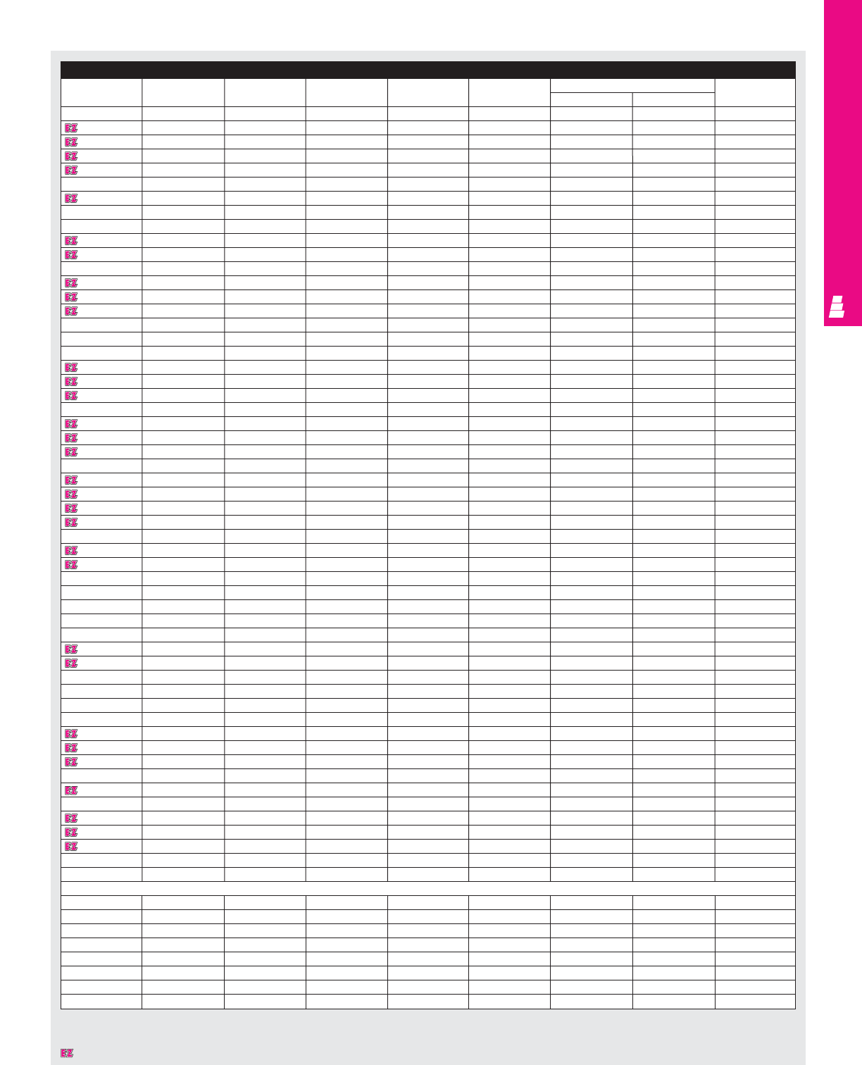
WALLMOUNT ENCLOSURES
IND 32
Accessories
Part No. Door stop kit Drip shield kit Terminal blocks Terminal rails Light kit Dead front kit Touch-up paint
Panel Risers
E 242016 -E DK20 E 20NTMA2 E 24NS See ACC 29 E DF20P16 E DF16R4 E L21
E 242406 E DSTOPK E DK24 E 24NTMA3 E 24NS See ACC 29 E DF24P24 E DF6R4 E L21
E 242408 E DSTOPK E DK24 E 24NTMA3 E 24NS See ACC 29 E DF24P24 E DF8R4 E L21
E 242410 E DSTOPK E DK24 E 24NTMA3 E 24NS See ACC 29 E DF24P24 E DF10R4 E L21
E 242412 E DSTOPK E DK24 E 24NTMA3 E 24NS See ACC 29 E DF24P24 E DF12R4 E L21
E 242416 E DSTOPK E DK24 E 24NTMA3 E 24NS See ACC 29 E DF24P24 E DF16R4 E L21
E 243008 E DSTOPK E DK30 E 30NTMA3 E 24NS See ACC 29 E DF30P24 E DF8R4 E L21
E 301606 -E DK16 E 16NTMA2 E 30NS See ACC 29 - - E L21
E 302006 -E DK20 E 20NTMA2 E 30NS See ACC 29 - - E L21
E 302008 -E DK20 E 20NTMA2 E 30NS See ACC 29 - - E L21
E 302010 -E DK20 E 20NTMA2 E 30NS See ACC 29 - - E L21
E 302406 E DSTOPK E DK24 E 20NTMA2 E 30NS See ACC 29 E DF30P24 E DF6R4 E L21
E 302408 E DSTOPK E DK24 E 24NTMA3 E 30NS See ACC 29 E DF30P24 E DF8R4 E L21
E 302410 E DSTOPK E DK24 E 24NTMA3 E 30NS See ACC 29 E DF30P24 E DF10R4 E L21
E 302412 E DSTOPK E DK24 E 24NTMA3 E 30NS See ACC 29 E DF30P24 E DF12R4 E L21
E 302416 E DSTOPK E DK24 E 24NTMA3 E 30NS See ACC 29 E DF30P24 E DF16R4 E L21
E 302420 E DSTOPK E DK24 E 24NTMA3 E 30NS See ACC 29 E DF30P24 E DF16R4 E L21
E 302424 E DSTOPK E DK24 E 24NTMA3 E 30NS See ACC 29 E DF30P24 E DF16R4 E L21
E 303008 E DSTOPK E DK30 E 30NTMA3 E 30NS See ACC 29 E DF30P30 E DF8R5 E L21
E 303012 E DSTOPK E DK30 E 30NTMA3 E 30NS See ACC 29 E DF30P30 E DF12R5 E L21
E 303608 E DSTOPK E DK36 E 36NTMA3 E 30NS See ACC 29 E DF36P30 E DF8R5 E L21
E 362406 E DSTOPK E DK24 E 24NTMA3 E 36NS See ACC 29 - - E L21
E 362408 E DSTOPK E DK24 E 24NTMA3 E 36NS See ACC 29 E DF36P24 E DF8R5 E L21
E 362410 E DSTOPK E DK24 E 24NTMA3 E 36NS See ACC 29 E DF36P24 E DF10R5 E L21
E 362412 E DSTOPK E DK24 E 24NTMA3 E 36NS See ACC 29 E DF36P24 E DF12R5 E L21
E 363006 E DSTOPK E DK30 E 30NTMA3 E 36NS See ACC 29 - - E L21
E 363008 E DSTOPK E DK30 E 30NTMA3 E 36NS See ACC 29 E DF36P30 E DF8R5 E L21
E 363010 E DSTOPK E DK30 E 30NTMA3 E 36NS See ACC 29 E DF36P30 E DF10R5 E L21
E 363012 E DSTOPK E DK30 E 30NTMA3 E 36NS See ACC 29 E DF36P30 E DF12R5 E L21
E 363016 E DSTOPK E DK30 E 30NTMA3 E 36NS See ACC 29 E DF36P30 E DF16R5 E L21
E 363020 E DSTOPK E DK30 E 30NTMA3 E 36NS See ACC 29 E DF36P30 E DF16R5 E L21
E 363608 E DSTOPK E DK36 E 36NTMA3 E 36NS See ACC 29 E DF36P36 E DF8R6 E L21
E 363612 E DSTOPK E DK36 E 36NTMA3 E 36NS See ACC 29 E DF36P36 E DF12R6 E L21
E 422408 E DSTOPK E DK24 E 24NTMA3 E 42NS See ACC 29 - - E L21
E 423008 E DSTOPK E DK30 E 30NTMA3 E 42NS See ACC 29 - - E L21
E 423010 E DSTOPK E DK30 E 30NTMA3 E 42NS See ACC 29 - - E L21
E 423012 E DSTOPK E DK30 E 30NTMA3 E 42NS See ACC 29 - - E L21
E 423608 E DSTOPK E DK36 E 36NTMA3 E 42NS See ACC 29 E DF42P36 E DF8R6 E L21
E 423610 E DSTOPK E DK36 E 36NTMA3 E 42NS See ACC 29 E DF42P36 E DF10R6 E L21
E 423612 E DSTOPK E DK36 E 36NTMA3 E 42NS See ACC 29 E DF42P36 E DF12R6 E L21
E 423616 E DSTOPK E DK36 E 36NTMA3 E 42NS See ACC 29 E DF42P36 E DF16R6 E L21
E 482408 E DSTOPK E DK24 E 24NTMA3 E 48NS See ACC 29 - - E L21
E 483008 E DSTOPK E DK30 E 30NTMA3 E 48NS See ACC 29 - - E L21
E 483010 E DSTOPK E DK30 E 30NTMA3 E 48NS See ACC 29 - - E L21
E 483608 E DSTOPK E DK36 E 36NTMA3 E 48NS See ACC 29 E DF48P36 E DF8R6 E L21
E 483610 E DSTOPK E DK36 E 36NTMA3 E 48NS See ACC 29 E DF48P36 E DF10R6 E L21
E 483612 E DSTOPK E DK36 E 36MTMA3 E 48NS See ACC 29 E DF48P36 E DF12R6 E L21
E 483616 E DSTOPK E DK36 E 36NTMA3 E 48NS See ACC 29 E DF48P36 E DF16R6 E L21
E 483620 E DSTOPK E DK36 E 36NTMA3 E 48NS See ACC 29 E DF48P36 E DF16R6 E L21
E 603608 E DSTOPK E DK36 E 36NTMA3 E 60NS See ACC 29 - - E L21
E 603610 E DSTOPK E DK36 E 36NTMA3 E 60NS See ACC 29 - - E L21
E 603612 E DSTOPK E DK36 E 36NTMA3 E 60NS See ACC 29 - - E L21
E 603616 E DSTOPK E DK36 E 36NTMA3 E 60NS See ACC 29 - - E L21
E 603620 E DSTOPK E DK36 E 36NTMA3 E 60NS See ACC 29 - - E L21
E 723612 E DSTOPK E DK36 - - See ACC 29 - - E L21
EMI/RFI Enclosure
E 161206RFI -E DK12 E 12NTMA2 E 16NS See ACC 29 E DF16P12 E DF6R4 E L21
E 201606RFI -E DK16 E 16NTMA2 E 20NS See ACC 29 E DF20P16 E DF6R4 E L21
E 242006RFI -E DK20 E 20NTMA2 E 24NS See ACC 29 E DF24P20 E DF6R4 E L21
E 242408RFI E DSTOPK E DK24 E 24NTMA3 E 24NS See ACC 29 E DF24P24 E DF8R4 E L21
E 302408RFI E DSTOPK E DK24 E 24NTMA3 E 30NS See ACC 29 E DF30P24 E DF8R4 E L21
E 363008RFI E DSTOPK E DK30 E 30NTMA3 E 36NS See ACC 29 E DF36P30 E DF8R5 E L21
E 483608RFI E DSTOPK E DK36 E 36NTMA3 E 48NS See ACC 29 E DF48P30 E DF8R6 E L21
E 603612RFI E DSTOPK E DK36 E 36NTMA3 E 60NS See ACC 29 - - E L21
Designates a product in the EnclosureZone program.
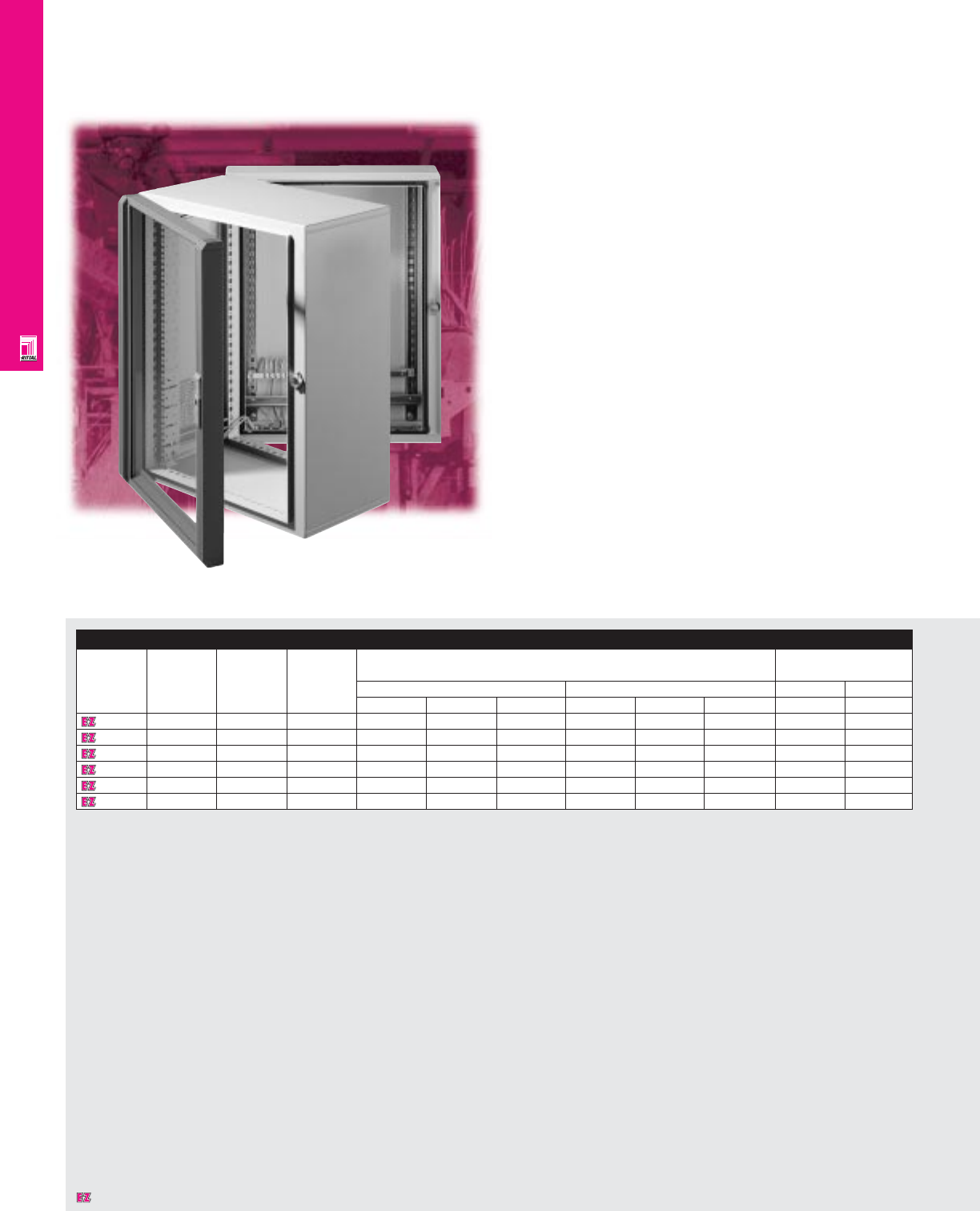
WALLMOUNT ENCLOSURES
IND 33
EL 3-Part Wallmount Enclosures
NEMA Rated Wallmount Enclosures
Rittal’s three part wallmount enclosures provide a
perfect solution for packaging and protecting electronic
equipment, even under extreme conditions. Its versatile design
offers integral 19" rails for direct mounting of 19" rackmount
equipment. Our special 3-7-8 program provides 378 different
sizes and configurations through standard components.
In addition to its attractive design, this cabinet features easy
assembly and installation, problem-free operation, and a NEMA
12 protection rating.
A swing frame lock, which is not accessible until after the
front door has been opened, provides limited access for
security purposes.
Enclosure
Part No.
Usable Approximate NEMA Exact outside dimensions Max. equipment
rack space outside rating depth
1U=1.75" dimensions inches mm inches mm
H"xW"xD" H W D H W D D D
7706024 614x24x24 1, 12 13.58 23.62 23.62 345 600 600 14.17 360
7709024 919x24x24 1, 12 18.82 23.62 23.62 478 600 600 18.11 460
7712024 12 24x24x24 1, 12 24.09 23.62 23.62 612 600 600 18.11 460
7715024 15 29x24x24 1, 12 29.37 23.62 23.62 746 600 600 18.11 460
7718024 18 35x24x24 1, 12 34.57 23.62 23.62 878 600 600 18.11 460
7721024 21 40x24x24 1, 12 39.84 23.62 23.62 1012 600 600 18.11 460
Designates a product in the EnclosureZone program.
WALLMOUNT ENCLOSURES
IND 34
Configuration
• NEMA 1, 12/IP55 protection
•UL/CSA approvals
•Swing-out mid-section provides easy
access to components
• Maximum stability through folded 16 ga
steel construction
• Lockable front door
• Viewing window provides easy visibility of
components
• Large, removable cable gland panels
• Adjustable 19" angles allow flexible space
utilization
• Patented mounting system provides efficient
space use
• E-coat primer and powder paint provide
superior corrosion protection
•Knife-edge design protects against
liquid entry
•Integrated grounding provisions
•Rear mounting holes allow direct
wallmounting or the use of optional
mounting feet
Technical Specifications
Material:
•Rear section module and mid-section:
16 ga/1.5 mm sheet steel
•Front door: extruded aluminum with diecast
aluminum corner pieces; .16"/4 mm
security glass
Finish:
•Enclosure: E-coat primed, textured,
RAL 7032 pebble grey
•Front door: textured, RAL 7033 mortar grey
Accessories
Part No. Wallmount brackets Mini Lock inserts for C-rail Slide rails 19" rack Captive Rackmount
Ergoform-S Mini Ergoform-S captive nuts nut screws shelf
3/8" standoff 1-1/2" standoff handle push/lock
7706024 2508200 2503200 2242000 2469000 2238000 2240000 2092200 2093200 7148000
7709024 2508200 2503200 2242000 2469000 2239000 2250000 2092200 2093200 7148000
7712024 2508200 2503200 2242000 2469000 2239000 2250000 2092200 2093200 7148000
7715024 2508200 2503200 2242000 2469000 2239000 2250000 2092200 2093200 7148000
7718024 2508200 2503200 2242000 2469000 2239000 2250000 2092200 2093200 7148000
7721024 2508200 2503200 2242000 2469000 2239000 2250000 2092200 2093200 7148000
Page . . . . . . . . . . . . . . . . . . . . . . . . . . . . . IND 57
NEMA Type 144X1213
UL CUL CSA TÜV
Listings
Protection Ratings
Certifications/Approvals
Technical Drawings
Designates a product in the EnclosureZone program.
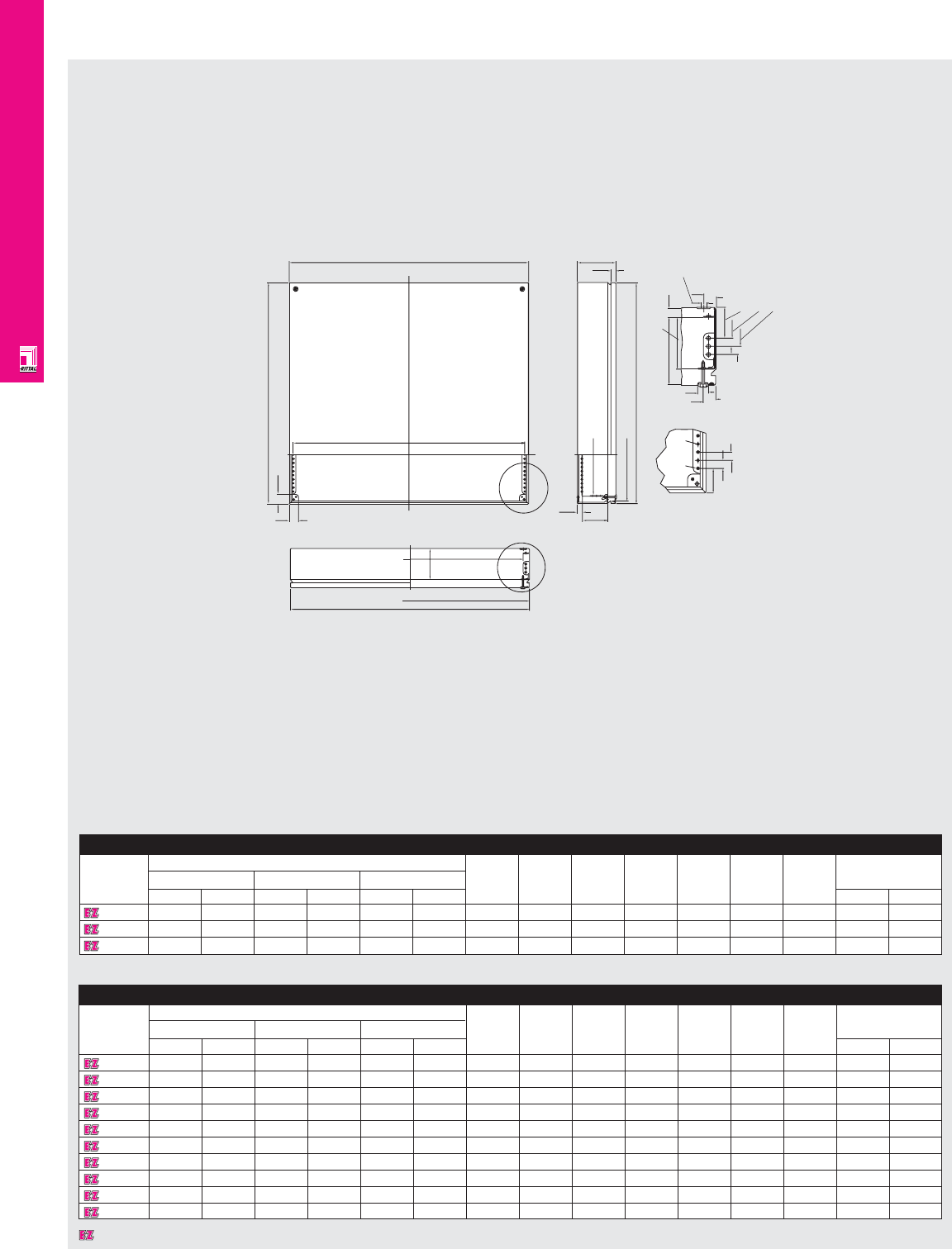
WALLMOUNT ENCLOSURES
IND 35
Technical Specifications
KL Junction Boxes Without Gland Panels
W1
H1
29.0
29.0
W5
W
X
93.6
W4
W3
W2
15.5
79.5
H4
H3
H2
D
15.0
14.0
103.0 79.5
20.0
Ø8.7
47.5
12.5
12.5
17.0
20.0 X Detail
W Detail
Ø 4.6
M5
12.5
12.5
37.5
KL Junction Boxes Without Gland Panels, 4.72"/120 mm Deep
Part No.
Exact outside dimensions H2 H3 H4 W2 W3 W4 W5 Weight
H (H1) W (W1) D (D)
inches mm inches mm inches mm lbs kg
1500210
5.91 150 5.91 150 4.72 120 148 132 100 148 132 109 125 3.5 1.6
1501210
5.91 150 11.81 300 4.72 120 148 132 100 298 282 259 275 5.5 2.5
1502210
7.87 200 7.87 200 4.72 120 198 182 150 198 182 159 175 5.1 2.3
1503210
7.87 200 11.81 300 4.72 120 198 182 150 298 282 259 275 6.8 3.1
1504210
7.87 200 15.75 400 4.72 120 198 182 150 398 382 359 375 8.6 3.9
1505210
7.87 200 19.69 500 4.72 120 198 182 150 498 482 459 475 9.9 4.5
1507210
11.81 300 11.81 300 4.72 120 298 282 250 298 282 259 275 9.3 4.2
1508210
11.81 300 15.75 400 4.72 120 298 282 250 398 382 359 375 11.0 5.0
1509210
11.81 300 19.69 500 4.72 120 298 282 250 498 482 459 475 13.2 6.0
1511210
15.75 400 15.75 400 4.72 120 398 382 350 398 382 359 375 13.7 6.2
KL Junction Boxes Without Gland Panels, 3.15"/80 mm Deep
Part No.
Exact outside dimensions H2 H3 H4 W2 W3 W4 W5 Weight
H (H1) W (W1) D (D)
inches mm inches mm inches mm lbs kg
1514210
5.91 150 5.91 150 3.15 80 148 132 100 148 132 109 125 3.1 1.4
1515210
5.91 150 11.81 300 3.15 80 148 132 100 298 282 259 275 4.6 2.1
1517210
7.87 200 11.81 300 3.15 80 198 182 150 298 282 259 275 5.7 2.6
Designates a product in the EnclosureZone program.
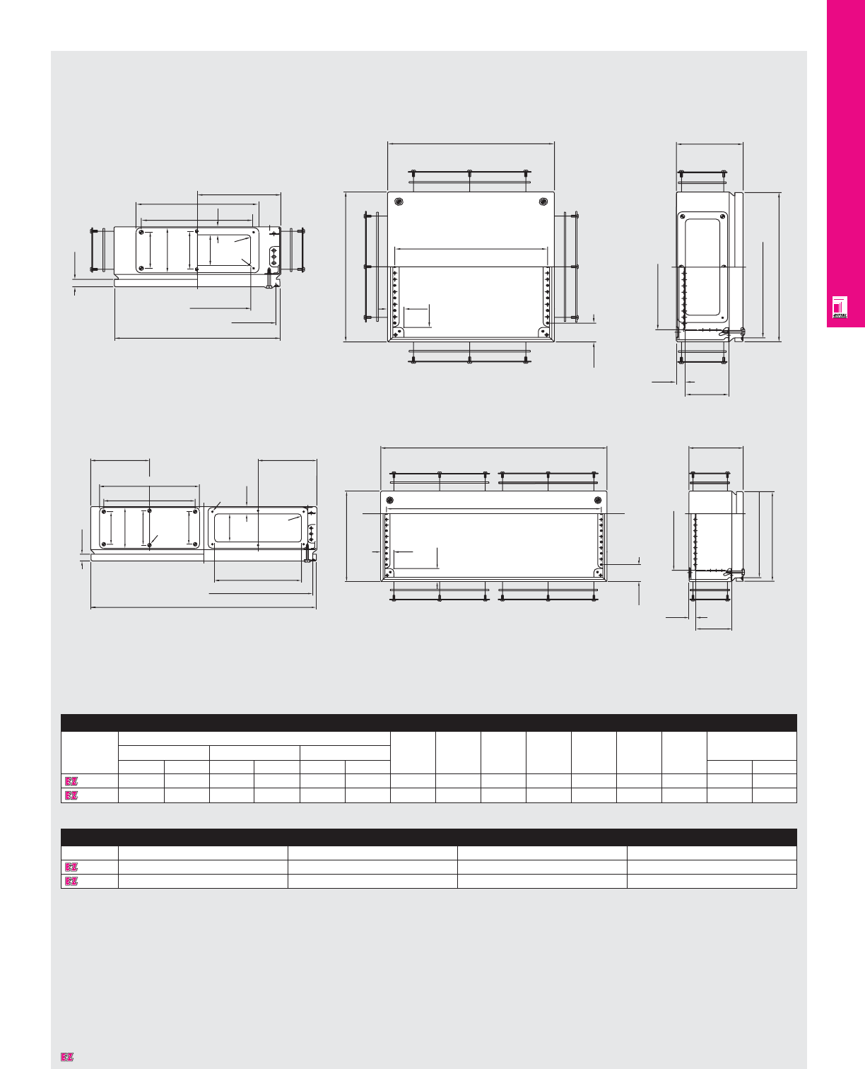
WALLMOUNT ENCLOSURES
IND 36
Technical Specifications
KL Junction Boxes With Gland Panels
Dimensions in millimeters (mm) unless otherwise indicated.
15
221
202
W6
16
72
90
76
6
R7
Ø3.5
192
W3
W2
W1
H1
29
29
37.5
D
H4
15.5 79.5
H3
H2
W1
W5
29
29
H1
37.5
120
H4
H3
H2
15.5
79.5
W6
221
202
15
72
90
76
Ø4.5
72
Ø3.5
16
62
W6
R7
192
W3
W2
KL Junction Boxes With Gland Panels
Part No.
Exact outside dimensions H2 H3 H4 W2 W3 W5 W6 Weight
H (H1) W (W1) D (D)
inches mm inches mm inches mm lbs kg
1530210
5.91 150 11.81 300 4.72 120 148 132 100 298 282 275 150 5.9 2.7
1531210
7.87 200 11.81 300 4.72 120 198 182 150 298 282 275 150 7.3 3.3
KL Junction Boxes With Gland Panels (Continued)
Part No.
Cover screws Total no. of glands No. of glands horizontal No. of glands vertical
1530210
421-
1531210
421-
Designates a product in the EnclosureZone program.
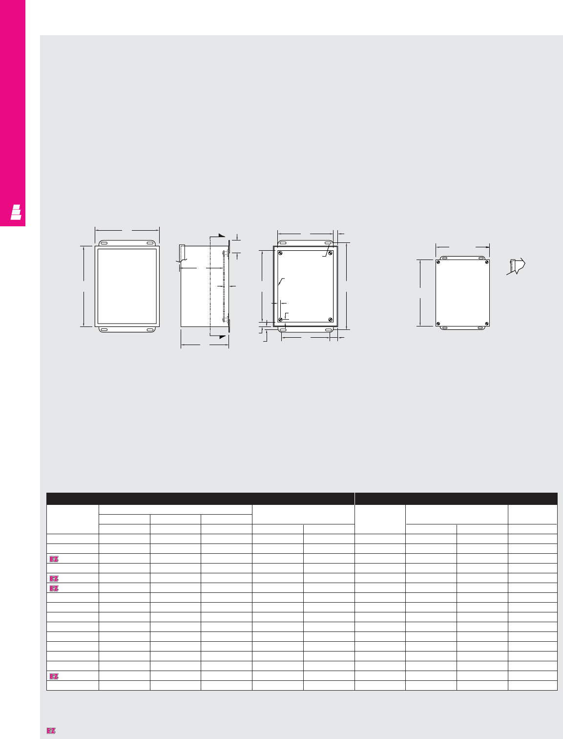
WALLMOUNT ENCLOSURES
IND 37
Technical Specifications
Screw Cover Junction Boxes
Enclosure Mounting Panel
Part No. Outside dimensions (inches) Mounting centers Part No. Panel size Usable depth
HWD
ABCHW EFG
E 404SC* 4.00 4.00 3.00 4.75 2.00 NONE -- -
E 4044SC 4.00 4.00 4.00 4.75 2.00 NONE -- -
E 604SC* 6.00 4.00 3.00 6.75 2.00 E 6P4 4.88 2.88 2.50
E 6044SC* 6.00 4.00 4.00 6.75 2.00 E 6P4 4.88 2.88 3.50
E 606SC* 6.00 6.00 4.00 6.75 4.00 E 6P6 4.88 4.88 3.50
E 806SC 8.00 6.00 3.50 8.75 4.00 E 8P6 6.88 4.88 3.00
E 8066SC 8.00 6.00 6.00 8.75 4.00 E 8P6 6.88 4.88 5.50
E 808SC 8.00 8.00 4.00 8.75 6.00 E 8P8 6.88 6.88 3.50
E 1008SC 10.00 8.00 4.00 10.75 6.00 E 10P8 8.88 6.88 3.50
E 1010SC 10.00 10.00 4.00 10.75 8.00 E 10P10 8.88 8.88 3.50
E 10106SC 10.00 10.00 6.00 10.75 8.00 E 10P10 8.88 8.88 5.50
E 10086SC 10.00 8.00 6.00 10.75 6.00 E 10P8 8.88 6.88 5.50
E 1210SC 12.00 10.00 5.00 12.75 8.00 E 12P10 10.88 8.88 3.50
E 1212SC 12.00 12.00 6.00 12.75 10.00 E 12P12 10.88 10.88 5.50
E 1412SC 14.00 12.00 6.00 14.75 10.00 E 14P12 12.88 10.88 5.50
E 1614SC 16.00 14.00 6.00 16.75 12.00 E 16P14 14.88 12.88 5.50
* 16 gauge
B
A
Y
Front View
Less Cover Right Side View Section Y-Y
G
1.75
.50
Y
C
F.56
.31 Dia.
(TYP)
Panel
(optional)
.31
.31
.56
.38 W1.00
EH
B+.31
A+.31
NEMA 12, 13 Screw Cover
Designates a product in the EnclosureZone program.
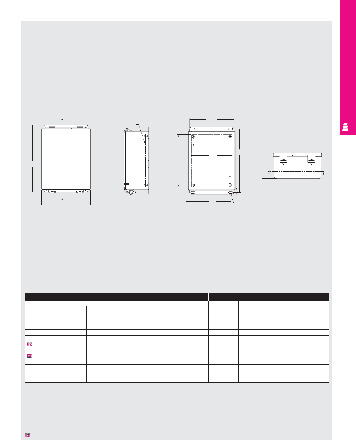
WALLMOUNT ENCLOSURES
IND 38
Technical Specifications
Lift-Off Hinge Cover Boxes
Enclosure Mounting Panel
Part No. Outside dimensions (inches) Mounting centers Part No. Panel size Usable depth
Height Width Depth
ABCHW EFG
E 404LP* 4.00 4.00 3.00 4.75 2.00 NONE ---
E 4044LP 4.00 4.00 4.00 4.75 2.00 NONE ---
E 604LP* 6.00 4.00 3.00 6.75 2.00 E 6P4 4.88 2.88 2.50
E 6044LP* 6.00 4.00 4.00 6.75 2.00 E 6P4 4.88 2.88 3.50
E 606LP* 6.00 6.00 4.00 6.75 4.00 E 6P6 4.88 4.88 3.50
E 806LP 8.00 6.00 3.50 8.75 4.00 E 8P6 6.88 4.88 3.00
E 1008LP 10.00 8.00 4.00 10.75 6.00 E 10P8 8.88 6.88 3.50
E 1210LP 12.00 10.00 5.00 12.75 8.00 E 12P10 10.88 8.88 4.50
E 1412LP 14.00 12.00 6.00 14.75 10.00 E 14P12 12.88 10.88 5.50
E 1614LP 16.00 14.00 6.00 16.75 12.00 E 16P14 14.88 12.88 5.50
E 1816LP 18.00 16.00 6.00 18.75 14.00 E 18P16 16.88 14.88 5.50
* 16 gauge
X
A
B
G
Panel (optional)
E
W
8.00
H
.75 x .31
.38
4.31
NEMA 12,13 Lift Cover Right Side View Section Y-Y Top View
Y
F
Designates a product in the EnclosureZone program.
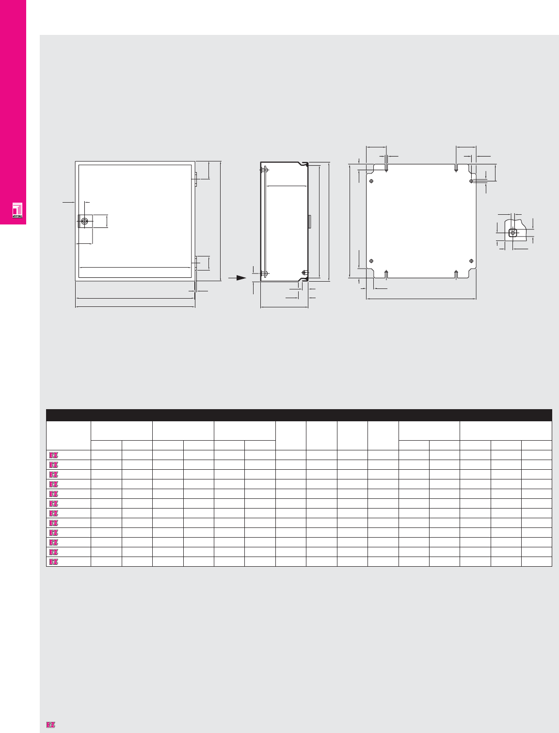
WALLMOUNT ENCLOSURES
IND 39
Technical Specifications
EB Instrument Enclosures
23.5
32.0
43.5
W3
W2
W1
4.5
H1
35.0 45.0
A
105.0
15.0
25.0
D1
20.0
H3
H2
G1
23.5 14.5
18.5 F1
F2 F2
12.0
6.6
42.5
8.2
Ø8.7
20.0
18.0
20.0
View A
Enclosure
Part No. H1 W1 D H2 H3 W2 W3 Weight Mounting panel
standard equipment
inches mm inches mm inches mm lbs kg F1 F2 G1
1551600 5.91 150 5.91 150 3.15 80 148 132 148 132 3.7 1.7 125 62.5 135
1553600 5.91 150 5.91 150 4.72 120 148 132 148 132 4.4 2.0 125 62.5 135
1751600 7.87 200 5.91 150 4.72 120 198 182 148 132 5.3 2.4 125 65 185
1549600 7.87 200 7.87 200 4.72 120 198 182 198 182 6.2 2.8 175 50 185
1554600 11.81 300 7.87 200 4.72 120 298 282 198 182 7.9 3.6 175 50 285
1555600 11.81 300 11.81 300 4.72 120 298 282 298 282 11.0 5.0 275 50 285
1556600 15.75 400 11.81 300 4.72 120 398 382 298 282 15.4 7.0 275 50 385
1752600 9.84 250 7.87 200 6.10 155 248 232 198 182 7.9 3.6 175 50 235
1753600 11.81 300 9.84 250 6.10 155 298 282 248 232 11.0 5.0 225 50 285
1754600 13.78 350 11.81 300 6.10 155 348 332 298 282 12.8 5.8 275 50 335
1755600 15.75 400 13.78 350 6.10 155 398 382 348 332 13.7 6.2 325 50 385
1578600 23.62 600 11.81 300 6.10 155 598 582 298 282 18.3 8.3 275 50 585
Dimensions in millimeters (mm) unless otherwise indicated.
Designates a product in the EnclosureZone program.
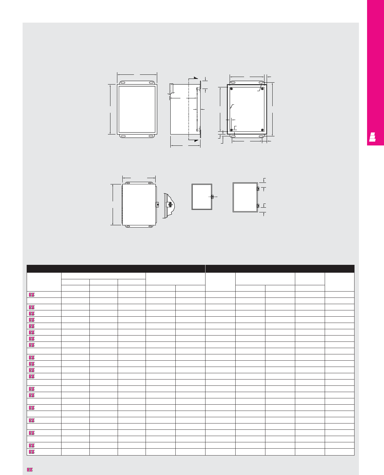
WALLMOUNT ENCLOSURES
IND 40
Technical Specifications
Continuous Hinge Cover Enclosures
Fig. 1 Fig. 2
Right Side View Section Y-Y
Front View
Less Cover
Enclosure Mounting Panel
Part No. Outside dimensions (inches) Mounting centers Part No. Panel size Usable depth Clamps
HWD
ABCH W E F G
E 404CH* 4.00 4.00 3.00 4.75 2.00 NONE ----
E 4044CH 4.00 4.00 4.00 4.75 2.00 NONE ---Fig. 1
E 604CH* 6.00 4.00 3.00 6.75 2.00 E 6P4 4.88 2.88 2.50 Fig. 1
E 6044CH* 6.00 4.00 4.00 6.75 2.00 E 6P4 4.88 2.88 3.50 Fig. 1
E 606CH* 6.00 6.00 4.00 6.75 4.00 E 6P6 4.88 4.88 3.50 Fig. 1
E 806CH 8.00 6.00 3.50 8.75 4.00 E 8P6 6.88 4.88 3.00 Fig. 2
E 8066CH 8.00 6.00 6.00 8.75 4.00 E 18P6 6.88 4.88 5.50 Fig. 2
E 808CH 8.00 8.00 4.00 8.75 6.00 E 8P8 6.88 6.88 3.50 Fig. 2
E 1008CH 10.00 8.00 4.00 10.75 6.00 E 10P8 8.88 6.88 3.50 Fig. 2
E 1008CHS 10.00 8.00 4.00 10.75 6.00 E 10P8 8.88 6.88 3.50 -
E 10086CH 10.00 8.00 6.00 10.75 6.00 E 10P8 8.88 6.88 5.50 Fig. 2
E 10106CH 10.00 10.00 6.00 10.75 8.00 E 10P10 8.88 8.88 5.50 Fig. 2
E 12064CH 12.00 6.00 4.00 12.75 4.00 E 12P6 10.88 4.88 3.50 Fig. 2
E 1210CH 10.00 10.00 5.00 10.75 8.00 E 10P10 8.88 8.88 4.50 Fig. 2
E 1210CHS 12.00 10.00 5.00 12.75 8.00 E 10P10 10.88 8.88 4.50 -
E 12108CH 12.00 10.00 8.00 12.75 8.00 E 12P10 10.88 8.88 7.50 Fig. 2
E 1212CH 12.00 12.00 6.00 12.75 10.00 E 12P12 10.88 10.88 5.50 Fig. 2
E 14086CH 14.00 8.00 6.00 14.75 6.00 E 14P8 12.88 6.88 5.50 Fig. 2
E 1412CH 14.00 12.00 6.00 14.75 10.00 E 14P12 12.88 10.88 5.50 Fig. 2
E 1412CHS 14.00 12.00 6.00 14.75 10.00 E 14P12 12.88 10.88 5.50 -
E 14128CH 14.00 12.00 8.00 14.75 10.00 E 14P12 12.88 10.88 7.50 Fig. 2
E 16106CH 16.00 10.00 6.00 16.75 8.00 E 16P10 14.88 8.88 5.50 Fig. 2
E 1614CH 16.00 14.00 6.00 16.75 12.00 E 16P14 14.88 12.88 5.50 Fig. 2
E 1614CHS 16.00 14.00 6.00 16.75 12.00 E 16P14 14.88 12.88 5.50 -
E 16148CH 16.00 14.00 8.00 16.75 12.00 E 16P14 14.88 12.88 7.50 Fig. 2
E 161410CH 16.00 14.00 10.00 16.75 12.00 E 16P14 14.88 12.88 9.50 Fig. 2
* 16 gauge
C
L
B
A
Y
Y
1.75
G
.50
C
F.56
.31 Dia
(TYP)
Panel
(optional)
.31
.31
EH
1.00
.56
.38 W
1.00
1.00
B+.31
A+.31
Designates a product in the EnclosureZone program.
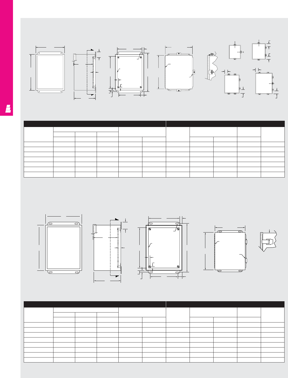
WALLMOUNT ENCLOSURES
IND 41
Technical Specifications
Continuous Hinge Quick Release Boxes
Front View
Less Cover Right Side View Section Y-Y NEMA 12, 13 Hinge Quick Release
B
A
Y
Y
G
1.75
.50
C
F.56
H
.31 Dia.
(TYP)
Panel
(optional)
.31
.31
1.00
W
.56
.38
E
Enclosure Mounting Panel
Part No. Outside dimensions (inches) Mounting centers Part No. Panel size Usable depth Clamps
HWD
ABC H W E F G
E 404CHQR* 4.00 4.00 3.00 4.75 2.00 NONE --- Fig. 1
E 604CHQR* 6.00 4.00 3.00 6.75 2.00 E 6P4 4.88 2.88 2.50 Fig. 1
E 606CHQR* 6.00 6.00 4.00 6.75 4.00 E 6P6 4.88 4.88 3.50 Fig. 1
E 806CHQR 8.00 6.00 3.50 8.75 4.00 E 8P6 6.88 4.88 3.00 Fig. 1
E 1008CHQR 10.00 8.00 4.00 10.75 6.00 E 10P8 8.88 6.88 3.50 Fig. 2
E 1210CHQR 12.00 10.00 5.00 12.75 8.00 E 12P10 10.88 8.88 4.50 Fig. 3
E 1412CHQR 14.00 12.00 6.00 14.75 10.00 E 14P12 12.88 10.88 5.50 Fig. 3
E 1614CHQR 16.00 14.00 6.00 16.75 12.00 E 16P14 14.88 12.88 5.50 Fig. 4
* 16 gauge
A+.31
B+.31
Continuous
hinge
Quick release
clamp (TYP)
L TYP
Technical Specifications
EMI/RFI Continuous Hinge Cover Enclosures
EMI/RFI Enclosure Mounting Panel
Part No. Outside dimensions (inches) Mounting centers Part No. Panel size Usable depth Clamps
HWD
ABC H W E F G
E 604CHRFI* 6.00 4.00 3.00 6.75 2.00 E 6P4 4.88 2.88 2.50 Fig. 1
E 606CHRFI 6.00 6.00 4.00 6.75 4.00 E 6P6 4.88 4.88 3.50 Fig. 1
E 806CHRFI* 8.00 6.00 3.50 8.75 4.00 E 8P6 6.88 4.88 3.00 Fig. 1
E 1008CHRFI 10.00 8.00 4.00 10.75 6.00 E 10P8 8.88 6.88 3.50 Fig. 2
E 1210CHRFI 12.00 10.00 5.00 12.75 8.00 E 12P10 10.88 8.88 4.50 Fig. 3
E 1412CHRFI 14.00 12.00 6.00 14.75 10.00 E 14P12 12.88 10.88 5.50 Fig. 3
E 1614CHRFI 16.00 14.00 6.00 16.75 12.00 E 16P14 14.88 12.88 5.50 Fig. 4
* 16 gauge
B
A
Front View
Less Cover Right Side
View
C
G
Y
1.75
.50
Y
F.56
H
.31 Dia
(TYP)
Panel
(optional)
.31
.31
E
.56
.56 W1.00
Section Y-Y Fig. 3 Fig. 4
Fig. 1 Fig. 2
B + .31
A+.31
Continuous
Hinge
Cover
Clamp
C
L
C
L
C
L
C
L
1.50
1.50
2.00 (TYP)
3.00 (TYP)
3.50 (TYP)
1.50 (TYP)
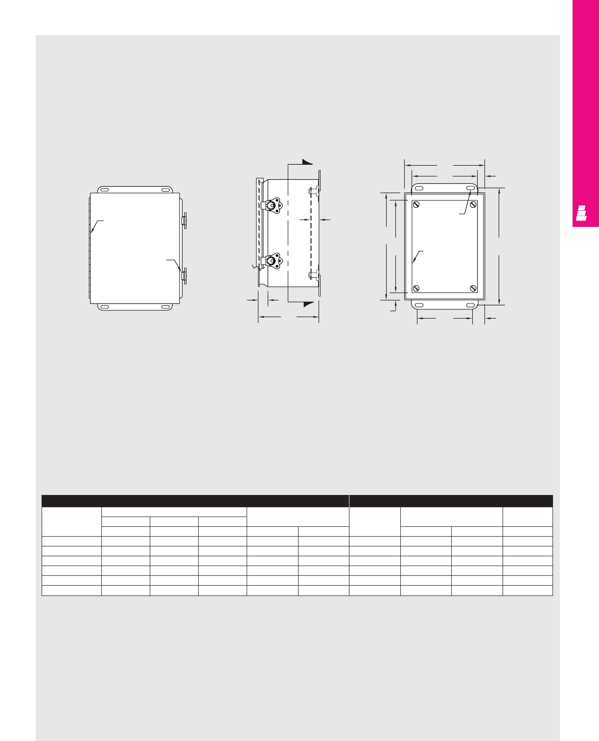
WALLMOUNT ENCLOSURES
IND 42
Technical Specifications
Continuous Hinge Wing Turn Boxes
Y
Y
.50
.56
C
B
F.56
H
.31 Dia. (TYP)
Panel
(optional)
A
E
.56
W1.00
Continuous hinge
Wing turn
quick release
Front View
Enclosure Mounting Panel
Part No. Outside dimensions (inches) Mountings Part No. Panel Usable
HWD centers size depth
ABC H W E F G
E 604CHWL* 6.00 4.00 4.48 6.75 2.00 E 6P4 4.88 2.88 4.04
E 806CHWL 8.00 6.00 4.48 8.75 4.00 E 8P6 6.88 4.88 4.04
E 1008CHWL 10.00 8.00 4.48 10.75 6.00 E 10P8 8.88 6.88 4.04
E 1210CHWL 12.00 10.00 5.48 12.75 8.00 E 12P10 10.88 8.88 5.04
E 1412CHWL 14.00 12.00 6.48 14.75 10.00 E 14P12 12.88 10.88 6.04
E 1614CHWL 16.00 14.00 6.48 16.75 12.00 E 16P14 14.88 12.88 6.04
* 16 gauge
Right Side View Section Y-Y
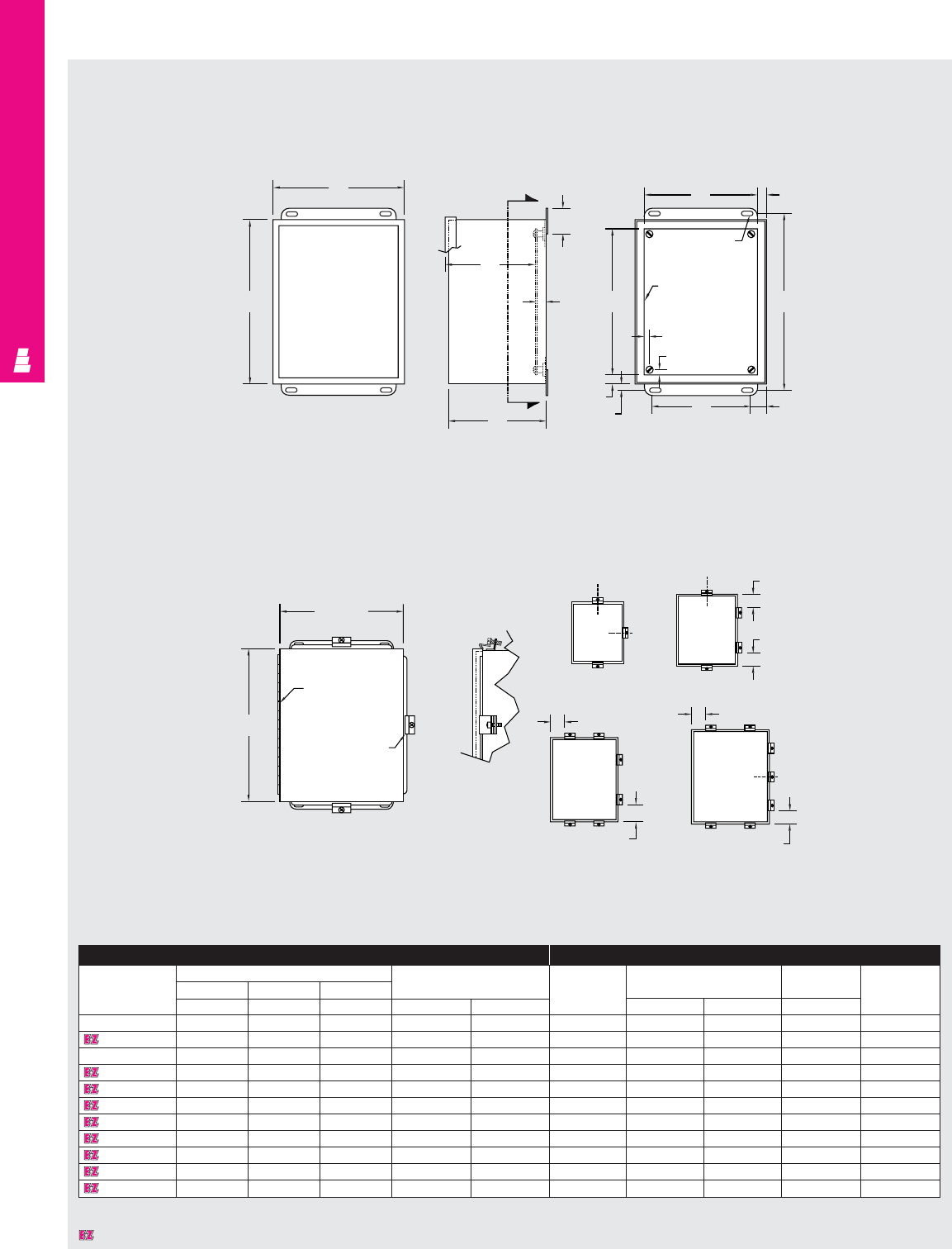
WALLMOUNT ENCLOSURES
IND 43
Technical Specifications
Continuous Hinge Cover Boxes
B
Front View
Less Cover
Fig.1 Fig. 2
Fig. 3 Fig. 4
Enclosure Mounting Panel
Part No. Outside dimensions (inches) Mounting Part No. Panel Usable Clamps
Height Width Depth centers size depth
ABC H W E F G
E 404CHNF* 4.00 4.00 3.00 4.75 2.00 NONE ---Fig. 1
E 604CHNF* 6.00 4.00 3.00 6.75 2.00 E 6P4 4.88 2.88 2.50 Fig. 1
E 6044CHNF* 6.00 4.00 4.00 6.75 2.00 E 6P4 4.88 2.88 3.50 Fig. 1
E 606CHNF* 6.00 6.00 4.00 6.75 4.00 E 6P6 4.88 4.88 3.50 Fig. 1
E 806CHNF 8.00 6.00 3.50 8.75 4.00 E 8P6 6.88 4.88 3.00 Fig. 1
E 1008CHNF 10.00 8.00 4.00 10.75 6.00 E 10P8 8.88 6.88 3.50 Fig. 2
E 10086CHNF 10.00 8.00 6.00 10.75 6.00 E 10P8 8.88 6.88 5.50 Fig. 2
E 1210CHNF 12.00 10.00 5.00 12.75 8.00 E 12P10 10.88 8.88 4.50 Fig. 3
E 1212CHNF 12.00 12.00 6.00 12.75 10.00 E 12P12 10.88 10.88 5.50 Fig. 3
E 1412CHNF 14.00 12.00 6.00 14.75 10.00 E 14P12 12.88 10.88 5.50 Fig. 3
E 1614CHNF 16.00 14.00 6.00 16.75 12.00 E 16P14 14.88 12.88 5.50 Fig. 4
* 16 gauge
Right Side View Section Y-Y
A
Y
Y
G
1.75
.50
C
F.56
.31 Dia. (TYP)
Panel
(optional)
E
.31
.31
.56
.38 W1.00
H
B+.31
A+.31
Continuous
hinge
Cover clamp
C
L1.50
C
L
C
L
1.50
2.00 (TYP)
3.00 (TYP)
3.50 (TYP)
1.50 (TYP)
C
L
Designates a product in the EnclosureZone program.
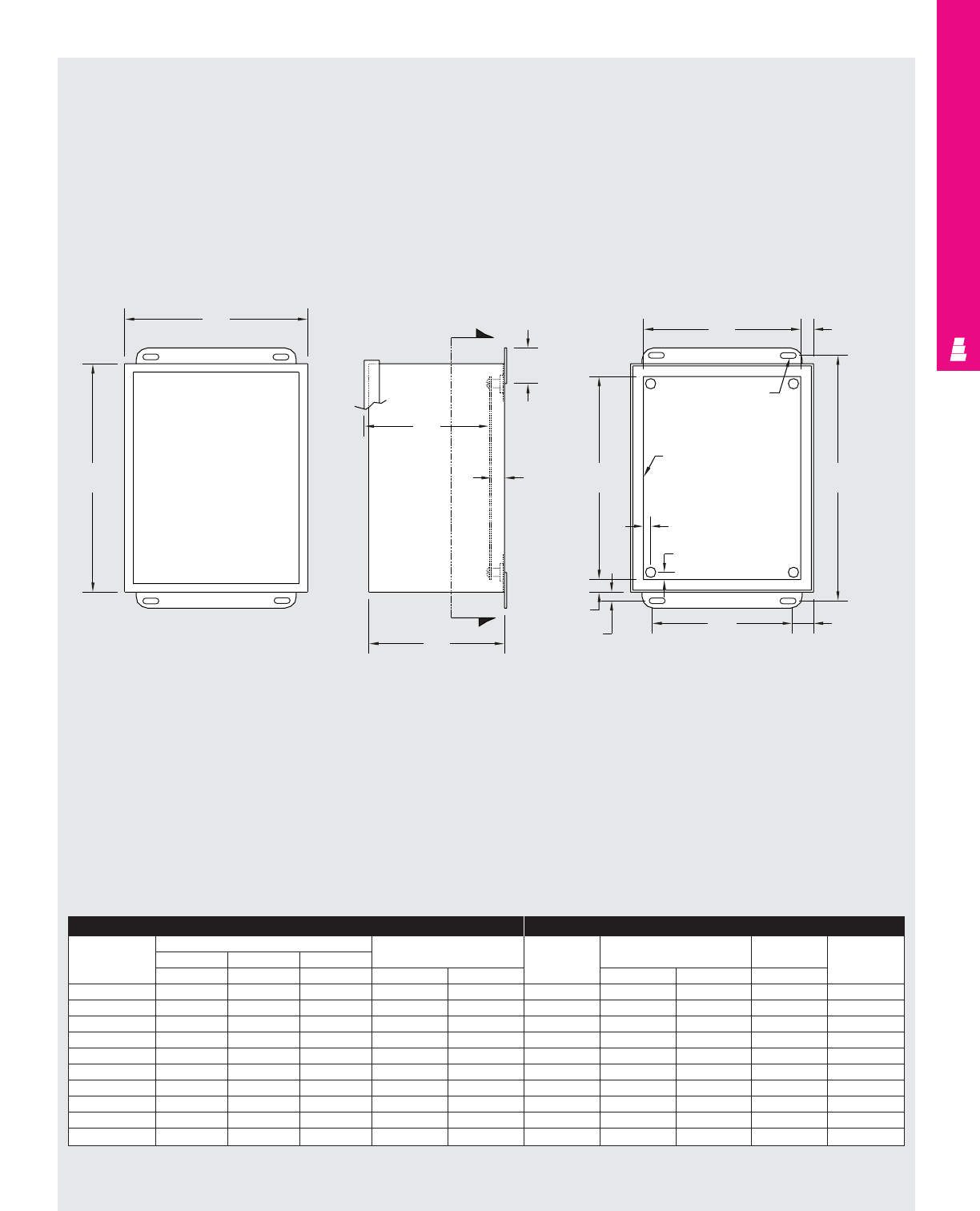
WALLMOUNT ENCLOSURES
IND 44
Technical Specifications
Clamp Cover Junction Enclosures
Front View
Less Cover Right Side View Section Y-Y
Enclosure Mounting Panel
Part No. Outside dimensions (inches) Mounting Part No. Panel Usable Clamps
HWD centers size depth
ABCH W E F G
E 404NF* 4.00 4.00 3.00 4.75 2.00 NONE ---Fig. 1
E 604NF* 6.00 4.00 3.00 6.75 2.00 E 6P4 4.88 2.88 2.50 Fig. 1
E 6044NF* 6.00 4.00 4.00 6.75 2.00 E 6P4 4.88 2.88 3.50 Fig. 1
E 606NF* 6.00 6.00 4.00 6.75 4.00 E 6P6 4.88 4.88 3.50 Fig. 1
E 806NF 8.00 6.00 4.00 8.75 4.00 E 8P6 6.88 4.88 3.50 Fig. 1
E 8064NF 8.00 6.00 4.00 8.75 4.00 E 8P6 6.88 4.88 3.50 Fig. 1
E 1008NF 10.00 8.00 4.00 10.75 6.00 E 10P8 8.88 6.88 3.50 Fig. 2
E 1210NF 12.00 10.00 5.00 12.75 8.00 E 12P10 10.88 8.88 4.50 Fig. 3
E 1412NF 14.00 12.00 6.00 14.75 10.00 E 14P12 12.88 10.88 5.50 Fig. 3
E 1614NF 16.00 14.00 6.00 16.75 12.00 E 16P14 14.88 12.88 5.50 Fig. 4
* 16 gauge
B
A
Y
Y
1.75
.50
G
C
F.56
H
1.00
W
.38
.56
E
.31 Dia. (TYP)
Panel
(optional)
.31
.31
G
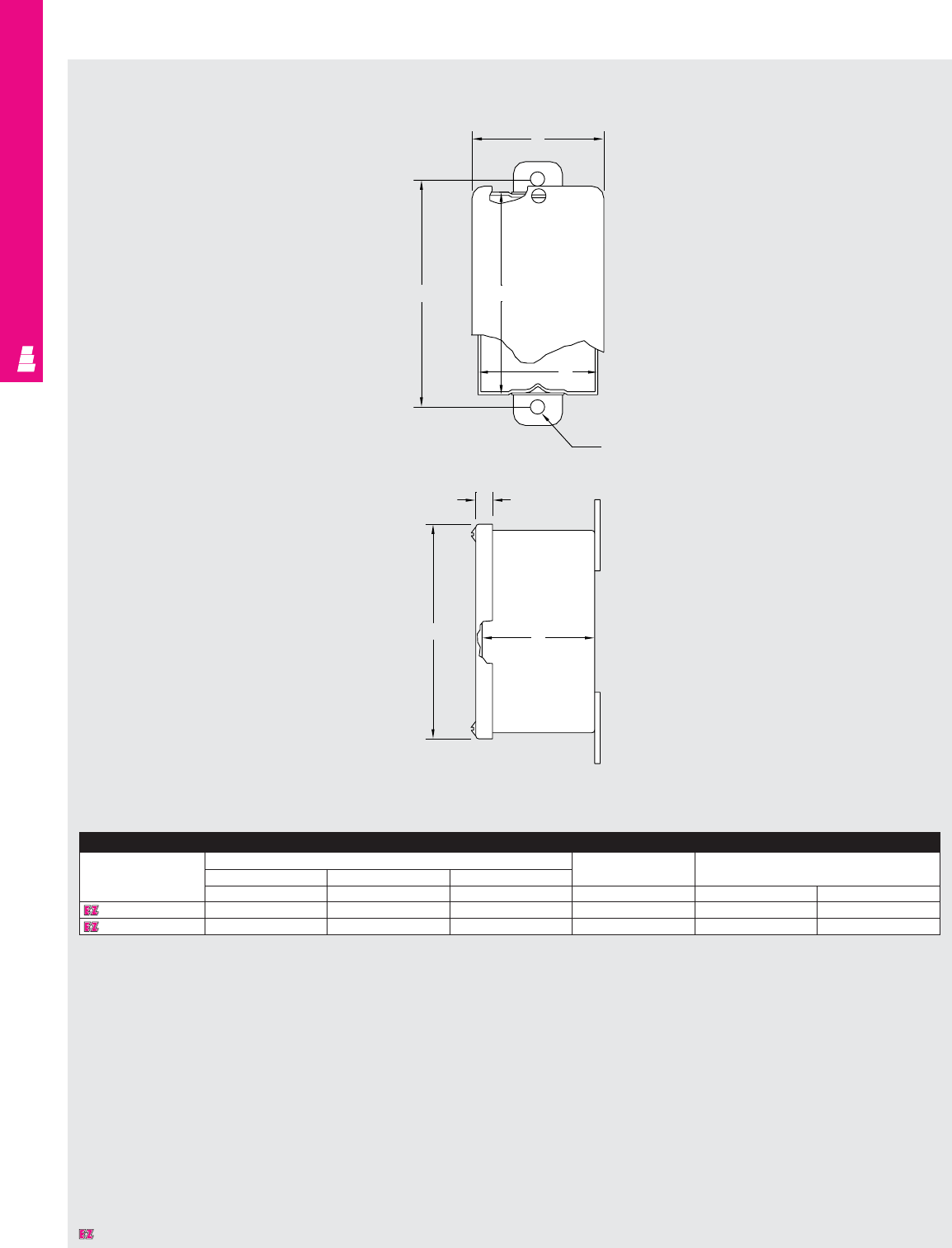
WALLMOUNT ENCLOSURES
IND 45
Technical Specifications
Handy Box Enclosures
Enclosure
Part No. Outside dimensions (inches) Mounting Cover
HWDcenters size
ABCHEF
E 4022HB 4.00 2.00 2.00 2.50 4.25 2.25
E 4033HB 4.25 2.88 2.63 3.38 4.50 3.13
F
DA
B
.31 Dia.
.38
C
E
Designates a product in the EnclosureZone program.
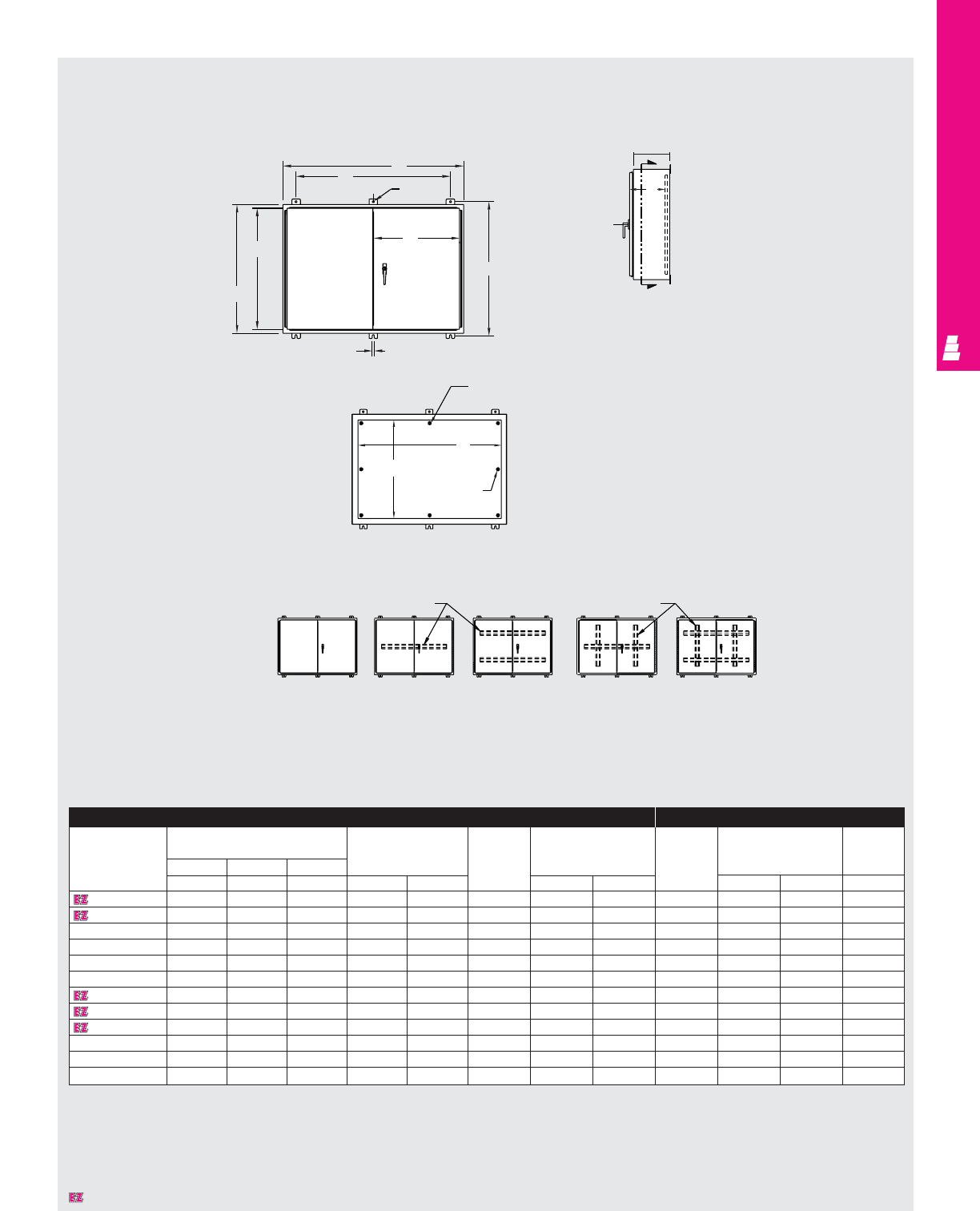
WALLMOUNT ENCLOSURES
IND 46
Technical Specifications
Two Door Wallmount Enclosures
Enclosure Mounting Panel
Part No. Outside dimensions Mounting Door Cover Part No. Panel Usable
(inches) centers and body size size depth
HWD stiffener
ABCHWarrangement J K E F G
E 244208WF 24.00 42.00 8.00 25.25 36.00 A 22.19 20.06 E 42P24 21.00 39.00 8.00
E 244808WF 24.00 48.00 8.00 25.25 42.00 A 22.19 23.06 E 48P24 21.00 45.00 8.00
E 304210WF 30.00 42.00 10.00 31.25 36.00 B 28.19 20.06 E 42P30 27.00 39.00 10.00
E 304810WF 30.00 48.00 10.00 31.25 42.00 B 28.19 23.06 E 48P30 27.00 45.00 10.00
E 306010WF 30.00 60.00 10.00 31.25 54.00 B 28.19 29.06 E 60P30 27.00 57.00 10.00
E 364212WF 36.00 42.00 12.00 37.25 36.00 B 34.19 20.06 E 42P36 33.00 39.00 12.00
E 364812WF 36.00 48.00 12.00 37.25 42.00 B 34.19 23.06 E 48P36 33.00 45.00 12.00
E 366012WF 36.00 60.00 12.00 37.25 54.00 D 34.19 29.06 E 60P36 33.00 57.00 11.37*
E 424212WF 42.00 42.00 12.00 43.25 36.00 C 40.19 20.06 E 42P42 39.00 39.00 12.00
E 424812WF 42.00 48.00 12.00 43.25 42.00 C 40.19 23.06 E 48P42 39.00 45.00 12.00
E 426012WFA 42.00 60.00 12.00 43.25 54.00 E 40.19 29.06 E 60WFP42 38.00 56.00 11.37*
E 484812WFA 48.00 48.00 12.00 49.25 42.00 C 46.19 23.06 E 48WFP48 44.00 44.00 12.00
* Usable depth reduced by .625” at door stiffener.
Side View
Section X-X
Front View
ABC DE
Stiffener Arrangement
A
W
J
A
K
H
0.44
.44 Dia.
C
L
X
C
X
G
C
L
Omit two middle studs if
B < 31.00
F
EOmit two
middle studs if
A < 31.00
Horizontal body stiffeners Vertical door stiffeners
Designates a product in the EnclosureZone program.
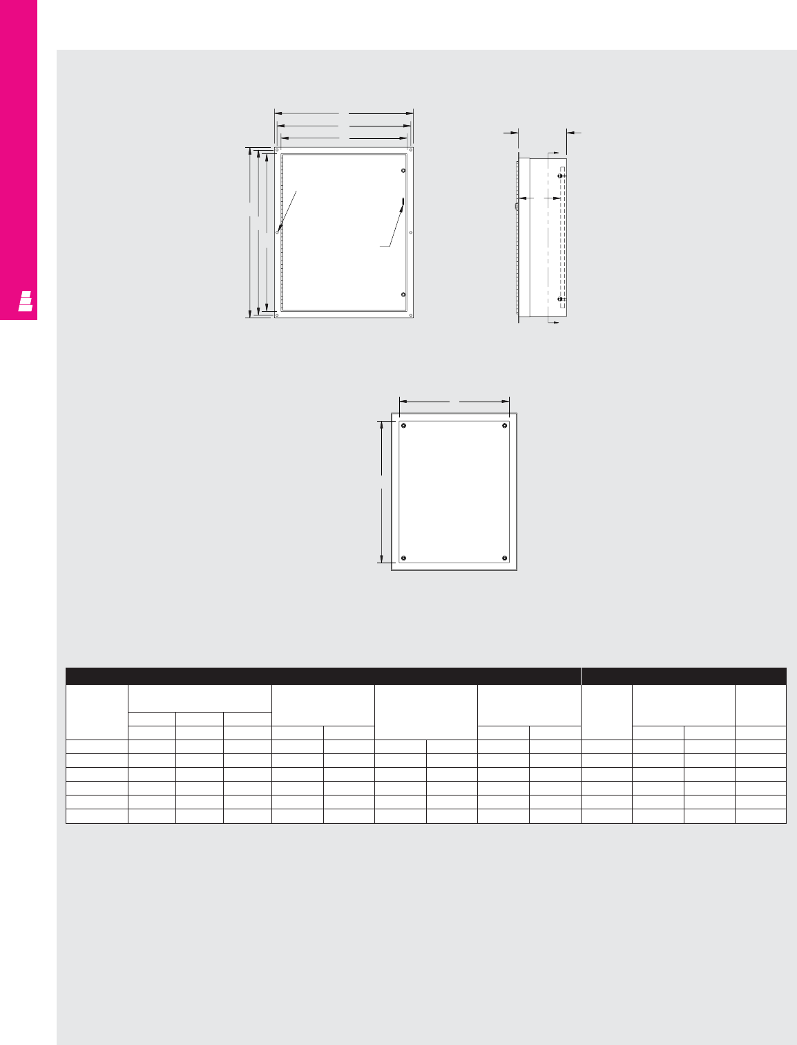
Technical Specifications
Flush Mount Boxes
WALLMOUNT ENCLOSURES
IND 47
Enclosure Mounting Panel
Part No. Outside dimensions Mounting Mounting Overall Part No. Panel Usable
(inches) centers cut-out flange size depth
HWD size size
ABC H W J K E FC
E 161206FM 16.00 12.00 6.00 17.50 13.50 15.75 11.75 18.50 14.50 E 16P12 13.00 9.00 6.00
E 201606FM 20.00 16.00 6.00 21.50 17.50 19.75 15.75 22.50 18.50 E 20P16 17.00 13.00 6.00
E 202006FM 20.00 20.00 6.00 21.50 21.50 19.75 19.75 22.50 22.50 E 20P20 17.00 17.00 6.00
E 242006FM 24.00 20.00 6.00 25.50 21.50 23.75 19.75 26.50 22.50 E 24P20 21.00 17.00 6.00
E 242408FM 24.00 24.00 8.00 25.50 25.50 23.75 23.75 26.50 26.50 E 24P24 21.00 21.00 8.00
E 302408FM 30.00 24.00 8.00 31.50 25.50 29.75 23.75 32.50 26.50 E 30P24 27.00 21.00 8.00
Front View Side View
Section Y-Y
J
H
A
K
W
B
Omit two middle mtg.
holes if A <= 29.00
Padlockable
hasp and staple
F
E
C
C + 1.13
Y
Y
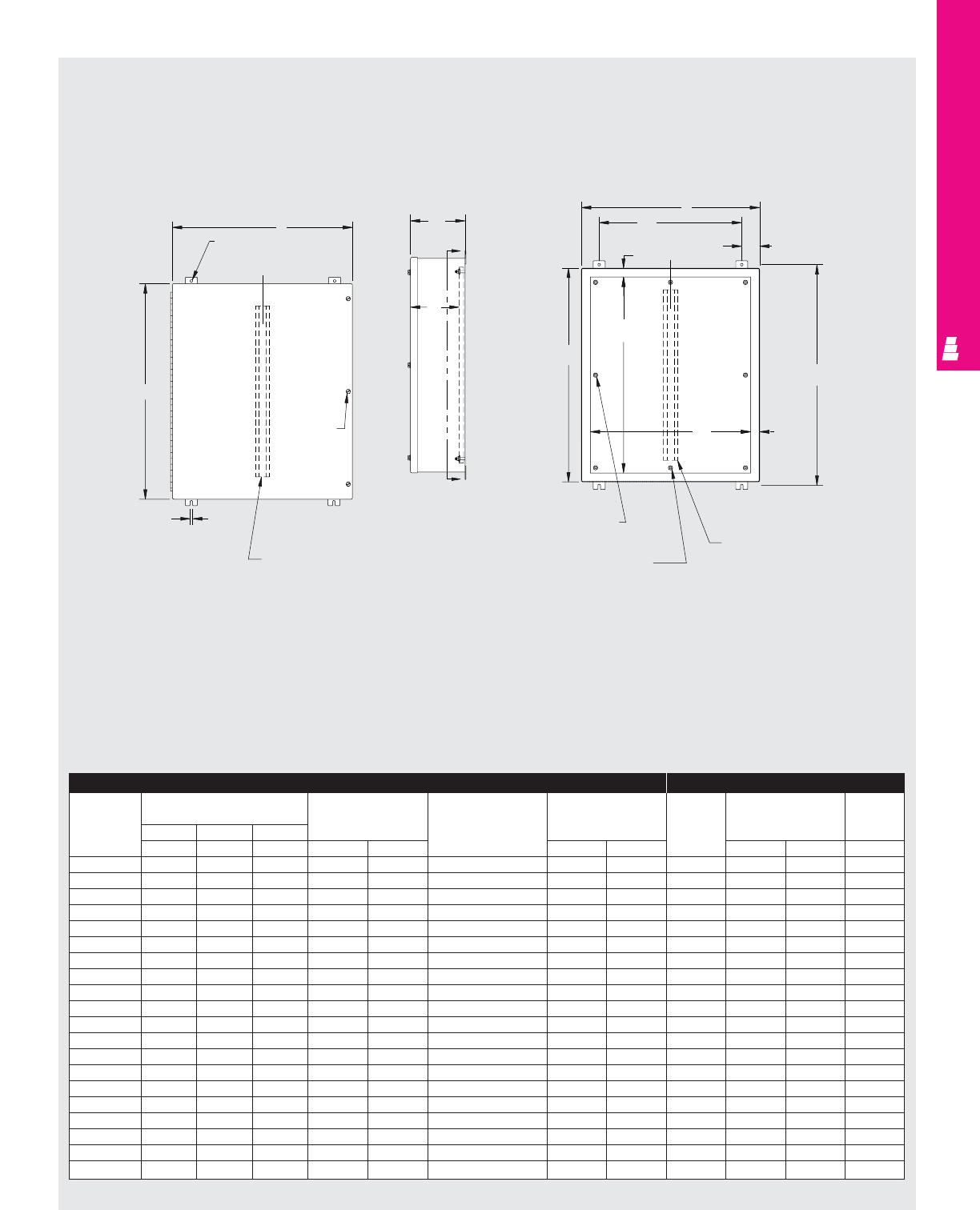
WALLMOUNT ENCLOSURES
IND 48
Technical Specifications
Large Oil-Tight Boxes
Front View
Side View
Section X-X
Enclosure Mounting Panel
Part No. Outside dimensions Mounting Door and Cover Part No. Panel Usable
(inches) centers body size size depth
HWD stiffener
ABC H W J K E F D
E 20C16A 20.00 16.00 7.00 21.25 10.00 NO 20.31 16.31 E 20P16 17.00 13.00 6.00
E 20C16B 20.00 16.00 9.00 21.25 10.00 NO 20.31 16.31 E 20P16 17.00 13.00 8.00
E 20C20A 20.00 20.00 7.00 21.25 14.00 NO 20.31 20.31 E 20P20 17.00 17.00 6.00
E 20C20B 20.00 20.00 9.00 21.25 14.00 NO 20.31 20.31 E 20P20 17.00 17.00 8.00
E 24C20A 24.00 20.00 7.00 25.25 14.00 NO 24.31 20.31 E 24P20 21.00 17.00 6.00
E 24C20B 24.00 20.00 9.00 25.25 14.00 NO 24.31 20.31 E 24P20 21.00 17.00 8.00
E 24C24A 24.00 24.00 7.00 25.25 18.00 NO 24.31 24.31 E 24P24 21.00 21.00 6.00
E 24C24B 24.00 24.00 9.00 25.25 18.00 NO 24.31 24.31 E 24P24 21.00 21.00 8.00
E 24C24C 24.00 24.00 11.00 25.25 18.00 NO 24.31 24.31 E 24P24 21.00 21.00 10.00
E 30C20A 30.00 20.00 7.00 31.25 14.00 NO 30.31 20.31 E 30P20 27.00 17.00 6.00
E 30C20B 30.00 20.00 9.00 31.25 14.00 NO 30.31 20.31 E 30P20 27.00 17.00 8.00
E 30C24A 30.00 24.00 7.00 31.25 18.00 NO 30.31 24.31 E 30P24 27.00 21.00 6.00
E 30C24B 30.00 24.00 9.00 31.25 18.00 NO 30.31 24.31 E 30P24 27.00 21.00 8.00
E 30C24D 30.00 24.00 13.00 31.25 18.00 NO 30.31 24.31 E 30P24 27.00 21.00 12.00
E 36C24A 36.00 24.00 7.00 37.25 18.00 NO 36.31 24.31 E 36P24 33.00 21.00 6.00
E 36C24B 36.00 24.00 9.00 37.25 18.00 NO 36.31 24.31 E 36P24 33.00 21.00 8.00
E 36C24C 36.00 24.00 11.00 37.25 18.00 NO 36.31 24.31 E 36P24 33.00 21.00 10.00
E 36C30B 36.00 30.00 9.00 37.25 24.00 YES 36.31 30.31 E 36P30 33.00 27.00 7.38*
E 36C30D 36.00 30.00 13.00 37.25 24.00 YES 36.31 30.31 E 36P30 33.00 27.00 11.38*
E 48C36C 48.00 36.00 11.00 49.25 30.00 YES 48.31 36.31 E 48P36 45.00 33.00 9.38*
* Usable depth reduced by .625" at door stiffener.
.44 dia. K
C
L
Omit if
A <= 36.00
Door stiffener
Omit if A <= 36.00
and B <= 30.00
.44
C
X
D
X
B
W
3.00
H
F
E
C
L
A
1.50
Omit center stud
if A <= 36.00
Omit center stud
if B <= 36.00
Body stiffener
Omit if A <= 36.00
and B <= 30.00
J
1.50
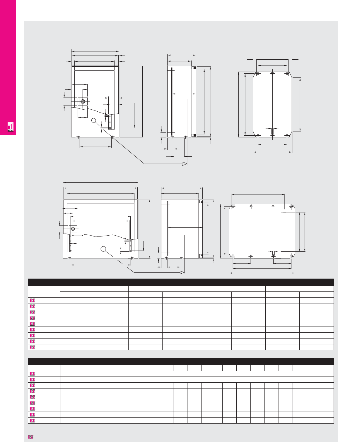
WALLMOUNT ENCLOSURES
IND 49
Technical Specifications
AE Wallmount Enclosures
1032600/1035600
1030600/1031600/1033600/1034600/1380600/1039600/1339600
X
195
200
i.L167 2.5
20
13
67.5
47.5
32
36
133
3.7
6.5
44.5
38.5
9x25=225
300
X
Interior of door X
43
28
20
2.5 295
i.L.274
100
120 (155)
100 (135) 134
122
14 14
275
260
18x12.5=225
6.5
122
162
Add wall fixing mounting holes.
W1
W2
W3
W5
W4
70
50
32
36
W6
6.5 3.7
N19x25=H4
H1
Interior of door X
D4 D5
27.5
D3
D2
D1
H3
H2
2.5
G3
G2
F3
90 F2
F1
90
10
N2x12.5=G3
N3x50=G3
Detailed Dimensions
Part No. H2 H3 H4 N1 W2 W3 W4 W5 W6 D2 D3 D4 D5 F1 F2 F3 G1 G2 G3
1032600 See drawings above.
1035600 See drawings above.
1030600 295 260 225 9 375 340 291 303 303 135 113-129 33 63 334 295 267.5 275 250 200
1033600 295 260 225 9 295 260 211 223 233 190 168-184 33 45 254 215 187.5 275 250 200
1031600 295 260 225 9 375 340 291 303 303 190 168-184 33 63 334 295 267.5 275 250 200
1380600 375 340 275 11 375 340 291 303 303 190 168-184 33 63 334 295 267.5 355 330 300
1039600 375 340 275 11 595 560 511 523 500 190 168-184 38 113 549 510 482.5 355 330 300
1339600 375 340 275 11 595 560 511 523 500 330 308-324 38 113 549 510 482.5 355 330 300
1034600 395 360 325 13 295 260 211 223 233 190 168-184 33 45 254 215 187.5 375 350 300
Dimensions in millimeters (mm) unless otherwise indicated.
Enclosure
Part No.
Height (H1) Width (W1) Depth (D1) Weight
inches mm inches mm inches mm lbs kg
1032600 11.81 300 7.87 200 4.72 120 8.8 4
1035600 11.81 300 7.87 200 6.10 155 9.9 4.5
1030600 11.81 300 14.96 380 6.10 155 18.5 8.4
1033600 11.81 300 11.81 300 8.27 210 15.4 7
1031600 11.81 300 14.96 380 8.27 210 19.2 8.7
1380600 14.96 380 14.96 380 8.27 210 25.3 11.5
1039600 14.96 380 23.62 600 8.27 210 37.4 17
1339600 14.96 380 23.62 600 13.78 350 48.5 22
1034600 15.75 400 11.81 300 8.27 210 19.4 8.8
Designates a product in the EnclosureZone program.
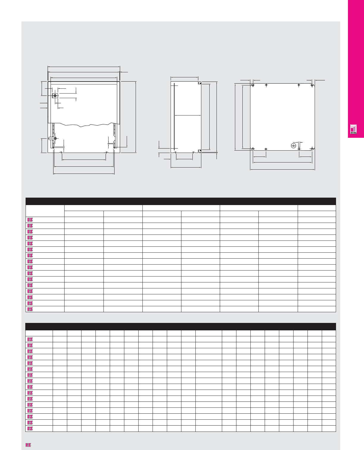
WALLMOUNT ENCLOSURES
IND 50
Technical Specifications
AE Wallmount Enclosures
Add wall fixing mounting holes.
Detailed Dimensions
Part No.
H2 H3 H4 H5 W2 W3 W4 W5 W6 D2 D3 D4 D5 N1 F1 F2 F3 G1 G2
1045600
495 460 425 30 395 360 311 323 303 190 168-184 38 113 17 354 315 13.5 450 400
1050600
495 460 425 30 495 460 411 423 303 190 168-184 38 113 17 449 410 21.0 470 445
1038600
595 560 525 30 375 340 291 303 303 190 168-184 33 63 21 334 295 13.5 570 545
1060600
595 560 525 30 595 560 511 523 500 190 168-184 38 113 21 549 510 21.0 570 545
1076600
755 720 675 30 595 560 511 523 500 190 168-184 38 113 27 549 510 21.0 730 705
1077600
755 720 675 30 755 720 671 683 500 190 168-184 38 113 27 704 665 21.0 730 705
1058600
795 760 725 30 595 560 511 523 500 230 208-224 38 113 29 549 510 21.0 770 745
1057600
695 660 625 30 495 460 411 423 303 230 208-224 38 113 25 449 410 21.0 670 645
1090600
995 960 925 35 595 560 511 523 500 230 208-224 38 113 37 539 500 21.0 955 930
1350600
495 460 425 30 495 460 411 423 303 280 258-274 38 113 17 449 410 21.0 470 445
1073600
755 720 675 30 755 720 671 683 500 280 258-274 38 113 27 704 665 21.0 730 705
1097500
895 860 750 30 755 720 671 683 500 280 258-274 38 113 30 704 665 21.0 870 845
1180600
995 960 925 35 795 760 711 723 500 280 258-274 70 113 37 739 700 21.0 955 930
1338600
595 560 525 30 375 340 291 303 303 330 308-324 84 113 21 334 295 13.5 570 545
1360600
595 560 525 30 595 560 511 523 500 330 308-324 38 113 21 549 510 21.0 570 545
1376600
755 720 675 30 595 560 511 523 500 330 308-324 38 113 27 549 510 21.0 730 705
Dimensions in millimeters (mm) unless otherwise indicated.
W1
W2
W3
2.5
100
36
50
70
100
32
6.5
3.7
W6
W4
W5
N1x25=H4
H1
H3
H2
D2
D3
D5
D1
D4
2.5
H5
G1
G2
F3
90
F2
F1
90
F3
Mounting Panel
Enclosure
Part No.
Height (H1) Width (W1) Depth (D1) Weight
inches mm inches mm inches mm lbs
1045600
19.69 500 15.75 400 8.27 210 28.6
1050600
19.69 500 19.69 500 8.27 210 41.6
1038600
23.62 600 14.96 380 8.27 210 36.6
1060600
23.62 600 23.62 600 8.27 210 57.5
1076600
29.92 760 23.62 600 8.27 210 70.7
1077600
29.92 760 29.92 760 8.27 210 88.1
1058600
31.50 800 23.62 600 9.84 250 97.9
1057600
27.56 700 19.69 500 9.84 250 57.4
1090600
39.37 1000 23.62 600 9.84 250 121.0
1350600
19.69 500 19.69 500 11.81 300 46.3
1073600
29.92 760 29.92 760 11.81 300 98.0
1097500
35.43 900 29.92 760 11.81 300 110.0
1180600
39.37 1000 31.50 800 11.81 300 125.6
1338600
23.62 600 14.96 380 13.78 350 46.9
1360600
23.62 600 23.62 600 13.78 350 67.8
1376600
29.92 760 23.62 600 13.78 350 83.7
Designates a product in the EnclosureZone program.
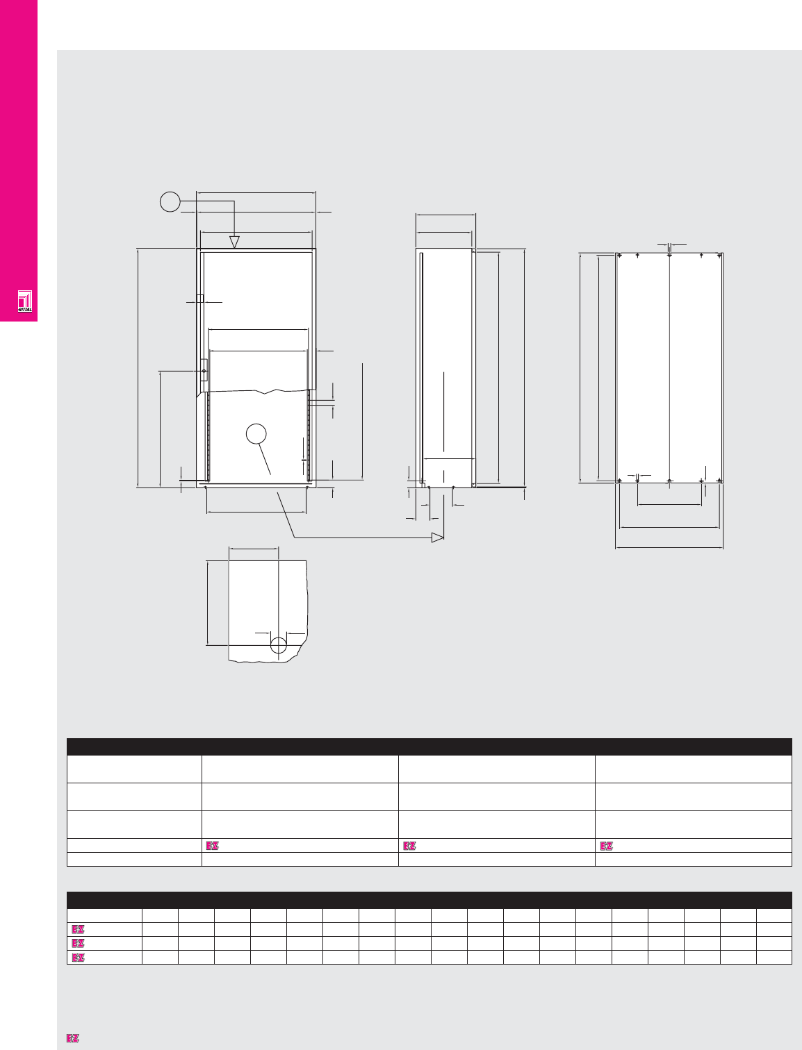
WALLMOUNT ENCLOSURES
IND 51
Technical Specifications
AE Wallmount Enclosures
Enclosure
Height (H1) inches 47.24 47.24 47.24
mm 1200 1200 1200
Width (W1) inches 23.62 31.50 35.43
mm 600 800 900
Depth (D1) inches 11.81 11.81 11.81
mm 300 300 300
Part No. 1260600 1280600 1097670
Weight lbs/kg 5.3/2.4 7.9/3.6 165.0/75.0
Detailed Dimensions
Part No.
H2 H3 H4 H5 W2 W3 W4 W5 W6 D2 D3 D4 N1 F1 F2 F3 G1 G2
1260600
1194 1160 1125 585 595 560 488 500 500 281 264 70 45 540 500 320 1155 1130
1280600
1194 1160 1125 585 795 760 688 700 500 281 264 70 45 740 700 520 1155 1130
1097670
1194 1160 1125 585 895 860 788 800 500 281 264 70 45 840 800 620 1155 1130
Dimensions in millimeters (mm) unless otherwise indicated.
Dimensions in millimeters (mm) unless otherwise indicated.
W1
W2
W3
W5
W4
35
44.5
W6
2.5
H1
H5
6.5
38.5 25
H4
2.5
Y
X
3.7
50
16
85
Interior of door x
D4
D3
113
35
H3
H2
D1
D2
4
F1
F2
F3
G1
G2
10
10
12.5
Detail Y
Designates a product in the EnclosureZone program.
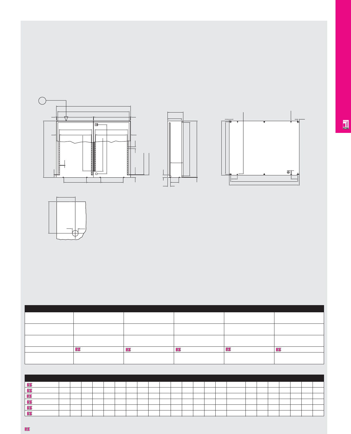
WALLMOUNT ENCLOSURES
Technical Specifications
AE Wallmount Enclosures
Enclosure
Height (H1) inches 29.92 29.92 39.37 47.24 55.12
mm 760 760 1000 1200 1400
Width (W1) inches 39.37 39.37 39.37 39.37 39.37
mm 1000 1000 1000 1000 1000
Depth (D1) inches 8.27 11.81 11.81 11.81 11.81
mm 210 300 300 300 300
Part No. 1100600 1130600 1110600 1213600 1114600
Weight lbs 114.6 123.5 156.5 187.4 213.8
kg 52.0 56.0 71.0 85.0 97.0
Dimensions in millimeters (mm) unless otherwise indicated.
Detailed Dimensions
Part No. H2 H3 H4 H5 H6 H7 H8 H9 W2 W3 W4 W5 W6 W7 D2 D3 D4 N1 N2 F1 F2 G1 G2
1100600 755 720 675 698 662 598 30 575 960 495 424 436 - - 190 168-184 38 27 23 944 905 730 705
1130600 755 720 675 698 662 598 30 575 960 495 424 436 - - 280 258-274 70 27 23 944 905 730 705
1110600 995 960 925 938 894 838 35 825 960 495 424 436 - - 280 258-274 70 37 33 939 900 955 930
1213600 1194 1160 1125 - 585 1125 35 - 960 495 424 436 393 405 282 264 70 45 - 940 900 1155 1130
1114600 1394 1360 1325 - 685 1325 35 - 960 495 424 436 393 405 282 264 70 53 - 940 900 1355 1330
Dimensions in millimeters (mm) unless otherwise indicated.
IND 52
Add rearwall fixing
mounted hole pattern.
YW1
W2
W3 W3
2.5 2.5
W5
W4
W5 (W7)
W4 (W6) 44.5
44.5
303 303
197
H1
6.5
3.7
N2 x 25=H9
N1 x 25=H4
H7
H6
38.5 25
H5
50
16
85
H8
H3
H2
D4 38/70 113
D2
D1
D3
4
21
90 90
F2
F1
10
21
Holes not for AE 1100/1130
Mounting panel
View Y
Designates a product in the EnclosureZone program.
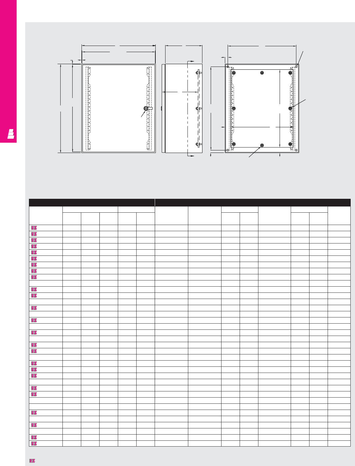
WALLMOUNT ENCLOSURES
IND 53
Technical Specifications
Legacy Series Enclosures
Front View Right Side View Section A-A
Enclosure Mounting Panel
Part No. Outside dimensions (inches) Mounting centers White Zinc Panel size White Panel size Usable
(Full Size) (Full Size) (NEMA Style) depth
HWDHWPanel Part No. Panel Part No. ABPanel Part No. AB J
L W120806 12.00 8.00 6.00 10.5 6.5 L W12P8W L W12P8 10.2 6.2 - - - 5.0
L W121206 12.00 12.00 6.00 10.5 10.5 L W12P12W L W12P12 10.2 10.2 - - - 5.0
L W121608 12.00 16.00 8.00 10.5 14.5 L W12P16W L W12P16 10.2 14.2 E 16P12 13.0 9.0 7.0
L W161206 16.00 12.00 6.00 14.5 10.5 L W16P12W L W16P12 14.2 10.2 E 16P12 13.0 9.0 5.0
L W161208 16.00 12.00 8.00 14.5 10.5 L W16P12W L W16P12 14.2 10.2 E 16P12 13.0 9.0 7.0
L W161606 16.00 16.00 6.00 14.5 14.5 L W16P16W L W16P16 14.2 14.2 E 16P16 13.0 13.0 5.0
L W161608 16.00 16.00 8.00 14.5 14.5 L W16P16W L W16P16 14.2 14.2 E 16P16 13.0 13.0 7.0
L W201606 20.00 16.00 6.00 18.5 14.5 L W20P16W L W20P16 18.2 14.2 E 20P16 17.0 13.0 5.0
L W201608 20.00 16.00 8.00 18.5 14.5 L W20P16W L W20P16 18.2 14.2 E 20P16 17.0 13.0 7.0
L W202006 20.00 20.00 6.00 18.5 18.5 L W20P20W L W20P20 18.2 18.2 E 20P20 17.0 17.0 5.0
L W202008 20.00 20.00 8.00 18.5 18.5 L W20P20W L W20P20 18.2 18.2 E 20P20 17.0 17.0 7.0
L W202012 20.00 20.00 12.00 18.5 18.5 L W20P20W L W20P20 18.2 18.2 E 20P20 17.0 17.0 11.0
L W202408 20.00 24.00 8.00 18.5 22.5 L W20P24W L W20P24 18.2 22.2 E 24P20 21.0 17.0 7.0
L W241608 24.00 16.00 8.00 22.5 14.5 L W24P16W L W24P16 22.2 14.2 E 24P16 21.0 13.0 7.0
L W242006 24.00 20.00 6.00 22.5 18.5 L W24P20W L W24P20 22.2 18.2 E 24P20 21.0 17.0 5.0
L W242008 24.00 20.00 8.00 22.5 18.5 L W24P20W L W24P20 22.2 18.2 E 24P20 21.0 17.0 7.0
L W242406 24.00 24.00 6.00 22.5 22.5 L W24P24W L W24P24 22.2 22.2 E 24P24 21.0 21.0 5.0
L W242408 24.00 24.00 8.00 22.5 22.5 L W24P24W L W24P24 22.2 22.2 E 24P24 21.0 21.0 7.0
L W242410 24.00 24.00 10.00 22.5 22.5 L W24P24W L W24P24 22.2 22.2 E 24P24 21.0 21.0 9.0
L W242412 24.00 24.00 12.00 22.5 22.5 L W24P24W L W24P24 22.2 22.2 E 24P24 21.0 21.0 11.0
L W242416 24.00 24.00 16.00 22.5 22.5 L W24P24W L W24P24 22.2 22.2 E 24P24 21.0 21.0 15.0
L W243008 24.00 30.00 8.00 22.5 28.5 L W24P20W L W24P20 22.2 18.2 E 30P24 27.0 21.0 7.0
L W302408 30.00 24.00 8.00 28.5 22.5 L W30P24W L W30P24 28.2 22.2 E 30P24 27.0 21.0 7.0
L W302412 30.00 24.00 12.00 28.5 22.5 L W30P24W L W30P24 28.2 22.2 E 30P24 27.0 21.0 11.0
L W303008 30.00 30.00 8.00 28.5 28.5 L W30P30W L W30P30 28.2 28.2 E 30P30 27.0 27.0 7.0
L W303010 30.00 30.00 10.00 28.5 28.5 L W30P30W L W30P30 28.2 28.2 E 30P30 27.0 27.0 9.0
L W303012 30.00 30.00 12.00 28.5 28.5 L W30P30W L W30P30 28.2 28.2 E 30P30 27.0 27.0 11.0
L W362408 36.00 24.00 8.00 34.5 22.5 L W36P24W L W36P24 34.2 22.2 E 36P24 33.0 21.0 7.0
L W362412 36.00 24.00 12.00 34.5 22.5 L W36P24W L W36P24 34.2 22.2 E 36P24 33.0 21.0 11.0
L W363008 36.00 30.00 8.00 34.5 28.5 L W36P30W L W36P30 34.2 28.2 E 36P30 33.0 27.0 7.0
L W363012 36.00 30.00 12.00 34.5 28.5 L W36P30W L W36P30 34.2 28.2 E 36P30 33.0 27.0 11.0
L W363612 36.00 36.00 12.00 34.5 34.5 L W36P36W L W36P36 34.2 34.2 E 36P36 33.0 33.0 11.0
L W423212 42.00 32.00 12.00 40.5 30.5 L W42P32W L W42P32 40.2 30.2 E 42P32 39.0 29.0 11.0
L W483612 48.00 36.00 12.00 46.5 34.5 L W48P36W L W48P36 46.2 34.2 E 48P36 45.0 33.0 11.0
L W483616 48.00 36.00 16.00 46.5 34.5 L W48P36W L W48P36 46.2 34.2 E 48P36 45.0 33.0 15.0
L W603612 60.00 36.00 12.00 58.5 34.5 L W60P36W L W60P36 58.2 34.2 E 60P36 57.0 33.0 11.0
.09 .09
B
B-.19
A-.19
A
Rail stiffener
for < 36" W;
door stiffener
for > 36" W
1/4 Turn
latch
C
L
D
A
A.75
1.50
Omit center studs if
B < 36.00 1.50
Omit center
studs if
A < 36.00
W
.75 C
L
.50 Ø (4 PLS)
HE
F
Designates a product in the EnclosureZone program.
J
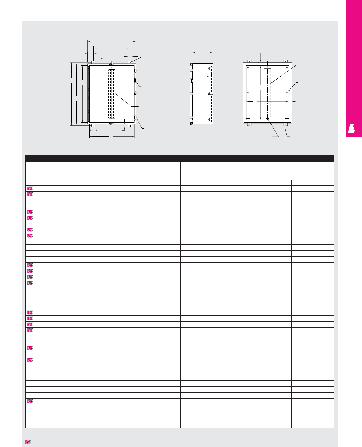
WALLMOUNT ENCLOSURES
Technical Specifications
One Door Wallmount Boxes
Front View Right Side View Section Y-Y
D
TYP
B
W
1.25
2.00 .44 Dia.
Padlockable
hasp and
keeper
Door clamp
.44 1.25
K
j
A
H
C
Y
G
Y
F
1.50
Omit center studs
if B < 36.00 Mounting feet
1.50
Omit center studs
if A < 36.00
Body stiffener
omit if A < 36.00
or B < 30.00
Door stiffener
omit if
A < 36.00
or B < 30.00
C
L
* Usable depth reduced by .625” at door stiffener.
Enclosure Mounting Panel
Part No. Outside dimensions Mounting Door Cover Part No. Panel Usable
(inches) centers and size size depth
HW D body
AB CH WDstiffener J K E F G
E 16H12A 16.00 12.00 6.00 17.25 9.50 1.25 NO 14.19 10.16 E 16P12 13.00 9.00 6.00
E 16H12B 16.00 12.00 8.00 17.25 9.50 1.25 NO 14.19 10.16 E 16P12 13.00 9.00 8.00
E 16H16A 16.00 16.00 6.00 17.25 10.00 3.00 NO 14.19 14.16 E 16P16 13.00 13.00 6.00
E 16H20A 16.00 20.00 6.00 17.25 14.00 3.00 NO 14.19 18.16 E 20P16 13.00 17.00 6.00
E 20H16A 20.00 16.00 6.00 21.25 10.00 3.00 NO 18.19 14.16 E 20P16 17.00 13.00 6.00
E 20H16B 20.00 16.00 8.00 21.25 10.00 3.00 NO 18.19 14.16 E 20P16 17.00 13.00 8.00
E 20H16C 20.00 16.00 10.00 21.25 10.00 3.00 NO 18.19 14.16 E 20P16 17.00 13.00 10.00
E 20H20A 20.00 20.00 6.00 21.25 14.00 3.00 NO 18.19 18.16 E 20P20 17.00 17.00 6.00
E 20H20B 20.00 20.00 8.00 21.25 14.00 3.00 NO 18.19 18.16 E 20P20 17.00 17.00 8.00
E 20H24B 20.00 24.00 8.00 21.25 18.00 3.00 NO 18.19 18.19 E 24P20 21.00 17.00 8.00
E 24H12A 24.00 12.00 6.00 25.25 9.50 1.25 NO 22.19 10.16 E 12P24 21.00 9.00 6.00
E 24H16A 24.00 16.00 6.00 25.25 10.00 3.00 NO 22.19 14.16 E 24P16 21.00 13.00 6.00
E 24H20A 24.00 20.00 6.00 25.25 14.00 3.00 NO 22.19 18.16 E 24P20 21.00 17.00 6.00
E 24H20B 24.00 20.00 8.00 25.25 14.00 3.00 NO 22.19 18.16 E 24P20 21.00 17.00 8.00
E 24H20C 24.00 20.00 10.00 25.25 14.00 3.00 NO 22.19 18.16 E 24P20 21.00 17.00 10.00
E 24H24A 24.00 24.00 6.00 25.25 18.00 3.00 NO 22.19 22.16 E 24P24 21.00 21.00 6.00
E 24H24B 24.00 24.00 8.00 25.25 18.00 3.00 NO 22.19 22.16 E 24P24 21.00 21.00 8.00
E 24H30B 24.00 30.00 8.00 25.25 24.00 3.00 NO 28.19 28.16 E 30P24 27.00 21.00 8.00
E 30H20A 30.00 20.00 6.00 31.25 14.00 3.00 NO 28.19 18.16 E 30P20 27.00 17.00 6.00
E 30H20B 30.00 20.00 8.00 31.25 14.00 3.00 NO 28.19 18.16 E 30P20 27.00 17.00 8.00
E 30H24A 30.00 24.00 60.00 31.25 18.00 3.00 NO 28.19 22.16 E 30P24 27.00 21.00 6.00
E 30H24B 30.00 24.00 8.00 31.25 18.00 3.00 NO 28.19 22.16 E 30P24 27.00 21.00 8.00
E 30H24C 30.00 24.00 10.00 31.25 18.00 3.00 NO 28.19 22.16 E 30P24 27.00 21.00 10.00
E 30H24D 30.00 24.00 12.00 31.25 18.00 3.00 NO 28.19 22.16 E 30P24 27.00 21.00 12.00
E 30H30B 30.00 30.00 8.00 31.25 24.00 3.00 NO 28.19 28.16 E 30P30 27.00 27.00 8.00
E 36H24A 36.00 24.00 6.00 37.25 18.00 3.00 NO 34.19 22.16 E 36P24 33.00 21.00 6.00
E 36H24B 36.00 24.00 8.00 37.25 18.00 3.00 NO 34.19 22.16 E 36P24 33.00 21.00 8.00
E 36H30B 36.00 30.00 8.00 37.25 24.00 3.00 YES 34.19 28.16 E 36P30 33.00 27.00 7.37*
E 36H30C 36.00 30.00 10.00 37.25 24.00 3.00 YES 34.19 28.16 E 36P30 33.00 27.00 9.37*
E 36H30D 36.00 30.00 12.00 37.25 24.00 3.00 YES 34.19 28.16 E 36P30 33.00 27.00 11.37*
E 36H30F 36.00 30.00 16.00 37.25 24.00 3.00 YES 34.19 28.16 E 36P30 33.00 27.00 15.37*
E 42H30B 42.00 30.00 8.00 43.25 24.00 3.00 YES 40.19 28.16 E 42P30 39.00 27.00 7.37*
E 42H36B 42.00 36.00 8.00 43.25 30.00 3.00 YES 40.19 34.16 E 42P36 39.00 33.00 7.37*
E 48H30C 48.00 30.00 10.00 49.25 24.00 3.00 YES 46.19 28.16 E 48P30 45.00 27.00 9.37*
E 48H36B 48.00 36.00 8.00 49.25 30.00 3.00 YES 46.19 34.16 E 48P36 45.00 33.00 7.37*
E 48H36C 48.00 36.00 10.00 49.25 30.00 3.00 YES 46.19 34.16 E 48P36 45.00 33.00 9.37*
E 48H36D 48.00 36.00 12.00 49.25 30.00 3.00 YES 46.19 34.16 E 48P36 45.00 33.00 11.37*
E 48H36F 48.00 36.00 16.00 49.25 30.00 3.00 YES 46.19 34.16 E 48P36 45.00 33.00 15.37*
E 60H36B 60.00 36.00 8.00 61.25 30.00 3.00 YES 58.19 34.16 E 60P36 57.00 33.00 7.37*
E 60H36C 60.00 36.00 10.00 61.25 30.00 3.00 YES 58.19 34.16 E 60P36 57.00 33.00 9.37*
E 60H36F 60.00 36.00 16.00 61.25 30.00 3.00 YES 58.19 34.16 E 60P36 57.00 33.00 15.37*
C
LC
L
JE
IND 54
Designates a product in the EnclosureZone program.
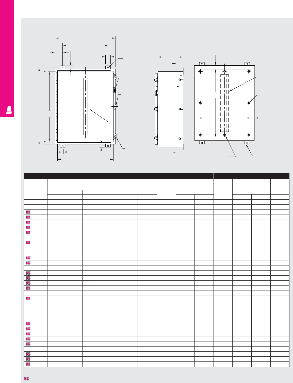
WALLMOUNT ENCLOSURES
IND 55
Technical Specifications
One Door Wallmount Enclosures
Enclosure Mounting Panel
Part No. Outside dimensions Mounting Door Door Part No. Panel Usable
(inches) centers and size size depth
HWD body
ABDH WDstiffener J K E F G
E 122406 12.00 24.00 6.00 13.25 18.00 3.00 NO 10.19 22.16 E 12P24 9.00 21.00 6.00
E 122408 12.00 24.00 8.00 13.25 18.00 3.00 NO 10.19 22.16 E 12P24 9.00 21.00 8.00
E 161206 16.00 12.00 6.00 17.25 9.50 1.25 NO 14.19 10.16 E 16P12 13.00 9.00 6.00
E 161208 16.00 12.00 8.00 17.25 9.50 1.25 NO 14.19 10.16 E 16P12 13.00 9.00 8.00
E 161210 16.00 12.00 10.00 17.25 9.50 1.25 NO 14.19 10.16 E 16P12 13.00 9.00 10.00
E 161606 16.00 16.00 6.00 17.25 10.00 3.00 NO 14.19 14.16 E 16P16 13.00 13.00 6.00
E 161608 16.00 16.00 8.00 17.25 10.00 3.00 NO 14.19 14.16 E 16P16 13.00 13.00 8.00
E 162006 16.00 20.00 6.00 17.25 14.00 3.00 NO 14.19 18.16 E 20P16 13.00 17.00 6.00
E 162008 16.00 20.00 8.00 17.25 14.00 3.00 NO 14.19 18.16 E 20P16 13.00 17.00 8.00
E 201206 20.00 12.00 6.00 21.25 9.50 1.25 NO 18.19 10.16 E 20P12 17.00 9.00 6.00
E 201208 20.00 12.00 8.00 21.25 9.50 1.25 NO 18.19 10.16 E 20P12 17.00 9.00 8.00
E 201606 20.00 16.00 6.00 21.25 10.00 3.00 NO 18.19 14.16 E 20P16 17.00 13.00 6.00
E 201608 20.00 16.00 8.00 21.25 10.00 3.00 NO 18.19 14.16 E 20P16 17.00 13.00 8.00
E 201610 20.00 16.00 10.00 21.25 10.00 3.00 NO 18.19 14.16 E 20P16 17.00 13.00 10.00
E 201612 20.00 16.00 12.00 21.25 10.00 3.00 NO 18.19 14.16 E 20P16 17.00 13.00 12.00
E 202006 20.00 20.00 6.00 21.25 14.00 3.00 NO 18.19 18.16 E 20P20 17.00 17.00 6.00
E 202008 20.00 20.00 8.00 21.25 14.00 3.00 NO 18.19 18.16 E 20P20 17.00 17.00 8.00
E 202010 20.00 20.00 10.00 21.25 14.00 3.00 NO 18.19 18.16 E 20P20 17.00 17.00 10.00
E 202406 20.00 24.00 6.00 21.25 18.00 3.00 NO 18.19 22.16 E 24P20 17.00 21.00 6.00
E 202408 20.00 24.00 8.00 21.25 18.00 3.00 NO 18.19 22.16 E 24P20 17.00 21.00 8.00
E 241206 24.00 12.00 6.00 25.25 9.50 1.25 NO 22.19 10.16 E 12P24 21.00 9.00 6.00
E 241208 24.00 12.00 8.00 25.25 9.50 1.25 NO 22.19 10.16 E 12P24 21.00 9.00 8.00
E 241210 24.00 12.00 10.00 25.25 9.50 1.25 NO 22.19 10.16 E 24P12 21.00 9.00 10.00
E 241606 24.00 16.00 6.00 25.25 10.00 3.00 NO 22.19 14.16 E 24P16 21.00 13.00 6.00
E 241608 24.00 16.00 8.00 25.25 10.00 3.00 NO 22.19 14.16 E 24P16 21.00 13.00 8.00
E 242006 24.00 20.00 6.00 25.25 14.00 3.00 NO 22.19 18.16 E 24P20 21.00 17.00 6.00
E 242008 24.00 20.00 8.00 25.25 14.00 3.00 NO 22.19 18.16 E 24P20 21.00 17.00 8.00
E 242010 24.00 20.00 10.00 25.25 14.00 3.00 NO 22.19 18.16 E 24P20 21.00 17.00 10.00
E 242012 24.00 20.00 12.00 25.25 14.00 3.00 NO 22.19 18.16 E 24P20 21.00 17.00 12.00
E 242016 24.00 20.00 16.00 25.25 14.00 3.00 NO 22.19 18.16 E 24P20 21.00 17.00 16.00
E 242406 24.00 24.00 6.00 25.25 18.00 3.00 NO 22.19 22.16 E 24P24 21.00 21.00 6.00
E 242408 24.00 24.00 8.00 25.25 18.00 3.00 NO 22.19 22.16 E 24P24 21.00 21.00 8.00
E 242410 24.00 24.00 10.00 25.25 18.00 3.00 NO 22.19 22.16 E 24P24 21.00 21.00 10.00
* Usable depth reduced by .625” at door stiffener. (Chart continued on next page).
Right Side View
Front View Section Y-Y
B
W
1.25
2.00 .44 Dia.
Padlockable
hasp and
staple
Omit center
clamp if
A < 48.00
C
L
C
L
Door stiffener
omit if
A < 36.00 or
B < 30.00
Door clamp
1.25
.44
K
J
A
H
D TYP.
C
Y
G
Y
1.50
1.50
Mounting feet
Omit center studs if
B < 36.00
F
E
Body stiffener
omit if
A < 36.00 or
B < 30.00
Omit center
studs if
A < 36.00
C
L
Designates a product in the EnclosureZone program.
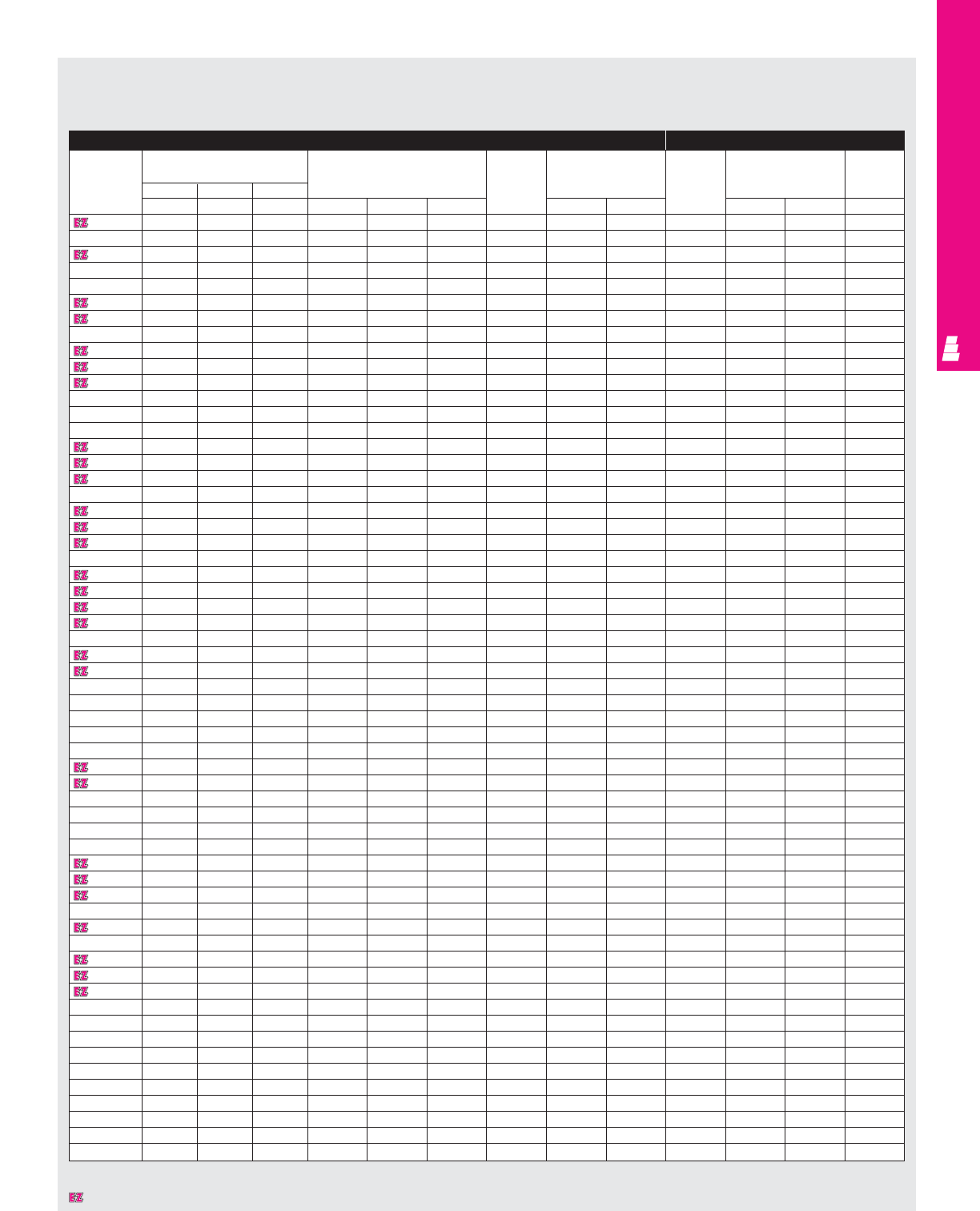
WALLMOUNT ENCLOSURES
Technical Specifications
One Door Wallmount Enclosures
Enclosure (Continued) Mounting Panel (Continued)
Part No. Outside dimensions Mounting Door Door Part No. Panel Usable
(inches) centers and size size depth
HWD body
ABDH WDstiffener J K E F G
E 242412 24.00 24.00 12.00 25.25 18.00 3.00 NO 22.19 22.16 E 24P24 21.00 21.00 12.00
E 242416 24.00 24.00 16.00 25.25 18.00 3.00 NO 22.19 22.16 E 24P24 21.00 21.00 16.00
E 243008 24.00 30.00 8.00 25.25 24.00 3.00 NO 22.19 28.16 E 30P24 21.00 27.00 8.00
E 301606 30.00 16.00 6.00 31.25 10.00 3.00 NO 28.19 14.16 E 30P16 27.00 13.00 6.00
E 302006 30.00 20.00 6.00 31.25 14.00 3.00 NO 28.19 18.16 E 30P20 27.00 17.00 6.00
E 302008 30.00 20.00 8.00 31.25 14.00 3.00 NO 28.19 18.16 E 30P20 27.00 17.00 8.00
E 302010 30.00 20.00 10.00 31.25 14.00 3.00 NO 28.19 18.16 E 30P20 27.00 17.00 10.00
E 302406 30.00 24.00 6.00 31.25 18.00 3.00 NO 28.19 22.16 E 30P24 27.00 21.00 6.00
E 302408 30.00 24.00 8.00 31.25 18.00 3.00 NO 28.19 22.16 E 30P24 27.00 21.00 8.00
E 302410 30.00 24.00 10.00 31.25 18.00 3.00 NO 28.19 22.16 E 30P24 27.00 21.00 10.00
E 302412 30.00 24.00 12.00 31.25 18.00 3.00 NO 28.19 22.16 E 30P24 27.00 21.00 12.00
E 302416 30.00 24.00 16.00 31.25 18.00 3.00 NO 28.19 22.16 E 30P24 27.00 21.00 16.00
E 302420 30.00 24.00 20.00 31.25 18.00 3.00 NO 28.19 22.16 E 30P24 27.00 21.00 20.00
E 302424 30.00 24.00 24.00 31.25 18.00 3.00 NO 28.19 22.16 E 30P24 27.00 21.00 24.00
E 303008 30.00 30.00 8.00 31.25 24.00 3.00 NO 28.19 28.16 E 30P30 27.00 27.00 8.00
E 303012 30.00 30.00 12.00 31.25 24.00 3.00 NO 28.19 28.16 E 30P30 27.00 27.00 12.00
E 303608 30.00 36.00 8.00 31.25 30.00 3.00 NO 28.19 34.16 E 36P30 27.00 33.00 8.00
E 362406 36.00 24.00 6.00 37.25 18.00 3.00 NO 34.19 22.16 E 36P24 33.00 21.00 6.00
E 362408 36.00 24.00 8.00 37.25 18.00 3.00 NO 34.19 22.16 E 36P24 33.00 21.00 8.00
E 362410 36.00 24.00 10.00 37.25 18.00 3.00 NO 34.19 22.16 E 36P24 33.00 21.00 10.00
E 362412 36.00 24.00 12.00 37.25 18.00 3.00 NO 34.19 22.16 E 36P24 33.00 21.00 12.00
E 363006 36.00 30.00 6.00 37.25 24.00 3.00 YES 34.19 28.16 E 36P30 33.00 27.00 5.37*
E 363008 36.00 30.00 8.00 37.25 24.00 3.00 YES 34.19 28.16 E 36P30 33.00 27.00 7.37*
E 363010 36.00 30.00 10.00 37.25 24.00 3.00 YES 34.19 28.16 E 36P30 33.00 27.00 9.37*
E 363012 36.00 30.00 12.00 37.25 24.00 3.00 YES 34.19 28.16 E 36P30 33.00 27.00 11.37*
E 363016 36.00 30.00 16.00 37.25 24.00 3.00 YES 34.19 28.16 E 36P30 33.00 27.00 15.37*
E 363020 36.00 30.00 20.00 37.25 24.00 3.00 YES 34.19 28.16 E 36P30 33.00 27.00 19.37*
E 363608 36.00 36.00 8.00 37.25 30.00 3.00 YES 34.19 34.16 E 36P36 33.00 33.00 7.37*
E 363612 36.00 36.00 12.00 37.25 30.00 3.00 YES 34.19 34.16 E 36P36 33.00 33.00 11.37*
E 422408 42.00 24.00 8.00 43.25 18.00 3.00 NO 40.19 22.16 E 42P24 39.00 21.00 8.00
E 423008 42.00 32.00 8.00 43.25 24.00 3.00 YES 40.19 28.16 E 42P30 39.00 27.00 7.37*
E 423010 42.00 32.00 10.00 43.25 24.00 3.00 YES 40.19 28.16 E 42P30 39.00 27.00 9.37*
E 423012 42.00 32.00 12.00 43.25 24.00 3.00 YES 40.19 28.16 E 42P30 39.00 27.00 11.37*
E 423608 42.00 36.00 8.00 43.25 30.00 3.00 YES 40.19 34.16 E 42P36 39.00 33.00 7.37*
E 423610 42.00 36.00 10.00 43.25 30.00 3.00 YES 40.19 34.16 E 42P36 39.00 33.00 9.37*
E 423612 42.00 36.00 12.00 43.25 30.00 3.00 YES 40.19 34.16 E 42P36 39.00 33.00 11.37*
E 423616 42.00 32.00 16.00 43.25 30.00 3.00 YES 40.19 34.16 E 42P36 39.00 33.00 15.37*
E 482408 48.00 24.00 8.00 49.25 18.00 3.00 NO 46.19 22.16 E 48P24 45.00 21.00 8.00
E 483008 48.00 30.00 8.00 49.25 24.00 3.00 YES 46.19 28.16 E 48P30 45.00 27.00 7.37*
E 483010 48.00 30.00 10.00 49.25 24.00 3.00 YES 46.19 28.16 E 48P30 45.00 27.00 9.37*
E 483608 48.00 36.00 8.00 49.25 30.00 3.00 YES 46.19 34.16 E 48P36 45.00 33.00 7.37*
E 483610 48.00 36.00 10.00 49.25 30.00 3.00 YES 46.19 34.16 E 48P36 45.00 33.00 9.37*
E 483612 48.00 36.00 12.00 49.25 30.00 3.00 YES 46.19 34.16 E 48P36 45.00 33.00 11.37*
E 483616 48.00 36.00 16.00 49.25 30.00 3.00 YES 46.19 34.16 E 48P36 45.00 33.00 15.37*
E 483620 48.00 36.00 20.00 49.25 30.00 3.00 YES 46.19 34.16 E 48P36 45.00 33.00 19.37*
E 603608 60.00 36.00 8.00 61.25 30.00 3.00 YES 58.19 34.16 E 60P36 57.00 33.00 7.37*
E 603610 60.00 36.00 10.00 61.25 30.00 3.00 YES 58.19 34.16 E 60P36 57.00 33.00 9.37*
E 603612 60.00 36.00 12.00 61.25 30.00 3.00 YES 58.19 34.16 E 60P36 57.00 33.00 11.37*
E 603616 60.00 36.00 16.00 61.25 30.00 3.00 YES 58.19 34.16 E 60P36 57.00 33.00 15.37*
E 603620 60.00 36.00 20.00 61.25 30.00 3.00 YES 58.19 34.16 E 60P36 57.00 33.00 19.37*
E 723612 72.00 36.00 12.00 73.25 30.00 3.00 YES 70.19 34.16 E 72P36 69.00 33.00 11.37*
E 161206RFI
16.00 12.00 6.00 17.25 9.50 1.25 NO 14.19 10.16 E 16P12 13.00 9.00 6.00
E 201606RFI
20.00 16.00 6.00 21.25 10.00 3.00 NO 18.19 14.16 E 20P16 17.00 13.00 6.00
E 242006RFI
24.00 20.00 6.00 25.25 14.00 3.00 NO 22.19 18.16 E 24P20 21.00 17.00 6.00
E 242408RFI
24.00 24.00 8.00 25.25 18.00 3.00 NO 22.19 22.16 E 24P24 21.00 21.00 8.00
E 302408RFI
30.00 24.00 8.00 31.25 18.00 3.00 NO 28.19 22.16 E 30P24 27.00 21.00 8.00
E 363008RFI
36.00 30.00 8.00 37.25 24.00 3.00 YES 34.19 28.16 E 36P30 33.00 27.00 7.37*
E 483608RFI
48.00 36.00 8.00 49.25 30.00 3.00 YES 46.19 34.16 E 48P36 45.00 33.00 7.37*
E 603612RFI
60.00 36.00 12.00 61.25 30.00 3.00 YES 58.19 34.16 E 60P36 57.00 33.00 11.37*
* Usable depth reduced by .625" at door stiffener.
IND 56
Designates a product in the EnclosureZone program.
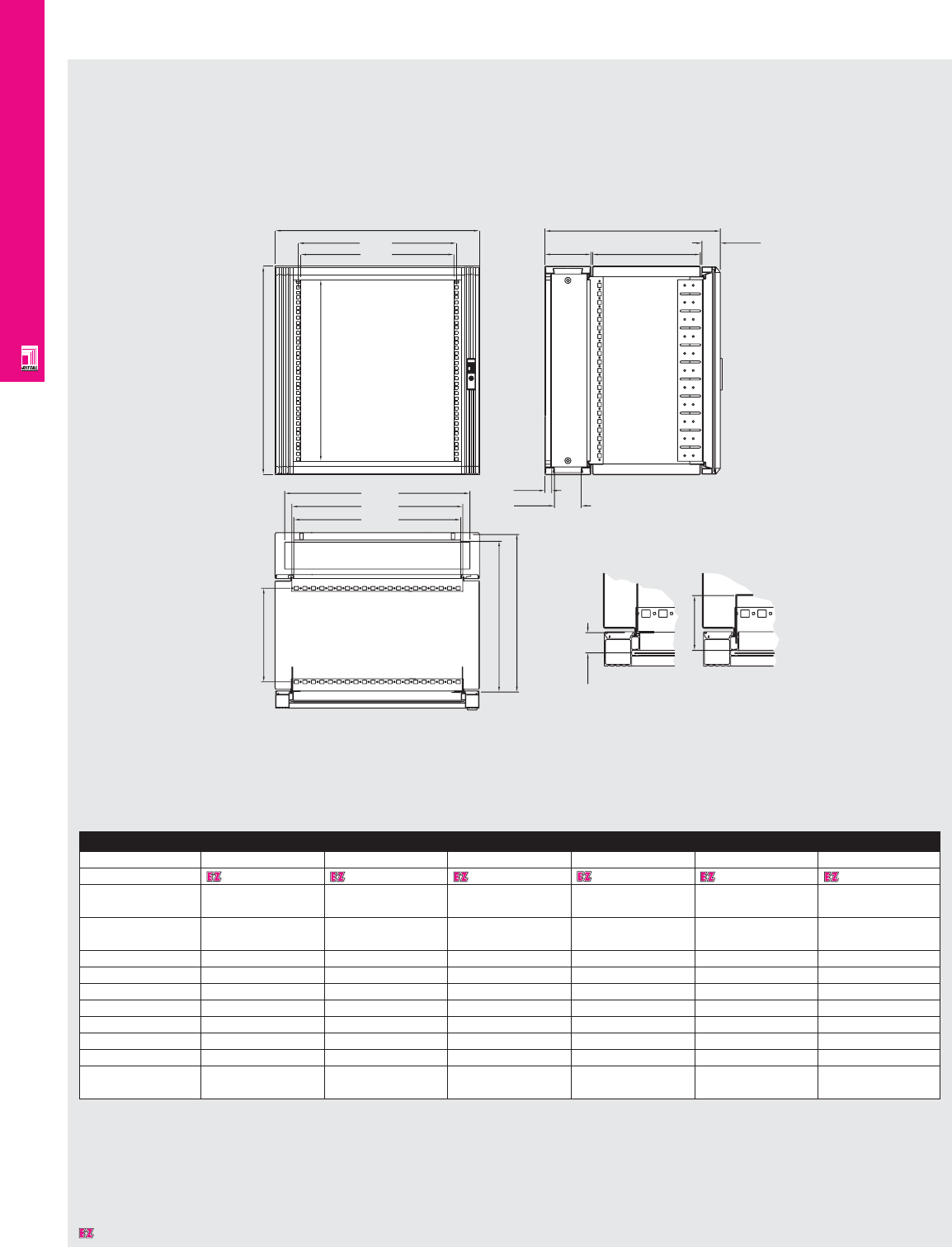
WALLMOUNT ENCLOSURES
IND 57
Technical Specifications
EL 3-Part Wallmount Enclosures
Enclosure
HU (1HU=1.75") 6HU 9HU 12HU 15HU 18HU 21HU
Part No. 7706024 7709024 7712024 7715024 7718024 7721024
Height (H) inches 13.58 18.82 24.09 29.37 34.57 39.84
mm 345 478 612 746 878 1012
Width (W) inches 23.62 23.62 23.62 23.62 23.62 23.62
mm 600 600 600 600 600 600
b (mm) 274 407 541 674 807 941
c (mm) 299 432 565 699 832 965
d (mm) 442 442 442 442 442 442
e (mm) 460 460 460 460 460 460
f (mm) 275 275 275 275 275 275
g (mm) 600 600 600 600 600 600
h (mm) 391 391 391 391 391 391
Load capacity lbs 66 99 132 165 165 165
center section kg 30 45 60 75 75 75
Dimensions in millimeters (mm) unless otherwise indicated.
W
465.0
450.0
aa
H
HU
g
Section B-B
h
135.0 54.0
max. 20
79.0
Installation of Angles
X
30-47 mm
72.5-118.5 mm
544.0
b
502.0
490.0
max. d
max. e
f
X
Designates a product in the EnclosureZone program.

Notes
IND 58
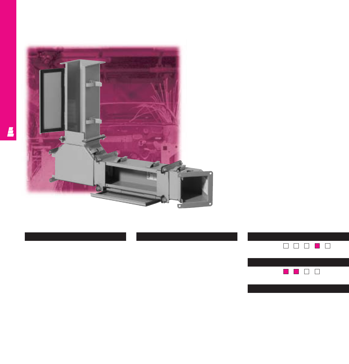
WIREWAY AND TROUGH
Lay-In Type 12 Wireway
Carbon Steel Wire Management
Wire management becomes effortless with Rittal Electromate’s
lay-in wireway products. This system allows fast installation and
easy access of wiring throughout the entire run. Wiring is
protected against dust, dirt, and water.
Technical Specifications
Material:
•Wireways/covers: 14 or 16 gauge
carbon steel
•Flange ends: 10 gauge carbon steel
Finish/color:
•Wireways/covers: polyester-urethane
powder coat over phosphatized surfaces
– ANSI 61 grey inside and outside
Pages . . . . . . . . . . . . . . . . . . . . . . . . . IND 65-68
NEMA Type
144X12 13
UL CUL CSA TÜV
Listings
Protection Ratings
Certifications/Approvals
Technical Drawings
IND 59
Configuration
•Lay-in type wireways are available in the
following sizes:
2.5" x 2.5"
4.0" x 4.0"
6.0" x 6.0"
6.0" x 12.0"
8.0" x 8.0"
•Lengths from 6" to 120"
•Continuously welded seams, finished
smooth
•Edges on all sections and fittings are
finished to prevent damage to wiring
•A complete seal is ensured through heavy
butt hinges and quick-release latches
•Oil-resistant urethane gaskets inside cover
and between flanges ensure seal when
sections and fittings are bolted together
•Hinged sealing plate allows fast and easy
access along entire run
•Complete line of fittings are available
* As indicated within the chart to the right.
**
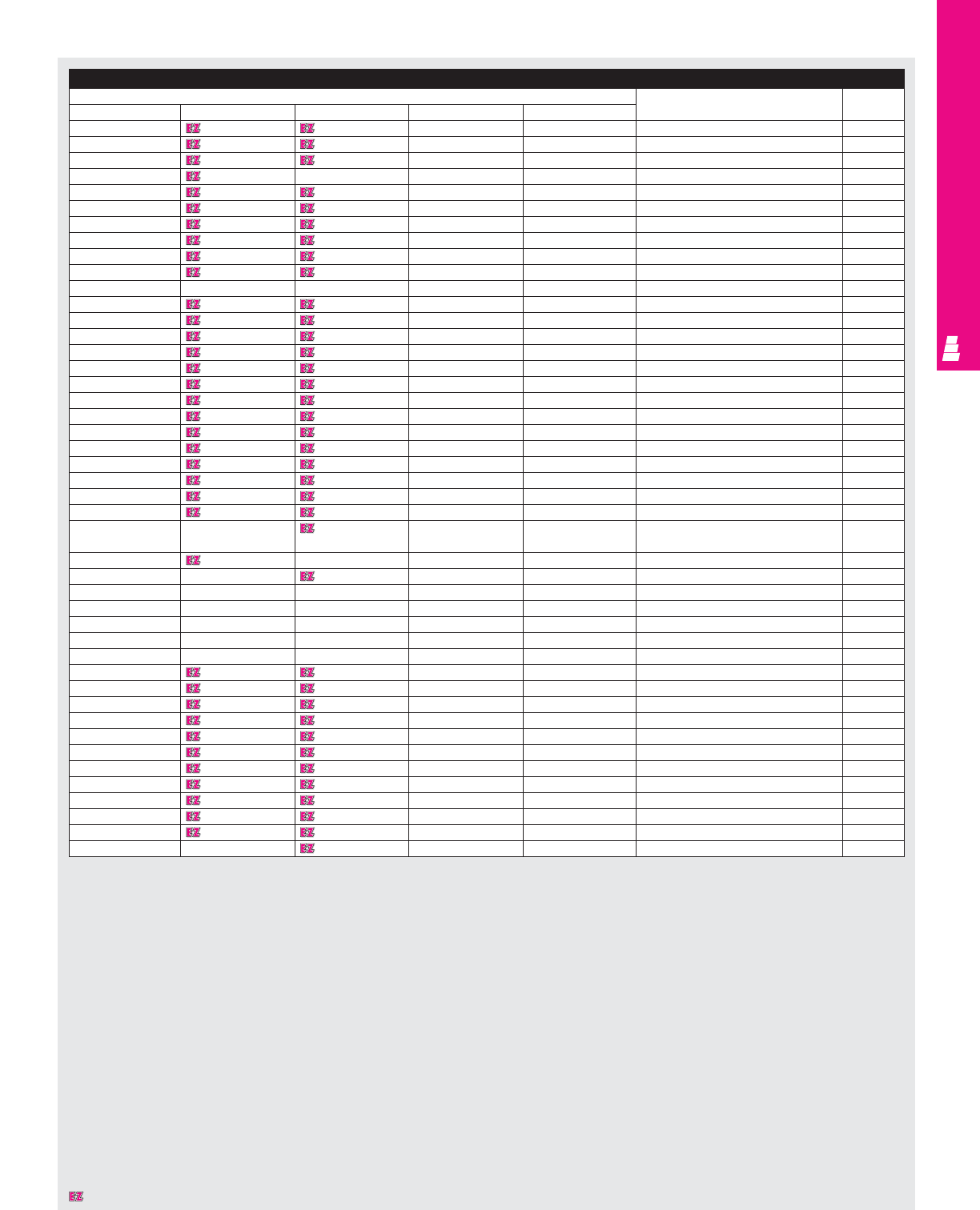
WIREWAY AND TROUGH
IND 60
Wireway
Part No. Description Touch-up
2.50x2.50 4.00x4.00 6.00x6.00 6.00x12.00 8.00x8.00 paint
E 22L06 E 44L06* E 66L06 E 612L06 E 88L06 6.00" straight section E L21
E 22L12 E 44L12* E 66L12 E 612L12 E 88L12 12.00" straight section E L21
E 22L24 E 44L24* E 66L24 E 612L24 E 88L24 24.00" straight section E L21
-E 44L30* ---30.00" straight section E L21
E 22L36 E 44L36* E 66L36 E 612L36 E 88L36 36.00" straight section E L21
E 22L48 E 44L48* E 66L48 E 612L48 E 88L48 48.00" straight section E L21
E 22L60 E 44L60* E 66L60 E 612L60 E 88L60 60.00" straight section E L21
E 22L120 E 44L120* E 66L120 E 612L120 E 88L120 120.00" straight section E L21
E 22LT4 E 44LT4 E 66LT4 -E 88LT4 Te lescopic fitting 2" to 4" E L21
E 22LT10 E 44LT10 E 66LT10 E 612LT10 -Telescopic fitting 4" to 10" E L21
----E 88LT10 Telescopic fitting 4.5" to 10.00" E L21
E 22LXL E 44LXL E 66LXL E 612LXL E 88LXL Lay-In cutoff fitting E L21
E 22LE45A E 44LE45A E 66LE45A E 612LE45A E 88LE45A 45° Elbow, top opening E L21
E 22LE45B E 44LE45B E 66LE45B -E 88LE45B 45° Elbow, inside opening E L21
E 22LE45C E 44LE45C E 66LE45C -E 88LE45C 45° Elbow, outside opening E L21
E 22LE90A E 44LE90A E 66LE90A E 612LE90A E 88LE90A 90° Elbow, top opening E L21
E 22LE90B E 44LE90B E 66LE90B E 612LE90B E 88LE90B 90° Elbow, inside opening E L21
E 22LE90C E 44LE90C E 66LE90C E 612LE90C E 88LE90C 90° Elbow, outside opening E L21
E 22LTA E 44LTA E 66LTA E 612LTA E 88LTA Tee fitting, top opening E L21
E 22LTC E 44LTC E 66LTC -E 88LTC Tee fitting, outside opening E L21
E 22LC E 44LC E 66LC E 612LC E 88LC Cross pull box E L21
E 22LP E 44LP E 66LP E 612LP E 88LP Closure plate E L21
E 22LB E 44LB E 66LB E 612LB E 88LB Box connecting kit E L21
E 22LCPK E 44LCPK E 66LCPK E 612LCPK E 88LCPK Center connecting plate kit E L21
E 22LG E 44LG E 66LG -E 88LG Collar gasket E L21
E 22LH E 44LH E 66LH E 612LH E 88LH Kit to Connect Robroy/Keystone to E L21
Rittal Electromate
-E 44LRE22 --- Reducer 4" to 2.5" E L21
--E 66LRE44 -- Reducer 6" to 4" E L21
-- -E 612LRE44 -Reducer 12" to 4" E L21
-- -E 612LRE66 -Reducer 12" to 6" E L21
-- -E 612LRE88 -Reducer 12" to 8" E L21
----E 88LRE44 Reducer 8" to 4" E L21
----E 88LRE66 Reducer 8" to 6" E L21
E 22HD E 44HD E 66HD -E 88HD Drop hanger E L21
E 22HB E 44HB E 66HB -E 88HB Bracket hanger E L21
E 22LN1 E 44LN1 E 66LN1 -E 88LN1 1.00" Nipple E L21
E 22LN2 E 44LN2 E 66LN2 -E 88LN2 2.00" Nipple E L21
E 22LN3 E 44LN3 E 66LN3 -E 88LN3 3.00" Nipple E L21
E 22LE90KT E 44LE90KT E 66LE90KT -E 88LE90KT 90° Elbow, clockwise transposition E L21
E 22LE90KOKT E 44LE90KOKT E 66LE90KOKT -E 88LE90KOKT 90° Elbow, counterclockwise transposition E L21
E 22LKT E 44LKT E 66LKT -E 88LKT Clockwise transposition section E L21
E 22LKOKT E 44LKOKT E 66LKOKT -E 88LKOKT Counterclockwise transposition section E L21
-E 44BK60 E 66BK60 -E 88BK60 60" Barrier kit E L21
E 22LF E 44LF E 66LF -E 88LF Kit to connect lay-in to feed-through E L21
E 22LH E 44LH E 66LH E 612LH E 88LH
Kit to connect to Robroy/Keystone lay-in type 12
E L21
* UL listed.
Designates a product in the EnclosureZone program.
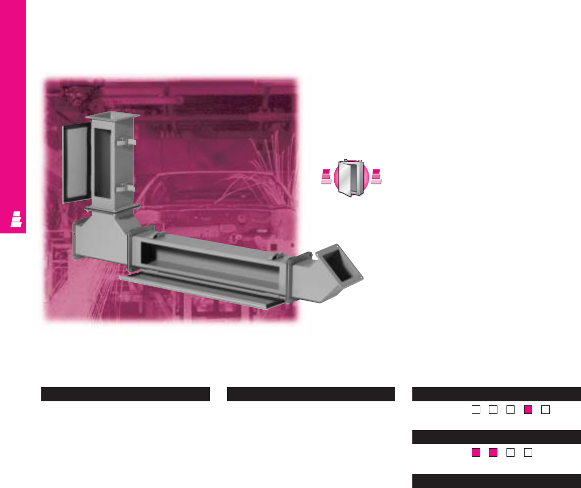
WIREWAY AND TROUGH
IND 61
Feed-Through Type 12 Wireway
Carbon Steel Wire Management
Rittal Electromate’s feed-through wireway products require
“pull through” installation of wiring. Wiring is protected against
dust, dirt, oil, and water. All straight sections feature a
hinged-top design for easy access.
Configuration
•Feed-through wireways are available in the
following sizes:
2.5" x 2.5"
4.0" x 4.0"
6.0" x 6.0"
8.0" x 8.0"
•Lengths from 12" to 120"
•Continuously welded seams, finished
smooth
•Edges on all sections and fittings are
finished to prevent damage to wiring
•A complete seal is ensured through heavy
butt hinges and quick-release latches
•Oil-resistant urethane gaskets inside cover
and between flanges ensure seal when
sections and fittings are bolted together
Technical Specifications
Material:
•Wireways/covers: 14 gauge carbon steel
•Flange ends: 10 gauge carbon steel
Finish/color:
•Wireways/covers: polyester-urethane
powder coat over phosphatized surfaces
– ANSI 61 grey inside and outside
Pages . . . . . . . . . . . . . . . . . . . . . . . . . IND 69-70
NEMA Type
144X12 13
UL CUL CSA TÜV
Listings
Protection Ratings
Certifications/Approvals
Technical Drawings
S
t
a
i
n
l
e
s
s
S
t
e
e
l
S
t
a
i
n
l
e
s
s
S
t
e
e
l
A
v
a
i
l
a
b
l
e
I
n
A
v
a
i
l
a
b
l
e
I
n
Page IND 225
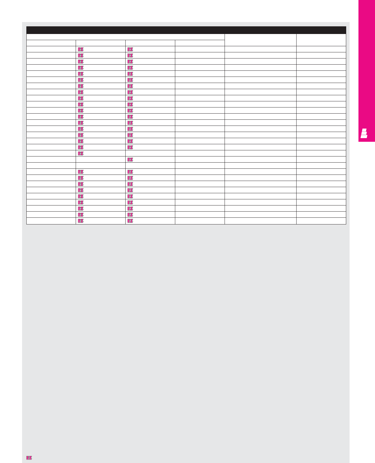
WIREWAY AND TROUGH
IND 62
Wireway
Part No. Description Touch-up paint
2.50x2.50 4.00x4.00 6.00x6.00 8.00x8.00
E 22W12 E 44W12 E 66W12 E 88W12 12.00" straight section E L21
E 22W24 E 44W24 E 66W24 E 88W24 24.00" straight section E L21
E 22W36 E 44W36 E 66W36 E 88W36 36.00" straight section E L21
E 22W48 E 44W48 E 66W48 E 88W48 48.00" straight section E L21
E 22W60 E 44W60 E 66W60 E 88W60 60.00" straight section E L21
E 22W120 E 44W120 E 66W120 E 88W120 120.00" straight section E L21
E 22WA E 44WA E 66WA E 88WA Telescopic fitting E L21
E 22WX E 44WX E 66WX E 88WX Cutoff fitting E L21
E 22WE22.5 E 44WE22.5 E 66WE22.5 E 88WE22.5 22.5° elbow E L21
E 22WE45 E 44WE45 E 66WE45 E 88WE45 45° elbow E L21
E 22WE90 E 44WE90 E 66WE90 E 88WE90 90° elbow E L21
E 22WT E 44WT E 66WT E 88WT Te e E L21
E 22WC E 44WC E 66WC E 88WC Cross pull box E L21
E 22WP E 44WP E 66WP E 88WP Closure plate E L21
E 22WB E 44WB E 66WB E 88WB Box connecting kit E L21
E 22WG E 44WG E 66WG E 88WG Collar gasket E L21
E 22WTF E 44WTF E 66WTF E 88WTF Flange E L21
-E 44WR22 --Reducer 4" to 2.5" E L21
--E 66WR44 -Reducer 6" to 4" E L21
---E 88WR66 Reducer 8" to 6" E L21
E 22WSC E 44WSC E 66WSC E 88WSC Swivel nipple E L21
E 22WN1 E 44WN1 E 66WN1 E 88WN1 1.00" nipple E L21
E 22WN2 E 44WN2 E 66WN2 E 88WN2 2.00" nipple E L21
E 22WN3 E 44WN3 E 66WN3 E 88WN3 3.00" nipple E L21
E 22WN6 E 44WN6 E 66WN6 E 88WN6 6.00" nipple E L21
E 22HB E 44HB E 66HB E 88HB Bracket hanger E L21
E 22HD E 44HD E 66HD E 88HD Drop hanger E L21
-E 44BK60 E 66BK60 E 88BK60 60" Barrier kit E L21
E 22LF E 44LF E 66LF E 88LF Kit to connect feed-through to lay-in E L21
Designates a product in the EnclosureZone program.
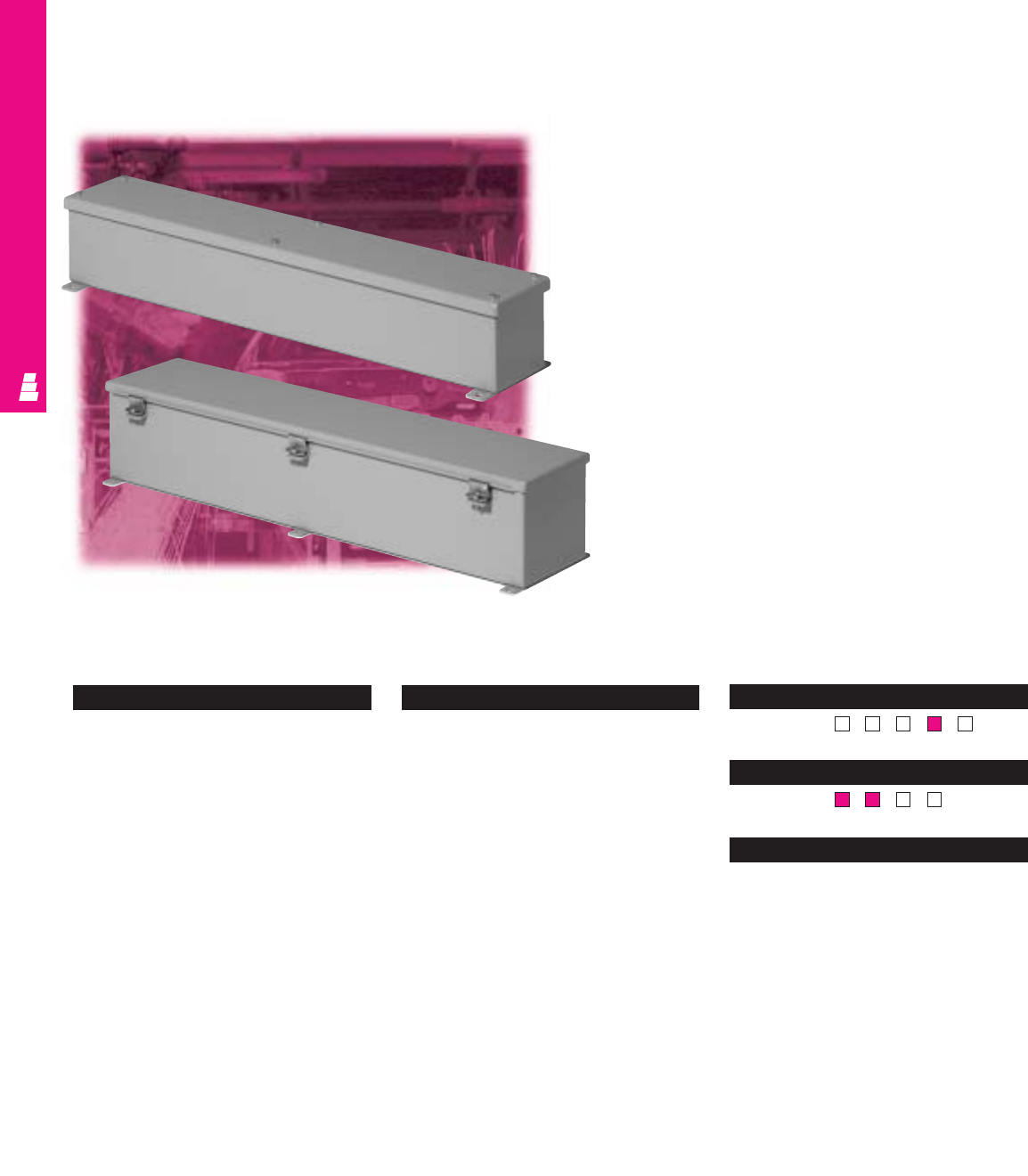
WIREWAY AND TROUGH
IND 63
Hinge/Screw Cover Wiring Trough
Carbon Steel Type 12 Wire Management
Rittal Electromate’s wireway trough offers a simple solution to
protect wiring against dust, dirt, oil, and water.
Configuration
•Hinge cover wireways are available in the
following sizes:
4.0" x 4.0"
6.0" x 6.0"
8.0" x 8.0"
12.0" x 12.0"
•Screw cover wireways are available in
two sizes:
2.5" x 2.5"
4.0" x 4.0"
•Lengths from 12" to 60" for hinge cover
•Lengths from 12" to 30" for screw cover
•Continuously welded seams, finished
smooth
•Edges on all sections and fittings are
finished to prevent damage to wiring
•Captive cover screws ensure proper seal
on screw cover versions
•A complete seal is ensured through
continuous hinges and screw clamps
•Oil-resistant urethane gaskets
•External mounting brackets
Technical Specifications
Material:
•Wireways/covers: 14 gauge carbon steel
Finish/color:
•Wireways/covers: polyester-urethane
powder coat over phosphatized surfaces
– ANSI 61 grey inside and outside
Pages . . . . . . . . . . . . . . . . . . . . . . . . . . IND 71-72
NEMA Type
144X12 13
UL CUL CSA TÜV
Listings
Protection Ratings
Certifications/Approvals
Technical Drawings
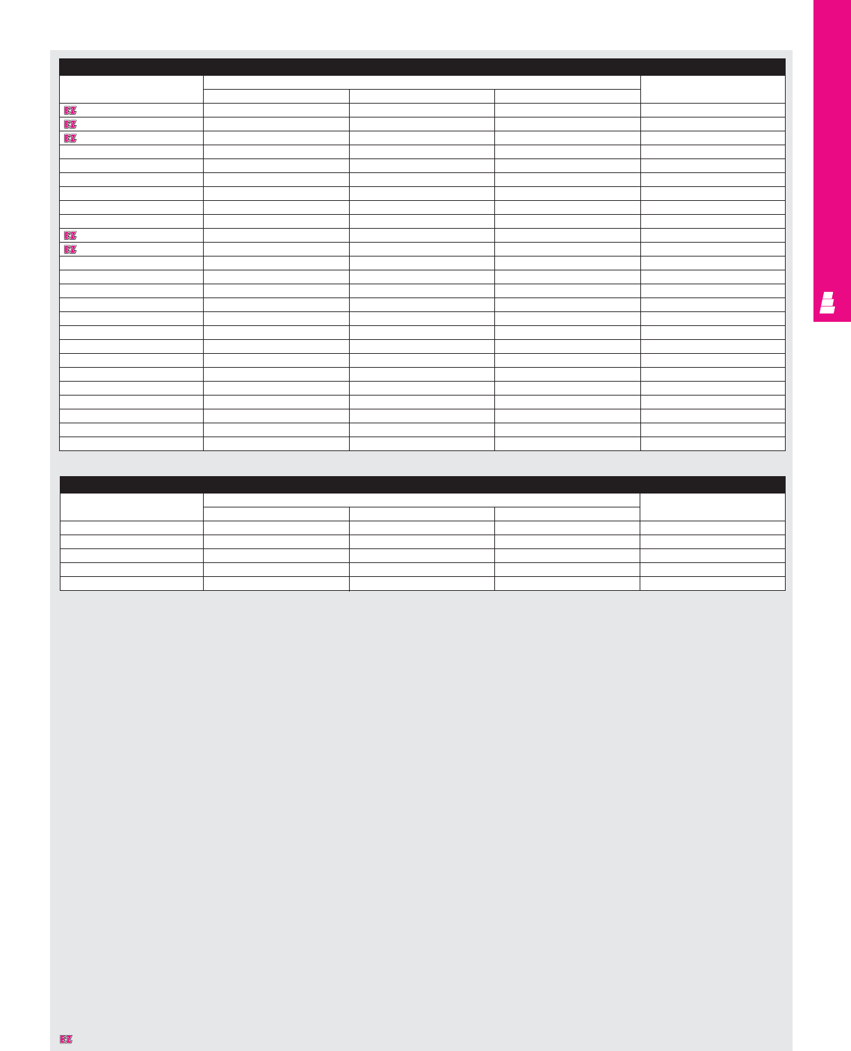
WIREWAY AND TROUGH
IND 64
Hinge Cover Wiring Trough
Part No. Outside dimensions (inches) Touch-up paint
HW L
E 4412HC 4.00 4.00 12.00 E L21
E 4418HC 4.00 4.00 18.00 E L21
E 4424HC 4.00 4.00 24.00 E L21
E 4430HC 4.00 4.00 30.00 E L21
E 4436HC 4.00 4.00 36.00 E L21
E 4448HC 4.00 4.00 48.00 E L21
E 4460HC 4.00 4.00 60.00 E L21
E 4472HC 4.00 4.00 72.00 E L21
E 6612HC 6.00 6.00 12.00 E L21
E 6618HC 6.00 6.00 18.00 E L21
E 6624HC 6.00 6.00 24.00 E L21
E 6630HC 6.00 6.00 30.00 E L21
E 6636HC 6.00 6.00 36.00 E L21
E 6648HC 6.00 6.00 48.00 E L21
E 6660HC 6.00 6.00 60.00 E L21
E 6672HC 6.00 6.00 72.00 E L21
E 8812HC 8.00 8.00 12.00 E L21
E 8824HC 8.00 8.00 24.00 E L21
E 8836HC 8.00 8.00 36.00 E L21
E 8848HC 8.00 8.00 48.00 E L21
E 8860HC 8.00 8.00 60.00 E L21
E 121224HC 12.00 12.00 24.00 E L21
E 121236HC 12.00 12.00 36.00 E L21
E 121248HC 12.00 12.00 48.00 E L21
E 121260HC 12.00 12.00 60.00 E L21
Screw Cover Wiring Trough
Part No. Outside dimensions (inches) Touch-up paint
HWL
E 2212SC 2.50 2.50 12.00 E L21
E 4412SC 4.00 4.00 12.00 E L21
E 4418SC 4.00 4.00 18.00 E L21
E 4424SC 4.00 4.00 24.00 E L21
E 4430SC 4.00 4.00 30.00 E L21
Designates a product in the EnclosureZone program.
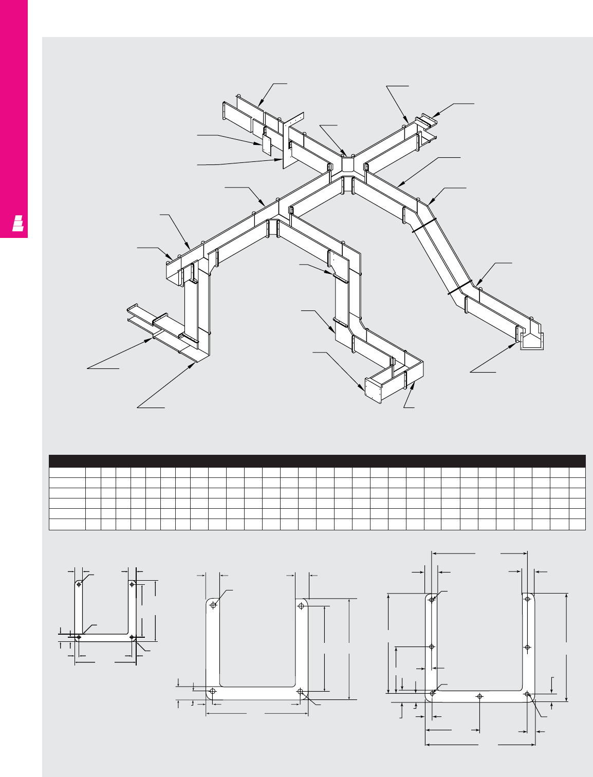
WIREWAY AND TROUGH
IND 65
Technical Specifications
Lay-In Type 12 Wireway
6" X 6"
7.62
.38
.81
6.86
.81
.38
2x .50
3.81
7.62
2x .50
4x R39
7.62
6xØ28
2x 3.31
.81 2x .50
2x .50
E_ _LXL
Cutoff fitting
E_ _LC
Cross pull box
E_ _LKDKT
90° Transition
section E_ _LN3
Nipple
E_ _L_ _
Straight length
E_ _LE45C
45° Elbow
outside opening
E_ _LE45B
45° Elbow
inside opening
E_ _LE45A
45° Elbow
top opening
E_ _LE90A
90° Elbow
top opening
E_ _LP
Closure plate
E_ _LE90B
90° Elbow
inside opening
E_ _LE90C
90° Elbow
outside opening
E_ _LE90KDKT
90° Elbow
transition section
E_ _ RE_ _
Reducing
bushing
E_ _LT10
Telescope fitting
E_ _LTC
Tee outside/side opening
E_ _LTA
Tee top opening
E_ _HD
Drop hanger
E_ _HB
Bracket hanger
Wireway
A x B
CCCCCCC C E F G H I J K M N O P Q R S T U V W X Y Z
2.5 x 2.5 61224-36 48 60 120 2.28 2.28 - 5.25 6.00 4.54 5.79 3.50 2.50 0.50 4.50 2.25 3.75 10.50 5.87 2.28 4.00 5.25 3.00 8.00 4.00
4 x 4 6122430364860120 3.77 3.77 3.82 6.75 6.00 5.29 7.29 4.75 3.00 1.00 6.00 2.25 4.75 11.50 5.87 3.77 4.75 6.75 3.30 9.50 4.75
6 x 6 61224-36 48 60 120 5.77 5.77 5.82 8.75 6.00 6.29 9.29 7.00 5.00 1.00 7.38 2.50 7.00 18.50 9.62 5.77 5.75 8.75 3.72 11.50 5.75
6 x 12 61224-36 48 60 120 5.84 11.77 - 14.75 - 6.29 9.29 - - - - - - - - - 5.75 8.75 5.00 17.50 8.75
8 x 8 61224-36 48 60 120 7.77 7.77 6.82 10.75 6.00 7.29 11.29 9.00 7.00 1.00 9.00 2.50 9.00 20.50 9.62 7.77 6.75 10.75 4.12 13.50 6.75
4" X 4"
2.5" X 2.5"
.69
.69
4xØ28
2x .38 2x .38 4x R39
5.38
2x .38
.69
4.62 5.38
2x R12
3.88
2x .38 2x .38
2x .38
.69
.69 .69
3.38
2x 3.12
4x R39
4xØ28
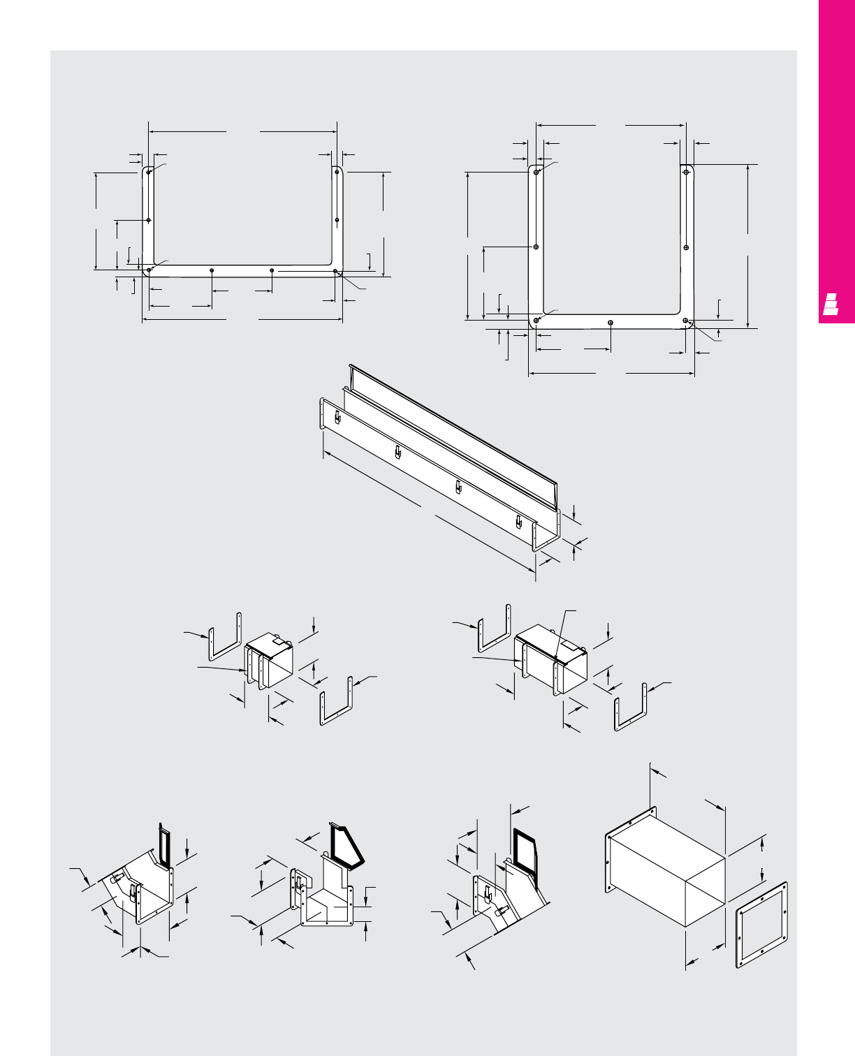
WIREWAY AND TROUGH
Technical Specifications
Lay-In Type 12 Wireway
IND 66
Straight Length
C
B
A
Telescope Fitting Telescope Fitting
Cut-Off Fitting
45° Elbow
Inside Opening 45° Elbow
Top Opening 45° Elbow
Outside Opening
Gasket
Adjustable
collar
Welded collar
Gasket
2” to 4” Adjustment 7.00
U
Gasket
Adjustable
collar
Welded collar
Gasket
4” to 10” Adjustment
13.00
E
F
U
10” Min.
18” Max.
A
B
A
X
B
X
X
A
B
X
X
A
B
X
8" X 8"
2x .50
8.62
.38
.81
.81
.81
8.86
4x R39
.38
9.62
2x .50
2x .50
4.31
9.62
2x .12
2x 4.31
6xØ28
6" X 12"
2x .50
2x .50 2x .50
13.62
12.86
4.12
4.25
.81
2x .38
.81
6.62
.38
7.62
2x 3.31
4x R39
.81
8xØ28
2x .12
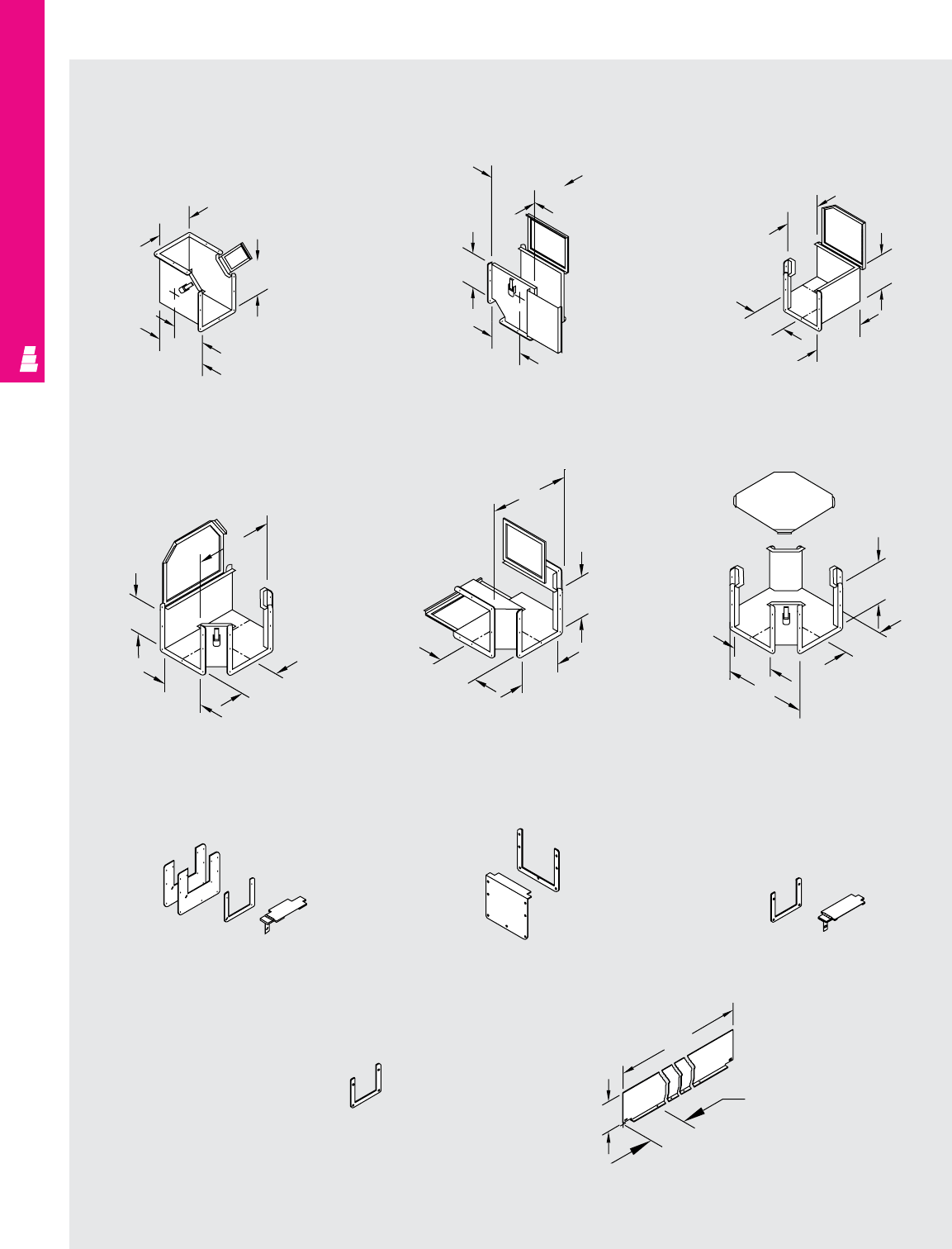
WIREWAY AND TROUGH
IND 67
Technical Specifications
Lay-In Type 12 Wireway
90° Elbow Inside Opening 90° Elbow Outside Opening 90° Elbow Top Opening
Tee Top Opening
Tee Outside &
Side Opening
A
B
J
K
X
WA
B
V
A
B
H
Z
A
Z
B
Y
B
AZ
Y
Cross Pull Box
B
Z
A
Y
Reducing Bushing Closure Kit Center Connecting Kit
60" Barrier Kit
Collar Gasket
60
6.00
G
Note: mounting holes
on 16” centers
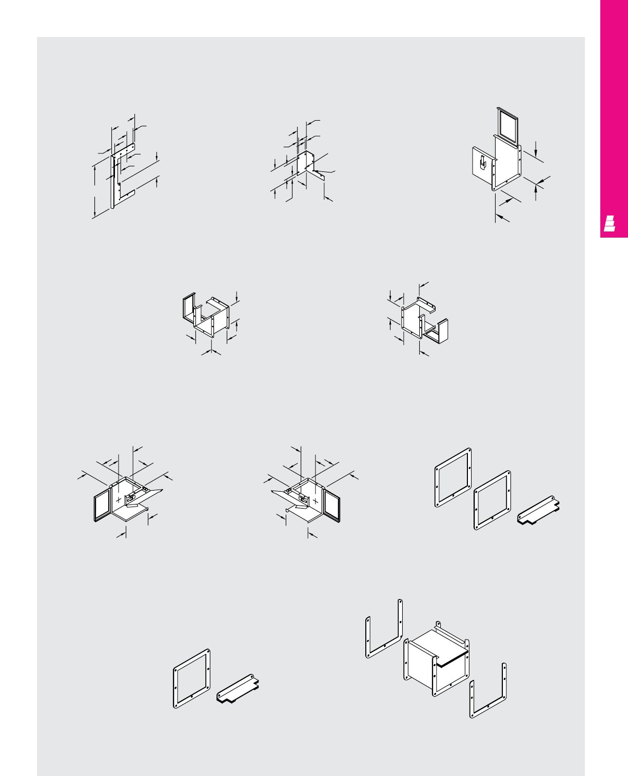
WIREWAY AND TROUGH
IND 68
Technical Specifications
Lay-In Type 12 Wireway
3.63
Drop Hanger Bracket Hanger Nipple
B
A
0.50
AB
AC
0.50
220/440 - .34 DIA.
660/880 - .41 DIA.
220/440 - .28 DIA.
660/880 - .34 DIA.
P
1.25
R
S
Q
Q
Q
T
90° Transition Section
Counter Clockwise 90° Transition Section
Clockwise
90° Elbow Counter Clockwise
Transition Section 90° Elbow Clockwise
Transition Section
Kit To Connect Lay-In
To Feed-Through
Box Connecting Kit
Rittal Electromate
To Robroy/Keystone Adaptor
AA
B
A
B
A
AA
A
H
B
Z
B
Z
A
H
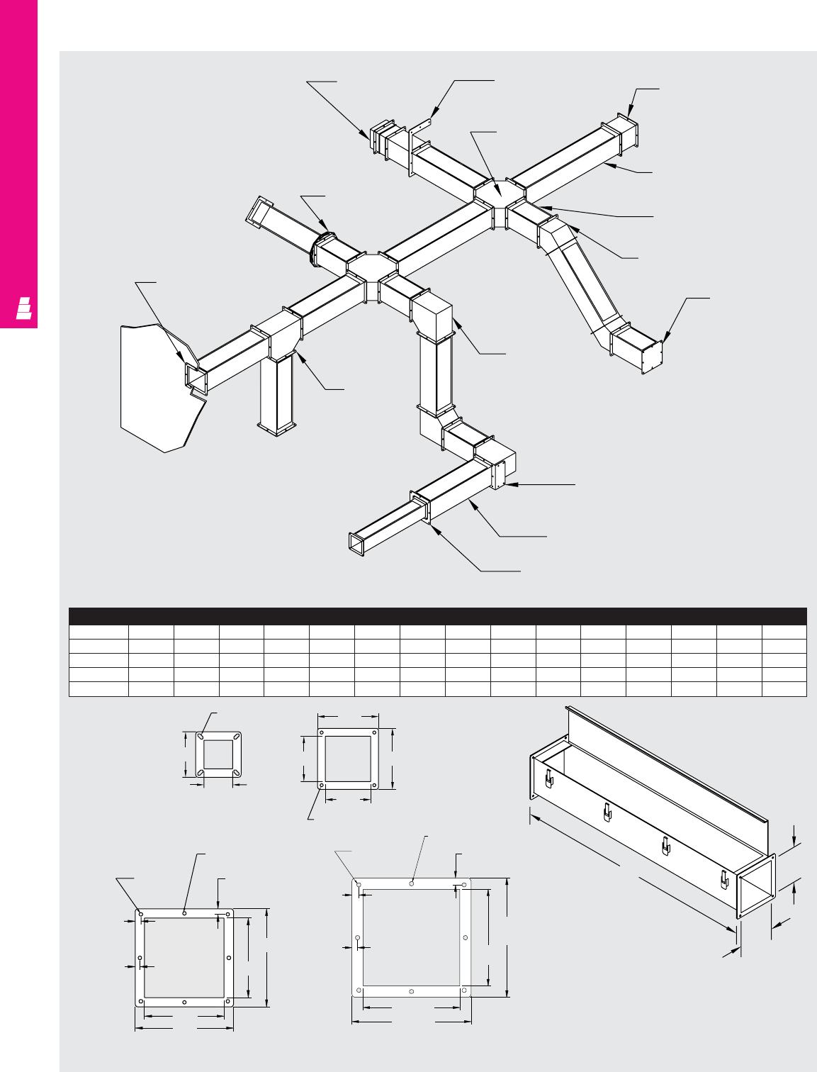
WIREWAY AND TROUGH
IND 69
E_ _WA
Telescope fitting
E_ _HD
Drop hanger E_ _HD
6" Long nipple
E_ _WCSS
Cross
E_ _W36
36" Straight section
E_ _W12
12" Straight section
E_ _WE45
45" elbow
E_ _WP
End plate
E_ _WE90
90° Elbow
E_ _HB
Bracket hanger
E_ _WSC
Swivel nipple
E_ _WB
Box connector
E_ _WT
Tee and
pull box
E_ _W24
24" Straight section
E_ _WR_ _
Reducing bushing
Wireway
A x B CCC CCCE FG I JKLMN
2.5 x 2.5 12 24 36 48 60 120 2.22 6.10 4.00 - 3.00 2.75 5.25 4.00 8.00
4 x 4 12 24 36 48 60 120 3.68 7.54 5.38 2.50 3.30 2.90 6.25 4.75 9.50
6 x 6 12 24 36 48 60 120 5.68 10.36 7.62 4.00 3.72 3.10 8.75 5.75 11.50
8 x 8 12 24 36 48 60 120 7.68 13.20 9.62 6.00 4.12 3.30 10.75 6.75 13.50
NEMA 12 Feed-Through
Straight Section
2.5" X 2.5"
B
A
C
.28 x .56
4 Places
4.00
2.50
5.38
4.00
4.00 5.38
.28 4 Places 4" X 4"
.28 Dia.
4 Places
.28 Dia.
4 Places
.50
4 Places
.50
4 Places
.41
4 Places
7.63
6.00
6.00
7.63
6" X 6"
Technical Specifications
Feed-Through Type 12 Wireway
.50
4 places
.41
4 places
.28 dia.
4 places
.34 dia. 4 places
.50
4 places
9.63
8.00
8.00
9.63
8" X 8"
6.00
7.63
6.00
7.63
.41
4 places
.50
4 places
.50
4 places
.28 dia.
4 places
.28 dia.
4 places
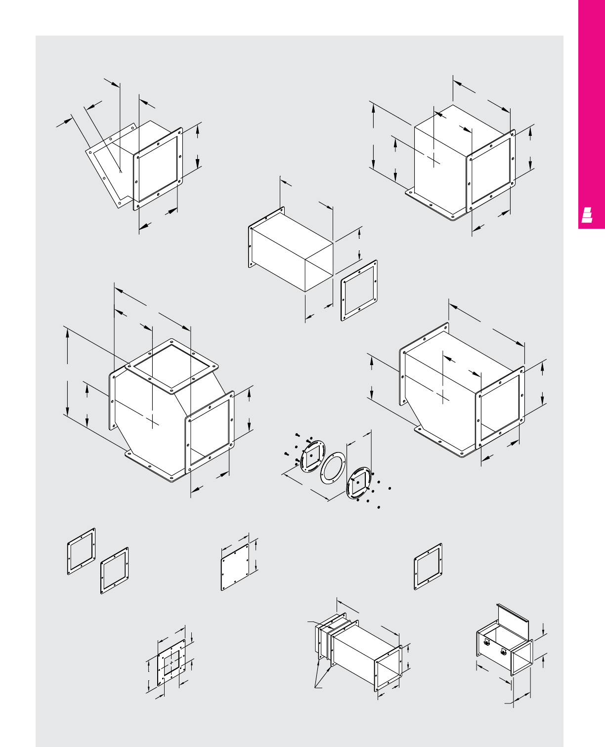
WIREWAY AND TROUGH
IND 70
Technical Specifications
Feed-Through Type 12 Wireway
45° Elbow 90° Elbow
Tee
Cross
J
B
A
J
A
B
L
M
M
L
M
M
A
B
N
B
A
M
N
N
M
Box Connector Closure Plate
Telescope Fitting
(1.50 to 13.50)
Reducing Bushing
Gasket Flange
G
G
H
H
Gasket
Flange
15.50
E
E
G
G
Cut-Off Fitting
Swivel Nipple
Nipple
B
C
A
F
.40
12.00
B
B
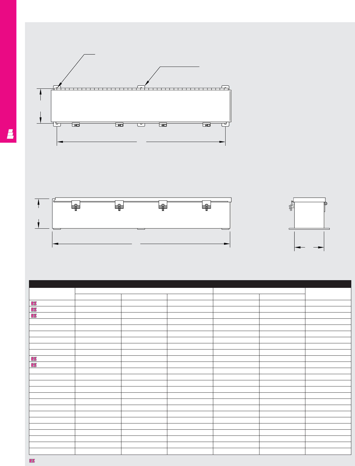
WIREWAY AND TROUGH
IND 71
Technical Specifications
Hinge Cover Wiring Trough
Wiring Trough
Part No. Outside dimensions (inches) Mounting centers No. of
HW LHWscrew clamps
E 4412HC 4.00 4.00 12.00 4.68 10.75 2
E 4418HC 4.00 4.00 18.00 4.68 16.75 2
E 4424HC 4.00 4.00 24.00 4.68 22.75 2
E 4430HC 4.00 4.00 30.00 4.68 28.75 3
E 4436HC 4.00 4.00 36.00 4.68 34.75 3
E 4448HC 4.00 4.00 48.00 4.68 46.75 3
E 4460HC 4.00 4.00 60.00 4.68 58.75 3
E 4472HC 4.00 4.00 72.00 4.68 70.75 3
E 6612HC 6.00 6.00 12.00 6.68 10.75 2
E 6618HC 6.00 6.00 18.00 6.68 16.75 2
E 6624HC 6.00 6.00 24.00 6.68 22.75 2
E 6630HC 6.00 6.00 30.00 6.68 28.75 3
E 6636HC 6.00 6.00 36.00 6.68 34.75 3
E 6648HC 6.00 6.00 48.00 6.68 46.75 3
E 6660HC 6.00 6.00 60.00 6.68 58.75 3
E 6672HC 6.00 6.00 72.00 6.68 70.75 3
E 8812HC 8.00 8.00 12.00 8.68 10.75 2
E 8824HC 8.00 8.00 24.00 8.68 22.75 2
E 8836HC 8.00 8.00 36.00 8.68 34.75 3
E 8848HC 8.00 8.00 48.00 8.68 46.75 3
E 8860HC 8.00 8.00 60.00 8.68 58.75 3
E 121224HC 12.00 12.00 24.00 12.68 22.75 2
E 121236HC 12.00 12.00 36.00 12.68 34.75 3
E 121248HC 12.00 12.00 48.00 12.68 46.75 3
E 121260HC 12.00 12.00 60.00 12.68 58.75 3
H
B
B
CA
Omit center mounting
foot if C <= 30.00
Mounting hole .281 DIA.
Top View
Right Side View End View
Designates a product in the EnclosureZone program.
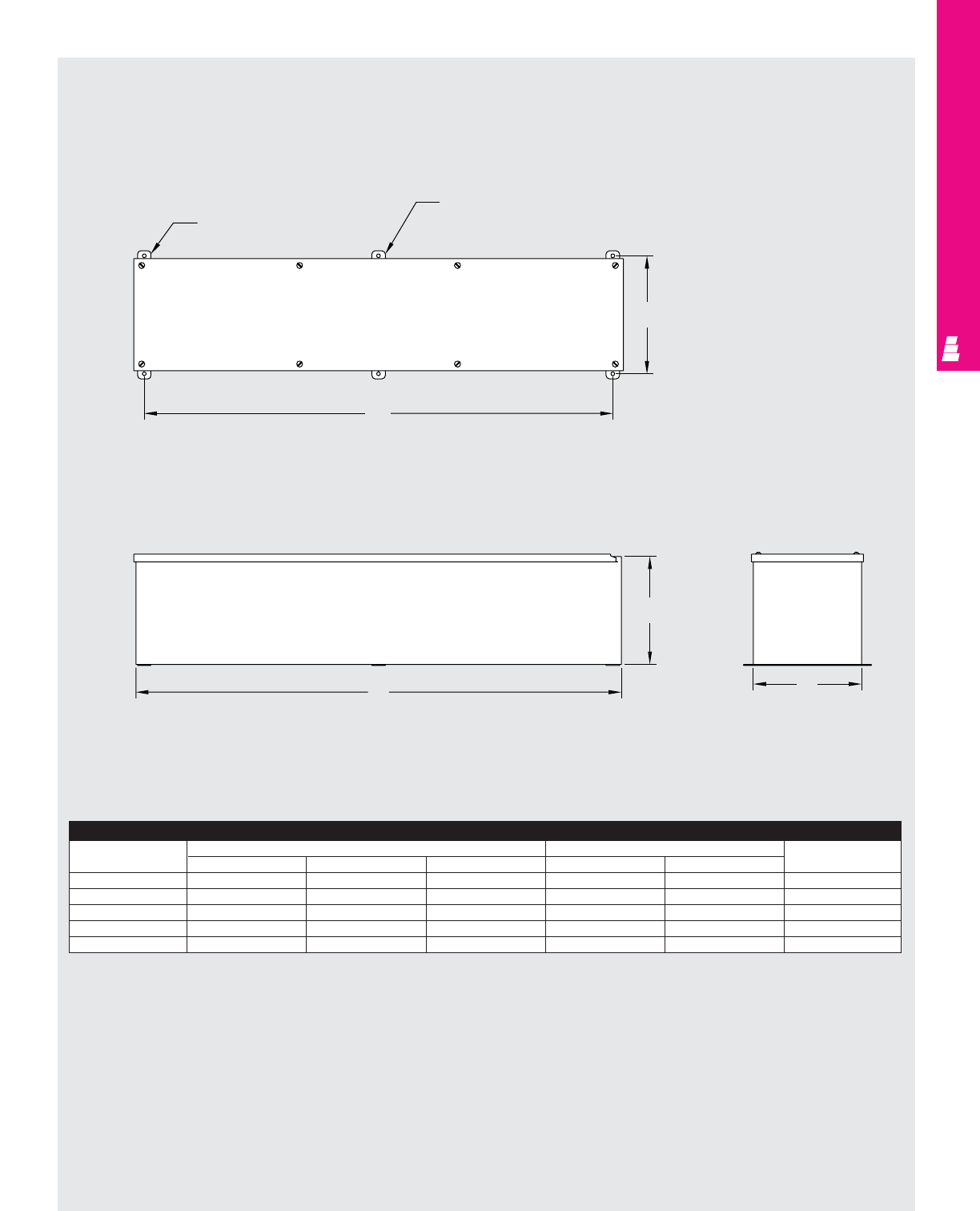
WIREWAY AND TROUGH
IND 72
Technical Specifications
Screw Cover Wiring Trough
Top View
Right Side View End View
W
Mounting hole .28 DIA.
Omit center mounting
foot if C <= 30.00
H
C
B
A
Wiring Trough
Part No. Outside dimensions (inches) Mounting centers No. of
HW LHWscrew clamps
E 2212SC 2.50 2.50 12.00 3.25 10.75 4
E 4412SC 4.00 4.00 12.00 4.75 10.75 4
E 4418SC 4.00 4.00 18.00 4.75 16.75 6
E 4424SC 4.00 4.00 24.00 4.75 22.75 6
E 4430SC 4.00 4.00 30.00 4.75 28.75 8
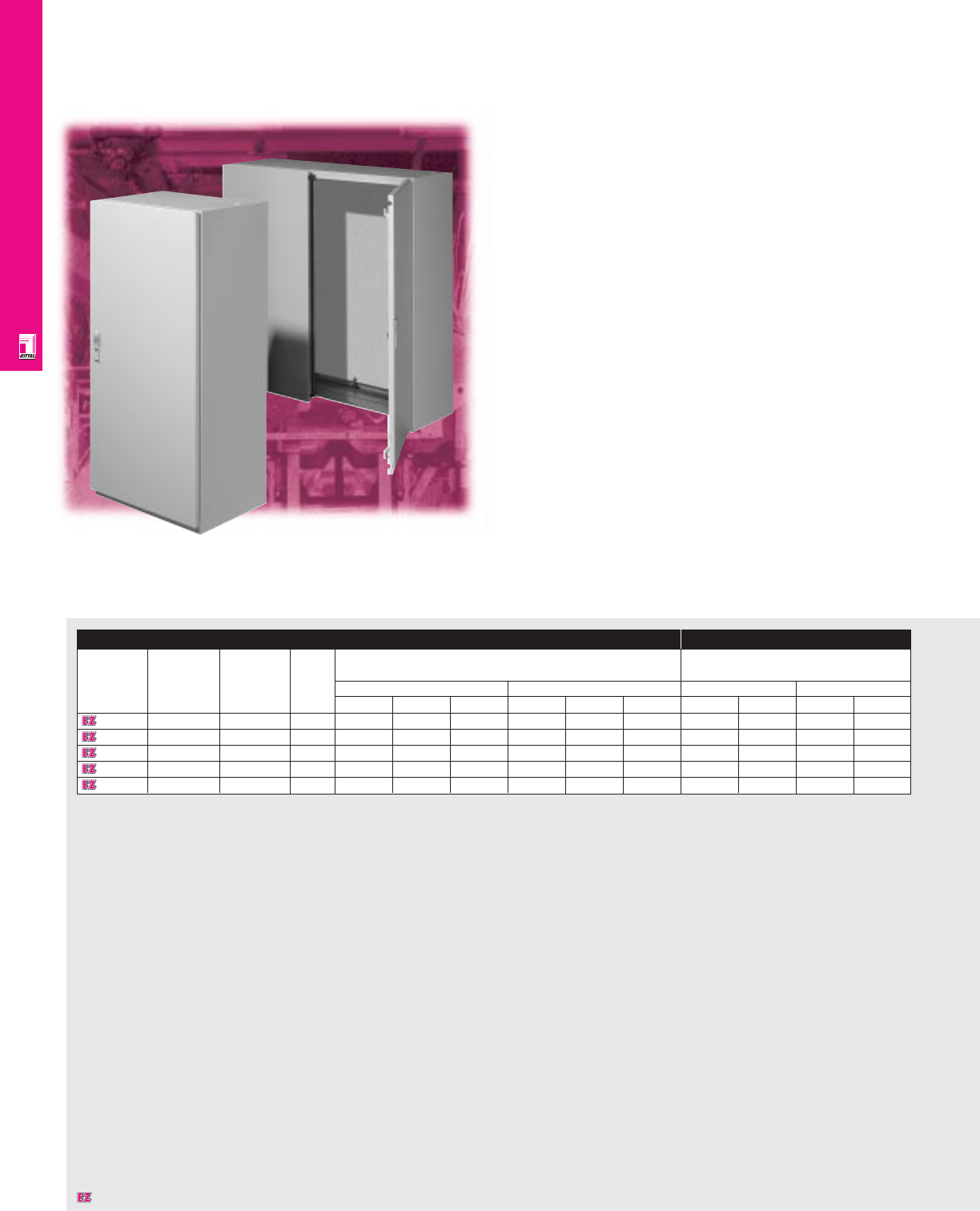
FREESTANDING ENCLOSURES
IND 73
AK Freestanding Enclosures
AK Series NEMA Rated Freestanding Enclosures
Rittal's AK enclosures provide mid-size solutions for industrial
applications. Rittal’s AK Series features sturdy, unibody
construction with a knife-edge perimeter to provide protection
against dust and moisture.
Enclosure Mounting Panel
Part No. Approximate NEMA Number Exact outside dimensions Dimensions
outside rating of doors
dimensions inches mm inches mm
H"xW"xD" H W D H W D H W H W
1646600 48x24x16 1, 12 1 47.24 23.62 15.75 1200 600 400 44.29 20.24 1125 514
1648600 48x32x16 1, 12 1 47.24 31.50 15.75 1200 800 400 44.29 28.11 1125 714
1650600 48x39x16 1, 12 1 47.24 39.37 15.75 1200 1000 400 44.29 35.39 1125 914
1652600 48x47x16 1, 12 2 47.24 47.24 15.75 1200 1200 400 44.29 43.86 1125 1114
1647600 56x39x16 1, 12 1 55.12 39.37 15.75 1400 1000 400 52.17 35.39 1325 914
Designates a product in the EnclosureZone program.

FREESTANDING ENCLOSURES
IND 74
Configuration
• NEMA 1 and 12, IP55 or 56
•Foamed-on gaskets
• Maximum strength and stability through a
welded unibody construction
•Stiffener/mounting frame on door
• Off-the-shelf availability
• E-coat primer and powder paint provide
superior corrosion resistance
•Knife-edge design protects against
liquid entry
•Integrated grounding provisions on
all surfaces
Technical Specifications
Material:
•Body: 16 ga/1.5 mm sheet steel
•Door(s): 14 ga/2 mm
•Mounting panel: 11 ga/3 mm, hot-dipped
galvanized zinc
Finish/color:
•Body, door(s): E-coat primed, powder
painted, RAL 7032 pebble grey
•Mounting panel: Type M
Accessories
Part No. Base Print pocket Door switch Handle
4" high 8" high Ergoform-S Pushbutton insert
1646600 2911200 2912200 2514000 4127000 2450000 2468000
1648600 2901200 2902200 2514000 4127000 2450000 2468000
1650600 2891200 2892200 2514000 4127000 2450000 2468000
1652600 2921200 2922200 2514000 4127000 2450000 2468000
1647600 2891200 2892200 2514000 4127000 2450000 2468000
Page . . . . . . . . . . . . . . . . . . . . . . . . . . . . . IND 85
NEMA Type 144X1213
UL CUL CSA TÜV
Listings
Protection Ratings
Certifications/Approvals
Technical Drawings
Designates a product in the EnclosureZone program.
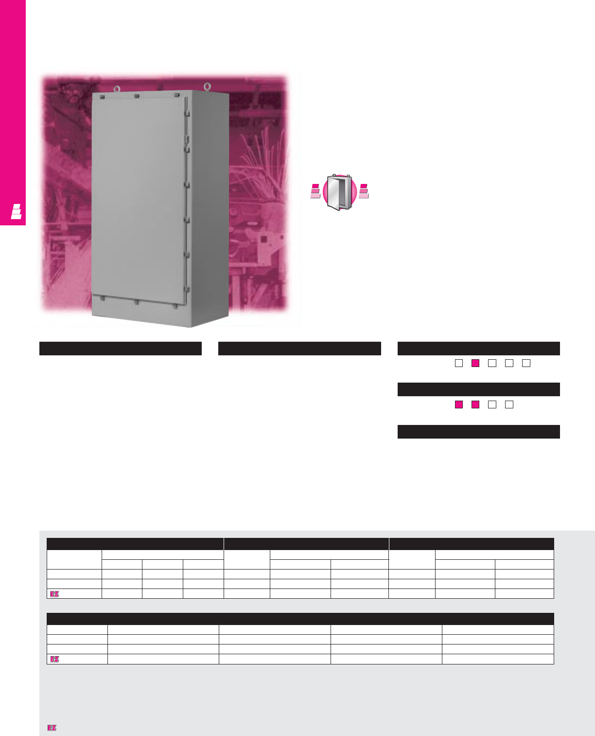
FREESTANDING ENCLOSURES
Configuration
•Continuously welded seams, finished
smooth
•Oil resistant neoprene strip gasket
•Continuous stainless steel hinge with
removable pin
•Hasp and staple for padlock
•Stainless steel captive clamps
•Removable heavy duty lifting eyes mounted
to the top
•C-channels are welded to interior sides for
optional mounting
•Print pocket included
Technical Specifications
Material:
•Enclosure/door: 12 gauge carbon steel
Finish/color:
•Enclosure/door: polyester-urethane powder
coat over phosphatized surfaces – ANSI 61
grey inside and outside
•Optional mounting panels: painted white
IND 75
One Door Freestanding Enclosures
NEMA Rated Carbon Steel Enclosures
Rittal Electromate NEMA 4 freestanding enclosures accept
standard as well as rackmount electrical and electronic
components. These enclosures are intended for indoor or
outdoor applications to protect installed equipment against
splashing water, seepage of water, falling or hose directed
water, and external condensation.
Enclosure Full Mounting Panel Half Mounting Panel
Part No. Outside dimensions (inches) Part No. Panel size Part No. Panel size
HW D H W H W
E 72H2518FS 72.00 25.00 18.00 E 72P24F1 60.00 20.00 E 72P24F2 30.88 20.00
E 72H3124FS 72.00 31.00 24.00 E 72P30F1 60.00 26.00 E 72P30F2 30.88 26.00
E 72H3724FS 72.00 37.00 24.00 E 72P36F1 60.00 32.00 E 72P36F2 30.88 32.00
Page . . . . . . . . . . . . . . . . . . . . . . . . . . . . . IND 86
NEMA Type 144X1213
UL CUL CSA TÜV
Listings
Protection Ratings
Certifications/Approvals
Technical Drawings
Accessories
Part No. Light kit Door stop kit Window kit Touch-up paint
E 72H2518FS See ACC 29 E DSTOPK E PWK2315NF E L21
E 72H3124FS See ACC 29 E DSTOPK E PWK3523NF E L21
E 72H3724FS See ACC 29 E DSTOPK E PWK3523NF E L21
S
t
a
i
n
l
e
s
s
S
t
e
e
l
S
t
a
i
n
l
e
s
s
S
t
e
e
l
A
v
a
i
l
a
b
l
e
I
n
A
v
a
i
l
a
b
l
e
I
n
Page IND 226
Designates a product in the EnclosureZone program.
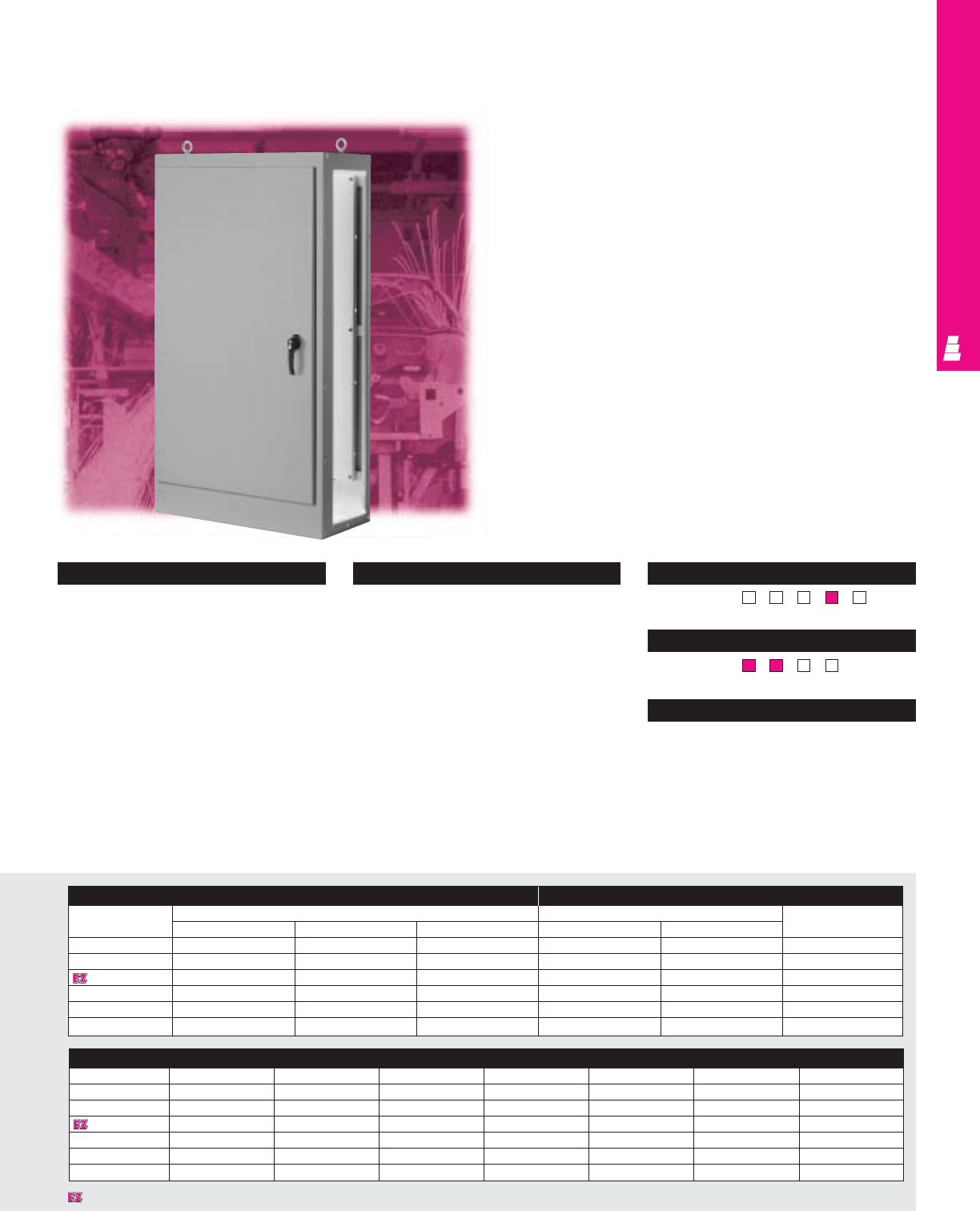
FREESTANDING ENCLOSURES
One Door Modular Cabinets
Freestanding Carbon Steel Modular Enclosures
Rittal Electromate modular NEMA 12 rated enclosures can be
interconnected together to form a multi-door system for large
control center applications. These enclosures are intended for
indoor use to protect installed equipment against dust, dirt, oil
and water.
Enclosure Mounting Panel
Part No. Outside dimensions (inches) Panel size Usable depth
HWD HW
E MOD723918 72.00 38.75 18.00 60.00 33.75 17.00
E MOD727718 72.00 77.00 18.00 60.00 72.00 17.00
E MOD843918 84.00 38.75 18.00 72.00 33.75 17.00
E MOD843924 84.00 38.75 24.00 72.00 33.75 23.00
E MOD847718 84.00 77.00 18.00 72.00 72.00 17.00
E MOD847724 84.00 77.00 24.00 72.00 72.00 23.00
Configuration
•Continuously welded seams, finished
smooth
•Body stiffener for added support
•Oil resistant neoprene strip gasket
•Continuous steel hinge with removable pin
•3-point latch with padlockable black
textured diecast zinc handle
•Removable heavy duty lifting eyes
mounted to the top
•Removable 10 gauge carbon steel
mounting panel included
•Print pocket included
•Both sides of enclosure are open with door
hinged on left side
•Interlock is furnished for use with modular
disconnect enclosures
Technical Specifications
Material:
•Enclosure/door: 10 gauge carbon steel
Finish/color:
•Enclosure/door: polyester-urethane powder
coat over phosphatized surfaces - ANSI 61
grey outside and white inside
•Mounting panel: painted white
Page . . . . . . . . . . . . . . . . . . . . . . . . . . . . . IND 86
NEMA Type 144X1213
UL CUL CSA TÜV
Listings
Protection Ratings
Certifications/Approvals
Technical Drawings
Accessories
Part No. End plates Flat plates Gasket kits Light kits Handle accessories Window kit Touch-up paint
E MOD723918 E MOD72EPT E MOD72FTPT E MOD72GK See ACC 29 See ACC 20 E PWK3523NF E L21
E MOD727718 E MOD72EPT E MOD72FTPT E MOD72GK See ACC 29 See ACC 20 E PWK3523NF E L21
E MOD843918 E MOD84EPT E MOD84FTPT E MOD84GK See ACC 29 See ACC 20 E PWK3523NF E L21
E MOD843924 E MOD8424EPT E MOD8424FTPT E MOD8424GK See ACC 29 See ACC 20 E PWK3523NF E L21
E MOD847718 E MOD84EPT E MOD84FTPT E MOD84GK See ACC 29 See ACC 20 E PWK3523NF E L21
E MOD847724 E MOD8424EPT E MOD8424FTPT E MOD8424GK See ACC 29 See ACC 20 E PWK3523NF E L21
IND 76
Designates a product in the EnclosureZone program.
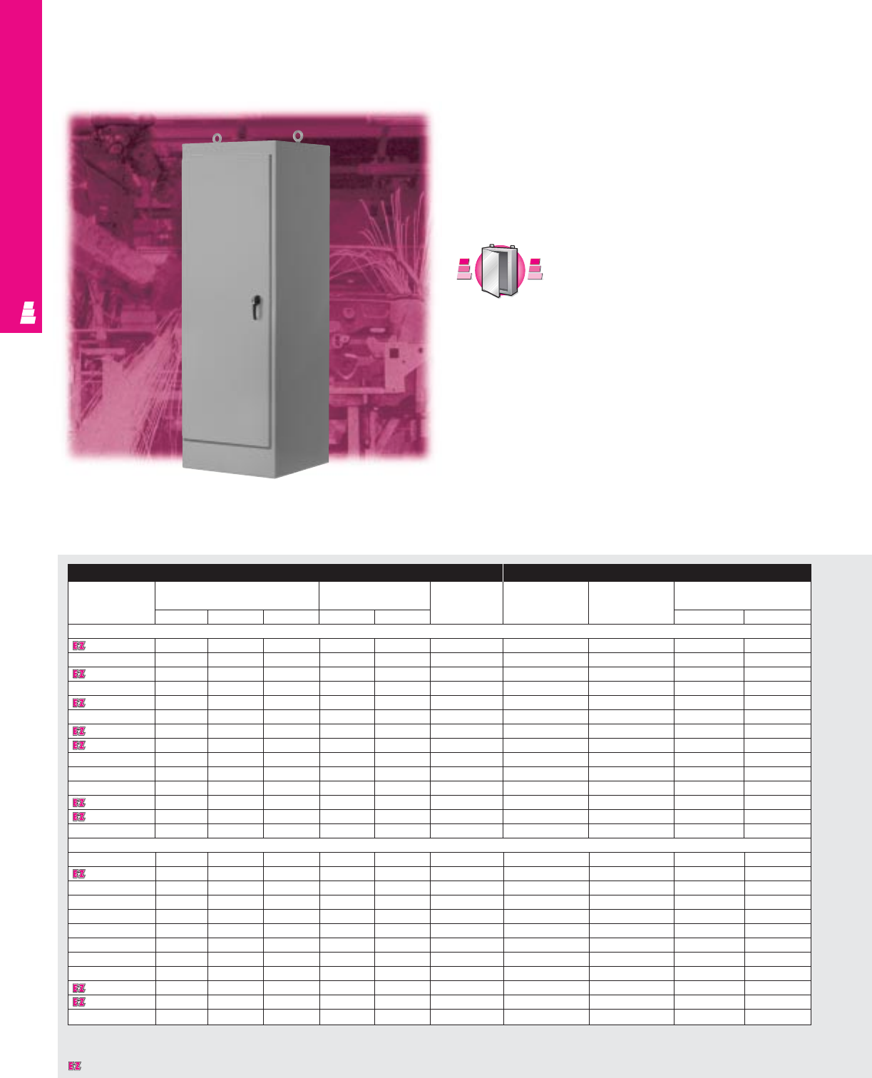
FREESTANDING ENCLOSURES
IND 77
One/Two Door Freestanding Cabinets
Single/Dual Access Enclosures
Rittal Electromate NEMA rated freestanding enclosures accept
standard as well as rackmount electrical and electronic
components. These enclosures are intended for indoor
applications to protect installed equipment against dust, dirt,
oil and water.
Enclosure Mounting Panel
Part No. Outside dimensions (inches) Door size Maximum Part No. Description* Panel size
usable depth
HWDHWpanel installed H W
One Door, Single Access
E 602418FS 60.00 24.00 18.00 50.25 22.22 17.63 E 60P24F1 Full Panel 48.00 20.00
E 603624FS 60.00 36.00 24.00 50.25 34.22 23.63 E 60P36F1 Full Panel 48.00 32.00
E 722418FS 72.00 24.00 18.00 62.25 22.22 17.63 E 72P24F1 Full Panel 60.00 20.00
E 722424FS 72.00 24.00 24.00 62.25 22.22 23.63 E 72P24F1 Full Panel 60.00 20.00
E 723018FS 72.00 30.00 18.00 62.25 28.22 17.63 E 72P30F1 Full Panel 60.00 26.00
E 723024FS 72.00 30.00 24.00 62.25 28.22 23.63 E 72P30F1 Full Panel 60.00 26.00
E 723618FS 72.00 36.00 18.00 62.25 34.22 17.63 E 72P36F1 Full Panel 60.00 32.00
E 723624FS 72.00 36.00 24.00 62.25 34.22 23.63 E 72P36F1 Full Panel 60.00 32.00
E 723630FS 72.00 36.00 30.00 62.25 34.22 29.63 E 72P36F1 Full Panel 60.00 32.00
E 723636FS 72.00 36.00 36.00 62.25 34.22 35.63 E 72P36F1 Full Panel 60.00 32.00
E 902420FS 90.00 24.00 20.00 80.25 22.22 19.63 E 90P24F1 Full Panel 78.00 20.00
E 903620FS 90.00 36.00 20.00 80.25 34.22 19.63 E 90P36F1 Full Panel 78.00 32.00
E 903624FS 90.00 36.00 24.00 80.25 34.22 23.63 E 90P36F1 Full Panel 78.00 32.00
E 903636FS 90.00 36.00 36.00 80.25 34.22 35.63 E 90P36F1 Full Panel 78.00 32.00
Two Door, Single Access
E 604818FSDD 60.00 48.00 18.00 50.25 23.06 15.13 E 60P48F1 Full Panel 48.00 44.00
E 724818FSDD 72.00 48.00 18.00 62.25 23.06 15.13 E 72P48F1 Full Panel 60.00 44.00
E 724824FSDD 72.00 48.00 24.00 62.25 23.06 21.13 E 72P48F1 Full Panel 60.00 44.00
E 726018FSDD 72.00 60.00 18.00 62.25 29.06 15.13 E 72P60F1 Full Panel 60.00 56.00
E 726024FSDD 72.00 60.00 24.00 62.25 29.06 21.13 E 72P60F1 Full Panel 60.00 56.00
E 726036FSDD 72.00 60.00 36.00 62.25 29.06 33.13 E 72P60F1 Full Panel 60.00 56.00
E 727218FSDD 72.00 72.00 18.00 62.25 35.06 15.15 E 72P72F1 Full Panel 60.00 68.00
E 727224FSDD 72.00 72.00 24.00 62.25 35.06 21.13 E 72P72F1 Full Panel 60.00 68.00
E 904820FSDD 90.00 48.00 20.00 80.25 23.06 17.13 E 90P48F1 Full Panel 78.00 44.00
E 907220FSDD 90.00 72.00 20.00 80.25 35.06 17.13 E 90P72F1 Full Panel 78.00 68.00
E 907224FSDD 90.00 72.00 24.00 80.25 35.06 21.13 E 90P72F1 Full Panel 78.00 68.00
E 907236FSDD 90.00 72.00 36.00 80.25 35.06 33.13 E 90P72F1 Full Panel 78.00 68.00
* Half panels also available.
S
t
a
i
n
l
e
s
s
S
t
e
e
l
S
t
a
i
n
l
e
s
s
S
t
e
e
l
A
v
a
i
l
a
b
l
e
I
n
A
v
a
i
l
a
b
l
e
I
n
Page IND 227
(Chart continued on page IND 79).
Designates a product in the EnclosureZone program.

FREESTANDING ENCLOSURES
IND 78
Configuration
•Standard types are available:
– Type “FS” – one door, single access
– Type “FSDD” – two door, single access
– Type “FSDA” – one door, dual access
– Type “FSDAD” – two door, dual access
•Continuously welded seams, finished
smooth
•Body stiffener for added support
•Oil resistant neoprene strip gasket
•Continuous steel hinge with removable pin
•3-point latch with padlockable black
textured diecast zinc handle
•Removable heavy duty lifting eyes
mounted to the top
•C-channels are welded to interior sides for
optional mounting
•Print pocket included
Technical Specifications
Material:
•All steel parts: 12 gauge carbon steel
Back of FSDD: 10 gauge carbon steel
Finish/color:
•Enclosure/door: polyester-urethane powder
coat over phosphatized surfaces,
ANSI 61 grey outside and white inside
•Optional mounting panels: painted white Pages . . . . . . . . . . . . . . . . . . . . . . . . . . IND 87-88
NEMA Type 144X1213
UL CUL CSA TÜV
Listings
Protection Ratings
Certifications/Approvals
Technical Drawings
Accessories
Part No. Door stop kit Light kit Handle accessories Window kit Touch-up paint
One Door, Single Access
E 602418FS E DSTOPK See ACC 29 See ACC 20 E PWK2315NF E L21
E 603624FS E DSTOPK See ACC 29 See ACC 20 E PWK3523NF E L21
E 722418FS E DSTOPK See ACC 29 See ACC 20 E PWK2315NF E L21
E 722424FS E DSTOPK See ACC 29 See ACC 20 E PWK2315NF E L21
E 723018FS E DSTOPK See ACC 29 See ACC 20 E PWK3523NF E L21
E 723024FS E DSTOPK See ACC 29 See ACC 20 E PWK3523NF E L21
E 723618FS E DSTOPK See ACC 29 See ACC 20 E PWK3523NF E L21
E 723624FS E DSTOPK See ACC 29 See ACC 20 E PWK3523NF E L21
E 723630FS E DSTOPK See ACC 29 See ACC 20 E PWK3523NF E L21
E 723636FS E DSTOPK See ACC 29 See ACC 20 E PWK3523NF E L21
E 902420FS E DSTOPK See ACC 29 See ACC 20 E PWK2315NF E L21
E 903620FS E DSTOPK See ACC 29 See ACC 20 E PWK3523NF E L21
E 903624FS E DSTOPK See ACC 29 See ACC 20 E PWK3523NF E L21
E 903636FS E DSTOPK See ACC 29 See ACC 20 E PWK3523NF E L21
Two Door, Single Access
E 604818FSDD E DSTOPK See ACC 29 See ACC 20 E PWK2919NF E L21
E 724818FSDD E DSTOPK See ACC 29 See ACC 20 E PWK2919NF E L21
E 724824FSDD E DSTOPK See ACC 29 See ACC 20 E PWK2919NF E L21
E 726018FSDD E DSTOPK See ACC 29 See ACC 20 E PWK3523NF E L21
E 726024FSDD E DSTOPK See ACC 29 See ACC 20 E PWK3523NF E L21
E 726036FSDD E DSTOPK See ACC 29 See ACC 20 E PWK3523NF E L21
E 727218FSDD E DSTOPK See ACC 29 See ACC 20 E PWK3523NF E L21
E 727224FSDD E DSTOPK See ACC 29 See ACC 20 E PWK3523NF E L21
E 904820FSDD E DSTOPK See ACC 29 See ACC 20 E PWK3523NF E L21
E 907220FSDD E DSTOPK See ACC 29 See ACC 20 E PWK3523NF E L21
E 907224FSDD E DSTOPK See ACC 29 See ACC 20 E PWK3523NF E L21
E 907236FSDD E DSTOPK See ACC 29 See ACC 20 E PWK3523NF E L21
(Chart continued on page IND 80).
Designates a product in the EnclosureZone program.
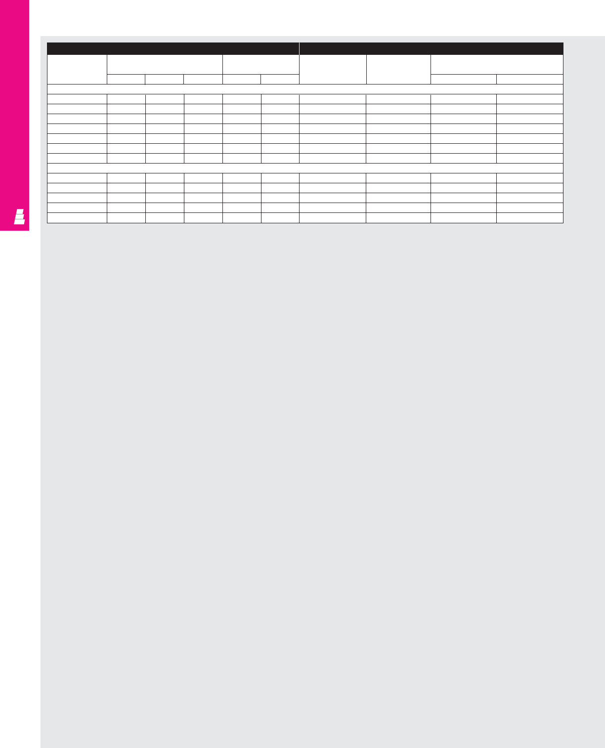
FREESTANDING ENCLOSURES
Enclosure (Continued) Mounting Panel (Continued)
Part No. Outside dimensions (inches) Door size Part No. Description Panel size
HWDHW H W
One Door, Dual Access
E 722424FSDA 72.00 24.00 24.00 62.25 22.22 E 72P24F1 Full Panel 60.00 20.00
E 722436FSDA 72.00 24.00 36.00 62.25 22.22 E 72P24F1 Full Panel 60.00 20.00
E 723024FSDA 72.00 30.00 24.00 62.25 28.22 E 72P30F1 Full Panel 60.00 26.00
E 723624FSDA 72.00 36.00 24.00 62.25 34.22 E 72P36F1 Full Panel 60.00 32.00
E 723636FSDA 72.00 36.00 36.00 62.25 34.22 E 72P36F1 Full Panel 60.00 32.00
E 903624FSDA 90.00 36.00 24.00 80.25 34.22 E 90P36F1 Full Panel 78.00 32.00
E 903636FSDA 90.00 36.00 36.00 80.25 34.22 E 90P36F1 Full Panel 78.00 32.00
Two Door, Dual Access
E 724824FSDAD 72.00 48.00 24.00 62.25 23.06 E 72P48F1 Full Panel 60.00 44.00
E 726024FSDAD 72.00 60.00 24.00 62.25 29.06 E 72P60F1 Full Panel 60.00 56.00
E 726036FSDAD 72.00 60.00 36.00 62.25 29.06 E 72P60F1 Full Panel 60.00 56.00
E 727218FSDAD 72.00 72.00 24.00 62.25 35.06 E 72P72F1 Full Panel 60.00 68.00
E 907224FSDAD 90.00 72.00 24.00 80.25 35.06 E 90P72F1 Full Panel 78.00 68.00
IND 79
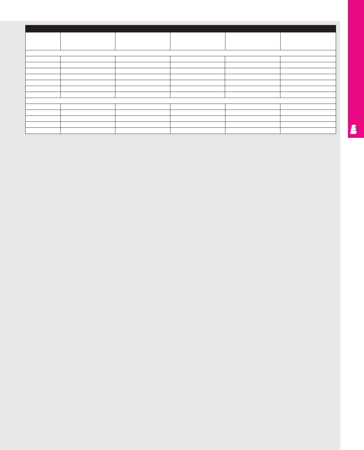
FREESTANDING ENCLOSURES
Accessories (Continued)
Part No. Door stop kit Light kit Handle accessories Window kit Touch-up paint
One Door, Dual Access
E 722424FSDA E DSTOPK See ACC 29 See ACC 20 E PWK2315NF E L21
E 722436FSDA E DSTOPK See ACC 29 See ACC 20 E PWK2315NF E L21
E 723024FSDA E DSTOPK See ACC 29 See ACC 20 E PWK3523NF E L21
E 723624FSDA E DSTOPK See ACC 29 See ACC 20 E PWK3523NF E L21
E 723636FSDA E DSTOPK See ACC 29 See ACC 20 E PWK3523NF E L21
E 903624FSDA E DSTOPK See ACC 29 See ACC 20 E PWK3523NF E L21
E 903636FSDA E DSTOPK See ACC 29 See ACC 20 E PWK3523NF E L21
Two Door, Dual Access
E 724824FSDAD E DSTOPK See ACC 29 See ACC 20 E PWK2315NF E L21
E 726024FSDAD E DSTOPK See ACC 29 See ACC 20 E PWK3523NF E L21
E 726036FSDAD E DSTOPK See ACC 29 See ACC 20 E PWK3523NF E L21
E 727218FSDAD E DSTOPK See ACC 29 See ACC 20 E PWK3523NF E L21
E 907224FSDAD E DSTOPK See ACC 29 See ACC 20 E PWK3523NF E L21
IND 80
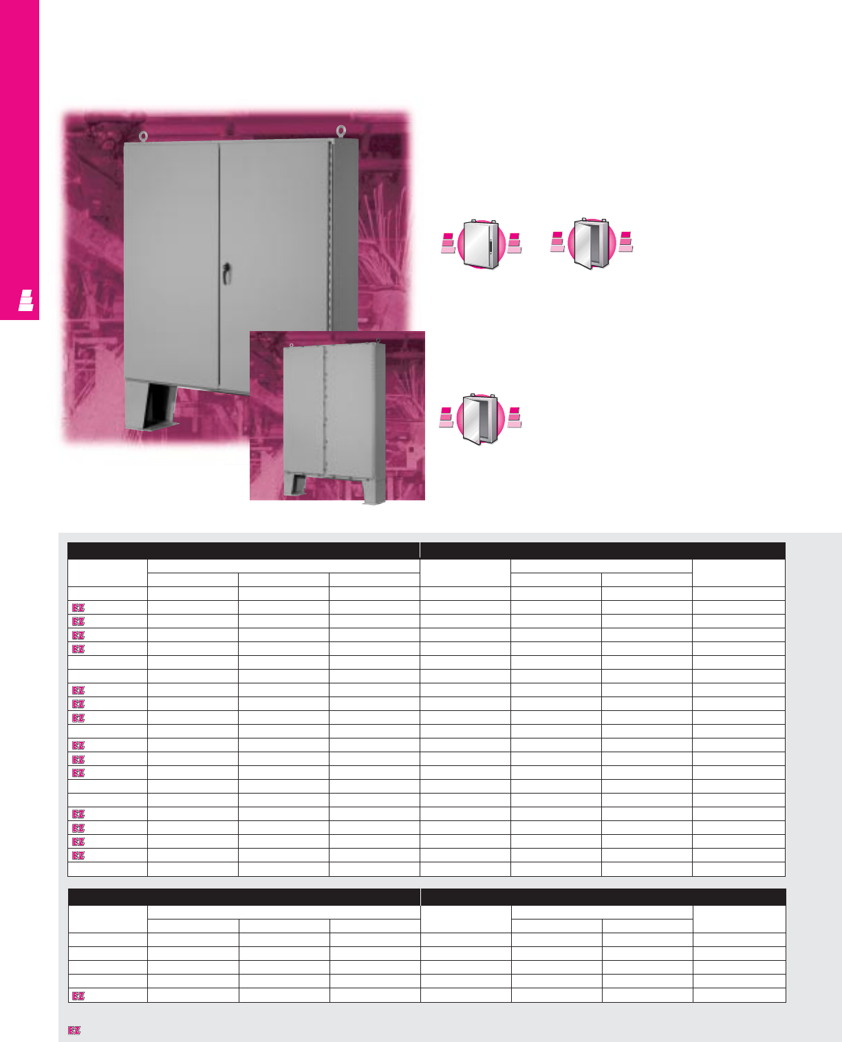
FREESTANDING ENCLOSURES
Two Door Floormount Enclosures
NEMA 12 and 4 Carbon Steel Cabinets
These NEMA 12 and 4 rated floormount enclosures are
designed for indoor or outdoor use to protect electrical and
electronic equipment against splashing water, seepage of
water, falling or hose directed water and external condensation.
NEMA 12 Enclosure Mounting Panel
Part No.
Outside dimensions (inches)
Part No.
Panel size Usable depth
HWD HW
E 544208 54.00 42.00 8.00 E 54P42 50.00 38.00 8.00
E 604808 60.00 48.00 8.00 E 60P48 56.00 44.00 8.00
E 604810 60.00 48.00 10.00 E 60P48 56.00 44.00 10.00
E 604812 60.00 48.00 12.00 E 60P48 56.00 44.00 12.00
E 604816 60.00 48.00 16.00 E 60P48 56.00 44.00 16.00
E 604820 60.00 48.00 20.00 E 60P48 56.00 44.00 20.00
E 604824 60.00 48.00 24.00 E 60P48 56.00 44.00 24.00
E 606010 60.00 60.00 10.00 E 60P60 56.00 56.00 10.00
E 606012 60.00 60.00 12.00 E 60P60 56.00 56.00 12.00
E 606016 60.00 60.00 16.00 E 60P60 56.00 56.00 16.00
E 606024 60.00 60.00 24.00 E 60P60 56.00 56.00 24.00
E 726010 72.00 60.00 10.00 E 72P60 68.00 56.00 10.00
E 726012 72.00 60.00 12.00 E 72P60 68.00 56.00 12.00
E 726016 72.00 60.00 16.00 E 72P60 68.00 56.00 16.00
E 726020 72.00 60.00 20.00 E 72P60 68.00 56.00 20.00
E 726024 72.00 60.00 24.00 E 72P60 68.00 56.00 24.00
E 727210 72.00 72.00 10.00 E 72P72 68.00 68.00 10.00
E 727212 72.00 72.00 12.00 E 72P72 68.00 68.00 12.00
E 727216 72.00 72.00 16.00 E 72P72 68.00 68.00 16.00
E 727220 72.00 72.00 20.00 E 72P72 68.00 68.00 20.00
E 727224 72.00 72.00 24.00 E 72P72 68.00 68.00 24.00
IND 81
NEMA 4 Enclosure Mounting Panel
Part No.
Outside dimensions (inches)
Part No.
Panel size Usable depth
HW D H W
E 62H48C 62.00 48.00 10.00 E 60P48 56.00 44.00 10.00
E 62H60D 62.00 60.00 12.00 E 60P60 56.00 56.00 12.00
E 74H60D 74.00 60.00 12.00 E 72P60 68.00 56.00 12.00
E 74H72D 74.00 72.00 12.00 E 72P72 68.00 68.00 12.00
E 74H72J 74.00 72.00 24.00 E 72P72 68.00 68.00 24.00
F
M
D
F
M
D
A
v
a
i
l
a
b
l
e
I
n
A
v
a
i
l
a
b
l
e
I
n
Page IND 103
S
t
a
i
n
l
e
s
s
S
t
e
e
l
S
t
a
i
n
l
e
s
s
S
t
e
e
l
A
v
a
i
l
a
b
l
e
I
n
A
v
a
i
l
a
b
l
e
I
n
Page IND 229
NEMA 12
NEMA 4
NEMA 4
NEMA 12
Designates a product in the EnclosureZone program.
S
t
a
i
n
l
e
s
s
S
t
e
e
l
S
t
a
i
n
l
e
s
s
S
t
e
e
l
A
v
a
i
l
a
b
l
e
I
n
A
v
a
i
l
a
b
l
e
I
n
Page IND 230
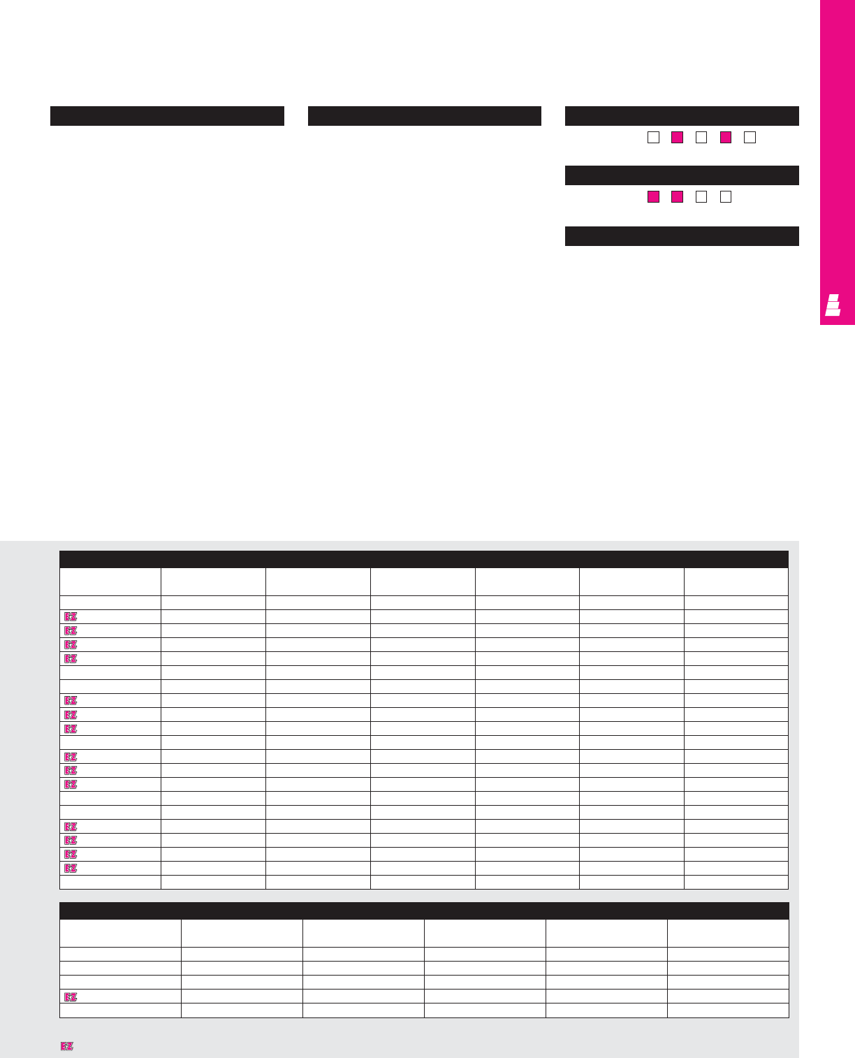
FREESTANDING ENCLOSURES
Configuration
•Continuously welded seams, finished
smooth
•Gasketed overlapping doors
•Body stiffener for added support
•3-point latching with padlockable black
textured diecast zinc handle (NEMA
12 only)
•Oil resistant neoprene strip gasket
•Continuous stainless steel heavy duty hinge
with removable pin
•Mounting panel provisions installed
•Removable heavy duty lifting eyes
•12" floor stands are welded to enclosure
•Print pocket included
•Removable center post (NEMA 4 only)
•Hasp and staple for padlocking (NEMA
4 only)
Technical Specifications:
NEMA 12 Material:
•Enclosure/door: 12 gauge carbon steel
NEMA 4 Material:
•Carbon steel
Body: 12 gauge
Back: 10 gauge for H or W ≥72"
Finish/color:
•Enclosure/door: polyester-urethane powder
coat over phosphatized surfaces,
ANSI 61 grey outside and white inside
•Optional mounting panels: painted white
Pages . . . . . . . . . . . . . . . . . . . . . . . . . IND 89-90
NEMA Type 144X1213
UL CUL CSA TÜV
Listings
Protection Ratings
Certifications/Approvals
Technical Drawings
Accessories
Part No.
Drip shield kit Door stop kit Light kit Handle Window kit Touch-up paint
accessories
E 544208 E DK48 E DSTOPK See ACC 29 See ACC 20 E PWK2315NF E L21
E 604808 E DK48 E DSTOPK See ACC 29 See ACC 20 E PWK2315NF E L21
E 604810 E DK48 E DSTOPK See ACC 29 See ACC 20 E PWK2315NF E L21
E 604812 E DK48 E DSTOPK See ACC 29 See ACC 20 E PWK2315NF E L21
E 604816 E DK48 E DSTOPK See ACC 29 See ACC 20 E PWK2315NF E L21
E 604820 E DK48 E DSTOPK See ACC 29 See ACC 20 E PWK2315NF E L21
E 604824 E DK48 E DSTOPK See ACC 29 See ACC 20 E PWK2315NF E L21
E 606010 E DK60 E DSTOPK See ACC 29 See ACC 20 E PWK3523NF E L21
E 606012 E DK60 E DSTOPK See ACC 29 See ACC 20 E PWK3523NF E L21
E 606016 E DK60 E DSTOPK See ACC 29 See ACC 20 E PWK3523NF E L21
E 606024 E DK60 E DSTOPK See ACC 29 See ACC 20 E PWK3523NF E L21
E 726010 E DK60 E DSTOPK See ACC 29 See ACC 20 E PWK3523NF E L21
E 726012 E DK60 E DSTOPK See ACC 29 See ACC 20 E PWK3523NF E L21
E 726016 E DK60 E DSTOPK See ACC 29 See ACC 20 E PWK3523NF E L21
E 726020 E DK60 E DSTOPK See ACC 29 See ACC 20 E PWK3523NF E L21
E 726024 E DK60 E DSTOPK See ACC 29 See ACC 20 E PWK3523NF E L21
E 727210 E DK72 E DSTOPK See ACC 29 See ACC 20 E PWK3523NF E L21
E 727212 E DK72 E DSTOPK See ACC 29 See ACC 20 E PWK3523NF E L21
E 727216 E DK72 E DSTOPK See ACC 29 See ACC 20 E PWK3523NF E L21
E 727220 E DK72 E DSTOPK See ACC 29 See ACC 20 E PWK3523NF E L21
E 727224 E DK72 E DSTOPK See ACC 29 See ACC 20 E PWK3523NF E L21
IND 82
Accessories
Part No.
Fast operating Door stop kit Light kit Window kit Touch-up paint
clamp
E 62H48C E FOC412SS E DSTOPK See ACC 29 E PWK2315NF E L21
E 62H60D E FOC412SS E DSTOPK See ACC 29 E PWK2919NF E L21
E 74H60D E FOC412SS E DSTOPK See ACC 29 E PWK2919NF E L21
E 74H72D E FOC412SS E DSTOPK See ACC 29 E PWK3523NF E L21
E 74H72J E FOC412SS E DSTOPK See ACC 29 E PWK3523NF E L21
Designates a product in the EnclosureZone program.
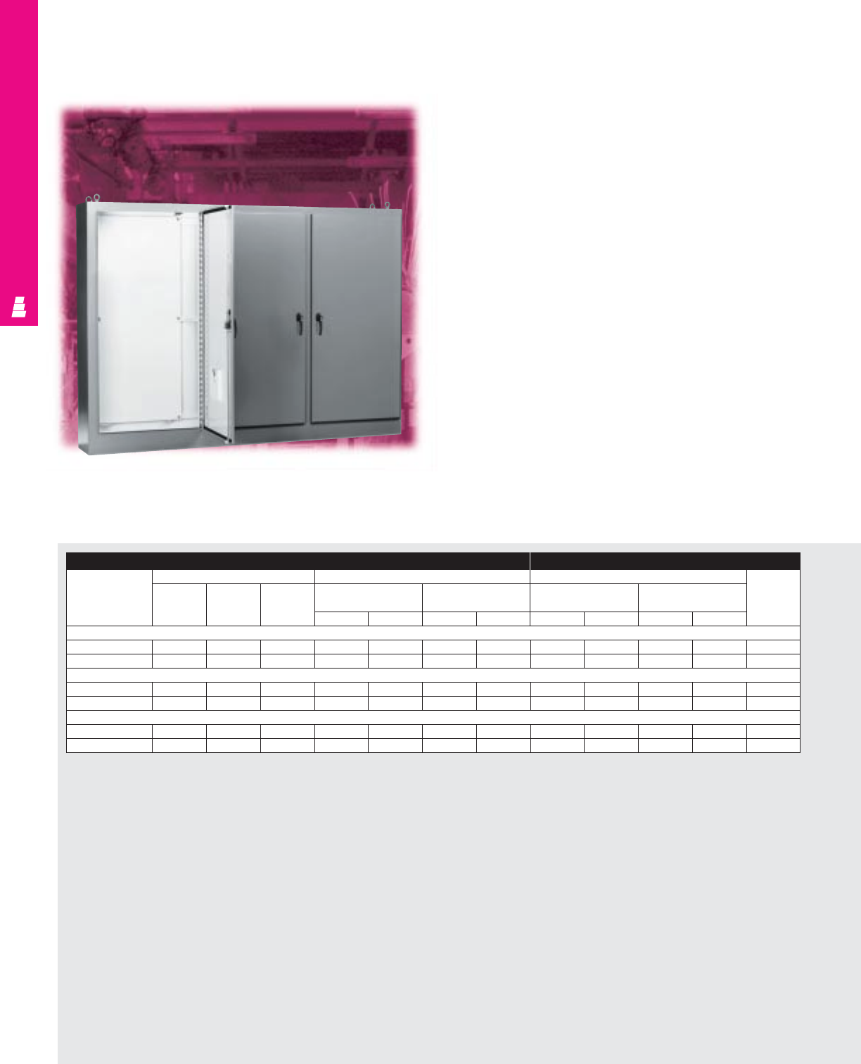
IND 83
Multi-Door Freestanding Enclosures
Multi-Door Carbon Steel
Rittal Electromate NEMA rated freestanding multi-door
enclosures are designed to accept standard as well as
rackmount electrical and electronic components in large control
centers. These enclosures are intended for indoor applications
to protect installed equipment against dust, dirt, oil and water.
FREESTANDING ENCLOSURES
Enclosure Mounting Panel
Part No.
Outside dimensions (inches) Door size Panel size Usable
Single Double Behind single Behind double depth
door door door door
HWDD ED F H JHK
3 Door Enclosure
E 86M3EDWP 86.00 112.00 18.00 80.50 35.69 80.50 35.78 78.00 34.00 78.00 70.00 17.00
E 86M3EWP 86.00 112.00 14.00 80.50 35.69 80.50 35.78 78.00 34.00 78.00 70.00 13.00
4 Door Enclosure
E 86M4EDWP 86.00 149.00 18.00 80.50 35.81 - - 78.00 70.00 - - 17.00
E 86M4EWP 86.00 149.00 14.00 80.50 35.81 - - 78.00 70.00 - - 13.00
5 Door Enclosure
E 86M5EDWP 86.00 187.00 18.00 80.50 35.69 80.50 35.84 78.00 34.00 78.00 70.00 17.00
E 86M5EWP 86.00 187.00 14.00 80.50 35.69 80.50 35.84 78.00 34.00 78.00 70.00 13.00
IND 84
FREESTANDING ENCLOSURES
Configuration
•Continuously welded seams, finished
smooth
•Body stiffener for added support
•Urethane gasket
•Overlapping doors at two door openings
•Continuous steel hinge with removable pin
•3-point latch with padlockable handle
•Removable heavy duty lifting eyes
mounted to the top
•Mounting panels included
•Print pocket included
Technical Specifications
Material:
•Enclosure/door: 10 gauge carbon steel
Finish/color:
•Enclosure/door: polyester-urethane powder
coat over phosphatized surfaces – ANSI 61
grey outside and white inside
•Mounting panels: painted white
Pages . . . . . . . . . . . . . . . . . . . . . . . . . . IND 91-92
NEMA Type 144X1213
UL CUL CSA TÜV
Listings
Protection Ratings
Certifications/Approvals
Technical Drawings
Accessories
Part No.
Door stop kit Light kit Handle accessories Window kit Touch-up paint
3 Door Enclosure
E 86M3EDWP E DSTOPK See ACC 29 See ACC 20 E PWK3523NF E L21
E 86M3EWP E DSTOPK See ACC 29 See ACC 20 E PWK3523NF E L21
4 Door Enclosure
E 86M4EDWP E DSTOPK See ACC 29 See ACC 20 E PWK3523NF E L21
E 86M4EWP E DSTOPK See ACC 29 See ACC 20 E PWK3523NF E L21
5 Door Enclosure
E 86M5EDWP E DSTOPK See ACC 29 See ACC 20 E PWK3523NF E L21
E 86M5EWP E DSTOPK See ACC 29 See ACC 20 E PWK3523NF E L21
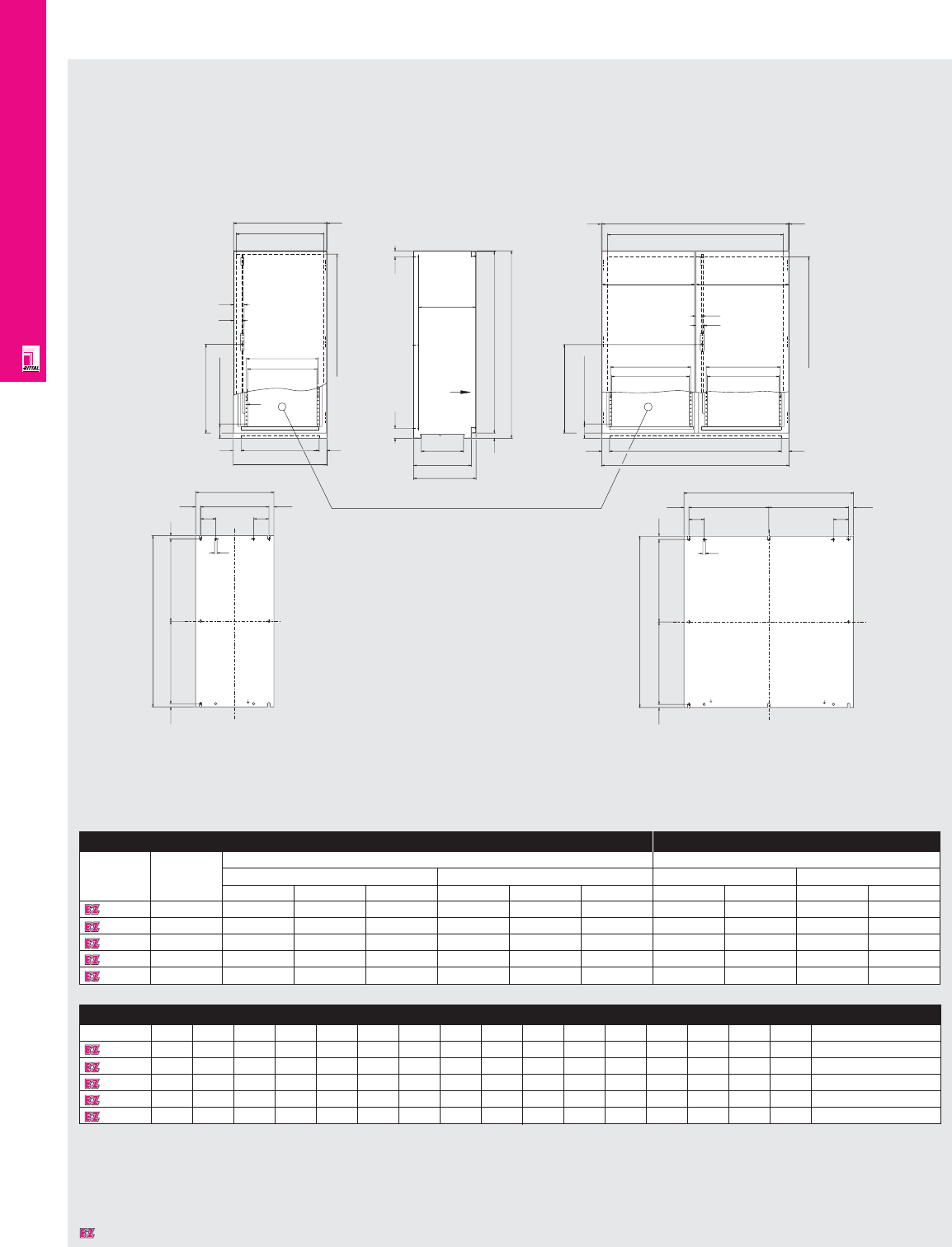
FREESTANDING ENCLOSURES
IND 85
Technical Specifications
AK Freestanding Enclosures
X
i.L.1092
568
141
B6
B5
55
69
B4 1.5
B3
B2
50 50
B1
Ø 6.5
X
270
370
400
62.5 37.5
355 – 373
H1
H2
33
X
50 50
B4
B3
1.5
H3
B5
B6 B8
B7
B1
B2
H4
H5
38 x 25 = 950
40
54
141
1.5
597 597
10
9090
F2
19.5 19.5
550
550
1125
12.5
12.5
F1
10
G2
G2
G1
12.5
12.5
90 90
F1
F2F219.5 19.5
Enclosure Mounting Panel
Part No. Number Exact outside dimensions Dimensions
of doors inches mm inches mm
HWD HW D H WHW
1646600 147.24 23.62 15.75 1200 600 400 44.29 20.24 1125 514
1648600 147.24 31.50 15.75 1200 800 400 44.29 28.11 1125 714
1650600 247.24 39.37 15.75 1200 1000 400 44.29 35.39 1125 914
1652600 247.24 47.24 15.75 1200 1200 400 44.29 43.86 1125 1114
1647600 255.12 39.37 15.75 1400 1000 400 52.17 35.39 1325 914
Detailed Dimensions
Part No.
Part No. B1 B2 B3 B4 B5 B6 B7 B8 F1 F2 G1 G2 H1 H2 H3 H4 H5
1646600 600 500 524 597 459 443 - - 514 475 - - 1200 1166 - - -
1648600 800 700 724 797 659 643 - - 714 675 - - 1200 1166 - - -
1650600 1000 900 924 997 413 397 377 361 914 437.5 1125 550 1200 1166 1092 568 38 x 28 = 950
1652600 1200 1100 1124 1197 513 497 477 461 1114 538 1125 550 1200 1166 1092 568 38 x 28 = 950
1647600 1000 900 924 997 413 397 377 361 914 437.5 1325 650 1400 1366 1292 668 46 x 25 = 1160
1646/1648
Side View
1650/1652/1647
Designates a product in the EnclosureZone program.
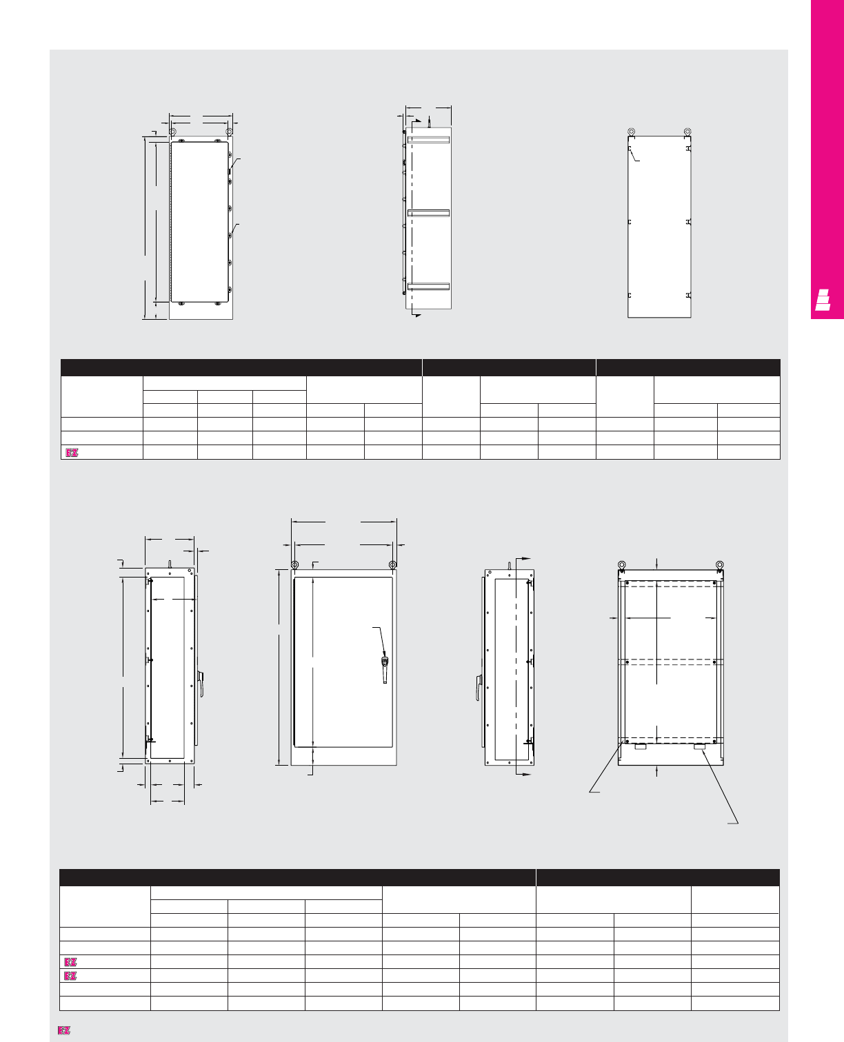
FREESTANDING ENCLOSURES
IND 86
Technical Specifications
One Door Freestanding Enclosures
C
B
(38.75)
1.13
3.38
2.00
D
2.00
E
3.75
Left Side View Front View
W
(35.88)
1.38
2.75
1.50
A3 point
padlockable
handle
H
6.75
Right Side View
4.00
G
(33.75)
panel
2.50
F
panel
8.00
Channel
(3) places
Panel support (2) places
B
B
Enclosure Mounting Panel
Part No.
Outside dimensions (inches)
Door size Panel size Usable depth
HWD
ABC HWF G J
E MOD723918 72.00 38.75 18.00 62.50 35.88 60.00 33.75 17.00
E MOD727718 72.00 77.00 18.00 62.50 35.88 60.00 72.00 17.00
E MOD843918 84.00 38.75 18.00 74.50 35.88 72.00 33.75 17.00
E MOD843924 84.00 38.75 24.00 74.50 35.88 72.00 33.75 23.00
E MOD847718 84.00 77.00 18.00 74.50 35.88 72.00 72.00 17.00
E MOD847724 84.00 77.00 24.00 74.50 35.88 72.00 72.00 23.00
Section A-A
Enclosure Full Mounting Panel Half Mounting Panel
Part No.
Outside dimensions (inches) Door size
Part No.
Panel size
Part No.
Panel size
HWD
ABCH W E F E F
E 72H2518FS 72.00 25.00 18.00 62.75 22.31 E 72P24F1 60.00 20.00 E 72P24F2 30.88 20.00
E 72H3124FS 72.00 31.00 24.00 62.75 28.31 E 72P30F1 60.00 26.00 E 72P30F2 30.88 26.00
E 72H3724FS 72.00 37.00 24.00 62.75 34.31 E 72P36F1 60.00 32.00 E 72P36F2 30.88 32.00
Front View Side View Section X-X
Panel
mounting
channel
(6) places
.81 B
W
2.37
Padlock
hasp and
staple
Door
clamp
1.88 1.16
CC
L
X
X
H
62.75
A
72.00
One Door Modular Cabinets
Designates a product in the EnclosureZone program.
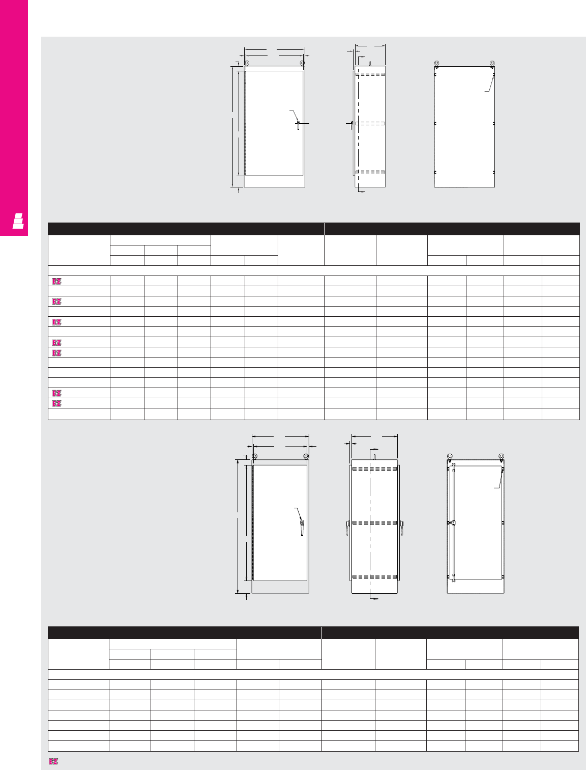
FREESTANDING ENCLOSURES
IND 87
Technical Specifications
One Door Freestanding Cabinets
Front View Side View Section X-X
Enclosure Mounting Panel
Part No. Outside dimensions (inches) Door size Maximum Part No. Description Panel size Fits enclosure
HWD usable depth
ABCH Wpanel installed H W A B
One Door, Single Access
E 602418FS 60.00 24.00 18.00 50.25 22.22 17.63 E 60P24F1 Full panel 48.00 20.00 60.00 24.00
E 603624FS 60.00 36.00 24.00 50.25 34.22 23.63 E 60P36F1 Full panel 48.00 32.00 60.00 36.00
E 722418FS 72.00 24.00 18.00 62.25 22.22 17.63 E 72P24F1 Full panel 60.00 20.00 72.00 24.00
E 722424FS 72.00 24.00 24.00 62.25 22.22 23.63 E 72P24F1 Full panel 60.00 20.00 72.00 24.00
E 723018FS 72.00 30.00 18.00 62.25 28.22 17.63 E 72P30F1 Full panel 60.00 26.00 72.00 30.00
E 723024FS 72.00 30.00 24.00 62.25 28.22 23.63 E 72P30F1 Full panel 60.00 26.00 72.00 30.00
E 723618FS 72.00 36.00 18.00 62.25 34.22 17.63 E 72P36F1 Full panel 60.00 32.00 72.00 36.00
E 723624FS 72.00 36.00 24.00 62.25 34.22 23.63 E 72P36F1 Full panel 60.00 32.00 72.00 36.00
E 723630FS 72.00 36.00 30.00 62.25 34.22 29.63 E 72P36F1 Full panel 60.00 32.00 72.00 36.00
E 723636FS 72.00 36.00 36.00 62.25 34.22 35.63 E 72P36F1 Full panel 60.00 32.00 72.00 36.00
E 902420FS 90.00 24.00 20.00 80.15 22.22 19.63 E 90P24F1 Full panel 78.00 20.00 90.00 24.00
E 903620FS 90.00 36.00 20.00 80.25 34.22 19.63 E 90P36F1 Full panel 78.00 32.00 90.00 36.00
E 903624FS 90.00 36.00 24.00 80.25 34.22 23.63 E 90P36F1 Full panel 78.00 32.00 90.00 36.00
E 903636FS 90.00 36.00 36.00 80.25 34.22 35.63 E 90P36F1 Full panel 78.00 32.00 90.00 36.00
B
W
.81
2.87 .968
3 point
padlockable
handle
H
A
6.88
C
81.156
X
X
C
L
Panel
mounting
channel (6)
places
Enclosure Mounting Panel
Part No. Outside dimensions (inches) Door size Part No. Description Panel size Fits enclosure
HWD
ABC HW HWAB
One Door, Dual Access
E 722424FSDA 72.00 24.00 24.00 62.25 22.22 E 72P24F1 Full panel 60.00 20.00 72.00 24.00
E 722436FSDA 72.00 24.00 36.00 62.25 22.22 E 72P24F1 Full panel 60.00 20.00 72.00 24.00
E 723024FSDA 72.00 30.00 24.00 62.25 28.22 E 72P30F1 Full panel 60.00 26.00 72.00 30.00
E 723624FSDA 72.00 36.00 24.00 62.25 34.22 E 72P36F1 Full panel 60.00 32.00 72.00 36.00
E 723636FSDA 72.00 36.00 36.00 62.25 34.22 E 72P36F1 Full panel 60.00 32.00 72.00 36.00
E 903624FSDA 90.00 36.00 24.00 80.25 34.22 E 90P36F1 Full panel 78.00 32.00 90.00 36.00
E 903636FSDA 90.00 36.00 36.00 80.25 34.22 E 90P36F1 Full panel 78.00 32.00 90.00 36.00
Designates a product in the EnclosureZone program.
B
W
.81
2.88
3 point
keylocking
handle
6.88
C
L
C
1.156 X
.968
X
Panel
mounting
channel
(6) places
Front View Right Side View Section X-X
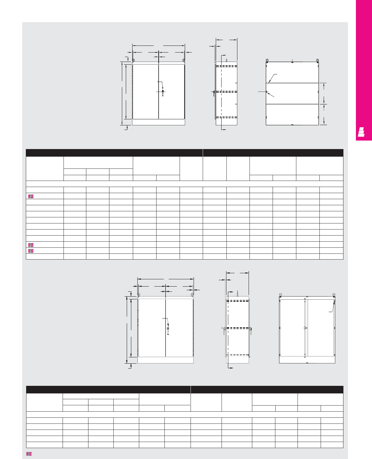
FREESTANDING ENCLOSURES
IND 88
.81
B1.156
X
C
L
.25 x 2 flat bar
(2) places
Enclosure Mounting Panel
Part No. Outside dimensions (inches) Door size Maximum Part No. Description Panel size Fits enclosure
usable depth
HW D panel
AB CHWinstalled H W A B
Two Door, Single Access
E 604818FSDD 60.00 48.00 18.00 50.25 23.06 15.13 E 60P48F1 Full panel 48.00 44.00 60.00 48.00
E 724818FSDD 72.00 48.00 18.00 62.25 23.06 15.13 E 72P48F1 Full panel 60.00 44.00 72.00 48.00
E 724824FSDD 72.00 48.00 24.00 62.25 23.06 21.13 E 72P48F1 Full panel 60.00 44.00 72.00 48.00
E 726018FSDD 72.00 60.00 18.00 62.25 29.06 15.13 E 72P60F1 Full panel 60.00 56.00 72.00 60.00
E 726024FSDD 72.00 60.00 24.00 62.25 29.06 21.13 E 72P60F1 Full panel 60.00 56.00 72.00 60.00
E 726036FSDD 72.00 60.00 36.00 62.25 29.06 33.15 E 72P60F1 Full panel 60.00 56.00 72.00 60.00
E 727218FSDD 72.00 72.00 18.00 62.25 35.06 15.13 E 72P72F1 Full panel 60.00 68.00 72.00 72.00
E 727224FSDD 72.00 72.00 24.00 62.25 35.06 21.13 E 72P72F1 Full panel 60.00 68.00 72.00 72.00
E 904820FSDD 90.00 48.00 20.00 80.25 23.06 17.13 E 90P48F1 Full panel 78.00 44.00 90.00 48.00
E 907220FSDD 90.00 72.00 20.00 80.25 35.06 17.13 E 90P72F1 Full panel 78.00 68.00 90.00 72.00
E 907224FSDD 90.00 72.00 24.00 80.25 35.06 21.13 E 90P72F1 Full panel 78.00 68.00 90.00 72.00
E 907236FSDD 90.00 72.00 36.00 80.25 35.06 33.13 E 90P72F1 Full panel 78.00 68.00 90.00 72.00
Technical Specifications
Two Door Freestanding Cabinets
Enclosure Mounting Panel
Part No. Outside dimensions (inches) Door size Part No. Description Panel size Fits enclosure
HW D
AB CHW HWAB
Two Door, Dual Access
E 724824FSDAD 72.00 48.00 24.00 62.25 23.06 E 72P48F1 Full panel 60.00 44.00 72.00 48.00
E 726024FSDAD 72.00 60.00 24.00 62.25 29.06 E 72P60F1 Full panel 60.00 56.00 72.00 60.00
E 726036FSDAD 72.00 60.00 36.00 62.25 29.06 E 72P60F1 Full panel 60.00 56.00 72.00 60.00
E 727218FSDAD 72.00 72.00 24.00 62.25 35.06 E 72P72F1 Full panel 60.00 68.00 72.00 72.00
E 907224FSDAD 90.00 72.00 24.00 80.25 35.06 E 90P72F1 Full panel 78.00 68.00 90.00 72.00
Designates a product in the EnclosureZone program.
WW
.25
.81
2.87
6.87
A
H
3 point
padlockable
handle
C
X
C
L
C
L
A/3
A/3
Panel mounting
channel
(8) places
Front View Side View Section X-X
B
WW
.25 .81
.81
2.88
A
H
3 point
keylocking
handle
6.88
C
1.156
C
L
C
L
X
X
Panel
mounting
channel
(8) places
Right Side ViewFront View Section X-X
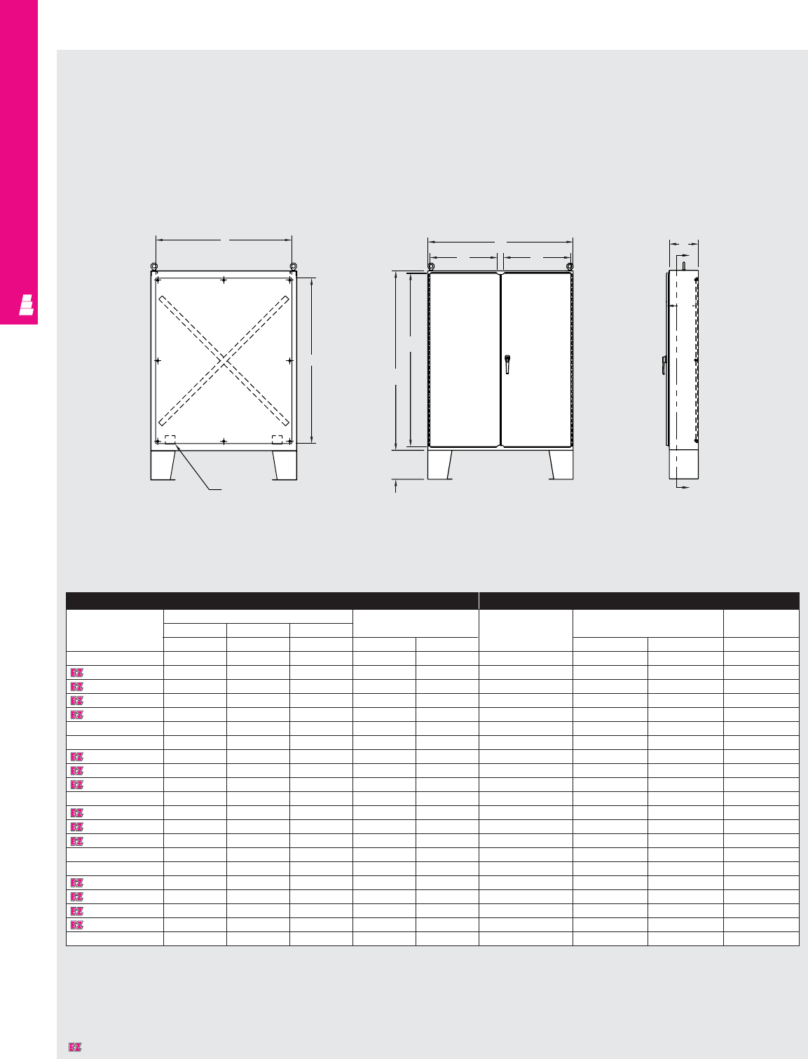
FREESTANDING ENCLOSURES
IND 89
Technical Specifications
Two Door Floormount Enclosures – NEMA 12
Section Y-Y
F
C
L
C
LE
Panel support
NEMA 12 Enclosure Mounting Panel
Part No.
Outside dimensions (inches) Door size
Part No.
Panel size Usable depth
HWD
ABC JK E F G
E 544208 54.00 42.00 8.00 52.25 20.06 E 54P42 50.00 38.00 8.00
E 604808 60.00 48.00 8.00 58.25 23.06 E 60P48 56.00 44.00 8.00
E 604810 60.00 48.00 10.00 58.25 23.06 E 60P48 56.00 44.00 10.00
E 604812 60.00 48.00 12.00 58.25 23.06 E 60P48 56.00 44.00 12.00
E 604816 60.00 48.00 16.00 58.25 23.06 E 60P48 56.00 44.00 16.00
E 604820 60.00 48.00 20.00 58.25 23.06 E 60P48 56.00 44.00 20.00
E 604824 60.00 48.00 24.00 58.25 23.06 E 60P48 56.00 44.00 24.00
E 606010 60.00 60.00 10.00 58.25 29.06 E 60P60 56.00 56.00 10.00
E 606012 60.00 60.00 12.00 58.25 29.06 E 60P60 56.00 56.00 12.00
E 606016 60.00 60.00 16.00 58.25 29.06 E 60P60 56.00 56.00 16.00
E 606024 60.00 60.00 24.00 58.25 29.06 E 60P60 56.00 56.00 24.00
E 726010 72.00 60.00 10.00 70.25 29.06 E 72P60 68.00 56.00 10.00
E 726012 72.00 60.00 12.00 70.25 29.06 E 72P60 68.00 56.00 12.00
E 726016 72.00 60.00 16.00 70.25 29.06 E 72P60 68.00 56.00 16.00
E 726020 72.00 60.00 20.00 70.25 29.06 E 72P60 68.00 56.00 20.00
E 726024 72.00 60.00 24.00 70.25 29.06 E 72P60 68.00 56.00 24.00
E 727210 72.00 72.00 10.00 70.25 35.06 E 72P72 68.00 68.00 10.00
E 727212 72.00 72.00 12.00 70.25 35.06 E 72P72 68.00 68.00 12.00
E 727216 72.00 72.00 16.00 70.25 35.06 E 72P72 68.00 68.00 16.00
E 727220 72.00 72.00 20.00 70.25 35.06 E 72P72 68.00 68.00 20.00
E 727224 72.00 72.00 24.00 70.25 35.06 E 72P72 68.00 68.00 24.00
Front View
B
K
12.00
K
J
A
A
Side View
C
Y
Y
G
Designates a product in the EnclosureZone program.
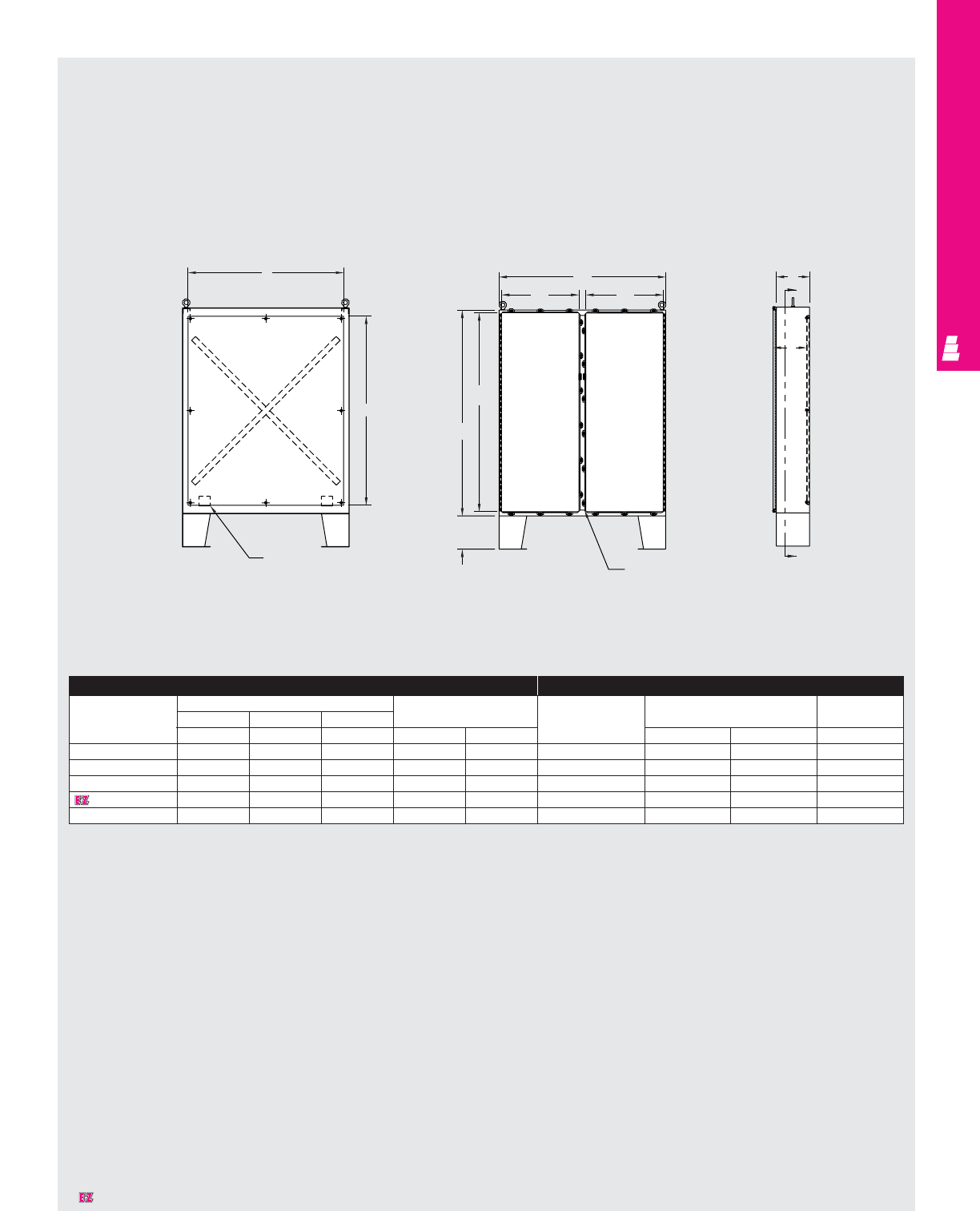
IND 90
Technical Specifications
Two Door Floormount Enclosures – NEMA 4
Front View
B
12.00
KK
J
A
Removable
centerpost
NEMA 4 Enclosure Mounting Panel
Part No.
Outside dimensions (inches) Door size
Part No.
Panel size Usable depth
HWD
ABC JK E F G
E 62H48C 62.00 48.00 10.00 59.50 21.81 E 60P48 56.00 44.00 10.00
E 62H60D 62.00 60.00 12.00 59.50 27.81 E 60P60 56.00 56.00 12.00
E 74H60D 74.00 60.00 12.00 71.50 27.81 E 72P60 68.00 56.00 12.00
E 74H72D 74.00 72.00 12.00 71.50 33.81 E 72P72 68.00 68.00 12.00
E 74H72J 74.00 72.00 24.00 71.50 33.81 E 72P72 68.00 68.00 24.00
Section Y-Y
F
C
L
C
LE
Panel support
Side View
CY
Y
G
Designates a product in the EnclosureZone program.
FREESTANDING ENCLOSURES
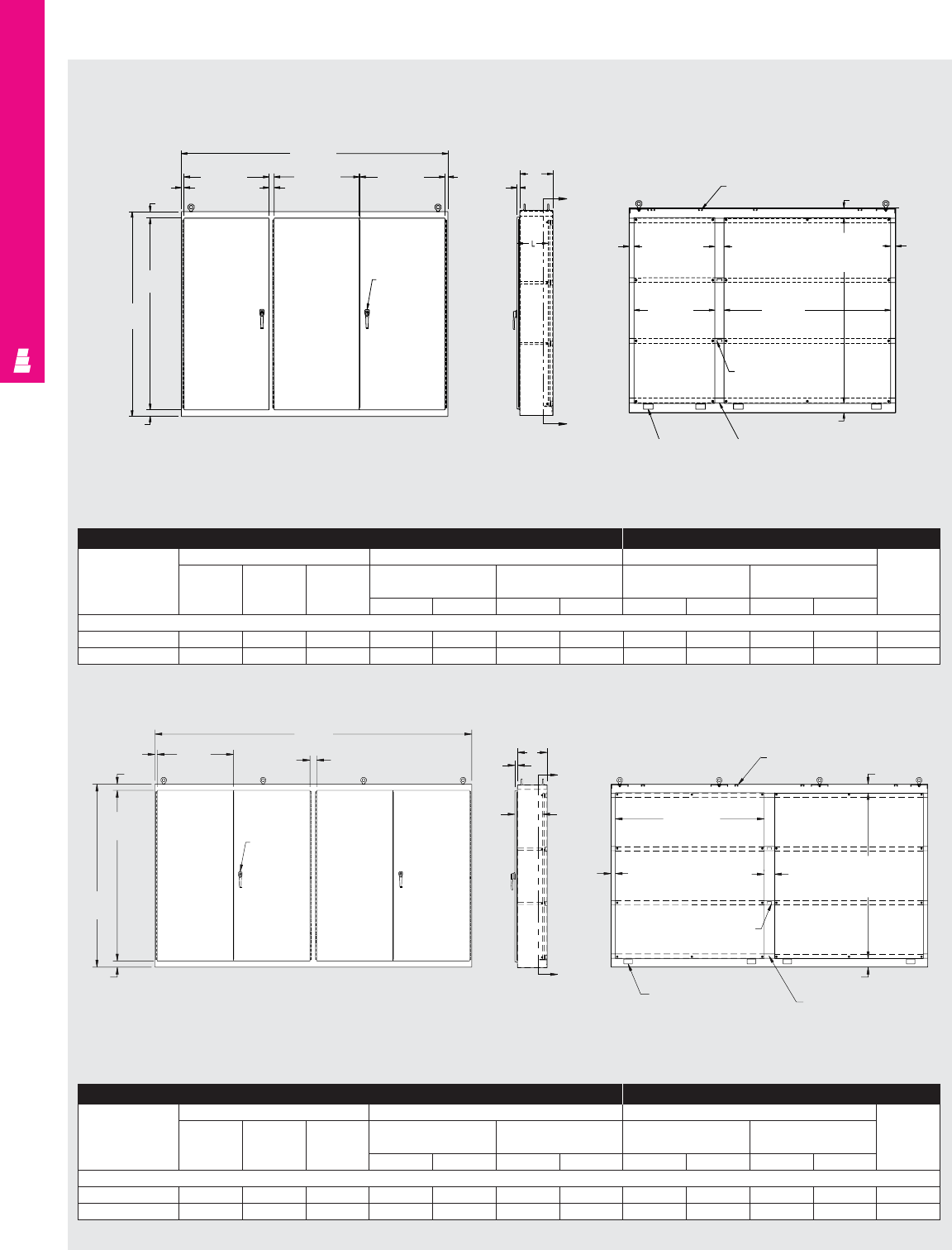
FREESTANDING ENCLOSURES
IND 91
Technical Specifications
Multi-Door Freestanding Enclosures
Section A-AFront View
B
(112.00)
Side View
F
(35.78) F
(35.78)
E
(35.69) 1.13
1.19
2.75
A
(86.00)
D
(80.50) 3 point
padlockable
handle
C
1.16 A
A
2.00 4.00
4.00
Light Strut
(4) Places
4.00
K
(70.00)
Panel
J
(34.00)
Panel
H
(78.00)
Panel
2.00
Enclosure Brace
Panel Support
(4) Places Channel Support
(4) Places
1.125
Typ.
2.75
3.0
D
(80.50)
A
(86.00)
2.75
B
(149.00)
3 point
padlockable
handle
E
(35.75)
Typ.
C
A
L
A
1.16
2.06 Typ. 4.88
K
(70.00)
Panel Typ.
Enclosure Brace
(2) Places
Panel Support
(4) Places Channel
(4) Places
4.00
4.00
Light Strut
(4) Places
H
(78.00)
Panel Typ.
Section A-AFront View Side View
Enclosure Mounting Panel
Part No.
Outside dimensions (inches) Door size Panel size Usable
Single Double Behind single Behind double depth
door door door door
HWDD ED F H JHK
3 Door Enclosure
E 86M3EDWP 86.00 112.00 18.00 80.50 35.69 80.50 35.78 78.00 34.00 78.00 70.00 17.00
E 86M3EWP 86.00 112.00 14.00 80.50 35.69 80.50 35.78 78.00 34.00 78.00 70.00 13.00
Enclosure Mounting Panel
Part No.
Outside dimensions (inches) Door size Panel size Usable
Single Double Behind single Behind double depth
door door door door
HWDD ED F H JHK
4 Door Enclosure
E 86M4EDWP 86.00 149.00 18.00 80.50 35.81 - - 78.00 70.00 - - 17.00
E 86M4EWP 86.00 149.00 14.00 80.50 35.81 - - 78.00 70.00 - - 13.00
2.75
2.13
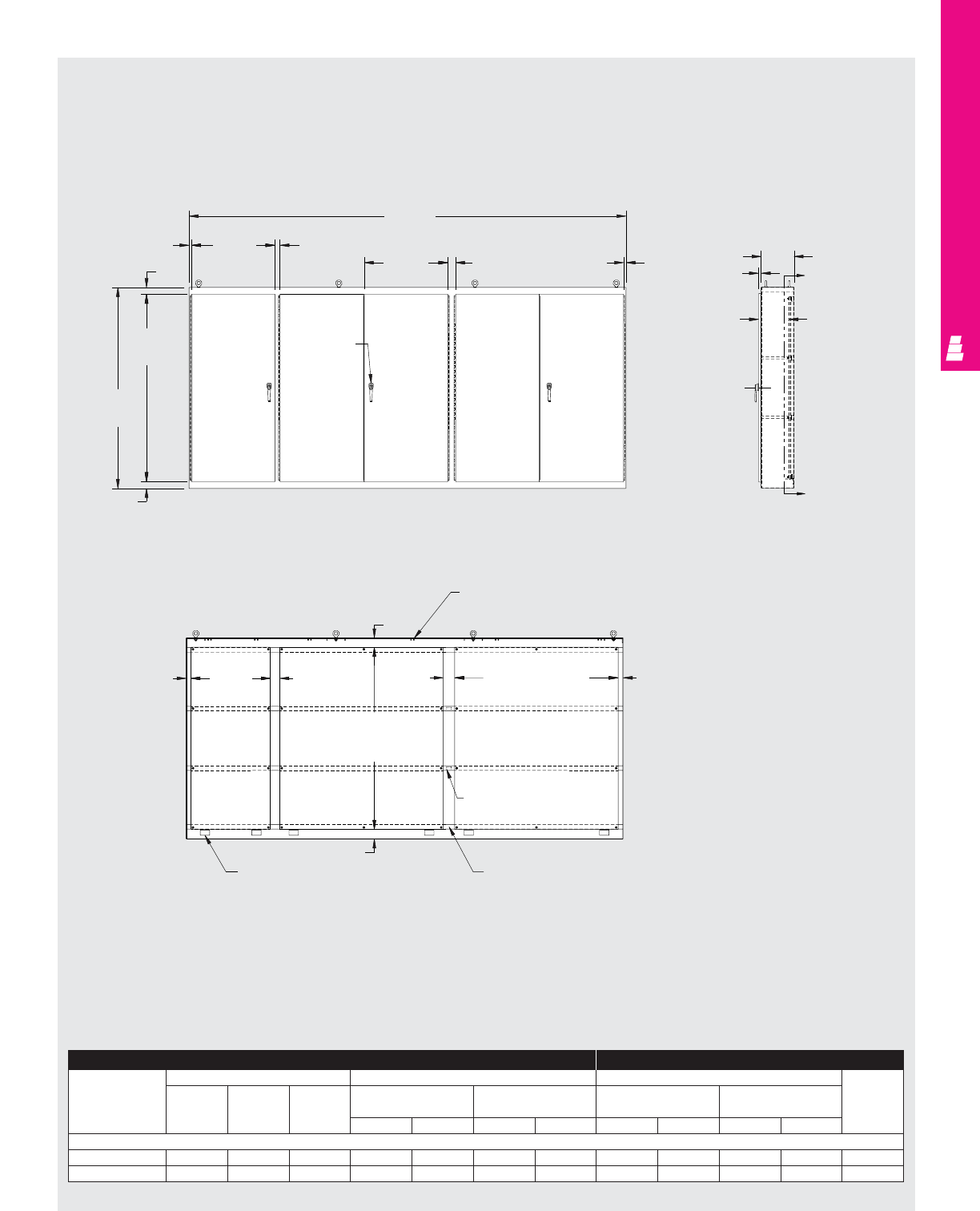
FREESTANDING ENCLOSURES
Technical Specifications
Multi-Door Freestanding Enclosures
IND 92
Section A-A
Front View Side View
1.13
2.75
E
(35.69)
B
(187.00)
F
(35.84)
Typ.
2.13
3.06 1.13
D
(80.50)
A
(86.00)
2.75
3 point
padlockable
handle
1.16
C
L
A
A
2.00 J
(34.00) 4.00 5.00
4.00
H
(78.00)
Panel (3) Places
Light Strut
(6) Places
2.00
K
(70.00)
Panel (2) Places
Enclosure Brace
Channel
(4) Places
4.00
Panel Support
(6) Places
Enclosure Mounting Panel
Part No.
Outside dimensions (inches) Door size Panel size Usable
Single Double Behind single Behind double depth
door door door door
HWDD ED F H JHK
5 Door Enclosure
E 86M5EDWP 86.00 187.00 18.00 80.50 35.69 80.50 35.84 78.00 34.00 78.00 70.00 17.00
E 86M5EWP 86.00 187.00 14.00 80.50 35.69 80.50 35.84 78.00 34.00 78.00 70.00 13.00
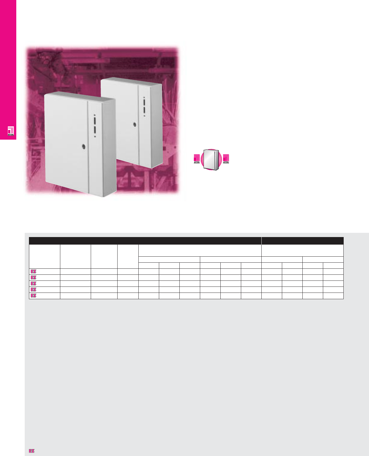
FMD ENCLOSURES
AE Wallmount Carbon Steel Cabinets
Superior in design, Rittal's AE flange mounted disconnect
enclosures have fewer moving parts, which reduces assembly
and installation time. The special lock system integrates the
door lock, operating lever, and door handle into one smooth
operating system. The unique, hinged flange door provides
easy access during installation and provides more usable
installation space.
Rittal FMD enclosures have a universal cut-out for all major
variable depth operator handles including Allen-Bradley,
Cutler-Hammer, GE, Square D, and Siemens.
Handle cutout and location has been designed for applications
up to 200A.
IND 93
AE Wallmount FMD Enclosures
Enclosure Mounting Panel
Part No. Nominal outside NEMA Number Exact outside dimensions Dimensions
dimensions rating of
H"xW"xD" doors inches mm inches mm
(approximate) H W D H W D H W H W
1075600 30x24x8 1, 12 1 29.92 23.62 8.27 760 600 210 28.74 21.61 730 549
1074600 30x30x12 1, 12 1 29.92 29.92 11.81 760 760 300 28.74 27.72 730 704
1183600 40x32x12 1, 12 1 39.37 31.50 11.81 1000 800 300 37.60 29.09 955 739
1283600 47x32x12 1, 12 1 47.24 31.50 11.81 1200 800 300 45.47 29.13 1155 740
1115600 55x40x12 1, 12 1 55.12 39.37 11.81 1400 1000 300 53.35 37.00 1355 940
C
a
r
b
o
n
S
t
e
e
l
C
a
r
b
o
n
S
t
e
e
l
A
v
a
i
l
a
b
l
e
I
n
A
v
a
i
l
a
b
l
e
I
n
Page IND 23
Designates a product in the EnclosureZone program.

FMD ENCLOSURES
IND 94
Configuration
•NEMA 1, and 12/IP55 protection
•UL/CSA approvals
•Hinged flange door allows easy component
installation and a larger mounting panel
•Universal cut-out accepts most operator
handles up to 200A
•All disconnecting hardware is included
•Rear mounting holes allow direct
wallmounting or the use of optional
mounting feet
•Reinforced mounting panel included
•Powder paint provides superior corrosion
protection
•Knife-edge design protects against
liquid entry
Technical Specifications
Material:
Sheet steel
•Housing: 16 ga/1.5 mm
•Door: 14 ga/2 mm
•Mounting panel: 14 ga/2 mm hot-dipped
galvanized zinc
Finish/color:
•Housing and door: powder painted, RAL
7032 pebble grey
•Mounting panel: Type M
Page . . . . . . . . . . . . . . . . . . . . . . . . . . . . IND 105
NEMA Type 144X1213
UL CUL CSA TÜV
Listings
Protection Ratings
Certifications/Approvals
Technical Drawings
Accessories
Part No. Wallmounting brackets Plastic print
pocket
3/8" standoff 1 1/2" standoff
1075600 2508200 2503200 2514000
1074600 2508200 2503200 2514000
1183600 2508200 2503200 2514000
1283600 2508200 2503200 2514000
1115600 2508200 2503200 2514000
Designates a product in the EnclosureZone program.
Pages . . . . . . . . . . . . . . . . . . . . . . . . . IND 111-142
FMD Technical Information
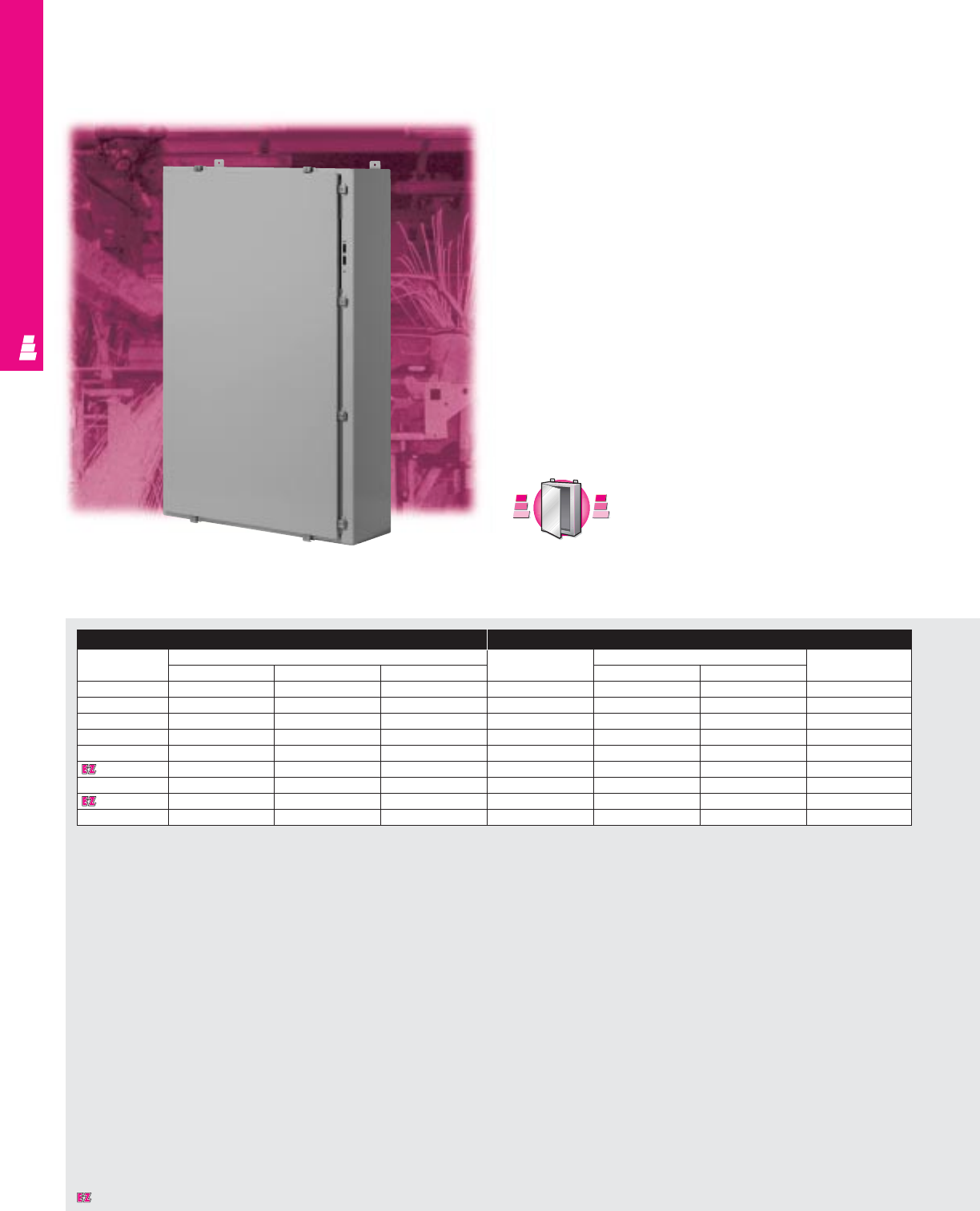
FMD ENCLOSURES
IND 95
NEMA 4 Wallmount Boxes
Carbon Steel FMD Cabinets
Rittal Electromate NEMA rated wallmount disconnect
enclosures accept all standard available disconnects and
circuit-breakers, including:
Allen Bradley:
1494 V operators for disconnects/circuit-breakers
Cutler Hammer/Westinghouse:
C361 operators for disconnect switches
C371 operators for circuit-breakers
General Electric:
Type STDA operators for disconnects
ITE/Siemens:
Max-Flex operators for disconnect switches/circuit-breakers
Square D:
Class 9422 operators for disconnects/circuit-breakers
ABB:
Operators for disconnect switches/circuit-breakers
Enclosure Mounting Panel
Part No. Outside dimensions (inches) Part No. Panel size Usable depth
HWD HW
E 24HS2108 24.00 21.38 8.00 E 24P20 21.00 17.00 8.00
E 24HS2508 24.00 25.38 8.00 E 24P24 21.00 21.00 8.00
E 30HS2508 30.00 25.38 8.00 E 30P24 27.00 21.00 8.00
E 36HS2508 36.00 25.38 8.00 E 36P24 33.00 21.00 8.00
E 36HS3108 36.00 31.38 8.00 E 36P30 33.00 27.00 7.37*
E 42HS3112 42.00 31.38 12.00 E 42P30 39.00 27.00 11.37*
E 42HS3712 42.00 37.38 12.00 E 42P36 39.00 33.00 11.37*
E 48HS3712 48.00 37.38 12.00 E 48P36 45.00 33.00 11.37*
E 60HS3712 60.00 37.38 12.00 E 60P36 57.00 33.00 11.37*
* Usable depth reduced by .625" at stiffener.
S
t
a
i
n
l
e
s
s
S
t
e
e
l
S
t
a
i
n
l
e
s
s
S
t
e
e
l
A
v
a
i
l
a
b
l
e
I
n
A
v
a
i
l
a
b
l
e
I
n
Page IND 231
Designates a product in the EnclosureZone program.
FMD ENCLOSURES
IND 96
Configuration (Style 04):
•Bullet Body (Style 06). Continuously welded
seams, finished smooth
•Continuous stainless steel
hinge with removable pin
•Robotically applied urethane
gasket
•Rolled edge prevents entry of dirt
and liquids
•Cutout in body for operating handle
•12 gauge stainless steel
captive clamps
•Mounting panel provisions installed
•External mounting brackets
•Print pocket included
Technical Specifications
Material:
•Enclosure/door: 14 gauge carbon steel
Finish/color:
•Enclosure/door: polyester-urethane powder
coat over phosphatized surfaces - ANSI 61
grey outside and white inside
•Optional mounting panels: painted white
Configuration
•Continuously welded seams, finished
smooth
•Continuous stainless steel hinge with
removable pin
•Robotically applied urethane gasket
•Rolled edge prevents entry of dirt and
liquids
•Cutout in body for operating handle
•12 gauge stainless steel captive clamps
•Mounting panel provisions installed
•External mounting brackets
•Print pocket included
Page . . . . . . . . . . . . . . . . . . . . . . . . . . . . IND 106
NEMA Type 144X1213
UL CUL CSA TÜV
Listings
Protection Ratings
Certifications/Approvals
Technical Drawings
Accessories
Part No. Window kit Touch-up paint
E 24HS2108 E PWK1711NF E L21
E 24HS2508 E PWK1711NF E L21
E 30HS2508 E PWK2315NF E L21
E 36HS2508 E PWK2919NF E L21
E 36HS3108 E PWK2919NF E L21
E 42HS3112 E PWK3523NF E L21
E 42HS3712 E PWK3523NF E L21
E 48HS3712 E PWK3523NF E L21
E 60HS3712 E PWK3523NF E L21
Designates a product in the EnclosureZone program.
Pages . . . . . . . . . . . . . . . . . . . . . . . . . IND 111-142
FMD Technical Information
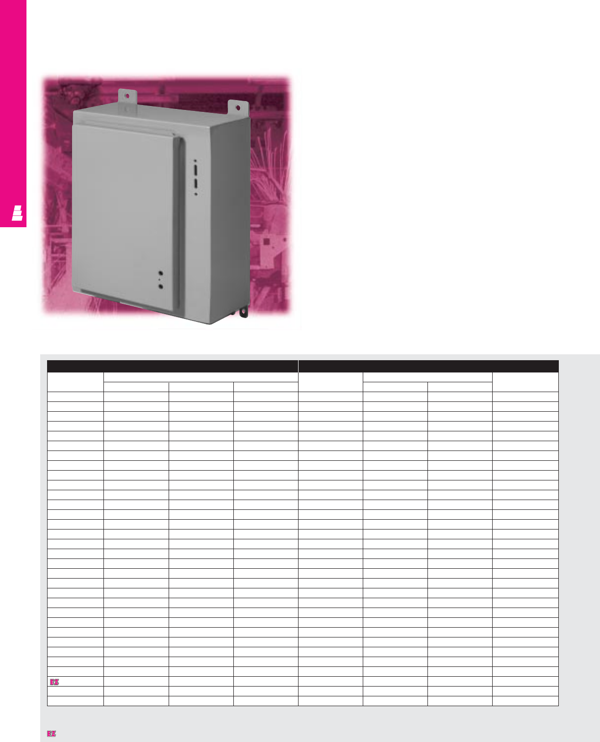
FMD ENCLOSURES
Carbon Steel FMD Cabinets
Rittal Electromate NEMA rated wallmount disconnect
enclosures accept all standard available disconnects and
circuit-breakers, including:
Allen Bradley:
1494 V operators for disconnects/circuit-breakers
Cutler Hammer/Westinghouse:
C361 operators for disconnect switches
C371 operators for circuit-breakers
General Electric:
Type STDA operators for disconnects
ITE/Siemens:
Max-Flex operators for disconnect switches/circuit-
breakers
Square D:
Class 9422 operators for disconnects/circuit-breakers
ABB:
Operators for disconnect switches/circuit-breakers
Note:
Additional door hardware is required and must be ordered
from disconnect manufacturer.
IND 97
NEMA 12 Wallmount Boxes
Enclosure Mounting Panel
Part No. Outside dimensions (inches) Part No. Panel size Usable depth
HWD HW
E 20SA2208 20.00 21.38 8.00 E 20P20 17.00 17.00 7.75
E 20SA2210 20.00 21.38 10.00 E 20P20 17.00 17.00 9.75
E 24SA2208 24.00 21.38 8.00 E 24P20 21.00 17.00 7.75
E 24SA2210 24.00 21.38 10.00 E 24P20 21.00 17.00 9.75
E 24SA2608 24.00 25.38 8.00 E 24P24 21.00 21.00 7.75
E 24SA2610 24.00 25.38 10.00 E 24P24 21.00 21.00 9.75
E 30SA2208 30.00 21.38 8.00 E 30P20 27.00 17.00 7.75
E 30SA2210 30.00 21.38 10.00 E 30P20 27.00 17.00 9.75
E 30SA2608 30.00 25.38 8.00 E 30P24 27.00 21.00 7.75
E 30SA2610 30.00 25.38 10.00 E 30P24 27.00 21.00 9.75
E 30SA2612 30.00 25.38 12.00 E 30P24 27.00 21.00 11.75
E 36SA2608 36.00 25.38 8.00 E 36P24 33.00 21.00 7.75
E 36SA2610 36.00 25.38 10.00 E 36P24 33.00 21.00 9.75
E 36SA3208 36.00 31.38 8.00 E 36P30 33.00 27.00 7.12*
E 36SA3210 36.00 31.38 10.00 E 36P30 33.00 27.00 9.12*
E 36SA3212 36.00 31.38 12.00 E 36P30 33.00 27.00 11.12*
E 36SA3216 36.00 31.38 16.00 E 36P30 33.00 27.00 15.12*
E 42SA3208 42.00 31.38 8.00 E 42P30 39.00 27.00 7.12*
E 42SA3210 42.00 31.38 10.00 E 42P30 39.00 27.00 9.12*
E 42SA3212 42.00 31.38 12.00 E 42P30 39.00 27.00 11.12*
E 42SA3808 42.00 37.38 8.00 E 42P36 39.00 33.00 7.12*
E 42SA3810 42.00 37.38 10.00 E 42P36 39.00 33.00 9.12*
E 42SA3812 42.00 37.38 12.00 E 42P36 39.00 33.00 11.12*
E 48SA3808 48.00 37.38 8.00 E 48P36 45.00 33.00 7.12*
E 48SA3810 48.00 37.38 10.00 E 48P36 45.00 33.00 9.12*
E 48SA3812 48.00 37.38 12.00 E 48P36 45.00 33.00 11.12*
E 48SA3816 48.00 37.38 16.00 E 48P36 45.00 33.00 15.12*
E 60SA3808 60.00 37.38 8.00 E 60P36 57.00 33.00 7.12*
E 60SA3810 60.00 37.38 10.00 E 60P36 57.00 33.00 9.12*
E 60SA3812 60.00 37.38 12.00 E 60P36 57.00 33.00 11.12*
E 60SA3812400# 60.00 37.38 12.00 E 60P36 57.00 33.00 11.12*
E 60SA3816 60.00 37.38 16.00 E 60P36 57.00 33.00 15.12*
* Usable depth reduced by .625” at door stiffener.
# Designed for 200 and 400 amp Allen Bradley Bulletin 1494V disconnect switches using 1494V-H2 operating handle.
Designates a product in the EnclosureZone program.
FMD ENCLOSURES
IND 98
Technical Specifications
Material:
•Enclosure/door: 14 gauge carbon steel
Finish/color:
•Enclosure/door: polyester-urethane powder
coat over phosphatized surfaces – ANSI 61
grey outside and white inside
•Optional mounting panels: painted white
Configuration
•Continuously welded seams, finished
smooth
•Continuous steel hinge with removable pin
•Urethane gasket
•Rolled edge prevents entry of dirt and
liquids
•Cutouts in body and door for operating
handle, operating mechanism, and door
closing mechanism
•Mounting panel provisions installed
•External mounting brackets
•Print pocket included
Page . . . . . . . . . . . . . . . . . . . . . . . . . . . . IND 107
NEMA Type 144X1213
UL CUL CSA TÜV
Listings
Protection Ratings
Certifications/Approvals
Technical Drawings
Accessories
Part No. Window kit Touch-up paint
E 20SA2208 E PWK138NF E L21
E 20SA2210 E PWK138NF E L21
E 24SA2208 E PWK1711NF E L21
E 24SA2210 E PWK1711NF E L21
E 24SA2608 E PWK1711NF E L21
E 24SA2610 E PWK1711NF E L21
E 30SA2208 E PWK1711NF E L21
E 30SA2210 E PWK1711NF E L21
E 30SA2608 E PWK2315NF E L21
E 30SA2610 E PWK2315NF E L21
E 30SA2612 E PWK2315NF E L21
E 36SA2608 E PWK2919NF E L21
E 36SA2610 E PWK2919NF E L21
E 36SA3208 E PWK2919NF E L21
E 36SA3210 E PWK2919NF E L21
E 36SA3212 E PWK2919NF E L21
E 36SA3216 E PWK2919NF E L21
E 42SA3208 E PWK3523NF E L21
E 42SA3210 E PWK3523NF E L21
E 42SA3212 E PWK3523NF E L21
E 42SA3808 E PWK3523NF E L21
E 42SA3810 E PWK3523NF E L21
E 42SA3812 E PWK3523NF E L21
E 48SA3808 E PWK3523NF E L21
E 48SA3810 E PWK3523NF E L21
E 48SA3812 E PWK3523NF E L21
E 48SA3816 E PWK3523NF E L21
E 60SA3808 E PWK3523NF E L21
E 60SA3810 E PWK3523NF E L21
E 60SA3812 E PWK3523NF E L21
E 60SA3812400#E PWK3523NF E L21
E 60SA3816 E PWK3523NF E L21
# Designed for 200 and 400 amp Allen Bradley Bulletin 1494V disconnect switches using 1494V-H2 operating handle.
Designates a product in the EnclosureZone program.
Pages . . . . . . . . . . . . . . . . . . . . . . . . . IND 111-142
FMD Technical Information
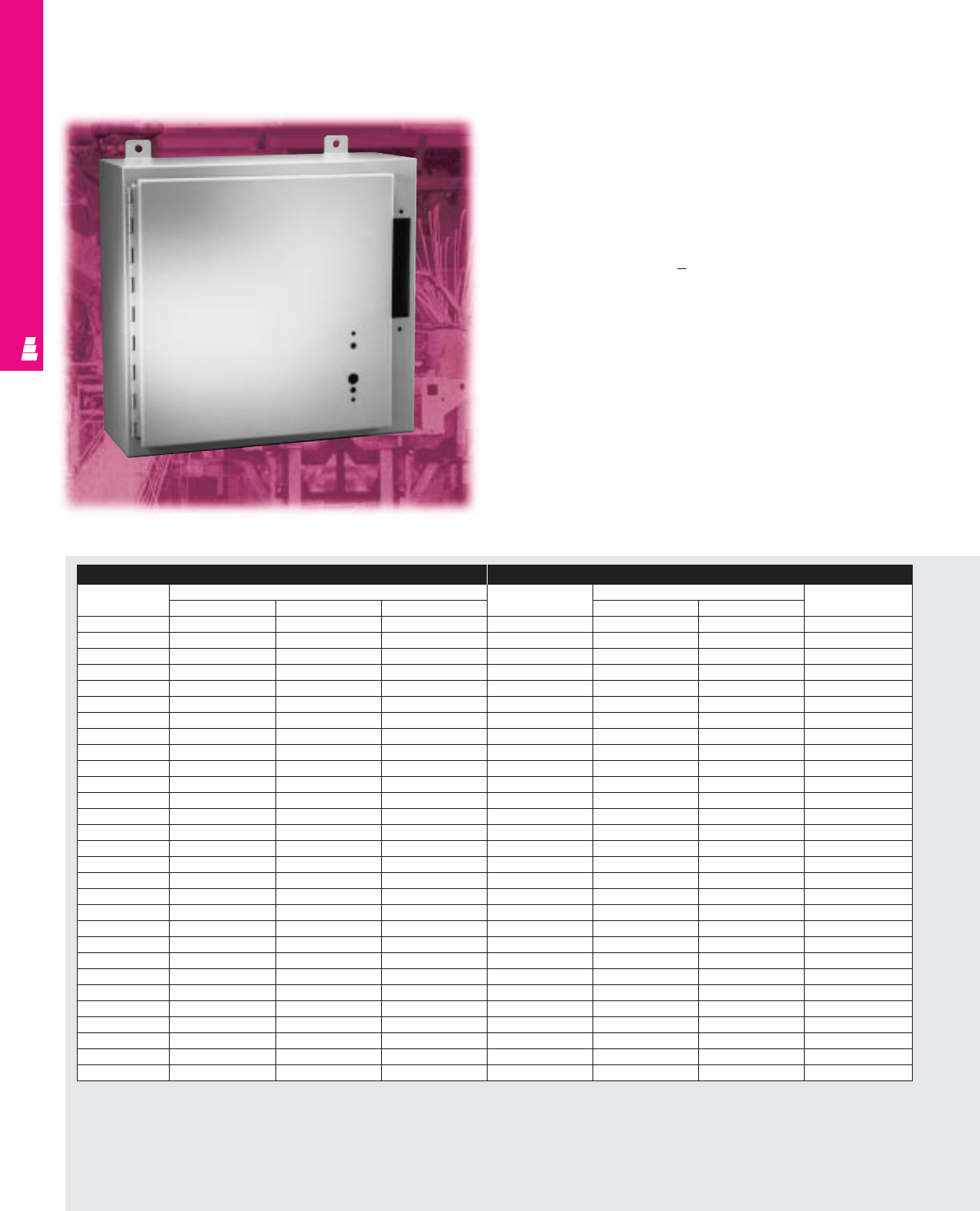
Carbon Steel FMD Enclosures
These Rittal Electromate NEMA rated wallmount disconnect
enclosures accept Allen-Bradley 1494F flange mounted
disconnect switches and 1494D flange mounted operators for
circuit-breakers.
For enclosure height (“A”) < 40":
A 2-point door closing mechanism is required
For enclosure height (“A”) > 40":
A 3-point door closing mechanism is required
Note:
Additional door hardware is required and must be ordered
from disconnect manufacturer.
IND 99
NEMA 12 Wallmount Enclosures
FMD ENCLOSURES
Enclosure Mounting Panel
Part No. Outside dimensions (inches) Part No. Panel size Usable depth
HWD HW
E 20AB2208 20.00 21.38 8.00 E 20P20 17.00 17.00 7.75
E 24AB2208 24.00 21.38 8.00 E 24P20 21.00 17.00 7.75
E 24AB2210 24.00 21.38 10.00 E 24P20 21.00 17.00 9.75
E 24AB2608 24.00 25.38 8.00 E 24P24 21.00 21.00 7.75
E 24AB2610 24.00 25.38 10.00 E 24P24 21.00 21.00 9.75
E 30AB2208 30.00 21.38 8.00 E 30P20 27.00 17.00 7.75
E 30AB2210 30.00 21.38 10.00 E 30P20 27.00 17.00 9.75
E 30AB2608 30.00 25.38 8.00 E 30P24 27.00 21.00 7.75
E 30AB2610 30.00 25.38 10.00 E 30P24 27.00 21.00 9.75
E 36AB2608 36.00 25.38 8.00 E 36P24 33.00 21.00 7.75
E 36AB2610 36.00 25.38 10.00 E 36P24 33.00 21.00 9.75
E 36AB3208 36.00 31.38 8.00 E 36P30 33.00 27.00 7.12*
E 36AB3210 36.00 31.38 10.00 E 36P30 33.00 27.00 9.12*
E 36AB3212 36.00 31.38 12.00 E 36P30 33.00 27.00 11.12*
E 42AB3208 42.00 31.38 8.00 E 42P30 39.00 27.00 7.12*
E 42AB3210 42.00 31.38 10.00 E 42P30 39.00 27.00 9.12*
E 42AB3212 42.00 31.38 12.00 E 42P30 39.00 27.00 11.12*
E 42AB3808 42.00 37.38 8.00 E 42P36 39.00 33.00 7.12*
E 42AB3810 42.00 37.38 10.00 E 42P36 39.00 33.00 9.12*
E 42AB3812 42.00 37.38 12.00 E 42P36 39.00 33.00 11.12*
E 48AB3808 48.00 37.38 8.00 E 48P36 45.00 33.00 7.12*
E 48AB3810 48.00 37.38 10.00 E 48P36 45.00 33.00 9.12*
E 48AB3812 48.00 37.38 12.00 E 48P36 45.00 33.00 11.12*
E 48AB381220# 48.00 37.38 12.00 E 48P36 45.00 33.00 11.12*
E 48AB3816 48.00 37.38 16.00 E 48P36 45.00 33.00 15.12*
E 60AB3810 60.00 37.38 10.00 E 60P36 57.00 33.00 9.12*
E 60AB3812 60.00 37.38 12.00 E 60P36 57.00 33.00 11.12*
E 60AB381220# 60.00 37.38 12.00 E 60P36 57.00 33.00 11.12*
E 60AB3816 60.00 37.38 16.00 E 48P36 45.00 33.00 15.12*
* Usable depth reduced by .625” at door stiffener.
# Designed for 200 and 400 amp Allen Bradley Bulletin 1494V disconnect switches using 1494V-H2 operating handle.
IND 100
FMD ENCLOSURES
Configuration
•Continuously welded seams, finished smooth
•Continuous steel hinge with removable pin
•Urethane gasket
•Rolled edge prevents entry of dirt and liquids
•Cutouts in body and door for operating
handle, operating mechanism, and door
closing mechanism
•Mounting panel provisions installed
•External mounting brackets
•Print pocket included
Technical Specifications
Material:
•Enclosure/door: 14 gauge carbon steel
Finish/color:
•Enclosure/door: polyester-urethane powder
coat over phosphatized surfaces – ANSI 61
grey outside and white inside
•Optional mounting panels: painted white
Accessories
Part No. Window kit Touch-up paint
E 20AB2208 E PWK138NF E L21
E 24AB2208 E PWK1711NF E L21
E 24AB2210 E PWK1711NF E L21
E 24AB2608 E PWK1711NF E L21
E 24AB2610 E PWK1711NF E L21
E 30AB2208 E PWK1711NF E L21
E 30AB2210 E PWK1711NF E L21
E 30AB2608 E PWK2315NF E L21
E 30AB2610 E PWK2315NF E L21
E 36AB2608 E PWK2919NF E L21
E 36AB2610 E PWK2919NF E L21
E 36AB3208 E PWK2919NF E L21
E 36AB3210 E PWK2919NF E L21
E 36AB3212 E PWK2919NF E L21
E 42AB3208 E PWK3523NF E L21
E 42AB3210 E PWK3523NF E L21
E 42AB3212 E PWK3523NF E L21
E 42AB3808 E PWK3523NF E L21
E 42AB3810 E PWK3523NF E L21
E 42AB3812 E PWK3523NF E L21
E 48AB3808 E PWK3523NF E L21
E 48AB3810 E PWK3523NF E L21
E 48AB3812 E PWK3523NF E L21
E 48AB381220# E PWK3523NF E L21
E 48AB3816 E PWK3523NF E L21
E 60AB3810 E PWK3523NF E L21
E 60AB3812 E PWK3523NF E L21
E 60AB381220# E PWK3523NF E L21
E 60AB3816 E PWK3523NF E L21
# Designed for 200 and 400 amp Allen Bradley Bulletin 1494V disconnect switches using 1494V-H2 operating handle.
Page . . . . . . . . . . . . . . . . . . . . . . . . . . . . IND 108
NEMA Type 144X1213
UL CUL CSA TÜV
Listings
Protection Ratings
Certifications/Approvals
Technical Drawings
Pages . . . . . . . . . . . . . . . . . . . . . . . . . IND 111-142
FMD Technical Information
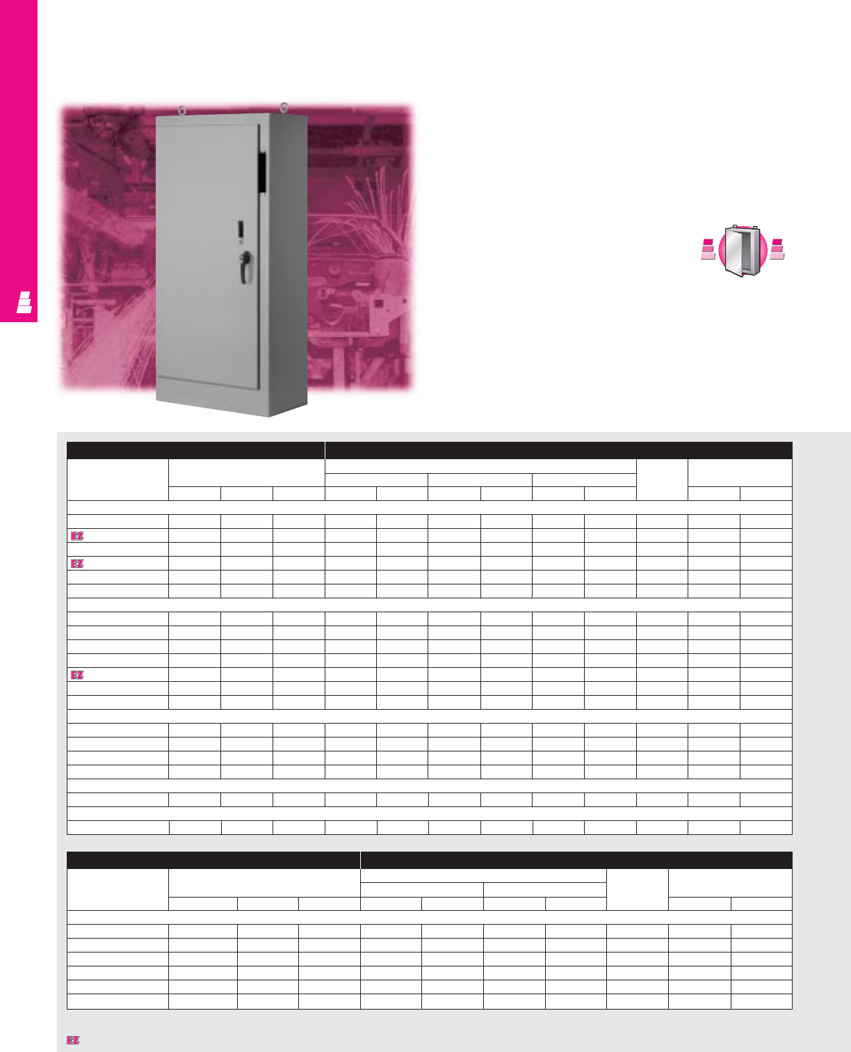
FMD ENCLOSURES
IND 101
Freestanding Heavy Duty Enclosures
NEMA 12 Carbon Steel Cabinets
Rittal Electromate NEMA rated freestanding disconnect
enclosures accept all standard available disconnects and
circuit-breakers, including:
Allen Bradley:
1494 V operators for disconnects/circuit-breakers
1494 F operators for disconnect switches
1494 D operators for circuit-breakers
Cutler Hammer/Westinghouse:
C361 operators for disconnect switches
C371 operators for circuit-breakers
General Electric:
Type STDA operators for disconnects
ITE/Siemens:
Max-Flex operators for disconnect switches/circuit-breakers
Square D:
Class 9422 operators for disconnects/circuit-breakers
ABB:
Operators for disconnect switches/circuit-breakers
Enclosure Mounting Panel
Part No.
Outside dimensions (inches) Panel size Usable Door
Panel size Size behind single door Size behind double door depth Size
HWDHWHWHW HW
One Door Heavy Duty Enclosure
E 72XM2818WP 72.00 27.50 18.00 60.00 21.75 - - - - 18.00 62.50 23.83
E 72XM3418WP 72.00 33.50 18.00 60.00 27.75 - - - - 18.00 62.50 29.83
E 72XM4018WP 72.00 39.50 18.00 60.00 33.75 - - - - 18.00 62.50 35.83
E 84XM4018WP 84.00 39.50 18.00 72.00 33.75 - - - - 18.00 74.50 35.83
E 90XM4020WP 90.00 39.50 20.00 78.00 33.75 - - - - 20.00 80.50 35.83
E 90XM4024WP 90.00 39.50 24.00 78.00 33.75 - - - - 24.00 80.50 35.83
Two Door Heavy Duty Enclosure
E 72XM5418WP 72.00 53.75 18.00 60.00 48.00 - - - - 17.00 62.50 23.88
E 72XM6618WP 72.00 65.75 18.00 60.00 60.00 - - - - 17.00 62.50 29.88
E 72XM7818WP 72.00 77.75 18.00 60.00 72.00 - - - - 17.00 62.50 35.88
E 72XM7824WP 72.00 77.75 24.00 60.00 72.00 - - - - 23.00 62.50 35.88
E 84XM7818WP 84.00 77.75 18.00 72.00 72.00 - - - - 17.00 74.50 35.88
E 90XM7820WP 90.00 77.75 20.00 78.00 72.00 - - - - 19.00 80.50 35.88
E 90XM7824WP 90.00 77.75 24.00 78.00 72.00 - - - - 23.00 80.50 35.88
Three Door Heavy Duty Enclosure
E 72XM3EQ18WP 72.00 99.50 18.00 - - 60.00 27.75 60.00 60.00 17.00 62.50 29.88
E 72XM3EW18WP 72.00 117.50 18.00 - - 60.00 33.75 60.00 72.00 17.00 62.50 35.88
E 84XM3EW18WP 84.00 117.50 18.00 - - 72.00 33.75 72.00 72.00 17.00 74.50 35.88
E 90XM3EW24WP 90.00 117.50 24.00 - - 78.00 33.75 78.00 72.00 23.00 80.50 35.88
Four Door Heavy Duty Enclosure
E 84XM4EW18WP 84.00 157.50 18.00 72.00* 72.00* - - - - 17.00 74.50 35.88
Five Door Heavy Duty Enclosure
E 84XM5EW18WP 84.00 196.75 18.00 - - 72.00 33.75 72.00* 72.00* 17.00 74.50 35.88
Designates a product in the EnclosureZone program.
Enclosure Mounting Panel
Part No.
Outside dimensions (inches) Panel size Usable Door
Panel size Opening size left side depth Size
HWDHWHW HW
Modular Enclosure
E MOD72X4018 1) 72.00 39.75 18.00 60.00 33.75 66.63 12.25 17.06 62.50 35.88
E MOD72X7818 2) 72.00 78.00 18.00 60.00 72.70 66.63 12.25 17.06 62.50 36.38
E MOD84X4018 1) 84.00 39.75 18.00 72.00 33.75 78.63 12.25 17.06 74.50 35.88
E MOD84X4024 1) 84.00 39.75 24.00 72.00 33.75 78.63 18.25 23.06 74.50 35.88
E MOD84X7818 2) 84.00 78.00 18.00 72.00 72.00 78.63 12.25 17.06 74.50 36.88
E MOD84X7824 2) 84.00 78.00 24.00 72.00 72.00 78.63 18.25 23.06 74.50 36.38
1) Single door. 2) Double door. *Two mounting panels used.
S
t
a
i
n
l
e
s
s
S
t
e
e
l
S
t
a
i
n
l
e
s
s
S
t
e
e
l
A
v
a
i
l
a
b
l
e
I
n
A
v
a
i
l
a
b
l
e
I
n
Page IND 233
FMD ENCLOSURES
IND 102
Configuration (Style 04):
•Bullet Body (Style 06). Continuously welded
seams, finished smooth
•Continuous stainless steel
hinge with removable pin
•Robotically applied urethane
gasket
•Rolled edge prevents entry of dirt
and liquids
•Cutout in body for operating handle
•12 gauge stainless steel
captive clamps
•Mounting panel provisions installed
•External mounting brackets
•Print pocket included
Technical Specifications
Material:
•Enclosure/door: 10 gauge carbon steel
•Mounting panel: 10 gauge carbon steel
Finish/color:
•Enclosure/door: polyester-urethane powder
coat over phosphatized surfaces – ANSI 61
grey outside and white inside
•Mounting panel: painted white
Configuration
• Continuously welded seams, finished
smooth
•Body stiffeners provide extra rigidity
•Center post can be removed for panel
installation
•Urethane gasket
•Rolled edge prevents entry of dirt and
liquids
•Heavy duty continuous steel hinge with
removable pin
•Heavy duty 3-point latch secures doors
•Mounting panels included
•Doors can be closed in any order
•Mechanical interlock on master door
prevents slave door from being opened
unless master door is opened first
•Intergrated defeater on master door
Pages . . . . . . . . . . . . . . . . . . . . . . . . IND 109-110
NEMA Type 144X1213
UL CUL CSA TÜV
Listings
Protection Ratings
Certifications/Approvals
Technical Drawings
Accessories
Part No. Window kit Touch-up paint
One Door Heavy Duty Enclosure E L21
E 72XM2818WP E PWK2315NF E L21
E 72XM3418WP E PWK3523NF E L21
E 72XM4018WP E PWK3523NF E L21
E 84XM4018WP E PWK3523NF E L21
E 90XM4020WP E PWK3523NF E L21
E 90XM4024WP E PWK3523NF E L21
Two Door Heavy Duty Enclosure
E 72XM5418WP E PWK2315NF E L21
E 72XM6618WP E PWK3523NF E L21
E 72XM7818WP E PWK3523NF E L21
E 72XM7824WP E PWK3523NF E L21
E 84XM7818WP E PWK3523NF E L21
E 90XM7820WP E PWK3523NF E L21
E 90XM7824WP E PWK3523NF E L21
Three Door Heavy Duty Enclosure
E 72XM3EQ18WP E PWK3523NF E L21
E 72XM3EW18WP E PWK3523NF E L21
E 84XM3EW18WP E PWK3523NF E L21
E 90XM3EW24WP E PWK3523NF E L21
Four Door Heavy Duty Enclosure
E 84XM4EW18WP E PWK3523NF E L21
Five Door Heavy Duty Enclosure
E 84XM5EW18WP E PWK3523NF E L21
Designates a product in the EnclosureZone program.
•Operator adaptors may be used to fit most
disconnect operators in universal cutout on
flange
•24” deep enclosures feature mounting base
to raise disconnects to the proper height off
the mounting panel
•Heavy duty lifting eyes
•Print pocket included
Accessories
Part No. Window kit Touch-up paint
Modular Enclosure
E MOD72X4018 E PWK3523NF E L21
E MOD72X7818 E PWK3523NF E L21
E MOD84X4018 E PWK3523NF E L21
E MOD84X4024 E PWK3523NF E L21
E MOD84X7818 E PWK3523NF E L21
E MOD84X7824 E PWK3523NF E L21
Pages . . . . . . . . . . . . . . . . . . . . . . . . . IND 111-142
FMD Technical Information
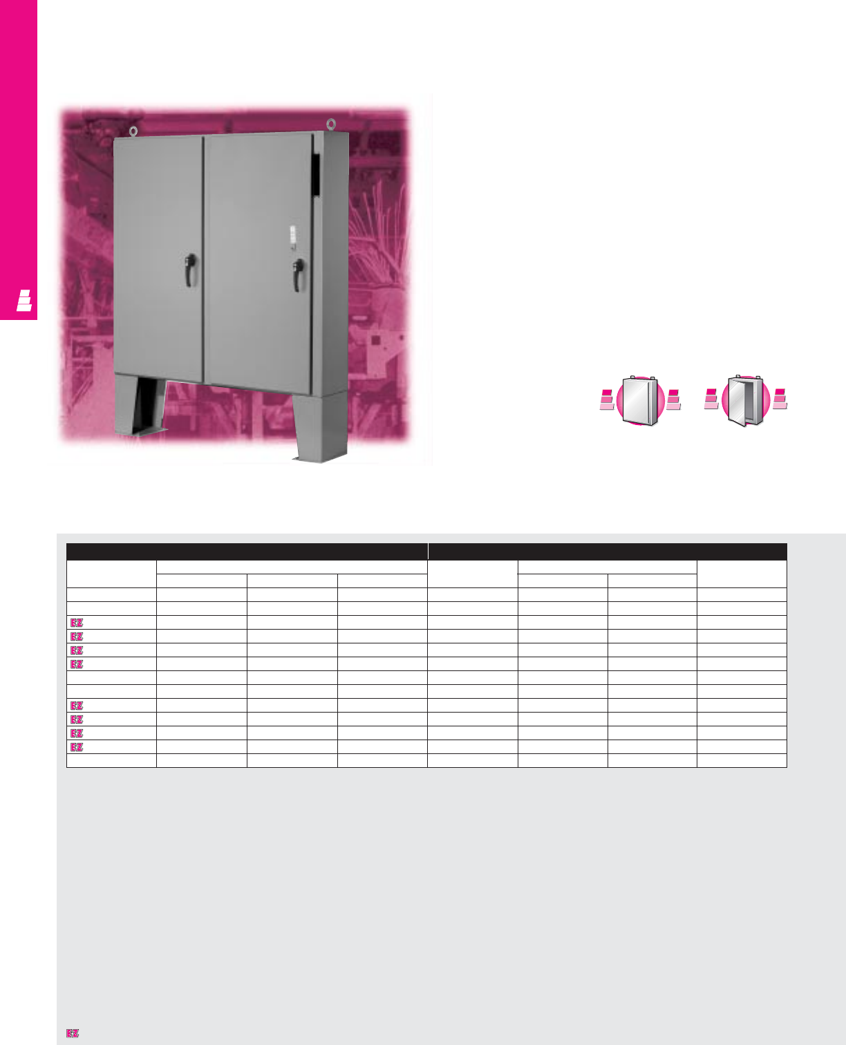
FMD ENCLOSURES
NEMA 12 Carbon Steel FMD Cabinets
Rittal Electromate NEMA rated floormount disconnect
enclosures accept all standard available disconnects and
circuit-breakers, including:
Allen Bradley:
1494 V Operators for disconnects/circuit-breakers
1494 F Operators for disconnect switches
1494 D Operators for circuit-breakers
Cutler Hammer/Westinghouse:
C361 Operators for disconnect switches
C371 Operators for circuit-breakers
General Electric:
Type STDA Operators for disconnects
ITE/Siemens:
Max-Flex Operators for disconnect switches/circuit-
breakers
Square D:
Class 9422 Operators
for disconnects/circuit-
breakers
ABB:
Operators for disconnect
switches/circuit-breakers
IND 103
Floormount Freestanding Enclosures
Enclosure Mounting Panel
Part No. Outside dimensions (inches) Part No. Panel size Usable depth
HWD HW
E 60CPX4812 1) 60.00 48.00 12.00 E 60P48 56.00 44.00 12.00
E 60CPX6012 1) 60.00 60.00 12.00 E 60P60 56.00 56.00 12.00
E 60X4912 2) 60.00 49.38 12.00 E 60P48 56.00 44.00 12.00
E 60X4918 2) 60.00 49.38 18.00 E 60P48 56.00 44.00 18.00
E 60X6112 2) 60.00 61.38 12.00 E 60P60 56.00 56.00 12.00
E 60X6118 2) 60.00 61.38 18.00 E 60P60 56.00 56.00 18.00
E 72CPX7212 1) 72.00 72.00 12.00 E 72P72 68.00 68.00 12.00
E 72CPX7218 1) 72.00 72.00 18.00 E 72P72 68.00 68.00 18.00
E 72X6112 2) 72.00 61.38 12.00 E 72P60 68.00 56.00 12.00
E 72X6118 2) 72.00 61.38 18.00 E 72P60 68.00 56.00 18.00
E 72X7312 2) 72.00 73.38 12.00 E 72P72 68.00 68.00 12.00
E 72X7318 2) 72.00 73.38 18.00 E 72P72 68.00 68.00 18.00
E 72X7324 2) 72.00 73.00 24.00 E 72P72 68.00 68.00 24.00
C
a
r
b
o
n
S
t
e
e
l
C
a
r
b
o
n
S
t
e
e
l
A
v
a
i
l
a
b
l
e
I
n
A
v
a
i
l
a
b
l
e
I
n
Page IND 81
Designates a product in the EnclosureZone program.
1) Disconnect operator on right flange. 2) Disconnect operator on center post.
S
t
a
i
n
l
e
s
s
S
t
e
e
l
S
t
a
i
n
l
e
s
s
S
t
e
e
l
A
v
a
i
l
a
b
l
e
I
n
A
v
a
i
l
a
b
l
e
I
n
Page IND 232
FMD ENCLOSURES
IND 104
Technical Specifications
Material:
•Enclosure/door: 10 gauge carbon steel
Finish/color:
•Enclosure/door: polyester-urethane powder
coat over phosphatized surfaces - ANSI 61
grey outside and white inside
•Optional mounting panels: painted white
Page . . . . . . . . . . . . . . . . . . . . . . . . . . . . IND 111
NEMA Type 144X1213
UL CUL CSA TÜV
Listings
Protection Ratings
Certifications/Approvals
Technical Drawings
Accessories
Part No. Window kit Touch-up paint
E 60CPX4812 E PWK2315NF E L21
E 60CPX6012 E PWK2919NF E L21
E 60X4912 E PWK2315NF E L21
E 60X4918 E PWK2315NF E L21
E 60X6112 E PWK2919NF E L21
E 60X6118 E PWK2919NF E L21
E 72CPX7212 E PWK3523NF E L21
E 72CPX7218 E PWK3523NF E L21
E 72X6112 E PWK2919NF E L21
E 72X6118 E PWK2919NF E L21
E 72X7312 E PWK3523NF E L21
E 72X7318 E PWK3523NF E L21
E 72X7324 E PWK3523NF E L21
Configuration
•
Continuously welded seams, finished smooth
•Body stiffeners provide extra rigidity
•Center post can be removed for panel
installation
•Urethane gasket
•Rolled edge prevents entry of dirt and
liquids
•Heavy duty continuous steel hinge with
removable pin
•Heavy duty 3-point latch secures doors
•Mounting panel provisions installed
•Enclosure is provided with 15" floor stands
welded to enclosure
•Heavy duty lifting eyes
•For type “X” enclosures: master door is
right-hand door
•Integrated defeater on master door; doors
can be closed in any order
•Mechanical interlock on master door
prevents slave door from being opened
unless master door is opened first
•Operator adaptors may be used to fit
most disconnect operators in universal
cutout on flange
•24" deep enclosures feature mounting base
to raise disconnects to the proper height off
the mounting panel
•Print pocket included
Designates a product in the EnclosureZone program.
Pages . . . . . . . . . . . . . . . . . . . . . . . . . IND 111-142
FMD Technical Information
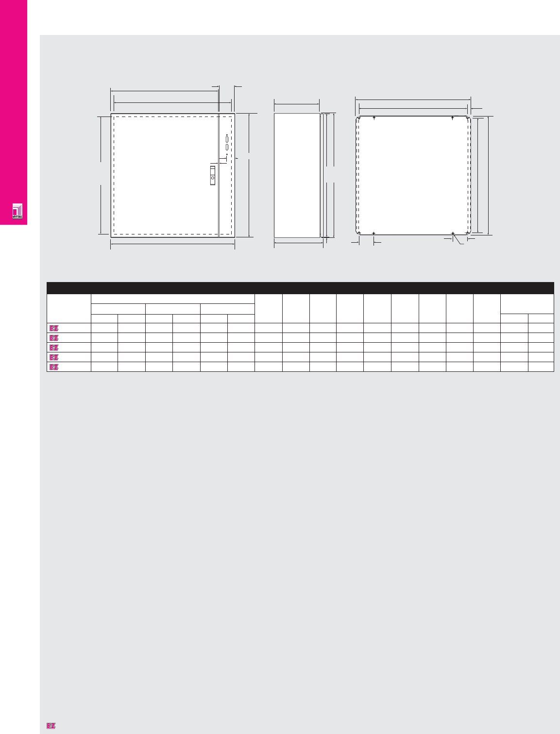
FMD ENCLOSURES
IND 105
Technical Specifications
AE Wallmount FMD Enclosures
H2
W2
W3
95.0
47.5
H1
3.0
W1 D1
2.5
D2 F1
F2
90.0 Ø 10.0x4
G2
G1
19.5
Mounting Panel
Enclosure
Part No. Exact outside dimensions H2 H3 W2 W3 D2 F1 F2 G1 G2 Weight
Height (H1) Width (W1) Depth (D1)
inches mm inches mm inches mm lbs kg
1075600 29.92 760 23.62 600 8.27 210 720 755 500 560 190 549 510 730 705 70.6 32.1
1074600 29.92 760 29.92 760 11.81 300 720 755 660 720 280 704 665 730 705 97.9 44.5
1183600 39.37 1000 31.50 800 11.81 300 960 995 700 760 280 739 700 955 930 125.4 57.0
1283600 47.24 1200 31.50 800 11.81 300 1160 1195 700 760 280 739 700 1155 1130 154.0 70.0
1115600 55.12 1400 39.37 1000 11.81 300 1360 1395 900 960 280 940 900 1355 1330 213.4 97.0
H2
H3
H1
Designates a product in the EnclosureZone program.
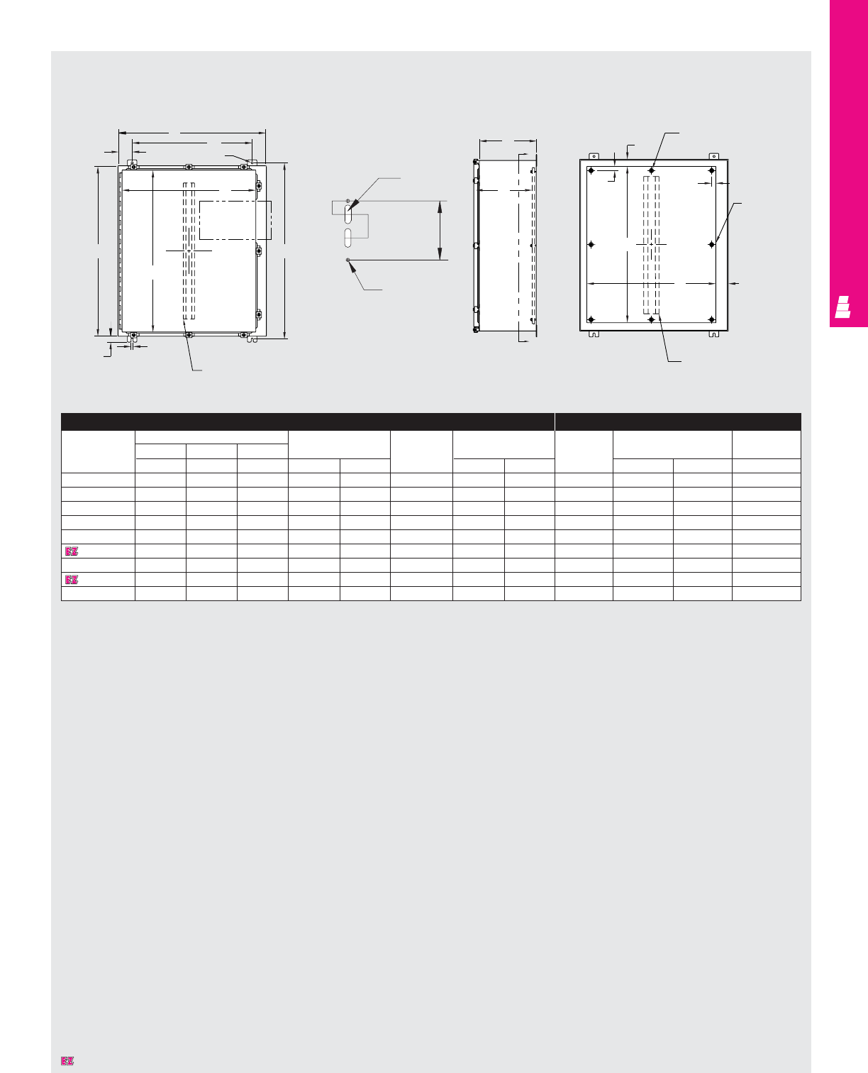
FMD ENCLOSURES
IND 106
Enclosure Mounting Panel
Part No. Outside dimensions (inches) Mounting Door Door size Part No. Panel size Usable
HW D centers and body depth
AB CHWstiffener J K E F G
E 24HS2108 24.00 21.38 8.00 25.25 15.38 NO 22.25 18.25 E 24P20 21.00 17.00 8.00
E 24HS2508 24.00 25.38 8.00 25.25 19.38 NO 22.25 22.25 E 24P24 21.00 21.00 8.00
E 30HS2508 30.00 25.38 8.00 31.25 19.38 NO 28.25 22.25 E 30P24 27.00 21.00 8.00
E 36HS2508 36.00 25.38 8.00 37.25 19.38 NO 34.25 22.25 E 36P24 33.00 21.00 8.00
E 36HS3108 36.00 31.38 8.00 37.25 25.38 YES 34.25 28.25 E 36P30 33.00 27.00 7.37*
E 42HS3112 42.00 31.38 12.00 43.25 25.38 YES 40.25 28.25 E 42P30 39.00 27.00 11.37*
E 42HS3712 42.00 37.38 12.00 43.25 31.38 YES 40.25 34.25 E 42P36 39.00 33.00 11.37*
E 48HS3712 48.00 37.38 12.00 49.25 31.38 YES 46.25 34.25 E 48P36 45.00 33.00 11.37*
E 60HS3712 60.00 37.38 12.00 61.25 31.38 YES 58.25 34.25 E 60P36 57.00 33.00 11.37*
* Usable depth reduced by .625” at door stiffener.
Technical Specifications
NEMA 4 Wallmount Boxes
Front View Right Side View Section Y-Y
BW
3.00 .44 DIA.
1.25
K
A
J
.44
H
Door stiffener omit if A
< 36.00 and B < 30.00
C
Lof
door
See detail
Y
G
Y
Body stiffener omit if A
< 36.00 and B < 30.00
F2.63
1.50
Omit center studs
if B < 31.00
Omit center
studs if
A < 36.00
.50X1.5
Slot
1.062
1.875 4.687
Ø.280 2 holes
Detail
.88
G
C
Lof
panel
E
.88
Designates a product in the EnclosureZone program.
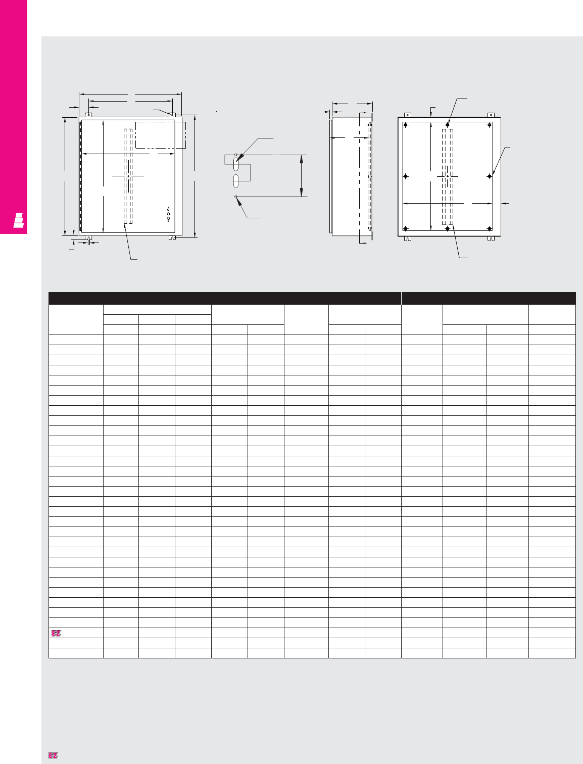
FMD ENCLOSURES
IND 107
Front View
3.00
B
W
.44 DIA.
See detail
K
AH
.44
J
1.25 Door stiffener omit if
A < 36.00 and B < 30.00
C
Lof door
C
.84 Y
G
Y
Enclosure Mounting Panel
Part No. Outside dimensions (inches) Mounting Door Door size Part No. Panel size Usable
HWD centers and body depth
ABCHWstiffener J K E F G
E 20SA2208 20.00 21.38 8.00 21.25 15.38 NO 18.25 18.25 E 20P20 17.00 17.00 7.75
E 20SA2210 20.00 21.38 10.00 21.25 15.38 NO 18.25 18.25 E 20P20 17.00 17.00 9.75
E 24SA2208 24.00 21.38 8.00 25.25 15.38 NO 22.25 18.25 E 24P20 21.00 17.00 7.75
E 24SA2210 24.00 21.38 10.00 25.25 15.38 NO 22.25 18.25 E 24P20 21.00 17.00 9.75
E 24SA2608 24.00 25.38 8.00 25.25 19.38 NO 22.25 22.25 E 24P24 21.00 21.00 7.75
E 24SA2610 24.00 25.38 10.00 25.25 19.38 NO 22.25 22.25 E 24P24 21.00 21.00 9.75
E 30SA2208 30.00 21.38 8.00 31.25 15.38 NO 28.25 18.25 E 30P20 27.00 17.00 7.75
E 30SA2210 30.00 21.38 10.00 31.25 15.38 NO 28.25 18.25 E 30P20 27.00 17.00 9.75
E 30SA2608 30.00 25.38 8.00 31.25 19.38 NO 28.25 22.25 E 30P24 27.00 21.00 7.75
E 30SA2610 30.00 25.38 10.00 31.25 19.38 NO 28.25 22.25 E 30P24 27.00 21.00 9.75
E 30SA2612 30.00 25.38 12.00 31.25 19.38 NO 28.25 22.25 E 30P24 27.00 21.00 11.75
E 36SA2608 36.00 25.38 8.00 37.25 19.38 NO 34.25 22.25 E 36P24 33.00 21.00 7.75
E 36SA2610 36.00 25.38 10.00 37.25 19.38 NO 34.25 22.25 E 36P24 33.00 21.00 9.75
E 36SA3208 36.00 31.38 8.00 37.25 25.38 YES 34.25 28.25 E 36P30 33.00 27.00 15.12*
E 36SA3210 36.00 31.38 10.00 37.25 25.38 YES 34.25 28.25 E 36P30 33.00 27.00 9.12*
E 36SA3212 36.00 31.38 12.00 37.25 25.38 YES 34.25 28.25 E 36P30 33.00 27.00 11.12*
E 36SA3216 36.00 31.38 16.00 43.25 25.38 YES 40.25 28.25 E 42P30 39.00 27.00 7.12*
E 42SA3208 42.00 31.38 8.00 43.25 25.38 YES 40.25 28.25 E 42P30 39.00 27.00 9.12*
E 42SA3210 42.00 31.38 10.00 43.25 31.38 YES 40.25 34.25 E 42P36 39.00 33.00 7.12*
E 42SA3212 42.00 31.38 12.00 43.25 25.38 YES 40.25 28.25 E 42P30 39.00 27.00 11.12*
E 42SA3808 42.00 37.38 8.00 43.25 31.38 YES 40.25 34.25 E 42P36 39.00 33.00 9.12*
E 42SA3810 42.00 37.38 10.00 43.25 31.38 YES 40.25 34.25 E 42P36 39.00 33.00 11.12*
E 42SA3812 42.00 37.38 12.00 49.25 31.38 YES 46.25 34.25 E 48P36 45.00 33.00 7.12*
E 48SA3808 48.00 37.38 8.00 49.25 31.38 YES 46.25 34.25 E 48P36 45.00 33.00 9.12*
E 48SA3810 48.00 37.38 10.00 49.25 31.38 YES 46.25 34.25 E 48P36 45.00 33.00 15.12*
E 48SA3812 48.00 37.38 12.00 49.25 31.38 YES 46.25 34.25 E 48P36 45.00 33.00 11.12*
E 48SA3816 48.00 37.38 16.00 49.25 31.38 YES 46.25 34.25 E 48P36 45.00 33.00 15.12*
E 60SA3808 60.00 37.38 8.00 61.25 31.38 YES 58.25 34.25 E 60P36 57.00 33.00 7.12*
E 60SA3810 60.00 37.38 10.00 61.25 31.38 YES 58.25 34.25 E 60P36 57.00 33.00 9.12*
E 60SA3812 60.00 37.38 12.00 61.25 31.38 YES 58.25 34.25 E 60P36 57.00 33.00 11.12*
E 60SA3812400# 60.00 37.38 12.00 61.25 31.38 YES 58.25 34.25 E 60P36 57.00 33.00 11.12*
E 60SA3816 60.00 37.38 16.00 61.25 31.38 YES 58.25 34.25 E 60P36 57.00 33.00 15.12
* Usable depth reduced by .625” at door stiffener. # Designed for 200 and 400 amp Allen Bradley Bulletin 1494V disconnect switches using 1494V-H2 operating handle.
Section Y-Y
1.50
Omit center studs
if B < 36.00
Omit center studs
if A < 36.00
C
Lof panel
E
2.63
F
Body stiffener omit if
A < 36.00 and B < 30
Right Side View
.50X1.5
Slot
1.062
1.875 4.687
Ø.280 2 holes
Detail
Technical Specifications
NEMA 12 Wallmount Boxes
Designates a product in the EnclosureZone program.
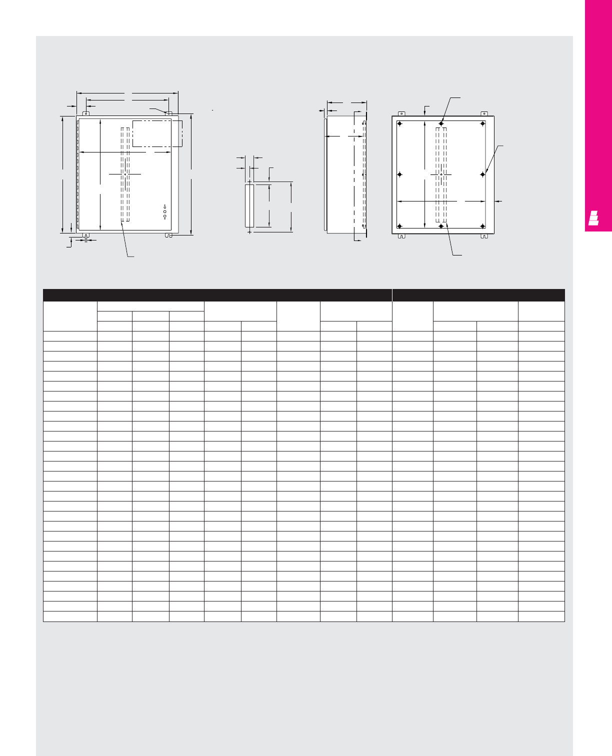
FMD ENCLOSURES
IND 108
Technical Specifications
NEMA 12 Wallmount Enclosures
Enclosure Mounting Panel
Part No. Outside dimensions (inches) Mounting Door Door size Part No. Panel size Usable
HWD centers and body depth
ABCHWstiffener J K E F G
E 20AB2208 20.00 21.38 8.00 21.25 15.38 NO 18.25 18.25 E 20P20 17.00 17.00 7.75
E 24AB2208 24.00 21.38 8.00 25.25 15.38 NO 22.25 18.25 E 24P20 21.00 17.00 7.75
E 24AB2210 24.00 21.38 10.00 25.25 15.38 NO 22.25 18.25 E 24P20 21.00 17.00 9.75
E 24AB2608 24.00 25.38 8.00 25.25 19.38 NO 22.25 22.25 E 24P24 21.00 21.00 7.75
E 24AB2610 24.00 25.38 10.00 25.25 19.38 NO 22.25 22.25 E 24P24 21.00 21.00 9.75
E 30AB2208 30.00 21.38 8.00 31.25 15.38 NO 28.25 18.25 E 30P20 27.00 17.00 7.75
E 30AB2210 30.00 21.38 10.00 31.25 15.38 NO 28.25 18.25 E 30P20 27.00 17.00 9.75
E 30AB2608 30.00 25.38 8.00 31.25 19.38 NO 28.25 22.25 E 30P24 27.00 21.00 7.75
E 30AB2610 30.00 25.38 10.00 31.25 19.38 NO 28.25 22.25 E 30P24 27.00 21.00 9.75
E 36AB2608 36.00 25.38 8.00 37.25 19.38 NO 34.25 22.25 E 36P24 33.00 21.00 7.75
E 36AB2610 36.00 25.38 10.00 37.25 19.38 NO 34.25 22.25 E 36P24 33.00 21.00 9.75
E 36AB3208 36.00 31.38 8.00 37.25 25.38 YES 34.25 28.25 E 36P30 33.00 27.00 7.12*
E 36AB3210 36.00 31.38 10.00 37.25 25.38 YES 34.25 28.25 E 36P30 33.00 27.00 9.12*
E 36AB3212 36.00 31.38 12.00 37.25 25.38 YES 34.25 28.25 E 36P30 33.00 27.00 11.12*
E 42AB3208 42.00 31.38 8.00 43.25 25.38 YES 40.25 28.25 E 42P30 39.00 27.00 7.12*
E 42AB3210 42.00 31.38 10.00 43.25 25.38 YES 40.25 28.25 E 42P30 39.00 27.00 9.12*
E 42AB3212 42.00 31.38 12.00 43.25 25.38 YES 40.25 28.25 E 42P30 39.00 27.00 11.12*
E 42AB3808 42.00 37.38 8.00 43.25 31.38 YES 40.25 34.25 E 42P36 39.00 33.00 7.12*
E 42AB3810 42.00 37.38 10.00 43.25 31.38 YES 40.25 34.25 E 42P36 39.00 33.00 9.12*
E 42AB3812 42.00 37.38 12.00 43.25 31.38 YES 40.25 34.25 E 42P36 39.00 33.00 11.12*
E 48AB3808 48.00 37.38 8.00 49.25 31.38 YES 46.25 34.25 E 48P36 45.00 33.00 7.12*
E 48AB3810 48.00 37.38 10.00 49.25 31.38 YES 46.25 34.25 E 48P36 45.00 33.00 9.12*
E 48AB3812 48.00 37.38 12.00 49.25 31.38 YES 46.25 34.25 E 48P36 45.00 33.00 11.12*
E 48AB381220# 48.00 37.38 12.00 49.25 31.38 YES 46.25 34.25 E 48P36 45.00 33.00 11.12*
E 48AB3816 48.00 37.38 16.00 49.25 31.38 YES 46.25 34.25 E 48P36 45.00 33.00 15.12*
E 60AB3810 60.00 37.38 10.00 61.25 31.38 YES 58.25 34.25 E 60P36 57.00 33.00 9.12*
E 60AB3812 60.00 37.38 12.00 61.25 31.38 YES 58.25 34.25 E 60P36 57.00 33.00 11.12*
E 60AB381220# 60.00 37.38 12.00 61.25 31.38 YES 58.25 34.25 E 60P36 57.00 33.00 11.12*
E 60AB3816 60.00 37.38 16.00 61.25 31.38 YES 58.25 34.25 E 48P36 45.00 33.00 15.12*
Front View
3.00
B
W
.44 DIA.
See detail
K
AH
.44
J
1.25 Door stiffener omit if
A < 36.00 and B < 30.00
C
Lof door
C
.84 Y
G
Y
Section Y-Y
1.50
Omit center studs
if B < 36.00
Omit center studs
if A < 36.00
C
Lof panel
E
2.63
F
Body stiffener omit if
A < 36.00 and B < 30
Right Side View
1.062
Detail
* Usable depth reduced by .625" at door stiffener.
# Designed for 200 and 400 amp Allen Bradley Bulletin 1494V disconnect switches using 1494V-H2 operating handle.
.719
1.437
7.187
.469
8.500
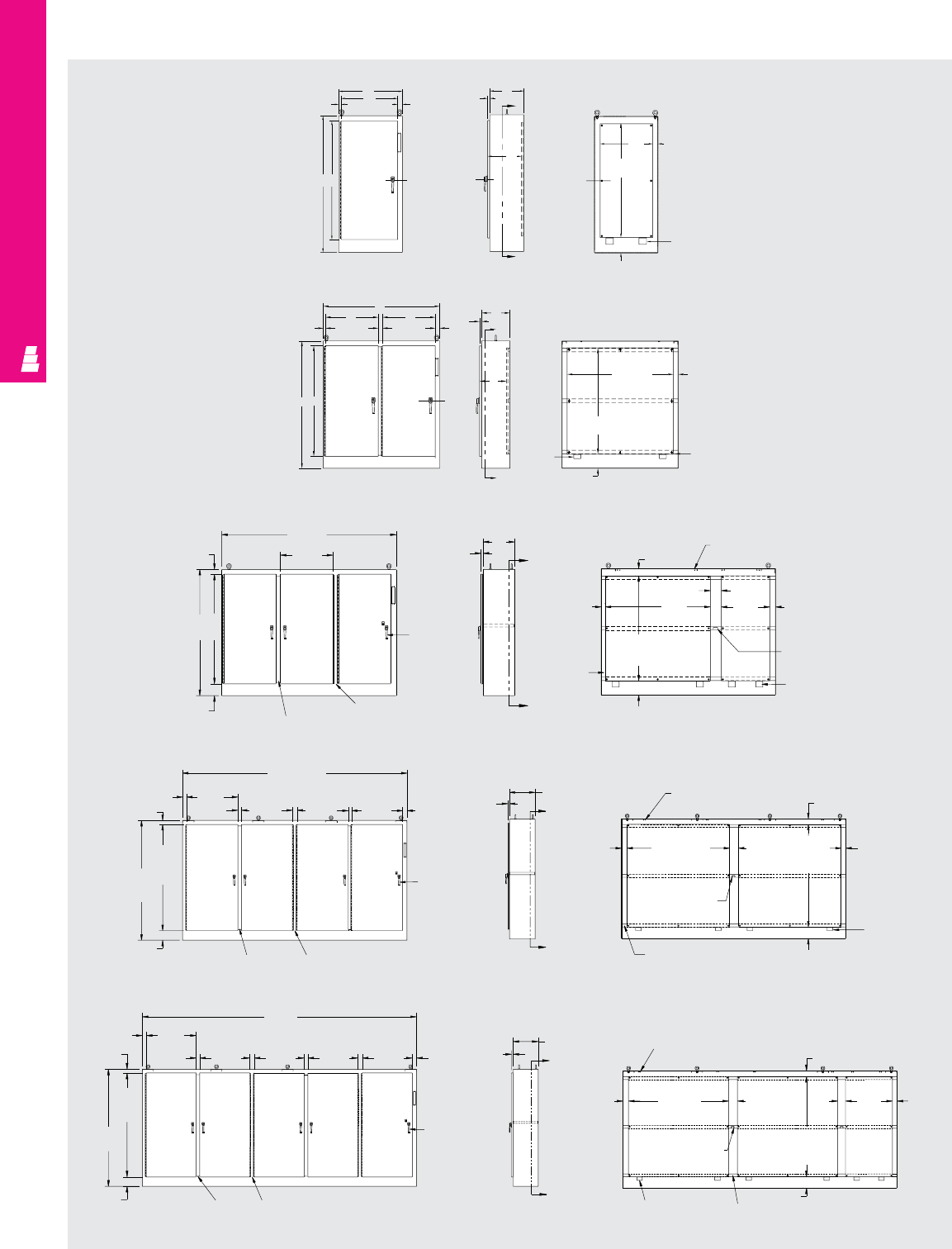
FMD ENCLOSURES
IND 109
Front View Right Side View Section A-A
B
2.50
1.13
C
L
of
door
A
G
A
2.75
F panel
E panel
Panel
support
(2)
places
2x1
Preformed
channel
(3) places
8.00
Front View Right Side View Section X-X
B
K
1.13 2.50
AC
Lof door
1.25 C
X
G
X
F
panel
E panel
C
L
of panel
2.75
8.00 Panel support
Technical Specifications
Freestanding
Heavy Duty Enclosures
— One Door
— Two Door
— Three Door
— Four Door
— Five Door
J
KK
2.38
C
1.25
B
K
Typ.
2.75
AJ
6.75 Removable centerpost
Stationary centerpost
3-point
padlockable
handle
Front View Side View Section Z-Z
C
1.25 Z
Z
4.00
Light bracket (unistrut channel)
(4) places
E
panel
D
panel Typ.
2.25
Channel
(3) places
8.00
Panel support
(4) places
Enclosure
brace
6.25
F
panel 3.25
B
(157.50)
2.88 K
(35.88)
door Typ.
2.75
J
(74.50)
door
A
(84.00)
6.75
2.50 3.25 2.38 3.00
3-point
padlockable
handle
Removable centerpost (2) places
Stationary centerpost
Front View Right Side View Section Z-Z
C
(18.00)
1.25 Z
Z
Light strut
(4) places
F
(72.00)
panel Typ.
4.00
Enclosure
brace
Channel (3) places
Panel support
(4) places
8.00
6.25 3.25
E
(72.00)
panel Typ.
4.00
B
(196.75)
K
(35.88)
Typ.
2.88
2.50 3.25 2.50 3.25 3.00
J
(74.50)
door
A
(84.00)
6.75 Removable centerpost (2) places
Stationary centerpost (2) places
3-point
padlockable
handle
Front View Right Side View Section Z-Z
C
(18.00)
Z
Z
1.25 Light strut (6) places 4.00
4.00
E
(72.00)
panel
(2) places
Enclosure brace
Panel support (4) places Channel (3) places
8.00
D
(72.00)
panel (3) places
6.25
5.50 F
(33.75) 3.25
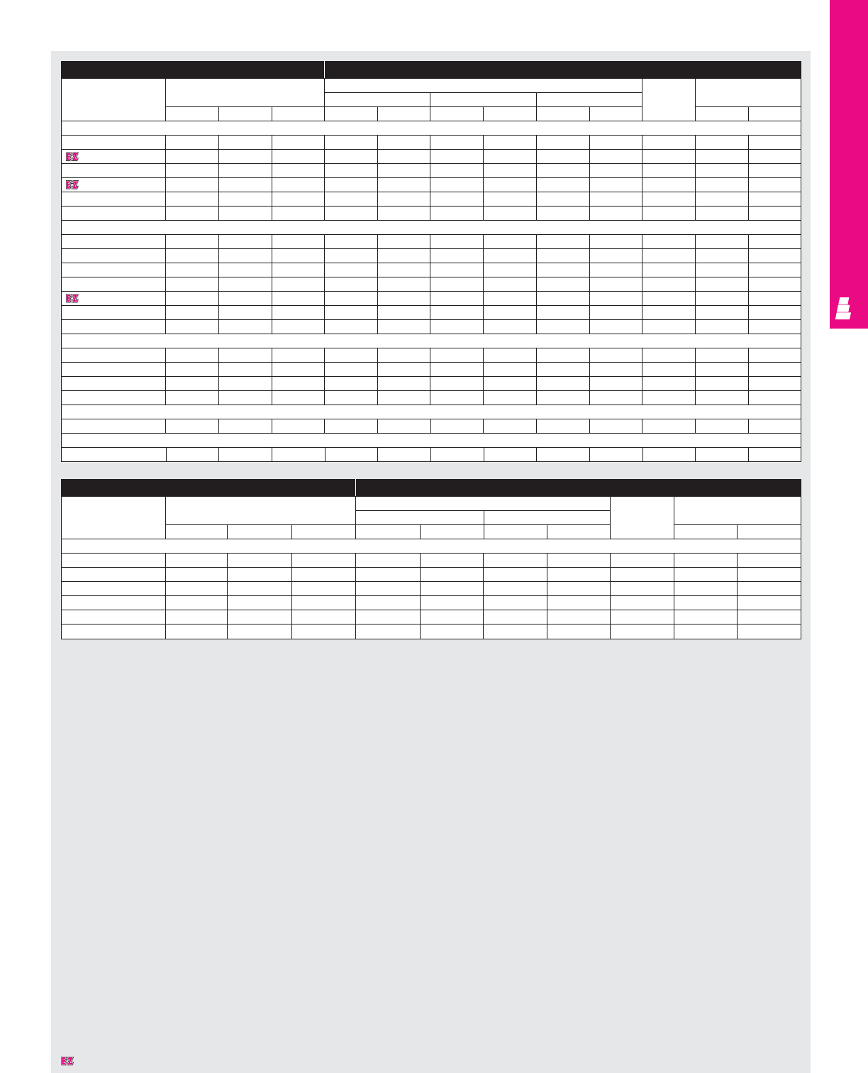
FMD ENCLOSURES
IND 110
Designates a product in the EnclosureZone program.
Enclosure Mounting Panel
Part No.
Outside dimensions (inches) Panel size Usable Door
Panel size Size behind single door Size behind double door depth Size
HWDHWHWHW HW
One Door Heavy Duty Enclosure
E 72XM2818WP 72.00 27.50 18.00 60.00 21.75 - - - - 18.00 62.50 23.83
E 72XM3418WP 72.00 33.50 18.00 60.00 27.75 - - - - 18.00 62.50 29.83
E 72XM4018WP 72.00 39.50 18.00 60.00 33.75 - - - - 18.00 62.50 35.83
E 84XM4018WP 84.00 39.50 18.00 72.00 33.75 - - - - 18.00 74.50 35.83
E 90XM4020WP 90.00 39.50 20.00 78.00 33.75 - - - - 20.00 80.50 35.83
E 90XM4024WP 90.00 39.50 24.00 78.00 33.75 - - - - 24.00 80.50 35.83
Two Door Heavy Duty Enclosure
E 72XM5418WP 72.00 53.75 18.00 60.00 48.00 - - - - 17.00 62.50 23.88
E 72XM6618WP 72.00 65.75 18.00 60.00 60.00 - - - - 17.00 62.50 29.88
E 72XM7818WP 72.00 77.75 18.00 60.00 72.00 - - - - 17.00 62.50 35.88
E 72XM7824WP 72.00 77.75 24.00 60.00 72.00 - - - - 23.00 62.50 35.88
E 84XM7818WP 84.00 77.75 18.00 72.00 72.00 - - - - 17.00 74.50 35.88
E 90XM7820WP 90.00 77.75 20.00 78.00 72.00 - - - - 19.00 80.50 35.88
E 90XM7824WP 90.00 77.75 24.00 78.00 72.00 - - - - 23.00 80.50 35.88
Three Door Heavy Duty Enclosure
E 72XM3EQ18WP 72.00 99.50 18.00 - - 60.00 27.75 60.00 60.00 17.00 62.50 29.88
E 72XM3EW18WP 72.00 117.50 18.00 - - 60.00 33.75 60.00 72.00 17.00 62.50 35.88
E 84XM3EW18WP 84.00 117.50 18.00 - - 72.00 33.75 72.00 72.00 17.00 74.50 35.88
E 90XM3EW24WP 90.00 117.50 24.00 - - 78.00 33.75 78.00 72.00 23.00 80.50 35.88
Four Door Heavy Duty Enclosure
E 84XM4EW18WP 84.00 157.50 18.00 72.00* 72.00* - - - - 17.00 74.50 35.88
Five Door Heavy Duty Enclosure
E 84XM5EW18WP 84.00 196.75 18.00 - - 72.00 33.75 72.00* 72.00* 17.00 74.50 35.88
Enclosure Mounting Panel
Part No.
Outside dimensions (inches) Panel size Usable Door
Panel size Opening size left side depth Size
HW D H WH W HW
Modular Enclosure
E MOD72X4018 1) 72.00 39.75 18.00 60.00 33.75 66.63 12.25 17.06 62.50 35.88
E MOD72X7818 2) 72.00 78.00 18.00 60.00 72.70 66.63 12.25 17.06 62.50 36.38
E MOD84X4018 1) 84.00 39.75 18.00 72.00 33.75 78.63 12.25 17.06 74.50 35.88
E MOD84X4024 1) 84.00 39.75 24.00 72.00 33.75 78.63 18.25 23.06 74.50 35.88
E MOD84X7818 2) 84.00 78.00 18.00 72.00 72.00 78.63 12.25 17.06 74.50 36.88
E MOD84X7824 2) 84.00 78.00 24.00 72.00 72.00 78.63 18.25 23.06 74.50 36.38
1) Single door. 2) Double door. *Two mounting panels used.
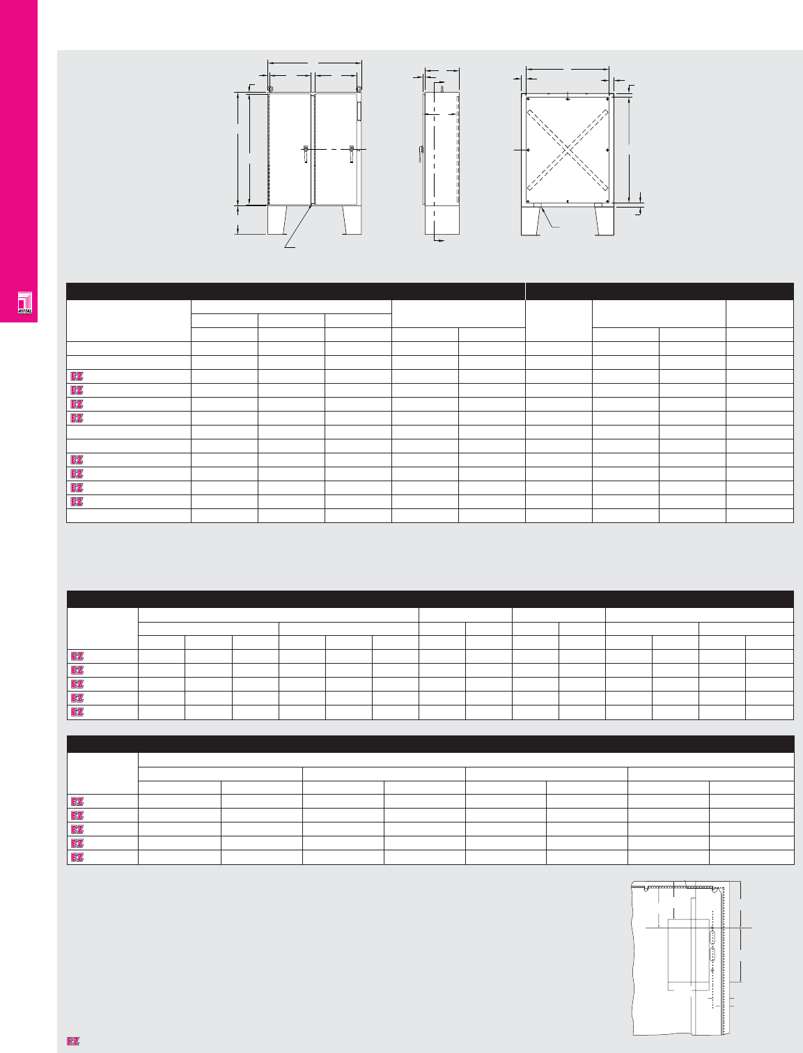
IND 111
FMD ENCLOSURES
AE Wallmount FMD Enclosures
Part No.
Dimensions Master door Slave door Panel size
inches mm inches mm inches mm inches mm
HWDH WDD1 D1 D2 D2 H W H W
1075600 29.92 23.62 8.27 760 600 210 19.68 500 - - 28.74 21.61 730 549
1074600 29.92 29.92 11.81 760 760 300 25.98 660 - - 28.74 27.72 730 704
1183600 39.37 31.50 11.81 1000 800 300 27.55 700 - - 37.60 29.09 955 739
1283600 47.24 31.50 11.81 1200 800 300 27.55 700 - - 45.47 29.13 1155 740
1115600 55.12 39.37 11.81 1400 1000 300 35.43 900 - - 53.35 37.00 1355 940
AE Wallmount FMD Enclosures
AE Wallmount FMD Enclosures (Continued)
Part No.
See figure A for illustration
CL HL PA PE
inches mm inches mm inches mm inches mm
1075600
1.87 47.5 5.18 131.6 4.59 116.6 1.003 25.5
1074600
1.87 47.5 5.18 131.6 4.59 116.6 1.102 28
1183600
1.87 47.5 9.74 247.6 8.86 225.1 1.2 30.5
1283600
1.87 47.5 9.74 247.6 8.86 225.1 1.18 30
1115600
1.87 47.5 11.6 295 10.72 272.5 1.18 30
PA WHL
DH
CL
DV
PE
Mounting
Panel
Designates a product in the EnclosureZone program.
Front View Right Side View Section A-A
B
K
.75
.75
A
J
15.00
Removable center post
1.13 C
A
C
A
F
E
C
L2.38
2.75 2.00
C
L
2.07
Panel
support
C
L
Enclosure Mounting Panel
Part No.
Outside dimensions (inches)
Door size Part No. Panel size Usable depth
HW D
AB CJ K E F C
E 60CPX4812 1) 60.00 48.00 12.00 58.50 22.00 E 60P48 56.00 44.00 12.00
E 60CPX6012 1) 60.00 60.00 12.00 58.50 28.00 E 60P60 56.00 56.00 12.00
E 60X4912 2) 60.00 49.38 12.00 58.50 21.88 E 60P48 56.00 44.00 12.00
E 60X4918 2) 60.00 49.38 18.00 58.50 21.88 E 60P48 56.00 44.00 18.00
E 60X6112 2) 60.00 61.38 12.00 58.50 27.88 E 60P60 56.00 56.00 12.00
E 60X6118 2) 60.00 61.38 18.00 58.50 27.88 E 60P60 56.00 56.00 18.00
E 72CPX7212 1) 72.00 72.00 12.00 70.50 34.00 E 72P72 68.00 68.00 12.00
E 72CPX7218 1) 72.00 72.00 18.00 70.50 34.00 E 72P72 68.00 68.00 18.00
E 72X6112 2) 72.00 61.38 12.00 70.50 27.88 E 72P60 68.00 56.00 12.00
E 72X6118 2) 72.00 61.38 18.00 70.50 27.88 E 72P60 68.00 56.00 18.00
E 72X7312 2) 72.00 73.38 12.00 70.50 33.88 E 72P72 68.00 68.00 12.00
E 72X7318 2) 72.00 73.38 18.00 70.50 33.88 E 72P72 68.00 68.00 18.00
E 72X7324 2) 72.00 73.00 24.00 70.50 33.88 E 72P72 68.00 68.00 24.00
Technical Specifications
Floormount
Freestanding
Enclosures
Fig. A
K
Mounting
panel
PA WHL
DH
CL
PE
DV
1) Disconnect operator on right flange. 2) Disconnect operator on center post.
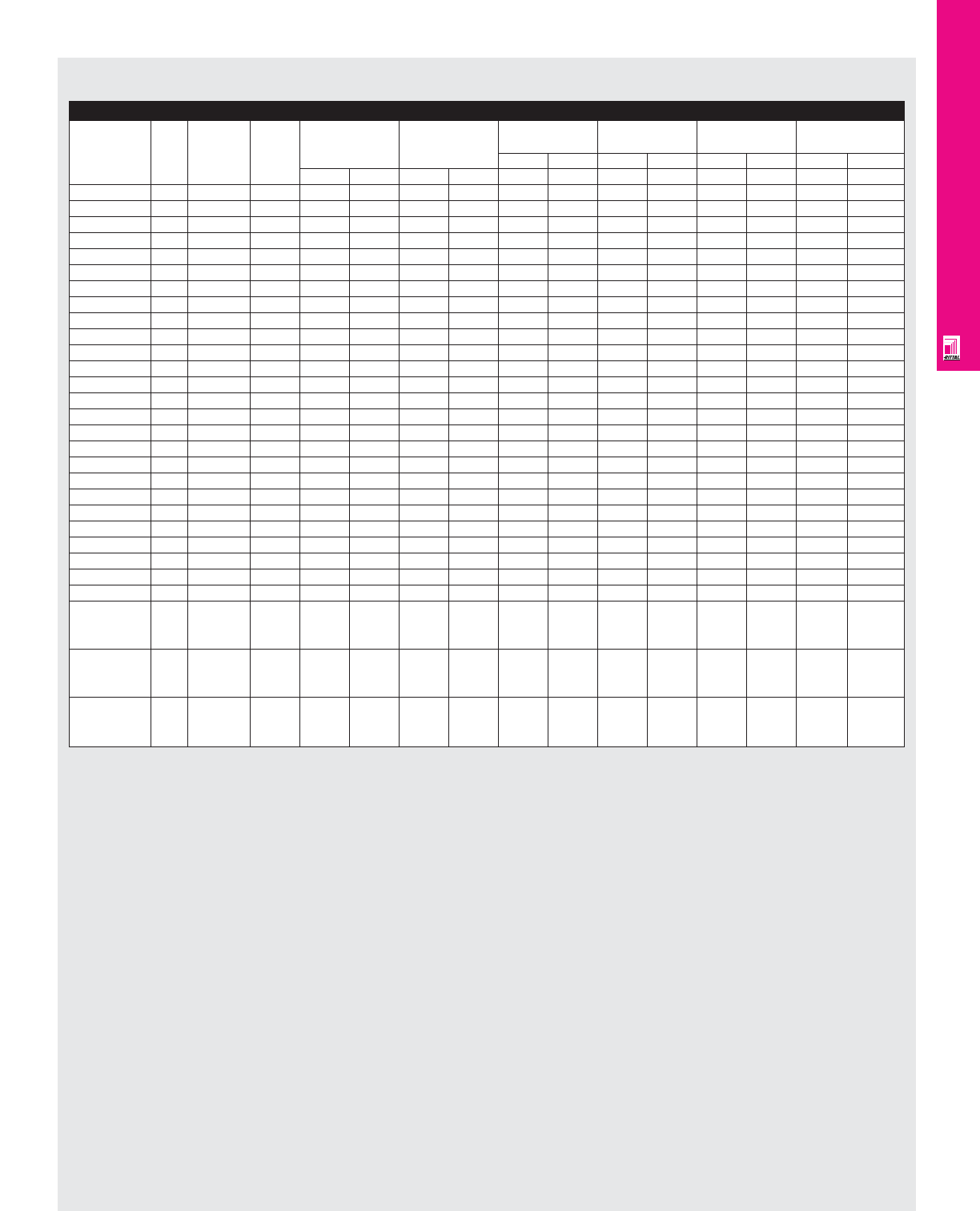
IND 112
FMD ENCLOSURES
Allen Bradley 1494V Disconnects/Circuit-Breakers (Fig. A pg. IND 111)
Allen Bradley
Amp Fuse Fuse DH DW* When When When When
Part No.
rating clip class HL=131.6 (5.1) HL=180.6 (7.11) HL=247.6 (9.74) HL=295 (11.6)
inches mm inches mm inches mm inches mm
inches mm inches mm W W W W W W W W
1494V-DS30 30A Unfused - 3.8 98.4 7.12 181 3.3 84.8 5.26 133.8 7.9 200.8 9.7 248.2
1494V-DS30 30A 30A-250V H,K,R 5.19 131.9 7.12 181 3.3 84.8 5.26 133.8 7.9 200.8 9.7 248.2
1494V-DS30 30A 30A-600V H,K,R 7.9 202.4 7.12 181 3.3 84.8 5.26 133.8 7.9 200.8 9.7 248.2
1494V-DS30 30A 30A-600V J 5.19 131.9 7.12 181 3.3 84.8 5.26 133.8 7.9 200.8 9.7 248.2
1494V-DS30 30A 60A-250V H,K,R 5.9 151.6 7.12 181 3.3 84.8 5.26 133.8 7.9 200.8 9.7 248.2
1494V-DS30 30A 60A-600V H,K,R 8.47 215.2 7.12 181 3.3 84.8 5.26 133.8 7.9 200.8 9.7 248.2
1494V-DS30 30A 60A-600V J 5.3 135.5 7.12 181 3.3 84.8 5.26 133.8 7.9 200.8 9.7 248.2
1494V-DS60 60A Unfused - 3.8 98.4 7.12 181 3.3 84.8 5.26 133.8 7.9 200.8 9.7 248.2
1494V-DS60 60A 60A-250V H,K,R 5.9 151.6 7.12 181 3.3 84.8 5.26 133.8 7.9 200.8 9.7 248.2
1494V-DS60 60A 60A-600V H,K,R 8.47 215.2 7.12 181 3.3 84.8 5.26 133.8 7.9 200.8 9.7 248.2
1494V-DS60 60A 60A-600V J 5.3 135.5 7.12 181 3.3 84.8 5.26 133.8 7.9 200.8 9.7 248.2
1494V-DS60 60A 30A-600V H,K,R 7.9 202.4 7.12 181 3.3 84.8 5.26 133.8 7.9 200.8 9.7 248.2
1494V-DS60 60A 100A-250V H,K 8.86 225.1 7.12 181 3.3 84.8 5.26 133.8 7.9 200.8 9.7 248.2
1494V-DS60 60A 100A-600V H,K 10.8 275.9 7.12 181 3.3 84.8 5.26 133.8 7.9 200.8 9.7 248.2
1494V-DS60 60A 100A-600V J 7.6 193.3 7.12 181 3.3 84.8 5.26 133.8 7.9 200.8 9.7 248.2
1494V-DS100 100A Unfused - 3.8 98.4 7.12 181 - - - - 7.3 186.1 9.19 233.5
1494V-DS100 100A 100A-250V H,K,R 9.6 244.1 7.12 181 - - - - 7.3 186.1 9.19 233.5
1494V-DS100 100A 100A-600V H,K,R 11.6 294.9 7.12 181 - - - - 7.3 186.1 9.19 233.5
1494V-DS100 100A 100A-600V J 8.3 212.3 7.12 181 - - - - 7.3 186.1 9.19 233.5
1494V-DS100 100A 200A-250V H,K 12.4 315.1 7.12 181 - - - - 7.3 186.1 9.19 233.5
1494V-DS100 100A 200A-600V H,K 14.9 378.6 7.12 181 - - - - 7.3 186.1 9.19 233.5
1494V-DS100 100A 200A-600V J 11.03 280.2 7.12 181 - - - - 7.3 186.1 9.19 233.5
1494V-DS200 200A Unfused - 4.6 118.3 8.4 213.9 - - - - 6.3 160.7 8.19 208.1
1494V-DS200 200A 200A-250V H,K,R 11.8 300.4 8.4 213.9 - - - - 6.3 160.7 8.19 208.1
1494V-DS200 200A 200A-600V H,K,R 14.3 363.9 8.4 213.9 - - - - 6.3 160.7 8.19 208.1
1494V-DS200 200A 200A-600V J 10.4 265.5 8.4 213.9 - - - - 6.3 160.7 8.19 208.1
1494V-M40 150A EDH, FD, - 6 152 4.125 104.7 4.1 104.1 6.11 155.1 8.74 222.2 10.6 269.6
FDB, FDC,
HFD, HMCP
1494V-M50 250A JD, JDB, - 10 254 4.125 104.7 - - 5.57 141.7 8.2 208.5 10.07 256
JDC, HJD
HMCP
1494V-M60 400A KD, KDB, - 10.125 257 5.5 140 - - 7.75 197 10.39 264 12.25 311.4
KDC, HKD
HMCP
AE Wallmount FMD Enclosures
* Does not include space for optional auxiliary switch. Note: 1. For applications above 200A, please contact your local Rittal representative.
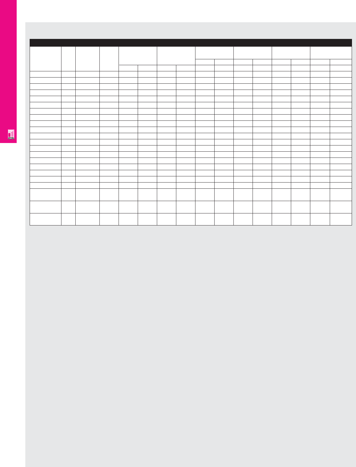
IND 113
FMD ENCLOSURES
AE Wallmount FMD Enclosures
Square D Class 9422 Disconnects/Circuit-Breakers (Fig. A pg. IND 111)
Square D
Amp Fuse Fuse DH DW* When When When When
Switch
rating clip class HL=131.6 (5.1) HL=180.6 (7.11) HL=247.6 (9.74) HL=295 (11.6)
Part No.
inches mm inches mm inches mm inches mm
inches mm inches mm W W W W W W W W
TCN30 30A Unfused - 3.8 96.52 6.2 157.48 3.5 88.9 5.51 139.9 8.14 206.7 10 254
TCF30 30A 30A-250V H, K, R 5.42 137.79 6.2 157.48 3.5 88.9 5.51 139.9 8.14 206.7 10 254
TCF33 30A 30A-600V H, K, R 8.05 204.4 6.2 157.48 3.5 88.9 5.51 139.9 8.14 206.7 10 254
TCF33 30A 30A-600V J 5.42 137.79 6.2 157.48 3.5 88.9 5.51 139.9 8.14 206.7 10 254
TCF33 30A 60A-250V H, K, R 6.05 153.6 6.2 157.48 3.5 88.9 5.51 139.9 8.14 206.7 10 254
TDN60 60A Unfused - 3.8 96.52 6.2 157.48 3.5 88.9 5.51 139.9 8.14 206.7 10 254
TDF60 60A 60A-250V H, K, R 6.05 153.6 6.2 157.48 3.5 88.9 5.51 139.9 8.14 206.7 10 254
TDF60 60A 30A-600V H, K, R 8.05 204.4 6.2 157.48 3.5 88.9 5.51 139.9 8.14 206.7 10 254
TDF63 60A 60A-600V H, K, R 8.55 217.17 6.2 157.48 3.5 88.9 5.51 139.9 8.14 206.7 10 254
TDF63 60A 60A-600V J 5.42 137.79 6.2 157.48 3.5 88.9 5.51 139.9 8.14 206.7 10 254
TEN10 100A Unfused - 3.8 96.52 6.2 157.48 - - 5.51 139.9 8.14 206.7 10 254
TEF10 100A 100A-250V H, K, R 8.25 209.55 6.2 157.48 - - 5.51 139.9 8.14 206.7 10 254
TEF10 100A 100A-600V H, K, R 10.25 260.35 6.2 157.48 - - 5.51 139.9 8.14 206.7 10 254
TEF10 100A 100A-600V J 7.05 179.07 6.2 157.48 - - 5.51 139.9 8.14 206.7 10 254
TF1 200A Unfused - 5.25 133.35 11.63 295.4 - - - - 6.49 164.8 8.35 212.09
TF2 200A 200A-250V H, K, R 11.2 284.48 11.63 295.4 - - - - 6.49 164.8 8.35 212.09
TF2 200A 200A-600V H, K, R 13.7 347.98 11.63 295.4 - - - - 6.49 164.8 8.35 212.09
TF2 200A 200A-600V J 9.83 249.68 11.63 295.4 - - - - 6.49 164.8 8.35 212.09
TF3 200A 400A-600V J 14.25 361.95 11.63 295.4 - - - - 6.49 164.8 8.35 212.09
RG1 75, GJL Circuit 3.75 95.2 3.54 90 4.1 104.1 6.11 155.1 8.74 221.9 10.6 269.2
100A breaker
RN1 100A FAL, FHL Circuit 8.03 203.9 4.5 114 4.63 117.6 6.64 168.6 9.27 235.4 11.13 282.7
breaker
RP1 250A KAL, KHL Circuit 9.66 245.3 4.5 114 - - 6.64 168.6 9.27 235.4 11.13 282.7
breaker
* DW dimension without operating mechanism.
Note:
1. For applications above 200A, please contact your local Rittal representative.
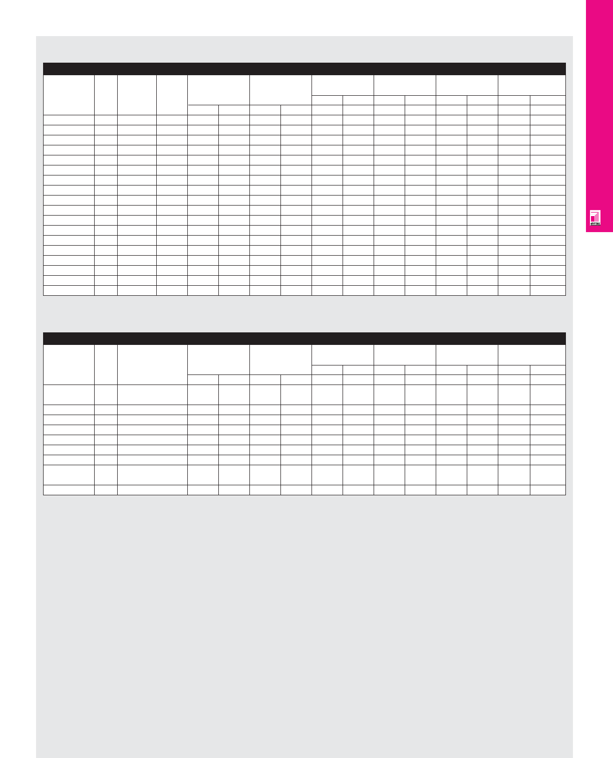
IND 114
FMD ENCLOSURES
AE Wallmount FMD Enclosures
GE Type STDA Disconnects (Fig. A pg. IND 111)
GE Operating
Amp Fuse Fuse DH DW When When When When
Mechanism
rating clip class HL=131.6 (5.1) HL=180.6 (7.11) HL=247.6 (9.74) HL=295 (11.6)
Part No.
inches mm inches mm inches mm inches mm
inches mm inches mm W W W W W W W W
TDOM1A 30A Unfused - 3.75 95.2 5.7 144.4 1.52 38.3 3.4 87.8 6.09 154.8 7.9 202.2
TDOM1A 30A 30A-250V H, R 5.6 142.8 5.7 144.4 1.52 38.3 3.4 87.8 6.09 154.8 7.9 202.2
TDOM1B 30A 30A-600V H, R 8.6 219 5.7 144.4 1.52 38.3 3.4 87.8 6.09 154.8 7.9 202.2
TDOM1B 30A 60A-250V H, R 7 177.8 5.7 144.4 1.52 38.3 3.4 87.8 6.09 154.8 7.9 202.2
TDOM1B 30A 60A-250V H, R 9.5 241.3 5.7 144.4 1.52 38.3 3.4 87.8 6.09 154.8 7.9 202.2
TDOM1A 60A Unfused - 4.06 103.1 5.7 144.4 1.52 38.3 3.4 87.8 6.09 154.8 7.9 202.2
TDOM1B 60A 60A-250V H, R 7 177.8 5.7 144.4 1.52 38.3 3.4 87.8 6.09 154.8 7.9 202.2
TDOM1B 60A 60A-600V H, R 9.5 241.3 5.7 144.4 1.52 38.3 3.4 87.8 6.09 154.8 7.9 202.2
TDOM1B 60A 100A-250V H, R 8.4 213.5 5.7 144.4 1.52 38.3 3.4 87.8 6.09 154.8 7.9 202.2
TDOM1B 60A 100A-600V H, R 10.4 264.3 5.7 144.4 1.52 38.3 3.4 87.8 6.09 154.8 7.9 202.2
TDOM1A 100A Unfused - 4.1 104.7 5.7 144.4 - - - - 6.09 154.8 7.9 202.2
TDOM1B 100A 100A-250V H, R 8.4 213.5 5.7 144.4 - - - - 6.09 154.8 7.9 202.2
TDOM1B 100A 100A-600V H, R 10.4 264.3 5.7 144.4 - - - - 6.09 154.8 7.9 202.2
TDOM1B 100A 200A-250V H, R 13.9 353.2 5.7 144.4 - - - - 6.09 154.8 7.9 202.2
TDOM1B 100A 200A-600V H, R 16.4 416.7 5.7 144.4 - - - - 6.09 154.8 7.9 202.2
TDOM2 200A Unfused - 7.59 192.8 8.78 223 - - - - - - 7.4 188.6
TDOM2 200A 200A-250V H, R 13.9 353.2 8.78 223 - - - - - - 7.4 188.6
TDOM2 200A 200A-600V H, R 16.4 416.7 8.78 223 - - - - - - 7.4 188.6
Note:
1. For applications above 200A, please contact your local Rittal representative.
GE Type STDA Circuit-Breakers (Fig. A pg. IND 111)
GE Operating
Amp Frame DH DW When When When When
Mechanism
rating type HL=131.6 (5.1) HL=180.6 (7.11) HL=247.6 (9.74) HL=295 (11.6)
Part No.
inches mm inches mm inches mm inches mm
inches mm inches mm W W W W W W W W
TDOM1A 150A TEB, TED, 5.59 142 4.1 104.1 - - - - 7.4 187.9 9.26 235.2
THED
TDOM1A 150A TEC 5.59 142 4.1 104.7 - - - - 7.4 187.9 9.26 235.2
TDOM1B 150A TB1 9.59 243.6 4.1 104.7 - - - - 7.4 187.9 9.26 235.2
TDOM1B 150A TEC, TECL 7.46 189.7 4.1 104.7 - - - - 7.4 187.9 9.26 235.2
TDOM1C 150A TEL 5.59 142 4.1 104.7 - - - - 7.4 187.9 9.26 235.2
TDOM1D 150A THLC1 8.37 212.7 4.1 104.7 - - - - 7.74 196.5 9.6 243.8
TDOM3 225A TFJ 8.93 227 4.1 104.7 - - - - 7.56 192 9.42 239.2
TDOM3 225A TFK, THFK, 8.93 227 4.1 104.7 - - - - 7.56 192 9.42 239.2
TFL
TDOM6 225A THLC2 10.8 275.4 5.7 145.2 - - - - 7.56 192 9.42 239.2
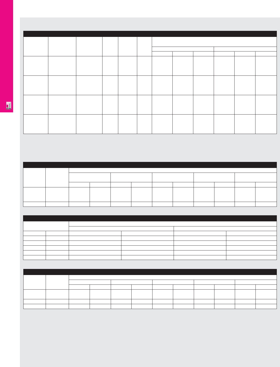
IND 115
FMD ENCLOSURES
AE Wallmount FMD Enclosures
ITE Max-Flex Operators for Disconnect Switches (Fig. A pg. IND 116)
Switch
Max-Flex Fixed depth Amp Fuse Fuse Panel space requirements
Operator
variable depth complete rating kit class
Part No.
complete handle handle inches mm
mechanism mechanism A B C A B C
MCS603R FHOS06036R FDFS06R 30 No fuse - 6.13 5.52 - 155.7 140.2 -
MCS603L FHOS06036L 30A, 250V H, R 6.13 5.52 8.11 155.7 140.2 205.9
30A, 600V H, R 6.13 5.52 10.11 155.7 140.2 256.7
30A, 600V J 6.13 5.52 8.48 155.7 140.2 215.3
MCS606R FHOS06036R FDFS06R 60 No fuse - 6.13 5.52 - 155.7 140.2 -
MCS606L FHOS06036L 60A, 250V H, R 6.13 5.52 7.86 155.7 140.2 199.6
60A, 600V H, R 6.13 5.52 10.38 155.7 140.2 263.6
60A, 600V J 6.13 5.52 8.35 155.7 140.2 212
MCS610R FHOS06036R FDFS06R 100 No fuse - 7.38 7.59 - 187.4 192.7 -
MCS610L FHOS06036L 100A, 250V H, R 7.38 7.59 11.85 187.4 192.7 300.9
100A, 600V H, R 7.38 7.59 13.85 187.4 192.7 351.7
100A, 600V J 7.38 7.59 10.6 187.4 192.7 269.2
MCS620R FHOS20036R FDFS20R 200 No fuse - 9.17 9.00 - 232.9 228.6 -
MCS620R 200A, 250V H, R 9.17 9.00 14.7 232.9 228.6 373.3
200A, 600V H, R 9.17 9.00 17.2 232.9 228.6 436.8
200A, 600V J 9.17 9.00 13.32 232.9 228.6 338.3
Note:
1. To order Class R fuse kit, you must order Class H fuse kit and corresponding Class R fuse conversion kit.
2. Max-Flex standard cable length is 36 inches. Alternate cable lengths are available.
3. Maximum length with Class H and R fuses.
Fixed Depth Flange Mounted Handle With ITE Disconnect Switch (Fig. C pg. IND 116)
Switch Handle Dimensions
Part No. Part No. X1 X2 Y1 Y2 Z1
inches mm inches mm inches mm inches mm inches mm
MCS603, FDFS06R 3.52 89.4 1.5 38.1 0.0 0.0 1.89 48 6.44 163.5
MCS606
MCS610 FDFS06R 3.91 99.3 1.81 45.9 0.13 3.3 3.0 76.2 6.44 163.5
MCS620 FDFS20R 1.51 38.3 7.86 199.6 0.38 9.6 5.44 138.1 10.93 277.6
Note:
1. Z1 is the distance between the enclosure door and MPL.
Maximum “E” Dimension For ITE Max-Flex With Disconnect Switch (Fig. B pg. IND 116)
Switch Cable When enclosure depth=MPL position
Part No. Part No. When When When When When
8.27 (210)= 7.24 (184) 9.84 (250)=8.82 (224) 11.81 (300)=10.78 (274) 13.87 (350)=12.75 (324) 15.75 (400)=10.75 (273)
inches mm inches mm inches mm inches mm inches mm
MCS603, FHOEC036 16.0 406 13.0 330 13.5 343 8.0 203 13.5 343
MCS606,
MCS610
MCS620 FHOEC036 15.0 381 12.0 304 12.5 317 7.0 178 12.5 317
Maximum “E” Dimension For ITE Max-Flex With Disconnect Switch (Fig. B pg. IND 116)
Enclosure depth 36" Cable
Fmin Fmax
inches mm inches mm inches mm
8.27 210 7.0 177.8 14.5 368.3
9.84 250 5.5 139.7 13.1 332.7
11.81 300 5.0 127 12.0 304.8
13.87 350 4.0 101.6 9.4 238.7
15.75 400 4.0 101.6 9.4 238.7
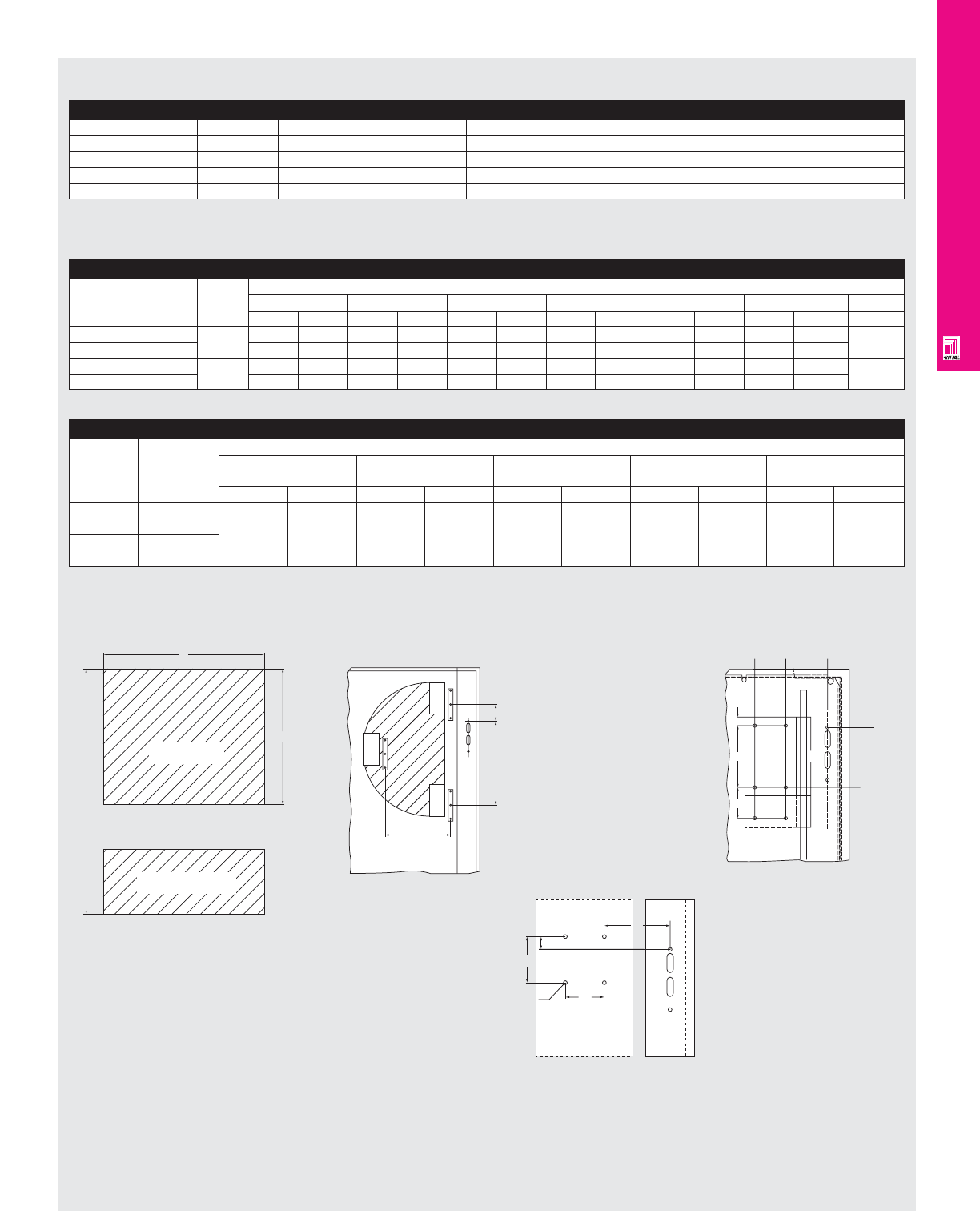
IND 116
FMD ENCLOSURES
AE Wallmount FMD Enclosures
For ITE Max-Flex Operators for Circuit-Breakers
Breaker Part No. Amp rating Circuit breaker frame size For use with breaker type(s)
FHOE036 125 ED, HED, EF (CE) ED2, ED4, ED6, HED4, HED6 ETI, HHED6, EFC
FHOE036 125 CED, EF (CE) CED6, CED6 ETI, EFF
FHOF036 250 FD, FXD, HFD, HFXD, FF (CE) FXD6-A, FD6-A, HFD6, HFXD6, HHFD6, FD6 ETI, FFC, FFF
FHOF036 250 CFD CFD6, CFD6 ETI
Note:
1. For applications above 200A, please contact your local Rittal representative.
ITE Circuit Breaker Mounting Dimensions (Fig. D pg. IND 116)
Circuit breaker Amp See fig. D
frame size rating A B C D* K DH (normal) Tap size
inches mm inches mm inches mm inches mm inches mm inches mm
ED, HED, EF 125 1.0 25.4 5.0 127 0.65 16.5 6.33 160.7 - - 6.81 172.9 #8-32
CED, EF 1.0 25.4 5.0 127 0.65 16.5 8.93 226.8 3.25 82.5 6.81 172.9
FXD, FD, HFD, HFXD,FF 250 1.5 38.1 7.5 190.5 1.0 25.4 9.5 241.3 - - 6.78 172.2 #1/4 20
CFD 1.5 38.1 7.5 190.5 1.0 25.4 14.2 361.9 4.6 117.4 6.78 172.2
B
A
C
FIG. A
Switch Base
Fuse Load Base
E
F min
F max
FIG. B
X2
Y2
D.156 DIA. (4x)
Y1
X1
FIG. C
DH-
AE
C
BD
K
DH+
DH
FIG. D
Mounting
Panel
Maximum “E” Dimension For ITE Max-Flex With Circuit-Breaker (Fig. D pg. IND 116)
Cable Frame size When enclosure depth=MPL position
Part No. When When When When When
8.27 (210)= 7.24 (184) 9.84 (250)=8.82 (224) 11.81 (300)=10.78 (274) 13.87 (350)=12.75 (324) 15.75 (400)=10.75 (273)
inches mm inches mm inches mm inches mm inches mm
FHOEC036 ED, HED,
CED, EF
FHOEC036 FXD, FD, HFD, 13.5 342.9 13.5 342.9 13 330 10.7 271 10.7 271
HFXD, FF, CFD
Fig. A
Fig. B
Fig. C
Fig. D
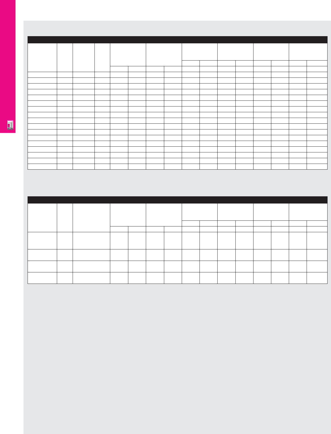
IND 117
FMD ENCLOSURES
AE Wallmount FMD Enclosures
Cutler-Hammer (C361 Disconnect Switches) (Fig. A pg. IND 111)
Cutler-
Amp Fuse Fuse DH DW When When When When
Hammer
rating clip class HL=131.6 HL=180.6 HL=247.6 HL=295
Part No.
(5.18) (7.11) (9.74) (11.6)
inches mm inches mm inches mm inches mm
inches mm inches mm W W W W W W W W
NC
30A Unfused - 3.9 99.18 6 152.4 3.58 91.13 5.51 140.1 8.14 206.9 10 254.2
SC21
30A 30A-250V H,K,R 7.6 194.74 6 152.4 3.58 91.13 5.51 140.1 8.14 206.9 10 254.2
SC61
30A 60A-250V H,K,R 8.16 207.4 6 152.4 3.58 91.13 5.51 140.1 8.14 206.9 10 254.2
SC61
30A 30A-600V H,K,J,R 7.6 194.74 6 152.4 3.58 91.13 5.51 140.1 8.14 206.9 10 254.2
ND
60A Unfused - 3.9 99.18 6 152.4 3.58 91.13 5.51 140.1 8.14 206.9 10 254.2
SD22
60A Unfused - 3.9 99.18 6 152.4 3.58 91.13 5.51 140.1 8.14 206.9 10 254.2
SD22
60A 60A-250V H,K,R 8.16 207.4 6 152.4 3.58 91.13 5.51 140.1 8.14 206.9 10 254.2
SD62
60A 60A-600V H,K,R 8.16 207.4 6 152.4 3.58 91.13 5.51 140.1 8.14 206.9 10 254.2
SD62
60A 60A-600V J 7.79 197.9 6 152.4 3.58 91.13 5.51 140.1 8.14 206.9 10 254.2
NE
100A Unfused - 8.9 226.05 7 187.5 3.23 82 5.16 131.06 7.79 197.8 9.65 245.1
SE263
100A 100A-250V H,K,R 8.9 226.05 7 187.5 3.23 82 5.16 131.06 7.79 197.8 9.65 245.1
SE263
100A 100A-600V H,K,R 8.9 226.05 7 187.5 3.23 82 5.16 131.06 7.79 197.8 9.65 245.1
SE263
100A 100A-600V J 8.9 226.05 7 187.5 3.23 82 5.16 131.06 7.79 197.8 9.65 245.1
NF
200A Unfused - 13.1 333.8 9.75 247.6 - - - - - - 6.74 171.3
SF264
200A 200A-250V H,K,R 13.1 333.8 9.75 247.6 - - - - - - 6.74 171.3
SF264
200A 200A-600V H,K,R 13.1 333.8 9.75 247.6 - - - - - - 6.74 171.3
SF264
200A 200A-600V J 13.1 333.8 9.75 247.6 - - - - - - 6.74 171.3
Note:
1. For applications above 200A, please contact your local Rittal representative.
2. DH dimension includes the lowering mechanism.
Cutler-Hammer (C371 Circuit-Breaker Operator) (Fig. A pg. IND 111)
Cutler-
Amp Frame DH DW When When When When
Hammer
rating type HL=131.6 HL=180.6 HL=247.6 HL=295
Part No.
(5.18) (7.11) (9.74) (11.6)
inches mm inches mm inches mm inches mm
inches mm inches mm W W W W W W W W
C371E
150A Cutler-Hammer 5.33 135.38 4.125 105 4.51 114.5 6.44 163.5 9.07 230.3 10.93 277.6
FDB, FD, FDC,
HFD EHD
C371E
150A Westinghouse 5.33 135.38 4.125 105 4.51 114.5 6.44 163.5 9.07 230.3 10.93 277.6
F Frame/Series C
C371F
225A Cutler-Hammer 9.37 238.1 10 254 - - 6.48 164.7 9.11 231.5 10.97 278.7
HJD, JD, JDC
C371F
250A Westinghouse 9.37 238.1 10 254 - - 6.48 164.7 9.11 231.5 10.97 278.7
J Frame/Series C
Note:
1. For applications above 200A, please contact your local Rittal representative.
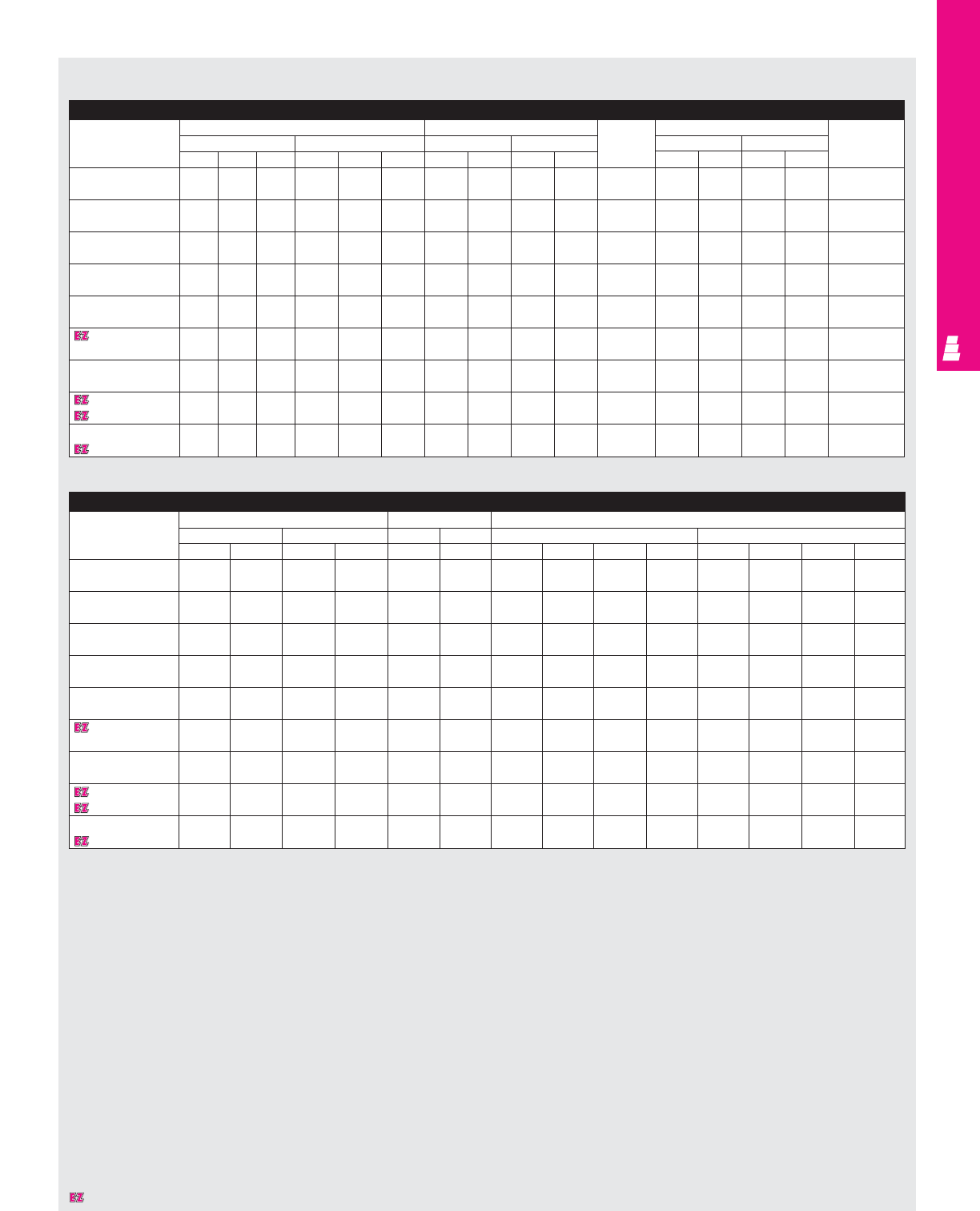
IND 118
FMD ENCLOSURES
NEMA 4/4X Wallmount Enclosures (HS)
NEMA 4 Wallmount Carbon Steel Enclosures/NEMA 4X Wallmount Stainless Steel Enclosures
Part No. Exact outside dimensions Mounting centers Door and Door size Mounting
inches mm inches mm body inches mm Panel
AB CA BCHWHWstiffener J K J K Part No.
E 24HS2108/ 24 21.38 8 609.6 543.1 203.2 25.25 15.38 641.4 390.7 NO 22.25 18.25 565.2 463.6 E 24P20
E 24HS2108SS 24 21.38 8 609.6 543.1 203.2 25.25 15.38 641.4 390.7 NO 22.25 18.25 565.2 463.6 E 24P20
E 24HS2508/ 24 25.38 8 609.6 644.7 203.2 25.25 19.38 641.4 492.3 NO 22.25 22.25 565.2 565.2 E 24P24
E 24HS2508SS 24 25.38 8 609.6 644.7 203.2 25.25 19.38 641.4 492.3 NO 22.25 22.25 565.2 565.2 E 24P24
E 30HS2508/ 30 25.38 8 762.0 644.7 203.2 31.25 19.38 793.8 492.3 NO 28.25 22.25 717.6 565.2 E 30P24
E 30HS2508SS 30 25.38 8 762.0 644.7 203.2 31.25 19.38 793.8 492.3 NO 28.25 22.25 717.6 565.2 E 30P24
E 36HS2508/ 24 21.38 8 609.6 543.1 203.2 25.25 15.38 641.4 390.7 NO 25.25 15.38 641.4 390.7 E 36P24
E 36HS2508SS 24 21.38 8 609.6 543.1 203.2 25.25 15.38 641.4 390.7 NO 25.25 15.38 641.4 390.7 E 36P24
E 36HS3108/ 36 31.38 8 914.4 797.1 203.2 37.25 25.38 946.2 644.7 YES* 34.25 28.25 870.0 717.6 E 36P30
E 36HS3108SS 36 31.38 8 914.4 797.1 203.2 37.25 25.38 946.2 644.7 YES* 34.25 28.25 870.0 717.6 E 36P30
E 42HS3112/ 42 31.38 12 1066.8 797.1 304.8 43.25 25.38 1098.6 644.7 YES* 40.25 28.25 1022.4 717.6 E 42P30
E 42HS3112SS 42 31.38 12 1066.8 797.1 304.8 43.25 25.38 1098.6 644.7 YES* 40.25 28.25 1022.4 717.6 E 42P30
E 42HS3712/ 42 37.38 12 1066.8 949.5 304.8 43.25 31.38 1098.6 797.1 YES* 40.25 34.25 1022.4 870.0 E 42P36
E 42HS3712SS 42 37.38 12 1066.8 949.5 304.8 43.25 31.38 1098.6 797.1 YES* 40.25 34.25 1022.4 870.0 E 42P36
E 48HS3712/ 48 37.38 12 1219.2 949.5 304.8 49.25 31.38 1251.0 797.1 YES* 46.25 34.25 1174.8 870.0 E 48P36
E 48HS3712SS 48 37.38 12 1219.2 949.5 304.8 49.25 31.38 1251.0 797.1 YES* 46.25 34.25 1174.8 870.0 E 48P36
E 60HS3712/ 60 37.38 12 1524.0 949.5 304.8 61.25 31.38 1555.8 797.1 YES* 58.25 34.25 1479.6 870.0 E 60P36
E 60HS3712SS 60 37.38 12 1524.0 949.5 304.8 61.25 31.38 1555.8 797.1 YES* 58.25 34.25 1479.6 870.0 E 60P36
NEMA 4 Wallmount Carbon Steel Enclosures/NEMA 4X Wallmount Stainless Steel Enclosures (Continued)
Part No. Mounting panel size Usable depth Fig. A pg. IND 123
inches mm inches mm inches mm
EF E F GGCLHL PA PE CL HL PA PE
E 24HS2108/ 21 17 533.4 431.8 8 203.2 1.594 8.625 7.125 2.565 40.5 219.1 181.0 65.2
E 24HS2108SS 21 17 533.4 431.8 8 203.2 1.594 8.625 7.125 2.565 40.5 219.1 181.0 65.2
E 24HS2508/ 21 21 533.4 533.4 8 203.2 1.594 8.625 7.125 2.565 40.5 219.1 181.0 65.2
E 24HS2508SS 21 21 533.4 533.4 8 203.2 1.594 8.625 7.125 2.565 40.5 219.1 181.0 65.2
E 30HS2508/ 27 21 685.8 533.4 8 203.2 1.594 8.625 7.125 2.565 40.5 219.1 181.0 65.2
E 30HS2508SS 27 21 685.8 533.4 8 203.2 1.594 8.625 7.125 2.565 40.5 219.1 181.0 65.2
E 36HS2508/ 21 17 533.4 431.8 8 203.2 1.594 8.625 7.125 2.565 40.5 219.1 181.0 65.2
E 36HS2508SS 21 17 533.4 431.8 8 203.2 1.594 8.625 7.125 2.565 40.5 219.1 181.0 65.2
E 36HS3108/ 33 27 838.2 685.8 7.37 187.2 1.594 8.625 7.125 2.565 40.5 219.1 181.0 65.2
E 36HS3108SS 33 27 838.2 685.8 7.37 187.2 1.594 8.625 7.125 2.565 40.5 219.1 181.0 65.2
E 42HS3112/ 39 27 990.6 685.8 11.37 288.8 1.594 11.625 10.125 2.565 40.5 295.3 257.2 65.2
E 42HS3112SS 39 27 990.6 685.8 11.37 288.8 1.594 11.625 10.125 2.565 40.5 295.3 257.2 65.2
E 42HS3712/ 39 33 990.6 838.2 11.37 288.8 1.594 11.625 10.125 2.565 40.5 295.3 257.2 65.2
E 42HS3712SS 39 33 990.6 838.2 11.37 288.8 1.594 11.625 10.125 2.565 40.5 295.3 257.2 65.2
E 48HS3712/ 45 33 1143.0 838.2 11.37 288.8 1.594 11.625 10.125 2.565 40.5 295.3 257.2 65.2
E 48HS3712SS 45 33 1143.0 838.2 11.37 288.8 1.594 11.625 10.125 2.565 40.5 295.3 257.2 65.2
E 60HS3712/ 57 33 1447.8 838.2 11.37 288.8 1.594 11.625 10.125 2.565 40.5 295.3 257.2 65.2
E 60HS3712SS 57 33 1447.8 838.2 11.37 288.8 1.594 11.625 10.125 2.565 40.5 295.3 257.2 65.2
* Usable depth reduced by .625" at door stiffener.
Designates a product in the EnclosureZone program.
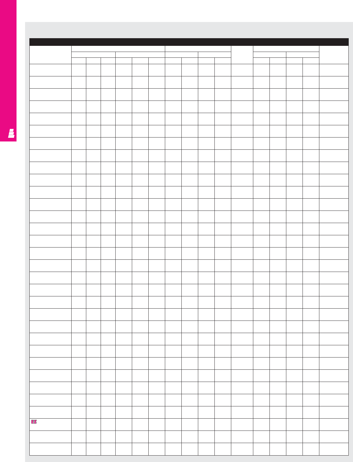
IND 119
FMD ENCLOSURES
NEMA 12 Wallmount Carbon Steel Enclosures/NEMA 12 Wallmount Stainless Steel Enclosures
Part No. Exact outside dimensions Mounting centers Door and Door size Mounting
inches mm inches mm body inches mm Panel
AB CA BCHWHWstiffener J K J K Part No.
E 20SA2208/ 20 21.38 8 508.0 543.1 203.2 21.25 15.38 539.8 390.7 NO 18.25 18.25 463.6 463.6 E 20P20
E 20SA2208SS 20 21.38 8 508.0 543.1 203.2 21.25 15.38 539.8 390.7 NO 18.25 18.25 463.6 463.6 E 20P20
E 20SA2210/ 20 21.38 10 508.0 543.1 254.0 21.25 15.38 539.8 390.7 NO 18.25 18.25 463.6 463.6 E 20P20
E 20SA2210SS 20 21.38 10 508.0 543.1 254.0 21.25 15.38 539.8 390.7 NO 18.25 18.25 463.6 463.6 E 20P20
E 24SA2208/ 24 21.38 8 609.6 543.1 203.2 25.25 15.38 641.4 390.7 NO 22.25 18.25 565.2 463.6 E 24P20
E 24SA2208SS 24 21.38 8 609.6 543.1 203.2 25.25 15.38 641.4 390.7 NO 22.25 18.25 565.2 463.6 E 24P20
E 24SA2210/ 24 21.38 10 609.6 543.1 254.0 25.25 15.38 641.4 390.7 NO 22.25 18.25 565.2 463.6 E 24P20
E 24SA2210SS 24 21.38 10 609.6 543.1 254.0 25.25 15.38 641.4 390.7 NO 22.25 18.25 565.2 463.6 E 24P20
E 24SA2608/ 24 25.38 8 609.6 644.7 203.2 25.25 19.38 641.4 492.3 NO 22.25 22.25 565.2 565.2 E 24P24
E 24SA2608SS 24 25.38 8 609.6 644.7 203.2 25.25 19.38 641.4 492.3 NO 22.25 22.25 565.2 565.2 E 24P24
E 24SA2610/ 24 25.38 10 609.6 644.7 254.0 25.25 19.38 641.4 492.3 NO 22.25 22.25 565.2 565.2 E 24P24
E 24SA2610SS 24 25.38 10 609.6 644.7 254.0 25.25 19.38 641.4 492.3 NO 22.25 22.25 565.2 565.2 E 24P24
E 30SA2208/ 30 21.38 8 762.0 543.1 203.2 31.25 15.38 793.8 390.7 NO 28.25 18.25 717.6 463.6 E 30P20
E 30SA2208SS 30 21.38 8 762.0 543.1 203.2 31.25 15.38 793.8 390.7 NO 28.25 18.25 717.6 463.6 E 30P20
E 30SA2210/ 30 21.38 10 762.0 543.1 254.0 31.25 15.38 793.8 390.7 NO 28.25 18.25 717.6 463.6 E 30P20
E 30SA2210SS 30 21.38 10 762.0 543.1 254.0 31.25 15.38 793.8 390.7 NO 28.25 18.25 717.6 463.6 E 30P20
E 30SA2608/ 30 25.38 8 762.0 644.7 203.2 31.25 19.38 793.8 492.3 NO 28.25 22.25 717.6 565.2 E 30P24
E 30SA2608SS 30 25.38 8 762.0 644.7 203.2 31.25 19.38 793.8 492.3 NO 28.25 22.25 717.6 565.2 E 30P24
E 30SA2610/ 30 25.38 10 762.0 644.7 254.0 31.25 19.38 793.8 492.3 NO 28.25 22.25 717.6 565.2 E 30P24
E 30SA2610SS 30 25.38 10 762.0 644.7 254.0 31.25 19.38 793.8 492.3 NO 28.25 22.25 717.6 565.2 E 30P24
E 30SA2612/ 30 25.38 12 762.0 644.7 304.8 31.25 19.38 793.8 492.3 NO 28.25 22.25 717.6 565.2 E 30P24
E 30SA2612SS 30 25.38 12 762.0 644.7 304.8 31.25 19.38 793.8 492.3 NO 28.25 22.25 717.6 565.2 E 30P24
E 36SA2608/ 36 25.38 8 914.4 644.7 203.2 37.25 19.38 946.2 492.3 NO 34.25 22.25 870.0 565.2 E 36P24
E 36SA2608SS 36 25.38 8 914.4 644.7 203.2 37.25 19.38 946.2 492.3 NO 34.25 22.25 870.0 565.2 E 36P24
E 36SA2610/ 36 25.38 10 914.4 644.7 254.0 37.25 19.38 946.2 492.3 NO 34.25 22.25 870.0 565.2 E 36P24
E 36SA2610SS 36 25.38 10 914.4 644.7 254.0 37.25 19.38 946.2 492.3 NO 34.25 22.25 870.0 565.2 E 36P24
E 36SA3208/ 36 31.38 8 914.4 797.1 203.2 37.25 25.38 946.2 644.7 YES * 34.25 28.25 870.0 717.6 E 36P30
E 36SA3208SS 36 31.38 8 914.4 797.1 203.2 37.25 25.38 946.2 644.7 YES * 34.25 28.25 870.0 717.6 E 36P30
E 36SA3210/ 36 31.38 10 914.4 797.1 254.0 37.25 25.38 946.2 644.7 YES * 34.25 28.25 870.0 717.6 E 36P30
E 36SA3210SS 36 31.38 10 914.4 797.1 254.0 37.25 25.38 946.2 644.7 YES * 34.25 28.25 870.0 717.6 E 36P30
E 36SA3212/ 36 31.38 12 914.4 797.1 304.8 37.25 25.38 946.2 644.7 YES * 34.25 28.25 870.0 717.6 E 36P30
E 36SA3212SS 36 31.38 12 914.4 797.1 304.8 37.25 25.38 946.2 644.7 YES * 34.25 28.25 870.0 717.6 E 36P30
E 36SA3216/ 36 31.38 16 914.4 797.1 406.4 37.25 25.38 946.2 644.7 YES * 34.25 28.25 870.0 717.6 E 36P30
E 36SA3216SS 36 31.38 16 914.4 797.1 406.4 37.25 25.38 946.2 644.7 YES * 34.25 28.25 870.0 717.6 E 36P30
E 42SA3208/ 42 31.38 8 1066.8 797.1 203.2 43.25 25.38 1098.6 644.7 YES * 40.25 28.25 1022.4 717.6 E 42P30
E 42SA3208SS 42 31.38 8 1066.8 797.1 203.2 43.25 25.38 1098.6 644.7 YES * 40.25 28.25 1022.4 717.6 E 42P30
E 42SA3210/ 42 31.38 10 1066.8 797.1 254.0 43.25 25.38 1098.6 644.7 YES * 40.25 28.25 1022.4 717.6 E 42P30
E 42SA3210SS 42 31.38 10 1066.8 797.1 254.0 43.25 25.38 1098.6 644.7 YES * 40.25 28.25 1022.4 717.6 E 42P30
E 42SA3212/ 42 31.38 12 1066.8 797.1 304.8 43.25 25.38 1098.6 644.7 YES * 40.25 28.25 1022.4 717.6 E 42P30
E 42SA3212SS 42 31.38 12 1066.8 797.1 304.8 43.25 25.38 1098.6 644.7 YES * 40.25 28.25 1022.4 717.6 E 42P30
E 42SA3808/ 42 37.38 8 1066.8 949.5 203.2 43.25 31.38 1098.6 797.1 YES * 40.25 34.25 1022.4 870.0 E 42P36
E 42SA3808SS 42 37.38 8 1066.8 949.5 203.2 43.25 31.38 1098.6 797.1 YES * 40.25 34.25 1022.4 870.0 E 42P36
E 42SA3810/ 42 37.38 10 1066.8 949.5 254.0 43.25 31.38 1098.6 797.1 YES * 40.25 34.25 1022.4 870.0 E 42P36
E 42SA3810SS 42 37.38 10 1066.8 949.5 254.0 43.25 31.38 1098.6 797.1 YES * 40.25 34.25 1022.4 870.0 E 42P36
E 42SA3812/ 42 37.38 12 1066.8 949.5 304.8 43.25 31.38 1098.6 797.1 YES * 40.25 34.25 1022.4 870.0 E 42P36
E 42SA3812SS 42 37.38 12 1066.8 949.5 304.8 43.25 31.38 1098.6 797.1 YES * 40.25 34.25 1022.4 870.0 E 42P36
E 48SA3808/ 48 37.38 8 1219.2 949.5 203.2 49.25 31.38 1251.0 797.1 YES * 46.25 34.25 1174.8 870.0 E 48P36
E 48SA3808SS 48 37.38 8 1219.2 949.5 203.2 49.25 31.38 1251.0 797.1 YES * 46.25 34.25 1174.8 870.0 E 48P36
E 48SA3810/ 48 37.38 10 1219.2 949.5 254.0 49.25 31.38 1251.0 797.1 YES * 46.25 34.25 1174.8 870.0 E 48P36
E 48SA3810SS 48 37.38 10 1219.2 949.5 254.0 49.25 31.38 1251.0 797.1 YES * 46.25 34.25 1174.8 870.0 E 48P36
E 48SA3812/ 48 37.38 12 1219.2 949.5 304.8 49.25 31.38 1251.0 797.1 YES * 46.25 34.25 1174.8 870.0 E 48P36
E 48SA3812SS 48 37.38 12 1219.2 949.5 304.8 49.25 31.38 1251.0 797.1 YES * 46.25 34.25 1174.8 870.0 E 48P36
E 48SA3816/ 48 37.38 16 1219.2 949.5 406.4 49.25 31.38 1251.0 797.1 YES * 46.25 34.25 1174.8 870.0 E 48P36
E 48SA3816SS 48 37.38 16 1219.2 949.5 406.4 49.25 31.38 1251.0 797.1 YES * 46.25 34.25 1174.8 870.0 E 48P36
E 60SA3808/ 60 37.38 8 1524.0 949.5 203.2 61.25 31.38 1555.8 797.1 YES * 58.25 34.25 1479.6 870.0 E 60P36
E 60SA3808SS 60 37.38 8 1524.0 949.5 203.2 61.25 31.38 1555.8 797.1 YES * 58.25 34.25 1479.6 870.0 E 60P36
E 60SA3810/ 60 37.38 10 1524.0 949.5 254.0 61.25 31.38 1555.8 797.1 YES * 58.25 34.25 1479.6 870.0 E 60P36
E 60SA3810SS 60 37.38 10 1524.0 949.5 254.0 61.25 31.38 1555.8 797.1 YES * 58.25 34.25 1479.6 870.0 E 60P36
E 60SA3812/ 60 37.38 12 1524.0 949.5 304.8 61.25 31.38 1555.8 797.1 YES * 58.25 34.25 1479.6 870.0 E 60P36
E 60SA3812SS 60 37.38 12 1524.0 949.5 304.8 61.25 31.38 1555.8 797.1 YES * 58.25 34.25 1479.6 870.0 E 60P36
E 60SA3816/ 60 37.38 16 1524.0 949.5 406.4 61.25 31.38 1555.8 797.1 YES * 58.25 34.25 1479.6 870.0 E 60P36
E 60SA3816SS 60 37.38 16 1524.0 949.5 406.4 61.25 31.38 1555.8 797.1 YES * 58.25 34.25 1479.6 870.0 E 60P36
E 60SA3812400#/
60 37.38 12 1524.0 949.5 304.8 61.25 31.38 1555.8 797.1 YES * 58.25 34.25 1479.6 870.0 E 60P36
E 60SA3812400SS#
60 37.38 12 1524.0 949.5 304.8 61.25 31.38 1555.8 797.1 YES * 58.25 34.25 1479.6 870.0 E 60P36
* Usable depth reduced by .625" at door stiffener. # Designed for 200 and 400A Allen Bradley Bulletin 1494V disconnect switches using 1494V-H2 operating handle.
NEMA 12 Wallmount Boxes (SA)

IND 120
FMD ENCLOSURES
NEMA 12 Wallmount Carbon Steel Enclosures/NEMA 12 Wallmount Stainless Steel Enclosures (Continued)
Part No. Mounting panel size Usable depth Fig. A pg. IND 123
inches mm inches mm inches mm
EF E F GGCLHL PA PE CL HL PA PE
E 20SA2208/ 17 17 431.8 431.8 7.75 196.9 1.5 4.75 3.250 2.565 38.1 120.7 82.6 65.2
E 20SA2208SS 17 17 431.8 431.8 7.75 196.9 1.5 4.75 3.250 2.565 38.1 120.7 82.6 65.2
E 20SA2210/ 17 17 431.8 431.8 9.75 247.7 1.5 7.094 5.594 2.565 38.1 180.2 142.1 65.2
E 20SA2210SS 17 17 431.8 431.8 9.75 247.7 1.5 7.094 5.594 2.565 38.1 180.2 142.1 65.2
E 24SA2208/ 21 17 533.4 431.8 7.75 196.9 1.5 4.75 3.250 2.565 38.1 120.7 82.6 65.2
E 24SA2208SS 21 17 533.4 431.8 7.75 196.9 1.5 4.75 3.250 2.565 38.1 120.7 82.6 65.2
E 24SA2210/ 21 17 533.4 431.8 9.75 247.7 1.5 7.094 5.594 2.565 38.1 180.2 142.1 65.2
E 24SA2210SS 21 17 533.4 431.8 9.75 247.7 1.5 7.094 5.594 2.565 38.1 180.2 142.1 65.2
E 24SA2608/ 21 21 533.4 533.4 7.75 196.9 1.5 4.75 3.250 2.565 38.1 120.7 82.6 65.2
E 24SA2608SS 21 21 533.4 533.4 7.75 196.9 1.5 4.75 3.250 2.565 38.1 120.7 82.6 65.2
E 24SA2610/ 21 21 533.4 533.4 9.75 247.7 1.5 7.094 5.594 2.565 38.1 180.2 142.1 65.2
E 24SA2610SS 21 21 533.4 533.4 9.75 247.7 1.5 7.094 5.594 2.565 38.1 180.2 142.1 65.2
E 30SA2208/ 27 17 685.8 431.8 7.75 196.9 1.5 4.75 3.250 2.565 38.1 120.7 82.6 65.2
E 30SA2208SS 27 17 685.8 431.8 7.75 196.9 1.5 4.75 3.250 2.565 38.1 120.7 82.6 65.2
E 30SA2210/ 27 17 685.8 431.8 9.75 247.7 1.5 7.094 5.594 2.565 38.1 180.2 142.1 65.2
E 30SA2210SS 27 17 685.8 431.8 9.75 247.7 1.5 7.094 5.594 2.565 38.1 180.2 142.1 65.2
E 30SA2608/ 27 21 685.8 533.4 7.75 196.9 1.5 4.75 3.250 2.565 38.1 120.7 82.6 65.2
E 30SA2608SS 27 21 685.8 533.4 7.75 196.9 1.5 4.75 3.250 2.565 38.1 120.7 82.6 65.2
E 30SA2610/ 27 21 685.8 533.4 9.75 247.7 1.5 7.094 5.594 2.565 38.1 180.2 142.1 65.2
E 30SA2610SS 27 21 685.8 533.4 9.75 247.7 1.5 7.094 5.594 2.565 38.1 180.2 142.1 65.2
E 30SA2612/ 27 21 685.8 533.4 11.75 298.5 1.5 11.625 10.125 2.565 38.1 295.3 257.2 65.2
E 30SA2612SS 27 21 685.8 533.4 11.75 298.5 1.5 11.625 10.125 2.565 38.1 295.3 257.2 65.2
E 36SA2608/ 33 21 838.2 533.4 7.75 196.9 1.5 4.75 3.250 2.565 38.1 120.7 82.6 65.2
E 36SA2608SS 33 21 838.2 533.4 7.75 196.9 1.5 4.75 3.250 2.565 38.1 120.7 82.6 65.2
E 36SA2610/ 33 21 838.2 533.4 9.75 247.7 1.5 7.094 5.594 2.565 38.1 180.2 142.1 65.2
E 36SA2610SS 33 21 838.2 533.4 9.75 247.7 1.5 7.094 5.594 2.565 38.1 180.2 142.1 65.2
E 36SA3208/ 33 27 838.2 685.8 7.12 180.8 1.5 4.75 3.250 2.565 38.1 120.7 82.6 65.2
E 36SA3208SS 33 27 838.2 685.8 7.12 180.8 1.5 4.75 3.250 2.565 38.1 120.7 82.6 65.2
E 36SA3210/ 33 27 838.2 685.8 9.12 231.6 1.5 7.094 5.594 2.565 38.1 180.2 142.1 65.2
E 36SA3210SS 33 27 838.2 685.8 9.12 231.6 1.5 7.094 5.594 2.565 38.1 180.2 142.1 65.2
E 36SA3212/ 33 27 838.2 685.8 11.12 282.4 1.5 11.625 10.125 2.565 38.1 295.3 257.2 65.2
E 36SA3212SS 33 27 838.2 685.8 11.12 282.4 1.5 11.625 10.125 2.565 38.1 295.3 257.2 65.2
E 36SA3216/ 33 27 838.2 685.8 15.12 384.0 1.5 11.625 10.125 2.565 38.1 295.3 257.2 65.2
E 36SA3216SS 33 27 838.2 685.8 15.12 384.0 1.5 11.625 10.125 2.565 38.1 295.3 257.2 65.2
E 42SA3208/ 39 27 990.6 685.8 7.12 180.8 1.5 4.75 3.250 2.565 38.1 120.7 82.6 65.2
E 42SA3208SS 39 27 990.6 685.8 7.12 180.8 1.5 4.75 3.250 2.565 38.1 120.7 82.6 65.2
E 42SA3210/ 39 27 990.6 685.8 9.12 231.6 1.5 7.094 5.594 2.565 38.1 180.2 142.1 65.2
E 42SA3210SS 39 27 990.6 685.8 9.12 231.6 1.5 7.094 5.594 2.565 38.1 180.2 142.1 65.2
E 42SA3212/ 39 27 990.6 685.8 11.12 282.4 1.5 11.625 10.125 2.565 38.1 295.3 257.2 65.2
E 42SA3212SS 39 27 990.6 685.8 11.12 282.4 1.5 11.625 10.125 2.565 38.1 295.3 257.2 65.2
E 42SA3808/ 39 33 990.6 838.2 7.12 180.8 1.5 4.75 3.250 2.565 38.1 120.7 82.6 65.2
E 42SA3808SS 39 33 990.6 838.2 7.12 180.8 1.5 4.75 3.250 2.565 38.1 120.7 82.6 65.2
E 42SA3810/ 39 33 990.6 838.2 9.12 231.6 1.5 7.094 5.594 2.565 38.1 180.2 142.1 65.2
E 42SA3810SS 39 33 990.6 838.2 9.12 231.6 1.5 7.094 5.594 2.565 38.1 180.2 142.1 65.2
E 42SA3812/ 39 33 990.6 838.2 11.12 282.4 1.5 11.625 10.125 2.565 38.1 295.3 257.2 65.2
E 42SA3812SS 39 33 990.6 838.2 11.12 282.4 1.5 11.625 10.125 2.565 38.1 295.3 257.2 65.2
E 48SA3808/ 45 33 1143.0 838.2 7.12 180.8 1.5 4.75 3.250 2.565 38.1 120.7 82.6 65.2
E 48SA3808SS 45 33 1143.0 838.2 7.12 180.8 1.5 4.75 3.250 2.565 38.1 120.7 82.6 65.2
E 48SA3810/ 45 33 1143.0 838.2 9.12 231.6 1.5 7.094 5.594 2.565 38.1 180.2 142.1 65.2
E 48SA3810SS 45 33 1143.0 838.2 9.12 231.6 1.5 7.094 5.594 2.565 38.1 180.2 142.1 65.2
E 48SA3812/ 45 33 1143.0 838.2 11.12 282.4 1.5 11.625 10.125 2.565 38.1 295.3 257.2 65.2
E 48SA3812SS 45 33 1143.0 838.2 11.12 282.4 1.5 11.625 10.125 2.565 38.1 295.3 257.2 65.2
E 48SA3816/ 45 33 1143.0 838.2 15.12 384.0 1.5 11.625 10.125 2.565 38.1 295.3 257.2 65.2
E 48SA3816SS 45 33 1143.0 838.2 15.12 384.0 1.5 11.625 10.125 2.565 38.1 295.3 257.2 65.2
E 60SA3808/ 57 33 1447.8 838.2 7.12 180.8 1.5 4.75 3.250 2.565 38.1 120.7 82.6 65.2
E 60SA3808SS 57 33 1447.8 838.2 7.12 180.8 1.5 4.75 3.250 2.565 38.1 120.7 82.6 65.2
E 60SA3810/ 57 33 1447.8 838.2 9.12 231.6 1.5 7.094 5.594 2.565 38.1 180.2 142.1 65.2
E 60SA3810SS 57 33 1447.8 838.2 9.12 231.6 1.5 7.094 5.594 2.565 38.1 180.2 142.1 65.2
E 60SA3812/ 57 33 1447.8 838.2 11.12 282.4 1.5 11.625 10.125 2.565 38.1 295.3 257.2 65.2
E 60SA3812SS 57 33 1447.8 838.2 11.12 282.4 1.5 11.625 10.125 2.565 38.1 295.3 257.2 65.2
E 60SA3816/ 57 33 1447.8 838.2 15.12 384.0 1.5 11.625 10.125 2.565 38.1 295.3 257.2 65.2
E 60SA3816SS 57 33 1447.8 838.2 15.12 384.0 1.5 11.625 10.125 2.565 38.1 295.3 257.2 65.2
E 60SA3812400#/
57 33 1447.8 838.2 11.12 282.4 1.5 18.375 16.875 2.565 38.1 466.7 428.6 65.2
E 60SA3812400SS#
57 33 1447.8 838.2 11.12 282.4 1.5 18.375 16.875 2.565 38.1 466.7 428.6 65.2
NEMA 12 Wallmount Enclosures (SA) Continued
* Usable depth reduced by .625" at door stiffener. # Designed for 200 and 400A Allen Bradley Bulletin 1494V disconnect switches using 1494V-H2 operating handle.
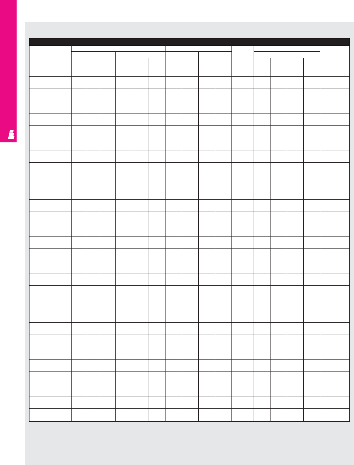
IND 121
FMD ENCLOSURES
NEMA 12 Wallmount Carbon Steel Enclosures/NEMA 12 Wallmount Stainless Steel Enclosures
Part No. Exact outside dimensions Mounting centers Door and Door size Mounting
inches mm inches mm body inches mm Panel
AB CA BCHWHWstiffener J K J K Part No.
E 20AB2208/ 20 21.38 8 508.0 543.1 203.2 21.25 15.38 539.8 390.7 NO 18.25 18.25 463.6 463.6 E 20P20
E 20AB2208SS 20 21.38 8 508.0 543.1 203.2 21.25 15.38 539.8 390.7 NO 18.25 18.25 463.6 463.6 E 20P20
E 24AB2208/ 24 21.38 8 609.6 543.1 203.2 25.25 15.38 641.4 390.7 NO 22.25 18.25 565.2 463.6 E 24P20
E 24AB2208SS 24 21.38 8 609.6 543.1 203.2 25.25 15.38 641.4 390.7 NO 22.25 18.25 565.2 463.6 E 24P20
E 24AB2210/ 24 21.38 10 609.6 543.1 254.0 25.25 15.38 641.4 390.7 NO 22.25 18.25 565.2 463.6 E 24P20
E 24AB2210SS 24 21.38 10 609.6 543.1 254.0 25.25 15.38 641.4 390.7 NO 22.25 18.25 565.2 463.6 E 24P20
E 24AB2608/ 24 25.38 8 609.6 644.7 203.2 25.25 19.38 641.4 492.3 NO 22.25 22.25 565.2 565.2 E 24P24
E 24AB2608SS 24 25.38 8 609.6 644.7 203.2 25.25 19.38 641.4 492.3 NO 22.25 22.25 565.2 565.2 E 24P24
E 24AB2610/ 24 25.38 10 609.6 644.7 254.0 25.25 19.38 641.4 492.3 NO 22.25 22.25 565.2 565.2 E 24P24
E 24AB2610SS 24 25.38 10 609.6 644.7 254.0 25.25 19.38 641.4 492.3 NO 22.25 22.25 565.2 565.2 E 24P24
E 30AB2208/ 30 21.38 8 762.0 543.1 203.2 31.25 15.38 793.8 390.7 NO 28.25 18.25 717.6 463.6 E 30P20
E 30AB2208SS 30 21.38 8 762.0 543.1 203.2 31.25 15.38 793.8 390.7 NO 28.25 18.25 717.6 463.6 E 30P20
E 30AB2210/ 30 21.38 10 762.0 543.1 254.0 31.25 15.38 793.8 390.7 NO 28.25 18.25 717.6 463.6 E 30P20
E 30AB2210SS 30 21.38 10 762.0 543.1 254.0 31.25 15.38 793.8 390.7 NO 28.25 18.25 717.6 463.6 E 30P20
E 30AB2608/ 30 25.38 8 762.0 644.7 203.2 31.25 19.38 793.8 492.3 NO 28.25 22.25 717.6 565.2 E 30P24
E 30AB2608SS 30 25.38 8 762.0 644.7 203.2 31.25 19.38 793.8 492.3 NO 28.25 22.25 717.6 565.2 E 30P24
E 30AB2610/ 30 25.38 10 762.0 644.7 254.0 31.25 19.38 793.8 492.3 NO 28.25 22.25 717.6 565.2 E 30P24
E 30AB2610SS 30 25.38 10 762.0 644.7 254.0 31.25 19.38 793.8 492.3 NO 28.25 22.25 717.6 565.2 E 30P24
E 36AB2608/ 36 25.38 8 914.4 644.7 203.2 37.25 19.38 946.2 492.3 NO 34.25 22.25 870.0 565.2 E 36P24
E 36AB2608SS 36 25.38 8 914.4 644.7 203.2 37.25 19.38 946.2 492.3 NO 34.25 22.25 870.0 565.2 E 36P24
E 36AB2610/ 36 25.38 10 914.4 644.7 254.0 37.25 19.38 946.2 492.3 NO 34.25 22.25 870.0 565.2 E 36P24
E 36AB2610SS 36 25.38 10 914.4 644.7 254.0 37.25 19.38 946.2 492.3 NO 34.25 22.25 870.0 565.2 E 36P24
E 36AB3208/ 36 31.38 8 914.4 797.1 203.2 37.25 25.38 946.2 644.7 YES * 34.25 28.25 870.0 717.6 E 36P30
E 36AB3208SS 36 31.38 8 914.4 797.1 203.2 37.25 25.38 946.2 644.7 YES * 34.25 28.25 870.0 717.6 E 36P30
E 36AB3210/ 36 31.38 10 914.4 797.1 254.0 37.25 25.38 946.2 644.7 YES * 34.25 28.25 870.0 717.6 E 36P30
E 36AB3210SS 36 31.38 10 914.4 797.1 254.0 37.25 25.38 946.2 644.7 YES * 34.25 28.25 870.0 717.6 E 36P30
E 36AB3212/ 36 31.38 12 914.4 797.1 304.8 37.25 25.38 946.2 644.7 YES * 34.25 28.25 870.0 717.6 E 36P30
E 36AB3212SS 36 31.38 12 914.4 797.1 304.8 37.25 25.38 946.2 644.7 YES * 34.25 28.25 870.0 717.6 E 36P30
E 42AB3208/ 42 31.38 8 1066.8 797.1 203.2 43.25 25.38 1098.6 644.7 YES * 40.25 28.25 1022.4 717.6 E 42P30
E 42AB3208SS 42 31.38 8 1066.8 797.1 203.2 43.25 25.38 1098.6 644.7 YES * 40.25 28.25 1022.4 717.6 E 42P30
E 42AB3210/ 42 31.38 10 1066.8 797.1 254.0 43.25 25.38 1098.6 644.7 YES * 40.25 28.25 1022.4 717.6 E 42P30
E 42AB3210SS 42 31.38 10 1066.8 797.1 254.0 43.25 25.38 1098.6 644.7 YES * 40.25 28.25 1022.4 717.6 E 42P30
E 42AB3212/ 42 31.38 12 1066.8 797.1 304.8 43.25 25.38 1098.6 644.7 YES * 40.25 28.25 1022.4 717.6 E 42P30
E 42AB3212SS 42 31.38 12 1066.8 797.1 304.8 43.25 25.38 1098.6 644.7 YES * 40.25 28.25 1022.4 717.6 E 42P30
E 42AB3808/ 42 37.38 8 1066.8 949.5 203.2 43.25 31.38 1098.6 797.1 YES * 40.25 34.25 1022.4 870.0 E 42P36
E 42AB3808SS 42 37.38 8 1066.8 949.5 203.2 43.25 31.38 1098.6 797.1 YES * 40.25 34.25 1022.4 870.0 E 42P36
E 42AB3810/ 42 37.38 10 1066.8 949.5 254.0 43.25 31.38 1098.6 797.1 YES * 40.25 34.25 1022.4 870.0 E 42P36
E 42AB3810SS 42 37.38 10 1066.8 949.5 254.0 43.25 31.38 1098.6 797.1 YES * 40.25 34.25 1022.4 870.0 E 42P36
E 42AB3812/ 42 37.38 12 1066.8 949.5 304.8 43.25 31.38 1098.6 797.1 YES * 40.25 34.25 1022.4 870.0 E 42P36
E 42AB3812SS 42 37.38 12 1066.8 949.5 304.8 43.25 31.38 1098.6 797.1 YES * 40.25 34.25 1022.4 870.0 E 42P36
E 48AB3808/ 48 37.38 8 1219.2 949.5 203.2 49.25 31.38 1251.0 797.1 YES * 46.25 34.25 1174.8 870.0 E 48P36
E 48AB3808SS 48 37.38 8 1219.2 949.5 203.2 49.25 31.38 1251.0 797.1 YES * 46.25 34.25 1174.8 870.0 E 48P36
E 48AB3810/ 48 37.38 10 1219.2 949.5 254.0 49.25 31.38 1251.0 797.1 YES * 46.25 34.25 1174.8 870.0 E 48P36
E 48AB3810SS 48 37.38 10 1219.2 949.5 254.0 49.25 31.38 1251.0 797.1 YES * 46.25 34.25 1174.8 870.0 E 48P36
E 48AB3812/ 48 37.38 12 1219.2 949.5 304.8 49.25 31.38 1251.0 797.1 YES * 46.25 34.25 1174.8 870.0 E 48P36
E 48AB3812SS 48 37.38 12 1219.2 949.5 304.8 49.25 31.38 1251.0 797.1 YES * 46.25 34.25 1174.8 870.0 E 48P36
E 48AB381220#/ 48 37.38 12 1219.2 949.5 304.8 49.25 31.38 1251.0 797.1 YES * 46.25 34.25 1174.8 870.0 E 48P36
E 48AB381220SS# 48 37.38 12 1219.2 949.5 304.8 49.25 31.38 1251.0 797.1 YES * 46.25 34.25 1174.8 870.0 E 48P36
E 48AB3816/ 48 37.38 16 1219.2 949.5 406.4 49.25 31.38 1251.0 797.1 YES * 46.25 34.25 1174.8 870.0 E 48P36
E 48AB3816SS 48 37.38 16 1219.2 949.5 406.4 49.25 31.38 1251.0 797.1 YES * 46.25 34.25 1174.8 870.0 E 48P36
E 60AB3810/ 60 37.38 10 1524.0 949.5 254.0 61.25 31.38 1555.8 797.1 YES * 58.25 34.25 1479.6 870.0 E 60P36
E 60AB3810SS 60 37.38 10 1524.0 949.5 254.0 61.25 31.38 1555.8 797.1 YES * 58.25 34.25 1479.6 870.0 E 60P36
E 60AB3812/ 60 37.38 12 1524.0 949.5 304.8 61.25 31.38 1555.8 797.1 YES * 58.25 34.25 1479.6 870.0 E 60P36
E 60AB3812SS 60 37.38 12 1524.0 949.5 304.8 61.25 31.38 1555.8 797.1 YES * 58.25 34.25 1479.6 870.0 E 60P36
E 60AB381220#/ 60 37.38 12 1524.0 949.5 304.8 61.25 31.38 1555.8 797.1 YES * 58.25 34.25 1479.6 870.0 E 60P36
E 60AB381220SS# 60 37.38 12 1524.0 949.5 304.8 61.25 31.38 1555.8 797.1 YES * 58.25 34.25 1479.6 870.0 E 60P36
E 60AB3816/ 60 37.38 16 1524.0 949.5 406.4 61.25 31.38 1555.8 797.1 YES * 58.25 34.25 1479.6 870.0 E 60P36
E 60AB3816SS 60 37.38 16 1524.0 949.5 406.4 61.25 31.38 1555.8 797.1 YES * 58.25 34.25 1479.6 870.0 E 60P36
* Usable depth reduced by .625" at door stiffener.
# Designed for 200 and 400A Allen Bradley Bulletin 1494V disconnect switches using 1494V-H2 operating handle.
NEMA 12 Wallmount Enclosures (AB)
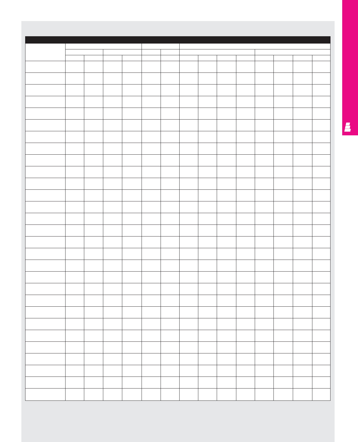
IND 122
FMD ENCLOSURES
NEMA 12 Wallmount Carbon Steel Enclosures/NEMA 12 Wallmount Stainless Steel Enclosures (Continued)
Part No. Mounting panel size Usable depth Fig. A pg. IND 123
inches mm inches mm inches mm
EF E F GGCLHL PA PE CL HL PA PE
E 20AB2208/ 17 17 431.8 431.8 7.75 196.9 1.313 3.844 2.344 2.565 33.4 97.6 59.5 65.2
E 20AB2208SS 17 17 431.8 431.8 7.75 196.9 1.313 3.844 2.344 2.565 33.4 97.6 59.5 65.2
E 24AB2208/ 21 17 533.4 431.8 7.75 1.313 1.313 3.844 2.344 2.565 33.4 97.6 59.5 65.2
E 24AB2208SS 21 17 533.4 431.8 7.75 1.313 1.313 3.844 2.344 2.565 33.4 97.6 59.5 65.2
E 24AB2210/ 21 17 533.4 431.8 9.75 247.7 1.313 6.75 5.250 2.565 33.4 171.5 133.4 65.2
E 24AB2210SS 21 17 533.4 431.8 9.75 247.7 1.313 6.75 5.250 2.565 33.4 171.5 133.4 65.2
E 24AB2608/ 21 21 533.4 533.4 7.75 196.9 1.313 3.844 2.344 2.565 33.4 97.6 59.5 65.2
E 24AB2608SS 21 21 533.4 533.4 7.75 196.9 1.313 3.844 2.344 2.565 33.4 97.6 59.5 65.2
E 24AB2610/ 21 21 533.4 533.4 9.75 247.7 1.313 6.75 5.250 2.565 33.4 171.5 133.4 65.2
E 24AB2610SS 21 21 533.4 533.4 9.75 247.7 1.313 6.75 5.250 2.565 33.4 171.5 133.4 65.2
E 30AB2208/ 27 17 685.8 431.8 7.75 196.9 1.313 6.75 5.250 2.565 33.4 171.5 133.4 65.2
E 30AB2208SS 27 17 685.8 431.8 7.75 196.9 1.313 6.75 5.250 2.565 33.4 171.5 133.4 65.2
E 30AB2210/ 27 17 685.8 431.8 9.75 247.7 1.313 6.75 5.250 2.565 33.4 171.5 133.4 65.2
E 30AB2210SS 27 17 685.8 431.8 9.75 247.7 1.313 6.75 5.250 2.565 33.4 171.5 133.4 65.2
E 30AB2608/ 27 21 685.8 533.4 7.75 196.9 1.313 3.844 2.344 2.565 33.4 97.6 59.5 65.2
E 30AB2608SS 27 21 685.8 533.4 7.75 196.9 1.313 3.844 2.344 2.565 33.4 97.6 59.5 65.2
E 30AB2610/ 27 21 685.8 533.4 9.75 247.7 1.313 6.75 5.250 2.565 33.4 171.5 133.4 65.2
E 30AB2610SS 27 21 685.8 533.4 9.75 247.7 1.313 6.75 5.250 2.565 33.4 171.5 133.4 65.2
E 36AB2608/ 33 21 838.2 533.4 7.75 196.9 1.313 3.844 2.344 2.565 33.4 97.6 59.5 65.2
E 36AB2608SS 33 21 838.2 533.4 7.75 196.9 1.313 3.844 2.344 2.565 33.4 97.6 59.5 65.2
E 36AB2610/ 33 21 838.2 533.4 9.75 247.7 1.313 6.75 5.250 2.565 33.4 171.5 133.4 65.2
E 36AB2610SS 33 21 838.2 533.4 9.75 247.7 1.313 6.75 5.250 2.565 33.4 171.5 133.4 65.2
E 36AB3208/ 33 27 838.2 685.8 7.12 180.8 1.313 3.844 2.344 2.565 33.4 97.6 59.5 65.2
E 36AB3208SS 33 27 838.2 685.8 7.12 180.8 1.313 3.844 2.344 2.565 33.4 97.6 59.5 65.2
E 36AB3210/ 33 27 838.2 685.8 9.12 231.6 1.313 6.75 5.250 2.565 33.4 171.5 133.4 65.2
E 36AB3210SS 33 27 838.2 685.8 9.12 231.6 1.313 6.75 5.250 2.565 33.4 171.5 133.4 65.2
E 36AB3212/ 33 27 838.2 685.8 11.12 282.4 1.313 9.5 8.000 2.565 33.4 241.3 203.2 65.2
E 36AB3212SS 33 27 838.2 685.8 11.12 282.4 1.313 9.5 8.000 2.565 33.4 241.3 203.2 65.2
E 42AB3208/ 39 27 990.6 685.8 7.12 180.8 1.313 3.844 2.344 2.565 33.4 97.6 59.5 65.2
E 42AB3208SS 39 27 990.6 685.8 7.12 180.8 1.313 3.844 2.344 2.565 33.4 97.6 59.5 65.2
E 42AB3210/ 39 27 990.6 685.8 9.12 231.6 1.313 6.75 5.250 2.565 33.4 171.5 133.4 65.2
E 42AB3210SS 39 27 990.6 685.8 9.12 231.6 1.313 6.75 5.250 2.565 33.4 171.5 133.4 65.2
E 42AB3212/ 39 27 990.6 685.8 11.12 282.4 1.313 9.5 8.000 2.565 33.4 241.3 203.2 65.2
E 42AB3212SS 39 27 990.6 685.8 11.12 282.4 1.313 9.5 8.000 2.565 33.4 241.3 203.2 65.2
E 42AB3808/ 39 33 990.6 838.2 7.12 180.8 1.313 3.844 2.344 2.565 33.4 97.6 59.5 65.2
E 42AB3808SS 39 33 990.6 838.2 7.12 180.8 1.313 3.844 2.344 2.565 33.4 97.6 59.5 65.2
E 42AB3810/ 39 33 990.6 838.2 9.12 231.6 1.313 6.75 5.250 2.565 33.4 171.5 133.4 65.2
E 42AB3810SS 39 33 990.6 838.2 9.12 231.6 1.313 6.75 5.250 2.565 33.4 171.5 133.4 65.2
E 42AB3812/ 39 33 990.6 838.2 11.12 282.4 1.313 9.5 8.000 2.565 33.4 241.3 203.2 65.2
E 42AB3812SS 39 33 990.6 838.2 11.12 282.4 1.313 9.5 8.000 2.565 33.4 241.3 203.2 65.2
E 48AB3808/ 45 33 1143.0 838.2 7.12 180.8 1.313 3.844 2.344 2.565 33.4 97.6 59.5 65.2
E 48AB3808SS 45 33 1143.0 838.2 7.12 180.8 1.313 3.844 2.344 2.565 33.4 97.6 59.5 65.2
E 48AB3810/ 45 33 1143.0 838.2 9.12 231.6 1.313 6.75 5.250 2.565 33.4 171.5 133.4 65.2
E 48AB3810SS 45 33 1143.0 838.2 9.12 231.6 1.313 6.75 5.250 2.565 33.4 171.5 133.4 65.2
E 48AB3812/ 45 33 1143.0 838.2 11.12 282.4 1.313 9.5 8.000 2.565 33.4 241.3 203.2 65.2
E 48AB3812SS 45 33 1143.0 838.2 11.12 282.4 1.313 9.5 8.000 2.565 33.4 241.3 203.2 65.2
E 48AB381220#/ 45 33 1143.0 838.2 11.12 282.4 1.313 10.5 9.000 2.565 33.4 266.7 228.6 65.2
E 48AB381220SS# 45 33 1143.0 838.2 11.12 282.4 1.313 10.5 9.000 2.565 33.4 266.7 228.6 65.2
E 48AB3816/ 45 33 1143.0 838.2 15.12 384.0 1.313 9.5 8.000 2.565 33.4 241.3 203.2 65.2
E 48AB3816SS 45 33 1143.0 838.2 15.12 384.0 1.313 9.5 8.000 2.565 33.4 241.3 203.2 65.2
E 60AB3810/ 57 33 1447.8 838.2 9.12 231.6 1.313 6.75 5.250 2.565 33.4 171.5 133.4 65.2
E 60AB3810SS 57 33 1447.8 838.2 9.12 231.6 1.313 6.75 5.250 2.565 33.4 171.5 133.4 65.2
E 60AB3812/ 57 33 1447.8 838.2 11.12 282.4 1.313 9.5 8.000 2.565 33.4 241.3 203.2 65.2
E 60AB3812SS 57 33 1447.8 838.2 11.12 282.4 1.313 9.5 8.000 2.565 33.4 241.3 203.2 65.2
E 60AB381220#/ 57 33 1447.8 838.2 11.12 282.4 1.313 10.5 9.000 2.565 33.4 266.7 228.6 65.2
E 60AB381220SS# 57 33 1447.8 838.2 11.12 282.4 1.313 10.5 9.000 2.565 33.4 266.7 228.6 65.2
E 60AB3816/ 57 33 1447.8 838.2 15.12 384.0 1.313 9.5 8.000 2.565 33.4 241.3 203.2 65.2
E 60AB3816SS 57 33 1447.8 838.2 15.12 384.0 1.313 9.5 8.000 2.565 33.4 241.3 203.2 65.2
* Usable depth reduced by .625" at door stiffener.
# Designed for 200 and 400A Allen Bradley Bulletin 1494V disconnect switches using 1494V-H2 operating handle.
NEMA 12 Wallmount Enclosures (AB) Continued
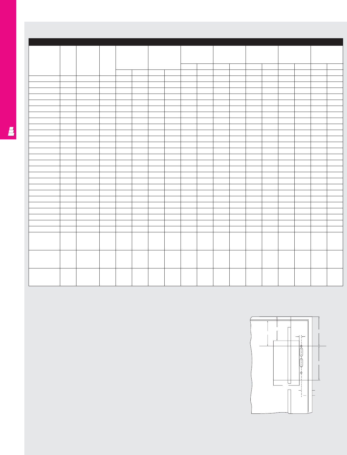
IND 123
FMD ENCLOSURES
For HS, SA Enclosures: Allen-Bradley 1494V Disconnects/Circuit-Breakers (Fig. A pg. IND 123)
Allen Bradley
Amp Fuse Fuse DH DW* SA SA HS HS, SA SA#
Part No.
rating clip class HL=4.75 HL=7.094 HL=8.625 HL=11.6 HL=18.375
(120.6) (180.2) (219) (295) (466.7)
inches mm inches mm inches mm inches mm inches mm
inches mm inches mm WWWWWWWWWW
1494V-DS30
30A Unfused - 3.87 98.3 7.12 180.8 3.01 76.5 5.35 135.9 6.8 172.7 9.86 250.4 - -
1494V-DS30
30A 30A-250V H,K,R 5.19 131.8 7.12 180.8 3.01 76.5 5.35 135.9 6.8 172.7 9.86 250.4 - -
1494V-DS30
30A 30A-600V H,K,R 7.96 202.2 7.12 180.8 3.01 76.5 5.35 135.9 6.8 172.7 9.86 250.4 - -
1494V-DS30
30A 30A-600V J 5.19 131.8 7.12 180.8 3.01 76.5 5.35 135.9 6.8 172.7 9.86 250.4 - -
1494V-DS30
30A 60A-250V H,K,R 5.41 137.4 7.12 180.8 3.01 76.5 5.35 135.9 6.8 172.7 9.86 250.4 - -
1494V-DS30
30A 60A-600V H,K,R 8.47 215.1 7.12 180.8 3.01 76.5 5.35 135.9 6.8 172.7 9.86 250.4 - -
1494V-DS30
30A 60A-600V J 5.3 134.6 7.12 180.8 3.01 76.5 5.35 135.9 6.8 172.7 9.86 250.4 - -
1494V-DS60
60A Unfused - 3.87 98.3 7.12 180.8 - - 5.1 129.5 6.69 169.9 9.67 245.6 - -
1494V-DS60
60A 60A-250V H,K,R 5.41 137.4 7.12 180.8 - - 5.1 129.5 6.69 169.9 9.67 245.6 - -
1494V-DS60
60A 60A-600V H,K,R 8.47 215.1 7.12 180.8 - - 5.1 129.5 6.69 169.9 9.67 245.6 - -
1494V-DS60
60A 60A-600V J 5.3 134.6 7.12 180.8 - - 5.1 129.5 6.69 169.9 9.67 245.6 - -
1494V-DS60
60A 30A-600V H,K,R 7.96 202.2 7.12 180.8 - - 5.1 129.5 6.69 169.9 9.67 245.6 - -
1494V-DS60
60A 100A-250V H,K 8.86 225.0 7.12 180.8 - - 5.1 129.5 6.69 169.9 9.67 245.6 - -
1494V-DS60
60A 100A-600V H,K 10.8 274.3 7.12 180.8 - - 5.1 129.5 6.69 169.9 9.67 245.6 - -
1494V-DS60
60A 100A-600V J 7.6 193.0 7.12 180.8 - - 5.1 129.5 6.69 169.9 9.67 245.6 - -
1494V-DS100
100A Unfused - 3.8 96.5 7.12 180.8 - - - - 6.5 165.1 9.5 241.3 - -
1494V-DS100
100A 100A-250V H,K,R 9.6 243.8 7.12 180.8 - - - - 6.5 165.1 9.5 241.3 - -
1494V-DS100
100A 100A-600V H,K,R 11.6 294.6 7.12 180.8 - - - - 6.5 165.1 9.5 241.3 - -
1494V-DS100
100A 100A-600V J 8.3 210.8 7.12 180.8 - - - - 6.5 165.1 9.5 241.3 - -
1494V-DS100
100A 200A-250V H,K 12.4 315.0 7.12 180.8 - - - - 6.5 165.1 9.5 241.3 - -
1494V-DS100
100A 200A-600V H,K 14.9 378.5 7.12 180.8 - - - - 6.5 165.1 9.5 241.3 - -
1494V-DS100
100A 200A-600V J 11.03 280.2 7.12 180.8 - - - - 6.5 165.1 9.5 241.3 - -
1494V-DS200
200A Unfused - 4.6 116.8 8.4 213.4 - - - - - - 8.15 207.0 - -
1494V-DS200
200A 200A-250V H,K,R 11.8 299.7 8.4 213.4 - - - - - - 8.15 207.0 - -
1494V-DS200
200A 200A-600V H,K,R 14.3 363.2 8.4 213.4 - - - - - - 8.15 207.0 - -
1494V-DS200
200A 200A-600V J 10.4 264.2 8.4 213.4 - - - - - - 8.15 207.0 - -
1494V-M40
150A EDH, FD, - 5 127.0 4.125 104.8 - - 6 152.4 7.6 193.0 10.6 269.2 - -
FDB, FDC,
HFD, HMCP
1494V-M50
250A JD, JDB, - 7.65 194.3 4.125 104.8 - - - - - - 10.57 268.5 17.3 439.42
JDC, HJD,
HMCP
1494V-M60
400A KD, KDB, - 8.3 210.8 5.5 139.7 - - - - - - - - 15.3 388.62
KDC, HKD,
HMCP
* Does not include space for optional auxiliary switch.
# Designed for 200 and 400A Allen Bradley Buletin 1494V disconnect switches using 1494V-H2 operating handle.
Note:
1. For applications above 200A, please contact your local Rittal representative.
NEMA 4/4X And NEMA 12 Wallmount Enclosures
PA WHL
27
(1.06)
DH
CL
DV
PE
FIG. A
Mounting
Panel
Fig. A
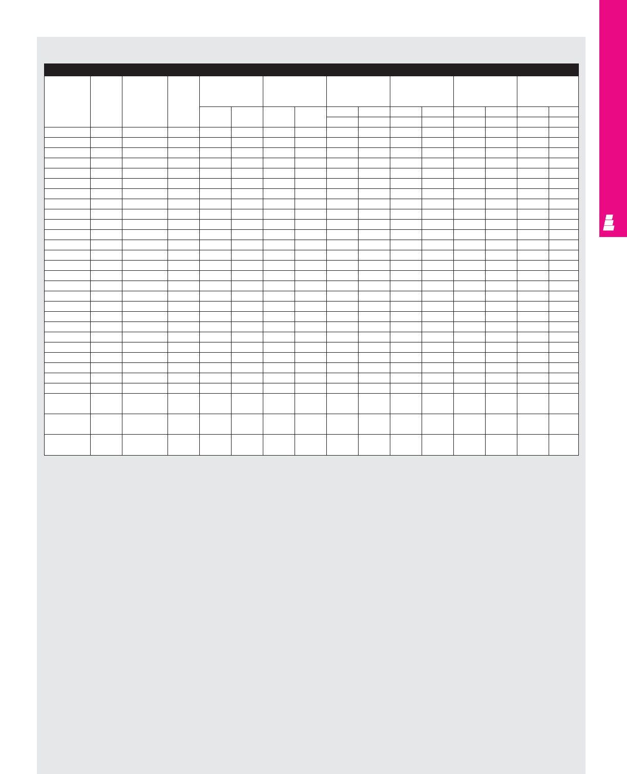
IND 124
FMD ENCLOSURES
NEMA 12 Wallmount Enclosures
For AB Enclosures: Allen-Bradley 1494V Disconnects/Circuit-Breakers
Allen Bradley Amp Fuse Fuse DH DW* AB AB AB AB
Part No. rating clip class
HL=6.504 in/97.6mm HL=9.41 in/171.4mm HL=12.16 in/241.3mm HL=13.16 in/266.7mm
(3.844) (6.75) (9.5) (10.5)
inches mm inches mm inches mm inches mm inches mm inches mm
WW W WW WWW
1494V-DS30 30A Unfused - 3.87 98.3 7.12 180.8 4.76 120.9 7.67 194.8 10.42 264.7 11.42 290.1
1494V-DS30 30A 30A-250V H, K, R 5.19 131.8 7.12 180.8 4.76 120.9 7.67 194.8 10.42 264.7 11.42 290.1
1494V-DS30 30A 30A-600V H, K, R 7.96 202.2 7.12 180.8 4.76 120.9 7.67 194.8 10.42 264.7 11.42 290.1
1494V-DS30 30A 30A-600V J 5.19 131.8 7.12 180.8 4.76 120.9 7.67 194.8 10.42 264.7 11.42 290.1
1494V-DS30 30A 60A-250V H, K, R 5.41 137.4 7.12 180.8 4.76 120.9 7.67 194.8 10.42 264.7 11.42 290.1
1494V-DS30 30A 60A-600V H, K, R 8.47 215.1 7.12 180.8 4.76 120.9 7.67 194.8 10.42 264.7 11.42 290.1
1494V-DS30 30A 60A-600V J 5.3 134.6 7.12 180.8 4.76 120.9 7.67 194.8 10.42 264.7 11.42 290.1
1494V-DS60 60A Unfused - 3.87 98.3 7.12 180.8 4.57 116.1 7.48 190.0 10.23 259.8 11.23 285.2
1494V-DS60 60A 60A-250V H, K, R 5.41 137.4 7.12 180.8 4.57 116.1 7.48 190.0 10.23 259.8 11.23 285.2
1494V-DS60 60A 60A-600V H, K, R 8.47 215.1 7.12 180.8 4.57 116.1 7.48 190.0 10.23 259.8 11.23 285.2
1494V-DS60 60A 60A-600V J 5.3 134.6 7.12 180.8 4.57 116.1 7.48 190.0 10.23 259.8 11.23 285.2
1494V-DS60 60A 30A-600V H, K, R 7.96 202.2 7.12 180.8 4.57 116.1 7.48 190.0 10.23 259.8 11.23 285.2
1494V-DS60 60A 100A-250V H, K 8.86 225.0 7.12 180.8 4.57 116.1 7.48 190.0 10.23 259.8 11.23 285.2
1494V-DS60 60A 100A-600V H, K 10.8 274.3 7.12 180.8 4.57 116.1 7.48 190.0 10.23 259.8 11.23 285.2
1494V-DS60 60A 100A-600V J 7.6 193.0 7.12 180.8 4.57 116.1 7.48 190.0 10.23 259.8 11.23 285.2
1494V-DS100 100A Unfused - 3.8 96.5 7.12 180.8 - - 7.31 185.7 10.06 255.5 11.06 280.9
1494V-DS100 100A 100A-250V H, K, R 9.6 243.8 7.12 180.8 - - 7.31 185.7 10.06 255.5 11.06 280.9
1494V-DS100 100A 100A-600V H, K, R 11.6 294.6 7.12 180.8 - - 7.31 185.7 10.06 255.5 11.06 280.9
1494V-DS100 100A 100A-600V J 8.3 210.8 7.12 180.8 - - 7.31 185.7 10.06 255.5 11.06 280.9
1494V-DS100 100A 200A-250V H, K 12.4 315.0 7.12 180.8 - - 7.31 185.7 10.06 255.5 11.06 280.9
1494V-DS100 100A 200A-600V H, K 14.9 378.5 7.12 180.8 - - 7.31 185.7 10.06 255.5 11.06 280.9
1494V-DS100 100A 200A-600V J 11.03 280.2 7.12 180.8 - - 7.31 185.7 10.06 255.5 11.06 280.9
1494V-DS200 200A Unfused - 4.6 116.8 8.4 213.4 - - - - 8.71 221.2 9.71 246.6
1494V-DS200 200A 200A-250V H, K, R 11.8 299.7 8.4 213.4 - - - - 8.71 221.2 9.71 246.6
1494V-DS200 200A 200A-600V H, K, R 14.3 363.2 8.4 213.4 - - - - 8.71 221.2 9.71 246.6
1494V-DS200 200A 200A-600V J 10.4 264.2 8.4 213.4 - - - - 8.71 221.2 9.71 246.6
1494V-M40 150A EHD,FD,FDB, - 5 127.0 4.125 104.8 - - 8.66 220.0 11.41 289.8 12.41 315.2
FDC,HFD,HMCP
1494V-M50 250A JD,JDB,JDC, - 7.65 194.3 4.125 104.8 - - 7.1 180.3 9.85 250.2 10.85 275.6
HJD,HMCP
1494V-M60 400A KD,KDB,KDC, - 8.3 210.8 5.5 139.7 - - - - 7.45 189.2 8.45 214.6
HKD,HMCP
* Does not include space for optional auxilliary switch.
Note:
1. For applications above 200A, please contact your local Rittal representative.
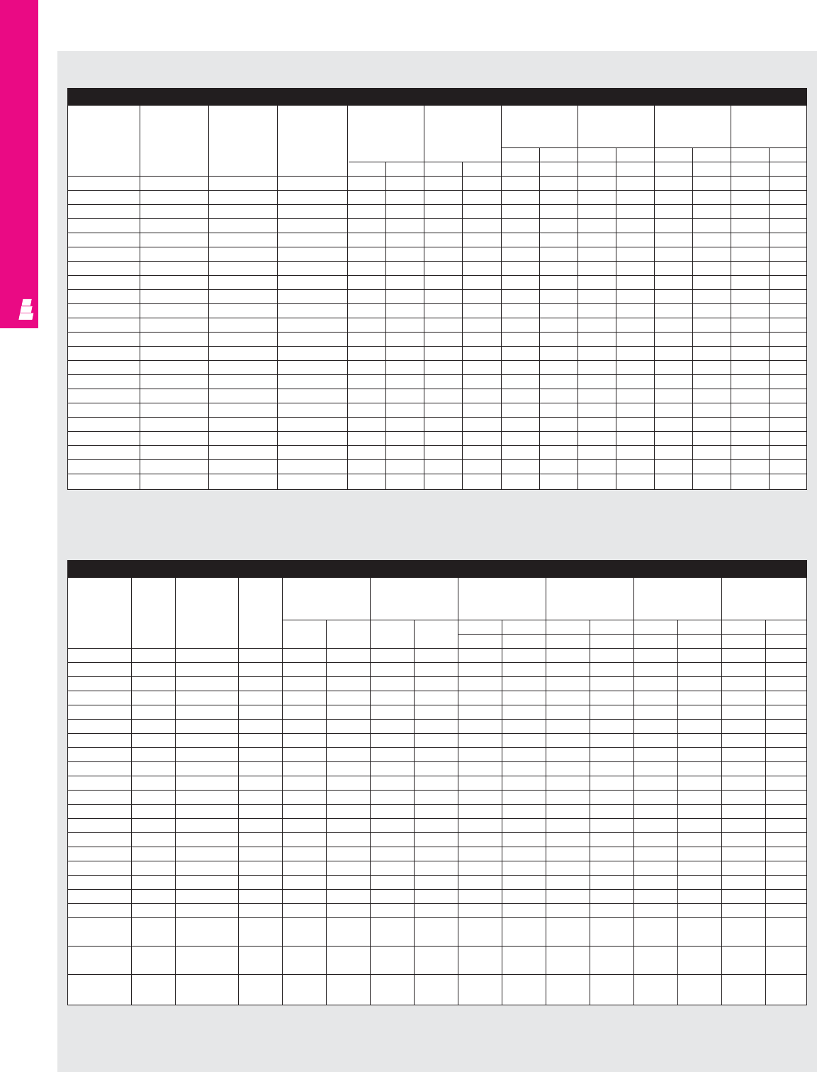
IND 125
FMD ENCLOSURES
NEMA 4/4X And NEMA 12 Wallmount Enclosures
For HS, SA Enclosures: Square D Class 9422 Disconnects/Circuit-Breakers (Fig. A pg. IND 123)
Square D
Amp Fuse Fuse DH DW* SA SA HS HS,SA
Type 9422
rating clip class HL=4.75 HL=7.094 HL=8.625 HL=11.625
Part No.
(120.6) (180.2) (219) (295)
inches mm inches mm inches mm inches mm
inches mm inches mm W W W W W W W W
TCN30
30A Unfused - 3.8 96.5 6.2 157.5 3.15 80.0 5.49 139.4 7.03 178.4 10 254.0
TCF30
30A 30A-250V H,K,R 5.42 137.7 6.2 157.5 3.15 80.0 5.49 139.4 7.03 178.4 10 254.0
TCF33
30A 30A-600V H,K,R 8.05 8.1 6.2 157.5 3.15 80.0 5.49 139.4 7.03 178.4 10 254.0
TCF33
30A 30A-600V J 5.42 137.7 6.2 157.5 3.15 80.0 5.49 139.4 7.03 178.4 10 254.0
TCF33
30A 60A-250V H,K,R 6.05 153.7 6.2 157.5 3.15 80.0 5.49 139.4 7.03 178.4 10 254.0
TDN60
60A Unfused - 3.8 96.5 6.2 157.5 3.15 80.0 5.49 139.4 7.03 178.4 10 254.0
TDF60
60A 60A-250V H,K,R 6.05 153.7 6.2 157.5 3.15 80.0 5.49 139.4 7.03 178.4 10 254.0
TDF60
60A 30A-600V H,K,R 8.05 204.5 6.2 157.5 3.15 80.0 5.49 139.4 7.03 178.4 10 254.0
TDF63
60A 60A-600V H,K,R 8.55 217.2 6.2 157.5 3.15 80.0 5.49 139.4 7.03 178.4 10 254.0
TDF63
60A 60A-600V J 5.42 137.7 6.2 157.5 3.15 80.0 5.49 139.4 7.03 178.4 10 254.0
TEN10
100A Unfused - 3.8 96.5 6.2 157.5 - - 5.49 139.4 7.03 178.4 10 254.0
TEF10
100A 100A-250V H,K,R 8.25 209.6 6.2 157.5 - - 5.49 139.4 7.03 178.4 10 254.0
TEF10
100A 100A-600V H,K,R 10.25 260.4 6.2 157.5 - - 5.49 139.4 7.03 178.4 10 254.0
TEF10
100A 100A-600V J 7.05 179.1 6.2 157.5 - - 5.49 139.4 7.03 178.4 10 254.0
TF1
200A Unfused - 5.25 133.4 11.63 295.4 - - - - - - 8.35 212.1
TF2
200A 200A-250V H,K,R 11.2 284.5 11.63 295.4 - - - - - - 8.35 212.1
TF2
200A 200A-600V H,K,R 13.7 348.0 11.63 295.4 - - - - - - 8.35 212.1
TF2
200A 200A-600V J 9.83 249.7 11.63 295.4 - - - - - - 8.35 212.1
TF3
200A 400A-600V J 14.25 362.0 11.63 295.4 - - - - - - 8.35 212.1
RG1
75,100A GJL Circuit-breaker 4.72 119.9 3.54 89.9 - - 6.09 154.7 7.63 193.7 10.6 269.2
RN1
100A FAL, FHL Circuit-breaker 6 152.4 4.5 114.3 - - 6.184 157.1 9.54 242.2 10.69 271.5
RP1
250A KAL, KHL Circuit-breaker 8 203.2 4.5 114.3 - - 6.184 157.1 9.54 242.2 10.69 271.5
* DW dimension without operating mechanism.
Note:
1. For applications above 200A, please contact your local Rittal representative.
NEMA 12 Wallmount Enclosures
For AB Enclosures: Square D Class 9422 Disconnect/Circuit-Breakers
Square D Amp Fuse Fuse DH DW* AB AB AB AB
Type 9422 rating clip class
HL=6.604 in/97.6mm HL=9.5 in/171.4mm HL=12.26 in/241.3mm HL=13.26 in/266.7mm
Part No. (3.844) (6.75) (9.5) (10.5)
inches mm inches mm inches mm inches mm inches mm inches mm
WW W WW WWW
TCN30 30A Unfused - 3.8 96.5 6.2 157.5 5.004 127.1 7.91 200.9 10.66 270.8 11.66 296.2
TCF30 30A 30A-250V H, K, R 5.42 137.7 6.2 157.5 5.004 127.1 7.91 200.9 10.66 270.8 11.66 296.2
TCF33 30A 30A-600V H, K, R 8.05 8.1 6.2 157.5 5.004 127.1 7.91 200.9 10.66 270.8 11.66 296.2
TCF33 30A 30A-600V J 5.42 6.1 6.2 157.5 5.004 127.1 7.91 200.9 10.66 270.8 11.66 296.2
TCF33 30A 60A-250V H, K, R 6.05 153.7 6.2 157.5 5.004 127.1 7.91 200.9 10.66 270.8 11.66 296.2
TDN60 60A Unfused - 3.8 96.5 6.2 157.5 5.004 127.1 7.91 200.9 10.66 270.8 11.66 296.2
TDF60 60A 60A-250V H, K, R 6.05 153.7 6.2 157.5 5.004 127.1 7.91 200.9 10.66 270.8 11.66 296.2
TDF60 60A 30A-600V H, K, R 8.05 204.5 6.2 157.5 5.004 127.1 7.91 200.9 10.66 270.8 11.66 296.2
TDF63 60A 60A-600V H, K, R 8.55 217.2 6.2 157.5 5.004 127.1 7.91 200.9 10.66 270.8 11.66 296.2
TDF63 60A 60A-600V J 5.42 137.7 6.2 157.5 5.004 127.1 7.91 200.9 10.66 270.8 11.66 296.2
TEN10 100A Unfused - 3.8 96.5 6.2 157.5 - - 7.91 200.9 10.66 270.8 11.66 296.2
TEF10 100A 100A-250V H, K, R 8.25 209.6 6.2 157.5 - - 7.91 200.9 10.66 270.8 11.66 296.2
TEF10 100A 100A-600V H, K, R 10.25 260.4 6.2 157.5 - - 7.91 200.9 10.66 270.8 11.66 296.2
TEF10 100A 100A-600V J 7.05 179.1 6.2 157.5 - - 7.91 200.9 10.66 270.8 11.66 296.2
TF1 200A Unfused - 5.25 133.4 11.63 295.4 - - 6.26 159.0 9.01 228.9 10.01 254.3
TF2 200A 200A-250V H, K, R 11.2 284.5 11.63 295.4 - - 6.26 159.0 9.01 228.9 10.01 254.3
TF2 200A 200A-600V H, K, R 13.7 348.0 11.63 295.4 - - 6.26 159.0 9.01 228.9 10.01 254.3
TF2 200A 200A-600V J 9.83 249.7 11.63 295.4 - - 6.26 159.0 9.01 228.9 10.01 254.3
TF3 200A 400A-600V J 14.25 362.0 11.63 295.4 - - 6.26 159.0 9.01 228.9 10.01 254.3
RG1 75, 100A GJL Circuit- 4.72 119.9 3.54 89.9 - - 5.85 148.6 8.6 218.4 9.6 243.8
breaker
RN1 100A FAL, FHL Circuit- 6 152.4 4.5 114.3 - - - - 8.69 220.7 9.69 246.1
breaker
RP1 250A KAL, KHL Circuit- 8 203.2 4.5 114.3 - - - - 8.69 220.7 9.69 246.1
breaker
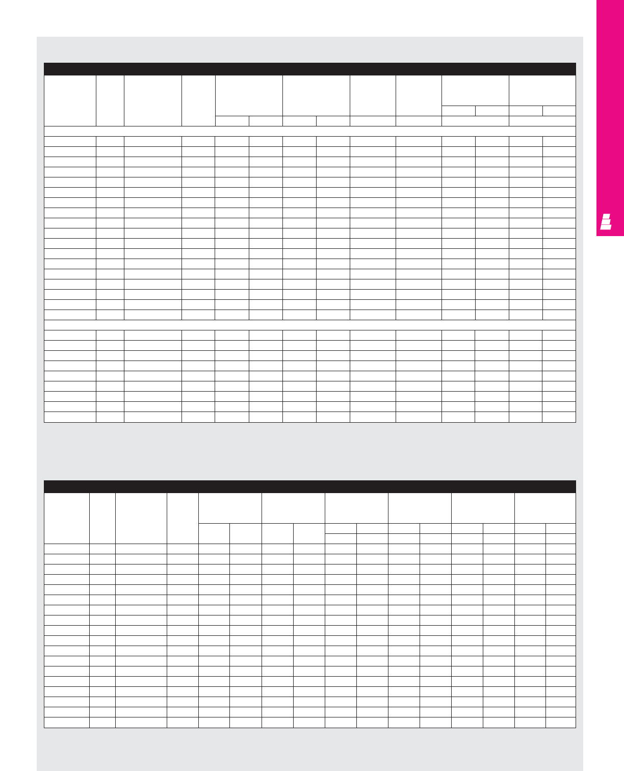
IND 126
FMD ENCLOSURES
For HS, SA Enclosures: General Electric STDA Disconnects/Circuit-Breakers (Fig. A pg. IND 123)
GE Type STDA Amp Fuse Fuse DH DW SA SA HS HS, SA
Part No. rating clip class HL=4.75 HL=7.094 HL=8.625 HL=11.6
(120.6) (180.2) (219) (295)
inches mm inches mm
inches mm inches mm W W W W
Disconnects
TDOM1A 30A Unfused - 1.18 30.0 4.09 103.9 - - 4.44 112.8 7.4 188.0
TDOM1A 30A 30A-250V H, R 3 76.2 4.09 103.9 - - 4.44 112.8 7.4 188.0
TDOM1B 30A 30A-600V H, R 6 8.1 5.68 144.3 - - 4.44 112.8 7.4 188.0
TDOM1B 30A 60A-250V H, R 3 6.1 4.09 103.9 - - 4.44 112.8 7.4 188.0
TDOM1B 30A 60A-600V H, R 6 152.4 5.68 144.3 - - 4.44 112.8 7.4 188.0
TDOM1A 60A Unfused - 1.18 30.0 4.09 103.9 - - 4.44 112.8 7.4 188.0
TDOM1B 60A 60A-250V H, R 4.4 111.8 5.68 144.3 - - 4.44 112.8 7.4 188.0
TDOM1B 60A 60A-600V H, R 6.9 175.3 5.87 149.1 - - 4.44 112.8 7.4 188.0
TDOM1B 60A 100A-250V H, R 4.4 111.8 5.68 144.3 - - 4.44 112.8 7.4 188.0
TDOM1B 60A 100A-600V H, R 6.9 175.3 5.87 149.1 - - 4.44 112.8 7.4 188.0
TDOM1A 100A Unfused - 1.18 30.0 4.09 103.9 - - 4.44 112.8 7.4 188.0
TDOM1B 100A 100A-250V H, R 5.8 147.3 6.18 157.0 - - 4.44 112.8 7.4 188.0
TDOM1B 100A 100A-600V H, R 7.8 198.1 6.18 157.0 - - 4.44 112.8 7.4 188.0
TDOM1B 100A 200A-250V H, R 11.6 294.6 6.18 157.0 - - 4.44 112.8 7.4 188.0
TDOM1B 100A 200A-600V H, R 16.1 408.9 6.18 157.0 - - 4.44 112.8 7.4 188.0
TDOM2 200A Unfused - 7.5 190.5 8.4 213.4 - - - - 8.35 7.9
TDOM2 200A 200A-250V H, R 13.5 342.9 8.4 213.4 - - - - 8.35 7.9
TDOM2 200A 200A-600V H, R 16 406.4 8.4 213.4 - - - - 8.35 7.9
Circuit-Breakers
TDOM1A 150A TEB, TED, THED - 3.96 100.6 4.1 104.1 - - 6.28 159.5 8.9 226.1
TDOM1A 150A TEC - 3.96 100.6 4.1 104.1 - - 6.28 159.5 8.9 226.1
TDOM1B 150A TB1 - 7.96 8.1 4.1 104.1 - - 6.28 159.5 8.9 226.1
TDOM1B 150A TEC, TECL - 5.84 6.1 4.1 104.1 - - 6.28 159.5 8.9 226.1
TDOM1C 150A TEL - 3.96 100.6 4.1 104.1 - - 6.28 159.5 8.9 226.1
TDOM1D 150A THLC1 - 6.75 171.5 4.1 104.1 - - 6.62 168.1 9.6 243.8
TDOM3 225A TFJ - 7.3 185.4 4.1 104.1 - - - - 8.78 223.0
TDOM3 225A TFK, THFK, TFL - 7.3 185.4 4.1 104.1 - - - - 8.78 223.0
TDOM3 225A THLC2 - 4.8 121.9 5.7 144.8 - - - - - -
Note:
1. For applications above 200A, please contact your local Rittal representative.
NEMA 4/4X And NEMA 12 Wallmount Enclosures
For AB Enclosures: General Electric STDA Disconnects
Allen Bradley Amp Fuse Fuse DH DW AB AB AB AB
Type rating clip class
HL=6.814 in/97.6mm HL=9.72 in/171.4mm HL=12.47 in/241.3mm HL=13.47 in/266.7mm
Disconnect (3.844) (6.75) (9.5) (10.5)
Part No. inches mm inches mm inches mm inches mm inches mm inches mm
WW W WW WWW
TDOM1A 30A Unfused - 1.18 30.0 4.09 103.9 - - 5.5325 140.5 8.2825 210.4 9.2825 235.8
TDOM1A 30A 30A-250V H, R 3 76.2 4.09 103.9 - - 5.5325 140.5 8.2825 210.4 9.2825 235.8
TDOM1B 30A 30A-600V H, R 6 8.1 5.68 144.3 - - 5.5325 140.5 8.2825 210.4 9.2825 235.8
TDOM1B 30A 60A-250V H, R 3 6.1 4.09 103.9 - - 5.5325 140.5 8.2825 210.4 9.2825 235.8
TDOM1B 30A 60A-600V H, R 6 152.4 5.68 144.3 - - 5.5325 140.5 8.2825 210.4 9.2825 235.8
TDOM1A 60A Unfused - 1.18 30.0 4.09 103.9 - - 5.5325 140.5 8.2825 210.4 9.2825 235.8
TDOM1B 60A 60A-250V H, R 4.4 111.8 5.68 144.3 - - 5.5325 140.5 8.2825 210.4 9.2825 235.8
TDOM1B 60A 60A-600V H, R 6.9 175.3 5.87 149.1 - - 5.5325 140.5 8.2825 210.4 9.2825 235.8
TDOM1B 60A 100A-250V H, R 4.4 111.8 5.68 144.3 - - 5.5325 140.5 8.2825 210.4 9.2825 235.8
TDOM1B 60A 100A-600V H, R 6.9 175.3 5.87 149.1 - - 5.5325 140.5 8.2825 210.4 9.2825 235.8
TDOM1A 100A Unfused - 1.18 30.0 4.09 103.9 - - 5.5325 140.5 8.2825 210.4 9.2825 235.8
TDOM1B 100A 100A-250V H, R 5.8 147.3 6.18 157.0 - - 5.5325 140.5 8.2825 210.4 9.2825 235.8
TDOM1B 100A 100A-600V H, R 7.8 198.1 6.18 157.0 - - 5.5325 140.5 8.2825 210.4 9.2825 235.8
TDOM1B 100A 200A-250V H, R 11.6 294.6 6.18 157.0 - - 5.5325 140.5 8.2825 210.4 9.2825 235.8
TDOM1B 100A 200A-600V H, R 16.1 408.9 6.18 157.0 - - 5.5325 140.5 8.2825 210.4 9.2825 235.8
TDOM2 200A Unfused - 7.5 190.5 8.4 213.4 - - 6.064 154.0 8.814 223.9 9.814 249.3
TDOM2 200A 200A-250V H, R 13.5 342.9 8.4 213.4 - - 6.064 154.0 8.814 223.9 9.814 249.3
TDOM2 200A 200A-600V H, R 16 406.4 8.4 213.4 - - 6.064 154.0 8.814 223.9 9.814 249.3
Note:
1. For applications above 200A, please contact your local Rittal representative.
NEMA 12 Wallmount Enclosures
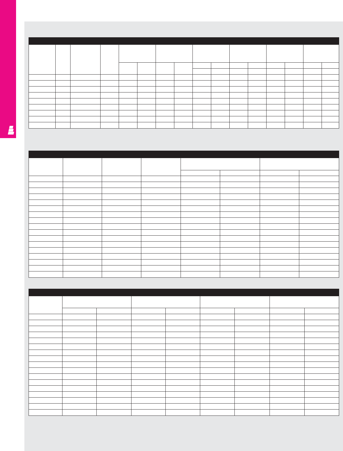
IND 127
FMD ENCLOSURES
For HS, SA Enclosures: Cutler-Hammer C361 Disconnect Switches (Fig. A pg. IND 123)
Cutler- Amp Fuse Fuse DH DW
Hammer rating clip class
Part No. inches mm inches mm
NC 30A Unfused - 3.90 99.06 6.00 152.40
SC21 30A 30A-250V H, K, R 7.60 193.04 6.00 152.40
SC61 30A 60A-250V H, K, R 8.16 207.26 6.00 152.40
SC61 30A 30A-600V H, K, J, R 7.60 193.04 6.00 152.40
ND 60A Unfused - 3.90 99.06 6.00 152.40
SD22 60A Unfused - 3.90 99.06 6.00 152.40
SD22 60A 60A-250V H, K, R 8.16 207.26 6.00 152.40
SD62 60A 60A-600V H, K, R 8.16 207.26 6.00 152.40
SD62 60A 60A-600V J 7.79 197.87 6.00 152.40
NE 100A Unfused - 8.90 226.06 7.00 177.80
SE263 100A 100A-250V H, K, R 8.90 226.06 7.00 177.80
SE263 100A 100A-600V H, K, R 8.90 226.06 7.00 177.80
SE263 100A 100A-600V J 8.90 226.06 7.00 177.80
NF 200A Unfused - 13.10 332.74 9.75 247.65
SF264 200A 200A-250V H, K, R 13.10 332.74 9.75 247.65
SF64 200A 200A-600V H, K, R 13.10 332.74 9.75 247.65
SF264 200A 200A-600V J 13.10 332.74 9.75 247.65
Note:
1. For applications above 200A, please contact your local Rittal representative.
2. DH dimension includes the lowering mechanism.
For HS, SA Enclosures: Cutler-Hammer C361 Disconnect Switches (Fig. A pg. IND 123) (Continued)
Cutler-Hammer HL=4.75 HL=7.094 HL=8.625 W (HS, SA)
Part No. (120.6) (180.2) (219) HL=11.6 (295)
inches mm inches mm inches mm inches mm
NC 3.10 78.74 5.50 139.70 7.03 178.56 10.00 254.00
SC21 3.10 78.74 5.50 139.70 7.03 178.56 10.00 254.00
SC61 3.10 78.74 5.50 139.70 7.03 178.56 10.00 254.00
SC61 3.10 78.74 5.50 139.70 7.03 178.56 10.00 254.00
ND 3.10 78.74 5.50 139.70 7.03 178.56 10.00 254.00
SD22 3.10 78.74 5.50 139.70 7.03 178.56 10.00 254.00
SD22 3.10 78.74 5.50 139.70 7.03 178.56 10.00 254.00
SD62 3.10 78.74 5.50 139.70 7.03 178.56 10.00 254.00
SD62 3.10 78.74 5.50 139.70 7.03 178.56 10.00 254.00
NE --5.08 129.03 6.60 167.64 9.59 243.59
SE263 --5.08 129.03 6.60 167.64 9.59 243.59
SE263 --5.08 129.03 6.60 167.64 9.59 243.59
SE263 --5.08 129.03 6.60 167.64 9.59 243.59
NF ----- -6.67 169.42
SF264 ----- -6.67 169.42
SF264 ----- -6.67 169.42
SF264 ----- -6.67 169.42
For AB Enclosures: General Electric STDA Disconnects
Allen Bradley Amp Fuse Fuse DH DW AB AB AB AB
Type Circuit- rating clip class
HL=6.814 in/97.6mm HL=9.72 in/171.4mm HL=12.47 in/241.3mm HL=13.47 in/266.7mm
Breaker (3.844) (6.75) (9.5) (10.5)
Part No. inches mm inches mm inches mm inches mm inches mm inches mm
WW W WW WWW
TDOM1A 150A EB, TED, THED - 3.96 100.6 4.1 104.1 - - 7.3762 187.4 10.126 257.2 11.126 282.6
TDOM1A 150A TEC - 3.96 100.6 4.1 104.1 - - 7.3762 187.4 10.126 257.2 11.126 282.6
TDOM1B 150A TB1 - 7.96 8.1 4.1 104.1 - - 7.3762 187.4 10.126 257.2 11.126 282.6
TDOM1B 150A TEC, TECL - 5.84 6.1 4.1 104.1 - - 7.3762 187.4 10.126 257.2 11.126 282.6
TDOM1C 150A TEL - 3.96 100.6 4.1 104.1 - - 7.3762 187.4 10.126 257.2 11.126 282.6
TDOM1D 150A THLC1 - 6.75 171.5 4.1 104.1 - - 7.72 196.1 10.47 265.9 11.47 291.3
TDOM3 225A TFJ - 7.3 185.4 4.1 104.1 - - 6.907 175.4 9.657 245.3 10.657 270.7
TDOM3 225A TFK, THFK, TFL - 7.3 185.4 4.1 104.1 - - 6.907 175.4 9.657 245.3 10.657 270.7
TDOM3 225A THLC2 - 4.8 121.9 5.7 144.8 - - - - - - 6.876 174.7
NEMA 12 Wallmount Enclosures
NEMA 4/4X And NEMA 12 Wallmount Enclosures
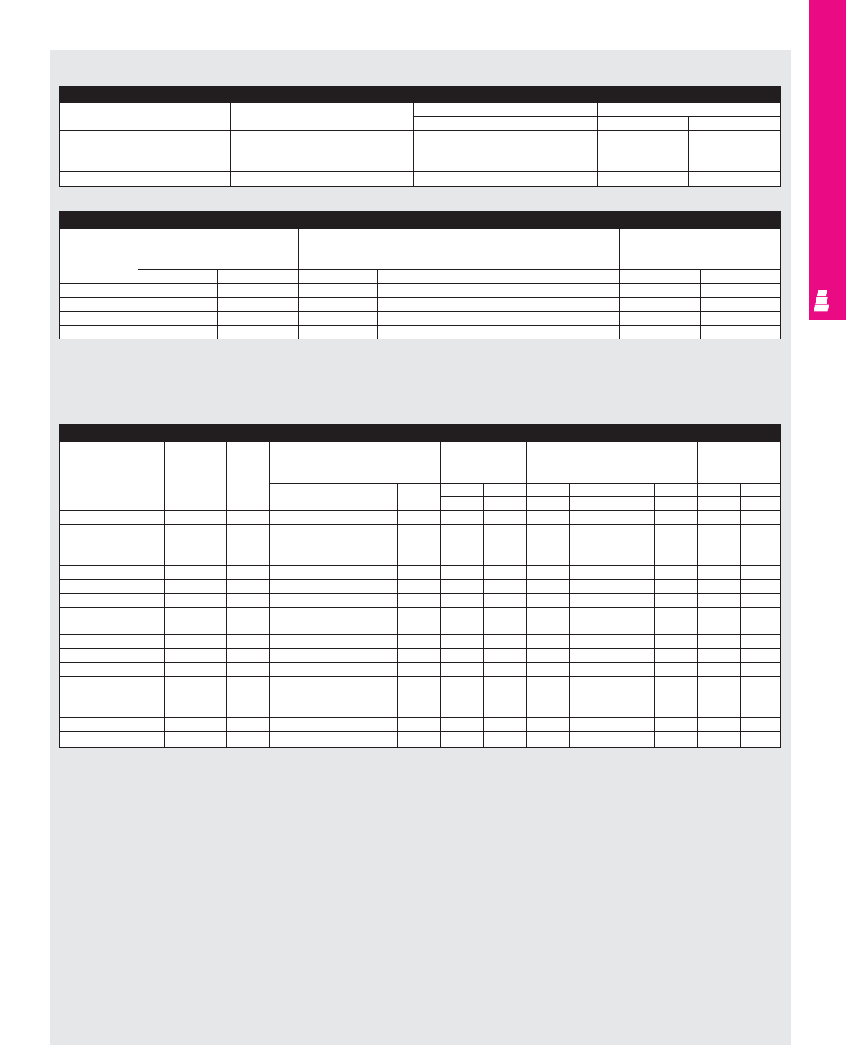
IND 128
FMD ENCLOSURES
For HS, SA Enclosures: Cutler-Hammer C371 Circuit-Breaker Operator (Fig. A pg. IND 123)
Cutler-Hammer Amp Frame DH DW
Part No. rating type inches mm inches mm
C371E 150A Cutler-Hammer FDB, FD, FDC, HFD, EHD 5.33 135.38 4.13 104.78
C371E 150A Westinghouse F Frame/Series C 5.33 135.38 4.13 104.78
C371F 225A Cutler-Hammer HJD, JD, JDC 9.37 238.00 10.00 254.00
C371F 225A Westinghouse J Frame/Series C 9.37 238.00 10.00 254.00
Note:
1. For applications above 200A, please contact your local Rittal representative.
For HS, SA Enclosures: Cutler-Hammer C371 Circuit-Breaker Operator (Fig. A pg. IND 123) (Continued)
Cutler-Hammer W (SA) W (SA) W (HS) W (HS, SA)
Part No. HL=4.75 HL=7.094 HL=8.625 HL=11.6
(120.6) (180.2) (219) (295)
inches mm inches mm inches mm inches mm
C371E 4.67 118.62 7.00 177.80 8.54 216.92 11.52 292.61
C371E 4.67 118.62 7.00 177.80 8.54 216.92 11.52 292.61
C371F --6.00 152.40 7.53 191.26 10.50 266.70
C371F --6.00 152.40 7.53 191.26 10.50 266.70
NEMA 4/4X And NEMA 12 Wallmount Enclosures
For AB Enclosures: Cutler-Hammer (C361 Disconnect Switches)
Cutler- Amp Fuse Fuse DH DW AB AB AB AB
Hammer rating clip class
HL=6.504 in/97.6mm HL=9.41 in/171.4mm HL=12.16 in/241.3mm HL=13.16 in/266.7mm
Type (3.844) (6.75) (9.5) (10.5)
Part No. inches mm inches mm inches mm inches mm inches mm inches mm
WW W WW WWW
NC 30A Unfused - 3.90 99.06 6.00 152.40 4.91 124.76 7.82 198.58 10.57 268.43 11.57 293.83
SC21 30A 30A-250V H,K,R 7.60 193.04 6.00 152.40 4.91 124.76 7.82 198.58 10.57 268.43 11.57 293.83
SC61 30A 60A-250V H,K,R 8.16 207.26 6.00 152.40 4.91 124.76 7.82 198.58 10.57 268.43 11.57 293.83
SC61 30A 30A-600V H,K,J,R 7.60 193.04 6.00 152.40 4.91 124.76 7.82 198.58 10.57 268.43 11.57 293.83
ND 60A Unfused - 3.90 99.06 6.00 152.40 4.91 124.76 7.82 198.58 10.57 268.43 11.57 293.83
SD22 60A Unfused - 3.90 99.06 6.00 152.40 4.91 124.76 7.82 198.58 10.57 268.43 11.57 293.83
SD22 60A 60A-250V H,K,R 8.16 207.26 6.00 152.40 4.91 124.76 7.82 198.58 10.57 268.43 11.57 293.83
SD62 60A 60A-600V H,K,R 8.16 207.26 6.00 152.40 4.91 124.76 7.82 198.58 10.57 268.43 11.57 293.83
SD62 60A 60A-600V J 7.79 197.87 6.00 152.40 4.91 124.76 7.82 198.58 10.57 268.43 11.57 293.83
NE 100A Unfused - 8.90 226.06 7.00 177.80 - - 7.40 187.96 10.15 257.81 11.15 283.21
SE263 100A 100A-250V H,K,R 8.90 226.06 7.00 177.80 - - 7.40 187.96 10.15 257.81 11.15 283.21
SE263 100A 100A-600V H,K,R 8.90 226.06 7.00 177.80 - - 7.40 187.96 10.15 257.81 11.15 283.21
SE263 100A 100A-600V J 8.90 226.06 7.00 177.80 - - 7.40 187.96 10.15 257.81 11.15 283.21
NF 200A Unfused - 13.10 332.74 9.75 247.65 - - - - 7.21 183.01 8.21 208.41
SF264 200A 200-250V H,K,R 13.10 332.74 9.75 247.65 - - - - 7.21 183.01 8.21 208.41
SF264 200A 200-600V H,K,R 13.10 332.74 9.75 247.65 - - - - 7.21 183.01 8.21 208.41
SF264 200A 200A-600V J 13.10 332.74 9.75 247.65 - - - - 7.21 183.01 8.21 208.41
Note:
1. For applications above 200A, please contact your local Rittal representative.
NEMA 12 Wallmount Enclosures

IND 129
FMD ENCLOSURES
For HS, SA, AB Enclosures: Siemens ITE Max-Flex Operators for Disconnect Switches (Fig. A pg. IND 130)
Switch
Max-Flex Fixed depth Amp rating Fuse kit Fuse class Panel space requirements
Part No.
variable depth Complete handle
Complete handle mechanism A B C
mechanism inches mm inches mm inches mm
MCS603R
FHOS06036R FDFS06R 30 No fuse - 6.13 155.7 5.52 140.2 - -
MCS603L
FHOS06036L 30A, 250V H, R 6.13 155.7 5.52 140.2 8.11 205.9
30A, 600V H, R 6.13 155.7 5.52 140.2 10.11 256.7
30A, 600V J 6.13 155.7 5.52 140.2 8.48 215.3
MCS606R
FHOS06036R FDFS06R 60 No fuse - 6.13 155.7 5.52 140.2 - -
MCS606L
FHOS06036L 60A, 250V H, R 6.13 155.7 5.52 140.2 7.86 199.6
60A, 600V H, R 6.13 155.7 5.52 140.2 10.38 263.6
60A, 600V J 6.13 155.7 5.52 140.2 8.35 212
MCS610R
FHOS06036R FDFS06R 100 No fuse - 7.38 187.4 7.59 192.7 - -
MCS610L
FHOS06036L 100A, 250V H, R 7.38 187.4 7.59 192.7 11.85 300.9
100A, 600V H, R 7.38 187.4 7.59 192.7 13.85 351.7
100A, 600V J 7.38 187.4 7.59 192.7 10.6 269.2
MCS620R
FHOS20036R FDFS20R 200 No fuse - 9.17 232.9 9.00 228.6 - -
MCS620L
FHOS20036L 200A, 250V H, R 9.17 232.9 9.00 228.6 14.7 373.3
200A, 600V H, R 9.17 232.9 9.00 228.6 17.2 436.8
200A, 600V J 9.17 232.9 9.00 228.6 13.32 338.3
*To order Class R fuse kit, you must order Class H fuse kit and corresponding Class R fuse conversion kit.
*Max-Flex standard cable length is 36 inches. Alternate cable lengths are available by special order.
*Maximum length with Class H and R fuses.
For HS, SA, AB Enclosures: Maximum “E” Dimension For ITE Max-Flex With Disconnect Switch (Fig. B pg. IND 130) (Continued)
Enclosure depth 36" Cable 46" Cable
Fmin Fmax Fmin Fmax
inches mm inches mm inches mm inches mm inches mm
8203.2 7 177.8 14.5 368.3 16.1 408.94 23.9 607.06
10 254 5.5 139.7 13.1 332.74 16 406.4 23.6 599.44
12 304.8 5 127 12 304.8 15.9 403.86 220.8 579.12
16 406.4 4 101.6 9.4 238.76 14.7 373.38 22 558.8
18 457.2 - - - - 14.6 370.84 21.9 556.26
20 508 - - - - 13.3 337.82 19.9 505.46
24 609.6 - - - - 12 304.8 16.9 429.26
For HS, SA, AB Enclosures: Maximum “E” Dimension For ITE Max-Flex With Disconnect Switch (Fig. B pg. IND 130)
Switch Cable
Enclosure depth
Part No. Part No.
When E=8 (203.2) When E=10 (254) When E=12 (304.8) When E=16 (406.4) When E=18 (457.2) When E=20 (508)
inches mm inches mm inches mm inches mm inches mm inches mm
MCS603, MCS606, FHOEC036 16.0 406 13.0 330 13.5 343 8.0 203 - - - -
MCS610 FHOEC048 16 660.4 16 660.4 16 660.4 23 584.2 21 533.4 18 457.2
MCS620 FHOJC036 15 381 12.0 304 12.5 317 7.0 178 - - - -
FHOJC046 25 635 25 635 25 635 22 558.8 20 508 17 431.8
Maximum “E” dimension only if F=4.6 (116.8)
For HS, SA, AB Enclosures: ITE Max-Flex Operators for Disconnect Switch (Fig. C, D pg. IND 130)
Switch Handle Dimensions — see fig. C, D
Part No. Part No. X1 X2 Y1 Y2 Z1*
inches mm inches mm inches mm inches mm inches mm
MCS603, FDFS06R
3.52 89.4 1.5 38.1 0.0 0.0 1.89 48 6.44 163.5
MCS606
MCS610 FDFS06R
3.91 99.3 1.81 45.9 0.13 3.3 3.0 76.2 6.44 163.5
MCS620 FDFS06R
1.51 38.3 7.86 199.6 0.38 9.6 5.44 138.1 10.93 277.6
*Z1 is the distance between the disconnect mounting surface and mounting panel (mechanical adjustments required if Z1 and usable depth not equal).
NEMA 4/4X And NEMA 12 Wallmount Enclosures
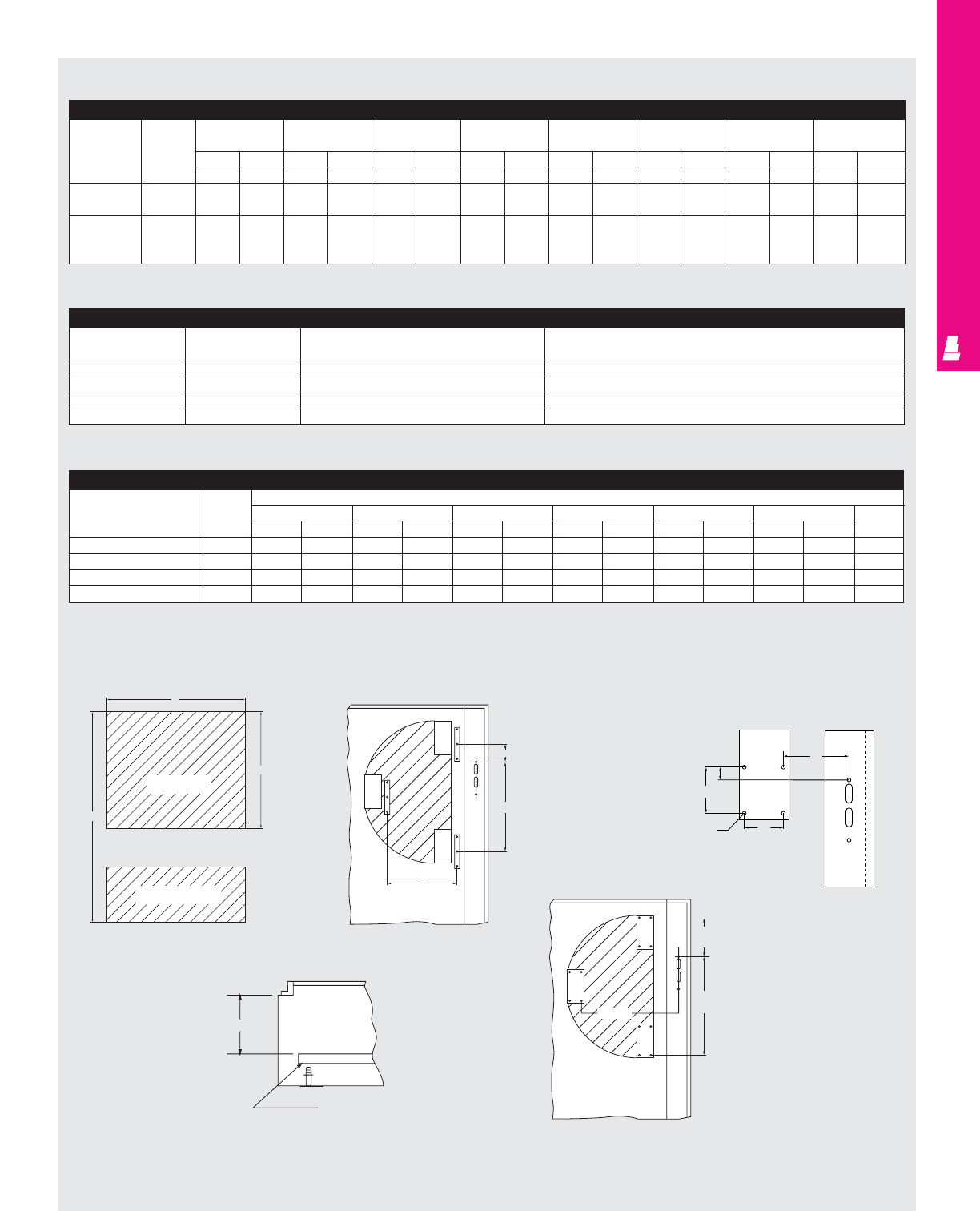
IND 130
FMD ENCLOSURES
B
A
C
Switch Base
Fuse Load Base E
F min
F max
FIG. B
Maximum “E” Dimension For ITE Max-Flex With Circuit-Breaker (Fig. E pg. IND 130)
Cable Frame When enclosure When enclosure When enclosure When enclosure When enclosure When enclosure When enclosure When enclosure
Part No. size depth=8 (203.2) depth=10 (254) depth=12 (304.8) depth=16 (406.4) depth=18 (457.2) depth=20 (508) depth=24 (609.6) depth=30 (762)
inches mm inches mm inches mm inches mm inches mm inches mm inches mm inches mm
E= E= E= E= E= E= E= E= E= E= E= E= E= E= E= E=
FHOEC036 ED, HED, 13.8 203.2 13.5 203.2 13 203.2 10.7 203.2 8.7 203.2 5.3 203.2 - - - -
CED, EF
FHOEC036 FXD, FD, 11.2 203.2 11 203.2 10.5 203.2 8.3 203.2 5.5 203.2 3.5 203.2 - - - -
HFD, CFD,
HFXD, FF,
Maximum “E” dimension only if F=116.8 (4.6).
X2
Y2
D.156 DIA. (4x)
Y1
X1
Z*
MPL
FIG. D
DH
min
DH
max
FIG. E
E max
For HS, SA, AB Enclosures: ITE Max-Flex Operators For Circuit-Breakers
Breaker Operator Amp Circuit-breaker For use with
Catalog No. rating frame size breaker type(s)
FHOE036 125 ED, HED, EF (CE) ED2, ED4, ED6, HED4, HED6, ED6, ETI, HHED6, EFC
FHOE036 125 CED, EF (CE) CED6, CED6 ETI, EFF
FHOF036 250 FD, FXD, HFD, HFXD, FF (CE) FXD6-A, FD6-A, HFD6, HFXD6, HHFD6, FD6 ETI, FFC, FFF
FHOF036 250 CFD CFD6, CFD6 ETI
* For applications above 200A, please contact your local Rittal representative.
Circuit-Breaker Mounting Dimensions
Circuit Breaker Amp See fig. E
Frame Size rating A B C D* K DH (normal) Tap size
inches mm inches mm inches mm i inches mm inches mm inches mm
ED, HED, EF, CED 125 1.0 25.4 5.0 127 0.65 16.5 6.33 160.7 - - 6.81 172.9 #8-32
CED6, CED6-ETI 125 1.0 25.4 5.0 127 0.65 16.5 8.93 226.8 3.25 82.5 6.81 172.9 #8-32
FXD, FD, HFD, HFXD, FF 250 1.5 38.1 7.5 190.5 1.0 25.4 9.5 241.3 - - 6.78 172.2 #1/4 20
CFD 250 1.5 38.1 7.5 190.5 1.0 25.4 14.25 361.9 4.6 117.4 6.78 172.2 #1/4 20
* For applications above 200A, please contact your local Rittal representative.
FIG. A
NEMA 4/4X And NEMA 12 Wallmount Enclosures
Fig. A Fig. B
Fig. D Fig. E
Fig. C
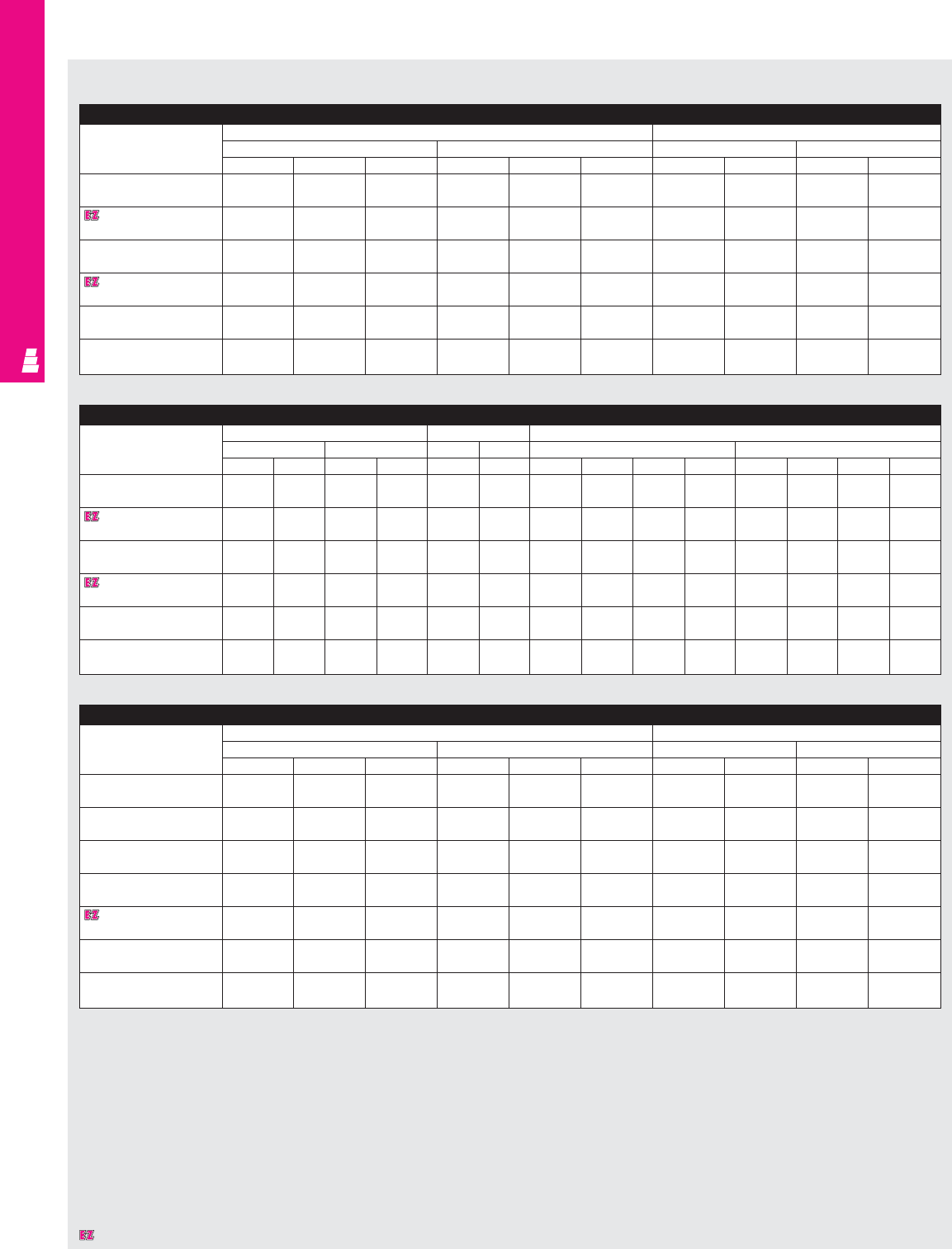
IND 131
FMD ENCLOSURES
Designates a product in the EnclosureZone program.
Freestanding Heavy Duty One Door Carbon Steel/Stainless Steel Disconnect Enclosures
Part No. Exact outside dimensions Door size
inches mm inches mm
ABCA BC J K JK
E 72XM2818WP/ 72 27.5 18 1828.8 698.5 457.2 62.5 23.83 1587.5 605.3
E 72XM2818WPSS 72 27.5 18 1828.8 698.5 457.2 62.5 23.83 1587.5 605.3
E 72XM3418WP/ 72 33.5 18 1828.8 850.9 457.2 62.5 29.83 1587.5 757.7
E 72XM3418WPSS 72 33.5 18 1828.8 850.9 457.2 62.5 29.83 1587.5 757.7
E 72XM4018WP/ 72 39.5 18 1828.8 1003.3 457.2 62.5 35.83 1587.5 910.1
E 72XM4018WPSS 72 39.5 18 1828.8 1003.3 457.2 62.5 35.83 1587.5 910.1
E 84XM4018WP/ 84 39.5 18 2133.6 1003.3 457.2 74.5 35.83 1892.3 910.1
E 84XM4018WPSS 84 39.5 18 2133.6 1003.3 457.2 74.5 35.83 1892.3 910.1
E 90XM4020WP/ 90 39.5 20 2286.0 1003.3 508.0 80.5 35.83 2044.7 910.1
E 90XM4020WPSS 90 39.5 20 2286.0 1003.3 508.0 80.5 35.83 2044.7 910.1
E 90XM4024WP/9039.5 24 2286.0 1003.3 609.6 80.5 35.83 2044.7 910.1
E 90XM4024WPSS 90 39.5 24 2286.0 1003.3 609.6 80.5 35.83 2044.7 910.1
Freestanding Heavy Duty One Door Carbon Steel/Stainless Steel Disconnect Enclosures (Continued)
Part No. Mounting panel size Usable depth Fig. A pg. IND 134
inches mm inches mm inches mm
EFEFCCCLHL H PE CL HL H PE
E 72XM2818WP/ 60 21.75 1524.0 552.5 18 457.2 - 9.125 3.875 2.5 - 231.8 98.4 63.5
E 72XM2818WPSS 60 21.75 1524.0 552.5 18 457.2 - 9.125 3.875 2.5 - 231.8 98.4 63.5
E 72XM3418WP/ 60 27.75 1524.0 704.9 18 457.2 - 9.125 3.875 2.5 - 231.8 98.4 63.5
E 72XM3418WPSS 60 27.75 1524.0 704.9 18 457.2 - 9.125 3.875 2.5 - 231.8 98.4 63.5
E 72XM4018WP/ 60 33.75 1524.0 857.3 18 457.2 - 9.125 3.875 2.438 - 231.8 98.4 61.9
E 72XM4018WPSS 60 33.75 1524.0 857.3 18 457.2 - 9.125 3.875 2.438 - 231.8 98.4 61.9
E 84XM4018WP/ 72 33.75 1828.8 857.3 18 457.2 - 14.625 3.875 2.438 - 371.5 98.4 61.9
E 84XM4018WPSS 72 33.75 1828.8 857.3 18 457.2 - 14.625 3.875 2.438 - 371.5 98.4 61.9
E 90XM4020WP/ 78 33.75 1981.2 857.3 20 508.0 - 17.594 3.875 2.438 - 446.9 98.4 61.9
E 90XM4020WPSS 78 33.75 1981.2 857.3 20 508.0 - 17.594 3.875 2.438 - 446.9 98.4 61.9
E 90XM4024WP/ 78 33.75 1981.2 857.3 24 609.6 - 17.594 3.875 2.438 - 446.9 98.4 61.9
E 90XM4024WPSS 78 33.75 1981.2 857.3 24 609.6 - 17.594 3.875 2.438 - 446.9 98.4 61.9
Freestanding Heavy Duty Enclosures (XM)
Freestanding Heavy Duty Two Door Carbon Steel/Stainless Steel Disconnect Enclosures
Part No. Exact outside dimensions Door size
inches mm inches mm
ABCABCJKJK
E 72XM5418WP/ 72 53.75 18 1828.8 1365.3 457.2 62.5 23.88 1587.5 606.6
E 72XM5418WPSS 72 53.75 18 1828.8 1365.3 457.2 62.5 23.88 1587.5 606.6
E 72XM6618WP/ 72 65.75 18 1828.8 1670.1 457.2 62.5 29.88 1587.5 759.0
E 72XM6618WPSS 72 65.75 18 1828.8 1670.1 457.2 62.5 29.88 1587.5 759.0
E 72XM7818WP/ 72 77.75 18 1828.8 1974.9 457.2 62.5 35.88 1587.5 911.4
E 72XM7818WPSS 72 77.75 18 1828.8 1974.9 457.2 62.5 35.88 1587.5 911.4
E 72XM7824WP/ 72 77.75 24 1828.8 1974.9 609.6 62.5 35.88 1587.5 911.4
E 72XM7824WPSS 72 77.75 24 1828.8 1974.9 609.6 62.5 35.88 1587.5 911.4
E 84XM7818WP/ 84 77.75 18 2133.6 1974.9 457.2 74.5 35.88 1892.3 911.4
E 84XM7818WPSS 84 77.75 18 2133.6 1974.9 457.2 74.5 35.88 1892.3 911.4
E 90XM7820WP/ 90 77.75 20 2286.0 1974.9 508.0 80.5 35.88 2044.7 911.4
E 90XM7820WPSS 90 77.75 20 2286.0 1974.9 508.0 80.5 35.88 2044.7 911.4
E 90XM7824WP/ 90 77.75 24 2286.0 1974.9 609.6 80.5 35.88 2044.7 911.4
E 90XM7824WPSS 90 77.75 24 2286.0 1974.9 609.6 80.5 35.88 2044.7 911.4
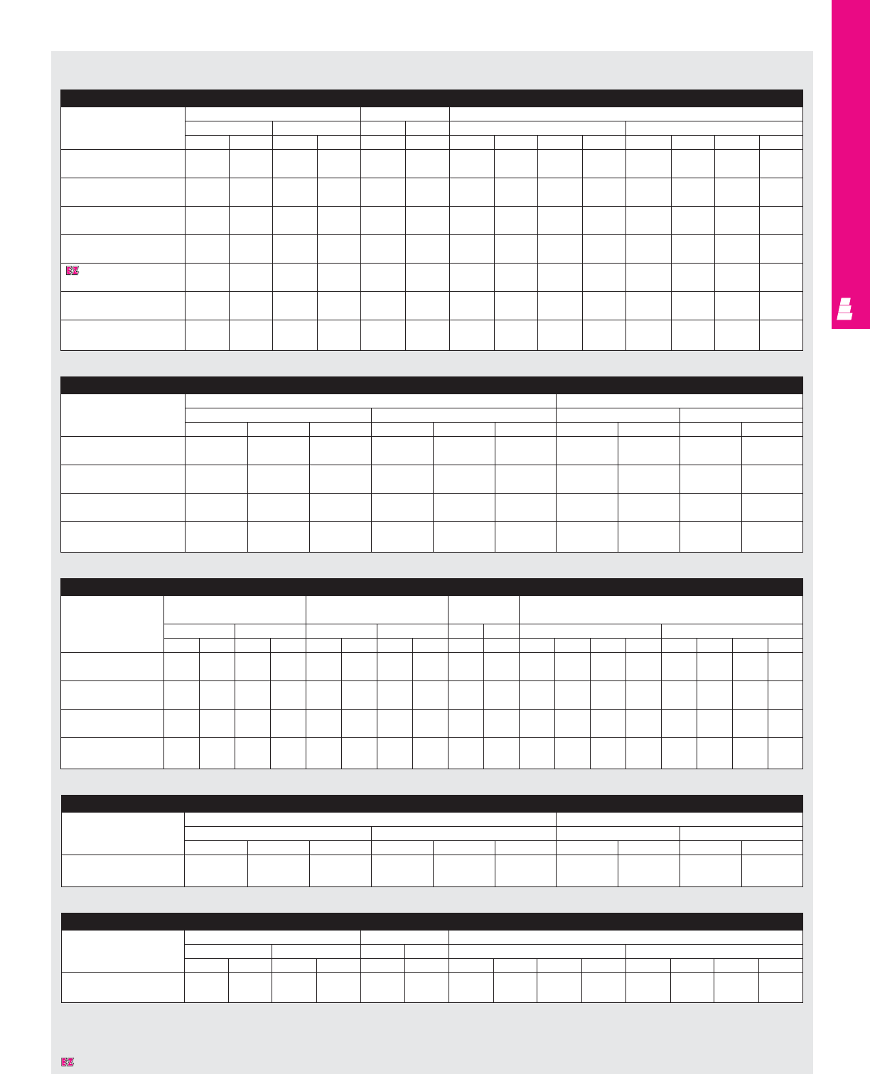
IND 132
FMD ENCLOSURES
Designates a product in the EnclosureZone program.
Freestanding Heavy Duty Enclosures (XM)
Freestanding Heavy Duty Two Door Carbon Steel/Stainless Steel Disconnect Enclosures (Continued)
Part No. Mounting panel size Usable depth Fig. A pg. IND 134
inches mm inches mm inches mm
EFEFCCCLHL H PE CL HL H PE
E 72XM5418WP/ 60 48 1524.0 1219.2 17 431.8 1.375 9.125 3.688 2.5 34.9 231.8 93.7 63.5
E 72XM5418WPSS 60 48 1524.0 1219.2 17 431.8 1.375 9.125 3.688 2.5 34.9 231.8 93.7 63.5
E 72XM6618WP/ 60 60 1524.0 1524.0 17 431.8 1.375 9.125 3.688 2.5 34.9 231.8 93.7 63.5
E 72XM6618WPSS 60 60 1524.0 1524.0 17 431.8 1.375 9.125 3.688 2.5 34.9 231.8 93.7 63.5
E 72XM7818WP/ 60 72 1524.0 1828.8 17 431.8 1.375 9.125 3.688 2.5 34.9 231.8 93.7 63.5
E 72XM7818WPSS 60 72 1524.0 1828.8 17 431.8 1.375 9.125 3.688 2.5 34.9 231.8 93.7 63.5
E 72XM7824WP/ 60 72 1524.0 1828.8 23 584.2 1.375 9.125 3.688 2.5 34.9 231.8 93.7 63.5
E 72XM7824WPSS 60 72 1524.0 1828.8 23 584.2 1.375 9.125 3.688 2.5 34.9 231.8 93.7 63.5
E 84XM7818WP/ 72 72 1828.8 1828.8 17 431.8 1.375 14.625 3.688 2.5 34.9 371.5 93.7 63.5
E 84XM7818WPSS 72 72 1828.8 1828.8 17 431.8 1.375 14.625 3.688 2.5 34.9 371.5 93.7 63.5
E 90XM7820WP/ 78 72 1981.2 1828.8 19 482.6 1.375 17.594 3.688 2.5 34.9 446.9 93.7 63.5
E 90XM7820WPSS 78 72 1981.2 1828.8 19 482.6 1.375 17.594 3.688 2.5 34.9 446.9 93.7 63.5
E 90XM7824WP/ 78 72 1981.2 1828.8 23 584.2 1.375 17.594 3.688 2.5 34.9 446.9 93.7 63.5
E 90XM7824WPSS 78 72 1981.2 1828.8 23 584.2 1.375 17.594 3.688 2.5 34.9 446.9 93.7 63.5
Freestanding Heavy Duty Three Door Carbon Steel/Stainless Steel Disconnect Enclosures (Continued)
Part No. Mounting panel size Mounting panel size Usable depth Fig. A pg. IND 134
behind double door behind single door
inches mm inches mm inches mm inches mm
DEDEDFDFCCCLHL H PE CL HL H PE
E 72XM3EQ18WP/ 60 60 1524.0 1524.0 60 27.75 1524.0 704.9 17 431.8 - 9.125 3.688 3 - 231.8 93.7 76.2
E 72XM3EQ18WPSS 60 60 1524.0 1524.0 60 27.75 1524.0 704.9 17 431.8 - 9.125 3.688 3 - 231.8 93.7 76.2
E 72XM3EW18WP/ 60 72 1524.0 1828.8 60 33.75 1524.0 857.3 17 431.8 - 9.125 3.688 3 - 231.8 93.7 76.2
E 72XM3EW18WPSS 60 72 1524.0 1828.8 60 33.75 1524.0 857.3 17 431.8 - 9.125 3.688 3 - 231.8 93.7 76.2
E 84XM3EW18WP/ 72 72 1828.8 1828.8 72 33.75 1828.8 857.3 17 431.8 - 14.625 3.688 3 - 371.5 93.7 76.2
E 84XM3EW18WPSS 72 72 1828.8 1828.8 72 33.75 1828.8 857.3 17 431.8 - 14.625 3.688 3 - 371.5 93.7 76.2
E 90XM3EW24WP/ 78 72 1981.2 1828.8 78 33.75 1981.2 857.3 23 584.2 - 17.564 3.688 3 - 446.1 93.7 76.2
E 90XM3EW24WPSS 78 72 1981.2 1828.8 78 33.75 1981.2 857.3 23 584.2 - 17.564 3.688 3 - 446.1 93.7 76.2
Freestanding Heavy Duty Three Door Carbon Steel/Stainless Steel Disconnect Enclosures
Part No. Exact outside dimensions Door size
inches mm inches mm
ABCABCJ KJK
E 72XM3EQ18WP/ 72 99.5 18 1828.8 2527.3 457.2 62.5 1587.5 29.88 759.0
E 72XM3EQ18WPSS 72 99.5 18 1828.8 2527.3 457.2 62.5 1587.5 29.88 759.0
E 72XM3EW18WP/ 72 117.5 18 1828.8 2984.5 457.2 62.5 1587.5 35.88 911.4
E 72XM3EW18WPSS 72 117.5 18 1828.8 2984.5 457.2 62.5 1587.5 35.88 911.4
E 84XM3EW18WP/ 84 117.5 18 2133.6 2984.5 457.2 74.5 1892.3 35.88 911.4
E 84XM3EW18WPSS 84 117.5 18 2133.6 2984.5 457.2 74.5 1892.3 35.88 911.4
E 90XM3EW24WP/ 90 117.5 24 2286.0 2984.5 609.6 80.5 2044.7 35.88 911.4
E 90XM3EW24WPSS 90 117.5 24 2286.0 2984.5 609.6 80.5 2044.7 35.88 911.4
Freestanding Heavy Duty Four Door Carbon Steel/Stainless Steel Disconnect Enclosures
Part No. Exact outside dimensions Door size
inches mm inches mm
ABCABCJKJK
E 84XM4EW18WP/ 84 157.5 18 2133.6 4000.5 457.2 74.5 35.88 1892.3 911.4
E 84XM4EW18WPSS 84 157.5 18 2133.6 4000.5 457.2 74.5 35.88 1892.3 911.4
Freestanding Heavy Duty Four Door Carbon Steel/Stainless Steel Disconnect Enclosures (Continued)
Part No. Mounting panel size 2 used Usable depth Fig. A pg. IND 134
inches mm inches mm inches mm
EFEFCCCLHL H PE CL HL H PE
E 84XM4EW18WP/ 72 72 1828.8 1828.8 17 431.8 - 14.625 3.688 3 - 371.5 93.7 76.2
E 84XM4EW18WPSS 72 72 1828.8 1828.8 17 431.8 - 14.625 3.688 3 - 371.5 93.7 76.2
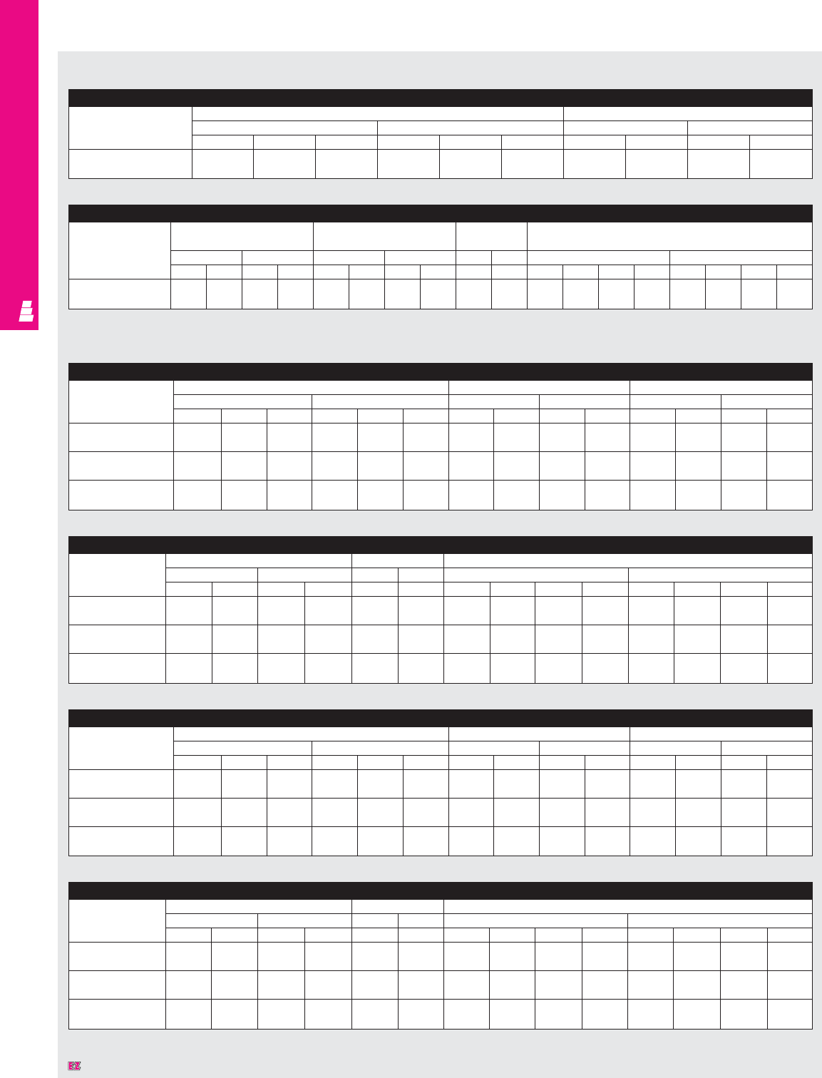
IND 133
FMD ENCLOSURES
Designates a product in the EnclosureZone program.
Freestanding Heavy Duty Enclosures (XM)
Freestanding Heavy Duty Five Door Carbon Steel/Stainless Steel Disconnect Enclosures (Continued)
Part No. Mounting panel size Mounting panel size Usable depth Fig. A pg. IND 134
behind double door behind single door
inches mm inches mm inches mm inches mm
DEDEDFDFCCCLHL H PE CL HL H PE
E 84XM5EW18WP/ 72 72 1828.8 1828.8 72 33.75 1828.8 857.3 17 431.8 - 14.625 3.688 3 - 371.5 93.7 76.2
E 84XM5EW18WPSS 72 72 1828.8 1828.8 72 33.75 1828.8 857.3 17 431.8 - 14.625 3.688 3 - 371.5 93.7 76.2
Freestanding Heavy Duty Five Door Carbon Steel/Stainless Steel Disconnect Enclosures
Part No. Exact outside dimensions Door size
inches mm inches mm
ABCABCJ KJK
E 84XM5EW18WP/ 84 196.75 18 2133.6 4997.5 457.2 74.5 35.88 1892.3 911.4
E 84XM5EW18WPSS 84 196.75 18 2133.6 4997.5 457.2 74.5 35.88 1892.3 911.4
Freestanding Modular Enclosures (MOD)
Freestanding Modular One Door Carbon Steel/Stainless Steel Disconnect Enclosures (Continued)
Part No. Mounting panel size Usable depth Fig. A pg. IND 134
inches mm inches mm inches mm
FG F G J JCLHL H PE CL HL H PE
E MOD72X4018/ 60 33.75 1524.0 857.3 17.06 433.3 - 9.125 3.688 2.5 - 231.8 93.7 63.5
E MOD72X4018SS 60 33.75 1524.0 857.3 17.06 433.3 - 9.125 3.688 2.5 - 231.8 93.7 63.5
E MOD84X4018/ 72 33.75 1828.8 857.3 17.06 433.3 - 14.625 3.688 2.5 - 371.5 93.7 63.5
E MOD84X4018SS 72 33.75 1828.8 857.3 17.06 433.3 - 14.625 3.688 2.5 - 371.5 93.7 63.5
E MOD84X4024/ 72 33.75 1828.8 857.3 23.06 585.7 - 14.625 3.688 2.5 - 371.5 93.7 63.5
E MOD84X4024SS 72 33.75 1828.8 857.3 23.06 585.7 - 14.625 3.688 2.5 - 371.5 93.7 63.5
Freestanding Modular One Door Carbon Steel/Stainless Steel Disconnect Enclosures
Part No. Exact outside dimensions Door size Size left side
inches mm inches mm inches mm
ABCABCHWHWDEDE
E MOD72X4018/ 72 39.75 18 1828.8 1009.7 457.2 62.5 35.88 1587.5 911.4 66.33 12.25 1684.8 311.2
E MOD72X4018SS 72 39.75 18 1828.8 1009.7 457.2 62.5 35.88 1587.5 911.4 66.33 12.25 1684.8 311.2
E MOD84X4018/ 84 39.75 18 2133.6 1009.7 457.2 74.5 35.88 1892.3 911.4 78.63 12.25 1997.2 311.2
E MOD84X4018SS 84 39.75 18 2133.6 1009.7 457.2 74.5 35.88 1892.3 911.4 78.63 12.25 1997.2 311.2
E MOD84X4024/ 84 39.75 24 2133.6 1009.7 609.6 74.5 35.88 1892.3 911.4 78.63 18.25 1997.2 463.6
E MOD84X4024SS 84 39.75 24 2133.6 1009.7 609.6 74.5 35.88 1892.3 911.4 78.63 18.25 1997.2 463.6
Freestanding Modular Two Door Carbon Steel/Stainless Steel Disconnect Enclosures (Continued)
Part No. Mounting panel size Usable depth Fig. A pg. IND 134
inches mm inches mm inches mm
FG F G J JCLHL H PE CL HL H PE
E MOD72X7818/ 60 72.7 1524.0 1846.6 17.06 433.3 - 9.125 3.688 2.5 - 231.8 93.7 63.5
E MOD72X7818SS 60 72.7 1524.0 1846.6 17.06 433.3 - 9.125 3.688 2.5 - 231.8 93.7 63.5
E MOD84X7818/ 72 72 1828.8 1828.8 17.06 433.3 - 14.625 3.688 2.5 - 371.5 93.7 63.5
E MOD84X7818SS 72 72 1828.8 1828.8 17.06 433.3 - 14.625 3.688 2.5 - 371.5 93.7 63.5
E MOD84X7824/ 72 72 1828.8 1828.8 23.06 585.7 - 14.625 3.688 2.5 - 371.5 93.7 63.5
E MOD84X7824SS 72 72 1828.8 1828.8 23.06 585.7 - 14.625 3.688 2.5 - 371.5 93.7 63.5
Freestanding Modular Two Door Carbon Steel/Stainless Steel Disconnect Enclosures
Part No. Exact outside dimensions Door size Size left side
inches mm inches mm inches mm
ABCABCHWHWD E DE
E MOD72X7818/ 72 78 18 1828.8 1981.2 457.2 62.5 36.38 1587.5 924.1 66.33 12.25 1684.8 311.2
E MOD72X7818SS 72 78 18 1828.8 1981.2 457.2 62.5 36.38 1587.5 924.1 66.33 12.25 1684.8 311.2
E MOD84X7818/ 84 78 18 2133.6 1981.2 457.2 74.5 36.38 1892.3 924.1 78.63 12.25 1997.2 311.2
E MOD84X7818SS 84 78 18 2133.6 1981.2 457.2 74.5 36.38 1892.3 924.1 78.63 12.25 1997.2 311.2
E MOD84X7824/ 84 78 24 2133.6 1981.2 609.6 74.5 36.38 1892.3 924.1 78.63 18.25 1997.2 463.6
E MOD84X7824SS 84 78 24 2133.6 1981.2 609.6 74.5 36.38 1892.3 924.1 78.63 18.25 1997.2 463.6
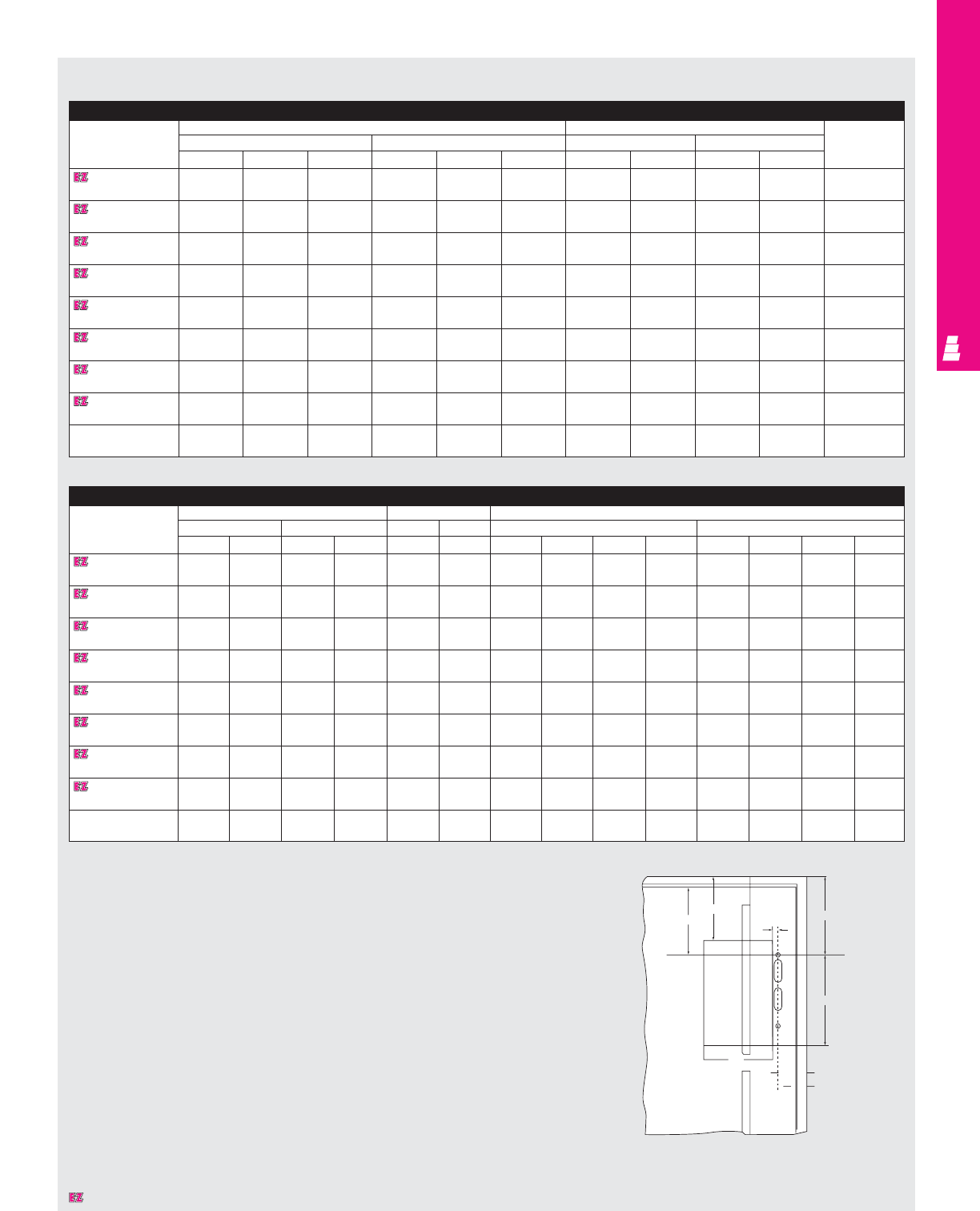
Floormount Freestanding Carbon Steel/Stainless Steel Enclosures
Part No. Exact outside dimensions Door size Mounting
inches mm inches mm Panel
ABC AB CJK J KPart No.
E 60X4912/ 60 49.38 12 1524.0 1254.3 304.8 58.5 21.88 1485.9 555.8 E 60P48
E 60X4912SS 60 49.38 12 1524.0 1254.3 304.8 58.5 21.88 1485.9 555.8 E 60P48
E 60X4918/ 60 49.38 18 1524.0 1254.3 457.2 58.5 21.88 1485.9 555.8 E 60P48
E 60X4918SS 60 49.38 18 1524.0 1254.3 457.2 58.5 21.88 1485.9 555.8 E 60P48
E 60X6112/ 60 61.38 12 1524.0 1559.1 304.8 58.5 27.88 1485.9 708.2 E 60P60
E 60X6112SS 60 61.38 12 1524.0 1559.1 304.8 58.5 27.88 1485.9 708.2 E 60P60
E 60X6118/ 60 61.38 18 1524.0 1559.1 457.2 58.5 27.88 1485.9 708.2 E 60P60
E 60X6118SS 60 61.38 18 1524.0 1559.1 457.2 58.5 27.88 1485.9 708.2 E 60P60
E 72X6112/ 72 61.38 12 1828.8 1559.1 304.8 70.5 27.88 1790.7 708.2 E 72P60
E 72X6112SS 72 61.38 12 1828.8 1559.1 304.8 70.5 27.88 1790.7 708.2 E 72P60
E 72X6118/ 72 61.38 18 1828.8 1559.1 457.2 70.5 27.88 1790.7 708.2 E 72P60
E 72X6118SS 72 61.38 18 1828.8 1559.1 457.2 70.5 27.88 1790.7 708.2 E 72P60
E 72X7312/ 72 73.38 12 1828.8 1863.9 304.8 70.5 33.88 1790.7 860.6 E 72P72
E 72X7312SS 72 73.38 12 1828.8 1863.9 304.8 70.5 33.88 1790.7 860.6 E 72P72
E 72X7318/ 72 73.38 18 1828.8 1863.9 457.2 70.5 33.88 1790.7 860.6 E 72P72
E 72X7318SS 72 73.38 18 1828.8 1863.9 457.2 70.5 33.88 1790.7 860.6 E 72P72
E 72X7324/ 72 73.38 24 1828.8 1863.9 609.6 70.5 33.88 1790.7 860.6 E 72P72
E 72X7324SS 72 73.38 24 1828.8 1863.9 609.6 70.5 33.88 1790.7 860.6 E 72P72
IND 134
FMD ENCLOSURES
Floormount Freestanding Enclosures (X)
Floormount Freestanding Carbon Steel/Stainless Steel Enclosures (Continued)
Part No. Mounting panel size Usable depth Fig. A pg. IND 134
inches mm inches mm inches mm
EF E F GGCLHL H PE CL HL H PE
E 60X4912/ 56 44 1422.4 1117.6 12 304.8 1.375 5.125 1.875 2.5 34.9 130.2 47.6 63.5
E 60X4912SS 56 44 1422.4 1117.6 12 304.8 1.375 5.125 1.875 2.5 34.9 130.2 47.6 63.5
E 60X4918/ 56 44 1422.4 1117.6 18 457.2 1.375 5.125 1.875 2.5 34.9 130.2 47.6 63.5
E 60X4918SS 56 44 1422.4 1117.6 18 457.2 1.375 5.125 1.875 2.5 34.9 130.2 47.6 63.5
E 60X6112/ 56 56 1422.4 1422.4 12 304.8 1.375 5.125 1.875 2.5 34.9 130.2 47.6 63.5
E 60X6112SS 56 56 1422.4 1422.4 12 304.8 1.375 5.125 1.875 2.5 34.9 130.2 47.6 63.5
E 60X6118/ 56 56 1422.4 1422.4 18 457.2 1.375 5.125 1.875 2.5 34.9 130.2 47.6 63.5
E 60X6118SS 56 56 1422.4 1422.4 18 457.2 1.375 5.125 1.875 2.5 34.9 130.2 47.6 63.5
E 72X6112/ 68 56 1727.2 1422.4 12 304.8 1.375 10.625 1.875 2.5 34.9 269.9 47.6 63.5
E 72X6112SS 68 56 1727.2 1422.4 12 304.8 1.375 10.625 1.875 2.5 34.9 269.9 47.6 63.5
E 72X6118/ 68 56 1727.2 1422.4 18 457.2 1.375 10.625 1.875 2.5 34.9 269.9 47.6 63.5
E 72X6118SS 68 56 1727.2 1422.4 18 457.2 1.375 10.625 1.875 2.5 34.9 269.9 47.6 63.5
E 72X7312/ 68 68 1727.2 1727.2 12 304.8 1.375 10.625 1.875 2.5 34.9 269.9 47.6 63.5
E 72X7312SS 68 68 1727.2 1727.2 12 304.8 1.375 10.625 1.875 2.5 34.9 269.9 47.6 63.5
E 72X7318/ 68 68 1727.2 1727.2 18 457.2 1.375 10.625 1.875 2.5 34.9 269.9 47.6 63.5
E 72X7318SS 68 68 1727.2 1727.2 18 457.2 1.375 10.625 1.875 2.5 34.9 269.9 47.6 63.5
E 72X7324/ 68 68 1727.2 1727.2 24 609.6 1.375 10.625 1.875 2.5 34.9 269.9 47.6 63.5
E 72X7324SS 68 68 1727.2 1727.2 24 609.6 1.375 10.625 1.875 2.5 34.9 269.9 47.6 63.5
PA WHL
27
(1.06)
DH
CL
DV
PE
FIG. A
Mounting
Panel
Fig. A
Designates a product in the EnclosureZone program.
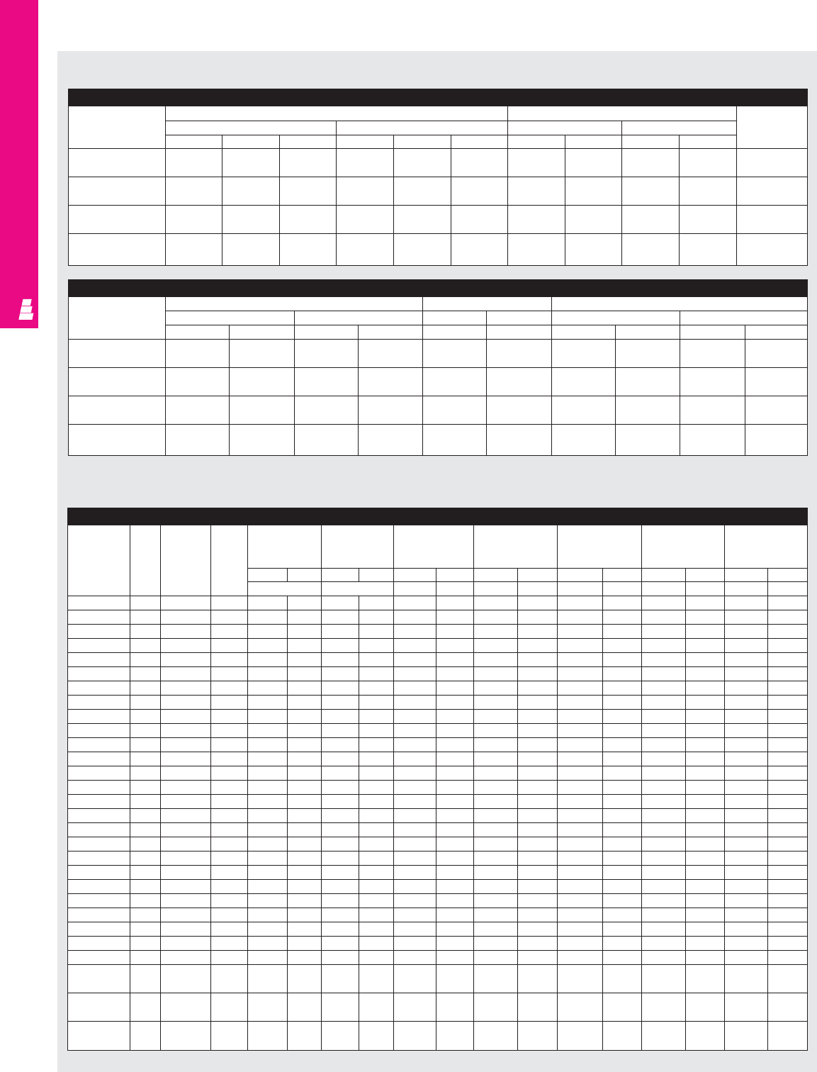
IND 135
FMD ENCLOSURES
Heavy Duty, Modular And Floormount Enclosures
For X, CPX, XM, MOD Enclosures: Allen-Bradley 1494V Disconnects/Circuit-Breakers (Fig. A pg. IND 134)
Allen Bradley
Amp Fuse Fuse DH DW* X, CPX X, CPX XM, MOD XM, MOD XM
Part No.
rating clip class HL=5.125 HL=10.625 HL=9.125 HL=14.625 HL=17.594
(130.2) (269.8) (231.7) (371.4) (446.8)
inches mm inches mm inches mm inches mm inches mm inches mm inches mm
WW W W WW W W WW
1494V-DS30 30A Unfused - 3.87 98.3 7.12 180.8 6.045 153.5 11.545 293.2 10.045 255.1 15.545 394.8 18.514 470.3
1494V-DS30 30A 30A-250V H,K,R 5.19 131.8 7.12 180.8 6.045 153.5 11.545 293.2 10.045 255.1 15.545 394.8 18.514 470.3
1494V-DS30 30A 30A-600V H,K,R 7.96 202.2 7.12 180.8 6.045 153.5 11.545 293.2 10.045 255.1 15.545 394.8 18.514 470.3
1494V-DS30 30A 30A-600V J 5.19 131.8 7.12 180.8 6.045 153.5 11.545 293.2 10.045 255.1 15.545 394.8 18.514 470.3
1494V-DS30 30A 60A-250V H,K,R 5.41 137.4 7.12 180.8 6.045 153.5 11.545 293.2 10.045 255.1 15.545 394.8 18.514 470.3
1494V-DS30 30A 60A-600V H,K,R 8.47 215.1 7.12 180.8 6.045 153.5 11.545 293.2 10.045 255.1 15.545 394.8 18.514 470.3
1494V-DS30 30A 60A-600V J 5.3 134.6 7.12 180.8 6.045 153.5 11.545 293.2 10.045 255.1 15.545 394.8 18.514 470.3
1494V-DS60 60A Unfused - 3.87 98.3 7.12 180.8 5.855 148.7 11.355 288.4 9.855 250.3 15.355 390 18.324 465.4
1494V-DS60 60A 60A-250V H,K,R 5.41 137.4 7.12 180.8 5.855 148.7 11.355 288.4 9.855 250.3 15.355 390 18.324 465.4
1494V-DS60 60A 60A-600V H,K,R 8.47 215.1 7.12 180.8 5.855 148.7 11.355 288.4 9.855 250.3 15.355 390 18.324 465.4
1494V-DS60 60A 60A-600V J 5.3 134.6 7.12 180.8 5.855 148.7 11.355 288.4 9.855 250.3 15.355 390 18.324 465.4
1494V-DS60 60A 30A-600V H,K,R 7.96 202.2 7.12 180.8 5.855 148.7 11.355 288.4 9.855 250.3 15.355 390 18.324 465.4
1494V-DS60 60A 100A-250V H,K 8.86 225.0 7.12 180.8 5.855 148.7 11.355 288.4 9.855 250.3 15.355 390 18.324 465.4
1494V-DS60 60A 100A-600V H,K 10.8 274.3 7.12 180.8 5.855 148.7 11.355 288.4 9.855 250.3 15.355 390 18.324 465.4
1494V-DS60 60A 100A-600V J 7.6 193.0 7.12 180.8 5.855 148.7 11.355 288.4 9.855 250.3 15.355 390 18.324 465.4
1494V-DS100 100A Unfused - 3.8 96.5 7.12 180.8 5.685 144.4 11.185 284.1 9.685 246 15.185 385.7 18.154 461.1
1494V-DS100 100A 100A-250V H,K,R 9.6 243.8 7.12 180.8 5.685 144.4 11.185 284.1 9.685 246 15.185 385.7 18.154 461.1
1494V-DS100 100A 100A-600V H,K,R 11.6 294.6 7.12 180.8 5.685 144.4 11.185 284.1 9.685 246 15.185 385.7 18.154 461.1
1494V-DS100 100A 100A-600V J 8.3 210.8 7.12 180.8 5.685 144.4 11.185 284.1 9.685 246 15.185 385.7 18.154 461.1
1494V-DS100 100A 200A-250V H,K 12.4 315.0 7.12 180.8 5.685 144.4 11.185 284.1 9.685 246 15.185 385.7 18.154 461.1
1494V-DS100 100A 200A-600V H,K 14.9 378.5 7.12 180.8 5.685 144.4 11.185 284.1 9.685 246 15.185 385.7 18.154 461.1
1494V-DS100 100A 200A-600V J 11.03 280.2 7.12 180.8 5.685 144.4 11.185 284.1 9.685 246 15.185 385.7 18.154 461.1
1494V-DS200 200A Unfused - 4.6 116.8 8.4 213.4 - - 9.835 249.8 8.335 211.7 13.835 351.4 16.804 462.8
1494V-DS200 200A 200A-250V H,K,R 11.8 299.7 8.4 213.4 - - 9.835 249.8 8.335 211.7 13.835 351.4 16.804 462.8
1494V-DS200 200A 200A-600V H,K,R 14.3 363.2 8.4 213.4 - - 9.835 249.8 8.335 211.7 13.835 351.4 16.804 462.8
1494V-DS200 200A 200A-600V J 10.4 264.2 8.4 213.4 - - 9.835 249.8 8.335 211.7 13.835 351.4 16.804 462.8
1494V-M40 150A
EHD, FD, FDB,
-5127.0 4.125 104.8 7.035 178.7 12.535 318.4 11.035 280.3 16.535 420 19.504 495.4
FDC, HFD, HMCP
1494V-M50 250A
JD, JDB, JDC,
-7.65 194.3 4.125 104.8 - - 10.975 278.8 9.475 240.7 14.975 380.4 17.944 455.8
HJD, HMCP
1494V-M60 400A
KD, KDB, KDC,
-8.3 210.8 5.5 139.7 - - 8.575 217.8 7.075 179.7 12.575 319.4 15.544 394.8
HKD, HMCP
* Does not include space for optional auxiliary switch. Note: 1. For applications above 200A, please contact your local Rittal representative.
Floormount Freestanding Enclosures (CPX)
Floormount Freestanding Disconnect Enclosures
Part No. Exact outside dimensions Door size Mounting
inches mm inches mm Panel
ABC AB CJK J KPart No.
E 60CPX4812/ 60 48 12 1524.0 1219.2 304.8 58.5 22 1485.9 558.8 E 60P48
E 60CPX4812SS 60 48 12 1524.0 1219.2 304.8 58.5 22 1485.9 558.8 E 60P48
E 60CPX6012/ 60 60 12 1524.0 1524.0 304.8 58.5 28 1485.9 711.2 E 60P60
E 60CPX6012SS 60 60 12 1524.0 1524.0 304.8 58.5 28 1485.9 711.2 E 60P60
E 72CPX7212/ 72 72 12 1828.8 1828.8 304.8 70.5 34 1790.7 863.6 E 72P72
E 72CPX7212SS 72 72 12 1828.8 1828.8 304.8 70.5 34 1790.7 863.6 E 72P72
E 72CPX7218/ 72 72 18 1828.8 1828.8 457.2 70.5 34 1790.7 863.6 E 72P72
E 72CPX7218SS 72 72 18 1828.8 1828.8 457.2 70.5 34 1790.7 863.6 E 72P72
Floormount Freestanding Disconnect Enclosures (Continued)
Part No. Mounting panel size Usable depth Fig. A pg. IND 134
inches mm inches mm inches mm
EFEFGGHLHHLH
E 60CPX4812/ 56 44 1422.4 1117.6 12 304.8 5.125 1.875 130.2 47.6
E 60CPX4812SS 56 44 1422.4 1117.6 12 304.8 5.125 1.875 130.2 47.6
E 60CPX6012/ 56 56 1422.4 1422.4 12 304.8 5.125 1.875 130.2 47.6
E 60CPX6012SS 56 56 1422.4 1422.4 12 304.8 5.125 1.875 130.2 47.6
E 72CPX7212/ 68 68 1727.2 1727.2 12 304.8 10.625 1.875 269.9 47.6
E 72CPX7212SS 68 68 1727.2 1727.2 12 304.8 10.625 1.875 269.9 47.6
E 72CPX7218/ 68 68 1727.2 1727.2 18 457.2 10.625 1.875 269.9 47.6
E 72CPX7218SS 68 68 1727.2 1727.2 18 457.2 10.625 1.875 269.9 47.6
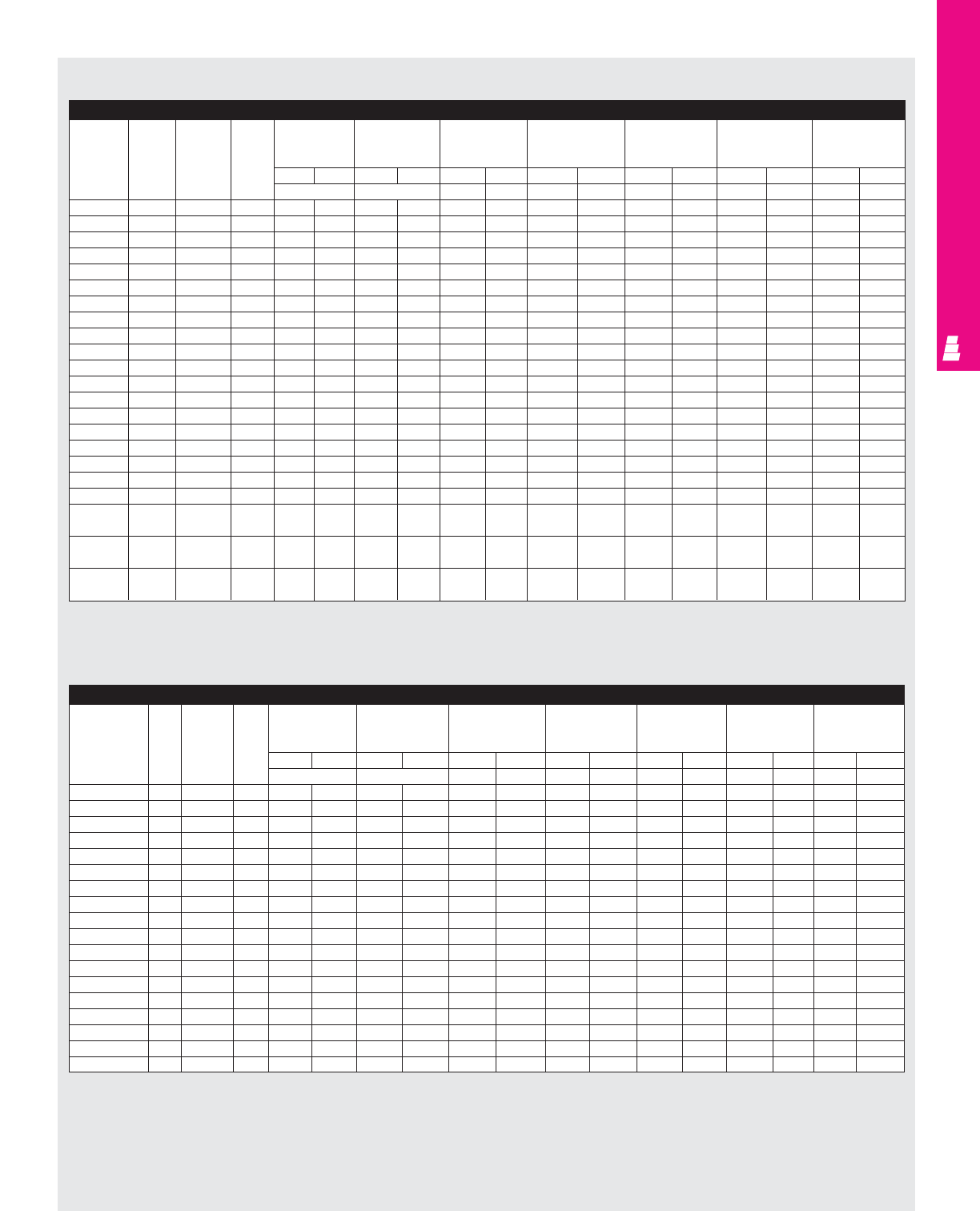
IND 136
FMD ENCLOSURES
Heavy Duty, Modular And Floormount Enclosures
For X, CPX, XM, MOD Enclosures: Square D Class 9422 Disconnects/Circuit-Breakers (Fig. A pg. IND 134)
Square D
Amp Fuse Fuse DH DW* X, CPX X, CPX XM, MOD XM, MOD XM
Type 9422
rating clip class HL=5.125 HL=10.625 HL=9.125 HL=14.625 HL=17.594
Part No.
(130.2) (269.8) (231.7) (3714) (446.8)
inches mm inches mm inches mm inches mm inches mm inches mm inches mm
WW W W W W W W W W
TCN30 30A Unfused - 3.8 96.5 6.2 157.5 6.285 159.6 11.785 299.3 10.285 261.2 15.785 400.9 18.754 476.4
TCF33 30A 30A-250V H,K,R 5.42 137.7 6.2 157.5 6.285 159.6 11.785 299.3 10.285 261.2 15.785 400.9 18.754 476.4
TCF33 30A 30A-600V H,K,R 8.05 204.5 6.2 157.5 6.285 159.6 11.785 299.3 10.285 261.2 15.785 400.9 18.754 476.4
TCF33 30A 30A-600V J 5.42 137.7 6.2 157.5 6.285 159.6 11.785 299.3 10.285 261.2 15.785 400.9 18.754 476.4
TCF33 30A 60A-250V H,K,R 6.05 153.7 6.2 157.5 6.285 159.6 11.785 299.3 10.285 261.2 15.785 400.9 18.754 476.4
TDN60 60A Unfused - 3.8 96.5 6.2 157.5 6.285 159.6 11.785 299.3 10.285 261.2 15.785 400.9 18.754 476.4
TDF60 60A 60A-250V H,K,R 6.05 153.7 6.2 157.5 6.285 159.6 11.785 299.3 10.285 261.2 15.785 400.9 18.754 476.4
TDF60 60A 30A-600V H,K,R 8.05 204.5 6.2 157.5 6.285 159.6 11.785 299.3 10.285 261.2 15.785 400.9 18.754 476.4
TDF63 60A 60A-600V H,K,R 8.55 217.2 6.2 157.5 6.285 159.6 11.785 299.3 10.285 261.2 15.785 400.9 18.754 476.4
TDF63 60A 60A-600V J 5.42 137.7 6.2 157.5 6.285 159.6 11.785 299.3 10.285 261.2 15.785 400.9 18.754 476.4
TEN10 100A Unfused - 3.8 96.5 6.2 157.5 6.285 159.6 11.785 299.3 10.285 261.2 15.785 400.9 18.754 476.4
TEF10 100A 100A-250V H,K,R 8.25 209.6 6.2 157.5 6.285 159.6 11.785 299.3 10.285 261.2 15.785 400.9 18.754 476.4
TEF10 100A 100A-600V H,K,R 10.25 260.4 6.2 157.5 6.285 159.6 11.785 299.3 10.285 261.2 15.785 400.9 18.754 476.4
TEF10 100A 100A-600V J 7.05 179.1 6.2 157.5 6.285 159.6 11.785 299.3 10.285 261.2 15.785 400.9 18.754 476.4
TF1 200A Unfused - 5.25 133.4 11.63 295.4 - - 10.135 257.4 8.635 219.3 14.135 359 17.104 434.4
TF2 200A 200A-250V H,K,R 11.2 284.5 11.63 295.4 - - 10.135 257.4 8.635 219.3 14.135 359 17.104 434.4
TF2 200A 200A-600V H,K,R 13.7 348.0 11.63 295.4 - - 10.135 257.4 8.635 219.3 14.135 359 17.104 434.4
TF2 200A 200A-600V J 9.83 249.7 11.63 295.4 - - 10.135 257.4 8.635 219.3 14.135 359 17.104 434.4
TF3 200A 400A-600V J 14.25 362.0 11.63 295.4 - - 10.135 257.4 8.635 219.3 14.135 359 17.104 434.4
RG1 75,100A GJL Circuit- 4.72 119.9 3.54 89.9 6.785 172.3 12.385 314.6 10.885 276.5 16.385 416.2 19.354 491.6
breaker
RN1 100A FAL, FHL Circuit- 6 152.4 4.5 114.3 6.875 174.6 12.475 316.9 10.975 278.8 16.475 418.5 19.444 493.9
breaker
RP1 250A KAL, KHL Circuit- 8 203.2 4.5 114.3 6.875 174.6 12.475 316.9 10.975 278.8 16.475 418.5 19.44 493.9
breaker
* DW dimension without operating mechanism
Note:
1. For applications above 200A, please contact your local Rittal representative.
For X, CPX, XM, MOD Enclosures: General Electric STDA Disconnects (Fig. A pg. IND 134)
GE Type STDA Amp Fuse Fuse DH DW X, CPX X, CPX XM, MOD XM, MOD XM
Part No. rating clip class HL=5.125 HL=10.625 HL=9.125 HL=14.625 HL=17.594
(130.2) (269.8) (231.7) (371.4) (446.8)
inches mm inches mm inches mm inches mm inches mm inches mm inches mm
WWWWWWWWWW
TDOM1A 30A Unfused - 1.18 30.0 4.09 103.9 3.9075 99.3 9.445 239.9 7.9075 200.9 13.4075 340.6 16.3765 416
TDOM1A 30A 30A-250V H, R 3 76.2 4.09 103.9 3.9075 99.3 9.445 239.9 7.9075 200.9 13.4075 340.6 16.3765 416
TDOM1B 30A 30A-600V H, R 6 8.1 5.68 144.3 3.9075 99.3 9.445 239.9 7.9075 200.9 13.4075 340.6 16.3765 416
TDOM1B 30A 60A-250V H, R 3 6.1 4.09 103.9 3.9075 99.3 9.445 239.9 7.9075 200.9 13.4075 340.6 16.3765 416
TDOM1B 30A 60A-600V H, R 6 152.4 5.68 144.3 3.9075 99.3 9.445 239.9 7.9075 200.9 13.4075 340.6 16.3765 416
TDOM1A 60A Unfused - 1.18 30.0 4.09 103.9 3.9075 99.3 9.445 239.9 7.9075 200.9 13.4075 340.6 16.3765 416
TDOM1B 60A 60A-250V H, R 4.4 111.8 5.68 144.3 3.9075 99.3 9.445 239.9 7.9075 200.9 13.4075 340.6 16.3765 416
TDOM1B 60A 60A-600V H, R 6.9 175.3 5.87 149.1 3.9075 99.3 9.445 239.9 7.9075 200.9 13.4075 340.6 16.3765 416
TDOM1B 60A 100A-250V H, R 4.4 111.8 5.68 144.3 3.9075 99.3 9.445 239.9 7.9075 200.9 13.4075 340.6 16.3765 416
TDOM1B 60A 100A-600V H, R 6.9 175.3 5.87 149.1 3.9075 99.3 9.445 239.9 7.9075 200.9 13.4075 340.6 16.3765 416
TDOM1A 100A Unfused - 1.18 30.0 4.09 103.9 - - - 239.9 7.9075 200.9 13.4075 340.6 16.3765 416
TDOM1B 100A 100A-250V H, R 5.8 147.3 6.18 157.0 - - - 239.9 7.9075 200.9 13.4075 340.6 16.3765 416
TDOM1B 100A 100A-600V H, R 7.8 198.1 6.18 157.0 - - - 239.9 7.9075 200.9 13.4075 340.6 16.3765 416
TDOM1B 100A 200A-250V H, R 11.6 294.6 6.18 157.0 - - - 239.9 7.9075 200.9 13.4075 340.6 16.3765 416
TDOM1B 100A 200A-600V H, R 16.1 408.9 6.18 157.0 - - - 239.9 7.9075 200.9 13.4075 340.6 16.3765 416
TDOM2 200A Unfused - 7.5 190.5 8.4 213.4 - - 9.939 252.5 8.439 214.4 13.939 354.1 16.908 429.5
TDOM2 200A 200A-250V H, R 13.5 342.9 8.4 213.4 - - 9.939 252.5 8.439 214.4 13.939 354.1 16.908 429.5
TDOM2 200A 200A-600V H, R 16 406.4 8.4 213.4 - - 9.939 252.5 8.439 214.4 13.939 354.1 16.908 429.5
Note:
1. For applications above 200A, please contact your local Rittal representative.
2. W dimension is greater than the required wire bending space specified in article 430-10 NEC.
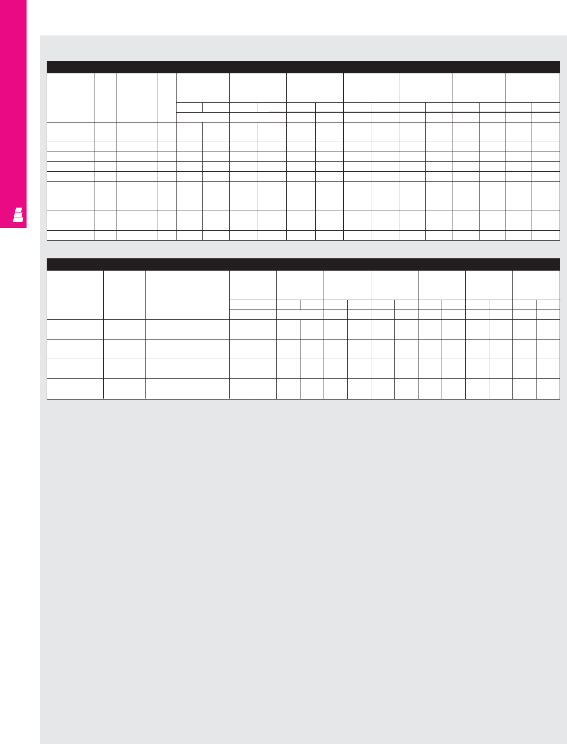
IND 137
FMD ENCLOSURES
For X, CPX, XM, MOD Enclosures: General Electric STDA Circuit-Breakers (Fig. A pg. IND 134)
GE Type STDA Amp Fuse Fuse DH DW X, CPX X, CPX XM, MOD XM, MOD XM
Part No. rating clip class HL=5.125 HL=10.625 HL=9.125 HL=14.625 HL=17.594
(130.2) (269.8) (231.7) (371.4) (446.8)
inches mm inches mm inches mm inches mm inches mm inches mm inches mm
WWWWWWWWWW
TDOM1A 150A TEB, TED, - 3.96 100.6 4.1 104.1 - - 11.251 285.8 9.751 247.7 15.251 387.4 18.22 462.8
THED
TDOM1A 150A TEC - 3.96 100.6 4.1 104.1 - - 11.251 285.8 9.751 247.7 15.251 387.4 18.22 462.8
TDOM1B 150A TB1 - 7.96 202.18 4.1 104.1 - - 11.251 285.8 9.751 247.7 15.251 387.4 18.22 462.8
TDOM1B 150A TEC, TECL - 5.84 148.33 4.1 104.1 - - 11.251 285.8 9.751 247.7 15.251 387.4 18.22 462.8
TDOM1C 150A TEL - 3.96 100.6 4.1 104.1 - - 11.251 285.8 9.751 247.7 15.251 387.4 18.22 462.8
TDOM1D 150A THLC1 - 6.75 171.5 4.1 104.1 6.095 154.8 11.595 294.5 10.095 256.4 15.595 396.1 18.564 471.5
TDOM3 225A TFJ - 7.3 185.4 4.1 104.1 - - 10.782 273.9 9.282 235.8 14.782 375.5 17.751 450.9
TDOM3 225A TFK, THFK, - 7.3 185.4 4.1 104.1 - - 10.782 273.9 9.282 235.8 14.782 375.5 17.751 450.9
TFL
TDOM3 225A THLC2 - 4.8 121.9 5.7 144.8 - - 7.001 177.8 - - 11.004 279.4 13.97 354.8
Heavy Duty, Modular And Floormount Enclosures
For X, CPX, XM, MOD Enclosures: Cutler-Hammer C371 Circuit-Breaker Operator (Fig. A pg. IND 134)
Cutler- Amp Frame DH DW X, CPX X, CPX XM, MOD XM, MOD XM
Hammer rating type HL=5.125 HL=10.625 HL=231.7 HL=371.4 HL=446.8
Part No. (130.2) (269.8) (9.125) (14.625) (17.594)
inches mm inches mm inches mm inches mm inches mm inches mm inches mm
WWWWWW WWW W
C371E 150A Cutler Hammer 5.33 135.38 4.13 104.78 7.71 195.71 13.21 335.41 11.71 297.31 17.21 437.01 20.17 512.42
FDB, FD, FDC, HFD, EHD
C371E 150A Westinghouse 5.33 135.38 4.13 104.78 7.71 195.71 13.21 335.41 11.71 297.31 17.21 437.01 20.17 512.42
F Frame/Series C
C371F 225A Cutler Hammer 9.37 238 10 254 6.69 169.95 12.19 309.65 10.69 271.55 16.19 411.25 19.16 486.66
HJD, JD, JDC
C371F 225A Westinghouse 9.37 238 10 254 6.69 169.95 12.19 309.65 10.69 271.55 16.19 411.25 19.16 486.66
F Frame/Series C
Note:
1. For applications above 200A, please contact your local Rittal representative.
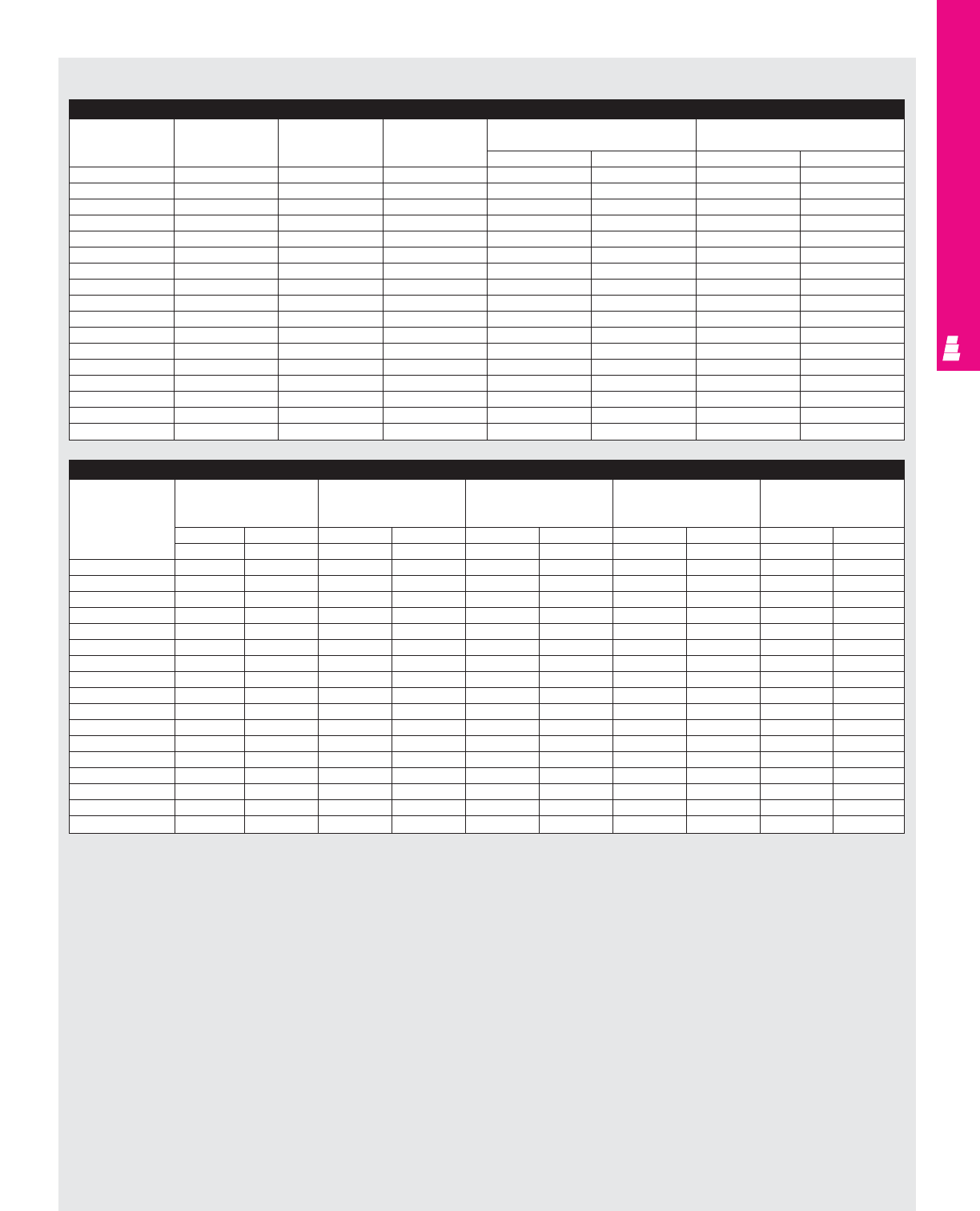
IND 138
FMD ENCLOSURES
Heavy Duty, Modular And Floormount Enclosures
For X, CPX, XM, MOD Enclosures: Cutler-Hammer (C361 Disconnect Switches) (Continued)
Cutler- X, CPX X, CPX XM, MOD XM, MOD XM
Hammer HL=7.785 in/130.2mm HL=13.285 in/269.8mm HL=11.785 in/231.7mm HL=17.285 in/371.4mm HL=20.254 in/446.8mm
Type (5.125) (10.625) (9.125) (14.625) (17.594)
Part No. inches mm inches mm inches mm inches mm inches mm
WW W WW W W W WW
NC 6.19 157.30 11.69 297.00 10.19 258.90 15.69 398.60 18.66 474.01
SC21 6.19 157.30 11.69 297.00 10.19 258.90 15.69 398.60 18.66 474.01
SC61 6.19 157.30 11.69 297.00 10.19 258.90 15.69 398.60 18.66 474.01
SC61 6.19 157.30 11.69 297.00 10.19 258.90 15.69 398.60 18.66 474.01
ND 6.19 157.30 11.69 297.00 10.19 258.90 15.69 398.60 18.66 474.01
SD22 6.19 157.30 11.69 297.00 10.19 258.90 15.69 398.60 18.66 474.01
SD22 6.19 157.30 11.69 297.00 10.19 258.90 15.69 398.60 18.66 474.01
SD62 6.19 157.30 11.69 297.00 10.19 258.90 15.69 398.60 18.66 474.01
SD62 6.19 157.30 11.69 297.00 10.19 258.90 15.69 398.60 18.66 474.01
NE 5.78 146.69 11.28 286.39 9.78 248.29 15.28 387.99 18.24 463.40
SE263 5.78 146.69 11.28 286.39 9.78 248.29 15.28 387.99 18.24 463.40
SE263 5.78 146.69 11.28 286.39 9.78 248.29 15.28 387.99 18.24 463.40
SE263 5.78 146.69 11.28 286.39 9.78 248.29 15.28 387.99 18.24 463.40
NF --8.33 211.58 6.83 173.48 12.33 313.18 15.30 388.59
SF264 --8.33 211.58 6.83 173.48 12.33 313.18 15.30 388.59
SF264 --8.33 211.58 6.83 173.48 12.33 313.18 15.30 388.59
SF264 --8.33 211.58 6.83 173.48 12.33 313.18 15.30 388.59
Q = 2.66 in - 30A,60A,100A,200A.
HL = “HL”+Q
Note:
1. For applications above 200A, please contact your local Rittal representative.
2. W dimension is greater than the required wire bending space specified in article 430-10 NEC.
3. DH dimension includes the lowering mechanism.
For X, CPX, XM, MOD Enclosures: Cutler-Hammer (C361 Disconnect Switches)
Cutler-Hammer Amp Fuse Fuse DH DW
Type rating clip class
Part No. inches mm inches mm
NC 30A Unfused - 3.90 99.06 6.00 152.40
SC21 30A 30A-250V H,K,R 7.60 193.04 6.00 152.40
SC61 30A 60A-250V H,K,R 8.16 207.26 6.00 152.40
SC61 30A 30A-600V H,K,J,R 7.60 193.04 6.00 152.40
ND 60A Unfused - 3.90 99.06 6.00 152.40
SD22 60A Unfused - 3.90 99.06 6.00 152.40
SD22 60A 60A-250V H,K,R 8.16 207.26 6.00 152.40
SD62 60A 60A-600V H,K,R 8.16 207.26 6.00 152.40
SD62 60A 60A-600V J 7.79 197.87 6.00 152.40
NE 100A Unfused - 8.90 226.06 7.00 177.80
SE263 100A 100A-250V H,K,R 8.90 226.06 7.00 177.80
SE263 100A 100A-600V H,K,R 8.90 226.06 7.00 177.80
SE263 100A 100A-600V J 8.90 226.06 7.00 177.80
NF 200A Unfused - 13.10 332.74 9.75 247.65
SF264 200A 200-250V H,K,R 13.10 332.74 9.75 247.65
SF264 200A 200-600V H,K,R 13.10 332.74 9.75 247.65
SF264 200A 200A-600V J 13.10 332.74 9.75 247.65

IND 139
FMD ENCLOSURES
Heavy Duty, Modular And Floormount Enclosures
For X, CPX, XM, MOD Enclosures: Siemens ITE Max-Flex Operators for Disconnect Switches (Fig. A pg. IND 140)
Switch
Max-Flex Fixed depth Amp rating Fuse kit Fuse class Panel space requirements
Part No.
variable depth complete handle
complete handle mechanism A B C
mechanism inches mm inches mm inches mm
MCS603R
FHOS06036R FDFS06R 30 No fuse - 6.13 155.7 5.52 140.2 - -
MCS603L
FHOS06036L 30A, 250V H, R 6.13 155.7 5.52 140.2 8.11 205.9
30A, 600V H, R 6.13 155.7 5.52 140.2 10.11 256.7
30A, 600V J 6.13 155.7 5.52 140.2 8.48 215.3
MCS606R
FHOS06036R FDFS06R 60 No fuse - 6.13 155.7 5.52 140.2 - -
MCS606L
FHOS06036L 60A, 250V H, R 6.13 155.7 5.52 140.2 7.86 199.6
60A, 600V H, R 6.13 155.7 5.52 140.2 10.38 263.6
60A, 600V J 6.13 155.7 5.52 140.2 8.35 212
MCS610R
FHOS06036R FDFS06R 100 No fuse - 7.38 187.4 7.59 192.7 - -
MCS610L
FHOS06036L 100A, 250V H, R 7.38 187.4 7.59 192.7 11.85 300.9
100A, 600V H, R 7.38 187.4 7.59 192.7 13.85 351.7
100A, 600V J 7.38 187.4 7.59 192.7 10.6 269.2
MCS620R
FHOS20036R FDFS20R 200 No fuse - 9.17 232.9 9.00 228.6 - -
MCS620L
FHOS20036L 200A, 250V H, R 9.17 232.9 9.00 228.6 14.7 373.3
200A, 600V H, R 9.17 232.9 9.00 228.6 17.2 436.8
200A, 600V J 9.17 232.9 9.00 228.6 13.32 338.3
*To order Class R fuse kit, you must order Class H fuse kit and corresponding Class R fuse conversion kit.
*Max-Flex standard cable length is 36 inches. Alternate cable lengths are available by special order.
*Maximum length with Class H and R fuses.
For X, CPX, XM, MOD Enclosures: Maximum “E” Dimension For ITE Max-Flex With Disconnect Switch (Fig. B pg. IND 140) (Continued)
Enclosure depth 36" Cable 46" Cable
Fmin Fmax Fmin Fmax
inches mm inches mm inches mm inches mm inches mm
8203.2 7 177.8 14.5 368.3 16.1 408.94 23.9 607.06
10 254 5.5 139.7 13.1 332.74 16 406.4 23.6 599.44
12 304.8 5 127 12 304.8 15.9 403.86 220.8 579.12
16 406.4 4 101.6 9.4 238.76 14.7 373.38 22 558.8
18 457.2 - - - - 14.6 370.84 21.9 556.26
20 508 - - - - 13.3 337.82 19.9 505.46
24 609.6 - - - - 12 304.8 16.9 429.26
For X, CPX, XM, MOD Enclosures: Maximum “E” Dimension For ITE Max-Flex With Disconnect Switch (Fig. B pg. IND 140)
Switch Cable
Enclosure depth
Part No. Part No.
When E=8 (203.2) When E=10 (254) When E=12 (304.8) When E=16 (406.4) When E=18 (457.2) When E=20 (508)
inches mm inches mm inches mm inches mm inches mm inches mm
MCS603, MCS606, FHOEC036 16.0 406 13.0 330 13.5 343 8.0 203 - - - -
MCS610 FHOEC048 16 660.4 16 660.4 16 660.4 23 584.2 21 533.4 18 457.2
MCS620 FHOJC036 15 381 12.0 304 12.5 317 7.0 178 - - - -
FHOJC046 25 635 25 635 25 635 22 558.8 20 508 17 431.8
Maximum “E” dimension only if F=4.6 (116.8)
For X, CPX, XM, MOD Enclosures: ITE Max-Flex Operators for Disconnect Switch (Fig. C, D pg. IND 140)
Switch Handle Dimensions — see fig. C, D
Part No. Part No. X1 X2 Y1 Y2 Z1*
inches mm inches mm inches mm inches mm inches mm
MCS603, FDFS06R
3.52 89.4 1.5 38.1 0.0 0.0 1.89 48 6.44 163.5
MCS606
MCS610 FDFS06R
3.91 99.3 1.81 45.9 0.13 3.3 3.0 76.2 6.44 163.5
MCS620 FDFS06R
1.51 38.3 7.86 199.6 0.38 9.6 5.44 138.1 10.93 277.6
*Z1 is the distance between the disconnect mounting surface and mounting panel (mechanical adjustments required if Z1 and usable depth not equal).
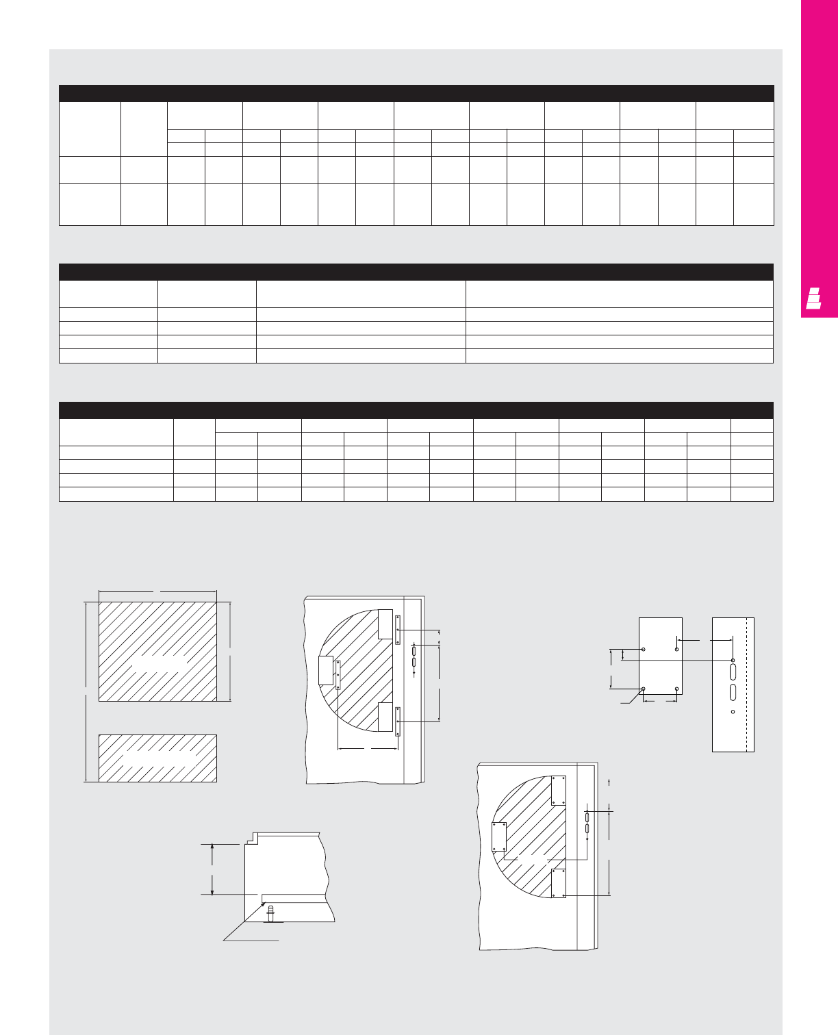
IND 140
FMD ENCLOSURES
Heavy Duty, Modular And Floormount Enclosures
B
A
C
Switch Base
Fuse Load Base
E
F min
F max
FIG. B
Maximum “E” Dimension For ITE Max-Flex With Circuit-Breaker (Fig. E pg. IND 140)
Cable Frame When enclosure When enclosure When enclosure When enclosure When enclosure When enclosure When enclosure When enclosure
Part No. size depth=8 (203.2) depth=10 (254) depth=12 (304.8) depth=16 (406.4) depth=18 (457.2) depth=20 (508) depth=24 (609.6) depth=30 (762)
inches mm inches mm inches mm inches mm inches mm inches mm inches mm inches mm
E= E= E= E= E= E= E= E= E= E= E= E= E= E= E= E=
FHOEC036 ED, HED, 13.8 203.2 13.5 203.2 13 203.2 10.7 203.2 8.7 203.2 5.3 203.2 - - - -
CED, EF
FHOEC036 FXD, FD, 11.2 203.2 11 203.2 10.5 203.2 8.3 203.2 5.5 203.2 3.5 203.2 - - - -
HFD, CFD,
HFXD, FF,
Maximum “E” dimension only if F=116.8 (4.6).
X2
Y2
D.156 DIA. (4x)
Y1
X1
FIG. C
Z*
MPL
FIG. D
DH
min
DH
max
FIG. E
E max
For X, CPX, XM, MOD Enclosures: ITE Max-Flex Operators For Circuit-Breakers
Breaker Operator Amp Circuit-breaker For use with
Catalog No. rating frame size breaker type(s)
FHOE036 125 ED, HED, EF (CE) ED2, ED4, ED6, HED4, HED6, ED6, ETI, HHED6, EFC
FHOE036 125 CED, EF (CE) CED6, CED6 ETI, EFF
FHOF036 250 FD, FXD, HFD, HFXD, FF (CE) FXD6-A, FD6-A, HFD6, HFXD6, HHFD6, FD6 ETI, FFC, FFF
FHOF036 250 CFD CFD6, CFD6 ETI
* For applications above 200A, please contact your local Rittal representative.
Circuit-Breaker Mounting Dimensions (Fig. E pg. IND 140)
Circuit-Breaker Amp A B C D* K DH (normal) Tap size
Frame Size rating inches mm inches mm inches mm i inches mm inches mm inches mm
ED, HED, EF, CED 125 1.0 25.4 5.0 127 0.65 16.5 6.33 160.7 - - 6.81 172.9 #8-32
CED6, CED6-ETI 125 1.0 25.4 5.0 127 0.65 16.5 8.93 226.8 3.25 82.5 6.81 172.9 #8-32
FXD, FD, HFD, HFXD, FF 250 1.5 38.1 7.5 190.5 1.0 25.4 9.5 241.3 - - 6.78 172.2 #1/4 20
CFD 250 1.5 38.1 7.5 190.5 1.0 25.4 14.25 361.9 4.6 117.4 6.78 172.2 #1/4 20
* For applications above 200A, please contact your local Rittal representative.
FIG. A
Fig. A Fig. B Fig. C
Fig. E
Fig. D
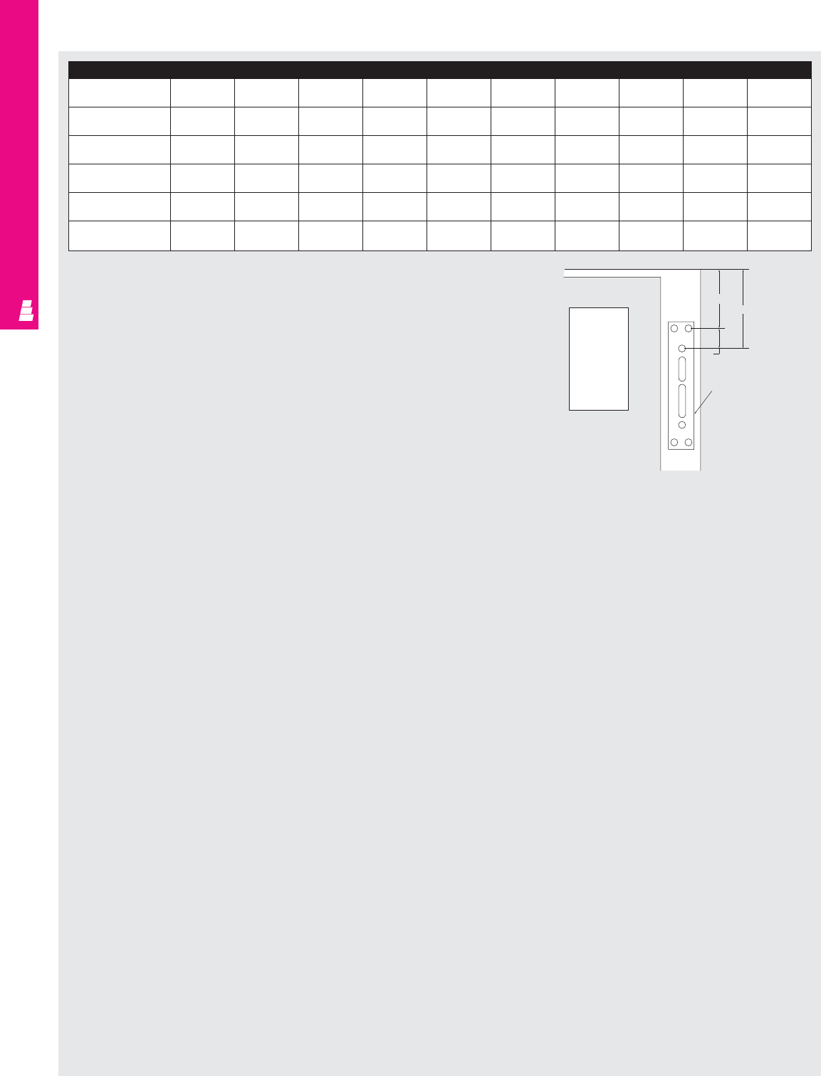
IND 141
FMD ENCLOSURES
Adapter Plate
Part No. EAKAB EAKAB EAKITE EAKITE EAKCHV EAKWHAMT EAKSD EAKABV EADABV EADKETDA
(200A) (1 Slot) (2 Slot) (1 Slot) (2 Slot) Spring Mount
Q-left inches 1.07 0.59 2.13 2.50 2.51 1.27 2.41 2.64 2.51 2.51
mm 27.18 14.99 54.10 63.50 63.75 32.26 61.21 67.06 63.75 63.75
Q-right inches 1.07 0.62 - 2.75 2.66 3.96 2.76 1.02 2.66 2.97
mm 127.18 15.75 - 69.85 67.56 100.58 70.10 25.91 67.56 75.44
Part No. EAKABCHR EAKABCHR
EAKWHAMTCHR
EAKSDCHR
EAKGETDACHR
EAKITECHR EAKITECHR EAKCHVCHR EAKABVCHR EAKABVCHR
(200A) (1 Slot) (2 Slot) (1 Slot) (2 Slot)
Q-left inches 0.69 0.59 1.27 2.41 2.51 2.13 2.50 2.51 2.64 2.51
mm 17.53 14.99 32.26 61.21 63.75 54.10 63.50 63.75 67.06 63.75
Q-right inches 1.07 0.62 3.96 2.76 2.97 - 2.75 2.66 1.02 2.66
mm 27.18 15.75 100.58 70.10 75.44 - 69.85 67.56 25.91 67.56
HL
Q
"HL"
Adapter Plate
Disconnect
OR
CB
Adapter plate
Disconnect Ordering Information
Allen-Bradley
Using 1494V disconnect switch, order:
*1.A disconnect switch (fusible or non-fusible).
2. An operating handle.
3. A connecting rod.
4. A trailer fuse block kit (if required).
5. A fuse clip kit (if required).
Using 1494V circuit-breaker operating mechanism, order:
1. A circuit-breaker (General Electric or Westinghouse).
2. A circuit-breaker operating mechanism.
3. An operating handle.
4. A connecting rod.
5. Accessories (if required).
General Electric
Using a disconnect switch, order:
*1.A disconnect switch (QMR/QMW).
*2.A fuse clip kit or no-fuse kit.
*3.A flange handle (STDA1).
*4.A variable depth operating mechanism.
5. An extended length drive rod (if required).
6. Accessories (if required).
Using a circuit-breaker, order:
1. A circuit-breaker.
2. A flange handle (STDA1).
3. A variable depth operating mechanism.
*These are available as a disconnect switch assembly
from General Electric.
Cutler-Hammer
Using C361 disconnect switch, order:
*1.A disconnect switch with an operating mechanism.
*2. An operating handle
Using C371 circuit-breaker, order:
1. A circuit-breaker (Cutler-Hammer or Westinghouse).
*2. An operating mechanism.
*3. An operating handle.
* These are available as an assembly from Cutler-Hammer.
Square D
Using a disconnect switch, order:
1. A disconnect switch with operating mechanism.
2. An universal handle mechanism.
3. An operating rod (if required).
Using a circuit-breaker, order:
1. A circuit-breaker
2. An operating mechanism.
3. An universal handle mechanism.
4. An operating rod (if required).
ITE
Using flange-mounted operating mechanisms and circuit-
breakers, order:
1. A circuit-breaker
2. Pressure wire connectors.
*3.A flange-mounted handle.
*4.A circuit-breaker operator mechanism.
*5. An operating cable.
*Available from ITE as a complete mechanism with 914 mm
(36") cable only. Order separate different cable lengths.

IND 142
FMD ENCLOSURES
Notes
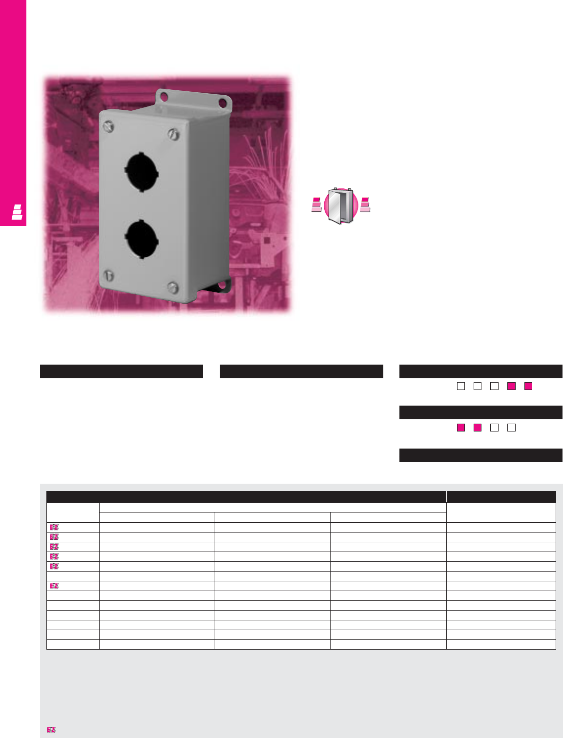
OPERATOR INTERFACE
Configuration
•Continuously welded seams, finished
smooth
•Poron strip gasket
•Standard pushbutton holes accept all
brands of 30.5 mm “4-way” oil tight
pushbuttons, switches, and pilot lights
•Captive plated screws to hold cover
•External mounting brackets
Technical Specifications
Material:
•Enclosure/cover: 14 gauge carbon steel
Finish/color:
•Enclosure/cover: polyester-urethane
powder coat over phosphatized surfaces,
inside and outside – ANSI 61 grey
Page . . . . . . . . . . . . . . . . . . . . . . . . . . . . IND 178
NEMA Type 144X1213
UL CUL CSA TÜV
Listings
Protection Ratings
Certifications/Approvals
Technical Drawings
IND 143
Standard Pushbutton Boxes
NEMA Rated Pushbutton Enclosures
These NEMA rated boxes are designed for indoor use to house
pushbuttons, selector switches, pilot lights, etc., and to protect
such equipment against dirt, dust, and spraying of water, oil
or coolant.
Several models of these pushbutton enclosures can be
mounted onto a Rittal Electromate column and base and used
as an operator station.
S
t
a
i
n
l
e
s
s
S
t
e
e
l
S
t
a
i
n
l
e
s
s
S
t
e
e
l
A
v
a
i
l
a
b
l
e
I
n
A
v
a
i
l
a
b
l
e
I
n
Page IND 235
Standard Pushbutton Box Accessories
Part No.
Outside dimensions (inches) Oil tight hole seals
HWD
E 1PB 3.50 3.25 2.75 See ACC 18
E 2PB 5.75 3.25 2.75 See ACC 18
E 3PB 8.00 3.25 2.75 See ACC 18
E 4PB 10.25 3.25 2.75 See ACC 18
E 4SPB 7.25 6.25 3.00 See ACC 18
E 5PB 12.50 3.25 2.75 See ACC 18
E 6PB* 9.50 6.25 3.00 See ACC 18
E 6PBVL 14.75 3.25 2.75 See ACC 18
E 8PB 20.25 3.25 2.75 See ACC 18
E 9PB*9.50 8.50 3.00 See ACC 18
E 10PB 24.75 3.25 2.75 See ACC 18
E 12PB* 11.75 8.50 3.00 See ACC 18
E 16PB* 11.75 10.75 3.00 See ACC 18
* Can be mounted to a Rittal Electromate column and base.
Designates a product in the EnclosureZone program.
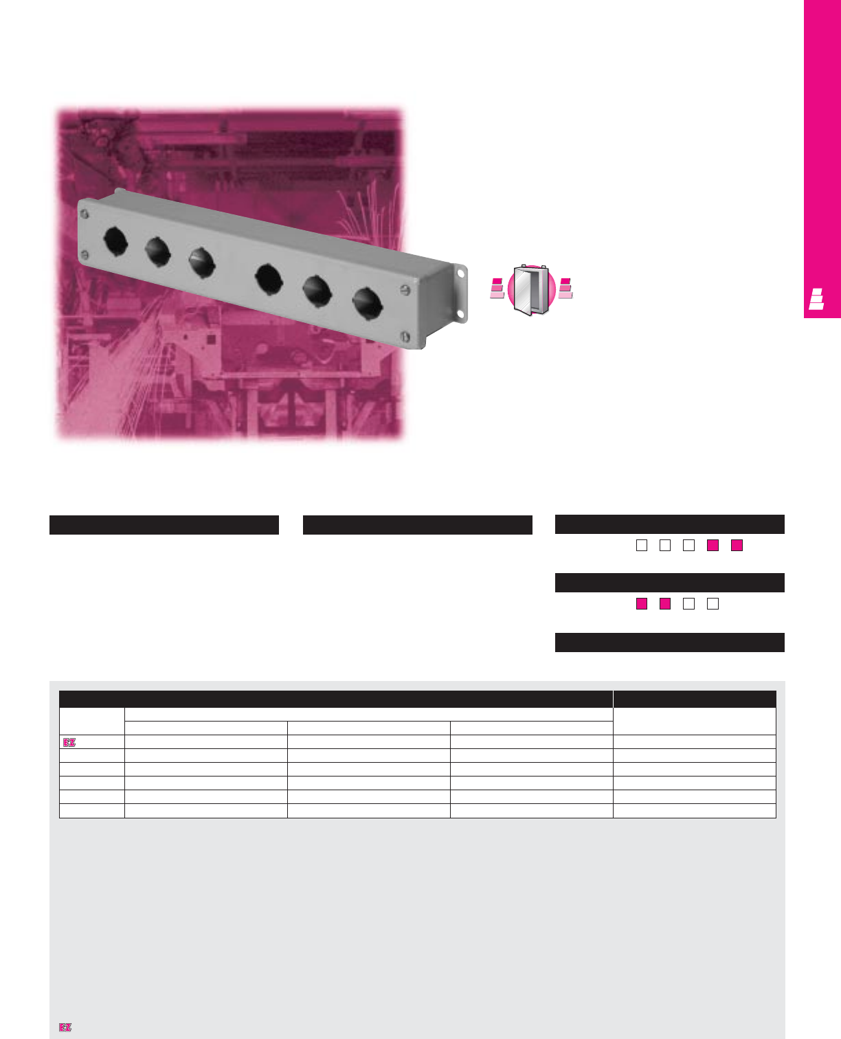
OPERATOR INTERFACEOPERATOR INTERFACE
IND 144
Slim Pushbutton Box Accessories
Part No. Outside dimensions (inches) Oil tight hole seals
HWD
E 1PBSL 4.00 2.50 2.50 See ACC 18
E 2PBSL 6.25 2.50 2.50 See ACC 18
E 3PBSL 8.50 2.50 2.50 See ACC 18
E 4PBSL 10.75 2.50 2.50 See ACC 18
E 5PBSL 13.00 2.50 2.50 See ACC 18
E 6PBSL*16.25 2.50 2.50 See ACC 18
* Add an additional 1" between pushbutton holes at center of enclosure.
Configuration
•Continuously welded seams, finished
smooth
•Poron strip gasket
•Standard pushbutton holes accept all
brands of 30.5 mm “4-way” oil tight
pushbuttons, switches, and pilot lights
•Captive plated screws to hold cover
•External mounting brackets
Technical Specifications
Material:
•Enclosure/cover: 14 gauge carbon steel
Finish/color:
•Enclosure/cover: polyester-urethane
powder coat over phosphatized surfaces,
inside and outside – ANSI 61 grey
Page . . . . . . . . . . . . . . . . . . . . . . . . . . . . IND 179
NEMA Type 144X1213
UL CUL CSA TÜV
Listings
Protection Ratings
Certifications/Approvals
Technical Drawings
Slim Pushbutton Boxes
NEMA Rated Pushbutton Enclosures
These NEMA rated boxes are designed for indoor use to house
pushbuttons, selector switches, pilot lights, etc., and to protect
such equipment against dirt, dust, and spraying of water, oil
or coolant.
Several models of these pushbutton enclosures can be
mounted onto a Rittal Electromate column and base and used
as an operator station.
S
t
a
i
n
l
e
s
s
S
t
e
e
l
S
t
a
i
n
l
e
s
s
S
t
e
e
l
A
v
a
i
l
a
b
l
e
I
n
A
v
a
i
l
a
b
l
e
I
n
Page IND 236
Designates a product in the EnclosureZone program.
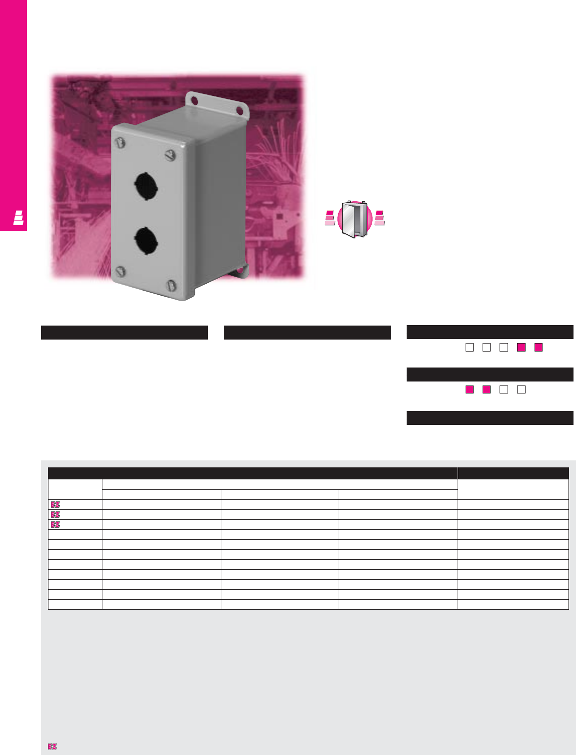
IND 145
OPERATOR INTERFACE
Configuration
•Continuously welded seams, finished
smooth
•Poron strip gasket
•Standard pushbutton holes accept all
brands of 22.5 mm “4-way” oil tight
pushbuttons, switches, and pilot lights
•Captive plated screws hold cover
•External mounting brackets
Technical Specifications
Material:
•Enclosure/cover: 14 gauge carbon steel
Finish/color:
•Enclosure/cover: polyester-urethane
powder coat over phosphatized surfaces,
inside and outside – ANSI 61 grey
Page . . . . . . . . . . . . . . . . . . . . . . . . . . . . IND 179
NEMA Type 144X1213
UL CUL CSA TÜV
Listings
Protection Ratings
Certifications/Approvals
Technical Drawings
Miniature Pushbutton Boxes
NEMA Rated Pushbutton Enclosures
These NEMA rated boxes are designed for indoor use to
house pushbuttons, selector switches, pilot lights, etc.,
which mount in miniature “4-way” pushbutton holes, and to
protect such equipment against dirt, dust, and spraying of
water, oil or coolant.
Several models of these pushbutton enclosures can be
mounted onto a Rittal Electromate column and base and
used as an operator station.
S
t
a
i
n
l
e
s
s
S
t
e
e
l
S
t
a
i
n
l
e
s
s
S
t
e
e
l
A
v
a
i
l
a
b
l
e
I
n
A
v
a
i
l
a
b
l
e
I
n
Page IND 237
Miniature Pushbutton Box Accessories
Part No. Outside dimensions (inches) Oil tight hole seals
HWD
E 1PBGM 3.25 2.75 3.50 See ACC 18
E 2PBGM 5.13 2.75 3.50 See ACC 18
E 3PBGM 7.00 2.75 3.50 See ACC 18
E 4PBGM 8.88 2.75 3.50 See ACC 18
E 6PBGM*8.50 5.00 4.25 See ACC 18
E 9PBGM* 8.50 6.50 4.25 See ACC 18
E 12PBGM* 10.38 6.50 4.25 See ACC 18
E 16PBGM* 10.38 8.00 4.25 See ACC 18
E 20PBGM* 12.25 8.00 4.25 See ACC 18
E 25PBGM* 12.25 9.50 4.25 See ACC 18
E 30PBGM* 14.13 9.50 4.25 See ACC 18
* Can be mounted to a Rittal Electromate column and base.
Designates a product in the EnclosureZone program.
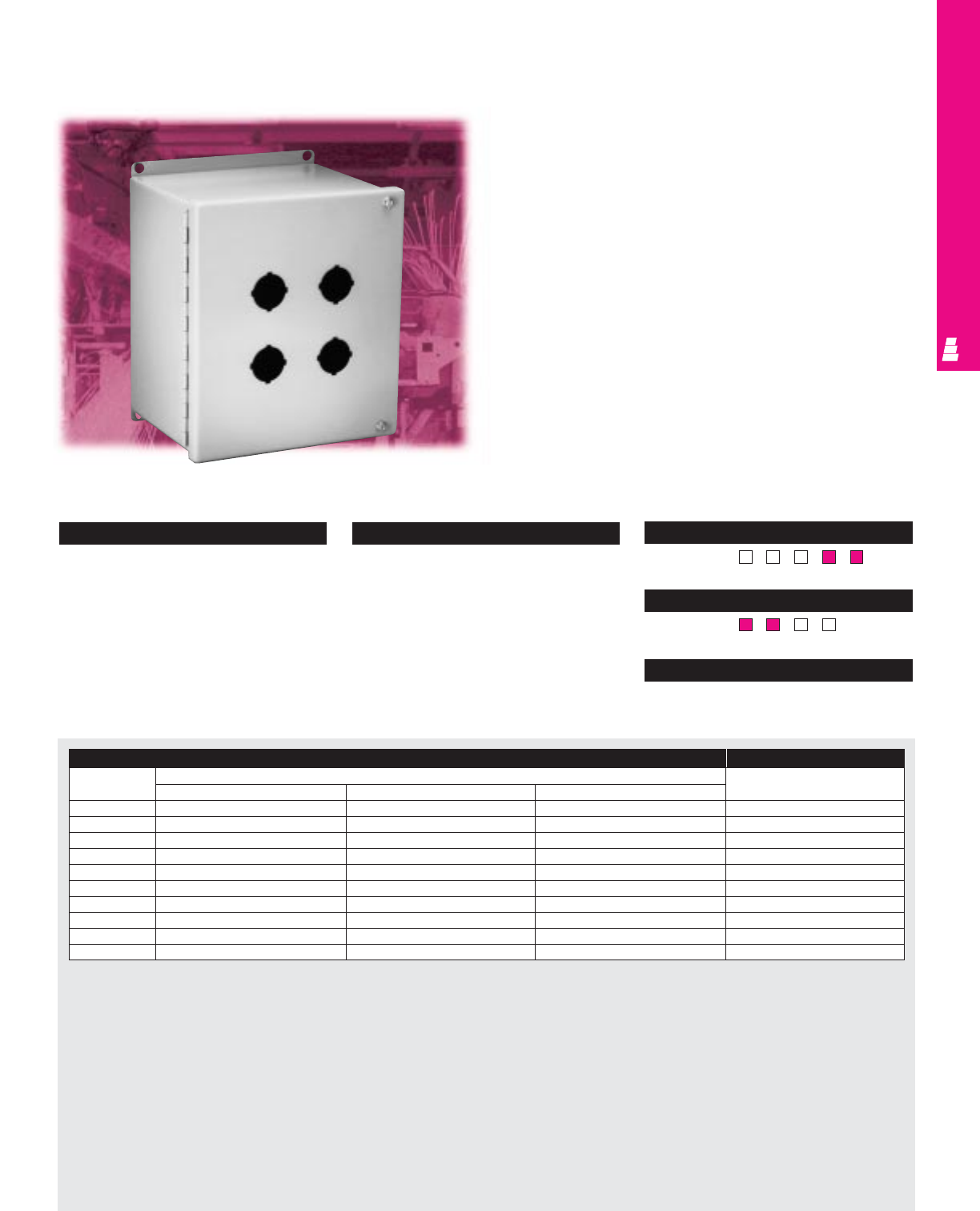
OPERATOR INTERFACE
IND 146
Configuration
•Continuously welded seams, finished smooth
•Poron strip gasket
•Standard pushbutton holes accept all
brands of 22.5 mm “4-way” oil tight
pushbuttons, switches, and pilot lights
•Continuous steel hinges
•Cover can be removed by pulling hinge pin
•Captive plated screws hold cover
•External mounting brackets
•Steel mounting panel installed
Technical Specifications
Material:
•Enclosure/cover: 14 gauge carbon steel
Finish/color:
•Enclosure/cover: polyester-urethane
powder coat over phosphatized surfaces,
inside and outside – ANSI 61 grey
•Mounting panels: painted white
Page . . . . . . . . . . . . . . . . . . . . . . . . . . . . IND 180
NEMA Type 144X1213
UL CUL CSA TÜV
Listings
Protection Ratings
Certifications/Approvals
Technical Drawings
Extra Large Pushbutton Boxes
NEMA Rated Pushbutton Enclosures
These NEMA rated boxes feature extra spacing between
pushbutton holes and are designed for indoor use to house
pushbuttons, selector switches, pilot lights, etc., and to protect
such equipment against dirt, dust, and spraying of water, oil
or coolant.
Extra Large Pushbutton Box Accessories
Part No. Outside dimensions (inches) Oil tight hole seals
HWD
E 4SPBY25 8.50 7.50 6.00 See ACC 18
E 6PBY25 11.00 7.50 6.00 See ACC 18
E 9PBY25 11.00 10.00 6.00 See ACC 18
E 12PBY25 13.50 10.00 6.00 See ACC 18
E 16PBY25 13.50 12.50 6.00 See ACC 18
E 20PBY25 16.00 12.50 6.00 See ACC 18
E 25PBY25 16.00 15.00 6.00 See ACC 18
E 30PBY25 18.50 15.00 6.00 See ACC 18
E 36PBY25 18.50 17.50 6.00 See ACC 18
E 42PBY25 21.00 17.50 6.00 See ACC 18
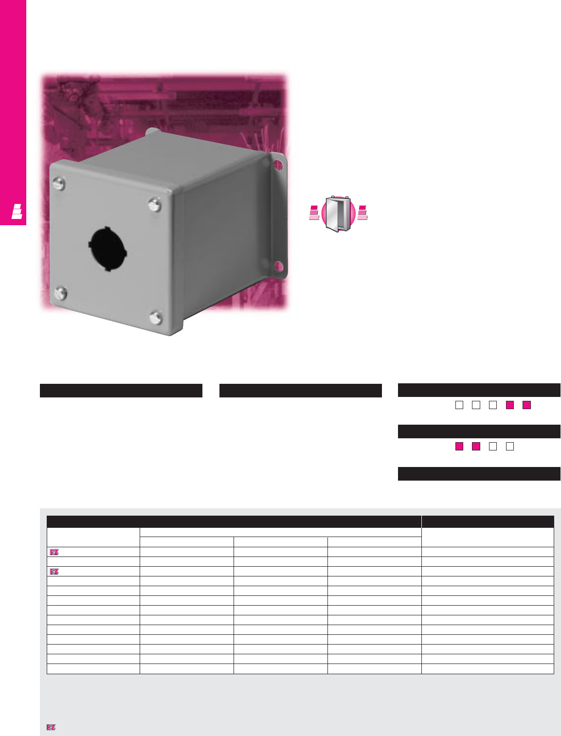
OPERATOR INTERFACE
Configuration
•Continuously welded seams,
finished smooth
•Poron strip gasket
•Standard pushbutton holes accept all
brands of 30.5 mm “4-way” oil tight
pushbuttons, switches, and pilot lights
•Captive plated screws hold cover
•External mounting brackets
Technical Specifications
Material:
•Enclosure/cover: 14 gauge carbon steel
Finish/color:
•Enclosure/cover: polyester-urethane
powder coat over phosphatized surfaces,
inside and outside – ANSI 61 grey
Page . . . . . . . . . . . . . . . . . . . . . . . . . . . . IND 181
NEMA Type 144X1213
UL CUL CSA TÜV
Listings
Protection Ratings
Certifications/Approvals
Technical Drawings
IND 147
Extra Deep Pushbutton Boxes
NEMA Rated Pushbutton Enclosures
These NEMA rated boxes are designed for indoor use to
house pushbuttons, selector switches, pilot lights, etc., and
to protect such equipment against dirt, dust, and spraying
of water, oil or coolant. Their extra depth accommodates
stacked pushbutton units.
Several models of these pushbutton enclosures can be
mounted onto a Rittal Electromate column and base and
used as an operator station.
Extra Deep Pushbutton Box Accessories
Part No. Outside dimensions (inches) Oil tight hole seals
HWD
E 1PBXD 4.00 4.00 4.75 See ACC 18
E 2PBXD 6.00 4.00 4.75 See ACC 18
E 3PBXD 8.00 4.00 4.75 See ACC 18
E 4PBXD 10.00 4.00 4.75 See ACC 18
E 4SPBXD* 7.25 6.25 4.75 See ACC 18
E 6PBXD*9.50 6.25 4.75 See ACC 18
E 9PBXD* 9.50 8.50 4.75 See ACC 18
E 10PBXD* 14.00 6.25 4.75 See ACC 18
E 12PBXD* 11.75 8.50 4.75 See ACC 18
E 16PBXD* 11.75 10.75 4.75 See ACC 18
E 16SPBXD* 20.75 6.25 4.75 See ACC 18
E 20PBXD* 14.00 10.75 4.75 See ACC 18
E 25PBXD* 14.00 13.00 4.75 See ACC 18
* Can be mounted to Rittal Electromate column and base.
S
t
a
i
n
l
e
s
s
S
t
e
e
l
S
t
a
i
n
l
e
s
s
S
t
e
e
l
A
v
a
i
l
a
b
l
e
I
n
A
v
a
i
l
a
b
l
e
I
n
Page IND 238
Designates a product in the EnclosureZone program.
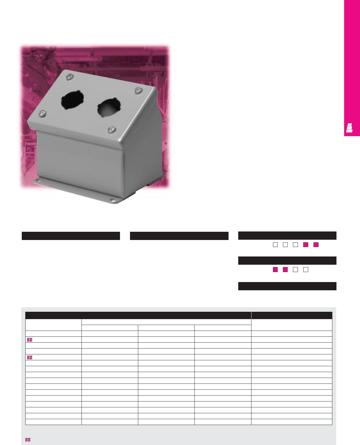
OPERATOR INTERFACE
IND 148
Configuration
•Continuously welded seams, finished
smooth
•Poron strip gasket
•Standard pushbutton holes accept all
brands of 30.5 mm “4-way” oil tight
pushbuttons, switches, and pilot lights
•Captive plated screws hold cover
•External mounting brackets
Technical Specifications
Material:
•Enclosure/cover: 14 gauge carbon steel
Finish/color:
•Enclosure/cover: polyester-urethane
powder coat over phosphatized surfaces,
inside and outside – ANSI 61 grey
Page . . . . . . . . . . . . . . . . . . . . . . . . . . . . IND 182
NEMA Type 144X1213
UL CUL CSA TÜV
Listings
Protection Ratings
Certifications/Approvals
Technical Drawings
Sloping Front Pushbutton Boxes
NEMA Rated Pushbutton Enclosures
These NEMA rated boxes feature a slanted front and are
designed for indoor use to house pushbuttons, selector
switches, pilot lights, etc., and to protect such equipment
against dirt, dust, and spraying of water, oil or coolant.
Several models of these pushbutton enclosures can be
mounted onto a Rittal Electromate column and base and
used as an operator station.
Sloping Front Pushbutton Box Accessories
Part No. Outside dimensions (inches) Oil tight hole seals
HW D
E 1PBA 3.50 3.25 4.88 See ACC 18
E 2PBA 3.50 5.50 4.88 See ACC 18
E 3PBA 3.50 7.75 4.88 See ACC 18
E 4PBA 3.50 10.00 4.88 See ACC 18
E 4SPBA 7.25 6.25 6.75 See ACC 18
E 6PBA 7.25 8.50 6.75 See ACC 18
E 8PBA 7.25 10.75 6.75 See ACC 18
E 9PBA 9.50 8.50 7.88 See ACC 18
E 10PBA 7.25 13.00 6.75 See ACC 18
E 12PBA 7.25 15.25 6.75 See ACC 18
E 12SPBA 11.75 8.50 9.00 See ACC 18
E 16PBA 11.75 10.75 9.00 See ACC 18
E 16SPBA 7.25 19.75 6.75 See ACC 18
E 20PBA 11.75 13.00 9.00 See ACC 18
E 25PBA 14.00 13.00 10.13 See ACC 18
E 30PBA 14.00 15.25 10.13 See ACC 18
Designates a product in the EnclosureZone program.
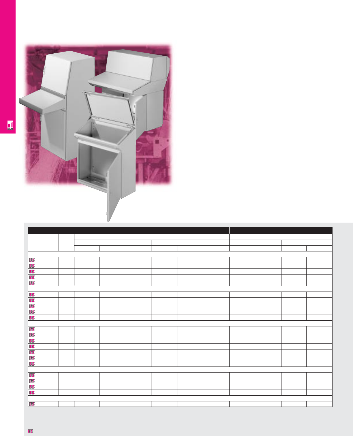
OPERATOR INTERFACE
IND 149
AP Desk Consoles Desk Console System
Rittal's AP Series console system answers the need for
variability, performance, safety, assembly, and aesthetics for
operator interface applications. The AP design allows unlimited
combinations of bottom, center, and top sections. Also available
are complete, one-piece desk units. Their perfect design facili-
tates easy assembly and provides security and usability.
Universal Console System
The universal AP console is the newest addition to the AP
family. It features a uni-body construction with an integrated
25mm interior hole pattern for easy component installation.
Available with or without an optional desk unit, it also features
a full-sized mounting panel.
Enclosure Mounting Panel
Part No. Number Exact outside dimensions Dimensions
Of inches mm inches mm
Doors H W D H W D H W H W
Bottom Section
260060011 f 26.38 31.50 15.75 670 800 400 23.62 28.15 600 715
262060022 f 26.38 47.24 15.75 670 1200 400 23.62 43.90 600 1115
261060031 f/1 r 26.38 31.50 19.69 670 800 500 20.94 27.64 532 702
264060042 f/2 r 26.38 47.24 19.69 670 1200 500 20.94 43.39 532 1102
265060052 f/2 r 26.38 62.99 19.69 670 1600 500 20.94 59.13 532 1502
Center Section
2611200117.87 31.50 33.46 200 800 850 – – – –
2641200217.87 47.24 33.46 200 1200 850 – – – –
2613200317.87 31.50 37.40 200 800 950 – – – –
2643200417.87 47.24 37.40 200 1200 950 – – – –
2653200517.87 62.99 37.40 200 1600 950 – – – –
Top Section
261260011 f 16.93 31.50 15.75 430 800 400 13.78 28.15 350 715
264260021 f 16.93 47.24 15.75 430 1200 400 13.78 43.90 350 1115
261460031 f/1 r 16.93 31.50 19.69 430 800 500 13.70 28.62 348 727
264460041 f/1 r 16.93 47.24 19.69 430 1200 500 13.70 44.37 348 1127
264760031 f/ 1 r 24.80 31.50 23.62 630 800 600 21.57 28.62 548 727
264860041 f/1 r 24.80 47.24 23.62 630 1200 600 21.57 44.37 548 1127
264960051 f/1 r 24.80 62.99 23.62 630 1600 600 21.57 60.12 548 1527
Desk Console System
2666600 1 f 37.80 23.62 15.75/18.90 960 600 400/480 30.71 20.87 780 530
2668600 1 f 37.80 31.50 15.75/18.90 960 800 400/480 30.71 28.74 780 730
2670600 1 f 37.80 39.37 15.75/18.90 960 1000 400/480 30.71 36.61 780 930
2672600 1 f 37.80 47.24 15.75/18.90 960 1200 400/480 30.71 44.49 780 1130
Universal Console System
2694600 2 f/1 r 51.18 23.62 16.42/19.76 1300 600 417/502 47.05 19.57 1195 497
Note: When specifying two or three-part consoles, please use the superscript number to match bottom, center and top sections.
Designates a product in the EnclosureZone program.

OPERATOR INTERFACE
IND 150
Technical Specifications
Material:
•Sheet steel housing: 16 ga/1.5 mm
•Doors and lids: 14 ga/2 mm
•Mounting panel: 11 ga/3 mm, hot dipped
galvanized zinc
Finish/color:
•Housing, doors, and lids: E-coat primed,
powder painted, RAL 7032 pebble grey
•Mounting panel: Type M
•Universal console trim: RAL 5018 teal green
Pages . . . . . . . . . . . . . . . . . . . . . . . . IND 183-187
NEMA Type 144X1213
UL CUL CSA TÜV
Listings
Protection Ratings
Certifications/Approvals
Technical Drawings
Configuration
•Doors front and rear on specific models
•Safety catches and cables secure open lid
•Mounting panel included
•Depth adjustable mounting panel for AP
2610600/2640600/2650600/2694600
•2-part and 3-part cable entry panels
•Integrated mounting rails in center section
•Knife-edge design protects against liquid
entry
•Maximum strength and stability through
unibody construction
•E-coat primer and powder paint provide
superior corrosion resistance
•Integrated grounding provisions
•Foamed-on gasketing
•Modular bottom, center, and top sections
allow a variety of combinations for specific
applications
•Top sections are available in two heights
and depths
•System installation holes (Univeral console)
(25 mm spacing)
•Desk unit can be rotated 180˚ for either
sloped or horizontal desk surface
(Universal console)
•Full height mounting panel (Universal
console)
Accessories
Part No. Bases Base Console Aluminum Handles Inductive Inductive Inductive Mouse pad
castors lid pencil mouse (COM mouse pad mouse pad support
4" high 8" high ledge Ergoform-S Pushbutton or PS/2) (COM) (PS/2)
Bottom Section
2600600 2901200 2902200 4570000 2615200 – 2450000 2468000 – – – –
2620600 2921200 2922200 4570000 2645200 – 2450000 2468000 – – – –
2610600 2841200 2842200 4570000 2616200 – 2450000 2468000 – – – –
2640600 2851200 2852200 4570000 2646200 – 2450000 2468000 – – – –
2650600 2863200 2864200 4570000 2656200 – 2450000 2468000 – – – –
Center Section
2611200 –––2615200 2678000 – – 6445000 6444000 6444500 2380000
2641200 –––2645200 2682000 – – 6445000 6444000 6444500 2380000
2613200 –––2616200 2678000 – – 6445000 6444000 6444500 2380000
2643200 –––2646200 2682000 – – 6445000 6444000 6444500 2380000
2653200 –––2656200 – – – 6445000 6444000 6444500 2380000
Desk Console System
2666600 2911200 2912200 4570000 – 2676000 2450000 2468000 6445000 6444000 6444500 2380000
2668600 2901200 2902200 4570000 – 2678000 2450000 2468000 6445000 6444000 6444500 2380000
2670600 2891200 2892200 4570000 – 2680000 2450000 2468000 6445000 6444000 6444500 2380000
2672600 2921200 2922200 4570000 – 2682000 2450000 2468000 6445000 6444000 6444500 2380000
Accessories
Part No. Bases Desk unit Handles Inductive Inductive Inductive Mouse pad
Ergoform-S Pushbutton mouse (COM mouse pad mouse pad support
4" high 8" high insert or PS/2) (COM) (PS/2)
Universal Console System
2694600 2807200 2808200 2696200 2450000 2468000 6445000 6444000 6444500 2380000
Designates a product in the EnclosureZone program.
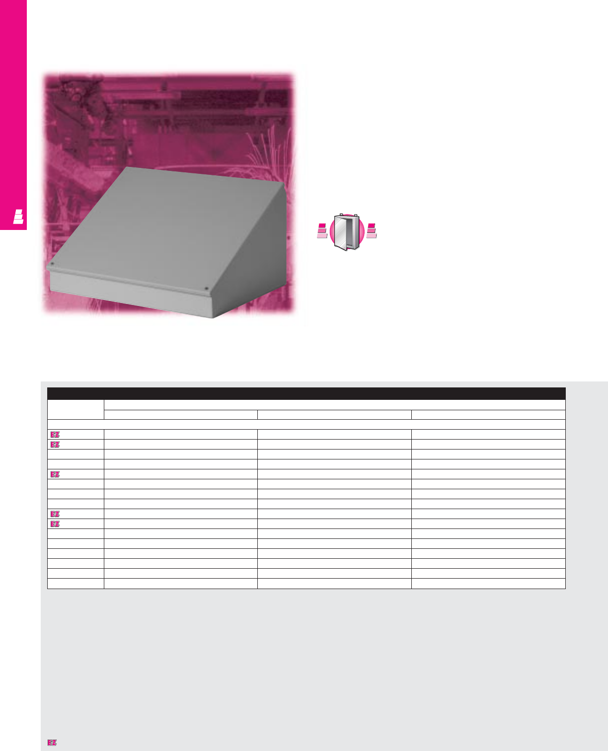
OPERATOR INTERFACE
IND 151
Consoles, Pedestals and Bases
Carbon Steel Desk Units
These NEMA rated individual desk units are designed for
indoor use to meet the requirements of most operator interface
applications.
Control components such as meters, pushbuttons, pilot lights,
and switches, can be mounted on the top-hinged control panel
that slants 30° or 60°.
Pedestal and base assemblies allow the desk units to be floor
mounted. Wiring connections can be made through the base,
the vertical column or directly to the desk unit.
S
t
a
i
n
l
e
s
s
S
t
e
e
l
S
t
a
i
n
l
e
s
s
S
t
e
e
l
A
v
a
i
l
a
b
l
e
I
n
A
v
a
i
l
a
b
l
e
I
n
Page IND 239
Consoles
Part No. Outside dimensions (inches)
HWD
Consoles
E 8C8 8.00 8.00 7.09
E 8C12 8.00 12.00 7.09
E 8C16 8.00 16.00 7.09
E 8C20 8.00 20.00 7.09
E 12C12 12.00 12.00 9.09
E 12C16 12.00 16.00 9.09
E 12C20 12.00 20.00 9.09
E 12C24 12.00 24.00 9.09
E 16C16 16.00 16.00 11.09
E 16C20 16.00 20.00 11.09
E 16C24 16.00 24.00 11.09
E 16C30 16.00 30.00 11.09
E 16C36 16.00 36.00 11.09
E 20C20 20.00 20.00 13.09
E 20C24 20.00 24.00 13.09
E 20C30 20.00 30.00 13.09
Designates a product in the EnclosureZone program.
OPERATOR INTERFACE
IND 152
Configuration
Console:
•Continuously welded seams, finished
smooth
•Poron strip gasket
•Control panel slants 30° or 60° and is
attached with a continuous steel hinge
at top and secured with captive screws
Pedestal/column:
•Removable, gasketed access plate in
column body
•Urethane gasket
Base:
• Pre-punched holes to accept column
• Two formed channels welded to underside
of base
Technical Specifications
Material:
•Console/desk unit: 14 gauge carbon steel
•Pedestal/column: 14 gauge carbon steel
with 10 gauge steel mounting flange at
each end
•Base: 12 gauge carbon steel
Finish/color:
•All steel parts: polyester-urethane powder
coat over phosphatized surfaces, inside
and outside – ANSI 61 grey
Pages. . . . . . . . . . . . . . . . . . . . . . . . . IND 188-189
NEMA Type 144X1213
UL CUL CSA TÜV
Listings
Protection Ratings
Certifications/Approvals
Technical Drawings
Pedestals and Bases
Part No. Outside dimensions (inches)
HWD
Pedestals
E 44CCOL 4.00 4.00 –
E 66CCOL 6.00 6.00 –
Bases
E 18SBASE 18.00 18.00 –
E 24SBASE 24.00 24.00 –
Designates a product in the EnclosureZone program.
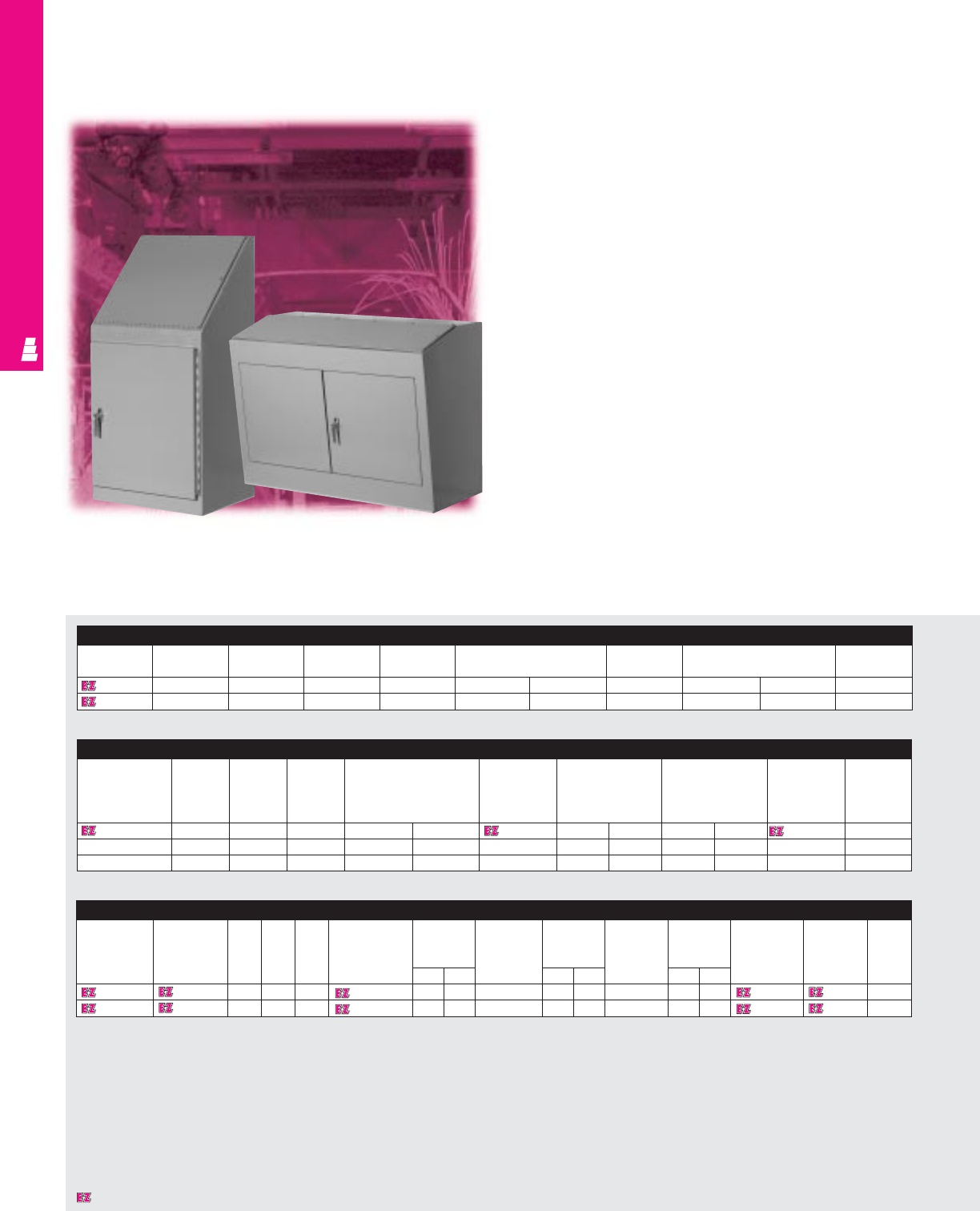
Carbon Steel Freestanding Consoles
These NEMA rated freestanding steel operator consoles are
designed for indoor use and meet the requirements of a variety
of operator interface applications.
Control instruments such as pushbuttons, pilot lights, meters,
switches, etc., can be mounted on the control panel that slants
16° (Series 9), 45° (Series 12) and 60° (Series 14). Optional
console top and/or writing desk provide additional flexibility.
Control equipment components can be mounted on removable
sub-panels on the side and back walls inside the enclosure.
Series 12 Console
Body Body Top Width Rear mounting Top Instrument panel Access panel Writing Caster
Part No. Height Height panel size Part Desk Kit
No. Part Part
No. No.
E C12B 36.00 20.00 36.00 32.00 30.00 E C12T 19.19 35.19 20.19 32.19 E C12W E 12C
E C1224B 36.00 20.00 24.00 32.00 18.00 E C1224T 19.19 23.19 20.19 20.19 E C1224W E 12C
E C1248BD 36.00 20.00 48.00 32.00 42.00 E C1248T 19.19 47.19 20.19 44.19 E C1248W E 12C
Series Operator Enclosures
Series 9 Console
Part No. Rear mounting Rear mounting panel size Side mounting Side mounting panel size Caster kit
Height Width Depth panel panel
E C924B 48.00 24.00 18.00 E 30P20 27.00 17.00 E 30P20 27.00 17.00 E C10C
E C936B 48.00 36.00 18.00 E 30P30 27.00 27.00 E 30P20 27.00 17.00 E C10C
IND 153
OPERATOR INTERFACE
Series 14 Console
Body Top Body Top Width Half Half Full Full Swingout Swingout Writing Relay Caster
Part No. Part No. height height Mounting mounting Mounting mounting Mounting mounting Desk Rack Kit
Panel panel size Panel panel size Panel panel size Part No. Part No. Part No.
Part No. HWPart No. HWPart No. HW
E C14B E C14T 50.00 16.00 24.00 E C14P2 22.00 17.00 E C14P3 42.50 17.00 E C14P1 22.00 18.13 E C14W E C14R E C12C
E C1436B E C1436T 50.00 16.00 36.00 E C1436P2 22.00 29.00 E C1436P3 42.50 29.00 E C1436P1 22.00 30.13 E C1436W E C14R E C12C
Designates a product in the EnclosureZone program.

Configuration
•Continuously welded seams, finished
smooth
•Urethane gasket
•Control panel slants (Series 9 slants 16°,
Series 12 slants 45°, Series 14 slants 60°)
and is attached with a continuous steel
hinge at front and secured with captive
screws
•Mechanical brace to hold control panel
open to 90°
•3-point latch with oil tight key locking handle
•Mounting panel provisions installed
•Print pocket included
Technical Specifications
Material:
•Enclosure/door: 14 gauge carbon steel
Finish/color:
•Enclosure/door: polyester-urethane powder
coat over phosphatized surfaces,
ANSI 61 grey outside and white inside
•Optional mounting panels: painted white
Pages . . . . . . . . . . . . . . . . . . . . . . . . IND 190-192
NEMA Type 144X1213
UL CUL CSA TÜV
Listings
Protection Ratings
Certifications/Approvals
Technical Drawings
IND 154
OPERATOR INTERFACE
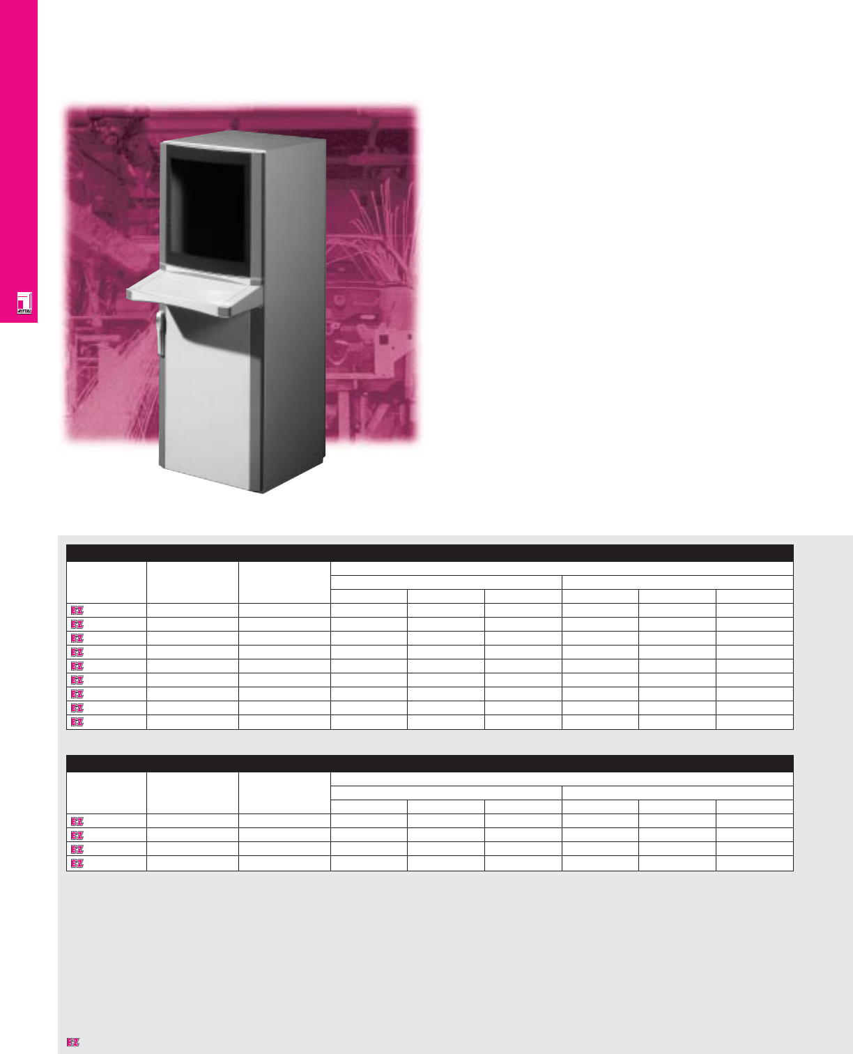
OPERATOR INTERFACE
IND 155
PC Computer Enclosures
Standard PC Freestanding Enclosures
Part No. Configuration Keyboard Exact outside dimensions
storage inches mm
HWD HW D
4603603 Solid front panel Drawer 63 24 26 1600 600 650
4603604 Solid front panel Console 63 24 26 1600 600 650
4603703 Safety glass Drawer 63 24 26 1600 600 650
4603704 Safety glass Console 63 24 26 1600 600 650
4603820 Solid front panel Fold-down 63 24 26 1600 600 650
4603913 Safety glass Drawer/Panel 63 24 26 1600 600 650
4603920 Safety glass Fold-down 63 24 26 1600 600 650
4609703 Safety glass Drawer 63 24 34 1660 600 850
4609920 Safety glass Fold-down 63 24 34 1600 600 850
PC Desktop/Pedestal Enclosures
Part No. Configuration Keyboard Exact outside dimensions
storage inches mm
HWD HW D
4617703 Safety glass Drawer 30 24 26 750 600 650
4617704 Safety glass Console 30 24 26 750 600 650
4617913 Safety glass Drawer/Panel 30 24 26 750 600 650
4617920 Safety glass Fold-down 30 24 26 750 600 650
Standard PC Freestanding Enclosures
PCs are important interfaces in today's computer-aided
manufacturing environment. The Rittal PC computer enclosure
houses monitor, CPU, keyboard, printer, and/or other
components in one cabinet that is equally at home on the
shop floor as in an office environment.
PC Desktop/Pedestal Enclosures
The PC Desktop/Pedestal enclosure is a one piece unit
designed to sit on a desk, table top or a pedestal.
Designates a product in the EnclosureZone program.

OPERATOR INTERFACE
IND 156
Accessories
Part No. Pedestals Pedestal accessories Mouse pad Shelf Inductive Inductive Inductive Mouse pad Mouse
Without cable With cable Mounting Casters mouse mouse pad mouse pad support holder
conduit conduit bracket (COM or PS/2) (COM) (PS/2)
4617703 6141000 6141100 6147000 6148000 4614000 4619660 6445000 6444000 6444500 2380000 2382000
4617704 6141000 6141100 6147000 6148000 – 4619660 6445000 6444000 6444500 2380000 2382000
4617913 6141000 6141100 6147000 6148000 4614000 4619660 6445000 6444000 6444500 2380000 2382000
4617920 6141000 6141100 6147000 6148000 4613000 4629660 6445000 6444000 6444500 2380000 2382000
Accessories
Part No. Bases Reinforced Mouse Shelf Tower PC Carriage Inductive Inductive Inductive Mouse pad Mouse
4" high Mobile castors pad Carriage Installation Kit Extra mouse mouse pad mouse pad support holder
shelf
(COM or PS/2)
(COM) (PS/2)
4603603 2813200 4640600 4634000 4614000 4619660 4641000 4376/4183/4162/9962544 4642000 6444500 6444000 6445000 2380000 2382000
4603604 2813200 4640600 4634000 – 4619660 4641000 4376/4183/4162/9962544 4642000 6444500 6444000 6445000 2380000 2382000
4603703 2813200 4640600 4634000 4614000 4619660 4641000 4376/4183/4162/9962544 4642000 6444500 6444000 6445000 2380000 2382000
4603704 2813200 4640600 4634000 – 4619660 4641000 4376/4183/4162/9962544 4642000 6444500 6444000 6445000 2380000 2382000
4603820 2813200 4640600 4634000 4613000 4619660 4641000 4376/4183/4162/9962544 4642000 6444500 6444000 6445000 2380000 2382000
4603913 2813200 4640600 4634000 4614000 4619660 4641000 4376/4183/4162/9962544 4642000 6444500 6444000 6445000 2380000 2382000
4603920 2813200 4640600 4634000 4613000 4629660 4641000 4376/4183/4162/9962544 4642000 6444500 6444000 6445000 2380000 2382000
4609703 2846200 4640800 4634000 4614000 4619680 4641000 4377/4183/4162/9962544 4642000 6444500 6444000 6445000 2380000 2382000
4609920 2846200 4640800 4634000 4613000 4629680 4641000 4377/4183/4162/9962544 4642000 6444500 6444000 6445000 2380000 2382000
Configuration
•Knife-edge design averts liquid away from
foamed-on gasket
•Integrated grounding provisions on all
surfaces
•Accepts up to 19" monitors
Designates a product in the EnclosureZone program.
Technical Specifications
Material:
•Body: 16 ga/1.5 mm sheet steel
•Rear door: 14 ga/2 mm sheet steel
•Sidewalls: 16 ga/1.5 mm sheet steel
•Bottom front door: 14 ga/2 mm sheet steel
•Corner trim panels: extruded aluminum
•Monitor panel: 3 mm security glass with 19" or
21" mask
•Keyboard front panel: plastic UL 94-VO
Finish/color:
•Body: E-coat primed, powder painted, RAL
7035 light grey
•Corner trim panels: powder painted, RAL
5018 teal green
Pages . . . . . . . . . . . . . . . . . . . . . . . . IND 193-195
NEMA Type 144X1213
UL CUL CSA TÜV
Listings
Protection Ratings
Certifications/Approvals
Technical Drawings
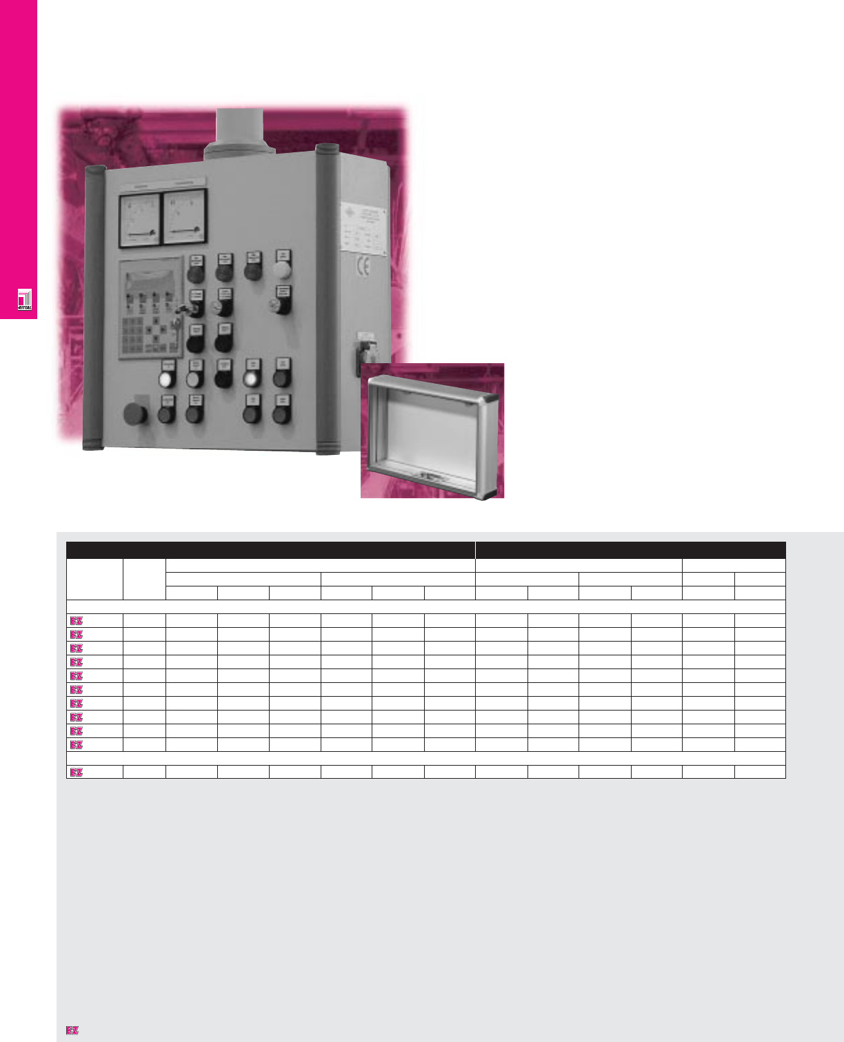
OPERATOR INTERFACE
Enclosure Mounting Area
Part No. NEMA Exact outside dimensions Usable mounting area Usable depth
rating inches mm inches mm inches mm
HWDH WDHWHWD D
Control Panel Enclosures/CP 6500 (CP-L) Series
6540200 1, 12 7.9 11.8 6.1 200 300 155 5.91 9.84 150 250 5.91 150
6534000 1, 12 7.9 11.8 7.1 200 300 180 6.11 8.94 155 227 6.62 168
6535000 1, 12 11.8 11.8 7.1 300 300 180 10.05 8.94 255 227 6.62 168
6536000 1, 12 11.8 15.7 7.1 300 400 180 10.05 12.88 255 327 6.62 168
6537000 1, 12 15.7 11.8 7.1 400 300 180 13.99 8.94 355 227 6.62 168
6538000 1, 12 15.7 15.7 7.1 400 400 180 13.99 12.88 355 327 6.62 168
6531200 1, 12 11.81 14.96 9.21 300 380 234 9.84 12.99 250 330 8.07 205
6530200 1, 12 14.96 14.96 9.21 380 380 234 12.99 12.99 330 330 8.07 205
6533200 1, 12 14.96 23.62 9.21 380 600 234 12.99 21.65 330 550 8.07 205
6532200 1, 12 19.69 19.69 9.21 500 500 234 17.72 17.72 450 450 8.07 205
Control Panel Enclosures/Optipanel Series
6380000 1, 12 13.94 20.75 4.33 354 527 110 12.22 19.00 310.3 482.6 3.94 100
IND 157
CP Pendant Arm Enclosures
Operator Interface Enclosures
Rittal’s CP Series was developed to meet the requirements
of today’s sophisticated control technology including:
• Dense packaging of sensitive components
• Direct accessibility, anywhere on the plant floor
• A high degree of flexibility and ergonomic adaptation
to the work place.
Numerous models of operator interface enclosures and
two pendant systems combine with an extensive range
of support arms, journals, hinges, and connection components
to cover virtually any operator interface situation.
The high degree of flexibility and ergonomic design provide
unlimited variety for today's diverse work environment.
Optipanel Series
Designates a product in the EnclosureZone program.
OPERATOR INTERFACE
IND 158
Configuration
Control Panel/CP 6500 Enclosures
•NEMA 1, 12/IP 54 or 55
•Various configurations for specific
applications
•Enclosures can be used with either the
CP 6000 or CP 6500 support arm system
•Integrated handle grip and front panel
•Designed for small to medium sized
HMI applications
Optipanel Enclosures
•NEMA 1, 12/IP 65 (with front plate installed)
•Designed specifically for compact operator
interface devices and components
•Extruded aluminum housing reduces weight
Page . . . . . . . . . . . . . . . . . . . . . . . . . . . . IND 196
NEMA Type 144X1213
UL CUL CSA TÜV
Listings
Protection Ratings
Certifications/Approvals
Technical Drawings
Accessories
Part No. Pendant arms and couplings Signal pillars Interface box
Control Panel Enclosures/CP 6500 (CP-L) Series
6540200 See accessories section See accessories section –
6534000 See accessories section See accessories section –
6535000 See accessories section See accessories section 2482000
6536000 See accessories section See accessories section 2482000
6537000 See accessories section See accessories section 2482000
6538000 See accessories section See accessories section 2482000
6531000 See accessories section See accessories section 2482000
6530000 See accessories section See accessories section 2482000
6533000 See accessories section See accessories section 2482000
6532000 See accessories section See accessories section 2482000
Technical Specifications
Control Panel/CP 6500 Enclosures
Material:
•Enclosure, door: 16 ga/1.5 mm sheet steel
•Front panel: 14 ga/2 mm aluminum
•Handle grips: aluminum
Finish:
•Enclosure, door: E-coat primed, painted,
RAL 7035 light grey
•Handle: painted
• 6534-6538 – RAL 5018 teal green
• 6530-6533/6540 – RAL 7030 stone grey
Optipanel Enclosures
•Enclosure, door: anodized aluminum
•Corner pieces: zinc die-cast,
powder coated RAL 7035 light grey
•Corner protectors, trim: self-extinguishing
plastic, RAL 7024 graphite
Accessories
Part No. Pendant arms and couplings Aluminum front panel Fixing hardware (panel) Fixing hardware for Signal pillars
O/I displays
Control Panel Enclosures/Optipanel Series
6380000 See accessories section 6028000 6050000 6058500 See accessories section
Designates a product in the EnclosureZone program.
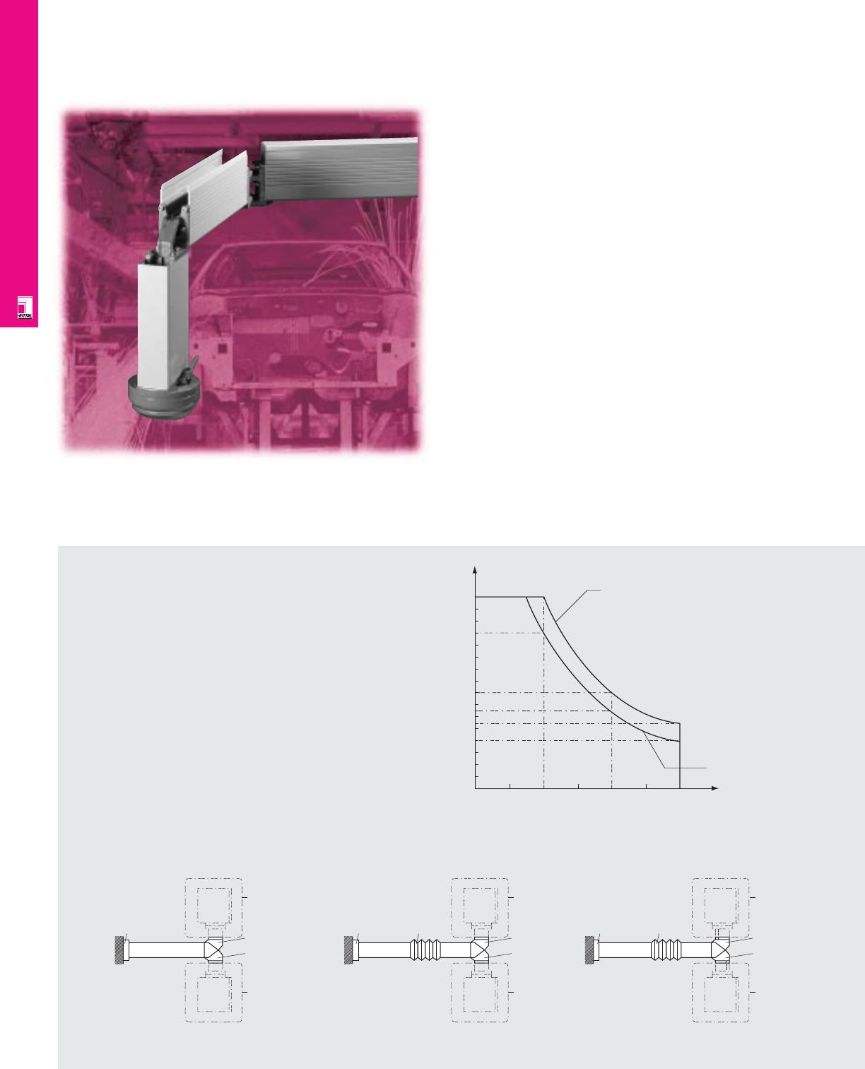
OPERATOR INTERFACE
IND 159
CP Pendant Arm Systems
Operator Interface And Support Arm Systems
Rittal’s CP 6000 (CP-XL) Series pendant arm systems were
developed to offer a high degree of flexibility and ergonomic
adaptation to the work environment required by today's
sophisticated control technology. A wide variety of enclosures,
support arm systems, and accessories combine to satisfy
virtually any operator interface need.
CP 6110000
CP 6160000
CP 6170000
CP 6180000
CP 6140000
Static
Load
Static
Load
CP 6180000
CP 6140000
Static
Load
Static
Load
A: Open and solid support section
CP 6110000
CP 6160000
CP 6170000
B: Solid support section
CP 6120000*
CP 6180000
CP 6140000
Static
Load
Static
Load
CP 6110000
CP 6160000
CP 6170000
C: Open support section
CP 6120000*
* Only once per system
where possible!
1600/360
1300/292
800/180
650/146
550/124
400/90
00 1000/39 2000/79 3000/118
Static load in N/lbf
Arm length in mm/inches
A + B
C
Unlimited Variety-CP 6000 (CP-XL)
Rittal's flexible CP 6000 pendant
arm system offers many advantages
over conventional support arm systems.
With its extensive range of support arms,
journals, and couplings, it offers a
sophisticated solution for virtually
every application.
Today's operator interface control
systems guarantee optimal information
exchange and user-friendliness, but at the
same time, place increasing demands on the
interface between the operator and machine.
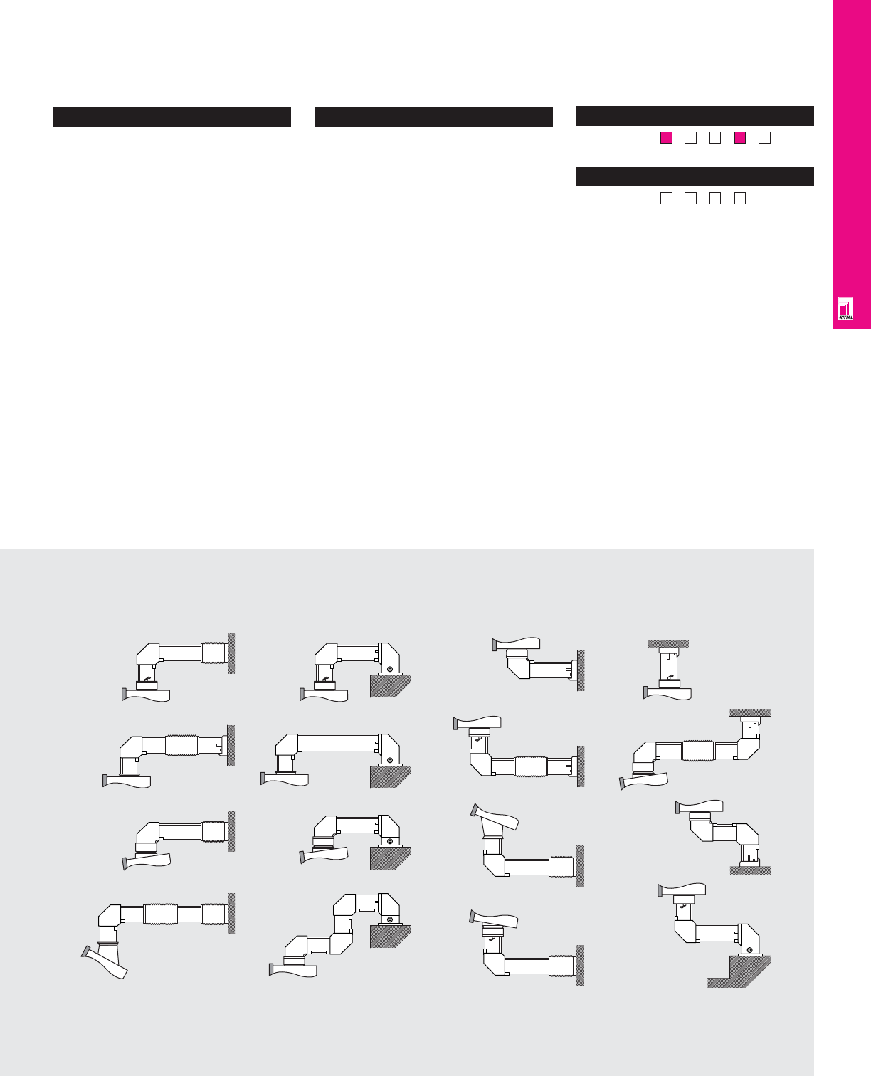
OPERATOR INTERFACE
Configuration
•Self-tapping screws for easy and secure
installation of the pendant arm system
•Support arm cover clips on to support arm
for easy access to wiring
•Cable routing before/after installation is easy
because one side of the support arm is
open
•The enclosed portion of the support arm
provides additional shielding
•Torsion resistant extruded aluminum support
arms have high load bearing capacity and
attractive styling
•Extruded aluminum support arms can be
easily cut to a required length
•Enclosures can swivel 350° continuously
with couplings
•90° elbow coupling secures connection
between support arm sections and also
allows easy cable routing
•Enclosure coupling can be used for top or
bottom installation
•Couplings come with either plastic covers
or rubber boots which can be removed for
easy access to wiring
Technical Specifications
Finish/color:
•Arm: RAL 7035 light grey
•Couplings: RAL 7030 stone grey
NEMA Type 144X1213
UL CUL CSA TÜV
Listings
Protection Ratings
Certifications/Approvals
These Are A Few Examples From A Wide Range Of CP 6000 (CP-XL) Possibilities
IND 160
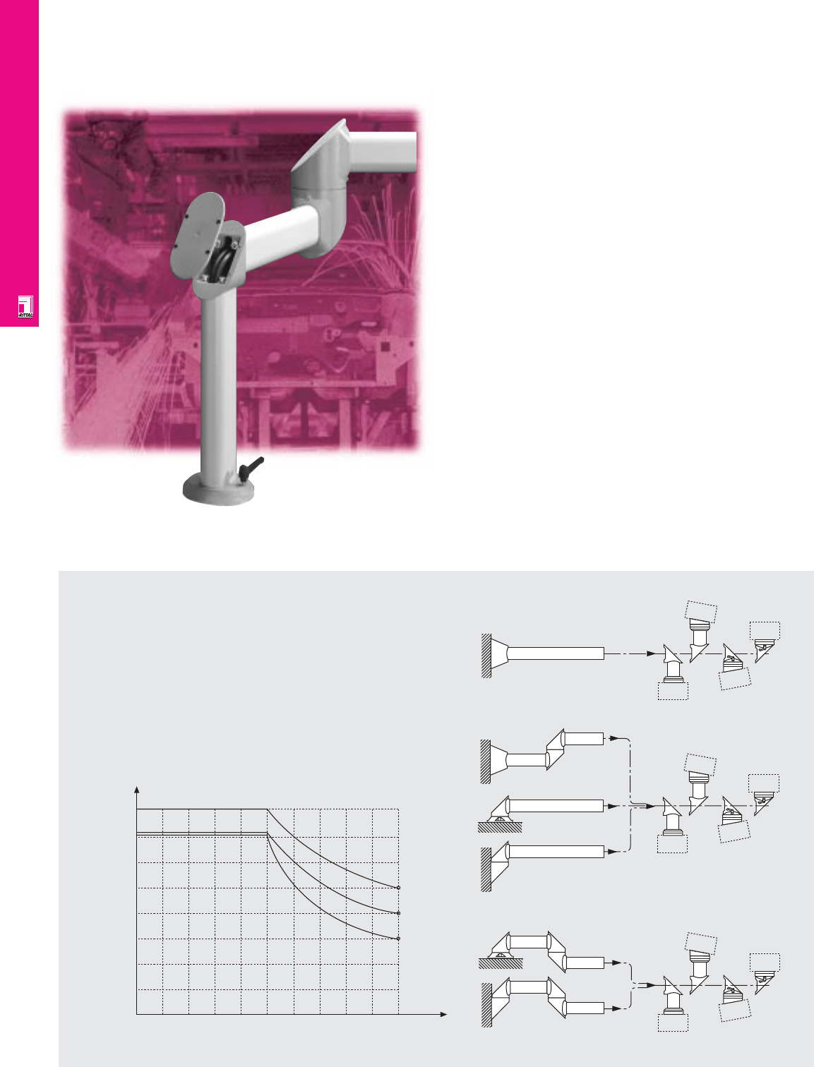
OPERATOR INTERFACE
IND 161
CP Pendant Arm Systems
Operator Interface And Support Arm Systems
Rittal’s CP 6500 (CP-L) Series pendant arm systems were devel-
oped to offer a high degree of flexibility and ergonomic adapta-
tion to the work environment required by today's
sophisticated control technology. A wide variety of enclosures,
support arm systems, and accessories combine to satisfy
virtually any operator interface need.
0
Permissable static load in Ibf
(Enclosure + vertical support arm section) [Ibf]
Arm length mm/inches
Permissable load depending on system configuration
Only one CP 6523 swivel hinge per system
200/
7.87
22
44
67
89
112
134
157
179
400/
15.75 600/
23.62 800/
31.50 1000/
39.37 1200/
47.24 1400/
55.12 1600/
63.00 1800/
70.87 2000/
78.74
A
B
C
A. System Configuration
(without hinge)
B. System Configuration
(with one hinge)
C. System Configuration
(with two hinges)
CP 6527
CP 6524 CP 6525
CP 6526
CP 6527
CP 6525
CP 6520
CP 6523
CP 6522
CP 6527
CP 6524
CP 6527
CP 6525
CP 6522
CP 6523
CP 6523
CP 6527
CP 6524
CP 6527
CP 6525
CP 6525
CP 6526
CP 6525
CP 6526
CP 6520
CP 6521
CP 6521
Extensive Versatility-CP 6500 (CP-L)
The support arm system CP-L is designed for small and
medium-sized command panels. It offers a whole range of
connection and hinged parts, and hence a large number of
possible applications.
This ensures optimum operation at the interface between man
and machine. In other words, the CP-L support arm system
provides perfect back-up for optimum information exchange and
user friendly handling of graphical interactive control systems.
0
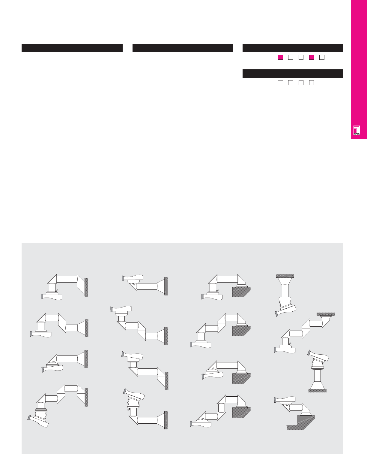
OPERATOR INTERFACE
Configuration
•Self-tapping screws for easy and secure
installation of the pendant arm system
•Torsion resistant extruded aluminum support
arms have high load bearing capacity and
attractive styling
•Extruded aluminum support arms can be
easily cut to a required length
•Enclosures can swivel 350° continuously
with couplings
•90° elbow coupling secures connection
between support arm sections and also
allows easy cable routing
•Enclosure coupling can be used for top
bottom installation
•Couplings come with plastic covers
which can be removed for easy access
to wiring
Technical Specifications
Finish/color:
•Arm: RAL 7035 light grey
•Couplings: RAL 7030 stone grey
NEMA Type 144X1213
UL CUL CSA TÜV
Listings
Protection Ratings
Certifications/Approvals
IND 162
These Are A Few Examples From A Wide Range Of CP 6500 (CP-L) Possibilities
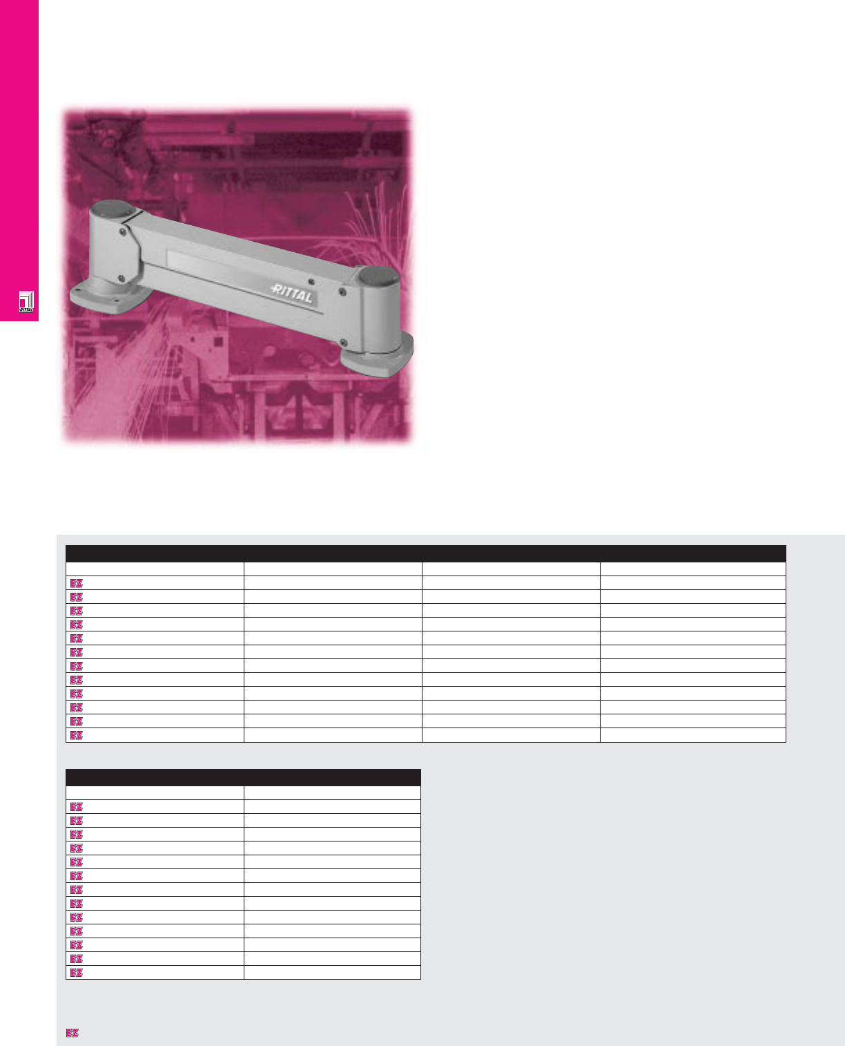
OPERATOR INTERFACE
IND 163
CP-Vertical Pendant Arm Systems
Smart HMI Solutions
Rittal’s new operator-driven CP-Vertical pendant arm systems
allow any operator to comfortably use a plant floor operator
interface device, regardless of the operator’s height. To adjust
height, the operator merely activates a release mechanism and
the interface can be effortlessly repositioned at a new height or
moved out of the way. The pendant arm uses a gas spring
counterbalancing system that can be easily user calibrated to
each system’s load that assists in moving and locking the
interface device in the desired vertical position.
What’s more is, this pendant arm system can be easily
incorporated with the new Optipanel enclosures that are
specifically designed for flat panel displays. The CP-V System
is also ideal for all of Rittal’s Command Panel (CP) enclosures.
1000/39.37 2000/78.74 3000/118.11
Pendant Arm System
Part No. Description Max. load Vertical travel T
9967987 Post top/CP-V 100 lbs 13"
9967988 Post top/CP-VL 75 lbs 23"
9967989 Post top/CP-VXL 50 lbs 30"
9967993 Wallmount/CP-V 100 lbs 13"
9967994 Wallmount/CP-VL 75 lbs 23"
9967995 Wallmount/CP-VXL 50 lbs 30"
9967996 Machine top/CP-V 100 lbs 13"
9967997 Machine top/CP-VL 75 lbs 23"
9967998 Machine top/CP-VXL 50 lbs 30"
9967999 Universal mount/CP-V 100 lbs 13"
9968000 Universal mount/CP-VL 75 lbs 23"
9968001 Universal mount/CP-VXL 50 lbs 30"
Accessories
Part No. Description
9968002 6" Horizontal extension
9968003 12" Horizontal extension
9968004 18" Horizontal extension
9968005 24" Horizontal extension
9968006 18" Jointed extension arm
9968007 24" Jointed extension arm
9968008 4" Vertical extension piece
9968009 8" Vertical extension piece
9968010 12" Vertical extension piece
9968011 36" Floor post
9968013 74" Floor post
9968014 Release handle W < 151
9968015 Release handle W > 15 1
1 Must choose one release handle per arm.
Designates a product in the EnclosureZone program.
OPERATOR INTERFACE
Configuration
• Sizes
CP-V 5" H x 3" W x 26" L
CP-VL 5" H x 3" W x 31" L
CP-VXL 5" H x 3" W x 39" L
• Vertical travel
CP-V 13"
CP-VL 23"
CP-VXL 30"
•Adjusts to viewing height of each operator
with simple motion
•Counterbalance can be adjusted by user
for loads up to 100 lbs. (depending on arm)
•13", 23", or 30" of vertical adjustment
•Locks and unlocks with a convenient
release mechanism
•Swivels at both ends
•Optional extensions and floor posts
•NEMA Type 4, 12 sealed cable
passageway protects wiring
•Wallmount, machine top, post top or
universal mounting options
•Universal mount incorporates the ability
to post, wall, or machine mount
CP-Vertical arm
•All arms can be easily reconfigured for
inverted applications
•A release handle mechanism must be
ordered for each arm
Technical Specifications
Material:
•Aluminum
Finish/color:
•Powder painted RAL 7035 light grey
NEMA Type 144X1213
UL CUL CSA TÜV
Listings
Protection Ratings
Certifications/Approvals
Each CP-Vertical Pendant Arm System Will Include The
Following:
•CP-Vertical pendant arm that can be counterbalanced by
the user based on load rating
• Mounting method (Post, Wallmount, Machine, Universal)
will be attached to pendant arm
• A release cable will be included
• Conversion wrench and instructions
•Hardware to attach enclosure to CP-Vertical arm
Note: Hardware to attach the CP-Vertical pendant arm to
mounting surface is not provided.
Below Is A Step-By-Step Guide To Selecting A
CP-Vertical Pendant Arm System:
1) Determine Maximum Load:*
Maximum load = Weight of enclosure (lbs.)
+ total weight of all components
mounted ON or INSIDE of
enclosure
Maximum load (lbs.) =
* Load = Weight of enclosure + total weight of
all components mounted inside enclosure.
2) Determine Proper CP-Vertical Pendent Arm
Based On Load:
Select a vertical travel based on your maximum load
calculation from above.
3) Determine Mounting Method:
Based on the CP-Vertical Pendant Arm you selected (i.e.
CP-V, CP-VL, CP-VXL) in step #2, select a mounting method
that best fits your application.
Maximum Load CP-V CP-VL CP-VXL
Range (+0%) 13" Vertical 23" Vertical 30" Vertical
Travel Travel Travel
0 to 50 lbs. Yes Yes Yes
51 to 75 lbs. Yes Yes No
76 to 100 lbs. Yes No No
Mounting
CP-V CP-VL CP-VXL
method
13" Vertical 23" Vertical 30" Vertical
Travel Travel Travel
Part No. Part No. Part No.
Post top
9967987 9967988 9967989
Wallmount
9967993 9967994 9967995
Machine top
9967996 9967997 9967998
Universal
9967999 9968000 9968001
Pages . . . . . . . . . . . . . . . . . . . . . . . . IND 197-198
Technical Drawings
IND 164
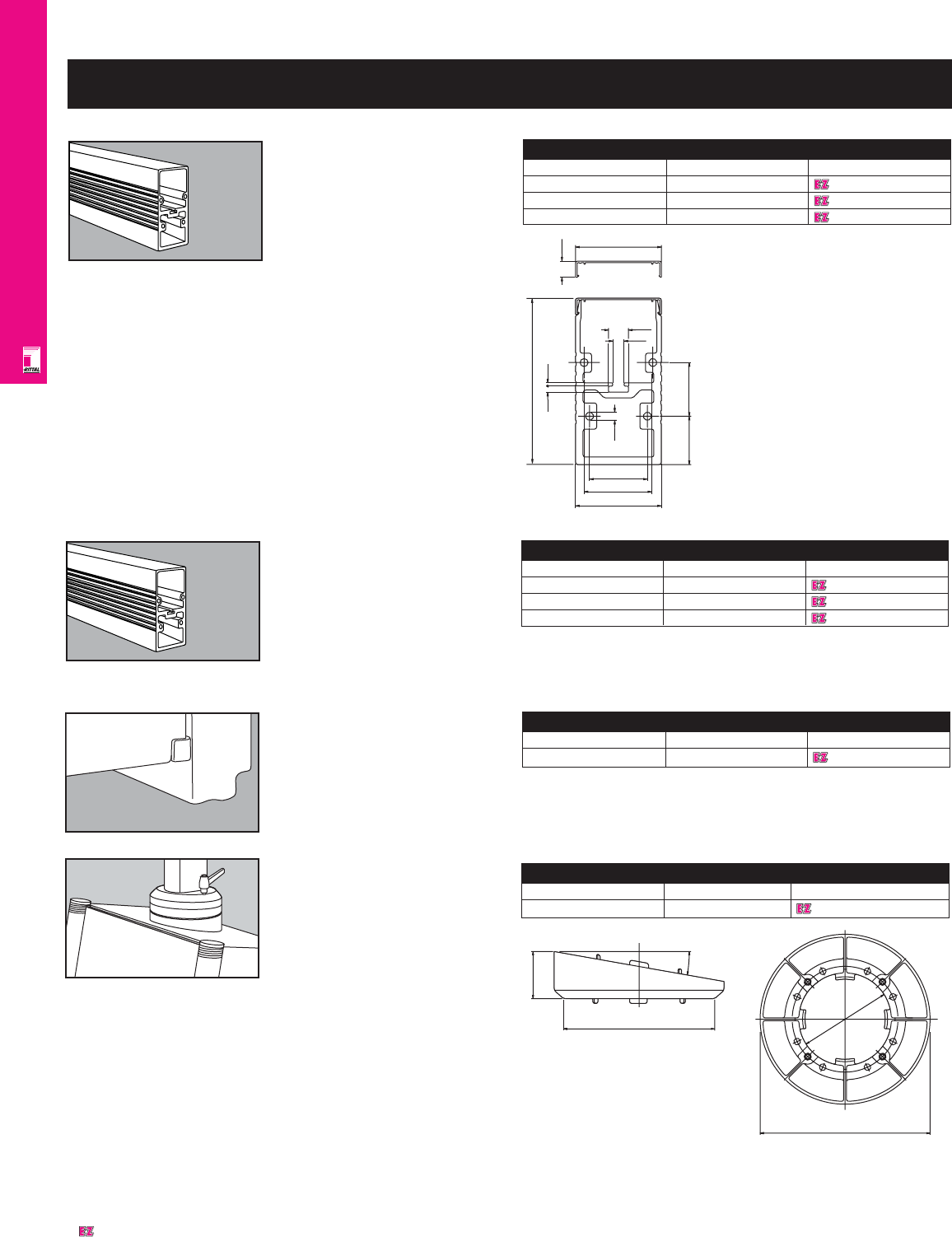
OPERATOR INTERFACE
IND 165
CP 6000 (CP-XL) Accessories
CP 6000 Support
Arm, Solid
The solution for higher weight loads.
Approximately 20% more loading
capacity than the clip-on cover
support arm version.
Color: RAL 7035 light grey
Weight: 23 lbs/10.3 kg
Solid CP 6000 Support Arm
Length (inches/mm) Packs of Part No.
19.7/500 1 6050500
39.4/1000 1 6100500
70.7/2000 1 6200500
CP 6000 Support Arm
The basic component of a CP 6000
pendant arm system. Connection
components are attached with
self-tapping screws and make
combinations of any desired
length possible.
Configuration: bend- and
torsion-resistant extruded aluminum
complete with clip-on cover. Available
in three different lengths.
Color: RAL 7035 light grey
Weight: support arm: 6.0 lbs/ft/9.05
kg/m
Cover: .3 lbs/ft/.45 kg/m.
155
5.7
80
64
7.45
54
45 50
3
15
10.6
18.5
80
CP 6000 Support Arm
Length (inches/mm) Packs of Part No.
19.7/500 1 6050000
39.4/1000 1 6100000
78.7/2000 1 6200000
10º Tilting Adaptor
Tilts enclosure for increased
user-friendliness; installed between
housing and enclosure or 90°
arm coupling.
Material: zinc diecast; comes with
gaskets and installation hardware.
Color: RAL 7030 stone grey.
10° Tilting Adaptor
Weight Packs of Part No.
2.6 lbs/1.2 kg 1 6023000
50
Ø 160
10°
180
98
Adjustment Shim
Allows subsequent adjustment of CP
support arms.
Material: sheet steel, zinc coated,
yellow chromate.
Adjustment Shim
Packs of Part No.
Adjustment shim 10 6205000
Designates a product in the EnclosureZone program.
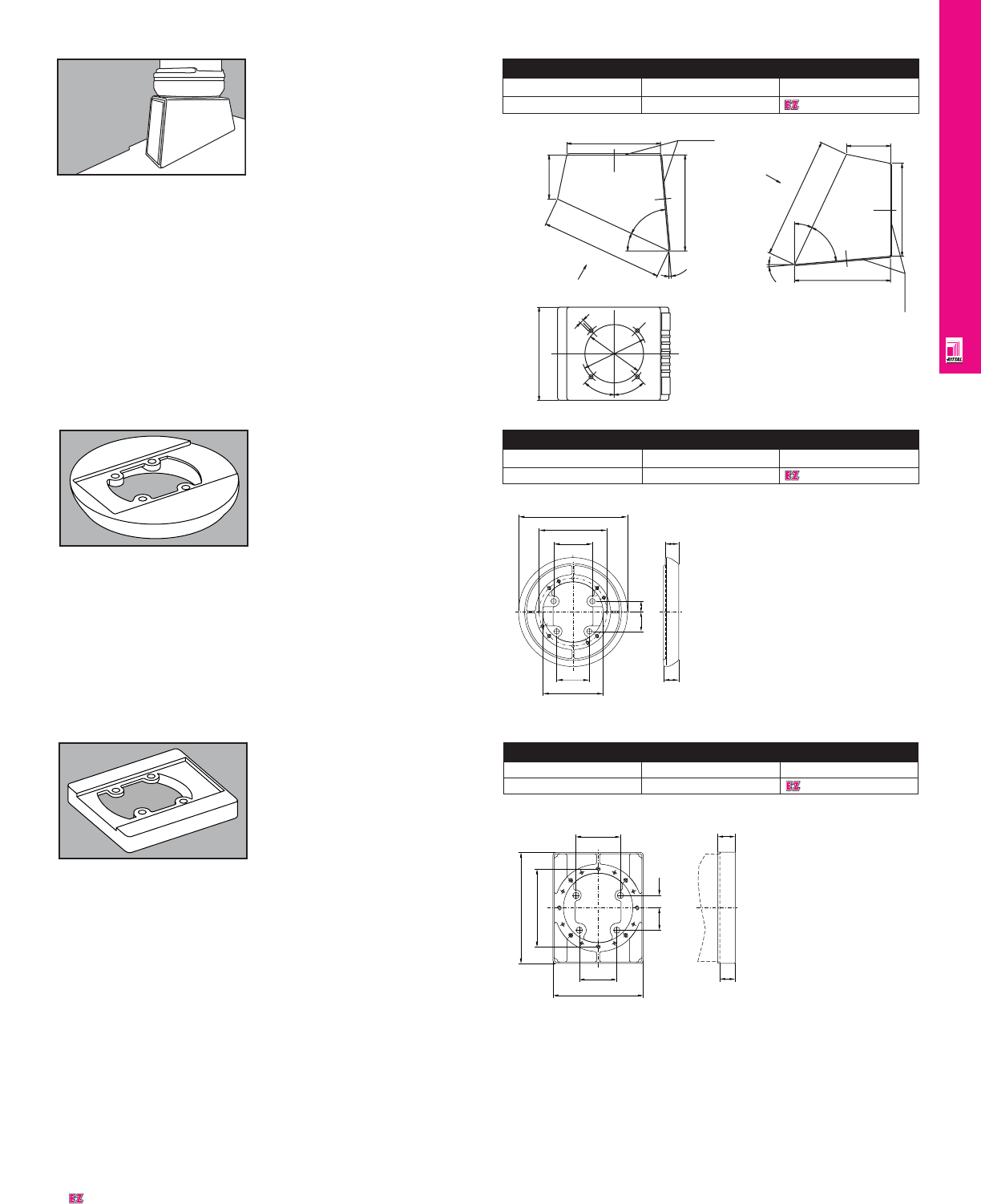
OPERATOR INTERFACE
IND 166
Tilting Adaptor 25º/60º
Installs between enclosure and CP
6130 enclosure coupling; tilts 25°
or 60°.
Material: zinc diecast; comes with
gaskets and installation hardware.
Color: RAL 7030 stone grey.
Tilting Adaptor 25°/60°
Weight Packs of Part No.
8.4 lbs/3.8 kg 1 6150000
Cover
A
160
45°
45°
112
100
7
75.5
25°
210
5°
60°
164.5
160
Cover
A
75.5
25°
210
5°
60°
164.5
160
Fixed Enclosure Coupling
For fixed attachment of the enclosure
in conjunction with 10° tilting adaptor
(CP 6023000) and 25°/60° tilting
adaptor (CP 6150000).
Configuration: Die-cast zinc;
including gasket and installation
hardware. Not suitable for use as a
base point for a support arm system.
Color: RAL 7030 stone grey.
Fixed Enclosure Coupling
For rigid top or bottom mounting of
enclosures to vertical support arms.
Configuration: zinc die-cast;
includes gaskets and installation
hardware.
Not suitable for use as base bracket
for a support arm system.
Color: RAL 7030 stone grey.
Enclosure Coupling, Fixed
Weight Packs of Part No.
3.1 lbs/1.4 kg 1 6130500
Fixed Enclosure Coupling
Weight Packs of Part No.
2.4 lbs/1.1 kg 1 6130600
54
64
112
180
32 18
100
22
25
64
54
32 18
Ø 112
160
130
25
22
Designates a product in the EnclosureZone program.
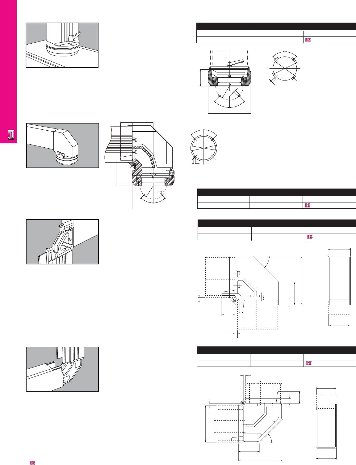
OPERATOR INTERFACE
IND 167
50
10
10
20
88
45°
80
188
86
90˚ Arm Coupling
Connects vertical support arms to
horizontal support arms.
Material: spheroidal graphite iron
with protective plastic cover; gaskets
and installation hardware.
Color: RAL 7030 stone grey.
US Patent No. 4,997,155
German Patent No. 38 05 422
European Patent No. 0 330 027
valid for FR, IT
90° Arm Coupling
Weight Packs of Part No.
4.2 lbs/1.9 kg 1 6140000
90° Arm Coupling
Weight Packs of Part No.
7.0 lbs/3.2 kg 1 6180000
90˚ Arm Coupling
(For Inverted Mounting)
Allows vertical support arm to be
directed upwards from a lower,
horizontal support arm at floor
level which ensures trouble-free
cable routing.
Material: spheroidal graphite iron
with protective plastic cover; gaskets
and installation hardware.
Color: RAL 7030 stone grey.
20
8
18
45°
155
10
10
86
50
80
88
45°45°
Ø100
Ø112
M6
8950
7
Ø100
45°
Ø120
45°
180
90˚ Enclosure Coupling
For top or bottom installation of enclosures to
horizontal support arms without having to install
an additional vertical support arm.
Material: spheroidal graphite iron and zinc diecast;
rotates 180˚ and can be locked in place;
maintenance-free bearing; plastic cover; gaskets and
installation hardware. Not to be used as a
support arm base bracket.
Color: RAL 7030 stone grey.
90° Enclosure Coupling
Weight Packs of Part No.
12.1 lbs/5.5 kg 1 6040000
Enclosure Coupling
For top or bottom installation of
enclosures to vertical support arms.
Material: zinc diecast; enclosure
rotates infinitely through 350° and
adjustable; maintenance-free
bearing; includes gaskets and
installation hardware. Not to be used
as a support arm base bracket.
Color: RAL 7030 stone grey.
Enclosure Coupling
Weight Packs of Part No.
7.7 lbs/3.5 kg 1 6130000
58
Ø100
112
M6
45°
45°
Ø180
7
Ø112
Ø100
45°
45°
Designates a product in the EnclosureZone program.
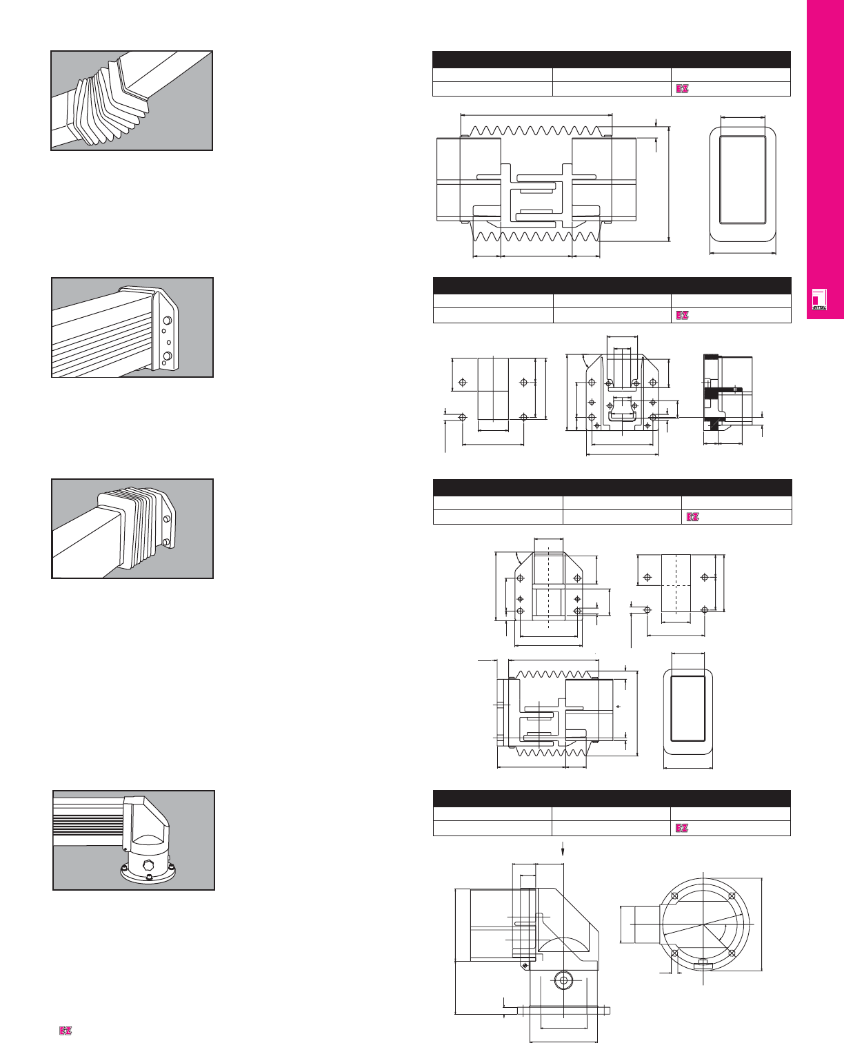
OPERATOR INTERFACE
IND 168
Wall/Base Bracket
Allows rigid mounting of the pendant
arm system to vertical or horizontal
surfaces.
Material: spheroidal graphite iron,
includes gaskets and installation
hardware.
Color: RAL 7030 stone grey.
Wall/Base Bracket
Weight Packs of Part No.
7.9 lbs/3.6 kg 1 6160000
14 / M12
1
7
30
75
140
80 55
174
80
45°
33
140
165
14
55
18
50
40
37
40
65
70
Horizontal Hinge
For installation of a swiveling pendant
arm system to horizontal surfaces.
Material: steel and cast iron with
plastic cover; maintenance free
bearing, rotates 350°, with safety
stop; includes gaskets and
installation hardware.
Note: Not to be used as an enclosure
coupling.
Color: RAL 7030 stone grey.
Horizontal Hinge
Weight Packs of Part No.
24.2 lbs/11.0 kg 1 6170000
15
115
Ø 145
Ø 100
155
33
50 60.5
A
14
80
175
View A
45°
200
Vertical Hinge
For installation of a swiveling pendant
arm system to vertical surfaces.
Material: spheroidal graphite iron;
rotates 180°, includes bellows,
gaskets, and installation hardware.
Color: RAL 7030 stone grey.
Vertical Hinge
Weight Packs of Part No.
18.5 lbs/8.4 kg 1 6110000
120
80
168
ca.28
50
220
"A"
10
208
20
22.5
140
165
167
80
45°
14 65
70
70
14 / M12 75
140
70
140
80 55
Intermediate Hinge
Connects horizontal suspension
arms.
Material: spheroidal graphite iron;
rotates 180°, includes bellows with
zip fastener for easy access to cable
duct; gaskets, and installation
hardware.
Color: RAL 7030 stone grey.
US Patent No. 4,998,702
German Patent No. 38 05 424
European Patent No. 0 330 029
valid for FR, GB, IT
Intermediate Hinge
Weight Packs of Part No.
13.4 lbs/6.1 kg 1 6120000
50 130 50
275
120
80
208
20
Designates a product in the EnclosureZone program.
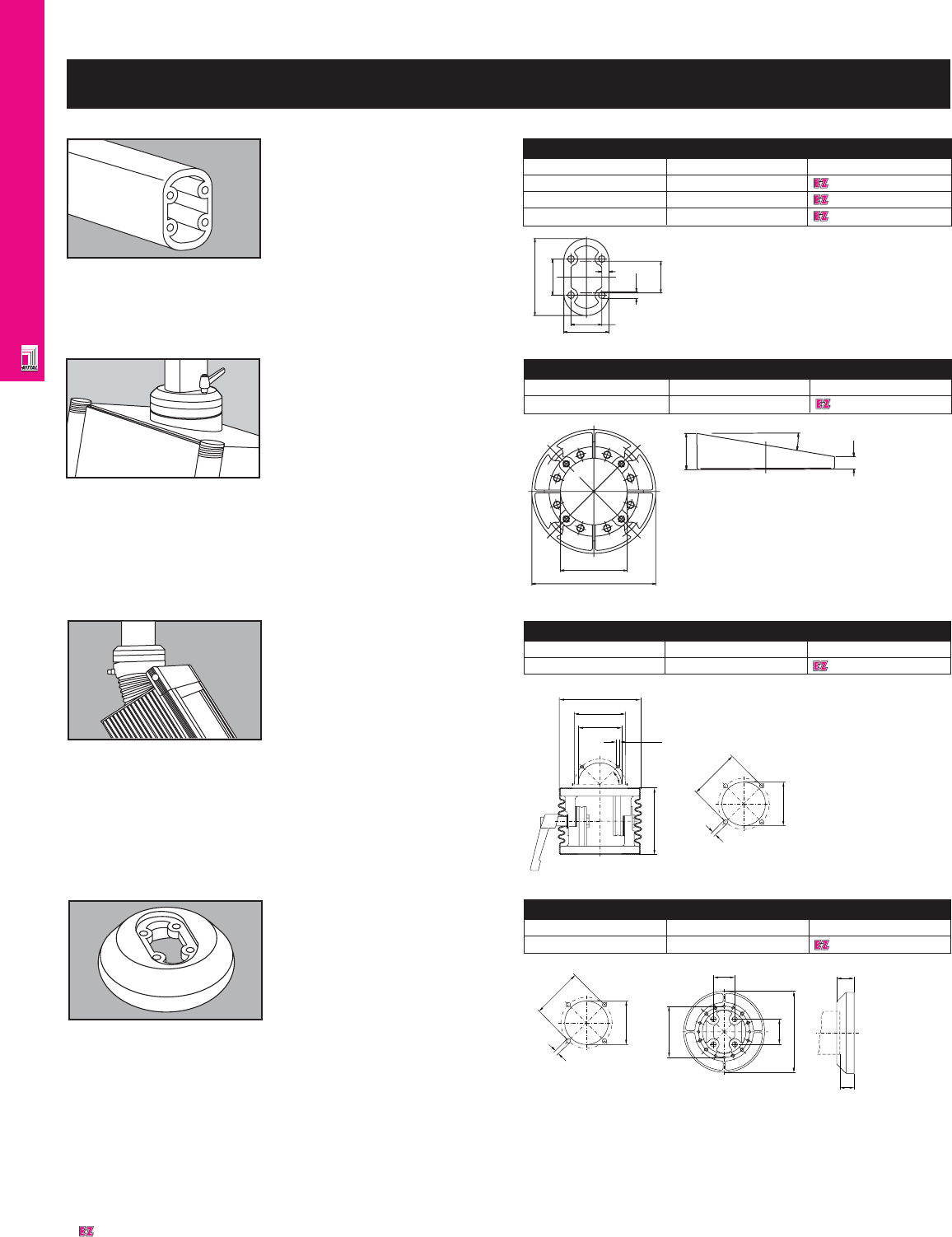
OPERATOR INTERFACE
IND 169
50.0 34.0
85.0
40.0
Ø 7.45
8.0
(35.0)
CP 6500 Support Arm
The basic component of the pendant
arm system.
Material: Bend- and torsion-resistant
extruded aluminum. Integrated holes
for self-tapping screws make
combinations up to any desired
length possible.
Color: RAL 7035 light grey
Weight: 3.16 lbs/ft/4.7 kg/m.
CP 6500 Support Arm
Length (inches/mm) Packs of Part No.
19.7/500 1 6511000
39.4/1000 1 6513000
78.7/2000 1 6515000
CP 6500 (CP-L) Accessories
Enclosure Coupling, Fixed
For fixed bottom mounting of
enclosure to vertical support arm.
Configuration: zinc die-cast;
includes gaskets and installation
hardware. Cannot be used as a
support base bracket.
Color: RAL 7030 stone grey.
Enclosure Coupling, Fixed
Weight Packs of Part No.
1.8 lbs/0.8 kg 1 6525500
10º Tilting Adaptor
Tilts enclosure for increased
operator friendliness; installed
between housing and enclosure
or 90° arm coupling.
Material: cast zinc; comes with
gaskets and installation hardware.
Color: RAL 7030 stone grey.
10° Tilting Adaptor
Weight Packs of Part No.
1.3 lbs/.6 kg 1 6527000
Ø70
Ø130
12
10°
35
+/-45° Tilt Adaptor
Weight Packs of Part No.
2.2 lbs/1.0 kg 1 6529000
Tilt Adaptor +/-45°
Adjustable
For flexible adjustment for optimum
viewing angle of flat screen LCD
displays. Can be mounted on
pendant arm with a CP 6525
enclosure coupling or a CP 6526 90°
enclosure coupling.
45°
M6
Ø 82
Ø 70
Ø 130
107
82
7
70
40
130
34
82
23
28
Installation
cutout
82
7
70
Installation
cutout
Designates a product in the EnclosureZone program.
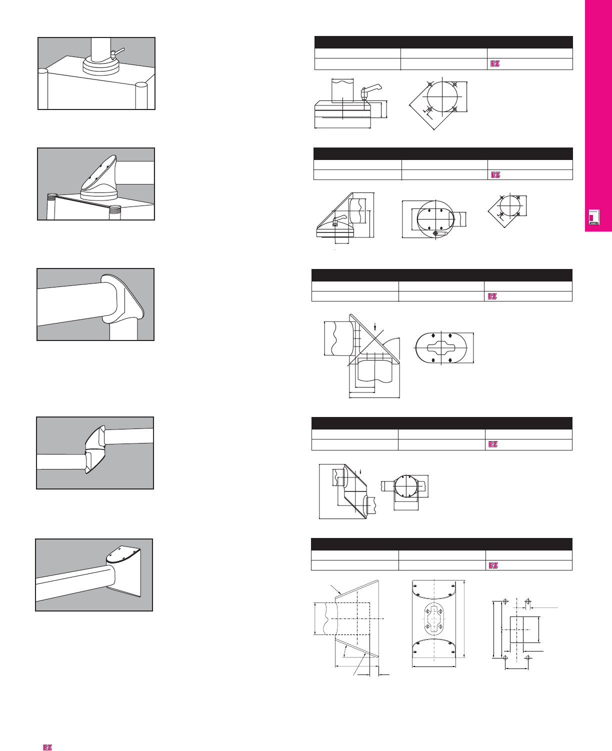
OPERATOR INTERFACE
IND 170
Mounting
cutout
Ø7
Ø82
Ø130
50
Ø70
35
40
Enclosure Coupling,
Rotating
For top or bottom installation of
enclosure to vertical support arm.
Configuration: maximum rotation
350°. Not to be used as a support
arm.
Color: RAL 7030 stone grey.
Enclosure Coupling
Weight Packs of Part No.
3.3 lbs/1.5 kg 1 6525000
90° Enclosure Coupling
Weight Packs of Part No.
3.3 lbs/1.5 kg 1 6526000
90º Enclosure Coupling
For top or bottom installation of
enclosure to vertical support arm.
Configuration: maximum rotation
350°. Not to be used as a base
mounting bracket.
Color: RAL 7030 stone grey.
157
50
93 85
Installation
cutout
Ø82
Ø7
Ø70
Ø130
75
50
Designates a product in the EnclosureZone program.
285
146.5 85
126
116
View A
50
115
A
Intermediate Hinge
Weight Packs of Part No.
5.5 lbs/2.5 kg 1 6523000
Intermediate Hinge
Connects horizontal suspension
arms.
Configuration: maximum rotation
350°.
Color: RAL 7030 stone grey.
90° Arm Elbow
Weight Packs of Part No.
1.1 lbs/.5 kg 1 6524000
90º Arm Elbow
Connects horizontal and vertical
support arms.
Color: RAL 7030 stone grey.
62.5 126
47.5
85
45°
AView A
75
Wall/Base Mounting
Bracket
For rigid installation of a stationary
suspension arm system to a vertical
or horizontal mounting surface.
Color: RAL 7030 stone grey.
Wall/Base Mounting Bracket
Weight Packs of Part No.
3.5 lbs/1.6 kg 1 6520000
85
22.5°
115
205
115
Ø 11 / M 10
150
70 – 110
60
==
24
35 – 65
Removable plate
Removable plate
Mounting cutout
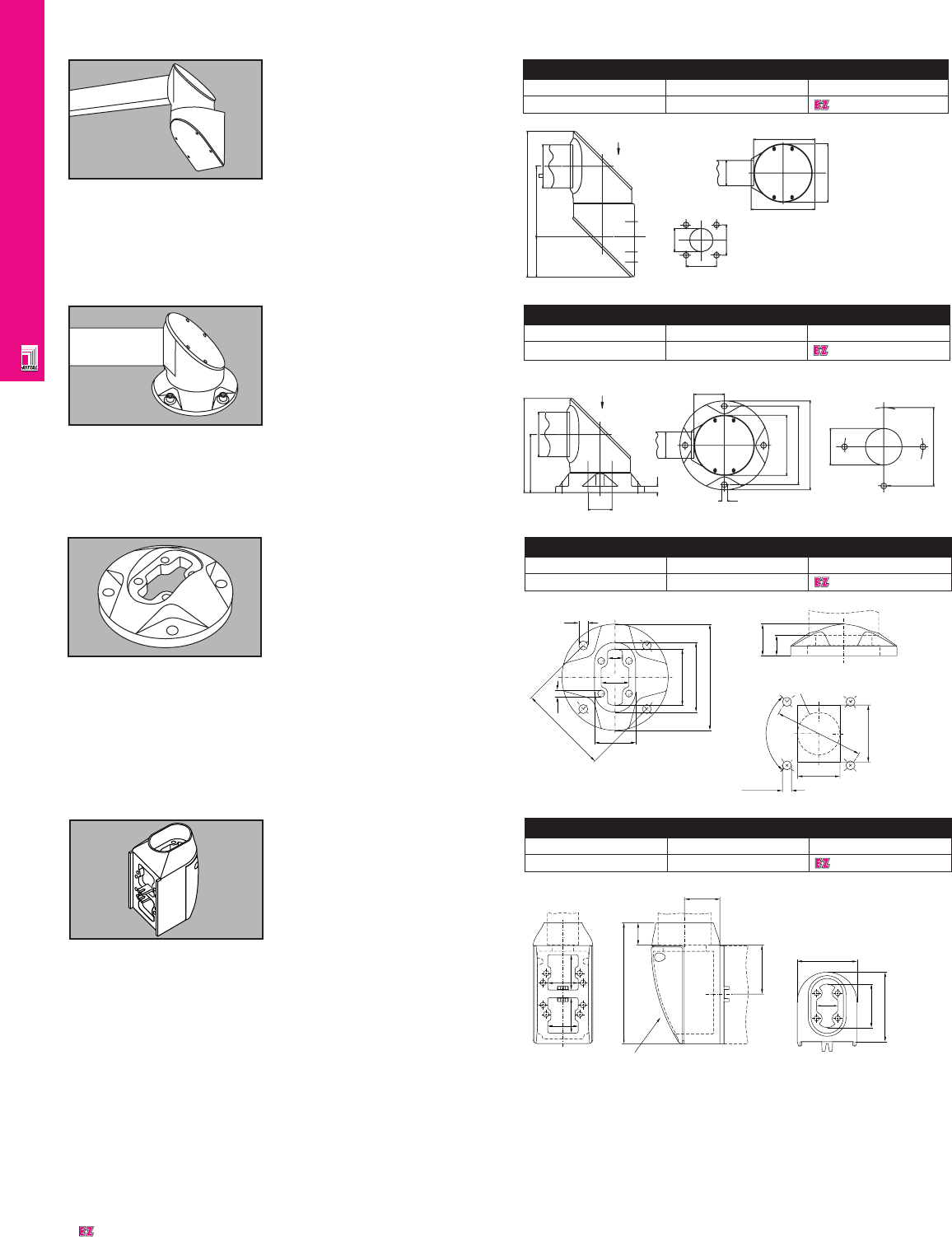
OPERATOR INTERFACE
IND 171
Horizontal Hinge
Weight Packs of Part No.
5.5 lbs/2.5 kg 1 6522000
Horizontal Hinge
For installation of a swiveling support
arm to a horizontal mounting surface.
Ceiling installation possible.
Configuration: maximum rotation
350° not to be used as a coupling
for enclosures.
Color: RAL 7030 stone grey.
Ø46
111 85
12
50
A
Ø11
58 View A
Ø115
Ø170
Ø150
MOUNTING
CUTOUT
Ø50-90
Ø150
Ø11/M10
Vertical Hinge
For installation of a swiveling support
arm system to a vertical mounting
surface.
Configuration: maximum rotation
350°, can be locked in place.
Color: RAL 7030 stone grey.
Vertical Hinge
Weight Packs of Part No.
6.2 lbs/2.8 kg 1 6521000
81
288
139
A
Ø11/M10
60
Ø46-55
60
MOUNTING
CUTOUT
50
126
121
VIEW A
115
Wall/Floor Mount, Small
For fixed mounting of support arm
systems on vertical and horizontal
surfaces. Especially well suited for
assembly of compact support arm
systems with cable entry from the
inside.
Description: aluminum die-cast,
including gasketing and
self-threading screws for CP-L
support arm installation.
Color: RAL 7030 stone grey.
Note: standard screws may be used
for the assembly of walls and floors.
Wall/Floor Mount, Small
Weight Packs of Part No.
1.3 lbs/0.6 kg 1 6520500
85
110
130
11
8.5
34
69
18
51
39
25
90¡
fl 110
fl 11 / M 10
Installation cutout
max. 52
max. 70
90° Angle Adaptor,
(6000 to 6500) (CP-XL
to CP-L)
A coupling between
• horizontal support rail CP-XL and
• vertical support rail CP-L when the
configuration is chosen for stan-
dard or aesthetic reasons.
Description: aluminum die-cast,
including gaskets and self-threading
screws for mounting of CP-L/CP-XL
support arm.
Color: RAL 7030 stone grey.
90° Angle Adaptor, CP-XL to CP-L
Weight Packs of Part No.
3.3 lbs/1.5 kg 1 6528100
56
49
49
56
191
78
57
35
Remove lid
69
96
110
34
Designates a product in the EnclosureZone program.
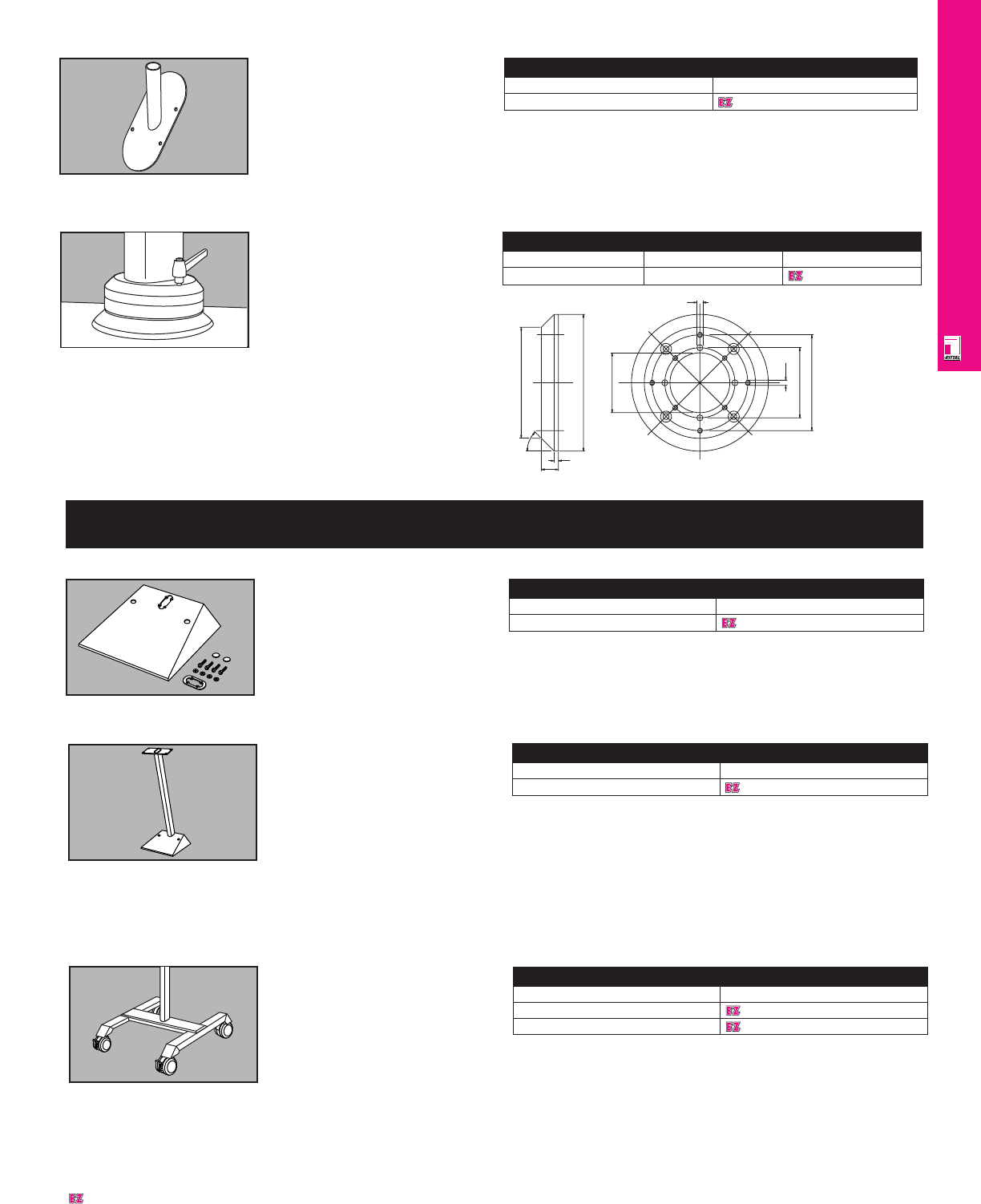
OPERATOR INTERFACE
IND 172
Mounting Component for
Support Arm System
For attaching a signal pillar with
connection component for conduit
mounting onto support arm system
CP-L. To fit angle piece CP 6524000
and angle coupling CP 6526000
Design: sheet steel
Color: RAL 7030 stone grey.
Mounting Component
Mounting component Part No.
For support arm system CP-L 2375000
Connection Adaptor
Makes following, interchangeable
connection options possible.
• Connect CP 6000 enclosure to CP
6500 support arm system.
• Connect CP 6500 enclosures to CP
6000 support arm system.
Material: cast aluminum; powder
painted, RAL 7030 stone grey.
Connection Adaptor
Weight Packs of Part No.
1.1 lbs/.5 kg 1 6528000
20 5
45°
Ø130
Ø70
Ø160
M 6
Ø82
Ø112
7
Designates a product in the EnclosureZone program.
Pedestal Accessories
Pedestal Base, Small
With reinforcement bracket for the
installation of support arm profile
CP-L:
• rear with one hole for a standard
M20 cable conduit connection.
• top with two holes (grommets
included) for bottom floor mounting
cross rail.
Small Pedestal Base
PU Part No.
16143200
Note: standard M8 screws are
acceptable for bottom mounting.
Material: sheet steel 3/22"/2.5 mm
Color: RAL 7035 light grey.
Mobile Pedestal For
CP 6000 And CP 6500
Offers operator friendliness and
installation flexibility for CP operator
enclosure applications. All CP and
similar operator enclosures can be
mounted on the special coupling
plate of the CP 6136000 mobile
pedestal. Large casters facilitate
easy movement, even on uneven
floors; the front casters feature brakes.
Mobile Pedestal For CP 6000 And CP 6500
Pedestal with mounting plate Part No.
for CP 6500 6136500
for CP 6000 6136000
The base allows for easy cable
entry while cables can be routed
through the support pillar.
Configuration: mobile base, with
4 casters, including two with
integral brakes; support pillar.
Only for CP 6136.000: special
coupling; installation hardware.
Color: RAL 7030/7035 grey.
Casters: RAL 9005 black.
Enclosure Flange CP-L
For the rigid installation of:
• KL enclosures 1515.210 (HWD
150 x 360 x 80 mm)
• mounted inside as reinforcement
plate for all appropriately sized
enclosures (also E-boxes and
compact AE enclosures) in
conjunction with:
- enclosure coupling CP 6525000
- enclosure mount CP 6525500
- tilted adaptor CP 6526000 to
support arm CP-L.
Enclosure Flange CP-L
PU Part No.
16143210
With installation materials for
enclosure and support arm plus
2 gaskets.
Material: sheet steel
Color: RAL 7035 light grey.
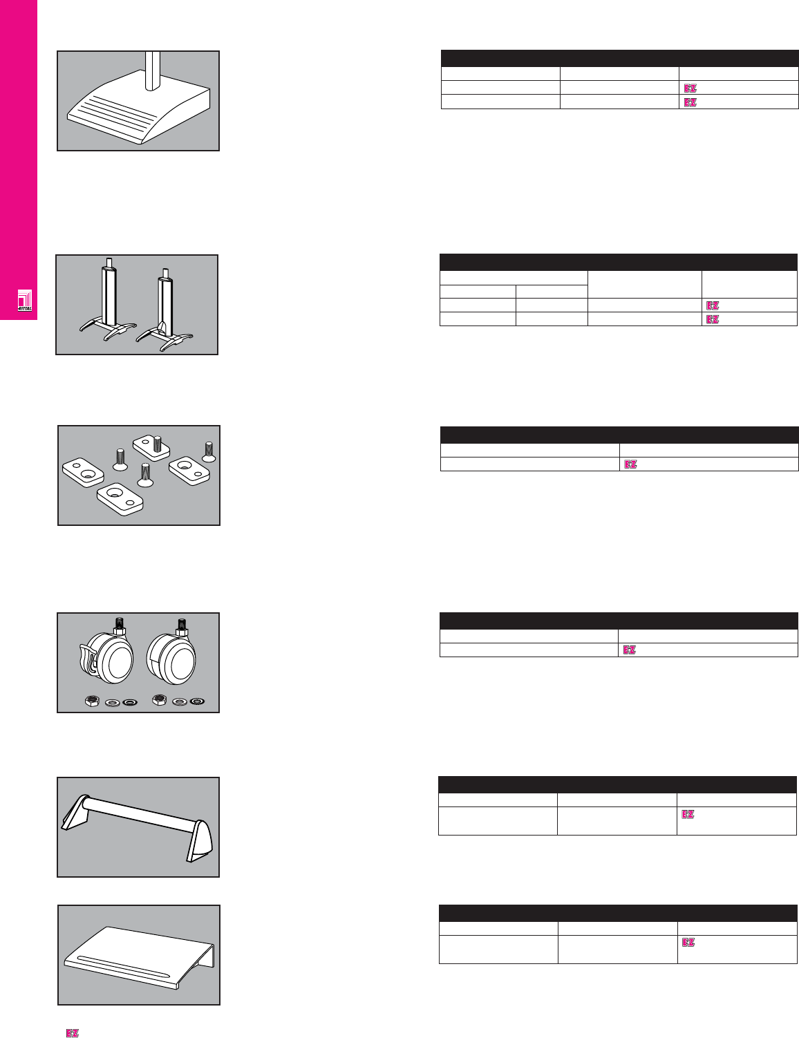
OPERATOR INTERFACE
IND 173
Pedestal For
Command Panel
Enclosure may be mounted via
•enclosure coupling CP 6525500
(rigid). .
•enclosure coupling CP 6525000
(swivel).
Technical details:
Cast feet with holes for floor
mounting.
Pedestal For Command Panel
Height Cable conduit Part No.
inches mm adaptor
39.37 1000 without 6141000
39.37 1000 with 6141100
Support tubes:
•oval, twin-walled cover, easily
opened from the outside. Cables
may then be routed behind the
cover for protection.
Base Mount For Pedestal
For CP 6141 Enclosure
For secure mounting at the
installation site.
•bracket is mounted to the pedestal
with four countersunk screws in the
existing threaded holes (M 12).
•bracket is mounted to the floor via
through-holes (Ø11 mm), depend-
ing on the construction of the floor,
with commercially available screws
and dowels.
Base Mount For Pedestal
Packs of Part No.
1 set 6147000
Configuration: 4 base mounting
brackets, 4 countersunk screws,
M 12.
Pedestal/Platform
Provides a fixed, mobile pedestal
mounting solution.
Standard configuration includes:
•knockouts for PG strain connector
inserts
•integrated cable collecting angle
•knockout for concealed mounting
of cable conduit adapters up to PG
36 or M 50.
With the following accessories:
•double wheel casters 7495000
•leveling feet 4612000
Pedestal/Platform
For support arm Color RAL Part No.
CP 6500 7035 6137535
CP 6000 7035 6137035
•wallmounting bracket KL
1580000 or 1590000 the
pedestal can be customized
for any environment.
Material: sheet steel
Finish: powder painted: RAL
7030 stone grey or RAL 7035
light grey textured
Configuration: pedestal/floor
plate with integrated reinforce-
ment and installation cutout for
CP 6000 or CP 6500 support
arms; includes installation
hardware for support arms.
Trim Panel For
CP 6141000/100
May be installed front and rear.
Trim Panel
For pedestal Packs of Part No.
CP 6141000 1 6144100
CP 6141100
Foot Rest For
CP 6141000/100
Packs of 2 connector pieces, 1
round tube.
Foot Rest
For pedestal Packs of Part No.
CP 6141000 1 set 6145100
CP 6141100
Twin Casters For CP
6141000/100 Enclosures
For mobile use, easy installation. For:
•pedestals CP 6141000 and CP
6141100.
•pedestal base plate CP 6137030—
CP 6137535.
Load capacity per castor: 165
lbs/75 kg static load 2 twin casters
with brake.
Overall height: 3.5"/90 mm
2 twin casters without brake
Color: black with grey wheels.
Twin Casters
Packs of Part No.
1 set 6148000
Designates a product in the EnclosureZone program.
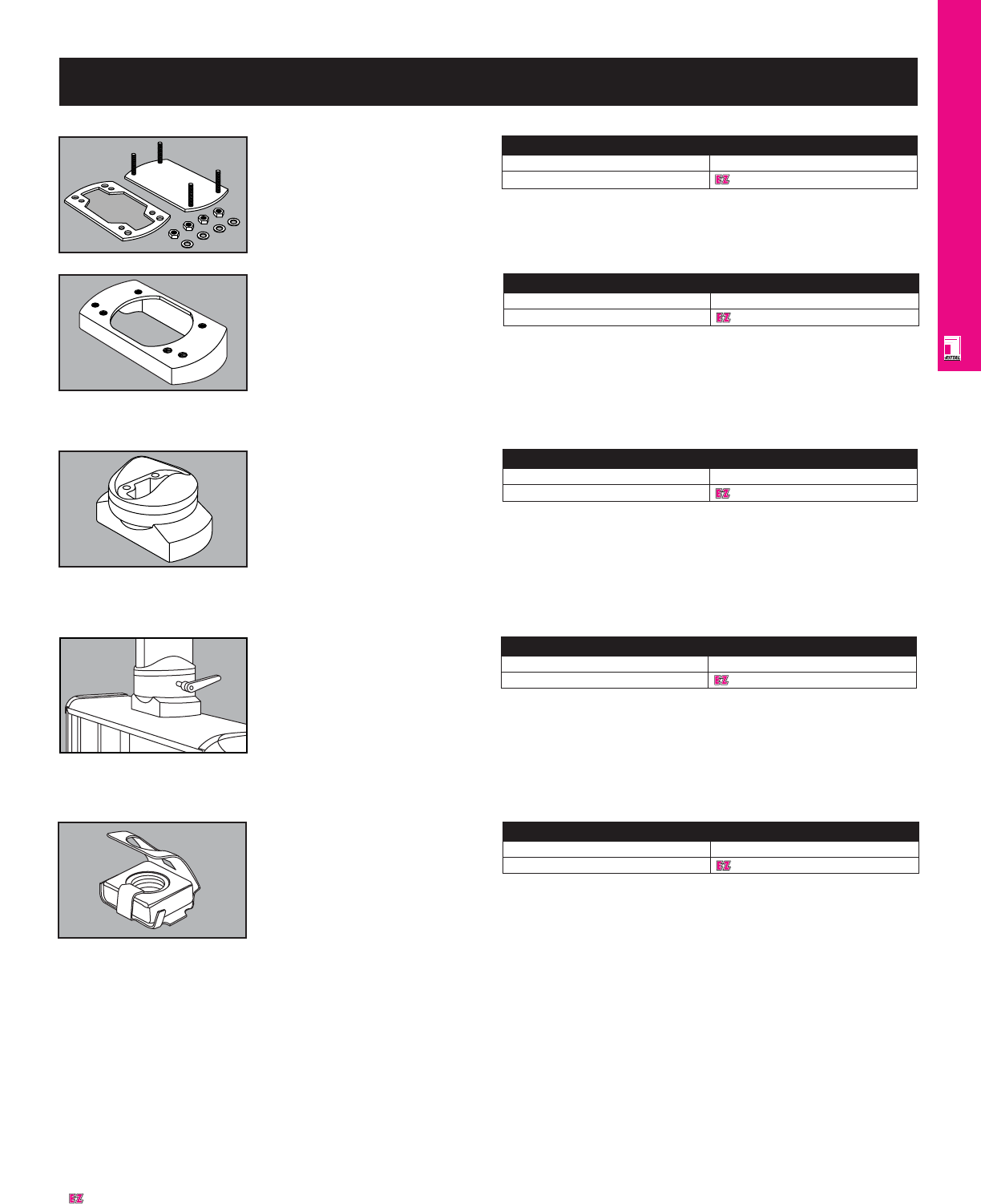
OPERATOR INTERFACE
IND 174
Optipanel Accessories
Cover Plate
To cover an unused support arm
cutout.
Material: sheet steel, clear chromate.
Configuration: cover plate with
gasket, including installation material.
Cover Plate
Support Arm Connection Part No.
CP-L 6505100
10° Tilting Adaptor CP-L
For installation between:
•enclosure coupling CP 6525100 or
•enclosure coupling CP 6525600
and housing.
Configuration: zinc die-cast; includes
gasketing and installation materials.
Not designed as a base for a support
arm system.
Color: RAL 7030 stone grey.
10° Tilting Adaptor
Weight Part No.
1.10 lbs/0.5 kg 6527100
Enclosure Mount
CP-L, Fixed
For fixed installation of enclosure to
support arm CP-L. Can be mounted
to the top or bottom of an enclosure.
Configuration: zinc die-cast;
includes gasketing and installation
materials. Not designed as a base
for a support arm system.
Color: RAL 7030 stone grey.
Enclosure Mount
Weight Part No.
2.20 lbs/1.0 kg 6525600
Designates a product in the EnclosureZone program.
Enclosure Coupling
CP-L, Rotating
Rotating mount of enclosure to CP-L.
Top or bottom mount.
Configuration: zinc die-cast
including gasketing and installation
materials. Approximately 350°
rotation. Not designed as a base for
a support arm.
Color: RAL 7030 stone grey.
Enclosure Coupling
Weight Part No.
2.65 lbs/1.2 kg 6525100
M5 Springnut
For internal installation of
components into Optipanel with
depth of 4 and 6"/100 and 150 mm.
Easy installation, the spring secures
against undesired movement.
Material: steel, galvanized,
chromated.
M5 Springnut
Packs of Part No.
50 6108000
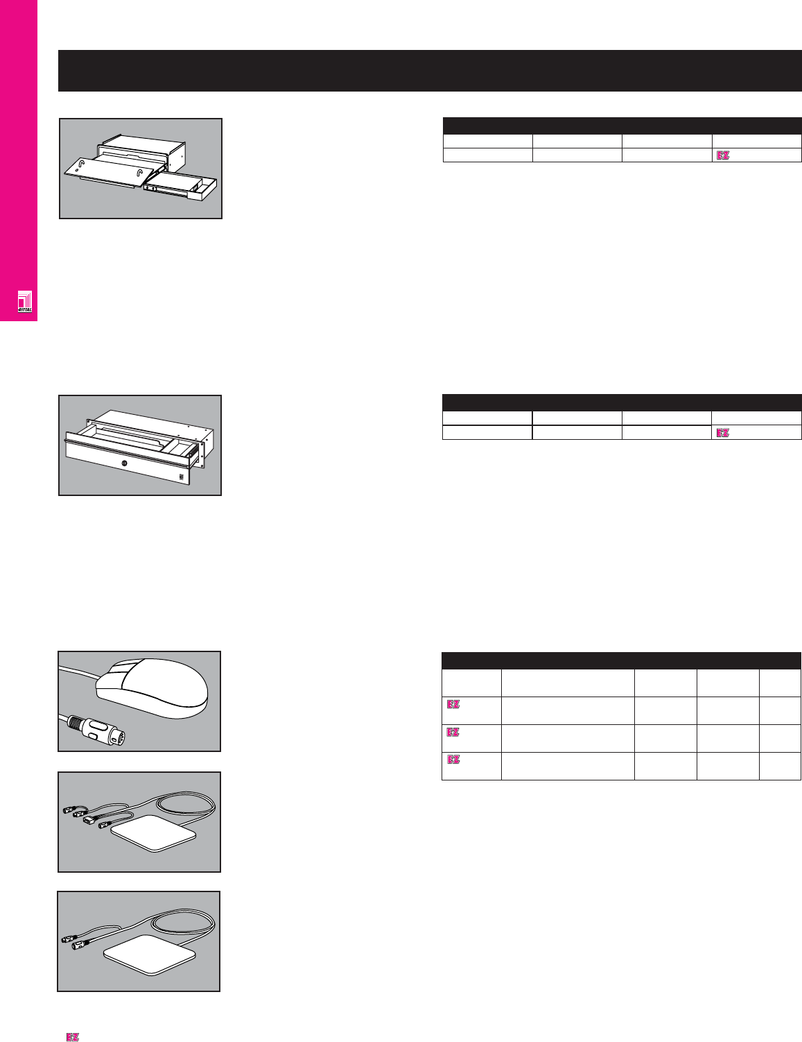
OPERATOR INTERFACE
IND 175
NEMA 6/IP 67 Mouse /Mouse Pad
Part No. Description H x W x D H x W x D Packs of
inches mm
6444000 Inductive mouse pad IP 67 8 x 10 x .6 205 x 250 x 15 1
COM interface
6444500 Inductive mouse pad IP 67 8 x 10 x .6 205 x 250 x 15 1
PS/2 interface
6445000 Mouse IP 67 - - 1
for COM and PS/2 interface
NEMA 6/IP 67
Mouse/Mouse Pad
An ideal input device for all areas
where heavy contamination is
unavoidable, or where high
standards of hygiene are crucial.
Because the mouse detects
positions inductively, there is no
need for a trackball, and the housing
is completely sealed with a protective
film. This achieves a high protection
category of NEMA 6/IP 67.
The mouse operates in conjunction
with the inductive mouse pad IP 67
and is available for connection to
either a COM or a PS/2 interface.
Material:
Mouse pad: plastic PBT
Mouse: plastic ABS
Color:
Mouse pad: similar to RAL 7032 grey
Mouse: similar to RAL 7032 grey
Technical specifications:
NEMA 6/IP 67 mouse
Mouse connector: DIN 7-pole
Mouse pad COM interface
Mouse pad—PC connection:
9-pole D-SUB socket DIN 5-pole
connector
Mouse pad PS/2 interface
Mouse pad -PC connection:
PS/2 connector
Temperature range:
32°F to 131°F/0°C to 55°C
Power consumption: < 20 mA
Pad size (H x W x D):
8" x 10" x .6"/205 x 250 x 15 mm
IP 67/NEMA 4
Cable lengths: 2,000 mm
Runs under DOS, Windows
3.1/3.11, Windows 95/98,
Windows NT
Ratings: NEMA 6/IP 67.
Keyboard Drawer With
Mouse Pad
19" front panel/3.5 U, for
installation in:
•any sufficiently large space
(door, side panel etc.).
The mouse pad is prepared to
accept the inductive mouse pad
NEMA 6/IP 67.
Technical specifications:
•space for keyboards up to
H x W x D = 1.7" x 18.4" x 6.8"
(42 x460 x170 mm)
Mouse pad:
•pulls out at the sides including
mouse storage compartment for
standard pads and prepared for
NEMA 6/IP 67 mouse pad.
Keyboard Drawer With Mouse Pad
Height Width Depth Part No.
3.5 U 482.6 mm 251 mm 6003000
Front panel:
•folds out as a wrist support
•lockable, 3 mm double-bit
insert may be exchanged for
27 mm inserts, version A, lock
cylinder insert with lock no.
3524 E (SZ 2571000).
•even with the drawer open, a
high level of mechanical
protection and shielding
are retained.
Material:
Drawer housing: sheet steel,
painted RAL 7035
Front panel: Aluminum, natural
anodized
Configuration: keyboard
drawer with mouse pad,
including installation hardware
and self-adhesive cable tie
attachment.
General Accessories
Keyboard Drawer 19"/2U
Can be mounted in all 19" systems
or on any sufficiently large surface
(door, side wall, etc.). Its low weight
(5.5 lbs/2.5 kg) makes it ideal for use
in support arm systems because
adequate room remains for cabling,
even when the support arm is
connected from below. It can also be
locked with a 3524 E lock.
High mechanical protection and
shielding is maintained, even when
the drawer is open.
Technical data:
•Total available space:
15.35" x 1.26" x 5.47"/
390 x 32 x 139 mm
19" Keyboard Drawer
Height Width Depth Part No.
2 U 19"/482.6 mm 5.90"/150 mm 6002000
•Drawer has 2.35"/60 mm high
space on right for a mouse or
trackball or for a 3 1/2" disk
drive.
•When a mouse is used or when
a 3 1/2" disk drive is installed,
only enough space remains
for an 11.2"/284 mm wide
keyboard.
Material:
Frame: sheet steel, zinc-plated,
chromated
Drawer housing and drawer:
aluminum
Front panel and handle:
aluminum, natural anodized
Configuration: Drawer housing
with drawer, includes slides with
stops for ‘open’ position, front
panel with handles, gasket and
installation hardware.
R
Designates a product in the EnclosureZone program.
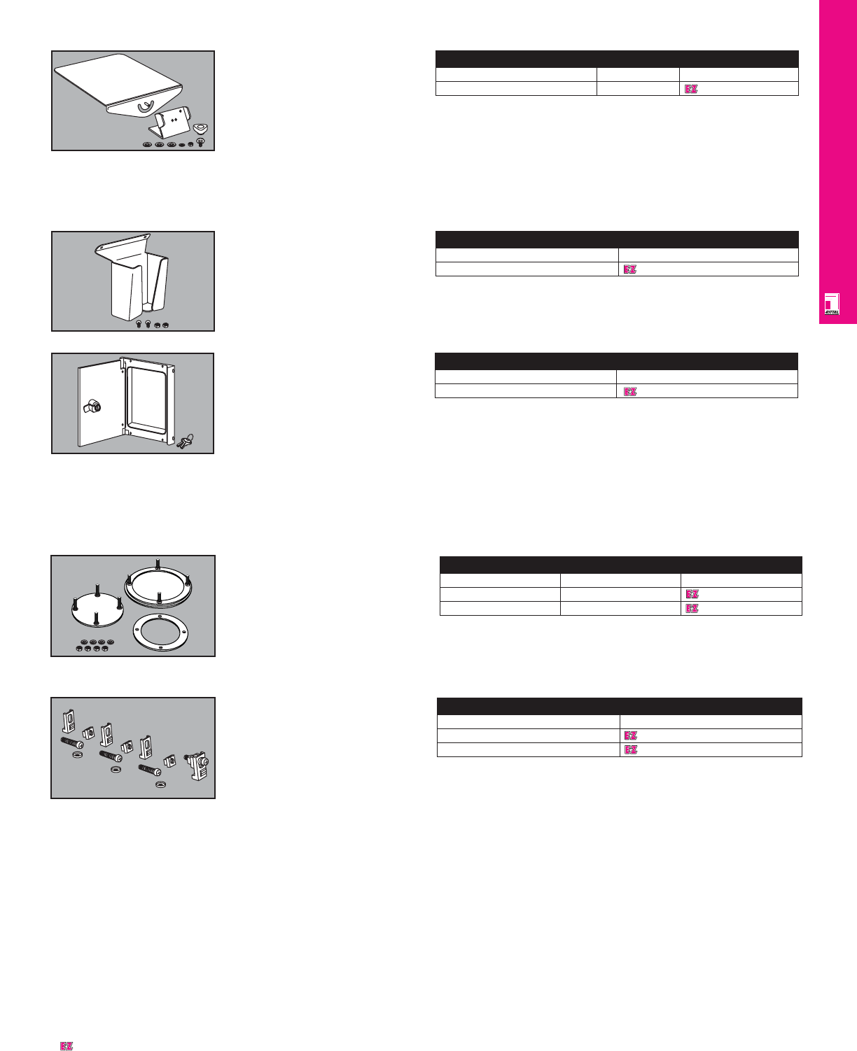
OPERATOR INTERFACE
IND 176
Mouse Pad Tray
Description Packs of
Part No.
Mouse pad tray 1
2381000
Mouse Pad Tray
Is mounted on vertical handles of
keyboard housings for accommodation
of SM 6444000 and SM 6444500 IP 67
mouse pads. The slope of the mouse
pad tray is infinitely adjustable.
Installation requires drilling two
installation holes in the handle grip
brackets.
Material: sheet steel, chromated
Configuration: mouse pad tray,
installation hardware.
Mouse Holder
Fits Rittal mouse pad trays to ensure
safe storage of a standard mouse or
the Rittal SM 6445000 IP 67 mouse.
Material: sheet steel, chromated
Configuration: mouse holder,
installation hardware.
Mouse Holder
Packs of
Part No.
1
2382000
Designates a product in the EnclosureZone program.
Interface Box
The Rittal interface box provides
secure accommodation for all standard
computer ports, disk drives and sockets.
The lockable metal cover provides a
high mechanical load-bearing capacity,
protects against unauthorized access
and ensures an increased shielding
effect for the installed equipment.
Material:
Frame: extruded aluminum section
Mounting tray: sheet steel, 1.5 mm
Cover: aluminum, 3.0 mm
Interface Box
Part No.
No socket 2482000
Surface finish:
Frame and mounting tray: powder
coated in RAL 7035 light grey
Cover: natural anodized
Supply includes: frame with
hinged cover, cam with lock insert
no. 3524 E, mounting tray including
seal and installation hardware.
Mounting Kit
For installation of:
• aluminum front panels
• control panels
• keyboards
in keyboard trays and keyboard
housings.
Packs of 30, including clip-in
clamps, cage nuts, screws, washers.
Mounting Kit
Thread Part No.
M4 6058000
M5 6053000
For installation of control panels
with studs, only clip-in clamps are
needed.
Cover Plate
For secure sealing of an unused
support arm connection in the
enclosure (CP-L, CP-XL).
Material: sheet steel, clear
chromate
Configuration: cover plate with
gasket, including installation
hardware.
Cover Plate
Support arm connection Packs of Part No.
CP 6000 1 6505000
CP 6500 1 6505500
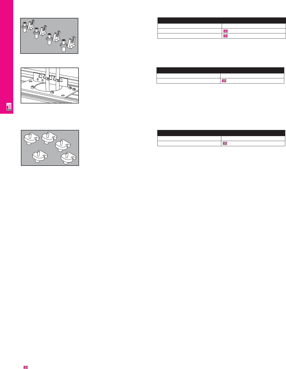
OPERATOR INTERFACE
IND 177
Cable Tie Fastener
For all commercially available cable
ties up to a width of 4.8 mm. The
fastener is inserted into the screw
channel and fixed by hammering
down the split rivet.
Material: polyamide 6.6
Cable Tie Fastener
Packs of Part No.
100 6059000
Mounting Kit For
Threaded Bolts
for fastening
•aluminum front panels
•control panels
•keyboards
to keyboard housings with threaded
bolts.
Mounting Kit
Thread Part No.
M4 6058500
M5 6053500
Cable Clamping Bracket
For Operator Housing
To fit support arm cutout CP-L
and CP-XL. Cable clamping
optionally via:
• cable clamps
• cable ties for quick assembly SZ
2597.000
• commercially available cable ties.
Bracket height = 25 mm with fitted
40 mm C rail.
Cable Clamping Bracket
Part No.
Cable clamping bracket 6052000
Material: sheet steel, zinc plated,
passivated.
Supply includes: 1 cable clamping
bracket, 1 C rail 2 self-tapping
screws M5 x 10 mm.
Designates a product in the EnclosureZone program.
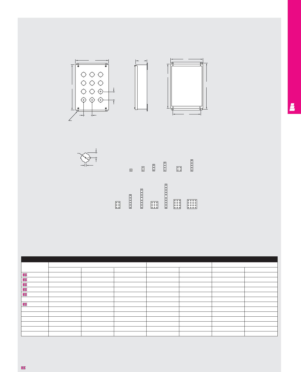
IND 178
OPERATOR INTERFACE
Technical Specifications
Standard Pushbutton Boxes
2.25
Typ.
.31 Dia.
Front View Side View Front View
Cover Removed
Hole Arrangement Centered On Cover
Standard 4-Way Keyed
Pushbutton Hole Detail
KC
J
2.25
Typ.
B
H
W
1.20 .67
.19
E-1PB
E-2PB
E-3PB
E-4PB
E-4SPB
E-5PB
E-6PBVL
E-6PB E-8PB
E-9PB
Standard Pushbutton Box
Part No.
Outside dimensions (inches) Mounting centers Cover size
HW D HW J K
E 1PB 3.50 3.25 2.75 4.00 2.38 3.81 3.56
E 2PB 5.75 3.25 2.75 6.25 2.38 6.06 3.56
E 3PB 8.00 3.25 2.75 8.50 2.38 8.31 3.56
E 4PB 10.25 3.25 2.75 10.75 2.38 10.56 3.56
E 4SPB 7.25 6.25 3.00 7.75 5.38 7.56 6.56
E 5PB 12.50 3.25 2.75 13.00 2.38 12.81 3.56
E 6PB*9.50 6.25 3.00 10.00 5.38 9.81 6.56
E 6PBVL 14.75 3.25 2.75 15.25 2.38 15.06 3.56
E 8PB 20.25 3.25 2.75 20.75 2.38 20.56 3.56
E 9PB*9.50 8.50 3.00 10.00 7.63 9.81 8.81
E 10PB 24.75 3.25 2.75 25.25 2.38 25.06 3.56
E 12PB* 11.75 8.50 3.00 12.25 7.63 12.06 8.81
E 16PB* 11.75 10.75 3.00 12.25 9.88 12.06 11.06
* Can be mounted to a Rittal Electromate column and base.
Designates a product in the EnclosureZone program.
E-10PB
E-12PB
E-16PB
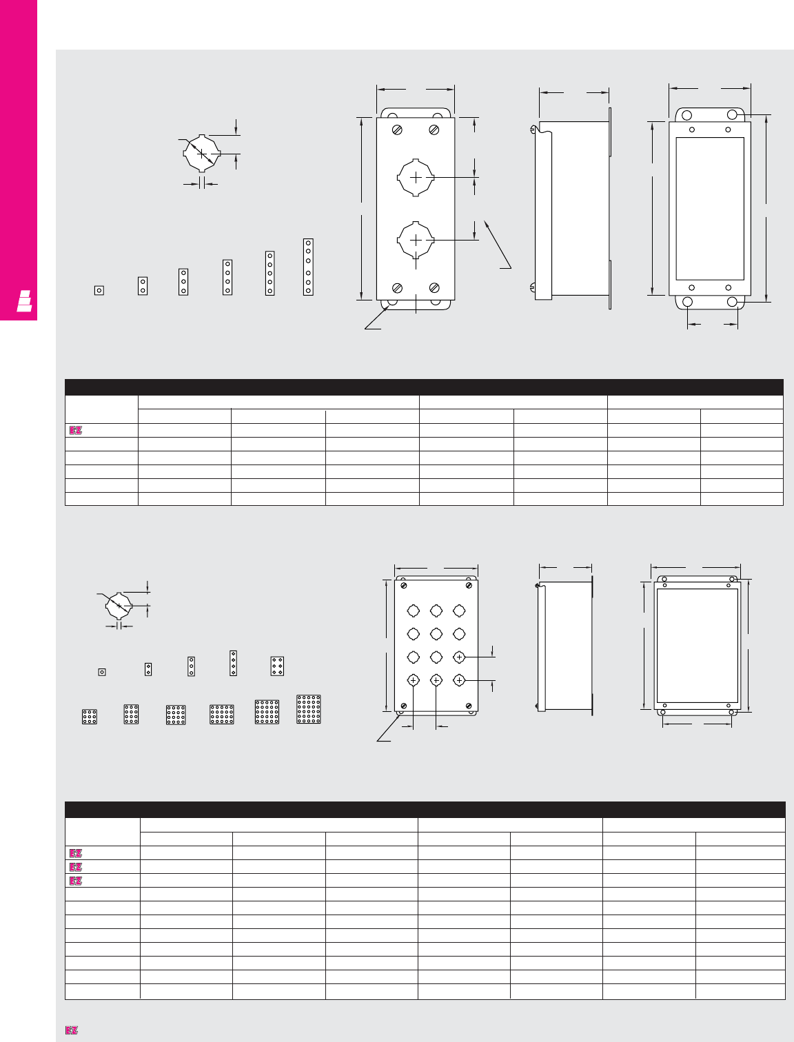
OPERATOR INTERFACE
IND 179
Technical Specifications
Slim Pushbutton Boxes
Front View Side View Front View
Cover Removed
Hole Arrangement Centered On Cover
Standard 4-Way Keyed
Pushbutton Hole Detail
2.25
Typ.
See note
.31 Dia.
1.20 .67
E-1PBSL
E-2PBSL
E-3PBSL
E-4PBSL E-6PBSL
.19
J
2.16
Typ.
K
2.81
C
2.50
B
2.50
H
A
W
1.63
Slim Pushbutton Box
Width
Part No. Outside dimensions (inches) Mounting centers Cover size
HWDHWJK
E 1PBSL 4.00 2.50 2.50 4.50 1.63 4.31 2.81
E 2PBSL 6.25 2.50 2.50 6.75 1.63 6.56 2.81
E 3PBSL 8.50 2.50 2.50 9.00 1.63 8.81 2.81
E 4PBSL 10.75 2.50 2.50 11.25 1.63 11.06 2.81
E 5PBSL 13.00 2.50 2.50 13.50 1.63 13.31 2.81
E 6PBSL*16.25 2.50 2.50 16.75 1.63 16.56 2.81
* Add an additional 1" between pushbutton holes at center of enclosure.
Standard 4-Way
Keyed Pushbutton
Hole Detail
Front View
Cover Assembled Side View Front View
Cover Removed
1.88
Typ.
1.50
Typ.
.31 Dia.
KC
J
B
H
A
W
.68
E-1PBGM E-2PBGM E-3PBGM E-4PBGM E-6PBGM
.48
.13
Miniature Pushbutton Box
Part No. Outside dimensions (inches) Mounting centers Cover size
HWDHWJK
E 1PBGM 3.25 2.75 3.50 3.75 1.88 3.56 3.06
E 2PBGM 5.13 2.75 3.50 5.63 1.88 5.44 3.06
E 3PBGM 7.00 2.75 3.50 7.50 1.88 7.31 3.06
E 4PBGM 8.88 2.75 3.50 9.38 1.88 9.19 3.06
E 6PBGM* 8.50 5.00 4.25 9.00 4.13 8.81 5.31
E 9PBGM* 8.50 6.50 4.25 9.00 5.63 8.81 6.81
E 12PBGM* 10.38 6.50 4.25 10.88 5.63 10.69 6.81
E 16PBGM* 10.38 8.00 4.25 10.88 7.13 10.69 8.31
E 20PBGM* 12.25 8.00 4.25 12.75 7.13 12.56 8.31
E 25PBGM* 12.25 9.50 4.25 12.75 8.63 12.56 9.81
E 30PBGM* 14.13 9.50 4.25 14.63 8.63 14.44 9.81
* Can be mounted to a Rittal Electromate column and base.
Hole Arrangement Centered On Cover
Miniature Pushbutton Boxes
Designates a product in the EnclosureZone program.
E-5PBSL
E-9PBGM
E-12PBGM
E-16PBGM
E-20PBGM
E-25PBGM
E-30PBGM
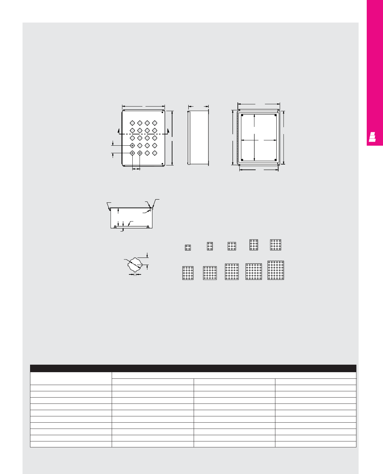
OPERATOR INTERFACE
IND 180
Technical Specifications
Extra Large Pushbutton Boxes
Extra Large Pushbutton Box
Part No. Outside dimensions (inches)
HWD
E 4SPBY25 8.50 7.50 6.00
E 6PBY25 11.00 7.50 6.00
E 9PBY25 11.00 10.00 6.00
E 12PBY25 13.50 10.00 6.00
E 16PBY25 13.50 12.50 6.00
E 20PBY25 16.00 12.50 6.00
E 25PBY25 16.00 15.00 6.00
E 30PBY25 18.50 15.00 6.00
E 36PBY25 18.50 17.50 6.00
E 42PBY25 21.00 17.50 6.00
K
X
2.50 TYP
2.50 TYP
X
J
Front View
C
6.00 B
Side View
A
E
D
H
W
Front View
Cover Removed
Hinge Captive
screw Gasket
Blind
rivnut
5.47 Panel
.63
.67
1.20
.19
Section X-X
Standard 4-way
Keyed Pushbutton
Hole Detail Hole Arrangement
Centered On Cover
E-4SPBY25 E-6BY25 E-9PBY25 E-12PBY25 E-16PBY25
E-20PBY25 E-25PBY25 E-30PBY25 E-36PBY25 E-42PBY25
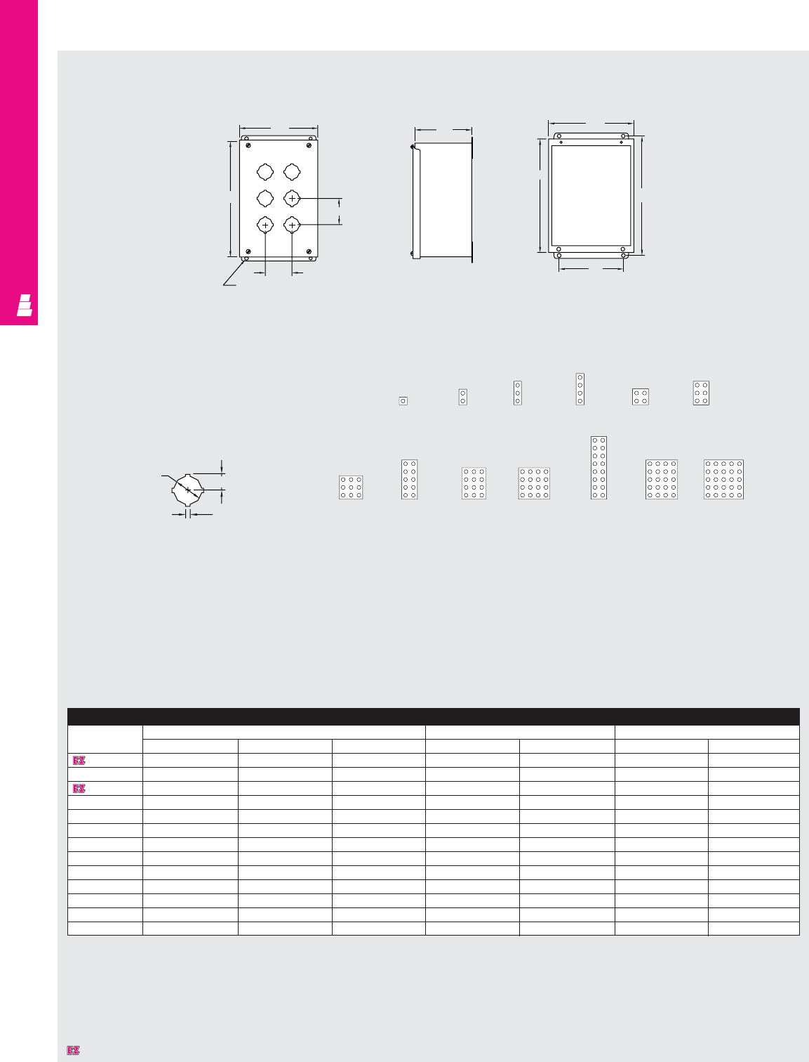
OPERATOR INTERFACE
IND 181
Technical Specifications
Extra Deep Pushbutton Boxes
2.25
Typ.
Standard 4-Way Keyed
Pushbutton Hole Detail
Front View
Cover Assembled Side View Front View
Cover Removed
2.25 Typ.
KB
1.20 .67
.19
A
H
W
C
4.75
J
.31 Dia.
Extra Deep Pushbutton Box
Part No. Outside dimensions (inches) Mounting centers Cover size
HWDHWJK
E 1PBXD 4.00 4.00 4.75 4.50 3.13 4.31 4.31
E 2PBXD 6.00 4.00 4.75 6.50 3.13 6.31 4.31
E 3PBXD 8.00 4.00 4.75 8.50 3.13 6.31 4.31
E 4PBXD 10.00 4.00 4.75 10.50 3.13 10.31 4.31
E 4SPBXD*7.25 6.25 4.75 7.75 5.38 7.56 6.56
E 6PBXD*9.50 6.25 4.75 10.00 5.38 9.81 6.56
E 9PBXD*9.50 8.50 4.75 10.00 7.63 9.81 8.81
E 10PBXD*14.00 6.25 4.75 14.50 5.38 14.31 6.56
E 12PBXD*11.75 8.50 4.75 12.25 7.63 12.06 8.81
E 16PBXD*11.75 10.75 4.75 12.25 9.88 12.06 11.06
E 16SPBXD*20.75 6.25 4.75 21.25 5.38 21.06 6.56
E 20PBXD*14.00 10.75 4.75 14.50 9.88 14.31 11.06
E 25PBXD*14.00 13.00 4.75 14.50 12.13 14.31 13.31
* Can be mounted to Rittal Electromate column and base.
Hole Arrangement Centered On Cover
E-1PBXD E-2PBXD E-3PBXD E-4PBXD E-4SPBXD
E-25PBXD
E-20PBXD
E-16PBXD E-16SPBXD
E-12PBXD
E-10PBXD
E-9PBXD
E-6PBXD
Designates a product in the EnclosureZone program.
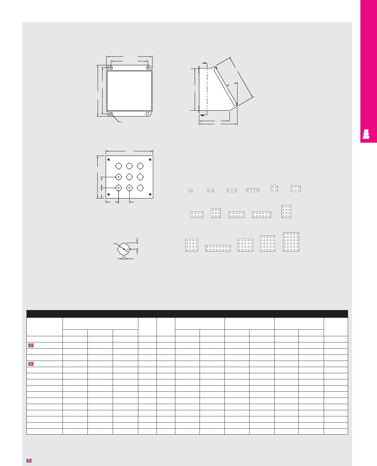
OPERATOR INTERFACE
IND 182
Technical Specifications
Sloping Front Pushbutton Boxes
.31 Dia.
Section X-X Side View
Cover Detail
Standard 4-Way Keyed
Pushbutton Hole Detail Hole Arrangement
BX
D
A
30°
X
W
E
H
C
2.25
2.25
.67
.19
1.20
N
J
C
M
F
Sloping Front Pushbutton Box
Part No. Outside dimensions (inches) Height of Overall Mounting Cover size Hole Usable
base height centers location depth
HWDDEHWF GMNJ
E 1PBA 3.50 3.25 4.88 3.53 4.53 4.03 2.38 3.81 3.56 1.78 1.91 3.38
E 2PBA 3.50 5.50 4.88 3.53 4.53 4.03 4.63 3.81 5.81 1.78 1.91 3.38
E 3PBA 3.50 7.75 4.88 3.53 4.53 4.03 6.88 3.81 8.06 1.78 1.91 3.38
E 4PBA 3.50 10.00 4.88 3.53 4.53 4.03 9.13 3.81 10.31 1.78 1.91 3.38
E 4SPBA 7.25 6.25 6.75 6.78 7.78 7.28 5.38 7.56 6.56 2.16 2.66 5.25
E 6PBA 7.25 8.50 6.75 6.78 7.78 7.28 7.63 7.56 8.81 2.16 2.66 5.25
E 8PBA 7.25 10.75 6.75 6.78 7.78 7.28 9.88 7.56 11.06 2.16 2.66 5.25
E 9PBA 9.50 8.50 7.88 8.75 9.75 9.25 7.63 9.81 8.81 2.16 2.66 6.38
E 10PBA 7.25 13.00 6.75 6.78 7.78 7.28 12.13 7.56 13.31 2.16 2.66 5.25
E 12PBA 7.25 15.25 6.75 6.78 7.78 7.28 14.38 7.56 15.56 2.16 2.66 5.25
E 12SPBA 11.75 8.50 9.00 10.69 11.69 11.19 7.63 12.06 8.81 2.16 2.66 7.50
E 16PBA 11.75 10.75 9.00 10.69 11.69 11.19 9.88 12.06 11.06 2.16 2.66 7.50
E 16SPBA 7.25 19.75 6.75 6.78 7.78 7.28 18.88 7.56 20.06 2.16 2.66 5.25
E 20PBA 11.75 13.00 9.00 10.69 11.69 11.19 12.13 12.06 13.31 2.16 2.66 7.50
E 25PBA 14.00 13.00 10.13 12.63 13.63 13.13 12.13 14.31 13.31 2.16 2.66 8.63
E 30PBA 14.00 15.25 10.13 12.63 13.63 13.13 14.38 14.31 15.56 2.16 2.66 8.63
Designates a product in the EnclosureZone program.
E-1PBA E-2PBA E-3PBA E-4PBA E-4SPBA E-6PBA
E-12SPBA
E-12PBAE-10PBA
E-9PBA
E-8PBA
E-16SPBA
E-16PBA E-20PBA E-25PBA E-30PBA
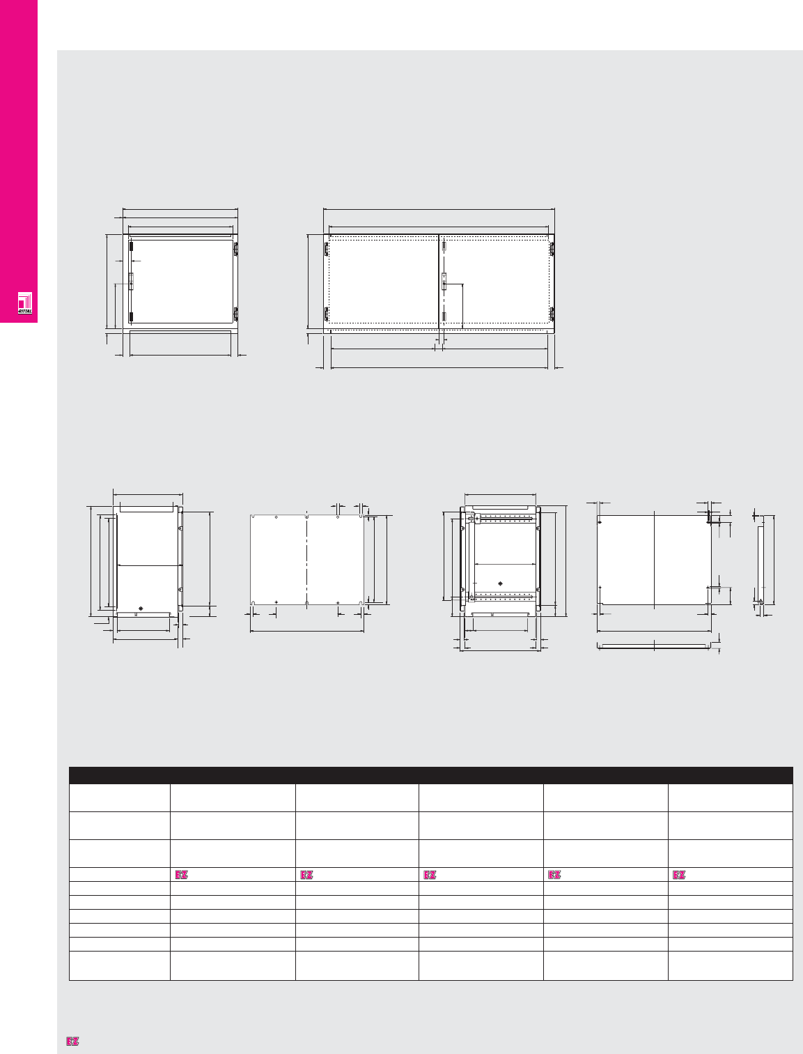
OPERATOR INTERFACE
IND 183
Technical Specifications
AP Desk Consoles, Bottom Section
2600600/2610600
300
33.5 630
50 700
58
1.5 W3
797
W1
50
Mounting panel
19
F1
16.5
101.5
36
19 24
10.2
20.5
532
40.5
10.2
8
16.5
3
70 557
500
30
24
120 532
472
340
50
30
24
max. 395
440
670
300
33.5 630
50 W4
W3
W1
50
50 33
W5 W5
90
F1
70
400
670
600
270
50 30
373
370
557
24
47.5
575
20 90 20
600
10 12.5
575
12.5 12.5
2620600/2640600/2650600
2610600/2640600/2650600
2600600/2620600
Enclosure
Height (H1) (inches) 26.38 26.38 26.38 26.38 26.38
(mm) 670 670 670 670 670
Width (W1) (inches) 31.50 31.50 47.24 47.24 62.99
(mm) 800 800 1200 1200 1600
Depth (D) (inches) 15.75 19.69 15.75 19.69 19.69
(mm) 400 500 400 500 500
Part No. 2600600 2610600 2620600 2640600 2650600
W3 724 724 1124 1124 1524
W4 - - 1100 1100 1500
W5 - - 525 525 725
F1 715 702 1115 1102 1502
No. doors 1 1 2 2 2
Weight lbs 95.7 115.5 137.5 165.2 211.5
kg 43.5 52.5 62.5 75.0 96.0
Designates a product in the EnclosureZone program.
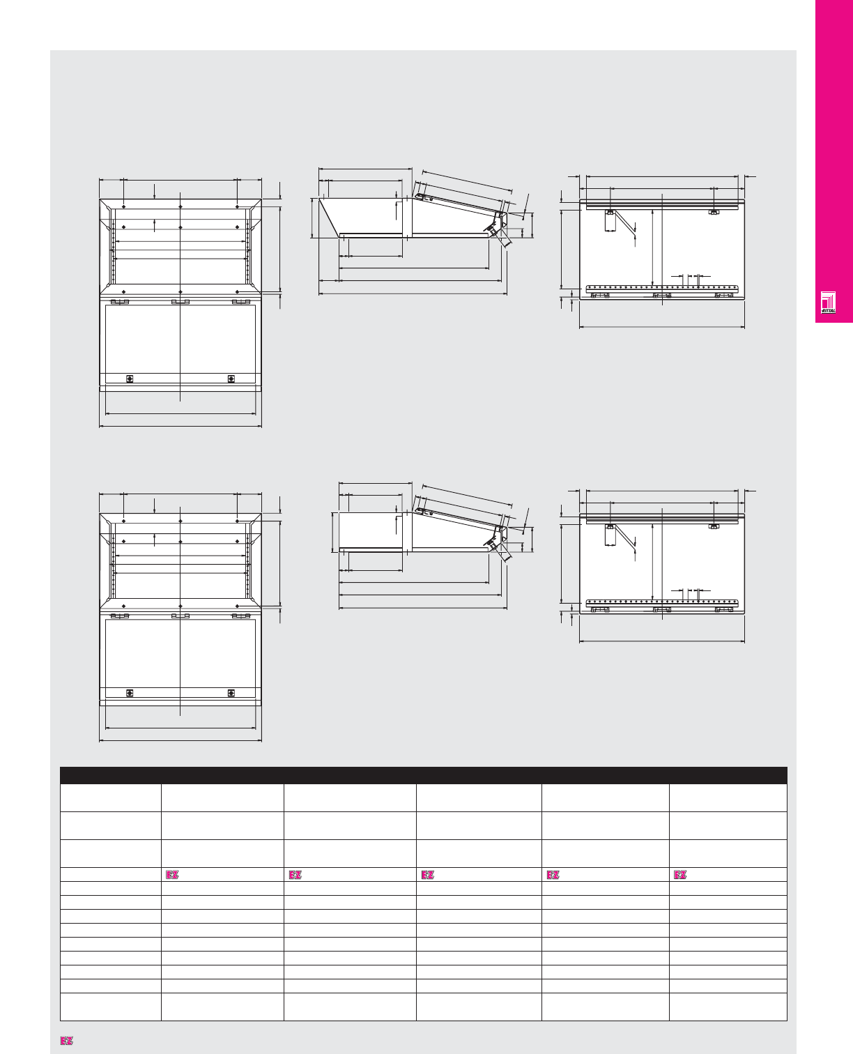
OPERATOR INTERFACE
IND 184
W3
W1
120
W7
W5
W4
10.5 421.5
120
100
W6
38
370
100
50
200
50
12°24'
820
950
270
758.5
19.5
41
46
125
55.5
470
460
393 12.5
148.5
39
13.4
380
32
38
W2
148.5
17
365
25 6.5
50
W9
W8 32
W3
W1
120
W7
W5
W4
10.5 321.5
120
100
W6
38
270
50
200
50
12°24'
820
850
270
758.5
19.5
41
46
125
55.5
370
460
393 12.5
148.5
39
13.4
380
32
38
W2
148.5
17
365
25 6.5
50
W9
W8 32
Technical Specifications
AP Desk Consoles, Center Section
2613200/2643200/2653200 Inside View Of Lid
2611200/2641200 Inside View Of Lid
Enclosure
Height (inches) 7.87 7.87 7.87 7.87 7.87
(mm) 200 200 200 200 200
Width (W1) (inches) 31.50 31.50 47.24 47.24 62.99
(mm) 800 800 1200 1200 1600
Depth (inches) 15.75 19.69 15.75 19.69 19.69
(mm) 400 500 400 500 500
Part No. 2611200 2613200 2641200 2643200 2653200
W2 797 797 1197 1197 1597
W3 742 742 1142 1142 1542
W4 640 640 1040 1040 1440
W5 660 660 1060 1060 1460
W6 560 560 960 960 1360
W7 700 700 1100 1100 1500
W8 733 733 1133 1133 1533
W9 500 500 900 900 2 x 650
Weight lbs 56.1 67.3 78.1 93.7 116.2
kg 25.5 30.6 35.5 42.6 52.8
Designates a product in the EnclosureZone program.
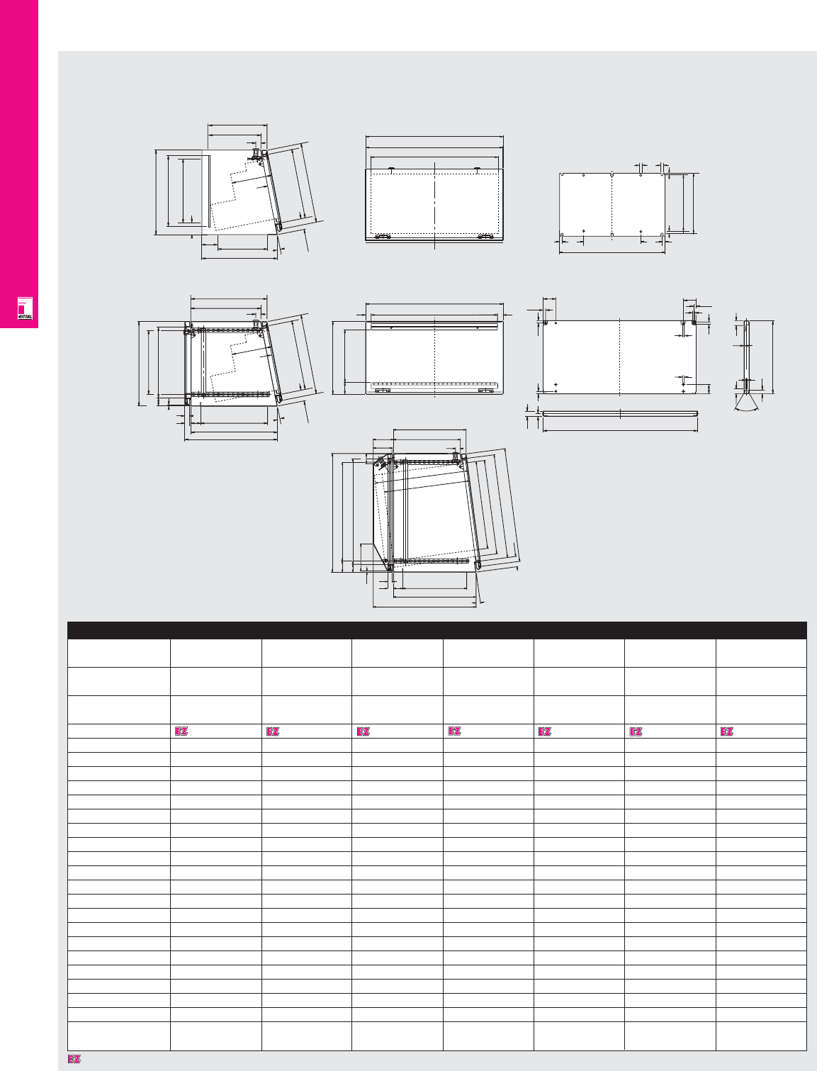
OPERATOR INTERFACE
IND 185
Technical Specifications
AP Desk Consoles, Top Section
146
59.5
42
6.5
24
30
H5
H1
H6
50 440
546
340
106
100 356.5
496*
T
26
387.5
55.5
7°
465*
H9
H7
H8
W4
View in direction X
68
32
H2
H1
32
11.5 11.5
11.5
60
44
9
23
60°
6
19 G1
9
9
11
60 11.5
2.5
23
11.5
23
F1
W2
353.5
359
340
470
440
30 50
6.5
42
430
325
24
11°
X
55.5 407
387.5
356.5
T
26
View in direction X
W2
W3
W1
View in direction X
90 F1
20 90 20
350
10 12.5
325
12.5 12.5
353.5
350
270
370
50
52.5
430
325
11°
X
55.5 407
317.5
286.5
T
26
View in direction X
Mounting panel
2612600/2642600
2614600/2644600
Enclosure
Height (inches) 16.93 16.93 16.93 16.93 24.80 24.80 24.80
(mm) 430 430 430 430 630 630 630
Width (W1) (inches) 31.50 31.50 47.24 47.24 31.50 47.24 62.99
(mm) 800 800 1200 1200 800 1200 1600
Depth (inches) 15.75 19.69 15.75 19.69 23.62 23.62 23.62
(mm) 400 500 400 500 600 600 600
Part No. 2612600 2614600 2642600 2644600 2647600 2648600 2649600
H1 422 422 422 422 622 622 622
H2 304 304 304 304 504 504 504
H3 - - - - 623.5 623.5 623.5
H4 - - - - 548 548 548
H5 - - - - 525 525 525
H6 - - - - 559 559 559
H7 - - - - 607 607 607
H8 - - - - 550 550 550
H9 - - - - 500 500 500
W2 797 797 1197 1197 797 1197 1597
W3 742 742 1142 1142 742 1142 1542
W4 733 733 1133 1133 733 1133 1533
W5 - - - - 732 1132 1532
W6 - - - - 500 900 1300
T rotatable, 3HU300 300 300 300 300 500 500 -
T rotatable, 6HU195 195 195 195 195 395 395 -
T rotatable, max. height 110 110 110 110 310 310 310
T fixed, max. height 300 430 300 430 455 455 455
F1 715 727 1115 1127 727 1127 1527
G1 - 348 - 348 548 548 548
Weight lbs 49.5 67.3 88.0 105.6 105.1 141.68 190.9
kg 22.5 30.6 40.0 48.0 47.8 64.4 86.8
2647600/2648600/2649600
Designates a product in the EnclosureZone program.
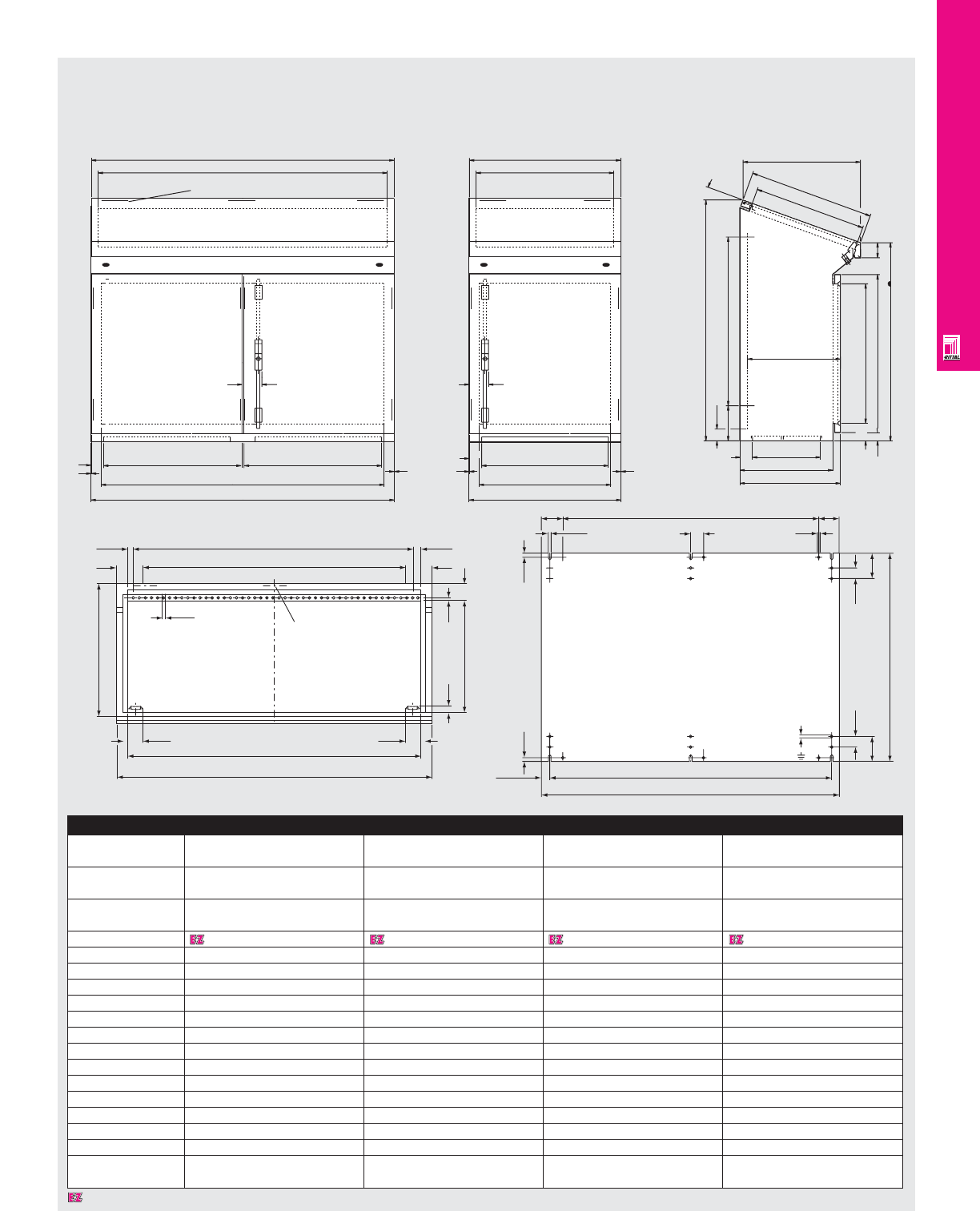
OPERATOR INTERFACE
IND 186
Technical Specifications
AP Desk Console Systems
1.5
50
72
W1
W4
W5
W2
W3
140 675
1.5
47
960
20∞
70 557
370
400
358-368
50 270
33 630
790
447
498
480
60
1.5
50
W1
W4
W6 W5
47
W7
W2
W3
1.5
2670600/2672600 2666600/2668600 2666600/2668600/
2670600/2672600
Enclosure
Height (inches) 37.80 37.80 37.80 37.80
(mm) 960 960 960 960
Width (W1) (inches) 23.62 31.50 39.37 47.24
(mm) 600 800 1000 1200
Depth (inches) 15.75/18.90 15.75/18.90 15.75/18.90 15.75/18.90
(mm) 400/480 400/480 400/480 400/480
Part No. 2666600 2668600 2670600 2672600
W2 597 797 997 1197
W3 544 744 944 1144
W4 524 724 924 1124
W5 500 700 900 1100
W6 - - 495 595
W7 - - 497 597
W8 500 700 900 1100
W9 398 598 798 998
W10 535 735 935 1135
W11 597 797 997 1197
F1 530 730 930 1130
F2 475 675 875 1075
No. doors 1 1 2 2
Weight lbs 113.3 137.5 174.9 198.0
kg 51.5 62.5 79.5 90.0
16.5
6.5
99.5
498
52.5
B10
B11
52.5
20
420
8
61
99.5
16.5
B8
B9
Np hinge for AP
2666600/
AP 2668600
12.5
11
78.5 F3
51
12.5
27.5 F2
F1
11
40
52.5
780
40
52.5
11
78.5
Not for AP 2670600
Designates a product in the EnclosureZone program.
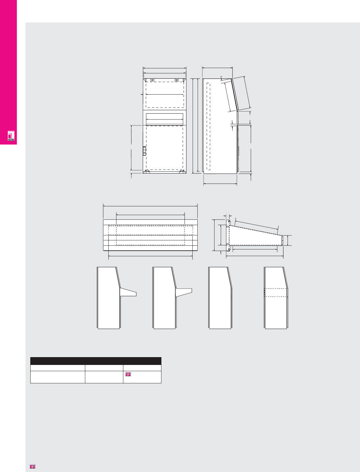
OPERATOR INTERFACE
IND 187
Technical Specifications
AP Universal Console Systems
2694600
36.5
i. L. 532
i. L. 432
592
20
122
195
i. L. 271.5
360
58
i. L. 274.5
515
512
42.5
42.5
173.5
440
11
417.5
365
1273.5
1300
502 25.5
635
592
600
604.5
44.3
28
Desk Unit
AP 2694 + 2696 AP 2694 + 2696 AP 2694 + MC 4702 AP 2694 + MC 4757
Console
Dimensions H x W x D Version Part No.
51.18" x 23.62" x 19.69" Top lid, 2694600
1300 x 600 x 500 mm shorted front door
Designates a product in the EnclosureZone program.
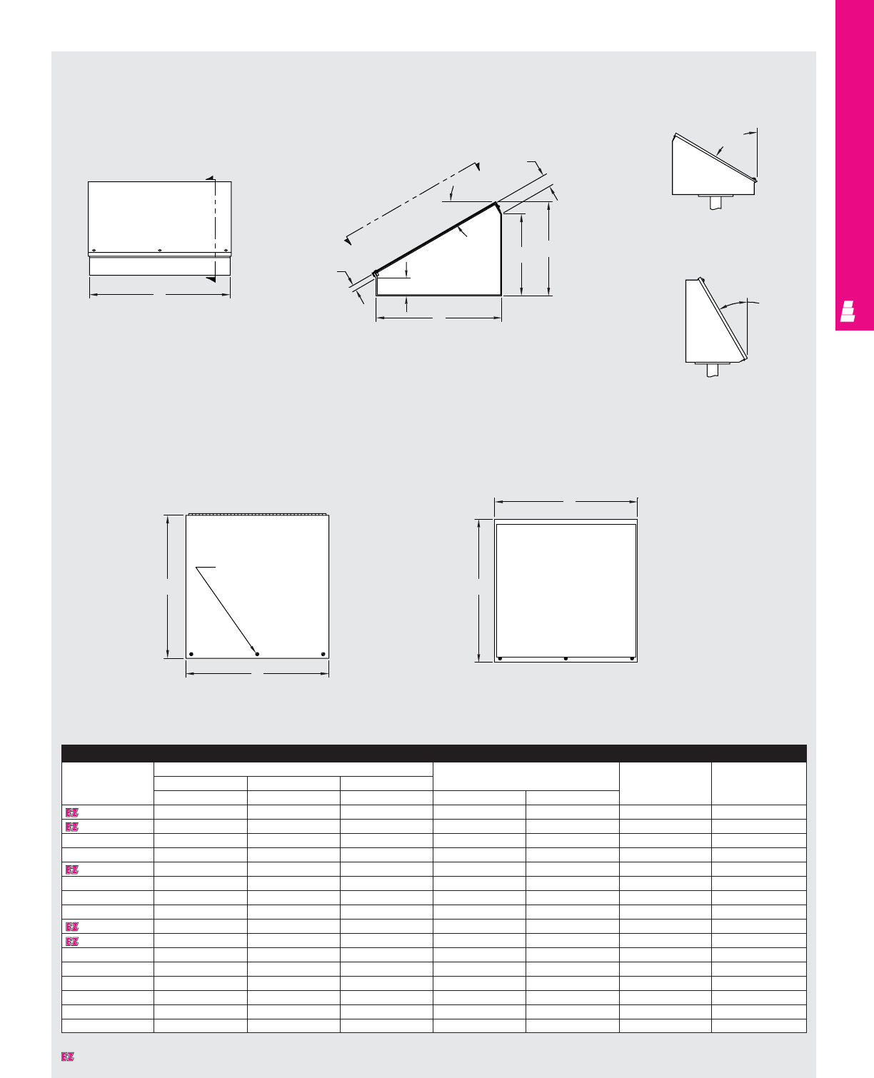
OPERATOR INTERFACE
IND 188
Technical Specifications
Consoles, Pedestals and Bases
Front View
View A-A View A-A
(with cover removed)
Section Y-Y
Section Y-Y
Console can be
positioned at either 60°
or 30° angle
Y
Y
B
1.75
30°
NC
2.50
60°
30°
M
Omit if E is
less than
30.00
E
D
B
A
.75
A
A
Consoles
Part No. Outside dimensions (inches) Cover size
HWD
ABCDEMN
E 8C8 8.00 8.00 7.09 8.31 8.31 7.44 5.63
E 8C12 8.00 12.00 7.09 8.31 12.31 7.44 5.63
E 8C16 8.00 16.00 7.09 8.31 16.31 7.44 5.63
E 8C20 8.00 20.00 7.09 8.31 16.31 7.44 5.63
E 12C12 12.00 12.00 9.09 12.31 12.31 10.91 7.63
E 12C16 12.00 16.00 9.09 12.31 16.31 10.91 7.63
E 12C20 12.00 20.00 9.09 12.31 24.31 10.91 7.63
E 12C24 12.00 24.00 9.09 12.31 24.31 10.91 7.63
E 16C16 16.00 16.00 11.09 16.31 16.31 14.38 9.63
E 16C20 16.00 20.00 11.09 16.31 70.31 14.38 9.63
E 16C24 16.00 24.00 11.09 16.31 24.31 14.38 9.63
E 16C30 16.00 30.00 11.09 8.31 16.31 7.44 5.63
E 16C36 16.00 36.00 11.09 16.31 36.31 14.38 9.63
E 20C20 20.00 20.00 13.09 20.31 20.31 17.84 11.63
E 20C24 20.00 24.00 13.09 20.31 24.31 17.84 11.63
E 20C30 20.00 30.00 13.09 20.31 30.31 17.84 11.63
Designates a product in the EnclosureZone program.
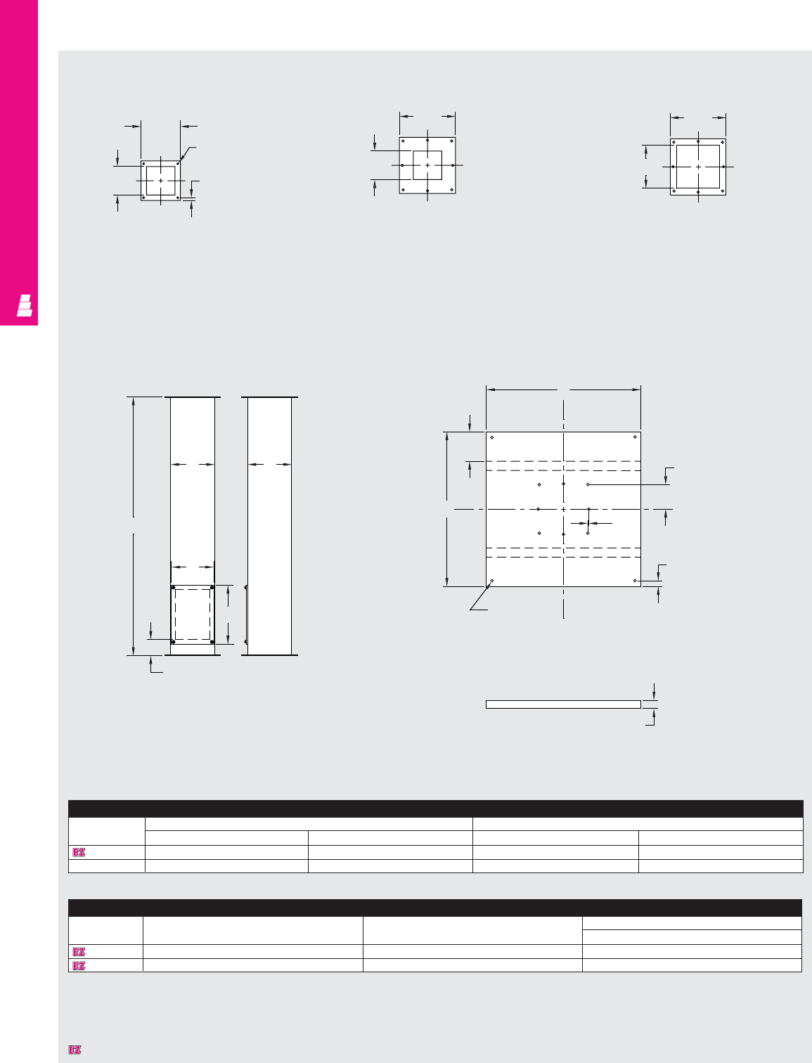
OPERATOR INTERFACE
IND 189
Technical Specifications
Consoles, Pedestals and Bases
4x4 Top
Column Flange 4x4 Bottom
Column Flange
See Base For Hole Locations
6x6 Bottom
Column Flange
See Base For Hole Locations
Column
Base Top View
Base End View
5.38
BA
B
C
A
3.31 Typ. 8
places
.13
Typ.
.75 Typ. 8
places
.31 Dia.
Typ. 12
places
1.13
F
E
35.00
2.13
7.63
3.88
7.63
5.88
.31 Dia. typ.
4 places
.75 Typ. 8
places
3.88
Pedestal
Part No. Outside dimensions (inches) Cover plate
AB EF
E 44CCOL 4.00 4.00 7.00 3.75
E 66CCOL 6.00 6.00 7.75 5.75
Base
Part No. Stiffener location
ABE
E 18SBASE 18.00 18.00 3.00
E 24SBASE 24.00 24.00 5.00
Designates a product in the EnclosureZone program.
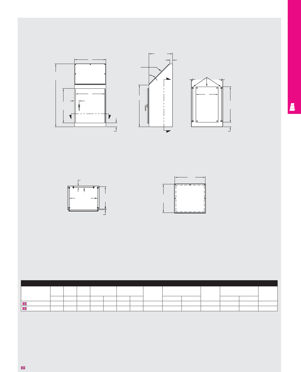
OPERATOR INTERFACE
IND 190
Technical Specifications
Series 9 Operator Enclosures
B
Front View Side View Section X-X
Section Y-Y Control Panel Detail
C
(18.00)
Removable
subpanels
(optional)
K
J
(27.00)
3.50
1.13
L
(17.00)
.50
Removable
subpanels
(optional)
2.00
45°
32.00
X
X
Control
panel
A
(48.00)
D
(26.25)
2.53
E
Y
Y
2.88
G
F
(22.63)
Console
Part No. HW D Door size Control Rear Rear mounting Side Side mounting Caster kit
panel panel mounting panel size mounting panel size
ABCDEFGpanel J F J L
E C924B 48.00 24.00 18.00 26.25 22.38 23.19 23.19 E 30P20 27.00 17.00 E 30P20 27.00 17.00 E C10C
E C936B 48.00 36.00 18.00 26.25 34.38 22.63 35.19 E 30P30 27.00 27.00 E 30P20 27.00 17.00 E C10C
Designates a product in the EnclosureZone program.
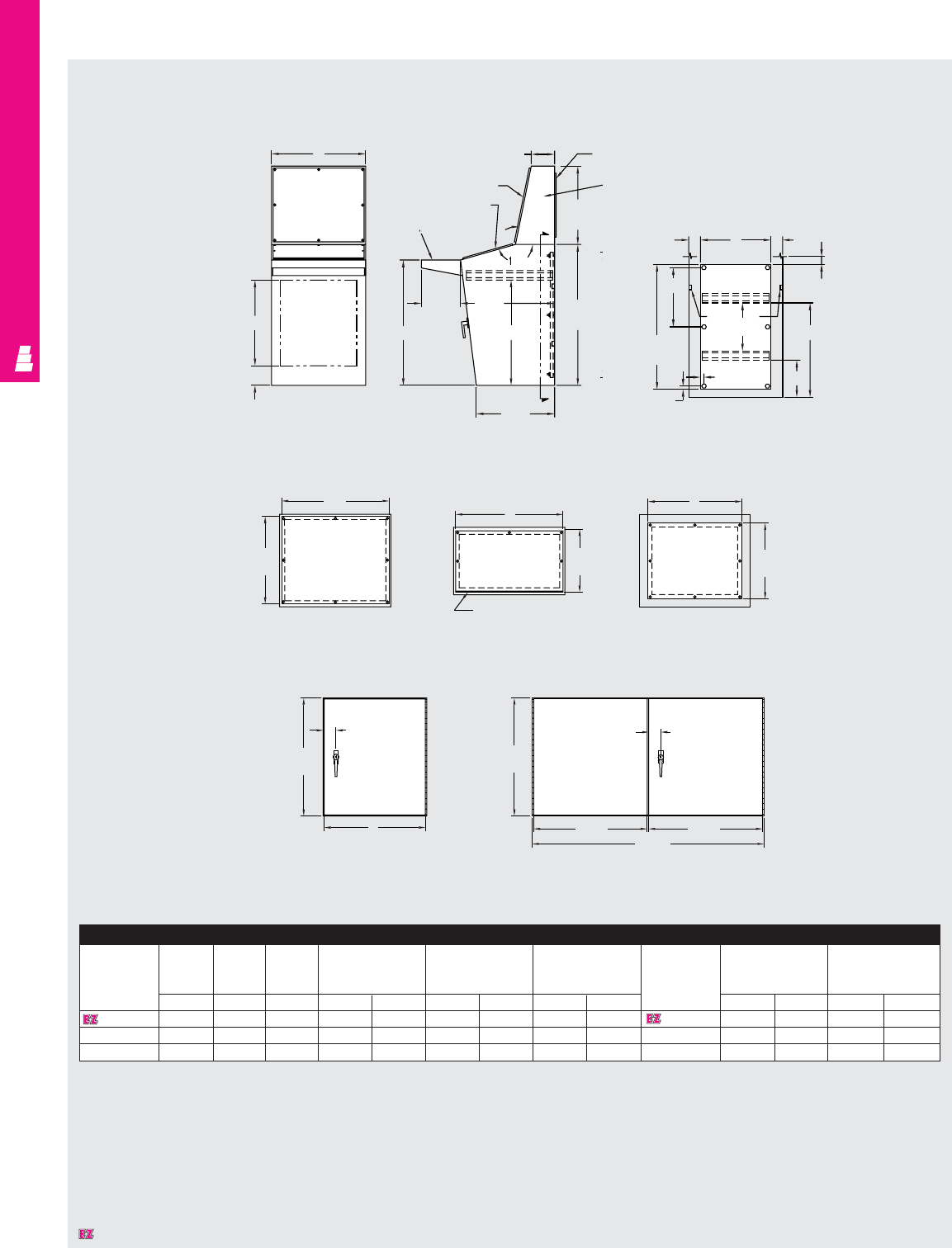
OPERATOR INTERFACE
IND 191
Technical Specifications
Series 12 Operator Enclosures
21.88
5.00
Front View Side View Section X-X
Single Door
Detail A
Control Panel
Instrument Panel Access Panel
Double Door
Detail B
C
See detail
for doors
6.00 Access
panel
Console
top
B
(20.00)
Instrument
panel
Control panel
A
(36.00)
20.00
3.00 3.00
K
2.00
24.13
9.500.88
J
(32.00)
0.88
15.13
L
(19.18)
GP
2.06
D
(21.88)
E
D
(21.88)
2.13
E
(21.31) E
(21.31)
N
(16.31)
F
(13.03)
Continuous hinge
Body
stiffeners
32.00
10.00
24.00
26.91
Writing desk
M
Console
Body Body Top
Width Door size
Control panel
Rear mounting Top Instrument panel Access panel
Part height height panel size Part
No. No.
ABCDEFGJK LMNP
E C12B 36.00 20.00 36.00 21.88 31.94 13.03 35.19 32.00 30.00 E C12T 19.19 35.19 20.19 32.19
E C1224B 36.00 20.00 24.00 21.88 18.94 13.03 23.19 32.00 18.00 E C1224T 19.19 23.19 20.19 20.19
E C1248BD 36.00 20.00 48.00 21.88 21.31 13.03 47.19 32.00 42.00 E C1248T 19.19 47.19 20.19 44.19
164°
43.38
Designates a product in the EnclosureZone program.
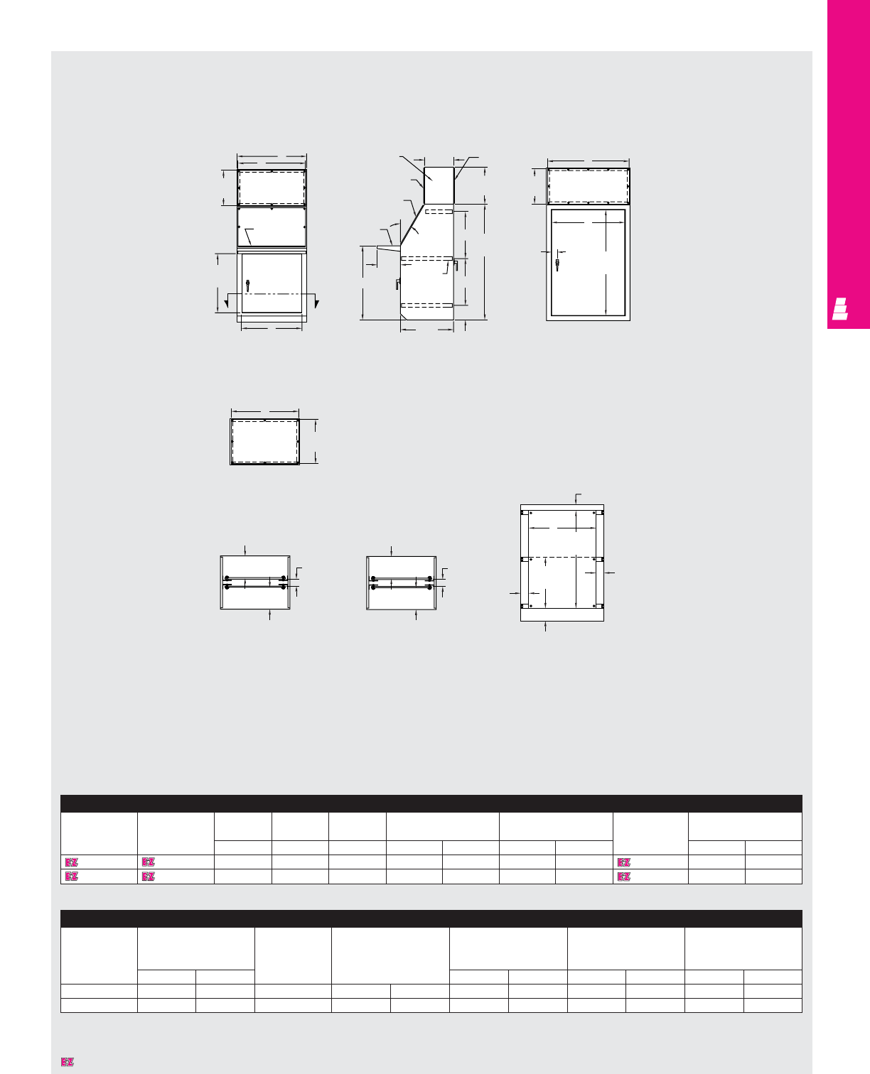
OPERATOR INTERFACE
IND 192
Technical Specifications
Series 14 Operator Enclosures
C
N
M
(15.19)
Front View Side View Back View
Control Panel
Section X-X
(Half Panels Installed)
Panel and panel
mounting hardware
shown are optional
Section X-X
(Half Panels Installed)
Panel and panel
mounting hardware
shown are optional
Section View Showing
Half And Full Panels
D
(25.25)
E
G
Console
top
Rear
access
panel
12.50
B
(16.00)
R
P
(15.19)
1.88 Min. 2.88 Min. 1.88 Min.
2.38
KL
(42.25)
3.50
J
(22.00)
5.38
3.50
2.88 Min.
12.88 Min.
1.88 Min.
S
(45.75)
2.06
Instrument
panel
Control panel
see detail
Writing desk
10.00
32.00 Channel
23.00
20.25
20.25
6.25
A
(50.00)
(19.13)
X
X
Continuous
hinge
Console
Body Top Body Top Width Front Control
Half Mounting
Half mounting
Part No. Part No. height height door size panel size Panel panel size
ABCDEFGPart No. JK
E C14B E C14T 50.00 16.00 24.00 25.25 19.59 19.13 23.19 E C14P2 22.00 17.00
E C1436B E C1436T 50.00 16.00 36.00 25.25 31.59 19.13 35.19 E C1436P2 22.00 29.00
Console (Continued)
Full Full Swingout Swingout Instrument Access Full
Mounting mounting Mounting mounting panel panel rear
Panel panel size Panel panel size size size door size
Part No. LKPart No. MNP R S T
E C14P3 42.50 17.00 E C14P1 22.00 18.13 15.19 23.19 15.19 23.19 45.75 19.59
E C1436P3 42.50 29.00 E C1436P1 22.00 30.13 15.19 35.19 15.19 35.19 45.75 31.59
Designates a product in the EnclosureZone program.
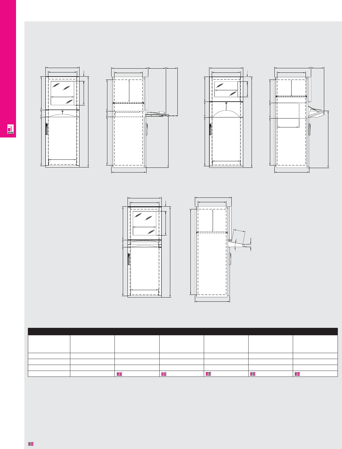
OPERATOR INTERFACE
IND 193
Technical Specifications
PC Computer Enclosures
i.L. = available space
HU = available installation height (1HU = 1.75")
1604
863
492
82
591
125
410
425
599
i. L. 512
854
939
620 (820)
i. L. 502 (702)
647 (847)
558
100
205318
1001
620 (820)
231647 (847)
i. L. 502 (702)
385 (585)
408
275829
1604
863
492
i. L. 512
441
82
599
275
410
275
i. L. 1512
620
204
45
11°
647
i. L. 502
82
1604
492
863
410
591
425
125
i. L. 512
599
Enclosure
Front installation Packs of With keyboard With keyboard With console With keyboard With keyboard
drawer (including shelf drawer (including shelf
keyboard bracket) keyboard bracket)
H (inches/mm) – 62.99"/1600 mm 62.99"/1600 mm 62.99"/1600 mm 62.99"/1600 mm 62.99"/1600 mm
W (inches/mm) – 23.62"/600 mm 23.62"/600 mm 23.62"/600 mm 23.62"/600 mm 23.62"/600 mm
D (inches/mm) – 25.59"/650 mm 25.59"/650 mm 35.83"/910 mm 33.46"/850 mm 33.46"/850 mm
Part No. 14603703 4603920 4603704 4609703 4609920
With Keyboard Drawer With Keyboard Shelf
With Console
Designates a product in the EnclosureZone program.
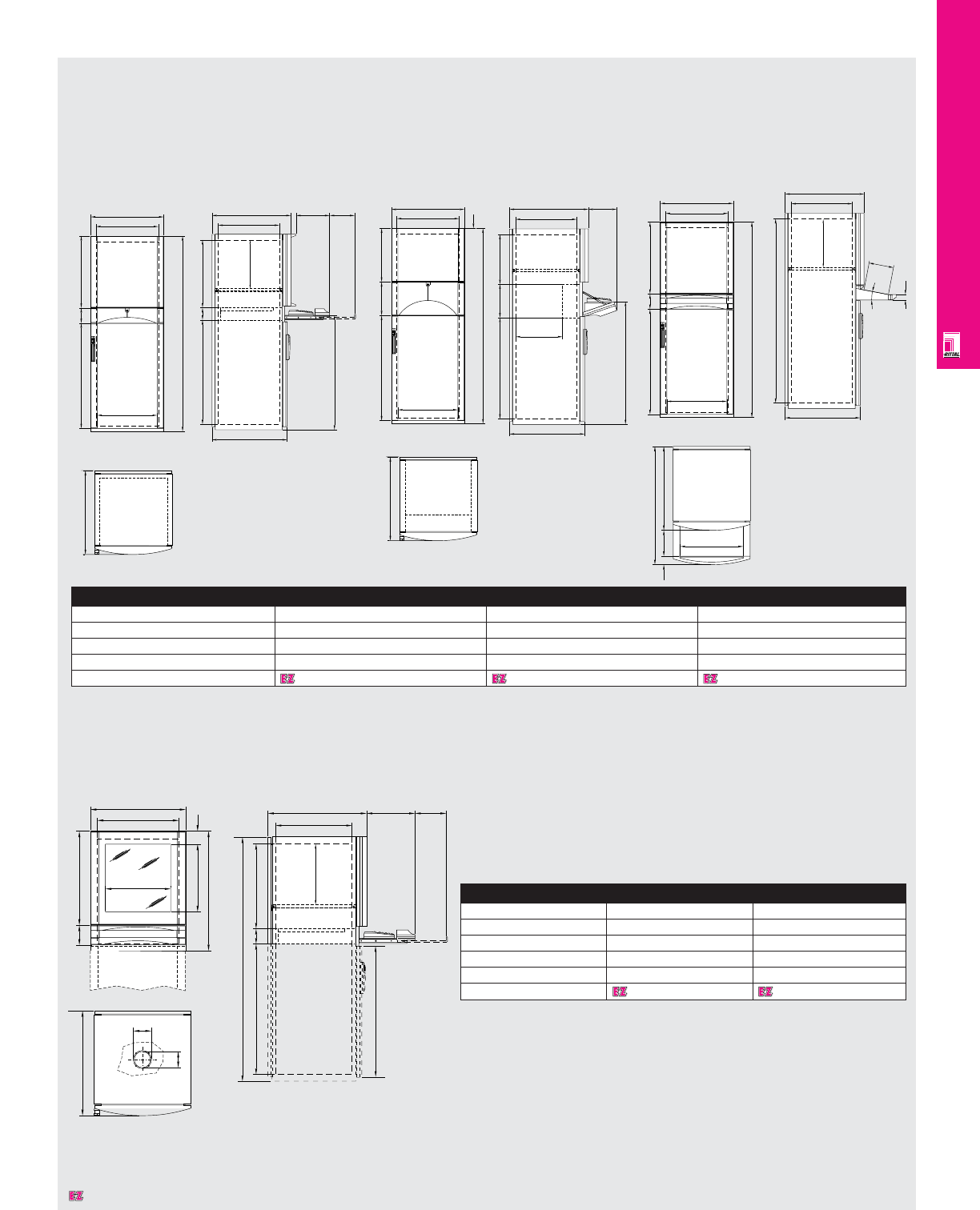
OPERATOR INTERFACE
IND 194
Technical Specifications
PC Computer Enclosures
Enclosure
Front installation PC enclosure PC desktop enclosure
Front door - -
H (inches/mm) 63.0/1600 29.5/750
W (inches/mm) 23.6/600 23.6/600
D (inches/mm) 25.6/650 25.6/650
Part No. 4603913 4617913
Enclosure
Front installation With keyboard drawer With folding keyboard With console
H (inches/mm) 63.0/1600 63.0/1600 63.0/1600
W (inches/mm) 23.6/600 23.6/600 23.6/600
D (inches/mm) 25.6/650 25.6/650 25.6/35.8 (650/910)
Part No. 4603603 4603820 4603604
854
863
i. L. 502 (702)
647 (847)
558
100
205318
1603.5
82
746
591
i. L. 512
125
410
425
599
112
647
100
1604
863
492
591
125
599
i. L. 512
854
939
620 (820)
i. L. 502 (702)
647 (847)
558
100
205317.5
variable
647
1604
492
863 591
125
i. L. 512
599
i. L. 1512
620
204
45
11°
647
i. L. 502
variable
647
912
65 200
486
1604
863
492
i. L. 512
441
82
599
275
1001
620 (820)
231647 (847)
i. L. 502 (702)
385 (585)
408
275829
647
With Keyboard Drawer With Folding Keyboard With Desk Section
Designates a product in the EnclosureZone program.
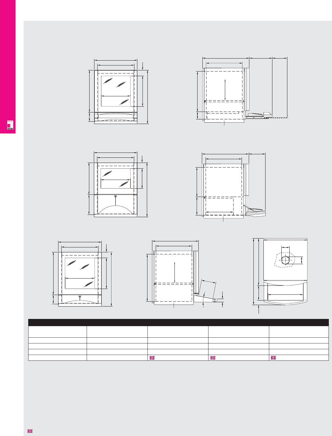
OPERATOR INTERFACE
IND 195
Enclosure
Front installation Packs of With keyboard With keyboard With console
drawer shelf
H (inches/mm) - 29.53”/750 mm 29.53”/750 mm 29.53”/750 mm
W (inches/mm) - 23.62”/600 mm 23.62”/600 mm 23.62”/600 mm
D (inches/mm) - 25.59”/650 mm 25.59”/650 mm 25.59”/650 mm
Part No. 14617703 4617920 4617704
Technical Specifications
PC Computer Enclosures
82
746
591
i. L. 512
125
410
425
599
i. L. 502
647
559
100
205
318
746
i. L. 512
82
599
441275
410
275
231
647
i. L. 502
250
385
409
746
82
591
125
410
425
599
i. L. 512
i. L. 502
i. L. 659
11°
204
45
647
112
647
912
65 200
486
100
With Keyboard Drawer
With Keyboard Shelf
With Console
Designates a product in the EnclosureZone program.
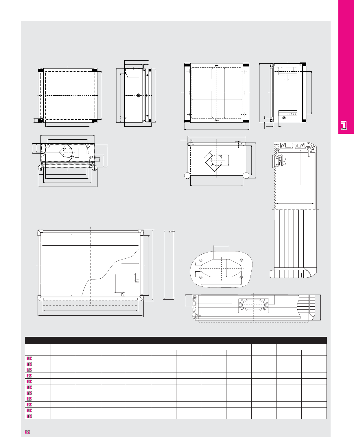
OPERATOR INTERFACE
IND 196
Technical Specifications
CP Pendant Arm Enclosures
6380000
Enclosure
Part No. Height dimensions Width dimensions Depth Weight
H1 H2 H3 H4 B1 B2 B3 B4 D lbs kg
6540200 200 250 52.5 95 300 250 340 260 155 9.9 4.5
6534000 200 205 122 155 300 338 258 260 180 22.0 10.0
6535000 300 305 250 255 300 338 258 215 180 26.2 11.9
6536000 300 305 250 255 400 438 358 295 180 29.1 13.2
6537000 400 405 350 355 300 338 258 215 180 29.1 13.2
6538000 400 405 330 355 400 438 358 295 180 30.8 14.0
6531200 300 250 62.5 175 380 330 420 340 210 22.3 10.1
6530200 380 330 52.5 275 380 330 420 340 210 18.3 8.3
6533200 380 330 52.5 275 600 550 640 560 210 32.9 14.9
6532200 500 450 62.5 375 500 450 540 460 210 28.7 13.0
6380000 310 354 321 277 483 527 - 450 110 - -
Dimensions in millimeters (mm) unless otherwise indicated.
Ø 70
Ø 82
Ø 7
75
B4
B1
B2
H5 H3
H1
135 40
180
H2
198 – 203
B3
30
B6
100
67
168
B715
30
B5
H3
B4
B2
H1
H2
20
10
8 x 12.5
35
Ø 4.6
190
234
Ø 70
20
B3
B1
Ø 82
Ø 7
6534000-6538000 6530200-6533200/6540200
B1
B4 (B1-33)
H4 (H1-33)
B3 (B1-8)
B2 (B1+44)
H1
B3 (B1-8)
H3 (H1-8)
H2 (H1+44)
H7 (H1+36)
B6 (B1+11)
52 43
110
43
95
38
14
max.
installation
depth
100mm
H6 (H1+11)
Designates a product in the EnclosureZone program.
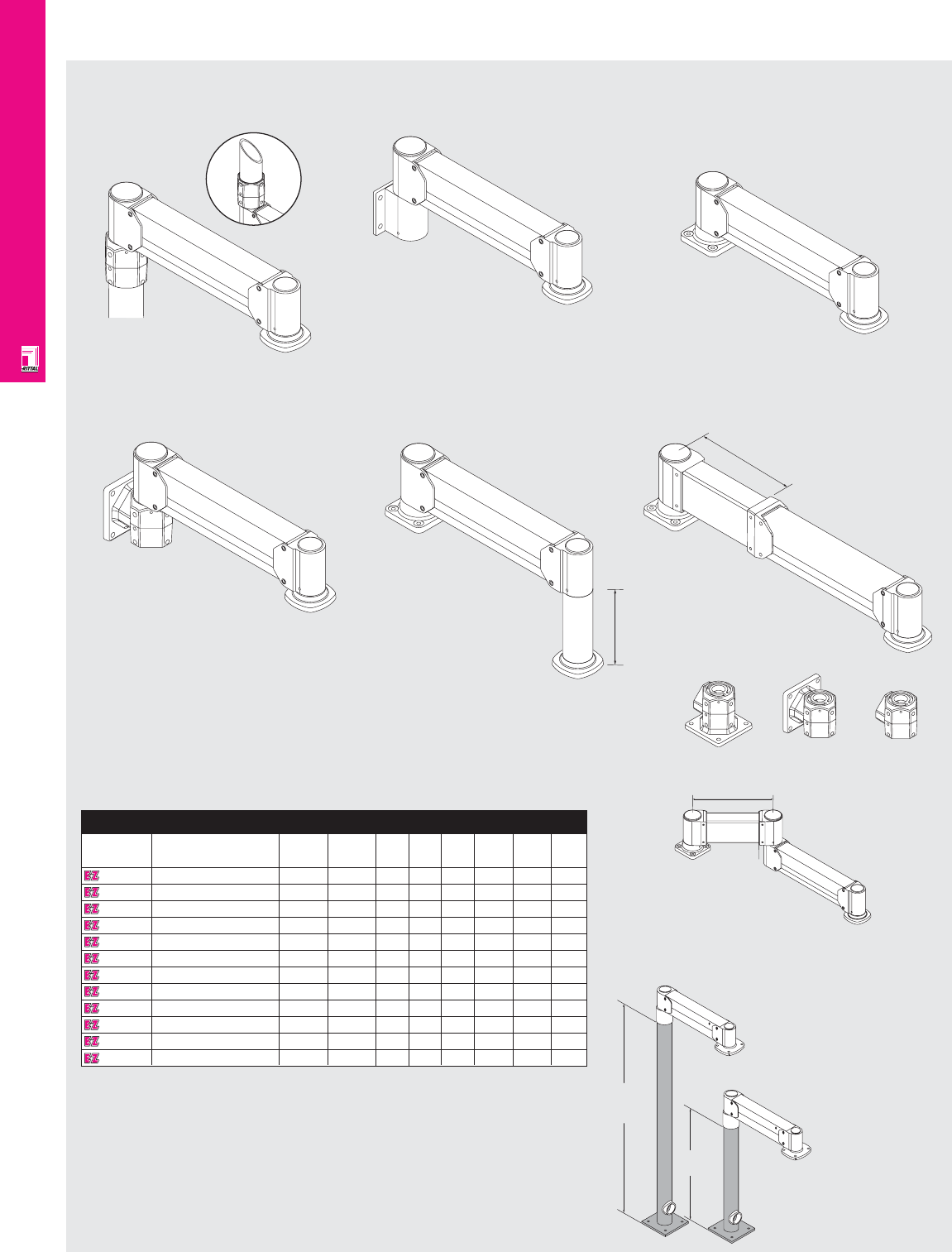
OPERATOR INTERFACE
IND 197
Technical Specifications
CP-Vertical Pendant Arm Systems
Post Top Arms
Attaches to a plain end 3.5" OD tube
or pipe. Cables exit through tube.
Wallmount
Arms
Attaches to a vertical surface with
5.3" H x 6.0" W mounting plate with
4 (.5") Ø hole pattern on 4.75" H x 3.50" W
centers. 2.0" Ø hole through center for
cable exit. 2.5" NPS threaded opening
as alternate cable exit.
Machine
Top Arms
Attaches to horizontal surface with
5" x 5" mounting plate with 4 (.37") Ø
hole pattern on 3.54" centers. 1.5" Ø
hole through center for cable exit.
Floor Posts
36", 74", or 79" tall,
3.5" x .25" OD post
with square base
plate. 1.5" NPT
female coupling
near base can be
used for cable
entry. Post can be
easily shortened.
Note: When using
jointed extension
arms, a 79" tall post
should be used.
H
H
TALL
SHORT
Horizontal
Extensions
Increases
overall length by
dimension “L”.
Vertical
Extensions
Lowers enclosure
by dimension “H”.
Jointed
Extension Arms
Increases overall length by
dimension “L” and adds additional swivel
joint, providing in-out motion.
LENGTH L
LENGTH L
UNIVERSAL AS
MACHINE TOP UNIVERSAL AS
WALLMOUNT UNIVERSAL AS
POST TOP
INVERTED
H
Universal
Arms
Designed for increased
flexibility. Mounting method can be
easily configured based on user
requirements.
CP-Vertical Pendant Arm Specifications
Part No. Description Max. Vertical T1 T2 T3 Length Height Base
load travel T (L) (H) plate
9967987 Post top / CP-V 100 lbs. 13" – – 5.6" 22.25" – –
9967988 Post top / CP-VL 75 lbs. 23" 5.9" 17.1" 6.3" 28" – –
9967989 Post top / CP-VXL 50 lbs. 30" 7.4" 22.6" 8.7" 35" – –
9967993 Wallmount / CP-V 100 lbs. 13" – – 5.6" 22.25" – –
9967994 Wallmount / CP-VL 75 lbs. 23" 5.9" 17.1" 6.3" 28" – –
9967995 Wallmount / CP-VXL 50 lbs. 30" 7.4" 22.6" 8.7" 35" – –
9967996 Machine top / CP-V 100 lbs. 13" – – 5.6" 22.25" – –
9967997 Machine top / CP-VL 75 lbs. 23" 5.9" 17.1" 6.3" 28" – –
9967998 Machine top / CP-VXL 50 lbs. 30" 7.4" 22.6" 8.7" 35" – –
9967999 Universal mount / CP-V 100 lbs. 13" – – 5.6" 22.25" – –
9968000 Universal mount / CP-VL 75 lbs. 23" 5.9" 17.1" 6.3" 28"
9968001 Universal mount / CP-VXL 50 lbs. 30" 7.4" 22.6" 8.7" 35" – –
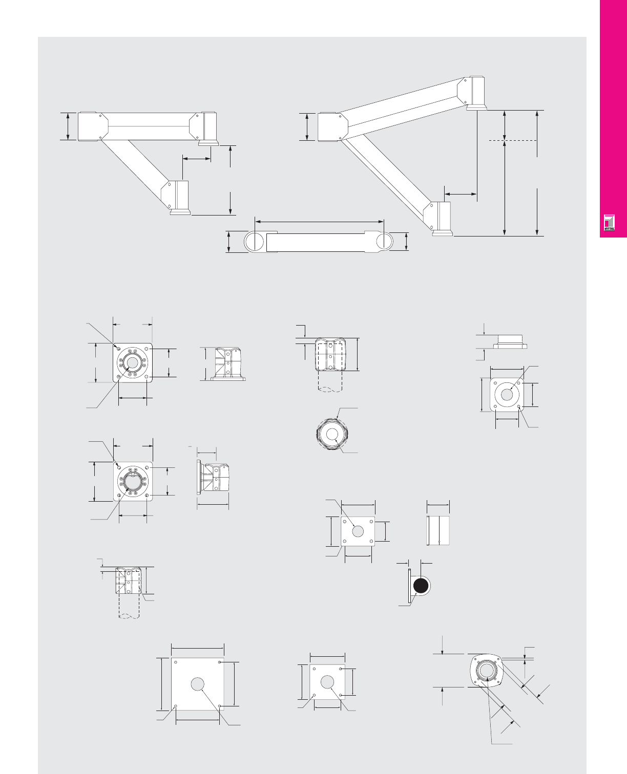
OPERATOR INTERFACE
IND 198
Technical Specifications
CP-Vertical Pendant Arm Systems
CP-Vertical Travel
CP-V
CP-Vertical Mounting Dimensions
3.5"
LENGTH L
3.0"
HORIZONTAL
T1
T2
T
TRAVEL
5"
T3
T
TRAVEL
T3
5"
Floor Post Plates
Machine Top Universal Mounting Post Top Mounting Machine Top Mounting
Wallmount Mounting
6.4"
6.4" 4.5"
4.5"
.53" Ø
(4) PLACES
1.4" Ø
CABLE EXIT
3.5"
5.75"
COVER
PLATE
TOP OF PIPE
.8"
5.0"
3-1/2" OD TUBE
(OR)3" PIPE
(PLAIN END)
.8"
TOP
OF
PIPE
5.0"
3-1/2" OD TUBE
(OR)3" PIPE
(PLAIN END)
4.8" Ø
CIRCUMFERENCE
1.4" Ø
CABLE EXIT
2.0" 5.0"
5.0" 3.54"
3.54" 3/8" Ø
(4) PLACES
1.4" Ø
CABLE EXIT
1.4" Ø
CABLE EXIT
.53" Ø
(4) PLACES
5.3"
6.0"
4.75"
3.5"
4.0"
2.2"
2-1/2" NPT ALTERNATE CABLE EXIT
(THREADED CAP SUPPLIED)
12"
10"
12"
10" 3" Ø ALTERNATE
CABLE ACCESS
.68" Ø
(4) PLACES
.50" Ø
(4) PLACES 3" Ø ALTERNATE
CABLE ACCESS
8"
6"
6"
8"
CP-VL/CP-VXL
6.4"
6.4" 4.5"
4.5"
.53" Ø
(4) PLACES
1.4" Ø
CABLE EXIT
Wallmount Universal Mounting
Post Universal Mounting
6.0"
Enclosure Mounting Coupling
4.5"
M6
3.23"
4.41"
1.82" Ø CABLE
PASSAGE
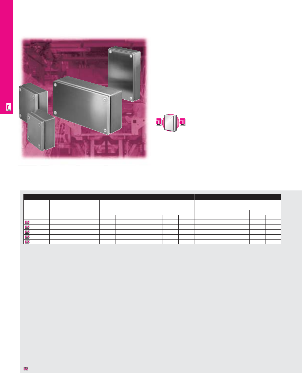
NONCORROSIVE WALLMOUNT
IND 199
KL Junction Boxes
KL NEMA Rated Junction Boxes
Rittal KL wallmount enclosures offer a sophisicated stainless
steel design with high protection ratings and practical
dimensions. They resist corrosion, protect against dust and
liquids, as well as promote hygiene.
Enclosure Mounting Panel
Part No. Approximate NEMA Exact outside dimensions Part No. Dimensions
outside rating
dimensions inches mm inches mm
H"xW"xD" H W D H W D H W H W
1521010 6x6x3 1, 4, 4X, 12 5.91 5.91 3.15 150 150 80 1560700 5.31 4.92 135 125
1522010 6x12x3 1, 4, 4X, 12 5.91 11.81 3.15 150 300 80 1561700 11.22 4.92 285 125
1523010 8x8x3 1, 4, 4X, 12 7.87 7.87 3.15 200 200 80 1562700 7.28 6.89 185 175
1524010 8x12x3 1, 4, 4X, 12 7.87 11.81 3.15 200 300 80 1563700 11.22 6.89 285 175
1525010 8x16x5 1, 4, 4X, 12 7.87 15.75 4.72 200 400 120 1564700 15.16 6.89 385 175
C
a
r
b
o
n
S
t
e
e
l
C
a
r
b
o
n
S
t
e
e
l
A
v
a
i
l
a
b
l
e
I
n
A
v
a
i
l
a
b
l
e
I
n
Page IND 1
Designates a product in the EnclosureZone program.
NONCORROSIVE WALLMOUNT
IND 200
Configuration
•NEMA 1, 4, 4X, 12/IP 66
•UL/CSA/TÜV approvals
•Optional mounting panel
•Constructed from Type 304 or 316
stainless steel
•Knife-edge design protects against
liquid entry
•Integrated grounding provisions
•Welded stainless steel body
•Screw down cover
•Foamed-on gaskets ensure perfect seal
•Wide range of accessories
•Off-the-shelf availability
Technical Specifications
Material:
•Type 304 stainless steel
•Housing: 18 ga/1.25 mm
•Cover: 18 ga/1.25 mm
•Finish: housing and cover, brushed finish
Finish:
•Exterior surfaces: brushed finish
•Mounting panel: Type M Page . . . . . . . . . . . . . . . . . . . . . . . . . . . . IND 255
NEMA Type
144X1213
UL CUL CSA TÜV
Listings
Protection Ratings
Certifications/Approvals
Technical Drawings
Accessories
Part No. Stainless steel Cover Quick Pole Ground
wallmounting hinge release mounting strap
brackets fastener kit 7" long/
5/16" stand-off 11 AWG
1521010 1594000 1592000 1593000 2584000 2564000
1522010 1594000 1592000 1593000 2584000 2564000
1523010 1594000 1592000 1593000 2584000 2564000
1524010 1594000 1592000 1593000 2584000 2564000
1525010 1594000 1592000 1593000 2584000 2564000
Designates a product in the EnclosureZone program.
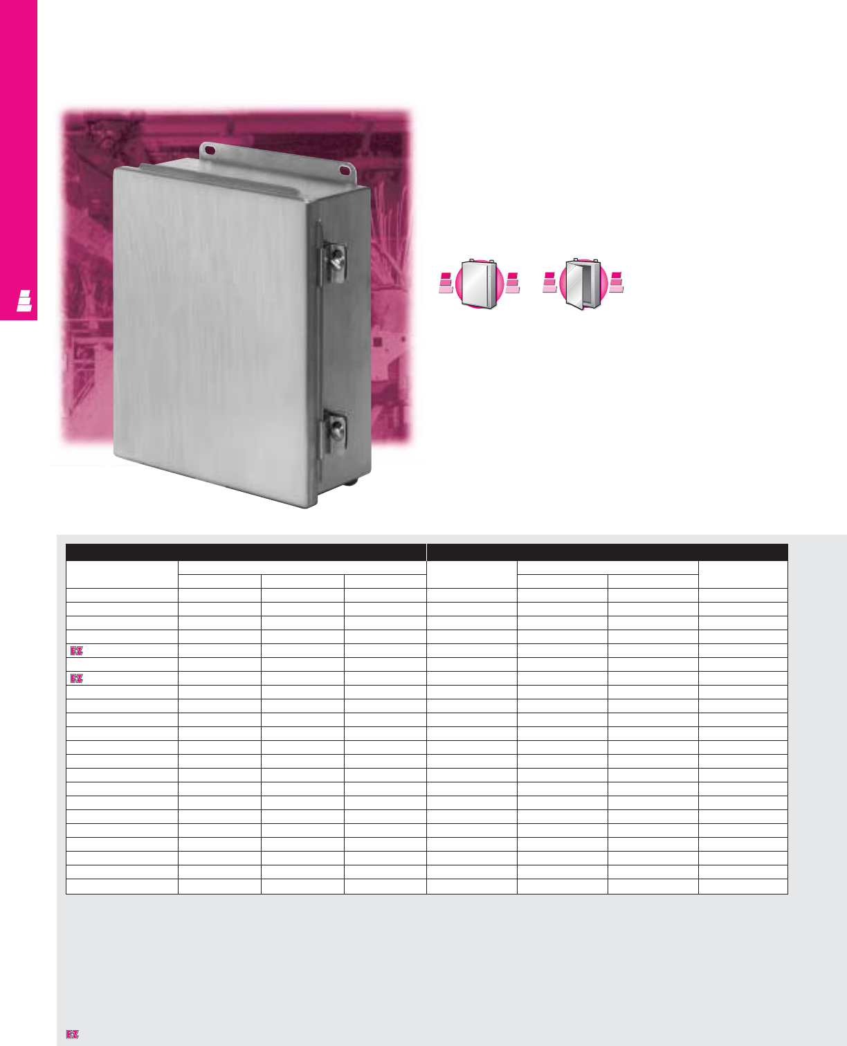
NONCORROSIVE WALLMOUNT
IND 201
Continuous Hinge Cover Enclosures
Stainless Steel Junction Boxes
These NEMA rated stainless steel junction boxes offer perfect
protection for delicate electrical and electronic equipment and
are designed primarily for indoor use. They are ideal for pilot
devices, such as limit switches, foot switches, pushbuttons,
selector switches, pilot lights, etc., and protect such equipment
against dirt, dust, external condensation, and spraying of water,
oil or coolant.
Enclosure Mounting Panel
Part No.
Outside dimensions (inches)
Part No.
Panel size Usable depth
HWD H W
E 404CHSS 4.00 4.00 3.00 NONE ---
E 4044CHSS 4.00 4.00 4.00 NONE ---
E 604CHSS 6.00 4.00 3.00 E 6P4 4.88 2.88 2.50
E 6044CHSS 6.00 4.00 4.00 E 6P4 4.88 2.88 3.50
E 606CHSS 6.00 6.00 4.00 E 6P6 4.88 4.88 3.50
E 806CHSS 8.00 6.00 3.50 E 8P6 6.88 4.88 3.00
E 8066CHSS 8.00 6.00 6.00 E 8P6 6.88 4.88 5.50
E 808CHSS 8.00 8.00 4.00 E 8P8 6.88 6.88 3.50
E 1008CHSS 10.00 8.00 4.00 E 10P8 8.88 6.88 3.50
E 10086CHSS 10.00 8.00 6.00 E 10P8 8.88 6.88 5.50
E 10106CHSS 10.00 10.00 6.00 E 10P10 8.88 8.88 5.50
E 12064CHSS 12.00 6.00 4.00 E 12P6 10.88 4.88 3.50
E 1210CHSS 12.00 10.00 5.00 E 12P10 10.88 8.88 4.50
E 12108CHSS 12.00 10.00 8.00 E 12P10 10.88 8.88 7.50
E 1212CHSS 12.00 12.00 6.00 E 12P12 10.88 10.88 5.50
E 14086CHSS 14.00 8.00 6.00 E 14P8 12.88 6.88 5.50
E 1412CHSS 14.00 12.00 6.00 E 14P12 12.88 10.88 5.50
E 14128CHSS 14.00 12.00 8.00 E 14P12 12.88 10.88 7.50
E 16106CHSS 16.00 10.00 6.00 E 16P10 14.88 8.88 5.50
E 1614CHSS 16.00 14.00 6.00 E 16P14 14.88 12.88 5.50
E 16148CHSS 16.00 14.00 8.00 E 16P14 14.88 12.88 7.50
E 161410CHSS 16.00 14.00 10.00 E 16P14 14.88 12.88 9.50
C
a
r
b
o
n
S
t
e
e
l
C
a
r
b
o
n
S
t
e
e
l
A
v
a
i
l
a
b
l
e
I
n
A
v
a
i
l
a
b
l
e
I
n
Page IND 9
A
l
u
m
i
n
u
m
A
v
a
i
l
a
b
l
e
I
n
A
v
a
i
l
a
b
l
e
I
n
A
l
u
m
i
n
u
m
Page IND 203
Designates a product in the EnclosureZone program.
NONCORROSIVE WALLMOUNT
IND 202
Configuration
•Continuously welded seams, finished smooth
•Robotically applied urethane gasket
•Continuous stainless steel hinges
•Door removed by pulling steel hinge pin
•Stainless steel cover clamps and screws
•External mounting brackets
•Mounting panel provisions installed
(except E 404CHSS and E 4044CHSS)
Technical Specifications
Material:
•Enclosure/door: 14 gauge Type 304
stainless steel
Finish:
•Enclosure/door: # 3 brushed finish
•Optional stainless steel mounting panels:
unpainted
•Optional carbon steel mounting panels:
painted white
Page . . . . . . . . . . . . . . . . . . . . . . . . . . . . IND 256
NEMA Type
144X1213
UL CUL CSA TÜV
Listings
Protection Ratings
Certifications/Approvals
Technical Drawings
Accessories
Part No. Terminal block kit Terminal rails Window kit
E 404CHSS -- -
E 4044CHSS -- -
E 604CHSS -- -
E 6044CHSS -- -
E 606CHSS -- -
E 806CHSS E 6JTMA E 8JS -
E 8066CHSS E 6JTMA E 8JS E PWK53NFSS
E 808CHSS E 8JTMA E 8JS E PWK53NFSS
E 1008CHSS E 8JTMA E 10JS E PWK53NFSS
E 10086CHSS E 8JTMA E 10JS E PWK53NFSS
E 10106CHSS E 10JTMA E 10JS E PWK53NFSS
E 12064CHSS E 6JTMA E 12JS E PWK53NFSS
E 1210CHSS E 10JTMA E 12JS E PWK53NFSS
E 12108CHSS E 10JTMA E 12JS E PWK53NFSS
E 1212CHSS E 12JTMA E 12JS E PWK53NFSS
E 14086CHSS E 8JTMA E 14JS E PWK53NFSS
E 1412CHSS E 12JTMA E 14JS E PWK95NFSS
E 14128CHSS E 12JTMA E 14JS E PWK95NFSS
E 16106CHSS E 10JTMA E 16JS E PWK95NFSS
E 1614CHSS E 14JTMA E 16JS E PWK95NFSS
E 16148CHSS E 14JTMA E 16JS E PWK95NFSS
E 161410CHSS E 14JTMA E 16JS E PWK95NFSS
Designates a product in the EnclosureZone program.
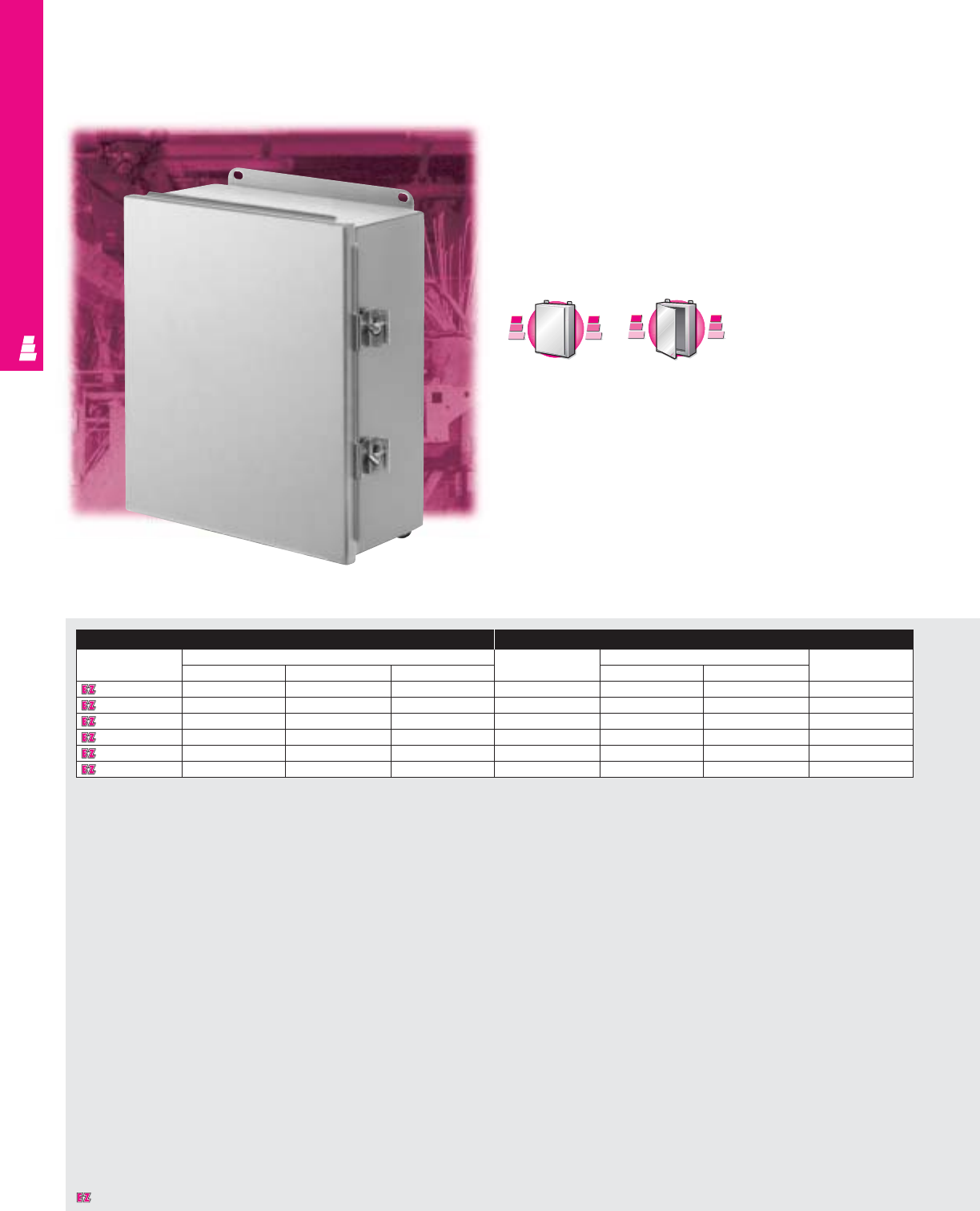
NONCORROSIVE WALLMOUNT
IND 203
Continuous Hinge Cover Enclosures
Aluminum Junction Boxes
These NEMA rated, light-weight aluminum junction boxes
offer perfect protection for delicate electrical and electronic
equipment in areas where corrosion problems exist. They are
ideal for pilot devices, such as limit switches, foot switches,
pushbuttons, selector switches, pilot lights, etc., and protect
such equipment against dirt, dust, and spraying of water, oil
or coolant.
Enclosure Mounting Panel
Part No.
Outside dimensions (inches)
Part No.
Panel size Usable depth
HWD HW
E 606CHAL 6.00 6.00 4.00 E 6P6 4.88 4.88 3.50
E 8064CHAL 8.00 6.00 4.00 E 8P6 6.88 4.88 3.50
E 1008CHAL 10.00 8.00 4.00 E 10P8 8.88 6.88 3.50
E 12106CHAL 12.00 10.00 6.00 E 12P10 10.88 8.88 5.50
E 1412CHAL 14.00 12.00 6.00 E 14P12 12.88 10.88 5.50
E 1614CHAL 16.00 14.00 6.00 E 16P14 14.88 12.88 5.50
C
a
r
b
o
n
S
t
e
e
l
C
a
r
b
o
n
S
t
e
e
l
A
v
a
i
l
a
b
l
e
I
n
A
v
a
i
l
a
b
l
e
I
n
Page IND 9
S
t
a
i
n
l
e
s
s
S
t
e
e
l
S
t
a
i
n
l
e
s
s
S
t
e
e
l
A
v
a
i
l
a
b
l
e
I
n
A
v
a
i
l
a
b
l
e
I
n
Page IND 201
Designates a product in the EnclosureZone program.
NONCORROSIVE WALLMOUNT
IND 204
Configuration
•Continuously welded seams, finished smooth
•Robotically applied urethane gasket
•Continuous aluminum hinge with
removable pin
•Stainless steel captive clamps and screws
•External mounting brackets
•Mounting panel provisions installed
Technical Specifications
Material:
•Enclosure/door: .080 aluminum
Type 5052 H-32
Finish:
•Enclosure/door: brushed finish
•Optional aluminum mounting panels:
unpainted
•Optional carbon steel mounting panels:
painted white
Page . . . . . . . . . . . . . . . . . . . . . . . . . . . . IND 257
NEMA Type
144X12 13
UL CUL CSA TÜV
Listings
Protection Ratings
Certifications/Approvals
Technical Drawings
Accessories
Part No. Terminal block kit Terminal rails Window kit
E 606CHAL ---
E 8064CHAL E 6JTMA E 8JS -
E 1008CHAL E 8JTMA E 10JS E PWK53NFSS
E 12106CHAL E 10JTMAXD E 12JS E PWK53NFSS
E 1412CHAL E 12JTMA E 14JS E PWK95NFSS
E 1614CHAL E 14JTMA E 16JS E PWK95NFSS
Designates a product in the EnclosureZone program.
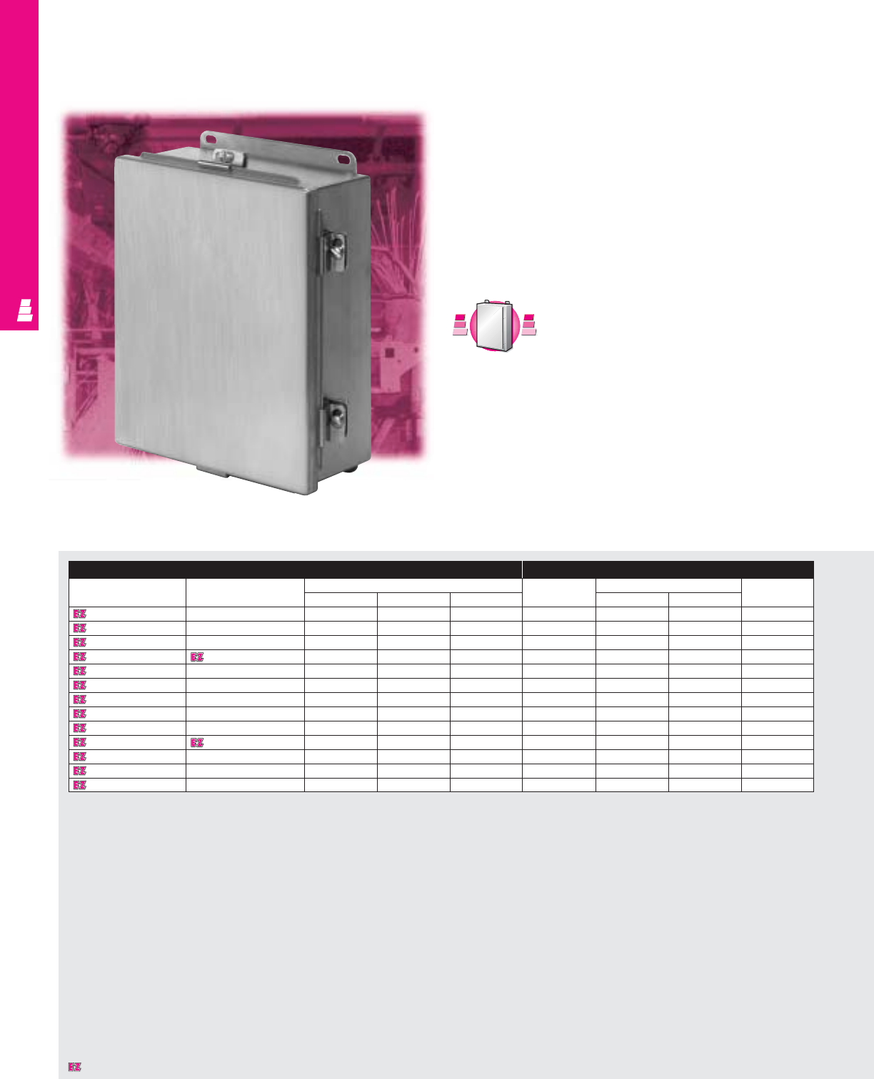
NONCORROSIVE WALLMOUNT
Continuous Hinge Cover Boxes
NEMA 4X Stainless Steel Enclosures
These NEMA rated stainless steel junction boxes offer perfect
protection for delicate electrical and electronic equipment. They
meet the tough requirements of the chemical and food
industries and off-shore environments. Their corrosion resistant
design offers protection against chemical influences.
They can be used inside or outside to protect installed
equipment against splashing water, seepage of water, falling or
hose directed water, severe external condensation and
spraying of water, oil or coolants.
Enclosure Mounting Panel
Part No. Part No.
Outside dimensions (inches)
Part No.
Panel size Usable depth
304 SS 316 SS
HWD HW
E 404CHNFSS E 404CHNFSS6 4.00 4.00 3.00 - - - -
E 604CHNFSS E 604CHNFSS6 6.00 4.00 3.00 E 6P4 4.88 2.88 2.50
E 6044CHNFSS E 6044CHNFSS6 6.00 4.00 4.00 E 6P4 4.88 2.88 3.50
E 606CHNFSS E 606CHNFSS6 6.00 6.00 4.00 E 6P6 4.88 4.88 3.50
E 806CHNFSS E 806CHNFSS6 8.00 6.00 3.50 E 8P6 6.88 4.88 3.00
E 8064CHNFSS E 8064CHNFSS6 8.00 6.00 4.00 E 8P6 6.88 4.88 3.50
E 1008CHNFSS E 1008CHNFSS6 10.00 8.00 4.00 E 10P8 8.88 6.88 3.50
E 10086CHNFSS E 10086CHNFSS6 10.00 8.00 6.00 E 10P8 8.88 6.88 5.50
E 1210CHNFSS E 1210CHNFSS6 12.00 10.00 5.00 E 12P10 10.88 8.88 4.50
E 12106CHNFSS E 12106CHNFSS6 12.00 10.00 6.00 E 12P10 10.88 8.88 5.50
E 1212CHNFSS E 1212CHNFSS6 12.00 12.00 6.00 E 12P12 10.88 10.88 5.50
E 1412CHNFSS E 1412CHNFSS6 14.00 12.00 6.00 E 14P12 12.88 10.88 5.50
E 1614CHNFSS E 1614CHNFSS6 16.00 14.00 6.00 E 16P14 14.88 12.88 5.50
C
a
r
b
o
n
S
t
e
e
l
C
a
r
b
o
n
S
t
e
e
l
A
v
a
i
l
a
b
l
e
I
n
A
v
a
i
l
a
b
l
e
I
n
Page IND 13
IND 205
Designates a product in the EnclosureZone program.

NONCORROSIVE WALLMOUNT
Configuration
•Continuously welded seams, finished smooth
•Robotically applied urethane gasket
•Continuous steel hinge
•Door removed by pulling steel hinge pin
•Stainless steel captive clamps and screws
•External mounting brackets
•Mounting panel provisions installed (except
E 404CHNFSS and E 404CHNFSS6)
Technical Specifications
Material:
•Enclosure/door: 14 gauge Type 304 or Type
316 stainless steel (see table)
Finish:
•Enclosure/door: # 3 brushed finish
•Optional stainless steel mounting panels:
unpainted
•Optional carbon steel mounting panels:
painted white
Page . . . . . . . . . . . . . . . . . . . . . . . . . . . . IND 258
NEMA Type
144X1213
UL CUL CSA TÜV
Listings
Protection Ratings
Certifications/Approvals
Technical Drawings
Accessories
Part No. Part No. Ter minal block kit Terminal rails Window kit
304 SS 316 SS
E 404CHNFSS E 404CHNFSS6 ---
E 604CHNFSS E 604CHNFSS6 ---
E 6044CHNFSS E 6044CHNFSS6 ---
E 606CHNFSS E 606CHNFSS6 ---
E 806CHNFSS E 806CHNFSS6 E 6JTMA E 8JS -
E 8064CHNFSS E 8064CHNFSS6 E 6JTMA E 8JS -
E 1008CHNFSS E 1008CHNFSS6 E 8JTMA E 10JS E PWK53NFSS
E 10086CHNFSS E 10086CHNFSS6 E 8JTMA E 10JS E PWK53NFSS
E 1210CHNFSS E 1210CHNFSS6 E 10JTMAXD E 12JS E PWK53NFSS
E 12106CHNFSS E 12106CHNFSS6 E 10JTMAXD E 12JS E PWK53NFSS
E 1212CHNFSS E 1212CHNFSS6 E 12JTMA E 12JS E PWK53NFSS
E 1412CHNFSS E 1412CHNFSS6 E 12JTMA E 14JS E PWK95NFSS
E 1614CHNFSS E 1614CHNFSS6 E 14JTMA E 16JS E PWK95NFSS
IND 206
Designates a product in the EnclosureZone program.
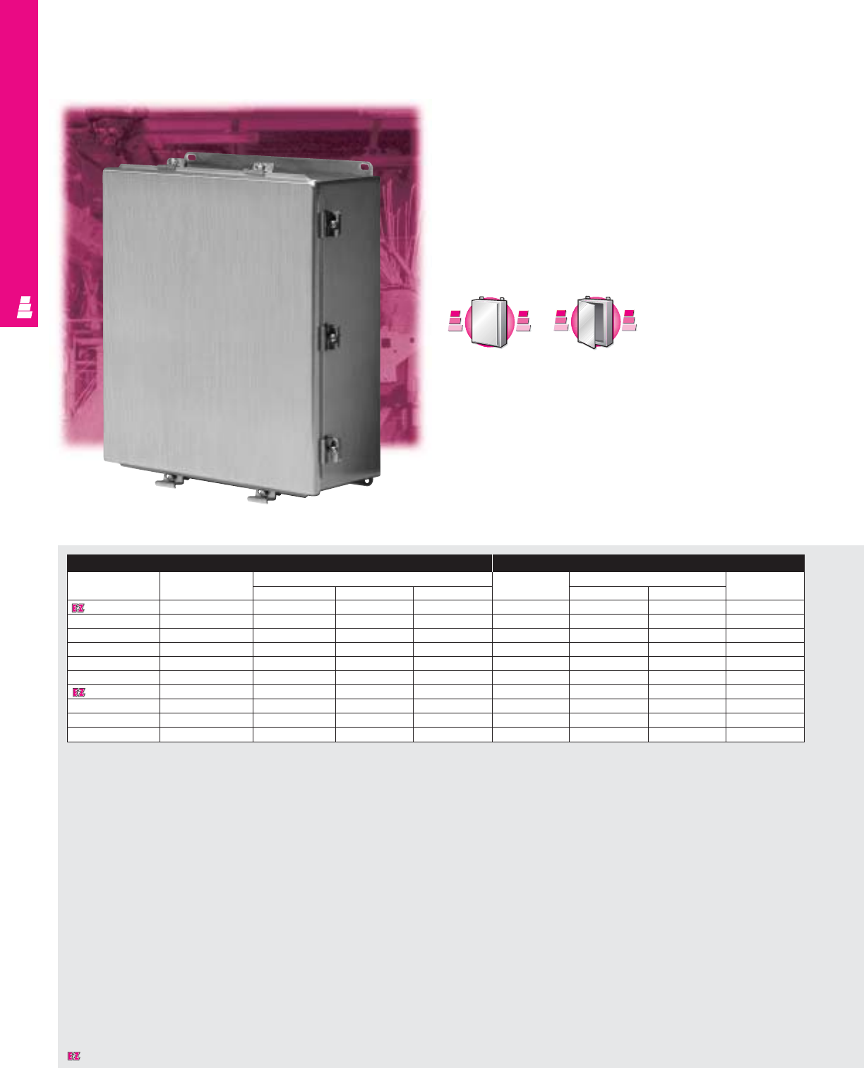
IND 207
Clamp Cover Junction Enclosures
NEMA Rated Stainless Steel Boxes
These NEMA rated stainless steel junction boxes offer perfect
protection for delicate electrical and electronic equipment.
They meet the tough requirements of the chemical and food
industries and off-shore environments. Their corrosion resistant
design offers protection against chemical influences.
They can be used inside or outside to protect installed
equipment against splashing water, seepage of water, falling
or hose directed water, severe external condensation and
spraying of water, oil or coolants.
Enclosure Mounting Panel
Part No. Part No.
Outside dimensions (inches)
Part No.
Panel size Usable depth
NFSS NFSS6
HWD HW
E 404NFSS E 404NFSS6 4.00 4.00 3.00 NONE ---
E 604NFSS E 604NFSS6 6.00 4.00 3.00 E 6P4 4.88 2.88 2.50
E 6044NFSS E 6044NFSS6 6.00 4.00 4.00 E 6P4 4.88 2.88 3.50
E 606NFSS E 606NFSS6 6.00 6.00 4.00 E 6P6 4.88 4.88 3.50
E 8064NFSS E 8064NFSS6 8.00 6.00 4.00 E 8P6 6.88 4.88 3.50
E 1008NFSS E 1008NFSS6 10.00 8.00 4.00 E 10P8 8.88 6.88 3.50
E 1210NFSS E 1210NFSS6 12.00 10.00 5.00 E 12P10 10.88 8.88 4.50
E 12106NFSS E 12106NFSS6 12.00 10.00 6.00 E 12P10 10.88 8.88 5.50
E 1412NFSS E 1412NFSS6 14.00 12.00 6.00 E 14P12 12.88 10.88 5.50
E 1614NFSS E 1614NFSS6 16.00 14.00 6.00 E 16P14 14.88 12.88 5.50
NONCORROSIVE WALLMOUNT
C
a
r
b
o
n
S
t
e
e
l
C
a
r
b
o
n
S
t
e
e
l
A
v
a
i
l
a
b
l
e
I
n
A
v
a
i
l
a
b
l
e
I
n
Page IND 15
A
l
u
m
i
n
u
m
A
v
a
i
l
a
b
l
e
I
n
A
v
a
i
l
a
b
l
e
I
n
A
l
u
m
i
n
u
m
Page IND 209
Designates a product in the EnclosureZone program.

IND 208
Configuration
•Continuously welded seams, finished smooth
•Robotically applied urethane gasket
•Stainless steel cover clamps and screws
•External mounting brackets
•Mounting panel provisions installed
(except E 404NFSS and E 404NFSS6)
NONCORROSIVE WALLMOUNT
Technical Specifications
Material:
•Enclosure/door: 14 gauge Type 304
stainless steel
Finish:
•Enclosure/door: # 3 brushed finish
•Optional stainless steel mounting panels:
unpainted
•Optional carbon steel mounting panels:
painted white
Page . . . . . . . . . . . . . . . . . . . . . . . . . . . . IND 259
NEMA Type
144X1213
UL CUL CSA TÜV
Listings
Protection Ratings
Certifications/Approvals
Technical Drawings
Accessories
Part No. Part No. Ter minal block kit Terminal rails Window kit
NFSS NFSS6
E 404NFSS E 404NFSS6 ---
E 604NFSS E 604NFSS6 ---
E 6044NFSS E 6044NFSS6 ---
E 606NFSS E 606NFSS6 ---
E 8064NFSS E 8064NFSS6 E 6JTMA E 8JS -
E 1008NFSS E 1008NFSS6 E 8JTMA E 10JS E PWK53NFSS
E 1210NFSS E 1210NFSS6 E 10JTMAXD E 12JS E PWK53NFSS
E 12106NFSS E 12106NFSS6 E 10JTMAXD E 12JS E PWK53NFSS
E 1412NFSS E 1412NFSS6 E12JTMA E 14JS E PWK95NFSS
E 1614NFSS E 1614NFSS6 E 14JTMA E 16JS E PWK95NFSS
Designates a product in the EnclosureZone program.
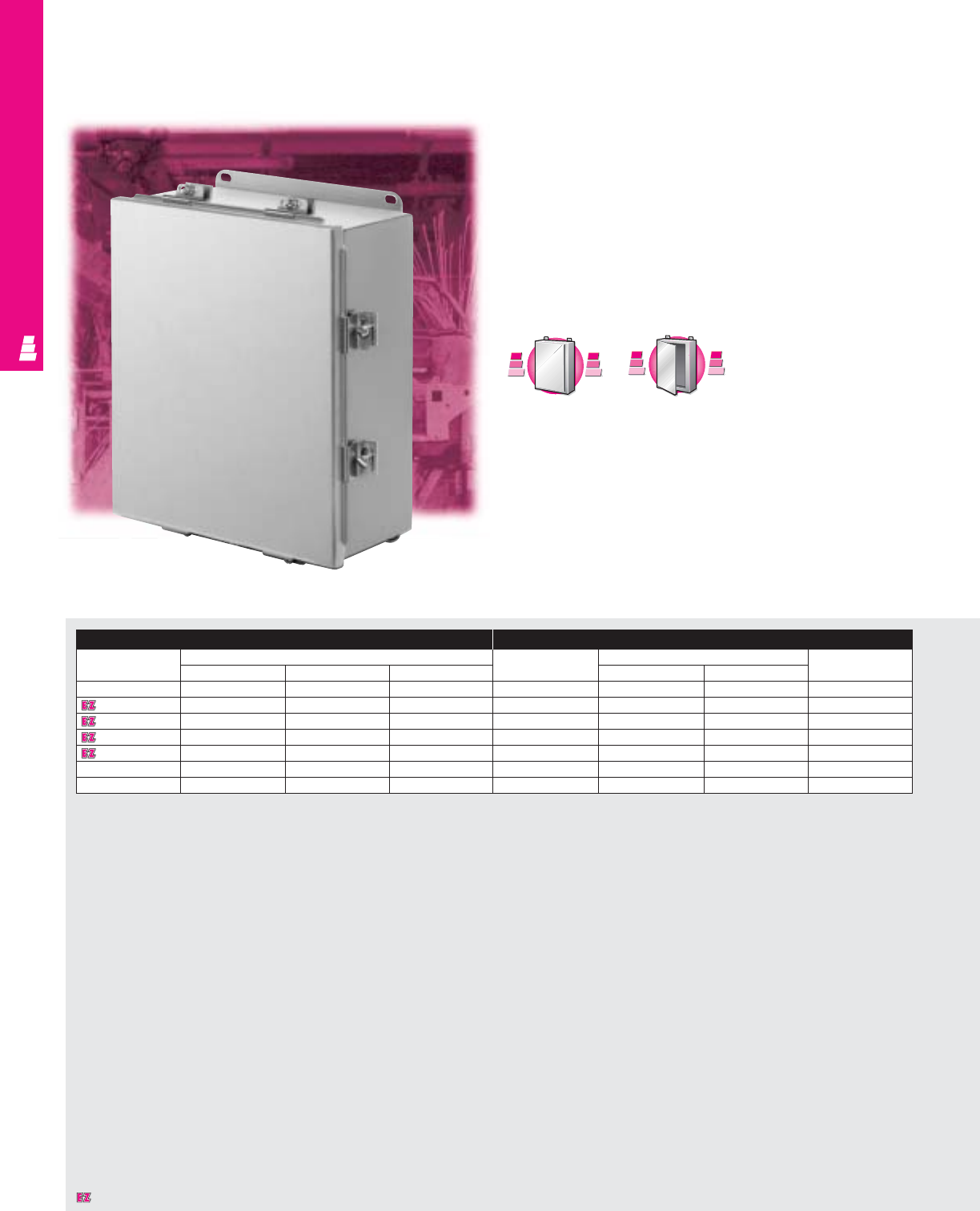
IND 209
Clamp Cover Junction Enclosures
NEMA Rated Aluminum Boxes
These NEMA rated, durable aluminum junction boxes offer
perfect protection for delicate electrical and electronic
equipment. They are designed to house pilot devices, such as
limit switches, foot switches, pushbuttons, selector switches
and pilot lights.
They can be used inside or outside to protect installed
equipment against splashing water, seepage of water, falling
or hose directed water, severe external condensation and
spraying of water, oil or coolants or where corrosion is a problem.
NONCORROSIVE WALLMOUNT
Enclosure Mounting Panel
Part No. Outside dimensions (inches) Part No. Panel size Usable depth
HWD HW
E 604NFAL 6.00 4.00 3.00 E 6P4 4.88 2.88 2.50
E 606NFAL 6.00 6.00 4.00 E 6P6 4.88 4.88 3.50
E 8064NFAL 8.00 6.00 4.00 E 8P6 6.88 4.88 3.50
E 1008NFAL 10.00 8.00 4.00 E 10P8 8.88 6.88 3.50
E 1210NFAL 12.00 10.00 5.00 E 12P10 10.88 8.88 4.50
E 1412NFAL 14.00 12.00 6.00 E 14P12 12.88 10.88 5.50
E 1614NFAL 16.00 14.00 6.00 E 16P14 14.88 12.88 5.50
C
a
r
b
o
n
S
t
e
e
l
C
a
r
b
o
n
S
t
e
e
l
A
v
a
i
l
a
b
l
e
I
n
A
v
a
i
l
a
b
l
e
I
n
Page IND 15
S
t
a
i
n
l
e
s
s
S
t
e
e
l
S
t
a
i
n
l
e
s
s
S
t
e
e
l
A
v
a
i
l
a
b
l
e
I
n
A
v
a
i
l
a
b
l
e
I
n
Page IND 207
Designates a product in the EnclosureZone program.

NONCORROSIVE WALLMOUNT
IND 210
Technical Specifications
Material:
•Enclosure/cover: .080 aluminum
Type 5052 H-32
Finish:
•Enclosure/cover: natural-brushed finish
•Optional aluminum mounting panels:
unpainted
•Optional carbon steel mounting panels:
painted white
Page . . . . . . . . . . . . . . . . . . . . . . . . . . . IND 260
NEMA Type
144X1213
UL CUL CSA TÜV
Listings
Protection Ratings
Certifications/Approvals
Technical Drawings
Configuration
•Continuously welded seams, finished smooth
•Robotically applied urethane gasket
•Stainless steel clamps and screws
•External mounting brackets
•Mounting panel provisions installed UL CUL CSA TÜV
Listings
Certifications/Approvals
Technical Drawings
Accessories
Part No. Terminal block kit Terminal rails Window kit
E 604NFAL ---
E 606NFAL ---
E 8064NFAL E 6JTMA E 8JS -
E 1008NFAL E 8JTMA E 10JS E PWK53NFSS
E 1210NFAL E 10JTMAXD E 12JS E PWK53NFSS
E 1412NFAL E 12JTMA E 14JS E PWK95NFSS
E 1614NFAL E 14JTMA E 16JS E PWK95NFSS
Designates a product in the EnclosureZone program.
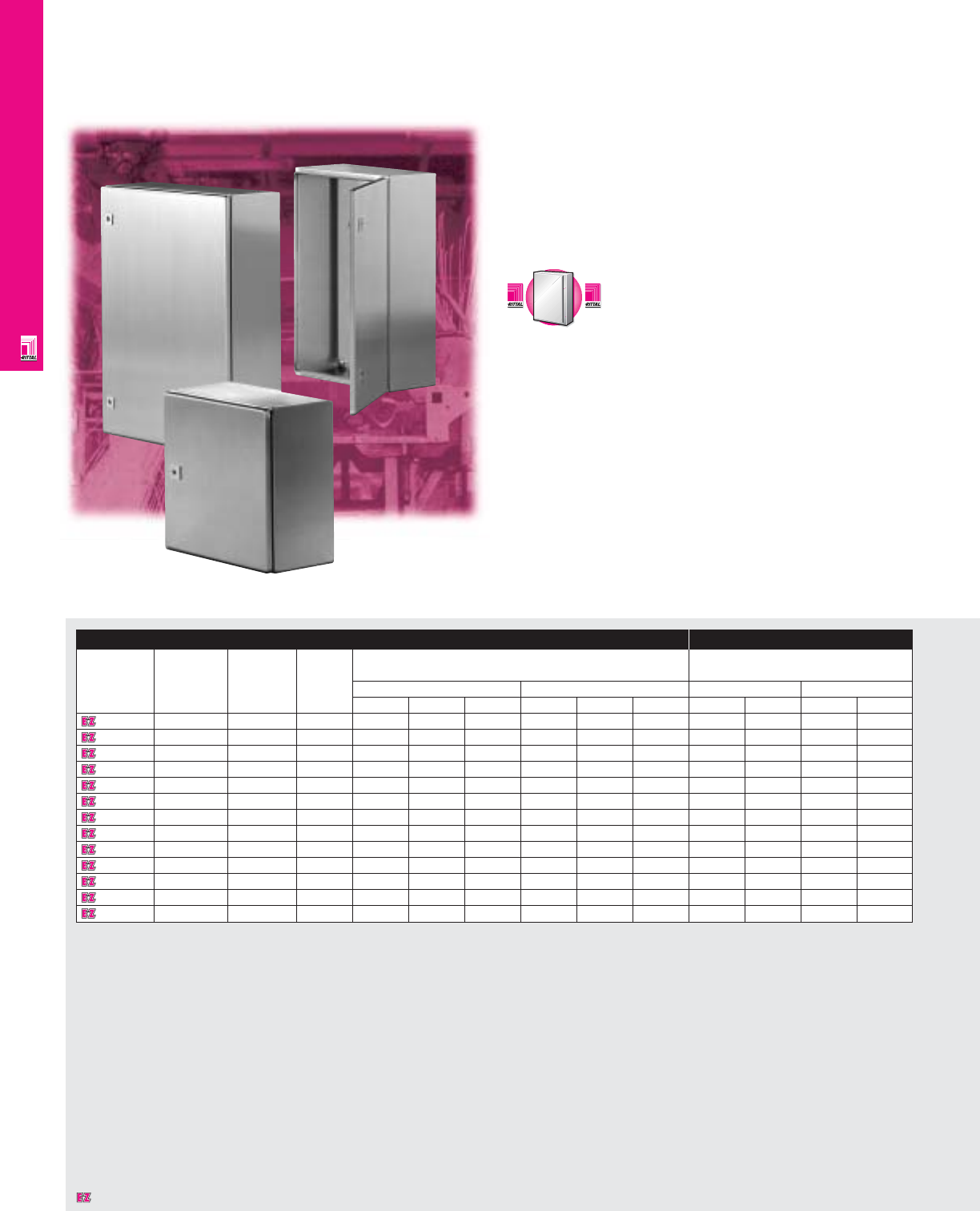
NONCORROSIVE WALLMOUNT
IND 211
AE Wallmount Enclosures
NEMA Rated Wallmount Enclosures
Since its introduction more than 30 years ago, Rittal's
unequaled AE wallmount enclosures have been continually
improved. The stainless steel AE enclosures provide the
strongest possible corrosion resistance, thus satisfying the
needs of the most demanding industries.
Enclosure Mounting Panel
Part No. Approximate NEMA Number Exact outside dimensions Dimensions
outside rating of
dimensions doors inches mm inches mm
H"xW"xD" H W D H W D H W H W
1002660 12x8x6 1, 4, 4X, 12 1 11.81 7.87 6.10 300 200 155 10.83 6.38 275 162
1004660 12x15x6 1, 4, 4X, 12 1 11.81 14.96 6.10 300 380 155 10.83 13.15 275 334
1005660 15x12x8 1, 4, 4X, 12 1 14.96 11.81 8.27 380 300 210 13.98 13.15 355 334
1006660 15x15x8 1, 4, 4X, 12 1 14.96 14.96 8.27 380 380 210 13.98 13.15 355 334
1009660 15x24x8 1, 4, 4X, 12 1 14.96 23.62 8.27 380 600 210 13.98 21.61 355 549
1097000 16x12x8 1, 4, 4X, 12 1 15.75 11.81 8.27 400 300 210 14.76 10.00 375 254
1007660 20x20x8 1, 4, 4X, 12 1 19.69 19.69 8.27 500 500 210 18.50 17.68 470 449
1008660 24x15x8 1, 4, 4X, 12 1 23.62 14.96 8.27 600 380 210 22.44 13.15 570 334
1010660 24x24x8 1, 4, 4X, 12 1 23.62 23.62 8.27 600 600 210 22.44 21.61 570 549
1012660 30x24x8 1, 4, 4X, 12 1 29.92 23.62 8.27 760 600 210 28.74 21.61 730 549
1014660 30x30x12 1, 4, 4X, 12 1 29.92 29.92 11.81 760 760 300 28.74 27.72 730 704
1016660 40x32x12 1, 4, 4X, 12 1 39.37 31.50 11.81 1000 800 300 37.60 29.09 955 739
1017660 47x31x12 1, 4, 4X, 12 1 47.24 31.50 11.81 1200 800 300 45.28 29.13 1150 740
Note: Also available with no integrated blind nuts — order Part No. XXXX.600.
C
a
r
b
o
n
S
t
e
e
l
C
a
r
b
o
n
S
t
e
e
l
A
v
a
i
l
a
b
l
e
I
n
A
v
a
i
l
a
b
l
e
I
n
Page IND 23
Designates a product in the EnclosureZone program.

NONCORROSIVE WALLMOUNT
Listings
IND 212
Configuration
•NEMA 1, 4X, 12, 14 protection/IP 66
•UL/CSA/TÜV approvals
•Mounting panel included
•Hinged door
•Constructed from Type 304 stainless steel
•Knife-edge design protects against
liquid entry
•Integrated grounding provisions
•Welded stainless steel body
•Foamed-on gaskets ensure perfect seal
•Wide range of accessories
•Off-the-shelf availability
Technical Specifications
Material:
•Type 304 stainless steel
•Housing: 18 ga/1.25 mm (AE 1002)
16 ga/1.5 mm (AE 1004-1017)
•Door: 16 ga/1.5 mm (AE 1002-1008)
14 ga/2.0 mm (AE 1010-1017)
•Mounting panel: hot-dipped
galvanized zinc
14 ga/2.0 mm (AE 1002-1004)
13 ga/2.5 mm (AE 1005-1009)
12 ga/2.75 mm (AE 1010)
11 ga/3.0 mm (AE 1012-1017)
Finish:
•Exterior surfaces: brushed finish
•Mounting panel: Type M
NEMA Type
144X1213
UL CUL CSA TÜV
Listings
Protection Ratings
Certifications/Approvals
Technical Drawings
Page . . . . . . . . . . . . . . . . . . . . . . . . . . . . IND 261
UL CUL CSA TÜV
Certifications/Approvals
Technical Drawings
Accessories
Part No. Stainless steel T-Handle Pole Ground strap Print
wallmounting brackets mounting 7" long/ pocket
3/8" stand-off kit 11 AWG
1002660 2433000 2572000 2584000 2564000 -
1004660 2433000 2572000 2584000 2564000 -
1005660 2433000 2572000 2584000 2564000 -
1006660 2433000 2572000 2584000 2564000 2514000
1009660 2433000 2572000 2584000 2564000 2514000
1097000 2433000 2572000 2584000 2564000 -
1007660 2433000 2572000 2584000 2564000 2514000
1008660 2433000 2572000 2584000 2564000 2514000
1010660 2433000 2572000 2584000 2564000 2514000
1012660 2433000 2572000 2584000 2564000 2514000
1014660 2433000 2572000 - 2564000 2514000
1016660 2433000 2572000 - 2564000 2514000
1017660 2433000 - - 2564000 2514000
Designates a product in the EnclosureZone program.
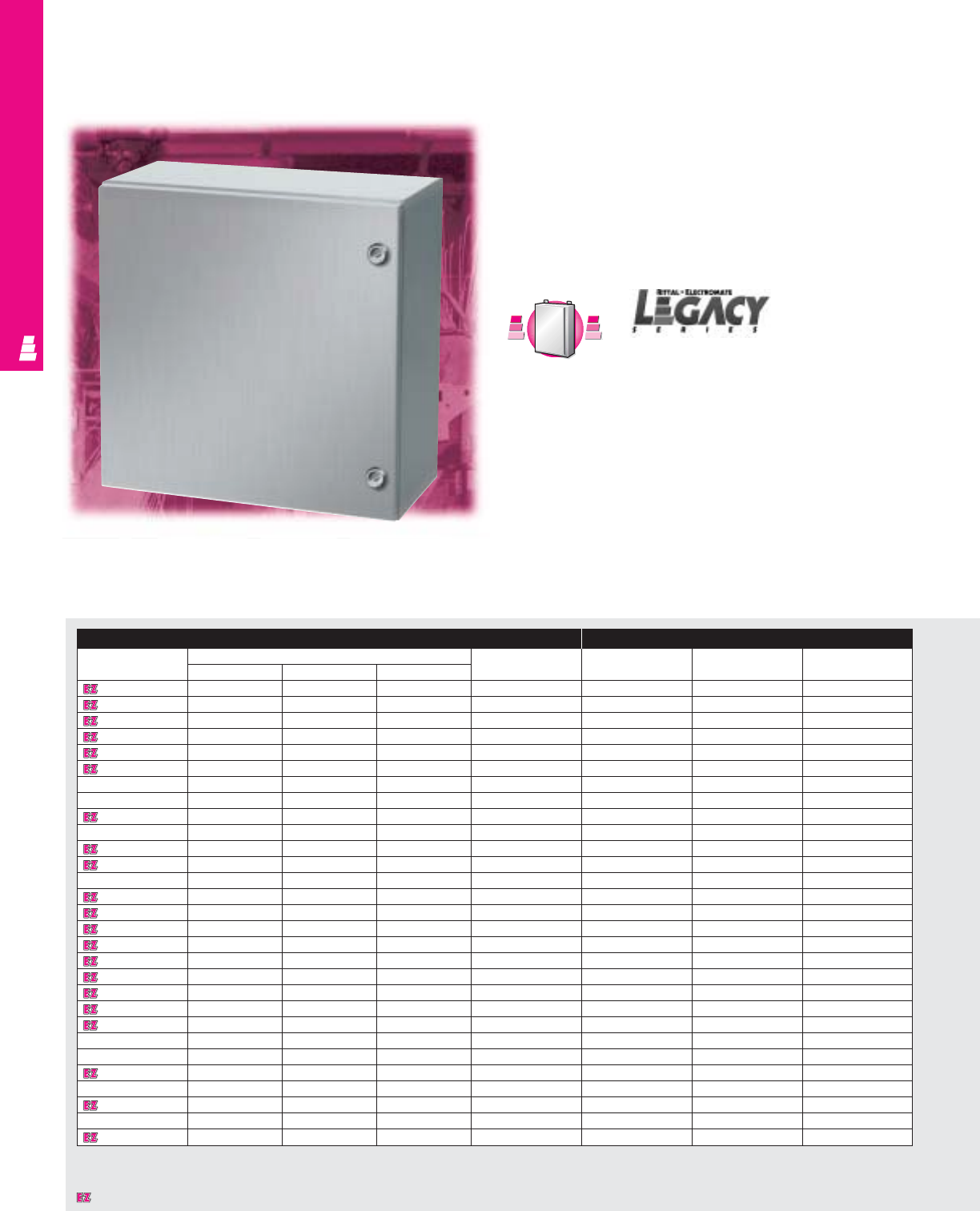
NONCORROSIVE WALLMOUNT
IND 213
Legacy Series Enclosures
Stainless Steel Wallmount Boxes
Legacy Series stainless steel instrument boxes offer protection
for dense wiring and sensitive small electronic and electric
equipment controls and pilot devices, such as limit switches,
foot switches, pushbuttons, selector switches and pilot lights.
Installed equipment is protected against splashing water,
seepage of water, falling or hose directed water, severe external
condensation and spraying of water, oil or coolant.
C
a
r
b
o
n
S
t
e
e
l
C
a
r
b
o
n
S
t
e
e
l
A
v
a
i
l
a
b
l
e
I
n
A
v
a
i
l
a
b
l
e
I
n
Page IND 25
Enclosure Mounting Panel
Part No. Outside dimensions (inches) Latch White (Full Size) Zinc (Full Size) White (NEMA Style)
HWDsystem Panel Part No. Panel Part No. Panel Part No.
L W120806SS 12.00 8.00 6.00 1 Qtr. Turn L W12P8W L W12P8 -
L W121206SS 12.00 12.00 6.00 1 Qtr. Turn L W12P12W L W12P12 -
L W161206SS 16.00 12.00 6.00 1 Qtr. Turn L W16P12W L W16P12 E 16P12
L W161208SS 16.00 12.00 8.00 1 Qtr. Turn L W16P12W L W16P12 E 16P12
L W161606SS 16.00 16.00 6.00 1 Qtr. Turn L W16P16W L W16P16 E 16P16
L W161608SS 16.00 16.00 8.00 1 Qtr. Turn L W16P16W L W16P16 E 16P16
L W162008SS 16.00 20.00 8.00 2 Qtr. Turn L W16P20W L W16P20 E 20P16
L W201606SS 20.00 16.00 6.00 2 Qtr. Turn L W20P16W L W20P16 E 20P16
L W201608SS 20.00 16.00 8.00 2 Qtr. Turn L W20P16W L W20P16 E 20P16
L W202006SS 20.00 20.00 6.00 2 Qtr. Turn L W20P20W L W20P20 E 20P20
L W202008SS 20.00 20.00 8.00 2 Qtr. Turn L W20P20W L W20P20 E 20P20
L W202012SS 20.00 20.00 12.00 2 Qtr. Turn L W20P20W L W20P20 E 20P20
L W241608SS 24.00 16.00 8.00 2 Qtr. Turn L W24P16W L W24P16 E 24P16
L W242008SS 24.00 20.00 8.00 2 Qtr. Turn L W24P20W L W24P20 E 24P20
L W242012SS 24.00 20.00 12.00 2 Qtr. Turn L W24P20W L W24P20 E 24P20
L W242408SS 24.00 24.00 8.00 2 Qtr. Turn L W24P24W L W24P24 E 24P24
L W242412SS 24.00 24.00 12.00 2 Qtr. Turn L W24P24W L W24P24 E 24P24
L W302408SS 30.00 24.00 8.00 2 Qtr. Turn L W30P24W L W30P24 E 30P24
L W302412SS 30.00 24.00 12.00 2 Qtr. Turn L W30P24W L W30P24 E 30P24
L W303008SS 30.00 30.00 8.00 2 Qtr. Turn L W30P30W L W30P30 E 30P30
L W303012SS 30.00 30.00 12.00 2 Qtr. Turn L W30P30W L W30P30 E 30P30
L W362408SS 36.00 24.00 8.00 2 Qtr. Turn L W36P24W L W36P24 E 36P24
L W362412SS 36.00 24.00 12.00 2 Qtr. Turn L W36P24W L W36P24 E 36P24
L W363008SS 36.00 30.00 8.00 2 Qtr. Turn L W36P30W L W36P30 E 36P30
L W363012SS 36.00 30.00 12.00 2 Qtr. Turn L W36P30W L W36P30 E 36P30
L W363612SS 36.00 36.00 12.00 2 Qtr. Turn L W36P36W L W36P36 E 36P36
L W483612SS 48.00 36.00 12.00 3 Point Lock System L W48P36W L W48P36 E 48P36
L W603612SS 60.00 36.00 12.00 3 Point Lock System L W60P36W L W60P36 E 60P36
L W603616SS 60.00 36.00 16.00 3 Point Lock System L W60P36W L W60P36 E 60P36
Designates a product in the EnclosureZone program.

NONCORROSIVE WALLMOUNT
IND 214
Technical Specifications
Material:
•Enclosure/door: 14 gauge Type 304
stainless steel
•Note: Type 316 available upon request
Finish:
•Enclosure/door: # 4 brushed finish
Page . . . . . . . . . . . . . . . . . . . . . . . . . . . . IND 262
NEMA Type
144X1213
UL CUL CSA TÜV
Listings
Protection Ratings
Certifications/Approvals
Technical Drawings
Configuration
•Continuously welded seams, finished smooth
•Robotically applied urethane gasket
•Easily removable stainless steel hinge pins
•Knife edge flange
•Door opens 130°
•Integral channel around door provides
additional stability and prevents entry of
water and dirt when enclosure is opened
•Quarter turn latching
•Screwdriver lock insert
•Mounting panel provisions installed
•Mounting panel available in white (NEMA/
full size) and zinc (full size) styles
•Wallmounting brackets included
•Grounding provisions on enclosure body
•Print pocket included
Accessories
Part No. Wallmounting Light kit Dead front kit
brackets Panel (full size) Panel (NEMA) Risers
L W120806SS 2433000 See ACC 29 - - -
L W121206SS 2433000 See ACC 29 L DF12P12 - L DF6R4
L W161206SS 2433000 See ACC 29 L DF16P12 E DF16P12 L DF6R4
L W161208SS 2433000 See ACC 29 L DF16P12 E DF16P12 L DF8R4
L W161606SS 2433000 See ACC 29 L DF16P16 E DF16P16 L DF6R4
L W161608SS 2433000 See ACC 29 L DF16P16 E DF16P16 L DF8R4
L W162008SS 2433000 See ACC 29 - E DF20P16 L DF8R4
L W201606SS 2433000 See ACC 29 L DF20P16 E DF20P16 L DF6R4
L W201608SS 2433000 See ACC 29 L DF20P16 E DF20P16 L DF8R4
L W202006SS 2433000 See ACC 29 L DF20P20 E DF20P20 L DF6R4
L W202008SS 2433000 See ACC 29 L DF20P20 E DF20P20 L DF8R4
L W202012SS 2433000 See ACC 29 L DF20P20 E DF20P20 L DF12R4
L W241608SS 2433000 See ACC 29 L DF24P16 - L DF8R4
L W242008SS 2433000 See ACC 29 L DF24P20 E DF24P20 L DF8R4
L W242012SS 2433000 See ACC 29 L DF24P20 E DF24P20 L DF12R4
L W242408SS 2433000 See ACC 29 L DF24P24 E DF24P24 L DF8R4
L W242412SS 2433000 See ACC 29 L DF24P24 E DF24P24 L DF12R4
L W302408SS 2433000 See ACC 29 L DF30P24 E DF30P24 L DF8R4
L W302412SS 2433000 See ACC 29 L DF30P24 E DF30P24 L DF12R4
L W303008SS 2433000 See ACC 29 L DF30P30 E DF30P30 L DF8R5
L W303012SS 2433000 See ACC 29 L DF30P30 E DF30P30 L DF12R5
L W362408SS 2433000 See ACC 29 L DF36P24 E DF36P24 L DF8R5
L W362412SS 2433000 See ACC 29 L DF36P24 E DF36P24 L DF12R5
L W363008SS 2433000 See ACC 29 L DF36P30 E DF36P30 L DF8R5
L W363012SS 2433000 See ACC 29 L DF36P30 E DF36P30 L DF12R5
L W363612SS 2433000 See ACC 29 L DF36P36 E DF36P36 L DF12R6
L W483612SS 2433000 See ACC 29 - E DF48P36 L DF12R6
L W603612SS 2433000 See ACC 29 - - -
L W603616SS 2433000 See ACC 29 - - -
Designates a product in the EnclosureZone program.
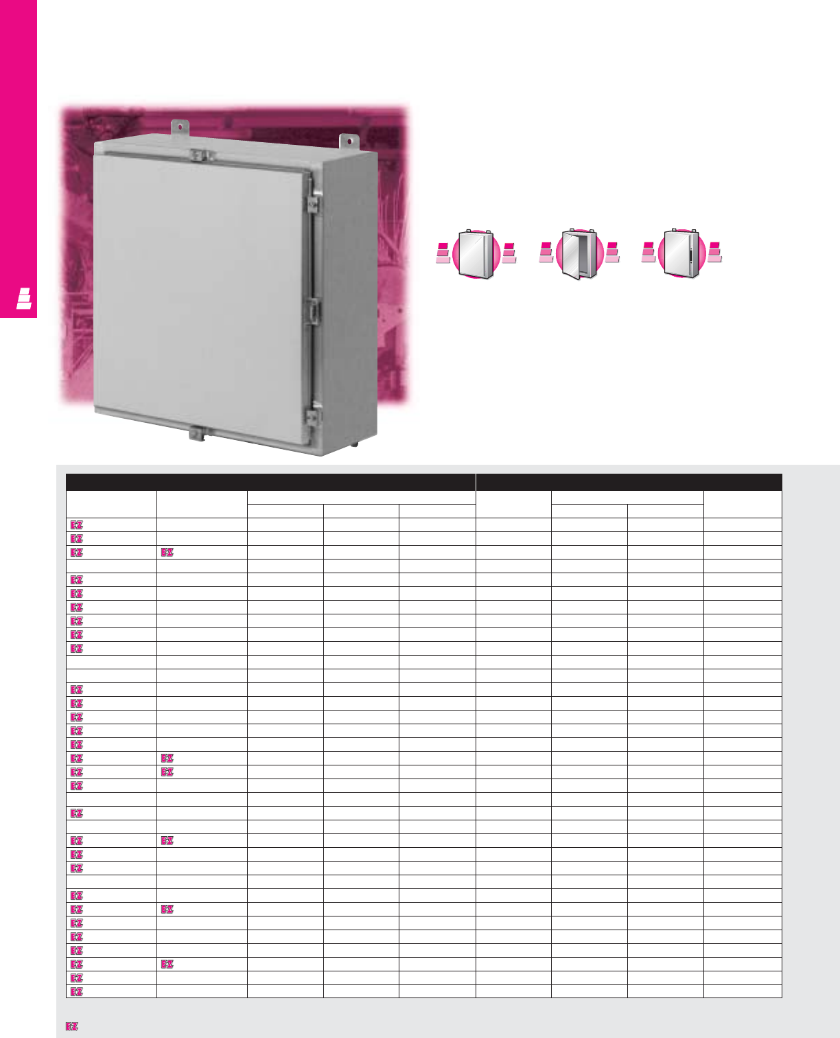
NONCORROSIVE WALLMOUNT
IND 215
One Door Wallmount Boxes
NEMA 4X Stainless Steel Enclosures
These NEMA 4X rated stainless steel enclosures are designed
for indoor or outdoor use and can be used for many different
applications. They protect installed equipment against
splashing water, seepage of water, falling or hose directed
water and severe external condensation.
* Usable depth reduced by .625" at door stiffener.
Enclosure Mounting Panel
Part No. Part No.
Outside dimensions (inches)
Part No.
Panel size Usable depth
304 SS 316 SS
HWD HW
E 16H1206SS E 16H1206SS6 16.00 12.00 6.00 E 16P12 13.00 9.00 6.00
E 16H1208SS E 16H1208SS6 16.00 12.00 8.00 E 16P12 13.00 9.00 8.00
E 16H1606SS E 16H1606SS6 16.00 16.00 6.00 E 16P16 13.00 13.00 6.00
E 16H2006SS E 16H2006SS6 16.00 20.00 6.00 E 20P16 13.00 17.00 6.00
E 20H1606SS E 20H1606SS6 20.00 16.00 6.00 E 20P16 17.00 13.00 6.00
E 20H1608SS E 20H1608SS6 20.00 16.00 8.00 E 20P16 17.00 13.00 8.00
E 20H1610SS E 20H1610SS6 20.00 16.00 10.00 E 20P16 17.00 13.00 10.00
E 20H2006SS E 20H2006SS6 20.00 20.00 6.00 E 20P20 17.00 17.00 6.00
E 20H2008SS E 20H2008SS6 20.00 20.00 8.00 E 20P20 17.00 17.00 8.00
E 20H2408SS E 20H2408SS6 20.00 24.00 8.00 E 24P20 17.00 21.00 8.00
E 24H1206SS E 24H1206SS6 24.00 12.00 6.00 E 12P24 21.00 9.00 6.00
E 24H1606SS E 24H1606SS6 24.00 16.00 6.00 E 24P16 21.00 13.00 6.00
E 24H1608SS E 24H1608SS6 24.00 16.00 8.00 E 24P16 21.00 13.00 8.00
E 24H2006SS E 24H2006SS6 24.00 20.00 6.00 E 24P20 21.00 17.00 6.00
E 24H2008SS E 24H2008SS6 24.00 20.00 8.00 E 24P20 21.00 17.00 8.00
E 24H2010SS E 24H2010SS6 24.00 20.00 10.00 E 24P20 21.00 17.00 10.00
E 24H2406SS E 24H2406SS6 24.00 24.00 6.00 E 24P24 21.00 21.00 6.00
E 24H2408SS E 24H2408SS6 24.00 24.00 8.00 E 24P24 21.00 21.00 8.00
E 24H2412SS E 24H2412SS6 24.00 24.00 12.00 E 24P24 21.00 21.00 12.00
E 24H3008SS E 24H3008SS6 24.00 30.00 8.00 E 30P24 21.00 27.00 8.00
E 30H2006SS E 30H2006SS6 30.00 20.00 6.00 E 30P20 27.00 17.00 6.00
E 30H2008SS E 30H2008SS6 30.00 20.00 8.00 E 30P20 27.00 17.00 8.00
E 30H2406SS E 30H2406SS6 30.00 24.00 6.00 E 30P24 27.00 21.00 6.00
E 30H2408SS E 30H2408SS6 30.00 24.00 8.00 E 30P24 27.00 21.00 8.00
E 30H2410SS E 30H2410SS6 30.00 24.00 10.00 E 30P24 27.00 21.00 10.00
E 30H2412SS E 30H2412SS6 30.00 24.00 12.00 E 30P24 27.00 21.00 12.00
E 30H2416SS E 30H2416SS6 30.00 24.00 16.00 E 30P24 27.00 21.00 16.00
E 30H3008SS E 30H3008SS6 30.00 30.00 8.00 E 30P30 27.00 27.00 8.00
E 36H2408SS E 36H2408SS6 36.00 24.00 8.00 E 36P24 33.00 21.00 8.00
E 36H2410SS E 36H2410SS6 36.00 24.00 10.00 E 36P24 33.00 21.00 10.00
E 36H3008SS E 36H3008SS6 36.00 30.00 8.00 E 36P30 33.00 27.00 7.37*
E 36H3010SS E 36H3010SS6 36.00 30.00 10.00 E 36P30 33.00 27.00 9.37*
E 36H3012SS E 36H3012SS6 36.00 30.00 12.00 E 36P30 33.00 27.00 11.37*
E 36H3016SS E 36H3016SS6 36.00 30.00 16.00 E 36P30 33.00 27.00 15.37*
E 36H3612SS E 36H3612SS6 36.00 36.00 12.00 E 36P36 33.00 33.00 11.37*
C
a
r
b
o
n
S
t
e
e
l
C
a
r
b
o
n
S
t
e
e
l
A
v
a
i
l
a
b
l
e
I
n
A
v
a
i
l
a
b
l
e
I
n
Page IND 27
A
l
u
m
i
n
u
m
A
v
a
i
l
a
b
l
e
I
n
A
v
a
i
l
a
b
l
e
I
n
A
l
u
m
i
n
u
m
Page IND 219
F
M
D
F
M
D
A
v
a
i
l
a
b
l
e
I
n
A
v
a
i
l
a
b
l
e
I
n
Page IND 231
Chart continues on page IND 217.
Designates a product in the EnclosureZone program.
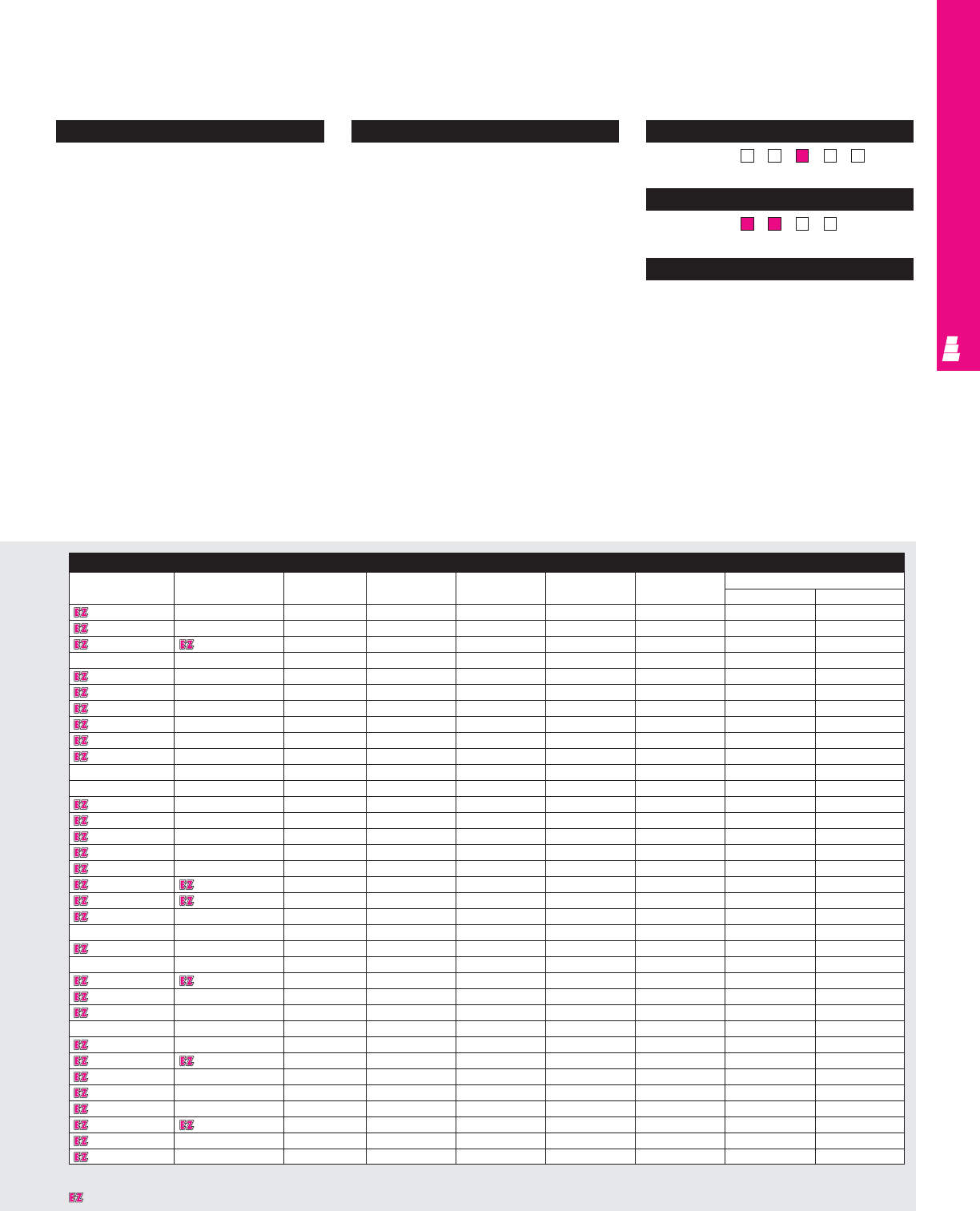
NONCORROSIVE WALLMOUNT
IND 216
Technical Specifications
Material:
•Enclosure/door: 14 gauge stainless steel
Type 304 or Type 316 (see table)
Finish:
•Enclosure/door: # 3 brushed finish
•Optional stainless steel mounting panels:
unpainted
•Optional carbon steel mounting panels:
painted white
Page . . . . . . . . . . . . . . . . . . . . . . . . . . . . IND 263
NEMA Type
144X1213
UL CUL CSA TÜV
Listings
Protection Ratings
Certifications/Approvals
Technical Drawings
Configuration
•Continuously welded seams, finished smooth
•Robotically applied urethane gasket
•Continuous stainless steel hinge with
removable pin
•Stainless steel captive clamps
•Hasp and staple for padlocking
•Door and body stiffeners on larger sizes
•Mounting panel provisions installed
•External mounting brackets
•Print pocket included
Accessories
Part No. Part No. Drip shield kit Terminal block kit Terminal rails Fast operating Window kit Dead front kits
304 SS 316 SS clamp Panel Riser
E 16H1206SS E 16H1206SS6 E DK12NFSS E 12NTMA2 E 16NS E FOC412SS E PWK95NFSS E DF16P12 E DF6R4
E 16H1208SS E 16H1208SS6 E DK12NFSS E 12NTMA2 E 16NS E FOC412SS E PWK138NFSS E DF16P12 E DF8R4
E 16H1606SS E 16H1606SS6 E DK16NFSS E 16NTMA2 E 16NS E FOC412SS E PWK95NFSS E DF16P16 E DF6R4
E 16H2006SS E 16H2006SS6 E DK20NFSS E 20NTMA2 E 16NS E FOC412SS E PWK138NFSS E DF20P16 E DF6R4
E 20H1606SS E 20H1606SS6 E DK16NFSS E 16NTMA2 E 20NS E FOC412SS E PWK138NFSS E DF20P16 E DF6R4
E 20H1608SS E 20H1608SS6 E DK16NFSS E 16NTMA2 E 20NS E FOC412SS E PWK138NFSS E DF20P16 E DF8R4
E 20H1610SS E 20H1610SS6 E DK16NFSS E 16NTMA2 E 20NS E FOC412SS E PWK138NFSS E DF20P16 E DF10R4
E 20H2006SS E 20H2006SS6 E DK20NFSS E 20NTMA2 E 20NS E FOC412SS E PWK138NFSS E DF20P20 E DF6R4
E 20H2008SS E 20H2008SS6 E DK20NFSS E 20NTMA2 E 20NS E FOC412SS E PWK138NFSS E DF20P20 E DF8R4
E 20H2408SS E 20H2408SS6 E DK24NFSS E 24NTMA3 E 20NS E FOC412SS E PWK138NFSS E DF24P20 E DF8R4
E 24H1206SS E 24H1206SS6 E DK12NFSS E 12NTMA2 E 24NS E FOC412SS E PWK138NFSS - -
E 24H1606SS E 24H1606SS6 E DK16NFSS E 16NTMA2 E 24NS E FOC412SS E PWK138NFSS - -
E 24H1608SS E 24H1608SS6 E DK16NFSS E 16NTMA2 E 24NS E FOC412SS E PWK138NFSS - -
E 24H2006SS E 24H2006SS6 E DK20NFSS E 20NTMA2 E 24NS E FOC412SS E PWK1711NFSS E DF24P20 E DF6R4
E 24H2008SS E 24H2008SS6 E DK20NFSS E 20NTMA2 E 24NS E FOC412SS E PWK1711NFSS E DF24P20 E DF8R4
E 24H2010SS E 24H2010SS6 E DK20NFSS E 20NTMA2 E 24NS E FOC412SS E PWK1711NFSS E DF24P20 E DF10R4
E 24H2406SS E 24H2406SS6 E DK24NFSS E 24NTMA3 E 24NS E FOC412SS E PWK1711NFSS E DF24P24 E DF6R4
E 24H2408SS E 24H2408SS6 E DK24NFSS E 24NTMA3 E 24NS E FOC412SS E PWK1711NFSS E DF24P24 E DF8R4
E 24H2412SS E 24H2412SS6 E DK24NFSS E 24NTMA3 E 24NS E FOC412SS E PWK1711NFSS E DF24P24 E DF12R4
E 24H3008SS E 24H3008SS6 E DK30NFSS E 30NTMA3 E 24NS E FOC412SS E PWK1711NFSS E DF30P24 E DF8R4
E 30H2006SS E 30H2006SS6 E DK20NFSS E 20NTMA2 E 30NS E FOC412SS E PWK1711NFSS - -
E 30H2008SS E 30H2008SS6 E DK20NFSS E 20NTMA2 E 30NS E FOC412SS E PWK1711NFSS - -
E 30H2406SS E 30H2406SS6 E DK24NFSS E 24NTMA3 E 30NS E FOC412SS E PWK2315NFSS E DF30P24 E DF6R4
E 30H2408SS E 30H2408SS6 E DK24NFSS E 24NTMA3 E 30NS E FOC412SS E PWK2315NFSS E DF30P24 E DF8R4
E 30H2410SS E 30H2410SS6 E DK24NFSS E 24NTMA3 E 30NS E FOC412SS E PWK2315NFSS E DF30P24 E DF10R4
E 30H2412SS E 30H2412SS6 E DK24NFSS E 24NTMA3 E 30NS E FOC412SS E PWK2315NFSS E DF30P24 E DF12R4
E 30H2416SS E 30H2416SS6 E DK24NFSS E 24NTMA3 E 30NS E FOC412SS E PWK2315NFSS E DF30P24 E DF16R4
E 30H3008SS E 30H3008SS6 E DK30NFSS E 30NTMA3 E 30NS E FOC412SS E PWK2315NFSS E DF30P30 E DF8R5
E 36H2408SS E 36H2408SS6 E DK24NFSS E 24NTMA3 E 36NS E FOC412SS E PWK2315NFSS E DF36P24 E DF8R5
E 36H2410SS E 36H2410SS6 E DK24NFSS E 24NTMA3 E 36NS E FOC412SS E PWK2315NFSS E DF36P24 E DF10R5
E 36H3008SS E 36H3008SS6 E DK30NFSS E 30NTMA3 E 36NS E FOC412SS E PWK2919NFSS E DF36P30 E DF8R5
E 36H3010SS E 36H3010SS6 E DK30NFSS E 30NTMA3 E 36NS E FOC412SS E PWK2919NFSS E DF36P30 E DF10R5
E 36H3012SS E 36H3012SS6 E DK30NFSS E 30NTMA3 E 36NS E FOC412SS E PWK2919NFSS E DF36P30 E DF12R5
E 36H3016SS E 36H3016SS6 E DK30NFSS E 30NTMA3 E 36NS E FOC412SS E PWK2919NFSS E DF36P30 E DF16R5
E 36H3612SS E 36H3612SS6 E DK36NFSS E 36NTMA3 E 36NS E FOC412SS E PWK2919NFSS E DF36P36 E DF12R6
Chart continued on page IND 218.
Designates a product in the EnclosureZone program.

IND 217
NONCORROSIVE WALLMOUNT
* Usable depth reduced by .625" at door stiffener.
Enclosure (Continued) Mounting Panel (Continued)
E 36H3612SS
Part No. Part No.
Outside dimensions (inches)
Part No.
Panel size Usable depth
304 SS 316 SS
HWD HW
E 42H3008SS E 42H3008SS6 42.00 30.00 8.00 E 42P30 39.00 27.00 7.37*
E 42H3010SS E 42H3010SS6 42.00 30.00 10.00 E 42P30 39.00 27.00 9.37*
E 42H3608SS E 42H3608SS6 42.00 36.00 8.00 E 42P36 39.00 33.00 7.37*
E 48H3010SS E 48H3010SS6 48.00 30.00 10.00 E 48P30 45.00 27.00 9.37*
E 48H3608SS E 48H3608SS6 48.00 36.00 8.00 E 48P36 45.00 33.00 7.37*
E 48H3610SS E 48H3610SS6 48.00 36.00 10.00 E 48P36 45.00 33.00 9.37*
E 48H3612SS E 48H3612SS6 48.00 36.00 12.00 E 48P36 45.00 33.00 11.37*
E 48H3616SS E 48H3616SS6 48.00 36.00 16.00 E 48P36 45.00 33.00 15.37*
E 60H3608SS E 60H3608SS6 60.00 36.00 8.00 E 60P36 57.00 33.00 7.37*
E 60H3610SS E 60H3610SS6 60.00 36.00 10.00 E 60P36 57.00 33.00 9.37*
E 60H3612SS E 60H3612SS6 60.00 36.00 12.00 E 60P36 57.00 33.00 11.37*
E 60H3616SS E 60H3616SS6 60.00 36.00 16.00 E 60P36 57.00 33.00 15.37*
Designates a product in the EnclosureZone program.
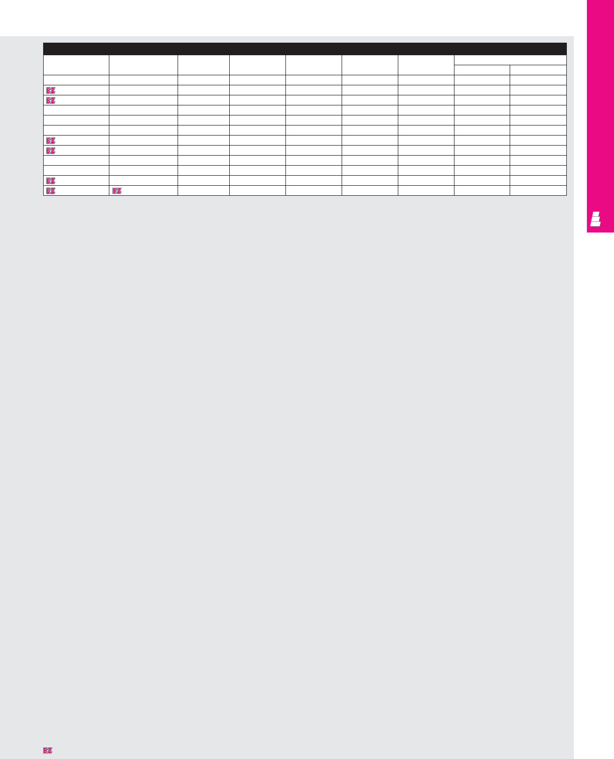
IND 218
NONCORROSIVE WALLMOUNT
Accessories (Continued)
Part No. Part No. Drip shield kit Terminal block kit Terminal rails Fast operating Window kit Dead front kit
304 SS 316 SS clamp Panel Risers
E 42H3008SS E 42H3008SS6 E DK30NFSS E 30NTMA3 E 42NS E FOC412SS E PWK2919NFSS - -
E 42H3010SS E 42H3010SS6 E DK30NFSS E 30NTMA3 E 42NS E FOC412SS E PWK2919NFSS - -
E 42H3608SS E 42H3608SS6 E DK36NFSS E 36NTMA3 E 42NS E FOC412SS E PWK2919NFSS E DF42P36 E DF8R6
E 48H3010SS E 48H3010SS6 E DK30NFSS E 30NTMA3 E 48NS E FOC412SS E PWK2919NFSS - -
E 48H3608SS E 48H3608SS6 E DK36NFSS E 36NTMA3 E 48NS E FOC412SS E PWK2919NFSS E DF48P36 E DF8R6
E 48H3610SS E 48H3610SS6 E DK36NFSS E 36NTMA3 E 48NS E FOC412SS E PWK2919NFSS E DF48P36 E DF10R6
E 48H3612SS E 48H3612SS6 E DK36NFSS E 36NTMA3 E 48NS E FOC412SS E PWK2919NFSS E DF48P36 E DF12R6
E 48H3616SS E 48H3616SS6 E DK36NFSS E 36NTMA3 E 48NS E FOC412SS E PWK2919NFSS E DF48P36 E DF16R6
E 60H3608SS E 60H3608SS6 E DK36NFSS E 36NTMA3 E 60NS E FOC412SS E PWK2919NFSS - -
E 60H3610SS E 60H3610SS6 E DK36NFSS E 36NTMA3 E 60NS E FOC412SS E PWK2919NFSS - -
E 60H3612SS E 60H3612SS6 E DK36NFSS E 36NTMA3 E 60NS E FOC412SS E PWK2919NFSS - -
E 60H3616SS E 60H3616SS6 E DK36NFSS E 36NTMA3 E 60NS E FOC412SS E PWK2919NFSS - -
Designates a product in the EnclosureZone program.
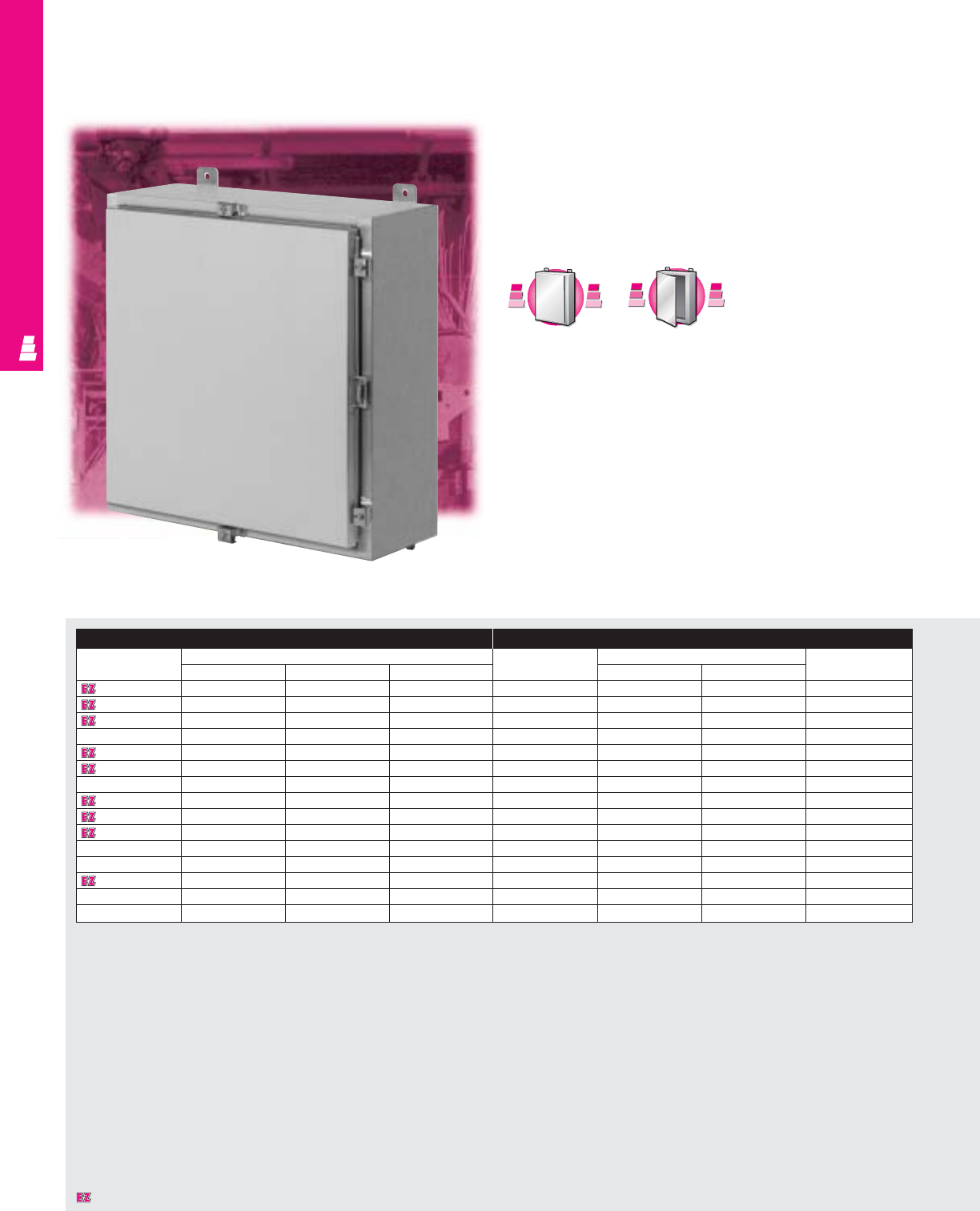
Enclosure (Style 07) Mounting Panel (Style 07)
Part No. Part No. Height Width Depth Mounting centers Part No. Mounting Usable Clamps
304 SS 316 SS Panel panel size depth
ABC H WPart No. EFG
E-404CHNFSS E-404CHNFSS6 4.00 4.00 3.00 4.75 2.00 None —— —— —— Fig. 1
E-604CHNFSS E-604CHNFSS6 6.00 4.00 3.00 6.75 2.00 E-6P4 4.88 X 2.88 2.50 Fig. 1
E-6044CHNFSS E-6044CHNFSS6 6.00 4.00 4.00 6.75 2.00 E-6P4 4.88 X 2.88 3.50 Fig. 1
E-806CHNFSS E-806CHNFSS6 8.00 6.00 3.50 8.75 4.00 E-8P6 6.88 X 4.88 3.00 Fig. 1
E-8064CHNFSS E-8064CHNFSS6 8.00 6.00 4.00 8.75 4.00 E-8P6 6.88 X 4.88 3.50 Fig. 1
E-606CHNFSS E-606CHNFSS6 6.00 6.00 4.00 6.75 4.00 E-6P6 4.88 X 4.88 3.50 Fig. 1
E-1008CHNFSS E-1008CHNFSS6 10.00 8.00 4.00 10.75 6.00 E-10P8 8.88 X 6.88 3.50 Fig. 2
E-1210CHNFSS E-1210CHNFSS6 12.00 10.00 5.00 12.75 8.00 E-12P10 10.88 X 8.88 4.50 Fig. 3
E-12106CHNFSS E-12106CHNFSS6 12.00 10.00 6.00 12.75 8.00 E-12P10 10.88 X 8.88 5.50 Fig. 3
E-10086CHNFSS E-10086CHNFSS6 10.00 8.00 6.00 10.75 6.00 E-10P8 8.88 X 6.88 5.50 Fig. 2
E-1212CHNFSS E-1212CHNFSS6 12.00 12.00 6.00 12.75 10.00 E-12P12 10.88 X 10.88 5.50 Fig. 3
E-1412CHNFSS E-1412CHNFSS6 14.00 12.00 6.00 14.75 10.00 E-14P12 12.88 X 10.88 5.50 Fig. 3
E-1614CHNFSS E-1614CHNFSS6 16.00 14.00 6.00 16.75 12.00 E-16P14 14.88 X 12.88 5.50 Fig. 4
* Footnote lorem ipsum dolor sit
NONCORROSIVE WALLMOUNT
IND 219
One Door Wallmount Boxes
NEMA 4X Aluminum Enclosures
These NEMA 4X rated aluminum enclosures are designed for
indoor or outdoor use and can be used for many different
applications. They protect installed equipment against
splashing water, seepage of water, falling or hose directed
water and severe external condensation.
Enclosure Mounting Panel
Part No. Outside dimensions (inches) Part No. Panel size Usable depth
HWD HW
E 16H1206AL 16.00 12.00 6.00 E 16P12 13.00 9.00 6.00
E 16H1608AL 16.00 16.00 8.00 E 16P16 13.00 13.00 8.00
E 20H1606AL 20.00 16.00 6.00 E 20P16 17.00 13.00 6.00
E 20H1610AL 20.00 16.00 10.00 E 20P16 17.00 13.00 10.00
E 20H2006AL 20.00 20.00 6.00 E 20P20 17.00 17.00 6.00
E 24H2006AL 24.00 20.00 6.00 E 24P20 21.00 17.00 6.00
E 24H2010AL 24.00 20.00 10.00 E 24P20 21.00 17.00 10.00
E 24H2408AL 24.00 24.00 8.00 E 24P24 21.00 21.00 8.00
E 30H2408AL 30.00 24.00 8.00 E 30P24 27.00 21.00 8.00
E 30H2412AL 30.00 24.00 12.00 E 30P24 27.00 21.00 12.00
E 36H2408AL 36.00 24.00 8.00 E 36P24 33.00 21.00 8.00
E 36H3008AL 36.00 30.00 8.00 E 36P30 33.00 27.00 7.37*
E 36H3012AL 36.00 30.00 12.00 E 36P30 33.00 27.00 11.37*
E 48H3608AL 48.00 36.00 8.00 E 48P36 45.00 33.00 7.37*
E 60H3612AL 60.00 36.00 12.00 E 60P36 57.00 33.00 11.37*
* Usable depth reduced by .625" at stiffener.
C
a
r
b
o
n
S
t
e
e
l
C
a
r
b
o
n
S
t
e
e
l
A
v
a
i
l
a
b
l
e
I
n
A
v
a
i
l
a
b
l
e
I
n
Page IND 27
S
t
a
i
n
l
e
s
s
S
t
e
e
l
S
t
a
i
n
l
e
s
s
S
t
e
e
l
A
v
a
i
l
a
b
l
e
I
n
A
v
a
i
l
a
b
l
e
I
n
Page IND 215
Designates a product in the EnclosureZone program.
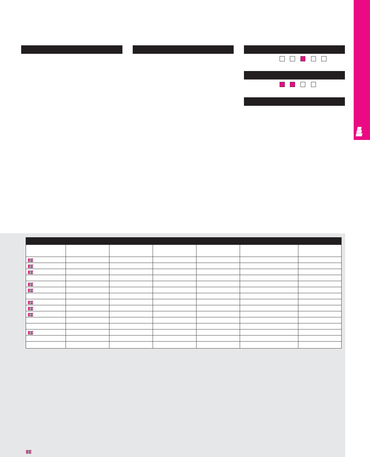
NONCORROSIVE WALLMOUNT
IND 220
Configuration
•Continuously welded seams, finished smooth
•Robotically applied urethane gasket
•Continuous hinge with removable pin
•12 gauge stainless steel captive clamps
•Hasp and staple for padlocking
•Door and body stiffeners on larger sizes
•Mounting panel provisions installed
•External mounting brackets
•Print pocket included
Technical Specifications
Material:
•Enclosure/door: .080 aluminum
Type 5052 H-32
Finish:
•Enclosure/door: natural, brushed finish
•Optional aluminum mounting panels:
unpainted
•Optional carbon steel mounting panels:
painted white
Page . . . . . . . . . . . . . . . . . . . . . . . . . . . . IND 264
NEMA Type
144X1213
UL CUL CSA TÜV
Listings
Protection Ratings
Certifications/Approvals
Technical Drawings
Accessories
Part No. Door stop kit Drip shield kit Terminal block kit Terminal rails Fast operating Window kit
clamp assembly
E 16H1206AL -E DK12NFSS E 12NTMA2 E 16NS E FOC412SS E PWK95NFSS
E 16H1608AL -E DK16NFSS E 16NTMA2 E 16NS E FOC412SS E PWK95NFSS
E 20H1606AL -E DK16NFSS E 16NTMA2 E 20NS E FOC412SS E PWK138NFSS
E 20H1610AL -E DK16NFSS E 16NTMA2 E 20NS E FOC412SS E PWK138NFSS
E 20H2006AL -E DK20NFSS E 20NTMA2 E 20NS E FOC412SS E PWK138NFSS
E 24H2006AL -E DK20NFSS E 20NTMA2 E 24NS E FOC412SS E PWK1711NFSS
E 24H2010AL -E DK20NFSS E 20NTMA2 E 24NS E FOC412SS E PWK1711NFSS
E 24H2408AL E DSTOPK E DK24NFSS E 24NTMA3 E 24NS E FOC412SS E PWK1711NFSS
E 30H2408AL E DSTOPK E DK24NFSS E 24NTMA3 E 30NS E FOC412SS E PWK2315NFSS
E 30H2412AL E DSTOPK E DK24NFSS E 24NTMA2 E 30NS E FOC412SS E PWK2315NFSS
E 36H2408AL E DSTOPK E DK24NFSS E 24NTMA2 E 36NS E FOC412SS E PWK2315NFSS
E 36H3008AL E DSTOPK E DK30NFSS E 30NTMA2 E 36NS E FOC412SS E PWK2919NFSS
E 36H3012AL E DSTOPK E DK30NFSS E 30NTMA3 E 36NS E FOC412SS E PWK2919NFSS
E 48H3608AL E DSTOPK E DK36NFSS E 36NTMA3 E 48NS E FOC412SS E PWK2919NFSS
E 60H3612AL E DSTOPK E DK36NFSS E 36NTMA3 E 60NS E FOC412SS E PWK2919NFSS
Designates a product in the EnclosureZone program.
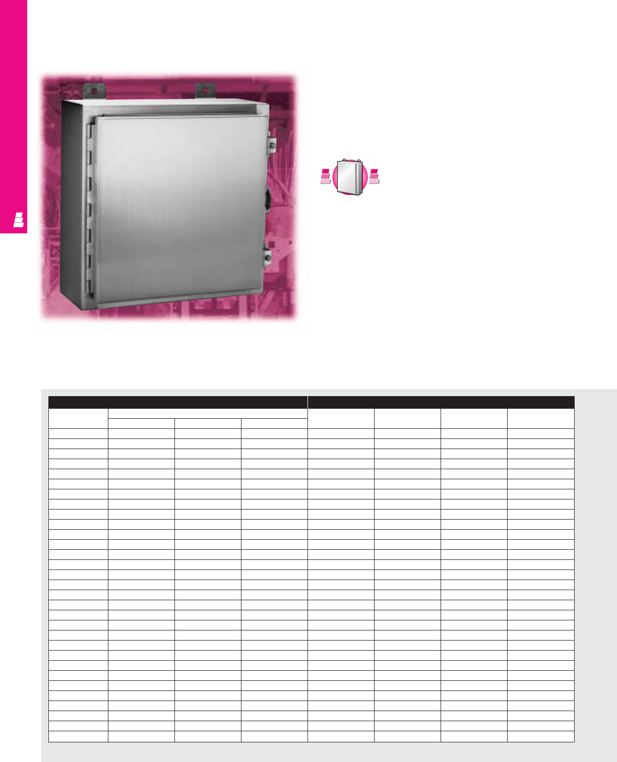
IND 221
One Door Wallmount Enclosures
Stainless Steel Electromate Boxes
These stainless steel NEMA rated enclosures are designed for
indoor or outdoor use to protect enclosed equipment against
lint and dust, external condensation, and spraying of water, oil
or coolant.
NONCORROSIVE WALLMOUNT
Enclosure Mounting Panel
Part No. Outside dimensions Part No. HWUsable depth
HWD
E 122406SS 12.00 24.00 6.00 E 12P24 9.00 21.00 6.00
E 122408SS 12.00 24.00 8.00 E 12P24 9.00 21.00 6.00
E 161206SS 16.00 12.00 6.00 E 16P12 13.00 9.00 6.00
E 161208SS 16.00 12.00 8.00 E 16P12 13.00 9.00 8.00
E 161210SS 16.00 12.00 10.00 E 16P12 13.00 9.00 10.00
E 161606SS 16.00 16.00 6.00 E 16P16 13.00 13.00 6.00
E 161608SS 16.00 16.00 8.00 E 16P16 13.00 13.00 8.00
E 162006SS 16.00 20.00 6.00 E 20P16 13.00 17.00 6.00
E 162008SS 16.00 20.00 8.00 E 20P16 13.00 17.00 8.00
E 201206SS 20.00 12.00 6.00 E 20P12 17.00 9.00 6.00
E 201208SS 20.00 12.00 8.00 E 20P12 17.00 9.00 8.00
E 201606SS 20.00 16.00 6.00 E 20P16 17.00 13.00 6.00
E 201608SS 20.00 16.00 8.00 E 20P16 17.00 13.00 8.00
E 201610SS 20.00 16.00 10.00 E 20P16 17.00 13.00 10.00
E 201612SS 20.00 16.00 12.00 E 20P16 17.00 13.00 12.00
E 202006SS 20.00 20.00 6.00 E 20P20 17.00 17.00 6.00
E 202008SS 20.00 20.00 8.00 E 20P20 17.00 17.00 8.00
E 202010SS 20.00 20.00 10.00 E 20P20 17.00 17.00 10.00
E 202406SS 20.00 24.00 6.00 E 24P20 17.00 21.00 6.00
E 202408SS 20.00 24.00 8.00 E 24P20 17.00 21.00 8.00
E 241206SS 24.00 12.00 6.00 E 12P24 21.00 9.00 6.00
E 241208SS 24.00 12.00 8.00 E 12P24 21.00 9.00 8.00
E 241210SS 24.00 12.00 10.00 E 12P24 21.00 9.00 10.00
E 241606SS 24.00 16.00 6.00 E 24P16 21.00 13.00 6.00
E 241608SS 24.00 16.00 8.00 E 24P16 21.00 13.00 8.00
E 242006SS 24.00 20.00 6.00 E 24P20 21.00 17.00 6.00
E 242008SS 24.00 20.00 8.00 E 24P20 21.00 17.00 8.00
E 242010SS 24.00 20.00 10.00 E 24P20 21.00 17.00 10.00
E 242012SS 24.00 20.00 12.00 E 24P20 21.00 17.00 12.00
E 242016SS 24.00 20.00 16.00 E 24P20 21.00 17.00 16.00
E 242406SS 24.00 24.00 6.00 E 24P24 21.00 21.00 6.00
Chart continues on page IND 223.
C
a
r
b
o
n
S
t
e
e
l
C
a
r
b
o
n
S
t
e
e
l
A
v
a
i
l
a
b
l
e
I
n
A
v
a
i
l
a
b
l
e
I
n
Page IND 29
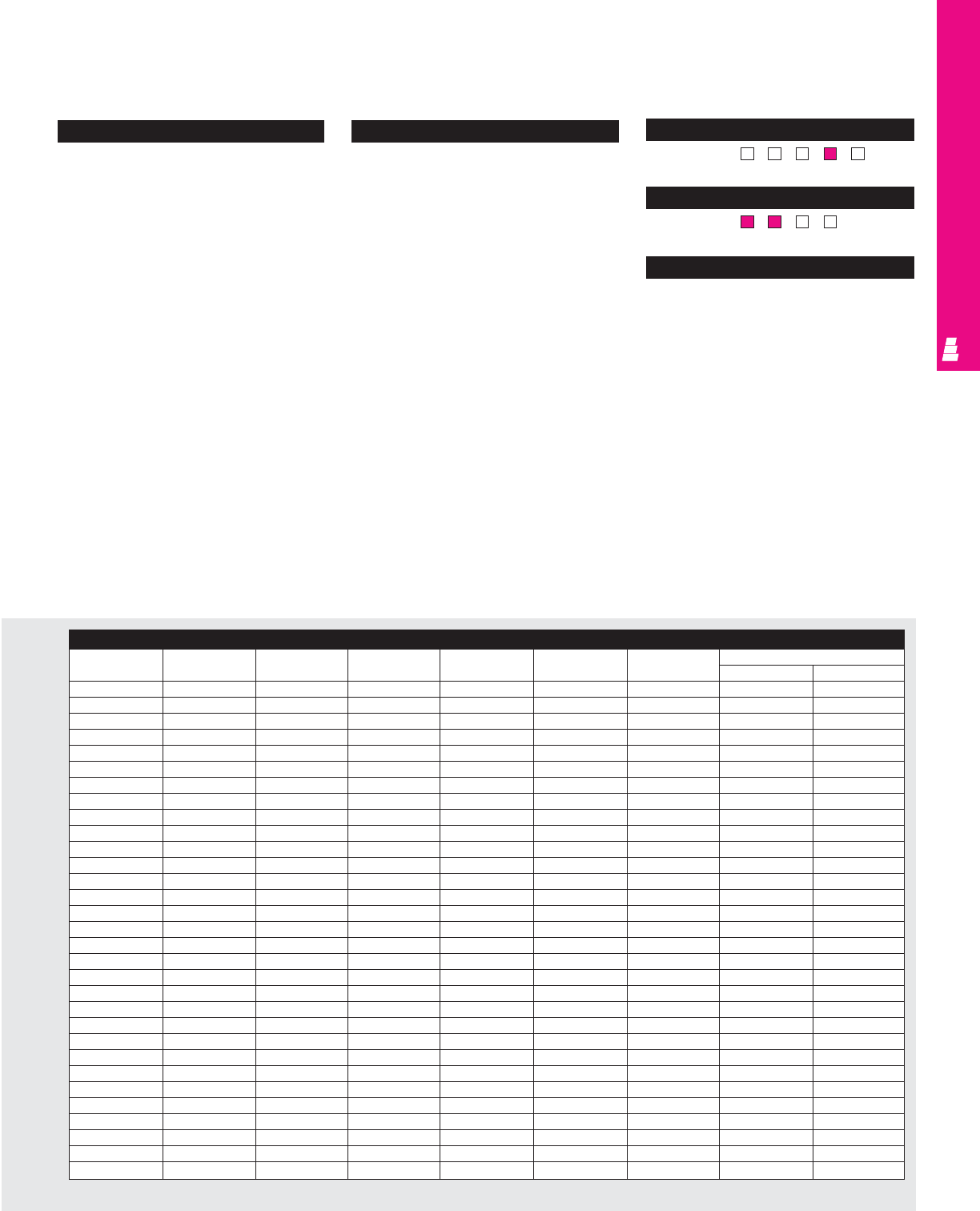
IND 222
NONCORROSIVE WALLMOUNT
Configuration
•Continuously welded seams, finished smooth
•Urethane gasket
•Continuous stainless steel hinge
•Door removed by pulling stainless steel
hinge pin
•Stainless steel captive clamps
•Hasp and staple for padlocking
•Door and body stiffeners in larger sizes
•Mounting panel provisions installed
•External mounting brackets
•Print pocket included
Technical Specifications
Material:
•Enclosure/door: 14 gauge Type 304
stainless steel
Finish/color:
•Enclosure/door: #3 brushed finish
•Optional stainless steel mounting panels:
unpainted
•Optional carbon steel mounting panels:
painted white
Pages . . . . . . . . . . . . . . . . . . . . . . . IND 265-266
NEMA Type
144X1213
UL CUL CSA TÜV
Listings
Protection Ratings
Certifications/Approvals
Technical Drawings
Chart continues on page IND 224.
Accessories
Part No. Drip shield Terminal block Terminal rails Light Fast operating Window Dead front kit
kit kit kit assembly kit Panel Riser
E 122406SS E DK24NFSS - - See ACC 29 E FOC412SS E PWK175NFSS - -
E 122408SS E DK24NFSS - - See ACC 29 E FOC412SS E PWK175NFSS - -
E 161206SS E DK12NFSS E 12NTMA2 E 16NS See ACC 29 E FOC412SS E PWK95NFSS E DF16P12 E DF6R4
E 161208SS E DK12NFSS E 12NTMA2 E 16NS See ACC 29 E FOC412SS E PWK95NFSS E DF16P12 E DF8R4
E 161210SS E DK12NFSS E 12NTMA2 E 16NS See ACC 29 E FOC412SS E PWK95NFSS E DF16P12 E DF10R4
E 161606SS E DK16NFSS E 16NTMA2 E 16NS See ACC 29 E FOC412SS E PWK138NFSS E DF16P16 E DF6R4
E 161608SS E DK16NFSS E 16NTMA2 E 16NS See ACC 29 E FOC412SS E PWK138NFSS E DF16P16 E DF8R4
E 162006SS E DK20NFSS E 20NTMA2 E 16NS See ACC 29 E FOC412SS E PWK138NFSS E DF20P16 E DF6R4
E 162008SS E DK20NFSS E 20NTMA2 E 16NS See ACC 29 E FOC412SS E PWK138NFSS E DF20P16 E DF8R4
E 201206SS E DK12NFSS E 12NTMA2 E 20NS See ACC 29 E FOC412SS E PWK138NFSS - -
E 201208SS E DK12NFSS E 12NTMA2 E 20NS See ACC 29 E FOC412SS E PWK138NFSS - -
E 201606SS E DK16NFSS E 16NTMA2 E 20NS See ACC 29 E FOC412SS E PWK138NFSS E DF20P16 E DF6R4
E 201608SS E DK16NFSS E 16NTMA2 E 20NS See ACC 29 E FOC412SS E PWK138NFSS E DF20P16 E DF8R4
E 201610SS E DK16NFSS E 16NTMA2 E 20NS See ACC 29 E FOC412SS E PWK138NFSS E DF20P16 E DF10R4
E 201612SS E DK16NFSS E 16NTMA2 E 20NS See ACC 29 E FOC412SS E PWK138NFSS E DF20P16 E DF12R4
E 202006SS E DK20NFSS E 20NTMA2 E 20NS See ACC 29 E FOC412SS E PWK138NFSS E DF20P20 E DF6R4
E 202008SS E DK20NFSS E 20NTMA2 E 20NS See ACC 29 E FOC412SS E PWK138NFSS E DF20P20 E DF8R4
E 202010SS E DK20NFSS E 20NTMA2 E 20NS See ACC 29 E FOC412SS E PWK138NFSS E DF20P20 E DF10R4
E 202406SS E DK24NFSS E 24NTMA3 E 20NS See ACC 29 E FOC412SS E PWK1711NFSS E DF24P20 E DF6R4
E 202408SS E DK24NFSS E 24NTMA3 E 20NS See ACC 29 E FOC412SS E PWK1711NFSS E DF24P20 E DF8R4
E 241206SS E DK12NFSS E 12NTMA2 E 24NS See ACC 29 E FOC412SS E PWK175NFSS - -
E 241208SS E DK12NFSS E 12NTMA2 E 24NS See ACC 29 E FOC412SS E PWK175NFSS - -
E 241210SS E DK12NFSS E 12NTMA2 E 24NS See ACC 29 E FOC412SS E PWK175NFSS - -
E 241606SS E DK16NFSS E 16NTMA2 E 24NS See ACC 29 E FOC412SS E PWK138NFSS - -
E 241608SS E DK16NFSS E 16NTMA2 E 24NS See ACC 29 E FOC412SS E PWK138NFSS - -
E 242006SS E DK20NFSS E 20NTMA2 E 24NS See ACC 29 E FOC412SS E PWK1711NFSS E DF24P20 E DF6R4
E 242008SS E DK20NFSS E 20NTMA2 E 24NS See ACC 29 E FOC412SS E PWK1711NFSS E DF24P20 E DF8R4
E 242010SS E DK20NFSS E 20NTMA2 E 24NS See ACC 29 E FOC412SS E PWK1711NFSS E DF24P20 E DF10R4
E 242012SS E DK20NFSS E 20NTMA2 E 24NS See ACC 29 E FOC412SS E PWK1711NFSS E DF24P20 E DF12R4
E 242016SS E DK20NFSS E 20NTMA2 E 24NS See ACC 29 E FOC412SS E PWK1711NFSS E DF24P20 E DF16R4
E 242406SS E DK24NFSS E 24NTMA3 E 24NS See ACC 29 E FOC412SS E PWK1711NFSS E DF24P24 E DF6R4
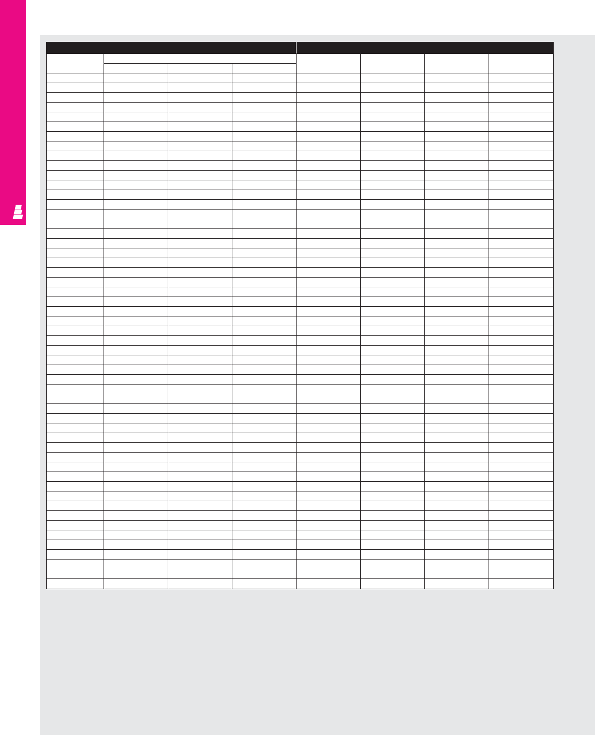
IND 223
NONCORROSIVE WALLMOUNT
Enclosure (Continued) Mounting Panel (Continued)
Part No. Outside dimensions Part No. HWUsable depth
HWD
E 242408SS 24.00 24.00 8.00 E 24P24 21.00 21.00 8.00
E 242410SS 24.00 24.00 10.00 E 24P24 21.00 21.00 10.00
E 242412SS 24.00 24.00 12.00 E 24P24 21.00 21.00 12.00
E 242416SS 24.00 24.00 16.00 E 24P24 21.00 21.00 16.00
E 243008SS 24.00 30.00 8.00 E 30P24 21.00 27.00 8.00
E 301606SS 30.00 16.00 6.00 E 30P16 27.00 13.00 6.00
E 302006SS 30.00 20.00 6.00 E 30P20 27.00 17.00 6.00
E 302008SS 30.00 20.00 8.00 E 30P20 27.00 17.00 8.00
E 302010SS 30.00 20.00 10.00 E 30P20 27.00 17.00 10.00
E 302406SS 30.00 24.00 6.00 E 30P24 27.00 21.00 6.00
E 302408SS 30.00 24.00 8.00 E 30P24 27.00 21.00 8.00
E 302410SS 30.00 24.00 10.00 E 30P24 27.00 21.00 10.00
E 302412SS 30.00 24.00 12.00 E 30P24 27.00 21.00 12.00
E 302416SS 30.00 24.00 16.00 E 30P24 27.00 21.00 16.00
E 302420SS 30.00 24.00 20.00 E 30P24 27.00 21.00 20.00
E 303008SS 30.00 30.00 8.00 E 30P30 27.00 27.00 8.00
E 303012SS 30.00 30.00 12.00 E 30P30 27.00 27.00 12.00
E 303608SS 30.00 36.00 8.00 E 36P30 27.00 33.00 8.00
E 362406SS 36.00 24.00 6.00 E 36P24 33.00 21.00 6.00
E 362408SS 36.00 24.00 8.00 E 36P24 33.00 21.00 8.00
E 362410SS 36.00 24.00 10.00 E 36P24 33.00 21.00 10.00
E 362412SS 36.00 24.00 12.00 E 36P24 33.00 21.00 12.00
E 363006SS 36.00 30.00 6.00 E 36P30 33.00 27.00 5.37*
E 363008SS 36.00 30.00 8.00 E 36P30 33.00 27.00 7.37*
E 363010SS 36.00 30.00 10.00 E 36P30 33.00 27.00 9.37*
E 363012SS 36.00 30.00 12.00 E 36P30 33.00 27.00 11.37*
E 363016SS 36.00 30.00 16.00 E 36P30 33.00 27.00 15.37*
E 363020SS 36.00 30.00 20.00 E 36P30 33.00 27.00 19.37*
E 363608SS 36.00 36.00 8.00 E 36P30 33.00 27.00 7.37*
E 363612SS 36.00 36.00 12.00 E 36P36 33.00 33.00 11.37*
E 422408SS 42.00 24.00 8.00 E 42P24 39.00 21.00 8.00
E 423008SS 42.00 30.00 8.00 E 42P30 39.00 27.00 7.37*
E 423010SS 42.00 30.00 10.00 E 42P30 39.00 27.00 9.37*
E 423012SS 42.00 30.00 12.00 E 42P30 39.00 27.00 11.37*
E 423608SS 42.00 36.00 8.00 E 42P36 39.00 33.00 7.37*
E 423610SS 42.00 36.00 10.00 E 42P36 39.00 33.00 9.37*
E 423612SS 42.00 36.00 12.00 E 42P36 39.00 33.00 11.37*
E 423616SS 42.00 36.00 16.00 E 42P36 39.00 33.00 15.37*
E 482408SS 48.00 24.00 8.00 E 42P24 39.00 21.00 8.00
E 483008SS 48.00 30.00 8.00 E 48P30 45.00 27.00 7.37*
E 483010SS 48.00 30.00 10.00 E 48P30 45.00 27.00 9.37*
E 483608SS 48.00 36.00 8.00 E 48P36 45.00 33.00 7.37*
E 483610SS 48.00 36.00 10.00 E 48P36 45.00 33.00 9.37*
E 483612SS 48.00 36.00 12.00 E 48P36 45.00 33.00 11.37*
E 483616SS 48.00 36.00 16.00 E 48P36 45.00 33.00 15.37*
E 483620SS 48.00 36.00 20.00 E 48P36 45.00 33.00 19.37*
E 603608SS 60.00 36.00 8.00 E 60P36 57.00 33.00 7.37*
E 603610SS 60.00 36.00 10.00 E 60P36 57.00 33.00 9.37*
E 603612SS 60.00 36.00 12.00 E 60P36 57.00 33.00 11.37*
E 603616SS 60.00 36.00 16.00 E 60P36 57.00 33.00 15.37*
E 603620SS 60.00 36.00 20.00 E 60P36 57.00 33.00 19.37*
E 723016SS 72.00 30.00 16.00 E 72P30 69.00 27.00 15.37*
E 723612SS 72.00 36.00 12.00 E 72P36 69.00 33.00 11.37*
* Usable depth reduced by .625" at door stiffener.
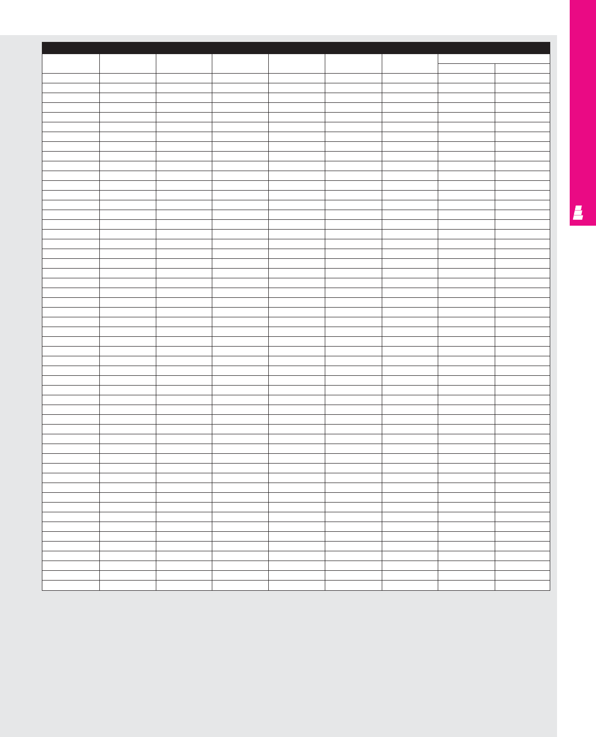
IND 224
NONCORROSIVE WALLMOUNT
Accessories (Continued)
Part No. Drip shield Terminal block Terminal rails Light Fast operating Window Dead front kit
kit kit kit assembly kit Panel Riser
E 242408SS E DK24NFSS E 24NTMA3 E 24NS See ACC 29 E FOC412SS E PWK1711NFSS E DF24P24 E DF8R4
E 242410SS E DK24NFSS E 24NTMA3 E 24NS See ACC 29 E FOC412SS E PWK1711NFSS E DF24P24 E DF10R4
E 242412SS E DK24NFSS E 24NTMA3 E 24NS See ACC 29 E FOC412SS E PWK1711NFSS E DF24P24 E DF12R4
E 242416SS E DK24NFSS E 24NTMA3 E 24NS See ACC 29 E FOC412SS E PWK1711NFSS E DF24P24 E DF16R4
E 243008SS E DK30NFSS E 30NTMA3 E 24NS See ACC 29 E FOC412SS E PWK1711NFSS E DF30P24 E DF8R4
E 301606SS E DK16NFSS E 16NTMA2 E 30NS See ACC 29 E FOC412SS E PWK138NFSS - -
E 302006SS E DK20NFSS E 20NTMA2 E 30NS See ACC 29 E FOC412SS E PWK1711NFSS - -
E 302008SS E DK20NFSS E 20NTMA2 E 30NS See ACC 29 E FOC412SS E PWK1711NFSS - -
E 302010SS E DK20NFSS E 20NTMA2 E 30NS See ACC 29 E FOC412SS E PWK1711NFSS - -
E 302406SS E DK24NFSS E 24NTMA3 E 30NS See ACC 29 E FOC412SS E PWK2315NFSS E DF30P24 E DF6R4
E 302408SS E DK24NFSS E 24NTMA3 E 30NS See ACC 29 E FOC412SS E PWK2315NFSS E DF30P24 E DF8R4
E 302410SS E DK24NFSS E 24NTMA3 E 30NS See ACC 29 E FOC412SS E PWK2315NFSS E DF30P24 E DF10R4
E 302412SS E DK24NFSS E 24NTMA3 E 30NS See ACC 29 E FOC412SS E PWK2315NFSS E DF30P24 E DF12R4
E 302416SS E DK24NFSS E 24NTMA3 E 30NS See ACC 29 E FOC412SS E PWK2315NFSS E DF30P24 E DF16R4
E 302420SS E DK24NFSS E 24NTMA3 E 30NS See ACC 29 E FOC412SS E PWK2315NFSS E DF30P24 E DF16R4
E 303008SS E DK30NFSS E 30NTMA3 E 30NS See ACC 29 E FOC412SS E PWK2315NFSS E DF30P30 E DF8R5
E 303012SS E DK30NFSS E 30NTMA3 E 30NS See ACC 29 E FOC412SS E PWK2315NFSS E DF30P30 E DF12R5
E 303608SS E DK36NFSS E 36NTMA3 E 30NS See ACC 29 E FOC412SS E PWK2919NFSS E DF36P30 E DF8R5
E 362406SS E DK24NFSS E 24NTMA3 E 36NS See ACC 29 E FOC412SS E PWK2315NFSS - -
E 362408SS E DK24NFSS E 24NTMA3 E 36NS See ACC 29 E FOC412SS E PWK2315NFSS E DF36P24 E DF8R5
E 362410SS E DK24NFSS E 24NTMA3 E 36NS See ACC 29 E FOC412SS E PWK2315NFSS E DF36P24 E DF10R5
E 362412SS E DK24NFSS E 24NTMA3 E 36NS See ACC 29 E FOC412SS E PWK2315NFSS E DF36P24 E DF12R5
E 363006SS E DK30NFSS E 30NTMA3 E 36NS See ACC 29 E FOC412SS E PWK2919NFSS - -
E 363008SS E DK30NFSS E 30NTMA3 E 36NS See ACC 29 E FOC412SS E PWK2919NFSS E DF36P30 E DF8R5
E 363010SS E DK30NFSS E 30NTMA3 E 36NS See ACC 29 E FOC412SS E PWK2919NFSS E DF36P30 E DF10R5
E 363012SS E DK30NFSS E 30NTMA3 E 36NS See ACC 29 E FOC412SS E PWK2919NFSS E DF36P30 E DF12R5
E 363016SS E DK30NFSS E 30NTMA3 E 36NS See ACC 29 E FOC412SS E PWK2919NFSS E DF36P30 E DF16R5
E 363020SS E DK30NFSS E 30NTMA3 E 36NS See ACC 29 E FOC412SS E PWK2919NFSS E DF36P30 E DF16R5
E 363608SS E DK36NFSS E 36NTMA3 E 36NS See ACC 29 E FOC412SS E PWK2919NFSS E DF36P36 E DF8R6
E 363612SS E DK36NFSS E 36NTMA3 E 36NS See ACC 29 E FOC412SS E PWK2919NFSS E DF36P36 E DF12R6
E 422408SS E DK24NFSS E 24NTMA3 E 42NS See ACC 29 E FOC412SS E PWK2315NFSS - -
E 423008SS E DK30NFSS E 30NTMA3 E 42NS See ACC 29 E FOC412SS E PWK2919NFSS - -
E 423010SS E DK30NFSS E 30NTMA3 E 42NS See ACC 29 E FOC412SS E PWK2919NFSS - -
E 423012SS E DK30NFSS E 30NTMA3 E 42NS See ACC 29 E FOC412SS E PWK2919NFSS - -
E 423608SS E DK36NFSS E 36NTMA3 E 42NS See ACC 29 E FOC412SS E PWK2919NFSS E DF42P36 E DF8R6
E 423610SS E DK36NFSS E 36NTMA3 E 42NS See ACC 29 E FOC412SS E PWK2919NFSS E DF42P36 E DF10R6
E 423612SS E DK36NFSS E 36NTMA3 E 42NS See ACC 29 E FOC412SS E PWK2919NFSS E DF42P36 E DF12R6
E 423616SS E DK36NFSS E 36NTMA3 E 42NS See ACC 29 E FOC412SS E PWK2919NFSS E DF42P36 E DF16R6
E 482408SS E DK24NFSS E 24NTMA3 E 48NS See ACC 29 E FOC412SS E PWK2919NFSS - -
E 483008SS E DK30NFSS E 30NTMA3 E 48NS See ACC 29 E FOC412SS E PWK2919NFSS - -
E 483010SS E DK30NFSS E 30NTMA3 E 48NS See ACC 29 E FOC412SS E PWK2919NFSS - -
E 483608SS E DK36NFSS E 36NTMA3 E 48NS See ACC 29 E FOC412SS E PWK2919NFSS E DF48P36 E DF8R6
E 483610SS E DK36NFSS E 36NTMA3 E 48NS See ACC 29 E FOC412SS E PWK2919NFSS E DF48P36 E DF10R6
E 483612SS E DK36NFSS E 36NTMA3 E 48NS See ACC 29 E FOC412SS E PWK2919NFSS E DF48P36 E DF12R6
E 483616SS E DK36NFSS E 36NTMA3 E 48NS See ACC 29 E FOC412SS E PWK2919NFSS E DF48P36 E DF16R6
E 483620SS E DK36NFSS E 36NTMA3 E 48NS See ACC 29 E FOC412SS E PWK2919NFSS E DF48P36 E DF16R6
E 603608SS E DK36NFSS E 36NTMA3 E 60NS See ACC 29 E FOC412SS E PWK2919NFSS - -
E 603610SS E DK36NFSS E 36NTMA3 E 60NS See ACC 29 E FOC412SS E PWK2919NFSS - -
E 603612SS E DK36NFSS E 36NTMA3 E 60NS See ACC 29 E FOC412SS E PWK2919NFSS - -
E 603616SS E DK36NFSS E 36NTMA3 E 60NS See ACC 29 E FOC412SS E PWK2919NFSS - -
E 603620SS E DK36NFSS E 36NTMA3 E 60NS See ACC 29 E FOC412SS E PWK2919NFSS - -
E 723016SS E DK30NFSS - - See ACC 29 E FOC412SS E PWK2919NFSS - -
E 723612SS E DK36NFSS - - See ACC 29 E FOC412SS E PWK2919NFSS - -
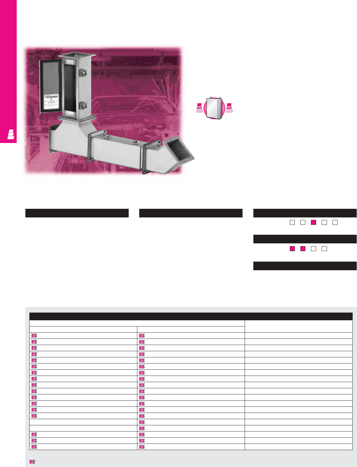
NONCORROSIVE WIREWAY
Configuration
•Stainless steel feed-through wireways are
available in two sizes:
4.0" x 4.0"
6.0" x 6.0"
•Lengths from 12" to 120"
•Continuously welded seams, finished smooth
•Edges on all sections and fittings are
finished to prevent damage to wiring
•A complete seal is ensured through heavy
butt hinges and quick-release latches
• Oil-resistant gaskets inside cover and
between flanges ensure seal when sections
and fittings are bolted together
Technical Specifications
Material:
•Wireways/covers: 14 gauge stainless steel
•Flange ends: 10 gauge stainless steel
Finish:
•Wireways/covers: # 3 brushed finish
Pages . . . . . . . . . . . . . . . . . . . . . . . IND 267-268
NEMA Type
144X12 13
UL CUL CSA TÜV
Listings
Protection Ratings
Certifications/Approvals
Technical Drawings
IND 225
Feed-Through Type 4X Wireway
Stainless Steel Wire Management
Rittal Electromate’s stainless steel feed-through wireway
products were designed to be used in applications where the
environment is wet or corrosive. All straight sections feature a
hinged-top design for easy access.
Wireway
Part. No.
Description
4.00 x 4.00 6.00 x 6.00
E 44W12SS E 66W12SS 12.00" Straight section
E 44W24SS E 66W24SS 24.00" Straight section
E 44W36SS E 66W36SS 36.00" Straight section
E 44W48SS E 66W48SS 48.00" Straight section
E 44W60SS E 66W60SS 60.00" Straight section
E 44W120SS E 66W120SS 120.00" Straight section
E 44WASS E 66WASS Telescopic fitting
E 44WX E 66WX Cutoff fitting
E 44WE45SS E 66WE45SS 45° Elbow
E 44WE90SS E 66WE90SS 90° Elbow
E 44WTSS E 66WTSS Tee
E 44WPSS E 66WPSS Closure plate
E 44WBSS E 66WBSS Box connecting kit
E 44WGSS E 66WGSS Collar gasket
-E 66WR44SS Reducer 6" to 4", center hole
-E 66WRE44SS Reducer 6" to 4", edge hole
E 44WN6SS E 66WN6SS 6.00" Nipple
E 44HBSS E 66HBSS Bracket hanger
E 44HDSS E 66HDSS Drop hanger
C
a
r
b
o
n
S
t
e
e
l
C
a
r
b
o
n
S
t
e
e
l
A
v
a
i
l
a
b
l
e
I
n
A
v
a
i
l
a
b
l
e
I
n
Page IND 61
Designates a product in the EnclosureZone program.
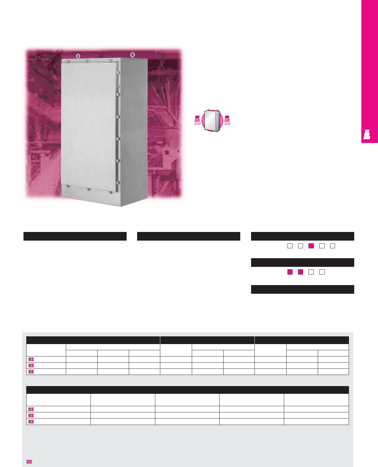
NONCORROSIVE FREESTANDING
IND 226
Configuration
•Continuously welded seams, finished smooth
•Neoprene strip gasket
•Continuous stainless steel hinge with
removable pin
•Hasp and staple for padlock
•Stainless steel captive clamps
•Removable heavy duty lifting eyes mounted
to the top
•C-channels are welded to interior sides for
optional mounting
•Print pocket included
Technical Specifications
Material:
•Enclosure/door: 12 gauge Type 304
stainless steel
Finish/color:
•Enclosure/door: # 3 brushed finish
•Optional stainless steel mounting panels:
unpainted
•Optional carbon steel mounting panels:
painted white
Page . . . . . . . . . . . . . . . . . . . . . . . . . . . IND 269
NEMA Type
144X1213
UL CUL CSA TÜV
Listings
Protection Ratings
Certifications/Approvals
Technical Drawings
One Door Freestanding Enclosures
NEMA Rated Stainless Steel Enclosures
Rittal Electromate NEMA 4X freestanding stainless steel
enclosures accept standard as well as rackmount electrical and
electronic components. These enclosures are intended for
indoor or outdoor applications to protect installed equipment
against splashing water, seepage of water, falling or hose
directed water, and external condensation.
Enclosure Full Mounting Panel Half Mounting Panel
Part No. Outside dimensions (inches) Part No. Panel size Part No. Panel size
HW D H W HW
E 72H2518FSSS 72.00 25.00 18.00 E 72P24F1 60.00 20.00 E 72P24F2 30.88 20.00
E 72H3124FSSS 72.00 31.00 24.00 E 72P30F1 60.00 26.00 E 72P30F2 30.88 26.00
E 72H3724FSSS 72.00 37.00 24.00 E 72P36F1 60.00 32.00 E 72P36F2 30.88 32.00
Accessories
Part No. Door stop kit Window kit Fast operating clamp Light kit
E 72H2518FSSS E DSTOPK E PWK2315NFSS E FOC412SS See ACC 29
E 72H3124FSSS E DSTOPK E PWK3523NFSS E FOC412SS See ACC 29
E 72H3724FSSS E DSTOPK E PWK3523NFSS E FOC412SS See ACC 29
C
a
r
b
o
n
S
t
e
e
l
C
a
r
b
o
n
S
t
e
e
l
A
v
a
i
l
a
b
l
e
I
n
A
v
a
i
l
a
b
l
e
I
n
Page IND 75
Designates a product in the EnclosureZone program.
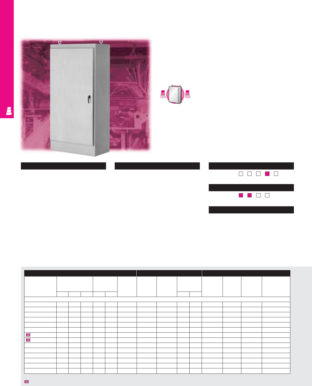
NONCORROSIVE FREESTANDING
IND 227
Configuration
•Standard types are available
Type “FS” – one door, single access
Type “FSDD” – two door, single access
Type “FSDA” – one door, dual access
Type “FSDAD” – two door, dual access
•Continuously welded seams, finished smooth
•Body stiffener for added support
•Neoprene strip gasket
•Continuous stainless steel hinge with
removable pin
•3-point latch with oil tight key
locking handle
•Removable heavy duty lifting eyes
mounted to the top
•C-channels are welded to interior sides for
optional mounting
•Print pocket included
Technical Specifications
Material:
•All steel parts: 12 gauge Type 304
stainless steel
Back of FSDD: 10 gauge Type 304
stainless steel
Finish:
•Enclosure/door(s): # 3 brushed finish
•Optional carbon steel mounting panels:
painted white
Pages . . . . . . . . . . . . . . . . . . . . . . . . IND 270-271
NEMA Type
144X12 13
UL CUL CSA TÜV
Listings
Protection Ratings
Certifications/Approvals
Technical Drawings
Single/Dual Access Enclosures
Rittal Electromate stainless steel NEMA rated freestanding
enclosures accept standard as well as rackmount electrical and
electronic components. These enclosures are intended for
indoor applications to protect installed equipment against dust,
dirt, oil and water.
One/Two Door Freestanding Cabinets
C
a
r
b
o
n
S
t
e
e
l
C
a
r
b
o
n
S
t
e
e
l
A
v
a
i
l
a
b
l
e
I
n
A
v
a
i
l
a
b
l
e
I
n
Page IND 77
Designates a product in the EnclosureZone program.
Enclosure Mounting Panel Accessories
Part No. Outside dimensions Door size Maximum
Part No.
Description Panel size Handle Door stop Light kit Window kit
(inches) usable accessories kit
depth panel
HWDHWinstalled H W
One Door Single Access
E 602418FSSS 60.00 24.00 18.00 50.25 22.22 17.63
E 60P24F1
Full panel 48.00 20.00 See ACC 20 E DSTOPK See ACC 29 E PWK2315NFSS
E 603624FSSS 60.00 36.00 24.00 50.25 34.22 23.63
E 60P36F1
Full panel 48.00 32.00 See ACC 20 E DSTOPK See ACC 29 E PWK3523NFSS
E 722418FSSS 72.00 24.00 18.00 62.25 22.22 17.63
E 72P24F1
Full panel 60.00 20.00 See ACC 20 E DSTOPK See ACC 29 E PWK2315NFSS
E 722424FSSS 72.00 24.00 24.00 62.25 22.22 23.63
E 72P24F1
Full panel 60.00 20.00 See ACC 20 E DSTOPK See ACC 29 E PWK2315NFSS
E 723018FSSS 72.00 30.00 18.00 62.25 28.22 17.63
E 72P30F1
Full panel 60.00 26.00 See ACC 20 E DSTOPK See ACC 29 E PWK3523NFSS
E 723024FSSS 72.00 30.00 24.00 62.25 28.22 23.63
E 72P30F1
Full panel 60.00 26.00 See ACC 20 E DSTOPK See ACC 29 E PWK3523NFSS
E 723618FSSS 72.00 36.00 18.00 62.25 34.22 17.63
E 72P36F1
Full panel 60.00 32.00 See ACC 20 E DSTOPK See ACC 29 E PWK3523NFSS
E 723624FSSS 72.00 36.00 24.00 62.25 34.22 23.63
E 72P36F1
Full panel 60.00 32.00 See ACC 20 E DSTOPK See ACC 29 E PWK3523NFSS
E 723630FSSS 72.00 36.00 30.00 62.25 34.22 29.63
E 72P36F1
Full panel 60.00 32.00 See ACC 20 E DSTOPK See ACC 29 E PWK3523NFSS
E 723636FSSS 72.00 36.00 36.00 62.25 34.22 35.63
E 72P36F1
Full panel 60.00 32.00 See ACC 20 E DSTOPK See ACC 29 E PWK3523NFSS
E 902420FSSS 90.00 24.00 20.00 80.25 22.22 19.63
E 90P24F1
Full panel 78.00 20.00 See ACC 20 E DSTOPK See ACC 29 E PWK2315NFSS
E 903620FSSS 90.00 36.00 20.00 80.25 34.22 19.63
E 90P36F1
Full panel 78.00 32.00 See ACC 20 E DSTOPK See ACC 29 E PWK3523NFSS
E 903624FSSS 90.00 36.00 24.00 80.25 34.22 23.63
E 90P36F1
Full panel 78.00 32.00 See ACC 20 E DSTOPK See ACC 29 E PWK3523NFSS
E 903636FSSS 90.00 36.00 36.00 80.25 34.22 35.63
E 90P36F1
Full panel 78.00 32.00 See ACC 20 E DSTOPK See ACC 29 E PWK3523NFSS
NONCORROSIVE FREESTANDING
IND 228
Enclosure Mounting Panel Accessories
Part No. Outside dimensions Door size Maximum Part No. Description Panel size Handle Door stop Light kit Window kit
(inches) usable accessories kit
depth panel
HWDHWinstalled H W
Two Door Single Access
E 604818FSDDSS
60.00 48.00 18.00 50.25 23.06 15.13
E 60P48F1
Full panel 48.00 44.00 See ACC 20 E DSTOPK See ACC 29 E PWK2315NFSS
E 724818FSDDSS
72.00 48.00 18.00 62.25 23.06 15.13
E 72P48F1
Full panel 60.00 44.00 See ACC 20 E DSTOPK See ACC 29 E PWK2315NFSS
E 724824FSDDSS
72.00 48.00 24.00 62.25 23.06 21.13
E 72P48F1
Full panel 60.00 44.00 See ACC 20 E DSTOPK See ACC 29 E PWK2315NFSS
E 726018FSDDSS
72.00 60.00 18.00 62.25 29.06 15.13
E 72P60F1
Full panel 60.00 56.00 See ACC 20 E DSTOPK See ACC 29 E PWK2919NFSS
E 726024FSDDSS
72.00 60.00 24.00 62.25 29.06 21.13
E 72P60F1
Full panel 60.00 56.00 See ACC 20 E DSTOPK See ACC 29 E PWK2919NFSS
E 726036FSDDSS
72.00 60.00 36.00 62.25 29.06 33.13
E 72P60F1
Full panel 60.00 56.00 See ACC 20 E DSTOPK See ACC 29 E PWK2919NFSS
E 727218FSDDSS
72.00 72.00 18.00 62.25 35.06 15.13
E 72P72F1
Full panel 60.00 68.00 See ACC 20 E DSTOPK See ACC 29 E PWK3523NFSS
E 727224FSDDSS
72.00 72.00 24.00 62.25 35.06 21.13
E 72P72F1
Full panel 60.00 68.00 See ACC 20 E DSTOPK See ACC 29 E PWK3523NFSS
E 904820FSDDSS
90.00 48.00 20.00 80.25 23.06 17.13
E 90P48F1
Full panel 78.00 44.00 See ACC 20 E DSTOPK See ACC 29 E PWK2315NFSS
E 907220FSDDSS
90.00 72.00 20.00 80.25 35.06 17.13
E 90P72F1
Full panel 78.00 68.00 See ACC 20 E DSTOPK See ACC 29 E PWK2919NFSS
E 907224FSDDSS
90.00 72.00 24.00 80.25 35.06 21.13
E 90P72F1
Full panel 78.00 68.00 See ACC 20 E DSTOPK See ACC 29 E PWK3523NFSS
E 907236FSDDSS
90.00 72.00 36.00 80.25 35.06 33.13
E 90P72F1
Full panel 78.00 68.00 See ACC 20 E DSTOPK See ACC 29 E PWK3523NFSS
Designates a product in the EnclosureZone program.
Enclosure Mounting Panel Accessories
Part No. Outside dimensions Door size Maximum
Part No.
Description Panel size Handle Door stop Light kit Window kit
(inches) usable accessories kit
depth panel
HWDHWinstalled H W
One Door Dual Access
E 722424FSDASS 72.00 24.00 24.00 62.25 22.31 -
E 72P24F1
Full panel 60.00 20.00 See ACC 20 E DSTOPK See ACC 29 E PWK2315NFSS
E 722430FSDASS 72.00 24.00 30.00 62.25 22.31 -
E 72P24F1
Full panel 60.00 20.00 See ACC 20 E DSTOPK See ACC 29 E PWK2315NFSS
E 722436FSDASS 72.00 24.00 36.00 62.25 22.31 -
E 72P24F1
Full panel 60.00 20.00 See ACC 20 E DSTOPK See ACC 29 E PWK2315NFSS
E 723024FSDASS 72.00 30.00 24.00 62.25 28.31 -
E 72P30F1
Full panel 60.00 26.00 See ACC 20 E DSTOPK See ACC 29 E PWK2919NFSS
E 723624FSDASS 72.00 36.00 24.00 62.25 34.31 -
E 72P36F1
Full panel 60.00 32.00 See ACC 20 E DSTOPK See ACC 29 E PWK3523NFSS
E 723636FSDASS 72.00 36.00 36.00 62.25 34.31 -
E 72P36F1
Full panel 60.00 32.00 See ACC 20 E DSTOPK See ACC 29 E PWK3523NFSS
E 903624FSDASS 90.00 36.00 24.00 80.25 34.31 -
E 90P36F1
Full panel 78.00 32.00 See ACC 20 E DSTOPK See ACC 29 E PWK3523NFSS
E 903636FSDASS 90.00 36.00 36.00 80.25 34.31 -
E 90P36F1
Full panel 78.00 32.00 See ACC 20 E DSTOPK See ACC 29 E PWK3523NFSS
Two Door Dual Access
E 724824FSDADSS 72.00 48.00 24.00 62.25 23.06 -
E 72P48F1
Full panel 60.00 44.00 See ACC 20 E DSTOPK See ACC 29 E PWK2315NFSS
E 726024FSDADSS 72.00 60.00 24.00 62.25 29.06 -
E 72P60F1
Full panel 60.00 56.00 See ACC 20 E DSTOPK See ACC 29 E PWK2919NFSS
E 726036FSDADSS 72.00 60.00 36.00 62.25 29.06 -
E 72P60F1
Full panel 60.00 56.00 See ACC 20 E DSTOPK See ACC 29 E PWK2919NFSS
E 727224FSDADSS 72.00 72.00 24.00 62.25 35.06 -
E 72P72F1
Full panel 60.00 68.00 See ACC 20 E DSTOPK See ACC 29 E PWK3523NFSS
E 907224FSDADSS 90.00 72.00 24.00 80.25 35.06 -
E 90P728F1
Full panel 78.00 68.00 See ACC 20 E DSTOPK See ACC 29 E PWK3523NFSS
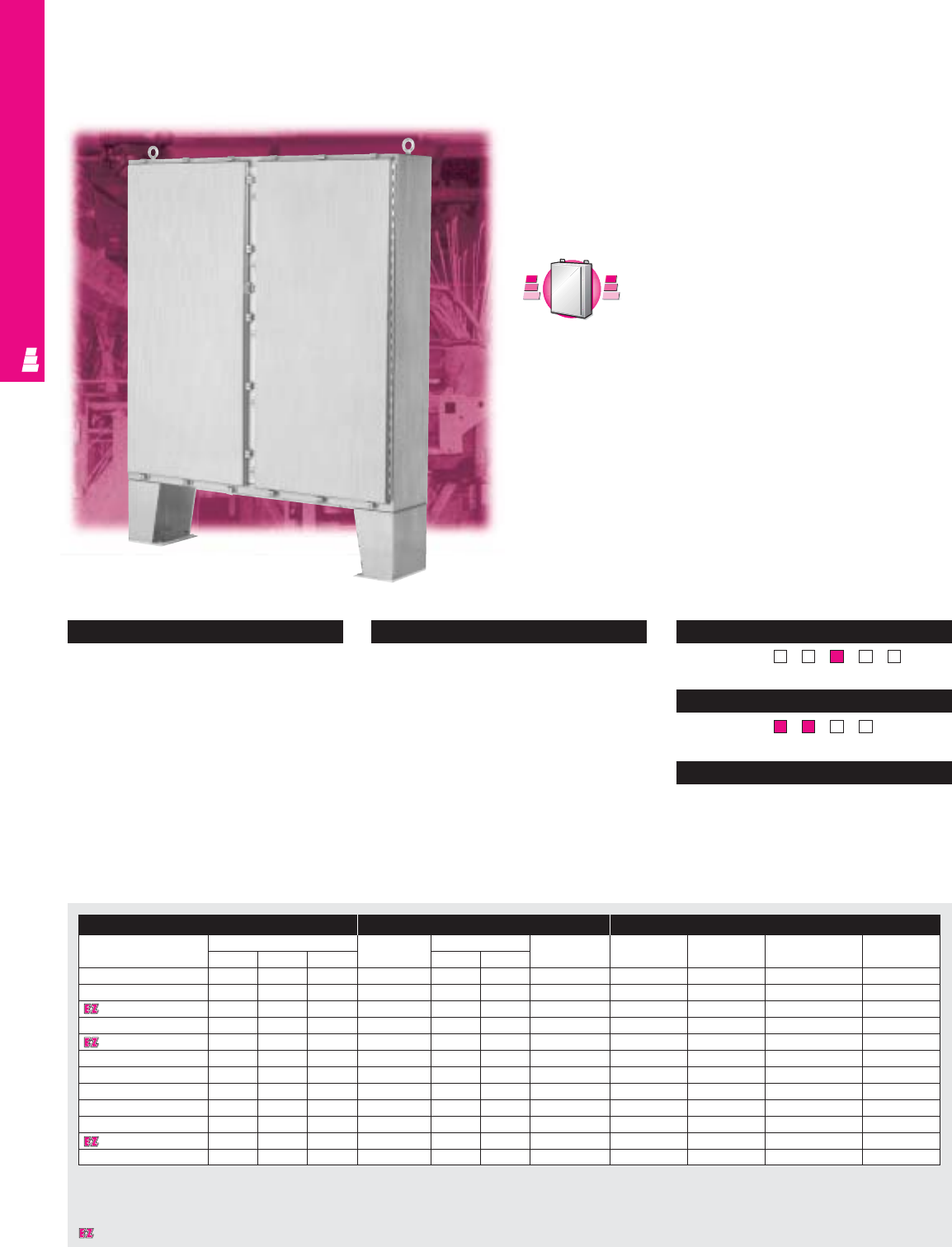
IND 229
NONCORROSIVE FREESTANDING
NEMA 4X Stainless Steel Cabinets
These NEMA 4X rated stainless steel floormount enclosures are
designed for indoor or outdoor use to protect equipment
against splashing water, seepage of water, falling or hose
directed water and external condensation.
Two Door Floormount Enclosures
Configuration
•Continuously welded seams, finished smooth
•Removable center post
•Body stiffener for added support
•Stainless steel captive clamps
•Oil resistant neoprene strip gasket
•Continuous stainless steel heavy duty hinge
with removable pin
•Hasp and staple for padlocking
•Mounting panel provisions installed
•Removable heavy duty lifting eyes
•12" floor stands are welded to enclosure
•Print pocket included
Technical Specifications
Material:
•Type 304/316 stainless steel
Body: 12 gauge
Back: 12 gauge
(10 gauge for H or W ≥72")
Finish:
•Enclosure/door: # 3 brushed finish
•Optional stainless steel mounting panels:
unpainted
•Optional carbon steel mounting panels:
painted white
Page . . . . . . . . . . . . . . . . . . . . . . . . . . . . IND 272
NEMA Type
144X1213
UL CUL CSA TÜV
Listings
Protection Ratings
Certifications/Approvals
Technical Drawings
Enclosure Mounting Panel Accessories
Part No. Outside dimensions (inches) Part No. Panel size Usable depth Light kit Door stop kit Window kit Fast operating
HWD HW clamp
E 62H4810SS 62.00 48.00 10.00 E 60P48 56.00 44.00 10.00 See ACC 29 E DSTOPK E PWK2315NFSS E FOC412SS
E 62H4810SS6 62.00 48.00 10.00 E 60P48 56.00 44.00 10.00 See ACC 29 E DSTOPK E PWK2315NFSS E FOC412SS
E 62H4812SS 62.00 48.00 12.00 E 60P48 56.00 44.00 12.00 See ACC 29 E DSTOPK E PWK2315NFSS E FOC412SS
E 62H4812SS6 62.00 48.00 12.00 E 60P48 56.00 44.00 12.00 See ACC 29 E DSTOPK E PWK2315NFSS E FOC412SS
E 62H6012SS 62.00 60.00 12.00 E 60P60 56.00 56.00 12.00 See ACC 29 E DSTOPK E PWK2919NFSS E FOC412SS
E 62H6012SS6 62.00 60.00 12.00 E 60P60 56.00 56.00 12.00 See ACC 29 E DSTOPK E PWK2919NFSS E FOC412SS
E 74H6012SS 74.00 60.00 12.00 E 72P60 68.00 56.00 12.00 See ACC 29 E DSTOPK E PWK2919NFSS E FOC412SS
E 74H6012SS6 74.00 60.00 12.00 E 72P60 68.00 56.00 12.00 See ACC 29 E DSTOPK E PWK2919NFSS E FOC412SS
E 74H7212SS 74.00 72.00 12.00 E 72P72 68.00 68.00 12.00 See ACC 29 E DSTOPK E PWK3523NFSS E FOC412SS
E 74H7212SS6 74.00 72.00 12.00 E 72P72 68.00 68.00 12.00 See ACC 29 E DSTOPK E PWK3523NFSS E FOC412SS
E 74H7224SS 74.00 72.00 24.00 E 72P72 68.00 68.00 24.00 See ACC 29 E DSTOPK E PWK3523NFSS E FOC412SS
E 74H7224SS6 74.00 72.00 24.00 E 72P72 68.00 68.00 24.00 See ACC 29 E DSTOPK E PWK3523NFSS E FOC412SS
C
a
r
b
o
n
S
t
e
e
l
C
a
r
b
o
n
S
t
e
e
l
A
v
a
i
l
a
b
l
e
I
n
A
v
a
i
l
a
b
l
e
I
n
Page IND 81
Designates a product in the EnclosureZone program.
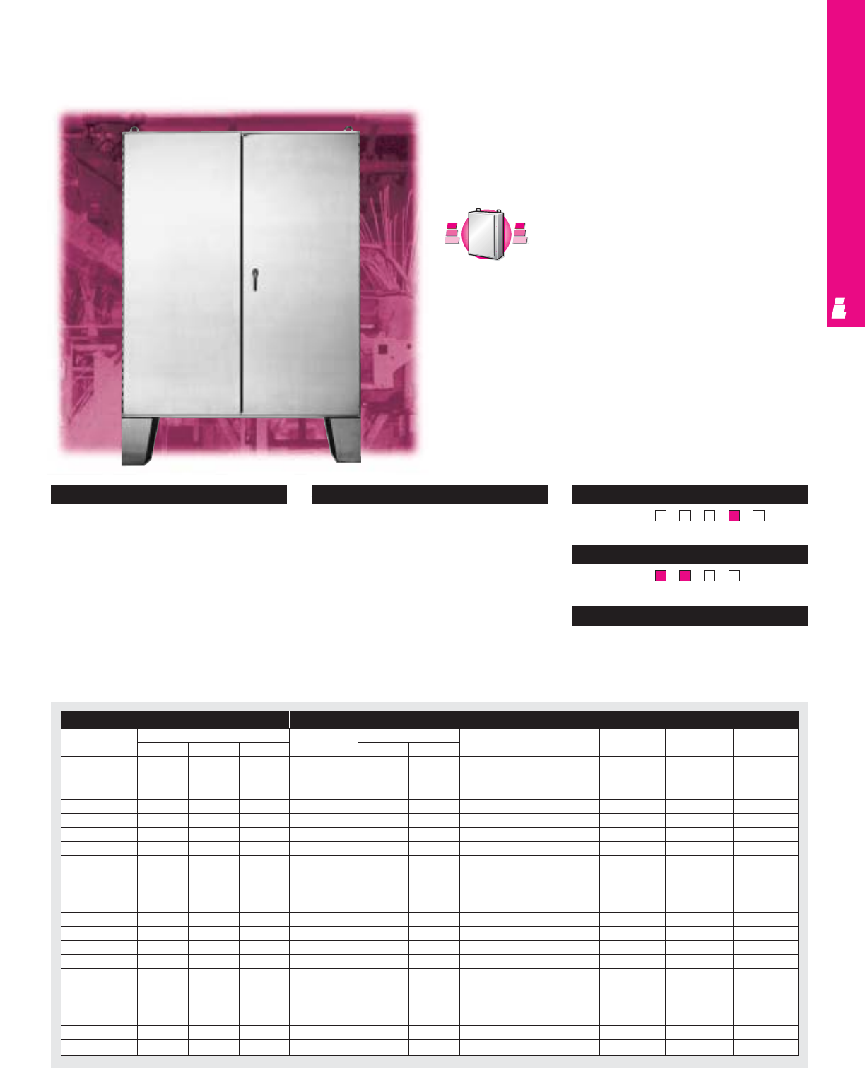
IND 230
NONCORROSIVE FREESTANDING
NEMA 12 Stainless Steel Cabinets
These NEMA rated stainless steel floormount enclosures are
designed for indoor use to protect equipment against lint,
dust, dirt, light splashing, seepage, and corrosive liquids.
Two Door Floormount Enclosures
Configuration
•Continuously welded seams, finished smooth
•Gasketed overlapping doors
•Body stiffener for added support
•3-point latching mechanism operated by oil
tight key-locking handle
•Urethane gasket
•Continuous stainless steel heavy duty hinge
with removable pin
•Mounting panel provisions installed
•Removable heavy duty lifting eyes
•12" floor stands are welded to enclosure
•Print pocket included
Technical Specifications
Material:
•Enclosure/door: 12 gauge Type 304
stainless steel
Finish:
•Enclosure/door: # 3 brushed finish
•Optional stainless steel mounting panels:
unpainted
•Optional carbon steel mounting panels:
painted white
Page . . . . . . . . . . . . . . . . . . . . . . . . . . . . IND 273
NEMA Type
144X12 13
UL CUL CSA TÜV
Listings
Protection Ratings
Certifications/Approvals
Technical Drawings
Enclosure Mounting Panel Accessories
Part No. Outside dimensions (inches) Part No. Panel size Usable Window kit Door stop Light kit Handle
HW DHWdepth kit accessories
E 544208SS 54.00 42.00 8.00 E 54P42 50.00 38.00 8.00 E PWK1711NFSS E DSTOPK See ACC 29 See ACC 20
E 604808SS 60.00 48.00 8.00 E 60P48 56.00 44.00 8.00 E PWK2315NFSS E DSTOPK See ACC 29 See ACC 20
E 604810SS 60.00 48.00 10.00 E 60P48 56.00 44.00 10.00 E PWK2315NFSS E DSTOPK See ACC 29 See ACC 20
E 604812SS 60.00 48.00 12.00 E 60P48 56.00 44.00 12.00 E PWK2315NFSS E DSTOPK See ACC 29 See ACC 20
E 604816SS 60.00 48.00 16.00 E 60P48 56.00 44.00 16.00 E PWK2315NFSS E DSTOPK See ACC 29 See ACC 20
E 604820SS 60.00 48.00 20.00 E 60P48 56.00 44.00 20.00 E PWK2315NFSS E DSTOPK See ACC 29 See ACC 20
E 604824SS 60.00 48.00 24.00 E 60P48 56.00 44.00 24.00 E PWK2315NFSS E DSTOPK See ACC 29 See ACC 20
E 606010SS 60.00 60.00 10.00 E 60P60 56.00 56.00 10.00 E PWK2919NFSS E DSTOPK See ACC 29 See ACC 20
E 606012SS 60.00 60.00 12.00 E 60P60 56.00 56.00 12.00 E PWK2919NFSS E DSTOPK See ACC 29 See ACC 20
E 606016SS 60.00 60.00 16.00 E 60P60 56.00 56.00 16.00 E PWK2919NFSS E DSTOPK See ACC 29 See ACC 20
E 606024SS 60.00 60.00 24.00 E 60P60 56.00 56.00 24.00 E PWK2919NFSS E DSTOPK See ACC 29 See ACC 20
E 726010SS 72.00 60.00 10.00 E 72P60 68.00 56.00 10.00 E PWK2919NFSS E DSTOPK See ACC 29 See ACC 20
E 726012SS 72.00 60.00 12.00 E 72P60 68.00 56.00 12.00 E PWK2919NFSS E DSTOPK See ACC 29 See ACC 20
E 726016SS 72.00 60.00 16.00 E 72P60 68.00 56.00 16.00 E PWK2919NFSS E DSTOPK See ACC 29 See ACC 20
E 726020SS 72.00 60.00 20.00 E 72P60 68.00 56.00 20.00 E PWK2919NFSS E DSTOPK See ACC 29 See ACC 20
E 726024SS 72.00 60.00 24.00 E 72P60 68.00 56.00 24.00 E PWK2919NFSS E DSTOPK See ACC 29 See ACC 20
E 727210SS 72.00 72.00 10.00 E 72P72 68.00 68.00 10.00 E PWK3523NFSS E DSTOPK See ACC 29 See ACC 20
E 727212SS 72.00 72.00 12.00 E 72P72 68.00 68.00 12.00 E PWK3523NFSS E DSTOPK See ACC 29 See ACC 20
E 727216SS 72.00 72.00 16.00 E 72P72 68.00 68.00 16.00 E PWK3523NFSS E DSTOPK See ACC 29 See ACC 20
E 727220SS 72.00 72.00 20.00 E 72P72 68.00 68.00 20.00 E PWK3523NFSS E DSTOPK See ACC 29 See ACC 20
E 727224SS 72.00 72.00 24.00 E 72P72 68.00 68.00 24.00 E PWK3523NFSS E DSTOPK See ACC 29 See ACC 20
C
a
r
b
o
n
S
t
e
e
l
C
a
r
b
o
n
S
t
e
e
l
A
v
a
i
l
a
b
l
e
I
n
A
v
a
i
l
a
b
l
e
I
n
Page IND 81
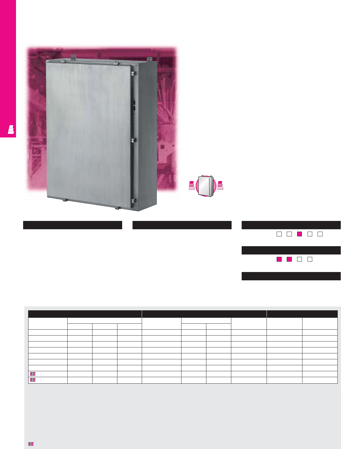
IND 231
NONCORROSIVE FMD
Stainless Steel FMD Cabinets
Rittal Electromate NEMA rated wallmount disconnect
enclosures accept all standard available disconnects and
circuit-breakers, including:
Allen Bradley:
1494 V operators for disconnects/circuit-breakers
Cutler Hammer/Westinghouse:
C361 operators for disconnect switches
C371 operators for circuit-breakers
General Electric:
Type STDA operators for disconnects
ITE/Siemens:
Max-Flex operators for disconnect switches/circuit-breakers
Square D:
Class 9422 operators for disconnects/circuit-breakers
ABB:
Operators for disconnect switches/circuit-breakers
NEMA 4X Wallmount Boxes
Configuration
•Continuously welded seams, finished smooth
•Continuous stainless steel hinge with
removable pin
•Robotically applied urethane gasket
•Rolled edge prevents entry of dirt
and liquids
•Cutout in body for operating handle
•12 gauge stainless steel captive clamps
•Mounting panel provisions installed
•External mounting brackets
•Print pocket included
Technical Specifications
Material:
•Enclosure/door: 14 gauge stainless steel
Finish:
•Enclosure/door: # 3 brushed finish
•Optional stainless steel mounting panels:
unpainted
•Optional carbon steel mounting panels:
painted white Page . . . . . . . . . . . . . . . . . . . . . . . . . . . . IND 274
NEMA Type
144X12 13
UL CUL CSA TÜV
Listings
Protection Ratings
Certifications/Approvals
Technical Drawings
Enclosure Mounting Panel Accessories
Part No. Outside dimensions (inches) Part No. Panel size Usable depth Operator Window
HW DHWadaptors kit
E 24HS2108SS 24.00 21.38 8.00 E 24P20 21.00 17.00 8.00 See ACC 17 E PWK1711NFSS
E 24HS2508SS 24.00 25.38 8.00 E 24P24 21.00 21.00 8.00 See ACC 17 E PWK1711NFSS
E 30HS2508SS 30.00 25.38 8.00 E 30P24 27.00 21.00 8.00 See ACC 17 E PWK2315NFSS
E 36HS2508SS 36.00 25.38 8.00 E 36P24 32.00 21.00 8.00 See ACC 17 E PWK2919NFSS
E 36HS3108SS 36.00 31.38 8.00 E 36P30 33.00 27.00 7.37* See ACC 17 E PWK2919NFSS
E 42HS3112SS 42.00 31.38 12.00 E 42P30 39.00 27.00 11.37* See ACC 17 E PWK2919NFSS
E 42HS3712SS 42.00 37.38 12.00 E 42P36 39.00 33.00 11.37* See ACC 17 E PWK3523NFSS
E 48HS3712SS 48.00 37.38 12.00 E 48P36 45.00 33.00 11.37* See ACC 17 E PWK3523NFSS
E 60HS3712SS 60.00 37.38 12.00 E 60P36 57.00 33.00 11.37* See ACC 17 E PWK3523NFSS
* Usable depth reduced by .625" at door stiffener.
C
a
r
b
o
n
S
t
e
e
l
C
a
r
b
o
n
S
t
e
e
l
A
v
a
i
l
a
b
l
e
I
n
A
v
a
i
l
a
b
l
e
I
n
Page IND 95
Designates a product in the EnclosureZone program.
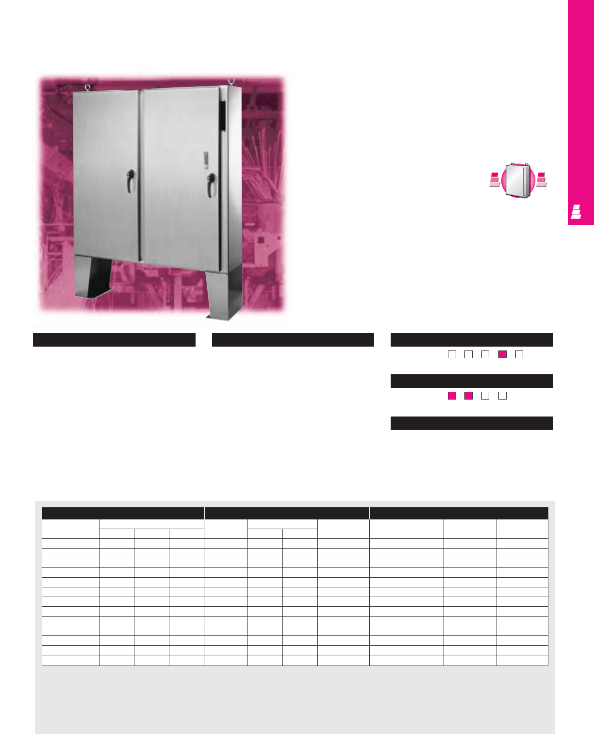
IND 232
NONCORROSIVE FMD
Floormount NEMA 12 Stainless Steel Cabinets
Rittal Electromate NEMA rated floormount disconnect
enclosures accept all standard available disconnects and
circuit-breakers, including:
Allen Bradley:
1494 V operators for disconnects/circuit-breakers
1494 F operators for disconnect switches
1494 D operators for circuit-breakers
Cutler Hammer/Westinghouse:
C361 operators for disconnect switches
C371 operators for circuit-breakers
General Electric:
Type STDA operators for disconnects
ITE/Siemens:
Max-Flex operators for disconnect switches/circuit-breakers
Square D:
Class 9422 operators for disconnects/circuit-breakers
ABB:
Operators for disconnect switches/circuit-breakers
Floormount Freestanding Enclosures
Technical Specifications
Material:
•Enclosure/door: 10 gauge stainless steel
Finish:
•Enclosure/door: # 3 brushed finish
•Optional stainless steel mounting panels:
unpainted
•Optional carbon steel mounting panels:
painted white Page . . . . . . . . . . . . . . . . . . . . . . . . . . . . IND 275
NEMA Type
144X1213
UL CUL CSA TÜV
Listings
Protection Ratings
Certifications/Approvals
Technical Drawings
Enclosure Mounting Panel Accessories
Part No. Outside dimensions (inches) Part No. Panel size Usable depth Window kit Light kit Handle
HW D HW accessories
E 60CPX4812SS2) 60.00 48.00 12.00 E 60P48 56.00 44.00 12.00 E PWK2315NFSS See ACC 29 See ACC 20
E 60CPX6012SS2) 60.00 60.00 12.00 E 60P60 56.00 56.00 12.00 E PWK2919NFSS See ACC 29 See ACC 20
E 60X4912SS1) 60.00 49.00 12.00 E 60P48 56.00 44.00 12.00 E PWK2315NFSS See ACC 29 See ACC 20
E 60X4918SS1) 60.00 49.00 18.00 E 60P48 56.00 44.00 18.00 E PWK2315NFSS See ACC 29 See ACC 20
E 60X6112SS1) 60.00 61.00 12.00 E 60P60 56.00 56.00 12.00 E PWK2919NFSS See ACC 29 See ACC 20
E 60X6118SS1) 60.00 61.00 18.00 E 60P60 56.00 56.00 18.00 E PWK2919NFSS See ACC 29 See ACC 20
E 72CPX7212SS2) 72.00 72.00 12.00 E 72P72 68.00 68.00 12.00 E PWK3523NFSS See ACC 29 See ACC 20
E 72CPX7218SS2) 72.00 72.00 18.00 E 72P72 68.00 68.00 18.00 E PWK3523NFSS See ACC 29 See ACC 20
E 72X6112SS1) 72.00 61.00 12.00 E 72P60 68.00 56.00 12.00 E PWK2919NFSS See ACC 29 See ACC 20
E 72X6118SS1) 72.00 61.00 18.00 E 72P60 68.00 56.00 18.00 E PWK2919NFSS See ACC 29 See ACC 20
E 72X7312SS1) 72.00 73.00 12.00 E 72P72 68.00 68.00 12.00 E PWK3523NFSS See ACC 29 See ACC 20
E 72X7318SS1) 72.00 73.00 18.00 E 72P72 68.00 68.00 18.00 E PWK3523NFSS See ACC 29 See ACC 20
E 72X7324SS1) 72.00 73.00 24.00 E 72P72 66.00 68.00 24.00 E PWK3523NFSS See ACC 29 See ACC 20
Configuration
•Continuously welded seams, finished smooth
•Body stiffeners provide extra rigidity
•Center post can be removed for panel
installation
•Urethane gasket
•Rolled edge prevents entry of dirt and liquids
•Heavy duty continuous steel hinge with
removable pin
•Heavy duty 3-point latch secures doors
•Mounting panel provision installed
•Enclosure is provided with 15" floor stands
welded to enclosure
•Heavy duty lifting eyes
1) Disconnect operator on right flange.
2) Disconnect operator on center post.
C
a
r
b
o
n
S
t
e
e
l
C
a
r
b
o
n
S
t
e
e
l
A
v
a
i
l
a
b
l
e
I
n
A
v
a
i
l
a
b
l
e
I
n
Page IND 103
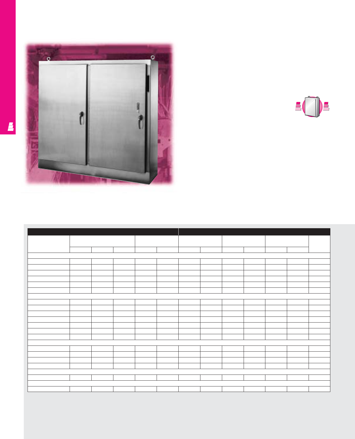
IND 233
Freestanding Heavy Duty Enclosures
Freestanding NEMA 12 Stainless Steel Enclosures
Rittal Electromate NEMA rated flange mount disconnect
enclosures accept all standard available disconnects and
circuit-breakers, including:
Allen Bradley:
1494 V operators for disconnects/circuit-breakers
1494 F operators for disconnect switches
1494 D operators for circuit-breakers
Cutler Hammer/Westinghouse:
C361 operators for disconnect switches
C371 operators for circuit-breakers
General Electric:
Type STDA operators for disconnects
ITE/Siemens:
Max-Flex operators for disconnect switches/circuit-breakers
Square D:
Class 9422 operators for disconnects/circuit-breakers
ABB:
Operators for disconnect switches/circuit-breakers
NONCORROSIVE FMD
Enclosure Mounting Panel
Part No. Outside dimensions Door size Panel size Panel size Panel size Usable
(behind single door) (behind double door) depth
HWDHWHWHWHW
One Door
E 72XM2818WPSS 72.00 27.50 18.00 62.50 23.83 60.00 21.75 - - - - 18.00
E 72XM3418WPSS 72.00 33.50 18.00 62.50 29.83 60.00 27.75 - - - - 18.00
E 72XM4018WPSS 72.00 39.50 18.00 62.50 35.83 60.00 33.75 - - - - 18.00
E 84XM4018WPSS 84.00 39.50 18.00 74.50 35.83 72.00 33.75 - - - - 18.00
E 90XM4020WPSS 90.00 39.50 20.00 80.50 35.83 78.00 33.75 - - - - 20.00
E 90XM4024WPSS 90.00 39.50 24.00 80.50 35.83 78.00 33.75 - - - - 24.00
Two Door
E 72XM5418WPSS 72.00 53.75 18.00 62.50 23.88 60.00 48.00 - - - - 17.00
E 72XM6618WPSS 72.00 65.75 18.00 62.50 29.88 60.00 60.00 - - - - 17.00
E 72XM7818WPSS 72.00 77.75 18.00 62.50 35.88 60.00 72.00 - - - - 17.00
E 72XM7824WPSS 72.00 77.75 24.00 62.50 35.88 60.00 72.00 - - - - 23.00
E 84XM7818WPSS 84.00 77.75 18.00 74.50 35.88 72.00 72.00 - - - - 17.00
E 90XM7820WPSS 90.00 77.75 20.00 80.50 35.88 78.00 72.00 - - - - 19.00
E 90XM7824WPSS 90.00 77.75 24.00 80.50 35.88 78.00 72.00 - - - - 23.00
Three Door
E 72XM3EQ18WPSS 72.00 99.50 18.00 62.50 29.88 60.00 60.00 60.00 27.75 60.00 60.00 17.00
E 72XM3EW18WPSS 72.00 117.50 18.00 62.50 35.88 60.00 72.00 60.00 33.75 60.00 72.00 17.00
E 84XM3EW18WPSS 84.00 117.50 18.00 74.50 35.88 72.00 72.00 72.00 33.75 72.00 72.00 17.00
E 90XM3EW24WPSS 90.00 117.50 24.00 80.50 35.88 78.00 72.00 78.00 33.75 78.00 72.00 23.00
Four Door
E 84XM4EW18WPSS 84.00 157.50 18.00 74.50 35.88 72.00 72.00 - - 72.00 72.00 17.00
Five Door
E 84XM5EW18WPSS 84.00 196.75 18.00 74.50 35.88 72.00 72.00 72.00 33.75 72.00 72.00 17.00
C
a
r
b
o
n
S
t
e
e
l
C
a
r
b
o
n
S
t
e
e
l
A
v
a
i
l
a
b
l
e
I
n
A
v
a
i
l
a
b
l
e
I
n
Page IND 101
IND 234
NONCORROSIVE FMD
Configuration
•Continuously welded seams, finished smooth
•Body stiffeners provide extra rigidity
•Center post can be removed for panel
installation
•Urethane gasket
•Rolled edge prevents entry of dirt and liquids
•Heavy duty continuous steel hinge with
removable pin
•Heavy duty 3-point latch secures doors
•Mounting panels included
•For type “X” enclosures:
master door is right-hand door
For type “CPX” enclosures:
master door is left-hand door
•Integrated defeater on master door
•Doors can be closed in any order
•Mechanical interlock on master door prevents
slave door from being opened unless master
door is opened first
•Operator adaptors may be used to fit most
disconnect operators in universal cutout
on flange
•24" deep enclosures feature mounting base
to raise disconnects to the proper height off
the mounting panel
•Heavy duty lifting eyes
•Print pocket included
Technical Specifications
Material:
•Enclosure/door: 10 gauge stainless steel
•Mounting panels: 10 gauge carbon steel
Finish/color:
•Enclosure/door: #3 brushed finish
•Carbon steel mounting panels:
painted white Pages . . . . . . . . . . . . . . . . . . . . . . . . . . . 276-278
NEMA Type
144X1213
UL CUL CSA TÜV
Listings
Protection Ratings
Certifications/Approvals
Technical Drawings
Accessories
Part No. Window kit Light kit Handle
accessories
One Door
E 72XM2818WPSS E PWK2315NFSS See ACC 29 See ACC 20
E 72XM3418WPSS E PWK2919NFSS See ACC 29 See ACC 20
E 72XM4018WPSS E PWK3523NFSS See ACC 29 See ACC 20
E 84XM4018WPSS E PWK3523NFSS See ACC 29 See ACC 20
E 90XM4020WPSS E PWK3523NFSS See ACC 29 See ACC 20
E 90XM4024WPSS E PWK3523NFSS See ACC 29 See ACC 20
Two Door
E 72XM5418WPSS E PWK2315NFSS See ACC 29 See ACC 20
E 72XM6618WPSS E PWK2919NFSS See ACC 29 See ACC 20
E 72XM7818WPSS E PWK3523NFSS See ACC 29 See ACC 20
E 72XM7824WPSS E PWK3523NFSS See ACC 29 See ACC 20
E 84XM7818WPSS E PWK3523NFSS See ACC 29 See ACC 20
E 90XM7820WPSS E PWK3523NFSS See ACC 29 See ACC 20
E 90XM7824WPSS E PWK3523NFSS See ACC 29 See ACC 20
Three Door
E 72XM3EQ18WPSS E PWK2919NFSS See ACC 29 See ACC 20
E 72XM3EW18WPSS E PWK3523NFSS See ACC 29 See ACC 20
E 84XM3EW18WPSS E PWK3523NFSS See ACC 29 See ACC 20
E 90XM3EW24WPSS E PWK3523NFSS See ACC 29 See ACC 20
Four Door
E 84XM4EW18WPSS E PWK3523NFSS See ACC 29 See ACC 20
Five Door
E 84XM5EW18WPSS E PWK3523NFSS See ACC 29 See ACC 20
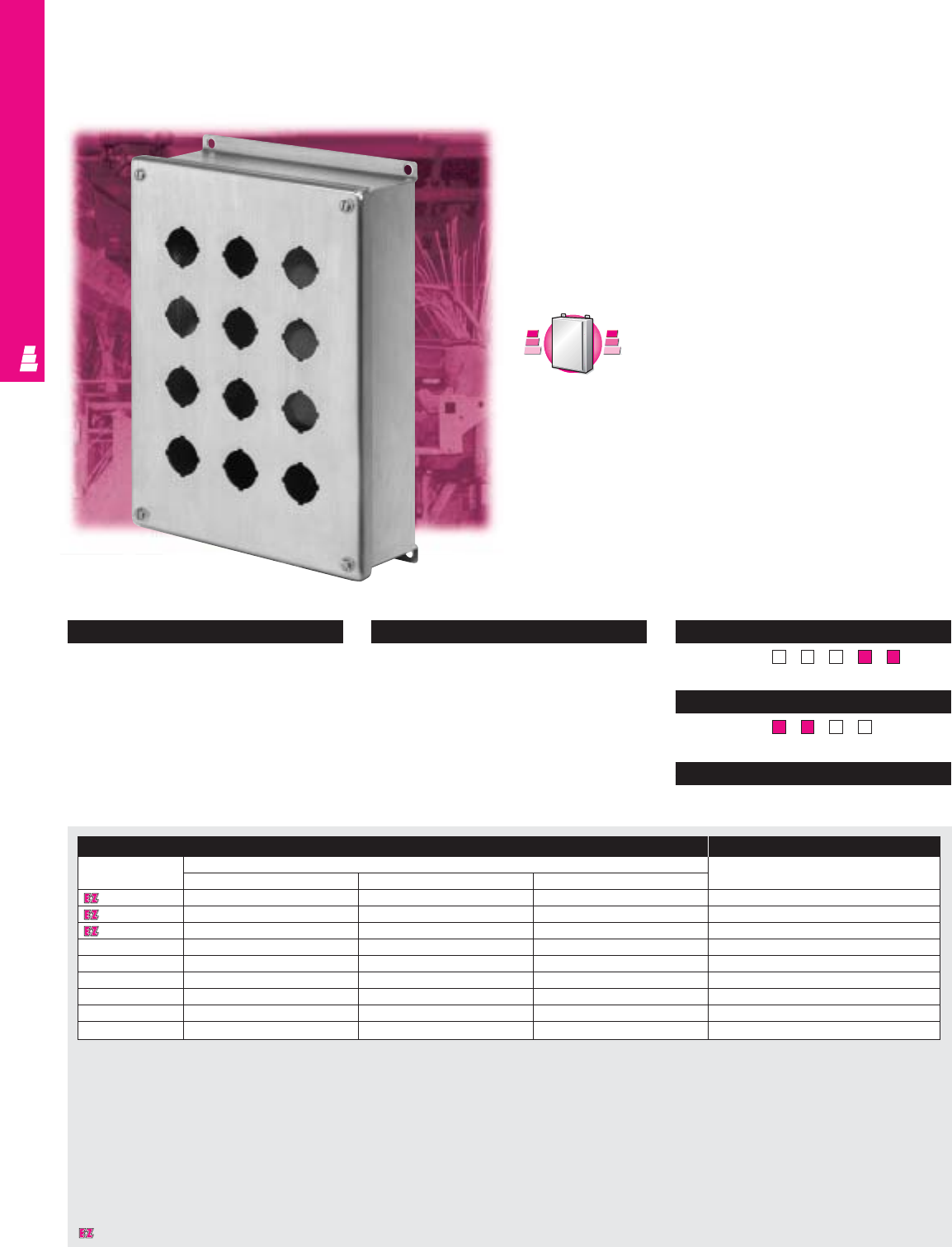
NONCORROSIVE OPERATOR INTERFACE
IND 235
NEMA Rated Pushbutton Enclosures
These stainless steel NEMA rated boxes are designed for
indoor use to house pushbuttons, selector switches, pilot lights,
etc., and to protect such equipment against dirt, dust, and
spraying of water, oil or coolant.
Several models of these pushbutton enclosures can be
mounted onto a Rittal Electromate column and base
and used as an operator station.
Standard Pushbutton Boxes
Standard Pushbutton Box Accessories
Part No. Outside dimensions (inches) Oil tight hole seals
HWD
E 1PBSS 3.50 3.25 2.75 See ACC 18
E 2PBSS 5.75 3.25 2.75 See ACC 18
E 3PBSS 8.00 3.25 2.75 See ACC 18
E 4PBSS 10.25 3.25 2.75 See ACC 18
E 4SPBSS* 7.25 6.25 3.00 See ACC 18
E 5PBSS 12.50 3.25 2.75 See ACC 18
E 6PBSS* 9.50 6.25 3.00 See ACC 18
E 9PBSS* 9.50 8.50 3.00 See ACC 18
E 12PBSS 11.75 8.50 3.00 See ACC 18
* Can be mounted to a Rittal Electromate column and base.
Configuration
•Continuously welded seams, finished smooth
•Poron strip gasket
•Standard pushbutton holes accept all
brands of “4-way” oil tight pushbuttons,
switches, and pilot lights
•Captive stainless steel screws to hold cover
•External mounting brackets
Technical Specifications
Material:
•Enclosure/cover: 14 gauge Type 304
stainless steel
Finish:
•Enclosure/cover: # 3 brushed finish
Page . . . . . . . . . . . . . . . . . . . . . . . . . . . . IND 279
NEMA Type
144X12 13
UL CUL CSA TÜV
Listings
Protection Ratings
Certifications/Approvals
Technical Drawings
C
a
r
b
o
n
S
t
e
e
l
C
a
r
b
o
n
S
t
e
e
l
A
v
a
i
l
a
b
l
e
I
n
A
v
a
i
l
a
b
l
e
I
n
Page IND 143
Designates a product in the EnclosureZone program.
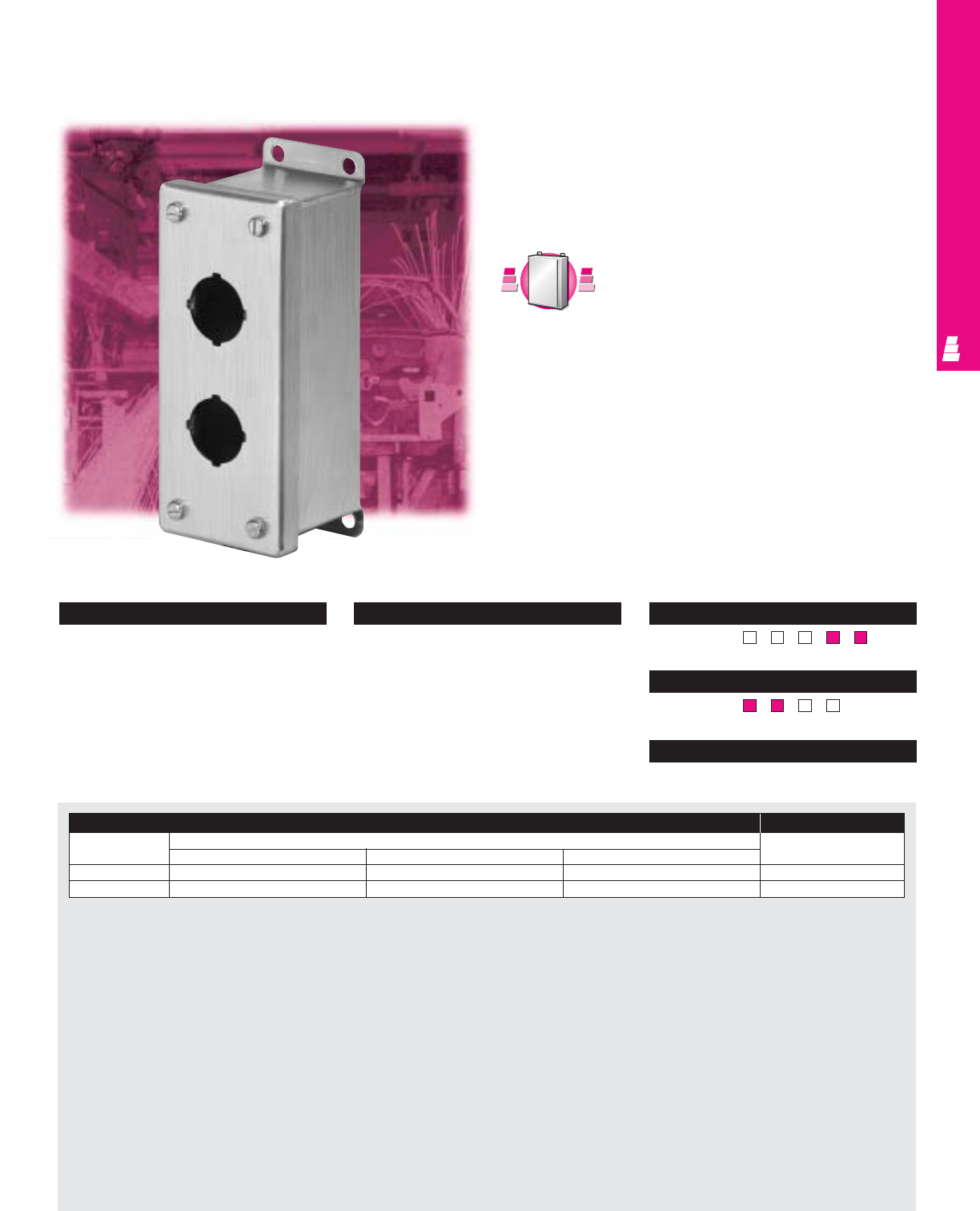
NONCORROSIVE OPERATOR INTERFACE
IND 236
Configuration
•Continuously welded seams, finished smooth
•Poron strip gasket
•Standard pushbutton holes accept all
brands of “4-way” oil tight pushbuttons,
switches, and pilot lights
•Captive stainless steel screws to hold cover
•External mounting brackets
Technical Specifications
Material:
•Enclosure/cover: 14 gauge Type 304
stainless steel
Finish:
•Enclosure/cover: # 3 brushed finish
Page . . . . . . . . . . . . . . . . . . . . . . . . . . . IND 280
NEMA Type
144X1213
UL CUL CSA TÜV
Listings
Protection Ratings
Certifications/Approvals
Technical Drawings
NEMA Rated Pushbutton Enclosures
These NEMA rated boxes are designed for indoor use to house
pushbuttons, selector switches, pilot lights, etc., and to protect
such equipment against dirt, dust, and spraying of water, oil
or coolant.
Slim Pushbutton Boxes
Slim Pushbutton Box Accessories
Part No. Outside dimensions (inches) Oil tight hole seals
HWD
E 1PBSLSS 4.00 2.50 2.50 See ACC 18
E 2PBSLSS 6.25 2.50 2.50 See ACC 18
C
a
r
b
o
n
S
t
e
e
l
C
a
r
b
o
n
S
t
e
e
l
A
v
a
i
l
a
b
l
e
I
n
A
v
a
i
l
a
b
l
e
I
n
Page IND 144
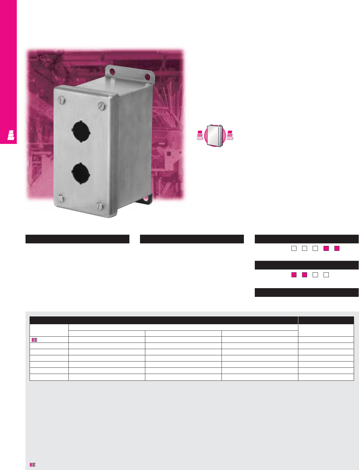
NONCORROSIVE OPERATOR INTERFACE
IND 237
NEMA Rated Pushbutton Enclosures
These stainless steel NEMA rated boxes are designed for
indoor use to house pushbuttons, selector switches, pilot lights,
etc., which mount in miniature “4-way” pushbutton holes, and to
protect such equipment against dirt, dust, and spraying of
water, oil or coolant.
Several models of these pushbutton enclosures can be
mounted onto a Rittal Electromate column and base and
used as an operator station.
Miniature Pushbutton Boxes
Miniature Pushbutton Box Accessories
Part No. Outside dimensions (inches) Oil tight hole seals
HWD
E 1PBGMSS 3.25 2.75 3.50 See ACC 18
E 2PBGMSS 5.13 2.75 3.50 See ACC 18
E 3PBGMSS 7.00 2.75 3.50 See ACC 18
E 4PBGMSS 8.88 2.75 3.50 See ACC 18
E 6PBGMSS* 8.50 5.00 4.25 See ACC 18
E 9PBGMSS 8.50 6.50 4.25 See ACC 18
E 12PBGMSS 10.38 6.50 4.25 See ACC 18
* Can be mounted to a Rittal Electromate column and base.
Configuration
•Continuously welded seams, finished smooth
•Poron strip gasket
•Standard pushbutton holes accept all
brands of 22.5 mm “4-way” oil tight
pushbuttons, switches, and pilot lights
•Captive stainless steel screws to
hold cover
•External mounting brackets
Technical Specifications
Material:
•Enclosure/cover: 14 gauge Type 304
stainless steel
Finish:
•Enclosure/cover: # 3 brushed finish
Page . . . . . . . . . . . . . . . . . . . . . . . . . . . . IND 281
NEMA Type
144X12 13
UL CUL CSA TÜV
Listings
Protection Ratings
Certifications/Approvals
Technical Drawings
C
a
r
b
o
n
S
t
e
e
l
C
a
r
b
o
n
S
t
e
e
l
A
v
a
i
l
a
b
l
e
I
n
A
v
a
i
l
a
b
l
e
I
n
Page IND 145
Designates a product in the EnclosureZone program.
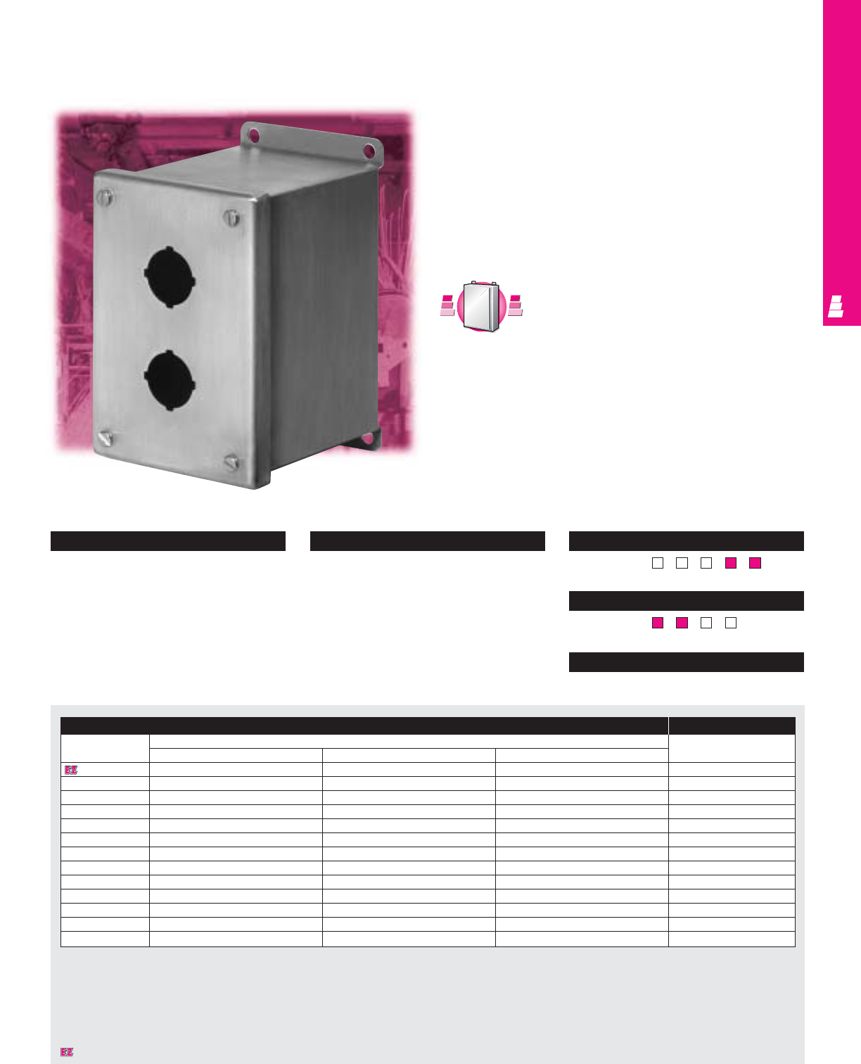
NONCORROSIVE OPERATOR INTERFACE
IND 238
NEMA Rated Pushbutton Enclosures
These stainless steel NEMA rated boxes are designed for
indoor use to house pushbuttons, selector switches, pilot lights,
etc., and to protect such equipment against dirt, dust,
and spraying of water, oil or coolant. Their extra depth
accommodates stacked pushbutton units.
Several models of these pushbutton enclosures can be
mounted onto a Rittal Electromate column and base and used
as an operator station.
Extra Deep Pushbutton Boxes
Extra Deep Pushbutton Box Accessories
Part No. Outside dimensions (inches) Oil tight hole seals
HWD
E 1PBXDSS 4.00 4.00 4.75 See ACC 18
E 2PBXDSS 6.00 4.00 4.75 See ACC 18
E 3PBXDSS 8.00 4.00 4.75 See ACC 18
E 4PBXDSS 10.00 4.00 4.75 See ACC 18
E 4SPBXDSS* 7.25 6.25 4.75 See ACC 18
E 6PBXDSS* 9.50 6.25 4.75 See ACC 18
E 9PBXDSS 9.50 8.50 4.75 See ACC 18
E 10PBXDSS 14.00 6.25 4.75 See ACC 18
E 12PBXDSS 11.75 8.50 4.75 See ACC 18
E 16PBXDSS 11.75 10.75 4.75 See ACC 18
E 16SPBXDSS 20.75 6.25 4.75 See ACC 18
E 20PBXDSS 14.00 10.75 4.75 See ACC 18
E 25PBXDSS 14.00 13.00 4.75 See ACC 18
* Can be mounted to a Rittal Electromate column and base.
Configuration
•Continuously welded seams, finished smooth
•Poron strip gasket
•Standard pushbutton holes accept all
brands of “4-way” oil tight pushbuttons,
switches, and pilot lights
•Captive stainless steel screws to hold cover
•External mounting brackets
Technical Specifications
Material:
•Enclosure/cover: 14 gauge Type 304
stainless steel
Finish:
•Enclosure/cover: # 3 brushed finish
Page . . . . . . . . . . . . . . . . . . . . . . . . . . . . IND 282
NEMA Type
144X12 13
UL CUL CSA TÜV
Listings
Protection Ratings
Certifications/Approvals
Technical Drawings
C
a
r
b
o
n
S
t
e
e
l
C
a
r
b
o
n
S
t
e
e
l
A
v
a
i
l
a
b
l
e
I
n
A
v
a
i
l
a
b
l
e
I
n
Page IND 147
Designates a product in the EnclosureZone program.
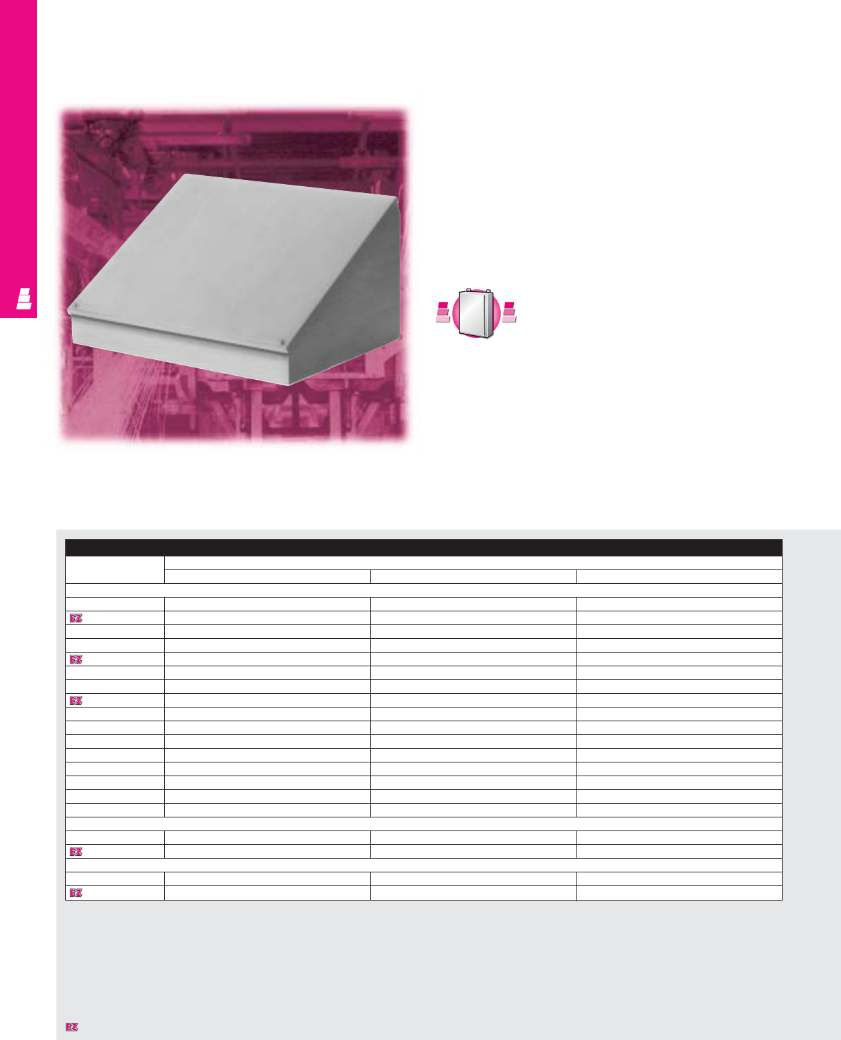
NONCORROSIVE OPERATOR INTERFACE
IND 239
Stainless Steel Desk Units
These NEMA rated individual desk units are designed for
indoor use to meet the requirements of most operator interface
applications.
Control components such as meters, pushbuttons, pilot lights,
and switches, can be mounted on the top-hinged control panel
that slants 30° or 60°. Pedestal and base assemblies allow the
desk units to be floor mounted. Wiring connections can be
made through the base, the vertical column or directly to the
desk unit.
Consoles, Pedestals and Bases
Console, Pedestal & Base
Part No. Outside dimensions (inches)
HW D
Consoles
E 8C8SS 8.00 8.00 7.09
E 8C12SS 8.00 12.00 7.09
E 8C16SS 8.00 16.00 7.09
E 8C20SS 8.00 20.00 7.09
E 12C12SS 12.00 12.00 9.09
E 12C16SS 12.00 16.00 9.09
E 12C20SS 12.00 20.00 9.09
E 12C24SS 12.00 24.00 9.09
E 16C16SS 16.00 16.00 11.09
E 16C20SS 16.00 20.00 11.09
E 16C24SS 16.00 24.00 11.09
E 16C30SS 16.00 30.00 11.09
E 16C36SS 16.00 36.00 11.09
E 20C20SS 20.00 20.00 13.09
E 20C24SS 20.00 24.00 13.09
E 20C30SS 20.00 30.00 13.09
Pedestals
E 44CCOLSS 4.00 4.00 -
E 66CCOLSS 6.00 6.00 -
Bases
E 18SBASESS 18.00 18.00 -
E 24SBASESS 24.00 24.00 -
C
a
r
b
o
n
S
t
e
e
l
C
a
r
b
o
n
S
t
e
e
l
A
v
a
i
l
a
b
l
e
I
n
A
v
a
i
l
a
b
l
e
I
n
Page 151
Designates a product in the EnclosureZone program.

NONCORROSIVE OPERATOR INTERFACE
IND 240
Configuration
Console:
•Continuously welded seams, finished smooth
•Poron strip gasket
•Control panel slants 30° or 60° and is
attached with a continuous steel hinge at
top and secured with captive screws
Pedestal/column:
•Removable, gasketed access plate in
column body
•Urethane gasket
Base:
• Pre-punched holes to accept column
• Two formed channels welded to underside
of base
Technical Specifications
Material:
•Console/desk unit: 14 gauge Type 304
stainless steel
•Pedestal/column: 14 gauge Type 304
stainless steel with 10 gauge steel
mounting flange at each end
•Base: 12 gauge Type 304 stainless steel
Finish:
•All stainless steel parts: # 3 brushed polish
Pages . . . . . . . . . . . . . . . . . . . . . . . . IND 283-284
NEMA Type
144X1213
UL CUL CSA TÜV
Listings
Protection Ratings
Certifications/Approvals
Technical Drawings
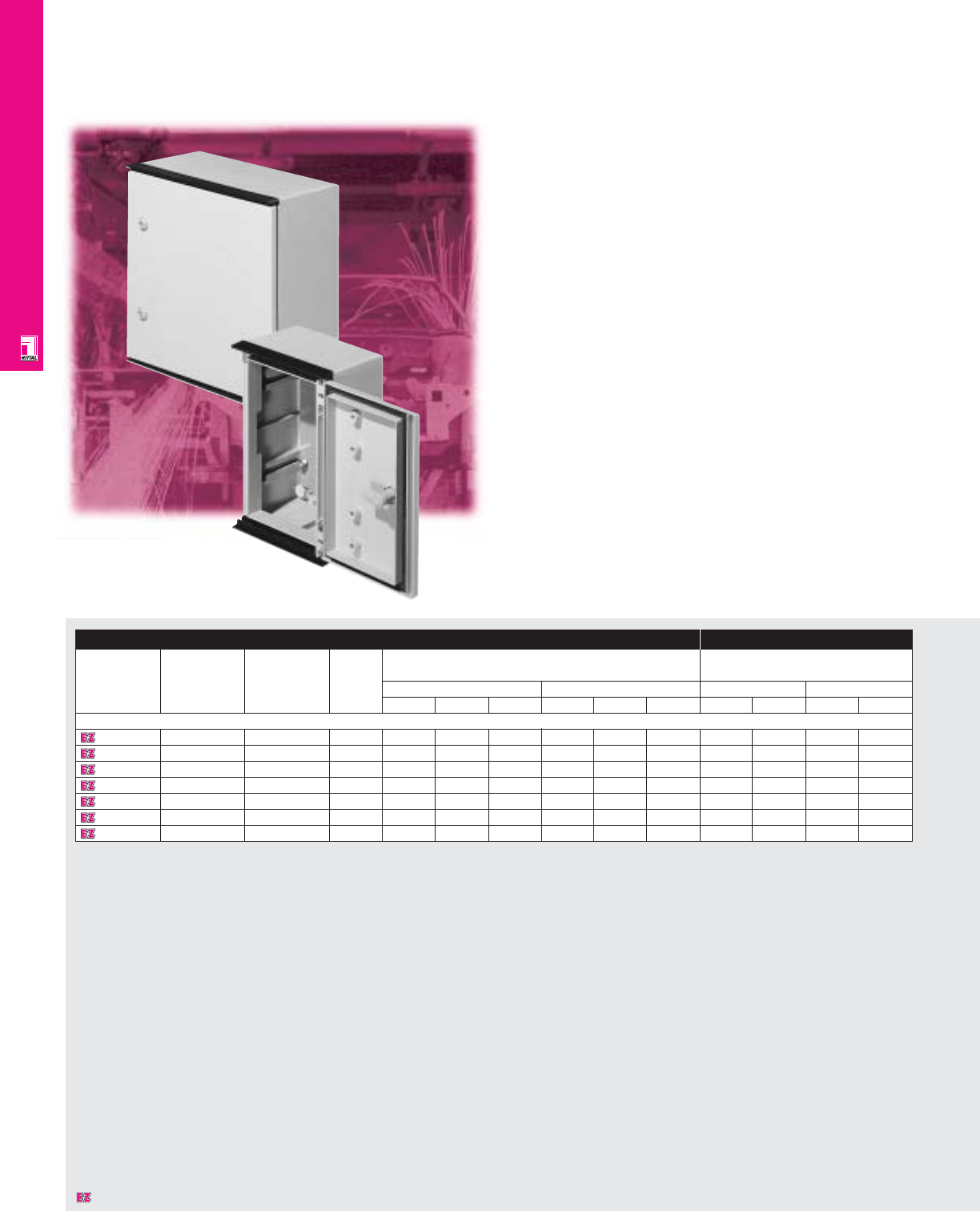
FIBERGLASS WALLMOUNT
IND 241
KS Fiberglass Enclosures
NEMA Rated Fiberglass Enclosures
Rittal’s corrosion resistant KS Series wallmount enclosures are
made of fiberglass-reinforced unsaturated polyester. These
fully insulated, fiberglass enclosures are appropriate for
indoor/outdoor and harsh industrial environments. In addition,
they are self-extinguishing per UL 94-VO and temperature
resistant between -22° and 212°F.
Enclosure Mounting Panel
Part No. Approximate NEMA Number Exact outside dimensions Dimensions
outside rating of
dimensions doors inches mm inches mm
H"xW"xD" H W D H W D H W H W
Without Viewing Window
1432600 14x10x6 1, 4, 4X, 12 1 13.78 9.84 5.91 350 250 150 11.81 7.68 300 195
1434600 16x12x8 1, 4, 4X, 12 1 15.75 11.81 7.87 400 300 200 13.78 9.65 350 245
1444600 16x16x8 1, 4, 4X, 12 1 15.75 15.75 7.87 400 400 200 13.78 13.58 350 345
1446600 24x16x8 1, 4, 4X, 12 1 23.62 15.75 7.87 600 400 200 21.65 13.58 550 345
1466600 24x24x8 1, 4, 4X, 12 1 23.62 23.62 7.87 600 600 200 21.65 21.46 550 545
1468600 32x24x12 1, 4, 4X, 12 1 31.50 23.62 11.81 800 600 300 29.53 20.35 750 517
1480600 40x32x12 1, 12 1 39.37 31.50 11.81 1000 800 300 37.40 28.23 950 717
Designates a product in the EnclosureZone program.
FIBERGLASS WALLMOUNT
IND 242
Configuration
•NEMA 1, 4, 4X, 12 protection/IP 66
•UL/CSA/TUV approvals
•Viewing window: 3 mm clear acrylic with
rubber gasket
•Integrated rain protection strip at top and
bottom edges of doors eliminates need for
rain canopy
•Foamed-on gasket
•180° stainless steel hinges
•Fixing nuts molded in backwall and door
accept M6 threaded nuts for easy
attachment of components
• C-sections molded in side walls allow
infinite depth adjustment of mounting panels
•Mounting panel included
•Off-the-shelf availability
Technical Specifications
Material:
•Body and door: fiberglass reinforced
unsaturated polyester
•Mounting panel: hot-dipped galvanized zinc
14 ga/2 mm (KS 1432-1434)
12 ga/2.5 mm (KS 1444-1480)
Finish/color:
•Body and door: fiberglass, pigmented
RAL 7032 pebble grey
•Mounting panel: Type M
Pages . . . . . . . . . . . . . . . . . . . . . . . . IND 285-286
NEMA Type
144X12 13
UL CUL CSA TÜV
Listings
Protection Ratings
Certifications/Approvals
Technical Drawings
Accessories
Part No. Wallmounting Mounting panel Threaded Handles Pole mount
bracket adjustment bracket insert nuts Thumb turn Ergoform-S kit
Without Viewing Window
1432600 1483000 1481000 1482000 1484000 - 2584000
1434600 1483000 1481000 1482000 1484000 - 2584000
1444600 1483000 1481000 1482000 1484000 - 2584000
1446600 1483000 1481000 1482000 1484000 - 2584000
1466600 1483000 1481000 1482000 1484000 - 2584000
1468600 1483000 1491000 1482000 - 1490000 2584000
1480600 1483000 1491000 1482000 - 1490000 2584000
Designates a product in the EnclosureZone program.
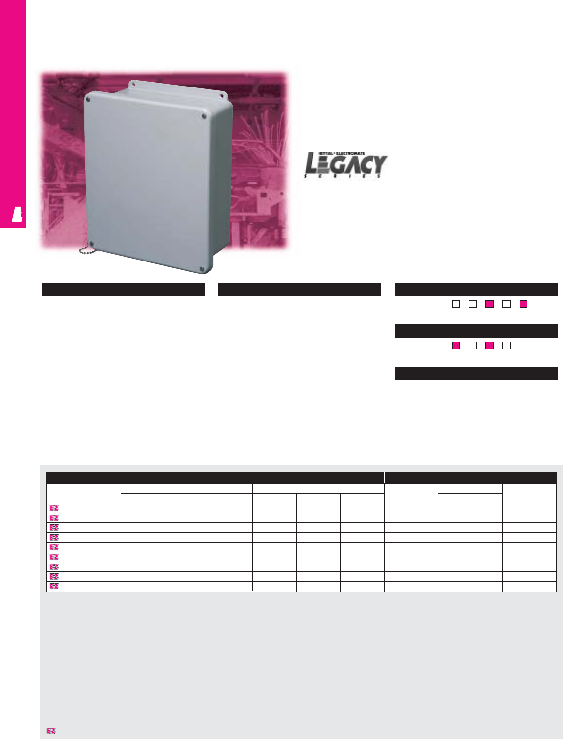
IND 243
Legacy Fiberglass Junction Enclosures
These fiberglass junction boxes are designed primarily for
indoor or outdoor use and can be used for many different
applications. They protect installed equipment against
splashing water, seepage of water, falling or hose directed
water and severe external condensation.
FIBERGLASS WALLMOUNT
Configuration
•Lift-off cover
•Stainless steel screw/retention chain
•Molded-in mounting provisions
•Rounded corners
•Overhang cover
•Foamed-in-place polyurethane gasketing
Technical Specifications
Material:
•Body and door: hot compression molded
fiberglass reinforced polyester
•Optional mounting panel: carbon steel
Finish/color:
•Body and door: fiberglass, pigmented
light grey
•Optional mounting panel: painted white Page . . . . . . . . . . . . . . . . . . . . . . . . . . . . IND 287
NEMA Type
134X126P
UL CUL CSA TÜV
Listings
Protection Ratings
Certifications/Approvals
Technical Drawings
Screw Cover Junction Boxes
Enclosure Mounting Panel
Part No. Outside dimensions (inches) Inside dimensions (inches) Part No. Panel size Usable depth
HWD HW D HWJ
L FJ604NFSC 7.50 5.43 4.75 5.84 3.85 4.45 L MPL64CS 4.875 2.875 4
L FJ606NFSC 7.50 7.50 4.75 5.72 5.72 4.45 L MPL66CS 4.875 4.875 4
L FJ806NFSC 9.62 7.50 4.74 7.73 5.74 4.45 L MPL86CS 6.875 4.875 4
L FJ1008NFSC 11.62 9.41 4.25 9.73 7.73 3.98 L MPL108CS 8.875 6.875 3.5
L FJ1210NFSC 13.56 11.43 5.21 11.79 9.80 4.94 L MPL1210CS 10.875 8.875 4.5
L FJ1412NFSC 15.50 13.50 6.25 13.53 11.55 5.94 L MPL1412CS 12.875 10.875 5.37
L FJ1614NFSC 17.53 15.46 6.23 15.63 13.60 5.94 L MPL1614CS 14.875 12.875 5.36
L FJ1816NFSC 19.62 17.61 8.82 17.69 15.69 8.45 L MPL1816CS 16.875 14.875 7.99
L FJ2016NFSC 22.00 17.68 8.83 19.72 15.72 8.45 L MPLJ2016CS 18.875 14.875 8
Designates a product in the EnclosureZone program.
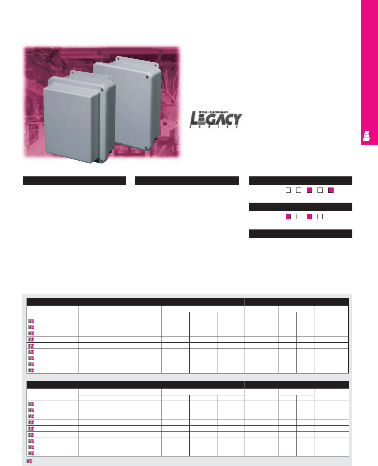
Legacy Fiberglass Junction Enclosures
These fiberglass junction boxes are designed primarily for
indoor or outdoor use and can be used for many different
applications. They protect installed equipment against
splashing water, seepage of water, falling or hose
directed water and severe external condensation.
These boxes are available in standard and extended
depth versions.
IND 244
FIBERGLASS WALLMOUNT
Configuration
Standard Version:
•Full length stainless steel hinged cover
•Stainless steel screws
•180° door opening
•Overhang cover
•Foamed-in-place polyurethane gasketing
Technical Specifications
Material:
•Body and door: hot compression molded
fiberglass reinforced polyester
•Optional mounting panel: carbon steel
Finish/color:
•Body and door: fiberglass, pigmented
light grey
•Optional mounting panel: painted white Page . . . . . . . . . . . . . . . . . . . . . . . . . . . . IND 288
NEMA Type
134X126P
UL CUL CSA TÜV
Listings
Protection Ratings
Certifications/Approvals
Technical Drawings
Hinged Screw Cover Junction Boxes
Standard Enclosure Mounting Panel
Part No. Outside dimensions (inches) Inside dimensions (inches) Part No. Panel size Usable depth
HWDHW D HWJ
L FJ604CHNFSC 7.50 5.47 6.22 5.84 3.85 5.95
L MPL64CS 4.875 2.875 4
L FJ606CHNFSC 7.50 7.50 4.75 5.72 5.72 4.45
L MPL66CS 4.875 4.875 4
L FJ806CHNFSC 9.62 7.50 4.74 7.73 5.74 4.45
L MPL86CS 6.875 4.875 4
L FJ1008CHNFSC 11.62 9.41 4.25 9.73 7.73 3.98
L MPL108CS 8.875 6.875 3.5
L FJ1210CHNFSC 13.56 11.43 5.21 11.79 9.80 4.94
L MPL1210CS 10.875 8.875 4.5
L FJ1412CHNFSC 15.50 13.50 6.25 13.53 11.55 5.94
L MPL1412CS 12.875 10.875 5.37
L FJ1614CHNFSC 17.53 15.46 6.23 15.63 13.60 5.94
L MPL1614CS 14.875 12.875 5.36
L FJ1816CHNFSC 19.62 17.61 8.82 17.69 15.69 8.45
L MPL1816CS 16.875 14.875 7.99
L FJ2016CHNFSC 22.00 17.68 8.83 19.72 15.72 8.45
L MPLJ2016CS
18.875 14.875 8
Extended Depth Enclosure Mounting Panel
Part No. Outside dimensions (inches) Inside dimensions (inches) Part No. Panel size Usable depth
HWDHWD HWJ
L FJ604CHNFSCX 7.50 5.47 6.22 5.84 3.85 5.95 L MPL64CS 4.875 2.875 5.49
L FJ606CHNFSCX 7.50 7.52 6.22 5.72 5.72 5.95 L MPL66CS 4.875 8.875 5.49
L FJ806CHNFSCX 9.62 7.46 6.22 7.73 5.74 5.95 L MPL86CS 6.875 4.875 5.49
L FJ1008CHNFSCX 11.62 9.37 6.61 9.73 7.73 6.36 L MPL108CS 8.875 6.875 5.91
L FJ1210CHNFSCX 13.56 11.43 6.61 11.79 9.80 6.32 L MPL1210CS 10.875 8.875 5.87
L FJ1412CHNFSCX 15.50 13.38 7.69 13.53 11.55 7.45 L MPL1412CS 12.875 10.875 6.87
L FJ1614CHNFSCX 17.53 15.43 7.71 15.63 13.60 7.45 L MPL1614CS 14.875 12.875 6.87
L FJ1816CHNFSCX 19.62 17.48 10.62 17.69 15.69 10.31 L MPL1816CS 16.875 14.875 9.86
L FJ2016CHNFSCX 22.00 17.56 10.64 19.72 15.72 10.33 L MPLJ2016CS 18.875 14.875 9.87
Extended Depth Version:
•Full length stainless steel hinged cover
•Stainless steel screws
•180° door opening
•Overhang cover
•Foamed-in-place polyurethane gasketing
•Extended depth cover available in 10 x 8
configuration only
Designates a product in the EnclosureZone program.
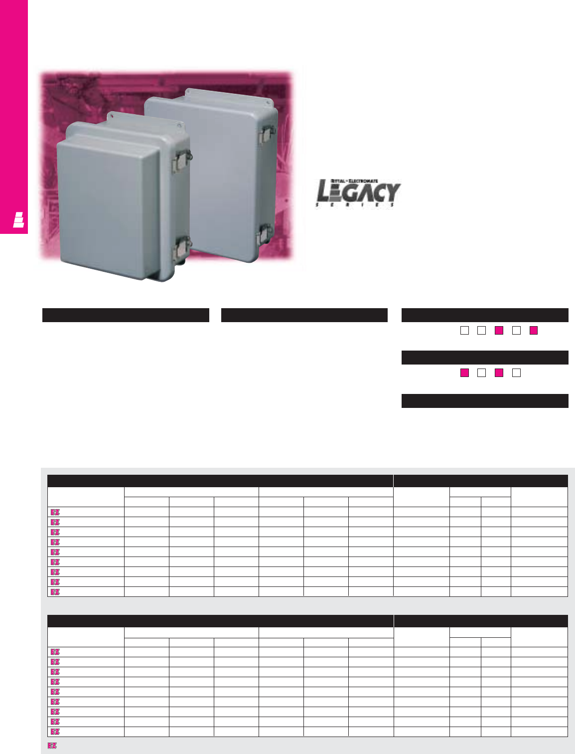
IND 245
FIBERGLASS WALLMOUNT
Lockable Quick Release Junction Boxes
Legacy Fiberglass Junction Enclosures
These fiberglass junction boxes are designed primarily for
indoor or outdoor use and can be used for many different
applications. They protect installed equipment against
splashing water, seepage of water, falling or hose directed
water and severe external condensation.
These boxes are available in standard and extended
depth versions.
Configuration
•Quick-release clamps with secure loop for
padlock provisions (padlock not included)
•Can be lifted and released with ease
•180° door opening
•Foamed-in-place polyurethane gasketing
Technical Specifications
Material:
•Body and door: hot compression molded
fiberglass reinforced polyester
•Optional mounting panel: carbon steel
Finish/color:
•Body and door: fiberglass, pigmented
light grey
•Optional mounting panel: painted white Page . . . . . . . . . . . . . . . . . . . . . . . . . . . . IND 289
NEMA Type
134X126P
UL CUL CSA TÜV
Listings
Protection Ratings
Certifications/Approvals
Technical Drawings
Standard Enclosure Mounting Panel
Part No. Outside dimensions (inches) Inside dimensions (inches) Part No. Panel size Usable depth
HWD H W D HWJ
L FJ604CHNFQ 7.50 5.43 4.75 5.84 3.85 4.45
L MPL64CS 4.875 2.875 4
L FJ606CHNFQ 7.50 7.50 4.75 5.72 5.72 4.45
L MPL66CS 4.875 4.875 4
L FJ806CHNFQ 9.62 7.50 4.74 7.73 5.74 4.45
L MPL86CS 6.875 4.875 4
L FJ1008CHNFQ 11.62 9.41 4.25 9.73 7.73 3.98
L MPL108CS 8.875 6.875 3.5
L FJ1210CHNFQ 13.56 11.43 5.21 11.79 9.80 4.94
L MPL1210CS 10.875 8.875 4.5
L FJ1412CHNFQ 15.50 13.50 6.25 13.53 11.55 5.94
L MPL1412CS 12.875 10.875 5.37
L FJ1614CHNFQ 17.53 15.46 6.23 15.63 13.60 5.94
L MPL1614CS 14.875 10.875 5.36
L FJ1816CHNFQ 19.62 17.61 8.82 17.69 15.69 8.45
L MPL1816CS 16.875 14.875 7.99
L FJ2016CHNFQ 22.00 17.68 8.83 19.72 15.72 8.45
L MPLJ2016CS 18.875 14.875 8
Extended Depth Enclosure Mounting Panel
Part No. Outside dimensions (inches) Inside dimensions (inches) Part No. Panel size Usable depth
HWDHWD HWJ
L FJ604CHNFQX 7.50 5.47 6.22 5.84 3.85 5.95 L MPL64CS 4.875 2.875 5.49
L FJ606CHNFQX 7.50 7.52 6.22 5.72 5.72 5.95 L MPL66CS 4.875 4.875 5.49
L FJ806CHNFQX 9.62 7.46 6.22 7.73 5.74 5.95 L MPL86CS 6.875 4.875 5.49
L FJ1008CHNFQX 11.62 9.37 6.61 9.73 7.73 6.36 L MPL108CS 8.875 6.875 5.91
L FJ1210CHNFQX 13.56 11.43 6.61 11.79 9.80 6.32 L MPL1210CS 10.875 8.875 5.87
L FJ1412CHNFQX 15.50 13.38 7.69 13.53 11.55 7.45 L MPL1412CS 12.875 10.875 6.87
L FJ1614CHNFQX 17.53 15.43 7.71 15.63 13.60 7.45 L MPL1614CS 14.875 12.875 6.87
L FJ1816CHNFQX 19.62 17.48 10.62 17.69 15.69 10.31 L MPL1816CS 16.875 14.875 9.86
L FJ2016CHNFQX 22.00 17.56 10.64 19.72 15.72 10.33 L MPLJ2016CS 18.875 14.875 9.87
Designates a product in the EnclosureZone program.
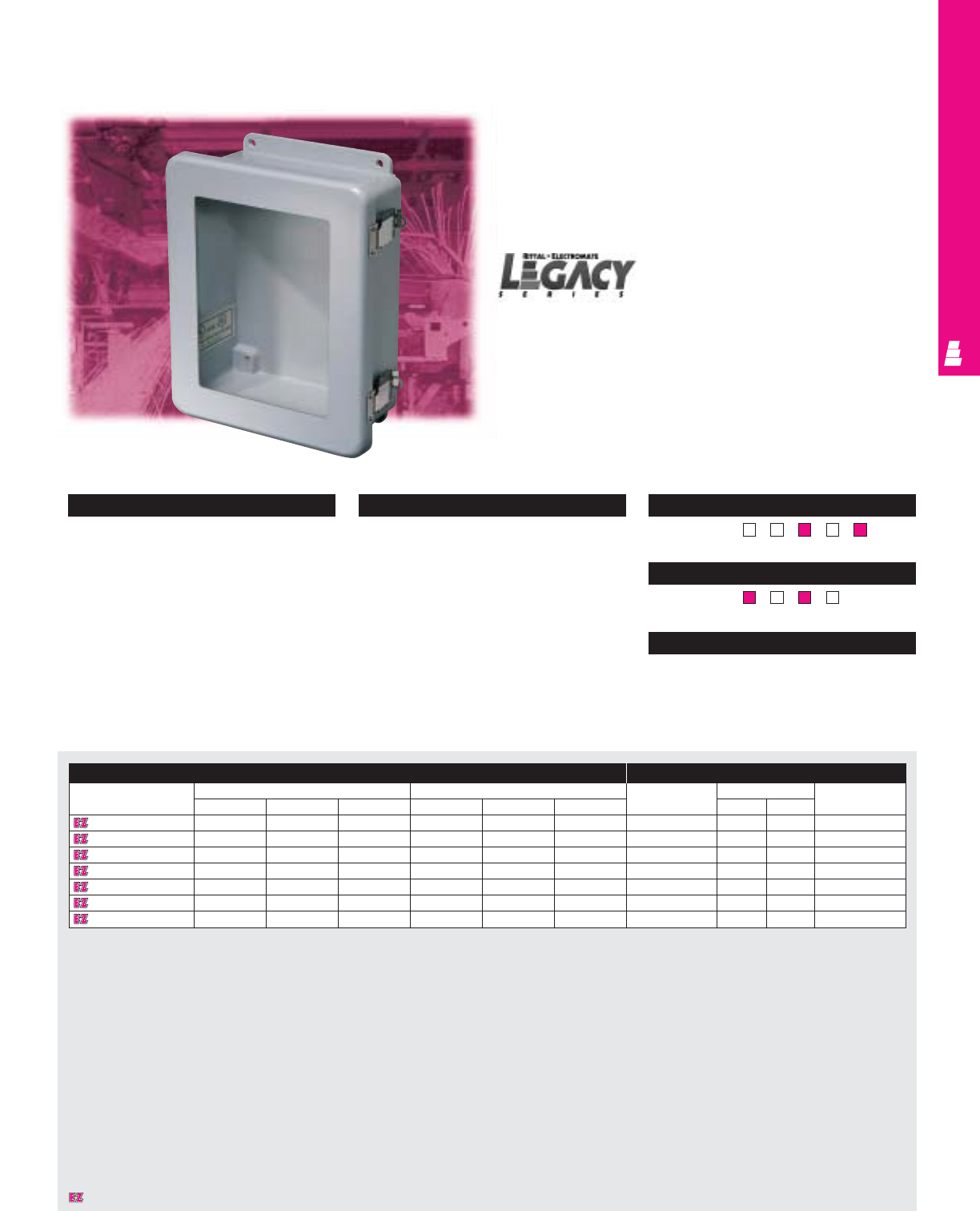
IND 246
FIBERGLASS WALLMOUNT
Legacy Fiberglass Junction Enclosures
These fiberglass junction boxes are designed primarily for
indoor or outdoor use and can be used for many different
applications. They protect installed equipment against
splashing water, seepage of water, falling or hose directed
water and severe external condensation.
Configuration
•Scratch and abrasion resistant UVA
acrylic flush viewing window
•Quick-release clamps with secure loop for
padlock provisions (padlock not included)
•Can be lifted and released with ease
•180° door opening
•Foamed-in-place polyurethane gasketing
Technical Specifications
Material:
•Body and door: hot compression molded
fiberglass reinforced polyester
•Optional mounting panel: carbon steel
Finish/color:
•Body and door: fiberglass, pigmented
light grey
•Optional mounting panel: painted white Page . . . . . . . . . . . . . . . . . . . . . . . . . . . IND 290
NEMA Type
134X126P
UL CUL CSA TÜV
Listings
Protection Ratings
Certifications/Approvals
Technical Drawings
Flush Viewing Window Junction Boxes
Enclosure Mounting Panel
Part No. Outside dimensions (inches) Inside dimensions (inches) Part No. Panel size Usable depth
HW D HWD HWJ
L FJ806CHNFQW 9.62 7.50 4.74 7.73 5.74 4.45 L MPL86CS 6.875 4.875 4
L FJ1008CHNFQW 11.62 9.41 4.25 9.73 7.73 3.98 L MPL108CS 8.875 6.875 3.5
L FJ1210CHNFQW 13.56 11.43 5.21 11.79 9.80 4.94 L MPL1210CS 10.875 8.875 4.5
L FJ1412CHNFQW 15.50 13.50 6.25 13.53 11.55 5.94 L MPL1412CS 12.875 10.875 5.37
L FJ1614CHNFQW 17.53 15.46 6.23 15.63 13.60 5.94 L MPL1614CS 14.875 12.875 5.36
L FJ1816CHNFQW 19.62 17.61 8.82 17.69 15.69 8.45 L MPL1816CS 16.875 14.875 7.99
L FJ2016CHNFQW 22.00 17.68 8.83 19.72 15.72 8.45 L MPLJ2016CS 18.875 14.875 8
Designates a product in the EnclosureZone program.
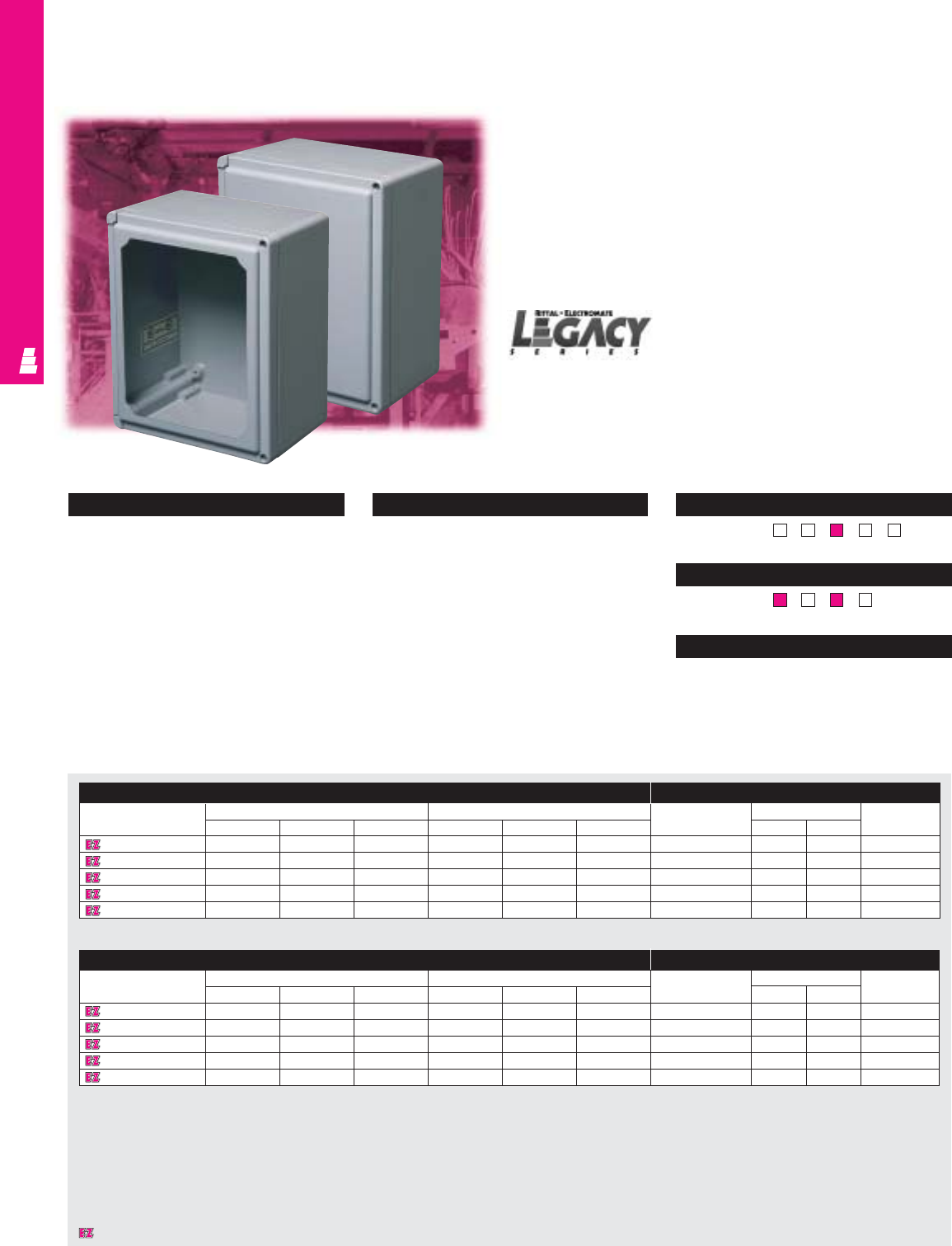
IND 247
Legacy Fiberglass Instrumentation Enclosures
These fiberglass instrumentation boxes are designed primarily
for indoor or outdoor use and can be used for many different
applications. They protect installed equipment against
splashing water, seepage of water, falling or hose directed
water and severe external condensation. These boxes are
ideal for the OEM looking for a housing with stylish protection.
These boxes are available in hinged screw cover and viewing
window versions.
FIBERGLASS WALLMOUNT
Configuration
Hinged Screw Cover Version:
•Integrally hinged cover that secures with
two screws
•Stainless steel screw recessed from cover
•180° door opening
Technical Specifications
Material:
•Body and door: hot compression molded
fiberglass reinforced polyester
•Optional mounting panel: carbon steel
Finish/color:
•Body and door: fiberglass, pigmented
light grey
•Optional mounting panel: painted white Page . . . . . . . . . . . . . . . . . . . . . . . . . . . . IND 291
NEMA Type
134X1213
UL CUL CSA TÜV
Listings
Protection Ratings
Certifications/Approvals
Technical Drawings
Hinged Screw Cover Instrumentation Boxes
Hinged Screw Cover Enclosure Mounting Panel
Part No. Outside dimensions (inches) Inside dimensions (inches) Part No. Panel size Usable depth
HWDHWD HWJ
L FI707CHNFSC 7.21 7.21 5.09 6.65 6.65 4.84 L MPL66CS 4.875 4.875 4.39
L FI907CHNFSC 9.21 7.21 5.09 8.59 6.59 4.84 L MPL86CS 6.875 4.875 4.39
L FI1109CHNFSC 11.21 9.21 6.09 10.59 8.59 5.84 L MPL108CS 8.875 6.875 5.39
L FI1311CHNFSC 13.21 11.21 6.59 12.59 10.59 6.34 L MPL1210CS 10.875 8.875 5.89
L FI1513CHNFSC 15.21 13.21 7.09 14.55 12.55 6.84 L MPL1412CS 12.875 10.875 6.39
Viewing Window Enclosure Mounting Panel
Part No. Outside dimensions (inches) Inside dimensions (inches) Part No. Panel size Usable depth
HW D HWD HWJ
L FI707CHNFSCW 7.21 7.21 5.09 6.65 6.65 4.84 L MPL66CS 4.875 4.875 4.39
L FI907CHNFSCW 9.21 7.21 5.09 8.59 6.59 4.84 L MPL86CS 6.875 4.875 4.39
L FI1109CHNFSCW 11.21 9.21 6.09 10.59 8.59 5.84 L MPL108CS 8.875 6.875 5.39
L FI1311CHNFSCW 13.21 11.21 6.59 12.59 10.59 6.34 L MPL1210CS 10.875 8.875 5.89
L FI1513CHNFSCW 15.21 13.21 7.09 14.55 12.55 6.84 L MPL1412CS 12.875 10.875 6.39
Viewing Window Version:
•Scratch and abrasion resistant UVA acrylic flush
viewing window
•Integrally hinged cover secures with two screws
•Stainless steel screw recessed from cover
•180° door opening
•Foamed-in-place polyurethane gasketing
Designates a product in the EnclosureZone program.
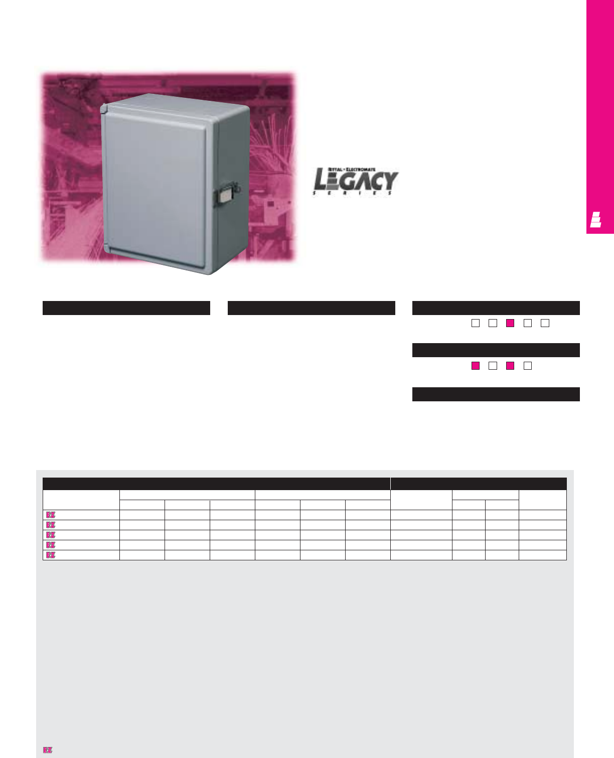
IND 248
FIBERGLASS WALLMOUNT
Legacy Fiberglass Instrumentation Enclosures
These fiberglass instrumentation boxes are designed primarily
for indoor or outdoor use and can be used for many different
applications. They protect installed equipment against
splashing water, seepage of water, falling or hose directed
water and severe external condensation. These boxes are
ideal for the OEM looking for a housing with stylish protection.
Hinged Quick Release Instrumentation Boxes
Configuration
•Quick-release clamps with secure loop for
padlock provisions (padlock not included)
•Can be lifted and released with ease
•180° door opening
•Foamed-in-place polyurethane gasketing
Technical Specifications
Material:
•Body and door: hot compression molded
fiberglass reinforced polyester
•Optional mounting panel: carbon steel
Finish/color:
•Body and door: fiberglass, pigmented
light grey
•Optional mounting panel: painted white Page . . . . . . . . . . . . . . . . . . . . . . . . . . . . IND 292
NEMA Type
134X12 13
UL CUL CSA TÜV
Listings
Protection Ratings
Certifications/Approvals
Technical Drawings
Enclosure Mounting Panel
Part No. Outside dimensions (inches) Inside dimensions (inches) Part No. Panel size Usable depth
HWD HWD HWJ
L FI707CHNFQ 7.21 7.21 5.09 6.65 6.65 4.84 L MPL66CS 4.875 4.875 4.39
L FI907CHNFQ 9.21 7.21 5.09 8.59 6.59 4.84 L MPL86CS 6.875 4.875 4.39
L FI1109CHNFQ 11.21 9.21 6.09 10.59 8.59 5.84 L MPL108CS 8.875 6.875 5.39
L FI1311CHNFQ 13.21 11.21 6.59 12.59 10.59 6.34 L MPL1210CS 10.875 8.875 5.89
L FI1513CHNFQ 15.21 13.21 7.09 14.55 12.55 6.84 L MPL1412CS 12.875 10.875 6.39
Designates a product in the EnclosureZone program.
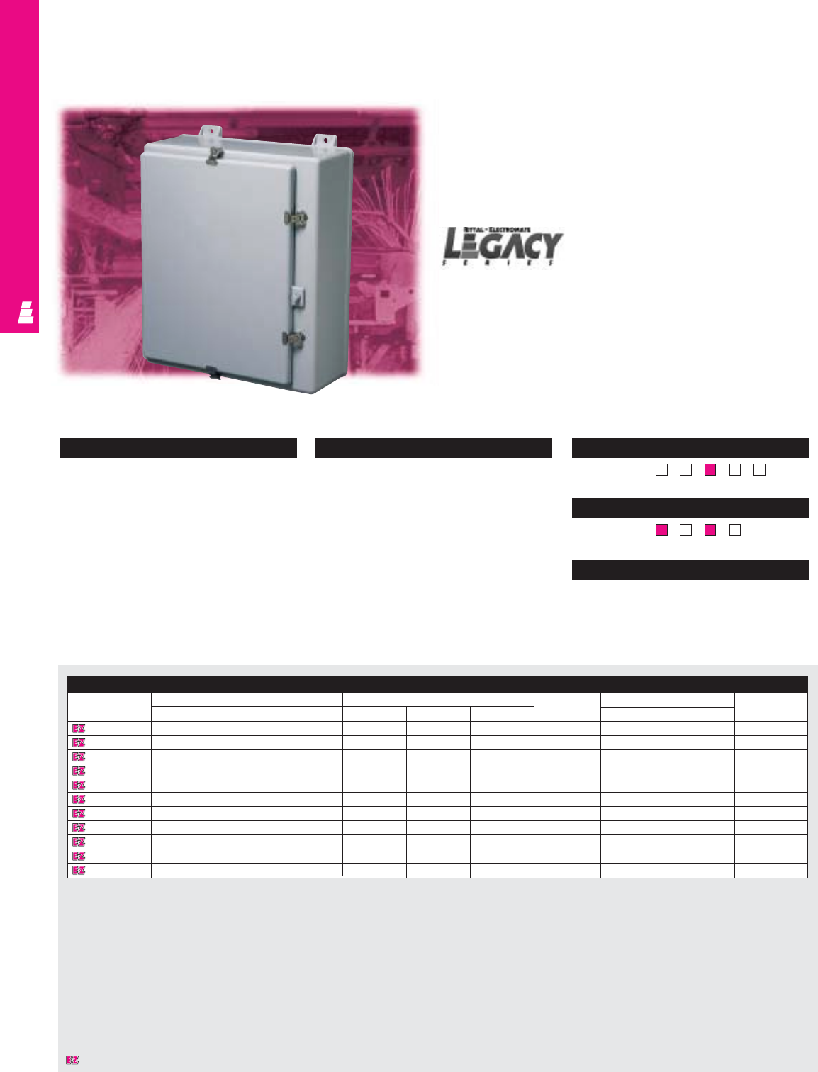
IND 249
FIBERGLASS WALLMOUNT
Legacy Fiberglass Wallmount Enclosures
These fiberglass wallmount boxes are designed primarily for
indoor or outdoor use and can be used for many different
applications. They protect installed equipment against
splashing water, seepage of water, falling or hose directed
water and severe external condensation.
Enclosure Mounting Panel
Part No. Outside dimensions (inches) Inside dimensions (inches) Part No. Panel size Usable depth
HWD HWD HW J
L FW20H1612 22.75 16.87 13.77 19.70 16.04 13.24 L MPL2016CS 17.00 13.00 12.26
L FW24H2008 27.00 21.24 9.90 24.05 20.39 9.25 L MPL2420CS 21.00 17.00 8.25
L FW24H2410 27.00 25.24 11.90 24.05 24.39 11.25 L MPL2424CS 21.00 21.00 10.25
L FW24H2412 27.00 25.24 13.90 24.05 24.39 13.25 L MPL2424CS 21.00 21.00 12.25
L FW30H2008 32.86 20.99 9.89 29.90 20.14 9.23 L MPL3020CS 27.00 17.00 8.23
L FW30H2407 33.41 26.32 8.81 30.46 25.47 8.12 L MPL3024CS 27.00 21.00 7.12
L FW30H2410 33.41 26.32 11.95 30.46 25.47 11.27 L MPL3024CS 27.00 21.00 10.27
L FW36H3010 39.31 32.50 12.05 36.31 31.69 11.36 L MPL3630CS 33.00 27.00 10.36
L FW36H3012 39.31 32.50 14.05 36.31 31.69 13.36 L MPL3630CS 33.00 27.00 12.36
L FW48H3612 51.29 36.62 13.93 48.33 36.22 13.25 L MPL4836CS 45.00 33.00 12.25
L FW48H3616 51.29 36.62 17.93 48.33 36.22 17.25 L MPL4836CS 45.00 33.00 16.25
NEMA 4X Wallmount Boxes
Configuration
•Rigid body construction and watertight seal
•Foamed-in-place polyurethane gasketing
•Integral mounting brackets
•Molded-in panel mounting inserts
•Built-in padlock hasp
Technical Specifications
Material:
•Body and door: hot compression molded
fiberglass reinforced polyester
•Optional mounting panel: carbon steel
Finish/color:
•Body and door: fiberglass, pigmented
light grey
•Optional mounting panel: painted white Page . . . . . . . . . . . . . . . . . . . . . . . . . . . . IND 293
NEMA Type
134X1213
UL CUL CSA TÜV
Listings
Protection Ratings
Certifications/Approvals
Technical Drawings
Designates a product in the EnclosureZone program.
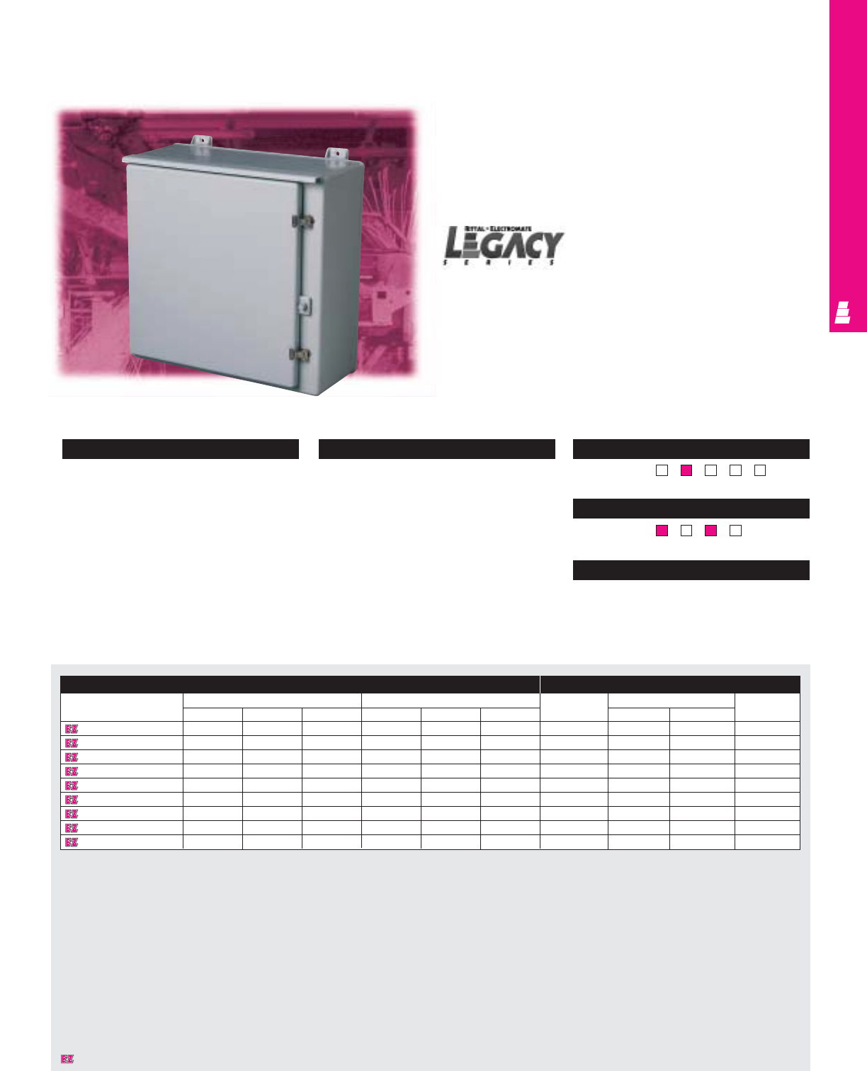
IND 250
FIBERGLASS WALLMOUNT
Legacy Fiberglass Wallmount Enclosures
These fiberglass wallmount boxes are designed primarily for
indoor or outdoor use and can be used for many different
applications. They protect installed equipment against
splashing water, seepage of water, falling or hose directed
water and severe external condensation.
Enclosure Mounting Panel
Part No. Outside dimensions (inches) Inside dimensions (inches) Part No. Panel size Usable depth
HW D HWD H W J
L FW20R1612HCR 22.75 16.87 14.27 19.70 16.04 13.24 L MPL2016CS 17.00 13.00 12.26
L FW24R2008HCR 27.00 21.24 9.90 24.05 20.39 9.25 L MPL2420CS 21.00 17.00 8.25
L FW24R2410HCR 27.00 25.24 11.90 24.05 24.39 11.25 L MPL2424CS 21.00 21.00 10.25
L FW30R2410HCR 33.41 26.32 11.95 30.46 25.47 11.27 L MPL3024CS 27.00 21.00 12.25
L FW30R2412HCR 33.41 26.32 13.79 30.46 25.47 13.10 L MPL3024CS 27.00 21.00 8.23
L FW36R3010HCR 39.31 32.50 12.05 36.31 31.69 11.36 L MPL3630CS 33.00 27.00 7.12
L FW36R3012HCR 39.31 32.50 14.05 36.31 31.69 13.36 L MPL3630CS 33.00 27.00 10.27
L FW48R3612HCR 51.29 36.62 14.43 48.33 36.22 13.25 L MPL4836CS 45.00 33.00 10.36
L FW48R3616HCR 51.29 36.62 18.43 48.33 36.22 17.25 L MPL4836CS 45.00 33.00 12.36
NEMA 3R Wallmount Boxes
Configuration
•Rainshield top for water protection
•Rigid body construction and watertight seal
•Integral mounting feet for ease of
installation
•Molded-in panel mounting inserts
•Built-in padlock hasp
Technical Specifications
Material:
•Body and door: hot compression molded
fiberglass reinforced polyester
•Optional mounting panel: carbon steel
Finish/color:
•Body and door: fiberglass, pigmented
light grey
•Optional mounting panel: painted white Page . . . . . . . . . . . . . . . . . . . . . . . . . . . . IND 294
NEMA Type
13R4X1213
UL CUL CSA TÜV
Listings
Protection Ratings
Certifications/Approvals
Technical Drawings
Designates a product in the EnclosureZone program.
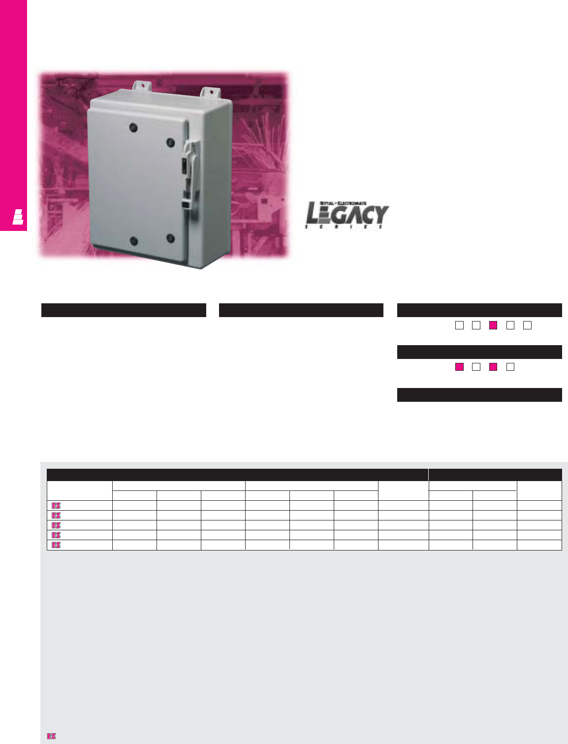
IND 251
FIBERGLASS FMD
Legacy Fiberglass FMD Enclosures
Rittal Electromate wallmount disconnect enclosures accept all
standard available disconnects and circuit-breakers, including:
•Square D non-fusible disconnects
•Square D fusible disconnects
•Allen Bradley non-fusible disconnects
•Allen Bradley fusible disconnects
•General Electric non-fusible disconnects
•General Electric fusible disconnects
Enclosure Mounting Panel
Part No. Outside dimensions (inches) Inside dimensions (inches) Part No. Panel size Usable depth
HW DHWD H WJ
L F16HS10 18.75 10.96 10.25 15.92 10.27 8.53 L MPL1610CD 13.00 8.50 7.8
L F20HS16 22.75 16.87 11.00 19.70 16.04 9.24 L MPL2016CD 16.875 13.375 8.26
L F24HS24 27.00 25.24 13.19 24.05 24.39 11.25 L MPL2424CD 20.875 21.375 10.25
L F30HS24 33.41 26.32 13.19 30.46 25.47 11.27 L MPL3024CD 26.875 21.375 10.27
L F36HS30 39.31 32.50 13.31 36.31 31.69 11.36 L MPL3630CD 32.875 27.375 10.36
Configuration
•Environmentally sealed disconnect
•Foamed-in-place polyurethane gasketing
•Rigid body construction and watertight seal
•Molded-in panel mounting inserts
•Integral mounting brackets for ease of
installation
Technical Specifications
Material:
•Body and door: hot compression molded
fiberglass reinforced polyester
•Optional mounting panel: carbon steel
Finish/color:
•Body and door: fiberglass, pigmented
light grey
•Optional mounting panel: painted white Page . . . . . . . . . . . . . . . . . . . . . . . . . . . . IND 295
NEMA Type
134X123R
UL CUL CSA TÜV
Listings
Protection Ratings
Certifications/Approvals
Technical Drawings
Fiberglass Wallmount Boxes
Designates a product in the EnclosureZone program.
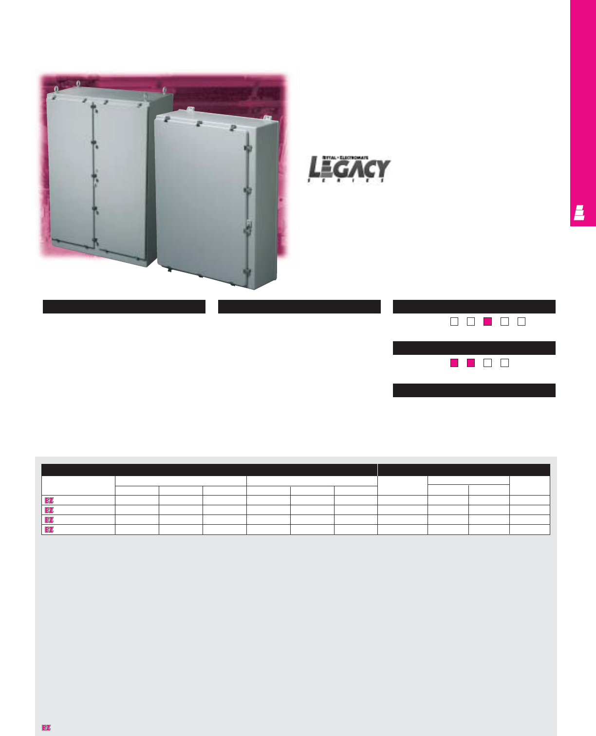
IND 252
FIBERGLASS FREESTANDING
Legacy Fiberglass Freestanding Enclosures
These fiberglass freestanding boxes are designed primarily
for indoor or outdoor use and can be used for many different
applications. They protect installed equipment against
splashing water, seepage of water, falling or hose directed
water and severe external condensation.
Enclosure Mounting Panel
Part No. Outside dimensions (inches) Inside dimensions (inches) Part No. Panel Size Usable depth
HWDHWD HWJ
L F60H3612 63.50 36.50 14.12 60.13 36.13 13.44 L MPL6036CS 57.00 33.00 12.44
L F60H3616 63.50 36.50 18.12 60.13 36.13 17.44 L MPL6036CS 57.00 33.00 16.44
L F72H2525FS 72.50 25.50 26.38 72.00 25.00 25.75 L MPL7225CS 64.00 21.00 24.74
L F72H4925FSDD 72.50 49.50 26.38 72.00 49.00 25.75 L MPL7249CS 64.00 22.00 24.74
Configuration
•Rigid body construction and water
resistant seal
•Foamed-in-place polyurethane gasketing or
neoprene gasketing (72.50" H cabinets)
•Wallmount or freestanding models available
•Molded-in panel mounting inserts or studs
•Eyebolts and crossbar construction
•Built-in padlock hasp
Technical Specifications
Material:
•Body and door: hot compression molded
fiberglass reinforced polyester
•Optional mounting panel: carbon steel
Finish/color:
•Body and door: fiberglass, pigmented
light grey
•Optional mounting panel: painted white
NEMA 4X Freestanding Boxes
Pages . . . . . . . . . . . . . . . . . . . . . . . IND 296-297
NEMA Type
134X123R
UL CUL CSA TÜV
Listings
Protection Ratings
Certifications/Approvals
Technical Drawings
Designates a product in the EnclosureZone program.
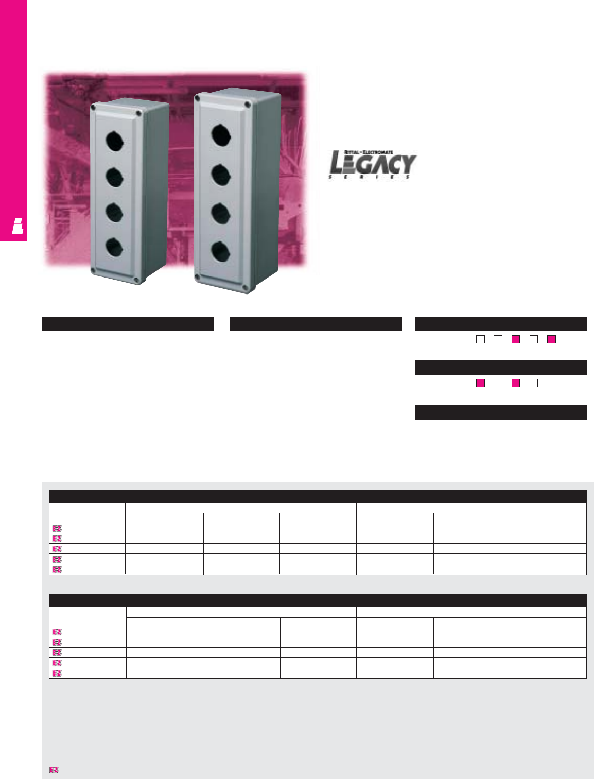
Configuration
•Lift-off cover
•Recessed captive stainless steel screws to
hold cover
•Notched key hole design
•Metal grounding strap provided
•External mounting brackets available
•Foamed-in-place polyurethane gasketing
Technical Specifications
Material:
•Body and door: hot compression molded
fiberglass reinforced polyester
Finish/color:
•Body and door: fiberglass, pigmented
light grey
Page . . . . . . . . . . . . . . . . . . . . . . . . . . . . IND 298
NEMA Type
134X126P
UL CUL CSA TÜV
Listings
Protection Ratings
Certifications/Approvals
Technical Drawings
IND 253
FIBERGLASS OPERATOR INTERFACE
Legacy Fiberglass Pushbutton Boxes
These fiberglass boxes are designed for indoor and outdoor
use to house pushbuttons, selector switches, pilot lights and
more and to protect such equipment against dirt, dust, and
spraying of water, oil or coolant.
22 mm Enclosure
Part No. Outside dimensions (inches) Inside dimensions (inches)
HWD H W D
L F1PBGM 6.63 3.81 3.89 6.00 3.19 3.63
L F2PBGM 6.63 3.81 3.89 6.00 3.19 3.63
L F3PBGM 6.63 3.81 3.89 6.00 3.19 3.63
L F4PBGM 8.88 3.81 3.89 8.26 3.19 3.63
L F5PBGM 11.13 3.81 3.89 10.51 3.19 3.63
30 mm Enclosure
Part No. Outside dimensions (inches) Inside dimensions (inches)
HWD HW D
L F1PB 6.63 3.81 3.89 6.00 3.19 3.63
L F2PB 6.63 3.81 3.89 6.00 3.19 3.63
L F3PB 8.88 3.81 3.89 8.26 3.19 3.63
L F4PB 11.13 3.81 3.89 10.51 3.19 3.63
L F5PB 13.78 3.63 3.14 13.19 3.03 2.87
30/22 mm Pushbutton Enclosures
Designates a product in the EnclosureZone program.
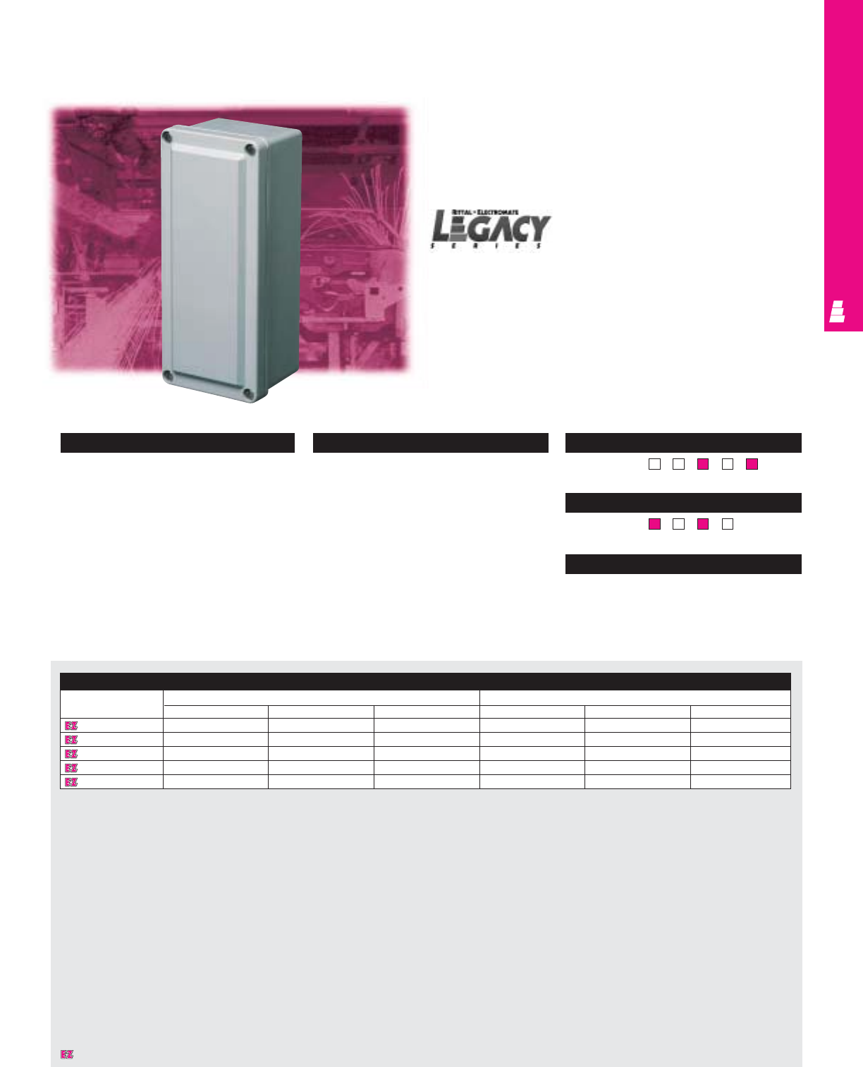
IND 254
FIBERGLASS OPERATOR INTERFACE
Legacy Fiberglass Pushbutton Boxes
These fiberglass boxes are designed for indoor and outdoor
use to house pushbuttons, selector switches, pilot lights and
more and to protect such equipment against dirt, dust, and
spraying of water, oil or coolant.
Enclosure
Part No. Outside dimensions (inches) Inside dimensions (inches)
HWD HWD
L FJ332HB 3.72 3.63 2.95 3.13 3.03 2.70
L FJ532HB 5.97 3.63 3.14 5.38 3.03 2.87
L FJ644HB 6.63 3.81 3.89 6.00 3.19 3.63
L FJ844HB 8.88 3.81 3.89 8.26 3.19 3.63
L FJ1144HB 11.13 3.81 3.89 10.51 3.19 3.63
Small Box Pushbutton Enclosures
Configuration
•Lift-off cover
•Continuous polyurethane cover gasket
•Small raised beveled cover flush with
enclosure sides
•Recessed captive stainless steel screws
•External mounting brackets available
•Foamed-in-place polyurethane gasketing
Technical Specifications
Material:
•Body and door: hot compression molded
fiberglass reinforced polyester
Finish/color:
•Body and door: fiberglass, pigmented
light grey
Page . . . . . . . . . . . . . . . . . . . . . . . . . . . IND 299
NEMA Type
134X126P
UL CUL CSA TÜV
Listings
Protection Ratings
Certifications/Approvals
Technical Drawings
Designates a product in the EnclosureZone program.
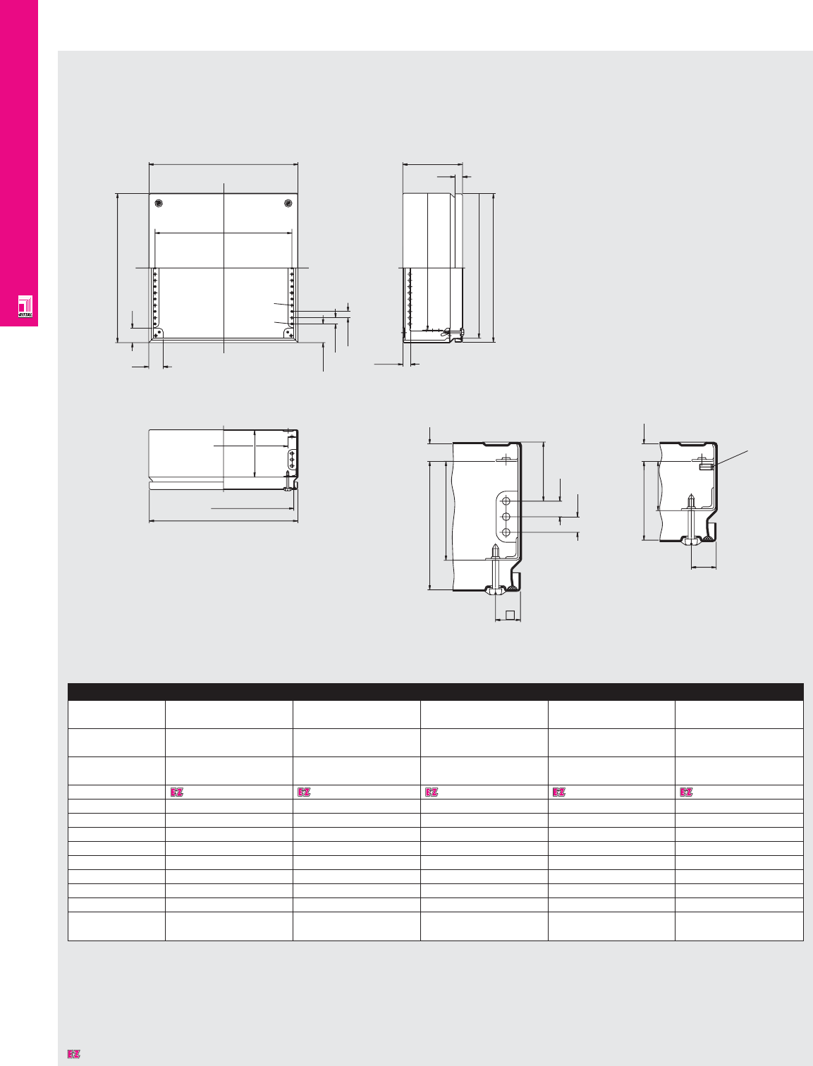
NONCORROSIVE WALLMOUNT
IND 255
Technical Specifications
KL Junction Boxes
Detail X
D=120
D1
W3
W2
79.5
103
29
29
H1
H2
12.5
37.5
W4
Ø4.6
M5
12.5
14
15.5
H4
W5
W1 D
15
20
47.5
12.5
12.5
H3
20.0
Detail Y
D=80
14
39.5
63
M6 x 12
Enclosure
Height (H1) inches 5.91 5.91 7.87 7.87 7.87
mm 150 150 200 200 200
Width (W1) inches 5.91 11.81 7.87 11.81 15.75
mm 150 300 200 300 400
Depth (D) inches 3.15 3.15 3.15 3.15 4.72
mm 80 80 80 80 120
Part No. 1521010 1522010 1523010 1524010 1525010
H2 132 132 182 182 182
H3 148 148 198 198 198
H4 100 100 150 150 150
W2 132 282 182 282 382
W3 148 298 198 298 398
W4 109 259 159 259 359
W5 125 275 175 275 375
D1 53.6 53.6 53.6 53.6 93.6
Weight lbs. 2.9 4.0 4.0 5.3 7.9
kg 1.3 1.8 1.8 2.4 1.5
Dimensions in millimeters (mm) unless otherwise indicated.
Designates a product in the EnclosureZone program.
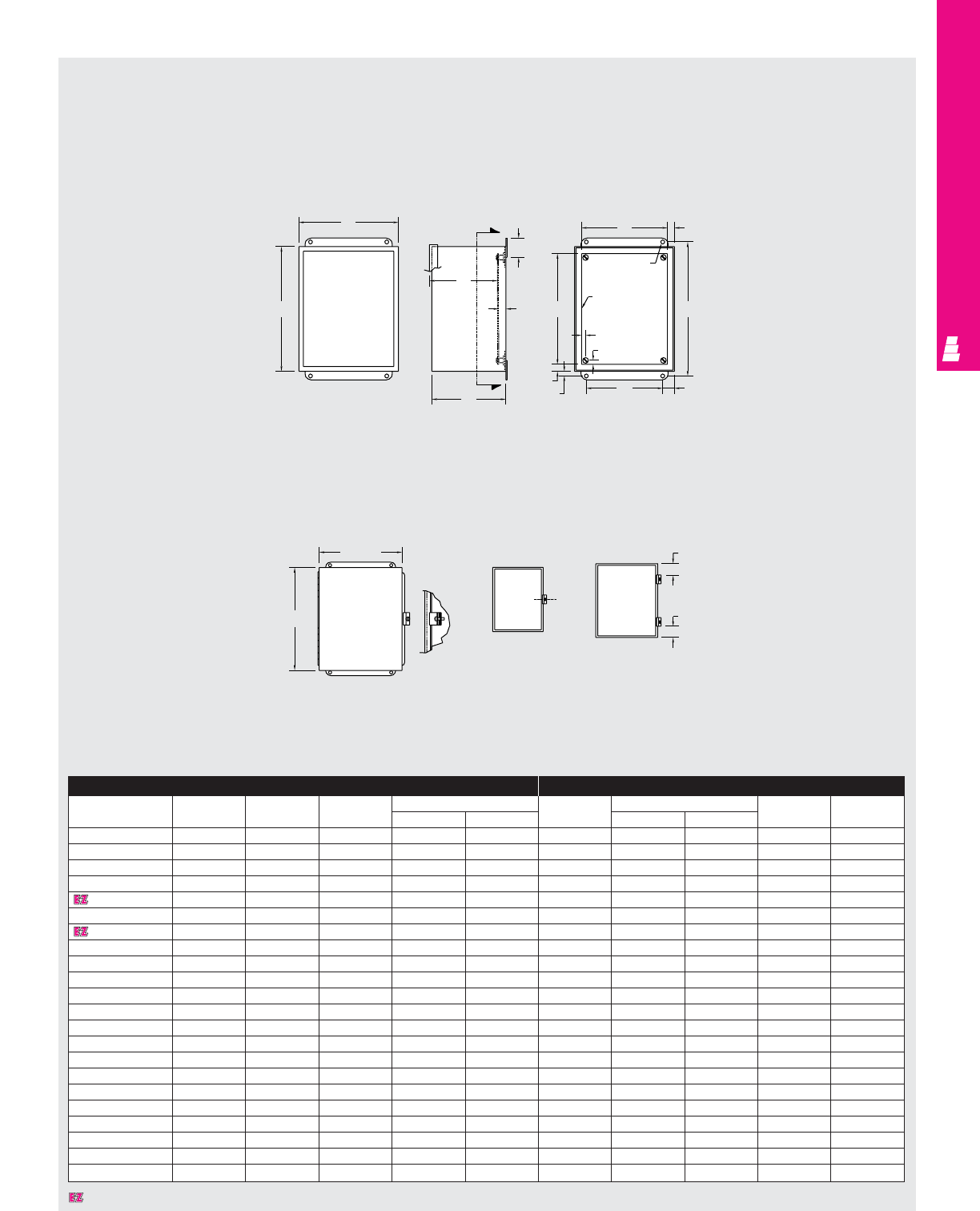
NONCORROSIVE WALLMOUNT
IND 256
Technical Specifications
Continuous Hinge Cover Enclosures
Front View
Less Cover Right Side View Section Y-Y
Fig. 1 Fig. 2
B
A
G
Y
1.75
.50
Y
CW
.38
.56 1.00
.31
.31
E
Panel
(optional) H
.31 DIA. (TYP)
F.56
B + .31
A + .31
C
L
1.00
1.00
Enclosure Mounting Panel
Part No.
Height Width Depth Mounting centers
Part No.
Panel size Usable depth Clamps
ABCHW EF G
E 404CHSS 4.00 4.00 3.00 4.75 2.00 NONE ---Fig. 1
E 4044CHSS 4.00 4.00 4.00 4.75 2.00 NONE ---Fig. 1
E 604CHSS 6.00 4.00 3.00 6.75 2.00 E 6P4 4.88 2.88 2.50 Fig. 1
E 6044CHSS 6.00 4.00 4.00 6.75 2.00 E 6P4 4.88 2.88 3.50 Fig. 1
E 606CHSS 6.00 6.00 4.00 6.75 4.00 E 6P6 4.88 4.88 3.50 Fig. 1
E 806CHSS 8.00 6.00 3.50 8.75 4.00 E 8P6 6.88 4.88 3.00 Fig. 2
E 8066CHSS 8.00 6.00 6.00 8.75 4.00 E 8P6 6.88 4.88 5.50 Fig. 2
E 808CHSS 8.00 8.00 4.00 8.75 6.00 E 8P8 6.88 6.88 3.50 Fig. 2
E 1008CHSS 10.00 8.00 4.00 10.75 6.00 E 10P8 8.88 6.88 3.50 Fig. 2
E 10086CHSS 10.00 8.00 6.00 10.75 6.00 E 10P8 8.88 6.88 5.50 Fig. 2
E 10106CHSS 10.00 10.00 6.00 10.75 8.00 E 10P10 8.88 8.88 5.50 Fig. 2
E 12064CHSS 12.00 6.00 4.00 12.75 4.00 E 12P6 10.88 4.88 3.50 Fig. 2
E 1210CHSS 12.00 10.00 5.00 10.75 8.00 E 12P10 10.88 8.88 4.50 Fig. 2
E 12108CHSS 12.00 10.00 8.00 12.75 8.00 E 12P10 10.88 8.88 7.50 Fig. 2
E 1212CHSS 12.00 12.00 6.00 12.75 10.00 E 12P12 10.88 10.88 5.50 Fig. 2
E 14086CHSS 14.00 8.00 6.00 14.75 6.00 E 14P8 12.88 6.88 5.50 Fig. 2
E 1412CHSS 14.00 12.00 6.00 14.75 10.00 E 14P12 12.88 10.88 5.50 Fig. 2
E 14128CHSS 14.00 12.00 8.00 14.75 10.00 E 14P12 12.88 10.88 7.50 Fig. 2
E 16106CHSS 16.00 10.00 6.00 16.75 8.00 E 16P10 14.88 8.88 5.50 Fig. 2
E 1614CHSS 16.00 14.00 6.00 16.75 12.00 E 16P14 14.88 12.88 5.50 Fig. 2
E 16148CHSS 16.00 14.00 8.00 16.75 12.00 E 16P14 14.88 12.88 7.50 Fig. 2
E 161410CHSS 16.00 14.00 10.00 16.75 12.00 E 16P14 14.88 12.88 9.50 Fig. 2
Designates a product in the EnclosureZone program.
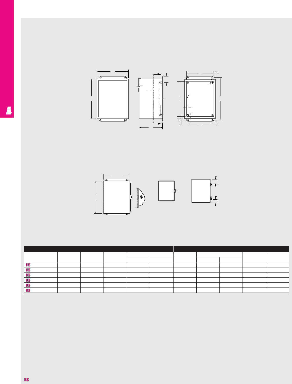
NONCORROSIVE WALLMOUNT
IND 257
Technical Specifications
Continuous Hinge Cover Enclosures
Front View
Less Cover Right Side View Section Y-Y
Fig. 1 Fig. 2
B
A
G
Y
1.75
.50
Y
CW
.38
.56 1.00
.31
.31
E
Panel
(optional) H
.31 DIA. (TYP)
F.56
B + .31
A + .31
C
L
1.00
1.00
Enclosure Mounting Panel
Part No.
Height Width Depth Mounting centers
Part No.
Panel size Usable depth Clamps
ABCHW EF G
E 606CHAL 6.00 6.00 4.00 6.75 4.00 E 6P6 4.88 4.88 3.50 Fig. 1
E 8064CHAL 8.00 6.00 4.00 8.75 4.00 E 8P6 6.88 4.88 3.50 Fig. 2
E 1008CHAL 10.00 8.00 4.00 10.75 6.00 E 10P8 8.88 6.88 3.50 Fig. 2
E 12106CHAL 12.00 10.00 6.00 12.75 8.00 E 12P10 10.88 8.88 5.50 Fig. 2
E 1412CHAL 14.00 12.00 6.00 14.75 10.00 E 14P12 12.88 10.88 5.50 Fig. 2
E 1614CHAL 16.00 14.00 6.00 16.75 12.00 E 16P14 14.88 12.88 5.50 Fig. 2
Designates a product in the EnclosureZone program.

NONCORROSIVE WALLMOUNT
IND 258
Front View
Less Cover Right Side
View Section Y-Y
B
A
Y
G
1.75
C
.50
Y
F
.31 DIA. (TYP)
Panel
(optional)
.31
.31
W
E
.56
.38
.56
H
1.00
Fig. 2 Fig. 2
Fig.1 Fig. 2
B + .31
A + .31
Continuous
hinge
Cover clamp
C
LC
L
C
L
1.50
1.50
2.00 (TYP) 3.50 (TYP)
3.00 (TYP) 1.50 (TYP)
Enclosure Mounting Panel
Part No. Part No.
Height Width Depth Mounting centers
Part No.
Panel size Usable depth Clamps
304 SS 316 SS
AB CHW EF G
E 404CHNFSS E 404CHNFSS6 4.00 4.00 3.00 4.75 2.00 - - - - Fig. 1
E 604CHNFSS E 604CHNFSS6 6.00 4.00 3.00 6.75 2.00 E 6P4 4.88 2.88 2.50 Fig. 1
E 6044CHNFSS E 6044CHNFSS6 6.00 4.00 4.00 6.75 2.00 E 6P4 4.88 2.88 3.50 Fig. 1
E 606CHNFSS E 606CHNFSS6 6.00 6.00 4.00 6.75 4.00 E 6P6 4.88 4.88 3.50 Fig. 1
E 806CHNFSS E 806CHNFSS6 8.00 6.00 3.50 8.75 4.00 E 8P6 6.88 4.88 3.00 Fig. 1
E 8064CHNFSS E 8064CHNFSS6 8.00 6.00 4.00 8.75 4.00 E 8P6 6.88 4.88 3.50 Fig. 1
E 1008CHNFSS E 1008CHNFSS6 10.00 8.00 4.00 10.75 6.00 E 10P8 8.88 6.88 3.50 Fig. 2
E 10086CHNFSS E 10086CHNFSS6 10.00 8.00 6.00 10.75 6.00 E 10P8 8.88 6.88 5.50 Fig. 2
E 1210CHNFSS E 1210CHNFSS6 12.00 10.00 5.00 12.75 8.00 E 12P10 10.88 8.88 4.50 Fig. 3
E 12106CHNFSS E 12106CHNFSS6 12.00 10.00 6.00 12.75 8.00 E 12P10 10.88 8.88 5.50 Fig. 3
E 1212CHNFSS E 1212CHNFSS6 12.00 12.00 6.00 12.75 10.00 E 12P12 10.88 10.88 5.50 Fig. 3
E 1412CHNFSS E 1412CHNFSS6 14.00 12.00 6.00 14.75 10.00 E 14P12 12.88 10.88 5.50 Fig. 3
E 1614CHNFSS E 1614CHNFSS6 16.00 14.00 6.00 16.75 12.00 E 16P14 14.88 12.88 5.50 Fig. 4
Designates a product in the EnclosureZone program.
Technical Specifications
Continuous Hinge Cover Boxes
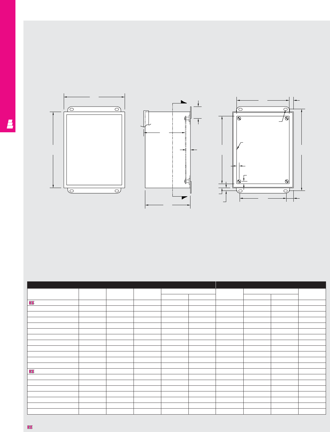
NONCORROSIVE WALLMOUNT
IND 259
Technical Specifications
Clamp Cover Junction Enclosures
Front View
Less Cover Right Side View Section Y-Y
B
A
G
C
Y
Y
.50
1.75
F.56
E
.31 DIA. (TYP)
Panel (optional)
.31
.31
.56
.38 W1.00
H
Enclosure Mounting Panel
Part No.
Height Width Depth Mounting centers
Part No.
Panel size Usable depth
ABCHW EFG
E 404NFSS 4.00 4.00 3.00 4.75 2.00 NONE ---
E 404NFSS6 4.00 4.00 3.00 4.75 2.00 NONE ---
E 604NFSS 6.00 4.00 3.00 6.75 2.00 E 6P4 4.88 2.88 2.50
E 604NFSS6 6.00 4.00 3.00 6.75 2.00 E 6P4 4.88 2.88 2.50
E 6044NFSS 6.00 4.00 4.00 6.75 2.00 E 6P4 4.88 2.88 3.50
E 6044NFSS6 6.00 4.00 4.00 6.75 2.00 E 6P4 4.88 2.88 3.50
E 606NFSS 6.00 6.00 4.00 6.75 4.00 E 6P6 4.88 4.88 3.50
E 606NFSS6 6.00 6.00 4.00 6.75 4.00 E 6P6 4.88 4.88 3.50
E 8064NFSS 8.00 6.00 4.00 8.75 4.00 E 8P6 6.88 4.88 3.50
E 8064NFSS6 8.00 6.00 4.00 8.75 4.00 E 8P6 6.88 4.88 3.50
E 1008NFSS 10.00 8.00 4.00 10.75 6.00 E 10P8 8.88 6.88 3.50
E 1008NFSS6 10.00 8.00 4.00 10.75 6.00 E 10P8 8.88 6.88 3.50
E 1210NFSS 12.00 10.00 5.00 12.75 8.00 E 12P10 10.88 8.88 4.50
E 1210NFSS6 12.00 10.00 5.00 12.75 8.00 E 12P10 10.88 8.88 4.50
E 12106NFSS 12.00 10.00 6.00 12.75 8.00 E 12P10 10.88 8.88 5.50
E 12106NFSS6 12.00 10.00 6.00 12.75 8.00 E 12P10 10.88 8.88 5.50
E 1412NFSS 14.00 12.00 6.00 14.75 10.00 E 14P12 12.88 10.88 5.50
E 1412NFSS6 14.00 12.00 6.00 14.75 10.00 E 14P12 12.88 10.88 5.50
E 1614NFSS 16.00 14.00 6.00 16.75 12.00 E 16P14 14.88 12.88 5.50
E 1614NFSS6 16.00 14.00 6.00 16.75 12.00 E 16P14 14.88 12.88 5.50
Designates a product in the EnclosureZone program.
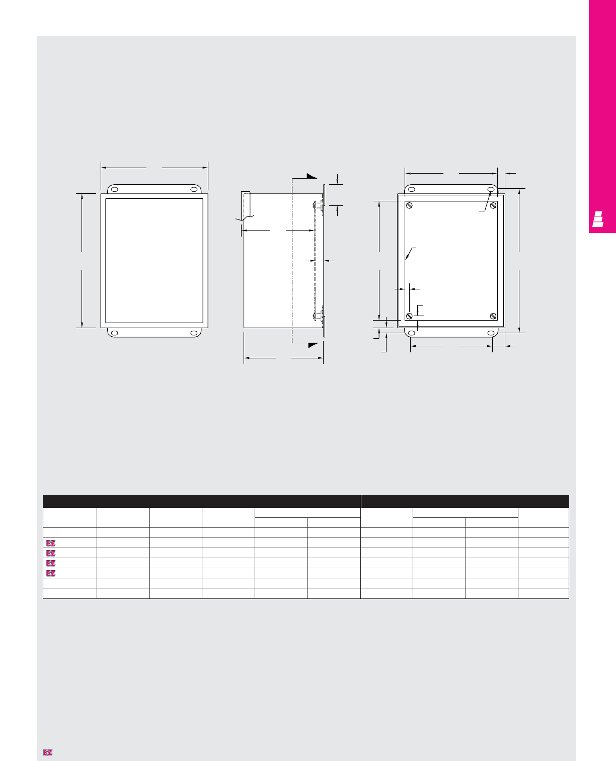
NONCORROSIVE WALLMOUNT
IND 260
Technical Specifications
Clamp Cover Junction Enclosures
Front View
Less Cover Right Side View Section Y-Y
B
A
G
C
Y
Y
.50
1.75
F.56
E
.31 DIA. (TYP)
Panel (optional)
.31
.31
.56
.38 W1.00
H
Enclosure Mounting Panel
Part No. Height Width Depth Mounting centers Part No. Panel size Usable depth
ABCHW EFG
E 604NFAL 6.00 4.00 3.00 6.75 2.00 E 6P4 4.88 2.88 2.50
E 606NFAL 6.00 6.00 4.00 6.75 4.00 E 6P6 4.88 4.88 3.50
E 8064NFAL 8.00 6.00 4.00 8.75 4.00 E 8P6 6.88 4.88 3.50
E 1008NFAL 10.00 8.00 4.00 10.75 6.00 E 10P8 8.88 6.88 3.50
E 1210NFAL 12.00 10.00 5.00 12.75 8.00 E 12P10 10.88 8.88 4.50
E 1412NFAL 14.00 12.00 6.00 14.75 10.00 E 14P12 12.88 10.88 5.50
E 1614NFAL 16.00 14.00 6.00 16.75 12.00 E 16P14 14.88 12.88 5.50
Designates a product in the EnclosureZone program.
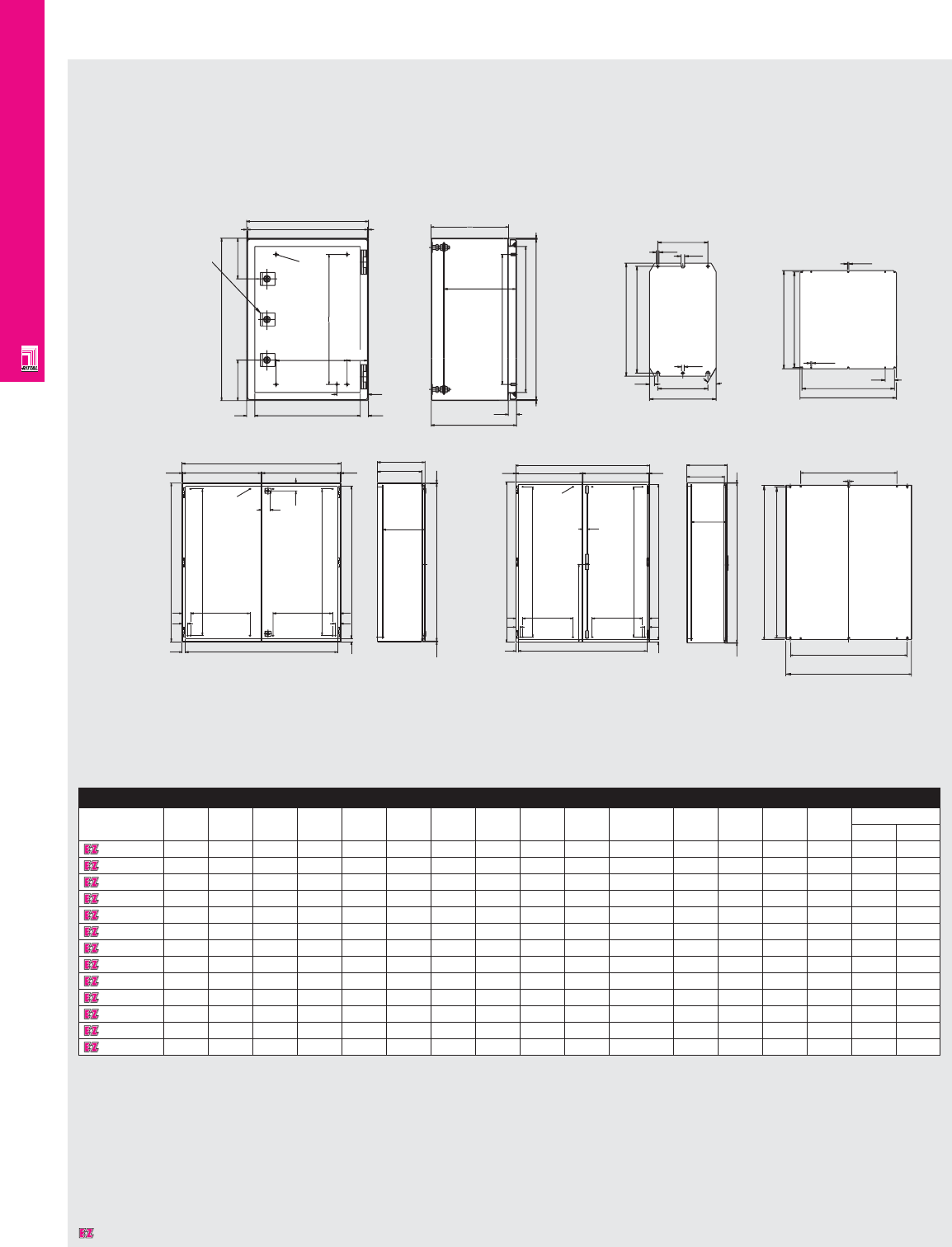
NONCORROSIVE WALLMOUNT
IND 261
Technical Specifications
AE Wallmount Enclosures
W2
20
20
32
50 W3
H1
H4
W3
32
50
H4
H3
2.5
M6x12
W4
51
46.5
W1
W4 2.5
2.5
H2
D3
2.5
D2
D1
W2
20
20
585
32
50 W3
H1
H4
W3
32
50
H4
H3
2.5
M6x12
W4
30.5
W1 W4 2.5
3.5
F1
F2
H2
G1
G2
D3
2.5
D2
D1
12.5
720
10
12.5
F1
F2
90
G2
G1
6.5
30°0'
G2
G1
12 F1
F2
6.5
9
122
lock in the middle
have only one turnbuckle
1097000,1097100
AE1002,1004,1005,
1006,1009
M6x12
100
H4
20
D1
D3
2.5
2.5
2.5
20
W2
H3
100
75.0
50
W3
2.5
W1
20
H1
H2
H4
W4 D2
Enclosure
Part No. H1 W1 D1 H2 H3 H4 W2 W3 W4 D2 D3 F1 F2 G1 G2 Weight
lbs kg
1002660 300 200 155 295 274 225 33 - 195 135 135 162 122 275 260 9.9 4.5
1004660 300 380 155 295 260 225 340 250 375 135 113-129 334 295 275 250 19.4 8.8
1005660 380 300 210 375 340 275 260 175 295 190 168-184 254 215 355 330 19.1 8.7
1006660 380 380 210 375 340 275 340 250 375 190 168-184 334 295 355 330 26.4 12.0
1009660 380 600 210 375 340 275 560 475 595 190 168-184 549 510 355 330 37.4 17.0
1097000 400 300 210 395 360 325 260 175 295 190 168-184 254 215 254 215 20.5 9.3
1007660 500 500 210 495 460 425 460 375 495 190 168-184 449 410 470 445 41.6 18.9
1008660 600 380 210 595 560 525 340 250 375 190 168-184 334 295 570 545 37.4 17.0
1010660 600 600 210 595 560 525 560 475 595 190 168-184 549 510 570 545 55.0 25.0
1012660 760 600 210 755 720 675 560 475 595 190 168-184 549 510 730 705 69.7 31.7
1014660 760 760 300 755 720 675 720 625 755 280 258-274 704 665 730 705 93.5 42.5
1016660 1000 800 300 995 960 920 760 675 795 280 258-274 739 700 955 930 116.4 52.9
1017660 1200 800 300 1194 1160 1125 760 675 795 280 258-274 739 700 1150 1130 154.0 70.0
Dimensions in millimeters (mm) unless otherwise indicated.
AE 1002660, 1004660,
1005660, 1006660,
1009660, 1097000
have only one
turnbuckle lock
in the middle
Designates a product in the EnclosureZone program.
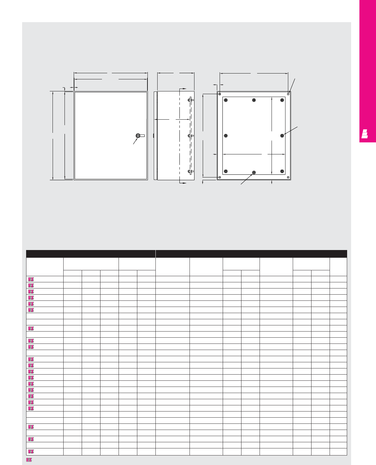
Designates a product in the EnclosureZone program.
NONCORROSIVE WALLMOUNT
IND 262
Technical Specifications
Legacy Series Enclosures
Front View Right Side View Section A-A
B
B - .19
.09 .09
A - .19
C
L
A
1/4 Turn latch
A
J
A
D
.75 C
L
W.50 Ø (4 PLS)
Omit center
studs if
A < 36.00
E
F
1.50
Omit center studs
if B < 36.00
.75
1.50
H
Enclosure Mounting Panel
Part No. Outside dimensions Mounting White Zinc Panel White Panel Usable
(inches) centers (Full Size) (Full Size) size (NEMA Style) size depth
HWDHWPanel Part No. Panel Part No. HWPanel Part No. HWJ
L W120806SS 12.00 8.00 6.00 10.5 10.5 L W12P8W L W12P8 10.2 6.2 E 12P8 --5.0
L W121206SS 12.00 12.00 6.00 10.5 10.5 L W12P12W L W12P12 10.2 10.2 E 12P12 --5.0
L W161206SS 16.00 12.00 6.00 14.5 10.5 L W16P12W L W16P12 14.2 10.2 E 16P12 13.0 9.0 5.0
L W161208SS 16.00 12.00 8.00 14.5 10.5 L W16P12W L W16P12 14.2 10.2 E 16P12 13.0 9.0 7.0
L W161606SS 16.00 16.00 6.00 14.5 14.5 L W16P16W L W16P16 14.2 14.2 E 16P16 13.0 13.0 5.0
L W161608SS 16.00 16.00 8.00 14.5 14.5 L W16P16W L W16P16 14.2 14.2 E 16P16 13.0 13.0 7.0
L W162008SS 16.00 20.00 8.00 14.5 18.5 L W16P20W L W16P20 14.2 18.2 E 20P16 13.0 13.0 7.0
L W201606SS 20.00 16.00 6.00 18.5 14.5 L W20P16W L W20P16 18.2 14.2 E 20P16 17.0 13.0 5.0
L W201608SS 20.00 16.00 8.00 18.5 14.5 L W20P16W L W20P16 18.2 14.2 E 20P16 17.0 13.0 7.0
L W202006SS 20.00 20.00 6.00 18.5 18.5 L W20P20W L W20P20 18.2 18.2 E 20P20 17.0 17.0 5.0
L W202008SS 20.00 20.00 8.00 18.5 18.5 L W20P20W L W20P20 18.2 18.2 E 20P20 17.0 17.0 7.0
L W202012SS 20.00 20.00 12.00 18.5 18.5 L W20P20W L W20P20 18.2 18.2 E 20P20 17.0 17.0 11.0
L W241608SS 24.00 16.00 8.00 22.5 14.5 L W24P16W L W24P16 22.2 14.2 E 24P16 21.0 13.0 7.0
L W242008SS 24.00 20.00 8.00 22.5 18.5 L W24P20W L W24P20 22.2 18.2 E 24P20 21.0 17.0 7.0
L W242012SS 24.00 20.00 12.00 22.5 18.5 L W24P20W L W24P20 22.2 18.2 E 24P20 21.0 17.0 11.0
L W242408SS 24.00 24.00 8.00 22.5 22.5 L W24P24W L W24P24 22.2 22.2 E 24P24 21.0 21.0 7.0
L W242412SS 24.00 24.00 12.00 22.5 22.5 L W24P24W L W24P24 22.2 22.2 E 24P24 21.0 21.0 11.0
L W302408SS 30.00 24.00 8.00 28.5 22.5 L W30P24W L W30P24 28.2 22.2 E 30P24 27.0 21.0 7.0
L W302412SS 30.00 24.00 12.00 28.5 22.5 L W30P24W L W30P24 28.2 22.2 E 30P24 27.0 21.0 11.0
L W303008SS 30.00 30.00 8.00 28.5 28.5 L W30P30W L W30P30 28.2 28.2 E 30P30 27.0 27.0 7.0
L W303012SS 30.00 30.00 12.00 28.5 28.5 L W30P30W L W30P30 28.2 28.2 E 30P30 27.0 27.0 11.0
L W362408SS 36.00 24.00 8.00 34.5 22.5 L W36P24W L W36P24 34.2 22.2 E 36P24 33.0 21.0 7.0
L W362412SS 36.00 24.00 12.00 34.5 22.5 L W36P24W L W36P24 34.2 22.2 E 36P24 33.0 21.0 11.0
L W363008SS 36.00 30.00 8.00 34.5 28.5 L W36P30W L W36P30 34.2 26.2 E 36P30 33.0 27.0 7.0
L W363012SS 36.00 30.00 12.00 34.5 28.5 L W36P30W L W36P30 34.2 28.2 E 36P30 33.0 27.0 11.0
L W363612SS 36.00 36.00 12.00 34.5 34.5 L W36P36W L W36P36 34.2 34.2 E 36P36 33.0 33.0 11.0
L W483612SS 48.00 36.00 12.00 46.5 34.5 L W48P36W L W48P36 46.2 34.2 E 48P36 45.0 33.0 11.0
L W603612SS 60.00 36.00 12.00 58.5 34.5 L W60P36W L W60P36 58.2 34.2 E 60P36 57.0 33.0 11.0
L W603616SS 60.00 36.00 16.00 58.5 34.5 L W60P36W L W60P36 58.2 34.2 E 60P36 57.0 33.0 15.0
Door stiffener omit
if A < 36.00
or B < 30.00
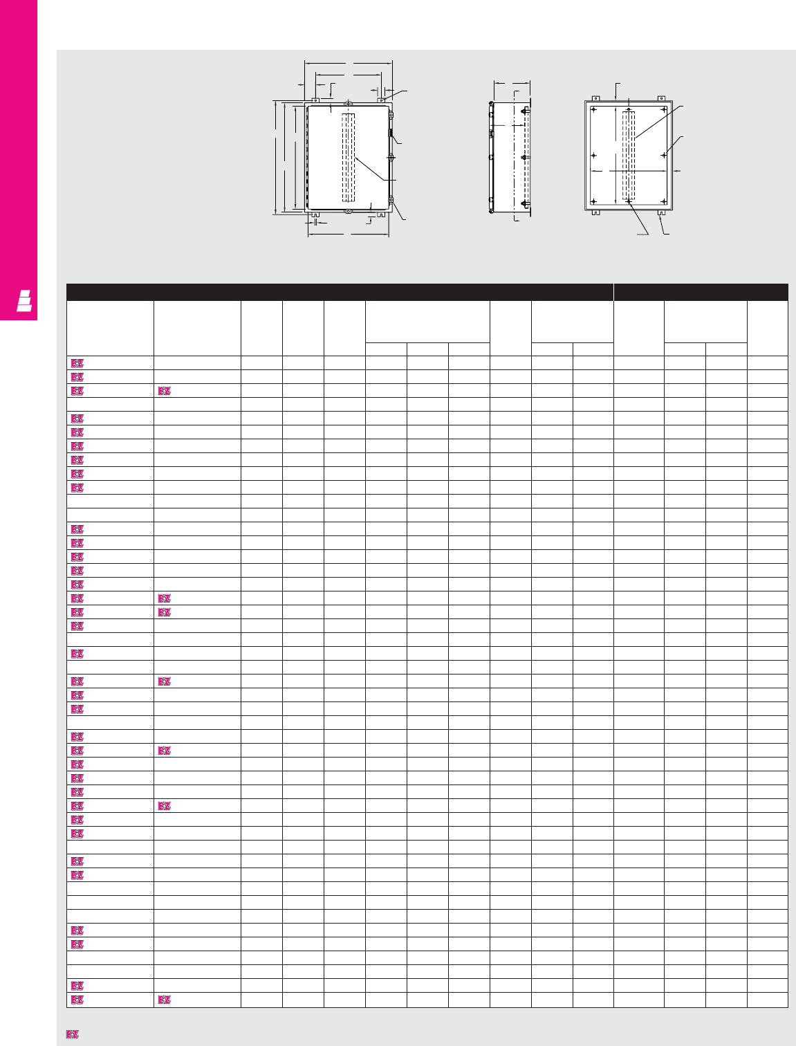
NONCORROSIVE WALLMOUNT
IND 263
Technical Specifications
One Door Wallmount Boxes
Front View Right Side View Section Y-Y
B
W
D TYP. 1.25 2.00 .44 DIA.
Padlockable HASP
and keeper
Door stiffener omit
if A < 36.00
or B < 30.00
A
J
H
.44 1.25 Door clamp
J
C
L
C
L
C
Y
G
Y
Omit center studs
if B < 36.00
Mounting feet
Omit center studs
if A < 36.00
Body stiffener
omit if A < 36.00
or B < 30.00
1.50
C
L
F
E
1.50
Enclosure Mounting Panel
Part No. Part No. Height Width Depth Mounting centers Door Cover size Part No. Panel size Usable
304 SS 316 SS and depth
body
ABCHWDstiffener J K E F G
E 16H1206SS E 16H1206SS6 16.00 12.00 6.00 17.25 9.50 1.25 NO 14.19 10.16 E 16P12 13.00 9.00 6.00
E 16H1208SS E 16H1208SS6 16.00 12.00 8.00 17.25 9.50 1.25 NO 14.19 10.16 E 16P12 13.00 9.00 8.00
E 16H1606SS E 16H1606SS6 16.00 16.00 6.00 17.25 10.00 3.00 NO 14.19 14.16 E 16P16 13.00 13.00 6.00
E 16H2006SS E 16H2006SS6 16.00 20.00 6.00 17.25 14.00 3.00 NO 14.19 18.16 E 20P16 13.00 17.00 6.00
E 20H1606SS E 20H1606SS6 20.00 16.00 6.00 21.25 10.00 3.00 NO 18.19 14.16 E 20P16 17.00 13.00 6.00
E 20H1608SS E 20H1608SS6 20.00 16.00 8.00 21.25 10.00 3.00 NO 18.19 14.16 E 20P16 17.00 13.00 8.00
E 20H1610SS E 20H1610SS6 20.00 16.00 10.00 21.25 10.00 3.00 NO 18.19 14.16 E 20P16 17.00 13.00 10.00
E 20H2006SS E 20H2006SS6 20.00 20.00 6.00 21.25 14.00 3.00 NO 18.19 18.16 E 20P20 17.00 17.00 6.00
E 20H2008SS E 20H2008SS6 20.00 20.00 8.00 21.25 14.00 3.00 NO 18.19 18.16 E 20P20 17.00 17.00 8.00
E 20H2408SS E 20H2408SS6 20.00 24.00 8.00 21.25 18.00 3.00 NO 18.19 22.16 E 24P20 17.00 21.00 8.00
E 24H1206SS E 24H1206SS6 24.00 12.00 6.00 25.25 9.50 1.25 NO 22.19 10.16 E 12P24 21.00 9.00 6.00
E 24H1606SS E 24H1606SS6 24.00 16.00 6.00 25.25 10.00 3.00 NO 22.19 14.16 E 24P16 21.00 13.00 6.00
E 24H1608SS E 24H1608SS6 24.00 16.00 8.00 25.25 10.00 3.00 NO 22.19 14.16 E 24P16 21.00 13.00 8.00
E 24H2006SS E 24H2006SS6 24.00 20.00 6.00 25.25 14.00 3.00 NO 22.19 18.16 E 24P20 21.00 17.00 6.00
E 24H2008SS E 24H2008SS6 24.00 20.00 8.00 25.25 14.00 3.00 NO 22.19 18.16 E 24P20 21.00 17.00 8.00
E 24H2010SS E 24H2010SS6 24.00 20.00 10.00 25.25 14.00 3.00 NO 22.19 18.16 E 24P20 21.00 17.00 10.00
E 24H2406SS E 24H2406SS6 24.00 24.00 6.00 25.25 18.00 3.00 NO 22.19 22.16 E 24P24 21.00 21.00 6.00
E 24H2408SS E 24H2408SS6 24.00 24.00 8.00 25.25 18.00 3.00 NO 22.19 22.16 E 24P24 21.00 21.00 8.00
E 24H2412SS E 24H2412SS6 24.00 24.00 12.00 25.25 18.00 3.00 NO 22.19 22.16 E 24P24 21.00 21.00 12.00
E 24H3008SS E 24H3008SS6 24.00 30.00 8.00 25.25 24.00 3.00 NO 22.19 28.16 E 30P24 21.00 27.00 8.00
E 30H2006SS E 30H2006SS6 30.00 20.00 6.00 31.25 14.50 3.00 NO 28.19 18.16 E 30P20 27.00 17.00 6.00
E 30H2008SS E 30H2008SS6 30.00 20.00 8.00 31.25 14.00 3.00 NO 28.19 18.16 E 30P20 27.00 17.00 8.00
E 30H2406SS E 30H2406SS6 30.00 24.00 6.00 31.25 18.00 3.00 NO 28.19 22.16 E 30P24 27.00 21.00 6.00
E 30H2408SS E 30H2408SS6 30.00 24.00 8.00 31.25 18.00 3.00 NO 28.19 22.16 E 30P24 27.00 21.00 8.00
E 30H2410SS E 30H2410SS6 30.00 24.00 10.00 31.25 18.00 3.00 NO 28.19 22.16 E 30P24 27.00 21.00 10.00
E 30H2412SS E 30H2412SS6 30.00 24.00 12.00 31.25 18.00 3.00 NO 28.19 22.16 E 30P24 27.00 21.00 12.00
E 30H2416SS E 30H2416SS6 30.00 24.00 16.00 31.25 18.00 3.00 NO 28.19 22.16 E 30P24 27.00 21.00 16.00
E 30H3008SS E 30H3008SS6 30.00 30.00 8.00 31.25 24.00 3.00 NO 28.19 28.16 E 30P30 27.00 27.00 8.00
E 36H2408SS E 36H2408SS6 36.00 24.00 8.00 37.25 18.00 3.00 NO 34.19 22.16 E 36P24 33.00 21.00 8.00
E 36H2410SS E 36H2410SS6 36.00 24.00 10.00 37.25 18.00 3.00 NO 34.19 22.16 E 36P24 33.00 21.00 10.00
E 36H3008SS E 36H3008SS6 36.00 30.00 8.00 37.25 24.00 3.00 YES 34.19 28.16 E 36P30 33.00 27.00 7.37*
E 36H3010SS E 36H3010SS6 36.00 30.00 10.00 37.25 24.00 3.00 YES 34.19 28.16 E 36P30 33.00 27.00 9.37*
E 36H3012SS E 36H3012SS6 36.00 30.00 12.00 37.25 24.00 3.00 YES 34.19 28.16 E 36P30 33.00 27.00 11.37*
E 36H3016SS E 36H3016SS6 36.00 30.00 16.00 37.25 24.00 3.00 YES 34.19 28.16 E 36P30 33.00 27.00 15.37*
E 36H3612SS E 36H3612SS6 36.00 36.00 12.00 37.25 30.00 3.00 YES 34.19 34.16 E 36P36 33.00 33.00 11.37*
E 42H3008SS E 42H3008SS6 42.00 30.00 8.00 43.25 24.00 3.00 YES 40.19 28.16 E 42P30 39.00 27.00 7.37*
E 42H3010SS E 42H3010SS6 42.00 30.00 10.00 43.25 24.00 3.00 YES 40.19 28.16 E 42P30 39.00 27.00 9.37*
E 42H3608SS E 42H3608SS6 42.00 36.00 8.00 43.25 30.00 3.00 YES 40.19 34.16 E 42P36 39.00 33.00 7.37*
E 48H3010SS E 48H3010SS6 48.00 30.00 10.00 49.25 24.00 3.00 YES 46.19 28.16 E 48P30 45.00 27.00 9.37*
E 48H3608SS E 48H3608SS6 48.00 36.00 8.00 49.25 30.00 3.00 YES 46.19 34.16 E 48P36 45.00 33.00 7.37*
E 48H3610SS E 48H3610SS6 48.00 36.00 10.00 49.25 30.00 3.00 YES 46.19 34.16 E 48P36 45.00 33.00 9.37*
E 48H3612SS E 48H3612SS6 48.00 36.00 12.00 49.25 30.00 3.00 YES 46.19 34.16 E 48P36 45.00 33.00 11.37*
E 48H3616SS E 48H3616SS6 48.00 36.00 16.00 49.25 30.00 3.00 YES 46.19 34.16 E 48P36 45.00 33.00 15.37*
E 60H3608SS E 60H3608SS6 60.00 36.00 8.00 61.25 30.00 3.00 YES 58.19 34.16 E 60P36 57.00 33.00 7.37*
E 60H3610SS E 60H3610SS6 60.00 36.00 10.00 61.25 30.00 3.00 YES 58.19 34.16 E 60P36 57.00 33.00 9.37*
E 60H3612SS E 60H3612SS6 60.00 36.00 12.00 61.25 30.00 3.00 YES 58.19 34.16 E 60P36 57.00 33.00 11.37*
E 60H3616SS E 60H3616SS6 60.00 36.00 16.00 61.25 30.00 3.00 YES 58.19 34.16 E 60P36 57.00 33.00 15.37*
* Usable depth reduced by .625" at door stiffener.
Designates a product in the EnclosureZone program.

NONCORROSIVE WALLMOUNT
IND 264
Technical Specifications
One Door Wallmount Boxes
Front View Right Side View Section Y-Y
B
W
D TYP. 1.25 2.00 .44 DIA.
Padlockable HASP
and keeper
Door stiffener omit
if A < 36.00
or B < 30.00
A
J
H
.44 1.25 Door clamp
J
C
L
C
L
C
Y
G
Y
Omit center studs
if B < 36.00
Mounting feet
Omit center studs
if A < 36.00
Body stiffener
omit if A < 36.00
or B < 30.00
1.50
C
L
F
E
1.50
Enclosure Mounting Panel
Part No. Height Width Depth Mounting centers Door Cover size Part No. Panel size Usable
and body depth
AB CH WDstiffener J K E F G
E 16H1206AL 16.00 12.00 6.00 17.25 9.50 1.25 NO 14.19 10.16 E 16P12 13.00 9.00 6.00
E 16H1608AL 16.00 16.00 8.00 17.25 10.00 3.00 NO 14.19 14.16 E 16P16 13.00 13.00 8.00
E 20H1606AL 20.00 16.00 6.00 21.25 10.00 3.00 NO 18.19 14.16 E 20P16 17.00 13.00 6.00
E 20H1610AL 20.00 16.00 10.00 21.25 10.00 3.00 NO 18.19 14.16 E 20P16 17.00 13.00 10.00
E 20H2006AL 20.00 20.00 6.00 21.25 14.00 3.00 NO 18.19 18.16 E 20P20 17.00 17.00 6.00
E 24H2006AL 24.00 20.00 6.00 25.25 14.00 3.00 NO 22.19 18.16 E 24P20 21.00 17.00 6.00
E 24H2010AL 24.00 20.00 10.00 25.25 14.00 3.00 NO 22.19 18.16 E 24P20 21.00 17.00 10.00
E 24H2408AL 24.00 24.00 8.00 25.25 18.00 3.00 NO 22.19 22.16 E 24P24 21.00 21.00 8.00
E 30H2408AL 30.00 24.00 8.00 31.25 18.00 3.00 NO 28.19 22.16 E 30P24 27.00 21.00 8.00
E 30H2412AL 30.00 24.00 12.00 31.25 18.00 3.00 NO 28.19 22.16 E 30P24 27.00 21.00 12.00
E 36H2408AL 36.00 24.00 8.00 37.25 18.00 3.00 NO 34.19 22.16 E 36P24 33.00 21.00 8.00
E 36H3008AL 36.00 30.00 8.00 37.25 24.00 3.00 YES 34.19 28.16 E 36P30 33.00 27.00 7.37*
E 36H3012AL 36.00 30.00 12.00 37.25 24.00 3.00 YES 34.19 28.16 E 36P30 33.00 27.00 11.37*
E 48H3608AL 48.00 36.00 8.00 49.25 30.00 3.00 YES 46.19 34.16 E 48P36 45.00 33.00 7.37*
E 60H3612AL 60.00 36.00 12.00 61.25 30.00 3.00 YES 58.19 34.16 E 60P36 57.00 33.00 11.37*
* Usable depth reduced by .625" at door stiffener.
Designates a product in the EnclosureZone program.
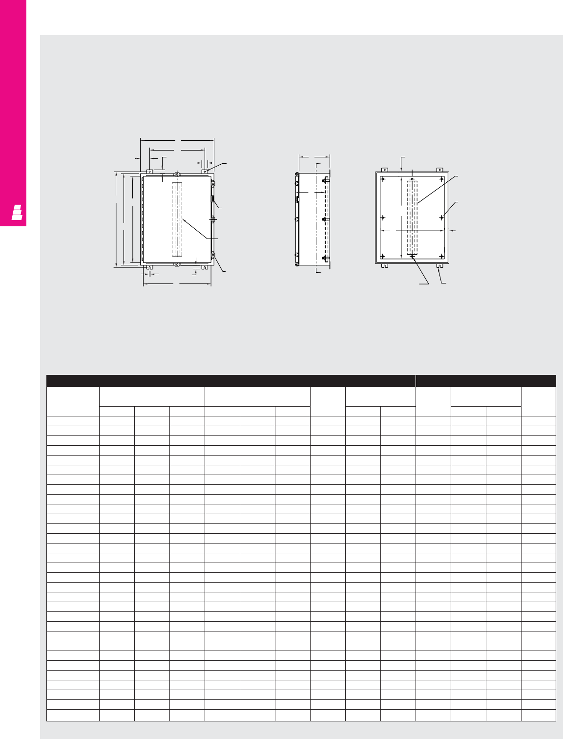
NONCORROSIVE WALLMOUNT
IND 265
Technical Specifications
One Door Wallmount Enclosures
Enclosure Mounting Panel
Part No. Outside Mounting Door and Door size Part No. Panel size Usable
dimensions centers body depth
HWDHWDstiffener J K H W
E 122406SS 12.00 24.00 6.00 13.25 18.00 3.00 NO 10.19 22.16 E 12P24 9.00 21.00 6.00
E 122408SS 12.00 24.00 8.00 13.25 18.00 3.00 NO 10.19 22.16 E 12P24 9.00 21.00 8.00
E 161206SS 16.00 12.00 6.00 17.25 9.50 1.25 NO 14.19 10.16 E 16P12 13.00 9.00 6.00
E 161208SS 16.00 12.00 8.00 17.25 9.50 1.25 NO 14.19 10.16 E 16P12 13.00 9.00 8.00
E 161210SS 16.00 12.00 10.00 17.25 9.50 1.25 NO 14.19 10.16 E 16P12 13.00 9.00 10.00
E 161606SS 16.00 16.00 6.00 17.25 10.00 3.00 NO 14.19 14.16 E 16P16 13.00 13.00 6.00
E 161608SS 16.00 16.00 8.00 17.25 10.00 3.00 NO 14.19 14.16 E 16P16 13.00 13.00 8.00
E 162006SS 16.00 20.00 6.00 17.25 14.00 3.00 NO 14.19 18.16 E 20P16 13.00 17.00 6.00
E 162008SS 16.00 20.00 8.00 17.25 14.00 3.00 NO 14.19 18.16 E 20P16 13.00 17.00 8.00
E 201206SS 20.00 12.00 6.00 21.25 9.50 1.25 NO 18.19 10.16 E 20P12 17.00 9.00 6.00
E 201208SS 20.00 12.00 8.00 21.25 9.50 1.25 NO 18.19 10.16 E 20P12 17.00 9.00 8.00
E 201606SS 20.00 16.00 6.00 21.25 10.00 3.00 NO 18.19 14.16 E 20P16 17.00 13.00 6.00
E 201608SS 20.00 16.00 8.00 21.25 10.00 3.00 NO 18.19 14.16 E 20P16 17.00 13.00 8.00
E 201610SS 20.00 16.00 10.00 21.25 10.00 3.00 NO 18.19 14.16 E 20P16 17.00 13.00 10.00
E 201612SS 20.00 16.00 12.00 21.25 10.00 3.00 NO 18.19 14.16 E 20P16 17.00 13.00 12.00
E 202006SS 20.00 20.00 6.00 21.25 14.00 3.00 NO 18.19 18.16 E 20P20 17.00 17.00 6.00
E 202008SS 20.00 20.00 8.00 21.25 14.00 3.00 NO 18.19 18.16 E 20P20 17.00 17.00 8.00
E 202010SS 20.00 20.00 10.00 21.25 14.00 3.00 NO 18.19 18.16 E 20P20 17.00 17.00 10.00
E 202406SS 20.00 24.00 6.00 21.25 18.00 3.00 NO 18.19 22.16 E 24P20 17.00 21.00 6.00
E 202408SS 20.00 24.00 8.00 21.25 18.00 3.00 NO 18.19 22.16 E 24P20 17.00 21.00 8.00
E 241206SS 24.00 12.00 6.00 25.25 9.50 1.25 NO 22.19 10.16 E 12P24 21.00 9.00 6.00
E 241208SS 24.00 12.00 8.00 25.25 9.50 1.25 NO 22.19 10.16 E 12P24 21.00 9.00 8.00
E 241210SS 24.00 12.00 10.00 25.25 9.50 1.25 NO 22.19 10.16 E 12P24 21.00 9.00 10.00
E 241606SS 24.00 16.00 6.00 25.25 10.00 3.00 NO 22.19 14.16 E 24P16 21.00 13.00 6.00
E 241608SS 24.00 16.00 8.00 25.25 10.00 3.00 NO 22.19 14.16 E 24P16 21.00 13.00 8.00
E 242006SS 24.00 20.00 6.00 25.25 14.00 3.00 NO 22.19 18.16 E 24P20 21.00 17.00 6.00
E 242008SS 24.00 20.00 8.00 25.25 14.00 3.00 NO 22.19 18.16 E 24P20 21.00 17.00 8.00
E 242010SS 24.00 20.00 10.00 25.25 14.00 3.00 NO 22.19 18.16 E 24P20 21.00 17.00 10.00
E 242012SS 24.00 20.00 12.00 25.25 14.00 3.00 NO 22.19 18.16 E 24P20 21.00 17.00 12.00
E 242016SS 24.00 20.00 16.00 25.25 14.00 3.00 NO 22.19 18.16 E 24P20 21.00 17.00 16.00
E 242406SS 24.00 24.00 6.00 25.25 18.00 3.00 NO 22.19 22.16 E 24P24 21.00 21.00 6.00
Chart continues on page IND 266.
Front View Right Side View Section Y-Y
B
W
D TYP. 1.25 2.00 .44 DIA.
Padlockable HASP
and keeper
Door stiffener omit
if A < 36.00
or B < 30.00
A
J
H
.44 1.25 Door clamp
J
C
L
C
L
C
Y
G
Y
Omit center studs
if B < 36.00
Mounting feet
Omit center studs
if A < 36.00
Body stiffener
omit if A < 36.00
or B < 30.00
1.50
C
L
F
E
1.50

NONCORROSIVE WALLMOUNT
IND 266
Enclosure Mounting Panel
Part No. Outside Mounting Door and Door size Part No. Panel size Usable
dimensions centers body depth
HWDHWDstiffener J K H W
E 242408SS 24.00 24.00 8.00 25.25 18.00 3.00 NO 22.19 22.16 E 24P24 21.00 21.00 8.00
E 242410SS 24.00 24.00 10.00 25.25 18.00 3.00 NO 22.19 22.16 E 24P24 21.00 21.00 10.00
E 242412SS 24.00 24.00 12.00 25.25 18.00 3.00 NO 22.19 22.16 E 24P24 21.00 21.00 12.00
E 242416SS 24.00 24.00 16.00 25.25 18.00 3.00 NO 22.19 22.16 E 24P24 21.00 21.00 16.00
E 243008SS 24.00 30.00 8.00 25.25 24.00 3.00 NO 22.19 28.16 E 30P24 21.00 27.00 8.00
E 301606SS 30.00 16.00 6.00 31.25 10.00 3.00 NO 28.19 14.16 E 30P16 27.00 13.00 6.00
E 302006SS 30.00 20.00 6.00 31.25 14.00 3.00 NO 28.19 18.16 E 30P20 27.00 17.00 6.00
E 302008SS 30.00 20.00 8.00 31.25 14.00 3.00 NO 28.19 18.16 E 30P20 27.00 17.00 8.00
E 302010SS 30.00 20.00 10.00 31.25 14.00 3.00 NO 28.19 18.16 E 30P20 27.00 17.00 10.00
E 302406SS 30.00 24.00 6.00 31.25 18.00 3.00 NO 28.19 22.16 E 30P24 27.00 21.00 6.00
E 302408SS 30.00 24.00 8.00 31.25 18.00 3.00 NO 28.19 22.16 E 30P24 27.00 21.00 8.00
E 302410SS 30.00 24.00 10.00 31.25 18.00 3.00 NO 28.19 22.16 E 30P24 27.00 21.00 10.00
E 302412SS 30.00 24.00 12.00 31.25 18.00 3.00 NO 28.19 22.16 E 30P24 27.00 21.00 12.00
E 302416SS 30.00 24.00 16.00 31.25 18.00 3.00 NO 28.19 22.16 E 30P24 27.00 21.00 16.00
E 302420SS 30.00 24.00 20.00 31.25 18.00 3.00 NO 28.19 22.16 E 30P24 27.00 21.00 20.00
E 303008SS 30.00 30.00 8.00 31.25 24.00 3.00 NO 28.19 22.16 E 30P30 27.00 27.00 8.00
E 303012SS 30.00 30.00 12.00 31.25 24.00 3.00 NO 28.19 28.16 E 30P30 27.00 27.00 12.00
E 303608SS 30.00 36.00 8.00 31.25 30.00 3.00 NO 28.19 34.16 E 36P30 27.00 33.00 8.00
E 362406SS 36.00 24.00 6.00 37.25 18.00 3.00 NO 34.19 22.16 E 36P24 33.00 21.00 6.00
E 362408SS 36.00 24.00 8.00 37.25 18.00 3.00 NO 34.19 22.16 E 36P24 33.00 21.00 8.00
E 362410SS 36.00 24.00 10.00 37.25 18.00 3.00 NO 34.19 22.16 E 36P24 33.00 21.00 10.00
E 362412SS 36.00 24.00 12.00 37.25 18.00 3.00 NO 34.19 22.16 E 36P24 33.00 21.00 12.00
E 363006SS 36.00 30.00 6.00 37.25 24.00 3.00 YES 34.19 28.16 E 36P30 33.00 27.00 5.37*
E 363008SS 36.00 30.00 8.00 37.25 24.00 3.00 YES 34.19 28.16 E 36P30 33.00 27.00 7.37*
E 363010SS 36.00 30.00 10.00 37.25 24.00 3.00 YES 34.19 28.16 E 36P30 33.00 27.00 9.37*
E 363012SS 36.00 30.00 12.00 37.25 24.00 3.00 YES 34.19 28.16 E 36P30 33.00 27.00 11.37*
E 363016SS 36.00 30.00 16.00 37.25 24.00 3.00 YES 34.19 28.16 E 36P30 33.00 27.00 15.37*
E 363020SS 36.00 30.00 20.00 37.25 24.00 3.00 YES 34.19 28.16 E 36P30 33.00 27.00 19.37*
E 363608SS 36.00 36.00 8.00 37.25 30.00 3.00 YES 34.19 28.16 E 36P36 33.00 33.00 7.37*
E 363612SS 36.00 36.00 12.00 37.25 30.00 3.00 YES 34.19 34.16 E 36P36 33.00 33.00 11.37*
E 422408SS 42.00 24.00 8.00 43.25 18.00 3.00 NO 40.19 22.16 E 42P24 39.00 21.00 8.00
E 423008SS 42.00 30.00 8.00 43.25 24.00 3.00 YES 40.19 28.16 E 42P30 39.00 27.00 7.37*
E 423010SS 42.00 30.00 10.00 43.25 24.00 3.00 YES 40.19 28.16 E 42P30 39.00 27.00 9.37*
E 423012SS 42.00 30.00 12.00 43.25 24.00 3.00 YES 40.19 28.16 E 42P30 39.00 27.00 11.37*
E 423608SS 42.00 36.00 8.00 43.25 30.00 3.00 YES 40.19 34.16 E 42P36 39.00 33.00 7.37*
E 423610SS 42.00 36.00 10.00 43.25 30.00 3.00 YES 40.19 34.16 E 42P36 39.00 33.00 9.37*
E 423612SS 42.00 36.00 12.00 43.25 30.00 3.00 YES 40.19 34.16 E 42P36 39.00 33.00 11.37*
E 423616SS 42.00 36.00 16.00 43.25 30.00 3.00 YES 40.19 34.16 E 42P36 39.00 33.00 15.37*
E 482408SS 48.00 24.00 8.00 49.25 18.00 3.00 NO 46.19 22.16 E 48P24 45.00 21.00 8.00
E 483008SS 48.00 30.00 8.00 49.25 24.00 3.00 YES 46.19 28.16 E 48P30 45.00 27.00 7.37*
E 483010SS 48.00 30.00 10.00 49.25 24.00 3.00 YES 46.19 28.16 E 48P30 45.00 27.00 9.37*
E 483608SS 48.00 36.00 8.00 49.25 30.00 3.00 YES 46.19 34.16 E 48P36 45.00 33.00 7.37*
E 483610SS 48.00 36.00 10.00 49.25 30.00 3.00 YES 46.19 34.16 E 48P36 45.00 33.00 9.37*
E 483612SS 48.00 36.00 12.00 49.25 30.00 3.00 YES 46.19 34.16 E 48P36 45.00 33.00 11.37*
E 483616SS 48.00 36.00 16.00 49.25 30.00 3.00 YES 46.19 34.16 E 48P36 45.00 33.00 15.37*
E 483620SS 48.00 36.00 20.00 49.25 30.00 3.00 YES 46.19 34.16 E 48P36 45.00 33.00 19.37*
E 603608SS 60.00 36.00 8.00 61.25 30.00 3.00 YES 58.19 34.16 E 60P36 57.00 33.00 7.37*
E 603610SS 60.00 36.00 10.00 61.25 30.00 3.00 YES 58.19 34.16 E 60P36 57.00 33.00 9.37*
E 603612SS 60.00 36.00 12.00 61.25 30.00 3.00 YES 58.19 34.16 E 60P36 57.00 33.00 11.37*
E 603616SS 60.00 36.00 16.00 61.25 30.00 3.00 YES 58.19 34.16 E 60P36 57.00 33.00 15.37*
E 603620SS 60.00 36.00 20.00 61.25 30.00 3.00 YES 58.19 34.16 E 60P36 57.00 33.00 19.37*
E 723016SS 72.00 30.00 16.00 73.25 24.00 3.00 YES 70.19 28.16 E 72P30 69.00 27.00 15.37*
E 723612SS 72.00 36.00 12.00 73.25 30.00 3.00 YES 70.19 34.16 E 72P36 69.00 33.00 11.37*
* Usable depth reduced by .625" at door stiffener.
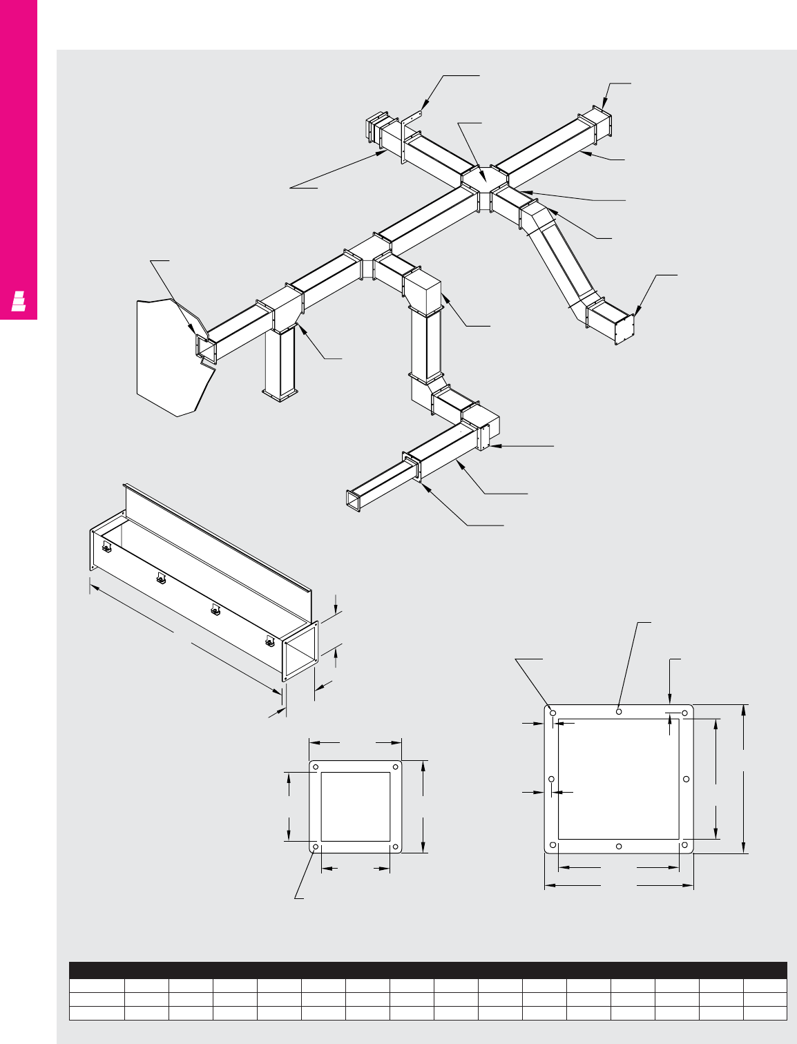
NONCORROSIVE WIREWAY
IND 267
Technical Specifications
Feed-Through Type 4X Wireway
Straight Section
4" X 4" Flange
E__HDSS
Drop hanger
E__WCSS
Cross
E__WN6SS
6” Long nipple
E__W36SS
12” Straight section
E__W12SS
12” Straight section
E__WE45SS
45° Elbow
E__WPSS
End plate
E__WE90SS
90° Elbow
E__HBSS
Bracket hanger
E__W24SS
24” Straight section
E__WRE__SS
Reducing bushing
E__WTSS
Tee
E__WBSS
Box connector
E__WASS
Telescope fitting
CB
A
4.00
.28 4 Places
5.38
4.00
5.38
Wireway
A x B CC CCC CE FGI JK LMN
4 x 4 12 24 36 48 60 120 3.68 7.54 5.38 2.50 3.30 2.90 7.00 4.75 9.50
6 x 6 12 24 36 48 60 120 5.68 10.36 7.62 4.00 3.72 3.10 9.00 5.75 11.50
6" X 6" Flange
.28 DIA
4 Places
.50
4 Places
.28 DIA
4 Places
.50
4 Places
.41
4 Places
6.00
7.63
7.63
6.00
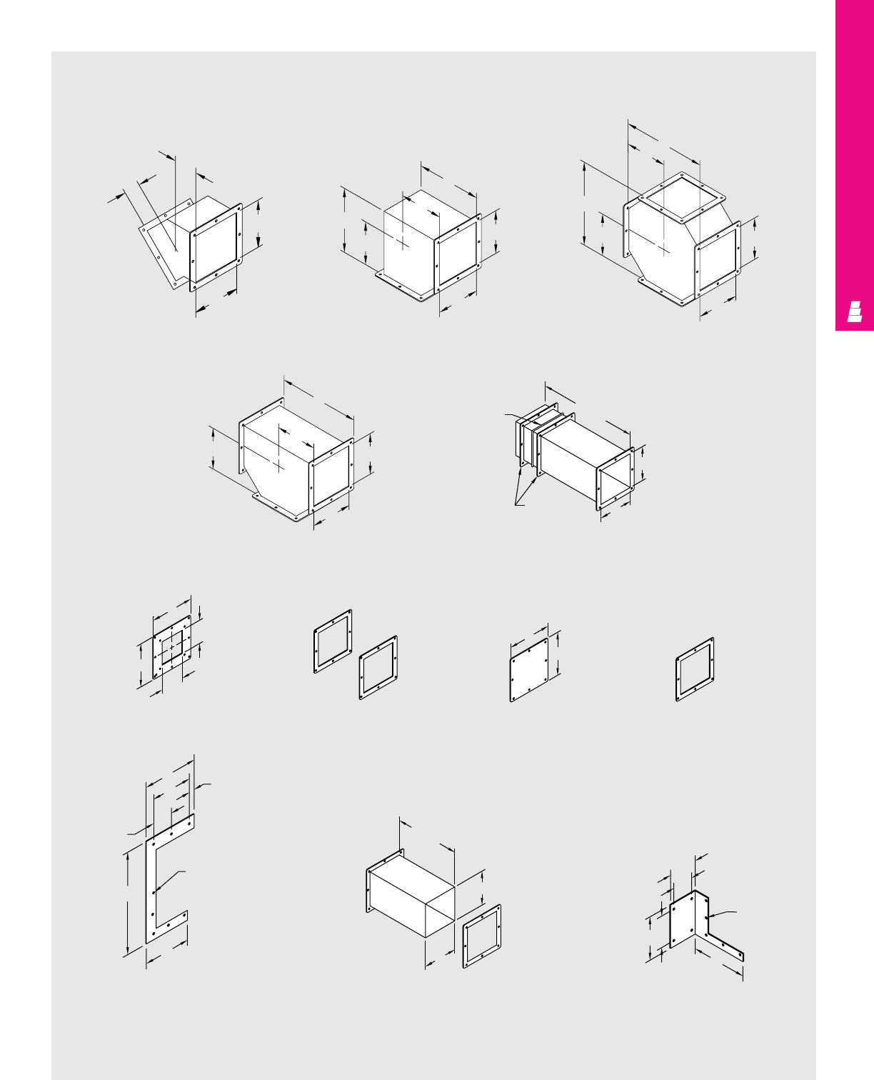
NONCORROSIVE WIREWAY
IND 268
Technical Specifications
Feed-Through Type 4X Wireway
45° Elbow 90° Elbow
Tee
Cross
J
J
B
A
L
M
M
L
B
A
M
M
N
B
A
A
M
N
M
N
B
Box Connector Closure Plate Gasket Flange
Telescope Fitting
Reducing Bushing
Cut-Off Fitting Bracket Hanger
Drop Hanger
G
G
15.50
Gasket
Flange E
E
G
H
G
H
12.00
B
B
B
D
AC
E
.28 DIA
C
ED
F
A
B
.28 DIA
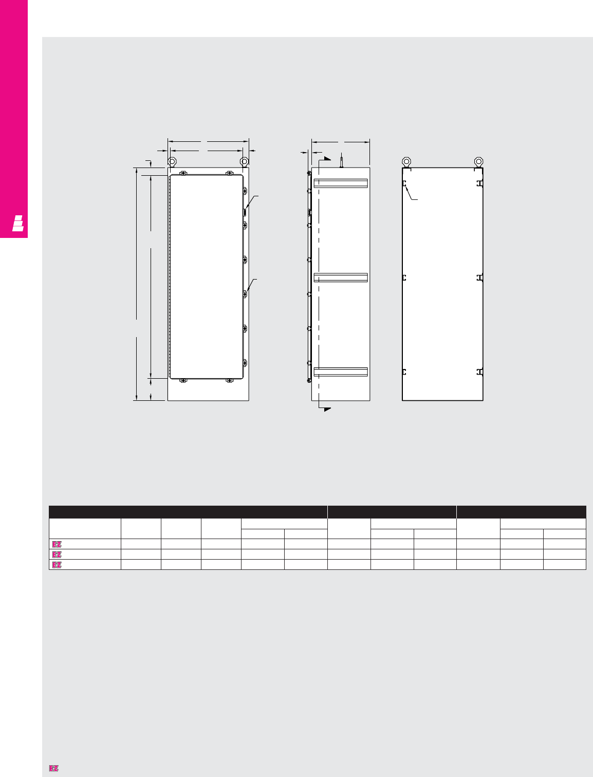
NONCORROSIVE FREESTANDING
IND 269
Technical Specifications
One Door Freestanding Enclosures
Front View Side View Section X-X
B
W.81
2.37
1.88
Padlock
HASP and
staple
Door clamp
6.88
A
72.00
H
62.75
1.16
C
C
L
X
Panel
mounting
channel
(6 places)
Enclosure Full Mounting Panel Half Mounting Panel
Part No. Height Width Depth Door size Part No. Panel size Part No. Panel size
ABC H W E F E F
E 72H2518FSSS 72.00 25.00 18.00 62.75 22.31 E 72P24F1 60.00 20.00 E 72P24F2 30.88 20.00
E 72H3124FSSS 72.00 31.00 24.00 62.75 28.31 E 72P30F1 60.00 26.00 E 72P30F2 30.88 26.00
E 72H3724FSSS 72.00 37.00 24.00 62.75 34.31 E 72P36F1 60.00 32.00 E 72P36F2 30.88 32.00
Designates a product in the EnclosureZone program.
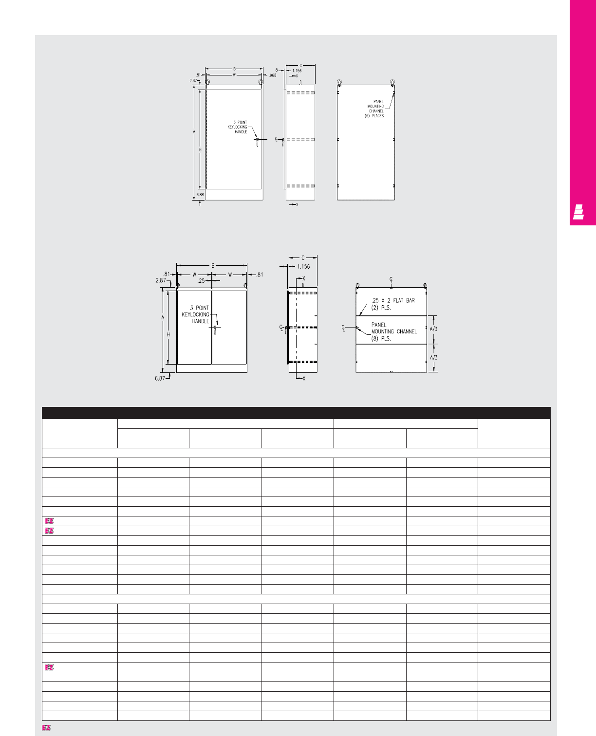
NONCORROSIVE FREESTANDING
IND 270
Technical Specifications
One Door Freestanding Single Access Cabinets
Designates a product in the EnclosureZone program.
Enclosure
Part No. Outside dimensions (inches) Door size Maximum usable
depth panel
HWDHWinstalled
One Door Single Access
E 602418FSSS 60.00 24.00 18.00 50.25 22.22 17.63
E 603624FSSS 60.00 36.00 24.00 50.25 34.22 23.63
E 722418FSSS 72.00 24.00 18.00 62.25 22.22 17.63
E 722424FSSS 72.00 24.00 24.00 62.25 22.22 23.63
E 723018FSSS 72.00 30.00 18.00 62.25 28.22 17.63
E 723024FSSS 72.00 30.00 24.00 62.25 28.22 23.63
E 723618FSSS 72.00 36.00 18.00 62.25 34.22 17.63
E 723624FSSS 72.00 36.00 24.00 62.25 34.22 23.63
E 723630FSSS 72.00 36.00 30.00 62.25 34.22 29.63
E 723636FSSS 72.00 36.00 36.00 62.25 34.22 35.63
E 902420FSSS 90.00 24.00 20.00 80.25 22.22 19.63
E 903620FSSS 90.00 36.00 20.00 80.25 34.22 19.63
E 903624FSSS 90.00 36.00 24.00 80.25 34.22 23.63
E 903636FSSS 90.00 36.00 36.00 80.25 34.22 35.63
Two Door Single Access
E 604818FSDDSS 60.00 48.00 18.00 50.25 23.06 15.13
E 724818FSDDSS 72.00 48.00 18.00 62.25 23.06 15.13
E 724824FSDDSS 72.00 48.00 24.00 62.25 23.06 21.13
E 726018FSDDSS 72.00 60.00 18.00 62.25 29.06 15.13
E 726024FSDDSS 72.00 60.00 24.00 62.25 29.06 21.13
E 726036FSDDSS 72.00 60.00 36.00 62.25 29.06 33.13
E 727218FSDDSS 72.00 72.00 18.00 62.25 35.06 15.13
E 727224FSDDSS 72.00 72.00 24.00 62.25 35.06 21.13
E 904820FSDDSS 90.00 48.00 20.00 80.25 23.06 17.13
E 907220FSDDSS 90.00 72.00 20.00 80.25 35.06 17.13
E 907224FSDDSS 90.00 72.00 24.00 80.25 35.06 21.13
E 907236FSDDSS 90.00 72.00 36.00 80.25 35.06 33.13
Front View Right Side
View Section X-X
Two Door Freestanding Single Access Cabinets
Right Front View Right Side View Section X-X
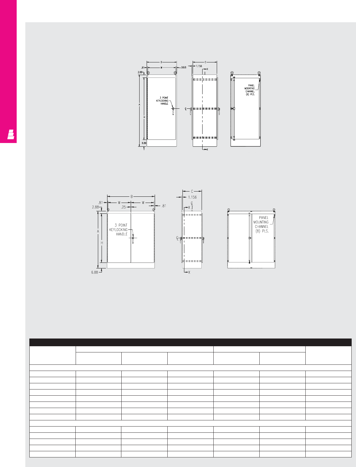
NONCORROSIVE FREESTANDING
IND 271
Technical Specifications
One Door Freestanding Dual Access Cabinets
Front View Right Side
View Section X-X
Front View Right Side View Section X-X
Enclosure Accessories
Part No. Outside dimensions (inches) Door size Maximum usable
depth panel
HW DHWinstalled
One Door Dual Access
E 722424FSDASS 72.00 24.00 24.00 62.25 22.31 -
E 722430FSDASS 72.00 24.00 30.00 62.25 22.31 -
E 722436FSDASS 72.00 24.00 36.00 62.25 22.31 -
E 723024FSDASS 72.00 30.00 24.00 62.25 28.31 -
E 723624FSDASS 72.00 36.00 24.00 62.25 34.31 -
E 723636FSDASS 72.00 36.00 36.00 62.25 34.31 -
E 903624FSDASS 90.00 36.00 24.00 80.25 34.31 -
E 903636FSDASS 90.00 36.00 36.00 80.25 34.31 -
Two Door Dual Access
E 724824FSDADSS 72.00 48.00 24.00 62.25 23.06 -
E 726024FSDADSS 72.00 60.00 24.00 62.25 29.06 -
E 726036FSDADSS 72.00 60.00 36.00 62.25 29.06 -
E 727224FSDADSS 72.00 72.00 24.00 62.25 35.06 -
E 907224FSDADSS 90.00 72.00 24.00 80.25 35.06 -
Two Door Freestanding Dual Access Cabinets
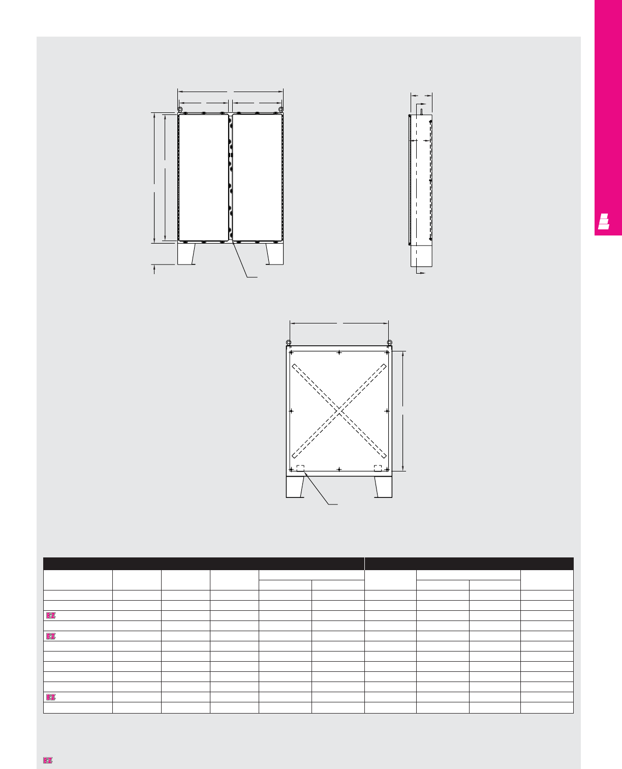
NONCORROSIVE FREESTANDING
IND 272
Technical Specifications
Two Door Floormount Enclosures
Front View Side View
Section Y-Y
B
KK
J
A
12.00
Removable
centerpost
C
Y
G
Y
Pannel support
E
F
Enclosure Mounting Panel
Part No. Height Width Depth Door size Part No. Panel size Usable depth
304SS ABC J K E F G
E 62H4810SS 62.00 48.00 10.00 59.50 21.81 E 60P48 56.00 44.00 10.00
E 62H4810SS6 62.00 48.00 10.00 59.50 21.81 E 60P48 56.00 44.00 10.00
E 62H4812SS 62.00 48.00 12.00 59.50 21.81 E 60P48 56.00 44.00 12.00
E 62H4812SS6 62.00 48.00 12.00 59.50 21.81 E 60P48 56.00 44.00 12.00
E 62H6012SS 62.00 60.00 12.00 59.50 27.81 E 60P60 56.00 56.00 12.00
E 62H6012SS6 62.00 60.00 12.00 59.50 27.81 E 60P60 56.00 56.00 12.00
E 74H6012SS 74.00 60.00 12.00 71.50 27.81 E 72P60 68.00 56.00 12.00
E 74H6012SS6 74.00 60.00 12.00 71.50 27.81 E 72P60 68.00 56.00 12.00
E 74H7212SS 74.00 72.00 12.00 71.50 33.81 E 72P72 68.00 68.00 12.00
E 74H7212SS6 74.00 72.00 12.00 71.50 33.81 E 72P72 68.00 68.00 12.00
E 74H7224SS 74.00 72.00 24.00 71.50 33.81 E 72P72 68.00 68.00 24.00
E 74H7224SS6 74.00 72.00 24.00 71.50 33.81 E 72P72 68.00 68.00 24.00
Designates a product in the EnclosureZone program.
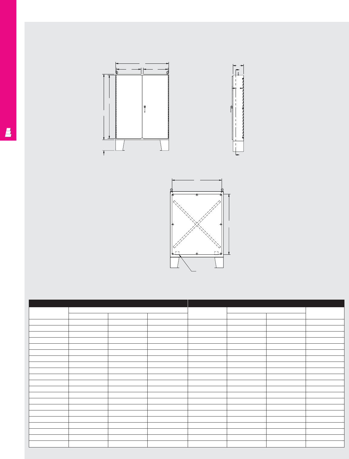
NONCORROSIVE FREESTANDING
IND 273
Technical Specifications
Two Door Floormount Enclosures
Enclosure Mounting Panel
Part No. Outside dimensions (inches) Part No. Panel size Usable depth
HW D HW
E 544208SS 54.00 42.00 8.00 E 54P42 50.00 38.00 8.00
E 604808SS 60.00 48.00 8.00 E 60P48 56.00 44.00 8.00
E 604810SS 60.00 48.00 10.00 E 60P48 56.00 44.00 10.00
E 604812SS 60.00 48.00 12.00 E 60P48 56.00 44.00 12.00
E 604816SS 60.00 48.00 16.00 E 60P48 56.00 44.00 16.00
E 604820SS 60.00 48.00 20.00 E 60P48 56.00 44.00 20.00
E 604824SS 60.00 48.00 24.00 E 60P48 56.00 44.00 24.00
E 606010SS 60.00 60.00 10.00 E 60P60 56.00 56.00 10.00
E 606012SS 60.00 60.00 12.00 E 60P60 56.00 56.00 12.00
E 606016SS 60.00 60.00 16.00 E 60P60 56.00 56.00 16.00
E 606024SS 60.00 60.00 24.00 E 60P60 56.00 56.00 24.00
E 726010SS 72.00 60.00 10.00 E 72P60 68.00 56.00 10.00
E 726012SS 72.00 60.00 12.00 E 72P60 68.00 56.00 12.00
E 726016SS 72.00 60.00 16.00 E 72P60 68.00 56.00 16.00
E 726020SS 72.00 60.00 20.00 E 72P60 68.00 56.00 20.00
E 726024SS 72.00 60.00 24.00 E 72P60 68.00 56.00 24.00
E 727210SS 72.00 72.00 10.00 E 72P72 68.00 68.00 10.00
E 727212SS 72.00 72.00 12.00 E 72P72 68.00 68.00 12.00
E 727216SS 72.00 72.00 16.00 E 72P72 68.00 68.00 16.00
E 727220SS 72.00 72.00 20.00 E 72P72 68.00 68.00 20.00
E 727224SS 72.00 72.00 24.00 E 72P72 68.00 68.00 24.00
12.00
A
J
B
KKC
Y
G
Y
F
C
L
C
LE
Panel support
Front View Side View
Section Y-Y
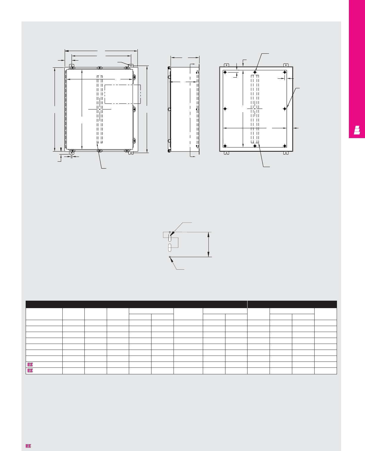
NONCORROSIVE FMD
IND 274
Technical Specifications
NEMA 4X Wallmount Boxes
Front View Right Side View Section Y-Y
B
W
.44 Dia.
3.00
K
See
detail
of door
J
AH
.44
.125
Door stiffener omit if
A < 36.00 and
B < 30.00
C
Y
G
Y
Omit center studs if
B < 31.00
1.50
.88 .88
C
L
of
panel
E
F
Body stiffener omit
if A < 36.00
and B < 30.00
Omit center studs
if A < 36.00
C
L
Enclosure Mounting Panel
Part No. Height Width Depth
Mounting centers Door and body Door size
Part No.
Panel size Usable
ABCHWstiffener J K E F depth
E 24HS2108SS 24.00 21.38 8.00 25.25 15.38 NO 22.25 18.25 E 24P20 21.00 17.00 8.00
E 24HS2508SS 24.00 25.38 8.00 25.25 19.38 NO 22.25 22.25 E 24P24 21.00 21.00 8.00
E 30HS2508SS 30.00 25.38 8.00 31.25 19.38 NO 28.25 22.25 E 30P24 27.00 21.00 8.00
E 36HS2508SS 36.00 25.38 8.00 37.25 19.38 NO 34.25 22.25 E 36P24 33.00 21.00 8.00
E 36HS3108SS 36.00 31.38 8.00 37.25 25.38 YES 34.25 28.25 E 36P30 33.00 27.00 7.37*
E 42HS3112SS 42.00 31.38 12.00 43.25 25.38 YES 40.25 28.25 E 42P30 39.00 27.00 11.37*
E 42HS3712SS 42.00 37.38 12.00 43.25 31.38 YES 40.25 34.25 E 42P26 39.00 33.00 11.37*
E 48HS3712SS 48.00 37.38 12.00 49.25 31.38 YES 46.25 34.25 E 48P36 45.00 33.00 11.37*
E 60HS3712SS 60.00 37.38 12.00 61.25 31.38 YES 58.25 34.25 E 60P36 57.00 33.00 11.37*
* Usable depth reduced by .625" at door stiffener.
.50X1.5
Slot
1.062
1.875 4.687
Ø.280 2 holes
Detail
Designates a product in the EnclosureZone program.
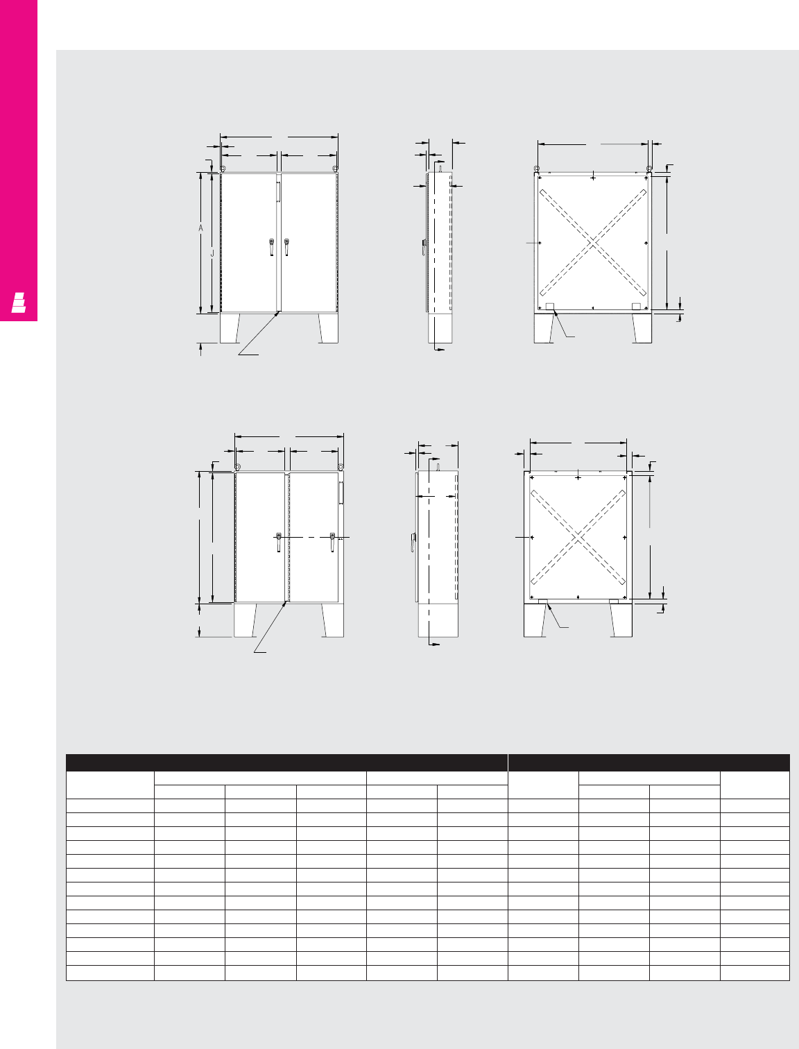
NONCORROSIVE FMD
IND 275
Technical Specifications
Floormount Freestanding Enclosures
Enclosure Mounting Panel
Part No. Outside dimensions (inches) Door size Part No. Panel size Usable
HW DHWHWdepth
E 60CPX4812SS 2) 60.00 48.00 12.00 58.50 22.00 E 60P48 56.00 44.00 12.00
E 60CPX6012SS 2) 60.00 60.00 12.00 58.50 28.00 E 60P60 56.00 56.00 12.00
E 60X4912SS 1) 60.00 49.00 12.00 58.50 21.88 E 60P48 56.00 44.00 12.00
E 60X4918SS 1) 60.00 49.00 18.00 58.50 21.88 E 60P48 56.00 44.00 18.00
E 60X6112SS 1) 60.00 61.00 12.00 58.50 27.88 E 60P60 56.00 56.00 12.00
E 60X6118SS 1) 60.00 61.00 18.00 58.50 27.88 E 60P60 56.00 56.00 18.00
E 72CPX7212SS 2) 72.00 72.00 12.00 70.50 34.00 E 72P72 68.00 68.00 12.00
E 72CPX7218SS 2) 72.00 72.00 18.00 70.50 34.00 E 72P72 68.00 68.00 18.00
E 72X6112SS 1) 72.00 61.00 12.00 70.50 27.88 E 72P60 68.00 56.00 12.00
E 72X6118SS 1) 72.00 61.00 18.00 70.50 27.88 E 72P60 68.00 56.00 18.00
E 72X7312SS 1) 72.00 73.00 12.00 70.50 33.88 E 72P72 68.00 68.00 12.00
E 72X7318SS 1) 72.00 73.00 18.00 70.50 33.88 E 72P72 68.00 68.00 18.00
E 72X7324SS 1) 72.00 73.00 24.00 70.50 33.88 E 72P72 68.00 68.00 24.00
.75
.75 K
B
K
Removable
center post
15.00
A
C
C
A
1.13 F
C
L
C
L
Panel
support
2.00
E
2.00
2.00
.75
.75
K
B
K
C
L
Removable
center post
15.00
J
A
1.13 C
A
C
A
Panel
support
2.07
E
2.00
2.38
F
C
L
2.75
C
L
Front View Right Side View Section A-A
Front View Right Side View Section A-A
Disconnect operator
on right flange
Disconnect operator
on center post
1) Disconnect operator on right flange.
2) Disconnect operator on center post.
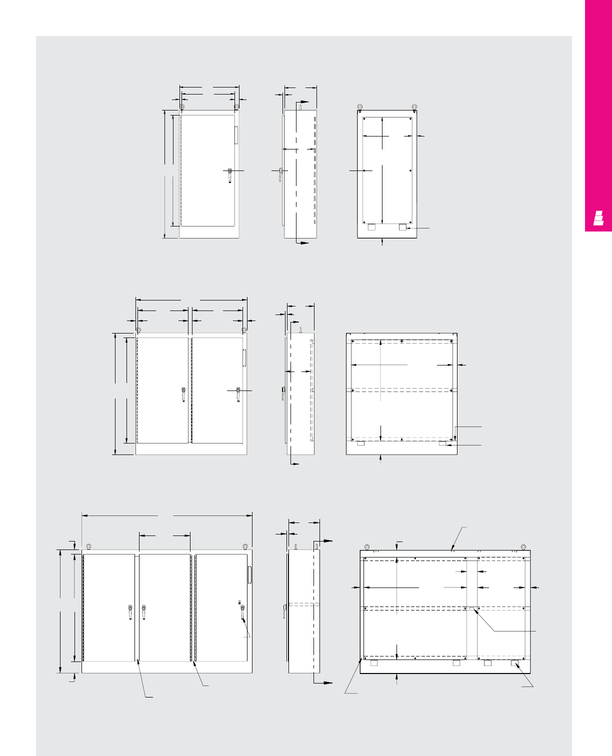
NONCORROSIVE FMD
IND 276
Technical Specifications
Freestanding Heavy Duty Enclosures
— One Door
— Two Door
— Three Door
— Four Door
— Five Door
Front View Right Side View Section X-X
B
K
1.13 2.50
C
L
of door
AJ
G
X
X
1.25
C
C
L
of panel
F
panel
E
panel
2.75
Panel support
8.00
Front View Right Side View Section A-A
2 X 1 Preformed
channel
(3) places
8.00 Panel support
(2) places
E
Panel
F
Panel 2.75
C
1.25
A
G
A
C
of door
L
2.50
K
2.38
B
K
1.13
AJ
Side View
B
Section Z-Z
Front View
K
Typ.
2.75
AJ
6.75
Removable
centerpost
Stationary
centerpost
3 point
padlockable
handle
C
1.25
Z
Z
Channel (3) places
8.00
Panel support (4) places
D
panel
Typ.
E
panel
2.25
4.00
6.25
F
panel
Light bracket
(unistrut channel)
(4) places
3.25
Enclosure
brace
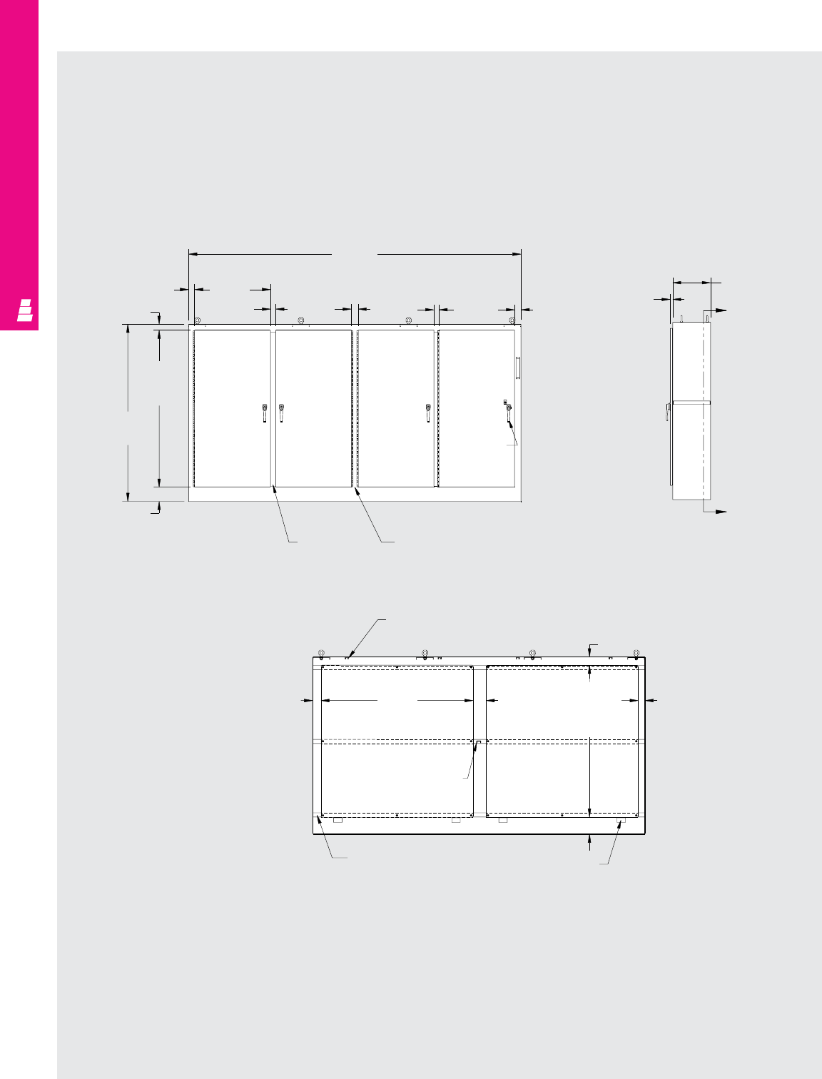
NONCORROSIVE FMD
IND 277
Right Side View
Stationary
centerpost
Front View
Section Z-Z
B
(157.50)
K
(35.88)
door
Typ.
2.88
2.75
J
(74.50)
door
A
(84.00)
6.75
2.50 3.25 2.38 3.00
3 point
padlockable
handle
Removable
center post
(2) places
C
(18.00)
Z
Z
1.25
4.00
3.25
E
(72.00)
panel
Typ.
8.00
Panel support (4) places
Channel (3) places
Enclosure
brace
6.25
F
(72.00)
panel
Typ.
4.00
Light strut
(4) places
Technical Specifications
Freestanding Heavy Duty Enclosures
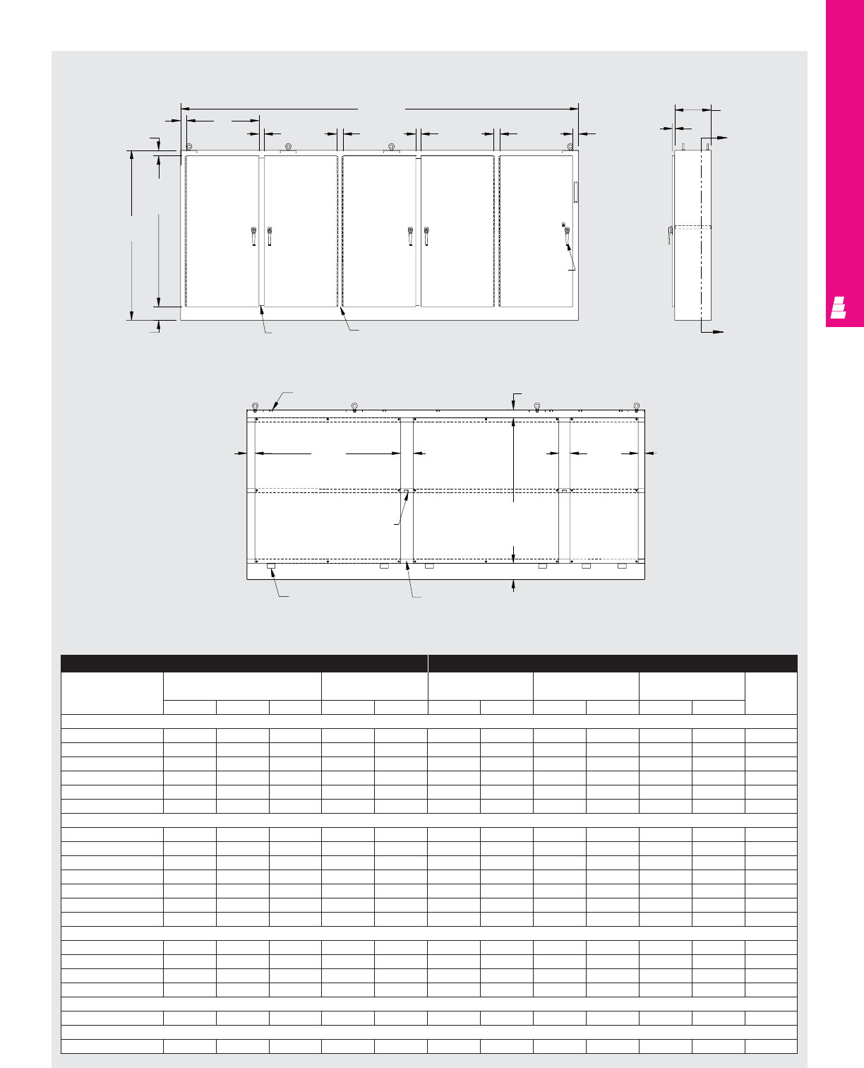
NONCORROSIVE FMD
IND 278
Enclosure Mounting Panel
Part No. Outside dimensions Door size Panel size Panel size Panel size Usable
(behind single door) (behind double door) depth
HWDHWHWHWHW
One Door
E 72XM2818WPSS 72.00 27.50 18.00 62.50 23.83 60.00 21.75 - - - - 18.00
E 72XM3418WPSS 72.00 33.50 18.00 62.50 29.83 60.00 27.75 - - - - 18.00
E 72XM4018WPSS 72.00 39.50 18.00 62.50 35.83 60.00 33.75 - - - - 18.00
E 84XM4018WPSS 84.00 39.50 18.00 74.50 35.83 72.00 33.75 - - - - 18.00
E 90XM4020WPSS 90.00 39.50 20.00 80.50 35.83 78.00 33.75 - - - - 20.00
E 90XM4024WPSS 90.00 39.50 24.00 80.50 35.83 78.00 33.75 - - - - 24.00
Two Door
E 72XM5418WPSS 72.00 53.75 18.00 62.50 23.88 60.00 48.00 - - - - 17.00
E 72XM6618WPSS 72.00 65.75 18.00 62.50 29.88 60.00 60.00 - - - - 17.00
E 72XM7818WPSS 72.00 77.75 18.00 62.50 35.88 60.00 72.00 - - - - 17.00
E 72XM7824WPSS 72.00 77.75 24.00 62.50 35.88 60.00 72.00 - - - - 23.00
E 84XM7818WPSS 84.00 77.75 18.00 74.50 35.88 72.00 72.00 - - - - 17.00
E 90XM7820WPSS 90.00 77.75 20.00 80.50 35.88 78.00 72.00 - - - - 19.00
E 90XM7824WPSS 90.00 77.75 24.00 80.50 35.88 78.00 72.00 - - - - 23.00
Three Door
E 72XM3EQ18WPSS 72.00 99.50 18.00 62.50 29.88 60.00 60.00 60.00 27.75 60.00 60.00 17.00
E 72XM3EW18WPSS 72.00 117.50 18.00 62.50 35.88 60.00 72.00 60.00 33.75 60.00 72.00 17.00
E 84XM3EW18WPSS 84.00 117.50 18.00 74.50 35.88 72.00 72.00 72.00 33.75 72.00 72.00 17.00
E 90XM3EW24WPSS 90.00 117.50 24.00 80.50 35.88 78.00 72.00 78.00 33.75 78.00 72.00 23.00
Four Door
E 84XM4EW18WPSS 84.00 157.50 18.00 74.50 35.88 72.00 72.00 - - 72.00 72.00 17.00
Five Door
E 84XM5EW18WPSS 84.00 196.75 18.00 74.50 35.88 72.00 72.00 72.00 33.75 72.00 72.00 17.00
Front View
2.88
Right Side View
Section Z-Z
2.75
J
(74.50)
door
A
(84.00)
6.75 Removable
centerpost (2) places
Stationary centerpost (2) places
3 point
padlockable
handle
3.003.252.50
3.25
2.50
K
(35.88)
Typ.
B
(196.75)
C
(18.00)
Z
1.25
Z
3.25
F
(33.75)
4.00
6.25
D
(72.00)
panel
(3) places
8.00
Channel
(3) places
Panel support
(4) places
Enclosure
brace
E
(72.00)
panel
(2) places
4.00
Light strut (6) places
Technical Specifications
Freestanding Heavy Duty Enclosures
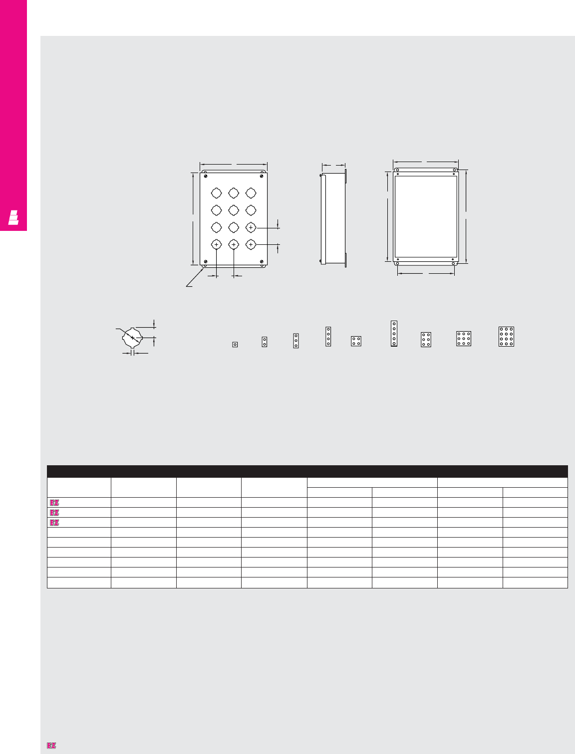
NONCORROSIVE OPERATOR INTERFACE
IND 279
Technical Specifications
Standard Pushbutton Boxes
Front View Side View Front View
Cover Removed
Standard 4-Way Keyed
Pushbutton Hole Detail Hole Arrangement Centered On Cover
K
J
2.25
Typ.
2.25
Typ.
.31 Dia.
CB
H
W
A
.19
1.20 .67
E-1PBSS E-2PBSS E-3PBSS E-4PBSS E-4SPBSS E-6PBSS E-9PBSS
Standard Pushbutton Box
Part No. Height Width Depth Mounting centers Cover size
AB CHW JK
E 1PBSS 3.50 3.25 2.75 4.00 2.38 3.81 3.56
E 2PBSS 5.75 3.25 2.75 6.25 2.38 6.06 3.56
E 3PBSS 8.00 3.25 2.75 8.50 2.38 8.31 3.56
E 4PBSS 10.25 3.25 2.75 10.75 2.38 10.56 3.56
E 4SPBSS* 7.25 6.25 3.00 7.75 5.38 7.56 6.56
E 5PBSS 12.50 3.25 2.75 13.00 2.38 12.81 3.56
E 6PBSS* 9.50 6.25 3.00 10.00 5.38 9.81 6.56
E 9PBSS* 9.50 8.50 3.00 10.00 7.63 9.81 8.81
E 12PBSS 11.75 8.50 3.00 12.25 7.63 12.06 8.81
* Can be mounted to a Rittal Electromate column and base.
Designates a product in the EnclosureZone program.
E-12PBSS
E-5PBSS
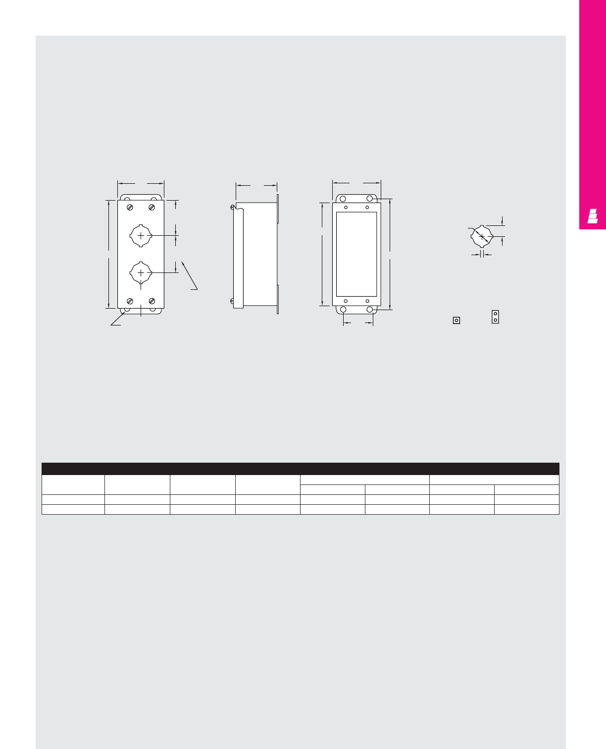
NONCORROSIVE OPERATOR INTERFACE
IND 280
Technical Specifications
Slim Pushbutton Boxes
Slim Pushbutton Box
Part No. Height Width Depth Mounting centers Cover size
ABCHWJK
E 1PBSLSS 4.00 2.50 2.50 4.50 1.63 4.31 2.81
E 2PBSLSS 6.25 2.50 2.50 6.75 1.63 6.56 2.81
Front View Side View Front View
Cover Removed
B
2.50
H
W
1.63
A
C
2.50
K
2.81
2.16
Typ.
2.25
Typ.
.31 Dia.
See
note
Standard 4-Way Keyed
Pushbutton Hole Detail
.19
1.20 .67
E-1PBSLSS E-2PBSLSS
Hole Arrangement
Centered On Cover
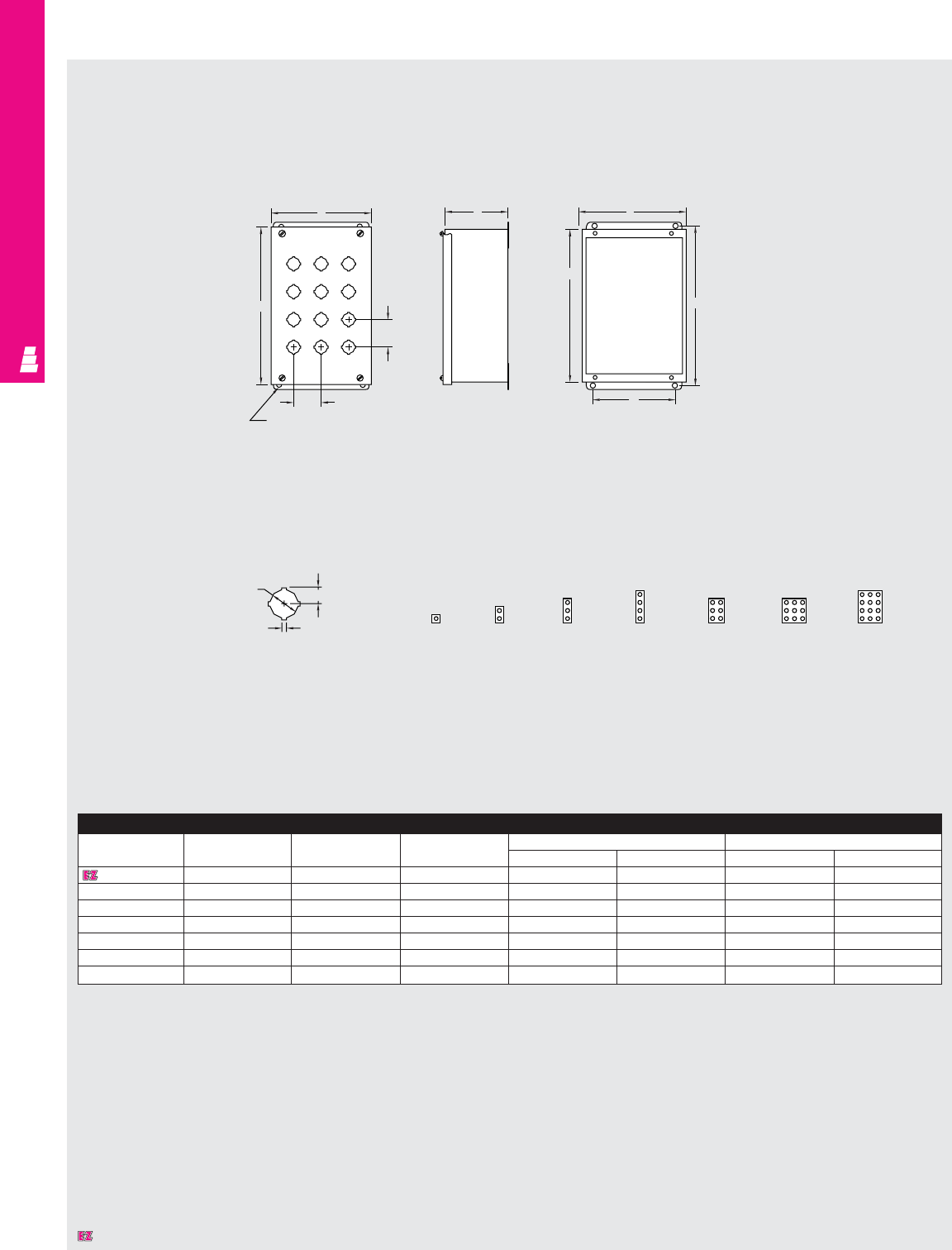
NONCORROSIVE OPERATOR INTERFACE
IND 281
KCB
Technical Specifications
Miniature Pushbutton Boxes
Standard 4-Way Keyed
Pushbutton Hole Detail
Side View Front View
Cover Removed
Front View
Cover Assembled
J
1.88
Typ.
1.50
Typ.
.31 Dia.
H
A
W
.88 .48
.13
Miniature Pushbutton Box
Part No. Height Width Depth Mounting centers Cover size
ABC HW J K
E 1PBGMSS 3.25 2.75 3.50 3.75 1.88 3.56 3.06
E 2PBGMSS 5.13 2.75 3.50 5.63 1.88 5.44 3.06
E 3PBGMSS 7.00 2.75 3.50 7.50 1.88 7.31 3.06
E 4PBGMSS 8.88 2.75 3.50 9.38 1.88 9.19 3.06
E 6PBGMSS* 8.50 5.00 4.25 9.00 4.13 8.81 5.31
E 9PBGMSS 8.50 6.50 4.25 9.00 5.63 8.81 6.81
E 12PBGMSS 10.38 6.50 4.25 10.88 5.63 10.69 6.81
* Can be mounted to a Rittal Electromate column and base.
Hole Arrangement Centered On Cover
E 1PBGMSS E 2PBGMSS E 3PBGMSS E 4PBGMSS E 6PBGMSS E 9PBGMSS E 12PBGMSS
Designates a product in the EnclosureZone program.

NONCORROSIVE OPERATOR INTERFACE
IND 282
Front View
Cover Assembled Side View Front View
Cover Removed
CB
H
W
A
K
J
2.25 Typ.
2.25
Typ.
.31 Dia.
E-9PBXDSS E-10PBXDSS E-12PBXDSS E-16SPBXDSS E-16PBXDSS E-20PBXDSS E-25PBXDSS
Extra Deep Pushbutton Box
Part No. Height Width Depth Mounting centers Cover size
AB C HW JK
E 1PBXDSS 4.00 4.00 4.75 4.50 3.13 4.31 4.31
E 2PBXDSS 6.00 4.00 4.75 6.50 3.13 6.31 4.31
E 3PBXDSS 8.00 4.00 4.75 8.50 3.13 8.31 4.31
E 4PBXDSS 10.00 4.00 4.75 10.50 3.13 10.31 4.31
E 4SPBXDSS* 7.25 6.25 4.75 7.75 5.38 7.56 6.56
E 6PBXDSS* 9.50 6.25 4.75 10.00 5.38 9.81 6.56
E 9PBXDSS 9.50 8.50 4.75 10.00 7.63 9.81 8.81
E 10PBXDSS 14.00 6.25 4.75 14.50 5.38 14.31 6.56
E 12PBXDSS 11.75 8.50 4.75 12.25 7.63 12.06 8.81
E 16PBXDSS 11.75 10.75 4.75 12.25 9.88 12.06 11.06
E 16SPBXDSS 20.75 6.25 4.75 21.25 5.38 21.06 6.56
E 20PBXDSS 14.00 10.75 4.75 14.50 9.88 14.31 11.06
E 25PBXDSS 14.00 13.00 4.75 14.50 12.13 14.31 13.31
* Can be mounted to a Rittal Electromate column and base.
Hole Arrangement Centered On Cover
Technical Specifications
Extra Deep Pushbutton Boxes
E 1PBXDSS E 2PBXDSS E 3PBXDSS E 4PBXDSS E 4SPBXDSS E 6PBXDSS
E 9PBXDSS E 10PBXDSS E 12PBXDSS E 16PBXDSS E 16SPBXDSS E 20PBXDSS E 25PBXDSS
Designates a product in the EnclosureZone program.
Standard 4-Way
Keyed Pushbutton
Hole Detail
.67
.19
1.20
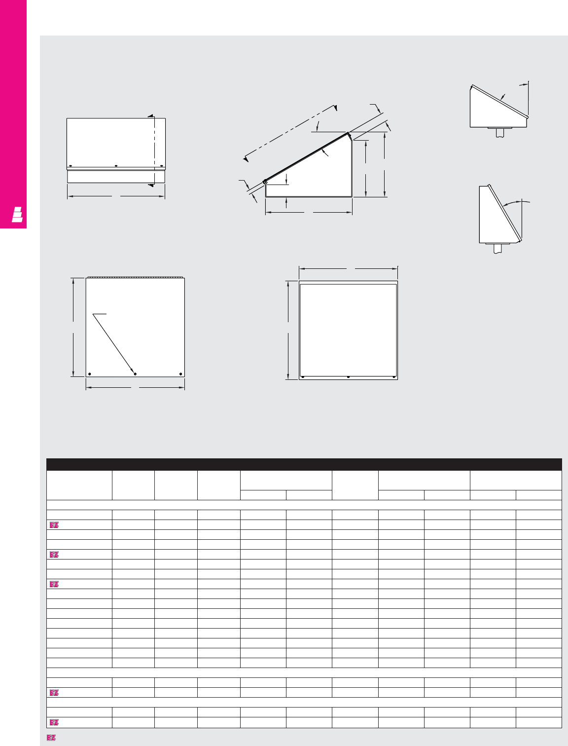
NONCORROSIVE OPERATOR INTERFACE
IND 283
Technical Specifications
Consoles, Pedestals and Bases
Console, Pedestal & Base
Part No. Height Width Depth Cover Stiffener Cover size Desk depth/height
plate location
ABC E F C D E M N
Consoles
E 8C8SS 8.00 8.00 7.09 - - - 8.31 8.31 7.44 5.63
E 8C12SS 8.00 12.00 7.09 - - - 8.31 12.31 7.44 5.63
E 8C16SS 8.00 16.00 7.09 - - - 8.31 16.31 7.44 5.63
E 8C20SS 8.00 20.00 7.09 - - - 8.31 20.31 7.44 5.63
E 12C12SS 12.00 12.00 9.09 - - - 12.31 12.31 10.91 7.63
E 12C16SS 12.00 16.00 9.09 - - - 12.31 16.31 10.91 7.63
E 12C20SS 12.00 20.00 9.09 - - - 12.31 20.31 10.91 7.63
E 12C24SS 12.00 24.00 9.09 - - - 12.31 24.31 10.91 7.63
E 16C16SS 16.00 16.00 11.09 - - - 16.31 16.31 14.38 9.63
E 16C20SS 16.00 20.00 11.09 - - - 16.31 20.31 14.38 9.63
E 16C24SS 16.00 24.00 11.09 - - - 16.31 24.31 14.38 9.63
E 16C30SS 16.00 30.00 11.09 - - - 16.31 30.31 14.38 9.63
E 16C36SS 16.00 36.00 11.09 - - - 16.31 36.31 14.38 9.63
E 20C20SS 20.00 20.00 13.09 - - - 20.31 20.31 17.84 11.63
E 20C24SS 20.00 24.00 13.09 - - - 20.31 24.31 17.84 11.63
E 20C30SS 20.00 30.00 13.09 - - - 20.31 30.31 17.84 11.63
Pedestals
E 44CCOLSS 4.00 4.00 - 7.00 3.75 - - - - -
E 66CCOLSS 6.00 6.00 - 7.75 5.75 - - - - -
Bases
E 18SBASESS 18.00 18.00 - - - 3.00 - - - -
E 24SBASESS 24.00 24.00 - - - 5.00 - - - -
Front View Section Y-Y
Section Y-Y
Console can be
positioned at either 30°
or 60° angle
Y
B
Y
.75
2.50
30°
1.75
NC
M
A
A
60°
30°
View A-A View A-A
(with cover removed)
E
Omit if E < 30.00
B
A
D
Designates a product in the EnclosureZone program.
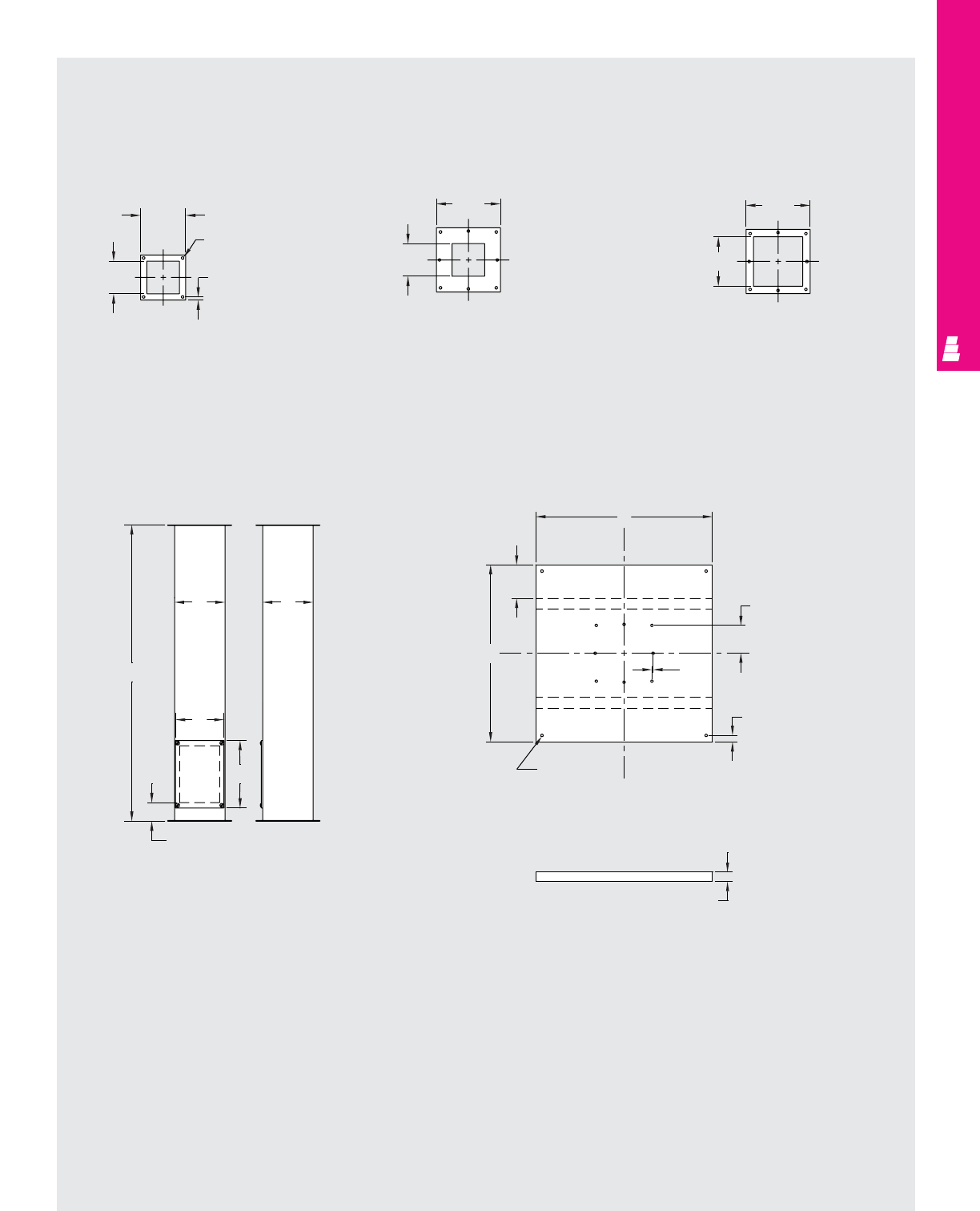
NONCORROSIVE OPERATOR INTERFACE
IND 284
Technical Specifications
Consoles, Pedestals and Bases
4x4 Top
Column Flange
5.38
.31 dia. TYP
(4) places
.75 TYP
(8) places
3.88
7.63
3.88
4x4 Bottom
Column Flange
See Base for Hole Locations
6x6 Bottom
Column Flange
See Base for Hole Locations
7.63
5.88
Column
BA
35.00
F
E
2.13
Base Top View
.31 dia. TYP
(12) places
A
C
B
3.31 TYP
(8) places
.75 TYP
(8) places
.13
TYP
Base End View
1.13
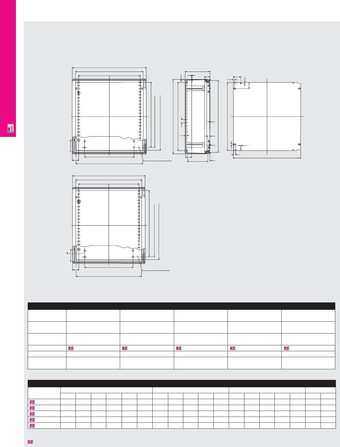
FIBERGLASS WALLMOUNT
IND 285
100
W2
52 W4
W5
W3
W1
10.5
Interior view of door D3 D4 12 F1
16
H2
H7
H5
H3
H6
H1
12.5
M2
12.5
25
3
4.5
D1
M1 42.5
8.5
G1
10.5
50
1
60
Technical Specifications
KS Fiberglass Enclosures
100
W2
52 W4
500
548
600
Interior view of door
H5
H3
H6
Detailed Dimensions
Part No. Height dimensions Width dimensions Depth dimensions Mounting panel
H1 H2 H3 H5 H6 H7 W1 W2 W3 W4 W5 D1 D3 D4 M1 M2 F1 G1
1432600 350 330 306 250 295 300 250 190 200 75 150 150 12- 55 130 2.0 3.0 195 300
1434600 400 380 355 300 345 350 300 240 249 100 200 200 12-105 180 2.0 3.0 245 350
1444600 400 380 354 300 345 350 400 340 458 200 300 200 12-105 180 2.5 3.2 345 350
1446600 600 580 554 500 545 550 400 340 348 200 300 200 12-105 180 2.5 3.5 345 550
1466600 600 580 554 500 545 550 600 540 548 400 500 200 12-105 180 2.5 3.5 545 550
Enclosure
Height (H1) inches 13.78 15.75 15.75 23.62 23.62
mm 350 400 400 600 600
Width (W1) inches 9.84 11.81 15.75 15.75 23.62
mm 250 300 400 400 600
Depth (D1) inches 5.91 7.87 7.87 7.87 7.87
mm 150 200 200 200 200
Part No. 1432600 1434600 1444600 1446600 1466600
Door(s) 1 1 1 1 1
Weight lbs 10.1 13.6 14.3 25.3 35.0
kg 4.6 6.0 6.5 11.5 15.9
Dimensions in millimeters (mm) unless otherwise indicated.
Dimensions in millimeters (mm) unless otherwise indicated.
Designates a product in the EnclosureZone program.
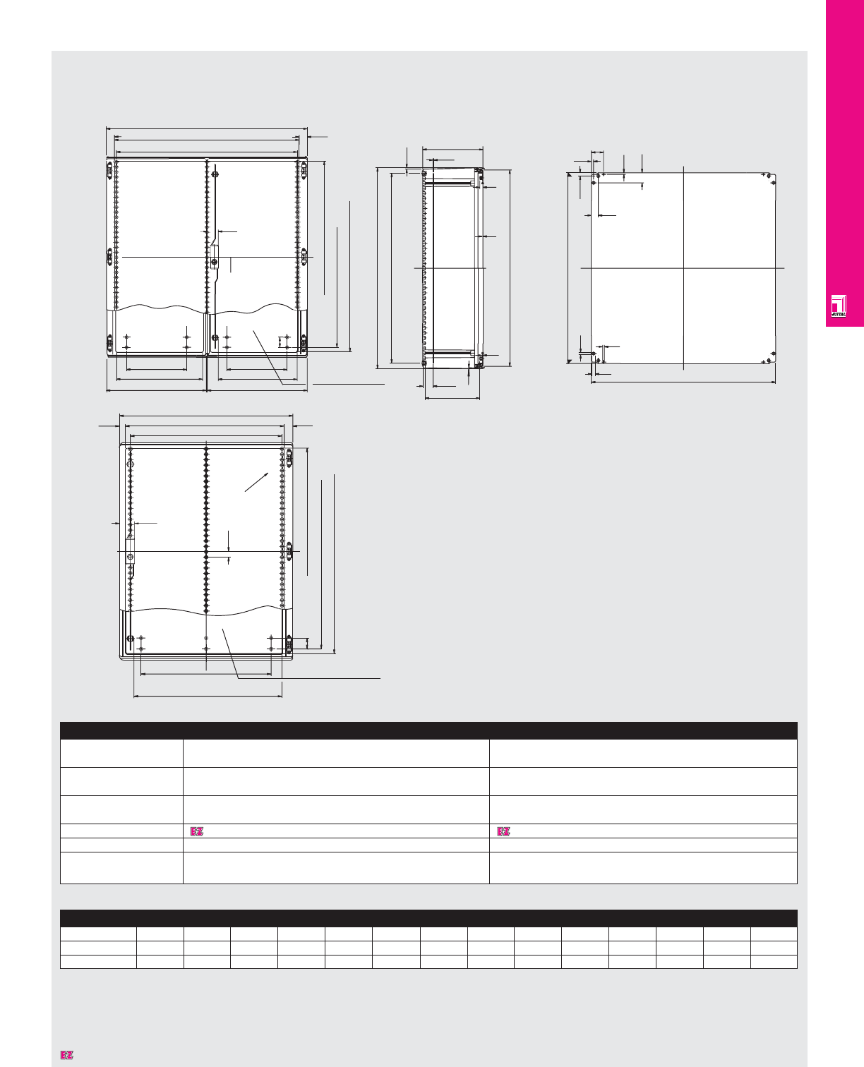
FIBERGLASS WALLMOUNT
IND 286
Technical Specifications
KS Fiberglass Enclosures
H7
H1
H6
W2
497.5
W6
394.5
497.5 Interior of door
W6
50.0
H5
55.0
H3
W3
W5
W1
41.0
7.0
G1
H2
16.0
12-205
280
4.0
M1
10.5
8.5
F1
3.0
12
17.5
33.5
3.0
300
10.5
10.0
50.0
60.0
H6
H5
W6
W2
Interior view of door
50
70.0
27.0
W5
W3
W1
25.0
H3
R 90.0
40.0
Enclosure
Height (H1) inches 31.50 39.37
mm 800 1000
Width (W1) inches 23.62 31.50
mm 600 800
Depth (D1) inches 11.81 11.81
mm 300 300
Part No. 1468600 1480600
Door(s) 1 1
Weight lbs. 53.5 85.9
kg 24.3 39.0
Detailed Dimensions
Part No. H1 H2 H3 H5 H6 H7 W1 W2 W3 W5 W6 M1 F1 G1
1468000 800 780 753 700 740 750 600 485 533 600 400 3.7 750 517
1480000 100 980 953 900 940 950 800 685 733 700 600 3.7 950 717
Dimensions in millimeters (mm) unless otherwise indicated.
Dimensions in millimeters (mm) unless otherwise indicated.
Designates a product in the EnclosureZone program.
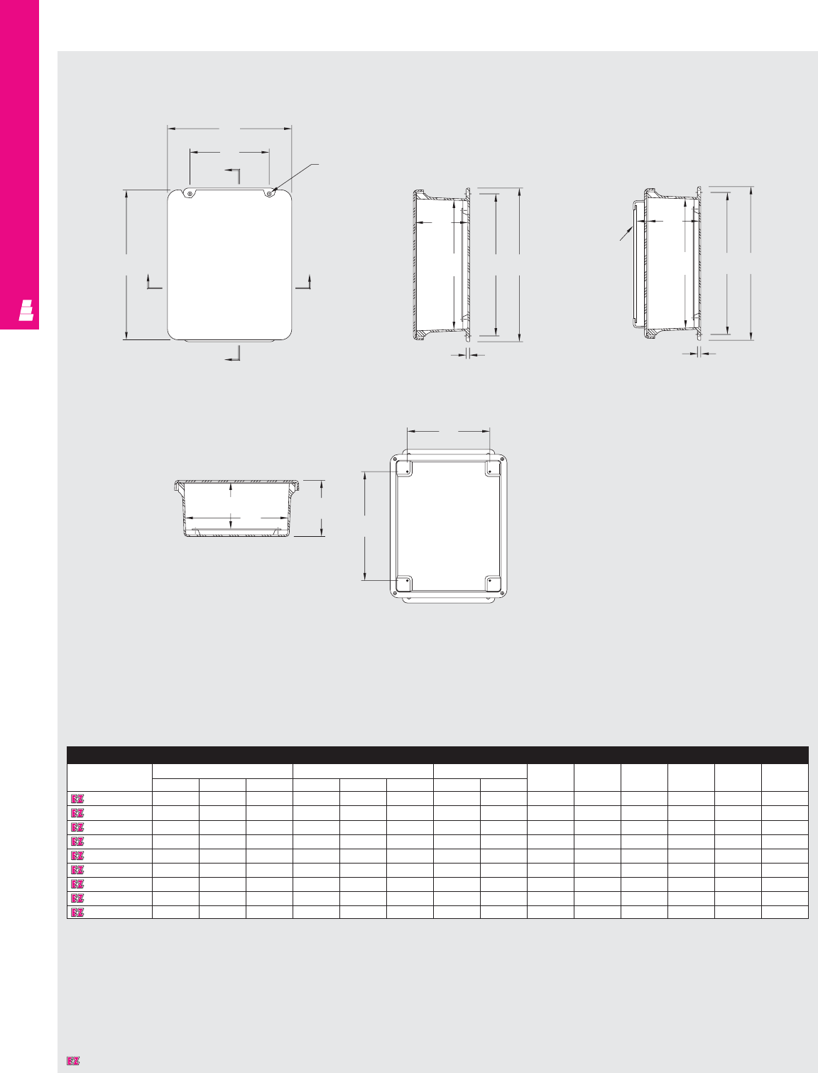
FIBERGLASS WALLMOUNT
IND 287
Technical Specifications
Screw Cover Junction Boxes
Enclosure
Part No. Outside dimensions (inches) Inside dimensions (inches) Mounting centers Hole
HW DABC HWJKLMNdia.
L FJ604NFSC 7.50 5.43 4.75 5.84 3.85 4.45 6.75 2 4 4.25 2.25 .25 7.39 .31
L FJ606NFSC 7.50 7.50 4.75 5.72 5.72 4.45 6.75 4 4 4.25 4.25 .25 7.52 .31
L FJ806NFSC 9.62 7.50 4.74 7.73 5.74 4.45 8.88 4 4 6.25 4.25 .25 9.5 .31
L FJ1008NFSC 11.62 9.41 4.25 9.73 7.73 3.98 10.75 6 3.5 8.25 6.25 .25 11.35 .31
L FJ1210NFSC 13.56 11.43 5.21 11.79 9.80 4.94 12.75 8 4.5 10.25 8.25 .25 13.41 .31
L FJ1412NFSC 15.50 13.50 6.25 13.53 11.55 5.94 14.62 10 5.37 12.25 10.25 .25 15.47 .31
L FJ1614NFSC 17.53 15.46 6.23 15.63 13.60 5.94 16.75 12 5.36 14.25 12.25 .25 17.45 .31
L FJ1816NFSC 19.62 17.61 8.82 17.69 15.69 8.45 18.88 12 7.99 16.25 14.25 .25 19.61 .31
L FJ2016NFSC 22.00 17.68 8.83 19.72 15.72 8.45 21.25 10 8 18.25 14.25 .25 21.68 .31
Section B-B Section B-B
Section A-A
Standard Flat Cover Crowned Cover
Front View Without Cover
W
F
B
Hole dia.
4 places
HA
B
A
C
AEH
M
Crowned
cover
available
in 1008
C
AEH
M
L
K
D
B
J
Designates a product in the EnclosureZone program.
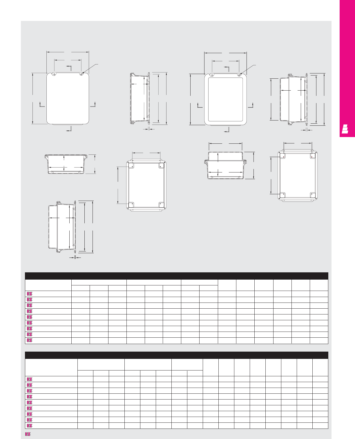
FIBERGLASS WALLMOUNT
IND 288
Technical Specifications
Hinged Screw Cover Junction Boxes
Standard Enclosure
Part No. Outside dimensions (inches) Inside dimensions (inches) Mounting centers Hole
HWDABC HW JKLMNdia.
L FJ604CHNFSC 7.50 5.47 6.22 5.84 3.85 5.95 6.75 2 4 4.25 2.25 .25 7.39 .31
L FJ606CHNFSC 7.50 7.50 4.75 5.72 5.72 4.45 6.75 4 4 4.25 4.25 .25 7.52 .31
L FJ806CHNFSC 9.62 7.50 4.74 7.73 5.74 4.45 8.88 4 4 6.25 4.25 .25 9.5 .31
L FJ1008CHNFSC 11.62 9.41 4.25 9.73 7.73 3.98 10.75 6 3.5 8.25 6.25 .25 11.35 .31
L FJ1210CHNFSC 13.56 11.43 5.21 11.79 9.80 4.94 12.75 8 4.5 10.25 8.25 .25 13.41 .31
L FJ1412CHNFSC 15.50 13.50 6.25 13.53 11.55 5.94 14.62 10 5.37 12.25 10.25 .25 15.47 .31
L FJ1614CHNFSC 17.53 15.46 6.23 15.63 13.60 5.94 16.75 12 5.36 14.25 12.25 .25 17.45 .31
L FJ1816CHNFSC 19.62 17.61 8.82 17.69 15.69 8.45 18.88 12 7.99 16.25 14.25 .25 19.61 .31
L FJ2016CHNFSC 22.00 17.68 8.83 19.72 15.72 8.45 21.25 10 8 18.25 14.25 .25 21.68 .31
Extended Depth Enclosure
Part No. Outside dimensions Inside dimensions Mounting centers Hole
(inches) (inches) dia.
HW D A B CH W J K L MN O P
L FJ604CHNFSCX 7.50 5.47 6.22 5.84 3.85 5.95 6.75 2 5.49 4.25 2.25 .25 7.45 5.31 3.34 .31
L FJ606CHNFSCX 7.50 7.52 6.22 5.72 5.72 5.95 6.75 4 5.49 4.25 4.25 .25 7.52 5.34 5.31 .31
L FJ806CHNFSCX 9.62 7.46 6.22 7.73 5.74 5.95 8.88 4 5.49 6.25 4.25 .25 9.36 7.25 5.28 .31
L FJ1008CHNFSCX 11.62 9.37 6.61 9.73 7.73 6.36 10.75 6 5.91 8.25 6.25 .25 11.38 9.3 7.38 .31
L FJ1210CHNFSCX 13.56 11.43 6.61 11.79 9.80 6.32 12.75 8 5.87 10.25 8.25 .25 13.41 11.2 9.23 .31
L FJ1412CHNFSCX 15.50 13.38 7.69 13.53 11.55 7.45 14.62 10 6.87 12.25 10.25 .25 15.42 13.2 11.16 .31
L FJ1614CHNFSCX 17.53 15.43 7.71 15.63 13.60 7.45 16.75 12 6.87 14.25 12.25 .25 17.43 15.2 13.24 .31
L FJ1816CHNFSCX 19.62 17.48 10.62 17.69 15.69 10.31 18.88 12 9.86 16.25 14.25 .25 19.49 17.25 15.25 .31
L FJ2016CHNFSCX 22.00 17.56 10.64 19.72 15.72 10.33 21.25 10 9.87 18.25 14.25 .25 21.56 19.31 15.39 .31
Section B-B
Section A-A
Front View
Without
Cover
Section B-B
Front View
Without
Cover
Section A-A
Section B-B
Standard Version Extended Depth Version
Standard Flat
Cover
Crowned Cover
W
F
B
NA
B
A
C
AE
H
M
NA
W
F
B
B
AO
C
AEH
M
P
J
B
B
K
L
Hole dia.
4 places
D
K
L
C
AEH
M
J
B
Designates a product in the EnclosureZone program.
Hole dia.
4 places
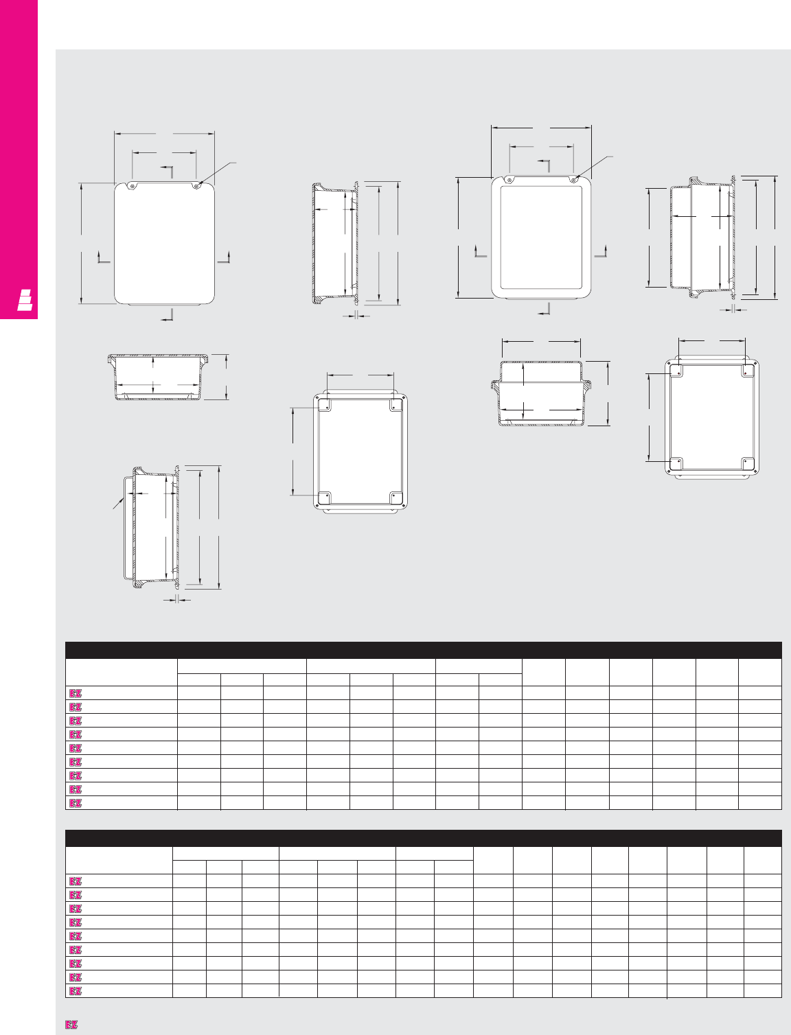
Standard Enclosure
Part No. Outside dimensions (inches) Inside dimensions (inches) Mounting centers Hole
HWDA BC HW JKLMNdia.
L FJ604CHNFQ 7.50 5.43 4.75 5.84 3.85 4.45 6.75 2 4 4.25 2.25 .25 7.39 .31
L FJ606CHNFQ 7.50 7.50 4.75 5.72 5.72 4.45 6.75 4 4 4.25 4.25 .25 7.52 .31
L FJ806CHNFQ 9.62 7.50 4.74 7.73 5.74 4.45 8.88 4 4 6.25 4.25 .25 9.5 .31
L FJ1008CHNFQ 11.62 9.41 4.25 9.73 7.73 3.98 10.75 6 3.5 8.25 6.25 .25 11.35 .31
L FJ1210CHNFQ 13.56 11.43 5.21 11.79 9.80 4.94 12.75 8 4.5 10.25 8.25 .25 13.41 .31
L FJ1412CHNFQ 15.50 13.50 6.25 13.53 11.55 5.94 14.62 10 5.37 12.25 10.25 .25 15.47 .31
L FJ1614CHNFQ 17.53 15.46 6.23 15.63 13.60 5.94 16.75 12 5.36 14.25 12.25 .25 17.45 .31
L FJ1816CHNFQ 19.62 17.61 8.82 17.69 15.69 8.45 18.88 12 7.99 16.25 14.25 .25 19.61 .31
L FJ2016CHNFQ 22.00 17.68 8.83 19.72 15.72 8.45 21.25 10 8 18.25 14.25 .25 21.68 .31
Extended Depth Enclosure
Part No.
Outside dimensions (inches)
Inside dimensions (inches) Mounting centers
Hole
HW DABCHW JK LMNOPdia.
L FJ604CHNFQX 7.50 5.47 6.22 5.84 3.85 5.95 6.75 2 5.49 4.25 2.25 .25 7.45 5.31 3.34 .31
L FJ606CHNFQX 7.50 7.52 6.22 5.72 5.72 5.95 6.75 4 5.49 4.25 4.25 .25 7.52 5.34 5.31 .31
L FJ806CHNFQX 9.62 7.46 6.22 7.73 5.74 5.95 8.88 4 5.49 6.25 4.25 .25 9.36 7.25 5.28 .31
L FJ1008CHNFQX 11.62 9.37 6.61 9.73 7.73 6.36 10.75 6 5.91 8.25 6.25 .25 11.38 9.3 7.38 .31
L FJ1210CHNFQX 13.56 11.43 6.61 11.79 9.80 6.32 12.75 8 5.87 10.25 8.25 .25 13.41 11.2 9.23 .31
L FJ1412CHNFQX 15.50 13.38 7.69 13.53 11.55 7.45 14.62 10 6.87 12.25 10.25 .25 15.42 13.2 11.16 .31
L FJ1614CHNFQX 17.53 15.43 7.71 15.63 13.60 7.45 16.75 12 6.87 14.25 12.25 .25 17.43 15.2 13.24 .31
L FJ1816CHNFQX 19.62 17.48 10.62 17.69 15.69 10.31 18.88 12 9.86 16.25 14.25 .25 19.49 17.25 15.25 .31
L FJ2016CHNFQX 22.00 17.56 10.64 19.72 15.72 10.33 21.25 10 9.87 18.25 14.25 .25 21.56 19.31 15.39 .31
FIBERGLASS WALLMOUNT
IND 289
Technical Specifications
Lockable Quick Release Junction Boxes
Section B-B
Section A-A
Front View
Without
Cover
Section A-A
Front View
Without
Cover
Section B-B
Standard Version Extended Depth Version
Standard Flat
Cover
W
F
B
NA
B
A
C
AEH
M
NA
B
A
B
F
W
O
C
A
M
EH
P
D
J
BK
L
Hole dia.
4 places
Hole dia.
4 places
J
BD
K
L
Crowned
cover
available in
1008 sizes
only
C
AE
H
M
Section B-B
Crowned Cover
Designates a product in the EnclosureZone program.
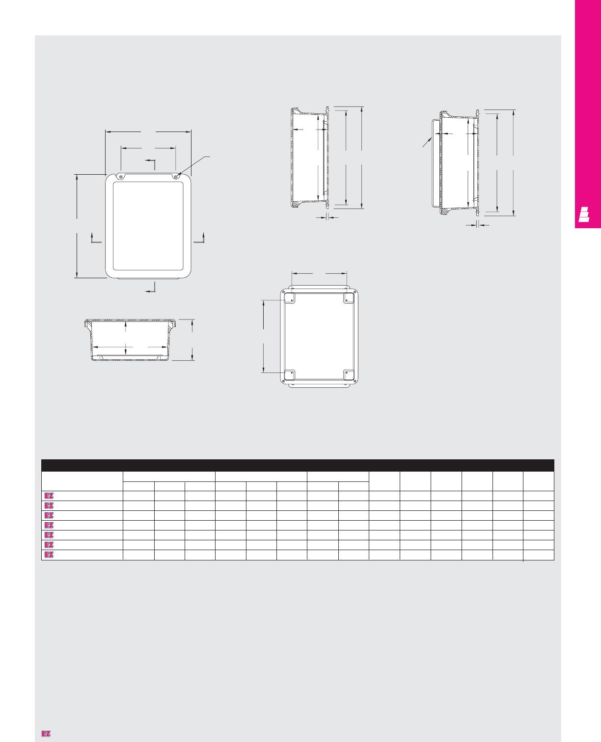
FIBERGLASS WALLMOUNT
IND 290
Technical Specifications
Flush Viewing Window Junction Boxes
Enclosure
Part No. Outside dimensions (inches) Inside dimensions (inches) Mounting centers Hole
HWDABC HWJK LMNdia.
L FJ806CHNFQW 9.62 7.50 4.74 7.73 5.74 4.45 8.88 4 4 6.25 4.25 .25 9.5 .31
L FJ1008CHNFQW 11.62 9.41 4.25 9.73 7.73 3.98 10.75 6 3.5 8.25 6.25 .25 11.35 .31
L FJ1210CHNFQW 13.56 11.43 5.21 11.79 9.80 4.94 12.75 8 4.5 10.25 8.25 .25 13.41 .31
L FJ1412CHNFQW 15.50 13.50 6.25 13.53 11.55 5.94 14.62 10 5.37 12.25 10.25 .25 15.47 .31
L FJ1614CHNFQW 17.53 15.46 6.23 15.63 13.60 5.94 16.75 12 5.36 14.25 12.25 .25 17.45 .31
L FJ1816CHNFQW 19.62 17.61 8.82 17.69 15.69 8.45 18.88 12 7.99 16.25 14.25 .25 19.61 .31
L FJ2016CHNFQW 22.00 17.68 8.83 19.72 15.72 8.45 21.25 10 8 18.25 14.25 .25 21.68 .31
Section A-A
Section B-B Crowned Cover
Front View
Without
Cover
Standard Flat
Cover
NAA
B
W
F
B
Hole dia.
4 places
J
B
DK
L
Crowned
cover
available in
1008 sizes
only
C
EH
M
C
AEH
M
Designates a product in the EnclosureZone program.
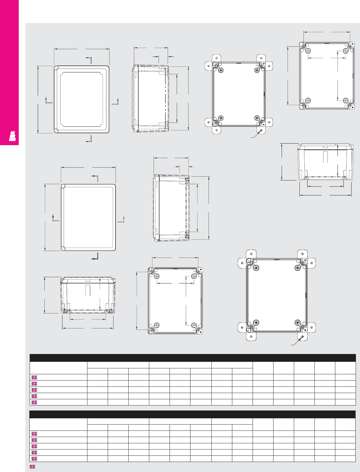
Hinged Screw Cover Enclosure
Part No. Outside dimensions (inches) Inside dimensions (inches) Mounting centers
HWDABC HWJ K LMN
L FI707CHNFSC 7.21 7.21 5.09 6.65 6.65 4.84 5.71 5.71 4.39 4.25 4.25 4.04 4.04
L FI907CHNFSC 9.21 7.21 5.09 8.59 6.59 4.84 7.71 5.71 4.39 6.25 4.25 6.04 4.04
L FI1109CHNFSC 11.21 9.21 6.09 10.59 8.59 5.84 9.71 7.71 5.39 8.25 6.25 8.04 6.04
L FI1311CHNFSC 13.21 11.21 6.59 12.59 10.59 6.34 11.71 9.71 5.89 10.25 8.25 10.04 8.04
L FI1513CHNFSC 15.21 13.21 7.09 14.55 12.55 6.84 13.71 11.71 6.39 12.25 10.25 12.04 10.04
FIBERGLASS WALLMOUNT
IND 291
Technical Specifications
Hinged Screw Cover Instrumentation Boxes
Section B-B
Section A-A
Front View
Without
Cover
W
B
H
A
B
A
DJ
N
B
F
E
Ø0.312
Viewing Window Enclosure
Part No. Outside dimensions (inches) Inside dimensions (inches) Mounting centers
HWDABC HWJ K LMN
L FI707CHNFSCW 7.21 7.21 5.09 6.65 6.65 4.84 5.71 5.71 4.39 4.25 4.25 4.04 4.04
L FI907CHNFSCW 9.21 7.21 5.09 8.59 6.59 4.84 7.71 5.71 4.39 6.25 4.25 6.04 4.04
L FI1109CHNFSCW 11.21 9.21 6.09 10.59 8.59 5.84 9.71 7.71 5.39 8.25 6.25 8.04 6.04
L FI1311CHNFSCW 13.21 11.21 6.59 12.59 10.59 6.34 11.71 9.71 5.89 10.25 8.25 10.04 8.04
L FI1513CHNFSCW 15.21 13.21 7.09 14.55 12.55 6.84 13.71 11.71 6.39 12.25 10.25 12.04 10.04
C
1.5
MA
Section B-B
H
A
B
B
A
1 1/2
A
M
Ø0.312
L
K
Section A-A Front View
Without Cover
D
N
B
F
E
L
K
J
C
Viewing Window Instrumentation Boxes
W
Designates a product in the EnclosureZone program.
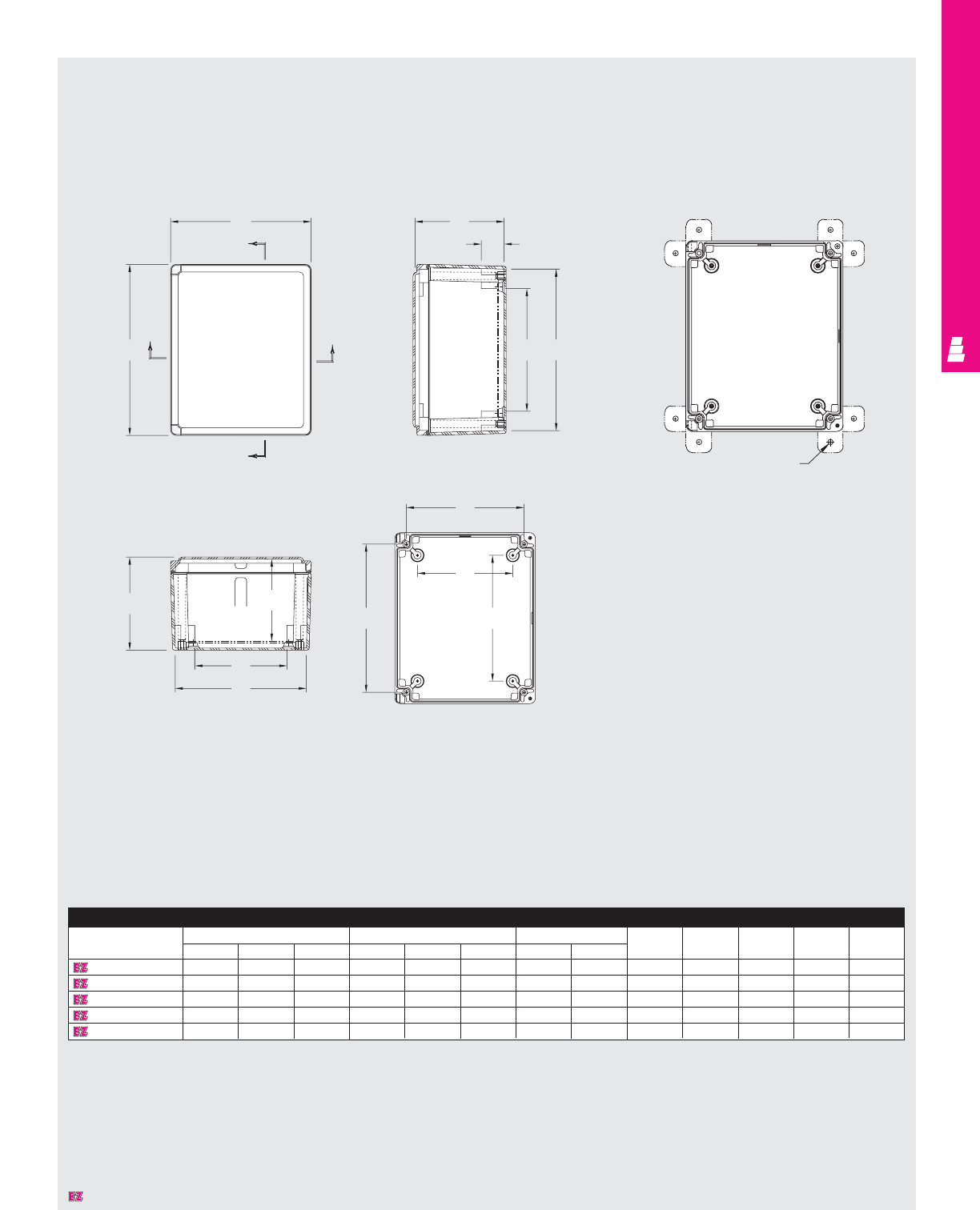
FIBERGLASS WALLMOUNT
IND 292
Technical Specifications
Hinged Quick Release Instrumentation Boxes
Section B-B
Section A-A Front View
Without
Cover
H
A
W
B
B
A
C
1.5
A
M
D
N
B
F
E
L
K
Ø0.312
Enclosure
Part No. Outside dimensions (inches) Inside dimensions (inches) Mounting centers
HWDA B CHW JK L MN
L FI707CHNFQ 7.21 7.21 5.09 6.65 6.65 4.84 4.875 4.875 4.39 4.25 4.25 4.25 4.04
L FI907CHNFQ 9.21 7.21 5.09 8.59 6.59 4.84 6.875 4.875 4.39 6.25 4.25 6.04 4.04
L FI1109CHNFQ 11.21 9.21 6.09 10.59 8.59 5.84 8.875 6.875 5.39 8.25 6.25 8.04 6.04
L FI1311CHNFQ 13.21 11.21 6.59 12.59 10.59 6.34 10.875 8.875 5.89 10.25 8.25 10.04 8.04
L FI1513CHNFQ 15.21 13.21 7.09 14.55 12.55 6.84 12.875 10.875 6.39 12.25 10.25 12.04 10.04
J
Designates a product in the EnclosureZone program.
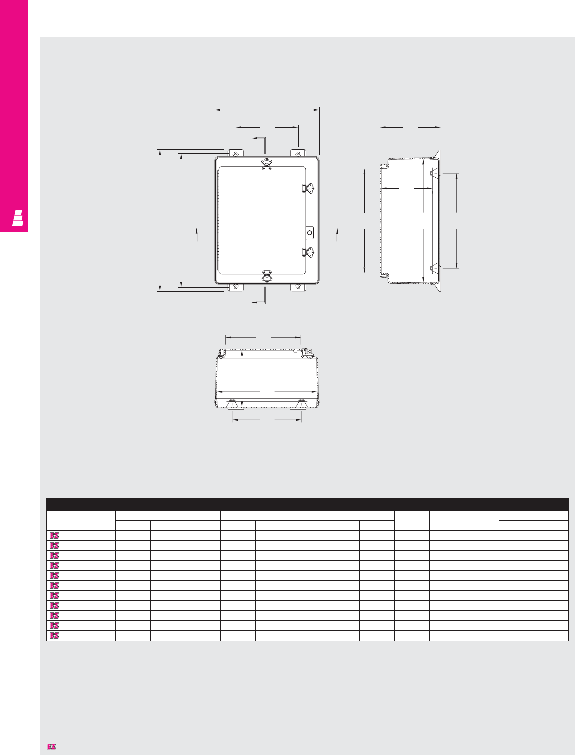
Enclosure
Part No. Outside dimensions (inches) Inside dimensions (inches) Mounting centers Enclosure opening
HW D A BC HW J KL MN
L FW20H1612 22.75 16.87 13.77 19.70 16.04 13.24 21.50 10.12 12.26 15.25 11.25 16.75 12.19
L FW24H2008 27.00 21.24 9.90 24.05 20.39 9.25 25.75 14.00 8.25 19.25 15.25 21.25 16.00
L FW24H2410 27.00 25.24 11.90 24.05 24.39 11.25 25.75 17.87 10.25 19.25 19.25 21.25 20.00
L FW24H2412 27.00 25.24 13.90 24.05 24.39 13.25 25.75 17.87 12.25 19.25 19.25 21.25 20.00
L FW30H2008 32.86 20.99 9.89 29.90 20.14 9.23 31.75 14.25 8.23 25.25 15.25 27.00 16.50
L FW30H2407 33.41 26.32 8.81 30.46 25.47 8.12 32.25 18.50 7.12 25.25 19.25 27.38 21.25
L FW30H2410 33.41 26.32 11.95 30.46 25.47 11.27 32.25 18.50 10.27 25.25 19.25 27.38 21.25
L FW36H3010 39.31 32.50 12.05 36.31 31.69 11.36 38.13 23.88 8.36 31.25 25.25 33.25 27.25
L FW36H3012 39.31 32.50 14.05 36.31 31.69 13.36 38.13 23.88 10.36 31.25 25.25 33.25 27.25
L FW48H3612 51.29 36.62 13.93 48.33 36.22 13.25 50.12 29.25 12.25 43.25 31.25 45.25 32.00
L FW48H3616 51.29 36.62 17.93 48.33 36.22 17.25 50.12 29.26 16.25 43.25 31.25 45.25 32.00
FIBERGLASS WALLMOUNT
IND 293
Technical Specifications
NEMA 4X Wallmount Boxes
Section B-B
Section A-A
W
F
HEAA
B
D
M
J
AK
N
L
C
B
Designates a product in the EnclosureZone program.
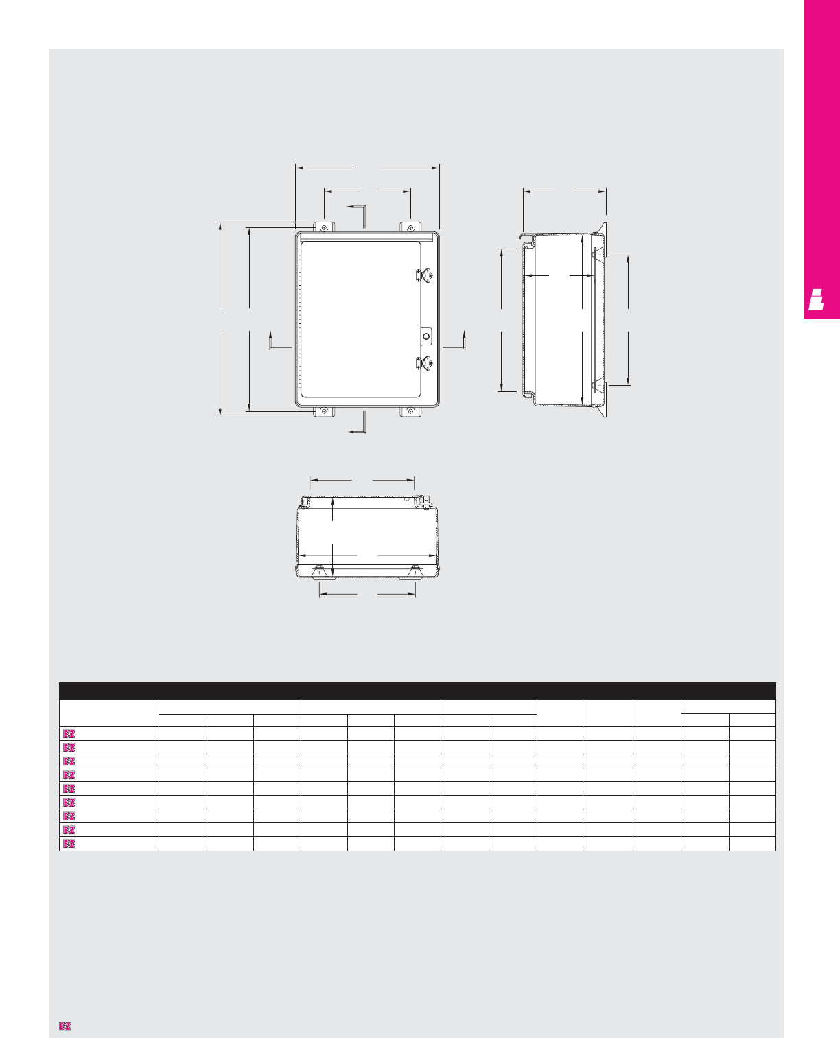
FIBERGLASS WALLMOUNT
IND 294
Technical Specifications
NEMA 3R Wallmount Boxes
Enclosure
Part No. Outside dimensions (inches) Inside dimensions (inches) Mounting centers Enclosure opening
HWDABCHW J K LMN
L FW20R1612HCR 22.75 16.87 14.27 19.70 16.04 13.24 21.50 10.12 12.26 15.25 11.25 16.75 12.19
L FW24R2008HCR 27.00 21.24 9.90 24.05 20.39 9.25 25.75 14.00 8.25 19.25 15.25 21.25 16.00
L FW24R2410HCR 27.00 25.24 11.90 24.05 24.39 11.25 25.75 17.87 10.25 19.25 19.25 21.25 20.00
L FW30R2410HCR 33.41 26.32 11.95 30.46 25.47 11.27 32.25 18.50 10.27 25.25 19.25 27.38 21.25
L FW30R2412HCR 33.41 26.32 13.79 30.46 25.47 13.10 32.25 18.50 12.10 25.25 19.25 27.38 21.25
L FW36R3010HCR 39.31 32.50 12.05 36.31 31.69 11.36 38.13 23.88 10.36 31.25 25.25 33.25 27.25
L FW36R3012HCR 39.31 32.50 14.05 36.31 31.69 13.36 38.13 23.88 12.36 31.25 25.25 33.25 27.25
L FW48R3612HCR 51.29 36.62 14.43 48.33 36.22 13.25 50.12 29.25 12.25 43.25 31.25 45.25 32.00
L FW48R3616HCR 51.29 36.62 18.43 48.33 36.22 50.12 29.26 29.26 16.25 43.25 31.25 45.25 32.00
Section B-B
Section A-A
HEA
B
A
B
F
W
D
M
J
AK
N
C
B
L
Designates a product in the EnclosureZone program.
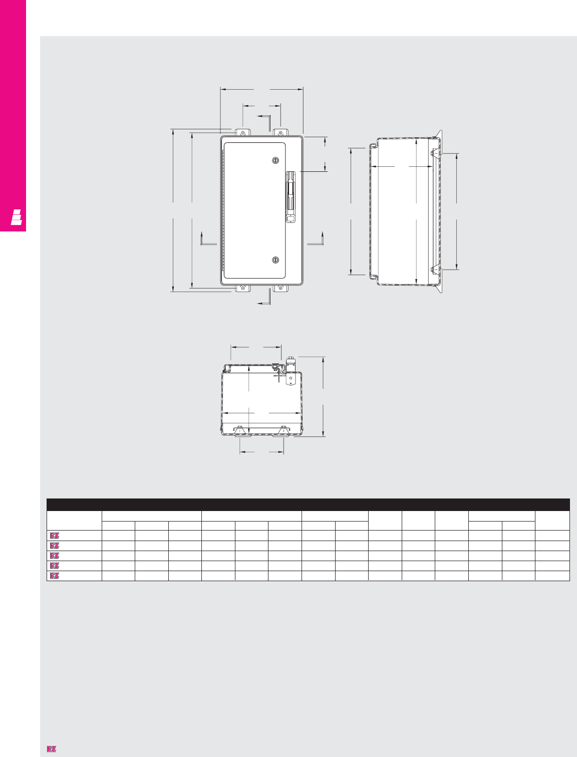
Enclosure
Part No. Outside dimensions (inches) Inside dimensions (inches) Mounting centers Enclosure opening
HWD A BC H WJ KL MNO
L F16HS10 18.75 10.96 10.25 15.92 10.27 8.53 17.50 7.00 7.8 12 7.5 13.14 6 3.50
L F20HS16 22.75 16.87 11.00 19.70 16.04 9.24 21.50 10.12 8.26 15.25 11.25 16.75 12.19 3.50
L F24HS24 27.00 25.24 13.19 24.05 24.39 11.25 25.75 17.87 10.25 19.25 19.25 21.25 20.00 5.75
L F30HS24 33.41 26.32 13.19 30.46 25.47 11.27 32.25 18.50 10.27 25.25 19.25 27.38 21.25 12.25
L F36HS30 39.31 32.50 13.31 36.31 31.69 11.36 38.13 23.88 10.36 31.25 25.25 33.25 27.50 12.25
FIBERGLASS FMD
IND 295
Technical Specifications
Fiberglass Wallmount Boxes
Section B-B
Section A-A
HE
A
B
A
O
B
F
W
M
J
AK
N
C
B
L
D
Designates a product in the EnclosureZone program.
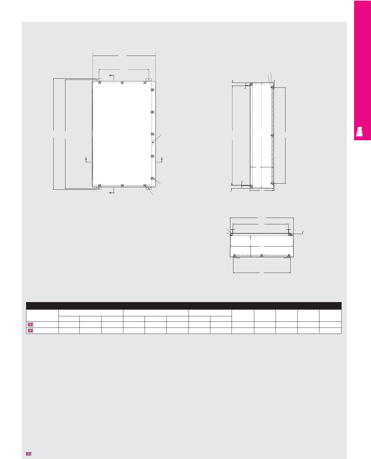
FIBERGLASS FREESTANDING
IND 296
Enclosure
Part No. Outside dimensions (inches) Inside dimensions (inches) Mounting centers
HWDABCH WJ KLMN
L F60H3612 63.50 36.50 14.12 60.13 36.13 13.44 57.00 33.00 12.44 53.06 31 55.75 32.00
L F60H3616 63.50 36.50 18.12 60.13 36.13 17.44 57.00 33.00 16.44 53.06 31 55.75 32.00
Technical Specifications
NEMA 4X Freestanding Boxes
W
F
B
HE
A
B90.5
LL150 Latch
A
Pad locking hasp
Mounting panel
(order seperately)
3/8-16 Alum.
panel studs
1.75
.25
M
.25
1.75
A
J
K
D
W
N
Gasket
24" SS Hinge
2 Required
CB
1
L
Section B-B
Section A-A
Designates a product in the EnclosureZone program.
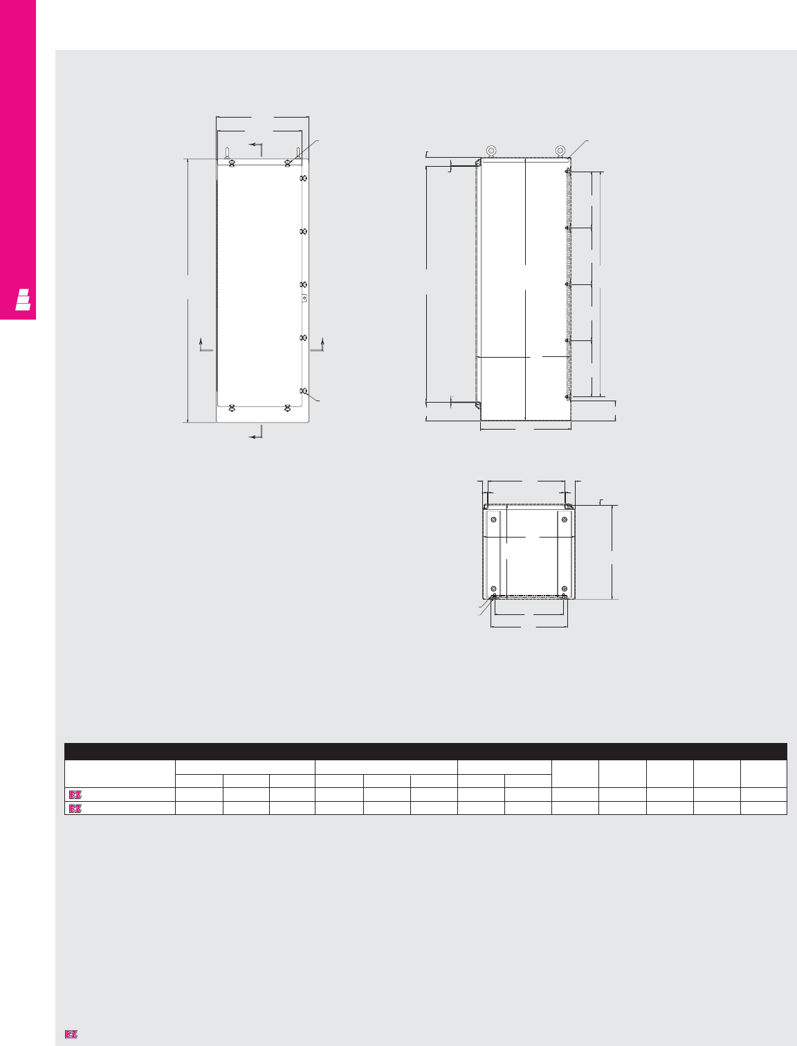
FIBERGLASS FREESTANDING
IND 297
Technical Specifications
NEMA 4X Freestanding Boxes
Enclosure
Part No. Outside dimensions (inches) Inside dimensions (inches) Mounting centers
HWD A B C H W J K L MN
L F72H2525FS 72.50 25.50 26.38 72.00 25.00 25.75 64.00 21.00 24.74 62 19 64.75 21.00
L F72H4925FSDD 72.50 49.50 26.38 72.00 49.00 25.75 64.00 22.00 24.74 62 20 64.75 21.00
W
23.25
BLL150 Latch
spring lift
H
AA
B
Stainless
steel
LL150 latch
2.5 4 x 1.125 x .25 Fiberglass
15.5
15.5
15.5
15.5
K
A
J
D
M
.25
5.25 5.625
N
1.5 .25 .25
3
1
D
C
B
L
21
Mounting panel
(order seperately)
3/8-16 Panel stud
Section B-B
Section A-A
Designates a product in the EnclosureZone program.
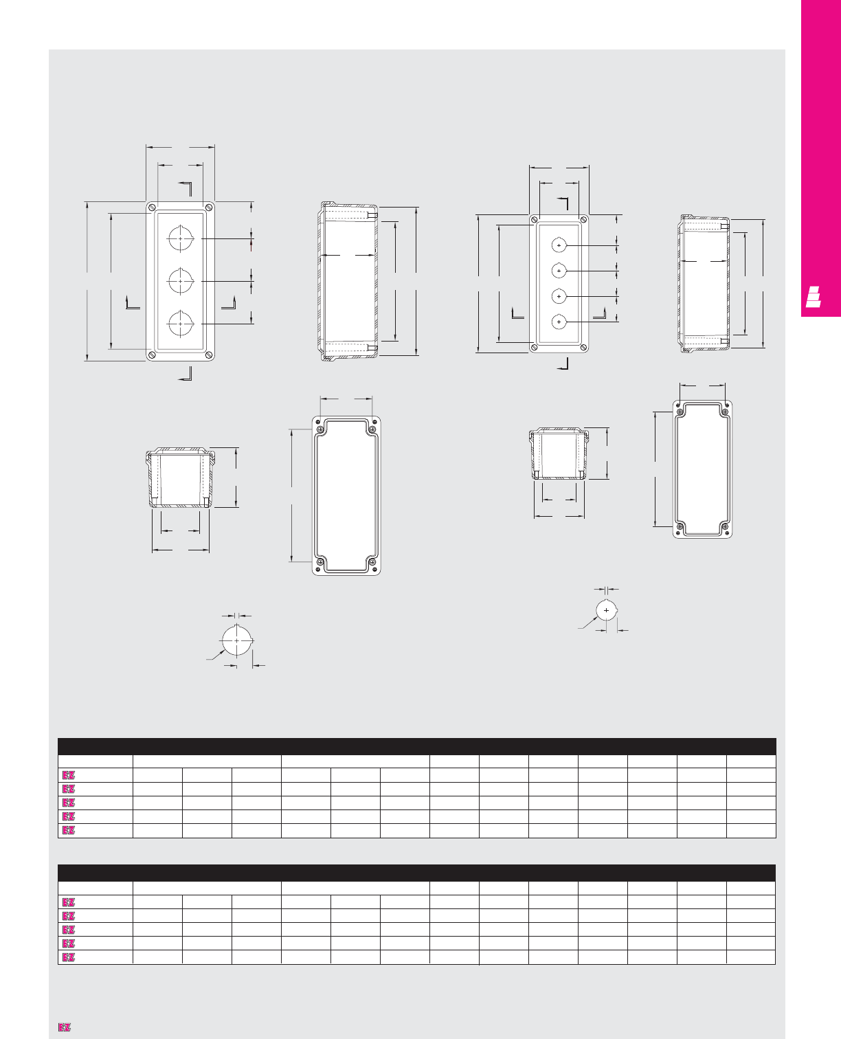
FIBERGLASS OPERATOR INTERFACE
IND 298
30mm Enclosure
Part No. Outside dimensions (inches) Inside dimensions (inches) I J K L M N O
L F1PB 6.63 3.81 3.89 6.00 3.19 5.31 5.31 2.5 4.88 2.94 4.13 2.19 3.31
L F2PB 6.63 3.81 3.89 6.00 3.19 3.63 5.31 2.5 4.88 2.94 4.13 2.19 2.19
L F3PB 8.88 3.81 3.89 8.26 3.19 3.63 7.56 2.5 7.13 2.94 6.38 2.19 2.19
L F4PB 11.13 3.81 3.89 10.51 3.19 3.63 9.81 2.5 9.37 2.94 8.63 2.19 2.19
L F5PB 13.78 3.63 3.14 13.19 3.03 2.87 12.53 2.38 12.37 2.75 11.66 2.03 2.39
22mm Enclosure
Part No. Outside dimensions (inches) Inside dimensions (inches) I J K L M N O
L F1PBGM 6.63 3.81 3.89 6.00 3.19 3.63 5.31 2.5 4.88 2.94 4.13 2.19 3.31
L F2PBGM 6.63 3.81 3.89 6.00 3.19 3.63 5.31 2.5 4.88 2.94 4.13 2.19 2.53
L F3PBGM 6.63 3.81 3.89 6.00 3.19 3.63 5.31 2.5 4.88 2.94 4.13 2.19 1.75
L F4PBGM 8.88 3.81 3.89 8.26 3.19 3.63 7.56 2.5 7.13 2.94 6.38 2.19 2.09
L F5PBGM 11.13 3.81 3.89 10.51 3.19 3.63 9.81 2.5 9.37 2.94 8.63 2.19 2.44
Technical Specifications
30/22mm Pushbutton Enclosures
Section B-B
Section A-A
Front View
Without
Cover
Section A-A
Front View
Without
Cover
Section B-B
HI
A
B
A
2.25 (57)
2.25 (57)
O
B
J
W
C
MA
D
N
B
K
L
.190
(5)
1.210
(31) .672
(17)
W
J
O
1.56 (40)
1.56 (40)
1.56 (40)
HI
B
B
C
MA
D
N
B
L
K
.125
(3)
.875
(22) .468
(12)
30 mm Enclosure 20 mm Enclosure
Designates a product in the EnclosureZone program.
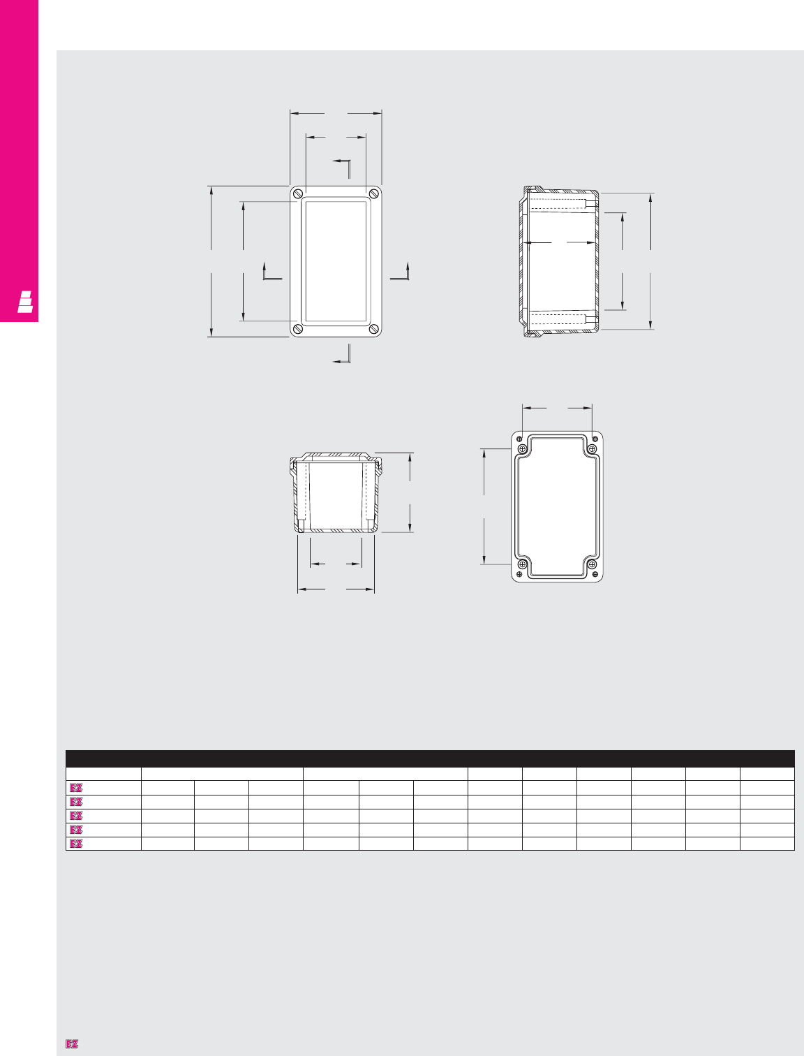
FIBERGLASS OPERATOR INTERFACE
IND 299
Technical Specifications
Small Box Pushbutton Enclosures
Enclosure
Part No. Outside dimensions (inches) Inside dimensions (inches) I J K L M N
L FJ332HB 3.72 3.63 2.95 3.13 3.03 2.70 3.22 2.12 2.31 2.75 1.59 2.03
L FJ532HB 5.97 3.63 3.14 5.38 3.03 2.87 4.72 2.38 4.56 2.75 3.84 2.03
L FJ644HB 6.63 3.81 3.89 6.00 3.19 3.63 5.31 2.50 4.88 2.94 4.13 2.19
L FJ844HB 8.88 3.81 3.89 8.26 3.19 3.63 7.56 2.50 7.13 2.94 6.38 2.19
L FJ1144HB 11.13 3.81 3.89 10.51 3.19 3.63 9.81 2.50 9.37 2.94 8.63 2.19
Section B-B
Section A-A Front View
Without
Cover
HIA
B
A
B
J
W
D
N
B
L
K
C
MA
Designates a product in the EnclosureZone program.

COMMERCIAL PRODUCTS
Type 1 Wallmount
Enclosures ..........................pgs COM 1-2
Hinge Cover Boxes ............pgs COM 3-5
Current Transformer
Enclosures ..............................pg COM 6
Lay-In Type 1 Wireway ........pgs COM 7-8
Screw Cover Pull Boxes ..pgs COM 9-10
Hinge Cover Pull Boxes ........pg COM 11
Raintight Screw Cover
Enclosures ............................pg COM 12
Raintight Wiring Trough ........pg COM 13
Gasketed Screw
Cover Boxes ..........................pg COM 14
Technical Drawings ....pgs COM 15-31
COMMERCIAL PRODUCTS
COMMERCIAL PRODUCTS
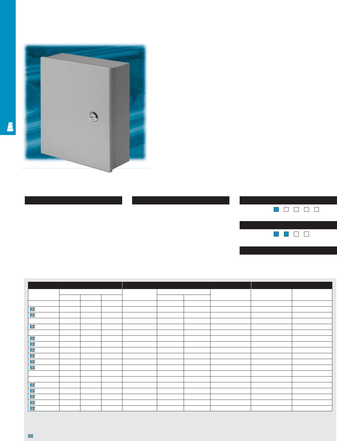
COMMERCIAL PRODUCTS
COM 1
NEMA Type
Page . . . . . . . . . . . . . . . . . . . . . . . . . . . . COM 15
NEMA Type 144X1213
UL CUL CSA TÜV
Listings
Protection Ratings
Certifications/Approvals
Technical Drawings
Configuration
• Continuous steel hinge with removable pin
• Flush, slotted latch
• Mounting panel provisions installed
• Mounting holes in back wall
Technical Specifications
Material:
•Enclosure/door: 16 gauge carbon steel
Finish/color:
•Enclosure/door: polyester-urethane powder
coat over phosphatized surfaces, inside
and outside – ANSI 61 grey
•Optional mounting panels: painted white
UL CUL CSA TÜV
Listings
Protection Ratings
Certifications/Approvals
Technical Drawings
Small Type 1 Wallmount Enclosures
Carbon Steel Commercial Boxes
These enclosures are ideal for housing electrical and electronic
controls. They are designed for indoor use to protect installed
equipment in standard environments.
Enclosure Mounting Panel Accessories
Part No. Outside dimensions (inches) Part No. Panel size Usable depth Cylinder lock Touch-up paint
HWD H W
E 6N64 6.00 6.00 4.00 E 6N6P 4.25 4.25 3.44 E L5 E L21
E 8N64 8.00 6.00 4.00 E 8N6P 6.25 4.25 3.44 E L5 E L21
E 8N66 8.00 6.00 6.00 E 8N6P 6.25 4.25 5.44 E L5 E L21
E 8N84 8.00 8.00 4.00 E 8N8P 6.25 6.25 3.44 E L5 E L21
E 10N84 10.00 8.00 4.00 E 10N8P 8.25 6.25 3.44 E L5 E L21
E 10N86 10.00 8.00 6.00 E 10N8P 8.25 6.25 5.44 E L5 E L21
E 10N104 10.00 10.00 4.00 E 10N10P 8.25 8.25 3.44 E L5 E L21
E 10N106 10.00 10.00 6.00 E 10N10P 8.25 8.25 5.44 E L5 E L21
E 12N104 12.00 10.00 4.00 E 12N10P 10.25 8.25 3.44 E L5 E L21
E 12N106 12.00 10.00 6.00 E 12N10P 10.25 8.25 5.44 E L5 E L21
E 12N124 12.00 12.00 4.00 E 12N12P 10.25 10.25 3.44 E L5 E L21
E 12N126 12.00 12.00 6.00 E 12N12P 10.25 10.25 5.44 E L5 E L21
E 12N128 12.00 12.00 8.00 E 12N12P 10.25 10.25 7.44 E L5 E L21
E 14N124 14.00 12.00 4.00 E 14N12P 12.25 10.25 3.44 E L5 E L21
E 14N126 14.00 12.00 6.00 E 14N12P 12.25 10.25 5.44 E L5 E L21
E 14N128 14.00 12.00 8.00 E 14N12P 12.25 10.25 7.44 E L5 E L21
E 16N126 16.00 12.00 6.00 E 16N12P 14.25 10.25 5.44 E L5 E L21
E 20N126 20.00 12.00 6.00 E 20N12P 18.25 10.25 5.44 E L5 E L21
E 24N126 24.00 12.00 6.00 E 24N12P 22.25 10.25 5.44 E L5 E L21
Designates a product in the EnclosureZone program.
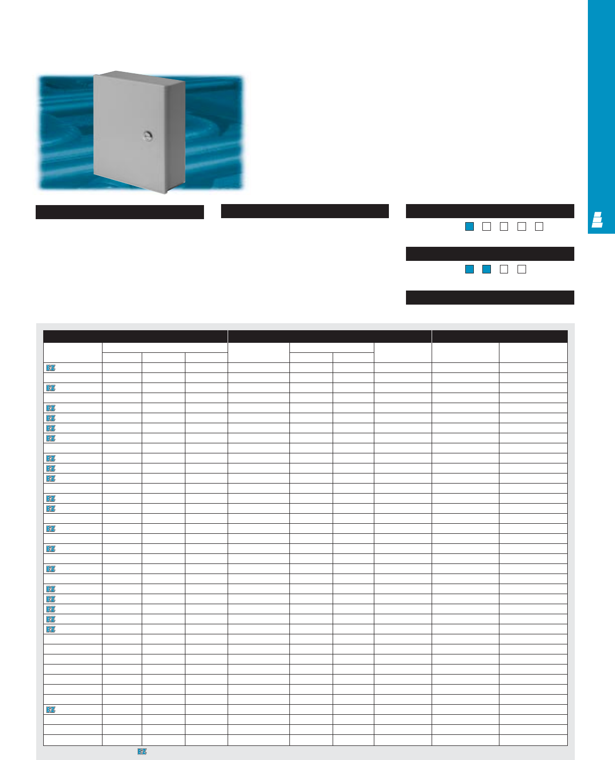
NEMA Type
COM 2
Page . . . . . . . . . . . . . . . . . . . . . . . . . . . . COM 16
NEMA Type 144X1213
UL CUL CSA TÜV
Listings
Protection Ratings
Certifications/Approvals
Technical Drawings
Configuration
•Removable doors, attached with
butt-hinges
•Flush, non-locking latch
•Single point key locking handle;
continuous hinge with removable pin —
extra large versions only
•Mounting holes in back of enclosure
Technical Specifications
Material
•Enclosure/door: 14 gauge carbon steel
Finish/color:
•Enclosure/door: polyester-urethane powder
coat over phosphatized surfaces, inside
and outside – ANSI 61 grey
•Optional mounting panel: painted white
UL CUL CSA TÜV
Listings
Protection Ratings
Certifications/Approvals
Technical Drawings
Large /Extra Large Type 1 Wallmount Enclosures
Carbon Steel Commercial Boxes
These large wallmount enclosures can be used for many
different applications. They are designed for indoor use to
prevent accidental contact with enclosed equipment in areas
where standard service conditions prevail.
Enclosure Mounting Panel Accessories
Part No. Outside dimensions (inches) Part No. Panel size Usable depth Cylinder lock kit Touch-up paint
HW D H W
E 16N12A 16.00 12.00 6.63 E 16N12P2 13.00 10.50 6.00 E L5 E L21
E 16N12B 16.00 12.00 8.63 E 16N12P2 13.00 10.50 8.00 E L5 E L21
E 16N16A 16.00 16.00 6.63 E 16N16P2 13.00 14.50 6.00 E L5 E L21
E 16N20A 16.00 20.00 6.63 E 16N20P 13.00 18.50 6.00 E L5 E L21
E 20N16A 20.00 16.00 6.63 E 20N16P 17.00 14.50 6.00 E L5 E L21
E 20N16B 20.00 16.00 8.63 E 20N16P 17.00 14.50 8.00 E L5 E L21
E 20N20A 20.00 20.00 6.63 E 20N20P 17.00 18.50 6.00 E L5 E L21
E 20N20B 20.00 20.00 8.63 E 20N20P 17.00 18.50 8.00 E L5 E L21
E 20N24B 20.00 24.00 8.63 E 20N24P 17.00 22.50 8.00 E L5 E L21
E 24N16A 24.00 16.00 6.63 E 24N16P 21.00 14.50 6.00 E L5 E L21
E 24N20A 24.00 20.00 6.63 E 24N20P 21.00 18.50 6.00 E L5 E L21
E 24N20B 24.00 20.00 8.63 E 24N20P 21.00 18.50 8.00 E L5 E L21
E 24N20C 24.00 20.00 10.63 E 24N20P 21.00 18.50 10.00 E L5 E L21
E 24N24A 24.00 24.00 6.63 E 24N24P 21.00 22.50 6.00 E L5 E L21
E 24N24B 24.00 24.00 8.63 E 24N24P 21.00 22.50 8.00 E L5 E L21
E 24N24D 24.00 24.00 12.63 E 24N24P 21.00 22.50 12.00 E L5 E L21
E 30N20A 30.00 20.00 6.63 E 30N20P 27.00 18.50 6.00 E L5 E L21
E 30N20B 30.00 20.00 8.63 E 30N20P 27.00 18.50 8.00 E L5 E L21
E 30N24A 30.00 24.00 6.63 E 30N24P 27.00 22.50 6.00 E L5 E L21
E 30N24B 30.00 24.00 8.63 E 30N24P 27.00 22.50 12 .00 E L5 E L21
E 30N24C 30.00 24.00 10.63 E 30N24P 27.00 22.50 10.00 E L5 E L21
E 30N24D 30.00 24.00 12.63 E 36N24P 27.00 22.50 12.00 E L5 E L21
E 30N30B 30.00 30.00 8.63 E 30N30P 27.00 28.50 8.00 E L5 E L21
E 36N24A 36.00 24.00 6.63 E 36N24P 33.00 22.50 6.00 E L5 E L21
E 36N24B 36.00 24.00 8.63 E 36N24P 33.00 22.50 8.00 E L5 E L21
E 36N30A 36.00 30.00 6.63 E 36N30P 33.00 28.50 6.00 E L5 E L21
E 36N30B 36.00 30.00 8.63 E 36N30P 33.00 28.50 8.00 E L5 E L21
E 36N30C 36.00 30.00 10.63 E 36N30P 33.00 28.50 10.00 E L5 E L21
E 36N30D 36.00 30.00 12.63 E 36N30P 33.00 28.50 12.00 E L5 E L21
E 42N24B 42.00 24.00 8.63 E 42N24P 39.00 22.50 8.00 E L5 E L21
E 42N3009* 42.00 30.00 9.25 E 42P30 39.00 27.00 7.50 E L5 E L21
E 42N3013* 42.00 30.00 13.25 E 42P30 39.00 27.00 11.50 E L5 E L21
E 42N3609* 42.00 36.00 9.25 E 42P36 39.00 33.00 7.50 E L5 E L21
E 42N3613* 42.00 36.00 13.25 E 42P36 39.00 33.00 11.50 E L5 E L21
E 48N3609* 48.00 36.00 9.25 E 48P36 45.00 33.00 7.50 E L5 E L21
E 48N3611* 48.00 36.00 11.25 E 48P36 45.00 33.00 9.50 E L5 E L21
E 48N3613* 48.00 36.00 13.25 E 48P36 45.00 33.00 11.50 E L5 E L21
E 48N3617* 48.00 36.00 17.25 E 48P36 45.00 33.00 15.50 E L5 E L21
COMMERCIAL PRODUCTS
* Extra large versions.
Designates a product in the EnclosureZone program.
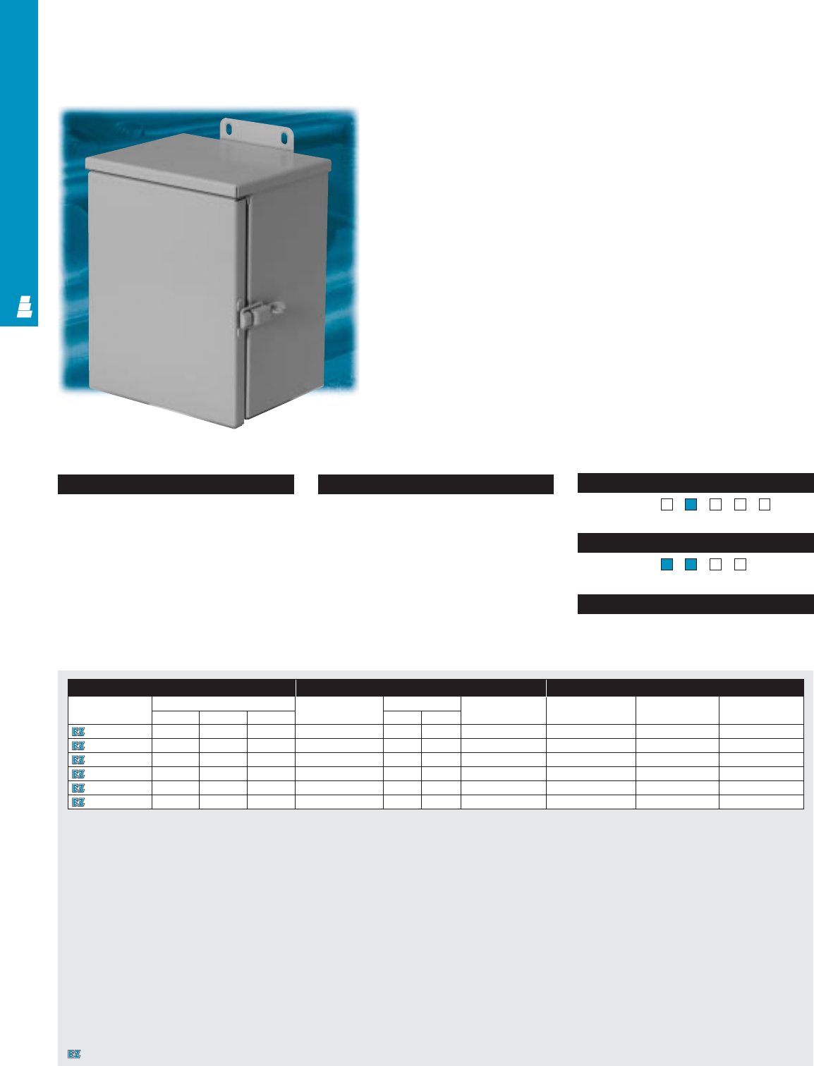
COMMERCIAL PRODUCTS
NEMA Type
Page . . . . . . . . . . . . . . . . . . . . . . . . . . . . COM 17
NEMA Type 13R4X1213
UL CUL CSA TÜV
Listings
Protection Ratings
Certifications/Approvals
Technical Drawings
Configuration
• Seamless sides, front and back
• Drip shield top
• Continuous steel hinge with removable pin
• Draw-latch with provision for padlock
• Mounting panel provisions installed
•External mounting brackets
• Knockouts for conduit in bottom
• No gasketing
Technical Specifications
Materials:
•Enclosure/cover: spot-welded 16 gauge
galvaneal steel
Finish/color:
•Enclosure/cover: polyester-urethane pow-
der coat over phosphatized surfaces,
inside and outside – ANSI 61 grey
•Optional mounting panels: painted white
UL CUL CSA TÜV
Listings
Protection Ratings
Certifications/Approvals
Technical Drawings
COM 3
Small Hinge Cover Boxes
Type 3R Galvaneal Steel Wallmount Boxes
These NEMA 3R rated hinge cover boxes are ideal as wiring
and junction boxes. Designed for both indoor and outdoor use,
they protect installed equipment against rain, sleet and snow, or
dripping water.
Enclosure Mounting Panel Accessories
Part No. Outside dimensions (inches) Part No. Panel size Usable depth Terminal block kit Terminal rails Touch-up paint
HWD HW
E 6R64HCR 6.00 6.00 4.00 E 6N6P 4.25 4.25 3.41 --E L21
E 8R64HCR 8.00 6.00 4.00 E 8N6P 6.25 4.25 3.41 E 6JTMA E 8JS E L21
E 8R86HCR 8.00 8.00 6.00 E 8N8P 6.25 6.25 5.41 E 8JTMA E 8JS E L21
E 10R86HCR 10.00 8.00 6.00 E 10N8P 8.25 6.25 5.41 E 8JTMA E 10JS E L21
E 12R106HCR 12.00 10.00 6.00 E 12N10P 10.25 8.25 5.41 E 10JTMA E 12JS E L21
E 12R126HCR 12.00 12.00 6.00 E 12N12P 10.25 10.25 5.41 E 12JTMA E 12JS E L21
Designates a product in the EnclosureZone program.
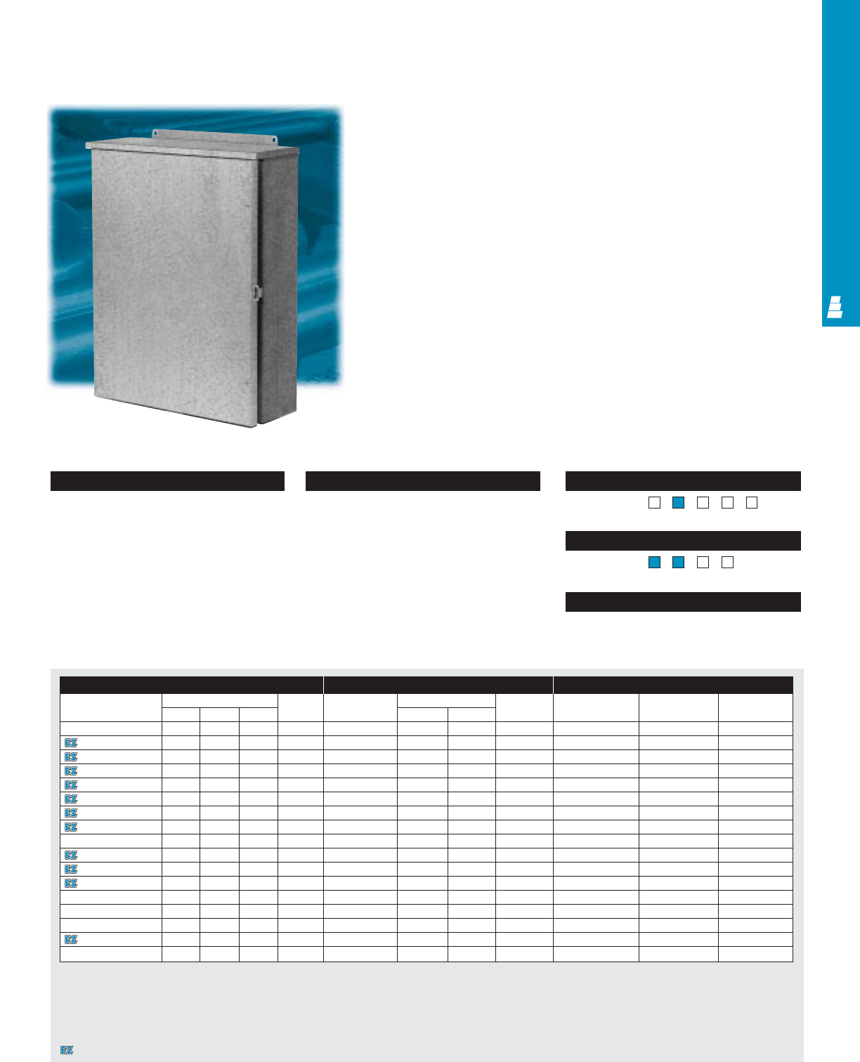
COM 4
NEMA Type
Page . . . . . . . . . . . . . . . . . . . . . . . . . . . . COM 18
NEMA Type 13R4X1213
UL CUL CSA TÜV
Listings
Protection Ratings
Certifications/Approvals
Technical Drawings
Configuration
• Seamless sides, front and back
• Drip shield top
• Continuous stainless steel hinge with
removable pin
• Captive plated steel screws secure cover
• Hasp and staple for padlock
• Mounting panel provisions installed
•External mounting brackets
• No gasketing or knockouts
Technical Specifications
Material:
•Enclosure/cover: 14 or 16 gauge
galvaneal steel
Finish/color:
•Enclosure/cover: polyester-urethane pow-
der coat over phosphatized surfaces,
inside and outside – ANSI 61 grey
•Optional mounting panels: painted white
UL CUL CSA TÜV
Listings
Protection Ratings
Certifications/Approvals
Technical Drawings
Large Hinge Cover Boxes
COMMERCIAL PRODUCTS
Type 3R Galvaneal Steel Wallmount Boxes
These NEMA 3R rated hinge cover boxes are ideal as wiring
and junction boxes. Designed for both indoor and outdoor use,
they protect installed equipment against rain, sleet and snow, or
dripping water.
Enclosure Mounting Panel Accessories
Part No. Outside dimensions (inches) Material Part No. Panel size Usable Terminal Terminal rails Touch-up paint
HWD
gauge HW
depth block kit
E 16R126HCR 16.00 12.00 6.00 16 E 16P12 13.00 9.00 4.81 E 12NTMA2 E 16NS E L21
E 16R166HCR 16.00 16.00 6.00 16 E 16P16 13.00 13.00 4.81 E 16NTMA2 E 16NS E L21
E 20R166HCR 20.00 16.00 6.00 16 E 20P16 17.00 13.00 4.81 E 16NTMA2 E 20NS E L21
E 20R208HCR 20.00 20.00 8.00 14 E 20P20 17.00 17.00 6.81 E 20NTMA2 E 20NS E L21
E 24R208HCR 24.00 20.00 8.00 14 E 24P20 21.00 17.00 6.81 E 20NTMA2 E 24NS E L21
E 24R248HCR 24.00 24.00 8.00 14 E 24P24 21.00 21.00 6.81 E 24NTMA3 E 24NS E L21
E 30R248HCR 30.00 24.00 8.00 14 E 30P24 27.00 21.00 6.81 E 24NTMA3 E 30NS E L21
E 30R3012HCR 30.00 30.00 12.00 14 E 30P30 27.00 27.00 10.81 E 30NTMA3 E 30NS E L21
E 30R3016HCR 30.00 30.00 16.00 14 E 30P30 27.00 27.00 14.81 E 30NTMA3 E 30NS E L21
E 36R2412HCR 36.00 24.00 12.00 14 E 36P24 33.00 21.00 10.81 E 24NTMA3 E 36NS E L21
E 36R3012HCR 36.00 30.00 12.00 14 E 36P30 33.00 27.00 10.81 E 30NTMA3 E 36NS E L21
E 36R3612HCR 36.00 36.00 12.00 14 E 36P36 33.00 33.00 10.81 E 36NTMA3 E 36NS E L21
E 36R3616HCR 36.00 36.00 16.00 14 E 36P36 33.00 33.00 14.81 E 36NTMA3 E 36NS E L21
E 42R3012HCR 42.00 30.00 12.00 14 E 42P30 39.00 27.00 10.81 E 30NTMA3 E 42NS E L21
E 42R3612HCR 42.00 36.00 12.00 14 E 42P36 39.00 33.00 10.81 E 36NTMA3 E 42NS E L21
E 48R3612HCR 48.00 36.00 12.00 14 E 48P36 45.00 33.00 10.81 E 36NTMA3 E 48NS E L21
E 60R3612HCR 60.00 36.00 12.00 14 E 60P36 57.00 33.00 10.81 E 36NTMA3 E 60NS E L21
Designates a product in the EnclosureZone program.
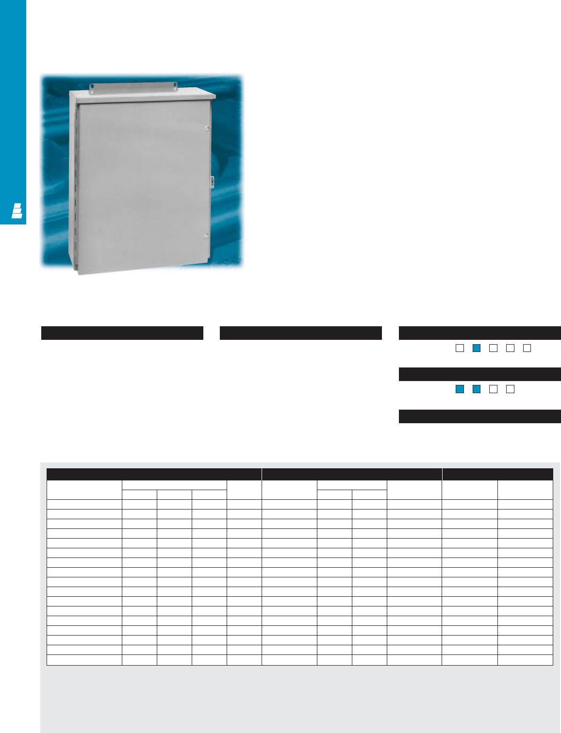
COMMERCIAL PRODUCTS
COM 5
NEMA Type
Page . . . . . . . . . . . . . . . . . . . . . . . . . . . . COM 19
NEMA Type 13R4X1213
UL CUL CSA TÜV
Listings
Protection Ratings
Certifications/Approvals
Technical Drawings
Configuration
• Seamless sides, front and back
• Drip shield top
• Continuous stainless steel hinge with
removable pin
• Captive plated steel screws secure cover
•Hasp and staple for padlock
•Mounting panel provisions installed
•External mounting brackets
•No gasketing or knockouts
Technical Specifications
Material:
•Enclosure/door: 14 or 16 gauge
stainless steel (see table)
Finish/color:
•Enclosure/cover: # 3 brushed finish
•Optional stainless steel mounting panels:
unpainted
•Optional carbon steel mounting panels:
painted white
UL CUL CSA TÜV
Listings
Protection Ratings
Certifications/Approvals
Technical Drawings
Hinge Cover Enclosures
Type 3R Stainless Steel Wallmount Boxes
These NEMA 3R rated stainless steel hinge cover boxes are
ideal as wiring and junction boxes. Designed for both indoor
and outdoor use, they protect installed equipment against rain,
sleet and snow, or dripping water.
Enclosure Mounting Panel Accessories
Part No. Outside dimensions (inches) Material Part No. Panel size Usable depth Terminal block Terminal rails
HWDgauge H W kit
E 16R126HCRSS 16.00 12.00 6.00 16 E 16P12 13.00 9.00 4.81 E 12NTMA2 E 16NS
E 16R166HCRSS 16.00 16.00 6.00 16 E 16P16 13.00 13.00 4.81 E 16NTMA2 E 16NS
E 20R166HCRSS 20.00 16.00 6.00 16 E 20P16 17.00 13.00 4.81 E 16NTMA2 E 20NS
E 20R208HCRSS 20.00 20.00 8.00 14 E 20P20 17.00 17.00 6.81 E 20NTMA2 E 20NS
E 24R208HCRSS 24.00 20.00 8.00 14 E 24P20 21.00 17.00 6.81 E 20NTMA2 E 24NS
E 24R248HCRSS 24.00 24.00 8.00 14 E 24P24 21.00 21.00 6.81 E 24NTMA3 E 24NS
E 30R248HCRSS 30.00 24.00 8.00 14 E 30P24 27.00 21.00 6.81 E 24NTMA3 E 30NS
E 30R3012HCRSS 30.00 30.00 12.00 14 E 30P30 27.00 27.00 10.81 E 30NTMA3 E 30NS
E 30R3016HCRSS 30.00 30.00 16.00 14 E 30P30 27.00 27.00 14.81 E 30NTMA3 E 30NS
E 36R2412HCRSS 36.00 24.00 12.00 14 E 36P24 33.00 21.00 10.81 E 24NTMA3 E 36NS
E 36R3012HCRSS 36.00 30.00 12.00 14 E 36P30 33.00 27.00 10.81 E 30NTMA3 E 36NS
E 36R3612HCRSS 36.00 36.00 12.00 14 E 36P36 33.00 33.00 10.81 E 36NTMA3 E 36NS
E 36R3616HCRSS 36.00 36.00 16.00 14 E 36P36 33.00 33.00 14.81 E 36NTMA3 E 36NS
E 42R3012HCRSS 42.00 30.00 12.00 14 E 42P30 39.00 27.00 10.81 E 30NTMA3 E 42NS
E 42R3612HCRSS 42.00 36.00 12.00 14 E 42P36 39.00 33.00 10.81 E 36NTMA3 E 42NS
E 48R3612HCRSS 48.00 36.00 12.00 14 E 48P36 45.00 33.00 10.81 E 36NTMA3 E 48NS
E 60R3612HCRSS 60.00 36.00 12.00 14 E 60P36 57.00 33.00 10.81 E 36NTMA3 E 60NS
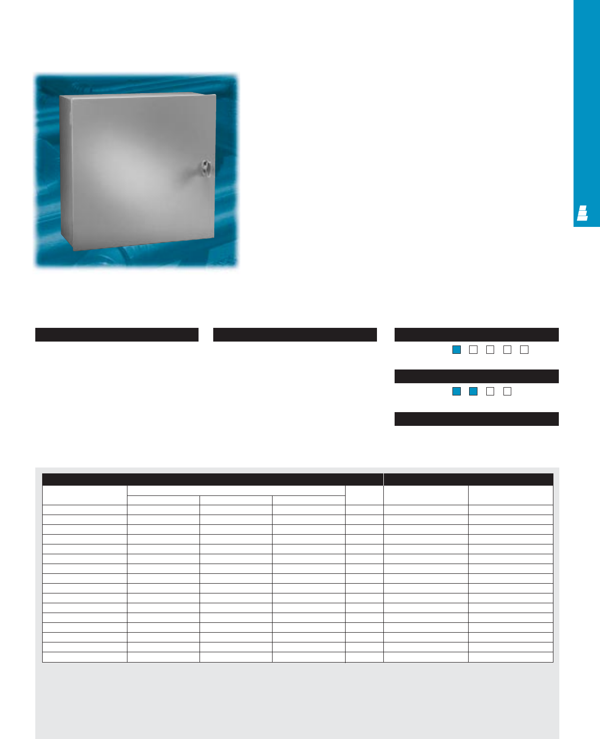
COM 6
NEMA Type
Page . . . . . . . . . . . . . . . . . . . . . . . . . . . COM 20
NEMA Type 13R4X1213
UL CUL CSA TÜV
Listings
Protection Ratings
Certifications/Approvals
Technical Drawings
Configuration
• Butt hinges
• Single door enclosures: non-locking
T handle
• Double door enclosures: vault handle with
3-way latch
• Mounting holes in back wall
• No gasketing or knockouts
Technical Specifications
Material:
•Enclosure/cover: 12 or 14 gauge
carbon steel (see table)
Finish/color:
•Enclosure/cover: polyester-urethane powder
coat over phosphatized surfaces, inside
and outside – ANSI 61 grey
UL CUL CSA TÜV
Listings
Protection Ratings
Certifications/Approvals
Technical Drawings
Current Transformer Enclosures
COMMERCIAL PRODUCTS
Type 1 Carbon Steel Enclosures
Rittal Electromate current transformer cabinets can also be
used as junction boxes, service boxes, meter boxes, etc.
They are designed for indoor use.
Enclosure Accessories
Part No. Outside dimensions (inches) Material Drip shield kit Touch-up paint
HWDgauge
E 182410CT 18.00 24.00 10.00 14 E DK2410CTC E L21
E 24167CTL 24.00 16.00 7.00 14 - E L21
E 242410CT 24.00 24.00 10.00 14 E DK2410CTC E L21
E 243210CT 24.00 32.00 10.00 14 E DK3210CTC E L21
E 244212CT 24.00 42.00 12.00 12 E DK4212CTC E L21
E 302410CT 30.00 24.00 10.00 14 E DK2410CTC E L21
E 303010CT 30.00 30.00 10.00 12 E DK3010CTC E L21
E 303610CT 30.00 36.00 10.00 12 E DK3610CTC E L21
E 32247CTL 32.00 24.00 7.00 14 - E L21
E 362410CT 36.00 24.00 10.00 14 E DK2410CTC E L21
E 363610CT 36.00 36.00 10.00 12 E DK3610CTC E L21
E 36427CTL 36.00 42.00 7.00 12 - E L21
E 364810CTL 36.00 48.00 7.00 12 E DK4810CTC E L21
E 443010CTL 44.00 30.00 10.00 12 E DK3010CTC E L21
E 484810CT 48.00 48.00 10.00 12 E DK4810CTC E L21
E 484812CT 48.00 48.00 10.00 12 - E L21
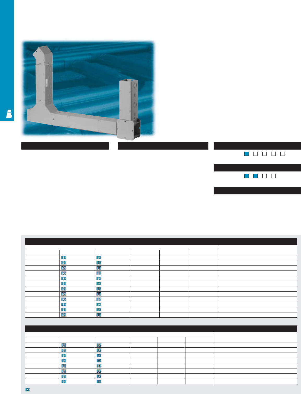
COMMERCIAL PRODUCTS
Pages . . . . . . . . . . . . . . . . . . . . . . . . . COM 21-24
NEMA Type 144X1213
Certifications/Approvals
Technical Drawings
Configuration
• Lay-in type wireways are available
in the following sizes:
2.5" x 2.5" 8.0" x 8.0"
4.0" x 4.0" 10.0" x 10.0"
6.0" x 6.0" 12.0" x 12.0"
• Lengths from 12" to 120"
• Available with and without knockouts
• Available in:
– Hinge cover
– Carbon steel screw cover
– Galvanized steel screw cover
•Key-hole screw-slot design permits easy
attaching of cover to body
•Cover attached with plated screws
Technical Specifications
Carbon Steel Version
Material:
•
Wireway/covers: 14 or 16 gauge carbon steel
Finish/color:
•Wireway/covers: polyester-urethane
powder coat over phosphatized surfaces,
inside and outside – ANSI 61 grey
Galvanized Steel Version
Material:
•
Wireway/covers: 14 or 16 gauge galvanized steel
Finish/color:
•Wireway/covers: unpainted
NEMA Type 144X1213
UL CUL CSA TÜV
Listings
Protection Ratings
Certifications/Approvals
Technical Drawings
COM 7
Lay-In Type 1 Wireway
Commercial Wireway
Wiring becomes effortless with Rittal Electromate’s wireway
products because wires and cables are laid in rather than
pulled through. Straight sections and fittings are open on one
side and later covered up.
Hinge Cover Wireway
Part No. Description
2.50 x 2.50 4.00 x 4.00 6.00 x 6.00 8.00 x 8.00 10.00 x 10.00 12.00 x 12.00
E W2212HCPK E W4412HCPK E W6612HCPK E W8812HCPK - -12.00" Straight Section (with 4 knockouts per side)
E W2212HCP E W4412HCP E W6612HCP E W8812HCP E W101012HCP E W121212HCP 12.00" Straight Section (without knockouts)
E W2224HCPK E W4424HCPK E W6624HCPK E W8824HCPK - - 24.00" Straight Section (with 8 knockouts per side)
E W2224HCP E W4424HCP E W6624HCP E W8824HCP E W101024HCP E W121224HCP 24.00" Straight Section (without knockouts)
E W2236HCPK E W4436HCPK E W6636HCPK E W8836HCPK - -36.00" Straight Section (with 12 knockouts per side)
E W2236HCP E W4436HCP E W6636HCP E W8836HCP E W101036HCP E W121236HCP 36.00" Straight Section (without knockouts)
E W2248HCPK E W4448HCPK E W6648HCPK E W8848HCPK - - 48.00" Straight Section (with 16 knockouts per side)
E W2248HCP E W4448HCP E W6648HCP E W8848HCP E W101048HCP E W121248HCP 48.00" Straight Section (without knockouts)
E W2260HCPK E W4460HCPK E W6660HCPK E W8860HCPK - - 60.00" Straight Section (with 20 knockouts per side)
E W2260HCP E W4460HCP E W6660HCP E W8860HCP E W101060HCP E W121260HCP 60.00" Straight Section (without knockouts)
E W22120HCPK E W44120HCPK E W66120HCPK E W88120HCPK - - 120.00" Straight Section (with 40 knockouts per side)
E W22120HCP E W44120HCP E W66120HCP E W88120HCP E W1010120HCP E W1212120HCP 120.00" Straight Section (without knockouts)
Designates a product in the EnclosureZone program.
Screw Cover Wireway
Carbon Steel Part No. Description
2.50 x 2.50 4.00 x 4.00 6.00 x 6.00 8.00 x 8.00 10.00 x10.00 12.00 x 12.00
E W2212PK E W4412PK E W6612PK E W8812PK - - 12.00" Straight Section (with 4 knockouts per side)
E W2212P E W4412P E W6612P E W8812LP E W101012P E W121212P 12.00" Straight Section (without knockouts)
E W2224PK E W4424PK E W6624PK E W8824PK - - 24.00" Straight Section (with 8 knockouts per side)
E W2224P E W4424P E W6624P E W8824P E W101024P E W121224P 24.00" Straight Section (without knockouts)
E W2236PK E W4436PK E W6636PK E W8836PK - - 36.00" Straight Section (with 12 knockouts per side)
E W2236P E W4436P E W6636P E W8836P E W101036P E W121236P 36.00" Straight Section (without knockouts)
E W2248PK E W4448PK E W6648PK E W8848PK - - 48.00" Straight Section (with 16 knockouts per side)
E W2248P E W4448P E W6648P E W8848P E W101048P E W121248P 48.00" Straight Section (without knockouts)
Screw Cover Wireway
Carbon Steel Part No. Description
2.50 x 2.50 4.00 x 4.00 6.00 x 6.00 8.00 x 8.00 10.00 x10.00 12.00 x 12.00
E W2260PK E W4460PK E W6660PK E W8860PK - - 60.00" Straight Section (with 20 knockouts per side)
E W2260P E W4460P E W6660P E W8860P E W101060P E W121260P 60.00" Straight Section (without knockouts)
E W22120PK E W44120PK E W66120PK E W88120PK - - 120.00" Straight Section (with 40 knockouts per side)
E W22120P E W44120P E W66120P E W88120P E W1010120P E W1212120P 120.00" Straight Section (without knockouts)
E W22OAP E W44OAP E W66OAP E W88OAP E W1010OAP E W1212OAP Open Adapter
E W22KEYAP E W44KEYAP E W66KEYAP E W88KEYAP E W10KEYAP E W12KEYAP Adapter Robroy/Keystone to REM f/ Type 1
Painted Wireway
E W22AP E W44AP E W66AP E W88AP E W10AP E W12AP Panel Adapter
E W22C E W44C E W66C E W88C E W10C E W12C Connector
E W22ETXP E W44ETXP E W66ETXP E W88ETXP E W10ETXP E W12ETXP 90° Elbow Tee-Cross
E W22HLP E W44HLP E W66HLP E W88HLP E W10HLP E W12HLP 45° Elbow
E W22IOLP E W44IOLP E W66IOLP E W88IOLP E W10IOLP E W12IOLP 90° In/Outside Elbow
E W22LP E W44LP E W66LP E W88LP - - 90° Elbow
E W22SLP E W44SLP E W66SLP E W88SLP E W10SLP E W12SLP 90° Sweep Elbow
E W22TP E W44TP E W66TP E W88TP E W10TP E W12TP Tee Pull Box
E W22CPBP E W44CPBP E W66CPBP E W88CPBP - - Cross Pull Fitting
E W22UHP E W44UHP E W66UHP E W88UHP E W10UHP E W12UHP Universal Hanger
E W44BK60 E W66BK60 E W88BK60 - - - 60" Barrier Kit
E W22SHP E W44SHP E W66SHP E W88SHP E W10SHP E W12SHP Support Hanger
E W22TSFP E W44TSFP E W66TSFP E W88TSFP E W10TSFP E W12TSFP Telescope Fitting
-E W44RE22P - - - - 4.00 to 2.00 Reducer
--E W66RE44P - - - 6.00 to 4.00 Reducer
---E W88RE66 - - 8.00 to 6.00 Reducer
---E W88RE66P - - 8.00 to 6.00 Reducer
----E W1010RE88P - 10.00 to 8.00 Reducer
-----E W1212RE1010P 12.00 to 10.00 Reducer
-----E W1212RE88P 12.00 to 8.00 Reducer
E W22LAP E W44LAP E W66LAP E W88LAP - - 90° Transposition Adaptor
E W22ECPK E W44ECPK E W66ECPK E W88ECPK E W10ECPK E W12ECPK End Cap (with 1 knockout)
E W22ECP E W44ECP E W66ECP E W88ECP E W10ECP E W12ECP End Cap (without knockout)
Galvanized Steel Part No. Description
2.50 x 2.50 4.00 x 4.00 6.00 x 6.00 8.00 x 8.00 10.00 x 10.00 12.00 x 12.00
E W2212K E W4412K E W6612K E W8812K E W101012 - 12.00" Straight Section (with 4 knockouts per side)
E W2212 E W4412 E W6612 E W8812 E W121212 - 12.00" Straight Section (without knockouts)
E W2224K E W4424K E W6624K E W8824K - - 24.00" Straight Section (with 8 knockouts per side)
E W2224 E W4424 E W6624 E W8824 E W101024 E W121224 24.00" Straight Section (without knockouts)
E W2236K E W4436K E W6636K E W8836K - - 36.00" Straight Section (with 12 knockouts per side)
E W2236 E W4436 E W6636 E W8836 E W101036 E W121236 36.00" Straight Section (without knockouts)
E W2248K E W4448K E W6648K E W8848K - - 48.00" Straight Section (with 16 knockouts per side)
E W2248 E W4448 E W6648 E W8848 E W101048 E W121248 48.00" Straight Section (without knockouts)
E W2260K E W4460K E W6660K E W8860K - - 60.00" Straight Section (with 20 knockouts per side)
E W2260 E W4460 E W6660 E W8860 E W101060 E W121260 60.00" Straight Section (without knockouts)
E W22120K E W44120K E W66120K E W88120K - - 120.00" Straight Section (with 40 knockouts per side)
E W22120 E W44120 E W66120 E W88120 E W1010120 E W1212120 120.00" Straight Section (without knockouts)
E W22OA E W44OA E W88OA E W1010OA E W1212OA - Open Adaptor
E W22A E W44A E W66A E W88A E W10A E W12A Panel Adaptor
E W22C E W44C E W66C E W88C E W10C E W12C Connector
E W22ETX E W44ETX E W66ETX E W88ETX E W10ETX E W12ETX 90° Elbow Tee-Cross
E W22HL E W44HL E W66HL E W88HL E W10HL E W12HL 45° Elbow
E W22IOL E W44IOL E W66IOL E W88IOL E W10IOL E W12IOL 90° In/Outside Elbow
E W22L E W44L E W66L E W88L E W10LE W12L - 90° Elbow
E W22SL E W44SL E W66SL E W88SL E W10SL E W12SL 90° Sweep Elbow
E W22T E W44T E W66T E W88T E W10TE W12T - Tee Pull Box
E W44CPB E W66CPB E W88CPB E W10CPB E W12CPB - Cross Pull Box
E W22UH E W44UH E W66UH E W88UH E W10UH E W12UH Universal Hanger
E W22SH E W44SH E W66SH E W88SH E W10SH E W12SH Support Hanger
E W22TSF E W44TSF E W66TSF E W88TSF E W10TSF E W12TSF Telescope Fitting
-E W44RE22 - - - - 4.00 to 2.00 Reducer
--E W66RE44 - - - 6.00 to 4.00 Reducer
----E W1010RE88 -10.00 to 8.00 Reducer
-----E W1212RE1010 12.00 to 10.00 Reducer
-----E W1212RE88 12.00 to 8.00 Reducer
E W22LA E W44LA E W66LA E W88LA - - 90° Transposition Adaptor
E W22ECK E W44ECK E W66ECK E W88ECK E W10ECK E W12ECK End Cap (with 1 knockout)
E W22EC E W44EC E W66EC E W88EC E W10EC E W12EC End Cap (without knockout)
COMMERCIAL PRODUCTS
COM 8
Designates a product in the EnclosureZone program.
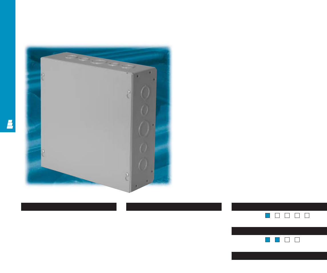
COMMERCIAL PRODUCTS
COM 9
Screw Cover Pull Boxes
Carbon Steel/Galvanized Steel Enclosures
These small enclosures are ideal for housing electrical and
electronic controls. They are designed for indoor use to protect
installed equipment in standard environments.
Pages . . . . . . . . . . . . . . . . . . . . . . . . COM 25-26
NEMA Type 144X1213
Certifications/Approvals
Technical Drawings
Configuration
•Flat, removable covers
•Covers fastened with plated steel screws
•Key-hole screw-slot design permits easy
attaching of cover to body
• Mounting holes on back wall
•Available with or without knockouts
•Covers must be ordered separately for
flush installations
•Available in painted steel or unpainted
galvanized steel
Technical Specifications
Material:
•Enclosure/cover: 12, 14, or 16 gauge
steel or galvanized steel
Finish/color:
•Enclosure/cover: polyester-urethane
powder coat over phosphatized surfaces,
inside and outside – ANSI 61 grey
•Galvanized product is unpainted
NEMA Type 144X1213
UL CUL CSA TÜV
Listings
Protection Ratings
Certifications/Approvals
Technical Drawings
COM 10
COMMERCIAL PRODUCTS
Designates a product in the EnclosureZone program.
Enclosure Accessories
Part No. Part No. Outside dimensions (inches) Flush Touch-up
Galvanized Painted covers paint
Without knockouts With knockouts With knockouts Without knockouts H W D
E SCB444 E SCB444K E SCB444PK E SCB444P 4.00 4.00 4.00 E FC44P E L21
E SCB644 E SCB644K E SCB644PK E SCB644P 6.00 4.00 4.00 E FC64P E L21
E SCB663 E SCB663K E SCB663PK E SCB663P 6.00 6.00 3.00 E FC66P E L21
E SCB664 E SCB664K E SCB664PK E SCB664P 6.00 6.00 4.00 E FC66P E L21
E SCB666 E SCB666K E SCB666PK E SCB666P 6.00 6.00 6.00 E FC66P E L21
E SCB864 E SCB864K E SCB864PK E SCB864P 8.00 6.00 4.00 E FC86P E L21
E SCB866 E SCB866K E SCB866PK E SCB866P 8.00 6.00 6.00 E FC86P E L21
E SCB884 E SCB884K E SCB884PK E SCB884P 8.00 8.00 4.00 E FC88P E L21
E SCB886 E SCB886K E SCB886PK E SCB886P 8.00 8.00 6.00 E FC88P E L21
E SCB1084 E SCB1084K E SCB1084PK E SCB1084P 10.00 8.00 4.00 E FC108P E L21
E SCB1086 E SCB1086K E SCB1086PK E SCB1086P 10.00 8.00 6.00 E FC108P E L21
E SCB10104 E SCB10104K E SCB10104PK E SCB10104P 10.00 10.00 4.00 E FC1010P E L21
E SCB10106 E SCB10106K E SCB10106PK E SCB10106P 10.00 10.00 6.00 E FC1010P E L21
E SCB1264 E SCB1264K E SCB1264PK E SCB1264P 12.00 6.00 4.00 E FC126P E L21
E SCB1284 E SCB1284K E SCB1284PK E SCB1284P 12.00 8.00 4.00 E FC128P E L21
E SCB1286 E SCB1286K E SCB1286PK E SCB1286P 12.00 8.00 6.00 E FC128P E L21
E SCB12104 E SCB12104K E SCB12104PK E SCB12104P 12.00 10.00 4.00 E FC1210P E L21
E SCB12124 E SCB12124K E SCB12124PK E SCB12124P 12.00 12.00 4.00 E FC1212P E L21
E SCB12126 E SCB12126K E SCB12126PK E SCB12126P 12.00 12.00 6.00 E FC1212P E L21
E SCB12128 --E SCB12128P 12.00 12.00 8.00 E FC1212P E L21
E SCB15124 E SCB15124K E SCB15124PK E SCB15124P 15.00 12.00 4.00 E FC1512P E L21
E SCB15126 E SCB15126K E SCB15126PK E SCB15126P 15.00 12.00 6.00 E FC1512P E L21
E SCB15156 E SCB15156K E SCB15156PK E SCB15156P 15.00 15.00 6.00 E FC1515P E L21
E SCB18124 E SCB18124K E SCB18124PK E SCB18124P 18.00 12.00 4.00 E FC1812P E L21
E SCB18126 E SCB18126K E SCB18126PK E SCB18126P 18.00 12.00 6.00 E FC1812P E L21
E SCB18156 E SCB18156K E SCB18156PK E SCB18156P 18.00 15.00 6.00 E FC1815P E L21
E SCB18186 E SCB18186K E SCB18186PK E SCB18186P 18.00 18.00 6.00 E FC1818P E L21
E SCB18188 --E SCB18188P 18.00 18.00 8.00 E FC1818P E L21
E SCB24186 E SCB24186K E SCB24186PK E SCB24186P 24.00 18.00 6.00 E FC2418P E L21
E SCB24188 --E SCB24188P 24.00 18.00 8.00 E FC2418P E L21
E SCB24246 E SCB24246K E SCB24246PK E SCB24246P 24.00 24.00 6.00 E FC2424P E L21
E SCB24248 --E SCB24248P 24.00 24.00 8.00 E FC2424P E L21
E SCB242410 --E SCB242410P 24.00 24.00 10.00 E FC2424P E L21
E SCB30246 E SCB30246K E SCB30246PK E SCB30246P 30.00 24.00 6.00 E FC3024P E L21
E SCB30248 --E SCB30248P 30.00 24.00 8.00 E FC3024P E L21
E SCB30308 --E SCB30308P 30.00 30.00 8.00 E FC3030P E L21
E SCB303010 --E SCB303010P 30.00 30.00 10.00 E FC3030P E L21
E SCB36248 --E SCB36248P 36.00 24.00 8.00 E FC3624P E L21
E SCB362412 --E SCB362412P 36.00 24.00 12.00 E FC3624P E L21
ESCB363610 --E SCB363610P 36.00 36.00 10.00 E FC3636P E L21
E SCB363612 --E SCB363612P 36.00 36.00 12.00 E FC3636P E L21
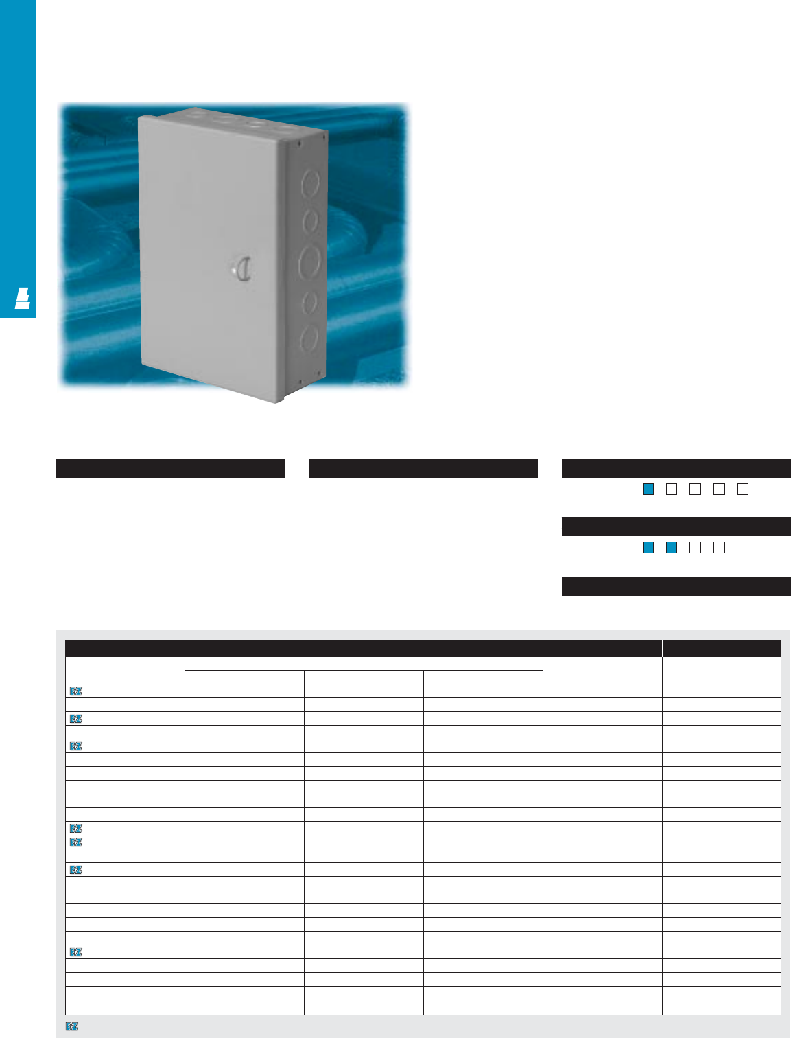
COMMERCIAL PRODUCTS
COM 11
Pages . . . . . . . . . . . . . . . . . . . . . . . . COM 27-28
NEMA Type 144X1213
Certifications/Approvals
Technical Drawings
Configuration
•Formed steel or butt hinges
•Various sizes of knockouts on side, top
and bottom
•Mounting holes on back wall
Technical Specifications
Material:
•Enclosure/cover: 14 or 16 gauge
carbon steel
Finish/color:
•Enclosure/cover: polyester-urethane
powder coat over phosphatized surfaces,
inside and outside – ANSI 61 grey
NEMA Type 144X1213
UL CUL CSA TÜV
Listings
Protection Ratings
Certifications/Approvals
Technical Drawings
Hinge Cover Pull Boxes
Carbon Steel Commerical Boxes
These Rittal Electromate hinge cover enclosures can be
used as a junction box, pull box, service box, switch box,
or cutout box.
Enclosure Accessories
Part No. Outside dimensions (inches) Material gauge Touch-up
HWDpaint
E HCB553PK 4.50 5.00 3.06 16 E L21
E HCB593PK 4.50 9.00 3.06 16 E L21
E HCB664PK 6.00 6.00 4.06 16 E L21
E HCB666PK 6.00 6.00 6.06 16 E L21
E HCB864PK 8.00 6.00 4.06 16 E L21
E HCB884PK 8.00 8.00 4.06 16 E L21
E HCB1082PK 10.00 8.00 2.00 16 E L21
E HCB1084PK 10.00 8.00 4.06 16 E L21
E HCB10104PK 10.00 10.00 4.06 16 E L21
E HCB1264PK 12.00 6.00 4.06 16 E L21
E HCB1284PK 12.00 8.00 4.06 16 E L21
E HCB12104PK 12.00 10.00 4.06 16 E L21
E HCB12106PK 12.00 10.00 6.06 16 E L21
E HCB12124PK 12.00 12.00 4.06 16 E L21
E HCB12126PK 12.00 12.00 6.06 16 E L21
E HCB15124PK 15.00 12.00 4.00 16 E L21
E HCB15126PK 15.00 12.00 6.00 16 E L21
E HCB18124PK 18.00 12.00 4.00 16 E L21
E HCB18126PK 18.00 12.00 6.00 16 E L21
E HCB18154PK 18.00 15.00 4.06 16 E L21
E HCB18156PK 18.00 15.00 6.00 16 E L21
E HCB18186PK 18.00 18.00 6.06 16 E L21
E HCB24186PK 24.00 18.00 6.06 14 E L21
E HCB24246PK 24.00 24.00 6.00 14 E L21
Designates a product in the EnclosureZone program.
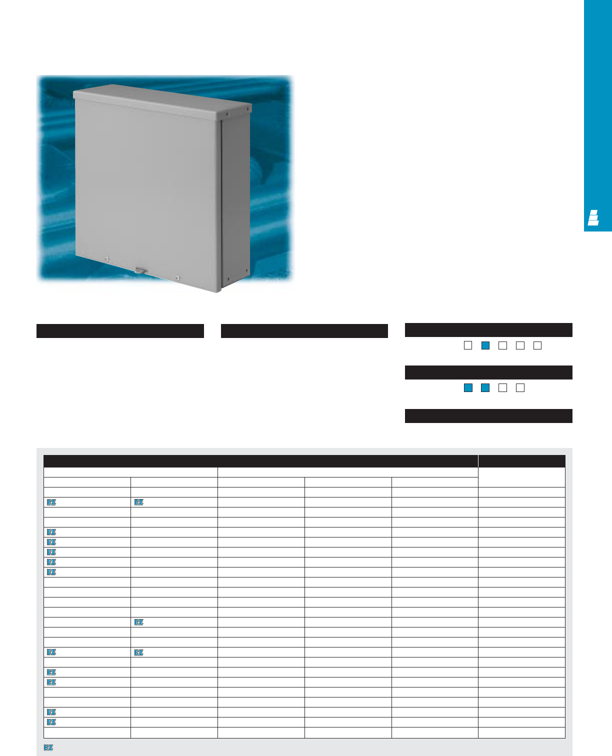
COMMERCIAL PRODUCTS
COM 12
Page . . . . . . . . . . . . . . . . . . . . . . . . . . . COM 29
NEMA Type 13R4X1213
UL CUL CSA TÜV
Listings
Protection Ratings
Certifications/Approvals
Technical Drawings
Configuration
•Drip shield top
•Seamless sides, front and back
•Removable, slip-on cover
•Plated steel screws secure cover
•Padlock provision
•Knockouts for conduit in bottom
•Mounting holes on back wall
•Available in painted galvaneal steel
or unpainted galvanized steel
Technical Specifications
Material:
•Enclosure/cover: 14 or 16 gauge galvaneal
or galvanized steel
Finish/color:
•Enclosure/cover: polyester-urethane
powder coat over phosphatized surfaces,
inside and outside – ANSI 61 grey
•Galvanized product is unpainted
Raintight Screw Cover Enclosures
Type 3R Galvaneal Steel/Galvanized Boxes
These Rittal Electromate screw cover enclosures can be used
as wiring and junction boxes for outdoor applications. They
protect installed equipment against rain, sleet and snow.
Enclosure Accessories
Part No. Outside dimensions (inches) Touch-up
Painted Galvanized HWDpaint
E RTB644P E RTB644 6.00 4.00 4.00 E L21
E RTB664P E RTB664 6.00 6.00 4.00 E L21
E RTB666P E RTB666 6.00 6.00 6.00 E L21
E RTB864P E RTB864 8.00 6.00 4.00 E L21
E RTB884P E RTB884 8.00 8.00 4.00 E L21
E RTB886P E RTB886 8.00 8.00 6.00 E L21
E RTB1084P E RTB1084 10.00 8.00 4.00 E L21
E RTB10104P E RTB10104 10.00 10.00 4.00 E L21
E RTB10106P E RTB10106 10.00 10.00 6.00 E L21
E RTB1264P E RTB1264 12.00 6.00 4.00 E L21
E RTB1284P E RTB1284 12.00 8.00 4.00 E L21
E RTB1286P E RTB1286 12.00 8.00 6.00 E L21
E RTB12124P E RTB12124 12.00 12.00 4.00 E L21
E RTB12126P E RTB12126 12.00 12.00 6.00 E L21
E RTB15124P E RTB15124 15.00 12.00 4.00 E L21
E RTB15126P E RTB15126 15.00 12.00 6.00 E L21
E RTB18126P E RTB18126 18.00 12.00 6.00 E L21
E RTB18128P E RTB18128 18.00 12.00 8.00 E L21
E RTB18186P E RTB18186 18.00 18.00 6.00 E L21
E RTB18188P E RTB18188 18.00 18.00 8.00 E L21
E RTB24126P -24.00 12.00 6.00 E L21
E RTB24186P E RTB24186 24.00 18.00 6.00 E L21
E RTB24248P E RTB24248 24.00 24.00 8.00 E L21
E RTB242412P E RTB242412 24.00 24.00 12.00 E L21
E RTB30248P E RTB30248 30.00 24.00 8.00 E L21
Designates a product in the EnclosureZone program.
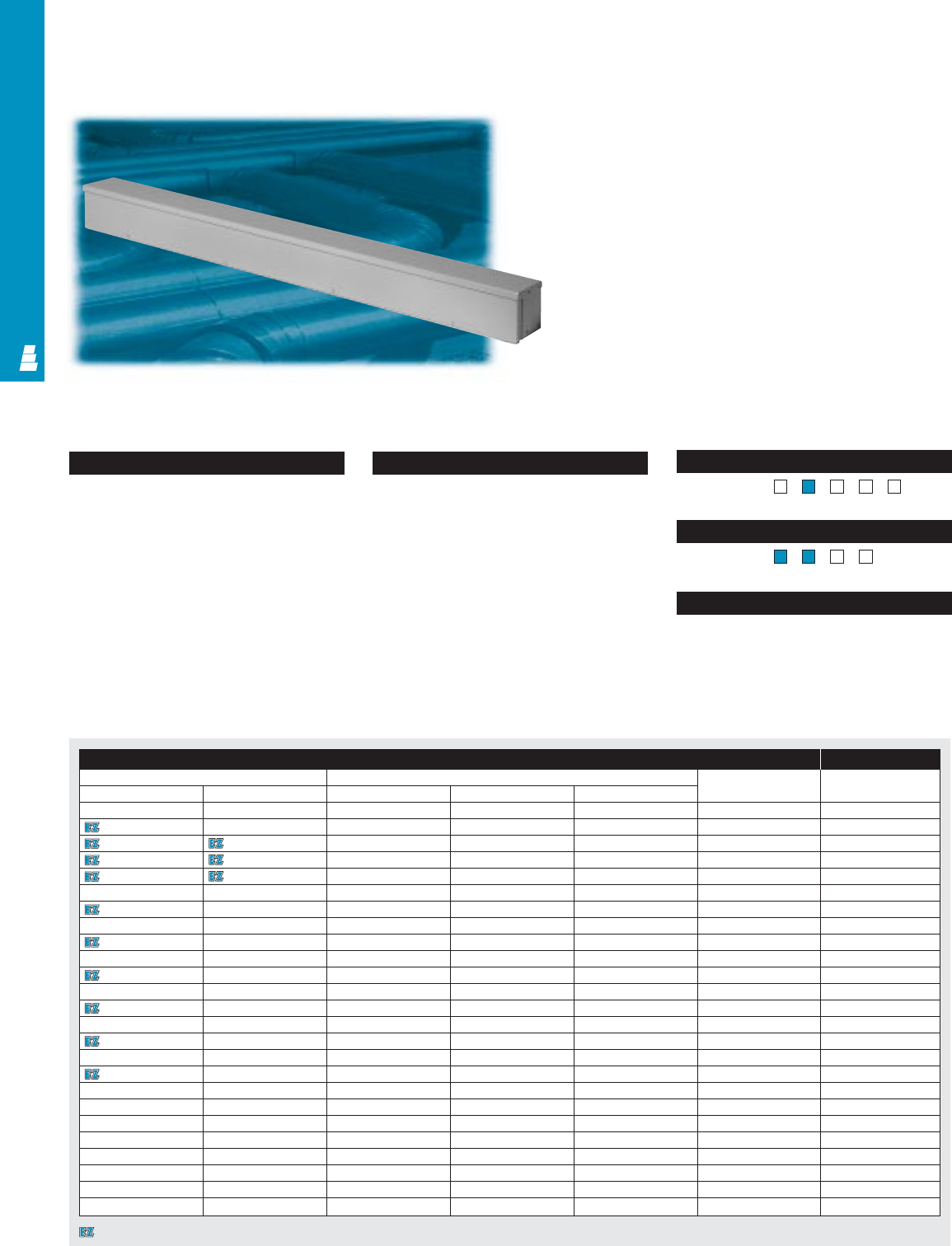
Configuration
•Galvaneal steel troughs are available in the
following sizes:
4.0" x 4.0" 10.0" x 10.0"
6.0" x 6.0" 12.0" x 12.0"
8.0" x 8.0"
•Lengths from 12" to 72"
•Drip shield top
•Seamless sides, front and back
•Removable, slip-on cover
•Cover fastened with plated steel screws
along bottom edge
•Knockouts for conduit on bottom
•Mounting holes on back wall
•No gasketing
Technical Specifications
Material:
•Enclosure/cover: 14 or 16 gauge
galvaneal steel
Finish/color:
•Enclosure/cover: polyester-urethane
powder coat over phosphatized surfaces,
inside and outside – ANSI 61 grey
•Galvanized product is unpainted Page . . . . . . . . . . . . . . . . . . . . . . . . . . . . COM 30
NEMA Type 13R4X1213
UL CUL CSA TÜV
Listings
Protection Ratings
Certifications/Approvals
Technical Drawings
Raintight Wiring Trough
Galvaneal Steel Commercial Wireway
These Rittal Electromate troughs are designed for indoor and
outdoor use. Indoors they protect against dripping water;
outdoors they protect wiring against rain, sleet and snow.
Wiring Trough Accessories
Part No. Outside dimensions (inches) Material Touch-up
Painted Galvanized HWDgauge paint
E RTT4412P E RTT4412 4.00 4.00 12.00 16 E L21
E RTT4424P E RTT4424 4.00 4.00 24.00 16 E L21
E RTT4436P E RTT4436 4.00 4.00 36.00 16 E L21
E RTT4448P E RTT4448 4.00 4.00 48.00 16 E L21
E RTT4460P E RTT4460 4.00 4.00 60.00 16 E L21
E RTT6612P E RTT6612 6.00 6.00 12.00 16 E L21
E RTT6624P E RTT6624 6.00 6.00 24.00 16 E L21
E RTT6636P E RTT6636 6.00 6.00 36.00 16 E L21
E RTT6648P E RTT6648 6.00 6.00 48.00 16 E L21
E RTT6660P E RTT6660 6.00 6.00 60.00 16 E L21
E RTT6672P E RTT6672 6.00 6.00 72.00 16 E L21
E RTT8812P E RTT8812 8.00 8.00 12.00 14 E L21
E RTT8824P E RTT8824 8.00 8.00 24.00 14 E L21
E RTT8836P E RTT8836 8.00 8.00 36.00 14 E L21
E RTT8848P E RTT8848 8.00 8.00 48.00 14 E L21
E RTT8860P E RTT8860 8.00 8.00 60.00 14 E L21
E RTT8872P E RTT8872 8.00 8.00 72.00 14 E L21
-E RTT1036 10.00 10.00 36.00 14 -
-E RTT1048 10.00 10.00 48.00 14 -
-E RTT1060 10.00 10.00 60.00 14 -
-E RTT1072 10.00 10.00 72.00 14 -
-E RTT1236 12.00 12.00 36.00 14 -
-E RTT1248 12.00 12.00 48.00 14 -
-E RTT1260 12.00 12.00 60.00 14 -
-E RTT1272 12.00 12.00 72.00 14 -
COMMERCIAL PRODUCTS
COM 13
Designates a product in the EnclosureZone program.
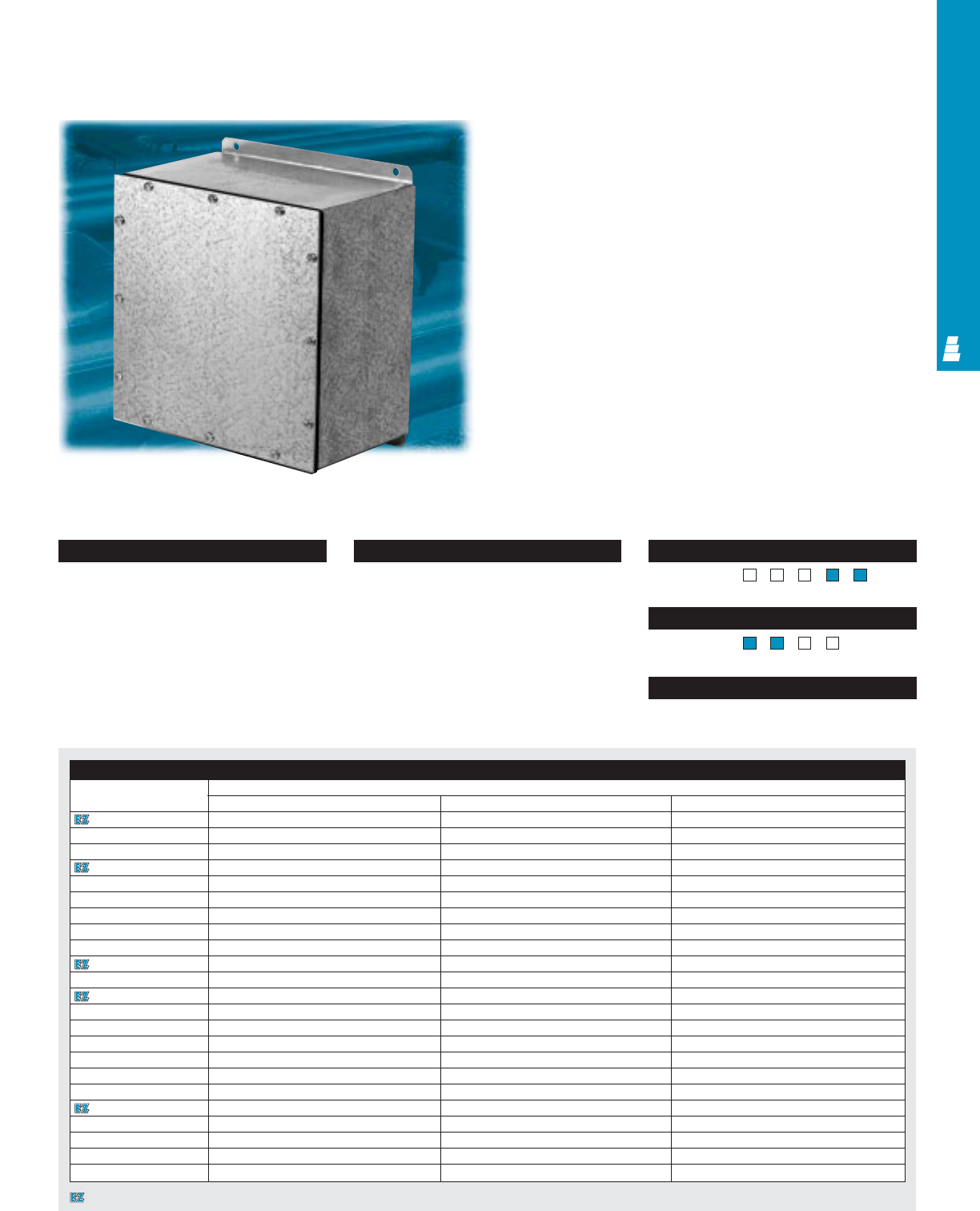
COMMERCIAL PRODUCTS
COM 14
Configuration
•Continuously welded seams, finished smooth
•Cover fastened with plated steel screws
•Oil resistant gasket
Technical Specifications
Material:
•Enclosure: 14 gauge G-90 galvanized steel
Cover: 14 gauge G-90 galvanized steel
Finish/color:
•Enclosure/cover: unpainted external
welded seams: zinc-rich covering provides
protection equivalent to galvanized steel
Page . . . . . . . . . . . . . . . . . . . . . . . . . . . . COM 31
NEMA Type 144X1213
UL CUL CSA TÜV
Listings
Protection Ratings
Certifications/Approvals
Technical Drawings
Gasketed Screw Cover Boxes
Galvanized Commerical Enclosures
These Rittal Electromate screw cover enclosures can be used
as wiring, pull, junction, or terminal boxes for indoor
applications in dusty or wet environments.
Enclosure
Part No. Outside dimensions (inches)
HWD
E WTB664 6.00 6.00 4.00
E WTB666 6.00 6.00 6.00
E WTB864 8.00 6.00 4.00
E WTB884 8.00 8.00 4.00
E WTB886 8.00 8.00 6.00
E WTB1084 10.00 8.00 4.00
E WTB10104 10.00 10.00 4.00
E WTB10106 10.00 10.00 6.00
E WTB12124 12.00 12.00 4.00
E WTB12126 12.00 12.00 6.00
E WTB12128 12.00 12.00 8.00
E WTB16126 16.00 12.00 6.00
E WTB16166 16.00 16.00 6.00
E WTB18188 18.00 18.00 8.00
E WTB20166 20.00 16.00 6.00
E WTB20208 20.00 20.00 8.00
E WTB24248 24.00 24.00 8.00
E WTB242410 24.00 24.00 10.00
E WTB242412 24.00 24.00 12.00
E WTB30248 30.00 24.00 8.00
E WTB362410 36.00 24.00 10.00
E WTB363012 36.00 30.00 12.00
E WTB363612 36.00 36.00 12.00
Designates a product in the EnclosureZone program.
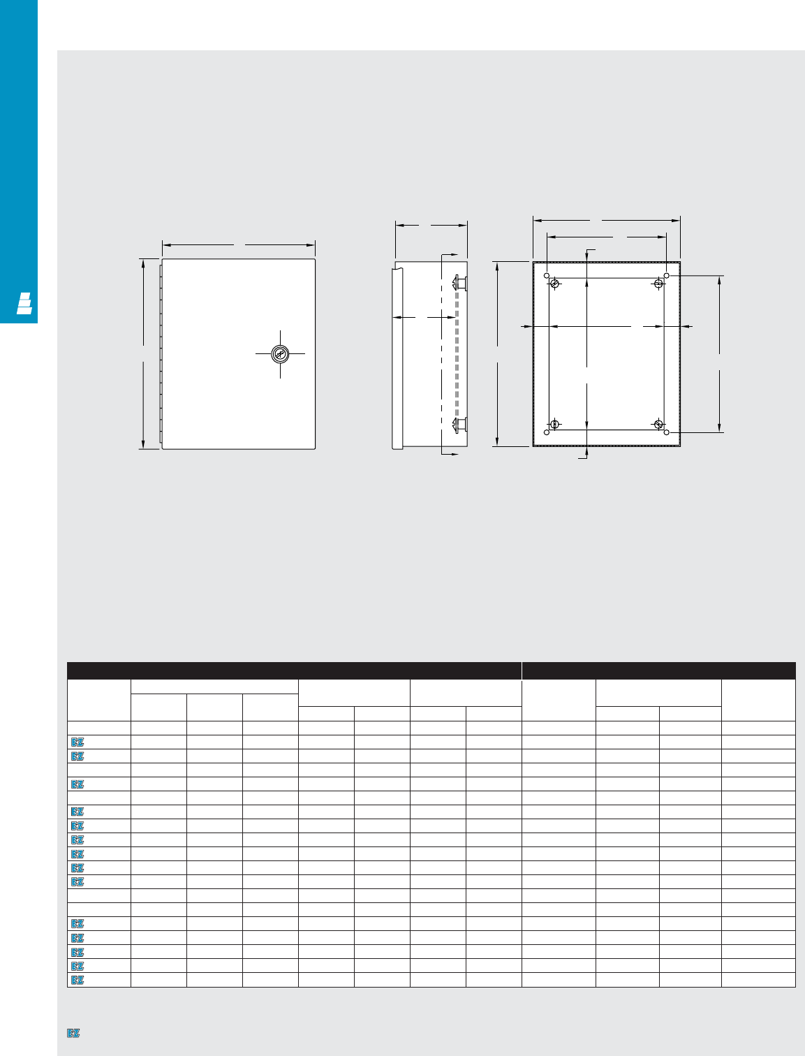
COMMERCIAL PRODUCTS
COM 15
Technical Specifications
Small Type 1 Wallmount Enclosures
Front View Section X-X
Right or Left
Side View
D
CB
W
.88
K
H
.88 .88
.88
X
G
X
C
L
E
Enclosure Mounting Panel
Part No. Outside dimensions (inches) Mounting centers Door size Part No. Panel size Usable depth
Height Width Depth
ABCHWDE J K G
E 6N64 6.00 6.00 4.00 3.00 5.00 6.31 6.31 E 6N6P 4.25 4.25 3.44
E 8N64 8.00 6.00 4.00 5.00 5.00 8.31 6.31 E 8N6P 6.25 4.25 3.44
E 8N66 8.00 6.00 6.00 5.00 5.00 8.31 6.31 E 8N6P 6.25 4.25 5.44
E 8N84 8.00 8.00 4.00 5.00 7.00 8.31 8.31 E 8N8P 6.25 6.25 3.44
E 10N84 10.00 8.00 4.00 7.00 7.00 10.31 8.31 E 10N8P 8.25 6.25 3.44
E 10N86 10.00 8.00 6.00 7.00 7.00 10.31 8.31 E 10N8P 8.25 6.25 5.44
E 10N104 10.00 10.00 4.00 7.00 9.00 10.31 10.31 E 10N10P 8.25 8.25 3.44
E 10N106 10.00 10.00 6.00 7.00 9.00 10.31 10.31 E 10N10P 8.25 8.25 5.44
E 12N104 12.00 10.00 4.00 9.00 9.00 12.31 10.31 E 12N10P 10.25 8.25 3.44
E 12N106 12.00 10.00 6.00 9.00 9.00 12.31 10.31 E 12N10P 10.25 8.25 5.44
E 12N124 12.00 12.00 4.00 9.00 11.00 12.31 12.31 E 12N12P 10.25 10.25 3.44
E 12N126 12.00 12.00 6.00 9.00 11.00 12.31 12.31 E 12N12P 10.25 10.25 5.44
E 12N128 12.00 12.00 8.00 9.00 11.00 12.31 12.31 E 12N12P 10.25 10.25 7.44
E 14N124 14.00 12.00 4.00 9.00 11.00 14.31 12.31 E 14N12P 12.25 10.25 3.44
E 14N126 14.00 12.00 6.00 11.00 11.00 14.31 12.31 E 14N12P 12.25 10.25 5.44
E 14N128 14.00 12.00 8.00 11.00 11.00 14.31 12.31 E 14N12P 12.25 10.25 7.44
E 16N126 16.00 12.00 6.00 13.00 11.00 16.31 12.31 E 16N12P 14.25 10.25 5.44
E 20N126 20.00 12.00 6.00 17.00 11.00 20.31 12.31 E 20N12P 18.25 10.25 5.44
E 24N126 24.00 12.00 6.00 21.00 11.00 24.31 12.31 E 24N12P 22.25 10.25 5.44
A
Designates a product in the EnclosureZone program.
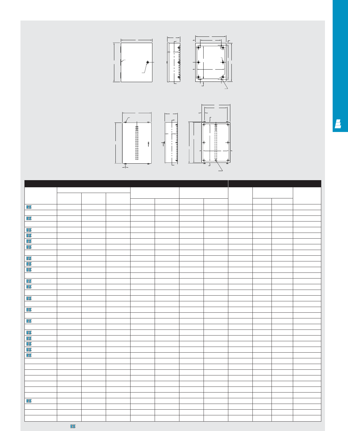
COMMERCIAL PRODUCTS
COM 16
Technical Specifications
Large Type 1 Wallmount Enclosures
Front View Right or Left Side View Section X-X
E
Omit center
hinge if
A < 36
1/4 Turn
slotted latch
FCX
X
D
2.50 B
W1.06
A
H
K
1.50 .34 small dia.
.63 large dia.
( 4 ) places
.75
C
L
C
L
Enclosure Mounting Panel
Part No. Outside dimensions (inches) Mounting centers Door size Part No. Panel size Usable depth
Height Width Depth
AB CHWE F JK D
E 16N12A 16.00 12.00 6.63 13.88 7.00 16.38 12.38 E 16N12P2 13.00 10.50 6.00
E 16N12B 16.00 12.00 8.63 13.88 7.00 16.38 12.38 E 16N12P2 13.00 10.50 8.00
E 16N16A 16.00 16.00 6.63 13.88 11.00 16.38 16.38 E 16N16P2 13.00 14.50 6.00
E 16N20A 16.00 20.00 6.63 13.88 15.00 16.38 20.38 E 16N120P 13.00 18.50 6.00
E 20N16A 20.00 16.00 6.63 17.88 11.00 20.38 16.38 E 20N16P 17.00 14.50 6.00
E 20N16B 20.00 16.00 8.63 17.88 11.00 20.38 16.38 E 20N16P 17.00 14.50 8.00
E 20N20A 20.00 20.00 6.63 17.88 15.00 20.38 20.38 E 20N20P 17.00 18.50 6.00
E 20N20B 20.00 20.00 8.63 17.88 15.00 20.38 20.38 E 20N20P 17.00 18.50 8.00
E 20N24B 20.00 24.00 8.63 17.88 19.00 20.38 24.38 E 20N24P 17.00 22.50 8.00
E 24N16A 24.00 16.00 6.63 21.88 11.00 24.38 16.38 E 24N16P 21.00 14.50 6.00
E 24N20A 24.00 20.00 6.63 21.88 15.00 24.38 20.38 E 24N20P 21.00 18.50 6.00
E 24N20B 24.00 20.00 8.63 21.88 15.00 24.38 20.38 E 24N20P 21.00 18.50 8.00
E 24N20C 24.00 20.00 10.63 21.88 15.00 24.38 20.38 E 24N20P 21.00 18.50 10.00
E 24N24A 24.00 24.00 6.63 21.88 19.00 24.38 24.38 E 24N24P 21.00 22.50 6.00
E 24N24B 24.00 24.00 8.63 21.88 19.00 24.38 24.38 E 24N24P 21.00 22.50 8.00
E 24N24D 24.00 24.00 12.63 21.88 19.00 24.38 24.38 E 24N24P 21.00 22.50 12.00
E 30N20A 30.00 20.00 6.63 27.88 15.00 30.38 20.38 E 30N20P 27.00 18.50 6.00
E 30N20B 30.00 20.00 8.63 27.88 15.00 30.38 20.38 E 30N20P 27.00 18.50 8.00
E 30N24A 30.00 24.00 6.63 27.88 19.00 30.38 24.38 E 30N24P 27.00 22.50 6.00
E 30N24B 30.00 24.00 8.63 27.88 19.00 30.38 24.38 E 30N24P 27.00 22.50 12.00
E 30N24C 30.00 24.00 10.63 27.88 19.00 30.38 24.38 E 30N24P 27.00 22.50 10.00
E 30N24D 30.00 24.00 12.63 27.88 19.00 30.38 24.38 E 30N24P 27.00 22.50 12.00
E 30N30B 30.00 30.00 8.63 27.88 25.00 30.38 30.38 E 30N30P 27.00 28.50 8.00
E 36N24A 36.00 24.00 6.63 33.88 19.00 36.38 24.38 E 36N24P 33.00 22.50 6.00
E 36N24B 36.00 24.00 8.63 33.88 19.00 36.38 24.38 E 36N24P 33.00 22.50 8.00
E 36N30A 36.00 30.00 6.63 33.88 25.00 36.38 30.38 E 36N30P 33.00 28.50 6.00
E 36N30B 36.00 30.00 8.63 33.88 25.00 36.38 30.38 E 36N30P 33.00 28.50 8.00
E 36N30C 36.00 30.00 10.63 33.88 25.00 36.38 33.00 E 36N30P 33.00 28.50 10.00
E 36N30D 36.00 30.00 12.63 33.88 25.00 36.38 30.38 E 36N30P 33.00 28.50 12.00
E 42N24B 42.00 24.00 8.63 39.88 19.00 42.38 24.38 E 42N24P 39.00 22.50 8.00
E 42N3009* 42.00 30.00 9.25 43.25 24.00 42.50 30.38 E 42N30 39.00 27.00 7.50
E 42N3013* 42.00 30.00 13.25 43.25 24.00 42.50 30.38 E 42N30 39.00 27.00 11.50
E 42N3609* 42.00 36.00 9.25 43.25 30.00 42.50 36.38 E 42N36 39.00 33.00 7.50
E 42N3613* 42.00 36.00 13.25 43.25 30.00 42.50 36.38 E 42N36 39.00 33.00 11.50
E 48N3609* 48.00 36.00 9.25 49.25 30.00 48.50 36.38 E 48P36 45.00 33.00 7.50
E 48N3611* 48.00 36.00 11.25 49.25 30.00 48.50 36.38 E 48P36 45.00 33.00 9.50
E 48N3613* 48.00 36.00 13.25 49.25 30.00 48.50 36.38 E 48P36 45.00 33.00 11.50
E 48N3617* 48.00 36.00 17.25 49.25 30.00 48.50 36.38 E 48P36 45.00 33.00 15.50
Omit
center
studs if
A < 36
Omit center
studs if B < 31
1.50
1.50 1.50
1.50
3.00 TYP.
B
W
H
A
Y
Y
C
.44 DIA TYP.
.44 TYP.
D
E
F
C
L
C
LC
L
C
L
Front View Side View Section Y-Y
Extra Large Type 1 Wallmount Enclosures
* Extra large versions.
Designates a product in the EnclosureZone program.
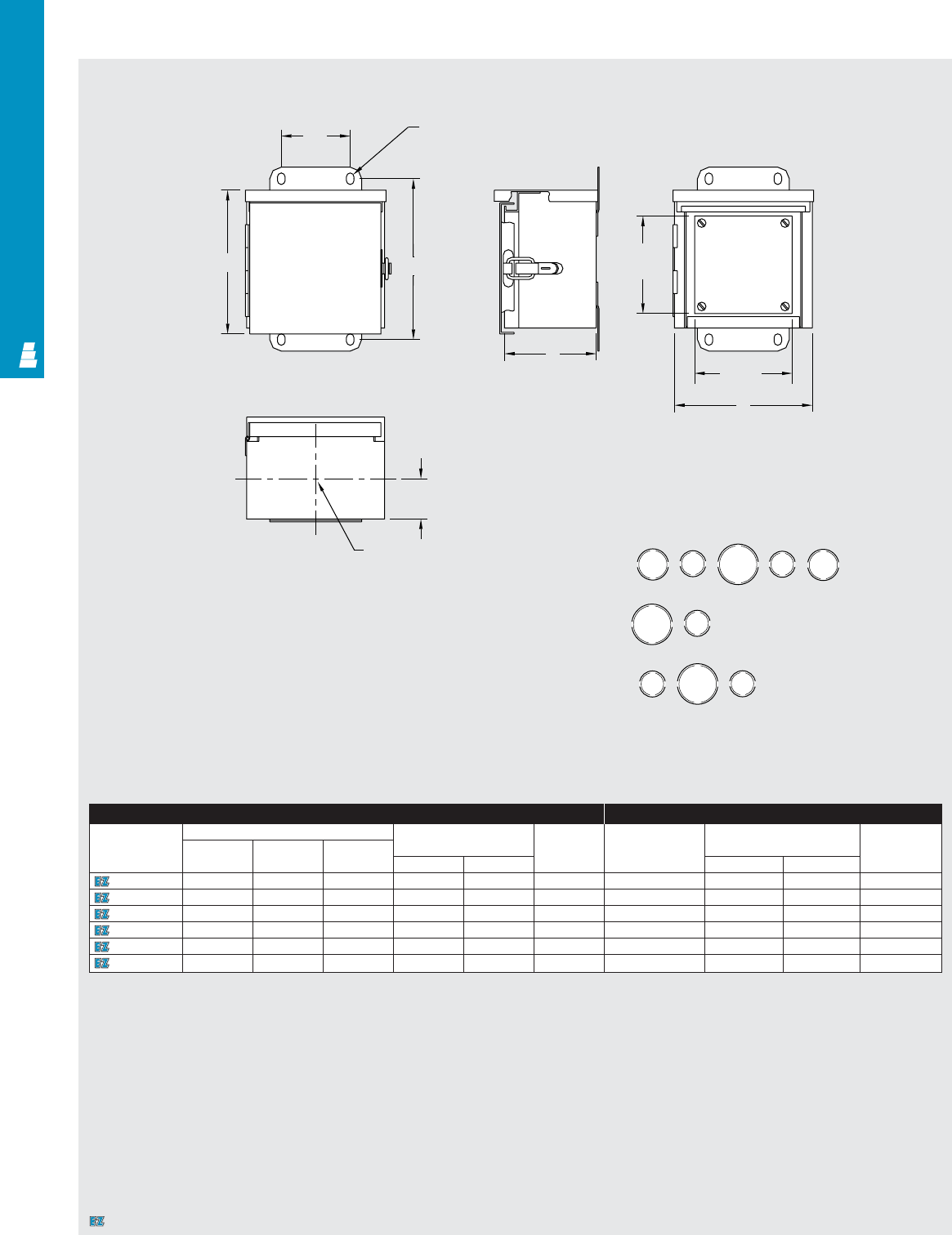
COMMERCIAL PRODUCTS
Technical Specifications
Small Hinge Cover Boxes
W
(3)
.33 X .50
Mounting slots
COM 17
Front View Right or Left
Side View
Front View
Cover Removed
Bottom View
Knockout Pattern
Knockout
(Conduit Size) Knockout Center
To Center Dim.
S: 1.750
T: 1.937
X: 1/2 & 3/4
Y: 3/4 & 1
Z: 1 & 1-1/4
YX
X
XX
Z
Z
Z
XY
AH
C
J
Panel Optional
panel
K
Panel
1.75
Center of knockout pattern
C
L
B
H
N
P
TT
SS
T
T
T
Enclosure Mounting Panel
Part No. Outside dimensions (inches) Mounting centers Knockout Part No. Panel size Usable depth
Height Width Depth pattern
ABCHW J K
E 6R64HCR 6.00 6.00 4.00 7.00 3.00 N E 6N6P 4.25 4.25 3.41
E 8R64HCR 8.00 6.00 4.00 9.00 3.00 N E 8N6P 6.25 4.25 3.41
E 8R86HCR 8.00 8.00 6.00 9.00 3.00 P E 8N8P 6.25 6.25 5.41
E 10R86HCR 10.00 8.00 6.00 11.00 3.00 P E 10N8P 8.25 6.25 5.41
E 12R106HCR 12.00 10.00 6.00 13.00 3.00 P E 12N10P 10.25 8.25 5.41
E 12R126HCR 12.00 12.00 6.00 13.00 3.00 H E 12N12P 10.25 10.25 5.41
Designates a product in the EnclosureZone program.
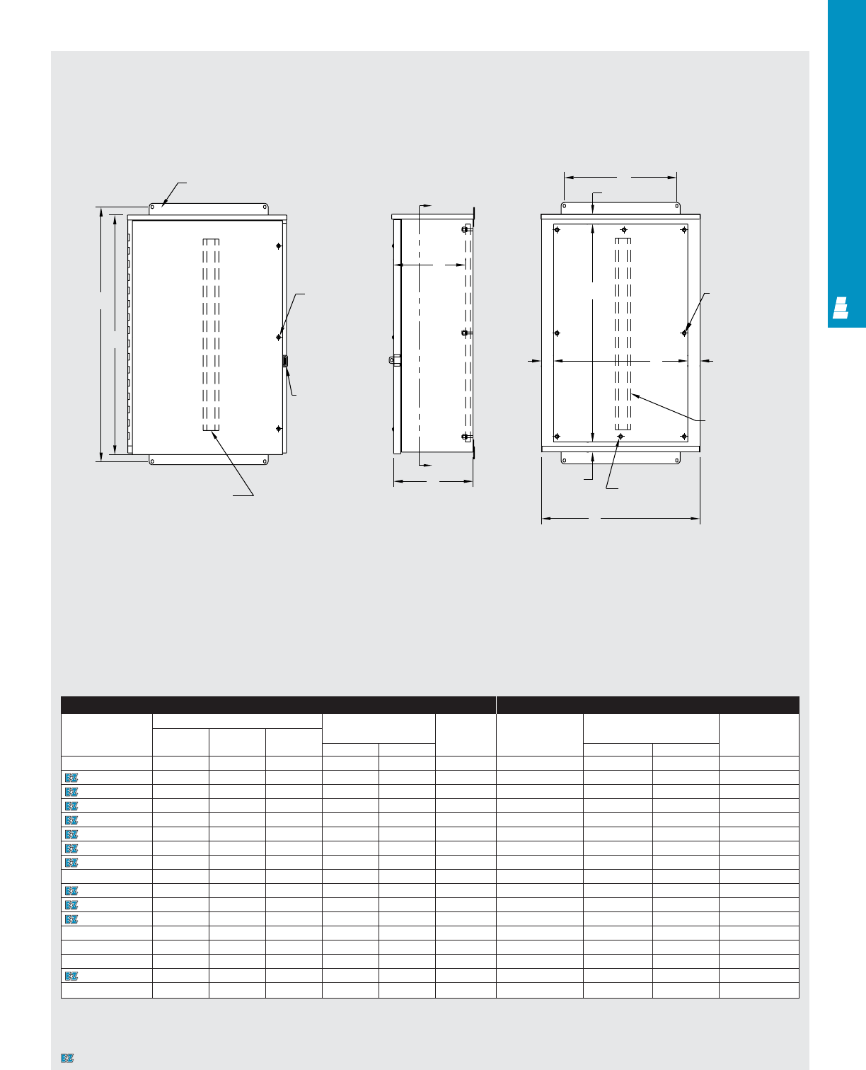
COMMERCIAL PRODUCTS
COM 18
Technical Specifications
Large Hinge Cover Boxes
Front View Right Side View Section Y-Y
Mounting foot
H
A
Omit middle
screw if
A < 36.00
Y
D
Y
W
1.50
B
1.50
Omit center
stud if
A < 36.00
1.50
1.50
Omit stiffener if
A < 36.00 and
B < 30.00
Omit middle
stud if
B > 36.00
C
Padlockable
hasp and staple
Omit door stiffener if
A < 36.00 and B < 30.00
Enclosure Mounting Panel
Part No. Outside dimensions (inches) Mounting centers Door and Part No. Panel size Usable depth
Height Width Depth body stiffener
ABCHW H W D
E 16R126HCR 16.00 12.00 6.00 17.00 5.00 NO E 16P12 13.00 9.00 4.81
E 16R166HCR 16.00 16.00 6.00 17.25 9.00 NO E 16P16 13.00 13.00 4.81
E 20R166HCR 20.00 16.00 6.00 21.25 9.00 NO E 20P16 17.00 13.00 4.81
E 20R208HCR 20.00 20.00 8.00 21.25 13.00 NO E 20P20 17.00 17.00 6.81
E 24R208HCR 24.00 20.00 8.00 25.25 13.00 NO E 24P20 21.00 17.00 6.81
E 24R248HCR 24.00 24.00 8.00 25.25 17.00 NO E 24P24 21.00 21.00 6.81
E 30R248HCR 30.00 24.00 8.00 31.25 17.00 NO E 30P24 27.00 21.00 6.81
E 30R3012HCR 30.00 30.00 12.00 31.25 23.00 NO E 30P30 27.00 27.00 10.81
E 30R3016HCR 30.00 30.00 16.00 31.25 23.00 NO E 30P30 27.00 27.00 14.81
E 36R2412HCR 36.00 24.00 12.00 37.25 17.00 NO E 36P24 33.00 21.00 10.81
E 36R3012HCR 36.00 30.00 12.00 37.25 23.00 YES E 36P30 33.00 27.00 10.81
E 36R3612HCR 36.00 36.00 12.00 37.25 29.00 YES E 36P36 33.00 33.00 10.81
E 36R3616HCR 36.00 36.00 16.00 37.25 29.00 YES E 36P36 33.00 33.00 14.81
E 42R3012HCR 42.00 30.00 12.00 43.25 23.00 YES E 42P30 39.00 27.00 10.81
E 42R3612HCR 42.00 36.00 12.00 43.25 29.00 YES E 42P36 39.00 33.00 10.81
E 48R3612HCR 48.00 36.00 12.00 49.25 29.00 YES E 48P36 45.00 33.00 10.81
E 60R3612HCR 60.00 36.00 12.00 61.25 29.00 YES E 60P36 57.00 33.00 10.81
K
J
Designates a product in the EnclosureZone program.
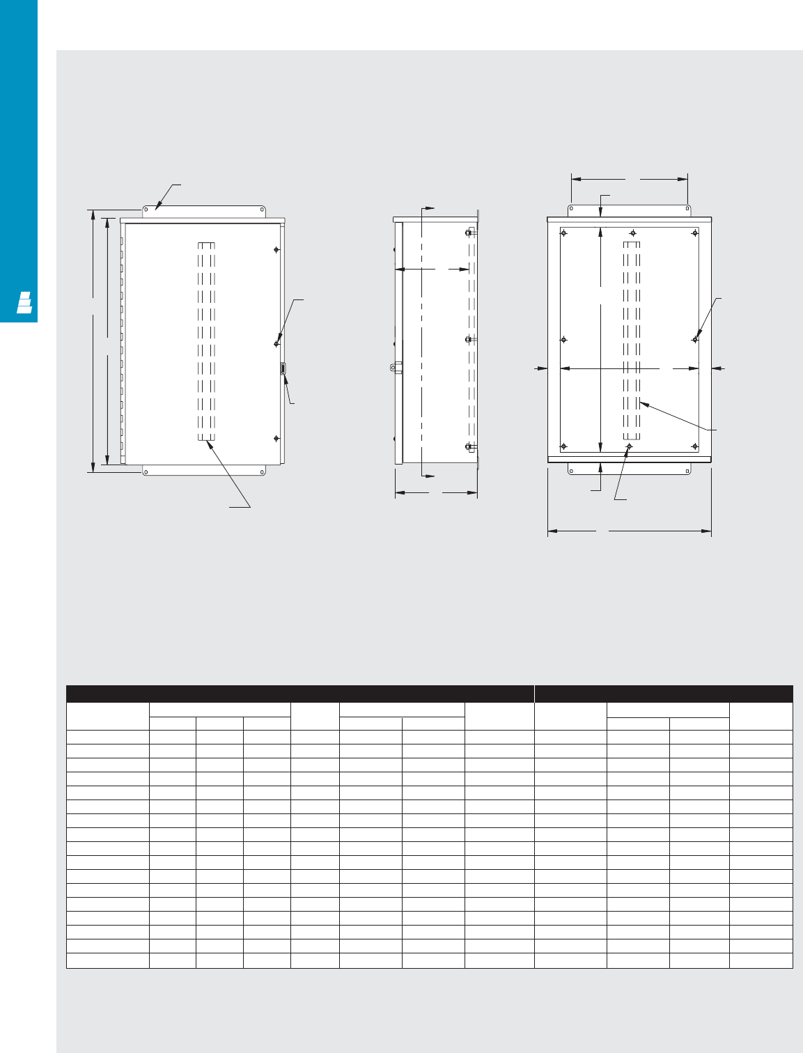
Enclosure Mounting Panel
Part No. Outside dimensions (inches) Material Mounting centers Door and Part No. Panel size Usable depth
HW Dgauge H W body stiffener J K D
E 16R126HCRSS 16.00 12.00 6.00 16 17.00 5.00 NO E 16P12 13.00 9.00 4.81
E 16R166HCRSS 16.00 16.00 6.00 16 17.25 9.00 NO E 16P16 13.00 13.00 4.81
E 20R166HCRSS 20.00 16.00 6.00 16 21.25 9.00 NO E 20P16 17.00 13.00 4.81
E 20R208HCRSS 20.00 20.00 8.00 14 21.25 13.00 NO E 20P20 17.00 17.00 6.81
E 24R208HCRSS 24.00 20.00 8.00 14 25.25 13.00 NO E 24P20 21.00 17.00 6.81
E 24R248HCRSS 24.00 24.00 8.00 14 25.25 17.00 NO E 24P24 21.00 21.00 6.81
E 30R248HCRSS 30.00 24.00 8.00 14 31.25 17.00 NO E 30P24 27.00 21.00 6.81
E 30R3012HCRSS 30.00 30.00 12.00 14 31.25 23.00 NO E 30P30 27.00 27.00 10.81
E 30R3016HCRSS 30.00 30.00 16.00 14 31.25 23.00 NO E 30P30 27.00 27.00 14.81
E 36R2412HCRSS 36.00 24.00 12.00 14 37.25 17.00 NO E 36P24 33.00 21.00 10.81
E 36R3012HCRSS 36.00 30.00 12.00 14 37.25 23.00 YES E 36P30 33.00 27.00 10.81
E 36R3612HCRSS 36.00 36.00 12.00 14 37.25 29.00 YES E 36P36 33.00 33.00 10.81
E 36R3616HCRSS 36.00 36.00 16.00 14 37.25 29.00 YES E 36P36 33.00 33.00 14.81
E 42R3012HCRSS 42.00 30.00 12.00 14 43.25 23.00 YES E 42P30 39.00 27.00 10.81
E 42R3612HCRSS 42.00 36.00 12.00 14 43.25 29.00 YES E 42P36 39.00 33.00 10.81
E 48R3612HCRSS 48.00 36.00 12.00 14 49.25 29.00 YES E 48P36 57.00 33.00 10.81
E 60R3612HCRSS 60.00 36.00 12.00 14 61.25 29.00 YES E 60P36 45.00 33.00 10.81
Technical Specifications
Hinge Cover Enclosures
Front View Side View Section Y-Y
Mounting foot
Y
H
A
D
Y
C
B
1.50
1.50 K1.50
Omit middle
stud if
B > 36.00
Omit stiffener
if A < 36.00
and B > 30.00
Omit center
stud if
A < 36.00
W
1.50
J
Omit middle
screw if
A < 37.00
Padlockable
HASP & staple
Omit door stiffener
if A < 36.00
and B < 30.00
COMMERCIAL PRODUCTS
COM 19
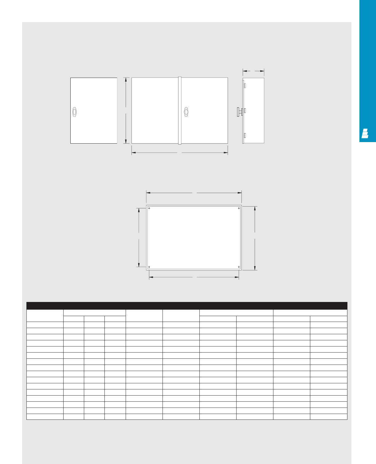
COMMERCIAL PRODUCTS
COM 20
Technical Specifications
Current Transformer Enclosures
Enclosure
Part No. Outside dimensions (inches) Number of Material Mounting centers Overall door size
ABC doors gauge D E F G
E 182410CT 18.00 24.00 10.00 2 14 16.12 21.38 18.40 24.34
E 24167CTL 24.00 16.00 7.00 1 14 22.12 13.38 24.40 16.34
E 242410CT 24.00 24.00 10.00 1 14 22.12 21.38 24.40 24.34
E 243210CT 24.00 32.00 10.00 2 14 22.12 29.38 24.40 32.34
E 244212CT 24.00 42.00 12.00 2 12 22.12 39.38 24.40 42.34
E 302410CT 30.00 24.00 10.00 1 14 28.12 21.38 30.40 24.34
E 303010CT 30.00 30.00 10.00 2 12 28.12 27.38 30.40 30.34
E 303610CT 30.00 36.00 10.00 2 12 28.12 33.38 30.40 36.34
E 32247CTL 32.00 24.00 7.00 1 14 30.12 21.38 32.40 24.34
E 362410CT 36.00 24.00 10.00 1 14 34.12 21.38 36.40 24.34
E 363610CT 36.00 36.00 10.00 2 12 34.12 33.38 36.40 36.34
E 36427CTL 36.00 42.00 7.00 2 12 34.12 39.38 36.40 42.34
E 364810CTL 36.00 48.00 7.00 2 12 34.12 45.38 36.40 48.34
E 443010CT 44.00 30.00 10.00 2 12 42.12 27.38 44.40 30.34
E 484810CT 48.00 48.00 10.00 2 12 46.12 45.38 48.40 48.34
E 484812CT 48.00 48.00 10.00 2 12 46.12 45.38 48.40 48.34
Front View (Two door)
F
G
C
A
B
E
D
Side View
Front View (doors removed)
Front View (One door)
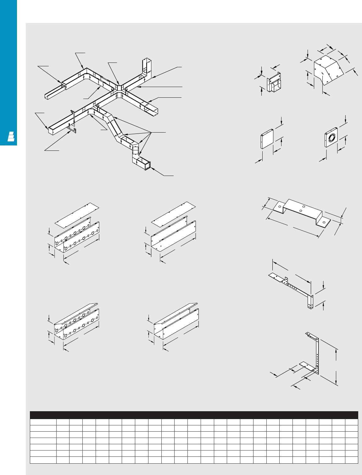
Technical Specifications
Lay-In Type 1 Carbon Steel Wireway
Lay-In Type 1 Carbon Steel
Wireway
Straight Section
Painted With Knockouts Straight Section Painted
Without Knockouts
Hinge Cover Wireway
Straight Section With Knockouts Hinge Cover Wireway
Straight Section Without Knockouts
90° Elbow
EW__LP 90° Elbow
tee-cross
EW__ETXP Inside-outside
90° elbow
EW__IOLP
Section
EW____P
Lay-in adaptor
EW__LAP
45° Elbow
EW__HLP
Panel adaptor
EW__AP
T-fitting
EW__TP
Universal hanger
EW__UHP
End cap
EW__ECP
Telescope
fitting
EW__TSP
Reducing
bushing
EW__RE__P
C
A
B
C
A
B
Wireway
A x B CCCCCCDE FGH J K LMNPQR STUV
2.50 x 2.50 12 24 36 48 60 120 4.50 2.75 2.25 2.25 7.91 4.62 8.50 4.50 3.38 7.25 3.75 3.25 5.50 6.88 11.12 5.50 6.00
4.00 x 4.00 12 24 36 48 60 120 6.00 3.38 2.50 3.00 9.41 6.12 10.50 6.00 4.12 9.25 4.50 4.00 6.25 8.12 12.38 6.19 6.00
6.00 x 6.00 12 24 36 48 60 120 8.00 4.25 3.00 4.00 11.34 8.12 15.00 7.12 5.12 13.75 5.50 5.00 7.25 10.12 14.38 7.19 6.00
8.00 x 8.00 12 24 36 48 60 120 10.00 5.00 3.38 5.00 13.44 10.12 21.00 10.81 7.00 13.75 7.75 6.00 8.25 12.38 16.62 8.31 6.00
10.00 x 10.00
12 24 36 48 60 120 12.00 6.33 4.22 6.00 15.62 12.12 22.00 13.51 8.75 13.75 9.69 7.00 - - 18.50 9.25 -
12.00 x 12.00
12 24 36 48 60 120 14.00 6.25 4.25 7.00 17.44 14.12 23.00 15.56 9.78 13.75 12.50 8.00 - - 20.50 10.25 -
C
A
B
C
A
B
Use As A Drop Hanger
Universal Hanger
Reducing Bushing
Support Hanger
End Cap
Without Knockouts
End Cap
With Knockouts
45° Elbow
1.00”
1.50”
P
N
K (max)
L
M
B
A
B
A
A
B
A
B
F
E
E
COMMERCIAL PRODUCTS
COM 21
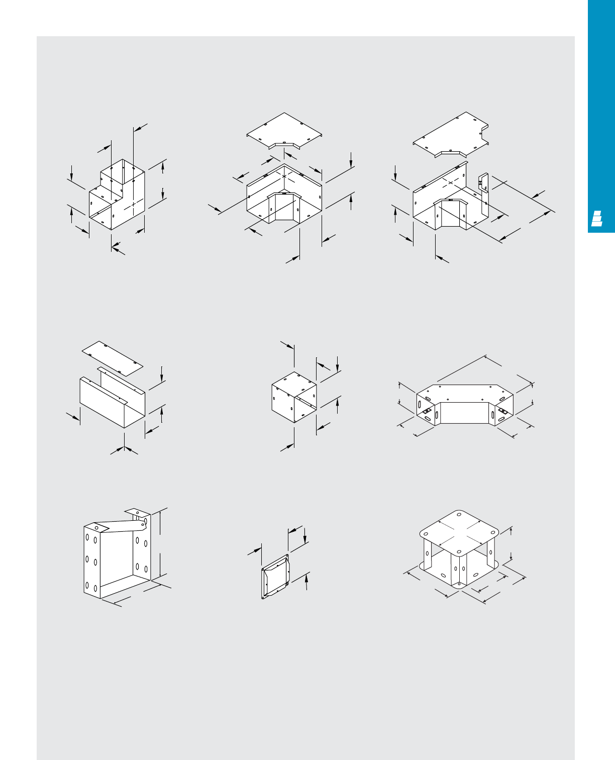
COMMERCIAL PRODUCTS
COM 22
Technical Specifications
Lay-In Type 1 Carbon Steel Wireway
Inside-Outside
90° Elbow 90° Elbow Tee Pull Box
Telescoping Fitting 90° Transposition
Adaptor
U-Connector Panel Adaptor 90° Elbow-Tee-Cross
90° Sweep Elbow
B
A
D
D
12.00 L
K
A
B
V
A
G
DD
B
AA
B
B
H
A
B
T
U
A
B
R
SS
BD
D
Q
A
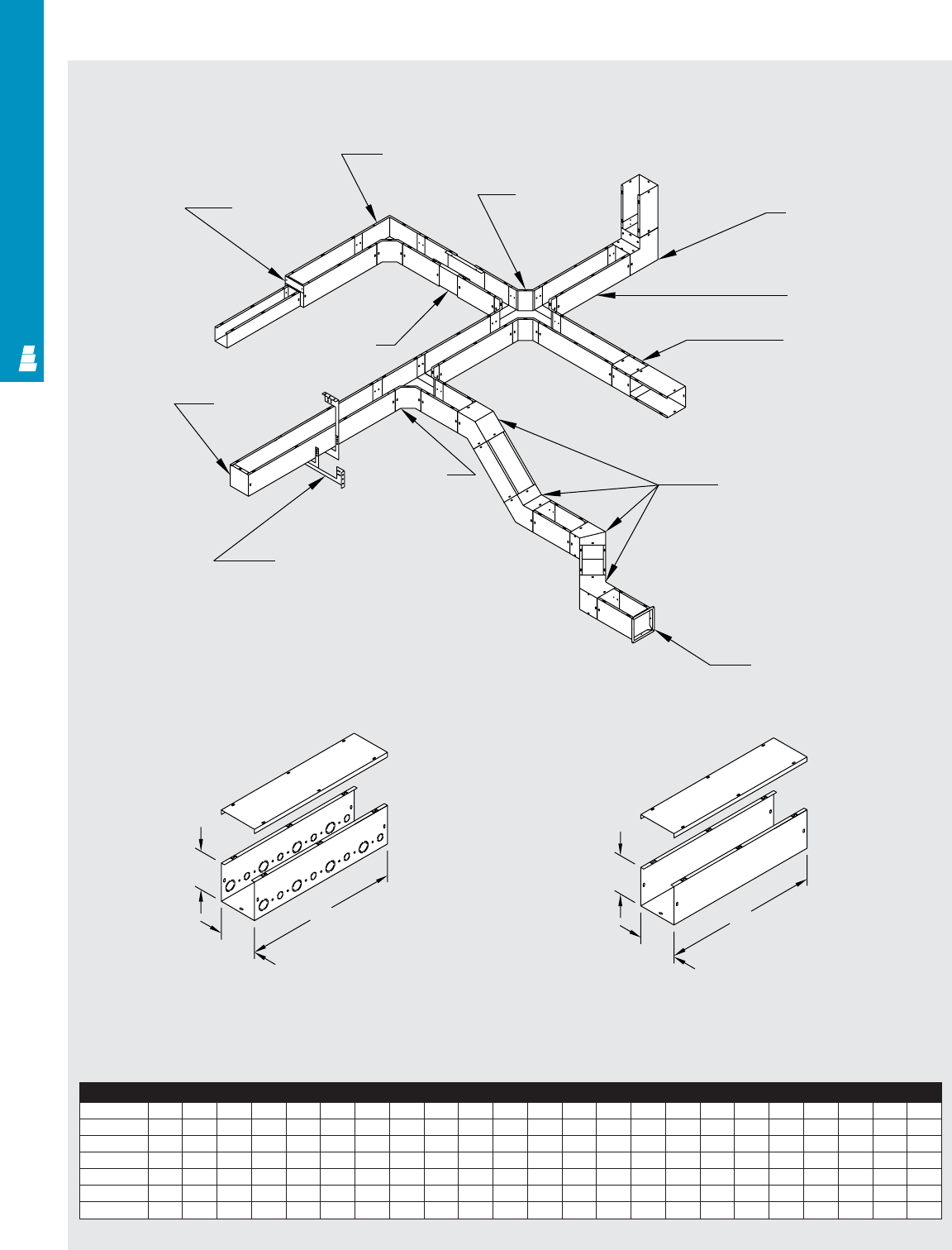
Technical Specifications
Lay-In Type 1 Galvanized Steel Wireway
Lay-In Type 1 Galvanized Steel Wireway
Panel adaptor
EW__A
45° Elbow
EW__HL
T-fitting
EW__T
Universal hanger
EW__UH
Lay-in adaptor
EW__LA
Section
EW____
Inside-outside
90° elbow
EW__IOL
90° Elbow
tee-cross
pull-box
EW__ETX
90° Elbow
EW__L
Reducing
bushing
EW__RE__
Telescope
fitting
EW__TSF
End cap
EW__EC
Wireway
A x B* CCCCCCDEFGHJ KLMNPQRS TUV
2.50 x 2.50 12 24 36 48 60 120 4.50 2.75 2.25 2.25 7.91 4.62 8.50 4.50 3.38 7.25 3.75 3.25 5.50 6.88 11.12 5.50 6.00
4.00 x 4.00 12 24 36 48 60 120 6.00 3.38 2.50 3.00 9.41 6.12 10.50 6.00 4.12 9.25 4.50 4.00 6.25 8.12 12.38 6.19 6.00
6.00 x 6.00 12 24 36 48 60 120 8.00 4.25 3.00 4.00 11.34 8.12 15.00 7.12 5.12 13.75 5.50 5.00 7.25 10.12 14.38 7.19 6.00
8.00 x 8.00 12 24 36 48 60 120 10.00 5.06 3.38 5.00 13.44 10.12 21.00 10.81 7.00 13.75 7.75 6.00 8.25 12.38 16.62 8.31 6.00
10.00 x 10.00
12 24 36 48 60 120 12.00 6.33 4.22 6.00 15.62 12.12 22.00 13.51 8.75 13.75 9.69 7.00 - - 18.50 9.25 -
12.00 x 12.00
12 24 36 48 60 120 14.00 6.75 4.25 7.00 17.44 14.12 23.00 15.56 9.78 13.75 12.50 8.00 - - 20.50 10.25 -
* Inside dimensions
Straight Section Galvanized
With Knockouts Straight Section Galvanized
Without Knockouts
B
C
AA
B
C
COM 23
COMMERCIAL PRODUCTS
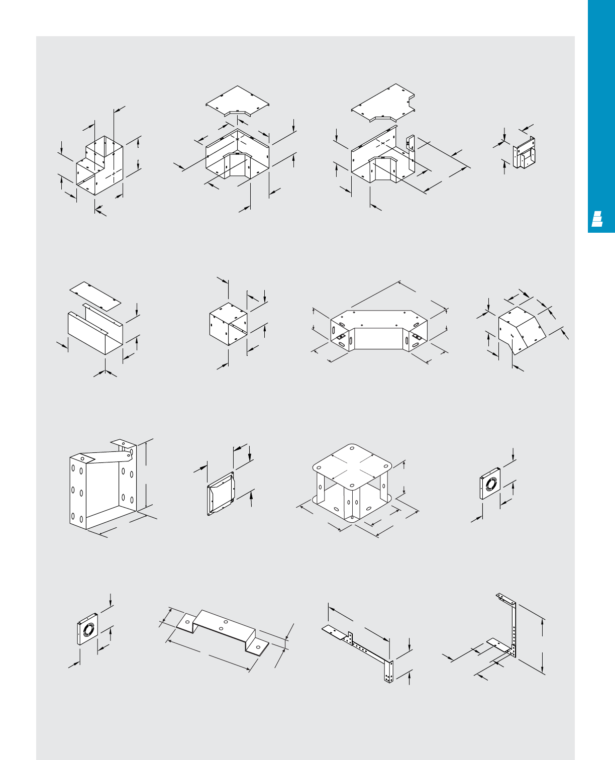
COMMERCIAL PRODUCTS
COM 24
Technical Specifications
Lay-In Type 1 Galvanized Steel Wireway
Inside-Outside
90° Elbow 90° Elbow Tee Pull Box
Telescoping Fitting 90° Transposition Adaptor
U-Connector Panel Adaptor 90° Elbow Tee-Cross
90° Sweep Elbow
Use As A Drop HangerUniversal Hanger
Reducing
Bushing
Support Hanger
End Cap
Without Knockouts
End Cap
With Knockouts
45° Elbow
Q
D
D
B
A
SS
B
A
R
B
A
T
U
A
B
12.00 L
K
A
B
V
B
AA
B
H
AE
E
F
B
B
A
B
G
D
A
D
D
D
B
A
B
AJ
1.50”
1.00”
N
PL
M
K (max)
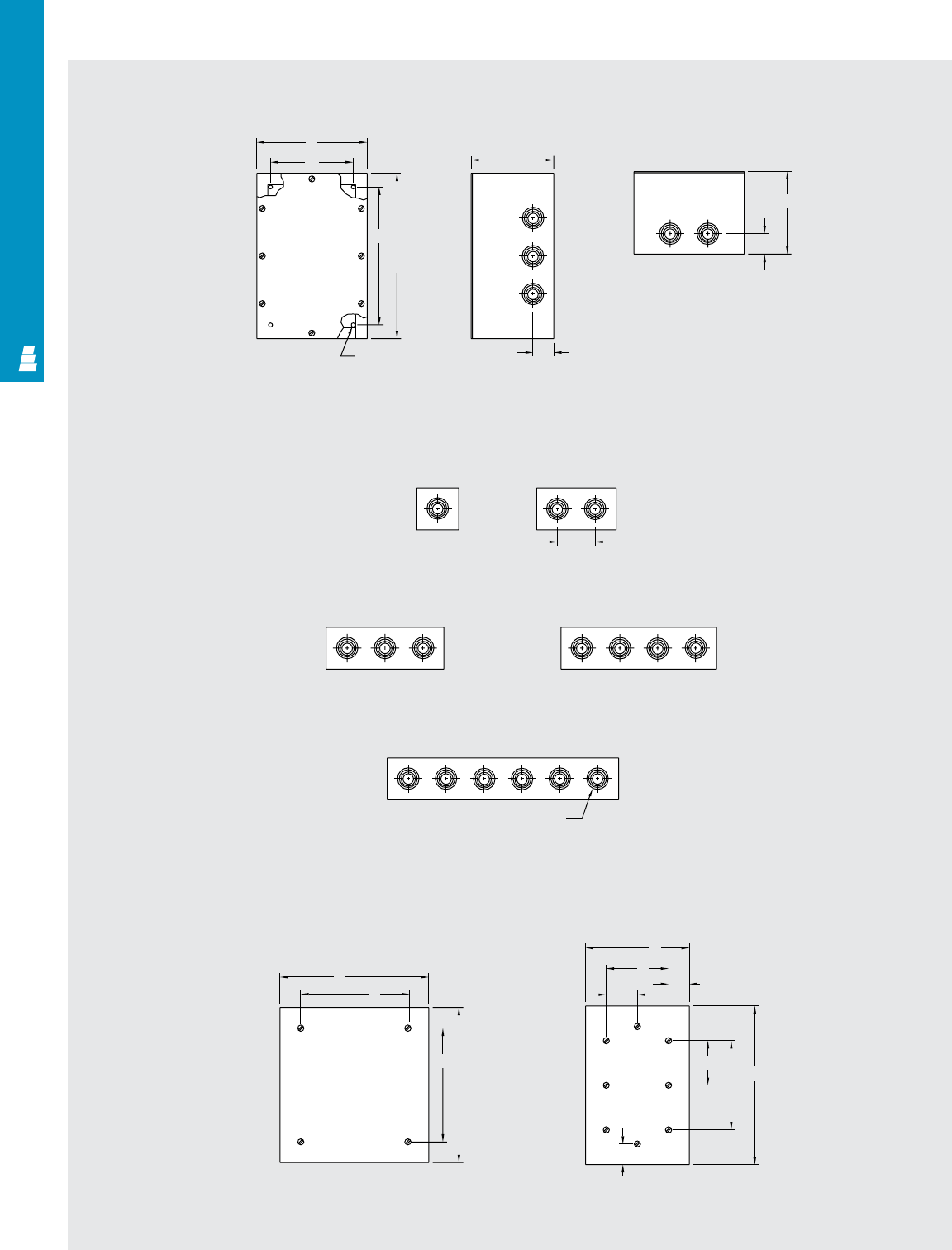
Technical Specifications
Screw Cover Pull Boxes
Front View Side View
Bottom View
1.50
C
1.50
C
Mtg.
hole
H
A
B
W
Screw Cover Pull Box
1/2, 3/4, 1 & 1 1/4 Dia. knockout
(conduit size) typ all knockouts
2.75
TYP.
B
A
E
Flush Covers
B
D
C
A
B
D
D/2 1.38
C/2 A
C
1.38
D
C
COM 25
COMMERCIAL PRODUCTS
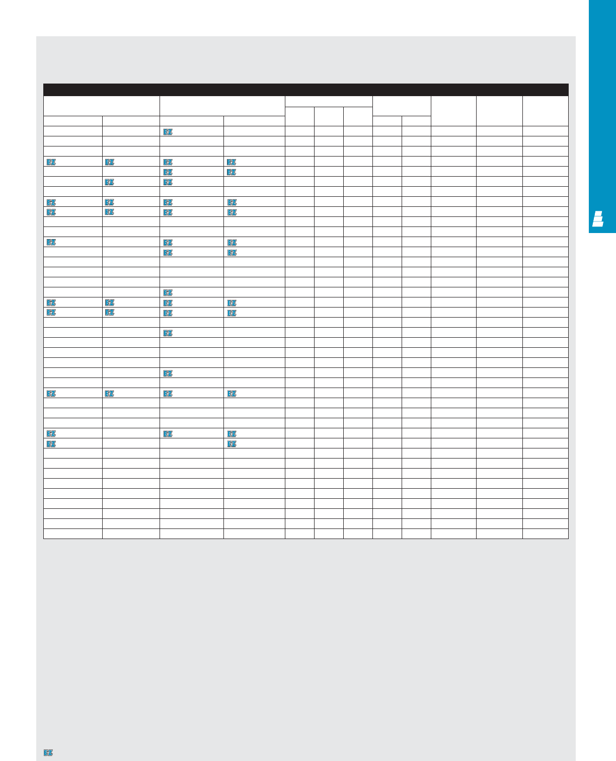
COMMERCIAL PRODUCTS
Enclosure
Part No. Part No. Outside dimensions (inches) Mounting Number Knockout Knockout
Galvanized Painted Height Width Depth centers of cover pattern pattern
Without knockouts With knockouts With knockouts Without knockouts A B C H W screws left/right side top/bottom
E SCB444 E SCB444K E SCB444PK E SCB444P 4.00 4.00 4.00 2.50 2.50 4 A A
E SCB644 E SCB644K E SCB644PK E SCB644P 6.00 4.00 4.00 4.50 2.50 4 A A
E SCB663 E SCB663K E SCB663PK E SCB663P 6.00 6.00 3.00 4.00 4.00 4 A A
E SCB664 E SCB664K E SCB664PK E SCB664P 6.00 6.00 4.00 4.50 4.50 4 B B
E SCB666 E SCB666K E SCB666PK E SCB666P 6.00 6.00 6.00 4.50 4.50 4 B B
E SCB864 E SCB864K E SCB864PK E SCB864P 8.00 6.00 4.00 6.50 4.50 4 B B
E SCB866 E SCB866K E SCB866PK E SCB866P 8.00 6.00 6.00 6.50 4.50 4 B B
E SCB884 E SCB884K E SCB884PK E SCB884P 8.00 8.00 4.00 6.50 6.50 4 B B
E SCB886 E SCB886K E SCB886PK E SCB886P 8.00 8.00 6.00 6.50 6.50 4 B B
E SCB1084 E SCB1084K E SCB1084PK E SCB1084P 10.00 8.00 4.00 8.50 6.50 4 B B
E SCB1086 E SCB1086K E SCB1086PK E SCB1086P 10.00 8.00 6.00 8.50 6.50 4 B B
E SCB10104 E SCB10104K E SCB10104PK E SCB10104P 10.00 10.00 4.00 8.50 8.50 4 C C
E SCB10106 E SCB10106K E SCB10106PK E SCB10106P 10.00 10.00 6.00 8.50 8.50 4 C C
E SCB1264 E SCB1264K E SCB1264PK E SCB1264P 12.00 6.00 4.00 10.50 4.50 4 D B
E SCB1284 E SCB1284K E SCB1284PK E SCB1284P 12.00 8.00 4.00 10.50 6.50 4 D B
E SCB1286 E SCB1286K E SCB1286PK E SCB1286P 12.00 8.00 6.00 10.50 6.50 4 D B
E SCB12104 E SCB12104K E SCB12104PK E SCB12104P 12.00 10.00 4.00 10.50 8.50 4 C C
E SCB12124 E SCB12124K E SCB12124PK E SCB12124P 12.00 12.00 4.00 10.50 10.50 4 C C
E SCB12126 E SCB12126K E SCB12126PK E SCB12126P 12.00 12.00 6.00 10.50 10.50 4 C C
E SCB12128 --E SCB12128P 12.00 12.00 8.00 9.12 9.38 4 - -
E SCB15124 E SCB15124K E SCB15124PK E SCB15124P 15.00 12.00 4.00 13.50 10.50 4 C C
E SCB15126 E SCB15126K E SCB15126PK E SCB15126P 15.00 12.00 6.00 13.50 10.50 4 C C
E SCB15156 E SCB15156K E SCB15156PK E SCB15156P 15.00 15.00 6.00 13.50 13.50 4 C C
E SCB18124 E SCB18124K E SCB18124PK E SCB18124P 18.00 12.00 4.00 16.50 10.50 4 E C
E SCB18126 E SCB18126K E SCB18126PK E SCB18126P 18.00 12.00 6.00 16.50 10.50 4 E C
E SCB18156 E SCB18156K E SCB18156PK E SCB18156P 18.00 15.00 6.00 16.50 13.50 4 E C
E SCB18186 E SCB18186K E SCB18186PK E SCB18186P 18.00 18.00 6.00 16.50 16.50 4 E E
E SCB18188 --E SCB18188P 18.00 18.00 8.00 16.50 16.50 4 - -
E SCB24186 E SCB24186K E SCB24186PK E SCB24186P 24.00 18.00 6.00 22.50 16.50 4 E E
E SCB24188 --E SCB24188P 24.00 18.00 8.00 21.12 15.38 4 - -
E SCB24246 E SCB24246K E SCB24246PK E SCB24246P 24.00 24.00 6.00 22.50 22.50 4 E E
E SCB24248 --E SCB24248P 24.00 24.00 8.00 21.12 21.38 4 - -
E SCB242410 --E SCB242410P 24.00 24.00 10.00 21.12 21.38 4 - -
E SCB30246 E SCB30246K E SCB30246PK E SCB30246P 30.00 24.00 6.00 27.12 21.38 8 E E
E SCB30248 --E SCB30248P 30.00 24.00 8.00 27.12 21.38 8 - -
E SCB30308 --E SCB30308P 30.00 30.00 8.00 27.12 27.38 8 - -
E SCB36248 --E SCB36248P 36.00 24.00 8.00 33.12 21.38 8 - -
E SCB303010 --E SCB303010P 30.00 30.00 10.00 27.12 27.38 8 - -
E SCB362412 --E SCB362412P 36.00 24.00 12.00 33.12 21.38 8 - -
E SCB363610 --E SCB363610P 36.00 36.00 10.00 33.12 33.38 8 - -
E SCB363612 --E SCB363612P 36.00 36.00 12.00 33.12 33.38 8 - -
Technical Specifications
Screw Cover Pull Boxes
Designates a product in the EnclosureZone program.
COM 26
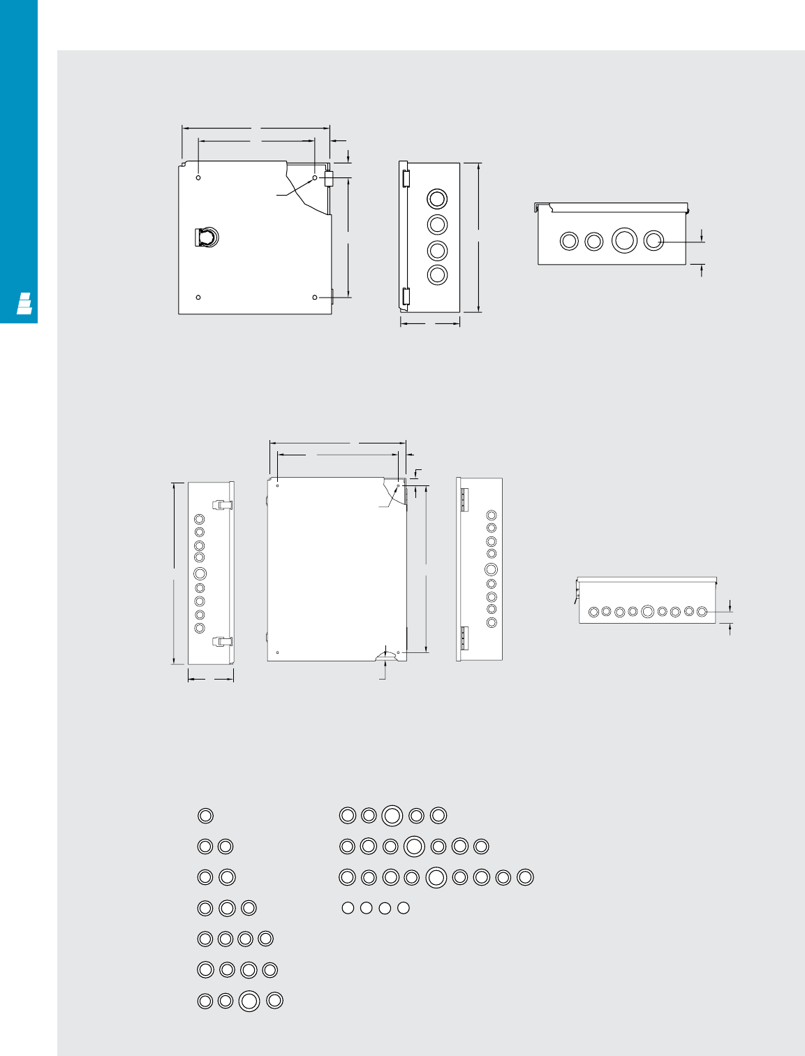
Technical Specifications
Hinge Cover Pull Boxes
Front View Side View
Bottom View
X
X
X
XY
Y
Y
Y
YYYY
Y
Y
Y
Z
Z
Z
Z
X
XX
X
X
X
XXXX
XXX
XX
XXX
WWWW
X
Y
Y
X
Knockout
Center To Center
P: 1.500
R: 1.625
S: 1.750
T: 1.937
U: 2.062
Knockout
(Conduit Size)
W: 1/2
X: 1/2 & 3/4
Y: 3/4 & 1
Z: 1 & 1-1/4
Side View
For 24" High EHCB Boxes Only
A
B
C
D
E
F
G
H
J
K
R
D
C
A
H
1.00
1.00
W
B
.281 Dia.
mounting hole
location typical
( 4 corners )
C
A
Front View
.38
( Flange )
.281 Dia.
mounting hole
location typical
( 4 corners )
B
W1.00
1.00
H
Bottom View
D
Right Side
View
R
S
SS
RRR
SS S
RT U
ST TS
SS
TT
SS
SSSTTSSS
PPP
COMMERCIAL PRODUCTS
COM 27
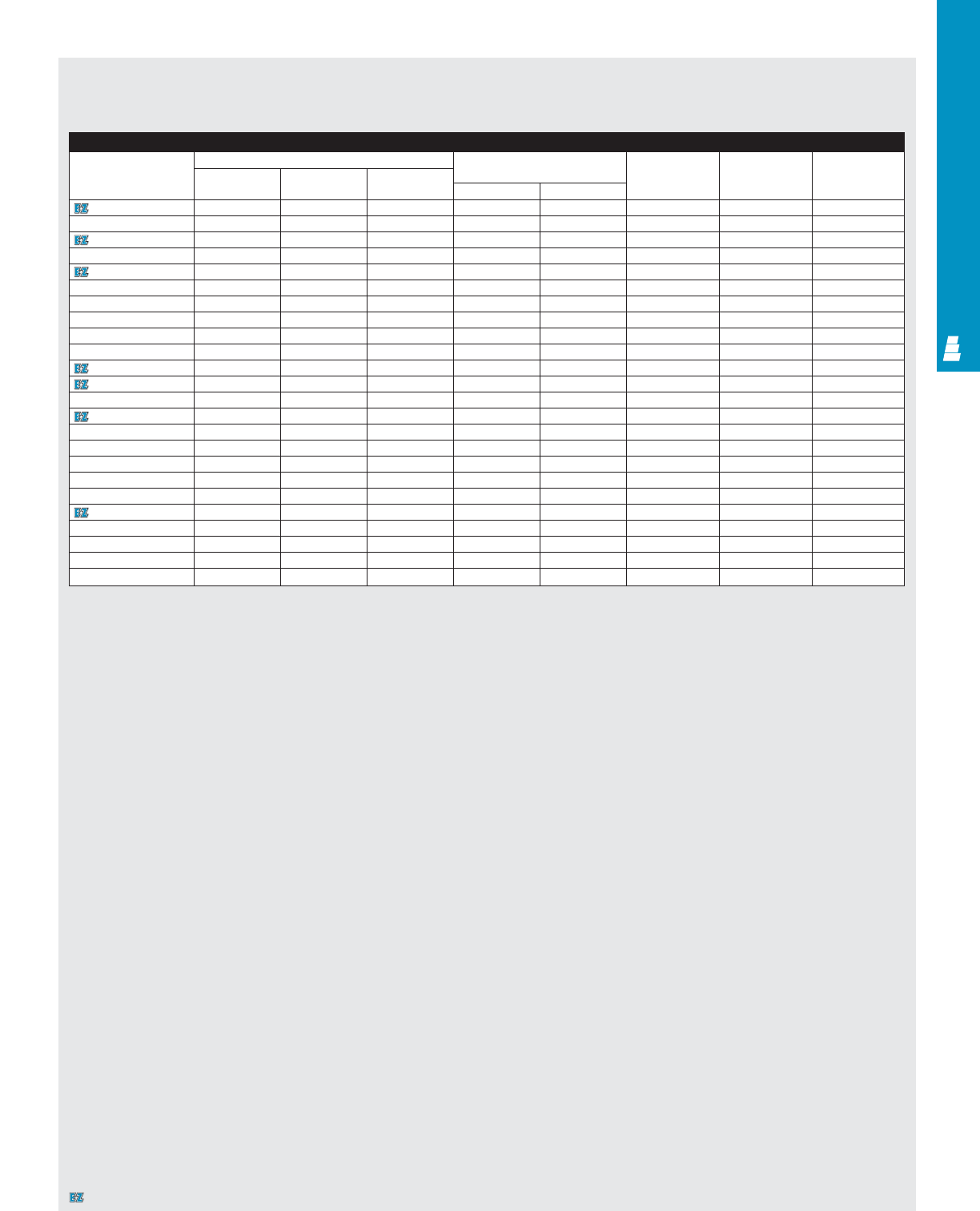
COM 28
COMMERCIAL PRODUCTS
Enclosure
Part No. Outside dimensions (inches) Mounting centers Knockout Knockout Knockout
Height Width Depth pattern pattern pattern location
ABCHWleft/right side top/bottom D
E HCB553PK 4.50 5.00 3.06 2.50 3.00 A C 1.25
E HCB593PK 4.50 9.00 3.06 2.50 7.00 A F 1.25
E HCB664PK 6.00 6.00 4.06 4.00 4.00 C D 1.50
E HCB666PK 6.00 6.00 6.06 4.00 4.00 B D 1.50
E HCB864PK 8.00 6.00 4.06 6.00 4.00 D D 1.50
E HCB884PK 8.00 8.00 4.06 6.00 6.00 D F 1.50
E HCB1082PK 10.00 8.00 2.00 8.00 6.00 R R 1.00
E HCB1084PK 10.00 8.00 4.06 8.00 6.00 F F 1.50
E HCB10104PK 10.00 10.00 4.06 8.00 8.00 F G 1.50
E HCB1264PK 12.00 6.00 4.06 10.00 4.00 H D 1.50
E HCB1284PK 12.00 8.00 4.06 10.00 6.00 H F 1.50
E HCB12104PK 12.00 10.00 4.06 10.00 8.00 H G 1.50
E HCB12106PK 12.00 10.00 6.06 10.00 8.00 H G 1.50
E HCB12124PK 12.00 12.00 4.06 10.00 10.00 H H 1.50
E HCB12126PK 12.00 12.00 6.06 10.00 10.00 H H 1.50
E HCB15124PK 15.00 12.00 4.00 13.00 10.00 J H 1.50
E HCB15126PK 15.00 12.00 6.00 13.00 10.00 J H 1.50
E HCB18124PK 18.00 12.00 4.00 16.00 10.00 J H 1.50
E HCB18126PK 18.00 12.00 6.00 16.00 10.00 K H 1.50
E HCB18154PK 18.00 15.00 4.06 16.00 13.00 K J 1.50
E HCB18156PK 18.00 15.00 6.00 16.00 13.00 K J 1.50
E HCB18186PK 18.00 18.00 6.06 16.00 16.00 K K 1.50
E HCB24186PK 24.00 18.00 6.06 22.00 16.00 K K 1.50
E HCB24246PK 24.00 24.00 6.00 22.00 62.00 K K 1.50
Technical Specifications
Hinge Cover Pull Boxes
Designates a product in the EnclosureZone program.
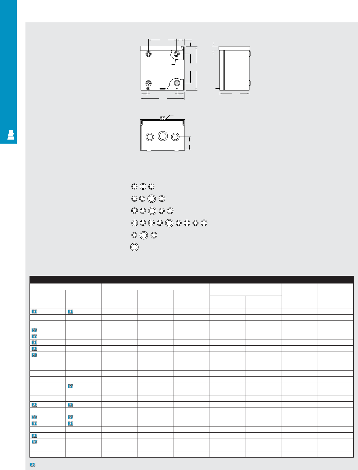
Technical Specifications
Raintight Screw Cover Enclosures 1.06
1.00
1.81
1.00
1.00
XX
XX
X
X
X
X
XX
X
Y
Y
Y
YY
Y
Y
Y
Y
Z
Z
Z
Z
Z
Front View Side View
Bottom View
Knockout
(Conduit Size)
X: 1/2 & 3/4
Y: 3/4 & 1
Z: 1 & 1-1/4
Knockout
Center To Center
R: 1.625
S: 1.750
T: 1.937
U: 2.062
Padlock hasp
B
W
0.56
D
G
S
SSS S SST
TU
T
S
TT
RTU
L
M
H
K
S
S
C
HA
.28 Dia.
mounting hole
location typical
(4 corners)
Enclosure
Part No. Outside dimensions (inches) Mounting centers Knockout Pattern Knockout Pattern
Painted Galvanized Height Width Depth Painted Galvanized
ABCHW
E RTB644P E RTB644 6.00 4.00 4.00 4.00 1.88 M M
E RTB664P E RTB664 6.00 6.00 4.00 4.00 3.88 D D
E RTB666P E RTB666 6.00 6.00 6.00 4.00 3.88 D D
E RTB864P E RTB864 8.00 6.00 4.00 6.00 3.88 D D
E RTB884P E RTB884 8.00 8.00 4.00 6.00 5.88 D L
E RTB886P E RTB886 8.00 8.00 6.00 6.00 5.88 L L
E RTB1084P E RTB1084 10.00 8.00 4.00 8.00 5.88 L L
E RTB10104P E RTB10104 10.00 10.00 4.00 10.00 5.88 G L
E RTB10106P E RTB10106 10.00 10.00 6.00 8.00 7.88 G G
E RTB1264P E RTB1264 12.00 6.00 4.00 8.00 7.88 L G
E RTB1284P E RTB1284 12.00 8.00 4.00 10.00 3.88 L D
E RTB1286P E RTB1286 12.00 8.00 6.00 10.00 7.88 L L
E RTB12124P E RTB12124 12.00 12.00 4.00 10.00 9.88 H H
E RTB12126P E RTB12126 12.00 12.00 6.00 10.00 9.88 H H
E RTB15124P E RTB15124 15.00 12.00 4.00 13.00 9.88 H H
E RTB15126P E RTB15126 15.00 12.00 6.00 13.00 9.88 H H
E RTB18126P E RTB18126 18.00 12.00 6.00 16.00 15.88 H H
E RTB18128P E RTB18128 18.00 12.00 8.00 16.00 9.88 - -
E RTB18186P E RTB18186 18.00 18.00 6.00 16.00 15.88 K K
E RTB18188P E RTB18188 18.00 18.00 8.00 16.00 15.88 - -
E RTB24126P -24.00 12.00 6.00 22.00 9.88 H -
E RTB24186P E RTB24186 24.00 18.00 6.00 22.00 15.88 K K
E RTB24248P E RTB24248 24.00 24.00 8.00 22.00 21.88 - -
E RTB242412P E RTB242412 24.00 24.00 12.00 22.00 21.88 - -
E RTB30248P E RTB30248 30.00 24.00 8.00 28.00 21.88 - -
Designates a product in the EnclosureZone program.
COM 29
COMMERCIAL PRODUCTS
COM 30
COMMERCIAL PRODUCTS
Technical Specifications
Raintight Wiring Trough
.281 Dia. mounting
holes location typical
(4 corners)
Wiring Trough
Part No. Outside dimensions (inches) Mounting centers Number of
Painted Galvanized Height Width Length knockouts in bottom
ABCHW
E RTT4412P E RTT4412 4.00 4.00 12.00 2.00 2.00 3
E RTT4424P E RTT4424 4.00 4.00 24.00 2.00 2.00 6
E RTT4436P E RTT4436 4.00 4.00 36.00 2.00 2.00 9
E RTT4448P E RTT4448 4.00 4.00 48.00 2.00 2.00 12
E RTT4460P E RTT4460 4.00 4.00 60.00 2.00 2.00 15
E RTT6612P E RTT6612 6.00 6.00 12.00 4.00 4.00 3
E RTT6624P E RTT6624 6.00 6.00 24.00 4.00 4.00 6
E RTT6636P E RTT6636 6.00 6.00 36.00 4.00 4.00 9
E RTT6648P E RTT6648 6.00 6.00 48.00 4.00 4.00 12
E RTT6660P E RTT6660 6.00 6.00 60.00 4.00 4.00 15
E RTT6672P E RTT6672 6.00 6.00 72.00 4.00 4.00 18
E RTT8812P E RTT8812 8.00 8.00 12.00 6.00 6.00 -
E RTT8824P E RTT8824 8.00 8.00 24.00 6.00 6.00 -
E RTT8836P E RTT8836 8.00 8.00 36.00 6.00 6.00 -
E RTT8848P E RTT8848 8.00 8.00 48.00 6.00 6.00 -
E RTT8860P E RTT8860 8.00 8.00 60.00 6.00 6.00 -
E RTT8872P E RTT8872 8.00 8.00 72.00 6.00 6.00 -
-E RTT1036 10.00 10.00 36.00 8.00 8.00 -
-E RTT1048 10.00 10.00 48.00 8.00 8.00 -
-E RTT1060 10.00 10.00 60.00 8.00 8.00 -
-E RTT1072 10.00 10.00 72.00 8.00 8.00 -
-E RTT1236 12.00 12.00 36.00 10.00 10.00 -
-E RTT1248 12.00 12.00 48.00 10.00 10.00 -
-E RTT1260 12.00 12.00 60.00 10.00 10.00 -
-E RTT1272 12.00 12.00 72.00 10.00 10.00 -
Front View Side View Bottom View
Mounting holes
centered
ERTT6672P only
1.00
HA
2.12
W
C
B
3/4 and 1 (conduit size)
1 and 1 1/4 (conduit size)
1/2 and 3/4 (conduit size)
2.062 1.937 8.00 2.062 1.937
2.00
Designates a product in the EnclosureZone program.
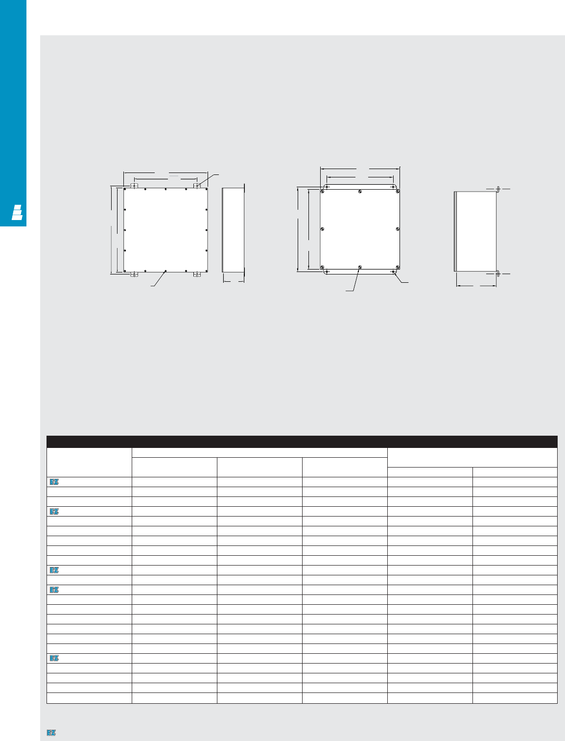
Technical Specifications
Gasketed Screw Cover Boxes
.438 Dia.
(4) places
Cover screw
secured by rivnut
H
C
A
Cover screw
secured by rivnut
.312
Dia.
(4 places)
C
Enclosure
Part No. Outside dimensions (inches) Mounting centers
Height Width Depth
ABCHW
E WTB664 6.00 6.00 4.00 6.75 4.00
E WTB666 6.00 6.00 6.00 6.75 4.00
E WTB864 8.00 6.00 4.00 8.75 4.00
E WTB884 8.00 8.00 4.00 8.75 6.00
E WTB886 8.00 8.00 6.00 8.75 6.00
E WTB1084 10.00 8.00 4.00 10.75 6.00
E WTB10104 10.00 10.00 4.00 10.75 8.00
E WTB10106 10.00 10.00 6.00 10.75 8.00
E WTB12124 12.00 12.00 4.00 12.75 10.00
E WTB12126 12.00 12.00 6.00 12.75 10.00
E WTB12128 12.00 12.00 8.00 12.75 10.00
E WTB16126 16.00 12.00 6.00 16.75 10.00
E WTB16166 16.00 16.00 6.00 16.75 14.00
E WTB18188 18.00 18.00 8.00 18.75 16.00
E WTB20166 20.00 16.00 6.00 20.75 14.00
E WTB20208 20.00 20.00 8.00 20.75 18.00
E WTB24248 24.00 24.00 8.00 25.25 18.00
E WTB242410 24.00 24.00 10.00 25.25 18.00
E WTB242412 24.00 24.00 12.00 25.25 18.00
E WTB30248 30.00 24.00 8.00 31.25 18.00
E WTB362410 36.00 24.00 10.00 37.25 18.00
E WTB363012 36.00 30.00 12.00 37.25 24.00
E WTB363612 36.00 36.00 12.00 37.25 30.00
B
A
W
B
W
H
Designates a product in the EnclosureZone program.
COM 31
COMMERCIAL PRODUCTS

NETWORKING SOLUTIONS
QuickRack ValuePack
Enclosures........................pgs NET 1-2
QuickRack PowerPack
Enclosures........................pgs NET 3-4
BasicRacks ......................pgs NET 5-6
QuickBox Enclosures........pgs NET 7-8
Technical Drawings ........pgs NET 9-11
NETWORKING SOLUTIONS
NETWORKING SOLUTIONS
NETWORKING SOLUTIONS
QuickRack ValuePack
Enclosures........................pgs NET 1-2
QuickRack PowerPack
Enclosures........................pgs NET 3-4
BasicRacks ......................pgs NET 5-6
QuickBox Enclosures........pgs NET 7-8
Technical Drawings ........pgs NET 9-11
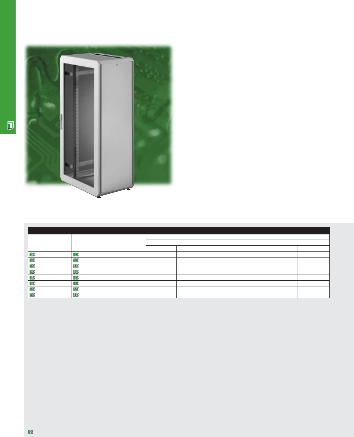
NETWORKING SOLUTIONS
NET 1
QuickRack ValuePack Enclosures
* Note: multiple cabinets can be bayed together using Part No. 7526565. Remember to order one cabinet with sidewalls per row of cabinets and the rest without.
Value-Packed Network Cabinets
Rittal offers a variety of QuickRack cabinets in the most
popular configurations for the networking market. Heights
range from 24 to 47U and include a choice of widths and
depths. These standard cabinets come packed full of
features that make the cabinet an easy to work with
solution for many network applications. For quick
availability, easy transportation and innovative design,
look no further than the QuickRack ValuePack.
ValuePack Enclosure
Part No. QR Part No. QR UDimensions
with without (Approx.) inches mm
sidewalls sidewalls H W D H W D
9967140 7503770 24 48 24 24 1200 600 600
9967139 7503773 24 48 32 32 1200 800 800
9967138 7503778 42 78 24 24 2000 600 600
9967137 7503779 42 78 24 32 2000 600 800
9967135 7503781 42 78 32 32 2000 800 800
9967134 7503782 47 86 24 24 2200 600 600
9967133 7503783 47 86 24 32 2200 600 800
9967131 7503785 47 86 32 32 2200 800 800
Designates a product in the EnclosureZone program.
NET 2
NETWORKING SOLUTIONS
Configuration
•Front safety glass viewing door with
lock insert
•Vented rear steel door with lock insert
•Full height 19" DK rails, front and rear
•Two sets of horizontal rail supports
•Leveling feet
•Available with or without sidewalls
•50 captive nuts
•100 mounting screws
Technical Specifications
Material:
•Enclosure/door: carbon steel
Finish/color:
•Flat parts: E-coat primed, powder painted,
RAL 7035 light grey
•Vertical posts: E-coat primed, powder
painted, RAL 7030 stone grey
Accessories
Part No. QR Part No. QR 19"rackmount shelf* Cable base Cable collecting rails
with sidewalls without sidewalls Across width Across depth
9967140 7503770 7144035 7526300 7526930 7526940
9967139 7503773 7145035 7526320 7526935 7526945
9967138 7503778 7144035 7526300 7526930 7526940
9967137 7503779 7145035 7526310 7526930 7526945
9967135 7503781 7145035 7526320 7526935 7526945
9967134 7503782 7144035 7526300 7526930 7526940
9967133 7503783 7145035 7526310 7526930 7526945
9967131 7503785 7145035 7526320 7526935 7526945
* Fixed shelves that mount to horizontal rail supports also available. Cabinets come standard with DK style rails.
Page . . . . . . . . . . . . . . . . . . . . . . . . . . . . . NET 9
NEMA Type
144X1213
UL CUL CSA TÜV
Listings
Protection Ratings
Certifications/Approvals
Technical Drawings
Designates a product in the EnclosureZone program.
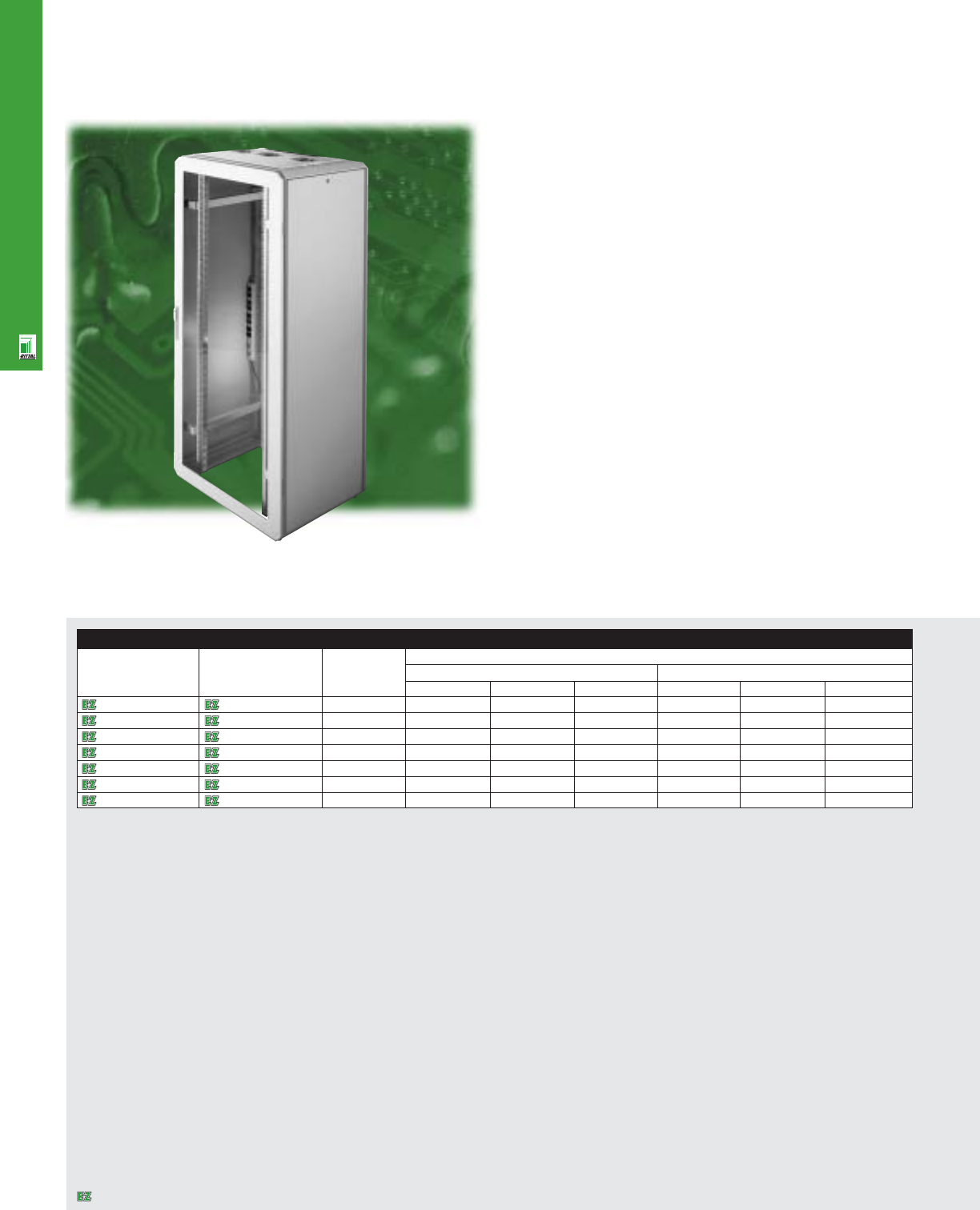
NETWORKING SOLUTIONS
Get The Rittal Power
For a more advanced network cabinet offering, get the
QuickRack PowerPack. The PowerPack offering combines the
value-packed QuickRack cabinet with two exciting features:
an eight outlet power strip and a fan tray for air movement
within the cabinet. Add to that the advantages of the cabinet
itself–cost-efficiency, accessibility and easy transition of
applications–and you’ll get the power from QuickRack.
NET 3
QuickRack PowerPack Enclosures
PowerPack Enclosure
Part No. QR with Part No. QR without UDimensions
sidewalls sidewalls (Approx.) inches mm
H W D H W D
9966977 9966978 24 48 24 24 1200 600 600
9966979 9966980 24 48 32 32 1200 800 800
9966971 9966972 42 78 24 24 2000 600 600
9966973 9966974 42 78 24 32 2000 600 800
9966975 9966976 42 78 32 32 2000 800 800
9966967 9966968 47 86 24 32 2200 600 800
9966969 9966970 47 86 32 32 2200 800 800
Note: multiple cabinets can be bayed together using Part No. 7526965. Remember to order one cabinet with sidewalls per row of cabinets and the rest without.
Designates a product in the EnclosureZone program.
NETWORKING SOLUTIONS
NET 4
Configuration
•Front safety glass viewing door with
lock insert
•Vented rear steel door with lock insert
•Full height 19" DK rails, front and rear
•Two sets of horizontal rail supports
•Roof with fan tray (two fans on 24" W,
three fans on 32" W), 9' cord/plug
•8 outlet, 15 amp power outlet strip
•Leveling feet
•Available with or without sidewalls
•50 captive nuts
•100 mounting screws
Technical Specifications
Material:
•Enclosure/door: carbon steel
Finish/color:
•Flat parts: E-coat primed, powder painted,
RAL 7035 light grey
•Vertical posts: E-coat primed, powder
painted, RAL 7030 stone grey
Accessories
Part No. QR Part No. QR 19" rackmount shelf* Cable base Cable collecting rails
with sidewalls without sidewalls Across width Across width
9966977 9966978 7144035 7526300 7526930 7526940
9966979 9966980 7145035 7526310 7526930 7526945
9966971 9966972 7144035 7526300 7526930 7526940
9966973 9966974 7145035 7526310 7526930 7526945
9966975 9966976 7145035 7526320 7526935 7526945
9966967 9966968 7145035 7526310 7526930 7526945
9966969 9966970 7145035 7526320 7526935 7526945
Page . . . . . . . . . . . . . . . . . . . . . . . . . . . . . NET 10
NEMA Type
144X1213
UL CUL CSA TÜV
Listings
Protection Ratings
Certifications/Approvals
Technical Drawings
* Fixed shelves that mount to horizontal rail supports also available.
Cabinets come standard with DK style rails.
Designates a product in the EnclosureZone program.
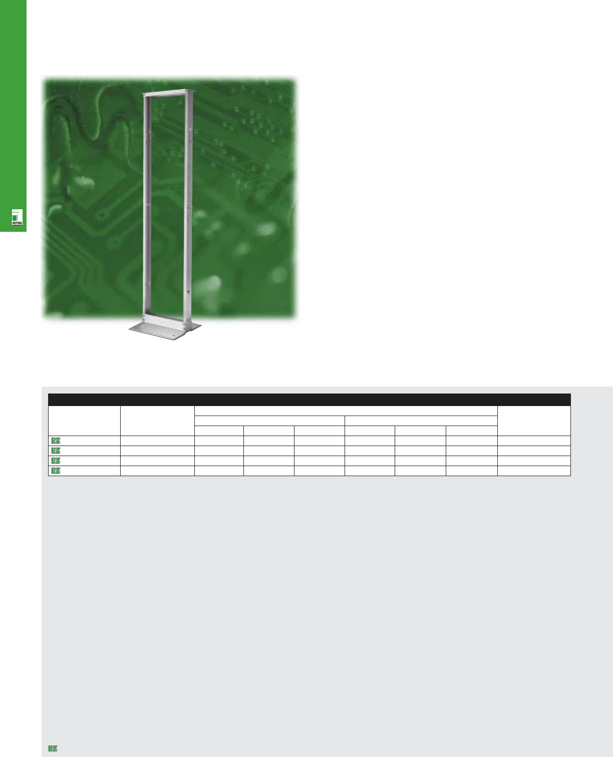
NETWORKING SOLUTIONS
19” Open Rack Solutions
Rittal’s 19" BasicRack is the perfect solution for standard
equipment applications and basic 19" component installations.
This rack is bolted to the floor for greater stability, either
standing alone or interconnected for larger projects. Because
of the simple design of this Rittal rack, users will benefit with
easy access to equipment as well as quick assembly and
installation. If you are looking for a complete, low-cost
but high-quality basic equipment management system,
Rittal’s BasicRack is the ideal solution.
NET 5
BasicRacks
Rack
Part No. U Exact dimensions Color
inches mm
HWD HWD
9967637 24 48 20 15 1200 500 375 Black
9967638 24 48 20 15 1200 500 375 Clear
9967635 45 84 20 15 2122 500 375 Black
9967636 45 84 20 15 2122 500 375 Clear
Designates a product in the EnclosureZone program.
NETWORKING SOLUTIONS
NET 6
Configuration
•Knock down in one package
•All hardware for installation
•2 aluminum extrusions
•5/8" - 5/8" x 1/2" hole pattern
•12-24 tapped screw holes
•Available in clear chemical coat and
black paint
Technical Specifications
Material:
•Aluminum
Finish/color:
•Clear chemical coated grey
•Black paint
Accessories
Part No. Rack storage Double divider Adjustable Divider shelf 3' vertical cable 7' vertical cable Sliding extension 19" keyboard
drawer shelf monitor shelf management management shelf w/mouse pad
9967637 9967641 9967643 9967645 9967639 9967653 - 9967647 9967649
9967638 9967642 9967644 9967646 9967640 9967654 - 9967648 9967650
9967635 9967641 9967643 9967645 9967639 9967653 9967651 9967647 9967649
9967636 9967642 9967644 9967646 9967640 9967654 9967652 9967648 9967650
Page . . . . . . . . . . . . . . . . . . . . . . . . . . . . . NET 11
NEMA Type
144X1213
UL CUL CSA TÜV
Listings
Protection Ratings
Certifications/Approvals
Technical Drawings
Designates a product in the EnclosureZone program.
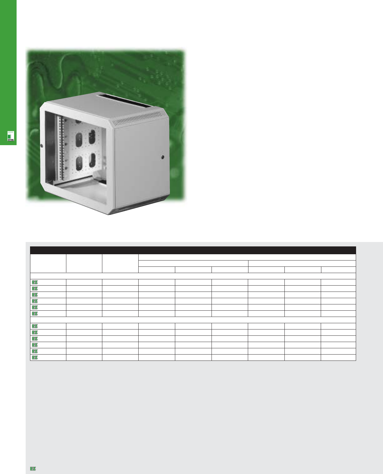
NETWORKING SOLUTIONS
NET 7
QuickBox Enclosures
Versatile Wallmount Solutions
Rittal’s new QuickBox wallmount enclosures combine variety
with flexibility and cost efficiency. With its depth-adjustable
19" mounting surface, the QuickBox is the ideal solution for
packaging network equipment or floor distributors. One
enclosure, 12 models - that means 12 standard products
instead of complicated custom fabrication. Choose from a
large selection of sizes, with or without viewing door, that
offer cost-efficient, customer-oriented solutions for the most
diverse applications.
The QuickBox is available off-the-shelf, completely assembled.
In every respect the QuickBox is the optimum combination of
the proven quality and flexibility of Rittal enclosures.
Enclosure
Part No. USU Exact dimensions
inches mm
H W D H W D
24" Wide x 24" Deep With Viewing Door
7502016 61014.25 23.62 23.62 362 600 600
7502026 91519.49 23.62 23.62 495 600 600
7502036 12 20 24.75 23.62 23.62 628 600 600
7502046 15 26 30.00 23.62 23.62 762 600 600
7502056 18 31 35.24 23.62 23.62 895 600 600
7502066 21 36 40.47 23.62 23.62 1028 600 600
24" Wide x 24" Deep With Solid Door
7502116 61014.25 23.62 23.62 362 600 600
7502126 91519.49 23.62 23.62 495 600 600
7502136 12 20 24.75 23.62 23.62 628 600 600
7502146 15 26 30.00 23.62 23.62 762 600 600
7502156 18 31 35.24 23.62 23.62 895 600 600
7502166 21 36 40.47 23.62 23.62 1028 600 600
Designates a product in the EnclosureZone program.
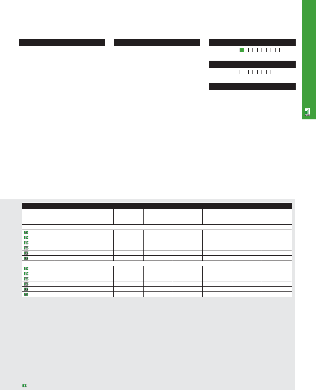
NETWORKING SOLUTIONS
NET 8
Configuration
•Wallmount section with 19" rails and
brush inserts
•Housing cover with base
•Cover with vent slots and brush inserts
•Sheet steel or viewing door options
•Security locks on front door and two sides
•Cable collecting combination rail
•Front 19" rails, infinitely depth
adjustable
Technical Specifications
Material:
•Wallmount section with mounting angles:
14 ga/2.0 mm sheet steel
•Housing cover: 19 ga/1.0 mm sheet steel
•Door: sheet steel or viewing door with sheet
steel frame and security glass insert
Finish/color:
•Powder painted, RAL 7035 light grey
Accessories
Part No. 19" rails Cable collecting Cable collecting 2U shelf Fixed shelf* Telescopic slides* Shelf 20" deep* Telescopic slides
rails (depth) rails (width) 20" deep
24" Wide x 24" Deep With Viewing Door
7502016 7502201 7502302 7502304 7119400 7144035 7061000 7145035 7081000
7502026 7502202 7502302 7502304 7119400 7144035 7061000 7145035 7081000
7502036 7502203 7502302 7502304 7119400 7144035 7061000 7145035 7081000
7502046 7502204 7502302 7502304 7119400 7144035 7061000 7145035 7081000
7502056 7502205 7502302 7502304 7119400 7144035 7061000 7145035 7081000
7502066 7502206 7502302 7502304 7119400 7144035 7061000 7145035 7081000
24" Wide x 24" Deep With Solid Door
7502116 7502201 7502302 7502304 7119400 7144035 7061000 7145035 7081000
7502126 7502202 7502302 7502304 7119400 7144035 7061000 7145035 7081000
7502136 7502203 7502302 7502304 7119400 7144035 7061000 7145035 7081000
7502146 7502204 7502302 7502304 7119400 7144035 7061000 7145035 7081000
7502156 7502205 7502302 7502304 7119400 7144035 7061000 7145035 7081000
7502166 7502206 7502302 7502304 7119400 7144035 7061000 7145035 7081000
Page . . . . . . . . . . . . . . . . . . . . . . . . . . . . . NET 11
NEMA Type
144X12 13
UL CUL CSA TÜV
Listings
Protection Ratings
Certifications/Approvals
Technical Drawings
* Need second set of 19" rails for rear cabinet.
Designates a product in the EnclosureZone program.
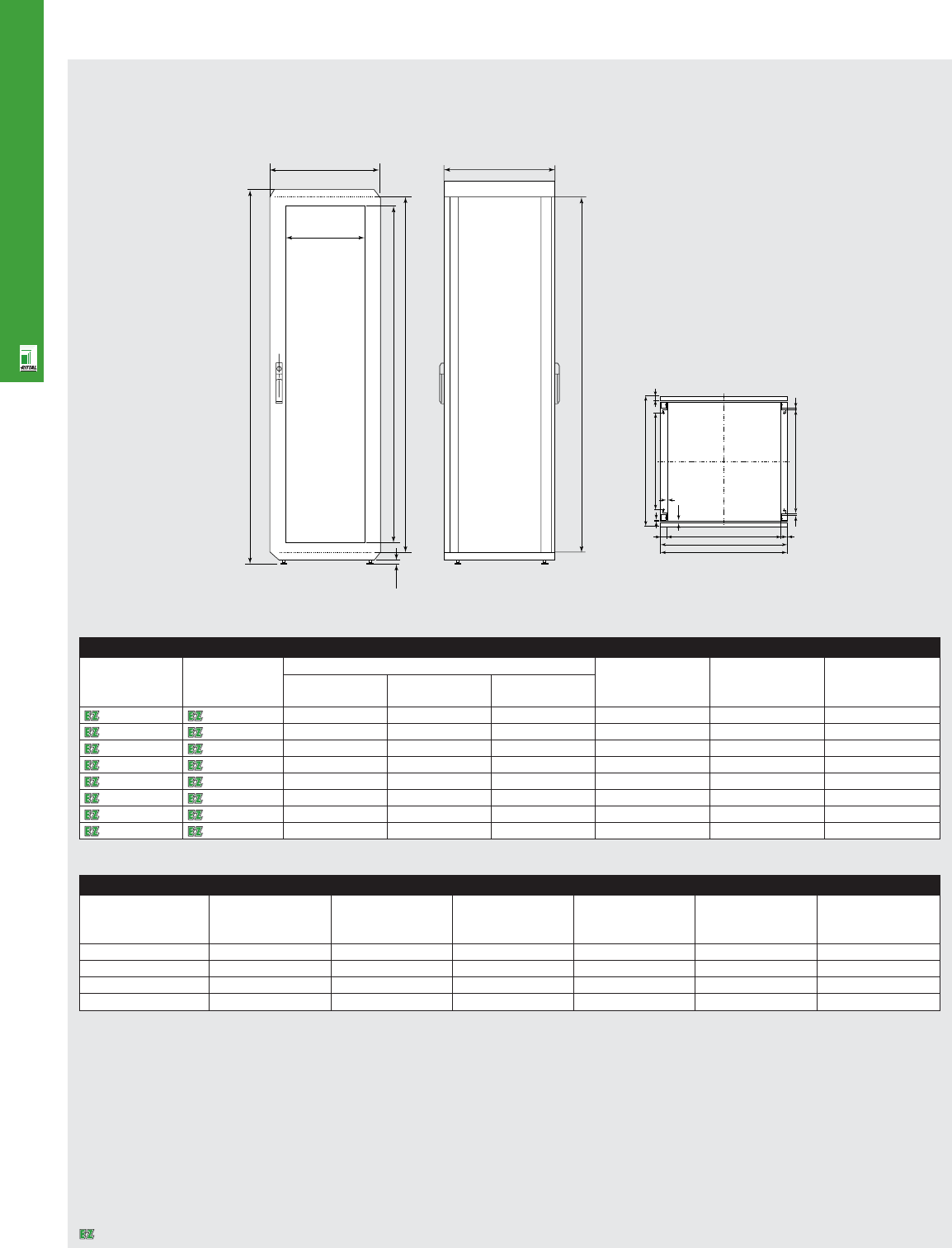
Roof Dimensions
NETWORKING SOLUTIONS
NET 9
Technical Specifications
QuickRack ValuePack Enclosures
B
X
H
Y
C (i.L.)
20.0
T
C
Width x depth Outside Width without Width inside frame Outside Inside frame Inside frame
width inches sidewalls inches uprights inches depth inches posts inches roll form inches
BB1B2 T T1T2
23.62" x 23.62" 23.62 23.46 21.50 18.90 17.22 17.72
23.62" x 31.50" 23.62 23.46 21.50 31.50 26.80 25.60
31.50" x 23.62" 31.50 31.30 29.40 23.62 18.90 17.72
31.50" x 31.50" 31.50 31.30 29.40 31.50 26.80 25.60
2
10
T2
T
25
20
21
T1
2
4
B2
B1
B
10
Enclosure
Part No. QR Part No. QR Cabinet dimensions Inside cabinet Width Height
with without Height mm Width mm Depth mm dimension mm of glass door mm of glass door mm
sidewalls sidewalls HBT C X Y
9967140 7503770 1200 600 600 1100 425 1000
9967139 7503773 1200 800 800 1100 625 1000
9967138 7503778 2000 600 600 1900 425 1800
9967137 7503779 2000 600 800 1900 425 1800
9967135 7503781 2000 800 800 1900 625 1800
9967134 7503782 2200 600 600 2100 425 2000
9967133 7503783 2200 600 800 2100 425 2000
9967131 7503785 2200 800 800 2100 625 2000
Designates a product in the EnclosureZone program.
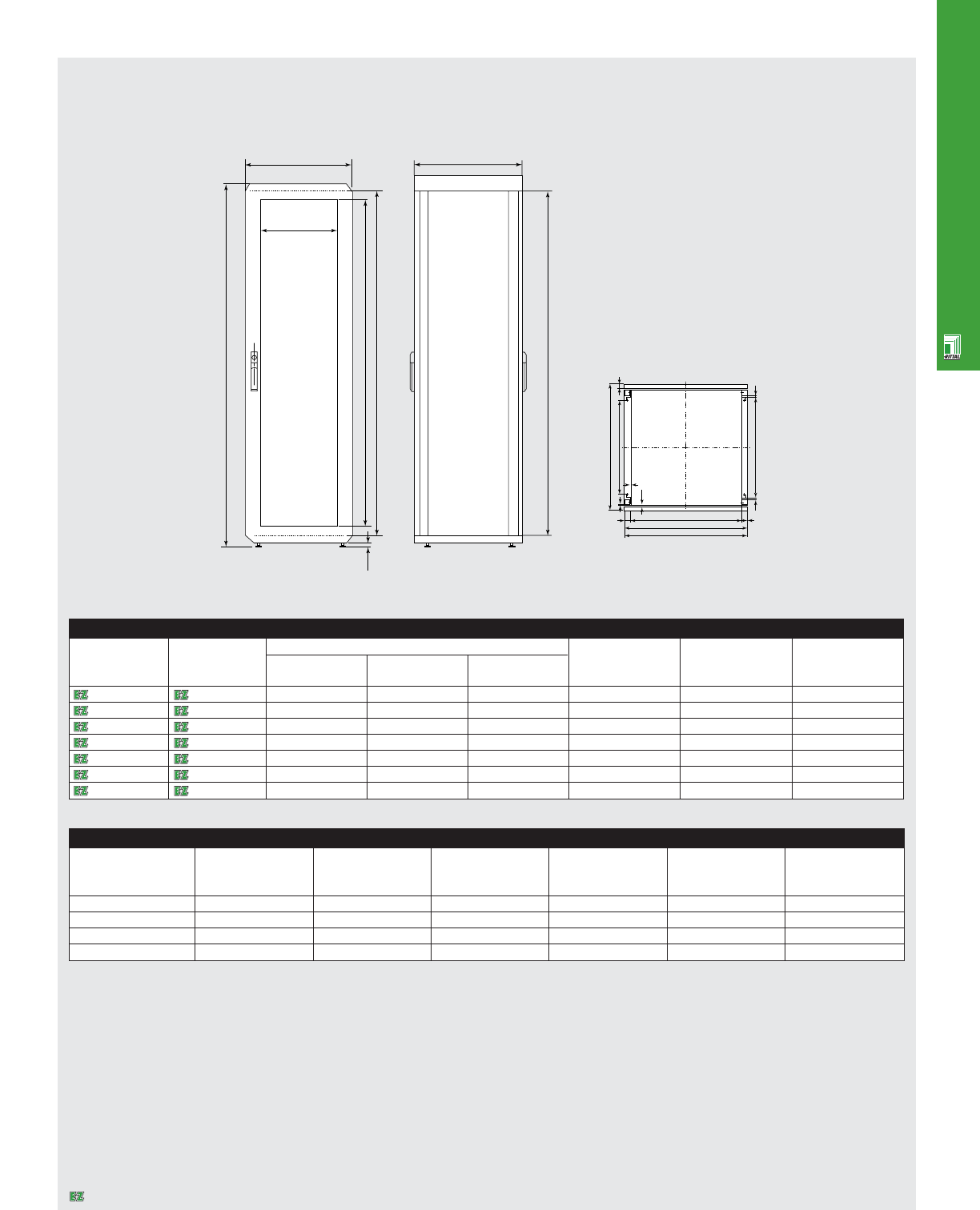
NETWORKING SOLUTIONS
NET 10
Technical Specifications
QuickRack PowerPack Enclosures
B
X
H
Y
C (i.L.)
20.0
T
C
2
10
T2
T
25
20
21
T1
2
4
B2
B1
B
10
Roof Dimensions
Enclosure
Width x depth Outside Width without Width inside frame Outside Inside frame Inside frame
width inches sidewalls inches uprights inches depth inches posts inches roll form inches
BB1B2 TT1 T2
23.62" x 23.62" 23.62 23.46 21.50 18.90 17.22 17.72
23.62" x 31.50" 23.62 23.46 21.50 31.50 26.80 25.60
31.50" x 23.62" 31.50 31.30 29.40 23.62 18.90 17.72
31.50" x 31.50" 31.50 31.30 29.40 31.50 26.80 25.60
Part No. QR Part No. QR Cabinet dimensions Inside cabinet Width Height
with without Height mm Width mm Depth mm dimension mm of glass door mm of glass door mm
sidewalls sidewalls HBT C X Y
9966977 9966978 1200 600 600 1100 425 1000
9966979 9966980 1200 800 800 1100 625 1000
9966971 9966972 2000 600 600 1900 425 1800
9966973 9966974 2000 600 800 1900 425 1800
9966975 9966976 2000 800 800 1900 625 1800
9966967 9966968 2200 600 800 2100 425 2000
9966969 9966970 2200 800 800 2100 625 2000
Designates a product in the EnclosureZone program.
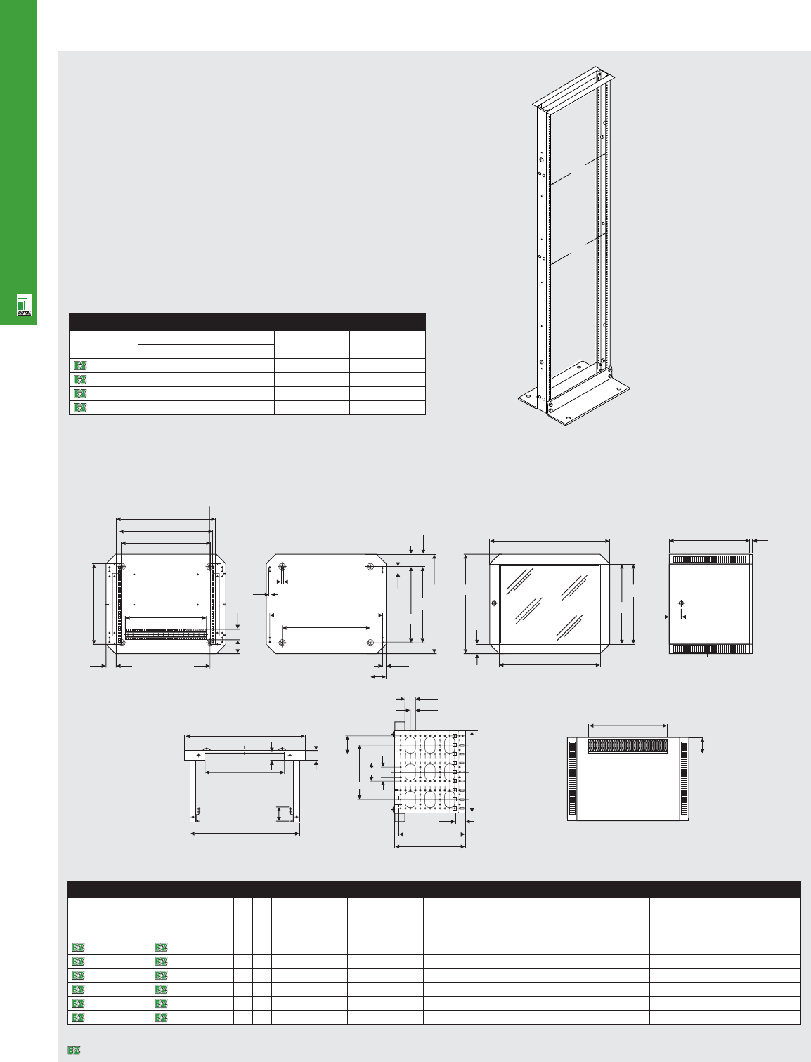
NETWORKING SOLUTIONS
NET 11
Technical Specifications
BasicRacks
Rack
Flange
edge to
flange
edge
Mounting
hole
to
mounting
hole
a
b
Part No. Dimensions (inches) a b
HW D
9967637 48 20 15 17.75 18.31
9967638 48 20 15 17.75 18.31
9967635 84 20 15 17.75 18.31
9967636 84 20 15 17.75 18.31
QuickBox Enclosures
Enclosure
465
485
450
400
HE
53 A
72.5
50 562
HE
16.5
435
80
h2
h1
h-7
18
60.3
56.5
18
9H
44.5
h3
I.L.h4
500
600 300/400/600 14
60
4X30
USU Height Width Depth h1 h2 h3 h4
7502016 7502116
610 14.25"/362 mm 23.62"/600 mm 23.62"/600 mm 9.53"/242 mm 9.21"/234 mm 10.51"/267 mm 10.75"/273 mm
7502026 7502126
915 19.49"/495 mm 23.62"/600 mm 23.62"/600 mm 14.76"/375 mm 14.45"/367 mm 15.75"/400 mm 15.98"/406 mm
7502036 7502136
12 20 24.75"/628 mm 23.62"/600 mm 23.62"/600 mm 20.00"/508 mm 19.72"/501 mm 21.02"/534 mm 21.26"/540 mm
7502046 7502146
15 26 30.00"/762 mm 23.62"/600 mm 23.62"/600 mm 25.28"/642 mm 24.96"/634 mm 26.26"/667 mm 26.50"/673 mm
7502056 7502156
18 31 35.24"/895 mm 23.62"/600 mm 23.62"/600 mm 30.51"/775 mm 30.20"/767 mm 31.50"/800 mm 31.73"/806 mm
7502066 7502166
21 36 40.47"/1028 mm 23.62"/600 mm 23.62"/600 mm 35.75"/908 mm 35.47"/901 mm 36.77"/934 mm 37.00"/940 mm
Part No. QB
with solid
door
Part No. QB
with viewing
door
391
595
40 50
540
70
50
25
80
50
58.9
266.7
230/330/530
250/350/550
50
h3
80
391
Designates a product in the EnclosureZone program.

OUTSIDE PLANT PRODUCTS
Basic Aluminum Outdoor
Enclosures ...................... pgs OSP 1-2
Technical Drawings .............. pg OSP 3
OUTSIDE PLANT PRODUCTS
OUTSIDE PLANT PRODUCTS
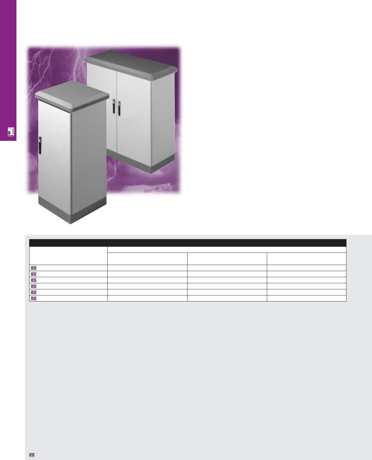
OUTSIDE PLANT PRODUCTS
OSP 1
Basic Aluminum Outdoor Enclosures
Single-Wall Modular Cabinets
CS Outdoor Basic enclosures combine the properties of a
compact housing design along with the modular enclosure
concept. These single-wall aluminum unibody housings are
especially suitable for use in traffic control, utilities distribution
and environmental technology.
Enclosure
Part No. Outside dimensions (mm)
HWD
9783040 800 600 400
9783010 800 800 400
9784010 800 1200 400
9783050 1200 600 400
9783020 1200 800 400
9784020 1200 1200 400
Designates a product in the EnclosureZone program.
OSP 2
OUTSIDE PLANT PRODUCTS
Configuration
•Enclosure closed on all sides
•3-point locking system through the
Ergoform-S handle
•Cabling via cable entry plates
•NEMA 3R protection
•4"/100 mm high plinth
•Rain hood
Technical Specifications
Material:
•Enclosure/door: Aluminum AIMg3: 5/64"/
2.0 mm
•Rain hood: Aluminum AIMg3: 5/64"/2.0 mm
•Plinth: Aluminum AIMg3: 7.64"/3.0 mm
Finish/color:
•Enclosure/door: powder painted, RAL 7035
light grey
•Rain hood: powder painted, RAL 5018 teal
green
•Plinth: powder painted, RAL 5018 teal
green
Accessories
Part No. Mounting panel One-piece 19" mounting angles Ergoform-S handle
gland plates Spray-finish, Zinc plated,
RAL 7035 passivated
9783040 9765090 9785017 9785001 9785002 9785030
9783010 9765097 9785018 9785001 9785002 9785030
9784010 2 x 9765090 2 x 9785017 9785001 9785002 9785030
9783050 9765092 9785017 9785003 9785004 9785030
9783020 9765095 9785018 9785003 9785004 9785030
9784020 2 x 9765092 2 x 9785017 9785003 9785004 9785030
Page . . . . . . . . . . . . . . . . . . . . . . . . . . . . . OSP 3
NEMA Type
3R 4 4X 12 13
UL CUL CSA TÜV
Listings
Protection Ratings
Certifications/Approvals
Technical Drawings
Designates a product in the EnclosureZone program.
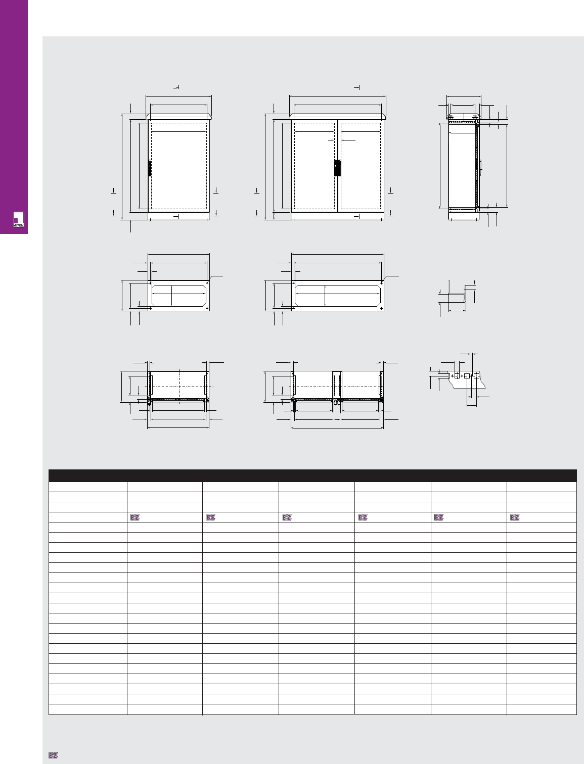
OUTSIDE PLANT PRODUCTS
11.8
44.3
20.5
Ø 18
B7
T7
62.5
37.5 T5
T1
B1
32.5 B5
50
62.5
37.5 T5
T1
Ø 18
B1
50
32.5 B5
B7
T7
OSP 3
Technical Specifications
Basic Aluminum Outdoor Enclosures
Enclosure
Height in mm 800 800 800 1200 1200 1200
Width in mm 600 800 1200 600 800 1200
Depth in mm 400 400 400 400 400 400
Part No. 9783040 9783010 9784010 9783050 9783020 9784020
Door(s) 1 1 2 1 1 2
B1 600 800 1200 600 800 1200
B2 511.4 711.4 511.4 511.4 711.4 511.4
B3 475 675 475 475 675 475
B4 540 740 1140 540 740 1140
B5 535 735 1135 535 735 1135
B6 650 850 1250 650 850 1250
B7 500 700 1100 500 700 1100
H1 800 800 800 1200 1200 1200
H2 711.4 711.4 711.4 1111.4 1111.4 1111.4
H3 675 675 675 1075 1075 1075
H4 975 975 975 1375 1395 1375
T1 400 400 400 400 400 400
T2 314.5 314.5 314.5 314.5 314.5 314.5
T3 250 250 250 250 250 250
T4 450 450 450 450 450 450
T5 325 325 325 325 325 325
T6 375 375 375 375 375 375
T7 275 275 275 275 275 275
H3
i. L. H2
T4
31 55.5
T2
44.3
30
62.5
62.5
44.3
T6
A
B
C
B6
B4
i. L. B2
H4
i. L. H2
75
100 H1
B
C
A
D
F
A
B6
B4
H4
i. L. H2
100 75
H1
F
D
A
88.6
i. L. B2 i. L. B2
Section A-A
Section B-B Section F-F Cross-section
Section C-C Section D-D Hole pattern
25
12.5
12.5
4.5
10.5
11.8
32.5
32.5
30
44.3 44.3
B2
30
B3
B1
T3
63.5
63.5
25
25
T1
32.5
32.5
44.3
30 30
B3 B3
B1
T3
T1
88.6
44.3
B2 B2
Designates a product in the EnclosureZone program.

CLIMATE CONTROL
SOLUTIONS
1S Filter Fans/Pagoda
Roof Fans ..........................pgs CLI 1-2
Air Conditioners..................pgs CLI 3-4
Micro/Mini
Air Conditioners..................pgs CLI 5-6
Air/Air
Heat Exchangers................pgs CLI 7-8
Enclosure Heaters ..................pg CLI 9
Air/Water
Heat Exchangers ..................pg CLI 10
Chillers ..........................pgs CLI 11-12
Vortex Kooler
Enclosure Coolers..........pgs CLI 13-14
Technical Drawings ........pgs CLI 15-30
CLIMATE CONTROL SOLUTIONS
CLIMATE CONTROL SOLUTIONS
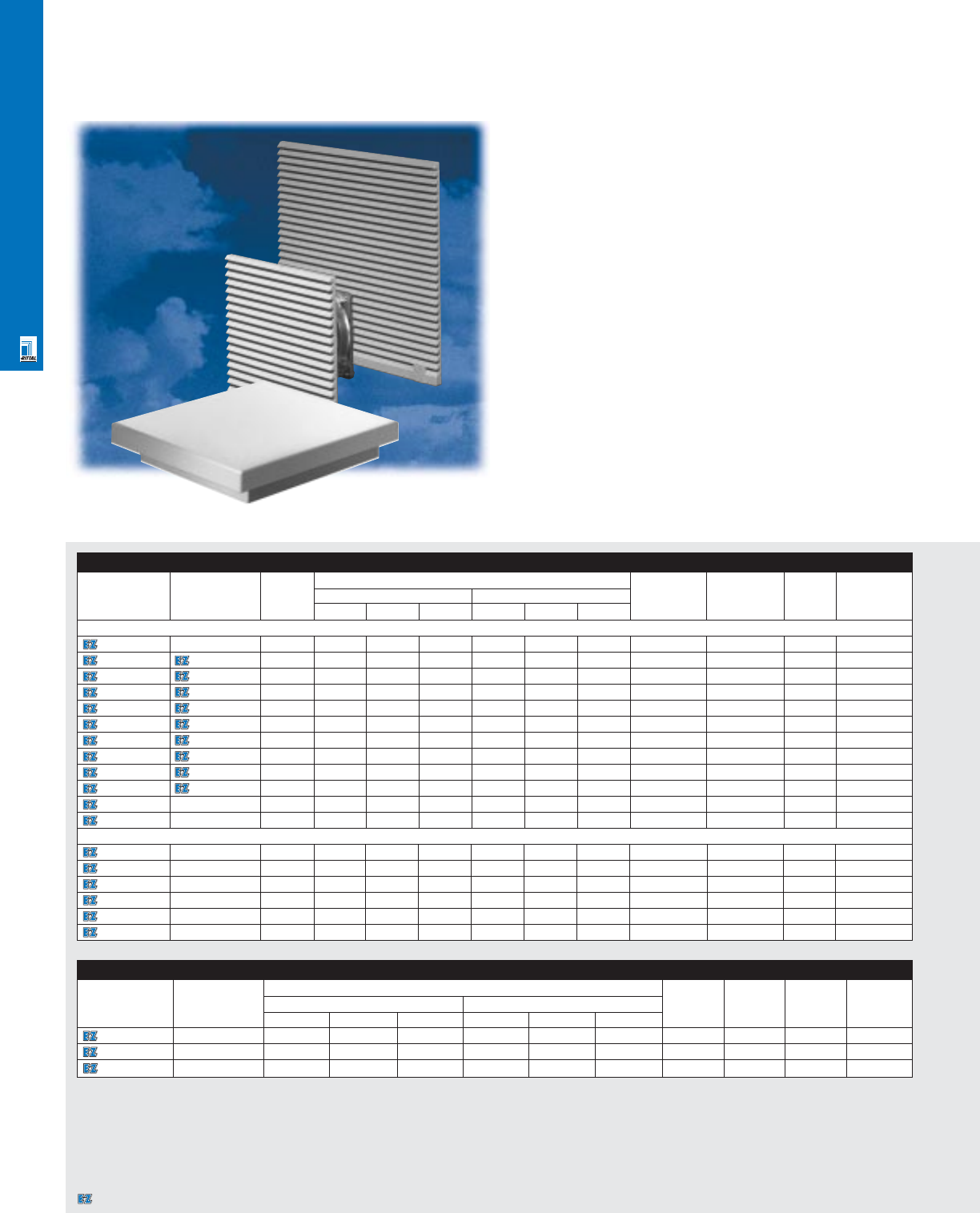
CLIMATE CONTROL SOLUTIONS
CLI 1
1S Filter Fans And Pagoda Roof Fans
1S Filter Fans and Pagoda Roof Fans
Rittal filter fans provide an off-the-shelf, easy to install,
economical, and effective method for providing enclosure
cooling when the allowable enclosure internal temperature is
higher than the ambient temperature. Available in a variety of
sizes and voltages, filter fans include dense polyester filters,
aerodynamically designed polymer plenums, long life fans,
terminal blocks for easy wiring, and attractive aesthetics.
Filter fans carry UL/CSA recognition and CE marking for the
entire assembly. NEMA 12/IP 54 protection offered via special
sealing gasket and fine filter. Unlike many competitive products,
Rittal filter fans’ cfm rating are derated to account for filter’s and
louver’s flow resistance.
Individual Fans
Part No. Rating Exact outside dimensions Voltage Current Noise Temperature
cfm1inches mm dBa range
HWD
2HWD
2
7980110 100 10.0 10.0 3.5 254.0 254.0 89.0 115/60 0.5 A 50 -4-140°F
9964163 500 4.6 4.6 1.0 119.0 119.0 25.0 115/50/60 0.1 A 49 -4-158°F
9965364 100 - - - - - - 115/50/60 - - -
1Unimplemented airflow (includes filter and louver) 2Denotes depth filter fan extends into enclosure.
Filter Fans/Pagoda Roof Fans
Part No. Part No. Rating Exact outside dimensions Voltage Current Noise Temperature
RAL 7032 RAL 7035 cfm1inches mm dBa range
pebble grey light grey HWD
2HWD
2
1S Filter Fans
3321100 -154.6 4.6 1.7 117.0 117.0 42.0 230/50/60 69/58 mA 41/46 14-131°F
3321115 3321117 15 4.6 4.6 1.7 117.0 117.0 42.0 115/50/60 138/115 mA 41/46 14-131°F
3322115 3322117 40 5.9 5.9 2.2 149.0 149.0 57.0 115/50/60 0.11/0.12 A 46/49 14-131°F
3322100 3322107 40 5.9 5.9 2.2 149.0 149.0 57.0 230/50/60 0.24/0.23 A 46/49 14-131°F
3323115 3323117 70 8.0 8.0 3.3 204.0 204.0 82.5 115/50/60 0.24/0.23 A 46/49 14-131°F
3323100 3323107 70 8.0 8.0 3.3 204.0 204.0 82.5 230/50/60 0.11/0.12 A 46/49 14-131°F
3325115 3325117 155 10.0 10.0 4.1 255.0 255.0 105.0 115/50/60 0.53/0.49 A 54/56 14-131°F
3325100 3325107 155 10.0 10.0 4.1 255.0 255.0 105.0 230/50/60 0.28/0.24 A 54/56 14-131°F
3326115 3326117 330 12.7 12.7 5.1 323.0 323.0 129.0 115/50/60 0.58/0.70 A 59/61 14-131°F
3326100 3326107 330 12.7 12.7 5.1 323.0 323.0 129.0 230/50/60 0.29/0.35 A 59/61 14-131°F
3327100 -425 12.7 12.7 5.7 323.0 323.0 145.0 230/50/60 0.65/0.95 A 75/76 14-131°F
3327115 -425 12.7 12.7 5.7 323.0 323.0 145.0 115/50/60 1.5/2.0 A 75/76 14-131°F
Pagoda Roof Fans
9966814 -360 20.8 17.6 2.2 529.0 446.0 55.0 115/50/60 0.72 A 59 14-140°F
9966815 -360 20.8 17.6 2.2 529.0 446.0 55.0 230/50/60 0.36 A 59 14-140°F
9966892 -Roof only 20.8 17.6 2.2 529.0 446.0 55.0 - - - -
3149000 -210 16.5 13.4 1.7 420.0 340.0 44.0 230/50/60 0.20 53 14-140°F
3169000 -210 16.5 13.4 1.7 420.0 340.0 44.0 115/50/60 0.55 59 14-140°F
3148000 -Roof only 16.5 13.4 0.6 420.0 340.0 15.0 - - - -
Designates a product in the EnclosureZone program.
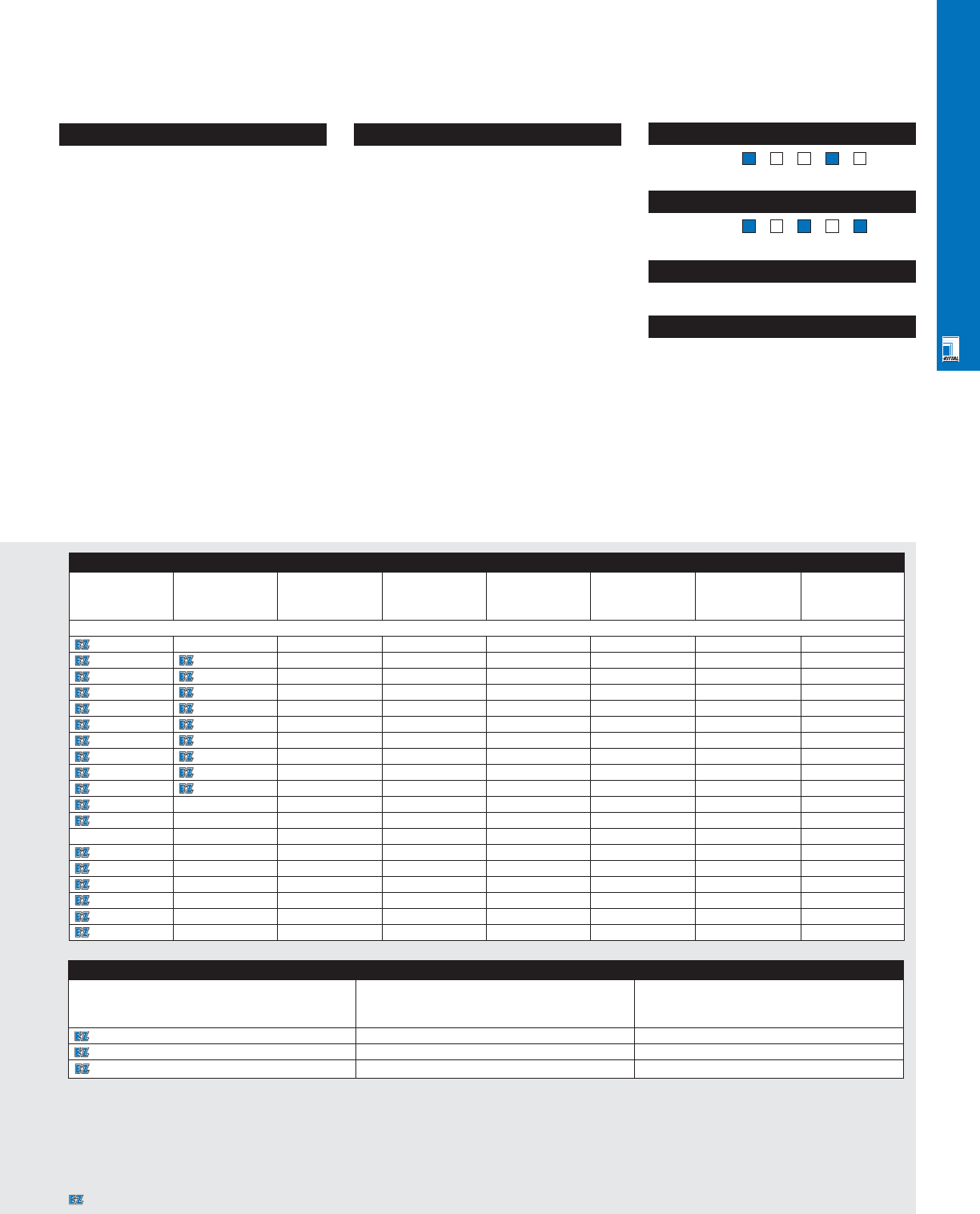
CLIMATE CONTROL SOLUTIONS
CLI 2
Configuration
•UL/CSA recognition, CE compliance
•Low profile design
•Quick installation
•Long life ball bearing fan motors
•NEMA 12/IP 54 with optional sealing gasket
and fine filter
•Off-the-shelf availability
•Terminal block connection
•Blow air into enclosure (except pagoda
roof fans)
Technical Specifications
Material:
•Polymer plenum/louver
•Metal fan housing
Finish/color:
•RAL 7032 pebble grey (.100/.115)
•RAL 7035 light grey (.107/.117)
Pages . . . . . . . . . . . . . . . . . . . . . . . . . . .CLI 15-17
NEMA Type 144X1213
UL CUL CSA TÜV CE
Listings
Protection Ratings
Certifications/Approvals
Technical Drawings
Accessories
Part No. Exhaust filter/louver Thermostat
7980110 3322200/3322207 3110000
9964163 3326200 3110000
9965364 --
Accessories
Part No. Part No. Exhaust Standard Fine filter Gasket Rain cover 10' power
RAL 7032 RAL 7035 filter/louver replacement (Type 304 cord/plug
pebble grey light grey filter stainless steel)
1S Filter Fans
3321100 -3321200 3321700 - - 3321800 -
3321115 3321117 3321200 3321700 - - 3321800 -
3322115 3322117 3322200/3322207 3322700 - 3322900 3322800 9962136
3322100 3322107 3322200/3322207 3322700 - 3322900 3322800 9965837
3323115 3323117 3323200/3323207 3171100 3181100 3191100 3323800 9962136
3323100 3323107 3323200/3323207 3171100 3181100 3191100 3323800 9965837
3325115 3325117 3325200/3325207 3172100 3182100 3192100 3324800 9962136
3325100 3325107 3325200/3325207 3172100 3182100 3192100 3324800 9965837
3326115 3326117 3326200/3326207 3173100 3183100 3193100 3326800 9962136
3326100 3326107 3326200/3326207 3173100 3183100 3193100 3326800 9965837
3327100 -3326200 3327700 3183100 3193100 3326800 9965837
3327115 -3326200 3327700 3183100 3193100 3326800 9962136
Pagoda Roof Fans Exhaust filter/louver Thermostat Fine filter Gasket Rain cover 10' power cord/plug
9966814 -3326200 311000 - - - -
9966815 -3326200 311000 - - - -
9966892 -3326200 - - - - -
3149000 -3326200 3110000 - - - -
3169000 -3326200 3110000 - - - -
3148000 -3326200 - - - - -
Pages . . . . . . . . . . . . . . . . . . . . . . . . . . TEC 17-30
CLI Technical Information
Designates a product in the EnclosureZone program.
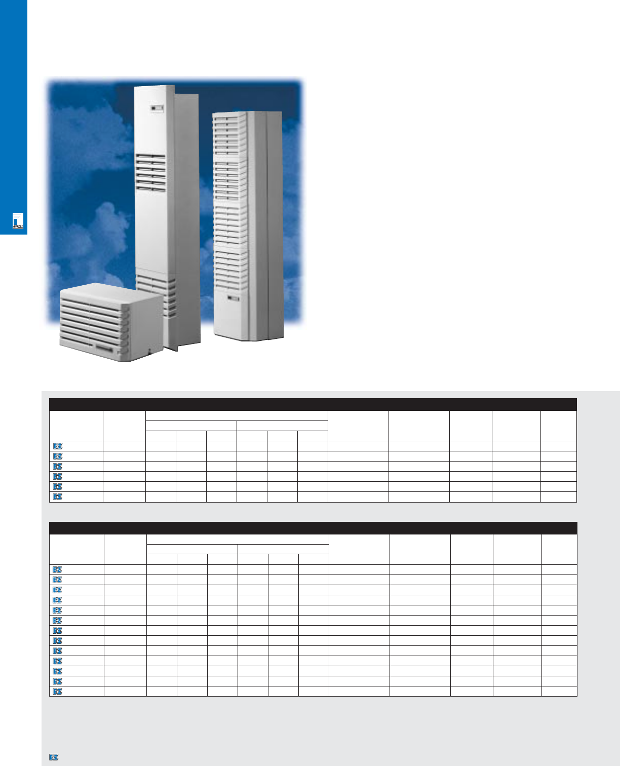
CLIMATE CONTROL SOLUTIONS
CLI 3
Air Conditioners
Pro-Ozone Industrial Air Conditioners
Designed to provide reliable cooling performance in a variety
of industrial environments, the Rittal line of enclosure air
conditioners are proven performers in a variety of applications
around the world. Providing temperature protection to sensitive
electronics in ambient temperatures up to 131°F while
integrating seamlessly into the enclosure is what sets Rittal air
conditioners apart from the competition. Global approvals and
a variety of available voltages ensure that the air conditioner
will be accepted wherever you are shipping your products.
Roofmount Air Conditioners
Part No. Rating Exact outside dimensions Voltage Temperature Current Temperature Weight
BTU/hr1inches mm control range lbs
HWD HWD
3272100 2950 13.39 23.62 14.88 340.0 600.0 378.0 115/50/60 Thermostat 6.3/6.6 A 68-131°F 90.0
3296100 2950 13.39 23.62 14.88 340.0 600.0 378.0 230/50/60 Thermostat 3.2/3.9 A 68-131°F 84.0
3280100 4800 15.7 23.6 13.4 400.0 600.0 340.0 115/50/60 Thermostat 10.5/12.8 A 68-131°F 110.0
3290100 4800 15.7 23.6 13.4 400.0 600.0 340.0 230/50/60 Thermostat 5.3/6.0 A 68-131°F 97.0
3256100 7030 18.0 24.0 18.0 454.0 600.0 460.0 230/50/60 Thermostat 8.9/9.8 A 68-131°F 119.0
3261140 9550 16.0 28.0 24.0 400.0 700.0 600.0 460/60-3~ Thermostat 2.8 A 68-131°F 171.0
160 Hz cooling performance at 95°F ambient, 95°F internal temperature per DIN 3168.
Wallmount Air Conditioners
Part No. Rating Exact outside dimensions Voltage Temperature Current Temperature Weight
BTU/hr1inches mm control range lbs
HWDHW D
3281100 3300 37.5 15.8 9.1 950.0 400.0 230.0 115/50/60 Thermostat 6.5/7.6 A 68-131°F 95.0
3293100 3300 37.5 15.8 9.1 950.0 400.0 230.0 230/50/60 Thermostat 3.0/3.6 A 68-131°F 88.0
3279100 4950 49.8 15.8 10.2 1265.0 400.0 260.0 115/50/60 Thermostat 11.5/12.0 A 68-131°F 126.0
3298100 4950 49.8 15.8 10.2 1265.0 400.0 260.0 230/50/60 Thermostat 5.5/5.7 A 68-131°F 119.0
3260460 5575 50.0 16.0 10.0 1265.0 400.0 260.0 460/60-3~ Microcontroller 2.0 A 68-131°F 132.0
3260146 5575 50.0 16.0 10.0 1265.0 400.0 260.0 460/60-3~ Thermostat 2.0 A 68-131°F 132.0
3390100 7575 62.0 16.0 12.0 1580.0 400.0 290.0 230/50/60-3~ Thermostat 6.9/8.9 A 68-131°F 146.0
3390115 7575 62.0 16.0 12.0 1580.0 400.0 290.0 115/50/60 Thermostat 13.8/17.8 A 68-131°F 154.0
3390146 7575 62.0 16.0 12.0 1580.0 400.0 290.0 460/60-3~ Thermostat 2.5 A 68-131°F 152.0
3392100 9965 62.0 16.0 12.0 1580.0 400.0 290.0 230/50/60 Thermostat 8.2/10.0 A 68-131°F 152.0
3392115 9965 62.0 16.0 12.0 1580.0 400.0 290.0 115/50/60 Thermostat 16.4/20.0 A 68-131°F 161.0
3392146 9965 62.0 16.0 12.0 1580.0 400.0 290.0 460/60-3~ Thermostat 3.5 A 68-131°F 161.0
3391560 15940 62.0 20.0 14.0 1580.0 500.0 340.0 460/60-3~ Microcontroller 5.3 A 68-131°F 187.0
160 Hz cooling performance at 95°F ambient, 95°F internal temperature per DIN 3168.
Designates a product in the EnclosureZone program.
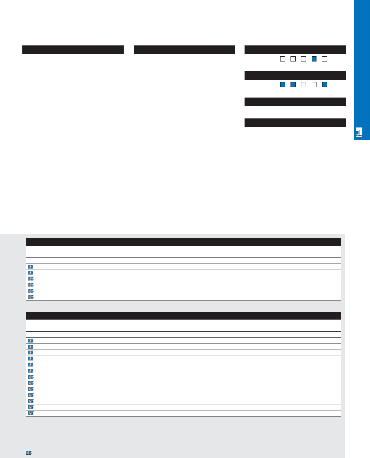
CLIMATE CONTROL SOLUTIONS
Accessories
Part No. Foam filter Metal filter 10’ power cord
Wallmount Air Conditioners
3281100 3294100 3294200 9962136
3293100 3294100 3294200 9965837
3279100 3294100 3294200 9962136
3298100 3294100 3294200 9965837
3260460 3294100 3294200 -
3260146 3294100 3294200 -
3390100 3294100 3294200 9965837
3390115 3294100 3294200 -
3390146 3294100 3294200 -
3392100 3294100 3294200 9965837
3392115 3294100 3294200 -
3392146 3294100 3294200 -
3391560 3294100 3294200 -
CLI 4
Configuration
•UL/CUL recognition, CE compliance
•CFC/HCFC-free R134a refrigerant
•Long life radial fans
•Exterior or interior mount for wallmount
versions
•Energy saving TXV technology
•50/60 Hz operation
•Easy filter change
•High pressure safety control
•Adjustable thermostat
•Off-the-shelf availability
•Terminal block connection
Technical Specifications
Material:
•Steel housing, polymer louvers
Finish:
•RAL 7032 pebble grey
Pages . . . . . . . . . . . . . . . . . . . . . . . . . . CLI 18-21
NEMA Type 144X1213
UL CUL CSA TÜV CE
Listings
Protection Ratings
Certifications/Approvals
Technical Drawings
Accessories
Part No. Foam filter Metal filter 10’ power cord
Roofmount Air Conditioners
3272100 3286100 3286200 9962136
3296100 3294100 3286200 9965837
3280100 3286100 3286200 -
3290100 3286100 3286200 9965837
3256100 3254000 3254200 9965837
3261140 3286100 3286200 -
Pages . . . . . . . . . . . . . . . . . . . . . . . . . . TEC 17-30
CLI Technical Information
Designates a product in the EnclosureZone program.
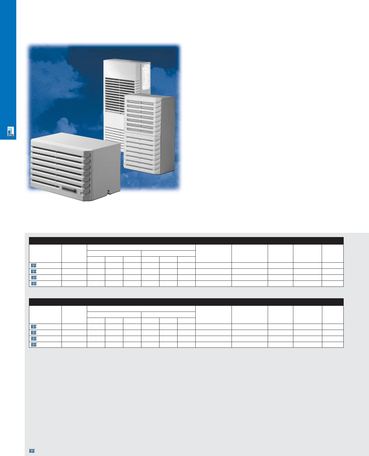
CLIMATE CONTROL SOLUTIONS
CLI 5
Micro And Mini Air Conditioners
Micro 1S Air Conditioners
As more densely populated enclosures continue to grow in
popularity, the need for air conditioners with smaller footprints
arises. The micro series air conditioners from Rittal meet this
need by providing impressive performance in an extremely
small footprint — maintaining a total depth of only 4.75".
Additional mounting flexibility is also offered through the ability
to mount the unit on the exterior of the enclosure or recessed
on the inside of the enclosure. NEMA 12 protection is assured
through a sealed barrier between the external and internal
airflow paths.
Mini 1S Air Conditioners
Rittal's mini air conditioner provides effective cooling in a
small footprint. Designed for versatility, the wallmount mini air
conditioner offers performance in excess of 2000 BTU/hr in a
footprint of only 25" H x 16" W. Additional mounting flexibility is
also offered through the ability to mount the unit on the wall of
the enclosure or recessed into the wall. NEMA 12 protection is
assured through a sealed barrier between the external and
internal airflow paths.
Micro 1S Air Conditioners
Part No. Rating Exact outside dimensions Voltage Mounting Current Temperature Weight
BTU/hr1inches mm range lbs
HWD HWD
3206100 1175 12.0 20.0 5.02300.0 490.0 120.0 115/50/60 Horizontal 3.5/3.8 A 68-122°F 35.0
3204100 1175 12.0 20.0 5.0 300.0 490.0 120.0 230/50/60 Horizontal 1.5 A 68-122°F 29.0
3205100 1230 20.5 10.6 5.02520.0 270.0 120.0 115/50/60 Vertical 3.5/3.6 A 68-122°F 35.0
3203100 1230 20.5 10.6 5.0 520.0 270.0 120.0 230/50/60 Vertical 1.8/1.6 A 68-122°F 29.0
160 Hz cooling performance at 95°F ambient, 95°F internal temperature per DIN 3168 2External transformer mounts to back of unit, 53 mm deep x 115 mm.
Mini 1S Air Conditioners
Part No. Rating Exact outside dimensions Voltage Mounting Current Temperature Weight
BTU/hr1inches mm range lbs
HWDHWD
3266100 1300 13.4 23.6 13.7 340.0 600.0 348.0 115/50/60 Roof 4.5/5.2 A 68-122°F 68.0
3265100 1300 13.4 23.6 13.7 340.0 600.0 348.0 230/50/60 Roof 2.2/2.5 A 68-122°F 57.0
3262100 2400 25.0 15.75 9.76 635.0 400.0 248.0 115/50/60 Wall 5.1/6.0 A 68-122°F 70.0
3269100 2400 25.0 15.75 9.76 635.0 400.0 248.0 230/50/60 Wall 3.1/4.0 A 68-122°F 66.0
160 Hz cooling performance at 95°F ambient, 95°F internal temperature per DIN 3168.
Designates a product in the EnclosureZone program.
CLIMATE CONTROL SOLUTIONS
CLI 6
Configuration
•UL/CUL recognition, CE compliance
•CFC/HCFC-free R134a refrigerant
•Overtemperature alarm contact (Micro only)
•Exterior or interior mount
•50/60 Hz operation
•Long life radial fans
•Off-the-shelf availability
•Terminal block connection
•Thermostat control
Technical Specifications
Material:
•Steel housing, polymer louvers
Finish/color:
•RAL 7032 pebble grey
Pages . . . . . . . . . . . . . . . . . . . . . . . . . .CLI 22-23
NEMA Type 144X1213
UL CUL CSA TÜV CE
Listings
Protection Ratings
Certifications/Approvals
Technical Drawings
Accessories
Part No. Foam filter 10’ power cord
3206100 9965899 9965837
3204100 9965899 9965837
3205100 9965899 9962136
3203100 9965899 9962136
Accessories
Part No. Foam filter Metal filter 10’ power cord
3266100 3267100 - 9962136
3265100 3267100 - 9965837
3262100 3294100 3294200 9962136
3269100 3294100 3294200 9965837
Pages . . . . . . . . . . . . . . . . . . . . . . . . . . TEC 17-30
CLI Technical Information
Designates a product in the EnclosureZone program.
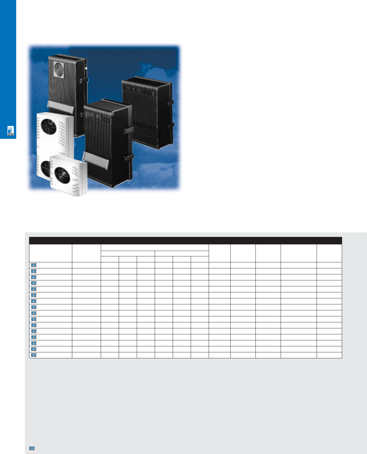
CLIMATE CONTROL SOLUTIONS
CLI 7
Air/Air Heat Exchangers
Techline Air/Air Heat Exchangers
Rittal Techline air/air heat exchangers provide a low
maintenance, high NEMA protection, and lightweight solution
for removing heat from enclosures when the allowable internal
temperature is higher than the ambient temperature.The high
performance, long life, radial fans along with the wide
heat exchanger channel spacing provide significant results —
including filterless operation whereby any dirt in the ambient
airpath is exhausted back out of the heat exchanger. A
separate internal airpath ensures that no dirty air is drawn
through the enclosure. Lightweight aluminum housings as
well as internal or external mounting options provide for flexible,
easy installation.
Outdoor/NEMA 4/3R Air/Air Heat Exchangers
Provide a low maintenance, high NEMA protection, and
lightweight solution for removing heat from enclosures when
the allowable internal temperature is higher than the ambient
temperature. The epoxy sealed impingement style heat
exchanger core meets Bellcore GR 487 salt fog and mil Std
810E blowing dust requirements, and the closed cell neoprene
gasketing helps maintain NEMA 4 enclosure protection. A
separate internal air path ensures that no dirty air is drawn in
through the enclosure. Lightweight aluminum housings as well
as internal or external mounting options provide for flexible,
easy installation.
Air/Air Heat Exchangers
Part No. Rating Exact outside dimensions Voltage Current2Noise Temperature Weight
W/C1inches mm dBa range lbs
HW D HWD
3125110 14.6 15.0 7.4 6.4 380.0 187.5 162.5 115 0.56/.50A 54.0 23-131°F 10.14
3125000 14.6 15.0 7.4 6.4 380.0 187.5 162.5 230 0.28/.25A 54.0 23-131°F 10.14
3126000 18.7 20.0 8.0 6.5 500.0 187.5 162.5 230/50/60 0.28/0.25A 54.0 23-131°F 10.8
3126110 18.7 20.0 8.0 6.5 500.0 187.5 162.5 115/50/60 0.28/0.25A 54.0 23-131°F 10.8
3128000 19.5 20.0 11.0 4.5 500.0 272.0 110.0 230/50/60 0.28/0.25A 61.0 23-131°F 11.24
3128110 19.5 20.0 11.0 4.5 500.0 272.0 110.0 115/50/60 0.28/0.25A 61.0 23-131°F 11.24
3129110 30.0 30.7 10.7 4.3 780.0 271.5 110.0 115 0.72/.90A 67.5 23-131°F 16.31
3129000 30.0 30.7 10.7 4.3 780.0 271.5 110.0 230 0.36/.45A 67.5 23-131°F 16.31
3130000 37.0 29.0 14.0 4.5 730.0 355.0 110.0 230/50/60 0.36A/0.45A 64.0 23-131°F 17.85
3130110 37.0 29.0 14.0 4.5 730.0 355.0 110.0 115/50/60 0.36A/0.45A 64.0 23-131°F 17.85
3131110 42.0 47.2 10.7 4.3 1200.0 271.5 110.0 115 0.72/.90A 62.0 23-131°F 20.5
3131000 42.0 47.2 10.7 4.3 1200.0 271.5 110.0 230 0.36/.45A 62.0 23-131°F 20.5
3133000 63.0 58.0 18.0 4.5 1480.0 439.0 110.0 230/50/60 0.36A/0.45A 68.0 23-131°F 27.5
3133110 63.0 58.0 18.0 4.5 1480.0 439.0 110.0 115/50/60 0.36A/0.45A 68.0 23-131°F 27.5
3134110 69.0 70.1 17.3 4.3 1780.0 439.0 110.0 115 0.72/.90A 61.0 23-131°F 41.6
3134000 69.0 70.1 17.3 4.3 1780.0 439.0 110.0 230 0.36/.45A 61.0 23-131°F 41.6
1Cooling capacity of heat exchanger only. Additional cooling effect of convection through enclosure walls depends on cabinet dimensions and delta T.
2Current draw per fan (2 fans per heat exchanger).
Designates a product in the EnclosureZone program.
CLIMATE CONTROL SOLUTIONS
CLI 8
Configuration
•UL/CUL recognition, CE compliance
(NEMA 12 models)
•Long life, powerful radial fans
•Internal or external mounting
•Lightweight/easy installation
•Separate internal and external airpaths
•Easily removable core for cleaning
(NEMA 12 models)
•Available in multiple sizes and voltages
•Off-the-shelf availability
•10' power cord (no plug) included
Technical Specifications
Material:
•Aluminum housing/core
Finish/color:
•Black (NEMA 12)
•RAL 7032 pebble grey (NEMA 4/3R)
Pages . . . . . . . . . . . . . . . . . . . . . . . . . .CLI 24-25
NEMA Type 13R44X1213
UL CUL CSA TÜV CE
Listings
Protection Ratings
Certifications/Approvals
Technical Drawings
NEMA 4/3R Air/Air Heat Exchangers
Part No.
Rating Exact outside Voltage Rated Pre- External cycle Internal cycle Noise Temperature Wt.
W/C1dimensions current fuse (free delivery) (free delivery) level range lbs
inches mm T
Bellcore
HWDHWD GR487 °F °C
9967581
20 10.25 14.25 7.4 260 362 188 115/50/60 0.54 A/0.52 A 0.75 A 230 cfm/390 m3/h 230 cfm/390 m3/h 64 dBa -40 to +158 -40 to +70 16
9967582
20 10.25 14.25 7.4 260 362 188 230/50/60 0.26 A/0.28 A 0.38 A 230 cfm/390 m3/h 230 cfm/390 m3/h 64 dBa -40 to +158 -40 to +70 16
9967584
38 24.25 14.25 7.4 616 362 188 115/50/60 1.1 A/1.0 A 1.5 A 460 cfm/788 m3/h 460 cfm/788 m3/h 67 dBa -40 to +158 -40 to +70 33
9967585
38 24.25 14.25 7.4 616 362 188 230/50/60 0.52 A/0.56 A 0.75 A 460 cfm/788 m3/h 460 cfm/788 m3/h 67 dBa -40 to +158 -40 to +70 33
9967587
57 35.25 14.25 7.4 895 362 188 115/50/60 1.6 A/1.5 A 2.0 A 690 cfm/1173 m3/h 690 cfm/1173 m3/h 68 dBa -40 to +158 -40 to +70 50
9967588
57 35.25 14.25 7.4 895 362 188 230/50/60 0.8 A/0.9 A 2.0 A 690 cfm/1173 m3/h 690 cfm/1173 m3/h 68 dBa -40 to +158 -40 to +70 50
1Cooling capacity of heat exchanger only. Additional cooling effect of convection through enclosure walls depends on cabinet dimensions and delta T.
Pages . . . . . . . . . . . . . . . . . . . . . . . . . . TEC 17-30
CLI Technical Information
Designates a product in the EnclosureZone program.
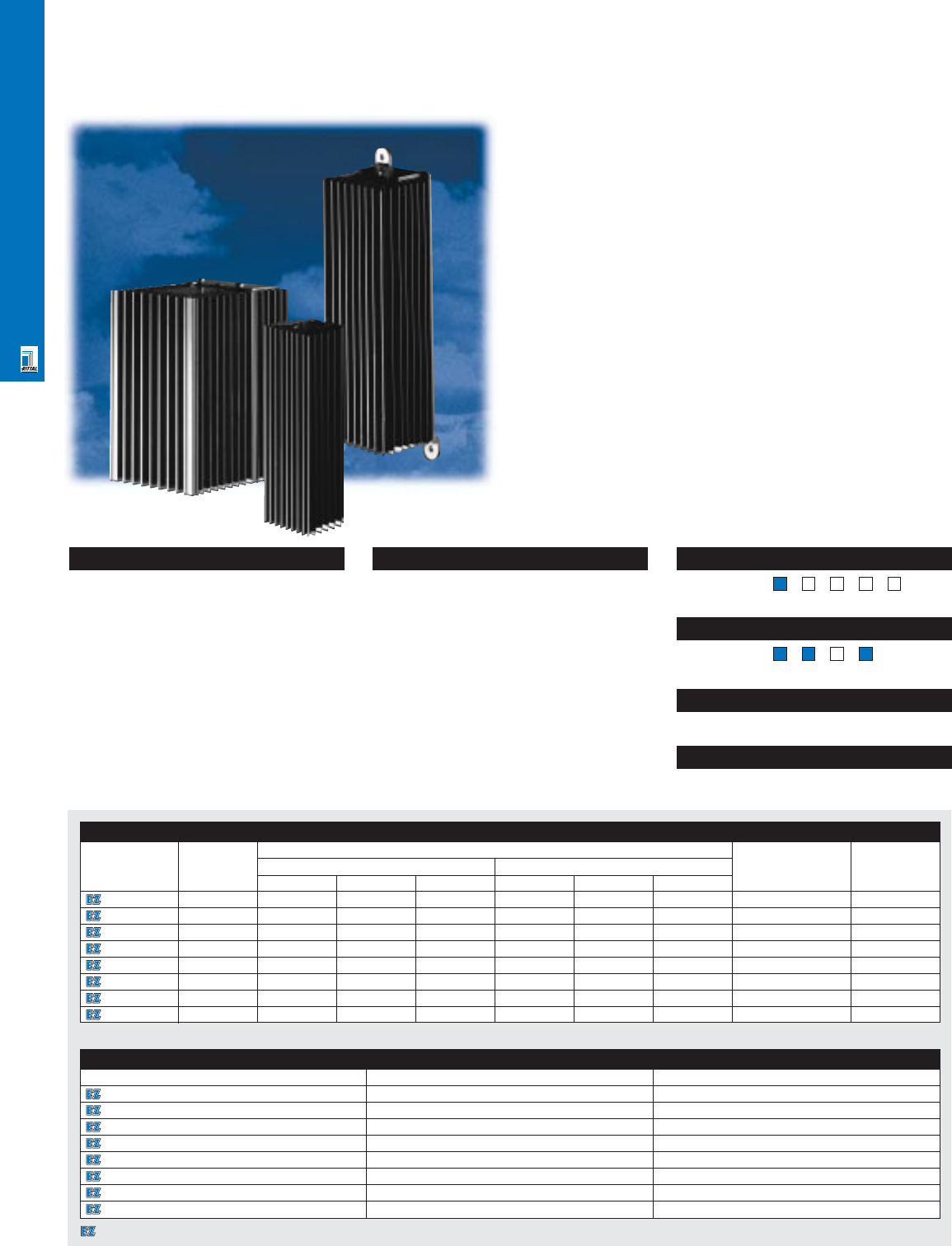
CLIMATE CONTROL SOLUTIONS
Enclosure Heaters
Rittal Enclosure Heaters
Enclosure heaters help ensure that a safe environment inside
the enclosure is maintained, even in applications where rapid
temperature change results in the dew point being reached,
thereby causing condensation on critical electronics. PTC
technology means that heater surface temperature is kept at a
safe level and that heat output is maximized while energy
consumption is minimized.
Additionally, the aluminum fin heat transfer element provides
efficient heat distribution. Finally, DIN rail or screw mounting
options provide users with maximum flexibility and fast
installation.
Heaters
Part No. Rating1Exact outside dimensions Voltage Fuse
(watts) inches mm
HWD HWD
3106000 20.0 4.9 1.8 1.4 125.0 45.0 35.0 110-240 V AC/DC 2.0 A
3115000 30.0 4.3 2.5 2.1 110.0 64.0 54.0 110-240 V AC/DC 2.0 A
3116000 50.0 7.3 2.5 2.1 185.0 64.0 54.0 110-240 V AC/DC 4.0 A
3107000 130.0 5.5 3.1 4.6 140.0 80.0 118.0 110-240 V AC/DC 4.0 A
3102000 300.0 6.6 4.7 4.7 168.0 120.0 120.0 230 V AC 4.0 A
3102110 300.0 6.6 4.7 4.7 168.0 120.0 120.0 115 V AC 4.0 A
9967053 1000.0 5.7 5.7 4.0 145.0 145.0 102.0 115/50/60 12.0 A
9967054 1000.0 5.7 5.7 4.0 145.0 145.0 102.0 230/50/60 6.0 A
1Continuous heat output at 68˚F ambient temperature.
Technical Specifications
Material:
•Aluminum extrusion
Finish/color:
•Black
Page . . . . . . . . . . . . . . . . . . . . . . . . . . . . . CLI 26
NEMA Type 144X1213
UL CUL TÜV CE
Listings
Protection Ratings
Certifications/Approvals
Technical Drawings
Configuration
•UL/CUL/CE approvals (most models)
•Dual voltage 110/230 V (some models)
•Maximum surface temperature of 160°F
ensures safety
•Quick mounting via DIN rail or screws
Accessories
Part No. Thermostat 10’ power cord
3106000 3110000 -
3115000 3110000 -
3116000 3110000 -
3107000 3110000 -
3102000 3110000 9965837
3102110 3110000 9962136
9967053 3110000 9962136
9967054 3110000 9965837
CLI 9
Pages . . . . . . . . . . . . . . . . . . . . . . . . . . TEC 17-30
CLI Technical Information
Designates a product in the EnclosureZone program.
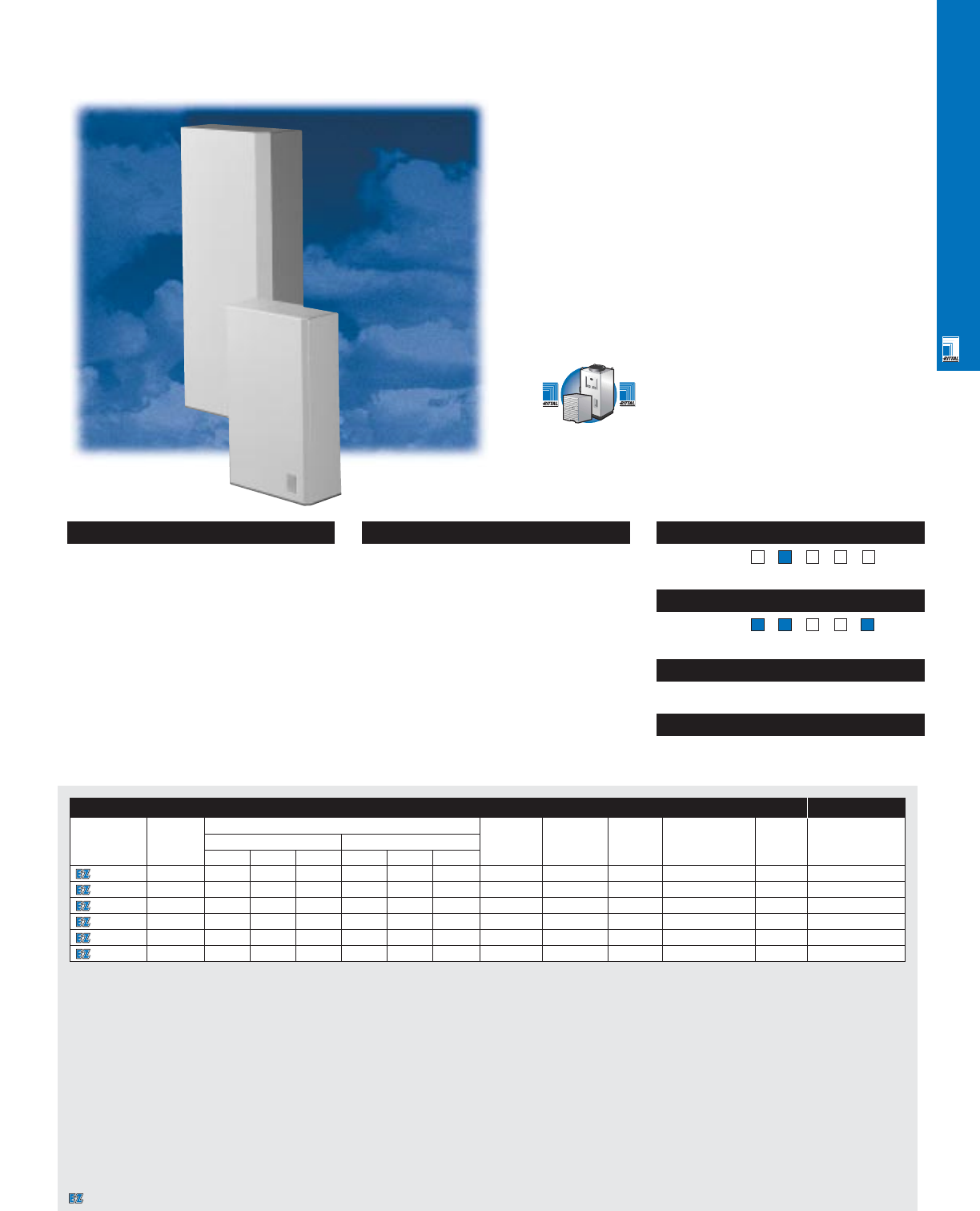
CLIMATE CONTROL SOLUTIONS
CLI 10
Air/Water Heat Exchangers
Air/Water Heat Exchangers
For the harshest of environments, where ambient temperatures
exceed 130˚F and the air is exceptionally dirty or oily, air/water
heat exchangers provide the best cooling solution. Since
ambient air does not enter the heat exchanger, performance is
maintained without having to worry about cleaning filters, heat
exchange cassettes, or coils. Other advantages include
compact footprint, the ability to cool below ambient temperature,
lower energy consumption, and lower capital cost than air
conditioners when cool plant water is available.
Rittal’s air/water heat exchangers include features such as
solenoid valves, condensate deflector screens, and overflow
drainage paths.
Air/Water Heat Exchangers Accessories
Part No.
Rating Exact outside dimensions Voltage Current Pressure, Air temperature Weight Power cord
BTU/hr1inches mm psi range lbs
HWDHWD
3214100 2050 19.7 7.9 3.7 500.0 200.0 100.0 230/50/60 0.17/0.18A 15-145 34-158°F 15 9965837
3217100 3400 20.5 11.8 5.3 520.0 300.0 135.0 230/50/60 0.6/0.55 A 15-145 34-158°F 21 9965837
3217115 3400 20.5 11.8 5.3 520.0 300.0 135.0 115/50/60 1.1 A 15-145 34-158°F 21 9962136
3218100 10240 37.4 15.8 7.9 950.0 400.0 200.0 230/50/60 0.42/0.48 A 15-145 34-158°F 46 9965837
3218115 10240 37.4 15.8 7.9 950.0 400.0 200.0 115/50/60 1.0 A 15-145 34-158°F 46 9962136
3216100 17050 55.5 18.0 10.0 1400.0 450.0 250.0 230/50/60 0.9/1.3A 15-145 34-158°F 123 9965837
1Cooling capacity at 95°F internal temperature, 50°F water temperature, 0.9 gal/hr flow rate.
Configuration
•UL/CUL recognition, CE compliance
•Operation up to 158°F ambient
•Work well in dirty environments
•Provide up to 17,000 BTU/hr in small
footprint
•Require only 1-2 gal/minute of water
•Long life radial fan
•Overtemperature alarm contact
•Off-the-shelf availability
•Terminal block connection
Technical Specifications
Material:
•Steel housing
Finish/color:
•RAL 7032 pebble grey
Page . . . . . . . . . . . . . . . . . . . . . . . . . . . . . CLI 27
NEMA Type 144X1213
UL CUL CSA TÜV CE
Listings
Protection Ratings
Certifications/Approvals
Technical Drawings
Pages . . . . . . . . . . . . . . . . . . . . . . . . . . TEC 17-30
CLI Technical Information
Designates a product in the EnclosureZone program.
A Complete Line Of
Chillers Is Also Available —
Check With Your Rittal
Representative.
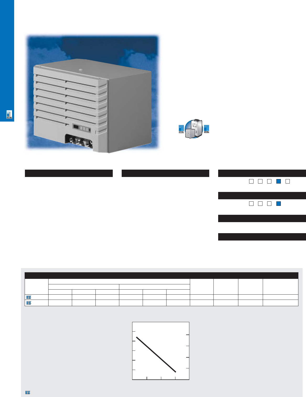
CLIMATE CONTROL SOLUTIONS
CLI 11
Pages . . . . . . . . . . . . . . . . . . . . . . . . . . TEC 17-30
CLI Technical Information
Mini Chillers
Mini Chillers
The chiller supplies coolant within a ± 2°C temperature range
via the electronic controller. In this way, the water can be
routed to the equipment by the integral pump, without the
need for an additional reservoir. The pump capacity curve
and flow resistance of the equipment connected to the chiller
allows for proper sizing. The design of the chillers will blend
in seamlessly with our climate control equipment. The micro-
controller may be installed in the front or the rear. A stand
alone installation is also possible.
Mini Chillers
Part No.
Exact outside dimensions Voltage Current Pressure, Cooling
capacity
inches mm psi BTU
HWDH WD
3318510 16 24 17 400 600 426 230/50/60 V 4.1 A 363 3275/3650
3319510 16 24 17 400 600 426 230/50/60 V 5.4 A 363 5085/5665
Technical Specifications
Material:
•Steel housing, plastic louvers
Finish/color:
•RAL 7032 pebble grey
Page . . . . . . . . . . . . . . . . . . . . . . . . . . . . . CLI 28
NEMA Type 144X1213
UL CUL TÜV CE
Listings
Protection Ratings
Certifications/Approvals
Technical Drawings
Configuration
•Space saving and modular construction
of the cooling components. Components
built on a rugged base panel, yet easily
accessible for maintenance
•Controls and electric components
protected to NEMA 12/IP 44
•Hermetically sealed compressor
•Condensers with axial fans
•Coolant transfer pumps
•Exact temperature control and monitoring
through microprocessor technology and
digital displays
•Ready for connection with terminal block
•Collective fault signal with potential free
relay contact
100
80
60
40
20
40
30
20
10
123
Pump Capacity Curve
(50/60 Hz)
Flow (gal./min.)
Head (ft.)
psi
A Complete Line Of
Chillers Is Also Available —
Check With Your Rittal
Representative.
Designates a product in the EnclosureZone program.
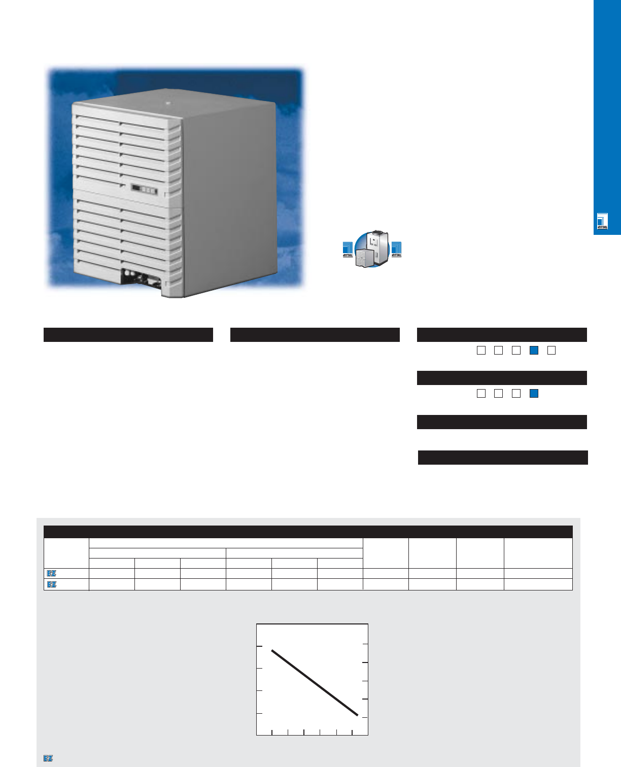
CLIMATE CONTROL SOLUTIONS
CLI 12
Pages . . . . . . . . . . . . . . . . . . . . . . . . . . TEC 17-30
CLI Technical Information
Chillers
Chillers
Compact, space saving design. These chillers are used to
cool water and are able to maintain constant coolant flow,
via an integral pump. The warmed return coolant flows into
the chiller reservoir, where it is cooled back down to the set
discharge temperature in the fully hermetic cooling cycle. All
safety components are designed to DIN EN 378 and VBG 20.
The refrigerants used comply with the latest regulations.
Chillers
Part No.
Exact outside dimensions Voltage Current Pressure, Cooling
capacity
inches mm psi BTU
HWDH WD
3320502 27 24 25 680 600 625 460/60, 3~ 3 A 334 11,390
3334502 27 24 25 680 600 625 460/60, 3~ 5.2 A 334 17,080
Technical Specifications
Material:
•Steel housing, plastic louvers
Finish/color:
•RAL 7032 pebble grey
Page . . . . . . . . . . . . . . . . . . . . . . . . . . . . . CLI 29
NEMA Type 144X1213
UL CUL TÜV CE
Listings
Protection Ratings
Certifications/Approvals
Technical Drawings
Configuration
•Compact design of the cooling components
with built-in reservoir
•Choice of front or back display
•Controls and electrical components
protected to NEMA 12/IP 54
•Hermetically sealed compressors;
condensers with axial fans
•High capacity pump
•Exact temperature control through micro-
processor technology and digital displays
•Fully wired, ready for connection
•Collective fault signal with potential
free contact
•Special configurations upon request
120
90
60
30
40
30
20
10
123
Pump Capacity Curve
(50/60 Hz)
Flow (gal./min.)
Head (ft.)
psi
4567
50
A Complete Line Of
Chillers Is Also Available —
Check With Your Rittal
Representative.
Designates a product in the EnclosureZone program.
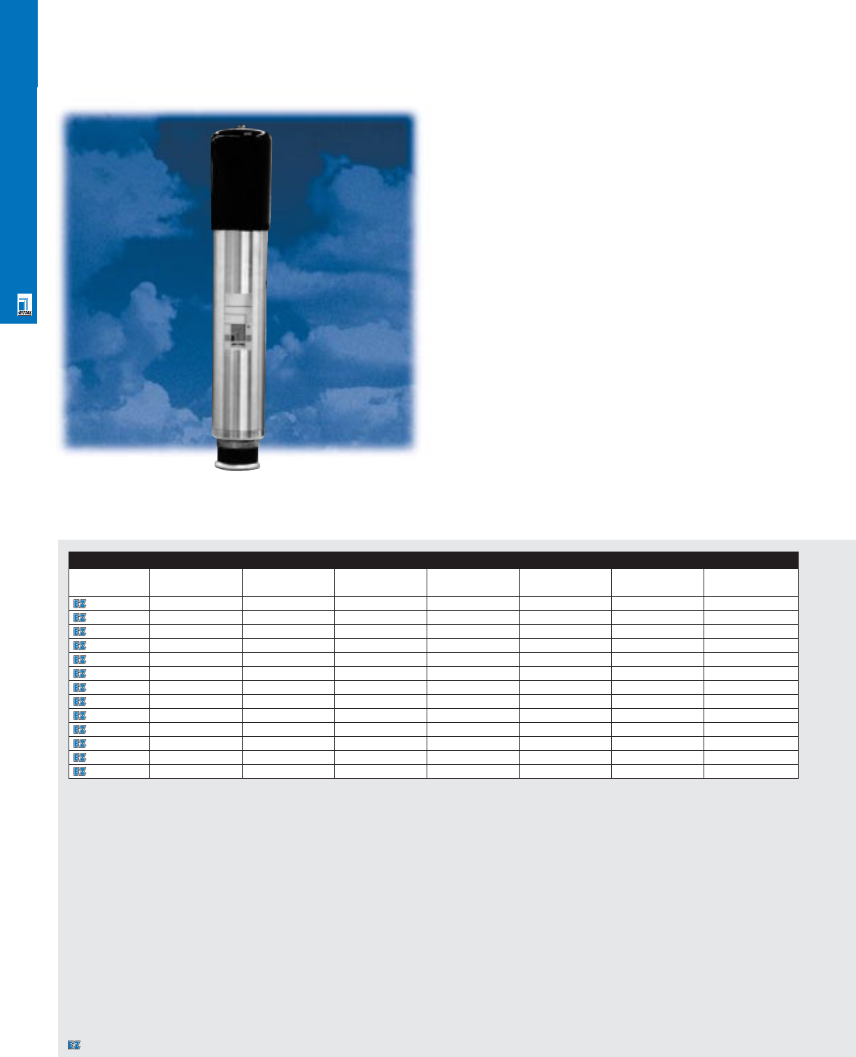
CLIMATE CONTROL SOLUTIONS
CLI 13
Vortex Kooler Enclosure Coolers
Vortex Koolers
These units use compressed air to create a cool stream of air
which is distributed inside the enclosure with a hose ducting kit.
These Koolers are especially effective in small enclosures,
when an existing source of compressed air exists, when heat
loads are low to moderate, or when a NEMA 4/4X cooling
solution is required. Vortex Koolers are also effective in
applications where EMI/RFI must be minimized.
Vortex Koolers
Part No.
NEMA rating Voltage1Cooling capacity
Noise level at
Air consumption Pressure range psi Port size NPT
(BTU)2dBa at 100 psi SCFM inches
8012903 12 115/50/60 400 69 8 70-150 .125
8012904 12 115/50/60 900 80 15 70-150 .25
8012905 12 115/50/60 1500 83 25 70-150 .25
8012906 12 115/50/60 2500 90 35 70-150 .25
8012907 12 115/50/60 5000 90 70 70-150 .25
8012908 4115/50/60 900 83 15 70-150 .25
8012909 4115/50/60 1700 86 25 70-150 .25
8012912 4115/50/60 2500 90 35 70-150 .25
8012913 4115/50/60 5000 90 70 70-150 .25
8012910 4X 115/50/60 900 83 15 70-150 .25
8012914 4X 115/50/60 1700 86 25 70-150 .25
8012915 4X 115/50/60 2500 90 35 70-150 .25
8012911 4X 115/50/60 5000 90 70 70-150 .25
1230 V available by substituting 230 V solenoid.
2Rated at 100 psig; 70°F/ 21°C inlet air temperature, 90°F/ 32°C thermostat setting, -40°F/ -40°C pressure dew point; derate 30% 110°F ambient, > 2% humidity, derate 25% for
80 psig pressure.
Designates a product in the EnclosureZone program.
CLIMATE CONTROL SOLUTIONS
CLI 14
Configuration
•Includes Vortex Kooler, thermostat,
solenoid, filter and ducting kit
•230 V solenoid is available for
230 V operation
Technical Specifications
Material:
•stainless steel or aluminum
Page . . . . . . . . . . . . . . . . . . . . . . . . . . . . . CLI 30
NEMA Type 144X1213
UL CUL CSA TÜV CE
Listings
Protection Ratings
Certifications/Approvals
Technical Drawings
Vortex Accessories
Part No.
Description Port size NPT (inches)
8012916 5 micron filter for up to 1700 BTU capacity .375
8012917 5 micron filter for up to 2500 BTU capacity .375
8012918 5 micron filter for up to 5000 BTU capacity .75
8012919 Oil filter for up to 1700 BTU capacity .375
8012920 Oil filter for up to 2500 BTU capacity .375
8012921 Water trap for up to 1700 BTU capacity .375
8012922 Water trap for up to 2500 BTU capacity .375
8012923 NEMA 12 230 V solenoid for up to 1700 BTU capacity .25
8012924 NEMA 4/4X 230 V solenoid for up to 1700 BTU capacity .25
8012925 NEMA 4/4X 230 V solenoid for up to 2500 BTU capacity .375
Pages . . . . . . . . . . . . . . . . . . . . . . . . . . TEC 17-30
CLI Technical Information
Designates a product in the EnclosureZone program.
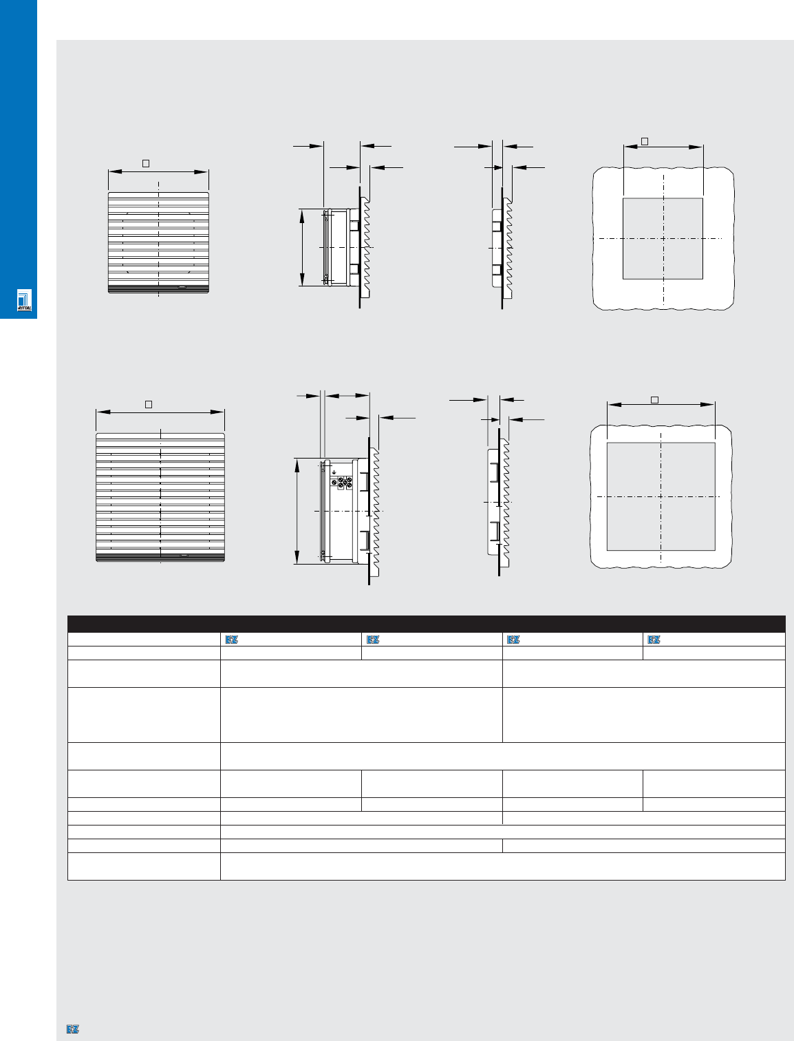
CLIMATE CONTROL SOLUTIONS
CLI 15
1S Filter Fans
Part No. 3321100 3321115/3321117 3322100/3322107 3322115/3322117
Rated voltage Volt/Hz 230/50/60 115/50/60 230/50/60 115/50/60
Air Displacement at 15 cfm/25 m3/h 40 cfm/66 m3/h
60 Hz (unimpeded air flow)
Air displacement at 60 Hz
1 SK 3321200: 9 cfm/18 m3/h 1 x 3322200 30 cfm/50 m3/h
1 x 3323200 33 cfm/55 m3/h
Axial fan with Self-starting shaded pole motor
Rated current 69.0 mA 136.0 mA 0.11 A 0.23 A
Power consumption 12.5 W 12.5 W 18 W 18 W
Type of connection 24" lead Terminal block
Temperature range +14°F to +131°F/-10°C to +55°C
Noise level 41/46 dBa 46/50 dBa
Protection rating IP 43 when using standard filters.
per EN 60 529/10.91
Specifications subject to change.
Dimensions in millimeters (mm) unless otherwise indicated.
Technical Specifications
1S Filter Fans
Installation Cut-Out Exhaust Filter
3322xxx
3321xxx
148.5 552
10.5
NL1
122.5
14
10.5
124
116.5
42
10
90
10
12 92 + 0.8
Installation Cut-Out Exhaust Filter
Designates a product in the EnclosureZone program.
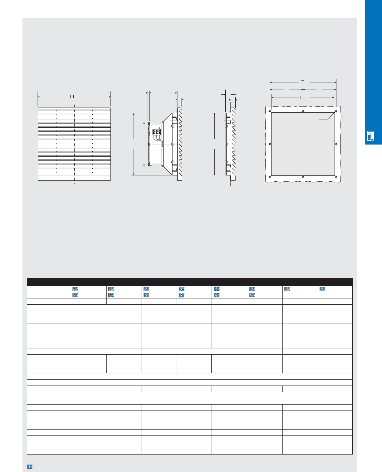
CLIMATE CONTROL SOLUTIONS
CLI 16
Technical Specifications
1S Filter Fans
Specifications subject to change. Dimensions in millimeters (mm) unless otherwise indicated.
1S Filter Fans (Continued)
Part No. 3323100/ 3323115/ 3325100/ 3325115/ 3326100/ 3326115/ 3327100 3327115
3323107 3323117 3325107 3325117 3326107 3326117
Rated voltage Volt/Hz 230/50/60 115/50/60 230/50/60 115/50/60 230/50/60 115/50/60 230/50/60 115/50/60
Air Displacement 70 cfm/120 m3/h 155 cfm/265 m3h330 cfm/560 m3h425 cfm/720 m3h
at 60 Hz
(unimpeded air flow)
Air displacement
at 60 Hz
1 x SK 3323200 50 cfm/82 m3/h 1 x SK 3325200 112 cfm/190 m3/h 1 x SK 3326200 230 cfm/390 m3/h 1 SK 3326200 335 cfm/575 m3/h
2 x SK 3323200 60 cfm/98 m3/h 2 x SK 3325200 127 cfm/220 m3/h 2 x SK 3326200 290 cfm/495 m3/h
1 x SK 3325200 55 cfm/90 m3/h 1 x SK 3326200 125 cfm/215 m3/h
Fan motor Self-starting shaded pole motor Self-starting shaded pole motor Permanent split capacitor motor
Rated current 0.12 A 0.24 A 0.28 A 0.53 A 0.29 A 0.58 A 0.65 A 1.5 A
0.11 A 0.23 A 0.24 A 0.49 A 0.35 A 0.70 A
Power consumption 19 W/18 W 19 W/18 W 41 W/38 W 41 W/38 W 64 W/80 W 64 W/80 W 155 W 167 W
Type of connection Terminal block
Temperature range +14°F to +131°F/-10°C to +55°C
Noise level 46/49 dBa 54/56 dBa 56/61 dBa 75/76 dBa
Protection rating IP 43/
per EN 60 529/10.91 NEMA 12/IP 54 when a sealing frame and fine filter is used.
Part No. exhaust filters
3323200 3325200 3326200 3326200
A (mm) 204 255 323 323
B (mm) 77.5 100 124 145
C (mm) 176 222 290 290
D (mm) 120 150 225 280
E (mm) 177 224 292 292
F (mm) 185 234 302 302
G (mm) (92.5) (117) (151) (151)
N
L1
C
17.5
12.5
A5.0 B
12.5
CD
F
E
GG
Ø4.5
3323xxx/3325xxx/3326xxx/3327xxx
Exhaust Filter Installation Cut-Out
A
F
E
Designates a product in the EnclosureZone program.
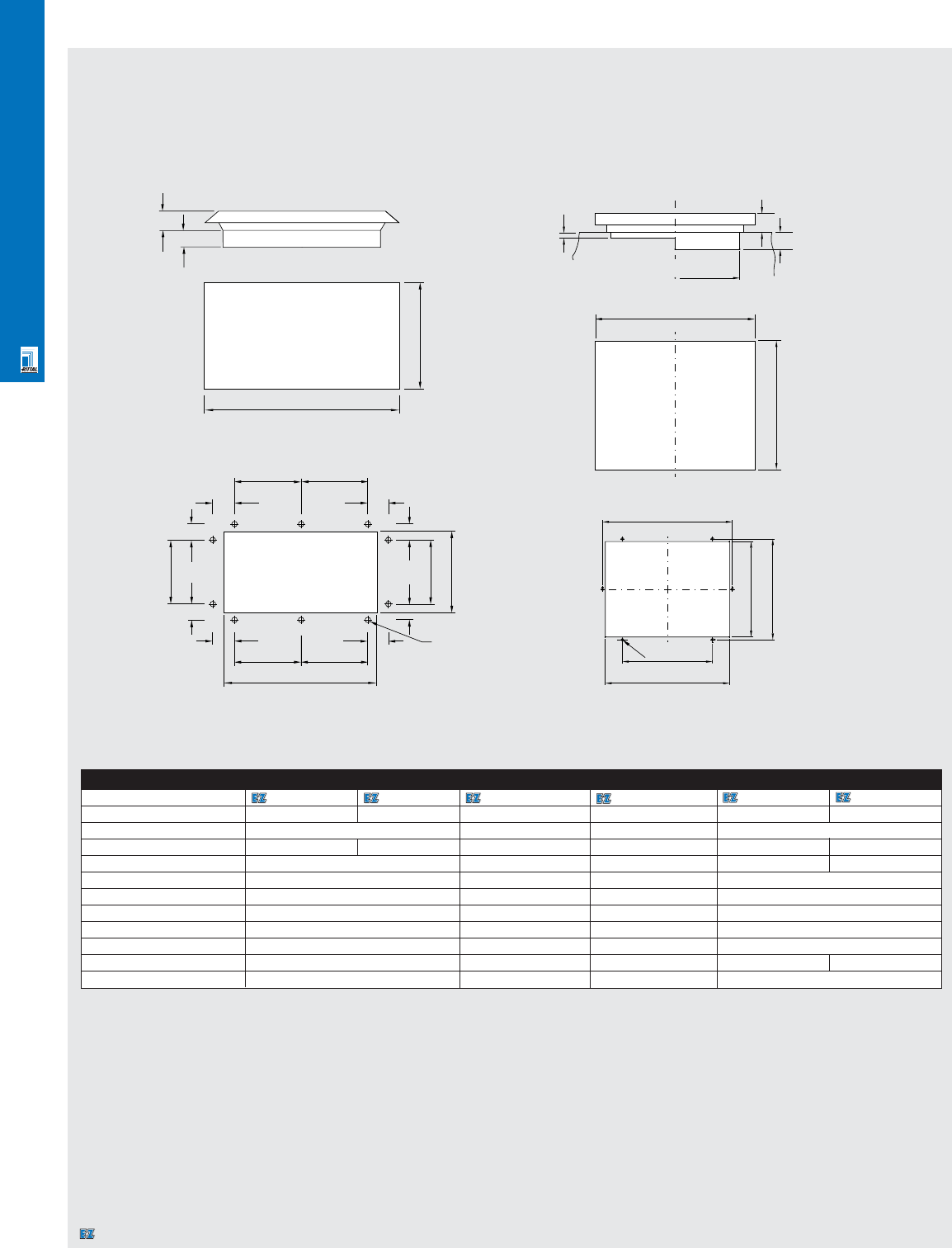
CLIMATE CONTROL SOLUTIONS
Pagoda Fans
Part No. 9966814 9966815 9966892 (vent only) 3148000 (vent only) 3149000 3169000
Rated operating voltage Volt/Hz 115/50/60 230/50/60 - - 230/50/60 115/50/60
Air Displacement at 60Hz 360 cfm --210 cfm
Rated current maximum 0.72 A 0.36 A - - 0.2 A 0.55 A
Power consumption 82 W - - 42 W 65 W
Temperature range 14°F to 140°F/-10°C to +60°C - - 14°F to 140°F/-10°C to +60°C
Type of connection 10" cord/no plug - - -
Noise Level 59 dBa - - 53 dBa
rpm 3400 min-1 --1400 min-1
Weight 20 lbs/9.1 kg 10 lbs/4.5 kg 8.8 lbs/4 kg 17.5 lbs/7.8 kg
Color RAL 7032 pebble grey RAL 7032, textured - - RAL 7032, textured
Protective category NEMA 3R/IP 55 - IP 43
Specifications subject to change.
CLI 17
Technical Specifications
Pagoda Roof Fans
9966814/9966815/9966892
529
62
55
446
265
180
50
50
50
50
180
125 125
55 55
55 55
125 125
345
Ø 8
3149000/3169000/3148000
h 260 x 340
420
340
15
50
44
250
345
265
360
280
Ø 8
Installation cutout
Designates a product in the EnclosureZone program.
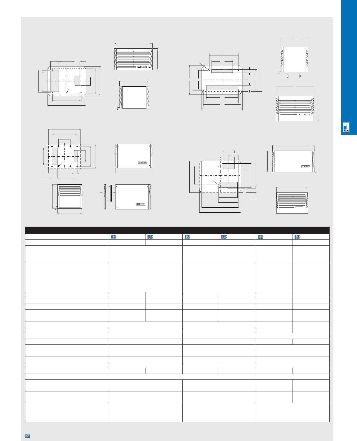
CLIMATE CONTROL SOLUTIONS
CLI 18
Technical Specifications
Roofmount Air Conditioners
3280100/3290100
70
300 340
45
Ø8
426
312
275
460
475
550
600
310
187.5 237.5
600
400
426
Roofmount Air Conditionersoofmount Air Conditioners
Part No. 3272100 3296100 3280100 3290100 3256100 3261140
Rated voltage Volt/Hz 115/50/60 230/50/60 115/50/60 230/50/60 230/50/60 460/60-3~
Dimensions in H 13.39"/340 mm 15.75"/400 mm 18"/454 mm 16"/400 mm
inches/mm W 23.62"/600 mm 23.62"/600 mm 24"/600 mm 28"/700 mm
(without grille) D 14.88"/378 mm 13.39"/340 mm 18"/460 mm 24"/600 mm
Useful cooling capacity
per DIN 3168 L35 L35 2750/2950 BTU/ 4800 BTU/ 7000/7030 BTU/ 9550 BTU/
(95°F internal/95°F ambient)
800/860 W 1400 W 2050/2060 W 2800 W
L35 L50 2100/2350 BTU/ 3625/4175 BTU/ 5085 BTU/ 8020 BTU/
(95°F internal/122°F ambient)
615/685 W 1060/1220 W 1490 W 2350 W
Maximum rated current 6.3 A/6.6 A 3.2 A/3.9 A 10.5 A/12.8 A 5.3 A/6.0 A 8.9 A/9.8 A 2.8 A
Starting current 18.2 A/20.7 A 11.4 A/11.0 A 24.6 A/28.7 A 16.6 A/15.5 A 24.7 A/22.5 A 14.0 A
Pre-fuse T 10.0 A/10.0 A 6.0 A/6.0 A 16.0 A/16.0 A 6.0 A/10 A 10.0 A/10.0 A 6.0 A
Power consumption L35 L35 345 W/450 W 330 W/430 W 740 W/825 W 710 W/800 W 1480 W/1480 W 1350 W
L35 L50 415 W/545 W 390 W/525 W 840 W/920 W 1590 W 1600 W
Refrigerant R134 a 25 oz/750 g 33.5 oz/950 g 35 oz/980 g 29 oz/825 g
Maximum pressure 363 psi/25 bar 335 psi/23 bar 348 psi/24 bar 348 psi/24 bar
Temperature range +68°F to +131°F/+20°C to +55°C +68°F to +131°F/+20°C to +55°C +68°F to +131°F/+20°C to +55°C
Noise level 62 dBa 62 dBa 62 dBa 65 dBa
Protection rating External circuit NEMA 2/IP 34 NEMA 2/IP 34 NEMA 2/IP 24
per EN 60 529/10.91 Internal circuit NEMA 12/13/IP 54 NEMA 12/13/IP 54 NEMA 12/IP 54
Duty cycle 100% 100% 100%
Type of connection Terminal block Terminal block Terminal block
Weight 90 lbs/41 kg 84 lbs/38 kg 110 lbs/50 kg 97 lbs/44 kg 119 lbs/54 kg 171 lbs/78 kg
Air displacement of fans (unimpeded air flow)
External circuit 535/615 cfm / 910 m3/h/1045 m3/h 2 x 535/555 cfm/910/940 m3/h 421 cfm/720 m3/h 618 cfm/1050 m3/h
Internal circuit 100/110 cfm / 171 m3/h/185 m3/h 129/131 cfm/220/222 m3/h 222 cfm/380 m3/h 412 cfm/700 m3/h
Temperature control Thermostat Thermostat Thermostat
Setting range +68°F to +131°F/+20°C to +55°C
Factory setting +95°F/+35°C
Specifications subject to change. Dimensions in millimeters (mm) unless otherwise indicated.
3256100 Installation cutout
686
70
315
100
65
600
475
225
320
460
375
215
Ø 10
454
460
200
350
375
230
350
700
Ø 10
105
100
455
480
785
600
98
85
785
400
600
350
450
330
600
140
Ø 8
130 250 80
378
464
3272100/3296100
3261140
464
600
340
Designates a product in the EnclosureZone program.
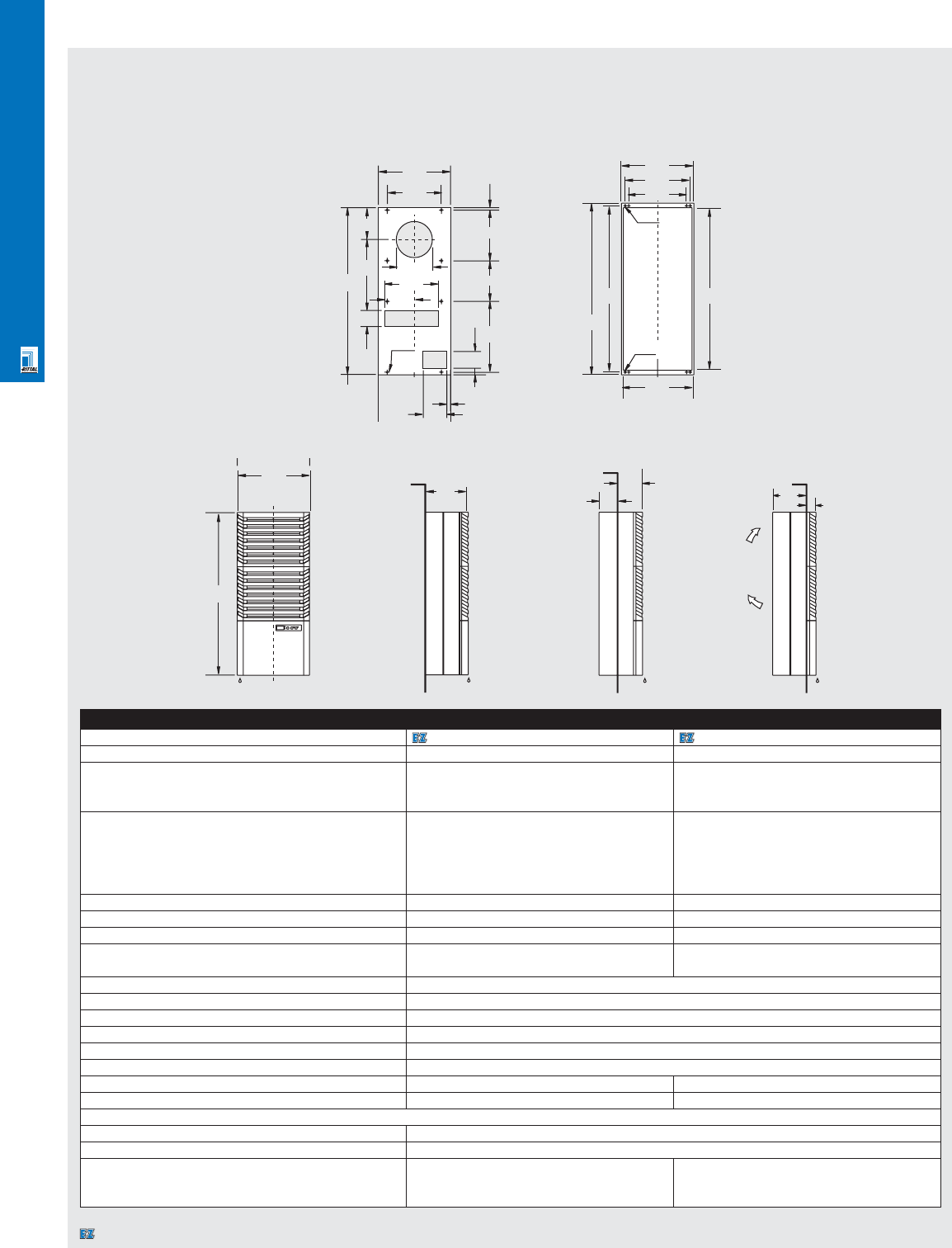
CLIMATE CONTROL SOLUTIONS
CLI 19
3281100/3293100
Wallmount Air Conditioners
Part No. 3293100 3281100
Rated voltage Volt/Hz 230/50/60 115/50/60
Dimensions in inches/mm H 37.40"/950 mm 37.40"/950 mm
(with grille) W 15.75"/400 mm 15.75"/400 mm
D9.06"/230 mm 9.06"/230 mm
Useful cooling capacity
per DIN 3168 L35 L35 2800/3300 BTU/ 2800/3300 BTU/
(95°F internal/95°F ambient) 825/960 W 825/960 W
L35 L50 2325/2525 BTU/ 2325/2525 BTU/
(95°F internal/122°F ambient) 680/740 W 680/740 W
Maximum rated current 3.0 A/3.6 A 6.5 A/7.6 A
Starting current 8.5 A/10.0 A 16.4 A/20.1 A
Pre-fuse T 6.0 A/6.0 A 10.0 A/10.0 A
Power consumption L35 L35 450 W/595 W 470 W/600 W
L35 L50 500 W/670 W 530 W/680 W
Refrigerant R134a 18.5 oz/525 g
Maximum pressure 363 psi/25 bar
Temperature range +68°F to +131°F/+20°C to +55°C
Noise level 62 dBa
Protection rating per EN 60 529/10.91 External circuit NEMA 2/IP 34/internal circuit NEMA 12/13/IP 54/NEMA 4/4x cover available
Duty cycle 100%
Type of connection Terminal block Terminal block
Weight 88 lbs/40 kg 95 lbs/43 kg
Air displacement of fans (unimpeded air flow)
External circuit 351 cfm/600 m3/h
Internal circuit 146 cfm/250 m3/h
Temperature control Built-in thermostat Built-in thermostat
Setting range +68°F to +131°F/+20°C to +55°C +68°F to +131°F/+20°C to +55°C/
Factory setting +95°F/+35°C +95°F/+35°C
Specifications subject to change. Dimensions in millimeters (mm) unless otherwise indicated.
Technical Specifications
Wallmount Air Conditioners
Partially recessed Fully recessedExternal
400
A
135
465
950
310225385 15
230
B
Ø 9.5
(8X)
400
360
320
Ø7
(4x)
900
950
920
380
Ø9.5
950
400
230 100
30
185 45
Installation cutout external Installation cutout fully/partially recessed
320
(4x)
Designates a product in the EnclosureZone program.
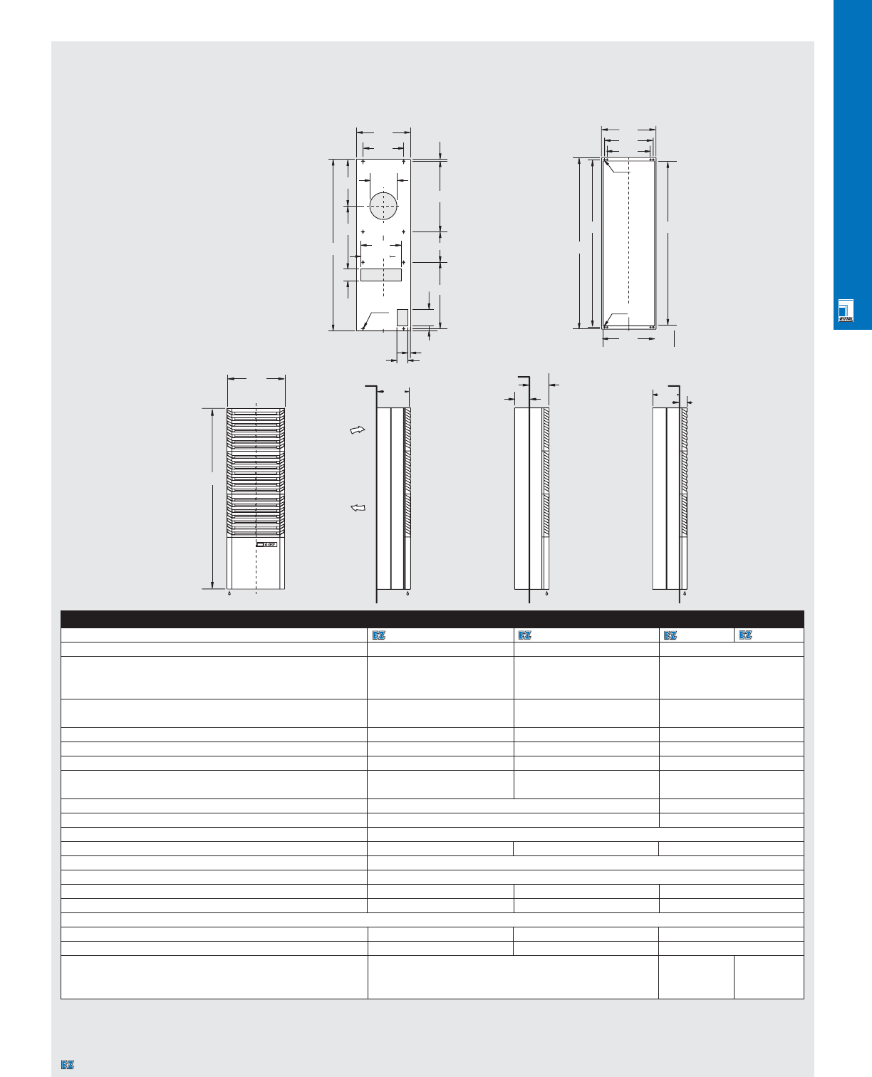
CLIMATE CONTROL SOLUTIONS
CLI 20
Technical Specifications
Wallmount Air Conditioners
3298100/3279100/3260460/3260146 Installation cutout
"on-the-wall" Installation cut-out
completely or partially
"through-the-wall"
Wallmount Air Conditioners
Part No. 3298100 3279100 3260460 3260146
Rated voltage Volt/Hz 230/50/60 115/50/60 460-3~
Dimensions in inches/mm H 49.80"/1265 mm 49.80"/1265 mm 50"/1265 mm
(with grille) W 15.75"/400 mm 15.75"/400 mm 16"/400 mm
D10.24"/260 mm 10.24"/260 mm 10"/260 mm
Useful cooling capacity (95°F internal/95°F ambient) L35 L35 4775/4950 BTU/1400/1450 W 4775/4950 BTU/1400/1450 W 5940/5560 BTU
per DIN 3168 (95°F internal/122°F ambient) L35 L50 3750/3925 BTU/1100/1150 W 3750/3925 BTU/1100/1150 W 4575/4160 BTU
Maximum rated current 5.5 A/5.7 A 11.5 A/12 A 2.1 A/2.0 A
Starting current 17.5 A/16.5 A 36.0 A/37.0 A 8.6 A
Pre-fuse T 10.0 A/10.0 A 16 A/16 A 6.0 A
Power consumption L35 L35 830 W/1040 W 850 W/1080 W 900 W/750 W
L35 L50 940 W/1170 W 975 W/1265 W 1060 W/920 W
Refrigerant R134a 19.0 oz/525 g 19.4 oz/550 g
Maximum pressure 363psi/25 bar 348 psi/24 bar
Temperature range +68°F to +131°F/+20°C to +55°C
Noise level 62 dBa 62 dBa 65 dBa
Protection rating per EN 60 529/10.91 External circuit NEMA 2/IP34/internal circuit NEMA 12/13 IP54/NEMA 4/4x cover available
Duty cycle 100%
Type of connection Terminal block Terminal block Terminal block
Weight 119 lbs/54 kg 126 lbs/57 kg 132 lbs/60 kg
Air displacement of fans (unimpeded air flow)
External circuit 410/310 cfm/685/510 m3/h 410/310 cfm/685/510 m3/h 257 cfm/440 m3/h
Internal circuit 520/620 cfm/860/1030 m3/h 520/620 cfm/860/1030 m3/h 170 cfm/290 m3/h
Temperature control Built-in thermostat Microcontroller Thermostat
Setting range +68°F to +131°F/+20°C to +55°C
Factory setting +95°F/+35°C
Specifications subject to change. Dimensions in millimeters (mm) unless otherwise indicated.
Partially
"through-the-wall" Completely
"through-the-wall"
Partially
"through-the-wall" "On-the-wall"
400
1265
260 160
100
215 45
400
300
450
225 15
360
400
360
320
345
260
520
1265
490
Ø9.5
(8X)
Ø7
(4X)
1215
1235
1265
380
440
Ø9.5
(4X)
Designates a product in the EnclosureZone program.
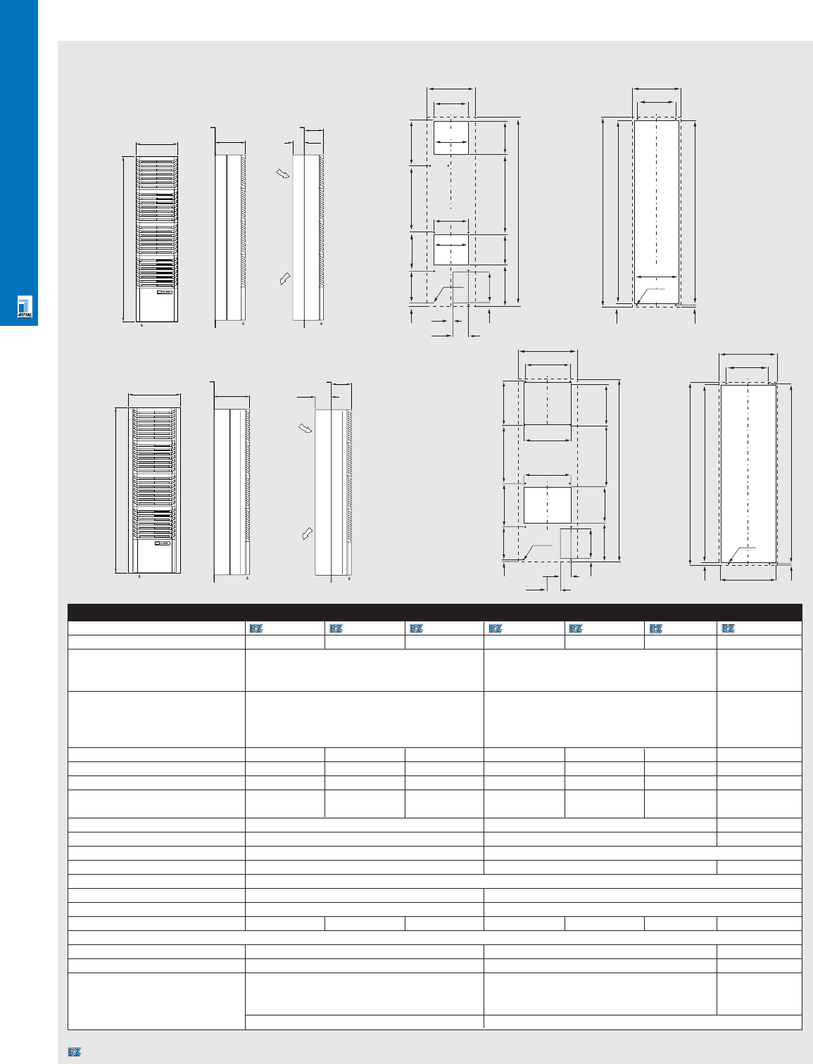
CLIMATE CONTROL SOLUTIONS
CLI 21
Wallmount Air Conditioners
Part No. 3390100 3390115 3390146 3392100 3392115 3392146 3391560
Rated voltage Volt/Hz 230/50/60 115/50/60 460/60-3~ 230/50/60 115/50/60 460/60-3~ 460/60-3~
Dimensions in inches/mm H 62"/1580 mm 62"/1580 mm 62"/1580 mm
(with grille) W 16"/400 mm 16"/400 mm 20"/500 mm
D12"/290 mm 12"/290 mm 13.5"/340 mm
Useful cooling capacity
(95°F internal/95°F ambient) L35 L35 6895/7575 BTU 8800/9965 BTU 13800/15940 BTU
per DIN 3168
(95°F internal/122°F ambient) L35 L50 4980/5390 BTU 6245/6825 BTU 10240/12115 BTU
Maximum rated current 6.9 A/8.9 A 13.8 A/17.8 A 2.3 A/2.5 A 8.2 A/10.0 A 16.4 A/20.0 A 3.2 A/3.5 A 4.5 A/5.3 A
Starting current 24.0 A/23.0 A 48.0 A/46.0 A 9.1 A/8.2 A 25.0 A/24.0 A 50.0 A/48.0 A 6.4 A 15.5 A/17.0 A
Pre-fuse T 10.0 A/10.0 A 20.0 A/20.0 A 10.0 A/10.0 A 10.0 A/16.0 A 20.0 A/24.0 A 10.0 A10.0 A 10 A/10 A
Power consumption L35 L35 1160 W/1460 W 1180 W/1490 W 870 W/1120 W 1400 W/1800 W 1430 W/1840 W 1320 W/1740 W 1600 W/2030 W
L35 L50 1310 W/1620 W 1330 W/1650 W 1060 W/1340 W 1620 W/2080 W 1650 W/2130 W 1570 W/2020 W 1900 W/2420 W
Refrigerant R134a 36 oz/1025 g 41 oz/1175 g 62 oz/1750 g
Maximum pressure 406 psi/28 bar 406 psi/28 bar 406 psi/28 bar
Temperature range +68˚F to +131˚F/+20˚C to +55˚C +68˚F to +131˚F/+20˚C to +55˚C
Noise level 66 dBa 67 dBa 65 dBa
Protection rating per EN 60 529/10.91 External circuit NEMA 2/IP 34/internal circuit NEMA 12/13 IP 54/NEMA 3R cover available
Duty cycle 100% 100%
Type of connection terminal block terminal block
Weight 146 lbs/66 kg 154 lbs/70 kg 152 lbs/69 kg 152 lbs/69 kg 161 lbs/73 kg 161 lbs/73 kg 187 lbs/85 kg
Air displacement of fans (unimpeded air flow)
External circuit 374 cfm/640 m3/h 415 cfm/710 m3/h 643 cfm/1100 m3/h
Internal circuit 320 cfm/550 m3/h 374 cfm/640 m3/h 497 cfm/850 m3/h
Temperature control Thermostat Thermostat Microcontroller
Setting range +68°F to +131°F/+20°C to +55°C +68°F to +131°F/+20°C to +55°C +68°F to +131°F/
+20°C to +55°C
Factory setting +95°F/+35°C +95°F/+35°C
Specifications subject to change. Dimensions in millimeters (mm) unless otherwise indicated.
Technical Specifications
Wallmount Air Conditioners
3390xxx/3392xxx
400
1580
500
1580
Partially recessed
External
Partially recessed
External
3391560
400
280
280
280
665
1580
250
350
225
35
280
280
Ø9.5
(10x)
20
120
25 275 325 550 380
400
352
380
Ø11
(4x)
15
25
1580
1530
1500
External Partially recessed
500
362
500
380
400
400
1580
1530
1550
Ø 11
(4 x)
480
25
15
360
380
525
500
375
275
25
35
120
80
Ø 9.5
(10 x)
225
350 310
1580
290
107
180
340
150
190
Fully recessed
External
Designates a product in the EnclosureZone program.
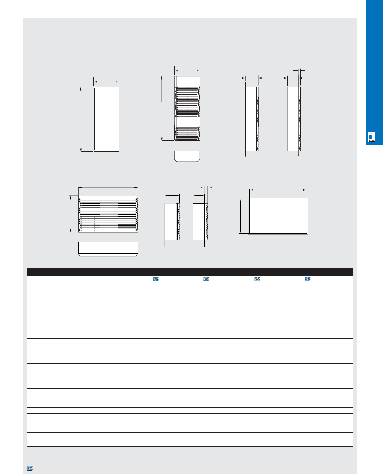
CLIMATE CONTROL SOLUTIONS
CLI 22
Installation cut-out
"on-the-wall"/"through-the-wall"
Technical Specifications
Micro Air Conditioners
501
251
"On-the-wall" "Through-the-wall"
3203100/3205100 (For Vertical Mounting)
3206100/3204100 (For Horizontal Mounting)
Micro Air Conditioners
Part No. 3203100 3205100 3206100 3204100
Rated voltage Volt/Hz 230/50/60 115/50/60 115/50/60 230/50/60
Dimensions in inches/mm H 20.47"/520 mm 20.47"/520 mm 12”/300 mm 12”/300 mm
(with grille) W 10.63"/270 mm 10.63"/270 mm 20”/490 mm 20”/490 mm
D5.0"/120 mm 5.0"/120 mm 5”/120 mm 5”/120 mm
(+53 Ext. transformer) (+53 Ext. transformer)
Useful cooling capacity (95°F internal/95°F ambient) L35 L35 1195/1230 BTU/350 W 1195/1230 BTU/350 W 1100/1175 BTU 1100/1175 BTU
per DIN 3168 (95°F internal/122°F ambient) L35 L50 715/680 BTU/200 W 715/680 BTU/200 W 545/580 BTU 545/580 BTU
Maximum rated current 1.8 A/1.6 A 3.5 A/3.6 A 3.5 A/3.8 A 1.5 A/1.5 A
Starting current 2.7 A/2.8 A 4 A/4.5 A 4.2 A/4.5 A 1.9 A/2.0 A
Pre-fuse T 4 A 6 A 6A 4A
Power consumption L35 L35 275 W/280 W 275 W/280 W 285 W/290 W 285 W/290 W
(per DIN 3168) L35 L50 315 W/315 W 315 W/315 W 295 W/305 W 295 W/305 W
Refrigerant R134 a 4.5 oz/125 g 4.5 oz/125 g 5 oz/150 g 5 oz/150 g
Temperature range +68°F to +122°F/+20°C to +50°C
Noise level 62 dBa
Protection rating per EN 60 529/10.91 External circuit NEMA 2/IP34/internal circuit NEMA 12/13/IP 54
Duty cycle 100%
Type of connection Terminal block Terminal block Terminal block Terminal block
Weight 29 lbs/13 kg 35 lbs/16 kg 35 lbs/16 kg 29 lbs/13 kg
Air displacement
External circuit 73/86 cfm/142/167 m3/h 83/98 cfm/142/167 m3/h
Internal circuit 41/48 cfm/80/93 m3/h 47/54 cfm/80/93 m3/h
Temperature control Electronic
Setting range +68°F to +122°F/+20°C to +50°C (factory setting +95°F/+35°C)
Overtemperature alarm Via built-in microcontroller
Potential free contact:Imax = 5 A, Umax = 230 V
Specifications subjects to change. Dimensions in millimeters (mm) unless otherwise indicated.
270
520
120 95
25
490
300
471
281
120
25
95
Fully recessedExternal
Designates a product in the EnclosureZone program.
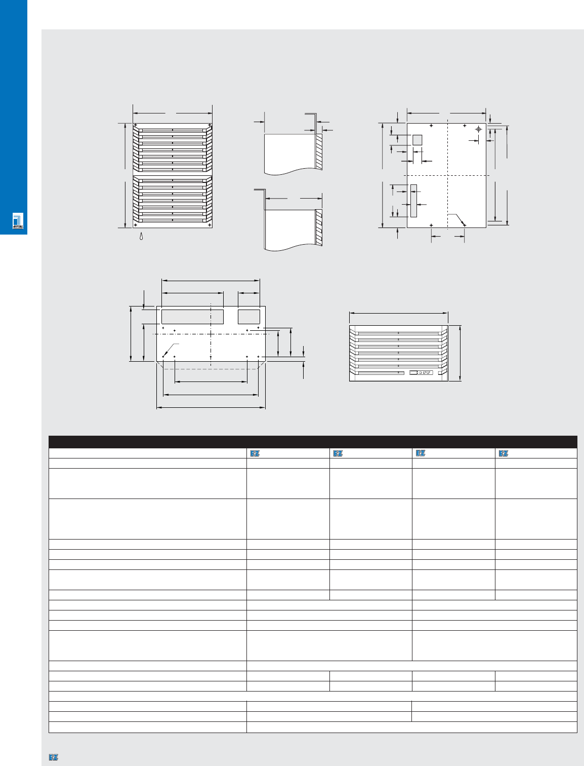
CLIMATE CONTROL SOLUTIONS
CLI 23
Technical Specifications
Mini Air Conditioners
635
400
577
605.0 ± 1.0
Ø8
210
74
34
32
64
40
194
32
64
44
40
52
400
635
248
205
45
3262100/3269100 Installation cut-out
"On-the-wall"
Mini Air Conditioners
Part No. 3262100 3269100 3265100 3266100
Rated voltage Volt/Hz 115/50/60 230/50/60 230/50/60 115/50/60
Dimensions in inches/mm H 25.00"/635 mm 25.00"/635 mm 13.4"/340 mm 13.4"/340 mm
(with grille) W 15.75"/400 mm 15.75"/400 mm 23.6"/600 mm 23.6"/600 mm
D9.76"/248 mm 9.76"/248 mm 13.7"/348 mm 13.7"/348 mm
Useful cooling capacity (95°F internal/95°F ambient) L35 L35 2352/2400 BTU/ 2325/2400 BTU/ 1400/1300 BTU/ 1400/1300 BTU/
680/700 W 680/700 W 410/380 W 410/380 W
per DIN 3168 (95°F internal/122°F ambient) L35 L50 1700/1775 BTU/ 1700/1775 BTU/ 785/820 BTU/ 820/820 BTU/
500/520 W 500/520 W 230/240 W 240/240 W
Maximum rated current 5.1 A/6.0 A 3.1 A/4.0 A 2.2 A/2.5 A 4.5 A/5.2 A
Starting current 25.2 A/34.3 A 12.6 A/14.4 A 6.6 A/7.2 A 13.5 A/13.5 A
Pre-fuse T 6.0 A/10.0 A 6.0 A/6.0 A 6.0 A/6.0 A 6.0 A/6.0 A
Power consumption L35 L35 480 W/600 W 460 W/580 W 310 W/440 W 340 W/450 W
L35 L50 540 W/675 W 520 W/660 W 350 W450 W 380 W/490 W
Refrigerant R134 a 12.0 oz/335 g 12.0 oz/335 g 11.5 oz/325 g 11.5 oz/325 g
Maximum pressure 350 psi/24 bar 350 psi/24 bar
Temperature range +68°F to +122°F/+20°C to +50°C 68°F to 122°F/ +20°C to +50°C
Noise level 62 dBa 62 dBa
Protection rating per EN 60 529/10.91 External circuit NEMA 2/IP 34 External circuit NEMA 2/IP 24
Internal circuit NEMA 12/13/IP 54 Internal circuit NEMA 12/IP 54
NEMA 4/4x cover available
Duty cycle 100%
Type of connection Terminal block Terminal block Terminal block Terminal block
Weight 70 lbs/32 kg 66 lbs/30 kg 57 lbs/26 kg 68 lbs/31 kg
Air displacement of fans (unimpeded air flow)
External circuit 145 cfm/243 m3/h 145 cfm/243 m3/h
Internal circuit 145 cfm/243 m3/h 145 cfm/243 m3/h
Temperature control Built-in thermostat (factory setting +95°F/+35°C)
Specifications subject to change. Dimensions in millimeters (mm) unless otherwise indicated.
"Through-the-wall"
"On-the-wall"
3265100/3266100
525
305
Ø 8
145
26
160
77
208
540
340 120
600
400
600
340
Designates a product in the EnclosureZone program.
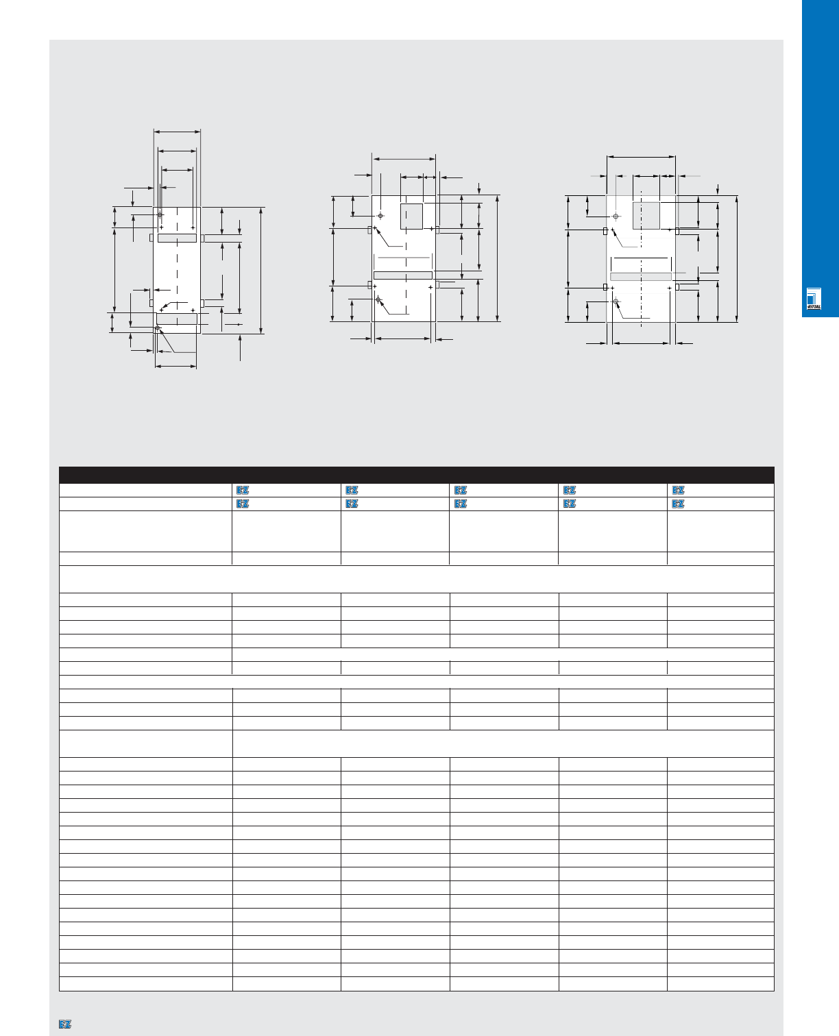
CLIMATE CONTROL SOLUTIONS
CLI 24
Technical Specifications
Air/Air Heat Exchangers
Air/Air Heat Exchangers
Part No. 115/50/60 3125110 3126110 3129110 3128110 3130110
Part No. 230/50/60 3125000 3126000 3129000 3128000 3130000
Dimensions in inches/mm H 14.96"/380.0 mm 20"/500 mm 30.71"/780 mm 20"/500 mm 29"/730 mm
W7.38"/187.5 mm 8"/187.5 mm 10.67"/271 mm 11"/272 mm 14"/355 mm
D6.40"/162.5 mm 6.5"/162.5 mm 4.33"/110 mm 4.5"/110 mm 4.5"/110 mm
Specific thermal capacity 14.6 W/C 18.7 W/C 30.0 W/C 19.5 W/C 37.0 W/C
Air displacement of fans
(unimpeded air flow)
External circuit 170 cfm/290 m3/h
152/175 cfm/260/300 m3/h
350 cfm/600 m3/h
152/175 cfm/260/300 m3/h
335 cfm/570 m3/h
Internal circuit 170 cfm/290 m3/h
152/175 cfm/260/300 m3/h
350 cfm/600 m3/h
152/175 cfm/260/300 m3/h
335 cfm/570 m3/h
Noise level 54 dBa 54 dBa 67.5 dBa 61 dBa 64 dBa
Fans per heat exchanger 2 2 2 2 2
Temperature range +23°F to +131°F/-50°C to +55°C
Weight 9.5 lbs/4.3 kg 10.8 lbs/4.9 kg 16.3 lbs/7.4 kg 11.24 lbs/5.1 kg 17.85 lbs/8.1 kg
Electrical specifications per fan
Rated current per fan 0.28 A/0.25 A 0.28 A/0.25 A 0.36 A/0.45 A 0.28 A/0.25 A 0.36 A/0.45 A
Power capacity per fan (230 V) 43/42 W 43/42 W 82/103 W 43/42 W 82/103 W
Cooling surface .62 m2.99 m21.01 m2.63 m21.23 m2
Protection rating NEMA 12/IP 54 per EN 60 529/10.91
(Internal circuit)
Power cord 2 x 10 ft./3 m 2 x 10 ft./3 m 2 x 16 ft./5 m 2 x 10 ft./3 m 2 x 16 ft./5 m
A (mm) 380 500 780 500 730
B (mm) 187.5 187.5 271 271 355
C (mm) 155 155 239 239 323
D (mm) 127 127 220 225 304
E (mm) 228 348 460 230 410
F (mm) 178 298 296.5 172 246.5
G (mm) - - 25.5 23 25.5
H (mm) - - 160 106 160
I (mm) - - 40 61.5 40
J (mm) - - 30 26.5 30
K (mm) - - 160 135 160
L (mm) - - 62 30 62
M (mm) - - 231.5 165.5 231.5
N (mm) - - 36 48 36
P (mm) - - 82.5 135 82.5
R (mm) - 107.5 - 117.5 127.5
Specifications subject to change. Dimensions in millimeters (mm) unless otherwise indicated.
3125XXX/3126XXX
Installation cutout
“external mount”
3128XXX/3129XXX/3130XXX
Installation cutout
“external mount”
3128XXX/3129XXX/3130XXX
Installation cutout
“external mount”
B
C
D
25
76
76
E
25
12
25
25
C
Ø 7
R
25
25
R
35
B
N
P
K
E
KP
GDG
Ø 18
Ø 7
C
HI
30
30
FA
Ø 18
12
R
R
L
M
F
H
A
25
25
B
H12
I
C
G
36
Ø7
K
E
K
25
12.75
H
A
82.5
82.5
LJ
DG
Ø18
12.75
F
M
25
Designates a product in the EnclosureZone program.
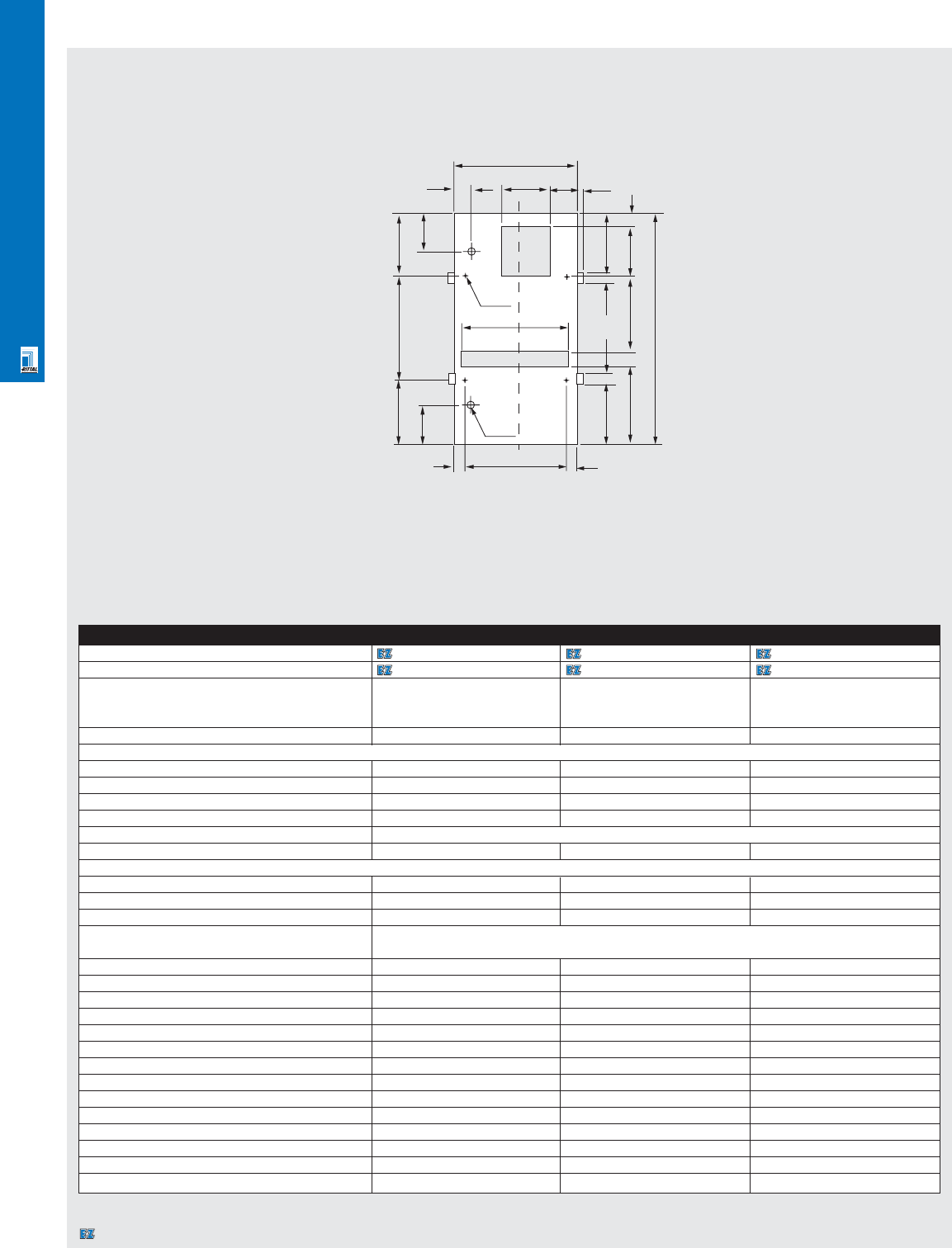
CLIMATE CONTROL SOLUTIONS
CLI 25
Technical Specifications
Air/Air Heat Exchangers
Air/Air Heat Exchangers
Part No. 115/50/60 3131110 3133110 3134110
Part No. 230/50/60 3131000 3133000 3134000
Dimensions in inches/mm H 47.24"/1200 mm 58"/1480 mm 70.08"/1780 mm
W10.67"/271 mm 18"/439 mm 17.28"/439 mm
D4.33"/110 mm 4.5"/110 mm 4.33"/110 mm
Specific thermal capacity 42.0 W/C 63.0 W/C 69.0 W/C
Air displacement of fans (unimpeded air flow)
External circuit 350 cfm/600 m3/h 335 cfm/570 m3/h 350 cfm/600 m3/h
Internal circuit 350 cfm/600 m3/h 335 cfm/570 m3/h 350 cfm/600 m3/h
Noise level 62 dBa 68 dBa 61 dBa
Fans per heat exchanger 2 2 2
Temperature range +23°F to +131°F/-5°C to +55°C
Weight 20.5 lbs/9.3 kg 27.5 lbs/12.5 kg 41.6 lbs/18.9 kg
Electrical specifications per fan
Rated current per fan (230 V) 0.36 A/0.45 A 0.36 A/0.45 A 0.36 A/0.45 A
Power capacity per fan 82/103 W 82/103 W 82/103 W
Cooling surface 2.46 m25.44 m27.00 m2
Protection rating NEMA 12/1P 54 per EN 60 529/10.91
(internal circuit)
Power cord 2 x 5 m 2 x 5 m 2 x 5 m
A (mm) 1200.00 1480.00 1780.00
B (mm) 271.00 439.00 439.00
C (mm) 239.00 407.00 407.00
D (mm) 220.00 388.00 388.00
E (mm) 880.00 1160.00 1460.00
F (mm) 716.50 996.50 1296.50
G (mm) 25.50 25.50 25.50
H (mm) 160.00 160.00 160.00
I (mm) 40.00 40.00 40.00
J (mm) 30.00 30.00 30.00
K (mm) 160.00 160.00 160.00
L (mm) 62.00 62.00 62.00
M (mm) 231.50 231.50 231.50
Specifications subject to change. Dimensions in millimeters (mm) unless otherwise indicated.
3131XXX/3133XXX/3134XXX
Installation cutout
“external mount”
B
36 HI12
82.5
K
E
K82.5
GG
D
Ø 18
Ø 7
C
127.5 127.5
25
25
F
H
A
M
L
Designates a product in the EnclosureZone program.
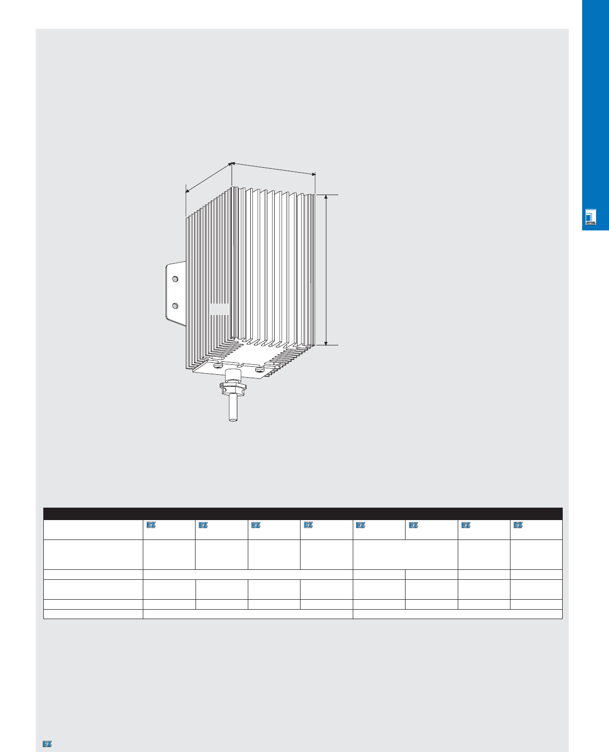
CLIMATE CONTROL SOLUTIONS
CLI 26
Technical Specifications
Enclosure Heaters
3106000/3115000/3116000/3107000/3102xxx
D
W
H
Enclosure Heaters
Part No. 3106000 3115000 3116000 3107000 3102000 3102110 9967053 9967054
includes fan includes fan includes fan includes fan
Dimensions in mm H 125 110 185 140 168 145 145
W45 64 6480 120 145 145
D35 54 54 118 145 102 102
Rated voltage Volt/Hz 110 V-240 V AC 230 V 115 V 115 V 230 V
Continuous heat 10 W 30 W 50 W 130 W 300 W 300 W 1000 W 1000 W
output at Tu = 20°C
Pre-fuse T 2.0 A 4.0 A 4.0 A 4.0 A 4.0 A 4.0 A 12.0 A 6.0 A
Type of connection 1'/0.3 m cord Terminal block
Specifications subject to change.
Dimensions in millimeters (mm) unless otherwise indicated.
D
W
H
Designates a product in the EnclosureZone program.
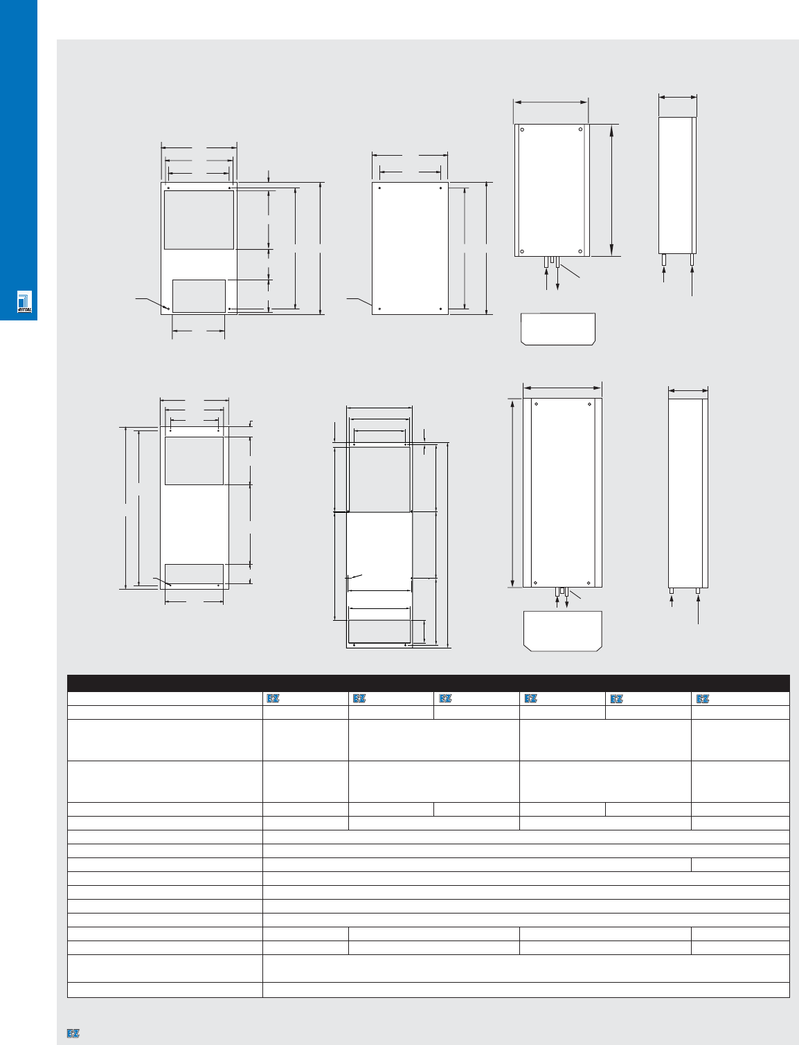
CLIMATE CONTROL SOLUTIONS
CLI 27
Technical Specifications
Air/Water Heat Exchangers
475 520
127 Ø7
475 520
240
298
Ø7
120
230
208
240
272
298
33
112
400
340
280
463
280
60
340
Ø7
950
904
Air/Water Heat Exchangers
Part No. 3214100 3217100 3217115 3218100 3218115 3216100
Rated voltage Volt/Hz 230/50/60 230/50/60 115/50/60 230/50/60 115/50/60 230/50/60
Dimensions in inches/mm H 19.7"/500 mm 20.47"/520 mm 37.40"/950 mm 55.5"/1400 mm
W7.9"/200 mm 11.73"/298 mm 15.75"/400 mm 18"/450 mm
D3.7"/100 mm 5.31"/135 mm 7.87"/200 mm 10"/250 mm
Useful cooling output L35 W 10, 200 l/h 2050 BTU/680 W 3400 BTU/1000 W 10250 BTU/3000 W 17050 BTU/5000 W
(95°F internal/50°F water) L35 W 10, 400 l/h 3400 BTU/1000 W 3750 BTU/1100 W 11950 BTU/3500 W 17050 BTU/5000 W
3750 BTU/1100 W
Maximum rated current 0.17/0.18 A 0.6/0.5 A 1.1 A 0.42 A/0.48 A 1.0 A 0.9/1.3 A
Pre-fuse T 2.0 A 4.0 A 4.0 A 4.0 A
Refrigerant water (pH-neutral)
Water entry temperature +35°F to +86°F/+1°C to +30°C
Operating pressure 15 to 145 psi/1 to 10 bar
14.5 to 145 psi/1 to 10 bar
Ambient temperature range +34°F to +158°F/+1°C to +70°C
Noise level 58 dBa
Protection rating per EN 60 529/10.91 NEMA 4/IP 65*
Type of connection Terminal block
Weight 15 lbs/6.8 kg 26.5 lbs/ 12 kg 46.3 lbs/21 kg 123 lbs/56 kg
Air displacement - 140 cfm/240 m3/h 260 cfm/450 m3/h -
Temperature control Thermostat Setting range +68°F to +140°F/
+20°C to +60°C
Temperature monitoring Built-in thermostat with change-over contact, 16 A capacity
* When heat exchanger/cabinet interface is sealed. Specifications subject to change. Dimensions in millimeters (mm) unless otherwise indicated.
3217XXX
"On-the-wall" mounting
3214100
"On-the-wall" mounting
3217XXX
3218XXX
"On-the-wall" mounting
298
520
.5"
400 200
Condensate
Drain .5"
Dia. Cooling Water
Connections
.5" Dia.
.5"
135
Condensate
Drain Cooling
Water
Intake
950
3218XXX3216100
"On-the-wall" mounting
450
350
410
15
33.5440711.5
180
455 455
1400
455
433.5
Ø 8
420
Designates a product in the EnclosureZone program.
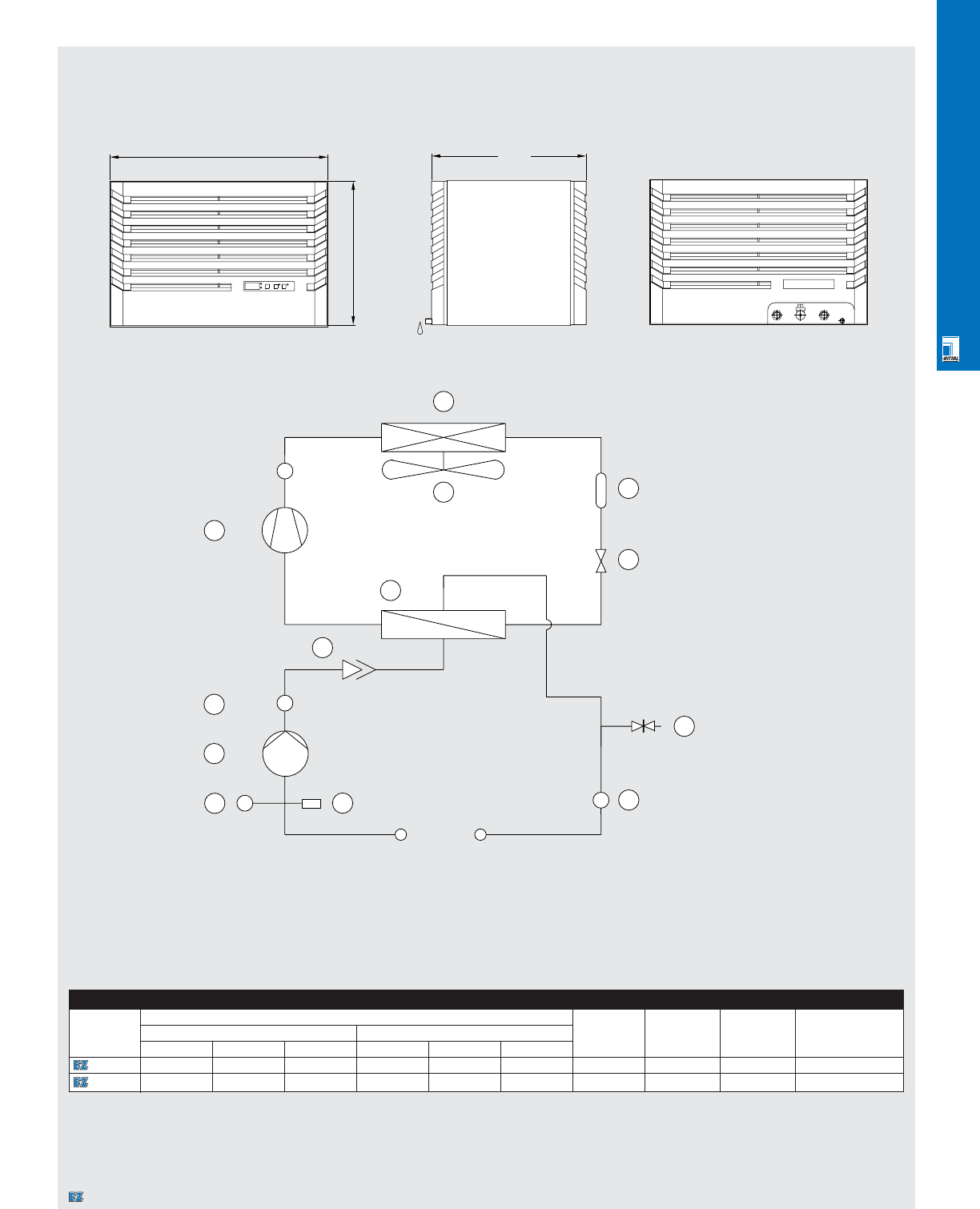
CLIMATE CONTROL SOLUTIONS
CLI 28
Technical Specifications
Mini Chillers
Front View
Legend:
1. Compressor
5. Condenser
10. Condenser fan
15. Evaporator
20. Expansion valve
25. Filter dryer
35. Water pump
40. Flow switches
45. Vent valve
50. Water intake
55. Water temperature sensor
60. Pressure valve
65. Pressure expansion chamber
Side View Rear View
Functional Diagram
400
600
426
T
P
S
5
10 25
20
30
1
15
45
40
35
65 60
50
55
Mini Chillers
Part No.
Exact outside dimensions Voltage Current Pressure, Cooling
capacity
inches mm psi BTU
HWDH WD
3318510 16 24 17 400 600 426 230/50/60 V 4.1 A 363 3275/3650
3319510 16 24 17 400 600 426 230/50/60 V 5.4 A 363 5085/5665
600
400
426
Designates a product in the EnclosureZone program.
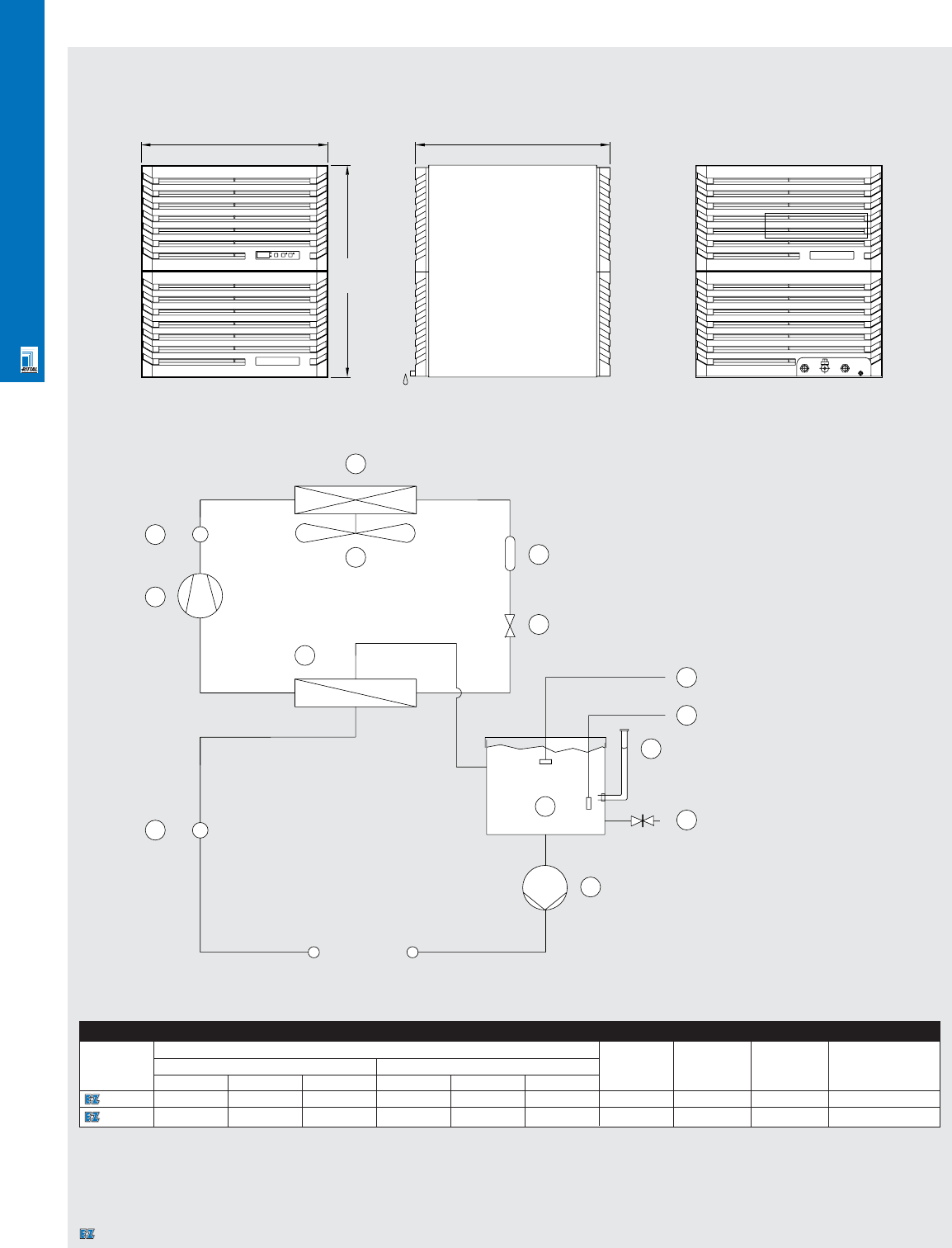
CLIMATE CONTROL SOLUTIONS
CLI 29
Technical Specifications
Chillers
Front View Side View Rear View
Legend:
1. Compressor
5. Condenser
10. Condenser fan
15. Evaporator
20. Expansion valve
25. Filter dryer
30. Water tank
35. Intake valve
40. Drain
45. Water level switch (optional)
50. Temperature sensor
55. Pump
60. Flow monitor
70. Pressostat
Functional Diagram
600
680
625
P
S
5
10 25
70
1
15
40
50
45
55
35
20
60
30
Chillers
Part No.
Exact outside dimensions Voltage Current Pressure, Cooling
capacity
inches mm psi BTU
HWDH WD
3320502 27 24 25 680 600 625 460/60, 3~ 3 A 334 11,390
3334502 27 24 25 680 600 625 460/60, 3~ 5.2 A 334 17,080
600
680
625
Designates a product in the EnclosureZone program.
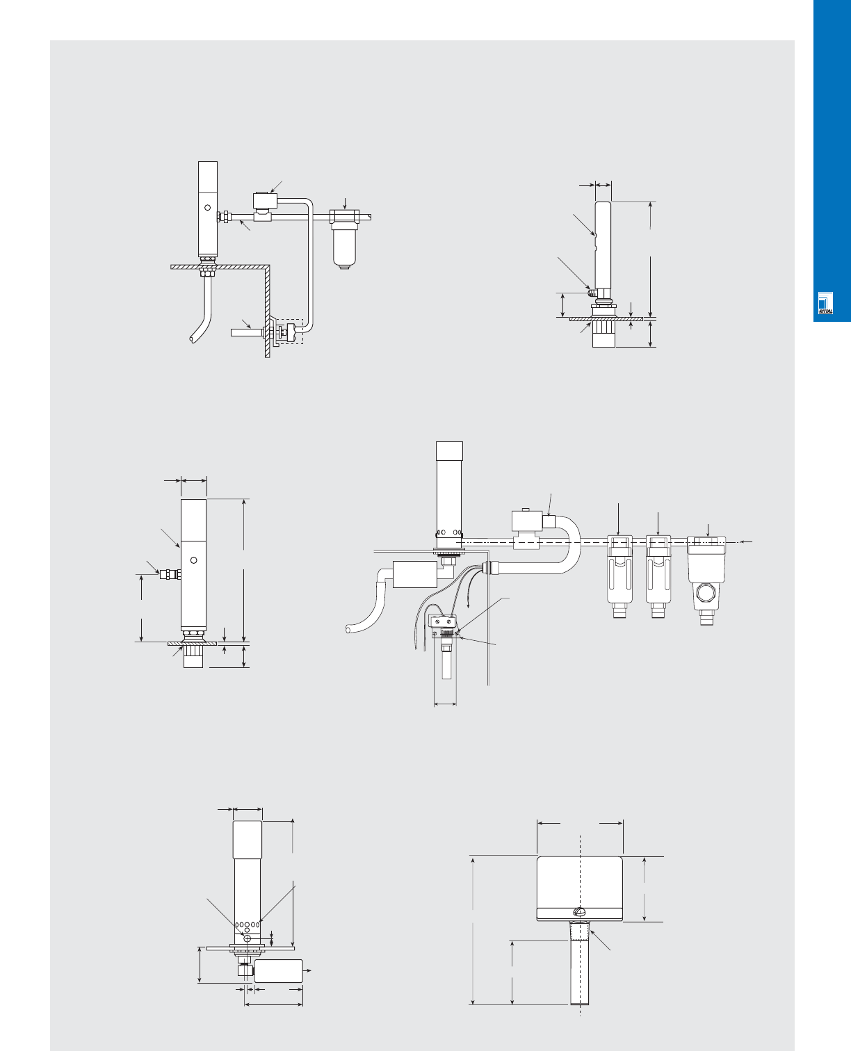
CLIMATE CONTROL SOLUTIONS
CLI 30
Technical Specifications
Vortex Kooler Enclosure Coolers
NEMA 12 Vortex Kooler System 400 BTU Vortex Koolers
NEMA 12 900-2500 BTU Vortex Koolers
NEMA 4/4X
Vortex Koolers
NEMA 4/4X Vortex Kooler System
Thermostat mounts in 11/16" hole in enclosure (mounts
inside enclosure for NEMA 4/4X applications)
NO NO COMMON
Solenoid
valve
Compressed
air inlet line
Thermostat
Ducting kit
Filter
7/8" Dia.
(22mm)
Exhaust
1/8" NPT
inlet
1-9/16"
(40mm)
Mounts in 1-3/32"
(28mm)
hole in enclosure
7-1/16"
(179mm)
1/4"
(6mm)
1-5/8"
(41mm)
1-3/4" Dia.
(44mm)
Hot
exhaust
1/4" NPT
(F) inlet
5-5/32"
(130mm)
Mounts in 1-3/32" (28mm)
hole in enclosure
(3/4 knockout)
10-3/4"
(273mm)
1/4"
(6mm)
1-5/8"
(41mm)
Solenoid valve
1/4" NPT normally closed
NEMA 4/4X Rated 15/50/60
or 230/50/60 1/2" NPT
conduit hole Oil filter
(optional) Water trap
(optional)
Airflow
User supplied
liquid tight conduit and
conduit fittings
Mount thermostat
to inside panel of
enclosure with (2) 6-32
screws on 1.75" centers
Adjustable thermostat
(remove black housing
and sheetmetal housing
base before attaching)
Thermostat must be mounted inside of
NEMA 4 or 4X enclosure to maintain NEMA
rating of Vortex Kooler system
5 Micron filter
(supplied)
2" (51mm)
Dia.
1/4"
18 NPT
inlet
10-3/4"
(273mm)
Hot exhaust
Cold air outlet
3.44 (97)
5.47 (.39)
2.125 (54.0)
3/8 NPT
2-11/16"
Mounts in
1-15/16" (49mm) hole
in enclosure
(1-1/2" Knockout)
5/8"
(16mm)
2-5/8"
(67mm)
4-1.2" (115mm)
Muffler
3-39/64"
(92mm)
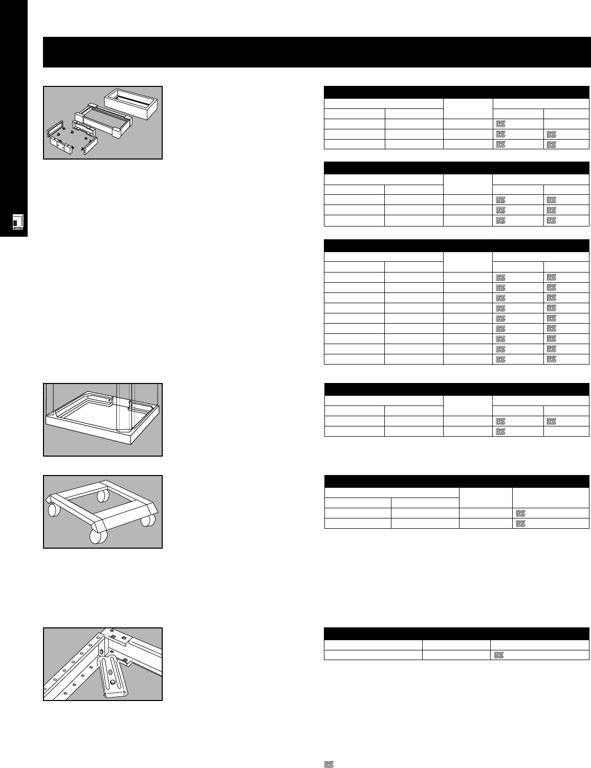
RITTAL ACCESSORIES
Plinths And Cable Bases For AP Enclosures
For enclosures WxD Packs of Part No.
inches mm 4" plinth 8" base
24x16 600x400 1 2911200 2912200
24x20 600x500 1 2807200 2808200
31x16 800x400 1 2901200 2902200
31x20 800x500 1 2841200 2842200
39x16 1000x400 1 2891200 2892200
47x16 1200x400 1 2921200 2922200
47x20 1200x500 1 2851200 2852200
63x16 1600x400 1 2961200 2962200
63x20 1600x500 1 2863200 2864200
ACC 1
Bases And Accessories
Plinths And Cable Bases
For AE Enclosures
Plinths And Cable Bases
For AK Enclosures
Plinths And Cable Bases
For AP Enclosures
Plinths And Cable Bases For AE Enclosures
For enclosures WxD Packs of Part No.
inches mm 4" plinth 8" base
24x12 600x300 1 2816200 -
31x12 800x300 1 2818200 2828200
39x12 1000x300 1 2801200 2802200
Floor Clamp
Packs of Part No.
Floor clamp 10 2817000
Mobile Base
Combines high functionality with
modern design.
•Enclosure can easily be moved
•High floor clearance
•High load capacity, 265 lbs/120 kg
static load per caster.
Configuration: base with 4 casters,
including two with brake.
Color:
Base: RAL 7032 pebble grey/
7033 mortar grey
Casters: RAL 9005 black
Floor Clamp
8 ga/4 mm galvanized sheet steel,
chromatized.
Plinths And Cable Bases
For PC Enclosures
Mobile Base
For enclosure WxD Packs of Part No.
inches mm
24x24 600x600 1 2981200
24x31 600x800 1 2982200
Plinths And Cable Bases For AK Enclosures
For enclosures WxD Packs of Part No.
inches mm 4" plinth 8" base
24x16 600x400 1 2911200 2912200
31x16 800x400 1 2901200 2902200
47x16 1200x400 1 2921200 2922200
Plinths And Cable Bases For PC Enclosures
For enclosure WxD Packs of Part No.
inches mm 4" base 8" base
24x24 600x600 1 2813200 2814200
24x31 600x800 1 2846200 -
Designates a product in the EnclosureZone program.
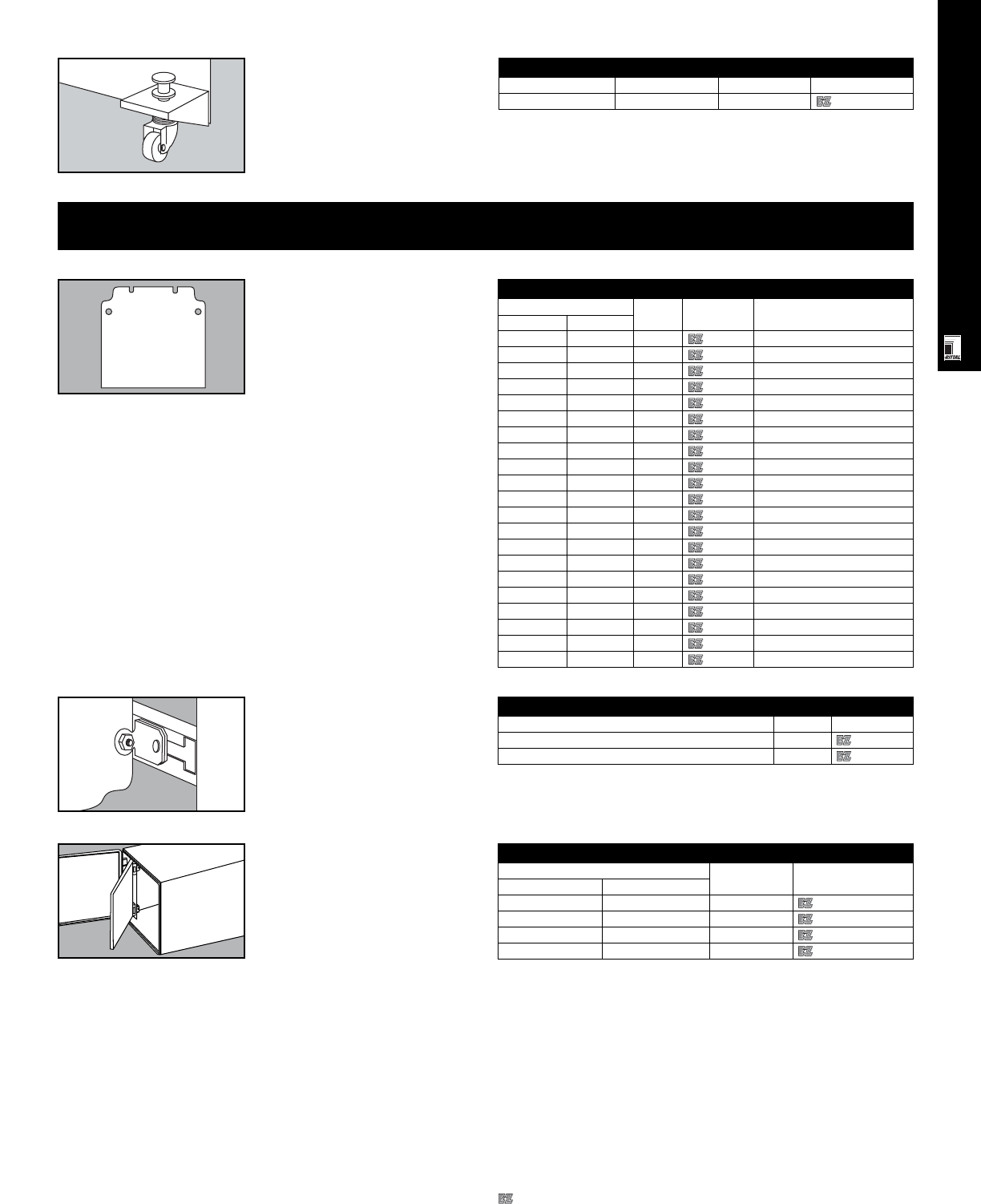
RITTAL ACCESSORIES
ACC 2
Wheel Casters
Use only on installed plinths or
cable bases.
Configuration: 1 set includes 4
casters. Also available with foot
brake: 2 casters with and 2 casters
without brakes per set.
Mounting Surfaces And Accessories
Mounting Panels For
KL Enclosures
Material: hot-dipped galvanized zinc
Finish: Type M
Mounting Panels For KL Enclosures
Mounting panel HxW Packs of Part No. Fits
inches mm
5.31x4.92 135x125 1 1560700 KL 1500/14/21
7.28x6.89 185x175 1 1562700 KL 1502/23
11.22x4.92 285x125 1 1561700 KL 1501/15/30/22
11.22x6.89 285x175 1 1563700 KL 1503/17/31/24
11.22x10.83 285x275 1 1567700 KL 1507
15.16x6.89 385x175 1 1564700 KL 1504/25
15.16x10.83 385x275 1 1568700 KL 1508
15.16x14.76 385x375 1 1571700 KL 1511
19.09x6.89 485x175 1 1565700 KL 1505
19.09x10.83 485x275 1 1569700 KL 1509
23.03x6.89 585x175 1 1566700 KL
23.03x10.83 585x275 1 1570700 KL
23.03x14.76 585x375 1 1572700 KL
30.91x6.89 785x175 1 1574700 KL
30.91x14.76 785x375 1 1573700 KL
7.28x4.92 185x125 1 1575700 EB 1751
15.16x4.92 385x125 1 1576700 KL
9.25x6.89 235x175 1 1597460 EB 1752
11.22x8.86 285x225 1 1597470 KL/EB
13.19x10.83 335x275 1 1597480 KL/EB
15.16x12.79 385x325 1 1597490 KL/EB
Dead-Front Kit For
AE Enclosures
Provides a NEMA 1 safety barrier and
mounting surface towards the front of
AE enclosures. Easy installation and
can be retrofitted to existing
enclosures. Depth adjustable by
using SZ 2574 system blocks and
modified C-rails.
Configuration: mounting brackets,
sheet steel panel and hardware.
Color: RAL 7032 pebble grey
Dead-Front Kit For AE Enclosures
For AE enclosure HxW Packs of Part No.
inches mm
20x20 500x500 1 9962957
24x24 600x600 1 9962958
30x24 760x760 1 9962959
30x30 760x760 1 9962960
Mounting Panel Depth
Adjustment Bracket
For KS
Slides into molded C-rails in KS
enclosures and is infinitely
adjustable. Also allows installation of
rails instead of mounting panel.
Wheel Casters
For enclosure Brake Packs of Part No.
AE, AK, PC yes 1 set 4570000
Mounting Panel Depth Adjustment Bracket For KS
For Enclosure Packs of Part No.
KS 1468, KS 1480 4 1491000
KS 1432, KS 1434, KS 1444, KS 1446, KS 1466 4 1481000
Designates a product in the EnclosureZone program.
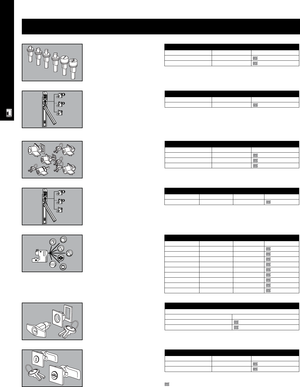
RITTAL ACCESSORIES
ACC 3
KS Lock Inserts
Specially designed safety lock system
for KS Series fiberglass-reinforced
enclosures. Replaces standard turn-
buckle locks and accepts a special
series of KS lock inserts and convenient
thumb turn handles.
Locking Systems
Ergoform-S Lock System
For KS Enclosures
Specially designed safety handle/lock
system for KS Series fiberglass-
reinforced enclosures. Accepts the
whole range of standard Ergoform-S
lock inserts as well as the special KS
lock system inserts.
KS Lock Inserts
KS lock system Packs of Part No.
Thumb turn handle with key 1 1484000
Screwdriver insert 1 1489000
Ergoform-S Lock System For KS Enclosures
Ergoform-S lock system Packs of Part No.
Ergoform-S safety handle 1 1490000
Thumb Turn Handles Thumb Turn Handles
For Packs of Part No.
AE/CP 1 2576000*
AE/EL 1 2533000*
AP (top/center) 1 2599000
* Does not fit AE 1114/1213 and AE stainless steel.
Ergoform-S Lock System
Rittal’s patented security lock system
for enclosures: handle springs forward
for easy door opening, accepts a wide
range of lock inserts, easy to install, no
modifications required.
Lock Inserts
For Ergoform-S.
Lock Inserts
Type Size Packs of Part No.
Square 0.28" (7 mm) 1 2460000
Square 0.31" (8 mm) 1 2461000
Triangular 0.28" (7 mm) 1 2462000
Triangular 0.31" (8 mm) 1 2463000
Screwdriver - 1 2464000
Daimler-Benz - 1 2465000
Double bit - 1 2466000
Pushbutton - 1 2468000
Pushbutton/key Key # 2123 E 1 2469000
T-Handles
Material: die-cast zinc, chrome plated.
Configuration: includes installation
hardware, gasket, and 2 keys.
T-Handles
Type B
Version Part No.
With no. 3524 E security insert 2575000
Without security insert 2572000
Replacement Lock For AE
Turn-buckle lock complete with
double bit or lock/key insert.
* Does not fit AE 1114/1213 and AE stainless steel.
Ergoform-S Lock System For KS Enclosures
Type Finish Packs of Part No.
Standard Grey/brown 1 2450000
Replacement Lock For AE
Replacement lock Packs of Part No.
With double bit insert 1 2420000*
With 3524E insert 1 2430000*
Designates a product in the EnclosureZone program.
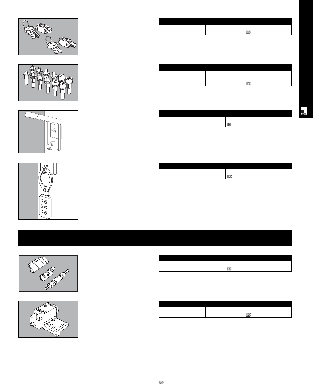
Lock Inserts
Type Packs of Part No.
1.61"
S/S screwdriver 1 9964254
RITTAL ACCESSORIES
ACC 4
Security Insert
For Packs of Part No.
AE/CP 1 2571000
Security Insert
Lock system with 2 keys.
* For all AE, EL and CP enclosures. Does not fit AE 1114/1213.
Lock Inserts
1.61" (41 mm) inserts for FT 2749
control panel lock; SR 2026/2027/2034
swing frames.
Padlock Hasp
Can be retrofitted on all AE compact
enclosures with Type A lock. Ready
for padlocks and safety lockouts.
Material: zinc diecast
Configuration: padlock hasp including
installation hardware.
Safety Lockout
Prevents unauthorized opening of the
enclosure and accidental activation of
the system. The safety lockout is the
ideal solution in cases where individual
access for several persons is required
for maintenance and repair purposes.
The safety lockout provides space for
6 padlocks.
Material: sheet steel, chromated
Configuration: safety lockout without
padlocks.
Padlock Hasp
Packs of Part No.
12493000
Safety Lockout
Packs of Part No.
22493500
Door System Accessories
180° Hinges
To replace standard 130° hinges
(installation hardware included).
Material: die-cast zinc
180° Hinges
Packs of Part No.
22449000
Door Switch
Activates enclosure lighting and/or
enclosure climate control
components.
Door Switch
Packs of Part No.
Complete set 1 4127000
Designates a product in the EnclosureZone program.
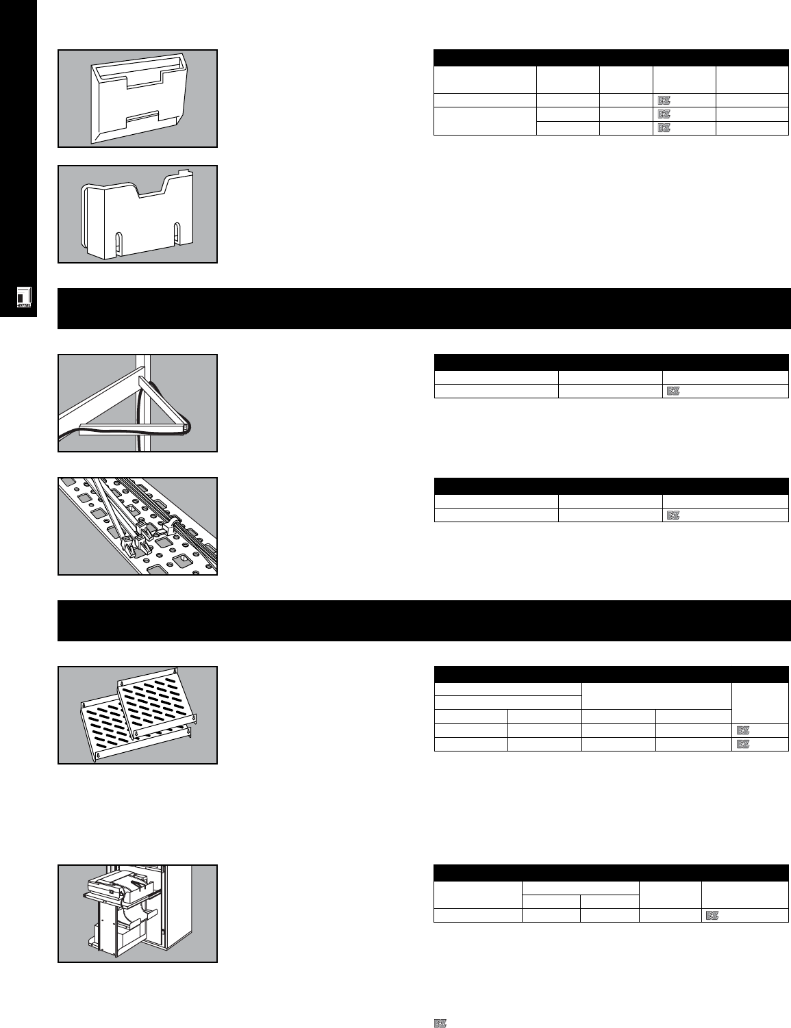
RITTAL ACCESSORIES
ACC 5
Print Pockets Print Pockets
Description Paper size Packs of Part No. For enclosure
(inches/mm)
Transparent pouch 8.5" x 11" 1 2510000 any size
Molded plastic 11" x 17" 1 2513000 any size
8.5" x 11" 1 2514000 any size
Cable Management
Hinged Cable Carrier
Installs behind component shelves
on telescopic slides to provide safe
cable routing.
Hinged Cable Carrier
Packs of Part No.
Cable carrier 1 7163000
Cable Ties
Clip into system installation holes.
Cable Ties
Packs of Part No.
Cable ties 100 2597000
Shelves And Accessories
Component Shelves For
Fixed installation in
24”/600 mm Wide PC
Are installed directly to enclosure frame
- simply hang on 4 screws and tighten.
Material: sheet steel
Finish: powder coated, textured, RAL
7035 light grey
Configuration: complete with
installation hardware.
Accessories: positioning bolts for
vented component shelves (DK 7115000)
Printer Carriage
For functional housing of printer in an
enclosure. Complete with telescopic
slides, paper feed and storage shelves.
Installation hardware included.
Load capacity: 55 lbs/25 kg
Material: sheet steel
Color: RAL 7032 pebble grey
Printer Carriage
Printer size For enclosure W x D Packs of Part No.
inches mm
Standard 24 x 24 600 x 600 1 4635000
Component Shelves For Fixed Installation
For enclosure depth Shelf area Part No.
PC
inches mm inches mm
26 650 20.08 x 21.85 510 x 555 4619660
33 850 20.08 x 29.72 510 x 755 4619680
Designates a product in the EnclosureZone program.
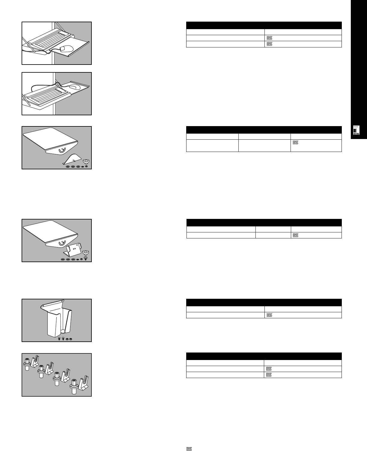
RITTAL ACCESSORIES
ACC 6
Mouse Pad
Can be installed in PC enclosures
with keyboard drawer or shelf. Pulls
out to right or left side (drawer) or
front (shelf). Complete with
self-adhesive pad covering and
installation hardware.
Mouse Pad
For enclosure Part No.
PC fold-down with keyboard shelf 4613000
PC pull-out with keyboard drawer 4614000
Mouse Pad Tray For Desk
Consoles
Can be mounted on operator interface
enclosures with a desk console (ie PC)
or on other AP Series consoles for
accommodation of SM 6444000 and
SM 6444500 IP 67 mouse pads. The
slope of the mouse pad tray can be
infinitely adjusted. Installation requires
drilling two installation holes in the
console.
Material: sheet steel, chromated
Configuration: mouse pad tray,
installation hardware.
Mouse Pad Tray
Description Packs of
Part No.
Mouse pad tray 1
2381000
Mouse Pad Tray
Is mounted on vertical handles of
keyboard housings for accommodation
of SM 6444000 and SM 6444500
IP 67 mouse pads. The slope of the
mouse pad tray is infinitely adjustable.
Installation requires drilling two
installation holes in the handle grip
brackets.
Material: sheet steel, chromated
Configuration: mouse pad tray,
installation hardware.
Mouse Holder
Fits Rittal mouse pad trays to ensure
safe storage of a standard mouse or
the Rittal SM 6445000 IP 67 mouse.
Material: sheet steel, chromated
Configuration: mouse holder,
installation hardware.
Mouse Holder
Packs of
Part No.
1
2382000
Mouse Pad Tray For Desk Consoles
For Packs of
Part No.
PC 4603704 1
2380000
AP Series consoles
Mounting Kit For Threaded Bolts
Thread Part No.
M4 6058500
M5 6053500
Mounting Kit For
Threaded Bolts
For fastening:
• aluminum front panels
• control panels
• keyboards.
Designates a product in the EnclosureZone program.
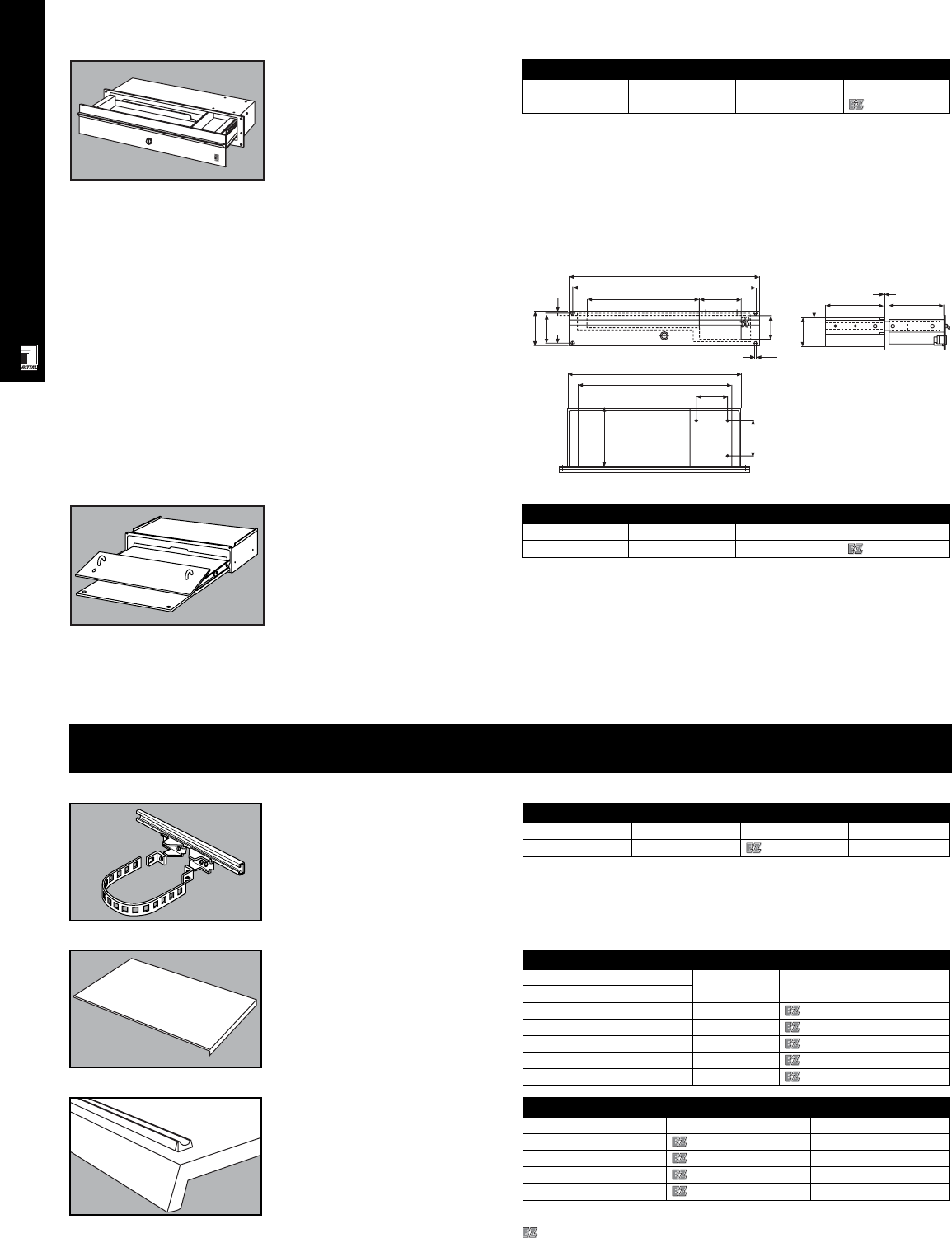
RITTAL ACCESSORIES
ACC 7
General Accessories
Pole Mounting Kit
For standard wallmount enclosures
up to 24" wide. Kit consists of 2
cross rails, 4 clamps, 2 straps and
installation hardware.
Pole Mounting Kit
Packs of Part No. Fits
Pole mounting kit 1 kit 2584000 AE, KL
Lids/Covers For AP Consoles
Width x Depth Packs of Part No. Fits
inches mm
31.50x15.55 800x395 1 2615200 AP 2600, 2611
31.50x19.49 800x495 1 2616200 AP 2610, 2613
47.24x15.55 1200x395 1 2645200 AP 2620, 2641
47.24x19.49 1200x495 1 2646200 AP 2640, 2643
62.99x19.49 1600x495 1 2656200 AP 2650, 2653
Lids/Covers For AP
Consoles
Can cover both bottom consoles
and center section.
Pencil Ledge For AP
Consoles
Prevents pencils and paper from
sliding off the console lid.
Pencil Ledge
Packs of Part No. Fits
32676000 AP 2666
32678000 AP 2611, 2613, 2668
32680000 AP 2670
32682000 AP 2641, 2643, 2672
Keyboard Drawer With Mouse Pad
Height Width Depth Part No.
3 U 19"/482.6 mm 232 mm 6003000
Keyboard Drawer With
Mouse Pad
With 19"/3 U front panel for installation
on all sufficiently large surfaces (door,
side wall, etc.).
Technical data:
•Accepts keyboards up to HxWxD =
1.65"x18.11"x6.69"/460x42x170 mm
•Storage area for mouse under side
of keyboard
•Front pull-out mouse pad
•Front panel:
- reversible, for track ball
- lockable, No. 3542 E insert
- features grip
•High protection rating and EMC
shielding is maintained, even
when drawer is open.
Material:
Mounting frame: steel,
zinc-coated, chromated
Keyboard housing and tray:
aluminum
Front panel and grip: aluminum,
natural anodized
Keyboard Drawer 19"/2 U
Height WIdth Depth Part No.
2 U 19"/482.6 mm 5.90"/150 mm 6002200
R
Keyboard Drawer 19"/2 U
Can be mounted in all 19" systems or
on any sufficiently large surface (door,
side wall, etc.). Its low weight (5.5
lbs/2.5 kg) makes it ideal for use in
support arm systems because
adequate room remains for cabling,
even when the support arm is
connected from below. It can also be
locked with a 3524 E lock.
High mechanical protection and
shielding is maintained, even when
the drawer is open.
Technical data:
•Total available space:
15.35"x1.26"x5.47"/390x32x139 mm
•Drawer has 2.36"/60 mm high space
on right for a mouse or trackball or
for a 3-1/2" disk drive.
•When a mouse is used or when
a 3-1/2" drive is installed, only
enough space remains for an
11.2"/284 mm wide keyboard.
Material:
Frame: sheet steel, zinc-plated,
chromated
Drawer housing and drawer:
aluminum
Front panel and handle: aluminum,
natural anodized
Configuration: Drawer housing
with drawer, includes slides with
stops for 'open' position, front panel
with handle, gasket and installation
hardware.
482.6
465
284
31
88
76.2
4.5
60
75
139
2
148.5
46
106
90
441
139
79
390
Designates a product in the EnclosureZone program.
RITTAL ACCESSORIES
ACC 8
Quick Release Fastener
Saves time during inspection and
maintenance. Fits into holes in cover
and housing bracket. No drilling
required.
US Patent No. 4,550,852
Quick Release Fastener
Packs of Part No.
Fastener 12 1593000
Cover Hinge
Is simply screwed onto the perimeter
channel and door edge.
Cover Hinge
Packs of Part No.
Cover hinge 6 1592000
Threaded Insert Nuts
For KS
Fit in molded fixing nuts on door and
inside rear wall of KS enclosures
and facilitate mounting of DIN rails,
panels, etc.
Threaded Insert Nuts
Packs of Part No.
Threaded insert nuts 20 1482000
Wall Brackets
For enclosure Stand-off Material Packs of Part No.
type from wall
(inches/mm)
EB/KL 5/16/8 Nickel plated brass 4 1580000
EB/KL 5/16/8 Zinc coated steel 4 1590000
EB/KL S/S 5/16/8 T 304 stainless steel 4 1594000
AE 1 5/8/40 Zinc coated steel 4 2503200
AE 3/8/10 Zinc coated steel 4 2508200
AE S/S 3/8/10 T 304 stainless steel 4 2433000
KS Flush Fiberglass reinforced 4 1483000
polymide
Wall Brackets For
KL/EB/AE/KS Enclosures
Fasten enclosure securely to wall.
Grounding Straps
Choose from 6 ready-to-use
grounding straps in different lengths
and thicknesses. For M6 and M8 screws.
Grounding Straps
Wire size Packs of Part No.
AWG ø 7" long 12" long
11 4 mm252564000 2567000
516 mm252565000 2568000
325 mm252566000 2569000
Screws For
Grounding Straps
Includes screws and washers.
Screws For Grounding Straps
Thread Packs of Part No.
M6 10 sets 2570000
M8 10 sets 2559000
Console
For installing display and control
components. Removable cover plates
top and bottom.
Material:
Desk section and cover plates: sheet
steel
Trim strips: aluminum
Color: textured RAL 7032
Trim strips: RAL 5018
Console
Height (mm) Part No.
200 2696200
Supply includes: console, 2 cover
plates, 3 trim strips, including
installation hardware.
Designates a product in the EnclosureZone program.

RITTAL ACCESSORIES
ACC 9
Light Bulbs
Light bulbs for optical components with bayonet fastenig, B 15d, for new
orders and spares.
Light Bulbs
Light bulb Packs of Part No.
24 V, 5 W 3 2374060
230 V, 5 W 3 2374070
Connections Components
With Cover
Choose from conduit mounting or
wall/base installation units. Screw
terminals are in the connection
component. Contact hazard protection
to VDE.
Material: enclosure of polyamide
Ratings: NEMA 12/IP 54
Color: black
Connections Components With Cover
Connection components with cover Part No.
For conduit mounting 2368000
For wall/base mounting 2368010
Optical Components
With 360° signal emission through
optimized prism technology. The
optical components may be mounted
at any point on the pillar. Number of
possible stages = 5 components of
equal voltage. Bayonet fastening, B
15d, for incandescent lamps up to a
maximum of 7 W.
Material:
Enclosure: polymide
Cap: transparent polycarbonate
Ratings: NEMA 12/IP 54 when end cover
or audible components are mounted.
Configuration: optical component including
gasket (light bulbs not supplied).
Optical Components
Color Red Green Yellow Clear Blue
Optical components Part No.
Continuous light component 2369000 2369010 2369020 2369030 2369040
12-240 V AC/DC
Flashing light component 2370000 2370010 2370020 2370030 2370040
24 V AC/DC, 125 mA/225 mA
Flashing light component 2370050 2370060 2370070 2370080 2370090
230 V AC, 15 mA
Strobe light component 2371000 2371010 2371020 2371030 2371040
24 V AC/DC, 125 mA/225 mA
Strobe light component 2371050 2371060 2371070 2371080 2371090
230 V AC, 15 mA
LED continuous light 2372000 2372010 2372020 2372030 2372040
component 24 V AC/DC, 60 mA
Enclosure Lights
Rittal's new flourescent enclosure
lights are designed for quick and easy
installation. The external terminal block
means no need to dissassemble the
light to make electrical connections.
Available in 15 or 18 watt rating, they
can be used with or without the Rittal
4127000 door switch. Equipped with
interference suppression capacitor or a
RFI filter they also come with or without
a lamp shade or 115 V U.S. style
receptacle.
Adavantages:
•Low profile for space efficiency
•Quick and easy installation
•Simple external electrical
connections
•With or without 120 V U.S. receptacle
•With or without lamE L21p shade
•Interference suppression
•UL and CSA approvals
Enclosure lights specifications:
•Rating: 120 V, 60 Hz
•Color: RAL 7044
•Lights medium: cool white
•Includes installation hardware
•Connection terminals: L1, N, Gnd
Enclosure Lights
Part No. Installation length Technical data
With interference With RFI filter, A
suppression capacitor U.S. receptacle
and no receptacle and lamp shade
or shade
9968108 9968111 18.3"/467 mm 15 W, 120 V, 60 Hz
9968109 9968112 24.41"/620 mm 18 w, 120 V, 60 Hz
•Suppression capacitor or RFI
filter
•UL recognized for Canadian
and U.S. requirements
•On/off rocker switch
•Clear lamp shade option
•U.S. receptacle option
Designates a product in the EnclosureZone program.
RITTAL ACCESSORIES
ACC 10
Interface Box
The Rittal interface box provides
secure accommodation for all standard
computer ports, 3-1/2" disk drives and
sockets. The lockable metal cover
provides a high mechanical load-
bearing capacity, protects against
unauthorized access and ensures an
increased shielding effect for the
installed equipment.
Material:
Frame: extruded aluminum section
Mounting tray: sheet steel, 1.5 mm
Cover: aluminum, 3.0 mm
Interface Box
Part No.
No socket 2482000
Surface finish:
Frame and mounting tray: powder
coated in RAL 7035 light grey
Cover: natural anodized
Supply includes: frame with
hinged cover, cam with lock insert
no. 3524 E, mounting tray including
seal and installation hardware.
Cable Flange For 24-pin
Plug Wall Cutouts
Allows routing of cables with
pre-assembled or molded plugs
without having to remove the plug.
Accommodates .31" to 1.42" (8 to 36
mm) ø cable.
Configuration: 2 half shells
including gaskets,1 attachment
clamp.
Cable Flange For 24-Pin Plug Wall Cutouts
Packs of Part No.
Cable flange 1 2400500
Audible Components
To indicate warnings or malfunctions.
Either a continuous or a pulsating tone
may be selected. The sound pressure
is 85 dB/100 dB.
Material:
Enclosure: polyamide
Color: black
Configuration: audible component
including gasket.
Audible Components
Audible components Part No.
85 dB 2376020
max. 25 mA
100dB 2376030
max. 25 mA
Mounting Components
Matching mounting components finish
off the new range of signal pillars from
Rittal. Here, you will find the correct
connection accessories to suit every
mounting variant.
Mounting Components
Mounting component Color Part No.
Base with integral conduit, 25 mm diameter, 110 mm long Black 2374000
Individual base, plastic Black 2374010
Individual conduit, 250 mm long Aluminum 2374020
Individual conduit, 400 mm long Aluminum 2374030
Bracket for one-sided mounting Black 2374040
Bracket for conduit mounting Black 2374050
Laminated Copper Bars
Rittal Flexibar “S”
Length: 2000 mm/bar
Material:
Cu Lamina —
• High-purity electrolyte copper F 20
Insulation —
•High-strength vinyl compound
•Expansion 370%
•Temperature range: -30°C to
+105°C
•Flame retardant version to UL 94-V0
•Dielectric strength: 20 kV/mm
Mounting Components
Construction1) InInInCurve Installa- Packs Part No.
(mm) at 50 K2) at 30 K2) at 10 K2) (short-circuit tion of
resistance) type
6x9.0x0.8 250 A 220 A 120 A - - 1 3565000
6x13.0x0.5 200 A 150 A 110 A - - 1 3566000
4x15.5x0.8 300 A 210 A 140 A - - 1 3567000
6x15.5x0.8 350 A 290 A 170 A a 1 1 3568000
10x15.5x0.8 450 A 350 A 190 A a 1 1 3569000
5x20.0x1.0 400 A 300 A 180 A a 1 1 3570000
5x24.0x1.0 450 A 370 A 230 A a 1 1 3571000
10x24.0x1.0 800 A 600 A 340 A b 1 1 3572000
5x32.0x1.0 550 A 470 A 280 A b 2/3 1 3573000
10x32.0x1.0 1000 A 800 A 460 A c 2/3 1 3574000
5x40.0x1.0 800 A 600 A 340 A b 2/3 1 3575000
10x40.0x1.0 1200 A 950 A 500 A c 2/3 1 3576000
10x63.0x1.0 1600 A 1240 A 715 A d 2/3 1 3579000
1) Number of layers x width of layers x thickness of layers.
2) The sum of the ambient temperature and temperature increase gives the resultant
conductor temperature of the laminated flat copper bar. Example: SV 3565000 loaded with
220 A, i. e. the temperature increases by 30 K. At an ambient temperature of 35°C, this
produces a resultant conductor temperature of 35°C + 30 K = 65°C.
Designates a product in the EnclosureZone program.
RITTAL ACCESSORIES
Pedestal/Platform
For support arm Color RAL Part No.
CP 6500 7035 6137535
CP 6000 7035 6137035
ACC 11
19" Rails
Aluminum or sheet steel 19" rails
punched for installation of 19"
components. Can easily be installed
into all 24"/600 mm wide enclosures
for conversion to 19" rack.
Note: must order EL 2093 screws
and EL 2094 nuts.
19” Rails
U For enclosure height Material Packs of Part No.
inches mm
17 Lower compartment of PC Aluminum 4 4632000
Compact Swing Frames
For AE And AP 6 - 14 HU
6-14U Compact Swing Frames For AE and AP
HU HWHWPacks Part No.
1HU=1.75" inches inches mm mm of
612.60 21.30 320 541 1 2026200
11 21.34 21.30 542 541 1 2027200
14 26.61 21.30 676 541 1 2034200
Pedestal/Platform
Provides good line of site for remote
applications.
Material: sheet steel
Finish: powder painted, textured,
RAL 7030 stone grey or RAL 7035
light grey
Configuration: pedestal/floor plate
with integrated reinforcement and
installation cutout for CP 6000 or
CP 6500 support arms; includes
installation hardware for support arms
Front Panels
Width Height Packs of Part No.
482.6 mm (19") 30.3 mm (7 U) 1 6028000
Aluminum Front Panels
For individual assembly of an operat-
ing interface. A fixing kit CP 6058000
is required for installation. Other sizes
and designs available on request.
Material: 3.0 mm aluminum, natural
anodized.
Wireway Reinforcement Bracket
Part No. Description For Electromate or industrial
wireway wireway families
Lay-in Feed- S/S feed-
Type 12 through through
Type 12 Type 4X
9967667 2.5"x2.5" Wireway reinforce plate 2.5"x2.5" X X -
9967668 4"x4" Wireway reinforce plate 4"x4" X X X
9967669 6"x6" Wireway reinforce plate 6"x6" X X X
9967670 8"x8" Wireway reinforce plate 8"x8" X X -
9967671 6"x12" Wireway reinforce plate 6"x12" X - -
Wireway Reinforcement
Bracket
The Rittal wireway reinforcement
support bracket is used as an
accessory for enclosures to facilitate
easy installation of NEMA-style
wireway directly to the sidewall or roof.
The kit makes installing wireway a snap
by positioning the enclosure's skin
between the wireway and
reinforcement bracket. Rittal's bracket
installation kit includes system bars,
brackets, nuts and bolts for a
complete reinforcement option.
Configuration:
•Sidewall/roof mounting
•Complete with hardware
•11 gauge steel
•RAL 7044 silk grey
•System bars for installation up to
1000 mm deep
•Dual brackets for variable mounting
of system bars
•Slide nuts facilitate easy location of
support bracket across entire length
of system bars
•M6 bolts for fastening
•M6 screws for wireway plate to
ensure flush fit
Technical specifications:
Material: steel
Finish: RAL 7044 silk grey
Wireway Reinforcement Bracket
Part No. Size A B C D
9967667
2.5"x2.5" 150 mm (591") 150 mm (5.91") 63.50 mm (2.50") 63.50 mm (2.50")
9967668
4"x4" 200 mm (7.87") 200 mm (7.87") 101.60 mm (4.00") 101.60 mm (4.00")
9967669
6"x6" 250 mm (9.84") 250 mm (9.84") 152.40 mm (6.00") 152.40 mm (6.00")
9967670
8"x8" 325 mm (12.79") 325 mm (12.79") 203.20 mm (8.13") 203.20 mm (8.13")
9967671
6"x12" 400 mm (15.75") 250 mm (9.84") 304.80 mm (12.00") 152.40 mm (6.00")
Designates a product in the EnclosureZone program.
RITTAL ACCESSORIES
ACC 12
Vented Component
Shelves
Weight capability: 110 lbs static
capacity
Color: RAL 7035 light grey
Configuration: 1 shelf with
installation hardware.
Vented Component Shelves
Shelf W x D Part No. Telescopic rails
inches mm
16.10 x 15.75 409 x 400 7144035 7061000
Base
The base provides 4"/100 mm
additional height for cable
management. Cable entry from all
four sides through removable panels.
Leveling feet can compensate for
unevenness of floor.
Material: sheet steel
Color: RAL 7035 light grey
Configuration: base, includes
installation hardware.
Base
For QuickRack enclosure Part No.
Frame width Frame depth
23.62"/600 mm 23.62"/600 mm 7526300
Combination Cable
Collecting Rails For
QuickRack
These rails make it possible to fasten
cables with cable clamps or cable
ties and also allow equipotential
bonding between the cable shield
and ground bus.
Material: sheet steel
Configuration: combination rail,
installation hardware.
Rack Storage Drawer
For BasicRacks Rack Storage Drawer For BasicRacks
Color Part No.
Black 9967641
Clear chemical coat 9967642
Double Divider Shelf
For BasicRacks Double Divider Shelf For BasicRacks
Color Part No.
Black 9967643
Clear chemical coat 9967644
Combination Cable Collecting Rails For QuickRack
Packs of Part No.
Frame width
23.62"/600 mm 6 7526930
Frame depth
23.62"/600 mm 6 7526940
Networking Accessories
Cable Tie Fastener
Packs of Part No.
100 6059000
Cable Tie Fastener
For all standard cable ties up to a
width of 3/16"/4.8 mm. The fastener is
inserted in a mounting channel and
fixed in place by striking the split-rivet.
Material: polyamide 6.6
Designates a product in the EnclosureZone program.
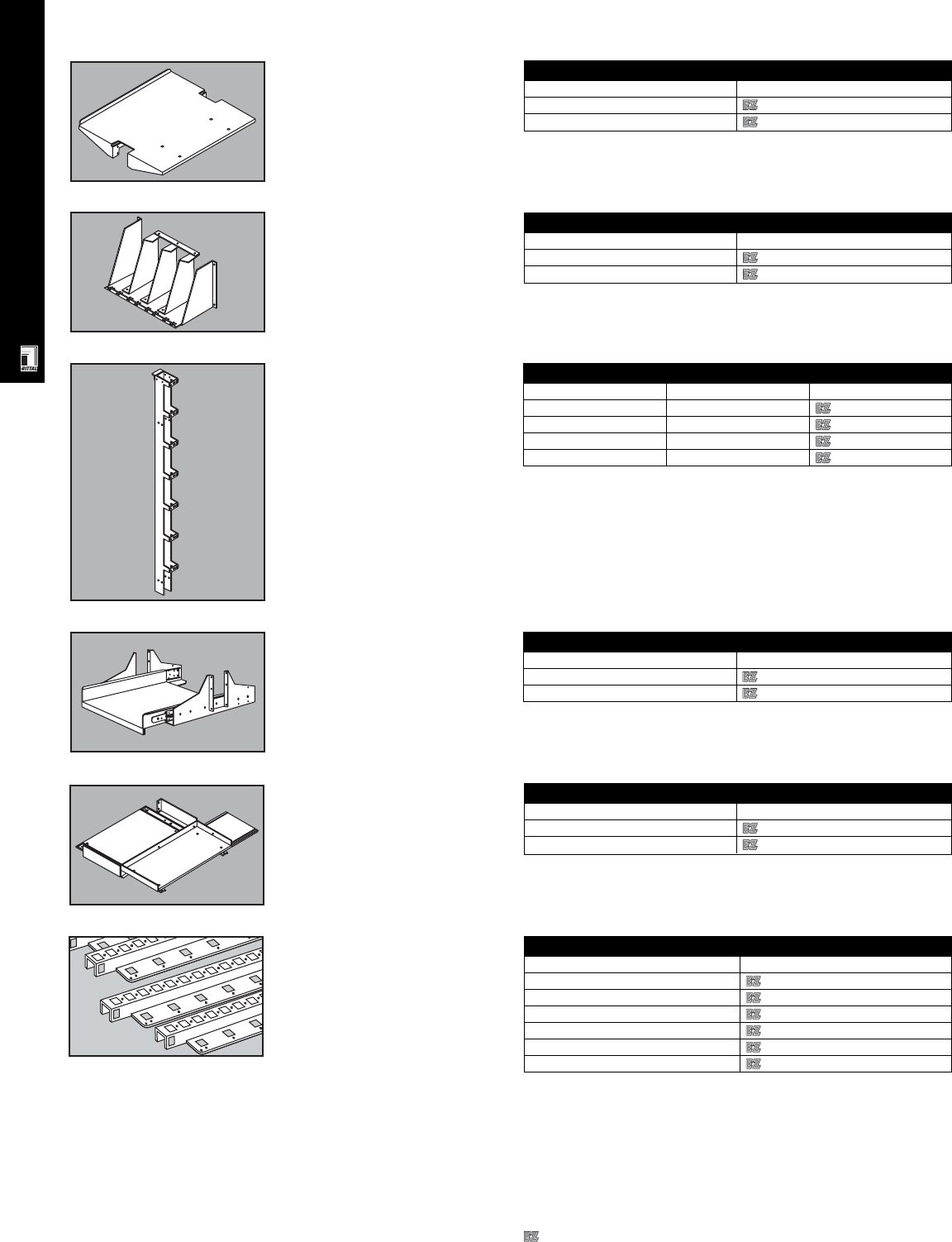
RITTAL ACCESSORIES
ACC 13
Adjustable Monitor Shelf
Convenient for video screens or any
equipment at any BasicRack
position. Mounting hardware not
included.
Adjustable Monitor Shelf
Color Part No.
Black 9967645
Clear chemical coat 9967646
Divider Shelf
Unique divider shelf for BasicRacks.
Divider Shelf
Color Part No.
Black 9967639
Clear chemical coat 9967640
Cable Management
Vertical cable management for
BasicRacks.
Cable Management
Description Color Part No.
3 ft. Black 9967653
3 ft. Clear chemical coat 9967654
7 ft. Black 9967651
7 ft. Clear chemical coat 9967652
Sliding Extension Shelf
For BasicRacks Sliding Extension Shelf For BasicRacks
Color Part No.
Black 9967647
Clear chemical coat 9967648
19" Full Size Sliding
Keyboard & Mouse Tray
Convenient 19" rack mount tray for
holding full size keyboard (up to
19.25" W) and mouse in BasicRacks.
19” Full Size Sliding Keyboard
Color Part No.
Black 9967649
Clear chemical coat 9967650
19" Rails (482.6/485 mm)
For mounting 19" components in
Rittal QuickBox.
Material: sheet steel, RAL 7035
light grey
Configuration: 2 rails, installation
hardware.
19” Rails
For housing U Part No.
67502201
97502202
12 7502203
15 7502204
18 7502205
21 7502206
Designates a product in the EnclosureZone program.
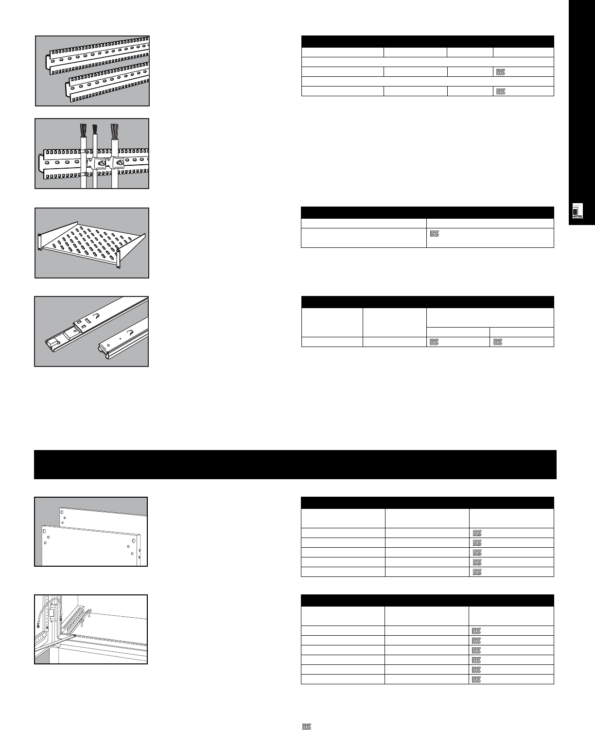
RITTAL ACCESSORIES
Telescopic Slides For
Component Shelves
Are fully extendable, and can also be
easily retrofitted to convert fixed shelf
into sliding shelf.
Available in two versions:
max. load capacity: 110/lbs/50 kg
max. load capacity: 220 lbs/100 kg
Technical description:
•installation adjustable in .98"/
25 mm increments
•2-stage extension
Material: sheet steel, zinc-coated,
chromated.
Telescopic Slides
For shelf depth Packs of Part No.
max. load capacity
110 lbs/50 kg 220 lbs/100 kg
16"/400 mm 1 set 7061000 7064000
Combination Cable
Collecting Rails For
QuickBox
Feature sprockets on top and bottom
to which cable ties can be fastened,
while cable clamps can be fastened
to the built-in C-rail.
Material: aluminum
Configuration: 6 combination rails,
installation hardware.
Combination Cable Collecting Rails For QuickBox
Length Packs of Part No.
For enclosure depth
23.62"/600 mm 15.75"/400 mm 6 7502302
For enclosure width
23.62"/600 mm 15.75"/400 mm 6 7502304
19" Cantilever Shelf 19” Cantilever Shelf
Description Part No.
2U fixed 19" component shelf 7119400
16"/400 mm (D)
Outside Plant Accessories
Mounting Panels For CS
Basic Enclosures
Material: 3 mm aluminum
Mounting Panels
For enclosure dimensions Mounting plate Part No.
H x W (mm) H x W (mm)
800 x 600 696 x 499 9765090
1200 x 600 1096 x 499 9765092
800 x 800 696 x 699 9765097
1200 x 800 1096 x 699 9765095
800 x 1200 696 x 499 2 x 9765090
One-Piece Gland Plates
For sealing the base opening and for
cable entry.
Material: unpainted aluminum, 2 mm
One-Piece Gland Plates
For enclosure dimensions Packs of Part No.
W x D (mm)
600 x 400 1 set 9785017
600 x 500 1 set 9785020
800 x 400 1 set 9785018
800 x 500 1 set 9785019
1200 x 400 1 set 2 x 9785017
1200 x 500 1 set 2 x 9785020
ACC 14
Designates a product in the EnclosureZone program.
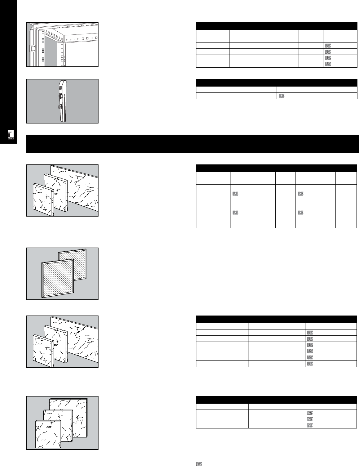
RITTAL ACCESSORIES
ACC 15
Replacement Filters
For Filter Fans
Made of random laid non-woven fabric
with progressive build-up and provide
reliable filtration of almost all types of
dust down to a 10 µm grain size.
Temperature resistant up to
212°F/100°C. Self extinguishing, class
F1 per DIN 53 438.
Dusty air side: open structure
Clean air side: closed structure
Replacement Filters For Filter Fans
Filter fan Exhaust filter Part No.
SK 3321 Series SK 3321200 3321700
SK 3322 Series SK 3322808 3322700
SK 3323 Series SK 3323200 3171100
SK 3325 Series SK 3325200 3172100
SK 3326 Series SK 3326200 3173100
SK 3327 SK 3326200 3327700
Fine Filters
They are used for extremely fine dust
with particle sizes below 10 µm. Also
used when NEMA 12/IP 54 is required.
Anticipate higher air resistance when
fine filters are used.
Material: Synthetic fiber
Configuration: Packs of 5
Fine Filters For Filter Fans
Filter fan Exhaust filter Part No.
3323 Series SK 3323200 3181100
3325 Series SK 3325200 3182100
3326 Series SK 3326200 3183100
Ergoform-S
Handle System
The Ergoform-S padlock handle system
provides comfort and security with an
additional shackle for a padlock. Hole
diameter of shackle: 7 mm.
Ergoform-S Padlock Handle System
Packs of Part No.
19785030
Foam Filters
For Air Conditioners
Rittal air conditioners require very little
maintenance and are supplied without
filters. Filters may be used for extreme
conditions.
Material: Open cell polyurethane
foam with excellent physical and
mechanical properties. Temperature
resistant from -40°F to +176°F/-40°C
to +80°C.
Thickness: 4"/10 mm
Air Conditioner Filters
For AC Model Part No. Packs Part No. Packs
for Standard Filters of for Metal Filters of
SK 3280100
SK 3290100 3286100 33286200 1
SK 3260146
SK 3279100
SK 3281100 3294100 33294200 1
SK 3293100
SK 3298100
Climate Control Accessories
Metal Filters
For Air Conditioners
When air conditioners are used in oily
environments, washable metal filters
are especially useful. Soiled metal
filters can be easily washed with water
or grease solvents.
Material: Aluminum
Thickness: 4"/10 mm
19" Mounting Angles
For mounting slide-in 19" electronic
equipment. Easily retrofitted.
Assembly parts included.
19” Mounting Angles
For enclosure Surface finish U Packs of Part No.
height (mm)
800 Spray-finish RAL 7035 15 4 9785001
800 Zinc plated, passivated 15 4 9785002
1200 Spray-finish, RAL 7035 24 4 9785003
1200 Zinc plated, passivated 24 4 9785004
Material: Synthetic fiber
Configuration: Packs of 5
Designates a product in the EnclosureZone program.
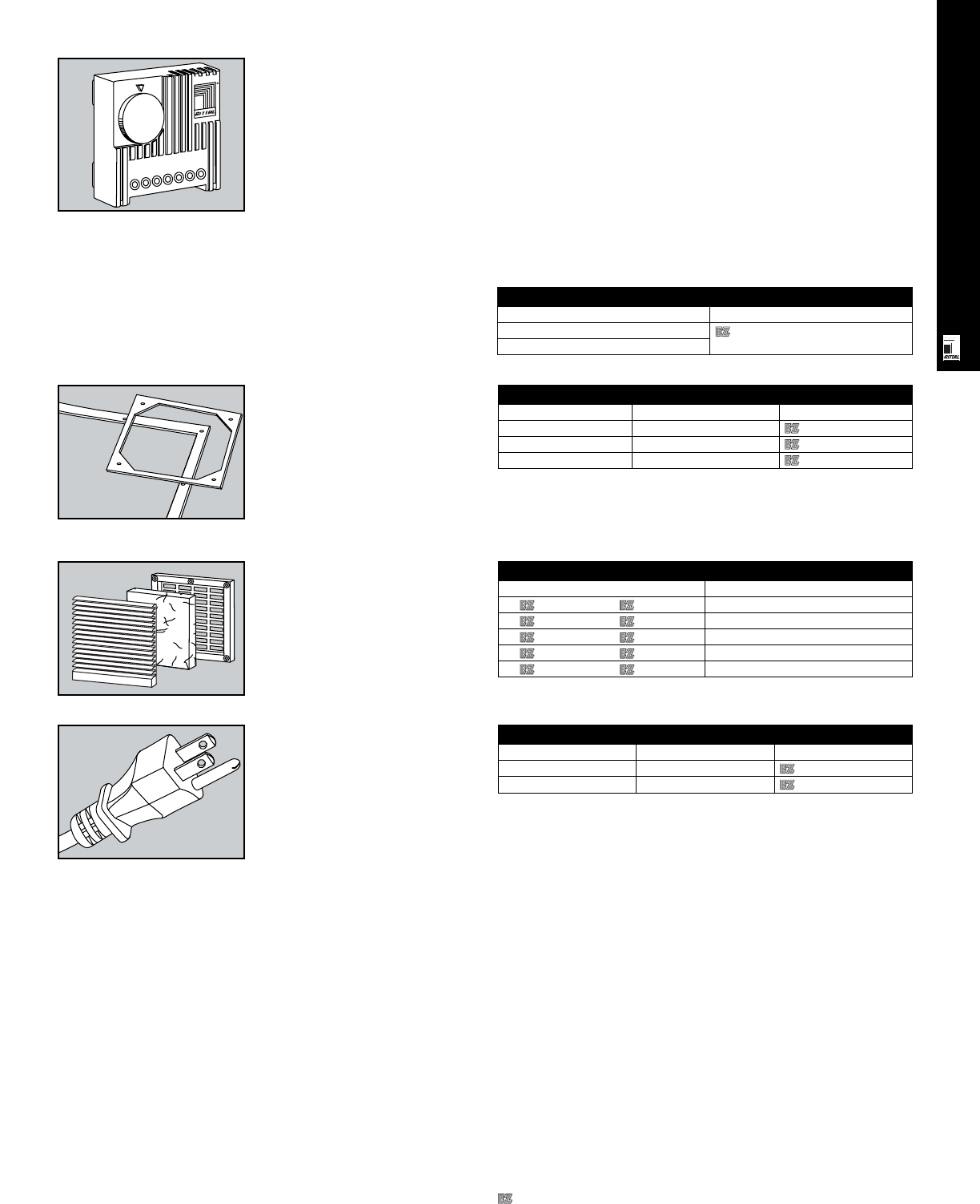
RITTAL ACCESSORIES
ACC 16
Temperature setting range: +41°F
to +131°F/+5°C to +55°C
Weight: approx. 4 oz./105 g
Dimensions: 2.8" x 2.8" x 1.4"/
71 x 71 x 33.5 mm
Temperature variance inside
enclosure: Approx. 1°C +/- 0.8°C
(with normal air)
Enclosure Thermostat
Voltage Part No.
230/115/60/48/24 V AC 3110000
60/48/24 V DC
Gaskets For
Filter Fan
Helps achieve a protection rating of
NEMA 12/IP 54 per EN 60 529/10.91,
part 1/11.92 when filter fans are
installed fine filters.
Material: Closed cell polythylene
Configuration: Packs of 5, with
installation material.
Sealing Frames for 1S Filter Fans
Filter fan Exhaust filter Part No.
3323 Series SK 3323200 3191100
3325 Series SK 3325200 3192100
3326 Series SK 3326200 3193100
Exhaust Filter Louvers
Can be installed in lower and upper
areas of an enclosure to benefit from
ventilation through natural convection.
Material: Noryl™ plastic, self-extin-
guishing per UL 94-VO
Color: RAL 7032 pebble grey
RAL 7035 light grey (.XX7 Designation)
Exhaust Louvers
Part No. Dimensions in mm
3321200 3321207 116.5 x 22.0
3322200 3322207 148.5 x 24.5
3323200 3323207 204.0 x 30.0
3325200 3325207 255.0 x 30.0
3326200 3326207 323.0 x 30.0
Power Cord
16 ga power cord has NEMA
5-15, 3-prong plug (9962136) and
can be used for filter fans and other
climate control devices that have
terminal block connection.
Power Cord
Packs of Voltage Part No.
1115/50/60 9962136
1230/50/60 9965837
Enclosure Thermostat
Particularly suitable to control filter
fans, panel heaters and heat
exchangers, but can also be used
to signal and monitor the temperature
inside an enclosure.
Technical data: Bi-metal sensor acts
as temperature sensitive device with
thermal feedback
Contact: Single-pole, spring-loaded
switch element
Max. contact load:
CI. 5 – 3 (heating) AC 10.0 (4*) A,
DC = 30 W
CI. 5 – 4 (cooling) AC 5.0 (4*) A,
DC = 30 W
*( ) = inductive load for cos ϕ = 0.6
Designates a product in the EnclosureZone program.
Technical description:
•Wide voltage range—only one
model is required to cover 24 V
to 230 V AC/DC
•Easy to connect—terminal block
with screw connections on
outside
•Flexible mounting options—
snaps directly with included
adaptor into enclosure profile or
can be vertically or horizontally
mounted on 35 mm DIN rails per
EN 50 022
•UL/CUL recognized. CE marked.
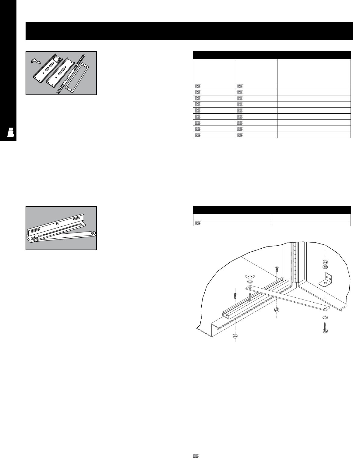
ELECTROMATE ACCESSORIES
ACC 17
Door System/Locking System Accessories
Operator Adapters
Installation of certain disconnects in
the universal cutouts of Rittal
Electro-mate flange mounted
disconnect enclosures may require an
operator adapter to interlock the
master door with the disconnect
operating mechanism.These adapters
are available for steel or stainless
steel enclosures and for several
brands and types of disconnects. The
kits include an adapter plate and
other required hardware, and come
complete with installation and drilling
instructions.
Note: Blank adapter plates can be
used to cover the universal cutout
when no disconnect is installed. The
enclosure can then be used as a
standard NEMA Type 12 enclosure.
Material:
Adapters for steel enclosures:
carbon steel
Adapters for stainless steel enclosures:
chrome plated carbon steel
Door Stop Kits
Door stops provide a quick and easy
method of securing the door in an
open position in most standard 24"
and wider Rittal Electromate Type 4,
4X and 12 enclosures. Door stops
can be bolted or welded at the top or
bottom of the door opening. The
opening angle of the door can be
easily adjusted with a wing nut.
Door stop kits are available in
zinc-plated steel and include the
required hardware and installation
instructions.
Material: zinc-plated steel
Operator Adapter
Adapter Plate Adapter Plate Description
For Carbon Steel For Stainless Steel
Enclosures Enclosures
Part No. Part No.
E AKAB E AKABCHR Allen-Bradley “1494F” and “1494D”
E AKABV E AKABVCHR Allen-Bradley variable depth “1494V”
E AKCHV E AKCHVCHR CUTLER HAMMER FOR C361/C371
E AKGETDA E AKGETDACHR G.E. TDA
E AKITE E AKITECHR ITE/G.E. STDA
E AKSD E AKSDCHR Square D 9422
E AKWH E AKWHCHR Westinghouse
E AKWHAMT E AKWHAMTCHR Westinghouse AMT
E AKBAP E AKBAPCHR Blank adapter plate
Door Stop Kit
Part No. Description
E DSTOPK Door stop kit
Finish/color:
Adapters for steel enclosures:
polyester-urethane powder coat over
phosphatized surfaces, inside and
outside – ANSI 61 grey
Adapters for stainless steel enclosures:
chrome plated
Designates a product in the EnclosureZone program.
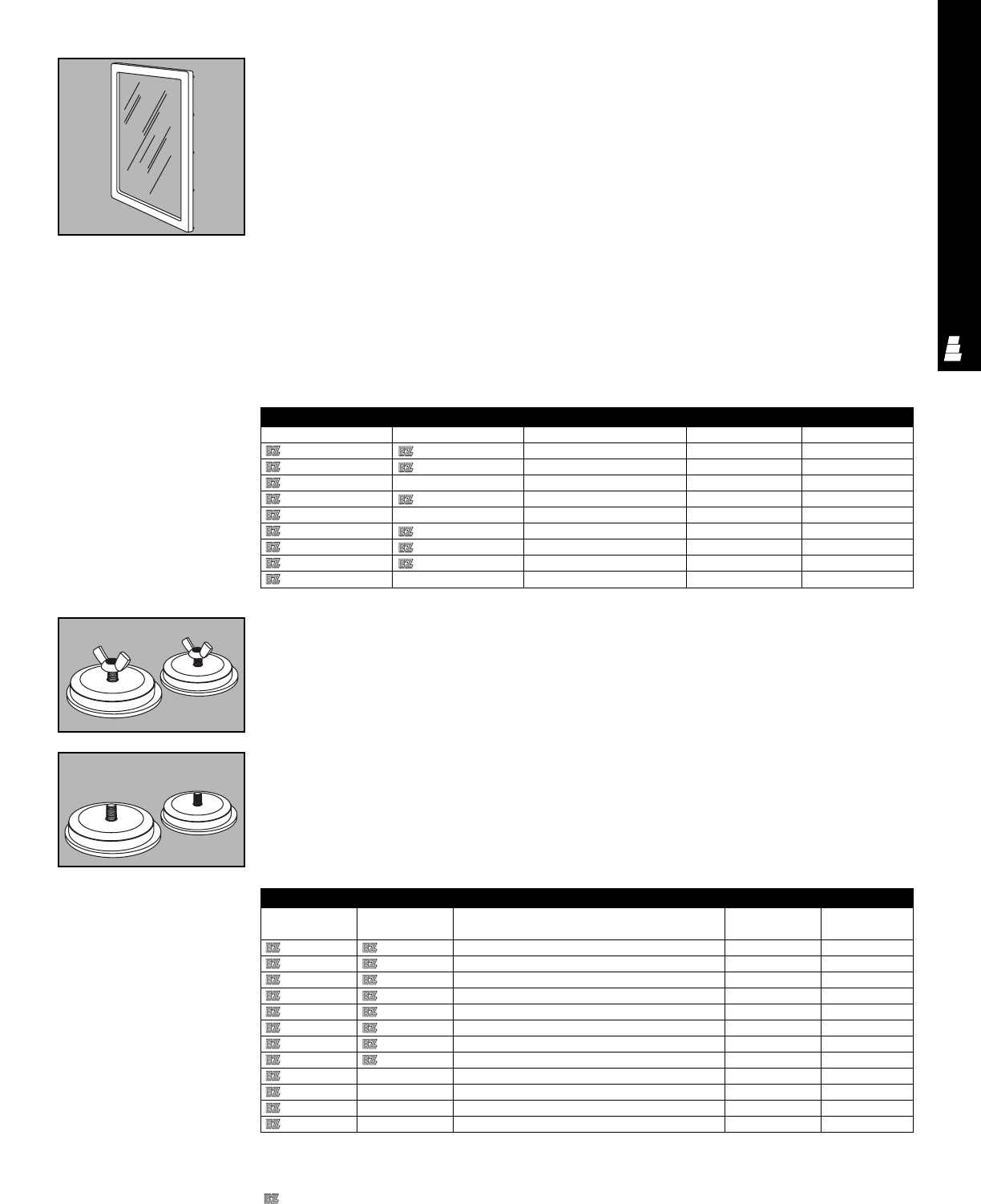
ELECTROMATE ACCESSORIES
ACC 18
Oiltight Hole Seals
Oiltight hole seals are used to seal
unused or empty pushbutton holes,
conduit openings, and knockout
openings from the entry of dirt, dust,
oil and water.
Steel Hole Seals:
• 12 sizes – for holes up to 4.83"
• Covers holes with a .19" diameter
• Can be used on material thickness up
to .31"
• Galvaneal with grey finish
• Back plate galvanized
• Mounting stud and wing nut zinc
plated
Oiltight Hole Seals
Steel Stainless Steel Designed for Max. hole Hole seal
Part No. Part No. diameter diameter
E SPBG E SPBGSS Miniature oiltight pushbutton hole 0.75 1.22
E S050 E S050SS .50 inch conduit hole 0.75 1.38
E S075 E S075SS .75 inch conduit hole 1.13 1.56
E SPB E SPBSS Standard oiltight pushbutton hole 1.25 1.75
E S100 E S100SS 1.00 inch conduit hole 1.38 1.88
E S125 E S125SS 1.25 inch conduit hole 1.69 2.19
E S150 E S150SS 1.50 inch conduit hole 2.00 2.50
E S200 E S200SS 2.00 inch conduit hole 2.50 3.00
E S250 -2.50 inch conduit hole 3.00 3.50
E S300 -3.00 inch conduit hole 3.63 4.13
E S350 -3.50 inch conduit hole 4.13 4.33
E S400 -4.00 inch conduit hole 4.63 5.13
• Oil-resistant gasket
• UL and CUL Component Recognized
Type 4, 12 and 13
Stainless Steel Hole Seals:
• 8 sizes – for holes up to 5.13"
• Covers holes with a .19" diameter
• Can be used on material thickness
up to .31"
• Front surface polished
• Seal, back plate, stud and wing nut
made of 300 series stainless steel
• Oil resistant gasket
• UL and CUL Component Recognized
Type 4, 4X, 12, and 13
Windows can be installed in most
Rittal Electromate enclosures of
suitable size.
Window Kits Are Available In
Two Versions:
Steel window kits for indoor use on
NEMA Type 4 and Type 12
enclosures.
Stainless steel window kits for indoor
or outdoor use on NEMA Type 4, 4X,
12 and 13 enclosures in corrosive
environments.
Window kits include all necessary
hardware. Installation is easy — just
make a cutout in the enclosure and
attach the frame and window.
Oil-resistant gaskets ensure a tight
seal around entire window.
Window Kits
Steel Part No. Stainless Steel Part No. Window clear viewing area Frame size Required cutout size
E PWK53NF E PWK53NFSS 5.00 x 3.00 7.50 x 5.50 6.69 x 4.69
E PWK95NF E PWK95NFSS 9.00 x 5.50 11.50 x 8.00 10.69 x 7.19
E PWK133NF -13.00 x 3.00 15.50 x 5.50 14.69 x 4.69
E PWK138NF E PWK138NFSS 13.00 x 8.00 15.50 x 10.50 14.69 x 9.69
E PWK175NF -17.00 x 5.50 19.50 x 8.00 18.69 x 7.19
E PWK1711NF E PWK1711NFSS 17.00 x 11.00 19.50 x 13.50 18.69 x 12.69
E PWK2315NF E PWK2315NFSS 23.00 x 15.00 25.50 x 17.50 24.69 x 16.69
E PWK2919NF E PWK2919NFSS 29.00 x 19.00 31.50 x 25.50 30.69 x 20.69
E PWK3523NF -35.00 x 23.00 37.50 x 25.50 36.69 x 24.69
Note: Allow for clearance of
gaskets, gasket retainers, door
stiffeners, print pockets, door
handles, latch rods, and other parts
attached to door or cover when you
determine the size of window kit you
require.
Steel Windows:
Window frame: heavy gauge steel
with polyester-urethane powder coat
over phosphatized surfaces, inside
and outside – ANSI 61 grey
Window pane: .25” lexan with
margard surface
Stainless Steel Windows:
Window frame: heavy gauge Type
304 stainless steel with # 3 brushed
finish
Window pane: .25” lexan with
margard surface
Window Kits For NEMA Type 4, 4X, 12 And 13 Enclosures
Designates a product in the EnclosureZone program.
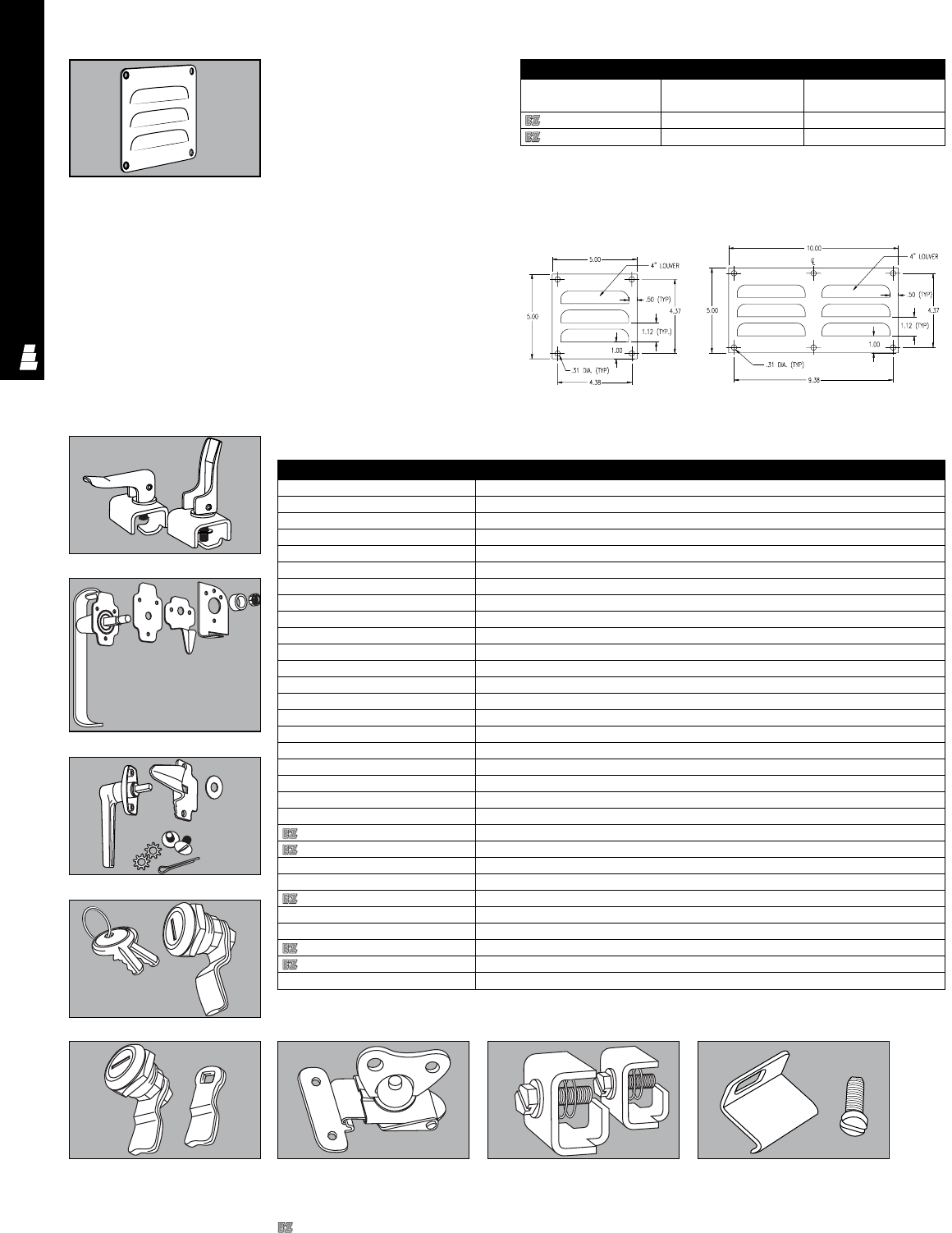
ELECTROMATE ACCESSORIES
ACC 19
Note: Proper installation of a louver
panel requires a cutout in the
enclosure wall or door. See table for
recommended sizes.
E-LV1
Louver Panel Kits
Part No. No. of louvers Recommended
cutout size
E LV1 34 x 4
E LV2 64 x 9
E-LV2
Latch And Lock Kits
Latch And Lock Kits
Part No.* Description
E L1A NEMA 12 Single point - padlockable
E L1B NEMA 12 Three point (short) - padlockable
E L1C NEMA 12 Three point (medium) - padlockable
E L1D NEMA 12 Three point (long) - padlockable
E L2A NEMA 12 Single point - key locking
E L2A - CCW NEMA 12 Single point - key locking, counter-clockwise operation
E L3A NEMA 12 Single point - nonlocking
E L3A - CCW NEMA 12 Single point - nonlocking counter-clockwise operation
E L3B NEMA 12 Three point (short) - nonlocking
E L3B - CCW NEMA 12 Three point (short) - nonlocking counter-clockwise operation
E L3C NEMA 12 Three point (medium) - nonlocking
E L3C - CCW NEMA 12 Three point (medium) - nonlocking counter-clockwise operation
E L3D NEMA 12 Three point (long) - nonlocking
E L3D - CCW NEMA 12 Three point (long) - nonlocking counter-clockwise operation
E L2B NEMA 12 Three point (short) - key locking
E L2B - CCW NEMA 12 Three point (short) - key locking, counter-clockwise operation
E L2C NEMA 12 Three point (medium) - key locking
E L2C - CCW NEMA 12 Three point (medium) - key locking, counter-clockwise operation
E L2D NEMA 12 Three point (long) - key locking
E L2D-CCW NEMA 12 Three point (long) - key locking, counter-clockwise operation
E FOC412SS Fast opening stainless steel clamp for NEMA 4,12 enclosures (2 per pkg.)
E L5 Cylinder lock
E L6 Draw latch
E L6P Draw latch (padlockable)
E L7 Flush slotted latch
E L9 “T” handle (key locking)
E L10 Butterfly draw latch
E L12SS NEMA 4 hold down assembly
E L13SS NEMA 4 JIC hold down assembly
E L23SS Fast operating stainless steel clamp for JIC Type Enclosure (1 per pkg.)
*NOTE: Single point designed for enclosures up to 24" in height
Three point (short) designed for enclosures 24" and 30" in height
E L1
E L5
E L2
E L7 E L10 E L12SS E L13SS
E FOC412SS
Louver Panel Kits
Louver panels help ventilation by using
convection and promote air circulation
in enclosures with low heat loss. Louver
panel kits consist of a steel plate,
prepunched with ventilation slots and
mounting holes. An oil-resistant gasket
is attached to the rear of the panel and
mounting hardware is included.
Material: 14 gauge carbon steel
Finish/color: polyester-urethane
powder coat over phosphatized
surfaces, ANSI 61 grey
Designates a product in the EnclosureZone program.
Three point (medium) designed for enclosures 36" and 48" in height
Three point (long) designed for enclosures 60" and 72" in height.
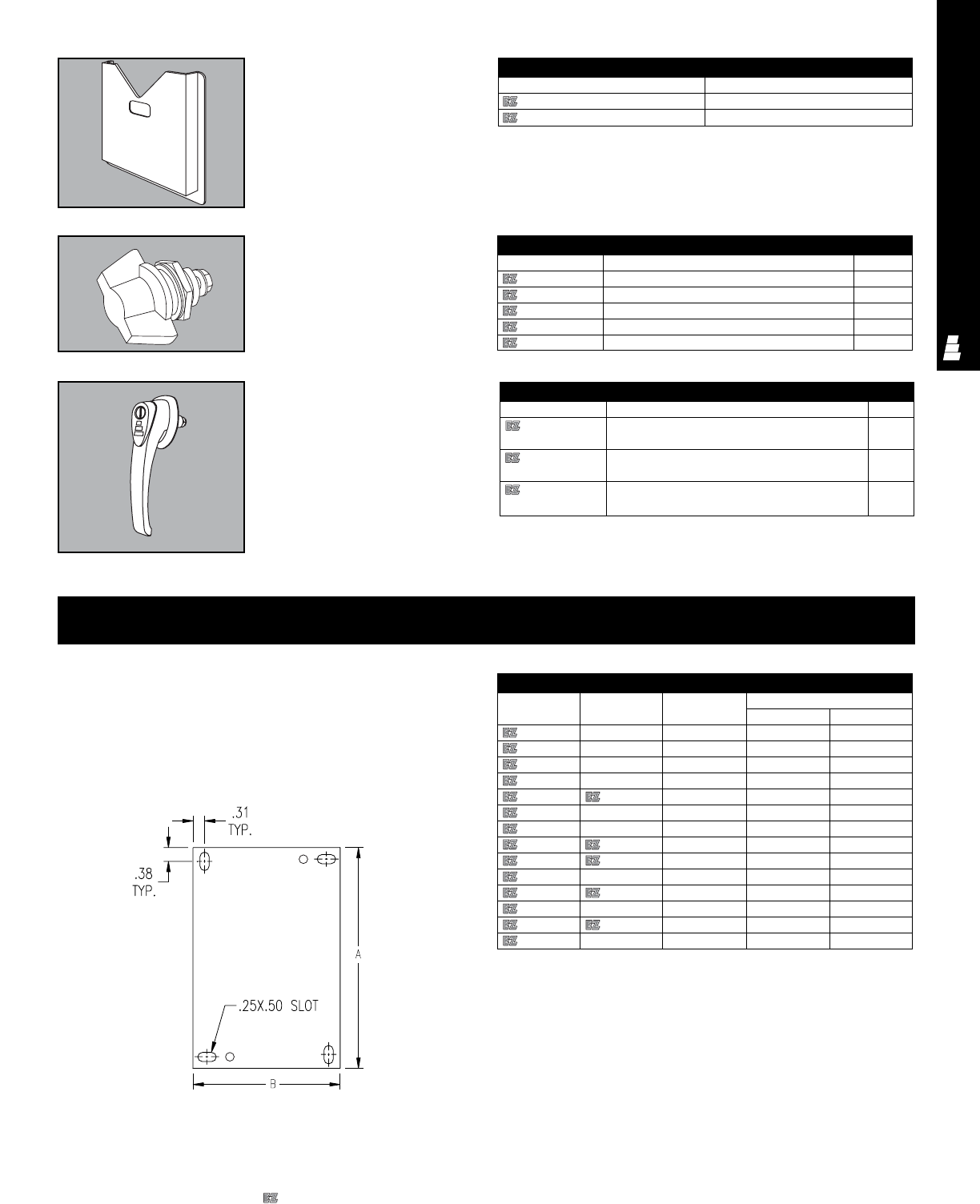
ELECTROMATE ACCESSORIES
ACC 20
Print Pockets
Print pockets can hold manuals,
drawings, and other documentation.
They are mounted on the inside of
doors with adhesive tape.
Print Pockets
Part No. Size
E POCKET1 Small
E POCKET2 Large
Mounting Panels For Junction Boxes
Mounting panels are available in two versions:
14 gauge steel mounting panels with a white finish.
14 gauge Type 304 stainless steel mounting panels with a commercial
#2B finish protected on one side with a plastic film.
Note: All enclosures that accept these mounting panels come complete
with mounting hardware.
JIC Mounting Panel
Mounting Panels For Junction Enclosures
Steel Stainless Steel Aluminum Size
Part No. Part No. Part No. AB
E 6P4 E 6P4SS E 6P4AL 4.88 2.88
E 6P6 E 6P6SS E 6P6AL 4.88 4.88
E 8P6 E 8P6SS E 8P6AL 6.88 4.88
E 8P8 E 8P8SS - 6.88 6.88
E 10P8 E 10P8SS E 10P8AL 8.88 6.88
E 10P10 E 10P10SS - 8.88 8.88
E 12P6 E 12P6SS - 10.88 4.88
E 12P10 E 12P10SS E 12P10AL 10.88 8.88
E 12P12 E 12P12SS - 10.88 10.88
E 14P8 E 14P8SS - 12.88 6.88
E 14P12 E 14P12SS E 14P12AL 12.88 10.88
E 16P10 E 16P10SS - 14.88 8.88
E 16P14 E 16P14SS E 16P14AL 14.88 12.88
E 18P16 - - 16.75 14.75
Mounting Surface Accessories
Legacy Latching
Accessories
Specific latching accessories
designed for carbon steel Legacy
enclosures.
Freestanding Handles
Legacy Latching Accessories
Part No. Description Packs of
L LQTKLB Legacy Latching Kit (Keylocking 1/4 turn) 1
L LWKB Legacy Latching Kit (Wingknob) 1
L LWKKLB Legacy Latching Kit (Wingknob keylocking) 1
L LTHB Legacy Latching Kit (T-handle) 1
L LTHKLB Legacy Latching Kit (T-handle keylocking) 1
Freestanding Handles
Part No. Description Packs of
E LBHDH 3-Point Latching Black 1
Heavy-Duty Handle (Padlock Only)
E LBHDHCP 3-Point Latching Black 1
Heavy-Duty Handle (Slotted Coin Proof)
E LBHDHKEY 3-Point Latching Black 1
Heavy-Duty Handle (Key Locking)
Designates a product in the EnclosureZone program.
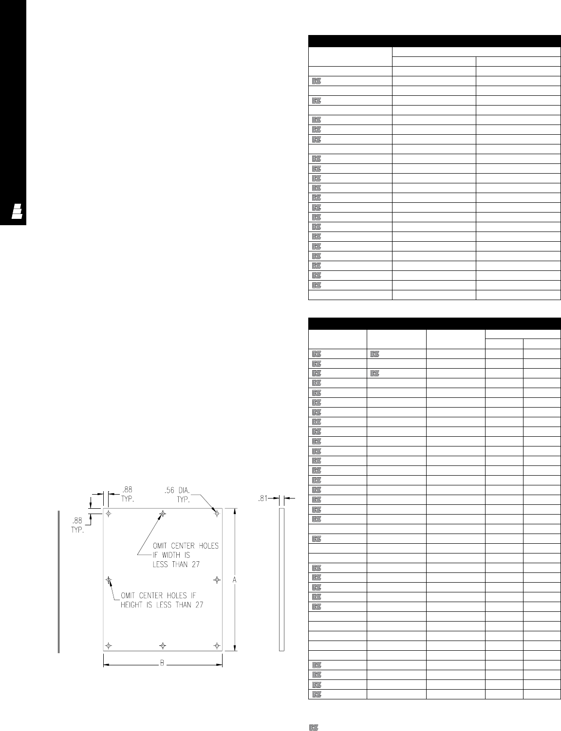
ELECTROMATE ACCESSORIES
ACC 21
Mounting Panels For NEMA Style Boxes
Mounting panels are available in two versions:
12 or 10 gauge steel mounting panels with a white finish.
12 gauge Type 304 stainless steel mounting panels with a commercial
#2B finish.
These panels fit the following enclosures:
NEMA 1 – Extra Large
NEMA 3R – Hinge Cover
NEMA 4 & 4X – Single Door
NEMA 12 – Two Door Wallmount, Single Door, Right Flange Disconnect,
Large JIC (CH)
Larger mounting panels have flanges on two or four sides; some also
have lifting holes.
Note: All enclosures that accept these mounting panels come complete
with mounting hardware.
Flat
Mounting
Panel
NEMA
Mounting
Panel
Flanged
Mounting
Panel
(Used If Both Dimensions
Are Less Than 17) (Used If Either Dimension
Is 17 Or Greater)
Mounting Panels For Type 1 And 3R Enclosures
14 gauge steel mounting panels with a white finish.
Note: All enclosures that accept these mounting panels come complete
with mounting hardware.
Mounting Panels For Type 1 And Type 3R
Part No. Size
AB
E 6N6P 4.25 4.25
E 8N6P 6.25 4.25
E 8N8P 6.25 6.25
E 10N8P 8.25 6.25
E 10N10P 8.25 8.25
E 12N10P 10.25 8.25
E 12N12P 10.25 10.25
E 14N12P 12.25 10.25
E 16N12P 14.25 10.25
E 16N12P2 13.00 10.50
E 16N16P2 13.00 14.50
E 20N12P 18.25 10.25
E 20N16P 17.00 14.50
E 20N20P 17.00 18.50
E 24N12P 22.25 10.25
E 24N16P 21.00 14.50
E 24N20P 21.00 18.50
E 24N24P 21.00 22.50
E 30N20P 27.00 18.50
E 30N24P 27.00 22.50
E 30N30P 27.00 28.50
E 36N24P 33.00 22.50
E 36N30P 33.00 28.50
E 42N24P 39.00 22.50
NEMA Style Mounting Panels
Steel Stainless Steel Aluminum Size
Part No. Part No. Part No. AB
E 16P12 E 16P12SS E 16P12AL 13.00 9.00
E 20P12 E 20P12SS - 17.00 9.00
E 16P16 E 16P16SS E 16P16AL 13.00 13.00
E 20P16 E 20P16SS - 17.00 13.00
E 24P16 E 24P16SS - 21.00 13.00
E 30P16 E 30P16SS E 20P20AL 27.00 13.00
E 20P20 E 20P20SS E 24P20AL 17.00 17.00
E 24P20 E 24P20SS - 21.00 17.00
E 30P20 E 30P20SS - 27.00 17.00
E 12P24 E 12P24SS E 24P24AL 9.00 21.00
E 24P24 E 24P24SS E 30P24AL 21.00 21.00
E 30P24 E 30P24SS E 36P24AL 27.00 21.00
E 36P24 E 36P24SS - 33.00 21.00
E 42P24 E 42P24SS - 39.00 21.00
E 48P24 E 48P24SS - 45.00 21.00
E 30P30 E 30P30SS E 36P30AL 27.00 27.00
E 36P30 E 36P30SS - 33.00 27.00
E 42P30 E 42P30SS - 39.00 27.00
E 42P32 - - 39.00 29.00
E 48P30 E 48P30SS - 45.00 27.00
E 60P30 E 60P30SS - 57.00 27.00
E 72P30 E 72P30SS - 69.00 27.00
E 36P36 E 36P36SS - 33.00 33.00
E 42P36 E 42P36SS E 48P36AL 39.00 33.00
E 48P36 E 48P36SS E 60P36AL 45.00 33.00
E 60P36 E 60P36SS - 57.00 33.00
E 72P36 E 72P36SS - 69.00 33.00
E 42P42 E 42P42SS - 39.00 39.00
E 48P42 E 48P42SS - 45.00 39.00
E 54P42 E 54P42SS - 50.00 38.00
E 60WFP42 E 60WFP42SS - 56.00 38.00
E 48WFP48 E 48WFP48SS - 44.00 44.00
E 60P48 E 60P48SS - 56.00 44.00
E 60P60 E 60P60SS - 56.00 56.00
E 72P60 E 72P60SS - 68.00 56.00
E 72P72 E 72P72SS - 68.00 68.00
Designates a product in the EnclosureZone program.
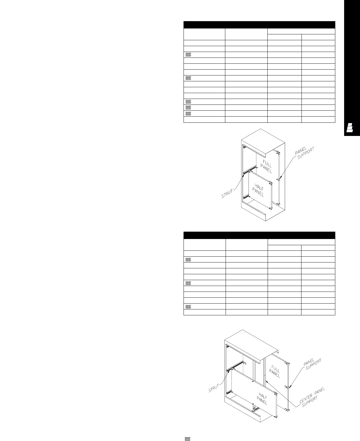
ELECTROMATE ACCESSORIES
ACC 22
Mounting Panels For One Door Freestanding
These mounting panels can be positioned at any depth along horizontal
C-channels. Half-length mounting panels can be mounted in the upper
or lower section of an enclosure. Mounting panel kits include zinc-plated
mounting hardware.
Mounting panels fit the following enclosures: one door single access,
Type 12
Freestanding Type 4 and 4X
Material: 10 gauge steel painted white
Mounting Panels For One Door Freestanding
Part No. Description Size
AB
E 60P24F1 Full panel 48.00 20.00
E 60P24F2 Half panel 24.88 20.00
E 72P24F1 Full panel 60.00 20.00
E 72P24F2 Half panel 30.88 20.00
E 90P24F1 Full panel 78.00 20.00
E 90P24F2 Half panel 39.88 20.00
E 72P30F1 Full panel 60.00 26.00
E 72P30F2 Half panel 30.88 26.00
E 60P36F1 Full panel 48.00 32.00
E 60P36F2 Half panel 24.88 32.00
E 72P36F1 Full panel 60.00 32.00
E 72P36F2 Half panel 30.88 32.00
E 90P36F1 Full panel 78.00 32.00
E 90P36F2 Half panel 39.88 32.00
Mounting Panels For Two Door Freestanding
These mounting panels can be positioned at any depth along horizontal
C-channels. Half-length mounting panels can be mounted in the upper
or lower section of an enclosure. Each full mounting panel for two-door
enclosures comes with a center support that attaches at any depth to
the top and bottom mounting C-channels. These center supports can
be used in conjunction with heavy duty panel supports.
Mounting panel kits include zinc-plated mounting hardware. Some
assembly required.
Mounting panels fit the following enclosures:
One door single access, Type 12
Freestanding Type 4 and 4X
Material: 10 gauge steel with a white finish
Regular Mounting Panels For Two Door Freestanding
Part No. Description Size
AB
E 60P48F1 Full panel 48.00 44.00
E 72P48F1 Full panel 60.00 44.00
E 72P48F2 Half panel 30.88 44.00
E 90P48F1 Full panel 78.00 44.00
E 90P48F2 Half panel 39.88 44.00
E 72P60F1 Full panel 60.00 56.00
E 72P60F2 Half panel 30.88 56.00
E 72P72F1 Full panel 60.00 68.00
E 72P72F2 Half panel 30.88 68.00
E 90P72F1 Full panel 78.00 68.00
E 90P72F2 Half panel 39.88 68.00
Designates a product in the EnclosureZone program.
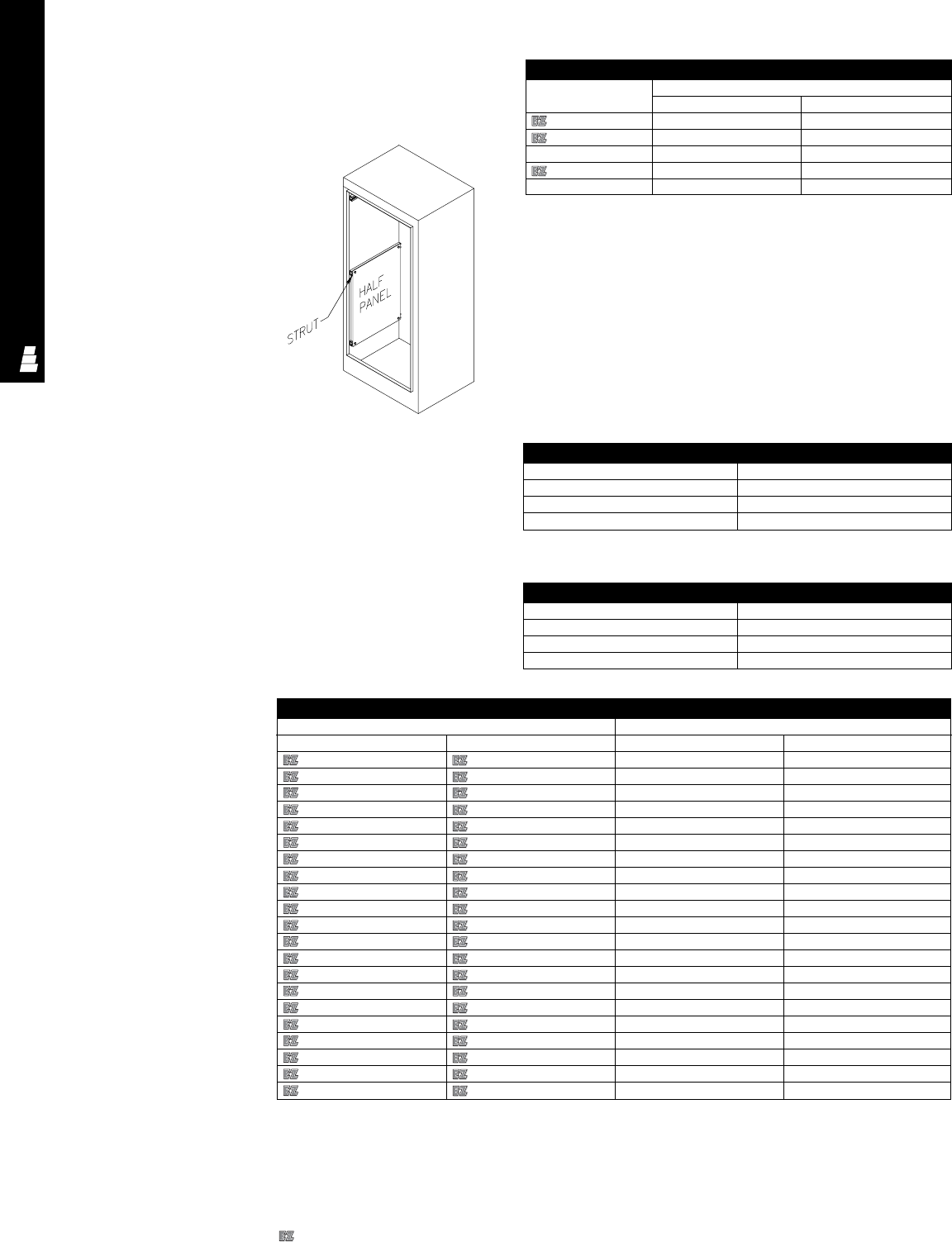
ELECTROMATE ACCESSORIES
ACC 23
Center Mounting Panel Supports
Center mounting panel supports can be mounted at any depth and
make it possible to install single-wide mounting panels, swing out
panels, and relay rack angles for two-door single-access enclosures.
Center Mounting Panel Supports For Two Door Freestanding
Part No. Length
E 60FSCPS 57.25
E 72FSCPS 69.25
E 90FSCPS 87.25
Side-Mount Mounting Panels For Freestanding
Enclosures
Side mount panels are attached to mounting channels and provide
additional mounting surface on the sides of enclosures. Mounting panel
kits include zinc-plated mounting hardware.
Material: 12 gauge steel with a white finish
Side-Mount Mounting Panels For Freestanding
Part No. Size
AB
E 60SMP14** 48.00 14.00
E 72SMP14** 60.00 14.00
E 90SMP14** 78.00 14.00
E 72SMP20*** 60.00 20.00
E 90SMP20*** 78.00 20.00
** 14” wide side-mount panels will not fit in
16” deep two doorenclosures if used in
conjunction with back panels
*** 20” wide side-mount panels will not fit in
24” deep two doorenclosures if used in
conjunction with back panels
Heavy Duty Mounting Panel Supports
Heavy duty mounting panel supports provide extra stabilization and
support when heavy equipment is installed. They replace the standard
mounting panel supports that are supplied with panels. Heavy duty panel
supports extend to the bottom of the enclosure and have adjustable
panel mounting studs that make it possible to mount panels of any height
or a combination of panels.
Heavy Duty Mounting Panel Supports
Part No. Length
E 60FSHDPS 57.25
E 72FSHDPS 69.25
E 90FSHDPS 87.25
Mounting Panels
For Legacy Enclosures
These mounting panels are
specifically for Legacy carbon
and stainless steel enclosures.
Available in white (full size),
zinc (full size) and white
(NEMA style).
Dead-Front Kit Parts
Part No. Length
E 60FSCPS 57.25
E 72FSCPS 69.25
E 90FSCPS 87.25
Legacy Mounting Panels
Part No. Dimensions (inches)
Zinc (Full Size) White (Full Size) HW
LW12P8 LW12P8W 10.2 6.2
LW12P12 LW12P12W 10.2 10.2
LW12P16 LW12P16W 10.2 14.2
LW16P12 LW16P12W 14.2 10.2
LW16P16 LW16P16W 14.2 14.2
LW16P20 LW16P20W 14.2 18.2
LW20P16 LW20P16W 18.2 14.2
LW20P20 LW20P20W 18.2 18.2
LW20P24 LW20P24W 18.2 22.2
LW24P16 LW24P16W 22.2 14.2
LW24P20 LW24P20W 22.2 18.2
LW24P24 LW24P24W 22.2 22.2
LW24P30 LW24P30W 22.2 28.2
LW30P24 LW30P24W 28.2 22.2
LW30P30 LW30P30W 28.2 28.2
LW36P24 LW36P24W 34.2 22.2
LW36P30 LW36P30W 34.2 28.2
LW36P36 LW36P36W 34.2 34.2
LW42P32 LW42P32W 40.2 30.2
LW48P36 LW48P36W 46.2 34.2
LW60P36 LW60P36W 58.2 34.2
Designates a product in the EnclosureZone program.
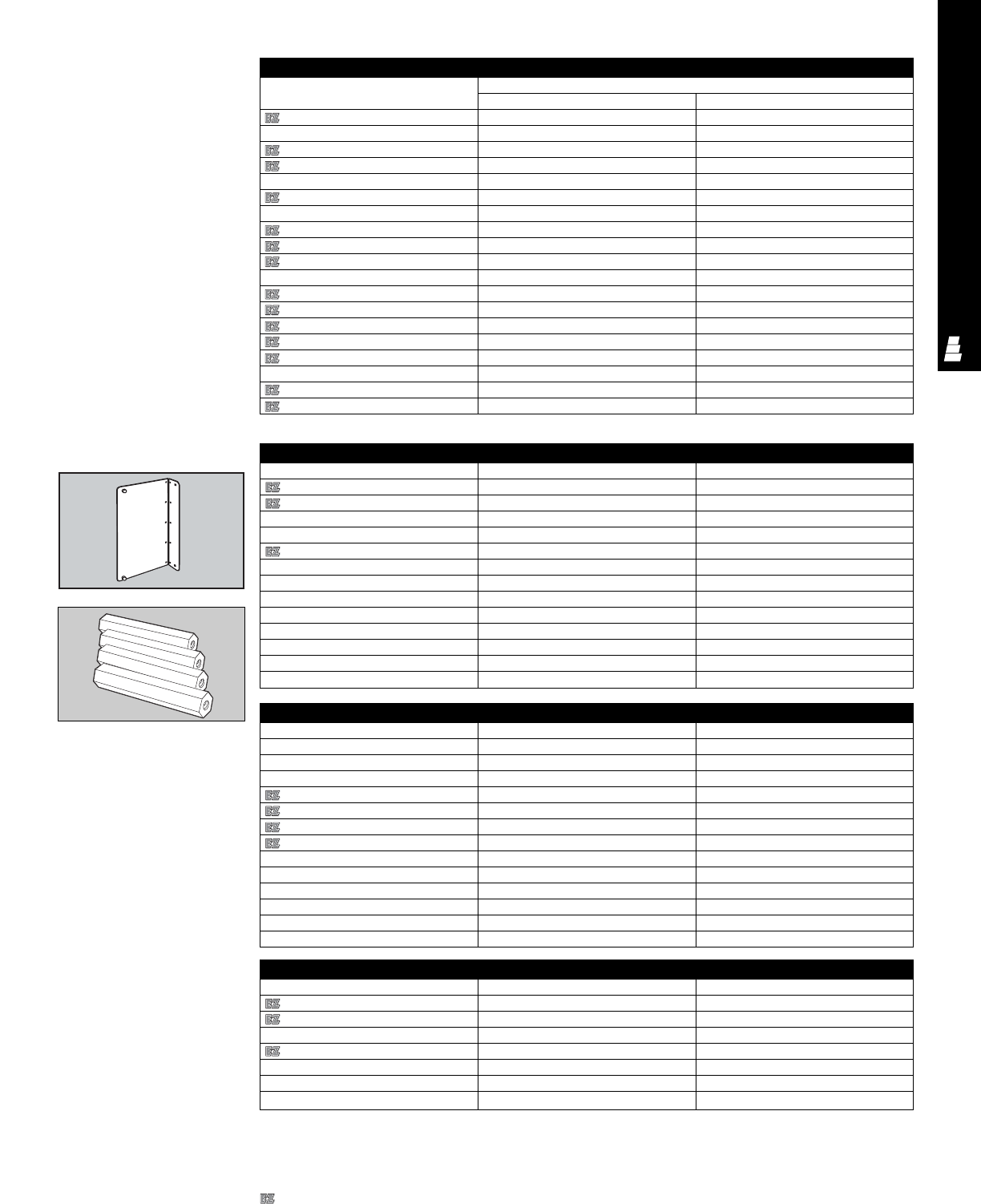
ELECTROMATE ACCESSORIES
ACC 24
Dead Front Kits
Dead-Front Kit Parts
Part No. Length
E 60FSCPS 57.25
E 72FSCPS 69.25
E 90FSCPS 87.25
Legacy Mounting Panels
Part No. Dimensions (inches)
White (NEMA Style) HW
E 16P12 13 9
E 16P12 13 9
E 16P16 13 13
E 20P16 17 13
E 20P16 17 13
E 20P20 17 17
E 24P20 21 17
E 24P16 21 13
E 24P20 21 17
E 24P24 21 21
E 30P24 27 21
E 30P24 27 21
E 30P30 27 27
E 36P24 33 21
E 36P30 33 27
E 36P36 33 33
E 42P32 39 29
E 48P36 45 33
E 60P36 57 33
Dead Front Kits
NEMA Dead Front Riser Part No. For enclosure depth (inches) Packs of
E DF6R4 64
E DF8R4 84
E DF8R5 85
E DF8R6 86
E DF10R4 10 4
E DF10R5 10 5
E DF10R6 10 6
E DF12R4 12 4
E DF12R5 12 5
E DF12R6 12 6
E DF16R4 16 4
E DF16R5 16 5
E DF16R6 16 6
Designates a product in the EnclosureZone program.
Dead Front Kits
NEMA Dead Front Panel Part No. For enclosure HxW (inches) Packs of
E DF16P12 16x12 1
E DF16P16 16x16 1
E DF20P16 20x16 1
E DF20P20 20x20 1
E DF24P20 24x20 1
E DF24P24 24x24 1
E DF30P24 30x24 1
E DF30P30 30x30 1
E DF36P24 36x24 1
E DF36P30 36x30 1
E DF36P36 36x36 1
E DF42P36 42x36 1
E DF48P36 48x36 1
Dead Front Kits
Legacy Dead Front Riser Part No. For enclosure depth (inches) Packs of
L DF6R4 64
L DF8R4 84
L DF8R5 85
L DF10R4 10 4
L DF10R5 10 5
L DF12R4 12 4
L DF12R5 12 5
Mounting Panels For
Legacy Enclosures
(Continued)
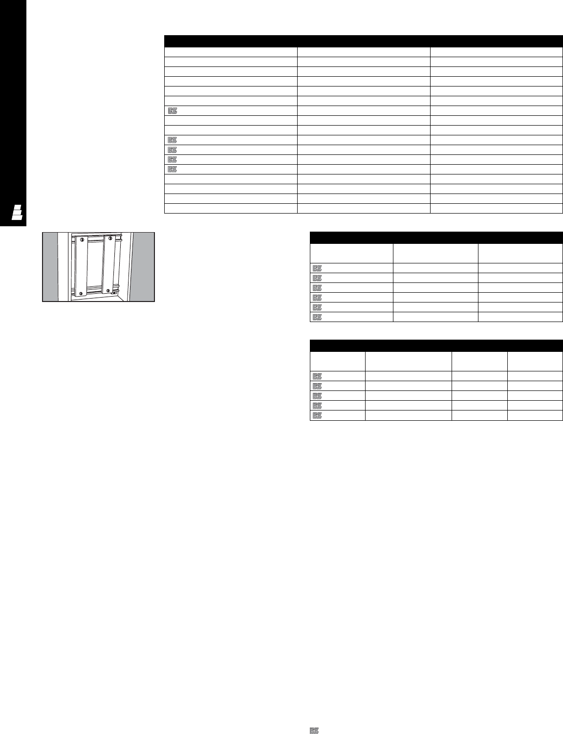
ELECTROMATE ACCESSORIES
ACC 25
Designates a product in the EnclosureZone program.
Terminal Block Kits
For JIC Enclosures
Terminal block kits allow for a quick
method for mounting terminal blocks
inside small Rittal Electromate
enclosures. Each kit consists of two
C-brackets that are mounted to weld
nuts in the enclosure, and includes
required mounting hardware.
Terminal mounting rails (must be
ordered separately) are held in place
with screws and spring locking nuts,
and can be mounted anywhere on
these brackets.
Material/finish:
Brackets and mounting rails: steel
with a white enamel finish over
phosphatized surfaces
Note: Bracket assemblies and
terminal mounting rails must be
ordered separately. One bracket
assembly plus the required number
of terminal mounting rails must be
ordered for each enclosure (terminal
blocks are not included).
Terminal Block Kit For JIC Enclosures
Bracket Assembly
Enclosure dimension Bracket length
Part No.
parallel to straps
E 6JTMA 6.00 5.00
E 8JTMA 8.00 7.00
E 10JTMA 10.00 9.00
E 10JTMAXD* 10.00 9.00
E 12JTMA 12.00 11.00
E 14JTMA 14.00 13.00
Terminal Mounting Rails
Part No. Enclosure dimension Rail length Usable
parallel to mounting rails rail length
E 8JS 8.00 5.75 4.63
E 10JS 10.00 7.75 6.63
E 12JS 12.00 9.75 8.63
E 14JS 14.00 11.75 10.63
E 16JS 16.00 13.75 12.63
* Provide extra 1.25" clearance from strap to rear wall of enclosure.
Dead Front Kits
Legacy Dead Front Panel Part No. For enclosure HxW (inches) Packs of
L DF12P12 12x12 1
L DF16P12 16x12 1
L DF16P16 16x16 1
L DF16P20 16x20 1
L DF20P16 20x16 1
L DF20P20 20x20 1
L DF20P24 20x24 1
L DF24P16 24x16 1
L DF24P20 24x20 1
L DF24P24 24x24 1
L DF30P20 30x20 1
L DF30P24 30x24 1
L DF30P30 30x30 1
L DF36P24 36x24 1
L DF36P30 36x30 1
L DF36P36 36x36 1
Dead Front Kits
(Continued)
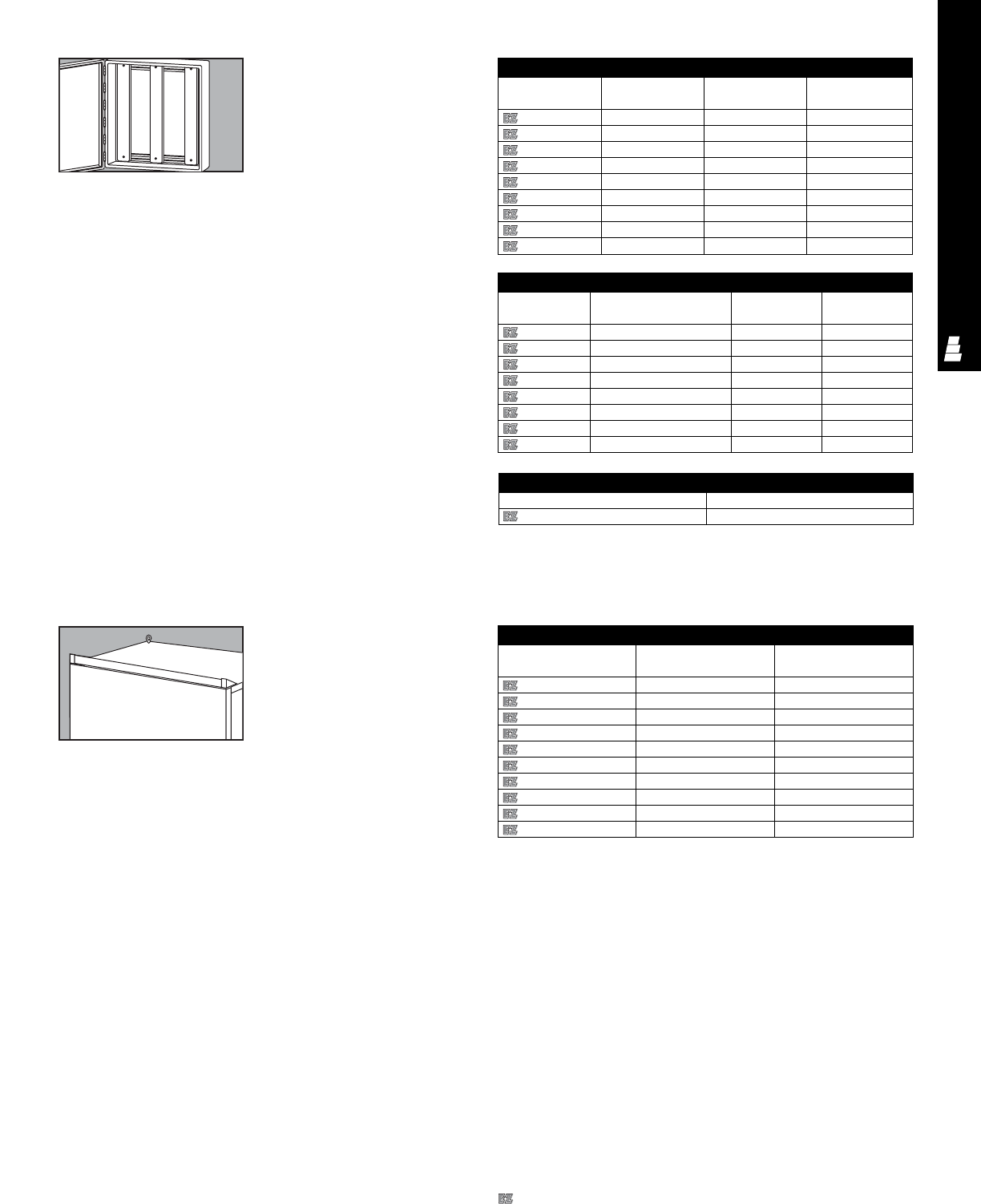
ELECTROMATE ACCESSORIES
ACC 26
Drip Shield Kits For
Type 12 Enclosures
Drip shields are available in standard
versions for Type 12 enclosures. They
are mounted above the door opening
to protect against dripping water and
settling dust when the door is opened.
These kits are easily mounted on the
enclosure with stainless steel screws
and sealing washers, and sealed with
sealing compound.
Configuration:
Drip shield
Stainless steel screws
Sealing washers
Sealing compound
Material/finish:
14 gauge steel with polyester-
urethane powder coat over
phosphatized surfaces, inside and
outside – ANSI 61 grey
Ratings:
When properly installed on a Rittal
Electromate enclosure, enclosure
maintains UL and CUL Type 12
protection.
Type 12 Drip Shield Kits
Steel Part No. Stainless Steel For use with
Part No. enclosure width
E DK12 E DK12SS 12
E DK16 E DK16SS 16
E DK20 E DK20SS 20
E DK24 E DK24SS 24
E DK30 E DK30SS 30
E DK36 E DK36SS 36
E DK42 E DK42SS 42
E DK48 E DK48SS 48
E DK60 E DK60SS 60
E DK72 E DK72SS 72
Terminal Block Kits For
Type 4, 4X, 12 And 13
Enclosures
These terminal block kits allow for a
quick method to mount terminal
blocks inside many Rittal Electromate
enclosures including large Type 1
and large hinge cover Type 3R
enclosures, as well as most of the two
door wallmount Type 4, 4X, 12 and 13
enclosures.
Each kit consists of two or three
C-brackets that can be mounted on
mounting panels or enclosure walls
and includes required mounting
hardware.
Terminal mounting rails (must be
ordered separately) are held in place
with screws and spring locking nuts,
and can be mounted anywhere on
these brackets. Terminal mounting rail
support kits consist of two Z-brackets
that make it easy to mount terminal
mounting rails.
Material/finish:
Brackets, mounting rails, support
brackets: Steel with a white enamel
finish over phosphatized surfaces.
Note: Bracket assemblies, terminal
mounting rails, and support kits must
be ordered separately. One bracket
assembly plus the required number of
terminal mounting rails and supports
must be ordered for each enclosure
(terminal blocks are not included).
Terminal Block Kit For NEMA 4 & NEMA 12 — Bracket Assembly
Part No. No. of brackets Enclosure dimension Bracket
parallel to straps length
E 12NTMA2 212.00 8.50
E 16NTMA2 216.00 12.50
E 20NTMA2 220.00 16.50
E 24NTMA2 224.00 20.50
E 24NTMA3 324.00 20.50
E 30NTMA2 230.00 26.50
E 30NTMA3 330.00 26.50
E 36NTMA2 236.00 32.50
E 36NTMA3 336.00 32.50
Terminal Mounting Rails
Part No. Enclosure dimension Rail length Usable
parallel to mounting rails rail length
E 16NS 16.00 13.00 11.75
E 20NS 20.00 17.00 15.75
E 24NS 24.00 21.00 19.75
E 30NS 30.00 27.00 25.75
E 36NS 36.00 33.00 31.75
E 42NS 42.00 39.00 37.75
E 48NS 48.00 45.00 43.75
E 60NS 60.00 57.00 55.75
Terminal Mounting Rail Support Kit
Part No. Description
E TZ Two “Z” brackets
Designates a product in the EnclosureZone program.
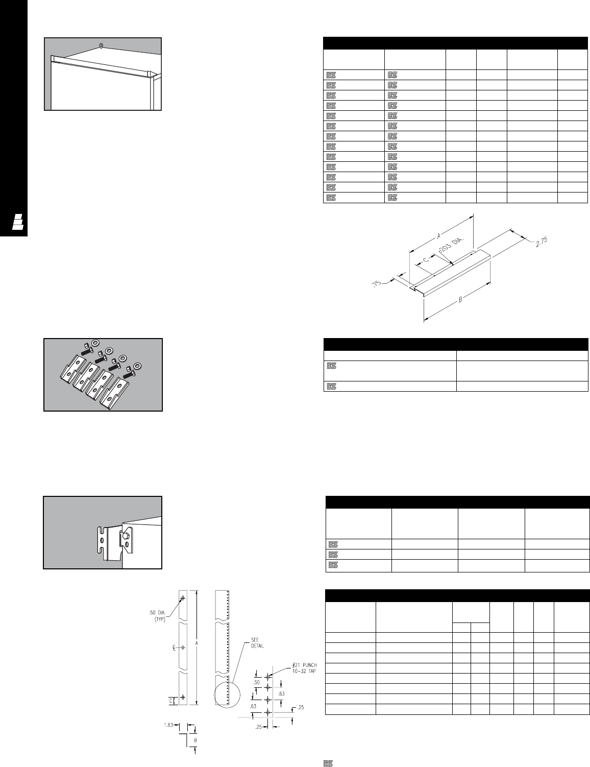
ELECTROMATE ACCESSORIES
ACC 27
Drip Shield Kits For
Type 4, 4X And Type 12
Enclosures
Type 4 and 4X drip shields are available
in standard and stainless steel versions.
They are mounted above the door
opening to protect against dripping
water and dust when the door is opened.
These kits are easily mounted on an
enclosure with stainless steel screws
and sealing washers, and sealed with
sealing compound.
Configuration:
Drip shield
Stainless steel screws
Sealing washers
Sealing compound
Material/finish:
Steel: 14 gauge steel with polyester
urethane powder coat over
phosphatized surfaces, ANSI 61 grey
Stainless steel: 14 gauge Type 304
stainless steel with a # 3 brushed
finish
Ratings: When properly installed on a
Rittal Electromate enclosure, enclosure
maintains UL and CUL Type 4, 4X and
12 protection.
NEMA 4 Drip Shields
Steel Stainless Steel ABMounting C
Part No. Part No. holes
E DK12NF E DK12NFSS 11.50 12.00 3 5.00
E DK16NF E DK16NFSS 15.50 16.00 3 7.00
E DK20NF E DK20NFSS 19.50 20.00 4 6.00
E DK21NF E DK21NFSS 20.50 21.00 4 6.33
E DK24NF E DK24NFSS 23.50 24.00 4 7.33
E DK25NF E DK25NFSS 24.50 25.00 4 7.67
E DK30NF E DK30NFSS 29.50 30.00 5 7.00
E DK31NF E DK31NFSS 30.50 31.00 5 7.25
E DK36NF E DK36NFSS 35.50 36.00 5 8.50
E DK37NF E DK37NFSS 36.50 37.00 5 8.75
E DK48NF E DK48NFSS 47.50 48.00 7 7.67
E DK60NF E DK60NFSS 59.50 60.00 8 8.29
E DK72NF E DK72NFSS 71.50 72.00 9 8.75
Wallmounting Bracket Kits
Wallmounting bracket kit C MTKIT is
used for wallmounting Legacy Series
enclosures. The E L14 wallmounting
bracket kit is used for wallmounting
NEMA style enclosures. Kits include
sealing washers to help maintain
NEMA 4 or 12 protection.
Configuration:
C MTKIT: packs of 4
E L14: packs of 1
Material:
C-MTKIT and E-L14: 10 gauge
stainless steel
Wallmounting Bracket Kits
Part No. Description
C MTKIT Wallmounting bracket kit for
Legacy Series enclosures
E L14 NEMA wallmounting bracket
Wall Brackets
Part No. Stand-off Material Packs of
from wall
(inches/mm)
2503200 15/8/40 Zinc coated steel 4
2508200 3/8/10 Zinc coated steel 4
2433000 3/8/10 T 304 stainless steel 4
Wall Brackets For
Legacy Enclosures
Fasten enclosure securely to wall.
Relay Rack Angles
For Freestanding
Enclosures
Relay rack angles with
# 10-32 tapped mounting
holes make it possible
to install 19" and 24"
rackmount equipment in
standard freestanding
enclosures. Includes
mounting hardware.
Material:
zinc plated, 10 gauge steel
Relay Rack Angles
Part No. Description Fits Center
enclosure mounting
HW A B C hole
E 60RP24F5 Two full length angles 60 24 49.00 2.16 1.38 YES
E 60RP24F6 Two half length angles 60 24 26.25 2.16 1.56 NO
E 72RP24F5 Two full length angles 72 24 61.25 2.16 1.50 YES
E 72RP24F6 Two half length angles 72 24 31.50 2.16 1.38 NO
E 72RP30F5 Two fulll length angles 72 30 61.25 2.69 1.50 YES
E 72RP30F6 Two half length angles 72 30 31.50 2.69 1.38 NO
E 90RP24F5 Two full length angles 90 24 78.75 2.16 1.25 YES
E 90RP24F6 Two half length angles 90 24 40.25 2.16 1.06 NO
Hole Pattern Detail
Typical Both Ends
Repeated Through Length
Designates a product in the EnclosureZone program.
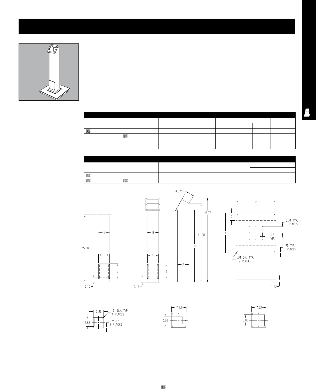
ELECTROMATE ACCESSORIES
ACC 28
Pedestal/Base
Pedestals provide extra flexibility
and operator friendliness for control
system applications. Both standard
and stainless steel versions are
available in two heights and either
straight or angled. Wiring and cable
routing can be either directly to the
enclosure or through the base and
column in which case a cutout is
required in the enclosure bottom.
Pedestals
Steel Stainless Steel Description Column Column Cover plate Column height
Part No. Part No. AB E F G
E 44CCOL E 44CCOLSS Straight Column 4.00 4.00 7.00 3.75 35.00
E 66CCOL E 66CCOLSS Straight Column 6.00 6.00 7.75 5.75 35.00
-E 44PBCCOLSS Angled Column 4.00 4.00 7.00 3.75 38.69
-E 66PBCCOLSS Angled Column 6.00 6.00 7.75 5.75 37.53
Bases
Steel Stainless Steel ABStiffener location
Part No. Part No. C
E 18SBASE E 18SBASESS 18.00 18.00 3.00
E 24SBASE E 24SBASESS 24.00 24.00 5.00
Pedestals And Bases
Straight Column
Base configuration:
Leveling screws
Holes
Material/finish:
Steel columns: 14 gauge steel with
polyester-urethane powder coat over
phosphatized surfaces, inside
and outside – ANSI 61 grey
Stainless steel columns: Type 304
stainless steel with a # 3 brushed finish
Flanges: 10 gauge steel
Base Top View
Base Side View
6x6 Top And Bottom Flange
(See Base For
Hole Location)
4x4 Bottom Flange
(See Base For
Hole Location)
4x4 Top Flange
Angle Column
Designates a product in the EnclosureZone program.
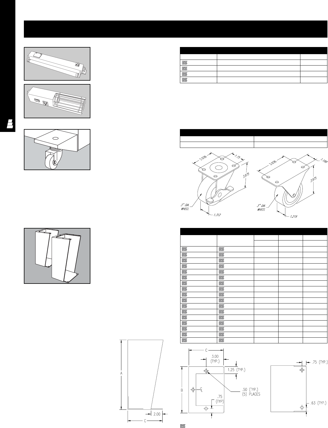
ELECTROMATE ACCESSORIES
ACC 29
Caster Kits
Casters make it easy to move
cabinets around.
Load capacity: 350 lbs per caster
Material:
Caster mounting plate: heavy gauge
steel with zinc-plated finish
Configuration:
2 fixed casters
2 swivel casters
Mounting hardware
Caster Kits
Part No. Description
E C10C Set of four casters
Floor Stand Kits
Floor stand kits can be used to raise
freestanding enclosures or to
floormount standard wallmount
enclosures off the floor. They are easily
installed — just drill holes in bottom of
enclosure and bolt to enclosure.
Note: Wallmounting feet do not have
to be removed from wallmount
enclosures.
Configuration:
2 stands
Mounting hardware
Material/finish:
Steel: 10 gauge steel with grey primer
over phosphatized surfaces
Stainless steel: 10 gauge Type 304
stainless steel with # 3 brushed finish
Floor Stand Kits
Steel Stainless Steel Height Width Depth
Part No. Part No. ABC
E FK0608 E FK0608SS 6.00 8.00 6.00
E FK0610 E FK0610SS 6.00 10.00 8.00
E FK0612 E FK0612SS 6.00 12.00 8.00
E FK0618 E FK0618SS 6.00 18.00 8.00
E FK1208 E FK1208SS 12.00 8.00 6.00
E FK1210 E FK1210SS 12.00 10.00 8.00
E FK1212 E FK1212SS 12.00 12.00 8.00
E FK1216 E FK1216SS 12.00 16.00 8.00
E FK1218 E FK1218SS 12.00 18.00 8.00
E FK1220 E FK1220SS 12.00 20.00 8.00
E FK1808 E FK1808SS 18.00 8.00 6.00
E FK1810 E FK1810SS 18.00 10.00 8.00
E FK1812 E FK1812SS 18.00 12.00 8.00
E FK2408 E FK2408SS 24.00 8.00 6.00
E FK2410 E FK2410SS 24.00 10.00 8.00
E FK2412 E FK2412SS 24.00 12.00 8.00
E FK2416 E FK2416SS 24.00 16.00 8.00
General Accessories
Light Kits Light Kits
Part No. Description Packs of
E LKF18D Light Kit - Flourescent (18") Door Switch 1
E LKF18M Light Kit - Flourescent (18") Manual Switch 1
E LKID Light Kit - Incandescent Door Switch 1
E LKIM Light Kit - Incandescent Manual Switch 1
Designates a product in the EnclosureZone program.
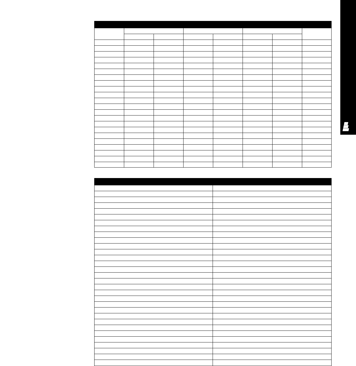
ELECTROMATE ACCESSORIES
ACC 30
NEMA 1 Wireway Painted Covers
Part No. Description
E WC2212P Cover for E W2212P
E WC2224P Cover for E W2224P
E WC2236P Cover for E W2236P
E WC2248P Cover for E W2248P
E WC2260P Cover for E W2260P
E WC4412P Cover for E W4412P
E WC4424P Cover for E W4424P
E WC4436P Cover for E W4436P
E WC4448P Cover for E W4448P
E WC4460P Cover for E W4460P
E WC6612P Cover for E W6612P
E WC6624P Cover for E W6624P
E WC6636P Cover for E W6636P
E WC6648P Cover for E W6648P
E WC6660P Cover for E W6660P
E WC8812P Cover for E W8812P
E WC8824P Cover for E W8824P
E WC8836P Cover for E W8836P
E WC8848P Cover for E W8848P
E WC8860P Cover for E W8860P
E WC101012P Cover for E W1012P
E WC101024P Cover for E W1024P
E WC101036P Cover for E W1036P
E WC101048P Cover for E W1048P
E WC101060P Cover for E W1060P
E WC121212P Cover for E W1212P
E WC121224P Cover for E W1224P
E WC121236P Cover for E W1236P
E WC121248P Cover for E W1248P
E WC121260P Cover for E W1260P
Painted/Flush Covers
Part No. Enclosure size Cover size Screw cover centers Material
HW ABCDgauge
E FC44P 4.00 4.00 6.00 6.00 - 3.25 14
E FC64P 6.00 4.00 8.00 6.00 - 3.25 14
E FC66P 6.00 6.00 8.00 8.00 - 5.25 14
E FC86P 8.00 6.00 10.00 8.00 4.38 5.25 14
E FC126P 12.00 6.00 14.00 8.00 8.38 5.25 14
E FC88P 8.00 8.00 10.00 10.00 4.38 7.25 14
E FC108P 10.00 8.00 12.00 10.00 6.38 7.25 14
E FC128P 12.00 8.00 14.00 10.00 8.38 7.25 14
E FC1010P 10.00 10.00 12.00 12.00 6.38 9.25 14
E FC1210P 12.00 10.00 14.00 12.00 8.38 9.25 14
E FC1212P 12.00 12.00 14.00 14.00 8.38 11.25 14
E FC1512P 15.00 12.00 17.00 14.00 11.38 11.25 14
E FC1812P 18.00 12.00 20.00 14.00 14.38 11.25 14
E FC1515P 15.00 15.00 17.00 17.00 11.38 14.25 14
E FC1815P 18.00 15.00 20.00 17.00 14.38 14.25 14
E FC1818P 18.00 18.00 20.00 20.00 14.38 17.25 14
E FC2418P 24.00 18.00 26.00 20.00 20.38 17.25 14
E FC2424P 24.00 24.00 26.00 26.00 20.38 23.25 14
E FC3024P 30.00 24.00 32.00 26.00 26.38 23.25 14
E FC3624P 36.00 24.00 38.00 26.00 32.38 23.25 14
E FC3030P 30.00 30.00 32.00 32.00 26.38 29.25 12
E FC3636P 36.00 36.00 38.00 38.00 32.38 35.25 12
Screw Cover Pull Box
Flush Covers
Covers fastened with plated
steel screws. Key-hole screw-
slot design permits easy
attaching of cover to body.
NEMA 1 Wireway
Painted Covers
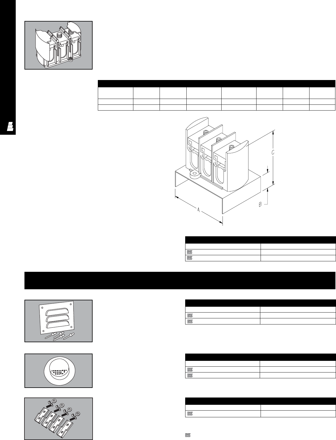
ELECTROMATE ACCESSORIES
ACC 31
Touch-Up Paint
Rittal Electromate paint can be used for touch-up and repairs of powder
coated or enameled surfaces.
Touch-up Paint
Part No. Color
E L17 White enamel
E L21 ANSI 61 grey polyester powder
Keytap®
Keytap®provides a simple, quick
and less expensive method for
mounting cable connectors and
terminal block assemblies to the
interior of Rittal Electromate
enclosures and wireways. 3 or 4 “U”
connectors are gang-mounted into
multi splice and tap blocks. Blocks
hold cables securely in place and
are complete with a quick snap
on/off insulating cover and
mounting platform. The quick snap
on/off insulating cover eliminates
tapping and reduces heat build-up
by allowing free airflow around the
connector. The mounting platform
facilitates installation, allows easy
access to the block, and permits
the routing of additional wires
under the block. This assembly is
rated at 600 volts and can be
used with either copper or
aluminum cable. Connectors are
electro-tin plated for low contact
resistance and protection against
galvanic corrosion.
Keytap®
Part No. No. of wires Wireway Max. wire capacity Tap size A B C
size per phase range
E 50063WTKIT 36 x 6 2-500 mcm 500 mcm thru 6 5.75 1.62 5.62
E 41063WTKIT 3 6 x 6 2-4/0 4/0 thru 6 5.75 2.62 5.62
Fiberglass Accessories
Louver Panel Kits
Part No. Number of louvers
L FLPK3KIT 1
L FLPI 1
Louver Panel Kits
Drain/Vent Kits Drain/Vent Kits
Part No. Packs of
L FDV3KIT 1
L FDVI 1
Designates a product in the EnclosureZone program.
Mounting Foot Mounting Foot
Part No. Packs of
L FIMTGFTKIT 1

In Europe, the CE Marking signifies that a product complies
with all European Union (EU) directives and with applicable
health, safety, environmental and consumer protection
standards. The mark also promotes free trade into and within
the EU. The CE marking is not applied to empty enclosures
because they are considered only as inactive parts of the
final equipment assembly. The equipment integrator is
responsible for compliance with applicable EU directives and
standards.
The IEC rating system uses different evaluation criteria and
has more classifications than the UL and CSA standards.
Because the classification ratings differ, equating IEC
classifications with NEMA Type enclosures can be
controversial and depends on individual interpretation
of ratings.
The National Electrical Manufacturers Association (NEMA)
publishes ratings, but does not test or list enclosures. The
NEMA enclosure designations are the standard reference for
enclosures in this publication, and regardless of type, all
enclosures provide protection to personnel against incidental
contact with the enclosed equipment. To assist in the proper
selection of an enclosure, the NEMA types are differentiated
by the environmental conditions as listed below:
NEMA 1 Indoor use to provide a degree of
protection against falling dirt.
NEMA 2 Indoor use to provide a degree of
protection against falling dirt; dripping and
light splashing of liquids.
NEMA 3 Indoor or outdoor use to provide a degree
of protection against falling dirt, rain, sleet,
snow and windblown dust; and that will be
undamaged by the external formation of
ice on the enclosure.
NEMA 3R Indoor or outdoor use to provide a degree
of protection against falling dirt, rain, sleet
and snow; and that will be undamaged by
the external formation of ice on the
enclosure.
NEMA 3S Indoor or outdoor use to provide a degree
of protection against falling dirt, rain, sleet,
snow and windblown dust; and in which
the external mechanism(s) remain
operable when ice laden.
NEMA 4 Indoor or outdoor use to provide a degree
of protection against falling dirt, rain, sleet,
snow, windblown dust, splashing water,
hose-directed water; and that will be
undamaged by the external formation of
ice on the enclosure.
Technical Information
Certifications & Standards
Application
The products in this catalog are designed for electrical and
electronic enclosure applications in commercial or industrial
locations which are classified as non-hazardous; currently
Rittal does not manufacture enclosures for hazardous
environments. Information on the classification of hazardous
and non-hazardous locations appears later in this section.
The enclosure products in this publication should be
applied, installed and used only by qualified engineers,
technicians or electricians knowledgeable of the standards,
laws, regulations and ordinances associated with the
respective application.
THE INFORMATION IN THIS SECTION HAS BEEN
CONDENSED FROM SEVERAL REFERENCES AND IS
PROVIDED FOR GUIDANCE IN SELECTING THE
APPROPRIATE ENCLOSURE FOR AN APPLICATION.THE
ORIGINAL REFERENCE MUST BE CONSULTED FOR
DETAILED INFORMATION.
Installation
Enclosures must be mounted to structures which will support
the weight and sustain all other forces which the enclosure
and its associated equipment may impose. Before any
circuits are energized, all electrical and mechanical
clearances must be checked to confirm that the equipment
functions safely and properly. Assemblers and installers
should consult with manufacturers and observe all regulatory
procedures and practices to assure electrical and
mechanical conformance in each application.
Industry Standards
The following information is provided with permission of the
respective organizations to assist in the selection of an
enclosure:
Enclosure Ratings
CSA, IEC, NEMA and UL use rating classifications which
establish performance requirements for enclosures. CSA,
NEMA and UL are the recognized organizations in North
America. IEC standards fulfill a similar function in Europe
and other parts of the world. Efforts to harmonize enclosure
standards are underway, however several years are
anticipated before the effort is complete.
In North America, both UL and CSA are accredited by the
Standard Council of Canada (SCC) as Certification
Organizations (CO) and Testing Organizations (TO). With its
SCC accreditation, UL is able to evaluate products for use in
Canada. Approved products carry the cUL mark. Both UL
(cUL) and CSA perform follow-up services to assure that
manufacturers continue to comply with material and process
specifications.
Technical Information
Certifications & Standards
TEC 1
TECHNICAL APPENDIX
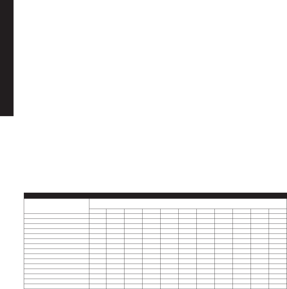
Comparison of Enclosure Types for Non-Hazardous Locations
Provides a Degree of Protection Against the
Following Environmental Conditions TYPE OF ENCLOSURE
1233R44X566P1213
Incidental Contact with Enclosed Equipment X X X X X X X X X X X
Indoor X X X X X X X X X X X
Outdoor X X X X X X
Falling Dirt X X X X X X X X X X X
Dripping and Light Splashing Liquids X X X X X X X X X X
Rain, Sleet* and Snow X X X X X X
Circulating Dust, Lint, Fibers and Flyings X X X X X X X
Settling Dust, Lint, Fibers and Flyings X X X X X X X X
External Ice* X X X X X X
Hosedown and Splashing Water X X X X
Oil and Coolant Seepage XX
Oil and Coolant Spraying and Splashing X
Corrosive Agents XX
Occasional Temporary Submersion XX
Occasional Prolonged Submersion X
* External operating mechanisms are not required to be operable when the enclosure is ice covered.
NEMA 4X Indoor or outdoor use to provide a
degree of protection against falling dirt,
rain, sleet, snow, windblown dust,
splashing water, hose-directed water and
corrosion; and that will be un-damaged
by the external formation of ice on the
enclosure.
NEMA 5 Indoor use to provide a degree of
protection against falling dirt; settling
airborne dust, lint, fibers and flyings; and
dripping and light splashing of liquids.
NEMA 6 Indoor or outdoor use to provide a
degree of protection against falling dirt;
hose-directed water and the entry of
water during occasional temporary
submersion at a limited depth; and will
be undamaged by the external formation
of ice on the enclosure.
NEMA 6P Indoor or outdoor use to provide a degree of
protection against falling dirt; hose-directed
water and the entry of water during
prolonged submersion at a limited depth;
and will be undamaged by the external
formation of ice on the enclosure.
NEMA 12 Indoor use to provide a degree of protection
against falling dirt; circulating dust, lint, fibers
and flyings; and dripping and light splashing
of liquids.
NEMA 13 Indoor use to provide a degree of protection
against falling dirt; circulating dust, lint, fibers
and flyings; and spraying, splashing and
seepage of water, oil and non-corrosive
coolants.
Technical Information
Certifications & Standards
TEC 2
TECHNICAL APPENDIX

Technical Information
Certifications & Standards
Reference Documents and Sources
NEMA Standards Publication 250, Enclosures for Electrical
Equipment (1000 Volts Maximum) and NEMA Standards
Publication ICS6, Enclosures for Industrial Controls and
Systems
National Electrical Manufacturers Association
1300 North 17th Street, Suite 1847
Rosslyn, VA 22209
CSA Standard C22.2 No. 14 Industrial Control Equipment for
Use in Ordinary (Non-Hazardous) Locations; CSA Standard
C22.2 No. 40 Cut-Out, Junction and Pull Boxes; and CSA
Standard 22.2 No. 94 Special Purpose Enclosures
Canadian Standard Association
178 Rexdale Boulevard
Etobicoke, Ontario, Canada M9W 1R3
UL 50 Enclosures for Electrical Equipment; UL 94 Tests for
Flammability of Plastic Materials for Parts in Devices and
Appliances; UL 508 Industrial Control Equipment; UL 870
Wireways, Auxiliary Gutters and Associated Fittings; and UL
746C Polymeric Materials - Use in Electrical Equipment
Evaluations
Underwriters Laboratories
333 Pfingsten Road
Northbrook, IL 60062-2096
Underwriters Laboratories of Canada
7 Crouse Road
Scarborough, Ontario M1R 3A9 Canada
IEC 529 Classification of Degrees of Protection
by Enclosures; IEC 204 Electrical Equipment of Industrial
Machines
International Electrotechnical Commission
1 Rue de Varembei
CH-1211
Geneva 20, Switzerland
ANSI Z55.1 Grey Finishes for Industrial Apparatus and
Equipment
American National Standards Institute
1430 Broadway
New York, NY 10018
Information for Comparison of IEC and
CSA/NEMA/UL/cUL Ratings
NEMA 250 and UL 50 specify tests for environmental
conditions such as falling dirt, ice, corrosion, oil and
coolants whereas IEC 529 does not have such
requirements. Different rating requirements make
comparison difficult and disagreements are common.
The IEC designation consists of the letters IP followed by
two numerals. The first number indicates the degree of
protection provided by the enclosure with respect to
persons and solid foreign objects entering the enclosure.
The second number indicates the degree of protection
provided by the enclosure with respect to the harmful
ingress of water.
The data contained in the following tables are provided for
information; however, caution is necessary when attempting
to equate IEC and NEMA enclosure ratings because an
exact equivalence is not possible. The table can only be
used to convert NEMA designations to IEC, it should not be
used inversely. The cross reference is based on engineering
judgement and is not approved by any standards
organization.
TEC 3
TECHNICAL APPENDIX

Technical Information
Certifications & Standards
Approximate Equivalence of CSA/NEMA/UL/cUL and IEC Enclosure Types*
*Comparison ratings in this table are taken from Appendix A, NEMA 250-1997. Test data
may change the equivalent rating published by the enclosure manufacturer.
Specifications for Construction
Materials Used in Rittal Enclosures
Cold Rolled Steel
A low carbon, cold finished steel, produced by passing bar
stock through a set of rolls. Cold rolled sheets have less
thickness variation and a better finish than hot rolled steel.
Galvanized Steel
A zinc coated steel which is hot dip galvanized, metal
sprayed or electroplated to provide corrosion resistance.
Galvanizing provides a sacrificial coating and cathodic
protection.
Hot Rolled Steel
A low carbon, hot finished steel, produced by passing bar
stock through a set of rolls at a temperature above the
re-crystallization temperature. Hot rolled steel sheet has a
poorer finish than cold rolled steel.
Pickled and Oiled Steel Sheets
Hot rolled steel sheets which have had the scale removed
by means of a hot, weak sulfuric acid bath after which an oil
film has been applied for corrosion resistance.
Stainless Steel
A highly corrosion resistant iron alloy containing between 12%
and 25% chromium. For superior corrosion resistance, Rittal
fabricates enclosures from both Type 304 and 316 Stainless
Steel which are non-magnetic. Type 316, a low carbon
stainless steel, is harder and more corrosion resistant;
it is an excellent material for marine application.
Aluminum
A lightweight metal which quickly forms a natural oxide layer
to resist corrosion. Rittal fabricates enclosures from Type 5052
aluminum, the highest strength non-heat treatable aluminum
alloy recommended for marine applications.
Galvaneal
A hot-dip zinc coated sheet which has been heated after
coating to allow interdiffusion of zinc and iron to form an alloy
coating.
Fiberglass
Enclosures are molded under heat and pressure with
fiberglass reinforced polyester resin to produce superior
chemical resistance in corrosive applications. The glass fiber
reinforcement increases enclosure strength to withstand
physical loads such as unexpected impacts or additional
tensile loads.
NEMA Enclosure Type IEC Enclosure Type
1IP10
2IP11
3IP54
3R IP14
3S IP54
4IP66
4X IP66
6IP67
12 IP52
13 IP54
TEC 4
TECHNICAL APPENDIX

The enclosure selection process includes the following five
considerations:
1. Examination of the Application
Industrial applications usually require strong mechanical
enclosures which are durable. Electronic and
communication applications are more diverse, but space
and security are usually the more dominant
considerations.
2. Environment Protection
The environment where the equipment will be located
(i.e., outdoors, factory floor, office, laboratory, chemical
plant, etc.) establishes the degree of protection required.
The NEMA enclosure ratings provide the information
needed to select the enclosure for your application
requirements.
The application environment is a significant factor in
specifying the enclosure material. For mild steel
enclosures, painting is the most basic protection;
stainless steel should be considered for more corrosive
applications. Electromagnetic interference (EMI) and
radio frequency interference (RFI) are additional
environmental factors which impact enclosure
material selection.
3. Space Requirements
Space requirements include size and equipment
arrangement as well as aesthetics. Accessories such as
windows, back panels, swingout panels, wiring terminals,
EMI/RFI shielding and climate control solutions also
influence size and appearance.
4. Climate Control Solutions
Especially in electronic enclosure applications, climate
control is becoming an important issue because
technology advances continue to reduce component
size. Smaller components increase heat generation by
placing more components in the same enclosure volume.
Also in some applications, heaters are required to
prevent condensation.
5. Security
The monetary value of equipment placed within
enclosures has increased. The safety of personnel can
be jeopardized by unauthorized access and operation of
equipment. Enclosure security can be enhanced by the
selection of hinges, latches, locks and fasteners.
The five steps in this enclosure selection process are not
new, but numerous enclosure and design options are
available to meet a diversity of needs in each area.
In addition almost any enclosure in this catalog can be
modified to meet unique application requirements in a
specific environment.
Selecting an Enclosure
The Selection Guidelines and the Enclosure Selection Guide
are designed to help select a Rittal enclosure which is best
for your application. Before using the Enclosure Selection
Guide, the first three steps in the selection process must
be completed.
The application, environmental and space requirements are
dependent on the sensitivity/criticality of the equipment, and
its size and operation. Once these parameters are
established, the first three steps are quickly and easily
completed. An Enclosure Selection Checklist and
supplemental information are provided within this Technical
Section to help select the enclosure material for the
application environment.
Technical Information
Enclosure Selection Guidelines
TEC 5
TECHNICAL APPENDIX

Technical Information
Enclosure Materials
Rittal offers Aluminum, Galvanized Steel, Painted Steel,
Stainless Steel and Fiberglass Enclosures. The choice of
material is dependent on the concentration of various
corrosives present in the application environment and other
physical properties necessary to meet the design
specifications. Although NEMA 4X is the only enclosure
fabricated and rated for resistance to corrosive agents, other
enclosure materials and ratings offer a degree of corrosion
resistance in less harsh environments.
To begin the selection process, one must consider all the
corrosive agents which can be present in an application,
but determining the concentration and corroding agents may
be a complex process. Usually several corrosive elements
are present and interactions are not always well documented.
Water is the most common corrosive and is usually present
to some extent in every enclosure application. Adjacent
processing operations or other intermittent activities such as
crop dusting, industrial cleaning or road salt may expose the
enclosure to a variety of corrosive agents and temperatures.
Each environment is unique and all possible corrosive agents
should be identified for the intended enclosure application.
Once the corrosive agents and concentrations are identified,
information in this section can be used to select the
enclosure material. Metal corrosion is influenced by surface
finish, surface treatment such as painting or galvanizing, and
use of materials such as stainless steel, fiberglass or
aluminum which are naturally corrosion resistant.
To select the best enclosure material for an application;
chemical resistance, physical strength and economic data
are presented in several tables beginning on the next page.
In Table 1 enclosure materials are rated on a continuum from
“Recommended” to “Limited or Unacceptable” in three broad
categories of chemicals. Since the chemical resistance
categories in the table are extremely broad, some materials
may perform well in specific corrosive environments within a
general category and it is best to consult the detailed
Chemical Resistance Information provided in Table 3.
Besides the enclosure material, the corrosion resistance of
features such as windows, gaskets, latches, etc. must also
be considered. Table 4 provides the chemical resistance
information which can be used to select the commonly
used materials for these features.
Much of the chemical resistance information in Tables 3
and 4 is based on total immersion testing in the chemical
for a minimum of 30 days at 72°F. The information in these
tables is intended as a guide only. Total immersion testing
is considered quite severe and the results may not
necessarily reflect the performance under actual field
conditions. The user assumes responsibility for selection
of the material based on the characteristics of the
application environment.
TEC 6
TECHNICAL APPENDIX
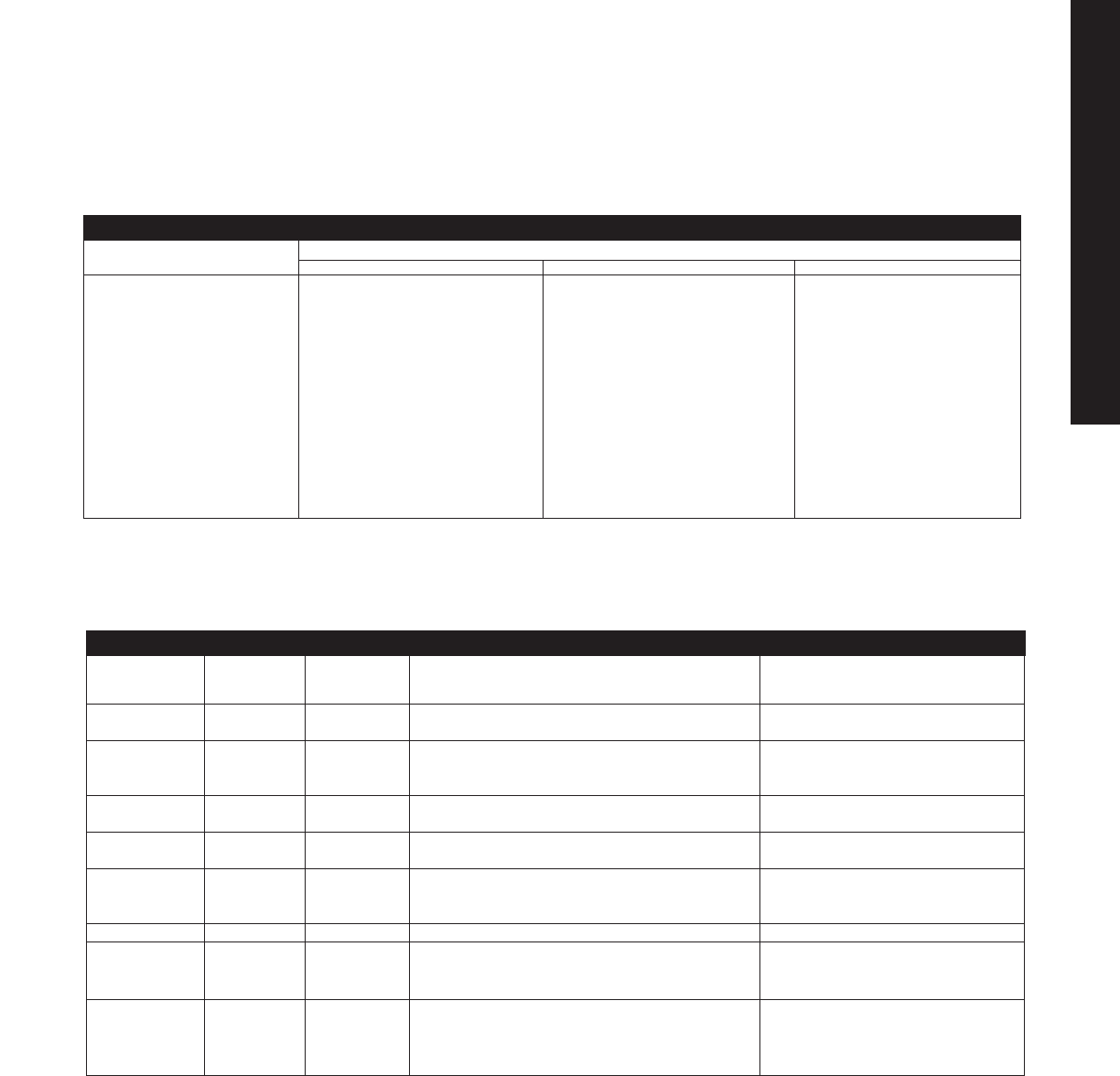
RELATIVE
MATERIAL PHYSICAL RELATIVE APPLICATION TEMPERATURE
STRENGTH COST CONDITIONS LIMITATIONS
Aluminum Average Average Indoor and outdoor, marine, solvents, petrochemical None for enclosure applications
sulfates, nitrates and specific acids.
Mild Steel: High Average Indoor and outdoor where the respective coating None for enclosure applications
Galvanized Low provides acceptable protection in a mildly corrosive
Painted environment.
Stainless High Average- Indoor and outdoor in highly corrosive applications. None for enclosure applications
Steel High Food and dairy processing or marine.
Acrylic Average Low Enclosure windows. Weatherable, scratch resistant. -31°F (-35°C) to 180°F (82°C)
Good resistance to solvents.
Poly- Average Low- Enclosure windows. Not recommended for direct -31°F (-35°C) to 248°F (120°C)
carbonate Average sunlight, exposure to organic solvents and
concentrated alkalis.
Nylon Average Low Cord grip, hinges, latches. -22°F (-30°C) to 212°F (100°C)
Fiberglass Average Low- Indoor and outdoor for continuously damp and highly -40°F (C) to 250° (121°C)
Average corrosive environments. Petrochem, water treatment,
food processing, coating, salts and chemicals.
Gaskets:
Neoprene Low Low Oil resistance. Seams may be a problem. -40°F (C) to 225°F (107°C)
Silicone Low Average Oil resistance temperature and chemical resistance. -40°F (-40°C) to 350°F (175°C)
Urethane Low Average Water and oil resistance, chemical resistance. -40°F (C) to 200°F (93°C)
Technical Information
Enclosure Materials
CONTINUUM GENERAL CATEGORY OF CHEMICALS
OF USE Acids Alkalines Solvents
Stainless Steel
Stainless Steel Stainless Steel Fiberglass
Recommended Fiberglass Aluminum
Fiberglass Powder Coated Steel
Acceptable
Galvanized Steel Galvanized Steel
Powder Coated Steel Powder Coated Steel
Limited or
Unacceptable
Aluminum
Galvanized Steel Aluminum
Detailed material strength information is beyond the scope of this catalog and should be obtained from a materials reference or Rittal; however, Table 2 provides some relative
data to help with this selection.
Table 1. Broad Categories Of Enclosure Material Chemical Resistance
Table 2. Relative Material Strength And Cost Comparison Of Commonly Used Enclosure Materials
➡➡ ➡➡ ➡➡ ➡➡
TEC 7
TECHNICAL APPENDIX
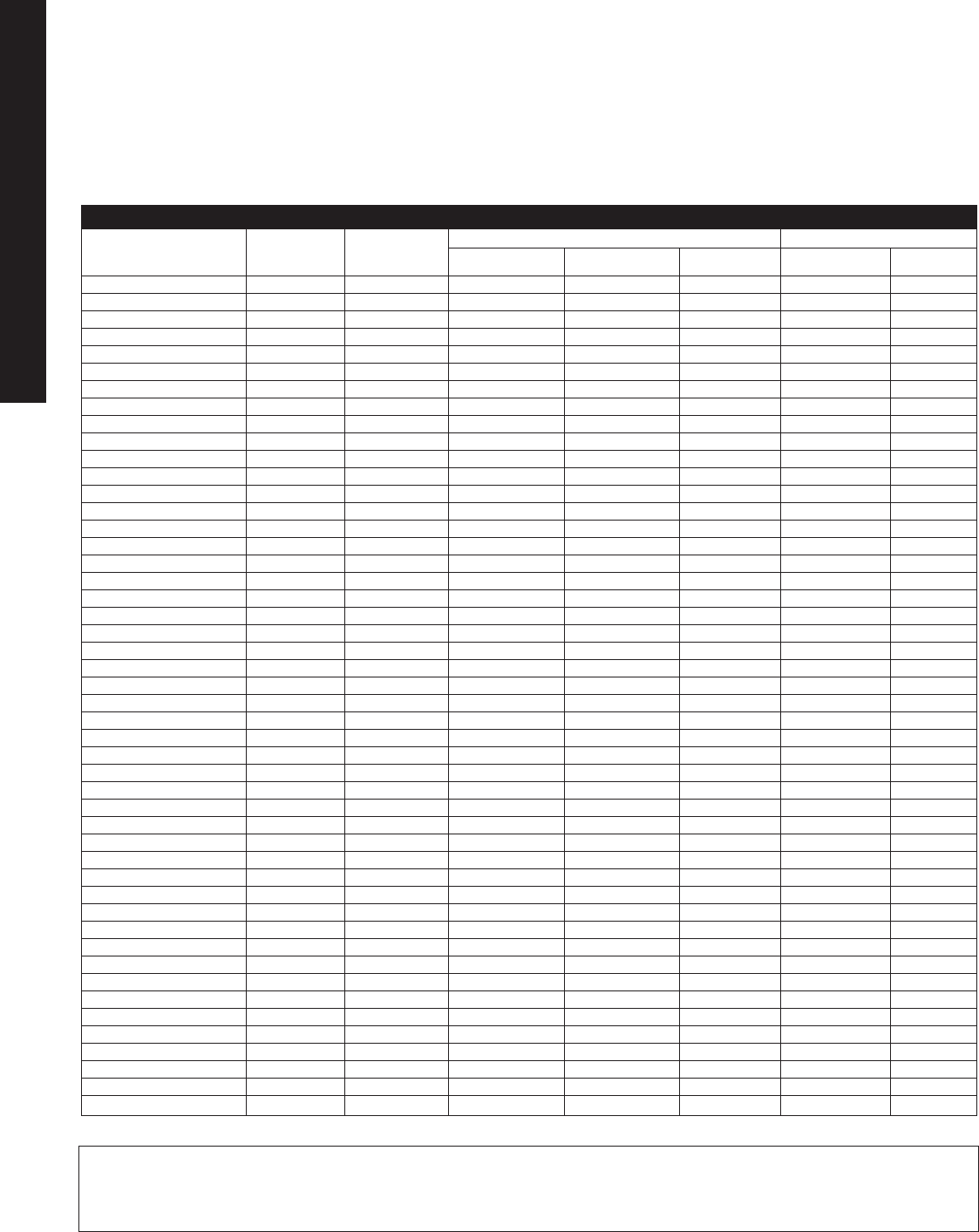
Fiber Steel Stainless Steel
Glass Polyester Urethane Galvanized Type Type
CHEMICAL Aluminum Polyester Powder Enamel 304 316
Acetyldehyde S U — — — S S
Acetic Acid (10%) L S U U U S U
Acetone S L L U L S S
Aluminum Chloride (10%) U S U U U U M
Aluminum Sulfate (10%) L S U U U U S
Ammonia Gas L S — — — S S
Ammonium Chloride U S U U U S S
Ammonium Hydroxide (10%) S L U U U S S
Ammonium Nitrate (10%) M S U U U S S
Ammonium Phosphate (10%) L M S L U S M
Ammonium Sulfate S S — — — S S
Aniline L U — — — S S
ASTM #1 Oil S S S S S S S
ASTM #3 Oil S S S S S S S
Axle Grease S S S S S S S
Benzene S S — — S S S
Boric Acid (10%) M S U U U S S
Bromine U L U U U U U
Butyl Acetate M L — — — S S
Butyric Acid U S — — — S S
Calcium Chloride (10%) L S U U U L S
Calcium Hydroxide (10%) U S U U U S S
Calcium Hypochlorite (10%) L M U U U U M
Calcium Sulfate M S U U U S S
Carbolic Acid (25%) M L U U U S S
Carbon Disulfide S L — — — S S
Carbon Tetrachloride S M U S S U S
Chlorine (dry) S S — — — S S
Chlorine (water) 5-10 ppm M L S U U U —
Chlorobenzene S S — — S S S
Chloroform L U — — — S S
Chrome Plating Solution U L U U U L L
Chromic Acid S S — — — U U
Citric Acid (10%) U M U U U S S
Copper Sulfate U S — — — S S
Creosote L L — — — S S
Cutting Fluid (5 Star) 10% S S U U U S S
Cutting Fluid (Castrol 980 H) S S S U U S S
Cutting Fluid (Norton 205) U S U U U S S
Cutting Fluid (Rustlick) 10% M S U U U S S
Cutting Oil (Dark) S S S S S S S
Diethyl Ether S S — — — S S
Ethyl Alcohol S S M U S S S
Ethylene Dichloride S L — — — — —
Ethylene Glycol S S S S U S S
Ferric Chloride U S U U U S U
Ferric Nitrate — S — — — S S
Ferric Sulfate M S — — — S S
KEY :
S = superior resistance /
completely unaffected
under all conditions
Technical Information
Chemical Resistance
Table 3. Specific Chemical Resistance Information Metals, Coated Metals And Fiberglass Materials
L = limited resistance / some chemical attack
may be expected over time, exposure
should be limited to fumes or occasional
light splashing
— = no data available
M = moderate resistance / superficial
(aesthetic) effects only, example:
some loss of surface gloss or color
change may occur, but mechanical
properties (strength) remain unaffected
U = unsatisfactory severe / chemical
attack in a relatively short time
TEC 8
TECHNICAL APPENDIX
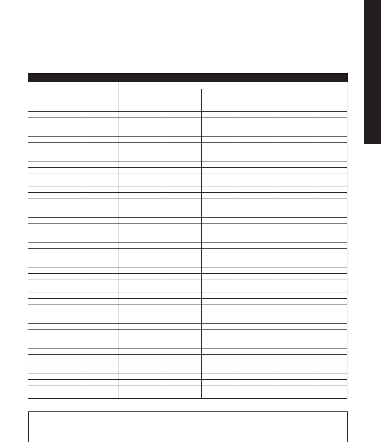
Fiber Steel Stainless Steel
Glass Polyester Urethane Galvanized Type Type
CHEMICAL Aluminum Polyester Powder Enamel 304 316
Fluorine S U — — — M —
Formaldehyde S S — — — L S
Formic Acid U S U U U M S
Fuel Oil (#2) S S M S S S M
Gasoline S M — — — S S
Glycerine S S — — S S S
Hydraulic Brake Fluid S S U U S S S
Hydraulic Oil S S S S S S S
Hydrochloric Acid (10%) U M U U U U U
Hydrocyanic Acid S U — — — S S
Hydrofluoric Acid (20%) U U U U U U U
Hydrogen Peroxide S M — — — L S
Hydrogen Sulfide M S — — — L S
Hypochlorus Acid U S — — — — —
Isopropyl Alcohol S S M U S S S
Kerosene S S S S S S S
Lacquer Thinner S S L U S S S
Lactic Acid M S — — — L S
Lime M M — — — — —
Liquid Dish Soap (10%) M S U U U S M
Lubricating Oils S S — — — S S
Magnesium Chloride (10%) L S U U U S S
Magnesium Hydroxide (10%) L S U U U S S
Mercuric Chloride (10%) U M U U U S U
Methyl Ethyl Ketone S L — — — S S
Methylene Chloride S S U U M S S
Milk S S — — — S S
Mineral Oil S S — — — S S
Mineral Spirits S S S S S S S
Motor Oil (10 weight) S S S S S S S
Nickel Salts L S — — — L S
Nitric Acid (10%) U M U U U S S
Nitrobenzene S L — — — S S
Oleic Acid S S — — — L S
Perchlorethylene S S S U S S S
Phosphoric Acid (25%) U L U U U S S
Phosphoric Acid (50%) U U U U U S S
Pickling Solution U M U U U S M
Potassium Carbonate (10%) U S S S L S S
Potassium Chloride (25%) L S U U U S S
Potassium Hydroxide (25%) U U U U U M M
Potassium Nitrate (10%) U S U U U S S
Potassium Sulfate (10%) L S U U U S S
Soap (Igepal) 10% L S S U U S S
Sodium Bicarbonate (10%) L S S S U S S
Sodium Bisulfate (10%) U L U U U S S
Sodium Chloride (25%) L S U U U S S
Sodium Hydroxide U U U U U M M
Technical Information
Chemical Resistance
Table 3. Continued
KEY :
S = superior resistance /
completely unaffected
under all conditions
L = limited resistance / some chemical attack
may be expected over time, exposure
should be limited to fumes or occasional
light splashing
— = no data available
M = moderate resistance / superficial
(aesthetic) effects only, example:
some loss of surface gloss or color
change may occur, but mechanical
properties (strength) remain unaffected
U = unsatisfactory severe / chemical
attack in a relatively short time
TEC 9
TECHNICAL APPENDIX
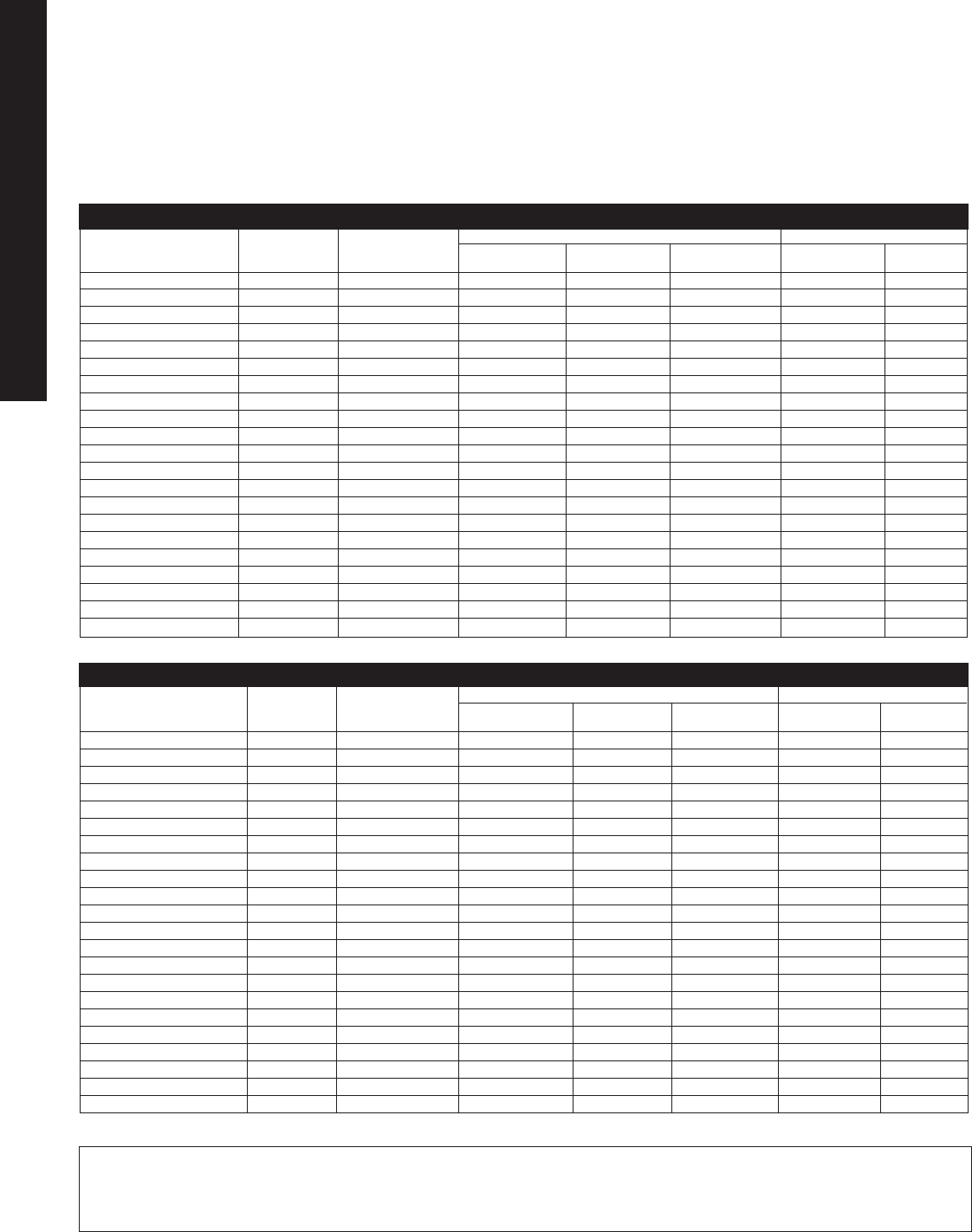
Fiber Steel Stainless Steel
Glass Polyester Urethane Galvanized Type Type
CHEMICAL Aluminum Polyester Powder Enamel 304 316
Sodium Hypochlorite U M U U U S M
Sodium Nitrate (10%) M S U U U S S
Sodium Phosphate (10%) L S U U U S S
Sulfuric Acid (25%) U S U U U S S
Sulfurus Acid (10%) U U U U U S S
Tannic Acid ((10%) L S U U U M M
Tetrahydrofuran M L U U U S S
Toluene S S L U S S S
Trichloroethylene S U — — — L S
Trisodium Phosphate L M — — — — —
Turpentine S M M U L S S
Vegetable Oils S S — — — S S
Vinegar M S — — — S S
Water, Industrial L S L L L S S
Water, Rain L S S L L S S
Water, Sea L S U U U S S
Water, Tap L S S L L S S
Xylene S S L U S S S
Zinc Acetate S S — — — S S
Zinc Chloride L S S U U M S
Zinc Sulfate S S — — — M S
Gaskets Windows
Rigid Glass Neoprene Silicone Poly-
CHEMICAL PVC Nylon Rubber Rubber Urethane Acrylic carbonate
Acetyldehyde U — S S — — —
Acetic Acid (10%) L U U M L S S
Acetone U S U S U U U
Aluminum Chloride (10%) S U S S S S S
Aluminum Sulfate (10%) S L U S S S S
Ammonia Gas — S S S — S —
Ammonium Chloride S U S S S S S
Ammonium Hydroxide (10%) S — L L S S U
Ammonium Nitrate (10%) S U U S S S U
Ammonium Phosphate (10%) — L U S S S S
Ammonium Sulfate S U S S — — —
Aniline S L U U — S —
ASTM #1 Oil — — M S S S M
ASTM #3 Oil — — U L S S M
Axle Grease — — L S S S M
Benzene U S U U — U —
Boric Acid (10%) L S S S S S S
Bromine U U U U U L U
Butyl Acetate U S U U — U —
Butyric Acid U U U — — — —
Calcium Chloride (10%) S U S S S S S
Calcium Hydroxide (10%) S — U S L S S
Table 4. Specific Chemical Resistance Information
Technical Information
Chemical Resistance
Table 3. Continued
KEY :
S = superior resistance /
completely unaffected
under all conditions
L = limited resistance / some chemical attack
may be expected over time, exposure
should be limited to fumes or occasional
light splashing
— = no data available
M = moderate resistance / superficial
(aesthetic) effects only, example:
some loss of surface gloss or color
change may occur, but mechanical
properties (strength) remain unaffected
U = unsatisfactory severe / chemical
attack in a relatively short time
TEC 10
TECHNICAL APPENDIX
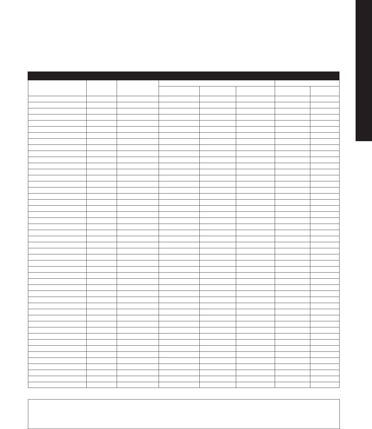
Gaskets Windows
Rigid Glass Neoprene Silicone Poly-
CHEMICAL PVC Nylon Rubber Rubber Urethane Acrylic carbonate
Calcium Hypochlorite (10%) S U U S U M S
Calcium Sulfate S U S S S S S
Carbolic Acid (25%) — — U U U U U
Carbon Disulfide U — U — — S —
Carbon Tetrachloride L S U U U S U
Chlorine (dry) L — — — — — —
Chlorine (water) 5-10 ppm L — L S S S S
Chlorobenzene U S U U — L —
Chloroform U U U U — U —
Chrome Plating Solution — — U U U S S
Chromic Acid L U U M — U —
Citric Acid (10%) S L U S U S S
Copper Sulfate S L S S — U —
Creosote — U U U — — —
Cutting Fluid (5 Star) 10% — — U S S S M
Cutting Fluid (Castrol 980 H) — — L S S S L
Cutting Fluid (Norton 205) — — S S S S S
Cutting Fluid (Rustlick) 10% — — S S S S S
Cutting Oil (Dark) — — U S S S S
Diethyl Ether U — — U — U —
Ethyl Alcohol S — L S S U M
Ethylene Dichloride U — U U — U —
Ethylene Glycol S — S S S S S
Ferric Chloride S U L S L S S
Ferric Nitrate S U S M — — —
Ferric Sulfate S U S M — — —
Fluorine L — — U — — —
Formaldehyde L U U M — S —
Formic Acid L S U L L U S
Fuel Oil (#2) S — U U U S S
Gasoline S S U L — S —
Glycerine S S S S — S —
Hydraulic Brake Fluid — — U S U U U
Hydraulic Oil — — U S S S M
Hydrochloric Acid (10%) S U L L U S S
Hydrocyanic Acid S — S M M — —
Hydrofluoric Acid (20%) L U U U — S M
Hydrogen Peroxide S U U M — S —
Hydrogen Sulfide S — U M — — —
Hypochlorus Acid — — — — — — —
Isopropyl Alcohol — — S S S S S
Kerosene S — U U S S M
Lacquer Thinner — S U S L U U
Lactic Acid S L L — — L —
Lime — — S M — — —
Liquid Dish Soap (10%) S — L S S S S
Lubricating Oils — — U U — S —
Magnesium Chloride (10%) S S S S S S S
Technical Information
Chemical Resistance
Table 4. Continued
KEY :
S = superior resistance /
completely unaffected
under all conditions
L = limited resistance / some chemical attack
may be expected over time, exposure
should be limited to fumes or occasional
light splashing
— = no data available
M = moderate resistance / superficial
(aesthetic) effects only, example:
some loss of surface gloss or color
change may occur, but mechanical
properties (strength) remain unaffected
U = unsatisfactory severe / chemical
attack in a relatively short time
TEC 11
TECHNICAL APPENDIX

Gaskets Windows
Rigid Glass Neoprene Silicone Poly-
CHEMICAL PVC Nylon Rubber Rubber Urethane Acrylic carbonate
Magnesium Hydroxide (10%) S — S S S S S
Mercuric Chloride (10%) L — U L U S S
Methyl Ethyl Ketone U S S U — L —
Methylene Chloride — U U S U U U
Milk S — S S — S —
Mineral Oil S — L M — S —
Mineral Spirits — — U U S S M
Motor Oil (10 weight) — — U U S S S
Nickel Salts S — U S — — —
Nitric Acid (10%) S U U U U S L
Nitrobenzene U S U — — — —
Oleic Acid S U — U — — —
Perchlorethylene — — U S U U U
Phosphoric Acid (25%) S U S S U S S
Phosphoric Acid (50%) S U S S U S S
Pickling Solution — — L M M S S
Potassium Carbonate (10%) L S S S S S S
Potassium Chloride (25%) S L S S S S S
Potassium Hydroxide (25%) S S U L M U U
Potassium Nitrate (10%) S L S S S S S
Potassium Sulfate (10%) SL S S S S S S
Soap (Igepal) 10% S — U S S S S
Sodium Bicarbonate (10%) S S S S S S S
Sodium Bisulfate (10%) S L S S L S S
Sodium Chloride (25%) S S S S S S S
Sodium Hydroxide S S U U M S U
Sodium Hypochlorite S U U S U S S
Sodium Nitrate (10%) S S S S S S S
Sodium Phosphate (10%) S — U S S S S
Sulfuric Acid (25%) S U S S U S S
Sulfurus Acid (10%) S — U U L S S
Tannic Acid ((10%) S U U L U S S
Tetrahydrofuran — S U U U U U
Toluene U S U U U U U
Trichloroethylene U U U U — U —
Trisodium Phosphate S — — — — — —
Turpentine — S U L U S S
Vegetable Oils S — L S — S —
Vinegar — S L S — S —
Water, Industrial S — S S S S S
Water, Rain S — S S S S S
Water, Sea S — S S S S S
Water, Tap S — S S S S S
Xylene — S U M U S U
Zinc Acetate — — — U — — —
Zinc Chloride S U M S U S M
Zinc Sulfate S L S S — — —
Technical Information
Chemical Resistance
Table 4. Continued
KEY :
S = superior resistance /
completely unaffected
under all conditions
L = limited resistance / some chemical attack
may be expected over time, exposure
should be limited to fumes or occasional
light splashing
— = no data available
M = moderate resistance / superficial
(aesthetic) effects only, example:
some loss of surface gloss or color
change may occur, but mechanical
properties (strength) remain unaffected
U = unsatisfactory severe / chemical
attack in a relatively short time
TEC 12
TECHNICAL APPENDIX
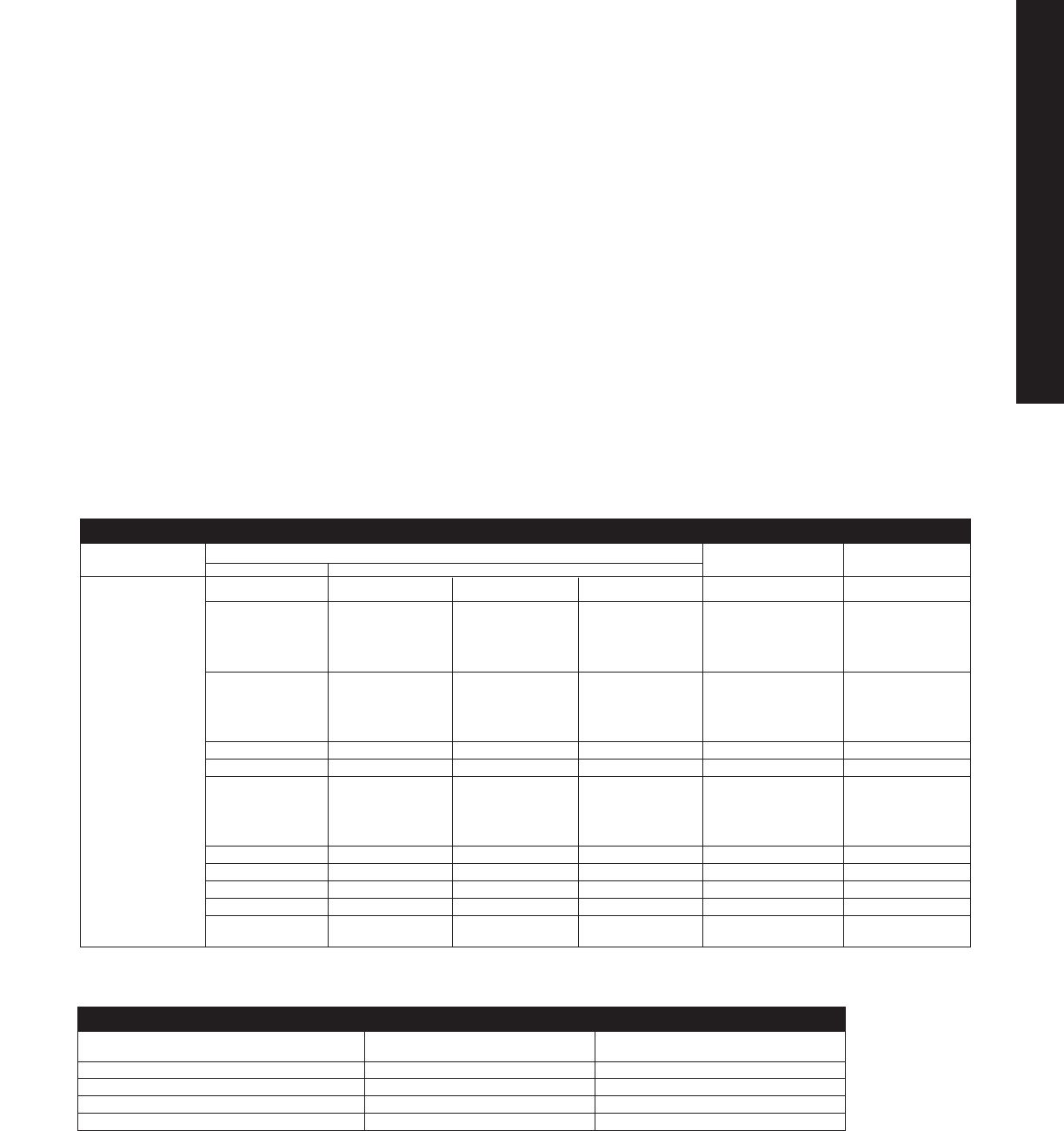
CONTINUUM CHEMICAL RESISTANCE CHIP HEAT
OF USE Acid Alkalines Solvents Water RESISTANCE RESISTANCE
Polyester Epoxy, Epoxy
Powder, Polyester
Urethane Powder,
Urethane
Recommended Urethane, Urethane, Urethane,
Polyester Polyester Polyester
Powder Powder, Powder
Epoxy
Epoxy
Acceptable Alkyds, Epoxy Alkyds, Alkyds Alkyds,
Epoxy Epoxy Polyester
Powder,
Urethane
Epoxy
Limited or
Unacceptable Alkyds Alkyds
PAINT COST MATERIAL
TYPES APPLICATION
Alkyd Medium Mild Steel
Epoxy Medium-High Mild Steel
Polyester Powder Low-Medium Mild Steel, Aluminum
Urethane Medium-High Mild Steel, Aluminum
The primary function of the enclosure’s
paint is to provide corrosion
protection, but benefits such as
improved appearance and added
distinction should also be considered.
The corrosive severity of the
application conditions is the first
consideration in selecting the finish.
Once a paint has been chosen for its
corrosion protection, other factors
such as color, gloss, texture, ease of
cleaning, retention of properties and
maintenance can be evaluated to
complete the selection.
Table 5 rates different paint types
on a continuum of use from
“Recommended” to “Unacceptable”
in three broad categories of chemical
corrosives. The table also provides
moisture, heat and chip resistance
information. Table 6 provides a
relative cost comparison of the
available paint categories and the
enclosure materials to which they
may be applied.
Technical Information
Enclosure Paint Finishes
➡➡➡ ➡
➡➡
➡➡
Table 5. Broad Categories Of Paint Type Characteristics
Table 6. Relative Cost Comparison Of Paint Types
TEC 13
TECHNICAL APPENDIX
➡

Technical Information
Enclosure Paint Finishes
Other considerations in selecting a
paint type include:
•Lighter colors will dissipate heat
and lower the temperature of
internal equipment; darker colors
will retain heat and increase the
temperature of the cabinet interior.
In outdoor applications lighter
colors reflect sunlight and operate
at lower temperatures.
•For severely corrosive applications,
an inhibiting primer with an overcoat
of epoxy or urethane is recommended.
•Textured finishes are generally less
expensive, easier to touch-up, do
not show fingerprints as readily and
provide an attractive appearance;
a textured paint finish is more
difficult to clean.
•Some epoxy paints chalk and
lose gloss.
•Safety concerns or corporate
specifications may be considered
in selecting a color; however, some
special colors may add cost and
increase lead times.
Topcoating Powdercoated
Enclosures
Rittal uses the latest electrostatic
powder coating technology to
deposit a premium powder paint
on enclosures; however, some
applications may require a
topcoating to meet unique
specifications such as a color
change or material requirement.
A topcoat can be applied to the
existing powdercoat using the
instructions below:
Topcoat Material Application Instructions
Air Dry Acrylic Lacquer Wipe the enclosure surfaces to be topcoated with a
Hi-Solid Catalyzed Acrylic clean solvent cloth. Allow the solvent to flash dry
Hi-Solid Two Part Urethane for approximately 5 minutes and apply the finish as
Automotive Air Dry Acrylic directed by the paint supplier.
Vinyl Air Dry
Hi-Solid Polyester Bake Enamel
Air Dry Alkyd Lightly sand all surfaces to be topcoated with 320
Hi-Solid Polyamide Epoxy grit or finer sandpaper. Wipe all surfaces with a clean
isopropyl alcohol impregnated cloth. Allow the solvent
to flash dry for 5 minutes and apply the finish as
directed by the paint supplier.
If the topcoat material does not appear in the table, consult Rittal.
TEC 14
TECHNICAL APPENDIX
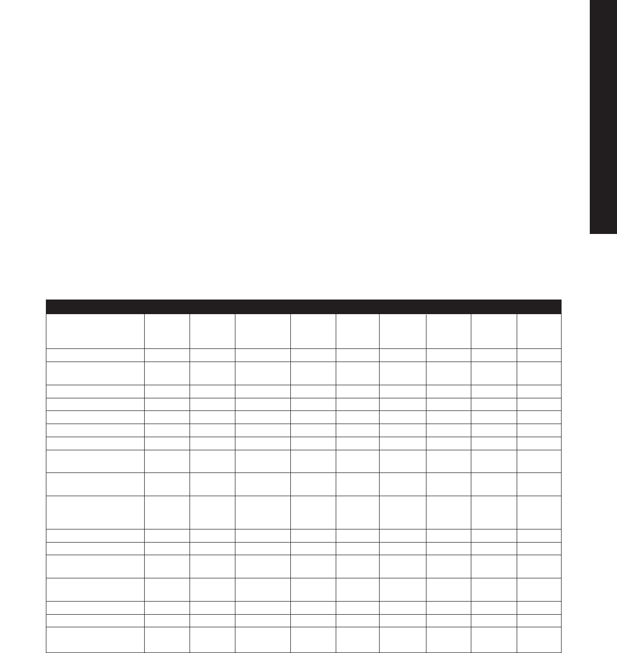
Materials Typical Test Polyester Polyester Polyester Acrylic Dispensed Foamed Extruded Neoprene
Properties Method Fiberglass Fiberglass Fiberglass Sheet for Silicone Urethane Silicone Gaskets
ASTM (SMC) Hand Lay-up Pultrusion Windows Gaskets Gaskets Gaskets
Flexural Strength (psi) D 790 18K 30K 45K 16K N/A N/A N/A N/A
Notched Izod D 256 7-22 5-30 25 0.3-0.4 N/A N/A N/A N/A
(ft - lb/in @ 1/8")
Impact Resistance (lb-in) UL 746C ≥216 — — — N/A N/A N/A N/A
Compressive Strength (psi) D 695 20K 35K 26K 18K N/A N/A N/A N/A
Tensile Strength (psi) D 638 8K 17.5K 40K 10.5K 200 60 100 500
Specific Gravity D 792 1.77 1.5-2.1 1.7 1.17-1.20 1.32 0.3 0.55 1.24
Flammability UL 94 V-0 & V-5 — V-0 — — — — —
Heat Deflection D 648 375-500 >400 <400 205 N/A N/A N/A N/A
(°F at 264 psi)
Service Temperature -40°F to -40°F to -40°F to -31°F -40°F to -40°F to -100°F to -40°F to
Range (°F) 250°F 250°F 250°F 180°F 350°F 200°F 500°F 225°F
K Factor, Thermal 1.68 1.68 1.68 1.3 1.3 1.0 1.3 1.45
Conductivity
(BTU/hr/ft2/°F/in)
Dielectric Strength (VPM) D 149 380 380 200 500 400 330 400 400
Arc Resistance (sec) D 570 200+ 200+ 80 No Track N/A N/A N/A N/A
Water Absorption D 570 0.10-0.25 0.05-0.5 0.05-0.5 <0.4 0.12-0.15 <2 5 —
(% in 24 hr)
Hardness (Barcol- 50-70 60-80 50 105 18 Shore 8 Shore — 15-95
Rockwell M-Shore A) Barcol Barcol Barcol Rockwell Shore
Shrinkage in/in Minimum .005 N/A N/A N/A N/A N/A N/A N/A
Elongation (%) N/A N/A N/A N/A 850 100 400 100-800
Compression Set 24 hr N/A N/A N/A N/A <5% <2% <5% 15-60
@ 50%, 72°F
Physical Properties Of
Non-Metallic Materials
Table 7 provides technical data for assistance in evaluating
non-metallic enclosures and selecting the materials used
with Legacy fiberglass enclosure accessories. Additional
considerations for inclusion in the fiberglass enclosure
specification are:
•The resin system shall be pigmented grey unless
otherwise specified.
•The resin system shall include a flame retardant to obtain
a flammability rating which meets UL 94-5V.
•The heat distortion temperature shall be at least 350°F.
•Standard cover screws shall be stainless steel or stainless
steel with fiberglass encapsulated heads. Other hardware
items such as hinges and latches shall be stainless steel
or fiberglass construction.
•External mounting feet shall be molded or securely
attached to the enclosures to provide a corrosion resistant
surface mounting system.
— no test data available
K = 1000
N/A not applicable
all materials are UL listed
Table 7. Physical Properties Of Non-Metallic Materials
Technical Information
Non-Metallic Properties
TEC 15
TECHNICAL APPENDIX
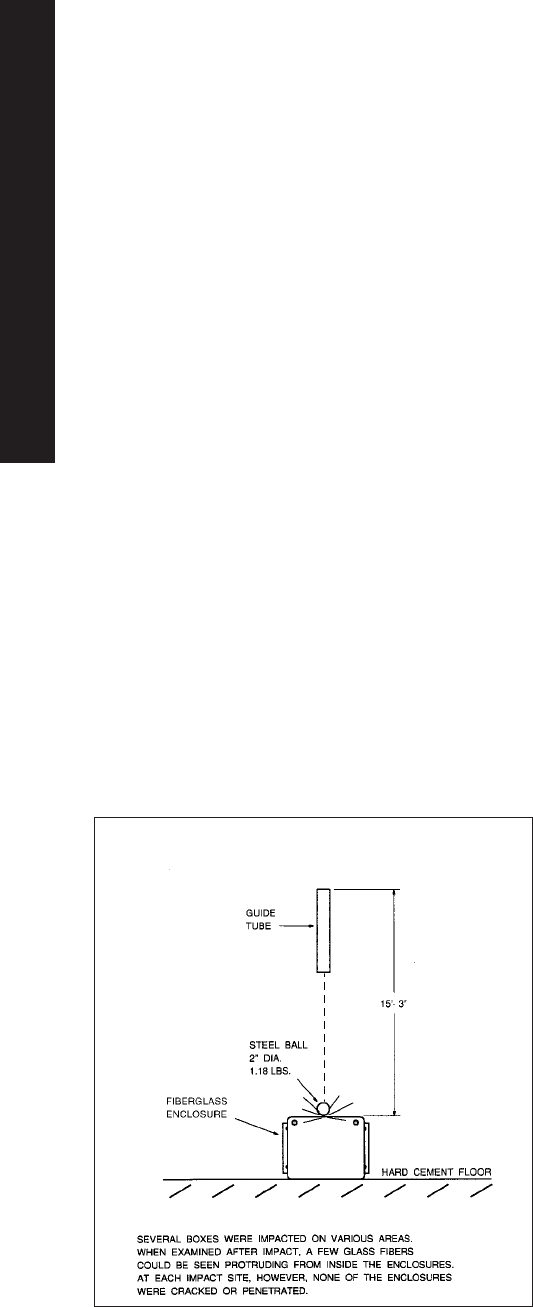
Technical Information
Non-Metallic Properties
Enclosure Load Capacity
Large control enclosures can support 200 lbs of equipment
on the back panel. Smaller junction and instrumentation
enclosures should be limited to 75 lbs. Listed values
assume the enclosure is vertically mounted against a
reasonably flat surface and are based on a minimum
safety factor of two.
Maximum Temperature Rating
The deflection temperature* of polyester fiberglass ranges
from 375-500°F. Rittal has conducted tests on enclosures at
sustained temperatures of 350°F. Polyester fiberglass is a
high temperature material compared to other polymers
such as PVC, polycarbonate or engineered thermoplastics.
In elevated temperature applications, the highest
temperature an enclosure can withstand depends on other
components used in the finished product. Such items as
PVC air vents, and special gaskets must be considered
when establishing a temperature limit for both fiberglass
and metal enclosures. Many times this issue is neglected or
minimized when rating the product.
Sunlight (UV) Resistance
In time, sunlight may roughen the fiberglass enclosure
surface, but its electrical and mechanical properties remain
unaffected. Surface roughening caused by UV exposure is
a common phenomenon encountered with virtually all
fiberglass products, but it only affects surface appearance.
Tests have confirmed the effect on polyester fiberglass is
only 40 to 80 microns (0.0015"-.003") in depth. If
appearance is a concern, an outdoor acrylic paint (clear or
pigmented) will provide protection for many years. Most
acrylic paints in ordinary spray cans work well.
Drilling, Sawing, Cutting and Punching
Installers find fiberglass easy to cut or drill. Ordinary drills,
hacksaws, hole saws and punches cut through fiberglass
with little effort. In large installations requiring many holes,
glass abrasion may cause tools to become dull over time.
Carbide tip tools work best for such applications. For
maximum accuracy, routing of openings is recommended.
Impact Resistance
Rittal’s Legacy fiberglass enclosures are quite resistant to
damage caused by falling tools or flying debris. When
tested in accordance with UL Standard 746C, Section 24,
these fiberglass enclosures withstood an impact in excess
of 216 pound/inches. The test was performed by dropping
a 2" diameter solid steel ball on various areas of the
enclosure from a height of 15 ft. The impact force from such
a test is comparable to dropping a large wrench from 3 or
4 ft. The durability results from randomly oriented glass
reinforcing fibers incorporated in all designs.
*Deflection temperature: The temperature when a material will deflect
(distort) under a flexural load of 264 psi. See ASTM D 648.
Integrity of the enclosure was not compromised
LEGACY FIBERGLASS ENCLOSURE
IMPACT TEST
TEC 16
TECHNICAL APPENDIX
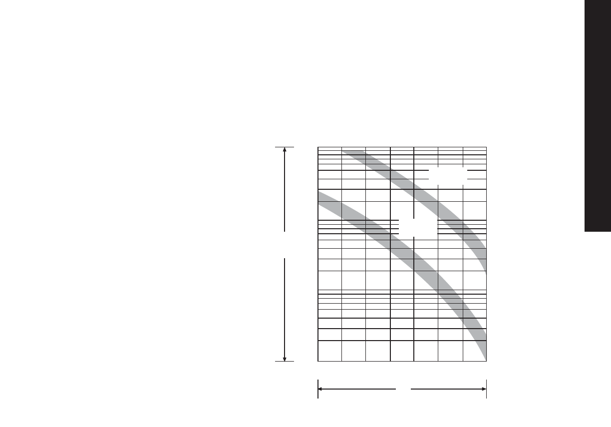
Introduction
Electronics, and especially
micro-electronics, have made modern
production technology more efficient.
But ever smaller electronic components
and increasingly dense packaging in
enclosures have also made these
complex systems more sensitive
to external influences such as
temperature, dust, oil, and humidity.
This can cause problems because the
failure of just one electronic component
may lead to the complete shutdown of
an entire assembly line. Resultant costs
quickly add up.
Heat especially is the number one
enemy of sensitive micro-electronics.
A rule of thumb says that the average life
span of semi-conductors is cut in half
every time the operating temperature
increases 20°F (11°C) over its maximum
operating temperature. Yet, high
temperatures in enclosures can hardly
be avoided because electric equipment
such as transformers, power distribution
components, programmable controllers,
and electronic components all generate
heat, also known as power loss.
Power related temperature swings in an
enclosure or electronic housing can also
be considerable. These swings cause
stress and premature aging of electronic
components which in turn lead to
premature failure.
As mentioned, correct functioning of
electronic systems and problem free
operation of entire assembly lines
depends to a great degree on removing
the heat that is generated in enclosures
or electronic cabinets. In principle, there
are three different ways in which heat
can be dissipated: conduction,
convection, and radiation.
Climate Control
Heat Removal From Enclosures
With conduction, matter itself moves
heat, without itself moving, energy is
passed on from molecule to molecule.
With convection, heat is moved through
a medium (another material such as a
gas or a liquid), the medium absorbs
energy in the form of heat and releases
energy as heat.
With radiation, heat is transferred from
one body to another in the form of
radiation energy, without any physical
matter in between.
Conduction and convection play an
important role in enclosures and
electronic cabinets; radiation is not a
big factor.
An important criterion for heat
removal from enclosures is whether the
enclosure is an ‘open’ (air can freely
stream through) or ‘closed’ (air-tight)
system. While heat naturally dissipated
from the inside of an ‘open’ enclosure
through a flow of air, heat can only be
dissipated from a ‘closed’ system
through the walls and roof.
20 30 40 50 60 70 80 90
0.1
1
10
100
°C
Years
°C = Component temperature
Years = Life span
Relationship between electronic component
life and temperature
Integrated
circuit
Electrolytic
capacitor
Climate Control
Heat Removal From Enclosures
TEC 17
TECHNICAL APPENDIX
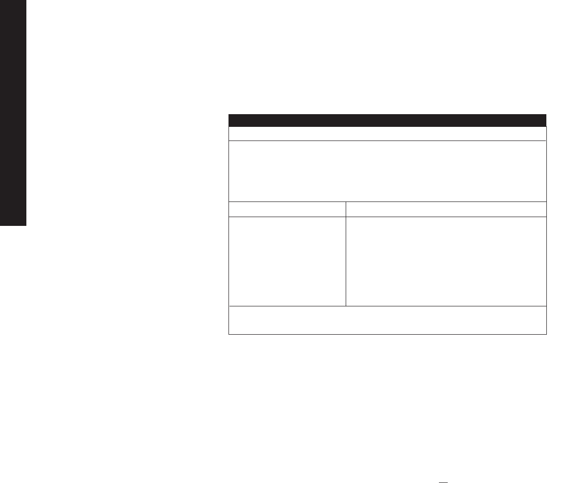
Specification
Fundamentals
To properly determine the
specifications of climate control
components, a few simple calculations
have to be made. The following terms
are used:
•Q
v[Watt]: total power loss (heat loss)
of all electric and electronic
components that are installed in the
enclosure.
•Q
s[Watt]: heat dissipation, or
absorption, through the outside
surfaces of the enclosure (per
VDE 0660, part 500). When the
temperature inside the enclosure is
higher than the ambient
temperature (Ti> Tu), heat will be
radiated from the enclosure (Qs> 0).
When the temperature inside the
enclosure is lower than the ambient
temperature (Ti< Tu), the enclosure
will absorb heat from its
environment (Qs< 0).
•Q
e[Watt]: required cooling capacity
of a climate control component; this
is the amount of heat a component
must remove from the enclosure.
•Q
H[Watt]: required heating capacity
of an enclosure heater.
•T
i[°C]: maximum allowable
temperature inside the enclosure per
the electronic component
manufacturer - usually between
+35°C and +45°C.
•T
u[°C]: maximum ambient
temperature at which all electronic
components inside an enclosure or
electronic cabinet should perform
faultlessly.
•V [m
3/h]: required air displacement
for a filter fan.
•A [m2]: exposed enclosure surface
accordance with DIN 57 600, part
500 or VDE 0600, part 500.
•K [W/m2K]: heat transfer coefficient
of an enclosure:
sheet steel - 5.5 W/m2K
plastic - 3.5 W/m2K
Calculation of exposed
enclosure surface
Special attention should be paid
to the total exposed enclosure
surface because heat loss
dissipated from the enclosure
depends not only on its actual value,
but also on the enclosure’s location.
An enclosure that stands all by itself in
the middle of a room can dissipate
more heat than an enclosure that is
placed next to a wall or in a corner.
For that reason there are special
directions on how the total exposed
enclosure surface should be
calculated depending on its location.
These formulae for the calculation of A
(see table above) are specified in DIN
57 660, part 500 or VDE 0660, part
500. (see table)
Inherent convection
Inherent convection is the dissipation
of heat through the enclosure walls.
For this to happen, the ambient
temperature must be lower than the
temperature in the enclosure. The
maximum temperature increase
(∆T) max that can occur as against
the ambient temperature can be
calculated with the following formula:
(∆T)max=Qv
Note:
When the heat loss within an
enclosure is unknown, but the actual
ambient temperature Tuand the
temperature Tiinside the enclosure
can be determined, the actual heat
loss can be calculated with the
following basic formula:
Qv= A.k .∆T [Watt]
This measurement must be taken with
the enclosure sealed and no fans, heat
exchangers or air
conditioners operating.
k.A
Climate Control
Heat Removal From Enclosures
Climate Control
Heat Removal From Enclosures
■Single enclosure,
freestanding
▲Single enclosure,
against a wall
✚First/last enclosure of
a suite, freestanding
Location of enclosure per VDE 0660, part 500
◆First/last enclosure of a
suite, against a wall
♠Enclosure within a suite,
freestanding
★Enclosure within a suite,
against a wall
●Enclosure within a suite,
against a wall, with
covered roof
Location per VDE 0660/500 Formula for calculation of A [m2]
■A=1.8 x H x (W+D) + 1.4 x W x D
▲A=1.4 x W x (H+D) + 1.8 x D x H
✚A=1.4 x D x (H+W) + 1.8 x W x H
◆A=1.4 x H x (W+D) + 1.4 x W x D
♠A=1.8 x W x H + 1.4 x W x D + D x H
★A=1.4 x W x (H+D) + D x H
●A=1.4 x W x H + .7 x W x D + D x H
H = enclosure height [m]
W = enclosure width [m]
D = enclosure depth [m]
Table 8
TEC 18
TECHNICAL APPENDIX

Climate Control
General Information
The Need For
Climate Control
When the expense of electronic and
electrical components and the costly
implications of a system’s down time are
considered, it is important that all
reasonable steps are taken to ensure that
steady and reliable performance of a
system continues. This should, in almost all
circumstances, include climate control —
cooling and/or heating.
The Purpose Of Cooling
Electronic and electric equipment often
generate a great deal of heat during
operation. Frequently located in hostile
environments, the equipment may also
encounter the additional problem of not
having safe, clean air available to dissipate
unwanted heat. Such adverse
conditions affect the performance
and the life expectancy of
electrical/electronic system
components.
Rittal cooling devices are precisely
designed to solve the problems of
internal heat build-up above
component tolerances, excessive
ambient temperatures, moisture and
contaminant laden atmospheres and
corrosive environments, which can
affect sensitive electronic equipment.
A little time and effort spent early in
the design process can save a great
deal of trouble and expense later by
preventing the need to retrofit with
proper cooling devices in the field
during a down time situation.
To:Rittal Corporation Tel: (937) 399-0500 Date:
1 Rittal Place Fax: (937) 390-8392 Page 1 of:
Springfield, Ohio 45504 e-mail: Climate-cntl@rittal-corp.com
Climate Control Group
Applications Engineer
Company Address:
Contact Name: Tel: Project Name/Number:
Title: Fax:
Application Questionnaire
1. What is the maximum ambient air temperature? °F
2. What is the maximum allowable internal enclosure temperature? °F
3. What is the size and mounting style of the enclosure to be heated or cooled? H W D Mounting: (freestanding, wall, suited)
4. a: What is the measured temperature difference between the outside and inside of the enclosure with the door closed and any vents
or openings sealed °F
or
b: How many Watts or BTUs of heat is given off by the equipment inside the enclosure?
5. At what voltage and frequency is the climate control device required to operate? Voltage and Hz
6. Is chilled water available for use in conjunction with an air/water heat exchanger? If no, is a chilled water cooling system a viable option?
7. Is there a specific NEMA or approval rating that the climate control equipment needs to comply with? NEMA UL CE CSA
8. Estimated project commercialization date
9. Estimated annual climate control product volume units/year
10. Special requirements or considerations
Request For Climate Control Application Information
Information Needed
For Climate Control
Selection
The following information should be
on hand to properly size cooling
products:
(1) Heat to be dissipated (Watts) by
the electrical components inside
the enclosure
(2) Maximum temperature expected
outside enclosure (°F)
(3) Maximum allowable internal
enclosure temperature (°F)
(4) Enclosure dimensions
(5) Mounting portion of enclosure, i.e.
against wall, freestanding, in a
suite of enclosures, etc.
TEC 19
TECHNICAL APPENDIX
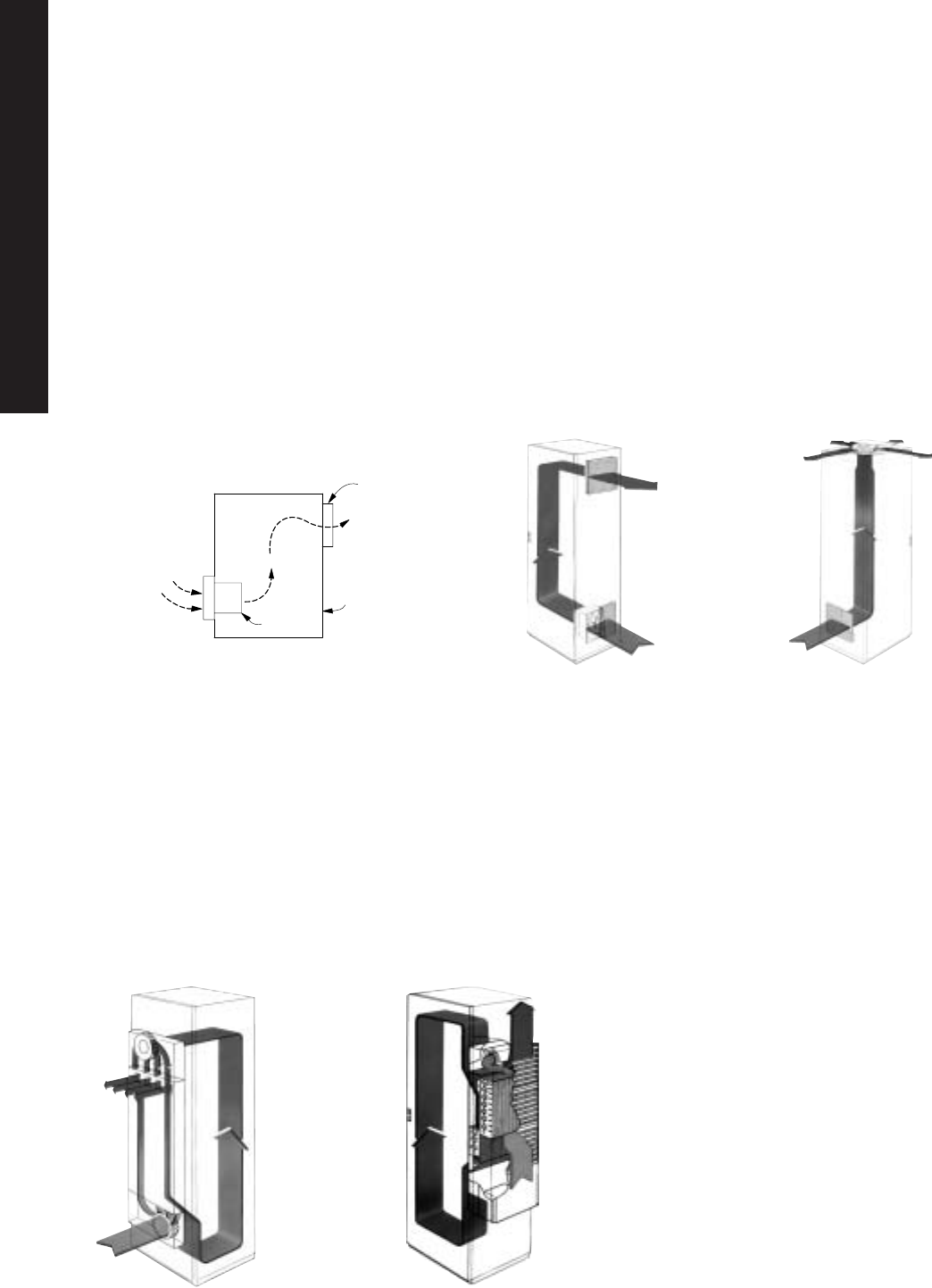
FIGURE 1 - Forced Convection Method
Pressurized System - pushes
air through enclosure
Ambient
Air
Ambient Air
with Heat Load
Fan or
Blower
Cabinet
Outlet louvers
Climate Control
General Selection Considerations
Three Basic Cooling Methods
When selecting a cooling method there are three types to consider.
(1) Passive Ventilation - If there is only a minimal heat gain in your circumstance and the ambient air is relatively cool and clean,
then the use of louvers or grilles with filters can be effective. This method, however, usually provides less cooling effect than is
necessary with today’s components. The temperature rise within a sealed enclosure is seen in Figure 2.
(2) Forced Convection Air Cooling - If the installation will be in a clean, non-hazardous environment with an acceptable ambient
(outside the enclosure) temperature range, a simple forced-air cooling system utilizing outside air is usually adequate.
Combined with an air filter, such devices generally meet the heat removal needs of typical electronic equipment and many
electrical applications (Figure 1). Examples of forced convection air cooling are filter fans, pagoda roof fans, fan trays, and
blowers of various types.
Fans And Blowers Can Be Used To Pressurize (Preferred) Or Exhaust Cabinet
Air. The Ambient Air Should Be Filtered Before It Enters The Cabinet.
(3) Closed-Loop Cooling - In harsh environments involving high temperatures, wash-down requirements, heavy particulate matter
or the presence of chemicals capable of damaging components (NEMA 4 or 12 environments), ambient air must be kept out of
the enclosure. Closed-loop cooling consists of two separate circulation systems. One system, sealed against the ambient air,
cools and recirculates the clean cool air throughout the enclosure. The second system uses ambient air or water to remove and
discharge the heat. Examples of closed-loop cooling equipment employed with electronics and process controls are heat
exchangers and air conditioners. Blowers are used in higher static pressure applications (when internal equipment is densely
packed), and are at maximum efficiency when operating near their peak static pressure.
Filter Fan Airflow
Air/Air Heat Exchanger
Airflow Air Conditioner
Airflow
Pagoda Roof Fan Airflow
TEC 20
TECHNICAL APPENDIX
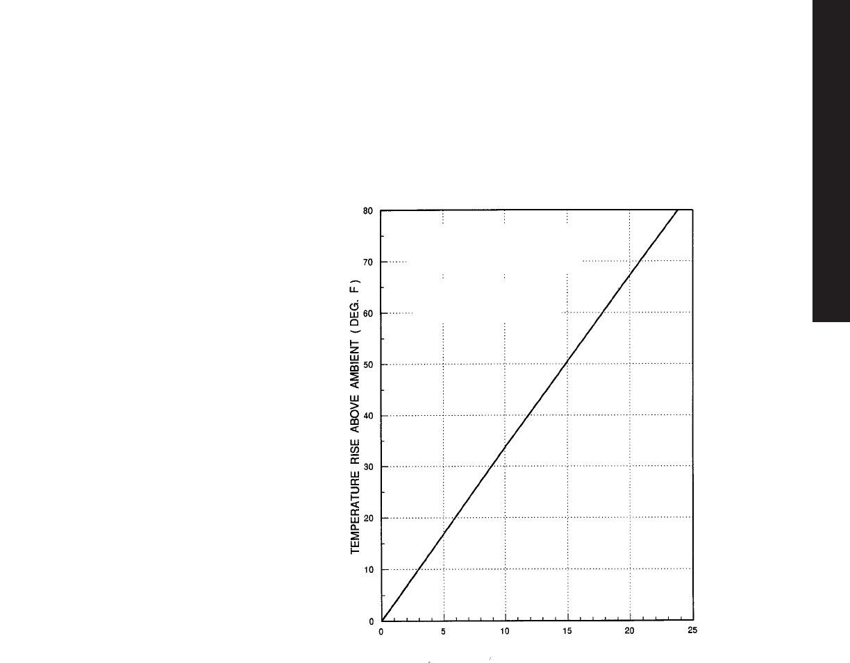
Climate Control
Technical Information
This temperature graph was developed
through empirical testing using several
enclosures of various sizes.
The temperatures represent an average
of one temperature measurement near
the bottom of the enclosure and a
second measurement near the top.
Electric heaters mounted equidistant
from the internal surfaces of the
enclosure were used as the heat
source. Because hot air rises,
a significant temperature gradient
occurred from top to bottom. Typical of
an actual installation, the top was much
hotter than the bottom.
The placement of internal parts can
affect temperature and enclosures
should be sized liberally in applications
where temperature rise is critical.
Recall that a larger enclosure with
twice the surface area reduces the
temperature rise by 50%.
Exterior surface finishes significantly
influence temperature rise in outdoor
applications. For example, painted
steel and fiberglass enclosures
dissipate heat better than unfinished
aluminum enclosures, even though
aluminum has superior thermal
conductivity, because the colored
surfaces of fiberglass and painted steel
enclosures are more efficient thermal
radiators than unfinished aluminum.
Painted surfaces have an emissivity of
0.96 whereas an unfinished aluminum
surface has an emissivity of 0.45. In
outdoor applications light colored
enclosures have a high reflectance
which minimizes solar heat gain while
dissipating internally generated heat at
about the same rate as a similar size
dark colored enclosure.
FIGURE 2. -Internal Temperature
Rise vs. Internal Heat Load
GRAPH ASSUMES ENCLOSURE IS
MOUNTED VERTICALLY AGAINST A
CEMENT WALL SURROUNDED BY STILL
AMBIENT AIR.
NOTE:
TO CONVERT GRAPH TEMP TO
CELSIUS MULTIPLY DEG. F BY 0.55
INTERNAL HEAT LOAD IN WATTS / SQ. FT. SURFACE AREA
TEC 21
TECHNICAL APPENDIX

Climate Control
Technical Information
Additional Cooling Methods
When it has been determined that
the heat load is too large for an
enclosure to dissipate by radiation
and convection, the following
supplemental cooling methods
are available:
Louvers And Special Ventilation
Slots
Louvers and special ventilation slots
are designed to remove heat from
the enclosure by allowing natural air
circulation around the heat source
and exhausting the hot air through
slots or louvers. This method is
relatively inexpensive and has no
operating cost; however, it can only
be used to dissipate a limited
amount of heat and it is difficult to
predict the temperature drop
produced by a vent utilizing natural
convection. This method should not
be used in areas where contaminants
will enter the enclosure.
Circulating Fans
In larger sealed enclosures, a fan
can be used to circulate the air
and reduce localized heat
concentrations; however, the
applications are limited because a
closed system fan only redistributes
heat, it does not remove the heat
generated by the hot spot.
Where an enclosure does not
need to be sealed from the outside
environment, fans can be used to
circulate air through an enclosure
and dissipate the heat generated by
power supplies, transformers and
other heat producing equipment.
Fans can provide as much as 10
times the heat transfer rate of natural
convection and radiation. Once the
heat input in watts/ft2is determined
and temperature rise is established
from Figure 2, the following equation
can be used to calculate the fan
flow rate:
Fan Flow Rate (cfm) =
3.17 x Internal Heat Load
(watts)/Temperature Rise
Example
Equipment in an E 363612
enclosure generates sufficient heat to
require a fan which will dissipate 300
watts. The maximum ambient
temperature in the application
environment is 115°F. If the
temperature of the other contents in
the enclosure cannot exceed 125°F,
what size fan is required?
The allowable temperature rise
is 125°F - 115°F = 10°F.
The application requires
dissipation of 300 watts.
Solution
To determine the cubic feet per
minute (cfm) required in a standard
application, use the following
equation (if the air density is
significantly more than 0.075 lb. per
cubic foot, a non-standard
application exists and this equation
should not be used):
Fan Flow Rate (cfm) = 3.17 x 300
watts/10°F
Fan Flow Rate (cfm) = 95 cfm
This calculation is exact, but adding
an additional 25% capacity to the
level is standard to provide a
safety factor.
1.25 x Fan Flow Rate (cfm) =
1.25 x 95 cfm = 119 cfm
If the air density is non-standard
(significantly more than 1.075 lb. per
cubic foot), the following equation
can be used to calculate the fan
capacity:
Fan Flow Rate (cfm) x 0.075 lb. per
cubic foot / Non-standard Air Density
(lb. per cubic foot)
Fans can be used to draw air through
an enclosure and exhaust hot air from
an enclosure or to draw cool air into
and circulate it through an enclosure.
An inlet fan offers the following
advantages:
•Raises the internal pressure
which helps keep dust and dirt
out of an unsealed or frequently
open enclosure.
•More turbulent air flow improves
heat transfer.
•Longer fan life in cooler
incoming air.
The following considerations are
important in locating a fan:
•Avoid placing transformers, power
supplies or other heat generating
devices in front of the fan.
Although this cools the device,
it increases the heat load on other
devices within the enclosure. It is
best to place these devices near
the exhaust outlet.
•To achieve maximum cooling,
the inlet and outlet should be
separated by the maximum
distance. If the outlet and inlet
are adjacent to each other, the hot
outlet air will be drawn into the inlet
and cooling efficiency will be
reduced. In general, the inlet
should be at the bottom of the
enclosure and the outlet at the top.
TEC 22
TECHNICAL APPENDIX

•Fans should not be used or
located in areas where the air
flow is restricted. A plenum is
recommended to accelerate
air velocity and improve fan
performance. A plenum is
particularly helpful when a filter
is used where airborne
contaminants are a problem.
•The air outlet area should at least
equal the inlet area. For best
results the exhaust opening should
be 1.5 times the area of the fan
opening.
•Air is less dense at high altitudes.
For this reason air flow should be
increased in high altitude
applications.
•All fans used in parallel should
be identical.
Heat Exchangers - Cooling
Applications requiring sealed
enclosures present the greatest need
for cooling to maintain safe operating
temperatures. Heat exchangers are a
good option when precise control of
heat and humidity are not required and
the heat transfer requirements are
significant. The required heat
exchanger capacity can be
calculated using the formula,
Heat Exchanger Capacity (watts/°C) =
(Internal Heat Load T + 5.5w/m2-C x
Enclosure Surface Area x ∆T) where
∆T = Temperature Rise.
Example
If the internal heat load is 1000 watts
in an E 603620 freestanding steel
enclosure, what is the minimum cooling
capacity for the heat exchanger unit?
The maximum ambient temperature is
105°F and the internal equipment will
malfunction if the internal enclosure
temperature exceeds 130°F.
Internal Heat Load = 1000 watts
Maximum Temperature Differential = Ti-
To= 105°F - 130°F = -25°F = -14°C, use
Absolute Value.
Climate Control
Technical Information
Enclosure Surface Area = 56.7 ft2=
5.3m2 from Table 1.
Heat Exchanger Capacity =
(1000 - 5.5 x 5.3 x 14)/14 =42w/c
In this example, the surface area
acts to cool the enclosure and is
subtracted, the Absolute
Temperature Value is used because
this is a temperature difference.
Air Conditioning - Cooling
Air conditioning will be required in
high ambient temperature locations
where precise temperature
control and humidity reduction
are required in a sealed enclosure.
Air conditioning can also be required
where neither convection, thermal
radiation, louvers, slots nor a
circulating fan system provide
adequate cooling. Because air
conditioners remove moisture from
the enclosure, a condensate drain is
generally required.
The four step process to size
and select the air conditioner is
influenced by the internal heat load,
enclosure size and the application
environment. The following
information is required:
Step 1. Determine the Internal
Heat Load
Heat generated by all sources
within the enclosure shall be added
together to establish the internal heat
load in watts. The heat load in watts
may be multiplied by 3.413 to
convert to BTU/hr.
Internal Heat Load ______________
watts X 3.413 BTU/hr/watt =
_____________ BTU/hr.
Step 2. Calculate the Surface Area
of the Enclosure
The enclosure surface area
calculation is made in Table 1 using
formulas.
The surface area for an enclosure
with a height (H = 16 in); a width (W
= 20 in); and a depth (D = 8 in); is:
Surface Area = [1.8(16 x 20) + 1.8
(16 x 8) + 1.4 (20 x 8)]/144in2= 7.2 ft2
= 0.67n2
Using the H, W and D dimensions,
select the appropriate formula and
calculate the surface area for your
enclosure application:
H = _______
W =_______
D = _______
Surface Area = _____________n2
Step 3. Establish the
Temperature Differential
The temperature differential (∆T) is
calculated by subtracting the
maximum allowable temperature
inside the enclosure (Ti) from the
maximum ambient temperature
outside the enclosure (To).
To- Ti= ∆T = _________°C
Step 4. Calculating the Required
Air Conditioning Capacity
The values determined in the first
three steps are used to calculate
the required capacity of the air
conditioner according to the
following formula,
Cooling Capacity (BTU/hr) = Surface
Area x ∆T x K + Internal Heat Load,
where
K = 1.25 BTU/hr/ ft2/°F (5.5w/m2-K)
for sheet metal enclosures.
TEC 23
TECHNICAL APPENDIX
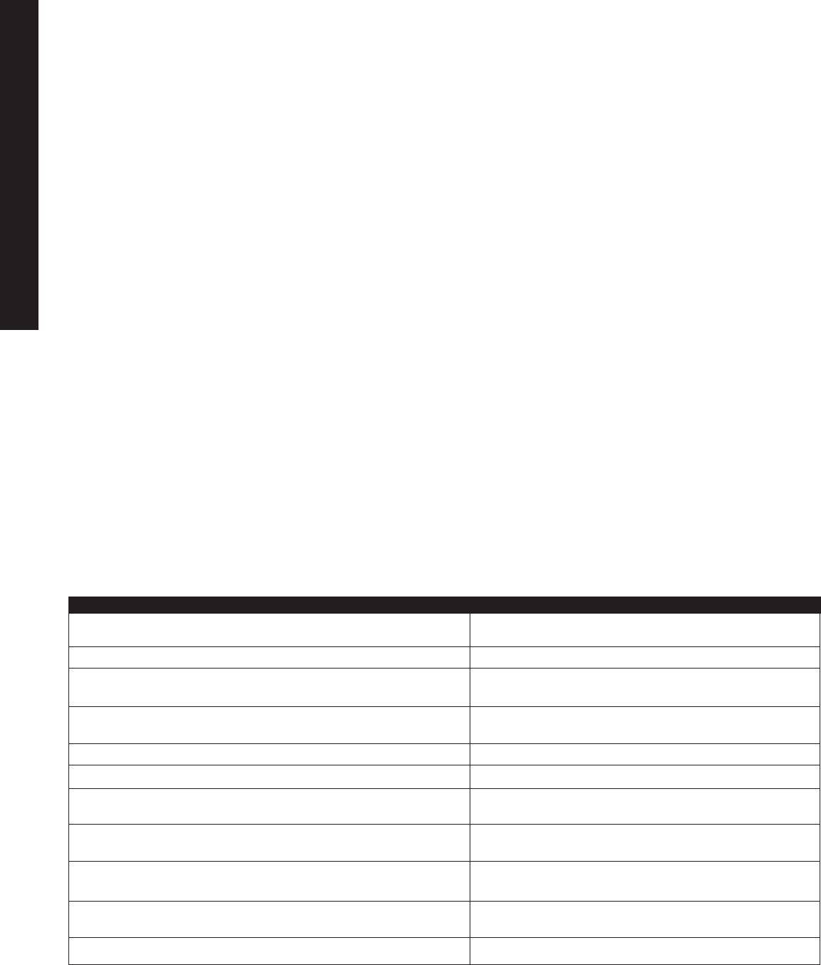
Enclosure Heating
Some enclosure systems have
minimum as well as maximum
operating temperature limitations.
When the equipment in an
enclosure must be maintained
above a minimum temperature at low
ambients, these same equations can
be modified and used to calculate
the supplemental heat required to
select and size the heaters. The only
differences are that the internal heat
load will help heat the enclosure and
the temperature difference, ∆T, is
calculated by subtracting the
minimum ambient temperature
(To) outside the enclosure from the
required temperature (Ti) inside
the enclosure. The minimum
supplementary heat can be
calculated according to one of
the following equations:
∆T = Ti- To
Supplementary Heat =
Surface Area x ∆T x K where
K = 0.37 watts/ft2°F
Example
If the internal heat load is 100
watts in an E 162008 steel
enclosure, which is wallmounted,
what is the minimum heating
capacity for the heating elements?
The minimum ambient temperature
is 0°F and the internal equipment
will malfunction if the internal
enclosure temperature drops
below 40°F.
∆T = Ti- To= 40°F - 0°F = 40°F
=
6.27 ft2x 40°F x 0.37 watts/ft2°F =
93 watts
In addition to heating, supplementary
heaters are often used in enclosures to
keep the internal enclosure ambient
temperature a few degrees above
the ambient temperature to prevent
condensation on internal equipment.
Equipment for Climate Control
Most cooling or heating requirements
can be calculated from the data in
this section and the climate control
equipment. If you have a problem
determining your cooling or heating
requirements or selecting the climate
control equipment, please contact Rittal.
Rittal’s thermal sizing software, Therm
3.0 for Windows, automatically makes
calculations for you.
Climate Control
Technical Information
1. Underestimating maximum ambient temperature Undersized cooling device — system failure
2. Not considering effect of temperature on performance of Undersized cooling device — system failure
an air conditioner
3. Not derating fan performance for inlet grills, filters, system Undersized cooling device — system failure
impedance, etc.
4. Not considering convective heat loss or gain Improperly sized cooling device
5. Not accurately estimating component heat loss Improperly sized cooling device
6. Underestimating component maximum allowable Oversized cooling device — higher cost
temperature
7. Placing cooling device inlets/outlets too close to Reduced performance
obstructions
8. Not specifying necessary filters & maintenance schedule for Reduced performance
dirty environments
9. Not specifying corrosion protection for corrosive System failure
environments
10. Inadequate warning system in the event of cooling failure Machine shutdown/system failure
Pitfall Effect
10 Common Pitfalls During Thermal Analysis/Design
TEC 24
TECHNICAL APPENDIX
Energy efficient design All Rittal air
conditioners come standard with
thermostatic expansion valves that
operate more efficiently than the
expansion devices found on most
competitors’ units. This can save the
end user over $100 per year per air
conditioner.
Environmentally friendly technology
Our air conditioners come standard with
R-134a refrigerant, which is not a CFC or
a HCFC. We were the first to convert
R-134a and is still the only company
with 100% of its product line using this
technology.
Reliability/safety Our air conditioners
come standard with pressostats helping
protect against compressor failure.
Evaporator housings are insulated to
maximize efficiency and minimize
condensation. CE compliances also meet
new standards for products exported to
Europe.
Low maintenance condensor coils
Rittal’s wider condensor fin spacing means
less likelihood of dirt clogging, and loss of
cooling performance.
Long life fans & compressors All Rittal
air conditioners come with long-life ball
bearing type radial fans. Compressors are
thermally protected.
Advanced microprocessor control
An advanced microprocessor control
option allows you to monitor the
performance, pinpoints maintenance
needs, and enables remote monitoring.
Installation Rittal’s air conditioners are
easily and quickly mounted. Terminal
blocks offer quick and easy wiring.
Availability/spare parts Rittal has five
distribution centers across the U.S., as
well as a broad distributor network, for
quick access to inventory and spare parts.
Air conditioner repair and disposal
Rittal has a repair facility in Springfield,
OH. We also offer customers refrigerant
recovery and disposal services and
on-site repair service.
Broad variety of voltages available
Rittal offers 115V, 230V, 400V, and 460V
50 Hz and 60 Hz air conditioner models.
Special features such as stainless steel
housings, environmentallly protected coils,
Class 1 Div 2 explosion proof upgrades
are available.
Regulatory Compliance We meet global
regulatory requirements such as UL, cUL,
GS, CE.
Advantages-At-A-Glance
Air Conditioners
Practical Hints
Rittal air conditioners offer the right
solution whenever optimum operating
conditions inside an enclosure are
required. Even with high ambient
temperatures is it possible to cool the
enclosure’s internal temperature down
to well below the ambient temperature.
In terms of airflow technology the
favorable arrangement of air intake
and exhaust openings for the internal
and external air circulation loops,
ensures optimum air circulation in
the enclosure.
The following example shows how to
quickly and accurately calculate the
specifications for an enclosure air
conditioner.
The fo!lowing should be taken into
consideration:
•Where will the enclosure be located
(dust or oil-laden air)?
•What type of location is specified per
VDE 0660, part 500?
•What conditions must be anticipated
(e.g. ambient temperature and
humidity)?
•What is the heat loss Qvin the
enclosure?
•What is the max. required interior
temperature Tifor the enclosure?
•Is a specific NEMA or IP (per DIN 40
050) protection rating required?
•What voltage is available for air
conditioner operation?
•In enclosure suites, it will be
necessary to also take into account
the heat which may have been
absorbed from adjacent enclosures.
•Air conditioners should always be
connected via door limit switches to
avoid excessive condensation.
•Enclosures and air conditioners
should be located and placed so
that there is sufficient space for air
intake and exhaust.
▼▼▼
How To Determine The Sizing For A Wallmounted Air
Conditioner, For The Bold Values:
▼
Enclosure dimensions:
H = 2000mm
W = 600mm
D = 500mm
Ambient temperature
outside the enclosure in °C
Temperature required
inside the enclosure in °C
Heat transfer coefficient
of an enclosure:
sheet steel ~ 5.5 W/m2K
plastic ~ 3.5 W/m2K
Heat loss in Watts
A 4.4
Tu= +50
Ti= +35
k = 5.5
QV= 700
Calculate the
effective enclosure
surface
Calculate the
temperature differential
∆T = Ti – TU
Enter the applicable
heat transfer
coefficient
Enter the
heat loss
Required
cooling capacity
QE =
Now calculate the
required cooling capacity
QE = QV – k • A ∆T
A = 4.4
∆T = -15
k = 5.5
QV = 700
Watt 1063
TEC 25
TECHNICAL APPENDIX

Advantages-At-A-Glance
Air Conditioners
•Air conditioners should be
positioned such that air intakes
and outlets have at least 8" of
clearance from obstructions.
•The enclosure should be sealed to
a NEMA 12 standard to avoid
condensation.
Condensation and dehumidification
of enclosure air when air
conditioners are used
When air conditioners are used,
dehumidification of the internal
enclosure air is an unavoidable side
effect. During the cooling process,
a part of the moisture in the air
condenses at the evaporator and must
be removed from the enclosure. The
quantity of condensate depends on the
relative humidity, the air temperature at
the evaporator as well as on the volume
of air inside the enclosure.
The diagram on this page (also called
the ‘Mollier h-x diagram’) specifies the
amount of water in the air, contingent
on its temperature and relative humidity.
Example:
A model 3293100 air conditioner is set
at Ti= 35°C. The relative humidity of the
ambient air is 70%. The surface
temperature of the evaporator is
approx. 18°C - the evaporation
temperature of the refrigerant. When air
of 35°C is blown over the evaporator to
be cooled down condensate will form
at the surface of the evaporator.
The difference x = x1- x2 indicates how
much condensate per kg air would
accumulate if the air were completely
dehumidified. A deciding factor for the
amount of condensate is how well the
enclosure is sealed off from its
environment.
The volume of condensate can be
calculated with the following formula:
W=V · p · ∆x
where:
W= Quantity of water [g]
V= Volume of the enclosure [m3]
p= Density of air [kg/m3]
∆x= Dehumidification [g/kg dry air]
per the Mollier h-x diagram
When the enclosure door is closed,
only the air within the enclosure will
be dehumidified and there will be
considerably less condensate than with
an open door.
V= H · W · D= 2m · 0.6m · 0.5m
V= 0.6 m3
W= V · p · ∆x=0.6 m3· 1.2 kg/m3· 11 g/kg
W= 7.92 g ≈8 ml
Poorly sealed cable entries, damaged
door gaskets, and unsealed installation of
display screens etc. on enclosures can
cause air leakage from the enclosure to
increase. If air was leaking from an
enclosure at a rate of only 3 cfm,
condensate would accumulate at the
rate of 3 oz/h.
Conclusion
•When the air conditioner is operating
the enclosure door should always be
closed.
•The enclosure should be sealed on all
sides.
•Door switches should be used.
•Air conditioner should meet DIN and
EN standards.
•Set temperature only as low as required
(Typically 95°F).
Sizing For The Air Conditioner
The calculations have specified the required cooling
capacity QE = 1063 W for an ambient temperature
TU = 50°C and a required interior enclosure
temperature Ti = +35°C.
From the available Rittal air conditioners we
selected wallmounted model 3298100 with a
cooling capacity of 1100 Watt (see performance
diagram above).
20 25 30 35 40 45 50 55
2000
1800
1600
1400
1200
1000
800
600
QK
25
30
35
40
45
50
55
Ti
2200
2400
-15
-10
-5
0
5
10
15
20
25
30
35
40
45
50
-20
051015 20 25 30 35 40
051015 20 25 30 35 40
45 50 55 60
Pd
x
T
10%
20%
30%
40%
50%
60%
70%
80%
90%
100%
x2x1
relative humidity
Performance diagram
3279100/3298100
(DIN 3168) (60 Hz)
Tu= Ambient temperature (°C)
Qk= Cont. refrigeration capacity (W)
Ti= Internal enclosure temperature (°C)
Pd= Partial water-vapor pressure (mbar)
T= Temperature of air (°C)
x= Water content (g/kg dry air)
Mollier h-x diagram to determine the
water content of air
TEC 26
TECHNICAL APPENDIX
Reliable and durable All Rittal heat
exchangers are known for their durability
and long life radial fans.
Easy maintenance They are equipped
with filterless operation for quick
maintenance with the easily removable
cassette.
Installation All Rittal heat exchangers
have simple and clean installation, and
no mounting flange is necessary.
Special features Although our heat
exchangers are lightweight, they are built
with very strong construction.
Regulatory compliance Rittal heat
exchangers meet global regulatory
requirements such as UL, cUL, VDE, CE.
Advantages-At-A-Glance
Air/Air Heat Exchangers
Practical Hints
When ambient temperature is
considerably lower than the
temperature required inside the
enclosure, air/air heat exchangers are
the climate control component of
choice especially if the ambient air
contains dust, oil and aggressive
chemicals that should not enter the
enclosure.
Because of separate interior and
exterior air circulation loops, outside
air can not enter into the enclosure.
The following should be taken into
consideration:
•What ambient temperatures Tucan
be expected?
•What is the required interior
temperature Tiinside the enclosure?
•What is the total heat loss of
components inside the enclosure?
▼▼▼
How To Determine The Sizing For An Air/Air Heat Exchanger, For
The Bold Values:
▼
Enclosure dimensions:
H = 2000mm
W = 600mm
D = 500mm
Ambient temperature
outside the enclosure in °C
Temperature required
inside the enclosure in °C
Heat transfer coefficient
of an enclosure:
sheet steel ~ 5.5 W/m2K
plastic ~ 3.5 W/m2K
Heat loss in Watts
A 4.4
Tu= +25
Ti= +35
k= 5.5
QV= 900
Calculate the
effective enclosure
surface
Calculate the
temperature differential
∆T = Ti – TU
Enter the applicable
heat transfer
coefficient
Enter the
heat loss
Required
cooling capacity
qW=
Now calculate the
required cooling capacity
qW = QV – (A • ∆T • k)
A = 4.4
∆T = +10
k = 5.5
QV = 900 W/K 65.8
Sizing For An Air/Air Heat Exchanger
When the parameters for enclosure surface A,
temperature differential ∆T, and heat loss QE have
been calculated, the required heat exchanger can
be determined.
Air/air heat exchanger model SK 3131000 with a
specific thermal capacity of 42 W/C most closely
meets the requirements.
∆T
▲
▲
▲
30201003050607080
12
10
8
6
4
2
0
A
30
40
50
60
70
∆T
qW
QV
100020003000
25 20 15 10 5 0
∆T= Temperature differential (K)
Qv = Heat loss (W)
qw= Specific heat output (W/K)
A = Enclosure surface per VDE 0660
part 500 (m2)
Selection diagram for air/air
heat exchangers
•How much heat, Qs, is
radiated from the inside of the
enclosure - through the walls to
the environment?
•Is enough space available
to install an air/air heat
exchanger?
TEC 27
TECHNICAL APPENDIX
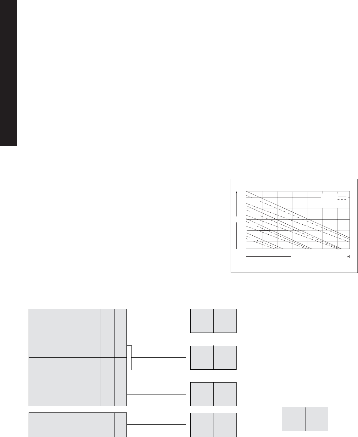
Reliable And Durable All Rittal heat
exchangers are known for their
durability and long life radial fans.
Safety These air/water heat
exchangers are equipped with such
safety features as overtemperature
alarm contact, solenoid valves, water
level sensors, and overflow drainage
paths.
Easy Maintenance They perform well
in dirty or oily environments, without the
need to clean filters, cassettes, or coils,
and require only 1-2 gal/minute of
water.
Special Features While the
exchangers offer low energy
consumption, they also help
maintain low capital cost.
Regulatory Compliance Rittal heat
exchangers meet global regulatory
requirements such as UL, cUL,
VDE, CE.
Advantages-At-A-Glance
Air/Water Heat Exchangers
▼▼▼
How To Determine The Sizing For A Wallmounted Air/Water Heat
Exchanger, For The Bold Values:
▼
Enclosure dimensions:
H = 2000mm
W = 600mm
D = 500mm
Ambient temperature
outside the enclosure in °C
Temperature required
inside the enclosure in °C
Heat transfer coefficient
of an enclosure:
sheet steel ~ 5.5 W/m2K
plastic ~ 3.5 W/m2K
Heat loss in Watts
A 4.4
Tu= +50
Ti= +40
k= 5.5
QV=
1300
Calculate the
effective enclosure
surface
Calculate the
temperature differential
∆T = Ti – TU
Enter the applicable
heat transfer
coefficient
Enter the
heat loss
Required
cooling capacity
QE =
Now calculate the
required cooling capacity
QE = QV – k • A ∆T
A = 4.4
∆T = -10
k = 5.5
QV = 1300
Watt 1542
Sizing For An Air/Water Heat
Exchanger
Because we know that the water temperature
is + 10°C and that the water flows at a rate of
200 l/h we have specified a model SK
3247000 air/water heat exchanger with a
cooling capacity of 1800 Watt which exceeds
the required cooling capacity QE = 1542.
Vw=200l/h
Vw=150l/h
Vw=100l/h
Performance diagram SK 3247000
(DIN 3168) (50/60Hz)
Tw= Water entry temperature (°C)
Qx= Cooling capacity (W)
Ti= Internal enclosure temperature (°C)
Tw
Qx
50°C
40°C
30°C
20°C
Practical Hints
Air/water heat exchangers offer the
greatest cooling performance in the
smallest available space.
•With a Rittal air/water heat
exchanger, the temperature inside
the enclosure can be cooled down to
below the ambient temperature.
•They can be used in ambient
temperatures up to 158°F (70°C).
•Air/water heat exchangers are
extremely practical in dirty
environments.
•Water as warm as 70°F can be used.
•Minimum service required because
there are no filters to exchange and
there is no direct contact with the
ambient air.
•They are available in wall and roof
mounted versions.
Performance diagram 3247000
(DIN 3168) (50/60Hz)
TEC 28
TECHNICAL APPENDIX
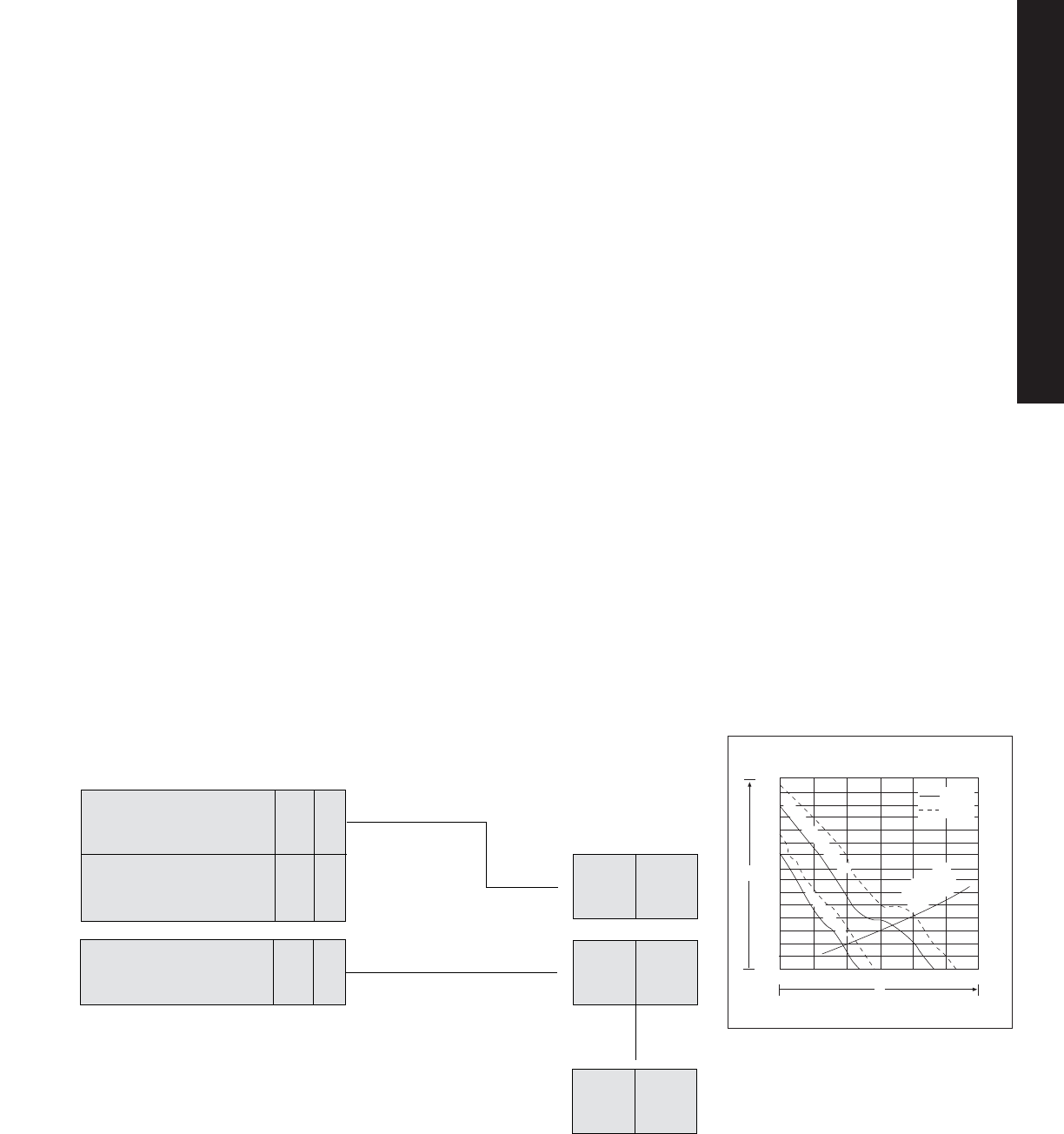
Regulatory Compliance Rittal filter fans
meet global regulatory requirements such
as UL, cUL, GS, CE.
Special features The air throughput in
our filter fans has high cfm in a given size.
Reliability and safety NEMA 12 is
achievable when using filter fans.
Installation Rittal’s filter fans are easily
and quickly mounted with the quick
snap-in feature, requiring no screws
or tools.
Aesthetics all of the filter fans are
available with a thin louver profile.
Broad variety of voltages available
Rittal offers 115V, 230V, 24V DC filter
fan models to meet the spectrum of
global needs.
Environmentally friendly technology
Rittal filter fans have a special EMC
capability that is available with an
off-the-shelf EMI/RFI shielded version.
Practical Hints
When the ambient air is clean and the
ambient temperature is considerably
lower than the temperature required
inside the enclosure, Rittal filter fans
should be used to remove heat from
inside the enclosure.
The design of the venting louvers of
Rittal filter fans ensures unsurpassed
stability of air volume as far as pressure
loss is concerned; it also provides
perfect contact hazard protection
against water.
A NEMA 12/13 (IP54) protection rating
can be achieved when a sealing
frame and fine filter are used (see
accessories).
Advantages-At-A-Glance
Filter Fans
Installation tips
The way in which filter fans are installed
in an enclosure, depends on the way
components are installed in the
enclosure.
•Filter fans and exhaust filters should
be installed on the enclosure so that
the air intake is at the bottom and the
exhaust is at the top.
•Air flow within the enclosure is
reversible: (suction or blowing).
•Since a fan’s filter will become dirty in
use, always select a larger fan than
indicated in the actual
calculation.
•Use a fine filter when there are very
small dust particles in the air.
•Install a sealing frame and fine
filter when you want to increase the
NEMA rating.
▼
How To Determine The Sizing For A Filter Fan,
For The Bold Values:
Temperature required
inside the enclosure in °C
TU = +20
Ti= +40
Calculate the
temperature differential
∆T = Ti– TU
∆T = 20
▼
Heat loss in Watts QV= 800 Enter the
heat loss QV = 800
Ambient temperature
outside the enclosure in °C
▼
The following applies for the
calculation of the volume of
displaced air.
f in this example is 3.1 m3 • K/Wh
V = f • = 3.1 • Watt 124
m3/h
_
∆T
QV_
20
800
h=altitude above sea level (h=0) [m]
f ( 0- 100) = 3.1 m3 • K/Wh
f (100- 250) = 3.2 m3 • K/Wh
f (250- 500) = 3.3 m3 • K/Wh
f (500- 750) = 3.4 m3 • K/Wh
f (750-1000) = 3.5 m3 • K/Wh
Sizing For A Filter Fan And
Exhaust Filter
We should select a combination of a filter with
an exhaust filter that can deliver an air
displacement of at least 124 m3/h.
The performance diagram above will help us
select the proper combination of filter fan and
exhaust filter.
Performance Diagram
SK 3325....
140
120
100
80
60
40
20
0
V= Volume Flow (m3/h)
∆Pst= Stat. pressure difference (Pa)
∆Pst
V
50 Hz
60 Hz
100 200 300
0
with standard filter mat
with fine filter mat
Resistance
curve
SK 3325.200
Performance Diagram
3325115
TEC 29
TECHNICAL APPENDIX
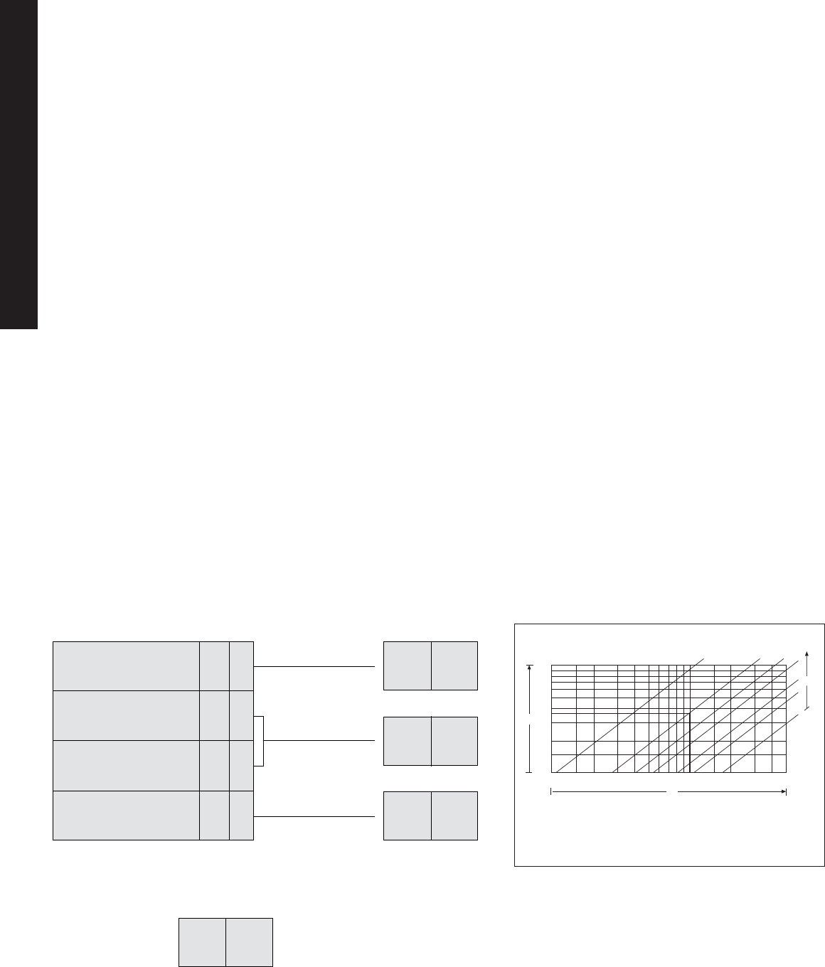
Advantages-At-A-Glance
Panel Heaters
▼▼▼
How To Determine The Sizing For A Panel Heater,
For The Bold Values:
Enclosure dimensions:
H = 500mm W = 500mm
D = 300mm
Ambient temperature
outside the enclosure in °C
Temperature required
inside the enclosure in °C
Heat transfer coefficient
of an enclosure:
sheet steel ~ 5.5 W/m2K
plastic ~ 3.5 W/m2K
A 3.6
Tu= +15
Ti= +20
k= 5.5
Calculate the
effective enclosure
surface
Calculate the
temperature differential
∆T = Ti – TU
Enter the applicable
heat transfer
coefficient
A = 3.6
∆T = +5
k = 5.5
The required heat output
can now be calculated
with the following
formula:
QH = A • ∆T • k
QH = 3.6 • 5 • 5.5
Watt 99 W
Sizing For A Heater
Once the values for the enclosure surface and
temperature differential are known, the
required heat output can be determined from
the heater performance diagram.In this case
model 3102000 with a heat output of 61 Watt
at 10°C was selected.
High performance Utilizing PTC
technology, the panel heaters operate
efficiently with even heat distribution.
Reliability And Safety They have a
long life expectancy, while their low
surface temperature ensures safe
operation.
Installation All panel heaters are wired
and ready for easy snap-in or screw
fastening installation.
Special Features Designed to be
compact and vibration-free, panel
heaters are quite powerful and sturdy.
Regulatory Compliance Rittal panel
heaters meet global regulatory
requirements such as UL, VDE, CE.
Practical Hints
•Maximum efficiency is achieved
when enclosure heaters are installed
vertically, with the cable entry at the
bottom.
•A gap of 2"/50mm from the top or
bottom should be allowed to
develop the required convection.
•Heaters should be installed at least
.4"/10mm from steel side walls
and at least 1.4"/35mm from
thermo-plastic materials.
•Insofar as possible, heaters should
be installed below the components
which require protection because hot
air rises and will indirectly heat those
components.
•In larger enclosures, even heat
distribution is best achieved by
installing several smaller heaters.
▲
▲
10 15 20 30 40 50 60 80 100 150 200 300 400 500
QH
30
20
15
10
∆T
7.5
5
2
10
8
6
5
4
3
2
1.5
1
A
Heater performance diagram
QH = Required heat output (W)
A = Enclosure surface area per VDE 0660, part 500 (m2)
∆T= Temperature difference (K)
Based on inside location, static air, heat transfer coefficient k=5.5 W/m2K.
For outdoor locations (moving air) the heat output should be doubled.
•Heaters can operate without a
separate thermostat, but in order
to ensure accurate air temperature
control within the enclosure,
installation of a thermostat is
recommended.
•To avoid condensation on installed
components, installation of a
hygrostat is also recommended.
TEC 30
TECHNICAL APPENDIX

a
a
a
a
a
a
a
a
a
a
a
a
a
a
a
a
a
a
a
a
a
a
a
a
a
a
a
a
a
a
a
a
a
a
a
a
a
a
a
a
a
a
a
a
a
a
a
a
a
a
a
a
a
a
a
a
a
a
a
a
a
a
a
a
a
a
a
a
a
a
a
a
a
a
a
a
a
a
a
a
a
a
a
a
a
a
a
a
a
a
a
a
a
a
a
a
a
a
a
a
a
a
a
a
INDEX 1
INDEX
1002600 IND 211, IND 261
1002660 IND 211, IND 261
1004600 IND 211, IND 261
1004660 IND 211, IND 261
1005600 IND 211, IND 261
1005660 IND 211, IND 261
1006600 IND 211, IND 261
1006660 IND 211, IND 261
1007600 IND 211, IND 261
1007660 IND 211, IND 261
1008600 IND 211, IND 261
1008660 IND 211, IND 261
1009600 IND 211, IND 261
1009660 IND 211, IND 261
1010600 IND 211, IND 261
1010660 IND 211, IND 261
1012600 IND 211, IND 261
1012660 IND 211, IND 261
1014600 IND 211, IND 261
1014660 IND 211, IND 261
1016600 IND 211, IND 261
1016660 IND 211, IND 261
1017600 IND 211, IND 261
1017660 IND 211, IND 261
1030600 IND 23, IND 49
1031600 IND 23, IND 49
1032600 IND 23, IND 49
1033600 IND 23, IND 49
1034600 IND 23, IND 49
1035600 IND 23, IND 49
1038600 IND 23, IND 50
1039600 IND 23, IND 49
1045600 IND 23, IND 50
1050600 IND 23, IND 50
1057600 IND 23, IND 50
1058600 IND 23, IND 50
1060600 IND 23, IND 50
1073600 IND 23, IND 50
1074600 IND 93, IND 105
1075600 IND 93, IND 105
1076600 IND 23, IND 50
1077600 IND 23, IND 50
1090600 IND 23, IND 50
1097000 IND 211, IND 261
1097500 IND 23, IND 50
1097670 IND 23, IND 51
1100600 IND 23, IND 52
1110600 IND 23, IND 52
1114600 IND 23, IND 52
1115600 IND 93, IND 105
1130600 IND 23, IND 52
1180600 IND 23, IND 50
1183600 IND 93, IND 105
1213600 IND 23, IND 52
1260600 IND 23, IND 51
1280600 IND 23, IND 51
1283600 IND 93, IND 105
1338600 IND 23, IND 50
1339600 IND 23, IND 49
1350600 IND 23, IND 50
1360600 IND 23, IND 50
1376600 IND 23, IND 50
1380600 IND 23, IND 49
1380700 IND 23, IND 50
1432600 IND 241, IND 285
1434600 IND 241, IND 285
1444600 IND 241, IND 285
1446600 IND 241, IND 285
1466600 IND 241, IND 285
1468600 IND 241, IND 286
1480600 IND 241, IND 286
1481000 ACC 2
1482000 ACC 8
1483000 ACC 8
1484000 ACC 3
1489000 ACC 3
1490000 ACC 3
1491000 ACC 2
1500210 IND 1, IND 35
1501210 IND 1, IND 35
1502210 IND 1, IND 35
1503210 IND 1, IND 35
1504210 IND 1, IND 35
1505210 IND 1, IND 35
1507210 IND 1, IND 35
1508210 IND 1, IND 35
1509210 IND 1, IND 35
1511210 IND 1, IND 35
1514210 IND 1, IND 35
1515210 IND 1, IND 35
1517210 IND 1, IND 35
1521010 IND 199, IND 255
1522010 IND 199, IND 255
1523010 IND 199, IND 255
1524010 IND 199, IND 255
1525010 IND 199, IND 255
1530210 IND 1, IND 36
1531210 IND 1, IND 36
1549600 IND 7, IND 39
1551600 IND 7, IND 39
1553600 IND 7, IND 39
1554600 IND 7, IND 39
1555600 IND 7, IND 39
1556600 IND 7, IND 39
1560700 ACC 2
1561700 ACC 2
1562700 ACC 2
1563700 ACC 2
1564700 ACC 2
1565700 ACC 2
1566700 ACC 2
1567700 ACC 2
1568700 ACC 2
1569700 ACC 2
1570700 ACC 2
1571700 ACC 2
1572700 ACC 2
1573700 ACC 2
1574700 ACC 2
1575700 ACC 2
1576700 ACC 2
1578600 IND 7, IND 39
1580000 ACC 8
1590000 ACC 8
1592000 ACC 8
1593000 ACC 8
1594000 ACC 8
1597460 ACC 2
1597470 ACC 2
1597480 ACC 2
1597490 ACC 2
1646600 IND 73, IND 85
1647600 IND 73, IND 85
1648600 IND 73, IND 85
1650600 IND 73, IND 85
1652600 IND 73, IND 85
1751600 IND 7, IND 39
1752600 IND 7, IND 39
1753600 IND 7, IND 39
1754600 IND 7, IND 39
1755600 IND 7, IND 39
2026200 ACC 11
2027200 ACC 11
2034200 ACC 11
2368000 ACC 9
2368010 ACC 9
2369000 ACC 9
2369010 ACC 9
2369020 ACC 9
2369030 ACC 9
2369040 ACC 9
2370000 ACC 9
2370010 ACC 9
2370020 ACC 9
2370030 ACC 9
2370040 ACC 9
2370050 ACC 9
2370060 ACC 9
2370070 ACC 9
2370080 ACC 9
2370090 ACC 9
2371000 ACC 9
2371010 ACC 9
2371020 ACC 9
2371030 ACC 9
2371040 ACC 9
2371050 ACC 9
2371060 ACC 9
2371070 ACC 9
2371080 ACC 9
2371090 ACC 9
2372000 ACC 9
2372010 ACC 9
2372020 ACC 9
2372030 ACC 9
2372040 ACC 9
2374000 ACC 10
2374010 ACC 10
2374020 ACC 10
2374030 ACC 10
2374040 ACC 10
2374050 ACC 10
2374060 ACC 9
2374070 ACC 9
2375000 IND 172
2376020 ACC 10
2376030 ACC 10
2380000 ACC 6
2381000 IND 176, ACC 6
2382000 IND 176, ACC 6
2400500 ACC 10
2420000 ACC 3
2430000 ACC 3
2433000 ACC 8, ACC 27
2449000 ACC 4
2450000 ACC 3
2460000 ACC 3
2461000 ACC 3
2462000 ACC 3
2463000 ACC 3
2464000 ACC 3
2465000 ACC 3
2466000 ACC 3
2468000 ACC 3
2469000 ACC 3
2482000 IND 176, ACC 10
2493000 ACC 4
2493500 ACC 4
Part No. Page Reference Part No. Page Reference Part No. Page Reference Part No. Page Reference
Ritta
l•E
lectromate EnclosureZone Catalog Index

a
a
a
a
a
a
a
a
a
a
a
a
a
a
a
a
a
a
a
a
a
a
a
a
a
a
a
a
a
a
a
a
a
a
a
a
a
a
a
a
a
a
a
a
a
a
a
a
a
a
a
a
a
a
a
a
a
a
a
a
a
a
a
a
a
a
a
a
a
a
a
a
a
a
a
a
a
a
a
a
a
a
a
a
a
a
a
a
a
a
a
a
a
a
a
a
a
a
a
a
a
a
a
a
a
a
a
a
INDEX 2
INDEX
2503200 ACC 8, ACC 27
2508200 ACC 8, ACC 27
2510000 ACC 5
2513000 ACC 5
2514000 ACC 5
2533000 ACC 3
2559000 ACC 8
2564000 ACC 8
2565000 ACC 8
2566000 ACC 8
2567000 ACC 8
2568000 ACC 8
2569000 ACC 8
2570000 ACC 8
2571000 ACC 4
2572000 ACC 3
2575000 ACC 3
2576000 ACC 3
2584000 ACC 7
2597000 ACC 5
2599000 ACC 3
2600600 IND 149, IND 183
2610600 IND 149, IND 183
2611200 IND 149, IND 184
2612600 IND 149, IND 185
2613200 IND 149, IND 184
2614600 IND 149, IND 185
2615200 ACC 7
2616200 ACC 7
2620600 IND 149, IND 183
2640600 IND 149, IND 183
2641200 IND 149, IND 184
2642600 IND 149, IND 185
2643200 IND 149, IND 184
2644600 IND 149, IND 185
2645200 ACC 7
2646200 ACC 7
2647600 IND 149, IND 185
2648600 IND 149, IND 185
2649600 IND 149, IND 185
2650600 IND 149, IND 183
2653200 IND 149, IND 184
2656200 ACC 7
2666600 IND 149, IND 186
2668600 IND 149, IND 186
2670600 IND 149, IND 186
2672600 IND 149, IND 186
2676000 ACC 7
2678000 ACC 7
2680000 ACC 7
2682000 ACC 7
2694600 IND 149, IND 187
2696200 ACC 8
2801200 ACC 1
2802200 ACC 1
2807200 ACC 1
2808200 ACC 1
2813200 ACC 1
2814200 ACC 1
2816200 ACC 1
2817000 ACC 1
2818200 ACC 1
2828200 ACC 1
2841200 ACC 1
2842200 ACC 1
2846200 ACC 1
2851200 ACC 1
2852200 ACC 1
2863200 ACC 1
2864200 ACC 1
2891200 ACC 1
2892200 ACC 1
2901200 ACC 1
2902200 ACC 1
2911200 ACC 1
2912200 ACC 1
2921200 ACC 1
2922200 ACC 1
2961200 ACC 1
2962200 ACC 1
2981200 ACC 1
2982200 ACC 1
3102000 CLI 9, CLI 26
3102110 CLI 9, CLI 26
3106000 CLI 9, CLI 26
3107000 CLI 9, CLI 26
3110000 ACC 16
3115000 CLI 9, CLI 26
3116000 CLI 9, CLI 26
3125000 CLI 7, CLI 24
3125110 CLI 7, CLI 24
3126000 CLI 7, CLI 24
3126110 CLI 7, CLI 24
3128000 CLI 7, CLI 24
3128110 CLI 7, CLI 24
3129000 CLI 7, CLI 24
3129110 CLI 7, CLI 24
3130000 CLI 7, CLI 24
3130110 CLI 7, CLI 24
3131000 CLI 7, CLI 25
3131110 CLI 7, CLI 25
3133000 CLI 7, CLI 25
3133110 CLI 7, CLI 25
3134000 CLI 7, CLI 25
3134110 CLI 7, CLI 25
3148000 CLI 1, CLI 17
3149000 CLI 1, CLI 17
3169000 CLI 1, CLI 17
3171100 ACC 15
3172100 ACC 15
3173100 ACC 15
3181100 ACC 15
3182100 ACC 15
3183100 ACC 15
3191100 ACC 16
3192100 ACC 16
3193100 ACC 16
3203100 CLI 5, CLI 22
3204100 CLI 5, CLI 22
3205100 CLI 5, CLI 22
3206100 CLI 5, CLI 22
3214100 CLI 10, CLI 27
3214100 CLI 9, CLI 27
3216100 CLI 10, CLI 27
3216100 CLI 9, CLI 27
3217100 CLI 10, CLI 27
3217100 CLI 9, CLI 27
3217115 CLI 10, CLI 27
3217115 CLI 9, CLI 27
3218100 CLI 10, CLI 27
3218100 CLI 9, CLI 27
3218115 CLI 9, CLI 10, CLI 27
3256100 CLI 3, CLI 18
3260146 CLI 3, CLI 20
3260460 CLI 3, CLI 20
3261140 CLI 3, CLI 18
3262100 CLI 5, CLI 23
3265100 CLI 5, CLI 23
3266100 CLI 5, CLI 23
3269100 CLI 5, CLI 23
3272100 CLI 3, CLI 18
3279100 CLI 3, CLI 20
3280100 CLI 3, CLI 18
3281100 CLI 3, CLI 19
3286100 ACC 15
3286200 ACC 15
3290100 CLI 3, CLI 18
3293100 CLI 3, CLI 19
3294100 ACC 15
3294200 ACC 15
3296100 CLI 3, CLI 18
3298100 CLI 3, CLI 20
3318510 CLI 11, CLI 28
3319510 CLI 11, CLI 28
3320502 CLI 12, CLI 29
3321100 CLI 1, CLI 15
3321115 CLI 1, CLI 15
3321117 CLI 1, CLI 15
3321200 ACC 16
3321700 ACC 15
3322100 CLI 1, CLI 15
3322107 CLI 1, CLI 15
3322115 CLI 1, CLI 15
3322117 CLI 1, CLI 15
3322200 ACC 16
3322700 ACC 15
3323100 CLI 1, CLI 16
3323107 CLI 1, CLI 16
3323115 CLI 1, CLI 16
3323117 CLI 1, CLI 16
3323200 ACC 16
3325100 CLI 1, CLI 16
3325107 CLI 1, CLI 16
3325115 CLI 1, CLI 16
3325117 CLI 1, CLI 16
3325200 ACC 16
3326100 CLI 1, CLI 16
3326107 CLI 1, CLI 16
3326115 CLI 1, CLI 16
3326117 CLI 1, CLI 16
3327100 CLI 1, CLI 16
3327115 CLI 1, CLI 16
3327700 ACC 15
3334502 CLI 12, CLI 29
3390100 CLI 3, CLI 21
3390115 CLI 3, CLI 21
3390146 CLI 3, CLI 21
3391560 CLI 3,CLI 21
3392100 CLI 3, CLI 21
3392115 CLI 3, CLI 21
3392146 CLI 3, CLI 21
3565000 ACC 10
3566000 ACC 10
3567000 ACC 10
3568000 ACC 10
3569000 ACC 10
3570000 ACC 10
3571000 ACC 10
3572000 ACC 10
3573000 ACC 10
3574000 ACC 10
3575000 ACC 10
3576000 ACC 10
3577000 ACC 10
3578000 ACC 10
3579000 ACC 10
4127000 ACC 4
4570000 ACC 2
4603603 IND 155, IND 194
4603604 IND 155, IND 194
4603703 IND 155, IND 193
4603704 IND 155, IND 193
4603820 IND 155, IND 194
4603913 IND 155, IND 194
4603920 IND 155, IND 193
4609703 IND 155, IND 193
Part No. Page Reference Part No. Page Reference Part No. Page Reference Part No. Page Reference

a
a
a
a
a
a
a
a
a
a
a
a
a
a
a
a
a
a
a
a
a
a
a
a
a
a
a
a
a
a
a
a
a
a
a
a
a
a
a
a
a
a
a
a
a
a
a
a
a
a
a
a
a
a
a
a
a
a
a
a
a
a
a
a
a
a
a
a
a
a
a
a
a
a
a
a
a
a
a
a
a
a
a
a
a
a
a
a
a
a
a
a
a
a
a
a
a
a
a
a
a
a
a
a
a
a
a
a
INDEX 3
INDEX
4609920 IND 155, IND 193
4613000 ACC 6
4614000 ACC 6
4617703 IND 155, IND 195
4617704 IND 155, IND 195
4617913 IND 155, IND 194
4617920 IND 155, IND 195
4619660 ACC 5
4619680 ACC 5
4632000 ACC 11
4635000 ACC 5
6002000 IND 175, ACC 7
6003000 IND 175, ACC 7
6023000 IND 165
6028000 ACC 11
6040000 IND 167
6045000 IND 176
6050000 IND 165
6050500 IND 165
6052000 IND 177
6053000 IND 176
6053500 IND 177, ACC 6
6058000 IND 176
6058500 IND 177, ACC 6
6059000 IND 177, ACC 12
6100000 IND 165
6100500 IND 165
6108000 IND 174
6110000 IND 168
6120000 IND 168
6130000 IND 167
6130500 IND 166
6130600 IND 166
6136000 IND 172
6136500 IND 172
6137035 IND 173, ACC 11
6137535 IND 173, ACC 11
6140000 IND 167
6141000 IND 173
6141100 IND 173
6143200 IND 172
6143210 IND 172
6144100 IND 173
6145100 IND 173
6147000 IND 173
6148000 IND 173
6150000 IND 166
6160000 IND 168
6170000 IND 168
6180000 IND 167
6200000 IND 165
6200500 IND 165
6205000 IND 165
6380000 IND 157, IND 196
6444000 IND 175
6444500 IND 175
6445000 IND 175
6505000 IND 176
6505100 IND 174
6505500 IND 176
6511000 IND 169
6513000 IND 169
6515000 IND 169
6520000 IND 170
6520500 IND 171
6521000 IND 171
6522000 IND 171
6523000 IND 170
6524000 IND 170
6525000 IND 170
6525100 IND 174
6525500 IND 169
6525600 IND 174
6526000 IND 170
6527000 IND 169
6527100 IND 174
6528000 IND 172
6528100 IND 171
6529000 IND 169
6530200 IND 157, IND 196
6531200 IND 157, IND 196
6532200 IND 157, IND 196
6533200 IND 157, IND 196
6534000 IND 157, IND 196
6535000 IND 157, IND 196
6536000 IND 157, IND 196
6537000 IND 157, IND 196
6538000 IND 157, IND 196
6540200 IND 157, IND 196
7061000 ACC 14
7064000 ACC 14
7119400 ACC 14
7144035 ACC 12
7163000 ACC 5
7502016 NET 7, NET 11
7502026 NET 7, NET 11
7502036 NET 7, NET 11
7502046 NET 7, NET 11
7502056 NET 7, NET 11
7502066 NET 7, NET 11
7502116 NET 7, NET 11
7502126 NET 7, NET 11
7502136 NET 7, NET 11
7502146 NET 7, NET 11
7502156 NET 7, NET 11
7502166 NET 7, NET 11
7502201 ACC 13
7502202 ACC 13
7502203 ACC 13
7502204 ACC 13
7502205 ACC 13
7502206 ACC 13
7502302 ACC 14
7502304 ACC 14
7503770 NET 1, NET 9
7503773 NET 1, NET 9
7503778 NET 1, NET 9
7503779 NET 1, NET 9
7503781 NET 1, NET 9
7503782 NET 1, NET 9
7503783 NET 1, NET 9
7503785 NET 1, NET 9
7526300 ACC 12
7526930 ACC 12
7526940 ACC 12
7706024 IND 33, IND 57
7709024 IND 33, IND 57
7712024 IND 33, IND 57
7715024 IND 33, IND 57
7718024 IND 33, IND 57
7721024 IND 33, IND 57
7980110 CLI 1
8012903 CLI 13, CLI 30
8012904 CLI 13, CLI 30
8012905 CLI 13, CLI 30
8012906 CLI 13, CLI 30
8012907 CLI 13, CLI 30
8012908 CLI 13, CLI 30
8012909 CLI 13, CLI 30
8012910 CLI 13, CLI 30
8012911 CLI 13, CLI 30
8012912 CLI 13, CLI 30
8012913 CLI 13, CLI 30
8012914 CLI 13, CLI 30
8012915 CLI 13, CLI 30
9765090 ACC 14
9765092 ACC 14
9765095 ACC 14
9765097 ACC 14
9783010 OSP 1, OSP 3
9783020 OSP 1, OSP 3
9783040 OSP 1, OSP 3
9783050 OSP 1, OSP 3
9784010 OSP 1, OSP 3
9784020 OSP 1, OSP 3
9785001 ACC 15
9785002 ACC 15
9785003 ACC 15
9785004 ACC 15
9785017 ACC 14
9785018 ACC 14
9785019 ACC 14
9785020 ACC 14
9785030 ACC 15
9962136 ACC 16
9962957 ACC 2
9962958 ACC 2
9962959 ACC 2
9962960 ACC 2
9964163 CLI 1
9964254 ACC 4
9965364 CLI 1
9965837 ACC 16
9966814 CLI 1, CLI 17
9966815 CLI 1, CLI 17
9966892 CLI 1, CLI 17
9966967 NET 3, NET 10
9966968 NET 3, NET 10
9966969 NET 3, NET 10
9966970 NET 3, NET 10
9966971 NET 3, NET 10
9966972 NET 3, NET 10
9966973 NET 3, NET 10
9966974 NET 3, NET 10
9966975 NET 3, NET 10
9966976 NET 3, NET 10
9966977 NET 3, NET 10
9966978 NET 3, NET 10
9966979 NET 3, NET 10
9966980 NET 3, NET 10
9967053 CLI 9, CLI 26
9967054 CLI 9, CLI 26
9967131 NET 1, NET 9
9967133 NET 1, NET 9
9967134 NET 1, NET 9
9967135 NET 1, NET 9
9967137 NET 1, NET 9
9967138 NET 1, NET 9
9967139 NET 1, NET 9
9967140 NET 1, NET 9
9967581 CLI 8
9967582 CLI 8
9967584 CLI 8
9967585 CLI 8
9967587 CLI 8
9967588 CLI 8
9967635 NET 5, NET 11
9967636 NET 5, NET 11
9967637 NET 5, NET 11
9967638 NET 5, NET 11
9967639 ACC 13
9967640 ACC 13
9967641 ACC 12
9967642 ACC 12
9967643 ACC 12
9967644 ACC 12
Part No. Page Reference Part No. Page Reference Part No. Page Reference Part No. Page Reference

a
a
a
a
a
a
a
a
a
a
a
a
a
a
a
a
a
a
a
a
a
a
a
a
a
a
a
a
a
a
a
a
a
a
a
a
a
a
a
a
a
a
a
a
a
a
a
a
a
a
a
a
a
a
a
a
a
a
a
a
a
a
a
a
a
a
a
a
a
a
a
a
a
a
a
a
a
a
a
a
a
a
a
a
a
a
a
a
a
a
a
a
a
a
a
a
a
a
a
a
a
a
a
a
a
a
a
a
INDEX 4
INDEX
9967645 ACC 13
9967646 ACC 13
9967647 ACC 13
9967648 ACC 13
9967649 ACC 13
9967650 ACC 13
9967651 ACC 13
9967652 ACC 13
9967653 ACC 13
9967654 ACC 13
9967667 ACC 11
9967668 ACC 11
9967669 ACC 11
9967670 ACC 11
9967671 ACC 11
9967987 IND 163, IND 197
9967988 IND 163, IND 197
9967989 IND 163, IND 197
9967993 IND 163, IND 197
9967994 IND 163, IND 197
9967995 IND 163, IND 197
9967996 IND 163, IND 197
9967997 IND 163, IND 197
9967998 IND 163, IND 197
9967999 IND 163, IND 197
9968000 IND 163, IND 197
9968001 IND 163, IND 197
9968002 IND 163, IND 197
9968003 IND 163, IND 197
9968004 IND 163, IND 197
9968005 IND 163, IND 197
9968006 IND 163, IND 197
9968007 IND 163, IND 197
9968008 IND 163, IND 197
9968009 IND 163, IND 197
9968010 IND 163, IND 197
9968011 IND 163, IND 197
9968012 IND 163, IND 197
9968013 IND 163, IND 197
9968014 IND 163, IND 197
9968015 IND 163, IND 197
9968016 IND 163, IND 197
9968017 IND 163, IND 197
9968108 ACC 9
9968109 ACC 9
9968111 ACC 9
9968112 ACC 9
C MTKIT ACC 27
E 10086CH IND 9, IND 40
E 10086CHNF IND 13, IND 43
E 10086CHNFSS IND 205, IND 258
E 10086CHNFSS6 IND 205, IND 258
E 10086CHSS IND 201, IND 256
E 10086SC IND 3, IND 37
E 1008CH IND 9, IND 40
E 1008CHAL IND 203, IND 257
E 1008CHNF IND 13, IND 43
E 1008CHNFSS IND 205, IND 258
E 1008CHNFSS6 IND 205, IND 258
E 1008CHQR IND 11, IND 41
E 1008CHRFI IND 9, IND 41
E 1008CHS IND 9, IND 40
E 1008CHSS IND 201, IND 256
E 1008CHWL IND 12, IND 42
E 1008LP IND 5, IND 38
E 1008NF IND 15, IND 44
E 1008NFAL IND 209, IND 260
E 1008NFSS IND 207, IND 259
E 1008NFSS6 IND 207, IND 259
E 1008SC IND 3, IND 37
E 10106CH IND 9, IND 40
E 10106CHSS IND 201, IND 256
E 10106SC IND 3, IND 37
E 1010SC IND 3, IND 37
E 10JS ACC 25
E 10JTMA ACC 25
E 10JTMAXD ACC 25
E 10N104 COM 1, COM 15
E 10N106 COM 1, COM 15
E 10N10P ACC 21
E 10N84 COM 1, COM 15
E 10N86 COM 1, COM 15
E 10N8P ACC 21
E 10P10 ACC 20
E 10P10SS ACC 20
E 10P8 ACC 20
E 10P8AL ACC 20
E 10P8SS ACC 20
E 10PB IND 143, IND 178
E 10PBA IND 148, IND 182
E 10PBXD IND 147, IND 181
E 10PBXDSS IND 238, IND 282
E 10R86HCR COM 3, COM 17
E 12064CH IND 9, IND 40
E 12064CHSS IND 201, IND 256
E 12106CHAL IND 203, IND 257
E 12106CHNFSS IND 205, IND 258
E 12106CHNFSS6 IND 205, IND 258
E 12106NFSS IND 207, IND 259
E 12106NFSS6 IND 207, IND 259
E 12108CH IND 9, IND 40
E 12108CHSS IND 201, IND 256
E 1210CH IND 9, IND 40
E 1210CHNF IND 13, IND 43
E 1210CHNFSS IND 205, IND 258
E 1210CHNFSS6 IND 205, IND 258
E 1210CHQR IND 11, IND 41
E 1210CHRFI IND 9, IND 41
E 1210CHS IND 9, IND 40
E 1210CHSS IND 201, IND 256
E 1210CHWL IND 12, IND 42
E 1210LP IND 5, IND 38
E 1210NF IND 15, IND 44
E 1210NFAL IND 209, IND 260
E 1210NFSS IND 207, IND 259
E 1210NFSS6 IND 207, IND 259
E 1210SC IND 3, IND 37
E 121224HC IND 64, IND 71
E 121236HC IND 64, IND 71
E 121248HC IND 64, IND 71
E 121260HC IND 64, IND 71
E 1212CH IND 9, IND 40
E 1212CHNF IND 13, IND 43
E 1212CHNFSS IND 205, IND 258
E 1212CHNFSS6 IND 205, IND 258
E 1212CHSS IND 201, IND 256
E 1212SC IND 3, IND 37
E 122406 IND 29, IND 55
E 122406SS IND 221, IND 265
E 122408 IND 29, IND 55
E 122408SS IND 221, IND 265
E 12C12 IND 151, IND 188
E 12C12SS IND 239, IND 283
E 12C16 IND 151, IND 188
E 12C16SS IND 239, IND 283
E 12C20 IND 151, IND 188
E 12C20SS IND 239, IND 283
E 12C24 IND 151, IND 188
E 12C24SS IND 239, IND 283
E 12JS ACC 25
E 12JTMA ACC 25
E 12N104 COM 1, COM 15
E 12N106 COM 1, COM 15
E 12N10P ACC 21
E 12N124 COM 1, COM 15
E 12N126 COM 1, COM 15
E 12N128 COM 1, COM 15
E 12N12P ACC 21
E 12NTMA2 ACC 26
E 12P10 ACC 20
E 12P10AL ACC 20
E 12P10SS ACC 20
E 12P12 ACC 20
E 12P12SS ACC 20
E 12P6 ACC 20
E 12P6SS ACC 20
E 12PB IND 143, IND 178
E 12PBA IND 148, IND 182
E 12PBGM IND 145, IND 179
E 12PBGMSS IND 237, IND 281
E 12PBSS IND 235, IND 279
E 12PBXD IND 147, IND 181
E 12PBXDSS IND 238, IND 282
E 12PBY25 IND 146, IND 180
E 12R106HCR COM 3, COM 17
E 12R126HCR COM 3, COM 17
E 12SPBA IND 148, IND 182
E 14086CH IND 9, IND 40
E 14086CHSS IND 201, IND 256
E 14128CH IND 9, IND 40
E 14128CHSS IND 201, IND 256
E 1412CH IND 9, IND 40
E 1412CHAL IND 203, IND 257
E 1412CHNF IND 13, IND 43
E 1412CHNFSS IND 205, IND 258
E 1412CHNFSS6 IND 205, IND 258
E 1412CHQR IND 11, IND 41
E 1412CHRFI IND 9, IND 41
E 1412CHS IND 9, IND 40
E 1412CHSS IND 201, IND 256
E 1412CHWL IND 12, IND 42
E 1412LP IND 5, IND 38
E 1412NF IND 15, IND 44
E 1412NFAL IND 209, IND 260
E 1412NFSS IND 207, IND 259
E 1412NFSS6 IND 207, IND 259
E 1412SC IND 3, IND 37
E 14JS ACC 25
E 14JTMA ACC 25
E 14N124 COM 1, COM 15
E 14N126 COM 1, COM 15
E 14N128 COM 1, COM 15
E 14N12P ACC 21
E 14P12 ACC 20
E 14P12AL ACC 20
E 14P12SS ACC 20
E 14P8 ACC 20
E 14P8SS ACC 20
E 16106CH IND 9, IND 40
E 16106CHSS IND 201, IND 256
E 161206 IND 29, IND 55
E 161206FM IND 19, IND 47
E 161206RFI IND 31, IND 56
E 161206SS IND 221, IND 265
E 161208 IND 29, IND 55
E 161208SS IND 221, IND 265
E 161210 IND 29, IND 55
E 161210SS IND 221, IND 265
E 161410CH IND 9, IND 40
E 161410CHSS IND 201, IND 256
E 16148CH IND 9, IND 40
E 16148CHSS IND 201, IND 256
E 1614CH IND 9, IND 40
E 1614CHAL IND 203, IND 257
E 1614CHNF IND 13, IND 43
E 1614CHNFSS IND 205, IND 258
Part No. Page Reference Part No. Page Reference Part No. Page Reference Part No. Page Reference

a
a
a
a
a
a
a
a
a
a
a
a
a
a
a
a
a
a
a
a
a
a
a
a
a
a
a
a
a
a
a
a
a
a
a
a
a
a
a
a
a
a
a
a
a
a
a
a
a
a
a
a
a
a
a
a
a
a
a
a
a
a
a
a
a
a
a
a
a
a
a
a
a
a
a
a
a
a
a
a
a
a
a
a
a
a
a
a
a
a
a
a
a
a
a
a
a
a
a
a
a
a
a
a
a
a
a
a
INDEX 5
INDEX
E 1614CHNFSS6 IND 205, IND 258
E 1614CHQR IND 11, IND 41
E 1614CHRFI IND 9, IND 41
E 1614CHS IND 9, IND 40
E 1614CHSS IND 201, IND 256
E 1614CHWL IND 12, IND 42
E 1614LP IND 5, IND 38
E 1614NF IND 15, IND 44
E 1614NFAL IND 209, IND 260
E 1614NFSS IND 207, IND 259
E 1614NFSS6 IND 207, IND 259
E 1614SC IND 3, IND 37
E 161606 IND 29, IND 55
E 161606SS IND 221, IND 265
E 161608 IND 29, IND 55
E 161608SS IND 221, IND 265
E 162006 IND 29, IND 55
E 162006SS IND 221, IND 265
E 162008 IND 29, IND 55
E 162008SS IND 221, IND 265
E 16C16 IND 151, IND 188
E 16C16SS IND 239, IND 283
E 16C20 IND 151, IND 188
E 16C20SS IND 239, IND 283
E 16C24 IND 151, IND 188
E 16C24SS IND 239, IND 283
E 16C30 IND 151, IND 188
E 16C30SS IND 239, IND 283
E 16C36 IND 151, IND 188
E 16C36SS IND 239, IND 283
E 16H1206AL IND 219, IND 264
E 16H1206SS IND 215, IND 263
E 16H1206SS6 IND 215, IND 263
E 16H1208SS IND 215, IND 263
E 16H1208SS6 IND 215, IND 263
E 16H12A IND 27, IND 54
E 16H12B IND 27, IND 54
E 16H1606SS IND 215, IND 263
E 16H1606SS6 IND 215, IND 263
E 16H1608AL IND 219, IND 264
E 16H16A IND 27, IND 54
E 16H2006SS IND 215, IND 263
E 16H2006SS6 IND 215, IND 263
E 16H20A IND 27, IND 54
E 16JS ACC 25
E 16N126 COM 1, COM 15
E 16N12A COM 2, COM 16
E 16N12B COM 2, COM 16
E 16N12P ACC 21
E 16N12P2 ACC 21
E 16N16A COM 2, COM 16
E 16N16P2 ACC 21
E 16N20A COM 2, COM 16
E 16N20P ACC 21
E 16NS ACC 26
E 16NTMA2 ACC 26
E 16P10 ACC 20
E 16P10SS ACC 20
E 16P12 ACC 21
E 16P12AL ACC 21
E 16P12SS ACC 21
E 16P14 ACC 20
E 16P14AL ACC 20
E 16P14SS ACC 20
E 16PB IND 143, IND 178
E 16PBA IND 148, IND 182
E 16PBGM IND 145, IND 179
E 16PBXD IND 147, IND 181
E 16PBXDSS IND 238, IND 282
E 16PBY25 IND 146, IND 180
E 16R126HCR COM 4, COM 18
E 16R126HCRSS COM 5, COM 19
E 16R166HCR COM 4, COM 18
E 16R166HCRSS COM 5, COM 19
E 16SPBA IND 148, IND 182
E 16SPBXD IND 147, IND 181
E 16SPBXDSS IND 238, IND 282
E 1816LP IND 5, IND 38
E 182410CT COM 6, COM 20
E 18P16 ACC 20
E 18SBASE IND 152, IND 189, ACC 28
E 18SBASESS IND 239, IND 283, ACC 28
E 1PB IND 143, IND 178
E 1PBA IND 148, IND 182
E 1PBGM IND 145, IND 179
E 1PBGMSS IND 237, IND 281
E 1PBSL IND 144, IND 179
E 1PBSLSS IND 236, IND 280
E 1PBSS IND 235, IND 279
E 1PBXD IND 147, IND 181
E 1PBXDSS IND 238, IND 282
E 201206 IND 29, IND 55
E 201206SS IND 221, IND 265
E 201208 IND 29, IND 55
E 201208SS IND 221, IND 265
E 201606 IND 29, IND 55
E 201606FM IND 19, IND 47
E 201606RFI IND 31, IND 56
E 201606SS IND 221, IND 265
E 201608 IND 29, IND 55
E 201608SS IND 221, IND 265
E 201610 IND 29, IND 55
E 201610SS IND 221, IND 265
E 201612 IND 29, IND 55
E 201612SS IND 221, IND 265
E 202006 IND 29, IND 55
E 202006FM IND 19, IND 47
E 202006SS IND 221, IND 265
E 202008 IND 29, IND 55
E 202008SS IND 221, IND 265
E 202010 IND 29, IND 55
E 202010SS IND 221, IND 265
E 202406 IND 29, IND 55
E 202406SS IND 221, IND 265
E 202408 IND 29, IND 55
E 202408SS IND 221, IND 265
E 20AB2208 IND 99, IND 108
E 20C16A IND 21, IND 48
E 20C16B IND 21, IND 48
E 20C20 IND 151, IND 188
E 20C20A IND 21, IND 48
E 20C20B IND 21, IND 48
E 20C20SS IND 239, IND 283
E 20C24 IND 151, IND 188
E 20C24SS IND 239, IND 283
E 20C30 IND 151, IND 188
E 20C30SS IND 239, IND 283
E 20H1606AL IND 219, IND 264
E 20H1606SS IND 215, IND 263
E 20H1606SS6 IND 215, IND 263
E 20H1608SS IND 215, IND 263
E 20H1608SS6 IND 215, IND 263
E 20H1610AL IND 219, IND 264
E 20H1610SS IND 215, IND 263
E 20H1610SS6 IND 215, IND 263
E 20H16A IND 27, IND 54
E 20H16B IND 27, IND 54
E 20H16C IND 27, IND 54
E 20H2006AL IND 219, IND 264
E 20H2006SS IND 215, IND 263
E 20H2006SS6 IND 215, IND 263
E 20H2008SS IND 215, IND 263
E 20H2008SS6 IND 215, IND 263
E 20H20A IND 27, IND 54
E 20H20B IND 27, IND 54
E 20H2408SS IND 215, IND 263
E 20H2408SS6 IND 215, IND 263
E 20H24B IND 27, IND 54
E 20N126 COM 1, COM 15
E 20N12P ACC 21
E 20N16A COM 2, COM 16
E 20N16B COM 2, COM 16
E 20N16P ACC 21
E 20N20A COM 2, COM 16
E 20N20B COM 2, COM 16
E 20N20P ACC 21
E 20N24B COM 2, COM 16
E 20N24P ACC 21
E 20NS ACC 26
E 20NTMA2 ACC 26
E 20P12 ACC 21
E 20P12SS ACC 21
E 20P16 ACC 21
E 20P16AL ACC 21
E 20P16SS ACC 21
E 20P20 ACC 21
E 20P20AL ACC 21
E 20P20SS ACC 21
E 20PBA IND 148, IND 182
E 20PBGM IND 145, IND 179
E 20PBXD IND 147, IND 181
E 20PBXDSS IND 238, IND 282
E 20PBY25 IND 146, IND 180
E 20R166HCR COM 4, COM 18
E 20R166HCRSS COM 5, COM 19
E 20R208HCR COM 4, COM 18
E 20R208HCRSS COM 5, COM 19
E 20SA2208 IND 97, IND 107
E 20SA2210 IND 97, IND 107
E 2212SC IND 64, IND 72
E 22HB IND 62
E 22HD IND 62
E 22L06 IND 60
E 22L12 IND 60
E 22L120 IND 60
E 22L24 IND 60
E 22L36 IND 60
E 22L48 IND 60
E 22L60 IND 60
E 22LB IND 60
E 22LC IND 60
E 22LCPK IND 60
E 22LE45A IND 60
E 22LE45B IND 60
E 22LE45C IND 60
E 22LE90A IND 60
E 22LE90B IND 60
E 22LE90C IND 60
E 22LE90KOKT IND 60
E 22LE90KT IND 60
E 22LF IND 62
E 22LG IND 60
E 22LH IND 60
E 22LKOKT IND 60
E 22LKT IND 60
E 22LN1 IND 60
E 22LN2 IND 60
E 22LN3 IND 60
E 22LP IND 60
E 22LT10 IND 60
E 22LT4 IND 60
E 22LTA IND 60
E 22LTC IND 60
E 22LXL IND 60
E 22W12 IND 62
E 22W120 IND 62
Part No. Page Reference Part No. Page Reference Part No. Page Reference Part No. Page Reference

a
a
a
a
a
a
a
a
a
a
a
a
a
a
a
a
a
a
a
a
a
a
a
a
a
a
a
a
a
a
a
a
a
a
a
a
a
a
a
a
a
a
a
a
a
a
a
a
a
a
a
a
a
a
a
a
a
a
a
a
a
a
a
a
a
a
a
a
a
a
a
a
a
a
a
a
a
a
a
a
a
a
a
a
a
a
a
a
a
a
a
a
a
a
a
a
a
a
a
a
a
a
a
a
a
a
a
a
INDEX 6
INDEX
E 22W24 IND 62
E 22W36 IND 62
E 22W48 IND 62
E 22W60 IND 62
E 22WA IND 62
E 22WB IND 62
E 22WC IND 62
E 22WE22.5 IND 62
E 22WE45 IND 62
E 22WE90 IND 62
E 22WG IND 62
E 22WN1 IND 62
E 22WN2 IND 62
E 22WN3 IND 62
E 22WN6 IND 62
E 22WP IND 62
E 22WSC IND 62
E 22WT IND 62
E 22WTF IND 62
E 22WX IND 62
E 241206 IND 29, IND 55
E 241206SS IND 221, IND 265
E 241208 IND 29, IND 55
E 241208SS IND 221, IND 265
E 241210 IND 29, IND 55
E 241210SS IND 221, IND 265
E 241606 IND 29, IND 55
E 241606SS IND 221, IND 265
E 241608 IND 29, IND 55
E 241608SS IND 221, IND 265
E 24167CTL COM 6, COM 20
E 242006 IND 29, IND 55
E 242006FM IND 19, IND 47
E 242006RFI IND 31, IND 56
E 242006SS IND 221, IND 265
E 242008 IND 29, IND 55
E 242008SS IND 221, IND 265
E 242010 IND 29, IND 55
E 242010SS IND 221, IND 265
E 242012 IND 29, IND 55
E 242012SS IND 221, IND 265
E 242016 IND 31, IND 55
E 242016SS IND 221, IND 265
E 242406 IND 31, IND 55
E 242406SS IND 221, IND 265
E 242408 IND 31, IND 55
E 242408FM IND 19, IND 47
E 242408RFI IND 31, IND 56
E 242408SS IND 223, IND 266
E 242410 IND 31, IND 55
E 242410CT COM 6, COM 20
E 242410SS IND 223, IND 266
E 242412 IND 31, IND 56
E 242412SS IND 223, IND 266
E 242416 IND 31, IND 56
E 242416SS IND 223, IND 266
E 243008 IND 31, IND 56
E 243008SS IND 223, IND 266
E 243210CT COM 6, COM 20
E 244208WF IND 17, IND 46
E 244212CT COM 6, COM 20
E 244808WF IND 17, IND 46
E 24AB2208 IND 99, IND 108
E 24AB2210 IND 99, IND 108
E 24AB2608 IND 99, IND 108
E 24AB2610 IND 99, IND 108
E 24C20A IND 21, IND 48
E 24C20B IND 21, IND 48
E 24C24A IND 21, IND 48
E 24C24B IND 21, IND 48
E 24C24C IND 21, IND 48
E 24H1206SS IND 215, IND 263
E 24H1206SS6 IND 215, IND 263
E 24H12A IND 27, IND 54
E 24H1606SS IND 215, IND 263
E 24H1606SS6 IND 215, IND 263
E 24H1608SS IND 215, IND 263
E 24H1608SS6 IND 215, IND 263
E 24H16A IND 27, IND 54
E 24H2006AL IND 219, IND 264
E 24H2006SS IND 215, IND 263
E 24H2006SS6 IND 215, IND 263
E 24H2008SS IND 215, IND 263
E 24H2008SS6 IND 215, IND 263
E 24H2010AL IND 219, IND 264
E 24H2010SS IND 215, IND 263
E 24H2010SS6 IND 215, IND 263
E 24H20A IND 27, IND 54
E 24H20B IND 27, IND 54
E 24H20C IND 27, IND 54
E 24H2406SS IND 215, IND 263
E 24H2406SS6 IND 215, IND 263
E 24H2408AL IND 219, IND 264
E 24H2408SS IND 215, IND 263
E 24H2408SS6 IND 215, IND 263
E 24H2412SS IND 215, IND 263
E 24H2412SS6 IND 215, IND 263
E 24H24A IND 27, IND 54
E 24H24B IND 27, IND 54
E 24H3008SS IND 215, IND 263
E 24H3008SS6 IND 215, IND 263
E 24H30B IND 27, IND 54
E 24HS2108 IND 95, IND 106
E 24HS2108SS IND 231, IND 274
E 24HS2508 IND 95, IND 106
E 24HS2508SS IND 231, IND 274
E 24N126 COM 1, COM 15
E 24N12P ACC 21
E 24N16A COM 2, COM 16
E 24N16P ACC 21
E 24N20A COM 2, COM 16
E 24N20B COM 2, COM 16
E 24N20C COM 2, COM 16
E 24N20P ACC 21
E 24N24A COM 2, COM 16
E 24N24B COM 2, COM 16
E 24N24D COM 2, COM 16
E 24N24P ACC 21
E 24NS ACC 26
E 24NTMA2 ACC 26
E 24NTMA3 ACC 26
E 24P16 ACC 21
E 24P16SS ACC 21
E 24P20 ACC 21
E 24P20AL ACC 21
E 24P20SS ACC 21
E 24P24 ACC 21
E 24P24AL ACC 21
E 24P24SS ACC 21
E 24R208HCR COM 4, COM 18
E 24R208HCRSS COM 5, COM 19
E 24R248HCR COM 4, COM 18
E 24R248HCRSS COM 5, COM 19
E 24SA2208 IND 97, IND 107
E 24SA2210 IND 97, IND 107
E 24SA2608 IND 97, IND 107
E 24SA2610 IND 97, IND 107
E 24SBASE IND 152, IND 189, ACC 28
E 24SBASESS IND 239, IND 283, ACC 28
E 25PBA IND 148, IND 182
E 25PBGM IND 145, IND 179
E 25PBXD IND 147, IND 181
E 25PBXDSS IND 238, IND 282
E 25PBY25 IND 146, IND 180
E 2PB IND 143, IND 178
E 2PBA IND 148, IND 182
E 2PBGM IND 145, IND 179
E 2PBGMSS IND 237, IND 281
E 2PBSL IND 144, IND 179
E 2PBSLSS IND 236, IND 280
E 2PBSS IND 235, IND 279
E 2PBXD IND 147, IND 181
E 2PBXDSS IND 238, IND 282
E 301606 IND 31, IND 56
E 301606SS IND 223, IND 266
E 302006 IND 31, IND 56
E 302006SS IND 223, IND 266
E 302008 IND 31, IND 56
E 302008SS IND 223, IND 266
E 302010 IND 31, IND 56
E 302010SS IND 223, IND 266
E 302406 IND 31, IND 56
E 302406SS IND 223, IND 266
E 302408 IND 31, IND 56
E 302408FM IND 19, IND 47
E 302408RFI IND 31, IND 56
E 302408SS IND 223, IND 266
E 302410 IND 31, IND 56
E 302410CT COM 6, COM 20
E 302410SS IND 223, IND 266
E 302412 IND 31, IND 56
E 302412SS IND 223, IND 266
E 302416 IND 31, IND 56
E 302416SS IND 223, IND 266
E 302420 IND 31, IND 56
E 302420SS IND 223, IND 266
E 302424 IND 31, IND 56
E 303008 IND 31, IND 56
E 303008SS IND 223, IND 266
E 303010CT COM 6, COM 20
E 303012 IND 31, IND 56
E 303012SS IND 223, IND 266
E 303608 IND 31, IND 56
E 303608SS IND 223, IND 266
E 303610CT COM 6, COM 20
E 304210WF IND 17, IND 46
E 304810WF IND 17, IND 46
E 306010WF IND 17, IND 46
E 30AB2208 IND 99, IND 108
E 30AB2210 IND 99, IND 108
E 30AB2608 IND 99, IND 108
E 30AB2610 IND 99, IND 108
E 30C20A IND 21, IND 48
E 30C20B IND 21, IND 48
E 30C24A IND 21, IND 48
E 30C24B IND 21, IND 48
E 30C24D IND 21, IND 48
E 30H2006SS IND 215, IND 263
E 30H2006SS6 IND 215, IND 263
E 30H2008SS IND 215, IND 263
E 30H2008SS6 IND 215, IND 263
E 30H20A IND 27, IND 54
E 30H20B IND 27, IND 54
E 30H2406SS IND 215, IND 263
E 30H2406SS6 IND 215, IND 263
E 30H2408AL IND 219, IND 264
E 30H2408SS IND 215, IND 263
E 30H2408SS6 IND 215, IND 263
E 30H2410SS IND 215, IND 263
E 30H2410SS6 IND 215, IND 263
E 30H2412AL IND 219, IND 264
E 30H2412SS IND 215, IND 263
E 30H2412SS6 IND 215, IND 263
E 30H2416SS IND 215, IND 263
E 30H2416SS6 IND 215, IND 263
E 30H24A IND 27, IND 54
Part No. Page Reference Part No. Page Reference Part No. Page Reference Part No. Page Reference

a
a
a
a
a
a
a
a
a
a
a
a
a
a
a
a
a
a
a
a
a
a
a
a
a
a
a
a
a
a
a
a
a
a
a
a
a
a
a
a
a
a
a
a
a
a
a
a
a
a
a
a
a
a
a
a
a
a
a
a
a
a
a
a
a
a
a
a
a
a
a
a
a
a
a
a
a
a
a
a
a
a
a
a
a
a
a
a
a
a
a
a
a
a
a
a
a
a
a
a
a
a
a
a
a
a
a
a
INDEX 7
INDEX
E 30H24B IND 27, IND 54
E 30H24C IND 27, IND 54
E 30H24D IND 27, IND 54
E 30H3008SS IND 215, IND 263
E 30H3008SS6 IND 215, IND 263
E 30H30B IND 27, IND 54
E 30HS2508 IND 95, IND 106
E 30HS2508SS IND 231, IND 274
E 30N20A COM 2, COM 16
E 30N20B COM 2, COM 16
E 30N20P ACC 21
E 30N24A COM 2, COM 16
E 30N24B COM 2, COM 16
E 30N24C COM 2, COM 16
E 30N24D COM 2, COM 16
E 30N24P ACC 21
E 30N30B COM 2, COM 16
E 30N30P ACC 21
E 30NS ACC 26
E 30NTMA2 ACC 26
E 30NTMA3 ACC 26
E 30P16 ACC 21
E 30P16SS ACC 21
E 30P20 ACC 21
E 30P20SS ACC 21
E 30P24 ACC 21
E 30P24AL ACC 21
E 30P24SS ACC 21
E 30P30 ACC 21
E 30P30SS ACC 21
E 30PBA IND 148, IND 182
E 30PBGM IND 145, IND 179
E 30PBY25 IND 146, IND 180
E 30R248HCR COM 4, COM 18
E 30R248HCRSS COM 5, COM 19
E 30R3012HCR COM 4, COM 18
E 30R3012HCRSS COM 5, COM 19
E 30R3016HCR COM 4, COM 18
E 30R3016HCRSS COM 5, COM 19
E 30SA2208 IND 97, IND 107
E 30SA2210 IND 97, IND 107
E 30SA2608 IND 97, IND 107
E 30SA2610 IND 97, IND 107
E 30SA2612 IND 97, IND 107
E 32247CTL COM 6, COM 20
E 362406 IND 31, IND 56
E 362406SS IND 223, IND 266
E 362408 IND 31, IND 56
E 362408SS IND 223, IND 266
E 362410 IND 31, IND 56
E 362410CT COM 6, COM 20
E 362410SS IND 223, IND 266
E 362412 IND 31, IND 56
E 362412SS IND 223, IND 266
E 363006 IND 31, IND 56
E 363006SS IND 223, IND 266
E 363008 IND 31, IND 56
E 363008RFI IND 31, IND 56
E 363008SS IND 223, IND 266
E 363010 IND 31, IND 56
E 363010SS IND 223, IND 266
E 363012 IND 31, IND 56
E 363012SS IND 223, IND 266
E 363016 IND 31, IND 56
E 363016SS IND 223, IND 266
E 363020 IND 31, IND 56
E 363020SS IND 223, IND 266
E 363608 IND 31, IND 56
E 363608SS IND 223, IND 266
E 363610CT COM 6, COM 20
E 363612 IND 31, IND 56
E 363612SS IND 223, IND 266
E 364212WF IND 17, IND 46
E 36427CTL COM 6, COM 20
E 364810CTL COM 6, COM 20
E 364812WF IND 17, IND 46
E 366012WF IND 17, IND 46
E 36AB2608 IND 99, IND 108
E 36AB2610 IND 99, IND 108
E 36AB3208 IND 99, IND 108
E 36AB3210 IND 99, IND 108
E 36AB3212 IND 99, IND 108
E 36C24A IND 21, IND 48
E 36C24B IND 21, IND 48
E 36C24C IND 21, IND 48
E 36C30B IND 21, IND 48
E 36C30D IND 21, IND 48
E 36H2408AL IND 219, IND 264
E 36H2408SS IND 215, IND 263
E 36H2408SS6 IND 215, IND 263
E 36H2410SS IND 215, IND 263
E 36H2410SS6 IND 215, IND 263
E 36H24A IND 27, IND 54
E 36H24B IND 27, IND 54
E 36H3008AL IND 219, IND 264
E 36H3008SS IND 215, IND 263
E 36H3008SS6 IND 215, IND 263
E 36H3010SS IND 215, IND 263
E 36H3010SS6 IND 215, IND 263
E 36H3012AL IND 219, IND 264
E 36H3012SS IND 215, IND 263
E 36H3012SS6 IND 215, IND 263
E 36H3016SS IND 215, IND 263
E 36H3016SS6 IND 215, IND 263
E 36H30B IND 27, IND 54
E 36H30C IND 27, IND 54
E 36H30D IND 27, IND 54
E 36H30F IND 27, IND 54
E 36H3612SS IND 215, IND 263
E 36H3612SS6 IND 215, IND 263
E 36HS2508 IND 95, IND 106
E 36HS2508SS IND 231, IND 274
E 36HS3108 IND 95, IND 106
E 36HS3108SS IND 231, IND 274
E 36N24A COM 2, COM 16
E 36N24B COM 2, COM 16
E 36N24P ACC 21
E 36N30A COM 2, COM 16
E 36N30B COM 2, COM 16
E 36N30C COM 2, COM 16
E 36N30D COM 2, COM 16
E 36N30P ACC 21
E 36NS ACC 26
E 36NTMA2 ACC 26
E 36NTMA3 ACC 26
E 36P24 ACC 21
E 36P24AL ACC 21
E 36P24SS ACC 21
E 36P30 ACC 21
E 36P30AL ACC 21
E 36P30SS ACC 21
E 36P36 ACC 21
E 36P36SS ACC 21
E 36PBY25 IND 146, IND 180
E 36R2412HCR COM 4, COM 18
E 36R2412HCRSS COM 5, COM 19
E 36R3012HCR COM 4, COM 18
E 36R3012HCRSS COM 5, COM 19
E 36R3612HCR COM 4, COM 18
E 36R3612HCRSS COM 5, COM 19
E 36R3616HCR COM 4, COM 18
E 36R3616HCRSS COM 5, COM 19
E 36SA2608 IND 97, IND 107
E 36SA2610 IND 97, IND 107
E 36SA3208 IND 97, IND 107
E 36SA3210 IND 97, IND 107
E 36SA3212 IND 97, IND 107
E 36SA3216 IND 97, IND 107
E 3PB IND 143, IND 178
E 3PBA IND 148, IND 182
E 3PBGM IND 145, IND 179
E 3PBGMSS IND 237, IND 281
E 3PBSL IND 144, IND 179
E 3PBSS IND 235, IND 279
E 3PBXD IND 147, IND 181
E 3PBXDSS IND 238, IND 282
E 4022HB IND 16, IND 45
E 4033HB IND 16, IND 45
E 4044CH IND 9, IND 40
E 4044CHSS IND 201, IND 256
E 4044LP IND 5, IND 38
E 4044SC IND 3, IND 37
E 404CH IND 9, IND 40
E 404CHNF IND 13, IND 43
E 404CHNFSS IND 205, IND 258
E 404CHNFSS6 IND 205, IND 258
E 404CHQR IND 11, IND 41
E 404CHSS IND 201, IND 256
E 404LP IND 5, IND 38
E 404NF IND 15, IND 44
E 404NFSS IND 207, IND 259
E 404NFSS6 IND 207, IND 259
E 404SC IND 3, IND 37
E 41063WTKIT ACC 31
E 422408 IND 31, IND 56
E 422408SS IND 223, IND 266
E 423008 IND 31, IND 56
E 423008SS IND 223, IND 266
E 423010 IND 31, IND 56
E 423010SS IND 223, IND 266
E 423012 IND 31, IND 56
E 423012SS IND 223, IND 266
E 423608 IND 31, IND 56
E 423608SS IND 223, IND 266
E 423610 IND 31, IND 56
E 423610SS IND 223, IND 266
E 423612 IND 31, IND 56
E 423612SS IND 223, IND 266
E 423616 IND 31, IND 56
E 423616SS IND 223, IND 266
E 424212WF IND 17, IND 46
E 424812WF IND 17, IND 46
E 426012WFA IND 17, IND 46
E 42AB3208 IND 99, IND 108
E 42AB3210 IND 99, IND 108
E 42AB3212 IND 99, IND 108
E 42AB3808 IND 99, IND 108
E 42AB3810 IND 99, IND 108
E 42AB3812 IND 99, IND 108
E 42H3008SS IND 217, IND 263
E 42H3008SS6 IND 217, IND 263
E 42H3010SS IND 217, IND 263
E 42H3010SS6 IND 217, IND 263
E 42H30B IND 27, IND 54
E 42H3608SS IND 217, IND 263
E 42H3608SS6 IND 217, IND 263
E 42H36B IND 27, IND 54
E 42HS3112 IND 95, IND 106
E 42HS3112SS IND 231, IND 274
E 42HS3712 IND 95, IND 106
E 42HS3712SS IND 231, IND 274
E 42N24B COM 2, COM 16
E 42N24P ACC 21
E 42N3009 COM 2, COM 16
E 42N3013 COM 2, COM 16
E 42N3609 COM 2, COM 16
Part No. Page Reference Part No. Page Reference Part No. Page Reference Part No. Page Reference

a
a
a
a
a
a
a
a
a
a
a
a
a
a
a
a
a
a
a
a
a
a
a
a
a
a
a
a
a
a
a
a
a
a
a
a
a
a
a
a
a
a
a
a
a
a
a
a
a
a
a
a
a
a
a
a
a
a
a
a
a
a
a
a
a
a
a
a
a
a
a
a
a
a
a
a
a
a
a
a
a
a
a
a
a
a
a
a
a
a
a
a
a
a
a
a
a
a
a
a
a
a
a
a
a
a
a
a
INDEX 8
INDEX
E 42N3613 COM 2, COM 16
E 42P24 ACC 21
E 42P24SS ACC 21
E 42P30 ACC 21
E 42P30SS ACC 21
E 42P32 ACC 21
E 42P36 ACC 21
E 42P36SS ACC 21
E 42P42 ACC 21
E 42P42SS ACC 21
E 42PBY25 IND 146, IND 180
E 42R3012HCR COM 4, COM 18
E 42R3012HCRSS COM 5, COM 19
E 42R3612HCR COM 4, COM 18
E 42R3612HCRSS COM 5, COM 19
E 42SA3208 IND 97, IND 107
E 42SA3210 IND 97, IND 107
E 42SA3212 IND 97, IND 107
E 42SA3808 IND 97, IND 107
E 42SA3810 IND 97, IND 107
E 42SA3812 IND 97, IND 107
E 4412HC IND 64, IND 71
E 4412SC IND 64, IND 72
E 4418HC IND 64, IND 71
E 4418SC IND 64, IND 72
E 4424HC IND 64, IND 71
E 4424SC IND 64, IND 72
E 443010CT COM 6, COM 20
E 4430HC IND 64, IND 71
E 4430SC IND 64, IND 72
E 4436HC IND 64, IND 71
E 4448HC IND 64, IND 71
E 4460HC IND 64, IND 71
E 4472HC IND 64, IND 71
E 44BK60 IND 62
E 44CCOL IND 152, IND 189, ACC 28
E 44CCOLSS IND 239, IND 283, ACC 28
E 44HB IND 62
E 44HBSS IND 225
E 44HD IND 62
E 44HDSS IND 225
E 44L06 IND 60
E 44L12 IND 60
E 44L120 IND 60
E 44L24 IND 60
E 44L30 IND 60
E 44L36 IND 60
E 44L48 IND 60
E 44L60 IND 60
E 44LB IND 60
E 44LC IND 60
E 44LCPK IND 60
E 44LE45A IND 60
E 44LE45B IND 60
E 44LE45C IND 60
E 44LE90A IND 60
E 44LE90B IND 60
E 44LE90C IND 60
E 44LE90KOKT IND 60
E 44LE90KT IND 60
E 44LF IND 62
E 44LG IND 60
E 44LH IND 60
E 44LKOKT IND 60
E 44LKT IND 60
E 44LN1 IND 60
E 44LN2 IND 60
E 44LN3 IND 60
E 44LP IND 60
E 44LRE22 IND 60
E 44LT10 IND 60
E 44LT4 IND 60
E 44LTA IND 60
E 44LTC IND 60
E 44LXL IND 60
E 44PBCCOLSS ACC 28
E 44W12 IND 62
E 44W120 IND 62
E 44W120SS IND 225
E 44W12SS IND 225
E 44W24 IND 62
E 44W24SS IND 225
E 44W36 IND 62
E 44W36SS IND 225
E 44W48 IND 62
E 44W48SS IND 225
E 44W60 IND 62
E 44W60SS IND 225
E 44WA IND 62
E 44WASS IND 225
E 44WB IND 62
E 44WBSS IND 225
E 44WC IND 62
E 44WE22.5 IND 62
E 44WE45 IND 62
E 44WE45SS IND 225
E 44WE90 IND 62
E 44WE90SS IND 225
E 44WG IND 62
E 44WGSS IND 225
E 44WN1 IND 62
E 44WN2 IND 62
E 44WN3 IND 62
E 44WN6 IND 62
E 44WN6SS IND 225
E 44WP IND 62
E 44WPSS IND 225
E 44WR22 IND 62
E 44WSC IND 62
E 44WT IND 62
E 44WTF IND 62
E 44WTSS IND 225
E 44WX IND 62
E 482408 IND 31, IND 56
E 482408SS IND 223, IND 266
E 483008 IND 31, IND 56
E 483008SS IND 223, IND 266
E 483010 IND 31, IND 56
E 483010SS IND 223, IND 266
E 483608 IND 31, IND 56
E 483608RFI IND 31, IND 56
E 483608SS IND 223, IND 266
E 483610 IND 31, IND 56
E 483610SS IND 223, IND 266
E 483612 IND 31, IND 56
E 483612SS IND 223, IND 266
E 483616 IND 31, IND 56
E 483616SS IND 223, IND 266
E 483620 IND 31, IND 56
E 483620SS IND 223, IND 266
E 484810CT COM 6, COM 20
E 484812CT COM 6, COM 20
E 484812WFA IND 17, IND 46
E 48AB3808 IND 99, IND 108
E 48AB3810 IND 99, IND 108
E 48AB3812 IND 99, IND 108
E 48AB381220 IND 99, IND 108
E 48AB3816 IND 99, IND 108
E 48C36C IND 21, IND 48
E 48H3010SS IND 217, IND 263
E 48H3010SS6 IND 217, IND 263
E 48H30C IND 27, IND 54
E 48H3608AL IND 219, IND 264
E 48H3608SS IND 217, IND 263
E 48H3608SS6 IND 217, IND 263
E 48H3610SS IND 217, IND 263
E 48H3610SS6 IND 217, IND 263
E 48H3612SS IND 217, IND 263
E 48H3612SS6 IND 217, IND 263
E 48H3616SS IND 217, IND 263
E 48H3616SS6 IND 217, IND 263
E 48H36B IND 27, IND 54
E 48H36C IND 27, IND 54
E 48H36D IND 27, IND 54
E 48H36F IND 27, IND 54
E 48HS3712 IND 95, IND 106
E 48HS3712SS IND 231, IND 274
E 48N3609 COM 2, COM 16
E 48N3611 COM 2, COM 16
E 48N3613 COM 2, COM 16
E 48N3617 COM 2, COM 16
E 48NS ACC 26
E 48P24 ACC 21
E 48P24SS ACC 21
E 48P30 ACC 21
E 48P30SS ACC 21
E 48P36 ACC 21
E 48P36AL ACC 21
E 48P36SS ACC 21
E 48P42 ACC 21
E 48P42SS ACC 21
E 48R3612HCR COM 4, COM 18
E 48R3612HCRSS COM 5, COM 19
E 48SA3808 IND 97, IND 107
E 48SA3810 IND 97, IND 107
E 48SA3812 IND 97, IND 107
E 48SA3816 IND 97, IND 107
E 48WFP48 ACC 21
E 48WFP48SS ACC 21
E 4PB IND 143, IND 178
E 4PBA IND 148, IND 182
E 4PBGM IND 145, IND 179
E 4PBGMSS IND 237, IND 281
E 4PBSL IND 144, IND 179
E 4PBSS IND 235, IND 279
E 4PBXD IND 147, IND 181
E 4PBXDSS IND 238, IND 282
E 4SPB IND 143, IND 178
E 4SPBA IND 148, IND 182
E 4SPBSS IND 235, IND 279
E 4SPBXD IND 147, IND 181
E 4SPBXDSS IND 238, IND 282
E 4SPBY25 IND 146, IND 180
E 50063WTKIT ACC 31
E 544208 IND 81, IND 89
E 544208SS IND 230, IND 273
E 54P42 ACC 21
E 54P42SS ACC 21
E 5PB IND 143, IND 178
E 5PBSL IND 144, IND 179
E 5PBSS IND 235, IND 279
E 602418FS IND 77, IND 87
E 602418FSSS IND 227, IND 270
E 603608 IND 31, IND 56
E 603608SS IND 223, IND 266
E 603610 IND 31, IND 56
E 603610SS IND 223, IND 266
E 603612 IND 31, IND 56
E 603612RFI IND 31, IND 56
E 603612SS IND 223, IND 266
E 603616 IND 31, IND 56
E 603616SS IND 223, IND 266
E 603620 IND 31, IND 56
E 603620SS IND 223, IND 266
E 603624FS IND 77, IND 87
E 603624FSSS IND 227, IND 270
Part No. Page Reference Part No. Page Reference Part No. Page Reference Part No. Page Reference

a
a
a
a
a
a
a
a
a
a
a
a
a
a
a
a
a
a
a
a
a
a
a
a
a
a
a
a
a
a
a
a
a
a
a
a
a
a
a
a
a
a
a
a
a
a
a
a
a
a
a
a
a
a
a
a
a
a
a
a
a
a
a
a
a
a
a
a
a
a
a
a
a
a
a
a
a
a
a
a
a
a
a
a
a
a
a
a
a
a
a
a
a
a
a
a
a
a
a
a
a
a
a
a
a
a
a
a
INDFEX 9
INDEX
E 6044CH IND 9, IND 40
E 6044CHNF IND 13, IND 43
E 6044CHNFSS IND 205, IND 258
E 6044CHNFSS6 IND 205, IND 258
E 6044CHSS IND 201, IND 256
E 6044LP IND 5, IND 38
E 6044NF IND 15, IND 44
E 6044NFSS IND 207, IND 259
E 6044NFSS6 IND 207, IND 259
E 6044SC IND 3, IND 37
E 604808 IND 81, IND 89
E 604808SS IND 230, IND 273
E 604810 IND 81, IND 89
E 604810SS IND 230, IND 273
E 604812 IND 81, IND 89
E 604812SS IND 230, IND 273
E 604816 IND 81, IND 89
E 604816SS IND 230, IND 273
E 604818FSDD IND 77, IND 88
E 604818FSDDSS IND 228, IND 270
E 604820 IND 81, IND 89
E 604820SS IND 230, IND 273
E 604824 IND 81, IND 89
E 604824SS IND 230, IND 273
E 604CH IND 9, IND 40
E 604CHNF IND 13, IND 43
E 604CHNFSS IND 205, IND 258
E 604CHNFSS6 IND 205, IND 258
E 604CHQR IND 11, IND 41
E 604CHRFI IND 9, IND 41
E 604CHSS IND 201, IND 256
E 604CHWL IND 12, IND 42
E 604LP IND 5, IND 38
E 604NF IND 15, IND 44
E 604NFAL IND 209, IND 260
E 604NFSS IND 207, IND 259
E 604NFSS6 IND 207, IND 259
E 604SC IND 3, IND 37
E 606010 IND 81, IND 89
E 606010SS IND 230, IND 273
E 606012 IND 81, IND 89
E 606012SS IND 230, IND 273
E 606016 IND 81, IND 89
E 606016SS IND 230, IND 273
E 606024 IND 81, IND 89
E 606024SS IND 230, IND 273
E 606CH IND 9, IND 40
E 606CHAL IND 203, IND 257
E 606CHNF IND 13, IND 43
E 606CHNFSS IND 205, IND 258
E 606CHNFSS6 IND 205, IND 258
E 606CHQR IND 11, IND 41
E 606CHRFI IND 9, IND 41
E 606CHSS IND 201, IND 256
E 606LP IND 5, IND 38
E 606NF IND 15, IND 44
E 606NFAL IND 209, IND 260
E 606NFSS IND 207, IND 259
E 606NFSS6 IND 207, IND 259
E 606SC IND 3, IND 37
E 60AB3810 IND 99, IND 108
E 60AB3812 IND 99, IND 108
E 60AB381220 IND 99, IND 108
E 60AB3816 IND 99, IND 108
E 60CPX4812 IND 103, IND 111
E 60CPX4812SS IND 232, IND 275
E 60CPX6012 IND 103, IND 111
E 60CPX6012SS IND 232, IND 275
E 60H3608SS IND 217, IND 263
E 60H3608SS6 IND 217, IND 263
E 60H3610SS IND 217, IND 263
E 60H3610SS6 IND 217, IND 263
E 60H3612AL IND 219, IND 264
E 60H3612SS IND 217, IND 263
E 60H3612SS6 IND 217, IND 263
E 60H3616SS IND 217, IND 263
E 60H3616SS6 IND 217, IND 263
E 60H36B IND 27, IND 54
E 60H36C IND 27, IND 54
E 60H36F IND 27, IND 54
E 60HS3712 IND 95, IND 106
E 60HS3712SS IND 231, IND 274
E 60NS ACC 26
E 60P24F1 ACC 22
E 60P24F2 ACC 22
E 60P30 ACC 21
E 60P30SS ACC 21
E 60P36 ACC 21
E 60P36AL ACC 21
E 60P36F1 ACC 22
E 60P36F2 ACC 22
E 60P36SS ACC 21
E 60P48 ACC 21
E 60P48F1 ACC 22
E 60P48SS ACC 22
E 60P60 ACC 21
E 60P60SS ACC 21
E 60R3612HCR COM 4, COM 18
E 60R3612HCRSS COM 5, COM 19
E 60RP24F5 ACC 27
E 60RP24F6 ACC 27
E 60SA3808 IND 97, IND 107
E 60SA3810 IND 97, IND 107
E 60SA3812 IND 97, IND 107
E 60SA3812400 IND 97, IND 107
E 60SA3816 IND 97, IND 107
E 60SMP14 ACC 23
E 60WFP42 ACC 21
E 60WFP42SS ACC 21
E 60X4912 IND 103, IND 111
E 60X4912SS IND 232, IND 275
E 60X4918 IND 103, IND 111
E 60X4918SS IND 232, IND 275
E 60X6112 IND 103, IND 111
E 60X6112SS IND 232, IND 275
E 60X6118 IND 103, IND 111
E 60X6118SS IND 232, IND 275
E 612L06 IND 60
E 612L12 IND 60
E 612L120 IND 60
E 612L24 IND 60
E 612L36 IND 60
E 612L48 IND 60
E 612L60 IND 60
E 612LB IND 60
E 612LC IND 60
E 612LCPK IND 60
E 612LE45A IND 60
E 612LE90A IND 60
E 612LE90B IND 60
E 612LE90C IND 60
E 612LH IND 60
E 612LP IND 60
E 612LRE44 IND 60
E 612LRE66 IND 60
E 612LRE88 IND 60
E 612LT10 IND 60
E 612LTA IND 60
E 612LXL IND 60
E 62H4810SS IND 229, IND 272
E 62H4810SS6 IND 229, IND 272
E 62H4812SS IND 229, IND 272
E 62H4812SS6 IND 229, IND 272
E 62H48C IND 81, IND 90
E 62H6012SS IND 229, IND 272
E 62H6012SS6 IND 229, IND 272
E 62H60D IND 81, IND 90
E 6612HC IND 64, IND 71
E 6618HC IND 64, IND 71
E 6624HC IND 64, IND 71
E 6630HC IND 64, IND 71
E 6636HC IND 64, IND 71
E 6648HC IND 64, IND 71
E 6660HC IND 64, IND 71
E 6672HC IND 64, IND 71
E 66BK60 IND 62
E 66CCOL IND 152, IND 189, ACC 28
E 66CCOLSS IND 239, IND 283, ACC 28
E 66HB IND 62
E 66HBSS IND 225
E 66HD IND 62
E 66HDSS IND 225
E 66L06 IND 60
E 66L12 IND 60
E 66L120 IND 60
E 66L24 IND 60
E 66L36 IND 60
E 66L48 IND 60
E 66L60 IND 60
E 66LB IND 60
E 66LC IND 60
E 66LCPK IND 60
E 66LE45A IND 60
E 66LE45B IND 60
E 66LE45C IND 60
E 66LE90A IND 60
E 66LE90B IND 60
E 66LE90C IND 60
E 66LE90KOKT IND 60
E 66LE90KT IND 60
E 66LF IND 62
E 66LG IND 60
E 66LH IND 60
E 66LKOKT IND 60
E 66LKT IND 60
E 66LN1 IND 60
E 66LN2 IND 60
E 66LN3 IND 60
E 66LP IND 60
E 66LRE44 IND 60
E 66LT10 IND 60
E 66LT4 IND 60
E 66LTA IND 60
E 66LTC IND 60
E 66LXL IND 60
E 66PBCCOLSS ACC 28
E 66W12 IND 62
E 66W120 IND 62
E 66W120SS IND 225
E 66W12SS IND 225
E 66W24 IND 62
E 66W24SS IND 225
E 66W36 IND 62
E 66W36SS IND 225
E 66W48 IND 62
E 66W48SS IND 225
E 66W60 IND 62
E 66W60SS IND 225
E 66WA IND 62
E 66WASS IND 225
E 66WB IND 62
E 66WBSS IND 225
E 66WC IND 62
E 66WE22.5 IND 62
E 66WE45 IND 62
E 66WE45SS IND 225
Part No. Page Reference Part No. Page Reference Part No. Page Reference Part No. Page Reference

a
a
a
a
a
a
a
a
a
a
a
a
a
a
a
a
a
a
a
a
a
a
a
a
a
a
a
a
a
a
a
a
a
a
a
a
a
a
a
a
a
a
a
a
a
a
a
a
a
a
a
a
a
a
a
a
a
a
a
a
a
a
a
a
a
a
a
a
a
a
a
a
a
a
a
a
a
a
a
a
a
a
a
a
a
a
a
a
a
a
a
a
a
a
a
a
a
a
a
a
a
a
a
a
a
a
a
INDEX 10
INDEX
E 66WE90 IND 62
E 66WE90SS IND 225
E 66WG IND 62
E 66WGSS IND 225
E 66WN1 IND 62
E 66WN2 IND 62
E 66WN3 IND 62
E 66WN6 IND 62
E 66WN6SS IND 225
E 66WP IND 62
E 66WPSS IND 225
E 66WR44 IND 62
E 66WR44SS IND 225
E 66WRE44SS IND 225
E 66WSC IND 62
E 66WT IND 62
E 66WTF IND 62
E 66WTSS IND 225
E 66WX IND 62
E 6JTMA ACC 25
E 6N64 COM 1, COM 15
E 6N6P ACC 21
E 6P4 ACC 20
E 6P4AL ACC 20
E 6P4SS ACC 20
E 6P6 ACC 20
E 6P6AL ACC 20
E 6P6SS ACC 20
E 6PB IND 143, IND 178
E 6PBA IND 148, IND 182
E 6PBGM IND 145, IND 179
E 6PBGMSS IND 237, IND 281
E 6PBSL IND 144, IND 179
E 6PBSS IND 235, IND 279
E 6PBVL IND 143, IND 178
E 6PBXD IND 147, IND 181
E 6PBXDSS IND 238, IND 282
E 6PBY25 IND 146, IND 180
E 6R64HCR COM 3, COM 17
E 722418FS IND 77, IND 87
E 722418FSSS IND 227, IND 270
E 722424FS IND 77, IND 87
E 722424FSDA IND 79, IND 87
E 722424FSDASS IND 228, IND 271
E 722424FSSS IND 227, IND 270
E 722430FSDASS IND 228, IND 271
E 722436FSDA IND 79, IND 87
E 722436FSDASS IND 228, IND 271
E 723016SS IND 223, IND 266
E 723018FS IND 77, IND 87
E 723018FSSS IND 227, IND 270
E 723024FS IND 77, IND 87
E 723024FSDA IND 79, IND 87
E 723024FSDASS IND 228, IND 271
Part No. Page Reference
E 723024FSSS IND 227, IND 270
E 723612 IND 31, IND 56
E 723612SS IND 223, IND 266
E 723618FS IND 77, IND 87
E 723618FSSS IND 227, IND 270
E 723624FS IND 77, IND 87
E 723624FSDA IND 79, IND 87
E 723624FSDASS IND 228, IND 271
E 723624FSSS IND 227, IND 270
E 723630FS IND 77, IND 87
E 723630FSSS IND 227, IND 270
E 723636FS IND 77, IND 87
E 723636FSDA IND 79, IND 87
E 723636FSDASS IND 228, IND 271
E 723636FSSS IND 227, IND 270
E 724818FSDD IND 77, IND 88
E 724818FSDDSS IND 228, IND 270
E 724824FSDAD IND 79, IND 88
E 724824FSDADSS IND 228, IND 271
E 724824FSDD IND 77, IND 88
E 724824FSDDSS IND 228, IND 270
E 726010 IND 81, IND 89
E 726010SS IND 230, IND 273
E 726012 IND 81, IND 89
E 726012SS IND 230, IND 273
E 726016 IND 81, IND 89
E 726016SS IND 230, IND 273
E 726018FSDD IND 77, IND 88
E 726018FSDDSS IND 228, IND 270
E 726020 IND 81, IND 89
E 726020SS IND 230, IND 273
E 726024 IND 81, IND 89
E 726024FSDAD IND 79, IND 88
E 726024FSDADSS IND 228, IND 271
E 726024FSDD IND 77, IND 88
E 726024FSDDSS IND 228, IND 270
E 726024SS IND 230, IND 273
E 726036FSDAD IND 79, IND 88
E 726036FSDADSS IND 228, IND 271
E 726036FSDD IND 77, IND 88
E 726036FSDDSS IND 228, IND 270
E 727210 IND 81, IND 89
E 727210SS IND 230, IND 273
E 727212 IND 81, IND 89
E 727212SS IND 230, IND 273
E 727216 IND 81, IND 89
E 727216SS IND 230, IND 273
E 727218FSDAD IND 78, IND 88
E 727218FSDD IND 77, IND 88
E 727218FSDDSS IND 228, IND 270
E 727220 IND 81, IND 89
E 727220SS IND 230, IND 273
E 727224 IND 81, IND 89
E 727224FSDAD IND 79, IND 88
E 727224FSDADSS IND 228, IND 271
E 727224FSDD IND 77, IND 88
E 727224FSDDSS IND 228, IND 270
E 727224SS IND 230, IND 273
E 72CPX7212 IND 103, IND 111
E 72CPX7212SS IND 232, IND 275
E 72CPX7218 IND 103, IND 111
E 72CPX7218SS IND 232, IND 275
E 72H2518FS IND 75, IND 86
E 72H2518FSSS IND 226, 269
E 72H3124FS IND 75, IND 86
E 72H3124FSSS IND 226, 269
E 72H3724FS IND 75, IND 86
E 72H3724FSSS IND 226, 269
E 72P24F1 ACC 22
E 72P24F2 ACC 22
E 72P30 ACC 21
E 72P30F1 ACC 22
E 72P30F2 ACC 22
E 72P30SS ACC 21
E 72P36 ACC 21
E 72P36F1 ACC 22
E 72P36F2 ACC 22
E 72P36SS ACC 21
E 72P48F1 ACC 22
E 72P48F2 ACC 22
E 72P60 ACC 21
E 72P60F1 ACC 22
E 72P60F2 ACC 22
E 72P60SS ACC 21
E 72P72 ACC 21
E 72P72F1 ACC 22
E 72P72F2 ACC 22
E 72P72SS ACC 21
E 72RP24F5 ACC 27
E 72RP24F6 ACC 27
E 72RP30F5 ACC 27
E 72RP30F6 ACC 27
E 72SMP14 ACC 23
E 72SMP20 ACC 23
E 72X6112 IND 103, IND 111
E 72X6112SS IND 232, IND 275
E 72X6118 IND 103, IND 111
E 72X6118SS IND 232, IND 275
E 72X7312 IND 103, IND 111
E 72X7312SS IND 232, IND 275
E 72X7318 IND 103, IND 111
E 72X7318SS IND 232, IND 275
E 72X7324 IND 103, IND 111
E 72X7324SS IND 232, IND 275
E 72XM2818WP IND 101, IND 110
E 72XM2818WPSS IND 233, IND 278
E 72XM3418WP IND 101, IND 110
E 72XM3418WPSS IND 233, IND 278
E 72XM3EQ18WP IND 101, IND 110
E 72XM3EQ18WPSS IND 233, IND 278
E 72XM3EW18WP IND 101, IND 110
E 72XM3EW18WPSS IND 233, IND 278
E 72XM4018WP IND 101, IND 110
E 72XM4018WPSS IND 233, IND 278
E 72XM5418WP IND 101, IND 110
E 72XM5418WPSS IND 233, IND 278
E 72XM6618WP IND 101, IND 110
E 72XM6618WPSS IND 233, IND 278
E 72XM7818WP IND 101, IND 110
E 72XM7818WPSS IND 233, IND 278
E 72XM7824WP IND 101, IND 110
E 72XM7824WPSS IND 233, IND 278
E 74H6012SS IND 229, IND 272
E 74H6012SS6 IND 229, IND 272
E 74H60D IND 81, IND 90
E 74H7212SS IND 229, IND 272
E 74H7212SS6 IND 229, IND 272
E 74H7224SS IND 229, IND 272
E 74H7224SS6 IND 229, IND 272
E 74H72D IND 81, IND 90
E 74H72J IND 81, IND 90
E 8064CHAL IND 203, IND 257
E 8064CHNFSS IND 205, IND 258
E 8064CHNFSS6 IND 205, IND 258
E 8064NF IND 15, IND 44
E 8064NFAL IND 209, IND 260
E 8064NFSS IND 207, IND 259
E 8064NFSS6 IND 207, IND 259
E 8066CH IND 9, IND 40
E 8066CHSS IND 201, IND 256
E 8066SC IND 3, IND 37
E 806CH IND 9, IND 40
E 806CHNF IND 13, IND 43
E 806CHNFSS IND 205, IND 258
E 806CHNFSS6 IND 205, IND 258
E 806CHQR IND 11, IND 41
E 806CHRFI IND 9, IND 41
E 806CHSS IND 201, IND 256
E 806CHWL IND 12, IND 42
E 806LP IND 5, IND 38
E 806NF IND 15, IND 44
E 806SC IND 3, IND 37
E 808CH IND 9, IND 40
E 808CHSS IND 201, IND 256
E 808SC IND 3, IND 37
E 84XM3EW18WP IND 101, IND 110
E 84XM3EW18WPSS IND 233, IND 278
E 84XM4018WP IND 101, IND 110
E 84XM4018WPSS IND 233, IND 278
E 84XM4EW18WP IND 101, IND 110
E 84XM4EW18WPSS IND 233, IND 278
E 84XM5EW18WP IND 101, IND 110
Part No. Page Reference Part No. Page Reference Part No. Page Reference

a
a
a
a
a
a
a
a
a
a
a
a
a
a
a
a
a
a
a
a
a
a
a
a
a
a
a
a
a
a
a
a
a
a
a
a
a
a
a
a
a
a
a
a
a
a
a
a
a
a
a
a
a
a
a
a
a
a
a
a
a
a
a
a
a
a
a
a
a
a
a
a
a
a
a
a
a
a
a
a
a
a
a
a
a
a
a
a
a
a
a
a
a
a
a
a
a
a
a
a
a
a
a
a
a
a
a
a
INDEX 11
INDEX
E 84XM5EW18WPSS IND 233, IND 278
E 84XM7818WP IND 101, IND 110
E 84XM7818WPSS IND 233, IND 278
E 86M3EDWP IND 83, IND 91
E 86M3EWP IND 83, IND 91
E 86M4EDWP IND 83, IND 91
E 86M4EWP IND 83, IND 91
E 86M5EDWP IND 83, IND 92
E 86M5EWP IND 83, IND 92
E 8812HC IND 64, IND 71
E 8824HC IND 64, IND 71
E 8836HC IND 64, IND 71
E 8848HC IND 64, IND 71
E 8860HC IND 64, IND 71
E 88BK60 IND 62
E 88HB IND 62
E 88HD IND 62
E 88L06 IND 60
E 88L12 IND 60
E 88L120 IND 60
E 88L24 IND 60
E 88L36 IND 60
E 88L48 IND 60
E 88L60 IND 60
E 88LB IND 60
E 88LC IND 60
E 88LCPK IND 60
E 88LE45A IND 60
E 88LE45B IND 60
E 88LE45C IND 60
E 88LE90A IND 60
E 88LE90B IND 60
E 88LE90C IND 60
E 88LE90KOKT IND 60
E 88LE90KT IND 60
E 88LF IND 62
E 88LG IND 60
E 88LH IND 60
E 88LKOKT IND 60
E 88LKT IND 60
E 88LN1 IND 60
E 88LN2 IND 60
E 88LN3 IND 60
E 88LP IND 60
E 88LRE44 IND 60
E 88LRE66 IND 60
E 88LT10 IND 60
E 88LT4 IND 60
E 88LTA IND 60
E 88LTC IND 60
E 88LXL IND 60
E 88W12 IND 62
E 88W120 IND 62
E 88W24 IND 62
E 88W36 IND 62
E 88W48 IND 62
E 88W60 IND 62
E 88WA IND 62
E 88WB IND 62
E 88WC IND 62
E 88WE22.5 IND 62
E 88WE45 IND 62
E 88WE90 IND 62
E 88WG IND 62
E 88WN1 IND 62
E 88WN2 IND 62
E 88WN3 IND 62
E 88WN6 IND 62
E 88WP IND 62
E 88WR66 IND 62
E 88WSC IND 62
E 88WT IND 62
E 88WTF IND 62
E 88WX IND 62
E 8C12 IND 151, IND 188
E 8C12SS IND 239, IND 283
E 8C16 IND 151, IND 188
E 8C16SS IND 239, IND 283
E 8C20 IND 151, IND 188
E 8C20SS IND 239, IND 283
E 8C8 IND 151, IND 188
E 8C8SS IND 239, IND 283
E 8JS ACC 25
E 8JTMA ACC 25
E 8N64 COM 1, COM 15
E 8N66 COM 1, COM 15
E 8N6P ACC 20
E 8N84 COM 1, COM 15
E 8N8P ACC 20
E 8P6 ACC 20
E 8P6AL ACC 20
E 8P6SS ACC 20
E 8P8 ACC 20
E 8P8SS ACC 20
E 8PB IND 143, IND 178
E 8PBA IND 148, IND 182
E 8R64HCR COM 3, COM 17
E 8R86HCR COM 3, COM 17
E 902420FS IND 77, IND 87
E 902420FSSS IND 227, IND 270
E 903620FS IND 77, IND 87
E 903620FSSS IND 227, IND 270
E 903624FS IND 77, IND 87
E 903624FSDA IND 79, IND 87
E 903624FSDASS IND 228, IND 271
E 903624FSSS IND 227, IND 270
E 903636FS IND 77, IND 87
E 903636FSDA IND 79, IND 87
E 903636FSDASS IND 228, IND 271
E 903636FSSS IND 227, IND 270
E 904820FSDD IND 77, IND 88
E 904820FSDDSS IND 228, IND 270
E 907220FSDD IND 77, IND 88
E 907220FSDDSS IND 228, IND 270
E 907224FSDAD IND 79, IND 88
E 907224FSDADSS IND 228, IND 271
E 907224FSDD IND 77, IND 88
E 907224FSDDSS IND 228, IND 270
E 907236FSDD IND 77, IND 88
E 907236FSDDSS IND 228, IND 270
E 90P24F1 ACC 22
E 90P24F2 ACC 22
E 90P36F1 ACC 22
E 90P36F2 ACC 22
E 90P48F1 ACC 22
E 90P48F2 ACC 22
E 90P72F1 ACC 22
E 90P72F2 ACC 22
E 90RP24F5 ACC 27
E 90RP24F6 ACC 27
E 90XM3EW24WP IND 101, IND 110
E 90XM3EW24WPSS IND 233, IND 278
E 90XM4020WP IND 101, IND 110
E 90XM4020WPSS IND 233, IND 278
E 90XM4024WP IND 101, IND 110
E 90XM4024WPSS IND 233, IND 278
E 90XM7820WP IND 101, IND 110
E 90XM7820WPSS IND 233, IND 278
E 90XM7824WP IND 101, IND 110
E 90XM7824WPSS IND 233, IND 278
E 9PB IND 143, IND 178
E 9PBA IND 148, IND 182
E 9PBGM IND 145, IND 179
E 9PBGMSS IND 237, IND 281
E 9PBSS IND 235, IND 279
E 9PBXD IND 147, IND 181
E 9PBXDSS IND 238, IND 282
E 9PBY25 IND 146, IND 180
E AKAB ACC 17
E AKABCHR ACC 17
E AKABV ACC 17
E AKABVCHR ACC 17
E AKBAP ACC 17
E AKBAPCHR ACC 17
E AKCHV ACC 17
E AKCHVCHR ACC 17
E AKGETDA ACC 17
E AKGETDACHR ACC 17
E AKITE ACC 17
E AKITECHR ACC 17
E AKSD ACC 17
E AKSDCHR ACC 17
E AKWH ACC 17
E AKWHAMT ACC 17
E AKWHAMTCHR ACC 17
E AKWHCHR ACC 17
E C10C ACC 29
E C1224B IND 153, IND 191
E C1224T IND 153, IND 191
E C1224W IND 153
E C1248BD IND 153, IND 191
E C1248T IND 153, IND 191
E C1248W IND 153, IND 191
E C12B IND 153, IND 191
E C12C IND 153
E C12T IND 153, IND 191
E C12W IND 153
E C1436B IND 153, IND 191
E C1436T IND 153, IND 191
E C1436W IND 153
E C1448BD IND 153, IND 191
E C14B IND 153, IND 191
E C14R IND 153
E C14T IND 153, IND 191
E C14W IND 153
E C924B IND 153, IND 190
E C936B IND 153, IND 190
E DF10R4 ACC 24
E DF10R5 ACC 24
E DF10R6 ACC 24
E DF12R4 ACC 24
E DF12R5 ACC 24
E DF12R6 ACC 24
E DF16P12 ACC 24
E DF16P16 ACC 24
E DF16R4 ACC 24
E DF16R5 ACC 24
E DF16R6 ACC 24
E DF20P16 ACC 24
E DF20P20 ACC 24
E DF24P20 ACC 24
E DF24P24 ACC 24
E DF30P24 ACC 24
E DF30P30 ACC 24
E DF36P24 ACC 24
E DF36P30 ACC 24
E DF36P36 ACC 24
E DF42P36 ACC 24
E DF48P36 ACC 24
E DF6R4 ACC 24
E DF8R4 ACC 24
E DF8R5 ACC 24
E DF8R6 ACC 24
E DK12 ACC 26
E DK12NF ACC 27
E DK12NFSS ACC 27
Part No. Page Reference Part No. Page Reference Part No. Page Reference Part No. Page Reference

a
a
a
a
a
a
a
a
a
a
a
a
a
a
a
a
a
a
a
a
a
a
a
a
a
a
a
a
a
a
a
a
a
a
a
a
a
a
a
a
a
a
a
a
a
a
a
a
a
a
a
a
a
a
a
a
a
a
a
a
a
a
a
a
a
a
a
a
a
a
a
a
a
a
a
a
a
a
a
a
a
a
a
a
a
a
a
a
a
a
a
a
a
a
a
a
a
a
a
a
a
a
a
a
a
a
a
a
INDEX 12
INDEX
E DK12SS ACC 26
E DK16 ACC 26
E DK16NF ACC 27
E DK16NFSS ACC 27
E DK16SS ACC 26
E DK20 ACC 26
E DK20NF ACC 27
E DK20NFSS ACC 27
E DK20SS ACC 26
E DK21NF ACC 27
E DK21NFSS ACC 27
E DK24 ACC 26
E DK24NF ACC 27
E DK24NFSS ACC 27
E DK24SS ACC 26
E DK25NF ACC 27
E DK25NFSS ACC 27
E DK30 ACC 26
E DK30NF ACC 27
E DK30NFSS ACC 27
E DK30SS ACC 26
E DK31NF ACC 27
E DK31NFSS ACC 27
E DK36 ACC 26
E DK36NF ACC 27
E DK36NFSS ACC 27
E DK36SS ACC 26
E DK37NF ACC 27
E DK37NFSS ACC 27
E DK42 ACC 26
E DK42SS ACC 26
E DK48 ACC 26
E DK48NF ACC 27
E DK48NFSS ACC 27
E DK48SS ACC 26
E DK60 ACC 26
E DK60NF ACC 27
E DK60NFSS ACC 27
E DK60SS ACC 26
E DK72 ACC 26
E DK72NF ACC 27
E DK72NFSS ACC 27
E DK72SS ACC 26
E DSTOPK ACC 17
E FC1010P ACC 30
E FC108P ACC 30
E FC1210P ACC 30
E FC1212P ACC 30
E FC126P ACC 30
E FC128P ACC 30
E FC1512P ACC 30
E FC1515P ACC 30
E FC1812P ACC 30
E FC1815P ACC 30
E FC1818P ACC 30
E FC2418P ACC 30
E FC2424P ACC 30
E FC3024P ACC 30
E FC3030P ACC 30
E FC3624P ACC 30
E FC3636P ACC 30
E FC44P ACC 30
E FC64P ACC 30
E FC66P ACC 30
E FC86P ACC 30
E FC88P ACC 30
E FK0608 ACC 29
E FK0608SS ACC 29
E FK0610 ACC 29
E FK0610SS ACC 29
E FK0612 ACC 29
E FK0612SS ACC 29
E FK0618 ACC 29
E FK0618SS ACC 29
E FK1208 ACC 29
E FK1208SS ACC 29
E FK1210 ACC 29
E FK1210SS ACC 29
E FK1212 ACC 29
E FK1212SS ACC 29
E FK1216 ACC 29
E FK1216SS ACC 29
E FK1218 ACC 29
E FK1218SS ACC 29
E FK1220 ACC 29
E FK1220SS ACC 29
E FK1808 ACC 29
E FK1808SS ACC 29
E FK1810 ACC 29
E FK1810SS ACC 29
E FK1812 ACC 29
E FK1812SS ACC 29
E FK1816 ACC 29
E FK1816SS ACC 29
E FK2408 ACC 29
E FK2408SS ACC 29
E FK2410 ACC 29
E FK2410SS ACC 29
E FK2412 ACC 29
E FK2412SS ACC 29
E FK2416 ACC 29
E FK2416SS ACC 29
E FOC412SS ACC 19
E HCB10104PK COM 11, COM 27
E HCB1082PK COM 11, COM 27
E HCB1084PK COM 11, COM 27
E HCB12104PK COM 11, COM 27
E HCB12106PK COM 11, COM 27
E HCB12124PK COM 11, COM 27
E HCB12126PK COM 11, COM 27
E HCB1264PK COM 11, COM 27
E HCB1284PK COM 11, COM 27
E HCB15124PK COM 11, COM 27
E HCB15126PK COM 11, COM 27
E HCB18124PK COM 11, COM 27
E HCB18126PK COM 11, COM 27
E HCB18154PK COM 11, COM 27
E HCB18156PK COM 11, COM 27
E HCB18186PK COM 11, COM 27
E HCB24186PK COM 11, COM 27
E HCB24246PK COM 11, COM 27
E HCB553PK COM 11, COM 27
E HCB593PK COM 11, COM 27
E HCB664PK COM 11, COM 27
E HCB666PK COM 11, COM 27
E HCB864PK COM 11, COM 27
E HCB884PK COM 11, COM 27
E L10 ACC 19
E L12SS ACC 19
E L13SS ACC 19
E L14 ACC 27
E L17 ACC 31
E L1A ACC 19
E L1B ACC 19
E L1C ACC 19
E L1D ACC 19
E L21 ACC 31
E L23SS ACC 19
E L2A ACC 19
E L2ACCW ACC 19
E L2B ACC 19
E L2BCCW ACC 19
E L2C ACC 19
E L2CCCW ACC 19
E L2D ACC 19
E L2DCCW ACC 19
E L3A ACC 19
E L3ACCW ACC 19
E L3B ACC 19
E L3BCCW ACC 19
E L3C ACC 19
E L3CCCW ACC 19
E L3D ACC 19
E L3DCCW ACC 19
E L5 ACC 19
E L6 ACC 19
E L6P ACC 19
E L7 ACC 19
E L9 ACC 19
E LBHDH ACC 20
E LBHDHCP ACC 20
E LBHDHKEY ACC 20
E LKF18D ACC 29
E LKF18M ACC 29
E LKID ACC 29
E LKIM ACC 29
E LV1 ACC 19
E LV2 ACC 19
E MOD723918 IND 76, IND 86
E MOD727718 IND 76, IND 86
E MOD72EPT IND 101
E MOD72FTPT IND 101
E MOD72GK IND 101
E MOD72X4018 IND 101
E MOD72X7818 IND 101
E MOD8424EPT IND 101
E MOD8424FTPT IND 101
E MOD8424GK IND 101
E MOD843918 IND 76, IND 86
E MOD843924 IND 76, IND 86
E MOD847718 IND 76, IND 86
E MOD847724 IND 76, IND 86
E MOD84EPT IND 101
E MOD84FTPT IND 101
E MOD84GK IND 101
E MOD84X4018 IND 101
E MOD84X4024 IND 101
E MOD84X7818 IND 101
E MOD84X7824 IND 101
E POCKET1 ACC 20
E POCKET2 ACC 20
E PWK133NF ACC 18
E PWK138NF ACC 18
E PWK138NFSS ACC 18
E PWK1711NF ACC 18
E PWK1711NFSS ACC 18
E PWK175NF ACC 18
E PWK2315NF ACC 18
E PWK2315NFSS ACC 18
E PWK2919NF ACC 18
E PWK2919NFSS ACC 18
E PWK3523NF ACC 18
E PWK53NF ACC 18
E PWK53NFSS ACC 18
E PWK95NF ACC 18
E PWK95NFSS ACC 18
E RTB10104 COM 12, COM 29
E RTB10104P COM 12, COM 29
E RTB10106 COM 12, COM 29
E RTB10106P COM 12, COM 29
E RTB1084 COM 12, COM 29
E RTB1084P COM 12, COM 29
E RTB12124 COM 12, COM 29
E RTB12124P COM 12, COM 29
E RTB12126 COM 12, COM 29
E RTB12126P COM 12, COM 29
Part No. Page Reference Part No. Page Reference Part No. Page Reference Part No. Page Reference

a
a
a
a
a
a
a
a
a
a
a
a
a
a
a
a
a
a
a
a
a
a
a
a
a
a
a
a
a
a
a
a
a
a
a
a
a
a
a
a
a
a
a
a
a
a
a
a
a
a
a
a
a
a
a
a
a
a
a
a
a
a
a
a
a
a
a
a
a
a
a
a
a
a
a
a
a
a
a
a
a
a
a
a
a
a
a
a
a
a
a
a
a
a
a
a
a
a
a
a
a
a
a
a
a
a
a
a
INDEX 13
INDEX
E RTB1264 COM 12, COM 29
E RTB1264P COM 12, COM 29
E RTB1284 COM 12, COM 29
E RTB1284P COM 12, COM 29
E RTB1286 COM 12, COM 29
E RTB1286P COM 12, COM 29
E RTB15124 COM 12, COM 29
E RTB15124P COM 12, COM 29
E RTB15126 COM 12, COM 29
E RTB15126P COM 12, COM 29
E RTB18126 COM 12, COM 29
E RTB18126P COM 12, COM 29
E RTB18128 COM 12, COM 29
E RTB18128P COM 12, COM 29
E RTB18186 COM 12, COM 29
E RTB18186P COM 12, COM 29
E RTB18188 COM 12, COM 29
E RTB18188P COM 12, COM 29
E RTB24186 COM 12, COM 29
E RTB24186P COM 12, COM 29
E RTB242412 COM 12, COM 29
E RTB242412P COM 12, COM 29
E RTB24248 COM 12, COM 29
E RTB24248P COM 12, COM 29
E RTB30248 COM 12, COM 29
E RTB30248P COM 12, COM 29
E RTB644 COM 12, COM 29
E RTB644P COM 12, COM 29
E RTB664 COM 12, COM 29
E RTB664P COM 12, COM 29
E RTB666 COM 12, COM 29
E RTB666P COM 12, COM 29
E RTB864 COM 12, COM 29
E RTB864P COM 12, COM 29
E RTB884 COM 12, COM 29
E RTB884P COM 12, COM 29
E RTB886 COM 12, COM 29
E RTB886P COM 12, COM 29
E RTT1036 COM 13, COM 30
E RTT1048 COM 13, COM 30
E RTT1060 COM 13, COM 30
E RTT1072 COM 13, COM 30
E RTT1236 COM 13, COM 30
E RTT1248 COM 13, COM 30
E RTT1260 COM 13, COM 30
E RTT1272 COM 13, COM 30
E RTT4412 COM 13, COM 30
E RTT4412P COM 13, COM 30
E RTT4424 COM 13, COM 30
E RTT4424P COM 13, COM 30
E RTT4436 COM 13, COM 30
E RTT4436P COM 13, COM 30
E RTT4448 COM 13, COM 30
E RTT4448P COM 13, COM 30
E RTT4460 COM 13, COM 30
E RTT4460P COM 13, COM 30
E RTT6612 COM 13, COM 30
E RTT6612P COM 13, COM 30
E RTT6624 COM 13, COM 30
E RTT6624P COM 13, COM 30
E RTT6636 COM 13, COM 30
E RTT6636P COM 13, COM 30
E RTT6648 COM 13, COM 30
E RTT6648P COM 13, COM 30
E RTT6660 COM 13, COM 30
E RTT6660P COM 13, COM 30
E RTT6672 COM 13, COM 30
E RTT6672P COM 13, COM 30
E RTT8812 COM 13, COM 30
E RTT8812P COM 13, COM 30
E RTT8824 COM 13, COM 30
E RTT8824P COM 13, COM 30
E RTT8836 COM 13, COM 30
E RTT8836P COM 13, COM 30
E RTT8848 COM 13, COM 30
E RTT8848P COM 13, COM 30
E RTT8860 COM 13, COM 30
E RTT8860P COM 13, COM 30
E RTT8872 COM 13, COM 30
E RTT8872P COM 13, COM 30
E S050 ACC 18
E S050SS ACC 18
E S075 ACC 18
E S075SS ACC 18
E S100 ACC 18
E S100SS ACC 18
E S125 ACC 18
E S125SS ACC 18
E S150 ACC 18
E S150SS ACC 18
E S200 ACC 18
E S200SS ACC 18
E S250 ACC 18
E S300 ACC 18
E S350 ACC 18
E S400 ACC 18
E SCB10104 COM 10, COM 25
E SCB10104K COM 10, COM 25
E SCB10104P COM 10, COM 25
E SCB10104PK COM 10, COM 25
E SCB10106 COM 10, COM 25
E SCB10106K COM 10, COM 25
E SCB10106P COM 10, COM 25
E SCB10106PK COM 10, COM 25
E SCB1084 COM 10, COM 25
E SCB1084K COM 10, COM 25
E SCB1084P COM 10, COM 25
E SCB1084PK COM 10, COM 25
E SCB1086 COM 10, COM 25
E SCB1086K COM 10, COM 25
E SCB1086P COM 10, COM 25
E SCB1086PK COM 10, COM 25
E SCB12104 COM 10, COM 25
E SCB12104K COM 10, COM 25
E SCB12104P COM 10, COM 25
E SCB12104PK COM 10, COM 25
E SCB12124 COM 10, COM 25
E SCB12124K COM 10, COM 25
E SCB12124P COM 10, COM 25
E SCB12124PK COM 10, COM 25
E SCB12126 COM 10, COM 25
E SCB12126K COM 10, COM 25
E SCB12126P COM 10, COM 25
E SCB12126PK COM 10, COM 25
E SCB12128 COM 10, COM 25
E SCB12128P COM 10, COM 25
E SCB1264 COM 10, COM 25
E SCB1264K COM 10, COM 25
E SCB1264P COM 10, COM 25
E SCB1264PK COM 10, COM 25
E SCB1284 COM 10, COM 25
E SCB1284K COM 10, COM 25
E SCB1284P COM 10, COM 25
E SCB1284PK COM 10, COM 25
E SCB1286 COM 10, COM 25
E SCB1286K COM 10, COM 25
E SCB1286P COM 10, COM 25
E SCB1286PK COM 10, COM 25
E SCB15124 COM 10, COM 25
E SCB15124K COM 10, COM 25
E SCB15124P COM 10, COM 25
E SCB15124PK COM 10, COM 25
E SCB15126 COM 10, COM 25
E SCB15126K COM 10, COM 25
E SCB15126P COM 10, COM 25
E SCB15126PK COM 10, COM 25
E SCB15156 COM 10, COM 25
E SCB15156K COM 10, COM 25
E SCB15156P COM 10, COM 25
E SCB15156PK COM 10, COM 25
E SCB18124 COM 10, COM 25
E SCB18124K COM 10, COM 25
E SCB18124P COM 10, COM 25
E SCB18124PK COM 10, COM 25
E SCB18126 COM 10, COM 25
E SCB18126K COM 10, COM 25
E SCB18126P COM 10, COM 25
E SCB18126PK COM 10, COM 25
E SCB18156 COM 10, COM 25
E SCB18156K COM 10, COM 25
E SCB18156P COM 10, COM 25
E SCB18156PK COM 10, COM 25
E SCB18186 COM 10, COM 25
E SCB18186K COM 10, COM 25
E SCB18186P COM 10, COM 25
E SCB18186PK COM 10, COM 25
E SCB18188 COM 10, COM 25
E SCB18188P COM 10, COM 25
E SCB24186 COM 10, COM 25
E SCB24186K COM 10, COM 25
E SCB24186P COM 10, COM 25
E SCB24186PK COM 10, COM 25
E SCB24188 COM 10, COM 25
E SCB24188P COM 10, COM 25
E SCB242410 COM 10, COM 25
E SCB242410P COM 10, COM 25
E SCB24246 COM 10, COM 25
E SCB24246K COM 10, COM 25
E SCB24246P COM 10, COM 25
E SCB24246PK COM 10, COM 25
E SCB24248 COM 10, COM 25
E SCB24248P COM 10, COM 25
E SCB30246 COM 10, COM 25
E SCB30246K COM 10, COM 25
E SCB30246P COM 10, COM 25
E SCB30246PK COM 10, COM 25
E SCB30248 COM 10, COM 25
E SCB30248P COM 10, COM 25
E SCB303010 COM 10, COM 25
E SCB303010P COM 10, COM 25
E SCB30308 COM 10, COM 25
E SCB30308P COM 10, COM 25
E SCB362412 COM 10, COM 25
E SCB362412P COM 10, COM 25
E SCB36248 COM 10, COM 25
E SCB36248P COM 10, COM 25
E SCB363610 COM 10, COM 25
E SCB363610P COM 10, COM 25
E SCB363612 COM 10, COM 25
E SCB363612P COM 10, COM 25
E SCB444 COM 10, COM 25
E SCB444K COM 10, COM 25
E SCB444P COM 10, COM 25
E SCB444PK COM 10, COM 25
E SCB644 COM 10, COM 25
E SCB644K COM 10, COM 25
E SCB644P COM 10, COM 25
E SCB644PK COM 10, COM 25
E SCB663 COM 10, COM 25
E SCB663K COM 10, COM 25
E SCB663P COM 10, COM 25
E SCB663PK COM 10, COM 25
E SCB664 COM 10, COM 25
E SCB664K COM 10, COM 25
E SCB664P COM 10, COM 25
E SCB664PK COM 10, COM 25
Part No. Page Reference Part No. Page Reference Part No. Page Reference Part No. Page Reference

a
a
a
a
a
a
a
a
a
a
a
a
a
a
a
a
a
a
a
a
a
a
a
a
a
a
a
a
a
a
a
a
a
a
a
a
a
a
a
a
a
a
a
a
a
a
a
a
a
a
a
a
a
a
a
a
a
a
a
a
a
a
a
a
a
a
a
a
a
a
a
a
a
a
a
a
a
a
a
a
a
a
a
a
a
a
a
a
a
a
a
a
a
a
a
a
a
a
a
a
a
a
a
a
a
a
a
a
INDEX 14
INDEX
E SCB666 COM 10, COM 25
E SCB666K COM 10, COM 25
E SCB666P COM 10, COM 25
E SCB666PK COM 10, COM 25
E SCB864 COM 10, COM 25
E SCB864K COM 10, COM 25
E SCB864P COM 10, COM 25
E SCB864PK COM 10, COM 25
E SCB866 COM 10, COM 25
E SCB866K COM 10, COM 25
E SCB866P COM 10, COM 25
E SCB866PK COM 10, COM 25
E SCB884 COM 10, COM 25
E SCB884K COM 10, COM 25
E SCB884P COM 10, COM 25
E SCB884PK COM 10, COM 25
E SCB886 COM 10, COM 25
E SCB886K COM 10, COM 25
E SCB886P COM 10, COM 25
E SCB886PK COM 10, COM 25
E SPB ACC 18
E SPBG ACC 18
E SPBGSS ACC 18
E SPBSS ACC 18
E TZ ACC 26
E W101012 COM 7-8
E W1010120 COM 7-8
E W1010120HCP COM 7-8
E W1010120P COM 7-8
E W101012HCP COM 7-8
E W101012P COM 7-8
E W101024 COM 7-8
E W101024HCP COM 7-8
E W101024P COM 7-8
E W101036 COM 7-8
E W101036HCP COM 7-8
E W101036P COM 7-8
E W101048 COM 7-8
E W101048HCP COM 7-8
E W101048P COM 7-8
E W101060 COM 7-8
E W101060HCP COM 7-8
E W101060P COM 7-8
E W101072 COM 7-8
E W101072HCP COM 7-8
E W1010OA COM 7-8
E W1010OAP COM 7-8
E W1010RE88 COM 7-8
E W1010RE88P COM 7-8
E W108R COM 7-8
E W10A COM 7-8
E W10AP COM 7-8
E W10C COM 7-8
E W10CPB COM 7-8
E W10EC COM 7-8
E W10ECK COM 7-8
E W10ECP COM 7-8
E W10ECPK COM 7-8
E W10ETX COM 7-8
E W10ETXP COM 7-8
E W10HL COM 7-8
E W10HLP COM 7-8
E W10IOL COM 7-8
E W10IOLP COM 7-8
E W10KEYAP COM 7-8
E W10L COM 7-8
E W10SH COM 7-8
E W10SHP COM 7-8
E W10SL COM 7-8
E W10SLP COM 7-8
E W10T COM 7-8
E W10TP COM 7-8
E W10TSF COM 7-8
E W10TSFP COM 7-8
E W10UH COM 7-8
E W10UHP COM 7-8
E W1210R COM 7-8
E W121212 COM 7-8
E W1212120 COM 7-8
E W1212120HCP COM 7-8
E W1212120P COM 7-8
E W121212HCP COM 7-8
E W121212P COM 7-8
E W121224 COM 7-8
E W121224HCP COM 7-8
E W121224P COM 7-8
E W121236 COM 7-8
E W121236HCP COM 7-8
E W121236P COM 7-8
E W121248 COM 7-8
E W121248HCP COM 7-8
E W121248P COM 7-8
E W121260 COM 7-8
E W121260HCP COM 7-8
E W121260P COM 7-8
E W121272 COM 7-8
E W1212OA COM 7-8
E W1212OAP COM 7-8
E W1212RE1010 COM 7-8
E W1212RE1010P COM 7-8
E W1212RE88 COM 7-8
E W1212RE88P COM 7-8
E W12A COM 7-8
E W12AP COM 7-8
E W12C COM 7-8
E W12CPB COM 7-8
E W12EC COM 7-8
E W12ECK COM 7-8
E W12ECP COM 7-8
E W12ECPK COM 7-8
E W12ETX COM 7-8
E W12ETXP COM 7-8
E W12HL COM 7-8
E W12HLP COM 7-8
E W12IOL COM 7-8
E W12IOLP COM 7-8
E W12KEYAP COM 7-8
E W12L COM 7-8
E W12SH COM 7-8
E W12SHP COM 7-8
E W12SL COM 7-8
E W12SLP COM 7-8
E W12T COM 7-8
E W12TP COM 7-8
E W12TSF COM 7-8
E W12TSFP COM 7-8
E W12UH COM 7-8
E W12UHP COM 7-8
E W2212 COM 7-8
E W22120 COM 7-8
E W22120HCP COM 7-8
E W22120HCPK COM 7-8
E W22120K COM 7-8
E W22120P COM 7-8
E W22120PK COM 7-8
E W2212HCP COM 7-8
E W2212HCPK COM 7-8
E W2212K COM 7-8
E W2212P COM 7-8
E W2212PK COM 7-8
E W2224 COM 7-8
E W2224HCP COM 7-8
E W2224HCPK COM 7-8
E W2224K COM 7-8
E W2224P COM 7-8
E W2224PK COM 7-8
E W2236 COM 7-8
E W2236HCP COM 7-8
E W2236HCPK COM 7-8
E W2236K COM 7-8
E W2236P COM 7-8
E W2236PK COM 7-8
E W2248 COM 7-8
E W2248HCP COM 7-8
E W2248HCPK COM 7-8
E W2248K COM 7-8
E W2248P COM 7-8
E W2248PK COM 7-8
E W2260 COM 7-8
E W2260HCP COM 7-8
E W2260HCPK COM 7-8
E W2260K COM 7-8
E W2260P COM 7-8
E W2260PK COM 7-8
E W22A COM 7-8
E W22AP COM 7-8
E W22C COM 7-8
E W22CPBP COM 7-8
E W22EC COM 7-8
E W22ECK COM 7-8
E W22ECP COM 7-8
E W22ECPK COM 7-8
E W22ETX COM 7-8
E W22ETXP COM 7-8
E W22HL COM 7-8
E W22HLP COM 7-8
E W22IOL COM 7-8
E W22IOLP COM 7-8
E W22KEYAP COM 7-8
E W22L COM 7-8
E W22LA COM 7-8
E W22LAP COM 7-8
E W22LP COM 7-8
E W22OA COM 7-8
E W22OAP COM 7-8
E W22SH COM 7-8
E W22SHP COM 7-8
E W22SL COM 7-8
E W22SLP COM 7-8
E W22T COM 7-8
E W22TP COM 7-8
E W22TSF COM 7-8
E W22TSFP COM 7-8
E W22UH COM 7-8
E W22UHP COM 7-8
E W42R COM 7-8
E W42RP COM 7-8
E W4412 COM 7-8
E W44120 COM 7-8
E W44120HCP COM 7-8
E W44120HCPK COM 7-8
E W44120K COM 7-8
E W44120P COM 7-8
E W44120PK COM 7-8
E W4412HCP COM 7-8
E W4412HCPK COM 7-8
E W4412K COM 7-8
E W4412P COM 7-8
E W4412PK COM 7-8
E W4424 COM 7-8
E W4424HCP COM 7-8
E W4424HCPK COM 7-8
E W4424K COM 7-8
E W4424P COM 7-8
E W4424PK COM 7-8
E W4436 COM 7-8
Part No. Page Reference Part No. Page Reference Part No. Page Reference Part No. Page Reference

a
a
a
a
a
a
a
a
a
a
a
a
a
a
a
a
a
a
a
a
a
a
a
a
a
a
a
a
a
a
a
a
a
a
a
a
a
a
a
a
a
a
a
a
a
a
a
a
a
a
a
a
a
a
a
a
a
a
a
a
a
a
a
a
a
a
a
a
a
a
a
a
a
a
a
a
a
a
a
a
a
a
a
a
a
a
a
a
a
a
a
a
a
a
a
a
a
a
a
a
a
a
a
a
a
a
a
a
INDEX 15
INDEX
E W4436HCP COM 7-8
E W4436HCPK COM 7-8
E W4436K COM 7-8
E W4436P COM 7-8
E W4436PK COM 7-8
E W4448 COM 7-8
E W4448HCP COM 7-8
E W4448HCPK COM 7-8
E W4448K COM 7-8
E W4448P COM 7-8
E W4448PK COM 7-8
E W4460 COM 7-8
E W4460HCP COM 7-8
E W4460HCPK COM 7-8
E W4460K COM 7-8
E W4460P COM 7-8
E W4460PK COM 7-8
E W44A COM 7-8
E W44AP COM 7-8
E W44B COM 7-8
E W44BK60 COM 7-8
E W44C COM 7-8
E W44CPB COM 7-8
E W44CPBP COM 7-8
E W44EC COM 7-8
E W44ECK COM 7-8
E W44ECP COM 7-8
E W44ECPK COM 7-8
E W44ETX COM 7-8
E W44ETXP COM 7-8
E W44HL COM 7-8
E W44HLP COM 7-8
E W44IOL COM 7-8
E W44IOLP COM 7-8
E W44KEYAP COM 7-8
E W44L COM 7-8
E W44LA COM 7-8
E W44LAP COM 7-8
E W44LP COM 7-8
E W44OA COM 7-8
E W44OAP COM 7-8
E W44RE22 COM 7-8
E W44RE22P COM 7-8
E W44SH COM 7-8
E W44SHP COM 7-8
E W44SL COM 7-8
E W44SLP COM 7-8
E W44T COM 7-8
E W44TP COM 7-8
E W44TSF COM 7-8
E W44TSFP COM 7-8
E W44UH COM 7-8
E W44UHP COM 7-8
E W64R COM 7-8
E W64RP COM 7-8
E W6612 COM 7-8
E W66120 COM 7-8
E W66120HCP COM 7-8
E W66120HCPK COM 7-8
E W66120K COM 7-8
E W66120P COM 7-8
E W66120PK COM 7-8
E W6612HCP COM 7-8
E W6612HCPK COM 7-8
E W6612K COM 7-8
E W6612P COM 7-8
E W6612PK COM 7-8
E W6624 COM 7-8
E W6624HCP COM 7-8
E W6624HCPK COM 7-8
E W6624K COM 7-8
E W6624P COM 7-8
E W6624PK COM 7-8
E W6636 COM 7-8
E W6636HCP COM 7-8
E W6636HCPK COM 7-8
E W6636K COM 7-8
E W6636P COM 7-8
E W6636PK COM 7-8
E W6648 COM 7-8
E W6648HCP COM 7-8
E W6648HCPK COM 7-8
E W6648K COM 7-8
E W6648P COM 7-8
E W6648PK COM 7-8
E W6660 COM 7-8
E W6660HCP COM 7-8
E W6660HCPK COM 7-8
E W6660K COM 7-8
E W6660P COM 7-8
E W6660PK COM 7-8
E W6672P COM 7-8
E W66A COM 7-8
E W66AP COM 7-8
E W66B COM 7-8
E W66BK60 COM 7-8
E W66C COM 7-8
E W66CPB COM 7-8
E W66CPBP COM 7-8
E W66EC COM 7-8
E W66ECK COM 7-8
E W66ECP COM 7-8
E W66ECPK COM 7-8
E W66ETX COM 7-8
E W66ETXP COM 7-8
E W66HL COM 7-8
E W66HLP COM 7-8
E W66IOL COM 7-8
E W66IOLP COM 7-8
E W66KEYAP COM 7-8
E W66L COM 7-8
E W66LA COM 7-8
E W66LAP COM 7-8
E W66LP COM 7-8
E W66OA COM 7-8
E W66OAP COM 7-8
E W66RE44 COM 7-8
E W66RE44P COM 7-8
E W66SH COM 7-8
E W66SHP COM 7-8
E W66SL COM 7-8
E W66SLP COM 7-8
E W66T COM 7-8
E W66TP COM 7-8
E W66TSF COM 7-8
E W66TSFP COM 7-8
E W66UH COM 7-8
E W66UHP COM 7-8
E W86R COM 7-8
E W86RP COM 7-8
E W8812 COM 7-8
E W88120 COM 7-8
E W88120HCP COM 7-8
E W88120HCPK COM 7-8
E W88120K COM 7-8
E W88120P COM 7-8
E W88120PK COM 7-8
E W8812HCP COM 7-8
E W8812HCPK COM 7-8
E W8812K COM 7-8
E W8812P COM 7-8
E W8812PK COM 7-8
E W8824 COM 7-8
E W8824HCP COM 7-8
E W8824HCPK COM 7-8
E W8824K COM 7-8
E W8824P COM 7-8
E W8824PK COM 7-8
E W8836 COM 7-8
E W8836HCP COM 7-8
E W8836HCPK COM 7-8
E W8836K COM 7-8
E W8836P COM 7-8
E W8836PK COM 7-8
E W8848 COM 7-8
E W8848HCP COM 7-8
E W8848HCPK COM 7-8
E W8848K COM 7-8
E W8848P COM 7-8
E W8848PK COM 7-8
E W8860 COM 7-8
E W8860HCP COM 7-8
E W8860HCPK COM 7-8
E W8860K COM 7-8
E W8860P COM 7-8
E W8860PK COM 7-8
E W8872 COM 7-8
E W8872HCP COM 7-8
E W8872K COM 7-8
E W88A COM 7-8
E W88AP COM 7-8
E W88B COM 7-8
E W88BK60 COM 7-8
E W88C COM 7-8
E W88CPB COM 7-8
E W88CPBP COM 7-8
E W88EC COM 7-8
E W88ECK COM 7-8
E W88ECP COM 7-8
E W88ECPK COM 7-8
E W88ETX COM 7-8
E W88ETXP COM 7-8
E W88HL COM 7-8
E W88HLP COM 7-8
E W88IOL COM 7-8
E W88IOLP COM 7-8
E W88KEYAP COM 7-8
E W88L COM 7-8
E W88LA COM 7-8
E W88LAP COM 7-8
E W88LP COM 7-8
E W88OA COM 7-8
E W88OAP COM 7-8
E W88RE66 COM 7-8
E W88RE66P COM 7-8
E W88SH COM 7-8
E W88SHP COM 7-8
E W88SL COM 7-8
E W88SLP COM 7-8
E W88T COM 7-8
E W88TP COM 7-8
E W88TSF COM 7-8
E W88TSFP COM 7-8
E W88UH COM 7-8
E W88UHP COM 7-8
E WC101012P ACC 30
E WC101024P ACC 30
E WC101036P ACC 30
E WC101048P ACC 30
E WC101060P ACC 30
E WC121212P ACC 30
E WC121224P ACC 30
E WC121236P ACC 30
E WC121248P ACC 30
E WC121260P ACC 30
E WC2212P ACC 30
Part No. Page Reference Part No. Page Reference Part No. Page Reference Part No. Page Reference

a
a
a
a
a
a
a
a
a
a
a
a
a
a
a
a
a
a
a
a
a
a
a
a
a
a
a
a
a
a
a
a
a
a
a
a
a
a
a
a
a
a
a
a
a
a
a
a
a
a
a
a
a
a
a
a
a
a
a
a
a
a
a
a
a
a
a
a
a
a
a
a
a
a
a
a
a
a
a
a
a
a
a
a
a
a
a
a
a
a
a
a
a
a
a
a
a
a
a
a
a
a
a
a
a
a
a
a
INDEX 16
INDEX
E WC2224P ACC 30
E WC2236P ACC 30
E WC2248P ACC 30
E WC2260P ACC 30
E WC4412P ACC 30
E WC4424P ACC 30
E WC4436P ACC 30
E WC4448P ACC 30
E WC4460P ACC 30
E WC6612P ACC 30
E WC6624P ACC 30
E WC6636P ACC 30
E WC6648P ACC 30
E WC6660P ACC 30
E WC8812P ACC 30
E WC8824P ACC 30
E WC8836P ACC 30
E WC8848P ACC 30
E WC8860P ACC 30
E WTB10104 COM 14, COM 31
E WTB10106 COM 14, COM 31
E WTB1084 COM 14, COM 31
E WTB12124 COM 14, COM 31
E WTB12126 COM 14, COM 31
E WTB12128 COM 14, COM 31
E WTB16126 COM 14, COM 31
E WTB16166 COM 14, COM 31
E WTB18188 COM 14, COM 31
E WTB20166 COM 14, COM 31
E WTB20208 COM 14, COM 31
E WTB242410 COM 14, COM 31
E WTB242412 COM 14, COM 31
E WTB24248 COM 14, COM 31
E WTB30248 COM 14, COM 31
E WTB362410 COM 14, COM 31
E WTB363012 COM 14, COM 31
E WTB363612 COM 14, COM 31
E WTB664 COM 14, COM 31
E WTB666 COM 14, COM 31
E WTB864 COM 14, COM 31
E WTB884 COM 14, COM 31
E WTB886 COM 14, COM 31
L DF10R4 ACC 24
L DF10R5 ACC 24
L DF12P12 ACC 24
L DF12R4 ACC 24
L DF12R5 ACC 24
L DF16P12 ACC 25
L DF16P16 ACC 25
L DF16P20 ACC 25
L DF20P16 ACC 25
L DF20P20 ACC 25
L DF20P24 ACC 25
L DF24P16 ACC 25
L DF24P20 ACC 25
L DF24P24 ACC 25
L DF30P20 ACC 25
L DF30P24 ACC 25
L DF30P30 ACC 25
L DF36P24 ACC 25
L DF36P30 ACC 25
L DF36P36 ACC 25
L DF6R4 ACC 24
L DF8R4 ACC 24
L DF8R5 ACC 24
L F16HS10 IND 251, IND 295
L F1PB IND 253, IND 298
L F1PBGM IND 253, IND 298
L F20HS16 IND 251, IND 295
L F24HS24 IND 251, IND 295
L F2PB IND 253, IND 298
L F2PBGM IND 253, IND 298
L F30HS24 IND 251, IND 295
L F36HS30 IND 251, IND 295
L F3PB IND 253, IND 298
L F3PBGM IND 253, IND 298
L F4PB IND 253, IND 298
L F4PBGM IND 253, IND 298
L F5PB IND 253, IND 298
L F5PBGM IND 253, IND 298
L F60H3612 IND 252, IND 296
L F60H3616 IND 252, IND 296
L F72H2525FS IND 252, IND 297
L F72H4925FSDD IND 252, IND 297
L FDV1 ACC 31
L FDV3KIT ACC 31
L FI1109CHNFQ IND 248, IND 292
L FI1109CHNFSC IND 247, IND 291
L FI1109CHNFSCW IND 247, IND 291
L FI1311CHNFQ IND 248, IND 292
L FI1311CHNFSC IND 247, IND 291
L FI1311CHNFSCW IND 247, IND 291
L FI1513CHNFQ IND 248, IND 292
L FI1513CHNFSC IND 247, IND 291
L FI1513CHNFSCW IND 247, IND 291
L FI707CHNFQ IND 248, IND 292
L FI707CHNFSC IND 247, IND 291
L FI707CHNFSCW IND 247, IND 291
L FI907CHNFQ IND 248, IND 292
L FI907CHNFSC IND 247, IND 291
L FI907CHNFSCW IND 247, IND 291
L FIMTGFTKIT ACC 31
L FJ 806CHNFSC IND 244, IND 288
L FJ1008CHNFQ IND 245, IND 289
L FJ1008CHNFQW IND 246, IND 290
L FJ1008CHNFQX IND 245, IND 289
L FJ1008CHNFSC IND 244, IND 288
L FJ1008CHNFSCX IND 244, IND 288
L FJ1008NFSC IND 243, IND 287
L FJ1144HB IND 254, IND 299
L FJ1210CHNFQ IND 245, IND 289
L FJ1210CHNFQW IND 246, IND 290
L FJ1210CHNFQX IND 245, IND 289
L FJ1210CHNFSC IND 244, IND 288
L FJ1210CHNFSCX IND 244, IND 288
L FJ1210NFSC IND 243, IND 287
L FJ1412CHNFQ IND 245, IND 289
L FJ1412CHNFQW IND 246, IND 290
L FJ1412CHNFQX IND 245, IND 289
L FJ1412CHNFSC IND 244, IND 288
L FJ1412CHNFSCX IND 244, IND 288
L FJ1412NFSC IND 243, IND 287
L FJ1614CHNFQ IND 245, IND 289
L FJ1614CHNFQW IND 246, IND 290
L FJ1614CHNFQX IND 245, IND 289
L FJ1614CHNFSC IND 244, IND 288
L FJ1614CHNFSCX IND 244, IND 288
L FJ1614NFSC IND 243, IND 287
L FJ1816CHNFQ IND 245, IND 289
L FJ1816CHNFQW IND 246, IND 290
L FJ1816CHNFQX IND 245, IND 289
L FJ1816CHNFSC IND 244, IND 288
L FJ1816CHNFSCX IND 244, IND 288
L FJ1816NFSC IND 243, IND 287
L FJ2016CHNFQ IND 245, IND 289
L FJ2016CHNFQW IND 246, IND 290
L FJ2016CHNFQX IND 245, IND 289
L FJ2016CHNFSC IND 244, IND 288
L FJ2016CHNFSCX IND 244, IND 288
L FJ2016NFSC IND 243, IND 287
L FJ332HB IND 254, IND 299
L FJ532HB IND 254, IND 299
L FJ604CHNFQ IND 245, IND 289
L FJ604CHNFQX IND 245, IND 289
L FJ604CHNFSC IND 244, IND 288
L FJ604CHNFSCX IND 244, IND 288
L FJ604NFSC IND 243, IND 287
L FJ606CHNFQ IND 245, IND 289
L FJ606CHNFQX IND 245, IND 289
L FJ606CHNFSC IND 244, IND 288
L FJ606CHNFSCX IND 244, IND 288
L FJ606NFSC IND 243, IND 287
L FJ644HB IND 254, IND 299
L FJ806CHNFQ IND 245, IND 289
L FJ806CHNFQW IND 246, IND 290
L FJ806CHNFQX IND 245, IND 289
L FJ806CHNFSCX IND 244, IND 288
L FJ806NFSC IND 243, IND 287
L FJ844HB IND 254, IND 299
L FLP1 ACC 31
L FLPK3KIT ACC 31
L FW20H1612 IND 249, IND 293
L FW20R1612HCR IND 250, IND 294
L FW24H2008 IND 249, IND 293
L FW24H2410 IND 249, IND 293
L FW24H2412 IND 249, IND 293
L FW24R2008HCR IND 250, IND 294
L FW24R2410HCR IND 250, IND 294
L FW30H2008 IND 249, IND 293
L FW30H2407 IND 249, IND 293
L FW30H2410 IND 249, IND 293
L FW30R2410HCR IND 250, IND 294
L FW30R2412HCR IND 250, IND 294
L FW36H3010 IND 249, IND 293
L FW36H3012 IND 249, IND 293
L FW36R3010HCR IND 250, IND 294
L FW36R3012HCR IND 250, IND 294
L FW48H3612 IND 249, IND 293
L FW48H3616 IND 249, IND 293
L FW48R3612HCR IND 250, IND 294
L FW48R3616HCR IND 250, IND 294
L LQTKLB ACC 20
L LTHB ACC 20
L LTHKLB ACC 20
L LWKB ACC 20
L LWKKLB ACC 20
L W120806 IND 25, IND 53
L W120806SS IND 213, IND 262
L W121206 IND 25, IND 53
L W121206SS IND 213, IND 262
L W121608 IND 25, IND 53
L W12P12 ACC 23
L W12P12W ACC 23
L W12P16 ACC 23
L W12P16W ACC 23
L W12P8 ACC 23
L W12P8W ACC 23
L W161206 IND 25, IND 53
L W161206SS IND 213, IND 262
L W161208 IND 25, IND 53
L W161208SS IND 213, IND 262
L W161606 IND 25, IND 53
L W161606SS IND 213, IND 262
L W161608 IND 25, IND 53
L W161608SS IND 213, IND 262
L W162008SS IND 213, IND 262
L W16P12 ACC 23
L W16P12W ACC 23
L W16P16 ACC 23
L W16P16W ACC 23
L W16P20 ACC 23
L W16P20W ACC 23
L W201606 IND 25, IND 53
L W201606SS IND 213, IND 262
L W201608 IND 25, IND 53
L W201608SS IND 213, IND 262
Part No. Page Reference Part No. Page Reference Part No. Page Reference Part No. Page Reference

a
a
a
a
a
a
a
a
a
a
a
a
a
a
a
a
a
a
a
a
a
a
a
a
a
a
a
a
a
a
a
a
a
a
a
a
a
a
INDEX 17
INDEX
L W202006 IND 25, IND 53
L W202006SS IND 213, IND 262
L W202008 IND 25, IND 53
L W202008SS IND 213, IND 262
L W202012 IND 25, IND 53
L W202012SS IND 213, IND 262
L W202408 IND 25, IND 53
L W20P16 ACC 23
L W20P16W ACC 23
L W20P20 ACC 23
L W20P20W ACC 23
L W20P24 ACC 23
L W20P24W ACC 23
L W241608 IND 25, IND 53
L W241608SS IND 213, IND 262
L W242006 IND 25, IND 53
L W242008 IND 25, IND 53
L W242008SS IND 213, IND 262
L W242012SS IND 213, IND 262
L W242406 IND 25, IND 53
L W242408 IND 25, IND 53
L W242408SS IND 213, IND 262
L W242410 IND 25, IND 53
L W242412 IND 25, IND 53
L W242412SS IND 213, IND 262
L W242416 IND 25, IND 53
L W243008 IND 25, IND 53
L W24P16 ACC 23
L W24P16W ACC 23
L W24P20 ACC 23
L W24P20W ACC 23
L W24P24 ACC 23
L W24P24W ACC 23
L W24P30 ACC 23
L W24P30W ACC 23
L W302408 IND 25, IND 53
L W302408SS IND 213, IND 262
L W302412 IND 25, IND 53
L W302412SS IND 213, IND 262
L W303008 IND 25, IND 53
L W303008SS IND 213, IND 262
L W303010 IND 25, IND 53
L W303012 IND 25, IND 53
L W303012SS IND 213, IND 262
L W30P24 ACC 23
L W30P24W ACC 23
L W30P30 ACC 23
L W30P30W ACC 23
L W362408 IND 25, IND 53
L W362408SS IND 213, IND 262
L W362412 IND 25, IND 53
L W362412SS IND 213, IND 262
L W363008 IND 25, IND 53
L W363008SS IND 213, IND 262
L W363012 IND 25, IND 53
L W363012SS IND 213, IND 262
L W363612 IND 25, IND 53
L W363612SS IND 213, IND 262
L W36P24 ACC 23
L W36P24W ACC 23
L W36P30 ACC 23
L W36P30W ACC 23
L W36P36 ACC 23
L W36P36W ACC 23
L W423212 IND 25, IND 53
L W42P32 ACC 23
L W42P32W ACC 23
L W483612 IND 25, IND 53
L W483612SS IND 213, IND 262
L W483616 IND 25, IND 53
L W48P36 ACC 23
L W48P36W ACC 23
L W603612 IND 25, IND 53
L W603612SS IND 213, IND 262
L W603616SS IND 213, IND 262
L W60P36 ACC 23
L W60P36W ACC 23
Part No. Page Reference Part No. Page Reference
