103777 Catalog
2014-07-30
: Pdf 103777-Catalog 103777-Catalog 034481 Batch6 unilog
Open the PDF directly: View PDF ![]() .
.
Page Count: 32
CIRCUIT
AN IRBY CO. PUBLICATION
Volume 4
Issue 2
2008
inside:
Presidents Letter pg. 1
3M - Firestop pg. 2
Summer Promos pg. 3
High Voltage Testing and
Safety Products pg. 5
Carlon® - PVC Conduit
Repair System pg. 9
Cooper Crouse-Hinds -
Portable Power pg. 11
Irby Emergency Disaster
- Hurricanes pg. 14
Top 10 NEC Changes for
2008 pg. 15
Chance - Wet/Dry Hot
Stick Tester pg. 23
Thomas & Betts -
Catamount® Twist Tail®
pg. 25
New Products pg. 27
Upcoming Events pg. 30
NEC
...
NEC
...
For over 82 years Irby has been providing
top quality products and exceptional
services to meet the everyday needs of
our commercial, industrial, contractor
and utility customers. Whether those
requirements are the results of storm
related emergency power outages
or new products needed to meet
code changes, Irby has always been
there. From one branch that started
in Jackson, Mississippi in 1926, to one
of the largest electrical distributors in
the U.S. and, as a division of Sonepar,
the largest electrical distributor in the
world, Irby continues to be the source
for top-quality, reliable products from
the best suppliers and the provider
of solutions to meet your changing
needs.
In this issue of Irby Circuit you will
find an article on Irby’s High Voltage
Testing Lab that offers a wide variety
of services including rubber glove
testing, tools and services, and the
latest in arc flash and flame retardant
clothing needs. This article will also
provide you with valuable information
regarding the HV value model with a
three-layered approach to electrical
safety and protection.
We bring you the top NEC Changes
for 2008 as the feature article for this
issue. Learn more about important
emergency response issues with
articles that will help you get prepared
as we enter into the hurricane
season, including emergency disaster
preparation and portable power; as
well as valuable information related to
fire stop products, PVC repair systems,
new twist ties and the latest hot/dry
wet stick.
I am pleased to share with you the
news of our latest acquisition. On July
1, Irby acquired Equity Utility Services
Company of Marietta, Georgia.
Equity has served the utility market in
Georgia for 42 years and is a welcome
addition to our Utility group. Through
this acquisition, Irby has cemented
their place as one of the largest utility
distributors in the country and the
largest in the South.
As always, I am very interested in
what we can do for you, our valued
customer. If you have a request on
subjects that you would like us to
address in future issues or suggestions
on what we can do to make the Irby
Circuit more meaningful and useful to
you, please don’t hesitate to contact
me at wigton@irby.com. And, again
thanks for your business.
letter from the president Table of Contents
For Comments or Suggestions
Contact Stuart C. Irby Co.:
division of
1. Presidents Letter
2. 3M - Firestop
3. Summer Promos
5. High Voltage Testing and
Safety Products
9. Carlon® - PVC Conduit
Repair System
11. Cooper Crouse-Hinds -
Portable Power
14. Irby Emergency Disaster -
Hurricanes
15. Top 10 NEC Changes for
2008
23. Chance - Wet/Dry Hot
StickTester
25. Thomas & Betts -
Catamount® Twist Tail®
27. New Products
30. Upcoming Events
Editorial Staff
Editor
Kirk Hughes
Managing Editors
Wendy Walker
Emily Barnes
Melissa Lohrmann
Graphic Design
Kim Townsend Advertising
Jackson, Mississippi
Irby Circuit is published by
Stuart C. Irby Co. It is printed
by Service Printers, Inc. in
Flowood, Mississippi.
P. O. Box 1819
Jackson, MS 39215-1819
Telephone 601-985-3516
Fax 601-960-7575
Toll Free 800-844-1811
irbycircuit@irby.com
1980 1981 1982 1990 1994 1997 2003 2004 2006
3M™ Fire 3M helps 3M™ Fire Barrier 3M develops 3M introduces 3M introduces 3M launches 3M named 3M develops
Barrier FS-195 write the CP25 Caulk, an industry fire protection Firedam Spray first firestop #1 brand e-Train,
Wrap/strip first specific 3M™ Fire Barrier milestone with wraps for grease, for construction sealants to preferred by a comprehensive
introduced. test standard Putty 303 reformulated, air, fume and joints to meet meet new installers of on-line firestop
for through and 3M™ Interam water-based 3M™ plenum ducts. 3M ASTM 1399 UL Water firestop products. program that
penetration Mat introduced. Fire Barrier This established 3M test criteria. Leakage Test, has become the
firestop systems CP25WB Caulk as a full service W Rating-Class industry
(ASTM E 814). – easier to clean fire protection 1 requirements. benchmark
and less provider for for training.
environmentally through
impactful than most penetrations,
solvent based caulks. construction joints
and now protective
insulative wraps.
3M is proud to be the industry leader in firestopping. Our
dedication to stringent testing and code developments
help make buildings safer today than they were even
10 years ago. And when that dedication is backed by a
brand as powerful of 3M, you get what you would expect
– proven reliability and outstanding service.
The construction industry is increasingly moving toward
easy-to-use firestop solutions. That’s why 3M, in its
leadership role, provides cutting-edge and fully-integrated
systems. These systems are designed to help you efficiently
build safer buildings that protect lives and property.
The majority of 3M’s firestopping innovations are tested
on-site in the company’s own UL and Intertek certified
fire-test center. By testing these systems in job-specific
conditions, we help you with high-quality, effective
firestopping solutions.
Being the fire protection leader goes beyond selling
innovative products. 3M partners with you from the start
– providing a comprehensive line of products and systems,
excellent technical services, and the superior training you
need to enhance your firestopping capabilities.
3M’s Firestop Risk Management Program is a comprehensive
approach to helping you manage the complexities of
project firestopping. From helping you define your initial
needs to helping manage your firestopping throughout
a building’s life, we walk you through the decisions and
steps required to keep your project on time, in budget
and code-compliant.
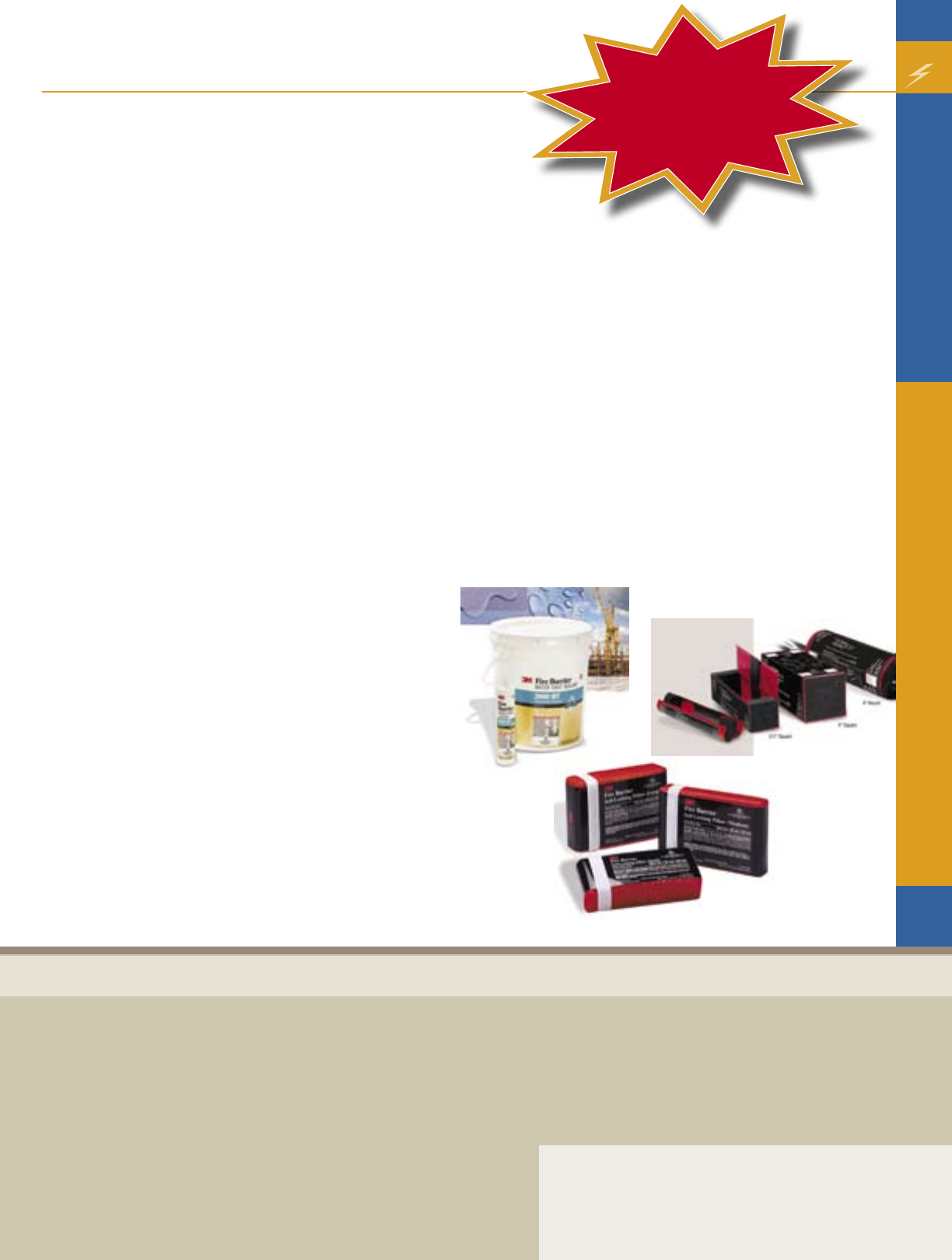
3M Fire Barrier Devices
Fire barrier devices offer an effective one-piece solution
for the firestopping of penetrating items through rated
walls and floors. During a fire, these devices expand to
form a seal, which helps protect against the spread of fire,
smoke and toxic gases. 3M offers pass-through options
for walls and floors, as well as cast-in place options for
poured concrete floors.
3M Fire Barrier Packing Material
This light-weight packing material is approved for use in
all 3M’s UL listed through-penetration firestop systems.
The 20’ roll is convenient to transport and features quick
and easy hand-tear dispensing. 3M Fire Barrier Packing
Material is ideal for use around metallic, nonmetallic,
insulated pipe, HVAC and power and communication cable
penetrants – a long-awaited alternative to mineral wool,
fiberglass or backer rod. The Material PM 4 is approved to
use in up to four hour firestop systems.
3M Fire Barrier Specialty Products
From wrap strips and restricting collars to 3M Fire Barrier
Mortar, these code approved, UL listed products help round
out 3M’s comprehensive offering of through-penetration
firestops. Additionally, 3M offers a residential fire block
designed to resist high temperatures and helps prevent
smoke passage in non-related residential and combustible
construction.
Please contact your local Irby sales representative regarding
the 3M Firestop promotion running July 1 – August 31st,
2008.
Table of Contents
2
3M Firestop
A Name You Can Trust
Contractor
1980 1981 1982 1990 1994 1997 2003 2004 2006
3M™ Fire 3M helps 3M™ Fire Barrier 3M develops 3M introduces 3M introduces 3M launches 3M named 3M develops
Barrier FS-195 write the CP25 Caulk, an industry fire protection Firedam Spray first firestop #1 brand e-Train,
Wrap/strip first specific 3M™ Fire Barrier milestone with wraps for grease, for construction sealants to preferred by a comprehensive
introduced. test standard Putty 303 reformulated, air, fume and joints to meet meet new installers of on-line firestop
for through and 3M™ Interam water-based 3M™ plenum ducts. 3M ASTM 1399 UL Water firestop products. program that
penetration Mat introduced. Fire Barrier This established 3M test criteria. Leakage Test, has become the
firestop systems CP25WB Caulk as a full service W Rating-Class industry
(ASTM E 814). – easier to clean fire protection 1 requirements. benchmark
and less provider for for training.
environmentally through
impactful than most penetrations,
solvent based caulks. construction joints
and now protective
insulative wraps.
From time-tested fire barrier sealants to today’s innovative firestop
devices and duct wraps, 3M scientists work to develop solutions to
firestop virtually anything on a building site. With over 100 products
and over 1000 tested approved systems, 3M has the most complete
program for all your firestopping needs.
Article provided by 3M
$10 Gas card
with $100 purchase of
FIRESTOP
PRODUCTS
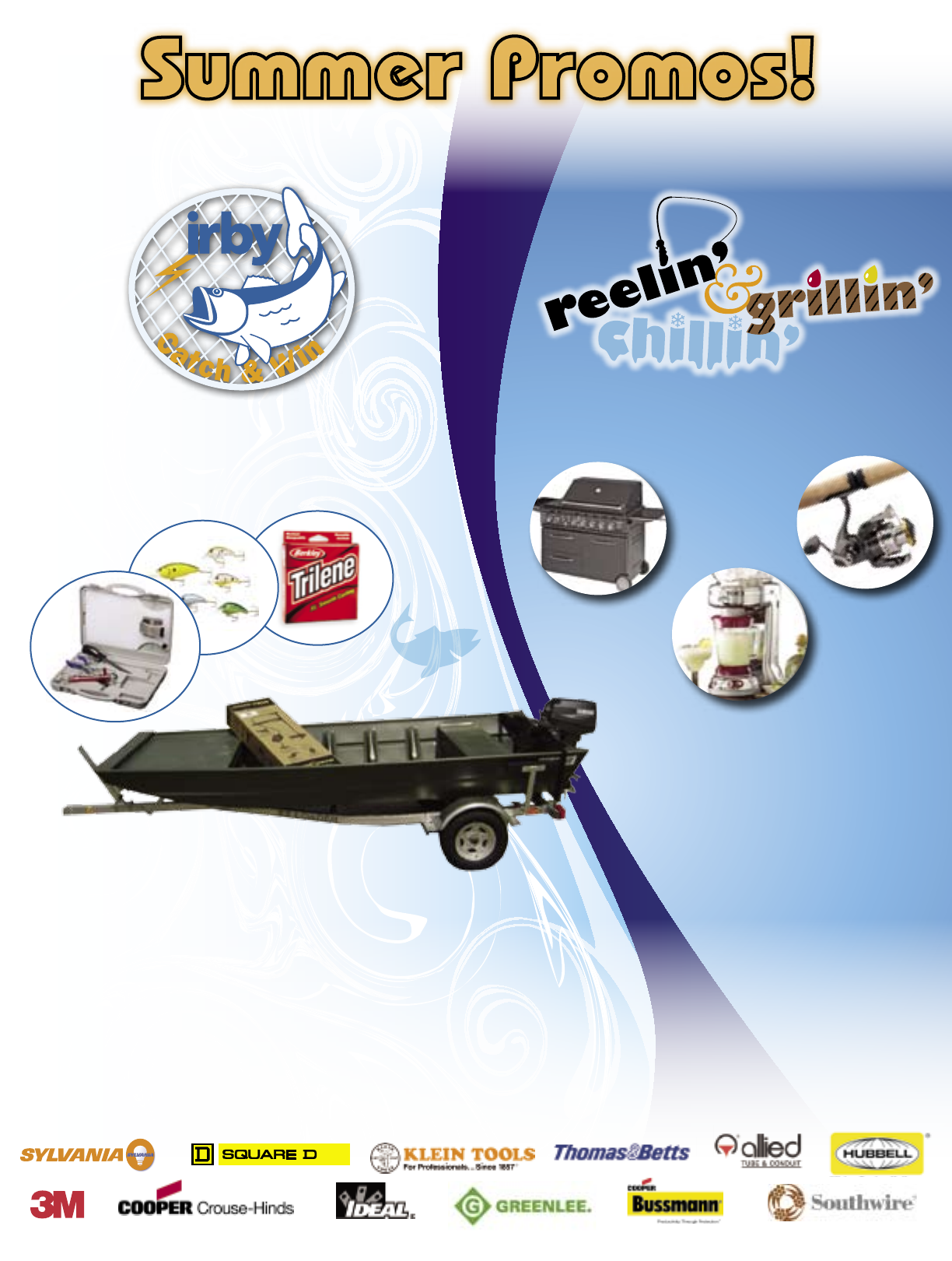
Visit participating locations during the months of June,
July and August and register to win one of 3 grand prizes
to be given away during the counter days in September.
Visit the Monroe, LA or Shreveport, LA counters during
the months of June, July and August for an opportunity
to catch one of 25 daily prizes. Then join us for our counter
day in September where someone will catch the grand prize
fish and claim a brand new bass boat!!
Quantum®
Catalyst PTi-A®
Reel and
Extreme® XPS®
Rod Spinning
Combo
Charmglow
3 Zone with Smoker
Multi Function
Frozen Drink Machine
Join us in September for counter days – we’ll have great food, product demonstrations from our supporting Sponsors and the
Irby team will be on hand to assist you with your electrical needs. Remember you must be present to win.
Through a combination of competitive pricing, broad inventory, knowledgeable customer service people, and dedicated
product specialists, Irby has the resources required to get you the material and knowledge when you need it, where you need
it, and at the right price. Our goal as your business partner is to help you get the job done and be more profitable. Irby is here
for you as a trusted partner for all your electrical solutions.
Exciting
During June, July and August, customers are encouraged to visit a participating location
and learn more about the following commercial and contractor promotions.
Summer Promos!
Sponsors*
Catch & Win Counter Days:
Shreveport, LA 9/18
Monroe, LA 9/19
Reelin’, Grillin’ & Chillin’
Counter Days:
Tupelo, MS 8/28
Jackson, TN 9/4
Tulsa , OK 9/11
Muskogee, OK 9/12
OK City, OK 9/25
Enid, OK 9/26
* Sponsors vary per location
* Sponsors vary per location
Cooper Bussmann
®
Compact Circuit
Protector (CCP)
Smaller.
Simpler.
Better.
For more information visit us at
www.cooperbussmann.com/CCP
SystemOne
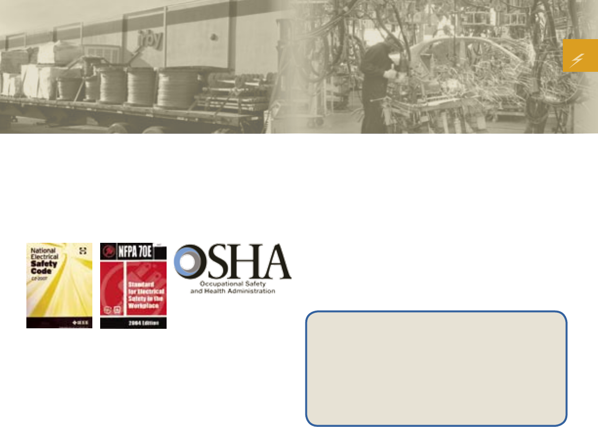
from Hubbell
Hubbell SystemOne Metal Floor Boxes...
The latest addition to the line of
SystemOne in-floor applications.
www.hubbell-wiring.com
• Cast Iron for
On-Grade Applications
• Stamped Steel for
Above-Grade Applications
• High-Capacity Multi-Media
• Accepts the Hubbell
SystemOne Universal Cover
WIRING SYSTEMS
Wiring Device-Kellems
Premise Wiring
SystemOneMetalFB.indd 1 6/5/2008 3:03:07 PM
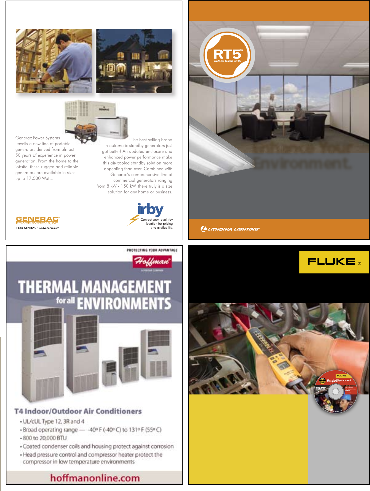
You spoke…
We listened
The new Square D® NQ (240V) lighting panelboard was designed
with electrical contractor input. Ask an Irby sales representative to
include an NQ panelboard in your next order.
Ready When You Are
• Full range of NQ ready-to-install
lighting panels offered from stock
• More eld-installable accessory
kits available
Simple to Install
• Semi-assembled NQ
ready-to-install kits
• New 54, 72 and 84 circuit interiors
that mount in a single enclosure
Built to Last
• Designed and durability tested
to all relevant industry standards
(2008 NEC® and UL 67)
•
Field tested with electrical contractors
Irvy NQ ad 0529.indd 1 5/29/08 3:19:11 PM
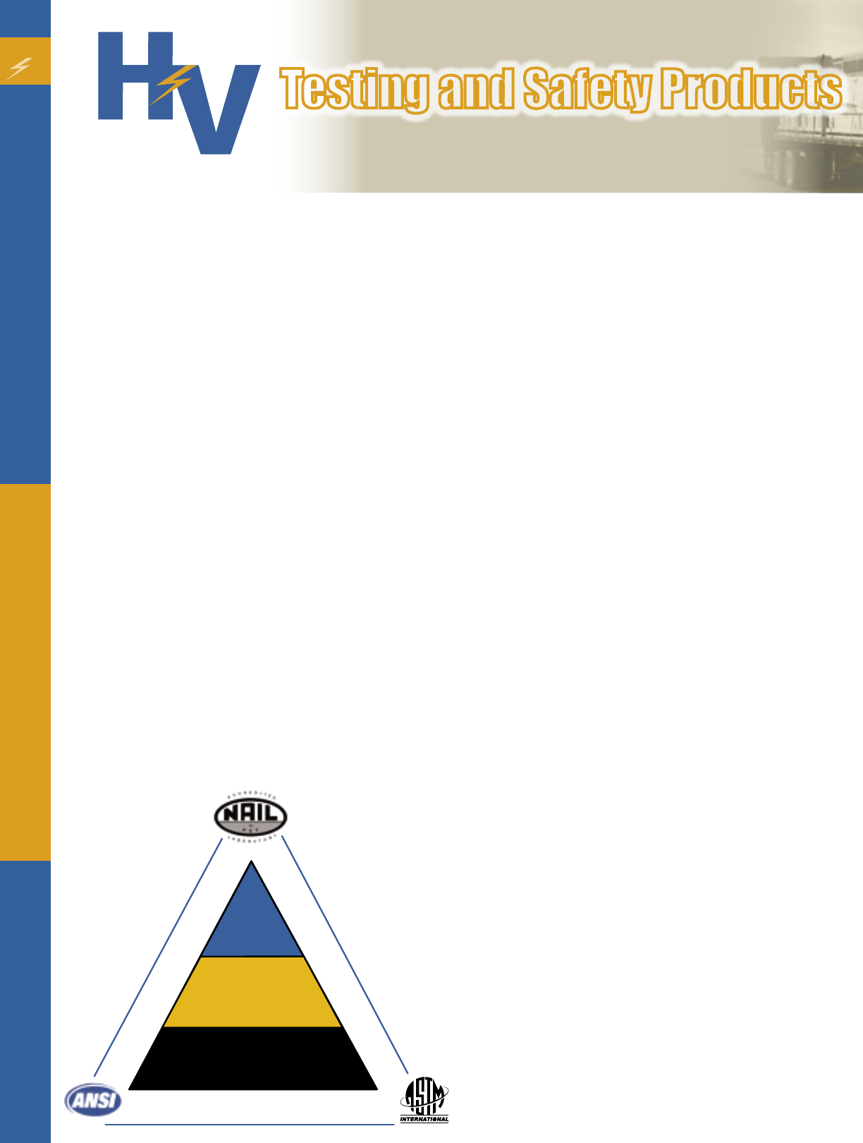
Simplify your job with 3M™ Performance
Plus Wire Connectors
Just four 3M Performance Plus
Wire Connectors handle the work of
seven standard connectors making
it easier to manage your connector
inventory and give you a better
chance of having the connector you
need on hand to do every job.
T/R+ replaces yellow, tan and red*
T/Y+ replaces yellow, orange, blue and gray*
O/B+ replaces orange, blue and gray*
R/Y+ replaces both red and yellow*
* in the majority of field applications
Ask your 3M sales rep for more information on these and
other quality 3M Electrical Products today - or check us out
on the web at www.3m.com/electrical
For information contact your
local Irby sales representative.
Known as a “testing laboratory” with a strong regional
presence in the Midwest, High Voltage Testing and Safety
Products (HV) was purchased by Irby in February of 2007.
At the time HV was implementing a new strategy to re-
position and re-brand itself in the market place. With the
acquisition, we were able to implement our new strategy of
being a one-stop, complete Personal Protective Equipment
(PPE) supplier with the goal of establishing ourselves
nationally. Since the purchase we have been working with
Irby marketing, sales and branch operations to integrate
our products and services to an expanded network of
customers and branches.
HV currently has two primary locations — Fargo, North
Dakota, which serves as the main warehouse / testing
laboratory and Minneapolis, Minnesota which operates as
a sales office. In addition to these locations, HV supports
and provides all testing services, PPE clothing systems and
related products to all the Irby branches nationally.
High Voltage Value Model
The HV value model is based on a three-layered approach
to electrical safety and protection. The three layers are
(1) Rubber Insulating Gloves and Equipment (2) Arc Flash
Protection (3) Flame Resistant (FR) Clothing. This is shown
in the “safety triangle” diagram that was developed based
on Maslow’s hierarchy of needs and being “actualized” or
in your case “safe” from an electrical discharge of energy.
The goal being to communicate that if you are missing any
one of the layers, then you are at risk from an electrical
shock or arc flash blast. This PPE value model is supported
by our NAIL Certified Testing Laboratory where we follow
stringent ASTM and ANSI standards. The value model has
application across all markets including Utility, Industrial,
Contractor and Commercial business segments.
Standards and Regulations Driving the Industry
Safety requirements and regulatory issues will continue to
significantly impact the electrical industry as enforcement
and compliance become more stringent. Many of them have
been recently updated or are in the process of revisions.
These standards affect all electrical workers across all
industries and utilities.
National Fire Protection Association (NFPA) 70E and
Arc Flash
NFPA 70E is one of the various documents comprising
the National Electric Code published by the National Fire
Protection Association. Its intent is to protect workers in
every industry around any device capable of generating an
arc flash or electrical shock.
•Arc Flash is a sudden release of electrical energy through
the air when a high voltage gap exits and there is a
breakdown between conductors. An arc flash gives off
thermal radiation and bright, intense light that can cause
burns. Temperatures have been recorded as high as 35,000
degrees Fahrenheit. An arc flash can be spontaneous or
result from inadvertently bridging electrical contacts with
a conducting object. Other causes may include dropped
tools or the buildup of conductive dust or corrosion.
•High voltage arcs can also produce considerable pressure
waves by rapidly heating the air and creating a blast. The
pressure burst can hit a worker with great force and send
molten metal droplets from melted copper and aluminum
electrical components great distances at extremely high
velocities.
It is important that you establish an electrically safe work
condition before working on a circuit or any energized
equipment. To create an electrically safe work condition
you should:
(1) Identify all power sources
(2) Interrupt the load and disconnect the power
(3) Visually verify that the disconnect opened the circuit
(4) Lock-out and tag-out the circuit
(5) Test for voltage
(6) Ground all power conductors
All these steps require the use of appropriate PPE for shock
and arc flash protection including voltage rated gloves,
Flame Resistant (FR) work clothes, arc-rated face shield,
flash suits with hoods and safety glasses.
National Electric Safety Code (NESC) 2007
The 2007 National Electric Safety Code has given power and
communications utilities until January 1, 2009 to determine
the potential exposure to energy and electric arcs for
employees who work on or near energized electrical lines
and equipment. Employees are required to wear clothing
or clothing systems with an effective arc rating greater than
RUBBER
INSULATED
GLOVES
ARC
FLASH
PROTECTION
Certi f i e d
Testing
L a borato r y
FR
PROTECTIVE
CLOTHING
12
5
Testing and Safety Products
High Voltage
Testing and
Safety Products
An irby company
Service
the anticipated level of energy. Furthermore, if the potential
employee exposure is greater than 2 cal/cm2 the employer
shall require employees to wear clothing or clothing systems
with an effective arc rating. In order to comply, utilities must
determine the expected levels of potential arc energy for
employees performing the work and choose appropriate PPE
to match the arc energy requirements.
New OSHA Ruling regarding PPE
As of May 15, 2008 all employers should be in compliance
with the new OSHA rule that all PPE must be provided by the
employer at no cost to the employee. The final rule clarifies
OSHA’s requirements regarding payment for employee-owned
PPE and replacement PPE and indicates it must be provided to
the employee at NO COST.
Who is responsible for Safety?
•Employer - responsible for complying with OSHA require-
ments, the Electrical Safety Program, Safety Policies / Proce-
dures and Safety Training
•Employee - responsible for adhering to the procedures
•Owner - responsible for contractors on their jobsite
Safety Facts (From WH Salisbury)
• Electrical Safety is the most over-looked employee work
hazard
• An estimated 30,000 non-fatal electrical shock accidents
occur each year or 3.5 per hour
• 600 people die from electrocution each year
• Electrocution is 4th in work related fatalities with the majority
of these incidents occurring at 600 volts or less
• Approximately 3,000 reported flash burn incidents are
reported annually from an arc flash and ignition of flammable
clothing
• 350 deaths related to arc flash or blast occur each year
How can HV help ensure that I comply with electrical
safety standards?
HV offers a complete one-stop safety solution for all your
electrical PPE and training needs. Based on our three-layered
approach to complete electrical safety coverage, supported by
our certified testing service, we can help ensure the safety of
your electrical workers.
HV services include:
Testing Services
High Voltage Testing and Safety Products is accredited by North
American Independent Laboratories (NAIL) for protective
equipment testing and we are capable of testing with voltages
from 500 to 100,000 volts. All equipment is tested according to
the latest American Society for Testing and Materials (ASTM)
and American National Standards Institute (ANSI) standards.
We test all types of rubber insulating gloves, sleeves, blankets
and line hoses. We can also test all types of tools such as
hot sticks, grounding equipment and jumper cables. It is
important that you re-test your equipment according to the
schedule below.
Arc Flash Suits and Flame Resistant (FR) Daily Wear
Clothing
The type of PPE you provide your workers is determined by
the type of electrical work you perform, your overall safety
program and whether you use sub-contractors for some of the
work.
As a general guideline, you should consider the following:
•All under garments should be of natural fibers such as cotton,
wool or silk
•Flame Resistant (FR) daily wear shirts and pants are
recommended for qualified and un-qualified workers if
there is a high or constant level of exposure to energized
equipment
•Use Arc Flash suits and hoods for higher levels of safety or
if you will be testing, de-energizing or turning equipment
back on.
It is critical from a safety standpoint that the appropriate
PPE be worn at all times when working on or near energized
equipment. All electrical work should be done by qualified
personnel and an assessment of the electrical hazard level
performed. All PPE should have labeling identifying the
cal/cm2 rating or hazard risk category (HRC) of each item.
Rubber Insulated Gloves and Equipment
Rubber insulating equipment is your first line of defense
from electrical shock. HV carries a complete line of rubber
8
6
Testing and Safety Products
Type of Equipment and When to Test
• Rubber insulating Gloves - Before 1st issue and every 6 months at maximum
• Rubber insulating Sleeves - Before 1st issue and every 12 months at maximum
• Rubber insulating Blankets - Before 1st issue and every 12 months at maximum
• Rubber insulating Line Hose - When dirty or insulating value is suspect, usually
every 12 months
• Other Rubber insulating Cover - When dirty or insulating value is suspect, usually
every 12 months

insulating gloves, sleeves, blankets and line hoses. If something
fails during the testing process we can provide a replacement
immediately. We can replace a single glove or a pair. Your
life depends on your rubber protective equipment. The level
of protection that rubber gloves provide depends on their
condition. It is the responsibility of the user to maintain their
gloves and other insulating equipment in good condition.
HV \ Irby Tools
Utility contractors and customers can count on HV\Irby Tools
and Services to have the products they need to get the job
done and the service expertise to keep them working properly.
When it comes to tool repair and service, Irby is authorized by
the industry’s top manufacturers. You can trust Irby to get the
job done right the first time.
In addition to tools and repair, Irby offers you product testing,
demonstrations and training to keep your tools industry
standard certified and to help ensure proper selection and
application. Custom designed grounds and jumpers are built
to your specifications. They can be built and shipped the same
day you place your order! No matter what the task demands,
a call to HV\Irby is the fastest and easiest way to get the right
tools to get the job done on time.
NFPA 70E Arc Flash Training
Need help in interpreting the various standards in the industry,
providing training to your employees on electrical safety or
selecting the proper PPE? HV can coordinate training at your
site or our branch. You can also earn CEU training credits!
The course content typically involves the following key areas:
• Electrical Safety Regulations and Standards
• Hazards of Electricity
• The Shockings Facts
• Equipment Arc Flash and Blast Boundaries and Hazards
• Personal Protective Equipment
• Arc Flash Calculations
• Training Recommendations
• Working with Contractors
In addition, a on-site training session may involve a preliminary
review of your electrical system, equipment and help with
formulating one-line diagrams.
What should be your next step to get compliant and
ensure the safety of your electrical workers?
• Contact your local Irby branch or sales representative to set-
up a meeting to review options for Electrical Safety Training
and/or selection of Personal Protective Equipment.
• Check your existing equipment, especially focusing on your
rubber glove certification dates. If they are out of compliance
(date is over 6 months old), remove them from service and
send to HV for testing and recertification.
• Request an HV Testing and Safety Products Catalog to
become more familiar with our complete products and
service offerings.
• Schedule NFPA 70E training for yourself and your
employees.
• Order NFPA 70E or NESC 2007 Standards Booklets as a
reference or to get up-to-date with the various standard
changes.
For more information or questions call 1-800-742-8054 or your
local Irby branch.
The tremendousgrowth of our company placed incredibledemands on our safety staff to maintain compli-
ance with PPE testing. High Voltage Testing and Safety Products met with our safety division andquicklyunder-
stoodour needs. Better than just understanding, they offered me aninnovative and extremely costecient
means to both complete the physical testing requirements as well as provide a management system of tracking that
ultimately savesoursafetydepartmentthousands of dollars of time during each scheduled change out. Their
staff is professional and knows the line of business. I was never approached from a sales point of view, their approach
is“Howcanwehelp”. HV has been one of my most beneficial business relationships I have had a chance to de-
velop.
Michael Patton
Razz Group, Baton Rouge LA
Corporate Environmental Health & Safety Director
7
Enhance Your
Environment.
RT5™ Volumetric Recessed Lighting: the new standard in
recessed fluorescent luminaires. RT5 uniformly illuminates
the entire volume of space, eliminating harsh shadows, dark
spots and the “cave effect” arising from the sharp cutoff of
parabolic fixtures. Yet, this new lighting system uses up to
33% less energy than a standard 18-cell, 3-lamp T8
parabolic fixture.
RT5™ Volumetric Recessed Lighting
www.lithonia.com/RT5
Introducing a
new face in the
portable power
line -up...
A reliable
standby gets
a whole
new look...
Better power. More choices.
FREE
Fluke Electrical Measurement
Safety CD with a T+PRO purchase
©2008 Fluke Corporation. Specifications
subject to change without notice.
The full-featured Fluke T+PRO Electrical
Tester offers all the advantages of a traditional
solenoid tester, without the typical hazards.
s Detect live voltage even with dead batteries
s 600V CAT IV and 1000V CAT III rated
s Complies with NFPA 70E*
For a limited time you can get a free Fluke
Electrical Measurement Safety CD with a purchase
of a Fluke T+PRO Electrical Tester. The CD explains
the procedures and precautions that help defend
against devastating dangers like arc flash and arc
blast based on safety guidelines from the NFPA,
ANSI, IEC and other safety regulators.
*When used properly per Article 110.9 Use of Equipment (A) Test
Instruments and Equipment.
To receive your free
Fluke Electrical
Measurement Safety
CD, after you purchase
your T+PRO, email
your name and contact
phone number to
irbycircuit@irby.com
by October 30, 2008.
9Carlon® PVC Conduit Repair System
Contractor
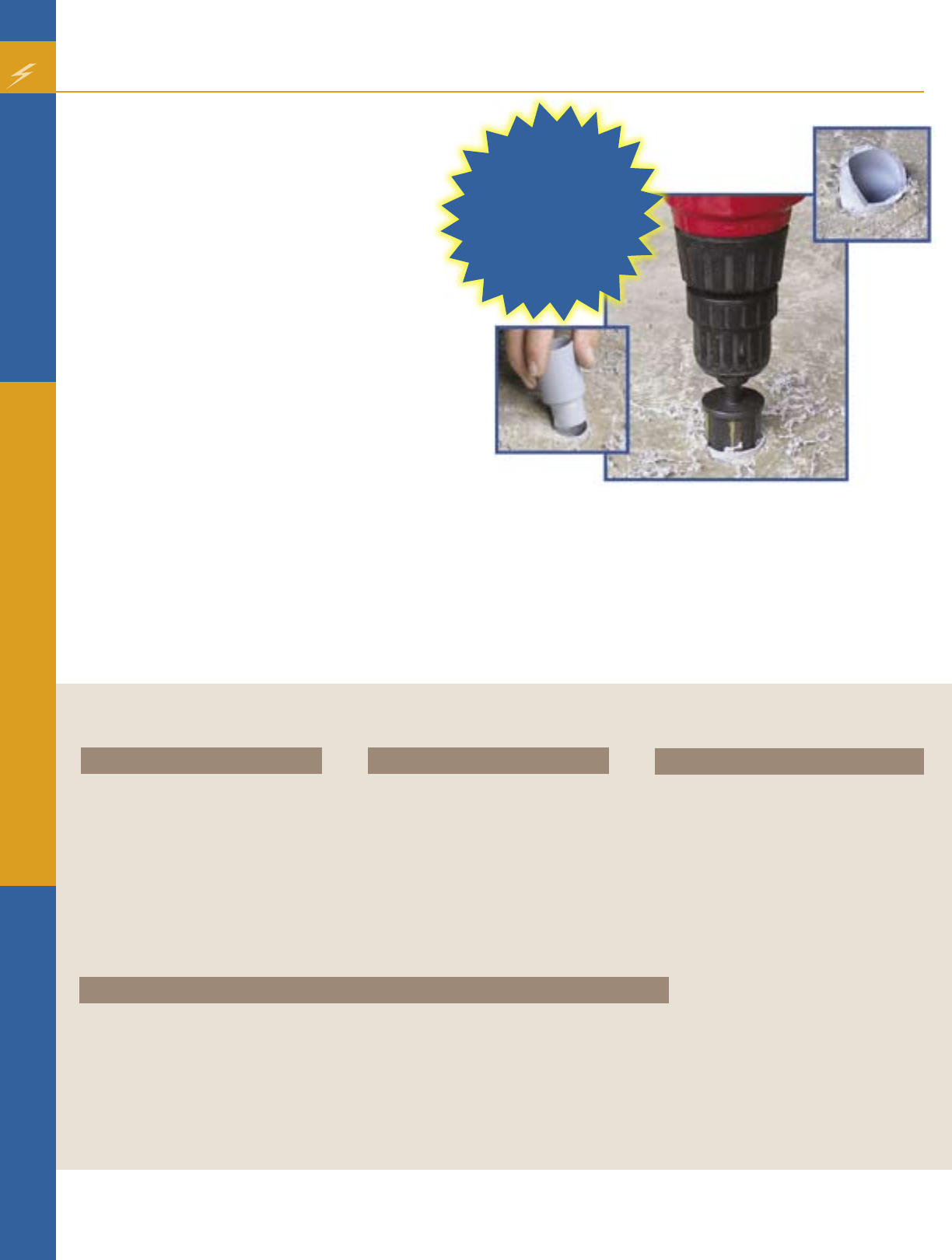
A job that normally takes 20 minutes can now be
done in 2 minutes or less.
In order to significantly reduce the time and costs
associated with repairing broken conduit a.k.a.
“stub-ups” in concrete slabs, Carlon® introduces
a new, revolutionary, patented design PVC
Conduit Repair System.
The Carlon® PVC Conduit Repair System is a line
of couplings, adapters and reamers that allows
you to quickly and easily repair broken PVC
conduits without having to chip-away and re-
pour concrete, while still maintaining the inside
diameter of the conduit. Simply cut off the
broken conduit; ream the ID of the conduit; and
insert a coupling or adapter, it’s that easy.
Features:
•UL and c-UL Listed
•PVC Repair Fittings are listed in accordance
with the NEC and Section 352.6
•Nonmetallic couplings, adapters and plugs won’t rust or corrode
•Available in sizes ½” through 2”
•Patented designed system
Benefits:
•Saves time and money
•Maintains inside diameter of conduit
•Metallic Reamers for extra strength, durability and longer life
•Quickly and easily repair broken PVC conduits
Specifications:
Couplings
Part No. Trade Size Std. Ctn. Qty.
E910D 1/2” 25
E910E 3/4” 25
E910F 1” 15
E910G 11/4” 10
E910H 11/2” 10
E910J 2” 10
Male Threaded Adapters
Part No. Trade Size Std. Ctn. Qty.
E920D 1/2” 25
E920E 3/4” 25
E920F 1” 15
E920G 11/4” 10
E920H 11/2” 10
E920J 2” 10
For more information, contact your local Irby sales representative.
Reamers
Part No. Size Std. Ctn. Qty.
E910REAMD 1/2” 12
E910REAME 3/4” 12
E910REAMF 1” 10
E910REAMG 11/4” 10
E910REAMH 11/2” 10
E910REAMJ 2” 10
E910REAMKIT All sizes
1/2”, 3/4”, 1”, 5
1
1/4”, 11/2”, & 2”
Schedule 40 Plugs
Part No. Size Color Part No. Size Color Part No. Size Color Std. Ctn. Qty.
HL-6XR 1/2” Red HL-6XY 1/2” Blue HL-6XY 1/2” Yellow 1 Bag of 50
HL-10R 3/4” Red HL-6XB 1/2” Blue HL-10Y 3/4” Yellow 1 Bag of 50
HL-13AR 1” Red HL-6XB 1/2” Blue HL-13AY 1” Yellow 1 Bag of 50
HL-16R 11/4” Red HL-6XB 1/2” Blue HL-16Y 11/4” Yellow 1 Bag of 50
HL-18R 11/2” Red HL-6XB 1/2” Blue HL-18Y 11/2” Yellow 1 Bag of 50
HL-21R 2” Red HL-6XB 1/2” Blue HL-21Y 2” Yellow 1 Bag of 50
A job that
normally takes
20 minutes,
DONE in 2
minutes or
less!
ALL THE GUARANTEE YOU’LL NEVER NEED.
SIM
pull
THHN®
– the original cable with a Product Performance Guarantee.
We’re so confi dent in SIM
pull
THHN cable that we back it with an unbeatable guarantee. If you have a performance
problem while installing the cable according to our installation and application guidelines, call 1-888-665-8230. We’ll
replace your cable and cover the direct costs associated with replacement. We’re confi dent because after two years
and countless installations, SIM
pull
THHN cable performs as promised. Visit southwire.com/guarantee to see the
complete Product Performance Guarantee.
888-665-8230
© Southwire 2008
47069_GuaranteeContAd_IC.indd 1 7/18/08 2:23:08 PM
11
Industrial
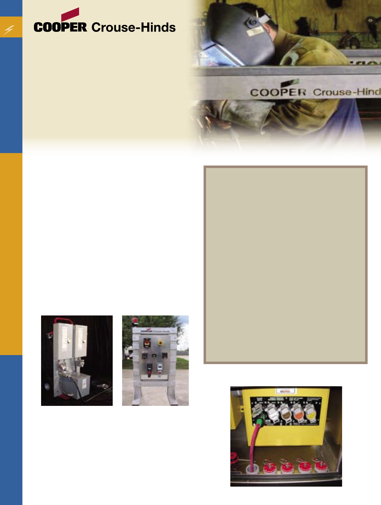
Virtually all industries today need equipment to
provide temporary power, either in the event of an
emergency or during standard operations such as
maintenance in a factory. Cooper Crouse-Hinds now
offers custom solutions as well as traditional out-of
-the-box products that effectively meet these needs.
The Cooper Crouse-Hinds Advantage
•New custom turn-key capabilities allow customers
to specify and order complete portable power carts
and enclosures
•Dedicated staff with a focus on the Oil & Gas, Military,
Disaster Relief and Entertainment industries
•Safe, durable and reliable
•Engineering support, including AutoCAD and design
specifications make the drawing and quotation
process seamless and streamlined
•UL approved assemblies, including suitability for Class
1, Division 1 and 2 applications or IEC applications
that would apply to International specifications
Cooper Crouse-Hinds has sales specialists in portable
power for support and in assisting and answering
questions from distributors, engineering firms and
customers. In addition, CCH has a full-time, on staff,
Application Electrical engineer devoted solely to
Portable Power.
For more information on how Cooper Crouse-Hinds
can help with your Portable Power solutions, contact
your local Irby sales representative.
Portable Power -
Total solutions from Cooper
Crouse-Hinds to meet the
industry’s ever-increasing
need for safe and reliable
temporary power.
Portable Power encompasses
anything that requires a need for
temporary power including:
•Government agencies
•Disaster relief
•Military bases
•Petro-chemical facilities
•Cell towers
•Generator/power distribution
manufacturers
•Solar or wind power
•Entertainment
•Food processing
•Gas stations
•Convenience stores
•Pharmacies
•Local electrical or mechanical contractors
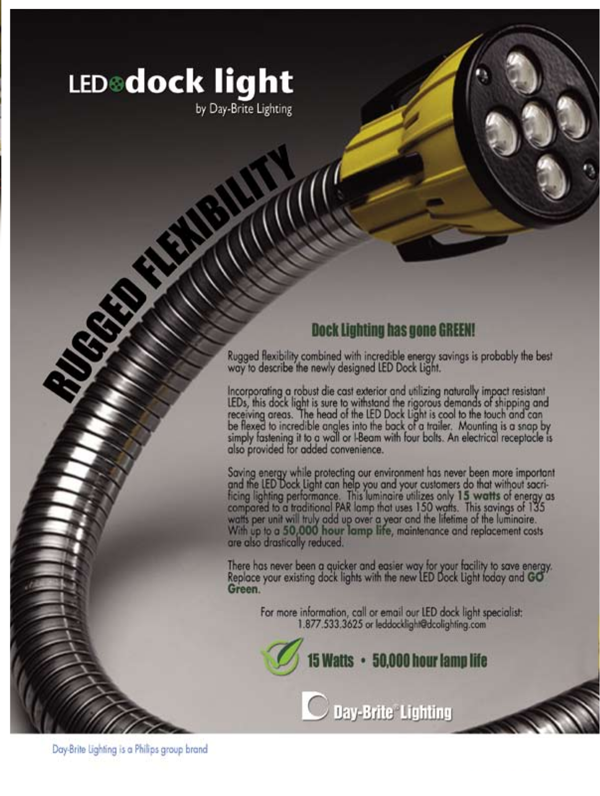
Irby_Docklight Ad 5/28/08 12:58 PM Page 1

Our newly designed Combination Devices
provide space-saving solutions for tight spots.
Our Commercial Specification Grade combination devices
feature space-saving versatility, quality construction and
smooth operation.
For more information, contact your local Irby sales
representative.
www.cooperwiringdevices.com
All Cooper logos are valuable trademarks of Cooper Industries in the U.S. and other
countries. You are not permitted to use Cooper trademarks without the prior written consent
of Cooper Industries.
New! Combination Decorator Devices.
Combo Ad:Layout 1 7/1/08 4:40 PM Page 1
www.alliedeg.com
© 2007-08 Allied Tube & Conduit, Tyco International.
ATC0807_KFC_NECA Ad2 7/3/08 9:57 AM Page 1
Alera Lighting
Architectural Area Lighting
Columbia Lighting
Compass Lighting
Devine Lighting
Dual-Lite
Hubbell Outdoor Lighting
Hubbell Industrial Lighting
Kim Lighting
Kurt Versen
Prescolite
Security Lighting
Spaulding Lighting
Sportsliter Solutions
Sterner
Whiteway
Hubbell Lighting, Inc.
701 Millennium Blvd.
Greenville, SC 29607
(864) 678-1000
hubbelllighting.com
One Company,
Distinct Brands
Emergency Disaster
Hurricane season is June 1 - November 30
14
How prepared are you to handle the affects of a natural
disaster? Natural disasters come in many forms: hurricanes,
tropical depressions, storm surges, high winds, tornadoes
and flooding – affecting communities and businesses in the
Southeastern United States.
Professor Gray, of the University of Colorado, forecasted the
Atlantic and Gulf Coast 2008 hurricane season to be more
active than usual. Conditions in the Atlantic are very favorable
for an active hurricane season because of the continued
increase of the Atlantic water temperature. The 2008 forecast
of named storms is 15 and the number of hurricanes is eight
with an estimated 44% chance that a category 3, 4 or 5 will
make landfall on the Gulf Coast.
24-Hour Emergency Response Program
Stuart C. Irby Co. specializes in disaster preparation and
recovery with its 24-Hour Emergency Response Program.
When conditions are at their worst, Irby is at its best. Our 24-
hour Emergency Response Program ensures that you can get
the products and resources you need, when you need them the
most. Irby’s network of strategically located branches allows
us to respond rapidly and maintain a reliable supply chain
for the duration of the storm. When disaster strikes, the best
protection is knowing what to do. By knowing vulnerability
and what actions need to be taken, we can help you reduce
the effects of a natural disaster.
Be prepared with Irby Storm Stock
Irby will work with you to make sure the products you need
during storm situations will be available for you. This assures
optimum response time enabling you to provide faster, better
service to your customers.
Readiness Has Its Rewards
Prepare a Disaster Supply Kit. Make a checklist of electrical
supplies most commonly destroyed and replaced during and
after a natural disaster. Use the following list as a reminder to
help you be prepared before a storm affects you:
Businesses and industries can limit injuries and damages
and return more quickly to normal operations if they plan
ahead. Emergency Management is the process of preparing
for, mitigating, responding to and recovering from an
emergency.
• It enhances a company’s ability to recover from financial
losses, regulatory fines, loss of market share, damages to
equipment or products or business interruption.
• It enhances a company’s image and credibility with
employees, customers, suppliers, and the community.
• It may reduce insurance premiums.
Visit our website at http://www.irby.com/resources/resources_
main.asp and download a copy of FEMA’s Emergency
Management Guide for Business and Industry. It’s a step-by-
step approach to emergency planning, response and recovery
for companies of all sizes.
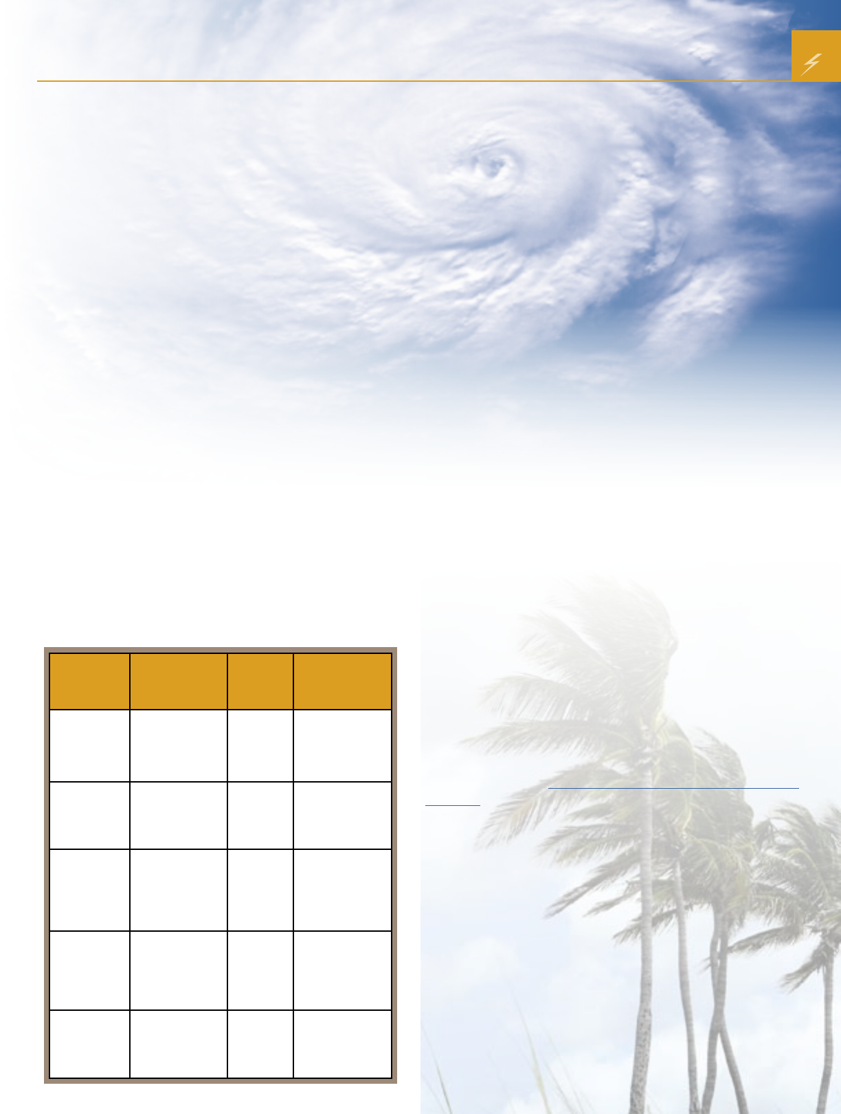
Are You Prepared?
Category Wind Speed Storm
Surge Damage Potential
1
(weak)
75-95 mph
65-82 kts
33-42 m/s
4.0-5.0 ft.
1.2-1.5 m
minimal damage to
vegetation
2
(moderate)
96-110 mph
83-95 kts
43-49 m/s
6.0-8.0 ft.
1.8-2.4 m
moderate damage
to houses
3
(strong)
111-130 mph
96-113 kts
50-58 m/s
9.0-12.0 ft.
2.7-3.7 m
extensive damage
to small buildings
4
(very strong)
131-155 mph
114-135 kts
59-69 m/s
13.0-18.0 ft.
3.9-5.5 m
extreme structural
damage
5
(devastating)
> 155 mph
> 136 kts
> 70 m/s
< 18.0 ft.
< 5.5 m
catastrophic
building failures
possible
• Repair sleeves
• Crossarms and braces
• Insulators
• Connectors and clamps
• Protective arresters and
switches
• Wire and cable
• Pole line hardware
• Ground rods and
grounding wire
• Anchors and rods
• Line construction tools
• Personnel safety devices
• Tie wire
• Staples
• Men Working signs
• Lighting fixtures
15
Feature
Top 10 2008 NEC Change Rules
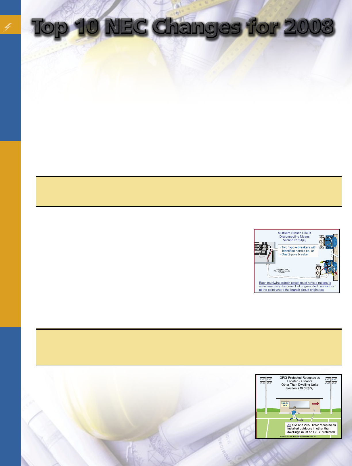
1. 210.4 Multiwire Branch Circuits
The rule for “Simultaneous Disconnecting Means” requirements for multiwire branch circuits was expanded.
(B) Disconnecting Means. Each multiwire branch circuit shall have a means to simultaneously disconnect all ungrounded
conductors at the point where the branch circuit originates. (See Figure 210.2)
Author’s Comment: Individual single-pole circuit breakers with handle ties identified
for the purpose, or a breaker with a common internal trip, can be used for this
application [240.15(B)(1)].
CAUTION: This rule is intended to prevent people from working on energized
circuits they believe are disconnected.
Analysis: Multiwire branch circuits can offer unexpected shock hazards when
work is being done on them unless all ungrounded conductors from the multiwire
branch circuit are disconnected simultaneously. This revised section requires
each ungrounded conductor of a multiwire branch circuit to be disconnected
simultaneously by common trip 2-pole or 3-pole circuit breakers or single-pole circuit breakers with an identified
handle tie.
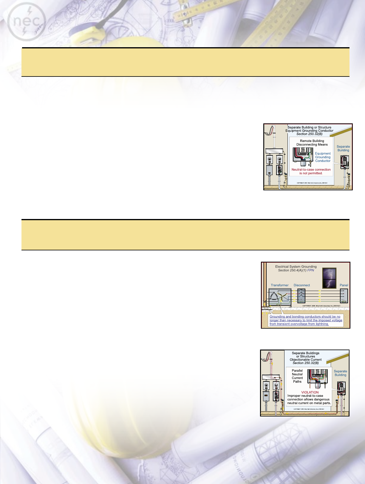
2. 210.8 Ground-Fault Circuit-Interrupter Protection for Personnel (GFCI)
Outdoor GFCI-protection requirements for 15A and 20A, 125V receptacles at nondwelling unit occupancies were
revised.
(B) Other Than Dwelling Units
(4) Outdoors - All 15A and 20A, 125V receptacles installed outdoors shall be GFCI-
protected. (See Figure 210–10)
Analysis: The 2005 NEC only required 15A and 20A, 125V “outdoors in public
spaces—for the purpose of this section a public space is defined as any space that
is for use by, or is accessible to, the public” to have GFCI protection. This change
now requires GFCI protection for these types of receptacles installed at all outdoor
locations, except as provided by the exceptions for snow-melting and deicing
equipment and industrial establishments.
By Mike Holt
Know What’s New
In this latest code cycle, the Code Making Panels (CMPs)
sifted through 3,688 change proposals. Some of the
resulting changes were minor editorial revisions. Others
were more significant, such as new Articles, Sections,
Exceptions, and Fine Print Notes.
Why does the NEC undergo revision every three years?
After all, electricity doesn’t change every three years. For
one thing, the NEC must keep up with changes in methods
and materials as technology marches forward. Other
factors behind those 3,688 proposals include fire data and
efforts to make the NEC more user-friendly.
Code Change Wrap-up
We’ve highlighted what we consider to be the top 10 code
changes for the industry in general, but this cycle produced
hundreds of changes. Which ones really apply to the work
you do? Use this simple three-step process to find the
answer:
1. Review a sampling of typical jobs you did over the past
year.
2. Note which NEC requirements apply.
3. Look up those requirements in the 2008 NEC. Compare
them to the 2005 requirements.
As you do this, jot down some notes on what you think
should be different in the NEC. This will give you the basis
for making change proposals of your own for the 2011
NEC. You have about a year left to submit those. But that
time will be gone before you know it, so get started now.
Fig. 210-2
Figure 210–10
Top 10 NEC Changes for 2008Top 10 NEC Changes for 2008
3. 250.4 General Requirements for Grounding and Bonding
A new Fine Print Note alerts Code users to the advantage of reducing the length of the grounding electrode conductor.
(A) Grounded Systems
(1) Electrical System Grounding. Electrical power systems, such as the secondary winding of a transformer are grounded to the
earth to limit the voltage caused by lightning, line surges or unintentional contact by higher-voltage lines.
FPN: An important consideration for limiting the imposed voltage is the routing of
bonding and grounding conductors so that they are not any longer than necessary to
complete the connection without disturbing the permanent parts of the installation and
so that unnecessary bends and loops are avoided. (See Figure 250-4)
Author’s Comment: System grounding helps reduce fires in buildings as well as voltage
stress on electrical insulation, thereby ensuring longer insulation life for motors,
transformers, and other system components.
Analysis: This new Fine Print Note is intended to call attention to the instructions contained
in Sections 800.100(A)(5), 810.21(E), and 820.100(A)(5) that grounding conductors be run
as short as possible and as straight as possible. This provides an effective path to the earth
for line surges caused by lightning events.
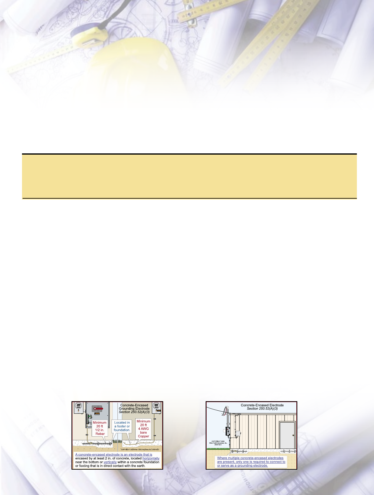
4. 250.32 Buildings or Structures Supplied by Feeder or Branch Circuit
The rule that permitted the regrounding of the neutral conductor at separate buildings and structures was deleted.
(B) Equipment Grounding Conductor. To quickly clear a ground fault and remove
dangerous voltage from metal parts, the building or structure disconnecting means
shall be connected to the circuit equipment grounding conductor of a type described in
250.118. Where the supply circuit equipment grounding conductor is of the wire type,
it shall be sized to 250.122, based on the rating of the supply circuit overcurrent device
rating. (See Figure 250-21)
Exception: For existing premises, when an equipment grounding conductor was not run
to the building or structure disconnecting means, the building or structure disconnecting
means can remain connected to the neutral conductor where there are no continuous
metallic paths between buildings and structures, ground-fault protection of equipment
isn’t installed on the supply side of the circuit, and the neutral conductor is sized no
smaller than the larger of:
(1) The maximum unbalanced neutral load in accordance with 220.61.
(2) The rating of the circuit overcurrent device, in accordance with 250.122.
Caution: To prevent dangerous objectionable neutral current from flowing onto metal
parts [250.6(A)], the supply circuit neutral conductor is not permitted to be connected to
the remote building or structure disconnecting means [250.142(B)]. (See Figure 250–22)
Analysis: In the 2005 NEC, 250.32(B)(2) permitted the neutral conductor to serve as
the effective ground-fault current path, this rule was converted into an exception for
existing premises. Using the neutral conductor to connect metal objects to the effective
ground-fault current path is a dangerous practice, especially if the neutral becomes open.
Figure 250-4
Figure 250-21
Figure 250-22

5. Article 708 – Critical Operations Power Systems
A new article addressing Critical Operations Power Systems was added to the 2008 NEC.
The provisions of this article apply to the installation, operation, monitoring, control, and maintenance of premises wiring
intended to supply, distribute, and control electricity to designated critical operations areas in the event of disruption to
elements of the normal system.
Critical operations power systems are those systems so classed by municipal, state, federal, or other codes, by any governmental
agency having jurisdiction, or by facility en gineering documentation establishing the necessity for such a system. These systems
include but are not limited to power systems, HVAC, fire alarms, security, communications, and signaling for designated
critical operations areas.
Critical Operations Power Systems are gener ally installed in vital infrastructure facilities that, if de stroyed or incapacitated,
will disrupt national security, the economy, public health or safety; and where enhanced electrical infrastructure for continuity
of operation is deemed necessary by governmental authority.
Threats to facilities that may require transfer of operation to the critical systems include both naturally occurring hazards and
human-caused events.
Analysis: Recent terrorist events and natural disasters, such the World Trade Center attack and Hurricane Katrina, highlighted
the need to assess the adequacy of the National Electrical Code requirements for electrical infrastructure protection
and reliability. This new Article 708 was created by a task group developed in response to Homeland Security activity,
specifically how to keep an emergency system operating for days. The task group was formed to review requirements in
the NEC and other NFPA codes and standards covering emergency and standby power systems and sources, and signaling
systems.
6. 250.94 Intersystem Bonding Terminal
A new rule requires an intersystem bonding terminal for communications systems.
An external accessible intersystem bonding terminal for the grounding and bonding of communications systems shall be
provided at service equipment and disconnecting means for buildings or structures supplied by a feeder. (See Figure 250–
39)
The intersystem bonding terminal shall not interfere with the opening of any equipment enclosure and be one of the
following:
(1) Terminals listed for grounding and bonding attached to a meter socket enclosure.
(2) Bonding bar connected to the equipment grounding conductor with a minimum 6 AWG copper conductor.
(3) Bonding bar connected to the grounding electrode conductor with a minimum 6 AWG copper conductor.
Author’s Comment: According to Article 100, an intersystem bonding terminal is a device that provides a means to connect
communications systems grounding and bonding conductors to the building grounding electrode system. See (See Figure
250-39)
Exception: At existing buildings or structures, an external accessible means for
bonding communications systems together can be:
(1) Nonflexible metallic raceway,
(2) Grounding electrode conductor, or
(3) Connection approved by the authority having jurisdiction.
Figure 250-39
FPN No. 2: Communications systems shall be bonded to the intersystem bonding terminal in accordance with the
following:
• Antennas/Satellite Dishes, 810.15 and 810.21
• CATV, 820.100
• Telephone Circuits, 800.100
Author’s Comment: All external communications systems must be bonded to the intersystem bonding terminal to
minimize the damage to communications systems from induced potential (voltage) differences between the systems from
a lightning event.
Analysis: This is one of several correlated proposals to improve the requirements related to the intersystem bonding and
grounding of communications systems. This provides a more accessible, safer means of bonding all systems, such as power
and communications, together.
7. 250.52 Grounding Electrodes
The requirements for a concrete-encased electrode now include vertical electrodes as well as what to do when multiple
isolated concrete-encased electrodes are present.
(A) Electrodes Permitted for Grounding.
(3) Concrete-Encased Grounding Electrode. A concrete-encased electrode is an electrode that is encased by at least 2 in. of
concrete, located horizontally near the bottom or vertically within a concrete foundation or footing that is in direct contact
with the earth consisting of one of the following: (See Figure 250–26)
• Twenty feet of one or more bare or zinc galvanized or other electrically conductive coated steel reinforcing bars bonded
together by the usual steel tie wires not less than ½ in. in diameter, or
• Twenty feet of bare copper conductor not smaller than 4 AWG
Author’s Comment: If a moisture/vapor barrier is installed under a concrete footer, then the steel rebar is not considered a
concrete-encased electrode.
Where multiple concrete-encased electrodes are present at a building or structure, only one is required to serve as the
grounding electrode system. (See Figure 250–27)
Author’s Comments:
• The grounding electrode conductor to a concrete-encased grounding electrode isn’t required to be larger than 4 AWG
copper [250.66(B)].
• The concrete-encased grounding electrode is also called an “Ufer Ground,” named after Herb Ufer, the person who
determined its usefulness as a grounding electrode in the 1960s. This type of grounding electrode generally offers the
lowest ground resistance for the cost.
Analysis: The requirements for concrete-encased electrodes have been expanded to allow structural steel rebar in vertical
foundations to be suitable as a grounding electrode, as long as it meets all of the requirements for horizontal structural
steel rebar electrodes. In addition, the 2008 NEC clarified that in a building or structure where multiple isolated concrete-
encased electrodes are present, such as for spot footings, only one of these “present” electrodes will be required to be
used. The purpose of the NEC [90.1] is the “practical safeguarding of persons and property,” and requiring all of the
concrete-encased electrodes to be bonded together served no safeguarding purpose.
Figure 250-26 Figure 250-27
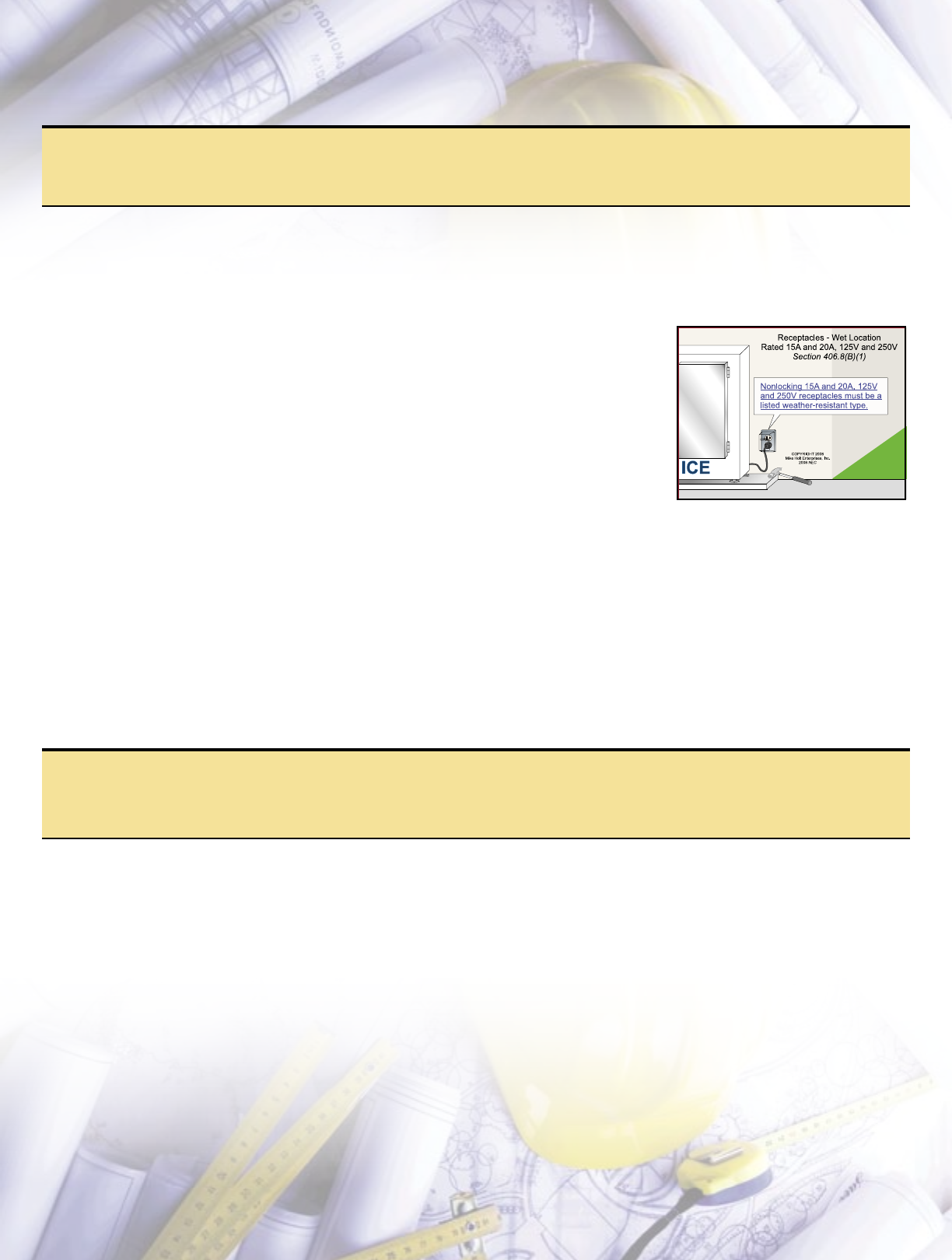
8. 406.8 Receptacles in Damp or Wet Locations
Receptacles installed in wet locations are now required to be weather resistant.
(B) Receptacles in Wet Locations.
(1) 15A and 20A Receptacles. All 15A and 20A receptacles installed in a wet location shall be within an enclosure that is
weatherproof when an attachment plug is inserted and all nonlocking 15A and 20A, 125V and 250V receptacles in a wet
location shall be listed as weather resistant. (See Figure 406–4)
Exception: Receptacles subject to routine high-pressure washing spray may have an
enclosure that is weatherproof when the attachment plug is removed.
Author’s Comments:
• Wet locations are those subject to saturation with water, and unprotected locations
exposed to weather [Article 100].
• Exposed plastic surface material of weather-resistant receptacles must have UV
resistance to ensure deterioration from sunlight does not take place or is minimal. In
testing, receptacles are subjected to temperature cycling from very cold to very warm
conditions and then additional dielectric testing. The rapid transition from the cold
to warm temperature will change the relative humidity and moisture content on the
device and the dielectric test ensures that this will not present a breakdown of the
insulation properties.
Analysis: The change to this subsection was made in response to concerns that receptacles located outdoors are not always
protected from detrimental conditions such as low temperatures, exposure to ultraviolet radiation (UV), physical damage,
etc., and that weatherproof covers and enclosures do not always provide sufficient protection from the elements. The new
exception allows receptacle covers in high-pressure spray washing areas to be of the type that is weatherproof when the
attachment plug is removed. When a weatherproof while-in-use cover is used with high-pressure spray cleaning, liquid can
spray into the enclosure through the cable openings. This change allows the use of a snap cover that does not have a cable
opening in it while closed.
9. 406.11 Tamper-Resistant Receptacles in Dwelling Units
Requirements for tamper-resistant receptacles were added to the 2008 NEC.
In dwelling units, all 15A and 20A, 125V receptacles shall be listed as tamper resistant.
Author’s Comment: This rule applies to receptacles installed behind appliances, above countertops, and other locations out
of the reach of children.
Analysis: This new section requires the use of listed tamper-resistant receptacles for all 15A and 20A, 125V receptacles
installed in dwelling units.
Figure 406-4
10. 310.15 Ampacities for Conductors Rated 0–2,000 Volts
A new subsection adds ambient temperature adjustments for conduits installed on rooftops.
(B) Tables
(2) Adjustment Factors
(C) Raceways Exposed to Sunlight on Rooftops. The ambient temperature adjustment contained in Table 310.15(B)(2)(c) is
added to the outdoor ambient tem perature for conductors or cables that are installed in raceways exposed to direct sunlight
on or above rooftops when applying ampacity adjustment correction factors contained in Table 310.16.
FPN No. 1: See ASHRAE Handbook–Fundamentals (www.ashrae.org) for the average ambient temperatures in various
locations.
FPN No. 2: The temperature adders in Table 310.15(B)(2)(c) are based on the results of averaging the ambient
temperatures.
Analysis: This new subsection requires the ambient temperature used for ampacity correction to be adjusted where
conductors or cables are installed in conduit on or above a rooftop and the conduit is exposed to direct sunlight. The
reasoning behind this change is that the air inside conduits in direct sunlight is significantly hotter than the surrounding
air, and appropriate ampacity corrections must be made in order to comply with 310.10.
For example, a conduit with three 6 THHN conductors with direct sunlight exposure that is 3/4 in. above the roof will
require 40°F to be added to the correction factors at the bottom of Table 310.16. Assuming an ambient temperature of
105°F, the temperature to use for conductor correction will be 145°F (105°F + 40°F), the 6 THHN conductor ampacity after
correction will be 43.50A (75A x 0.58). (See Figure 310–5)
Author’s Comment: When adjusting conductor ampacity, use the conductor ampacity as listed in Table 310.16 based
on the conductor’s insulation rating. In this case, it’s 75A at 90°F. Conductor ampacity adjustment is not based on the
temperature terminal rating as per 110.14(C).
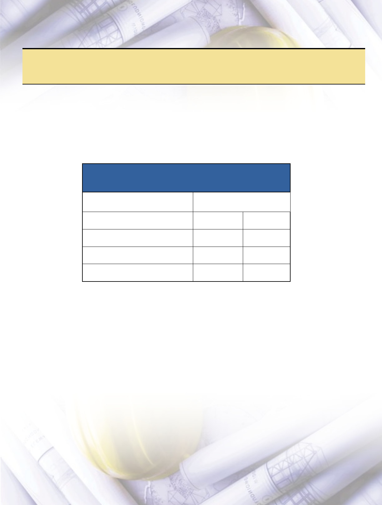
Table 310.15(B)(2)(c)
Ambient Temperature Adjustments for Raceways
Exposed to Sunlight On or Above Rooftops
Distance Above Roof to Bottom of Conduit Temperature Added
C F
0 – ½ in. 33 60
Above ½ in. to 3½ in. 22 40
Above 3½ in. to 12 in. 17 30
Above 12 in. to 36 in. 14 25
(Figure 310–5)
NAME TITLE
COMPANY
MAILING ADDRESS (Cannot ship to PO Boxes)
CITY STATE ZIP
PHONE FAX
E-MAIL ADDRESS WEB SITE
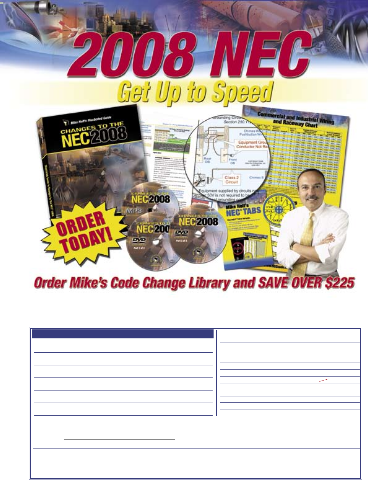
Mike Holt Enterprises, Inc.
3604 Parkway Blvd. Suite 3, Leesburg, FL. 34748 •
1.888.NEC.CODE • 1.352.360.2620 • FAX 1.352.360.0983 • E-mail: Info@MikeHolt.com
Visit www.MikeHolt.com to Order Online
Changes to the NEC 2008 Textbook $48
Online Training Part 1 (8 hours) $89
Online Training Part 2 (8 hours) $89
Textbook and DVD Program (2 DVDs) $198
Code Tabs $12
MP3 Audio CD $59
Code Change Library (includes everything above) List $495 You Pay $269
2008 NEC Spiral Code book $79
2008 NEC Paper Back Code book $75
2008 NEC Handbook $130
❏
❏
❏
❏
❏
❏
❏
❏
❏
❏
❏ CHECK ❏ VISA ❏ MASTER CARD ❏ DISCOVER ❏ AMEX ❏ MONEY ORDER
CREDIT CARD # : EXP. DATE: ________
3 or 4 digit security number on front for AmEx on back for all others:
Sub-Total $ ________
Sales Tax FLORIDA RESIDENTS ONLY add 6% $ ________
Shipping (4% of Total Price) – Minimum $7.50 $ ________
TOTAL $ ________
2008 Code Change Library Order Form
All prices and availability are subject to change. • If you are not 100% satisfied with your order, return it within 10 days and receive a full refund excluding shipping and handling.
Mike Holt’s Illustrated Guide to Changes to the NEC 2008 textbook has been completely
redesigned with over 330 pages of easy-to-understand text. Practice questions and answers
have also been added to give you the ultimate learning experience.
Also Available
*Volume discounts available, please call our office for more information
23
Utility
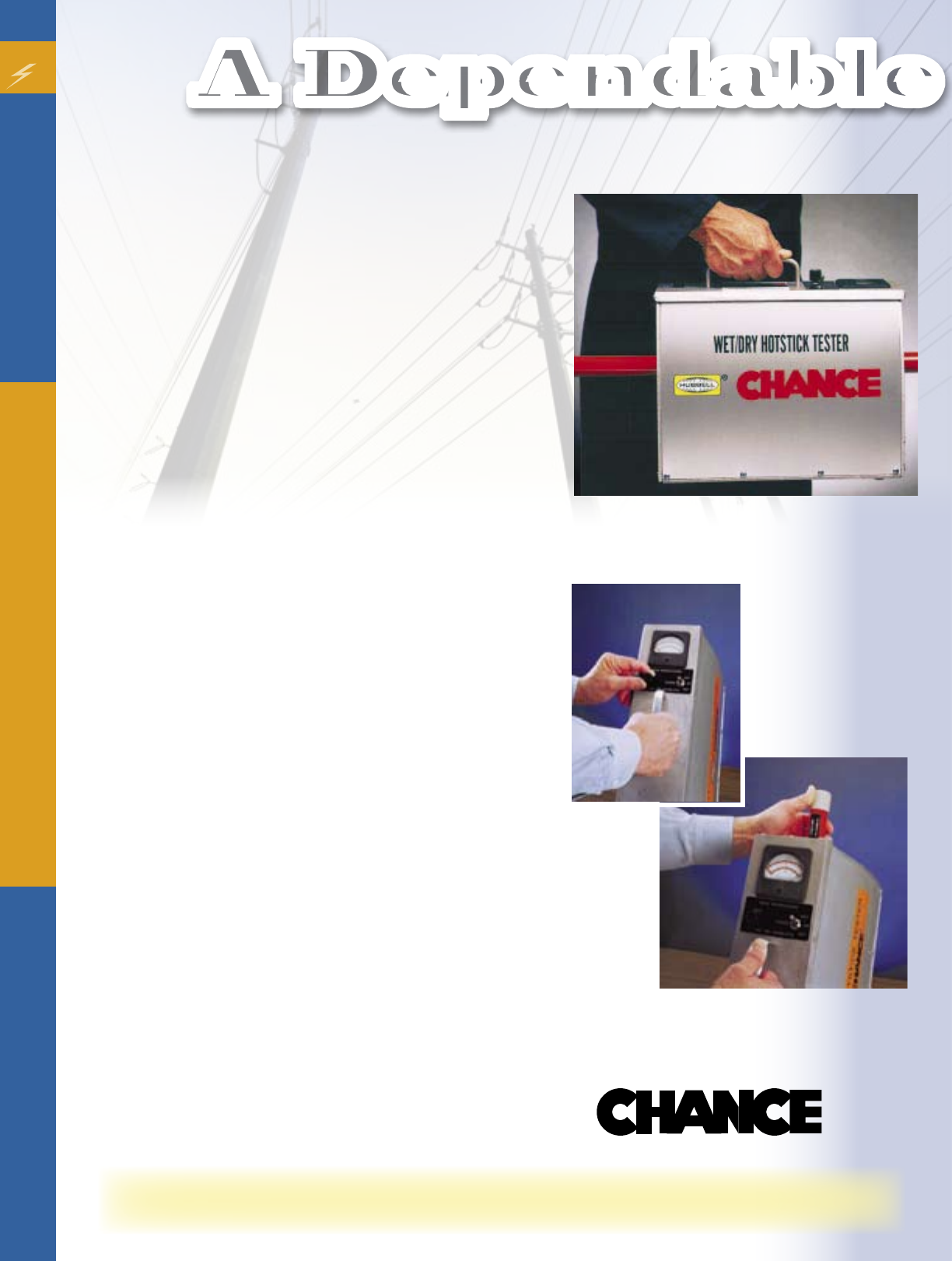
New and Improved Wet/Dry
Hot-stick Tester
Test procedures specified by IEEE and OSHA can seem men-
acing, but not those about how to test live-line tools.
This tester makes it easy for you to “get with the program.”
It’s based on the original Chance Hot Stick Tester used over
the years by conscientious utilities, which now has advanced
their safety programs into uniform regulations.
It’s a common-sense preventive measure for the responsible
use of insulated tools on energized transmission and distri-
bution lines.
On-site Portability, Two Voltages Cover the Globe
For compliance with industry standards, this tester features
wet and dry modes selected by a toggle switch. A portable
and self-contained unit, the tester is convenient for spot
checks at field jobsites or periodic diagnostics in the work-
shop. It can test up to a 3-inch-diameter of any brand fiber-
glass-reinforced-plastic (FRP) live-line tool.
Numeric Readout from Analog Meter
In a form one person can carry and operate, the tester ac
tually performs the equivalent of full-scale test setups for
both Wet (75kV per foot) and Dry (100kV per foot). In either
case, the meter displays the increase in leakage current due
to placing the meter on a hot stick. This value may be com-
pared to the level allowable by the individual utility. This
quantitative test result immediately indicates the stick’s true
leakage condition, inside and out. It detects leakage currents
due to surface and internal contamination, independent of
stray currents because the tester is “zeroed” while empty
before each use.
Wet/Dry Switch Upgrade Available for Old Models
If you own a previous Chance LS-80 or LS-81 Tester with a
Pass/Fail meter, the Wet/Dry selector-switch circuitry can be
factory retrofit. Simply contact the Chance Tool Repair Cen-
ter by phone (573-682-8748) or facsimile (573-682-8647). A
repair-service specialist will assign a Reference Number, give
you a cost estimate within 48 hours and usually complete the
job in one to two weeks.
Operating Ease, free Videotape Offer
Simple to operate, the tester comes with a Check Bar to
verify the unit is functional before each use. Besides a fully
illustrated Owners Manual, which must be read and under-
stood before operating the tester, a seven-minute videotape
is included with each unit.
Now with switchable modes for easy compliance with industry test specs
For wet or dry testing, unit simply takes overlapping readings
along the full length of any hot stick up to 3-inch-diameter.
A Dependable Combination
®
Before each use, set the meter needle to zero with nothing in the
Tester and self-test the Tester with the Check Bar included.
Description Part No.
1 Pole & Ferrule E403-2742P 11⁄16” Outside Diameter
2 Tube P403-0987P 11⁄4” Outside Diameter
3 Tube P403-0988P 11⁄2” Outside Diameter
4 Tube P403-0989P 111⁄16” Outside Diameter
5 Tube P403-0990P 17⁄8” Outside Diameter
6 Tube P403-0991P 21⁄16” Outside Diameter
7 Tube P403-0992P 21⁄4” Outside Diameter
8 Base Tube P403-0999P 21⁄2” Outside Diameter
9 Base Tube P403-0998P 21⁄4” Outside Diameter
10 Base Tube P403-0997P 21⁄16” Outside Diameter
11 Base Tube P403-0996P 17⁄8” Outside Diameter
12 Base Tube P403-0995P 111⁄16” Outside Diameter
13 Base Tube P403-0994P 11⁄2” Outside Diameter
14 Base Tube P403-0993P 11⁄4” Outside Diameter
15 Bottom Cap P403-1014P
16 Bottom Cap P403-1013P
17 Bottom Cap P403-1012P
18 Bottom Cap P403-1011P
19 Bottom Cap P403-1010P
20 Bottom Cap P403-1009P
21 Bottom Cap P403-1008P
22 Plug P403-1007P
23 Plug P403-1006P
24 Plug P403-1005P
25 Plug P403-1004P
26 Plug P403-1003P
27 Plug P403-1002P
28 Plug P403-1001P
29 Thumbscrew P403-0467P
30 Spring P403-2351P
31 Spring P403-2352P
32 Retainer P403-1977P
33 Button P403-3001P
34 Button P403-3002P
35 Mach. Screw P001-0309P
36 Drive Lock Pin P001-0419P
37 Universal Fitting P403-2514P
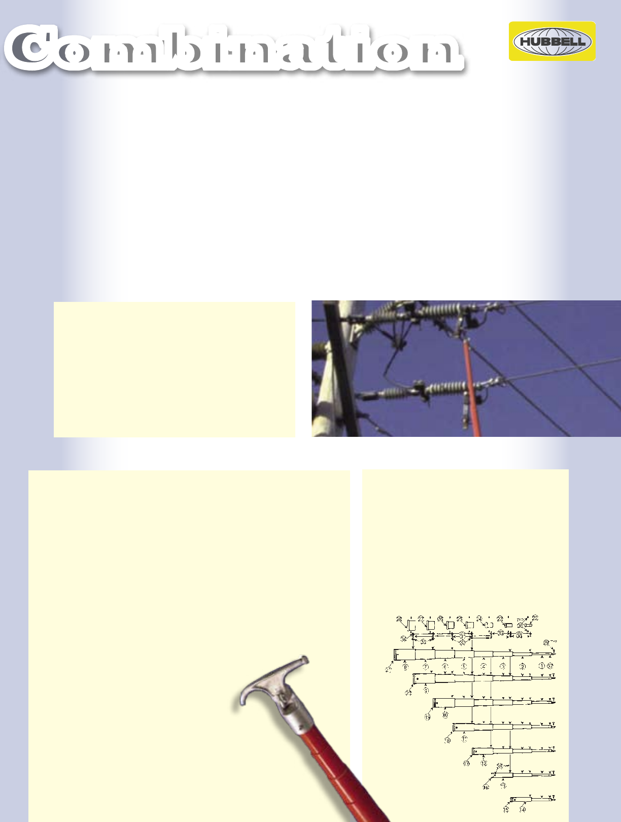
A Dependable Combination
More than sixty-five years of safety driven innovation and service
are incorporated into Chance Telescopic Tools.
Chance Tools are dependable and rugged. They are designed to meet the rigorous electrical and mechanical demands of daily
use by crews. Chance foam-core fiberglass poles are tested to the equivalent of 100kV per foot before they go into a hot-line
tool. With Chance, you have the toughest, longest lasting, most dependable hot-line tools in the industry.
Chance telescopic tool design includes features that make field use simple and trouble free. Our button locking system
doesn’t pinch fingers or damage gloves. Air cushioning action protects fiberglass sections when they are retracted and our
glossy surface is easily restored to its original luster after cleaning. Chance tool features provide years of reliable service.
Sticks For Small Vehicles
When storage space is extremely tight, a 25’ Telescoping Tool is available that compacts down to 4’.
Telescoping Tool Repair Kits
BUTTON & SPRING KITS — With normal care and maintenance, Chance Telescoping Tools have long service lives, but when
repairs are necessary, complete kits are available containing all of the buttons and springs needed to repair particular length
sticks. Refer to the cross reference below for the individual kit part numbers.
Standard Duty Heavy Duty Button &
Tool Cat. No. Tool Cat. No. Spring Kit No.
C403-1023 T403-1245
C403-1017 C403-1597 T403-1246
C403-1018 C403-1598 T403-1247
C403-1019 C403-1599 T403-1248
C403-1020 C403-1600 T403-1249
C403-1021 C403-1601 T403-1250
C403-1022 C403-1602 T403-1251
T403-2205 T403-1248
C403-1739 T403-1251
Replacement Parts List for Standard Duty Telescoping Disconnect Tool
(If only a single part is required, the correct part number can be ordered, referring to the below drawing and table.)
3
C403-1022
C403-1021 -
C403-1020 -
C403-1019 -
C403-1018 -
C403-1017 -
C403-1023 -
®
POWER SYSTEMS, INC.
Contractor
25
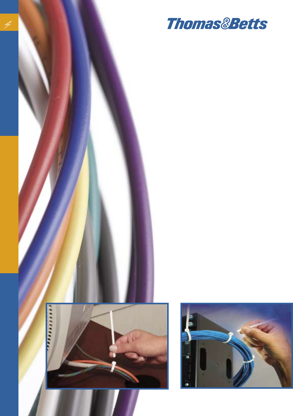
This innovative new product will help differentiate Thomas & Betts
from the large number of general purpose cable tie manufacturers
worldwide. Twist Tail® is a perfect complement to Ty-Rap®. This
product is ideal for the general application user who wants a simple
cable tie that installs quickly.
The new “twist-off” tail means no tools and no sharp edges. This
allows the tail to be easily removed by bending the tail back and
forth and easily twisting off the tail after the cable tie is installed.
This valuable, time saving feature allows you to use the “tool-
less” approach to cable ties, as well as work with limited space
where you cannot fit a cut-off tool.
TwistTail makes tail removal easy with its unique, patent-
pending design but still provides a full 50 lbs. minimum loop
tensile strength — perfect for any general-purpose cable tie
application.
The Twist Tail® is available in 7”, 11” and 14” lengths to give
you a wide variety of bundling options. It is also available
in white to differentiate from standard cable ties or in UV-
resistant black for outdoor applications. Twist Tail® is UL
recognized.
When strength, aesthetics, reliability and performance
are required, knowledgeable professionals turn to the
original and the best source for cable ties and accessories
— Thomas & Betts.
Catamount® Twist Tail®
The highly anticipated
cable tie is here!
Thomas & Betts brands have built a reputation for reliability and innovation. From oor boxes,
pre-fab components and strut fasteners to connectors, wiring duct and cable ties, we design
our products for faster, easier installation to help lower your install time and cost. And our
nationwide network of more than 6,000 distributor partners makes our innovative solutions
easy for you to nd! For more information contact your local Irby sales representative.
Sign up online at www.irby.com.
Click on SUBSCRIBE TO IRBY CIRCUIT
and start receiving the next issue!
An Irby Co. Publication
CIRCUIT
AN IRBY CO. PUBLICAT I ON
Volume 4
Issue 1
2008
inside:
Presidents Letter pg. 1
Manage your Inventory
with iStock pg. 2
Nuclear Power: Clean-Air
Energy Today and for
the Future pg. 5
Irby: More Services.
More Value. pg. 7
Going Green with
Lighting pg. 10
Remanufacturing, An
Effective Choice pg. 13
Relationship for Repair
pg. 16
Increase Productivity,
SIMpull THHN pg. 19
New Products pg. 21
Upcoming Trade Show
Events pg. 22
Green
Power FO R
THE Future
CIRCUIT
AN IRBY CO. PUBLICAT I ON
Volume 3
Issue 2
2007
inside:
Power
to the
People
Maintaining Your
Most Powerful Resource
CIRCUIT
AN IRBY CO. PUBLICAT I ON
Volume 3
Issue 3
2007
inside:
Letter from the President
pg. 1
Cooper Invision™ :
Pro-active Approach to
Reducing Downtime pg. 4
Lock in Safety:
3M™ PanelSafe™ pg. 7
Changing Workforce
Demographics Transform
Manufacturing pg. 10
FactoryTalk
®
: Where
Production Control and
Information Systems Meet
pg. 11
Increase Productivity:
Modicon
®
M3405™ pg. 14
Pulling is Believing:
Romex
®
Simpull
™
pg. 16
The Truth About CFLs
pg. 18
Irby’s Technical Products
Group: Your Experts on Call
pg. 19
New Products pg. 21
Upcoming Industry & Trade
Show Events pg. 22
Automation
and
Your Business
A profitable, productive partnership
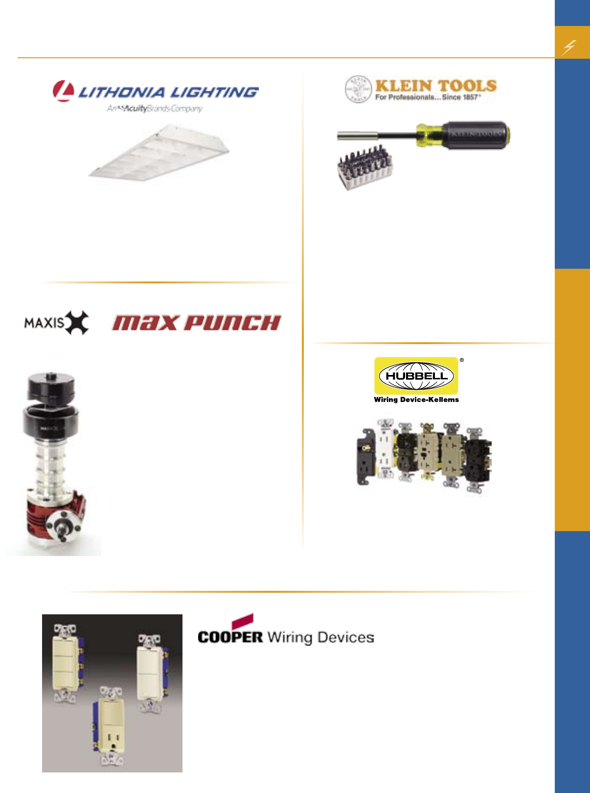
3M Fire Production Products
•The complete line of 3M fire protection products helps prevent
fire, smoke, toxic fumes and moisture from passing through
penetrations in fire-rated walls and floors.
•The easy-to-install products are suitable for a wide variety
of firestop applications, including plastic pipes, metal pipes,
HVAC ductwork, cables, construction gaps, grease ducts, wall
tops and control joints.
New Products
POLYPRO® Type 4X Polyester Enclosures
•POLYPRO® features versatile; non-glass filled polyester to
safely house electronic controls indoors and out
•A cost-effective alternative to aluminum and stainless
steel, corrosion-fighting polyester is also lightweight and
easy to modify
•POLYPRO® is flame resistant and provides ultraviolet
protection while maintaining a high environmental seal
Steel City® 68R Recessed Covers
Aesthetic Recessed Service Made Affordable!
Plug in power and communication cords, and then close the lid
to hide unsightly plugs and receptacles below the floor!
• Unique cover provides aesthetic recessed service with cost-
effective box options for concrete, wood sub-floor and raised
floor applications
• Patented lid can be rotated to expose a small opening for
cords, enabling the lid to close flush with the floor while in
use
• Cover accepts one duplex or GFCI receptacle – no special
device plates required (receptacle purchased separately)
• Cover accepts up to two communications jacks – includes
one 2-port keystone data plate and one blank data plate for
custom cut-outs or power-only applications (communications
jacks purchased separately)
• Nonmetallic covers are available in black, gray, beige and
brown. Black covers are available with an optional brass or
aluminum flange.
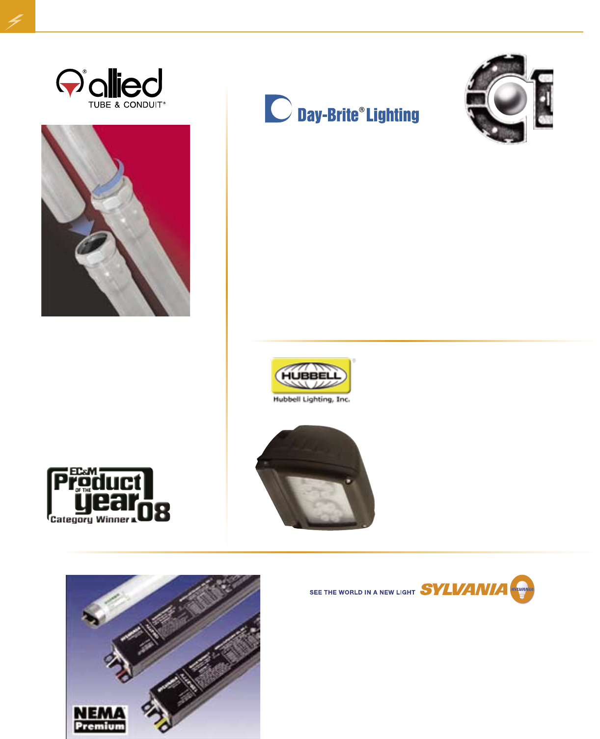
Portable Generators from Generac Power
Systems
•From the smallest needs to the largest with sizes from
1,800 to 17,500 Watts*
•Easy to use in a variety of applications from camping
to emergency home backup
•Quality engineering and design
•Durable construction for rugged reliability
• Long life engines for years of dependable perfor-
mance
*Full product line available in 2009
27
New Products 28
•Hubbell offers TR code compliant devices for
residential and commercial applications
•Available in decorator, standard and GFCI styles
•Spring-loaded shutters allow plugs to enter but
keep single pronged items like keys, pins and
screwdrivers out
Magnetic Screwdriver with 32-Piece
Tamperproof Bit Set
•Cushion-grip handle for greater torque and comfort
•
Sturdy bit and screw holding magnet allows for
screws to fit securely in place for easy use
•
Includes complete tamperproof bit set in block
•
TORX® is a registered trademark of Acument
Intellectual Properties, LLC
•TORQ-SET® and Tri-Wing® are registered
trademarks of Phillips Screw Co.
Assembled in USA of US and imported components.
An advanced knockout tool used with a
cordless drill to draw punch dies together for
quick accurate knockouts.
No hydraulics, no ratcheting, no mess.
Compatible with your current punch dies.
2 inch knockout in 4 seconds.
4 inch knockout in 6 seconds.
MP-01CS
•Max Punch
•½ inch – 4 inch die set
•Step drill bit and Maxis Marksman
MP-01SD
•Max Punch
•½ inch – 2 inch die set
•Step drill bit and Maxis Marksman
MP-01
•Max Punch only
Commercial Grade Decorator Combination Devices
•15A 120/277V/AC rating is ideal for incandescent or fluorescent lighting fixtures
typical in commercial applications
•Thermoplastic rocker, top and back body are virtually unbreakable for durable
performance
•Available in Almond, Light Almond, Ivory and White
•Back wire clamps on side terminals provide for easy installation of #12 and #14
gauge wire
•Automatic grounding system on all devices
ES8
• High performance louver
• 2-lamp profile - 44% savings compared to
3-lamp T8
• Full balanced illumination of the space
New Products
29 New Products
Capri One BY CAPRI LIGHTING
Capri One is a modular downlight system designed for speed and flexibility.
There are three components to the Capri One system.
Metal frames
• Can be ordered for 4”, 6”, 8” or 10” apertures, with remodel and
sloped ceiling options available.
Wide variety of electrical systems
• The electrical systems are designed around either incandescent,
compact fluorescent, or HID lamp sources of all wattages.
Broad selection of Capri One trims
• Trims can be ordered with lenses or baffles, and many are listed for
use in wet location areas.
Allied’s Kwik-Fit® Compression EMT
•Reduce installation time by 50%
• Eliminates the need to purchase, store,
or install separate couplings
• E-Z Pull® interior finish provides a
smooth raceway for fast wire-pulling
• Strength combined with ductility for
easy bending
•Hot-galvanized steel for durability
Sylvania Quicktronic High Efficiency T8 Universal
Voltage Ballast
•Standard QHE ballasts offered in low ballast factor, normal
ballast factor, and high ballast factor models
•UL Type CC (commercial cabinet) rated units in low ballast factor
and normal ballast factor models
•Features LSC (lamp striation control) to minimize striations in T8
energy saving lamps
Laredo LCC Series
(LED version shown)
•The compact Laredo is designed for
entrance and single story perimeter
lighting
•6-12 foot applications
•Available in energy-saving Pulse Start,
CFL, HPS and LED
•Full cut off, StarView compliant
• Neighbor friendly, CSA certified to UL
1598 for use in wet locations
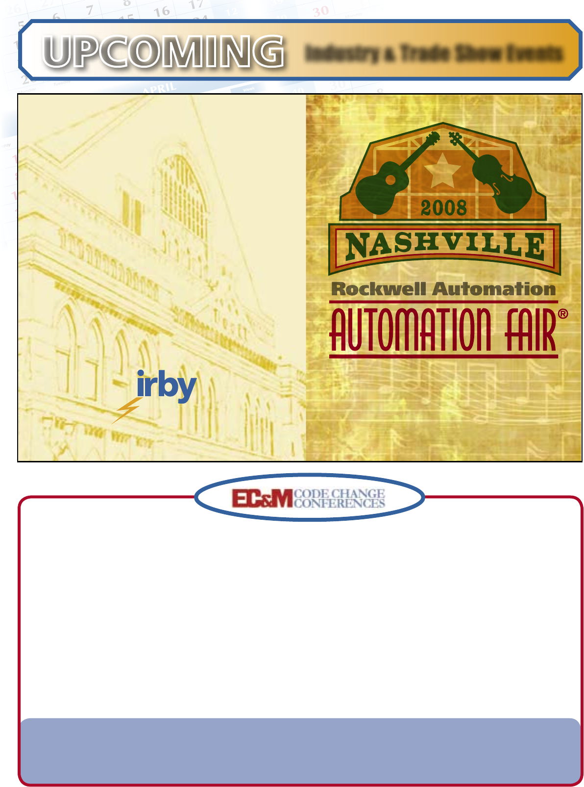
UPCOMING Industry & Trade Show Events
The 2008 NEC is Here!
LEARN ABOUT THE CHANGES IN THIS NEW CODE CYCLE BY ATTENDING THE PREMIER SOURCE OF
NEC INFORMATION AND TRAINING: EC&M SEMINARS’ 2008 NEC CODE CHANGE CONFERENCES.
In two informative and interest-filled days, you’ll learn about major NEC changes that will impact your work,
whether you’re an electrician, contractor, engineer, designer, or plant/facility maintenance person.
Learn from Mike Holt, nationally recognized NEC authority and trainer.
View and discuss new products and technologies with Exhibitor/Sponsors:
• Many electrical product manufacturers will be exhibiting their products at each breakfast, lunch, and session break.
• Technical discussions will be held at each exhibition booth.
• Hand out material will be distributed by each exhibitor
Two conferences are scheduled for 2008:
PORTLAND, OR: September 4 - 5, 2008
SAN ANTONIO, TX: September 8 – 9, 2008
Attend Automation Fair
and learn how to:
• Improve your product’s time-to-market
• Increase your company’s profitability
• Develop asset management and
optimization strategies
• Manage manufacturing business risk
Irby will host the Automation Fair 2008, at the
famed Gaylord Opryland Complex in Nashville,
Tennessee on November 19-20.
Make your plans now! If you’re interested in
attending the 2008 Rockwell Automation Fair,
contact your local Irby sales representative for
more information.
November 19-20, 2008
Nashville, Tennessee USA
Gaylord Opryland Complex
IRBY ELECTRIC EXPRESS
Sugar Valley Market Place
6601 Sugar Valley Dr., Suite 110
Nashville, TN 37211
615.941.5453
IRBY ELECTRIC EXPRESS
Wall Street Center at Campbell Station
2021 Wall St.
Spring Hill, TN 37174
615.302.2725
TEXAS
655 N. Fairfield
Amarillo, TX 79117
806.383.2100
9705 Beck Circle
Austin, TX 78766
512.837.2113
7125 Belton St.
Fort Worth, TX 76118
817.284.0868
1945 Tellepsen St.
Houston, TX 77023
713.923.4400
5908 La Colonia
San Antonio, TX 78218
210.661.2348
1204 Waterall St.
Texarkana, TX 75501
903.791.9000
ALABAMA
144 Woodall Rd.
Decatur, AL 35601
256.350.2491
2341 N. Range St.
Dothan, AL 36303
334.793.2313
300 N. Water St.
Mobile, AL 36602
251.433.3911
675 Hornady Dr.
Monroeville, AL 36460
251.575.3127
211 N. Race St.
Selma, AL 36703
334.872.6238
ARKANSAS
122 Sanford St.
Hot Springs, AR 71901
501.321.1660
6100 Scott Hamilton Dr.
Little Rock, AR 72209
501.565.4466
COLORADO
4720 Lima St.
Denver, CO 80239
303.576.0656
FLORIDA
Beach Commerce Park
102-B Amar Place
Panama City Beach, FL 32413
850.230.0588
5208 Sycamore Dr.
Pensacola, FL 32503
850.476.5580
8820 N. US 301
Wildwood, FL 34785
352.748.2051
GEORGIA
1060-D Triad Court
Marietta, GA 30062
770.422.1005
KENTUCKY
2371 Palumbo Dr.
Lexington, KY 40509
859.335.9854
LOUISIANA
7984 S. Commerce Ave.
Baton Rouge, LA 70815
225.927.0500
19146 Hwy 190 E
Hammond, LA 70401
985.419.8200
703 Stella St.
West Monroe, LA 71291
318.325.2307
IRBY LIGHTING
703 Stella St.
West Monroe, LA 71291
318.325.2307
1211 Airport Dr.
Shreveport, LA 71107
318.221.8501
MAINE
977 West River Rd.
Waterville, ME 04901
207.872.7921
MISSISSIPPI
815 S. State St.
Jackson, MS 39201
601.969.1811
IRBY ELECTRIC EXPRESS
1511 Gardner Blvd.
Columbus, MS 39702
662.327.3500
9175 A Hwy 49 South
Gulfport, MS 39505
228.865.9774
1314 W. Pine St.
Hattiesburg, MS 39401
601.544.1611
815 S. President St.
Jackson, MS 39201
601.969.1811
1260 Parklane Rd.
McComb, MS 39648
601.249.2913
IRBY ELECTRIC EXPRESS
1380 Roebuck Dr.
Meridian, MS 39301
601.553.8614
3733 14th St.
Pascagoula, MS 39567
228.762.7411
601 Crossover Rd.
Tupelo, MS 38801
662.842.0835
IRBY ELECTRIC EXPRESS
2690 Hwy 61 North
Vicksburg, MS 39183
601.636.7382
MISSOURI
12628 E. Hwy. 86
Neosho, MO 64850
417.455.2160
NEW MEXICO
2417 Aztec Rd.
Albuquerque, NM 87107
505.353.5820
NEW YORK
E. 547 Genesee
Fayetteville, NY 13066
315.329.0038
4583 Buckley Rd.
Liverpool, NY 13088
315.622.0020
NORTH CAROLINA
2913 South Church St.
Rocky Mount, NC 27803
252.442.0154
OKLAHOMA
1208 W. Poplar
Enid, OK 73703
580.242.3700
2500 Northeast Lincoln Rd.
Idabel, OK 74745
580.286.2469
1910 Roosevelt St.
Muskogee, OK 74401
918.687.4474
1700 S. Prospect
Oklahoma City, OK 73129
405.672.6737
10302 E. 58th St.
Tulsa, OK 74146
918.250.2491
5920 E. 12th St.
Tulsa, OK 74112
918.836.5500
TENNESSEE
507-A W. 26th St.
Chattanooga, TN 37408
423.624.6414
228 West Spring St.
Cookeville, TN 38501
931.526.2646
IRBY ELECTRIC EXPRESS
The Village Place Shopping Cntr.
102 Lumber Dr., Suite E
Franklin, TN 37064
615.591.7380
1159 Hwy 45 Bypass
Jackson, TN 38301
731.668.4094
501 W. Mountain View
Johnson City, TN 37604
423.283.4987
1284 Heil Quaker Blvd.
LaVergne, TN 37086
615.280.3300
IRBY ELECTRIC EXPRESS
Legacy Point Business Cntr.
2805 Old Fort Pkwy, Suite G
Murfreesboro, TN 37128
615.895.8556
I B L
UTILITY, COMMERCIAL, INDUSTRIAL & CONTRACTOR
COMMERCIAL, INDUSTRIAL & CONTRACTOR
UTILITY CORPORATE OFFICE
★
★
an irby company
MINNESOTA
3776 West Broadway
Minneapolis, MN 55422
763.588.0545
16260 Asher Ave.
Rosemount, MN 55068
763.588.0545
IOWA
1234 1st Avenue South
Fort Dodge, IA 50501
515.573.2887
SOUTH DAKOTA
1575 B Samco Road
Rapid City, SD 57702
605.348.1888
PRSRT STD
US Postage
PAID
Jackson, MS
Permit No. 369
P. O. Box 1819
Jackson, MS 39215-1819
High Voltage
Testing and
Safety Products
An irby company
MINNESOTA
3776 West Broadway
Minneapolis, MN 55422
763.588.0545
NORTH DAKOTA
1472 43rd Street NW
Fargo, ND 58102
800.742.8054
