Brochure
2014-11-11
: Pdf 103985-Brochure 103985-Brochure 004810 Batch12 unilog
Open the PDF directly: View PDF ![]() .
.
Page Count: 57

GE Intelligent Platforms RSTi MODBUS TCP/IP Starter Guide
Page | 1
PACSystems RSTi MODBUS TCP/IP
Getting Started Guide
Distributed Slice I/O
GE Intelligent Platforms RSTi MODBUS TCP/IP Starter Guide
Page | 2
August 2012
Table of Content
Starter Kit Introduction Page 3
Introduction to RSTi Page 5
Getting Started - Assembly Page 6
Configuring RSTi Page 8
Downloading RSTi Configuration Page 12
Proficy Machine Edition MODBUS TCP/IP Network Discovery Tool Page 13
Understanding RSTi LED Status Page 14
Power Distribution Options Page 16
Introduction to IO Guide Pro Page 17
RSTi Part Numbers Page 19
Sample RSTi Configuration Page 20
Modbus TCP Network Interface Specifications and Drawing Page 24
PROFINET Network Interface Specifications and Drawing Page 21
PROFIBUS DP Network Interface Specifications and Drawing Page 22
DeviceNet Network Interface Specifications and Drawing Page 23
Modbus Serial RS-232 Network Interface Specifications and Drawing Page 25
Modbus Serial RS-485 Network Interface Specifications and Drawing Page 26
Ethernet IP Network Interface Specifications and Drawing Page 27
EtherCAT Network Interface Specifications and Drawing Page 28
CANOpen Network Interface Specifications and Drawing Page 29
CC-Link Network Interface Specifications and Drawing Page 30
Discrete Inputs Specifications and Drawings Page 31
Discrete Outputs Specifications and Drawings Page 34
Analog Inputs Specifications and Drawings Page 37
Analog Outputs Specifications and Drawings Page 40
Serial Communications Module Specifications and Drawings Page 43
Motion Modules – High Speed Counting Specifications and Drawings Page 45
Motion Modules – PWM and Pulse Train Specifications and Drawings Page 48
System Modules – Power Distribution, Bus Power Booster Page 49
GE Intelligent Platforms RSTi MODBUS TCP/IP Starter Guide
Page | 3
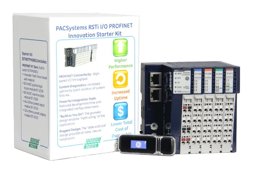
RSTi MODBUS TCP/IP Starter Kit
The RSTi MODBUS TCP/IP Starter Kit includes the following:
Innovation Starter Kit Flash Drive: The Flash drive includes various RSTi tools.
RSTi MODBUS TCP/IP Network Interface module (Part Number STXPNS001)
RSTi 8 points discrete input module, 24VDC positive logic (Part Number ST-1218)
RSTi 8 points discrete output module, 24VDC source, 0.5amps (Part Number ST-2328)
RSTi 4 channels analog input module, 4-20ma current (Part Number ST-3214)
RSTi 2 channels analog output module, 4-20ma current (Part Number ST-4212)
Items required that are not included in the starter kit:
DIN rail minimum length 6 inches long (150mm)
Narrow blade screwdriver or other tool to 1/8 to 1/16 inches (3mm to 4mm) wide for depressing the
spring clamp wiring terminal
24VDC power supply (minimum 1.5 amp, recommend 2 amps or larger
Controller with MODBUS TCP/IP connectivity
Ethernet cable
Items on Innovation Starter Kit Flash Drive:
RSTi Modbus Serial and Ethernet Network Interface Manual
RSTi PROFINET Interface Manual (GFK-2746)
RSTi PROFIBUS Network Interface Manual
RSTi DeviceNet Network Interface Manual
RSTi I/O Manual (GFK-2745)
RSTi CAD drawings
RSTi data sheets
RSTi IO Configuration Tool for DeviceNet, PROFIBUS, CANOpen, Ethernet IP, Modbus TCP and Modbus
serial
PROFINET GSDML file
PROFIBUS GSD file
GE Intelligent Platforms RSTi MODBUS TCP/IP Starter Guide
Page | 4
RXi Controller data sheets and manuals
RXi IPC data sheets and manuals
GE Control Solutions Catalog
GE Automation Solutions
Proficy MAChine Edition programming tool (45 day free evaluation)
And other tools
GE Intelligent Platforms RSTi MODBUS TCP/IP Starter Guide
Page | 5
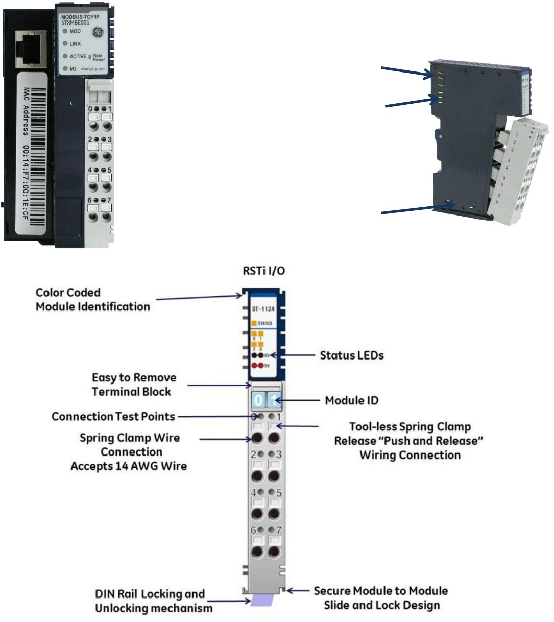
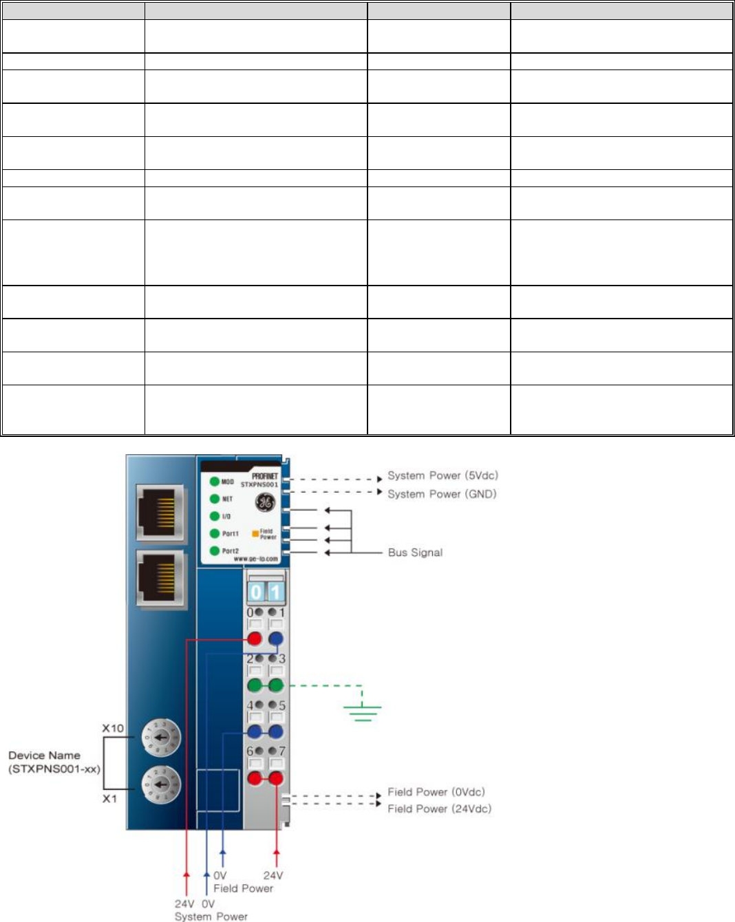
Key Features of the RSTi network Interface and I/O Modules
The RSTi innovative design enables module power, communications and field power to be passed from one
module to the next. The RSTi mechanical design provides integrated mechanical interlocking for securing
module to module and modules to DIN rail locking.
5VDC Bus pins
passes power from
one module to the
next.
Communications
passed from one
module to the next.
Field Bus power
passed from one
module to the next.
Module Power and System
Power
Pin 0 (24VDC) and Pin 1 (0VDC)
Field Ground
Pin 2 and Pin 3
Field Power (Field Power Supply
should be independent of
Module System Power
Pin 4 and Pin 5 (0VDC)
Pin 6 and Pin 7 (24VDC)
GE Intelligent Platforms RSTi MODBUS TCP/IP Starter Guide
Page | 6
Getting Started
Building the RSTi
Step 1: Open the individual boxes and remove modules.
Step 2: Attaching the MODBUS TCP/IP network adapter to the DIN rail:
Remove the end cover from the right side of the MODBUS TCP/IP Network Interface module (Part
Number STXMBE001) by sliding the end cover up. On the bottom of the network adapter release the
DIN rail locking mechanism by flipping the blue lever downward. Place the network interface module
on the DIN rail and engage the DIN rail locking mechanism by flipping the blue lever back to the
original position. The module should now be firmly secure on the DIN rail.
Step 3: Attaching the first I/O module:
Open the DIN rail locking mechanism on the bottom of the ST-1218 I/O module by flipping the blue
lever downward. Slide the I/O module onto the network interface module, from top to bottom, until it
is securely on the DIN rail. Lock the I/O module onto the DIN rail by engage the DIN rail locking
mechanism. (Flip the blue lever back to the original position).
Note: The RSTi does not limit the sequence of the I/O modules. For the purpose of the startup guide we will
place the modules in the following sequence.
1. MODBUS TCP/IP Network adapter (STXMBE001)
2. 24VDC discrete input module (ST-1218)
3. Analog input module (ST-3214)
4. Analog output module (ST-4212)
5. 24VDC discrete output module (ST-2328)
6. End cap cover
Step 4: Attach the remaining modules following the sequence in Step 3. Once all modules are securely
attached to the DIN rail place the end cap cover on the right most module.
GE Intelligent Platforms RSTi MODBUS TCP/IP Starter Guide
Page | 7
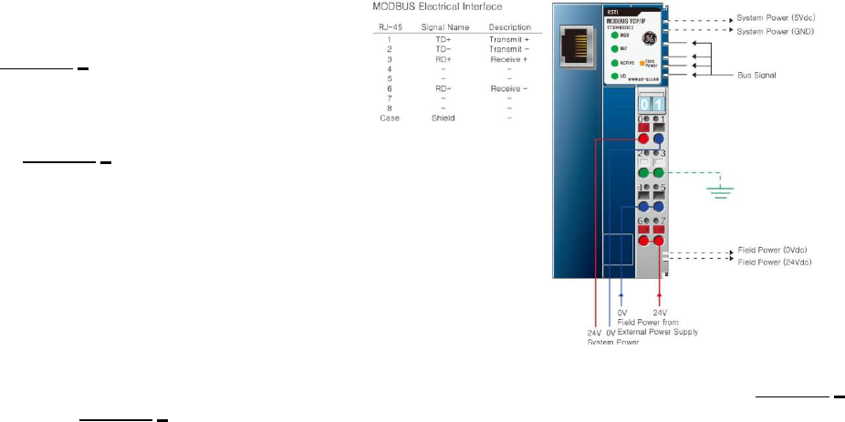
Step 5: Attaching 24VDC Power to the Network
Interface:
Connect + 24VDC from the power supply to
the terminal 0 of the MODBUS TCP/IP
Network Interface Module by pushing in on
the spring clamp release button (Red).
Attach 0VDC power from the power supply
to the terminal 1 of the MODBUS TCP/IP
Network Interface Module by pushing in on
the spring clamp release button (Black)
Note: The 24VDC power is used to power up the
network interface module. Internally the
24VDC is converted to 5VDC that is used for
the network interface module and is also
transferred to all the I/O modules attached
to the network interface. If field devices like motors and switches are going to be wired to the RSTi
Starter Kit a separate 24VDC power supply is required and should be connected +24VDC to terminal 6
and 0VDC to terminal 4. Attach terminal 2 to earth ground.
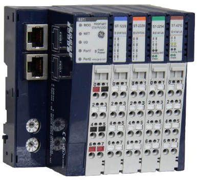
Step 6: Apply power to the RSTi and connect the Ethernet cable from the PC to the RSTi Modbus TCP/IP.
The following LEDs should be observed on the RSTi Network Interface and I/O modules.
MODBUS TCP/IP Network adapter (STXMBE001)
Mod LED – Steady Green ON
LINK LED – Green ON (If LED is off check cable connections to the PC)
ACTIVE LED – OFF (LED will be off until the PC sends activity to the RSTi)
I/O LED – Green ON indicating that I/O bus is working properly. If off check to make sure the
modules are seated properly.
Field Power LED – OFF if no power is applied to pins 4 or 5 (Ground) and pins 6 or 7 (+24VDC)
24VDC discrete input module (ST-1218)
Status LED – Green ON for normal operation.
Input LEDs – OFF unless an input has been connected and in the ON state.
Analog input module (ST-3214)
Status LED – Green ON for normal operation.
Input LEDs – Solid Red ON. No inputs wired to inputs, this is a normal operation. Diagnostics is
detecting no load or open channel.
Analog output module (ST-4212)
Status LED – Green ON for normal operation.
Output LEDs – Solid Green ON. Normal operation.
24VDC discrete output module (ST-2328)
Status LED – Green ON for normal operation.
Output LEDs – OFF. Normal operation.
GE Intelligent Platforms RSTi MODBUS TCP/IP Starter Guide
Page | 8
Configuring the RSTi from a PC running IO Guide Pro
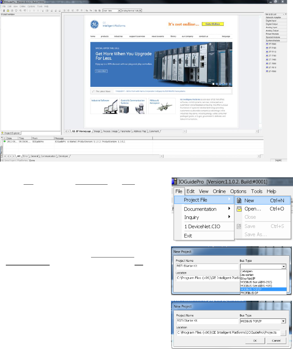
Step 1: Configuring the RSTi Modbus TCP/IP. Launch IO Guide Pro from either a standalone application or
from Proficy Machine Edition.
Step 2. Go to File, right click on Project File and New.
Step 3. Give your project a name like RSTi Starter Kit. Select
Modbus TCP/IP for the bus type and click on OK.
GE Intelligent Platforms RSTi MODBUS TCP/IP Starter Guide
Page | 9
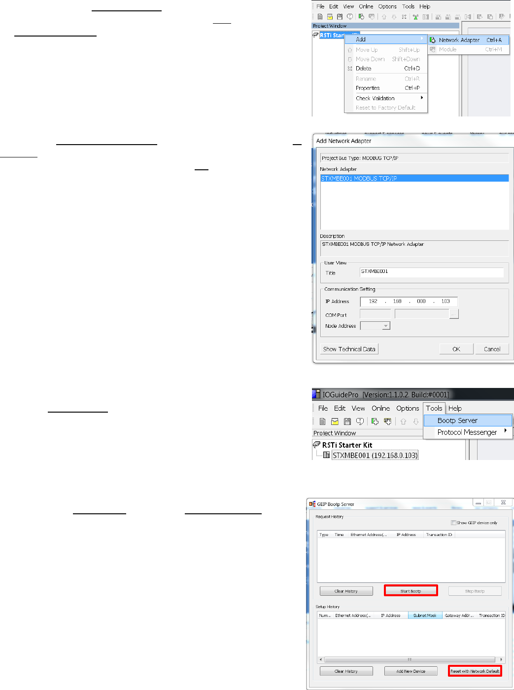
Step 4. Left click on RSTi Starter Kit (or what you called the
project) in the Project Window. Right click on Add and then click
on Network Adapter.
Step 5. The Add Network Adapter box should appear. Add the IP
address that you would like to assign the STXMBE001. For this
exercise 192.168.0.103 will be used. Click OK when IP address is
entered.
Step 6: Assigning IP Address to the RSTi Modbus TCP : Click on
Tools and Bootp Server.
Step 7: Click on Start Bootp. Reset with Network Default to
reset the STXMBE001.
GE Intelligent Platforms RSTi MODBUS TCP/IP Starter Guide
Page | 10
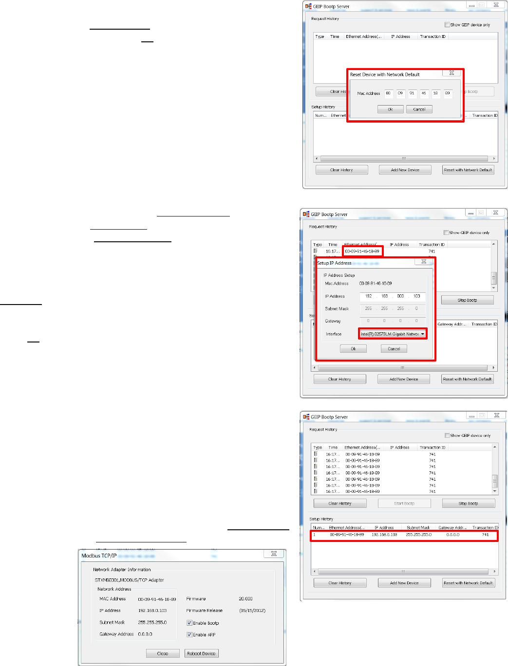
Step 8: The following will reset the STXMBE001 to factory
defaults. Enter the MAC address of the STXMBE001, located
below the Ethernet port. Click Ok when MAC address is
entered. The RSTi STXMBE001 will reset with the lights flashing
and returning to their normal state.
Step 9: After several seconds the Request History window will
display the device. Double Click on the MAC Address of the
STXMBE001 and the Setup IP Address window will appear. The
Bootp Server will update every couple seconds so the device
will reappear.
Enter the IP address that you want to use and click on
Interface to select the PC network that the STXMBE001 is
connected to.
Enter Ok.
Close the Bootp Server once the device with the new IP
addresses appears in the Setup History. The STXMBE001 is
now enabled with the new IP address. The IP address is stored
in the FLASH memory of the STXMBE001 and will not be lost
during power outage but can be changed at any time using
the same above procedures. Close GEIP Bootp server when
complete.
Note: You can right click on the IP address in the Setup History
window and click on Device Information to see detailed
information on
the interface.
GE Intelligent Platforms RSTi MODBUS TCP/IP Starter Guide
Page | 11
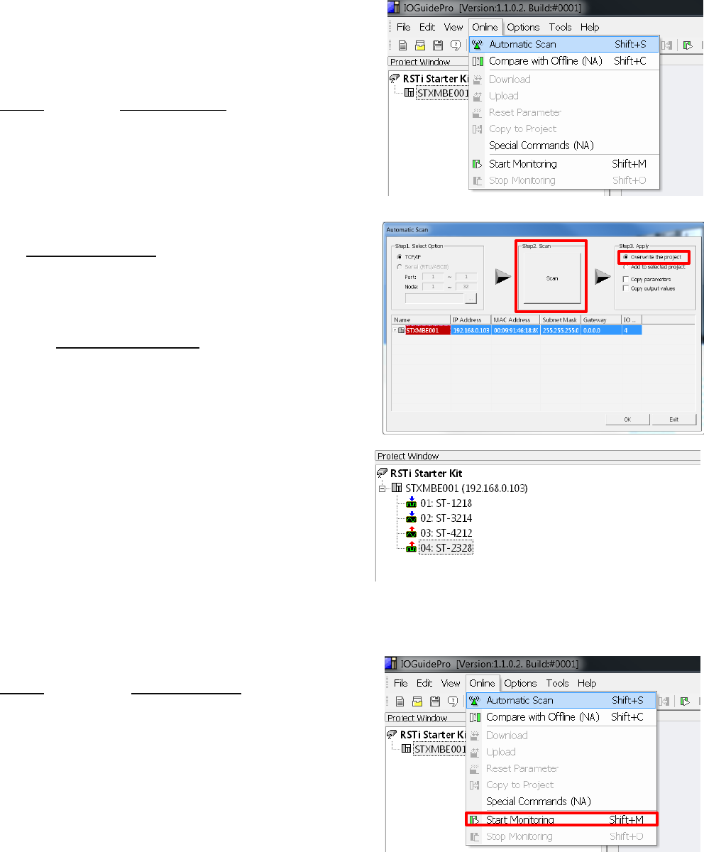
Step 10: Connecting to the STXMBE001. The following steps
will establish a connection with the STXMBE001 and enable
the user to view the configuration, monitor the status and
save the configuration to the IOGuidePro.
Click Online and select Automatic Scan.
Click the Step 2: Scan button. After several seconds the
STXMBE001 should appear with the IP and MAC address.
You can double click on the STXMBE001 and the list of
modules attached the STXMBE001 will appear.
Selecting the Overwrite the project radial and the tool will
download the configuration to the IOGuidePro once the Ok
is clicked.
The Project Window will reflect the configuration of your
system.
Click Online and click on Start Monitoring. The IOGuidePro
will now poll the STXMBE001.
You will notice the ACTIVE LED on the STXMBE001 will flash
showing activity.
GE Intelligent Platforms RSTi MODBUS TCP/IP Starter Guide
Page | 12
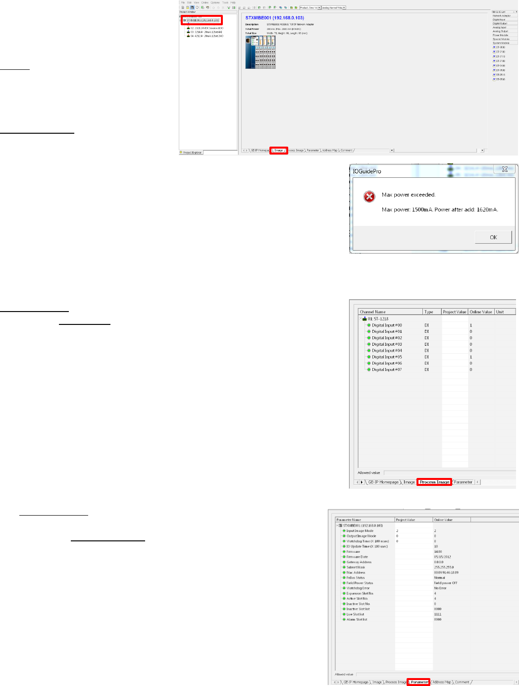
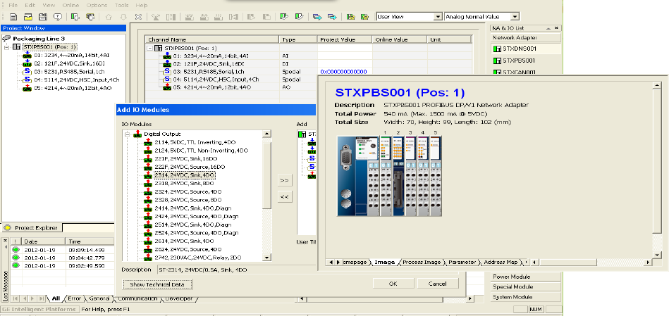
By clicking on the modules and the
tabs in the view window the user
can see a wide range of
information.
Image tab shows module
description, image and specification
data.
By clicking on the modules in the
Project Window such as STXMBE001
the Image tab will show the
modules along with loading of the
5VDC bus and the dimensions.
Note: The current modules consume 300mA of the 1500mA available
from the STXMBE001. If this data had been close to the 1500mA limit a
warning would pop up. When this occurs you should add a ST-7511
(with module ID and occupies a bus address) or ST-7111 (without module
ID and does not occupy a bus address). The ST-7x11 module must be
left of the module that exceeded the 1500mA. The ST-7x11provides an
additional 1500mA to all modules to the right of the ST-7x11.
Process Image tab displays the individual parts, data types and values.
When in the Monitoring mode it will display the status of inputs and
outputs.
The Parameter tab provides key information such as firmware
revision, date of revision and other system status of the modules
selected in the Project Window.
GE Intelligent Platforms RSTi MODBUS TCP/IP Starter Guide
Page | 13
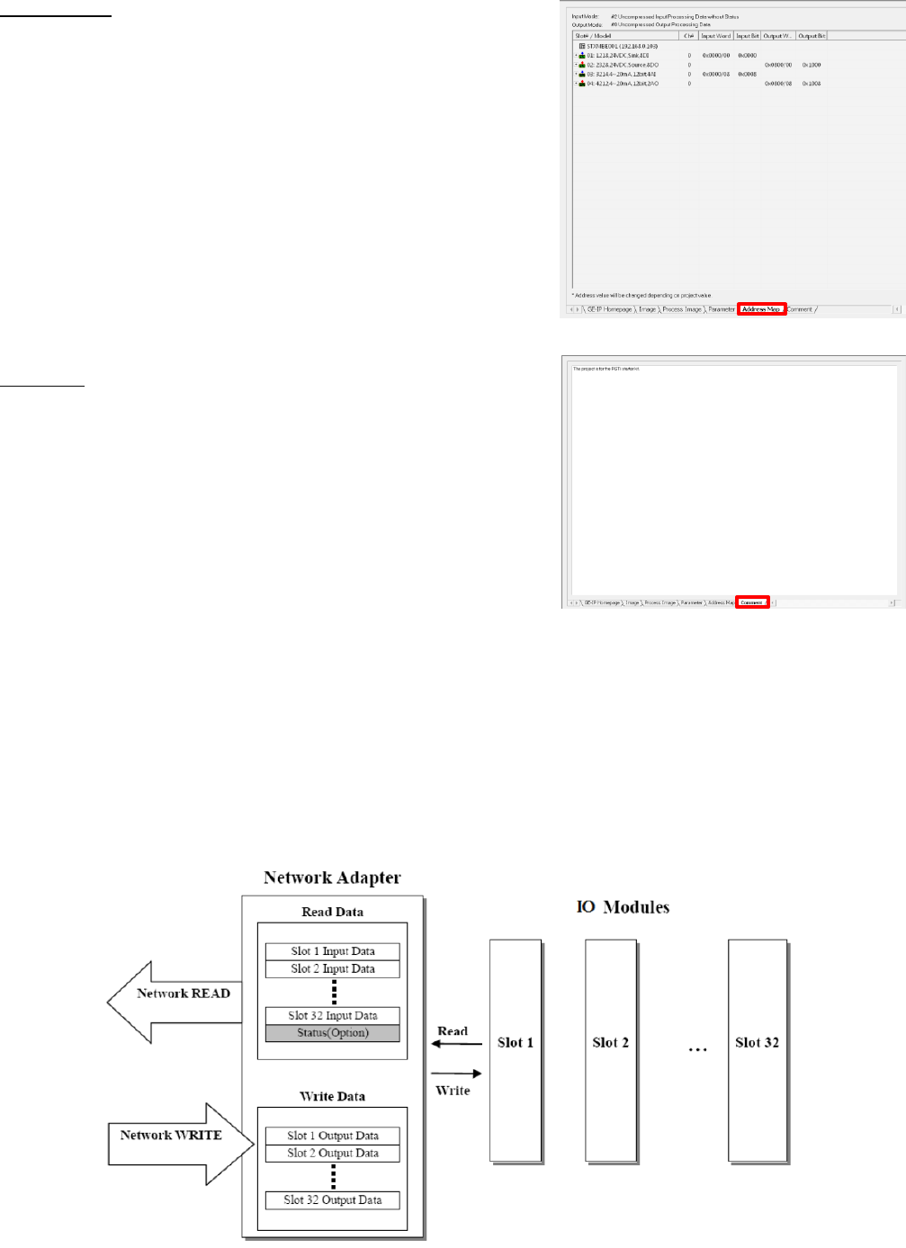
The Address Map tab lays out the addressing of each module that
data will be mapped to.
The Comment tab enables the user to document the application.
The text is saved in the project.
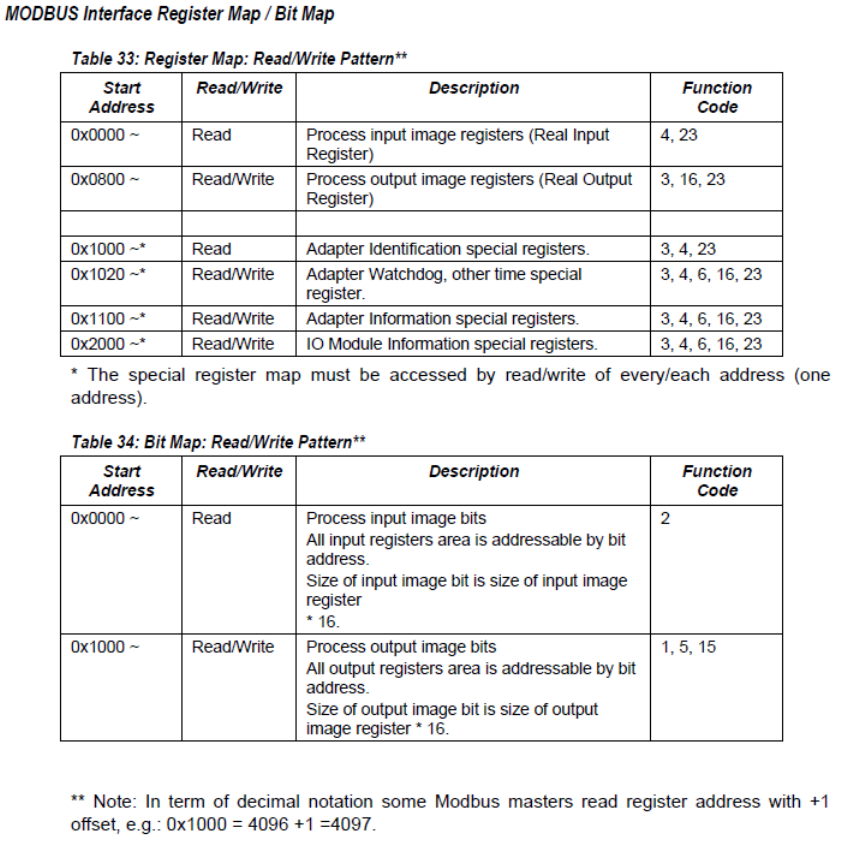
Transferring Data from RSTi to a controller
I/O Process Image Map
An IO module may have three types of data as I/O data, configuration parameter and memory register. The
data exchange between network adapter and IO modules is done via an I/O process image data by Bus
protocol. The following figure shows the data flow of process image between network adapter and IO
modules.
GE Intelligent Platforms RSTi MODBUS TCP/IP Starter Guide
Page | 14
Controlling and Monitoring I/O from IOGuidePro
The following steps will enable the user to exercise inputs and outputs using the Modbus TCP commands. The
Modbus Communications window in the Tools tab will enable you to enter the functions.

GE Intelligent Platforms RSTi MODBUS TCP/IP Starter Guide
Page | 15
Reading Hex data to and from the STXMBE001
The following example demonstrates how the input and output data is packed into the Hex addressing when
reading from the STXMBE001 Modbus TCP network interface configured as Uncompressed (The default for the
STXMBE001 is Uncompressed Input Processing). It is important to note that modules with only 4 or 8 bits of
data, such as a discrete in or output module, will have their data packed the next modules word data.
Starter Kit Memory Addressing Example with the following:
Discrete inputs (0) and (5) ON, on ST-1214
Analog inputs channels (0) 10.0mA and channel (1) 20mA, on ST-3214
Analog outputs channels (0) 10.0mA and channel (1) 20mA, on ST-4212
Discrete outputs (1), (2) and (4) forced ON, on ST-2328
All address are in Hex
ST-1214
Discrete Input
(8 Points)
ST-3214
Analog Input
(2 channels)
ST-4212
Analog Out
(2 channels)
ST-2328
Discrete Out
(8 Points)
Reading Input Registers
(Function 4) the first 3 Hex words
from STXMBE001.
Hex 000F FF05 FE21
Hex 000F FF05
FE21
21 represents
the inputs (0)
and (5) ON
Hex 000F FF05
FE21
Channel (0)
10mA
000F FF05 FE21
Channel (1)
20mA
Writing Multiple registers
(Function 16) first 3 Hex words
from STXMBE001.
Hex 0016 05FF 0FFF to set
analog output channel (0) to
20mA, channel (1) to 10mA and
turn outputs 1, 2 and 4 ON.
Hex 0016 05FF
0FFF
Writes 20mA to
channel (0)
0016 05FF 0FFF
Writes 10mA to
channel 1
Hex 0016 05FF
0FFF
Turns outputs 1,
2 and 4 ON
Reading Discrete Inputs
(Function 2) ST-1214 Input
Module
Hex 21
Hex 21
represents the
inputs (0) and (5)
ON
Writing Single Coil (Function 5) a
single output (3) ON ST-2328.
Write Hex 1022.
The base address is decimal
4096 (Hex 1000) + 32 (32 bits
used by the analog output
module ST-4212)+2 = 4130 or
1022 Hex.
Hex 1022,
Send FF00 to
turn ON the first
output.
Writing Single Register (Function
6) 7 mA to channel 2, of ST-4212.
Write Hex 0300 to Hex register
address 0801.
Hex register address 0800 is
channel 1, 0801 is channel 2.
Hex register 0802 are the 8 bits
of ST-2328
Address Hex
0801
Write Hex 0300
for 7 mA or
decimal 768
GE Intelligent Platforms RSTi MODBUS TCP/IP Starter Guide
Page | 16
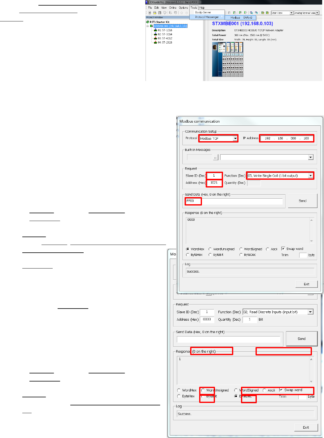
Step 1: Open Protocol Messenger by clicking on
Tools, Protocol Messenger and clicking on
Modbus.
Step 2: Writing a single output ON. The following steps
will turn output 1 ON (second output on ST-2328).
The following will allow you to determine the Hex address
that will be written to based on decimal addressing and
then converting to Hex.
The base address is 4096 (Hex 1000) + 32 (32 bits used by
the analog output module ST-4212) + 1= 4129 or 1021
Hex.
a) In Protocol field select Modbus TCP.
b) In IP Address field enter IP address of RSTi Modbus
TCP slave device.
c) Slave ID: 1
d) Select Function: 05, Write Single Coil (1bit output)
e) Address (Hex format): 1021 (this will control
output 2)
f) Send Data (Hex) FF00 will turn ON (0000 will
turn OFF output 1)
g) Click Send.
h) You will see the response back from the slave
in the Response window.
i) Change the Send Data to 0000 and you will see
the output 1 go OFF.
Step 3: Reading a single discrete input status. The
following steps will read input status. This assumes
input 0 is wired ON.
a) In Protocol field select Modbus TCP.
b) In IP Address field enter IP address of RSTi
Modbus TCP slave device.
c) Slave ID: 1
d) Select Function: 02, Read Discrete Inputs (input
bit)
GE Intelligent Platforms RSTi MODBUS TCP/IP Starter Guide
Page | 17
e) Address (Hex format): 0000 (this will read input address 0)
f) Quantity (Dec): Enter 1 bit
g) Send Data (Hex) should be blank
h) Click Send.
i) You will see the response back from the slave in the Response window. Click on radial ByteDec and a
1 will appear showing that input 0 is ON.
j) By changing the Quantity (Dec) to 8 and click ByteBit in the Response window. The data should reflect
the status of the 8 inputs on the module 00000001. The 1 represents input zero.
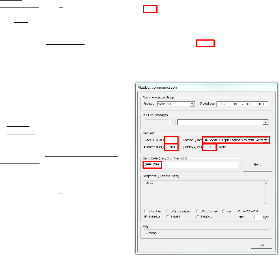
Step 4: Writing to analog outputs. The following
steps will write two analog output channels on the ST-
4212. The example will write Hex 05FF (10mA) to
channel 0 and Hex 0FFF (20mA)to channel 1
a) In Protocol field select Modbus TCP.
b) In IP Address field enter IP address of RSTi
Modbus TCP slave device.
c) Slave ID: 1
d) Select Function: 16, Write Multiple registers
(output words)
e) Address (Hex format): 0800 (this will write to
starting address 0800 Hex which is the starting
address of analog output channel 0)
f) Quantity (Dec): Enter 2 words
g) Send Data (Hex): 0FFF 05FF
a. Reading from right to left
Hex 05FF will command channel 0 on the
ST-4212 to go to 10ma Analog out 1, 0FFF
(20ma) Analog out 2
h) Click Send.
For more information on how to read and write to the RSTi Modbus TCP slave device refer to GFK-2799,
chapter 4.
First two are output module Hex 02, 05FF(10ma) Analog out 1, 0FFF (20ma) Analog out 2
View Process Image
Congratulations on a successful RSTi MODBUS TCP/IP hardware configuration.
GE Intelligent Platforms RSTi MODBUS TCP/IP Starter Guide
Page | 18
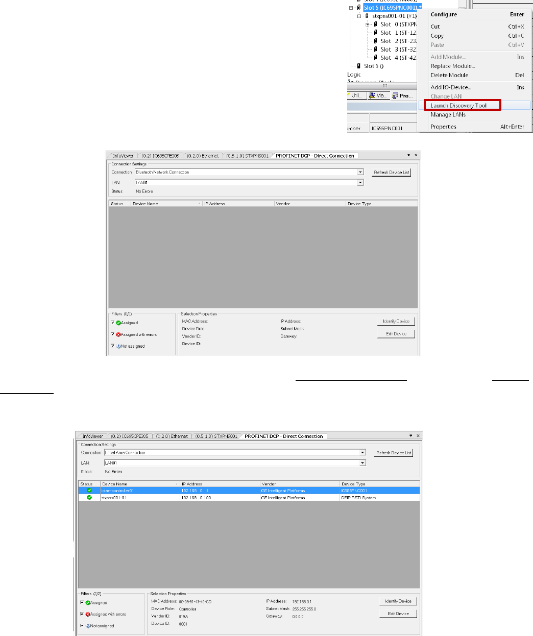
Using Auto Discovery Tool to Find PROFINET Devices on the network
The Proficy MAChine Edition has a powerful tool that enables the user to see all of the devices on the network.
Follow the following steps to use the Auto Discovery Tool:
Step 1: Connect the PC directly to the PROFINET controller. Place the MAChine Edition in the Offline mode.
Step 2: Left click on the PROFINET Controller and when the pop up
appears right click on Launch Discovery Tool.
The following should appear in the InfoViewer Window.
Step 3: In the Connection Settings change the Connection to Local Area Connection and then click on Refresh
Device-List. The tool will display the devices on the network, Device Name, IP Address, Vendor and Device
Type. The slave devices can be dragged from the list to the PROFINET controller to be configured. The
discovery tool will not bring over the I/O configuration only the network interface.

GE Intelligent Platforms RSTi MODBUS TCP/IP Starter Guide
Page | 19
RSTi STXPNS001 Status LEDs
RSTi STXPNS001
Module
Before Download
After Download
Comments
MOD Status LED
(Module status LED)
Green “ON” Normal
Green “ON” Normal
If OFF check to make sure power is
on module. Check wiring. If there is
a hardware fault the LED could also
be off.
RED LED solid or blinking is a
firmware or hardware fault on the
STXPNS001.
Net Status LED
(Network Status
LED)
No LED: Normal
This is normal
indication until
controller is
connected and
configuration is
downloaded.
Green “ON” Flashing
(0.5 seconds) Normal
when CPU in Stop
mode
Green “ON” Controller
in RUN mode
If LED is “OFF” after a controller
configuration is downloaded, check
cable and rotary switch to make sure
it matches device name (STXPNS001-
01 as example if rotary is in 0 1
positions) in the Inspector window for
the STXPNS001.
If LED is Flashing RED or solid RED
the configuration did not download
properly. Check configuration and
download again to the controller.
I/O LED indicates
the status of the
network interface
and the I/O it is
connected to.
“OFF” No power or
no I/O attached
Green “ON” I/O Bus
and Configuration is
normal.
“OFF” No power or No
I/O attached
Green “ON” I/O Bus
and Configuration is
normal.
“RED” solid or flashing bus or
configuration error. Check
configuration and try downloading
again
Network interface requires at least
one I/O module attached to function
properly.
Port 1 and Port 2
“OFF” No cable or
PROFINET Controller
attached
Green “Flashing”
PROFINET Controller
attached and
activity.
“OFF” No cable or
PROFINET Controller
attached
Green “Flashing”
PROFINET Controller
attached and activity.
If “OFF” confirm cable is attached to
both ends and controller is powered
and connected.
Note: RSTi STXPNS001 does not
support MRP therefore it should not
be used in a ring.
Field Power
“OFF” no field power
applied
Green “ON” when
field power is applied
“OFF” no field power
applied
Green “ON” when field
power is applied
If field power is “ON” but LED is not,
check wiring.
Field power should be an
independent power source from the
Network Interface power

GE Intelligent Platforms RSTi MODBUS TCP/IP Starter Guide
Page | 20
RSTi ST-xxxx I/O Modules Status LEDs
RSTi ST-xxxx I/O
Modules
Before Download
After Download
Comments
Status LED
Green “Flashing”
normal. I/O is ok and
waiting for
configuration.
Green “ON” normal.
Flashing Red: I/O bus time out
Red: module fault.
Discrete LEDs
Discrete In: Green
when power is “ON”
Discrete Out: Off
Discrete In: Green
when power is “ON”
Discrete Out: Off logic
control is off
Green when logic is
turning output on.
Analog LEDs
Analog In:
LED Green: Normal
Analog Out:
LED Green: Normal
operation
Analog In:
LED Green: Normal
Analog Out:
LED Green: Normal
operation
Analog In:
If LED is RED check field wiring for
open wire.
Analog Out:
LED off module not working properly.

GE Intelligent Platforms RSTi MODBUS TCP/IP Starter Guide
Page | 21
RSTi Additional Power Module Information
System Power: It is recommended that the 24VDC System Power be from an independent power source than
the Field Bus Power. The separation allows the field power to be turned off without impacting the Network
Interface. The network interface provides 5VDC to the corresponding I/O modules and each module passes
the 5VDC to the next module.
5VDC Booster Module: The ST-7111 (No bus ID type support, does not occupy an address on the bus)
or ST-7511 (Uses a bus ID and occupies an address on the bus) are available to boost the 5VDC signal
in the event that modules power consumption exceed network interface. The booster module will
provide 5VDC at 1 amp to modules to the right of the booster module. The module requires 24VDC
System Power. 24VDC Field Power is also required and is supplied to all modules to the right.
Field Power: Field Power on the Network Interface is 24VDC and the Field Power is passed from one module
to the next. The maximum current available on the Field Power Bus is 10 amps.
Isolated Field Distribution Module: The ST-7241 (No bus ID type support, does not occupy an
address on the bus) or ST-7641 (Uses a bus ID and occupies an address on the bus) are available to
change field voltages such as 5VDC, 24VDC, 48VDC or AC with a maximum of 10 amps available on the
Field Power Bus to the right of the module. The module can also be used when additional current and
isolation. The Field Bus on the I/O modules to the right of the Isolated Field Distribution Module will
carry the voltage of the Isolated Field Distribution Module.
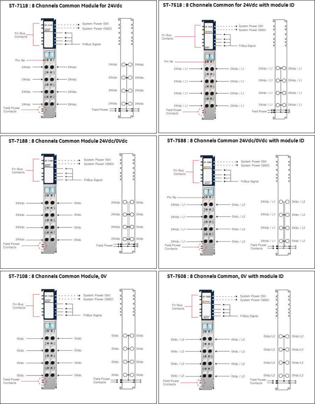
Shield Termination Modules: The ST-7008 (No bus ID type support, does not occupy an address on the bus)
or ST-7408 (Uses a bus ID and occupies an address on the bus) is available to group all shields to the RSTi bus
ground. Modules such as analog and motion could use the module to reduce noise impact on the RSTi
system. Field Bus power is passed through the module to the module on the right.
0VDC Distribution Modules 8 points, 10 amps: The ST-7108 (No bus ID type support, does not occupy an
address on the bus) or ST-7508 (Uses a bus ID and occupies an address on the bus) is available to group
commons from field devices to simplify wiring. The module commons group is connected to the Field Power
0VDC bus. Field Bus power is passed through the module to the module on the right.
24VDC Distribution Modules 8 points, 10 amps: The ST-7118 (No bus ID type support, does not occupy an
address on the bus) or ST-7518 (Uses a bus ID and occupies an address on the bus) is available to group
24VDC from field devices to simplify wiring. The module 24VDC group is connected to the Field Power 24VDC
bus. Field Bus power is passed through the module to the module on the right.
0VDC and 24VDC Distribution Modules 4 points each, 10 amps: The ST-7188 (No bus ID type support, does
not occupy an address on the bus) or ST-7588 (Uses a bus ID and occupies an address on the bus) is available
to group four 0VDC and four 24VDC from field devices to simplify wiring. The module 0VDC is connected to
the Field Power 0VDC and the 24VDC group is connected to the Field Power 24VDC bus. Field Bus power is
passed through the module to the module on the right.
GE Intelligent Platforms RSTi MODBUS TCP/IP Starter Guide
Page | 22
IO Guide Pro - Third Party Configuration Tool
The IO Guide Pro enables integrators network independence. I/O systems can be easily configured using the
various RSTi network interfaces. Changing from Ethernet IP to PROFIBUS is as simple as a mouse click without
impacting the rest of the I/O configuration. The tool provides technical data, address mapping, product
image and bus loading.
The IO Guide Pro Supports the Following Network Interfaces:
DeviceNet STXDNX001 only
PROFIBUS DP STXPBS001 only
CANOpen STXCAN001
Ethernet IP STXEIP001
Modbus TCP STXMBE001
Modbus serial RS-232 STXMBS001
Modbus serial RS-485 STXMBS002
Key Features:
Automatic scan Modbus devices online
Configuration validation
View address map
Configure parameters
Documentations

GE Intelligent Platforms RSTi MODBUS TCP/IP Starter Guide
Page | 23
RSTi Part Numbers:
Network Interface Units (*Check for release date)
STXPNS001
PROFINET RT Network Adapter
STXMBE001
MODBUS/TCP network adapter
STXPBS001
PROFIBUS DP/V1 network adapter
STXECT001*
EtherCAT Network Adapter
STXDNS001
DeviceNet network adapter
STXEIP001*
EtherNet/IP Network Adapter
STXMBS001
MODBUS RS-232C network adapter
STXCAN001*
CANopen network adapter
STXMBS002
MODBUS RS-485 network adapter
STXCCL001*
CC-link network adapter
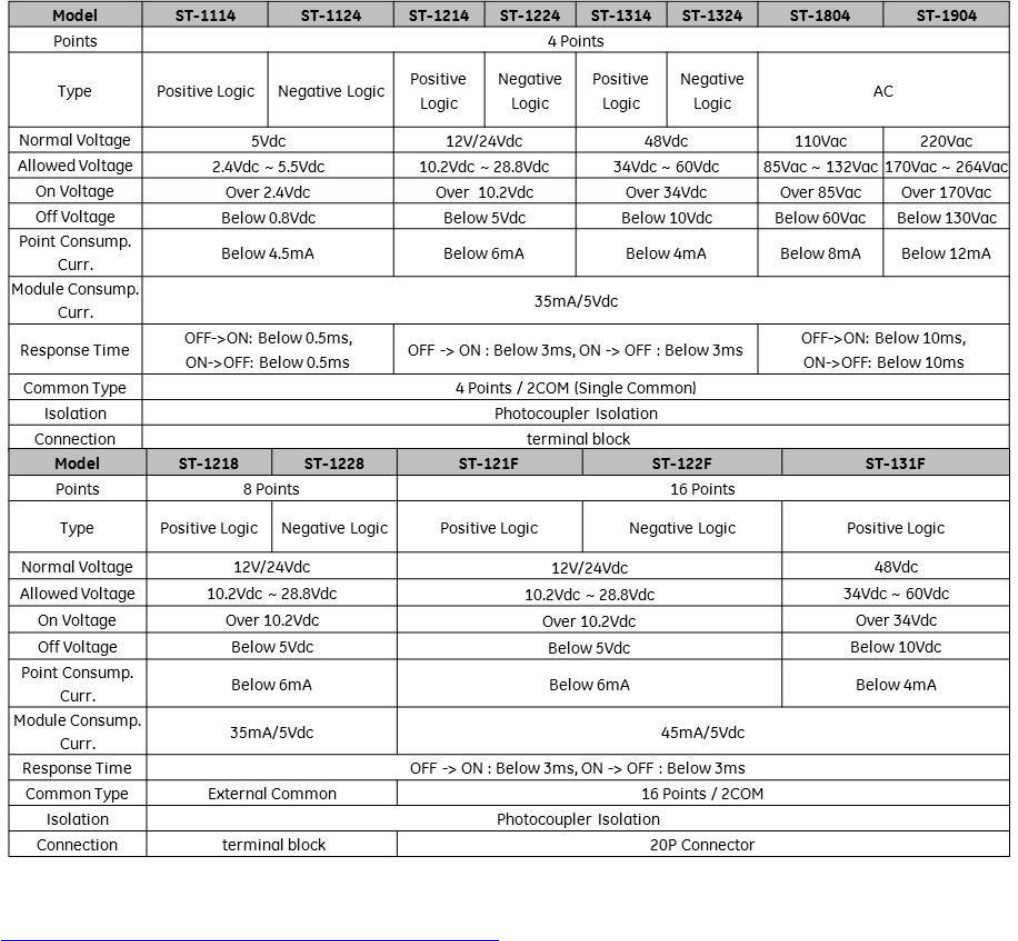
Discrete Inputs
ST-1124
4 points, Negative Logic 5VDC
ST-1218
8 points, Positive Logic, 12V/ 24VDC
ST-1114
4 points, Positive Logic 5VDC
ST-1228
8 points, Negative Logic, 12V/ 24VDC
ST-1214
4 points, Positive Logic, 12V/ 24VDC
ST-121F
16 points, Positive Logic, 12V/ 24VDC (Requires
connector Type Hirose , HIF3BA-20D-2.54C)
ST-1224
4 points, Negative Logic, 12V/ 24V DC
ST-122F
16 points, Negative Logic, 12V/ 24VDC (Requires
connector Type Hirose , HIF3BA-20D-2.54C)
ST-1314
4 points, Positive Logic, 48V DC
ST-1804
4 points, 110V AC (AC 85V ~ 132V)
ST-1324
4 points, Negative Logic, 48VDC
ST-1904
4 points, 220V AC (AC 170V ~ 264V)
ST-131F
16 points, Positive Logic, 48VDC (Requires
connector Type Hirose , HIF3BA-20D-2.54C)
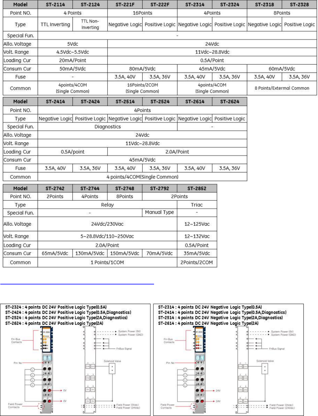
Digital Outputs
ST-2114
4 points, TTL, 5VDC/20mA Inverting
ST-2318
8 points, Negative Logic, 24VDC/ 0.5A
ST-2124
4 points, TTL, 5VDC/20mA Non inverting
ST-2328
8 points, Positive Logic, 24VDC/ 0.5A
ST-2314
4 points, Negative Logic, 24VDC/ 0.5A
ST-221F
16 points, Negative Logic, 24VDC/ 0.3A
(Requires connector Type Hirose , HIF3BA-20D-
2.54C)
ST-2324
4 points, Positive Logic, 24VDC/ 0.5A
ST-222F
16 points, Positive Logic, 24VDC/ 0.3A (Requires
connector Type Hirose , HIF3BA-20D-2.54C)
ST-2414
4 points, Negative Logic, Diagnostics, 24VDC/
0.5A
ST-2742
Isolated Relay Output 2 points, 230V AC/ 2A
ST-2424
4 points, Positive Logic, Diagnostics, 24VDC/
0.5A
ST-2744
Isolated Relay Output 4 Points, 230V AC/ 2A
ST-2514
4 points, Negative Logic, Diagnostics, 24VDC/
2A
ST-2748
Isolated Relay Output 8 Points, 230V AC/ 2A
ST-2524
4 points, Positive Logic, Diagnostics, 24VDC/ 2A
ST-2792
Relay Output 2 points, 230V AC/ 2A, Manual
ST-2852
Triac Output 2 points, 12V ~ 125VAC/ 0.5A
Analog Inputs
ST-3114
4 Channels, 0~20mA, 12-bit
ST-3524
4 Channels, -10~+10Vdc, 12-bit
ST-3118
8 Channels, 0~20mA, 12bit
ST-3544
4 Channels, -10~+10Vdc, 14-bit
ST-3134
4 Channels, 0~20mA, 14-bit
ST-3624
4 Channels, 0~5Vdc, 12-bit
ST-3214
4 Channels, 4~20mA, 12-bit
ST-3644
4 Channels, 0~5Vdc, 14-bit
ST-3218
8 Channels, 4~20mA, 12bit
ST-3702
2 Channels, RTD
ST-3234
4 Channels, 4~20mA, 14-bit
ST-3704
4 Channels, RTD (Requires connector Type
Hirose , HIF3BA-20D-2.54C)
ST-3274*
4 Channels, 4~20mA, 12-bit, (Requires Sensor
Connect 3M Mini-Clamp Plug, 37104 Series)
ST-3708
8 Channels, RTD Connector Type (Requires
connector Type Hirose , HIF3BA-20D-2.54C)
ST-3424
4 Channels, 0~10Vdc, 12-bit
ST-3802
2 Channels, Thermocouple
ST-3428
8 Channels, 0~10V, 12bit
ST-3804
4 Channels, Thermocouple Connector Type
(Requires connector Type Hirose , HIF3BA-20D-
2.54C)
ST-3444
4 Channels, 0~10Vdc, 14-bit
ST-3808
8 Channels, Thermocouple Connector Type
(Requires connector Type Hirose , HIF3BA-20D-
2.54C)
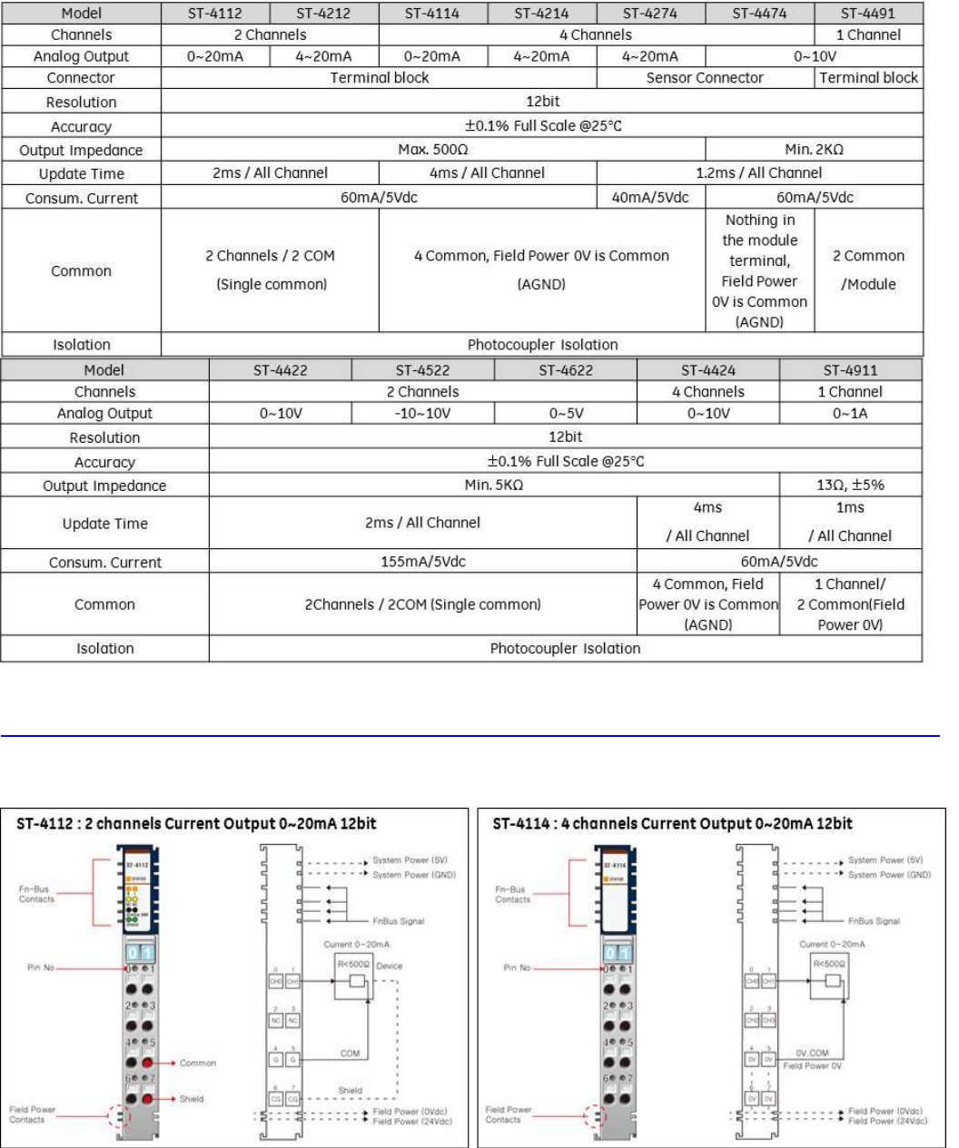
Analog Output
ST-4112
2 Channels, 0~20mA, 12-bit
ST-4424
4 Channels, 0~10Vdc, 12bit
ST-4114
4 Channels, 0~20mA,, 12bit
ST-4474*
4 Channels, 0~10Vdc, 12bit, (Requires Sensor
Connect 3M Mini-Clamp Plug, 37104 Series)
ST-4212
2 Channels, 4~20mA, 12-bit
ST-4491
1 Channel, 0~10V, 12bit, Manual type
ST-4214
4 Channels, 4~20mA, 12bit
ST-4522
2 Channels, -10~+10Vdc, 12-bit
ST-4274*
4 Channels, 4-20mA, 12bit, (Requires Sensor
Connect 3M Mini-Clamp Plug, 37104 Series)
ST-4622
2 Channels, 0~5Vdc, 12-bit
ST-4422
2 Channels, 0~10Vdc, 12-bit
ST-4911
1 Channel, 0~1 A, 12bit

GE Intelligent Platforms RSTi MODBUS TCP/IP Starter Guide
Page | 24
PID Loop Controllers (*Check release date)
ST-3814*
1 Loop PID Controller 4 Channels, TC, Temp.
Controller, SSR out (DeviceNet only)
ST-3714*
1 Loop PID Controller 4 Channels, RTD, Temp.
Control, SSR Out (DeviceNet only)
ST-3834*
1 Loop PID Controller 4 Ch. TC, Temp.
Controller, Current out (DeviceNet only)
ST-3734*
1 Loop PID Controller 4 Ch, RTD, Temp. Control,
Current Out (DeviceNet only)
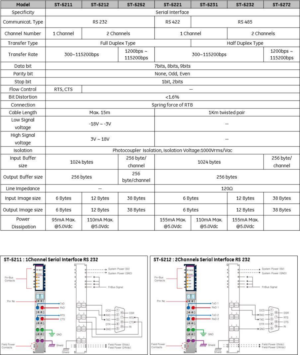
Serial Interface Modules (ASCII)
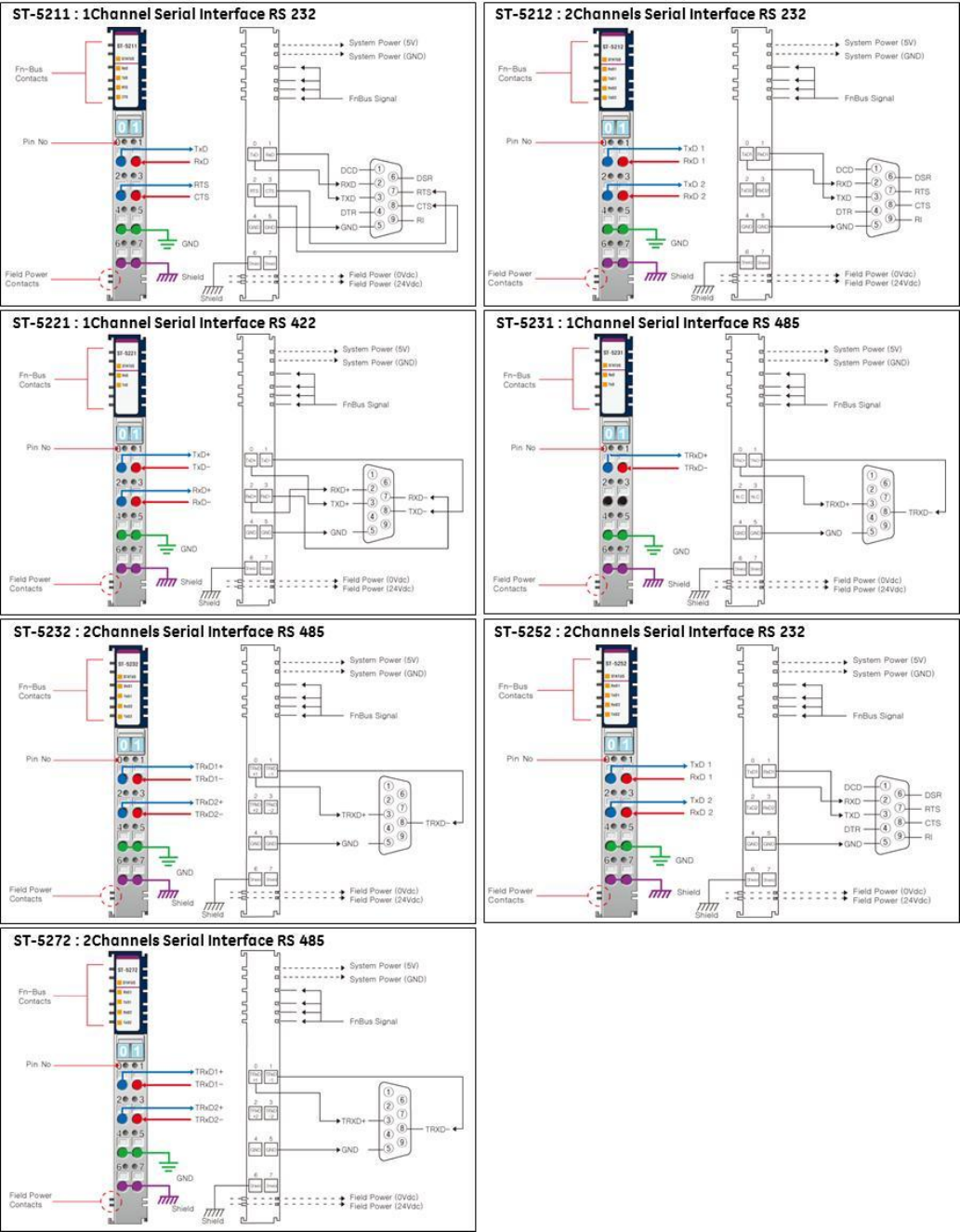
ST-5211
Serial Interface RS-232C, 1 Channel
ST-5231
Serial Interface RS-485, 1 Channel
ST-5212
Serial Interface RS-232C, 2 Channels
ST-5232
Serial Interface RS-485, 2 Channels
ST-5221
Serial Interface RS-422, 1 Channel
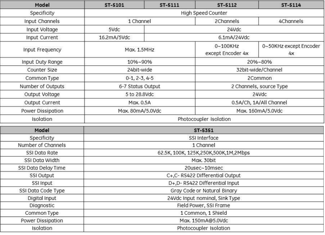
Motion Modules
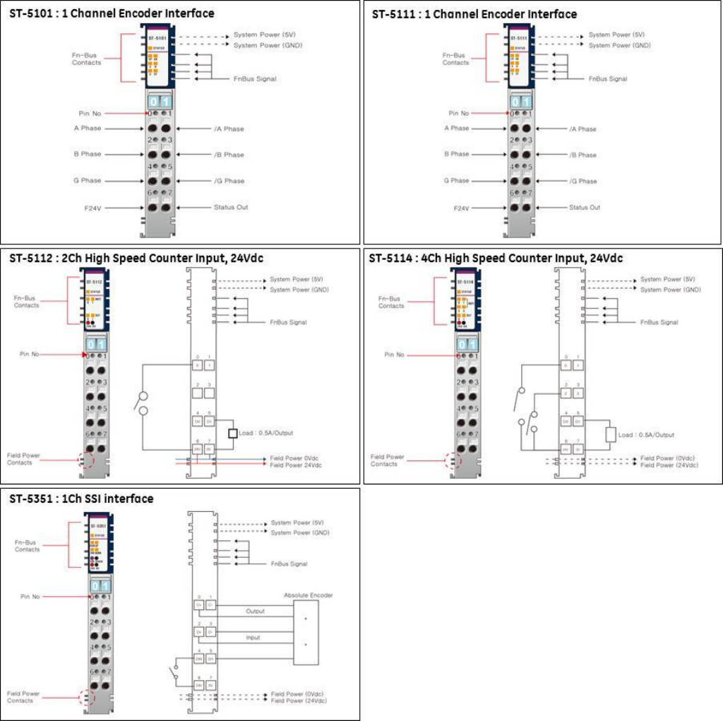
ST-5101
High Speed Counter, 1 Channel, 5VDC 1.5MHz
ST-5442
2 Channel, PWM Out, 0.5A/24V, Positive Logic,
2.5Khz
ST-5111
High Speed Counter, 1 Channel, 24VDC 1.5MHz
ST-5444
PWM Out, 0.5A/24V, Positive Logic, 4 Channels,
2.5Khz
ST-5112
High Speed Counter, 2 Channel, 24VDC,100Khz
ST-5641
1 Channel, Pulse Out, 0.5A/24V, Positive Logic,
20Khz
ST-5114
High Speed Counter, 4 Channel, 24VDC, 50Khz
ST-5642
2 Channel, Pulse Out, 0.5A/24V, Positive Logic,
20Khz
ST-5351
SSI Interface 1 CH; 62.5K, 100K, 125K, 250K,
500K, 1M, 2Mbps
ST-5651
1 Channel, Pulse Out, 0.5A/5V (RS422), 20Khz
ST-5422
PWM Out, 2A/24V, Positive Logic, 2 Channels
2.5Khz
System Modules
(Modules with ID type occupy 1 of the 32 available module ID addresses and will appear in the hardware
configuration. The modules without ID support will not occupy a module address and will not appear in the
hardware configuration.)
ST-7008
Shield termination module, 8 points, 10A No
LED
ST-7588
0VDC and 24VDC 4 points distribution module
for field devices ID type with status LEDs (ID
type uses module address)
ST-7408
Shield termination module, 8 points, 10A, ID
type with LED (ID type uses module address)
ST-7111
5VDC bus booster, 24VDC in
ST-7108
0VDC distribution module for field devices, 8
points, 10A
ST-7511
5VDC bus booster, 24VDC in with LED ID type
(ID type uses module address)
ST-7508
0VDC distribution module for field devices, 8
points, 10A with LED (ID type uses module
address)
ST-7241
Isolated Field Power Distribution, 5 VDC, 24VDC,
48VDC, 120/240VAC 10 Amp no LED status
ST-7118
24VDC distribution module for field devices, 8
points, 10A
ST-7641
Isolated Field Distributor 5 VDC, 24VDC, 48VDC,
120/240VAC, 10 amp with LED status ID type (ID
type uses module address)
ST-7518
24VDC distribution module for field devices, 8
points, 10A ID type with status LEDs (ID type
uses module address)
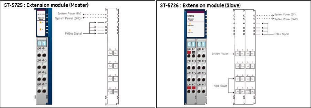
ST-5725*
Extension IO, Master (Tx). Up to 3 master/slave
combinations supported. Maximum 300
meters. Only one slave supported per master
module.
ST-7188
0VDC and 24VDC 4 points distribution module
for field devices
ST-5726*
Extension IO, Slave (Rx). Each Slave requires a
Master module.
PROFIBUS Network Interface with built-in I/O ( Up to 8 expansion modules supported) (* Check release date)
STXPBS032
24VDC Positive Logic input, 32 points
STXPBS432
16 24VDC Positive Logic input and 16 24VDC
Positive Logic output
STXPBS132
24VDC Negative Logic input, 32 points
STXPBS532
16 24VDC Negative Logic input and 16 24VDC
Negative Logic output
STXPBS232
24VDC Negative Logic output, 32 points
STXPBS824
16 24VDC Positive Logic input and 16 relay
output
STXPBS332
24VDC Positive Logic output, 32 points
STXPBS924
16 24VDC Negative Logic input and 16 relay
output
STXPBS016
Relay output, 16 points
STXPBS825
16 24VDC Positive Logic input and 16 isolated
relay output
STXPBS116
Relay output, 16 points, isolated
STXPBS925
16 24VDC Negative Logic input and 16 isolated
relay output
DeviceNet Network Interface with built-in I/O ( Up to 10 expansion modules supported) (* Check release date)
STXDNS032
24VDC Positive Logic input, 32 points
STXDNS532
16 24VDC Negative Logic input and 16 24VDC
Negative Logic output
STXDNS132
24VDC Negative Logic input, 32 points
STXDNS824
16 24VDC Positive Logic input and 16 relay
output
STXDNS232
24VDC Negative Logic output, 32 points
STXDNS924
16 24VDC Negative Logic input and 16 relay

GE Intelligent Platforms RSTi MODBUS TCP/IP Starter Guide
Page | 25
output
STXDNS332
24VDC Positive Logic output, 32 points
STXDNS825
16 24VDC Positive Logic input and 16 isolated
relay output
STXDNS016
Relay output, 16 points
STXDNS925
16 24VDC Negative Logic input and 16 isolated
relay output
STXDNS116
Relay output, 16 points, isolated
STXDNS032
24VDC Positive Logic input, 32 points
STXDNS432
16 24VDC Positive Logic input and 16 24VDC
Positive Logic output
STXDNS132
24VDC Negative Logic input, 32 points
Accessories
STXACC004
End Module, 7pcs (End module ships with
Network Interface)
STXACC001
Marker with numbers 100pcs
STXRTB009
Removable Terminal Block, 9pcs (Modules ship
with terminal block except connector style.)
STXACC002
Blank markers 100pcs
Typical Configuration Example:
Requirement: PROFINET network connection, (24) 24VDC positive logic inputs, (12) 24VDC Positive Logic, 0.5
amp outputs, (4) analog inputs 4-20mA, (2) analog outputs 4-20mA, (6) 120VAC inputs
QTY
Part Number
Description
Comments
1
STXPNS001
PROFINET RT Network Adapter
Supports up to 32 modules with built-in
Ethernet switch (ring topology not
supported)
3
ST-1218
8 points, Positive Logic 12V/ 24VDC inputs
Includes terminal block
1
ST-2328
8 points, Positive Logic, 24VDC/ 0.5A
outputs
Includes terminal block
1
ST-2324
4 points, Positive Logic, 24VDC/ 0.5A
outputs
Includes terminal block
1
ST-3214
4 Channels, 4~20mA, 12-bit in
Includes terminal block
1
ST-4212
2 Channels, 4~20mA, 12-bit out
Includes terminal block
1
ST-7408
Shield module, ID type with LED (ID type
uses module address)
Optional Shield module for analog modules.
1
ST-7641
Power distribution module 5, 24, 48, AC , 10
amp with LED status ID type (ID type uses
module address)
The ST-7641 is needed to support the
120VAC input module ST-1804. All modules
to the right of the ST-7641 will be 120VAC
unless a ST-7641 is installed to switch the
bus voltage.
2
ST-1804
4 points, 110V AC (AC 85V ~ 132V) inputs
Includes terminal block
Notes:
A. The total number of modules used is 11 (ST-7408 and ST-7641 occupy a module address)
B. The above configuration only requires 177mm width by 70mm deep and 99mm high. (6.97 in. W x 2.76
in. D x 3.9 in. H)
GE Intelligent Platforms RSTi MODBUS TCP/IP Starter Guide
Page | 26
PROFINET Network Interface Specifications – STXPNS001
ITEM
SPECIFICATION
ITEM
SPECIFICATION
Network Type
PROFINET I/O RT Slave (No MRP
support) with built-in switch
Surrounding Air
Temperature
-20C to 55C
Storage -40C to 85C
Cable Type
Ethernet RJ 45 (2) connections
Relative Humidity
5% to 90% Non condensation
Cable Length
Up to 100 meters from Ethernet
Hub
Vibration
IEC 60068-2-6:1995
Communication Rate
10/100Mbps
Atmosphere
No excessive dust
No corrosive gases
Maximum number of
nodes
Limited by the IP address
Module Power
24VDC Nominal (11 to 28.8VDC)
Supplies 1.5 amps to I/O modules
Topology
Line or Star Topology
Backplane Power
1.5 amps to I/O modules
Mounting Position
First module of the RSTi I/O sytem
Field Power
Class II 24VDC Nominal (11 to
28.8VDC) 10 amps
Number of I/O
Up to 32 I/O modules supported
Isolation
System power to internal logic:
Non-isolated
System power to I/O driver:
Isolated
Maximum Digital I/O
Input: 1,024 points
Outputs: 1,024 points
Power Dissipation
115mA typical @ 24VDC
Maximum Analog I/O
Input: 64 channels
Outputs: 64 channels
Weight
150 grams
Maximum Byte Size
Input: 1288 bytes
Output: 1288 bytes
Size (W x H x D)
45mm x 99mm x 70mm
Node Address
Rotary Selection 1 to 99
Certification
UL/CUL/CE
PROFINET
UL Class 1/Div 2 and ATEX pending
GE Intelligent Platforms RSTi MODBUS TCP/IP Starter Guide
Page | 27
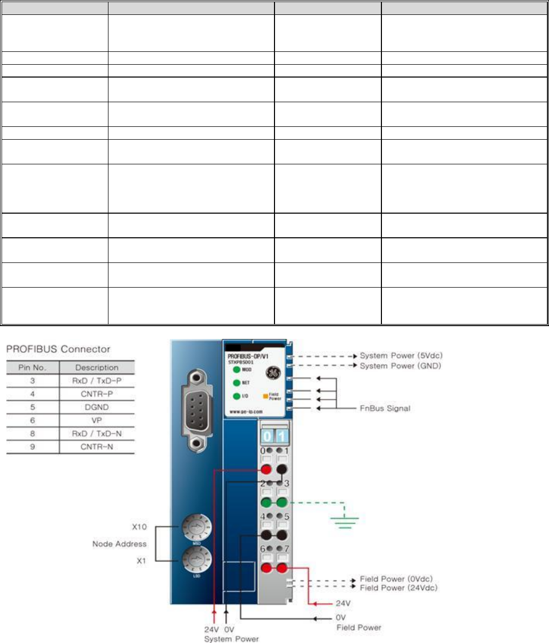
PROFIBUS DP Interface Specifications – STXPBS001
ITEM
SPECIFICATION
ITEM
SPECIFICATION
Network Type
PROFIBUS DP/V1 Slave
Surrounding Air
Temperature
-20C to 55C for UL
-20 to 60C for non-UL
Storage -40C to 85C
Cable Type
PROFIBUS DP Cables
Relative Humidity
5% to 90% Non condensation
Cable Length
1.2Km to 100 meters
Vibration
IEC 60068-2-6:1995
Communication Rate
9.6 kbaud to 12 Mbaud
Supports Auto Sensing
Atmosphere
No excessive dust
No corrosive gases
Maximum number of
nodes
101 including master
Module Power
24VDC Nominal (11 to 28.8VDC)
Supplies 1.5 amps to I/O modules
Topology
Line
Backplane Power
1.5 amps to I/O modules
Mounting Position
First module of the RSTi I/O sytem
Field Power
Class II 24VDC Nominal (11 to
28.8VDC) 10 amps
Number of I/O
Up to 32 I/O modules supported
Isolation
System power to internal logic:
Non-isolated
System power to I/O driver:
Isolated
Maximum Digital I/O
Input: 1,024 points
Outputs: 1,024 points
Power Dissipation
60mA typical @ 24VDC
Maximum Analog I/O
Input: 64 channels
Outputs: 64 channels
Weight
155 grams
Maximum Byte Size
Input: 1288 bytes
Output: 1288 bytes
Size (W x H x D)
42mm x 99mm x 70mm
Station Number
Rotary switch 1 to 99
Certification
UL/CUL/CE
PROFIBUS
UL Class 1/Div 2 and ATEX pending
GE Intelligent Platforms RSTi MODBUS TCP/IP Starter Guide
Page | 28
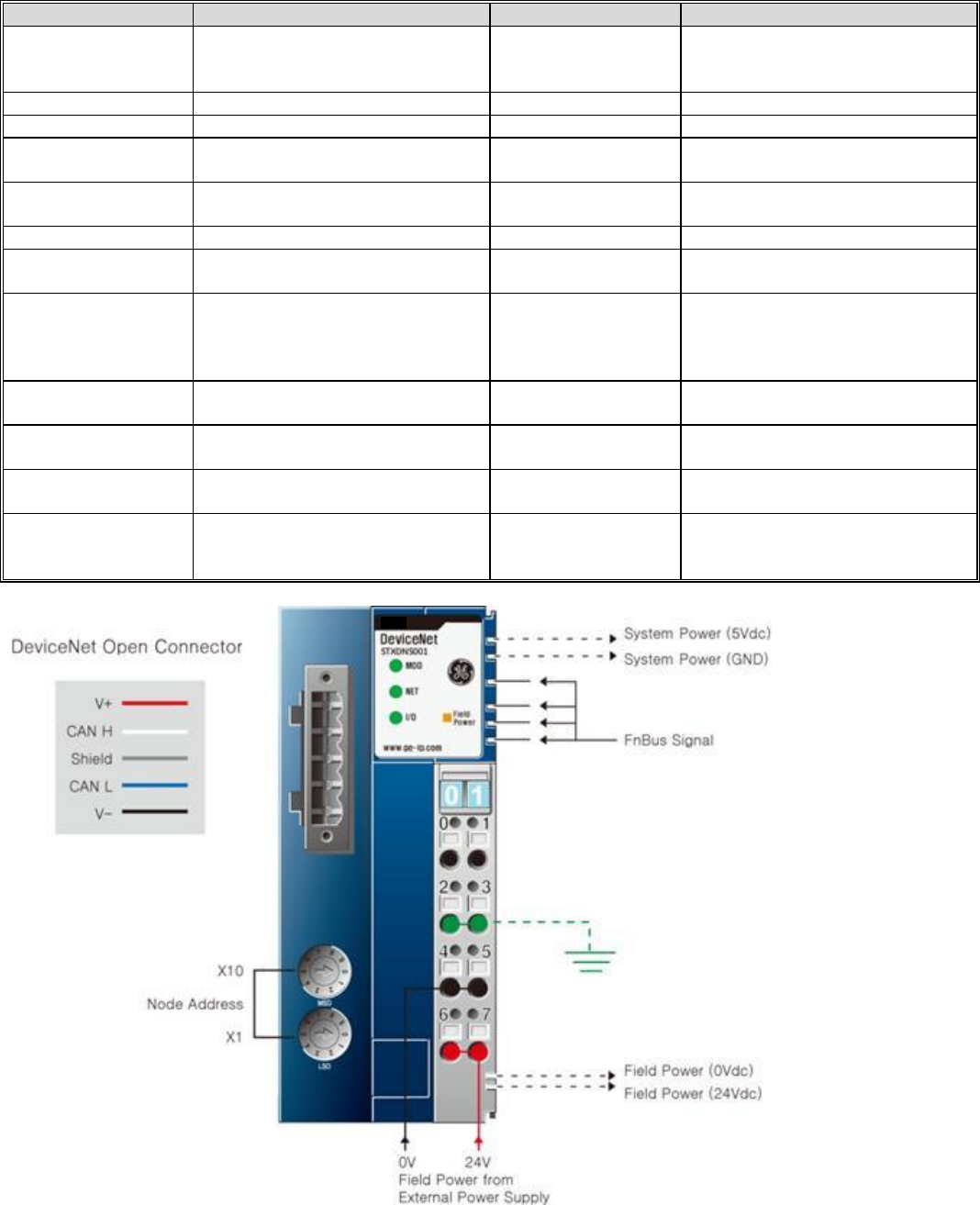
DeviceNet Interface Specifications – STXDNS001
ITEM
SPECIFICATION
ITEM
SPECIFICATION
Network Type
DeviceNet
Supports Bit Strobe, Polling, Cyclic,
COS
Surrounding Air
Temperature
-20C to 55C for UL
-20 to 60C for non-UL
Storage -40C to 85C
Cable Type
Dedicated DeviceNet Cable 5 pin
Relative Humidity
5% to 90% Non condensation
Cable Length
100 to 500 meters
Vibration
IEC 60068-2-6:1995
Communication Rate
125Kbps, 250Kbps and 500Kbps
with auto negotiating
Atmosphere
No excessive dust
No corrosive gases
Maximum number of
nodes
64
Module Power
24VDC Nominal (11 to 28.8VDC)
Supplies 1.2 amps to I/O modules
Topology
Line
Backplane Power
1.5 amps to I/O modules
Mounting Position
First module of the RSTi I/O sytem
Field Power
Class II 24VDC Nominal (11 to
28.8VDC) 10 amps
Number of I/O
Up to 32 I/O modules supported
Isolation
System power to internal logic:
Non-isolated
System power to I/O driver:
Isolated
Maximum Digital I/O
Input: 2,016 points
Outputs: 2,016 points
Power Dissipation
30mA typical @ 24VDC
Maximum Analog I/O
Input: 126 channels
Outputs: 126 channels
Weight
155 grams
Maximum Byte Size
Input: 252 bytes
Output: 252 bytes
Size (W x H x D)
42mm x 99mm x 70mm
Station Number
Rotary switch 1 to 99
Certification
UL/CUL/CE
DeviceNet (ODVA)
UL Class 1/Div 2 and ATEX pending
GE Intelligent Platforms RSTi MODBUS TCP/IP Starter Guide
Page | 29
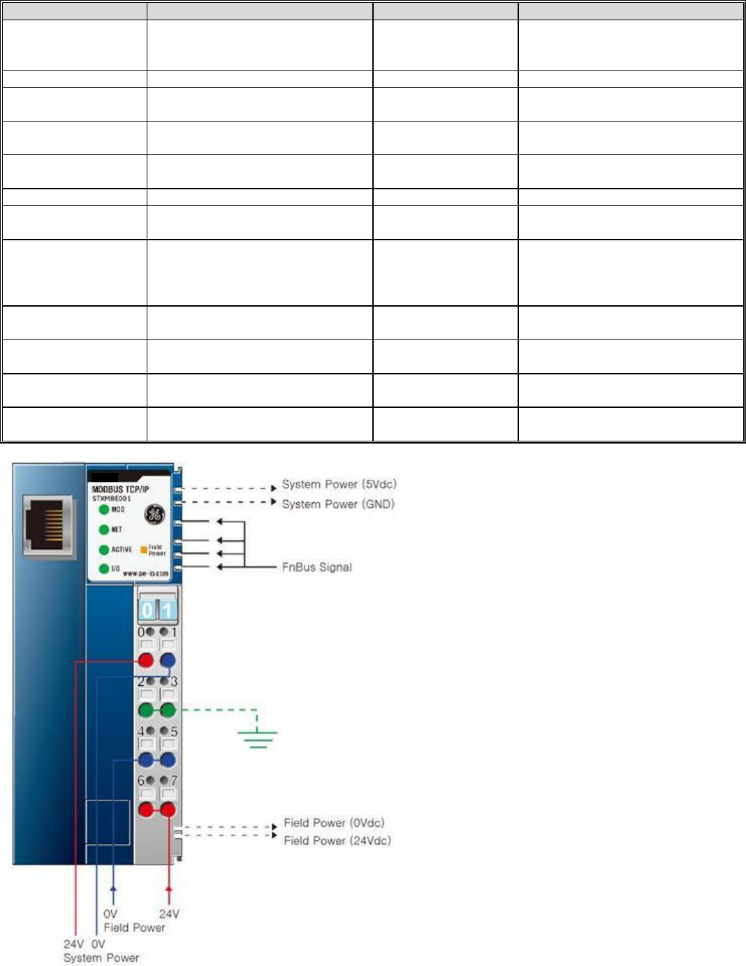
Modbus TCP Specifications – STXMBE001
ITEM
SPECIFICATION
ITEM
SPECIFICATION
Network Type
Modbus TCP Slave (1 port)
Supports 16 connection
Surrounding Air
Temperature
-20C to 55C
-20 to 60C Non-UL
Storage -40C to 85C
Cable Type
Ethernet Shielded RJ 45
Relative Humidity
5% to 90% Non condensation
Cable Length
Up to 100 meters from Ethernet
Hub
Vibration
IEC 60068-2-6:1995
Communication Rate
10/100Mbps
Atmosphere
No excessive dust
No corrosive gases
Maximum number of
nodes
Limited by the IP address
Module Power
24VDC Nominal (11 to 28.8VDC)
Supplies 1.5 amps to I/O modules
Topology
Line or Star Topology
Backplane Power
1.5 amps to I/O modules
Mounting Position
First module of the RSTi I/O sytem
Field Power
Class II 24VDC Nominal (11 to
28.8VDC) 10 amps
Number of I/O
Up to 32 I/O modules supported
Isolation
System power to internal logic:
Non-isolated
System power to I/O driver:
Isolated
Maximum Digital I/O
Input: 2,016 points
Outputs: 2,016 points
Power Dissipation
60mA typical @ 24VDC
Maximum Analog I/O
Input: 126 channels
Outputs: 126 channels
Weight
150 grams
Maximum Byte Size
Input: 252bytes
Output: 252 bytes
Size (W x H x D)
45mm x 99mm x 70mm
Operating Mode
8 Modbus TCP, 4 HTTP, BOOTP
Certification
UL/CUL/CE
UL Class 1/Div 2 and ATEX pending
GE Intelligent Platforms RSTi MODBUS TCP/IP Starter Guide
Page | 30
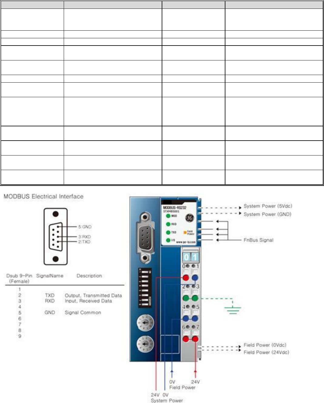
Modbus Serial RS-232 Specifications – STXMBS001
ITEM
SPECIFICATION
ITEM
SPECIFICATION
Network Type
Modbus RS-232 Slave
Surrounding Air
Temperature
-20C to 55C
-20 to 60C Non-UL
Storage -40C to 85C
Cable Type
Serial Twisted Cable
Relative Humidity
5% to 90% Non condensation
Cable Length
15 meters
Vibration
IEC 60068-2-6:1995
Communication Rate
1.2Kbps to 115.2kbps
Atmosphere
No excessive dust
No corrosive gases
Maximum number of
nodes
1
Module Power
24VDC Nominal (11 to 28.8VDC)
Supplies 1.5 amps to I/O modules
Topology
Point to Point
Backplane Power
1.5 amps to I/O modules
Mounting Position
First module of the RSTi I/O sytem
Field Power
Class II 24VDC Nominal (11 to
28.8VDC) 10 amps
Number of I/O
Up to 32 I/O modules supported
Isolation
System power to internal logic:
Non-isolated
System power to I/O driver:
Isolated
Maximum Digital I/O
Input: 2,016 points
Outputs: 2,016 points
Power Dissipation
70mA typical @ 24VDC
Maximum Analog I/O
Input: 126 channels
Outputs: 126 channels
Weight
150 grams
Maximum Byte Size
Input: 252bytes
Output: 252 bytes
Size (W x H x D)
45mm x 99mm x 70mm
Node Address
Rotary Selection 1 to 99
Certification
UL/CUL/CE
UL Class 1/Div 2 and ATEX pending
GE Intelligent Platforms RSTi MODBUS TCP/IP Starter Guide
Page | 31
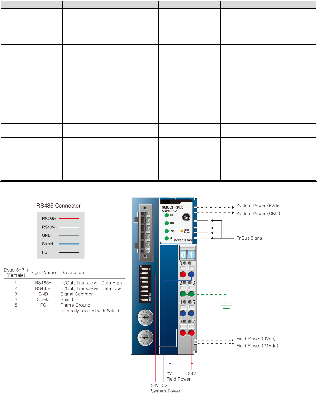
Modbus Serial RS-485 Specifications – STXMBS002
ITEM
SPECIFICATION
ITEM
SPECIFICATION
Network Type
Modbus RS-485 Slave
RTU and ASCII
Surrounding Air
Temperature
-20C to 55C
-20 to 60C Non-UL
Storage -40C to 85C
Cable Type
Serial Twisted Cable
Relative Humidity
5% to 90% Non condensation
Cable Length
1200 meters
Vibration
IEC 60068-2-6:1995
Communication Rate
1.2Kbps to 115.2kbps
Atmosphere
No excessive dust
No corrosive gases
Maximum number of
nodes
1
Module Power
24VDC Nominal (11 to 28.8VDC)
Supplies 1.5 amps to I/O modules
Topology
Point to Point
Backplane Power
1.5 amps to I/O modules
Mounting Position
First module of the RSTi I/O sytem
Field Power
Class II 24VDC Nominal (11 to
28.8VDC) 10 amps
Number of I/O
Up to 32 I/O modules supported
Isolation
System power to internal logic:
Non-isolated
System power to I/O driver:
Isolated
Maximum Digital I/O
Input: 2,016 points
Outputs: 2,016 points
Power Dissipation
70mA typical @ 24VDC
Maximum Analog I/O
Input: 126 channels
Outputs: 126 channels
Weight
150 grams
Maximum Byte Size
Input: 252bytes
Output: 252 bytes
Size (W x H x D)
45mm x 99mm x 70mm
Node Address
Rotary Selection 1 to 99
Certification
UL/CUL/CE
UL Class 1/Div 2 and ATEX pending
GE Intelligent Platforms RSTi MODBUS TCP/IP Starter Guide
Page | 32
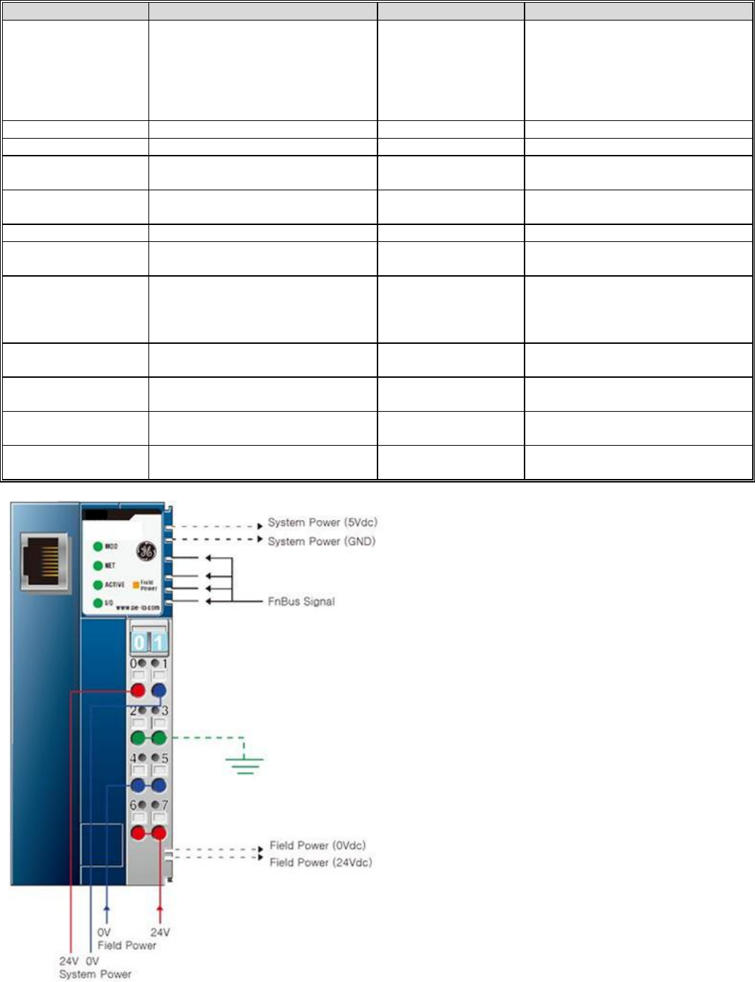
Ethernet IP Specifications – STXEIP001 (Target October 2012 release)
ITEM
SPECIFICATION
ITEM
SPECIFICATION
Network Type
EtherNet/IP Slave (1 port)
BOOTP,Level 2 I/O Server (Explicit,
I/O Message)
16 IO Message connections
64 CIP connections
64 Explicit message connections
Surrounding Air
Temperature
-20C to 55C
-20 to 60C Non-UL
Storage -40C to 85C
Cable Type
Ethernet Shielded RJ 45
Relative Humidity
5% to 90% Non condensation
Cable Length
Up to 100 meters from Hub
Vibration
IEC 60068-2-6:1995
Communication Rate
10/100Mbps
Atmosphere
No excessive dust
No corrosive gases
Maximum number of
nodes
Limited by the IP address
Module Power
24VDC Nominal (11 to 28.8VDC)
Supplies 1.5 amps to I/O modules
Topology
Line or Star Topology
Backplane Power
1.5 amps to I/O modules
Mounting Position
First module of the RSTi I/O sytem
Field Power
Class II 24VDC Nominal (11 to
28.8VDC) 10 amps
Number of I/O
Up to 32 I/O modules supported
Isolation
System power to internal logic:
Non-isolated
System power to I/O driver:
Isolated
Maximum Digital I/O
Input: 2,016 points
Outputs: 2,016 points
Power Dissipation
60mA typical @ 24VDC
Maximum Analog I/O
Input: 126 channels
Outputs: 126 channels
Weight
150 grams
Maximum Byte Size
Input: 252bytes
Output: 252 bytes
Size (W x H x D)
45mm x 99mm x 70mm
Operating Mode
8 Modbus TCP, 4 HTTP, BOOTP
Certification
UL/CUL/CE
UL Class 1/Div 2 and ATEX pending

GE Intelligent Platforms RSTi MODBUS TCP/IP Starter Guide
Page | 33
EtherCAT Specifications – STXECT001 (Target November 2012 release)
ITEM
SPECIFICATION
ITEM
SPECIFICATION
Network Type
EtherCAT Slave (2 ports)
Supports redundancy
Surrounding Air
Temperature
-20C to 55C
-20 to 60C Non-UL
Storage -40C to 85C
Cable Type
Ethernet Shielded RJ 45
Relative Humidity
5% to 90% Non condensation
Cable Length
Up to 100 meters from Hub
Vibration
IEC 60068-2-6:1995
Communication Rate
100Mbps
Atmosphere
No excessive dust
No corrosive gases
Maximum number of
nodes
65,535
Module Power
24VDC Nominal (11 to 28.8VDC)
Supplies 1.5 amps to I/O modules
Topology
Line or Star Topology
Backplane Power
1.5 amps to I/O modules
Mounting Position
First module of the RSTi I/O sytem
Field Power
Class II 24VDC Nominal (11 to
28.8VDC) 10 amps
Number of I/O
Up to 32 I/O modules supported
Isolation
System power to internal logic:
Non-isolated
System power to I/O driver:
Isolated
Maximum Digital I/O
Input: 2,016 points
Outputs: 2,016 points
Power Dissipation
60mA typical @ 24VDC
Maximum Analog I/O
Input: 126 channels
Outputs: 126 channels
Weight
150 grams
Size (W x H x D)
54.2mm x 99mm x 70mm
Certification
UL/CUL/CE
UL Class 1/Div 2 and ATEX pending
GE Intelligent Platforms RSTi MODBUS TCP/IP Starter Guide
Page | 34
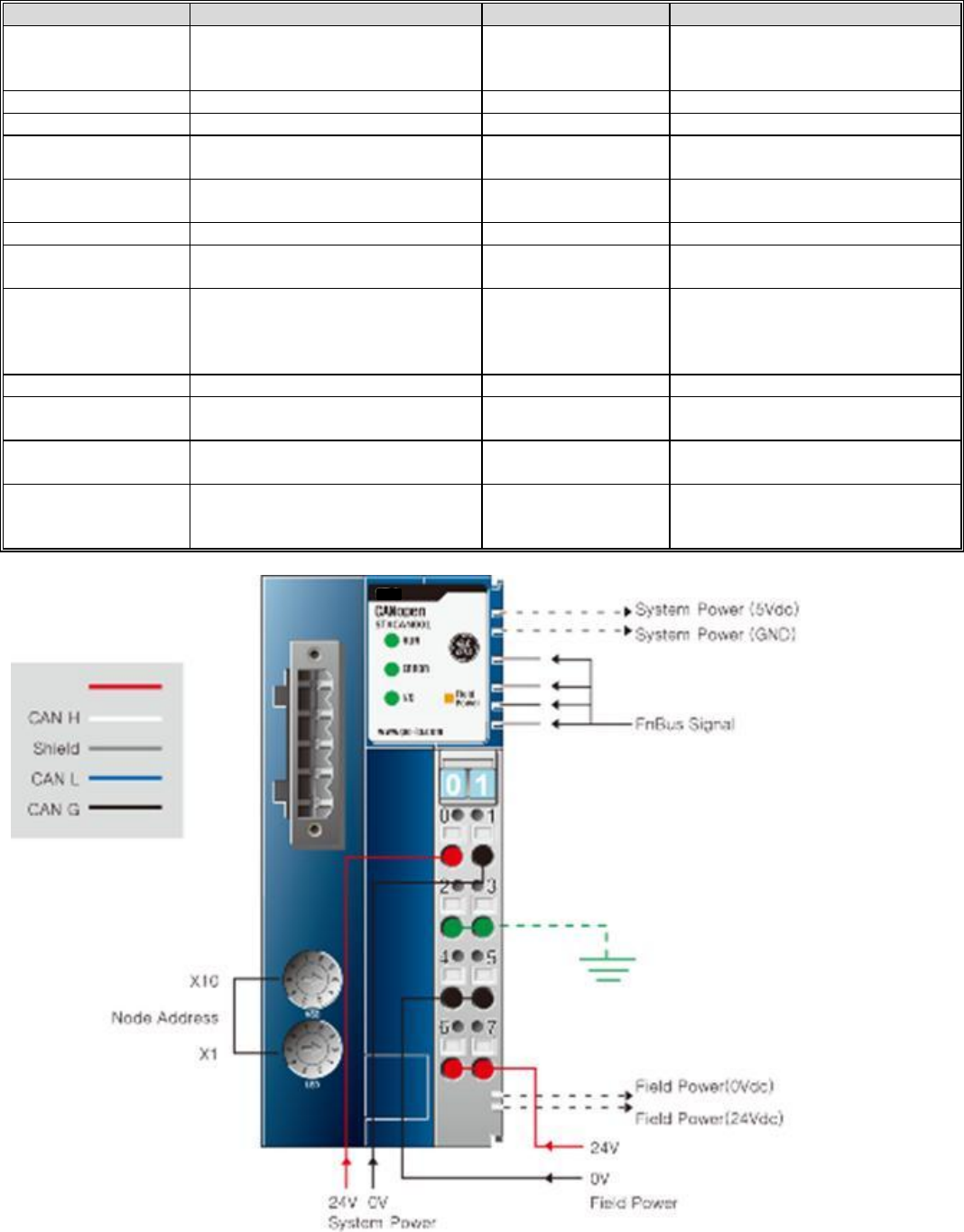
CANOpen Specifications – STXCAN001 (Target October 2012 release)
ITEM
SPECIFICATION
ITEM
SPECIFICATION
Network Type
CANOpen
Surrounding Air
Temperature
-20C to 55C for UL
-20 to 60C for non-UL
Storage -40C to 85C
Cable Type
Dedicated CAN Cable 5 pin
Relative Humidity
5% to 90% Non condensation
Cable Length
25 meters to 25 Kmeters
Vibration
IEC 60068-2-6:1995
Communication Rate
10Kbps to 1Mbps with auto
negotiating
Atmosphere
No excessive dust
No corrosive gases
Maximum number of
nodes
99
Module Power
24VDC Nominal (11 to 28.8VDC)
Supplies 1.2 amps to I/O modules
Topology
Line
Backplane Power
1.5 amps to I/O modules
Mounting Position
First module of the RSTi I/O sytem
Field Power
Class II 24VDC Nominal (11 to
28.8VDC) 10 amps
Number of I/O
Up to 32 I/O modules supported
Isolation
System power to internal logic:
Non-isolated
System power to I/O driver:
Isolated
Station Number
Rotary switch 1 to 99
Power Dissipation
100mA typical @ 24VDC
Number of PDOs
available
8 Transmit PDOs
8 Receive PDOs
Weight
155 grams
Number SDOs
Available
1 Standard SDOs
Size (W x H x D)
42mm x 99mm x 70mm
Certification
UL/CUL/CE
DeviceNet (ODVA)
UL Class 1/Div 2 and ATEX pending
GE Intelligent Platforms RSTi MODBUS TCP/IP Starter Guide
Page | 35
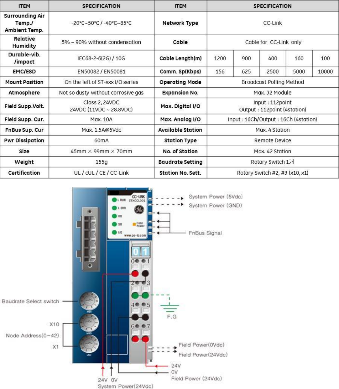
CC-Link Specification – STXCCL001 (Target release October 2012)
GE Intelligent Platforms RSTi MODBUS TCP/IP Starter Guide
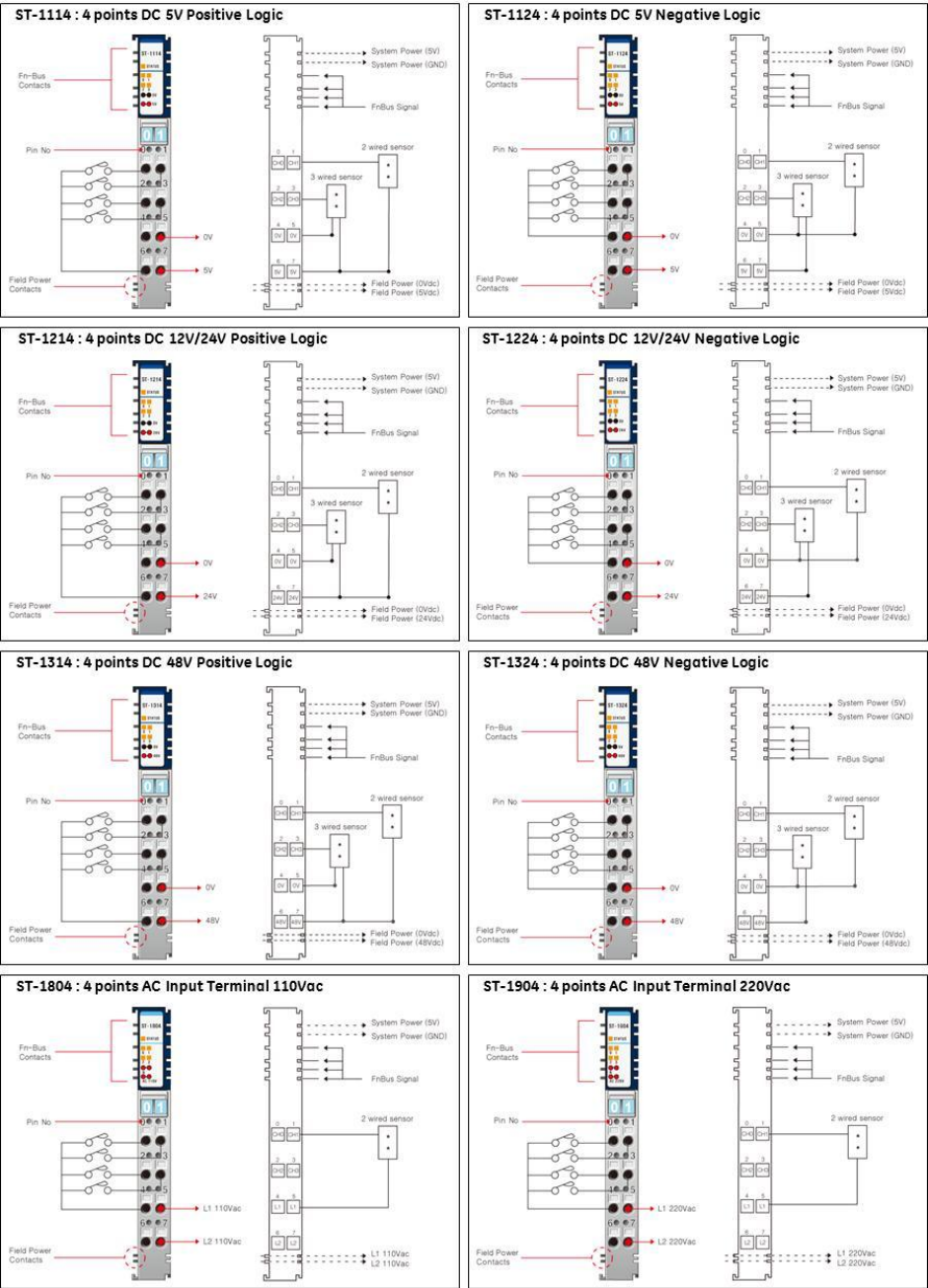
Page | 37
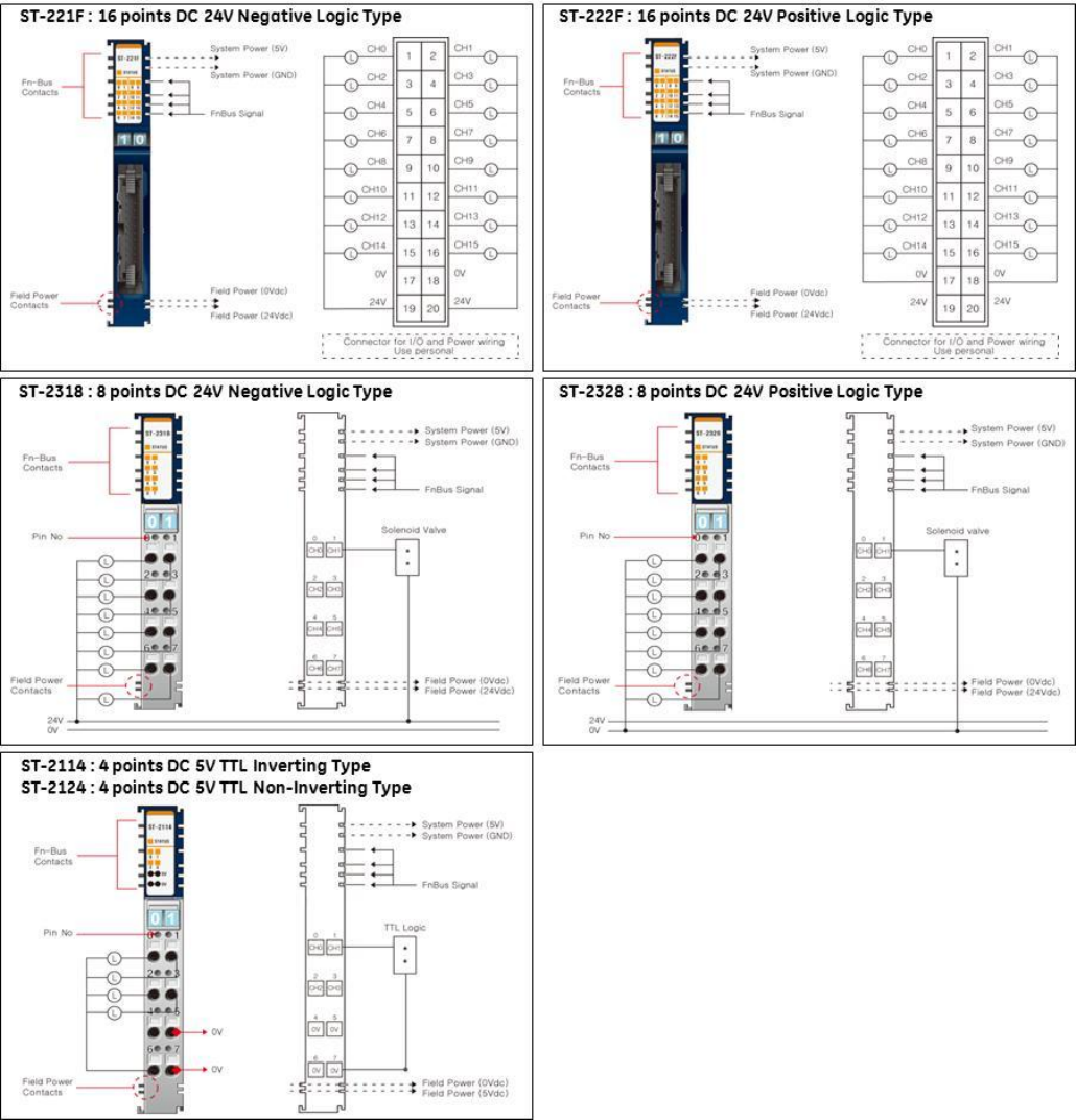
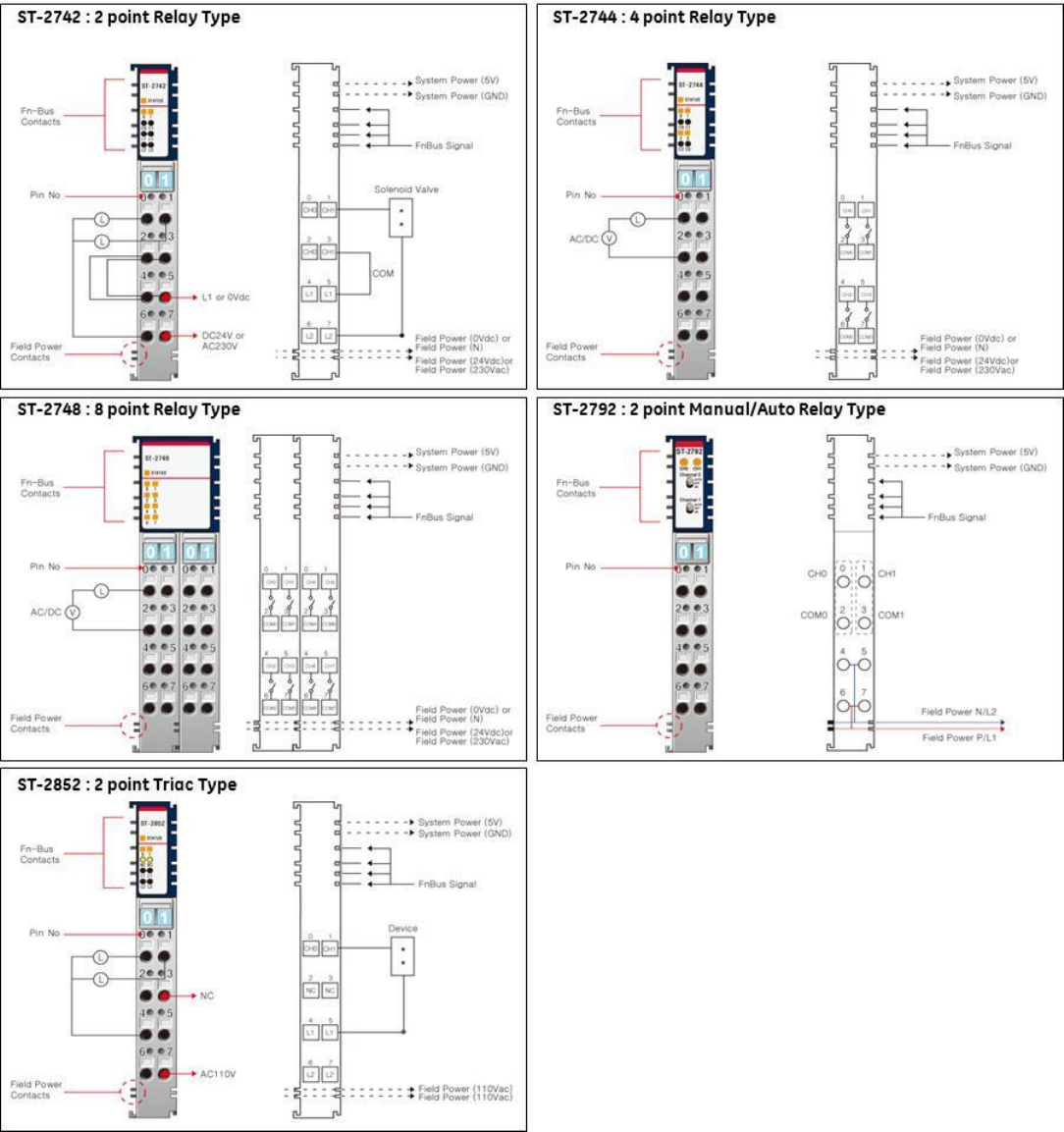
Discrete Digital Input Wiring Diagrams
*External Field Power and Field Power are same power.
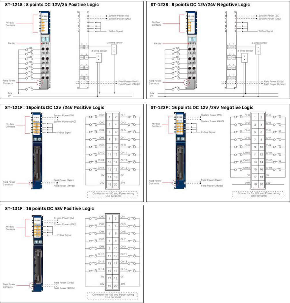
GE Intelligent Platforms RSTi MODBUS TCP/IP Starter Guide
Page | 38
*External Field Power and Field Power are same power.
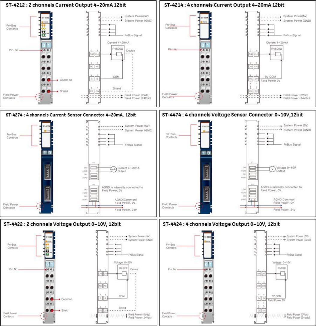
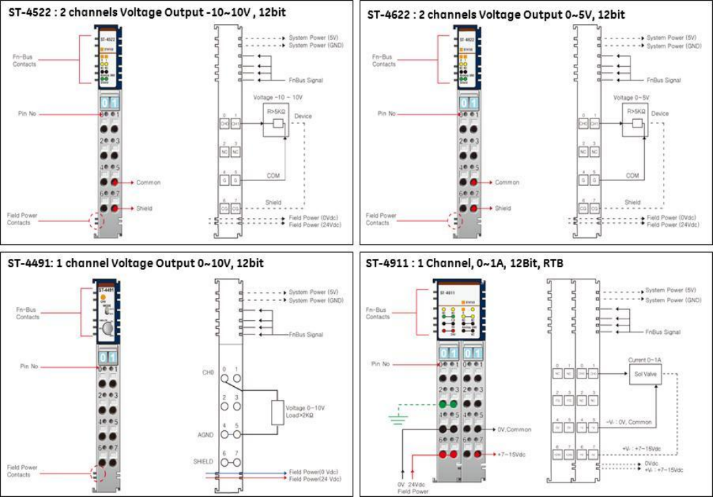
GE Intelligent Platforms RSTi MODBUS TCP/IP Starter Guide
Page | 40
GE Intelligent Platforms RSTi MODBUS TCP/IP Starter Guide
Page | 41
GE Intelligent Platforms RSTi MODBUS TCP/IP Starter Guide
Page | 42
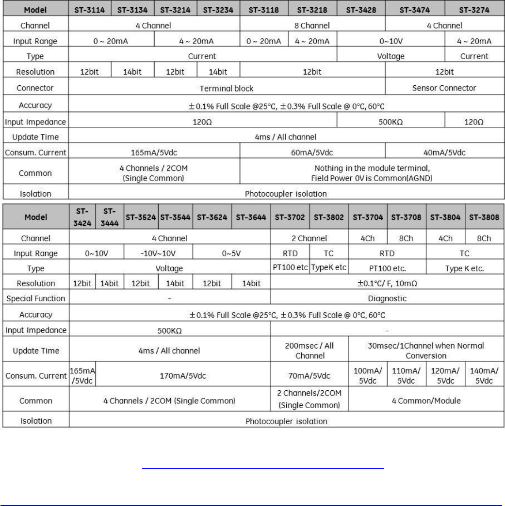
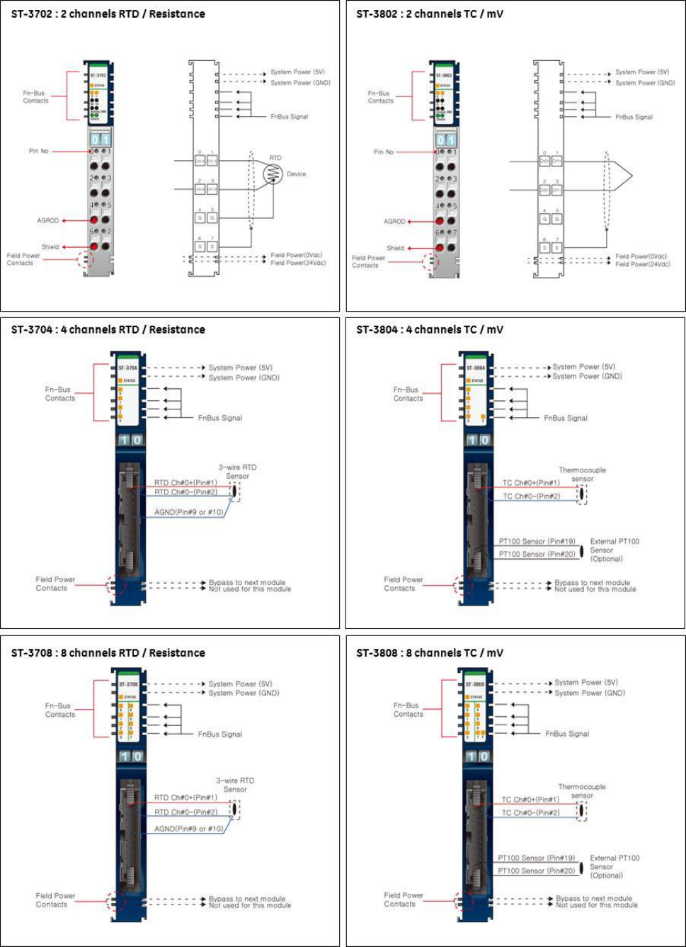
Analog Input Specifications
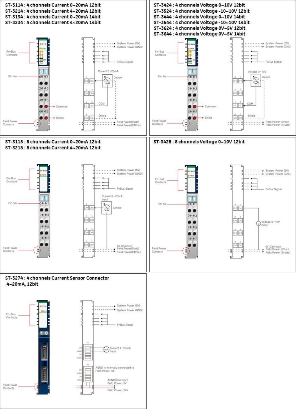
Note: The ST-3704, ST-3708, ST-3804 and ST-3808 require a 20 pin connector. The connector uses a Hirose ,
HIF3BA-20D-2.54C connector http://www.hirose.co.jp/cataloge_hp/e61000010.pdf
Note: The ST-3274 requires Sensor Connect 3M Mini-Clamp Plug, 37104 Series
http://multimedia.3m.com/mws/mediawebserver?66666UuZjcFSLXTt4xMcLXTyEVuQEcuZgVs6EVs6E666666--
GE Intelligent Platforms RSTi MODBUS TCP/IP Starter Guide
Page | 43
Analog Input Wiring Diagrams
GE Intelligent Platforms RSTi MODBUS TCP/IP Starter Guide
Page | 44
GE Intelligent Platforms RSTi MODBUS TCP/IP Starter Guide
Page | 46
GE Intelligent Platforms RSTi MODBUS TCP/IP Starter Guide
Page | 47
GE Intelligent Platforms RSTi MODBUS TCP/IP Starter Guide
Page | 48
Serial Module Specifications
Serial Module Wiring Diagrams
GE Intelligent Platforms RSTi MODBUS TCP/IP Starter Guide
Page | 49
GE Intelligent Platforms RSTi MODBUS TCP/IP Starter Guide
Page | 50
Motion Module Specifications – High Speed Counter
GE Intelligent Platforms RSTi MODBUS TCP/IP Starter Guide
Page | 51
Motion Module Wiring – High Speed Counter
GE Intelligent Platforms RSTi MODBUS TCP/IP Starter Guide
Page | 52
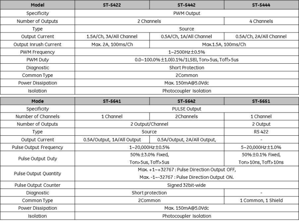
Motion Module Specifications – PWM and Pulse Train Outputs
GE Intelligent Platforms RSTi MODBUS TCP/IP Starter Guide
Page | 53
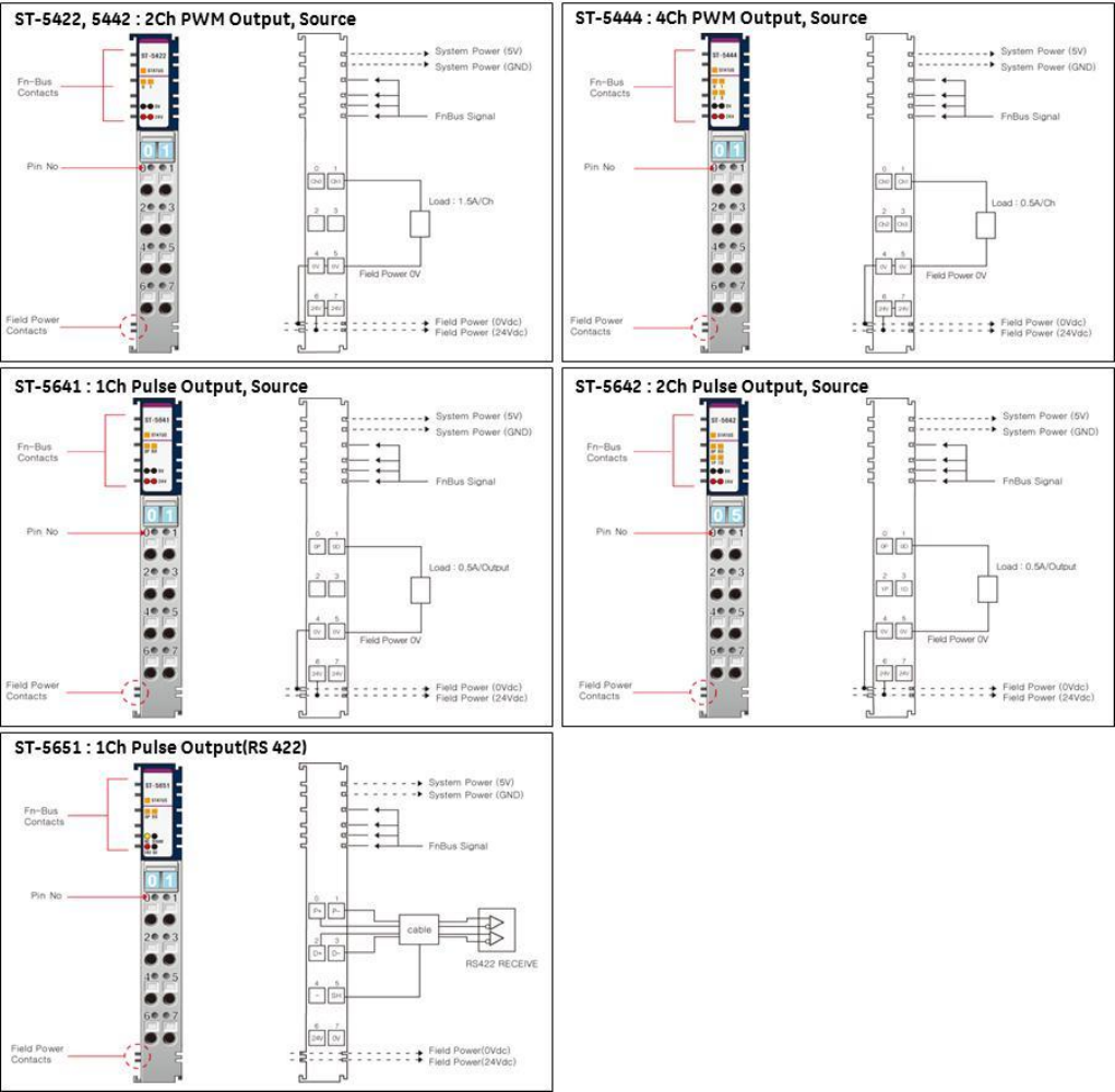
Motion Module Wiring – PWM and Pulse Train Outputs
GE Intelligent Platforms RSTi MODBUS TCP/IP Starter Guide
Page | 54
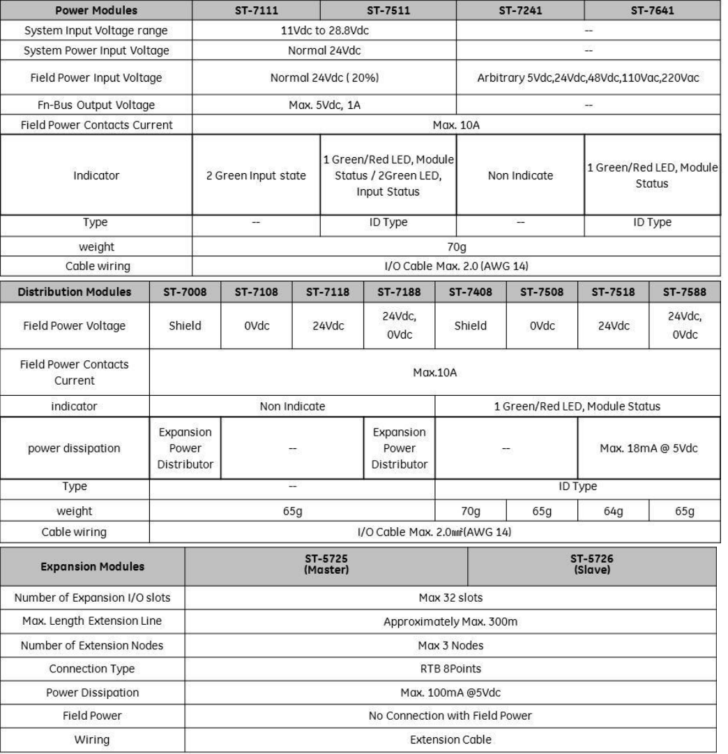
System Modules Specifications
Note: The Bus Master (ST-5725) and Slave (ST-5726) enables the RSTi to break the bus in the event that panel
width or the user wishes to distribute the modules. When expansion is required, add a Bus Master to the end
of the DIN rail section, then put in a Bus Slave at the beginning of the next set of I/O modules. Connection
between the master and slave is a twisted shielded cable. The master and slave have screw terminals so you
don’t need special connectors. The Master-Slave network is NOT multi-drop. Each Master can have only 1
Slave. You can add more drops by putting a Master at the end of the second DIN rail and connecting to
another Slave. The limit is 3 Master Slave pairs with a total distance of 300 meters. The maximum number of
modules allowed is a total of 32, Master and Slave modules occupy a module address.
GE Intelligent Platforms RSTi MODBUS TCP/IP Starter Guide
Page | 55
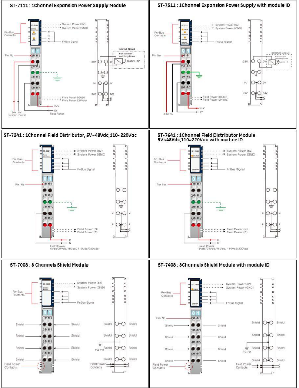
System Modules Wiring
GE Intelligent Platforms RSTi MODBUS TCP/IP Starter Guide
Page | 56
GE Intelligent Platforms RSTi MODBUS TCP/IP Starter Guide
Page | 57
