104131 Catalog
85729-Catalog 85729-Catalog 85729-Catalog Batch9 unilog cesco-content
2014-07-30
: Pdf 104131-Catalog 104131-Catalog 079458 Batch6 unilog
Open the PDF directly: View PDF ![]() .
.
Page Count: 212 [warning: Documents this large are best viewed by clicking the View PDF Link!]

POWR-GARD®
PRODUCTS
CATALOG
Indicating Fuses • Blocks & Holders • Relays & Controls • MOVs • Medium Voltage Fuses
®
POWR-GARD® PRODUCTS CATALOG

Noida
Roskilde
Kaunas
Norwich
Muzquiz
Bellingham
Matamoros
Boston
Baldwinsville
Bremen
Trollhättan
Saskatoon
Piedras Negras
Seoul Yokohama
Suzhou
Wuxi Shanghai
Taipei
Dongguan
Shenzhen
Hong Kong
Lipa City
Singapore
São Paulo
Lake Mills
Rapid City
Chicago
Champaign
Swindon
Fuses & Holders
UL Class Fuses
Medium Voltage Fuses
High-Speed Fuses
UL Class Fuse Blocks
Dead-Front Fuse Holders
Indicating Products
Power Distribution Blocks
OEM Custom Products
A Broad Portfolio of Circuit Protection
Products, Relays and Controls
Technical & Safety Resources
Datasheets
White Papers
CAD Drawings
Electrical Curves
Training Videos
Technical Articles
High Power Test Lab
Technical Hotline
Relays & Controls
Ground-Fault Protection
Trailing Cable Protection
Resistance Grounding
Motor & Pump Protection
Arc-Flash Protection
Generator Controls
Engine Control & Diagnosis
Custom Products
Littelfuse App!
Download our free
Littelfuse Catalogs
and Literature App to
keep our products and
technical resources at
your finger tips!
Littelfuse products help protect
electrical equipment used in
construction, general industrial,
oil & gas, solar, mining, and OEM
applications. We offer a broad and
reliable selection of fuses, fuse blocks,
protection relays, and generator
controls to improve safety and
reduce downtime.
For decades, we have helped OEMs, electrical
installers, design engineers and end-users select
the right product for their applications. Today,
Littelfuse offers a broader range of products
addressing protection, sensing, and control needs
while still providing the same great service and
support that customers have learned to expect.
Local Resources for a GLOBAL Market

1littelfuse.com © 2014 Littelfuse POWR-GARD® Products Catalog
Fuses
Class L Fuses ..................................................................................... 8
Class RK1 Fuses ............................................................................... 13
Class RK5 Fuses .............................................................................. 16
Class K5 Fuses ................................................................................. 20
Class J Fuses ................................................................................... 21
Class T Fuses ................................................................................... 24
Class G Fuses ................................................................................... 26
Class CC / CD Fuses .........................................................................27
UL Supplemental / 10 x 38 Fuses .....................................................30
Electronic Fuses & Automotive Blade
Glass / Electronic Fuses ...................................................................33
Blade / Automotive Fuses ................................................................36
Medium Voltage Fuses
Medium Voltage Fuses Overview ...................................................39
R-Rated Medium Voltage Fuses .....................................................40
E-Rated Medium Voltage Fuses .....................................................42
Telecommunication Products
Telecommunications Power Fuses ..................................................50
Special Purpose Fuses
Solar Products Overview ................................................................56
1500 Vdc Solar Rated Fuses ........................................................... 57
1000 Vdc Solar Rated Fuses ...........................................................59
Forklift / Stud Mounted Fuses ......................................................... 62
Plug Fuses ........................................................................................ 63
MEGA® Bolt-Down Fuses ............................................................... 63
In-Line Fuses & Holders ..................................................................64
Cable Limiters .................................................................................. 65
Cylindrical Fuses ..............................................................................66
OEM Custom Products .................................................................... 67
L Series (Traditional) Semiconductor Fuses ................................... 69
LA Series (Alternate Dimension) Semiconductor Fuses ................ 71
Square Body Semiconductor Fuses ................................................ 77
Fuse Blocks & Holders
LF Series Fuse Blocks Overview .....................................................83
Class J Fuse Blocks .........................................................................85
Class H , K5 & R Fuse Blocks ...........................................................88
Class T Fuse Blocks .........................................................................94
Class G Fuse Blocks .........................................................................99
Class CC / CD & Midget Fuse Blocks ............................................. 101
LF Series Fuse Block Covers ......................................................... 105
Solar Rated Fuse Blocks ................................................................ 106
Dead Front Fuse Holders ............................................................... 109
Miscellaneous Fuse Blocks & Holders ..........................................116
Semiconductor Fuse Blocks .......................................................... 120
Distribution & Splicer Blocks ........................................................ 122
In-Line Fuse Holders ...................................................................... 132
Pre-Engineered Solutions
LCP Fused Selective Coordination Panel ...................................... 138
LPS Series POWR-Switch (Shunt Trip Disconnect)...................... 141
Protection Relays & Controls
Relay & Control Products Overview ............................................. 143
Feature Comparisons .................................................................... 146
Ground-Fault Protection ................................................................148
Trailing Cable Protection ............................................................... 151
Resistance Grounding & NGR Monitoring.................................... 152
Motor Protection ........................................................................... 154
Pump & Feeder Protection ............................................................ 156
Arc-Flash Protection ...................................................................... 157
Industrial GFCI (Shock-Block™) ..................................................... 157
Generator & Single-Function Protection ...................................... 158
Generator Control ..........................................................................163
Engine Control & Diagnosis .......................................................... 167
Alarm Monitoring .......................................................................... 168
Custom-Engineered Electrical Equipment .................................... 170
Relay & Control Accessories ........................................................ 171
Suppression Products
Industrial Varistor Products .......................................................... 173
Surge Suppression Fuses .............................................................. 175
BVSP Suppression Fuses............................................................... 176
Miscellaneous Accessories
Fuse Reducers ............................................................................... 178
Box Cover Units ............................................................................. 179
Fuse Replacement & Custom Kit (FRCK Series) ........................... 180
Fuse Display & Cabinet ................................................................. 181
Technical Application Guide
Fuseology Fundamentals ...............................................................183
Selection Considerations .............................................................. 184
Time-current Curves & Peak Let-through Charts ......................... 189
Selective Coordination .................................................................. 191
UL / CSA Fuse Classes & Applications .......................................... 194
Terms & Definitions ....................................................................... 196
Motor Protection Tables................................................................203
Alphanumeric Index of Catalog Numbers ....................................206
Condensed Fuse Cross Reference ................................................208
Table of Contents
1
2
3
4
7
5
8
6
9
10
11
1
6
2
7
3
8
5
10
11
4
9

2© 2014 Littelfuse POWR-GARD® Products Cataloglittelfuse.com
UL CLASS LITTELFUSE
SERIES OVERLOAD
CHARACTERISTICS
AC RATINGS DC RATINGS RECOMMENDED
FUSE BLOCKS AND
FUSE HOLDERS
FUSE SERIES
PAGE
NUMBERS
VOLTAGE
(VOLTS) CURRENT
(AMPERES) INTERRUPTING
(AMPERES) VOLTAGE
(VOLTS) CURRENT
(AMPERES) INTERRUPTING
(AMPERES)
L
KLPC Time-Delay 600 200 - 6000 200K / 300K* 480 200 - 6000 20,000
–
8
KLLU Time-Delay 600 601 - 4000 200,000 300 601 - 4000 20,000 9
LDC Fast-Acting 600 150 - 2000 200,000 600 150 - 2000 50,000 10
RK1
LLNRK Time-Delay 250 0.1 - 600
200K / 300K*
125 0.1 - 600
20,000
LFR25 13
LLSRK_ID Time-Delay 600 0.1 - 600 300 0.1 - 600 LFR60 13
LLSRK Time-Delay 600 0.1 - 600 300 0.1 - 600 LFR60 13
KLNR Fast-Acting 250 1 - 600
200,000
125 1 - 600 LFR25 15
KLSR Fast-Acting 600 1 - 600 250
300
1 - 30
35 - 600 LFR60 15
RK5
FLNR_ID
Time-Delay
250 35 - 600
200K / 300K*
125 35 - 600
20,000
LFR25 17
FLNR 250 0.1 - 600 125 0.1 - 600 17
FLSR_ID 600 0.1 - 600 300 0.1 - 600
LFR60
17
FLSR 600 0.1 - 600 300 0.1 - 600 17
IDSR 600 0.1 - 600 600 0.1 - 600 16
J
JTD_ID Time-Delay 600 0.8 - 600 200K / 300K* 300
500
0.8 - 100
110 - 600 20,000 LFJ60 • LFPSJ
21
JTD Time-Delay 600 0.8 - 600 21
JLS Fast-Acting 600 1 - 600 200,000 – – – 22
T
JLLN
Fast-Acting
300 1 - 1200
200,000
160
125
1 - 60
70 - 1200 20,000
LFT30 •
LSCR002 (700-800A) 24
JLLS 600 1 - 1200 300 1 - 1200 LFT60 •
LSCR002 (700-800A) 24
CC
CCMR Time-Delay 600 0.2 - 30 200K / 300K*
250
250
300
500
0.2 - 2
4.5 - 10
2.25 - 4
12 - 30 20,000
L60030C • LFPSC •
LINK00_C •
571 • 572 •
LEC • LEY
27
KLDR Time-Delay 600 0.1 - 30 200,000 300 0.1 - 30 28
KLKR Fast-Acting 600 0.1 - 30 200,000 300 0.1 - 30 28
CD CCMR Time-Delay 600 35 - 60 200K / 300K* 250 35 - 60 20,000 LFC60060 27
GSLC Time Lag 600
480
0.2 - 20
25 - 60 100,000 170 0.5 - 60 10,000 LFG480 (1 - 20A) 26
LFG480 (25 - 60A)
Solar
SPF Solar – – – 1000 1 - 30 20,000 LFPHV 60
SPFJ Solar – – – 1000 70 - 450
20K (70 - 200A)
10K (250 - 400A)
20K (400A)
LFJ1000 61
SPFI Solar – – – 1000 2 - 20 20,000 Not Required 59
SPXV Solar – – – 1500 6 - 30 30,000 LPXV 57
SPXI Solar – – – 1500 2.5 - 3.5 15,000 Not Required 58
K5
NLN
Fast-Acting
250 1 - 600
50,000
250 1 - 600 20K (1 - 60A)
50K (70 - 600A) LFH25 20
NLS 600 1 - 600
600
500
400
600
500
1 - 7
8 - 30
35 - 60
70 - 200
225 - 600
20K (1 - 60A)
50K (70 - 600A) LFH60 20
Semiconductor
L15S
Very Fast-Acting
150 1 - 1000
200,000
150
100
1 - 60
70 - 1000
20,000 LSCR • 1LS
(except L70S)
69
L25S 250 1 - 800 250
200
1 - 200
225 - 800 69
L50S 500 10 - 800 450 10 - 800 69
L60S 600 1 - 800 – – 69
L70S 700 10 - 800 650 10 - 800 69
Midget
(Supplementary)
BLF Fast-Acting 250
125
0.5 - 15
20 - 30 10,000 – – –
L60030M • LFPSM •
LINK00_M •
571 • 572 •
LEB • LEX
30
BLN Fast-Acting 250 1 - 30 10,000 – – – 30
BLS Fast-Acting 600
250
0.2 - 5
6 - 10 10,000 – – – 31
FLA Time-Delay 125 0.1 - 30 10,000 – – – 31
FLM Time-Delay 250 0.1 - 30 10,000 125 0.1 - 30 10,000 30
FLQ Time-Delay 500 0.1 - 30 10,000 300 0.1 - 30 10,000 30
KLK Fast-Acting 600 0.1 - 30 100K / 200K* 500 0.1 - 30 50,000 30
KLKD Fast-Acting 600 0.1 - 30 100,000 600 0.1 - 30 50,000 30
KLQ Time-Delay 600 1 - 6 10,000 – – – 31
FLU Fast-Acting 1000 0.44
11
10,000
20,000 1000 0.44
11
10,000
20,000 LFPHV 31
Plug SOO, TOO Time-Delay 125 0.25 - 30 10,000 – – – Box Cover Units 63
SLO, TLO Medium Time-Delay 125 15 - 30 10,000 – – –
Telecom
L17T
Fast-Acting
– – –
170
70 - 1200
100,000
LTFD Series 50
TLN – – – 1 - 600 LFR25 51
TLS – – – 1 - 125 LTFD101 •
LFT30060 (cartridge) 52
* Series are UL Listed with I.R. of 200,000A and Littelfuse® self-certified with 300,000A I.R.
UL FUSE CLASSES AND SELECTION CHART

3littelfuse.com © 2014 Littelfuse POWR-GARD® Products Catalog
UL FUSE CLASS POWR-PRO®PAGE NUMBERS
Class L KLPC & LDC 8, 10
Class RK1 LLNRK/LLSRK_ID 13
Class J JTD/JTD_ID 21
Class CC / CD CCMR (2/10–60) 27
TM
Increase safety and reduce inventory
with MROplus
Your detailed reports will include:
• A streamlined current-limiting fuse inventory
recommendation
• A guide to reducing electrical hazards within your facility
• An annual cost savings estimate
• A detailed cross reference
All you need to do is e-mail an Excel file of your fuse inventory
to techline@littelfuse.com or to your local sales representative.
We will do the rest!
Look for the POWR-PRO® logo
for superior protection
Littelfuse POWR-GARD®–
Advanced Protection and
Facility Savings
Increase safety with POWR-PRO® Fuses
• Superior current-limitation from 1/10 – 6000 amperes
• Type 2 “No Damage” coordination with NEMA
and IEC motor circuits
• Blown fuse indication (LLSRK_ID and JTD_ID Series)
• Compact motor protection (JTD/JTD_ID, CCMR Series)
• 300,000 AIR to meet trends toward higher SCCR

4© 2014 Littelfuse POWR-GARD® Products Cataloglittelfuse.com
SPXV Series Space-Saving Solar Fuse ................... 57
SPXI Series In-Line Solar Fuse ................................58
LPXV Series 1500 Vdc Fuse Holder ...................... 106
New Products............................... littelfuse.com/solar
SPF Series 1000 Vdc 10x38mm Fuse.......................60
SPFJ Series 1000 Vdc Class J size Fuse ................... 61
LFPHV 1000 Vdc Fuse Holder ................................. 109
IDSR Series 600 Vdc Class RK5 Fuse ....................... 16
KLKD Series 600 Vdc 10x38 Fuse ............................ 30
SE-601 Ground-Fault Protection Relay ................... 148
1500 Vdc Solar Products 600-1000 Vdc Solar Products
Look for this logo to indicate products that are used in solar applications.
Visit our website littelfuse.com/solar for the latest updates on
approvals, certifications, and new products.
POWR-GARD® SOLAR RATED PRODUCTS
This catalog incorporates our line of products designed specifically for the growing solar industry. As global
standards are constantly changing, Littelfuse continues to develop circuit protection products that meet the
requirements of the evolving photovoltaic market.
Developing Next Generation
1500 Vdc Products for High
And Low Current Ratings
5littelfuse.com © 2014 Littelfuse POWR-GARD® Products Catalog
Enhanced
Overload Relays
Protect motors and
pumps from over/
under current, over/
under voltage, phase
issues and ground
faults. Communication
modules also available.
Voltage/Phase
Monitors
A cost-effective means
to protect motors and
pumps from voltage
and phase issues.
Alternating
Relays
Start and stop up to
four pumps or use as
a multi-channel switch.
Intrinsically safe
options available.
Pump
Controllers
Balance runtime
between loads and can
be used in hazardous
locations.
Load Sensors
Detect if the load is
running or if there is an
overload or underload
condition.
Timers &
Flashers
Delay starting
and stopping
loads, cycling, and
sequencing of motors,
pumps, compressors,
heaters, and lighting.
PROTECTION RELAYS & CONTROLS
Expanding our Line of Motor Protection Products
SymCom and SSAC manufacture robust products such as motor monitoring, protection and control
relays, electronic controls, timers and flashers. SymCom and SSAC products are used to control and
protect applications in the Industrial Pumping, Irrigation, Water and Waste Water, HVAC/R, Oil and Gas,
Food and Beverage, and Elevator markets.
Littelfuse
Acquires
SymCom
SymCom has three key brands:
SymCom and SSAC products include:
For more information visit SymCom.com, SSAC.com or Littelfuse.com/Electrical

6© 2014 Littelfuse POWR-GARD® Products Cataloglittelfuse.com
LCP Series Coordination Panel
Ideal for circuits that require selective coordination
such as emergency lighting circuits or essential
electrical systems.
Features/Benefits
• Meets NEC® requirements
• Class CC & J fuse holders have open-circuit indication
• Fast-acting fuses protect against short circuits
• Feed through/sub feed lugs and 84-circuit
configuration available
• Ground and neutral bars
• Copper bus standard
littelfuse.com/LCP
See page 141
LPS Series POWR-Switch
Individual fusible shunt trip disconnect switch easily
coordinates with system’s overcurrent protection.
Typical applications include elevator circuits.
Features/Benefits
• Pre-engineered single unit makes procurement easy
• Reduces labor costs up to 66%
• Flexibility for a variety of applications
• Control power terminal block
• UL Listed package
• Cu and AI wire rated
• Lockable operating handle meets all code and
safety requirements
littelfuse.com/LPS
See page 143
Meet NEC® Requirments
And Save Time With
Pre
-
Engineered Solutions

7littelfuse.com © 2014 Littelfuse POWR-GARD® Products Catalog
FUSES
UL Class L Fuses ........................................................ 8
UL Class RK1 Fuses .................................................... 13
UL Class RK5 Fuses....................................................16
UL Class J Fuses .......................................................21
UL Class T Fuses .......................................................24
UL Class G Fuses ......................................................26
UL Class CC & CD Fuses ..............................................27
UL Supplementary Midget (10x38) Fuses ........................... 30
Table of Contents
Section Overview
For over 85 years Littelfuse® has been providing fuses to the electrical
market. You can continue to count on our manufacturing and supply
chain processes to deliver high quality fuses when you need them.
At Littelfuse we leverage our global reach to stay on top of the latest
applications and standards. Whether your circuit protection needs are
focused on OEM, MRO, or construction, we are committed to being
your circuit protection partner and appreciate your business.

8© 2014 Littelfuse POWR-GARD® Products Cataloglittelfuse.com
UL Class L Fuses
Fuses – UL Class L
KLPC SERIES POWR-PRO® FUSES
600 Vac • Time-Delay • 200-6000 A
Web Resources
Download TC Curves, CAD drawings and other technical
information: littelfuse.com/klpc
Dimensions
Please refer to the Class L dimensions ............................. 12
Peak Let-Thru Curve
Note: For more information, see Peak Let-Thru Table on pg. 11
Ordering Information
KLPC
Description
KLPC series POWR-PRO® fuses meet or exceed the most
stringent project specifications, including silver links, silver-plated
copper end bells, glass-reinforced melamine bodies, O-ring seals
between body and end bells, and granular quartz fillers.
Applications
• Switchboard mains and feeders
• Motor control center mains
• Large motor branch circuits
• Protection of power circuit breakers
Features/Benefits
• POWR-PRO® Performance
• Best-in-class time-delay withstand
• Current-Limiting
• Easily coordinated with other system components
• 300 kA AC Interrupting Rating (self-certified)
Specifications
Voltage Ratings AC: 600 Vac or less
DC: 480 V
Ampere Range 200 – 6000 A
Interrupting Ratings AC: 200 kA rms symmetrical
300 kA rms symmetrical
(Littelfuse self-certified)
DC: 20,000 A
Approvals AC: Standard 248-10, Class L
UL Listed 601–6000 A (File: E81895)
UL Recognized 200–600 A (File: E71611)
CSA Certified 601–6000 A (File: LR29862)
Federal Specifications 700–6000 A
(QPL-W-F-1814)
DC: Littelfuse self-certified
Material Melamine body, Copper caps (silver plated)
Country of Origin Mexico
AMPERE RATINGS
200 500 800 1350 2000 3000
250 600 900 1400 2100 3500
300 601 1000 1500 2200 4000
350 650 1100 1600 2300 4500
400 700 1200 1800 2400 5000
450 750 1300 1900 2500 6000
SERIES AMPERAGE CATALOG NUMBER ORDERING NUMBER
KLPC 800 KLPC800 KLPC800.X
1
9littelfuse.com © 2014 Littelfuse POWR-GARD® Products Catalog
UL Class L Fuses
Fuses – UL Class L
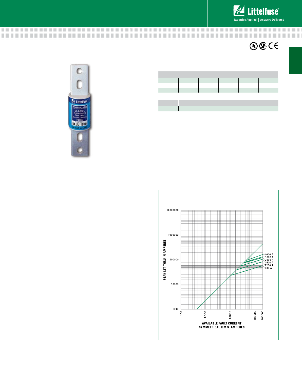
KLLU SERIES FUSES
600 Vac • Time-Delay • 601-4000 A
Web Resources
Download TC Curves, CAD drawings and other technical
information: littelfuse.com/kllu
Dimensions
Please refer to the Class L dimensions ............................. 12
Peak Let-Thru Curve
Note: For more information, see Peak Let-Thru Table on pg. 11
Ordering Information
KLLU
Description
KLLU series fuses meet or exceed UL requirements for
UL Class L fuses. The KLLU series offers an economical
alternative to KLPC POWR-PRO® fuse with a slightly
higher peak let through current.
Applications
• Service switches
• Switchboard mains and feeders
• Motor control center mains
• Large motor branch circuits
• Circuit breaker protection
Features/Benefits
• Current-Limiting
• Easily coordinated with other system components
• 200 kA AC Interrupting Rating
Specifications
Voltage Ratings AC: 600 Vac or less
DC: 300 V
Ampere Range 601–4000 A
Interrupting Ratings AC: 200 kA rms symmetrical
DC: 20 kA rms symmetrical
Approvals Standard 248-10, Class L
UL Listed (File: E81895)
CSA Certified (File: LR29862)
DC: Littelfuse self-certified
Material Melamine body, Copper caps (silver plated)
Country of Origin Mexico
AMPERE RATINGS
601 750 1000 1400 1800 3000
650 800 1200 1500 2000 3500
700 900 1350 1600 2500 4000
SERIES AMPERAGE CATALOG NUMBER ORDERING NUMBER
KLLU 601 KLLU601 KLLU601.X
1
10 © 2014 Littelfuse POWR-GARD® Products Cataloglittelfuse.com
UL Class L Fuses
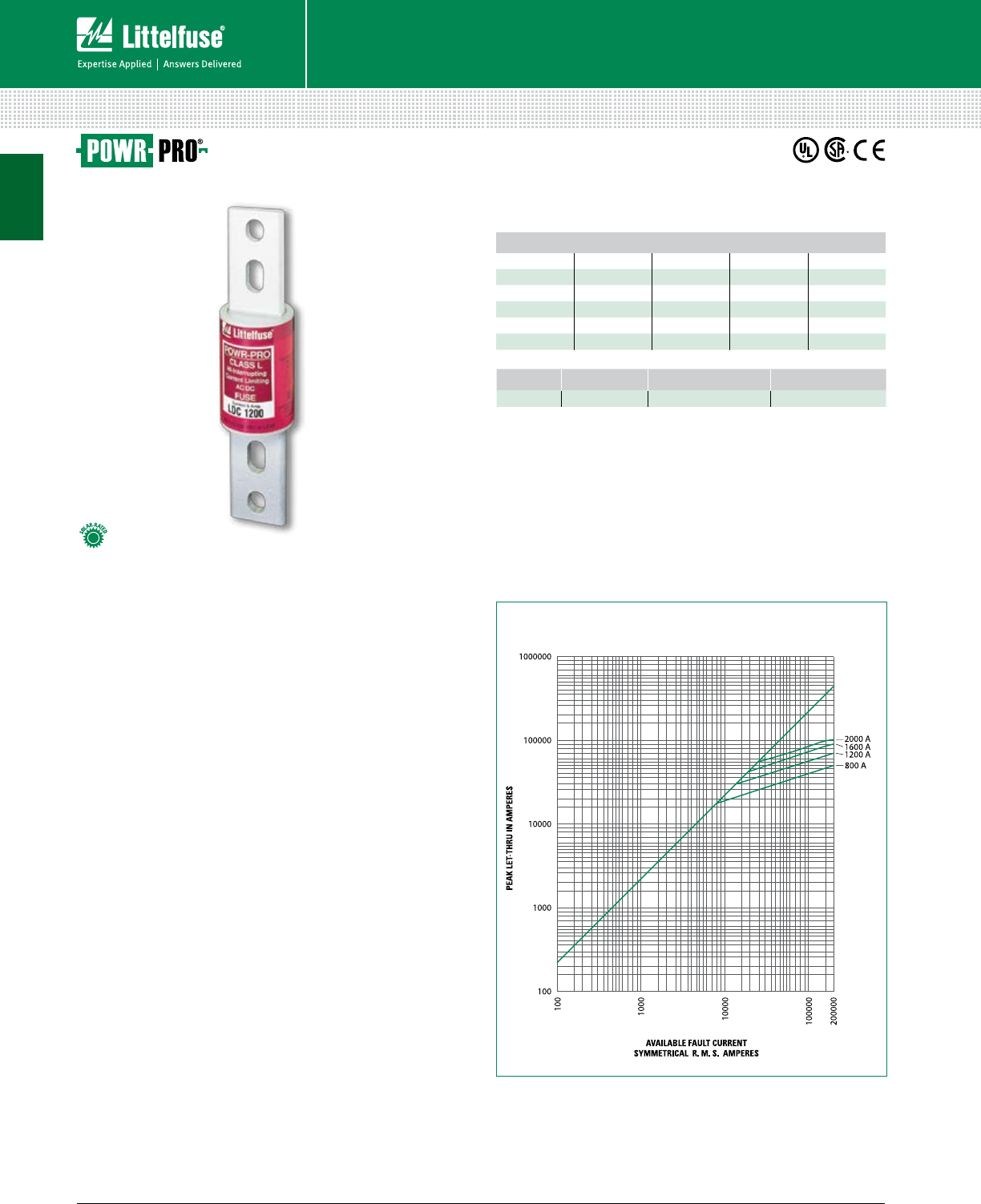
LDC SERIES POWR-PRO® FUSES
600 Vac/dc • Fast Acting • 150-2000 A
Description
High DC voltage and interrupting ratings make the
POWR-PRO® LDC ideal for DC applications. The DC
interrupting performance exceeds UL listing requirements.
Applications
• Solar inverter and array protection
• UPS protection especially for large battery circuits
• DC distribution and variable speed drives
• Mass transit systems
Features/Benefits
• POWR-PRO® Performance
• Extremely Current-Limiting
• 600 Vac/dc rated
• 200 kA AC Interrupting Rating
• 50 kA DC Interrupting Rating
Specifications
Voltage Ratings 600 Vac/dc or less
Ampere Range 150–2000 A
Interrupting Ratings AC: 200 kA rms symmetrical
DC: 50 kA
Time Constant 16 ms
Approvals Standard 248-10, Class L
UL Listed 601–2000 A (File: E81895)
UL Recognized 150–600 A (File: E71611)
CSA Certified (File: LR29862)
Material Melamine body, Copper caps (silver plated)
Country of Origin Mexico
AMPERE RATINGS
150 450 750 1201 1601
200 500 800 1300 1800
250 600 900 1350 1900
300 601 1000 1400 2000
350 650 1100 1500
400 700 1200 1600
Web Resources
Download TC curves, CAD drawings and other technical
documents: littelfuse.com/ldc
Dimensions
Please refer to the Class L dimensions ............................. 12
Peak Let-Thru Curve
Note: For more information, see Peak Let-Thru Table on pg. 11
SERIES AMPERAGE CATALOG NUMBER ORDERING NUMBER
LDC 700 LDC700 0LDC700.X
Ordering Information
LDC
Fuses – UL Class L
1

11 littelfuse.com © 2014 Littelfuse POWR-GARD® Products Catalog
UL Class L Fuses
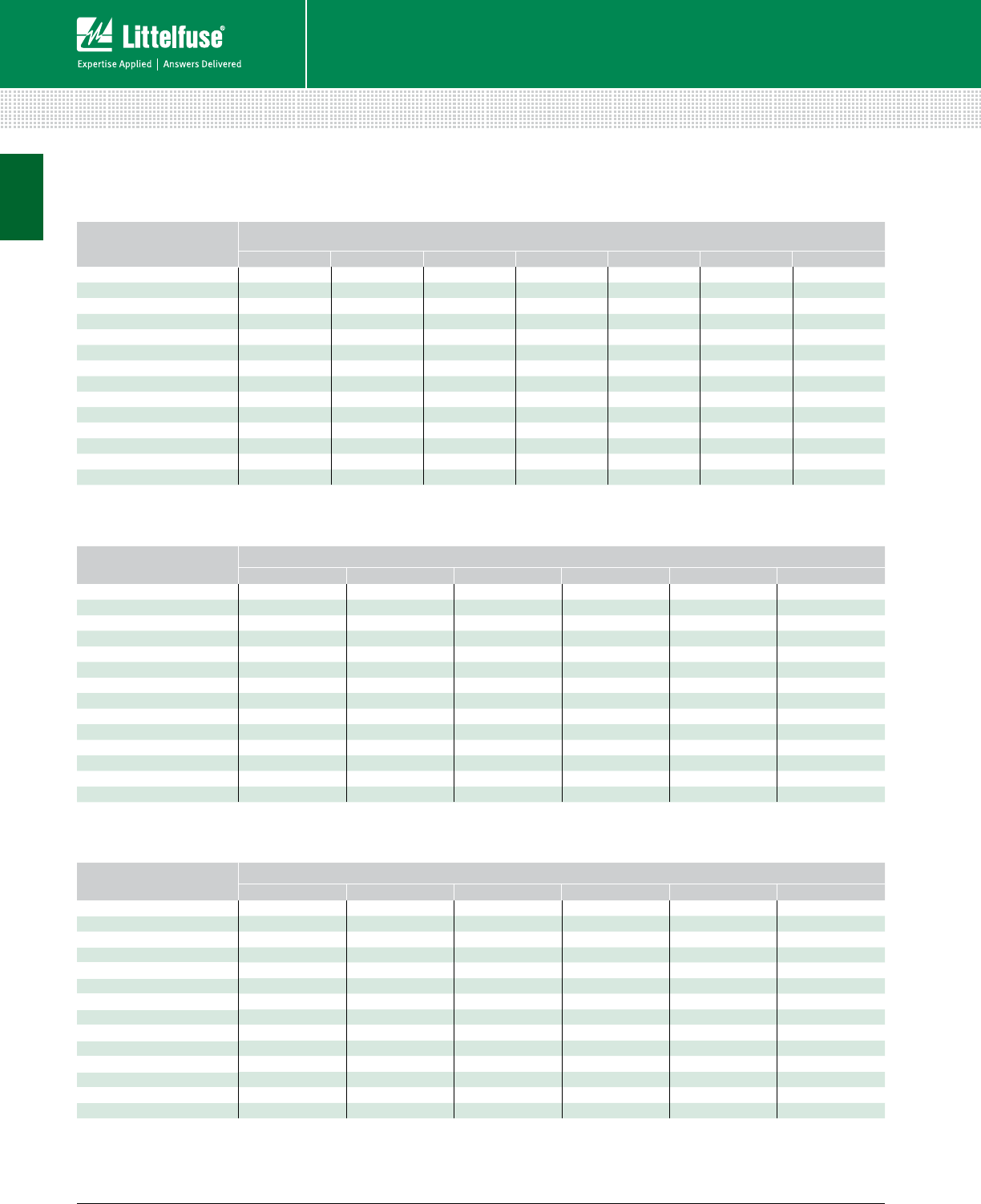
SHORT CIRCUIT
CURRENT*
APPARENT RMS SYMMETRICAL CURRENT FOR VARIOUS FUSE RATINGS
800 A 1200 A 1600 A 2000 A 3000 A 4000 A 5000 A 6000 A
5,000 5,000 5,000 5,000 5,000 5,000 5,000 5,000 5,000
10,000 8,800 10,000 10,000 10,000 10,000 10,000 10,000 10,000
15,000 10,500 13,500 15,000 15,000 15,000 15,000 15,000 15,000
20,000 12,000 15,000 19,000 20,000 20,000 20,000 20,000 20,000
25,000 13,000 16,000 21,000 24,000 25,000 25,000 25,000 25,000
30,000 14,000 18,000 23,000 26,000 30,000 30,000 30,000 30,000
35,000 15,000 19,000 24,000 27,000 32,000 35,000 35,000 35,000
40,000 16,000 20,000 25,000 28,000 34,000 40,000 40,000 40,000
50,000 17,000 22,000 27,000 31,000 37,000 42,500 50,000 50,000
60,000 18,000 24,000 29,000 34,000 40,000 46,000 52,000 60,000
80,000 20,000 26,000 32,000 37,000 44,000 51,000 57,000 70,000
100,000 21,000 27,000 34,000 40,000 46,000 57,000 65,000 75,000
150,000 23,000 31,000 38,000 44,000 54,000 67,000 75,000 87,000
200,000 24,000 34,000 42,000 46,000 57,000 70,000 80,000 95,000
Current-Limiting Effects of KLPC (600 V) Fuses
Current-Limiting Effects of LDC (600 V) Fuses
SHORT CIRCUIT
CURRENT*
APPARENT RMS SYM MET RI CAL CURRENT FOR VARIOUS FUSE RATINGS
800 A 1200 A 1600 A 2000 A
5,000 5,000 5,000 5,000 5,000
10,000 8,500 10,000 10,000 10,000
15,000 9,750 14,000 15,000 15,000
20,000 10,500 15,000 19,000 20,000
25,000 11,500 16,000 21,000 25,000
30,000 12,000 17,000 22,000 26,000
35,000 12,500 18,000 23,000 28,000
40,000 13,500 19,000 24,000 30,000
50,000 14,000 21,000 26,000 32,000
60,000 15,000 22,000 28,000 34,000
80,000 16,000 24,000 30,000 36,000
100,000 18,000 25,000 33,000 40,000
150,000 20,000 30,000 38,000 44,000
200,000 23,000 32,000 41,000 46,000
*Prospective RMS Sym met ri cal Amperes Short-Circuit Current
Note: Data derived from Peak Let-Thru Curves
SHORT-CIRCUIT
CURRENT*
APPARENT RMS SYMMETRICAL CURRENT FOR VARIOUS FUSE RATINGS
800 A 1200 A 1600 A 2000 A 3000 A 4000 A
5,000 5,000 5,000 5,000 5,000 5,000 5,000
10,000 10,000 10,000 10,000 10,000 10,000 10,000
15,000 11,900 15,000 15,000 15,000 15,000 15,000
20,000 13,000 18,500 20,000 20,000 20,000 20,000
25,000 14,000 20,000 25,000 25,000 25,000 25,000
30,000 14,500 21,000 26,500 30,000 30,000 30,000
35,000 15,000 22,000 28,500 34,000 35,000 35,000
40,000 16,000 23,000 30,000 35,000 37,000 40,000
50,000 17,000 24,000 32,000 38,000 39,000 44,000
60,000 18,000 26,000 34,000 42,000 43,000 50,000
80,000 19,000 28,000 36,000 44,000 46,000 54,500
100,000 21,000 30,000 38,000 46,000 48,000 57,500
150,000 24,000 35,000 44,000 50,000 51,000 68,000
200,000 26,000 38,000 48,000 53,000 60,000 74,000
Current-Limiting Effects of KLLU (600 V) Fuses
CLASS L CURRENT-LIMITING EFFECTS
Fuses – UL Class L
1
12 © 2014 Littelfuse POWR-GARD® Products Cataloglittelfuse.com
UL Class L Fuses
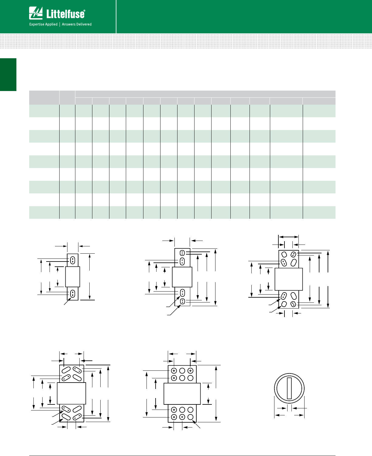
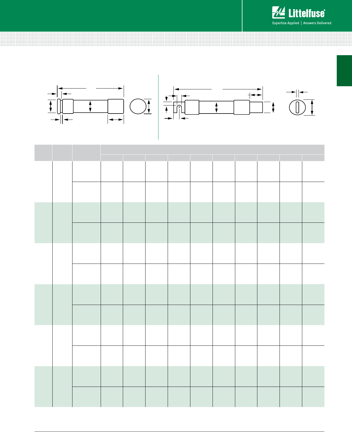
CLASS L SERIES DIMENSIONS
B
C
J
F
M
FIG.1
AABC
J
D E F
N
M
FIG.2
D E F
ABC
G
H
N
M
J
FIG. 3
BD
G
A F
H
J
M
FIG. 5
N
MG
D E F
ABC
H
J
FIG. 4
K
L
AMPERES FIG.
NO.
DIMENSIONS INCHES (mm)
A B C D E F G H J K L M N
150-800 133⁄4
(95.3)
53⁄4
(14 6.1)
63⁄4
(171.5) — —85⁄8
(219.1) — — 2
(50.8)
21⁄2
(63.5)
3⁄8
(9.5)
5⁄8 x 11⁄8
(15.9) x (28.6) —
900-1200 233⁄4
(95.3)
53⁄4
(14 6.1)
63⁄4
(171.5)
91⁄4
(235.0)
91⁄2
(241.3)
103⁄4
(273.1) — — 2
(50.8)
21⁄2
(63.5)
3⁄8
(9.5)
5⁄8 x 3⁄4
(15.9) x (19.1)
5⁄8 x 11⁄8
(15.9) x (28.6)
1300-1600 233⁄4
(95.3)
53⁄4
(14 6.1)
63⁄4
(171.5)
91⁄4
(235.0)
91⁄2
(241.3)
103⁄4
(273.1) — — 23⁄8
(60.3)
3
(76.2)
7⁄16
(11.1)
5⁄8 x 3⁄4
(15.9) x (19.1)
5⁄8 x 11⁄8
(15.9) x (28.6)
1800-2000 233⁄4
(95.3)
53⁄4
(14 6.1)
63⁄4
(171.5)
91⁄4
(235.0)
91⁄2
(241.3)
103⁄4
(273.1) — — 23⁄4
(69.9)
31⁄2
(88.9)
1⁄2
(12.7)
5⁄8 x 3⁄4
(15.9) x (19.1)
5⁄8 x 11⁄8
(15.9) x (28.6)
2100-2500 34
(101.6)
53⁄4
(14 6.1)
63⁄4
(171.5)
91⁄4
(235.0)
91⁄2
(241.3)
103⁄4
(273.1)
15⁄8
(41.3)
13⁄4
(44.5)
31⁄2
(88.9)
5
(127.0)
3⁄4
(19.1)
5⁄8 x 3⁄4
(15.9) x (19.1)
5⁄8 x 11⁄8
(15.9) x (28.6)
2501-3000 34
(101.6)
53⁄4
(14 6.1)
63⁄4
(171.5)
91⁄4
(235.0)
91⁄2
(241.3)
103⁄4
(273.1)
15⁄8
(41.3)
13⁄4
(44.5)
4
(101.6)
5
(127.0)
3⁄4
(19.1)
5⁄8 x 3⁄4
(15.9) x (19.1)
5⁄8 x 11⁄8
(15.9) x (28.6)
3500-4000 44
(101.6)
53⁄4
(14 6.1)
63⁄4
(171.5)
91⁄4
(235.0)
91⁄2
(241.3)
103⁄4
(273.1)
13⁄4
(44.5)
31⁄4
(82.6)
43⁄4
(120.7)
53⁄4
(14 6.1)
3⁄4
(19.1)
5⁄8 x 13⁄8
(15.9) x (34.9)
5⁄8 x 13⁄8
(15.9) x (34.9)
4500-5000 54
(101.6)
53⁄4
(14 6.1) —91⁄4
(235.0) —103⁄4
(273.1)
15⁄8
(41.3)
31⁄4
(82.6)
51⁄4
(133.4)
71⁄8
(181.0)
1
(25.4)
5⁄8 DIA.
(15.9) —
6000 54
(101.6)
53⁄4
(14 6.1) —91⁄4
(235.0) —103⁄4
(273.1)
15⁄8
(41.3)
31⁄4
(82.6)
51⁄4
(133.4)
71⁄8
(181.0)
1
(25.4)
5⁄8 DIA.
(15.9) —
Dimensions
Fuses – UL Class L
1

13 littelfuse.com © 2014 Littelfuse POWR-GARD® Products Catalog
UL Class RK1 Fuses
LLNRK / LLSRK / LLSRK_ID SERIES INDICATOR® FUSES
250/600 Vac • Dual Element • Time-Delay • 1/10-600 A
AMPERE RATINGS
1/10 1 2 8/10 6 1/420 75†225
15/100 1 1/83 7 25 80 250
2/10 1 1/43 2/10 7 1/2* 30 90 300
1/41 4/10 3 1/28 35 100 350
3/10 1 6/10 4 9 40 110 400
4/10 1 8/10 4 1/210 45 125 450
1/22 5 12 50 150 500
6/10 2 1/45 6/10 15 60 175 600
8/10 2 1/26 17 1/270 200
Note: All LLSRK_ID fuses rated 1 amp and above are Indicator® fuses.
*7.5 A is only available for the ID versions
†75 A is only available for the 600 V
Web Resources
Download TC Curves, CAD drawings and other technical
information: littelfuse.com/llsrk
littelfuse.com/llnrk
Recommended Fuse Blocks
LFR Series ......................................................................... 88
Dimensions
Please refer to the Class R dimensions ............................. 19
PEAK LET-THRU IN AMPERES
AVAILABLE FAULT CURRENT
SYMMETRICAL R.M.S. AMPERES
1000000
100000
10000
1000
100
200000
100000
10000
1000
100
500 A
400 A
200 A
100 A
60 A
30 A
Peak Let-Thru Curve (600 V)
Note: For more information, see Peak Let-Thru Table on pg. 14
Ordering Information
VOLTAGE SERIES AMP
INDICATION
CATALOG
NUMBER
ORDERING
NUMBER
600 LLSRK_ID 60 •LLSRK060ID LSRK060.TXID
600 LLSRK 60 –LLSRK060 LSRK060.T
250 LLNRK 80 –LLNRK080 LNRK080.V
LLSRK
QP
L
Fuses – UL Class RK1
Description
RK1 fuses are extremely current-limiting fuses meaning they greatly
reduce or eliminate damage to circuits and equipment under short-
circuit conditions. Replacing existing Class H, K and RK5 fuses with
RK1 fuses is one of the easiest ways to immediately improve the
protection of plant workers and equipment.
Applications
• All general purpose circuits
• Motors
• Transformers
• Safety upgrades
Features/Benefits
• POWR-PRO® Performance
• Indicator and Non-Indicator versions available
• Dual-element design
• Extremely Current-Limiting
• IEC Type 2 “No Damage” protection to IEC and
NEMA type motor starters
• Indicating and DIN mount fuse holders available
Specifications
Voltage Ratings AC: 600 Vac or less (LLSRK/LLSRK_ID)
250 Vac or less (LLNRK)
DC: 300 Vdc (LLSRK/LLSRK_ID)
125 Vdc (LLNRK)
Ampere Range 1/10 – 600 A
Interrupting Ratings AC: 200 kA rms symmetrical
300 kA rms symmetrical
(Littelfuse self-certified)
DC: 20 kA
Approvals AC: Standard 248-12, Class RK1
UL Listed (File: E81895)
CSA Certified (File: LR29862)
DC: Littelfuse self-certified
Federal Specification WF-1814
(QPL- W-F-1814)
Material
LLNRK: 1/10-30 A: Fiber body, Bronze cap
35-60 A: Composite body, Bronze cap (nickel plated)
70-600 A: Composite body, Copper cap
LLSRK: 1/10-60 A: Composite body, Bronze cap (nickel plated)
70-600 A: Composite body, Copper cap
Country of Origin Mexico
1

14 © 2014 Littelfuse POWR-GARD® Products Cataloglittelfuse.com
UL Class RK1 Fuses
CLASS RK1 CURRENT LIMITING EFFECTS
SHORT CIRCUIT
CURRENT*
APPARENT RMS SYMMETRICAL CURRENT FOR VARIOUS FUSE RATINGS
30 A 60 A 100 A 200 A 400 A 600 A
5,000 1,060 1,600 2,100 2,600 4,100 —
10,000 1,350 2,000 2,800 3,400 5,250 8,000
15,000 1,600 2,300 3,200 3,900 6,000 9,000
20,000 1,700 2,600 3,600 4,500 6,700 10,000
25,000 1,900 2,800 3,800 4,800 7,500 11,000
30,000 2,000 3,000 4,100 5,200 8,000 12,000
35,000 2,100 3,100 4,400 5,700 8,500 12,500
40,000 2,200 3,300 4,600 6,000 9,000 13,000
50,000 2,400 3,500 4,900 6,500 9,500 14,000
60,000 2,500 3,800 5,200 7,000 10,000 15,000
80,000 2,700 4,000 5,700 7,750 11,000 17,000
100,000 2,900 4,200 6,200 8,500 12,000 18,000
150,000 3,200 4,600 7,30 0 10,000 14,000 21,000
200,000 3,300 4,700 8,000 11,000 16,000 23,000
Current-Limiting Effects of LLSRK and LLSRK_ID (600 V) Fuses
SHORT CIRCUIT
CURRENT*
APPARENT RMS SYMMETRICAL CURRENT FOR VARIOUS FUSE RATINGS
30 A 60 A 100 A 200 A 400 A 600 A
5,000 900 1,400 2,000 2,700 4,800 5,000
10,000 1,100 1,900 2,700 3,500 6,200 8,500
15,000 1,250 2,100 3,100 4,200 7,000 9,500
20,000 1,400 2,400 3,500 4,600 8,000 10,800
25,000 1,500 2,600 3,900 5,000 8,300 11,500
30,000 1,600 2,800 4,000 5,250 9,000 12,000
35,000 1,700 2,850 4,300 5,500 9,500 12,500
40,000 1,800 3,000 4,600 5,800 9,800 13,500
50,000 1,900 3,200 4,800 6,300 10,200 14,000
60,000 2,000 3,500 5,200 6,700 11,000 15,000
80,000 2,200 3,900 5,700 7, 200 12,200 16,000
100,000 2,300 4,000 6,000 8,100 12,700 17,000
150,000 2,500 4,500 6,700 9,100 14,000 19,000
200,000 2,600 4,800 7,000 9,700 15,000 20,000
*Prospective RMS Symmetrical Amperes Short-Circuit Current
Note: Data derived from Peak Let-Thru Curves
Current-Limiting Effects of LLNRK (250 V) Fuses
Blown Fuse Indicator Assembly
Granular Quartz Filling
Precision Formed Short Circuit Element
Fiberglass Reinforced Pultruded Body
Elastomeric Silicone Overload Section
Plated End Caps
LLSRK_ID Fuses—Quality Construction
for performance you can rely on…
Littelfuse LLSRK_ID Fuses feature true dual-element
construction. This robust design withstands
repeated surges within rated time delay
without opening needlessly, eliminating
downtime caused by power surges
or equipment demands.
Fuses – UL Class RK1
1

15 littelfuse.com © 2014 Littelfuse POWR-GARD® Products Catalog
UL Class RK1 Fuses
KLNR / KLSR SERIES FUSES
250/600 Vac • Fast-Acting • 1-600 A
AMPERE RATINGS
1 10 40 100 250
2 12 45 110 300
3 15 50 125 350
4 20 60 150 400
5 25 70 175 450
6 30 80 200 500
8 35 90 225 600
Web Resources
Download TC Curves, CAD drawings and other technical
information: littelfuse.com/klsr
littelfuse.com/klnr
Recommended Fuse Blocks
LFR Series ......................................................................... 88
Dimensions
Please refer to the Class R dimensions ............................. 19
05549002
Peak Let-Thru Curve (600 V)
Ordering Information
VOLTAGE SERIES AMP CATALOG
NUMBER
ORDERING
NUMBER
600 KLSR 90 KLSR090 KLSR090.V
250 KLNR 90 KLNR090 KLNR090.V
KLSR
Fuses – UL Class RK1
Description
KLSR and KLNR series are en economical design providing
the safety of a RK1 fuse. The single element design
provides fast-acting overload and short-circuit protection.
Use POWR-PRO® LLNRK and LLSRK series RK1, dual-
element, time-delay fuses in all new applications requiring
the current-limiting ability of UL Class RK1 fuses or in
existing applications where fast-acting RK1 or RK5 fuses
have been opening on harmless system surges such as
motor starting currents.
Applications
• Resistance heaters
• Lighting circuits
• Non-inductive loads
Features/Benefits
• Extremely Current-Limiting
• Indicating and DIN mount fuse blocks available
Specifications
Voltage Ratings AC: 600 Vac or less (KLSR)
250 Vac or less (KLNR)
DC: 250 V (1 – 30 A KLSR);
300 V (35 – 600 A KLSR)
125 V (KLNR)
Ampere Range 1 – 600 A
Interrupting Ratings AC: 200 kA rms symmetrical
DC: 20 kA
Approvals AC: Standard 248-12, Class RK1
UL Listed (File: E81895)
CSA Certified (File: LR29862)
DC: Littelfuse self-certified
Material
1-60 A: Composite body, Bronze cap (nickel plated)
70-100 A: Composite body, Copper caps
110-600 A: Melamine body, Copper caps
Country of Origin Mexico
1

16 © 2014 Littelfuse POWR-GARD® Products Cataloglittelfuse.com
UL Class RK5 Fuses
Fuses – UL Class RK5
IDSR SERIES INDICATOR® POWR-PRO® FUSES
600 Vac/dc • Dual Element • Time-Delay • 1/10-600 A
Ordering Information
AMPERE RATINGS
1/10 6/10 1 8/10 4 8 30 80 225
1/88/10 2 4 1/29 35 90 250
15/100 1 2 1/45 10 40 100 300
2/10 1 1/82 1/25 6/10 12 45 110 350
1/41 1/42 8/10 6 15 50 125 400
3/10 1 4/10 3 6 1/417 1/260 150 450
4/10 1 1/23 2/10 7 20 70 175 500
1/21 6/10 3 1/27 1/225 75 200 600
Note: All fuses rated 1A and above are Indicator® fuses.
Web Resources
Download TC Curves, CAD drawings and other technical
information: littelfuse.com/idsr
Recommended Fuse Blocks
LFR Series ......................................................................... 88
Dimensions
Please refer to the Class R dimensions ............................. 19
VOLTAGE SERIES AMP CATALOG
NUMBER
ORDERING
NUMBER
600 IDSR 30 IDSR030 IDSR030.T
Description
The IDSR combines 600 Vdc capability with indication to
provide an ideal solution for many DC applications.
Applications
• DC circuits
• Solar inverters
• Motors
• Transformers
• Solenoids
• Fluorescent lighting
Features/Benefits
• POWR-PRO® Performance
• Current limiting
• Indication
Specifications
Voltage Ratings AC: 600 Vac or less
DC: 600 Vdc or less
Ampere Range 1/10 – 600 A
Interrupting Ratings AC: 200 kA rms symmetrical
300 kA rms symmetrical
(Littelfuse self-certified)
DC: 20 kA
Approvals Standard 248-12, Class RK5
UL Listed (File: E81895)
CSA Certified (File: LR29862)
Material 1/10-60 A: Composite body, Bronze caps
70-600 A: Composite body, Copper caps
Country of Origin Mexico
Peak Let-Thru Curve
Note: For more information, see Peak Let-Thru Table on pg. 18
100
1000
10000
100000
1000000
100
1000
10000
100000
2000000
AVAILABLE FAULT CURRENT
SYMMETRICAL R.M.S. AMPERES
PEAK LET-THRU IN AMPERES
15 A
30 A
60 A
100 A
200 A
400 A
600 A
IDSR
1

17 littelfuse.com © 2014 Littelfuse POWR-GARD® Products Catalog
UL Class RK5 Fuses
Fuses – UL Class RK5
FLNR_ID / FLSR_ID SERIES INDICATOR® FUSES
250/600 Vac • Dual Element • Time Delay • 1/10-600 A
Description
Available in both Indicating and Non-Indicating versions,
the FLNR/FLSR series of fuses set the standard for general
purpose fuses. The dual-element design provides advanced
short circuit and overload protection. FLSR series fuses
provide excellent protection for all types of circuits especially
those containing motors.
Applications
• Service entrance switches
• Switchboard mains and feeders
• Motor control central mains and motor branch circuits
• All general purpose circuits
Features/Benefits
• Indicator and Non-Indicator versions available
• Dual-element design
• Current limiting
Specifications
Voltage Ratings AC: 600 Vac or less (FLSR_ID)
250 Vac or less (FLNR_ID)
DC: 300 V (FLSR_ID)
125 V (FLNR 1/10 – 30 A);
125 V (FLNR_ID 35 – 600 A)
Ampere Range 1/10 – 600 A
Interrupting Ratings AC: 200 kA rms symmetrical
300 kA rms symmetrical
(Littelfuse self-certified)
DC: 20 kA
Approvals Standard 248-12, Class RK5
UL Listed (File: E81895)
CSA Certified (File: LR29862)
Federal Specification WF-1814
(QPL- W-F-1814)
Material FLSR: 1/10-60 A: Composite body, Bronze caps
70-600 A: Composite body, Copper caps
FLNR: 1/10-60 A: Fiber body, Bronze caps
70-600 A: Composite body, Copper caps
Country of Origin Mexico
Web Resources
Download TC Curves, CAD drawings and other technical
information: littelfuse.com/flsr
littelfuse.com/flnr
Recommended Fuse Blocks
LFR Series ......................................................................... 88
Dimensions
Please refer to the Class R dimensions ............................. 19
Refer to FLNR dim. for FLNR_ID and the FLSR dim. for FLSR_ID.
AMPERE RATINGS
1/10 6/10 1 8/10 4 8 30 80 225
1/8*8/10 2 4 1/29 35 90 250
15/100 1 2 1/45 10 40 100 300
2/10 1 1/82 1/25 6/10 12 45 110 350
1/41 1/42 8/10 6 15 50 125 400
3/10†1 4/10 3 6 1/417 1/260 150 450
4/10 1 1/23 2/10 7 20 70 175 500
1/21 6/10 3 1/27 1/225 75** 200 600
Note: For 1/10 – 30A 250 volt fuses, order non-indicating FLNR series fuses.
*FLNR only. †FLNR, FLSR, FLSR_ID only. *
*FLNR, FLSR, FLSR_ID only
Peak Let-Thru Curve (600 V)
Note: For more information, see Peak Let-Thru Table on pg. 18
Ordering Information
VOLTAGE
INDICATION
SERIES AMP CATALOG
NUMBER
ORDERING
NUMBER
600 V –FLSR 15 FLSR015 FLSR015.T
600 V •FLSR_ID 15 FLSR015ID FLSR015.TXID
250 V –FLNR 60 FLNR060 FLNR060.T
250 V •FLNR_ID 60 FLNR060ID FLNR060.TXID
QP
L
FLSR_ID
1
18 © 2014 Littelfuse POWR-GARD® Products Cataloglittelfuse.com
UL Class RK5 Fuses
Fuses – UL Class RK5
CLASS RK5 CURRENT-LIMITING EFFECTS
SHORT-CIRCUIT CURRENT* APPARENT RMS SYMMETRICAL CURRENT FOR VARIOUS FUSE RATINGS
30 A 60 A 100 A 200 A 400 A 600 A
5,000 1,400 2,100 3,100 5,000 5,000 5,000
10,000 1,550 2,500 3,900 6,500 9,500 10,000
15,000 2,000 3,150 4,400 7,25 0 10,500 14,000
20,000 2,250 3,400 5,000 8,250 12,000 16,000
25,000 2,400 3,750 5,250 9,000 12,500 16,500
30,000 2,550 4,100 5,600 9,500 13,500 18,000
35,000 2,650 4,300 5,800 9,750 14,000 19,000
40,000 2,800 4,400 6,250 10,250 15,000 20,000
50,000 3,000 5,000 6,500 10,500 16,000 21,000
60,000 3,200 5,250 7,000 11,500 17,000 23,000
80,000 3,400 5,750 7,500 12,500 19,000 25,500
100,000 3,850 6,000 8,000 13,500 21,000 27,500
150,000 4,100 7,000 9,000 15,200 24,000 31,500
200,000 4,300 7,500 9,750 16,500 26,000 34,000
SHORT-CIRCUIT CURRENT* APPARENT RMS SYMMETRICAL CURRENT FOR VARIOUS FUSE RATINGS
30 A 60 A 100 A 200 A 400 A 600 A
5,000 1,250 2,100 3,200 5,000 5,000 5,000
10,000 1,600 2,850 4,300 7,2 50 10,000 10,000
15,000 1,800 3,400 5,000 8,500 13,500 15,000
20,000 2,250 3,800 5,500 9,500 15,750 19,000
25,000 2,450 4,100 5,700 10,250 17,000 21,000
30,000 2,700 4,500 6,400 10,750 18,000 23,000
35,000 2,900 4,800 6,700 11,500 19,000 24,250
40,000 3,000 5,000 7, 25 0 12,000 19,500 27,000
50,000 3,400 5,250 7,7 5 0 13,000 21,000 29,000
60,000 3,600 5,750 8,100 14,000 22,000 30,500
80,000 3,900 6,250 9,000 15,000 24,000 33,000
100,000 4,300 6,750 9,750 16,500 26,000 35,000
150,000 4,500 7,60 0 11,100 19,000 28,000 38,000
200,000 4,600 8,400 12,250 21,500 30,000 40,000
Current-Limiting Effects of FLNR and FLNR_ID (250V) Fuses
*Prospective RMS Symmetrical Amperes Short-Circuit Current
Note: Data Derived from Peak Let-Thru Curves
Current-Limiting Effects of FLSR and FLSR_ID (600 V) Fuses
SHORT CIRCUIT CURRENT* APPARENT RMS SYMMETRICAL CURRENT FOR VARIOUS FUSE RATINGS
15 A 30 A 60 A 100 A 200 A 400 A 600 A
5,000 800 1,100 2,100 3,200 5,000 5,000 5,000
10,000 1,100 1,600 2,900 4,300 7, 300 10,000 10,000
15,000 1,300 1,900 3,400 5,000 8,600 13,700 15,000
20,000 1,400 2,200 3,800 5,600 9,500 15,500 19,000
25,000 1,500 2,500 4,100 6,100 10,300 16,700 21,500
30,000 1,600 2,700 4,500 6,500 11,000 17,70 0 23,500
35,000 1,700 2,900 4,700 6,800 11,600 18,600 25,200
40,000 1,800 3,100 5,000 7, 200 12,100 19,400 26,600
50,000 1,900 3,400 5,400 7, 800 13,100 20,800 29,500
60,000 2,000 3,600 5,800 8,300 13,900 22,000 30,600
80,000 2,200 4,000 6,300 9,100 15,400 24,000 33,200
100,000 2,300 4,200 6,800 9,800 16,700 25,500 35,100
150,000 2,600 4,500 7,700 11,200 19,300 28,100 38,000
200,000 2,800 4,600 8,400 12,400 21,400 30,000 39,600
Current-Limiting Effects of IDSR (600 V) Fuses
1
19 littelfuse.com © 2014 Littelfuse POWR-GARD® Products Catalog
Fuses – UL Class R
UL Class R Fuses
CLASS R SERIES DIMENSIONS
AMPS FIGURE
NUMBER SERIES DIMENSIONS INCHES (mm)
A B C D E F G H J K
1
/
10
–30
1
LLNRK
KLNR
FLNR
2 (50.8) 1⁄2 (12.7) 1⁄2 (12.7) 9⁄16 (14.3) 5⁄64 (2.0) 5⁄32 (4.0) 3⁄8 (9.5) — — —
LLSRK
KLSR
FLSR
IDSR
5 (127.0) 3⁄4 (19.1) 5⁄8 (15.9) 13⁄16 (20.6) 3⁄32 (2.4) 3⁄16 (4.8) 5⁄8 (15.9) — —
—
35 – 60
1
LLNRK
KLNR
FLNR
3 (76.2) 3⁄4 (19.1) 5⁄8 (15.9) 13 ⁄16 (20.6) 3⁄32 (2.4) 3⁄16 (4.8) 5⁄8 (15.9) — — —
LLSRK
KLSR
FLSR
IDSR
51⁄2 (139.7) 1 (25.4) 5⁄8 (15.9) 11⁄16 (27.0) 3⁄32 (2.4) 1⁄4 (6.4) 7⁄8 (22.2) — — —
70 – 100
2
LLNRK
KLNR
FLNR
57⁄8 (149.2) 1 (25.4) 11⁄16 (27.0) 11⁄16 (27.0) 1⁄8 (3.2) 3⁄4 (19.1) —1⁄4 (6.4) 9⁄32 (7.1) 1⁄2 (12.7)
LLSRK
KLSR
FLSR
IDSR
77⁄8 (200.0) 11⁄4 (31.8) 11⁄16 (27.0) 15⁄16 (33.3) 1⁄8 (3.2) 3⁄4 (19.1) —1⁄4 (6.4) 9⁄32 (7.1) 1⁄2 (12.7)
110 – 200
2
LLNRK
KLNR
FLNR
71⁄8 (181.0) 11⁄2 (38.1) 115 ⁄32 (3 7.3) 119 ⁄32 (40.5) 3⁄16 (4.8) 11⁄8 (28.6) —7⁄16 (11.1) 9⁄32 (7.1) 11 ⁄16 (17.5)
LLSRK
KLSR
FLSR
IDSR
95⁄8 (244.5) 13⁄4 (44.5) 115 ⁄32 (37.3) 127⁄32 (46.8) 3⁄16 (4.8) 11⁄8 (28.6) —7⁄16 (11.1) 9⁄32 (7.1) 11 ⁄16 (17.5)
225 – 400
2
LLNRK
KLNR
FLNR
85⁄8 (219.1) 2 (50.8) 115 ⁄16 (49.2) 23⁄32 (53.2) 1⁄4 (6.4) 15⁄8 (41.3) —5⁄8 (15.9) 13 ⁄32 (10.3) 15 ⁄16 (23.8)
LLSRK
KLSR
FLSR
IDSR
115⁄8 (295.3) 21⁄2 (63.5) 2 (50.8) 219 ⁄32 (65.9) 1⁄4 (6.4) 15⁄8 (41.3) —5⁄8 (15.9) 13⁄32 (10.3) 15 ⁄16 (23.8)
450 – 600 2
LLNRK
KLNR
FLNR
103⁄8 (263.5) 21⁄2 (63.5) 23⁄8 (60.3) 219 ⁄32 (65.9) 1⁄4 (6.4) 2 (50.8) —3⁄4 (19.1) 17⁄32 (13.5) 11⁄8 (28.6)
LLSRK
KLSR
FLSR
IDSR
133⁄8 (339.7) 3 (76.2) 213⁄32 (61.1) 33⁄32 (78.6) 1⁄4 (6.4) 2 (50.8) —3⁄4 (19.1) 17⁄32 (13.5) 11⁄8 (28.6)
A
F
EC
D
G
B
A
J
K
H
B
C
FD
70-600A
FIG. 1 FIG. 2
E
Dimensions 1

20 © 2014 Littelfuse POWR-GARD® Products Cataloglittelfuse.com
UL Class K5 Fuses
Fuses – UL Class K5
NLN / NLS SERIES (ONE-TIME) FUSES
250/600 Vac • “One-Time” • 1-600 A
AMPERE RATINGS
1 7 *25 *60 125 300
2 8 *30 70 150 350
3 10 *35 80 175 400
4 12 *40 90 200 450
5 *15 *45 100 225 500
6 *20 *50 110 250 600
*NLKP series available only in those amperages preceded by an asterisk.
Recommended Fuse Blocks
LFH Series ......................................................................... 88
VOLTAGE SERIES AMP CATALOG NUMBER ORDERING NUMBER
600 NLS 20 NLS020 0NLS020.T
250 NLN 15 NLN015 0NLN015.T
Description
NLN and NLS fuses provide low cost protection for general
purpose feeder and branch circuits when available short
circuit currents are less than 50 kA.
Note: Canadian Electrical Code NLKP Type P fuse available. Visit littelfuse.com/nlkp
Applications
General purpose residential and commercial circuits with
little or no motor load.
Features/Benefits
• Economical
• 50 kA interrupting rating
• Indicating and DIN mount holders available
Web Resources
Download TC Curves, CAD drawings and other technical
information: littelfuse.com/nln
littelfuse.com/nls
Dimensions
Specifications
Voltage Ratings AC: 600 Vac or less (NLS)
250 Vac or less (NLN)
DC: 400 V (NLS 35 – 60 A)
500 V (NLS 8 – 30 A) (NLS 225 – 600 A)
600 V (NLS 1 – 7 A) (NLS 70 – 200 A)
250 V (NLN))
Ampere Range 1 – 600 A
Interrupting Ratings AC: 50 kA rms symmetrical
DC: 20 kA (1 – 60 A)
50 kA (70 – 600 A)
Approvals Standard 248-9, Class K5
UL Listed (File: E81895)
CSA Certified (File: LR29862)
Material
NLS: 1-15 A: Fiber body, Bronze cap
20-60 A: Composite body, Bronze cap
70-600 A: Fiber body, Copper cap (tin plated)
NLN: 1-30 A: Ceramic body
35-60 A: Fiber body, Bronze cap
70-600 A: Fiber body, Copper cap (tin plated)
Country of Origin Mexico
Ordering Information
A
CC
D
AE
B
BFD G
FIG. 1 FIG. 2
AMPERES REFER TO
FIG. NO. SERIES DIMENSIONS INCHES (mm)
A B C D E F G
1 – 30 1NLN 2 (50.8) 1⁄2 (12.7) 1⁄2 (12.7) 9⁄16 (14.3) — — —
NLS 5 (127.0) 3⁄4 (19.1) 5⁄8 (15.9) 13 ⁄16 (20.6) — — —
35 – 60 1NLN 3 (76.2) 3⁄4 (19.1) 5⁄8 (15.9) 13⁄16 (20.6) — — —
NLS 51⁄2 (139.7) 1 (25.4) 5⁄8 (15.9) 11⁄16 (27.0) — — —
70 – 100 2NLN 57⁄8 (149.2) 1 (25.4) 1 (25.4) 11⁄16 (27.0) 1⁄8 (3.2) 3⁄4 (19.1) 15⁄16 (33.3)
NLS 77⁄8 (200.0) 11⁄4 (31.8) 1 (25.4) 15⁄16 (33.3) 1⁄8 (3.2) 3⁄4 (19.1) 19⁄16 (39.7)
110 – 200 2NLN 71⁄8 (181.0) 11⁄2 (38.1) 13⁄8 (34.9) 19⁄16 (39.7) 3⁄16 (4.8) 11⁄8 (28.6) 17⁄8 (47.6)
NLS 95⁄8 (244.5) 13⁄4 (44.5) 13⁄8 (34.9) 127⁄32 (46.8) 3⁄16 (4.8) 11⁄8 (28.6) 23⁄32 (53.2)
225 – 400 2NLN 85⁄8 (219.1) 2 (50.8) 17⁄8 (47.6) 23⁄32 (53.2) 1⁄4 (6.4) 15⁄8 (41.3) 213⁄32 (61.1)
NLS 11 5⁄8 (295.3) 21⁄2 (63.5) 17⁄8 (47.6) 219 ⁄32 (65.9) 1⁄4 (6.4) 15⁄8 (41.3) 27⁄8 (73.0)
450 – 600 2NLN 10 3⁄8 (263.5) 21⁄2 (63.5) 21⁄4 (57.2) 219 ⁄32 (65.9) 1⁄4 (6.4) 2 (50.8) 27⁄8 (73.0)
NLS 13 3⁄8 (339.7) 3 (76.2) 21⁄4 (57.2) 33⁄32 (78.6) 1⁄4 (6.4) 2 (50.8) 37⁄16 (87.3)
1
21 littelfuse.com © 2014 Littelfuse POWR-GARD® Products Catalog
Fuses – UL Class J
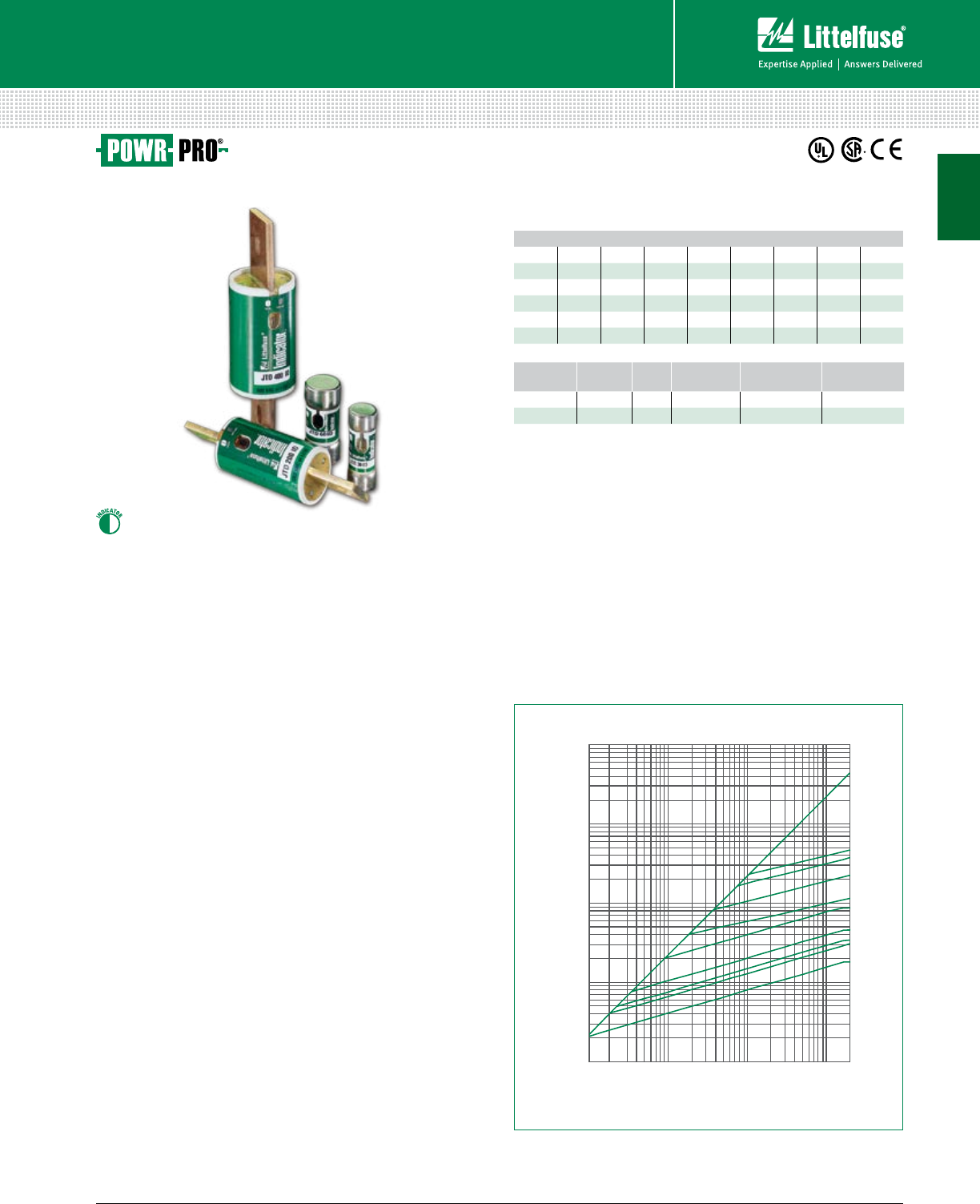
JTD_ID SERIES INDICATOR® POWR-PRO® FUSES
600 Vac • Time Delay • 8/10-600 A
Description
The Littelfuse POWR-PRO® JTD Class J fuse is available with
visual blown fuse indication or in standdard non-indicating
versions. The current-limiting time delay JTD_ID offers a
patented design which reduces nuisance fuse openings.
Features/Benefits
• POWR-PRO® Performance
• Current-Limiting
• IEC Type 2 Protection
• Indication and non-indication versions available
Applications
• Fused combination motor controllers and control centers
• Transformer protection
• Protection for series rated molded case circuit-breaker panels
• General purpose circuits
Specifications
Voltage Ratings AC: 600 Vac or less
DC: 300 V (8⁄10 –100 A)
500 V (110–600 A)
Ampere Range 8⁄10 –600 A
Interrupting Rating AC: 200 kA rms symmetrical
300 kA rms symmetrical
DC: 20 kA
Material Body: Melamine
Caps: Nickel-plated Bronze (8⁄10 –60 A)
Brass (70–200 A)
Brass Cap & Copper Blade (225–600 A)
Approvals AC: Standard 248-8, Class J
UL Listed (File: E81895)
CSA Certified (File: LR29862)
DC: Littelfuse self-certified
Material
8/10-60 A: Melamine body, Bronze cap (nickel plated)
70-200 A: Melamine body, Brass cap
225-600 A: Melamine body, Copper cap
Country of Origin Mexico
1000000
100000
10000
1000
1000 10000 100000 200000
100
100
600 A
400 A
200 A
100 A
60 A
30 A
15 A
12 A
5.6 A
AVAILABLE FAULT
SYMMETRICAL R.M.S. AMPERES
PEAK LET-THRU IN AMPERES
Note: For more information, see Peak Let-Thru Table on pg. 23
Web Resources
Download TC Curves, CAD drawings and other technical
information: littelfuse.com/jtd
Recommended Fuse Holders
LFJ60 Series ...................................................................... 85
LFPSJ Series (8⁄10 –60 A) .......................................................111
Dimensions
Please refer to the Class J dimensions ............................. 23
Peak Let-Thru Curve
VOLTAGE SERIES AMP
INDICATION
CATALOG
NUMBER
ORDERING
NUMBER
600 JTD_ID 60 •JTD60ID 0JTD060.TXID
600 JTD 60 –JTD060 0JTD060.T
Ordering Information
JTD_ID
UL Class J Fuses
AMPERE RATINGS
8⁄10 2 31⁄27171⁄245 100 225 500
1 21⁄44 8 20 50 110 250 600
11⁄421⁄241⁄2925 60 125 300
11⁄228⁄10 510 30 70 150 350
16⁄10 3 5 6⁄10 12 35 80 175 400
18⁄10 32⁄10 615 40 90 200 450
1
22 © 2014 Littelfuse POWR-GARD® Products Cataloglittelfuse.com
UL Class J Fuses
Fuses – UL Class J
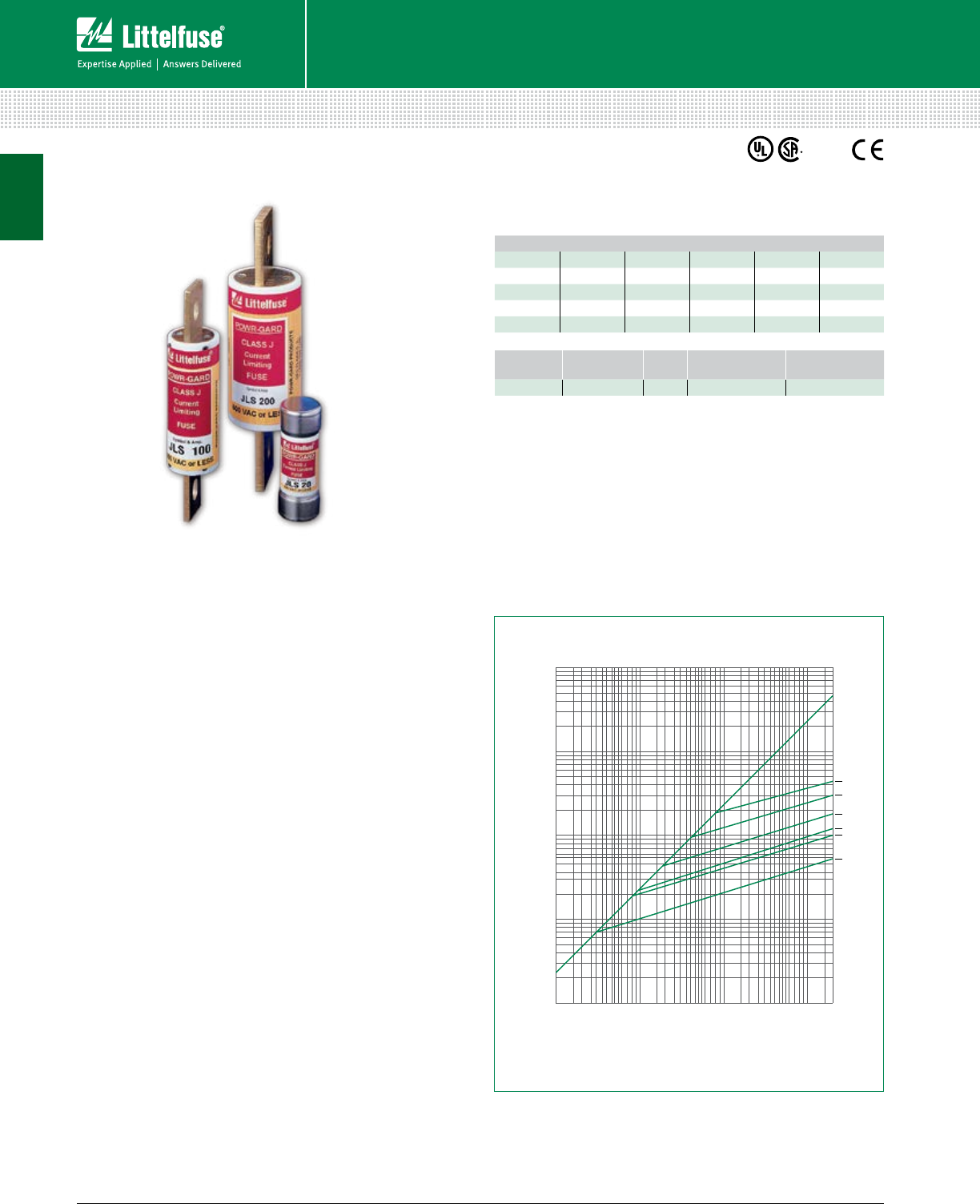
JLS SERIES FUSES
600 Vac • Fast-Acting • 1-600 A
AMPERE RATINGS
120 45 90 175 350
325 50 100 200 400
630 60 110 225 450
10 35 70 125 250 500
15 40 80 150 300 600
Description
JLS series fuses provide space saving, fast-acting overload
and short-circuit protection for non-inductive loads.
For ap pli ca tions where short-duration surg es and spikes may
cause nuisance fuse opening, consider the use of Littelfuse
POWR-PRO® JTD or JTD_ID series time-delay fuses.
Applications
• General purpose circuits with little or no motor load.
• Resistive loads, such as resistance electric heat.
• Loads requiring fast-acting overload protection, such as
equipment containing solid-state devices.
Specifications
Voltage Ratings 600 Vac or less
Ampere Range 1–600 A
Interrupting Ratings 200 kA rms symmetrical
Approvals Standard 248-8, Class J
UL Listed (File: E81895)
CSA Certified (File: LR29862)
Federal Specification WF-1814
(QPL-W-F-1814)
Material
1-60 A: Melamine body,
Bronze cap (nickel plated)
70-400 A: Melamine body
Brass cap
450-600 A: Melamine body
Copper cap
Country of Origin Mexico
Dimensions
Please refer to the Class J dimensions ............................. 23
10000
100000
200000
100
1000
100
1000
10000
100000
1000000
600 A
400 A
200 A
100 A
60 A
30 A
PEAK LET-THRU IN AMPERES
AVAILABLE FAULT CURRENT
SYMMETRICAL R. M. S. AMPERES
05567005
VOLTAGE SERIES AMP CATALOG
NUMBER
ORDERING
NUMBER
600 JLS 110 JLS110 0JLS110.X
Ordering Information
Web Resources
Download TC curves, CAD drawings and other technical
information: littelfuse.com/jls
Recommended Fuse Holders
LFJ60 Series ...................................................................... 85
LFPSJ Series (8⁄10 –60 A) .......................................................111
Peak Let-Thru Curve
QP
L
JLS
1

23 littelfuse.com © 2014 Littelfuse POWR-GARD® Products Catalog
Fuses – UL Class J
UL Class J Fuses
CLASS J DIMENSIONS AND CURRENT-LIMITING EFFECTS
A
C
D
GF
E
H
A
B
C
D
Fig. 1 Fig. 2
Dimensions Inches (mm)
Current-Limiting Effects of JTD_ID (600 V) Fuses
SHORT CIRCUIT
CURRENT†
APPARENT RMS SYM MET RI CAL CURRENT FOR VARIOUS FUSE RATINGS
15 A 30 A 60 A 100 A 200 A 400 A 600 A
5,000 565 750 1,500 1,800 2,800 4,800 5,000
10,000 675 925 1,900 2,450 3,600 5,700 7,750
15,000 775 1,050 2,100 2,800 4,100 6,500 9,000
20,000 825 1,125 2,300 3,000 4,400 7, 25 0 9,700
25,000 900 1,200 2,500 3,300 5,000 8,000 10,500
30,000 950 1,300 2,600 3,500 5,100 8,400 11,000
35,000 1,000 1,350 2,700 3,700 5,400 9,000 12,000
40,000 1,050 1,400 2,800 3,900 5,600 9,200 12,500
50,000 1,100 1,500 3,000 4,200 6,000 10,000 13,000
60,000 1,200 1,600 3,200 4,500 6,400 10,500 14,000
80,000 1,300 1,700 3,400 4,900 7,200 11,200 15,500
100,000 1,375 1,800 3,600 5,200 7,80 0 12,200 16,500
150,000 1,500 2,000 3,950 6,000 9,000 14,500 19,000
200,000 1,600 2,175 4,000 6,500 10,000 16,000 20,500
†Prospective RMS Symmetrical Amperes Short-Circuit Current
Note: Data derived from Peak Let-Thru Curves
*70-100 A JLS dimension = 1 (25.4)
AMPERES FIGURE
NUMBER
DIMENSIONS INCHES (mm)
A B C D E F G H
1 – 30 1 21⁄4 (57.2) —1⁄2 (12.7) 13 ⁄16 (20.6) — — — —
35 – 60 1 23⁄8 (60.3) —5⁄8 (15.9) 11⁄16 (2 7.0) — — — —
70 – 100 2 25⁄8 (66.7) 317⁄32 (89.7) 323⁄32 (94.5) 45⁄8 (117.5) 11⁄8 (28.6)* 3⁄4 (19.1) 9⁄32 (7.1) 1⁄8 (3.2)
110 – 200 23 (76.2) 49⁄32 (108.7) 415 ⁄32 (113.5) 53⁄4 (146.1) 11⁄2 (38.1) 11⁄8 (28.6) 9⁄32 (7.1) 3⁄16 (4.8)
225 – 400 2 33⁄8 (85.7) 51⁄8 (130.2) 53⁄8 (136.5) 71⁄8 (181.0) 2 (50.8) 15⁄8 (41.3) 13⁄32 (10.3) 1⁄4 (6.4)
450 – 600 2 33⁄4 (95.3) 527⁄32 (148.4) 65⁄32 (156.4) 8 (203.2) 21⁄2 (63.5) 2 (50.8) 17⁄32 (13.5) 3⁄8 (9.5)
Dimensions of JTD_ID, JTD and JLS
1

24 © 2014 Littelfuse POWR-GARD® Products Cataloglittelfuse.com
UL Class T Fuses
Fuses – UL Class T
JLLN / JLLS SERIES FUSES
300/600 Vac • Fast-Acting • 1-1200 A
Description
JLLN / JLLS fuses are less than 1/3 the size of comparable
Class R fuses and are typically used for short circuit
protection of drives and surge sensitive components.
When rated in accordance with the NEC®, JLLN / JLLS
fuses provide fast-acting overload and short circuit
protection for non-inductive circuits and equipment.
Features/Benefits
• Extremely current-limiting
• Compact design
• 200 kA Interrupting Rating
• JLLN 35-60 A available with PCB mounts (see datasheet)
Applications
• Variable speed drive protection
• Compact mains switches
Specifications
Voltage Ratings AC: 600 V (JLLS)
300 V (JLLN)
DC: 300 V (JLLS)
160 V (JLLN 1 – 60 A)
125 V (JLLN 70 – 1200 A)
Ampere Range 1 – 1200 A
Interrupting Ratings AC: 200 kA rms symmetrical
DC: 20 kA
Approvals AC: Standard 248-15, Class T
UL Listed (File: E81895):
JLLN (1 – 1200 A) JLLS (1 – 800 A)
UL Recognized (File: E71611)
JLLS (900 – 1200 A)
CSA Certified (File: LR29862)
JLLN/JLLS (1 – 600 A)
DC: UL Listed (File: E81895):
JLLN (35 – 1200 A)
Littelfuse self-certified
JLLN (1 – 30 A) JLLS (1 – 1200 A)
Material JLLS: 1-30 A: Melamine body, Copper caps
35-60 A: Melamine body, Bronze caps
70-1200 A: Melamine body, Copper caps
JLLN: 1-30 A: Melamine body, Bronze caps
35-1200 A: Melamine body, Copper caps
Environmental RoHS Compliant
*JL L S only
Note: Contact the factory for RoHS compliant Class T fuses.
Web Resources
Download TC Curves, CAD drawings and other technical
information: littelfuse.com/jlln
littelfuse.com/jlls
Recommended Fuse Holders
LFT30 Series ...................................................................... 94
LFT60 Series ...................................................................... 94
LSCR Series for 700-800 A .............................................. 120
Dimensions
Please refer to the Class T dimensions .............................. 25
Peak Let-Thru Curve
Note: For more information, see Peak Let-Thru Table on pg. 25
Ordering Information
SERIES VOLTAGE AMP CATALOG
NUMBER
ORDERING
NUMBER
JLLS 600 V 6JLLS006 JLLS006.T
JLLN 300 V 10 JLLN010 JLLN010.T
JLLS
AMPERE RATINGS
1 25 70 175 450 1100
2 30 80 200 500 1200
3 35 90 225 600
6 40 100 250 700
10 45 110 300 800
15 50 125 350 900*
20 60 150 400 1000
1
25 littelfuse.com © 2014 Littelfuse POWR-GARD® Products Catalog
Fuses – UL Class T
UL Class T Fuses
CLASS T DIMENSIONS AND CURRENT-LIMITING EFFECTS
B
C
A
F
DF
E
A
B
C
D
G
A
C
D
Fig. 1 Fig. 2 Fig. 3
Current-Limiting Effects of JLLS (600 V) fuses
SHORT
CIRCUIT
CURRENT*
APPARENT RMS SYMMETRICAL CURRENT FOR
VARIOUS FUSE RATINGS
30 A 60 A 100 A 200 A 400 A 600 A 800 A 1200 A
5,000 750 1,225 1,810 2,500 4,600 5,000 5,000 5,000
10,000 945 1,525 2,300 3,150 6,000 8,500 9,400 10,000
15,000 1,050 1,700 2,610 3,600 6,600 9,750 10,500 13,000
20,000 1,150 1,900 2,900 3,950 7,25 0 10,500 11,000 14,750
25,000 1,300 2,050 3,100 4,250 8,000 11,500 12,500 15,500
30,000 1,375 2,150 3,300 4,500 8,250 12,000 13,750 16,500
35,000 1,400 2,250 3,500 4,750 8,500 13,000 14,000 17,000
40,000 1,425 2,400 3,650 4,950 8,700 14,000 14,750 18,000
50,000 1,600 2,450 3,900 5,350 9,500 14,500 16,000 20,000
60,000 1,650 2,625 4,150 5,650 10,000 15,500 17, 300 21,000
80,000 1,825 2,800 4,570 6,250 11,000 17,000 18,750 23,000
100,000 2,000 3,100 4,950 6,700 12,000 18,000 20,000 25,000
150,000 2,250 3,400 5,650 7,70 0 13,000 21,000 23,000 28,500
200,000 2,450 3,800 6,200 8,450 15,000 23,000 25,000 31,000
*Prospective RMS Symmetrical Amperes Short-Circuit Current
Note: Data Derived from Peak Let-Thru Curves
Current-Limiting Effects of JLLN (300 V) fuses
SHORT
CIRCUIT
CURRENT*
APPARENT RMS SYMMETRICAL CURRENT FOR
VARIOUS FUSE RATINGS
30 A 60 A 100 A 200 A 400 A 600 A 800 A 1200 A
5,000 700 775 1,100 1,650 3,500 4,000 5,000 5,000
10,000 900 1,000 1,400 2,100 4,400 5,100 6,750 8,250
15,000 1,000 1,100 1,600 2,400 5,000 5,900 7,75 0 10,000
20,000 1,100 1,250 1,800 2,700 5,500 6,500 8,750 11,000
25,000 1,230 1,300 1,950 2,900 6,000 7,000 9,500 12,000
30,000 1,300 1,475 2,050 3,100 6,400 7,500 10,000 12,500
35,000 1,330 1,575 2,150 3,300 6,750 7,7 50 10,500 13,500
40,000 1,430 1,600 2,300 3,500 7,000 8,000 11,000 14,000
50,000 1,500 1,750 2,400 3,700 7,500 8,750 12,000 15,000
60,000 1,700 1,900 2,700 4,000 8,000 9,500 12,500 16,000
80,000 1,850 2,100 2,800 4,400 9,000 10,500 14,000 17,500
100,000 2,000 2,250 3,150 4,800 9,750 11,500 15,000 18,500
150,000 2,300 2,600 3,600 5,500 11,000 13,000 17,500 22,000
200,000 2,600 2,800 3,900 6,000 12,000 14,500 19,500 24,000
*Prospective RMS Symmetrical Amperes Short-Circuit Current
Note: Data Derived from Peak Let-Thru Curves
Dimensions Inches (mm)
AMPERES FIGURE
NUMBER SERIES DIMENSIONS INCHES (mm)
A B C D E F G
1 – 30 1JLLN 7⁄8 (22.2) —9⁄32 (7.1) 13 ⁄32 (10.3) — — —
JLLS 11⁄2 (38.1) —9⁄32 (7.1) 9⁄16 (14.3) — — —
35 – 60 1JLLN 7⁄8 (22.2) —9⁄32 (7.1) 9⁄16 (14.3) — — —
2JLLS 19⁄16 (39.7) 13⁄16 (20.6) 13 ⁄32 (10.3) 1 (25.4) 1⁄16 (1.6) 13⁄32 (2 7.8) —
70 – 100 3JLLN 25⁄32 (54.8) 19⁄16 (39.7) 3⁄4 (19.1) 13 ⁄16 (20.6) 27⁄32 (21.4) 9⁄32 (7.1) 1⁄8 (3.2)
JLLS 261⁄64 (75.0) 223⁄64 (59.9) 3⁄4 (19.1) 13⁄16 (20.6) 141⁄64 (41.7) 9⁄32 (7.1) 1⁄8 (3.2)
110 – 200 3JLLN 27⁄16 (61.9) 111 ⁄16 (42.9) 7⁄8 (22.2) 11⁄16 (27.0) 27⁄32 (21.4) 11⁄32 (8.7) 3⁄16 (4.8)
JLLS 31⁄4 (82.6) 21⁄2 (63.5) 7⁄8 (22.2) 11⁄16 (2 7.0) 121⁄32 (42.1) 11 ⁄32 (8.7) 3⁄16 (4.8)
225 – 400 3JLLN 23⁄4 (69.9) 127⁄32 (46.8) 1 (25.4) 15⁄16 (33.3) 53⁄64 (21.0) 13 ⁄32 (10.3) 1⁄4 (6.4)
JLLS 35⁄8 (92.1) 223⁄32 (69.1) 1 (25.4) 119 ⁄32 (40.5) 123⁄32 (43.7) 13 ⁄32 (10.3) 1⁄4 (6.4)
450 – 600 3JLLN 31⁄16 (7 7.8) 21⁄32 (51.6) 11⁄4 (31.8) 119 ⁄32 (40.5) 7⁄8 (22.2) 31⁄64 (12.3) 5⁄16 (7.9)
JLLS 363⁄64 (101.2) 261⁄64 (75.0) 11⁄4 (31.8) 21⁄16 (52.4) 149⁄64 (44.8) 31⁄64 (12.3) 5⁄16 (7.9)
700 – 800 3JLLN 33⁄8 (85.7) 27⁄32 (64.3) 13⁄4 (44.5) 21⁄16 (52.4) 7⁄8 (22.2) 35⁄64 (13.9) 3⁄8 (9.5)
JLLS 421⁄64 (109.9) 311⁄64 (80.6) 13⁄4 (44.5) 21⁄2 (63.5) 155⁄64 (47.2) 35⁄64 (13.9) 3⁄8 (9.5)
900 – 1200 3JLLN 4 (101.6) 217⁄32 (64.3) 2 (50.8) 21⁄2 (63.5) 11⁄32 (26.2) 39⁄64 (15.5) 7⁄16 (11.1)
JLLS 5.27 (133.9) 3.80 (96.5) 2 (50.8) 2.63 (66.8) 2.30 (58.4) 0.67 (15.5) 0.44 (11.2)
1

26 © 2014 Littelfuse POWR-GARD® Products Cataloglittelfuse.com
UL Class G Fuses
Fuses – UL Class G
SLC SERIES FUSES
480/600 Vac • Time-Delay • 1/2-60 A
AMPERE RATINGS
1/23 6 12 25 40 60
1 4 8 15 30 45
2 5 10 20 35 50
Web Resources
Download TC Curves, CAD drawings and other technical
information: littelfuse.com/slc
Recommended Fuse Holders
LFG60 Series (1-20 A) ........................................................ 99
LFG48 Series (25-60 A) ...................................................... 99
A
B
CD
AMPERES DIMENSIONS INCHES (mm)
A B C D
1/2 – 15 1 5/16 (33.3) 3/8 (9.5) 9/32 (7.1) 13/32 (10.3)
20 1 13/32 (35.7) 3/8 (9.5) 9/32 (7.1) 13/32 (10.3)
25, 30 1 5/8 (41.3) 3/8 (9.5) 9/32 (7.1) 13/32 (10.3)
35 – 60 2 1/4 (57.2) 3/8 (9.5) 1/2 (12.7) 13/32 (10.3)
Dimensions
Ordering Information
SERIES AMP CATALOG NUMBER ORDERING NUMBER
SLC 10 SLC010 0SLC010.T
Description
Littelfuse SLC fuses provide cost effective branch circuit
protection. Fuse length varies to prevent over-fusing.
Compact Class G fuses were the first fuse series to
approach midget fuse dimensions and meet NEC®
requirements for branch-circuit protection.
Features/Benefits
• Branch circuit rated
• Current-limiting
• 100 kA interrupting rating
• 600 Vac rated 1/2-20 A
Applications
• Branch circuit protection
Specifications
Voltage Ratings AC: 600 Vac or less (1/2 – 20 A)
480 Vac or less (25 – 60 A)
DC: 170 Vdc (Littelfuse self-certified)
Ampere Range 1/2 – 60 A
Interrupting Ratings AC: 100 kA rms symmetrical
DC: 10 kA
Approvals Standard 248-5, Class G
UL Listed (File: E81895)
CSA Certified (File: LR29862)
Federal Specification WF-1814
(QPL-W-F-1814)
Material 1/2-30 A: Melamine body,
Bronze cap (nickel plated)
35-60 A: Melamine body
Brass cap (silver plated)
Environmental RoHS Compliant
QP
L
1
27 littelfuse.com © 2014 Littelfuse POWR-GARD® Products Catalog
UL Class CC/CD Fuses
Fuses – UL Class CC / CD
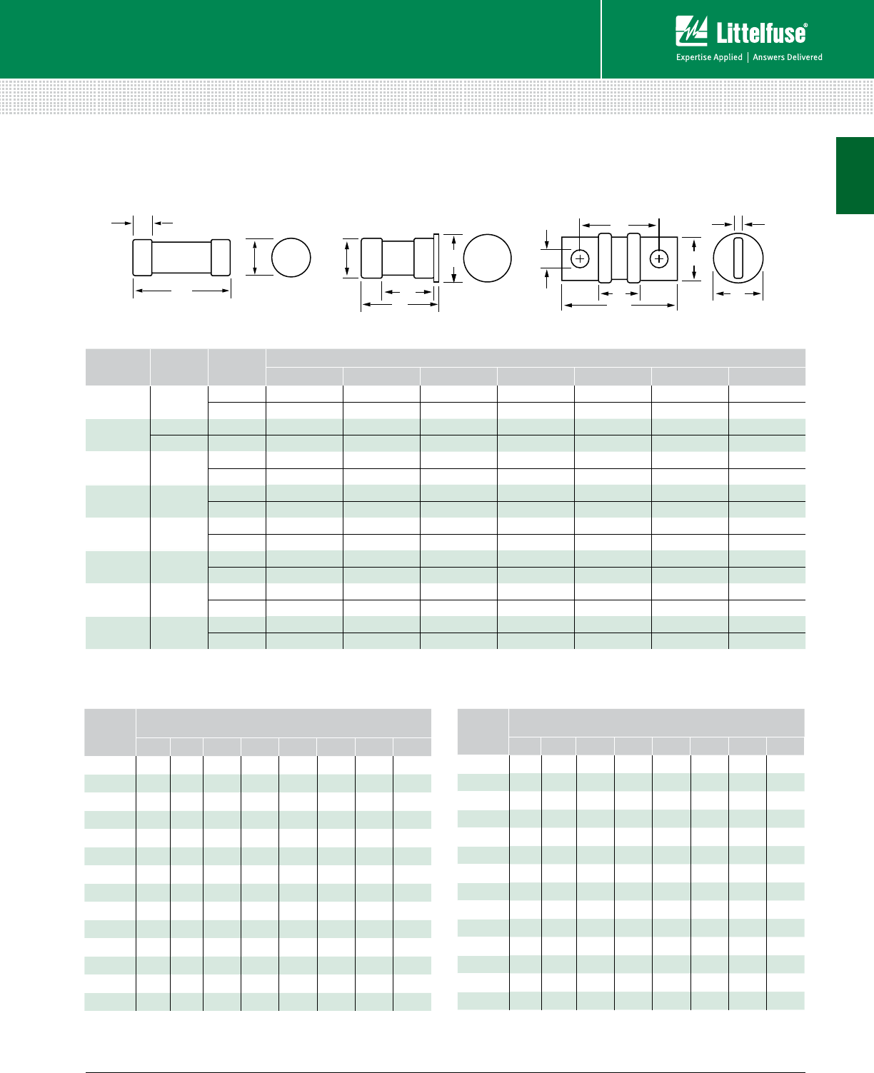
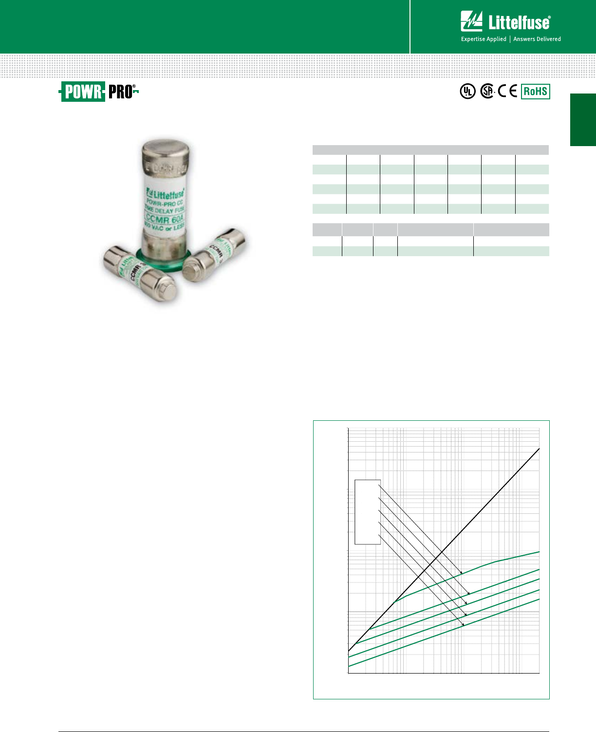
CCMR SERIES POWR-PRO® FUSES
600 Vac • Dual Element • Time-Delay • 2/10-60 A
AMPERE RATINGS
2/10 1 2 3 1/26 1/412 35
1/41 1/42 1/44 7 15 40
3/10 1 4/10 2 1/24 1/27 1/217 1/245
1/21 1/22 8/10 5 8 20 50
6/10 1 6/10 3 5 6/10 9 25 60
8/10 1 8/10 3 2/10 6 10 30
Web Resources
Download TC Curves, CAD drawings and other technical
information: littelfuse.com/ccmr
Recommended Fuse Holders
LFC600 Series ..................................................................101
L60030C Series ................................................................101
LFPSC Touch-Safe Series ..................................................110
Dimensions
Please refer to the Class CC/CD dimensions .................... 29
Peak Let-Thru Curve
10,000
100,000
1,000,000
PEAK LET- THRU IN AMPERES
60A -
30A -
15A-
4A-
2.25A-
100
1,000
000,001000,01000,1001
AVAILABLE FAULT CURRENT
SYMMETRICAL R.M.S. AMPERES
BASIS FOR DATA:
TEST VOLTAGE: TIME CONSTANT/POWER FACTOR: FUSE CATALOG NUMBER:
DRAWN BY:
DATE:
REVISION:
DRAWING NO.: SHEET
PEAK LET-THRU CHARACTERISTIC CURVES
LITTELFUSE, INC.
CHICAGO, IL. USA
LLL
11/12/12
C
9 OF 9
FCC05-CCMRP
CCMRP 2.25A - 30A
FOR CATALOG PAGE ONLY
- DATA GENERATED IN EXCEL -
Note: For more information, see Peak Let-Thru Table on pg. 29
Ordering Information
* Consult Motor Protection Tables on page 208 in the Technical Application Guide
section for specific motor sizing information.
SERIES AMP ROHS CATALOG NUMBER ORDERING NUMBER
CCMR 10 •CCMR010 CCMR010.TXP
CCMR 45 CCMR045 CCMR045.T
Description
The CCMR series is ideal for space saving protection
of motors up to 40 hp*. It was designed specifically to
withstand sustained starting currents of small motors. The
CCMR 60 fuse is the smallest 60 A fuse available rated at
600 V. Compared to other UL Listed fuses, Class CC fuses
are the most current-limiting, rating for rating.
Features/Benefits
• POWR-PRO® Performance
• Extremely current-limiting
• Ratings up to 60 Amps
• 300 kA Interrupting Rating (self-certified)
Applications
• Motor and motor branch circuit protection
Specifications
Voltage Rating AC: 600 Vac or less
DC: 250 V (CCMR 2/10 – 2 A)
(CCMR 41/2– 10 A)
(CCMR 35– 60 A)
300 V (CCMR 21/4– 4 A)
500 V (CCMR 12– 30 A)
Ampere Rating 2/10 – 60 A
Interrupting Rating AC: 200 kA rms symmetrical
300 kA Littelfuse self-certified
DC: 20 kA
Approvals AC: Standard 248-4, Class CC
UL Listed 2/10-30 A (File: E81895)
Standard 248, Class CD
UL Listed 35-60 A (File: E81895)
CSA Certified (File: LR29862)
DC: Littelfuse self-certified
Material 2/10-30 A: Melamine body,
Bronze cap (nickel plated)
Environmental RoHS Compliant (except 35-60 A)
Country of Origin Mexico
1

28 © 2014 Littelfuse POWR-GARD® Products Cataloglittelfuse.com
UL Class CC Fuses
Fuses – UL Class CC
Specifications
Voltage Rating AC: 600 Vac or less
DC: 300 Vdc
Ampere Range 1/10 – 30 A
Interrupting Rating AC: 200 kA rms symmetrical
DC: 20 kA
Approvals AC: Standard 248-4, Class CC
UL Listed 1/10-30 A (File: E81895)
CSA Certified 1/10 -30 A (File: LR29862)
DC: Littelfuse self-certified
Material Melamine body
Bronze caps (nickel plated)
Environmental RoHS Compliant
Country of Origin Mexico
KLDR / KLKR SERIES FUSES
KLKR Series
600 Vac/300 Vdc • Fast-Acting • 1/10-30 A
KLDR Series
600 Vac/300 Vdc • Time-Delay • 1/10-30 A
Description
KLKR Series Class CC fuses are fast-acting
fuses intended for general purpose branch
circuit protection. Their compact size, fast-
acting overload response, and highly current-
limiting design make them ideal for use in
OEM equipment and control panels.
Specifications
Voltage Rating AC: 600 Vac or less
DC: 300 Vdc
Ampere Range 1/10 – 30 A
Interrupting Rating AC: 200 kA rms symmetrical
DC: 20 kA
Approvals AC: Standard 248-4, Class CC
UL Listed 1/10-30 A (File: E81895)
CSA Certified 1/10 -30 A (File: LR29862)
DC: Littelfuse self-certified
Material Melamine body
Bronze caps (nickel plated)
Environmental RoHS Compliant
Country of Origin Mexico
AMPERE RATINGS
1/10 6/10 1 8/10 4 1/210
1/83/42 5 12
15/100 8/10 2 1/45 6/10 15
3/16 1 2 1/26 17 1/2
2/10 1 1/82 8/10 6 1/420
1/41 1/43 7 25
3/10 1 4/10 3 2/10 7 1/230
4/10 1 1/23 1/28 —
1/21 6/10 4 9 —
AMPERE RATINGS
1/10 1/22 1/26 12
1/83/43 7 15
2/10 13 1/28 20
1/41 1/24 9 25
3/10 2 5 10 30
Ordering Information
SERIES AMP CATALOG
NUMBER
ORDERING
NUMBER
KLDR 10 KLDR010 KLDR010.T XP
Ordering Information
SERIES AMP CATALOG
NUMBER
ORDERING
NUMBER
KLKR 12 KLKR012 KLKR012.T
Recommended Fuse Holders
L60030C Series .................................................... 101
LFPSC Touch-Safe Series ...................................... 110
Dimensions
Please refer to the Class CC dimensions ............... 29
Recommended Fuse Holders
L60030C Series .................................................... 101
LFPSC Touch-Safe Series ...................................... 110
Dimensions
Please refer to the Class CC dimensions ............... 29
Web Resources
For additional information, visit:
littelfuse.com/klkr
Web Resources
For additional information, visit:
littelfuse.com/kldr
Description
KLDR fuses are time-delay fuses designed to
protect control transformers, so le noids and
similar inductive components with high mag-
ne tiz ing currents during the first half-cycle.
They provide ex cel lent protection of motor
branch circuits con tain ing IEC or NEMA
rated motor con trol lers or contactors.
1

29 littelfuse.com © 2014 Littelfuse POWR-GARD® Products Catalog
UL Class CC/CD Fuses
Fuses – UL Class CC / CD
1.880
(47.8)
.850
(21.6)
1.50
(38.1)
.50
(12.7)
.41
(10.3)
.25
(6.4)
.125
(3.2)
35-60 A
0-30 A
CLASS CC / CD DIMENSIONS AND CURRENT-LIMITING EFFECTS
Dimensions Inches (mm)
- DATA GENERATED IN EXCEL -
100
1,000
10,000
100,000
1,000,000
100 1,000 10,000 100,000
PEAK LET- THRU IN AMPERES
AVAILABLE FAULT CURRENT
SYMMETRICAL R.M.S. AMPERES
8A -
6A -
4A -
BASIS FOR DATA:
TEST VOLTAGE: TIME CONSTANT/POW ER FACTOR: FUSE CATALOG NUMBER:
DRAWN BY:
DATE:
REVISION:
DRAWING NO.: SHEET
PEAK LET-THRU CHARACTERISTIC CURVES
LITTELFUSE, INC.
CHICAGO, IL. USA
LLL
11/12/12
B
2 OF 4
FCC05-KLDRP
KLDRP 4A - 30A
10000
100000
200000
100
1000
100
1000
10000
100000
1000000
30 A
25 A
20 A
15 A
12 A
PEAK LET-THRU IN AMPERES
AVAILABLE FAULT CURRENT
SYMMETRICAL R. M. S. AMPERES
05542001
Peak Let-Thru Curve KLDR Peak Let-Thru Curve KLKR
SHORT
CIRCUIT
CURRENT*
APPARENT RMS SYMMETRICAL CURRENT FOR VARIOUS FUSE RATINGS
2.25A 2.5A 3A 4A 5A 6.25A 7.5A 8A 10A 12A 15A 20A 30A 35A 40A 45A 50A 60A
5,000 203 224 287 289 460 472 442 437 359 369 435 355 621 1,170 1,240 1,320 1,070 1,525
10,000 256 282 361 364 580 595 557 551 452 465 548 447 783 1,480 1,565 1,670 1,355 1,930
15,000 293 323 413 416 664 681 637 631 517 532 627 512 896 1,695 1,795 1,915 1,555 2,200
20,000 323 356 455 458 730 750 702 694 569 585 690 563 987 1,870 1,980 2,110 1,710 2,430
25,000 348 383 490 493 787 808 756 748 613 630 743 607 1,063 2,015 2,135 2,275 1,845 2,620
30,000 370 407 521 524 836 858 803 795 651 670 790 645 1,129 2,145 2,270 2,420 1,965 2,780
35,000 389 429 548 552 880 903 845 837 686 705 832 679 1,189 2,260 2,390 2,550 2,070 2,885
40,000 407 448 573 577 920 944 884 875 717 737 870 709 1,243 2,360 2,500 2,665 2,165 3,025
50,000 438 483 617 622 991 1,017 952 942 772 794 937 764 1,339 2,545 2,695 2,875 2,330 3,200
60,000 466 513 656 661 1,053 1,081 1,012 1,001 821 844 995 812 1,423 2,705 2,865 3,055 2,480 3,350
80,000 513 564 722 727 1,159 1,190 1,114 1,102 903 929 1,096 894 1,566 2,985 3,160 3,365 2,730 3,540
100,000 552 608 778 783 1,249 1,282 1,200 1,187 973 1,001 1,180 963 1,687 3,215 3,405 3,630 2,945 3,685
150,000 632 696 890 897 1,430 1,467 1,373 1,359 1,114 1,146 1,351 1,102 1,931 3,685 3,905 4,160 3,375 4,030
200,000 696 766 980 987 1,574 1,615 1,511 1,496 1,226 1,261 1,487 1,213 2,125 4,060 4,300 4,580 3,720 4,230
*Prospective RMS Symmetrical Amperes Short-Circuit Current
Note: Data Derived from Peak Let-Thru Curves
Current-Limiting Effects of CCMR (600 V) fuses
1
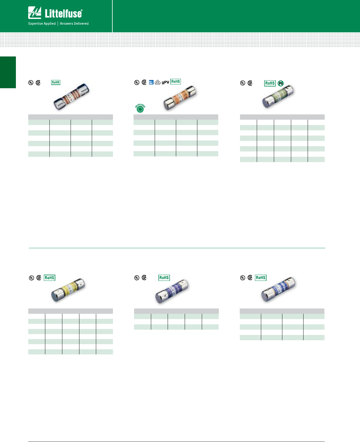
30 © 2014 Littelfuse POWR-GARD® Products Cataloglittelfuse.com
UL Supplemental Fuses
Fuses – UL Supplemental
10 x 38mm MIDGET FUSES
KLKD Series
Fast-Acting Fuse
600 Vac/dc
FLM Series
Time-Delay Fuse
250 Vac
QPL
FLQ Series
Time-Delay Fuse
500 Vac
BLF Series
Laminated Fast-Acting Fuse
125/250 Vac
AMPERE RATINGS
1/10 1 5 15
1/81 1/2620
2/10 2 7 25
1/42 1/2830
3/10 3 9 —
1/23 1/210 —
3/4412 —
AMPERE RATINGS
1/10 1 5 15
1/81 1/2620
2/10 2 7 25
1/42 1/2830
3/10 3 9 —
1/23 1/210 —
3/4412 —
AMPERE RATINGS
1/10 8/10 24 1/210
15/100 12 1/4512
2/10 1 1/82 1/25 6/10 15
1/41 1/42 8/10 620
3/10 1 4/10 36 1/425
4/10 1 1/23 2/10 730
1/21 6/10 3 1/28 —
6/10 1 8/10 4 9 —
AMPERE RATINGS
1/10 1/22 5 12
1/86/10 2 1/45 6/10 14
15/100 8/10 2 1/2615
3/16 1 3 6 1/420
2/10 1 1/83 2/10 725
1/41 1/43 1/2830
3/10 1 1/24 9 —
4/10 1 6/10 4 1/210 —
AMPERE RATINGS
1 3 6 12 25
1 1/24 8 15 30
2 5 10 20 —
AMPERE RATINGS
1/23 7 15
1 4 8 20
1 1/25 9 25
2 6 10 30
2 1/26 1/412 —
Specifications
Fast-acting, high-interrupting capacity fuse
designed for control circuits, HID lighting,
street-lighting, meter circuits.
Voltage Ratings 600 Vac
500 Vdc
Interrupting Ratings 100 kA @ 600 Vac
50 kA @ 500 Vdc
(capable of 200 kA)
Approvals UL Listed (E10480)
CSA Certified (LR29862)
Dimensions L 38.1mm (1 1/2”)
D 10.31mm (13/32”)
littelfuse.com/klk
Specifications
Fast-acting, high DC rated fuse used in solar
combiner boxes, DC control circuits, UPS
protection. Available in PC board mount.
Voltage Ratings 600 Vac/dc
Interrupting Ratings 100 kA @ 600 Vac
10 kA @ 600 Vdc (UL2579)
50 kA @ 600 Vdc (UL248-14)
(capable of 200 kA)
Approvals UL Listed (E339112 & E10480)
CSA Certified (LR29862)
Dimensions L 38.1mm (1 1/2”)
D 10.31mm (13/32”)
littelfuse.com/klkd
Specifications
250V time-delay fuses used to protect
circuits with high in-rush. Especially suited for
supplemental protection of small motors.
Voltage Ratings 250 Vac
125 Vdc self-certified @ 10 kA
Interrupting Ratings 10 kA @ 250 Vac
Approvals UL Listed (File: E10480)
CSA Certified (029862_0_000)
Dimensions L 38.1mm (1 1/2”)
D 10.31mm (13/32”)
littelfuse.com/flm
Specifications
500V time-delay fuses for supplemental
protection of control power transformers,
solenoids, and circuits with high in-rush. Ideal
for 480 V systems.
Voltage Ratings 500 Vac
300 Vdc self-certified @ 10 kA
Interrupting Ratings 10 kA @ 500V ac
Approvals UL Listed (E10480)
CSA Certified (LR29862)
Dimensions L 38.1mm (1 1/2”)
D 10.31mm (13/32”)
littelfuse.com/flq
Specifications
Fiber tube, 250 volt BLN fuses provide low-
cost protection for military applications and
control circuits.
Voltage Ratings 250 Vac
Interrupting Ratings 10 kA @ 250 Vac
Approvals UL Listed (E10480)
CSA Certified (LR29862)
Dimensions L 38.1mm (1 1/2”)
D 10.31mm (13/32”)
littelfuse.com/bln
Specifications
Laminated tube BLF fuses are the lowest price
midget fuse. They are suitable for control circuit
and instrument protection in dry locations.
Voltage Ratings 250 Vac 1/2 - 15 A
125 Vac 20 - 30 A
Interrupting Ratings 10 kA @ rated Vac
Approvals UL Listed (E10480)
CSA Certified (LR29862)
Dimensions L 38.1mm (1 1/2”)
D 10.31mm (13/32”)
littelfuse.com/blf
KLK Series
Fast-Acting Fuse
600 Vac
QPL
BLN Series
Fiber Body Fast-Acting Fuse
250 Vac
QPL
1

31 littelfuse.com © 2014 Littelfuse POWR-GARD® Products Catalog
TOUCH SAFE
LFPSM (600 V)
pg. 110
LFPHV (1000 V)
pg. 109
Fuses – UL Supplemental
UL Supplemental Fuses
10 x 38mm MIDGET FUSES
BLS Series
Fast-Acting Fuse
600 Vac / 250 Vac
KLQ Series
Increased Time-Delay
600 Vac
AMPERE RATINGS
2/10 1 3 8
4/10 1 1/2410
1/21 6/10 5 —
3/41 8/10 6 —
8/10 2 7 —
AMPERE RATINGS
125
1 6/10 3 6
Specifications
Slightly shorter than a traditional 10 x 38, BLS
fuses provide space saving protection for low
amperage applications.
Voltage Ratings 600 Vac 2/10 - 5 A
250 Vac 6 - 10 A
Interrupting Ratings 10 kA @ rated Vac
Approvals UL Listed (E10480)
CSA Certified (LR29862)
Dimensions L 34.9 mm (1 3/8”)
D 10.31 mm (13/32”)
littelfuse.com/bls
Specifications
Same physical size as the BLS fuse with more
time delay. Designed to protect gaseous vapor
fixtures, HID ballasts and other electronic
lighting circuits.
Voltage Ratings 600 Vac
Interrupting Ratings 10 kA @ rated Vac
Approvals UL Listed (E10480)
CSA Certified (LR29862)
Dimensions L 34.9 mm (1 3/8”)
D 10.31 mm (13/32”)
littelfuse.com/klq
FLA Series
Time-Delay Pin Indicating Fuse
125 Vac
AMPERE RATINGS
1/10 8/10 24 1/212*
15/100 12 1/4515*
2/10 1 1/82 1/25 6/10 20*
1/41 1/42 8/10 625*
3/10 1 4/10 36 1/430*
4/10 1 1/23 2/10 7 —
1/21 6/10 3 1/28 —
6/10 1 8/10 410 —
*12-30 A are dual tube design
Specifications
Pin indicating time-delay fuses. Use in
conjunction with special fuse blocks to
operate mechanical signal switches or
energize alarm circuits.
Voltage Ratings 125 Vac
Interrupting Ratings 10 kA @ rated Vac
Approvals UL Listed (E10480)
Dimensions L 38.1 mm (1 1/2”)
D 10.31 mm (13/32”)
littelfuse.com/fla
Specifications
Multimeter protection fuses.
Voltage Rating 1000 Vac/Vdc
Interrupting Rating 44⁄100 A: 10 kA
11 A: 20 kA
Ampere Ratings 44⁄100 & 11 A
Time Constant 10 ms
Approvals UL Recognized (E10480)
CSA Certified (LR29862)
Dimensions 44⁄100 A: 13⁄32” x 13⁄8”
11 A: 13⁄32” x 11⁄2”
littelfuse.com/flu
10 x 38 Midget Fuse Holder Configurations
OPEN FUSE BLOCK PC BOARD MOUNT
FUSE BLOCK
L60030M
pg. 101
L60030MPCB
pg. 103
FLU Series
Multimeter Protection
1000 Vac/dc
1

32 © 2014 Littelfuse POWR-GARD® Products Cataloglittelfuse.com
Glass / Electronic Fuses ............................................................. 33
Blade / Automotive Fuses ........................................................... 36
ELECTRONIC FUSES AND BLADE FUSES
Table of Contents
Section Overview
Diverse application needs require a broad range of fuses. Littelfuse
offers a full line of fuses for various applications. As the market leader
in Automotive and Electronics fuses, we are able to deliver innovative
circuit protection solutions to our customers. Visit littelfuse.com for
our full line of Automotive and Electronics solutions.

33 littelfuse.com © 2014 Littelfuse POWR-GARD® Products Catalog
Glass / Electronic Fuses
HIGH DC VOLTAGE AND PC BOARD MOUNT FUSES
505 Series
Lead-Free 3AB, Fast-Acting
477 Series
5 x 20 mm Slo-Blo® Fuse
Dimensions mm (inches)
273 Series
Very Fast-Acting Microfuse
251 Series
Fast-Acting Pico® II Fuse
451 Series
NANO2® Very Fast-Acting
AMPERE RATINGS
10 16 25
12 20 30
AMPERE RATINGS
.5 2 5 10
.8 3.15 6.3 12
1 4 8 16
AMPERE RATINGS
.002 .031 .125 .400 .750 2
.005 .050 .200 .500 .800 3
.010 .062 .250 .600 1 4
.015 .100 .300 .700 1.5 5
AMPERE RATINGS
0.062 0.25 0.630 1.5 3.15 7
0.1 0.315 0.750 1.6 3.5 8
0.125 0.375 0.800 2 4 10
0.160 0.400 12.5 512
0.2 0.5 1.25 36.3 15
AMPERE RATINGS
.062 .500 1.25 3 7
.125 .630 1.5 3.5 10
.250 .750 2 4 12
.375 12.5 515
Add “L” suffix when
ordering RoHS compliant
451 series
Specifications
A 500 Vac/Vdc rated ceramic fuse with
remarkable interrupting rating in a compact
6.3 x 32 mm package, well suited for circuit
protection in high energy applications.
Voltage Rating 450 Vac (10 – 12 A)
250 Vdc (10 – 12 A)
500 Vac/dc (16 – 30 A)
Sample Part 0505010.MXP*
Axial Lead 505_XEP Series
Dimensions L 31.75 mm (1.25”)
D 6.35 mm (.25”)
littelfuse.com/505
*Bulk configurations only
Specifications
500 Vac/400 Vdc rated, 5 x 20 mm, time-lag,
surge withstand ceramic body fuse.
Voltage Rating 500 Vac
400 Vdc
Sample Part 0477002.MXP*
Axial Lead 477_XEP Series
Dimensions L 20 mm (.79”)
D 5.2 mm (.20”)
littelfuse.com/477
*Bulk configurations only
Specifications
Similar to 272 and 278 series, except has
transparent cap for visual indication of
fuse status. *See web for approvals by part.
Voltage Rating 125 Vac/dc
Sample Part 0273002.V
littelfuse.com/273
Specifications
The Nano2 SMF Fuse is a very small, Wire-in-
Air (WIA) square shape surface mount fuse
which is very suitable for the secondary side
circuit over-current protection applications
and is designed for PCB using surface mount
technology
*See web for approvals by part.
Voltage Rating 65 – 125 V
Sample Part 0451.125MP
littelfuse.com/451
F
L1 A
7.11 (.280")
REF.
0.64 (.025") DIA.
(1/16 – 10A)
0.81 (.032") DIA.
(12 – 15A)
2.80 (.110"
)
DIA. MAX.
6.35
(.25") 8.89
(.35")
4.32
(.17")
2.54 (.10")
314 000P Series 324 000P Series
6.35 (.25)
31.75
(1.25)
32.72
(1.288)
6.985 (.275)
38.1
(1.5)
0.813 (.032)
1.016 (.040)
229 000P Series 230 000P Series
4.5
(.177")
14.48
(.57")
14.48
(.57")
4.7 (.184") .635
(.025")
38.1
(1.50") TYP.
5.1 (.2 2)5.1 (.22)
5.2 (.20)
40 (1.57)22.5 (.89)
max.
6.0 (.24)
max.
.65* (.026)
*Ratings above 6.3 A have 0.8 mm diameter lead.
Ratings above 12 A have 1.2 m diameter lead.
20 (.79)
3AG/3AB
2AG
5 x 20 mm
Fuses – Glass / Electronic
Specifications
Subminiature fuse for soldered mounting on
printed circuit boards. Available on tape and
reel for automatic insertion. *See web for
approvals by part.
Voltage Ratings 125 Vac/dc 1/16 – 10 A
32 Vac/dc 12 – 15 A
Sample Part 0251001.NAT1L
littelfuse.com/251
2

34 © 2014 Littelfuse POWR-GARD® Products Cataloglittelfuse.com
Glass / Electronic Fuses
Fuses – Glass / Electronic
LEADED AND CARTRIDGE FUSES
312/318 Series
3AG Fast-Acting
313/315 Series
3AG Slo-Blo®
314/324 Series
3AB Fast-Acting
326/325 Series
3AB Slo-Blo®
229/230 Series
2AG Slo-Blo®
AMPERE RATINGS
.062 .200 .750 1.8 515
.100 .250 12620
.125 .300 1.25 2.25 725
.15 .375 1.5 2.5 830
.175 .500 1.6 310 35
.187 .600 1.75 412 —
225/224 Series
2AG Fast-Acting
AMPERE RATINGS
.010 .175 .500 1.25 2.8 730
.031 .187 .600 1.5 3 8 —
.040 .200 .700 1.6 3.2 10 —
.062 .250 .750 1.8 412 —
.100 .300 .800 2 5 15 —
.125 .375 12.25 6.25 20 —
.150 .400 1.2 2.5 6.3 25 —
AMPERE RATINGS
.375 2 6 12 30
.500 3 7 15 40
.750 4 8 20 —
1 5 10 25 —
AMPERE RATINGS
.010 .187 .600 1.5 415
.031 .200 .700 1.6 520
.062 .250 .750 26.25 25
.100 .300 .800 2.5 730
.125 .375 12.8 8 —
.150 .400 1.2 310 —
.175 .500 1.25 3.2 12 —
AMPERE RATINGS
.250 .750 2 4
.350 .800 2.25 5
.375 12.5 6
.500 1.25 3 7
.600 1.5 3.5 —
AMPERE RATINGS
.375 12.5 4 7
.500 1.5 3 5 8
.750 23.5 610
Specifications
Designed for fast-acting protection of
electronic equipment and appliances. The
“standard” fast-acting, glass tube fuse.
Voltage Ratings 250 Vac 1/100 – 10 A
32 Vac 12 – 35 A
Dimensions L 31.75 mm (1.25”)
D 6.35 mm (.25”)
Sample Part 0312005.VXP
For fuses with axial leads, request 318 Series.
littelfuse.com/312
Specifications
313 and 315 series fuses have time-delay
in the overload range, providing superior
protection for inductive loads. ID feature
available which discolors upon opening.
Voltage Ratings 250 Vac 1/100 – 8 A
32 Vac 10 – 30 A
Dimensions L 31.75 mm (1.25”)
D 6.35 mm (.25”)
Sample Part 0313005.VXP
For fuses with axial leads, request 315 Series.
For Fuses with ID, add “ID” suffix.
littelfuse.com/313
Specifications
Similar to 312 series, but ceramic tube
permits higher interrupting ratings and voltage
ratings: 250 volt ratings to 40 amps.
Voltage Rating 250 Vac 3/8 – 40 A
125 Vdc 3/8 – 30 A
150 Vdc 40 A
Dimensions L 31.75 mm (1.25”)
D 6.35 mm (.25”)
Sample Part 03145005.VXP
For fuses with axial leads, request 324 Series.
littelfuse.com/314
Specifications
The 326 series fuse has time-delay similar to
the 313 series, but the ceramic body permits
higher voltage ratings for the 8 – 30 ampere
sizes and faster opening of short-circuits.
Voltage Ratings 250 Vac 1/100 – 30 A
125 Vdc 1/4 – 3 A
125 Vdc 12 – 30 A
Dimensions L 31.75 mm (1.25”)
D 6.35 mm (.25”)
Sample Part 0326.100VXP
For fuses with axial leads, request 325 Series.
littelfuse.com/326
Specifications
2AG indicating fuses instantly identify
themselves upon opening by showing a
discoloration of their glass bodies, eliminating
guesswork. This unique design offers the same
quality performance characteristics as the
standard 2AG fuse design.*
Voltage Ratings 250 Vac 1/4 – 3 1/2 A
125 Vac 4 – 7 A
125 Vdc 1/4 – 7 A
Dimensions L 14.48 mm (.57”)
D 4.5 mm (.177”)
Sample Part 02291.25VXP
For fuses with axial leads, request 230 Series.
*Must add “S” suffix when ordering indicating fuse
littelfuse.com/229
Specifications
Fast-acting performance of the 312 series
3AG fuses in less than one-third the space.
For protection of electronic equipment
and appliances.
Voltage Ratings 250 Vac 3/8 – 3 1/2 A
125 Vac 4 – 10 A
125 Vdc 3/8 – 3 1/2 A
Dimensions L 14.48 mm (.57”)
D 4.5 mm (.177”)
Sample Part 0225003.VXP
For fuses with axial leads, request 224 Series.
littelfuse.com/225
Note: All fuses on this page are available in packaged and bulk configurations
2

35 littelfuse.com © 2014 Littelfuse POWR-GARD® Products Catalog
Glass / Electronic Fuses
Fuses – Glass / Electronic
5 x 20 mm IEC LEADED AND CARTRIDGE FUSES
215 Series
5 x 20 mm IEC Slo-Blo®
216 Series
5 x 20 mm IEC Fast-Acting
217 Series
5 x 20 mm IEC Fast-Acting
218 Series
5 x 20 mm IEC Slo-Blo®
235 Series
5 x 20 mm UL/CSA Fast-Acting
239 Series
5 x 20 mm UL/CSA Slo-Blo®
AMPERE RATINGS
.125 .315 .800 2 5 12
.160 .400 12.5 6.3 15
.200 .500 1.25 3.15 816
.250 .630 1.6 410 20
AMPERE RATINGS
.050 .125 .315 12.5 6.3 16
.063 .160 .500 1.25 3.15 8 —
.080 .200 .630 1.6 410 —
.100 .250 .800 2 5 12.5 —
AMPERE RATINGS
.032 .100 .250 .630 1.6 410
.050 .125 .315 .800 2 5 15
.063 .160 .400 12.5 6.3 —
.080 .200 .500 1.25 3.15 8 —
AMPERE RATINGS
.032 .100 .315 13.15 10
.040 .125 .400 1.25 412.5
.050 .160 .500 1.6 515
.063 .200 .630 26.3 16
.080 .250 .800 2.5 8 —
AMPERE RATINGS
.100 .300 .700 1.60 3.5 7
.125 .400 .800 2 4 —
.200 .500 12.5 5 —
.250 .600 1.25 3 6 —
AMPERE RATINGS
.080 .200 .500 .800 23.20 7
.100 .250 .600 12.5 3.50 —
.125 .300 .700 1.25 3 4 —
.150 .400 .750 1.60 3.15 5 —
Specifications
Time-delay protection of electronic equipment
and appliances when fuses to International
Standards are required. Replacement fuse
for foreign equipment.
Voltage Rating 250 Vac
Dimensions L 20 mm (.79”)
D 5.2 mm (.20”)
Sample Part 0215005.VXP
For fuses with axial leads, request 215_XEP series.
littelfuse.com/215
Specifications
Fast-acting protection of electronic equipment
and appliances when fuses to International
Standards are required. Replacement fuse for
foreign equipment.
Voltage Rating 250 Vac
60 Vdc (1.25-3.15, 4-6.3 A only)
Dimensions L 20 mm (.79”)
D 5.2 mm (.20”)
Sample Part 0216005.VXP
For fuses with axial leads, request 216_XEP series.
littelfuse.com/216
Specifications
Fast-acting protection of electronic equipment
and appliances when fuses to International
Standards are required. Replacement fuse for
foreign equipment.
Voltage Rating 250 Vac
75Vdc (2-3.15 A only)
60 Vdc (6.3, 2.-5 A only)
Dimensions L 20 mm (.79”)
D 5.2 mm (.20”)
Sample Part 0217005.VXP
For fuses with axial leads, request 217_XEP series.
littelfuse.com/217
Specifications
Time-delay protection of electronic equipment
and appliances when fuses to International
Standards are required. Replacement fuse
for foreign equipment.
Voltage Rating 250 Vac
Dimensions L 20 mm (.79”)
D 5.2 mm (.20”)
Sample Part 0218005.VXP
For fuses with axial leads, request 218_XEP series.
littelfuse.com/218
Specifications
5 x 20 mm fuses designed to UL and CSA
standards. Fast-acting protection of electronic
equipment and appliances.
Voltage Ratings 250 Vac 1/10 – 3 1/2 A
125 Vac 4 – 7 A
Dimensions L 20 mm (.79”)
D 5.2 mm (.20”)
Sample Part 0235005.VXP
For fuses with axial leads, request 235_XEP series.
littelfuse.com/235
Specifications
5 x 20 mm fuses designed to UL and CSA
standards. Time-delay protection of electronic
equipment and appliances.
Voltage Ratings 250 Vac 2/10 – 3 1/2 A
125 Vac 4 – 7 A
Dimensions L 20 mm (.79”)
D 5.2 mm (.20”)
Sample Part 0239005.VXP
For fuses with axial leads, request 239_XEP series.
littelfuse.com/239
Note: All fuses on this page are available in packaged and bulk configurations
2

36 © 2014 Littelfuse POWR-GARD® Products Cataloglittelfuse.com
Fuses – Blade / Automotive
Blade / Automotive Fuses
BLADE FUSES
CURRENT
RATING
HOUSING
COLOR
1 A
2 A
3 A
4 A
5 A
7.5 A
10 A
15 A
20 A
25 A
30 A
40 A
10.90
(.429)
4.46
(.175)
1.00
(.039)
2.58
(.101)
6.15
(.242)
8.10
(.319)
3.81
(.150)
3.56
(.140)
2.21
(.087)
0.80
(.031)
CURRENT
RATING
HOUSING
COLOR
20 A
25 A
30 A
35 A
40 A
50 A
60 A
70 A
80 A
MAXI dimensions in mm (inches)
ATO dimensions in mm (inches)
MAXI™
Color Key
Specifications
Smart Glow fuses are innovative
automotive style fuses (ATO, MINI, and
MAXI) that feature an indicator light that
glows when the fuse is blown, saving
time to troubleshoot an open circuit.
Voltage Rating 14 Vdc
Sample Part 0MIN010.VPGLO
Specifications
The MINI® Fuse, with its miniature
design patented by Littelfuse, meets
the need for more circuits to be
protected while utilizing less space.
Voltage Rating 32 Vdc
Sample Part 0MIN020.V
littelfuse.com/mini
Fuses Rated 58 V
Low Profile MINI®
MINI®
Smart Glow
MINI® Fast-Acting
Specifications
The low profile MINI has similar
performance as the standard mini fuse.
The lower overall height allows for more
space and weight savings.
Voltage Rating 58 Vdc
Sample Part LMIN010.V
littelfuse.com/lmin
MINI dimensions in mm
Low Profile MINI
dimensions in mm (inches)
Specifications
Smart Glow fuses are innovative
automotive style fuses (ATO, MINI, and
MAXI) that feature indicator light that
glows when the fuse is blown, saving
time to troubleshoot an open circuit.
Voltage Rating 14 Vdc
Sample Part 0ATO010.VPGLO
ATO® Fast-Acting
ATO®
Smart Glow
Specifications
The ATO® Fuse was designed and
patented by Littelfuse in 1976 and set
the standard for automotive circuit
protection. It features industry standard
color coding to indicate amperage rating.
Voltage Rating 32 Vac/dc
Sample Part 0ATO020.V
littelfuse.com/ato
Specifications
Smart Glow fuses are innovative
automotive style fuses (ATO, MINI, and
MAXI) that feature an indicator light that
glows when the fuse is blown, saving
time to troubleshoot an open circuit.
Voltage Rating 14 Vdc
Sample Part 0MAX030.XPGLO
Specifications
Designed and patented by Littelfuse,
the MAXI™ Fuse is ideal for motor
powered applications which have
large inrush currents.
Voltage Rating 32 Vdc
Sample Part 0MAX030.X
littelfuse.com/maxi
ATO® / MINI®
Color Key
MINI Fuses are available in packaged and bulk configurations. See 297 series on web.
ATO Fuses are available in packaged and bulk configurations. See 287 series on web.
MAXI Fuses are available in packaged and bulk configurations. See 299 series on web.
Note: MINI not available in
1 A or 40 A.
MAXI™ Slo-Blo
MAXI™
Smart Glow
2

37 littelfuse.com © 2014 Littelfuse POWR-GARD® Products Catalog
Blade / Automotive Fuses
Fuses – Blade / Automotive
BLADE FUSES
Specifications
The JCASE is a cartridge style fuse
with female terminal design. JCASE
provides both increased time delay
and low voltage drop to protect high
current circuits. JCASE has the ability to
handle in-rush currents. The JCASE was
designed and patented by Littelfuse.
littelfuse.com/jcase
Low Profile JCASE®
Fuse Rated 58 V
JCASE® Cartridge
Fuse Rated 32 V
Specifications
The Low Profile JCASE fuse has
similar performance characteristics as
the standard JCASE fuse. The lower
overall height reduction allows for
more space and weight savings and
also allows for a shorter male blade
terminal, saving additional weight and
material savings in fuse box designs.
FHAC Blade Fuse Holders—In-Line Splash-Waterproof
Fuse Holder for ATO® Style Blade Fuse
Wire length, color and diameter can be
customized upon request.
Used with ATO Fuse 1 to 20 A or
25 A and 30 A. Supplied with
two 4” (102mm) wire leads.
Includes protective cover for
harsh environments.
littelfuse.com/fha
FHA Blade Fuse Holders—In-Line Fuse Holder
for ATO® Style Blade Fuse
Wire length, color and diameter can be
customized upon request.
Used with ATO Fuse 1 to 20 A or
25 A and 30 A. Supplied with
two 4” (102mm) wire leads.
littelfuse.com/fha
MAH Blade Fuse Holders—In-Line Fuse Holder for
MAXI™ Style Blade Fuse
Supplied with two 6”, 6-gauge wire leads
for up to 60 A MAXI Fuse applications,
this In-Line Fuse holder also provides a
protective cover for harsh under-the-hood
environments. Mounting hole permits
easy bulkhead installation.
littelfuse.com/mah
FHM Blade Fuse Holders—In-Line Splash-Waterproof
Fuse Holder for MINI® Style Blade Fuse
Wire length, color and diameter can be
customized upon request.
Used with MINI Fuse 1 to 20 A
or 25 A and 30 A. Supplied with
two 4.78” (122 mm) wire leads.
Includes protective cover for
harsh environment.
littelfuse.com/fhm
Low Profile JCASE® 58 V
Dimensions in mm
CURRENT
RATING
HOUSING
COLOR
20 A
25 A
30 A
40 A
50 A
60 A
JCASE®
Color Key
0FHA0002
0FHA0001
PART
NUMBER DESCRIPTION FUSE
RATING
0FHA0001_ 16AWG/1.3mm2
STRANDED BLACK WIRE 20 A
0FHA0002_ 12AWG/3.3mm2
STRANDED ORANGE WIRE 30 A
PART
NUMBER DESCRIPTION FUSE
RATING
FHAC0001_ 16AWG/1.3mm2
STRANDED BLACK WIRE 20 A
FHAC0002_ 12AWG/3.3mm2
STRANDED ORANGE WIRE 30 A
PART
NUMBER DESCRIPTION FUSE
RATING
0FHM0001_ 14AWG/2.1mm2
STRANDED BLACK WIRE 20 A
0FHM0002_ 12AWG/3.3mm2
STRANDED ORANGE WIRE 30 A
Dimensions in mm
PART
NUMBER DESCRIPTION FUSE
RATING
0MAH0001Z WIRE COLOR BLACK 60 A
JCASE® 32 V
Dimensions in mm
Dimensions in mm Dimensions in mm
2

38 © 2014 Littelfuse POWR-GARD® Products Cataloglittelfuse.com
Medium Voltage Fuses Overview .............................................. 39
R-Rated Medium Voltage Fuses ................................................. 40
E-Rated Medium Voltage Fuses ................................................. 42
Medium Voltage Live Parts ......................................................... 48
MEDIUM VOLTAGE FUSES
Table of Contents
Section Overview
Littelfuse is your source for a fast replacement of E- and R-rated
medium voltage fuses. Our emergency service gets you the fuses
you need quickly to minimize downtime of your critical operations.

39 littelfuse.com © 2014 Littelfuse POWR-GARD® Products Catalog
Fuses – Medium Voltage
Medium Voltage Fuses
3
Fuses – Medium Voltage
Description
Littelfuse® offers a selection of E- and R-rated medium
voltage fuses for the protection of trans formers, potential
transformers, feeders, and motor circuits. Single, double,
and triple barrel designs are available to cover a wide range
of current, voltage, and interrupting ratings. Conventional
ferrule type, clip lock, and bolt-in mounting configurations
are available for virtually any application. Hermetically sealed
fuses for use in hazardous environments are also offered.
Contact the factory or your local Littelfuse representative for
additional fuse ratings or custom mounting configurations.
24-Hour Emergency Service - Call 800-227-0029
Applications
• Power Transformer Protection
• Potential Transformer Protection
• Motor Controller Back-up Protection
• Fused Switches
• Feeder Circuits
General Information
The terms “Medium Voltage” and “High Voltage” have been
used interchangeably by many people to describe fuses
operating above 600 volts. Technically speaking, medium
voltage fuses are those intended for the voltage range from
2,400 to 38,000 Vac. High voltage fuses are for circuits
carrying voltages greater than 38,000 Vac.
E-rated fuses are considered to be general purpose fuses
and can be used to protect against low and high values
of fault current. R-rated fuses are designed for back-up
protection. They must be used in series with other devices
such as motor overload relays in order to achieve both
overload and short-circuit protection.
Medium voltage fuses are not intended to provide overload
protection in the same sense as fuses rated 600 volts or
less. Medium voltage fuse current ratings do not have the
same meanings as the ampere ratings of low voltage fuses.
All medium voltage fuses are limited in their ability to
interrupt low value overcurrents, especially those between
100% and 200% of the fuse’s continuous current rating.
They are designed to carry their rated current without
exceeding the temperature rise permitted by NEMA and
ANSI standards.
Current-limiting E- and R-rated
fuses are equipped with a
mechanical indicator or striker pin
that protrudes through the fuse
cap upon operation of the fuse.
This provides visual identification
of a blown fuse and can be used
as a trigger for external devices.
Note: Extension distance 1/2” minimum;
extension force 2 lb. minimum.
MEDIUM VOLTAGE FUSES
2,400-38,000 Vac • Current-Limiting
Bolt-in Mount Fuses
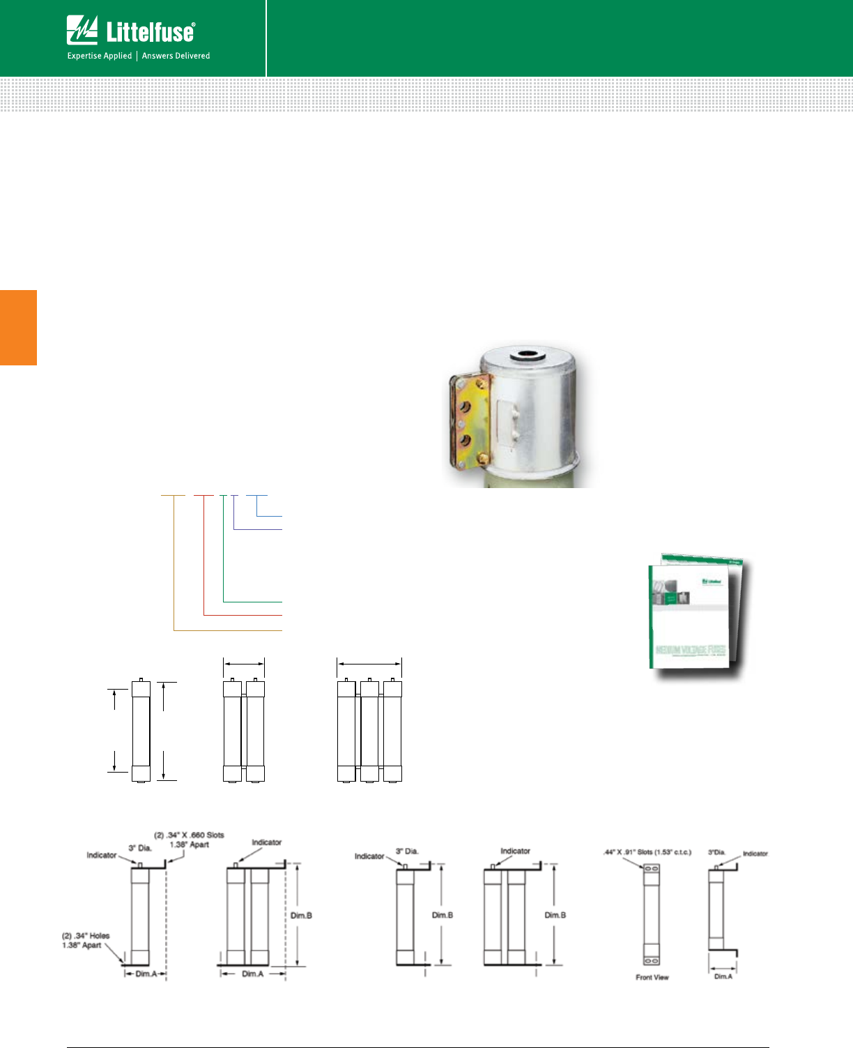
40 © 2014 Littelfuse POWR-GARD® Products Cataloglittelfuse.com
Fuses – Medium Voltage
Medium Voltage Fuses
3
Fuses
R-RATED MEDIUM VOLTAGE FUSES
Description
R-rated fuses provide required short-circuit protection for
medium voltage motors, motor controllers and associated
circuitry. These components have limited ability to absorb the
energy of large short-circuit currents. Medium voltage motor
controllers contain overload relays which provide both overload
protection and locked rotor protection to the motor. The
controllers are also intended to interrupt low value short-circuits
within the capability of the motor controller. This protects the
medium voltage fuse from sustained overcurrents which are
less than their minimum interrupting rating.
NEMA Standards for R-rated medium voltage power fuses
require they operate within 15-35 seconds when subjected
to an rms current 100 times the R rating. For example, a
fuse with a 2R rating will open within 15 to 35 seconds on
an applied current of 2 x 100 = 200 amperes.
Ordering Number
3"DIA
Dim.A
Clip
Center
6.38"
Dim.B
9.75"
A
D DD DDD
Figure 1 Figure 2 Figure 3
Hookeye Feature*
For hookeye attachment; add “W” suffix
to part number
* See web for Bolt Mount, Inverted Bolt Mount, and Bolt-In dimensions
Max Voltage (KV)
Style:
C (Cartridge)
B (Bolt Mount)
IB (Inverted Bolt Mount)
BI (Bolt-In Mount)
No. of Barrels
Rating (size)
Continuous Current
Characteristics
Voltage Ratings 2,750 V – 8,250 V
Current Range 2R – 36R
Options
• Hermetically sealed for use in hazardous locations
(add “S” suffix to part number)
• Bolt-in mounting configurations
Bolt Mount “B”
Sample Part #: 130-4R-1B-5.5
Inverted-Bolt “IB”
Sample Part #: 130-4R-1IB-5.5
Bolt-In Mount “BI”
Sample Part #: 130-4R-1BI-5.5
Cartridge “C”
Dimensions
Medium Voltage
Fuse Protection
POWR-GARD® medium
voltage fuses provide
short-circuit protection
for motors and
transformers rated
2,400 to 38,000 volts AC.
Visit littelfuse.com/MediumVoltage to
download the white paper featuring protection
tables, sizing recommendations, and applications.
130-4R-1C-5.5

41 littelfuse.com © 2014 Littelfuse POWR-GARD® Products Catalog
Fuses – Medium Voltage
Medium Voltage Fuses
3
R-RATED MEDIUM VOLTAGE FUSES
R
RATED
ORDERING/
CATALOG
NUMBER
SIZE
MAXIMUM
CONTINUOUS
CURRENT @
40 DEGREES C°
DIM. A
(INCHES)
DIM. B
(INCHES)
MINIMUM
INTERRUPTING
RATING RMS
AMPS
MAXIMUM
INTERRUPTING
RATING RMS
(ASYM)*
FIGURE
NUMBER
5.5 KV
702R1C5.5 2R 70 12" 15.875" 170 80,000 1
1003R1C5.5 3R 100 12" 15.875" 250 80,000 1
1304R1C5.5 4R 130 12" 15.875" 340 80,000 1
1505R1C5.5 5R 150 12" 15.875" 390 80,000 1
1706R1C5.5 6R 170 12" 15.875" 500 80,000 1
2009R1C5.5 9R 200 12" 15.875" 760 80,000 1
23012R1C5.5 12R 230 12" 15.875" 1000 80,000 1
39018R2C5.5 18R 390 12" 15.875" 1500 80,000 2
45024R2C5.5 24R 450 12" 15.875" 1950 80,000 2
48026R2C5.5 26R 480 12" 15.875" 2100 80,000 2
55030R2C5.5 30R 550 12" 15.875" 2400 80,000 2
60032R2C5.5 32R 600 12" 15.875" 2600 80,000 2
65036R2C5.5 36R 650 12" 15.875" 2900 80,000 2
55030R3C5.5 30R 550 12" 15.875" 2400 80,000 3
60032R3C5.5 32R 600 12" 15.875" 2600 80,000 3
65036R3C5.5 36R 650 12" 15.875" 2900 80,000 3
R
RATED
ORDERING/
CATALOG
NUMBER
SIZE
MAXIMUM
CONTINUOUS
CURRENT @
40 DEGREES C°
DIM. A
(INCHES)
DIM. B
(INCHES)
MINIMUM
INTERRUPTING
RATING RMS
AMPS
MAXIMUM
INTERRUPTING
RATING RMS
(ASYM)*
FIGURE
NUMBER
8.25 KV
702R1C8.25 2R 70 12" 15.875" 190 80,000 1
1003R1C8.25 3R 100 12" 15.875" 225 80,000 1
1304R1C8.25 4R 130 12" 15.875" 330 80,000 1
1505R1C8.25 5R 150 12" 15.875" 440 80,000 1
1706R1C8.25 6R 170 12" 15.875" 500 80,000 1
2009R1C8.25 9R 200 12" 15.875" 740 80,000 1
23012R1C8.25 12R 230 12" 15.875" 955 80,000 1
39018R2C8.25 18R 390 12" 15.875" 1440 80,000 2
45024R2C8.25 24R 450 12" 15.875" 1910 80,000 2
R
RATED
ORDERING/
CATALOG
NUMBER
SIZE
MAXIMUM
CONTINUOUS
CURRENT @
40 DEGREES C°
DIM. A
(INCHES)
DIM. B
(INCHES)
MINIMUM
INTERRUPTING
RATING RMS
AMPS
MAXIMUM
INTERRUPTING
RATING RMS
(ASYM)*
FIGURE
NUMBER
5.5 KV
14”CLIP CENTERS
702R1C5.5X 2R 70 14" 17.875" 170 80,000 1
1003R1C5.5X 3R 100 14" 17.875" 250 80,000 1
1304R1C5.5X 4R 130 14" 17.875" 340 80,000 1
1505R1C5.5X 5R 150 14" 17.875" 390 80,000 1
1706R1C5.5X 6R 170 14" 17.8 75" 500 80,000 1
2009R1C5.5X 9R 200 14" 17.8 75" 760 80,000 1
23012R1C5.5X 12R 230 14" 17.875" 1000 80,000 1
39018R2C5.5X 18R 390 14" 17.8 75" 1500 80,000 2
45024R2C5.5X 24R 450 14" 17.875" 1950 80,000 2
55030R2C5.5X 30R 550 14” 17.875” 2400 80,000 2
R
RATED
ORDERING/
CATALOG
NUMBER
SIZE
MAXIMUM
CONTINUOUS
CURRENT @
40 DEGREES C°
DIM. A
(INCHES)
DIM. B
(INCHES)
MINIMUM
INTERRUPTING
RATING RMS
AMPS
MAXIMUM
INTERRUPTING
RATING RMS
(ASYM)*
FIGURE
NUMBER
2.75 KV
702R1C2.75 2R 70 7" 10.875" 170 80,000 1
1003R1C2.75 3R 100 7" 10.875" 250 80,000 1
1304R1C2.75 4R 130 7" 10.875" 340 80,000 1
1505R1C2.75 5R 150 7" 10.875" 390 80,000 1
1706R1C2.75 6R 170 7" 10.875" 500 80,000 1
2009R1C2.75 9R 200 7" 10.875" 760 80,000 1
23012R1C2.75 12R 230 7" 10.875" 1000 80,000 1
39018R2C2.75 18R 390 7" 10.875" 1500 80,000 2
45024R2C2.75 24R 450 7" 10.875" 1950 80,000 2
* RMS Asymmetrical amperes = RMS Symmetrical amperes x 1.6
For hookeye attachment add “W” suffix to part number
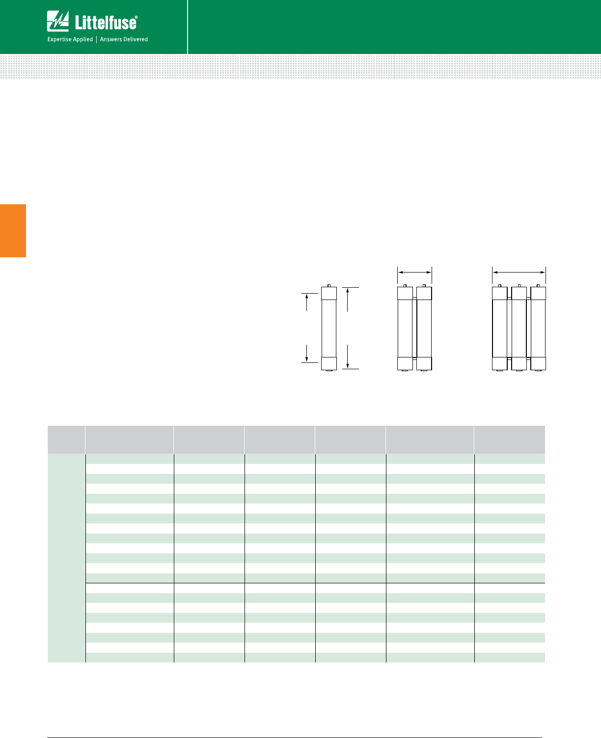
42 © 2014 Littelfuse POWR-GARD® Products Cataloglittelfuse.com
Fuses – Medium Voltage
Medium Voltage Fuses
3
E-RATED MEDIUM VOLTAGE FUSES
Description
E-rated fuses have time current characteristics designed to
provide current-limiting protection for power transformers,
potential transformers, power centers, feeder centers, and
unit sub stations. When properly applied, they can protect
against high and low fault currents.
NEMA Standards for E-rated medium voltage fuses require
that fuses rated 100E or less open within 300 seconds
(5 minutes) when subjected to an RMS value of 200-240%
of the fuse continuous current rating; and fuses with an
E rating larger than 100E must open within 600 seconds
(10 minutes) when subjected to an RMS current of 220-
240% of the fuse’s continuous current rating. These values
establish one point on the time-current curve.
Application Note
Since these fuses are used for the protection of general
purpose circuits which may contain transformers, motors,
and other equipment producing in-rush and/or overload
currents, fuses should generally be rated at 140% of the
normal full load current, and circuits should be analyzed
to ensure that system load currents will not exceed the
current rating of the fuse.
3"DIA
Dim.A
Clip
Center
6.38"
Dim.B
9.75"
A
D DD DDD
Figure 4 Figure 5 Figure 6
Characteristics
Voltage Ratings 2,750 V – 38,000 V
Current Range 10E – 600E
Options
• Hermetically sealed for use in hazardous locations
(add “S” suffix to part number)
• Clip-lock (CL) available.
E-RATED ORDERING/CATALOG
NUMBER SIZE DIM. A (INCHES) DIM. B (INCHES) MAX INTERRUPTING
RATING RMS (ASYM)*
FIGURE
NUMBER
2.75 MAX. KV
10E1C2.75 10E 7" 10.875" 80,000 4
15E1C2.75 15E 7" 10.875" 80,000 4
20E1C2.75 20E 7" 10.875" 80,000 4
25E1C2.75 25E 7" 10.875" 80,000 4
30E1C2.75 30E 7" 10.875" 80,000 4
40E1C2.75 40E 7" 10.875" 80,000 4
50E1C2.75 50E 7" 10.875" 80,000 4
65E1C2.75 65E 7" 10.875" 80,000 4
80E1C2.75 80E 7" 10.875" 80,000 4
100E-1C2.75 100E 7" 10.875" 80,000 4
125E1C2.75 125E 7" 10.875" 80,000 4
150E1C2.75 150E 7" 10.875" 80,000 4
200E1C2.75 200E 7" 10.875" 80,000 4
125E2C2.75 125E 7" 10.875" 80,000 5
150E2C2.75 150E 7" 10.875" 80,000 5
200E2C2.75 200E 7" 10.875" 80,000 5
250E2C2.75 250E 7" 10.875" 80,000 5
300E2C2.75 300E 7" 10.875" 80,000 5
350E2C2.75 350E 7" 10.875" 80,000 5
400E2C2.75 400E 7" 10.875" 80,000 5
450E2C2.75 450E 7" 10.875" 80,000 5
Dimensions
* RMS Asymmetrical amperes = RMS Symmetrical amperes x 1.6

43 littelfuse.com © 2014 Littelfuse POWR-GARD® Products Catalog
Fuses – Medium Voltage
Medium Voltage Fuses
3
E-RATED MEDIUM VOLTAGE FUSES
E-RATED ORDERING/CATALOG
NUMBER SIZE DIM. A (INCHES) DIM. B (INCHES) MAX INTERRUPTING
RATING RMS (ASYM)* FIGURE NUMBER
5.5 MAX. KV
10E1C5.5 10E 12" 15.875" 80,000 4
15E1C5.5 15E 12" 15.875" 80,000 4
20E1C5.5 20E 12" 15.875" 80,000 4
25E1C5.5 25E 12" 15.875" 80,000 4
30E1C5.5 30E 12" 15.875" 80,000 4
40E1C5.5 40E 12" 15.875" 80,000 4
50E1C5.5 50E 12" 15.875" 80,000 4
65E1C5.5 65E 12" 15.875" 80,000 4
80E1C5.5 80E 12" 15.875" 80,000 4
100E1C5.5 100E 12" 15.875" 80,000 4
125E1C5.5 125E 12" 15.875" 80,000 4
150E1C5.5 150E 12" 15.875" 80,000 4
175E1C5.5 175E 12" 15.875" 80,000 4
200E1C5.5 200E 12" 15.875" 80,000 4
125E2C5.5 125E 12" 15.875" 80,000 5
150E2C5.5 150E 12" 15.875" 80,000 5
175E2C5.5 175E 12" 15.875" 80,000 5
200E2C5.5 200E 12" 15.875" 80,000 5
250E2C5.5 250E 12" 15.875" 80,000 5
300E2C5.5 300E 12" 15.875" 80,000 5
350E2C5.5 350E 12" 15.875" 80,000 5
400E2C5.5 400E 12" 15.875" 80,000 5
450E2C5.5 450E 12" 15.875" 80,000 5
500E3C5.5 500E 12" 15.875" 80,000 6
550E3C5.5 550E 12" 15.875" 80,000 6
600E3C5.5 600E 12" 15.875" 80,000 6
E-RATED ORDERING/CATALOG
NUMBER SIZE DIM. A (INCHES) DIM. B (INCHES) MAX INTERRUPTING
RATING RMS (ASYM)* FIGURE NUMBER
5.5 MAX. KV
5NLE10E 10E 14” 17 7⁄8"80,000 4
5NLE15E 15E 14” 17 7⁄8"80,000 4
5NLE20E 20E 14” 17 7⁄8"80,000 4
5NLE25E 25E 14” 17 7⁄8"80,000 4
5NLE30E 30E 14” 17 7⁄8"80,000 4
5NLE40E 40E 14” 17 7⁄8"80,000 4
5NLE50E 50E 14” 17 7⁄8"80,000 4
5NLE65E 65E 14” 17 7⁄8"80,000 4
5NLE80E 80E 14” 17 7⁄8"80,000 4
5NLE100E 100E 14” 17 7⁄8"80,000 4
5NLE125E 125E 14“ 17 7⁄8"80,000 4
5NLE150E 150E 14” 17 7⁄8"80,000 4
5NLE175E 175E 14” 17 7⁄8"80,000 4
5NLE200E 200E 14” 17 7⁄8"80,000 4
5NLE2225E 225E 14” 17 7⁄8"80,000 5
5NLE2250E 250E 14” 17 7⁄8"80,000 5
5NLE2300E 300E 14” 17 7⁄8"80,000 5
5NLE2350E 350E 14” 17 7⁄8"80,000 5
5NLE2400E 400E 14” 17 7⁄8"80,000 5
5NLE2450E 450E 14” 17 7⁄8"80,000 5
* RMS Asymmetrical amperes = RMS Symmetrical amperes x 1.6

44 © 2014 Littelfuse POWR-GARD® Products Cataloglittelfuse.com
Fuses – Medium Voltage
Medium Voltage Fuses
3
E-RATED MEDIUM VOLTAGE FUSES
E-RATED ORDERING/CATALOG
NUMBER SIZE DIM. A (INCHES) DIM. B (INCHES) MAX INTERRUPTING
RATING RMS (ASYM)* FIGURE NUMBER
15.5 MAX. KV
10E1C15.5 10E 15" 18.875" 80,000 4
15E1C15.5 15E 15" 18.875" 80,000 4
20E1C15.5 20E 15" 18.875" 80,000 4
25E1C15.5 25E 15" 18.875" 80,000 4
30E1C15.5 30E 15" 18.875" 80,000 4
40E1C15.5 40E 15" 18.875" 80,000 4
50E1C15.5 50E 15" 18.875" 80,000 4
65E1C15.5 65E 15" 18.875" 80,000 4
80E1C15.5 80E 15" 18.875" 80,000 4
100E1C15.5 100E 15" 18.875" 80,000 4
65E2C15.5 65E 15" 18.875" 80,000 5
80E2C15.5 80E 15" 18.875" 80,000 5
100E2C15.5 100E 15" 18.875" 80,000 5
125E2C15.5 125E 15" 18.875" 80,000 5
150E2C15.5 150E 15" 18.875" 80,000 5
175E2C15.5 175E 15" 18.875" 80,000 5
200E2C15.5 200E 15" 18.875" 80,000 5
200E3C15.5 200E 15" 18.875" 80,000 6
250E3C15.5 250E 15" 18.875" 80,000 6
300E3C15.5 300E 15" 18.875" 80,000 6
E-RATED ORDERING/CATALOG
NUMBER SIZE DIM. A (INCHES) DIM. B (INCHES) MAX INTERRUPTING
RATING RMS (ASYM)* FIGURE NUMBER
8.25 MAX. KV
10E1C8.25 10E 12" 15 7⁄8"80,000, 4
15E1C8.25 15E 12" 15 7⁄8"80,000 4
20E1C8.25 20E 12" 15 7⁄8"80,000 4
25E1C8.25 25E 12" 15 7⁄8"80,000 4
30E1C8.25 30E 12" 15 7⁄8"80,000 4
40E1C8.25 40E 12" 15 7⁄8"80,000 4
50E1C8.25 50E 12" 15 7⁄8"80,000 4
65E1C8.25 65E 12" 15 7⁄8"80,000 4
80E1C8.25 80E 12" 15 7⁄8"80,000 4
100E1C8.25 100E 12" 15 7⁄8"80,000 4
125E1C8.25 125E 12" 15 7⁄8"80,000 4
150E1C8.25 150E 12" 15 7⁄8"80,000 4
125E2C8.25 125E 12" 15 7⁄8"80,000 5
150E2C8.25 150E 12" 15 7⁄8"80,000 5
200E2C8.25 200E 12" 15 7⁄8"80,000 5
250E2C8.25 250E 12" 15 7⁄8"80,000 5
300E2C8.25 300E 12" 15 7⁄8"80,000 5
350E3C8.25 350E 12" 15 7⁄8"80,000 6
400E3C8.25 400E 12" 15 7⁄8"80,000 6
E-RATED ORDERING/CATALOG
NUMBER SIZE DIM. A (INCHES) DIM. B (INCHES) MAX INTERRUPTING
RATING RMS (ASYM)* FIGURE NUMBER
8.25 MAX. KV
8NLE10E 10E 14" 17 7⁄8"80,000 4
8NLE15E 15E 14" 17 7⁄8"80,000 4
8NLE20E 20E 14" 17 7⁄8"80,000 4
8NLE25E 25E 14" 17 7⁄8"80,000 4
8NLE30E 30E 14" 17 7⁄8"80,000 4
8NLE40E 40E 14" 17 7⁄8"80,000 4
8NLE50E 50E 14" 17 7⁄8"80,000 4
8NLE65E 65E 14" 17 7⁄8"80,000 4
8NLE80E 80E 14" 17 7⁄8"80,000 4
8NLE100E 100E 14" 17 7⁄8"80,000 4
8NLE2100E 100E 14" 17 7⁄8"80,000 5
8NLE2125E 125E 14" 17 7⁄8"80,000 5
8NLE2150E 150E 14" 17 7⁄8"80,000 5
8NLE2200E 200E 14" 17 7⁄8"80,000 5
8NLE2250E 250E 14" 17 7⁄8"80,000 5
* RMS Asymmetrical amperes = RMS Symmetrical amperes x 1.6
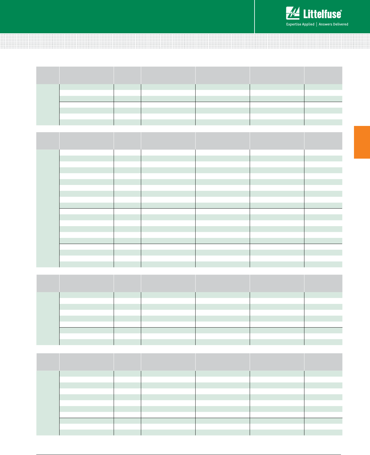
45 littelfuse.com © 2014 Littelfuse POWR-GARD® Products Catalog
Fuses – Medium Voltage
Medium Voltage Fuses
3
* RMS Asymmetrical amperes = RMS Symmetrical amperes x 1.6
E-RATED MEDIUM VOLTAGE FUSES
E-RATED ORDERING/CATALOG
NUMBER SIZE DIM. A (INCHES) DIM. B (INCHES) MAX INTERRUPTING
RATING RMS (ASYM)* FIGURE
NUMBER
15.5 MAX. KV
15GSE65E 65E 18" 217⁄8"60,000 4
15GSE80E 80E 18" 217⁄8"60,000 4
15GSE100E 100E 18" 217⁄8"60,000 4
15GSE2125E 125E 18" 217⁄8"60,000 5
15GSE2150E 150E 18" 217⁄8"60,000 5
15GSE2175E 175E 18" 217⁄8"60,000 5
15GSE2200E 200E 18" 217⁄8"60,000 5
E-RATED ORDERING/CATALOG
NUMBER SIZE DIM. A (INCHES) DIM. B (INCHES) MAX INTERRUPTING
RATING RMS (ASYM)* FIGURE
NUMBER
38 MAX. KV
3E1C38.0 3E 27" 307⁄8"20,000 4
7E1C38.0 7E 27" 307⁄8”20,000 4
10E1C38.0 10E 27" 307⁄8”20,000 4
15E1C38.0 15E 27" 307⁄8”20,000 4
20E1C38.0 20E 27" 307⁄8”20,000 4
25E1C38.0 25E 27" 307⁄8”20,000 4
30E1C38.0 30E 27" 307⁄8”20,000 4
40E1C38.0 40E 27" 307⁄8”20,000 4
50E2C38.0 50E 27" 307⁄8”20,000 5
65E2C38.0 65E 27" 307⁄8”20,000 5
80E2C38.0 80E 27" 307⁄8”20,000 5
E-RATED ORDERING/CATALOG
NUMBER SIZE DIM. A (INCHES) DIM. B (INCHES) MAX INTERRUPTING
RATING RMS (ASYM)* FIGURE
NUMBER
25.8 MAX. KV
15E1C25.8 15E 21" 247⁄8"40,000 4
20E1C25.8 20E 21" 247⁄8”40,000 4
25E1C25.8 25E 21" 24 7⁄8”40,000 4
30E1C25.8 30E 21" 247⁄8”40,000 4
40E1C25.8 40E 21" 247⁄8”40,000 4
50E1C25.8 50E 21" 247⁄8”40,000 4
65E2C25.8 65E 21" 24 7⁄8”40,000 5
80E2C25.8 80E 21" 247⁄8”40,000 5
100E2C25.8 100E 21" 247⁄8”40,000 5
E-RATED ORDERING/CATALOG
NUMBER SIZE DIM. A (INCHES) DIM. B (INCHES) MAX INTERRUPTING
RATING RMS (ASYM)* FIGURE
NUMBER
15.5 MAX. KV
15NLE10E 10E 20" 237⁄8"60,000 4
15NLE15E 15E 20" 237⁄8"60,000 4
15NLE20E 20E 20" 237⁄8"60,000 4
15NLE25E 25E 20" 237⁄8"60,000 4
15NLE30E 30E 20" 237⁄8"60,000 4
15NLE40E 40E 20" 237⁄8"60,000 4
15NLE50E 50E 20" 237⁄8"60,000 4
15NLE65E 65E 20" 237⁄8"60,000 4
15NLE80E 80E 20" 237⁄8"60,000 4
15NLE100E 100E 20" 237⁄8"60,000 4
15NLE280E 80E 20" 237⁄8"60,000 5
15NLE2100E 100E 20" 237⁄8"60,000 5
15NLE2125E 125E 20" 237⁄8"60,000 5
15NLE2150E 150E 20" 237⁄8"60,000 5
15NLE2175E 175E 20" 237⁄8"60,000 5
15NLE2200E 200E 20" 237⁄8"60,000 5
15NLE3150E 150E 20" 237⁄8"60,000 6
15NLE3175E 175E 20" 237⁄8"60,000 6
15NLE3250E 250E 20" 237⁄8"60,000 6
15NLE3300E 300E 20" 237⁄8"60,000 6

46 © 2014 Littelfuse POWR-GARD® Products Cataloglittelfuse.com
Fuses – Medium Voltage
Medium Voltage Fuses
3
E-RATED MEDIUM VOLTAGE FUSES
E-RATED ORDERING/CATALOG
NUMBER SIZE DIM. A (INCHES) DIM. B (INCHES) MAX INTERRUPTING
RATING RMS (ASYM)*
FIGURE
NUMBER
5.5 MAX. KV
CLIP LOCK
10E1CL5.5 10E 16.38" 15.13" 80,000 7
15E1CL5.5 15E 16.38" 15.13" 80,000 7
20E1C5.5 20E 16.38" 15.13" 80,000 7
25E1CL5.5 25E 16.38" 15.13" 80,000 7
30E1CL5.5 30E 16.38" 15.13" 80,000 7
40E1CL5.5 40E 16.38" 15.13" 80,000 7
50E1CL5.5 50E 16.38" 15.13" 80,000 7
65E1CL5.5 65E 16.38" 15.13" 80,000 7
80E1CL5.5 80E 16.38" 15.13" 80,000 7
100E1CL5.5 100E 16.38" 15.13" 80,000 7
125E1CL5.5 125E 16.38" 15.13" 80,000 7
150E1CL5.5 150E 16.38" 15.13" 80,000 7
225E2CL5.5 225E 17.38" 16.13" 80,000 8
250E2CL5.5 250E 17.38" 16.13" 80,000 8
300E2CL5.5 300E 17.38" 16.13" 80,000 8
350E2CL5.5 350E 17.38" 16.13" 80,000 8
400E2CL5.5 400E 17.3 8" 16.13" 80,000 8
450E2CL5.5 450E 17.38" 16.13" 80,000 8
500E3CL5.5 500E 17.38" 16.13" 80,000 9
550E3CL5.5 550E 17.38" 16.13" 80,000 9
600E3CL5.5 600E 17.38" 16.13" 80,000 9
4.31 7.94 11.56
1.25
AB
1.25
.25
3.0
Clip Lock Design
The clip lock type designs ensures a positive contact between
the fuse and the connection cam. The fuse’s clip lock tab slides
in between the clip casting and the cam to prevent the fuse
from slipping or blowing out of the holder. This positive contact
improves heat dissipation and allows fuses to run cooler.
Figure 7 Figure 8 Figure 9
E-RATED ORDERING/CATALOG
NUMBER SIZE DIM. A (INCHES) DIM. B (INCHES) MAX INTERRUPTING
RATING RMS (ASYM)*
FIGURE
NUMBER
8.25 MAX. KV
CLIP LOCK
10E1CL8.25 10E 17.3 8" 16.13" 80,000 7
15E1CL8.25 15E 17.3 8" 16.13" 80,000 7
20E1C8.25 20E 17.3 8" 16.13" 80,000 7
25E1CL8.25 25E 17.38" 16.13" 80,000 7
30E1CL8.25 30E 17.38" 16.13" 80,000 7
40E1CL8.25 40E 17.3 8" 16.13" 80,000 7
50E1CL8.25 50E 17.38" 16.13" 80,000 7
65E1CL8.25 65E 17. 3 8" 16.13" 80,000 7
80E1CL8.25 80E 17.38" 16.13" 80,000 7
100E1CL8.25 100E 17.38" 16.13" 80,000 7
125E2CL8.25 125E 17.38" 16.13" 80,000 8
150E2CL8.25 150E 17.38" 16.13" 80,000 8
175E2CL8.25 175E 17.38" 16.13" 80,000 8
200E2CL8.25 200E 17.38" 16.13" 80,000 8
225E2CL8.25 225E 17.38" 16.13" 80,000 8
250E2CL8.25 250E 17.3 8" 16.13" 80,000 8
300E2CL8.25 300E 17.3 8 " 16.13" 80,000 8
350E3CL8.25 350E 17.38" 16.13" 80,000 9
E-RATED ORDERING/CATALOG
NUMBER SIZE DIM. A (INCHES) DIM. B (INCHES) MAX INTERRUPTING
RATING RMS (ASYM)*
FIGURE
NUMBER
15.5 MAX. KV
CLIP LOCK
10E1CL15.5 10E 19.8" 18.1" 60,000 7
15E1CL15.5 15E 19.8" 18.1" 60,000 7
20E1CL15.5 20E 19.8" 18.1" 60,000 7
25E1CL15.5 25E 19.8" 18.1" 60,000 7
30E1CL15.5 30E 19.8" 18.1" 60,000 7
40E1CL15.5 40E 19.8" 18.1" 60,000 7
50E1CL15.5 50E 19.8" 18.1" 60,000 7
65E1CL15.5 65E 22.81" 21.13" 60,000 7
80E1CL15.5 80E 22.81" 21.13" 60,000 7
100E1CL15.5 100E 22.81" 21.13" 60,000 7
125E2CL15.5 125E 22.81" 21.13” 60,000 8
150E2CL15.5 150E 22.81” 21.13” 60,000 8
175E2CL15.5 175E 22.81" 21.13” 60,000 8
200E2CL15.5 200E 22.81” 21.13” 60,000 8
150E3CL15.5 150E 22.81" 21.13” 60,000 9
200E3CL15.5 200E 22.81" 21.13” 60,000 9
250E3CL15.5 250E 22.81" 21.13” 60,000 9
300E3CL15.5 300E 22.81" 21.13” 60,000 9
Dimensions in inches
* RMS Asymmetrical amperes = RMS Symmetrical amperes x 1.6
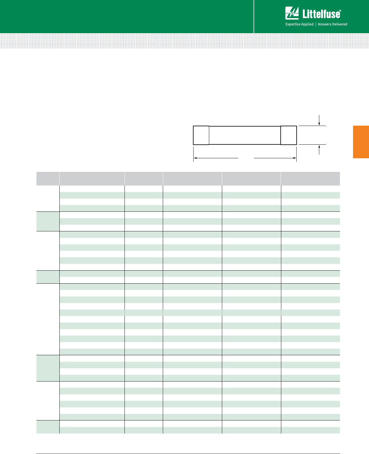
47 littelfuse.com © 2014 Littelfuse POWR-GARD® Products Catalog
Fuses – Medium Voltage
Medium Voltage Fuses
3
E-RATED POTENTIAL TRANSFORMER FUSES
A
B
Description
Potential Transformer (PT) fuses are current-limiting fuses
with high interrupting ratings designed for the protection of
potential transformers.
Application Note
When applying fuses for the protection of transformers,
the magnetizing current in-rush must be considered. The
characteristics of the in-rush, which can be matched with
a fuse time-current curve, should be available from the
transformer manufacturer.
Characteristics
Voltage Ratings 625 Vac – 25,800 Vac
Current Range ½E – 10E
E-RATED ORDERING/CATALOG
NUMBER SIZE LENGTH DIM. A
(INCHES) DIAMETER DIM. B
(INCHES) MAX INTERRUPTING
RATING RMS (ASYM)*
625
VOLT
3E4PT.6 3E 4.6” 0.8125” 37,500
5E4PT.6 5E 4.6” 0.8125” 37,500
7E4PT.6 7E 4.6” 0.8125” 37,500
10E4PT.6 10E 4.6” 0.8125” 37,500
2.75
MAX.
KV
500E4PT2.4 ½E 4.6” 0.8125” 37,500
1E4PT2.4 1E 4.6” 0.8125” 37,500
2E4PT2.4 2E 4.6” 0.8125” 37,500
2.75
MAX. KV
1E6PT2.75 1E 7.4” 1.5625” 37,500
2E6PT2.75 2E 7.4” 1.5625” 37,500
3E6PT2.75 3E 7.4” 1.5625” 37,500
1E8PT2.75 1E 9.5” 1.5625” 37,500
2E8PT2.75 2E 9.5” 1.5625” 37,500
3E8PT2.75 3E 9.5” 1.5625” 37,500
4.8
MAX.
KV
1E5PT4.8 1E 5.6” 0.8125” 50,000
2E5PT4.8 2E 5.6” 0.8125” 50,000
5.5
MAX. KV
500E6PT5.5 ½E 7.4” 1.5625” 50,000
1E6PT5.5 1E 7.4” 1.5625” 50,000
2E6PT5.5 2E 7.4” 1.5625” 50,000
3E6PT5.5 3E 7.4” 1.5625” 50,000
5E6PT5.5 5E 7.4” 1.5625” 50,000
500E8PT5.5 ½E 9.5” 1.5625” 50,000
1E8PT5.5 1E 9.5” 1.5625” 50,000
2E8PT5.5 2E 9.5” 1.5625” 50,000
3E8PT5.5 3E 9.5” 1.5625” 50,000
5E8PT5.5 5E 9.5” 1.5625” 50,000
10E8PT5.5 10E 9.5” 1.5625” 50,000
8.25
MAX.
KV
500E8PT8.25 ½E 9.5” 1.5625” 50,000
1E8PT8.25 1E 9.5” 1.5625” 50,000
2E8PT8.25 2E 9.5” 1.5625” 50,000
3E8PT8.25 39.5” 1.5625” 50,000
15.5
MAX. KV
500E11PT15.5 ½E 12.8” 1.5625” 35,000
1E11P T15.5 1E 12.8” 1.5625” 35,000
2E11P T15.5 2E 12.8” 1.5625” 35,000
3E11PT15.5 3E 12.8” 1.5625” 35,000
3E16PT15.5 3E 17.5” 1.5625” 35,000
5E16PT15.5 5E 17.5” 1.5625” 35,000
25.8
MAX.
KV
500E16PT25.5 ½E 17.5” 1.5625” 32,000
1E16PT25.5 1E 17.5” 1.5625” 32,000
Dimensions
* RMS Asymmetrical amperes = RMS Symmetrical amperes x 1.6
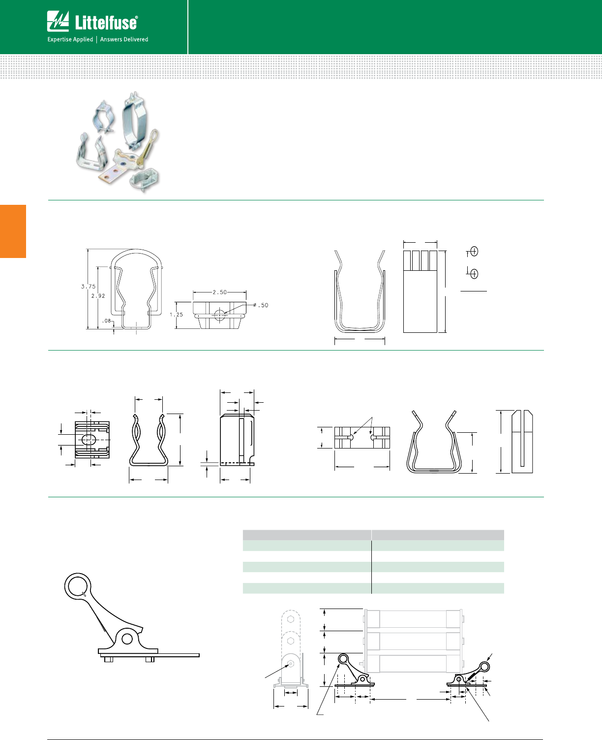
48 © 2014 Littelfuse POWR-GARD® Products Cataloglittelfuse.com
Medium Voltage Fuses
3
Fuses – Medium Voltage
LIVE PARTS
TRIPLE BARREL
Bottom Lever In
Closed Position
.56 Dia. (2) Holes
For Mounting
Cable/Bus
.44 DIA. (2) HOLES
DOUBLE BARREL
SINGLE BARREL
1.75
1.00
2.00
2.00
2.00
4.9
4.85
3.63
3.63
3.75
Top Lever in
Open Position
A
Blown Fuse
Indicator
TOP
VIEW
4.50
3.08
1.50
4.16
0.38" HOLES
.78 .63
.08
.30
.31
.08
.71
1.15 .05
.78
Description
Live parts are available for mounting E, R, and PT single, double, and triple barrel
fuses. Mounting clips are available for ferrule type and clip lock style fuses.
All clips are sold in pairs.
Part Number 700-520-CL
Ordering Number 0700520.ZXCL
Clip Lock Design
Part Number 700-530
Ordering Number 0700530.Z
For use with all 3" diameter fuses.
Dimensions for reference only.
Part Number 700-500
Ordering Number 0700500.Z
For use with all 13/16" (.8125”) diameter PT fuses
Part Number 700-156
Ordering Number 0700156.Z
For use with 19/16" (1.5625”) to 15/8” (1.625”) diameter PT fuses.
Part Number 700-300
Ordering Number 0700300.Z
For use with 3” diameter fuses.
2.85
Mounting Hole
Dimension
2.00
3.74
1.00
Dimensions in inches
Dimensions in inches
Mounting Details for Clip Lock
CATALOG NUMBER DIMENSION A (INCHES)
10E1CL5.5 thru 150E1CL5.5 12.88
225E2CL5.5 thru 600E3CL5.5 13.88
10E1CL8.25 thru 350E3CL8.25 13.88
10E1CL15.5 thru 50E1CL15.5 16.25
65E1CL15.5 thru 300E3CL15.5 19.25
49 littelfuse.com © 2014 Littelfuse POWR-GARD® Products Catalog
Medium Voltage Fuses
3
L17T Series Telecommunications Power Fuse ........................... 50
TLN Series Telecommunications Power Fuse .............................51
TLS Series Telecommunications Power Fuse ............................ 52
Alarm Indicating Fuses ................................................................ 53
LTFD101 Telecommunication Disconnect Switch ...................... 54
TELECOM PRODUCTS
Table of Contents
Section Overview
Rely on Littelfuse for short circuit protection of telecommunications
circuits and sensitive DC power distribution circuits.
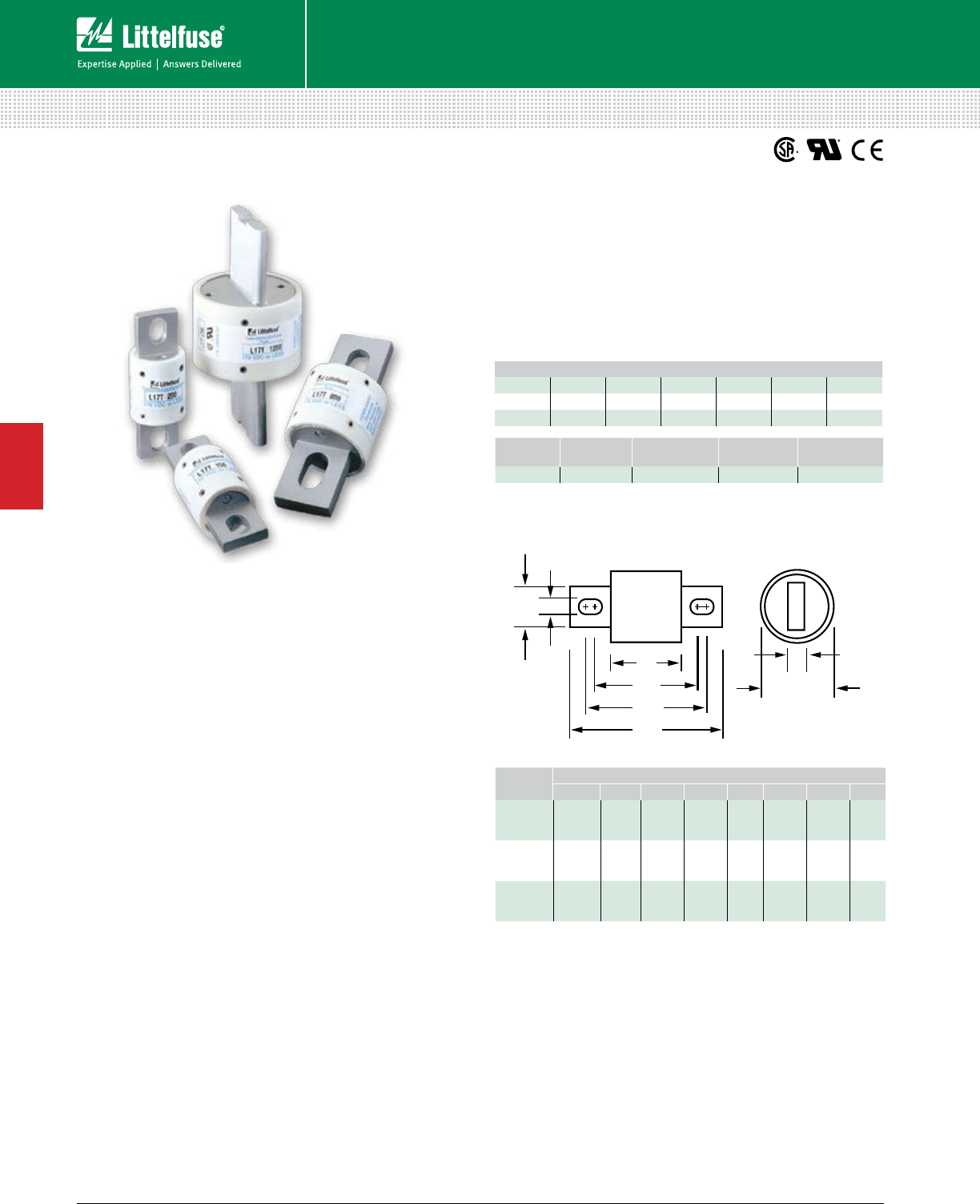
50 © 2014 Littelfuse POWR-GARD® Products Cataloglittelfuse.com
Fuses – Telecom Products
Telecom Products
4
L17T SERIES TELECOM POWER FUSE
170 Vdc • Current-Limiting • 70 -1200 A
Description
Specifically designed for short-circuit protection of
telecommunications circuits, the Littelfuse L17T
series fuses provide reliable protection of sensitive
DC power distribution systems. Constructed with
silver plated elements for low I2t and peak let-through,
these advanced fuses virtually eliminate equipment
damage due to surges and spikes. The L17T series
fuse unique element geometry also provides
cooler running temperatures, helping to minimize
heat within enclosures.
Features
• Low I2t
• Extremely current-limiting
• Low operating temperature
• 170 Vdc rating
Specifications
Voltage Rating 170 Vdc
Interrupting Rating 100 kA
Ampere Range 70 – 1200 A
Approvals UL Recognized (File: E71611)
CSA Recognized (File: LR29862)
A
B
C
D
F
G
E
H
Fig. 3
Ordering Information
AMPERE
RATING
DIMENSIONS INCHES (mm)
A B C D E F G H
70 – 250 15⁄32
(29.4)
17⁄8
(47.6)
23⁄16
(55.6)
221⁄32
(67.5)
1
(25.4)
7⁄8
(22.2)
5⁄16
(7.9)
3⁄16
(4.8)
300 – 800 11⁄4
(31.8)
115 ⁄16
(49.2)
29⁄16
(65.1)
31⁄2
(88.9)
11⁄2
(38.1)
1
(25.4)
13 ⁄32
(10.3)
1⁄4
(6.35)
900–1200 111 ⁄32
(34.0) — — 41⁄16
(103.1)
2
(50.8)
11⁄2
(38.1) —
1⁄4
(6.35)
AMPERE RATINGS
70 125 200 300 450 800 1100
90 150 225 350 500 900 1200
100 175 250 400 600 1000 —
Web Resources
For additional information, visit:
littelfuse.com/l17t
SERIES VOLTAGE AMPERAGE CATALOG
NUMBER
ORDERING
NUMBER
L17T 170 1200 L17T 1200 L17T1200V
Dimensions Inches (mm)
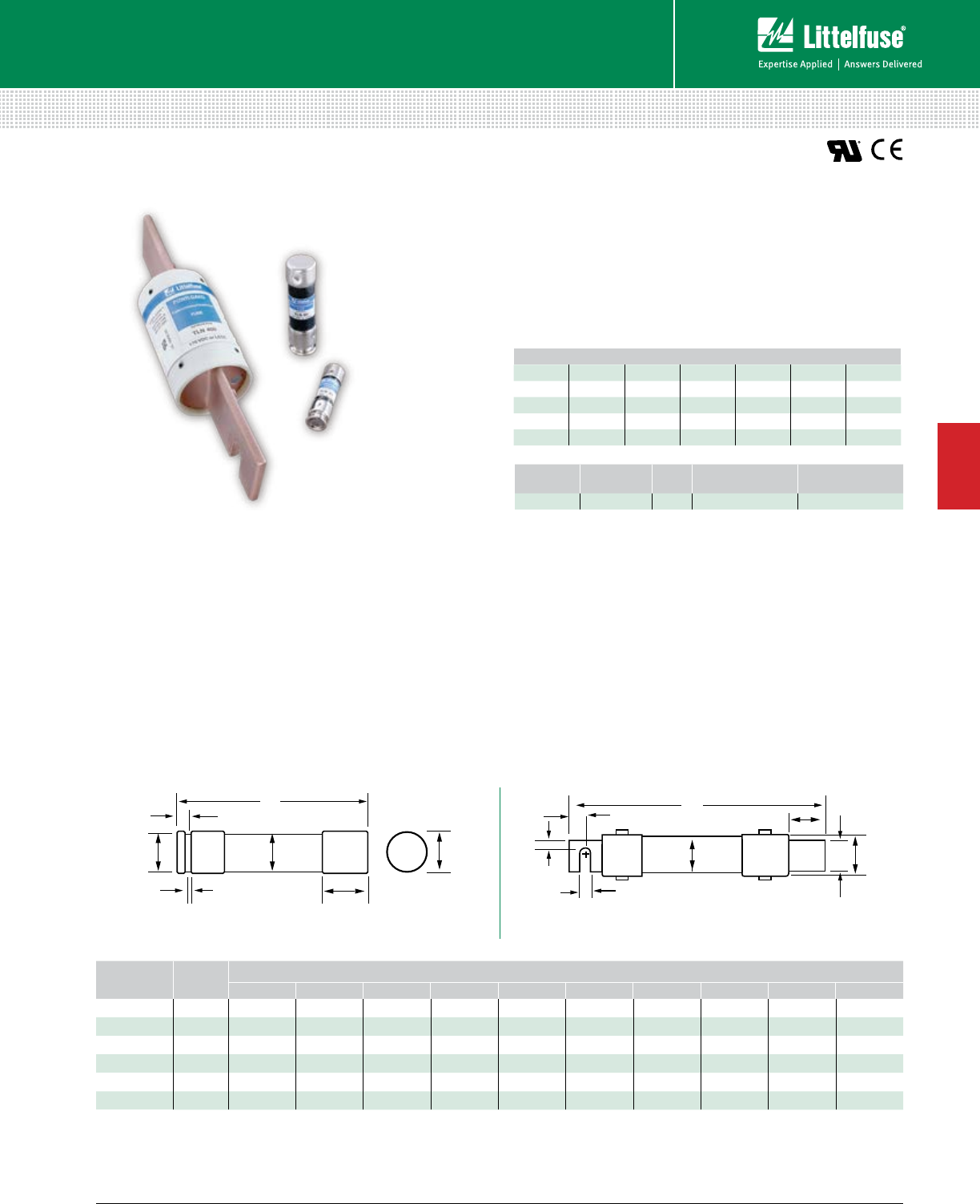
51 littelfuse.com © 2014 Littelfuse POWR-GARD® Products Catalog
Fuses – Telecom Products
Telecom Products
4
TLN SERIES TELECOM POWER FUSE
170 Vdc • Current-Limiting • 1-600 A
Description
The TLN Series fuses are specifically designed for
the protection of telecommunications DC power
distribution circuits.
Features
• 170 Vdc rating
• Fast-acting and current-limiting
• 1 to 600 amperes rating
• Dimensionally similar to 250 V Class R fuses
Dimensions Inches (mm)
Specifications
Voltage Rating 170 Vdc
Interrupting Rating 100 kA
Ampere Range 1 – 600 A
Approvals UL Recognized (File: E71611)
Ordering Information
Web Resources
For additional information, visit:
littelfuse.com/tln
Recommended Fuse Holders
LFR25 Series ...................................................................... 88
AMPERE RATINGS
1 15 40 80 150 300 600
3 20 45 90 175 350 —
5 25 50 100 200 400 —
6 30 60 110 225 450 —
10 35 70 125 250 500 —
SERIES VOLTAGE AMP CATALOG
NUMBER
ORDERING
NUMBER
TLN 170VDC 6TLN006 0TLN006.T
Replaces competitors’ TPN and TGN Series.
F
A
FIG. 1
D
G
EC
BD
J
F
FIG. 2
A
B
C
A
H
K
AMPERES FIGURE
NUMBER
DIMENSIONS INCHES (mm)
A B C D E F G H J K
1 – 30 12 (50.8) 1⁄2 (12.7) 1⁄2 (12.7) 9⁄16 (14.3) 5⁄64 (2.0) 5⁄32 (4.0) 3⁄8 (9.5) — — —
35 – 60 13 (76.2) 3⁄4 (19.1) 5⁄8 (15.9) 13⁄16 (20.6) 3⁄32 (2.4) 3⁄16 (4.8) 5⁄8 (15.9) — — —
70 – 100 2 57⁄8 (149.2) 1 (25.4) 11⁄16 (27.0) 11⁄16 (27.0) 1⁄8 (3.2) 3⁄4 (19.1) 11⁄4 (31.6) 1⁄4 (6.4) 9⁄32 (7.1) 1⁄2 (12.7)
110 – 200 2 71⁄8 (181.0) 11⁄2 (38.1) 115 ⁄32 (37.3) 119 ⁄32 (40.5) 3⁄16 (4.8) 11⁄8 (28.6) 127⁄32 (46.8) 7⁄16 (11.1) 9⁄32 (7.1) 11⁄16 (17.5)
225 – 400 2 8 5⁄8 (219.1) 2 (50.8) 115 ⁄16 (49.2) 23⁄32 (53.2) 1⁄4 (6.4) 15⁄8 (41.3) 211⁄32 (59.5) 5⁄8 (15.9) 13⁄32 (10.3) 15 ⁄16 (23.8)
450 – 600 210 3⁄8 (263.5) 21⁄2 (63.5) 23⁄8 (60.3) 219 ⁄32 (65.9) 1⁄4 (6.4) 2 (50.8) 227⁄32 (72.2) 3⁄4 (19.1) 17⁄32 (13.5) 11⁄8 (28.6)
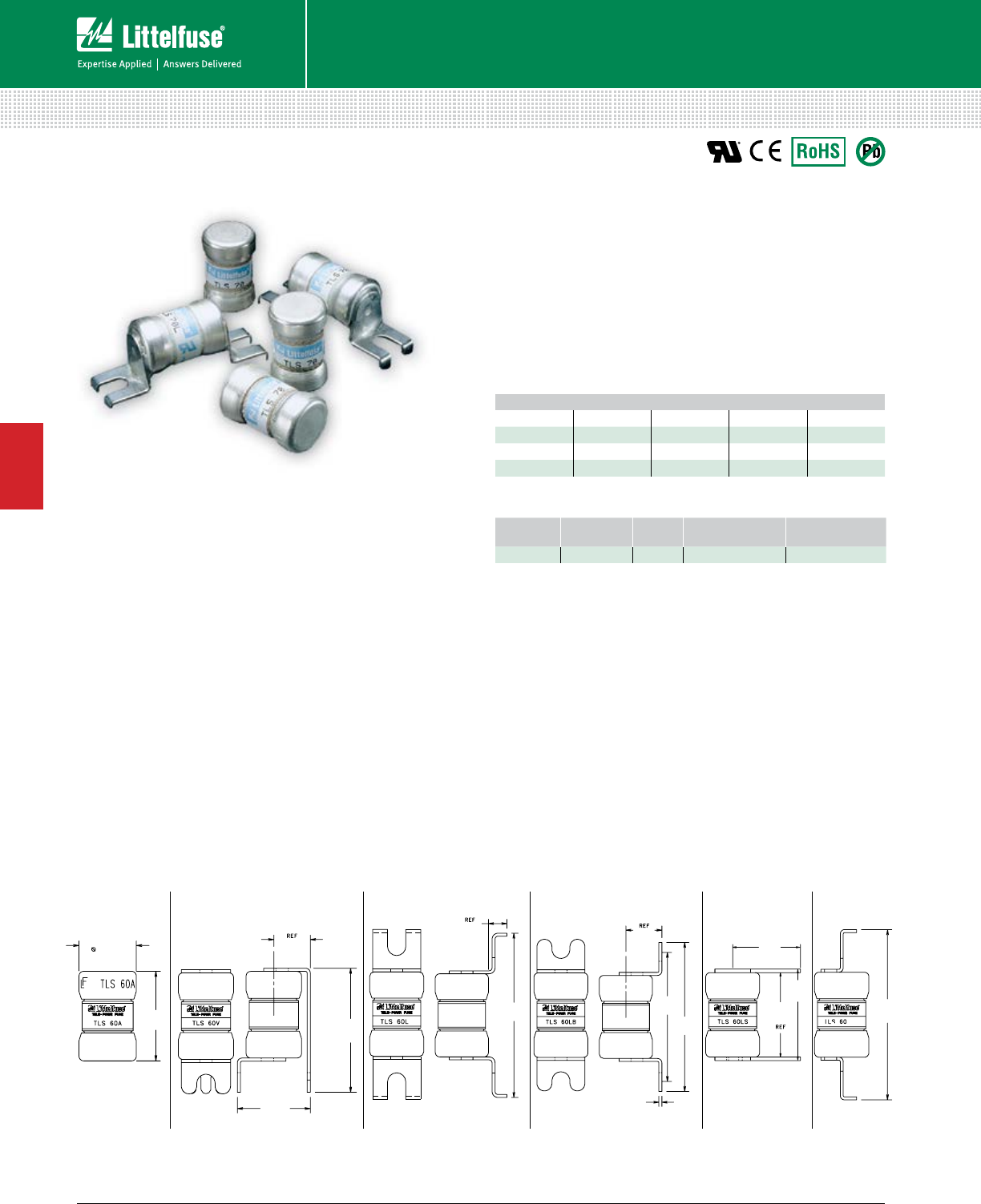
52 © 2014 Littelfuse POWR-GARD® Products Cataloglittelfuse.com
Fuses – Telecom Products
Telecom Products
4
.563
(14.3)
.877
(22.28)
.74
(18.8)
1.26
(32.0)
.195
(4.95)
1.74
(44.20)
.382
(9.70)
1.367
(34.72)
1.58
(40.13)
.032
(.81)
.559
(14.20)
.944
(23.98)
1.74
(44.20)
.87
(22.28)
.37
(9.4)
MB
TLS SERIES TELECOM POWER FUSE
170 Vdc • Current-Limiting • 1-125 A
Description
Littelfuse TLS Series fuses are designed specifically for
the protection of telecommunications equipment. TLS
fuses have been engineered to operate up to 170 Vdc to
provide current-limiting short-circuit protection for cables
and components found in the DC power distribution circuits
of telecommunications systems. The compact design and
multiple mounting configurations of the TLS series allow it
to be used in a variety of applications.
Features
• 170 Vdc rating
• Current-limiting
• 1 to 125 amperes rating
• Multiple mounting configurations
• RoHS Compliant
TLS-V TLS-L TLS-LBTLS
Specifications
Voltage Rating 170 Vdc
Ampere Range 1 – 125 A
Interrupting Rating 100 kA
Approvals UL Recognized (File: E71611)
Construction Body: Glass melamine
Caps: Silver-plated brass
Environmental RoHS Compliant, Lead (Pb) Free
Ordering Information
*Available in cartridge only.
Note: To order leaded versions of TLS fuses, add suffix V, L, LB, or LS to part number.
Web Resources
For additional information, visit: littelfuse.com/tls
Recommended Fuse Holders
LFT30060 for TLS series cartridge style fuse ......................94
TLS-LS TLS-MB
Vertical Mount Leaded Bolt-In SolderCartridge
AMPERE RATINGS
1 6 25 50 90
2 10 30 60 100
3 15 35 70 110*
5 20 40 80 125*
Dimensions Inches (mm)
SERIES VOLTAGE AMP CATALOG
NUMBER
ORDERING
NUMBER
TLS 170VDC 6TLS006V 0TLS006.TXV
Replaces competitors’ TPS and TGS Series.
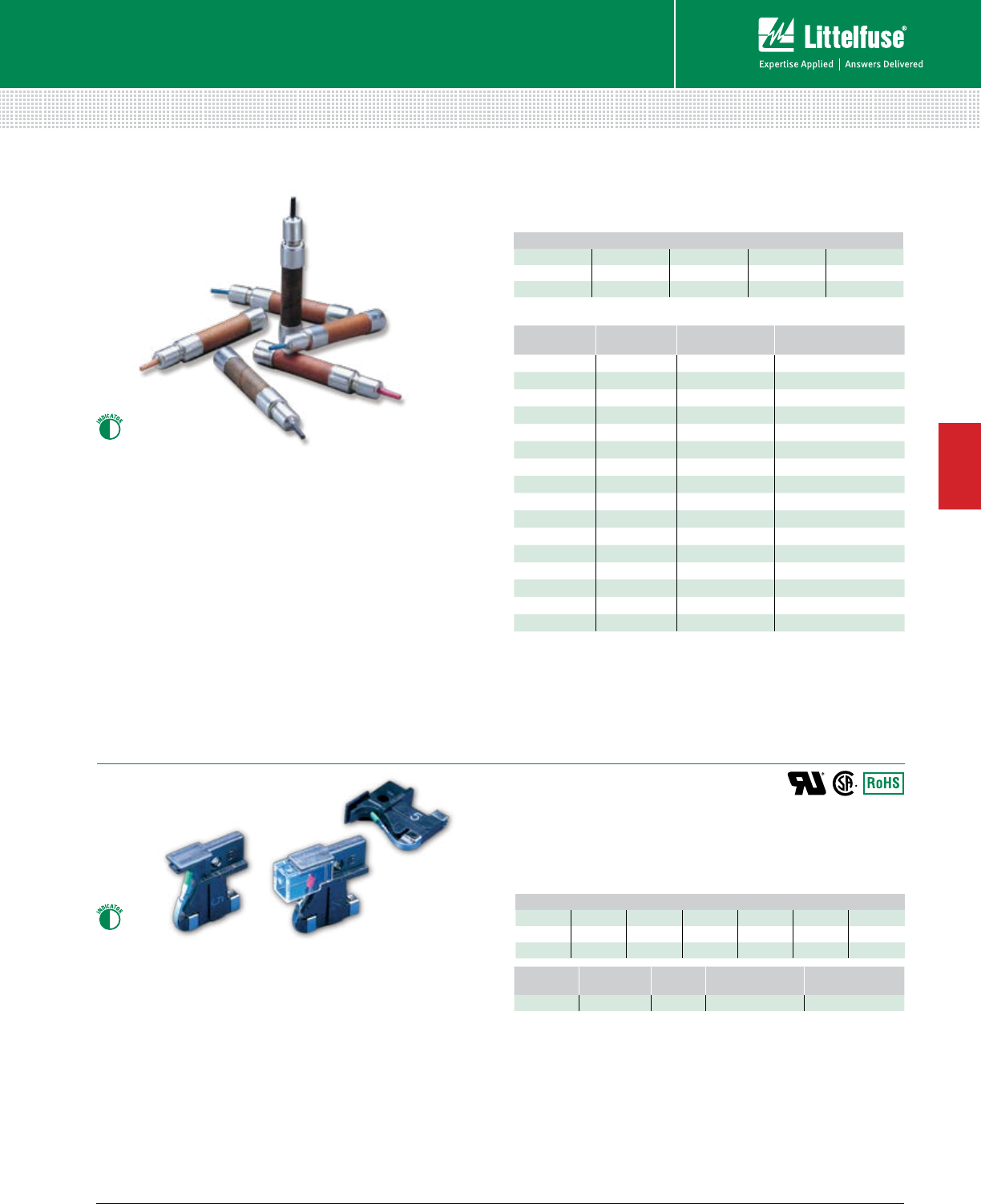
53 littelfuse.com © 2014 Littelfuse POWR-GARD® Products Catalog
Fuses – Telecom Products
Telecom Products
4
70 SERES & 481 SERIES ALARM INDICATING FUSESSES
Alarm Indicating Fuses
Ordering Information
10 MINUTE
RATING
CATALOG
NUMBER
ORDERING
NUMBER
COLOR
CODE
100 mA 70P 70P00000Z GREY/ WHITE
150 mA 70R 70R00000Z RED/WHITE
180 mA 70E 70E00000Z YELLOW
200 mA 70X 70X00000Z BLACK
250 mA 70F 70F00000Z VIOLET
250 mA 70K 70K00000Z VIOLET/WHITE
350 mA 70S 70S00000Z GRAY
500 mA 70G 70G00000Z RED
750 mA 70H 70H00000Z BROWN
1.33 A 70A 70A00000Z WHITE
2 A 70B 70B00000Z ORANGE
3 A 70C 70C00000Z BLUE
3.5 A 70J 70J00000Z BLACK/WHITE
5 A 70D 70D00000Z GREEN/BLACK
8 A 70M 70M00000Z TAN/WHITE
10 A 70N 70N00000Z YELLOW/PURPLE
70 Series Alarm Indicating Fuses
Description
The 70 Series alarm indicating fuses are designed for use in
telecommunications equipment. A color coded tip provides
visual identification of the ampere rating and the fuse status.
Features
• Color coded tip
• Rated 125 Vac, 300 Vdc
Specifications
Voltage Ratings 125 Vac/300 Vdc
Interrupting Ratings 1,000 A @ 125 Vac
1,000 A @ 300 Vdc
481 Series Alarm Indicating Fuses
Description
481 Series alarm indicating fuses are designed to reduce
down time by immediately pinpointing the blown (open)
circuit while triggering an LED or audio alarm. This item
requires 482 Series mating fuse holder.
All ranges of 481 Series fuses are available as our original
design, and the 2-20 amp range is now available as a RoHS
compliant option (use the “P” designator when ordering).
See the part numbering section of the datasheet for related
ordering instructions.
Specifications
Voltage Rating 125 Vac/dc
Approvals UL Recognized (File: E71611)
CSA Recognized (File: LR29862)
Ordering Information
AMPERE RATINGS
18/100 3/83/41 1/23 5 12
1/51/21 2 3 1/27 1/215
1/465/100 1 1/32 1/24 10 20
SERIES VOLTAGE AMP CATALOG
NUMBER
ORDERING
NUMBER
481 125 ac/dc 2481002L 0481002.V XL
Note: For 481 Dummy fuse, order 481000.
Recommended Fuse Holders
482 Series, see website: littelfuse.com/482
Available 1-20 pole with PCB or panel mounting.
To order with protective lens add suffix XL.
Web Resources
For additional information, visit: littelfuse.com/481
AMPERE RATINGS
100 mA 200 mA 500 mA 2 5
150 mA 250 mA 750 mA 3 8
180 mA 350 mA 1.33 3.5 10
Web Resources
For additional information, visit: littelfuse.com/70
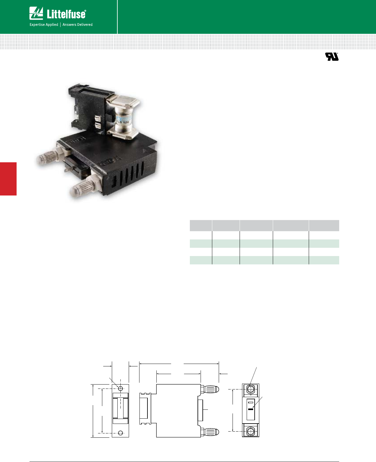
54 © 2014 Littelfuse POWR-GARD® Products Cataloglittelfuse.com
Telecom Products
4
Fuses – Telecom Products
LTFD 101 SERIES TELECOM DISCONNECT SWITCH
80 Vdc • 1-125 A
Specifications
Voltage Rating 80 Vdc
Ampere Range 1 – 125 A
Approvals UL Recognized (File: E122674)
Recommended Fuses
Littelfuse TLS Series fuses ................................................ 52
Description
Littelfuse compact LTFD 101 fuse holders for TLS fuses
are designed for quick installation into telecom equipment
panels. Their modular design fits into spaces originally
designed for circuit breakers and can be front panel
mounted or rear mounted using bullet connectors.
The innovative new pull-out design eliminates the
need for tools to replace fuses and includes an
alarm signaling circuit to identify the blown fuse.
Features
• Extremely compact
• Quick mounting
• Replaces circuit breakers
• Includes alarm signaling circuit
Web Resources
For additional information, visit:
littelfuse.com/ltfd101
Dimensions for reference only. For additional options and dimensions, contact the factory.
6-32 UNF Insert
0.20 ±.030 Deep
0.75"
(19.05)
2.50"
(63.5)
2.062"
(52.375)
1.940"
(49.276)
2.00"
(50.8)
0.85"
(21.59)
LOAD
LINE
3.75"
(95.25) 0.305" (7.747) Dia.
Bullet Terminal
Alarm pin
0.02" (.508) x 0.11" (2.794)
position optional
C
L
Ordering Information
SERIES AMPERAGE CATALOG
NUMBER
ORDERING
NUMBER
TERMINAL
TYPE
LTFD 125 A MAX LTFD101-1 LTFD0101ZX1 BULLET
LTFD 125 A MAX LTFD101-2 LTFD0101ZX2 SCREW
LTFD 125 A MAX LTFD101-3 LTFD0101ZX3 STUD
LTFD 70 A MAX LTFD101-4 LTFD0101ZX4 CLIP
Dimensions Inches (mm)
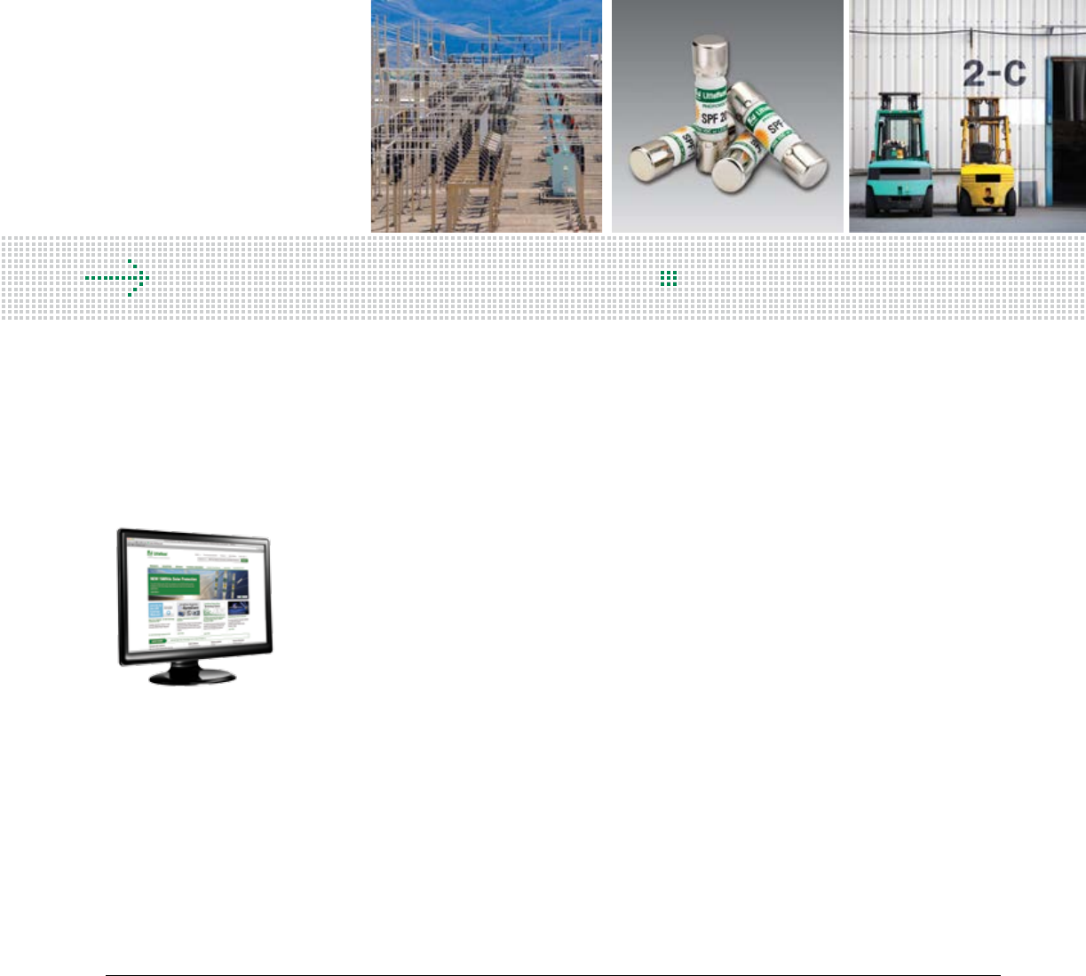
55 littelfuse.com © 2014 Littelfuse POWR-GARD® Products Catalog
Solar Rated Products Overview .................................................. 56
1500 Vdc Solar Rated Fuses ....................................................... 57
1000 Vdc Solar Rated Fuses ....................................................... 59
Forklift / Stud Mounted Fuses .................................................... 62
Plug Fuses ................................................................................... 63
MEGA® Bolt-Down Fuses ........................................................... 63
In-Line Fuses And Holder ........................................................... 64
Cable Limiters ............................................................................. 65
Cylindrical Fuses ......................................................................... 66
OEM Custom Products ............................................................... 67
SPECIAL PURPOSE FUSES
Table of Contents
POWR-GARD® Circuit Protection
Littelfuse engineering is constantly
developing new products to meet the
needs of the photovoltaic industry. For
the latest information on the growing
POWR-GARD Product portfolio, visit:
littelfuse.com/solar
Section Overview
Whether you are protecting solar equipment or finding a
replacement fuse for an aging HVAC unit, Littelfuse carries the
breadth of fuses to meet your needs. Our “special purpose”
fuse section includes application-specific products to meet
all of your application needs.
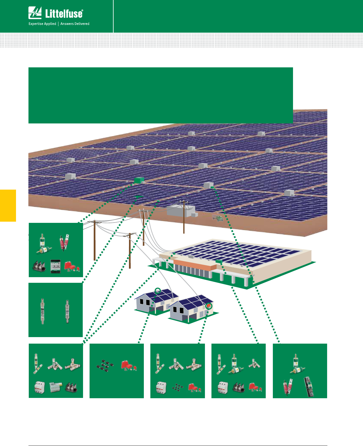
56 © 2014 Littelfuse POWR-GARD® Products Cataloglittelfuse.com
5
Solar Fuses
Fuses – Solar
3 7
CENTRAL INVERTER
12 1411
913
1413 1 3
7
COMBINER BOX MICRO INVERTER SMALL INVERTER COMMERCIAL INVERTER ARRAY COMBINER
14 911
4
14 8
3
2 5
WIRE HARNESS
910 11
4 614 61
1. SPXV 1500 V – 6-30 A Fuse
2. SPXI 1500 V – 2.5-3.5 A In-Line Fuse
3. SPFJ 1000 V – 70-450 A Fuse
4. SPF 1000 V – 1-30 A Fuse
5. SPFI 1000 V – 2-20 A In-Line Fuse
6. KLKD 600 V – 1/10-30 A Fuse
7. IDSR & LDC 600 V Fuse and Holder
8. LFJ1000 Fuse Block for SPFJ Fuse
9. LFPHV & LFPSM Touch-Safe Fuse Holder
10. Busbar for Touch-Safe Fuse Holder s
11. Power Distribution Block
12. SE-601 DC Ground-Fault Relay
13. TVS Diodes / SCRs
14. Varistor Products
SOLAR PRODUCTS BY APPLICATION
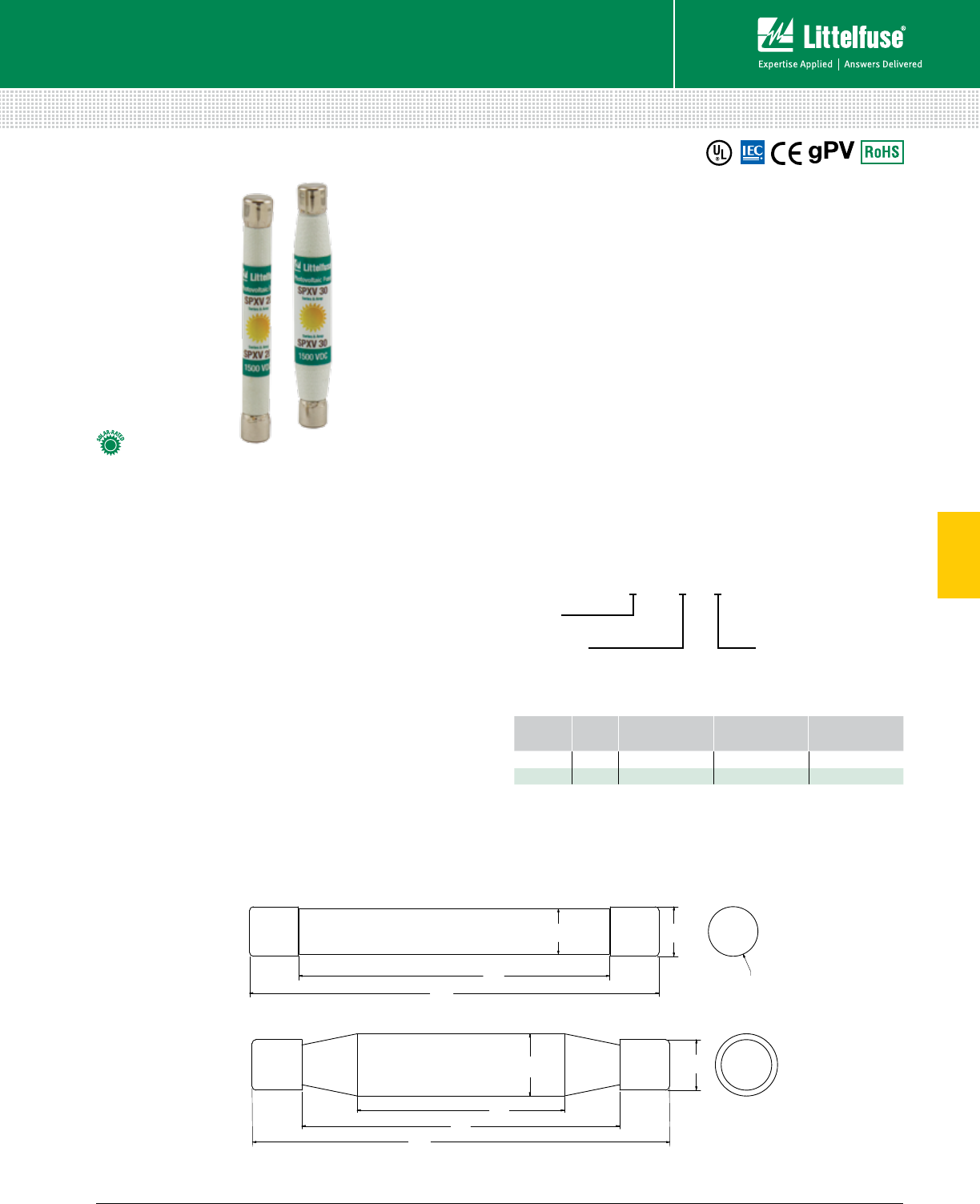
57 littelfuse.com © 2014 Littelfuse POWR-GARD® Products Catalog
5
Solar Fuses
Fuses – Solar
SPXV SERIES SOLAR FUSES
1500 Vdc • 6 - 30 A
Dimensions inches (mm)
6 – 20 A
25 – 30 A
1.67
(42.4)
.50
(12.7)
3.36
(85.3)
2.56
(65.0)
.41
(10.4)
2.55
(64.8)
.38
(9.6)
3.36
(85.3)
.41
(10.4)
ø .41
(10.4)
Specifications
Voltage Rating 1500 Vdc
Amperage Rating 6, 8, 10, 12, 15, 20, 25, 30
Max. Interrupting Rating 30 kA
Time Constant ≤ 1ms
Material Body: Melamine
Caps: Copper Alloy
Approvals UL 2579 Listed (File: E339112)
IEC 60269-6
Environmental RoHS Compliant
Reach Compliant
Country of Origin Mexico
Part Numbering System
SPXV xxx T
Package Quantity
Series
Amp Code
T = 10
L = 50
Refer to datasheet
for amp code
SERIES AMP PACKAGE
QUANTITY
CATALOG
NUMBER
ORDERING
NUMBER
SPXV 610 SPXV006 SPXV006.T
SPXV 30 50 SPXV030 SPXV030.L
Description
The Littelfuse SPXV solar string fuse is designed
specifically for 6-30 A 1500 Vdc applications.
Features/Benefits
• 10 x 85 mm package size
• UL 2579 Listed and IEC 60269-6
• 30,000 A interrupting rating
Applications
• Inverters
• Combiner boxes
Recommended Fuse Holder
Littelfuse LPXV Solar Series ..............................................106
Web Resources
Download the complete datasheet and other technical
documents: littelfuse.com/spxv
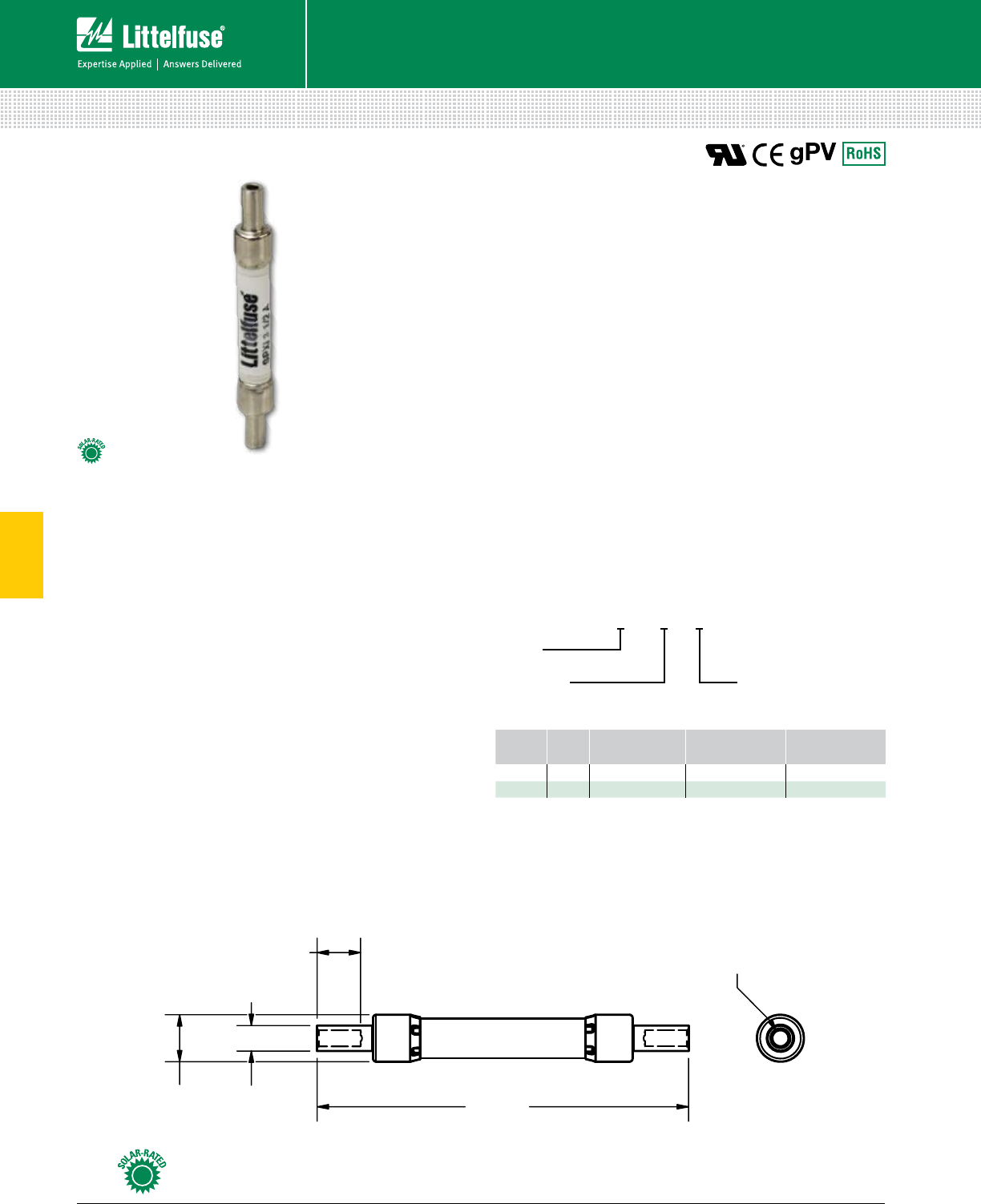
58 © 2014 Littelfuse POWR-GARD® Products Cataloglittelfuse.com
5
Solar Fuses
Fuses – Solar
SPXI SERIES SOLAR FUSES
1500 Vdc • 2.5 - 3.5 A • Patent Pending
Specifications
Voltage Rating 1500 Vdc
Amperage Rating 2.5-3.5 A*
Interrupting Rating 15 kA
Time Constant ≤ 1ms
Material Body: Melamine
Caps: Copper Alloy (Nickel Plated)
Approvals UL 2579 Recognized (File: E339112)
Environmental RoHS Compliant
Country of Origin Mexico
*Visit littelfuse.com/solar for the newest available amperages
Part Numbering System
SPXI xxx T
Package Quantity
Series
Amp Code
T = 10
L = 50
Refer to datasheet
for amp code
SERIES AMP PACK QUANTITY CATALOG
NUMBER
ORDERING
NUMBER
SPXI 2.5 10 SPXI02.5 SPXI02.5T
SPXI 3.5 50 SPXI03.5 SPXI03.5L
Description
The Littelfuse SPXI solar fuse is designed to integrate
into an in-line assembly within a wire harness. The fuse
provides photovoltaic (PV) protection that meets UL 2579 for
photovoltaic applications. The SPXI can be electrically insulated
by either overmolding or using approved heat-shrink.
Features/Benefits
• Meets UL 2579 photovoltaic specifications
• Meets IEC 60269-6 electrical performance requirements
• 15,000 A interrupting rating
• No fuse holder required
Applications
• Photovoltaic wire harness
Recommended Crimping Tool
T&B Sta-Kon ERG4002 or equivalent
Weidmüller HTN 21 or equivalent
Web Resources
Download the complete datasheet and other technical
documents: littelfuse.com/spxi
Dimensions mm (in)
81.41
(3.205)
10.31
(0.406)
5.59
(0.220)
9.53
(0.375)
ø 3.56
(0.140)
Look for this logo to indicate products that are used in solar applications. Visit our website
littelfuse.com/solar for the latest updates on approvals, certifications, and new products.
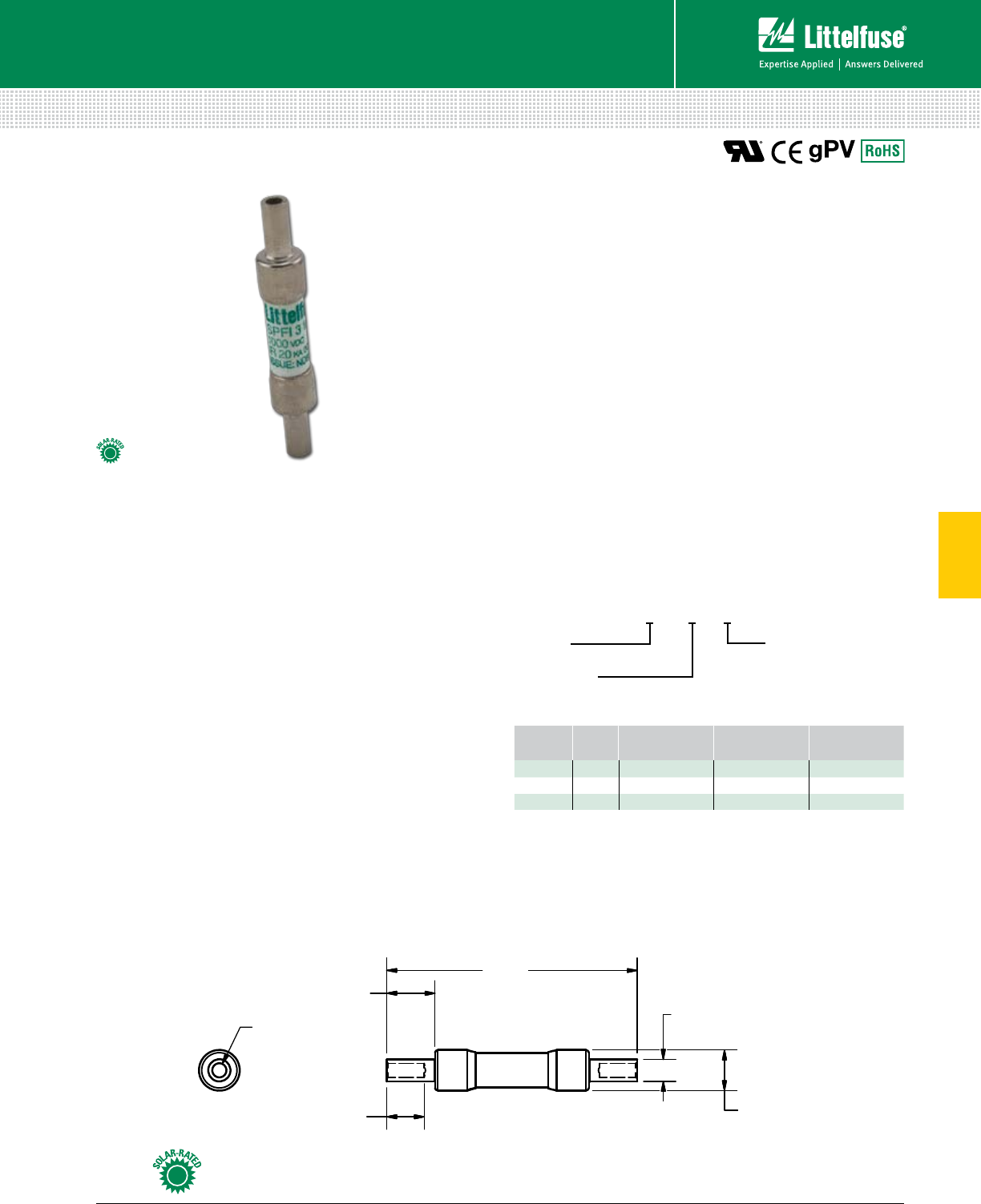
59 littelfuse.com © 2014 Littelfuse POWR-GARD® Products Catalog
5
Solar Fuses
Fuses – Solar
SPFI SERIES SOLAR FUSES
1000 Vdc • 2 - 20 A • Patent Pending
Specifications
Voltage Rating 1000 Vdc
Amperage Rating 2, 3, 3.5, 4, 5, 6, 8, 10, 12, 15, 20*
Max. Interrupting Rating 20 kA
Time Constant ≤ 1ms
Material Body: Melamine
Caps: Copper Alloy (Nickel Plated)
Approvals UL 2579 Recognized (File: E339112)
Environmental RoHS Compliant
Country of Origin Mexico
*Visit littelfuse.com/solar for the newest available amperages
Part Numbering System
Description
The Littelfuse SPFI solar fuse has been designed to
integrate into an in-line assembly within a wire harness.
The fuse provides photovoltaic (PV) protection is UL 2579
Recognized for photovoltaic applications. The SPFI can
be electrically insulated by either overmolding or using
approved heat-shrink.
Features/Benefits
• Meets UL 2579 photovoltaic specifications
• Meets IEC 60269-6 electrical performance requirements
• 20,000 A interrupting rating
• No fuse holder required
Applications
• Photovoltaic wire harness
Recommended Crimping Tool
T&B Sta-Kon ERG4002 or equivalent
Weidmüller HTN 21 or equivalent
Web Resources
Download the complete datasheet and other technical
documents: littelfuse.com/spfi
Dimensions mm (in)
SERIES AMP PACKAGE
QUANTITY
CATALOG
NUMBER
ORDERING
NUMBER
SPFI 210 SPFI002 SPFI002.T
SPFI 3.5 10 SPFI03.5 SPFI03.5T
SPFI 20 50 SPFI020 SPFI020.L
SPFI xxx T
Package Quantity
Series
Amp Code
T = 10
L = 50
Refer to datasheet
for amp code
63.50
(2.50)
12.26
(0.483)
Typ. 2 5.59
(0.22)
Typ. 2
10.31
(0.406)
Typ. 2
9.53
(0.375)
Typ. 2
ø 3.56
(0.140)
Look for this logo to indicate products that are used in solar applications. Visit our website
littelfuse.com/solar for the latest updates on approvals, certifications, and new products.
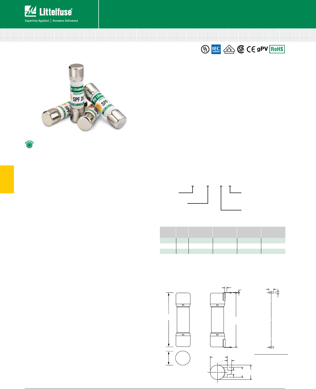
60 © 2014 Littelfuse POWR-GARD® Products Cataloglittelfuse.com
5
Solar Fuses
Fuses – Solar
SPF SERIES SOLAR FUSES
1000 Vdc • 1-30 A
Specifications
Voltage Rating 1000 Vdc
Amperage Rating 1, 2, 3, 3.5, 4, 5, 6, 8, 10, 12, 15, 20, 25, 30
Max. Interrupting Rating 20 kA
Time Constant ≤ 2ms
Material Body: Melamine
Caps: Copper Alloy
Approvals UL 2579 Listed (File: E339112)
IEC 60269-6 (1-25 A)
VDE Certified (No. 40033098)
CSA Certified (File: 029862_0_000)
Environmental RoHS Compliant
Country of Origin Mexico
Part Numbering System
Description
The SPF Solar Protection Fuse series has been specifically
designed for the protection of photovoltaic (PV) systems.
This series of Midget style fuses (10 x 38 mm) can safely
protect PV modules and conductors from
reverse-overcurrent conditions.
As PV systems have grown in size, so have the
corresponding voltage requirements. This increase in
system voltage has typically been intended to minimize
power loss associated with long conductor runs. Standard
circuit protection devices are not designed to completely
protect photovoltaic panels. However, the SPF series is
UL Listed to safely interrupt faulted circuits up to this
demanding voltage level.
Features/Benefits
• Meets UL, IEC and VDE photovoltaic standards
• UL 2579 Listed 1000 Vdc maximum
• 1-30 A ratings available
• 20,000 A Interrupting Rating
• Both PCB mount and dead-front holder options available
Applications
• Inverters
• Combiner boxes
• Battery charge controllers
Recommended Fuse Holders
Littelfuse LFPHV Series ................................................... 109
Web Resources
Download the complete datasheet and other technical
documents: littelfuse.com/spf
.06 (1.52) .14
(3.56)
.04
(1.02)
.02 (.51)
1.53
(38.86)
.50 (12.7)
.12 (3.05)
MOUNTING HOLE
DETAIL
.406 (10.31)
.12
(3.05) .28
(7.11)
1.5 (38.1)
.406
(10.31)
Dimensions Inches (mm)
Ferrule Version PCB Version
SERIES AMP PACKAGE
QUANTITY
MOUNTING
METHOD
CATALOG
NUMBER
ORDERING
NUMBER
SPF 210 FERRULE SPF002 0SPF002.T
SPF 3.5 10 FERRULE SPF03.5 0SPF03.5T
SPF 30 100 PCB TABS SPF030R 0SPF030.HXR
0SPF xxxx H XR
Package Quantity
Series Mounting Options
Amp Code
T = 10
H = 100
Blank = Ferrule
XR = PCB
Refer to datasheet
for amp code
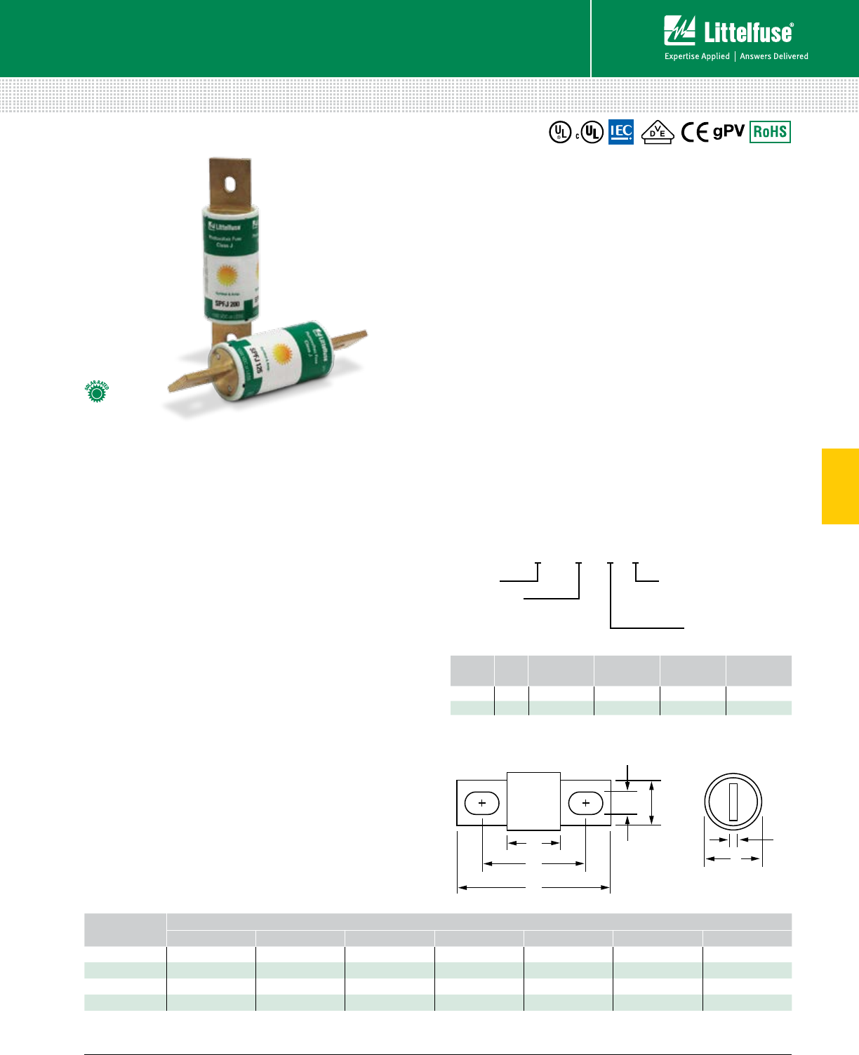
61 littelfuse.com © 2014 Littelfuse POWR-GARD® Products Catalog
5
Solar Fuses
Fuses – Solar
SPFJ SERIES SOLAR FUSES
1000 Vdc • 70-450 A
Specifications
Voltage Rating 1000 Vdc
600 Vac (125-450 A)
Amperage Rating 70, 80, 90, 100, 125, 160, 200,
250, 300, 350, 400, 450
Interrupting Rating AC: 200 kAIC (125-450 A)
DC: 70-200 A: 20 kAIC
250-400 A: 10 kAIC
450 A: 20 kAIC
Time Constant ≤ 1ms
Material Body: Melamine
End Bells: Copper Alloy
Approvals UL 2579 Listed (File: E339112)
UL 248-8, Class J (125-450 A)
C UL (125-450 A)
IEC 60269-6 (125-450 A)
VDE Certified (125-450 A)
(No. 40033659, 40033660, 40033661)
Environmental RoHS Compliant
Country of Origin Mexico
Description
The SPFJ series is the smallest 1000 Vdc 70-450 A
photovoltaic fuse available in the market. The SPFJ series is
manufactured in Class J case sizes that allows for both fuse
holder and busbar mounting configuration. The SPFJ meets
both UL and IEC requirements.
Features/Benefits
• Meets UL and IEC photovoltaic standards
• VDE certified specifications
• Small footprint reduces panel size
• Flexibility of fuse holder or busbar mounting
• Higher amperage solar fuses in standard sizes
• UL Listed branch and feeder circuit rated
• Class J case sizes for the 70-450 A ratings
Applications
• Inverters
• Re-combiner boxes
Recommended Fuse Holders
Littelfuse LFJ1000 Solar Series .........................................107
Web Resources
Download the complete datasheet and other technical
documents: littelfuse.com/spfj
Dimensions Inches (mm)
A
B
C
F E
D
G
AMPERAGE DIMENSIONS IN INCHES (MM)
A B C D E F G
70-100 3.02 (76.5) 4.38 (111.3) 5.75 (146.1) 1.5 (38.1) 1.125 (28.3) .335 (8.5) .189 (4.8)
125-200 3.02 (76.5) 4.38 (111.3) 5.75 (146.1) 1.5 (38.1) 1.125 (28.3) .281 (7.1)* .189 (4.8)
250-400 3 .37 (85.7) 5.25 (133.4) 7.125 (181.0) 2.0 (50.8) 1.63 (41.3) .406 (10.3) .252 (6.4)
450 3.75 (95.3) 5.98 (152.0) 8.0 (203.2) 2.5 (63.5) 2.0 (50.8) .531 (13.5) .374 (9.5)
* SPFJ L option = 8.5 mm (UL 2579 approval only)
SERIES AMP PACKAGE
QUANTITY
MOUNTING
METHOD
CATALOG
NUMBER
ORDERING
NUMBER
SPFJ 70 1CLASS J SPFJ070 SPFJ070.X
SPFJ 200 1LARGE SPFJ200 SPFJ200.XXL
Part Numbering System
SPFJ xxx X —
Package Quantity
Series Mounting Options
Amp Code
X = 1
Blank = Class J
XL = 8.5mm opening
Refer to datasheet
for amp code
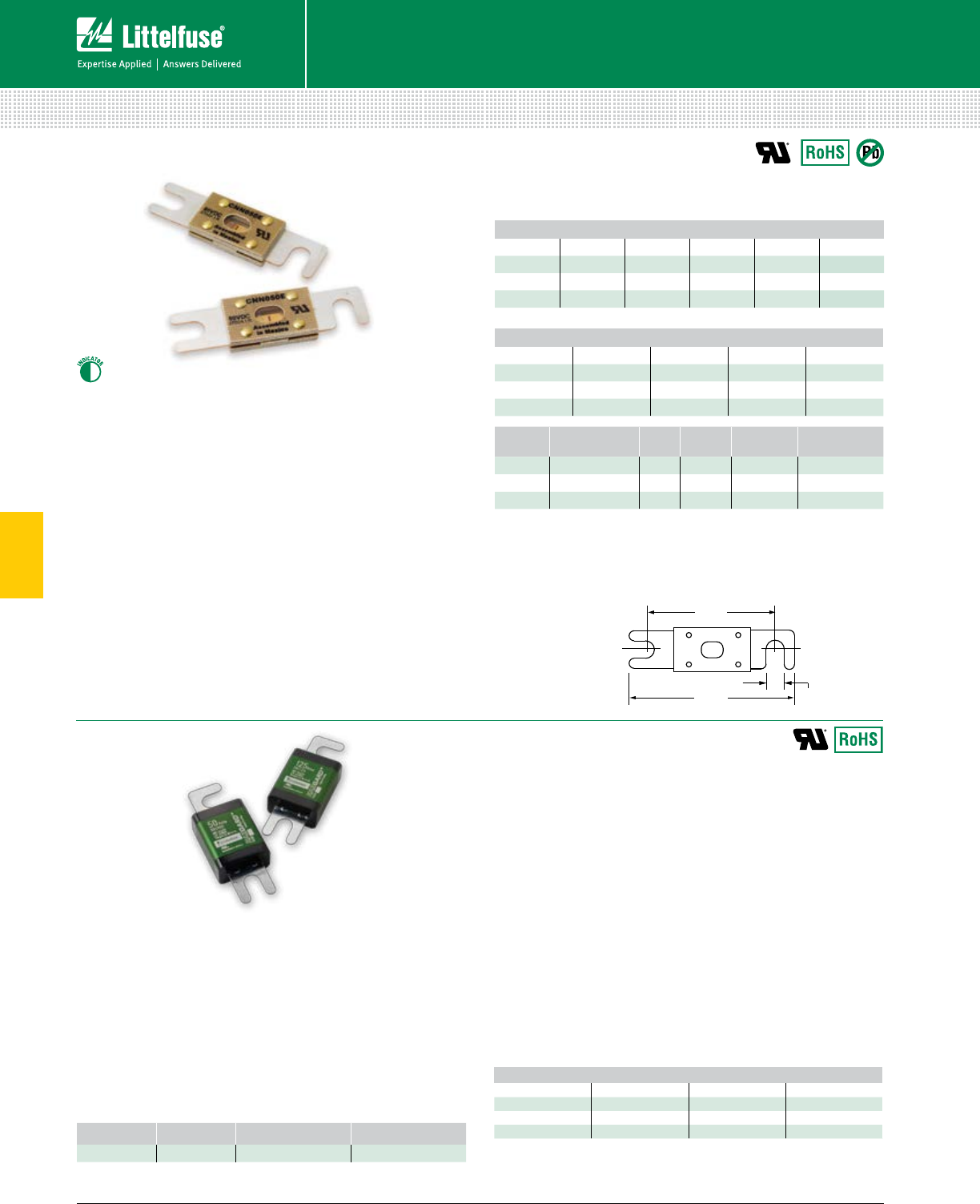
62 © 2014 Littelfuse POWR-GARD® Products Cataloglittelfuse.com
5
Ordering Information
Special Purpose Fuses
Fuses — Special Purpose
3.18"
(80.8) 0.343"
(8.7)
2.43"
(61.7)
Applications
Lift trucks, scissor lifts, pallet movers, and other
low voltage battery operated equipment used to
move hazardous materials.
Features/Benefits
• Evaluated for use in UL 583 hazardous applications
• Easily upgrade Type E and ES equipment to Type EE
• Does not require an external enclosure
Specifications
Voltage Ratings 48 Vac/dc
Interrupting Rating 2,500 A
Ampere Rating 35 – 800 A
Approval UL Recognized (File: E71611)
Torque 90 in-lb
Fuse Holder LFFB003
Environmental RoHS Compliant
Country of Origin Mexico
CNN_E, CNN & CNL Limiter Fuses
Description
CNN_E fuses are rated for applications up to 80 Vdc.
As fork lift trucks and electrical vehicle system voltages
increase, circuit protection needs to be rated higher than the
standard CNN products to handle the increased voltage. The
CNN_E is considered very fast-acting for quicker reaction time.
Specifications
Voltage Ratings CNN_E: 80 Vdc / 125 Vac
CNN: 48 Vdc / 125 Vac
CNL: 32 Vdc / 32 Vac
Ampere Ratings 10 – 800 A*
Max. Interrupting Rating 2,500 A
Approval UL Recognized (File: E71611)
Environmental RoHS Compliant, Lead (Pb) Free
Country of Origin Mexico (CNN_E only)
*See ordering information table for available amperages by series
†CNN Series only
FORK-LIFT STUD-MOUNTED FUSES
32/48/80 Vdc • Fast-Acting and Very Fast-Acting • 35-800 A
Recommended Fuse Holders
LFFB0003Z .......................................................................118
Web Resources
littelfuse.com/ForkLift
Dimensions
AMPERE RATINGS
35 100 250 500
50 125 300 750*
60 150 400 800*
90 200 425 —
Ordering Information
SERIES AMPERAGE CATALOG NUMBER ORDERING NUMBER
581 200 581200 0581200.X *Contact factory for availability
HAZGARD™ Forklift Fuses
Description
HAZGARD fuses are designed to provide overcurrent protection
for low voltage equipment used in hazardous operations. It
is UL 248 recognized and has been evaluated for the use in
UL 583 type EE and ES applications. Unique design does not
require an additional enclosure as is needed with a standard
forklift fuse, saving assembly time and costs.
AMPERE RATINGS CNN_E & CNN
10†60 125 225 325 600
35 80 150 250 350 700
40 90 175 275 400 800
50 100 200 300 500 —
AMPERE RATINGS CNL (32 Vdc)
35 80 150 250 350
40 100 175 275 400
50 125 200 300 500
60 130 225 325 —
SERIES TYPE VOLT
DC AMP CATALOG
NUMBER
ORDERING
NUMBER
CNN_E
VERY-FAST-ACTING
80 200 CNN200E 0CNN200E.V
CNN
VERY FAST-ACTING
48 125 CNN125 0CNN125.V
CNL
FAST-ACTING
32 50 CNL050 0CNL050.V
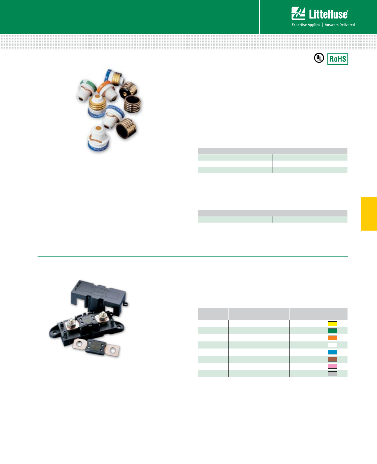
63 littelfuse.com © 2014 Littelfuse POWR-GARD® Products Catalog
5
Special Purpose Fuses
Fuses — Special Purpose
Specifications
Voltage Rating 32 Vac/dc
Interrupting Rating 2000 A @ 32 Vdc
Ordering Information
CATALOG
NUMBER
ORDERING
NUMBER
AMPERAGE
RATING
VOLTAGE
RATING
COLOR
CODE
MEG100 0MEG100.X 100 32
MEG125 0MEG125.X 125 32
MEG150 0MEG150.X 150 32
MEG175 0MEG175.X 175 32
MEG200 0MEG200.X 200 32
MEG225 0MEG225.X 225 32
MEG250 0MEG250.X 250 32
MEG300 0MEG300.X 300 32
PLUG FUSES AND BOLT-DOWN FUSES
125 Vac • 2-30 A
TOO Fuses are dual-element time-delay Edison-base fuses
designed for motor and motor branch circuit protection; also
suitable for all general purpose circuits.
TOO Fuses Sample Part # 0TOO020.Z
Edison-base plug fuses
Description
Littelfuse Plug fuses provide overcurrent protection to general
purpose circuits and small motor loads. Edison-base Plug
fuses (TOO and TLO series) feature metal threads similar to
incandescent lamp bases.
Type S Plug fuses (SOO and SLO series) utilize a
nonmetallic threaded base and must be used with Type S
adapters (SAO series).
The National Electrical Code® permits Edison base Plug fuses
to be used for replacement purposes only. Type S fuses and
adapters prevent shunting open fuses and over-fusing.
TLO Fuses are medium time-delay Edison-base fuses
designed for general purpose branch circuit protection.
TLO Fuses Sample Part # 0TLO020.Z
AMPERE RATINGS
26 1/412 25
4 8 15 30
510 20 —
MEGA® SLO-BLO® bolt-on fuse
Description
The MEGA Fuse is designed for the protection of high
current applications. Designed and patented by Littelfuse, it
is ideal for battery and alternator protection and other heavy
gauge cable applications.
Recommended Fuse Holders
Part Number - 298900, see website: littelfuse.com/mega
Web Resources
Find more information: littelfuse.com/mega
AMPERE RATINGS
15 20 25 30
Specifications
Voltage Rating 125 Vac
Interrupting Rating 10 kA rms symmetrical
Approvals UL Listed 248-11
32 Vac/dc • 100-300 A
Web Resources
Fine more information: littelfuse.com/plug
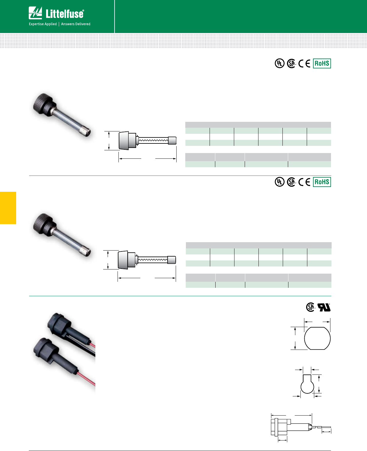
64 © 2014 Littelfuse POWR-GARD® Products Cataloglittelfuse.com
5
In-Line Fuses
Fuses — Special Purpose
LGR / LMF IN-LINE FUSES & LHR FUSE HOLDER
Specifications
Voltage Rating 300 Vac
Interrupting Rating 10 kA
Approvals Standard 248-14
UL Listed (File: E10480)
CSA Certified (File: LR29862)
Ordering Information
LGR Fuses
Fast-Acting • 300 Vac
Used as in-line protection
for fluorescent fixtures, this
fast-acting fuse is ideal for
increasing the safety and
reliability of lighting fixtures.
LMF Fuses
Time-Delay • 300 Vac
Perfect for use in lighting
systems, this 300 Vac time-
delay fuse is designed to
handle ballast transformer
in-rush currents.
LHR Fuse Holder
Used as in-line protection
for fluorescent fixtures, the
Littelfuse LGR and LMF
series fuses and LHR holder
offer increased safety and
reliability to lighting systems.
By individually fusing fixtures,
electrical problems are
isolated from the rest of the
circuit. The added benefits of
this is the ability to quickly
identify the problem fixture
and reduce the repair time.
Fuse holders are rated up to 10 amperes at 300 volts and are
equipped with 7" 18 AWG leads. Order part number LHR000
for two leads, and part number LHR001 for one lead; with the
other terminal used for insertion of 18 AWG ballast lead.
Specifications
Voltage Rating 300 Vac
Ampere Rating LHR000 10 A
LHR001 10 A
Approvals UL Recognized
CSA Certified
(File: 73160)
Flammability Rating UL94 V-0
Example part number LHR001
Ordering number 0LHR001T
Mounting Information
LHR001/LHR000 will fit keyhole
punch or 0.875" knock-out hole.
Anti-ro ta tion fea ture is pro vid ed
when used with key hole punch.
A “U-shaped” clip is avail able
for panel mount ing (pack aged
10 clips per bag): Order part
number LHROCA.
Specifications
Voltage Rating 300 Vac
In ter rupt ing Rating 10 kA
Approvals Standard 248-14
UL Listed (File: E10480)
CSA Certified (File: LR29862)
Ordering Information
AMPERE RATINGS
1/21 6/10 3 6 9 15
1 2 4 7 10 —
1 1/22 1/25 8 12 —
AMPERE RATINGS
3/10 8/10 1 6/10 2 8/10 4 7
1/212358
6/10 1 1/42 1/23 2/10 6 1/410
SERIES AMPERAGE CATALOG NUMBER ORDERING NUMBER
LGR 5LGR005 0LGR005.V
SERIES AMPERAGE CATALOG NUMBER ORDERING NUMBER
LMF 5LMF005 0LMF005.V
1.82"
0.610"
1.82"
0.610"
2.25" 7/8"
3/4"
0.263"
0.423"
0.630"
Knock-out Hole Keyhole Punch
0.50"
0.50"
1.82"
0.610"
1.82"
0.610"
2.25" 7/8"
3/4"
0.263"
0.423"
0.630"
Knock-out Hole Keyhole Punch
0.50"
0.50"
1.82"
0.610"
1.82"
0.610"
2.25"
7/8"
3/4"
0.263"
0.423"
0.630"
Knock-out Hole Keyhole Punch
0.50"
0.50"
1.82"
0.610"
1.82"
0.610"
2.25" 7/8"
3/4"
0.263"
0.423"
0.630"
Knock-out Hole Keyhole Punch
0.50"
0.50"
Keyhole Punch
Knock-out Hole
1.82"
0.610"
1.82"
0.610"
2.25" 7/8"
3/4"
0.263"
0.423"
0.630"
Knock-out Hole Keyhole Punch
0.50"
0.50"
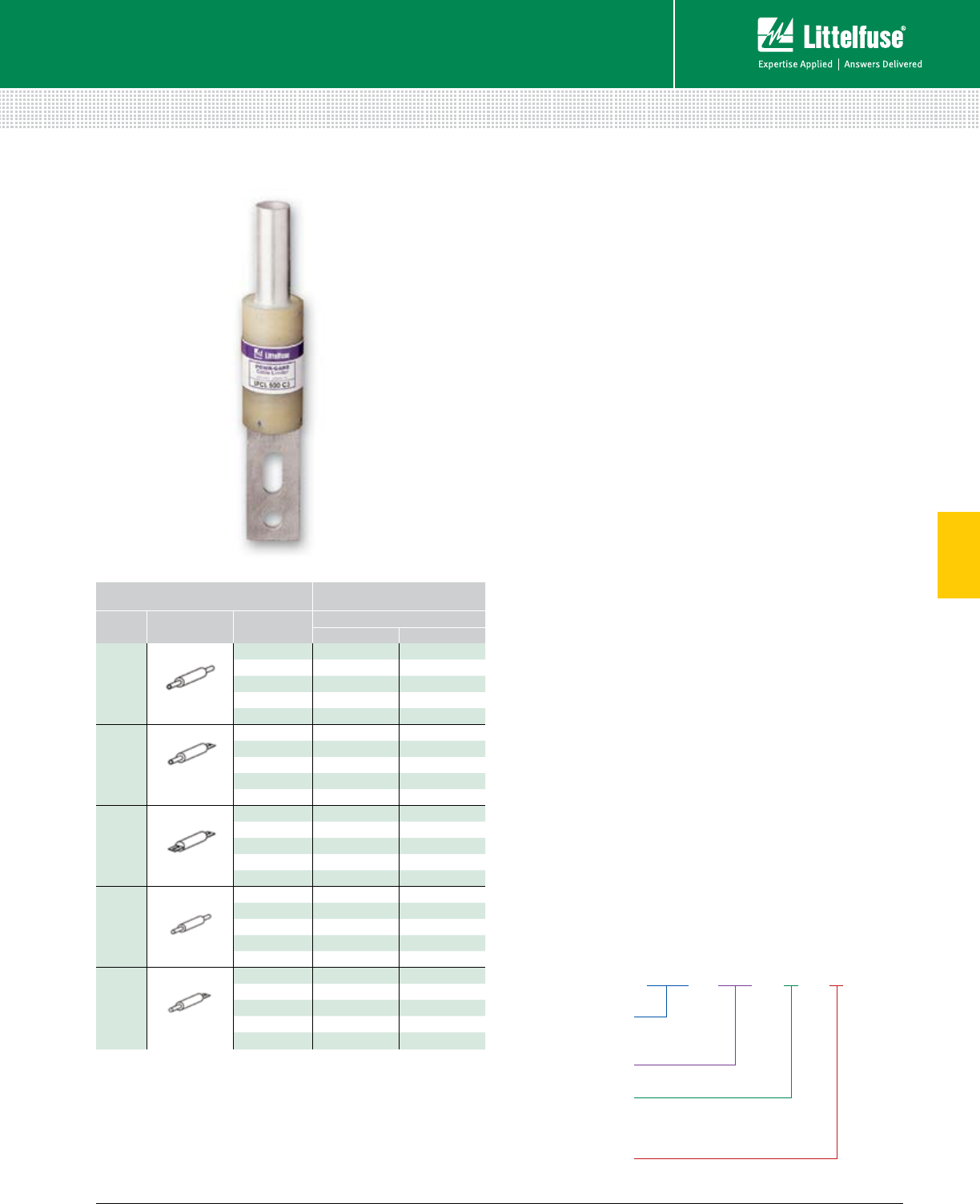
65 littelfuse.com © 2014 Littelfuse POWR-GARD® Products Catalog
5
Cable Limiters
Fuses — Special Purpose
CABLE LIMITERS
600 Vac
LFCL - 500 - C - 1
Terminal Material
Littelfuse
Cable Limiter
Type of
Termination
Conductor Size
(Aluminum or Copper)
DESCRIPTION CATALOG NUMBER
TYPE TERMINATION CABLE SIZE CABLE TYPE
COP PER ALUMINUM
1
CABLE TO CABLE
4/0 LFCL4/0C1 LFCL4/0A1
250MCM LFCL250C1 LFCL250A1
350MCM LFCL350C1 LFCL350A1
500MCM LFCL500C1 LFCL500A1
750MCM LFCL750C1 LFCL750A1
3
CABLE TO
OFFSET BUS
4/0 LFCL4/0C3 LFCL4/0A3
250MCM LFCL250C3 LFCL250A3
350MCM LFCL350C3 LFCL350A3
500MCM LFCL500C3 LFCL500A3
750MCM LFCL750C3 LFCL750A3
5
STRAIGHT BUS
TO OFFSET BUS
4/0 LFCL4/0C5 —
250MCM LFCL250C5 —
350MCM LFCL350C5 —
500MCM LFCL500C5 —
750MCM LFCL750C5 —
6
MOLE TO CABLE
4/0 LFCL4/0C6 LFCL4/0A6
250MCM LFCL250C6 LFCL250A6
350MCM LFCL350C6 LFCL350A6
500MCM LFCL500C6 LFCL500A6
750MCM LFCL750C6 LFCL750A6
8
MOLE TO
OFFSET BUS
4/0 LFCL4/0C8 —
250MCM LFCL250C8 —
350MCM LFCL350C8 —
500MCM LFCL500C8 —
750MCM LFCL750C8 —
Note: For Type 5 and Type 8 Aluminum cable limiters, use the Copper Type C5 and C8.
Description
Cable limiters are fusible devices that provide very fast
short-circuit protection, primarily to faulted cables, but also to
other conductors such as busway. Cable limiters do not have
an ampere rating, and cannot be used to provide overload
protection. They are instead selected by cable size; for example,
a 500 kcmil cable requires a 500 kcmil cable limiter. Their
main use is to isolate faulted cables in circuits con tain ing
three or more parallel conductors per phase. They may be
installed on the line side of the main service to provide short-
circuit protection to the service conductors. This is especially
important when service conductors are tapped from large low
voltage networks or from large low impedance transformers.
Cable limiters have terminals which permit them to be installed
in a variety of equipment. The most common configuration is
the offset blade on one end and the crimp terminal on the other
end. This permits the limiter to replace a cable terminal (lug).
Applications
• Service entrance conductors
• Between transformer or network bus and busway
terminal boxes
• Large feeders with three or more conductors per phase
Features
• Current-limiting characteristics provide pro tec tion to
conductor insulation and reduce damage when faults occur.
• Properly applied cable limiters may permit the use of
equip ment with reduced withstand ratings
• Wide variety of terminations and cable ratings permit use
in almost every situation.
Specifications
Voltage Ratings 600 Vac
Interrupting Rating 200 kA
Cable Size Range 4/0 – 750MCM Copper or Aluminum
Note: For Type 5 and Type 8 Aluminum cable limiters, use the Copper Type C5 and C8.
Ordering Information
Web Resources
For additional information, visit: littelfuse.com/lfcl
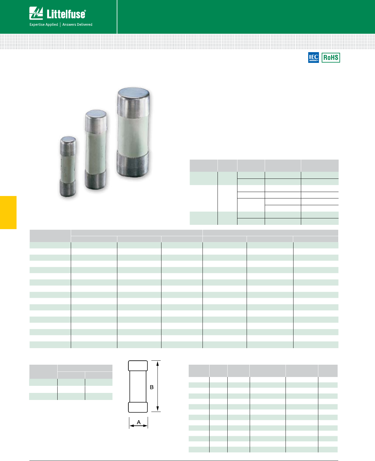
66 © 2014 Littelfuse POWR-GARD® Products Cataloglittelfuse.com
5
Cylindrical Fuses
Fuses — Special Purpose
BASE PART
NUMBER
SIZE
(mm)
CURRENT
RANGE VOLTAGE (AC) INTERRUPTING
RATING
CY10X38 10 x 38 0.5-25 A 500 V 120 kA
32 A 400 V 120 kA
CY14X51 14 x 51
2-25 A 690 V 80 kA
32-40 A 500 V 120 kA
50 A 500 V (gL-gG) 120 kA
400 V (aM) 120 kA
CY22X58 22 x 58 16-63 A 690 V 80 kA
80-100 A 500 V 120 kA
AMPERAGE gL-gG ORDERING NUMBERS aM ORDERING NUMBERS
10 X 38 14 X 51 22 X 58 10 X 38 14 X 51 22 X 58
0.5 CY10X38G05 — — CY10X38M05 — —
1 CY10X38G1 — — CY10X38M1 — —
2 CY10X38G2 CY14X51G2 — CY10X38M2 CY14X51M2 —
4 CY10X38G4 CY14X51G4 — CY10X38M4 CY14X51M4 —
6 CY10X38G6 CY14X51G6 — CY10X38M6 CY14X51M6 —
8 CY10X38G8 CY14X51G8 — CY10X38M8 CY14X51M8 —
10 CY10X38G10 CY14X51G10 — CY10X38M10 CY14X51M10 —
12 CY10X38G12 CY14X51G12 — CY10X38M12 CY14X51M12 —
16 CY10X38G16 CY14X51G16 CY22X58G16 CY10X38M16 CY14X51M16 CY22X58M16
20 CY10X38G20 CY14X51G20 CY22X58G20 CY10X38M20 CY14X51M20 CY22X58M20
25 CY10X38G25 CY14X51G25 CY22X58G25 CY10X38M25 CY14X51M25 CY22X58M25
32 CY10X38G32 CY14X51G32 CY22X58G32 CY10X38M32 CY14X51M32 CY22X58M32
40 — CY14X51G40 CY22X58G40 — CY14X51M40 CY22X58M40
50 — CY14X51G50 CY22X58G50 — CY14X51M50 CY22X58M50
63 — — CY22X58G63 — — CY22X58M63
80 — — CY22X58G80 — — CY22X58M80
100 — — CY22X58G100 — — CY22X58M100
CYLINDRICAL FUSES
0.5 -100 A
Description
Littelfuse fast acting (gL-gG) fuses are used for the
protection of cables against short-circuits. Time-lag (aM)
fuses are used for protection of motors.
Specifications
Standards 10x38 mm: IEC 60269
14x51 mm / 22x58mm: IEC 269-2-1
Ordering Information
Dimensions
Web Resources
For additional product information
Fuses: littelfuse.com/cylindrical
Fuse Holders: littelfuse.com/lfpsm
littelfuse.com/cyh
FUSE SIZE DIMENSIONS mm
A B
10 X 38 10 38
14 X 51 14 51
22 X 58 22 58
Fuse Holders
AMP
RATING POLES SIZE CATALOG /
ORDERING #
TERMINAL
TYPE
DIN RAIL
MOUNT
32 A 1 10 X 38 LFPSM0001Z Pressure Plate •
32 A 2 10 X 38 LFPSM0002Z Pressure Plate •
32 A 3 10 X 38 LFPSM0003Z Pressure Plate •
32 A 4 10 X 38 LFPSM0004Z Pressure Plate •
32 A 1 10 X 38 LFPSM0001ZXID* Pressure Plate •
32 A 2 10 X 38 LFPSM0002ZXID* Pressure Plate •
32 A 3 10 X 38 LFPSM0003ZXID* Pressure Plate •
32 A 4 10 X 38 LFPSM0004ZXID* Pressure Plate •
50 A 1 14 X 51 CYH14511 Pressure Plate •
50 A 2 14 X 51 CYH14512 Pressure Plate •
50 A 3 14 X 51 CYH14513 Pressure Plate •
125 A 1 22 X 58 CYH22581 Pressure Plate •
125 A 2 22 X 58 CYH22582 Pressure Plate •
125 A 3 22 X 58 CYH22583 Pressure Plate •
* Indicating
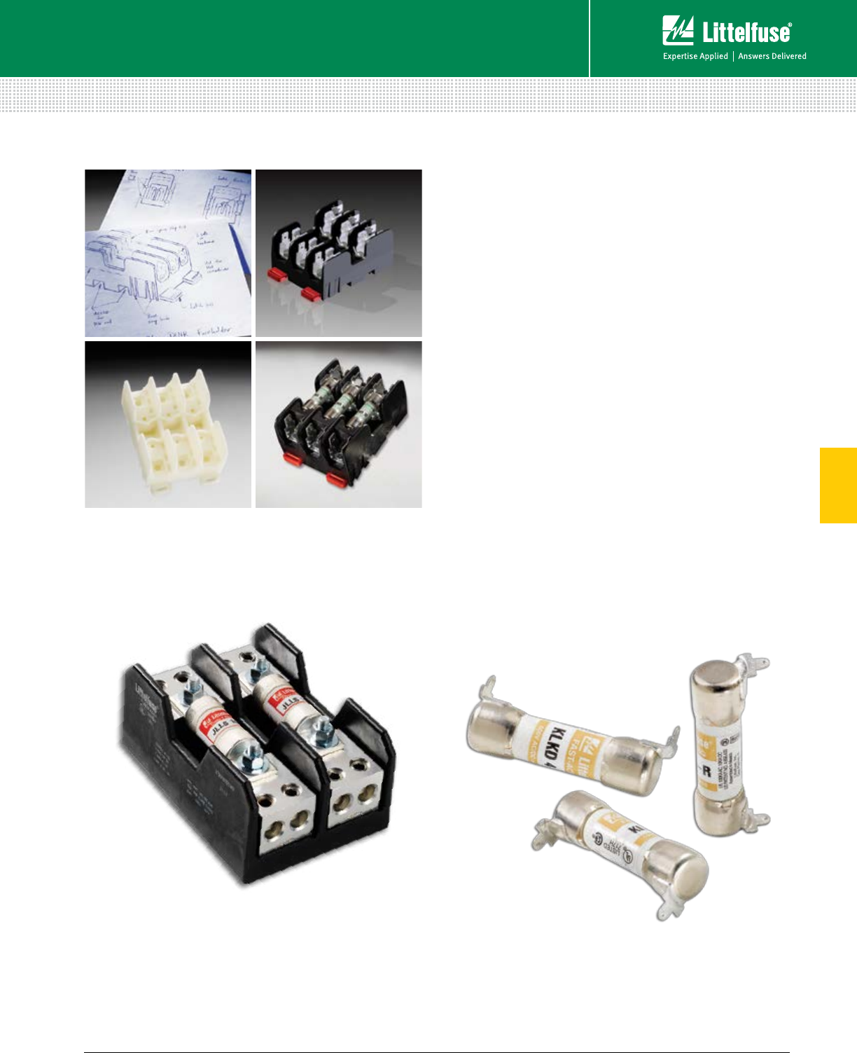
67 littelfuse.com © 2014 Littelfuse POWR-GARD® Products Catalog
5
OEM Custom Products
Fuses — Special Purpose
OEM CUSTOM PRODUCTS
Two-Pole Combination Block
Save space and money by combining multiple
components in one unit. Littelfuse collaborated with the
customer to develop a cost effective UL listed component
that combined a 600 Volt 100A two-pole Class T fuse
block with a two-openings-per-pole splicer block.
Examples
Custom-Leaded Fuse
Save space and reduce cost by eliminating the fuse
block component. Littelfuse designed a series of custom
through-hole PC-board mountable KLKD Midget fuses for
a consumer application where reduced cost was more
important than replaceability.
Description
We understand that existing solutions don’t always solve
your current problems. Building on more than 85 years of
circuit protection experience, the Littelfuse engineering
team collaborates with customers to develop customized
solutions for applications such as solar panels, HVAC
systems, lift trucks, lighting fixtures, industrial restaurant
equipment and power converters.
Process
The custom product design process begins with a situation
analysis from our experienced engineers followed by our
4-step collaborative product development process.
1. Initial concept sketch created
2. CAD drawings to formalize the product description
3. 3D solid prototype to verify design
4. Final production parts that meet your design needs
and specifications
Additional Customized Products
HAZGARD Fork Lift Fuse ..............................................62
Web Resources
To learn more and contact our OEM team, visit:
littelfuse.com/industrialoem
To speak with a sales associate regarding your application needs,
call 800-TEC-FUSE (800-382-3873) or email techline@littelfuse.com.
1
3
2
4
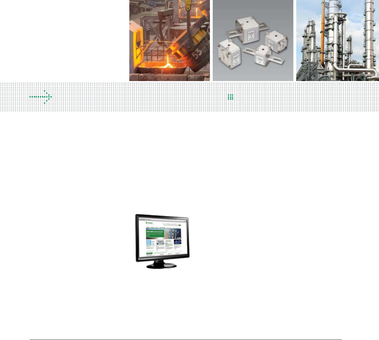
68 © 2014 Littelfuse POWR-GARD® Products Cataloglittelfuse.com
L Series (Traditional) Semiconductor Fuses ............................... 69
LA Series (Alternate Dimension) Semiconductor Fuses .............71
Square Body Semiconductor Fuses ............................................ 77
SEMICONDUCTOR FUSES
Table of Contents
Section Overview
Littelfuse high-speed semiconductor fuses protect critical power
semiconductors against short circuits in applications including
inverters, variable-speed drives, UPS and DC drive systems.
For the complete portfolio of high-speed products visit:
littelfuse.com/High-Speed
POWR-GARD® High-Speed
Circuit Protection
Littelfuse engineering is constantly developing
new products to meet the needs of the industry.
For the latest information on the growing
POWR-GARD Product portfolio, visit:
littelfuse.com/High-Speed
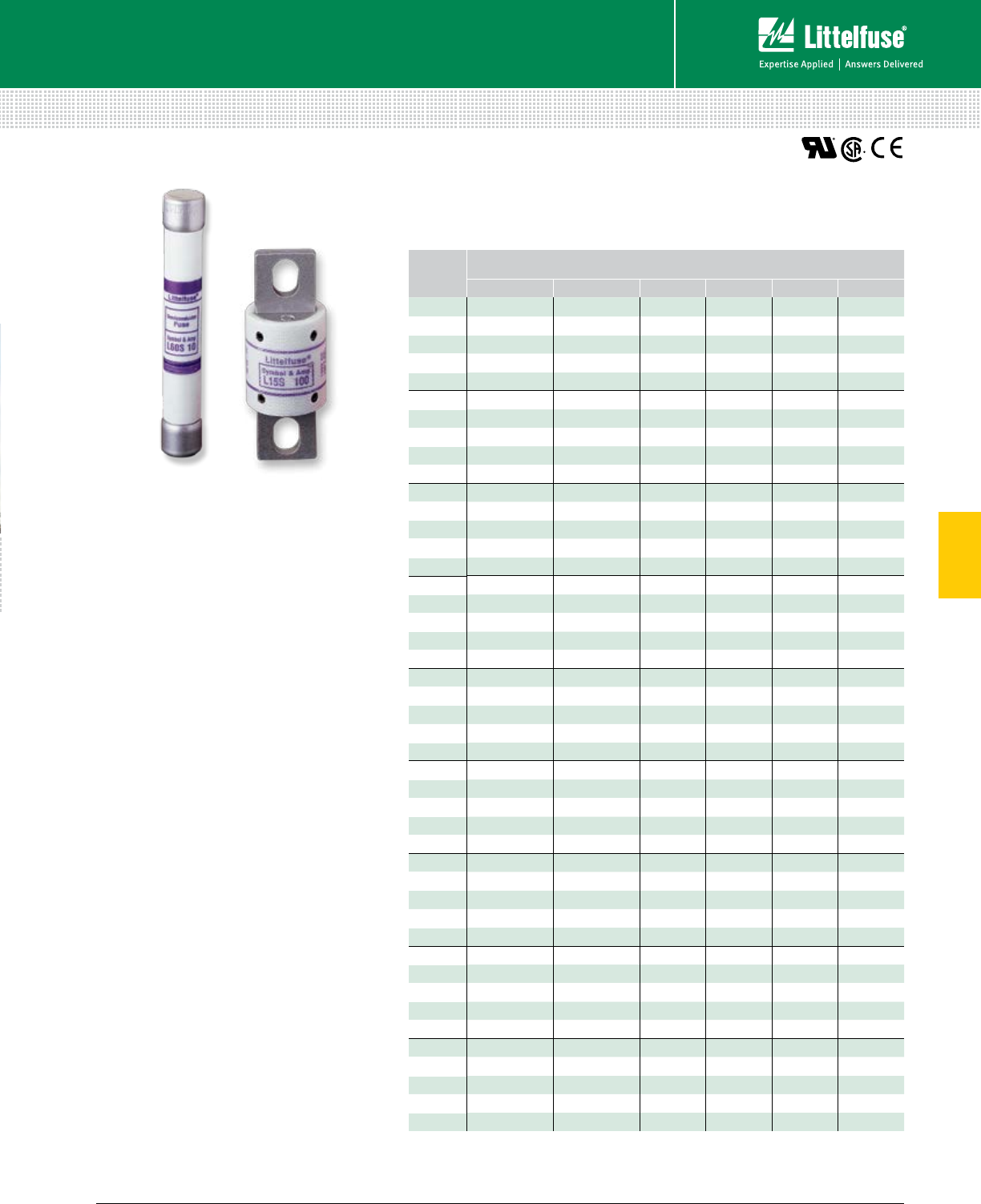
69 littelfuse.com © 2014 Littelfuse POWR-GARD® Products Catalog
5
Semiconductor Fuses
Fuses – Semiconductor
TRADITIONAL SEMICONDUCTOR FUSES
150/250/500/600/700 Vac • Very Fast-Acting • 1-1200 A
AMPERE
RATINGS
SERIES ORDERING NUMBER
L15S L25S L50S L60S KLC‡L70S
1L15S001 L25S001 –L60S001 KLC001 –
2L15S002 L25S002 –L60S002 KLC002 –
3L15S003 L25S003 –L60S003 KLC003 –
4L15S004 L25S004 –L60S004 KLC004 –
5L15S005 L25S005 –L60S005 KLC005 –
6L15S006 L25S006 –L60S006 KLC006 –
7L15S007 – – – KLC007 –
8L15S008 L25S008 –L60S008 KLC008 –
9L15S009 – – – – –
10 L15S010 L25S010 L50S010 L60S010 KLC010 L70S010
12 L15S012 L25S012 L50S012 L60S012 KLC012 –
15 L15S015 L25S015 L50S015 L60S015 KLC015 L70S015
171⁄2– – – L60 S17.5 KLC17.5 –
20 L15S020 L25S020 L50S020 L60S020 KLC020 L70S020
25 L15S025 L25S025 L50S025 L60S025 KLC025 L70S025
30 L15S030 L25S030 L50S030 L60S030 KLC030 L70S030
35 L15S035 L25S035 L50S035 L60S035 KLC035 L70S035
40 L15S040 L25S040 L50S040 L60S040 KLC040 L70S040
45 L15S045 L25S045 –L60S045 KLC045 –
50 L15S050 L25S050 L50S050 L60S050 KLC050 L70S050
60 L15S060 L25S060 L50S060 L60S060 KLC060 L70S060
70 L15S070 L25S070 L50S070 L60S070 KLC070 L70S070
80 L15S080 L25S080 L50S080 L60S080 KLC080 L70S080
90 L15S090 L25S090 L50S090 L60S090 KLC090 L70S090
100 L15S100 L25S100 L50S100 L60S100 KLC100 L70S100
110 – – – – KLC110 –
125 L15S125 L25S125 L50S125 L60S125 KLC125 L70S125
150 L15S150 L25S150 L50S150 L60S150 KLC150 L70S150
175 –L25S175 L50S175 L60S175 KLC175 L70S175
200 L15S200 L25S200 L50S200 L60S200 KLC200 L70S200
225 –L25S225 L50S225 L60S225 KLC225 L70S225
250 L15S250 L25S250 L50S250 L60S250 KLC250 L70S250
275 –L25S275 L50S275 – – –
300 L15S300 L25S300 L50S300 L60S300 KLC300 L70S300
350 L15S350 L25S350 L50S350 L60S350 KLC350 L70S350
400 L15S400 L25S400 L50S400 L60S400 KLC400 L70S400
450 L15S450 L25S450 L50S450 L60S450 KLC450 L70S450
500 L15S500 L25S500 L50S500 L60S500 KLC500 L70S500
550 – – L50S550 – – –
600 L15S600 L25S600 L50S600 L60S600 KLC600 L70S600
700 –L25S700 L50S700 L60S700 KLC700 L70S700
800 L15S800 L25S800 L50S800 L60S800 KLC800 L70S800
900 – – LA50P9004 – – LA70P9004
1000 L15S1000 –LA50P10004 – – LA70P10004
1200 – – LA50P12004 – – LA70P12004
‡ KLC series fuses are recommended for replacement use only.
Ordering Information
Specifications
Voltage Ratings
L15S: 150 Vac/dc (1 – 60 A)
150 Vac (70 – 1000 A)
100 Vdc (70 – 1000 A)
L25S: 250 Vac/dc (1 – 200 A)
250 Vac (225 – 800 A)
200 Vdc (225 – 800 A)
L50S: 500 Vac/450 Vdc
L60S: 600 Vac
KLC: 600 Vac
L70S: 700 Vac/650 Vdc
L25S series fuses are Littelfuse Certified for DC ratings
shown in Rating Table.
Interrupting Rating
AC: 200 kA rms
(L15S series 100 kA)
DC: 20 kA
Ampere Range 1 – 1200 A See Rating Table for
ratings available in each series.
Approvals UL Recognized (File: E71611)
CSA Recognized (File: LR29862)
Recommended Fuse Holders
1LFS101/1LFS102 ...................................121
LSCR001/LSCR002 .................................120
Web Resources
For additional information, visit:
littelfuse.com/semi
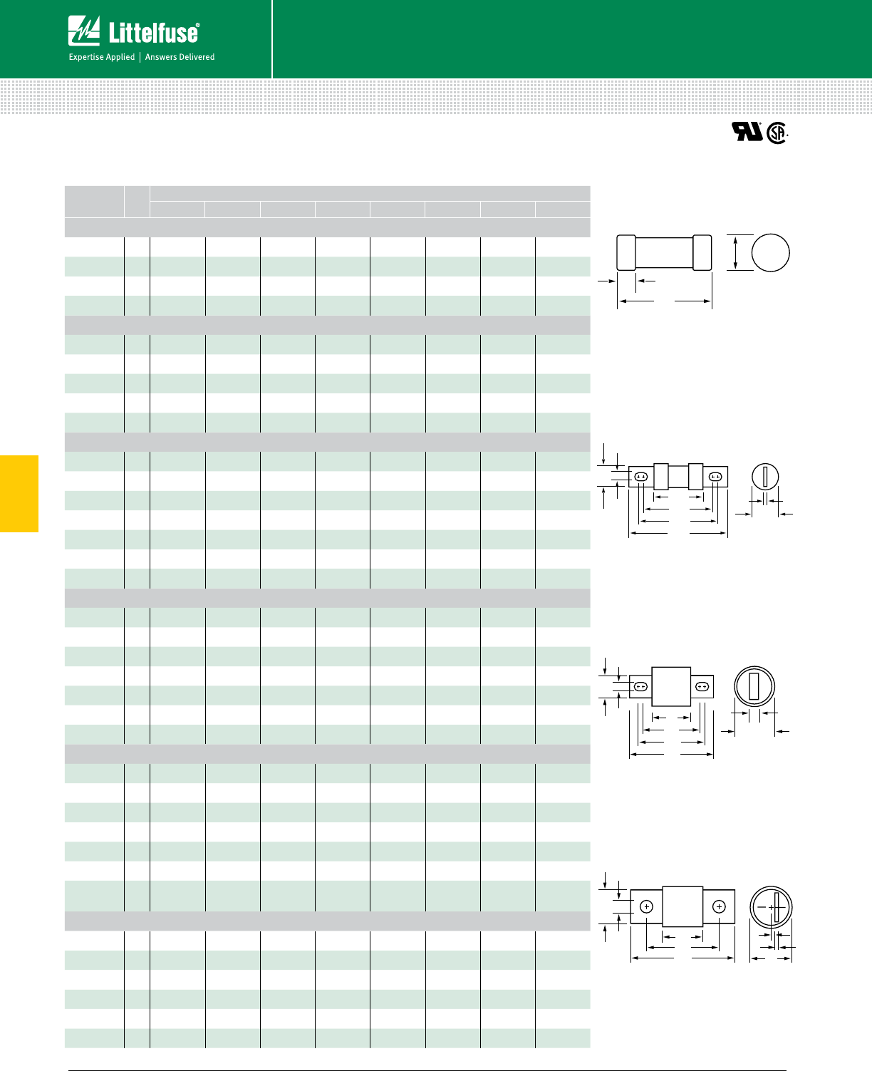
70 © 2014 Littelfuse POWR-GARD® Products Cataloglittelfuse.com
5
Fuses – Semiconductor
Semiconductor Fuses
TRADITIONAL SEMICONDUCTOR FUSES
F
GA
B
CE
J
H
Fig. 4
A
B
C
D
F
G
E
H
Fig. 3
AMPERE
RATING
FIG.
NO.
DIMENSIONS INCHES (mm)
A B C D E F G H
L15S Series, 150 Vac
1 – 30 1 11⁄2 (38.1) —3⁄8 (9.5) 13 ⁄32 (10.3) — — — —
31 – 60 12 (50.8) —5⁄8 (15.9) 13 ⁄16 (20.6) — — — —
61 – 450 3 15⁄32 (29.4) 17⁄8 (47.6) 23⁄16 (55.6) 221⁄32 (67.5) 1 (25.4) 43⁄64 (17.1) 5⁄16 (7.9) 3⁄16 (4.8)
451 – 1000 3 11⁄4 (31.8) 115 ⁄16 (49.2) 29⁄16 (65.1) 31⁄2 (88.9) 11⁄2 (38.1) 1 (25.4) 13 ⁄32 (10.3) 1⁄4 (6.4)
L25S Series, 250 Vac
1 – 30 12 (50.8) —1⁄2 (12.7) 9⁄16 (14.3) — — — —
31 – 60 2 15⁄8 (41.3) 21⁄4 (5 7. 2) 21⁄2 (63.5) 33⁄16 (81.0) 13⁄16 (20.6) 23⁄32 (18.3) 11⁄32 (8.7) 1⁄8 (3.2)
61 – 200 3 15⁄8 (41.3) 25⁄16 (58.7) 27⁄16 (61.9) 31⁄8 (79.4) 17⁄32 (31.0) 1 (25.4) 5⁄16 (7.9) 3⁄16 (4.8)
201 – 700 3 119 ⁄32 (40.5) 29⁄32 (57.9) 229⁄32 (73.8) 327⁄32 (97.6) 11⁄2 (38.1) 1 (25.4) 13⁄32 (10.3) 1⁄4 (6.4)
701 – 800 3 119 ⁄32 (40.5) 29⁄32 (57.9) 229⁄32 (73.8) 327⁄32 (97.6) 2 (50.8) 11⁄2 (38.1) 13 ⁄32 (10.3) 1⁄4 (6.4)
L50S Series, 500 Vac / 450 Vdc
10 – 30 12 (50.8) —1⁄2 (12.7) 9⁄16 (14.3) — — — —
31 – 60 2 15⁄8 (41.3) 21⁄4 (57.2) 21⁄2 (63.5) 33⁄16 (81.0) 13 ⁄16 (20.6) 23⁄32 (18.3) 11⁄32 (8.7) 1⁄8 (3.2)
61 – 100 3 21⁄8 (54.0) 211⁄16 (68.3) 3 (76.2) 35⁄8 (92.1) 1 (25.4) .6 70 (17.0) 11 ⁄32 (8.7) 1⁄8 (3.2)
101 – 200 3 21⁄8 (54.0) 213⁄16 (71.4) 215 ⁄16 (74.6) 35⁄8 (92.1) 17⁄32 (31.0) .895 (22.7) 5⁄16 ( 7.9) 3⁄16 (4.75)
201 – 400 3 23⁄32 (53.2) 225⁄32 (70.6) 313 ⁄32 (86.5) 411⁄32 (110.3) 11⁄2 (38.1) 1 (25.4) 13⁄32 (10.3) 1⁄4 (6.4)
401 – 600 3 2 7⁄32 (56.4) 229⁄32 (73.8) 317⁄32 (89.7) 415 ⁄32 (113.5) 2 (50.8) 11⁄2 (38.1) 13⁄32 (10.3) 1⁄4 (6.4)
601 – 800 3 27⁄32 (56.4) 49⁄32 (108.7) 45⁄8 (117.5) 615 ⁄32 (164.3) 21⁄2 (63.5) 2 (50.8) 17⁄32 (13.5) 3⁄8 (9.5)
L60S Series, 600 Vac
1 – 30 15 (127.0) —5⁄8 (15.9) 13⁄16 (20.6) — — — —
31 – 60 2 225⁄32 (70.6) 37⁄16 (87.3) 311 ⁄16 (93.7) 43⁄8 (111.1) 13 ⁄16 (20.6) 23⁄32 (18.3) 11 ⁄32 (8.7) 1⁄8 (3.2)
61 – 100 2 2 29⁄32 (73.8) 317⁄32 (89.7) 325⁄32 (96.0) 415 ⁄32 (113.5) 11⁄16 (27.0) 23⁄32 (18.3) 11 ⁄32 (8.7) 1⁄8 (3.2)
101 – 200 2 229⁄32 (73.8) 39⁄16 (90.5) 33⁄4 (95.3) 413 ⁄32 (111.9) 15⁄16 (33.3) 1 (25.4) 5⁄16 (7.9) 3⁄16 (4.8)
201 – 400 2 229⁄32 (73.8) 331⁄32 (100.8) 45⁄32 (105.6) 51⁄8 (130.2) 137⁄64 (40.1) 1 (25.4) 13 ⁄32 (10.3) 1⁄4 (6.4)
401 – 600 2 27⁄8 (73.0) 331⁄32 (100.8) 49⁄64 (105.2) 51⁄8 (130.2) 21⁄16 (52.8) 11⁄2 (38.1) 13 ⁄32 (10.3) 1⁄4 (6.4)
601 – 800 2 31⁄32 (7 7.0) 55⁄32 (133.4) 511⁄32 (135.7) 71⁄4 (184.2) 21⁄2 (63.5) 2 (50.8) 17⁄32 (13.5) 3⁄8 (9.5)
L70S Series, 700 Vac / 650 Vdc
10 – 30 12 (50.8) —1⁄2 (12.7) 9⁄16 (14.3) — — — —
31 – 60 3 27⁄8 (73.0) 37⁄16 (87.3) 325⁄32 (96.0) 43⁄8 (111.1) 1 (25.4) 43⁄64 (17.1) 11 ⁄32 (8.7) 1⁄8 (3.2)
61 – 100 3 2 7⁄8 (73.0) 39⁄16 (90.5) 311 ⁄16 (93.7) 43⁄8 (111.1) 17⁄32 (31.0) 29⁄32 (22.9) 5⁄16 (7.9) 3⁄16 (4.8)
101 – 200 3 227⁄32 (72.2) 317⁄32 (89.7) 45⁄32 (105.6) 53⁄32 (129.4) 11⁄2 (38.1) 1(25.4) 13 ⁄32 (10.3) 1⁄4 (6.4)
201 – 400 3 227⁄32 (72.2) 317⁄32 (89.7) 45⁄32 (105.6) 53⁄32 (129.4) 2 (50.8) 11⁄2 (38.1) 13 ⁄32 (10.3) 1⁄4 (6.4)
401 – 600 3 227⁄32 (72.2) 429⁄32 (124.6) 51⁄4 (133.4) 73⁄32 (180.2) 21⁄2 (63.5) 2 (50.8) 17⁄32 (13.5) 3⁄8 (9.5)
601 – 800 4 35⁄16 (84.1) 55⁄16 (134.9) 613 ⁄16 (173.0) — 27⁄8 (73.0) 2 (50.8) 5⁄8 (15.9) H: 3⁄8 (9.5)
J: 5⁄16 (7.9)
KLC Series, 600 Vac
1 – 30 2 17⁄8 (47.6) 21⁄2 (63.5) — 27⁄8 (73.0) 9⁄16 (14.3) 13 ⁄32 (10.3) 1⁄4 (6.4) 3⁄64 (1.2)
31 – 60 2 23⁄4 (69.9) 33⁄8 (85.7) 35⁄8 (92.1) 45⁄16 (109.5) 13 ⁄16 (20.6) 23⁄32 (18.3) 11 ⁄32 (8.7) 1⁄8 (3.2)
61 – 100 3 27⁄8 (73.0) 321⁄32 (92.9) 41⁄16 (103.2) 5 (127.0) 1 (25.4) 3⁄4 (19.1) 13 ⁄32 (10.3) 1⁄8 (3.2)
101 – 200 3 227⁄32 (72.2) 317⁄32 (89.7) 43⁄8 (111.1) 53⁄32 (129.4) 11⁄2 (38.1) 1 (25.4) 13 ⁄32 (10.3) 1⁄4 (6.4)
201 – 400 3 227⁄32 (72.2) 421⁄32 (118.3) 427⁄32 (123.0) 61⁄4 (158.8) 2 (50.8) 15⁄8 (41.3) 9⁄16 (14.3) 1⁄4 (6.4)
401 – 800 3 227⁄32 (72.2) 421⁄32 (118.3) 511 ⁄32 (135.7) 61⁄4 (158.8) 21⁄2 (63.5) 2 (50.8) 9⁄16 (14.3) 3⁄8 (9.5)
E
H
F
GA
B
C
D
Fig, 2
A
C
D
Fig. 1
Dimensions
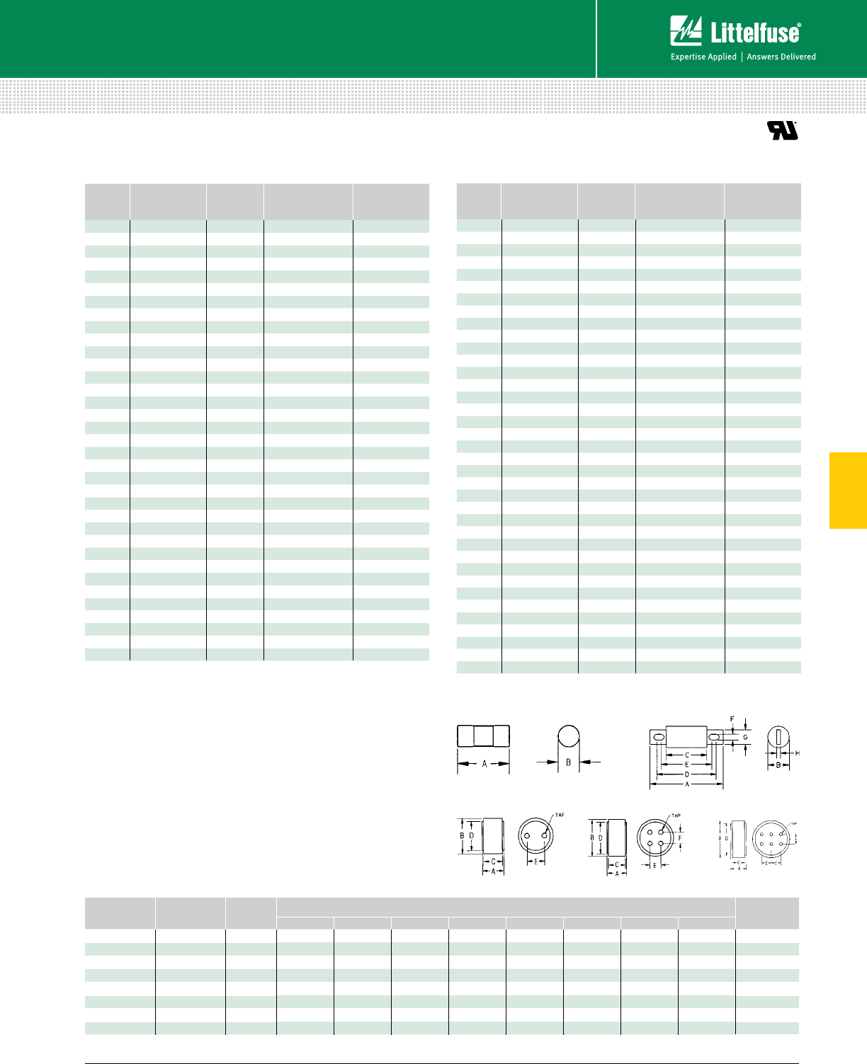
71 littelfuse.com © 2014 Littelfuse POWR-GARD® Products Catalog
5
Fuses – Semiconductor
Semiconductor Fuses
ALTERNATE DIMENSION SEMICONDUCTOR FUSES
150 Vac • Very Fast-Acting • 1-6000 A
LA15QS Series
Specifications
Voltage Rating AC: 150 V
DC: 150 V
Interrupting Rating 100 kA
Ampere Range 1 – 6000 A
Approvals UL Recognized
AMPERE
RATING
CATALOG
NUMBER
MOUNTING
TYPE
MAXIMUM
CLEARING I2t @
150 Vac (A2s x 103)
WATTS LOSS
@ RATED
CURRENT (W)
1LA15QS1-2 20.0002 0.68
3LA15QS3-2 20.003 1.7
4LA15QS4-2 20.007 2.1
5LA15QS5-2 20.012 2.8
6LA15QS6-2 20.022 3.1
7LA15QS7-2 20.011 2.2
8LA15QS8-2 20.015 2.5
10 LA15QS10-2 20.019 2.6
12 LA15QS12-2 20.030 3
15 LA15QS15-2 20.042 3
20 LA15QS20-2 20.072 4
25 LA15QS25-2 20.14 5.2
30 LA15QS30-2 20.25 5.6
35 LA15QS35-1 10.21 9
40 LA15QS40-1 10.28 10
40 LA15QS40-4TI 4TI 0.39 3.1
45 LA15QS45-1 10.34 12
50 LA15QS50-1 10.47 13
50 LA15QS50-4 40.64 4
55 LA15QS55-1 1Contact Factory Contact Factory
60 LA15QS60-1 10.94 14
70 LA15QS70-4 4 2 5.6
70 LA15QS70-4TI 4TI 25.6
80 LA15QS80-4 42.5 8
80 LA15QS80-4TI 4TI 2.5 8
90 LA15QS90-4 43.1 9
100 LA15QS100-4 43.6 10
100 LA15QS100-4TI 4TI 3.6 10
130 LA15QS130-4 45.3 14
130 LA15QS130-4TI 4TI 5.3 14
150 LA15QS150-4 46.8 16
150 LA15QS150-4IL 4IL 6.8 16
150 LA15QS150-4TI 4TI 6.8 16
200 LA15QS200-4 4 9 22
200 LA15QS200-4IL 4IL 922
AMPERE
RATING
CATALOG
NUMBER
MOUNTING
TYPE
MAXIMUM
CLEARING I2t @
150 Vac (A2s x 103)
WATTS LOSS
@ RATED
CURRENT (W)
250 LA15QS250-4 415 22
250 LA15QS250-4TI 4TI 15 27
300 LA15QS300-4 422 33
300 LA15QS300-4IL 4IL 22 33
300 LA15QS300-4TL 4TI 22 33
350 LA15QS350-4 432 40
350 LA15QS350-4TI 4TI 32 40
400 LA15QS400-4 440 45
400 LA15QS400-4IL 4IL 40 45
400 LA15QS400-4TI 4TI 40 45
450 LA15QS450-4 450 50
450 LA15QS450-4IL 4IL 50 50
500 LA15QS500-4 490 30
500 LA15QS500-4IL 4IL 90 30
600 LA15QS600-4 4130 35
600 LA15QS600-4IL 4IL 130 35
800 LA15QS800-4 4290 57
1000 LA15QS1000-4 4520 75
1000 LA15QS1000-4IL 4IL 520 75
1000 LA15QS1000-4TI 4TI 520 75
1000 LA15QS1000-128 128 540 88
1000 LA15QS1000-128IL 128IL 540 88
1200 LA15QS1200-128 128 680 100
1200 LA15QS1200-128IL 128IL 680 100
1500 LA15QS1500-128 128 1200 130
1500 LA15QS1500-128IL 128IL 1200 130
2000 LA15QS2000-128 128 1900 165
2000 LA15QS2000-128IL 128IL 1900 165
2500 LA15QS2500-128 128 3200 195
2500 LA15QS2500-128IL 128IL 3200 195
3000 LA15QS3000-128 128 4800 240
3000 LA15QS3000-128IL 128IL 4800 240
3500 L A15QS3500-128 128 6500 260
4000 LA15QS4000-128 128 8500 270
4000 LA15QS4000-128IL 128IL 8500 270
5000 LA15QS5000-128 128 Contact Factory Contact Factory
6000 LA15QS6000-128 128 Contact Factory Contact Factory
AMPERE
RATINGS
MOUNTING
TYPE
FIGURE
NO.
DIMENSIONS INCHES (mm)TAP
A B C D E F G H
1 – 30 2 1 1.50 (38.1) 0.41 (10.4) –––––– –
35 – 60 1 1 2.00 (50.8) 0.81 (20.6) –––––– –
40 – 450 4, 4TI*, 4IL* 22.66 (67.6) 1.00 (25.4) 1.16 (29.5) 2.19 (55.6) 1.91 (48.5) 0.31 (7.9) 0.88 (22.4) 0.19 (4.8) –
500 – 1000 4, 4TI*, 4IL* 23.50 (88.9) 1.50 (38.1) 1.25 (31.8) 2.56 (65.0) 1.94 (49.3) 0.41 (10.4) 1.00 (25.4) 0.25 (6.4) –
750 – 2000 128, 128IL* 31.8 8 (47.9) 2.00 (50.8) 1.63 (41.4) 1.75 (44.5) 1.00 (25.4) –––3⁄8-24-1⁄2 deep
2500 – 3000 128, 128IL* 31.8 8 (47.9) 3.00 (76.2) 1.63 (41.4) 2.50 (63.5) 1.50 (38.1) –––1⁄2-20-1⁄2 deep
3500 – 4000 128, 128IL* 41.8 8 (47.9) 3.50 (88.9) 1.63 (41.4) 3.00 (76.2) 1.06 (27.0) 1.06 (27.0) – – 1⁄2-20-1⁄2 deep
5000 – 6000 128 52.38 (60.5) 5.75 (146) 1.88 (47.7) 5.00 (127) 1.50 (38.1) 1.50 (38.1) – – 1⁄2-20-1⁄2 deep
*Optional Trigger Actuator (IL). Optional Trigger Indicator (TI) see web for dimensions.
Figure 1 Figure 2
Figure 3 Figure 4 Figure 5
Dimensions for reference only.
Dimensions
Web Resources
For additional information, visit: littelfuse.com/la15qs
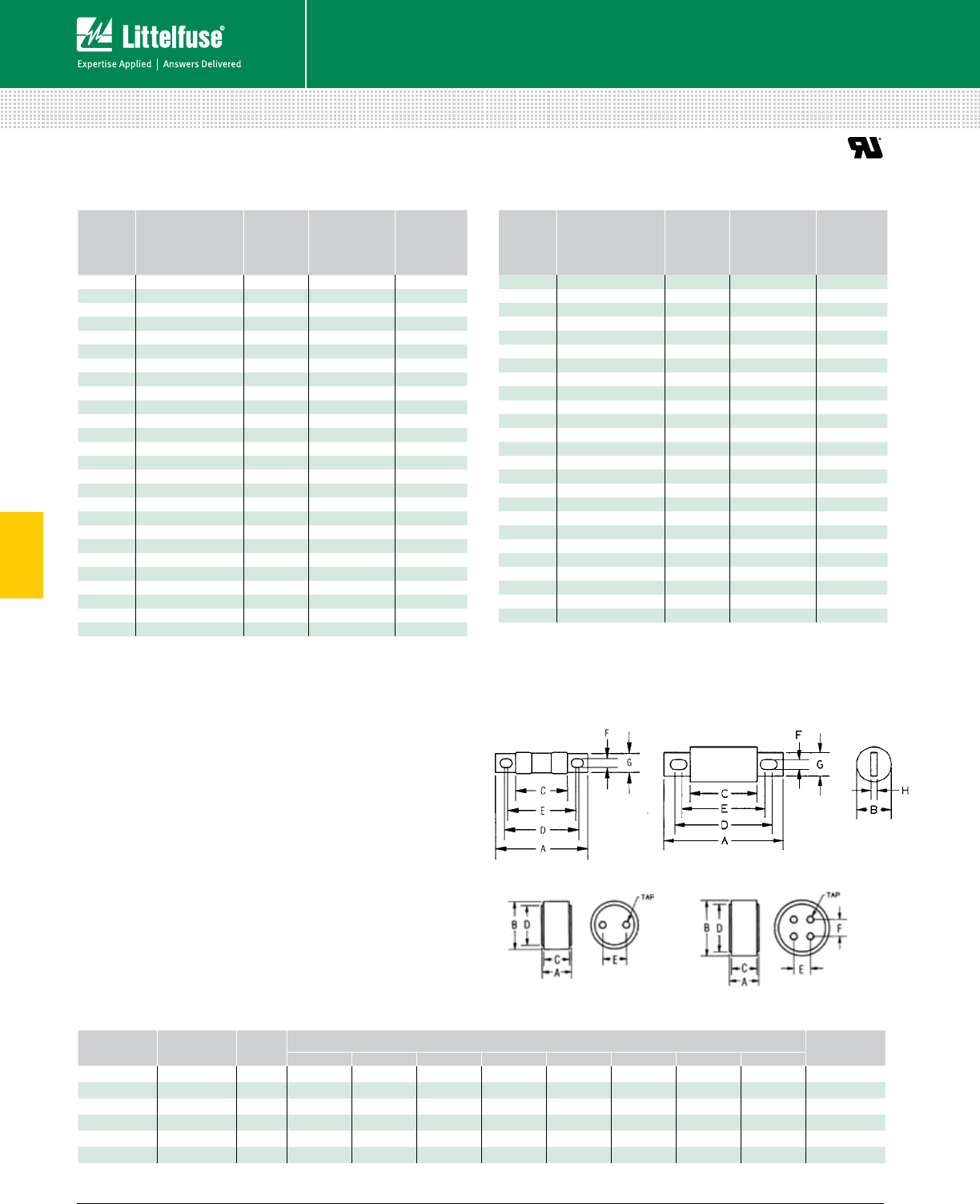
72 © 2014 Littelfuse POWR-GARD® Products Cataloglittelfuse.com
5
Fuses – Semiconductor
Semiconductor Fuses
ALTERNATE DIMENSION SEMICONDUCTOR FUSES
300 Vac • Very Fast-Acting • 35-4500 A
Description
Littelfuse LA30QS series Semiconductor protection fuses
are intended for the protection of Power Semiconductors
such as diodes, phase control SCR’s and other power
semiconductor devices. The LA30QS is recommended
for new applications providing solutions for your critical
protection needs for 300V and less semiconductors.
Specifications
Voltage Rating AC: 300 V
DC: 300 V
Interrupting Rating 200 kA
Ampere Range 35 – 4500 A
Approvals UL Recognized
Web Resources
For additional information, visit: littelfuse.com/la30qs
AMPERE
RATING
CATALOG
NUMBER
MOUNTING
TYPE
MAXIMUM
CLEARING I2t
@300 VAC
(A2s X 103)
WATTS LOSS
@ RATED
CURRENT
(W)
35 LA30QS35-4 40.9 6.4
40 LA30QS40-4 41.2 7
50 LA30QS50-4 4 2 9.9
60 LA30QS60-4 42.7 11.6
70 LA30QS70-4 41.6 11
80 LA30QS80-4 42.6 11
90 LA30QS90-4 43.2 13
100 LA30QS100-4 44.1 13
100 LA30QS100-4TI 4TI 4.1 13
125 LA30QS125-4 46.3 16
130 LA30QS130-4 46.3 16
150 LA30QS150-4 49.3 19
150 LA30QS150-4TI 4TI 9.3 19
175 LA30QS175-4 410 27
200 LA30QS200-4 415 30
200 LA30QS200-4TI 4TI 15 30
225 LA30QS225-4 422 33
250 LA30QS250-4 425 41
250 LA30QS250-4TI 4TI 25 41
300 LA30QS300-4 437 47
300 LA30QS300-4TI 4TI 37 47
350 LA30QS350-4 462 49
400 LA30QS400-4 483 56
400 LA30QS400-4IL 4IL 83 56
400 LA30QS400-4TI 4TI 83 56
450 LA30QS450-4 4130 53
AMPERE
RATING
CATALOG
NUMBER
MOUNTING
TYPE
MAXIMUM
CLEARING I2t
@300 VAC
(A2s X 103)
WATTS LOSS
@ RATED
CURRENT
(W)
500 LA30QS500-4 4160 59
550 LA30QS550-4 4190 65
600 LA30QS600-4 4230 69
600 LA30QS600-4TI 4TI 230 69
600 LA30QS600-4IL 4IL 230 69
700 LA30QS700-4 4260 90
700 LA30QS700-128 128 260 73
800 LA30QS800-4 4330 108
800 LA30QS800-4IL 4IL 330 108
800 LA30QS800-128 128 330 84
1000 LA30QS1000-128 128 460 105
1000 LA30QS1000-128IL 128IL 460 105
1200 LA30QS1200-128 128 880 110
1500 LA30QS1500-128 128 1400 140
1500 LA30QS1500-128IL 128IL 1400 140
1600 L A30QS1600-128 128 1690 150
2000 LA30QS2000-128 128 2600 190
2000 LA30QS2000-128IL 128IL 2600 190
2500 LA30QS2500-128 128 4000 230
2500 LA30QS2500-128IL 128IL 4000 230
3000 LA30QS3000-128 128 4700 340
3500 LA30QS3500-128 128 6500 380
3500 LA30QS3500-128IL 128IL 6500 380
4000 LA30QS4000-128 128 8600 450
4500 LA30QS4500-128 128 11000 500
Figure 1 Figure 2
Figure 3 Figure 4
Dimensions for reference only.
AMPERE
RATING
MOUNTING
TYPE
FIGURE
NO.
DIMENSIONS INCHES (mm)TAP
A B C D E F G H
35 – 60 4 1 3.19 (81.0) 0.81 (20.6) 1.63 (41.4) 2.50 (63.5) 2.25 (57.5) 0.34 (8.6) 0.72 (18.3) 0.13 (3.3) –
70 – 200 4 2 3.13 (79.5) 1.22 (31.0) 1.63 (41.4) 2.44 (62.0) 2.31 (58.7) 0.31 (7.9) 1.00 (25.4) 0.19 (4.8) –
225 – 800 4, 4IL* 23.84 (97.5) 1.50 (38.1) 1.59 (40.1) 2.91 (73.9) 2.2 8 (5 7.9) 0.41 (10.4) 1.00 (25.4) 0.25 (6.4) –
800 – 1200 128 32.59 (65.8) 3.00 (76.2) 2.34 (59.4) 2.50 (63.5) 1.50 (38.1) –––3⁄8-24-1⁄2 deep
1500 – 2500 128, 128IL* 42.59 (65.8) 3.50 (88.9) 2.34 (59.4) 3.00 (76.2) 1.50 (38.1) 1.50 (38.1) – – 3⁄8-24-1⁄2 deep
3000 – 4500 128, 128IL* 42.59 (65.8) 4.50 (114) 2.34 (59.4) 3.75 (95.3) 1.50 (38.1) 1.50 (38.1) – – 1⁄2-20-1⁄2 deep
*Optional Trigger Actuator (IL). Optional Trigger Indicator (TI) see web for dimensions.
Dimensions
LA30QS Series
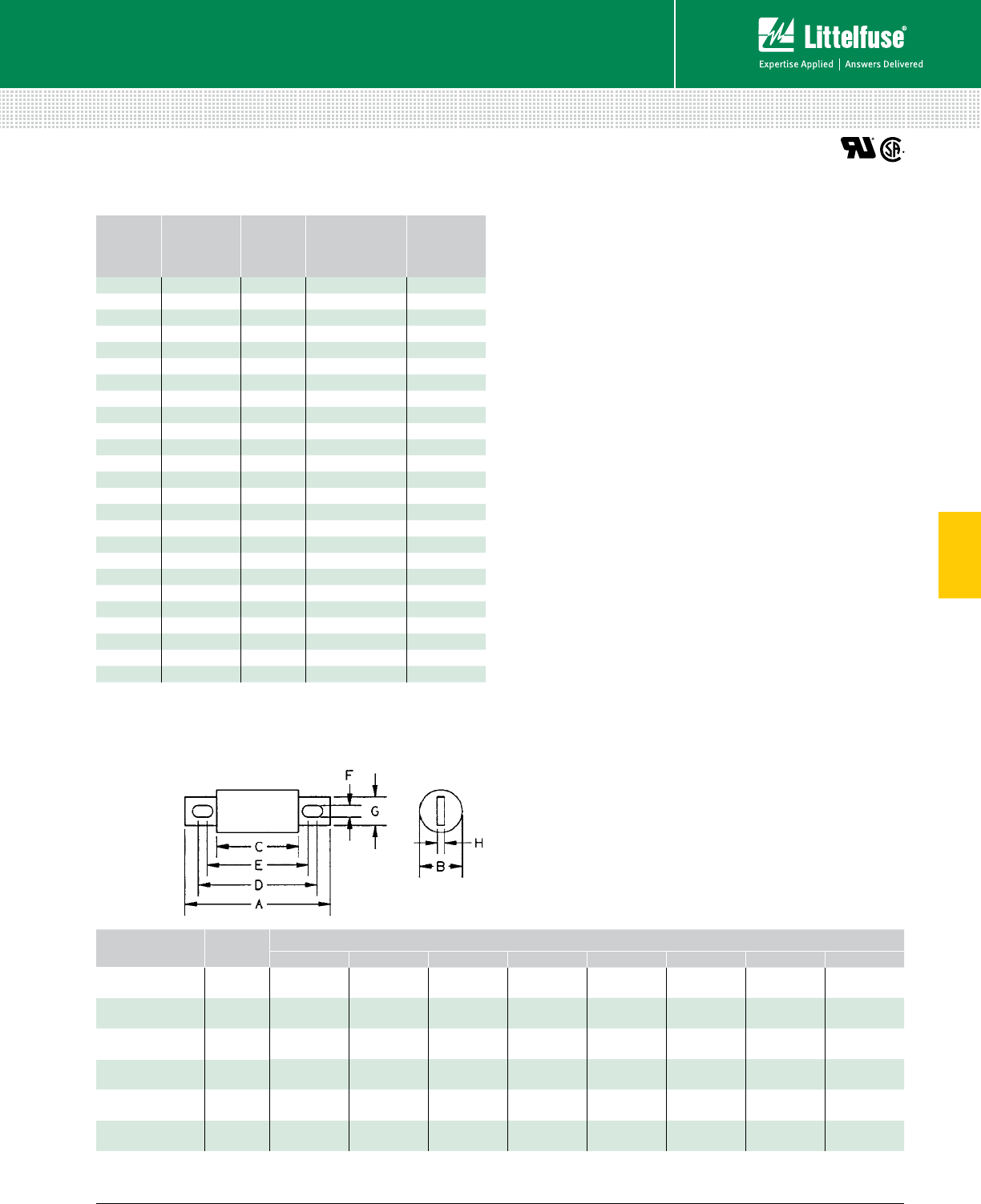
73 littelfuse.com © 2014 Littelfuse POWR-GARD® Products Catalog
5
Fuses – Semiconductor
Semiconductor Fuses
ALTERNATE DIMENSION SEMICONDUCTOR FUSES
500 Vac • Very Fast-Acting • 35-1200 A
Description
Littelfuse LA50QS series fuses were developed to
improve the overall performance of semiconductor fuses.
The LA50QS provides the high performance protection
characteristics including lower I2t, longer life when subjected
to cyclic loading and lower watts loss. LA50QS is the leading
choice for the protection of dynamic solid state equipment.
Specifications
Voltage Rating AC: 500 V
DC: 500 V
Interrupting Rating AC: 200 kA
DC: 100 kA
Ampere Range 35 – 1200 A
Approvals UL Recognized
CSA Certified
Web Resources
For additional information, visit: littelfuse.com/la50qs
AMPERE
RATING
CATALOG
NUMBER
MOUNTING
TYPE
MAXIMUM
CLEARING I2t
@500 VAC
(A2s X 103)
WATTS LOSS
@ RATED
CURRENT (W)
35 LA50QS35-4 40.56 6
40 LA50QS40-4 40.69 7
50 LA50QS50-4 41.1 8
60 LA50QS60-4 41.6 10
70 LA50QS70-4 41.9 12
80 LA50QS80-4 42.6 14
90 LA50QS90-4 43.6 15
100 LA50QS100-4 44.4 17
125 LA50QS125-4 45.6 21
150 LA50QS150-4 4 9 25
175 LA50QS175-4 415 29
200 LA50QS200-4 420 33
225 LA50QS225-4 425 37
250 LA50QS250-4 429 41
300 LA50QS300-4 455 49
350 LA50QS350-4 488 57
400 LA50QS400-4 498 65
450 LA50QS450-4 4130 69
500 LA50QS500-4 4160 77
600 LA50QS600-4 4220 92
700 LA50QS700-4 4270 110
800 LA50QS800-4 4360 130
900 LA50QS900-4 4500 140
1000 LA50QS1000-4 4560 160
1200 LA50QS1200-4 4930 175
Dimensions for reference only.
AMPERE
RATING
MOUNTING
TYPE
DIMENSIONS INCHES (mm)
A B C D E F G H
35 – 100 43.63
(92.2)
1.00
(25.4)
2.13
(54.1)
2.94
(74.7)
2.75
(69.9)
0.31
(7.9)
0.75
(19.1)
0.13
(3.3)
125 – 200 43.63
(92.2)
1.22
(31.0)
2.13
(54.1)
2.94
(74.7)
2.81
(71.4)
0.31
(7.9)
1.00
(25.4)
0.19
(4.8)
225 – 400 44.34
(110)
1.50
(38.1)
2.09
(53.1)
3.41
(86.6)
2.78
(70.6)
0.41
(10.4)
1.00
(25.4)
0.25
(6.4)
450 – 600 44.47
(114)
2.00
(50.8)
2.22
(56.4)
3.53
(89.7)
2.91
(73.9)
0.41
(10.4)
1.50
(38.1)
0.25
(6.4)
700 – 800 46.47
(164.3)
2.50
(63.5)
2.22
(56.4)
5.00
(127.0)
3.44
(8 7.3)
0.53
(13.5)
1.50
(38.1)
0.25
(6.4)
900 – 1200 46.97
(177.0)
3.00
(76.2)
3.22
(81.8)
5.47
(138.9)
4.47
(113.5)
0.63
(15.9)
2.38
(60.3)
0.44
(11.1)
Contact Littelfuse for characteristic curves.
Dimensions
LA50QS Series
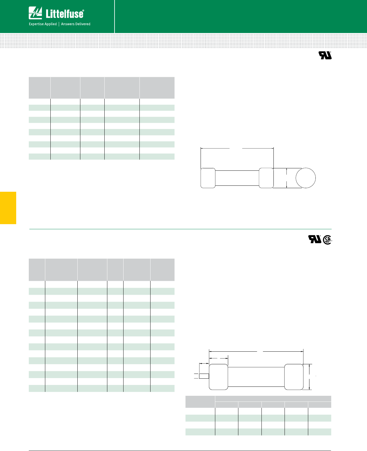
74 © 2014 Littelfuse POWR-GARD® Products Cataloglittelfuse.com
5
Fuses – Semiconductor
Semiconductor Fuses
ALTERNATE DIMENSION SEMICONDUCTOR FUSES
600 Vac/dc • Very Fast-Acting • 5-40 A
690 Vac/700 Vdc • Very Fast-Acting • 10-100 A
Specifications
Voltage Rating AC: 600 V
DC: 600 V
Interrupting Rating AC: 200 kA
DC: 100 kA
Ampere Range 5 – 40 A
Approvals UL Recognized
AMPERE
RATING
CATALOG
NUMBER
MOUNTING
TYPE
MAXIMUM
CLEARING I2t
@600 VAC (A2s)
WATTS LOSS
@ RATED
CURRENT (W)
5LA60Q5-2 260 0.7
8LA60Q8-2 270 1.1
10 LA60Q10-2 2110 1.6
12 LA60Q12-2 2150 2
15 LA60Q15-2 2180 3
20 LA60Q20-2 2330 4.4
25 LA60Q25-2 2440 5.5
30 LA60Q30-2 2860 5.6
35 LA60Q35-2 21300 6.4
40 LA60Q40-2 21800 7
1 ½
13/32
Description
Littelfuse LA60Q semiconductor protection fuses feature
a 600 volt ac/dc rating in a compact size (1 1⁄2” x 13 ⁄32”).
LA60Q also has the lowest I2t of all similar fuses and
excellent cycling ability. Applications include inverters and
small equipment requiring extremely fast response to
faults, without the need to carry sustained heavy overloads.
Dimensions Inches
Contact Littelfuse for characteristic curves.
Description
Littelfuse French Cylindrical style semiconductor fuses are
an extension to the LA70QS series. They offer a solid-fill
design with high interrupting ratings and an optional striker
for visual or remote blown fuse indication.
Web Resources
For additional information, visit: littelfuse.com/semi
Dimensions
Specifications
Voltage Rating AC: 690 V
DC: 700 V
Interrupting Rating AC: 200 kA
DC: 100 kA
Ampere Range 10 – 100 A
Approvals UL Recognized
CSA Certified
Web Resources
For additional information, visit: littelfuse.com/la60q
AMPERE
RATING
CATALOG
NUMBER
(NO STRIKER)
CATALOG
NUMBER
(WITH STRIKER)
BODY
SIZE
MAXIMUM
CLEARING I2t
@700 VAC
(A2s X 103)
WATTS LOSS
@ RATED
CURRENT (W)
10 LA70QS10-14F LA70QS10-14FI 14 x 51 0.04 3.5
12 LA70QS12-14F LA70QS12-14FI 14 x 51 0.06 4.4
16 LA70QS16-14F LA70QS16-14FI 14 x 51 0.10 4.8
20 LA70QS20-14F LA70QS20-14FI 14 x 51 0.16 5.2
25 LA70QS25-14F LA70QS25-14FI 14 x 51 0.27 5.8
32 LA70QS32-14F LA70QS32-14FI 14 x 51 1.50 7.0
40 LA70QS40-14F LA70QS40-14FI 14 x 51 0.70 10.7
50 LA70QS50-14F LA70QS50-14FI 14 x 51 1.50 11.6
20 LA70QS20-22F LA70QS20-22FI 22 x 58 0.076 8.0
25 LA70QS25-22F LA70QS25-22FI 22 x 58 0.125 10.0
32 LA70QS32-22F LA70QS32-22FI 22 x 58 0.27 11.0
40 LA70QS40-22F LA70QS40-22FI 22 x 58 0.48 13.0
50 LA70QS50-22F LA70QS50-22FI 22 x 58 0.80 14.9
63 LA70QS63-22F LA70QS63-22FI 22 x 58 1.85 16.0
80 LA70QS80-22F LA70QS80-22FI 22 x 58 3.80 17.8
100 LA70QS100-22F LA70QS100-22FI 22 x 58 8.00 19.0
FUSE SIZE DIMENSIONS mm
A B C D E
14x51 14 51 14 – –
22x58 22 58 16 – –
14x51 Striker 14 51 14 7.5 3.8
22x58 Striker 22 58 16 7.5 3.8
LA60Q Series Semiconductor Fuses
LA70QSF Series French Cylindrical Fuses
A
B
C
A
B
C
D
E
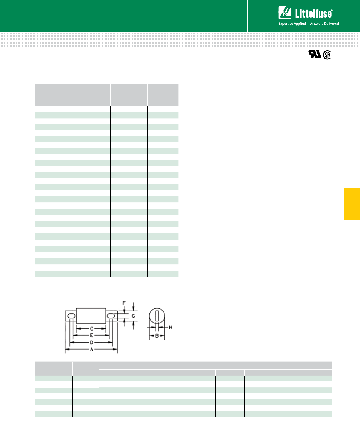
75 littelfuse.com © 2014 Littelfuse POWR-GARD® Products Catalog
5
Fuses – Semiconductor
Semiconductor Fuses
ALTERNATE DIMENSION SEMICONDUCTOR FUSES
700 Vac/dc • Very Fast-Acting • 35-800 A
AMPERE
RATING
CATALOG
NUMBER
MOUNTING
TYPE
MAXIMUM
CLEARING I2t
@700 VAC
(A2s X 103)
WATTS LOSS
@ RATED
CURRENT (W)
35 LA70QS35-4 40.47 6.2
40 LA70QS40-4 40.58 7.5
50 LA70QS50-4 40.86 9.8
60 LA70QS60-4 41.2 12
70 LA70QS70-4 41.8 15
80 LA70QS80-4 42.3 18
90 LA70QS90-4 4 3 20
100 LA70QS100-4 43.6 24
125 LA70QS125-4 46.9 22
125 LA70QS125-4K 4K 6.9 22
150 LA70QS150-4 411 29
150 LA70QS150-4K 4K 11 29
175 LA70QS175-4 414 35
175 LA70QS175-4K 4K 14 35
200 LA70QS200-4 419 41
200 LA70QS200-4K 419 41
250 LA70QS250-4 442 42
300 LA70QS300-4 455 53
350 LA70QS350-4 472 64
400 LA70QS400-4 499 75
450 LA70QS450-4 4125 78
450 LA70QS450-4K 4K 125 78
500 LA70QS500-4 4160 92
500 LA70QS500-4K 4K 160 92
600 LA70QS600-4 4222 116
600 LA70QS600-4K 4K 222 116
700 LA70QS700-4 4332 125
800 LA70QS800-4 4433 143
Dimensions for reference only.
AMPERES MOUNTING
TYPE
DIMENSIONS INCHES (mm)
A B C D E F G H
35 – 100 44.38 (111) 1.00 (25.4) 2.88 (73) 3.69 (93.6) 3.50 (88.9) 0.31 (7.9) 0.75 (19.0) 0.13 (3.2)
125 – 200 44.38 (111) 1.22 (31.0) 2.88 (73) 3.69 (93.6) 3.56 (90.5) 0.31 (7.9) 1.00 (25.4) 0.19 (4.8)
125 – 200 4K 5.09 (129) 1.22 (31.0) 2.88 (73) 4.19 (106) 3.50 (88) 0.41 (10.3) 1.00 (25.4) 0.19 (4.8)
225 – 400 45.09 (129) 1.50 (38.1) 2.84 (72.2) 4.16 (106) 3.53 (89.7) 0.40 (10.3) 1.50 (38.1) 0.25 (6.4)
450 – 600 45.09 (129) 2.00 (50.8) 2.84 (72.2) 4.16 (106) 3.53 (89.7) 0.41 (10.3) 1.50 (38.1) 0.25 (6.4)
450 – 600 4K 7.09 (180) 2.00 (50.8) 2.84 (72.2) 6.16 (156) 3.53 (89.7) 0.53 (13.5) 1.50 (38.1) 0.25 (6.4)
700 – 800 47.0 9 (180) 2.50 (63.5) 2.84 (72.2) 5.28 (134) 4.91 (125) 0.53 (13.5) 2.00 (50.8) 0.38 (9.5)
Contact Littelfuse for characteristic curves.
Description
Littelfuse LA70QS semiconductor fuses were developed
to provide improved performance required by today’s new
equipment. The LA70QS features lower I2t, improved cycling,
and lower watts loss. It is the best choice for the protection
of dynamic solid-state equipment.
Features/Benefits
• I2t improved protection of equipment.
• Superior cycling ability for long, reliable life on high
cycling loading.
• Lower watts loss for cooler operation.
• 700 Volt ac/dc rating provides greater design versatility
• Compact sizes allow downsizing of equipment
Specifications
Voltage Rating AC: 700 V
DC: 700 V
Interrupting Rating AC: 200 kA
DC: 100 kA
Ampere Range 35 – 800 A
Approvals UL Recognized
CSA Certified
Web Resources
For additional information, visit: littelfuse.com/la70qs
Dimensions
LA70QS Series Semiconductor Fuses
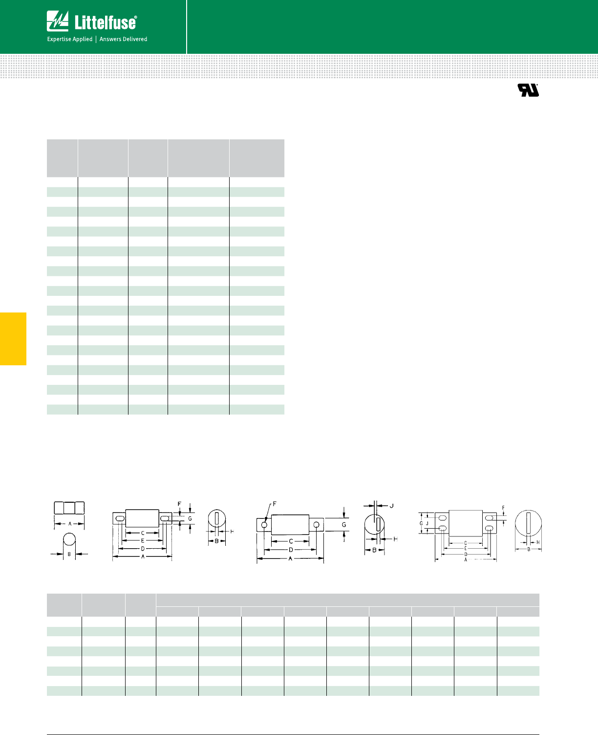
76 © 2014 Littelfuse POWR-GARD® Products Cataloglittelfuse.com
5
Fuses – Semiconductor
Semiconductor Fuses
ALTERNATE DIMENSION SEMICONDUCTOR FUSES
1000 Vac • Very Fast-Acting • 15-1000 A
Description
Littelfuse LA100P semiconductor protection fuses are
rated 1000 Vac, extending the range of protection for UPS
systems, AC and DC drives, reduced voltage motor starters
and similar applications where lower I2t and superior
reliability are needed. With ratings from 15-1000 amperes, a
wide range of high voltage applications can be served.
Features/Benefits
• Low I2t minimizes damage to protected components
on short-circuit.
• Controlled arc voltage reduces stress to circuit
components during fuse clearing.
Specifications
Voltage Rating AC: 1000 V
DC: 750 V
Interrupting Rating 100 kA
Ampere Range 15 – 1000 A
Approvals UL Recognized
Web Resources
For additional information, visit: littelfuse.com/la100p
AMPERE
RATING
CATALOG
NUMBER
MOUNTING
TYPE
MAXIMUM
CLEARING I2t
@1000 Vac
(A2s X 103)
WATTS LOSS
@ RATED
CURRENT (W)
15 LA100P15-1 10.6 3.4
20 LA100P20-1 10.8 5.9
25 LA100P25-1 11,3 9
30 LA100P30-1 11.5 12.8
35 LA100P35-4 42.2 7.3
40 LA100P40-4 42.9 8.3
50 LA100P50-4 44.5 11
60 LA100P60-4 46.5 13
80 LA100P80-4 412 14
100 LA100P100-4 418 18
125 LA100P125-4 428 23
150 LA100P150-4 441 28
200 LA100P200-4 472 36
225 LA100P225-4 491 40
250 LA100P250-4 4110 46
300 LA100P300-4 4160 55
350 LA100P350-4 4220 65
400 LA100P400-4 4290 70
500 LA100P500-4 4450 90
600 LA100P600-4 4650 110
650 LA100P650-4 4780 120
700 LA100P700-4 4880 125
800 LA100P800-4 41200 140
1000 LA100P1000-4 41900 190
Dimensions for reference only.
AMPERES MOUNTING
TYPE
FIGURE
NO.
DIMENSIONS INCHES (mm)
A B C D E F G H J
15 – 30 1 1 2.53 (66.8) 0.56 (14.2) –––––––
35 – 60 4 2 5.00 (127) 1.00 (25.4) 3.50 (88.9) 4.31 (109) 4.19 (106) 0.31 (7.9) 0.75 (19.1) 0.13 (3.3) –
65 – 100 4 2 5.00 (127) 1.22 (31) 3.50 (88.9) 4.31 (109) 4.19 (106) 0.31 (7.9) 1.00 (25.4) 0.19 (4.8) –
125 – 200 4 2 5.72 (145) 1.50 (38.1) 3.47 (88.1) 4.78 (121) 4.16 (106) 0.41 (10.4) 1.00 (25.4) 0.25 (6.4) –
225 – 400 4 2 5.72 (145) 2.00 (50.8) 3.47 (88.1) 4.78 (121) 4.16 (106) 0.41 (10.4) 1.50 (25.4) 0.25 (6.4) –
500 – 600 4 2 7.72 (196) 2.50 (63.5) 3.47 (8 8.1) 5.88 (149) 5.56 (147) 0.53 (13.5) 2.00 (50.8) 0.38 (9.7) –
650 – 800 4 3 7.4 4 (18 9) 2.88 (73.2) 3.94 (100) 5.94 (151) –0.63 (16) 2.00 (50.8) 0.38 (9.7) 0.31 (7.9)
1000 4 4 8.22 (209) 3.50 (88.9) 4.47 (114) 6.59 (167) 5.84 (148) 0.63 (16) 2.75 (69.9) 0.50 (12.7) 1.38 (35.1)
Optional Trigger Indicator (TI) for 50 A - 1000 A available
Contact Littelfuse for characteristic curves.
Figure 1 Figure 3Figure 2 Figure 4
Dimensions
LA100P Series Semiconductor Fuses
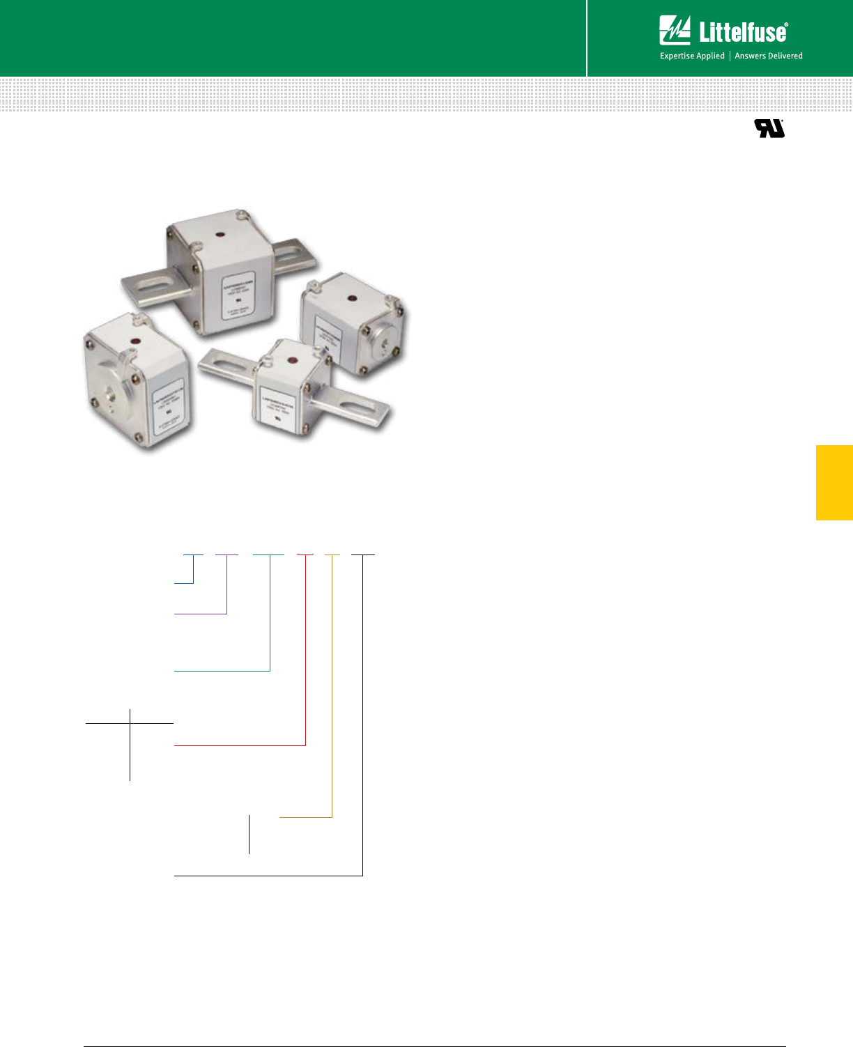
77 littelfuse.com © 2014 Littelfuse POWR-GARD® Products Catalog
5
Fuses – Semiconductor
Semiconductor Fuses
LA 070 URD 31 LI 350
Class
Littelfuse
Size
Mounting Type
Voltage
070=700 V
130 =130 0 V
Amp Rating
Straight-blade KI LI
Straight-blade LI LLI
Flat-type, one hole TTI TTI
700 V 1300 V
30
31
32
33
70
71
72
73
Description
Littelfuse North American style square body semiconductor
fuses provide maximum flexibility in equipment design and
ultimate protection for today’s power conversion equipment.
Available in different body sizes and multiple mounting
styles, the broad range of ampere ratings allows great
flexibility in equipment design.
Engineered to provide state-of-the-art protection for SCRs,
diodes, thyristors, GTOs, and IGBT devices, Littelfuse
square body fuses have pure die-cut elements embedded in
solidified sand to control arcing and lower I2t. All fuses are
also equipped with a blown fuse trip indicator.
Features
• Choice of mounting styles provides a wide choice for
equipment design.
• Broad range of ampere ratings in a given body size for
design flexibility.
• Very low I2t minimizes damage to protected components.
• Superior cycling ability for long, reliable life on high
cyclic loading.
• Extremely fast-acting and current-limiting for improved
protection to equipment.
Applications
Protection of rectifiers, inverters, DC drives, UPS systems,
reduced voltage motor starters, and other equipment in
globally accepted applications.
Specifications
Voltage Rating AC: 700 V (LA070)
1300 V (LA130)
DC: Contact factory
Interrupting Rating AC: 200 kA (LA070)
100 kA (LA130)
DC: Contact factory
Ampere Range 63 – 2500 A
Approvals UL Recognized Component
Ordering Information
SQUARE BODY SEMICONDUCTOR FUSES
700/1300 Vac • Very Fast-Acting • 63-2500 A
Dimensions
Please refer to the Square Body dimensions ............... 79-81
Web Resources
For additional information, visit: littelfuse.com/la070

78 © 2014 Littelfuse POWR-GARD® Products Cataloglittelfuse.com
5
Fuses – Semiconductor
Semiconductor Fuses
SQUARE BODY SEMICONDUCTOR FUSES
700/1300 Vac • Very Fast-Acting • 63-2500 A
BODY
SIZE
AMPERE
RATING
RATED
VOLTAGE
MELTING I2T
(A2S X 103)
TOTAL I2T
@ RATED
VOLTAGE
(A2S X 103)
*WATTS LOSS
@ RATED
CURRENT
(W)
LONG BLADE
CATALOG NUMBER
TYPE LI
SHORT BLADE
CATALOG NUMBER
TYPE KI
TAPPED TERMINAL
CATALOG NUMBER
TYPE TTI
30
63 700 0.2 1.2 14 LA070URD30LI0063 LA070URD30KI0063 LA070URD30TTI0063
80 700 0.33 1.9 19 LA070URD30LI0080 LA070URD30KI0080 LA070URD30TTI0080
100 700 0.47 2.7 26 LA070URD30LI0100 LA070URD30KI0100 LA070URD30TTI0100
125 700 0.85 4.9 30 LA070URD30LI0125 LA070URD30KI0125 LA070URD30TTI0125
160 700 1.6 9.2 37 –LA070URD30KI0160 LA070URD30TTI0160
200 700 316.7 42 ⁄ 43 LA070URD30LI0200 LA070URD30KI0200 LA070URD30TTI0200
250 700 5.8 32.4 48 ⁄ 50 LA070URD30LI0250 LA070URD30KI0250 LA070URD30TTI0250
315 700 12 67 53 ⁄ 55 LA070URD30LI0315 LA070URD30KI0315 LA070URD30TTI0315
350 700 15.5 86 57 ⁄ 60 LA070URD30LI0350 LA070URD30KI0350 LA070URD30TTI0350
400 700 23 130 60 ⁄ 65 LA070URD30LI0400 LA070URD30KI0400 LA070URD30TTI0400
450 700 26 165 80 ⁄ 88 LA070URD30LI0450 LA070URD30KI0450 LA070URD30TTI0450
500 700 41 264 80 ⁄ 88 LA070URD30LI0500 LA070URD30KI0500 LA070URD30TTI0500
550 700 52 330 80 ⁄ 90 LA070URD30LI0550 LA070URD30KI0550 LA070URD30TTI0550
31
200 700 2.5 14.6 45 LA070URD31LI0200 LA070URD31KI0200 LA070URD31TTI0200
250 700 4.7 27 52 LA070URD31LI0250 LA070URD31KI0250 LA070URD31TTI0250
315 700 7.5 43 65 LA070URD31LI0315 LA070URD31KI0315 LA070URD31TTI0315
350 700 10.5 59 67 LA070URD31LI0350 LA070URD31KI0350 LA070URD31TTI0350
400 700 19 110 68 LA070URD31LI0400 LA070URD31KI0400 LA070URD31TTI0400
450 700 26.5 150 70 LA070URD31LI0450 LA070URD31KI0450 LA070URD31TTI0450
500 700 37 210 70 ⁄ 72 LA070URD31LI0500 LA070URD31KI0500 LA070URD31TTI0500
550 700 52 300 70 ⁄ 75 LA070URD31LI0550 LA070URD31KI0550 LA070URD31TTI0550
630 700 75 421 75 ⁄ 85 LA070URD31LI0630 LA070URD31KI0630 LA070URD31TTI0630
700 700 95 530 85 ⁄ 95 LA070URD31LI0700 LA070URD31KI0700 LA070URD31TTI0700
800 700 140 880 105 ⁄ 120 LA070URD31LI0800 LA070URD31KI0800 LA070URD31TTI0800
32
400 700 15 86 72 ⁄ 75 LA070URD32LI0400 LA070URD32KI0400 LA070URD32TTI0400
450 700 22 124 77 ⁄ 80 LA070URD32LI0450 LA070URD32KI0450 LA070URD32TTI0450
500 700 28 157 85 ⁄ 90 LA070URD32LI0500 LA070URD32KI0500 LA070URD32TTI0500
550 700 37 211 90 ⁄ 95 LA070URD32LI0550 LA070URD32KI0550 LA070URD32TTI0550
630 700 54 302 95 ⁄ 105 LA070URD32LI0630 LA070URD32KI0630 LA070URD32TTI0630
700 700 76 432 100 ⁄ 110 LA070URD32LI0700 LA070URD32KI0700 LA070URD32TTI0700
800 700 115 648 110 ⁄ 120 LA070URD32LI0800 LA070URD32KI0800 LA070URD32TTI0800
900 700 170 972 110 ⁄ 125 LA070URD32LI0900 LA070URD32KI0900 LA070URD32TTI0900
1000 700 240 1350 115 ⁄ 135 LA070URD32LI1000 LA070URD32KI1000 LA070URD32TTI1000
1100 650 270 1620 140 ⁄ 165 LA065URD32LI1100 –LA065URD32TTI1100
1250 600 410 2100 150 ⁄ 180 LA060URD32LI1250 –LA060URD32TTI1250
1400 550 555 2600 160 ⁄ 190 LA055URD32LI1400 –LA055URD32TTI1400
1600 550 870 4000 165 ⁄ 195 LA055URD32LI1600 –LA055URD32TTI1600
1800 500 1050 4400 195 ⁄ 330 LA050URD32LI1800 –LA050URD32TTI1800
33
500 700 19 108 105 LA070URD33LI0500 LA070URD33KI0500 LA070URD33TTI0500
550 700 27 151 105 ⁄ 110 LA070URD33LI0550 LA070URD33KI0550 LA070URD33TTI0550
630 700 40 227 110 ⁄ 120 LA070URD33LI0630 LA070URD33KI0630 LA070URD33TTI0630
700 700 55 324 115 ⁄ 125 LA070URD33LI0700 LA070URD33KI0700 LA070URD33TTI0700
800 700 95 529 120 ⁄ 130 LA070URD33LI0800 LA070URD33KI0800 LA070URD33TTI0800
900 700 135 760 120 ⁄ 135 LA070URD33LI0900 LA070URD33KI0900 LA070URD33TTI0900
1000 700 170 970 135 ⁄ 155 LA070URD33LI1000 LA070URD33KI1000 LA070URD33TTI1000
1100 700 240 1360 135 ⁄ 160 LA070URD33LI1100 LA070URD33KI1100 LA070URD33TTI1100
1250 700 350 2000 150 ⁄ 180 LA070URD33LI1250 LA070URD33KI1250 LA070URD33TTI1250
1400 700 480 2700 160 ⁄ 200 LA070URD33LI1400 LA070URD33KI1400 LA070URD33TTI1400
1600 650 555 3250 210 ⁄ 240 LA065URD33LI1600 –LA065URD33TTI1600
1800 650 720 4330 225 ⁄ 260 LA065URD33LI1800 –LA065URD33TTI1800
2000 600 950 5000 250 ⁄ 290 LA060URD33LI2000 –LA060URD33TTI2000
2250 550 1250 5900 280 ⁄ 330 LA055URD33LI2250 –LA055URD33TTI2250
2500 500 1870 7600 280 ⁄ 330 LA050URD33LI2500 –LA050URD33TTI2500
*Watts loss data is published for both blade and tapped style mounting configurations.
When two watts loss values are shown, this represents tapped/blade values respectively.
Contact Littelfuse for characteristic curves.
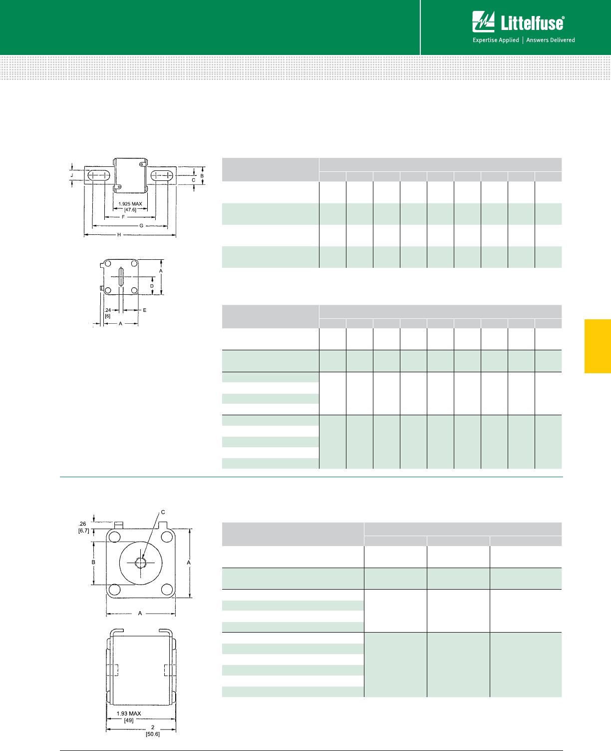
79 littelfuse.com © 2014 Littelfuse POWR-GARD® Products Catalog
5
Fuses – Semiconductor
Semiconductor Fuses
Dimensions Dimensions for reference only.
CATALOG NUMBER DIMENSIONS INCHES (mm)
A B C D E F G H J
LA070URD30KI (63-550) 1.57
(40)
0.98
(25)
0.49
(12.5)
0.83
(21)
0.71
(18)
2.68
(68)
4.21
(107)
5.08
(129)
0.41
(10.5)
LA070URD31KI (200-800) 2.01
(51)
0.98
(25)
0.49
(12.5)
1.0
(25.5)
0.89
(22.5)
2.66
(6 7.6)
4.22
(107.1)
5.07
(128.8)
0.56
(14.3)
LA070URD32KI (400-1000) 2.36
(60)
1.26
(32)
0.63
(16)
1.18
(30)
1.06
(27)
2.92
(74.2)
4.29
(109)
5.28
(134)
0.57
(14.6)
LA070URD33KI (500-1400) 2.93
(74.5)
1.57
(40)
0.79
(20)
1.46
(3 7.2)
1.35
(34.2)
2.97
(75.4)
4.24
(107.6)
5.28
(134)
0.63
(15.9)
Dimensions Dimensions for reference only.
CATALOG NUMBER DIMENSIONS INCHES (mm)
A B C D E F G H J
LA070URD30LI (63-550) 1.57
(40)
0.98
(25)
0.49
(12.5)
0.83
(21)
0.71
(18)
3.45
(8 7.6)
4.98
(126.6)
5.85
(148.6)
0.41
(10.5)
LA070URD31LI (200-800) 2.01
(51)
0.98
(25)
0.49
(12.5)
1.0
(25.5)
0.89
(22.5)
3.61
(91.6)
4.82
(122.4)
5.85
(148.6)
0.57
(14.6)
LA070URD32LI (400-1000)
2.36
(60)
1.26
(32)
0.63
(16)
1.18
(30)
1.06
(27)
3.71
(94.2)
5.08
(129)
6.02
(153)
0.57
(14.6)
LA060URD32LI (1250)
LA055URD32LI (1400-1600)
LA050URD32LI (1800)
LA070URD33LI (500-1400)
2.93
(74.5)
1.57
(40)
0.79
(20)
1.46
(3 7.2)
1.35
(34.2)
3.72
(94.4)
4.98
(126.6)
6.02
(153)
0.63
(15.9)
LA065URD33LI (1600-1800)
LA060URD33LI (2000)
LA055URD33LI (2250)
LA050URD33LI (2500)
Dimensions Dimensions for reference only.
CATALOG NUMBER DIMENSIONS INCHES (mm)
A B C
LA070URD30TTI (100-550) 1.57
(40)
1.00
(25)
5⁄16-18 x 0.35
LA070URD31TTI (200-800) 2.00
(50.8)
1.19
(30.2)
5⁄16-18 x 0.35
LA070URD32TTI (400-1000)
2.37
(60.3)
1.50
(38.1)
3⁄8-16 x 0.35
LA065URD32TTI (1100)
LA060URD32TTI (1250)
LA055URD32TTI (1400-1600)
LA060URD33TTI (1800)
2.94
(74.5)
1.81
(46)
1⁄2-18 x 0.35
LA070URD33TTI (500-1400)
LA065URD33TTI (1600)
LA060URD33TTI (2000)
LA055URD33TTI (2250)
LA050URD33TTI (2500)
SQUARE BODY SEMICONDUCTOR FUSES
700/1300 Vac • Very Fast-Acting • 63-2500 A
TYPE TTI
TYPES KI AND LI North American Straight Blade, Type KI
North American Straight Blade, Type LI
North American Flat Single Hole, Type TTI

80 © 2014 Littelfuse POWR-GARD® Products Cataloglittelfuse.com
5
Fuses – Semiconductor
Semiconductor Fuses
SQUARE BODY SEMICONDUCTOR FUSES
700/1300 Vac • Very Fast-Acting • 63-2500 A
BODY
SIZE
AMPERE
RATING
RATED
VOLTAGE
MELTING I2T
(A2S X 103)
TOTAL I2T
@ RATED
VOLTAGE
(A2S X 103)
*WATTS LOSS @
RATED CURRENT
(W)
LONG BLADE
CATALOG NUMBER
TYPE LI/LLI
TAPPED TERMINAL
CATALOG NUMBER
TYPE TTI
70
63 1300 0.21 1.8 26 LA130URD70LI0063 LA130URD70TTI0063
80 1300 0.47 427 LA130URD70LI0080 LA130URD70TTI0080
100 1300 0.83 7.2 30 LA130URD70LI0100 LA130URD70TTI0100
125 1300 1.3 11 38 LA130URD70LI0125 LA130URD70TTI0125
160 1300 2.5 22 45 LA130URD70LI0160 LA130URD70TTI0160
200 1300 4.7 40 54 ⁄ 56 LA130URD70LI0200 LA130URD70TTI0200
250 1300 9.6 82 58 ⁄ 61 LA130URD70LI0250 LA130URD70T TI0250
315 1300 20 172 66 ⁄ 72 LA130URD70LI0315 LA130URD70TTI0315
350 1200 28 205 68 ⁄ 75 LA120URD70LI0350 LA120URD70TTI0350
71
160 1300 2.6 22 46 LA130URD71LLI0160 LA130URDT1TTI0160
200 1300 4.7 40 54 LA130URD71LLI0200 LA130URD71TTI0200
250 1300 8.9 76 61 LA130URD71LLI0250 L A130URD71TTI0250
280 1300 12 102 68 ⁄ 70 LA130URD71IL0280 LA130URD71TTI0280
315 1300 16 138 73 ⁄ 76 LA130URD71LLI0315 LA130URD71T TI0315
350 1300 22 190 76 ⁄ 80 LA130URD71LLI0350 LA130URD71TTI0350
400 1300 38 330 76 ⁄ 80 LA130URD71LLI0400 LA130URD71TTI0400
450 1300 47 405 87 ⁄ 95 LA130URD71LLI0450 LA130URD71T TI0450
500 1200 68 500 90 ⁄ 100 LA120URD71LLI0500 LA120URD71TTI0500
550 1200 84 620 98 ⁄ 112 LA120URD71LLI0550 LA120URD71TTI0550
630 1100 125 930 105 LA110URD71LLI0630 –
630 1200 125 930 120 –LA120URD71TTI0630
72
280 1300 10 90 72 LA130URD72LI0280 LA130URD72TTI0280
315 1300 15 130 76 LA130URD72LI0315 LA130URD72TTI0315
350 1300 21 180 77 LA130URD72LI0350 LA130URD72TTI0350
400 1300 32 285 80 LA130URD72LI0400 LA130URD72TTI0400
450 1300 44 380 87 ⁄ 89 LA130URD72LI0450 LA130URD72TTI0450
500 1300 57 500 94 ⁄ 98 LA130URD72LI0500 LA130URD72TTI0500
550 1300 68 590 110 ⁄ 120 LA130URD72LI0550 LA130URD72TTI0550
630 1200 105 920 113 LA120URD72LI0630 –
630 1300 105 920 125 –LA130URD72TTI0630
700 1100 145 1040 122 LA110URD72LI0700 –
700 1200 145 1040 140 –LA120URD72TTI0700
800 1100 215 1590 125 LA110URD72LI0800 –
800 1200 215 1590 146 –LA120URD72TTI0800
73
315 1300 12 102 84 LA130URD73LI0315 LA130URD73TTI0315
350 1300 17 150 86 LA130URD73LI0350 LA130URD73TTI0350
400 1300 25 220 93 LA130URD73LI0400 L A130URD73TTI0400
450 1300 35 310 99 ⁄ 100 LA130URD73LI0450 LA130URD73T TI0450
500 1300 44 390 110 ⁄ 112 LA130URD73LI0500 LA130URD73TTI0500
550 1300 57 500 116 ⁄ 120 LA130URD73LI0550 LA130URD73TTI0550
630 1300 84 730 125 ⁄ 132 LA130URD73LI0630 LA130URD73TTI0630
700 1300 110 960 135 ⁄ 146 LA130URD73LI0700 LA130URD73TTI0700
800 1200 190 1630 136 LA120URD73LI0800 –
800 1300 190 1630 148 –LA130URD73TTI0800
900 1100 250 2160 150 LA110URD73LI0900 –
900 1000 250 2160 170 –LA100URD73TTI0900
1000 1000 370 2430 152 ⁄ 174 LA100URD73LI1000 LA100URD73TTI1000
1100 1000 445 2580 168 ⁄ 208 LA100URD73LI1100 LA100URD73TTI1100
1250 1000 585 3480 186 ⁄ 200 LA100URD73LI1250 LA100URD73TTI1250
1400 900 755 3880 210 ⁄ 228 LA090URD73LI1400 LA090URD73TTI1400
1600 700 1430 5630 203 LA070URD73LI1600 LA070URD73TTI1600
1800 660 2040 7600 206 LA065URD73LI1800 LA065URD73TTI1800
*Watts loss data is published for both blade and tapped style mounting configurations. When two watts loss values are shown, this represents tapped/blade values respectively.
Contact Littelfuse for characteristic curves.
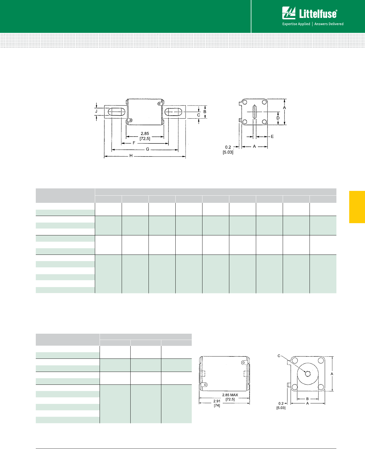
81 littelfuse.com © 2014 Littelfuse POWR-GARD® Products Catalog
5
Fuses – Semiconductor
Semiconductor Fuses
Dimensions Dimensions for reference only.
CATALOG NUMBER DIMENSIONS INCHES (mm)
A B C
LA130URD70TTI (63-315) 1.57
(40)
1.00
(26.4)
5⁄16-18 x 0.23 DP
LA120URD70TTI (350)
LA130URD71TTI (160-450) 2.01
(51)
1.19
(30.2)
5⁄16-18 x 0.36 DP
LA120URD71TTI (550-630)
LA130URD72TTI (280-630) 2.36
(60)
1.50
(38.1)
3⁄8-18 x 0.36 DP
LA120URD72TTI (700-800)
LA130URD73TTI (315-900)
2.93
(74.5)
1.81
(46)
1⁄2-18 x 0.36 DP
LA120URD73TTI (1000)
LA110URD73TTI (1250)
LA090URD73TTI (1400)
LA070URD73TTI (1600)
LA065URD73TTI (1800)
SQUARE BODY SEMICONDUCTOR FUSES
700/1300 Vac • Very Fast-Acting • 63-2500 A
TYPES LI AND LLI
TYPE TTI
North American Flat Single Hole, Type TTI
North American Straight Blade, Types LI and LLI
Dimensions Dimensions for reference only.
CATALOG NUMBER DIMENSIONS INCHES (mm)
A B C D E F G H J
LA130URD70LI (63-315) 1.57
(40)
0.98
(25)
0.49
(12.5)
0.83
(21)
0.71
(18)
3.60
(91.4)
5.13
(130.4)
6.00
(152.4)
0.41
(10.5)
LA120URD70LI (350)
LA130URD71LLI (160-450) 2.01
(51)
0.98
(25)
0.49
(12.5)
1.0
(26.5)
0.89
(22.5)
3.60
(91.4)
5.13
(130.4)
6.00
(152.4)
0.57
(14.6)
LA120URD71LLI (500-550)
LA110URD71LLI (630)
LA130URD72LI (280-550) 2.36
(60)
1.26
(32)
0.63
(16)
1.18
(30)
1.06
(27)
3.84
(97.6)
5.2
(132.4)
6.20
(157.4)
0.57
(14.6)
LA120URD72LI (800)
LA110URD72LI (700-800)
LA130URD73LI (315-700)
2.93
(74.5)
1.57
(40)
0.79
(20)
1.46
(3 7.2)
1.35
(34.2)
3.89
(98.8)
5.21
(132.4)
6.20
(157.4)
0.63
(15.9)
LA120URD73LI (800)
LA110URD73LI (900-1000)
LA090URD73LI (1400)
LA070URD73LI (1600)
LA065URD73LI (1800)
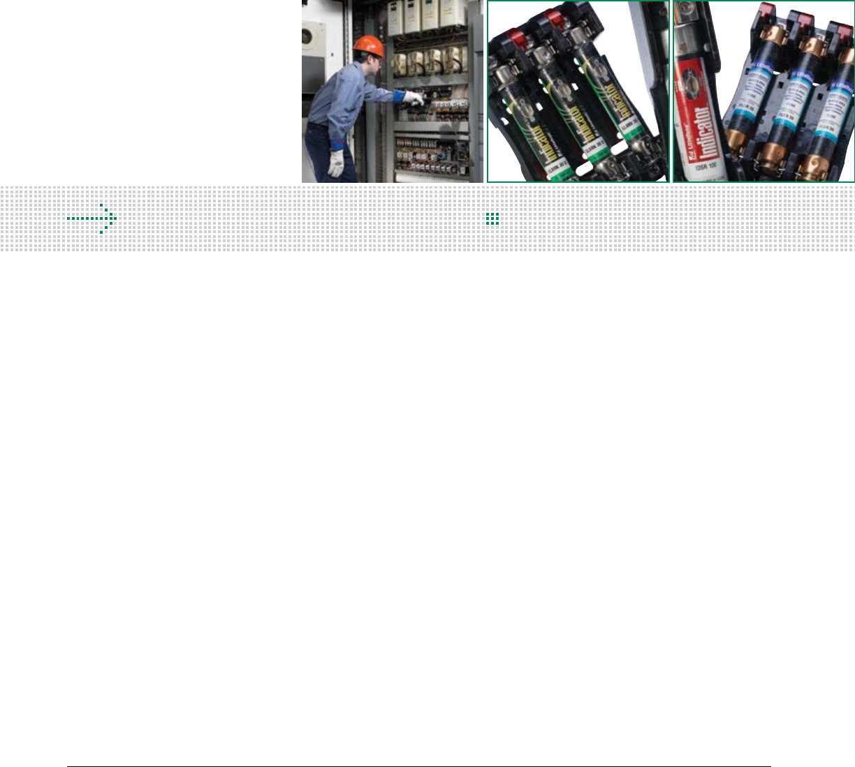
82 © 2014 Littelfuse POWR-GARD® Products Cataloglittelfuse.com
Section Overview
Littelfuse® offers a wide variety of open-face and dead-front fuse blocks,
in addition to a variety of in-line fuse holders, distribution/splicer blocks,
fuse pullers and accessories.
BLOCKS AND HOLDERS
Table of Contents
LF Series Fuse Blocks Overview ..................................................83
Class J Fuse Blocks .......................................................................85
Class H / K5 and R Fuse Blocks .....................................................88
Class T Fuse Blocks ......................................................................94
Class G Fuse Blocks ......................................................................99
Class CC / CD and Midget Fuse Blocks .......................................101
LF Series Fuse Block Covers ......................................................105
Solar Rated Fuse Blocks .............................................................106
Dead Front Fuse Holders ............................................................109
Miscellaneous Fuse Blocks and Holders .................................... 116
Semiconductor Fuse Blocks ........................................................120
Distribution and Splicer Blocks ...................................................122
In-Line Fuse Holders ...................................................................132
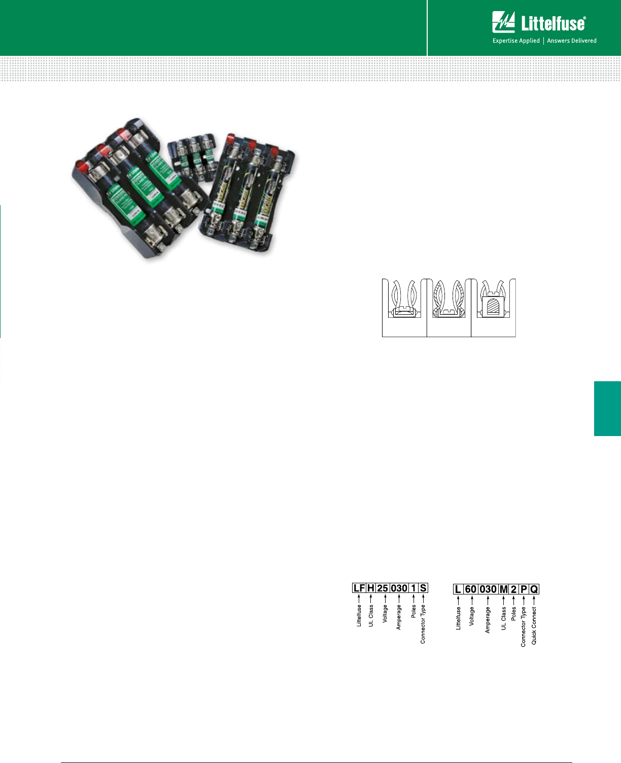
83 littelfuse.com © 2014 Littelfuse POWR-GARD® Products Catalog
Fuse Blocks and Holders
6
Blocks and Holders
FUSE BLOCK OVERVIEW
Description
Littelfuse offers a comprehensive line of fuse blocks
that incorporate many benefits such as indication, snap to-
release, DIN-Rail mounting and universal mounting holes.
New Options Available
• Reduced Footprint—Save space with
designs up to 35% smaller in width
• Indication—Increase safety and reduce
downtime with built-in local indication
• Universal Mounting Holes—Simplify
replacement with universal mounting options
• DIN Rail Mountable—Ease installation with
a 35 mm hat DIN Rail mounting option
• One-Hand Release—Save time by using only
one hand for a simple release from DIN Rail
Fuse Block Selection
The following guidelines should help simplify the selection
of proper fuse blocks:
1. Determine the system voltage—Since fuses are
selected on the basis of sys tem voltage, fuse blocks are
selected to match the voltage rating of the fuse.
2. Determine the design short-circuit current—If available
short-circuit current cannot be determined, or if it will vary
with equip ment location, select fuses with a 200,000 ampere
interrupting rating (A.I.R.) and mating fuse blocks with a
withstand rating of 200,000 amperes for maximum safety.
3. Determine the type and ampere rating of the fuse
to be used—The fuse ampere rating, opening characteristics
(fast acting or time-delay) and size are important considerations
in fuse selection. Fuse blocks may be used with a fuse rated
at the corresponding amperage rating or below. For example,
a fuse block rated at 30 amperes may be used with a fuse
rated from 0 to 30 amperes.
4. Determine if NEC®, CSA, UL, or other requirements
are applicable—Any of these requirements should be
obtained from the approving agency in advance of fuse and
fuse block selection.
5. Select the type of wire termination
Three types of wire termination are available:
• Screw*—for use with spade lugs or ring terminals
• Screw with Pressure Plate*—for use with solid or
stranded wire without terminal. Recommended where
vibration will be a factor
• Box Lug—for use with all types of solid wire and
Class B and Class C stranded wire. The most durable, but
not for use with welding cable or other
rope-stranded conductors.
*
1⁄4” Quick Connect terminals rated for up to 20 amperes are
available on the Midget and Class CC fuse blocks.
6. Decide on the number of poles in each block—The
number of poles for each set of fuses is determined by the
characteristics of the circuit.
7. Determine if block should be DIN Rail mounted—Many
of the new Littelfuse fuse blocks are DIN Rail mountable. Be
sure to look to corresponding ordering tables to match the
correct part number on the following product pages.
8. Determine if fuse clips need to be re in forced
Fuse clips may have a tendency to lose some of their tension
over a period of time. This may be prevented by specifying
reinforced fuse clips.
Ordering Information
The Littelfuse fuse block part number con sists of the below skeleton.
Please refer to UL Class Tables for specific information.
† These new fuse blocks replace previous Littelfuse fuse blocks that had very similar
part numbers for customer convenience. The only change is an “F” has been added as
the second character in the new block part numbers.
Caution: Littelfuse indicating fuse blocks are intended to quickly identify open fuses
while power is still applied. Only qualified electrically trained technicians should
replace fuses and follow standard OSHA and NFPA 70E safe work practices, such
as Lock-Out and Tag-Out procedures and verification before replacing any fuses in
indicating fuse blocks.
†For all Class R, H, J, G
and T Fuse blocks
For all Class CC,
and Midget-Style
Screw
with
Pressure
Plate
(P)
Screw
(S)
Box
Lug
(C)
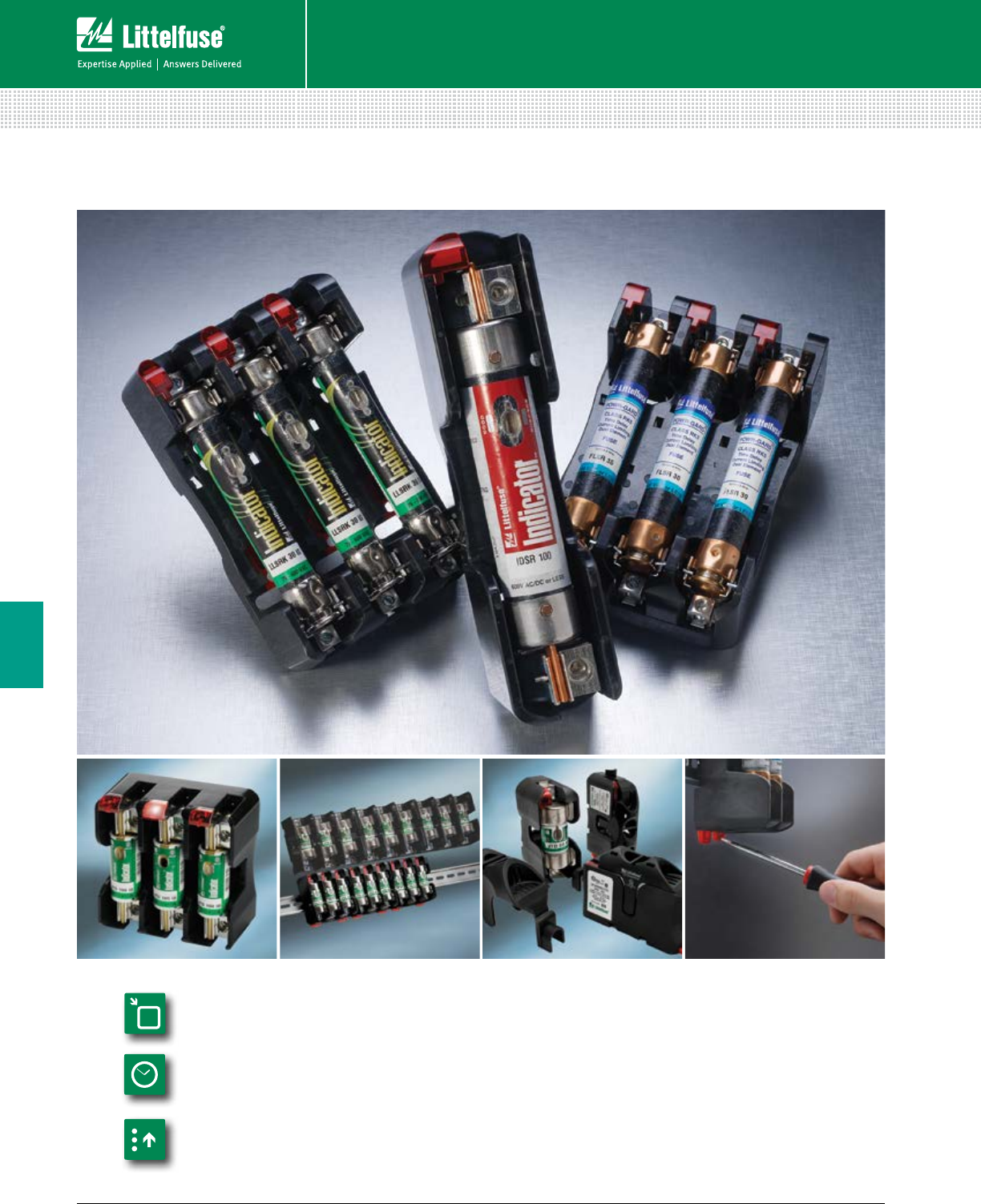
84 © 2014 Littelfuse POWR-GARD® Products Cataloglittelfuse.com
Blocks and Holders
Fuse Blocks and Holders
6
LF SERIES INDICATING FUSE BLOCKS
Smaller Footprint
Provides Space Savings
DIN-Rail Mounting
Eases Installation
Indication Improves
Functionality
An Indication of Value
The Littelfuse LF Series Fuse Blocks and Covers offer
generous space savings and a greater value over previous
generations. View the different series classes for available
indication, snap-to-release DIN rail mounting, universal
mounting holes and touch-safe covers.
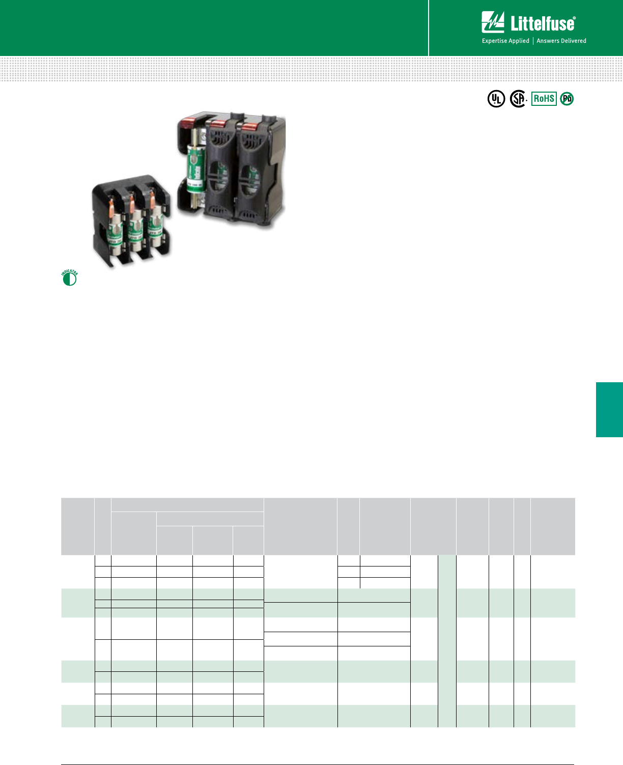
85 littelfuse.com © 2014 Littelfuse POWR-GARD® Products Catalog
Blocks and Holders
Fuse Blocks and Holders
6
LF SERIES CLASS J FUSE BLOCKS
600 V
Specifications
Voltage Ratings 600 V
Ampere Ratings 0 – 600 A
Leakage Current <0.6 mA at 600 V
Flammability Rating UL94 V-0
Approvals UL Listed (File: E14721)
CSA Certified (File: LR7316)
Environmental RoHS Compliant, Lead (Pb) Free
Recommended Fuses
Time Delay
Series: JTD_ID ................................................................... 21
Series: JTD ........................................................................ 21
Fast Acting
Series: JLS ......................................................................... 22
Web Resources
Download CAD drawings, fuse block cover datasheet and
other technical information:
littelfuse.com/lfj
Description
The Littelfuse 600 V Class J blocks offer generous space
savings and enhanced value over previous generations,
such as indication, snap-to-release DIN rail mounting and
universal mounting holes.
Features/Benefits
• Space-saving design – up to 45% smaller
• Universal mounting holes for easy replacement
• Indication offered on all versions except 200–600 A
• One hand release from DIN rail for ferrule style fuses
• Reinforced fuse clips are standard on all Class J blocks
• Covers available for up to 100 A to enhance safety
Ordering Information
(Class J 600 V)
AMP
RATING
POLES
ORDERING NUMBER
TORQUE
TERMINAL
WIRE RANGE WIRE TYPE
BASE
TEMP
RATING
DIN
RAIL
INDICATION
COVER
ORDERING
NUMBER*
BASE
PART
NUMBER
TERMINAL SUFFIX
BOX LUG PRES SURE
PLATE SCREW
30
1 LFJ600301 CID PID SID
2.8 N-m (25 in-lbs)
C 6-14 AWG
CU Only
Solid / Stranded
125˚C • • LFJ60030FBC2 LFJ600302 CID PID SID P 10-14 AWG
3 LFJ600303 CID PID SID S 10-22 AWG
60
1 LFJ600601 CID — — 5.6 N-m (50 in-lbs) 2-4 AWG CU-AL 125˚C • • LFJ60060FBC
2 LFJ600602 CID — — 2.8 N-m (25 in-lbs) 6-14 AWG
3 LFJ600603 CID — —
100
1 LFJ601001 CID — — 13.6 N-m (120 in-lbs) 2/0-6 AWG
CU-AL 130˚C — • LFJ60100FBC4.5 N-m (40 in-lbs) 8 AWG
3 LFJ601003 CID — — 4.0 N-m (35 in-lbs) 10-14 AWG
200 1 LFJ602001 C — — 31.1 N-m (275 in-lbs) 250 kcmil-6 CU-AL 130˚C — — —
3 LFJ602003 C — —
400 1 LFJ604001 C — — 31.1 N-m (275 in-lbs) (2) 350 kcmil-1/0 CU-AL 130˚C — — —
3 LFJ604003 C — —
600 1 LFJ606001 C — — 42.4 N-m (375 in-lbs) (2) 500 kcmil-4 CU-AL 130˚C — — —
3 LFJ606003 C — —
Note: Reinforcing springs standard on all Class J fuse blocks.
*Covers sold individually. One cover needed for each pole.
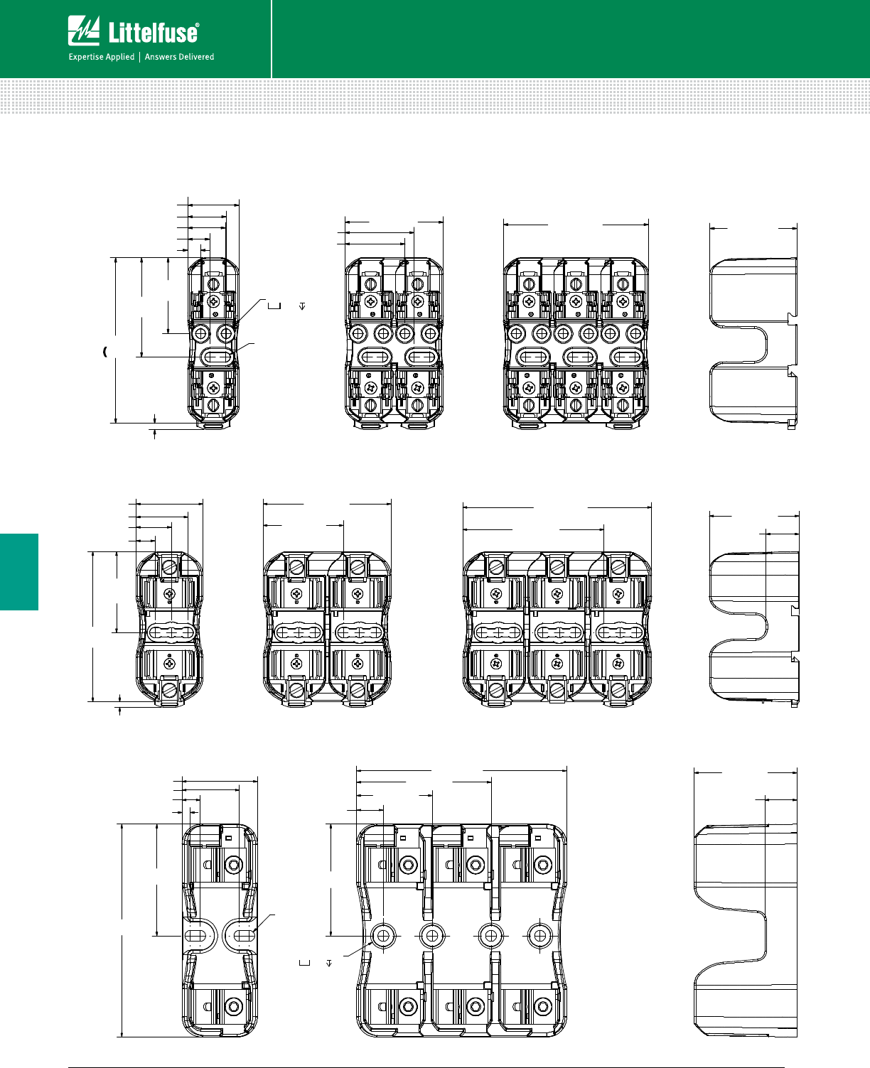
86 © 2014 Littelfuse POWR-GARD® Products Cataloglittelfuse.com
Blocks and Holders
Fuse Blocks and Holders
6
94.1
(3.70)
3.6 (.14)
43.2
(1.70)
56.5
(2.23)
7.4 (.29)
12.5 (.49)
21.4 (.84)
21.8 (.86)
29.2 (1.15)
55.9 (2.20)
34.0 (1.34)
39.2 (1.54)82.5 (3.25)49.5 (1.95)
R2.8 (.11)
TYP.
Ø.2 THRU
Ø.4 .2
600 V 30 A
CLASS J FUSE BLOCK DIMENSIONS
97.2
(3.83)
3.6 (.14)
42.4 (1.67)
12.0 (.47)
22.5 (.89)
32.9 (1.30)
52.5
(2.07)
81.2 (3.20)
50.8 (2.00)
119.9 (4.72)
89.5 (3.52)
56.9 (2.24)
21.1 (.83)
138.2 (5.44)
48.8 (1.92)
5.3 (.21)
11.7 (.46)
37.1 (1.46)
72.5 (2.86)
R3.6 (.14)
TYP.
136.1 (5.36)
17.3 (.68)
49.0 (1.93)
87.1 (3.43)
72.5 (2.86)
Ø.3 THRU
66.5 (2.62)
21.0 (.83)
Ø.5 .6
600 V 60 A
600 V 100 A
Dimensions mm (inches)
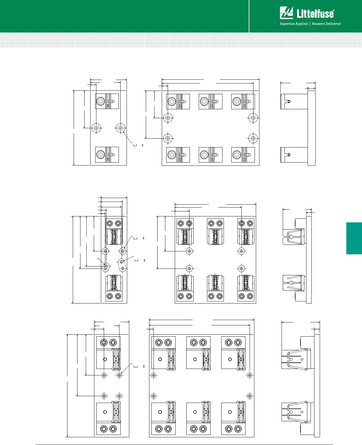
87 littelfuse.com © 2014 Littelfuse POWR-GARD® Products Catalog
Blocks and Holders
Fuse Blocks and Holders
6
CLASS J FUSE BLOCK DIMENSIONS
76.2 (3.00)
254.0
(10.00)
236.7 (9.32)
15.9 (.63)
84.4 (3.32)
12.7 (.50)
16.0 (.63)
60.2 (2.37)
63.5 (2.50)
101.6
(4.00)
146.1
(5.75)
152.4
(6.00)
101.6 (4.00)
152.4 (6.00)
42.2 (1.66)
194.6 (7.66)
R4.3 (.17)
TYP.
Ø.3 THRU
Ø.8 .4
Ø.3 THRU
Ø.8 .4
298.5 (11.75)
101.6 (4.00)
119.0 (4.69)
304.8 (12.00)
15.9 (.63)
110.6 (4.36)
179.5 (7.07)
28.6 (1.13)
73.0 (2.88)
12.7 (.50)
292.1 (11.50)
Ø.3 THRU
Ø.6 .4
600 V 400 A
600 V 600 A
76.2 (3.00)
155.7 (6.13)
203.2 (8.00)
12.7 (.50) 63.5 (2.50)
77.9 (3.07)
56.4 (2.22)
99.3 (3.91)
12.7 (.50)
190.5 (7.50)
15.9 (.63)
72.4 (2.85)
Ø.3 THRU
Ø.8 .4
600 V 200 A
Dimensions mm (inches)
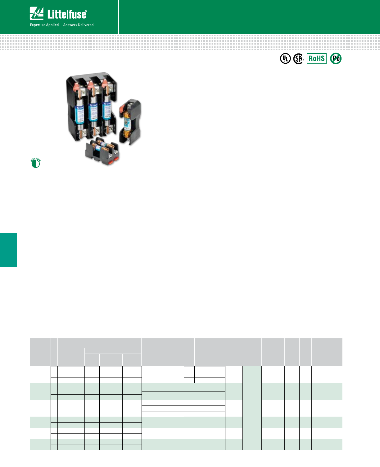
88 © 2014 Littelfuse POWR-GARD® Products Cataloglittelfuse.com
Blocks and Holders
Fuse Blocks and Holders
6
LF SERIES CLASS R & H/K5 FUSE BLOCKS
250 V • 600 V
Description
The Littelfuse Class R and H/K5 blocks offer many benefits
such as indication, snap-to-release DIN rail mounting
and universal mounting holes. Class H and Class R fuse
blocks are dimensionally the same, but Class R blocks
incorporate a rejection feature, which only allows Class R
fuses to be inserted.
Features/Benefits
• Universal mounting holes for easy replacement
• Indication offered on most 250 V and 600 V versions
• One hand release from DIN rail for ferrule style fuses
• Reinforced fuse clips are standard on all Class H and
Class R fuse blocks
• Covers available for 100 A and lower to enhance safety
Web Resources
Download CAD drawings, fuse block cover datasheet and
other technical information: littelfuse.com/lfr
littelfuse.com/lfh
Specifications
Voltage Rating 250 V, 600 V
Ampere Ratings 0-600 A
Leakage Current <0.6 mA at 600 V
Withstand Rating Class H: 10 kA RMS SYM
Class R: 200 kA RMS SYM
Flammability Rating UL94 V-0
Approvals UL Listed (File: E14721)
CSA Certified (File: LR7316)
Environmental RoHS Compliant, Lead (Pb) Free
Recommended Fuses
250 – Class R Blocks
LLNRK ................................................................................ 13
KLNR .................................................................................. 15
FLNR/FLNR_ID ....................................................................17
250 V – Class H / K5 Blocks
NLN .................................................................................... 20
600 V – Class R Blocks
LLSRK/LLSRK_ID ................................................................ 13
KLSR ................................................................................... 15
IDSR ................................................................................... 16
FLSR/FLSR_ID .....................................................................17
600 V – Class H / K5 Blocks
NLS ..................................................................................... 20
Ordering Information (Class H 250 V)
AMP
RATING
POLES
ORDERING NUMBER
TORQUE
TERMINAL
WIRE
RANGE WIRE TYPE
BASE
TEMP
RATING
DIN
RAIL
INDICATION
COVER
ORDERING
NUMBER*
BASE PART
NUMBER
SUFFIX
BOX
LUG
PRES SURE
PLATE SCREW
30
1 LFH250301 C P S
2.8 N-m (25 in-lbs)
C 6-14 AWG
CU Only
Solid/
Stranded
125˚C • — LFH25030FBC2 LFH250302 C P S P 10-14 AWG
3 LFH250303 C P S S 10-22 AWG
60
1 LFH250601 CID — — 5.6 N-m (50 in-lbs) 2-4 AWG CU-AL 125˚C • • LFH25060FBC2 LFH250602 CID — — 2.8 N-m (25 in-lbs) 6-14 AWG
3 LFH250603 CID — —
100 1 LFH251001 CID — — 13.6 N-m (120 in-lbs) 2/0-6 AWG
CU-AL 130˚C — • LFH25100FBC4.5 N-m (40 in-lbs) 8 AWG
3 LFH251003 CID — — 4.0 N-m (35 in-lbs) 10-14 AWG
200 1 LFH252001 C — — 31.1 N-m (275 in-lbs) 250 kcmil-6 CU-AL 130˚C — — —
3 LFH252003 C — —
400 1 LFH254001 C — — 31.1 N-m (275 in-lbs) (2) 350 kcmil-1/0 CU-AL 130˚C — — —
3 LFH254003 C — —
600 1 LFH256001 C — — 42.4 N-m (375 in-lbs) (2) 500 kcmil-4 CU-AL 130˚C — — —
3 LFH256003 C — —
Note: Reinforcing springs standard on all Class H fuse blocks.
*Covers sold individually. One cover needed for each pole.
89 littelfuse.com © 2014 Littelfuse POWR-GARD® Products Catalog
Blocks and Holders
Fuse Blocks and Holders
6
LF SERIES CLASS R & H/K5 FUSE BLOCKS
Note: Reinforcing springs standard on all Class H fuse blocks.
Note: Reinforcing springs standard on all Class R fuse blocks.
Note: Reinforcing springs standard on all Class R fuse blocks.
*Covers sold individually. One cover needed for each pole.
Ordering Information (Class H 600 V)
AMP
RATING
POLES
ORDERING NUMBER
TORQUE
TERMINAL
WIRE
RANGE WIRE TYPE
BASE
TEMP
RATING
SNAP
TO
RELEASE
INDICATION
COVER
ORDERING
NUMBER*
BASE
ORDERING
NUMBER
SUFFIX
BOX
LUG
PRES SURE
PLATE SCREW
30
1LFH600301 CID PID SID
2.8 N-m (25 in-lbs)
C 6-14 AWG
CU Only
Solid/
Stranded
130˚C • • LFH60030FBC2 LFH600302 CID PID SID P 10-14 AWG
3 LFH600303 CID PID SID S 10-22 AWG
60
1 LFH600601 CID — — 5.6 N-m (50 in-lbs) 2-4 AWG CU-AL 130˚C • • LFH60060FBC2 LFH600602 CID — — 2.8 N-m (25 in-lbs) 6-14AWG
3 LFH600603 CID — —
100 1 LFH601001 CID — — 13.6 N-m (120 in-lbs) 2/0-6AWG
CU-AL 130˚C — • LFH60100FBC4.5 N-m (40 in-lbs) 8 AWG
3 LFH601003 CID — — 4.0 N-m (35 in-lbs) 10-14 AWG
200 1 LFH602001 C — — 31.1 N-m (275 in-lbs) 250 kcmil-6 CU-AL 130˚C — — —
3 LFH602003 C — —
400 1 LFH604001 C — — 31.1 N-m (275 in-lbs) (2) 350 kcmil-1/0 CU-AL 130˚C — — —
3 LFH604003 C — —
600 1 LFH606001 C — — 42.4 N-m (375 in-lbs) (2) 500 kcmil-4 CU-AL 130˚C — — —
3 LFH606003 C — —
Ordering Information (Class R 250 V)
AMP
RATING
POLES
ORDERING NUMBER
TORQUE
TERMINAL
WIRE
RANGE WIRE TYPE
BASE
TEMP
RATING
SNAP
TO
RELEASE
INDICATION
COVER
ORDERING
NUMBER*
BASE
ORDERING
NUMBER
SUFFIX
BOX
LUG
PRES SURE
PLATE SCREW
30
1 LFR250301 C P S
2.8 N-m (25 in-lbs)
C 6-14 AWG
CU Only
Solid/
Stranded
125˚C • — LFH25030FBC2 LFR250302 C P S P 10-14 AWG
3 LFR250303 C P S S 10-22 AWG
60
1 LFR250601 CID — — 5.6 N-m (50 in-lbs) 2-4 AWG CU-AL 125˚C • • LFH25060FBC2 LFR250602 CID — — 2.8 N-m (25 in-lbs) 6-14 AWG
3 LFR250603 CID — —
100 1 LFR251001 CID — — 13.6 N-m (120 in-lbs) 2/0-6 AWG
CU-AL 130˚C — • LFH25100FBC4.5 N-m (40 in-lbs) 8 AWG
3 LFR251003 CID — — 4.0 N-m (35 in-lbs) 10-14 AWG
200 1 LFR252001 C — — 31.1 N-m (275 in-lbs) 250 kcmil-6 CU-AL 130˚C — — —
3 LFR252003 C — —
400 1 LFR254001 C — — 31.1 N-m (275 in-lbs) (2) 350 kcmil-1/0 CU-AL 130˚C — — —
3 LFR254003 C — —
600 1 LFR256001 C — — 42.4 N-m (375 in-lbs) (2) 500 kcmil-4 CU-AL 130˚C — — —
3 LFR256003 C — —
Ordering Information (Class R 600 V)
AMP
RATING
POLES
ORDERING NUMBER
TORQUE
TERMINAL
WIRE
RANGE WIRE TYPE
BASE
TEMP
RATING
SNAP
TO
RELEASE
INDICATION
COVER
ORDERING
NUMBER*
BASE
ORDERING
NUMBER
SUFFIX
BOX
LUG
PRES SURE
PLATE SCREW
30
1 LFR600301 CID PID SID
2.8 N-m (25 in-lbs)
C 6-14 AWG
CU Only
Solid/
Stranded
130˚C • • LFH60030FBC2 LFR600302 CID PID SID P 10-14 AWG
3 LFR600303 CID PID SID S 10-22 AWG
60
1 LFR600601 CID — — 5.6 N-m (50 in-lbs) 2-4 AWG CU-AL 130˚C • • LFH60060FBC2 LFR600602 CID — — 2.8 N-m (25 in-lbs) 6-14 AWG
3 LFR600603 CID — —
100 1 LFR601001 CID — — 13.6 N-m (120 in-lbs) 2/0-6 AWG
CU-AL 130˚C — • LFH60100FBC4.5 N-m (40 in-lbs) 8 AWG
3 LFR601003 CID — — 4.0 N-m (35 in-lbs) 10-14 AWG
200 1 LFR602001 C — — 31.1 N-m (275 in-lbs) 250 kcmil-6 CU-AL 130˚C — — —
3 LFR602003 C — —
400 1 LFR604001 C — — 31.1 N-m (275 in-lbs) (2) 350 kcmil-1/0 CU-AL 130˚C — — —
3 LFR604003 C — —
600 1 LFR606001 C — — 42.4 N-m (375 in-lbs) (2) 500 kcmil-4 CU-AL 130˚C — — —
3 LFR606003 C — —
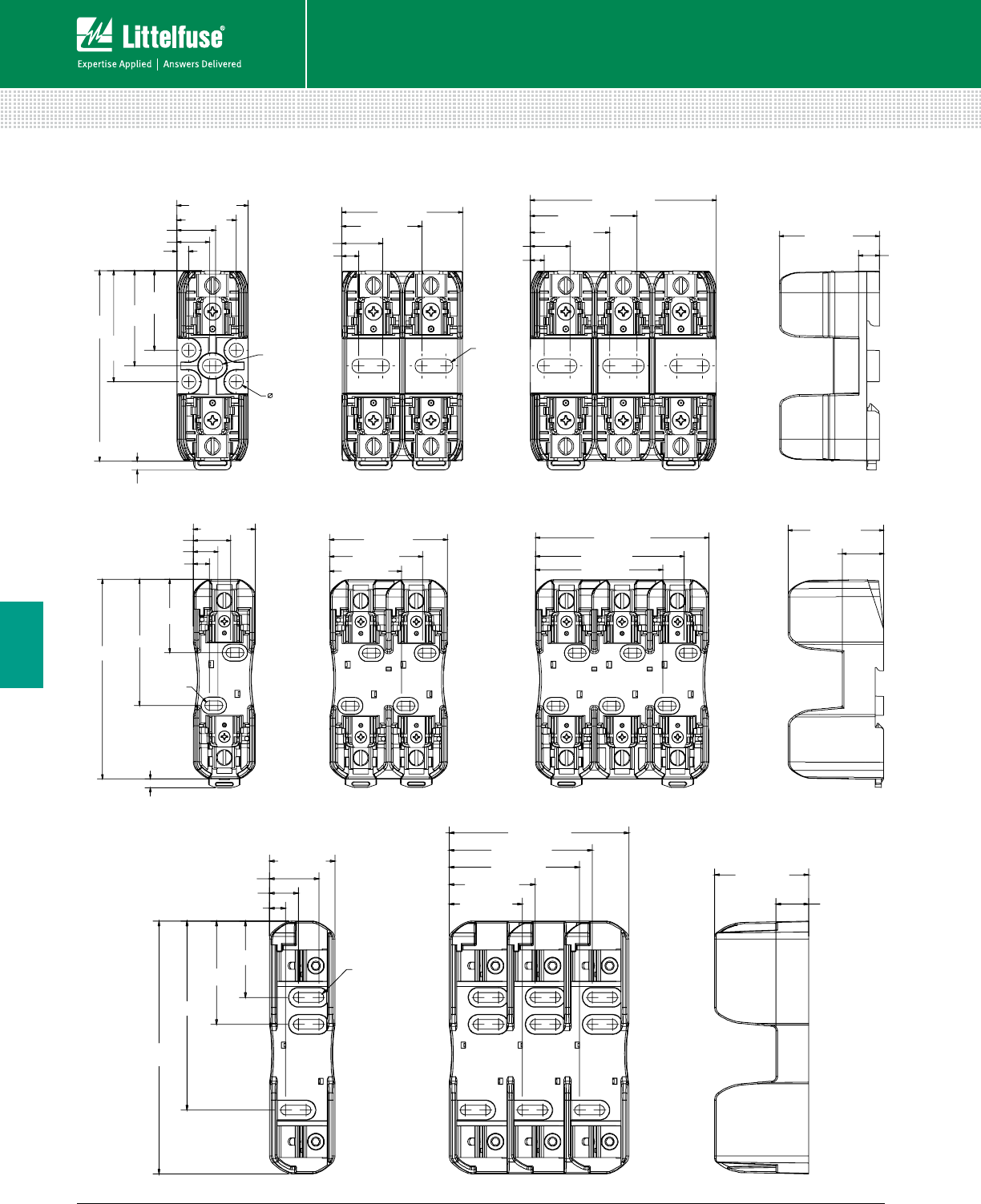
90 © 2014 Littelfuse POWR-GARD® Products Cataloglittelfuse.com
Blocks and Holders
Fuse Blocks and Holders
6
LF SERIES CLASS R & H/K5 FUSE BLOCKS
31.9
[1.26]
28.6 [1.13] 48.5 [1.91]
6.8 [.27]
74.7 [2.94]
40.1 [1.58]
8.4
[.33]
5.6 [.22]
R2.8 [.11]
TYP
.2 THRU
R2.8 [.11]
TYP
76.5
[3.01]
3.6 [.14]
38.2
[1.51]
44.6
[1.76]
4.8 [.19]
13.0 [.51]
15.6 [.61]
23.8 [.94]
16.3 [.64]
32.2 [1.27]
15.9 [.63]
31.8 [1.25]
42.9 [1.69]
119.7 [4.71]
37.3 [1.47]
70.7 [2.78] 104.1 [4.10] 57.4 [2.26]
24.9 [.98]
R2.8 [.11]
TYP
43.9 [1.73]
75.7 [2.98]
9.7 [.38]
14.8 [.58]
22.4 [.88]
55.8 [2.20]
43.1 [1.70]
5.5 [.21]
89.2 [3.51]
76.5 [3.01]
177.8 [7.00]
46.0 [1.81]
126.3 [4.97]
66.0 [2.60]
22.9 [.90]
R3.4 [.13]
TYP
53.6 [2.11]
72.6 [2.86]
133.0 [5.23]
11.3 [.45]
20.3 [.80]
34.7 [1.37] 60.5 [2.38]
100.6 [3.96]
51.5 [2.03]
91.6 [3.61]
250 V 30 A
250 V 60 A
250 V 100 A
Dimensions mm (inches)
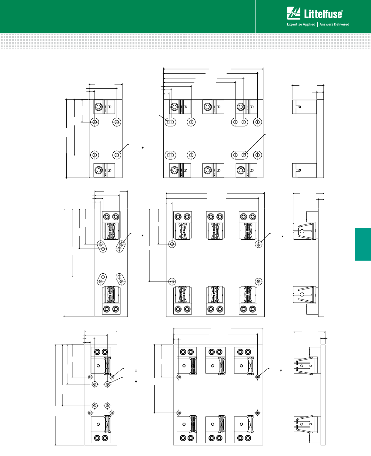
91 littelfuse.com © 2014 Littelfuse POWR-GARD® Products Catalog
Blocks and Holders
Fuse Blocks and Holders
6
LF SERIES CLASS R & H/K5 FUSE BLOCKS
181.1
[7.13]
76.2 [3.00]
228.6 [9.00]
Ø.3 THRU
72.4 [2.85]
15.9 [.63]
R4.3 [.17]
TYP.
63.5 [2.50]
12.7 [.50]
63.5 [2.50]
52.6
[2.07]
128.5
[5.06]
12.7 [.50]
19.1 [.75]
165.1 [6.50]
184.2 [7.25]
215.9 [8.50]
Ø.3 THRU
Ø.8 .4
88.9 [3.50]
292.1
[11.50]
95.3
[3.75]
15.9 [.63]
266.7 [10.50] 84.4 [3.32]
15.9 [.63]
108.0
[4.25]
184.2
[7.25]
22.2 [.88]
66.7 [2.63]
95.3 [3.75]
196.9 [7.75]
15.9 [.63]
250.8 [9.88]
Ø.3 THRU
Ø.8 .4
Ø.3 THRU
Ø.8 .4
355.6
[14.0]
114.3 [4.5]
114.3
[4.5]
317.5 [12.5]
19.1 [.8]
114.3 [4.5]
110.6 [4.4]
15.9 [.6]
139.7
[5.5]
215.9
[8.5]
19.1 [.8]
34.9 [1.4]
79.4 [3.1]
241.3 [9.5]
298.5 [11.8]
Ø.3 THRU
Ø.6 .4
Ø.3 THRU
Ø.8 .4
Ø.3 THRU
Ø.6 .4
250 V 200 A
250 V 400 A
250 V 600 A
Dimensions mm (inches)
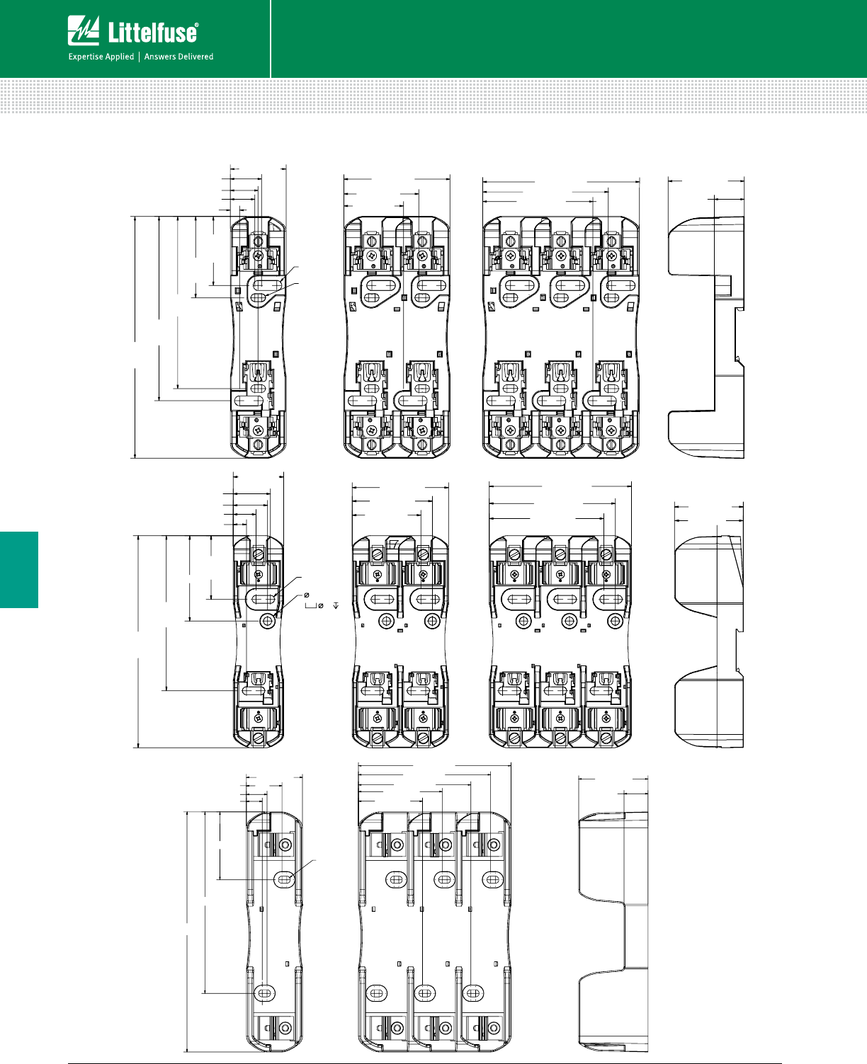
92 © 2014 Littelfuse POWR-GARD® Products Cataloglittelfuse.com
Blocks and Holders
Fuse Blocks and Holders
6
LF SERIES CLASS R & H/K5 FUSE BLOCKS
166.
7
[6.56]
38.4 [1.51]
73.1 [2.88]
R3.4 [.13]
TYP
R2.6 [.10]
TYP
47.6
[1.87]
56.0
[2.20]
118.6
[4.67]
127.1
[5.00]
16.8 [.66]
21.5 [.85]
6.4 [.25]
19.2 [.76] 51.6 [2.03]
41.1 [1.62]
107.9 [4.25]
20.7 [.82]
52.5 [2.07]
75.9 [2.99]
86.4 [3.40]
184.
2
[7.25]
43.8 [1.73]
.5 .5
R3.4 [.13]
TYP
83.6 [3.29] 123.2 [4.85]
59.7 [2.35]
22.9 [.90]
55.2
[2.18]
74.2
[2.92]
134.6
[5.30]
11.4 [.45]
19.9 [.78]
29.8 [1.17]
32.4 [1.28]
59.6 [2.35]
69.5 [2.74]
99.4 [3.91]
109.3 [4.30]
.2 THRU
228.6 [9.00]
R3.4 [.13]
TYP
53.4 [2.10]
145.3 [5.72]
66.0 [2.60]
22.9 [.90]
64.6 [2.54]
15.0 [.59]
19.6 [.77]
33.8 [1.33]
172.8 [6.80]
61.0 [2.40]
79.8 [3.14]
107.0 [4.21]
125.7 [4.95]
600 V 30 A
600 V 60 A
600 V 100 A
Dimensions mm (inches)
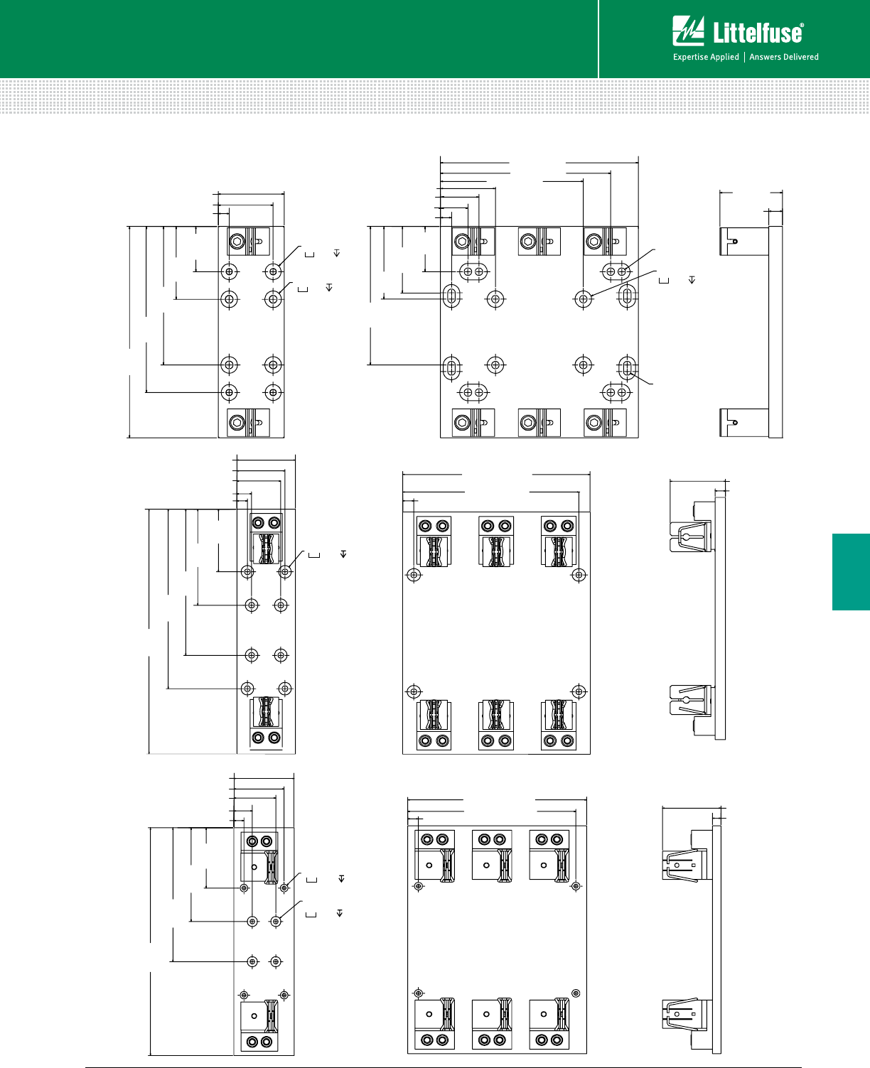
93 littelfuse.com © 2014 Littelfuse POWR-GARD® Products Catalog
Blocks and Holders
Fuse Blocks and Holders
6
LF SERIES CLASS R & H/K5 FUSE BLOCKS
244.3
[9.62]
76.2 [3.00]
12.7 [.50]
52.3
[2.06]
84.2
[3.32]
228.6 [9.00]
12.7 [.50]
31.8 [1.25]
Ø.3 THRU
Ø.3 THRU
Ø.3 THRU
Ø.3 THRU
Ø.8 .4
R4.3 [.17]
TYP.
52.3
[2.06]
72.4
[2.85]
15.9
[.63]
160.1
[6.31]
192.0
[7.56]
63.5 [2.50] 44.5 [1.75]
63.5 [2.50] 165.1 [6.50]
76.7
[3.02]
84.1
[3.31]
160.3
[6.31]
196.9 [7.75]
Ø.7 .4
Ø.8 .4
88.9 [3.50]
368.3
[14.50]
15.9 [.63]
22.2 [.88]
95.3
[3.75]
146.1
[5.75]
266.7 [10.50]
15.9 [.63]
84.4 [3.32]
15.9 [.63]
222.3
[8.75]
273.1
[10.75]
66.7 [2.63]
73.0 [2.88]
250.8 [9.88]
Ø.8 .4
Ø.3 THRU
114.3 [4.50]
431.8
[1
7.00]
19.1 [.75]
114.3
[4.50]
177.8
[7.00]
317.5 [12.50]
110.6 [4.3
6]
15.9 [.63]
254.0
[10.00]
34.9 [1.38]
79.4 [3.13]
95.3 [3.75]
19.1 [.75]298.5 [11.75]
Ø.8 .4
Ø.3 THRU
Ø.6 .4
Ø.3 THRU
600 V 200 A
600 V 400 A
600 V 600 A
Dimensions mm (inches)
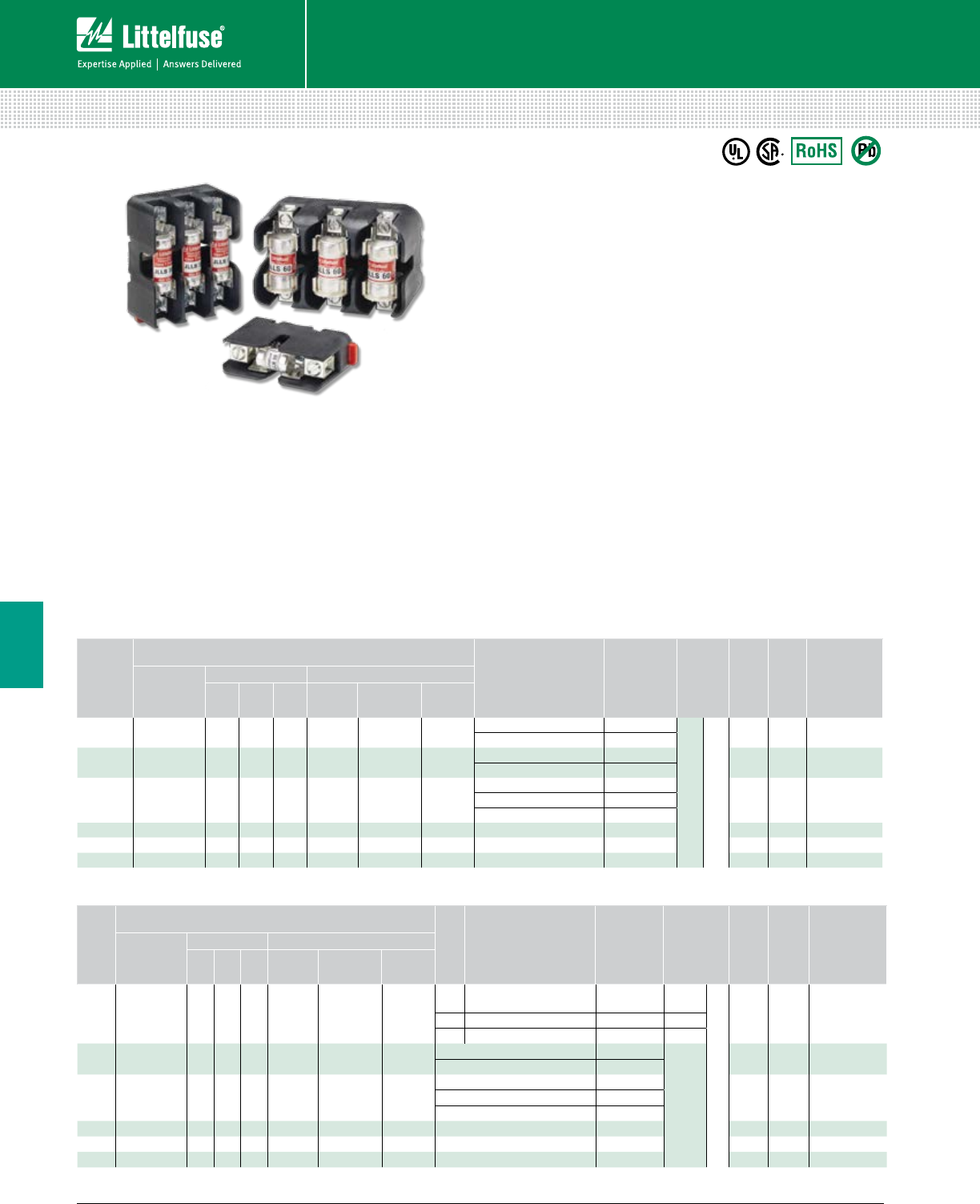
94 © 2014 Littelfuse POWR-GARD® Products Cataloglittelfuse.com
Blocks and Holders
Fuse Blocks and Holders
6
LF SERIES CLASS T FUSE BLOCKS
300 V • 600 V
Specifications
Voltage Ratings 300 Vac/600 Vac
Ampere Ratings 0 – 600 A
Leakage Current <0.6 mA at 600 V
Withstand Rating 200 kA RMS SYM
Flammability Rating UL94 V-0
Approvals UL Listed (File: E14721)
CSA Certified (File: LR7316)
Environmental RoHS Compliant, Lead (Pb) Free
Recommended Fuses
300 V JLLN ........................................................................ 24
600 V JLLS ......................................................................... 24
Web Resources
Download CAD drawings, fuse block cover datasheet and
other technical information: littelfuse.com/lft
Description
The Littelfuse Class T fuse blocks offer many advantages
such as space saving design, universal mounting holes,
snap-to-release DIN rail mounts and available covers.
Features/Benefits
• Space-saving design
• Universal mounting holes for easy replacement
• One hand release from DIN rail for 30–60 A fuses
• Reinforced fuse clips are standard
• Covers available for most amperages to enhance safety
* Covers sold individually. One cover needed for each pole.
Ordering Information
(Class T 600 V)
AMP
RATING
ORDERING NUMBER
TERMINAL
TORQUE WIRE
RANGE
WIRE
TYPE
BASE TEMP
RATING
DIN RAIL
MOUNT
COVER
ORDERING
NUMBER*
BASE
ORDERING
NUMBER
POLES TERMINAL SUFFIX
123 BOX
LUG
PRES SURE
PLATE SCREW
30 LFT60030 1 2 3 C P S
C2.5 N-m (25 in-lbs)
5.6 N-m (50 in-lbs) 6-14 AWG
2-4 AWG CU-AL
Solid / Stranded
125˚C •LFT60030FBC
P2.8 N-m (25 in-lbs) 10-14 AWG CU Only
S2.8 N-m (25 in-lbs) 10-22 AWG CU Only
60 LFT60060 1 2 3 C — — 5.6 N-m (50 in-lbs) 2-4 AWG
CU-AL
125˚C •LFT60060FBC
2.8 N-m (25 in-lbs) 6-14 AWG
100 LFT60100 1—3 CS — —
13.6 N-m (120 in-lbs) 2/0-6 AWG
130˚C —LT60100FBC4.5 N-m (40 in-lbs) 8 AWG
4.0 N-m (35 in-lbs) 10-14 AWG
200 LFT60200 1—3 CS — — 31.1 N-m (275 in-lbs) 250 kcmil-6 130˚C —LT60200FBC
400 LFT60400 1—3 CS — — (2) 31.1 N-m (275 in-lbs) 250 kcmil-6 130˚C —LT60400FBC
600 LFT60600 1—3 CS — — (2) 42.4 N-m (375 in-lbs) 500 kcmil-6 130˚C —LT60600FBC
Ordering Information
(Class T 300 V)
AMP
RATING
ORDERING NUMBER
TORQUE WIRE
RANGE
WIRE
TYPE
BASE TEMP
RATING
DIN RAIL
MOUNT
COVER
ORDERING
NUMBER*
BASE
ORDERING
NUMBER
POLES TERMINAL SUFFIX
123BOX
LUG
PRES SURE
PLATE SCREW
30 LFT30030 1 2 3 C — — 5.6 N-m (50 in-lbs) 2-4 AWG
CU-AL
Solid / Stranded
125˚C • LFT30030FBC
2.8 N-m (25 in-lbs) 6-14 AWG
60 LFT30060 1 2 3 C — — 5.6 N-m (50 in-lbs) 2-4 AWG 125˚C • LFT30060FBC
2.8 N-m (25 in-lbs) 6-14 AWG
100 LFT30100 1 — 3 CS — —
13.6 N-m (120 in-lbs) 2/0-6 AWG
130˚C —LFT30100FBC4.5 N-m (40 in-lbs) 8 AWG
4.0 N-m (35 in-lbs) 10-14 AWG
200 LFT30200 1 — 3 CS — — 31.1 N-m (275 in-lbs) 250 kcmil-6 130˚C ——
400 LFT30400 1 — 3 CS — — (2) 31.1 N-m (275 in-lbs) 250 kcmil-6 130˚C ——
600 LFT30600 1 — 3 CS — — (2) 42.4 N-m (375 in-lbs) 500 kcmil-6 130˚C ——
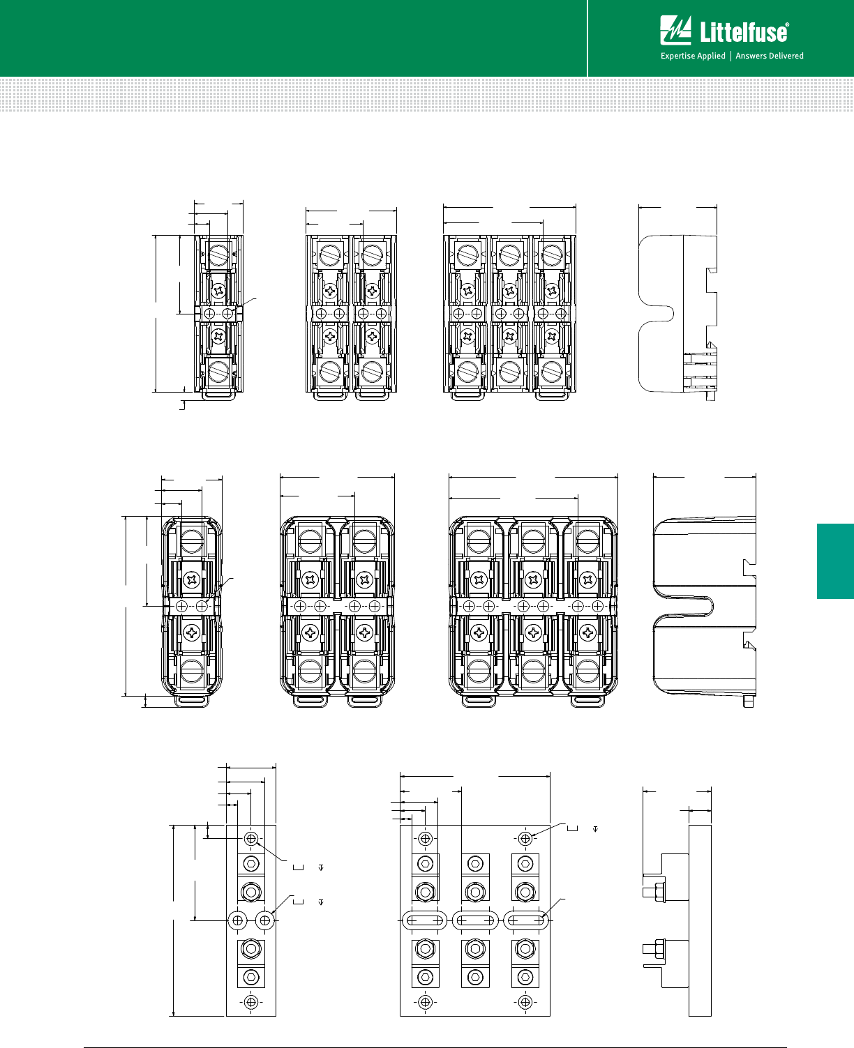
95 littelfuse.com © 2014 Littelfuse POWR-GARD® Products Catalog
Blocks and Holders
Fuse Blocks and Holders
6
LF SERIES CLASS T FUSE BLOCKS
Dimensions mm (inches)
21.8 [.86]
71.1
[2.80]
3.7 [.15]
TYP.
35.6
[1.40]
6.9 [.27]
40.9 [1.61]
15.0 [.59]
25.9 [1.02] 44.9 [1.77]
59.9 [2.36] 35.6 [1.40]
Ø4.5 [.18]
300 V 30 A
73.7
[2.90]
4.5 [.18]
24.6 [.97]
36.8
[1.45]
8.2 [.32]
16.4 [.65]
46.9 [1.85]
30.5 [1.20]
69.1 [2.72]
52.7 [2.07]
41.9 [1.65]
Ø4.5 [.18]
TYP.
34.8 [1.37]
133.4
[5.25]
7.9 [.31]
17.4 [.69]
66.7
[2.63]
104.6 [4.12]
R3.2 [.13]
TYP.
17.4 [.69] 15.9 [.63]
47.6 [1.88]
7.9 [.31]
9.5 [.38]
26.9 [1.06]
26.0 [1.03]
42.8 [1.69]
Ø.2 THRU
Ø.4 .5
Ø.2 THRU
Ø.4 .5
Ø.2 THRU
Ø.5 .4
300 V 60 A
300 V 100 A
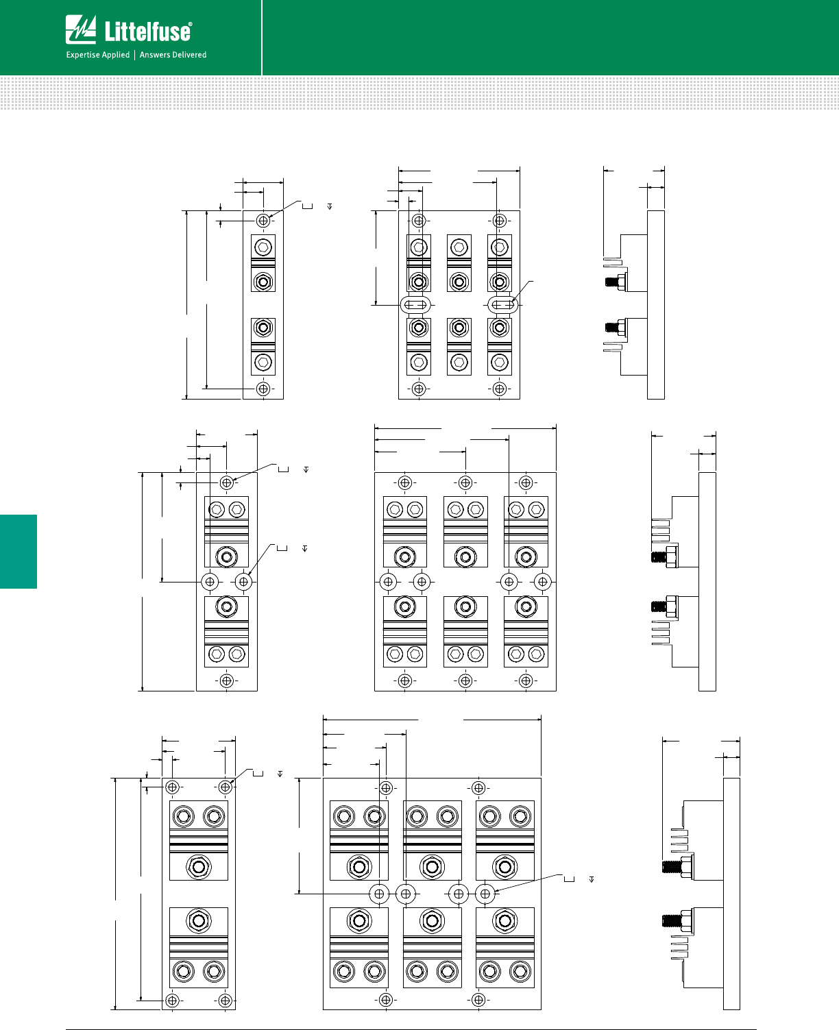
96 © 2014 Littelfuse POWR-GARD® Products Cataloglittelfuse.com
Blocks and Holders
Fuse Blocks and Holders
6
222.3
[8.75]
69.9 [2.75]
8.8 [.35]
9.5 [.38]
209.6 [8.25]
60.3 [2.38]
15.9 [.63]
74.4 [2.93]
213.5
[8.41]
60.3 [2.38]
54.0 [2.13]
79.4 [3.13]
111.1
[4.38]
Ø.3 THRU
Ø.8 .5
Ø.3 THRU
Ø.5 .5
38.1 [1.50]
177.8
[7.00]
19.1 [.75]
9.5 [.38]
114.3 [4.50]
R3.6 [.14]
TYP.
15.9 [.63]
57.2 [2.25]
168.3
[6.63]
88.9
[3.50]
9.5 [.38]
22.2 [.88]
92.1 [3.63]
Ø.3 THRU
Ø.5 .5
206.2
[8.12]
57.2 [2.25]
9.5 [.38]
28.6 [1.13]
171.5 [6.75]
15.9 [.63]
60.6 [2.38]
12.7 [.50]
103.1
[4.06]
85.7 [3.38]
127.0 [5.00]
Ø.3 THRU
Ø.5 .5
Ø.3 THRU
Ø.6 .5
LF SERIES CLASS T FUSE BLOCKS
Dimensions mm (inches)
300 V 200 A
300 V 400 A
300 V 600 A
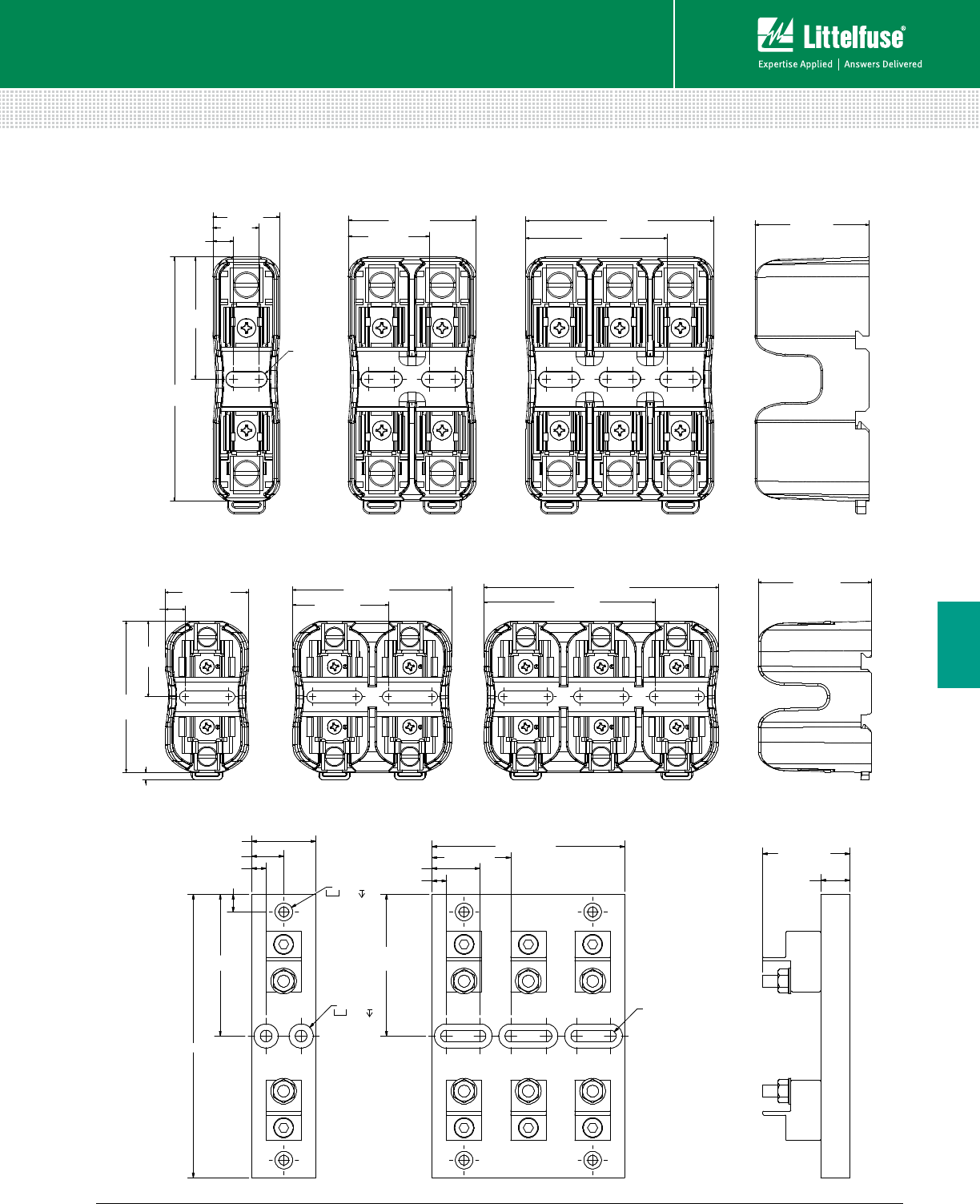
97 littelfuse.com © 2014 Littelfuse POWR-GARD® Products Catalog
Blocks and Holders
Fuse Blocks and Holders
6
LF SERIES CLASS T FUSE BLOCKS
Dimensions mm (inches)
39.9 [1.57]
72.3
[2.85]
3.7 [.15]
9.5 [.38]
36.2
[1.42]
76.1 [3.00]
45.7 [1.80]
112.3 [4.42]
81.9 [3.23]
54.0 [2.13]
89.7
[3.53]
7.6 [.30]
24.6 [.97]
17.0 [.67]
R2.9 [.11]
TYP.
46.9 [1.85]
29.8 [1.17]
44.8
[1.77]
69.1 [2.72] 41.9 [1.65]
52.0 [2.05]
34.8 [1.37]
153.9 [6.06]
9.5 [.38]
17.5 [.69]
77.0 [3.03]
104.6 [4.12]
7.9 [.31] 15.9 [.63]
47.6 [1.88]
7.9 [.31] 26.0 [1.03]
42.8 [1.69]
77.0
[3.03]
R3.2 [.13]
TYP.
Ø.3 THRU
Ø.5 .4
Ø.2 THRU
Ø.4 .5
600 V 30 A
600 V 60 A
600 V 100 A
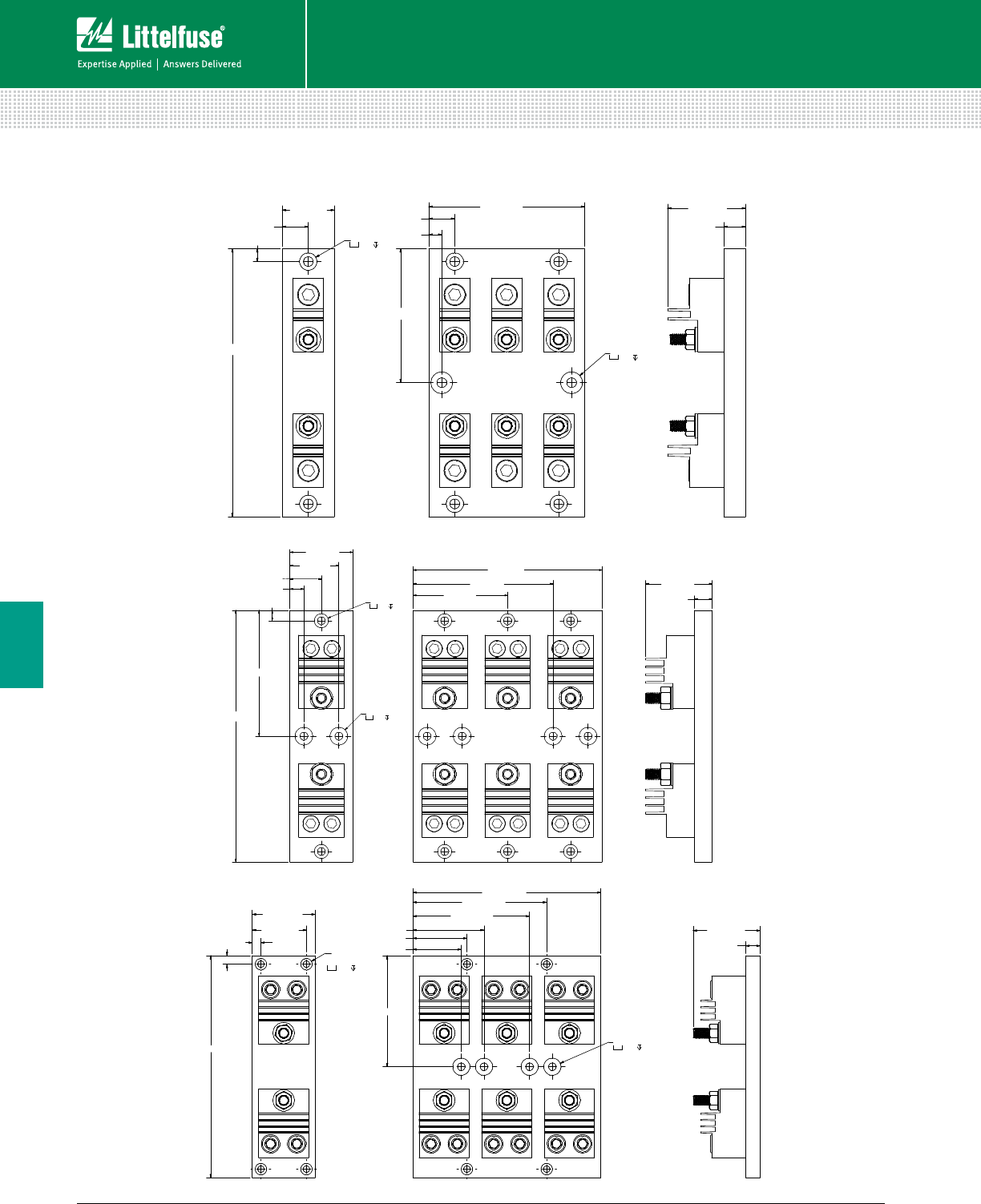
98 © 2014 Littelfuse POWR-GARD® Products Cataloglittelfuse.com
Blocks and Holders
Fuse Blocks and Holders
6
LF SERIES CLASS T FUSE BLOCKS
Dimensions mm (inches)
38.1 [1.50]
196.9 [7.75]
9.5 [.38]
19.1 [.75]
114.3 [4.50]
9.5 [.38]
98.4 [3.88]
15.9 [.63]
57.2 [2.25]
19.1 [.75]
Ø.3 THRU
Ø.6 .5
Ø.3 THRU
Ø.5 .5
57.2 [2.25]
228.6 [9.00]
9.5 [.38]
28.6 [1.13]
12.7 [.50]
114.3 [4.50]
171.5 [6.75]
15.9 [.63]
60.3 [2.38]
85.7 [3.38]
127.0 [5.00]
44.5 [1.75]
Ø.3 THRU
Ø.5 .5
Ø.3 THRU
Ø.6 .5
69.9 [2.75]
247.7 [9.75]
9.5 [.38] 9.5 [.38]
209.6 [8.25]
60.3 [2.38]
123.8 [4.88]
15.9 [.63]
74.4 [2.93]
54.0 [2.13]
79.4 [3.13]
130.2 [5.13]
60.3 [2.38]
149.2 [5.88]
Ø.3 THRU
Ø.8 .5
Ø.3 THRU
Ø.5 .5
600 V 200 A
600 V 400 A
600 V 600 A
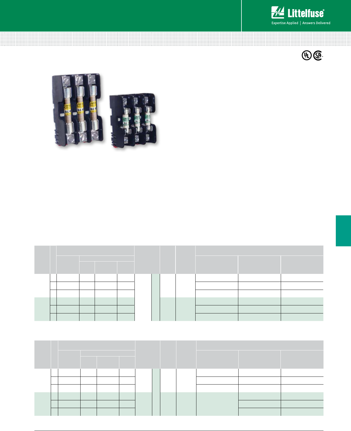
99 littelfuse.com © 2014 Littelfuse POWR-GARD® Products Catalog
Blocks and Holders
Fuse Blocks and Holders
6
LF SERIES CLASS G FUSE BLOCKS
480 V • 600 V
Ordering Information (Class G 600 V)
AMP
RATING
POLES
ORDERING NUMBER
WIRE
TYPE
BASE
TEMP
RATING
DIN RAIL
MOUNT
TERMINAL INFORMATION
BASE
PART
NUMBER
SUFFIX
TERMINAL WIRE RANGE TORQUE
BOX
LUG
PRES SURE
PLATE SCREW
15
1 LFG600151 CDINR PQDINR SQDINR
CU Only
Solid / Stranded
•
Box Lug 6-14 AWG 4.0 N-m (35 in-lbs)
2 LFG600152 CDINR PQDINR SQDINR 150˚ C Pressure Plate 10-14 AWG 2.3 N-m (20 in-lbs)
3 LFG600153 CDINR PQDINR SQDINR Screw 10-14 AWG 2.3 N-m (20 in-lbs)
20
1 LFG600201 CDINR PQDINR SQDINR
•
Box Lug 6-14 AWG 4.0 N-m (35 in-lbs)
2 LFG600202 CDINR PQDINR SQDINR 150˚ C Pressure Plate 10-14 AWG 2.3 N-m (20 in-lbs)
3 LFG600203 CDINR PQDINR SQDINR Screw 10-14 AWG 2.3 N-m (20 in-lbs)
Ordering Information
(Class G 480 V)
AMP
RATING
POLES
ORDERING NUMBER
WIRE
TYPE
BASE
TEMP
RATING
DIN RAIL
MOUNT
TERMINAL INFORMATION
BASE
PART
NUMBER
SUFFIX
TERMINAL WIRE RANGE TORQUE
BOX
LUG
PRES SURE
PLATE SCREW
30
1 LFG480301 CDINR PQDINR SQDINR
CU Only
Solid / Stranded
•
Box Lug 6-14 AWG 4.0 N-m (35 in-lbs)
2 LFG480302 CDINR PQDINR SQDINR 150˚ C Pressure Plate 10-14 AWG 2.3 N-m (20 in-lbs)
3 LFG480303 CDINR PQDINR SQDINR Screw 10-14 AWG 2.3 N-m (20 in-lbs)
60
1 LFG480601 CDINR — —
CU/Al • Box Lug
2-4 AWG 5.6 N-m (50 in-lbs)
2 LFG480602 CDINR — — 125˚ C 6-14 AWG 2.8 N-m (25 in-lbs)
3 LFG480603 CDINR — — 6-14 AWG 2.8 N-m (25 in-lbs)
Description
All Littelfuse Class G fuse blocks offer snap-to-release
DIN rail mounting and universal mounting holes. Class
G fuse blocks are designed for use with time-delay
current limiting Class G fuses.
Features/Benefits
• Universal mounting holes for easy replacement
• One hand release from DIN rail for most amperages
• Meet requirements for branch circuit protection
Specifications
Voltage Ratings 600 Vac (0–20 A)
480 Vac (25–60 A)
Ampere Ratings 0–60 A
Flammability Rating UL94 V-0
Approvals UL Listed (File: E14721)
CSA Certified (File: LR7091)
Recommended Fuses
Time Delay
Series: SLC ........................................................................ 26
Web Resources
Download CAD drawings and other technical information:
littelfuse.com/lfg
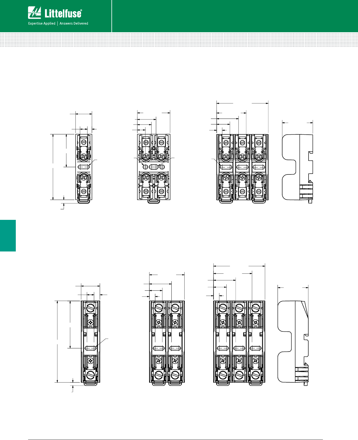
100 © 2014 Littelfuse POWR-GARD® Products Cataloglittelfuse.com
Blocks and Holders
Fuse Blocks and Holders
6
LF SERIES CLASS G FUSE BLOCKS
76.2 (3.00)
38.1 (1.50)
19.1 (0.75)
5.3 (0.21)8.5 (0.34)
4.1 (0.16)
R2.2 (0.09)
TYP.
9.3 (0.37)
16.4 (0.65)
21.7 (0.85)
38.1 (1.50)
R2.7 (0.11)
TYP.
R2.6 (0.10)
TYP.
6.5 (0.26)
15.4 (0.61)
25.5 (1.01)
34.4 (1.36)
59.9 (2.36)
35.6 (1.40)
R2.3 (0.09)
TYP.
21.8 (0.86)
95.3 (3.75)
55.1 (2.17)
6.8 (0.27)
8.3 (0.33)
R2.3 (0.09)
TYP.
3.7 (0.15)
6.8 (0.27)
15.1 (0.59)
25.8 (1.02)
40.9 (1.61)
6.8 (0.27)
15.1 (0.59)
25.8 (1.02)
44.9 (1.77)
59.9 (2.36)
35.6 (1.40)
600 V 15 & 20 A
480 V 30 A
480 V 60 A
Dimensions mm (inches)
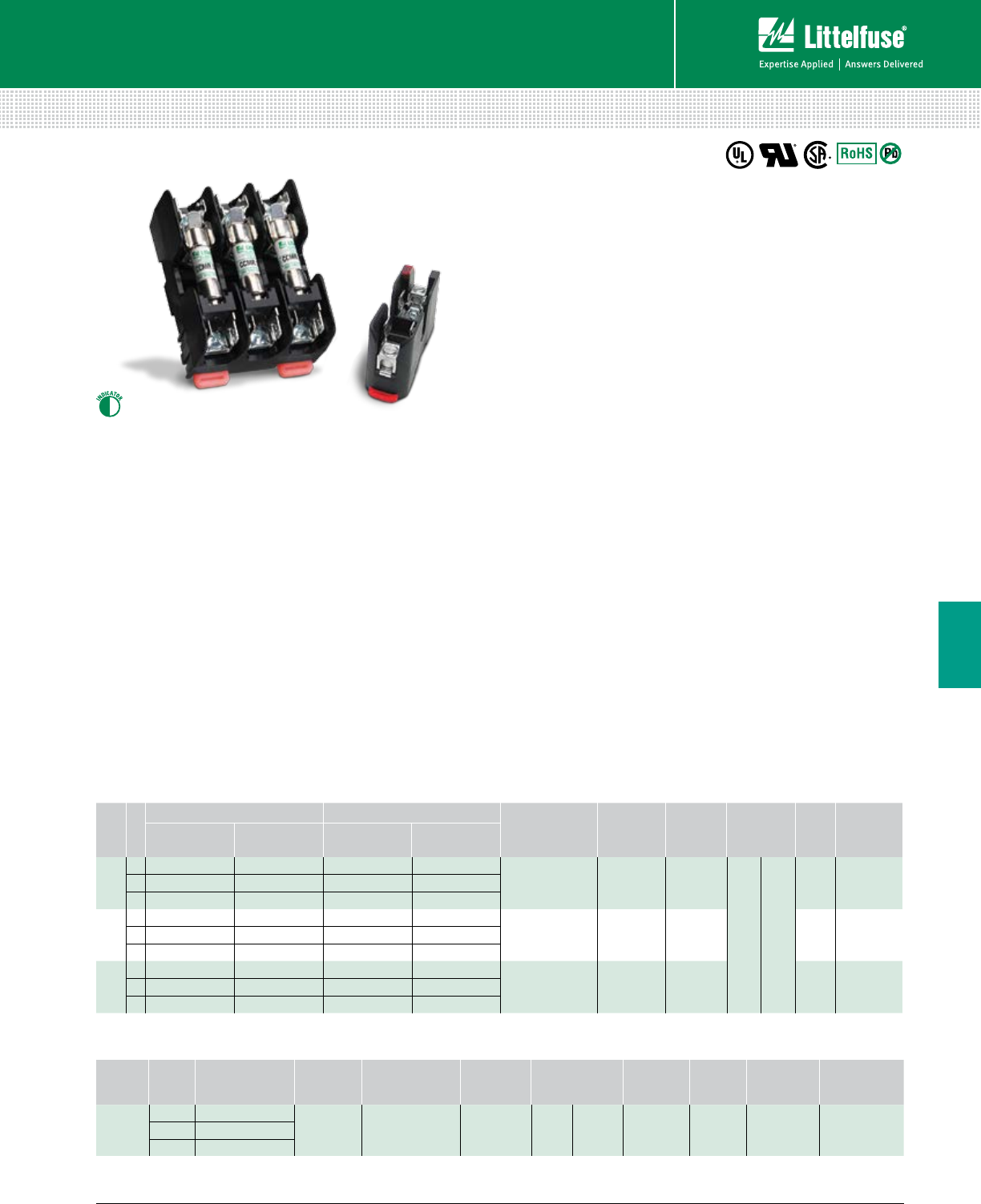
101 littelfuse.com © 2014 Littelfuse POWR-GARD® Products Catalog
Blocks and Holders
Fuse Blocks and Holders
6
LF SERIES CLASS CC/CD AND MIDGET (10X38 mm) FUSE BLOCKS
600 V
Description
The Littelfuse Class CC, CD and midget blocks offer
generous space savings and enhanced value. DIN rail
mounting and universal mounting holes are available as
well as an indication feature on all Class CD fuse blocks.
Features/Benefits
• Space-saving design
• Universal mounting holes for easy replacement
• Indication offered on CD blocks
• One hand release from DIN rail optional
• Rejection feature that prevents the insertion of fuses
with lower interrupting rating or voltage ratings
• Clip design reduces resistance and heat
• Non DIN Rail fuse blocks have interlocking feature
allowing ganging for any number of poles
• Covers available for all amperages to enhance safety
Specifications
Voltage Rating 600 Vac/dc
Ampere Ratings L600M Midget (10x38): 30 A
L600C Class CC: 30 A
LFC Class CD: 60 A
Dielectric strength 1200 V minimum
Material Base: Thermoplastic
Clip/Terminals: Copper alloy (tin plated)
Box Lug: Copper
Screw & Pressure Plate: Steel (zinc plated)
Flammability Rating UL94 V-0
Approvals L600M: UL Recognized (File: E14721)
CSA Certified (File: LR7316)
L600C: UL Listed (File: E14721)
CSA Certified (File: LR7316)
LFC: UL Listed (File: E14721)
CSA Certified (File: LR7316)
Environmental RoHS Compliant, Lead (Pb) Free
Recommended Fuses
Class CC & CD
CCMR ................................................................................ 27
KLDR, KLKR ....................................................................... 28
Midget Series ................................................................... 30
Web Resources
Download CAD drawings, fuse block cover datasheet and
other technical information: littelfuse.com/fuseblocks
Ordering Information (L600C Class CC and L600M Midget 30 A)
AMP
RATING
POLES
CLASS CC ORDERING NUMBER MIDGET ORDERING NUMBER CONNECTOR
TYPE TORQUE WIRE
RANGE WIRE TYPE BASE
TEMP
COVER
ORDERING
NUMBER†
NON-DIN* DIN-RAIL NON-DIN* DIN-RAIL
30
1
L60030C1C L60030C1CDINR L60030M1C L60030M1CDINR
Box Lug
4.0 N-m
(35 in-lbs) 6-14 AWG
CU Only
Solid / Stranded
125˚C
SPL0012L60030C2C L60030C2CDINR L60030M2C L60030M2CDINR
3L60030C3C L60030C3CDINR L60030M3C L60030M3CDINR
30
1L60030C1PQ L60030C1PQDINR L60030M1PQ L60030M1PQDINR Pres sure Plate
w/Q.C. Terminal
2.3 N-m
(20 in-lbs) 10-14 AWG 125˚C
SPL0012L60030C2PQ L60030C2PQDINR L60030M2PQ L60030M2PQDINR
3L60030C3PQ L60030C3PQDINR L60030M3PQ L60030M3PQDINR
30
1L60030C1SQ L60030C1SQDINR L60030M1SQ L60030M1SQDINR Screw
w/Q.C. Terminal
2.3 N-m
(20 in-lbs) 10-14 AWG 125˚C
SPL0012L60030C2SQ L60030C2SQDINR L60030M2SQ L60030M2SQDINR
3L60030C3SQ L60030C3SQDINR L60030M3SQ L60030M3SQDINR
Ordering Information (LFC Class CD 60 A)
AMP
RATING POLES ORDERING
NUMBER
CONNECTOR
TYPE TORQUE WIRE
RANGE WIRE TYPE BASE TEMP
RATING
DIN RAIL
MOUNT INDICATION
COVER
ORDERING
NUMBER†
60
1LFC600601CID
Box Lug 5.6 N-m (50 in-lbs)
2.8 N-m (25 in-lbs)
2-4 AWG
6-14 AWG CU-AL Solid /
Stranded 125˚C • •
LFC60060FBC
2LFC600602CID
3LFC600603CID
* Gangable
† Covers sold individually. One cover needed for each pole.
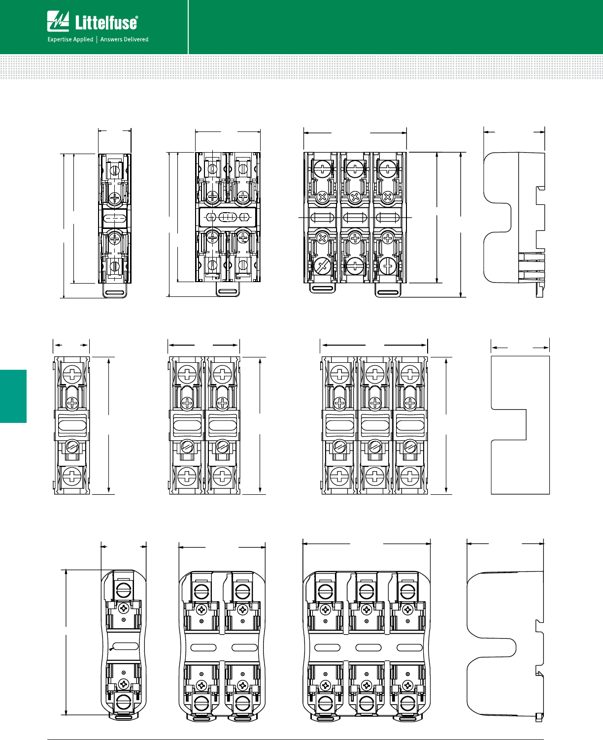
102 © 2014 Littelfuse POWR-GARD® Products Cataloglittelfuse.com
Blocks and Holders
Fuse Blocks and Holders
6
Dimensions mm (inches)
LF SERIES CLASS CC/CD AND MIDGET (10X38 mm) FUSE BLOCKS
35.56
[1.400]
84.97
[3.345]
76.20
[3.000]
19.05
[0.750]
35.56
[1.400]
84.97
[3.345]
76.20
[3.000]
38.10
[1.500]
59.94 [2.360]
76.20 [3.000]
35.56 [1.400]
84.56 [3.329]
(2) PLACES
UNLATCHED
1.89"
[48.0]
3.35"
[85.09]
3.35"
[85.09]
3.35"
[85.09]
1.01"
[25.65]
1 POLE 2 POLE 3 POLE ADDER
0.783"
[19.89]
3.0"
[76.2]
1.533"
[38.15]
2.283"
[57.15]
1.25"
[31.75]
1 POLE 2 POLE 3 POLE
3.12"
[79.25]
1.01"
[25.65]
1.01"
[25.65]
2.12"
[53.85]
3.0"
[76.2]
3.0"
[76.2]
3.35"
[85.09]
29.2 [1.15]
94.1 [3.70]
55.9 [2.20] 82.6 [3.25] 49.5 [1.95]
CLASS CC / MIDGET DIN RAIL 600 V 30 A
CLASS CC / MIDGET NON-DIN RAIL 600 V 30 A
CLASS CD DIN RAIL 600 V 60 A
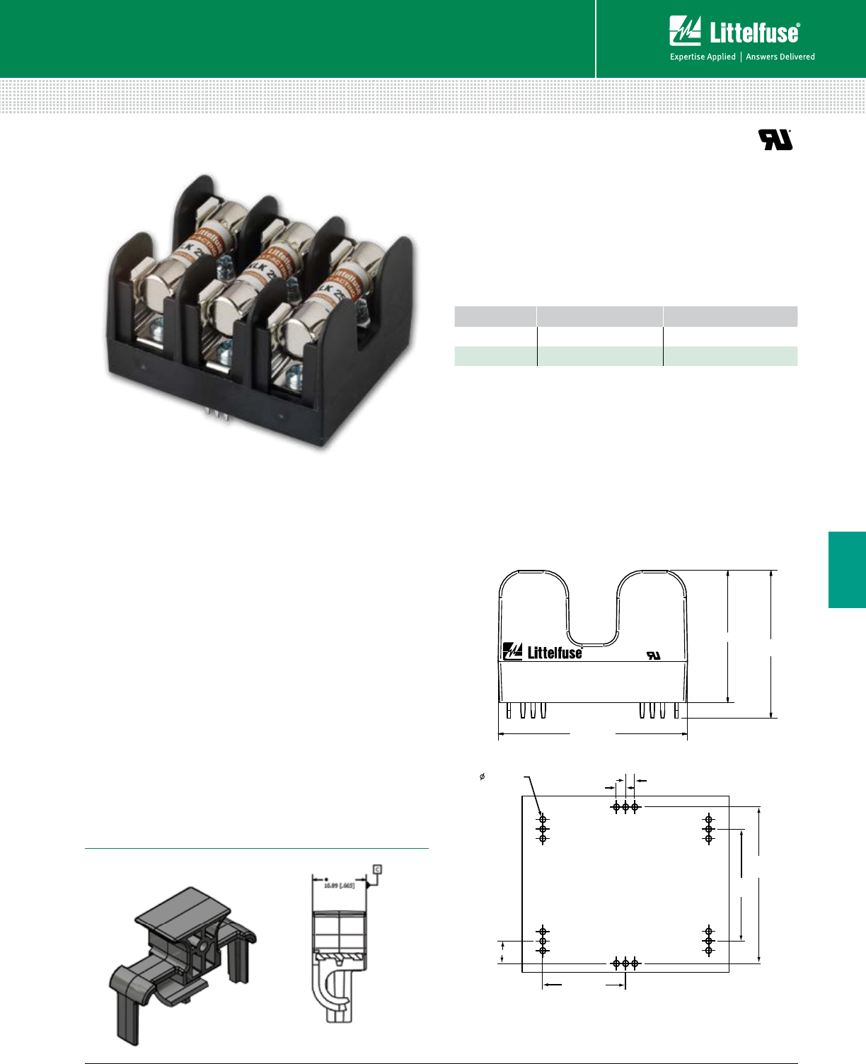
103 littelfuse.com © 2014 Littelfuse POWR-GARD® Products Catalog
Blocks and Holders
Fuse Blocks and Holders
6
BOARD MOUNT MIDGET (10X38 mm) FUSE HOLDER
600 V
1.47 (.058)
(18 PLACES) 2.54 (.100) 2.54 (.100)
41.61
(1.638)
29.57
(1.164)
22.86 (.900)
6.02 (.237)
SPL001PCB Cover
29.57 [1.164]
1.47 [.058]
(1 8 PLACES) 2.54 [.100]
41.61 [1.638]
22.86 [.900]
6.02 [.237]
2.54 [.100]
46.99 (1.850)
3
600 V 30 A
100,000 A RMS SYM.
L60030M3PCB
3.15 (1.305) 36.97
(1.455)
Description
The PC board-mounted midget fuse holder is a one-piece
holder designed to provide a more robust and secure
solution. It offers a smaller footprint and flexible
mounting options.
For use with Midget-style fuses and fuse covers, it is
UL Recognized and can be covered for additional protection.
Features/Benefits
• Through hole PCB mounting
• Robust and secure block design
• All-in-one package offers easy installation
• Space saving footprint
• Touch Safe cover/puller available
• 3-pole configurations
Applications
• HVAC market
• Industrial manufacturing
• Mass production facilities
Specifications
Voltage Rating 600 Vac/dc
Amperage Rating 30 A
Approval UL Recognized (File: E14721)
Mounting Method Through hole solder/PCB
Ordering Information
Recommended Fuses
Midget (10 x 38 mm) series .............................................. 30
Web Resources
Download CAD drawings and other technical information:
littelfuse.com/fuseblocks
Dimensions mm (inches)
Dimensions mm (inches)
CATALOG NUMBER ORDERING NUMBER
Block L60030M3PCB L60030M3PCB
Cover* SPL001PCB SPL0001PCBT
* Covers are single pole—need to order a quantity of 3 for each block.
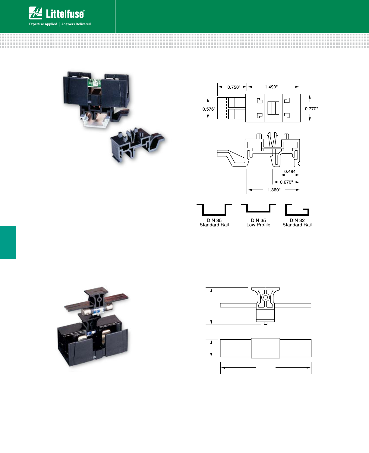
104 © 2014 Littelfuse POWR-GARD® Products Cataloglittelfuse.com
Blocks and Holders
Fuse Blocks and Holders
6
CLASS CC AND MIDGET FUSE BLOCK ACCESSORIES
FBDIN1 Rail Adapter
1.22"
0.665"
3.0"
SPL001 Cover Puller
Features/Benefits
• 600 V 1⁄10-30 A Class CC and Midget fuse cover puller
that offers increased protection when removing fuses
• Simple removal without the need for a separate puller
• Meets Dead Front requirements
• Easily gangable with 1⁄8" diameter wire
• For use with all 600 V Class CC and Midget 1⁄10-30 A fuses
• Label provided for easy fuse identification
Features/Benefits
• DIN Rail adaptor for 30 A Midget, Class CC and
Class G fuse blocks
• Patented design with no tools necessary for installation
• Permits snap-mounting of 30 A Midget, Class CC and
Class G fuse blocks to standard and low profile 35 mm
symmetrical DIN rails and 32 mm asymmetrical DIN rails
• Easy removal via disconnect tab
Web Resources
For additional technical information visit:
littelfuse.com/fbdin1
Dimensions Inches
Recommended Fuse Blocks
L60030C .......................................................................... 101
L60030M ......................................................................... 101
Web Resources
For additional technical information visit:
littelfuse.com/spl001
Dimensions Inches
Recommended Fuse Blocks
Midget-Style and Class CC .............................................. 101
Class G ............................................................................. 99
New DIN rail mountable fuse holders available on page 101
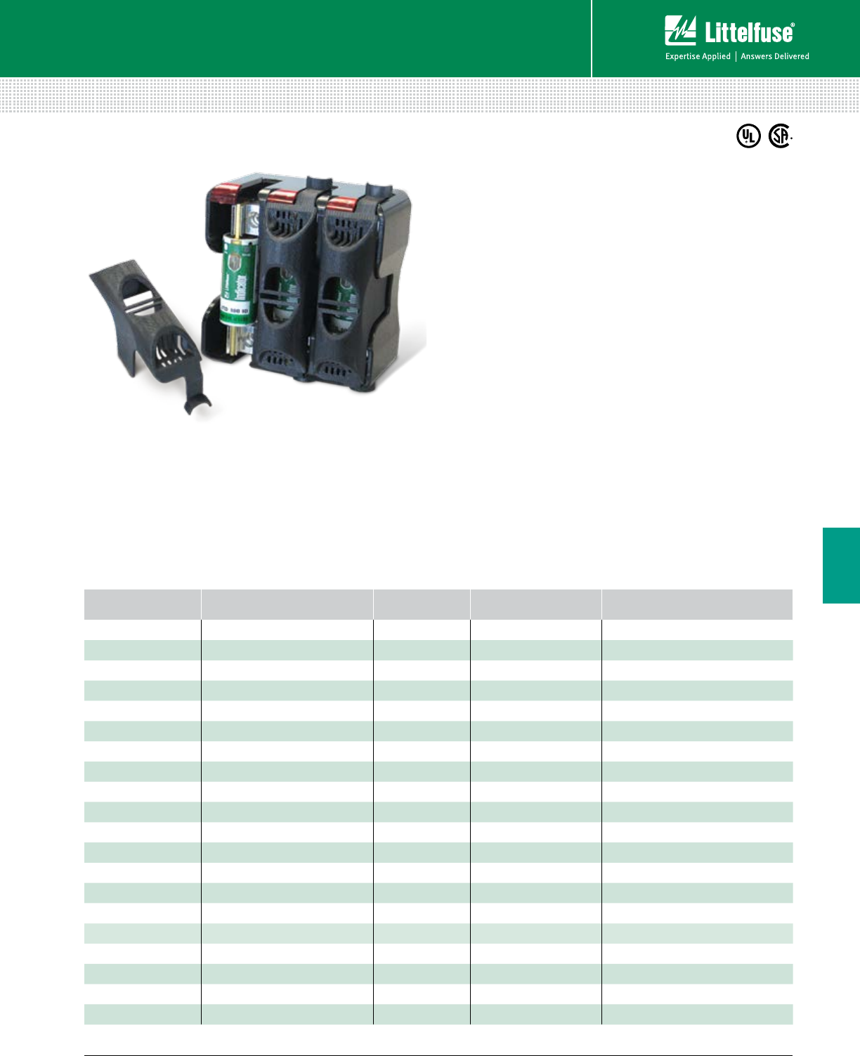
105 littelfuse.com © 2014 Littelfuse POWR-GARD® Products Catalog
Blocks and Holders
Fuse Blocks and Holders
6
LF SERIES FUSE BLOCK COVERS
Description
Littelfuse fuse block covers protect personnel from
accidentally coming into contact with energized
parts. Covers are for use with Littelfuse LF Series UL
class fuse blocks.
Contact the Littelfuse Tech-Line (800-TEC-FUSE) for block
and cover compatibility questions.
Ordering Information
Specifications
Connection Snap to fuse body
Material Black thermoplastic
Flammability Rating UL94 V-0
Approvals UL Listed (File: E184929)
CSA Certified
(File: 007316_0_000 Class 6225-01)
Features/Benefits
• Added safety to personnel
• Ventilation helps avoid fuse derating
• Reusable and convenient snap-on design
• UL listed and CSA certified
• Available for Class H/R, Class J, Class T and Class CD
• Allows visibility of LF series fuse block indicator
Web Resources
For dimensions, cad drawings and additional technical
information visit: littelfuse.com/fuseblocks
UL CLASS FUSE BLOCK BASE
PART NUMBER* VOLTAGE AMPERAGE COVER ORDERING NUMBER
Class H/R LFH25030 / LFR25030 250 30 LFH25030FBC
Class H/R LFH25060 / LFR25030 250 60 LFH25060FBC
Class H/R LFH25100 / LFR25100 250 100 LFH25100FBC
Class H/R LFH60030 / LFR60030 600 30 LFH60030FBC
Class H/R LFH60060 / LFR60060 600 60 LFH60060FBC
Class H/R LFH60100 / LFR60100 600 100 LFH60100FBC
Class J LFJ60030 600 30 LFJ60030FBC
Class J LFJ60060 600 60 LFJ60060FBC
Class J LFJ60100 600 100 LFJ60100FBC†
Class T LFT30030 300 30 LFT30030FBC
Class T LFT30060 300 60 LFT30060FBC
Class T LFT30100 300 100 LFT30100FBC
Class T LFT60030 600 30 LFT60030FBC
Class T LFT60060 600 60 LFT60060FBC
Class T LFT60100 600 100 LT60100FBC
Class T LFT60200 600 200 LT60200FBC
Class T LFT60400 600 400 LT60400FBC
Class T LFT60600 600 600 LT60600FBC
Class CD LFC60060 600 60 LFC60060FBC
Class CC L60030C 600 30 SPL001
* Part number shown excludes reference to number of poles and terminal type
† Cover is not compatible with 70-100 A JLS series fuses
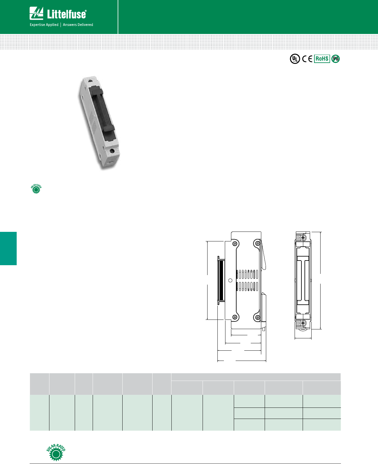
106 © 2014 Littelfuse POWR-GARD® Products Cataloglittelfuse.com
Blocks and Holders
Fuse Blocks and Holders
6
LPXV TOUCH-SAFE FUSE HOLDERS
1500 Vdc • 30 A
Specifications
Voltage Ratings 1500 Vdc
Amperage Rating 30 A
SCCR Rating 15 kA
Fuse Type 10x85mm
Material Thermoplastic
Flammability Rating UL94 V-0
Temperature Stability Body: 125˚ C
Carrier: 140˚ C
Approvals UL 4248-18 Listed (File: E345481)
IEC 60269-1 & IEC 60269-2
Environmental RoHS compliant, Lead (Pb) free
Dimensions Inches (mm)
Ordering Information
Description
The Littelfuse LPXV fuse holder is designed to hold
1500 Vdc 10x85mm fuses.
Features/Benefits
• Finger-Safe design offers personnel protection
• No fuse pullers or tools required for fuse removal
• 35 mm DIN Rail Mountable
• Compact design
Recommended Fuses
Littelfuse SPXV 1500 Vdc Fuses ....................................... 57
Web Resources
For additional technical informations, visit:
littelfuse.com/lpxv
SERIES VOLTAGE
(Vdc) POLES CATALOG
NUMBER
ORDERING
NUMBER
PACK
QTY
TERMINAL INFORMATION
TERMINAL
TYPE WIRE TYPE NUMBER
OF WIRES WIRE SIZE TORQUE
LPXV 1500 1 LPXV001 LPXV0001Z 5 Box Lug
90˚ Max
CU Only
Stranded
16-4 AWG
(16-25 mm2)
22-26 lb-in
(2.5-3 N-m)
118-8 AWG
(.75-10 mm2)
18-22 lb-in
(2-2.5 N-m)
2* 18-6 AWG
(.75-16 mm2)
18-22 lb-in
(2-2.5 N-m)
*Must be the same cross-sectioned size
5.1
(130.0)
.88
(22.3)
2.54
(64.5)
4.11
(104.5)
2.28
(58.0)
1.89
(48.0)
1.57
(40.0)
Look for this logo to indicate products that are used in solar applications. Visit our website
littelfuse.com/solar for the latest updates on approvals, certifications, and new products.
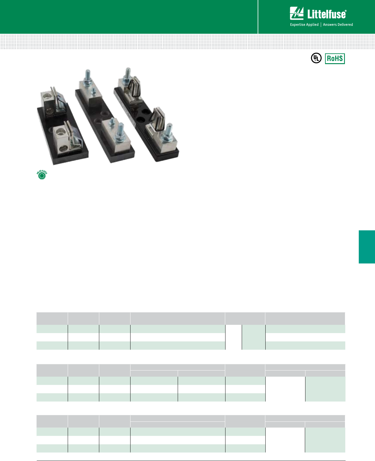
107 littelfuse.com © 2014 Littelfuse POWR-GARD® Products Catalog
Blocks and Holders
Fuse Blocks and Holders
6
Specifications
Voltage Ratings 1000 Vdc
Ampere Ratings 200, 400, 450 A
Flammability Rating UL94 V-0
Termination Type Box Lug or Stud Mount
Base Temp Rating 130˚ C
Approvals UL 4248-18 Listed
File: E345481 Vol. 1
Environmental RoHS Compliant
Recommended Fuses
SPFJ Solar Series .............................................................. 61
Web Resources
Download CAD drawings, dimensions and other technical
information: littelfuse.com/LFJ1000
Clip-to-Box Stud-to-Stud Clip-to-Stud
Description
The LFJ1000 series fuse block is specifically designed
for the Littelfuse SPFJ 1000 V Solar Fuse. It meets UL
electrical requirements, is available in multiple amperages,
and comes in a variety of fuse mounting and termination
configurations; fuse clip to box lug, fuse stud to wire stud
and fuse clip to wire stud.
Features/Benefits
• Narrow width increases space savings
• Range of amperages to match all SPFJ fuse options
• Box Lug termination style accommodates a wide
range of cable sizes
• Stud-mounted option increases convenience
• Approval for use with copper or aluminum lugs
allowing for design flexibility
Ordering Information
(Clip-to-Box Lug 1000 V)
AMPERAGE ORDERING
NUMBER
INTERRUPT
RATING
WIRE RANGE
STANDARD (METRIC) WIRE TYPE RECOMMENDED
TORQUE
200 LFJ102001C 20 kA 250 kcmil - #6 (127mm2 - 16mm2)
Cu/Al Solid/
Stranded
275 in-lb (31.1 N-m)
400 LFJ104001C 10 kA 350 kcmil - 1/0 (177mm2 - 55mm2) 275 in-lb (31.1 N-m)
450 LFJ104501C 20 kA 500 kcmil - #4 (253mm2 - 25mm2) 375 in-lb (42.4 N-m)
LFJ1000 SERIES SOLAR FUSE BLOCKS
1000 Vdc • Clip-to-Box • Stud-to-Stud • Clip-to-Stud
(Stud-to-Stud 1000 V)
AMPERAGE ORDERING
NUMBER
INTERRUPT
RATING
RECOMMENDED TORQUE MAX. BUSBAR
THICKNESS
RECOMMENDED BASE TORQUE
FUSE TERMINAL BOLT SIZE TORQUE
200 LFJ102001STST 20 kA 65 in-lb (7.3 N-m) 200 in-lb (22.6 N-m) .774” (19.66 mm)
1/4”
5/16”
30-40 in-lb
40-50 in-lb
400 LFJ104001STST 10 kA 170 in-lb (19.2 N-m) 200 in-lb (22.6 N-m) .555” (14.10 mm)
450 LFJ104501STST 20 kA 300 in-lb (33.9 N-m) 300 in-lb (33.9 N-m) .570” (14.18 mm)
(Clip-to-Stud 1000 V)
AMPERAGE ORDERING
NUMBER
INTERRUPT
RATING
RECOMMENDED TORQUE MAX. BUSBAR
THICKNESS
RECOMMENDED BASE TORQUE
TERMINAL BOLT SIZE TORQUE
200 LFJ102001CST 20 kA 200 in-lb (22.6 N-m) .774” (19.66 mm)
1/4”
5/16”
30-40 in-lb
40-50 in-lb
400 LFJ104001CST 10 kA 200 in-lb (22.6 N-m) .555” (14.10 mm)
450 LFJ104501CST 20 kA 300 in-lb (33.9 N-m) .570” (14.18 mm)
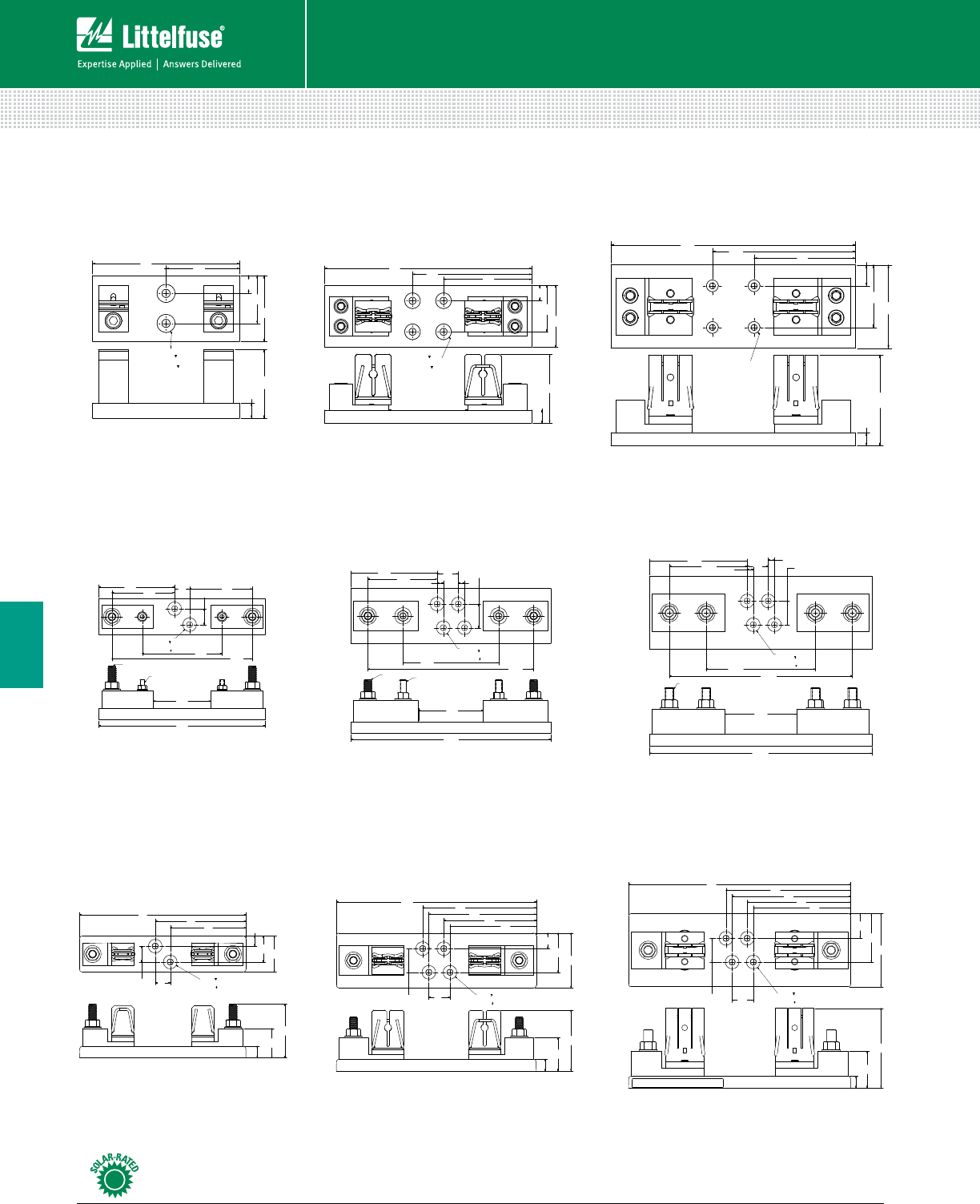
108 © 2014 Littelfuse POWR-GARD® Products Cataloglittelfuse.com
Blocks and Holders
Fuse Blocks and Holders
6
LF SERIES SOLAR FUSE BLOCKS
1000 Vdc
Look for this logo to indicate products that are used in solar applications. Visit our website
littelfuse.com/solar for the latest updates on approvals, certifications, and new products.
Clip-to-Box
200 A
200 A
200 A
400 A
400 A
400 A
450 A
450 A
450 A
Stud-to-Stud
Clip-to-Stud
84.4
(3.32)
76.2
(3.00)
57.2
(2.25)
19.1
(0.75)
108.0
(4.25)
146.1
(5.75)
254.0
(10.0)
15.9
(0.63)
[ ]
ø8.6 THRU
⊔
ø19.1 11.2
ø0.34 THRU
⊔
ø0.75 0.44
15.88
(0.63)
110.58
(4.35)
101.60
(4.00)
76.20
(3.00)
25.40
(1.00)
123.83
(4.88)
174.63
(6.88)
298.45
(11.75)
[ ]
ø7.1 THRU
⊔
ø14.2 x 11.2
ø0.28 THRU
⊔
ø0.56 x 0.44
72.4
(2.85)
69.9
(2.75)
50.8
(2.00)
19.1
(0.75)
77.9
(3.07)
155.7
(6.13)
15.9
(0.63)
[ ]
ø8.64 THRU
⊔
ø19.1 10.2
ø0.34 THRU
⊔
ø0.75 0.40
Dimensions mm (inches)
20.88
(.822)
105.41
(4.150) 87.33
(3.438)
87.33
(3.438)
111.13
(4.375) 195.53
(7.698)
79.76
(3.140)
34.14
(1.344)
74.93
(2.950)
50.00
(1.969)
231.70
(9.122)
22.10
(.870)
∅8.64 THRU
⊔
∅19.05 10.16
∅0.34 THRU
⊔
∅0.75 0.40
[ ]
7/16-14 UNC-2A
1/4-20 UNC-2A
16.13
(.635)
40.79
(1.606)
135.80
(5.347) 108.41
(4.268)
152.40
(6.000)
1/2-13 UNC-2A
254.91
(10.036)
99.61
(3.922)
309.70
(12.193)
30.17
(1.188)
51.11
(2.012)
101.160
(4.000)
81.28
(3.200)
16.13
(.635)
8.61
(.339)
29.49
(1.161)
8.61
(.339) 33.02
(1.300)
∅8.64 THRU
⊔
∅19.05 10.16
∅0.34 THRU
⊔
∅0.75 0.40
[ ]
33.02
(1.30)
29.49
(1.161)
TYP
120.17
(4.731)
133.35
(5.250) 230.94
(9.092)
90.08
(3.547)
278.43
(10.962)
76.20
(3.000)
96.42
(3.796) 8.61
(.339)
8.61
(.339)
∅8.64 THRU
⊔
∅19.05 10.16
∅0.34 THRU
⊔
∅0.75 0.40
[ ]
7/16-14 UNC-2A 3/8-16 UNC-2A
28.57
(1.125)
46.36
(1.825)
74.93
(2.950)
16.13
(.635)
[ ]
ø8.6 THRU
⊔
ø19.1 10.2
ø.34 THRU
⊔
ø.75 0.40
110.8
(4.36)
101.6
(4.00)
135.8
(5.35)
34.3
(1.35)
309.7
(12.19) 173.9
(6.85) 165.3
(6.51) 144.4
(5.69)
67.3
(2.65)
29.5
(1.16)
33.0
(1.30)
51.1
(2.01)
16.1
(.64)
84.6
(3.33)
76.2
(3.00)
29.5
(1.16)
33.0
(1.30)
21.6
(.85)
120.2
(4.73)
128.8
(5.07)
149.7
(5.89)
158.3
(6.23)
278.4
(10.96)
54.6
(2.15)
46.4
(1.83)
16.1
(.64)
[ ]
ø8.6 THRU
⊔
ø19.1 10.2
ø.34 THRU
⊔
ø.75 0.40
[ ]
ø8.6 THRU
⊔
ø19.1 10.2
ø.34 THRU
⊔
ø.75 0.40
16.1
(.64)
74.9
(2.95)
14.0
(.55)
105.4
(4.15)
126.3
(4.97)
231.7
(9.12)
36.0
(1.42) 50.0
(1.97)
22.1
(.87)
20.9
(.82)
40.8
(1.61)
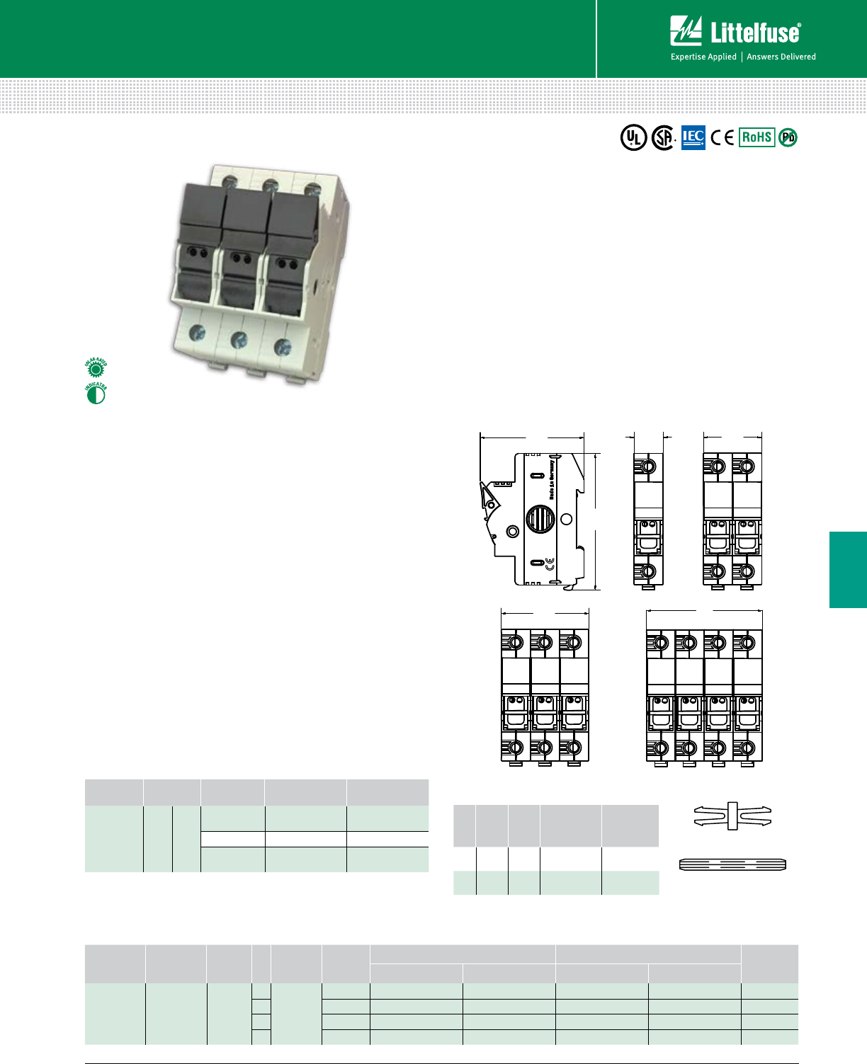
109 littelfuse.com © 2014 Littelfuse POWR-GARD® Products Catalog
Blocks and Holders
Fuse Blocks and Holders
6
LFPHV DEAD FRONT 10x38mm (MIDGET) FUSE HOLDERS
1000 Vdc
Specifications
Voltage Ratings 1000 Vdc
Ampere Rating 30 A
SCCR Rating 33 kA
Power Acceptance 4W Maximum
Indication Voltage Range 400-1000 Vdc
Terminal Type Pressure Plate
Material Thermoplastic
Flammability Rating UL94 V-0, self-extinguishing
Approval UL Listed (File: E345481)
CSA Certified
IEC 60269
Environmental RoHS compliant, Lead (Pb) free
Dimensions mm (inches)
Description
The Littelfuse LFPHV fuse holder is designed to house
1000 Vdc 10x38mm (midget style) fuses. It is not designed
for load break but is ideal for isolating photovoltaic module
strings for maintenance and meets UL requirements for
1000 Vdc solar fuse protection.
Features/Benefits
• Finger-Safe design offers personnel protection
• Compact design
• 35 mm DIN Rail Mountable
• No fuse pullers or tools required for fuse removal
• Indication option available
• Approved for field wiring
Web Resources
Download technical documents: littelfuse.com/lfphv
Recommended Fuses
SPF Solar Series ...............................................................60
FLU Series (DC only) ........................................................31
Ordering Information (LFPHV 10x38mm)
VOLTAGE AMPERE SCCR
Rating
POLES
FUSE TYPE SERIES
NON-INDICATING
INDICATING PACK
QUANTITY
CATALOG NUM. ORDERING NUM. CATALOG NUM. ORDERING NUM.
1000 Vdc 30 A 33 kA
1
10x38mm
(midget)
LFPHV LFPHV001 LFPHV0001Z LFPHV001ID LFPHV0001ZXID 12
2 LFPHV LFPHV002 LFPHV0002Z LFPHV002ID LFPHV0002ZXID 6
3 LFPHV LFPHV003 LFPHV0003Z LFPHV003ID LFPHV0003ZXID 4
4 LFPHV LFPHV004 LFPHV0004Z LFPHV004ID LFPHV0004ZXID 3
Terminal Information
TERMINAL
TYPE
WIRE
TYPE
NUMBER
OF WIRES WIRE SIZE TORQUE
Pressure
Plate
90˚ Max
CU Only
Stranded*
1
18-8 AWG
(.75 -.25 mm
2
)
18-22 lb-in
(2-2.5 N-m)
1
6-4 AWG 22-26 lb-in
2†
18-6 AWG
(.75 -10 mm
2
)
18-22 lb-in
(2-2.5 N-m)
*Contact Tech-Line (800-TEC-FUSE) for other wire types.
†Must be the same cross-sectioned size*
83.20
(3.28)
62.82
(2.47)
70.40
(2.77)
35.20
(1.39)
17.60
(0.69)
52.80
(2.08)
Connector Pincer
Handle Pin
Multi-Pole Assembly Kits
POLES
PINCER
QTY.
PIN
QTY.
ASSEMBLY
SETS
ORDERING
NUMBER
220 10 10 pack LFPHV2PAK
340 10 10 pack LFPHV3PAK
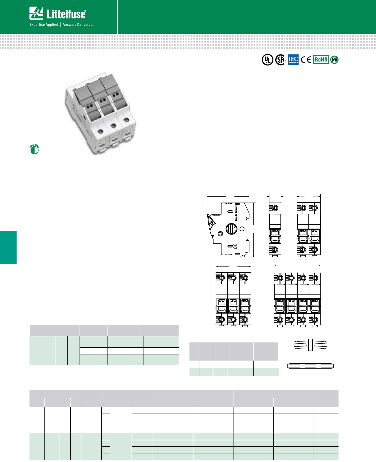
110 © 2014 Littelfuse POWR-GARD® Products Cataloglittelfuse.com
Blocks and Holders
Fuse Blocks and Holders
6
LFPSC/LFPSM CLASS CC/MIDGET DEAD FRONT FUSE HOLDERS
600 Vac/dc
Specifications
Voltage Rating UL: 600 Vac/dc
IEC: 690 Vac (LFPSM only)
Ampere Rating UL: 30 A
IEC: 32 A (LFPSM only)
SCCR Rating 200 kA (Class CC)
100 kA (Midget)
Power Acceptance 3W Maximum
Indication Voltage Range 110 -690 Vac/dc
Terminal Type Pressure Plate
Material Thermoplastic
Flammability Rating UL94 V-0, self-extinguishing
Approvals UL Listed (File: E14721)
CSA Certified
IEC 60269 (LFPSM Only)
Environmental RoHS compliant, Lead (Pb) free
Dimensions mm (inches)
Description
Littelfuse LFPSC Class CC and LFPSM 10x38mm dead-front
holders feature optional LED indication, DIN rail mounts and
a small space saving design. These high SCCR rated holders
provide optimum protection to personnel and have a large
clamping range with dual wire rated terminals.
Features
• Indicating and non-indicating options available
• Dual LED indication distinguishes polarity in DC applications
• Small compact design offers ultimate flexibility
• 35 mm DIN-Rail Mountable
• 1-, 2-, 3- and 4-pole configurations
• Easy installation and fuse removal with no additional
pullers or tools required
Web Resources
Download technical documents at: littelfuse.com/lfpsc
littelfuse.com/lfphv
Recommended Fuses
Class CC ............................................................................ 27
Midget (10x38mm) ............................................................ 30
Ordering Information (LFPSC Class CC and LFPSM Midget)
VOLTAGE AMPERE SCCR
Rating
POLES
FUSE TYPE SERIES
NON-INDICATING
INDICATING PACK
QUANTITY
UL IEC UL IEC
CATALOG NUM. ORDERING NUM. CATALOG NUM. ORDERING NUM.
600
Vac/dc — 30 A — 200 kA
1
Class CC
LFPSC LFPSC001 LFPSC0001Z LFPSC001ID LFPSC0001ZXID 12
2 LFPSC LFPSC002 LFPSC0002Z LFPSC002ID LFPSC0002ZXID 6
3 LFPSC LFPSC003 LFPSC0003Z LFPSC003ID LFPSC0003ZXID 4
4 LFPSC LFPSC004 LFPSC0004Z LFPSC004ID LFPSC0004ZXID 3
600
Vac/dc
690
Vac 30 A 32 A 100 kA
1
10x38mm
(Midget)
LFPSM LFPSM001 LFPSM0001Z LFPSM001ID LFPSM0001ZXID 12
2 LFPSM LFPSM002 LFPSM0002Z LFPSM002ID LFPSM0002ZXID 6
3 LFPSM LFPSM003 LFPSM0003Z LFPSM003ID LFPSM0003ZXID 4
4 LFPSM LFPSM004 LFPSM0004Z LFPSM004ID LFPSM0004ZXID 3
Connector Pincer
Handle Pin
Multi-Pole Assembly Kits
POLES
PINCER
QTY.
PIN
QTY.
ASSEMBLY
SETS
ORDERING
NUMBER
220 10 10 pack LFPHV2PAK
340 10 10 pack LFPHV3PAK
Terminal Information
TERMINAL
TYPE
WIRE
TYPE
NUMBER
OF WIRES WIRE SIZE TORQUE
Pressure
Plate
75˚ Max
CU Only
Stranded*
1
18-8 AWG
(.75-25 mm
2
)
18-22 lb-in
(2-2.5 N-m)
1
6-4 AWG 22-26 lb-in
2†
18-6 AWG
(.75-10 mm
2
)
18-22 lb-in
(2-2.5 N-m)
*Contact Tech-Line (800-TEC-FUSE) for other wire types.
†Must be the same cross-sectioned size
83.20
(3.28)
62.82
(2.47)
70.40
(2.77)
35.20
(1.39)
17.60
(0.69)
52.80
(2.08)
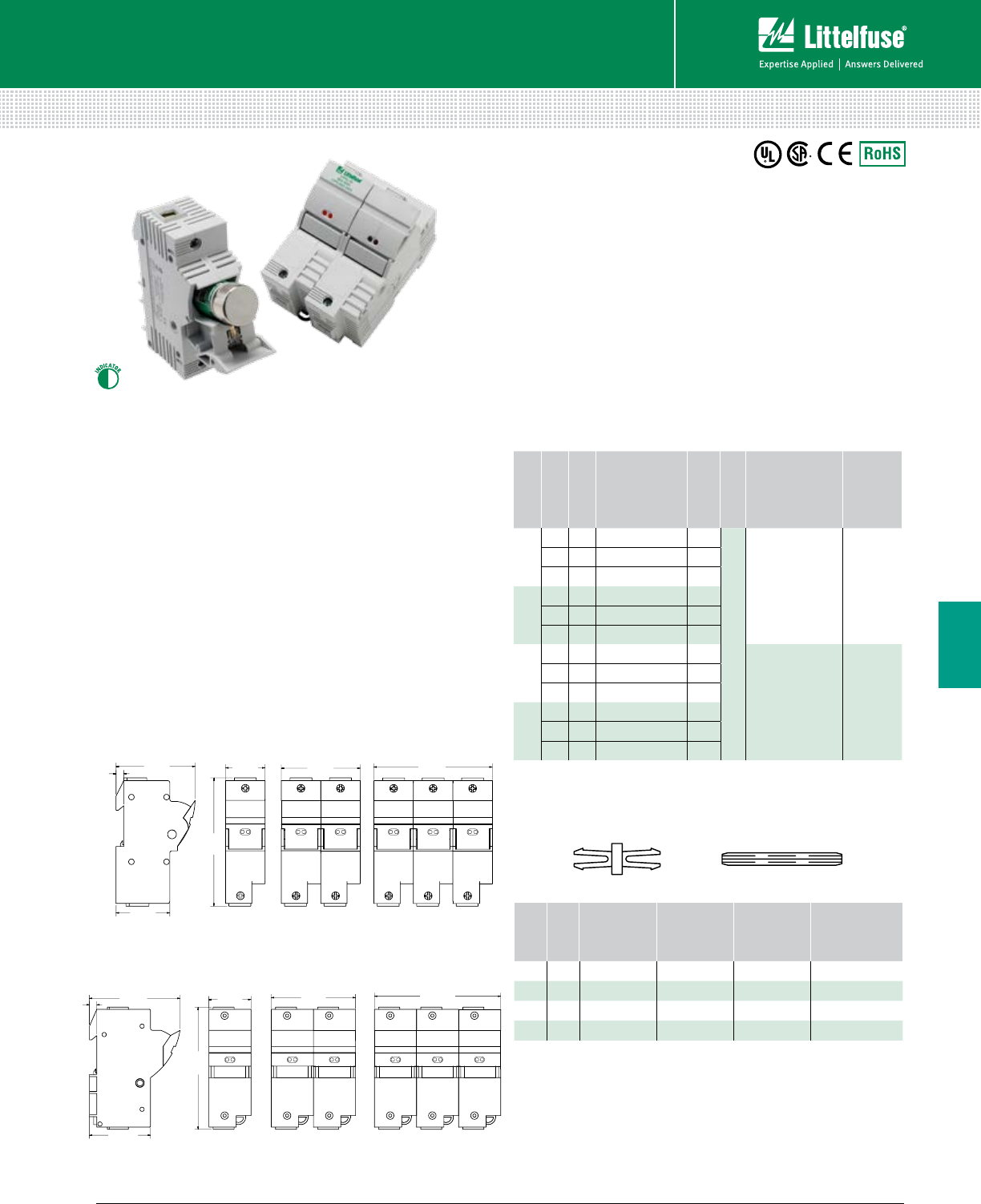
111 littelfuse.com © 2014 Littelfuse POWR-GARD® Products Catalog
Blocks and Holders
Fuse Blocks and Holders
6
LFPSJ CLASS J DEAD FRONT FUSE HOLDERS
600 Vac/dc
Specifications
Voltage Ratings 600 Vac/Vdc
Interrupting Rating 200 kA
Ampere Rating 30 and 60 A
LEDs 110 V – 600 V
Terminal Type Pressure Plate
Material Thermoplastic
Flammability Rating UL94 V-0
Terminal Screws Phillips / Slotted
Approvals UL Listed (File: E14721)
CSA Certified (File: 2529839)
Environmental RoHS compliant
Ordering Information
Multi-Pole Assembly Kit
Kits are used to create multi-pole holders from 1-pole LFPSJ
fuse holders. Please contact factory for more information.
Web Resources
Download CAD drawings and other technical information:
littelfuse.com/lfpsj
Recommended Fuses
Class J - JTD, JTD_ID, JLS ............................................... 21
30 Amp
60 Amp
Description
Littelfuse Class J POWR-SAFE Dead Front holders
provide optimum protection to personnel and are
UL Listed and CSA Certified.
Features
• Indicating and non-indicating options available
• Dual LED indication distinguishes polarity in
DC power applications
• Small compact design offers ultimate flexibility
• 35mm DIN Rail Mountable
• 1-, 2-, and 3-pole configurations
• Easy installation and fuse removal with no
additional pullers or tools required
Dimensions Inches (mm)
Note: These dimensions are for reference only. Please contact factory for additional information.
AMP
POLES
PINCER
QUANTITY
PIN
QUANTITY
ASSEMBLY
SETS
ORDERING
NUMBER
30 230 10 10 LF3J2PAK
30 360 10 10 LF3J3PAK
60 230 10 10 LF6J2PAK
60 360 10 10 LF6J3PAK
Connector Pincer Handle Pin
AMP
POLES
INDICATION
ORDERING
NUMBER
PACK
QTY.
WIRE TYPE
WIRE
RANGE TORQUE
30
1 – LFPSJ301.Z 6
Stranded
0.75mm2 – 1mm2
1.5mm2 – 50mm2
18 – 1 AWG
2.5 N-m
4.0 N-m
35 lb-in
2 – LFPSJ302.Z 3
3 – LFPSJ303.Z 2
30
1 • LFPSJ301.ZXID 6
2 • LFPSJ302.ZXID 3
3 • LFPSJ303.ZXID 2
60
1 – LFPSJ601.Z 6
2.5mm2 – 50mm2
14 – 1 AWG
4.0 N-m
35 lb-in
2 – LFPSJ602.Z 3
3 – LFPSJ603.Z 2
60
1 • LFPSJ601.ZXID 6
2 • LFPSJ602.ZXID 3
3 • LFPSJ603.ZXID 2
LFPSJ-ID
30A 600V
LFPSJ-ID
30A 600V
LFPSJ-ID
30A 600V
LFPSJ-ID
30A 600V
LFPSJ-ID
30A 600V
LFPSJ-ID
30A 600V
108.0
(4.251)
72.0
(2.835)
36.0
(1.417)
72.08
(2.838)
49.0
(1.929)
7.0
(.276)
117.0
(4.606)
86.0
(3.386)
7.0
(.276)
58.0
(2.283)
116
(4.567)
40.0
(1.575)
LFPSJ-ID
60A 600V
LFPSJ-ID
60A 600V
LFPSJ-ID
60A 600V
LFPSJ-ID
60A 600V
LFPSJ-ID
60A 600V
LFPSJ-ID
60A 600V
80.0
(3.150)
120
(4.72)
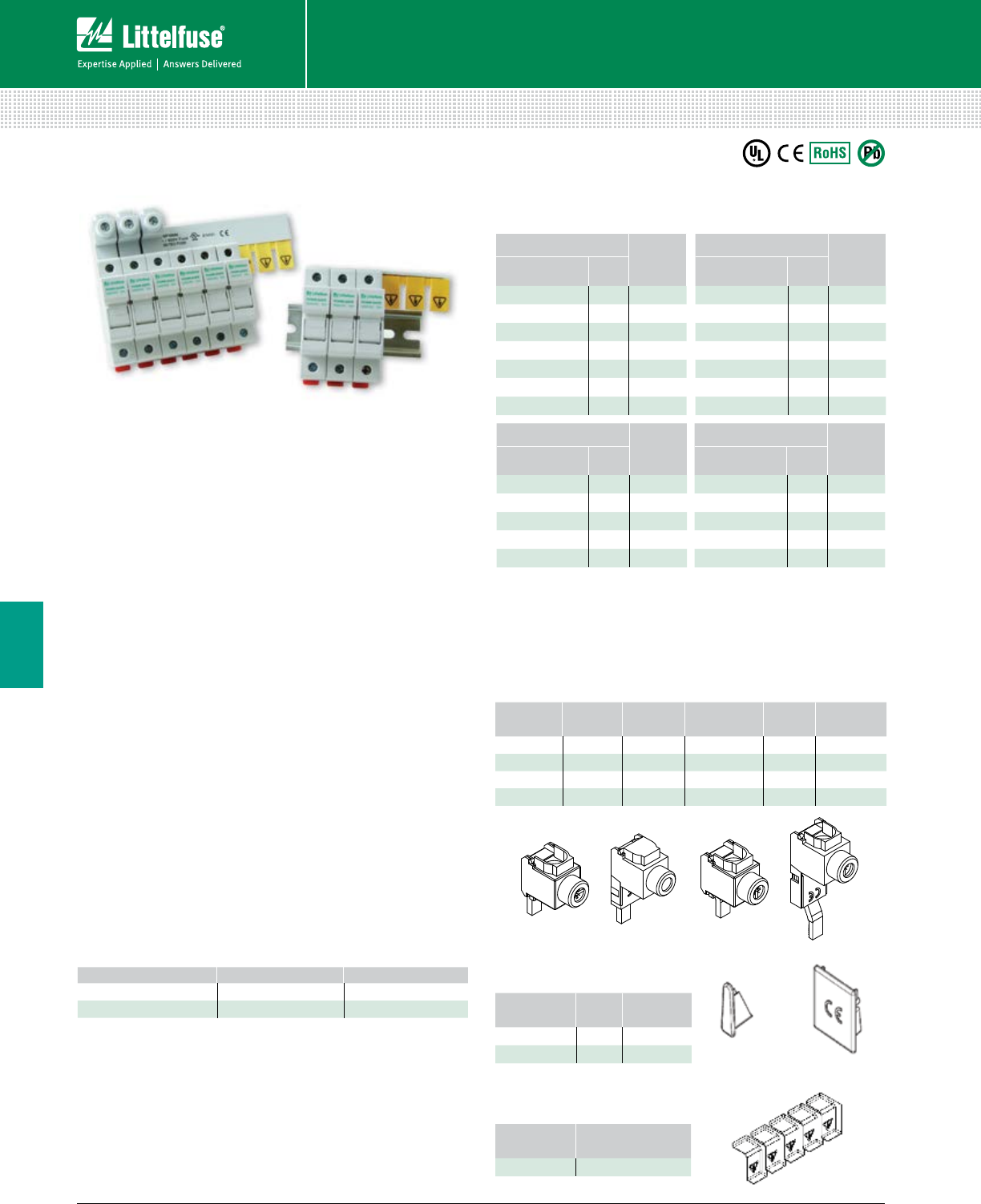
112 © 2014 Littelfuse POWR-GARD® Products Cataloglittelfuse.com
Blocks and Holders
Fuse Blocks and Holders
6
BUS BAR SYSTEM
POWR-BAR Distribution
Ordering Information
Description
A key objective for panel designers is safe distribution
of power to multiple fuse holders in a compact design.
The Littelfuse UL 508 Listed bus bar system eliminates
most wire terminations in a timesaving package. A power
distribution block and associated conductors are no longer
needed to feed multiple POWR-SAFE fuse holders.
Features/Benefits
• Touch-safe design offers protection when replacing fuses
• Compact design
• 35 mm DIN Rail Mountable
• Available in one and three phase configurations
• No fuse pullers or tools required for fuse removal
• Can be cut down to optimal size
Recommended Fuse Holders
LFPSM / LFPSC (600 Vac/dc) ............................................ 110
LFPHV (1000 Vdc) ............................................................ 109
Web Resources
Download CAD drawings, dimensions and other technical
information: littelfuse.com/busbar
Specifications
Voltage Ratings 600 Vac/dc
1000 Vdc*
Current Ratings
CROSS SECTION (mm2)18 mm225 mm2
END FED 80 A 100 A
CENTER FED 160 A 200 A
SCCR 10 kA, 100 kA†
Conductor Copper
Pitch 17.8 mm
Approvals UL 508 Listed (File E328654)
Environmental RoHS Compliant, Lead (Pb) free
* 1 Phase 18 mm2 rated 1000 Vdc up to 160 A when center fed
1 Phase 25 mm2 rated 1000 Vdc up to 200 A when center fed
†
When protected directly upstream by Class J 175 amperes max
(18 mm2 bus bar) and Class J 200 amperes max (25 mm2 bus bar).
Accessories
Endcaps are standard with all 3 phase configurations except 57-pole.
Endcaps are not needed for the 1 phase configurations from the factory or
if the copper bus is trimmed per the supplied instructions.
Power feed lugs and protective covers are extra.
Power Feed Lug
PART
NUMBER
AMP
RATING
VOLTAGE
(AC / DC) WIRE RANGE WIRE
TYPE TORQUE
BB17 115 1000 #10 - 1/0 AWG CU 50 lb-in
BB18 115 1000 #10 - 1/0 AWG CU 50 lb-in
BB19 115 1000 #10 - 1/0 AWG CU 50 lb-in
BB20 115 1000 #10 - 1/0 AWG CU 50 lb-in
Pole Protective Covers
PART
NUMBER QUANTITY
CTPT5 5
Endcaps
PART
NUMBER PHASE QUANTITY
EDCP42 Single 50
EDCP7 Three 50
3 PHASE, 25 mm2LENGTH
(mm)
ORDERING
NUMBER POLES
3PH6P25mm 6 104
3PH9P25mm 9 158
3PH12P25mm 12 214
3PH15P25mm 15 266
3PH57P25mm 57 1009
1 PHASE, 18 mm2LENGTH
(mm)
ORDERING
NUMBER POLES
1PH3P18mm 3 50
1PH4P18mm 4 79
1PH6P18mm 6 104
1PH9P18mm 9 155
1PH12P18mm 12 208
1PH15P18mm 15 270
1PH57P18mm 57 1009
1 PHASE, 25 mm2LENGTH
(mm)
ORDERING
NUMBER POLES
1PH3P25mm 3 50
1PH4P25mm 4 79
1PH6P25mm 6 104
1PH9P25mm 9 155
1PH12P25mm 12 208
1PH15P25mm 15 270
1PH57P25mm 57 1009
3 PHASE, 18 mm2LENGTH
(mm)
ORDERING
NUMBER POLES
3PH6P18mm 6 104
3PH9P18mm 9 158
3PH12P18mm 12 214
3PH15P18mm 15 266
3PH57P18mm 57 1009
EDCP42 EDCP7
BB17 BB18 BB19 BB20
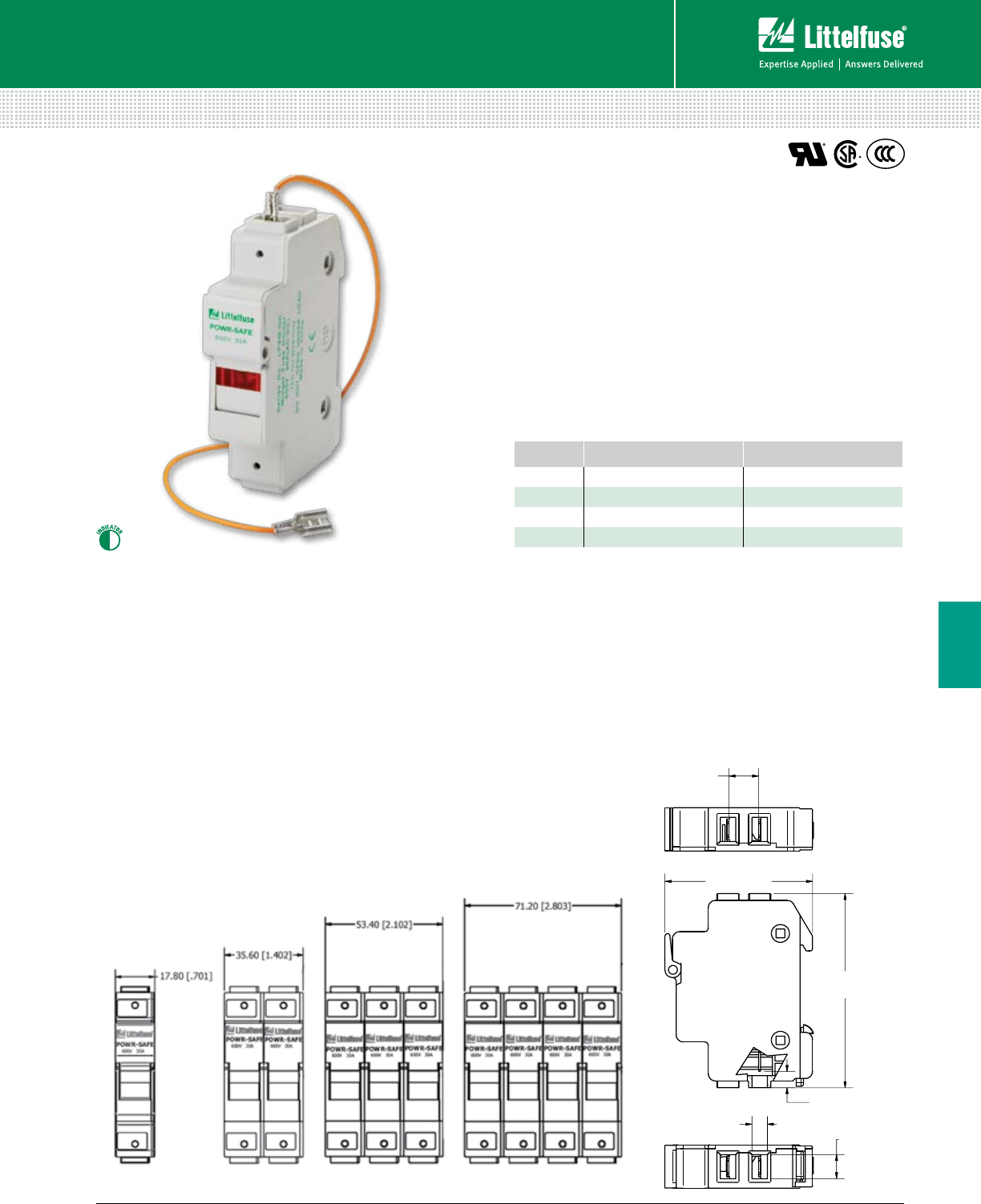
113 littelfuse.com © 2014 Littelfuse POWR-GARD® Products Catalog
Blocks and Holders
Fuse Blocks and Holders
6
LPSM QUICK CONNECT POWR-SAFE FUSE HOLDERS
Specifications
Voltage Rating 600 Vac/dc
Amperage Rating 30 A
Approval UL Recognized (File No. E14721)
CSA Certified (File No. LR7316)
CCC Approved
Terminal Type 1/4” Quick Connect Terminals
Fuse Type Midget (10 X 38 mm) series
Material Thermoplastic
Flammability Rating UL94 V-0
SCCR Rating Same as Fuse Rating
Ordering Information
POLES CATALOG NUMBER ORDERING NUMBER
1 LPSM001QCID LPSM0001ZQCID
2 LPSM002QCID LPSM0002ZQCID
3 LPSM003QCID LPSM0003ZQCID
4 LPSM004QCID LPSM0004ZQCID
Recommended Fuses
Midget-Style (10x38mm) .................................................. 30
Web Resources
Download CAD drawings and other technical information:
littelfuse.com/lpsmqc
6.20 (.244)
9.90 (.390)
6.77 (.267)
80.00 (3.15)
59.70 (2.35)
11.99 (4.72)
17.80 (.701)
Description
The LPSM midget fuse holder series is a dead front
design providing protection to personnel when installing
and removing fuses. The compact fuse holder mounts
quickly onto 35 mm DIN rail, decreasing panel layout
and assembly time. This product has two Quick Connect
terminals on both the top and bottom of the holder,
offering an additional connection option. It is available in
1-, 2-, 3- and 4-pole configurations.
Features/Benefits
• Dual 1⁄4” Quick Connect Terminals on Top and
Bottom of Holder
• Meets Dead Front requirements
• Mountable on 35 mm DIN Rail
• Local LED Indication
Dimensions mm (inches)
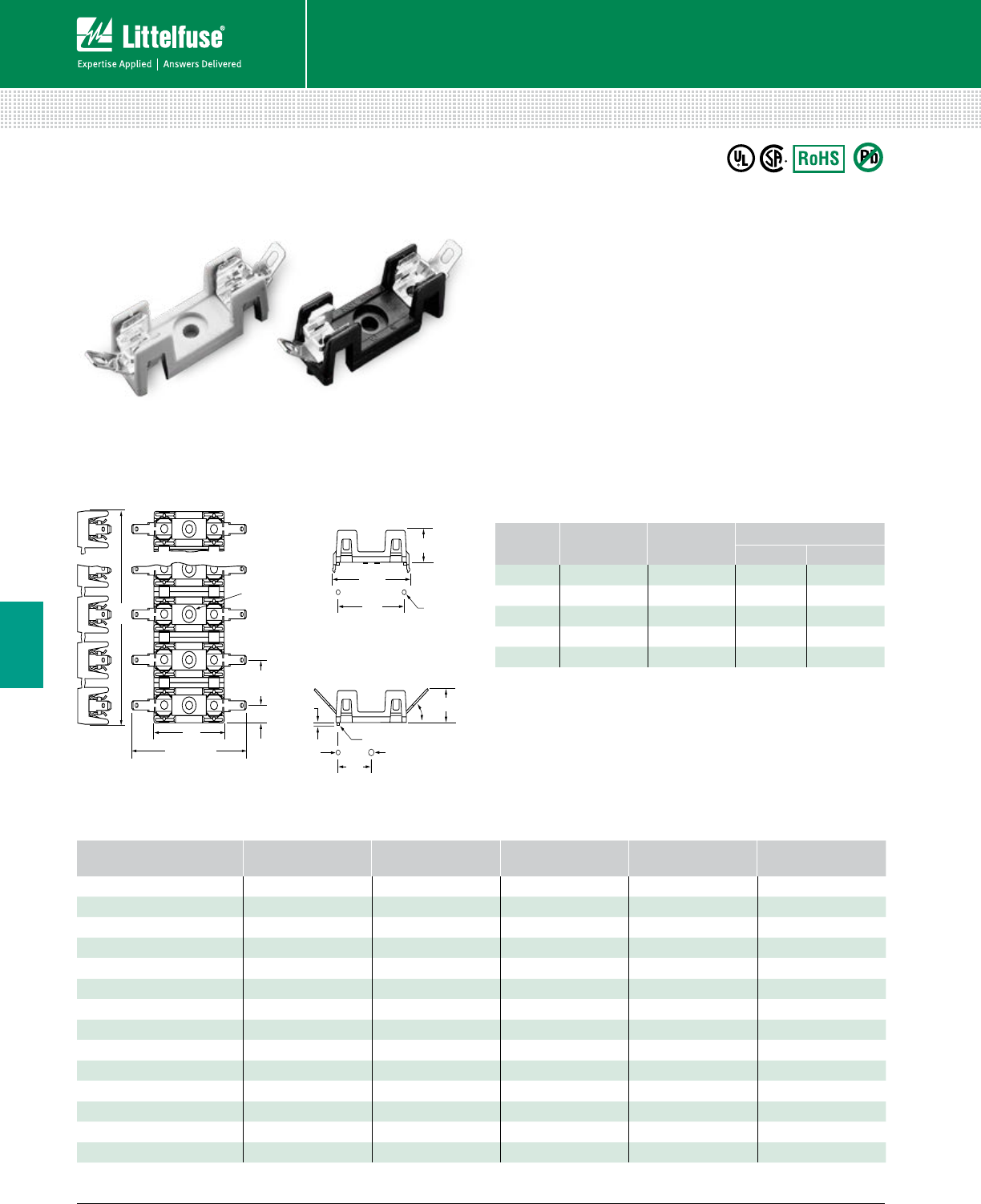
114 © 2014 Littelfuse POWR-GARD® Products Cataloglittelfuse.com
Blocks and Holders
Fuse Blocks and Holders
6
354 SERIES 3AG OMNI BLOCK®
Molded Base Type Fuse Block
XX
.55" MAX.
45
XXXXXXXX
A
.312" REF. DIA. C BORE
.06" REF. DEEP (.10 REMAINS)
1.4"
2.19" REF.
.625"
TYP.
.25"
TYP.
.146" REF.
DIA. THRU
.08" REF.
.08" REF. DIA.
.10" DIA. .156" DIA.
.65"
.53" REF.
.06" DIA. (2)
1.4"
1.46"
REF.
Dimensions Inches
Web Resources
For additional technical information visit: littelfuse.com
Description
A low profile fuse block featuring individual barriers that
reinforce the fuse clips while providing greater protection
against clip damage and electrical shock. The unique design
permits self-alignment of clips to fuse cap. This, plus a
one-piece clip/terminal, assures low contact resistance.
Specifications
Dielectric Strength 1500 V Minimum
Clip/Terminals Tin-Plated Spring Brass; two different style clips
can be supplied for circuit identity or polarization
Base Glass reinforced Thermoplastic:
Gray except anit-rotation series which is black
Flammability Rating UL94 V-0
Ambient Temperature –40˚C to +85˚C
Ordering Information
CATALOG
NUMBER TERMINALS VOLTAGE CURRENT RATING
UL CSA
354 000 Solder 300 V* 30 A 30 A
354 600 3/16” Q.C. 300 V 20 A 20 A
354 800 1/4” Q.C. 300 V 20 A 20 A
354 900 1/4” Q.C. 300 V 30 A 25 A
354 101-GY P.C. Board 300 V 15 A 15 A
*30 A capability is based on temperature rise with #10 AWG wire properly soldered.
Technical Information
SOLDER TYPE TERMINALS 3/16” Q.C.
TERMINALS†
1/4” Q.C.
TERMINALS
1/4” Q.C.
TERMINALS†POLES DIM “A”
354 001GY 354 601GY 354 801GY 354 901GY 1 .50”
354 002GY 354 602GY 354 802GY 354 902GY 2 1.12”
354 003GY 354 603GY 354 803GY 354 903GY 3 1.75”
354 004 GY 354 604GY 354 804GY 354 904GY 4 2.38”
354 005GY 354 605GY 354 805GY 354 905GY 5 3.00”
354 006GY 354 606GY 354 806GY 354 906GY 6 3.63”
354 007GY 354 607GY 354 807GY 354 907GY 7 4.25”
354 008GY 354 608GY 354 808GY 354 908GY 8 4.88”
354 009GY 354 609GY 354 809GY 354 909GY 9 5.50”
354 010GY 354 610GY 354 810GY 354 910GY 10 6.13”
354 011GY 354 611GY 354 811GY 354 911GY 11 6.75”
354 012GY 354 612GY 354 812GY 354 912GY 12 7.38”
354 021BL* 354 621BL*354 821BL*354 921BL*1 .50”
354 101GY — — — 1 .50”
† NEMA style
* With Anti-Rotation Boss
Recommended Fuses
3AG Cartridge ................................................................... 33
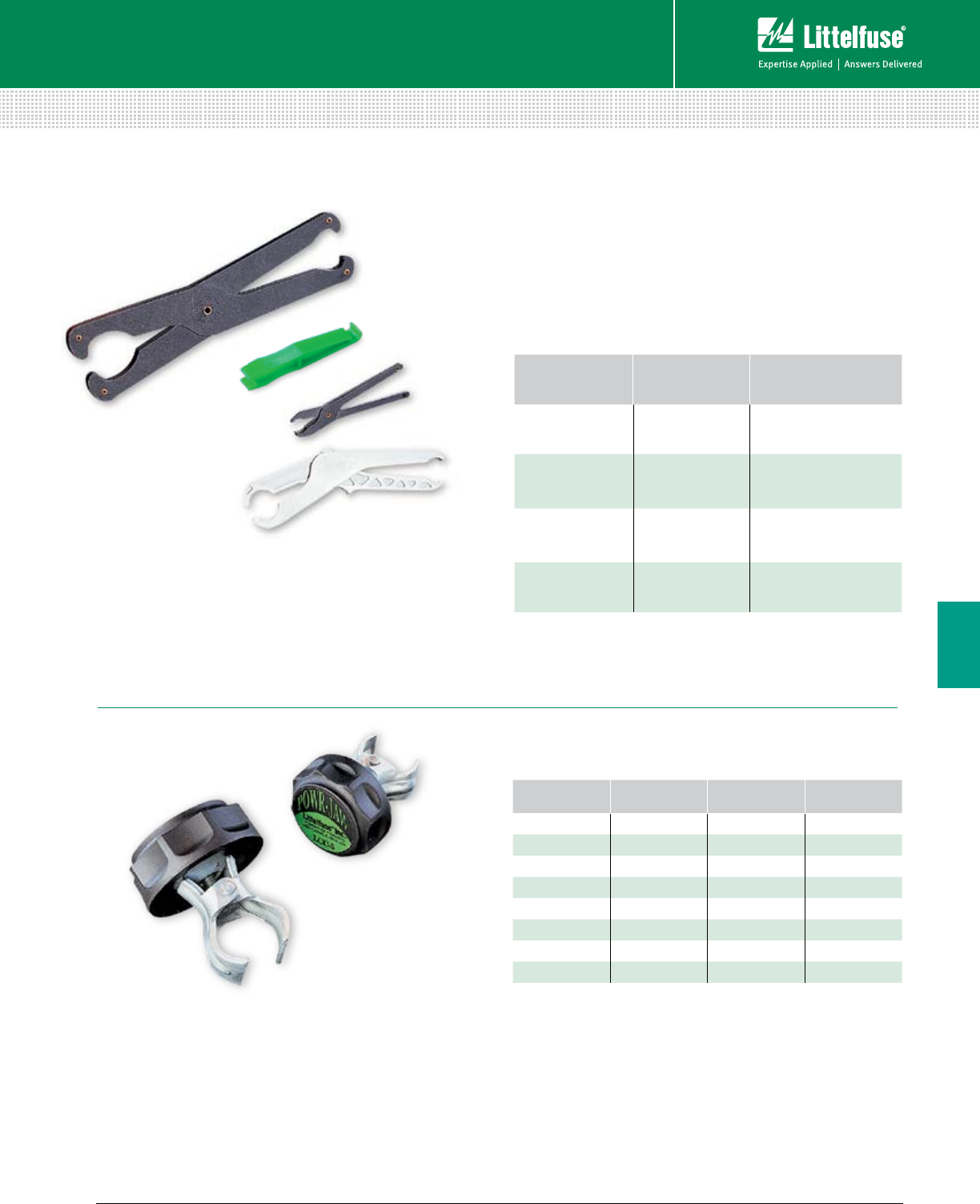
115 littelfuse.com © 2014 Littelfuse POWR-GARD® Products Catalog
Blocks and Holders
Fuse Blocks and Holders
6
Features/Benefits
• Ergonomically designed fuse pullers designed to safely
remove power fuses
• Molded design offers more comfortable and natural
grip than traditional pullers, increasing performance
Specifications
FUSE PULLERS & POWR-JAW CLIP CLAMPS
MFP • LPFP • GFP • 097023
Web Resources
For additional technical information visit:
littelfuse.com/clipclamps
Web Resources
For additional technical information visit:
littelfuse.com/fusepullers
Ordering Information
CATALOG
NUMBER
ORDERING
NUMBER VOLTS AMPERES
LCC1 0LCC1 250 0-30
LCC2 0LCC2 250 35-60
LCC2 0LCC2 600 0-30
LCC4 0LCC4 600 35-60
LCC5 0LCC5 250 or 600 70-100
LCC6 0LCC6 250 or 600 110-200
LCC7 0LCC7 250 or 600 225-400
LCC8 0LCC8 250 or 600 450-600
Note: POWR-JAW Clip Clamps are sold individually, not in pairs.
A minimum of 1/8” of clearance between the fuse block barrier and fuse clip is required to
install Clip Clamps.
TYPE OF FUSE
PULLER PART NUMBER FUSE SIZE (DIAMETER)
Midget Fuse MFP 3⁄16" - 1⁄2" fuses
Pocket Fuse LPFP
250 V fuses from 0-200 A
600 V fuses from 0-100 A
9⁄16" - 119⁄32" fuses
Giant Fuse GFP
250 V fuses from 61-600 A
600 V fuses from 61-400 A
11⁄16" - 219⁄32" fuses
Tri-puller 097023 For ATO, MINI and glass fuses
Features/Benefits
• Improve contact between fuse and clip
• Help prevent unnecessary heat from poor contact
due to the loss of spring force. This reduces:
1. Nuisance fuse opening
2. Premature aging of surrounding components
• High temperature phenolic resin knob for durability
• Wide range of coverage with simple design
GFP
097023
MFP
LPFP
LCC Series POWR-JAW
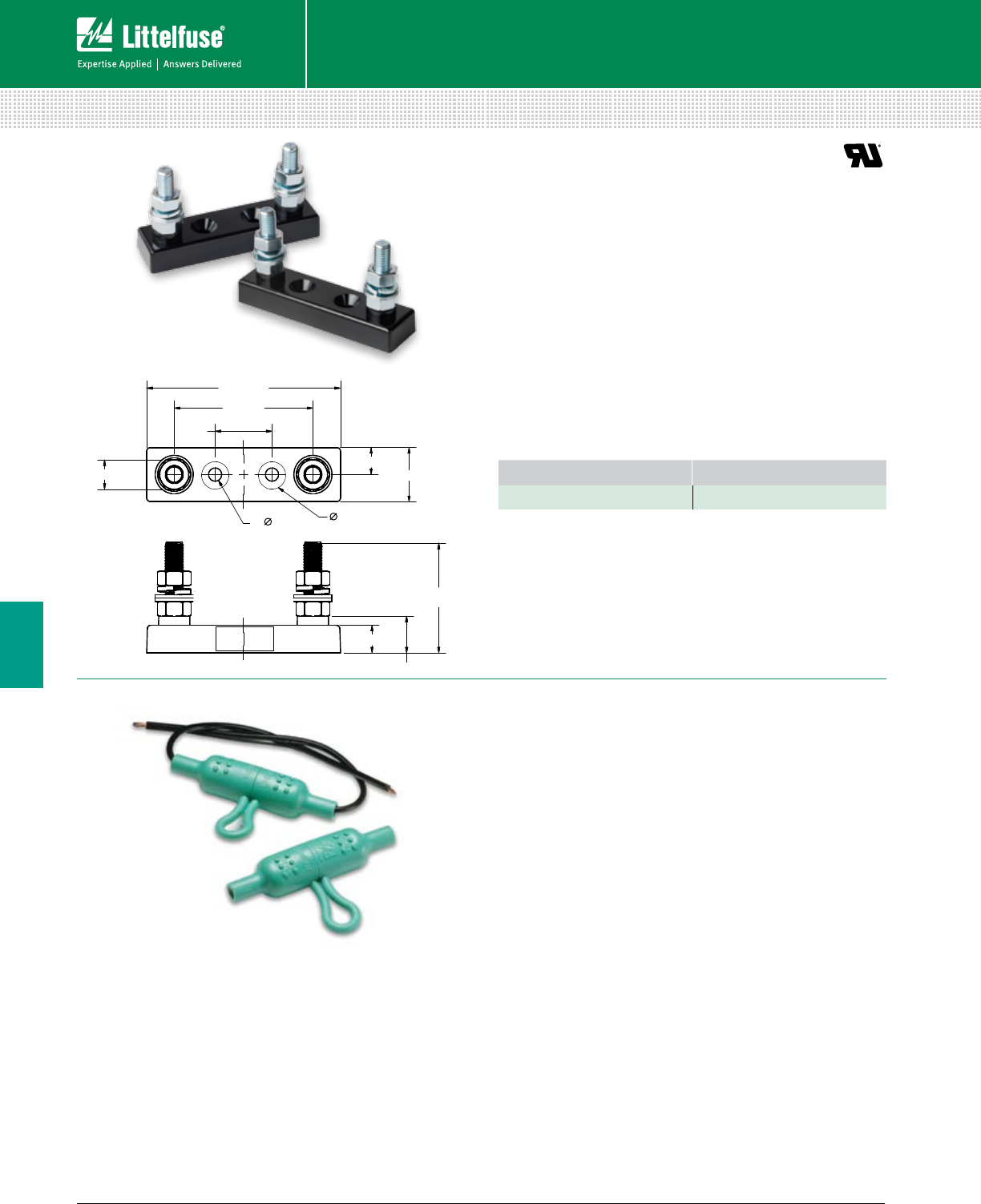
116 © 2014 Littelfuse POWR-GARD® Products Cataloglittelfuse.com
Blocks and Holders
Fuse Blocks and Holders
6
LFFB SERIES LIMITER BLOCK/LHFB INLINE HOLDER
LFFB
86.61 (3.410)
62.0 (2.44)
25.4 (1.0)
11.94 (0.470)
23.88 (0.940)
2x 49.14 (1.935)
2x 16.19 (0.637)
12.19 (0.480)
12.6 C’BORE X 82, (2) HOLES
2x 5.84 (0.230)
2x 13.0 (0.512)
LHFB
Dimensions mm (inches)
Recommended Fuses
CNL/CNN Cable limiter fuses ........................................... 62
HAZGARD fuse ................................................................. 62
Description
The LFFB003 fuse block is designed to accept CNN and CNL
style limiter fuses. Applications include but are not limited to
forklifts, golf carts and other low-voltage battery equipment.
It is specifically designed for the HAZGARD™ fuse but can
be used for CNN/CNL fuses as well.
Specifications
Voltage Rating 150 Vac/Vdc
Ampere Rating 800 A
Approvals UL Recognized (File: E14721)
Construction Base—Thermoplastic
Studs—Steel Zinc Plated
Ordering Information
CATALOG NUMBER ORDERING NUMBER
LFFB003 LFFB0003Z
Web Resources
Sample requests and other technical information:
littelfuse.com/lffb
Specifications
Voltage Rating 32 V
Ampere Rating 30 A
Fuses
1/4” to 11/4” fuses
Wire Size Accepts #16 to #18 gauge wire
Operating Temperature -20˚ C to 80˚ C
Installation Instructions
1. Thread wire through fuse holder body
2. Strip wire insulation per strip gauge
3. Crimp wire to fuse clip*
4. Pull wire through and seat fuse clip in the holder body
5. Insert desired fuse type and rating
6. Snap holder body together
*Recommended crimping tools: Thomas & Betts No. WT-111M
Note: Wire is not supplied with the holder.
Web Resources
Sample requests and other technical information:
littelfuse.com/lhfb
Description
The Littelfuse LHFB waterproof in-line fuse holder is ideal
for harsh environments. The LHFB holder features the
voltage and ampere rating molded into the body, along with
a wire strip gauge. It also withstands solvents and vibration.
Features/Benefits
• Waterproof in-line fuse holder for harsh environments
• One-piece molded thermoplastic body
• Bright green color offers high visibility
• Voltage and ampere rating molded into body
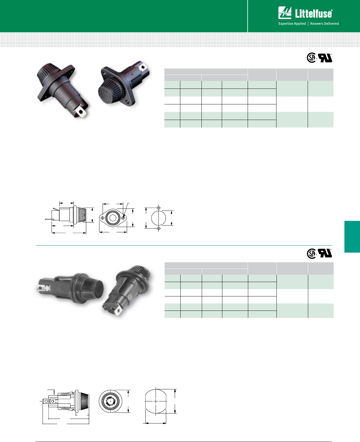
117 littelfuse.com © 2014 Littelfuse POWR-GARD® Products Catalog
Blocks and Holders
Fuse Blocks and Holders
6
Ordering Information
0.86"
[21.84]
0.92"
[23.37] 0.890
"
[22.6]
1.12"
[28.45]
1.310"
[33.3]
1.34"
[34.04]
2.10"
[53.34]
1.74"
[44.20]
1.312"
[33.33]
.172 DIA.
[4.37]
Load
Line
Mounting Hole
Specifications
Voltage Rating 600 V
Ampere Rating 30 A for Class CC and Midget fuses
Dielectric Strength 4000 V Minimum
Terminals Tin-plated brass combination solder & quick-connect
O-Rings 901-184 (body), 901-260 (knob)
Molded Parts Black thermoplastic
Approvals UL Recognized (File: E14721)
UL Recognized for branch circuit protection
(571OCC/RCC)
CSA Certified (File: LR7316)
Web Resources
Additional technical information: littelfuse.com/571
†Fuse diameter is 13/32”
Note: Contact factory for versions with pre-assembled wire leads.
572
Specifications
Voltage Rating 600 V
Ampere Rating 30 A for Class CC and Midget fuses
Dielectric Strength 4000 V Minimum
Terminals Tin-plated brass combination solder & quick-connect
Molded Parts Black thermoplastic
Approvals UL Recognized (File: E14721)
UL Recognized for branch circuit protection
(5720CC/RCC) Class CC version
CSA Certified (File: LR7316)
Mounting Double "D" punch - Greenlee #61092
(14-18 gauge panel thickness recommended)
Web Resources
Additional technical information: littelfuse.com/572
Description
The 572 series panel mount fuse holders are
designed to minimize installation time. Its unique
design incorporates a snap-mount feature that
allows the holder to be installed without any tools
or mounting hardware.
Description
Panel mount fuse holders are for Midget-Style
and Class CC fuses. Class CC fuses have a
rejection feature on one end cap, which mates
with the rejection feature of Littelfuse Class CC
fuses holders to prevent the installation of fuses
with lower voltage ratings or interrupting ratings.
Watertight version must be front panel mounted.
CATALOG/ORDERING NUMBER BOTTOM
TERMINAL
FUSE LENGTH
RANGE*
FOR USE
WITH
STANDARD WATERTIGHT
571027 05710027L 571027P 05710027LXP Straight 15⁄16” – 13⁄8”Midget
Fuses
571028 05710028L 571028P 05710028LXP Rt. Angle
571007 05710007L 571007P 05710007LXP Straight 113⁄32” – 11⁄2”Midget
Fuses
571008 05710008L 571008P 05710008LXP Rt. Angle
5710CC 057100CCL 5710CCP 057100CCLXP Straight 11⁄2”Class CC
Fuses
571RCC 05710RCCL 571RCCP 05710RCCLXP Rt. Angle
*Fuse diameter is 13/32”
Note: Contact factory for versions with pre-assembled wire leads.
Ordering Information
CATALOG/ORDERING NUMBER BOTTOM
TERMINAL
FUSE LENGTH
RANGE†
FOR USE
WITH
STANDARD WATERTIGHT
572027 05720027L 572027P 05720027LXP Straight 15⁄16” – 13⁄8”Midget
Fuses
572028 05720028L 572028P 05720028LXP Rt. Angle
572007 05720007L 572007P 05720007LXP Straight 113⁄32” – 11⁄2”Midget
Fuses
572008 05720008L 572008P 05720008LXP Rt. Angle
5720CC 057200CCL 5720CCP 057200CCLXP Straight 11⁄2”Class CC
Fuses
572RCC 05720RCCL 572RCCP 05720RCCLXP Rt. Angle
Dimensions Inches (mm)
0.756”
1.20”
(30.5)
2.40”
2.10” 0.69”
0.913”
Load
Line
Dimensions Inches (mm)
Mounting Hole
571 & 572 SERIES PANEL-MOUNT FUSE HOLDERS
571
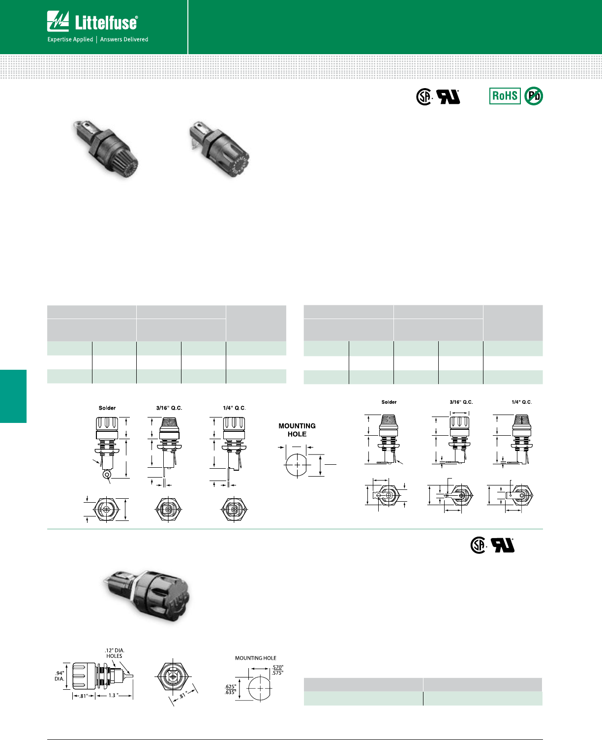
118 © 2014 Littelfuse POWR-GARD® Products Cataloglittelfuse.com
Blocks and Holders
Fuse Blocks and Holders
6
342 SERIES 3AG (1/4" X 11/4") PANEL MOUNT FUSE HOLDERS
Traditional Panel Mount Type
Right Angle Terminal
FLUTED KNOB KNURLED KNOB
TERMINAL
CATALOG/ORDERING
NUMBER
CATALOG/ORDERING
NUMBER
342004 03420004X 342022A 03420022X Solder
342028A 03420028X 342048A 03420048X 3/16” Q.C.
342828 03420828X 342848A 03420848X 1/4” Q.C.
.7"
.11" DIA.
.090" X .12"
HOLE 1.31"
.78"
1"
.3"
.7"
1"
.4"
.020" .032"
.502"
.510"
.45"
FLATS
TYP.
.69"
HEX
FLATS
.475"
.480"
.085" X .12"
HOLE
.78"
1"
.7"
1"
.020"
.78"
1"
.032"
.63"
.14" DIA. HOLE
.502"
.510"
.187"
.475"
.480"
.69"
DIA.
.69"
HEX
FLATS
.250"
.69"
DIA.
TYP.
.56"
.69" DIA.
.59"
DETENT
.06" DIA.HOLE
.45"
FLATS
TYP.
.085" X .12"
HOLE
.78"
1"
.7"
1"
.020"
.78"
1"
.032"
.63"
.14" DIA. HOLE
.502"
.510"
.187"
.475"
.480"
.69"
DIA.
.69"
HEX
FLATS
.250"
.69"
DIA.
TYP.
.56"
.69" DIA.
.59"
DETENT
.06" DIA.HOLE
.45"
FLATS
TYP.
Straight Terminal Right Angle Terminal
Right Angle
Terminal
Fluted Knob
Straight Terminal
Knurled Knob
Dimensions Inches
QPL
QPL
Dimensions
in inches
Straight Terminal
FLUTED KNOB KNURLED KNOB
TERMINAL
CATALOG/ORDERING
NUMBER
CATALOG/ORDERING
NUMBER
342014A 03420014X 342012A 03420012X Solder
342038A 03420038X 342058A 03420058X 3/16” Q.C.
342838A 03420838X 342858A 03420858X 1/4” Q.C.
Specifications
Electrical Rated at 20 A for any voltage up to 250 V
Dielectric Strength 2400 V minimum
Mounting Withstands 15 lb-in mounting torque;
maximum panel thickness .187”
Molded Parts Black thermoplastic (UL94 V-0)
Knob Bayonet style with lettering
Terminals Copper & copper alloy. Tin plated, except ¼”
Quick-Connect terminals are nickel plated
Ambient Temperature –40˚C to +85˚C
Recommended Fuses
3AG Cartridge ................................................................... 33
Web Resources
Additional technical information available at:
littelfuse.com/342
342 Series (Watertight Panel Mount Type) Specifications
Electrical Rated at 20 A for any voltage up to 250 V
Dielectric Strength 1500 V minimum
Mounting Withstands 15 lb-in mounting torque;
maximum panel thickness is .250”
Molded Parts Black thermoset (UL94 V-0)
Knob Screw type
Seal O-ring provides a watertight seal on the
front side of the panel per MIL-PRF-19207
Terminals Copper & copper alloy. Tin plated. Solder type
Ambient Temperature –40˚C to +85˚C
Hardware O-rings (2) and hex nut, unassembled
Ordering Information
Recommended Fuses
3AG Cartridge ................................................................... 33
Description
Panel Mount Fuse holders for 3AG (1/4" x 11/4") fuses. Both
fluted and knurled knob terminal options are available.
Ordering Information
Web Resources
Additional technical information available at: littelfuse.com/342
CATALOG NUMBER ORDERING NUMBER
342006A 0342006ZXA
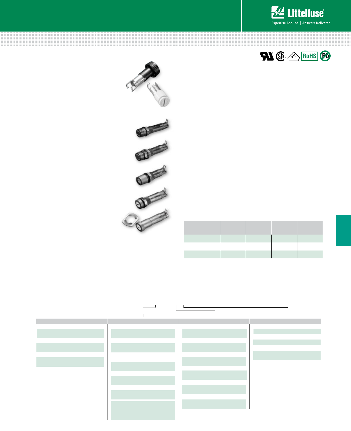
119 littelfuse.com © 2014 Littelfuse POWR-GARD® Products Catalog
Blocks and Holders
Fuse Blocks and Holders
6
345 SERIES PANEL MOUNT FUSE HOLDERS
International Shock-Safe Panel Mount Type
Insulation Resistance 10,000 megaohm minimum at 500 Vdc
Contact Resistance Less than .005 ohm average at currents up to 1 A
Mounting Threaded styles withstand 15 in-lb mounting torque
Profile panel thickness .032” min/310” max.
Quick mount panel thickness .012” min/360” max.
Rear mount panel thickness.012” min/260” max.
Body Material Black glass-filled thermoplastic (UL94 V-0)
Knob Material Grey, blue or black glass-filled thermoplastic (UL94 V-0)
Hex Nut Material Black glass-filled thermoplastic
Knob Finger-Grip, Fuse Extractor type or Screwdriver Slot,
Fuse Extractor type with plated copper alloy insert
Plated copper alloy contact clips.
Spring loaded, locking mechanism provides an anti-
tease feature and will not vibrate loose
Terminals Copper alloy, Tin-plated
Ambient Temperature –40˚C to +85˚C
Hardware Threaded style fuse holders are supplied with
a thermoplastic hex nut unassembled
Quick mount style fuse holders are supplied with
a push-on type retaining nut, black oxide finish,
unassembled
A synthetic rubber O-ring will be supplied only
with the screwdriver slot knob when the drip-proof
version is requested
AGENCY
APPROVAL
FILE
NUMBER 3AG 5 X 20 mm 2AG
UL E75961 20 A 250 V 10 A 250 V 10 A 250 V
CSA LR91788 20 A 250 V 10 A 250 V 10 A 250 V
VDE 116895E 10 A 250 V 10 A 250 V —
Note: To order with a metal internal tooth lockwasher (L) and/or neoprene panel washer (N)
and/or drip-proof synthetic rubber “O” ring with Neoprene washer (NP) [Screwdriver slot
knob only], add the appropriate suffix (L, N, or NP) respectively.
Please refer to Technical Application Guide section for information
on proper fuse holder de-rating.
Description
Designed to eliminate electrical
shock as defined by IEC standards
60065 and 60127, these panel-
mount fuses holders offer a wide
variety of options. This allows for
inventory reduction and versatility.
Features/Benefits
• Anti-tease feature eliminates
circuit interruption when knob
is accidentally depressed
• Five fuse holder types
for maximum flexibility
• Two knob styles—
screwdriver slot and fingergrip
• Drip proof option available on
screwdriver slot knob style
• Two terminal choices
depending on application
Web Resources
For more informations, visit:
littelfuse.com/shocksafe
Recommended Fuses
Ordering Information
Specifications
Glass / Electronic Fuses .................................................... 32
EXAMPLE:
(Complete Assembly with Options) Series Number
FUSE SIZE
2
3
5
LF
RF
HS
LS
QS
8
7
4
3
2
1L
N
NP
Lockwasher
Neoprene Washer
Drip-Proof O-Ring†
with Neoprene Washer
*Options (L, N, NP) can be ordered
individually or in combination.
†
Screwdriver slot knob only.
2AG
.177” x .570”
3/16” (Right Angle)
Dual Purpose Solder/QC
3/16” (Right Angle)
NEMA QC
1/4” (Right Angle)
NEMA/DIN QC
1/4” (Straight)
NEMA/DIN QC
3/16” (Straight)
NEMA QC
3/16” (Straight)
Dual Purpose Solder/QC
Rear Mount Body
Black Fingergrip Knob
Low Profile Body
Black Fingergrip Knob
High Profile Body
Screwdriver Slot Knob
Low Profile Body
Screwdriver Slot Knob
Quick Mount Body
Screwdriver Slot Knob
Screwdriver Slot Knob
2AG–Blue Knob
3AG–Grey Knob
5 x 20 mm–Black Knob
3AG
.250” x 1.250”
5 x 20 mm
.197” X .787”
STYLE TERMINALS OPTIONS*
345 3 LS 7 LNP
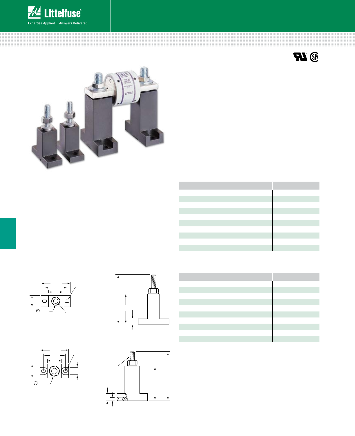
120 © 2014 Littelfuse POWR-GARD® Products Cataloglittelfuse.com
Blocks and Holders
Fuse Blocks and Holders
6
Description
Modular-designed Semiconductor fuse blocks are designed
to accommodate a wide range of Semiconductor fuses, with
a maximum diameter of 3".
Features/Benefits
• Modular design reduces inventory requirements
• Sold in pairs for convenience
• Constructed of molded phenolic (with plated steel studs)
Dimensions Inches
SEMICONDUCTOR FUSE BLOCKS
LSCR Series
Specifications
Voltage Rating
LSCR001: Accepts fuses 1” diameter or less at 600 V
LSCR002: Accepts fuses up to 3” diameter at 600 V
Ampere Ratings LSCR001: 1 – 400 A capacity
LSCR002: 70 – 800 A capacity
Approvals UL Recognized (File: E14721)
CSA Certified (File: 73160)
Stud Size LSCR001:
1
⁄
4
-20 thread (Torque 61 in-lbs.)
LSCR002:
3
⁄
8
-16 thread (Torque 192 in-lbs)
Base Molded phenolic. 150˚ C temperature rating
Terminal Construction Plated steel. Supplied with nut and belleville washer
FUSE SERIES AMPERE RATING PAGE
L15S 70-400 69
L17T 70-250 50
L25S 35-60 69
LA30QS 35-60 72
L50S 35-100 69
LA5OQS 35-100 73
L60S 35-60 69
KLC 35-60 69
JLLN 70-100 24
JLLS 70-100 24
FUSE SERIES AMPERE RATING PAGE
L15S 500-800 69
L17T 300-800 50
L25S 225-800 69
LA30QS 225-800 72
L50S 225-800 69
LA50QS 225-800 73
L60S 225-800 69
KLC 125-800 69
JLLN 225-800 24
JLLS 225-800 24
Recommended Fuses
Semiconductor and Class T fuses. See tables below.
1.88"
1.30"
0.70"
0.70"
0.203" × 0.30" SLO
T
0.50" 1/4-20" × 1.00"
USABLE LENGTH
2.48"
1.32"
0.25"
1.88"
1.30"
0.70"
0.70"
0.203" × 0.30" SLO
T
0.50" 1/4-20" × 1.00"
USABLE LENGTH
2.48"
1.32"
0.25"
LSCR002
LSCR001
2.13"
1.60"
1.00"
1.00"
0.75"
0.50"
0.203" × 0.30" SLO
T
3/8-16"x1.00"
USABLE LENGTH
0.25"
0.50"
3.632"
2.38"
2.13"
1.60"
1.00"
1.00"
0.75"
0.50"
0.203" × 0.30" SLO
T
3/8-16"x1.00"
USABLE LENGTH
0.25"
0.50"
3.632"
2.38"
LSCR001 Semiconductor Fuse Block Selection Guide
LSCR002 Semiconductor Fuse Block Selection Guide
Web Resources
For more information, visit: littelfuse.com/lscr
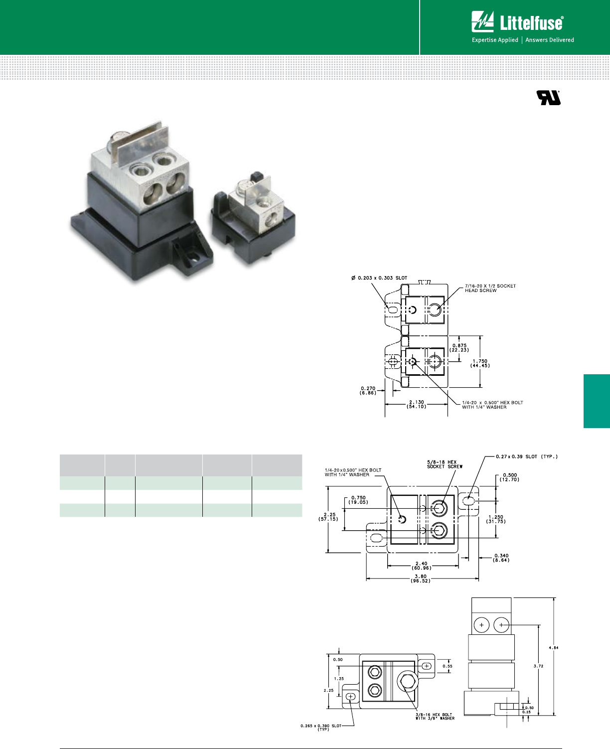
121 littelfuse.com © 2014 Littelfuse POWR-GARD® Products Catalog
Blocks and Holders
Fuse Blocks and Holders
6
Specifications
Voltage Rating 600 V
Ampere Range 1 – 400 A
Approvals UL Recognized
Insulator Base 150˚ C general purpose phenolic
Box Lug Terminal Tin plated aluminum
Dimensions Inches (mm)
Dimensions for reference only.
SEMICONDUCTOR FUSE BLOCKS
1LFS and 1LS Series
Description
Littelfuse modular style semiconductor fuse blocks
accommodate a wide range of semiconductor fuses.
Blocks are provided in pairs with fuse mounting hardware.
Features/Benefits
• Modular design reduces inventory requirements
• Sold in pairs for convenience
• Constructed of molded phenolic (with plated steel studs)
Ordering Information
CATALOG
NUMBER
AMPERE
RATING WIRE RANGE WIRE
RATING APPROVALS
1LFS101 100 A #2/0 - 14 CU/AL 120 in-lbs UL Recognized
1LFS102 400 A 250MCM - #6 CU/AL 275 in-lbs UL Recognized
1LS110 400 A 250MCM - #6 CU/AL 275 in-lbs Self-Certified
Web Resources
Download CAD drawings and other technical information:
littelfuse.com/1lfs
Recommended Fuses
Wide range of semiconductor fuses ................................ 68
1LFS101
1LFS102
1LS110
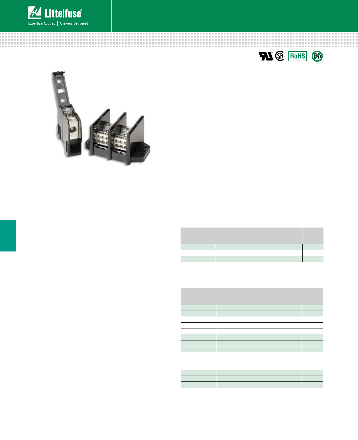
122 © 2014 Littelfuse POWR-GARD® Products Cataloglittelfuse.com
Blocks and Holders
Fuse Blocks and Holders
6
Specifications
Voltage Rating 600 V
Current Rating Based on NEC Table 310.16, using 75°C copper wire
Material Phenolic rated at 150°C and Thermoplastic
rated at 125°C (LD1400 and LS1300 series only)
Connector Standard: Highly con duc tive aluminum, tin plated
Copper: Highly conductive copper, tin plated
Flammability Rating UL94 V-0
Approvals UL Recognized - LD/LS Series (File: E171395)
LFD/LFS Series (File: E309688)
CSA Certified - LD/LS Series (File: LR700111)
LFD/LFS Series (File: 007316_0_000)
Environmental RoHS compliant, Lead (Pb) free
Ordering Information
See Selection Guide on next pages
Web Resources
For technical information, visit:
littelfuse.com/powrbloks
POWR-BLOKS™
Distribution Blocks • Splicer Blocks • Covers
Description
POWR-BLOKSTM power distribution blocks offer a safe,
convenient way of splicing cables, providing a fixed junction
tap-off point or splitting primary power into secondary
circuits. Lx2xxx-DIN series offers integral DIN-Rail mount
and an optional hinged safety cover.
Optional power distribution block covers provide protection
against accidental shorting between poles caused by
loose wires, tools, or other conductive material. They also
protect personnel from accidentally contacting energized
connectors. To order protective covers, match the number
of poles for the block to the cover.
Applications
Typical applications include heating, air conditioning and
refrigeration systems, el e va tor systems, material handling
equipment, control panels, motor controls, switchgear,
and anywhere power needs to be distributed to more
than one load.
Connectors
Box lug connectors are designed for use with a single, solid
or class B or C stranded conductor. Use of more than one
con ductor per connector opening or use of extra-flexible,
fine-stranded conductors, such as welding cable, voids the
UL Listing and may cause overheating. Manufacturers of
cable ter minations can furnish crimp-on sleeves for fine
stranded conductors which permit these conductors to be
used with box lugs.
Ampere Ratings
The ampere rating per pole for power distribution blocks is
based on the line ampacity of 75°C insulated conductors per
NEC® Table 310.15 (b)(16).* If 60°C insulated conductors
are used, load must not exceed the ampacity of 60°C
conductors. Use of conductors rated in excess of 75°C
is permitted (for example 90°C), however, load must not
exceed the ampacity of 75°C conductors.
*Formerly table 210.16
Hinged Plastic Covers
CATALOG/
ORDERING
NUMBER
FOR USE WITH
DISTRIBUTION/SPLICER BLOCK NO. POLES
0LCH1321Z LD2xxx-1DIN / LS2xxx-1DIN 1
0LCH1322Z LD2xxx-2DIN / LS2xxx-2DIN 2
0LCH1323Z LD2xxx-3DIN / LS2xxx-3DIN 3
Note: Optional hinged covers snap on to blocks.
Clear Plastic Covers
CATALOG/
ORDERING
NUMBER
FOR USE WITH
DISTRIBUTION/SPLICER BLOCK NO. POLES
LPBC02 LD0xxx-2 / LS0xxx-2 2
LPBC03 LFD0xxx-3 / LD0xxx-3 / LS0xxx-3 3
LPBC21 LD2xxx-1 / LS2xxx-1 1
LPBC22 LD2xxx-2 / LS2xxx-2 2
LPBC23 LFD2xxx-3 / LD2xxx-3 / LFS2xxx-3 / LS2xxx-3 3
LPBC31 LD3xxx-1 / LS3xxx-1 1
LPBC32 LD3xxx-2 / LS3xxx-2 2
LPBC33 LFD3xxx-3 / LD3xxx-3 / LS3xxx-3 3
LPBC41 LD4xxx-1 / LS4xxx-1 1
LPBC42 LD4xxx-2 / LS4xxx-2 2
LPBC43 LD4xxx-3 / LS4xxx-3 3
LPBC51 LD5xxx-1 / LS5xxx-1 1
LPBC52 LD5xxx-2 / LS5xxx-2 2
LPBC53 LFD5xxx-3 / LD5xxx-3 / LS5xxx-3 3
Note: For installation of optional clear plastic covers, use the screws provided with each cover.
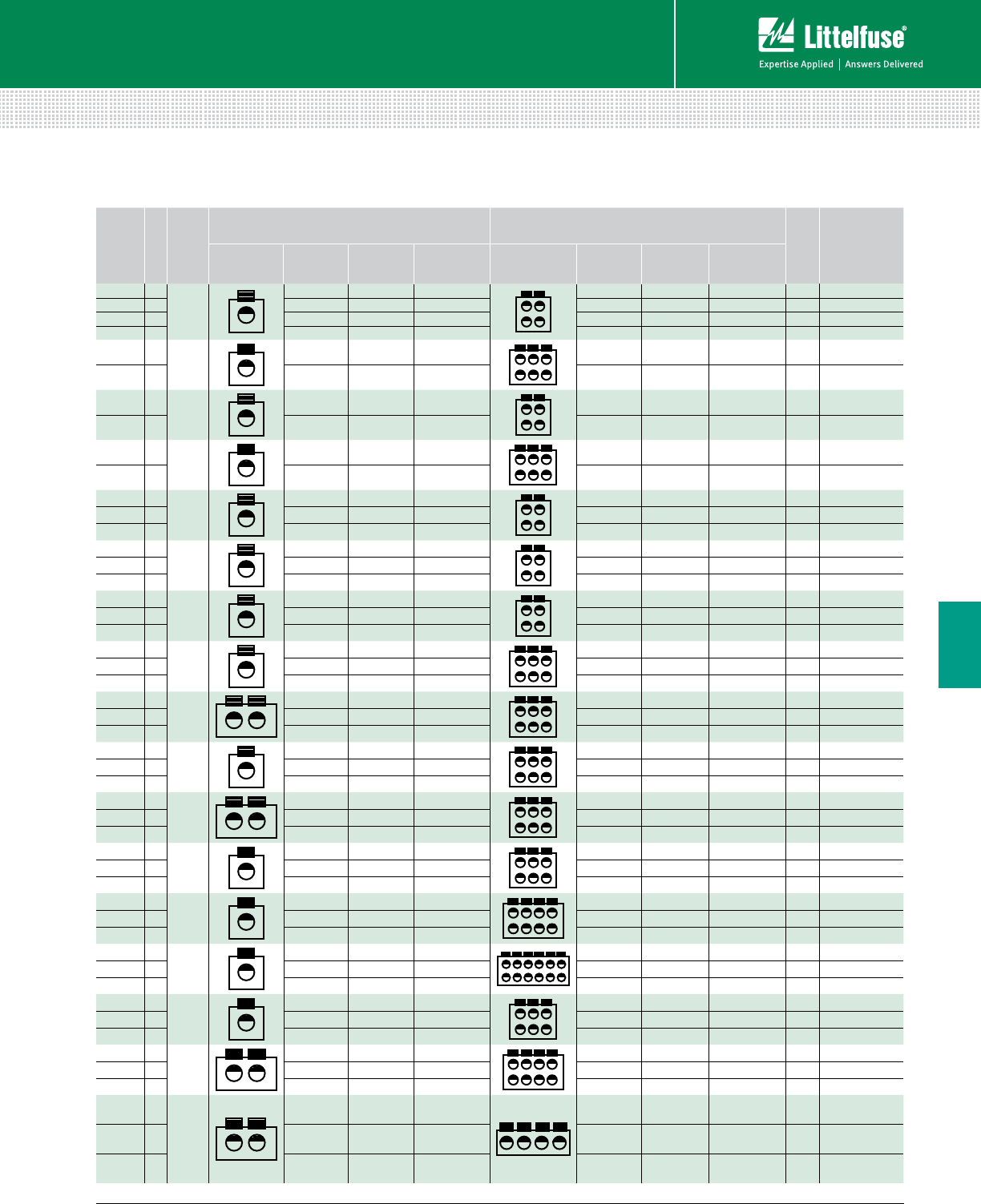
123 littelfuse.com © 2014 Littelfuse POWR-GARD® Products Catalog
Blocks and Holders
Fuse Blocks and Holders
6
POWR-BLOKS™
Distribution Block Selection Guide
AMP
RATING
PER
POLE
POLES
CONNECTOR
MATERIAL
LINE CONNECTION LOAD CONNECTION
FIGURE
CATALOG/
ORDERING
NUMBER
CONNECTOR OPENINGS
PER POLE LUG TYPE WIRE RANGE CONNECTOR OPENINGS
PER POLE LUG TYPE WIRE RANGE
115 1
AL
1Slotted #2 - #14 4 Slotted #10 - #18 2 0LD14001Z
115 2 1 Slotted #2 - #14 4 Slotted #10 - #18 2 0LD14002Z
115 3 1 5/32" Hex #2 - #14 4 5/64" Hex #10 - #18 2 LFD14003Z
115 4 1 Slotted #2 - #14 4 Slotted #10 - #18 2 0LD14004Z
175 2
AL
15/16" Hex 2⁄0 - #14 6 Slotted #4 - #14 1 0LD04012Z
175 3 1 3/16" Hex 2⁄0 - #14 6 1/8" Hex #4 - #14 1 LFD04013Z
175 2
AL
15/16" Hex 2⁄0 - #14 4 Slotted #4 - #14 1 0LD04022Z
175 3 1 5/16" Hex 2⁄0 - #14 4 Slotted #4 - #14 1 0LD04023Z
310 2
AL
15/16" Hex 350mcm - #6 6 Slotted #4 - #14 1 0LD04042Z
310 3 1 5/16" Hex 350mcm - #6 6 Slotted #4 - #14 1 0LD04043Z
175 1
AL
15/16" Hex 2⁄0 - #14 4 1/8" Hex #4 - #14 3 0LD25701Z
175 2 1 3/16" Hex 2⁄0 - #14 4 1/8" Hex #4 - #14 3 LFD25702Z
175 3 1 3/16" Hex 2⁄0 - #14 4 1/8" Hex #4 - #14 3 LFD25703Z
175 1
CU
13/16" Hex 2⁄0 - #14 4 Slotted #4 - #14 3 0LD29701Z
175 2 1 3/16" Hex 2⁄0 - #14 4 Slotted #4 - #14 3 0LD29702Z
175 3 1 3/16" Hex 2⁄0 - #14 4 Slotted #4 - #14 3 0LD29703Z
335 1
AL
15/16" Hex 400mcm - #6 4 Slotted #2 - #14 5 0LD35521Z
335 2 1 5/16" Hex 400mcm - #6 4 Slotted #2 - #14 5 0LD35522Z
380 3 1 3/8" Hex 500mcm - #6 4 5/32" Hex #2 - #14 5 LFD35523Z
335 1
AL
15/16" Hex 400mcm - #6 6 Slotted #2 - #14 5 0LD35531Z
335 2 1 5/16" Hex 400mcm - #6 6 Slotted #2 - #14 5 0LD35532Z
380 3 1 3/8" Hex 500mcm - #6 6 5/32" Hex #2 - #14 5 LFD35533Z
350 1
AL
25/16" Hex 2⁄0 - #14 6 Slotted #4 - #14 5 0LD35551Z
350 2 2 5/16" Hex 2⁄0 - #14 6 Slotted #4 - #14 5 0LD35552Z
350 3 2 3/16" Hex 2⁄0 - #14 6 1/8" Hex #4 - #14 5 LFD35553Z
380 1
CU
1Slotted 500mcm - #4 6 5/32" Hex #2 - #14 5 0LD39531Z
380 2 1 Slotted 500mcm - #4 6 5/32" Hex #2 - #14 5 0LD39532Z
380 3 1 Slotted 500mcm - #4 6 5/32" Hex #2 - #14 5 0LD39533Z
350 1
CU
2Slotted 2⁄0 - #14 6 1/8" Hex #4 - #14 5 0LD39551Z
350 2 2 Slotted 2⁄0 - #14 6 1/8" Hex #4 - #14 5 0LD39552Z
350 3 2 Slotted 2⁄0 - #14 6 1/8" Hex #4 - #14 5 0LD39553Z
380 1
AL
1Slotted 500mcm - #4 6 Slotted #2 - #14 6 0LD45511Z
380 2 1 Slotted 500mcm - #4 6 Slotted #2 - #14 6 0LD45512Z
380 3 1 Slotted 500mcm - #4 6 Slotted #2 - #14 6 0LD45513Z
335 1
AL
1Slotted 400mcm - #6 8 Slotted #2 - #14 6 0LD45601Z
335 2 1 Slotted 400mcm - #6 8 Slotted #2 - #14 6 0LD45602Z
335 3 1 Slotted 400mcm - #6 8 Slotted #2 - #14 6 0LD45603Z
380 1
AL
1Slotted 500mcm - #4 12 Slotted #2 - #14 7 0LD55521Z
380 2 1 Slotted 500mcm - #4 12 Slotted #2 - #14 7 0LD55522Z
380 3 1 3/8" Hex 500mcm - #4 12 5/32" Hex #2 - #14 7 LFD55523Z
380 1
AL
13/8" Hex 500mcm - #4 6 5/16" Hex 2⁄0 - #14 7 0LD55791Z
380 2 1 3/8" Hex 500mcm - #4 6 5/16" Hex 2⁄0 - #14 7 0LD55792Z
380 3 1 3/8" Hex 500mcm - #4 6 3/16" Hex 2⁄0 - #14 7 LFD55793Z
760 1
AL
23/8" Hex 500mcm - #4 8 5/16" Hex 2⁄0 - #14 7 0LD55861Z
760 2 2 3/8" Hex 500mcm - #4 8 5/16" Hex 2⁄0 - #14 7 0LD55862Z
760 3 2 3/8" Hex 500mcm - #4 8 3/16" Hex 2⁄0 - #14 7 LFD55863Z
665 1
AL
13/8" Hex 500mcm - #4 4 Slotted 2⁄0 - #14 7 0LD55871Z
1 350mcm - #6
665 2 13/8” Hex 500mcm - #4 4 Slotted 2⁄0 - #14 7 0LD55872Z
1 350mcm - #6
665 3 13/8” Hex 500mcm - #4 4 Slotted 2⁄0 - #14 7 0LD55873Z
1 350mcm - #6
Note: AL = Aluminum / CU = Copper
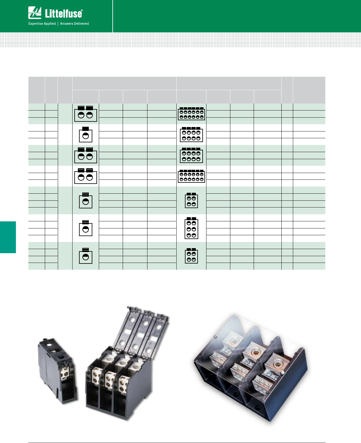
124 © 2014 Littelfuse POWR-GARD® Products Cataloglittelfuse.com
Blocks and Holders
Fuse Blocks and Holders
6
Hinged Plastic Covers Clear Plastic Covers
POWR-BLOKS™
Distribution Block Selection Guide
AMP
RATING
PER
POLE
POLES
CONNECTOR
MATERIAL
LINE CONNECTION LOAD CONNECTION
FIGURE
CATALOG/
ORDERING
NUMBER
CONNECTOR OPENINGS
PER POLE LUG TYPE WIRE RANGE CONNECTOR OPENINGS
PER POLE LUG TYPE WIRE RANGE
760 1
AL
23/8" Hex 500mcm-#4 12 Slotted #4 - #14 7 0LD55921Z
760 2 2 3/8" Hex 500mcm-#4 12 Slotted #4 - #14 7 0LD55922Z
760 3 2 3/8" Hex 500mcm-#4 12 1/8" Hex #4 - #14 7 LFD55923Z
380 1
AL
13/8" Hex 500mcm-#4 8 5/32" Hex #2 - #14 7 0LD55941Z
380 2 1 3/8" Hex 500mcm-#4 8 5/32" Hex #2 - #14 7 0LD55942Z
380 3 1 3/8" Hex 500mcm-#4 8 5/32" Hex #2 - #14 7 0LD55943Z
760 1
CU
23/8" Hex 500mcm-#4 8 3/16" Hex 2⁄0 - #14 7 0LD59861Z
760 2 2 3/8" Hex 500mcm-#4 8 3/16" Hex 2⁄0 - #14 7 0LD59862Z
760 3 2 3/8" Hex 500mcm-#4 8 3/16" Hex 2⁄0 - #14 7 0LD59863Z
760 1
CU
23/8" Hex 500mcm-#4 12 Slotted #2 - #14 7 0LD59921Z
760 2 2 3/8" Hex 500mcm-#4 12 Slotted #2 - #14 7 0LD59922Z
760 3 2 3/8" Hex 500mcm-#4 12 Slotted #2 - #14 7 0LD59923Z
175 1
AL
13/16" Hex 2⁄0 - #14 4 1/8" Hex #4 - #14 4 0LD25701ZXDIN
175 2 1 3/16" Hex 2⁄0 - #14 4 1/8" Hex #4 - #14 4 0LD25702ZXDIN
175 3 1 3/16" Hex 2⁄0 - #14 4 1/8" Hex #4 - #14 4 0LD25703ZXDIN
175 Adder 1 – 2⁄0 - #14 4 – #4 - #14 4 0LD2570AZXDIN
175 1
AL
15/16” Hex 2⁄0 - #14 6 1/8” Hex #4 - #14 4 0LD25801ZXDIN
175 2 1 5/16" Hex 2⁄0 - #14 6 1/8” Hex #4 - #14 4 0LD25802ZXDIN
175 3 1 5/16" Hex 2⁄0 - #14 6 1/8” Hex #4 - #14 4 0LD25803ZXDIN
175 Adder 1 5/16” Hex 2⁄0 - #14 6 1/8” Hex #4 - #14 4 0LD2580AZXDIN
175 1
CU
13/16" Hex 2⁄0 - #14 4 Slotted #4 - #14 4 0LD29701ZXDIN
175 2 1 3/16" Hex 2⁄0 - #14 4 Slotted #4 - #14 4 0LD29702ZXDIN
175 3 1 3/16" Hex 2⁄0 - #14 4 Slotted #4 - #14 4 0LD29703ZXDIN
175 Adder 1 – 2⁄0 - #14 4 – #4 - #14 4 0LD2970AZXDIN
Note: AL = Aluminum / CU = Copper
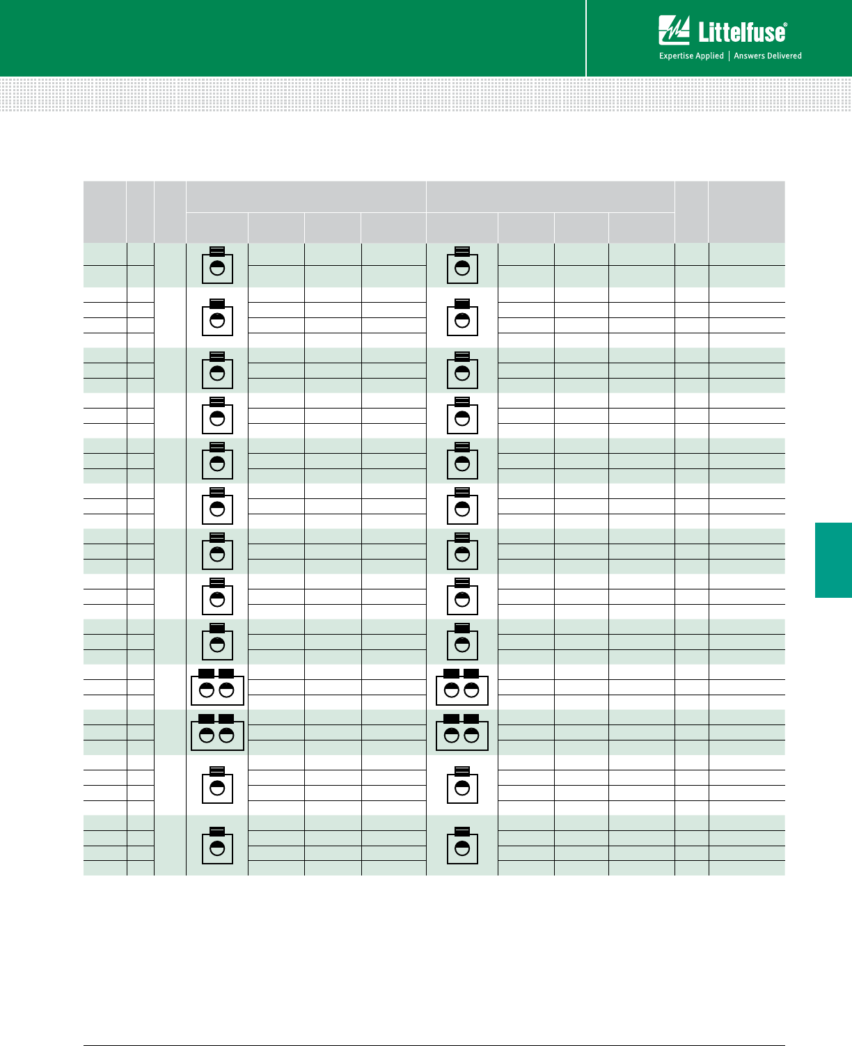
125 littelfuse.com © 2014 Littelfuse POWR-GARD® Products Catalog
Blocks and Holders
Fuse Blocks and Holders
6
POWR-BLOKS™
Splicer Block Selection Guide
AMP
RATING
PER
POLE
POLES
CONNECTOR
MATERIAL
LINE CONNECTION LOAD CONNECTION
FIGURE
CATALOG/
ORDERING
NUMBER
CONNECTOR OPENINGS
PER POLE LUG TYPE WIRE RANGE CONNECTOR OPENINGS
PER POLE LUG TYPE WIRE RANGE
310 2
AL
15/16" Hex 350mcm-#6 1 5/16" Hex 350mcm-#6 1 0LS03032Z
310 3 1 5/16" Hex 350mcm-#6 1 5/16" Hex 350mcm-#6 1 0LS03033Z
115 1
AL
1Slotted #2 - #14 1 Slotted #2 - #14 2 0LS13001Z
115 2 1 Slotted #2 - #14 1 Slotted #2 - #14 2 0LS13002Z
115 3 1 5/32" Hex #2 - #14 1 5/32" Hex #2 - #14 2 LFS13003Z
115 4 1 Slotted #2 - #14 1 Slotted #2 - #14 2 0LS13004Z
150 1
CU
13/16" Hex 1⁄0 - #18 1 3/16" Hex 1⁄0 - #18 3 0LS21211Z
150 2 1 3/16" Hex 1⁄0 - #18 1 3/16" Hex 1⁄0 - #18 3 0LS21212Z
150 3 1 3/16" Hex 1⁄0 - #18 1 3/16" Hex 1⁄0 - #18 3 0LS21213Z
115 1
AL
1Slotted #2 - #14 1 Slotted #2 - #14 3 0LS25521Z
115 2 1 Slotted #2 - #14 1 Slotted #2 - #14 3 0LS25522Z
115 3 1 Slotted #2 - #14 1 Slotted #2 - #14 3 0LS25523Z
175 1
AL
15/16" Hex 2⁄0 - #14 1 5/16" Hex 2⁄0 - #14 3 0LS25721Z
175 2 1 5/16" Hex 2⁄0 - #14 1 5/16" Hex 2⁄0 - #14 3 0LS25722Z
175 3 1 3/16" Hex 2⁄0 - #14 1 3/16" Hex 2⁄0 - #14 3 LFS25723Z
255 1
AL
15/16" Hex 250mcm-#6 1 5/16" Hex 250mcm-#6 5 0LS31231Z
255 2 1 5/16" Hex 250mcm-#6 1 5/16" Hex 250mcm-#6 5 0LS31232Z
255 3 1 5/16" Hex 250mcm-#6 1 5/16" Hex 250mcm-#6 5 0LS31233Z
255 1
CU
13/8" Hex 250mcm-#6 1 3/8" Hex 250mcm-#6 5 0LS31241Z
255 2 1 3/8" Hex 250mcm-#6 1 3/8" Hex 250mcm-#6 5 0LS31242Z
255 3 1 3/8" Hex 250mcm-#6 1 3/8" Hex 250mcm-#6 5 0LS31243Z
310 1
AL
15/16" Hex 350mcm-#6 1 5/16" Hex 350mcm-#6 5 0LS31261Z
310 2 1 5/16" Hex 350mcm-#6 1 5/16" Hex 350mcm-#6 5 0LS31262Z
310 3 1 5/16" Hex 350mcm-#6 1 5/16" Hex 350mcm-#6 5 0LS31263Z
420 1
AL
11/2" Hex 600mcm-#4 1 1/2" Hex 600mcm-#4 6 0LS45571Z
420 2 1 1/2" Hex 600mcm-#4 1 1/2" Hex 600mcm-#4 6 0LS45572Z
420 3 1 1/2" Hex 600mcm-#4 1 1/2" Hex 600mcm-#4 6 0LS45573Z
620 1
AL
25/16" Hex 350mcm-#4 2 5/16" Hex 350mcm-#4 7 0LS51291Z
620 2 2 5/16" Hex 350mcm-#4 2 5/16" Hex 350mcm-#4 7 0LS51292Z
620 3 2 5/16" Hex 350mcm-#4 2 5/16" Hex 350mcm-#4 7 0LS51293Z
760 1
AL
23/8" Hex 500mcm-#4 2 3/8" Hex 500mcm-#4 7 0LS53011Z
760 2 2 3/8" Hex 500mcm-#4 2 3/8" Hex 500mcm-#4 7 0LS53012Z
760 3 2 3/8" Hex 500mcm-#4 2 3/8" Hex 500mcm-#4 7 0LS53013Z
175 1
AL
15/16" Hex 2⁄0 - #14 1 5/16" Hex 2⁄0 - #14 4 0LS25721ZXDIN
175 2 1 5/16" Hex 2⁄0 - #14 1 5/16" Hex 2⁄0 - #14 4 0LS25722ZXDIN
175 3 1 5/16" Hex 2⁄0 - #14 1 5/16" Hex 2⁄0 - #14 4 0LS25723ZXDIN
175 Adder 1 – 2⁄0 - #14 1 – 2⁄0 - #14 4 0LS2572AZXDIN
175 1
CU
15/16" Hex 2⁄0 - #14 1 5/16" Hex 2⁄0 - #14 4 0LS29721ZXDIN
175 2 1 5/16" Hex 2⁄0 - #14 1 5/16" Hex 2⁄0 - #14 4 0LS29722ZXDIN
175 3 1 5/16" Hex 2⁄0 - #14 1 5/16" Hex 2⁄0 - #14 4 0LS29723ZXDIN
175 Adder 1 – 2⁄0 - #14 1 – 2⁄0 - #14 4 0LS2972AZXDIN
Note: AL = Aluminum / CU = Copper
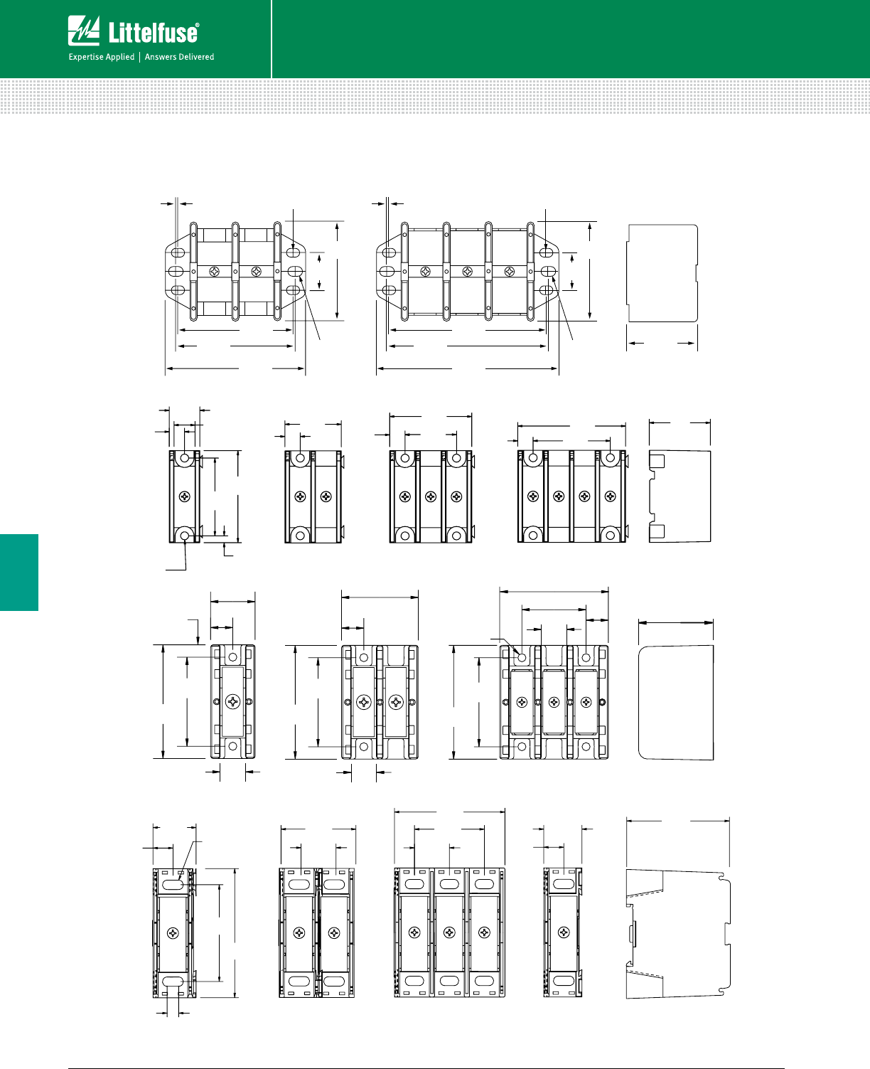
126 © 2014 Littelfuse POWR-GARD® Products Cataloglittelfuse.com
Blocks and Holders
Fuse Blocks and Holders
6
POWR-BLOKS™
Distribution Block and Splicer Block Outline Drawings
1.00"
[25.4]
2.90"
[73.7]
.07"
[1.8]
.07"
[1.8]
.218 x .375"
[5.5 x 9.5]SLOT
3.52"
[89.3]
4.13"
[104.8]
.265 x .375"
[6.7 x 9.5] SLOT
1.00"
[25.4]
2.90"
[73.7]
.218 x .375"
[5.5 x 9.5]SLOT
.265 x .375"
[6.7 x 9.5] SLOT
3.38"
[85.8] 4.73"
[121]
5.38"
[137]
4.63"
[118]3.38"
[85.8]
Figure 1
Dimensions Inches (mm)
2-pole 3-pole
2.04”
[51.6]
0.38”
[9.7]
2.68”
[67.7] 1.52”
[38.7]
1.92”
[48.4]
0.38”
[9.7] 1.28”
[32.5]
1.40”
[35.6]
0.38”
[9.7]
2.29”
[58.1]
0.38”
[9.7]
0.76”
[19] 0.52”
[13]
0.17”
[4.5]
ø .201 / [5.11]
THRU
1.93”
[49.1]
Figure 2
2-pole 3-pole 4-pole1-pole
2.88"
[73.0]
2.25"
[57.2]
.56"
[14]
1.94"
[49.2]
2.75"
[69.9]
1.62"
[42]
2.25"
[57.2]
2.88"
[73.0]
.63"
[16.1]
.56"
[14]
Ø .205 [5.2]
THRU
1.13"
[28.6]
.56"
[14]
.62"
[16]
.62"
[16]
2.25"
[57.2]
2.88"
[73.0]
1.78"
[45.2]
.31"
[7.9]
Figure 3
2-pole 3-pole1-pole
2.42”
[61.5]
1.00”
[25.4]
0.47”
[11.8]
0.47”
[11.8]
2.25”
[57.2]
3.00”
[76.2]
1.74”
[44.2]
2.57”
[65.3]
0.89”
[22.6]
1.63”
[41.3]
0.81”
[20.6]
0.81”
[20.6]
0.25”
[6.4]
R 0.11” [2.77]
SLOT THRU TYPE
Figure 4
1-pole 2-pole 3-pole Adder
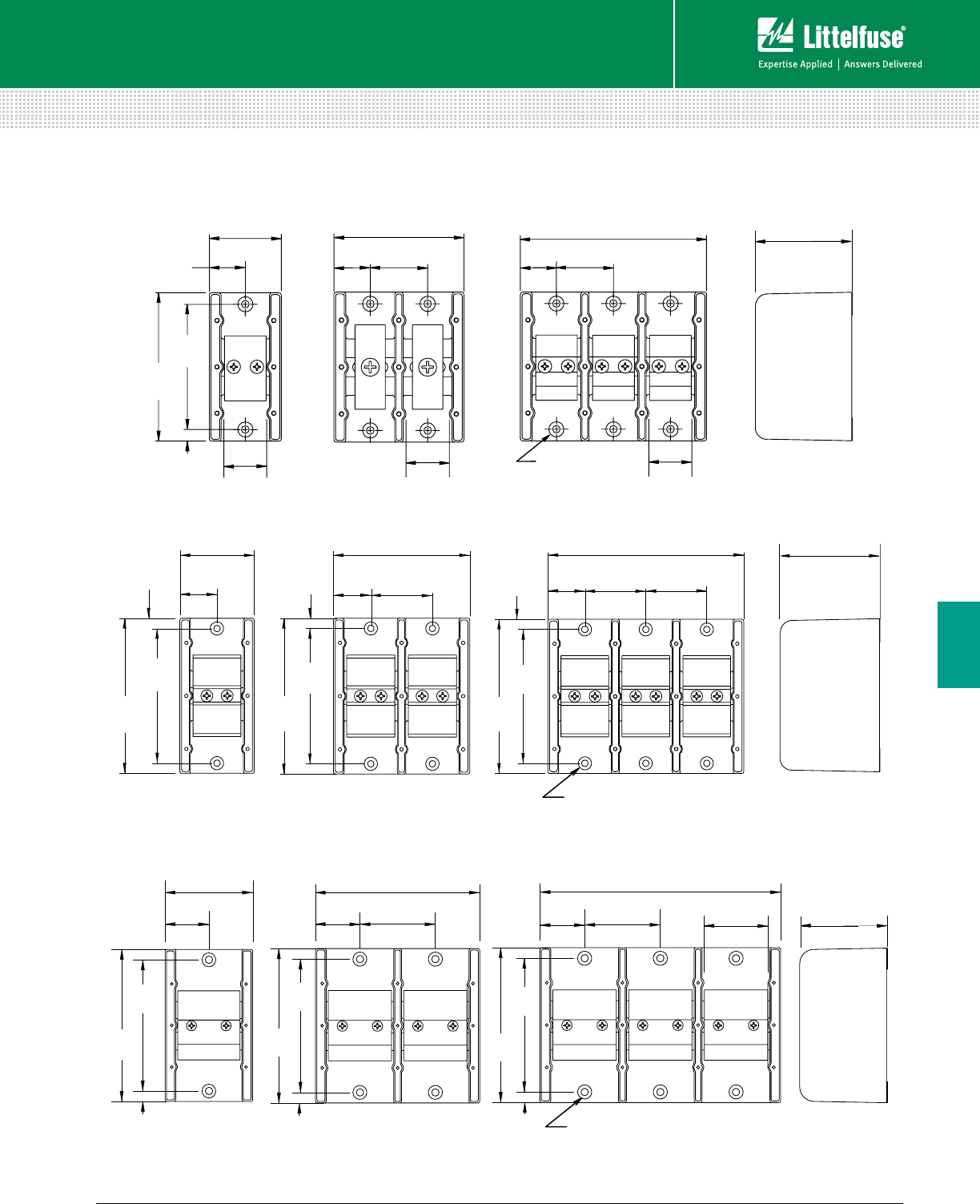
127 littelfuse.com © 2014 Littelfuse POWR-GARD® Products Catalog
Blocks and Holders
Fuse Blocks and Holders
6
POWR-BLOKS™
Distribution Block and Splicer Block Outline Drawings
Dimensions Inches (mm)
1.94”
[49.3]
0.97”
[25.0]
0.97”
[25.0]
3.47”
[88.1]
5.00”
[127.0]
2.61”
[66.2]
1.53”
[38.9]
0.97”
[25.0]
1.53”
[38.9]
4.00”
[102]
0.31”
[7.9]
1.17”
[29.7]
1.17”
[29.7]
1.17”
[29.7]
3.38”
[85.7]
n
.203” THRU
v n
..406”
x
.180”
Figure 5
2-pole 3-pole1-pole
3.12"
[79.2]
.37"
(9.5)
.37"
[9.5]
.37"
[9.5]
5.50"
[140]
4.75"
[121]
1.58"
[40.2]
3.17"
[80.4]
4.75"
[121]
5.50"
[140]
1.58"
[40.2]
2.69"
[68.2]
5.88"
[149]
4.75"
[121]
5.50"
[140]
2.30"
[58.5]
8.54"
[217]
2.69"
[68.2]
1.58"
[40.2]
n
.265” THRU
v n
.500”
x
.219”
Figure 7
2-pole 3-pole1-pole
.31"
[7.9] .31"
[7.9]
.31"
[7.9]
2.28"
[57.9]
1.14"
[29.0]
4.75"
[121]
4.13"
[105]
1.14"
[29.0]
1.88"
[47.8]
4.16"
[106]
4.13"
[105]
4.75"
[121]
2.92
1.88"
[47.8]
6.04"
[153]
1.88"
[47.8]
1.14"
[29.0]
4.13"
[105]
4.75"
[121]
[74.0]
n
.20” THRU
v n
.41”
x
.18”
Figure 6
2-pole 3-pole1-pole
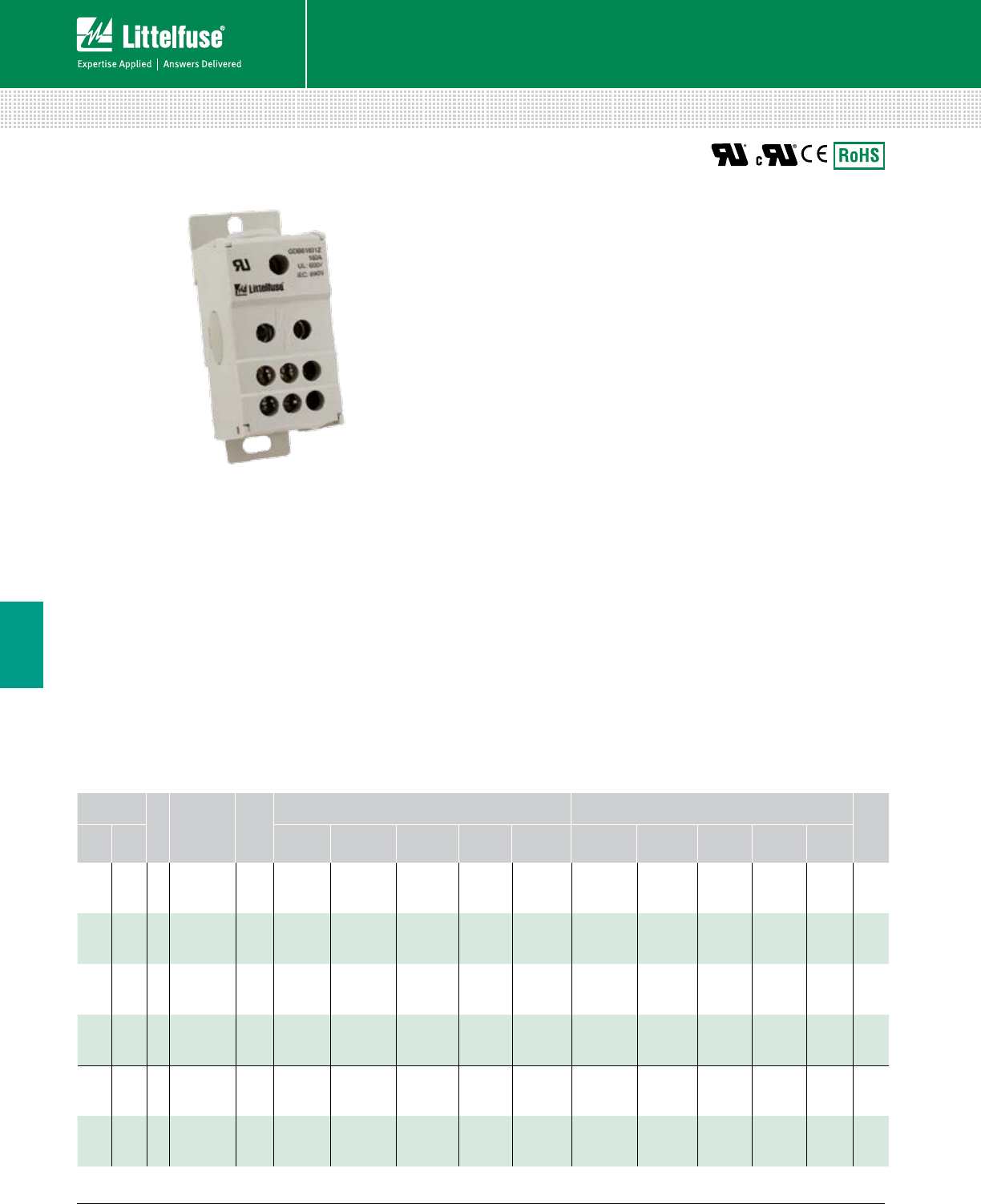
128 © 2014 Littelfuse POWR-GARD® Products Cataloglittelfuse.com
Blocks and Holders
Fuse Blocks and Holders
6
TOUCH-SAFE POWR-BLOKS™
Global Distribution Blocks
Features/Benefits
• Global part meeting UL standards
• Space saving design
• Integrated touch-safe cover to increase safety
• IP20 protection rating
• Mounts to DIN rail or panels
• Reliable brass connections for excellent continuity
in a smaller design
Specifications
Voltage Rating UL: 600 Vac/Vdc
IEC: 690 Vac/Vdc
Ampere Rating 80 – 310 A
Material Thermoplastic
Connector Brass: Better continuity,
Smaller design
Flammability Rating UL94 V-0
Approvals UL Recognized (File: E309688)
c-UL Recognized*
CE: IEC 60947-7-1
Environmental RoHS compliant
*GDB60801Z, GDB61151Z, GDB61153Z, GDB61753Z Only
Web Resources
For additional technical information, visit:
littelfuse.com/gdb
Description
POWR-BLOKSTM Global Distribution Blocks add safety and
mounting versatility to our distribution block solutions. The
Global Distribution Blocks are approved to UL standards.
The Global Distribution Blocks are IP20 finger safe to reduce
the risk of contact and eliminate the need for block or panel
covers. Installation is quick and easy, all blocks can be
mounted on DIN rail or to the panel.
Ordering Information
AMP RATING
PER POLE
POLES
CATALOG/
ORDERING
NUMBER
CONNECTOR
MATERIAL
LINE CONNECTION LOAD CONNECTION
DIN RAIL
MOUNT
UL IEC OPENINGS
PER POLE
OPENING
DIAMETER
WIRE
RANGE TORQUE SCREW
TYPE
OPENINGS
PER POLE
OPENING
DIAMETER
WIRE
RANGE TORQUE SCREW
TYPE
80 80 1 GDB60801Z Brass 1 ø7.0 mm #8 – #4 13.5 in-lbs Slotted 6 2x ø7.0 mm
3x ø4.5 mm
#8 – #4
#10 – #14
13.5 in-lbs
7.2 in-lbs Slotted •
115 125 1 GDB61151Z Brass 1 ø10.0 mm #8 – #2 31 in-lbs Hex 5 mm 6 ø7.0 mm #14 – #4 17.5 in-lbs Slotted •
160 160 1 GDB61601Z Brass 1 ø12.5 mm #8 – 2/0 35.5 in-lbs Hex 5 mm 6 ø7.0 mm #14 – #4 17.5 in-lbs Slotted •
310 400 1 GDB63101Z Brass 1 ø19.0 mm 3/0 – 350
kcmil 230 in-lbs Hex 8 mm 11
2x ø9.0 mm
5x ø6.5 mm
4x ø5.3 mm
#14 – #2
#14 – #6
#14 – #8
34.1 in-lbs
19.8 in-lbs
19.8 in-lbs
Slotted •
115 115 3 GDB61153Z Brass 1 ø10.0 mm #8 – #2 31 in-lbs Hex 4 mm 6 ø6.5 mm #14 – #4 17.5 in-lbs Hex 3 •
175 175 3 GDB61753Z Brass 1 ø12.0 mm #8 – 2/0 35.7 in-lbs Hex 5 mm 6 ø6.5 mm #14 – #4 17.5 in-lbs Hex 3 •
* GDB60801Z, GDB61151Z, GDB61153X, GDB61753Z Only
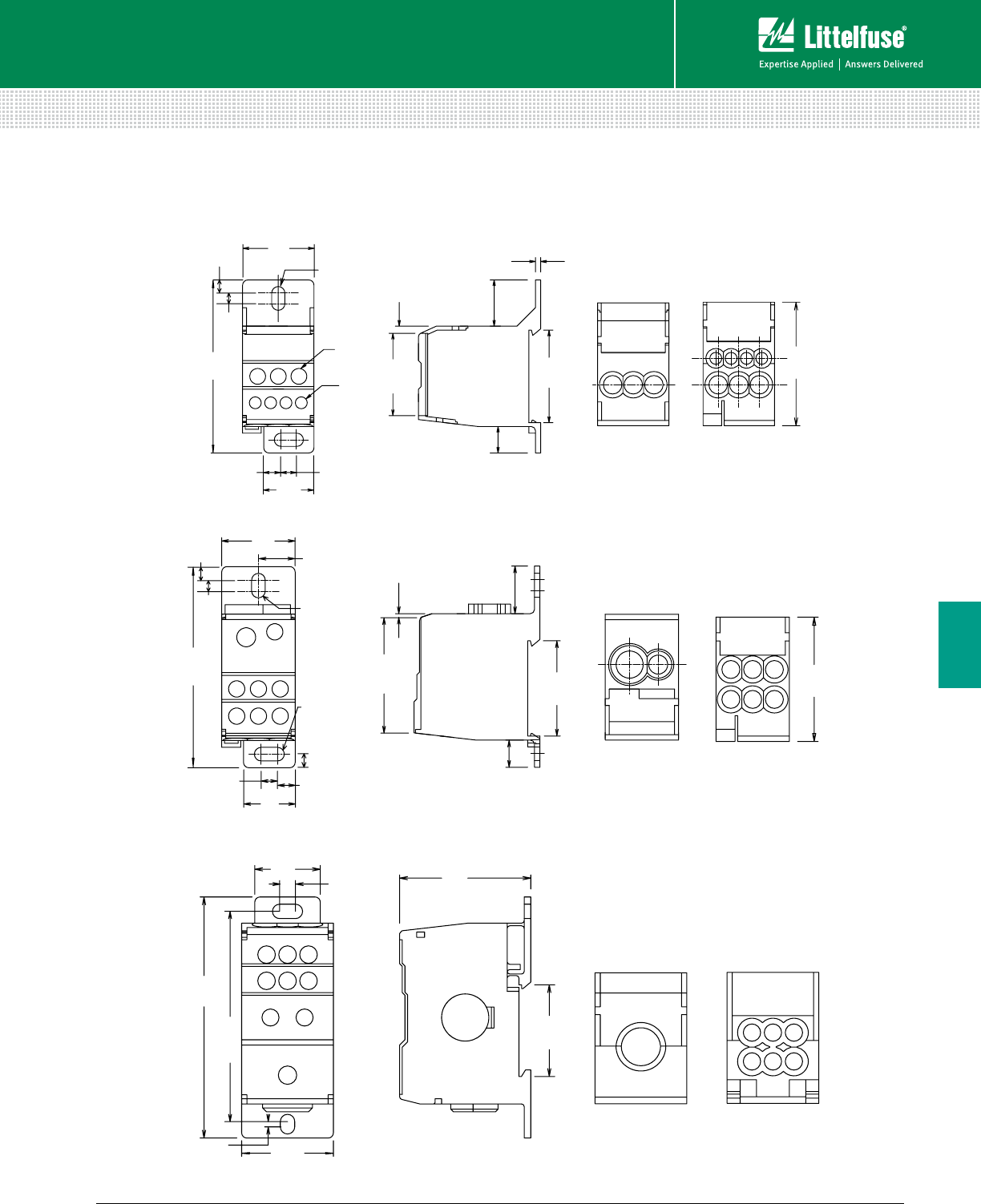
129 littelfuse.com © 2014 Littelfuse POWR-GARD® Products Catalog
Blocks and Holders
Fuse Blocks and Holders
6
TOUCH-SAFE POWR-BLOKS™
Global Distribution Blocks
4x Ø 0.18
(4x Ø 4.5)
3x Ø 0.24
(3x Ø 6)
Ø 0.22
(Ø 5.5)
0.08
(2)
0.75
(19)
2.58
(65.5)
1.06
(27)
0.20
(5)
0.16
(4)
0.24
(6)
0.26
(6.5)
0.39
(10)
1.22
(31.1)
1.84
(46.8)
0.11
(2.7)
1.38
(35)
0.69
(17.5)
0.75
(19)
0.20
(5.0)
Ø 0.22
(Ø 5.5)
1.80
(45.8)
0.24
(6.0) 0.26
(6.5)
1.06
(27)
0.20
(5.0)
0.16
(4.0)
2.9
(74)
0.53
(13.5)
1.67
(42.3) 1.38
(35)
0.69
(17.5)
0.05
(1.3)
0.39
(10)
Ø 0.22
(Ø 5.5)
0.98
(25)
3.62
(92)
3.16
(80.3)
1.38
(35)
0.08
(2.0)
2.0
(50)
1.4
(35)
0.24
(6.0)
80 A
GDB60801Z
115 A
GDB61151Z
160 A
GDB61601Z
Dimensions Inches (mm)
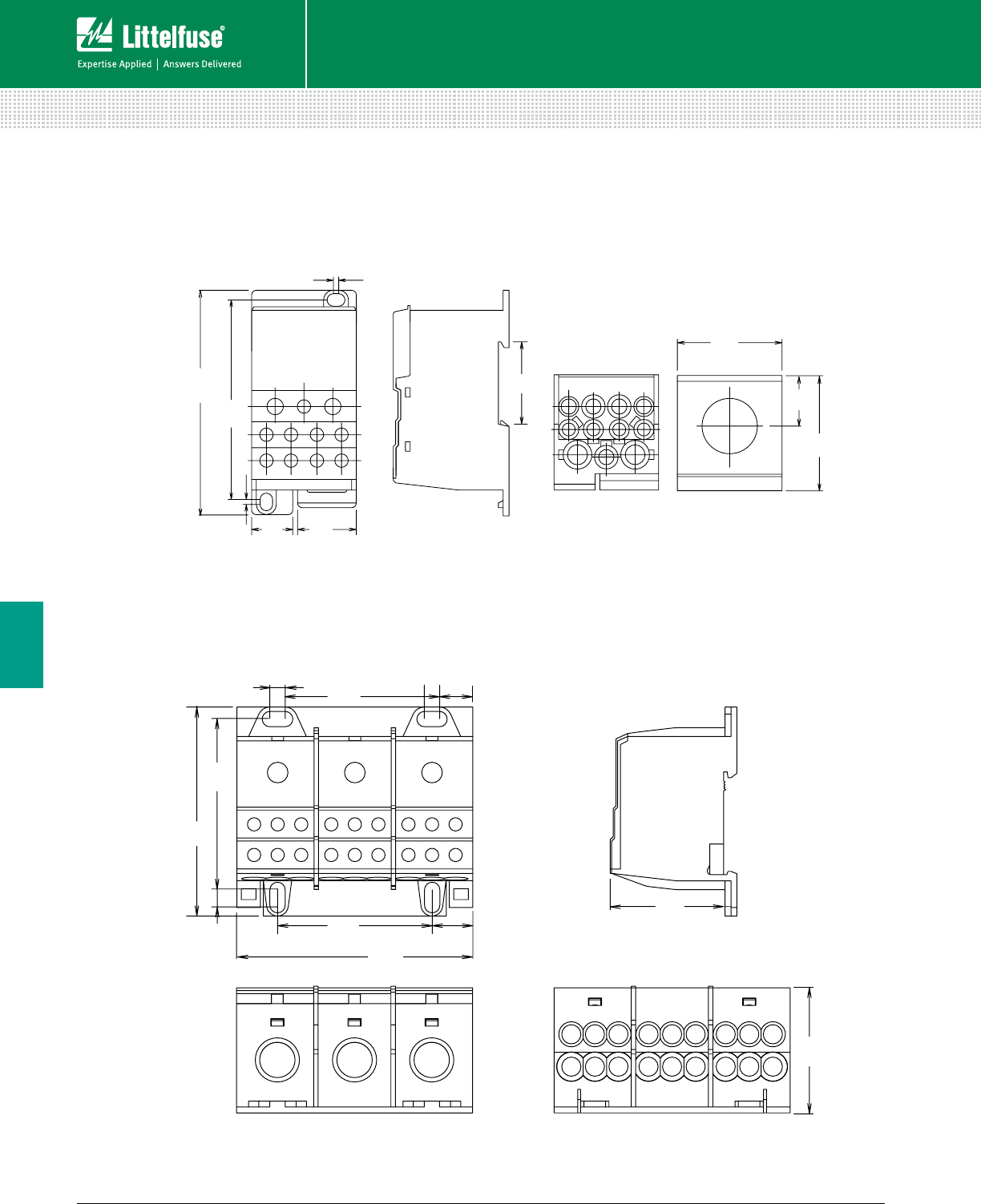
130 © 2014 Littelfuse POWR-GARD® Products Cataloglittelfuse.com
Blocks and Holders
Fuse Blocks and Holders
6
1.75
(44.5)
1.93
(49)
0.85
(21.5)
0.09
(2.3)
3.74
(95)
3.34
(84.8)
0.69
(17.5)
0.98
(25)
0.09
(2.2)
1.38
(35)
1.50
(38)
2.80
(71)
3.14
(80)
0.54
(13.8)
1.69
(43)
2.07
(52.5)
0.20
(5.2)
2.07
(52.5)
2.28
(58)
0.20
(5.2)
0.43
(11.2)
310 A
GDB63101Z
115 A
GDB61153Z
175 A
GDB61753Z
Dimensions Inches (mm)
TOUCH-SAFE POWR-BLOKS™
Global Distribution Blocks
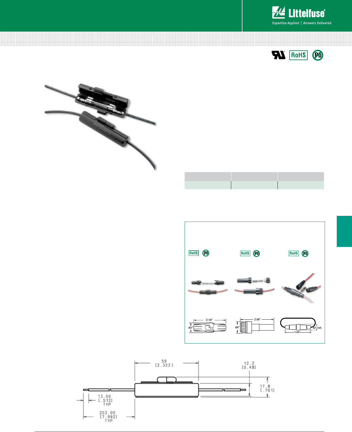
131 littelfuse.com © 2014 Littelfuse POWR-GARD® Products Catalog
Blocks and Holders
Fuse Blocks and Holders
6
Specifications
Voltage Rating 500 Vac, 125 Vdc
Ampere Rating 15 A
Fuse Type 1⁄4” x 11⁄4”
Fuse Clips Tin-plated brass
Wire Black 18 AWG, 150˚ C Stranded
Molded Body Single piece thermoplastic
Flammability Rating UL94 V-0
Approvals UL Recognized (File: E14721)
Environmental RoHS complaint, Lead (Pb) free
Storage Temperature -40˚ C to 80˚ C
Operating Temperature -55˚ C to 125˚ C
Ordering Information
Web Resources
For more information, visit: littelfuse.com/150322
CATALOG NUMBER ORDERING NUMBER STANDARD PACK
150322 01500322H 100 PIECES
Dimensions mm (inches)
Recommended Fuses
3AG (312, 313 Series) ....................................................... 33
3AB (314, 326, 505 Series) ............................................... 33
Description
The 150322 is a 500 Vac/125 Vdc rated inline fuse
holder ideal for applications where supplemental
protection is needed, such as lighting ballasts and
power supplies. 8-inch pre-stripped wire leads and
fuse clips come preassembled for quick installation.
Features/Benefits
• Single piece body minimizes component count
• High voltage rating accommodates many
power applications
• Wire leads are pre-attached to fuse clips for
quick assembly
• Single piece molded body
• UL Recognized
Twist-Lock
155 Series
In-Line Mount
32 V 3AG, SFE
Heavy-Duty Bayonet
155 Series
In-Line Mount
32 V 3AG
Special Type
150 Series
In-Line Mount
250 V 2AG, 5x20mm
Additional In-Line Glass Fuse Holders
Dimensions Inches
IN-LINE GLASS FUSE HOLDERS
150322
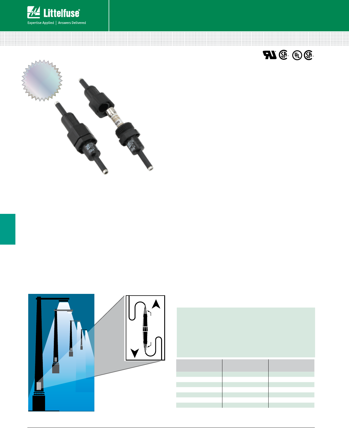
132 © 2014 Littelfuse POWR-GARD® Products Cataloglittelfuse.com
Blocks and Holders
Fuse Blocks and Holders
6
IN-LINE WATERTIGHT FUSE HOLDERS
LEB/LEX LEC/LEY
TO
LOAD
TO
SOURCE
ELECTRICAL TAPE
TO
LOAD
TO
SOURCE
ELECTRICAL TAPE
Description
Recently redesigned, the Littelfuse 600 V in-line watertight
fuse holders allow maximum protection for high humidity and
corrosive environments. The fuse holders are designed to be
touch-safe and flexible for use in a variety of applications. See
the list below for the redesigned part numbers.
Applications
• Street lighting and parking lot lighting
• Sports lighting and various outdoor illuminated signs
• Boat electrical circuits, tractors/yard equipment and
general outdoor circuit protection (such as traffic
signals, alley lighting and electric wheelchairs)
Specifications
Voltage rating 600 V
Ampere rating up to 30 A
Interrupting rating 200 kA rms symmetrical (with Class CC fuses)
Approvals LEB/LEX series UL Recognized Miscellaneous
Fuse holder per UL UL 4248 (File: E14721)
CSA Certified per C22.2, No. 39 (File: LR7316)
LEC/LEY series UL Listed Class CC Branch Circuit
Fuse holder per UL 512 (File: E14721)
CSA Certified per C22.2, No. 39 (File: LR7316)
Features/Benefits
• Design increases safety by individual device
disconnection for easy servicing, eliminating shock risk
• Increases efficiency by preventing faulted ballast from
severely damaging fixture or device
• Watertight seal
• Variety of terminations available for flexible design
• Insulating boots available for harsh environments
Recommended Fuses
LEB/LEX series:
Accepts all Littelfuse Midget and Class CC series fuses
CCMR ............................................................................... 27
KLDR, KLKR ...................................................................... 28
BLF, BLN, FLM, FLQ, KLK, KLKD ..................................... 30
LEC/LEY series:
Accepts only Littelfuse Class CC fuses
CCMR ............................................................................... 27
KLDR, KLKR ...................................................................... 28
Web Resources
Download CAD drawings, dimensions and other technical
information: littelfuse.com/in-line
IMPROVED
Look for these part numbers featuring our
improved design
• Better surface area for ergonomic comfort, improved grip
and better torque
• More pronounced seating – automatically seats as user
begins twisting
• Chamfered edges for additional installation comfort
BASE PART
NUMBER
PREVIOUS ORDERING
NUMBER
NEW ORDERING
NUMBER
LEB-AA 0LEB00AAX 0LEB00AAXK
LEB-AA-S 0LEB0AASX 0LEB0AASXK
LEB-AB 0LEB00ABX 0LEB00ABXK
LEB-AYC-S 0LEBAYCSX 0LEBAYCSXK
LEB-BB 0LEB00BBX 0LEB00BBXK
LEB-JJ 0LEB00JJX 0LEB00JJXK
LEB-JJ-S 0LEB0JJSX 0LEB0JJSXK
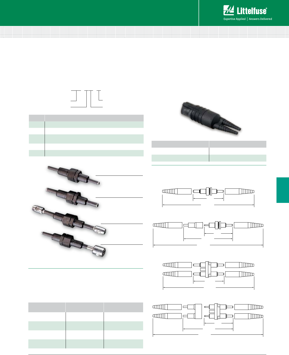
133 littelfuse.com © 2014 Littelfuse POWR-GARD® Products Catalog
Blocks and Holders
Fuse Blocks and Holders
6
IN-LINE WATERTIGHT FUSE HOLDERS
Recommended Crimping Tools
The following crimping tools or equivalents may be used
on either the non-breakaway or breakaway watertight
in-line fuse holders.
TERMINAL SIZE T&B PART NUMBER BURNDY PART
NUMBER
A WT161M –
B WT161M MR4C
C M5-GREY Hypress Y34A
D M5-BROWN Hypress Y34A
4.5"
10.3"
( ASSEMBLED LENGTH )
5.4"
( ASSEMBLED LENGTH )
4.5"
9.3"
( ASSEMBLED LENGTH )
WPB1 BOOT
(OPTIONAL)
WPB1 BOOT
(OPTIONAL)
INSULATING BOOT
(STANDARD)
INSULATING BOOT
(STANDARD)
4.2"
4.5"
9.3"
( ASSEMBLED LENGTH )
10.3"
( ASSEMBLED LENGTH )
5.3"
( ASSEMBLED LENGTH )
Dimensions Inches
1-Pole
1-Pole Breakaway
2-Pole
2-Pole Breakaway
A & B Crimp Terminal
C & D Crimp Terminal
J Terminal
Y Terminal
Insulating Boots
• Molded from engineering-grade thermoplastics which
provide high resistance to corrosive environments
• Standard with all breakaway style fuse holders
• For watertight protection of non-breakaway Y-pole
termination, order one WPB1 and one WPB3 boot
ORDERING NUMBER TERMINAL TYPE
WPB1 A, B, C, D, J
WPB3 Y
SERIES DESCRIPTION
LEB One-pole in-line fuse holder for Midget and Class CC fuses
LEC One-pole in-line fuse holder for Class CC fuses
LET One-pole in-line fuse holder with
permanently installed solid neutral
LEX Two-pole in-line fuse holder for Midget and Class CC fuses
LEY Two-pole in-line fuse holder for Class CC fuses
Ordering Information
To order Littelfuse in-line fuse holders by part number,
refer to the charts on the next page.
LEB - AA - S
Littelfuse Series
Load Side/Terminal Size
Breakaway Feature
Line Side/Terminal Size

134 © 2014 Littelfuse POWR-GARD® Products Cataloglittelfuse.com
Blocks and Holders
Fuse Blocks and Holders
6
IN-LINE WATERTIGHT FUSE HOLDERS
SINGLE POLE DOUBLE POLE LOAD TERMINAL SELECTION LINE TERMINAL SELECTION
STANDARD
PART
NUMBER
BREAKAWAY
PART
NUMBER
STANDARD
PART
NUMBER
BREAKAWAY
PART
NUMBER
TERMINAL
TYA PE
LOAD
TERMINAL
WIRE SIZE
RANGE
NUMBER
OF WIRES
PER
TERMINAL
SOLID
WIRE
STRANDED
WIRE
TERMINAL
TYPE
LINE
TERMINAL
WIRE SIZE
RANGE
NUMBER
OF WIRES
PER
TERMINAL
SOLID
WIRE
STRANDED
WIRE
LEB-AA
LEC-AA LEB-AA-S
LEC-AA-S LEX-AA
LEY-AA LEX-AA-S
LEY-AA-S Copper
Crimp #12 to #8
#12 1
2•
••
•Copper
Crimp #12 to #8
#12 1
2•
••
•
LEB-AB
LEC-AB LEB-AB-S
LEC-AB-S LEX-AB
LEY-AB LEX-AB-S
LEY-AB-S Copper
Crimp #12 to #8
#12 1
2•
••
•Copper
Crimp
#10
#6
#4
2
1
1
•
•
—
•
•
•
LEB-AC
LEC-AC —
—LEX-AC
LEY-AC —Copper
Crimp #12 to #8
#12 1
2•
••
•Copper
Crimp #8
#4 2
1•
—•
•
LEB-AD
LEC-AD —
—LEX-AD
LEY-AD —
—Copper
Crimp #12 to #8
#12 1
2•
••
•Copper
Crimp #6
#2 2
1•
—•
•
LEB-AJ
LEC-AJ LEB-AJ- S
LEC-AJ-S — — Copper
Crimp #12 to #8
#12 1
2•
••
•Copper
Set-Screw #12 to #8
#10 to #2 1
1•
——
•
LEB-AYC
LEC-AYC LEB-AYC-S
LEC-AYC-S LEX-AYC
LEY-AYC LEX-AYC-S
LEY-AYC-S Copper
Crimp #12 to #8
#12 1
2•
••
•
"Y" Type
Copper
Set-Screw
#12 to #8
#10 to #2 1
1•
——
•
LEB-BA
LEC-BA LEB-BA-S
LEC-BA-S LEX-BA
LEY-BA LEX-BA-S
LEY-BA-S Copper
Crimp
#10
#6
#4
2
1
1
•
•
—
•
•
•
Copper
Crimp #12 to #8
#12 1
2•
••
•
LEB-BB
LEC-BB LEB-BB-S
LEC-BB-S LEX-BB
LEY-BB LEX-BB-S
LEY-BB-S Copper
Crimp
#10
#6
#4
2
1
1
•
•
—
•
•
•
Copper
Crimp
#10
#6
#4
2
1
1
•
•
—
•
•
•
LEB-BC
LEC-BC —
—LEX-BC
LEY-BC —
—Copper
Crimp
#10
#6
#4
2
1
1
•
•
—
•
•
•
Copper
Crimp #8
#4 2
1•
—•
•
LEB-BD
LEC-BD —
—LEX-BD
LEY-BD —
—Copper
Crimp
#10
#6
#4
2
1
1
•
•
—
•
•
•
Copper
Crimp #6
#2 2
1•
—•
•
LEB-BJ
LEC-BJ LEB-BJ-S
LEC-BJ-S —
——
—Copper
Crimp
#10
#6
#4
2
1
1
•
•
—
•
•
•
Copper
Set-Screw #12 to #8
#10 - #2 1
1•
——
•
LEB-BYC
LEC-BYC LEB-BYC-S
LEC-BYC-S LEX-BYC
LEY-BYC LEX-BYC-S
LEY-BYC-S Copper
Crimp
#10
#6
#4
2
1
1
•
•
—
•
•
•
"Y" Type
Copper
Set-Screw
#12 to #8
#10 - #2 1
1•
——
•
LEB-CA
LEC-CA —
—LEX-CA
LEY-CA —
—Copper
Crimp #8
#4 2
1•
—•
•Copper
Crimp #12 to #8
#12 1
2•
••
•
LEB-CB
LEC-CB —
—LEX-CB
LEY-CB —
—Copper
Crimp #8
#4 2
1•
—•
•Copper
Crimp
#10
#6
#4
2
1
1
•
•
—
•
•
•
LEB-CC
LEC-CC —
—LEX-CC
LEY-CC —
—Copper
Crimp #8
#4 2
1•
—•
•Copper
Crimp #8
#4 2
1•
—•
•
LEB-CD
LEC-CD —
—LEX-CD
LEY-CD —
—Copper
Crimp #8
#4 2
1•
—•
•Copper
Crimp #6
#2 2
1•
—•
•
LEB-CJ
LEC-CJ —
—LEX-CJ
LEY-CJ —
—Copper
Crimp #8
#4 2
1•
—•
•Copper
Set-Screw #12 to #8
#10 - #2 1
1•
—•
•
LEB-CYC
LEC-CYC —
—LEX-CYC
LEY-CYC —
—Copper
Crimp #8
#4 2
1•
—•
•
"Y" Type
Copper
Set-Screw
#12 to #8
#10 to #2 1
1•
——
•
LEB-DA
LEC-DA —
—LEX-DA
LEY-DA —
—Copper
Crimp #6
#2 2
1•
—•
•Copper
Crimp #12 to #8
#12 1
2•
•—
•
LEB-DB
LEC-DB —
—LEX-DB
LEY-DB —
—Copper
Crimp #6
#2 2
1•
—•
•Copper
Crimp
#10
#6
#4
2
1
1
•
•
—
•
•
•
LEB-DC
LEC-DC —
—LEX-DC
LEY-DC —
—Copper
Crimp #6
#2 2
1•
—•
•Copper
Crimp #8
#4 2
1•
—•
•
LEB-DD
LEC-DD —
—LEX-DD
LEY-DD —
—Copper
Crimp #6
#2 2
1•
—•
•Copper
Crimp #6
#2 2
1•
—•
•
LEB-DJ
LEC-DJ —
—LEX-DJ
LEY-DJ —
—Copper
Crimp #6
#2 2
1•
—•
•Copper
Set-Screw #12 to #8
#10 - #8 2
1•
—•
•
LEB-DYC
LEC-DYC —
—LEX-DYC
LEY-DYC —
—Copper
Crimp #6
#2 2
1•
—•
•
"Y" Type
Copper
Set-Screw
#12 to #8
#10 to #8 1
1•
——
•
LEB-JJ
LEC-JJ LEB-JJ-S
LEC-JJ-S LEX-JJ
LEY-JJ LEX-JJ-S
LEY-JJ-S Copper
Set-Screw #12 to #8
#10 to #2 1
1•
——
•Copper
Set-Screw #12 to #8
#10 to #2 1
1•
——
•
LEB-JYC
LEC-JYC LEB-JYC-S
LEC-JYC-S —
——
—Copper
Set-Screw #12 to #8
#10 to #2 1
1•
——
•
"Y" Type
Copper
Set-Screw
#12 to #8
#10 to #2 1
1•
——
•
Ordering Information (1-Pole LEB/LEC and 2-Pole LEX/LEY for Class CC and Midget Fuses)
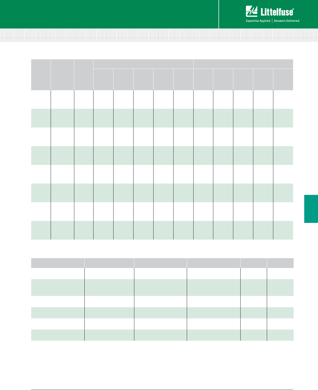
135 littelfuse.com © 2014 Littelfuse POWR-GARD® Products Catalog
Blocks and Holders
Fuse Blocks and Holders
6
IN-LINE WATERTIGHT FUSE HOLDERS
STANDARD
PART
NUMBER
BREAKAWAY
PART
NUMBER
FUSE
TYPE
LOAD TERMINAL SELECTION LINE TERMINAL SELECTION
TERMINAL
TYPE
LOAD
TERMINAL
WIRE SIZE
RANGE
NUMBER
OF WIRES
PER
TERMINAL
SOLID
WIRE
STRANDED
WIRE
TERMINAL
TYPE
LINE
TERMINAL
WIRE SIZE
RANGE
NUMBER
OF WIRES
PER
TERMINAL
SOLID
WIRE
STRANDED
WIRE
LET-AA LET-AA-S Solid
Neutral
Copper
Crimp
#12 to #8
#12
1
2
•
•
•
•
Copper
Crimp
#12 to #8
#12
1
2
•
•
•
•
LET-AB LET-AB-S Solid
Neutral
Copper
Crimp
#12 to #8
#12
1
2
•
•
•
•
Copper
Crimp
#10
#6
#4
2
1
1
•
•
—
•
•
•
LET-AYC LET-AYC-S Solid
Neutral
Copper
Crimp
#12 to #8
#12
1
2
•
•
•
•
“Y” Type
Copper
Set-Screw
#12 to #8
#10 to #2
1
1
•
—
—
•
LET-BA LET-BA-S Solid
Neutral
Copper
Crimp
#10
#6
#4
2
1
1
•
•
—
•
•
•
Copper
Crimp
#12 to #8
#12
1
2
•
•
•
•
LET-BB LET-BB-S Solid
Neutral
Copper
Crimp
#10
#6
#4
2
1
1
•
•
—
•
•
•
Copper
Crimp
#10
#6
#4
2•
•
—
•
•
•
1
1
LET-BYC LET-BYC-S Solid
Neutral
Copper
Crimp
#10
#6
#4
2
1
1
•
•
—
•
•
•
“Y” Type
Copper
Set-Screw
#12 to #8
#10 to #2
1
1
•
—
—
•
LET-JJ LET-JJ-S Solid
Neutral
Copper
Set-Screw
#12 to #8
#10 to #2
1
1
•
—
—
•
Copper
Set-Screw
#12 to #8
#10 to #2
1
1
•
—
—
•
LET-JYC LET-JYC-S Solid
Neutral
Copper
Set-Screw
#12 to #8
#10 to #2
1
1
•
—
—
•
“Y” Type
Copper
Set-Screw
#12 to #8
#10 to #2
1
1
•
—
—
•
Ordering Information (Terminals)
TERMINAL DESIGNATION TERMINAL DESCRIPTION NUMBER OF WIRES
PER TERMINAL WIRE RANGE SOLID
WIRE
STRANDED
WIRE
A Copper Crimp 1 #12-#8 • •
2 #12 • •
B Copper Crimp
2 #10 • •
1 #6 • •
1 #4 — •
C Copper Crimp 2 #8 • •
1 #4 — •
D Copper Crimp 2 #6 • •
1 #2 — •
J Copper Set-Screw 1 #12-#8 • —
1 #10-#2 — •
Y (2 terminals) “Y” Style Copper Set-Screw 1 #12-#8 • —
1 #10-#2 — •
Ordering Information (Solid Neutral LET Fuse Holders)
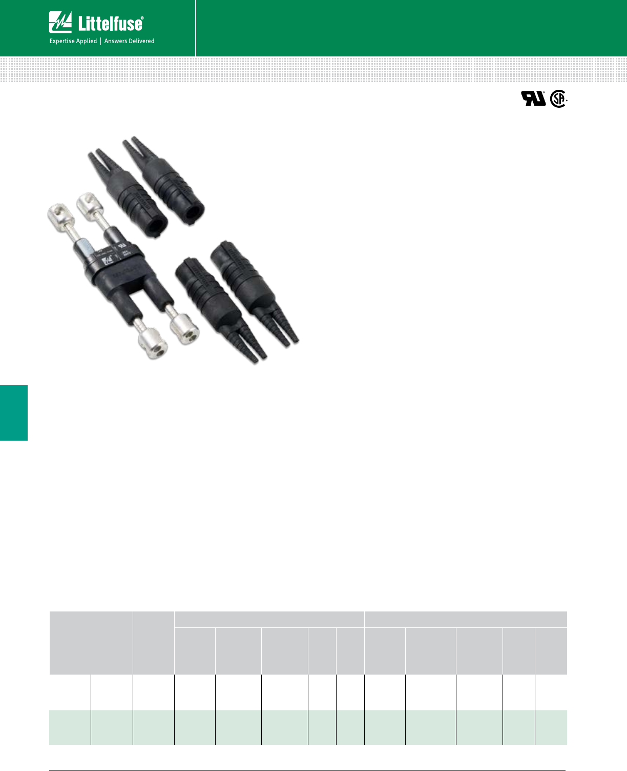
136 © 2014 Littelfuse POWR-GARD® Products Cataloglittelfuse.com
Blocks and Holders
Fuse Blocks and Holders
6
IN-LINE WATERTIGHT FUSE HOLDERS
Two-Pole Breakaway Holder
Description
New Littelfuse LEXT-YY-S and LEX-YYC-S series breakaway
fuse holders meet state and federal highway commission
safety standards requiring fuse holders to readily disconnect
from power in case of a pole knockdown.
The breakaway feature consists of a receptacle permanently
attached to the power line and a fuse holder with matching
terminals. If a knockdown occurs, the parts separate, leaving
the energized conductor recessed and unexposed.
Applications
• Street lighting
• Marinas
• Travel trailer parks
• Physically strained fuse holders applications
Features/Benefits
• LEXT-YY version has a permanently installed “neutral”
slug to prevent the neutral from accidentally being fused
• LEX-YYC version allows for fusing of line-to-line loads or
other applications requiring two fuses to disconnect
under strain
• Fiberglass polymer body resists damage from impact
• Four “Y” type set-screw terminals accommodate a wide
range of solid and stranded Cu or Al conductors
• O-ring and terminal boots form watertight seal,
preventing leakage
Specifications
Part numbers LEXT-YY-S (Solid neutral)
LEX-YYC-S
Voltage Rating 600 Vac/Vdc
Ampere Rating 30 A
Interrupting Rating 200 kA with Class CC Fuses
Y Terminals Tin Plated Copper w/ set screws
Wire Size 1 solid #12 to #8 or
1 stranded #10 to #2
Approvals UL Recognized (File: E14721)
CSA Certified (File: LR7316)
Recommended Fuses
Accepts all Littelfuse Midget and Class CC series fuses
CCMR ............................................................................... 27
KLDR, KLKR ...................................................................... 28
BLF, BLN, FLM, FLQ, KLK, KLKD ..................................... 30
Four WPB3 insulating boots come standard with the
LEXT-YY-S and LEX-YY-C-S fuse holders. Molded from
non-conductive engineering grade thermoplastic to deliver
a watertight seal in corrosive environments, they can be
trimmed to the specific conductor size insuring a snug fit.
Web Resources
Additional technical information:
littelfuse.com/in-line
ORDERING
NUMBER
FUSE
TYPE
LOAD TERMINAL SELECTION LINE TERMINAL SELECTION
TERMINAL
TYPE
LOAD
TERMINAL
WIRE SIZE
RANGE
NUMBER OF
WIRES PER
TERMINAL
SOLID
WIRE
STRANDED
WIRE
TERMINAL
TYPE
LINE
TERMINAL
WIRE SIZE
RANGE
NUMBER OF
WIRES PER
TERMINAL
SOLID
WIRE
STRANDED
WIRE
LEXTYYS LEXT0YYSX Midget
Class CC
“Y” type
Copper
Set-Screw
#12 to #8 1 • — “Y” type
Copper
Set-Screw
#12 to #8
#10 to #2
1 • —
#10 to #2 1 — • 1 — •
LEXYYCS 0LEXYYCSX Midget
Class CC
“Y” type
Copper
Set-Screw
#12 to #8
#10 to #2
1 • — “Y” type
Copper
Set-Screw
#12 to #8
#10 to #2
1 • —
1 — • 1 — •
Ordering Information
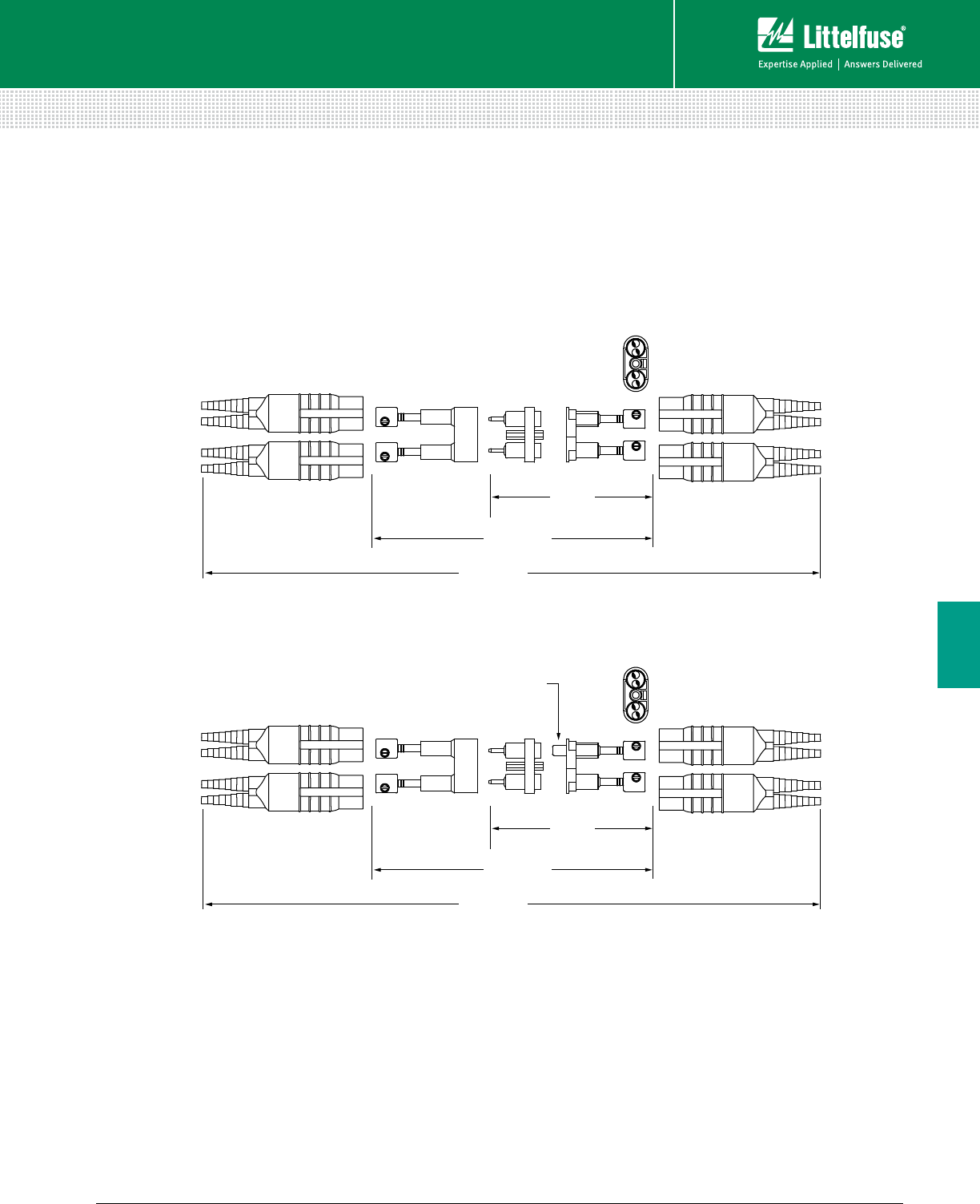
137 littelfuse.com © 2014 Littelfuse POWR-GARD® Products Catalog
Blocks and Holders
Fuse Blocks and Holders
6
IN-LINE WATERTIGHT FUSE HOLDERS
Two-Pole Breakaway Holder
4 9/16"
( ASSEMBLED LENGTH )
11 1/4"
( ASSEMBLED LENGTH )
5 1/8"
( ASSEMBLED LENGTH )
4 9/16"
( ASSEMBLED LENGTH )
11 1/4"
( ASSEMBLED LENGTH )
5 1/8"
( ASSEMBLED LENGTH )
PERMANENT
NEUTRAL SLUG
LEXT-YY-S
LEX-YY-C-S
Dimensions Inches
138 © 2014 Littelfuse POWR-GARD® Products Cataloglittelfuse.com
LCP Fused Selective Coordination Panel ..........................................138
LPS Series POWR-Switch (Shunt Trip Disconnect) ......................... 141
PRE-ENGINEERED SOLUTIONS
Table of Contents
Section Overview
POWR-GARD’s Pre-Engineered Solutions include
custom-built electrical panels designed specifically
to meet NEC® requirements, as well as fused and
non-fused disconnect switches.
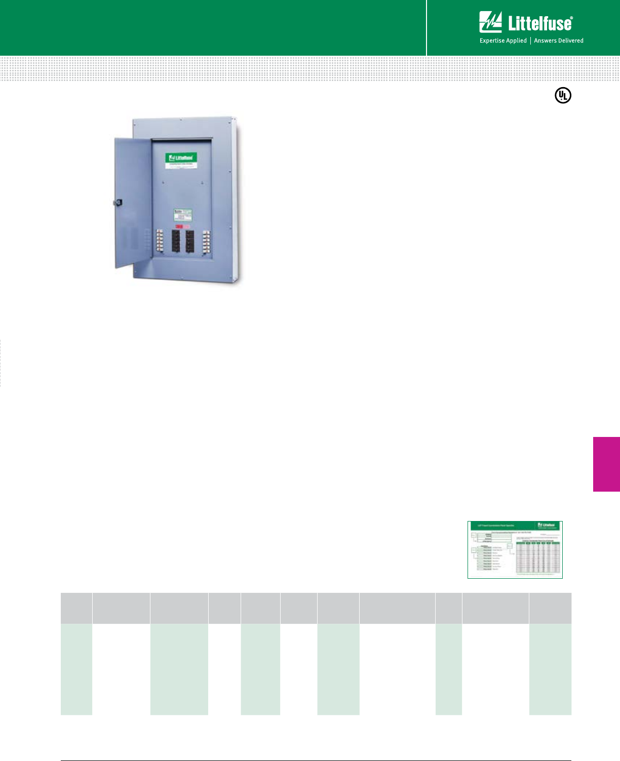
139 littelfuse.com © 2014 Littelfuse POWR-GARD® Products Catalog
Pre-Engineered Solutions
7
Pre-Engineered Solutions
Features/Benefits
• Meets NEC® requirements
• Class CC and J fuse holders have built-in
open-circuit indication
• Fast-acting UL Listed fuses protect against short circuits
• Feed through/sub feed lugs and 84-circuit
configuration available
• Ground and neutral bars
• Copper bus standard
Advanced Design Options
• MLO, Main Circuit Breaker, or Main Fused Pullout device
• Fused Class T branch circuit pullout
• Spare fuse cabinet accessory (holds six spare fuses)
• TVSS overvoltage protection
• Any NEMA enclosure required
• High amperage sub-fed branch breakers (J60A)
• Unique Specifier Tool (see pg. 146) to easily identify panel
configurations from tens of thousands of options
Specifications
Voltage Ratings 120/208, 120/240, 277/480 Vac
Main Bus Rating 100 A - 400 A Standard
Conductor Terminals 6 AWG - 300 kcmil
UL Listed UL 67 Panel boards and UL 50 Enclosures
Web Resources
For more information, visit:
littelfuse.com/lcp
Description
The Littelfuse® Coordination Panel provides a simple,
time-saving solution for circuits that require selective
coordination. This UL Listed product saves time and money,
and increases safety by minimizing system downtime.
Applications
• Elevators
• Hospitals
• Hotel and Entertainment Industry
• Amusement Parks and Stadiums
Code Requirements
Systems required by the NEC® to be selectively
coordinated include:
• Health Care Essential Electrical Systems (NEC 517.30)
• Elevators (NEC 620.62)
• Emergency Systems (NEC 700.28)
• Legally Required Standby Systems (NEC 701.27)
• Critical Operations Power Systems (NEC 708.54)
† Fuses quoted separately to meet panel specifications. Coordination for breakers >60 A depends on upstream and downstream devices. More specialized configurations are also available.
Contact factory for more information.
Note: The Littelfuse LPS and LCP products are custom designed products that fall outside standard specifications.
Customizable Options (select one from each column)
NUMBER
OF
CIRCUITS
VOLTAGE MAIN DEVICES NEUTRAL
RATING
PANEL
MOUNTING
PANEL
DOOR
FUSE
HOLDERS
BRANCH CIRCUIT
PROTECTION DEVICES
(1-3 POLE)†
PANEL
FEED OPTIONAL LUGS
STANDARD
ENCLOSURE
RATING
2 - 42
120/208 V 3P, 4 W
120/240 V 1P, 3 W
277/480 V 3P, 4 W
125, 225, 400 or
600 A MLO
Up to 600 A MCB
or Main Fuse
Pullout
100%
200%
Surface
Flush
Standard
Door-in-door
30 A Class CC
60 A Class J
10 A- 60 A fused
circuit breaker
60 A-200 A
fused pullouts
Sub-fed circuit breakers
>60 A
(not fused)
Top
Bottom
None
Sub-Fed (MLO panels)
Feed-Through
NEMA 1
NEMA 3R
NEMA 4X
To quickly specify the LCP panel,
visit littelfuse.com/lcp and
download the Specifier Tool.
LCP FUSED COORDINATION PANEL
Selective Coordination Panel
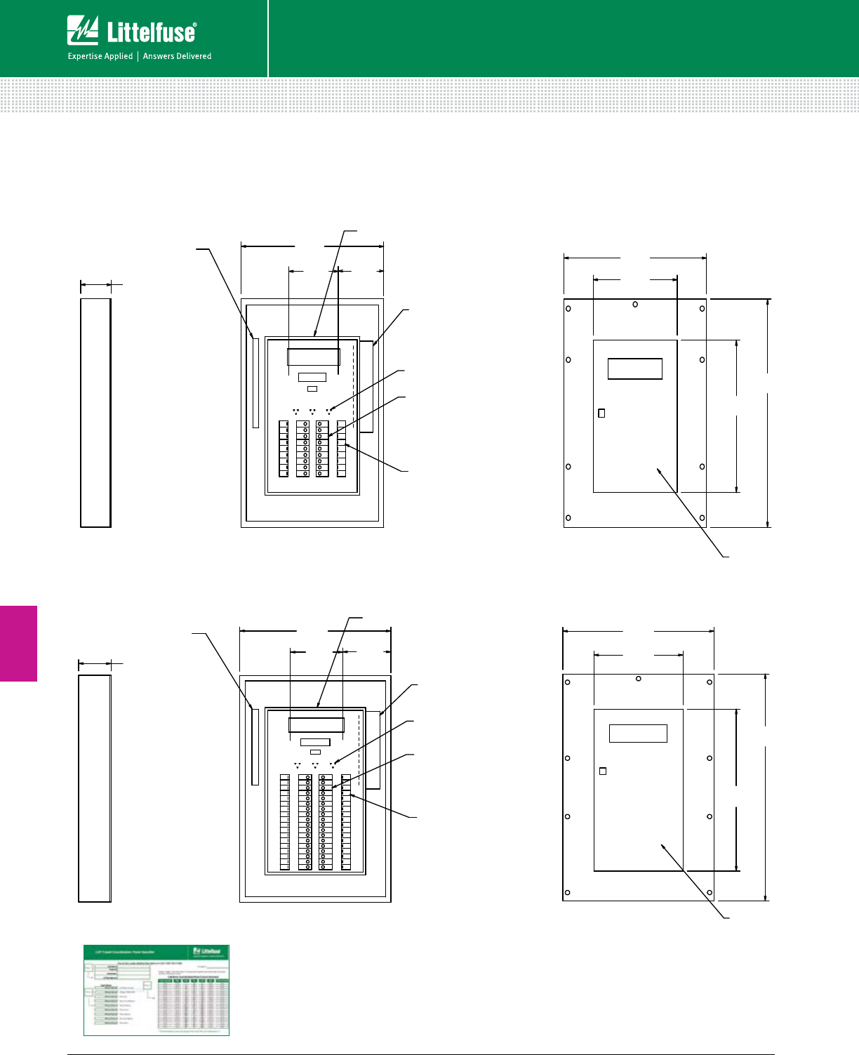
140 © 2014 Littelfuse POWR-GARD® Products Cataloglittelfuse.com
Pre-Engineered Solutions
Pre-Engineered Solutions
7
LCP FUSED COORDINATION PANEL
Selective Coordination Panel
Inner Line
GND Bus
Neutral Detail
Neutral Detail
(6 AWG - 300 kcmil) Cu/Al
Incoming Main Lugs
Cutler Hammer
GHB (480 V) or BAB (208 V)
Circuit Breakers
(or Pullouts)
LPSC001ID POWR-Safe
Dead front Class CC 600 VAC
Fuseholder for use with Littelfuse
CCMR, KLKR or KLDR Class CC fuses
or POWR-Safe LPSJ holders for use
the Class J fuses. (Fuses not included)
LPSC001ID POWR-Safe
Dead front Class CC 600 VAC
Fuseholder for use with Littelfuse
CCMR, KLKR or KLDR Class CC fuses
or POWR-Safe LPSJ holders for use
the Class J fuses. (Fuses not included)
Front Trim
Type 1 (NEMA) Enclosure
Front View with Front Removed Hinged Door with
Catch and Lock
Dimensions in mm [inches]
Dimensions in mm [inches]
GND Bus
Inner Line
(6 AWG - 300 kcmil) Cu/Al
Incoming Main Lugs
Cutler Hammer
GHB (480 V) or BAB (208 V)
Circuit Breakers
(or Pullouts)
Front Trim
Type 1 (NEMA) Enclosure
Front View with Front Removed Hinged Door with
Catch and Lock
[6.00]
152.4
[6.00]
152.4
[28.00]
711.2
[28.00]
711.2
[36.00]
914.4
[24.00]
609.6
[16.50]
419.1
[28.00]
711.2
[42.00]
1066.8
[30.00]
762
[16.50]
419.1
[9.69]
246.06
[8.94]
227.01
[28.00]
711.2
[9.69]
246.06
[8.94]
227.01
Dimensions mm (inches)
Standard Coordination Panel Board (up to 30 circuits)
Standard Coordination Panel Board (31-42 circuits)
Inner Line
GND Bus
Neutral Detail
Neutral Detail
(6 AWG - 300 kcmil) Cu/Al
Incoming Main Lugs
Cutler Hammer
GHB (480 V) or BAB (208 V)
Circuit Breakers
(or Pullouts)
LPSC001ID POWR-Safe
Dead front Class CC 600 VAC
Fuseholder for use with Littelfuse
CCMR, KLKR or KLDR Class CC fuses
or POWR-Safe LPSJ holders for use
the Class J fuses. (Fuses not included)
LPSC001ID POWR-Safe
Dead front Class CC 600 VAC
Fuseholder for use with Littelfuse
CCMR, KLKR or KLDR Class CC fuses
or POWR-Safe LPSJ holders for use
the Class J fuses. (Fuses not included)
Front Trim
Type 1 (NEMA) Enclosure
Front View with Front Removed Hinged Door with
Catch and Lock
Dimensions in mm [inches]
Dimensions in mm [inches]
GND Bus
Inner Line
(6 AWG - 300 kcmil) Cu/Al
Incoming Main Lugs
Cutler Hammer
GHB (480 V) or BAB (208 V)
Circuit Breakers
(or Pullouts)
Front Trim
Type 1 (NEMA) Enclosure
Front View with Front Removed
Hinged Door with
Catch and Lock
[6.00]
152.4
[6.00]
152.4
[28.00]
711.2
[28.00]
711.2
[36.00]
914.4
[24.00]
609.6
[16.50]
419.1
[28.00]
711.2
[42.00]
1066.8
[30.00]
762
[16.50]
419.1
[9.69]
246.06
[8.94]
227.01
[28.00]
711.2
[9.69]
246.06
[8.94]
227.01
To quickly specify the LCP panel,
visit littelfuse.com/lcp and
download the Specifier Tool
Note: The Littelfuse LPS and LCP products are custom
designed products that fall outside standard specifications.
Dimensions may change depending on panel components.
More specialized configurations are also available.
Contact factory for more information.
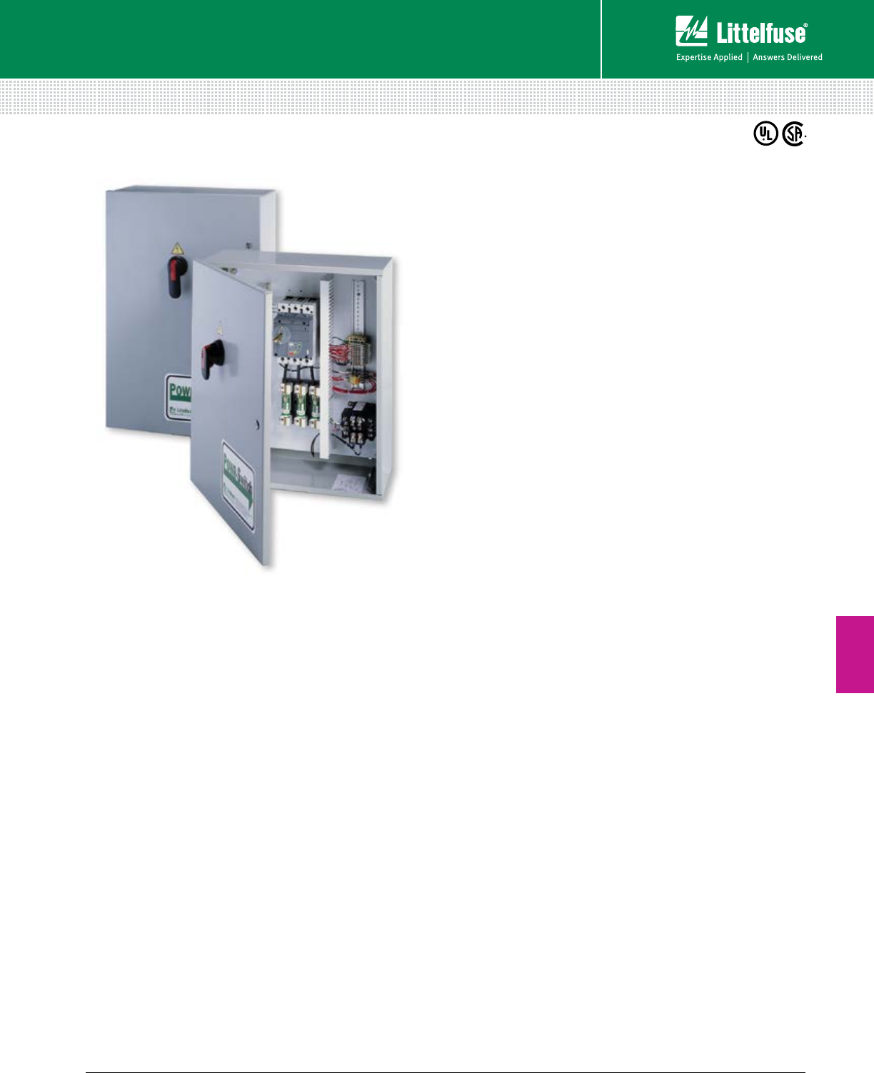
141 littelfuse.com © 2014 Littelfuse POWR-GARD® Products Catalog
Pre-Engineered Solutions
Pre-Engineered Solutions
7
LPS SERIES POWR-SWITCH
Shunt Trip Disconnect Switch
Description
The Littelfuse® POWR-Switch provides a simple
and economical solution for applications that require
selective coordination and shunt trip capabilities.
Utilizes Class J time-delay fuses that are easily
coordinated with other system overcurrent devices.
The shunt trip capability allows the POWR-Switch
to meet the ANSI/ASME standard that requires
power to be automatically disconnected before
water is turned on by the fire safety system.
Applications
• Elevator circuits
• Data processing rooms
• Building emergency systems
Web Resources
Download technical information: littelfuse.com/lps
Specifications (POWR-Switch)
Supply Voltage Rating* 208 V, 240 V, 480 V
Ampere Range 30 A, 60 A, 100 A, 200 A, 400 A
Interrupting Rating 200 kA
Enclosures NEMA 1 (standard)
NEMA 3R, NEMA 4, NEMA 12 (optional)
Approvals UL Listed (File: E219511)
CSA Certified
*Contact factory for 600 V options.
Specifications (Shunt Trip)
Voltage Rating 120 V, 60 Hz
Max Inrush 4 A
Max On time 1.5 cycles
Momentary Inrush 140 VA
Features/Benefits
• Pre-engineered single unit, which makes
procurement easier than systems with
multiple components
• Reduces labor costs up to 66% and total
installation costs by over 30%
• Optional features offer flexibility for a variety
of applications
• Control power terminal block
• UL Listed package
• Cu and AI wire rated
• Pre-wired control circuits lower installation time
• Lockable operating handle meets all code and
safety requirements (Accepts up to 3 locks)
• Every unit is fully tested before delivery
Options
• Control power transformer with fuses and blocks
• Fire safety interface relay
• Key to test switch
• Pilot light ”On”
• Isolated neutral lug
• Mechanical interlock auxiliary contact for hydraulic
elevators with automatic recall (5 amp 120 Vac rated)
• Fire alarm voltage monitoring relay
• Option to bypass alarm when performing
maintenance (-AZ option)
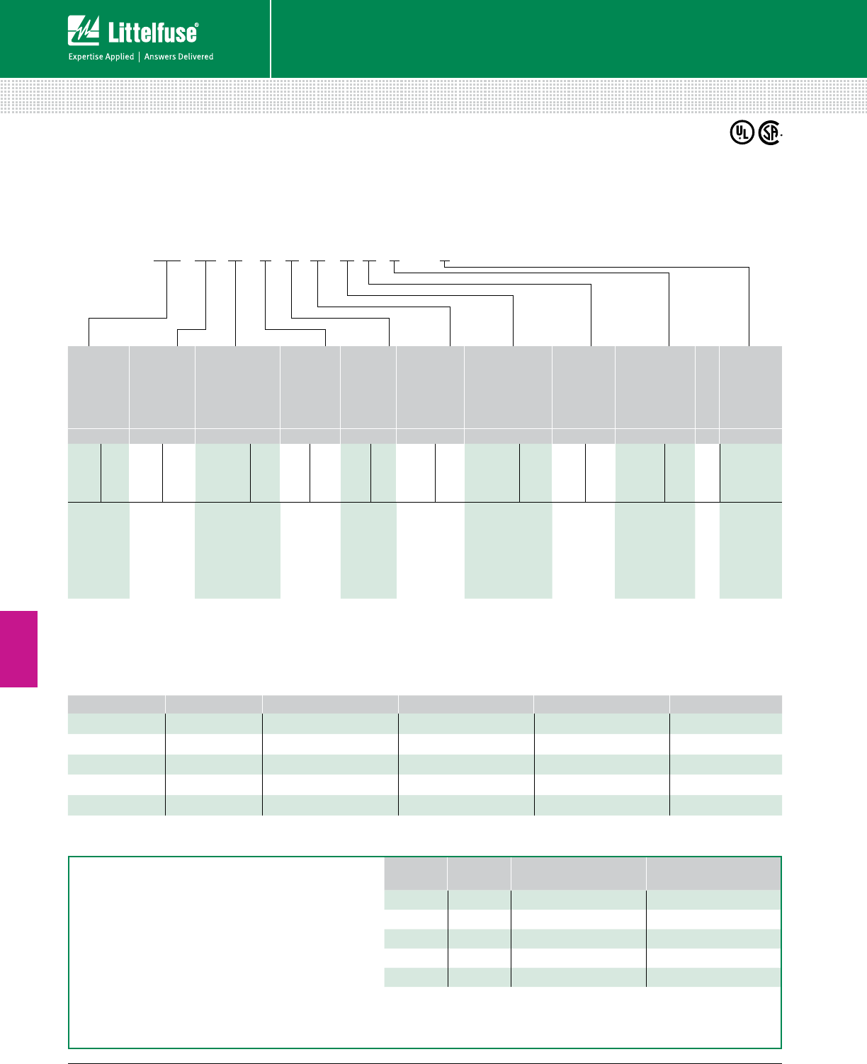
142 © 2014 Littelfuse POWR-GARD® Products Cataloglittelfuse.com
Pre-Engineered Solutions
7
Pre-Engineered Solutions
LPS SERIES POWR-SWITCH
Shunt Trip Disconnect Switch
LITTELFUSE
SWITCH
CATALOG
NUMBER
CONTROL
POWER
TRANSFORMER
STD. 100VA WITH
PRI & SEC FUSE
(120 V SEC.)
FIRE SAFETY
INTERFACE RELAY
(3 PDT, 10 A, 120 V)
KEY TO
TEST SWITCH
PILOT LIGHT
“ON”
ISOLATED
NEUTRAL
LUG
MECHANICAL
INTERLOCK AUX.
CONTACT FOR
HYDRAULIC
ELEVATORS W/
AUTOMATIC RECALL
(5 A ,120 VAC)
FIRE ALARM
SHUNT TRIP
VOLTAGE
MONITORING
RELAY
OPTIONAL
ENCLOSURES —
AZ OPTION
(BYPASS
FIRE
ALARM
DURING
MAINT.
TEST)
REQUIRED REQUIRED REQUIRED OPTIONAL OPTIONAL OPTIONAL REQUIRED REQUIRED OPTIONAL OPTIONAL
BASE
CATALOG #
RATING
RATING
OPTION
CODE
RATING
OPTION
CODE
RATING
OPTION
CODE
RATING
OPTION
CODE
RATING
OPTION
CODE
RATING
OPTION
CODE
RATING
OPTION
CODE
RATING
OPTION
CODE
OPTION
CODE
LPS3* 30 A 208 V T20 24 VDC Coil R2 120 V K Red R 30–60 A N6 1 NO & 1 NC A 1-Pole F1 NEMA 3R U – AZ
LPS6* 60 A 240 V T24 120 VAC Coil R1 Green G 100 A N1 2 NO & 2 NC B 3-Pole F3 NEMA 4 Y –
LPS1* 100 A 480 V T48 White W 200 A N2 NEMA 12 Z –
LPS2* 200 A 400 A N4 –
LPS4* 400 A –
*Part Numbers: Any voltage can be paired with any amperage. Options can be any combination but the ratings must match the option code. Not all options are required.
Contact factory for 600 V control power transformer option.
Note: When ordering - desired options must be listed in the order shown above. Typical options include Control Power Transformer, Fire Safety Interface Relay,
Mechanical Interlock Auxiliary Contact and Fire Alarm Voltage Monitoring Relay.
Example Catalog Number from Desired Options
Dimensions of Enclosure
CATALOG SERIES AMPERE RATING NEMA 1 DIMENSIONS NEMA 3R DIMENSIONS NEMA 4, 12 DIMENSIONS LUG SIZE
LPS3 30 24”H x 20”W x 9”D 24”H x 20”W x 8”D 24”H x 20”W x 10”D #14 - #8 AL or CU
LPS6 60 24”H x 20”W x 9”D 24”H x 20”W x 8”D 24”H x 20”W x 10”D #14 - #2 AL or CU
LPS1 100 24”H x 20”W x 9”D 24”H x 20”W x 8”D 24”H x 20”W x 10”D #8 - 1/0 AL or CU
LPS2 200 30”H x 20”W x 9”D 30”H x 24”W x 8”D 30”H x 20”W x 10”D #6 - 250kcmil AL or CU
LPS4 400 48”H x 36”W x 11”D Contact Factory Contact Factory 3/0 AL or CU
Note: Over-size enclosures used to accommodate control power transformer, interface relay and terminal blocks.
Ordering Information
Complete catalog numbers consist of switch catalog numbers and the desired options. See example below.
LPS1 T20 R1 K G N1 B F3 U – AZ =
Littelfuse Catalog Number
LPS1T20R1KGN1BF3U-AZ
XPress-Ship™AMPERE
RATING
VOLTAGE
RATING CATALOG NUMBER XPress-Ship™
ORDERING NUMBER
60 A 480 V LPS6T48R1KGN6BF3-AZ XPS6T48R1KGN6BF3-AZ
US Only 100 A 480 V LPS1T48R1KGN1BF3-AZ XPS1T48R1KGN1BF3-AZ
Littelfuse XPress-Ship™ service offers 48 Hours* direct shipment
service on our fully loaded POWR-SWITCH to meet your urgent
system requirement ON-Time.
Xpress-Ship™ switches include three JTD_ID Series
fuses rated at the device’s maximum ampacity.
100 A 480 V LPS1T48R1KGN1BF3 XPS1T48R1KGN1BF3
200 A 208 V LPS2T20R1KGN2BF3-AZ XPS2T20R1KGN2BF3-AZ
200 A 480 V LPS2T48R1KGN2BF3 XPS2T48R1KGN2BF3
*48 Hours Xpress Shipment requires ordering from identified XPS Series Catalog Numbers shown, subject to maximum of three switches per catalog number per customer order.
Xpress-Ship™ service offers 48 Hours shipment from factory through standard ground transportation, for expedited delivery contact your local Littelfuse Representative.
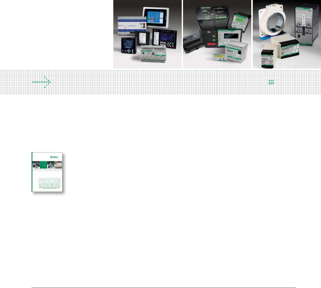
143 littelfuse.com © 2014 Littelfuse POWR-GARD® Products Catalog
Section Overview
Our comprehensive line of single- and multi-function protection
relays safeguard equipment and personnel in order to prevent
expensive damage, downtime or injury due to electrical faults.
The features and flexibility within the products and the software
allow you to select the appropriate protection for each part of
your electrical system.
Feature Comparisons ................................................................ 143
Ground-Fault Protection ............................................................ 146
Trailing Cable Protection ............................................................ 148
Resistance Grounding and NGR Monitoring ..............................151
Motor Protection ....................................................................... 154
Pump and Feeder Protection .................................................... 156
Arc-Flash Protection ...................................................................157
Industrial GFCI (Shock-Block™) ..................................................157
Generator and Single-Function Protection ................................ 158
Generator Control ...................................................................... 163
Engine Control and Diagnostics ................................................ 167
Alarm Monitoring ...................................................................... 168
Custom-Engineered Electrical Equipment .................................170
Accessories ................................................................................171
PROTECTION RELAYS AND CONTROLS
Table of Contents
Download our Complete
Relay and Controls Catalog
For more information on relays and
controls or to download our full-
line relay catalog (PF130N), Visit:
littelfuse.com/RelaysControls
A Full Range of PROTECTION RELAYS & CONTROLS
for the Harshest Environments
Fault Damage
Equipment Replacement
Calibration Costs
Compliance Citations
Motor Rewinds
Shock Hazard
Injury to Personnel
Arc-Flash Hazards
Open-CT Hazards
Failed Resistors
Replacement Time
Nuisance Tripping
Intermittent Faults
Unreliable Protection
Calibration Time
CostSafety Downtime
For All Harsh Environments
Petrochemical, Oil and Gas
Pipelines and Transportation
Aggregate and Cement
Mining
Pulp and Paper
Water and Waste Water
Shore-to-Ship Power
Marine
Data Centers
Semiconductor Equipment
Hospitals
Alternative Energy
Power Generators
We Improve Electrical Safety and Increase Uptime
For decades, Littelfuse has been helping customers improve their electrical systems. In
addition to well-designed products, our technical expertise brings years of experience and
product design support to your application.
We can provide immediate access to specialized technical resources, online references or
field application support. This catalog outlines the Littelfuse line of protection relays,
custom-engineered electrical equipment, generator and engine controls, and alarm and
annunciator systems, plus the technical capabilities we offer for your application.
Why are Protection Relays Necessary?
Protection relays safeguard critical components of an electrical circuit from
damage. When the relay detects a potentially damaging or unsafe condition,
the relay will send an alarm or trip signal in order to notify personnel or
prevent the condition from continuing.
Protection relays increase the uptime of critical systems and enhance the
safety of people and equipment during fault situations.
A Full Range of PROTECTION RELAYS & CONTROLS
for the Harshest Environments
GENERATOR PROTECTION & CONTROL
Our line of generator protection and control equipment
offers synchronizing, frequency control, load sharing, power
management, engine control and more for marine, emergency
or power generation applications.
ENGINE CONTROL & MONITORING
These monitors can be configured from the front panel, a PC, or via an
SD card, and support both digital and analog sensor inputs. Common
alarms and shut-downs have large, user-friendly LED displays.
ALARM & ANNUNCIATOR PANELS
These panels monitor instantaneous current, temperature or pressure,
and include local indication, alarm and event logging.
ENGINE DIAGNOSTICS
The EngineEye diagnostic unit can improve the efficiency and
performance of combustion engines by measuring and analyzing the
engine combustion process. It utilizes a unique handheld high-precision
indicator of cylinder pressure.
00 GENERAL PROTECTION RELAYS
These single-function, compact and cost-efficient relays are typically used
on low-voltage applications. Most are DIN-rail mountable, easy to operate,
install and commission. The wide-range power supply for AC and DC make
these relays universal.
ARC-FLASH DETECTION
Our Arc-Flash relays can rapidly detect developing
Arc-Flash incidents and send a trip signal to interrupt
power before significant damage occurs.
FEEDER PROTECTION RELAYS
Protect feeder circuits from overcurrents, ground faults, phase
loss or other detrimental conditions in critical applications and
processes. They provide essential data for predictive and preventive
maintenance— extending the life of equipment, enhancing safety and
maximizing efficiency.
MOTOR & PUMP PROTECTION RELAYS
Prevent expensive damage to motors caused by overloads,
jams, phase loss or unbalance, heat from non-electric
sources, heavy start-ups or excessive operational cycles.
Dynamic thermal curves, integrated protection, metering,
and data-logging functions extend motor life and maximize
process efficiency.
RESISTANCE GROUNDING & MONITORING
Overcome many of the issues experienced with
solidly-grounded and ungrounded systems.
High-Resistance Grounding eliminates Arc-Flash
Hazards associated with ground faults and
transient overvoltages, and allows for
continuous operation during a ground fault.
GROUND-FAULT PROTECTION RELAYS
Improve the safety of workers and reduce incidents of Arc-Flash without
affecting the uptime of critical operations. Sensitive ground-fault relays
with advanced filtering will detect the breakdown in insulation resistance
caused by moisture, vibration, chemicals and dust without nuisance trips.
146 © 2014 Littelfuse POWR-GARD® Products Cataloglittelfuse.com
Protection Relays & Controls
Protection Relays & Controls
8
FEATURES COMPARISONS
NOTE:
Tables are for reference only and include standard and optional configurations.
Please see the respective catalog page for exact product specifications.
IEEE Device Numbers are shown in parenthesis after the applicable features.
Motor & Feeder Protection Relays
Arc-Flash Relays
Alarm Monitors
FEATURE (IEEE #)
PGR-6100
PGR-6130
PGR-6150
MPU-32
MPS
PGR-6800
FPU-32
FPS
Ground fault (50G/N, 51G/N)
a a a a a a
Overload (49, 51)
aaaaaaa
Unbalance (current) (46)
aaaaaaa
Phase loss (current) (46)
aaaaaaa
Phase reverse (current) (46)
aaaaaaa
PTC overtemperature (49)
aaaa a
Undercurrent (37)
aaaa
Jam
aaa
Overcurrent (50, 51)
a a a a a
Failure to accelerate
aaa
RTD temperature (38, 49)
a a a a
Starts per hour (66)
a a
Differential (87)
a a
Reduced overcurrent setting
a a
Phase loss (voltage) (47)
a a
Phase reverse (voltage) (47)
a a
Unbalance (voltage) (47)
a a
Overvoltage (59)
a a a
Undervoltage (27)
a a
Power factor (55)
a a
Overfrequency (81)
a a
Underfrequency (81)
a a
Starter control
a
Breaker control
a
Underspeed (14)
a
Integrated CTs
a a a
Off-line insulation monitoring
a
Metering and data logging
a a a a a
Communications
a a a a a
Conformal coating ‡
a a a a
10-year warranty
a a a a
FEATURE
D0100
PGR-8800
Current detection
a
Point sensors
a a
Fiber optic sensors
a
Cable monitoring
on sensor inputs
a
USB
a
DC supply
a a
AC supply
a
Data logging
a
FEATURE
M1000
M3000
M4200
M4500
M4600
M4700
M4780
Alarm panel
a
a
a
Indicator panel
a a a a a a a
No. of inputs
10 24 8 6 8 20 20
Digital input
a a
*
a a a a a
No. of open collector outputs
10 14 4
Common alarm output†
1oc 1oc 2dryc 1dryc
‡
1dryc
‡
Siren output
1dryc 1oc 1dryc 1dryc
‡
1dryc
‡
LCD display
a
Configure from PC
a
a
a
Configure from DIP switches/
jumper
a a a a
Configure from front panel
a
MODBUS-RTU (RS485)
a
a
LED dimming
a
a
a
LED synchronizing
a
a
Panel linking
a
Remote reset
a
a
a
Sensor monitoring
a
a
a
Insulation monitoring of
supply voltage
a
a
Monitoring of supply voltage
a
a
Ground-Fault Protection Relays
FEATURE
SE-601
EL731
EL3100
PGR-3200
T3200
SE-502
SE-701
SE-703
SE-704
T2800
SE-105
SE-107
SE-134C
SE-135
SE-145
SE-325
SE-330
SE-330HV
SE-330AU
Detects GF via voltage
a a a a a
Detects GF via current
a a a a a a a a a a
Detects DC GF
a a
Adjustable GF pickup
a a a a a a a a a
Adjustable time delay
a a a a a a a a a a
Remote reset
a a a a a a a a a a
Analog output
a a a a a a
Fail-safe option
a a a a a a a a a
Harmonic filtering
a a a a a a a a
CT-Loop monitoring
a a a a
Insulation monitoring
a a a
Ground-check monitoring
a a a
Grounding-resistor monitoring
a a
PTC/RTD overtemperature
a
Communications
a a
Conformal coating ‡
a a
‡
a
‡ ‡
a a a a a a
*Both analog and digital input.
†oc=open collector; dryc=dry contact
‡Optional
147 littelfuse.com © 2014 Littelfuse POWR-GARD® Products Catalog
Protection Relays & Controls
Protection Relays & Controls
8
FEATURES COMPARISONS
FEATURES
BASIC
E5000
& E5100
ADVANCED
E5000,
E5100
& E5200
PROFESSIONAL
E5000, E5100,
E5200 & 5300
USB
a a a
Color LCD
a a a
PC software included
a a a
Upgradable
a a a
Temperature compensation
a a a
Calibration-check
integration
a a a
Connecting sensor ports
1 2 5
Pressure graph
a a a
MIP mode
*
a
Misfire analysis
a a
pmax
a a
p/time
a a a
pmax bar graph
a a
p/alpha
*
a
d
p/alpha
*
a
p/V
*
a
Pressure sensor
a a a
Crank-angle sensor
a
Maximum engines
(memory)
5 10 20
Maximum cylinders/
engine (memory)
20 20 20
Maximum number of
strokes (memory)
30 30 30
00
NOTE: These tables are for reference only and include standard and optional configurations. *Possible with a crank angle sensor E5300.
Generator Protection & Single-Function Relays
Generator Controls
Engine Controls
Engine Diagnostics
FEATURE (IEEE #)
PGR-
4300
G2000
G3000
G3300
T2000
T2100
T2200
T2300
T2400
T2500
T2700
T2900
T3000
T3100
T3300
Overload
a
Overcurrent
a a a
Undercurrent (37)
Short circuit
a a
Reverse power (32)
a a
Overfrequency (81)
a a
Underfrequency (81)
a a
Overvoltage (59)
a a a
Undervoltage (27)
a a a
Excitation loss (40)
a
Earth fault
Differential current relay (87)
a
Insulation monitoring relay
Single phase measurement
a a a a a a a
3-phase measurement
a a a a a a a
Conformal coating
aaaaaaaaaa
FEATURE (IEEE #)
T2600
T4500
T4800
T4900
T5000
E7800
T7900
M8100
T8400
C6200
S6000
S6100
S6610
3 phase true RMS measurement
aaaaa a aaa
Overcurrent
a a
Short circuit
a a
Overload
a a
Reverse power (32)
a a a
Excitation loss (40)
a a
Overfrequency (81)
aaa
Underfrequency (81)
aaa
Overvoltage (59)
aaa
Undervoltage (27)
aaa
ROCOF (81)
a a
Vector shift
a
Preferential load trip
a a
Synchronizing (25)
a a a
Check synchronizer (25)
a a a a
Active load sharing [kW]
a a a
Reactive load sharing [kVAR]
a a a
Power factor regulation
a a a
Dead bus monitoring/
black out limiter
aaa
Load depending start/stop
(PM)
a a a
Large consumer control (PM)
a a
Dynamic grid-parallel
operation control
a a
MODBUS RTU
(RS485 interface)
aaaa
Motorized potentiometer
a
Electronic potentiometer
a
Dead bus closure
a
FEATURE (IEEE #)
M2000
M2500
M2600
Start/stop
a a
Digital sensor inputs
a a a
Analog sensor inputs
a
Cable monitoring on fuel/
stop solenoid output
a a
Graphical display
a
CAN J1939
a
USB
a
SD card slot
a
Pick-up input
a a a
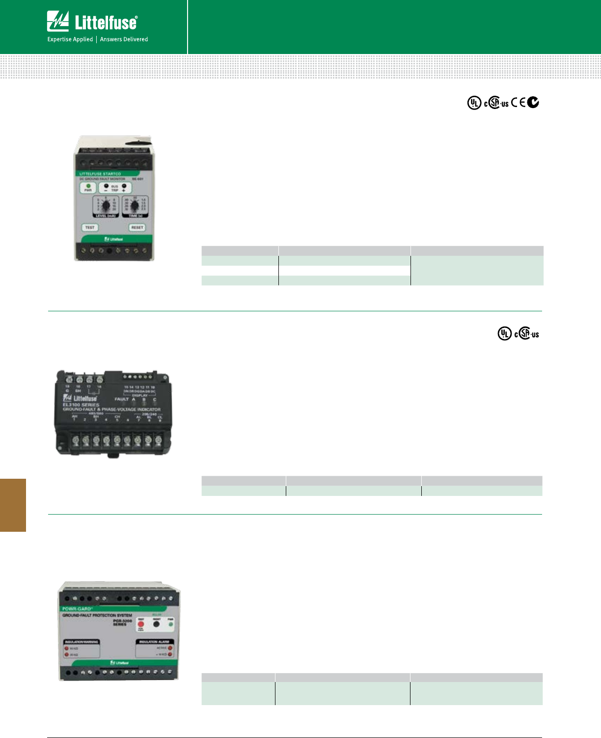
148 © 2014 Littelfuse POWR-GARD® Products Cataloglittelfuse.com
Protection Relays & Controls
Protection Relays & Controls
8
GROUND-FAULT PROTECTION
Features/Benefits
• Sensitive 1- to 20-mA trip settings
• A microprocessor-based ground-fault relay
for ungrounded dc systems
• 50-ms to 2.5-s time-delay settings
• Limits ground-fault current to 25 mA
• Form-A and Form-B trip contacts
Specifications
IEEE Device Number 76G
Dimensions H 75 mm (3.0”)
W 55 mm (2.2”)
D 115 mm (4.5”)
Communications Analog Output
Warranty 5 Year
Web Resources
littelfuse.com/se-601
ORDERING NUMBER SPECIFICATIONS ACCESSORIES
SE-601-OD 24 Vdc Control Power SE-GRM Series Ground Reference Modules
PGA-0500 Analog Current Meter
SE-601-OT 48 Vdc Control Power
SE-601-OU 120/240 Vac/dc 50/60 Hz Control Power
SE-601 (PGR-2601) DC Ground-Fault Relay
For Ungrounded DC Systems
Features/Benefits
• Meets National Electrical Code (NEC®)
Article 250.21 and Canadian Electrical
Code Part 1, Section 10-106 (2)
requirements for ungrounded systems
• System voltage is not present at the
remote LED locations
• Indicates the presence of voltage on both
grounded and ungrounded systems
Specifications
Input Voltage Input L: 208/240 Vac
Input H: 480/600 Vac
Dimensions H 87.0 mm (3.43”)
W 112.5 mm (4.43”)
D 56.0 mm (2.2”)
Approvals
CSA certified,
UL Listed
(E340889)
Warranty 5 years
Web Resources
littelfuse.com/el3100
ORDERING NUMBER MOUNTING ACCESSORIES
EL3100-00 DIN, Surface RK-310X-0Y (optional)
EL3100 Ground-Fault & Phase-Voltage Indicator
For Grounded/Ungrounded AC Systems
Features/Benefits
• Meets NEC Article 250.21 (B)
• Continuously monitors the insulation
integrity of ungrounded electrical systems
for ground faults
• Provides 2 warnings and 1 alarm
• Analog output for insulation reading
Specifications
IEEE Device Number 27, 64
Dimensions H 99.7 mm (3.9”)
W 75 mm (4.3”)
D 110 mm (4.3”)
Communications Analog Output
Warranty 5 Year
Web Resources
littelfuse.com/pgr-3200
ORDERING NUMBER SPECIFICATIONS ACCESSORIES
PGR-3200 240 Vac Control Power PGH family High Tension Couplers
PGA-0510 Analog Insulation Meter
PGR-3200 Ground-Fault Protection System
For Ungrounded AC Systems
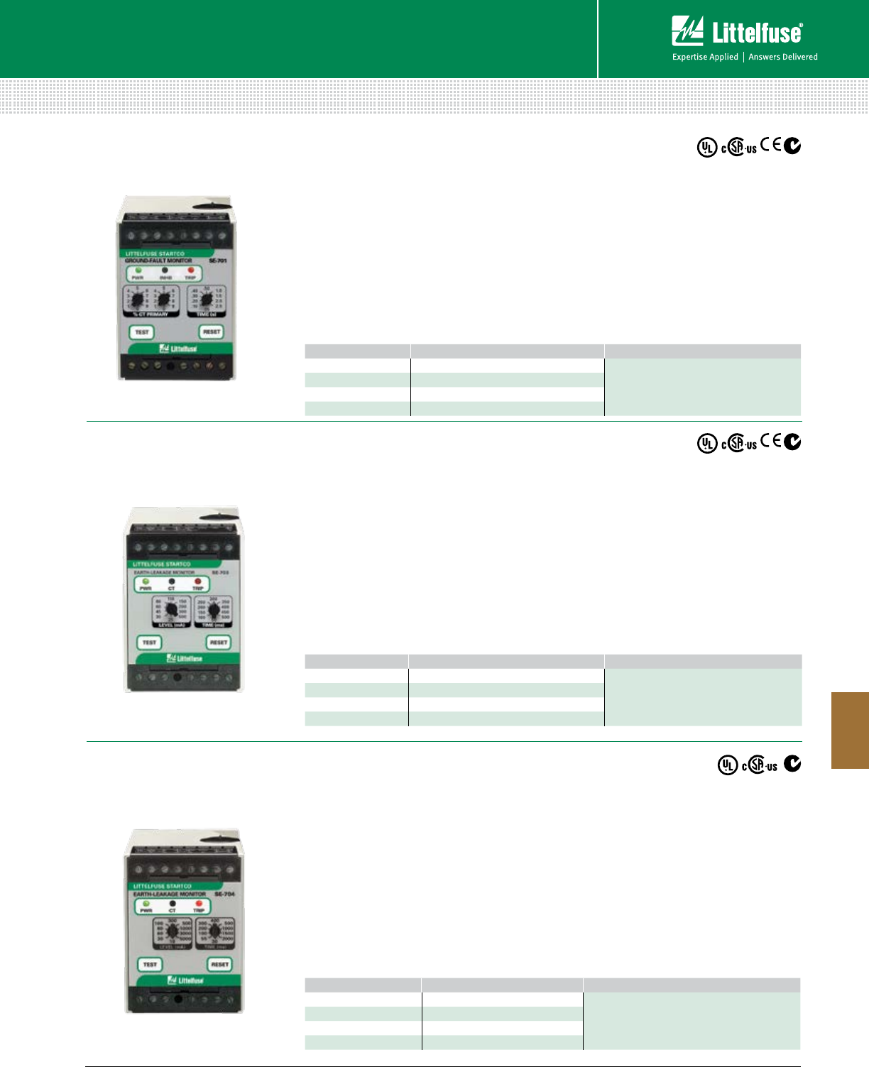
149 littelfuse.com © 2014 Littelfuse POWR-GARD® Products Catalog
Protection Relays & Controls
Protection Relays & Controls
8
GROUND-FAULT PROTECTION
Features/Benefits
• Provides very sensitive ground-
fault protection
• Microprocessor-based unit with DFT
• Non-volatile trip memory retains trip state
• Compatible with VFD applications
• Adjustable pick-up settings from
10 mA to 5 A
• Adjustable time-delay settings from
• 0.5 to 2.5 sec
Specifications
IEEE Device Numbers 50G/N, 51G/N
Dimensions H 75 mm (3.0”)
W 55 mm (2.2”)
D 115 mm (4.5”)
Communications Analog Output
Warranty 5 Year
Web Resources
littelfuse.com/se-704
Features/Benefits
• Provides sensitive ground-fault protection
• A microprocessor-based ground-fault relay
for resistance-grounded and solidly earthed
systems
• Microprocessor-based unit with DFT
• Non-volatile trip memory retains trip state
• Compatible with VFD applications
• Adjustable pick-up settings from
25 mA to 500 mA
• Adjustable time-delay settings from
50 to 500 ms
Specifications
IEEE Device Numbers 50G/N, 51G/N
Dimensions H 75 mm (3.0”)
W 55 mm (2.2”)
D 115 mm (4.5”)
Communications Analog Output
Warranty 5 Year
Web Resources
littelfuse.com/se-703
SE-704 (PGR-4704) Earth Leakage Monitor
For Solidly and Resistance-Grounded Systems
SE-703 Earth Leakage Monitor
For Solidly and Resistance-Grounded Systems
ORDERING NUMBER SPECIFICATIONS ACCESSORIES
SE-704-OU 120/240 Vac/dc Control Power
SE-CS30 series Current Transformers
PGA-0500 Analog Current Meter
SE-704-OD 12/24 Vdc Control Power
SE-704-OT 48 Vdc Control Power
SE-704-O3 24 Vac Control Power
ORDERING NUMBER SPECIFICATIONS ACCESSORIES
SE-703-OU 120/240 Vac/dc Control Power
EFCT series Current Transformers
PGA-0500 Analog Current Meter
SE-703-OD 12/24 Vdc Control Power
SE-703-OT 48 Vdc Control Power
SE-703-O3 24 Vac Control Power
Features/Benefits
• Choice of input CT gives wide setting range
• A microprocessor-based ground-fault relay for
resistance-grounded and solidly
grounded systems
• Microprocessor-based unit with DFT
• Non-volatile trip memory retains trip state
• Compatible with VFD applications
• Adjustable pick-up settings from 1% to 99%
of CT primary rating, as low as 50 mA
• Adjustable time-delay settings from
0.5 to 2.5 sec
Specifications
IEEE Device Numbers 50G/N, 51G/N
Dimensions H 75 mm (3.0”)
W 55 mm (2.2”)
D 115 mm (4.5”)
Communications Analog Output
Warranty 5 Year
Web Resources
littelfuse.com/se-701
SE-701 (PGR-5701) Ground-Fault Relay
For Solidly and Resistance-Grounded Systems
ORDERING NUMBER SPECIFICATIONS ACCESSORIES
SE-701-OU 120/240 Vac/dc Control Power
Ground Fault Current Transformers
PGA-0500 Analog Current Meter
SE-701-OD 12/24 Vdc Control Power
SE-701-OT 48 Vdc Control Power
SE-701-O3 24 Vac Control Power
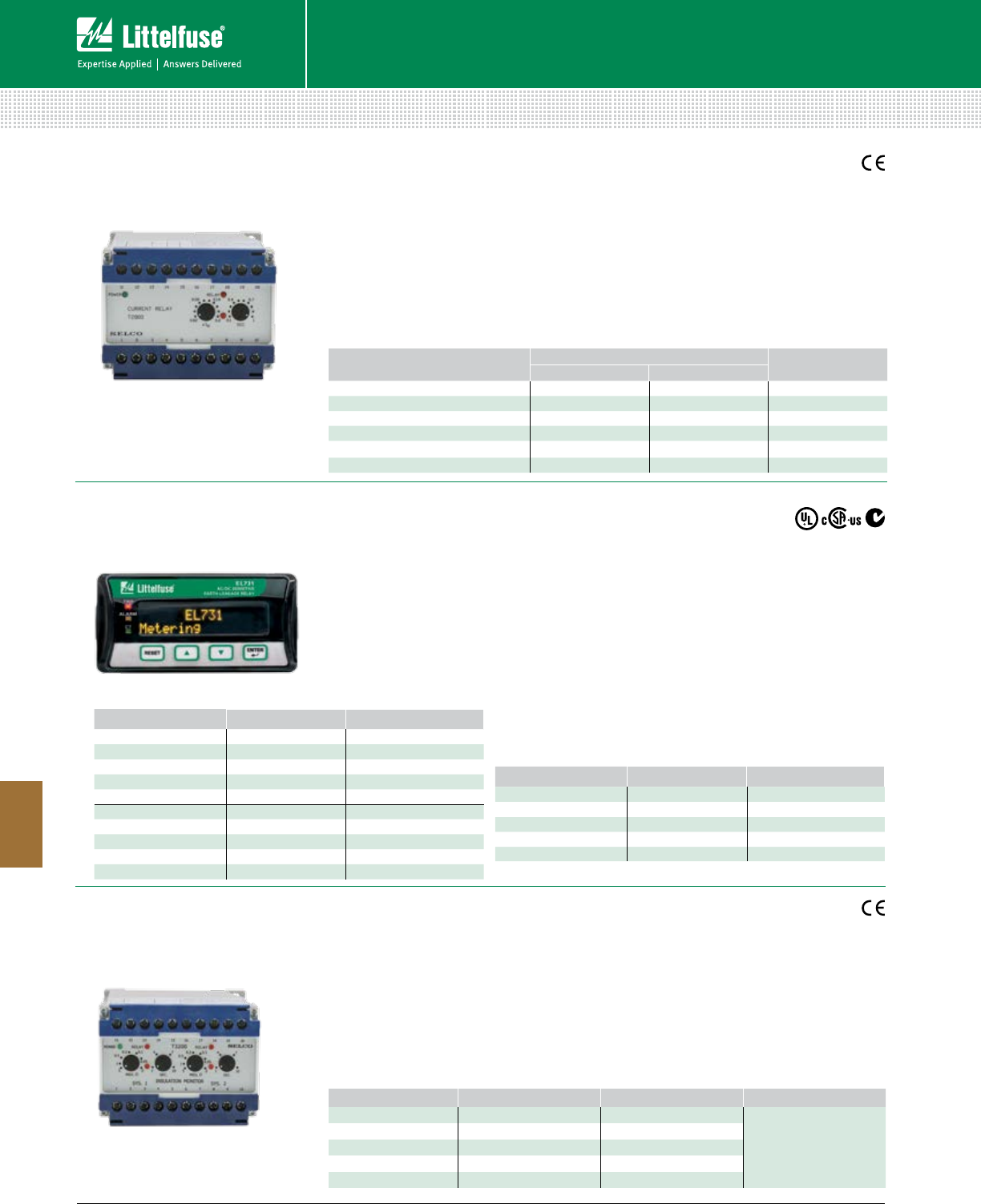
150 © 2014 Littelfuse POWR-GARD® Products Cataloglittelfuse.com
Protection Relays & Controls
Protection Relays & Controls
8
GROUND-FAULT PROTECTION
Features/Benefits
• Accepts high supply voltage variation
• Visual indication of power, pick-up and
output trip
• Direct line-line or line-neutral voltage supply
• Wide range of combined current and delay
settings
• DIN-rail or Screw-mount
Specifications
Trip Level 0.02-0.2 x IN or 0.2-2 x IN
Delay 0.1-1 sec or 1-10 sec
Dimensions H 70 mm (2.76”)
W 100 mm (3.94”)
D 115 mm (4.52”)
Web Resources
littelfuse.com/t2800
T2800 Earth-Fault Relay
For Solidly and Resistance-Grounded Systems
Features/Benefits
• Microprocessor based relay that offers
complete coverage for all frequencies
• Adjustable trip settings provide wide range
protection and coordination
• Operate in both AC or DC mode and single
or combined ranges
• LED indication for visual trip, alarm and CT
Specifications
IEEE Device Numbers 38, 49, 50G/N,
51G/N, 79G
Dimensions H 48 mm (1.9”)
W 96 mm (3.8”)
D 129 mm (5.0”)
Warranty 5 Years
Web Resources
littelfuse.com/el731
EL731 AC/DC Sensitive Earth-Leakage
For Solidly-Grounded Systems
Features/Benefits
• Continuously monitors two systems
galvanically separated from each other
• Ensures correct operation in spite of
voltage supply fluctuations
• Visual indication of power pick-up, and
output trip
Specifications
Insulation Level 0-5 MW
Max Voltage 660 V
Dimensions H 70 mm (2.75”)
W 100 mm (3.94”)
D 115 mm (4.52”)
Web Resources
littelfuse.com/t3200
T3200 Double Insulation Monitoring Relay
For Ungrounded Systems
ORDERING NUMBER TERMINALS IN
1-3 2-3
T2800-00 230 V 5 A
T2800-01 450 V 400 V 5 A
T2800-02 127 V 120 V 5 A
T2800-04 24V DC+AC 5 A
T2800-05 480 V 415 V 5 A
T2800-08 230 V 1 A
ORDERING NUMBER CONTROL POWER COMMUNICATIONS
EL731-00-XO 120/240 Vac/Vdc None
EL731-01-XO 120/240 Vac/Vdc DeviceNet™
EL731-02-XO 120/240 Vac/Vdc Profibus®
EL731-03-XO 120/240 Vac/Vdc Ethernet/IP™
EL731-04-XO 120/240 Vac/Vdc Modbus®TCP
EL731-10-XO 48 Vdc & 24 Vac None
EL731-11-XO 48 Vdc & 24 Vac DeviceNet™
EL731-12-XO 48 Vdc & 24 Vac Profibus®
EL731-13-XO 48 Vdc & 24 Vac Ethernet/IP™
EL731-14-XO 48 Vdc & 24 Vac Modbus®TCP
ORDERING NUMBER CONTROL POWER COMMUNICATIONS
EL731-20-XO 24 Vdc None
EL731-21-XO 24 Vdc DeviceNet™
EL731-22-XO 24 Vdc Profibus®
EL731-23-XO 24 Vdc Ethernet/IP™
EL731-24-XO 24 Vdc Modbus®TCP
ORDERING NUMBER 1-3 TERMINALS 2-3 TERMINALS ACCESSORIES
T3200.0010 230 V
E2333 Megaohmmeter
T3200.0020 450 V 400 V
T3200.0030 480 V 415 V
T3200.0050 110 V 100 V
T3200.0060 127 V 120 V
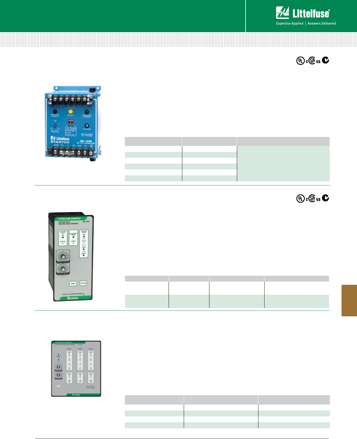
151 littelfuse.com © 2014 Littelfuse POWR-GARD® Products Catalog
Protection Relays & Controls
Protection Relays & Controls
8
TRAILING CABLE PROTECTION
Features/Benefits
• Adjustable pickup so unit can be used on a
wide variety of trailing cable applications
• Adjustable time delay for quick protection
and system coordination
• Harmonic filter prevents false operation
Specifications
IEEE Device Numbers 3GC, 50G/N, 51G/N
Dimensions H 150 mm (5.9”)
W 109 mm (4.3”)
D 100 mm (4.0”)
Warranty 5 Years
Web Resources
littelfuse.com/se-105
littelfuse.com/se-107
SE-105 • SE-107 Ground-Fault Ground-Check Monitor
SE-134C (PGM-8134C) • SE-135 Ground-Fault Ground-Check Monitor
Features/Benefits
• Adjustable pick can be used on a wide variety
of trailing cable applications
• Adjustable time delay for quick protection and
system coordination
• Separate annunciations of ground-fault and
ground-check faults
Specifications
IEEE Device Number 3GC, 50G, 50N, 51G, 51N
Dimensions H 213 mm (8.4”)
W 192 mm (7.6”)
D 176 mm (7.0”)
Communications Ethernet Optional
Warranty 5 Year
Web Resources
littelfuse.com/se-145
SE-145 Ground-Fault Ground-Check Monitor
Features/Benefits
• Fail-safe ground check circuit
• Combination ground-wire monitor and
ground-fault relay
• Zener-characteristic termination device
• High-induced-ac rejection
• DFT (harmonic) filter
Specifications
IEEE Device Numbers 3GC, 50G, 50N, 51G, 51N
Dimensions H 213 mm (8.4”)
W 99 mm (3.9”)
D 145 mm (5.7”)
Warranty 5 Year
Web Resources
littelfuse.com/se-134c
littelfuse.com/se-135
ORDERING NUMBER OPTION POWER SUPPLY COMM
SE-134C Blank or XGC 0= 120/240 Vac/Vdc
1=24/48 Vdc 0=None
SE-135 Blank or XGC 0= 120/240 Vac/Vdc
1=24/48 Vdc
0=None
3=Ethernet
ORDERING NUMBER CONTROL POWER ACCESSORIES
SE-105 120 Vac
CT200 Series Current Transformer
1N5339B Termination Assembly
SE-TA6 Termination Assembly
SE-TA6-SM Stud-Mount Termination Assembly
SE-105D 120 Vac/Vdc
SE-105E 240 Vac
SE-107 120 Vac
SE-107D 120 Vac/Vdc
SE-107E 240 Vac
ORDERING NUMBER CONTROL POWER COMM
SE-145-00-00 120/240 Vac; 110-250 Vdc —
SE-145-03-00 120/240 Vac; 110-250 Vdc Modbus®TCP
SE-145-30-00 24 Vdc Battery Back-up —
SE-145-33-10 24 Vdc Battery Back-up Modbus®TCP
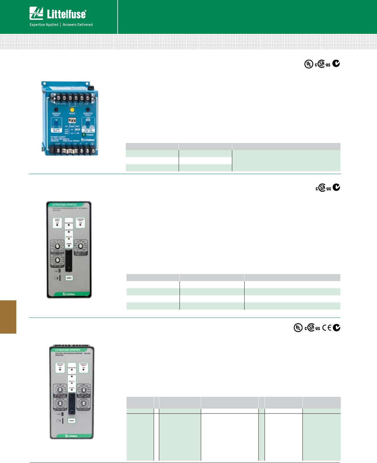
152 © 2014 Littelfuse POWR-GARD® Products Cataloglittelfuse.com
Protection Relays & Controls
Protection Relays & Controls
8
Description
The SE-325 Neutral-Grounding-Resistor Monitor
is used on resistance-grounded systems up to
25 kVac to monitor the integrity of the neutral-to-
ground path for loose connection, corrosion, and
ground faults.
Features/Benefits
• Adjustable ground-fault detection
• Adjustable time-delay settings
• Selectable fail-safe mode
• Conformally coated circuit boards
Specifications
IEEE Device Numbers 50G/N, 51G/N,
59N, 86, 3
Dimensions H 150 mm (5.9”)
W 109 mm (4.3”)
D 100 mm (4.0”)
Warranty 5 Year
Web Resources
littelfuse.com/se-325
ORDERING NUMBER SPECIFICATIONS ACCESSORIES
SE-325 120 Vac CT200 Series Current Transformers
ER Series Sensing Resistors
SE-325D 120 Vdc
SE-325E 240 Vac
Description
Advanced ground-fault and grounding-resistor
monitoring relay. It measures neutral current,
neutral-to-ground voltage and neutral-to-ground
resistance.
Features/Benefits
• Continuous NGR monitoring
• Detect ground-fault on monitored system
• Adjustable pickup (2-100%)
• Adjustable time delay (0.1 - 10s)
Specifications
IEEE Device Numbers 50G/N, 51G/N, 59N, 3, 86
Dimensions H 213 mm (8.4”)
W 98 mm (3.9”)
D 132 mm (5.2”)
Warranty 5 Year
Web Resources
littelfuse.com/se-330
Description
An advanced ground-fault and ground-resistor
monitoring relay for low and medium-voltage
transformers and generators. The SE-330AU
complies with AS/NZS 2081.3:2002.
Features/Benefits
• Continuous NGR monitoring
• Detect ground-fault anywhere on
monitored system
• Adjustable pickup settings
• Adjustable time delay settings
Specifications
Dimensions H 213 mm (8.4”)
W 98 mm (3.9”)
D 132 mm (5.2”)
Communications RS-232; DeviceNet™,
Profibus®, Ethernet
Warranty 5 Year
Web Resources
littelfuse.com/se-330au
RESISTANCE GROUNDING AND NGR MONITORING
SE-330 (PGR-5330), SE-330HV Neutral-Grounding-Resistor Monitor
SE-330AU Neutral-Grounding-Resistor Monitor
SE-325 (PGM-8325) Neutral-Grounding-Resistor Monitor
ORDERING
NUMBER POWER SUPPLY COMM CERTIFICATION K4 UNIT HEALTHY
CONTACT
SE-330 - X X - X X
SE-330 for all
app. 35 kV
or less
SE-330HV for
72 kV apps.
0=120/240 Vac/Vdc
2=48 Vdc
0=USB only
1= DeviceNet
3=Ethernet (Dual RJ45)
4=Ethernet (SC fiber & RJ45)
5=Ethernet (Dual SC Fiber)
6=IEC61850 (Dual RJ45)
7=IEC61850 (SC Fiber & RJ45)
8=IEC61850 (Dual SC Fiber)
0=CSA, UL
1= CSA, UL,
CE, C-Tick
0= Normally
Open
1= Normally
Closed
ORDERING NUMBER CONTROL POWER COMM
SE-330AU-00-OX 120/240 Vac/Vdc RS-232
SE-330AU-01-OX 120/240 Vac/Vdc RS-232 & DeviceNet™
SE-330AU-02-OX 120/240 Vac/Vdc RS-232 & Profibus®
SE-330AU-03-OX 120/240 Vac/Vdc RS-232 & Ethernet/IP™ & Modbus®TCP
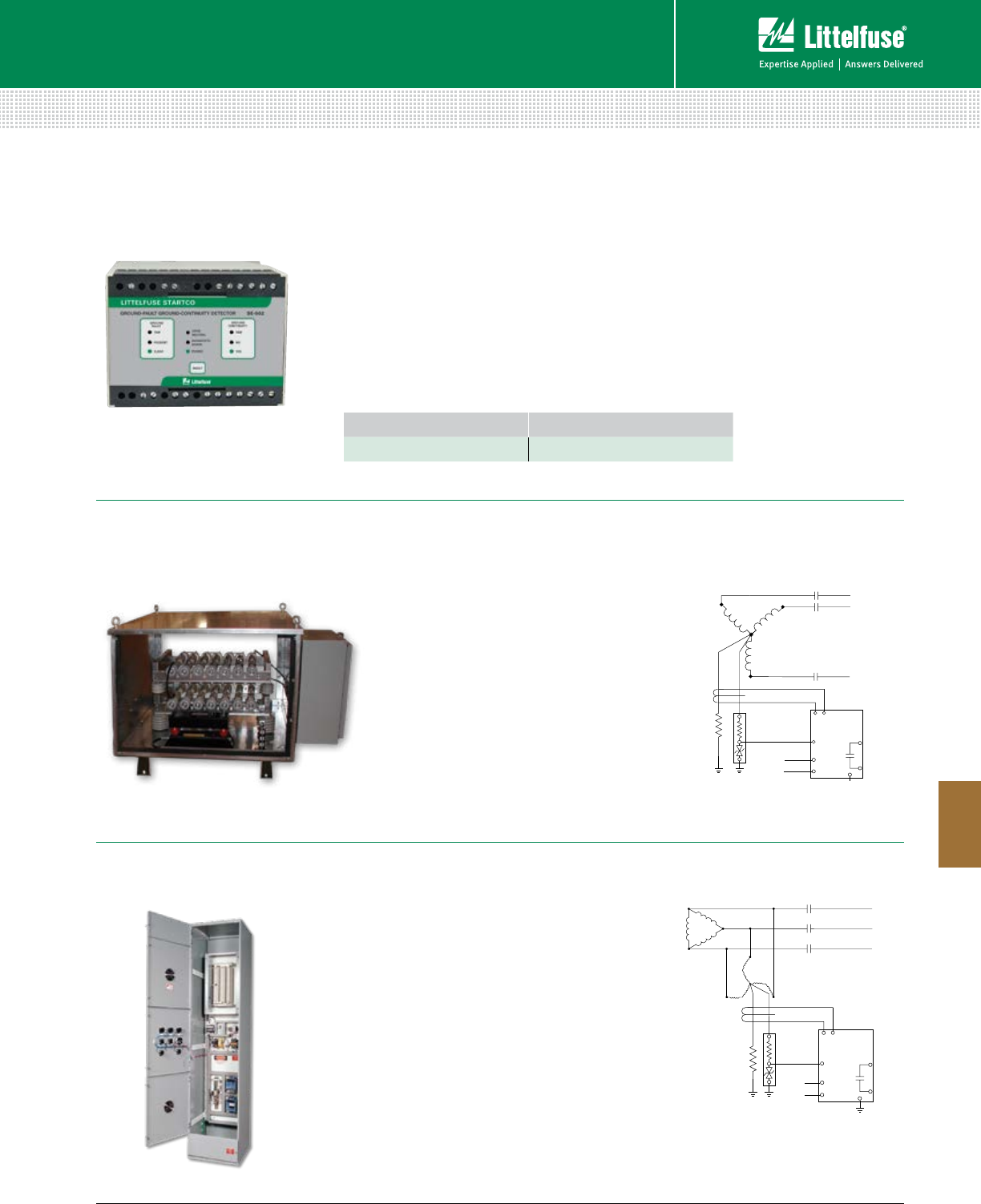
153 littelfuse.com © 2014 Littelfuse POWR-GARD® Products Catalog
Protection Relays & Controls
Protection Relays & Controls
8
Low-Resistance grounding is typically applied
on transformers and generators, and limits the
ground-fault current to 25 A and above. Since
ground-fault current is above 25 A, the faulted
feeder must be de-energized. The reduced
ground-fault current allows for an orderly shut-
down procedure, typically within 10 seconds.
Web Resources
For more information on Resistance Grounding
Systems, visit littelfuse.com/pgn-1000
SE-330
or
SENSING
RESISTOR
NGR
L2
SE-325
CT
L1
Description
Provides Class-A GFCI trip level and trip times for
personnel protection.
Features/Benefits
• Sensitive ground-fault detection
• Internal neutral-grounding resistor eliminates
arc-flash hazards
• Neutral-to-ground connection monitoring can
detect a hazardous ungrounded condition
Specifications
IEEE Device Numbers 64, 86, 95
Dimensions H 75 mm (3.0”)
W 100 mm (4.0”)
D 113 mm (4.4”)
Warranty 5 Year
Web Resources
littelfuse.com/se-502
PGN-3000
High-Resistance Grounding System
High-Resistance grounding is typically applied
on transformers and generators, and limits
the ground-fault current to 10 A or less. Since
ground-fault current is below 10 A, the faulted
feeder can remain in operation. The reduced
ground-fault current allows for an orderly shut-
down procedure.
Web Resources
For more information on Resistance Grounding
Systems, visit littelfuse.com/pgn-3000
SE-330 or
NGR
TRANSFORMER
SECONDARY
(Delta-connected
or wye-connected
with inaccessible
neutral)
ZIGZAG
TRANSFORMER
SENSING
RESISTOR
L2
SE-325
CT
L1
(Included with
PGN Series if necessary)
NGR Series (PGN-1000)
Low-Resistance Grounding System
RESISTANCE GROUNDING AND NGR MONITORING
SE-502 Ground-Fault Ground-Continuity Detector
ORDERING NUMBER CONTROL POWER
SE-502-01 120 Vac
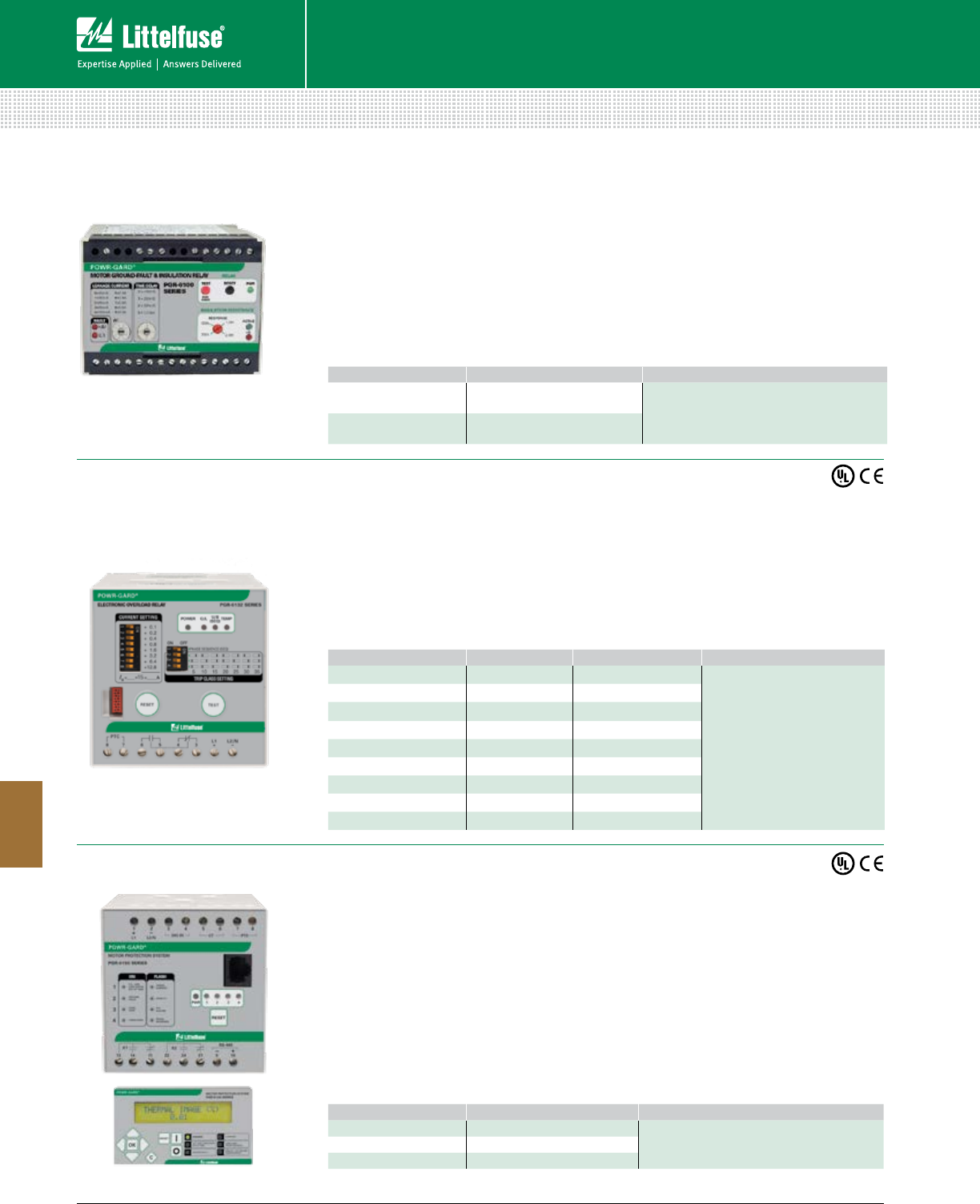
154 © 2014 Littelfuse POWR-GARD® Products Cataloglittelfuse.com
Protection Relays & Controls
Protection Relays & Controls
8
MOTOR PROTECTION
Features/Benefits
• Online monitoring to detect ground faults
• Offline monitoring of insulation resistance
• Continuously monitors for predictive
protective capabilities
• CT loop monitoring
• Individual alarm contacts (form C)
• Individual analog outputs to indicate insulation
resistance and ground-fault current
Specifications
IEEE Device Numbers 50G/N, 51G/N, 64, 74
Dimensions H 75 mm (3.0”)
W 100 mm (3.9”)
D 115 mm (4.5”)
Communications 2 Analog Outputs
Warranty 5 years
Web Resources
littelfuse.com/pgr-6100
ORDERING NUMBER SPECIFICATIONS ACCESSORIES
PGR-6100-120 24 Vdc/120 Vac Control Power PGC-5000 Series Ground-Fault Transformers
PGA-0500 Analog % Current Meter
PGA-0510 Analog Ohm Meter
PGH Family High Tension Couplers
PGR-6100-240 240 Vac Control Power
ORDERING NUMBER SPECIFICATIONS FULL-LOAD CURRENT ACCESSORIES
PGR-6131-24 24 Vdc 4-16.7 A
PGB-6130 Remote Indication
and Reset Assembly
PGR-6131-120 120 Vac 4-16.7 A
PGR-6131-240 240 Vac 4-16.7 A
PGR-6132-24 24 Vdc 15-40.5 A
PGR-6132-120 120 Vac 15-40.5 A
PGR-6132-240 240 Vac 15-40.5 A
PGR-6133-24 24 Vdc 40-91 A
PGR-6133-120 120 Vac 40-91 A
PGR-6133-240 240 Vac 40-91 A
Features/Benefits
• No external CT required for currents up to 90 A
• Cause-of-trip indication
• N.O. and N.C. alarm contacts
• Adjustable overload trip class setting
• Adjustable current pickup
• Over-temperature (PTC) protection
• Thermal overload protection
Specifications
IEEE Device Numbers 46, 49, 51
Dimensions H 83 mm (3.3”)
W 78 mm (3.1”)
D 99 mm (3.9”)
Warranty 5 years
Web Resources
littelfuse.com/pgr-6130
ORDERING NUMBER SPECIFICATIONS ACCESSORIES
PGR-6150-24 24/48 Vdc (Control Unit) PGR-6150-OPI Operator Interface
PGC-6000 Series Ground-Fault Transformer
PGR-6150-120 120/240 Vac/dc (Control Unit)
PGR-6150-OPI Operator Interface
Features/Benefits
• 13 protective functions
• 2 relay outputs, 1 digital input
• No external CT required for currents up to 25 A
• Thermal protection through starting, running,
overload and cooling cycles
• RS-485 interface with Modbus
®
RTU
• Optional PGR-6150-OPI Operator Interface
Specifications
IEEE Device Numbers 37, 46, 49, 50, 50G/N,
51, 51G/N, 66
Dimensions (Relay) H 83 mm (3.3”)
W 78 mm (3.1”)
D 99 mm (3.95”)
Dimensions (OPI) H 56 mm (2.2”)
W 106 mm (4.2”)
D 23 mm (0.9”)
Communications RS-485 with Modbus® RTU
Warranty 5 years
Web Resources
littelfuse.com/pgr-6150
PGR-6150 Motor Protection System
PGR-6130 Electronic Overload Relay
PGR-6100 (GFR-4000) Motor Ground-Fault and Insulation Relay
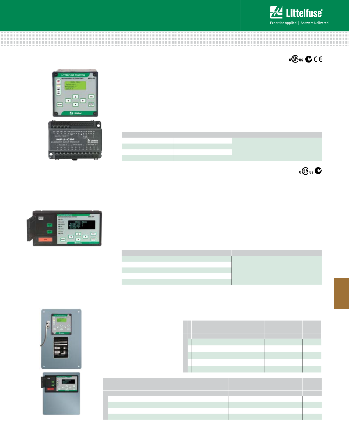
155 littelfuse.com © 2014 Littelfuse POWR-GARD® Products Catalog
Protection Relays & Controls
Protection Relays & Controls
8
MOTOR PROTECTION
ORDERING NUMBER COMMUNICATIONS ACCESSORIES
MPS-CTU-01-00 RS-485 Phase Current Transformers
Ground-Fault Current Transformers
MPS-RTD Temperature Input Module
MPS-DIF Differential Current Module
MPS-CTU-02-00 RS-485 & DeviceNet™
MPS-CTU-03-00 RS-485 & Profibus®
MPS-CTU-04-00 RS-485 & Ethernet
MPS-OPI-01-00 Operator Interface
MPS (PGR-6300) Motor Protection System
MPU-32-X69X (PGR-6210) & MPS-469X (PGR-6310)
Motor Protection Retrofit Kits
MPU-32 (PGR-6200) Motor Protection Unit
Features/Benefits
• Direct replacement for GE Multilin
169, 269, 369 and 469 relays
• Microprocessor-based protection
• Proven reliability
• Conformally coated circuit boards
• Pre-wired module allows minimal
change-out time
• Ability to match existing
overcurrent values
Ordering Information
MPU-32-X69X
Ordering Information
MPS-469X
Features/Benefits
• Reduced overcurrent setting for maintenance
• Dynamic thermal modeling
• Communications for different networks
• Optional RTD protection
• Optional differential protection
• Conformal coating
• Modular system and compact design makes
installation easy for new or retrofit applications
Specifications
IEEE Device Numbers 37, 38, 46, 49, 50, 50G/N,
51, 51G/N, 66, 74, 86, 87
Dimensions H 96 mm (3.78”)
W 96 mm (3.78”)
D 132 mm (5.2”)
Communications RS-232 (Standard);
RS-485, DeviceNet™
Ethernet (Optional)
Warranty 10 years
Web Resources
littelfuse.com/mpu-32
Features/Benefits
• Overcurrent reduction setting for maintenance
• Monitors voltage, current, and temperature
• 22 motor protection functions
• Conformal coating
• Dynamic thermal modeling
• Starter control, Metering, and Data Logging
• Optional RTD protection with hazardous-
location certified RTD module
• Optional differential protection
• Modular design makes installation easy
Specifications
IEEE Device Numbers 1, 2, 3, 5, 9, 14, 18, 19, 27, 34,
37, 38,46, 47, 48, 49, 50, 50G,
50N, 51, 51G/N, 55, 59, 66,
74, 81, 86, 87, 94
Dimensions (OPI) H 98 mm (3.86”)
W 192 mm (7.56”)
D 0.42 mm (1.65”)
Communications Allen-Bradley® DF1 & Modbus®
RTU (Standard); DeviceNet™,
Profibus®, Ethernet (Optional)
Warranty 10 years
Web Resources
littelfuse.com/mps
ORDERING NUMBER COMMUNICATIONS ACCESSORIES
MPU-32-00-00 TIA-232 Phase Current Transformers
Ground-Fault Current Transformers
MPS-RTD Temperature Input Module
MPS-DIF Differential Current Module
MPU-32-01-00 TIA-232 & RS-485
MPU-32-02-00 TIA-232 & DeviceNet™
MPU-32-04-00 TIA-232 & Ethernet
RTD INPUTS MPU-32
COMMUNICATION
GROUND-FAULT CT
FUTURE
OPTIONS
MPU-32-X69X
- X X X 00
0 = One Platinum 100 Ω 0 = TIA232 0 = Wired for wGround-Fault CT (50 mA Secondary)
1 = One Platinum 100 Ω & 8-input MPS-RTD Module 1 = TIA232 & TIA485 1 = Wired for 1- or 5-A Secondary Ground-Fault CT
2 = TIA232 & DeviceNet
4 = TIA232 & Ethernet
MODULE CONFIGURATION MPS
COMMUNICATION
FUTURE
OPTIONS
MPS-469X
- X X 000
0 = None 1 = RS485
1 = One MPS-RTD Module 2 = RS485 & DeviceNet
2 = Two MPS-RTD Modules 3 = RS485 & Profibus
3 = One MPS-DIF Module 4 = RS485 & Ethernet
4 = One MPS-RTD Module & One MPS-DIF Module
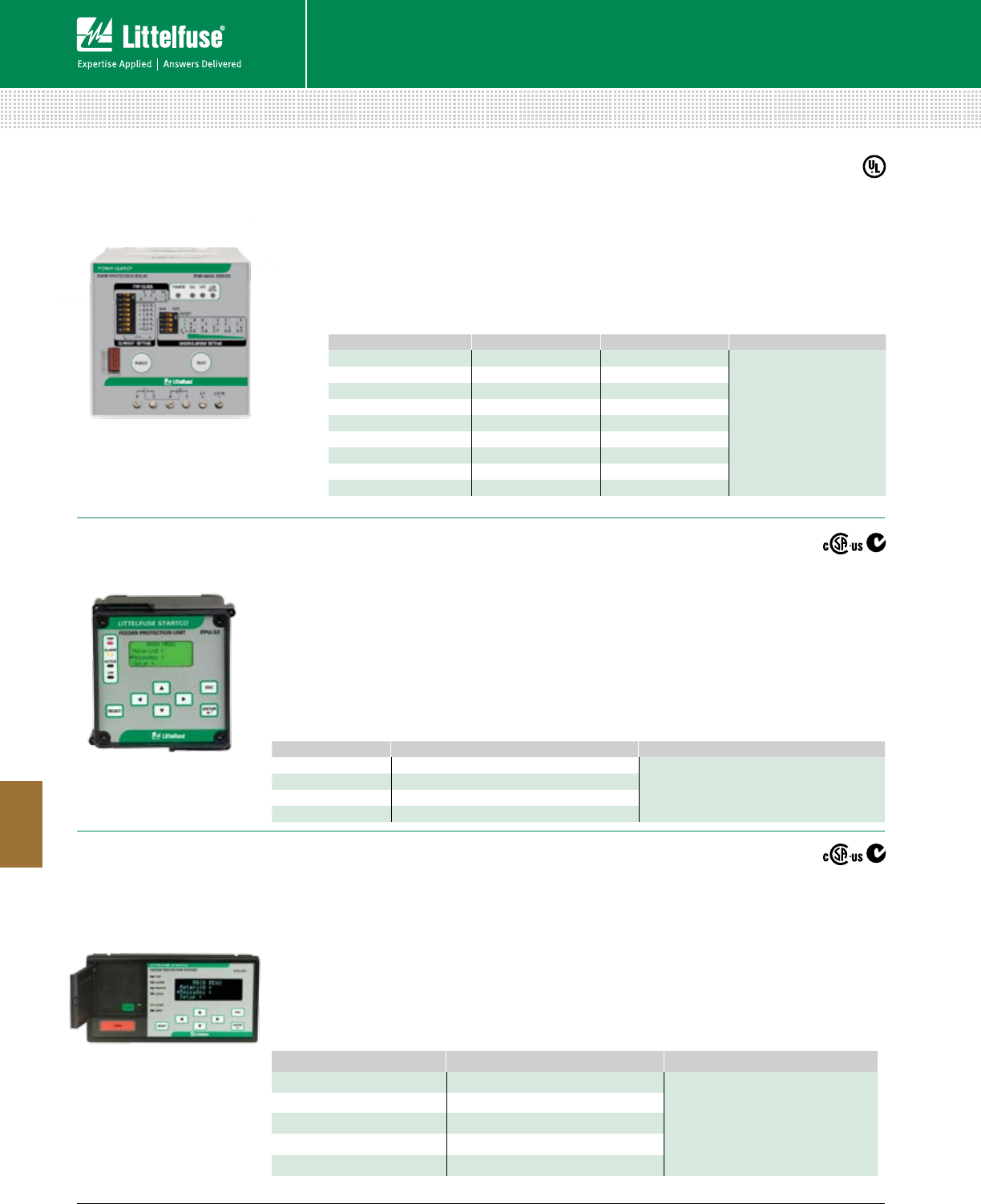
156 © 2014 Littelfuse POWR-GARD® Products Cataloglittelfuse.com
Protection Relays & Controls
Protection Relays & Controls
8
PUMP AND FEEDER PROTECTION
PGR-6800 Pump Protection Relay
FPS (PGR-7300) Feeder Protection System
FPU-32 (PGR-7200) Feeder Protection Unit
Features/Benefits
• Monitors voltage and current
• Long-time overcurrent provides thermal protection for
feeder or load
• Instantaneous overcurrent to detect catastrophic
failure
• Coordinations using IEEE and IEC
Specifications
IEEE Device Numbers 27, 38, 46, 47, 49, 50, 50G/N,
51, 51G/N, 55, 59, 81,
Dimensions (OPI) H 98 mm (3.86”)
W 192 mm (7.56”)
D 0.42 mm (1.65”)
Warranty 10 years
Web Resources
littelfuse.com/fps
ORDERING NUMBER SPECIFICATIONS FULL-LOAD CURRENT ACCESSORIES
PGR-6801-24 24 Vdc 7-19.6 A
PGB-6800 - Remote Indication
and Reset Assembly
PGR-6801-120 120 Vac 7-19.6 A
PGR-6801-240 240 Vac 7-19.6 A
PGR-6802-24 24 Vdc 19-44.2 A
PGR-6802-120 120 Vac 19-44.2 A
PGR-6802-240 240 Vac 19-44.2 A
PGR-6803-24 24 Vdc 40-90.4 A
PGR-6803-120 120 Vac 40-90.4 A
PGR-6803-240 240 Vac 40-90.4 A
Features/Benefits
• No external CT required for currents up to 90 A
• Cause-of-trip indication
• N.O. and N.C. alarm contacts
• Adjustable overload trip class setting
• Adjustable current pickup
• Undercurrent protection
Specifications
IEEE Device Numbers 37, 46, 49, 51
Dimensions H 83 mm (3.3”)
W 78 mm (3.1”)
D 99 mm (3.9”)
Warranty 5 years
Web Resources
littelfuse.com/pgr-6800
ORDERING NUMBER SPECIFICATIONS ACCESSORIES
FPU-32-00-00 TIA-232 Communications
Phase Current Transformers
Ground-Fault Transformer
FPU-3200-01-00 TIA-232 & RS-485 Communications
FPU-3200-02-00 TIA-232 & DeviceNet™ Communications
FPU-3200-04-00 TIA-232 & Ethernet Communications
Features/Benefits
• Protection, metering, and data-logging functions
• Programmable using the operator interface, the TIA-
232 port, or an optional communications network
• IEC & IEEE protection curves
• CT saturation compensation
• Communications for different networks
• Two set-point groups
Specifications
IEEE Device Numbers 26, 46, 49, 50, 50G/N,
51, 51G/N, 74, 86
Dimensions H 96 mm (3.78”)
W 96 mm (3.78”)
D 132 mm (5.2”)
Communications TIA-232, RS-485, DeviceNet™, Ethernet
Warranty 10 years
Web Resources
littelfuse.com/fpu-32
ORDERING NUMBER SPECIFICATIONS ACCESSORIES
FPS-CTU-01-00 RS-485 Communications
Phase Current Transformers
Ground-Fault Current Transformer
MPS-RTD Temperature Input Module
SE-IP65CVR-M Cover
FPS-CTU-02-00 RS-485 & DeviceNet™ Communications
FPS-CTU-03-00 RS-485 & Profibus® Communications
FPS-CTU-04-00 RS-485 & Ethernet Communications
FPS-OPI-01-OO Recommended
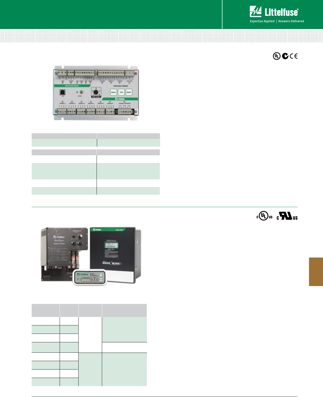
157 littelfuse.com © 2014 Littelfuse POWR-GARD® Products Catalog
Protection Relays & Controls
Protection Relays & Controls
8
ARC-FLASH PROTECTION AND GFCI
PGR-8800 (D1000) Arc-Flash Protection Relay
Industrial Shock-Block Ground-Fault Circuit Interruption
Open-Chassis Model
Enclosed Model
Operator Interface
Ordering Information
ORDERING NUMBER COMMUNICATIONS
PGR-8800-00 (UL, CE, C-tick) Multi-unit linking, Modbus® RTU
ACCESSORIES REQUIREMENT
PGA-LS10 (A1000) Required*
PGA-LS20 (A2000)/
PGA-LS25 (A2000.0020)
PGA-LS30 (A2000.0030)
Required*
PGA-1100 (D1100) Optional
Current Transformer Recommended
*At least one sensor is required. However, the exact number of sensors for proper coverage
depends on the application.
Description
The PGR-8800 is a microprocessor-based relay that limits arc-fault
damage by detecting the light from an arc flash and rapidly tripping.
Phase-current-transformer inputs are provided for current-constrained
arc-flash protection and, when so equipped, a programmable definite-
time overcurrent function can be enabled. An optical sensor on the
PGR-8800 and adjustable trip level reduce the chance of nuisance
tripping by setting a threshold for ambient light. Sensors, inputs, and
connections are monitored to ensure fail-safe operation. A secondary
solid-state trip circuit provides a redundant trip path. A USB port is used
for configuration and access to event logs and graphs.
Specifications
IEEE Device Numbers Overcurrent (50), Arc Flash (AFD)
Input Voltage 100-240 Vac, 14-48 Vdc, and 110-250 Vdc
Dimensions H 130 mm (5.2”); W 200 mm (7.9”);
D 54 mm (2.2”)
Optical Trip Settings 9-25 klux, 800 μs-20 s
Current Trip Setting (A) Programmable
Indication Contact Mode Fail-safe
Trip Coil Voltage(1) 24-300 Vdc, 24-300 Vac
Expandable System Link up to 4 PGR-8800 units
Warranty 5 years
Mounting DIN (with D0050 adapter clips), Surface
Web Resources
littelfuse.com/arcflash
Description
Special Purpose Ground-Fault Circuit Interrupter (GFCI),
Class C and Class D
Industrial Shock Block (ISB) is a personnel protection device designed to
meet the new requirements for special-purpose GFCIs defined by UL
943C. ISB is the first and only permanently connected Class C and Class
D GFCI on the market. Class C GFCIs is introduced to be used on systems
where the line-to-line voltage is 480 V or less with a trip level of 20 mA,
while Class D GFCI is intended to be used on 600 V systems. These
improvements to the standard Class A GFCI (6 mA trip level used on 240 V
systems or less) were made to allow the use of GFCIs in industrial facilities.
Equipment Ground-Fault Protective Device (EGFPD)
ISB is also available with adjustable protection settings as an EGFPD. The
EGFPD models can be set to trip at 6, 10, 20 or 30 mA. This offers more
flexibility since GFCI devices are not allowed to have an adjustable trip level.
Specifications
Voltage Rating See ordering information
Amperage Rating 100 A (continuous)
Short Circuit Rating 50,000 A
Trip Level Settings Selectable (6, 10, 20, 30 mA), or
fixed at 20 mA
Trip Time Setting Inverse time trip curve
Dimensions Enclosed: H 453.8 mm (17.9”);
W 406.2 mm (16.0”); D 223.3 mm (8.8”)
Open-chassis: H 455.0 mm (17.9”);
W 340.7 mm (13.4”); D 174.9 mm (6.8”)
Web Resources
littelfuse.com/IndustrialShockBlock
ORDERING
NUMBER
VOLTAGE
(V)
TRIP
LEVEL (mA) UL CATEGORY/CLASS
SB6100-00x-0 208
20
(Fixed)
UL 943C Class C
special-purpose GFCI
SB6100-10x-0 240
SB6100-20x-0 480
SB6100-30x-0 600 UL 943C Class D
special-purpose GFCI
SB6100-01x-0 208
6, 10, 20, 30
(Selectable)
UL 943/UL 1053
Equipment ground-fault
protective device (EGFPD)
SB6100-11x-0 240
SB6100-21x-0 480
SB6100-31x-0 600
Ordering Information
Note: x=0 for open-chassis models and 1 for enclosed models
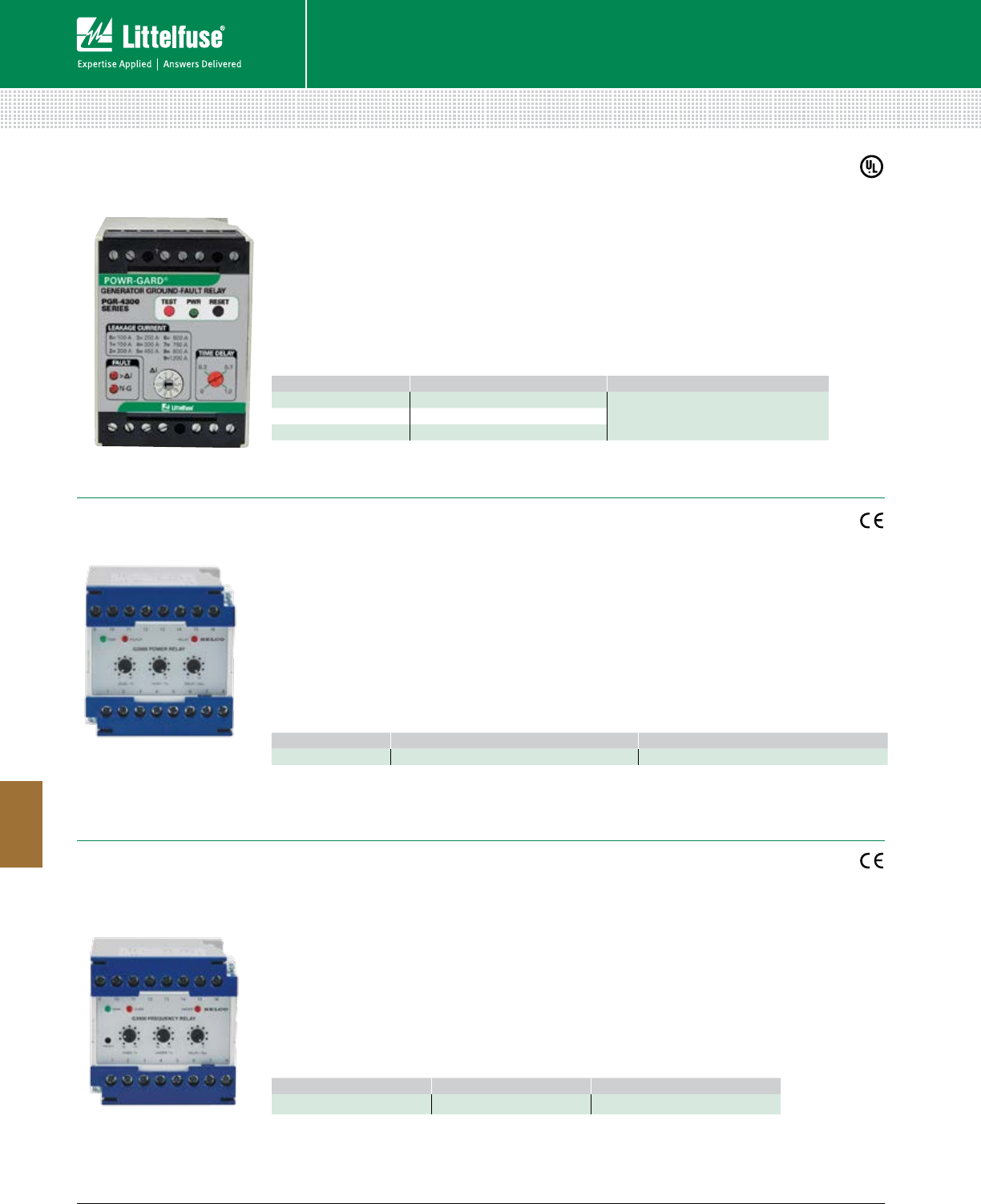
158 © 2014 Littelfuse POWR-GARD® Products Cataloglittelfuse.com
Protection Relays & Controls
Protection Relays & Controls
8
GENERATOR & SINGLE-FUNCTION PROTECTION
PGR-4300 Generator Ground-Fault Relay
G3000 Frequency Relay
G2000 Power Relay
ORDERING NUMBER SPECIFICATIONS ACCESSORIES
G3000.0010 24 Vdc Control Power G0100 Programming Kit
Features/Benefits
• Frequency monitor generators, busbars or other
distribution systems
• PC configuration for over and under frequency
protection one unit
• User configured scales and setpoints suits a
broad variety of applications
• 63 Vac to 690 Vac systems can be monitored by
the same unit
Specifications
Supply 8-36 Vdc/0.75 W at 24 Vdc
Input Voltage 63-690 Vac ± 30%
Input Current 5 A CT, max. 10 A
Frequency 35-75 Hz
Dimensions H 73 mm (2.9”)
W 75 mm (3.0”)
D 114 mm (4.5”)
Web Resources
littelfuse.com/g3000
ORDERING NUMBER SPECIFICATIONS ACCESSORIES
G2000.0010
24 Vdc, 5 A Control Power
G0100 Programming Kit
Features/Benefits
• Detects power level for protection, control and
monitoring
• PC configuration for forward power or reverse
power functionality
• User configured scales and setpoints suits a
broad variety of applications
• 63 Vac to 690 Vac systems can be monitored by
the same unit
Specifications
Supply 8-36 Vdc/0.75 W at 24 Vdc
Input Voltage 63-690 Vac ± 30%
Input Current 5 A CT, max. 10 A
Frequency 35-75 Hz
Dimensions H 73 mm (2.9”)
W 75 mm (3.0”)
D 114 mm (4.5”)
Web Resources
littelfuse.com/g2000
Features/Benefits
• No CTs required
• Provides a simple method for tripping a ground-
fault condition on generators
• Use with 3- or 4-pole transfer switches
• Monitors neutral-to-ground integrity
• Adjustable pick-up settings from 100 to 1200 A
• Adjustable time-delay settings from 0 to 1 sec
Specifications
IEEE Device Numbers 50G/N, 51G/N
Dimensions H 75 mm (3.0”)
W 55 mm (2.2”)
D 115 mm (4.5”)
Communications Analog Output
Warranty 5 Year
Web Resources
littelfuse.com/pgr-4300
ORDERING NUMBER SPECIFICATIONS ACCESSORIES
PGR-4300-12 12 Vdc Control Power
PGA-0500 Analog Current MeterPGR-4300-24 24 Vdc Control Power
PGR-4300-120 120 Vac Control Power
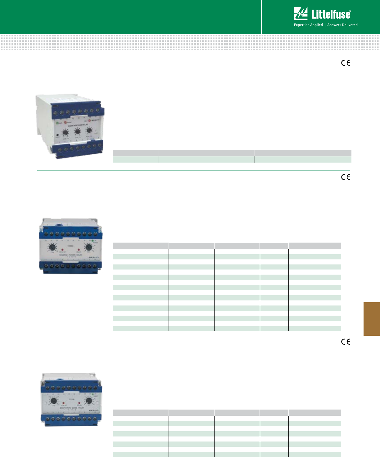
159 littelfuse.com © 2014 Littelfuse POWR-GARD® Products Catalog
Protection Relays & Controls
Protection Relays & Controls
8
GENERATOR & SINGLE-FUNCTION PROTECTION
T2000 Reverse Power Relay
T2100 Excitation Loss Relay
G3300 Voltage Relay
ORDERING NUMBER TERMINALS 1-3 TERMINALS 2-3 INSUPPLY
T2000.0010 230 V 5 A L-N
T2000.0020 450 V 400 V 5 A L-L
T2000.0030 127 V 120 V 5 A L-N
T2000.0040 110 V 100 V 5 A L-L
T2000.0050 110 V 100 V 5 A L-L
T2000.0060 230 V 1 A L-N
T2000.0070 660 V 5 A L-L
T2000.0080 450 V 400 V 5 A L-N
T2000.0090 127 V 120 V 5 A L-L
T2000.0100 110 V 100 V 1 A L-L
T2000.0110 450 V 400 V 5 A L-L
T2000.0120 480 V 415 V 5 A L-L
T2000.0130 230 V 5 A L-N
T2000.0140 230 V 5 A L-L
T2000.0150 480 V 415 V 1 A L-L
T2000.0160 450 V 400 V 1 A L-L
ORDERING NUMBER TERMINALS 1-3 TERMINALS 2-3 INSUPPLY
T2100.0010 230 V 5 A L-N
T2100.0020 480 V 415 V 5 A L-L
T2100.0030 450 V 400 V 5 A L-L
T2100.0040 110 V 100 V 1 A L-L
T2100.0050 110 V 100 V 5 A L-L
T2100.0060 110 V 100 V 5 A L-L
T2100.0070 480 V 415 V 5 A L-L
T2100.0080 110 V 100 V 5 A L-L
ORDERING NUMBER SPECIFICATIONS ACCESSORIES
G3300.0010
24 Vdc Control Power
G0100 Programming Kit
Features/Benefits
• Protects the generator from being run as an
electric motor
• Accepts high supply voltage variation to ensure
correct operation in spite of voltage supply
fluctuations
• Visual indication of power, pick-up and output trip
provides quick and concise status information
Specifications
Trip level 2-20% IN
Delay 2-20 sec.
Max. Voltage 660 V
Dimensions H 70 mm (2.8”)
W 100 mm (3.9”)
D 115 mm (4.5”)
Web Resources
littelfuse.com/t2000
Features/Benefits
• Protects against loss of excitation in a
synchronous generator
• Accepts high supply voltage variation to ensure
correct operation in spite of voltage supply
fluctuations
• Visual indication of power, pick-up and output trip
provides quick and concise status information
Specifications
Trip level 0.5-1.5 x IN
Delay 2-20 sec.
Max. Voltage 660 V
Dimensions H 70 mm (2.8”)
W 100 mm (3.9”)
D 115 mm (4.5”)
Web Resources
littelfuse.com/t2100
Features/Benefits
• Monitors voltage on generators, busbars or other
distribution systems
• PC configuration for over and undervoltage
protection in one relay
• User configured scales and setpoints suits a
broad variety of applications
• Phase symmetry monitor enables use in grid
connection applications
• 63 Vac to 690 Vac systems can be monitored by
the same unit
Specifications
Supply 8-36 Vdc/0.75 W at 24 Vdc
Input Voltage 63-690 Vac ± 30%
Frequency 35-75 Hz
Dimensions H 73 mm (2.9”)
W 75 mm (3.0”)
D 114 mm (4.5”)
Web Resources
littelfuse.com/g3300
160 © 2014 Littelfuse POWR-GARD® Products Cataloglittelfuse.com
Protection Relays & Controls
Protection Relays & Controls
8
GENERATOR & SINGLE-FUNCTION PROTECTION
T2200 3-Phase Overcurrent Relay
T2400 3-Phase Dual Overcurrent Relay
T2300 3-Phase Short-Circuit Relay
ORDERING NUMBER TERMINALS 1-3 TERMINALS 2-3 INFUNCTION
T2200.0010 450 V 400 V 5 A Latching output, resetable
T2200.0020 450 V 400 V 5 A Normally energized output, latching, resetable
T2200.0030 230 V 5 A Latching output, resetable
T2200.0040 230 V 110 V 5 A Latching output, resetable
T2200.0050 230 V 1 A Latching output, resetable
T2200.0060 450 V 400 V 5 A Normally energized output, latching, resetable
T2200.0070 110 V 100 V 5 A Latching output, resetable
T2200.0080 480 V 415 V 5 A Latching output, resetable
T2200.0090 24 Vdc 5 A Latching output, resetable
T2200.0100 450 V 400 V 5 A Instantly extra output relay
T2200.0110 450 V 400 V 1 A Instantly extra output relay
ORDERING NUMBER TERMINALS 1-3 TERMINALS 2-3 INFUNCTION
T2400.0010 230 V 5 A
T2400.0020 450 V 400 V 5 A
T2400.0030 110 V 100 V 5 A
T2400.0040 450 V 400 V 5 A Latching output on relay 1,
6-60 sec. delay on relay 1
T2400.0050 480 V 415 V 5 A
T2400.0060 450 V 400 V 1 A
T2400.0070 450 V 400 V 5 A Latching output on relay 1,
normally energized relay 1
T2400.0080 127 V 120 V 5 A
T2400.0090 24 Vdc 5 A
ORDERING NUMBER TERMINALS 1-3 TERMINALS 2-3 INFUNCTION
T2300.0100 230 V 5 A
T2300.0020 450 V 400 V 5 A
T2300.0030 24 Vdc 5 A
T2300.0040 24 Vdc 1 A
T2300.0050 450 V 400 V 5 A Normally de-energized output
T2300.0060 480 V 415 V 5 A
T2300.0070 230 V 1 A
Features/Benefits
• Designed for generator or feeder protection
against overcurrent in each of the 3 phases
• Accepts high supply voltage variation to
ensure correct operation in spite of voltage
supply fluctuations
• Visual indication of power, pick-up and output trip
provides quick and concise status information
Specifications
Trip level 0.5-1.4 x IN
Delay 3-30 sec.
Max. Voltage 660 V
Dimensions H 70 mm (2.8”)
W 100 mm (3.9”)
D 115 mm (4.5”)
Web Resources
littelfuse.com/t2200
Features/Benefits
• Includes 2 combined overcurrent designed
for protection or monitoring of generators and
power transmissions
• Accepts high supply voltage variation to
ensure correct operation in spite of voltage
supply fluctuations
• Combining 2 relays is an economic solution for
non-essential load tripping and occupying less
space in the switch panel
Specifications
Trip level 0.5-1.4 x IN
Delay 3-30 sec.
Max. Voltage 660 V
Dimensions H 70 mm (2.8”)
W 100 mm (3.9”)
D 115 mm (4.5”)
Web Resources
littelfuse.com/t2400
Features/Benefits
• Designed for protection of generators, power
transmissions and consumer’s supply against
short circuit
• Accepts high supply voltage variation to
ensure correct operation in spite of voltage
supply fluctuations
• Visual indication of power, pick-up and output trip
provides quick and concise status information
Specifications
Trip level 1.0-4.0 x IN
Delay 0.1-1.0 sec.
Max. Voltage 660 V
Dimensions H 70 mm (2.8”)
W 100 mm (3.9”)
D 115 mm (4.5”)
Web Resources
littelfuse.com/t2300
161 littelfuse.com © 2014 Littelfuse POWR-GARD® Products Catalog
Protection Relays & Controls
Protection Relays & Controls
8
GENERATOR & SINGLE-FUNCTION PROTECTION
T2700 Power Relay
T2900 3-Phase Differential Relay
T2500 Overcurrent and Short-Circuit Relay
ORDERING NUMBER TERMINALS 1-3 TERMINALS 2-3 INFUNCTION
T2500.0010 450 V 400 V 5 A Latching output, resetable
T2500.0020 230 V 5 A Latching output, resetable
T2500.0030 480 V 415 V 5 A Latching output, resetable
T2500.0040 450 V 400 V 1 A Latching output, resetable
T2500.0050 24 Vdc 5 A Latching output, resetable
T2500.0060 230 V 5 A De-energized extra output relay
T2500.0070 450 V 400 V 5 A De-energized extra output relay
T2500.0080 450 V 400 V 5 A De-energized extra output relay, latching outputs
T2500.0090 480 V 415 V 5 A De-energized extra output relay
T2500.0100 24 Vdc 1 A De-energized extra output relay
T2500.0110 450 V 400 V 5 A De-energized extra output relay, latching short
circuit output
T2500.0120 24 Vdc 5 A De-energized extra output relay, de-energized
relay 1, no internal power backup
ORDERING NUMBER TERMINALS 1-3 TERMINALS 2-3 INSUPPLY FUNCTION
T2700.00 230 V 5 A L-N
T2700.02 450 V 400 V 5 A L-L
T2700.03 230 V 400 V 5 A L-L
T2700.04 110 V 100 V 5 A L-L Normally energized output
T2700-08 127 V 120 V 5 A L-N
ORDERING NUMBER TERMINALS 1-3 TERMINALS 2-3 IN
T2900.0010 450 V 400 V 5 A
T2900.0020 230 V 5 A
T2900.0030 480 V 415 V 5 A
T2900.0040 110 V 100 V 5 A
Features/Benefits
• The short-circuit relays protects against faults
causing high currents and the overcurrent relay
protects against thermal damage
• Accepts high supply voltage variation to
ensure correct operation in spite of voltage
supply fluctuations
• Combining 2 relays is an economic solution,
occupying less space in the switch panel
Specifications
Trip level 0.5-1.4 x IN
Delay 3-30 sec.
Max. Voltage 660 V
Dimensions H 70 mm (2.8”)
W 100 mm (3.9”)
D 115 mm (4.5”)
Web Resources
littelfuse.com/t2500
Features/Benefits
• Detects power levels for protection, control or
monitoring and will protect against excessive
active loads
• Accepts high supply voltage variation to
ensure correct operation in spite of voltage
supply fluctuations
• Visual indication of power, pick-up and output trip
provides quick and concise status information
Specifications
Trip level 15-150 x IN
Delay 2-20 sec.
Max. Voltage 660 V
Dimensions H 70 mm (2.8”)
W 100 mm (3.9”)
D 115 mm (4.5”)
Web Resources
littelfuse.com/t2700
Features/Benefits
• Monitors current leakage in generators and
measures the differential current of each
of the 3 phases
• Accepts high supply voltage variation to
ensure correct operation in spite of voltage supply
fluctuations
• Visual indication of power, pick-up and output trip
provides quick and concise status information
Specifications
Trip level 0.04-0.4 x IN
Delay 1-10 sec.
(0.1-1 sec. bridging terminals 18/19)
Max. Voltage 660 V
Dimensions H 70 mm (2.8”)
W 100 mm (3.9”)
D 115 mm (4.5”)
Web Resources
littelfuse.com/t2900
162 © 2014 Littelfuse POWR-GARD® Products Cataloglittelfuse.com
Protection Relays & Controls
Protection Relays & Controls
8
GENERATOR & SINGLE-FUNCTION PROTECTION
T3000 Frequency Relay
T3300 3-Phase Voltage Relay
T3100 Voltage Relay
ORDERING NUMBER TERMINALS 1-3 TERMINALS 2-3
T3000.0010 230 V
T3000.0020 450 V 400 V
T3000.0030 110 V 100 V
T3000.0040 480 V 415 V
T3000.0050 127 V 120 V
ORDERING NUMBER TERMINALS 1-3 TERMINALS 2-3
T3100.0010 230 V
T3100.0020 450 V 400 V
T3100.0030 110 V 100 V
T3100.0040 480 V 415 V
T3100.0060 127 V 120 V
ORDERING NUMBER TERMINALS 17-19, 21-23, 25-27 TERMINALS 18-19, 22-23, 26-27
T3300.0010 230 V
T3300.0020 450 V 400 V
T3300.0030 110 V 100 V
T3300.0040 480 V 415 V
Features/Benefits
• Frequency monitor generators, busbars or other
distribution systems
• Accepts high supply voltage variation to
ensure correct operation in spite of voltage
supply fluctuations
• Visual indication of power, pick-up and output trip
provides quick and concise status information
• Combining 2 relays is an economic solution
for monitoring both underfrequency and
overfrquency in the same unit
Specifications
Overfrequency Level 45-65 Hz
Delay 1-10 sec.
Underfrequency Level 45-65 Hz
Delay 1-10 sec.
Max. Voltage 660 V
Dimensions H 70 mm (2.8”)
W 100 mm (3.9”)
D 115 mm (4.5”)
Web Resources
littelfuse.com/t3000
Features/Benefits
• Monitors voltage on generators, busbars or other
distribution systems
• Signals when voltage is out of its limits
• Consists of two, one for overvoltage and one for
undervoltage monitoring
• Accepts high supply voltage variation to
ensure correct operation in spite of voltage
supply fluctuations
Specifications
Overvoltage level 100-120%
Delay 1-10 sec.
Undervoltage Level 80-100%
Max. Voltage 660 V
Dimensions H 70 mm (2.8”)
W 100 mm (3.9”)
D 115 mm (4.5”)
Web Resources
littelfuse.com/t3100
Features/Benefits
• Monitors voltage on generators, busbars or other
distribution systems
• Signals when voltage is out of its limits
• Consists of two, one for overvoltage and one for
undervoltage monitoring
• Accepts high supply voltage variation to
ensure correct operation in spite of voltage
supply fluctuations
Specifications
Overvoltage Level 100-120%
Delay 1-10 sec.
Undervoltage Level 80-100%
Max. Voltage 660 V
Dimensions H 70 mm (2.8”)
W 150 mm (5.9”)
D 115 mm (4.5”)
Web Resources
littelfuse.com/t3300
163 littelfuse.com © 2014 Littelfuse POWR-GARD® Products Catalog
Protection Relays & Controls
Protection Relays & Controls
8
GENERATOR CONTROL
T4500 Auto Synchronizer for Conventional Governors
T4800 Load Sharer for Conventional Governors
T2600 Dual-Current Relay
Features/Benefits
• Start or stop the standby diesel generator
according to the load situation
• Accepts high supply voltage variation to
ensure correct operation in spite of voltage
supply fluctuations
• Visual indication of power, pick-up and output trip
provides quick and concise status information
Specifications
Max. Voltage 600 V
Voltage Range 70-110%
Dimensions H 70 mm (2.8”)
W 150 mm (5.9”)
D 115 mm (4.5”)
Web Resources
littelfuse.com/t2600
Features/Benefits
• Provides automatic synchronization of a generator
to a busbar quickly via speed controller
• Inputs for disabling internal frequency control
enables synchronization to external setpoint
from other busbar sections, generators or
the main grid
• Visual indication of signals provides quick and
concise status information
Specifications
Max. Voltage 600 V
Voltage Range 70-110%
Dimensions H 70 mm (2.8”)
W 100 mm (3.9”)
D 115 mm (4.5”)
Web Resources
littelfuse.com/t4500
Features/Benefits
• Provides automatic load sharing and frequency
control for parallel running generators
• Inputs for disabling internal frequency control
enables operation where system frequency is
set externally such as in grid-parallel operation
• Visual indication of signals provides quick and
concise status information
Specifications
Max. Voltage 600 V
Voltage Range 70-110%
Dimensions H 70 mm (2.8”)
W 150 mm (5.9”)
D 115 mm (4.5”)
Web Resources
littelfuse.com/t4800
ORDERING NUMBER TERMINALS 1-3 TERMINALS 2-3 INFUNCTION
T2600.0010 230 V 5 A 30 sec. or 1 sec.*
T2600.0020 450 V 400 V 5 A 30 sec. or 1 sec.*
T2600.0030 480 V 415 V 5 A 30 sec. or 1 sec.*
T2600.0040 450 V 400 V 5 A 30 sec.*, bridge 17-18 = stop current increased 34%
T2600.0050 480 V 5 A 30 sec.*, bridge 17-18 = stop current increased 34%
T2600.0060 110 V 100 V 5 A 30 sec. or 1 sec.*
T2600.0070 110 V 100 V 5 A 30 sec. or 1 sec.*, start current delay 1.0-10 secs
T2600.0080 230 V 5 A 30 sec. or 1 sec.*, normally de-energized start relay
T2600.0090 Extension Unit
ORDERING NUMBER TERMINALS 1-3 TERMINALS 2-3 IN
T4800.0010 450 V 400 V 5 A
T4800.0020 230 V 5 A
T4800.0030 480 V 415 V 5 A
T4800.0040 110 V 100 V 1 A
T4800.0050 450 V 400 V 1 A
T4800.0060 127 V 120 V 5 A
T4800.0070 110 V 100 V 5 A
ORDERING NUMBER TERMINALS 1-3, 5-7 TERMINALS 2-3, 6-7
T4500.0010 450 V 400 V
T4500.0020 230 V
T4500.0030 480 V 415 V
T4500.0040 110 V 63 V
T4500.0050 127 V 120 V
T4500.0060 110 V 100 V
T4500.0070 600 V
164 © 2014 Littelfuse POWR-GARD® Products Cataloglittelfuse.com
Protection Relays & Controls
Protection Relays & Controls
8
GENERATOR CONTROL
T4900 VAR Load Sharer
E7800 Motorized Potentiometer
T5000 Paralleling Relay
Features/Benefits
• Provides automatic load sharing of reactive power
and voltage control for parallel running generators
• Inputs for disabling internal voltage control
enables operation where system voltage is set
externally such as in grid-parallel operation
• Visual indication of voltage increase/decrease
provides quick and concise status information
Specifications
Max. Voltage 660 V
Voltage Range 110%
Dimensions H 70 mm (2.8”)
W 150 mm (5.9”)
D 115 mm (4.5”)
Web Resources
littelfuse.com/t4900
Features/Benefits
• Inhibits closure of circuit breaker if synchronizing
parameters such as voltage, frequency and phase
angle are outside limits
• Prevents generator damage and disturbance
to busbar
• Visual indication of voltage and closing signal
provides quick and concise status information
Specifications
Max. Voltage 600 V
Voltage Range 70-110%
Dimensions H 70 mm (2.8”)
W 100 mm (3.9”)
D 115 mm (4.5”)
Web Resources
littelfuse.com/t5000
Features/Benefits
• Interface between increase/decrease contacts
and a device requiring control/adjustments by an
external potentiometer
• Can be used as speed trim of an electric speed
governor in generator applications
• Wire would for longer life than carbon
potentiometers
Specifications
Voltage Range AC: 90-120% DC: 75-125%
Consumption AC: 2.5 VA DC: 2 W
Dimensions H 96 mm (3.8”)
W 96 mm (3.8”)
D 80 mm (3.1”)
Web Resources
littelfuse.com/e7800
ORDERING NUMBER TERMINALS 1-3 TERMINALS 2-3 INACCESSORIES
T4900.0010 450 V 400 V 5 A
T4910-07 Potentiometer with Cable
for External Power Factor Setting
T4900.0020 230 V – 5 A
T4900.0030 480 V 415 V 5 A
T4900.0040 110 V 63 V 5 A
T4900.0050 127 V 120 V 1 A
T4900.0060 110 V 100 V 1 A
ORDERING NUMBER TERMINALS 1-3 TERMINALS 2-3 FUNCTION
T5000.0010 450 V 400 V
T5000.0020 230 V
T5000.0030 480 V 415 V
T5000.0040 110 V 100 V
T5000.0050 127 V 120 V
T5000.0060 480 V 415 V Df=9-13.5°, DF=0.2-0.3 Hz
T5000.0070 450 V 400 V DU=15-20%, Df=9-13.5°, DF=0.2-0.3 Hz
T5000.0080 110 V 100 V DU=15-20%, Df=9-13.5°, DF=0.2-0.3n Hz
T5000.0090 450 V 400 V Df=9-13.5°, DF=0.2-0.3 Hz
T5000.0100 660 V
ORDERING NUMBER VOLTAGE RPM POTENTIOMETER
E7800.00.xx 230 V-240 Vac 1.0 (50 Hz) 5 kΩ-1 turn
E7800.01.xx 220 V-240 Vac 2.0 (50 Hz) 5 kΩ-10 turn
E7800.02.xx 100 V-110 Vac 1.0 (50 Hz) 5 kΩ-1 turn
E7800.03.xx 24 Vac 2.0 (50 Hz) 5 kΩ-10 turn
E7800.04.xx 100 V-110 Vac 2.0 (50 Hz) 5 kΩ-10 turn
E7800.05.xx 220 V-240 Vac 2.0 (50 Hz) 5 kΩ-1 turn
E7800.09.xx 24 Vac 1.0 (50 Hz) 5 kΩ-1 turn
E7800.23.xx 24 Vdc 0.8-6 Adj. 5 kΩ-1 turn
E7800.24.xx 24 Vdc 0.8-6 Adj. 5 kΩ-10 turn
E7800.90.00 24 Vdc 0.8-6 Adj. DC output voltage, 0-1.0 V (0-100%)
165 littelfuse.com © 2014 Littelfuse POWR-GARD® Products Catalog
Protection Relays & Controls
Protection Relays & Controls
8
GENERATOR CONTROL
M8100 Synchroscope
T8400 Blackout Limiter
T7900 Electronic Potentiometer
Features/Benefits
• Used as a converter between pulse contacts and a
device requiring control adjustment by a voltage or
current signal
• Wide selection of output ranges including PWM
which ensures possible use with a broad variety
of speed governors and voltage regulators
• Independent ramp-up and ramp-down time
setting provides optimum controllability
Specifications
Supply 8-36 Vdc/Vac
Consumption Max. 120 mA at 24 Vdc
Dimensions H 70 mm (2.8”)
W 100 mm (3.9”)
D 115 mm (4.5”)
Web Resources
littelfuse.com/t7900
Features/Benefits
• Provides illuminated indication of the phase and
frequency difference between voltages on two
separate AC systems
• High resolutions visual indications by 38 LEDs
• Available with check synchronizer relay which
enables use as manual synchronizing unit, or as
auto -synchronizing back-up
Specifications
Max. Voltage 600 V
Voltage Range 70-110%
Consumption 2x3 VA max.
Dimensions H 96 mm (3.8”)
W 96 mm (3.8”)
D 80 mm (3.1”)
Web Resources
littelfuse.com/m8100
Features/Benefits
• Enables fast clearing of a blackout
• Monitors up to four generators or eight
generators with two units
• Independent 24 Vdc supply with wide tolerance
operates regardless of system voltage failure
Specifications
Supply Voltage 24 Vdc 30%
Max. Voltage 660 Vac
Frequency Range 35-70 Hz
Dimensions H 70 mm (2.7”)
W 150 mm (5.9”)
D 115 mm (4.5”)
Web Resources
littelfuse.com/m8400
ORDERING NUMBER TERMINALS 11-12 TERMINALS 1-3
T7900.0010 24 Vdc/Vac
T7900.0030 250 Vac
ORDERING NUMBER TERMINALS 1-1, 5-7 TERMINALS 1-3, 6-7 FUNCTION
M8100.0010 450 V 400 V
M8100.0020 230 V
M8100.0030 480 V 415 V
M8100.0040 110 V 100 V
M8100.0050 450 V 400 V With check synchronizer relay
M8100.0060 230 V With check synchronizer relay
M8100.0070 480 V 415 V With check synchronizer relay
M8100.0080 110 V 100 V With check synchronizer relay
ORDERING NUMBER TERMINALS 1-3, 8-10, 17-19, 24-26 FUNCTION
T8400.0010 400 V 1-1.5-2-2.5 sec.
T8400.0020 400 V 3-3.5-4-4.5 sec.
T8400.0030 230 V 1-1.5-2-2.5 sec.
T8400.0040 230 V 3-3.5-4-4.5 sec.
T8400.0050 415 V 1-1.5-2-2.5 sec.
T8400.0060 415 V 3-3.5-4-4.5 sec.
166 © 2014 Littelfuse POWR-GARD® Products Cataloglittelfuse.com
Protection Relays & Controls
Protection Relays & Controls
8
GENERATOR CONTROL
C6200 FlexGen Standard Generator Control
S6000 Sigma Advanced Protection Module
Description
FlexGen controllers are intended for paralleling
of generators with each other or with the grid.
One FlexGen controller is installed for each
generator in the installation and handles all
electrical control.
Both Basic and Advanced versions include
basic functions such as auto-synchronizing,
frequency control, active load sharing, dead
bus monitoring and reverse power protection.
In addition the FlexGen Advanced contains
reactive load sharing, voltage matching, power
factor control, grid-parallel operation control,
and protection against excitation loss, RoCoF
(df/dt), and vector shift.
Features/Benefits
• 3-phase true RMS measurement is more
reliable and immune to high noise
• Analog outputs for speed and voltage
control fit most electronic governors and
• 10 programmable inputs and outputs
for flexible configuration on wide
range of applications
Specifications
Auxiliary Supply 10 Vdc to 36 Vdc
(24 Vdc-58%/+50%)
Generator Voltage 63 V-690 V
Generator Rated Frequency 50 Hz/60 Hz
C/T Secondary Current 5 A
Consumption 7 W
Ambient Temp Range –20°C to +70°C
Dimensions H 182 mm (7.2”)
W 282 mm (11.1”)
D 50 mm (2.0”)
Web Resources
littelfuse.com/c6200
Description
The SIGMA Generator Control and Protection
System is a range of integrated modules for
protection and control of marine and land
based generators. The modules are marine
approved and include all relevant functions,
such as protection of generators, synchronizing
and active/ reactive load sharing and Power
Management.
IO/P Module S6000
Input/ Output and Protection Module
The SIGMA S6000 performs all measurements
on the generator side (voltages, currents,
frequency), does the generator protection,
includes a non-essential load trip in
two steps and includes three measurement
transducers.
S/LS Module S6100
Synchronizing and Load-Sharing Module
This module performs the control functions
like synchronizing and active and reactive load
sharing. It performs the measurements on the
busbar side.
Features/Benefits
• 3-phase true RMS measurement is more
reliable and immune to high noise
• Analog outputs for speed and voltage control
fit most electronic governors and
• Large consumer request inputs with load
feedback optimizes quantity of running
generators and saves fuel
Specifications
Primary Supply +24 Vdc (-30%/+30%) Isolated, 500 mA
Backup Supply +24 Vdc (-30%/+30%) Isolated, 500 mA
Environmental
Temp Range –15°C to +70°C
Dimensions H 145 mm (5.7”)
W 190 mm (7.5”)
D 64 mm (2.5”)
Web Resources
littelfuse.com/s6000
ORDERING NUMBER MODEL NAME ACCESSORIES
C6200.0060 FlexGen Basic C6500 FlexGen UI User Interface Module
C6200.0100 FlexGen Advanced
ORDERING NUMBER DESCRIPTION ACCESSORIES
S6000.0010 Input/ Output and Protection Module– 5 A C/T
S6500.0010 Power Manager Module
S6610.0010 User Interface Module
S6000.0020 Input/ Output and Protection Module– 1 A C/T
S6100.0010 Synchronization and Load Sharing Module
167 littelfuse.com © 2014 Littelfuse POWR-GARD® Products Catalog
Protection Relays & Controls
Protection Relays & Controls
8
ENGINE CONTROL AND DIAGNOSIS
M2500 Engine Control and Monitoring Unit
E5000 Handheld EngineEye Unit
M2000 Engine Control
Features/Benefits
• Controls start and stop of the engine, monitors
and protects the engine during start and
operation, and simultaneously indicates the
engine and alarm status on the front of the unit
• Eight inputs for monitoring e.g. oil pressure,
coolant, temperature and engine speed
• Cable monitoring on sensor inputs for a
fail safe system
• Can be combined with M0600 to build a
complete control, alarm and safety system for
marine engines
Specifications
Voltage Supply 12-24 Vdc±30% (8-32 Vdc)
Consumption Max. 180 mA
Dimensions H 144 mm (5.7”)
W 144 mm (5.7”)
D 35 mm (1.4”)
Web Resources
littelfuse.com/m2000
Features/Benefits
• Control and monitor engines in marine
applications such as auxiliary generators,
emergency generators and propulsion engines
• Allows manual (local) and automatic (remote)
start of the engine and will monitor all
engine parameters
• Nine digital alarm/shutdown inputs for monitoring
e.g. oil pressure, coolant, temperature and
engine speed
• Combine with M2600 to bui ld a complete
control, alarm and safety system for
marine engines
Specifications
Operating Temp. –15°C to +70°C
Humidity 95%
Dimensions H 137 mm (6.2”)
W 209 mm (8.2”)
D 39 mm (1.5”)
Web Resources
littelfuse.com/m2500
Features/Benefits
• Reliable robust tool for engine diagnostics
,
consisting
of a cylinder pressure analyzer for
collection of measurements, a pressure sensor,
an optional top dead center sensor and an optional
crank angle sensor
• Tune and balance engine during operation
• Large display and intuitive software for
easy operation
Specifications
Pressure Range 0-250 Bar
Pressure Accuracy 1%
Temperature Range –50 to +350°C
Dimensions H 150 mm (5.9”)
W 260 mm (10.2”)
D 55 mm (2.2”)
Web Resources
littelfuse.com/e5000
ORDERING NUMBER CONTROL POWER ACCESSORIES
M2000.0130 12-24 Vdc, IP54 at front
M0600 Shutdown Unit
M0500 Tacho Detector
K3452 RS232 Cable
ORDERING NUMBER CONTROL POWER ACCESSORIES
M2500.0010 12-24 Vdc
M2600 Shutdown Unit
K2502 SD Card
K1025 USB A to B Cable
ORDERING NUMBER DESCRIPTION ACCESSORIES
E5000.1000 EngineEye Basic (E5000.0010 and E5100.0010)
See datasheet at:
littelfuse.com/e5000
E5000.3000 EngineEye Professional
(E5000.0030, E5100.0010 and E5300.0010)
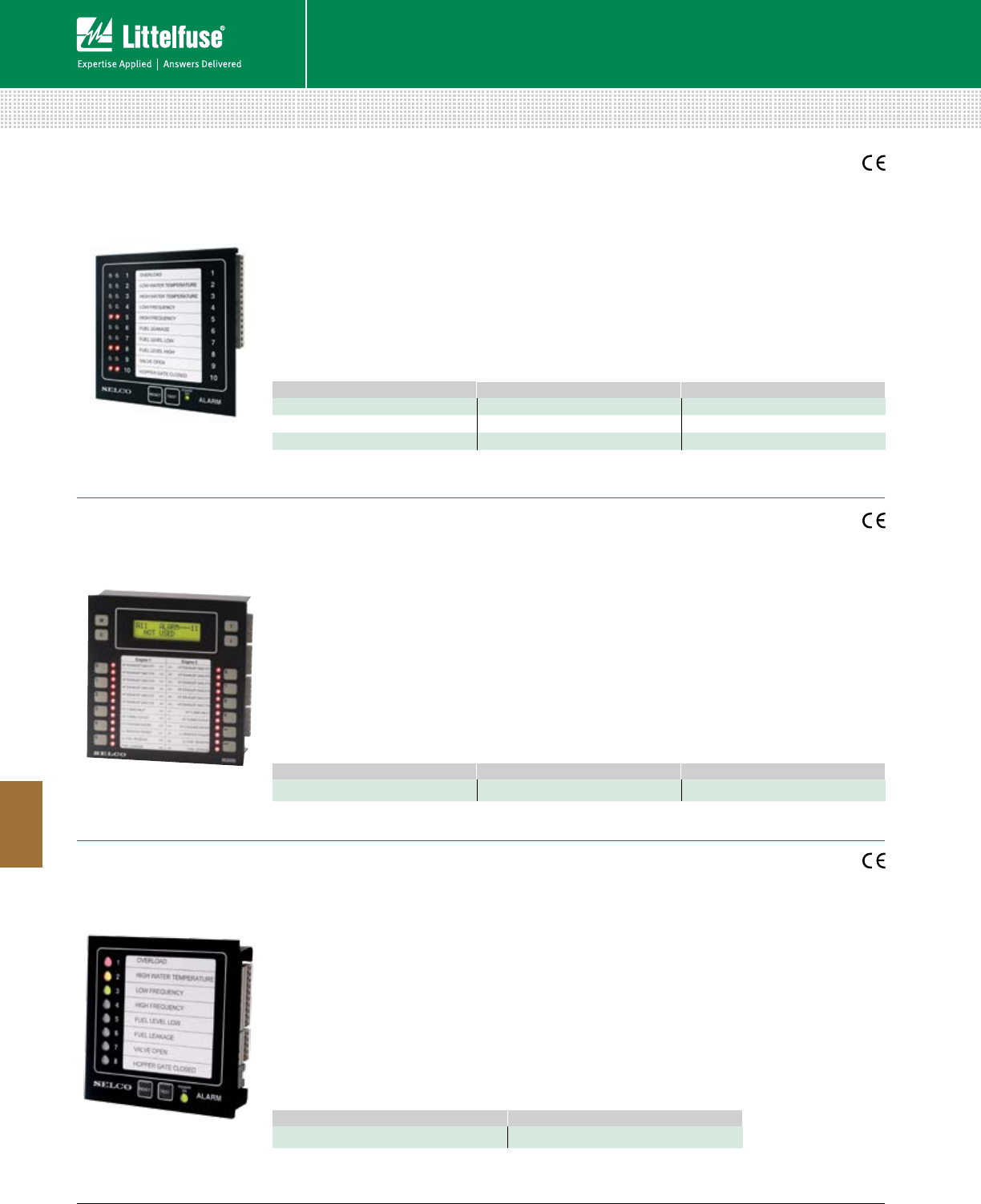
168 © 2014 Littelfuse POWR-GARD® Products Cataloglittelfuse.com
Protection Relays & Controls
Protection Relays & Controls
8
ALARM MONITORING
M1000 Alarm Monitor
M4200 Alarm Monitor
M3000 Analog Alarm Annunciator
Features/Benefits
• Alarm panel with ten digital inputs that trigger
a corresponding LED to flash with a common
alarm and siren output
• Supports both normally open and normally
closed input contacts
• Multiple units can be connected ad one system
for a modular and scalable solution
Specifications
Voltage Supply 12-24 Vdc –30/+30% (8-32 Vdc)
48-110 Vdc –30/+40% (33-155 Vdc)
Siren Relay Contact 220 Vac/2 A; 30 Vdc/2 A, 30 W
Communication RS485 Interface
Dimensions H 144 mm (5.7”)
W 144 mm (5.7”)
D 35 mm (1.4”)
Web Resources
littelfuse.com/m1000
Features/Benefits
• 24 inputs that can be configured individually for
dry contact (normally open or normally closed)
inputs or analog inputs
• Programmable 10-character LCD text so each
alarm is indicated clearly
• 24 inputs and 48 alarms allow for individual
reference to any input and easy configuration of
group and individual alarms
Specifications
Voltage Supply 24 Vdc ±30%
Consumption Max. 400 mA
Sensor Inputs 24
Alarms 48
LEDs 24
Communication RS485 Interface
Dimensions H 144 mm (5.7”)
W 144 mm (5.7”)
D 70 mm (2.7”)
Web Resources
littelfuse.com/m3000
Features/Benefits
• Cost effective solution, with the possibility of
monitoring eight individual sensors
• Supports both normally open and normally
closed input contacts
• Programmable LED color change allows flexible
adjustment according to application
• Cable monitoring on sensor inputs indicates
sensor health in case a sensor is lost
Specifications
Voltage Supply 8.4-40 Vdc; 8.4-50 Vac
Consumption Max. 180 mA
Relay Output Max. 250 Vac/6 A
Dimensions H 96 mm (3.8”)
W 96 mm (3.8”)
D 20 mm (0.8”)
Web Resources
littelfuse.com/m4200
ORDERING NUMBER CONTROL POWER FUNCTION
M1000.0040 48-110 Vdc IP54 front
M1000.0080 12-24 Vdc IP54 front
M1000.0220 12-24 Vdc Internal siren, IP54 at front
ORDERING NUMBER CONTROL POWER ACCESSORIES
M3000.0010 24 Vdc M1500 PT100 6-way Transmitter
ORDERING NUMBER CONTROL POWER
M4200.0010 24 Vdc
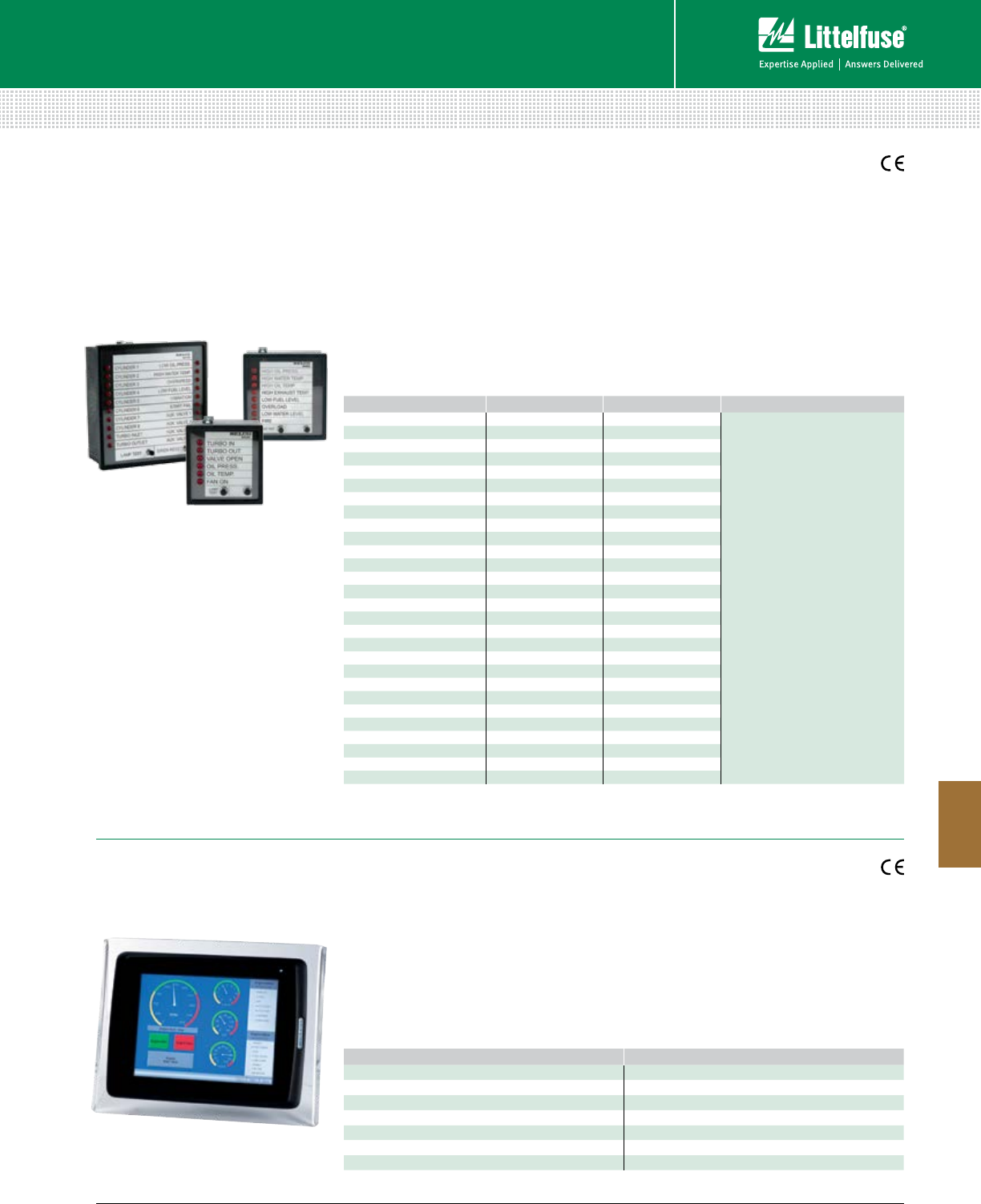
169 littelfuse.com © 2014 Littelfuse POWR-GARD® Products Catalog
Protection Relays & Controls
Protection Relays & Controls
8
ALARM MONITORING
H4000 HMI Operator Panels
M4500, M4600 & M4700 Alarm Indicators
Features/Benefits
The M4500, M4600 and M4700 Indicator Panels
are intended for status indication of any process
providing on/off outputs. The panels contain 6, 8
or 20 channels.
• Clamping fittings and plug-in terminal blocks
allow for easy installation
• RS485 communication available for a remote
display or PLCs
Specifications
Voltage Supply 24 Vdc ±25%
Dimensions M4500: H 72 mm (2.8”)
W 72 mm (2.8”) D 67 mm (2.6”)
M4600: H 96 mm (3.8)
W 96 mm (3.8”) D 67 mm (2.6”)
M4700: H 144 mm (5.7”)
W 144 mm (5.7”) D 67 mm (2.6”)
Web Resources
littelfuse.com/m4500
littelfuse.com/m4600
littelfuse.com/m4700
ORDERING NUMBER CONTROL POWER INPUT REFERENCE ACCESSORIES
M4500.0010 24 Vdc/Vac +24 Vdc
M0845.0010 Front cover for M4500
with handle IP54
M0845.0020 Front cover for M4500
with key IP54
M0846.0010 Front cover for M4600
with handle IP54
M0846.0020 Front cover for M4600
with key IP54
M0847.0010 Front cover for M4700/
M4780 with handle IP54
M0847.0020 Front cover for M4700/
M4780 with key IP54
M4500.0020 48 Vdc/Vac +48 Vdc
M4500.0030 12 Vdc/Vac +12 Vdc
M4500.0040 24 Vdc/Vac 0 Vdc
M4500.0050 48 Vdc/Vac 0 Vdc
M4500.0060 12 Vdc/Vac 0 Vdc
M4600.0010 24 Vdc/Vac +24 Vdc
M4600.0020 48 Vdc/Vac +48 Vdc
M4600.0030 12 Vdc/Vac +12 Vdc
M4600.0040 110 Vdc +110 Vdc
M4600.0050 24 Vdc/Vac 0 Vdc
M4600.0060 48 Vdc/Vac 0 Vdc
M4600.0070 12 Vdc/Vac 0 Vdc
M4700.0010 24 Vdc/Vac +24 Vdc
M4700.0020 48 Vdc/Vac +48 Vdc
M4700.0030 12 Vdc/Vac +12 Vdc
M4700.0040 110 Vdc +110 Vdc
M4700.0050 24 Vdc/Vac 0 Vdc
M4700.0060 48 Vdc/Vac 0 Vdc
M4700.0070 12 Vdc/Vac 0 Vdc
M4700.0080 110 Vdc 0 Vdc
M4700.0090 230 Vac +24 Vdc
M4700.0100 110 Vac +24 Vdc
M4700.0110 230 Vac 0 Vdc
M4700.0120* 24 Vdc +24 Vdc
M4700.0120* 24 Vdc +24 Vdc
M4700.0130† 230 Vac +24 Vdc
M4780.0010‡24 Vdc 24 Vdc
*With common alarm relay, siren relay and built-in siren.
†Inverted reference. With common alarm relay, siren relay and built-in siren.
‡ Modbus Indicator Panel, 20 channels, 24 Vdc, common alarm relay and built in siren.
ORDERING NUMBER DESCRIPTION
H4000.0010 HMI Panel 6,5”
H4000.0020 HMI Panel 6,5”, sun readable
H4100.0010 HMI Panel 10,4”
H4100.0020 HMI Panel 10,4” sun readable
H4200.0010 HMI Panel 15,1”
H4200.0020 HMI Panel 15,1” sun readable
H4900.0010 Programming Software
Features/Benefits
The HMI operator panel is a touch-screen
solution for SCADA solutions, designed for
applications like engine control and supervision
systems, power management systems and
alarm systems. They can be integrated with
products such as the M2500, Engine Controller,
Generator Controllers and Alarm Panels.
• Clear, high-resolution screen provides high
level of details
Specifications
Dimensions M4000: H 219 mm (8.6”)
W 154 mm (6.0”) D 6 mm (0.2”)
M4100: H 301 mm (11.9”)
W 228 mm (9.0”) D 6 mm (0.2”)
M4200: H 398 mm (15.7”)
W 304 mm (12.0”) D 6 mm (0.2”)
Web Resources
littelfuse.com/h4000
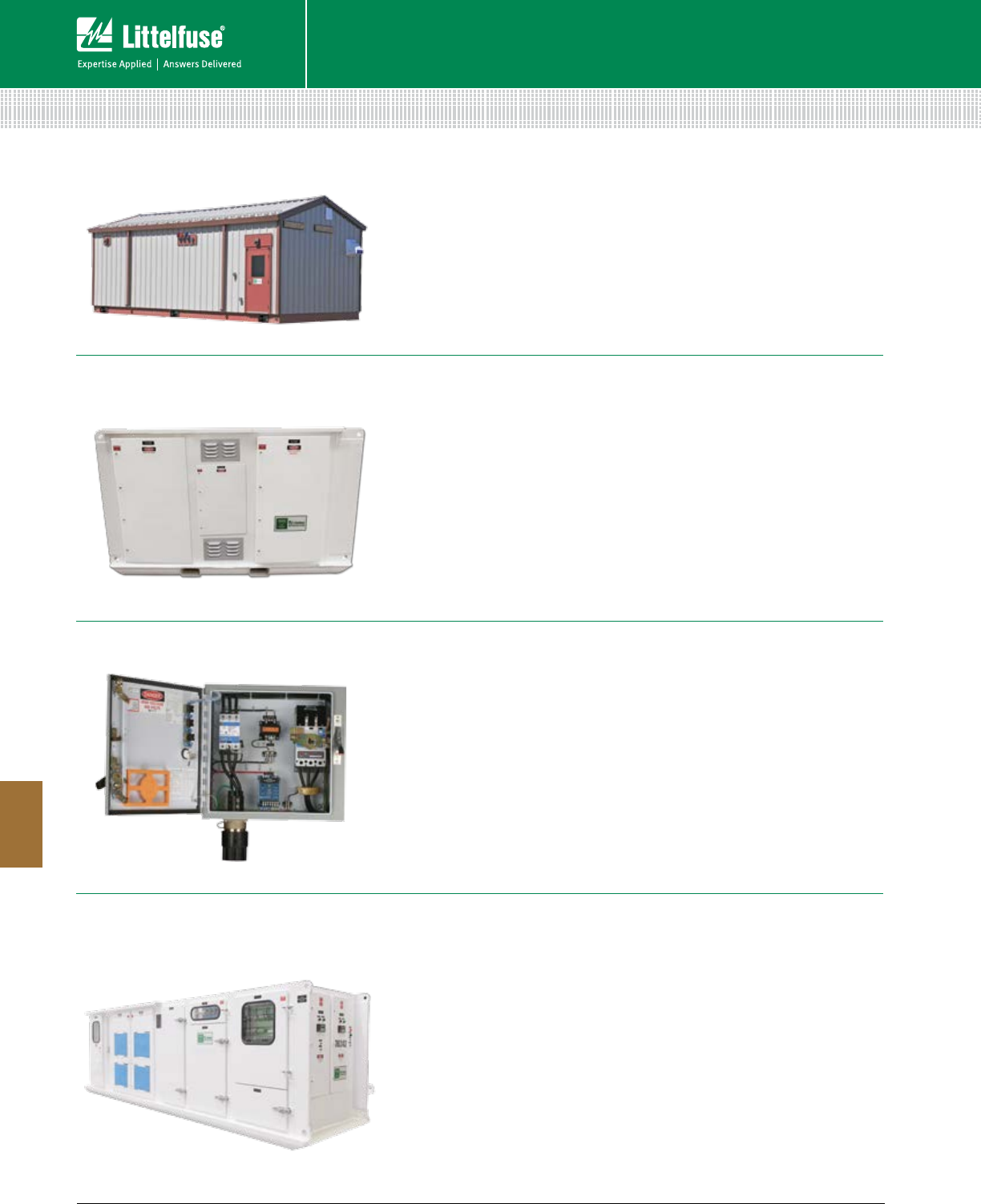
170 © 2014 Littelfuse POWR-GARD® Products Cataloglittelfuse.com
Protection Relays & Controls
Protection Relays & Controls
8
Electrical Modular Building/E-Houses
Modular Variable-Frequency Drives (VFDs)
SEL-PTO Custom Electrical Panels
Underground Portable Power Centres
CUSTOM-ENGINEERED ELECTRICAL EQUIPMENT
Description
Littelfuse Startco offers fully integrated electrical and automation systems.
Our products include prefabricated, modular, skid-mounted enclosures for
switchgear and auxiliary equipment. We deliver self-contained units, which
are completely coordinated, assembled and tested inside our controlled
factory environment. The primary switchgear and control applications
include low- and/or medium-voltage switchgear and motor control centre
enclosures; relay panel enclosures; and RTU and SCADA enclosures.
Description
Littelfuse Startco is the leading Canadian manufacturer of custom-built
electrical equipment for mining and oil & gas. Ground-fault panels, also
known as power-take-off or starter panels, are a convenient means of
protecting and isolating trailing-cable-fed or hard-wired equipment such as
pumps, jumbos, drills, and electric machines. Littelfuse Startco Custom
Panels are metal-enclosed, rugged, high-quality, and are intended for use
in non-hazardous resistance-grounded systems. Littelfuse Startco has
earned a reputation for prompt delivery of Custom Panels.
The Littelfuse Startco custom-products engineering team will assist with
your design. All designs are reviewed by engineers prior to quoting.
Description
Variable-frequency drives have been used in a variety of industries for
years to start motors, optimize load control, and achieve energy savings.
Unfortunately, the mining industry has not been able to fully realize these
benefits as the combination of the electronics used in VFD’s and the dirty
or harsh environments found in underground and open-pit mining tends
to decrease the drive’s reliability and expected life. Littelfuse Startco has
solved this problem by designing a low-maintenance modular system that
keeps the critical components of the VFD isolated from the harsh mining
conditions, yet meets the thermal cooling requirements of the VFD.
Description
Littelfuse Startco is the leading Canadian manufacturer of custom-built,
portable mine power centres up to 38-kV. Littelfuse Startco portable mine
power centres are skid-mounted, metal enclosed, and typically consist of
the following:
• Primary medium-voltage section, with fused load-break switch or
visible disconnect.
• Dry-type mine-duty power transformer.
• Primary and secondary power-distribution circuit breakers.
• Control and protection specific to the application.
• The Littelfuse Startco custom-products engineering team will assist
with your design. All designs are reviewed by engineers prior to quoting.
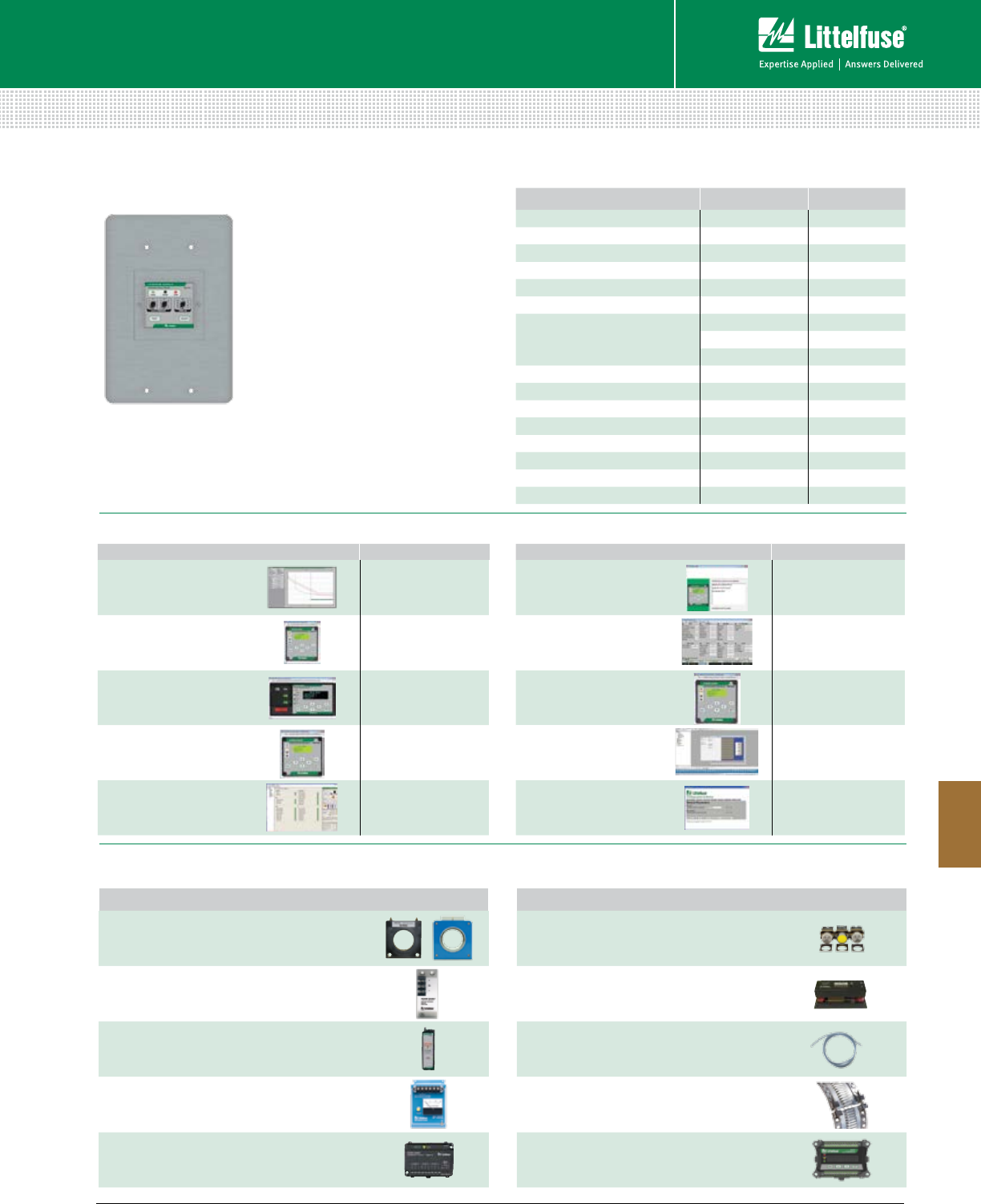
171 littelfuse.com © 2014 Littelfuse POWR-GARD® Products Catalog
Protection Relays & Controls
Protection Relays & Controls
8
PRODUCT
Current Transformers
Ground Reference Modules
High Tension Couplers
Protection Relay Testers
Input Modules
PRODUCT
Remote Indication
and Meters
Sensing Resistors
Terminations and Adapters
Accessories for Controls and Diagnostics
DIN Mount Adapters
Accessories
Most protective relays require an accessory for operation. Visit littelfuse.com/relayscontrols for a complete listing.
Software
Panel Mount Adapters
Product
Software For
SE-COMM-RIS
Relay Interface Software
MPU-32
MPS
FPU-32
FPS
VMPU
Virtual Motor
Protection Relay
MPU-32
VMPS
Virtual Motor
Protection System
MPS
VFPU
Virtual Feeder
Protection Relay
FPU-32
PGW-6150
Relay Interface Software PGR-6150
Product
Software For
SE-FLASH
Firmware Update Utility
MPU-32
MPS
FPU-32
FPS
SE-MON330
Relay Interface Software
SE-330
SE-330HV
SE-330AU
MPU-32 Tutorial
PGR-6200 Online
Self-Training Tutorial
MPU-32
H4900
Programming Software
H4000
H4100
H4200
PGW-8800
Relay Interface Software PGR-8800
Features/Benefits
• Add communications capability to
older switchgear and improve
system performance
• Save cost by not calibrating older
electromechanical devices
• Conformally coated circuit boards
• Additional protective functions,
including reduced overcurrent and
dynamic thermal model
• Minimal change-out time by using
existing CTs
• PGR-6200 and PGR-6300 can use
existing RTDs with an optional
RTD module
• Ability to match existing
overcurrent curves
RELAY TO REPLACE PANEL MOUNT NEW RELAY
AB BULLETIN 1406 PMA-14 MPS
FPL-GFRM PMA-6 SE-704
FPL-GFRM PMA-6 SE-701
GE S1 GE S1 PMA-9 MPU-32
GE S1 PMA-9 FPU-32
GE LODTRAK III PMA-10 MPU-32
GE MULTILIN 169, 269, OR 369
PMA-13 MPS
PMA-16 MPU-32
PMA-16 FPU-32
GE MULTILIN 469 PMA-24 MPS
GE MULTILIN P4A PMA-15 MPU-32
GE MULTILIN P4A PMA-15 FPU-32
GEC/MCGG PMA-3 SE-704
GEC/MCGG PMA-3 SE-701
GE & WESTINGHOUSE FT-11 PMA-12 MPU-32
P&B GOLDS Contact Factory FPU-32
WESTINGHOUSE CO9 & CO11 Contact Factory FPU-32
Adapter Plates
PANEL MOUNT ADAPTERS • SOFTWARE • ACCESSORIES
172 © 2014 Littelfuse POWR-GARD® Products Cataloglittelfuse.com
Section Overview
System overvoltage is a growing concern in the electrical industry.
Component miniaturization has resulted in increased sensitivity
to many devices. The majority of these devices are unable to
handle high currents that result from Electrostatic Discharge (ESD)
and other voltage transients. Littelfuse® offers a broad range of
overvoltage protection to safeguard against these conditions.
Industrial Varistor Products ........................................................173
LVSP Series Surge Suppression Fuses .....................................175
BVSP Series Surge Protection Device .......................................176
SUPPRESSION PRODUCTS
Table of Contents
173 littelfuse.com © 2014 Littelfuse POWR-GARD® Products Catalog
Suppression Products
9
Suppression Products
OVERVOLTAGE SUPPRESSION PRODUCTS
Varistors, Surge Fuses and Varistor Assemblies
What Are Transients?
Transients are short duration surges of electrical energy that
result from the sudden release of previously stored energy.
In terms of electrical and electronic circuits, this energy can
be released through intentional, controlled switching action,
or induced into a circuit from external sources. If the
voltage magnitude of the transient is large enough, circuit
component damage or malfunction of the circuit may result.
Transient Voltage Scenarios
The switching of inductive loads generates high energy
transients that increase in magnitude with increasingly
heavy loads. When the inductive load is switched off, the
collapsing magnetic field is converted into electrical energy,
which takes the form of a double exponential transient.
Depending on the source, these transients can be as large
as hundreds of volts and hundreds of amps with duration
times of 400 milliseconds.
Typical sources of inductive transients are:
• Generators • Motors
• Relays • Transformers
These examples are extremely common in electrical and
electronic systems. Because the sizes of the loads vary
according to the application, the wave shape, duration,
peak current, and peak voltage are all variables which
exist in real world transients. Once these variables
can be approximated, a suitable suppressor technology
can be selected.
Overvoltage Applications
• Industrial, High Energy AC Products such as Solenoids,
Motor Drives and Robotics
• Telecommunications Products
• UPS, AC Panels, Power Supplies, Circuit Breakers
(TVSS Products)
• Portable and Automotive Electronic Equipment
Lightning Induced Transients
Transients induced by lightning are not the result of a direct
strike. When a lightning strike occurs, the event creates
a magnetic field which can induce transients of large
magnitude in nearby electrical cables.
Technological Solutions for
Transient Threats
Because of the various types of transients and applications,
it is necessary to employ protection devices with different
characteristics in different applications. Littelfuse offers the
broadest range of circuit protection technologies.
Overvoltage Protection Portfolio Includes:
MOVs (Metal Oxide Varistors)
A ceramic technology that offers medium to very high
energy ratings for a wide range of applications. Available in
screw terminal, radial, square and axial leaded connections.
Discrete TVS Diode
This Silicon Avalanche Diode Technology is available in
surface mount and axial leaded packages. It offers protection
from medium to very high energy transients and can be
used in wide range of applications.
Transient Sources and Magnitude
VOLTAGE CURRENT RISE-TIME DURATION
Lightning 25 kV 20 kA 10 µs 50 ms
Switching 600 V 500 A 50 µs 500 ms
EMP 300 kV 10 A 20 ns 1 ms
ESD 15 kV 30 A 1-5 ns 100 ns
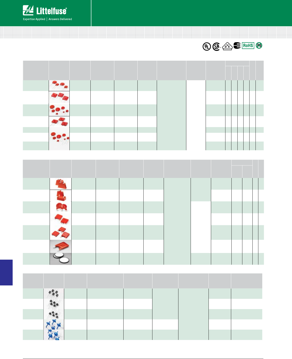
174 © 2014 Littelfuse POWR-GARD® Products Cataloglittelfuse.com
Suppression Products
Suppression Products
9
OVERVOLTAGE SUPPRESSION PRODUCTS
Varistors, Surge Fuses and Varistor Assemblies
Industrial High Energy Terminal MOV
SERIES
NAME1
OPERATING
AC VOLTAGE
RANGE
OPERATING
DC VOLTAGE
RANGE
PEAK
CURRENT
RANGE2 (A)
PEAK
ENERGY
RANGE3
OPERATING
TEMPERATURE
RANGE
MOUNT/
FORM
FACTOR
DISC SIZE
AGENCY
ROHS
LEAD FREE
UL
CSA
BA/BB 130-2800 175-3500 50,000
70,000 450-10,000
-55 to +85°C
Screw /
Clip
Terminals
60 mm • •
DA/DB 130-750 175-970 40,000 270-1050 40 mm • • •
HA 130-750 175-970 25,000
40,000 200-1050
Industrial
Packaged
Radial Leads
32, 40 mm • • • •
TMOV34S®115-750 —40,000 235-1050 34 mm • • •
HB34,
HG34, HF34 130-750 175-970 40,000 270-1050 34 mm • • • •
DHB34 250-2800 330-3500 20,000
70,000 330-10,000 34 mm •
CA 250-2800 330-3500 20,000
70,000 330-10,000 Bare Disc 60 mm •
High Power TVS Diodes
SERIES
NAME
1
PACKAGE
TYPE
REVERSE STANDOFF
VOLTAGE (V
R
)
PEAK PULSE
POWER RANGE
1
(P
PP
)
PEAK PULSE
CURRENT
(I
PP
8x20µs)
OPERATING
TEMPERATURE
HALOGEN
FREE
ROHS
COMPLIANT
15KPA
P600 17-280 15,000 W
Not Applicable
-85° to +302° F
(-55° to +175° C)
• •
20KPA
P600 20.0-300 20,000 W
• •
30KPA
P600 28.0-288 30,000 W
• •
AK6
Radial Lead 58-430 NA 6,000 A
-67° to +347° F
(-55° to +150° C)
• •
AK10
Radial Lead 58-430 NA 10,000 A
• •
Radial Leaded MOV
SERIES
NAME1
OPERATING
AC VOLTAGE
RANGE
OPERATING
DC VOLTAGE
RANGE
PEAK
CURRENT
RANGE2 (A)
PEAK
ENERGY
RANGE3
OPERATING
TEMPERATURE
RANGE
MOUNT/
FORM
FACTOR
DISC SIZE
AGENCY
ROHS
LEAD FREE
UL
CSA
VDE
CECC
TMOV®/iTMOV®115-750 — 6000-10,000 35-480
-55 to +85°C Radial
Leaded
14, 20, 34 mm ••••• •
TMOV®
25S 115-750 — 20,000 170-670 25 mm
•
• •
UltraMOVTM 130-625 170-825 1750-10,000 12.5-720 7, 10, 14, 20,
25 mm ••••• •
UltraMOVTM 25S 115-750 150-970 22,000 230-890 25 mm • • • • • •
C-III 130-660 3500-9000 40-530 10, 14, 20 mm • • • • •
LA 130-1000 175-1200 1200-6500 11-360 7, 10, 14,
20 mm ••••• •
ZA 4-460 5.5-615 50-6500 0.1-52 5, 7, 10, 14,
20 mm • • • • •
1. Detailed information about most product series listed here can be found on littelfuse.com/varistor
2. Not an applicable parameter for Crowbar devices
3. Value shown in Joules
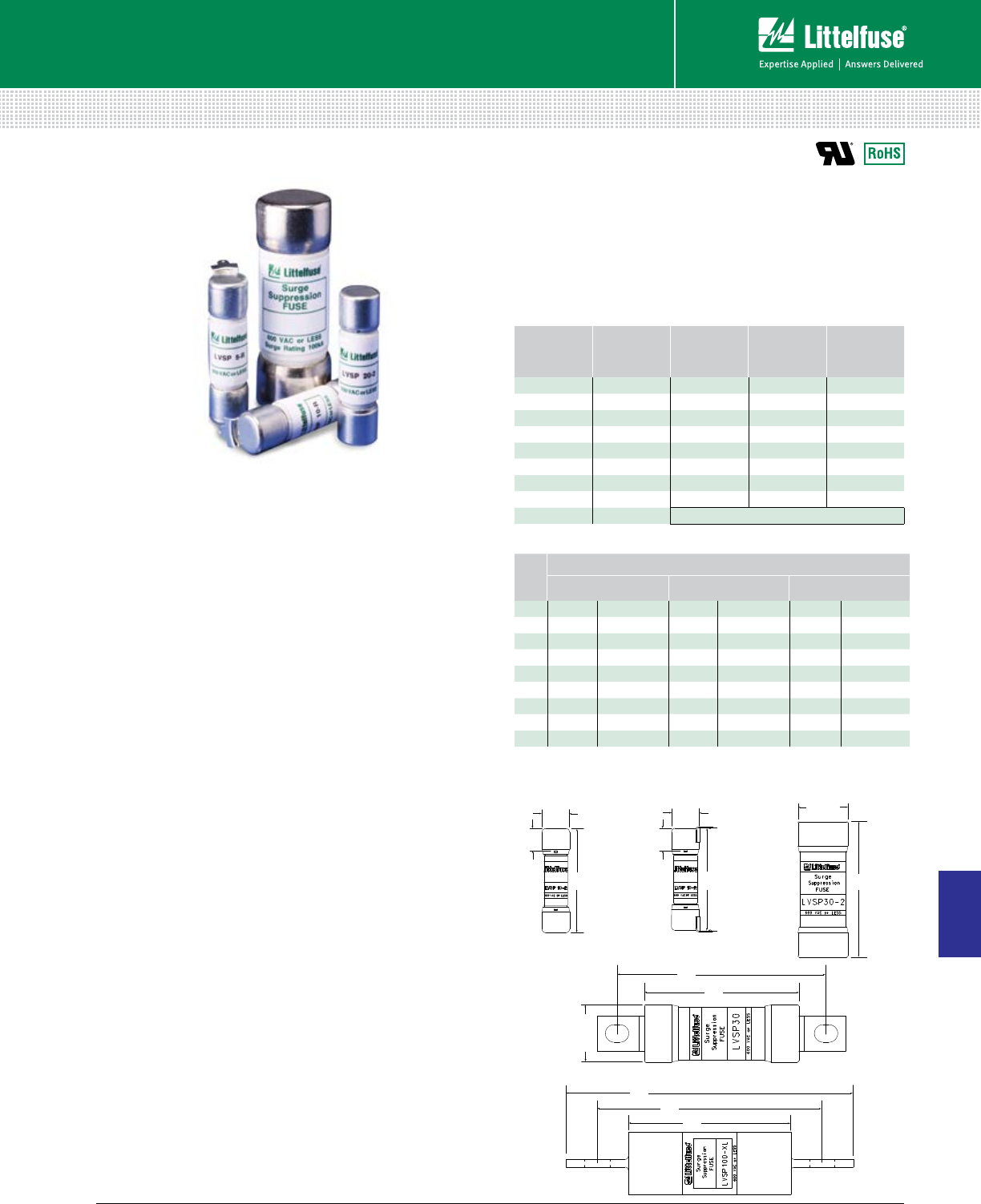
175 littelfuse.com © 2014 Littelfuse POWR-GARD® Products Catalog
Suppression Products
Suppression Products
9
LVSP SURGE SUPPRESSION FUSE
600 Vac • 5-100 kA
Specifications
Voltage Rating 600 Vac
Interrupting Rating 200 kA
Ratings 5 – 100 kA 8 x 20 µs surge withstand
Approvals UL Recognized (File: E71611)
Environmental RoHs Compliant
Electrical Specifications
CATALOG
NUMBER
8 X 20
µ
S
SURGE
RATING
NOMINAL
MELTING I
2
T
(A
2
S)
NOMINAL
CLEARING I
2
T
(A
2
S)
Ipeak@100 kA
60 HZ (A)
LVSP5 5,000 359 981 3,700
LVSP10 10,000 1,300 3,210 5,823
LVSP15 15,000 3,267 6,235 7,765
LVSP20 20,000 4,940 11,710 8,135
LVSP30 30,000 11,950 35,325 12,478
LVSP40 40,000 20,550 61,700 15,250
LVSP60 60,000 39,240 145,555 19,604
LVSP80 80,000 75,000 254,000 24,600
LVSP100 100,000 Contact Factory
Ordering Information
SURGE
RATING
CATALOG/ORDERING NUMBER
CARTRIDGE LEADED BOLT-IN
5 LVSP52 LVSP0005TX2 LVSP5R LVSP0005TXR – –
10 LVSP102 LVSP0010TX2 LVSP10R LVSP0010TXR – –
15 LVSP152 LVSP0015TX2 LVSP15R LVSP0015TXR – –
20 LVSP202 LVSP0020TX2 LVSP20R LVSP0020TXR – –
30 LVSP302 LVSP0030TX2 – – LVSP30 LVSP0030T
40 LVSP402 LVSP0040TX2 – – LVSP40 LVSP0040T
60 LVSP60-2 LVSP0060TX2 – – LVSP60 LVSP0060T
80 LVSP802 LVSP0080TX2 – – LVSP80 LVSP0080T
100 – – – – LVSP100-L LVSP0100VXL
Dimensions Inches (mm)
.328
(8.33)
1.5
(38.1)
.410
(10.41)
2.25
(57.15)
.812
(20.62)
.328
(8.33)
1.53
(38.86)
.410
(10.41)
Cartridge 5-20 A
Bolt-In 30-80 A
Cartridge 30-80 A
Bolt-In 100 A
Leaded 5-20 A
4.62
(117.35)
3.62
(91.95) 2.62
(66.55)
2.25
(57.15)
3.04
(77.21)
.816
(20.73)
Description
The Littelfuse® Varistor Protection (LVSP) Fuses are intended
for the protection of TVSS products. The LVSP series has
been designed to survive the 8 x 20 µs lightning surges
described in various standards (UL 1449, IEC 61000-4-5
and IEEE C62.41) without opening. This allows the TVSS to
perform the necessary suppression. The LVSP is not rated
for continuous current and the ratings are specific 8 x 20 µs
surge capability. The LVSP series can be used to facilitate
TVSS module compliance to UL 1449 in permanently
connected applications (abnormal overvoltage, unlimited
current conditions).
Features/Benefits
• Very current limiting under AC short-circuit conditions
• Available in multiple mounting configurations
(cartridge, bolt-in, PC board mount)
• Provides short circuit protection in TVSS systems and
complements the Littelfuse line of overvoltage products
(HA, HB34, TMOV® and iTMOV® varistors as well
as the AK-10 series TVS diodes)
Applications
• TVSS products
• Surge arrestors
Recommended Fuse Blocks
LVSP (5-20)-2
L60030M (open block) ................................................... 101
LFPSM (dead front) ....................................................... 110
LVSP (30-80)-2
LFJ60030 (open block) ................................................... 85
LFPSJ30 (dead front) ..................................................... 111
LVSP (100)
LFJ60100 (open block) .................................................... 85
Web Resources
Download other technical information:
littelfuse.com/lvsp
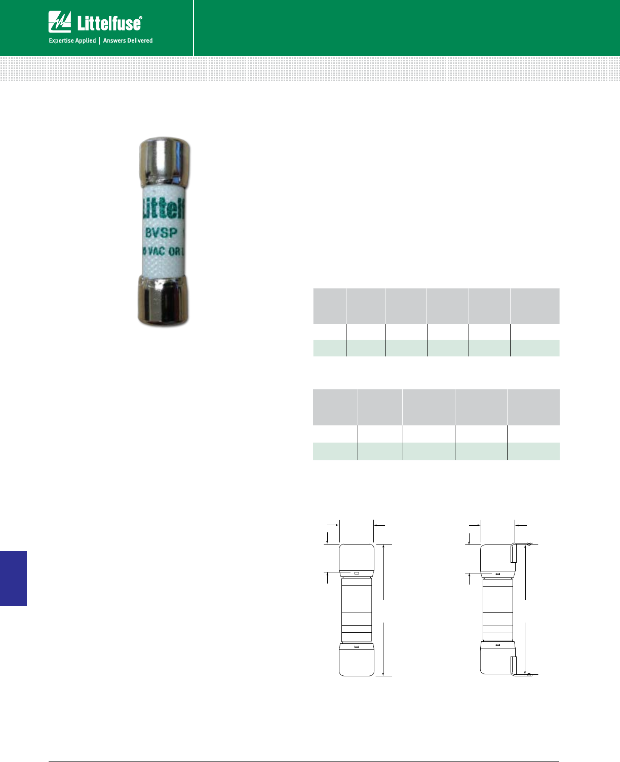
176 © 2014 Littelfuse POWR-GARD® Products Cataloglittelfuse.com
Suppression Products
9
Suppression Products
BVSP SERIES SURGE PROTECTION DEVICE
600 Vac • 10 kA
Specifications
Voltage Rating 600 Vac
Interrupting Rating 200 kA
Ratings 10 kA 8 x 20 µs surge withstand
Ordering Information
SERIES
8 X 20 µS
SURGE
RATING (A)
PACKAGE
QUANTITY
MOUNTING
METHOD
CATALOG
NUMBER
ORDERING
NUMBER
BVSP 10,000 10 Ferrule BVSP10-2 BVSP0010TX2
BVSP 10,000 10 PCB Tabs BVSP10-R BVSP0010TXR
Electrical Specifications
CATALOG
NUMBER
8 X 20 µS
SURGE
RATING (A)
NOMINAL
MELTING I2T
(A2S)
NOMINAL
CLEARING I2T
(A2S)
Ipeak @ 200 kA
60 HZ (A)
BVSP10-2 10,000 1,580 9,960 8,160
BVSP10-R 10,000 1,580 9,960 8,160
Dimensions Inches (mm)
.328
(8.33)
1.5
(38.1)
.410
(10.41)
.328
(8.33)
1.53
(38.86)
.410
(10.41)
Ferrule Version PCB Version
Description
The Littelfuse® BVSP surge protection device (SPD) is
intended for the protection of transient voltage surge
suppressions (TVSS) systems. The BVSP series has been
designed to survive the 8 x 20 µs lightning surges described
in various standards (UL 1449, IEC 61000-4-5 and IEEE
C62.41) without opening. This allows the TVSS to perform
the necessary suppression. The BVSP is not rated for
continuous current and the ratings are specific 8 x 20 µs
surge capability. The BVSP series can be used to facilitate
TVSS module compliance to UL 1449 in permanently
connected applications (abnormal overvoltage, unlimited
current conditions).
Features/Benefits
• Very current limiting under AC short-circuit conditions
• Available in ferrule and printed circuit board (PCB)
configurations
• Provides short circuit protection in TVSS systems and
complements the Littelfuse line of overvoltage products
(HA, HB34, TMOV® and iTMOV® varistors as well
as the AK-10 series TVS diodes)
Applications
• TVSS products
• Surge arrestors
Recommended Fuse Holders
L60030M (open block) ................................................... 101
LFPSM (dead front) ....................................................... 110

177 littelfuse.com © 2014 Littelfuse POWR-GARD® Products Catalog
Fuse Reducers ....................................................................................178
Box Cover Units ..................................................................................179
Fuse Replacement & Custom Kits ....................................................180
Electronic Fuse Display & Spare Fuse Cabinet .................................181
MISCELLANEOUS PRODUCTS
Table of Contents
Section Overview
Miscellaneous Accessories include custom-built solutions designed
specifically to meet code requirements, fuse reducers, box cover units
and an assortment of useful fuse and holder accessories.
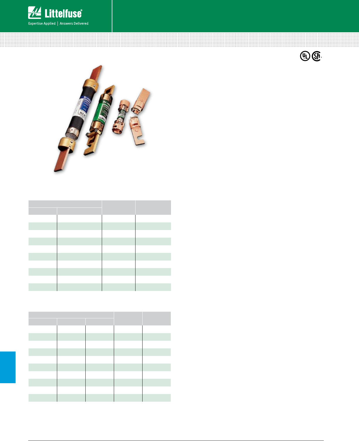
178 © 2014 Littelfuse POWR-GARD® Products Cataloglittelfuse.com
10
Miscellaneous Accessories
Accessories
FUSE REDUCERS
¶ Fuse and reducer com bi na tion is slightly larger in diameter than 100 A Class J fuses. For
specific ap pli ca tions, contact factory.
Class J reducers cannot be used in bolt-on applications.
Description
Littelfuse® fuse reducers allow smaller size fuses to be
installed into existing fuse clips to prevent overfusing.
Features/Benefits
• Simple installation
• Reduces inventory requirements
• Silver brazed joints for maximum strength
• UL Listed (File: E136855)
• CSA Certified (File: LR92899)
Web Resources
Download technical information: littelfuse.com/lruh
littelfuse.com/lrur
littelfuse.com/lruj
Dimensions
Refer to the fuse section of this catalog for fuse dimensions.
Recommended Fuses
Class H/K5 Fuse Reducers
NLN / NLS ........................................................................... 20
Class R Fuse Reducers
FLNR / FLSR ....................................................................... 17
FLNR_ID / FLSR_ID ............................................................ 17
IDSR ................................................................................... 16
LLNRK / LLSRK ................................................................... 13
LLSRK_ID ........................................................................... 13
KLNR / KLSR ....................................................................... 15
Class J Fuse Reducers
JTD_ID / JTD ..............................................................................21
JLS ..............................................................................................22
600 Volt
CATALOG / ORDERING NUMBER FUSE CLIP FUSE
CASE SIZE
CLASS H/K5 CLASS R CLASS J
LRU 663 LRU 663 R LRUJ63 60 A 30 A
LRU 216 LRU 216 R LRUJ13 100 A 30 A
LRU 616 LRU 616 R LRUJ16¶100 A 60 A
LRU 626 LRU 626 R LRUJ26 200 A 60 A
LRU 2621 LRU 2621 R LRUJ21 200 A 100 A
LRU 2641 LRU 2641 R LRUJ41 400 A 100 A
LRU 2642 LRU 2642 R LRUJ42 400 A 200 A
LRU 2661 LRU 2661 R — 600 A 100 A
LRU 2662 LRU 2662 R — 600 A 200 A
LRU 2664 LRU 2664 R†LRUJ64 600 A 400 A
†Only one reducer required.
Ordering Information
250 Volt
CATALOG / ORDERING NUMBER FUSE CLIP FUSE
CASE SIZE
CLASS H/K5 CLASS R
LRU 263 LRU 263 R 60 A 30 A
LRU 213 LRU 213 R 100 A 30 A
LRU 216 LRU 216 R 100 A 60 A
LRU 226 LRU 226 R 200 A 60 A
LRU 2621 LRU 2621 R 200 A 100 A
LRU 2641 LRU 2641 R 400 A 100 A
LRU 2642 LRU 2642 R 400 A 200 A
LRU 2661 LRU 2661 R 600 A 100 A
LRU 2662 LRU 2662 R 600 A 200 A
LRU 2664 LRU 2664 R* 600 A 400 A
*Only one reducer required.
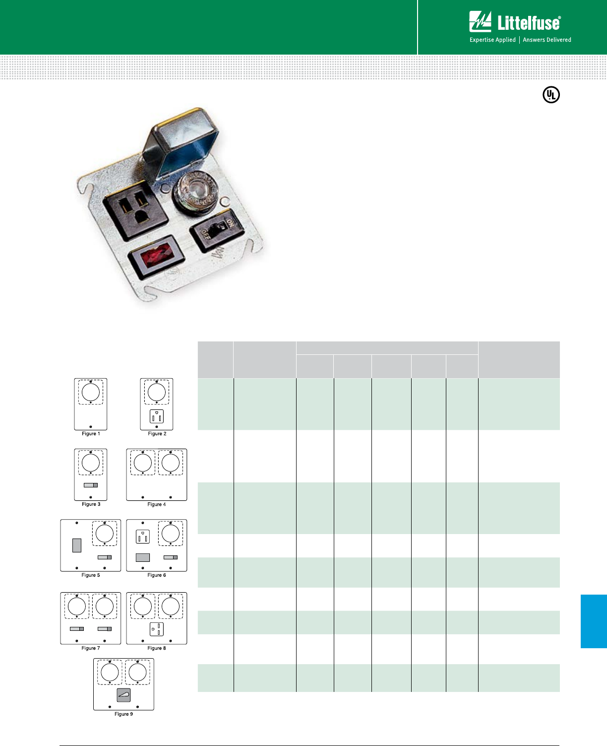
179 littelfuse.com © 2014 Littelfuse POWR-GARD® Products Catalog
10
Miscellaneous Accessories
Accessories
BOX COVER UNITS
Description
Provide eco nom i cal method of protecting small motors
against overcurrent damage.
Applications
• Edison-Base plug fuses (TOO, TLO)
• Type S plug fuses (SOO, SLO) with adapters (SAO)
Specifications
Voltage Rating 125 V
Max Ampere Rating 15 A
Approvals UL Listed parts
Web Resources
Additional technical information available at:
littelfuse.com/boxcover
FIGURE
NUMBER
LITTELFUSE
PART NUMBER
BOX COVER FEATURES TO BE
MOUNTED ON
EDISON BASE
FUSE HOLDER
GROUNDING
RECEPTACLE
SINGLE POLE
SWITCH
TWO POLE
SWITCH
PILOT
LIGHT
1
LSOU 1 — — — — 2-1⁄4" Handy Box
LSOW 1 — — — — 2-3⁄4” Switch Box
LSOX 1 — — — — 4" Octagon Box
LSOY 1 — — — — 4" Square Box
2
LSRU* 1 1 — — — 2-1⁄4" Handy Box
LSRW 1 1 — — — 2-3⁄4” Switch Box
LSRX 1 1 — — — 4" Octagon Box
LSRY 1 1 — — — 4" Square Box
3
LSSU* 1 — 1 — — 2-1⁄4" Handy Box
LSSW 1 — 1 — — 2-3⁄4" Switch Box
LSSX 1 — 1 — — 4" Octagon Box
LSSY* 1 — 1 — — 4" Square Box
4 LSOY-B 2 — — — — 4" Square Box
5 LSSY-L 1 — 1 — 1 4" Square Box
6 LSSY-RL 1 1 1 — 1 4" Square Box
7LSCY 2 — 2 — — 4" Square Box
8 LSKA 2 1 (250V) — — — 4-1⁄16" Square Box
9 LSTY 2 — — 1 — 4" Square Box
*UL Listed (File: E308725)
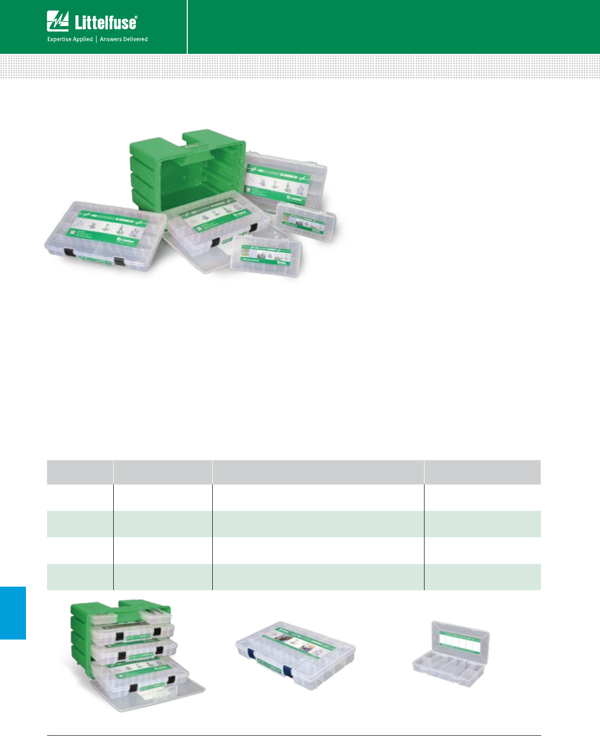
180 © 2014 Littelfuse POWR-GARD® Products Cataloglittelfuse.com
10
Miscellaneous Accessories
Accessories
FRCK SERIES FUSE REPLACEMENT & CUSTOM KITS
Description
Fuse Replacement and Custom Kits help reduce downtime
by providing mobile storage and organization for replacement
fuses. The FRCK Series provides a custom solution that can
be filled with multiple fuse series that are more common or
specific to your needs or application.
Features/Benefits
nCustom sized compartments fit various fuse series
nLarge kit features a convenient handle for carrying
nKits are sold empty for complete customization
nEach kit comes with a blank label on the inside cover
so users can write in part numbers or use bar code
labels to help with refills.
Web Resources
Additional information: littelfuse.com/kits
Ordering Information
KIT SIZE DIMENSIONS
L X W X H (INCHES) DESCRIPTION CATALOG NUMBER
Large 16.00 x 12.00 x 10.00 Mobile organizer with 2 small and 3 medium drawers;
Unique FRACK Label for Oil & Gas FRCK-OG
Large 16.00 x 12.00 x 10.00 Mobile organizer with 2 small and 3 medium drawers FRCK-LG
Medium 14.00 x 9.13 x 2.00 14” organizer with adjustable dividers FRCK-MD
Small 8.25 x 4.25 x 1.00 8” organizer with up to 6 compartments FRCK-SM
FRCK-SMFRCK-MDFRCK-OG & FRCK-LG
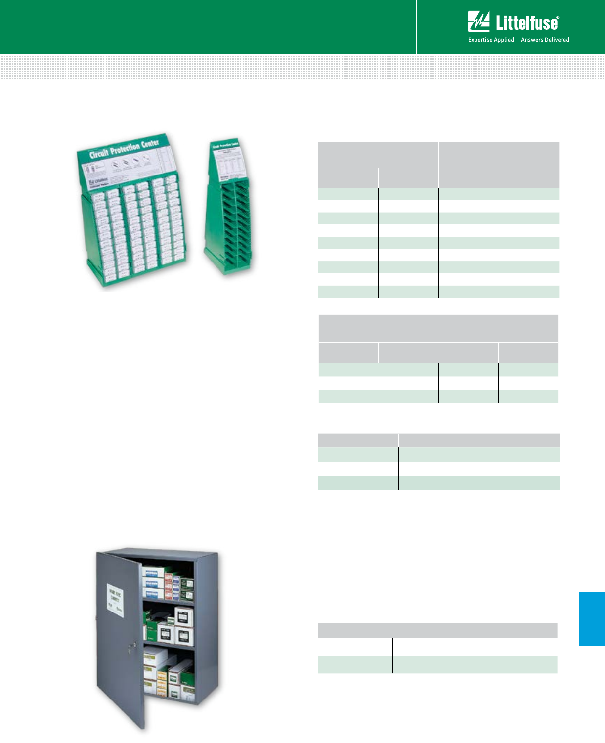
181 littelfuse.com © 2014 Littelfuse POWR-GARD® Products Catalog
10
Miscellaneous Accessories
Accessories
FUSE DISPLAYS AND CABINETS
3AB (CERAMIC)
NORMAL-BLO FUSES
3AB (CERAMIC)
SLO-BLO® FUSES
QUAN TI TY CATALOG
NUMBER QUAN TI TY CATALOG
NUMBER
25 314 15A 25 326 8A
25 314 20A 20 326 10A
25 314 30A — —
Description
• Steel cabinet with piano hinges that can be locked
to prevent un au tho rized access. Weather stripped to
reduce the ac cu mu la tion of dust, dirt and moisture
• Con ve nient inventory card located inside door.
Measures 30" H × 24" W × 12" D. Keyhole mounting
holes 16" on center for easy installation
Ordering Information
TYPE CATALOG NUMBER ORDERING NUMBER
Spare Fuse Cabinet LSFC LSFC
Spare Keys LKEY001 LKEY0001Z
Description
This wall-mountable or free-standing modular rack system
prominently displays Littelfuse glass and automotive fuses.
Additional sections can be quickly snapped on for a larger
product selection. Each rack features a cross reference
guide to help customers locate the proper replacement fuse.
Features/Benefits
• Holds 720 (144 5-packs) of the most popular glass,
ceramic, and automotive fuses
• Designed to save space—measures 14" H × 9" W × 4" D
Suitable for wall or counter mounting
• Includes cross reference, product identification
guide, and back-up card for easy reordering
• Expandable with modular section that can hold
240 fuses (48 5-packs) per section
Web Resources
Additional information: littelfuse.com/lsfc
Fully stocked rack includes the following parts
3AG (GLASS)
FAST ACTING FUSES
3AG (GLASS)
SLO-BLO® FUSES
QUANTITY CATALOG
NUMBER QUAN TI TY CATALOG
NUMBER
25 312 1⁄2A 25 313 1⁄2A
50 312 1A 25 313 3⁄4A
25 312 1 1⁄2A 25 313 1A
75 312 2A 25 313 1 1⁄2A
25 312 2 1⁄2A 50 313 2A
75 312 3A 25 313 2 1⁄2A
25 312 4A 25 313 3A
25 312 5A 25 313 4A
25 312 10A 25 313 5A
Electronic Fuse Display
Spare Fuse Cabinet
Ordering Information
TYPE CATALOG NUMBER ORDERING NUMBER
Fully Stocked Display 094324PG 00940324ZXPG
Empty Display Rack FDR001PG 0FDR0001ZXPG
Additional Sections MRS001PG 0MRS0001ZXPG

182 © 2014 Littelfuse POWR-GARD® Products Cataloglittelfuse.com
Section Overview
This Technical Application Guide or ‘Fuseology’ section provides the
information needed to select the correct types of Littelfuse POWR-GARD®
fuses for most applications. If there are any questions or if additional
data is needed for a specific use, call the Littelfuse Technical Support
and Engineering Service Group at 1-800-TEC-FUSE (1-800-832-3873),
email them at techline@littelfuse.com or visit us at littelfuse.com.
Fuseology Fundamentals ............................................................183
Selection Considerations ............................................................184
Time-current Curves and Peak Let-through Charts .....................189
Selective Coordination ................................................................191
UL/CSA Fuse Classes and Applications ......................................194
Terms and Definitions .................................................................196
Motor Protection Tables ............................................................. 203
Alphanumeric Index of Catalog Numbers .................................. 206
Condensed Fuse Cross Reference ............................................ 208
TECHNICAL APPLICATION GUIDE
Table of Contents
Technical Information
White papers, and a library
of technical information is
available online at
littelfuse.com/technicalcenter

183 littelfuse.com © 2014 Littelfuse POWR-GARD® Products Catalog
11
Technical
Technical Application Guide
FUSEOLOGY FUNDAMENTALS
I. OVERCURRENT PROTECTION
FUNDAMENTALS
(FUSES AND HOW THEY WORK)
Introduction
An important part of developing quality overcurrent protection
is an understanding of system needs and overcurrent
protective device fundamentals. This section discusses these
topics with special attention to the application of fuses. If you
have additional questions, call our Technical Support Group at
1-800-TEC-FUSE (1-800-832-3873). Definitions of terms used
in this section are located towards the end of this Technical
Application Guide.
Why Overcurrent Protection?
All electrical systems eventually experience overcurrents.
Unless removed in time, even moderate overcurrents
quickly overheat system components, damaging insulation,
conductors, and equipment. Large overcurrents may melt
conductors and vaporize insulation. Very high currents
produce magnetic forces that bend and twist bus bars.
These high currents can pull cables from their terminals and
crack insulators and spacers.
Too frequently, fires, explosions, poisonous fumes and
panic accompany uncontrolled overcurrents. This not only
damages electrical systems and equipment, but may cause
injury or death to personnel nearby.
To reduce these hazards, the National Electrical Code®
(NEC®), OSHA regulations, and other applicable design and
installation standards require overcurrent protection that will
disconnect overloaded or faulted equipment.
Industry and governmental organizations have developed
performance standards for overcurrent devices and testing
procedures that show compliance with the standards and
with the NEC. These organizations include: the American
National Standards Institute (ANSI), National Electrical
Manufacturers Association (NEMA), and the National
Fire Protection Association (NFPA), all of which work in
conjunction with Nationally Recognized Testing Laboratories
(NRTL) such as Underwriters Laboratories (UL).
Electrical systems must meet applicable code requirements
including those for overcurrent protection before electric
utilities are allowed to provide electric power to a facility.
What is Quality Overcurrent Protection?
A system with quality overcurrent protection has the
following characteristics:
1. Meets all legal requirements, such as NEC®, OSHA, local
codes, etc.
2. Provides maximum safety for personnel, exceeding
minimum code requirements as necessary.
3. Minimizes overcurrent damage to property, equipment,
and electrical systems.
4. Provides coordinated protection. Only the protective
device immediately on the line side of an overcurrent
opens to protect the system and minimize unnecessary
downtime.
5. Is cost effective while providing reserve interrupting
capacity for future growth.
6. Consists of equipment and components not subject to
obsolescence and requiring only minimum maintenance
that can be performed by regular maintenance personnel
using readily available tools and equipment.
Overcurrent Types and Effects
An overcurrent is any current that exceeds the ampere rating of
conductors, equipment, or devices under conditions of use. The
term “overcurrent” includes both overloads and short-circuits.
Overloads
An overload is an overcurrent confined to normal current
paths in which there is no insulation breakdown.
Sustained overloads are commonly caused by installing
excessive equipment such as additional lighting fixtures
or too many motors. Sustained overloads are also caused
by overloading mechanical equipment and by equipment
breakdown such as failed bearings. If not disconnected
within established time limits, sustained overloads
eventually overheat circuit components causing thermal
damage to insulation and other system components.
Overcurrent protective devices must disconnect circuits and
equipment experiencing continuous or sustained overloads
before overheating occurs. Even moderate insulation
overheating can seriously reduce the life of the components
and/or equipment involved. For example, motors overloaded
by just 15% may experience less than 50% of normal
insulation life.
Temporary overloads occur frequently. Common causes
include temporary equipment overloads such as a machine
tool taking too deep of a cut, or simply the starting of an
inductive load such as a motor. Since temporary overloads
are by definition harmless, overcurrent protective devices
should not open or clear the circuit.
It is important to realize that fuses selected must have
sufficient time-delay to allow motors to start and temporary
overloads to subside. However, should the overcurrent
continue, fuses must then open before system components
are damaged. Littelfuse POWR-PRO® and POWR-GARD®
time-delay fuses are designed to meet these types of
protective needs. In general, time-delay fuses hold 500% of
the rated current for a minimum of ten seconds, yet will still
open quickly on higher values of current.

184 © 2014 Littelfuse POWR-GARD® Products Cataloglittelfuse.com
11
Technical Application Guide
Technical
Even though government-mandated high-efficiency motors
and NEMA Design E motors have much higher locked rotor
currents, POWR-PRO® time-delay fuses such as the FLSR_
ID, LLSRK_ID, or IDSR series have sufficient time-delay to
permit motors to start when the fuses are properly selected
in accordance with the NEC®.
Short-Circuits
A short-circuit is an overcurrent flowing outside of its normal
path. Types of short-circuits are generally divided into
three categories: bolted faults, arcing faults, and ground
faults. Each type of short-circuit is defined in the Terms and
Definitions section.
A short-circuit is caused by an insulation breakdown or
faulty connection. During a circuit’s normal operation, the
connected load determines current. When a short-circuit
occurs, the current bypasses the normal load and takes a
“shorter path,” hence the term ‘short-circuit’. Since there is
no load impedance, the only factor limiting current flow is
the total distribution system’s impedance from the utility’s
generators to the point of fault.
A typical electrical system might have a normal load impedance
of 10 ohms. But in a single-phase situation, the same system
might have a load impedance of 0.005 ohms or less. In order
to compare the two scenarios, it is best to apply Ohm’s Law (I
= E/R for AC systems). A 480 volt single-phase circuit with the
10 ohm load impedance would draw 48 amperes (480/10 = 48).
If the same circuit has a 0.005 ohm system impedance when
the load is shorted, the available fault current would increase
significantly to 96,000 amperes (480/0.005 = 96,000).
As stated, short-circuits are currents that flow outside
of their normal path. Regardless of the magnitude of
overcurrent, the excessive current must be removed quickly.
If not removed promptly, the large currents associated
with short-circuits may have three profound effects on an
electrical system: heating, magnetic stress, and arcing.
Heating occurs in every part of an electrical system when
current passes through the system. When overcurrents
are large enough, heating is practically instantaneous. The
energy in such overcurrents is measured in ampere-squared
seconds (I2t). An overcurrent of 10,000 amperes that lasts for
0.01 seconds has an I2t of 1,000,000 A2s. If the current could
be reduced from 10,000 amperes to 1,000 amperes for the
same period of time, the corresponding I2t would be reduced
to 10,000 A2s, or just one percent of the original value.
If the current in a conductor increases 10 times, the I2t
increases 100 times. A current of only 7,500 amperes
can melt a #8 AWG copper wire in 0.1 second. Within
eight milliseconds (0.008 seconds or one-half cycle), a
current of 6,500 amperes can raise the temperature of #12
AWG THHN thermoplastic insulated copper wire from its
operating temperature of 75°C to its maximum short-circuit
temperature of 150°C. Any currents larger than this may
immediately vaporize organic insulations. Arcs at the point
of fault or from mechanical switching such as automatic
transfer switches or circuit breakers may ignite the vapors
causing violent explosions and electrical flash.
Magnetic stress (or force) is a function of the peak current
squared. Fault currents of 100,000 amperes can exert forces
of more than 7,000 lb. per foot of bus bar. Stresses of this
magnitude may damage insulation, pull conductors from
terminals, and stress equipment terminals sufficiently such
that significant damage occurs.
Arcing at the point of fault melts and vaporizes all of the
conductors and components involved in the fault. The arcs
often burn through raceways and equipment enclosures,
showering the area with molten metal that quickly starts fires
and/or injures any personnel in the area. Additional short-circuits
are often created when vaporized material is deposited on
insulators and other surfaces. Sustained arcing-faults vaporize
organic insulation, and the vapors may explode or burn.
Whether the effects are heating, magnetic stress, and/or
arcing, the potential damage to electrical systems can be
significant as a result of short-circuits occurring.
II. SELECTION CONSIDERATIONS
Selection Considerations for Fuses (600 volts and below)
Since overcurrent protection is crucial to reliable electrical
system operation and safety, overcurrent device selection
and application should be carefully considered. When
selecting fuses, the following parameters or considerations
need to be evaluated:
• Current Rating
• Voltage Rating
• Interrupting Rating
• Type of Protection and Fuse Characteristics
• Current Limitation
• Physical Size
• Indication
Current Rating
The current rating of a fuse is the AC or DC current,
expressed in amperes, which the fuse is capable of carrying
continuously under specified conditions. Fuses selected
for a circuit must have ampere ratings that meet NEC®
requirements, namely those found in NEC® Articles 240 and
430. These NEC® requirements establish maximum ratings
and in some cases, minimum ratings. When selecting a
fuse, it is generally recommended to select a current rating
as close as possible to the system’s normal running current.
FUSEOLOGY FUNDAMENTALS
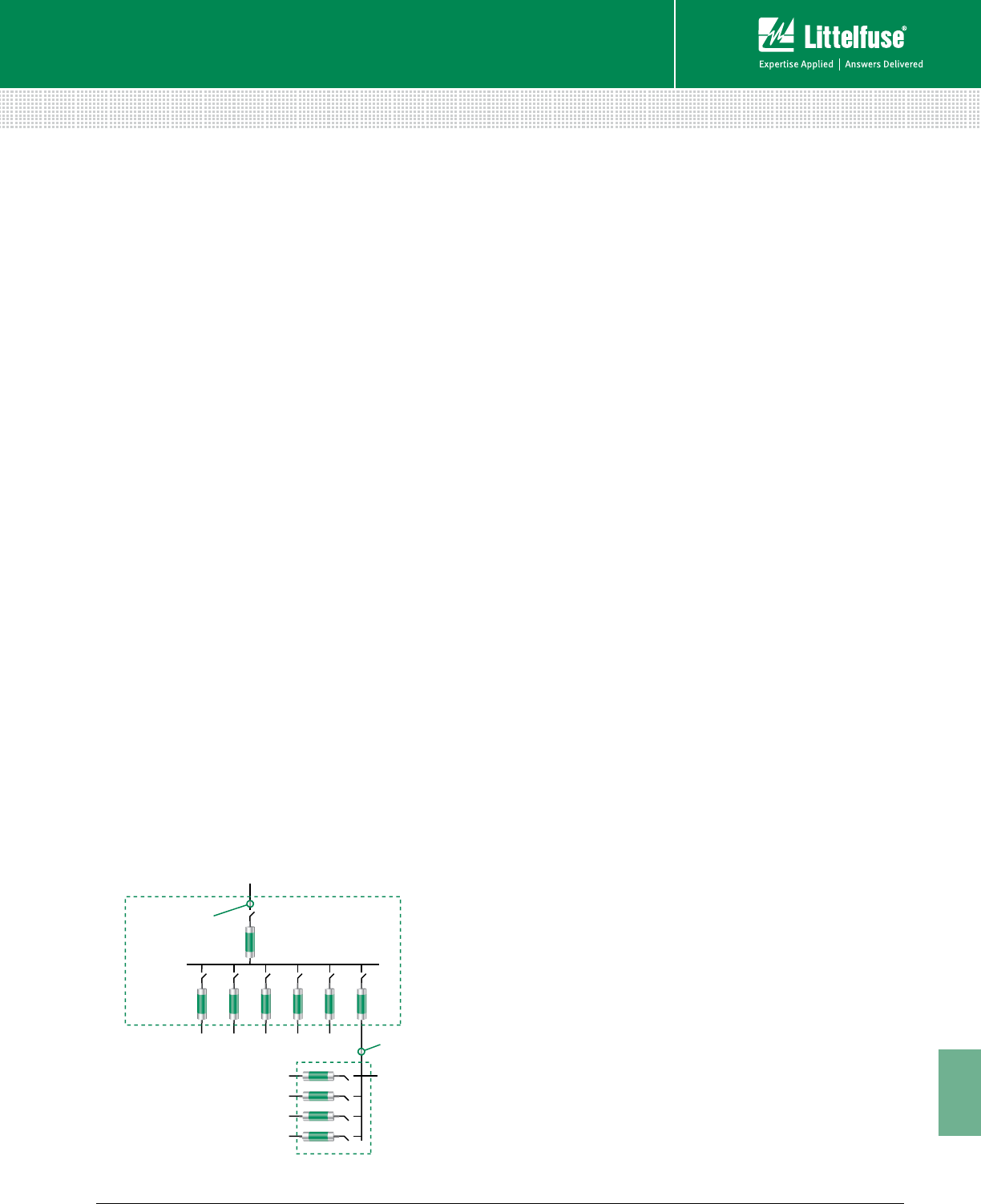
185 littelfuse.com © 2014 Littelfuse POWR-GARD® Products Catalog
11
Technical Application Guide
Technical
Voltage Rating
The voltage rating of a fuse is the maximum AC or DC
voltage at which the fuse is designed to operate. Fuse
voltage ratings must equal or exceed the circuit voltage
where the fuses will be installed, and fuses used in DC
circuits must be specifically rated for DC applications. In
terms of voltage, fuses may be rated for AC only, DC only, or
both AC and DC. However, exceeding the voltage ratings or
using an AC only fuse in a DC circuit could result in violent
destruction of the fuse.
The standard 600 volt rated fuses discussed in this section
may be applied at any voltage less than or equal to their
rating. For example, a 600 volt fuse may be used in a 277
volt or even a 32 volt system, but not any system exceeding
600 volts.
NOTE: This does not apply to semiconductor fuses and medium
voltage fuses. See the semiconductor and medium voltage fuse
application information on littelfuse.com for voltage limitations
of these fuses.
Interrupting Rating
The interrupting rating of a fuse is the highest available
symmetrical rms alternating current that the fuse is required
to safely interrupt at its rated voltage under standardized test
conditions. A fuse must interrupt all overcurrents up to its
interrupting rating without experiencing damage. Standard
UL fuses are available with interrupting ratings of 10,000 A,
50,000 A, 100,000 A, 200,000 A, and 300,000 A.
NEC® Article 110.9 requires that all equipment intended
to break current at fault levels have an interrupting rating
sufficient for the system voltage and current available at
the equipment’s line terminals. Refer to Figure 1. It is vitally
important to select fuses with interrupting ratings which
equal or exceed the available fault current.
The recommendation to standardize on fuses with at least
a 200,000 ampere interrupting rating (AIR) ensures that all
fuses have an adequate interrupting rating while providing
reserve interrupting capacity for future increases in available
fault current.
300,000 AIR Fuses
Littelfuse POWR-PRO® fuse series have a Littelfuse Self-
Certified interrupting rating of 300,000 amperes rms
symmetrical. The 300,000 ampere testing was performed
in a Nationally Recognized Testing Laboratory, and the tests
were UL witnessed. UL has ruled that fuses with a UL
interrupting rating greater than 200,000 amperes must be
marked as “Special Purpose Fuses” and may not be labeled
as UL Listed Class RK5, RK1, L, etc.
Type of Protection and Fuse Characteristics
Time current characteristics determine how fast a fuse
responds to overcurrents. All fuses have inverse time
characteristics; that is, the fuse opening time decreases as
the magnitude of overcurrent increases. When properly rated
in accordance with NEC® requirements, fuses provide both
overload and short-circuit protection to system conductors
and components. However, in some instances such as when
fuses are used to backup circuit breakers or to provide motor
branch circuit short-circuit and ground fault protection, fuses
provide only short-circuit protection. A fuse’s response to
overcurrents is divided into short-circuits and overloads.
Short-Circuits
A fuse’s short-circuit response is its opening time on higher-
value currents. For power fuses, higher-value currents are
generally over 500-600% of the fuse’s current rating. As
stated earlier, all fuses have inverse time characteristics: the
higher the current, the faster the opening time. Since short-
circuits should be removed quickly, inverse time is especially
important for short-circuit protection.
Overloads
While fuses must disconnect overloaded conductors and
equipment before the conductors and components are
seriously overheated, they should not disconnect harmless
temporary overloads. To provide sufficient overload
protection for system conductors, UL has established
maximum fuse opening times at 135% and 200% of a
fuse’s current rating. All UL Listed fuses for application in
accordance with the National Electrical Code® must meet
these limits whether they are fast-acting or time-delay fuses.
As just stated, a fuse is designed to respond to two types
of overcurrents – short circuits and overloads. As a result,
selecting the proper fuse for a given application usually
involves deciding whether to use a time-delay fuse or a
fast-acting fuse. A more in-depth review of both possible
scenarios is important at this time.
SELECTION CONSIDERATIONS
Main Switchboard
Available Fault
Current = 125,000A
Available Fault
Current = 85,000A
All fuses in main switchboard
must have an A.I.R. of at least
125,000A. Next higher standard
rating is 200,000A.
Fuses in panel must have at
least an 85,000 A.I.C. Next higher
standard rating is 100,000A., but
best choice is time-delay fuses
with 200,000 A.I.R.
Figure 1 – Interrupting Rating Requirements per NEC
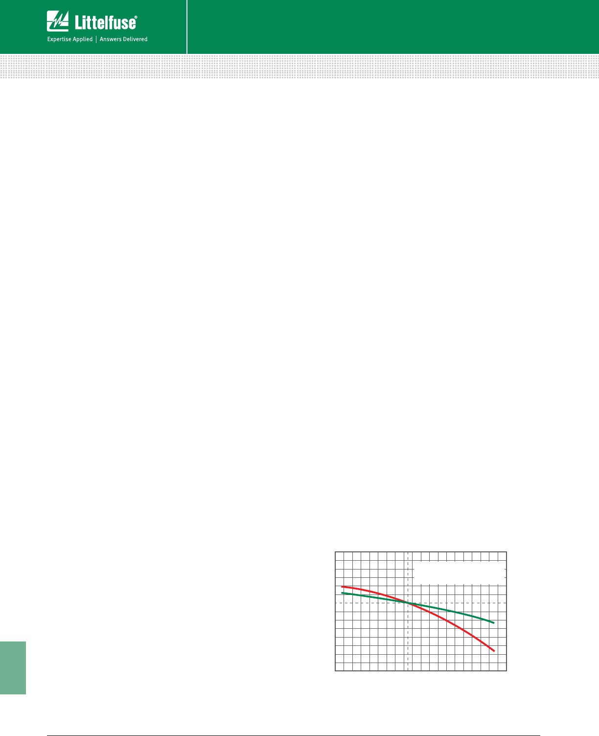
186 © 2014 Littelfuse POWR-GARD® Products Cataloglittelfuse.com
11
Technical Application Guide
Technical
Fast-Acting (Normal-Opening) Fuses
Fast-acting fuses (sometimes called “Normal-opening”
fuses) have no intentional time-delay. Typical opening
times at 500% of the fuse ampere rating range from 0.05
second to approximately 2 seconds. Fast-Acting fuses
are suitable for non-inductive loads such as incandescent
lighting and general-purpose feeders, or branch circuits
with little or no motor load. When protecting motors and
other inductive loads, fast-acting fuses must be rated at
200-300% of load currents to prevent nuisance opening on
in-rush currents. Fuses with such increased ratings no longer
furnish adequate protection from overloads and only provide
short-circuit protection. Overload relays or other overload
protection devices must be provided to properly protect
conductors and equipment from overload conditions.
All fast-acting fuses provide fast short-circuit response
within their interrupting rating. Some are considered current-
limiting, such as UL Class T and Class J. Others are non-
current-limiting, such as UL Class H.
Time-Delay (SLO-BLO®) Fuses
Most UL Class CC, CD, G, J, L, RK5 and RK1 fuses, plus
some of the UL Listed Miscellaneous fuses are considered
time-delay. If so, they are identified as such on the fuse
label with the words “Time-Delay”, “T-D”, “D”, or some
other suitable marking. Minimum time-delay varies with
the fuse class, and to some degree with the fuse ampere
rating. UL standards for POWR-GARD® fuse series FLNR,
FLNR_ID, FLSR, FLSR_ID, IDSR (UL Class RK5), LLNRK,
LLSRK, LLSRK_ID (UL Class RK1), and JTD, JTD_ID (UL
Class J) require these fuses to carry 500% rated current for a
minimum of 10 seconds. Standards for CCMR and KLDR (UL
Class CC and CD) and SLC (UL Class G) fuses require them
to carry 200% rated current for a minimum of 12 seconds.
Although there is no UL Classification for time-delay Class
L fuses, it is still permissible for them to be marked “Time-
Delay.” The amount of time-delay is determined by the
manufacturer. Littelfuse KLPC series and KLLU series fuses
will hold 500% current for 10 seconds or more.
In addition to providing time-delay for surges and short time
overloads, time-delay fuses meet all UL requirements for
sustained overload protection. On higher values of current,
time-delay fuses are current-limiting; meaning they remove
large overcurrents in less than one-half cycle (0.00833
seconds). Time-delay fuses provide the best overall protection
for both motor and general purpose circuits, and eliminate
nuisance fuse opening and most situations of downtime.
Compared to fast-acting fuses, time-delay fuses can be
selected with ratings much closer to a circuit’s operating
current. For example, on most motor circuits Class RK5 and
RK1 fuses can be rated at 125-150% of a motor’s full load
current (FLA). This provides superior overload and short-
circuit protection, and often permits the use of smaller,
less expensive disconnect switches. Time-delay fuses
have gradually replaced most one-time (UL Class K5) and
renewable (UL Class H) fuses. Today, more than 50% of all
fuses sold by electrical distributors are time-delay fuses.
Dual Element Fuses
Littelfuse time-delay FLNR, FLNR_ID, FLSR, FLSR_ID, IDSR
(UL Class RK5), and LLNRK, LLSRK, LLSRK_ID (UL Class RK1),
and some JTD, JTD_ID (UL Class J) series fuses have true
dual-element construction meaning the fuse has an internal
construction consisting of separate short-circuit and overload
sections or elements. Time-delay elements are used for
overload protection, and separate fast acting fuse elements or
links are used to provide current-limiting short-circuit protection.
Very Fast-Acting Fuses
This category of fuses exists for limited applications. The
principle use of very fast acting fuses is to protect solid-
state electronic components, such as semiconductors. Fuse
series designated as ‘Semiconductor Fuses’ have special
characteristics including quick overload response, very
low I2t and Ipeak currents, and peak transient voltages, that
provide protection for components that cannot withstand
line surges, low value overloads, or short-circuit currents.
Very fast-acting fuses are designed for very fast response to
overloads and short-circuits, and are very current-limiting.
Effect of Ambient Temperature on Fuses
The current carrying capacity of fuses is 110% of the fuse
rating when installed in a standard UL test circuit and tested
in open air at 25°C ambient. This allows for derating to 100%
of rating in an enclosure at 40°C ambient.
SELECTION CONSIDERATIONS
A
A
B
B
0 0
20
40
60
20
40
60
AMBIENT TEMPERATURE
PERCENT OF UPRATING
PERCENT OF DOWNRA
TING
KEY TO CHART:
Curve A - Slo-Blo® Fuse
Curve B - Medium and Fast-Acting Fuses
FUSE RERATING CURVE
-60°C
-76°F
-40°C
-40°F
-20°C
-4°F
0°C
32°F
20°C
68°F
40°C
104°F
60°C
140°F
80°C
176°F
100°C
212°F
120°C
248°F
140°C
264°F
Figure 2 – Fuse Rerating Curve

187 littelfuse.com © 2014 Littelfuse POWR-GARD® Products Catalog
11
Technical Application Guide
Technical
Current Limitation
A current-limiting fuse is one that opens and clears a fault
in less than 180 electrical degrees, or in other words, within
the first half electrical cycle (0.00833 seconds). See the
definition of Current-limiting Fuse and Figure 13 in the Terms
and Definitions section.
NEC® Article 240.2 states that a current-limiting overcurrent
protective device must reduce the peak let-through current to a
value substantially less than the potential peak current that would
have occurred if the fuse were not used in the circuit or were
replaced with solid conductors of the same impedance. The total
destructive heat energy (I2t) to the circuit and its components is
greatly minimized as a result of using current-limiting fuses.
It is important to note that UL Class H ‘Renewable’ fuses
designed decades ago are considered non-current limiting. Other
than Midget fuses, almost all other fuse types used in today’s
electrical systems and applications are considered current-
limiting per the above parameters. This selection consideration
now involves determining the degree or level of current limitation
required to properly protect a given device or system.
It is also important to point out that matching fuse holders
and/or fuse blocks must reject non-current-limiting fuses and
accept only current-limiting fuses of the stated UL Class.
Physical Size
While often overlooked, the physical size or overall
dimensions of the fuse to be used in a given application is
another important selection consideration to evaluate. There
is a trend toward reduction of size in almost everything, and
electrical equipment is no exception. Fuse size is actually
determined by the size and dimensions of the fuse block or
disconnect switch in which it is installed.
While saving space may be an important factor when
selecting the proper fuses, other considerations should not
be overlooked. Some of these include:
• Does the smallest fuse have the most desirable
characteristics for the application?
• Does the equipment in which the fuse will be installed
provide adequate space for maintenance?
• Do smaller fuses coordinate well with the system’s other
overcurrent protection?
If looking at just physical dimensions, a 600 volt, 60 ampere,
200,000 AIR, time-delay, dual-element UL Class CD fuse is smaller
than a similarly rated UL Class J fuse, which is in turn, considerably
smaller than a similarly rated UL Class RK1 or Class RK5 fuse.
However, smaller-sized fuses can sometimes have less time-delay
or more nuisance openings than their larger counterparts, so it is
always important to consider all factors involved.
Indication
The newest consideration for selecting the best fuse for a
given application is indication. Many of the more commonly
used UL fuse classes are now available in both indicating
and non-indicating versions. Built-in, blown-fuse indication
that quickly identifies which fuse or fuses within an electrical
panel or system have blown can be found on the Littelfuse
POWR-PRO® LLSRK_ID Class RK1, FLNR_ID, FLSR_ID and
IDSR Class RK5, and JTD_ID Class J fuse series.
The indicating feature on these fuses provides reduced
downtime, increased safety, and reduced housekeeping or
troubleshooting headaches and delays. Littelfuse Indicator®
fuses will help lower the costs associated with downtime,
provide longer fuse life by minimizing nuisance openings,
increase system performance by minimizing equipment
damage, and improve safety by minimizing accidents.
III. GENERAL FUSING RECOMMENDATIONS
Based on the above selection considerations, the following
is recommended:
Fuses with ampere ratings from 1/10 through 600 amperes
• When available fault currents are less than 100,000
amperes and when equipment does not require the more
current-limiting characteristics of UL Class RK1 fuses,
FLNR and FLSR_ID Series Class RK5 current-limiting fuses
provide superior time-delay and cycling characteristics at a
lower cost than RK1 fuses. If available fault currents exceed
100,000 amperes, equipment may need the additional
current-limitation capabilities of the LLNRK, LLSRK and
LLSRK_ID series Class RK1 fuses.
• Fast-acting JLLN and JLLS series Class T fuses possess
space-saving features that make them especially suitable
for protection of molded case circuit breakers, meter
banks, and similar limited-space applications.
• Time-delay JTD_ID and JTD series Class J fuses are used
in OEM motor control center applications as well as other
MRO motor and transformer applications requiring space-
saving IEC Type 2 protection.
• Class CC and Class CD series fuses are used in control
circuits and control panels where space is at a premium.
The Littelfuse POWR-PRO CCMR series fuses are best
used for protection of small motors, while the Littelfuse
KLDR series fuses provide optimal protection for control
power transformers and similar devices.
For questions about product applications, call our Technical
Support Group at 800-TEC-FUSE.
SELECTION CONSIDERATIONS

188 © 2014 Littelfuse POWR-GARD® Products Cataloglittelfuse.com
11
Technical Application Guide
Technical
Fuses with ampere ratings from 601 through 6,000 amperes
For superior protection of most general-purpose and motor
circuits, it is recommended to use the POWR-PRO® KLPC
series Class L fuses. The Class L fuses are the only time-
delay fuse series available in these higher ampere ratings.
Information on all the Littelfuse fuse series referenced above
can be found on the UL/CSA Fuse Classes and Applications
Charts found later in this Technical Application Guide.
IV. SELECTION CONSIDERATIONS FOR
FUSE HOLDERS
Equally important to the selection of the proper fuse is the
correct selection of the proper fuse holder or fuse block for
a given application. Fuse holders are available using most
of the same Selection Considerations outlined above for UL
fuse classes. Considerations for fuse holders include:
• Current Rating
• Voltage Rating
• Interrupting Rating
• Physical Size
• Indication
Additional selection considerations for fuse holders and fuse
blocks include:
• Number of poles
• Mounting configuration
• Connector type
Number of Poles
The number of poles for each set of fuses is determined by
the characteristics of the circuit. Most fuse block series are
available in 1, 2, or 3 pole configurations, although some are
also available with four or more poles. The option to gang
individual fuse blocks into longer strips will be determined
by the available space and type of wire being used.
Mounting Configuration
Depending on the fuse block design, another selection
consideration to evaluate is how the fuse block is mounted
or inserted into the panel. Historically, fuse blocks simply
screwed into the back of the panel, but many newer designs
have now added (or replaced the screw-in design with) a DIN
rail mounting capability. The DIN rail mounting feature allows
the blocks to be quickly installed and removed from the rails.
Connector Type
For Littelfuse fuse blocks, a choice of three connector types
or wire terminations is available:
• Screw – for use with spade lugs or ring terminals.
• Screw with Pressure Plate – for use with solid or
stranded wire without terminal and recommended for
applications where vibration will be a factor.
• Box Lug – the most durable of the three options and
used with all types of solid wire and Class B and Class C
stranded wire.
There are a few additional aspects to keep in mind when
selecting the fuse holder or fuse block needed for a given
application. UL Class H blocks accept Class H, Class K5, and
Class R fuses. Similarly, Midget-style fuse blocks accept
both Midget and UL Class CC fuses.
Both UL Class R and Class CC fuse holders contain a
rejection feature which prevents the insertion of a different
Class or type of fuse. The physical size and dimensions of
UL Class J and Class T fuses accomplish the same thing in
preventing the insertion of a different Class of fuse as well.
V. CIRCUIT PROTECTION CHECKLIST
To select the proper overcurrent protective device for an
electrical system, circuit and system designers should ask
themselves the following questions before a system is
designed:
• What is the normal or average current expected?
• What is the maximum continuous (three hours or more)
current expected?
• What inrush or temporary surge currents can be
expected?
• Are the overcurrent protective devices able to distinguish
between expected inrush and surge currents, and open
under sustained overloads and fault conditions?
• What kind of environmental extremes are possible? Dust,
humidity, temperature extremes and other factors need
to be considered.
• What is the maximum available fault current the
protective device may have to interrupt?
• Is the overcurrent protective device rated for the system
voltage?
• Will the overcurrent protective device provide the safest
and most reliable protection for the specific equipment?
• Under short-circuit conditions, will the overcurrent
protective device minimize the possibility of a fire or
explosion?
• Does the overcurrent protective device meet all the
applicable safety standards and installation requirements?
Answers to these questions and other criteria will help to
determine the type overcurrent protection device to use for
optimum safety, reliability and performance.
SELECTION CONSIDERATIONS
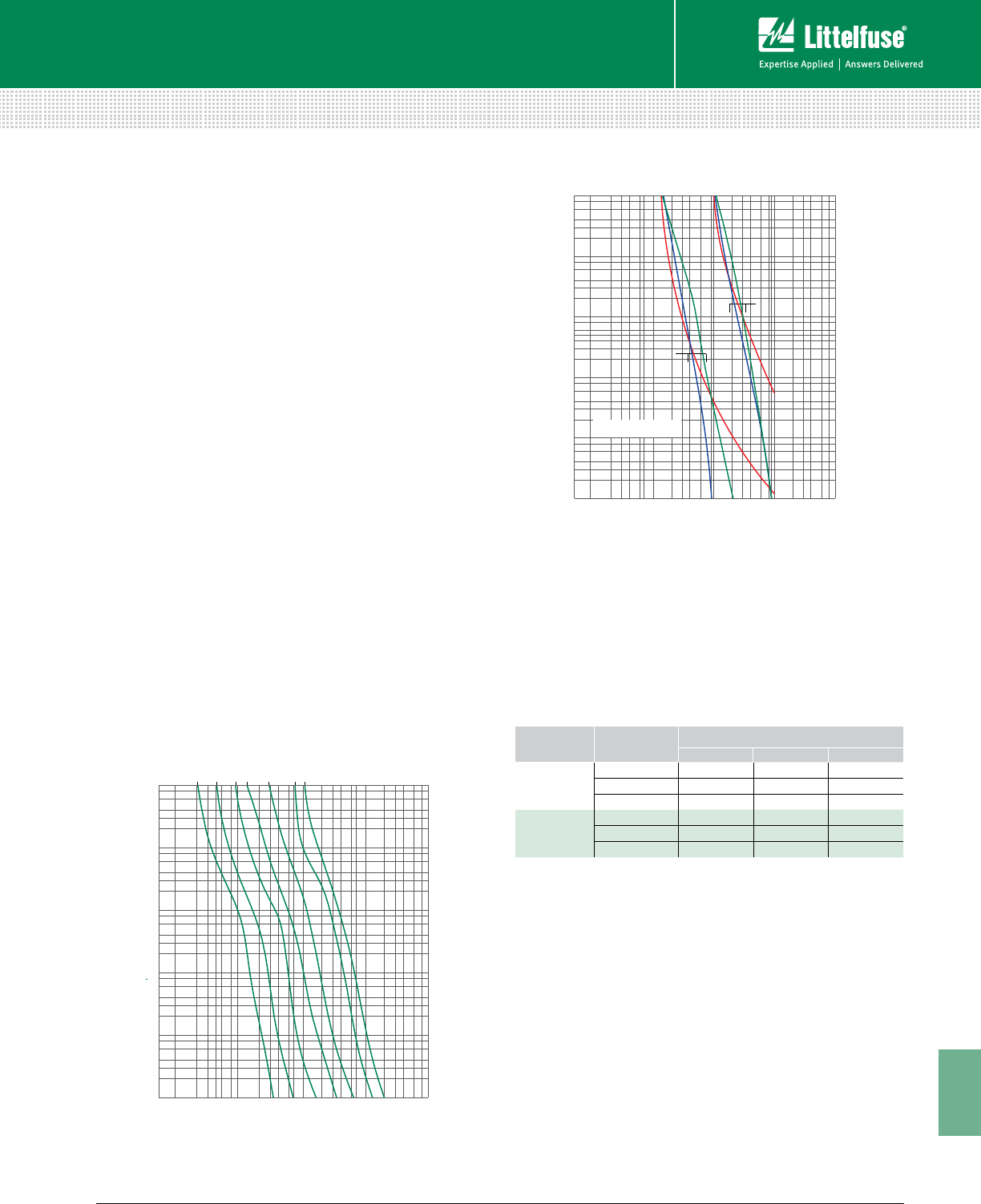
189 littelfuse.com © 2014 Littelfuse POWR-GARD® Products Catalog
11
Technical Application Guide
Technical
The performance capabilities of various fuses are graphically
represented by two different types of fuse characteristic
curves: time-current curves and peak let-through charts.
These curves and charts define the operating characteristics
of a given fuse, and assist system designers and engineers
in selecting the proper fuse to protect equipment and
electrical systems.
Understanding Time-current Curves
Time-current curves provide a graphical representation
or plot of a fuse’s average melting (opening) time at any
current. Time-current curves for Littelfuse POWR-GARD®
fuses can be found online at
littelfuse.com/technicalcenter.
In order to make the curves more readable, the performance
information is presented on log-log paper. The overcurrent
values appear across the bottom and increase in magnitude
from left to right. Average melting times appear on the
left-hand side of the curve and increase in magnitude from
bottom to top. The ampere ratings of the individual fuses
for a given series are listed at the top and increase in rating
from left to right. Figure 4 shows the average melting time
curves for a typical time-delay fuse series.
As discussed earlier in the Fuseology Fundamentals
section, time-delay, fast-acting, and very fast-acting fuses
all respond differently based on the overcurrents occurring
in the systems each is protecting. To illustrate the basic
differences between each type of fuse, Figure 5 compares
the average melting times for 100 and 600 amp ratings
of three fuse types: Littelfuse dual-element, time-delay
LLSRK series class RK1 fuses (green); Littelfuse normal
opening NLS series class K5 fuses (red); and Littelfuse very
fast acting L60S series semiconductor fuses (blue).
To better illustrate this point, Table 3 also compares the
opening times for each of these fuses.
Peak Let-through Charts
Peak let-through charts illustrate the maximum instantaneous
current through the fuse during the total clearing time. This
represents the current limiting ability of a fuse.
Fuses that are current-limiting open severe short-circuits
within the first half-cycle (180 electrical degrees or 0.00833
seconds) after the fault occurs. Current-limiting fuses also
reduce the peak current of the available fault current to a
value less than would occur without the fuse. This reduction
is shown in Figure 6.
A fuse’s current-limiting effects are shown graphically on
Peak Let-through charts such as the one shown in Figure 7.
The values across the chart’s bottom represent the available
FUSE CHARACTERISTIC CURVES AND CHARTS
1000
800
600
400
300
200
100
80
60
40
30
20
10
8
6
4
3
2
1
.8
.6
.4
.3
.2
.1
.08
.06
.04
.03
.02
.01
200
300
400
600
800
1000
2000
3000
4000
6000
8000
10000
20000
30000
40000
60000
80000
100000
10
20
30
40
60
80
100
15 A
30 A
60 A
100 A
200 A
400 A
600 A
TIME IN SECONDS
CURRENT IN AMPERES
1000
800
600
400
300
200
100
80
60
40
30
20
10
8
6
4
3
2
1
.8
.6
.4
.3
.2
.1
.08
.06
.04
.03
.02
.01
200
300
400
600
800
1000
2000
3000
4000
6000
8000
10000
20000
30000
40000
60000
80000
100000
10
20
30
40
60
80
100
100 AMP
600 AMP
GREEN = TIME-DELAY FUSE
RED = NORMAL OPENING FUSE
BLUE = VERY-FAST ACTING FUSE
TIME IN SECONDS
CURRENT IN AMPERES
AMPERE
RATING FUSE TYPE OPENING TIME IN SECONDS
500% RATING 800% RATING 1200% RATING
100
TIME-DELAY 12 secs. 0.9 secs. 0.14 secs.
NORMAL OPENING 2 secs. 0.7 secs. 0.3 secs.
VERY FAST-ACTING 1.3 secs. 0.02 secs. >0.01 secs.
600
TIME-DELAY 14 secs. 0.7 secs. 0.045 secs.
NORMAL OPENING 10 secs. 3 secs. 1.1 secs.
VERY FAST-ACTING 2 secs. 0.05 secs. >0.01 secs.
Figure 4 – Average Melting Time Curves for Typical Time-Delay
Fuse Series
Figure 5 – Comparison of Average Melting Times for
Three Fuse Types
Table 3 – Comparative Opening Times for Time-Delay, Fast-
Acting, and Very Fast-Acting Fuses
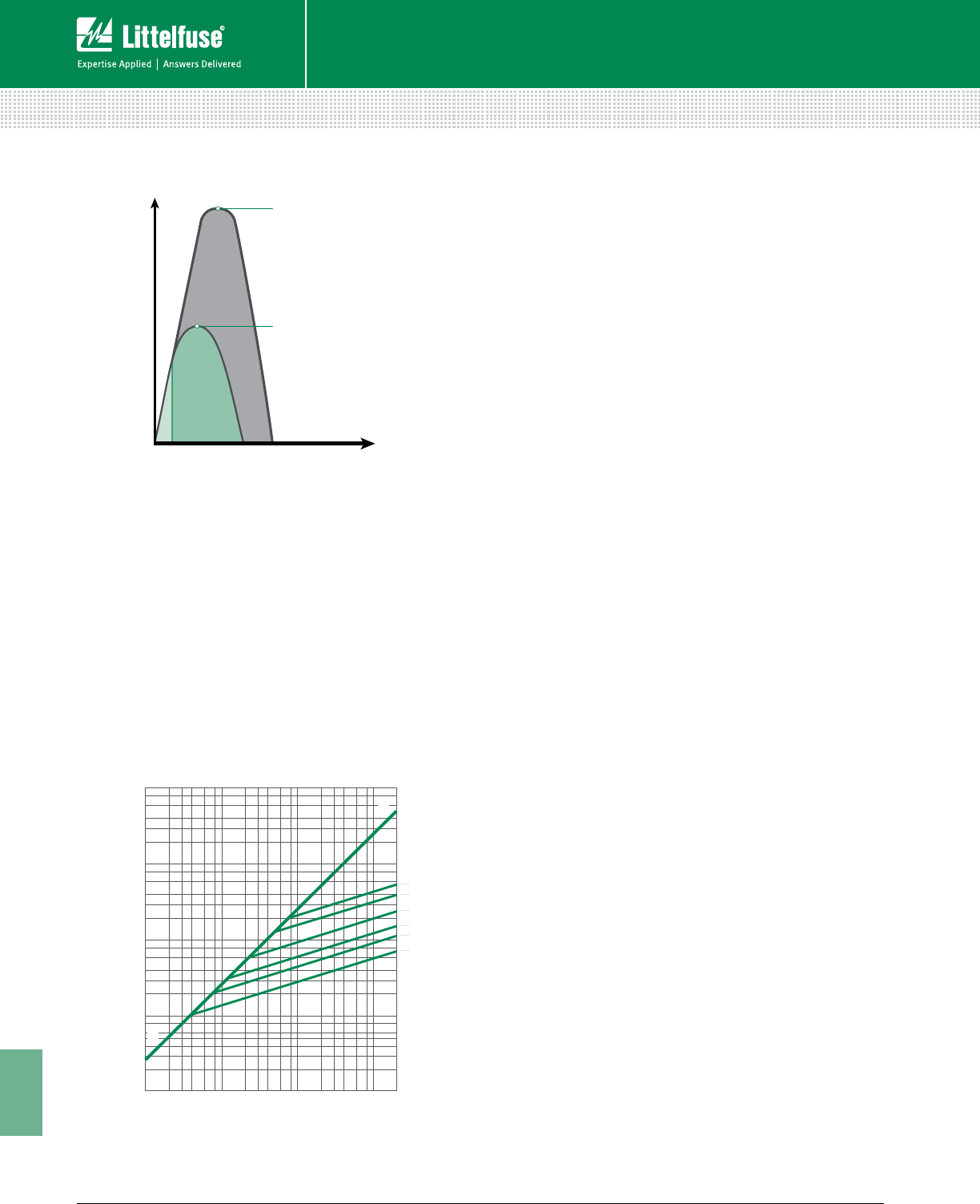
190 © 2014 Littelfuse POWR-GARD® Products Cataloglittelfuse.com
11
Technical Application Guide
Technical
(also referred to as potential or prospective) rms symmetrical
fault current. The values on the chart’s left side represent
the instantaneous available peak current and the peak let-
through current for various fuse ratings.
To better explain the function of these charts, let’s run
through an example. Start by entering the chart on the
bottom at 100,000 rms symmetrical amperes and read
upwards to the A-B line. From this point, read horizontally
to the left and read the instantaneous peak let-thru current
of 230,000 amperes. In a circuit with a typical 15% short-
circuit power factor, the instantaneous peak of the available
current is approximately 2.3 times the rms symmetrical
value. This occurs since the A-B line on the chart has a
2.3:1 slope.
The diagonal curves that branch off the A-B line illustrate the
current-limiting effects of different fuse ampere ratings for
a given fuse series. To continue the example from above,
enter the chart in Figure 7 on the bottom at 100,000 rms
symmetrical amperes and read upwards to the intersection
of the 200 ampere fuse curve. Now read from this point
horizontally to the left and read a peak let-through current of
approximately 20,000 amperes.
What this tells us is that the 200 ampere fuse has reduced
the peak current during the fault from 230,000 amperes to
20,000 amperes. In other words, this is the current-limiting
effect of the 200 ampere fuse. 20,000 amperes is less than
one-tenth of the available current. This is important because
the magnetic force created by current flow is a function of
the peak current squared. If the peak let-through current of
a current-limiting fuse is one-tenth of the available peak, the
magnetic force is reduced to less than 1/100 of what would
occur without the fuse.
Using the Peak Let-through Charts
(“Up-Over-and-Down”)
Peak Let-through Charts for Littelfuse POWR-GARD® fuses
can be found online at littelfuse.com/technicalcenter.
These charts are useful in determining whether a given fuse
can properly protect a specific piece of equipment.
For example, given an available fault-current of 100,000
rms symmetrical amperes, determine whether 600 amp
250 volt time-delay Class RK1 fuses can sufficiently protect
equipment that has a 22,000 amp short-circuit rating. Refer
to Figure 8.
Start by locating the 100,000 A available fault-current on the
bottom of the chart (Point A) and follow this value upwards
to the intersection with the 600 amp fuse curve (Point B).
Next, follow this point horizontally to the left to intersect
with the A-B line (Point C). Finally, read down to the bottom
of the chart (Point D) to read a value of approximately 18,000
amps.
Can the fuse selected properly protect the equipment for
this application? Yes, the POWR-PRO® LLNRK 600 ampere
RK1 current-limiting fuses have reduced the 100,000
amperes available current to an apparent or equivalent
18,000 amps. When protected by 600 amp LLNRK RK1
fuses, equipment with short-circuit ratings of 22,000 amps
may be safely connected to a system having 100,000
available rms symmetrical amperes.
This method, sometimes referred to as the “Up-Over-and-
Down” method, may be used to:
1. Provide back-up short-circuit protection to large air
power circuit breakers.
2. Enable non-interrupting equipment such as bus duct to be
FUSE CHARACTERISTIC CURVES AND CHARTS
Current
Time
Peak current which would
occur without current limitation
Peak Let-Thru Current
Figure 14
100
1000000
200000
300000
400000
600000
800000
100000
20000
30000
40000
60000
80000
10000
2000
3000
4000
6000
8000
1000
200
300
400
600
800
100
200
300
400
600
800
1000
2000
3000
4000
6000
8000
10000
20000
30000
40000
60000
80000
100000
200000
FUSE
AMPERE
RATING
600
400
200
100
60
30
A
B
AVAILABLE FAULT CURRENT
SYMMETRICAL R.M.S. AMPERES
PEAK LET-THRU IN AMPERES
Figure 7 – Peak Let-through Charts
Figure 6 – Current limiting effect of fuses
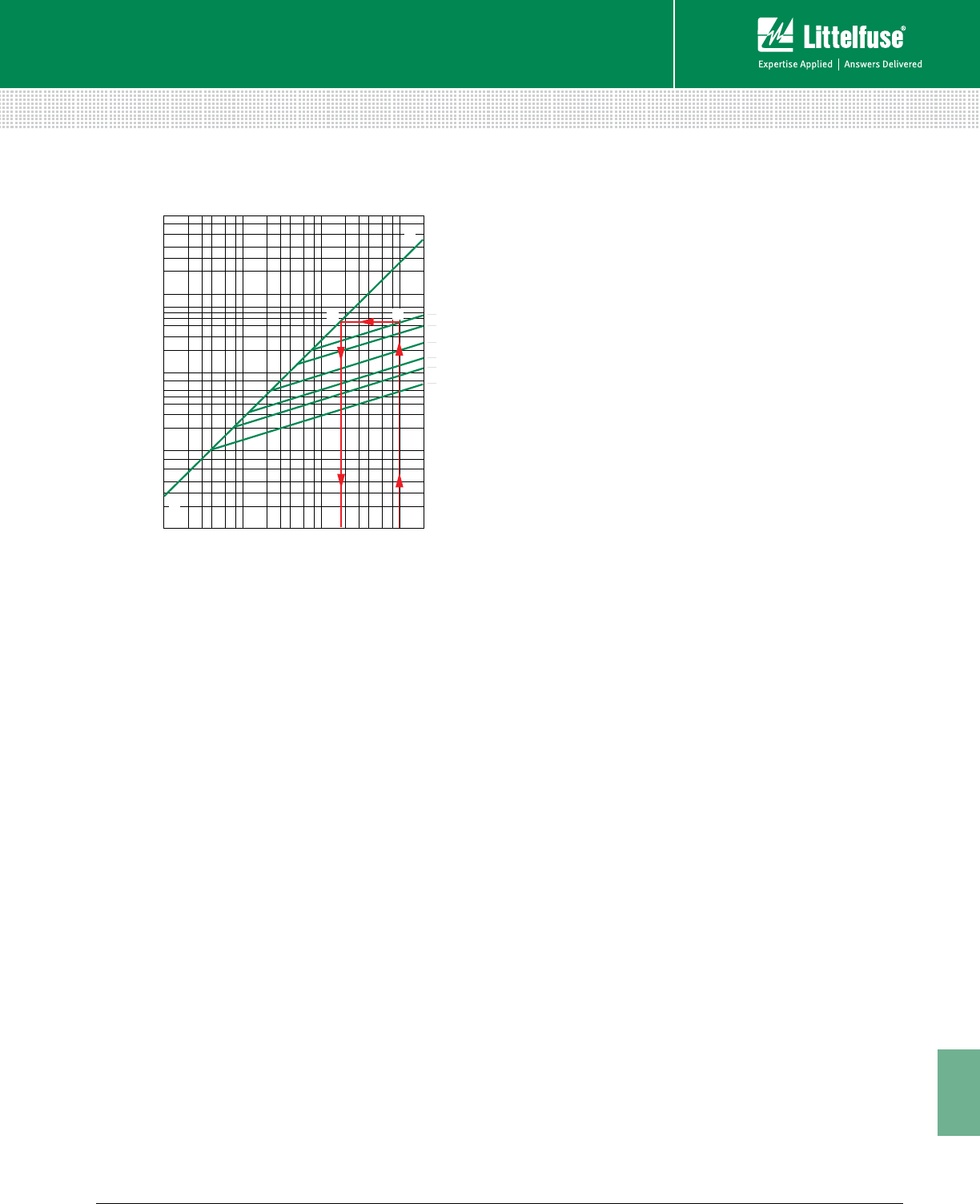
191 littelfuse.com © 2014 Littelfuse POWR-GARD® Products Catalog
11
Technical Application Guide
Technical
installed in systems with available short-circuit currents
greater than their short circuit (withstand) ratings.
However, this method may not be used to select fuses for
backup protection of molded case or intermediate frame
circuit breakers. National Electrical Code® (NEC®) Article
240.86 requires Series Ratings. Refer to the NEC® for more
information.
UL Listed fuse-to-circuit breaker series ratings are now
available from most national load center and panelboard
manufacturers. Listings are shown in their product digests,
catalogs, and online. Many local builders have also obtained
fuse-to-circuit breaker series ratings. For additional
information contact the Littelfuse Technical Support Group at
1-800-TEC-FUSE (1-800-832-3873).
Short-Circuit Current Rating (SCCR)
Since 2005, the NEC® has required Industrial Control Panels
to be labeled with their SCCR. These labels allow users
and inspectors to compare the SCCR of the equipment
to the available fault current in order to avoid potential
hazards in facilities.
Selective Coordination
A “coordinated” or “selective” system is a system whose
overcurrent protective devices have been carefully chosen and
their time-current characteristics coordinated.
Only the overcurrent device immediately on the line side of an
overcurrent will open for any overload or short-circuit condition.
To further clarify, refer to the Terms and Definitions section
for the definition of Selective Coordination and Figure 15 for a
graphical example.
Since the advent of electrical and electronic equipment,
businesses have become entirely dependent on the
continuous availability of electric energy. Loss of power
halts all production and order processing, yet expenses
continue to increase. Even many UPS systems become
unintentionally non-selective causing power loss to
computers and other critical equipment. Non-selectivity may
defeat otherwise well-engineered UPS systems.
In a selective system, none of this occurs. Overloads and
faults are disconnected by the overcurrent protective device
immediately on the line side of the problem. The amount of
equipment removed from service is minimized, the faulted
or overloaded circuit is easier to locate, and a minimum
amount of time is required to restore full service.
For these and many other reasons, selectivity is the
standard by which many systems are judged and designed.
Fuse Selectivity
To get a better sense of how to ensure that fuses are
selectively coordinated within an electrical system, refer
to Figure 4 shown earlier in this Technical Application
Guide. This figure shows typical average melting time-
current curves for one class of fuses. Note that the curves
are roughly parallel to each other and that for a given
overcurrent, the smaller fuse ratings respond quicker than
the larger ratings. The heat energy required to open a fuse
is separated into melting I2t and arcing I2t (see definition of
Ampere-Squared-Seconds). The sum of these is the total
clearing I2t.
For a system to be considered coordinated, the smaller
fuse total clearing I2t must be less than the larger fuse
melting I2t. In other words, if the downstream (branch)
fuse opens the circuit before the overcurrent affects
the upstream (feeder) fuse element, the system will be
considered selective. This can be determined by analyzing
curves displaying melting and total clearing I2t, or from
minimum melting and maximum clearing time-current
curves.
But the simplest method of coordinating low voltage power
fuses is by using a Fuse Coordination Table such as the
one shown in Table 4. This table is only applicable for the
Littelfuse POWR-PRO® and POWR-GARD® fuse series listed.
Tables such as this greatly reduce design time. For example,
the coordination table shows that POWR-PRO KLPC Class
L fuses coordinate at a two-to-one ratio with other Class L
fuses, with POWR-PRO LLNRK / LLSRK / LLSRK_ID series
FUSE CHARACTERISTICS CURVES AND CHARTS
100
1000000
200000
300000
400000
600000
800000
100000
20000
30000
40000
60000
80000
10000
2000
3000
4000
6000
8000
1000
200
300
400
600
800
100
200
300
400
600
800
1000
2000
3000
4000
6000
8000
10000
20000
30000
40000
60000
80000
100000
200000
FUSE
AMPERE
RATING
600
400
200
100
60
30
A
B
D A
B
C
AVAILABLE FAULT CURRENT
SYMMETRICAL R.M.S. AMPERES
PEAK LET-THRU IN AMPERES
Figure 8 – Peak Let-through Chart for POWR-PRO® LLNRK Class
RK1 Dual-Element Fuses Using the Up-Over-and-Down Method

192 © 2014 Littelfuse POWR-GARD® Products Cataloglittelfuse.com
11
Technical Application Guide
Technical
Class RK1 fuses, and POWR-PRO JTD / JTD_ID series Class
J fuses.
In the system shown in Figure 9, the 3000 amp Class L
main fuses are at least twice the ratings of the 1500, 1200,
and 1000 amp Class L feeder fuses. Using the 2:1 ratio
just referenced above, it is determined that these fuses
will coordinate. The Coordination Table also shows that the
LLSRK_ID series time-delay RK1 feeder and branch circuit
fuses coordinate at a two-to-one ratio with the Class L
feeder fuses, so the entire system in Figure 9 would be
considered 100% coordinated.
Circuit Breaker Coordination
As a result of the numerous types of circuit breakers
and circuit breaker trip units available in today’s market,
developing a coordinated circuit breaker system or
coordinating circuit breakers with fuses is beyond the scope
of this Technical Application Guide. For further questions,
contact the Littelfuse Technical Support Group.
NEC® Requirements for Selective
Coordination
Component Short-Circuit Protecting Ability
As shown in Figure 10, the NEC® requires equipment
protection to be coordinated with overcurrent protective
devices and the available fault current in order to prevent
extensive damage to the equipment. Essentially, this
means that electrical equipment must be capable of
withstanding heavy overcurrents without damage or be
properly protected by overcurrent protective devices that
will limit damage.
When a severe fault occurs in an unprotected circuit, current
immediately increases to a very high value. This is the
available or prospective fault current. Some fuses respond
so quickly to the increasing current that they interrupt
current within the first half-cycle - or before the current even
reaches its first peak. This is illustrated in Figure 6 found
earlier in the Technical Application Guide. Such fuses are
termed “current-limiting fuses.”
Current-limiting fuses stop damaging current faster than
any other protective device, and greatly reduce or totally
prevent component damage from high fault currents. This
performance capability helps users meet the NEC® Article
110.10 requirements listed in Figure 10.
Pre-Engineered Solutions
Applicable code requirements also continue to expand with
each new edition of the National Electrical Code®. As of the
2014 edition of the NEC®, the following requirements need
to be met – and can be, utilizing Littelfuse POWR-GARD®
Pre-Engineered Solutions:
• NEC 517.26 – Healthcare Essential Electrical Systems
• NEC 620.82 – Elevators
• NEC 700.27 – Emergency Systems
• NEC 701.27 – Legally Required Standby Systems
• NEC 708.54 – Critical Operations Power Systems
SELECTIVE COORDINATION
LINE-SIDE FUSES LOAD-SIDE FUSES
AMPERE
RANGE UL CLASS
LITTELFUSE
CATALOG
NUMBER
TIME-DELAY FUSES
AMPERE RANGE, UL CLASS AND CATALOG NO.
FAST-ACTING FUSES
AMPERE RANGE, UL CLASS AND CATALOG NO.
601-6000 601-4000 30-600 30-600 30-600 0-30 30-600 30-1200 30-600 1-60
L L RK1 JRK5 CC RK1 T J G
KLPC
LDC KLLU LLNRK
LLSRK_ID
JTD_ID
JTD
FLNR_ID
FLSR_ID
IDSR
CCMR KLNR
KLSR
JLLN
JLLS JLS SLC
601-6000 LKLPC 2:1 2:1 2:1 2:1 4:1 2:1 2:1 2:1 2:1 N/A
601-4000 LKLLU 2:1 2:1 2:1 2:1 4:1 2:1 2:1 2:1 2:1 N/A
601-2000 LLDC 2:1 2:1 2:1 2:1 4:1 2:1 2:1 2:1 2:1 N/A
30-600 RK1 LLNRK N/A N/A 2:1 2:1 8:1 2:1 3:1 3:1 3:1 4:1
30-600 RK1 LLSRK_ID N/A N/A 2:1 2:1 8:1 2:1 3:1 3:1 3:1 4:1
30-600 JJTD_ID N/A N/A 2:1 2:1 8:1 2:1 3:1 3:1 3:1 4:1
30-600 RK5 IDSR N/A N/A 1.5:1 1.5:1 2:1 2:1 1.5:1 1.5:1 1.5:1 1.5:1
30-600 RK5 FLNR_ID N/A N/A 1.5:1 1.5:1 2:1 2:1 1.5:1 1.5:1 1.5:1 1.5:1
30-600 RK5 FLSR_ID N/A N/A 1.5:1 1.5:1 2:1 2:1 1.5:1 1.5:1 1.5:1 1.5:1
30-600 RK1 KLNR N/A N/A 3:1 3:1 8:1 N/A 3:1 3:1 3:1 4:1
30-600 RK1 KLSR N/A N/A 3:1 3:1 8:1 N/A 3:1 3:1 3:1 4:1
30-1200 TJLLN N/A N/A 3:1 3:1 8:1 N/A 3:1 3:1 3:1 4:1
30-1200 TJLLS N/A N/A 3:1 3:1 8:1 N/A 3:1 3:1 3:1 4:1
30-600 JJLS N/A N/A 3:1 3:1 8:1 N/A 3:1 3:1 3:1 4:1
1-60 GSLC N/A N/A 3:1 3:1 4:1 N/A 2:1 2:1 2:1 2:1
Table 4 – Fuse Coordination Table. Selecting the Correct Fuse Ampere Ratio to Maintain Selectively Coordinated Systems.
(Ratios are expressed as Line-Side Fuse to Load-Side Fuse.)
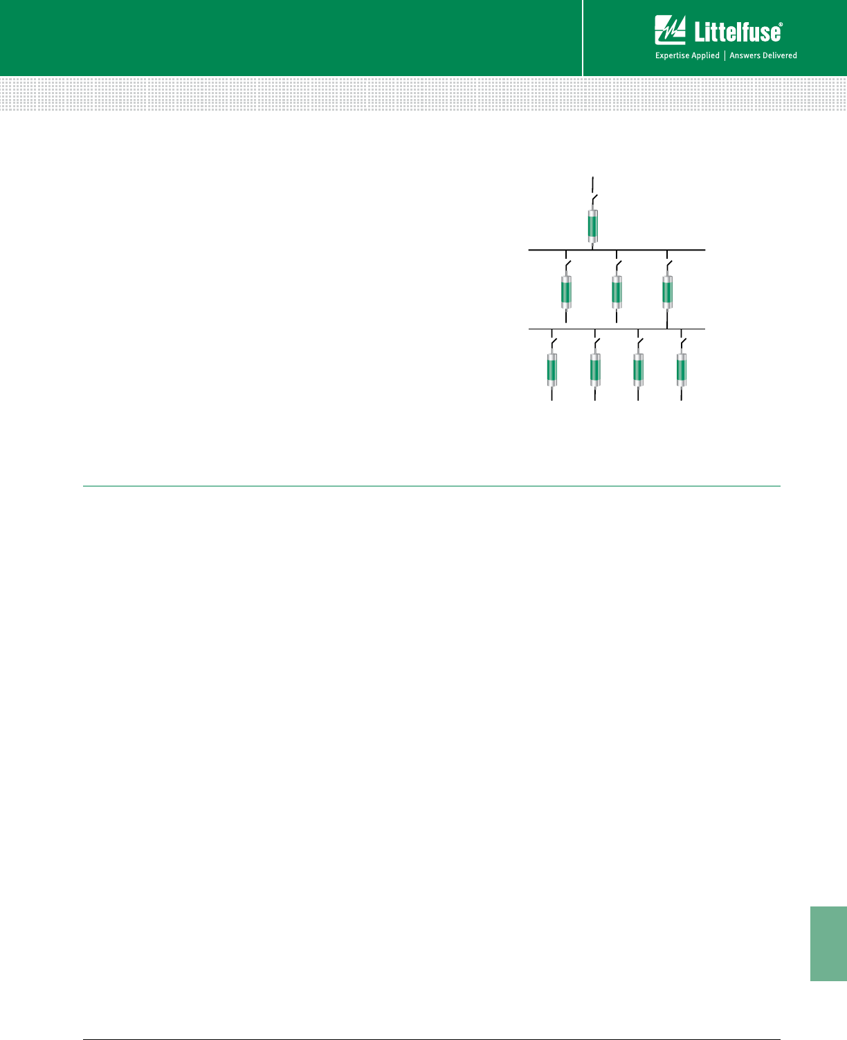
193 littelfuse.com © 2014 Littelfuse POWR-GARD® Products Catalog
11
Technical Application Guide
Technical
The Littelfuse product line of Pre-Engineered Solutions
includes:
• LPS Series POWR-Switch (single elevator shunt-trip
disconnect switch)
• LCP Selective Coordination Panel
These products continue to gain in popularity because they
meet NEC® requirements and offer simple, economical
solutions for a variety of applications.
Visit littelfuse.com/lcp for more information on Littelfuse
Pre-Engineered Solution products and corresponding
selective coordination requirements.
SELECTIVE COORDINATION
KLPC
3000
KLPC
1500
KLPC
1200
KLPC
1000
LLSRK
200
LLSRK
200
LLSRK
400
LLSRK
400
Figure 9 – Example of Selectively Coordinated Fused System
NATIONAL ELECTRICAL CODE®
ARTICLE 110 – Requirements for Electrical Installations
I. General
110.3. Examination, Identification, Installation, and Use of Equipment.
(A) Examination. In judging equipment, considerations such as the following shall be evaluated:
(5) Heating effects under normal conditions of use and also under abnormal conditions likely to arise in service.
(6) Arcing effects.
(B) Installation and Use. Listed or labeled equipment shall be used or installed in accordance with any instructions included in the listing
or labeling.
110.9 Interrupting Rating. Equipment intended to interrupt current at fault levels shall have an interrupting rating at nominal circuit
voltage sufficient for the current that is available at the line terminals of the equipment.
Equipment intended to interrupt current at other than fault levels shall have an interrupting rating at nominal circuit voltage sufficient for
the current that must be interrupted.
110.10 Circuit Impedance, Short-Circuit Current Ratings, and Other Characteristics. The overcurrent protective devices, the
total impedance, the equipment short-circuit current ratings, and other characteristics of the circuit to be protected shall be selected and
coordinated to permit the circuit protective devices used to clear a fault to do so without extensive damage to the electrical equipment of
the circuit. This fault shall be assumed to be either between two or more of the circuit conductors or between any circuit conductor and
the equipment grounding conductor(s) permitted in 250.118. Listed equipment applied in accordance with their listing shall be considered
to meet the requirements of this section.
ARTICLE 240 – Overcurrent Protection
240.1 Scope. Parts I through VII of this article provide the general requirements for overcurrent protection and overcurrent protective
devices not more than 1000 volts, nominal. Part VIII covers overcurrent protection for those portions of supervised industrial installations
operating at voltages of not more than 1000 volts, nominal. Part IX covers overcurrent protection over 1000 volts, nominal.
Informational Note: Overcurrent protection for conductors and equipment is provided to open the circuit if the current reaches a value
that will cause an excessive or dangerous temperature in conductors or con ductor insulation. See also Articles 110.9 for requirements for
interrupting ratings and 110.10 for require ments for protection against fault currents.
(Reproduced by permission of NFPA)
Figure 10 – National Electrical Code Requires Effective Overcurrent Protection

194 © 2014 Littelfuse POWR-GARD® Products Cataloglittelfuse.com
11
Technical Application Guide
Technical
UL/CSA FUSE CLASSES AND APPLICATIONS
CLASS L
STANDARDS: UL Standard 248-14,
CSA Standard C22.2, No. 106, classified as HRCI-L
VOLTAGE RATING: 600 volts, AC and/or DC
CURRENT RATINGS: 601-6000 amps
KLPC also available 200-600A; LDC also available 150-600A
INTERRUPTING RATING: AC: 200,000 amps rms symmetrical
DC: 50,000, 100,000, or 200,000 amps
Not interchangeable with any other UL fuse class.
Time delay: Class L fuses may be marked “Time-Delay” although UL does not
investigate time-delay characteristics of Class L fuses.
KLPC & KLLU: 10 seconds at 500% current rating
LDC: 4 seconds at 500% current rating
LF SERIES: KLPC, KLLU, LDC
PAGE: 8
CLASS R
STANDARDS: UL Standard 248-12,
CSA Standard C22.2, No. 106, classified as HRCI-R
VOLTAGE RATINGS: 250 and 600 volts, AC; 125 and 300 volts DC
CURRENT RATINGS: 0-600 amps
INTERRUPTING RATING: 200,000 amps rms symmetrical
TWO CLASSES: RK1 and RK5
Time delay is optional for Class R fuses.
Time Delay fuses are required to hold 500% current rating for a minimum of ten seconds.
Same dimensions as UL Class H fuses, terminals modified to provide rejection feature.
Fits UL Class R fuse holders which reject non Class R fuses.
Physically interchangeable with UL Class H, NEMA Class H, and UL Classes K1 &
K5 when equipment has Class H fuse holders.
CLASS K
STANDARDS: UL Standard 248-9; No CSA Standard
VOLTAGE RATINGS: 250 and 600 volts, AC
CURRENT RATING: 0-600 amps
INTERRUPTING RATINGS: Three permitted: 50,000, 100,000, and 200,000 amps
rms symmetrical
Time delay is optional for Class K fuses.
Time Delay fuses are required to hold 500% current rating for a minimum of ten seconds.
Same Dimensions and Physically interchangeable with UL Class H fuse holders.
Class K fuses are not permitted to be labeled Current Limiting because there is no rejec-
tion feature as required by NEC® Article 240-60(B).
CLASS J
STANDARDS: UL Standard 248-8,
CSA Standard C22.2, No. 106, classified as HRCI-J
VOLTAGE RATING: 600 volts, AC
CURRENT RATINGS: 0-600 amps
INTERRUPTING RATING: 200,000 amps rms symmetrical
Not interchangeable with any other UL fuse class.
Time delay optional: Minimum of 10 seconds at 500% current rating.
LF SERIES: Time Delay: JTD_ID, JTD
Fast Acting: JLS
PAGE: 21
CLASS G
STANDARDS: UL Standard 248-5
CSA Standard C22.2, No. 106, classified as HRCI Misc.
VOLTAGE RATING: 480 volts, AC
CURRENT RATINGS: 0-60 amps
INTERRUPTING RATING: 100,000 amps rms symmetrical
Not interchangeable with any other UL fuse class.
Time delay optional: Minimum of 12 seconds at 200% current rating.
LF SERIES: SLC
PAGE: 26
CLASS RK1
High degree of current limitation.
Provides IEC Type 2 (no damage)
protection for motor starters and
control components. Time Delay
optional, LLSRK_ID Series provides
visual indication of blown fuse.
LF SERIES: Time Delay: LLNRK,
LLSRK, LLSRK_ID
Fast Acting: KLNR, KLSR
PAGE: 13
CLASS RK5
Moderate degree of current limita-
tion, adequate for most applica-
tions. Time delay optional.
FLNR_ID, FLSR_ID and IDSR series
provides visual indication of blown
fuse.
LF SERIES: FLNR, FLNR_ID,
FLSR, FLSR_ID, and IDSR
PAGE: 16
CLASS K5
Same prescribed degree of current
limitation as RK5 fuses when
tested at 50,000 or 100,000 amps
rms symmetrical.
LF SERIES: NLN, NLS
PAGE: 20
CLASS T
STANDARDS: UL Standard 248-15
CSA Standard C22.2, No. 106, classified as HRCI-T
VOLTAGE RATINGS: 300 and 600 volts AC, 125 and 300 volts DC
CURRENT RATINGS: 0-1200 amps
900 to 1200 amps UL Recognized for 600V version
INTERRUPTING RATING: 200,000 amps rms symmetrical
Fast-Acting fuses. High degree of current limitation.
Very small fuses; space-saving and non-interchangeable with any other UL fuse class.
LF SERIES: JLLN, JLLS
PAGE: 24
CLASS CC/CD
STANDARDS: UL Standard 248-4,
CSA Standard C22.2, No. 106, classified as HRCI Misc.
VOLTAGE RATING: 600 volts, AC
CURRENT RATINGS: UL Class CC: 0-30 amps
UL Class CD: 35-60 amps
INTERRUPTING RATINGS: 200,000 amps rms symmetrical
Time delay optional: Minimum of 12 seconds at 200% current rating.
LF SERIES: Time Delay: CCMR (motors), KLDR (transformers)
Fast Acting: KLKR
PAGE: 27
CLASS K1
Same prescribed degree of current
limitation as RK1 fuses when
tested at 50,000 or 100,000 amps
rms symmetrical.
LF SERIES: Time Delay: LLNRK,
LLSRK
Fast Acting: KLNR,
KLSR
PAGE: 13
Overcurrent and short-circuit protection of power and lighting feeders and branch circuits
Current Limiting
Fuses which meet the requirements for current limiting fuses are required to be labeled “Current Limiting”. Fuse labels must
include: UL/CSA fuse class, manufacturer’s name or trademark, current rating, AC and/or DC voltage rating, and AC and/or DC
interrupting rating. “Time Delay”, “D”, “TD” or equivalent may also be included on the label when the fuse complies with the
time delay requirements of its class.

195 littelfuse.com © 2014 Littelfuse POWR-GARD® Products Catalog
11
Technical Application Guide
Technical
UL/CSA FUSE CLASSES AND APPLICATIONS
FUSES FOR SUPPLEMENTARY OVERCURRENT PROTECTION
STANDARDS: UL Standard 248-14; CSA Standard C22.2,
No. 59-1. Three Classifications covered:
NOTE: Fuses may be rated for AC and/or DC when suitable for
such use.
(1) MICRO FUSES
Voltage ratings: UL, 125 volts; CSA, 0-250 volts
Current ratings: UL, 0-10 amps; CSA, 0-60 amps
Interrupting rating: 50 amps rms symmetrical
(2) MINIATURE FUSES (CSA classifies these as Supplemental Fuses)
Voltage ratings: UL, 125 or 250 volts; CSA, 0-600 volts
Current ratings: UL, 0-30 amps; CSA, 0-60 amps
Interrupting rating: 10,000 amps rms symmetrical
(3) MISCELLANEOUS CARTRIDGE FUSES (CSA classifies these as
Supplemental Fuses)
Voltage ratings: UL, 125-1000 volts; CSA, 0-100 volts
Current ratings: UL, 0-30 amps; CSA 0-60 amps
Interrupting ratings: 10,000, 50,000, or 100,000 amps rms symmetrical
Time delay (Optional); Minimum delay at 200% fuse rating:
5 seconds for fuses rated 3 amps or less
12 seconds for fuses rated more than 3 amps
LF SERIES: BLF, BLN, BLS, FLA, FLM, FLQ, FLU, KLK, KLQ KLKD, SPF
NOTE: Littelfuse electronic fuses are also covered by these standards; see
electronic section of this catalog, or littelfuse.com for complete listing.
PAGE: 30
SPECIAL PURPOSE FUSES
There are no UL Standards covering this category of fuses. These fuses have
special characteristics designed to protect special types of electrical or electronic
equipment such as diodes, SCR, transistors, thyristors, capacitors, integrally fused
circuit breakers, parallel cable runs, etc.
Fuses may be UL Recognized for use as a component in UL Listed equipment.
UL Recognized fuses are tested for characteristics such as published interrupting
capacity. They are also covered by UL re-examination service.
Non-renewable
VOLTAGE RATINGS: up to 1000 volts AC and/or DC
AMPERE RATINGS: up to 6000 amperes
INTERRUPTING RATINGS: up to 200,000 amperes
Many of these fuses are extremely current limiting. When considering application of
these fuses, or if you have special requirements, contact Littelfuse Technical Support
Group for assistance.
LF SERIES: KLC, LA15QS, LA30QS, LA50QS, LA60QS, LA60X, LA70QS, LA100P,
LA120X, LA070URD, LA130URD, L15S, L25S, L50S, L60S, L70S, JLLS 900 amp
through 1200 amp
PAGES: 56
CLASS H
STANDARDS: UL Standard 248-6
CSA Standard C22.2, No. 59.1
Also known as NEMA Class H, and sometimes
referred to as “NEC” or “Code” fuses
VOLTAGE RATINGS: 250 and 600 volts, AC
AMPERE RATINGS: 0-600 amps
INTERRUPTING RATINGS: 10,000 amps rms symmetrical
Two types: one-time and renewable
Physically interchangeable with UL Classes K1 & K5;
Fits UL Class H fuse holders which will also accept K1, K5, RK5, and RK1 fuses.
Manufacturers are upgrading Class H One-time fuses to Class K5 per UL Standard
248-9D, See Class K fuses.
ONE-TIME FUSES
(NON-RENEWABLE)
Time delay: Optional
Time-delay fuses must hold 500%
current rating for a minimum of ten
seconds.
LF SERIES: NLKP
PAGE: 20
RENEWABLE FUSES
Only Class H fuses may be renew-
able. While time delay is optional,
no renewable fuses meet require-
ments for time delay.
Some renewable fuses have a mod-
erate amount of time delay, referred
to as “time lag” to differentiate
from true time delay.
LF SERIES: Discontinued - Please
cross to RK5 or RK1 class fuses
PLUG FUSES
STANDARDS: UL Standard 248-11,
CSA Standard C22.2, No. 59.1
VOLTAGE RATINGS: 125 volts AC only
AMPERE RATINGS: 0-30 amps
INTERRUPTING RATINGS: 10,000 amps rms symmetrical. Interrupting
rating need not be marked on fuse.
Two types: Edison-base and Type S
EDISON-BASE: Base is same as standard light bulb. All amp ratings interchange
able. NEC® permits Edison-base plug fuses to be used only as replacements for
existing fuses, and only when there is no evidence of tampering or overfusing.
TYPE S: Not interchangeable with Edison-base fuses unless non-removable Type
S fuse adapter is installed in Edison-base fuse socket. To prevent overfusing,
adapters have three ampere ratings: 10-15, 16-20, and 21-30 amps.
Time delay: Fuses may be time delay, if so, they are required to hold 200% of rating
for 12 seconds minimum.
NOTE: Plug fuses may be used where there is not more than 125 volts between
conductors or more than 150 volts from any conductor to ground. This permits their
use in 120/240 volts grounded, single-phase circuits.
LF SERIES: Edison-base: TOO, TLO
Type S: SOO, SLO
Type S Adapters: SAO
PAGE: 63
Non-Current Limiting
Overcurrent and short-circuit protection of power and lighting feeders and branch circuits
Additional Resources and POWR-GARD® Products
Littelfuse is continually developing new technical resources
and products that meeting evolving industry standards.
For the latest information, visit:
littelfuse.com
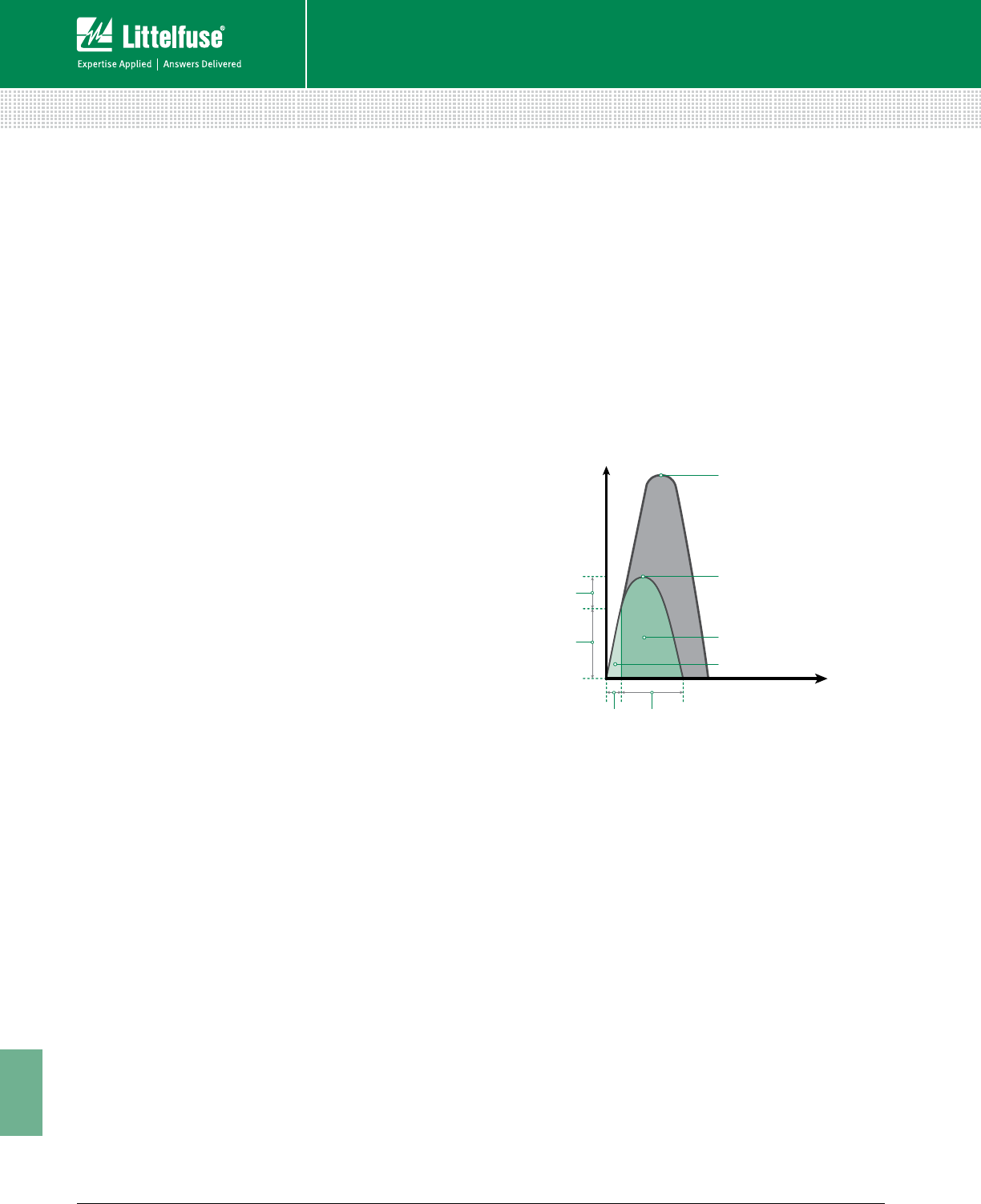
196 © 2014 Littelfuse POWR-GARD® Products Cataloglittelfuse.com
11
Technical Application Guide
Technical
Adjustable Alarm Level – A setting on a protection relay at
which an LED or an output contact operates to activate a visual
or audible alarm.
Adjustable Time Delay – A setting on a protection relay that
determines the time between the fault detection and relay
operation.
AIC or A.I.C. – See Interrupting Capacity.
AIR or A.I.R. – See Interrupting Rating.
Alarm Relay Contact – The output of the relay that acts as a
switch and is connected to a visual or audible alarm.
Ambient Temperature – The air temperature surrounding a
device. For fuses or circuit breakers in an enclosure, the air
temperature within the enclosure.
Ampacity – The current in amperes that a conductor can carry
continuously under the conditions of use without exceeding
its temperature rating. It is sometimes informally applied to
switches or other devices which are more properly referred to
by their ampere rating.
Ampere Rating – The current rating, in amperes, that is marked
on fuses, circuit breakers, or other equipment.
Ampere-Squared-Seconds (I2t) – A means of describing the
thermal energy generated by current flow. When a fuse is
interrupting a current within its current-limiting range, the term
is usually expressed as melting, arcing, or total clearing I2t.
• Melting I2t is the heat energy passed by a fuse after an
overcurrent occurs and until the fuse link melts. It equals
the rms current squared multiplied by the melting time in
seconds. For times less than 0.004 seconds, melting I2t
approaches a constant value for a given fuse.
• Arcing I2t is the heat energy passed by a fuse during its
arcing time. It is equal to the rms arcing current squared (see
definition below), multiplied by arcing time.
• Clearing I2t (also Total Clearing I2t) is the ampere-squared
seconds (I2t) through an overcurrent device from the
inception of the overcurrent until the current is completely
interrupted. Clearing I2t is the sum of the Melting I2t plus the
Arcing I2t.
Analog Output – A 0–1 mA, 4–20 mA or 0–5 Vdc signal from
a protection relay used to pass information to a device or
controller.
Arc-Blast – A pressure wave created by the heating, melting,
vaporization, and expansion of conducting material and
surrounding gases or air.
Arc-Flash – The sudden release of heat energy and intense
light at the point of an arc. Can be considered a short-circuit
through the air, usually created by accidental contact between
live conductors.
Arc Gap – The distance between energized conductors or
between energized conductors and ground. Shorter arc gaps
result in less energy being expended in the arc, while longer
gaps reduce arc current. For 600 volts and below, arc gaps of
1.25 inches (32 mm) typically produce the maximum incident
energy.
Arc Rating – A rating assigned to material(s) that relates to the
maximum incident energy the material can resist before break
open of the material or onset of a second-degree burn. The arc
rating is typically shown in cal/cm².
Arcing Current (See Figure 11) – The current that flows through
the fuse after the fuse link has melted and until the circuit is
interrupted.
Figure 11 – Arcing and melting currents plus arcing, melting and clearing
times
Arcing I2t – See Ampere-Squared-Seconds (I2t).
Arcing Fault – A short-circuit that arcs at the point of fault. The
arc impedance (resistance) tends to reduce the short-circuit
current. Arcing faults may turn into bolted faults by welding of
the faulted components. Arcing faults may be phase-to-phase
or phase-to-ground.
Arcing Time (See Figure 11) – The time between the melting
of a fuse link or parting of circuit breaker contacts, until the
overcurrent is interrupted.
Arc Voltage (See Figure 12) – Arc voltage is a transient voltage
that occurs across an overcurrent protection device during
the arcing time. It is usually expressed as peak instantaneous
voltage (Vpeak or Epeak), or on rare occasion as rms voltage.
Asymmetrical Current – See Symmetrical Current.
Available Short-Circuit Current (also Available or
Prospective Fault Current) – The maximum rms Symmetrical
Current that would flow at a given point in a system under
bolted-fault conditions. Short-circuit current is maximum during
the first half-cycle after the fault occurs. See definitions of
Bolted Fault and Symmetrical Current.
TERMS AND DEFINITIONS
Current
Time
Peak Let-Thru Current
Peak current which would
occur without current limitation
Arcing Energy (I2t)
Melting Energy (I2t)
Melting
Time
Arcing
Time
Arcing
Current
Melting
Current
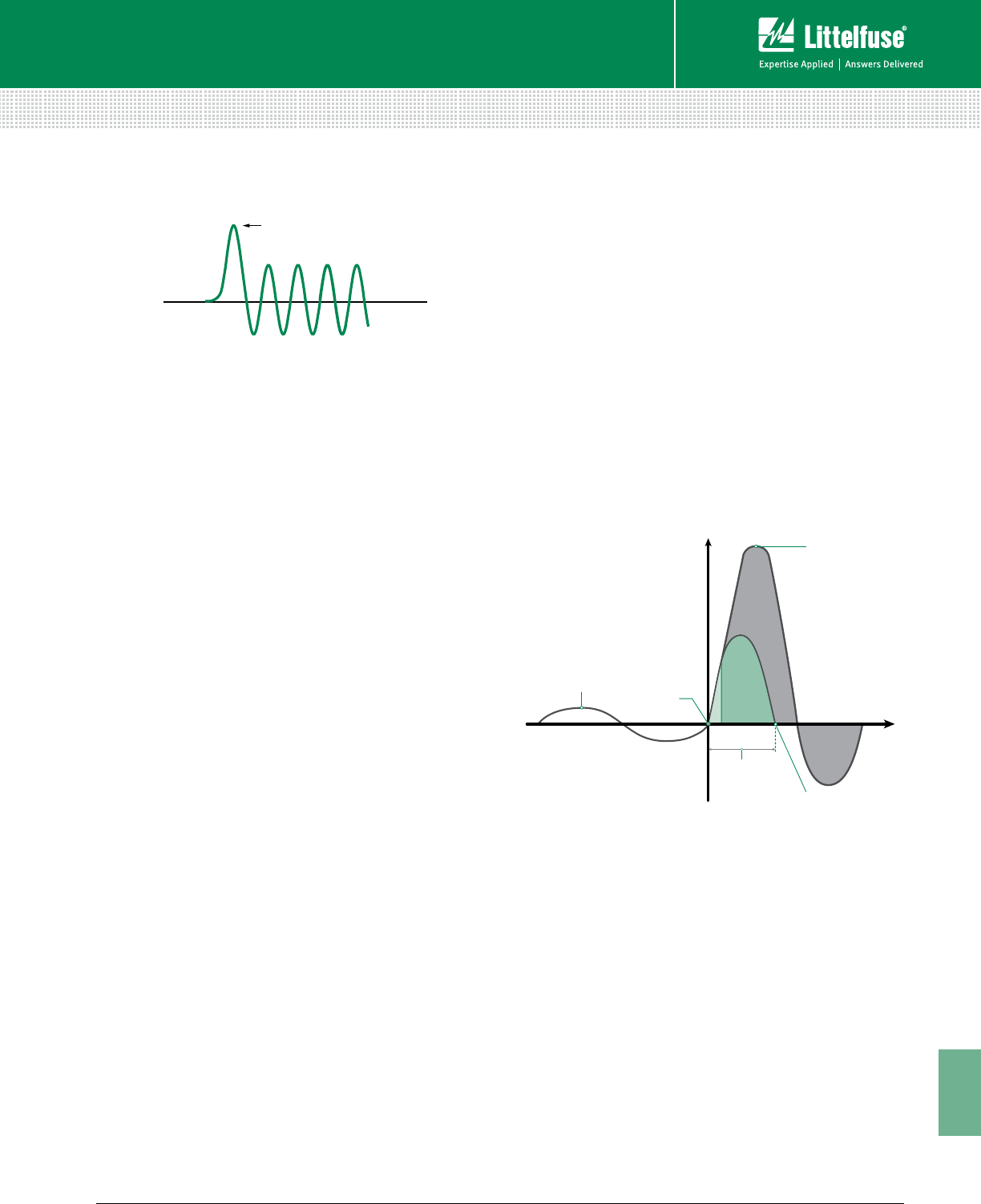
197 littelfuse.com © 2014 Littelfuse POWR-GARD® Products Catalog
11
Technical Application Guide
Technical
Blade Fuse – See Knife Blade Fuse.
Body – The part of a fuse enclosing the fuse elements and
supporting the contacts. Body is also referred to as cartridge,
tube, or case.
Bolted Fault – A short-circuit that has no electrical resistance
at the point of the fault. It results from a firm mechanical
connection between two conductors, or a conductor and
ground. Bolted faults are characterized by a lack of arcing.
Examples of bolted faults are a heavy wrench lying across two
bare bus bars, or a crossed-phase condition due to incorrect
wiring
Boundaries of Approach – Protection boundaries established
to protect personnel from shock and Arc-Flash hazards.
Calorie – The amount of heat needed to raise the temperature
of one gram of water by one degree Celsius.1 cal/cm² is
equivalent to the exposure on the tip of a finger by a cigarette
lighter for one second.
Cartridge Fuse – A fuse that contains a current-responsive
element inside a tubular fuse body with cylindrical ferrules (end
caps).
Case Size (also Cartridge Size) – The maximum allowable
ampere rating of a cartridge fuse having defined dimensions
and shape. For example, case sizes for UL Listed Class H, K, J,
RK1, and RK5 are 30, 60, 100, 200, 400, and 600 amperes. The
physical dimensions vary with fuse class, voltage, and ampere
rating. UL Standards establish the dimensions for each UL
Fuse Class. This catalog’s product section contains case size
dimensions for all Littelfuse POWR-GARD® fuses.
Clearing I2t – See Ampere-Square-Seconds (I2t).
Clearing Time (see Figure 11) – The time between the initiation
of an overcurrent condition to the point at which the overcurrent
is interrupted. Clearing Time is the sum of Melting Time and
Arcing Time.
Conformal Coating – Coating used to protect circuit boards
from pollutants, corrosion, and mildew.
Contacts (Fuse) – The external metal parts of the fuse used to
complete the circuit. These consist of ferrules, caps, blades or
terminals, as shown in this catalog.
Coordination or Coordinated System – See Selective
Coordination.
Continuous Load – An electrical load where the maximum
current is expected to continue for three hours or more.
CT Loop – The electrical circuit between a current transformer
and a protection relay or monitoring device.
Current-Based Protection – Protection parameters (trip-levels/
data collection etc.) derived from current levels in a circuit.
Current-limiting Fuse (See Figure 13) – A fuse which, when
interrupting currents within its current-limiting range, reduces
the current in the faulted circuit to a magnitude substantially
less than that obtainable in the same circuit if the device was
replaced with a solid conductor having comparable impedance.
To be labeled “current limiting,” a fuse must mate with a
fuse block or fuse holder that has either a rejection feature or
dimensions that will reject non-current-limiting fuses.
Figure 13 – Current-limiting Fuse
Current-limiting Range - For an individual overcurrent
protective device, the current-limiting range begins at the
lowest value of rms symmetrical current at which the device
becomes current-limiting (the threshold current) and extends
to the maximum interrupting capacity of the device. See
definitions of Threshold Current and Interrupting Capacity.
Current Rating – See Ampere Rating.
Current Transformer (CT) – A transformer that produces a
current in its secondary circuit in a known proportion to current
in its primary circuit.
Data Logging – Collecting and storing information in a
format that can be reviewed for trending, troubleshooting and
reporting.
DFT (Discrete Fourier Transform) Harmonic Filter – An
algorithm used to measure the fundamental component of
current and voltage and reject harmonics. This allows lower trip
settings and eliminates nuisance trips due to harmonics.
TERMS AND DEFINITIONS
INSTANTANEOUS ARC VOLTAGE
183% OF CYCLEPEAK
RESTORED VOLTAGE
Figure 2
PEAK
Current
Time
Fault occurs
Arc is extinguished
Current before fault
Fuse opens and
clears short circuit
in less than ½ cycle
Current which would
flow if not interrupted
Figure 12 – Transient overvoltage during arcing time

198 © 2014 Littelfuse POWR-GARD® Products Cataloglittelfuse.com
11
Technical Application Guide
Technical
Distance to Arc – Refers to the distance from the receiving
surface to the arc center. The value used for most calculations is
typically 18 inches.
Dual-Element Fuse – A fuse with internal construction
consisting of a separate time-delay overload element(s) that
interrupts overcurrents up to approximately 500%-600% of
its nominal rating, plus separate fuse links that quickly open
higher value currents. All dual-element fuses have time delay,
but, since there are other methods of achieving time delay,
not all time-delay fuses have dual-element construction.
See Time-Delay Fuse.
EFCT (Earth Fault Current Transformer) – A current
transformer engineered to accurately detect low level
ground-fault current.
Electrical Hazard Analysis – A study performed to identify the
potential electrical hazards to which personnel may be exposed.
The analysis should address both shock and Arc-Flash hazards.
Electrically Safe Work Condition – Condition where the
equipment and or circuit components have been disconnected
from electrical energy sources, locked/tagged out, and tested to
verify all sources of power are removed.
Element – A fuse’s internal current-carrying components that
melt and interrupt the current when subjected to an overcurrent
of sufficient duration or value. Also called fuse link.
Fail-Safe Mode (also known as Under Voltage or UV) –
Output relay is energized during normal (not tripped) operation.
If the protection relay loses supply voltage, the system will trip
or alarm.
Fast-Acting Fuse – May also be termed Normal-opening fuse,
this is a fuse that has no intentional or built-in time delay. Actual
opening time is determined by the fuse class, the overcurrent,
and other conditions. Fast-acting is indicated on the fuse label
by “Fast-Acting”, “F-A”, “F”, or other suitable marking.
Fault – Same as Short-Circuit and used interchangeably.
Fault Current – The current that flows when a phase conductor
is faulted to another phase or ground.
Feeder Protection – Overcurrent or overvoltage devices
installed on a feeder circuit to supplement, compliment or
replace downstream protective devices.
Filler – A material, such as granular quartz, used to fill a section
or sections of a fuse and aid in arc quenching.
Filter – An algorithm used to measure the fundamental
component of current and voltage and reject harmonics. This
allows lower trip settings and eliminates nuisance trips due to
harmonics.
Flash Hazard Analysis – A study that analyzes potential
exposure to Arc-Flash hazards. The outcome of the study
establishes Incident Energy levels, Hazard Risk Categories,
Flash Protection Boundaries, and required PPE. It also helps
define safe work practices.
Flash Protection Boundary – A protection boundary
established to protect personnel from Arc-Flash hazards.
The Flash Protection Boundary is the distance at which
an unprotected worker can receive a second-degree
burn to bare skin.
Fuse – An overcurrent protective device consisting of one
or more current carrying elements enclosed in a body fitted
with contacts, so that the fuse may be readily inserted into or
removed from an electrical circuit. The elements are heated by
the current passing through them, thus interrupting current flow
by melting during specified overcurrent conditions.
Ground Continuity Monitor - A protection relay that
continuously monitors a ground conductor and trips if this
conductor opens or shorts to the ground-check conductor.
Ground-Fault – Unintentional contact between a phase
conductor and ground or equipment frame. The words
“ground” and “earth” are used interchangeably when it comes
to electrical applications.
Ground-Fault Current – The current that returns to the supply
neutral through the ground-fault and the ground-return path.
Ground-Fault Protection – A system that protects
equipment from damaging ground-fault current by operating a
disconnecting means to open all ungrounded conductors of a
faulted circuit. This protection is at current levels less than those
required to operate a supply circuit overcurrent device.
Ground-Fault Relay – A protection relay designed to detect
a phase-to-ground-fault on a system and trip when current
exceeds the pickup setting for greater than the trip time setting.
Hazard Risk Category – A classification of risks (from 0 to
4) defined by NFPA 70E®. Each category requires PPE and is
related to incident energy levels.
High-Resistance Grounding – Achieved when a neutral-
ground resistor (NGR) is used to limit the current to a low level.
Typically high-resistance grounding is 25 A and lower. See Low-
Resistance Grounding.
I2t – See Ampere-Squared-Seconds (I2t).
IEEE Device Numbers – The devices in switching equipment
are referred to by numbers, according to the functions they
perform. These numbers are based on a system which has
been adopted as standard for automatic switchgear by IEEE.
This system is used on connection diagrams, in instruction
books and in specifications.
IEC Type 2 Protection – Fused protection for control
components that prevents damage to these components under
short-circuit conditions. See definition of No Damage.
TERMS AND DEFINITIONS

199 littelfuse.com © 2014 Littelfuse POWR-GARD® Products Catalog
11
Technical Application Guide
Technical
Incident Energy – The amount of thermal energy impressed on
a surface generated during an electrical arc at a certain distance
from the arc. Typically measured in cal/cm2.
Instantaneous Peak Current (Ip or Ipeak) – The maximum
instantaneous current value developed during the first
half-cycle (180 electrical degrees) after fault inception. The
peak current determines magnetic stress within the circuit.
See Symmetrical Current.
Insulation Monitoring – Monitoring the resistance from phase
to ground to detect insulation breakdown on a system.
Interrupting Capacity (AIC) – The highest available
symmetrical rms alternating current (for DC fuses the highest
direct current) at which the protective device has been tested,
and which it has interrupted safely under standardized test
conditions. The device must interrupt all available overcurrents
up to its interrupting capacity. Also commonly called interrupting
rating. See Interrupting Rating below.
Interrupting Rating (IR, I.R., AIR or A.I.R.) – The highest RMS
symmetrical current, at specified test conditions, which the
device is rated to interrupt. The difference between interrupting
capacity and interrupting rating is in the test circuits used to
establish the ratings.
Inverse-time Characteristics – A term describing protective
devices whose opening time decreases with increasing current.
IR or I.R. (also AIR or A.I.R.) – See Interrupting Rating above.
Kiloamperes (kA) – 1,000 amperes.
Knife Blade Fuse – Cylindrical or square body fuses with flat
blade terminals extending from the fuse body. Knife blades may
be designed for insertion into mating fuse clips and/or
to be bolted in place. Knife blade terminals may include a
rejection feature that mates with a similar feature on a fuse
block of the same class.
Leakage Current – Very low level ground-fault current, typically
measured in milliamperes (mA, thousandths of amperes).
Limited Approach Boundary – An approach boundary
to protect personnel from shock. A boundary distance is
established from an energized part based on system voltage. To
enter this boundary, unqualified persons must be accompanied
with a qualified person and use the proper PPE.
Low-Resistance Grounding – A Resistance Grounded System
that allows high currents to flow during a ground-fault. Typically
100A and higher is considered Low-Resistance grounding. See
High-Resistance Grounding.
Melting Current (see Figure 11) – The current that flows
through the fuse from the initiation of an overcurrent condition
to the instant arcing begins inside the fuse.
Melting I2t – See Ampere-Squared-Seconds (I2t).
Melting Time (see Figure 11) – The time span from the initiation
of an overcurrent condition to the instant arcing begins inside
the fuse.
Motor Protection – Overload protection designed to protect
the windings of a motor from high current levels. Modern
motor protection relays add many additional features, including
metering, data logging and communications.
NEC – In general, the National Electrical Code® (NEC®).
Specifically, as referenced herein, NEC refers to NFPA
Standard 70, National Electrical Code, National Fire Protection
Association, Quincy, MA 02269.
Sections of the NEC reprinted herein, and/or quotations
there from, are done so with permission. The quoted and
reprinted sections are not the official position of the National
Fire Protection Association which is represented only by the
Standard in its entirety. Readers are cautioned that not all
authorities have adopted the most recent edition of the NEC;
many are still using earlier editions.
Neutral Grounding Resistor (NGR) – A current-limiting
resistor connecting the power-system neutral to ground.
No Damage – A term describing the requirement that a system
component be in essentially the same condition after the
occurrence of a short-circuit as prior to the short-circuit.
Non-renewable Fuse – A fuse that must be replaced
after it has opened due to an overcurrent. It cannot be
restored to service.
Normal-opening Fuse – See Fast-Acting Fuse.
Nuisance Trip – An undesired change in relay output due to
misinterpreted readings.
One-time Fuse – Technically, any non-renewable fuse. However,
the term usually refers to UL Class H fuses and to fast acting
UL Class K5 fuses. Such fuses are not current-limiting and do
not have a rejection feature. One-time fuses are also referred to
as “Code” fuses.
Open CT Hazard – An open-circuited CT secondary
can develop a dangerously high voltage when the
primary is energized.
Overcurrent – Any current larger than the equipment,
conductor, or devices are rated to carry under
specified conditions.
Overload – An overcurrent that is confined to the normal
current path (e.g., not a short-circuit), which if allowed
to persist, will cause damage to equipment and/or
wiring. Additional information regarding fuse applications
for overload protection can be found earlier in this
Technical Application Guide.
TERMS AND DEFINITIONS
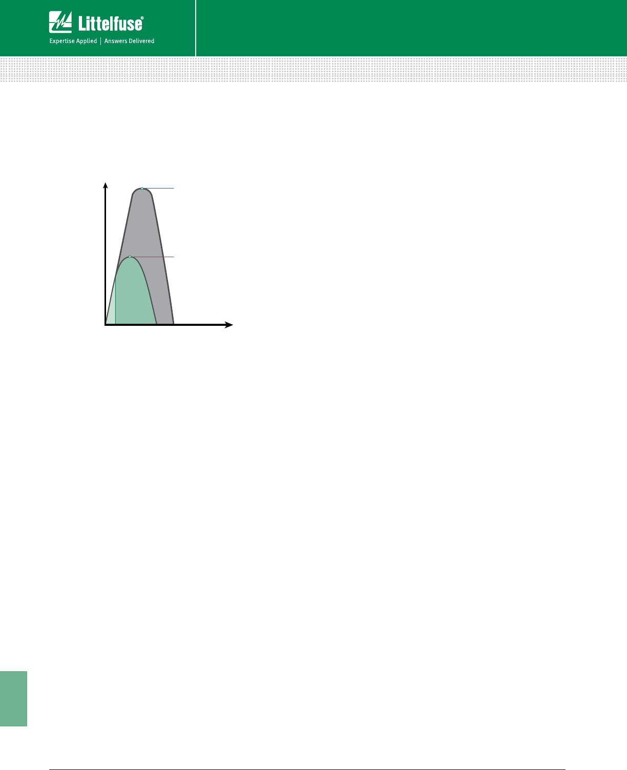
200 © 2014 Littelfuse POWR-GARD® Products Cataloglittelfuse.com
11
Technical Application Guide
Technical
Peak Let-through Current (See Figure 14) – The maximum
instantaneous current that passes through an overcurrent
protective device during its total clearing time when the
available current is within its current-limiting range.
Figure 14 – Peak Let-through Current
Phase Current – The current present in a phase conductor.
Phase Voltage – The voltage measured between a phase
conductor and ground.
Power Factor (X/R) – As used in overcurrent protection,
power factor is the relationship between the inductive
reactance (X) and the resistance (R) in the system during a
fault. Under normal conditions a system may be operating at
a 0.85 power factor (85%). When a fault occurs, much of the
system resistance is shorted out and the power factor may
drop to 25% or less. This may cause the current to become
asymmetrical. See definition of Symmetrical Current. The
UL test circuits used to test fuses with interrupting ratings
exceeding 10,000 amperes are required to have a power factor
of 20% or less. Since the power factor of test circuits tends to
vary during test procedures, actual test circuits are usually set
to a 15% power factor. The resulting asymmetrical current has
an rms value of 1.33 times the available symmetrical rms. The
instantaneous peak current of the first peak after the fault is
2.309 times the available symmetrical rms.
PPE – An acronym for Personal Protective Equipment. It can
include clothing, tools, and equipment.
Primary Rating (for CTs) – The current rating of the primary
side of a current transformer. The first number in the ratio 500:5
is the primary rating. Under ideal conditions 500 A of primary
current flow through the CT will produce 5 A of current out the
secondary terminals.
Prohibited Approach Boundary – An approach boundary
to protect personnel from shock. Work in this boundary
is considered the same as making direct contact with an
energized part. Only qualified persons are allowed to enter this
boundary and they must use the proper PPE.
Prospective Current – See Available Short-Circuit Current.
Protection Boundaries – Boundaries established to protect
personnel from electrical hazards.
Pulsing – Modulating the ground-fault current on a resistance
grounded system using a contactor to short out part of the NGR
elements (or to open one of two NGRs connected in parallel).
Another version of pulsing is imposing a higher frequency signal
on power lines and using a wand detector to locate the point of
fault on a conductor.
QPL (Qualified Products List) – A list of approved fuses and
holders that meet various Military specifications.
Qualified Person – A person who is trained, knowledgeable,
and has demonstrated skills on the construction and operation
of the equipment, and can recognize and avoid electrical
hazards that may be encountered.
Rating – A designated limit of operating characteristics based
on definite conditions such as current rating, voltage rating and
interrupting rating.
Rectifier Fuse – See Semiconductor Fuse.
Rejection Feature – The physical characteristic(s) of a fuse
block or fuse holder that prevents the insertion of a fuse unless
it has the proper mating characteristics. This may be achieved
through the use of slots, grooves, projections, or the actual
physical dimensions of the fuse. This feature prevents the
substitution of fuses of a Class or size other than the Class
and size intended.
Relay – An electrical switch that opens and closes a
contact (or contacts) under the control of another circuit.
Typically an electromagnet.
Renewable Element (also Renewable Link) – A renewable
fuse current-carrying component that is replaced to restore
the fuse to a functional condition after the link opens due to an
overcurrent condition.
Renewable Fuse – A fuse that may be readily restored to
service by replacing the renewable element after operation.
Resistance-Grounded System – An electrical system in
which the transformer or generator neutral is connected to
ground through a current-limiting resistor. See Solidly Grounded
System, Ungrounded System.
Restricted Approach Boundary – An approach boundary
to protect personnel from shock. A boundary distance is
established from an energized part based on system voltage.
Only qualified persons are allowed in the boundary and they
must use the proper PPE.
Selective Coordination (See Figure 15) – In a selectively
coordinated system, only the protective device immediately
on the line side of an overcurrent opens. Upstream protective
devices remain closed. All other equipment remains in service,
which simplifies the identification and location of overloaded
TERMS AND DEFINITIONS
Current
Time
Peak current which would
occur without current limitation
Peak Let-Thru Current
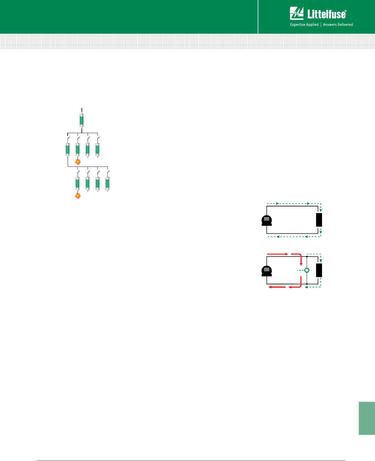
201 littelfuse.com © 2014 Littelfuse POWR-GARD® Products Catalog
11
Technical Application Guide
Technical
equipment or short-circuits. For additional information, refer
to the Selective Coordination pages of this Technical
Application Guide.
Figure 15 – Selective Coordination Example
Semiconductor Fuse – A fuse specifically designed to protect
semiconductors such as silicon rectifiers, silicon-controlled
rectifiers, thyristors, transistors, and similar components.
Sensitive Ground-Fault Protection – Protection designed
to accurately detect extremely low ground-fault current levels
without nuisance tripping.
Shock – A trauma subjected to the body by electrical current.
When personnel come in contact with energized conductors,
it can result in current flowing through their body often causing
serious injury or death.
Short-Circuit (See Figure 16) – A current flowing outside its
normal path, caused by a breakdown of insulation or by faulty
equipment connections. In a short-circuit, current bypasses the
normal load. Current is determined by the system impedance
(AC resistance) rather than the load impedance. Short-circuit
currents may vary from fractions of an ampere to 200,000
amperes or more.
Short-Circuit Current Rating (SCCR) – The prospective
symmetrical fault current at a nominal voltage to which an
apparatus or system is able to be connected without sustaining
damage exceeding defined acceptance criteria.
Short-Circuit Rating – The maximum RMS symmetrical short-
circuit current at which a given piece of equipment has been
tested under specified conditions, and which, at the end of the
test is in essentially the same condition as prior to the test.
Short-circuit ratings (also called withstand ratings) apply to
equipment that will be subjected to fault currents, but which
are not required to interrupt them. This includes switches,
busway (bus duct), switchgear and switchboard structures,
motor control centers and transformers.
Most short-circuit ratings are based on tests which last three
complete electrical cycles (0.05 seconds). However, if the
equipment is protected during the test by fuses or by a circuit
breaker with instantaneous trips, the test duration is the time
required for the overcurrent protective device to open
the circuit.
When protected as such during testing, the equipment
instructions and labels must indicate that the equipment
shall be protected by a given fuse class and rating or by a
specific make, type, and rating of circuit breaker. Circuit
breakers equipped with short-delay trip elements instead of
instantaneous trip elements have withstand (short-circuit)
ratings in addition to their interrupting rating. The breaker must
be able to withstand the available fault current during the time
that opening is delayed.
Solidly Grounded System – An electrical system in which
the neutral point of a wye connected supply transformer is
connected directly to ground.
Symmetrical Current – The terms “Symmetrical Current”
and “Asymmetrical Current” describe an AC wave symmetry
around the zero axis. The current is symmetrical when the
peak currents above and below the zero axis are equal in value,
as shown in Figure 17 (next page). If the peak currents are
not equal, as shown in Figure 18, the current is considered
asymmetrical. The degree of asymmetry during a fault is
determined by the change in power factor (X/R) and the point in
the voltage wave when the fault occurs. See definition of Power
Factor. In general, lower short-circuit power factors increase the
degree of asymmetry.
TERMS AND DEFINITIONS
In a selective system:
For a fault at "X" only fuse "C" will open.
For a fault at "Y" only fuse "F" will open.
X
B C D E
A
F G H J
YCURRENT FLOW
GEN.
LOAD
Accidental
connection
creates fault
GEN.
LOAD
In a "normal" circuit,
current is determined by
load IMPEDANCE
(Heavy lines indicate
increased current)
In a short-circuit, current is limited
only by impedance of fault path.
Current may increase to many times
load current.
Figure 16 – Current Flow in Normal and Short Circuit Situations
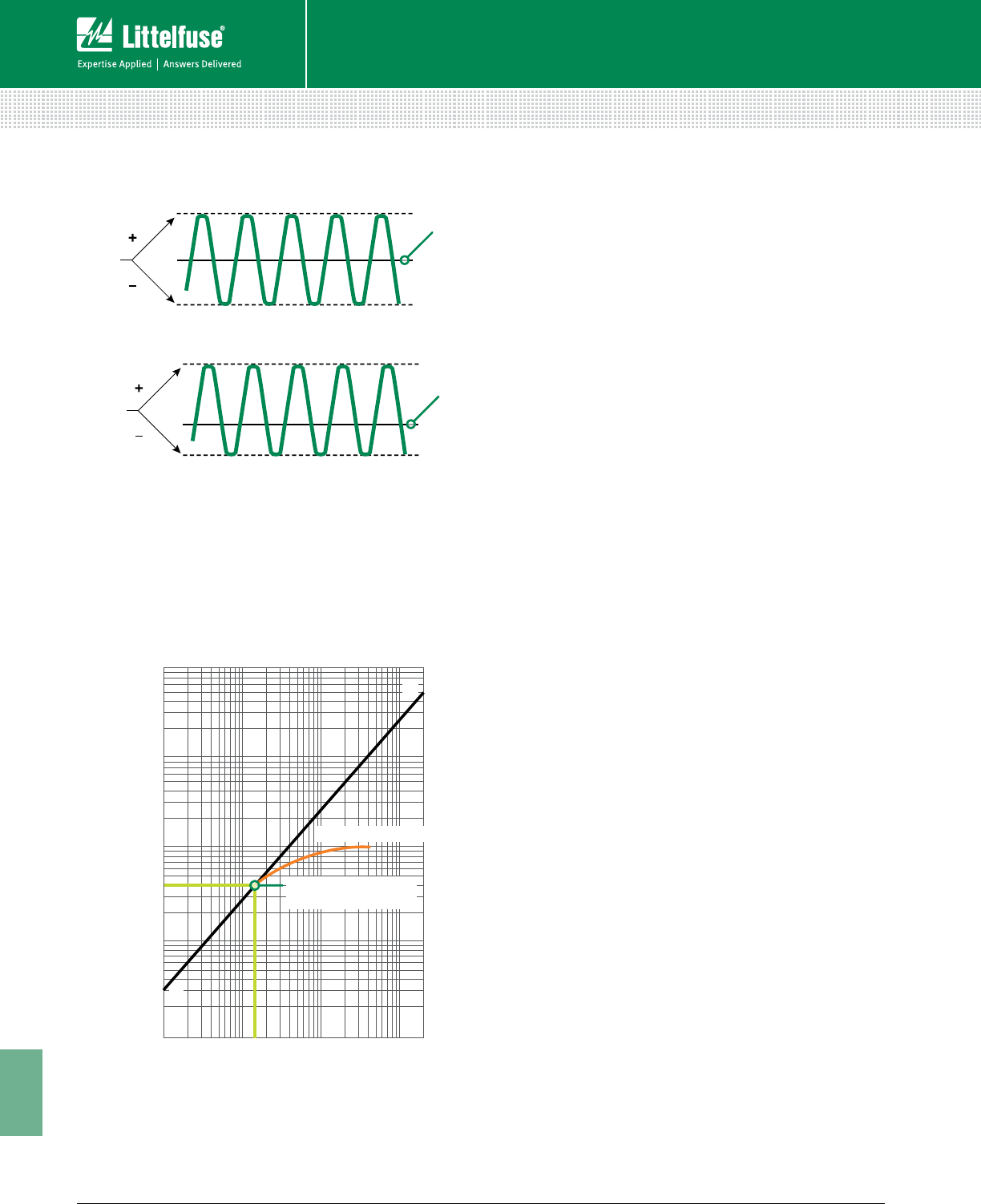
202 © 2014 Littelfuse POWR-GARD® Products Cataloglittelfuse.com
11
Technical Application Guide
Technical
Figure 17 – Symmetrical Current
Figure 18 – Asymmetrical Current
Threshold Current – The minimum current for a given fuse
size and type at which the fuse becomes current-limiting. It is
the lowest value of available rms symmetrical current that will
cause the device to begin opening within the first 1/4 cycle (90
electrical degrees) and completely clear the circuit within 1/2
cycle (180 electrical degrees). The approximate threshold current
can be determined from the fuse’s peak let-through charts.
(See Figure 19.)
Threshold Ratio – Consists of the threshold current divided
by the ampere rating of a specific type or class of overcurrent
device. A fuse with a threshold ratio of 15 becomes current-
limiting at 15 times its current rating.
Time-Delay Fuse – Fuses designed with an intentional, built-in
delay in opening. When compared to fast-opening fuses, time-
delay fuses have an increased opening time for overcurrents
between approximately 200% and 600% of the fuse’s current
rating. Time-delay is indicated on the fuse label by “Time-Delay”,
“T-D”, “D”, or other suitable marking. Time-delay in the overload
range (200%-600% of the fuse rating) permits the fuse to
withstand system switching surges, motor starting currents, and
other harmless temporary overcurrents.
UL Standards require time-delay Class H, K, RK1, RK5, and J
fuses to hold 500% of their normal current rating for a minimum
of 10 seconds. They must also pass the same opening time
tests (135% and 200% of current rating) as fast acting fuses.
Time-delay Class CC, CD, G, Plug, and Miscellaneous fuses
have different requirements. For more information, please
refer to the corresponding descriptions provided in the Product
Information Section.
For the UL Standard, Class L fuses have no standard time-
delay. The time-delay varies from series to series for a given
manufacturer, as well as from manufacturer to manufacturer. For
reference, Littelfuse KLPC series POWR-PRO® fuses hold 500%
of rated current for a minimum of 10 seconds.
Ungrounded System – An electrical system in which no point
in the system is intentionally grounded. This was most common
in process industries where continuity of service during a single-
phase-to-ground-fault was required.
Unqualified Person – A person that does not possess
all the skills and knowledge or has not been trained for a
particular task.
Voltage Rating – The maximum rms AC voltage and/or the
maximum DC voltage at which the fuse is designed to operate.
For example, fuses rated 600 volts and below may be applied
at any voltage less than their rating. There is no rule for applying
AC fuses in DC circuits such as applying the fuse at half its AC
voltage rating. Fuses used on DC circuits must have DC ratings.
Withstand Rating – See Short-Circuit.
TERMS AND DEFINITIONS
Equal
Peaks
Symmertrical Current
Zero Axis
Unequal
Peaks
Asymmertrical Current
Zero Axis
Equal
Peaks
Symmertrical Current
Zero Axis
Unequal
Peaks
Asymmertrical Current
Zero Axis
1000
4000
A
B
Fuse approximate
threshold current = 4000A
Peak let-through current
Available Fault Current Symmetrical RMS Amperes
Peak Let-Through in Amperes
Figure 19 – Determining Threshold Current from Peak
Let-through Chart
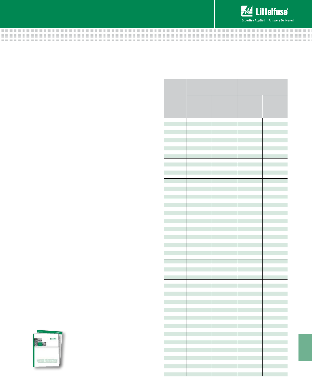
203 littelfuse.com © 2014 Littelfuse POWR-GARD® Products Catalog
11
Technical Application Guide
Technical
Using AC Motor Protection Tables to Select
Fuse Ratings
Time-delay RK1 and RK5 fuse ratings selected in
accordance with the following recommendations also
meet NEC® requirements for Motor Branch circuit and
Short-Circuit Protection.
Selecting Fuses for Motor Running Protection
Based on Motor Horsepower
Motor horsepower and motor Full Load Amperes (FLA)
shown are taken from NEC® Tables 430.248 through
430.250 covering standard speed AC motors with normal
torque characteristics. Fuse ratings for motors with special
characteristics may need to vary from given values.
If motor running protection will be provided by the
fuses, select fuse ratings for correct type of motor
from Motor Protection Table Columns headed,
“Without Overload Relays.”
If overload relays will provide principal motor running
protection, select fuse ratings for correct type of motor
from Motor Protection Table Columns headed, “Back-up
Running Protection” or “With Overload Relays.” Fuse ratings
selected from these columns coordinate with most UL
Class 10 and 20 overload relays which covers over 90%
of motor applications.
Selecting Fuses for Motor Running Protection
Based on Motor Actual Full Load Currents
Better protection is achieved when fuse ratings are based on
motor actual FLA obtained from motor nameplates. Locate
motor nameplate FLA in the column appropriate for the
type of motor and type of protection required. Then select
the corresponding ampere rating of the fuse from the first
column of that line.
MOTOR PROTECTION TABLES
TIME DEL AY
UL CLASS RK1
OR RK5 FUSE
AMPERE RATING
MOTOR RUNNING PROTECTION
(USED WITHOUT PROPERLY SIZED
OVERLOAD RELAYS)
MOTOR FULL-LOAD AMPS
BACK-UP MOTOR RUNNING
PROTECTION (USED WITH PROPERLY
SIZED OVERLOAD RELAYS)
MOTOR FULL-LOAD AMPS
MOTOR SERVICE
FACTOR OF 1.15 OR
GREATER OR WITH
TEMP. RISE NOT
OVER 40°C.
MOTOR SERVICE
FACTOR LESS
THAN 1.15 OR
WITH TEMP. RISE
GREATER
THAN 40°C.
MOTOR SERVICE
FACTOR OF 1.15 OR
GREATER OR WITH
TEMP. RISE NOT
OVER 40°C.
MOTOR SERVICE
FACTOR LESS
THAN 1.15 OR
WITH TEMP. RISE
GREATER
THAN 40°C
1⁄10 0.08-0.09 0.09-0.10 0-0.08 0-0.09
1⁄80.10-0.11 0.11-0.125 0.09-0.10 0.10- 0.11
15 ⁄100 0.12-0.15 0.14- 0.15 0.11-0.12 0.12-0.13
2⁄10 0.16-0.19 0.18-0.20 0.13-0.16 0.14-0.17
1⁄40.20-0.23 0.22-0.25 0.17-0.20 0.18-0.22
3⁄10 0.24-0.30 0.27-0.30 0.21-0.24 0.23-0.26
4⁄10 0.32-0.39 0.35-0.40 0.25-0.32 0.27-0.35
1⁄20.40-0.47 0.44-0.50 0.33-0.40 0.36-0.43
6⁄10 0.48-0.60 0.53-0.60 0.41-0.48 0.44-0.52
8⁄10 0.64-0.79 0.70-0.80 0.49-0.64 0.53-0.70
10.80-0.89 0.87-0.97 0.65-0.80 0.71-0.87
11⁄80.90-0.99 0.98-1.08 0.81-0.90 0.88-0.98
11⁄41.00-1.11 1.09-1.21 0.91-1.00 0.99-1.09
14⁄10 1.12-1.19 1.22-1.30 1.01-1.12 1.10-1.22
11⁄21.20-1.27 1.31-1.39 1.13-1.20 1.23-1.30
16⁄10 1.28-1.43 1.40-1.56 1.21-1.28 1.31-1.39
18⁄10 1.44-1.59 1.57-1.73 1.29-1.44 1.40-1.57
21.60-1.79 1.74-1.95 1.45-1.60 1.58-1.74
21⁄41.80-1.99 1.9 6-2.17 1.61-1.80 1.75-1.96
21⁄22.00-2.23 2.18-2.43 1.81-2.00 1.97-2.17
28⁄10 2.24-2.39 2.44-2.60 2.01-2.24 2.18-2.43
32.40-2.55 2.61-2.78 2.25-2.40 2.44-2.60
32⁄10 2.56-2.79 2.79-3.04 2.41-2.56 2.61-2.78
31⁄22.80 -3.19 3.05-3.47 2.57-2.80 2.79-3.04
43.20-3.59 3.48-3.91 2.81-3.20 3.05-3.48
41⁄23.60-3.99 3.92-4.34 3.21-3.60 3.49-3.91
54.00-4.47 4.35-4.86 3.61-4.00 3.92-4.35
56⁄10 4.48-4.79 4.87-5.21 4.01-4.48 4.36-4.87
64.80-4.99 5.22-5.43 4.49-4.80 4.88-5.22
61⁄45.00-5.59 5.44-6.08 4.81-5.00 5.23-5.43
75.60-5.99 6.09-6.52 5.01-5.60 5.44-6.09
71⁄26.00-6.39 6.53-6.95 5.61-6.00 6.10-6.52
86.40 -7.19 6.96-7.82 6.01-6.40 6.53-6.96
97.2 0 -7.99 7.83-8.69 6.41-7.2 0 6.97-7.83
10 8.00-9.59 8.70-10.00 7.21-8.00 7.84-8.70
12 9.60-11.99 10.44-12.00 8.01-9.60 8.71-10.43
15 12.00-13.99 13.05-15.00 9.61-12.00 10.4 4-13.04
171⁄214.00-15.99 15.22-17.39 12.01-14.00 13.05- 15.21
20 16.00-19.99 17.4 0-2 0.0 0 14.01-16.00 15.22-17.39
25 20.00-23.99 21.74-25.00 16.01-20.00 17.4 0 -21.74
30 24.00 -2 7.99 26.09-30.00 20.01-24.00 21.75-26.09
35 28.00-31.99 30.44-34.78 24.01-28.00 26.10-30.43
40 32.00-35.99 34.79-39.12 28.01-32.00 3 0.4 4- 37.78
45 36.00-39.99 39.13-4 3.47 32.01-36.00 37.79 -39.13
50 40.00-47.99 43.48-50.00 36.01-40.00 39.14-4 3.48
60 48.00-55.99 52.17-60.0 0 40.01-48.00 43.49-52.17
70 56.00-59.99 60.87-65.21 48.01-56.00 52.18-60.87
75 60.00-63.99 65.22-69.56 56.01-60.00 60.88-65.22
80 64.00-71.99 69.57-78.25 60.01-64.00 65.23-69.57
90 72.00-79.99 78.26-86.95 64.01-72.00 69.58-78.26
100 80.00-87.99 86.96-95.64 72.01-80.00 78.27-86.96
110 88.00-99.99 95.65-108.69 80.01-88.00 86.97-95.65
125 100.00-119.99 108.70-125.00 88.01-100.00 95.66-108.70
150 120.00-139.99 131.30-150.00 100.01-120.00 108.71-130.43
175 140.00-159.99 152.17-173.90 120.01-140.00 130.44-152.17
200 160.00-179.99 173.91-195.64 140.01-160.00 152.18-173.91
225 180.00-199.99 195.65-217.38 160.01-180.00 173.92-195.62
250 200.00-239.99 217.39-250.00 180.01-200.00 195.63-217.39
300 240.00-279.99 260.87-300.00 200.01-240.00 217.40-260.87
350 280.00-319.99 304.35-347.82 240.01-280.00 260.88-304.35
400 320.00-359.99 3 47.83-3 91.29 280.01-320.00 304.36-347.83
450 360.00-399.99 391.30-434.77 320.01-360.00 347.84-391.3 0
500 400.00-479.99 434.78-500.00 360.01-400.00 391.31-434.78
600 480.00-600.00 521.74-600.00 400.01-480.00 434.79-521.74
Selection of Class RK5 Fuses (FLNR_ID / FLSR_ID / IDSR Series) or POWR-PRO® Class
RK1 Fuses (LLNRK / LLSRK / LLSRK_ID Series) Based on Motor Full Load Amps
Motor Protection
White Paper
Download our white paper
on motor protection at
littelfuse.com/technicalcenter
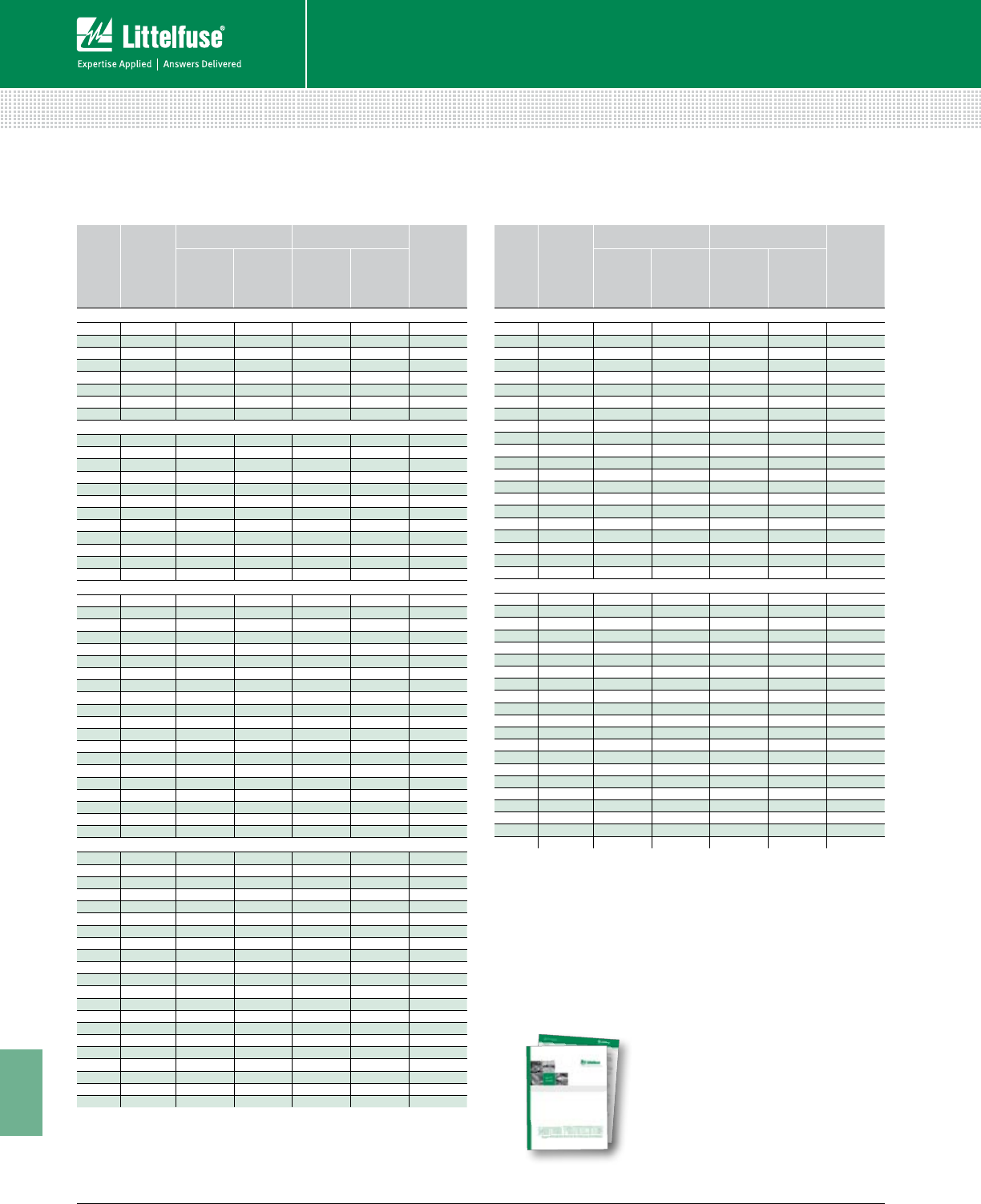
204 © 2014 Littelfuse POWR-GARD® Products Cataloglittelfuse.com
11
Technical Application Guide
Technical
MOTOR PROTECTION TABLES
MOTOR
HP
FULL LOAD
AMPS
WITHOUT OVERLOAD
RELAYS WITH OVERLOAD RELAYS
SWITCH OR
FUSE CLIP
RATING
S.F. = 1.15 OR
MORE, TEMP
RISE NOT
OVER 40
°
C
S.F. = LESS
THAN 1.15 OR
TEMP RISE
MORE THAN
40
°
C
S.F. = 1.15 OR
MORE, TEMP
RISE NOT
OVER 40
°
C
S.F. = LESS
THAN 1.15 OR
TEMP RISE
MORE THAN
40
°
C
460 VOLT 3-PHASE MOTORS (480V CIRCUIT)
1⁄21.1 14⁄10 11⁄414⁄10 14⁄10 30
3⁄41.6 2 18⁄10 2 2 30
12.1 21⁄221⁄428⁄10 21⁄230
11⁄23.0 31⁄232⁄10 4 31⁄230
23.4 4 31⁄241⁄24 30
34.8 56⁄10 5 6 56⁄10 30
57.6 9 8 10 9 30
71⁄211 12 12 15 15 30
10 14 171⁄215 171⁄2171⁄230
15 21 25 20 30 25 30
20 27 30* 30* 35 35 60
25 34 40 35 45 40 60
30 40 50 45 50 50 60
40 54 60* 60* 70 60* 100
50 65 80 70 90 75 100
60 77 90 80 100 90 100
75 96 110 110 125 125 200
100 124 150 125 175 150 200
125 156 175 175 200 200 200
150 180 225 200* 225 225 400
200 240 300 250 300 300 400
575 VOLT 3-PHASE MOTORS (600V CIRCUIT)
1⁄20.9 11⁄81 11⁄811⁄830
3⁄41.3 16⁄10 14⁄10 16⁄10 16⁄10 30
11.7 2 18⁄10 21⁄42 30
11⁄22.4 3 21⁄23 3 30
22.7 32⁄10 28⁄10 31⁄232⁄10 30
33.9 41⁄24 5 41⁄230
56.1 71⁄27 8 71⁄230
71⁄2910 10 12 12 30
10 11 12 12 15 15 30
15 17 20 171⁄225 20 30
20 22 25 25 30 30 30
25 27 30* 30* 35 35 60
30 32 40 35 40 40 60
40 41 50 45 60 50 60
50 52 60 60 70† 60 60
60 62 75 70 80 75 100
75 77 90 80 100 90 100
100 99 110 110 125 125 200
125 125 150 125 175 150 200
150 144 175 150 200 175 200
200 192 225 200* 250 225 400
NOTES
S.F. = Motor Service Factor
* Fuse Reducers Required
† 100 Amp Switch Required
MOTOR
HP
FULL LOAD
AMPS
WITHOUT OVERLOAD
RELAYS WITH OVERLOAD RELAYS
SWITCH OR
FUSE CLIP
RATING
S.F. = 1.15 OR
MORE, TEMP
RISE NOT
OVER 40
°
C
S.F. = LESS
THAN 1.15 OR
TEMP RISE
MORE THAN
40
°
C
S.F. = 1.15 OR
MORE, TEMP
RISE NOT
OVER 40
°
C
S.F. = LESS
THAN 1.15 OR
TEMP RISE
MORE THAN
40
°
C
120 VOLT 1-PHASE MOTORS (120V CIRCUIT)
1⁄64.4 5 5 56⁄10 56⁄10 30
1⁄45.8 7 61⁄471⁄27 30
1⁄37.2 9 8 9 9 30
1⁄29.8 12 10 15 12 30
3⁄413.8 15 15 171⁄2171⁄230
116 20 171⁄220 20 30
11⁄220 25 20 25 25 30
224 30 25 30 30 30
230 VOLT 1-PHASE MOTORS (240V CIRCUIT)
1⁄62.2 21⁄221⁄228⁄10 28⁄10 30
1⁄42.9 31⁄232⁄10 4 31⁄230
1⁄33.6 41⁄24 41⁄241⁄230
1⁄24.9 56⁄10 56⁄10 61⁄46 30
3⁄46.9 8 71⁄29 8 30
1 8 10 910 10 30
11⁄210 12 10 15 12 30
212 15 12 15 15 30
317 20 171⁄225 20 30
528 35 30* 35 35 60
71⁄240 50 45 50 50 60
10 50 60 50 70 60 60
200 VOLT 3-PHASE MOTORS (208V CIRCUIT)
1⁄22.5 3 28⁄10 32⁄10 3 30
3⁄43.7 41⁄24 5 41⁄230
14.8 6 56⁄10 61⁄46 30
11⁄26.9 8 71⁄271⁄28 30
27.8 9 8 10 9 30
311 12 12 15 15 30
517.5 20 20 25 25 30
71⁄225.3 30* 25* 35 30* 60
10 32.2 40 35 45 40 60
15 48.3 60 50 70† 60 60
20 62.1 75 70 80 75 100
25 78.2 90 80 100 90 100
30 92 110 100* 125 110 200
40 120 150 125 150 150 200
50 150 175 150 200 175 200
60 177 200* 200* 225 225 400
75 221 250 250 300 300 400
100 285 350 300 400 350 400
125 359 400* 400* 450 450 600
150 414 500 450 600 500 600
230 VOLT 3-PHASE MOTORS (240V CIRCUIT)
1⁄22.2 28⁄10 21⁄228⁄10 28⁄10 30
3⁄43.2 4 31⁄24 4 30
14.2 5 41⁄256⁄10 5 30
11⁄26.0 71⁄261⁄471⁄271⁄230
26.8 8 71⁄29 8 30
39.6 12 10 12 12 30
515.2 171⁄2171⁄220 171⁄230
71⁄222 25 25 30 30 30
10 28 35 30* 35 35 60
15 42 50 45 60 50 60
20 54 60* 60* 70 70 100
25 68 80 75 90 80 100
30 80 100 90 100 100 100
40 104 125 110 150 125 200
50 130 150 150 175 150 200
60 154 175 175 200 200 200
75 192 225 200* 250 225 400
100 248 300 250 350 300 400
125 312 350 350 400 400 400
150 360 450 400* 450 450 600
200 480 600 500 600 600 600
Selection of Class RK5 Fuses (FLNR_ID / FLSR_ID / IDSR Series) or POWR-PRO® Class
RK1 Fuses (LLNRK / LLSRK / LLSRK_ID Series) Based on Motor Horsepower
Motor Protection
White Paper
Download our white paper
on motor protection at
littelfuse.com/technicalcenter
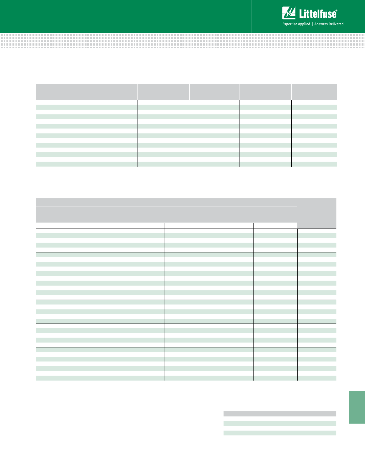
205 littelfuse.com © 2014 Littelfuse POWR-GARD® Products Catalog
11
Technical Application Guide
Technical
MOTOR PROTECTION TABLES
MOTOR F.L.A. JTD_ID / JTD
AMPERE RATING MOTOR F.L.A. JTD_ID / JTD
AMPERE RATING MOTOR F.L.A. JTD_ID / JTD
AMPERE RATING
0.00 – 0.60 8⁄10 12.1 – 14.5 17 1/276.1 – 84.0 110
0.61 – 0.80 114.6 – 17.0 20 84.1 – 90.0 125
0.81 – 1.00 11⁄417.1 – 21.0 25 90.1 – 102 150
1.01 – 1.20 11⁄221.1 – 25.0 30 103 – 125 175
1.21 – 1.65 225.1 – 28.5 35 126 – 144 200
1.66 – 2.00 21⁄228.6 – 34.0 40 145 – 162 225
2.01 – 2.40 334.1 – 37.0 45 163 – 180 250
2.41 – 3.30 437.1 – 41.0 50 181 – 204 300
3.31 – 4.10 541.1 – 48.0 60 205 – 240 350
4.11 – 4.90 648.1 – 52.0 70 241 – 288 400
4.91 – 6.40 852.1 – 59.0 80 289 – 312 450
6.41 – 8.00 10 59.1 – 66.0 90 313 – 360 500
8.01 – 9.80 12 66.1 – 76.0 100 361 – 432 600
9.81 – 12.0 15
NOTE: For severe motor starting conditions, fuses may be sized up to 225% motor F.L.A. (See NEC® Article 430.52 for Exceptions)
MOTOR FULL LOAD CURRENT (F.L.A.)
CCMR
AMPERE RATING
FOR MOTORS WITH AN ACCELERATION
TIME OF 2 SECONDS OR LESS
FOR MOTORS WITH AN ACCELERATION
TIME OF 5 SECONDS OR LESS
FOR MOTORS WITH AN ACCELERATION
TIME OF 8 SECONDS OR LESS
MIN. F.L.A. (1) MAX F.L.A. (3) MIN. F.L.A. (1) MAX F.L.A. (3) MIN F.L.A. (2) MAX F.L.A. (3)
0.2 0.2 0.2 0.2 0.2 0.2 3⁄10
0.3 0.4 0.3 0.4 0.3 0.3 1⁄2
0.4 0.6 0.4 0.5 0.4 0.5 8⁄10
0.5 0.7 0.5 0.6 0.5 0.6 1
0.6 1.0 0.6 0.9 0.6 0.8 11⁄4
0.8 1.1 0.8 1.0 0.7 0.9 11⁄2
0.9 1.3 0.9 1.1 0.8 1.0 18⁄10
1.1 1.4 1.1 1.2 0.9 1.1 2
1.2 2.1 1.2 2.1 1.2 1.8 21⁄2
1.5 2.6 1.5 2.6 1.4 2.3 3
1.8 3.0 1.8 3.0 1.6 2.6 31⁄2
2.1 3.4 2.1 3.2 1.8 2.8 4
2.3 3.9 2.3 3.3 2.0 2.8 41⁄2
2.6 4.3 2.6 3.4 2.3 2.8 5
2.9 4.8 2.9 3.7 2.5 3.1 56⁄10
3.3 5.2 3.3 4.0 2.7 3.4 6
3.5 5.4 3.5 4.1 2.8 3.5 61⁄4
3.6 5.7 3.6 4.2 3.2 3.7 7
4.1 5.8 4.1 4.3 3.4 3.8 71⁄2
4.3 6.2 4.3 4.6 3.6 4.2 8
4.6 6.9 4.6 5.2 4.0 4.5 9
5.2 7.7 5.2 5.8 4.5 4.9 10
5.8 8.9 5.8 6.6 5.4 5.5 12
6.9 10.0 6.9 7.7 6.7 6.7 15
8.9 13.5 8.9 10.0 6.8 9.0 20
11.5 15.8 11.2 (2) 11.8 9.0 11.0 25
14.3 17.8 13.4 (2) 13.4 10.0 15.0 30
20.7 23.3 16.1 17.9 15.6 15.9 35
23.7 26.7 18.4 20.5 17.8 18.2 40
26.6 30.0 20.7 23.1 20.0 20.4 45
30.0 33.3 23.0 25.6 22.3 22.7 50
35.5 40.0 27.6 30.1 26.7 27.3 60
1 Based on NEC® requirement limiting the rating of time-delay fuses to 175% of motor
F.L.A., or next higher rating.
2 Based on NEC® exception permitting fuse rating to be increased, but not to exceed,
225% motor F.L.A., however per NEC® Article 430.52 Class CC (0-30) fuses can now be
sized up to 400% of motor F.L.A.
3 Based on Littelfuse CCMR time-delay characteristics.
NOTE: These values were calculated for motors with Locked Rotor
Current (LRA), not exceeding the following values:
MOTOR F.L.A. *LRA
0.00 – 1.00 850%
1.01 – 2.00 750%
2.01 – 10.0 650%
10.1 – 17.8 600%
*If motor LRA varies from these values, contact Littelfuse.
Selection of POWR-PRO® Class J Fuses (JTD_ID / JTD Series)
Based on Motor Full Load Amps
Selection of CCMR Time-Delay Fuses Based on Motor Full Load Amps

206 © 2014 Littelfuse POWR-GARD® Products Cataloglittelfuse.com
11
Technical Application Guide
Technical
ALPHANUMERIC INDEX
Product Name Page Number
97023 115
150322 131
1LFS, 1LS Series 121
215 Series 35
216 Series 35
217 Series 35
218 Series 35
224 Series 34
225 Series 34
229 Series 34
230 Series 34
235 Series 35
239 Series 35
251 Series 33
273 Series 33
287 Series 36
297 Series 36
299 Series 36
312 Series 34
313 Series 34
314 Series 34
315 Series 34
318 Series 34
324 Series 34
325 Series 34
326 Series 34
342 Series 118
345 Series 119
354 Series 114
451 Series 33
477 Series 33
481 Series 53
505 Series 33
571 Series 117
572 Series 117
70 Series 53
Alarm Monitoring 168
Arc-Flash 157
ATO Series 36
BLF Series 30
BLN Series 30
BLS Series 31
Box Cover Units 179
Bus Bar Series 112
BVSP Series 176
C6200 166
Cable Limiters 65
CCMR Series 27
Class CC 27
Class CD 27
Class G 26
Class J 21
Class K5 20
Class L 8
Product Name Page Number
Class RK1 13
Class RK5 16
Class T 24
CNL Series 62
CNN / CNN_E Series 62
Coordination Panels 138
Cylindrical Fuses 66
D0900 157
Definitions 198
Displays 181
Distribution Blocks 122
E-Rated Fuses 42
E5000 167
E7800 164
EL731 150
Electronic Fuses 32
Engine Controls/Diagnosis 167
EngineEye 167
FBDIN1 104
Feeder Protection 156
FLA Series 31
FlexGen 166
FLM Series 30
FLNR Series 17
FLNR_ID Series 17
FLQ Series 30
FLSR Series 17
FLSR_ID Series 17
FLU Series 31
Fork-Lift Fuses 62
FPS 156
FPU-32 156
FRCK Series 180
Fuse Blocks, Fuse Holders 82
Fuse Classifications 194
Fuse Reducers 178
Fuseology 183
G2000 158
G3000 158
G3300 159
GDB Series 128
Generator Protection/Control 158
GFP 115
Ground-Fault Protection 143
H4000 169
HAZGARD™ 62
IDSR Series 16
In-Line Fuse Holders 131
Industrial Shock-Block 157
JCASE Series 37
JLLN Series 24
JLLS Series 24
JLS Series 22
JTD/JTD_ID Series 21
Product Name Page Number
KLC Series 69
KLDR Series 28
KLK Series 30
KLKD Series 30
KLKR Series 28
KLLU Series 9
KLNR Series 15
KLPC Series 8
KLQ Series 31
KLSR Series 15
L15S Series 69
L17T Series 50
L25S Series 69
L50S Series 69
L60030C, L60030M Series 101
L60030MPCB 103
L60S Series 69
L70S Series 69
LA100P Series 76
LA15QS Series 71
LA30QS Series 72
LA50QS Series 73
LA60Q Series 74
LA70QS Series 75
LA70QSF Series 74
LAxxxURD Series 77
LCC Series 115
LCP Series 139
LD Series 122
LDC Series 10
LEB Series 132
LEC Series 132
LET Series 132
LEX Series 132
LEX YY Series 136
LEXT YY Series 136
LEY Series 132
LF Series Covers 105
LFC600 101
LFCL Series 65
LFFB003 116
LFG480, LFG600 Series 99
LFH250, LFH600 Series 88
LFJ 1000V Series 107
LFJ600 Series 85
LFPHV 109
LFPSC 110
LFPSJ 111
LFR250, LFR600 Series 88
LFT300, LFT600 Series 94
LGR Series 64
LHFB 116
LHR Series 64
Live Parts 48

207 littelfuse.com © 2014 Littelfuse POWR-GARD® Products Catalog
11
Technical Application Guide
Technical
Product Name Page Number
LLNRK Series 13
LLSRK/ LLSRK_ID Series 13
LMF Series 64
LPBC Series 122
LPFP 115
LPS 141
LPSM-QC 113
LPXV Series 106
LRU Series 178
LS Series 122
LSCR Series 120
LSCY 179
LSKA 179
LSOU 179
LSOW 179
LSOX 179
LSOY 179
LSOY-B 179
LSRU 179
LSRW 179
LSRX 179
LSRY 179
LSSU 179
LSSW 179
LSSX 179
LSSY 179
LSTY 179
LTFD Series 54
LVSP Series 175
M1000 168
M2000 167
M2500 167
M3000 168
M4200 168
M4500 169
M4600 169
M4700 169
M8100 165
MAXI Series 36
Medium Voltage 39
MEGA Series 63
MFP 115
Midget Fuses 30
MINI Series 36
Motor Protection 154
MOV 174
MPS 155
MPU-32 155
MROplus 3
NLKP Series 20
NLN Series 20
NLS Series 20
OEM Products 67
Overvoltage Suppression 173
Product Name Page Number
Panel Mount Adapters 171
PGN-1000 153
PGN-3000 153
PGR-3100 148
PGR-3200 148
PGR-4300 158
PGR-6100 154
PGR-6130 154
PGR-6150 154
PGR-6800 156
PGR-8800 157
Plug Fuses 63
Potential Transformer 47
POWR-PRO® Fuses 3
Pre-Engineered Solutions 138
Protection Relays 143
Pump Protection 156
R-Rated Fuses 40
Resistance Grounding 151
S6000 166
SB6100 157
SE-105 151
SE-107 151
SE-134C 151
SE-145 151
SE-325 152
SE-330 152
SE-330AU 152
SE-502 153
SE-601 148
SE-701 149
SE-703 149
SE-704 149
Semiconductor Fuses 68
Sigma 166
SLC Series 26
Solar Fuses 56
SPF Series 60
SPFI Series 59
SPFJ Series 61
SPL001 104
Splicer Blocks 122
SPXI Series 58
SPXV Series 57
Stud-Mounted Fuse Blocks 120
Suppression Products 172
T2000 158
T2100 159
T2200 160
T2300 160
T2400 160
T2500 161
T2600 163
T2700 161
Product Name Page Number
T2800 150
T2900 161
T3000 162
T3100 162
T3200 150
T3300 162
T4500 163
T4800 163
T4900 164
T5000 164
T7900 165
T8400 165
Technical Information 182
Telecom Fuses 49
TLN Series 51
TLO Series 63
TLS Series 52
TMOV 174
TOO Series 63
Trailing Cable Protection 148
Varistors 174
WPB Series 133
ALPHANUMERIC INDEX

208 © 2014 Littelfuse POWR-GARD® Products Cataloglittelfuse.com
11
Technical
Technical Application Guide
CONDENSED CROSS REFERENCE
Power (Electrical) and Electronic Fuses
This cross reference covers the most popular fuses for which there is a similar Littelfuse standard item. Furnished for your
convenience, it is meant to serve as a guide only for product selection. We suggest you check all applicable specifications before
making substitutions. For special applications, more complete information, and for fuse block and medium voltage fuse cross
referencing, visit littelfuse.com or call 1-800-TEC-FUSE (1-800-832-3873).
COMPETITION LITTELFUSE COMPETITION LITTELFUSE COMPETITION LITTELFUSE COMPETITION LITTELFUSE
10KOTN NLN CNQ FLQ KBH L50S NRN NLN
10KOTS NLS CRN-R FLNR_ID3KLM KLKD NRN (15-60A) NLKP
50KOTN NLN CRS-R FLSR_ID KLMR CCMR NRS NLS
50KOTS NLS CSF13X L15S KLU KLLU or KLPC OT NLN
A251 CSF25X L25S (AC only) KN KLNR OTM BLF or BLN
A013F L15S CSF50P L50S KON NLN OTN NLN
A015F L15S CSF60C KLC (AC only) KOS NLS OTS NLS
A015R L15S CSF60X L60S (AC only) KRPC (SP) KLPC REN FLNR or LLNRK5
A025F L25S CSF70P L70S KRPC-L KLPC RES FLSR or LLSRK5
A050F L50S CTN-R KLNR KS KLSR RF FLNR or LLNRK5
A060F L60S CTS-R KLSR KTK KLK RFA L15S
A060URL KLK EBS BLS KTKR KLKR RFC KLC
A070F L70S ECNR FLNR_ID3KTNR KLNR RFL (750V) L70S (700 V)
A13X L15S ECSR FLSR_ID KTSR KLSR RFN (Ferraz) FLNR or LLNRK5
A25X L25S (AC only) ELN FLNR or LLNRK5KTU KLPC or LDC RFS (Ferraz) FLSR or LLSRK5
A2D-R LLNRK ELS FLSR or LLSRK5LKLLU or KLPC RFV L50S
A2K-R KLNR ERN FLNR or LLNRK5LCL KLPC or KLLU RHN KLNR
A3T JLLN ERS FLSR or LLSRK5LCU KLPC or KLLU RHS KLSR
A4BQ KLPC FNA FLA LENRK LLNRK RLN (Ferraz)
FLNR or LLNRK
5
A4BT KLLU or KLPC FNB 235 LESRK LLSRK_ID RLS (Ferraz) FLSR or LLSRK5
A4BY KLPC or KLLU FNM FLM LKN FLNR or LLNRK5SSOO
A4J JLS FNQ FLQ LKS FLSR or LLSRK5SA SAO
A50P (type 1 & 4) L50S FNQ-R KLDR LKU KLLU SC SLC
A60X L60S FRN-R FLNR_ID3LONRK LLNRK SCLR KLSR
A6D-R LLSRK_ID4FRS-R FLSR_ID LOSRK LLSRK_ID SEC SLC
A6K-R KLSR FWA2L15S LPCC CCMR SF13X L15S
A6T JLLS FWH2L50S LPJ (SP) JTD_ID SF25X L25S
A70P L70S FWP1L70S LPNRK (SP) LLNRK SF50P L50S
ACK CCK FWX1L25S LPSRK (SP) LLSRK_ID4SF60X L60S
AG SLC GDA 216 MCL KLK SF70P L70S
AGA AGA GDB 217 MDA 326 SFE SFE
AGC 312 GDC 218 MDL 313 SL SLO
AGU (1-30A) BLN GDL 313 MDQ 313 TTOO
AGW AGW GEB LEB MDV 315 TJN JLLN
AJT JTD_ID GEBN LET MDX 313 TJS JLLS
ANL CNL GFA 251 MEN FLM TL TLO
ANN CNN GFN FLA MEQ FLQ TR FLNR_ID3
ATC ATO (257) GGC 312 MID FLA TRM FLM
AT-DE FLNR_ID3GGM 235 MOF BLN TRN-R FLNR_ID3
ATDR CCMR GLR LGR MOL BLF TRS FLSR_ID
ATM (Ferraz) KLKD GMT 481 MTH 312 TRS-R FLSR_ID4
ATMR KLKR HCLR KLKR NCLR KLNR XL25X L25S
ATQ FLQ HCTR KLDR NON NLN XL50F L50S1
ATQR KLDR HEB LEB NOS NLS XL70F L70S1
AX 481 HET LET
BAF BLF HLR LHR
BAN BLN JJLS
BBS BLS JDL JTD_ID
CJ JLS JFL JLS
CJS JLS JHC JTD_ID
CLF KLPC or KLLU JJN JLLN
CLL KLLU or KLPC JJS JLLS
CLU KLLU or KLPC JKS JLS
CM BLF KAA L15S
CMF BLN KAB L25S
CNM FLM KAC KLC
1) Check specific mounting dimensions before substituting.
2) Check fuse characteristics and mounting dimensions for specific application before substituting.
3) For
1
/
10
- 30 amperes, order non-indicating FLNR series fuses.
4) Verify voltage for DC applications.
5) Littelfuse has discontinued Class H fuses and recommends upgrading to RK1 or RK5 Class fuses.
A fuse may be used in circuits where the fuse’s voltage rating is equal to or greater than the circuit
voltage, unless otherwise stated on the fuse. For example, the FLSR_ID indicating fuse has a
voltage rating of 75-600 volts. This fuse can be used on 600 volts, 480 volts, 250 volts, 125 volts, or
75 volts. Never use a fuse in a circuit having a higher rated voltage than the fuse.

Motor Protection
Effective motor protection is critical in today’s highly
automated industrial facilities. POWR-GARD® fuses
and protection relays provide optimum protection
for motors in main, feeder, and branch circuits.
Medium Voltage Fuse Protection
POWR-GARD medium voltage fuses provide
short-circuit protection for motors and
transformers rated 2,400 to 38,000 Vac.
Transformer Protection
POWR-GARD fuses provide optimal overcurrent
protection for both the primary and secondary of
control transformers and other regular transformers
above and below 600 volts.
SCCR
The NEC® requires Industrial Control Panels be labeled
with their Short-Circuit Current Rating so users and
inspectors can compare their equipment to available
fault currents to avoid potential hazards.
Arc-Flash Protection
Arc-flash protection relays are intelligent controllers
that safeguard equipment and personnel to prevent
damage, downtime or injury due to arc flash.
Overvoltage Suppression Basics
Overvoltage conditions are an increasing concern
in the electrical industry. Littelfuse has a diverse
portfolio of circuit protection technologies to protect
against voltage transients in multiple applications.
Experienced Technical Professionals
For additional questions, call or email
the Littelfuse Technical Support and
Engineering Service Group at
1-800-TEC-FUSE or techline@littelfuse.com.
White Papers and Additional Technical Information
Littelfuse is committed to developing technical resources that help improve electrical safety and product knowledge.
Gain access to Technical Application Guides, White Papers, and a library of information at littelfuse.com/technicalcenter.
Additional Resources
Littelfuse is in the App Store!
Our free Littelfuse Catalogs and Literature
App keeps our products and resources at
your finger tips, wherever you are. Find the
information you need, quickly and easily!
Need more information about
Littelfuse® POWR-GARD® products?
Littelfuse publishes technical resources to help enhance the productivity
and safety of electrical systems. To learn more about a specific product or
application, visit our extensive online library at littelfuse.com
Specifications, descriptions and illustrative material in this literature are as accurate as known at the time of publication,
but are subject to changes without notice. Visit littelfuse.com for the most up-to-date technical information.
©2014 Littelfuse, Inc. Printed in USA.
Form: PF101N
Rev: 5-A-060114
WWW.LITTELFUSE.COM
POWR-GARD® PRODUCTS CATALOG
Protection Relays & Controls Catalog (PF130N)
The comprehensive line of electronic and microprocessor-based protection
relays safeguard equipment and personnel to prevent expensive damage,
downtime or injury due to electrical faults.
POWR-GARD® Solar Catalog (PF140N)
POWR-GARD Solar Products are designed specifically for photovoltaic
applications where issues such as heat, efficiency, longevity and global
standards impact the choices in selecting circuit protection.
SymCom/SSAC Catalogs
SymCom and SSAC are leaders in electronic control and protection for all types
and sizes of motors, pumps, timers and flashers used in many applications.
A Full Line of Catalogs:
nExtended Datasheets
nTime-Current Curves
nPeak Let-Thru Curves
nWhite Papers
nCAD Drawings
n3D Models
nCertifications
nCross References
To view all Littelfuse product catalogs, visit our website at littelfuse.com/Catalogs
Littelfuse Electrical Product Portfolio Includes:
FUSES Industrial
