Product Detail Manual
2014-06-02
: Pdf 105061-Attachment 105061-Attachment 662019 Batch4 unilog
Open the PDF directly: View PDF ![]() .
.
Page Count: 124 [warning: Documents this large are best viewed by clicking the View PDF Link!]

ABB Control Inc. 2.1
AC 1600 – 3/00
Isomax
Gen.
info.
Isomax
Molded case circuit breakers
1Available up to 225A at 480VAC
Derived versions
• Circuit breakers with selective and non-
selective residual current protection
• Switch disconnectors
• Circuit breakers for motor control with
adjustable magnetic release
• Circuit breakers for machine tools
• Circuit breakers for direct current
ABB Isomax versions
• Fixed: all models
• Plug-in: up to S5 400A (IEC)
• Withdrawable: from S3 to
S7 1200A (IEC)
Introduction
ABB Isomax molded case circuit breakers are
modern, innovative units designed after
extensive analysis of the demands of today’s
market. These new units embody all the
experience and advances derived from ABB’s
previous highly successful and acclaimed
range of circuit breakers. ABB Isomax circuit
breakers are designed for the total safety of
both operators and systems. This complete
and versatile series of circuit breakers can
satisfy the most demanding system
specifications.
ABB Isomax circuit breakers are ideal for all
electrical power generation and distribution
applications. The Isomax series maximizes
safety and dependability for all power users.
The new line is particularly suitable for
applications involving special protection
coordination needs and automated control
systems.
ABB Isomax units also satisfy the most
demanding requirements for rated current
and fault current levels.
With the wide range of optional trip functions
total system selectivity can be maximized.
• Continuous currents from 15A to 2500A
• Rated interrupting capacities from 14kA
to 85kA (600VAC UL/CSA)
• Extended working life of all mechanical
and electrical parts for continuity of
operation
• Suitable for isolation applications
• UL/CSA 100% equipment rated versions
Frame sizes — seven basic sizes
The ABB Isomax series inclues seven basic
frame sizes with continuous rated currents
from 15A to 2500A and with 600VAC
interrupting capacities up to 85kA. The
various versions have the following breaking
capacity ratings:
•B basic breaking capacity
•N normal breaking capacity
•H high breaking capacity
•L, V very high breaking capacity
2.2 ABB Control Inc.
AC 1600 – 3/00
Isomax
Gen.
info.
General information
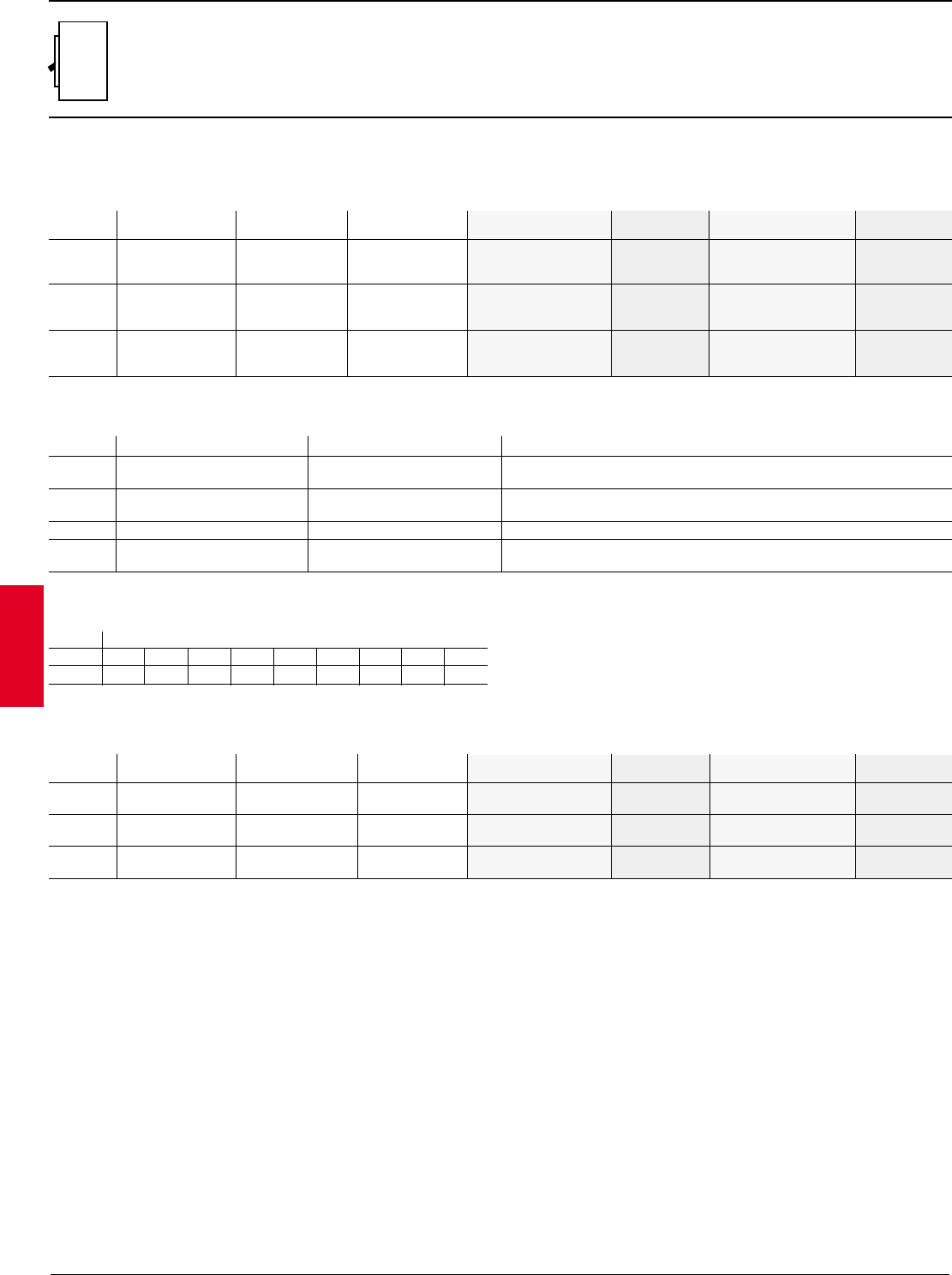
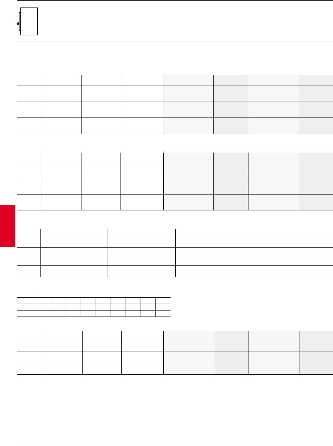
General ratings and specifications
1For use with thermal-magnetic trip only:
500VDC, 2 poles in series
600 VDC, 3 poles in series
215-30A units are 65kA at 480VAC
315A units are 14kA at 480VAC
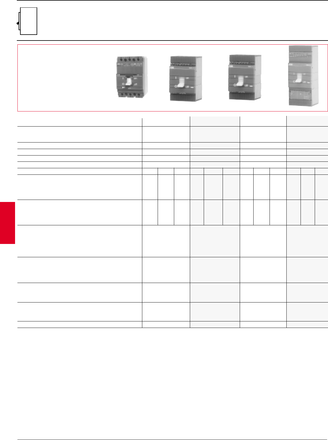
S1 S3B S3 S4
1
1
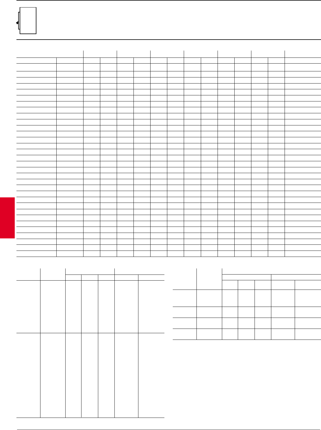
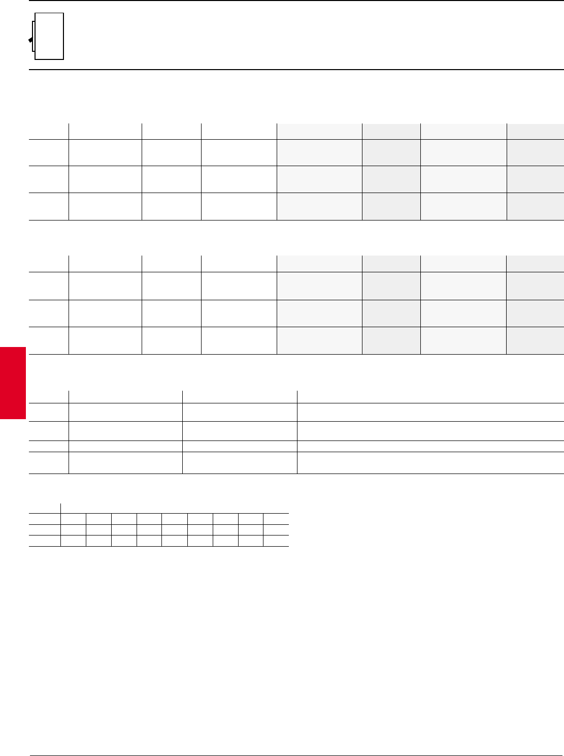
Circuit-breaker type S1 S3B S3 S4
Maximum frame
continuous 40°C A 100 225 225 250
rated current
Rated operational voltage 50/60 Hz V 277/480V 240 600 600
Test voltage 1 min. 50/60 Hz V 3000 3000 3000 3000
Rated impulse withstand voltage kV 6 6 6 8
Poles No. 3 2-3 2-3-4 2-3-4
Performance level NBNHLNHL
240VAC 50 150 65 100 150 65 150 200
UL/CSA short-circuit 480VAC 203—25 50 85 25 65 100
interrupting capacity 600VAC kA RMS ——14 14 25 18 22 35
UL 489, File # E93565 500VDC —50 35 50 65 ———
CSA, File # LR90467 600VDC ——20 35 50 ———
220/230VAC 40 150 65 100 170 65 150 200
IEC-947 rated ultimate 380/400/415VAC 25 —35 65 85 35 65 100
short-circuit Icu 440VAC kA RMS 16 —30 50 65 30 50 80
breaking capacity 500VAC 12 —25 40 50 25 40 65
660/690VAC ——14 18 20 18 22 30
Overcurrent trip unit/relays
Thermal-magnetic •••—
Microprocessor-based ——— •
Dialogue unit ——— •
Interchangeability ——— •
Version — Terminals
Fixed — front or rear ••• •
Plug-in — front or rear (IEC) ••• •
Withdrawable — front or rear (IEC) —• • •
Dimensions (fixed circuit-breaker)
2P & 3P (H x W x D) in 4.72 x 3.07 x 2.75 6.70 x 4.13 x 4.07 6.70 x 4.13 x 4.07 10.0 x 4.13 x 4.07
4P IEC (H x W x D) in 4.72 x 4.09 x 2.75 6.70 x 5.51 x 4.07 6.70 x 5.51 x 4.07 10.0 x 5.51 x 4.07
Mechanical duration
Operations No. 25,000 25,000 25,000 25,000
Frequency ops./hour 240 240 120 120
Weights (Fixed 3P) lbs 2.42 6.75 6.75 8.8
2
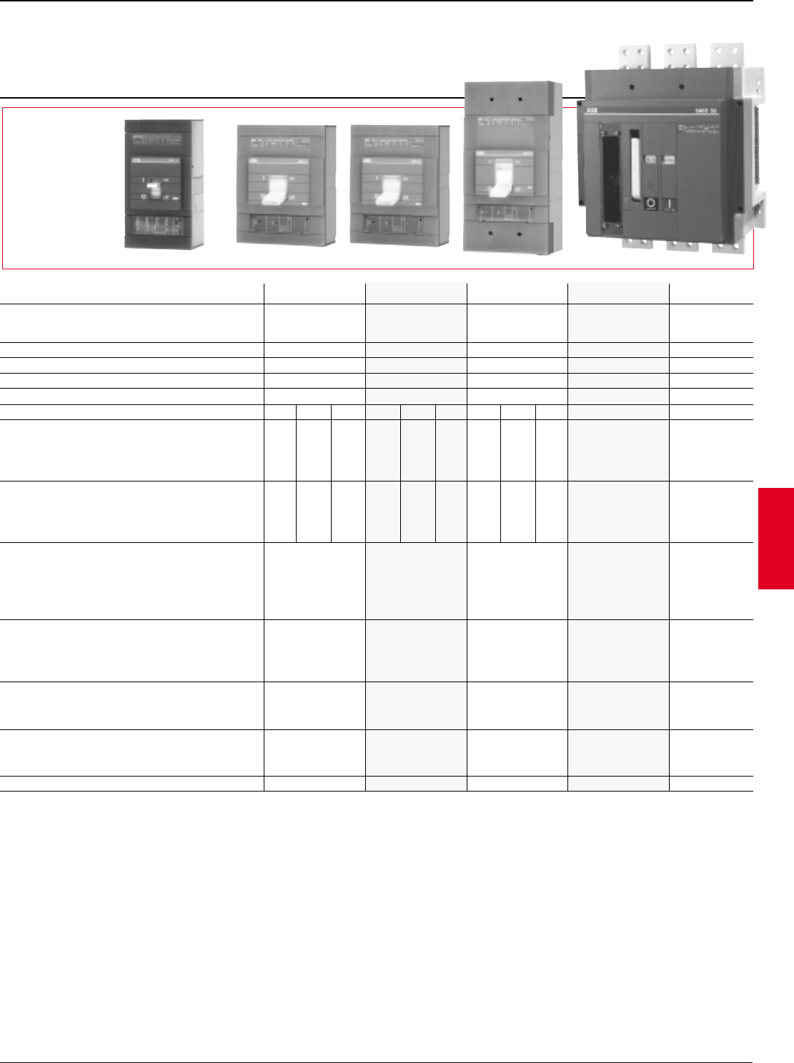
ABB Control Inc. 2.3
AC 1600 – 3/00
Isomax
Gen.
info.
General information
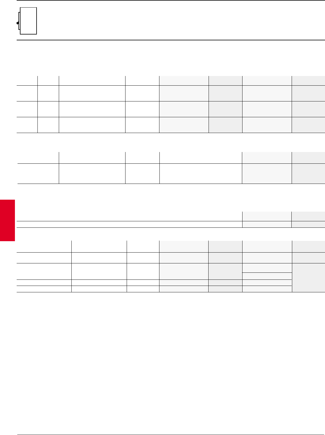
General ratings and specifications
S5 S6 S6 S7 S8
1For use with thermal-magnetic trip only:
500VDC, 2 poles in series
600 VDC, 3 poles in series
Circuit-breaker type S5 S6 S6 S7 S8
Maximum frame
continuous 40°C A 400 600 800 1200 1600/2000/
rated current 2500
Rated operational voltage 50/60 Hz V- 600 600 600 600 600
Test voltage 1 min. 50/60 Hz V- 3000 3000 3000 3000 3000
Rated impulse withstand voltage kV 8 8 8 8 8
Poles No. 2-3-4 2-3-4 2-3-4 2-3-4 3
Performance level NH LN HL NHL H V
240VAC 65 150 200 65 150 200 65 150 200 100 125
UL/CSA short-circuit 480VAC 35 65 100 50 65 100 50 65 100 65 100
interrupting capacity 600VAC kA RMS 22 22 35 25 35 42 25 35 42 50 85
UL 489, File # E93565 500VDC 35 50 65 35 50 65 35 50 65 ——
CSA, File # LR90467 600VDC 20 35 50 20 35 50 20 35 50 ——
220/230VAC 65 100 200 65 100 200 65 100 200 100 120
IEC-947 rated ultimate 380/400/415VAC 35 65 100 35 65 100 35 65 100 65 120
short-circuit Icu 440VAC kA RMS 30 50 80 30 50 80 30 50 80 55 100
breaking capacity 500VAC 25 40 65 25 40 65 25 40 65 45 70
660/690VAC 20 25 30 20 25 35 20 25 35 25 50
Overcurrent trip unit/relays
Thermal-magnetic •••——
Microprocessor-based •••••
Dialogue unit •••••
Interchangeability •••••
Version-Terminals
Fixed – front or rear •••••
Plug-in – front or rear •••——
Withdrawable — front or rear ••••—
Dimensions (fixed circuit-breaker)
2P & 3P (H x W x D) in
13.62 x 5.51 x 4.07 10.55 x 8.27 x 4.07 14.25 x 8.27 x 4.07 15.98 x 8.27 x 5.45 15.75 x 15.98 x 9.25
4P IEC (H x W x D) in
13.62 x 7.24 x 4.07 10.55 x 11.0 x 4.07 14.25 x 11.0 x 4.07 15.98 x 11.0 x 5.45
—
Mechanical endurance
Operations No. 20,000 20,000 20,000 10,000 10,000
Frequency (ops./hour) 120 120 120 120 20
Weights Fixed 3P lbs. 11.0 21.0 22.0 37.5 135
1
1
2.4 ABB Control Inc.
AC 1600 – 3/00
Isomax
Gen.
info.
ABB Isomax circuit breakers — from Model S4 to S8 and starting from 40A are provided with
microprocessor based modular relays.
These are available in two versions:
–ABB PR211: with overload and short-circuit protection
–ABB PR212: with overload protection, short-circuit protection, and ground fault protection.
This version can also be fitted with a dialog unit for connection to automation systems.
These reliable and precise relays are unaffected by electromagnetic disturbances. Minimal
response tolerances ensure high precision in discrimination computations.
S1, S3 and selected versions of the S5 and S6 breakers are fitted with thermal-magnetic trip
releases.
Flexible and modular construction
simplify panel design and construction
for:
•primary distribution (switchboards)
•motor control (MCC)
•secondary distribution
(panelboards)
•panel builders (OEM & users)
Maximum versatility
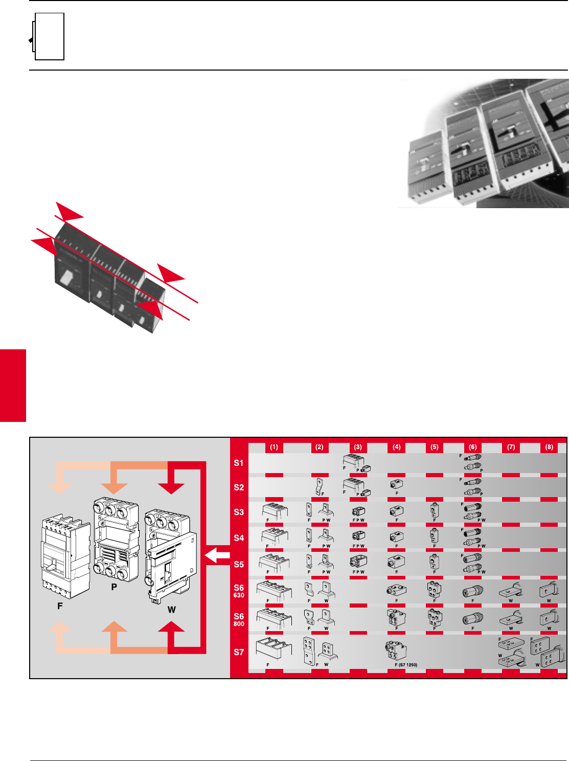
ABB Isomax circuit breakers can be fitted with a wide range of terminals for all types of connections.
Modular design also makes installation and assembly extremely simple.
The various terminal options can be fitted in different combinations in the same unit (e.g. one type at the top and another at the bottom). This
makes ABB Isomax circuit breakers easy to adapt to any installation.
General information
Improved use
–Standard modular dimensions
–Standard circuit breaker depths S3-S6
–Assembly onto DIN profile up to 400 A
–Full range of accessories
–Standard front flange:
- for DIN 45mm cut-outs on S3-S5
- for 105mm cut-outs on S3-S7.
–Handle operators:
- flange type
- variable depth rotary type
- fixed depth rotary type
(1) Front
(2) Extended front
(3) CU front cable terminals (saddle type)
(4) CU/AL front cables (standard type)
(5) CU rear cables
(6) Rear threaded
(7) Rear horizontal flat bar
(8) Rear vertical flat bar
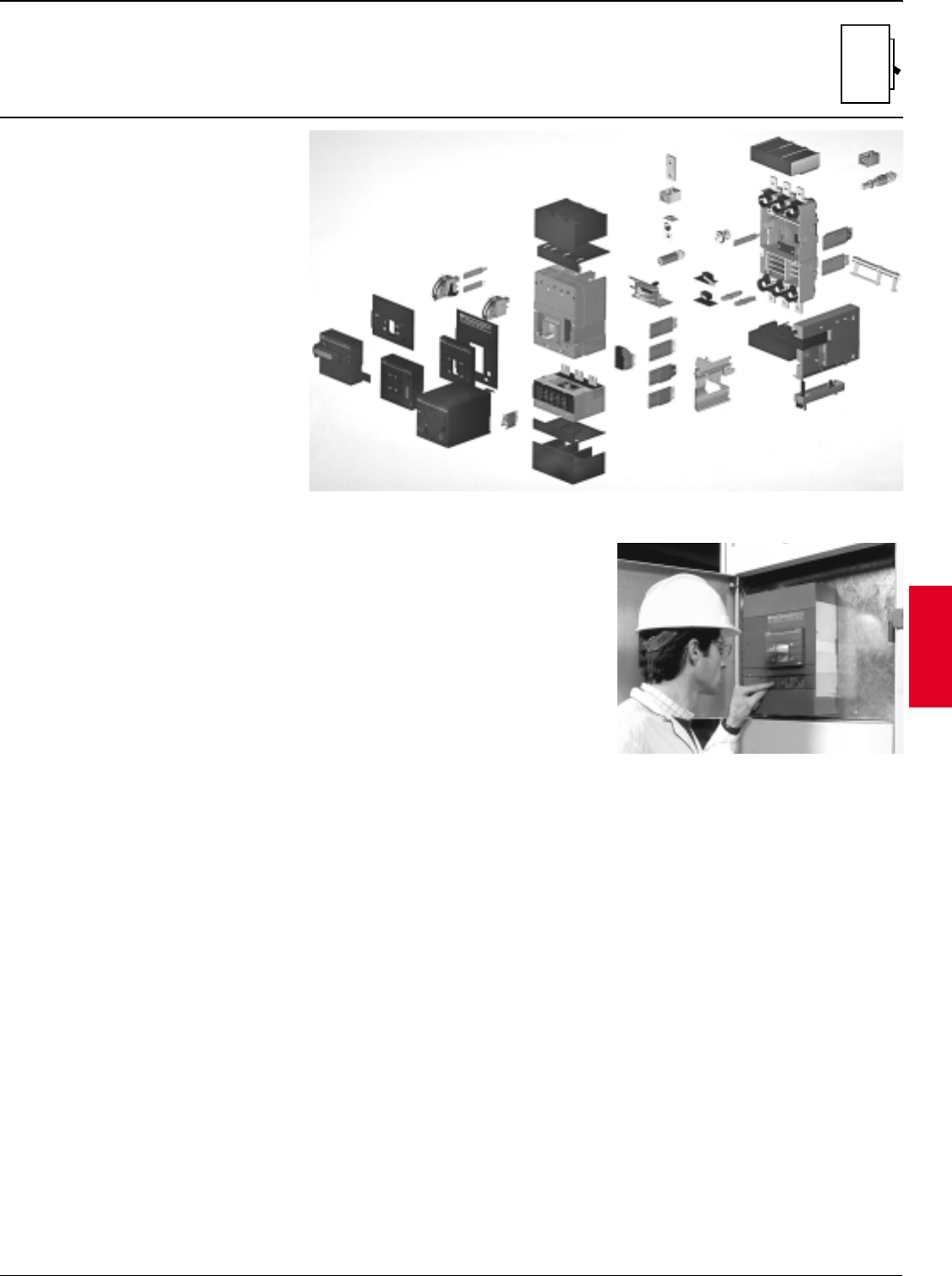
ABB Control Inc. 2.5
AC 1600 – 3/00
Isomax
Gen.
info.
ABB Isomax circuit breakers are
complemented by a complete range of
accessories to satisfy the widely differing
operational and automation requirements.
Accessories are standardized for groups of
circuit breakers to streamline storage logistics
and simplify installation.
ABB Isomax units can be customized as
required under conditions of absolute safety.
All accessories for S3 – S7 can be mounted
with simple operations without having to
remove the circuit breaker power cover and
without any accessory adjustments.
General information
Accessories
Simplified maintenance
Complete range of accessories
Simplified maintenance
Maintenance operations are kept to a minimum. All inspection can be performed quickly and
easily.
A dialog unit (optional) can be installed to store operational data for efficient maintenance
scheduling.
Reliability is ensured by the high quality of all materials and by advanced manufacturing in
automated assembly systems capable of ensuring consistent product quality.
Insulation distances are as required for both UL/CSA 600VAC approvals and also IEC-947
690VAC rating, which ensures safe insulation even under the severest operating conditions.
Double insulation. The cover on S3 – S7 encloses all electrical accessory cavities which are
also completely separated from the power circuit.
Moreover:
•positive operation to guarantee safe and reliable signalling.
•optional draw-out with closed-door racking-out for maximum operational safety.
•high and low terminal covers are available to increase operator protection level.
2.6 ABB Control Inc.
AC 1600 – 3/00
Isomax
Gen.
info.
General information
Technical and design specifications
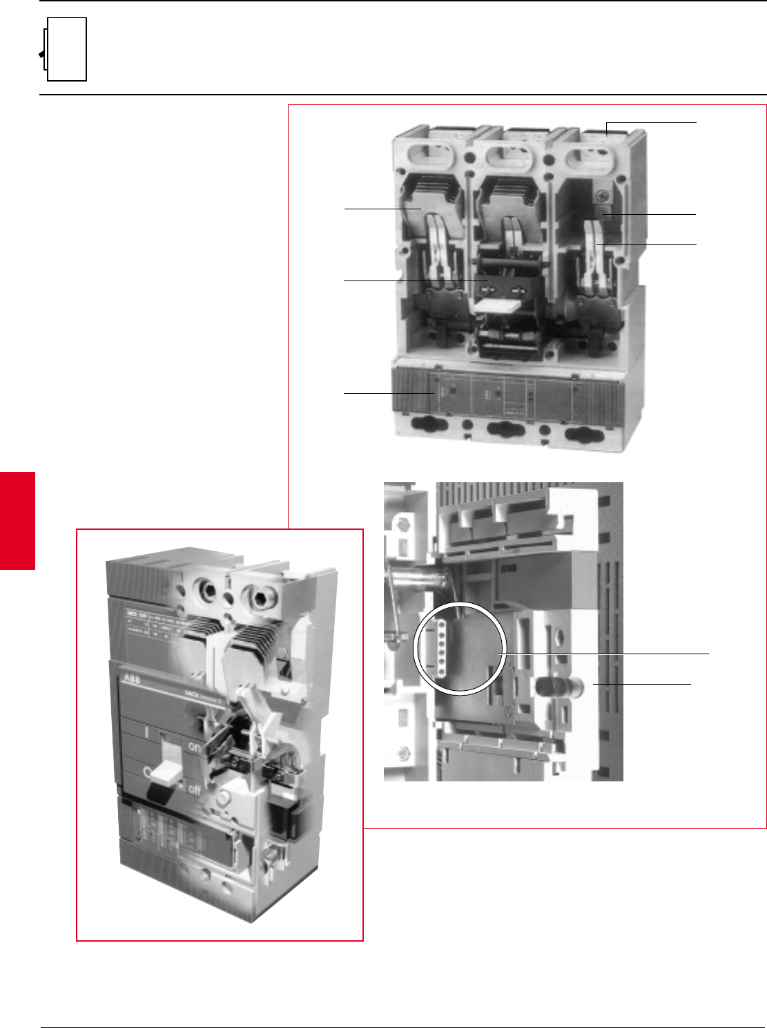
Main component parts
Versions
On request, IEC circuit breakers can be delivered in
plug-in or withdrawable, two, three or four pole
versions. Units are normally provided with front or
rear terminals. Fixed parts are always manufactured
to IP20 protection. See Accessories section for
details of other optional accessories.
Key
1 Terminals
2 Fixed contacts
3 Arcing chamber
4 Moving contacts
5 Operating mechanism
6 Microprocessor based solid-state relay
7 Closed door isolation device
8 Plug-in connector for auxiliary circuits
1
2
4
3
5
6
7
8
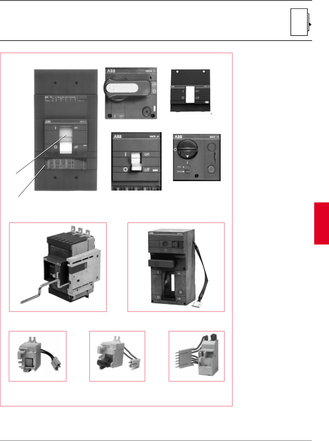
ABB Control Inc. 2.7
AC 1600 – 3/00
Isomax
Gen.
info.
Operating and signalling devices
2
1
4
5
6
7
3
10
Key
1 Operating lever
2 Overcurrent relay
adjustments
3 Closed door racking-in and
racking-out device
4 Rotary handle operating
mechanism
5 Standard front flange (105
mm/4.13" high). Available for
circuit-breakers S3 – S7
6 Flange (45 mm/1.77" high) for
installation of circuit breakers
behind standard IEC doors.
Available for circuit-breakers
up to S5 frame
7 Direct acting motor operator
S3 – S5
8 Stored energy motor operator
S6 – S7
9 Shunt trip device
10 Undervoltage release
11 Auxiliary contact switch for
circuit breaker position
indication
General information
Technical and design specifications
Main component parts
8
911
2.8 ABB Control Inc.
AC 1600 – 3/00
Isomax
Gen.
info.
General information
Technical and design specifications
Main component parts
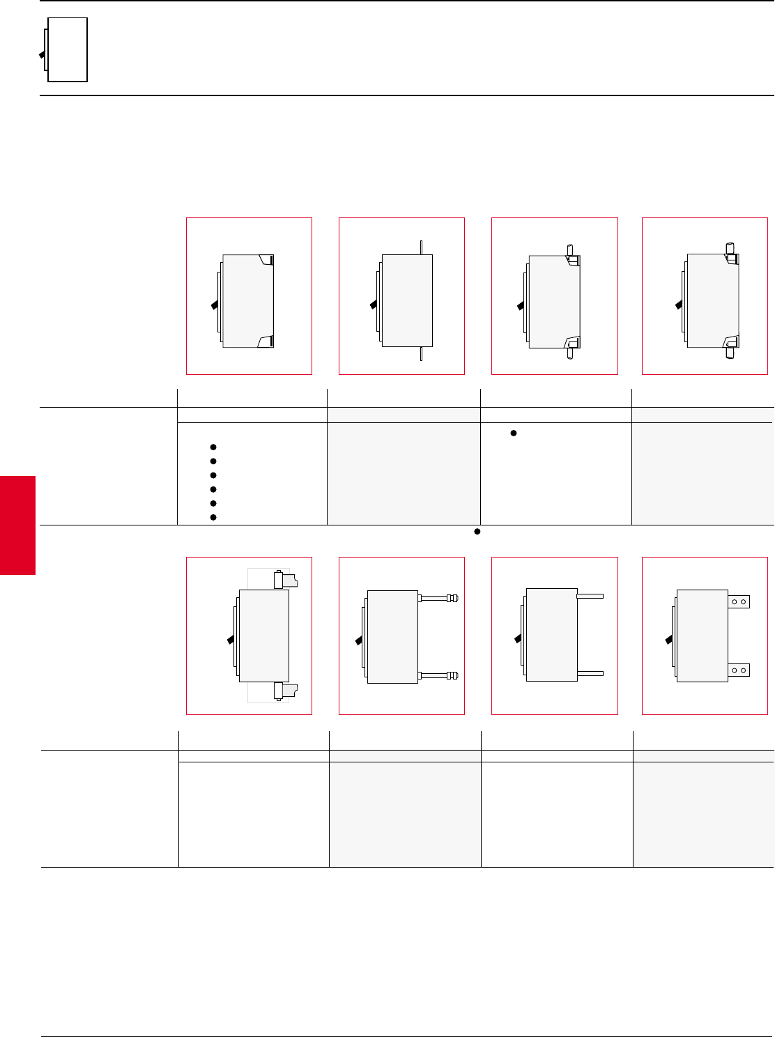
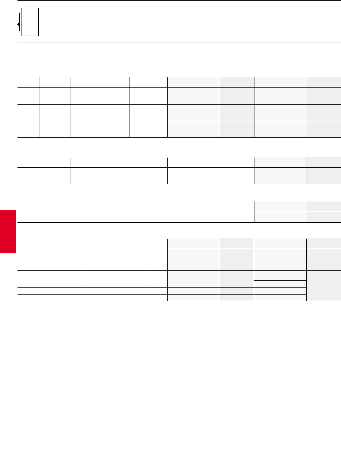
Combinations of terminals
All circuit breaker bus terminations are made of silver-plated copper.
Terminals can be provided in different combinations (e.g. one type at
the top and another type at the bottom). Various connection schemes
are available making ABB Isomax circuit breakers easily adapted to
any installation requirements. In particular, this exceptional versatility
makes ABB Isomax units ideal for wall mounted switchboards with
connections accessible from the front and for rear connection
switchboards.
Connection type
Key: F = Fixed P = Plug-in W = Withdrawable ♦ = Optional terminals =Standard connections
Circuit-breaker Front bar Extended front bar CU front cable lugs CU/AL front cable lugs
FP W F P W FPW FPW
S1 —— — — — — ♦————
S3 —— ♦♦♦ ♦♦♦ ♦——
S4 —— ♦♦♦ ♦♦♦ ♦——
S5 —— ♦♦♦ ♦♦♦ ♦——
S6 —— ♦—♦——— ♦——
S7 —— ♦—♦——— ♦——
S8 —— ——— ——— ♦——
Key: F = Fixed P = Plug-in W = Withdrawable ♦ = Optional terminals
Circuit-breaker CU rear cable lugs Rear threaded studs Rear horizontal flat bus Rear vertical flat bus
FP W F P W FPW FPW
S1 —— — ♦♦— ——— ———
S3 ♦—— ♦♦♦ ——— ———
S4 ♦—— ♦♦♦ ——— ———
S5 ♦—— ♦♦♦ ——— ———
S6 ♦—— ♦—— ——♦—— ♦
S7 —— — — — — ♦—♦♦—♦
S8 —— — — — — ♦—— ♦——
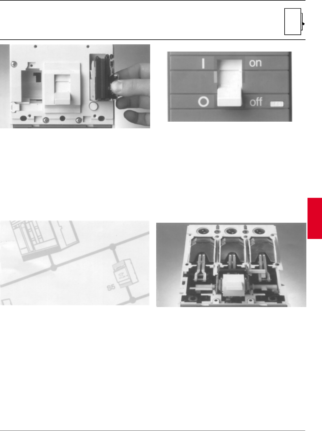
ABB Control Inc. 2.9
AC 1600 – 3/00
Isomax
Gen.
info.
General information
Construction characteristics
Double insulation
The double insulation technique involves the total separation of the
power and auxiliary circuits, and is a characteristic of all Isomax
switchgear, from size S3 to S7.
The housing of each electrical accessory is completely segregated
from the power circuit, thus avoiding all risk of contact with the active
parts and hence improving operator safety conditions in plant
management and inspection.
In addition, the insulation of the internal active parts, in terms of both
the thickness of the materials and the distances, is superior to that
required by the IEC Standards and complies with American usage.
Positive operation
The operating lever always indicates the exact position of the moving
contacts in the circuit-breaker, thus guaranteeing safe and reliable
indication (I = Closed; O = Open; yellow line = Open due to tripping of
releases).
The operating mechanism of the circuit-breaker is trip-free,
independently of the pressure on the lever or the speed of operation.
Tripping of the releases automatically opens the moving contacts; to
close them again, the operating mechanism has to be reset by
pushing the operating lever from the intermediate position fully down
to the lower limit of the open position.
In the plug-in or withdrawable circuit breakers, the mobile part can
only be detached from the fixed part when the circuit-breaker is open
(i.e. moving contacts separate from fixed contacts).
Selectivity
The complete range of releases available makes it possible to
coordinate protection functions using current-type, time-type, energy-
type or residual-current selectivity chains.
This makes it possible to isolate only those zones affected by faults,
ensuring maximum operating continuity.
Circuit-breakers in category B are available from 400 A upwards.
(IEC 947-2)
Inspection
A direct check can be made on the state of the internal parts and
active components when the circuit-breaker is out of service.
Access can be gained to the arcing chambers and fixed and moving
contacts simply by removing the cover of the circuit-breaker.
The operation, made easier by the limited number of components,
reduces maintenance times and guarantees a higher level of safety.
2.10 ABB Control Inc.
AC 1600 – 3/00
Isomax
Gen.
info.
General information
Construction characteristics
Isolation behavior
In the open position, the circuit-breaker guarantees the isolation of
the circuit in accordance with IEC 947-2 specifications.
In the IEC withdrawable or plug-in versions, the power and auxiliary
circuits are isolated in the racked out or removed positions, thus
guaranteeing that no parts are live.
In these conditions, using suitable connectors, blank tests can be
conducted, with the operations on the circuit-breaker being carried
out in complete safety.
The redundant insulation distances guarantee the absence of leakage
currents and dielectric strength in the event of any overvoltages
across the input and output.
Racking-out with the door closed
This system, present for the first time on a series of molded-case
circuit-breakers, starting from Isomax S3, allows racking-in and
racking-out with the compartment door closed, thus increasing
operator safety and allowing the construction of internal-arc-proof low-
voltage switchboards.
Racking out can only be done with the circuit-breaker open, using the
racking-out crank handle supplied with the withdrawable version of the
circuit-breaker.
Electromagnetic compatibility
With the use of the PR211/P microprocessor-based overcurrent
releases and the RC211 and RC212 electronic residual current
releases, slow non-operation is guaranteed, even in the presence of
interference caused by electronic equipment, atmospheric disturbance
or discharges of an electrical nature.
Furthermore, the appliances do not generate interference with other
electronic equipment in the vacinity.
This is in accordance with IEC 947-2 Addendum F, IEC 1000-4, EN
61000-4, EN 50081-2, European Directive No. 49/12-12-1992
specifications on electromagnetic compatibility EMC.
Tropicalization
The Isomax series of circuit-breakers and accessories comply with the
strictest regulations on use in hot-damp saline climates (in conformity
with climatographic chart No. 8 of the IEC 721-2-1 specifications),
thanks to:
–insulating cases made of fiberglass-reinforced synthetic resins
–corrosion-resistant treatment on all main metal parts (environment C
UNI 3564-65)
–Fe/Zn 12 galvanizing (UNI ISO 2081), protected by a conversion
layer composed mainly of chromates (UNI ISO 4520).
ABB Control Inc. 2.11
AC 1600 – 3/00
Isomax
Gen.
info.
General information
Construction characteristics
Protection classes
Various measures have been incorporated in Isomax S circuit-
breakers to achieve IP20 protection for the fixed, plug-in and
withdrawable versions of the circuit-breaker, excluding the terminals,
and IP 30 for the front parts of circuit-breakers installed in
switchboards.
The fixed parts are always IP20 protection grade. IP54 protection can
be achieved for circuit-breakers installed in switchboards by using
door-mounted crank handle operating mechanisms and special
insulating gaskets that can be ordered separately.
Mounting on DIN channel up to Isomax S5
The brackets for mounting on the standardized DIN EN 50022
channels for S1 and S2 and on DIN EN 50023 for S3, S4, S5 simplify
the fitting for the circuit-breakers on standard switchboards.
This allows standarized support structures to be installed and
simplifies the phase for designing and building the switchboard
structure.
Resistance to vibration
The circuit-breakers are unaffected by vibrations generated
mechanically or by electromagnetic effects, in compliance with the IEC
68-2-6 standards and the strictest regulations set by the most
important classification organizations:
– RINA
–DET Norske Veritas
–Lloyd's Register of Shipping
–Germanischer Lloyd
–Bureau Veritas
Installation positions
The circuit-breakers can be installed in any position with no variations
to their rated characteristics.
In compliance with UL and IEC 947-2 standards, Isomax S circuit-
breakers can be powered from either their top or bottom terminals,
without affecting operation.
They can be installed in switchboards, mounted directly on the base
plate or on DIN channels up to size S5.
2.12 ABB Control Inc.
AC 1600 – 3/00
Isomax
Gen.
info.
Table of power losses
General information
Table of power losses
400 Hz ratings
R15 15 7 7.3 11.8 13
R20 20 8.6 8.9 10.8 11.9
R25 25 7.9 8.3 12 13.2
R30 30 8.6 8.4 16.9 18.5
R40 40 8.6 9.5 15.1 16.6
R50 50 10 11 16.4 18
R60 60 12.8 13 14.4 16
R70 70 15.8 17.4 15.8 18.8
R80 80 13.5 15 17.9 21
R90 90 17 19 21.9 26
R100 100 13.8 15.5 21 25
R125 125 18.5 26
R150 150 40.5 52
R175 175 35.9 40
R200 200 36 46
R225 225 55 67
R300 300 52.7 79
R400 400 66.4 96
R600 600 83 106
R800 800 93.2 119
In = 100 100 5.2 8
In = 150 150 13 19
In = 250 250 40 55
In = 300 300 40 57
In = 400 400 60 90
In = 600 600 63 104
In = 800 800 96 125
In = 1000 1000 102 140
In = 1200 1200 151 203
In = 1600 1600 41
In = 2000 2000 64
In = 2500 2500 100
Dissipated power (W) S1 S3 S4 S5 S6 S7 S8
Setting In (A) F P F P•WFP•WF P•WF P•WF P•WF
Breaker Breaker Thermal amperes Magnetic rating
frame rating Minimum Maximum Fixed Minimum Maximum
S1 15 ——15 —1000
20 ——19 —1000
25 ——23 —1000
30 ——28 —1000
40 ——37 —1000
50 ——46 —1000
60 ——55 —1200
70 ——65 —1400
80 ——74 —1600
90 ——81 —1800
100 ——90 —2000
S3 15 ——15 —850
20 ——19 —850
25 ——23 —850
30 ——28 —850
35 ——32.4 —850
40 ——37 —850
50 ——46 —850
60 ——55.5 —1020
70 ——64.8 —1190
80 ——74 —1360
90 ——81 —1530
100 ——90 —1700
125 ——112 —1360
150 ——135 —1605
175 ——157.5 —1640
200 ——180 —1875
225 ——202.5 —2138
250 ——225 —2400
400Hz response 400Hz response
S41100 44 88 —180 1440
150 66 132 —270 2160
250 110 180.4 —450 3600
S51300 132 264 —540 4320
400 176 352 —720 5760
S61600 264 528 —1080 8640
800 352 704 —1440 11,520
S711000 440 880 —1800 14,400
1200 528 1056 —2160 17,280
Electronic trip headers
Breaker Breaker Thermal amperes Magnetic rating
frame rating Minimum Maximum Fixed Minimum Maximum
x 0.4(.44) x 0.8(.88) x 1.5(1.8) x 12(14.4)
1PR211 Trip unit — maximum allowable setting of “L” is 0.8.
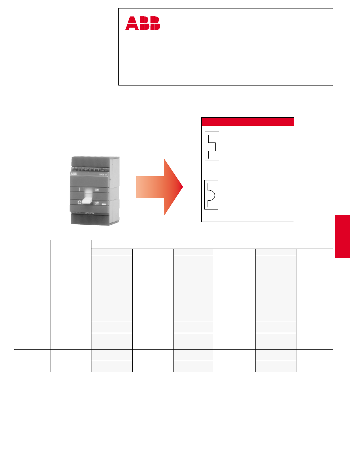
ABB Control Inc. 2.13
AC 1600 – 3/00
Isomax
Protective releases
Variation in thermal element setting currents according to ambient temperature
S3 150 – S3 225
Fixed thermal
Ith = 15 – 150A
Ith = 175 – 225A
+
Fixed magnetic
I3 = 10 x Ith
500A min.
Thermal-magnetic S1, S3, S5, S6
The S1 – S3 Isomax series uses a non-interchangeable tripping mechanism with a
fixed thermal and magnetic trip. These breakers utilize a heat sensitive bimetal for
protection against overload currents. The magnetic element is an instantaneous
acting device for protection against short circuit faults. The S5, S6 Isomax series
with thermal-magnetic tripping mechanism are adjustable from .7 to 1.
Circuit breaker Trip Variation in current
frame release
10°C 20°C 30°C 40°C 50°C 60°C
R1518 171615 1413
R2024 222120 1917
R2530 282725 2321
R3035 333230 2826
S1 100, S3 100 R35 41 39 37 35 33 30
R4047 444240 3734
R4553 504845 4238
R5059 565350 4743
R6071 676460 5651
R7083 787470 6660
R8094 908580 7568
R90 106 101 95 90 85 77
R100 118 112 106 100 95 85
S3 150 R125 148 140 133 125 119 106
R150 177 168 159 150 143 127
R175 207 196 186 175 166 149
S3 225 R200 236 224 212 200 190 170
R225 266 252 239 225 214 191
S5 400 R300 345 328 314 300 286 267
R400 465 442 420 400 380 355
S6 600 R600 690 656 628 600 572 534
R800 965 90 855 800 740 670
2.14 ABB Control Inc.
AC 1600 – 3/00
Isomax
Protective releases
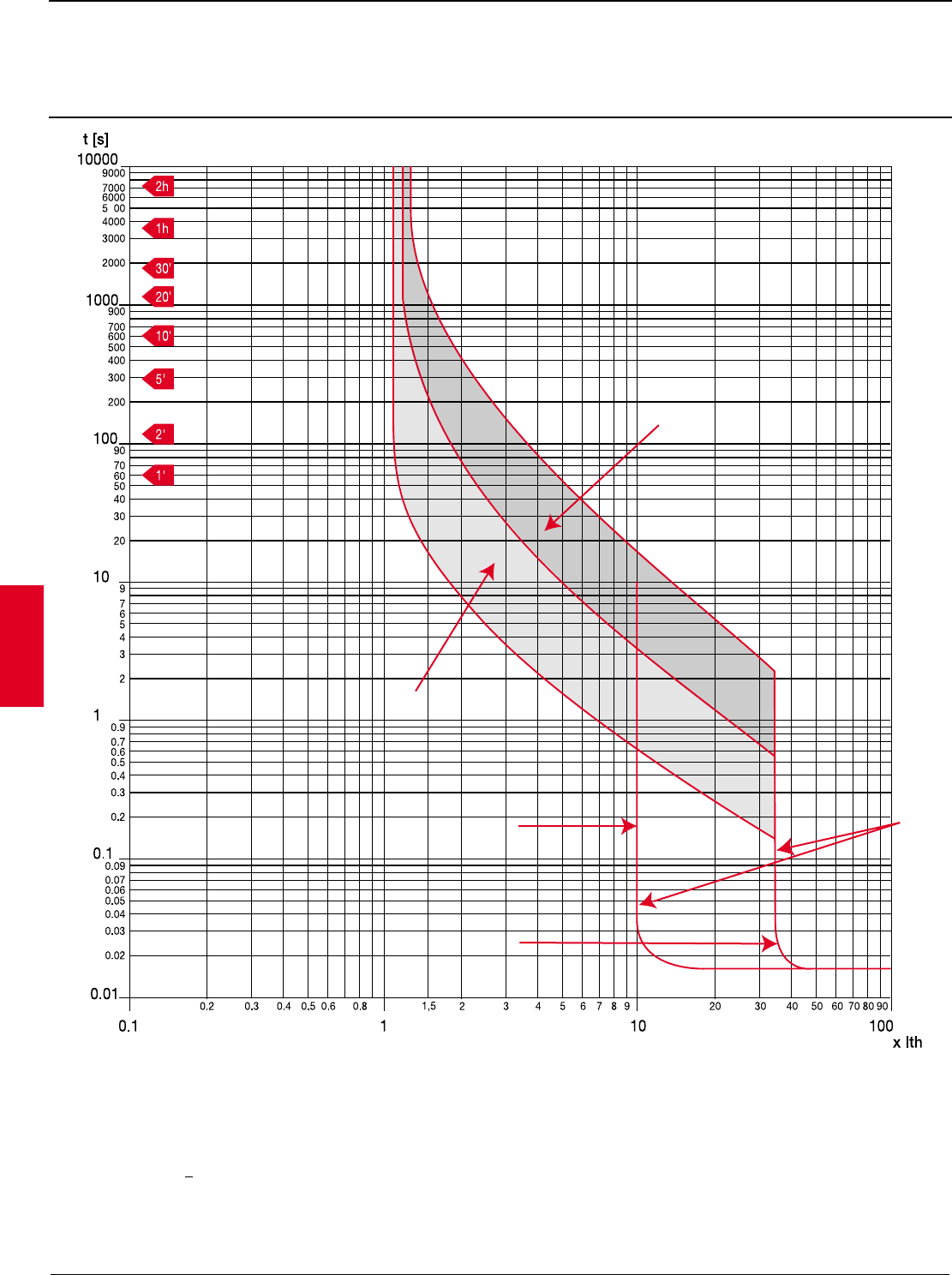
Thermal magnetic overcurrent release
Time current curves, S1
Key
Ith = Rated current of overcurrent release at 40 °C temperature
–multiples of Ith for thermal releases
–multiples of Ith for magnetic releases
a= Thermal releases cold
b= Thermal releases under operating conditions
c= Magnetic releases (+ 20%)
t= Tripping time
a
b
R50-100A
R15-40A
c
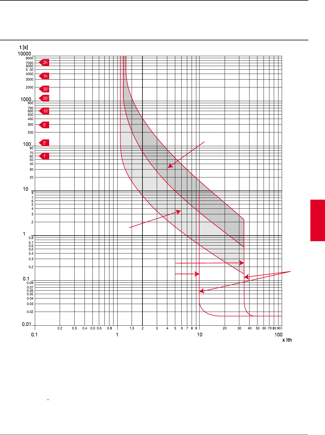
ABB Control Inc. 2.15
AC 1600 – 3/00
Isomax
a
b
c
R15-30A
R35-70A
Key
Ith = Rated current of overcurrent release at 40 °C temperature
–multiples of Ith for thermal releases
–multiples of Ith for magnetic releases
a= Thermal releases cold
b= Thermal releases under operating conditions
c= Magnetic releases (+ 20%)
t= Tripping time
Protective releases
Thermal-magnetic overcurrent release
Time-current curves, S3 150 1
1 Direct current may shift tripping characteristic. Consult ABB.
2.16 ABB Control Inc.
AC 1600 – 3/00
Isomax
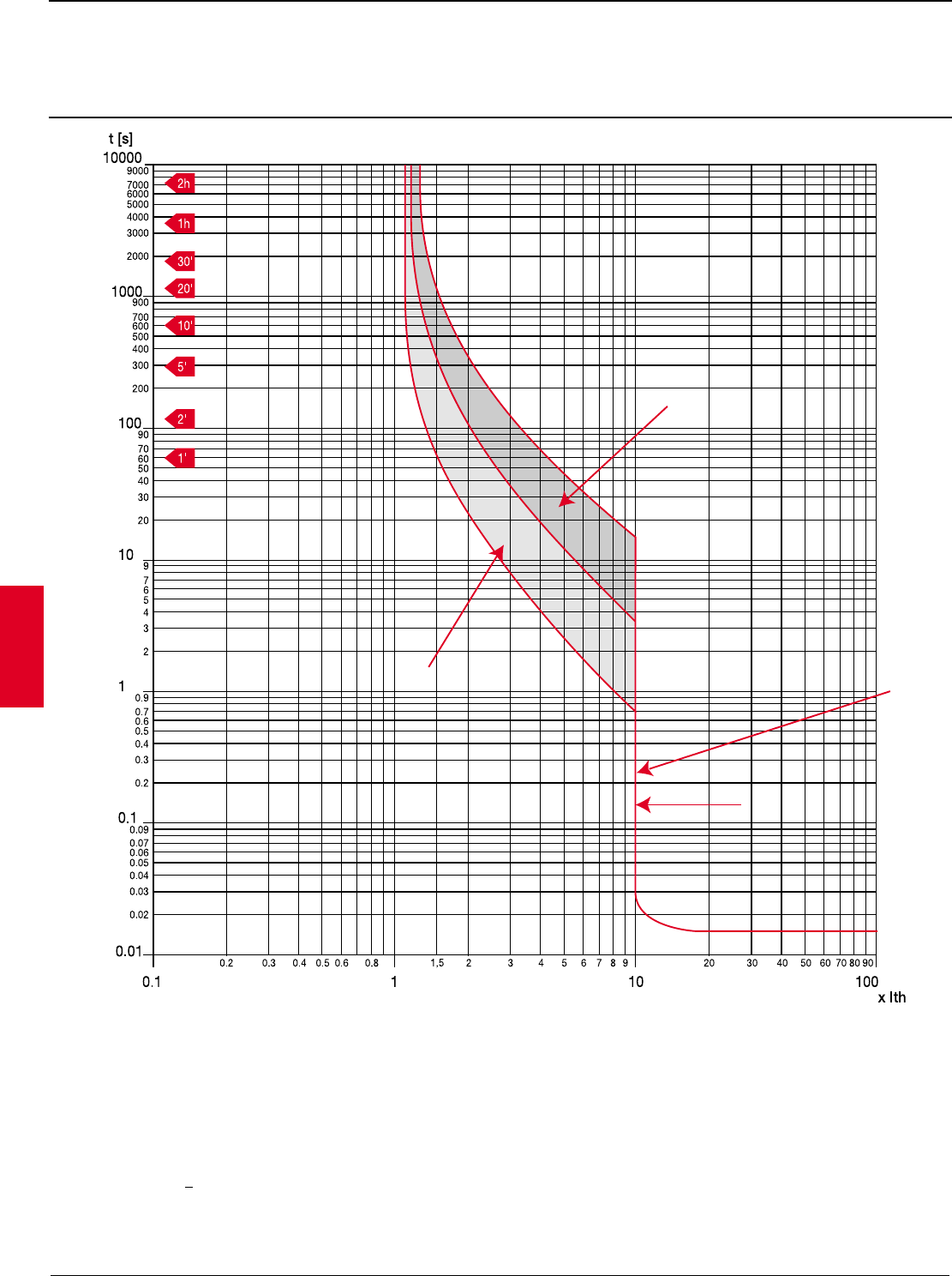
a
b
c
R80-225A
Key
Ith = Rated current of overcurrent release at 40 °C temperature
–multiples of Ith for thermal releases
–multiples of Ith for magnetic releases
a= Thermal releases cold
b= Thermal releases under operating conditions
c= Magnetic releases (+ 20%)
t= Tripping time
Protective releases
Thermal-magnetic overcurrent release
Time-current curves, S3 150 – S3 225
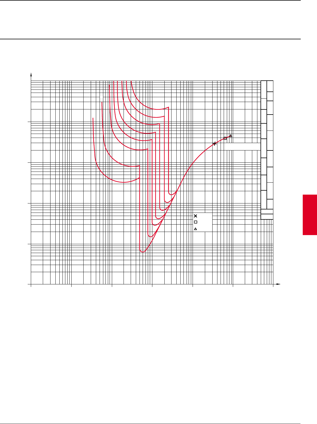
ABB Control Inc. 2.17
AC 1600 – 3/00
Isomax
4
6
2,5
4
6
10
16
25
35
10
16
25
pvc
xlpe
mm
2
480 VAC
K s
22
S3N
S3H
S3L
35
50
50
R30
R50
R80
R100
R125
R150
R200
R225
I
10
8
10
2
Is
t[As]
2
023468
2
10
[A]
8
6
4
3
2
10
34
10 10
56
10
(*)
10
7
6
10
10
5
10
4
3
10
2
3
4
6
8
8
6
4
3
2
2
3
4
6
8
8
6
4
3
2
864
3
22
3468 864
3
22
3468 864
3
2
Key
Is = Prospective short-circuit symmetrical current
Ith = Rated current of overcurrent release at 40 °C temperature
I2t = Specific let-through energy at the voltages shown
(*)= Section of copper cable
Protective releases
Specific let-through energy I2t curves
S3— TM - Ith = 30A – 225A

2.18 ABB Control Inc.
AC 1600 – 3/00
Isomax
Protective releases
Microprocessor trip release
S4, S5, S6, S7, S8
The microprocessor based overcurrent relays (actual RMS) for Isomax S circuit-
breakers are interchangeable and offer a wide range of current and trip time
settings.
They are available in two versions:
PR211/P with overcurrent protection «L» and instant short circuit protection «I».
Available with functions «L», «I», or «L+I». L function includes adjustable long-
time pick-up and long-time delay.
PR212/P with overcurrent protection «L», selective short circuit protection «S»,
instant short circuit protection «I» and ground fault protection «G». Available
with functions «L+S+I» or «L+S+I+G». Functions «S», «I» and «G» can be
excluded manually by means of the trip current threshold selector (OFF
position). In its most complete configuration, i.e. with functions «L+S+I+G», the
PR212/P relay can be combined, on request, with the following units:
PR212/D — dialog unit
Essential for two-way communication with electrical plant management systems.
When the unit is present, it is possible to choose between the manually set
parameters (LOC), and the parameters set by the electrical plant control system
(REM) by means of the appropriate selector. The dialog unit must be supplied
with an auxiliary voltage of 24 V d.c.
The following information is made available through the dialog unit on the field
bus:
• protection parameters
• current values of phases, neutral and ground
• circuit-breaker state
• number of operations of circuit-breaker
• interrupted currents
• state of the overcurrent relay with indication of:
- normal operation
- pre-alarm (0.9 x I1)
- overcurrent function «L»
- trip function «S»
- trip function «I»
- trip function «G».
It is possible to provide and/or modify the protection parameters and the circuit-
breaker opening/closing controls. In the event of a serial communication error,
the overcurrent relay operates in accordance with the last parameters set and in
any event always in accordance with the manually programmed setting. The
same occurs in the event of a dialog unit fault, and in the absence of auxiliary
supply.
The dialog unit is external for circuit breakers S4 and S5 and is located inside
the relay box for circuit breakers S6 and S7.
The external dialog unit is connected by means of a cable for supply and
communication with the PR212/P protection relay.
The standard version of the dialog interface has the following specifications:
• hardware: EIA RS485 serial transmission line
• communication protocol: ABB INSUM
• transmission speed: 150 – 19200 baud (bit/s).
PR212/K — signalling unit
Can be connected directly to the PR212/P protection relay and provides
contacts for the protection unit trip and alarm signals: pre-alarm, overcurrent
function «L», trip functions «S», «I» and «G», trip by relay and internal
communication error with PR212/P.
PR212/T — actuator unit
Can be installed only if the dialog unit is present, and by means of suitable
relays, controls the opening and closing of the circuit-breaker. In order that
opening and closing can be actuated, the circuit-breaker must be equipped with
a motor operator (direct-acting for S4 and S5; stored energy type for S6 and
S7).
Note
The K and T units are always external.
Other important features of the microprocessor based relays are as follows:
•protection of neutral with programmable automatic adjustment, executed by
the manufacturer, to 50% (standard) or 100% (on request) of the current
value selected for the phases. The optional version has no code in this
catalog;
•reliable operation also when one phase only is live;
•individual and simultaneous adjustment on the three phases and neutral;
•no need for auxiliary supply;
•trip specifications not affected by the ambient temperature;
•consistency of specifications and reliability including in contaminated
environments;
•signalling of tripped relay (available for all versions) by means of voltage-
free contact for 24 V d.c. or a.c. circuits maximum 3 W.
Circuit-breaker rated current change according to ambient temperature. The
tripping characteristics of Isomax S4 – S8 with electronic trip units are
unaffected by ambient temperatures from -25°C to +60°C. Max operating
temperature is 70°C.
400Hz
All S1 through S8 breakers are suitable for use in 400Hz power systems.
Microprocessor based overcurrent relays for alternating current for S4, S5, S6 and S7 circuit-breakers
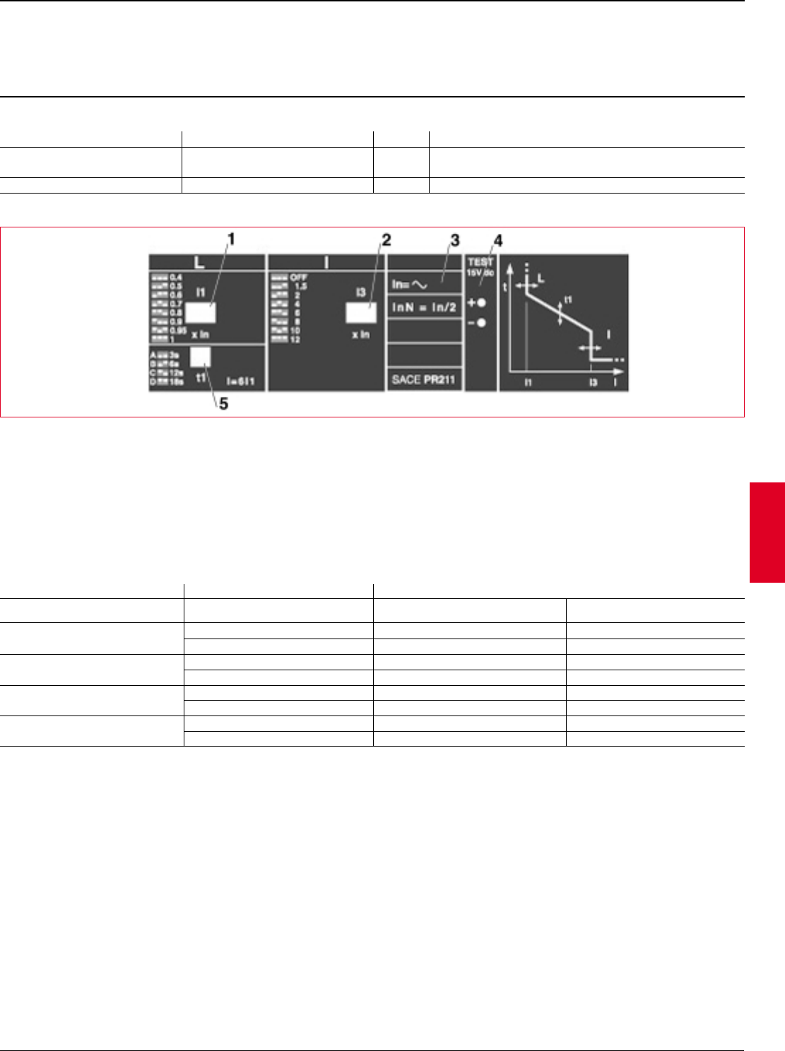
ABB Control Inc. 2.19
AC 1600 – 3/00
Isomax
Rated and setting currents
PR211
Key
1 Dip-switch for function L setting
2 Dip-switch for function I setting
3 Rated current of current transformers
4 15 V d.c. input for release functioning check
5 Function L trip time setting dip switch
Iu = Rated uninterrupted current of circuit-breaker
In = Rated current of current transformers
I1 = Current setting value for relay overload protection (L)
I3 = Current setting value for relay instantaneous short-circuit protection (I)
Protective releases
Microprocessor based overcurrent relays, PR211
for S4, S5, S6 & S7 breakers
Protection against Trip Symbol Set values (manual adjustment in steps)
Overload Long delay L I1 = 0.4-0.5-0.6-0.7-0.8-0.9-0.95-1 x In
t1 = 4 curves A,B,C,D
Short-circuit Instantaneous adjustment I I3 = 1.5-2-4-6-8-10-12 x In
Circuit-breaker Current transformer Functions
Iu-A In-A L (I1) I (I3)
A (0.4 – 1 x In) A (1.5 – 12 x In)
S4 250 100 40 – 100 150 – 1200
250 100 – 250 375 – 3000
S5 400 300 120 – 300 450 – 3600
400 160 – 400 600 –4800
S6 600/800 600 240 –600 900 – 7200
800 320 – 800 1200 – 9600
S7 1200 1000 400 – 1000 1000 – 12,000
1200 480 – 1200 1800 – 14,400
Protective functions and set values
2.20 ABB Control Inc.
AC 1600 – 3/00
Isomax
Protective releases
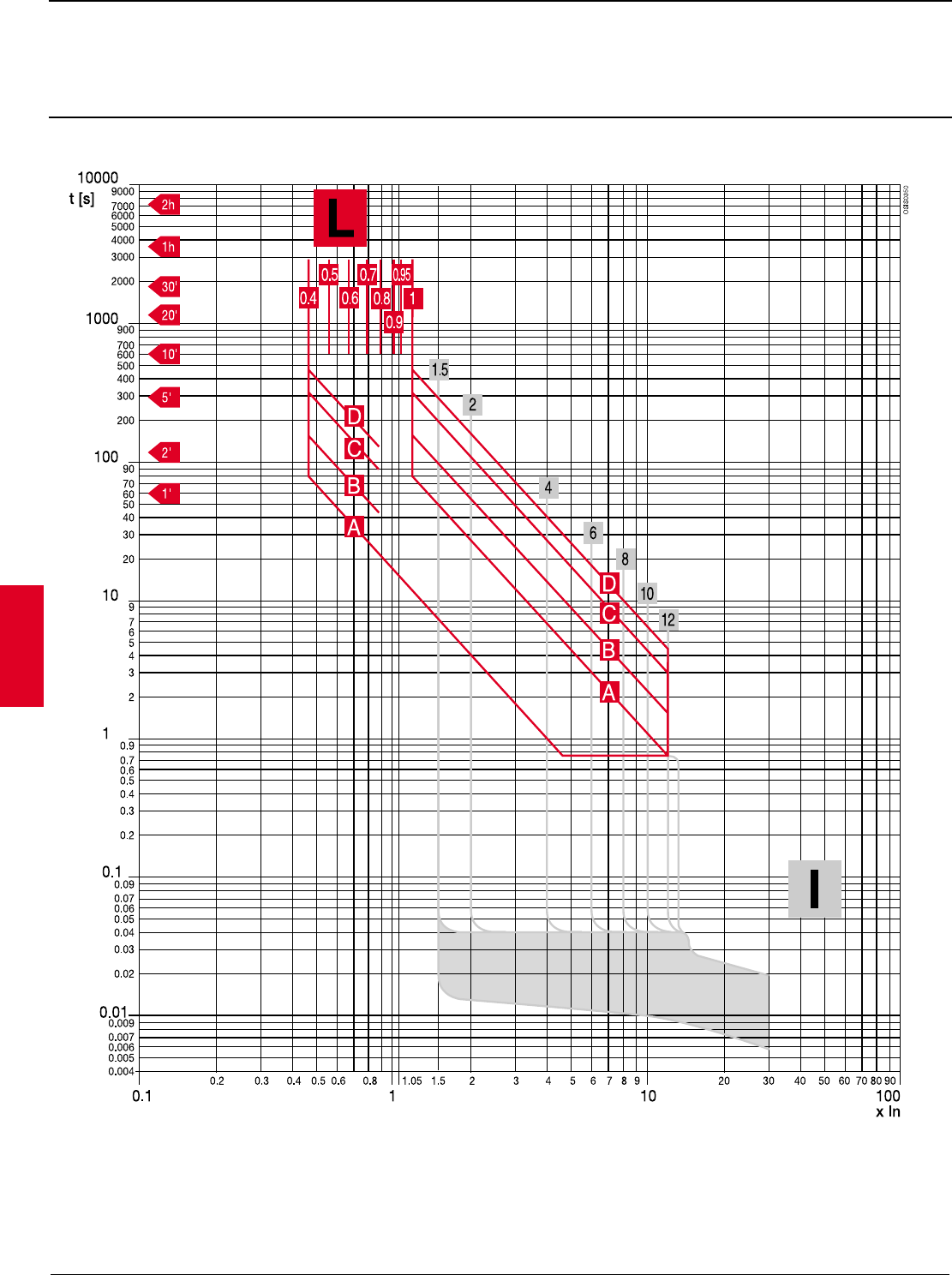
Microprocessor based overcurrent relays, PR211
Time-current curves, S4 – S7
Function L - I
Key
In = Rated current of current transformers
t= Tripping time
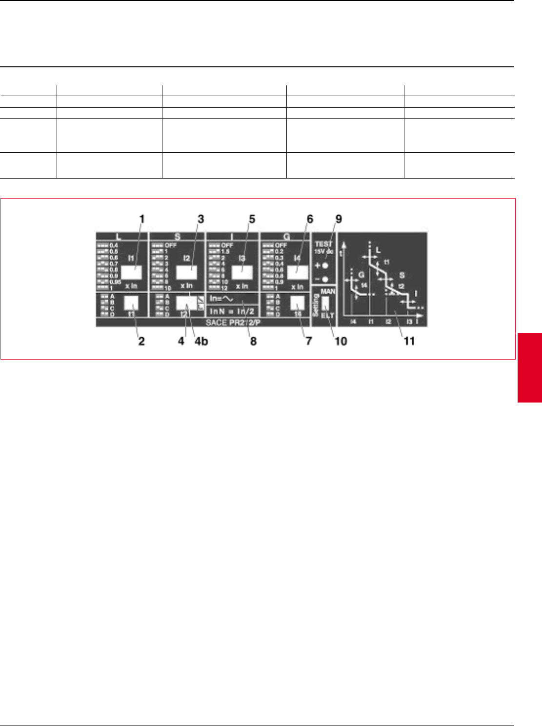
ABB Control Inc. 2.21
AC 1600 – 3/00
Isomax
Protection functions and set values
Key
1 Function L setting dip-switch
2 Function L trip time setting dip-switch
3 Function S setting dip-switch
4 Function S trip time setting dip-switch
4b Fixed/variable trip time selection dip-switch
5 Function I setting dip-switch
6 Function G setting dip-switch
7 Function G trip time setting dip-switch
8 Rated current of current transformers
9 15 V d.c. input for release functioning check
10 Manual/electronic parameter setting selector switch
11 Dialogue unit
Protective releases
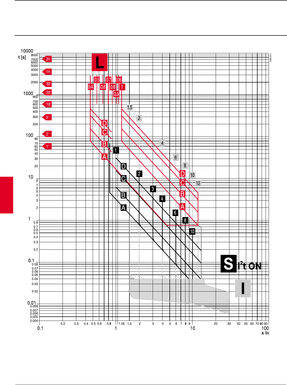
Microprocessor based overcurrent relays, PR212
Protection functions and set values, S4 – S8
Protection against Overload Short-circuit Short circuit Earth fault
Trip Long delay Inverse or definite short delay Instantaneous adjustable Inverse short delay
Symbol L S I G 1
Set values I1 = 0.4-0.5-0.6-0.7- I2 = 1-2-3-4-6-8-10 I4 = 0.2-0.3-0.4-0.7-0.8-0
(manual 0.8-0.9-0.95-1 x In OFF x In I3 = 1.5-2-4-6-8-10-12
adjustment t1 = 4 curves A – D t2 = 4 curves A – D t4 = 4 curves A – D
in steps
Set values I1 = 0.4 - 1 x In I2 = 1 … 10 OFF x In I4 = 0.2 – 1 OFF x In
(electronic t1 = 3 - 18s t2 = 0.05 – 0.5 I3 = 1.5-12 OFF x In t4 = 0.1 – 0.8s
adjustment)
PR212
1 S8 it = 0.2 - 0.4
2.22 ABB Control Inc.
AC 1600 – 3/00
Isomax
Protective releases
Rated and setting currents, PR212
S4 – S8
Rated and setting currents
Key
Iu = Rated uninterrupted current of circuit-breaker
In = Rated current of current transformers
I1 = Current setting value for relay overload protection
I2 = Current setting value for relay short-circuit selective protection
I3 = Current setting value for relay instantaneous short-circuit protection
I4 = Current setting value for earth fault protection
Circuit Current Functions
breaker transformer
Iu In-A L(I1) S (I1) I (I3) G (I4)
A (0.4 – 1.0 x In) A (1 – 10 x In) A (1.5 – 12 x In) A (0.2 – 1 x In) / S8 (0.2 – 0.4)
S4 250 100 40 –100 100 –1000 150 –1200 20 –100
250 100 –250 250 –2500 375 –3000 50 –250
S5 400 300 120 –300 300 –3000 450 –3600 60 –300
400 160 –400 400 –4000 600 –4800 80 –400
S6 600 600 240 –600 600 –6000 900 –7200 120 –600
800 800 320 –800 800 –8000 1200 –9600 160 –800
S7 1200 1000 400 –1000 1000 –10,000 1500 –12,000 200 –1000
1200 480 –1200 1200 –12,000 1800 –14,400 240 –1200
1600 640 –1600 1600 –16,000 2400 –19,200 320 –640
S8 1600 – 2500 2000 800 –2000 2000 –20,000 3000 –24,000 400 –800
2500 1000 –2500 2500 –25,000 3750 –30,000 500 –1000
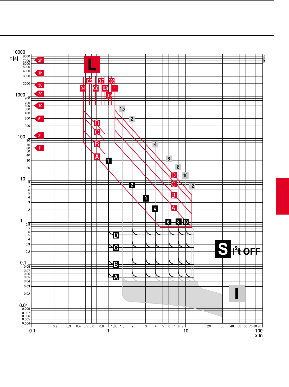
ABB Control Inc. 2.23
AC 1600 – 3/00
Isomax
Function L - S - I
Key
In = Rated current of current transformers
t= Tripping time
Protective releases
Microprocessor based overcurrent relays, PR212
Time-current curves, S4 – S8
2.24 ABB Control Inc.
AC 1600 – 3/00
Isomax
Function L - S - I
Protective releases
Microprocessor based overcurrent relays, PR212
Time-current curves, S4 – S8
Key
In = Rated current of current transformers
t= Tripping time
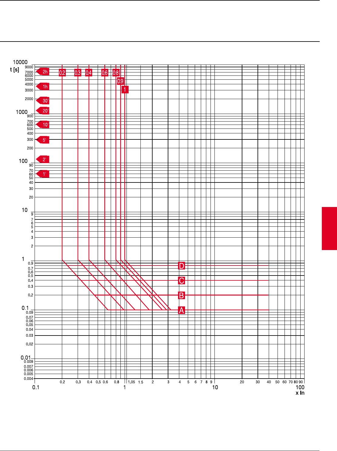
ABB Control Inc. 2.25
AC 1600 – 3/00
Isomax
Function G1
Key
In = Rated current of current transformers
t= Tripping time
Protective releases
Microprocessor based overcurrent relays, PR212
Time-current curves, S4 – S8
1 S8 maximum setting is 0.4 per NEC guidelines.
2.26 ABB Control Inc.
AC 1600 – 3/00
Isomax
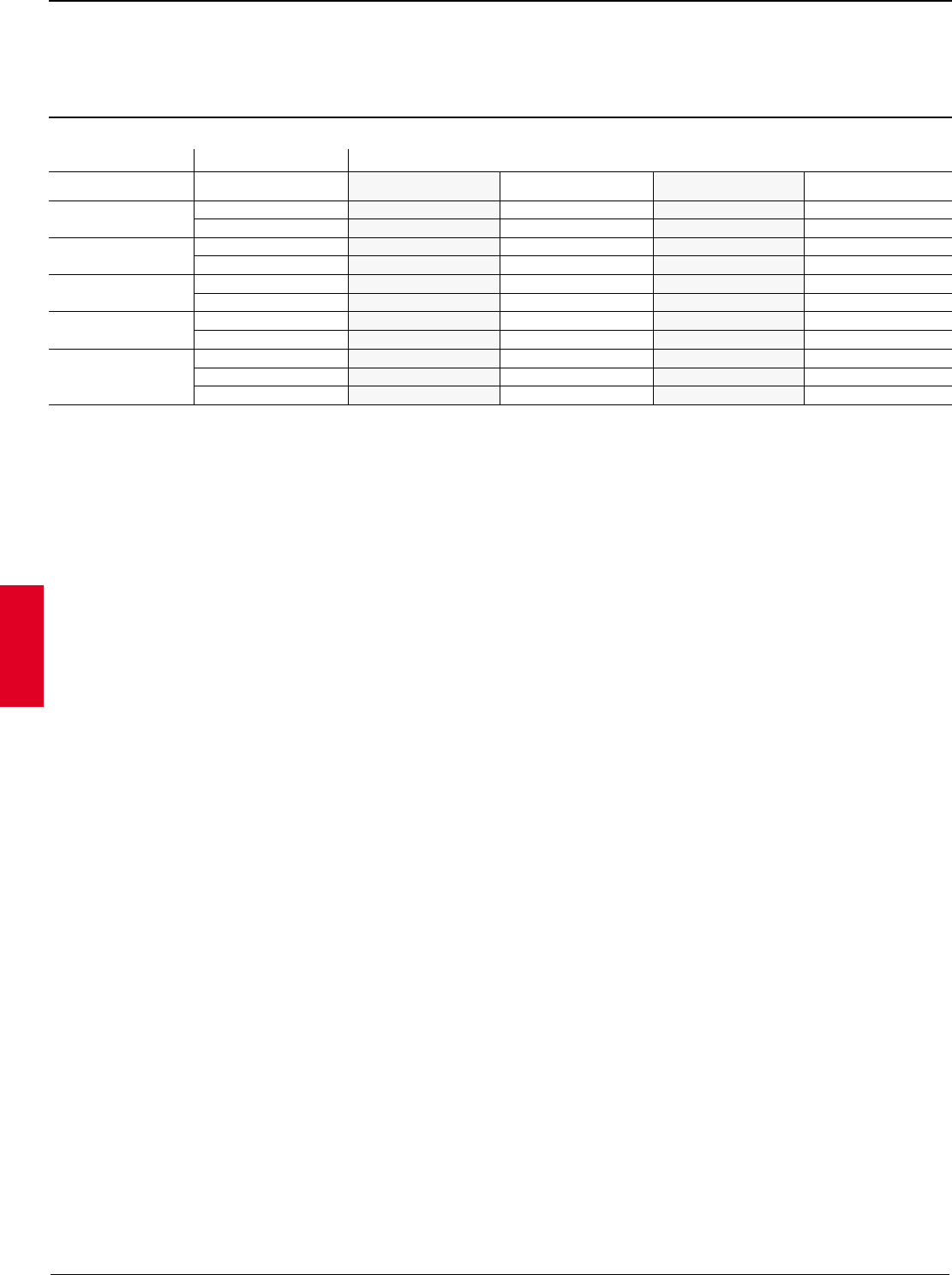
Motor horsepower ratings
Magnetic trip
1/2HP @ 575V to 100HP @ 575V
Horsepower per NEC 430-50 Motor full Isomax MCP Approximate trip setting % of MFLA
208V 230V 460V 575V Load amps Type Rating 1.5X 2X 4X 6X 8X 10X 12X
%%%%%%%
1/2 0.9 S3 3 ——1300 2000 2700 3400 4000
1/2 1.1 S3 3 ——1100 1600 2200 3700 3300
3/4 1.3 S3 3 ——900 1400 1800 2300 2800
3/4 1.6 S3 3 ——800 1100 1500 1900 2300
11.7S33 ——700 1100 1400 1800 2100
12.1S35——1000 1400 1900 2400 2900
1/2 2.2 S3 5 ——900 1400 1800 2300 2700
1/2 1 1/2 2.4 S3 5 ——800 1300 1700 2100 2500
22.7S35 ——700 1100 1500 1900 2200
1 1/2 3 S3 5 ——700 1000 1300 1700 2000
3/4 3.2 S3 5 ——600 900 1300 1600 1900
23.4S35——600 900 1200 1500 1800
3/4 3.5 S3 10 ——1100 1700 2300 2900 3400
33.9S310——1000 1500 2100 2600 3100
14.2S310——1000 1400 1900 2400 2900
14.6S310——900 1300 1700 2200 2600
34.8S310——800 1300 1700 2100 2500
1 1/2 6 S3 10 ——700 1000 1300 1700 2000
56.1S310——700 1000 1300 1600 2000
1 1/2 6.6 S3 10 ——600 900 1200 1500 1800
26.8S310——600 900 1200 1500 1800
7.5 S3 25 ——1300 2000 2700 3300 4000
257.6S325——1300 2000 2600 3300 3900
7 1/2 9 S3 25 ——1100 1700 2200 2800 3300
39.6S325——1000 1600 2100 2600 3100
3 10.6 S3 25 ——900 1400 1900 2400 2800
7 1/2 10 11 S3 25 ——900 1400 1800 2300 2700
10 14 S3 25 ——700 1000 1400 1800 2100
5 15.2 S3 25 ——700 1000 1300 1600 2000
5 16.7 S3 25 ——600 900 1200 1500 1800
15 17 S3 25 ——600 900 1200 1500 1800
15 21 S3 50 ——1000 1400 1900 2400 2800
7 1/2 20 22 S3 50 ——900 1400 1800 2300 2700
7 1/2 24.2 S3 50 ——800 1200 1700 2100 2500
20 25 27 S3 50 ——700 1100 1500 1900 2200
10 28 S3 50 ——700 1100 1400 1800 2100
10 30.8 S3 50 ——600 1000 1300 1600 1900
30 32 S3 50 ——600 900 1300 1600 1900
25 34 S3 50 ——600 900 1200 1500 1800
30 40 S3 100 ——1000 1500 2000 2500 3000
40 41 S3 100 ——1000 1500 2000 2400 2900
15 42 S3 100 ——1000 1400 1900 2400 2900
15 46.2 S3 100 ——900 1300 1700 2200 2600
40 50 52 S3 100 ——800 1200 1500 1200 2300
20 54 S3 100 ——700 1100 1500 1900 2200
20 59.4 S3 100 ——700 1000 1300 1700 2000
60 62 S3 100 ——600 100 1300 1600 1900
50 65 S3 100 ——600 900 1200 1500 1800
25 68 S3 100 ——600 900 1200 1500 1800
25 74.8 S3 150 ——800 1200 1600 2000 —
60 75 77 S3 150 ——800 1200 1600 1900 —
30 80 S3 150 ——800 1100 1500 1900 —
30 88 S3 150 ——700 1000 1400 1700 —
75 96 S3 150 ——600 900 1300 1600 —
100 99 S3 150 ——600 900 1200 1500 —
Magnetic trip
ABB Control Inc. 2.27
AC 1600 – 3/00
Isomax
Motor horsepower ratings
Electronic trip
40HP @ 230V to 500HP @ 460V
Horsepower per NEC 430-50 Motor full Isomax MCP Approximate trip setting % of MFLA
208V 230V 460V 575V Load amps Type Rating 1.5X 2X 4X 6X 8X 10X 12X
%%%%%%%
40 104 S4 250 350 500 1000 1400 1900 2400 2900
40 114 S4 250 350 450 900 1300 1800 2200 2600
100 124 S4 250 300 400 800 1200 1600 2000 2400
125 125 S4 250 300 400 800 1200 1600 2000 2400
50 130 S4 250 300 400 800 1200 1500 1900 2300
50 143 S4 250 250 350 700 1000 1400 1700 2100
150 144 S4 250 250 350 700 1000 1400 1700 2100
60 154 S4 250 250 300 600 1000 1300 1600 1900
125 156 S4 250 250 300 600 1000 1300 1600 1900
60 169 S4 250 200 300 600 900 1200 1500 1800
150 180 S5 400 350 450 900 1300 1800 2200 2700
75 192 S5 400 300 400 800 1300 1700 2100 2500
75 211 S5 400 300 400 800 1100 1500 1900 2300
200 240 S5 400 250 350 700 1000 1300 1700 2000
250 242 S5 400 250 350 700 1000 1300 1700 2000
100 248 S5 400 250 300 600 1000 1300 1600 1900
100 273 S6 600 350 450 900 1300 1800 2200 2600
300 289 S6 600 300 400 800 1200 1700 2100 2500
250 302 S6 600 300 400 800 1200 1600 2000 2400
125 312 S6 600 300 400 800 1200 1500 1900 2300
350 336 S6 600 250 350 700 1100 1400 1800 2100
125 343 S6 600 250 350 700 1100 1400 1700 2100
150 360 S6 600 250 350 700 1000 1300 1700 2000
300 361 S6 600 250 350 700 1000 1300 1700 2000
400 362 S6 600 250 300 600 900 1300 1600 1900
150 396 S6 600 250 300 600 900 1200 1500 1800
450 412 S6 800 300 400 800 1200 1600 1900 2300
350 414 S6 800 300 400 800 1200 1600 1900 2300
500 472 S6 800 250 350 700 1000 1400 1700 2000
400 477 S6 800 250 350 700 1000 1300 1700 2000
200 480 S6 800 250 350 700 1000 1300 1700 2000
450 515 S6 800 250 300 600 900 1200 1600 1900
200 528 S6 800 250 300 600 900 1200 1500 1800
500 590 S7 1000 250 350 700 1000 1400 1700 2000
Electronic trip

2.28 ABB Control Inc.
AC 1600 – 3/00
Isomax
Notes
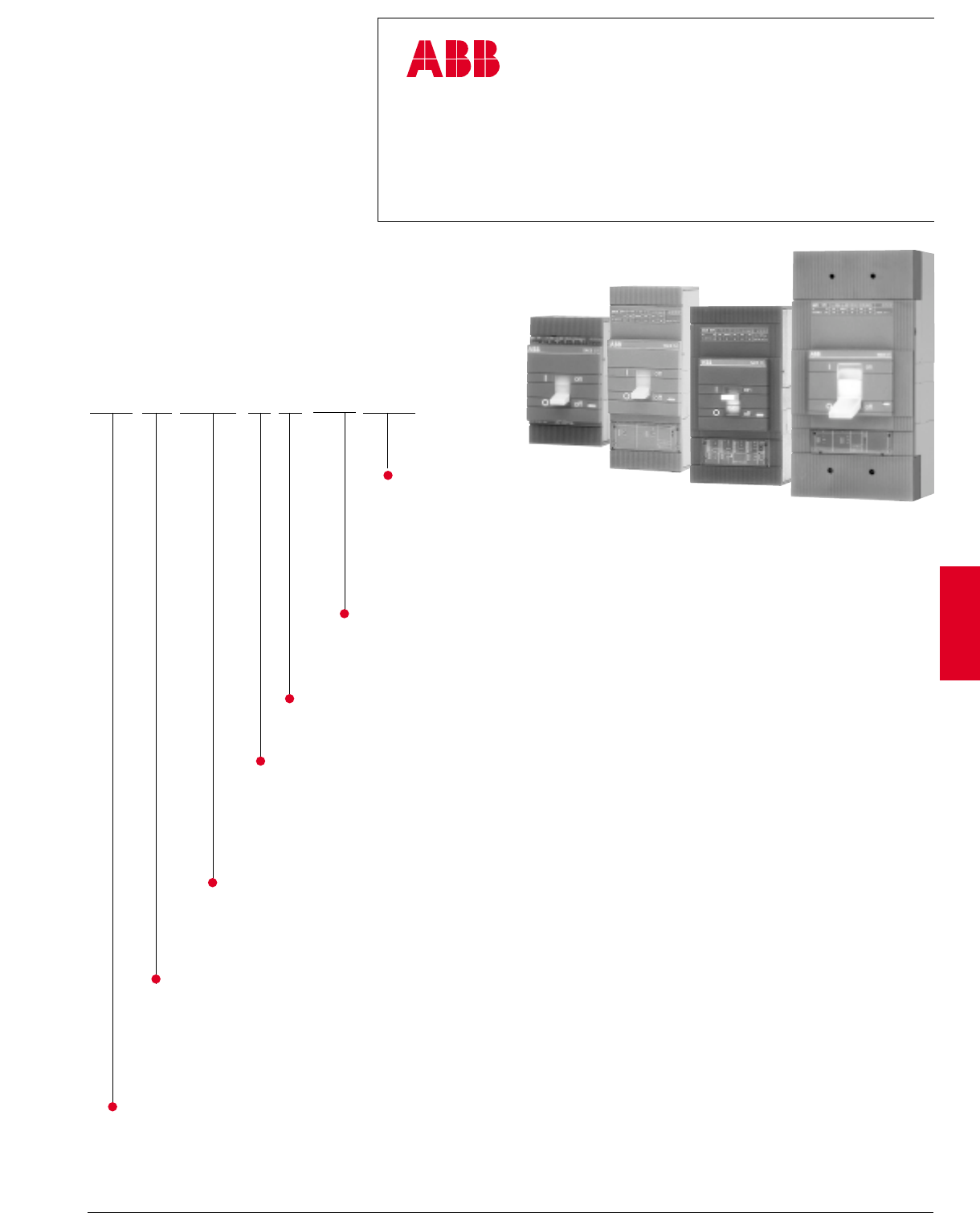
ABB Control Inc. 2.29
AC 1600 – 3/00
Isomax
Isomax
Molded case circuit breakers
S1 – S8
S4 N 250 BW - 2xxx
Interrupting rating class
B = Basic (240VAC) BQ = Basic, 100% rated
N =Normal NQ = Normal, 100% rated
H =High HQ = High, 100% rated
L = Extra High LQ = Extra High, 100% rated
D = Special molded case switch
(No trip IEC)
Current rating
015 = 15A
250 = 250A
400 = 400A
1200 = 1200A
Trip unit function
B =LI F = LSIG/K
C =LSI H = LSIG/D
D = Molded Case Switch (MCS) J = LSIG/DT
E =LSIG K = LSIG/DTK
T = Thermal-magnetic M = Magnetic only (MCP)
Type connectors
W = None
Number of poles
-2 = 2 pole
-4 = 4 pole
None = 3 pole
Accessories (added in alpha-numeric order) 1
A = Auxiliary Switch
BA = Bell Alarm
BA3 = Bell Alarm (S6/S7 only)
H = Fixed Rotary Handle mounted on CB
S_ = Shunt trip with voltage code
U_ = Undervoltage release with voltage code
Frame size
S1= 100A S6 = 600 / 800A
S3 = 150 / 225A S7 = 1200A
S4 = 250A
S5 = 400A 1 Consult ABB for factory installed accessories.
2.30 ABB Control Inc.
AC 1600 – 3/00
Isomax
S1
100A
Standard thermal-magnetic
General
The S1 breaker family ranges from 15 through 100 amperes. The S1 trip
mechanisms are non-interchangeable and use sensitive electromagnetic relays
for overcurrent trip protection. Heat sensitive bimetal are used for thermal rating
of the breaker. Lugs are included with the S1 breaker.
Number of poles
The S1 is available in three pole or four pole versions. The four pole version is
IEC only. For price estimate of a four pole device, add 35% to list price of
selected version three pole breaker, contact ABB Control for details.
Accessory mounting
Shunt trips or undervoltage releases mount in the left cavity. Auxiliary or bell
alarm switches mount in the right cavity.
Reverse feeding
All versions of the S1 family are suitable for reverse feed applications.
UL489 / CSA C22.2 Interrupting capacity (kA RMS)
S1N
230VAC 40kA
380/400/415VAC 15 – 100A 25kA
440VAC 16kA
500VAC 12kA
Voltage Continuous rating N
IEC-947 Interrupting capacity (kA RMS)
Voltage Continuous rating N
14kA 15A 500A S1N015TL $ 392
20A 500A S1N020TL
25A 500A S1N025TL
30A 500A S1N030TL
S1N 20kA 40A 500A S1N040TL 392
50A 500A S1N050TL
60A 600A S1N060TL
70A 700A S1N070TL
80A 800A S1N080TL 459
90A 900A S1N090TL
100A 1000A S1N100TL
Breaker IC at Rating Magnetic 3 pole List
480 VAC catalog number price
Discount schedule S1
240VAC 15 – 100A 50kA
277/480VAC 15A 14kA
20 – 100A 20kA
H x W x D
4.72" x 3.07" x 2.75"
S1
S1
ABB Control Inc. 2.31
AC 1600 – 3/00
Isomax
UL/CSA Interrupting capacity (kA RMS)
UL489 / CSA C22.2
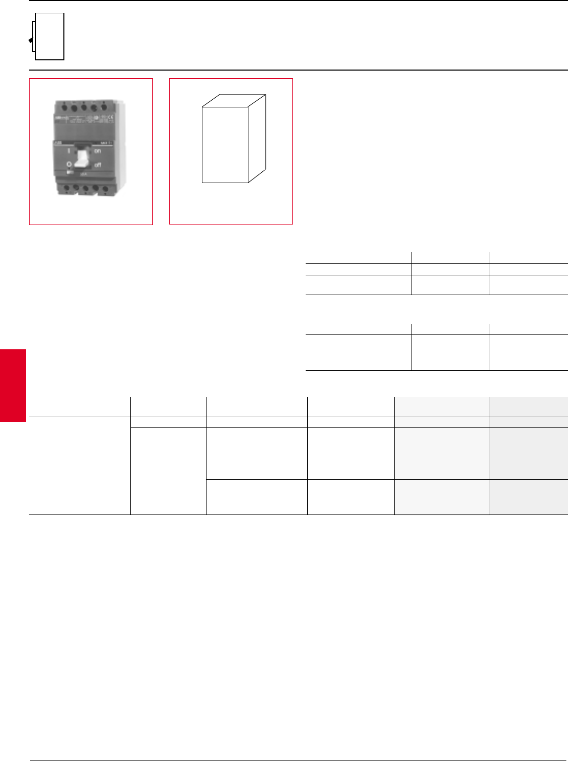
S3
150/225A
Standard thermal-magnetic
H x W x D
6.70" x 4.13" x 4.07"
Standard S3 package includes
complete circuit breaker and
mounting hardware. Order cable
lugs as a separate item, copper/
aluminum (Cu/Al) lugs are no
charge when ordered with breaker.
General
The S3 breaker family ranges from 15 through 225 amperes. The S3 trip
mechanisms are non-interchangeable and use sensitive electromagnetic relays
for overcurrent trip protection. Heat sensitive bimetal are used for thermal
overcurrent protection. Short circuit current protection begins at 10 times the
thermal rating of the breaker and uses a magnetic coil principle.
Versions
To meet all application needs, the S3 is available in various versions:
T =Thermal-magnetic
Q =100% UL rated
D = Molded case switch
M = Magnetic only (MCP)
Performance level
Each version is also available in different maximum fault interrupting levels
B = 240VAC
N = Normal
H = High
L = Extra high
Number of poles
In UL/CSA form, the S3 is available in two pole or three pole versions, both with
the same dimensions. A four pole version is also available in IEC form. For price
estimate, add 35% to list price of selected version three pole breaker, contact
ABB Control for details.
Accessory mounting
Internal accessories are UL/CSA approved for both factory or field installation.
Accessories require control cable connectors. Shunt trips or UVR's mount in the
left cavity. Auxiliary or bell alarm switches mount in the right cavity.
Reverse feeding
All versions of the S3 family are suitable for reverse feed applications.
Molded case switches
UL1087 switches include no overcurrent protection except for a high
instantaneous trip mechanism for self protection. IEC type molded case
switches with no trip protection are also available.
Voltage N H L
230VAC 65 100 170
380/400/415VAC 35 65 85
440VAC 30 50 65
500VAC 25 40 50
690VAC 14 18 20
500VDC 35 50 65
750VDC 20 35 50
1 15-30A are 65kA at 480VAC
S3N S3H S3LS3B
Voltage N H L
240VAC 65 100 150
480VAC 25 50 851
600VAC 14 14 25
500VDC 35 50 65
600VDC 20 35 50
IEC-947 Interrupting capacity (kA RMS)
Discount schedule S3
S3
2.32 ABB Control Inc.
AC 1600 – 3/00
Isomax
S3
150/225A
Standard thermal-magnetic
Discount schedule S3
S3L
15A 500A S3L015TW-2 S3L015TW
65kA 20A 500A S3L020TW-2 $ 634 S3L020TW $ 824
25A 500A S3L025TW-2 S3L025TW
30A 500A S3L030TW-2 S3L030TW
35A 500A S3L035TW-2 S3L035TW
40A 500A S3L040TW-2 634 S3L040TW 824
S3L 50A 500A S3L050TW-2 S3L050TW
85kA 60A 600A S3L060TW-2 S3L060TW
70A 700A S3L070TW-2 S3L070TW
80A 800A S3L080TW-2 816 S3L080TW 1010
90A 900A S3L090TW-2 S3L090TW
100A 1000A S3L100TW-2 S3L100TW
125A 1250A S3L125TW-2 S3L125TW
150A 1500A S3L150TW-2 S3L150TW
175A11750A S3L175TW-2 1818 S3L175TW 2260
200A12000A S3L200TW-2 S3L200TW
225A12250A S3L225TW-2 S3L225TW
Breaker IC at Rating Magnetic 2 pole, 480VAC/500VAC List 3 pole, 600VAC/DC List
480VAC trip catalog number price catalog number price
15A 500A S3H015TW-2 S3H015TW
20A 500A S3H020TW-2 S3H020TW
25A 500A S3H025TW-2 S3H025TW
30A 500A S3H030TW-2 $ 527 S3H030TW $ 619
35A 500A S3H035TW-2 S3H035TW
40A 500A S3H040TW-2 S3H040TW
50A 500A S3H050TW-2 S3H050TW
S3H 50kA 60A 600A S3H060TW-2 S3H060TW
70A 700A S3H070TW-2 S3H070TW
80A 800A S3H080TW-2 617 S3H080TW 702
90A 900A S3H090TW-2 S3H090TW
100A 1000A S3H100TW-2 S3H100TW
125A 1250A S3H125TW-2 S3H125TW
150A 1500A S3H150TW-2 S3H150TW
175A11750A S3H175TW-2 1376 S3H175TW 1586
200A12000A S3H200TW-2 S3H200TW
225A12250A S3H225TW-2 S3H225TW
Breaker IC at Rating Magnetic 2 pole, 480VAC/500VAC List 3 pole, 600VAC/DC List
480VAC trip catalog number price catalog number price
S3H
15A 500A S3N015TW-2 S3N015TW
20A 500A S3N020TW-2 S3N020TW
25A 500A S3N025TW-2 S3N025TW
30A 500A S3N030TW-2 $ 316 S3N030TW $ 413
35A 500A S3N035TW-2 S3N035TW
40A 500A S3N040TW-2 S3N040TW
50A 500A S3N050TW-2 S3N050TW
S3N 25kA 60A 600A S3N060TW-2 S3N060TW
70A 700A S3N070TW-2 S3N070TW
80A 800A S3N080TW-2 407 S3N080TW 504
90A 900A S3N090TW-2 S3N090TW
100A 1000A S3N100TW-2 S3N100TW
125A 1250A S3N125TW-2 S3N125TW
150A 1500A S3N150TW-2 S3N150TW
175A11750A S3N175TW-2 911 S3N175TW 1131
200A12000A S3N200TW-2 S3N200TW
225A12250A S3N225TW-2 S3N225TW
Breaker IC at Rating Magnetic 2 pole, 480VAC/500VDC List 3 pole, 600VAC/DC List
480VAC trip catalog number price catalog number price
S3N
175A 1750A S3B175TW-2 S3B175TW
S3B 150kA 200A 2000A S3B200TW-2 $ 460 S3B200TW $ 590
225A 2250A S3B225TW-2 S3B225TW
Breaker IC at Rating Magnetic 2 pole, 240VAC List 3 pole, 240VAC List
240VAC trip catalog number price catalog number price
S3B
1 480VAC maximum
S3
ABB Control Inc. 2.33
AC 1600 – 3/00
Isomax
S3
150/225A
100% UL rated
S3NQ
Note: When applied correctly, UL tested 100% equipment rated breakers may be applied at full rating rather than on the sizing rules of the NEC where breakers and
cable are sized based on actual continuous load current divided by 80%. This 100% rating can save the user the cost of larger cable or bus bar. Please consult the
NEC for details and other design factors needed for this application.
Breaker IC at Rating Magnetic 3 pole 600VAC/DC List
480VAC trip catalog number price
S3HQ
S3LQ
Discount schedule S3
15A 500A S3LQ015TW
65kA 20A 500A S3LQ020TW
25A 500A S3LQ025TW
30A 500A S3LQ030TW $ 916
35A 500A S3LQ035TW
40A 500A S3LQ040TW
50A 500A S3LQ050TW
60A 600A S3LQ060TW
S3LQ 85kA 70A 700A S3LQ070TW
80A 800A S3LQ080TW 1123
90A 900A S3LQ090TW
100A 1000A S3LQ100TW
125A 1250A S3LQ125TW
150A 1500A S3LQ150TW
175A11750A S3LQ175TW 2511
200A12000A S3LQ200TW
225A12250A S3LQ225TW
Breaker IC at Rating Magnetic 3 pole List
480VAC trip catalog number price
15A 500A S3HQ015TW
20A 500A S3HQ020TW
25A 500A S3HQ025TW
30A 500A S3HQ030TW $ 688
35A 500A S3HQ035TW
40A 500A S3HQ040TW
50A 500A S3HQ050TW
S3HQ 50kA 60A 600A S3HQ060TW
70A 700A S3HQ070TW
80A 800A S3HQ080TW 780
90A 900A S3HQ090TW
100A 1000A S3HQ100TW
125A 1250A S3HQ125TW
150A 1500A S3HQ150TW
175A11750A S3HQ175TW 1762
200A12000A S3HQ200TW
225A12250A S3HQ225TW
Breaker IC at Rating Magnetic 3 pole List
480VAC trip catalog number price
15A 500A S3NQ015TW
20A 500A S3NQ020TW
25A 500A S3NQ025TW
30A 500A S3NQ030TW $ 459
35A 500A S3NQ035TW
40A 500A S3NQ040TW
50A 500A S3NQ050TW
S3NQ 25kA 60A 600A S3NQ060TW
70A 700A S3NQ070TW
80A 800A S3NQ080TW 560
90A 900A S3NQ090TW
100A 1000A S3NQ100TW
125A 1250A S3NQ125TW
150A 1500A S3NQ150TW
175A11750A S3NQ175TW 1257
200A12000A S3NQ200TW
225A12250A S3NQ225TW
1 480VAC maximum
S3
2.34 ABB Control Inc.
AC 1600 – 3/00
Isomax
Molded case switches
Connection options
S3
150/225A, 600VAC
CU/AL front lugs 14AWG –2AWG 60 K3TA-2 $ 4 K3TA $ 6
CU/AL front lugs 14AWG –1/0 100 K4TB-2 4K4TB 6
CU/ALfront lugs 2AWG –4/0 150 K4TC-2 4K4TC 6
CU/AL front lugs 4AWG –300kcmil 225 K4TD-2 10 K4TD 15
CU front lugs (saddle) 14AWG –250kcmil 250 ——K4TES 30
CU rear lugs 6AWG –350kcmil 250 ——K4TER
Extended front bar –250 ——K4ET-250
Wire Set of 2 List Set of 3 List
Type range Amps➀catalog number price catalog number price
1Suggested lugs for circuit breaker up to amps shown. Cable size and type determine maximum amperage.
2480VAC maximum.
Discount schedule SM – S3 MCPs only Discount schedule S3
Type Interruption Amps Magnetic 3 pole List
capacity trip catalog number price
Set of 6
catalog number
S3B-D 240VAC 150KA 225 2250A S3B225DW $ 410
240VAC 100kA
480VAC 50kA
S3H-D 600VAC 14kA 150 1500A S3H150DW 892
500VDC 65kA 225 22250A S3H225DW 1254
600VDC 50kA
Non-UL Withstand rating
switches 100 none S3D100W 531
without 600VAC 6.5kA 160 none S3D160W 892
overcurrent 250 none S3D250W 1393
protection
Magnetic only circuit breakers are instantaneous trip only devices which are Underwriters Laboratories Recognized. MCPs must be used with some other device that
will provide overload protection.
Magnetic only (MCP)
240VAC 50kA 3 12 –36 S3L003MW
480VAC 25kA 5 20 –60 S3L005MW
600VAC 10kA 10 40 –120 S3L010MW
$ 710
240VAC 50kA
480VAC 25kA 25 100 –300 S3L025MW
S3L 600VAC 10kA
240VAC 150kA 50 200 –600 S3L050MW 710
480VAC 85kA 100 400 –1200 S3L100MW 843
600VAC 25kA 125 500 –1500 S3L125MW 1910
150 600 –1500 S3L150MW 1910
480VAC 65kA 200 2800 –2400 S3L200MW 1910
Type Interruption Amps Magnetic 3 pole List
capacity trip catalog number price
240VAC 35kA 3 12 –36 S3N003MW
480VAC 18kA 5 20 –60 S3N005MW
600VAC 10kA 10 40 –120 S3N010MW
240VAC 35kA $ 568
480VAC 18kA 25 100 –300 S3N025MW
S3N 600VAC 10kA
240VAC 75kA 50 200 –600 S3N050MW 633
480VAC 35kA 100 400 –1200 S3N100MW 763
600VAC 14kA 125 500 –1500 S3N125MW 929
150 600 –1500 S3N150MW 929
Type Interruption Amps Magnetic 3 pole List
capacity trip catalog number price
S3
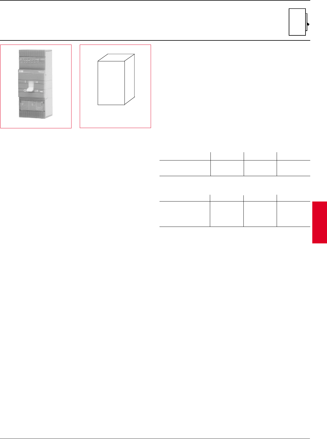
ABB Control Inc. 2.35
AC 1600 – 3/00
Isomax
S4
250A, 600VAC
Electronic trip type
H x W x D
10.0" x 4.13" x 4.07"
General
The S4 breaker family is a 250A frame utilizing a microprocessor based
overcurrent protective trip system. In the 250A version, the trip unit is
adjustable from 100A up to 250A without the addition of any parts or rating
plugs. As standard, the S4 includes adjustable long time function for overload
protection and adjustable instantaneous function for short circuit protection.
Versions
To meet all application needs, the S4 is available in various versions:
B = Adjustment LI
C = Adjustment LSI
E = Adjustment LSIG
Q = 100% UL rated
D = Molded case switch
M = Magnetic only (MCP)
Trip functions
These tripping functions are available:
L = Long time I = Instantaneous
S = Short time G = Ground fault
Performance level
Each version is also available in different maximum fault interrupting levels:
N = Normal
H = High
L = Extra high
Number of poles
In UL/CSA form, the S4 is available in two pole or three pole versions, both with
the same dimensions. A four pole version is also available in UL/IEC form. For
price estimate, add 35% to list price of selected version three pole breaker,
contact ABB Control for details.
Accessory mounting
Internal accessories are UL/CSA approved for both factory or field installation.
Accessories require control cable connectors. Shunt trips or UVR's mount in the
left cavity. Auxiliary or bell alarm switches mount in the right cavity.
Reverse feeding
All versions of the S4 family are suitable for reverse feed applications.
Molded case switches
UL1087 switches include no overcurrent protection except for a high
instantaneous trip mechanism for self protection.
Voltage N H L
240VAC 65 150 200
480VAC 25 65 100
600VAC 18 22 35
Voltage N H L
230VAC 65 150 200
380/400/415VAC 35 65 100
440VAC 30 50 80
500VAC 25 40 65
690VAC 18 22 30
Standard S4 package includes
complete circuit breaker and
mounting hardware. Order cable
lugs or other connection scheme
as a separate item.
S4
UL/CSA Interrupting capacity (kA RMS)
UL489 / CSA C22.2
IEC-947 Interrupting capacity (kA RMS)
Discount schedule S4
S4
2.36 ABB Control Inc.
AC 1600 – 3/00
Isomax
PR211 LI S4N100BW-2 $ 1073 S4N100BW $ 1347
S4N 25kA PR212 LSI S4N100CW-2 1679 S4N100CW 1913
PR212 LSIG —S4N100EW 2813
PR211 LI S4H100BW-2 2572 S4H100BW 3030
S4H 65kA PR212 LSI S4H100CW-2 3138 S4H100CW 3596
PR212 LSIG —S4H100EW 4496
PR211 LI S4L100BW-2 3159 S4L100BW 3950
S4L 100kA PR212 LSI S4L100CW-2 3725 S4L100CW 4516
PR212 LSIG ——S4L100EW 5416
The S4 breaker family uses two available microprocessor based internal trip
units. The standard PR211 trip unit includes adjustments for long time current
pick-up and instantaneous current trip point.
The optional PR212 trip unit includes adjustments for long time current pick-up/
delay, short time pick-up/delay I2t (on/off), instantaneous current trip point and
further optional ground fault protection.
S4
250A, 600VAC
Electronic trip type
100A Frame (40 – 100A adjustable continuous range)
Breaker IC at 480VAC Trip Adjustment 2 pole List 3 pole List
type catalog number price catalog number price
250A Frame (100 – 250A adjustable continuous range)
Breaker IC at 480VAC Trip Adjustment 2 pole List 3 pole List
type catalog number price catalog number price
LLong time pick-up 0.4 –1.0 0.4-0.5-0.6-0.7-0.8-0.9-0.95-1.0 x Frame rating
Long time delay 3.0 –18 sec. A - B - C - D
SShort time pick-up 1.0 –10.0 Off-1.0-2.0-3.0-4.0-6.0-8.0-10.0 x Frame rating
Short time delay 0.05 –0.5 sec. A - B - C - D (I2t On-Off)
I Instantaneous trip 1.5 –12.0 1.5-2.0-4.0-6.0-8.0-10.0-12.0 x Frame rating
GGround fault 0.2 –1.0 Off-0.2-0.3-0.4-0.6-0.8-0.9-1.0 x Frame rating
Ground fault delay 0.1 –0.8 sec. A - B - C - D
PR211 LI S4N250BW-2 $ 1073 S4N250BW $ 1347
S4N 25kA PR212 LSI S4N250CW-2 1679 S4N250CW 1913
PR212 LSIG —S4N250EW 2813
PR211 LI S4H250BW-2 2572 S4H250BW 3030
S4H 65kA PR212 LSI S4H250CW-2 3138 S4H250CW 3596
PR212 LSIG —S4H250EW 4496
PR211 LI S4L250BW-2 3159 S4L250BW 3950
S4L 100kA PR212 LSI S4L250CW-2 3725 S4L250CW 4516
PR212 LSIG ——S4L250EW 5416
Trip settings
Discount schedule S4
Continuous amperage settings (long time adjustment)
Frame Set points
Adjustment Trip Range Individual
function settings
0.4 0.5 0.6 0.7 0.8 0.9 0.95 1.0 Setting
100A 40 50 60 70 80 90 95 100 Amps
250A 100 125 150 175 200 225 237 250 Amps
S4
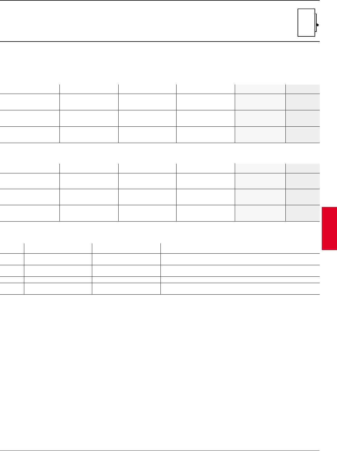
ABB Control Inc. 2.37
AC 1600 – 3/00
Isomax
S4
250A, 600 VAC
100% UL rated
PR211 LI S4NQ100BW $ 1482
S4N 25kA PR212 LSI S4NQ100CW 2104
PR212 LSIG S4NQ100EW 3094
PR211 LI S4HQ100BW 3333
S4H 65kA PR212 LSI S4HQ100CW 3956
PR212 LSIG S4HQ100EW 4946
PR211 LI S4LQ100BW 4345
S4L 100kA PR212 LSI S4LQ100CW 4968
PR212 LSIG S4LQ100EW 5958
When applied correctly, UL tested 100% equipment rated breakers may be
applied at full rating rather than on the sizing rules of the NEC where breakers
and cable are sized based on actual continuous load current divided by 80%.
Adjustment Trip Range Individual
function settings
LLong time pick-up 0.4 –1.0 0.4-0.5-0.6-0.7-0.8-0.9-0.95-1.0 x Frame rating
Long time delay 3.0 –18 sec. A - B - C - D
SShort time pick-up 1.0 –10.0 Off-1.0-2.0-3.0-4.0-6.0-8.0-10.0 x Frame rating
Short time delay 0.05 –0.5 sec. A - B - C - D (I2t On-Off)
I Instantaneous trip 1.5 –12.0 1.5-2.0-4.0-6.0-8.0-10.0-12.0 x Frame rating
GGround fault 0.2 –1.0 Off-0.2-0.3-0.4-0.6-0.8-0.9-1.0 x Frame rating
Ground fault delay 0.1 –0.8 sec. A - B - C - D
100A Frame (40 – 100A adjustable continuous range)
Breaker IC at Trip Adjustment 3 pole List
480VAC type catalog number price
250A Frame (100 – 250A adjustable continuous range)
Trip settings
Discount schedule S4
PR211 LI S4NQ250BW $ 1482
S4N 25kA PR212 LSI S4NQ250CW 2104
PR212 LSIG S4NQ250EW 3094
PR211 LI S4HQ250BW 3333
S4H 65kA PR212 LSI S4HQ250CW 3956
PR212 LSIG S4HQ250EW 4946
PR211 LI S4LQ250BW 4345
S4L 100kA PR212 LSI S4LQ250CW 4968
PR212 LSIG S4LQ250EW 5958
Breaker IC at Trip Adjustment 3 pole List
480VAC type catalog number price
This 100% rating can save the user the cost of larger cable or bus bar. Please
consult the NEC for details and other design factors needed for this application.
S4
2.38 ABB Control Inc.
AC 1600 – 3/00
Isomax
Type Interruption Amps Magnetic 3 pole List
capacity trip catalog number price
Molded case switch
All S4 magnetic only breakers utilize the electronic PR211 trip unit with an
adjustable range of 1.5 to 12 times frame rating. Both two and three pole MCPs
are 600VAC rated.
Type Amps Interruption Adjustment 2 pole 600VAC List 3 pole 600VAC List
capacity range catalog number price catalog number price
CU/AL front lugs 14AWG –1/0 100 K4TB-2 $ 4 K4TB $ 6
CU/AL front lugs 2AWG –4/0 150 K4TC-2 4K4TC 6
CU/AL front lugs 4AWG –300kcmil 225 K4TD-2 10 K4TD 15
CU/AL front lugs 6AWG –350kcmil 250 K4TE-2 20 K4TE 30
CU front lugs (saddle) 14AWG –250kcmil 250 ——K4TES 30
CU rear lugs 6AWG –250kcmil 250 ——K4TER
Extended front bar —250 ——K4ET-250
Amps Catalog List
number price
Neutral GF current transformer (required for 4 wire GF systems)
S4
250A, 600VAC
Connection options
Type Wire Amps Set of 2 List Set of 3 List
range ➀catalog number price catalog number price
Magnetic only (MCP)
Discount schedule S4
Set of 6
catalog number
1 Suggested lugs for a circuit breaker up to the amps shown. Cable size and type determine maximum amperage.
100 240VAC 65kA 150 –1200A S4N100MW-2 S4N100MW
S4N 250 480VAC 25kA 375 –3000A S4N250MW-2 $ 1073 S4N250MW $ 1347
600VAC 18kA
100 240VAC 150kA 150 –1200A S4H100MW-2 S4H100MW
S4H 250 480VAC 65kA 375 –3000A S4H250MW-2 2572 S4H250MW 3030
600VAC 22kA
100 240VAC 200kA 150 –1200A S4L100MW-2 S4L100MW
S4L 250 480VAC 100kA 375 –3000A S4L250MW-2 3159 S4L250MW 3950
600VAC 35kA
240VAC 150kA
S4H-D 480VAC 65kA 250 3000A S4H250DW $ 1215
600VAC 22kA
100 K4NCT-100 $ 250
250 K4NCT-250
S4
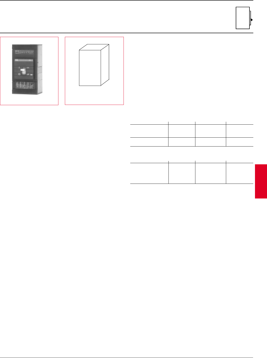
ABB Control Inc. 2.39
AC 1600 – 3/00
Isomax
S5
400A, 600V
Electronic and thermal-magnetic trip types
Standard S5 package includes
complete circuit breaker and
mounting hardware. Order cable
lugs or other connection scheme
as a separate item.
General
The S5 breaker family is a 400A frame utilizing a microprocessor-based
overcurrent protective trip system. In the 400A version, the trip unit is adjustable
from 160A up to 400A without the addition of any parts or rating plugs. As
standard the S5 includes adjustable long time function for overload protection
and adjustable instantaneous function for short circuit protection.
Versions
To meet all application needs, the S5 is available in various versions:
B = Adjustment LI
C = Adjustment LSI
E = Adjustment LSIG
Q = 100% UL rated
D = Molded case switch
M = Magnetic only (MCP)
T = Thermal magnetic
Trip functions
These tripping functions are available:
L = Long time I = Instantaneous
S = Short time G = Ground fault
Performance level
Each version is also available in different maximum fault interrupting levels
N = Normal
H = High
L = Extra high
Number of poles
In UL/CSA version, the S5 is available in two pole or three pole version, both
with the same dimensions. A four pole version is also available in UL/IEC form.
For price estimate, add 35% to list price of selected version three pole breaker,
contact ABB Control for details.
Accessory mounting
Internal accessories are UL/CSA approved for both factory or field installation.
Accessories require control cable connectors. Shunt trips or UVR's mount in the
left cavity. Auxiliary or bell alarm switches mount in the right cavity.
Reverse feeding
All versions of the S5 family are suitable for reverse feed applications.
Molded case switches
UL1087 switches include no overcurrent protection except for a high
instantaneous trip mechanism for self protection.
UL/CSA Interrupting capacity (kA RMS)
UL489 / CSA C22.2
Voltage N H L
240VAC 65 150 200
480VAC 35 65 100
600VAC 22 22 35
500VDC135 50 65
600VDC120 35 50
IEC-947 Interrupting capacity (kA RMS)
Voltage N H L
230VAC 65 100 200
380/400/415VAC 35 65 100
440VAC 30 50 80
500VAC 25 40 65
690VAC 20 25 30
(a) With K5TF cable lugs, breaker is 10.0" tall.
(b) With K5TG cable lugs, terminal covers are provided and breaker is
13.62" tall.
S5
H x W x D
10.0" x 5.51" x 4.07" (a)
13.62" x 5.51" x 4.07" (b)
Discount schedule S5
1 Thermal magnetic only.
S5
2.40 ABB Control Inc.
AC 1600 – 3/00
Isomax
The S5 breaker family uses two available microprocessor based internal trip
units. The standard PR211 trip unit includes adjustments for long time current
pick-up and instantaneous current trip point.
The optional PR212 trip unit includes adjustments for long time current pick-up/
delay, short time pick-up/delay, I2t (on/off), instantaneous current trip point and
further optional ground fault protection.
S5
400A, 600 VAC
Electronic and thermal-magnetic trip types
Adjustment Trip Range Individual
function settings
LLong time pick-up 0.4 –1.0 0.4-0.5-0.6-0.7-0.8-0.9-0.95-1.0 x Frame rating
Long time delay 3.0 –18 sec. A - B - C - D
SShort time pick-up 1.0 –10.0 Off-1.0-2.0-3.0-4.0-6.0-8.0-10.0 x Frame rating
Short time delay 0.05 –0.5 sec. A - B - C - D (I2t On-Off)
I Instantaneous trip 1.5 –12.0 1.5-2.0-4.0-6.0-8.0-10.0-12.0 x Frame rating
GGround fault 0.2 –1.0 Off-0.2-0.3-0.4-0.6-0.8-0.9-1.0 x Frame rating
Ground fault delay 0.1 –0.8 sec. A - B - C - D
Trip settings
Discount schedule S5
Continuous amperage settings (long time adjustment)
Frame Set points
PR211 LI S5N400BW-2 $ 1798 S5N400BW $ 2151
S5N 35kA PR212 LSI S5N400CW-2 2464 S5N400CW 2817
PR212 LSIG ——S5N400EW 3717
PR211 LI S5H400BW-2 3285 S5H400BW 3654
S5H 65kA PR212 LSI S5H400CW-2 3951 S5H400CW 4320
PR212 LSIG ——S5H400EW 5220
PR211 LI S5L400BW-2 3945 S5L400BW 4733
S5L 100kA PR212 LSI S5L400CW-2 4611 S5L400CW 5399
PR212 LSIG ——S5L400EW 6299
400A Frame (160 – 400A adjustable continuous range)
Breaker IC at 480VAC Trip Adjustment 2 pole, 600VAC List 3 pole, 600VAC List
catalog number price catalog number price
300A (210 –300A) 3000A S5N300TW-2 $ 1798 S5N300TW $ 2151
S5N 35kA 400A (280 –400A) 4000A S5N400TW-2 S5N400TW
S5H 50kA 300A (210 –300A) 3000A S5H300TW-2 3285 S5H300TW 3654
400A (280 –400A) 4000A S5H400TW-2 S5H400TW
S5L 65kA 300A (210 –300A) 3000A S5L300TW-2 3945 S5L300TW 4733
400A (280 –400A) 4000A S5L400TW-2 S5L400TW
S5 thermal-magnetic breakers, for AC and DC applications
Breaker IC at 500VDC Rating Magnetic trip 2 pole, 600VAC/500VDC List 3 pole, 600VAC/DC List
catalog number price catalog number price
0.4 0.5 0.6 0.7 0.8 0.9 0.95 1.0 Setting
400A 160 200 240 280 320 360 380 400 Amps
S5

ABB Control Inc. 2.41
AC 1600 – 3/00
Isomax
PR211 LI S5NQ400BW $ 2366
S5N 35kA PR212 LSI S5NQ400CW 3099
PR212 LSIG S5NQ400EW 4089
PR211 LI S5HQ400BW 4019
S5H 65kA PR212 LSI S5HQ400CW 4752
PR212 LSIG S5HQ400EW 5742
PR211 LI S5LQ400BW 5206
S5L 100kA PR212 LSI S5LQ400CW 5939
PR212 LSIG S5LQ400EW 6929
S5
400A, 600 VAC
100% UL rated, electronic trip type
When applied correctly, UL tested 100% equipment rated breakers may be
applied at full rating rather than on the sizing rules of the NEC where breakers
and cable are sized based on actual continuous load current divided by 80%.
LLong time pick-up 0.4 –1.0 0.4-0.5-0.6-0.7-0.8-0.9-0.95-1.0 x Frame rating
Long time delay 3.0 –18 sec. A - B - C - D
SShort time pick-up 1.0 –10.0 Off-1.0-2.0-3.0-4.0-6.0-8.0-10.0 x Frame rating
Short time delay 0.05 –0.5 sec. A - B - C - D (I2t On-Off)
I Instantaneous trip 1.5 –12.0 1.5-2.0-4.0-6.0-8.0-10.0-12.0 x Frame rating
GGround fault 0.2 –1.0 Off-0.2-0.3-0.4-0.6-0.8-0.9-1.0 x Frame rating
Ground fault delay 0.1 –0.8 sec. A - B - C - D
400A Frame (160 – 400A adjustable continuous range)
This 100% rating can save the user the cost of larger cable or bus bar. Please
consult the NEC for details and other design factors needed for this application.
Trip settings
Breaker IC at 480VAC Trip Adjustment 3 pole, 600VAC List
type catalog number price
Discount schedule S5
Adjustment Trip Range Individual
function settings
S5
2.42 ABB Control Inc.
AC 1600 – 3/00
Isomax
Molded case switch
All S5 magnetic only breakers utilize the electronic PR211 trip unit with an
adjustable range of 1.5 to 12 times frame rating. Both two and three pole MCP's
are 600VAC rated.
240 VAC 65kA
S5N 400 480VAC 35kA 600 – 4800A S5N400MW-2 $ 1798 S5N400MW $ 2151
600VAC 22kA
240VAC 150kA
S5H 400 480VAC 65kA 600 – 4800A S5H400MW-2 3285 S5H400MW 3654
600VAC 22kA
240VAC 200kA
S5L 400 480VAC 100kA 600 – 4800A S5L400MW-2 3945 S5L400MW 4733
600VAC 35kA
S5
400A, 600VAC
Type Amps Interruption Adjustment 2 pole 600VAC List 3 pole 600VAC List
capacity range catalog number price catalog number price
1 Including lug cover.
2 Suggested lugs for a circuit breaker up to amps shown. Cable size and type determine maximum amperage.
Magnetic only (MCP)
Discount schedule S5
Switch Interruption Amps Magnetic 3 pole List
capacity trip catalog number price
240VAC 150kA
S5H-D 480VAC 65kA 400A 5000A S5H400DW $ 1994
600VAC 22kA
600VDC 50kA
Type Wire Amps2Set of 2 List Set of 3 List
range catalog number price catalog number price
CU/AL front lugs 250kcmil –500kcmil 300 K5TF-2 $ 30 K5TF $ 45
CU/AL front lugs (2) 3/0 –250kcmil 400 K5TG-21K5TG1
CU front lugs (saddle) 250kcmil –500kcmil 400 ——K5TGS 90
CU rear lugs 6AWG –350kcmil 400 ——K5TGR
Extended front bar —400 ——K5ET-400
Amps Catalog List
number price
400 K5NCT-400 $ 250
Neutral GF current transformer (required for 4 wire GF systems)
Connection options
Set of 6
catalog number
S5
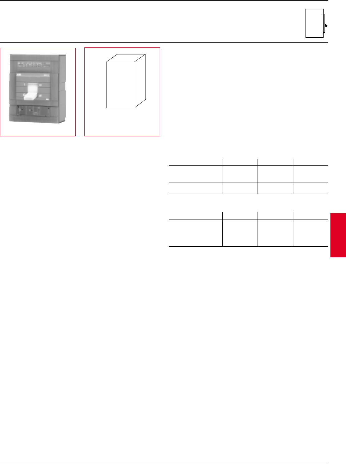
ABB Control Inc. 2.43
AC 1600 – 3/00
Isomax
S6
600A / 800A, 600V
Electronic and thermal-magnetic trip type
General
The S6 breaker family is an 800A frame with a 600A and 800A version, both
utilizing a microprocessor based overcurrent protective trip system. Both
versions are adjustable from 40% to 100% of rating without the addition of any
parts or rating plugs. As standard, the S6 includes adjustable long time function
for overload protection and adjustable instantaneous function for short circuit
protection.
Versions
To meet all application needs, the S6 is available in various versions:
B = Adjustment LI
C = Adjustment LSI
E = Adjustment LSIG
Q = 100% UL rated
D = Molded case switch
M = Magnetic only (MCP)
T = Thermal magnetic
Trip functions
These tripping functions are available:
L = Long time I = Instantaneous
S = Short time G = Ground fault
Performance level
Each version is also available in different maximum fault interrupting levels
N = Normal
H = High
L = Extra high
Number of poles
In UL/CSA version, the S6 is available as in two pole or three pole version, both
with the same dimensions. A four pole version is also available in UL/IEC form.
For price estimate, add 35% to list price of selected version three pole breaker,
contact ABB Control for details.
Accessory mounting
Internal accessories are UL/CSA approved for both factory or field installation.
Accessories require control cable connectors. Shunt trips or UVR's mount in the
left cavity. Auxiliary or bell alarm switches mount in the right cavity.
Reverse feeding
All versions of the S6 family are suitable for reverse feed applications.
Molded case switches
UL1087 switches include no overcurrent protection except for a high
instantaneous trip mechanism for self protection. IEC type molded case
switches with no trip protection are also available.
UL/CSA Interrupting capacity (kA RMS)
UL489 / CSA C22.2
IEC-947 Interrupting capacity (kA RMS)
H x W x D
10.55" x8.27" x 4.07" (a)
14.25" x 8.27" x 4.07" (b)
(a) With K6TH cable lugs breaker is
10.55" tall.
(b) With K6TJ cable lugs, terminal
covers are provided and breaker
is 14.25" tall.
S6
Standard S6 package includes
complete circuit breaker and
mounting hardware. Order cable
lugs or other connection scheme
as a separate item.
Voltage N H L
240VAC 65 150 200
480VAC 50 65 100
600VAC 25 35 42
500VDC135 50 65
600VDC120 25 50
Voltage N H L
230VAC 65 100 200
380/400/415VAC 35 65 100
440VAC 30 50 80
500VAC 25 40 65
690VAC 20 25 35
Discount schedule S6
1 Thermal magnetic only.
S6
2.44 ABB Control Inc.
AC 1600 – 3/00
Isomax
PR211 LI S6N600BW-2 $ 2847 S6N600BW $ 3608
S6N 50kA PR212 LSI S6N600CW-2 4237 S6N600CW 4998
PR212 LSIG ——S6N600EW 6998
PR211 LI S6H600BW-2 4275 S6H600BW 5271
S6H 65kA PR212 LSI S6H600CW-2 5665 S6H600CW 6661
PR212 LSIG ——S6H600EW 8661
PR211 LI S6L600BW-2 5481 S6L600BW 6482
S6L 100kA PR212 LSI S6L600CW-2 6871 S6L600CW 7872
PR212 LSIG ——S6L600EW 8972
The S6 breaker family uses two available microprocessor based internal trip
units. The standard PR211 trip unit includes adjustments for long time current
pick-up and instantaneous current trip point.
The optional PR212 trip unit includes adjustments for long time current pick-up/
delay, short time pick-up/delay, I2t (on/off), instantaneous current trip point and
further optional ground fault protection.
PR211 LI S6N800BW-2 $ 3842 S6N800BW $ 4802
S6N 50kA PR212 LSI S6N800CW-2 5232 S6N800CW 6192
PR212 LSIG ——S6N800EW 8192
PR211 LI S6H800BW-2 5275 S6H800BW 6465
S6H 65kA PR212 LSI S6H800CW-2 6665 S6H800CW 7855
PR212 LSIG ——S6H800EW 9855
PR211 LI S6L800BW-2 6476 S6L800BW 7676
S6L 100kA PR212 LSI S6L800CW-2 7866 S6L800CW 9066
PR212 LSIG ——S6L800EW 11,066
S6
600A / 800A, 600 VAC
Electronic and thermal magnetic trip type
600A Frame (240 – 600A adjustable continuous range)
Breaker IC at 480VAC Trip Adjustment 2 pole, 600VAC List 3 pole, 600VAC List
type catalog number price catalog number price
800A Frame (320 – 800A adjustable continuous range)
Adjustment Trip Range Individual
function settings
LLong time pick-up 0.4 –1.0 0.4-0.5-0.6-0.7-0.8-0.9-0.95-1.0 x Frame rating
Long time delay 3.0 –18 sec. A - B - C - D
SShort time pick-up 1.0 –10.0 Off-1.0-2.0-3.0-4.0-6.0-8.0-10.0 x Frame rating
Short time delay 0.05 –0.5 sec. A - B - C - D (I2t On-Off)
I Instantaneous trip 1.5 –12.0 1.5-2.0-4.0-6.0-8.0-10.0-12.0 x Frame rating
GGround fault 0.2 –1.0 Off-0.2-0.3-0.4-0.6-0.8-0.9-1.0 x Frame rating
Ground fault delay 0.1 –0.8 sec. A - B - C - D
Trip settings
Discount schedule S6
Breaker IC at 480VAC Trip Adjustment 2 pole, 600VAC List 3 pole, 600VAC List
type catalog number price catalog number price
Continuous amperage settings (long time adjustment)
Frame Set points
600A (420 – 600A) 6000A S6N600TW-2 $ 2847 S6N600TW $ 3608
S6N 35kA 800A (560 – 800A) 8000A S6N800TW-2 3842 S6N800TW 4802
S6H 50kA 600A (420 – 600A) 6000A S6H600TW-2 4275 S6H600TW 5270
800A (560 – 800A) 8000A S6H800TW-2 5275 S6H800TW 6465
S6L 65kA 600A (420 – 600A) 6000A S6L600TW-2 5481 S6L600TW 6482
800A (560 – 800A) 8000A S6L800TW-2 6476 S6L800TW 7676
S6 thermal-magnetic breakers, for AC and DC applications
Breaker IC at 500VDC Rating Magnetic trip 2 pole, 600VAC /500DC List 3 pole, 600VAC/DC List
catalog number price catalog number price
0.4 0.5 0.6 0.7 0.8 0.9 0.95 1.0 Setting
600A 240 300 360 420 480 540 570 600 Amps
800A 320 400 480 560 640 720 760 800 Amps
S6

ABB Control Inc. 2.45
AC 1600 – 3/00
Isomax
S6
600A / 800A, 600 VAC
100% UL rated, electronic trip type
When applied correctly, UL tested 100% equipment rated breakers may be
applied at full rating rather than on the sizing rules of the NEC where breakers
and cable are sized based on actual continuous load current divided by 80%.
This 100% rating can save the user the cost of larger cable or bus bar. Please
consult the NEC for details and other design factors needed for this application.
600A Frame (240 – 600A adjustable continuous range)
800A Frame (320 – 800A adjustable continuous range)
LLong time pick-up 0.4 –1.0 0.4-0.5-0.6-0.7-0.8-0.9-0.95-1.0 x Frame rating
Long time delay 3.0 –18 sec. A - B - C - D
SShort time pick-up 1.0 –10.0 Off-1.0-2.0-3.0-4.0-6.0-8.0-10.0 x Frame rating
Short time delay 0.05 –0.5 sec. A - B - C - D (I2t On-Off)
I Instantaneous trip 1.5 –12.0 1.5-2.0-4.0-6.0-8.0-10.0-12.0 x Frame rating
GGround fault 0.2 –1.0 Off-0.2-0.3-0.4-0.6-0.8-0.9-1.0 x Frame rating
Ground fault delay 0.1 –0.8 sec. A - B - C - D
Trip settings
PR211 LI S6NQ600BW $ 3969
S6N 50kA PR212 LSI S6NQ600CW 5498
PR212 LSIG S6NQ600EW 7698
PR211 LI S6HQ600BW 5798
S6H 65kA PR212 LSI S6HQ600CW 7327
PR212 LSIG S6HQ600EW 9527
PR211 LI S6LQ600BW 7130
S6L 100kA PR212 LSI S6LQ600CW 8659
PR212 LSIG S6LQ600EW 9869
Breaker IC at Trip Adjustment 3 pole 600VAC List
480VAC type catalog number price
PR211 LI S6NQ800BW $ 5282
S6N 50kA PR212 LSI S6NQ800CW 6811
PR212 LSIG S6NQ800EW 9011
PR211 LI S6HQ800BW 7112
S6H 65kA PR212 LSI S6HQ800CW 8641
PR212 LSIG S6HQ800EW 10,841
PR211 LI S6LQ800BW 8444
S6L 100kA PR212 LSI S6LQ800CW 9973
PR212 LSIG S6LQ800EW 12,173
Discount schedule S6
Adjustment Trip Range Individual
function settings
Breaker IC at Trip Adjustment 3 pole 600VAC List
480VAC type catalog number price
S6
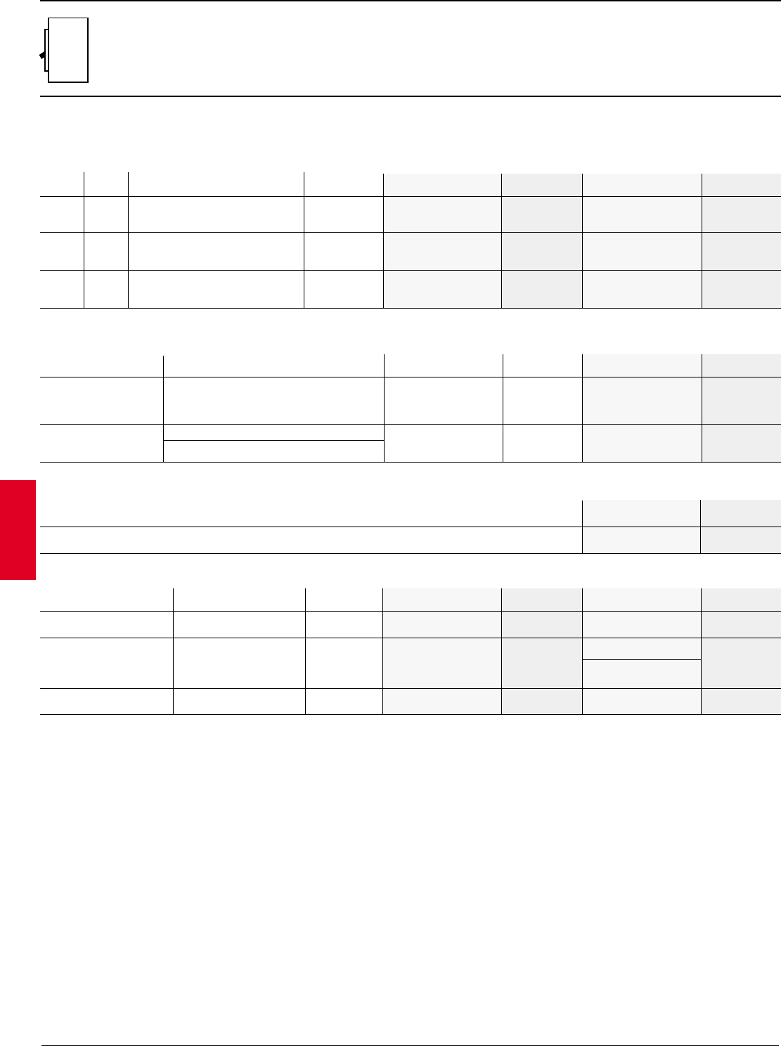
2.46 ABB Control Inc.
AC 1600 – 3/00
Isomax
All S6 magnetic only breakers utilize the electronic PR211 trip unit with an
adjustable range of 1.5 to 12 times frame rating. Both two and three pole MCPs
are 600VAC rated.
Molded case switches
Neutral current transformer (required for 4 wire GF systems)
Amps Catalog List
number price
600 K6NCT-600 $ 250
800 K6NCT-800
S6
600A / 800A
600 240VAC 65kA 900 –7200A S6N600MW-2 $ 2847 S6N600MW $ 3608
S6N 800 480VAC 50kA 1200 –9600A S6N800MW-2 3842 S6N800MW 4802
600VAC 25kA
600 240VAC 150kA 900 –7200A S6H600MW-2 4275 S6H600MW 5271
S6H 800 480VAC 65kA 1200 –9600A S6H800MW-2 5270 S6H800MW 6465
600VAC 35kA
600 240VAC 200kA 900 –7200A S6L600MW-2 5481 S6L600MW 6482
S6L 800 480VAC 100kA 1200 –9600A S6L800MW-2 6476 S6L800MW 7676
600VAC 42kA
Type Interruption Amps Magnetic 3 pole List
capacity trip catalog number price
Connection options
1 Includes lug cover.
2 Suggested lugs for a circuit breaker up to amps shown. Cable size and type determine maximum amperage.
Type Wire Amps2Set of 2 List Set of 3 List
range catalog number price catalog number price
CU/AL front lugs (2) 250kcmil –500kcmil 600 K6TH-2 $ 50 K6TH $ 75
CU/AL front lugs (3) 2/0 –400kcmil 800 K6TJ-2 190 K6TJ 1135
CU rear lugs (2) 250kcmil –500kcmil 600 ——K6THR 150
CU rear lugs (3) 2/0 –400kcmil 800 ——K6TJR 170
Extended front bar —600 ——K6ET-600 150
Extended front bar —800 ——K6ET-800 170
Magnetic only (MCP)
Discount schedule S6
240VAC 200kA –– –– –– ––
S6H-D 480VAC 100kA 600 10,000A S6H600DW $ 3275
600VAC 42kA 800 10,000A S6H800DW 4248
600VDC 50kA –– –– –– ––
Non-UL, switches without Withstand rating 400 none S6D400W 3275
overcurrent protection 600VAC 15kA 630 none S6D630W 3275
800 none S6D800W 4248
Type Amps Interruption Adjustment 2 pole 600VAC List 3 pole 600VAC List
capacity range catalog number price catalog number price
Set of 6
catalog number
S6
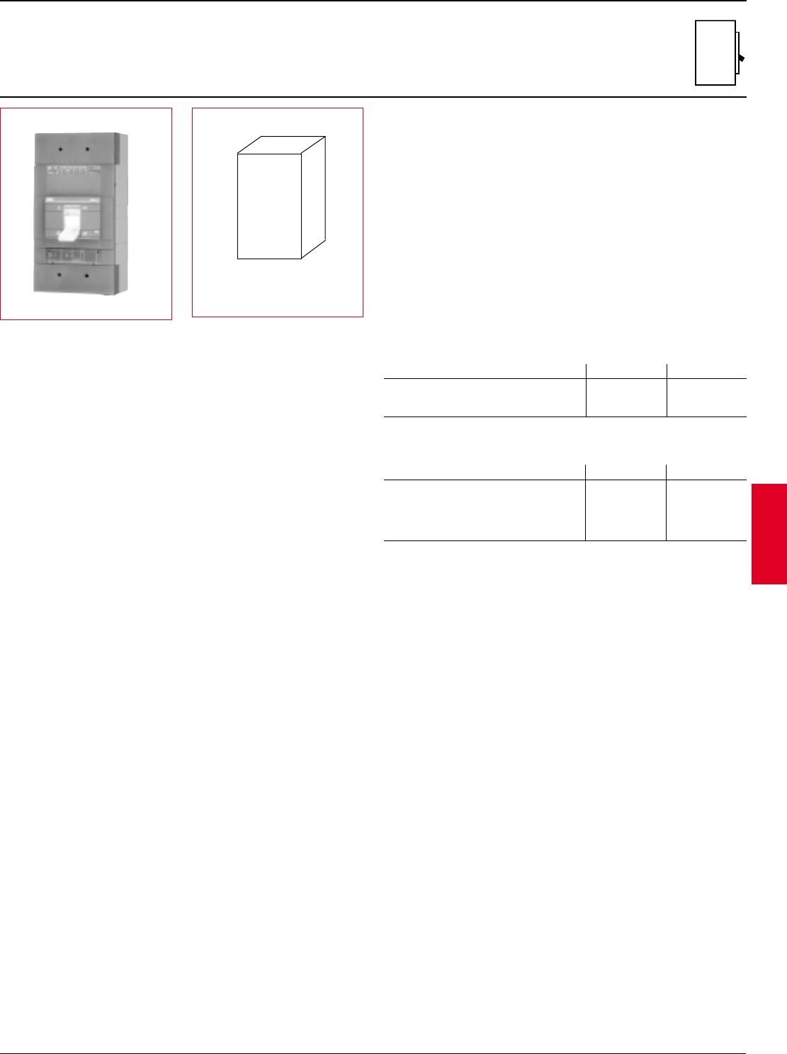
ABB Control Inc. 2.47
AC 1600 – 3/00
Isomax
S7
1200A, 600 VAC
Electronic trip type
H x W x D
15.98" x 8.27" x 5.45"
General
The S7 breaker family is a 1200A frame utilizing a microprocessor based
overcurrent protective trip system. In the 1200A version, the trip unit is
adjustable from 480A up to 1200A without the addition of any parts or rating
plugs. As standard, the S7 includes adjustable long time function for overload
protection and adjustable instantaneous function for short circuit protection.
Versions
To meet all application needs, the S7 is available in various versions:
B = Adjustment LI
C = Adjustment LSI
E = Adjustment LSIG
Q = 100% UL rated
D = Molded case switch
M = Magnetic only (MCP)
Trip functions
These tripping functions are available:
L = Long time I = Instantaneous
S = Short time G = Ground fault
Performance level
Each version is also available in different maximum fault interrupting levels
H = High
L = Extra high (IEC only)
Number of poles
In UL/CSA version, the S7 is available as in two pole or three pole version, both
with the same dimensions. A four pole version is also available in IEC form. For
price estimate, add 35% to list price of selected three pole, contact ABB Control.
Accessory mounting
Internal accessories are UL/CSA approved for both factory or field installation.
Accessories require control cable connectors. Shunt trips or UVR's mount in the
left cavity. Auxiliary or bell alarm switches mount in the right cavity.
Reverse feeding
All versions of the S7 family are suitable for reverse feed applications.
Molded case switches
UL1087 switches include no overcurrent protection except for a high
instantaneous trip mechanism for self protection. IEC type molded case
switches with no trip protection are also available.
Voltage H
240VAC 100
480VAC 65
600VAC 50
Voltage H L
230VAC 100 200
380/400/415VAC 65 100
440VAC 55 80
500VAC 45 70
690VAC 25 35
Standard S7 package includes
complete circuit breaker and
mounting hardware. Order cable
lugs or other connection scheme
as a separate item.
S7
IEC-947 Interrupting capacity (kA RMS)
UL/CSA Interrupting capacity (kA RMS)
UL480 / CSA C22.2
Discount schedule S7
1 Consult factory
S7
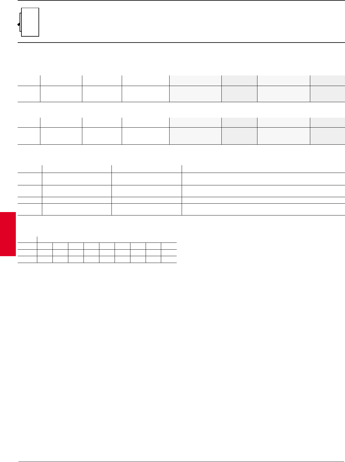
2.48 ABB Control Inc.
AC 1600 – 3/00
Isomax
PR211 LI S7H1000BW-2 $ 6959 S7H1000BW $ 7724
S7H 65kA PR212 LSI S7H1000CW-2 8039 S7H1000CW 8804
PR212 LSIG ——S7H1000EW 10,604
The S7 breaker family uses two available microprocessor based internal trip
units. The standard PR211 trip unit includes adjustments for long time current
pick-up and instantaneous current trip point.
The optional PR212 trip unit includes adjustments for long time current pick-up/
delay, short time pick-up/delay, I2t (on/off), instantaneous current trip point and
further optional ground fault protection.
S7
1200A, 600 VAC
Electronic trip type
1000A Frame (400 – 1000A adjustable continuous range)
1200A Frame (480 – 1200A adjustable continuous range)
PR211 LI S7H1200BW-2 $ 6959 S7H1200BW $ 7724
S7H 65kA PR212 LSI S7H1200CW-2 8039 S7H1200CW 8804
PR212 LSIG ——S7H1200EW 10,604
LLong time pick-up 0.4 –1.0 0.4-0.5-0.6-0.7-0.8-0.9-0.95-1.0 x Frame rating
Long time delay 3.0 –18 sec. A - B - C - D
SShort time pick-up 1.0 –10.0 Off-1.0-2.0-3.0-4.0-6.0-8.0-10.0 x Frame rating
Short time delay 0.05 –0.5 sec. A - B - C - D (I2t On-Off)
I Instantaneous trip 1.5 –12.0 1.5-2.0-4.0-6.0-8.0-10.0-12.0 x Frame rating
GGround fault 0.2 –1.0 Off-0.2-0.3-0.4-0.6-0.8-0.9-1.0 x Frame rating
Ground fault delay 0.1 –0.8 sec. A - B - C - D
Trip settings
Discount schedule S7
Breaker IC at 480VAC Trip Adjustment 2 pole, 600VAC List 3 pole, 600VAC List
type catalog number price catalog number price
Breaker IC at 480VAC Trip Adjustment 2 pole, 600VAC List 3 pole, 600VAC List
type catalog number price catalog number price
Adjustment Trip Range Individual
function settings
Continuous amperage settings (long time adjustment)
Frame Set points
0.4 0.5 0.6 0.7 0.8 0.9 0.95 1.0 Setting
1000A 400 500 600 700 800 900 950 1000 Amps
1200A 480 600 720 840 960 1080 1140 1200 Amps
1 Consult factory.
S7
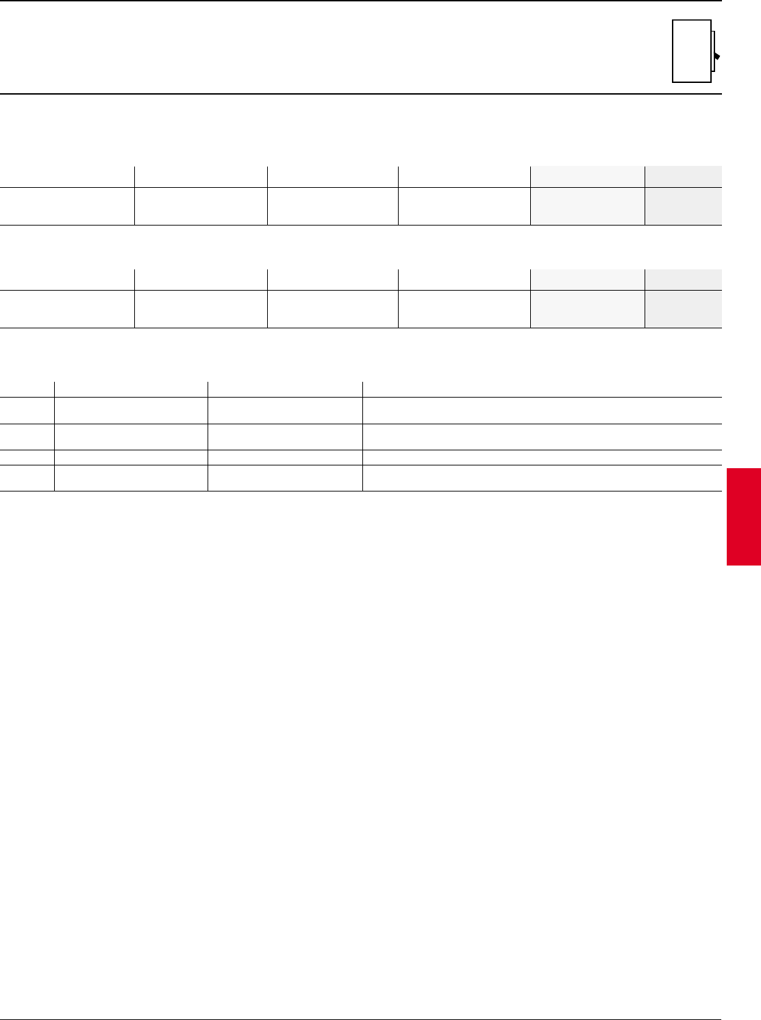
ABB Control Inc. 2.49
AC 1600 – 3/00
Isomax
S7
1200A, 600VAC
UL 100% rated
When applied correctly, UL tested 100% equipment rated breakers may be
applied at full rating rather than on the sizing rules of the NEC where breakers
and cable are sized based on actual continuous load current divided by 80%.
This 100% rating can save the user the cost of larger cable or bus bar. Please
consult the NEC for details and other design factors needed for this application.
LLong time pick-up 0.4 –1.0 0.4-0.5-0.6-0.7-0.8-0.9-0.95-1.0 x Frame rating
Long time delay 3.0 –18 sec. A - B - C - D
SShort time pick-up 1.0 –10.0 Off-1.0-2.0-3.0-4.0-6.0-8.0-10.0 x Frame rating
Short time delay 0.05 –0.5 sec. A - B - C - D (I2t On-Off)
I Instantaneous trip 1.5 –12.0 1.5-2.0-4.0-6.0-8.0-10.0-12.0 x Frame rating
GGround fault 0.2 –1.0 Off-0.2-0.3-0.4-0.6-0.8-0.9-1.0 x Frame rating
Ground fault delay 0.1 –0.8 sec. A - B - C - D
Trip settings
PR211 LI S7HQ1000BW $ 8495
S7H 65kA PR212 LSI S7HQ1000CW 9684
PR212 LSIG S7HQ1000EW 11,664
1000A Frame (400 – 1000A adjustable continuous range)
Breaker IC at Trip Adjustment 3 pole List
480VAC type catalog number price
1200A Frame (480 – 1200A adjustable continuous range)
PR211 LI S7HQ1200BW $ 8495
S7H 65kA PR212 LSI S7HQ1200CW 9684
PR212 LSIG S7HQ1200EW 11,664
Discount schedule S7
Adjustment Trip Range Individual
function settings
Breaker IC at Trip Adjustment 3 pole List
480VAC type catalog number price
1 Consult factory.
S7
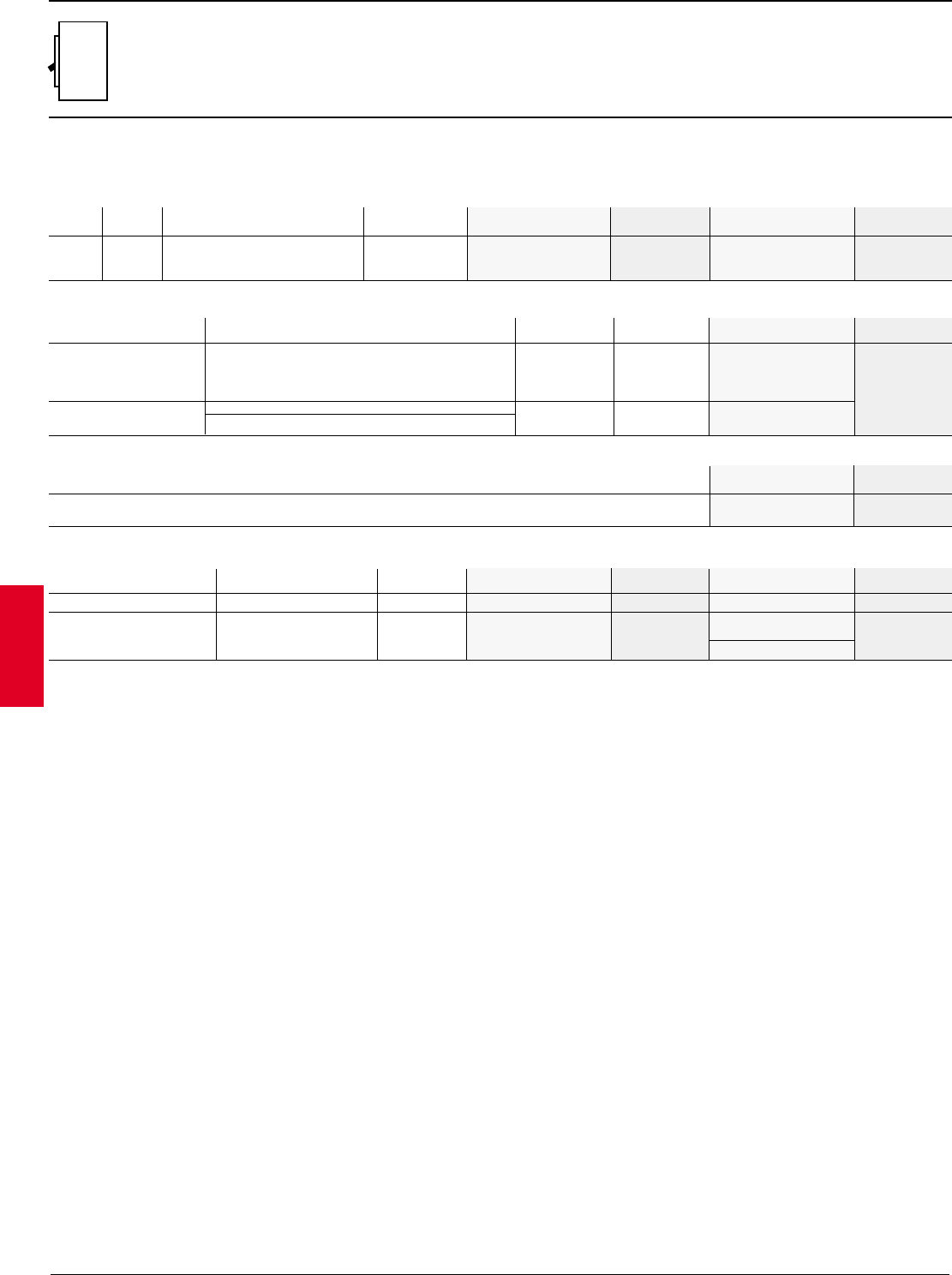
2.50 ABB Control Inc.
AC 1600 – 3/00
Isomax
Type Amps Interruption Adjustment 2 pole List 3 pole List
capacity range catalog number price catalog number price
Molded case switches
Neutral current transformer (required for 4 wire GF systems)
S7
1200A, 600V
All S7 magnetic only breakers utilize the electronic PR211 trip unit with an
adjustable range of 1.5 to 12 times frame rating. Both two and three pole MCPs
are 600VAC rated.
Amps Catalog List
number price
1000 K7NCT-1000 $ 250
1200 K7NCT-1200
Connection options
Type Wire Amps Set of 2 List Set of 3 List
range 1catalog number price catalog number price
CU/AL front lugs (4) 4/0 – 500kcmil 1200 K7TK-2 $ 120 K7TK $ 180
Extended front bar —1200 ——K7ET-1250 240
Magnetic only (MCP)
Discount schedule S7
Type Interruption Amps Magnetic 3 pole List
capacity trip catalog number price
1 Suggested lugs for a circuit breaker up to amps shown. Cable size and type determine maximum amperage.
Set of 6
catalog number
240VAC 100kA
S7H 1000 480VAC 65kA 1500 –12,000A S7H1000MW-2 $ 6959 S7H1000MW $ 7724
1200 600VAC 50kA 1800 –14,400A S7H1200MW-2 S7H1200MW
240VAC 100kA
S7H-D 480VAC 65kA 1000 20,000A S7H1000DW
600VAC 50kA 1200 20,000A S7H1200DW $ 7300
600VDC 12kA
Non-UL, switches without Withstand rating 1000 —S7D1000W
overcurrent protection 600VAC 25kA 1250 —S7D1250W
S7
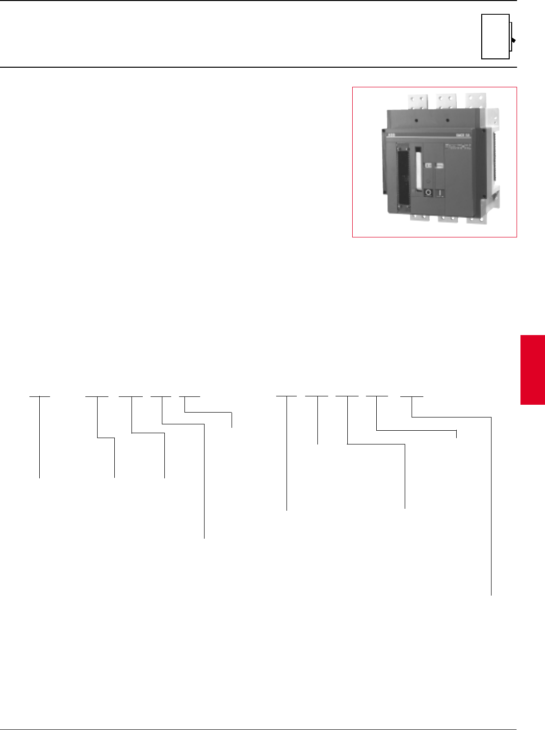
ABB Control Inc. 2.51
AC 1600 – 3/00
Isomax
Breaker catalog numbers
The breaker catalog number must be
completed. Please note that
variations can affect price.
•Wide range of adjustments on trip settings, trip
unit includes cover to prevent tampering.
•Front indicators for contact position.
•Uses convenient mounting pads for ease of
installation in enclosures.
•Internal accessories are prewired to terminal
block mounted on right side of breaker.
•Trip signal contact option indicates when breaker
has tripped due to overcurrent.
•Canadian Standards Association certification
under C22.2 No. 5 under File LR90467 for both
breakers and internal accessories.
•In compliance with IEC947 including 690VAC.
Breakers are labeled with both UL/CSA and IEC
ratings.
•Breakers are Underwriters Laboratories listed
under Standard UL 489 for molded case circuit
breakers per File E93565, internal accessories
are per File E116596.
Description
•Insulated case type molded case circuit breaker
with manually operated stored energy
mechanism. Optional electric charging motor
available
•Three cycle closing time for use in generator
synchronizing applications.
•Electric spring charging mechanism rated for
over 5,000 operations
•Three different frame ratings, 1600, 2000 and
2500 amperes. All are same compact physical
size.
•Solid state trip units are available in four different
configurations including adjustments for long
time, short time, instantaneous and ground fault.
•Standard interrupting rating of 100kA at 480VAC.
•Short time withstand rating of 35kA at 600VAC
for one second when breaker ordered with
adjustable short time trip.
•Breaker includes charging handle for manual
energizing of closing/opening springs
•Built-in ground fault (LSIG) for use with four-wire
systems requires neutral GF sensor. Meets NEC
ground fault requirements for service entrance
applications.
•Internal accessories include electric charging
motor, shunt trips, a combination auxiliary/bell
alarm switch, and an undervoltage release.
•Breakers are suitable for use in reverse feed
applications.
S8 2500A
S8
1600 / 2000 / 2500A
Insulated case circuit breaker
Catalog number information
Current
rating
16 - 1600A
20 - 2000A
25 - 2500A
Trip
C - LSI
E - LSIG
M - I
D - Molded
case switch
Connection scheme
W - Without connectors
R - Rear connectors, line & load
L - Cable terminals, line & load
D - Rear connectors, line side only
E - Rear connectors, load side only
S - Cable terminals, line side only
V - Cable terminals, load side only
H -Cable terminals, line side; rear connectors, load side
J - Rear connectors, line side; cable terminals, load side
Closing coil
1 - 480VAC
2 - 240VAC
3 - 208VAC
4 - 120VAC
5 - 250VDC
6 - 125VDC
7 - 48VDC
8 - 24VAC/VDC
0 - None
Motor
2 - 240,208VAC/250VDC
4 - 120VAC/125VDC
7 - 48VDC
8 - 24 – 30 VAC/VDC
0 - None
Shunt trip
1 - 480VAC
2 - 240,208VAC/250VDC
3 - 24VAC/30VDC
4 - 120VAC/125VDC
7 - 48VAC/48VDC
8 - 24VDC
0 - None
UV release
1 - 480VAC
2 - 240VAC
4 - 120VAC
5 - 250VDC
6 - 125VDC
7 - 48VDC
8 - 24VDC
0 - None
Contacts
A - Aux switches
B - Trip Signal
P-Both
0 - None
S8V 16EWX XXXX X
Frame size
Accessories
D - Locking button
device (open)
L - Key lock (open)
X - None
S8
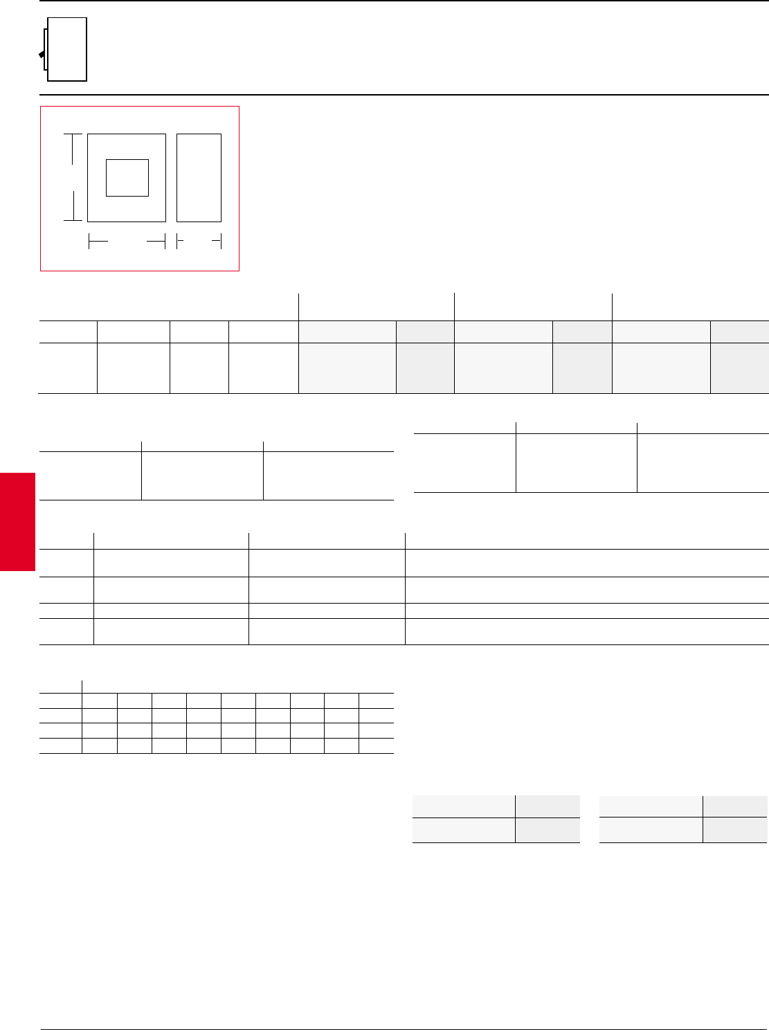
2.52 ABB Control Inc.
AC 1600 – 3/00
Isomax
➀Three pole breakers are listed and approved for use in two pole applications with center-pole not connected.
2Applies to MCS only.
Breaker IC at 480VAC Trip Adjustment Catalog List Catalog List Catalog List
type number price number price number price
3 pole, 600VAC maximum 1
Approximate dimensions
S8
1600 / 2000 / 2500A
Insulated case circuit breaker
LSI S8V16CW $ 12,540 S8V20CW $ 14,427 S8V25CW $ 21,561
S8V 100kA PR212 LSIG S8V16EW 14,505 S8V20EW 16,561 S8V25EW 24,487
I S8V16MW 11,267 S8V20MW 12,988 S8V25MW 20,916
MCS S8V16DW 9620 S8V20DW 10,999 S8V25DW 16,267
Description
Breaker is shipped complete with installed trip unit and accessories. Cable
terminals or rear T connectors can be included if desired. For four-wire systems
an external neutral ground fault sensor must be ordered separately.
Trip functions
L–Long time pick-up and delay
S–Short time pick-up and delay
I–Instantaneous trip
G–Ground fault pick-up and delay
Maximum continuous rating 1600A 2000A 2500A
Discount schedule S8
Catalog List
number price
1600A, S8 Frame —
stored energy
S8VQ16CW $ 13,168
S8VQ16EW 15,231 S8VQ20CW $ 15,148
S8VQ20EW 17,390
2000A, S8 Frame —
stored energy
Catalog List
number price
UL 100% equipment rated circuit breakers
Circuit breakers and cable are sized per the National Electric Code on a basis of
actual continuous load current divided by 80%. For example, a 360 ampere load
should be connected by cable capable of handling 450 amperes (360A / 0.80 =
450A) and therefore be protected by a 450 ampere rated circuit breaker. Other
factors may need to be considered when sizing breakers in special applications.
When applied correctly, UL-tested 100% equipment rated breakers may be applied
at full rating, therefore saving the user the cost of larger cable or bus. Using the
example above, the 360 ampere load could be used with cable capable of
handling 360 amperes (360A / 1.00 = 360A) and only a 400 ampere rated circuit
breaker (400A is next available size CB).
IEC-947 Interrupting capacity (kA RMS)
Voltage V
230VAC 120
300/400/415VAC 120
440VAC 100
500VAC 70
690VAC 50
UL/CSA Interrupting capacity (kA RMS)
UL489 / CSA C22.2
Voltage V
240VAC 125
480VAC 100
600VAC 85
600VDC 225
15.75"
9.25"
15.98"
S8
LLong time pick-up 0.4 –1.0 0.4-0.5-0.6-0.7-0.8-0.9-0.95-1.0 x Frame rating
Long time delay 3.0 –18 sec. A - B - C - D
SShort time pick-up 1.0 –10.0 Off-1.0-2.0-3.0-4.0-6.0-8.0-10.0 x Frame rating
Short time delay 0.05 –0.5 sec. A - B - C - D (I2t On-Off)
I Instantaneous trip 1.5 –12.0 1.5-2.0-4.0-6.0-8.0-10.0-12.0 x Frame rating
GGround fault 0.2 –0.4 Off-0.2-0.3-0.4 x Frame rating
Ground fault delay 0.1 –0.8 sec. A - B - C - D
Trip settings
Adjustment Trip Range Individual
function settings
Continuous amperage settings (long time adjustment)
Frame Set points
0.4 0.5 0.6 0.7 0.8 0.9 0.95 1.0 Setting
1600A 640 800 960 1120 1280 1440 1520 1600 Amps
2000A 800 1000 1200 1400 1600 1800 1900 2000 Amps
2500A 1000 1250 1500 1750 2000 2250 2375 2500 Amps
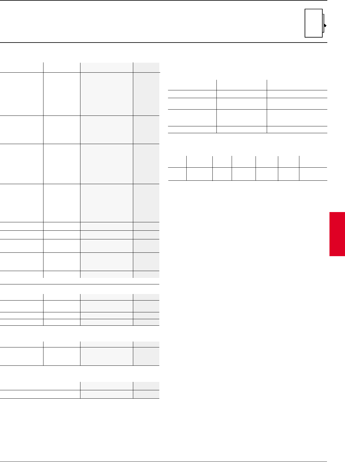
ABB Control Inc. 2.53
AC 1600 – 3/00
Isomax
Discount schedule S8
S8
1600A, 2000A & 2500A
Accessories
Internal accessories
(Must be factory mounted for UL/CSA)
Factory installed List
Item Type catalog number suffix price
Closing coil
Required for closing breaker electrically, the coil voltage must be specified at
the time of order entry.
Internal accessory ratings
Shunt trip All 100VA/120Watts
Undervoltage AC/DC 30VA (12 Watts/
releases 10VA (4 Watts)
240VAC 10A Max.
Auxiliary contacts 125VDC 0.3A Max.
250VDC 0.15A Max
Closing coil AC/DC 30VA / 40VA
Accessory Voltage Rating
type
E.O. Type Inrush Normal Closing Opening Resetting
(VA) (watts) time time time
Stored energy electric motor operators
Mechanical life of 10,000 cycles at 20 operations per hour.
Item Type Catalog number List price
Connection accessories (includes sets of 3)
Note: Neutral GF CT required for proper GF operation.
Item Type Catalog number List price
Ground 1600A K8NCT-1600
Fault 2000A K8NCT-2000 $ 888
Neutral CT 2500A K8NCT-2500
Neutral ground fault current transformer
Item Catalog number List price
Door flange
Face plate K8FP $ 25
Cable terminals
1600A Max.
1/0 – 750kcmil (4)
K8TL $ 274
2500A Max.
1/0 – 750kcmil (6)
K8TM 315
Rear T conn. 2500A Max. K8RT2500 855
480VAC 1
240VAC 2
208VAC 3
Closing coil 120VAC 4
250VDC 5 $ 575
125VDC 6
48VDC 7
24VAC/VDC 8
Electric 240,208VAC 2
motor & 250VDC
(inc. spring
120VAC/125VDC
43217
charged signal 48VDC 7
contact) 24 – 30VAC/VDC 8
480VAC 1
240,208VAC 2
& 250VDC
Shunt trip
24VAC/30VDC
3
120VAC/125VDC
4518
48VAC/48VDC
7
24VDC 8
480VAC 1
240VAC 2
Undervoltage 120VAC 4
release 250VDC 5 518
125VDC 6
48VDC 7
24VDC 8
Aux. contacts 2A/1B A 396
Trip signal 1A/1B B 192
Combo. aux. & 2A/1B Aux & P588
trip contacts 1A/1B Trip
Padlockable
button cover –– D144
(open)
Key lock —L155
(open)
MS8 Stored 1000 230 0.05s 0.035s 9.0s
energy
S8
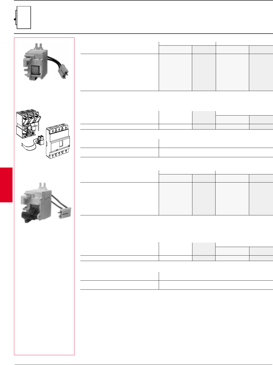
2.54 ABB Control Inc.
AC 1600 – 3/00
Isomax
Electrical accessories
Shunt trip, undervoltage release
S1
Shunt trip
Factory installation Field installation
Voltage Catalog number List Catalog number List
suffix 1price adder S1 – S2 price
Undervoltage releases (IEC)
Factory installation Field installation
Voltage Catalog number List Catalog number List
suffix 1price adder S1 – S2 Price
380/400VAC U1 K2U1
220/230VAC U2 K2U2
24VAC U3 K2U3
110VAC U4 $ 212 K2U4 $ 197
110VDC U6 K2U6
48VDC U7 K2U7
24VDC U8 K2U8
48VAC U9 K2U9
Electrical specifications
V24, 120, 240, 480VAC ~ 50/60 Hz
24, 48, 125, 250VDC –
For S1 – S2 100VA~/120W–
P Instananeous duty
K5S4
For remote opening of circuit breaker and includes internal cut-off switch to protect solenoid. All shunt trips are left pole mounted
and can not be used with undervoltage releases. All shunt trips are approved for use in ground fault systems. Shunt trips must
be ordered with correct connector.
48VAC/60VDC S1 K1S1
220/250VAC S2 K1S2
24 – 30VAC S3 K1S3
110 – 130VAC S4 $ 212 K1S4 $ 197
250VDC S5 K1S5
110VDC S6 K1S6
48VDC S7 K1S7
24VDC S8 K1S8
220VDC S9 K1S9
Shunt trip connectors (required) Field installation
Type Voltage Factory Catalog number List
installation S1 – S2 price
Fixed mounted All Included K2C-SU $ 15
V24, 120, 240, 480VAC ~ 50/60 Hz
24, 48, 125, 250VDC –
For S1 – S2 6VA~/3W–
P Continuous duty
Undervoltage release connectors (required)
Field kit
Type Voltage Factory Catalog number List
installation S1 – S2 Price
Fixed mounted All Included K2C-SU $ 15
Electrical specifications
Will trip circuit breaker when connected voltage drops to 35 – 70% of undervoltage release voltage rating. Will allow circuit
breaker to close (ON) when voltage is approximately 85% of rated voltage. All undervoltage releases are left pole mounted and
can not be used with shunt trips. Undervoltage releases must be ordered with correct connector.
1 For factory installation add suffix given to end of circuit breaker catalog number per accessory format.
Discount schedule SA
S1 with K1S4
K5U4
Acc.
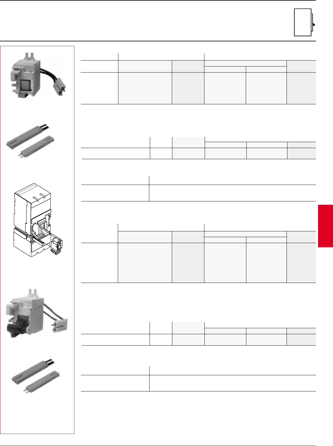
ABB Control Inc. 2.55
AC 1600 – 3/00
Isomax
Electrical accessories
Shunt trip, undervoltage release
S3 – S7
1 For factory installation add suffix given to end of circuit breaker catalog number per accessory format.
K5S1
K6C-SUP
K5U1
K6C-SUP
Shunt trip
480VAC/250VDC S1 K5S1 K7S1
240VAC S2 K5S2 K7S2
120VAC/125VDC S4 $ 430 K5S4 K7S4 $ 415
48VDC S7 K5S7 K7S7
24VAC/VDC S8 K5S8 K7S8
12VDC S9 K5S9 K7S9
For remote opening of circuit breaker and includes internal cut-off switch to protect solenoid. All shunt trips are left pole
mounted and can not be used with UVRs. Except for 12VDC, all shunt trips are approved for use in GF systems. Shunt
trips must be ordered with correct connector.
Factory installation Field installation
Voltage Catalog number List Catalog numbers List
suffix 1price adder S3 – S4 – S5 S6 – S7 price
480VAC U1 K5U1 K7U1
240VAC U2 K5U2 K7U2
120VAC U4 K5U4 K7U4
24VAC U3 $ 430 K5U3 K7U3 $ 415
250VDC U5 K5U5 K7U5
125VDC U6 K5U6 K7U6
48VDC U7 K5U7 K7U7
24VDC U8 K5U8 K7U8
Will trip CB when connected voltage drops to 35-70% of UVR voltage rating. Will allow CB to close (ON) when voltage is
approximately 85% of rated voltage. All UVRs are left pole mounted and can not be used with shunt trips. UVRs must be
ordered with correct connector.
Undervoltage releases
Factory installation Field installation
Voltage Catalog number List Catalog numbers List
suffix 1price adder S3 – S4 – S5 S6 – S7 price
Shunt trip connectors (required)
Fixed mounted All included K6C-SU K7C-SU $ 15
Plug-in/Draw-out All included K6C-SUP K7C-SUP
V24, 120, 240, 480VAC ~ 50/60 Hz
12, 24, 48, 125, 250 VDC –
For S3-S5 100 VA~/120W–
P Instantaneous duty
For S6-S7 150 VA~/150W–
Electrical specifications
Type Factory Field kit catalog number
circuit breaker Voltage installation1S3 – S4 – S5 – S6 S7 List price
Undervoltage release connectors (required)
V24, 120, 240, 480 VAC ~ 50/60 Hz
24, 48, 125, 250 VDC –
For S3-S5 6 VA~/3W–
P Continuous duty
For S6-S7 10 VA~/4W–
Electrical specifications
Fixed mounted All included K6C-SU K7C-SU $ 15
Plug-in/Draw-out All included K6C-SUP K7C-SUP
Type Factory Field kit catalog number
circuit breaker Voltage installation1S3 – S4 – S5 – S6 S7 List price
Discount schedule SA
S5 with K5S2
Acc.
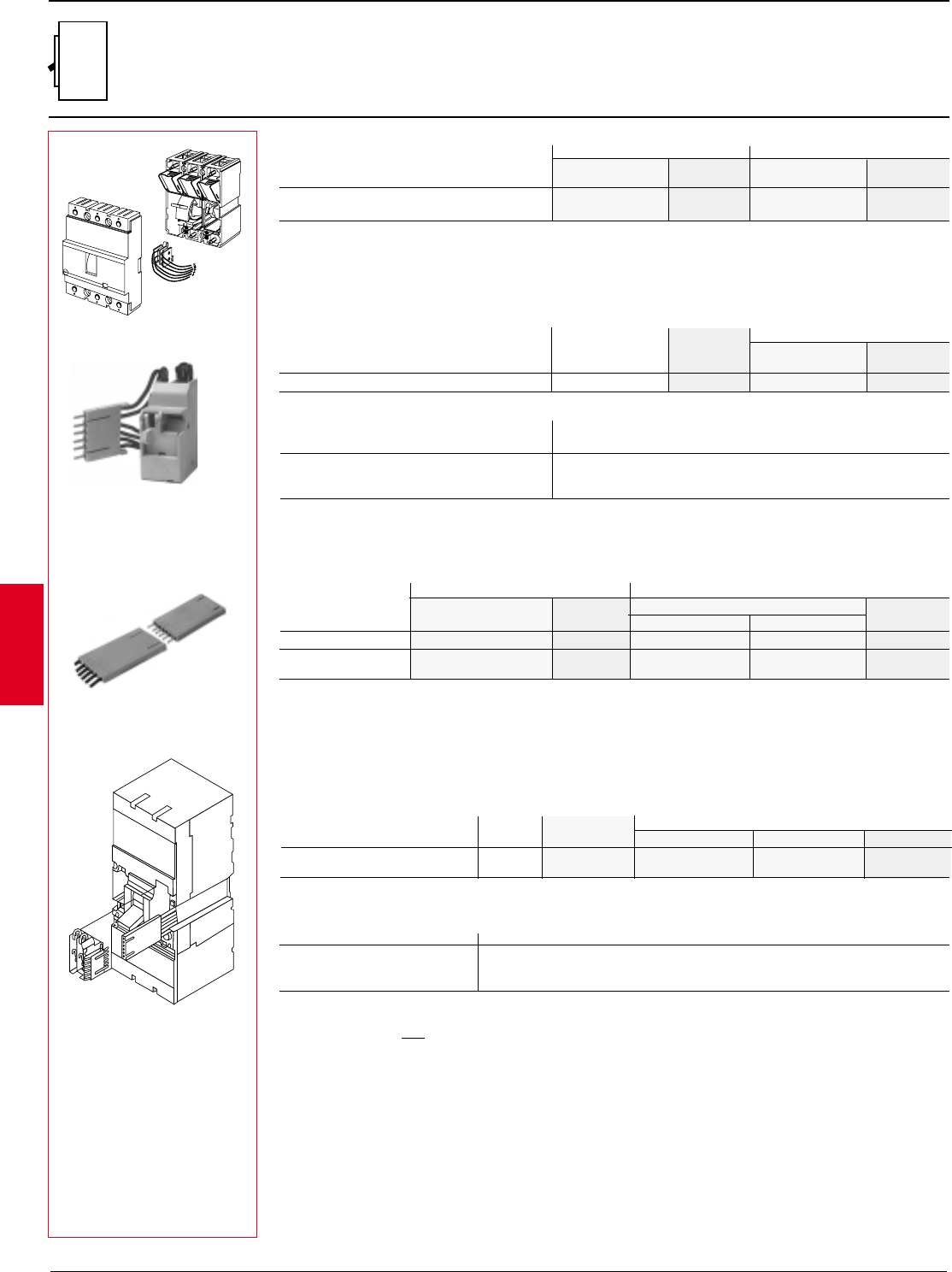
2.56 ABB Control Inc.
AC 1600 – 3/00
Isomax
1 For factory installation add suffix given to end of circuit breaker catalog number per accessory format.
Electrical accessories
Auxiliary contacts
S1 – S7
Auxiliary contacts — S1
Factory install Field installation
Voltage Catalog number List Catalog number List
suffix 1price adder S1 price
Auxiliary contact connectors (required) — S1
Field installation
Type Voltage Factory Catalog number List
installation S1 price
Fixed mounted All Included K2C-AB $ 15
Electrical specifications — S1
Voltage Maximum contact amperage rating
30 VDC 4A
127 VDC 4A
220 VAC 4A
2N.O./N.C. A $ 190 K1AS $ 175
1B.A. + 1N.O./N.C. BA K1BA
The auxiliary contacts are accessory contacts for the indication of circuit breaker
open-closed or tripped. Bell alarm contacts (B.A.) can be used to indicate circuit
breaker tripping. All contacts are right pole mounted.
Availability:
a) 2 N.O. or N.C. Form C auxiliary contacts
N.O. = contact is open as circuit breaker is open
N.C. = contact is closed when circuit breaker is open
B.A. = will open/close only when circuit breaker trips
The auxiliary contacts are accessory contacts for the indication of circuit breaker open-closed or tripped. Bell alarm
contacts (B.A.) can be used to indicate circuit breaker tripping. All contacts are right pole mounted.
Availability:
a) 2 N.O. or N.C. Form C auxiliary contacts
b) 1 N.O. or N.C. Form C auxiliary contacts plus 1 B.A. trip contact
c) 1 N.O. and 1 N.C. auxiliary contacts plus 1 B.A. trip contact (for S6 – S7 only).
Auxiliary contacts — S3 – S7
2 N.O./N.C. A $ 275 K5AS K7AS $ 260
1B.A. + 1N.O./1N.C. BA 365 K5BA K7BA 350
1B.A. + 1N.O./1N.C. BA3 —K7BA-3
Auxiliary contact connectors (required) — S3 – S7
N.O. = contact is open as circuit breaker is open
N.C. = contact is closed when circuit breaker is open
B.A. = will open/close only when circuit breaker trips
Voltage Maximum contact amperage rating
K6C-ABP
Fixed mounted All included K6C-AB K7C-AB $ 15
Plug-in/Draw-out All included K6C-ABP K7C-ABP
Electrical specifications
Factory installation Field installation
Voltage Catalog number List Catalog numbers List
suffix 1price adder S3 – S4 – S5 S6 – S7 price
Type Factory Field kit catalog number
circuit breaker Voltage installation1S3 – S4 –- S5 – S6 S7 List price
125 VDC 0.3 A
250 VDC 0.15 A
250 VAC 6 A
S1 with auxiliaries
Discount schedule SA
K5AS
S5 with K6C-AB
Acc.
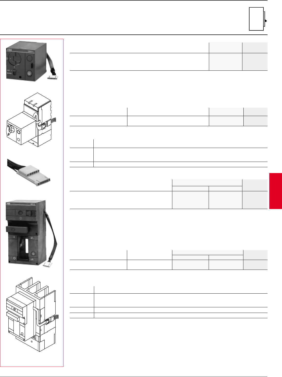
ABB Control Inc. 2.57
AC 1600 – 3/00
Isomax
Type Field kit catalog number List
circuit breaker Voltage S3 – S4 – S5 price
240VAC/250VDC K5M2
120VAC/125VDC K5M4 $ 678
48VDC K5M7
24VDC K5M8
For remote control of circuit breaker opening and closing.
Complete with manual operating lever, padlock device and emergency opening push-button.
When ordering the connector always specify type and version of the circuit-breaker.
The following options are also available:
–key lock for open position
–key lock for open position of two or more circuit breakers (using the same key for groups of circuit breakers)
Motor operator
Motor operator connectors (required)
V120, 240VAC ~ 50/60 Hz
24, 48, 125, 250 VDC –
P inrush 500 VA~/500W–
P normal 350 VA~/500W–
Close time 0.1 s
Open time 0.1 s
Catalog number List
Voltage S3 – S4 – S5 price
K5M2
K6C-M
Electrical accessories
Motor operators, stored energy motor operators
S3 – S7
Electrical specifications
Fixed mounted All K6C-M $ 15
Plug-in/Draw-out All K6C-MP
K6M2
Type Field kit catalog number List
circuit breaker Voltage S6 S7 price
• Stored-energy motor operator with springs automatically pre-loaded by motor.
• Complete with shunt opening and closing release, and compartment door flange.
• When ordering the connector always specify type and version of the circuit-breaker.
• The following options are also available:
– key lock for open position
– key lock for open position of two or more circuit-breakers (using the same key for groups of circuit-breakers).
Stored-energy motor operator
Stored-energy motor operator connectors (required)
240VAC/250VDC K6M2 K7M2
120VAC/125VDC K6M4 K7M4 $ 2407
48VDC K6M7 K7M7
24VDC K6M8 K7M8
Catalog number List
Voltage S6 S7 price
Fixed mounted All K6C-M K7C-M $ 15
Plug-in/Draw-out All K6C-MP K7C-MP
Electrical specifications
Discount schedule SA
V120, 240 VAC ~ 50/60 Hz
24, 48, 125, 250 VDC –
P inrush 660 VA~/600W–
P normal 180 VA~/180W–
Close time 0.09 s
Open time 1.2 s
Reset time 2.0 s
S7 with K7M4
S4 with K5M2
Acc.
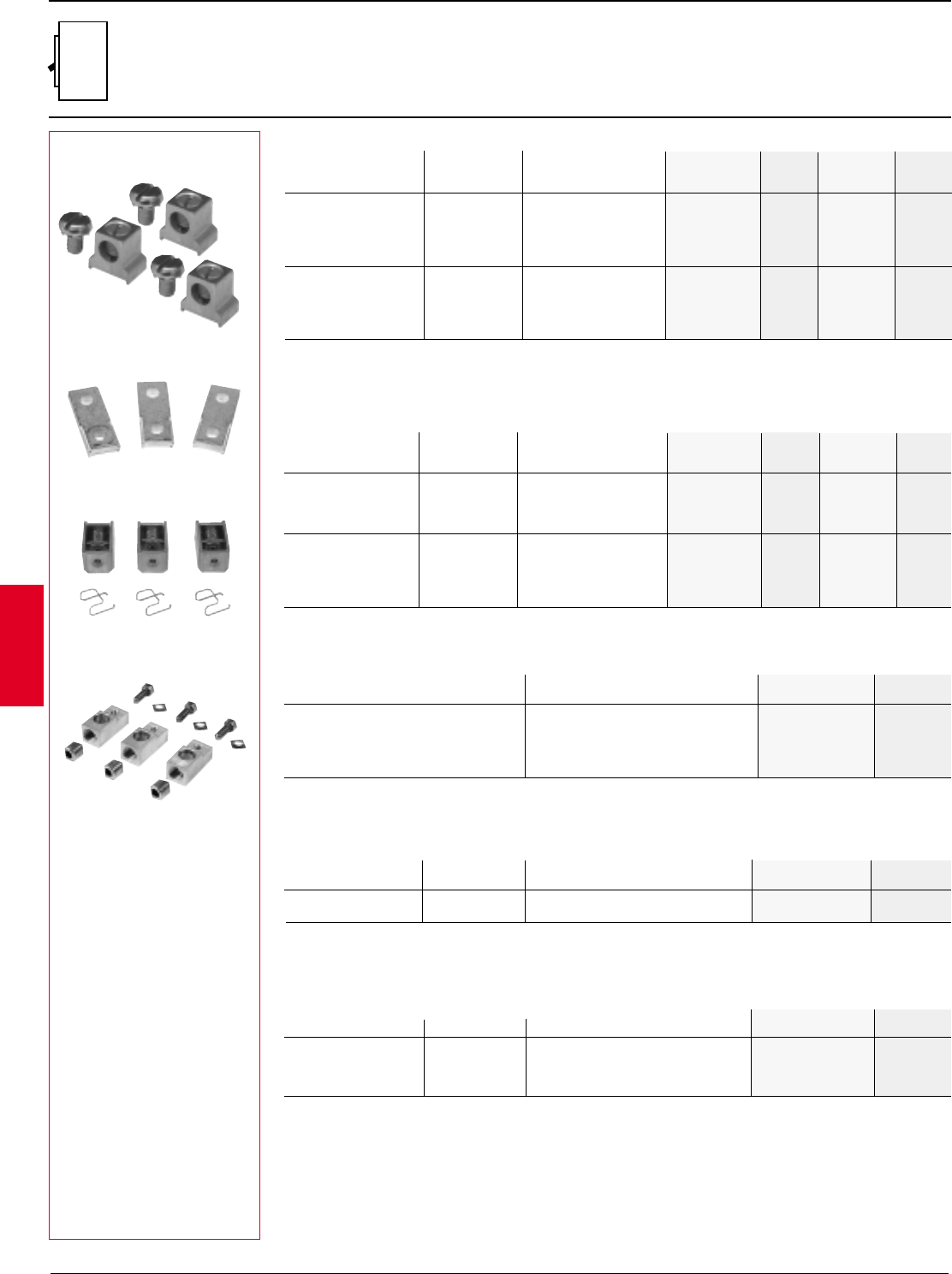
2.58 ABB Control Inc.
AC 1600 – 3/00
Isomax
Standard cable lugs, for use on line and load side of circuit breaker. Suitable for use with Cu or Al. Special versions
available with taps and screws for control wire connection. Note: S6 and S7 lugs are Al9Cu (90°C); all others Al7Cu (75°C).
S3 60 14AWG –2AWG K3TA-2 $ 4 K3TA $ 6
S3 – S4 100 14AWG –1/0 K4TB-2 4K4TB 6
S3 – S4 150 2AWG –4/0 K4TC-2 4K4TC 6
S3 – S4 – S5 225 4AWG –300kcmil K4TD-2 10 K4TD 15
S4 250 6AWG –350kcmil K4TE-2 20 K4TE 30
S5 300 250kcmil –500kcmil K5TF-2 30 K5TF 45
S5 400 (2) 3/0 –250kcmil K5TG-2230 K5TG245
S6 600
(2)
250kcmil –500kcmil K6TH-2 50 K6TH 75
S6 800 (3) 2/0 –400kcmil K6TJ-2290 K6TJ2135
S7 1200 (4) 4/0 –500kcmil K7TK-2 120 K7TK 180
Standard cable lug kits
Standard cable lug kits with control power taps
S3 – S4 100 14AWG –1/0 K4TB-2C $ 8 K4TBC $ 12
S3 – S4 150 2AWG –4/0 K4TC-2C 8K4TCC 12
S3 – S4 – S5 225 4AWG –300kcmil K4TD-2C 14 K4TDC 21
S4 250 6AWG –350kcmil K4TE-2C 24 K4TEC 36
S5 300 250kcmil –500kcmil K5TF-2C 34 K5TFC 51
S5 400 (2) 3/0 –250kcmil K5TG-2C234 K5TGC251
S6 600 (2) 250kcmil – 500kcmil K6TH-2C 54 K6THC 81
S6 800 (3) 2/0 –400kcmil K6TJ-2C294 K6TJC2141
S7 1200 (4) 4/0 –500kcmil K7TK-2C 124 K7TKC 186
Set of 2 Set of 3
For breakers Amps1Wire catalog List catalog List
range number price number price
External accessories
Lugs and termination kits
S3 – S7
K4ET-250
K4TES
K4TER
1Suggested lugs for circuit breaker up to amps shown. Cable size and type determine maximum amperes.
2Includes lug covers.
K4TB
For adding onto standard circuit breaker front terminals, extending available connection area for user termination.
Suitable for spaded cable or bus connection. S3 – S5 include terminal covers.
S3 – S4 250 K4ET-250 $ 46
S5 400 K5ET-400 114
S6 630 K6ET-600 150
S6 800 K6ET-800 170
S7 1250 K7ET-1250 240
These special non-aluminum cable lugs are for use with copper cable. Lugs are intended for use with copper cable or
where non-aluminum connectors are required (marine, salt or corrosive environments).
S3 – S4 250 14AWG – 250kcmil K4TES $ 30
S5 400 250kcmil – 500kcmil K5TGS 90
For use where cable connection from the back-rear of the breaker is desired.
Extended front termination kits
Suitable for Maximum Set of 6 List
use with amps catalog number price
Saddle cable lug kits (Cu cable only)
Suitable for Max Wire Set of 6 List
use with amps range catalog number price
Rear cable lug kits (Cu cable only)
S3 – S4 250 14AWG – 250kcmil K4TER $ 30
S5 400 250kcmil – 500kcmil K5TGR 90
S6 600 250kcmil – 500kcmil K6THR 150
S6 800 250kcmil – 500kcmil K6TJR 170
Suitable for Max Wire Set of 6 List
use with amps range catalog number price
Set of 2 Set of 3
For breakers Amps1Wire catalog List catalog List
range number price number price
Discount schedule SA
Acc.
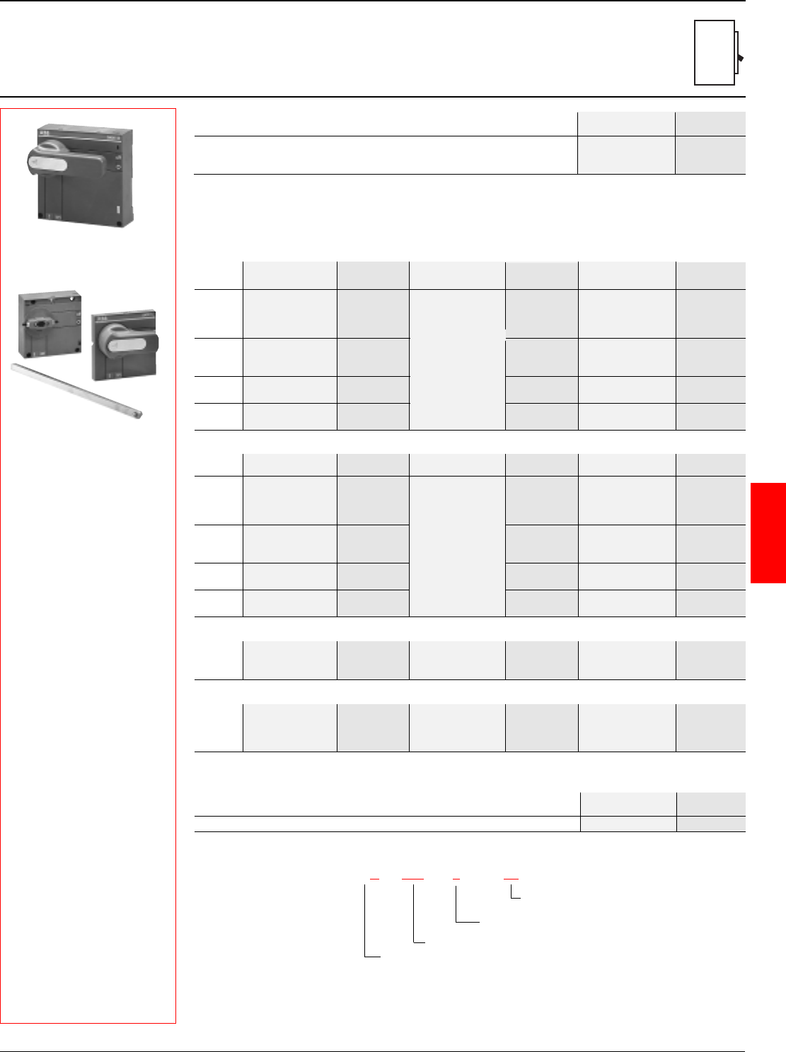
ABB Control Inc. 2.59
AC 1600 – 3/00
Isomax
External accessories
Rotary and variable depth handle operators
S1 – S7
S3 – S4 – S5 K5RH $ 108
S6 K6RH 124
S7 K7RH 145
Rotary handle operating mechanism Catalog List
Frame number price
K5RH
K5VD-M, K5VD-S12,
K5VD-H
Variable depth rotary handles
Frame Catalog number List Shaft catalog number List Handle catalog number List
mechanism price (length in inches) price (length in inches) price
Pistol type 4
OHB45J10 (1.8)
S1–S2 K2VD-M $ 59 OHG45J10 (1.8) $ 70
OHB65J10 (2.6)
OHG65J10 (2.6)
OXP10X148 (5.8) $ 24
S3–S4–S5
K5VD-M 49 OXP10X225 (8.9) 26 OHB95J10 (3.7) 80
OXP10X500 (19.7) 32 OHG95J10 (3.7)
S6 K6VD-M 80 OHB125J10 (4.9) 90
OHG125J10 (4.9)
S7 K7VD-M 80 OHB175J10 (6.9) 100
OHG175J10 (6.9)
Discount schedule SH
Mounts directly onto breaker. Includes door interlock to prevent CB door opening while CB is in ON position. Padlock
provision included to padlock CB in open position. Can also be key locked with optional cylinder lock assembly. Door
interlock bracket must be ordered separately, if required. See page 9.9.
New pistol type 1, 3R, 12
S1–S2 K2VD-M $ 59 K2VD-H $ 25
S3–S4–S5
K5VD-M 49 K5VD-S12 $ 24 K5VD-H 25
S6 K6VD-M 80 K7VD-S20 27 K7VD-H 28
S7 K7VD-M 80 K7VD-H 28
Pistol type 4 — metal
S3–S4–S5
K5VD-M $ 49
S6 K6VD-M 80 K7VD-S25 $ 34 K7VD-HM $ 190
S7 K7VD-M 80
Square type 1
S3 – S4 – S5 K5VD-LSS $ 25
Variable depth shaft support
For frames Catalog List
number price
NOTE: Complete assembly requires a mechanism, shaft and handle.
New pistol handle catalog number explanation
OHB125 J10
Color
B = black
G = gray
Physical size (length in mm)
Shaft size (diameter in mm)
J = Type 1, 3R, 12
L = Type 1, 3R, 4, 4X, 12
Frame Catalog number List Shaft catalog number List Handle catalog number List
mechanism price (length in inches) price (length in inches) price
OHB45L10 (1.8)
S1–S2 K2VD-M $ 59 OHG45L10 (1.8) $ 110
OHB65L10 (2.6)
OHG65L10 (2.6)
OXP10X148 (5.8) $ 24
S3–S4–S5
K5VD-M 49 OXP10X225 (8.9) 26 OHB95L10 (3.7) 120
OXP10X500 (19.7) 32 OHG95L10 (3.7)
S6 K6VD-M 80 OHB125L10 (4.9) 130
OHG125L10 (4.9)
S7 K7VD-M 80 OHB175L10 (6.9) 140
OHG175L10 (6.9)
Acc.
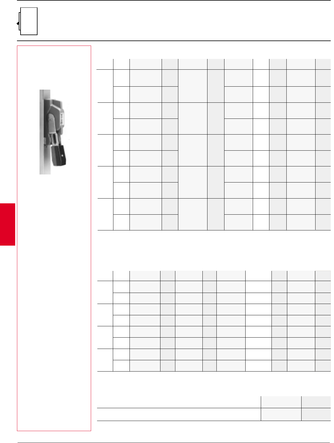
2.60 ABB Control Inc.
AC 1600 – 3/00
Isomax
External accessories
Flange handle operators
S1 – S6
1 Cable not included.
Flange handle
New version — cable linkage
Door hardware
Item Catalog List
number price
Safety door latch, 2 point with 6" handle FH-DHK $ 150
Roller for 3 point latch, add to FH-DHK FH-3RL 30
Breaker NEMA Mech & handle List Mechanism List Cable Cable List Handle List
type kit1price only price only length price only price
1,3R,12 K2FHDC-S12 $ 291 K2FHDC-M $ 198 K6FHDC-036 36"(91mm)$ 114 K7FHD-HS12 $ 93
S1 – S2 K6FHDC-060 60"(152mm)146
4 K2FHDC-S4 331 K2FHDC-M 198 K6FHDC-036 36"(91mm)114 K7FHD-HS4 133
K6FHDC-060 60"(152mm)146
1,3R,12 K3FHDC-S12 291 K3FHDC-M 198 K6FHDC-036 36"(91mm)114 K7FHD-HS12 93
S3 K6FHDC-060 60"(152mm)146
4 K3FHDC-S4 331 K3FHDC-M 198 K6FHDC-036 36"(91mm)114 K7FHD-HS4 133
K6FHDC-060 60"(152mm)146
1,3R,12 K4FHDC-S12 356 K4FHDC-M 263 K6FHDC-036 36"(91mm)114 K7FHD-HS12 93
S4 K6FHDC-060 60"(152mm)146
4 K4FHDC-S4 396 K4FHDC-M 263 K6FHDC-036 36"(91mm)114 K7FHD-HS4 133
K6FHDC-060 60"(152mm)146
1,3R,12 K5FHDC-S12 396 K5FHDC-M 303 K6FHDC-036 36"(91mm)114 K7FHD-HS12 93
S5 K6FHDC-060 60"(152mm)146
4 K5FHDC-S4 436 K5FHDC-M 303 K6FHDC-036 36"(91mm)114 K7FHD-HS4 133
K6FHDC-060 60"(152mm)146
K4FH-17S12
Notes: For complete assembly; mechanism, cable and handle are required.
All mechanisms above mount onto the right side of the breaker.
For mounting of the cable on the left side of the breaker, add “L” to mechanism part number. Price is unchanged.
Available as complete kits including flange handle, shaft and breaker operating mechanism. Mechanism mounts directly
onto breaker and shaft can be cut to the desired length for the breaker enclosure. Door is interlocked with the handle when
the breaker is in the closed (ON) position; handles include interlock defeater for emergency override. Handle can be
padlocked in the open (OFF) position. Can be field converted for left hand mounting.
Flange handle
New version — solid shaft linkage
K2FHD-12S12 $ 240 K7FHD-S12 12 $ 19
1,3R,12 K2FHD-17S12 248 K7FHD-S17 17 27 K7FHD-HS12 $ 93
S1 – S2 K2FHD-22S12 255 K7FHD-S22 22.5 34
K2FHD-12S4 280 K7FHD-S12 12 19
4 K2FHD-17S4 288 K7FHD-S17 17 27 K7FHD-HS4 133
K2FHD-22S4 295 K7FHD-S22 22.5 34
K3FHD-12S12 240 K7FHD-S12 12 19
1,3R,12 K3FHD-17S12 248 K7FHD-S17 17 27 K7FHD-HS12 93
S3 K3FHD-22S12 255 K7FHD-S22 22.5 34
K3FHD-12S4 280 K7FHD-S12 12 19
4 K3FHD-17S4 288 K7FHD-S17 17 27 K7FHD-HS4 133
K3FHD-22S4 295 K7FHD-S22 22.5 34
K4FHD-12S12 240 K7FHD-S12 12 19
1,3R,12 K4FHD-17S12 248 K7FHD-S17 17 27 K7FHD-HS12 93
S4 K4FHD-22S12 255 K7FHD-S22 22.5 34
K4FHD-12S4 280 K7FHD-S12 12 19
4 K4FHD-17S4 288 K7FHD-S17 17 27 K7FHD-HS4 133
K4FHD-22S4 295 K7FHD-S22 22.5 34
K5FHD-12S12 240 K7FHD-S12 12 19
1,3R,12 K5FHD-17S12 248 K7FHD-S17 17 27 K7FHD-HS12 93
S5 K5FHD-22S12 255 K7FHD-S22 22.5 34
K5FHD-12S4 280 K7FHD-S12 12 19
4 K5FHD-17S4 288 K7FHD-S17 17 27 K7FHD-HS4 133
K5FHD-22S4 295 K7FHD-S22 22.5 34
K6FHD-12S12 523 K7FHD-S12 12 19
1,3R,12 K6FHD-17S12 531 K7FHD-S17 17 27 K7FHD-HS12 93
S6 K6FHD-22S12 538 K7FHD-S22 22.5 34
K6FHD-12S4 563 K7FHD-S12 12 19
4 K6FHD-17S4 571 K7FHD-S17 17 27 K7FHD-HS4 133
K6FHD-22S4 578 K7FHD-S22 22.5 34
K3FHD-M 128
K4FHD-M 128
K6FHD-M 411
K2FHD-M $ 128
K5FHD-M 128
NEMA Complete List Mechanism List Shaft Shaft List Handle List
Breaker type handle kit price only price only length price only price
Discount schedule SH
Acc.
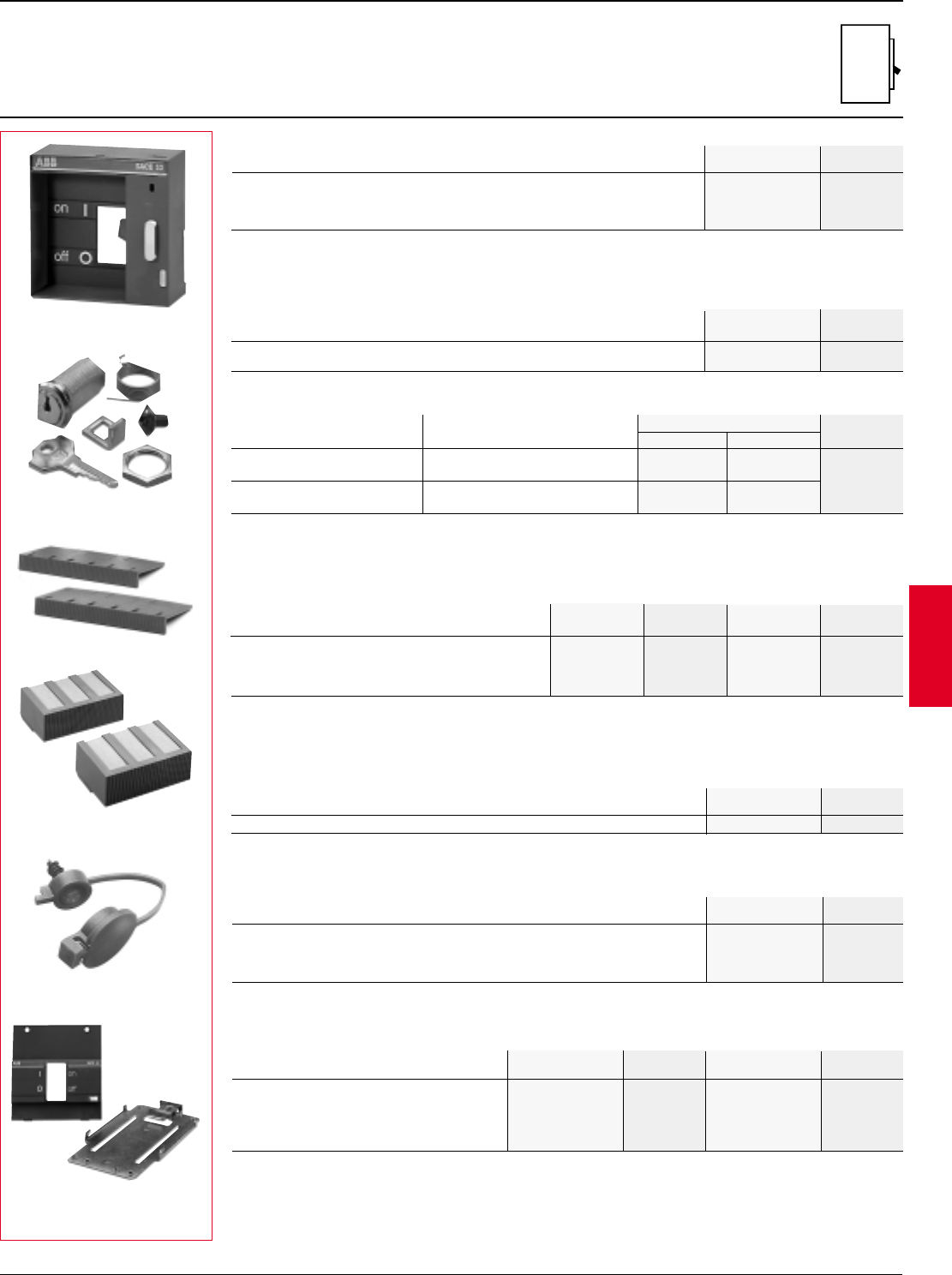
ABB Control Inc. 2.61
AC 1600 – 3/00
Isomax
S1 K1DMB $ 11
S3 K3DMB 24
S4 K4DMB 26
S5 K5DMB 38
Kit consists of mounting bracket to fix S3-S5 breakers onto 75mm DIN rail (EN 50023 rail) and includes 45mm high front
face plate to match up with miniature circuit breakers and manual motor starters. S1 breaker mounts on 35mm DIN rail.
DIN rail mounting kits
Suitable for use with breakers Catalog List
number price
S1 K2LD $ 16
S3 – S4 – S5 K5LD 14
S6 K6LD 16
S7 K7LD 20
Electric operator different K5KL-EO K7KL-EO
same K5KL-EO-2 K7KL-EO-2 $ 25
Rotary HM & locking device different K7KL K7KL
same K7KL-2 K7KL-2
S3 – S4 K4LC $ 8 K4LCH $ 16
S5 K5LC 12 K5LCH 24
S6 K6LC 18 K6LCH 32
S7 K7LC 40 –– ––
Mounts directly onto front of CB. Includes padlock device for locking CB in open position. Can be used as a manual handle
block, with padlock or with optional key lock accessory. Optional door interlock kit that will prevent CB door from opening
while CB is in the closed (ON) position.
Keyed cylinder locks are available for mounting onto Isomax electric operators, rotary handle mechanisms and front
locking devices. Key locks can be for one individual circuit breaker (different keys in each order) or for two circuit breakers
using the same key.
Both high and low types are available for fixed circuit-breakers. Covers provide IP40 degree of protection for fixed mounted
circuit breakers. Lug covers are required and included as standard with S5 400A and S6 800A cable lug kits. Covers up to
S6 can be sealed with lug cover seal shown in next section.
Front locking device
Bracket K7DB $ 5
Door interlock bracket
Key locks
Terminal covers for fixed circuit breakers
Frame Low profile List High profile List
catalog number price catalog number price
Item Catalog List
number price
External accessories
S1 – S7
Catalog number List
Item S3 – S7 price
Suitable for use with breakers Used with List
LC covers price
These screws prevent the terminal covers from being removed.
Terminal cover seals
S3 – S4 – S5 – S6 K6LC-S $ 5
K5LD
K7KL
K6LC
K6LCH
K6LC-S
K3DMB
Provides for mounting of two similar breakers on a single mounting plate. CBs are interlocked via a “walking beam” type
interlock, preventing breakers from being ON or closed at the same type. Both breakers can be OFF or tripped. MIP is
available in two versions, one with breakers mounted horizontally and then also a version for vertical mounting of breakers.
Mechanical interlock plate
Frame Horizontal List Vertical List
catalog number price catalog number price
S3 K3MI-H $ 570 K3MI-V $ 570
S4 K4MI-H 570 K4MI-V 570
S5 K5MI-H 590 K5MI-V 590
S6 K6MI-H 620 K6MI-V 620
S7 K7MI-H 630 K7MI-V 630
Accessory Keys Catalog number List
S3 – S4 – S5 S6 – S7 price
Discount schedule SA
Acc.
2.62 ABB Control Inc.
AC 1600 – 3/00
Isomax
Provides means to connect breakers directly onto rear bus bars.
S3 – S4 250 K4RC $ 87
S5 400 K5RC 225
S6 800 K6RC 280
S7 1200 K7RC 340
Accessories
S1 – S7
IEC
Rear connected stud kits1
For Max. Set of 6 List
breakers amps catalog number price
K4RC
Rear plug-in & drawout
circuit breakers
K7TUT
S4 – S5 – S6 – S7 K7TUT $ 210
Hand-held test kit (for all electronic trip types)
Isomax Catalog List
frames number price
Isomax breakers are available in both rear plug-in and complete draw-out configurations. Plug-in breakers can be rear bus,
front bus or front cable connected and are available up to the S5 400A size. The draw-out configuration uses a unique
racking system and is available for all breakers from S3 through S7.
Rear plug-in and draw-out circuit breakers
Plug-in (3 pole)1
Isomax hand-held test kit is used to both test and exercise microprocessor trip units in breakers S4 through S7. Unit
includes test forks that insert into the test plugs on all Isomax microprocessor trip units. Tester generates 15VDC signal
that performs diagnostic on electronic trip functions and will confirm test by tripping the CB. Will not test S3 nor any molded
case switch versions.
Four pole versions (plug-in and/or draw-out)
Take the above list prices times 1.35 for four (4) pole versions and add "-4" to the end of the catalog number.
S3 K4FCT $ 72
S4 K4FCT 72
S5 K5FCT 86
Frame Set of 6 List price
Cable termination kits (3 pole only)1
Compression type cable lug kit used to modify extended front bus connectors for direct cable connection.
Movable kit = parts needed to modify standard CB to movable type.
Fixed base kit = fix mount onto panel.
Ext Fr bus = fixed base with line and load side extended front bus connectors. (FF)
Rear Conn. = fixed base with line and load side rear bus connectors. (FR)
Complete kit = includes all parts required for plug-in or draw-out connection; does not include CB.
Plug-in = open breaker can be physically removed from fixed base without disconnecting cable or bus from fixed base. (P)
Draw-out = also known as withdrawable, breaker can be removed from fixed base via a through the door crank. Includes
ON, TEST and OFF position. (W)
Draw-out (3 pole)1
S1 K1PMK $ 171 K1PFC2$ 171 K1PFR $ 207 K1PC2$ 342 K1PR $ 378
S3 K4PMK 203 K3PFF 190 K3PFR 230 K3PF 393 K3PR 433
S4 K4PMK 203 K4PFF 203 K4PFR 243 K4PF 406 K4PR 446
S5 K5PMK 238 K5PFF 278 K5PFR 278 K5PF 516 K5PR 516
Separate kits fixed and movable Complete draw-out kits
Movable kit Fixed base kit Includes both fixed and movable portion
Frame Movable List price Ext fr bus List price Rear conn. List price Ext fr bus List price Rear conn. List price
S1 – S7 K7WCR $ 20
Draw-out crank
Isomax Catalog List
frames number price
1IEC ratings only.
2Front cable connection.
Discount schedule SA
Acc.
S3 K4WMK $ 203 K3WFF $ 230 K3WFR $ 270 K3WF $ 433 K3WR $ 473
S4 K4WMK 203 K4WFF 283 K4WFR 323 K4WF 486 K4WR 526
S5 K5WMK 278 K5WFF 318 K5WFR 318 K5WF 596 K5WR 596
S6 Horiz K6WMK 523 K6WFF 1346 K6WFR-H 1346 K6WF 1869 K6WR-H 1869
S6 Vert K6WMK 523 K6WFF 1346 K6WFR-V 1346 K6WF 1869 K6WR-V 1869
S7 Horiz K7WMK 821 K7WFF 2111 K7WFR-H 2111 K7WF 2932 K7WR-H 2932
S7 Vert K7WMK 821 K7WFF 2111 K7WFR-V 2111 K7WF 2932 K7WR-V 2932
Separate kits fixed and movable Complete draw-out kits
Movable kit Fixed base kit Includes both fixed and movable portion
Frame Movable List price Ext fr bus List price Rear conn. List price Ext Fr bus List price Rear conn. List price
ABB Control Inc. 2.63
AC 1600 – 3/00
Isomax
Enclosures
Type 1, 3R/12
Type 7/9
Description
Type 1
• General purpose indoor enclosure
intended for use in normal environments
to provide a degree of protection against
contact with enclosed equipment.
• Sheet steel, surface mount.
• Breaker is front-operable and can be
padlocked via front hasp.
• Available through 2500A, 600VAC
• UL Listed for use as service entrance
equipment (SUSE), per UL file E116374.
Type 3R/12
• Type 3R is intended for outdoor use
providing protection against rain, sleet or
snow.
• Type 12 is for use in indoor atmospheres
to provide a degree of protection against
circulating dust, lint, sawdust, falling dirt
and dripping non-corrosive liquids.
• Surface-mounted, sheet steel enclosure.
• Breaker can be operated via separately
ordered handle mechanism; door is
interlocked with mechanism.
• Available through 2500A, 600VAC.
• UL Listed for use as service entrance
equipment (SUSE), per UL file E116374.
Type 7/9
• Cast from copper-free aluminum (max.
0.025 copper content)
• Stainless steel shotblasted or sandblasted
natural finish
• Standard conduit openings in top and
bottom
• Breaker is operated from front handle and
can be padlocked
• NEC Class I Groups D, Div. 1 & 2
NEC Class II Groups E, F & G, Div 1 & 2
NEC Class III
• External machined flange joint design
• Integral cast mounting feet
• Machined flange for ease of hinge
installation
• Ground lug
• Cast mounting pan bosses
• All enclosures suitable for drilling &
tapping
• UL panel listed per UL File # E183868
2.64 ABB Control Inc.
AC 1600 – 3/00
Isomax
Isomax enclosures
Type 1 & 3R/12
Enclosures (Price does not include circuit breaker; order as a separate item.) 4
NEMA Breaker Enclosure maximum rating Approximate dimensions1Catalog List
designation type AL cables CU cables H x W x D (inches) number price
S1 100A 100A 14 x 10 x 3.1 S1E-1 $ 200
S22125A 125A 16 x 11 x 3.1 S2E-1 200
S3 150A 225A 22 x 12 x 4.5 S3E-1 235
S4 225A 250A 30 x 17.5 x 4.5 S4E-1 305
Type 1 S5 400A 400A 30 x 17.5 x 4.5 S5E-1 305
S6 800A 800A 44 x 22 x 6 S6E-1 685
S7 1000A 1200A 44 x 22 x 6 S7E-1 685
S8 2500A 2500A 88 x 36 x 24 S8ES250-1 5285
S1 100A 100A 14 x 10 x 8.8 S1E-3R12 305
S2 2125A 125A 16 x 11 x 8 S2E-3R12 305
S3 150A 225A 22 x 12 x 9 S3E-3R12 395
S4 225A 250A 30 x 17.5 x 9 S4E-3R12 575
Type 3R/123S5 400A 400A 30 x 17.5 x 9 S5E-3R12 575
S6 800A 800A 44 x 22 x 11 S6E-3R12 905
S7 1000A 1200A 44 x 22 x 11 S7E-3R12 905
S8 2500A 2500A 88 x 36 x 24 S8ES250-3R12 5285
1Enclosures may not meet size requirement for UL 100% rated breakers.
2Not UL approved.
3Variable depth rotary handle must be ordered separately (S1 - S7).
4Consult ABB for breakers installed in enclosures.
Discount schedule SE
S3E-1 S4E-3R12
Breaker Neutral cable capacity Neutral kit List
type and wire range catalog number price
S1 – S2 Neutral #14-1/0 S2NK125 $ 100
Bonding Lug #14-1/0
S3 Neutral #6-250 kcmil S3NK225 135
Bonding Lug #14-1/0
S4 Neutral #6-250 kcmil S4NK250 155
Bonding Lug #14-1/0 kcmil
S5 Neutral (2) #6-250 kcmil S5NK400 260
Bonding Lug #14-1/0 kcmil
S6 Neutral (2) #2-600 kcmil S6NK800 350
Bonding Lug #6-250 kcmil
S7 Neutral (4) #2-600 kcmil S7NK1200 535
Bonding Lug #6-250 kcmil
S8 Neutral (6) #1/0-750 kcmil —included
Bonding Lug (2) #2-600 kcmil
Neutral kits
Encl.
ABB Control Inc. 2.65
AC 1600 – 3/00
Isomax
Additional options
Explosion-proof enclosures
(Price does not include circuit breaker; order as a separate item for factory assembly.)
NEMA Breaker Enclosure Approximate dimensions Catalog number List price
designation type max. rating H x W x D (inches) suffix adder
S3 Cu only 100A 17 x 10 x 8.65 7 $ 2100
S3 Cu only 225A 22.5 x 11.5 x 8.77 7 2850
S4 Cu only 250A 25 x 18 x 9.92 7 4700
Type 7/9 S5 Cu only 400A 30 x 17 x 9.25 7 6600
S6 Cu only 600A 35 x 17 x 11 7 8600
S6 Cu only 800A 41 x 17 x 11 7 10,450
S7 Cu only 1200A 51 x 17 x 13 7 22,450
Isomax enclosures
Type 7/9
S5N400BW7
Discount schedule SE
S3 Cu only 100A -X $ 130 -S $ 20 -B $ 145 -D
S3 Cu only 225A -X 145 -S 25 -B 170 -D
S4 Cu only 250A -X 145 -S 45 -B 355 -D
Type 7/9 S5 Cu only 400A -X 175 -S 60 -B 415 -D $ 110
S6 Cu only 600A -X 250 -S 60 -B 465 -D
S6 Cu only 800A -X 315 -S 60 -B 535 -D
S7 Cu only 1200A -X 430 -S 80 -B 600 -D
NEMA 4X Stainless steel bolts Captive bolts Drain
NEMA Breaker Enclosure Cat. no. List price Cat. no. List price Cat. no. List price Cat. no. List price
designation type max. rating adder adder adder adder adder adder adder adder
S4 N 250 BW7 - 2xxx
Catalog number information — Type 7/9
Frame size
S3 = 150 / 225A
S4 = 250A
S5 = 400A
S6 = 600 / 800A
S7 = 1200A
Interrupting rating class
B= Basic (240VAC)
N=Normal
H=High
L= Extra high
D= Special molded case switch
Type connectors
W = None L = Lugs
Current rating
015 = 15A
250 = 250A
400 = 400A
600 = 600A
800 = 800A
1200 = 1200A
Trip unit function
B=LI F=LSIG/K
C=LSI H= LSIG/D
D= Molded case switch (MCS) J= LSIG/DT
E=LSIG K= LSIG/DTK
T= Thermal-magnetic M= Magnetic only (MCP)
NEMA enclosure 7/9
Number of poles
-2 = 2 pole
-4 = 4 pole
None = 3 pole
Accessories (added in alpha-numeric order)
A= Auxiliary switch
B= Captive bolts
BA = Bell alarm
BA3 = Bell alarm (S6/S7 only)
D= Breather/drain
H= Fixed rotary handle mounted on CB
S_ = Shunt trip with voltage code
S= Stainless steel bolts
U_ = Undervoltage release with voltage code
X= NEMA 7/9/4X
To order a breaker in an explosion-proof enclosure, add the suffix "7" to the end of the catalog number and add the list price adder to the list
price of the breaker.
Example: S5N400BW7
S5N400BW breaker ............ $ 2151
Explosion proof enclosure ..... 6600
Total ..................................... $ 8751
To add additional options, simply add the suffix to the end of the catalog number.
Example: S5N400BW7XSD
S5N400BW breaker ............ $ 2151
Explosion proof enclosure ..... 6600
NEMA 4X .................................. 175
Stainless steel bolts ................... 60
Drain ......................................... 110
Total ..................................... $ 9096
Encl.
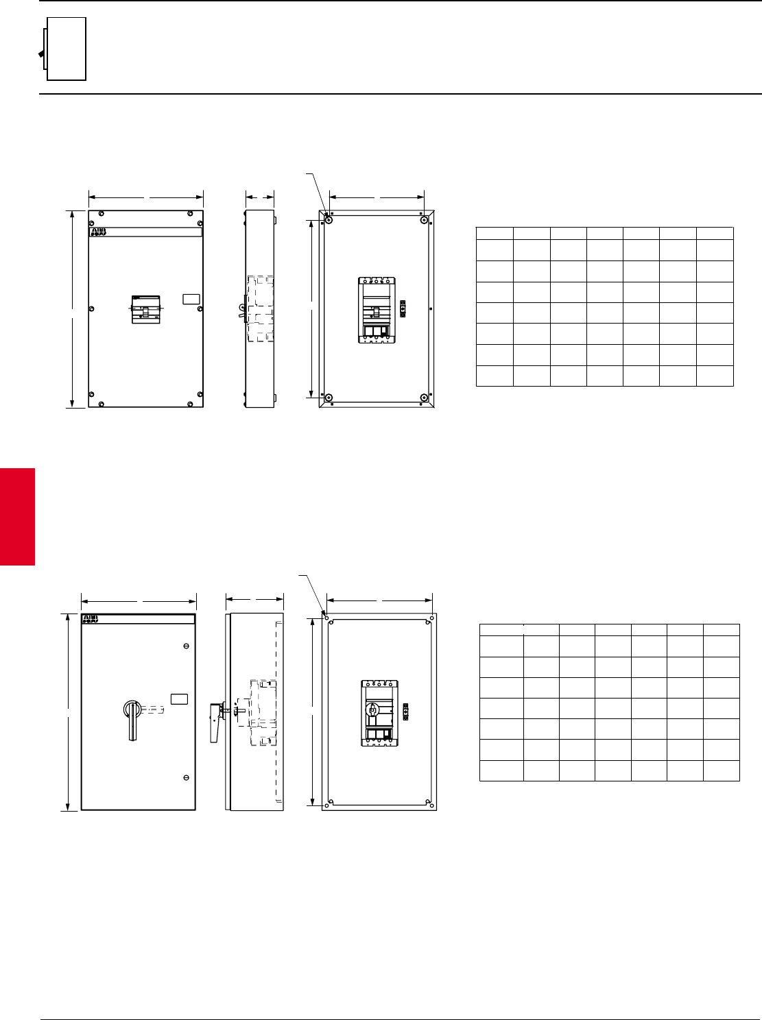
2.66 ABB Control Inc.
AC 1600 – 3/00
Isomax
Approximate dimensions
S1 – S7 enclosures
NEMA 1, 3R & 12
NEMA 1
S2E-1
S3E-1
S4E-1
S5E-1
S6E-1
S7E-1
16.0
406.5
22.0
559.0
30.0
762.0
30.0
762.0
44.0
1118.0
44.0
1118.0
11.0
280.0
12.0
305.0
17.5
444.5
17.5
444.5
22.0
559.0
22.0
559.0
2.85
72.5
4.25
108.0
4.25
108.0
4.25
108.0
5.75
146.0
5.75
146.0
13.0
330.0
19.0
482.0
27.0
686.0
27.0
686.0
41.0
1041.5
41.0
1041.5
8.0
203.0
9.0
229.0
14.5
368.5
14.5
368.5
19.0
483.0
19.0
483.0
.312
7.93
.312
7.93
.312
7.93
.312
7.93
.312
7.93
.312
7.93
A
FRONT VIEW
B
SIDE VIEW
C
SECTION
E
D
F
4-MTG. HOLES
AB C D E
CAT.# F
S1E-1 14.0
355.6 10.0
254.0 2.85
72.39 11.0
279.4 7.0
177.8 .312
7.93
S2E-3R12
S3E-3R12
S4E-3R12
S5E-3R12
S6E-3R12
S7E-3R12
16.0
406.5
22.0
559.0
30.0
762.0
30.0
762.0
44.0
1118.0
44.0
1118.0
11.0
280.0
12.0
305.0
17.5
444.5
17.5
444.5
22.0
559.0
22.0
559.0
10.8
274.5
14.5
368.5
20.5
520.5
28.5
724.0
9.5
242.0
10.5
267.0
16.0
16.0
406.5
20.5
521.0
20.5
521.0
8.8
224.0
8.8
224.0
8.8
224.0
8.8
224.0
10.8
274.5
28.5
724.0
42.5
1080.0
42.5
1080.0
0.50
13.7
0.50
13.7
0.50
13.7
0.50
13.7
0.50
13.7
0.50
13.7
406.5
FRONT VIEW
B
A
SIDE VIEW SECTION
F
4-MTG. HOLES
D
E
C
AB C D E
CAT.# F
S1E-3R12 14.0
355.6 10.0
254.0 12.5
317.50 8.5
215.90
8.8
223.52 0.50
13.7
NEMA 3R, 12
Encl.
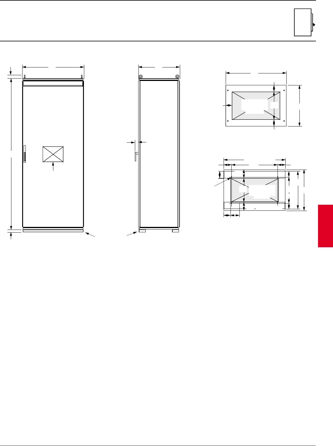
ABB Control Inc. 2.67
AC 1600 – 3/00
Isomax
Approximate dimensions
S8 enclosures
NEMA 1, 3R & 12
CONDUIT
ENTRY SPACE
(16.2 X 28.0)
FRONT ELEVATION
( DOOR CLOSED )
CIRCUIT
BREAKER
ESCUTCHEON
CUT-OUT
TYPE 1 ONLY
FRONT
REAR
LEFT RIGHT
TOP VIEW
ENCLOSURE ROOF
(SOLID REMOVABLE ROOF PANEL)
BOTTOM VIEW
ENCLOSURE FLOOR
(SOLID NON-MOVABLE FLOOR PANEL)
0.50 DIA.
MTG. HOLES
( QTY. 4 )
FRONT
REAR
LEFT
RIGHT
CONDUIT
ENTRY SPACE
(28.0 X 13.8)
SILL CHANNEL
SILL CHANNEL
ABB
35.8
909
2.0
51
87.4
2220
1.5
38
2.0
51
4.0 x 1.5 INCHES
103 38
SILL CHANNEL
24.0
610
35.1
892
23.8
605
3.8
97
3.8
97
3.6
91
35.79 (OVER ALL)
909
26.73
679
4.53
115
4.53
115
4.00
102
5.00
127
13.8
351
5.00
127
5.20
132
3.9
99
3.36
85
15.09
383
23.80
605
711 351
411
711
13
3.36
85
21.81
554
16.2
411
Encl.
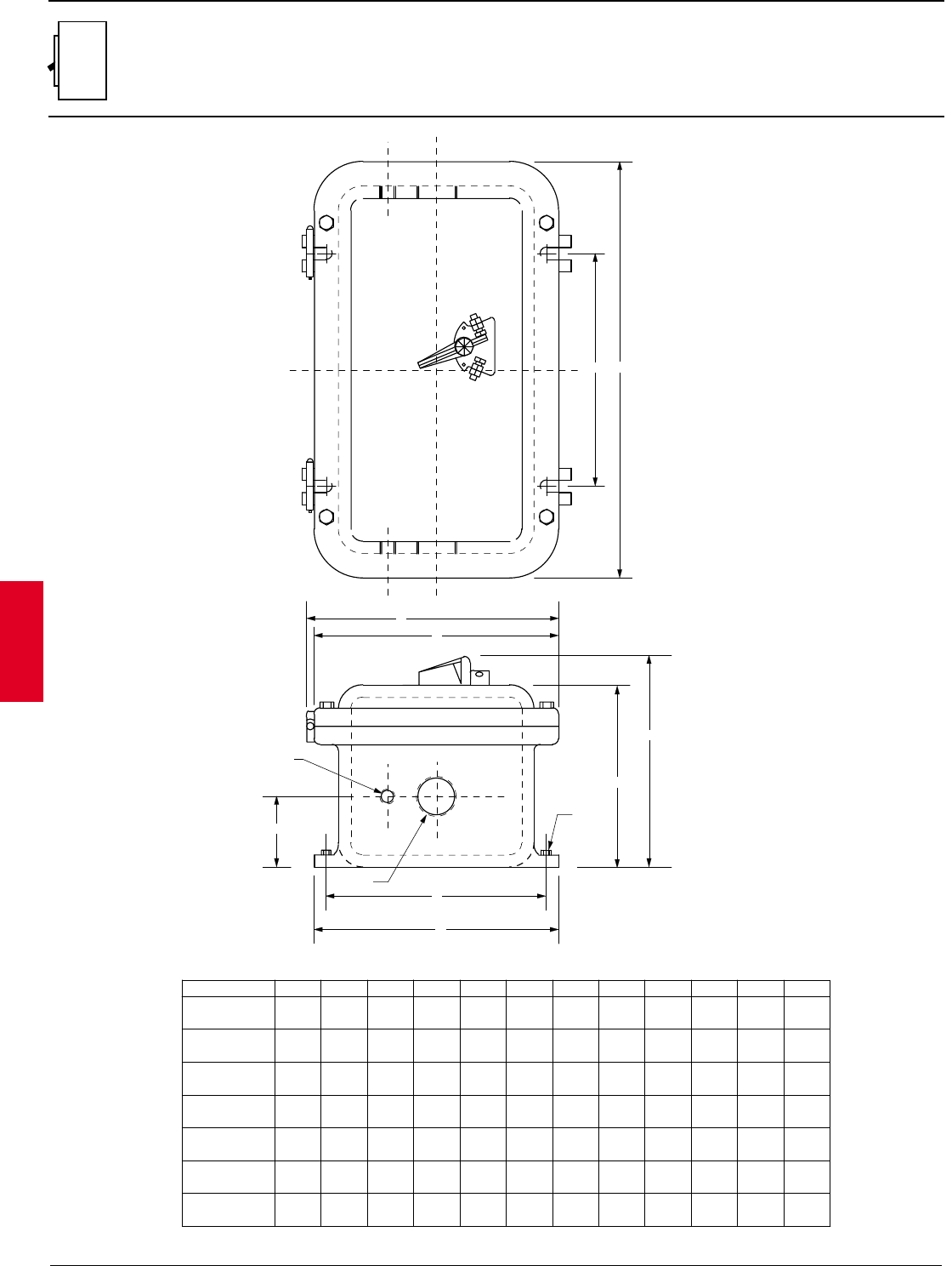
2.68 ABB Control Inc.
AC 1600 – 3/00
Isomax
Approximate dimensions
S1 – S7 enclosures
NEMA 7 & 9
A B C D E F G H J K L
S3 100A
Breaker type
S3 225A
S4 250A
S5 400A
S6 600A
S6 800A
S7 1200A
A
K
F
H
D
J
L
C
G
1/2" NPT
THRU TOP &
BOTTOM (2 PL)
B
E
10.00
254.0
11.50
292.1
17.00
431.8
17.13
435.1
17.00
431.8
17.00
431.8
17.13
435.1
17.00
431.8
22.50
571.5
25.00
635.0
29.13
739.9
35.00
889.0
41.00
1041.4
51.13
1298.7
7.44
189.0
7.56
192.0
8.50
215.9
7.63
193.8
9.63
244.6
9.63
244.6
11.63
295.4
10.00
254.0
11.00
279.4
18.00
457.2
18.00
457.2
18.00
457.2
18.00
457.2
18.00
457.2
9.50
241.3
14.50
368.3
14.38
365.3
18.75
476.3
23.00
584.2
29.00
736.6
39.00
990.6
9.00
228.6
9.75
247.7
15.75
400.0
15.75
400.0
15.75
400.0
15.75
400.0
15.75
400.0
3/8
9.5
3/8
9.5
1/2
13
1/2
13
1/2
13
1/2
13
1/2
13
2.88
73.2
3.00
76.2
3.13
79.5
2.75
69.9
3.75
95.3
3.88
98.6
4.88
124.0
1-1/2
38.1
2-1/2
63.5
2-1/2
63.5
3
76.2
4
101.6
4
101.6
4
101.6
10.31
261.9
11.81
300.0
17.81
452.4
17.94
455.7
17.81
452.4
17.81
452.4
17.94
455.7
8.65
219.7
8.77
222.8
9.92
252.0
9.05
229.9
11.05
280.7
11.05
280.7
13.05
331.5
Wgt.(lbs)
43
70
124
141
203
236
408
NEMA 7 & 9
Encl.
ABB Control Inc. 2.69
AC 1600 – 3/00
Isomax
Technical data
★Unless otherwise specifically permitted elsewhere, the overcurrent protection for conductor types marked with a star (★) shall not exceed 15 amperes for No. 14,
20 amperes for No. 12, and 20 amperes for No. 10 copper; or 15 amperes for No. 12 and 25 amperes for No. 10 aluminum and copper-clad aluminum after any
correction factors for ambient temperature and number of conductors have been applied.
Ampacities of insulated conductors (From 1996 NEC Table 310-16)
21 – 25 1.08 1.05 1.04 1.08 1.04 1.05 70 – 77
26 – 30 1.00 1.00 1.00 1.00 1.00 1.00 78 – 86
31 – 35 .91 .94 .96 .91 .94 .96 87 – 95
36 – 40 .82 .88 .91 .82 .88 .91 96 – 104
41 – 45 .71 .82 .87 .71 .82 .87 105 – 113
46 – 50 .58 .75 .82 .58 .75 .82 114 – 122
51 – 55 .41 .67 .76 .41 .67 .71 123 – 131
56 – 60 — .58 .71 — .58 .71 132 – 140
61 – 70 — .33 .58 — .33 .58 141 – 158
71 – 80 — — .41 — — .41 159 – 176
Ambient Correction factors Ambient
temperature For ambient temperatures other than 30° C (86° F) multiply the allowable ampacities temperature
°C shown above by the appropriate factor shown below. °F
18 — — 14 — — — —
16 — — 18 — — — —
14 20★20★25★————
12 25★25★30★20★20★25★12
10 30 35★40★25 30★35★10
840 50 55 30 40458
655 65 75 40 50606
470 85 95 55 65754
3 85 100 110 65 75 85 3
2 95 115 130 75 90 100 2
1 110 130 150 85 100 115 1
1/0 125 150 170 100 120 135 1/0
2/0 145 175 195 115 135 150 2/0
3/0 165 200 225 130 155 175 3/0
4/0 195 230 260 150 180 205 4/0
250 215 255 290 170 205 230 250
300 240 285 320 190 230 255 300
350 260 310 350 210 250 280 350
400 280 335 380 225 270 305 400
500 320 380 430 260 310 350 500
600 355 420 475 285 340 385 600
700 385 460 520 310 375 420 700
750 400 475 535 320 385 435 750
800 410 490 555 330 395 450 800
900 435 520 585 355 425 480 900
1000 455 545 615 375 445 500 1000
1250 495 590 665 405 485 545 1250
1500 520 625 705 435 520 585 1500
1750 545 650 735 455 545 615 1750
2000 560 665 750 470 560 630 2000
Temperature rating of conductor
Size 60° C 75° C 90° C 60° C 75° C 90° C Size
(140° F) (167° F) (194° F) (140° F) (167° F) (194° F)
Types Types Types Types Types★Types
TW★FEPW★TA, TBS, SA TW★RH★, RHW★TA, TBS
UF★RH★, RHW★SIS, FEP★UF★THHW★SA, SIS
THHW★FEBP, MI THW★THHN★
AWG THW★RHH, RHW-2 THWN★THHW★AWG
kcmil THWN★THHN, THHW XHHW★THW-2, THWN-2 kcmil
XHHW★USE-2, XHH USE★RHH, RHW-2
USE★, ZW★XHHW USE-2
XHHW-2, ZW-2 XHH, XHHW
XHHW-2, SW-2
Copper Aluminum or copper-clad
Tech.
data
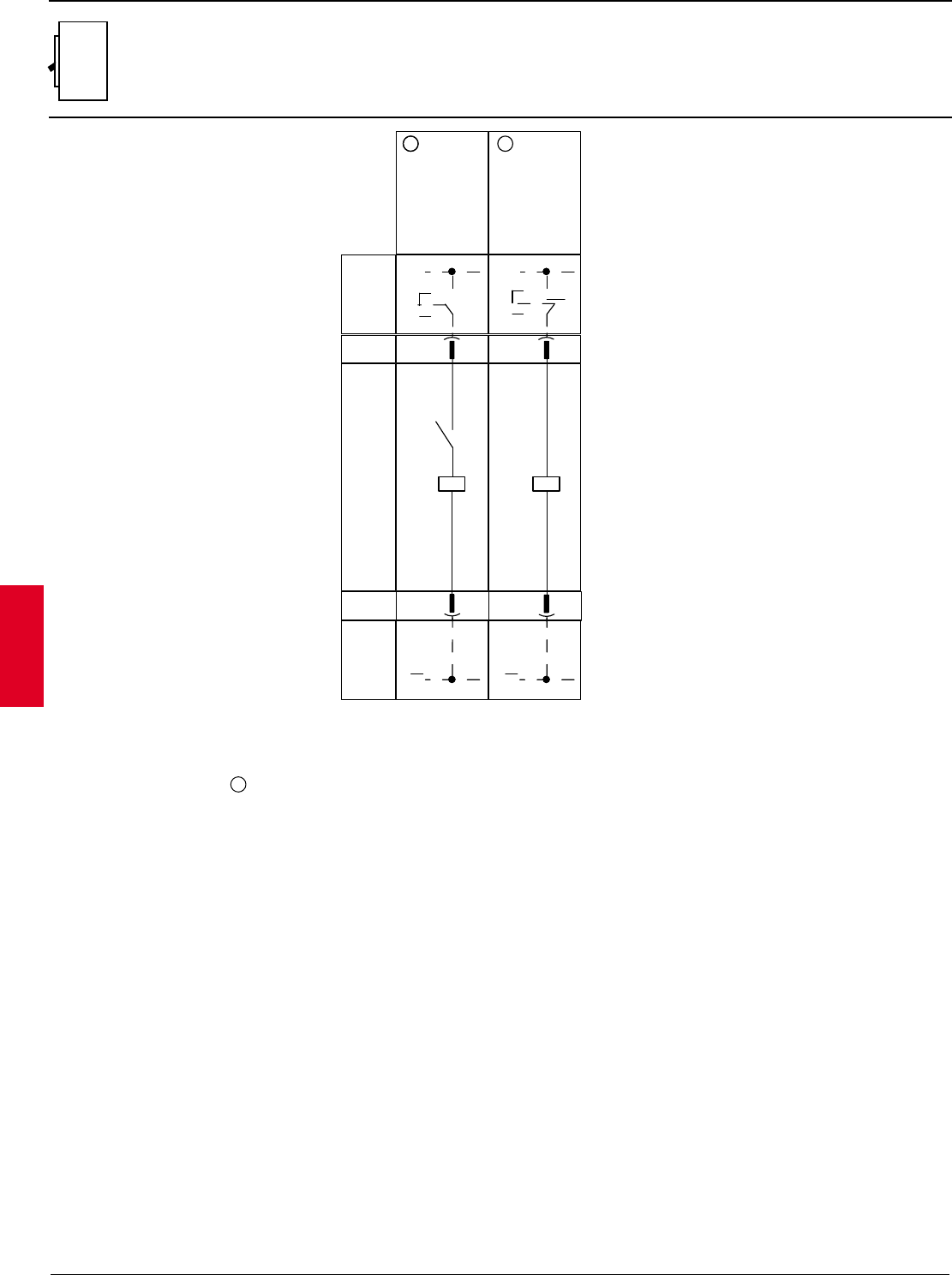
2.70 ABB Control Inc.
AC 1600 – 3/00
Isomax
Wiring diagrams
Duty releases
S11
C2
YO
C1
~
~
SO
~
+
~
SO
+
YU
D1
D2
1
1 4
Opening
release Instantaneous
undervoltage
release
( * A )
Conn. X1
Internal
Circuit Externial
Circuit
A4
Externial
Circuit
A4
Conn. X1
Q/0
11
22
Legend
Figure number of diagram
Example switchgear and connections for control
and signalling, ouside the circuit-breaker
A4 -
Auxiliary contacts of the circuit-breaker
Q/0 -
SO - Pushbutton or contact for opening the circuit-breaker
-
Incompatibility:
The circuits indicated in the
following figures cannot be powered
simultaneously on the same circuit-breaker:
1 - 4 - 5 - 6 2 - 3
Availability:
Connectors X1 and X2 are
only supplied to order for circuit breakers S1 -S2.
Notes:
( * A ) The undervoltage release is powered from
upstream circuit-breaker or by an independent
power supply: closing of the circuit-breaker is
only allowed when the release is energized (the
closing lock is implemented mechanically).
1 Used for IEC S2.
Wiring

ABB Control Inc. 2.71
AC 1600 – 3/00
Isomax
Wiring diagrams
Duty releases
S3 – S7
C2
C2
C2
YO
C1
C1
C1
~
~
SO
~
+
~
SO
+~
SO
+
~
~
~
YU
D1
D1
D1
D2
D2
D2
YU
D1
D1
D1
D2
D2
D2
+
146
Opening
release Instantaneous
undervoltage
release
undervoltage release with
electronic time-lag device
outside the circuit-breaker
( * A ) ( * A )
Conn. X1
Term. X V
Internal
Circuit Externial
Circuit
A4
Externial
Circuit
A4
Term. X V
Conn. X1
Q/0
Legend
-
Incompatibility:
The circuits indicated in the following figures
cannot be powered simultaneously on the same
circuit-breaker:
1 - 4 - 5 - 6 2 - 3
Availability:
Connectors X1 and X2 are only supplied to order
for circuit breakers S1 -S2.
Notes:
( * A ) The undervoltage release is powered from
upstream of the circuit-breaker or by an
independent power supply: closing of the circuit-
breaker is only allowed when the release is
energised (the closing lock is implemented
mechanically).
Figure number of diagram
A4 - Example switchgear and connections for control
and signalling, ouside the circuit-breaker
Q/0 - Auxiliary contacts of the circuit-breaker
SO - Pushbutton or contact for opening the circuit-
breaker
Wiring
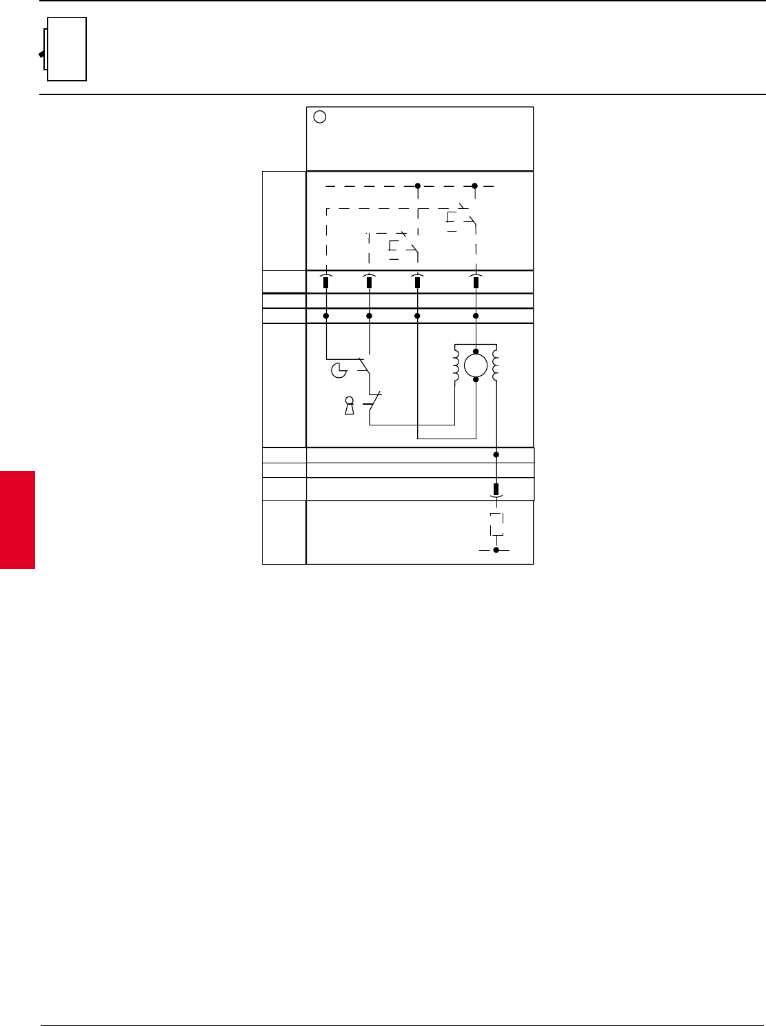
2.72 ABB Control Inc.
AC 1600 – 3/00
Isomax
Wiring diagrams
Motor operators
S3 – S5
~
+
Conn. X2
Term. XV
Internal
Circuit Externial
Circuit
A4
Externial
Circuit
A4
Term. XV
Conn. X2
M
SO2
SC
U1
U1
U8
U8
U6
U6
U2
U2
U5
U5
7
Direct action motor operation
~
+
R
S2
S1
A1
Legend
O- Figure number of diagram
A1 - Applications of the circuit-breaker
A4 - Example switchgear and connections for control
and signalling, ouside the circuit-breaker
M - For S6 -S7: motor for opening the circuit-breaker
and loading the closing springs of the circuit-
breaker
S1 - For S3 - S4 - S5: position contact operated by
a circuit-breaker cam for S6 - S7: contact
controlled by the motor operated cam:
closes when the circuit-breaker reaches it’s
closed positon and opens when the circuit-
breaker reaches its open position
(doesn’t switch when the circuit breaker
goes into its tripped position)
S2 - For S3 - S4 - S5: safety contact operated by:
- key lock (if mounted)
- padlock device
- local control Allen key
SC - Pushbutton or contact for closing the circuit-breaker.
For circuit breakers S3 - S4 -S5, the operating
mechanism must have a time of not less than 100ms
S02 - Pushbutton or contact for opening the circuit-breaker.
For circuit breakers S3 - S4 - S5, the operating
mechanism must have a time of not less than 100 ms
(see instructions for resetting the circuit-breaker after
the releases have tripped.
Wiring
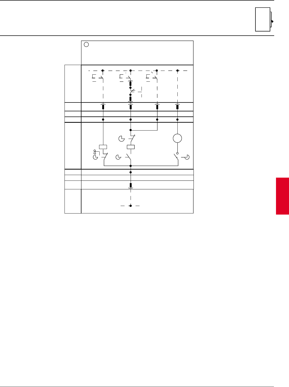
ABB Control Inc. 2.73
AC 1600 – 3/00
Isomax
Wiring diagrams
Motor operators
S6 – S7
Conn. X2
Term. XV
Internal
Circuit Externial
Circuit
A4
Externial
Circuit
A4
Term. XV
Conn. X2
SO2
A1
A1
C11
C11
8
Stored-energy motor operation
~
+
A2
M
U1
U1
U1
A3
A3
A3
SO1SC
C11 A1
KO
S3
KO
S1
S2
YC
U2
U2
U2
~
+
X2
XV
SY
XV
X2
96
2
1
95
Legend
O- Figure number of diagram
A1 - Applications of the circuit-breaker
A2 - Applications of the motor operators
A4 - Example switchgear and connections for control and
signalling, outside the circuit breaker
S1 - For S3 - S4 - S5: position contact operated by a
circuit breaker cam for S6 - S7: contact controlled
by the motor operated cam: closes when the circuit
breaker reaches its closed position and opens when
the circuit breaker reaches its open position (doesn’t
switch when the circuit breaker goes into its tripped
position)
S2 - For S3 - S4 - S5: safety contact operated by:
- key lock (if mounted
- padlock device
- local control Allen key
SC - Pushbutton or contact for closing the circuit breaker.
For circuit breakers S3 - S4 - S5, the operating
mechanism must have a time of not less than 100ms
SO1 Pushbutton or contact for opening the circuit breaker
S02 - For circuit breakers S3 - S4 - S5, the operating
mechanism must have a time of not less than 100ms
(see instructions for resetting the circuit breaker after
the releases have tripped)
SY - Contact for electrical signalling of circuit breaker open
due to tripping of thermomagnetic releases, YO, YO1, YU
(tripped position)
KO - For S6 - S7: opening and spring-loading relay with
held position make contact, released by a cam of the
motor operator when the circuit breaker reaches its open
position and the closing springs have been loaded
M - For S6 - S7: motor for opening the circuit breaker and
loading the closing springs of the circuit breaker
X1 - Connectors for the auxiliary circuits of the circuit breaker
X2 - For circuit breakers S1 - S2 supplied for order only
XV - Terminal block for accessories
YC - Closing release
Wiring
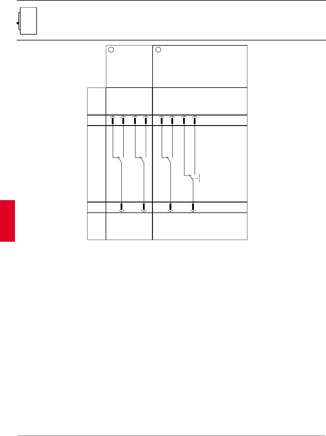
2.74 ABB Control Inc.
AC 1600 – 3/00
Isomax
Wiring diagrams
Auxiliary contacts
S11
11
Two change-over
contacts, for electrical
signalling of circuit-
breaker open/close
Internal
Circuit
Externial
Circuit
A4
Legend
Externial
Circuit
A4
Conn. X2
Conn. X2.
12
One changed-over contact for electrical signalling
of circuit-breaker open or closed and one change-
over contact for electrical signalling of circuit-
breaker open due to triping of thermomagnetic
releases YO, YO1, YU ( tripped position )
6
Q/1 Q/2
734
12 14 22 24
6
Q/1
SY
734
12 14 96 98
11 21
52
11 95
52
O- Figure number of diagram
A4 - Example switchgear and connections for control and
signalling, outside the circuit breaker
Q/1...2 - Auxiliary contacts of the circuit breaker
SY - Contact for electrical signalling of circuit breaker
open due to tripping of thermomagnetic
releases YO, YO1, YU (tripped position)
1 Used for IEC S2.
Wiring
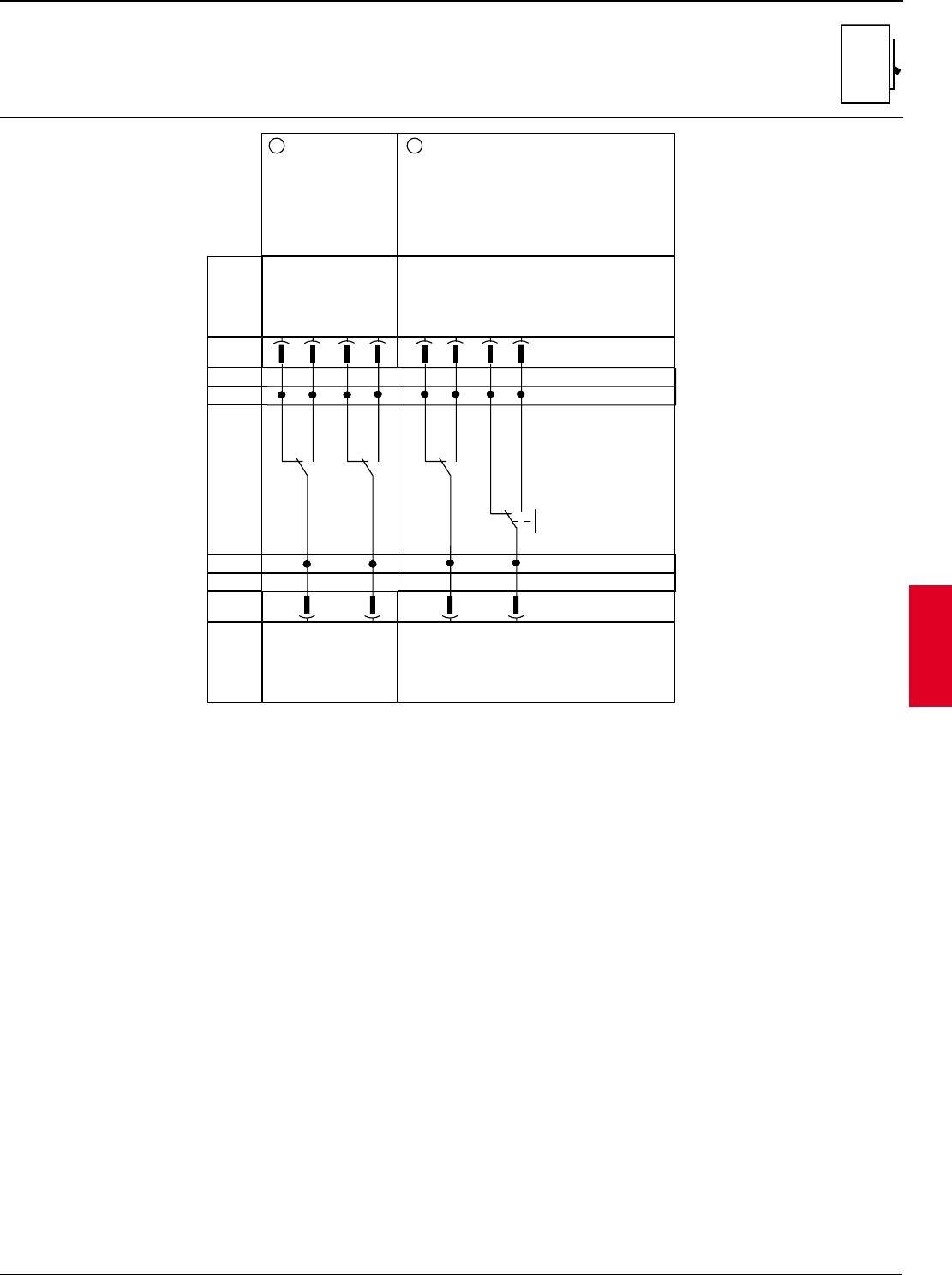
ABB Control Inc. 2.75
AC 1600 – 3/00
Isomax
Wiring diagrams
Auxiliary contacts
S3 – S7
11
Two change-over
contacts, for electrical
signalling of circuit-
breaker open/close
Internal
Circuit
Externial
Circuit
A4
Externial
Circuit
A4
Conn. X2
Conn. X2
12
One changed-over contact for electrical signalling
of circuit-breaker open or closed and one change-
over contact for electrical signalling of circuit-
breaker open due to triping of thermomagnetic
releases YO, YO1, YU ( tripped position )
12
Q/1 Q/2
12 14 22 24
Q/1
SY
12 14 96 98
11 21
11
11 95
Term. X V
Term. X V
14 22 24 12 14 96 98
4242 42 24
21
21 11 95
11 1 1
Legend
O- Figure number of diagram
A4 - Example switchgear and connections for control and
signalling, outside the circuit breaker
Q/1...2 - Auxiliary contacts of the circuit breaker
SY - Contact for electrical signalling of circuit breaker
open due to tripping of thermomagnetic
releases YO, YO1, YU (tripped position)
Wiring
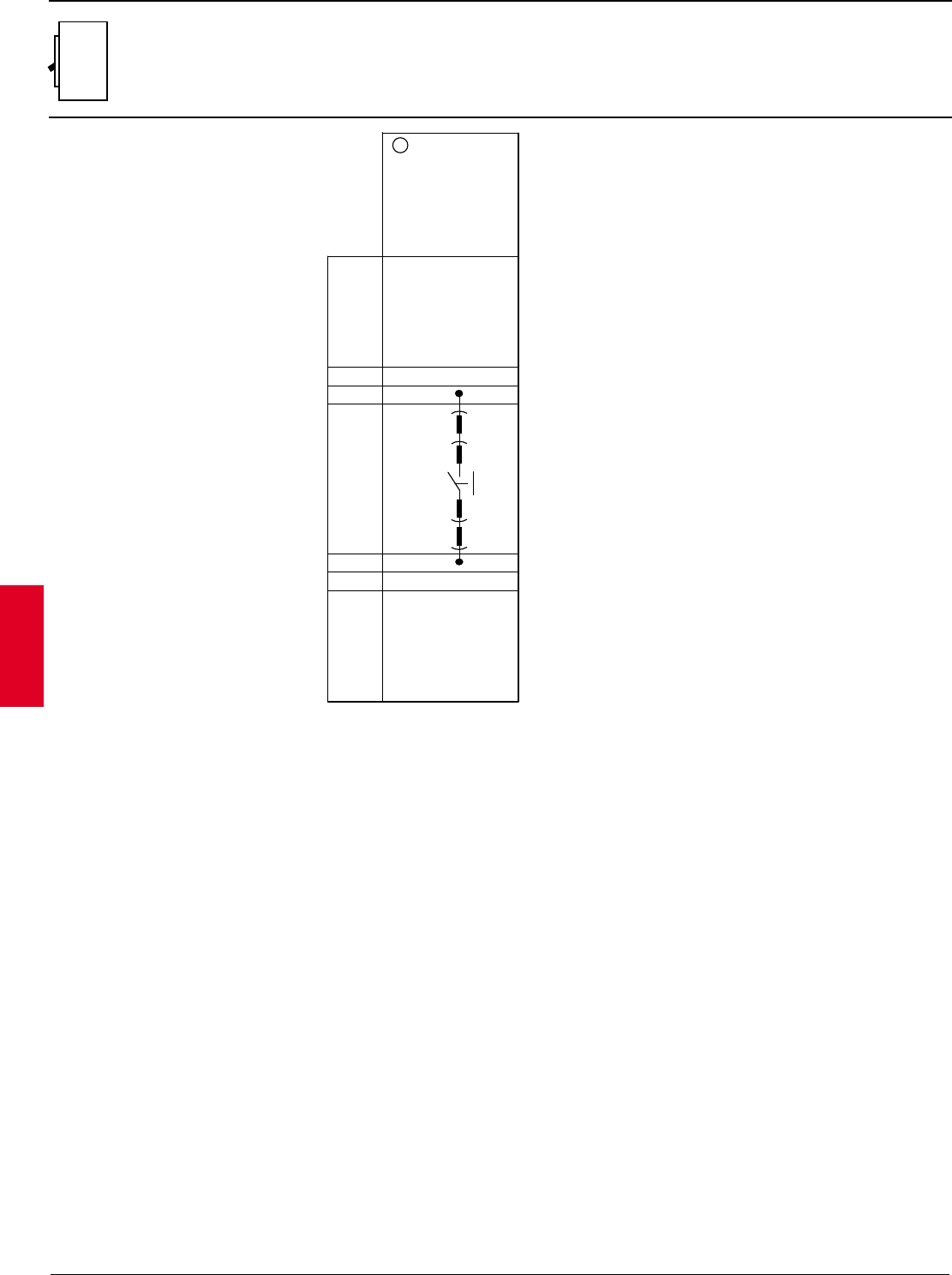
2.76 ABB Control Inc.
AC 1600 – 3/00
Isomax
Wiring diagrams
Auxiliary contacts
S4 – S7
Internal
Circuit
Externial
Circuit
A4
Externial
Circuit
A4
41
Contact for
signalling release
YO1 tripped
Term. X5 1
4
Term. X6
Term. X5
Term. X6
( * C )
1
3
4
4
X3
K51
YO1
XO
XO
X3
Legend
O- Figure number of diagram
A4 - Example switchgear and connections for control and
signalling, outside the circuit breaker
K51/YO1 - Electrical signalling of alarm for release YO1
tripped due to overcurrent or "trip test"
X3 - Connectors for the circuits of the microprocessor-
based overcurrent release (with plug in or with-
drawable circuit breakers, the connectors are pulled
out at the same time as the circuit breaker
XO - Connector for the opening solenoid YO1
Incompatibility:
The circuits indicated in the following figures cannot be
powered simultaneously on the same circuit breaker:
11 - 12 - 13 41 - 42 - 43 - 44
Availability:
Connectors X1 and X2 are only supplied to order for circuit
breakers S1 - S2.
Notes:
(*C) The electrical signalling contact for the microprocessor-
based overcurrent release, shown in Fig. 41, has the
following electrical characteristics:
¥ rated voltage = 24V
¥ breaking capacity (resistive load = 3 W/VA)
¥ maximum interrupted current = 0.5A
¥ For S4 - S5 available with PR212/P release only
Wiring
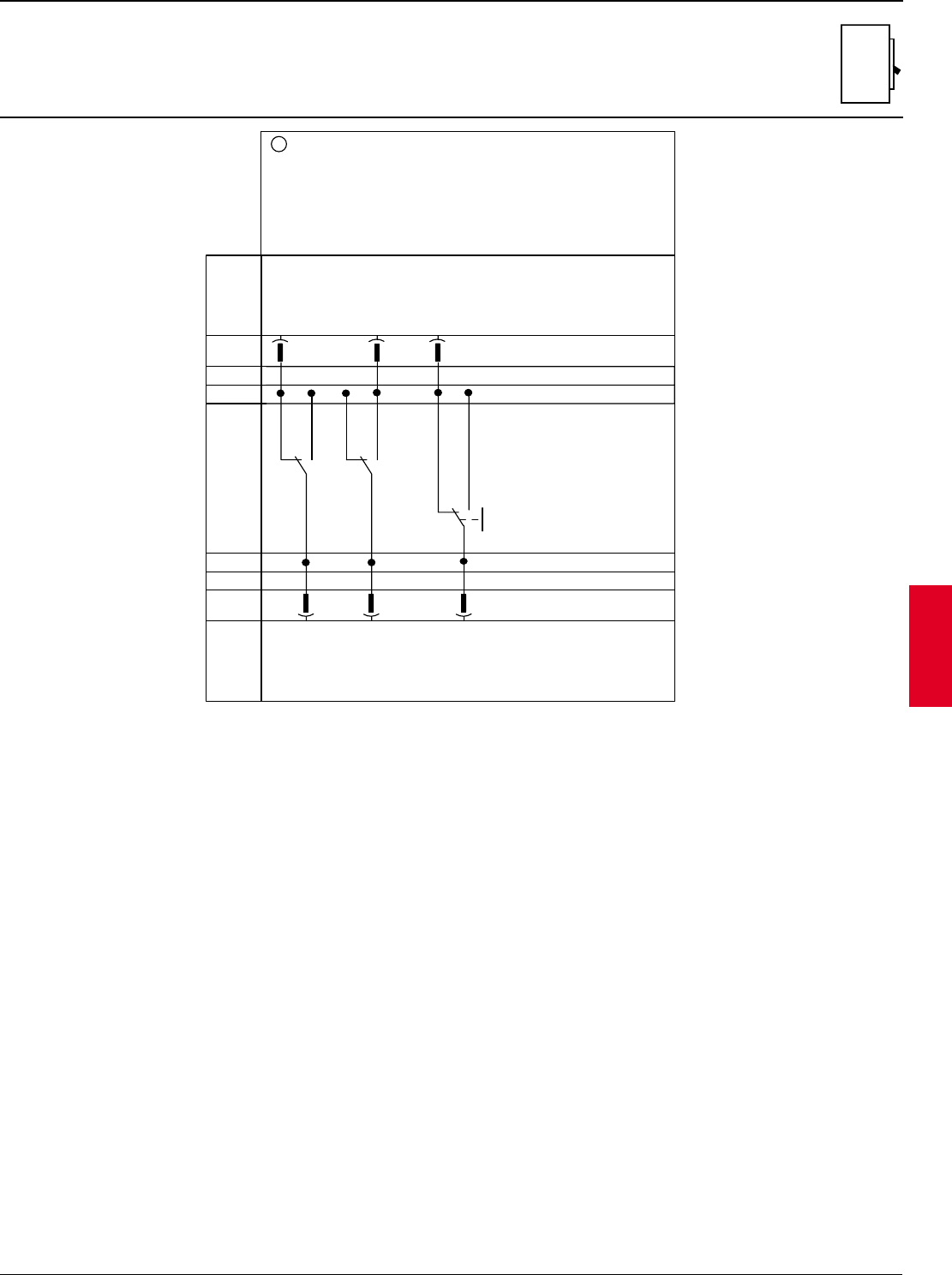
ABB Control Inc. 2.77
AC 1600 – 3/00
Isomax
Wiring diagrams
Auxiliary contacts
S6 – S7
Internal
Circuit
Externial
Circuit
A4
Externial
Circuit
A4
Conn. X2
Conn. X2
13
One contact for electrical signalling of circuit-breaker open, one change-over
contact for electrical signalling of circuit-breaker closed and one contact for
electrical signalling of circuit-breaker not open due to tripping of
thermomagnetic releases YO1, YO1,YU ( not tripped position )
12
Q/1 Q/2
12 24
SY
96
11 23
11
95
Term. XV
Term. XV
24 96
4242 24
23 95
11 1
Legend
O- Figure number of diagram
A4 - Example switchgear and connections for control and
signalling, outside the circuit breaker
Q/1...2 - Auxiliary contacts of the circuit breaker
SY - Contact for electrical signalling of circuit breaker
open due to tripping of thermomagnetic
releases YO, YO1, YU (tripped position)
Wiring
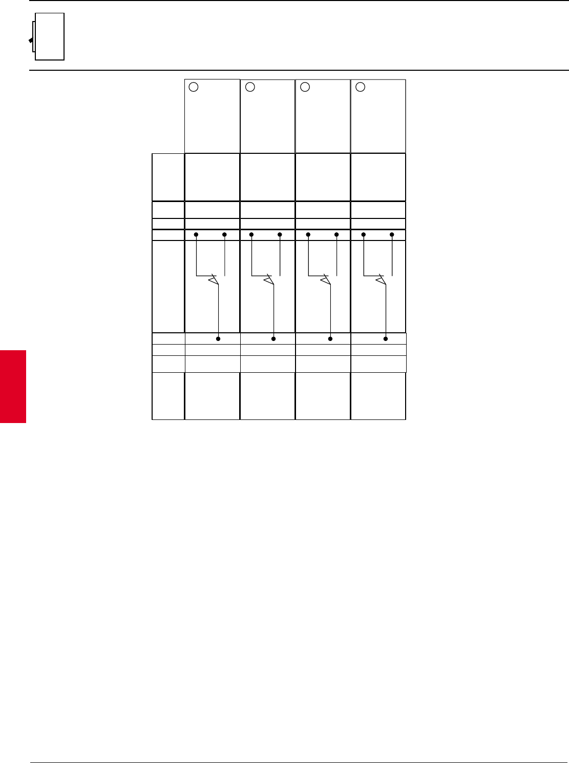
2.78 ABB Control Inc.
AC 1600 – 3/00
Isomax
Wiring diagrams
Position contacts
S3
21 22
Term. X V
Internal
Circuit Externial
Circuit
A4
Externial
Circuit
A4
Term. X V 1
42
S75I/1
1
42
S75I/2
31
1
24
S75S/1
32
1
24
S75S/2
( * D ) ( * D ) ( * D ) ( * D )
First circuit-
breaker position
contact, for
electrical
signalling of
inserted
Second circuit-
breaker position
contact, for
electrical
signalling of
inserted
First circuit-
breaker position
contact, for
electrical
signalling of
racked put or
removed
Second circuit-
breaker position
contact, for
electrical
signalling of
racked out or
removed
Legend
O- Figure number of diagram
A4 - Example switchgear and connections for control and
signalling, outside the circuit breaker
S75I/1...5 - Contacts for electrical signalling of circuit
breaker in inserted position (only for plug in or
withdrawable circuit breakers, see Note D.)
S75S/1...5 - Contacts for electrical signalling of circuit
breaker in removed or racked out position (only
for plug in or withdrawable circuit breakers, see
Note D.)
Incompatibility
The circuits indicated in the following figures cannot be
powered simultaneously on the same circuit breaker:
20 - 21 - 31, 22 - 32, 23 - 33, 24 - 34, 25 - 35
Notes
(*D) The circuit breaker can be mounted with position
contacts S75I and S75S in any combination up to a
maximum of:
¥ Total of 2 contacts for S3
¥ Total of 3 contacts for S4, S5
¥ Total of 5 contacts for S6, S7
Wiring
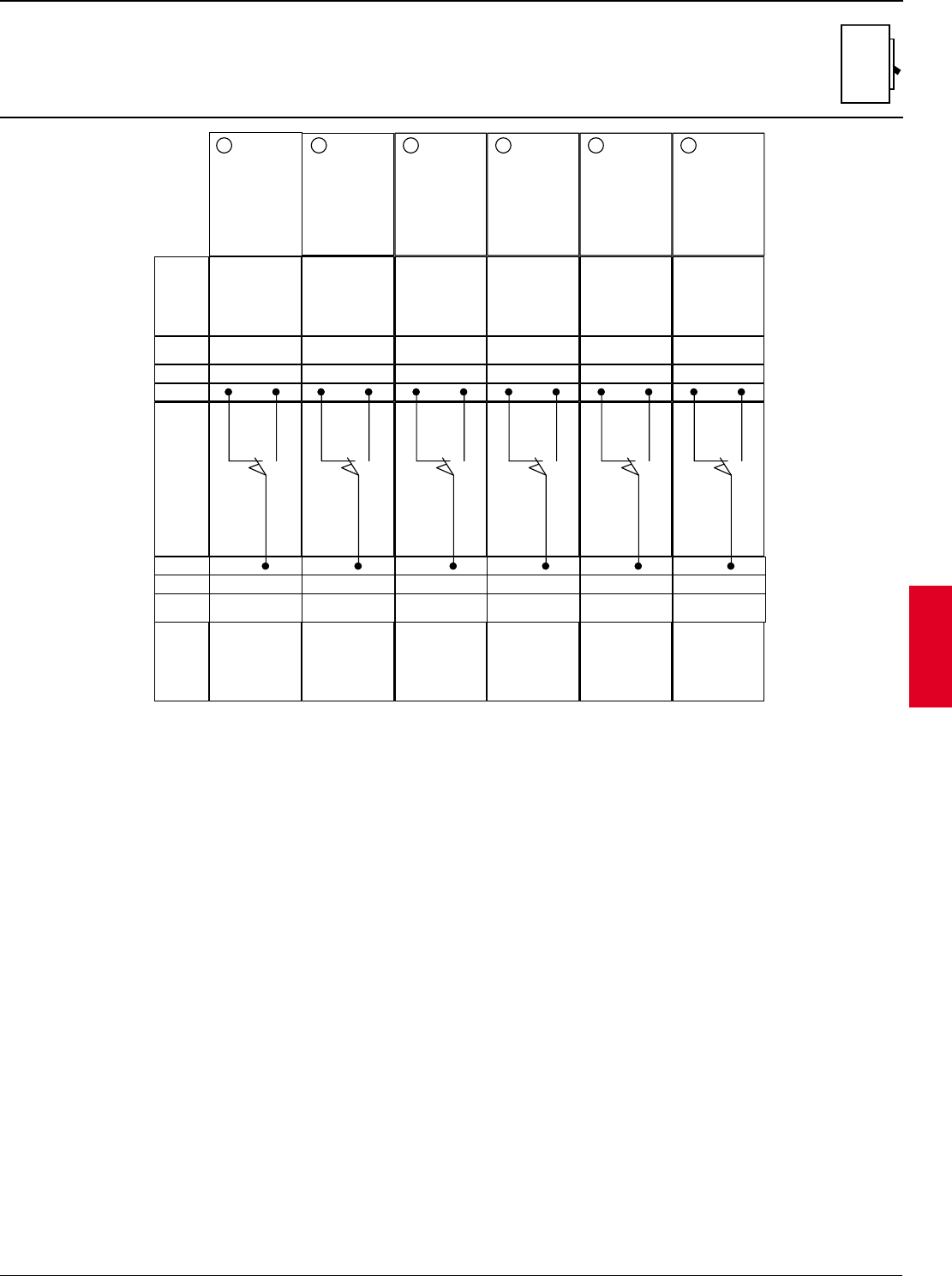
ABB Control Inc. 2.79
AC 1600 – 3/00
Isomax
Wiring diagrams
Position contacts
S4 – S5
21 22
Term. X V
Internal
Circuit Externial
Circuit
A4
Externial
Circuit
A4
Term. X V 1
42
S75I/1
1
42
S75I/2
( * D ) ( * D )
First circuit-
breaker position
contact, for
electrical
signalling of
inserted
Second circuit-
breaker position
contact, for
electrical
signalling of
inserted
31
1
24
S75S/1
( * D )
First circuit-
breaker position
contact, for
electrical
signalling of
racked put or
removed
23
Third circuit-
breaker position
contact, for
electrical
signalling of
inserted
1
42
S75I/3
33
1
24
S75S/3
( * D )
Third circuit-
breaker position
contact, for
electrical
signalling of
racked out or
removed
32
1
24
S75S/2
( * D )
Second circuit-
breaker position
contact, for
electrical
signalling of
racked out of
removed
Legend
O- Figure number of diagram
A4 - Example switchgear and connections for control and
signalling, outside the circuit breaker
S75I/1...5 - Contacts for electrical signalling of circuit
breaker in inserted position (only for plug in or
withdrawable circuit breakers, see Note D.)
S75S/1...5 - Contacts for electrical signalling of circuit
breaker in removed or racked out position (only
for plug in or withdrawable circuit breakers, see
Note D.)
Incompatibility
The circuits indicated in the following figures cannot be
powered simultaneously on the same circuit breaker:
20 - 21 - 31, 22 - 32, 23 - 33, 24 - 34, 25 - 35
Notes
(*D) The circuit breaker can be mounted with position
contacts S75I and S75S in any combination up to a
maximum of:
¥ Total of 2 contacts for S3
¥ Total of 3 contacts for S4, S5
¥ Total of 5 contacts for S6, S7
Wiring
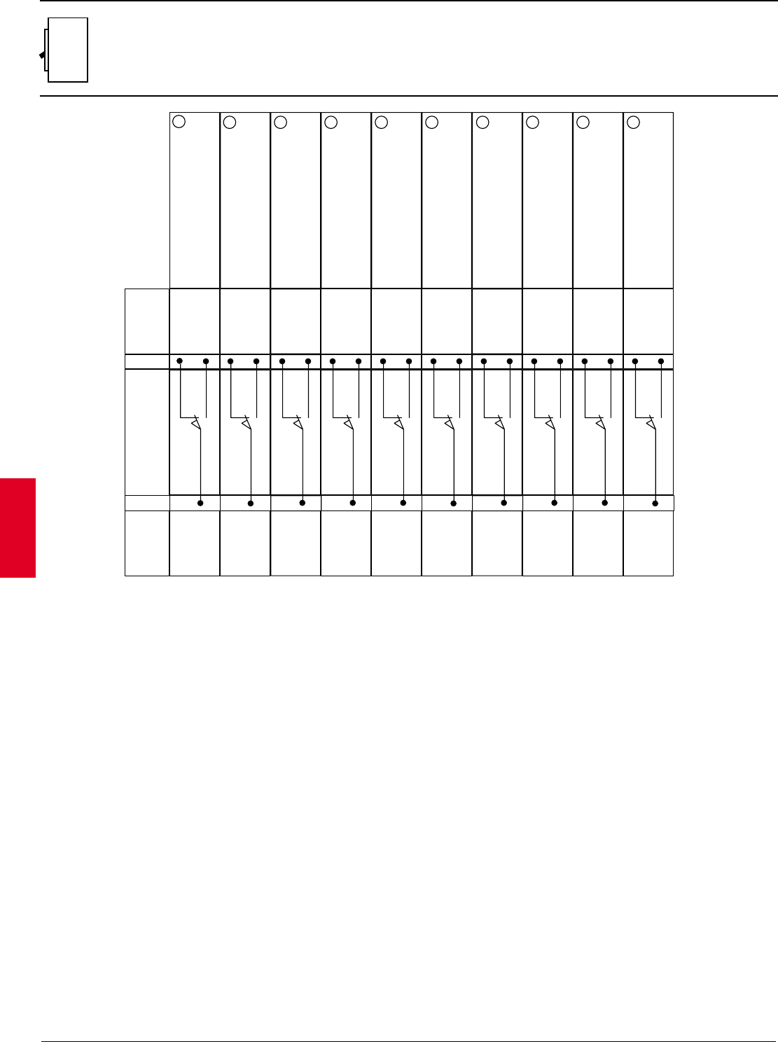
2.80 ABB Control Inc.
AC 1600 – 3/00
Isomax
Wiring diagrams
Position contacts
S6 – S7
Term. XV
Internal
Circuit
Term. XV
Externial
Circuit
A4
Externial
Circuit
A4
First circuit-breaker position
contact, for electrical signalling of
inserted
1
42
S75I/1
1
42
S75I/2
1
42
S75I/3
1
42
S75I/4
1
42
S75I/5
1
24
S75S/1
1
24
S75S/2
1
24
S75S/3
1
24
S75S/4
1
24
S75S/5
21 ( * D )
Third circuit-breaker position
contact, for electrical signalling of
inserted
23 ( * D )
Second circuit-breaker position
contact, for electrical signalling of
inserted
22 ( * D )
Fourth circuit-breaker position
contact, for electrical signalling of
inserted
24 ( * D ) ( * D )
Fifth circuit-breaker position
contact, for electrical signalling of
inserted
25
First circuit-breaker position
contact, for electrical signalling of
racked out
( * D )
31
Second circuit-breaker position
contact, for electrical signalling of
racked out
( * D )
32
Third circuit-breaker position
contact, for electrical signalling of
racked out
( * D )
33
Fifth circuit-breaker position
contact, for electrical signalling of
racked out
( * D )
35
Fourth circuit-breaker position
contact, for electrical signalling of
racked out
( * D )
34
Legend
O- Figure number of diagram
A4 - Example switchgear and connections for control and
signalling, outside the circuit breaker
S75I/1...5 - Contacts for electrical signalling of circuit
breaker in inserted position (only for plug in or
withdrawable circuit breakers, see Note D.)
S75S/1...5 - Contacts for electrical signalling of circuit
breaker in removed or racked out position (only
for plug in or withdrawable circuit breakers, see
Note D.)
Incompatibility
The circuits indicated in the following figures cannot be
powered simultaneously on the same circuit breaker:
20 - 21 - 31, 22 - 32, 23 - 33, 24 - 34, 25 - 35
Notes
(*D) The circuit breaker can be mounted with position
contacts S75I and S75S in any combination up to a
maximum of:
¥ Total of 2 contacts for S3
¥ Total of 3 contacts for S4, S5
¥ Total of 5 contacts for S6, S7
Wiring
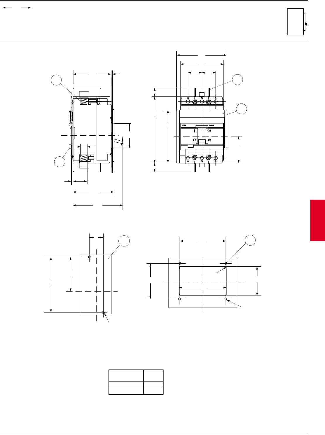
ABB Control Inc. 2.81
AC 1600 – 3/00
Isomax
00.00
00.00 Inches
Millimeters
Dim.
Approximate dimensions
S1 Fixed version, front
LEGEND
1-FRONT TERMINALS FOR CABLE OR FOR FLAT BAR
2-MOUNTING ON CHANNEL TO DIN EN 50022 (OPTIONAL)
3-COMPARTMENT DOOR SHEET STEEL DRILLING FOR FIXING THE FLANGE
4-MOUNTING ON SHEET STEEL
5-FLANGE FOR THE COMPARTMENT DOOR
6-INSULATING BARRIER
45
1.77
0.06
1
2
X
71
2.80
91
3.58
75
2.95
25.5
1.00
3
0.12
10.5 5x11 X
Y
96
3.78
120
4.72
91
3.58
78
3.07
25
0.98
25
0.98
6
48
1.89
C
L
C
L
C
L
X
X
Y
53
2.09
3
83.5
3.29
85
3.35
R - 0.06
Ø 4
0.16
64
2.52
Y
XX
100
3.94
62
2.44
6-32
25
0.98
4
16.0
0.63
16.0
0.63
5
1.5
1.5
WIRE RANGE WIRE
TORQUE
14 AWG - 8 AWG 22 lb-in
6 AWG - 3 AWG 44 lb-in
COPPER WIRE ONLY
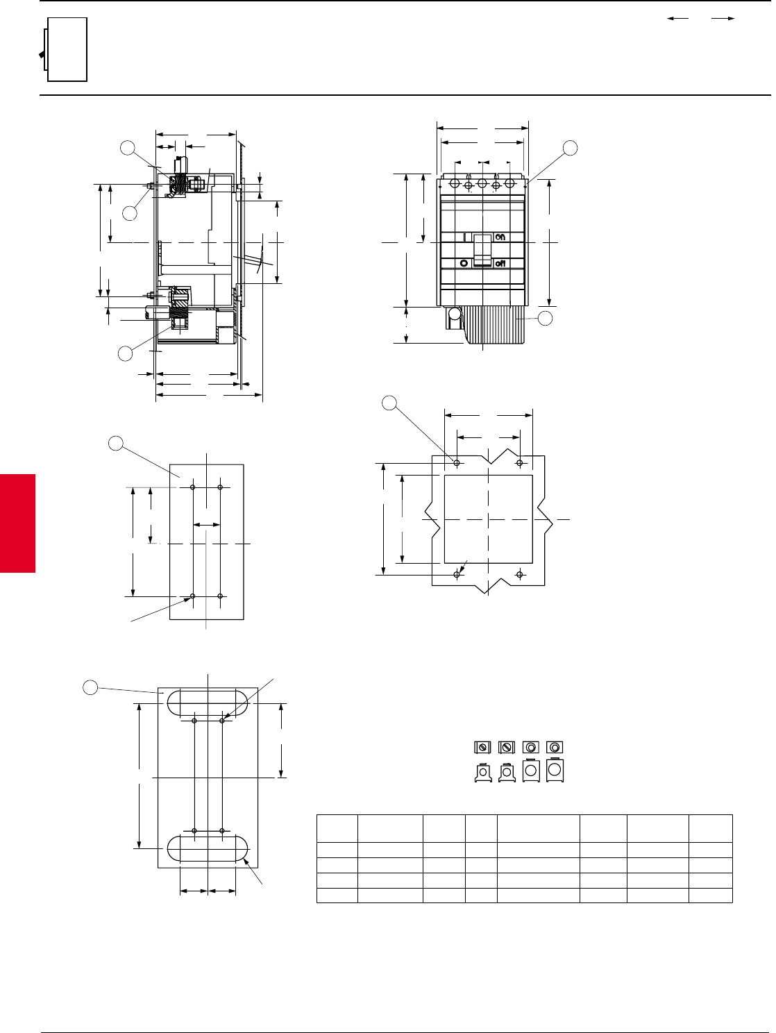
2.82 ABB Control Inc.
AC 1600 – 3/00
Isomax
00.00
00.00 Inches
Millimeters
Dim.
Approximate dimensions
S3 Fixed version, front
C
L
Y
XX
35
1.38
35
1.38
R - 0.59
185
7.28
94.75
3.73
X
8
18x18
2
1
101.5
4.00
25
0.98
73.75
2.90
13.5
0.53
4.07
103.5
4.21
107
5.31
135
0.12
3
0.08
2
143
5.63
105
4.13
10
0.39
Y
X
7
3
35
1.38
35
1.38
161
6.34
X
Y
46
1.81
87.25
3.44
170
6.69
Y
Y
X
X
71.75
2.82
10-24
139
5.47
35
1.38
4
112
4.41
80
3.15
X
Y
X
142
5.59
112
4.41
Ø 7
0.28
C
L
C
L
5
6
105
4.13
4.61
117
10-24
LUG KIT
CAT. NO.
K3TA, K3TA-2
K4TB, K4TB-2
K4TC, K4TC-2
K4TD, K4TD-2
A
B
C
D
FIGURE LUG NO.
D3477
D3447
D3449
D3448
TEMP.
75° C
75° C
75° C
75° C
WIRE RANGE WIRE
TORQUE MOUNTING
TORQUE
14AWG - 2AWG 50 lb-in 130 lb-in
14AWG - 1/0 50 lb-in 130 lb-in
2AWG - 4/0 120 lb-in 150 lb-in
4AWG - 300kcmil 275 lb-in 150 lb-in
WIRE
SCREW
SIZE
SLOT
SLOT
3/16
1/4
" A " " B " " C " " D "
15
LEGEND
1-FRONT TERMINALS FOR CABLE CONNECTION
2-REAR TERMINALS FOR CABLE CONNECTION
3-FLANGE FOR THE COMPARTMENT DOOR
4-COMPARTMENT DOOR SHEET STEEL DRILLING FOR FIXING THE FLANGE
5-MOUNTING ON SHEET STEEL
6-MOUNTING ON SHEET STEEL WITH REAR CABLE TERMINALS
7-HIGH TERMINAL COVERS WITH IP 20 PROTECTION DEGREE
8-TIGHTENING TORQUE 17.70 lb-in
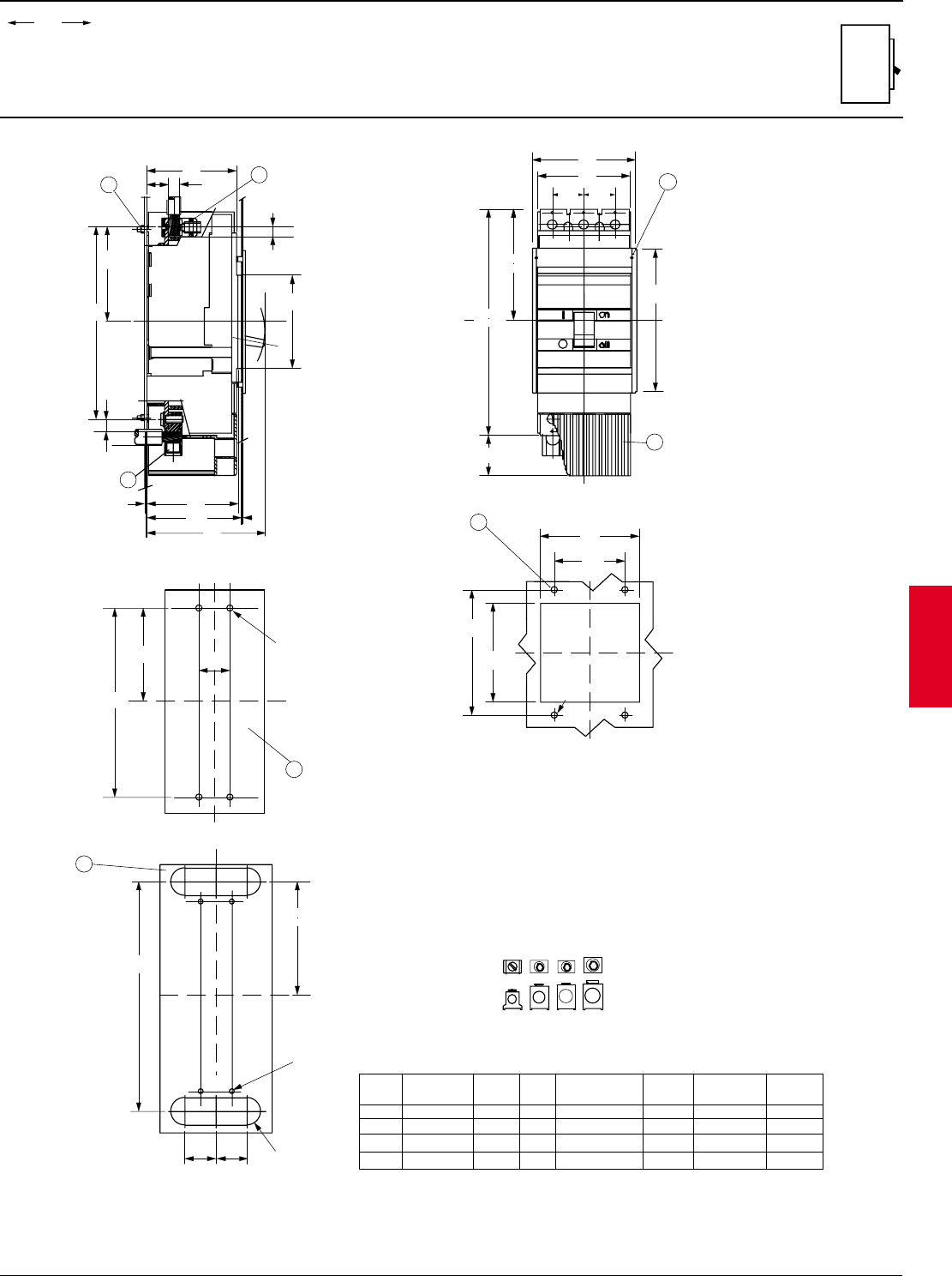
ABB Control Inc. 2.83
AC 1600 – 3/00
Isomax
00.00
00.00 Inches
Millimeters
Dim.
Approximate dimensions
S4 Fixed version, front
LEGEND
1-FRONT TERMINALS FOR CABLE CONNECTION
2-REAR TERMINALS FOR CABLE CONNECTION
3-FLANGE FOR THE COMPARTMENT DOOR
4-COMPARTMENT DOOR SHEET STEEL DRILLING FOR FIXING THE FLANGE
5-MOUNTING ON SHEET STEEL
6-MOUNTING ON SHEET STEEL REAR CABLE TERMINALS
7-HIGH TERMINAL COVERS WITH IP 20 PROTECTION DEGREE
8-TIGHTENING TORQUE 17.70 lb-in
3
7
X
X
Y
105
4.13
4.61
117
35
1.38
35
1.38
6.34
161
254
10.00
46
1.81
C
L
C
L
4
112
4.41
80
3.15
X
X
142
5.59
112
4.41
107.25
4.93
107.25
4.93
C
L
81
X
107.25
4.22
218
8.58
13.5
0.53
4.07
103.5
4.21
107
135
0.12
3
0.08
2
11
0.43
105
4.13
18x18
101.5
4.00
25
0.98
Ø 7
0.28
" B " " C " " E "" D "
260
10.24
128.25
5.04
6
R - 0.59
35
1.38
35
1.38
XX
10-24
Y
10-24
X
Y
8.42
214
4.14
105.25 35
1.38
5
Y
2
5.31
LUG KIT
CAT. NO. LUG NO.
K4TB, K4TB-2 D3447
K4TC, K4TC-2 D3449
K4TD, K4TD-2 D3448
K4TE, K4TE-2 D3472
A
B
C
D
FIGURE TEMP.
75° C
75° C
75° C
75° C
WIRE RANGE WIRE
TORQUE MOUNTING
TORQUE
14AWG - 1/0 50 lb-in 130 lb-in
2AWG - 4/0 120 lb-in 150 lb-in
4AWG - 300 kcmil 275 lb-in 150 lb-in
6AWG - 350kcmil 275 lb-in 150 lb-in
WIRE
SCREW
SIZE
SLOT
1/4
5/16
3/16
15
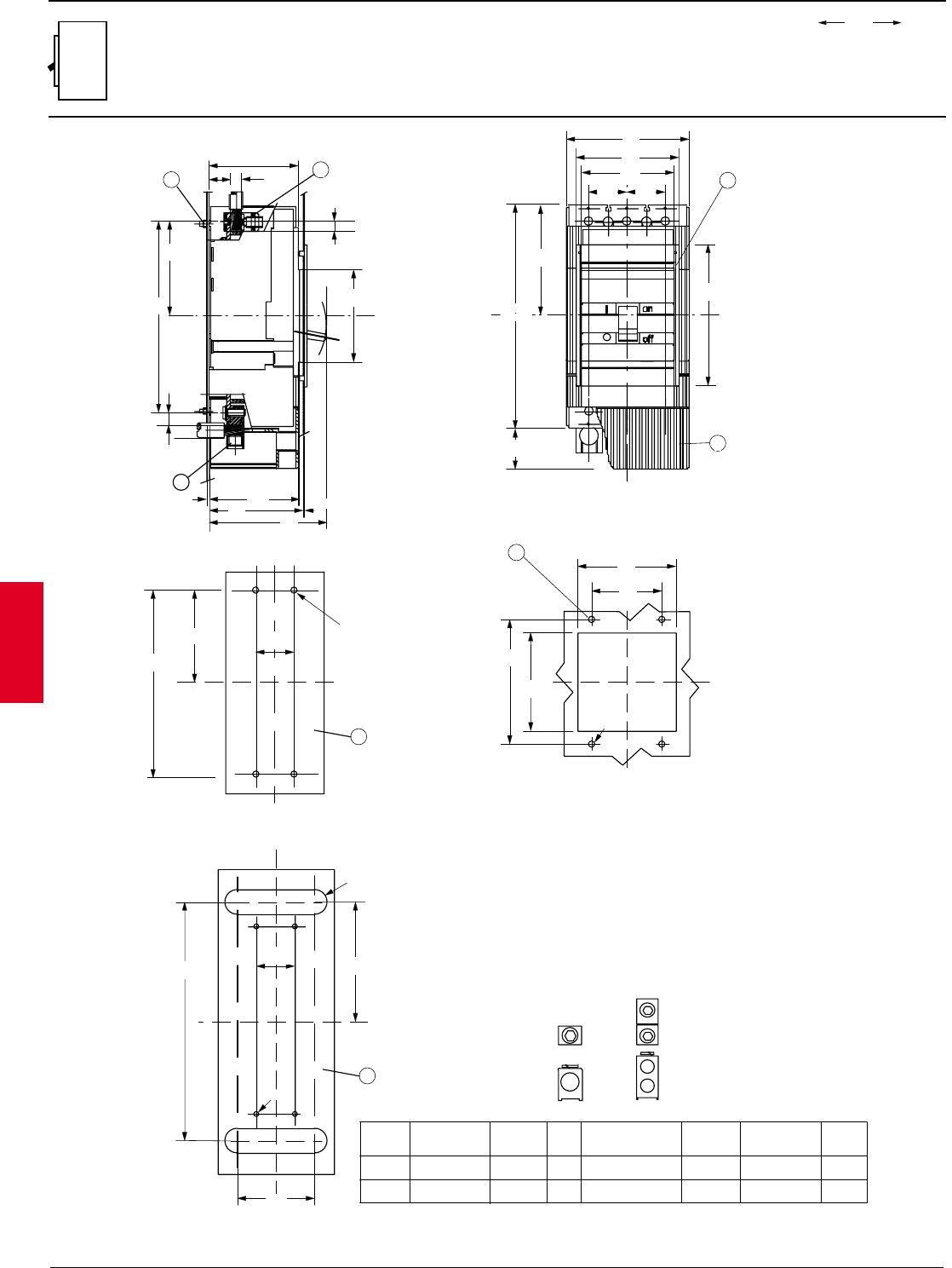
2.84 ABB Control Inc.
AC 1600 – 3/00
Isomax
00.00
00.00 Inches
Millimeters
Dim.
Approximate dimensions
S5 Fixed version, front
LEGEND
1-FRONT TERMINALS FOR CABLE CONNECTION
2-REAR TERMINALS FOR CABLE CONNECTION
3-FLANGE FOR THE COMPARTMENT DOOR
4-COMPARTMENT DOOR SHEET STEEL DRILLING FOR FIXING THE FLANGE
5-MOUNTING ON SHEET STEEL
6-MOUNTING ON SHEET STEEL REAR CABLE TERMINALS
7-HIGH TERMINAL COVERS WITH IP 20 PROTECTION DEGREE
8-TIGHTENING TORQUE 17.70 lb-in
3
C
L
4
112
4.41
80
3.15
X
Y
X
142
5.59
112
4.41
Ø 7
0.28
81
X
107.25
4.22
218
8.58
13.5
0.53
4.07
103.5
4.21
107 5.31
0.12
30.08
2
11
0.43
105
4.13
24x24
101.5
4.00
25
0.98
Y
XX
7
43.75
1.72
43.75
1.72 105
4.13
4.61
117
5.51
140
X254
10.00
46
1.81
107.25
4.93
X
C
L
C
L
6.34
161
8.42
214
10-24
43.75
1.72
2
5
4.14
105.25
10.71
272
5.29
134.25
43.75
1.72
87.5
3.45
10-24
6
Y
XX
Y
LUG KIT
CAT. NO. LUG NO.
K5TF, K5TF-2 D3450
K5TG, K5TG-2 D3484
F
G
FIGURE TEMP.
75° C
75° C
WIRE RANGE WIRE
TORQUE MOUNTING
TORQUE
250 - 500 kcmil 375 lb-in 175 lb-in
3/0 - 250 kcmil (2) 275 lb-in 175 lb-in
WIRE
SCREW
SIZE
3/8
5/16
" F " " G "
135
C
L
R - 0.79
20
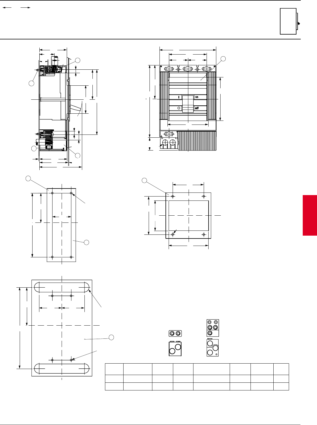
ABB Control Inc. 2.85
AC 1600 – 3/00
Isomax
00.00
00.00 Inches
Millimeters
Dim.
Approximate dimensions
S6 Fixed version, front
XX
4
142
5.59
112
4.41
Y
115
4.53
Y
147
5.79
Ø 7
0.28
3
XX
Y
Y
8.27
210
70
2.76
70
2.76
268
10.56
125.25
4.93
47
1.85
Ø21
0.83
6.34
161
C
L
C
L
140
5.51
152
5.98
8
7
1
2
21.5
101.5
4.00
47
1.85
32
1.26
111.75
4.34
105
4.13
12
0.47
19.5
0.77
4.07
103.5
4.21
107
6.26
159
0.12
3
0.08
2
C
L
C
L
241
9.49
Y
LEGEND
1-FRONT TERMINALS FOR CABLE PROTECTION
2-REAR TERMINALS FOR CABLE CONNECTION
3-FLANGE FOR THE COMPARTMENT DOOR
4-COMPARTMENT DOOR SHEET STEEL DRILLING
TEMPLATE
5-MOUNTING ON SHEET STEEL
6-MOUNTING ON SHEET STEEL REAR CABLE TERMINALS
7-HIGH TERMINAL COVERS WITH IP 20 PROTECTION
DEGREE
8-TIGHTENING TORQUE 17.70 lb-in
X
Y
Y
X
9.33
237
4.32
109.75
70
2.76
5
10-24
5
X
6
301
11.85
301
11.85
141.75
5.58
R - 0.85
85.75
3.38
85.75
3.38
10-24
Y
" H " " J "
LUG KIT
CAT. NO. LUG NO. WIRE RANGE WIRE
TORQUE MOUNTING
TORQUE
K6TH, K6TH-2 D2957 250 - 500 kcmil (2) 275 lb-in 85 lb-in
K6TJ, K6TJ-2 D2958 3/0 - 400 kcmil (3) 375 lb-in 110 lb-in
H
J
FIGURE TEMP.
90° C
90° C
WIRE
SCREW
SIZE
3/8
5/16
21.5
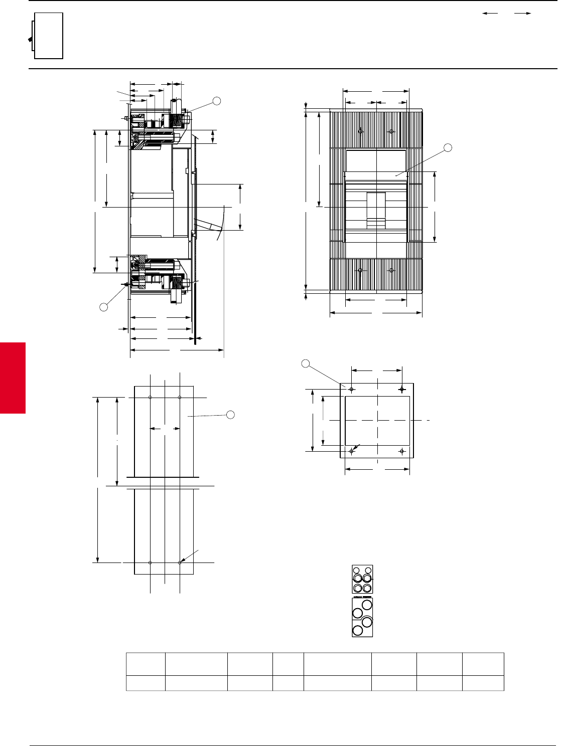
2.86 ABB Control Inc.
AC 1600 – 3/00
Isomax
00.00
00.00 Inches
Millimeters
Dim.
Approximate dimensions
S7 Fixed version, front
Y
X
70
2.76 70
2.76
406
15.98
217
8.54
7
0.28
7
0.28
152
5.51
210
8.27
2
140
5.51
6.34
161 C
L
C
L
LEGEND
1-FRONT TERMINALS FOR CABLE CONNECTION
2-FLANGE FOR THE COMPARTMENT DOOR
3-COMPARTMENT DOOR SHEET STEEL DRILLING
TEMPLATE
4-MOUNTING ON SHEET STEEL
5-TIGHTENING TORQUE 17.70 lb-in
XX
3
142
5.59
112
4.41
Y
115
4.53
Y
147
5.79
Y
Ø 7
0.28
" K "
Y
Y
X
X378
14.88
203
7.99
4
10-24
70
2.76
LUG KIT
CAT. NO. LUG NO. WIRE RANGE WIRE
TORQUE MOUNTING
TORQUE
K7TK, K7TK-2 D2959 4/0 - 500 kcmil (4) 375 lb-in 375 lb-inK
FIGURE TEMP.
90° C
WIRE
SCREW
SIZE
3/8
21.4
X
97
3.82
78
3.07
57
2.24
38
1.50
326
12.83
177
6.97
37
1.46
37
1.46
0.12
3
5.45
138.5
0.08
2
5.75
146.5
5.53
140.5
8.44
214.5
30.5
1.20
105
4.13
1
5
C
L
C
C
L
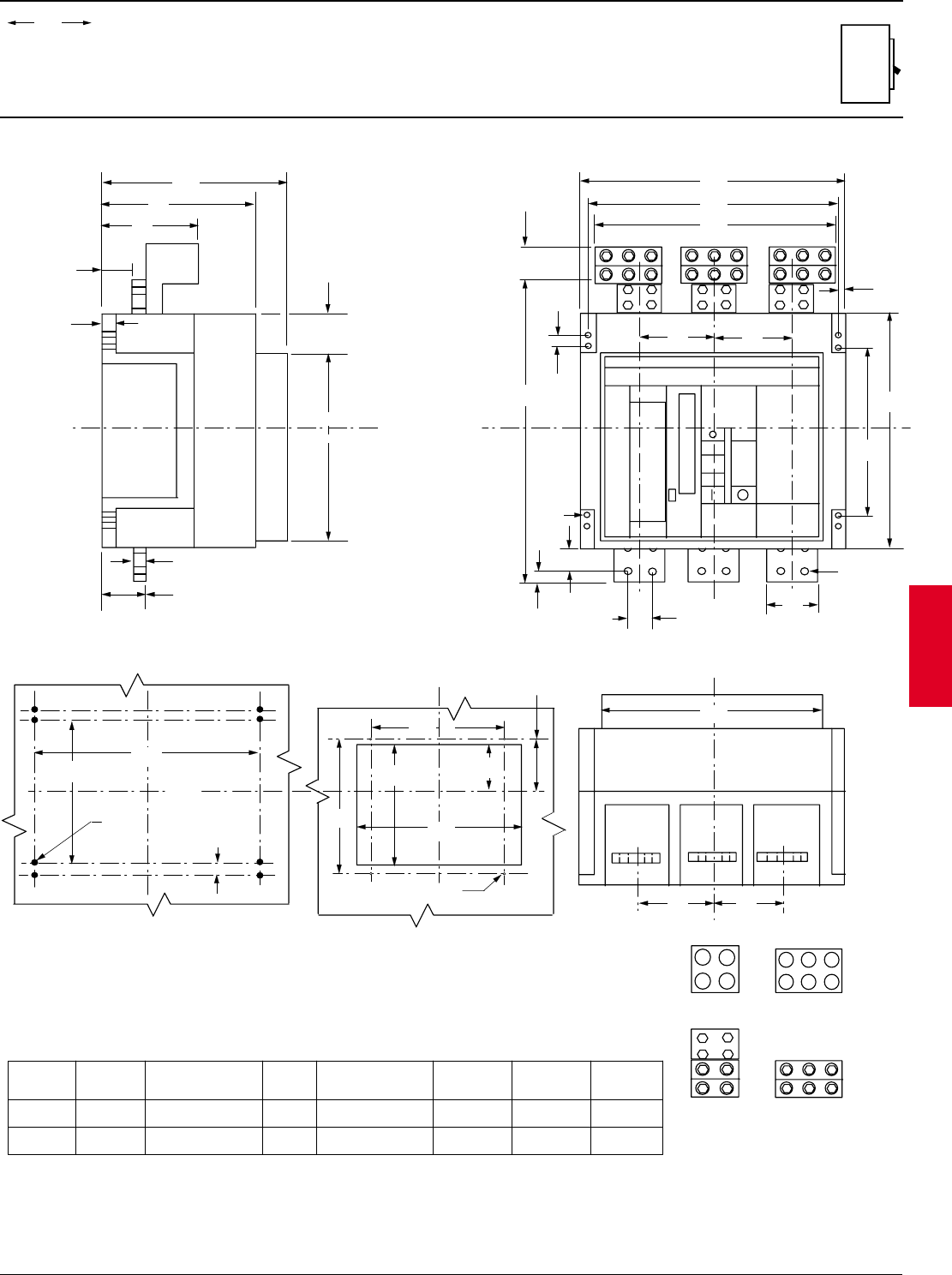
ABB Control Inc. 2.87
AC 1600 – 3/00
Isomax
00.00
00.00 Inches
Millimeters
Dim.
Approximate dimensions
S8, fixed version, front
1600A / 2000A / 2500A
0.79
TYP 2
1600A LUG
MOUNTING HOLES
11.02
BKR.
BKR.
0.35 D
TYP 8
14.96
ESCUTCHEON CUT-OUT
12.88
13.54
5.32
5.65
0.20 DIA. TYP 4
BKR.
13.43
11.81
BKR
0.83
9.25
11.22
2.56
1.77
0.79
12.32
2.84
5.65
20.47
0.79
0.35D
1.57
0.79 1.57
3.15
0.55D
4.72 4.72
14.96
15.98
0.51
11.02
15.75
2.17
15.17
4.72
4.72
BREAKER
12.76
20
65
920
380
280
344
5
341
327 135
300
143.5
324
120 120
520
9
40
20 40
80
14
280
400
120
120
55.2
406
380
305.3
13
20
45
141
235
285
72.1
313
21.1
"L"
NOTE: Lugs are interchangeable and may be ordered as required by the installed wire gauge.
2500A LUG
( 2500A LUGS SHOWN ON BREAKER )
"M"
C
L
C
L
C
L
C
L
C
L
LUG KIT
CAT. NO. LUG NO. WIRE RANGE WIRE
TORQUE MOUNTING
TORQUE
K8TL D1922 1/0 - 750 kcmil (4) 500 lb-in 500 lb-inL
FIGURE TEMP.
90° C
WIRE
SCREW
SIZE
1/2
K8TM D3185, D3186, D3187 1/0 - 750 kcmil (6) 500 lb-in 500 lb-inM90° C 1/2
BKR
C
L
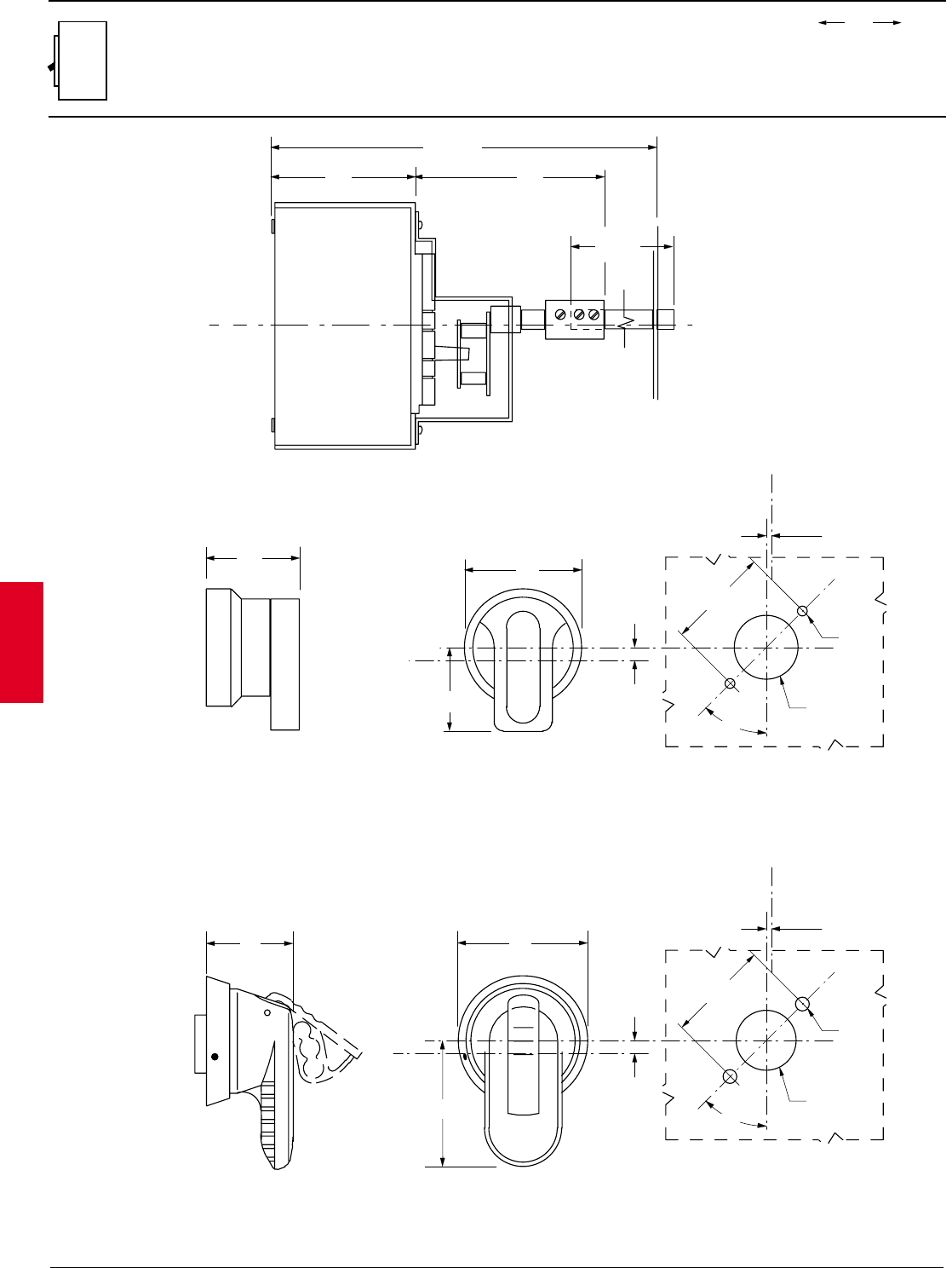
2.88 ABB Control Inc.
AC 1600 – 3/00
Isomax
00.00
00.00 Inches
Millimeters
Dim.
Approximate dimensions
Variable depth handle mechanism, S1
Type 1, 3R, 4, 4X, 12
2.68
68
6.61 / 11.81
168 / 300
SHAFT
4.7
119.5
X
2.66
67.5
2.56
65
1.77
45
3.64
93
HANDLE
TYPE 1, 3R, 4, 4X, 12
FRONT PANEL CUT-OUT
"X"
0.27
6.8
0.10
2.5
2.09
53.0
45º
1.22
31.0
D
0.28
7.0
D
C
L
FRONT PANEL CUT-OUT
"X"
0.27
6.8
0.10
2.5
2.09
53.0
45º
1.30
33.0
D
0.20
5.0
D
C
L
1.65
42
2.56
65
HANDLE
TYPE 1
1.85
47
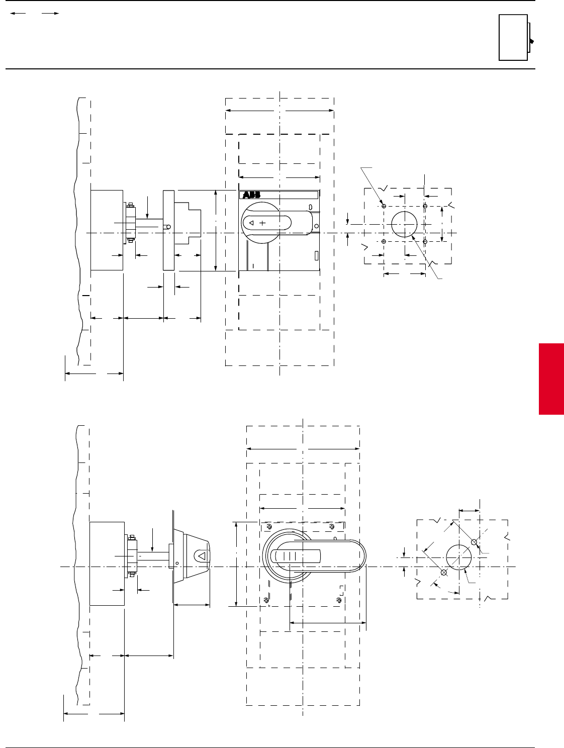
ABB Control Inc. 2.89
AC 1600 – 3/00
Isomax
00.00
00.00 Inches
Millimeters
Dim.
Approximate dimensions
Variable depth handle mechanism, S3 – S5
Variable depth handle mechanism
S3 – S5, Type 1
"X"
SACE S5
on
off
4.13
S3
S5 W/O LUG COVER
S5 W LUG COVER
S4
140.0
105.0
5.75
146.0
TO BASE OF BREAKER
1.67
42.5
MIN. 2.6
11.8 MAX.
MIN. 66
300 MAX.
1.95
49.5
0.59
15.0
0.61
15.5 34.5
4.13
105.0
0.394 SQ
10 SQ
0.45
11.5
0.20 DIA ( TYP 4 )
5.0 DIA
54.0 1.30 DIA.
33.0 DIA
FRONT PANEL CUT-OUT
1.36
5.51
C
L
C
L
1.02
26.0
1.81
46.0
1.06
27.0
2.13
Variable depth handle mechanism
S3 – S5, Type 1, 3R, 4, 4X & 12
S3
S5 W/O LUG COVER
S5 W LUG COVER
S4
5.75
146.0
TO BASE OF BREAKER
1.67
42.5 MIN. 28.0
SHAFT LENGTH
- 20mm = MAX.
45.0
0.61
15.5
4.13
105.0
0.394 SQ
10 SQ
FRONT PANEL CUT-OUT
"X"
0.45
11.5
1.02
26.0
on
MIN. 1.1
SHAFT LENGTH
- 0.79" = MAX.
C
L
5.51
140.0
4.13
105.0
1.77
2.09
53.0
45º
1.22
31.0
D
0.28
7.0
D
C
L
3.74
95.0
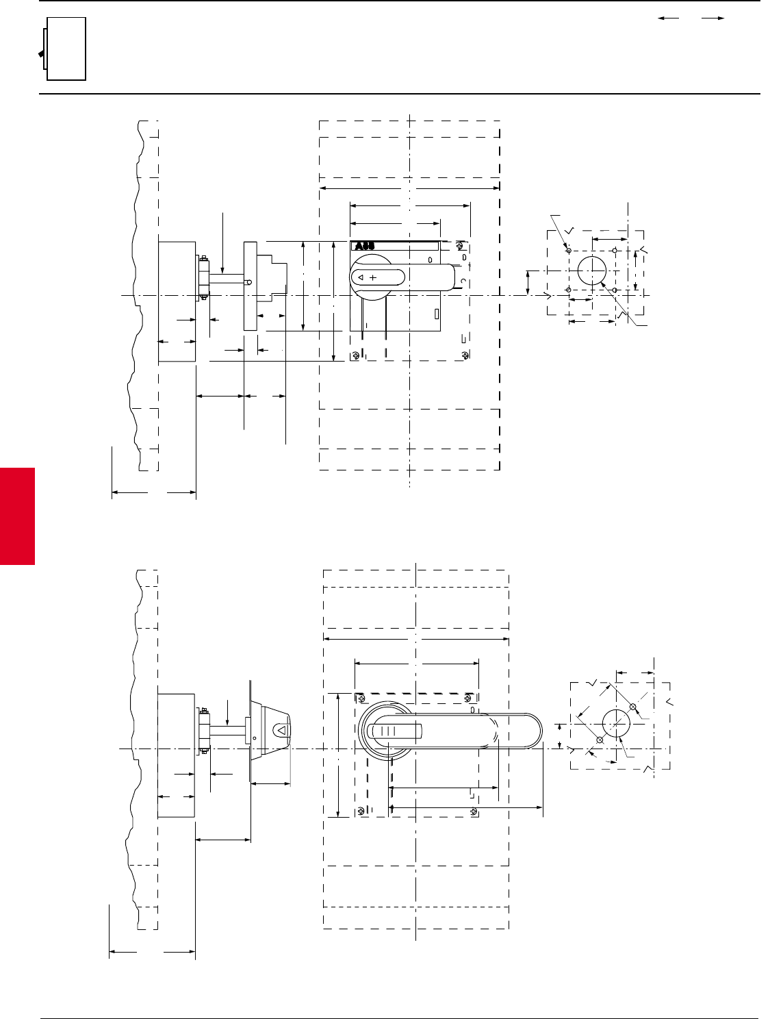
2.90 ABB Control Inc.
AC 1600 – 3/00
Isomax
00.00
00.00 Inches
Millimeters
Dim.
Approximate dimensions
Variable depth handle mechanism, S6 – S7
Variable depth handle mechanism
S6 – S7, Type 1
Variable depth handle mechanism
S6 – S7, Type 1, 3R, 4, 4X & 12
" X "
SACE S7
on
on
off
8.27
210.0
5.51
140.0
4.13
105.0
4.13
105.0
5.51
140.0
MIN 2.6
11.8 MAX
MIN 105
300 MAX
1.95
49.5
0.59
15.0
0.89
22.6
1.67
42.5
1.36
34.5
S6 =5.41
137.3
TO BASE OF BREAKER
S7 =6.78
172.3
0.394 SQ
10 SQ
1.81
46.0
1.63
41.5
1.06
27.0
1.10
28.0
2.12
54.0 1.30 DIA
33.0 DIA
0.20 DIA (TYP 4)
5.0 DIA
FRONT PANEL CUT-OUT
S 6 W/O LUG COVER
S6 W LUG COVER
S7
C
L
C
L
2.09
53.0
45º
MIN. 35.6
SHAFT LENGTH
- 20mm = MAX.
45.0
0.394 SQ
10 SQ
MIN. 1.4
SHAFT LENGTH
- 0.79" = MAX.
1.77
" X "
on
8.27
210.0
5.51
140.0
5.51
140.0
0.89
22.6
1.67
42.5
TO BASE OF BREAKER
1.63
41.5
1.10
28.0
FRONT PANEL CUT-OUT
S 6 W/O LUG COVER
S6 W LUG COVER
S7
C
L
C
L
S6 =5.41
137.3
S7 =6.78
172.3
1.22
31.0
0.28
7.0
D
D
4.91
125.0
6.89
175.0
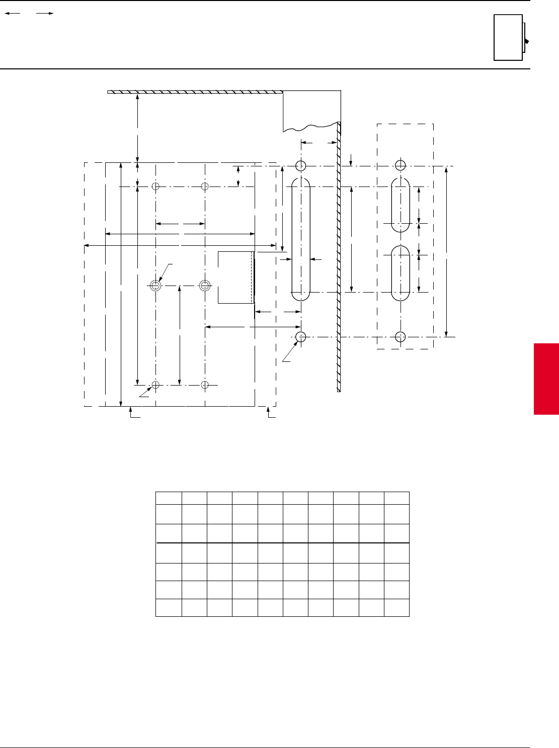
ABB Control Inc. 2.91
AC 1600 – 3/00
Isomax
00.00
00.00 Inches
Millimeters
Dim.
Approximate dimensions
S1 - S6 Flange handle, shaft operated
NOTES:
1. " A " DIM. IS THE WIRING BENDING SPACE AS
REQUIRED BY THE NATIONAL ELECTRIC CODE.
2. " B " DIM. IS 2.340 in. IF ENCLOSURE DOES NOT
HAVE A SAFETY DOOR INTERLOCK, AND 1.500 in.
IF IT DOES HAVE A SAFETY DOOR INTERLOCK.
0.56
2.88
0.281 DIA.
TYP 2
BREAKER
MOUNTING
HOLES
FLANGE
DRILLING
DOOR
INTERLOCK
BRACKET
ENCLOSURE
BREAKER OUTLINE
0.50
DRILL & TAP 10-24 TYP 4
MECH. OUTLINE
1.00
OPTIONAL
FLANGE
DRILLING
" A "
" X "
MAY DRILL & TAP FOR
10-32, FLATHEAD SCREW
IF THE MECHANISM IS
TO BE MOUNTED ALONE.
" X "
DL
C
J
" B "
1.00
MIN.
F
E
G
K
1.30
0.88
1.00
4.69
H
S1
S2
S3
C D E F G H J K L
1.18
1.38
0.39
5.47
3.94
5.47
4.72
6.69
2.53
2.64
3.54
4.13
4.89
5.31
1.97
2.73
-.97
-.59
0.98 0.39 3.94 4.72 2.53 3.07 4.89 1.97 -.97
FRAME
S4
S5 1.72 8.43 8.43 10.00 3.16 5.51 6.69 4.22 +.76
1.38 8.43 8.43 10.00 2.64 4.13 5.31 4.22 +.76
S6 2.76 9.33 9.33 10.55 4.41 8.27 10.36 4.66 +1.61
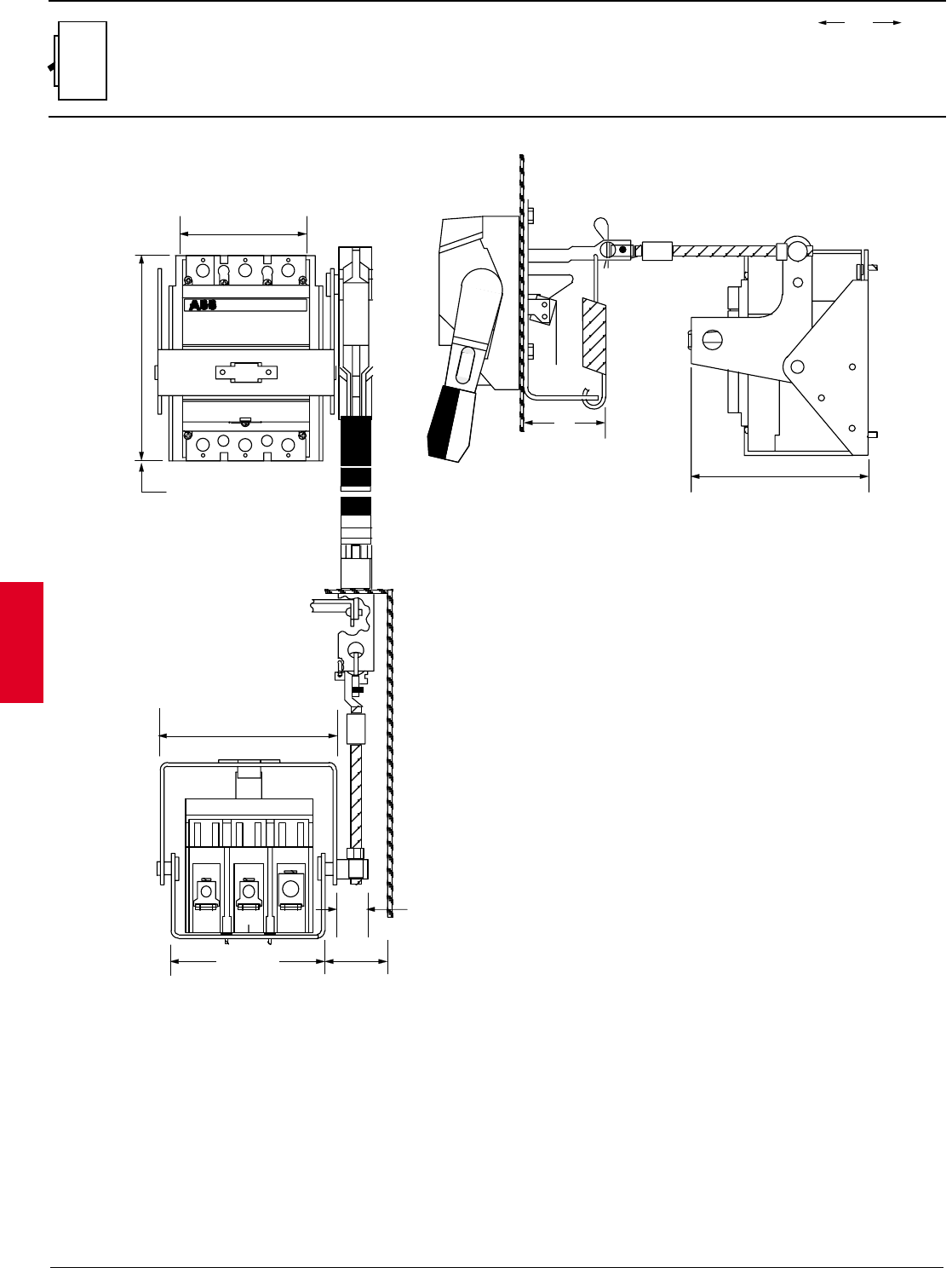
2.92 ABB Control Inc.
AC 1600 – 3/00
Isomax
00.00
00.00 Inches
Millimeters
Dim.
Approximate dimensions
Flange handle, shaft operated
1.83 Min
46
SACE S3
S1, S2 = 4.72
120
S3 = 6.69
170
S4, S5 = 10.00
254
S1, S2 = 3.54
90
S3, S4 = 4.13
105
S5 = 5.51
140
S1, S2 = 4.89
124
S3, S4 = 5.31
135
S5 = 6.69
170
S1, S2 = 4.04
103
S3, S4 = 5.02
128
S5 = 6.40
163
1.07
27
S1, S2 = 4.14
105
S3, S4, S5 = 5.86
149
3.00
76
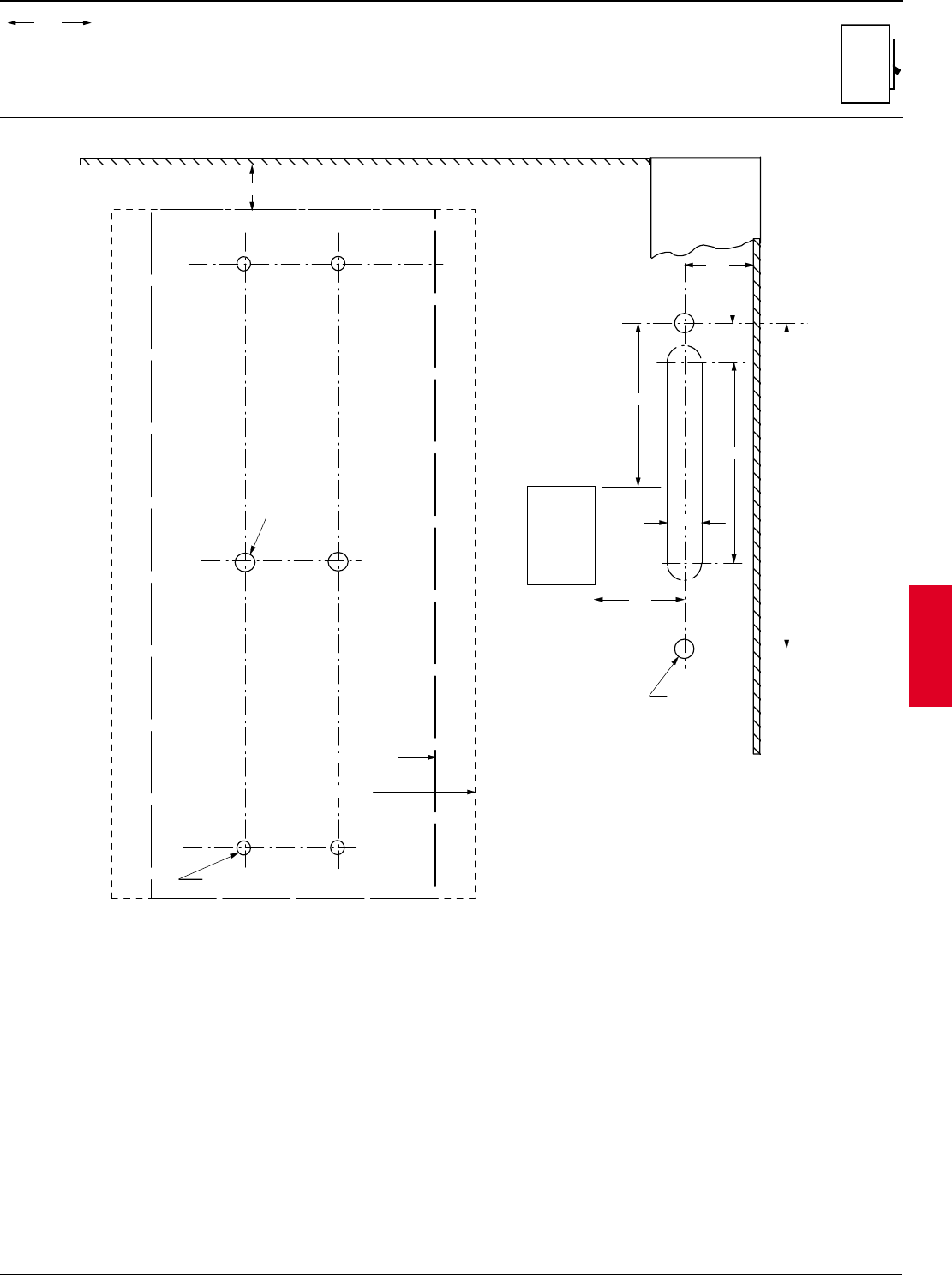
ABB Control Inc. 2.93
AC 1600 – 3/00
Isomax
00.00
00.00 Inches
Millimeters
Dim.
Approximate dimensions
S1 – S5 Flange handle, cable operated
NOTES:
1. " A " DIM. IS THE WIRING BENDING SPACE AS REQUIRED BY THE NATIONAL ELECTRIC CODE.
2. " B " DIM. IS 2.340 in. IF ENCLOSURE DOES NOT HAVE A SAFETY DOOR INTERLOCK, AND 1.500 in.
IF IT DOES HAVE A SAFETY DOOR INTERLOCK.
3. " X " MAY DRILL & TAP FOR 10-32, FLATHEAD SCREW IF THE MECHANISM IS TO BE MOUNTED ALONE
ENCLOSURE
BREAKER
MOUNTING
HOLES
" X "
DRILL & TAP FOR 10-24, TYP 4
( 6-32 FOR S1 BREAKER )
MECH. OUTLINE
BREAKER OUTLINE
0.56
0.281 DIA.
TYP 2
FLANGE
DRILLING
0.50
DOOR
INTERLOCK
BRACKET
" A "
1.00
MIN.
" B "
2.88
1.30
4.69
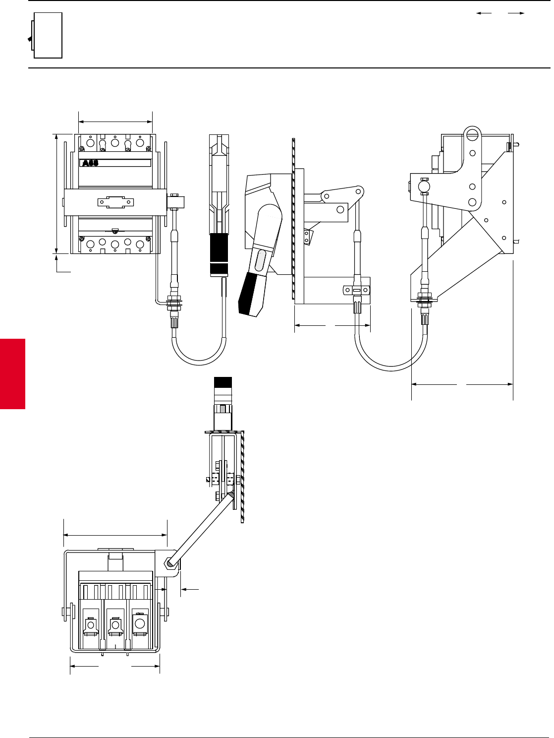
2.94 ABB Control Inc.
AC 1600 – 3/00
Isomax
00.00
00.00 Inches
Millimeters
Dim.
Approximate dimensions
Flange handle, cable operated
SACE S3
S1, S2 = 4.04
103
S3, S4 = 5.02
128
S5 = 6.40
163
1.05
27
S1, S2 = 4.72
120
S3 = 6.69
170
S4, S5 = 10.00
254
5.70
145
F.O. HANDLE ACCESSORIES
WITH FLEX CABLE
K_FHDC-S12
LEFT OR RIGHT MOUNT HANDLE
RIGHT MOUNT CABLE
S1, S2, S3, S4 & S5
4.30
109
S1, S2 = 3.54
90
S3, S4 = 4.13
105
S5 = 5.51
140
S1, S2 = 4.89
124
S3, S4 = 5.31
135
S5 = 6.69
170
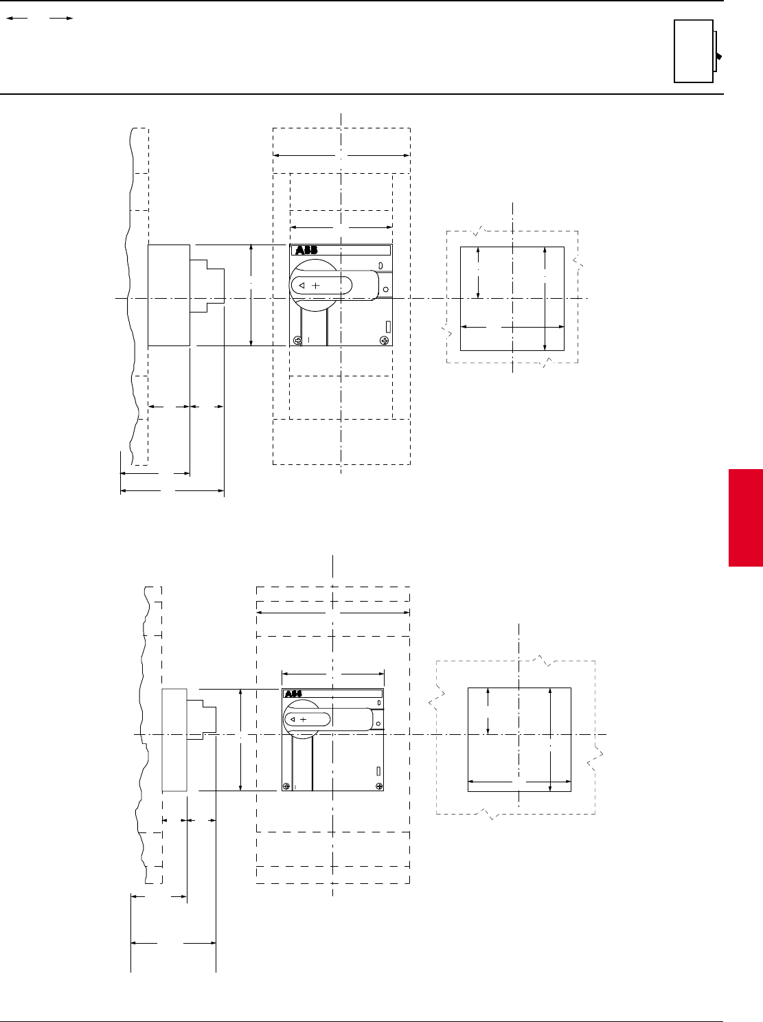
ABB Control Inc. 2.95
AC 1600 – 3/00
Isomax
00.00
00.00 Inches
Millimeters
Dim.
Approximate dimensions
Rotary handle operator, S3 - S7
Rotary handle operator, S6 - S7
on
off
SACE S7
S6 W/O LUG COVER
S6 W LUG COVER
S7
S6 = 5.41
S6 = 7.02
1.33 1.61
33.8 41.0
137.3
172.3
178.3
213.3
5.51
5.51
140.0
140.0
8.27
210.0
FRONT PANEL CUT-OUT
S7 ROTARY HANDLE OPERATOR
TO BASE OF BREAKER
S7 = 8.40
S7 = 6.78
" X "
C
L
5.60
5.60
2.50
63.5
142.0
142.0
C
L
SACE S5
on
off
5.75
7.11
TO BASE OF BREAKER
4.13
4.13
S3
S5 W/O LUG COVER
S5 W LUG COVER
S4
5.51
140.0
105.0
105.0
146.0
180.5
1.67 1.36
34.5
42.5
S5 ROTARY HANDLE OPERATOR
"X"
2.10
4.20
4.20
53.5
107.0
107.0
FRONT PANEL CUT-OUT
C
L
C
L
Rotary handle operator, S3 - S5
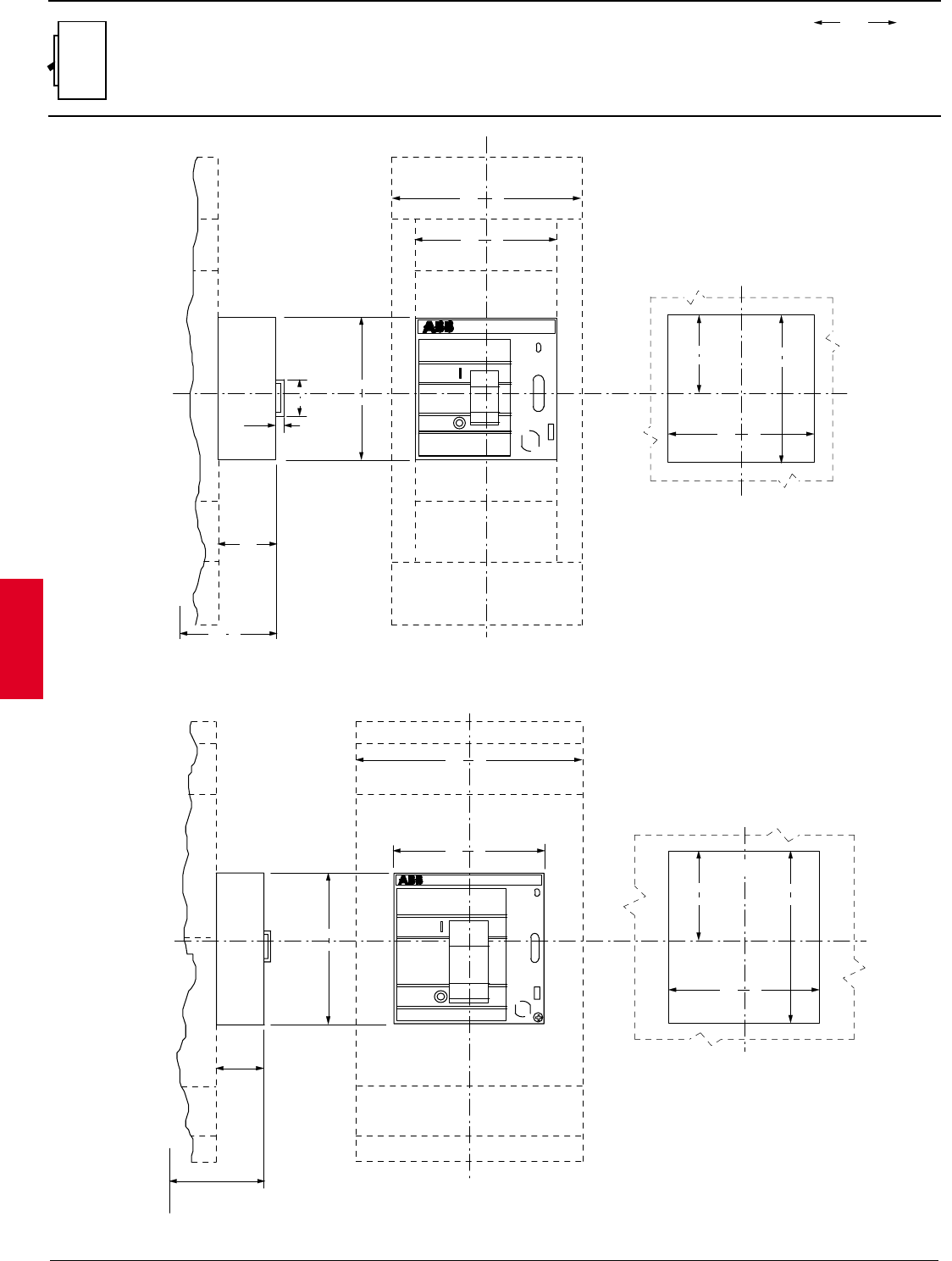
2.96 ABB Control Inc.
AC 1600 – 3/00
Isomax
00.00
00.00 Inches
Millimeters
Dim.
Approximate dimensions
Locking devices, S3 - S7
"X"
C
L
C
L
5.75
TO BASE OF BREAKER
4.13
4.13
S3
S5 W/O LUG COVER
S5 W LUG COVER
S4
5.51
140
105
105
146
1.67
42.5
107
53.5 107
2.10 4.20
4.20
FRONT PANEL CUT-OUT
0.24
6
1.06
27
SACE S5
SACE S5
on
off
" X "
CL
CL
S6 W/O LUG COVER
S6 W LUG COVER
S7
S6 = 5.75
1.67
42.5
146
181
5.51
5.51
140
140
8.27
210
5.60
5.60
2.50
63.5 142
142
FRONT PANEL CUT-OUT
TO BASE OF BREAKER
SACE S7
on
off
S7 = 7.12
Locking device, S5 - S7
Locking device, S3 - S5
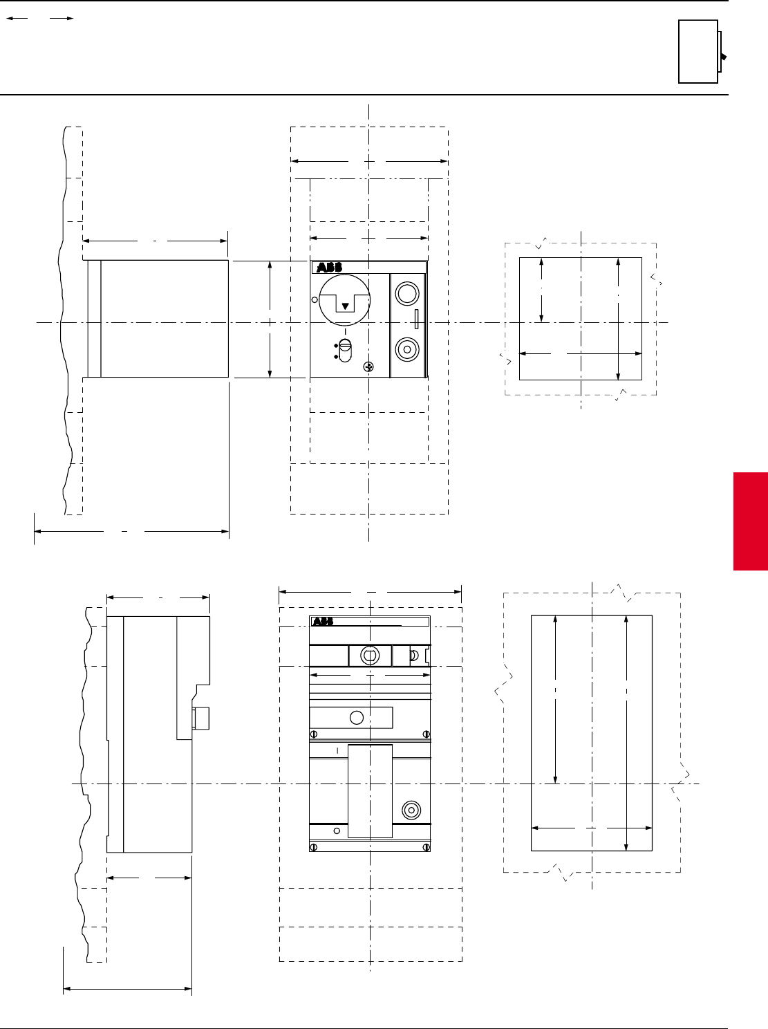
ABB Control Inc. 2.97
AC 1600 – 3/00
Isomax
00.00
00.00 Inches
Millimeters
Dim.
Approximate dimensions
Electrical operators, S3 - S7
SACE S5
Auto
Manual
"X"
S5 W LUG COVER
S5 W/O LUG COVER
S3
S4
2.10
4.20
4.20
53.5
107
107
FRONT PANEL CUT-OUT
5.51 140
4.13 105
4.13
105
4.80 122
TO BASE OF BREAKER
225.5
8.88
CL
CL
" X "
CL
CL
SACE S7
off
on
S6 = 8.82
TO BASE OF BREAKER
224
257
210
8.27
S6 W/O LUG COVER
S6 W LUG COVER
S7
3.87
98.3
4.67 118.6
140
5.51
193.5 272
142
5.6
7.62 10.71
FRONT PANEL CUT-OUT
S7 = 10.12
Electrical operator, S3 - S5
Electrical operator, S6 - S7
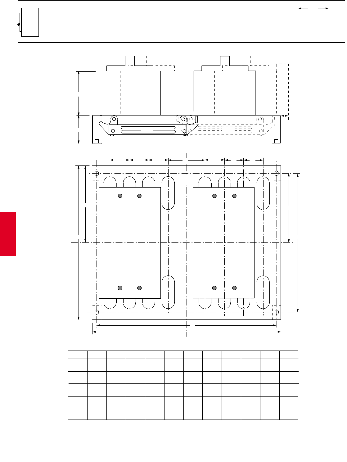
2.98 ABB Control Inc.
AC 1600 – 3/00
Isomax
00.00
00.00 Inches
Millimeters
Dim.
Approximate dimensions
Mechanically interlocked, horizontal, S3 – S7
A
B
C
CL
D D D E D D D
J G
K
L
H
F
S3/S5 S6/S7
S3/S5 S6/S7
S3
S4
S5
A B C D E F G H J K L
4.08
4.08
2.56
2.56
0.47
0.63
1.38
1.72
2.60
3.29
6.83
6.83
13.78
13.78
6.14
6.14
12.40
12.40
12.76
15.85
13.78
16.93
4.08 2.56 0.47 1.38 2.60 5.31 10.43 4.57 8.96 12.76 13.78
103.5 65 12 35 66 135 265 116 227.5 324 350
103.5 65 16 35 83.5 173.5 350 156 315 402.5 430
103.5 65 12 35 66 173.5 350 156 315 324 350
FRAME
S6
S7
4.07 2.56 0.41 2.76 4.72 7.38 14.76 6.89 13.78 20.67 25.60
103.5 65 10.5 70 120 187.5 375 175 350 525 650
5.53 2.56 0.22 2.76 4.72 8.86 17.72 8.27 16.54 21.65 25.98
140.5 65 5.5 70 120 225 450 210 420 550 660
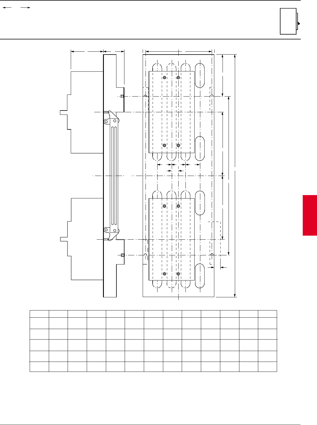
ABB Control Inc. 2.99
AC 1600 – 3/00
Isomax
00.00
00.00 Inches
Millimeters
Dim.
Approximate dimensions
Mechanically interlocked, vertical, S3 – S7
A
B
D
E
F
H
J
G
K
L L L
M
CL
CL
S3
S4
S5
FRAME A B C D E F G H J K L
4.07
4.07
2.56
2.56
7.08
8.67
6.20
7.91
5.12
5.12
7.81
7.81
29.53
29.53
19.29
19.29
7.70
7.70
0.45
0.45
1.38
1.72
M
0.69
0.94
4.07 2.56 7.08 6.20 4.49 6.00 22.76 13.78 6.20 0.45 1.38 0.69
103.5 65 180 201 130 198.5 750 490 195.5 11.5 43.75 23.75
103.5 65 180 157.5 114 152.5 578 350 157.5 11.5 35 17.5
103.5 65 180 157.5 130 198.5 750 490 195.5 11.5 35 17.5
S6
S7
4.07 2.56 12.20 11.02 5.81 8.82 32.28 20.67 8.82 0.67 2.76 1.44
103.5 65 310 280 147.5 224 820 525 224 17 70 36.5
5.53 2.56 13.39 12.40 5.12 11.26 43.31 34.45 11.26 0.0 2.76 1.38
140.5 65 340 315 14.43 286 1100 875 286 070 35
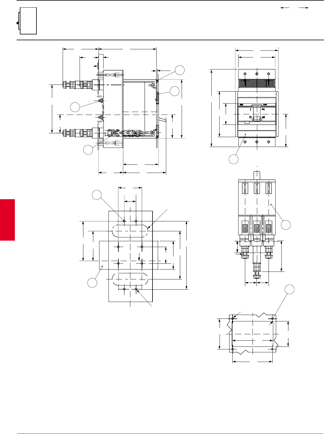
2.100 ABB Control Inc.
AC 1600 – 3/00
Isomax
00.00
00.00 Inches
Millimeters
Dim.
Approximate dimensions
S1 Plug-in rear
LEGEND
1-PLUG IN BASE
2-FLANGE FOR THE COMPARTMENT DOOR
3-MOUNTING SCREWS FOR PLUG IN BASE ON PLATE
4-MOUNTING HOLES FOR PLUG IN BASE ON CHANNEL
5-MOUNTING HOLES FOR FRONT FLANGE
6-MOUNTING HOLES FOR SHEET STEEL MOUNTING
7-TERMINAL COVERS (SEPERATE ITEM)
8-SEALING SCREWS (OPTIONAL)
X
2 max1.5
123
4.84
0.06
50
1.97
75
2.95
91
3.58
52
2.05
3
1
76
2.99
40
1.57
0.09
2.5
X
102
4.02
39
1.54
2
8
124
4.88
10
0.39
C
L
C
L
X
X
Y
Y
163
6.44
96
3.78
70
2.76
1.77
45
78
3.07
91
3.58
2
Y
Y
50
1.97
25
0.98
X
35
1.38
60 max
2.36
84
3.31
144
5.67
5.5
0.22
X
M4 Ø 4.5
0.18
102
4.02
63
2.48
6
4
13
R - 0.51
Y
X
Y
X
Ø 4
64
2.52
R 1.5
0.16
53
2.09
83.5
3.29
0.06
86
3.39
5
C
L
C
L
C
L
65.5
2.59
M8
7
25
0.98
25
0.98
26
1.02
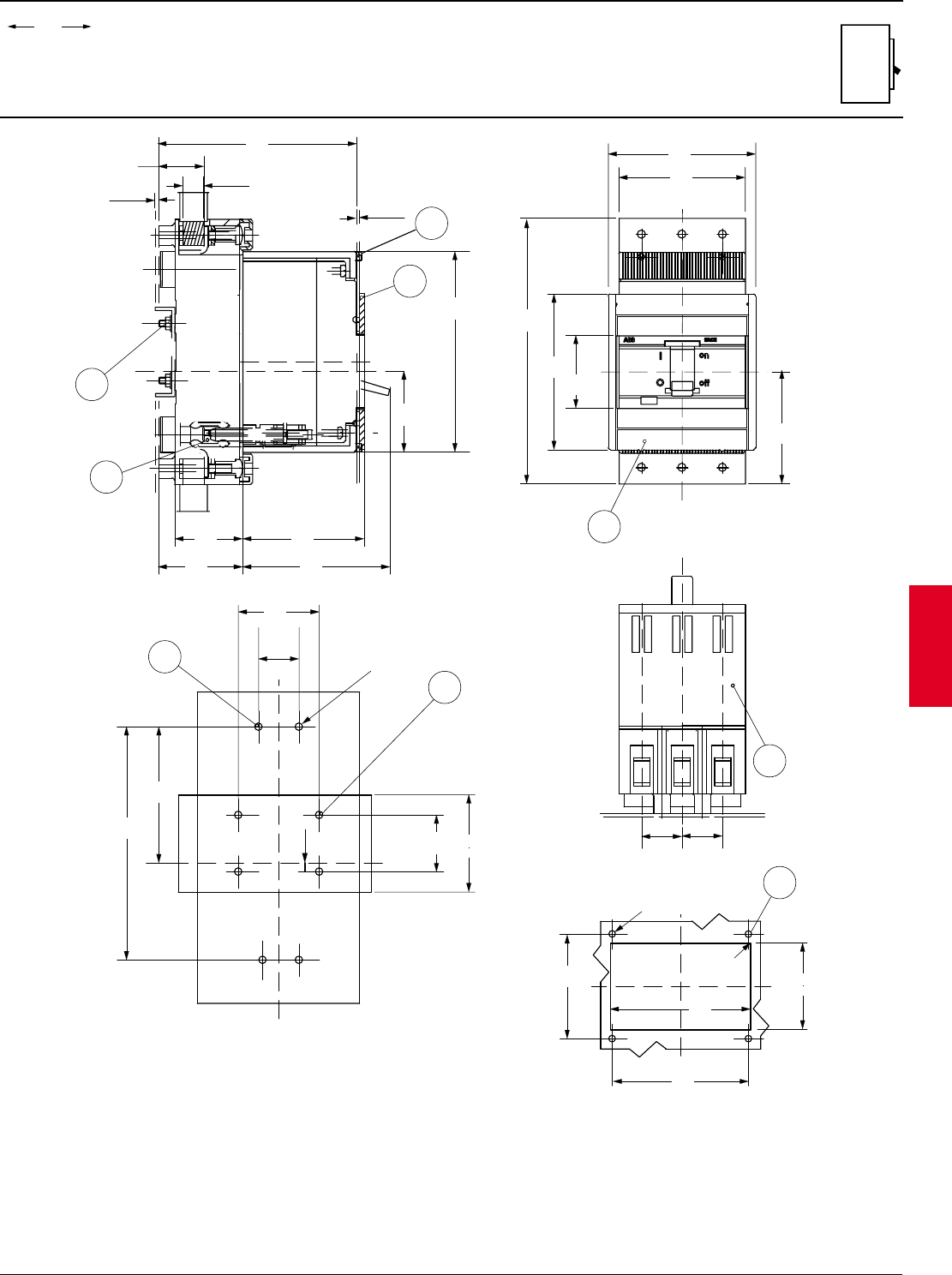
ABB Control Inc. 2.101
AC 1600 – 2/00
Isomax
00.00
00.00 Inches
Millimeters
Dim.
Approximate dimensions
S1 Plug-in front
X
X
10.5x11
8
1
4.84
123
75
2.95
91
3.58
42
1.65
52
2.05
3
C
L
2
Y
Y
X
4
84
3.31
50
1.97
25
0.98
5.5
0.22
35
1.38
60 max
2.36
M4 Ø 4.5
0.18
X
6
C
L
144
5.67
C
L
X
X
Y
Y
163
6.42
96
3.78
70
2.76
1.77
45
78
3.07
91
3.58
2
Y
X
Y
X
Ø 4
64
2.52
R 1.5
0.16
53
2.09
83.5
3.29
0.06
86
3.39
C
L
5
7
25
0.98
25
0.98
1.10
28
0.09
2.5
0.06
1.5 : -2
4.88
124
1.97
50
LEGEND
1-PLUG IN BASE
2-FLANGE FOR THE COMPARTMENT DOOR
3-MOUNTING SCREWS FOR PLUG IN BASE ON PLATE
4-MOUNTING HOLES FOR PLUG IN BASE ON CHANNEL
5-MOUNTING HOLES FOR FRONT FLANGE
6-MOUNTING HOLES FOR SHEET STEEL MOUNTING
7-TERMINAL COVERS (SEPERATE ITEM)
8-SEALING SCREWS (OPTIONAL)
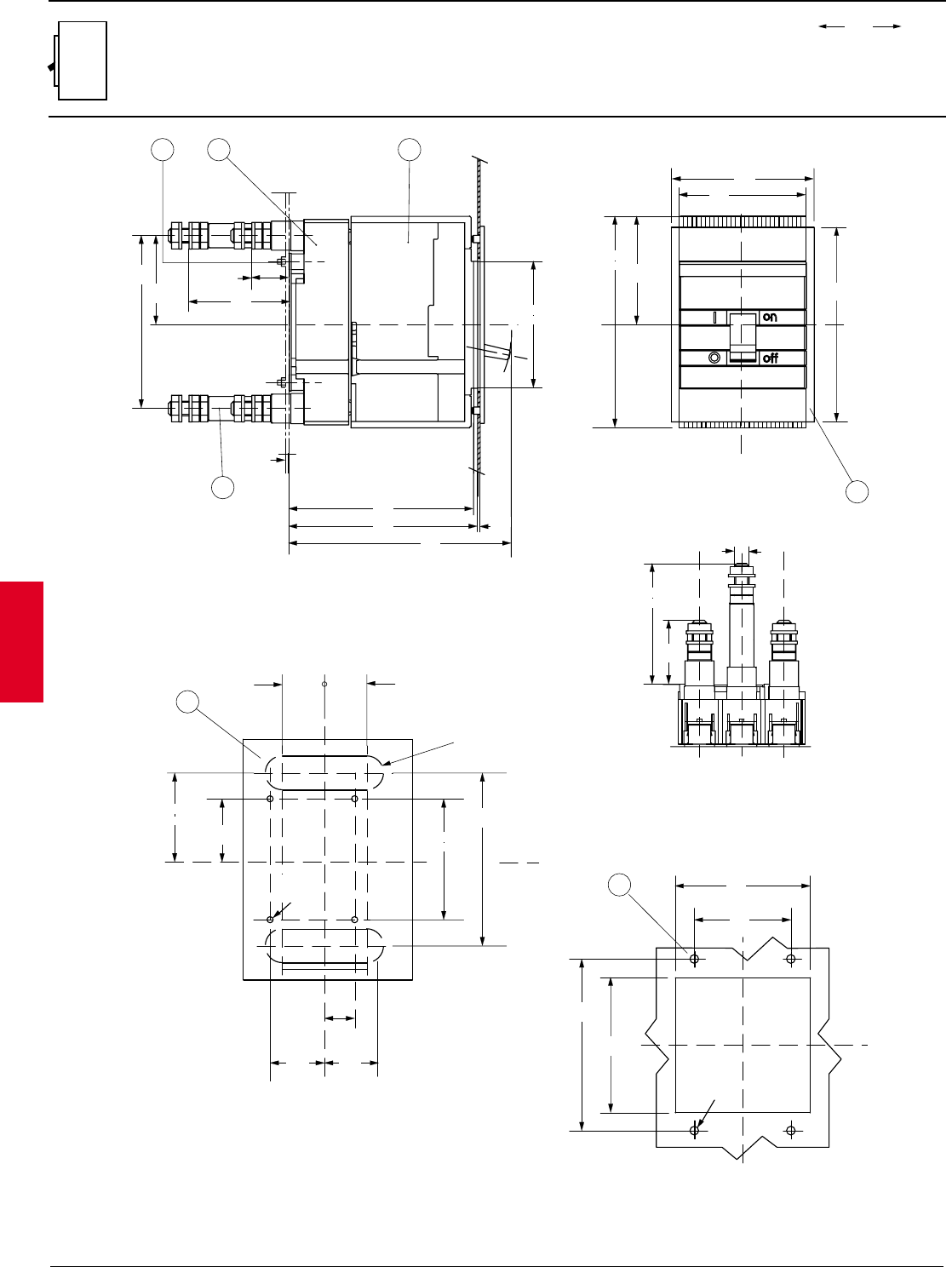
2.102 ABB Control Inc.
AC 1600 – 2/00
Isomax
00.00
00.00 Inches
Millimeters
Dim.
Approximate dimensions
S3 Plug-in rear
LEGEND
1-PLUG IN BASE
2-MOVING PART FITTED WITH TERMINAL COVERS
3-REAR TERMINALS
4-FLANGE FOR THE COMPARTMENT DOOR
5-MOUNTING HOLES FOR FRONT FLANGE
6-MOUNTING HOLES FOR SHEET STEEL MOUNTING
7-TIGHTENING TORQUE 9.7 lb-in
Y
X
117
4.61
105
89.75
3.53
175
6.89
X
Y
4.13
6
161
6.34
184.55
7.27
156.5
6.16
153
6.02
1
3
27
105
4.13
X
==
2
0.08
3
0.11
73.75
2.90
143
5.63
84
3.31
31
1.22
Y
100
3.94
48
1.89
Ø 5 (M12)
C
L
C
L
C
L
X
X
Y
Ø 5
(M4)
Y
100
3.94
143
5.63
35
1.38
35
1.38
R - 0.55
73.75
2.90
52.25
2.06
Y
4
45
1.77
0.20
C
L
X
Y
X
142
5.59
112
4.41
112
4.41
80
3.15
5
Ø 7
0.28
25
0.98
45
1.77
14
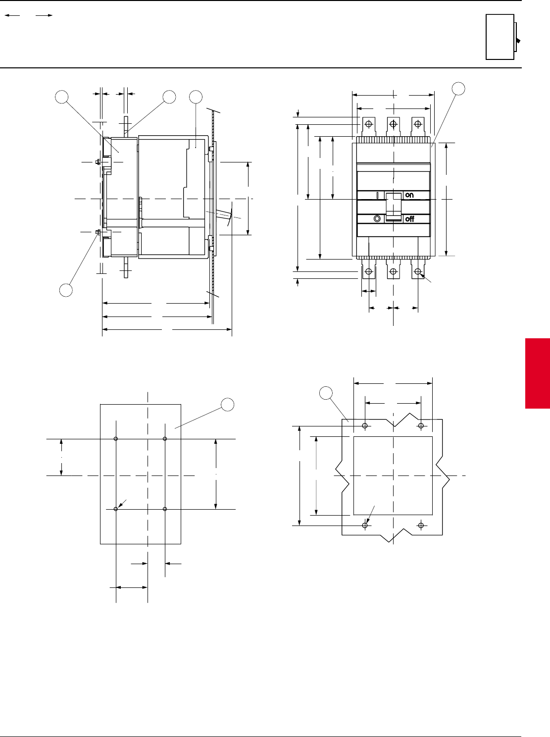
ABB Control Inc. 2.103
AC 1600 – 2/00
Isomax
00.00
00.00 Inches
Millimeters
Dim.
Approximate dimensions
S3 Plug-in front
LEGEND
1-PLUG IN BASE
2-MOVING PART FITTED WITH TERMINAL COVERS
3-FRONT TERMINALS
4-FLANGE FOR THE COMPARTMENT DOOR
5-MOUNTING HOLES FOR FRONT FLANGE
6-MOUNTING HOLES FOR SHEET STEEL MOUNTING
7-TIGHTENING TORQUE 9.7 lb-in
312
7
X
==
156.5
6.16
184.55
7.27
153
6.02
31
1.22
5
0.19
3
0.12
105
4.13
89.75
3.53
Y
107.25
4.22
105
4.13
175
6.89
210
8.27
10
0.39
10
0.39 20
0.79
35
1.38
X
Ø 8.2
0.32
==
161
6.34
6
117
4.60
35
1.38
C
L
C
L
Y
X
Y
X
142
5.59
112
4.41
112
4.41
80
3.15
5
X
X
Y
Y
52.25
45
1.77
25
0.98
100
3.94
Ø 5 (M4)
2.06
4
C
L
0.20
Ø 5 (M4) 0.28
Ø 7
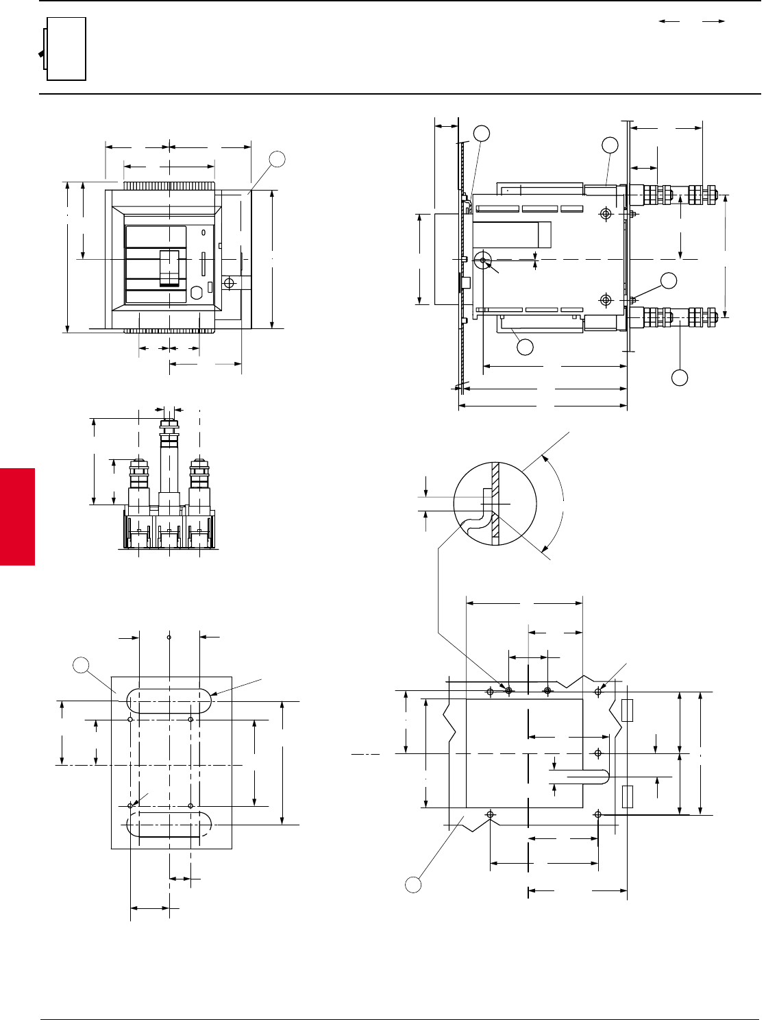
2.104 ABB Control Inc.
AC 1600 – 2/00
Isomax
00.00
00.00 Inches
Millimeters
Dim.
Approximate dimensions
S3 Withdrawable rear
LEGEND
1-WITHDRAWABLE BASE
2-MOVING PART FITTED WITH TERMINAL
COVERS
3-REAR TERMINALS
4-FLANGE FOR THE COMPARTMENT DOOR
5-MOUNTING HOLES FOR FLANGE
6-MOUNTING HOLES FOR SHEET STEEL
MOUNTING
7-COMPARTMENT DOOR INTERLOCK
8-TIGHTENING TORQUE 9.7 lb-in
3
X
X
27.5
1.08
1.75
0.07
190
7.48
195.5
7.70
0.079
2
Ø 5.5
0.22
7
8
1
2
105
4.13 143
5.63
167
6.57
83
3.27
73.75
2.90
31
1.22
X
Y
Y
72.5
2.85
125
4.92
81
3.19
R min. 200
142
5.59
27.25
1.07
135
5.31
63
45
1.77
126
4.96
94
3.70
16
0.63
5 for Ø 7
0.28
2.48
C
L
80˚
Ø 4
0.16
5
YY
X
96
3.78
74
2.91
105
4.13
89.75
3.53
175
6.89
35
1.38
84
3.31
X161
6.34
Y
Y
4
35
1.38
100
3.94
48
1.89
Ø 5 (M12)
Y
Y
C
L
C
L
C
L
X
Ø 5 (M4)
100
3.94
143
5.63
25
0.98
45
1.77
73.75
2.90
52.25
2.06
Y
R - 0.55
35
1.38 35
1.38
6
0.20
14
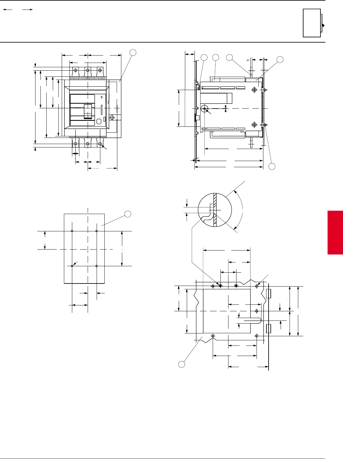
ABB Control Inc. 2.105
AC 1600 – 2/00
Isomax
00.00
00.00 Inches
Millimeters
Dim.
Approximate dimensions
S3 Withdrawable front
Y
Y
72.5
2.85
125
4.92
81
3.19
R min. 200
142
5.59
27.25
1.07
135
5.31
63
45
1.77
126
4.96
94
3.70
16
0.63
5 for Ø 7
0.28
2.48
C
L
80˚
Ø 4
0.16
5
X
X
32
7
8
27.5
1.08
5
0.19
1.75
0.07
105
4.13
167
6.57
190
7.48
195.5
7.70
0.079
2
Ø 5.5
0.22
1.22
3
0.12
31
1
X
X
Y
Y
52.25
45
1.77
25
0.98
100
3.94
Ø 5 (M4)
2.06
6
0.20
Ø 5 (M4)
Y4
X
107.25
4.22
161
6.34
96
3.78
74
2.91
105
4.13
89.75
3.53
175
6.89
210
8.27
10
0.39
10
0.39
20
0.79
35
1.38
84
3.31
X
Ø 8.2
0.32
35
1.38
LEGEND
1-WITHDRAWABLE BASE
2-MOVING PART FITTED WITH TERMINAL COVERS
3-FRONT TERMINALS
4-FLANGE FOR THE COMPARTMENT DOOR
5-MOUNTING HOLES FOR FLANGE
6-MOUNTING HOLES FOR SHEET STEEL MOUNTING
7-COMPARTMENT DOOR INTERLOCK
8-TIGHTENING TORQUE 9.7 lb-in
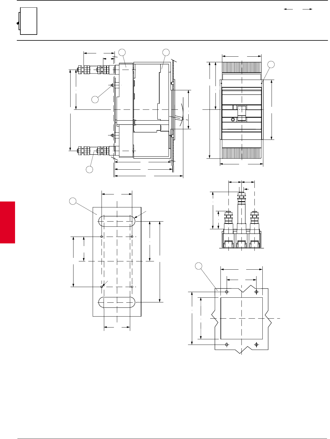
2.106 ABB Control Inc.
AC 1600 – 2/00
Isomax
00.00
00.00 Inches
Millimeters
Dim.
Y
4
XX
127.75
5.03
259
10.20
105
4.13
Y
161
6.34
117
4.61
3
12
7
156.5
6.16
184.5
7.27
153
6.02
218
8.58
127.75
5.03
105
4.13
83
3.27
31
3.94
100
1.89
48
1.38
35
Ø 5 (M12)
1.38
35
X
Y
Y
X
142
5.59
112
4.41
112
4.41
80
3.15
5
X
65.75
2.59
Y
X
Ø 5 (M4)
135
5.31
70
2.76
82
3.23
107.25
4.22
218
8.58
6
R - 0.55
LEGEND
1-PLUG IN BASE
2-MOVING PART FITTED WITH TERMINAL COVERS
3-REAR TERMINALS
4-FLANGE FOR THE COMPARTMENT DOOR
5-MOUNTING HOLES FOR FRONT FLANGE
6-MOUNTING HOLES FOR SHEET STEEL MOUNTING
7-TIGHTENING TORQUE 9.7 lb-in
14
1.22
Approximate dimensions
S4 Plug-in rear
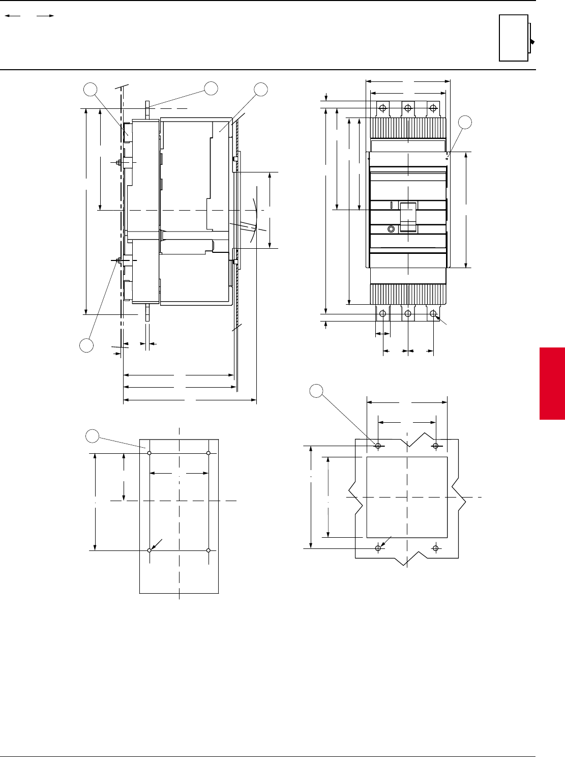
ABB Control Inc. 2.107
AC 1600 – 2/00
Isomax
00.00
00.00 Inches
Millimeters
Dim.
Approximate dimensions
S4 Plug-in front
Y
4
XX
20
0.79
35
1.38
Ø 8.2
0.32
35
1.38
127.75
5.03
10
0.39
10
0.39
285
11.20
259
10.20
140.75
5.54
105
4.13
117
4.06
161
6.34
Y
X
X
135
5.31
Ø 5 (M4)
65.75
2.59 3.23
82
6
0.20
5
112
4.41
80
3.15
X
Y
X
142
5.59
112
4.41
Ø 7
0.28
X
2
3
1
7
153
6.02
156.5
6.16
184.5
7.27
3
0.12
285
11.22
140.75
5.54
X
==
105
4.13
31
1.22
5
0.19
LEGEND
1-PLUG IN BASE
2-MOVING PART FITTED WITH TERMINAL COVERS
3- FRONT TERMINAL
4-FLANGE FOR THE COMPARTMENT DOOR
5-MOUNTING HOLES FOR FRONT FLANGE
6-MOUNTING HOLES FOR SHEET STEEL MOUNTING
TIGHTENING TORQUE 9.7 lb-in
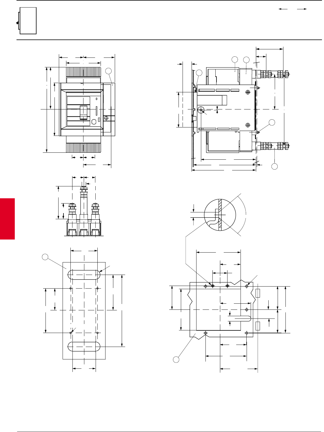
2.108 ABB Control Inc.
AC 1600 – 2/00
Isomax
00.00
00.00 Inches
Millimeters
Dim.
Approximate dimensions
S4 Withdrawable rear
LEGEND
1-WITHDRAWABLE BASE
2-MOVING PART FITTED WITH TERMINAL COVERS
3-REAR TERMINALS
4-FLANGE FOR THE COMPARTMENT DOOR
5-MOUNTING HOLES FOR FRONT FLANGE
6-MOUNTING HOLES FOR SHEET STEEL MOUNTING
7-COMPARTMENT DOOR INTERLOCK
8-TIGHTENING TORQUE 9.7 lb-in
105
35
1.38
161
6.34
Y
4.13
259
84
96
3.78
74
2.91
4
3.31
35
1.38
X
3.94
100
1.89
48
Ø 5 (M12)
1.381.38
35 35
10.20
127.75
5.03
Y
X
65.75
2.59
Y
X
Ø 5 (M4)
135
5.31
70
2.76
82
3.23
107.25
4.22
218
8.58
6
R - 0.55
21
3
7
8
218
8.58
127.75
5.03
X105
4.13
190
7.48
195.5
7.70
167
6.57
3
0.12
Ø 5.5
0.22 0.07
1.75
27.5
1.08
X
72.5
2.85
Y
Y
5125
4.92
81
3.19
R min. 200
142
5.59
27.25
1.07
135
5.31
63
2.48
45
1.77
126
4.96
94
3.70
16
0.63
5 for Ø 7
0.28
80˚
Ø 4
0.16
=
=
14
31
1.22
83
3.27
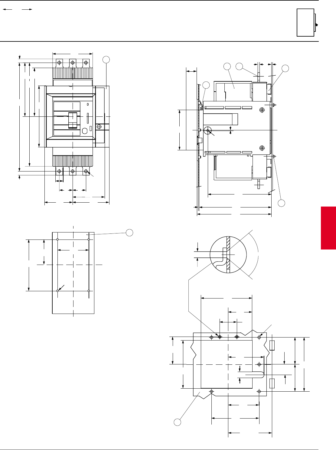
ABB Control Inc. 2.109
AC 1600 – 2/00
Isomax
00.00
00.00 Inches
Millimeters
Dim.
Approximate dimensions
S4 Withdrawable front
0.12
27.5
1.08
105
4.13 X
7
2 3
X
5
0.19 31
1.22
3
167
6.57
190
7.48
195.5
7.70
0.079
2
1.75
0.07
Ø 5.5
0.22
8
1
Y
10.20
Y
Y
4
334
10
0.39
10
0.39
105
4.13
20
0.79
35
1.38
84
3.31
Ø 8.2
0.32
96
3.78
74
2.91
161
6.34
127.75
5.03
140.75
5.54
259
35
1.38
13.15
Y
X
X
6
135
5.31
Ø 5 (M4)
65.75
2.59 3.23
82
LEGEND
1-WITHDRAWABLE BASE
2-MOVING PART FITTED WITH TERMINAL COVERS
3-FRONT TERMINALS
4-FLANGE FOR THE COMPARTMENT DOOR
5-MOUNTING HOLES FOR FLANGE
6-MOUNTING HOLES FOR SHEET STEEL MOUNTING
7-COMPARTMENT DOOR INTERLOCK
8-TIGHTENING TORQUE 9.7 lb-in
Y
Y
5
72.5
2.85
125
4.92
81
3.19
R min. 200
142
5.59
27.25
1.07
135
5.31
63
2.48
45
1.77
126
4.96
94
3.70
16
0.63
5 for Ø 7
0.28
80˚
Ø 4
0.16
==
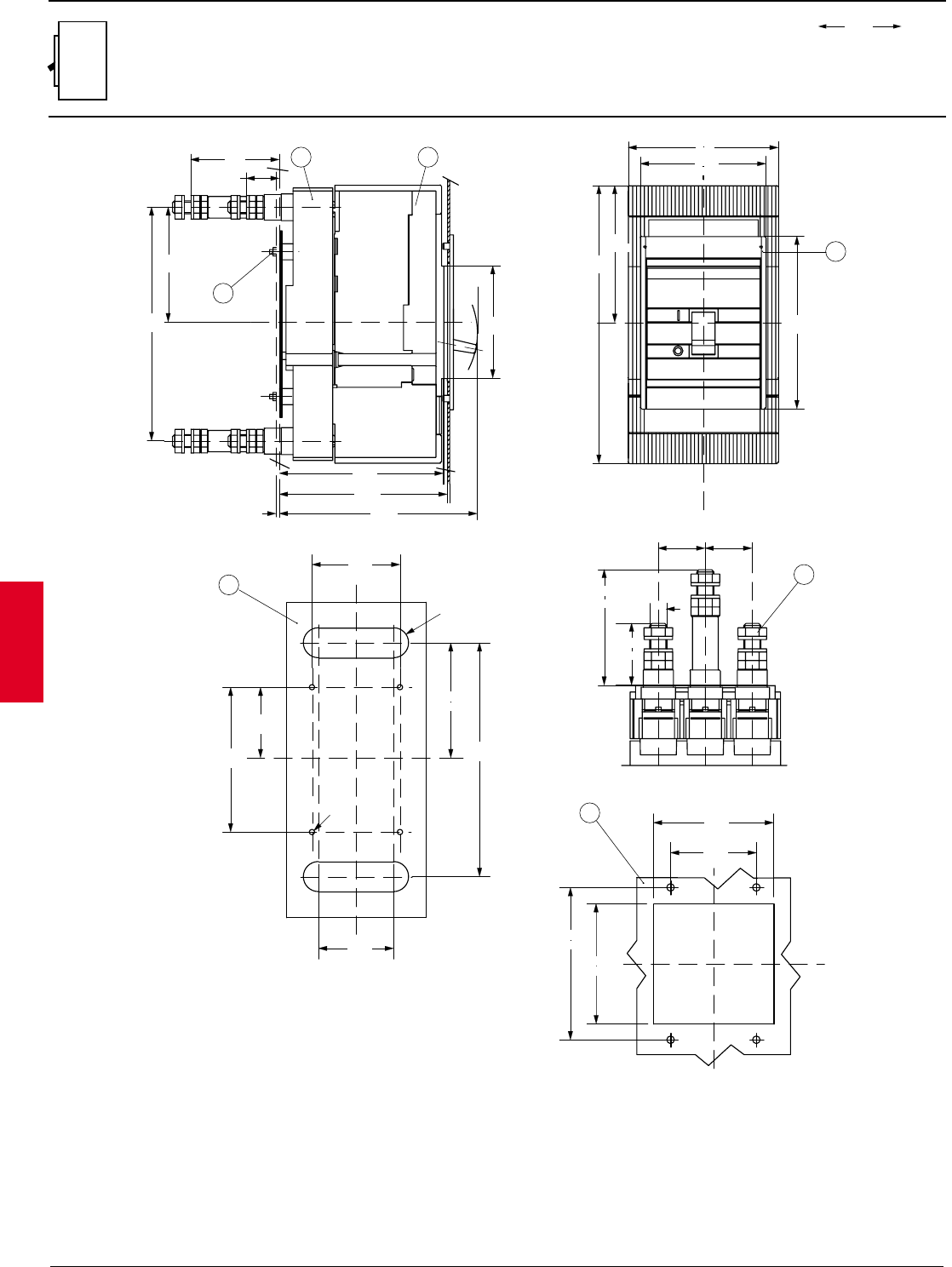
2.110 ABB Control Inc.
AC 1600 – 2/00
Isomax
00.00
00.00 Inches
Millimeters
Dim.
Approximate dimensions
S5 Plug-in rear
LEGEND
1-PLUG IN BASE
2-MOVING PART FITTED WITH TERMINAL COVERS
3-REAR TERMINALS
4-FLANGE FOR THE COMPARTMENT DOOR
5-MOUNTING HOLES FOR FRONT FLANGE
6-MOUNTING HOLES FOR SHEET STEEL MOUNTING
7-TIGHTENING TORQUE 17.7 lb-in
12
7
156.5
6.16
184.5
7.27
153
6.02
X
218
8.58
107.75
4.22
105
4.13
84
3.31
34
1.34
3
0.12
Y
Y
X
142
5.59
112
4.41
112
4.41
80
3.15
5
X
65.75
2.59
Y
X
Ø 5 (M4)
135
5.31
87.5
3.44
115
4.53
107.25
4.22
218
8.58
6
18
Y1.72
43.75
1.72
43.75
2.28
58
4.25
108 M16
3
4
Y
117
4.61
140
5.51
127.75
5.03
259
10.20
X
161
6.34
R - 0.71
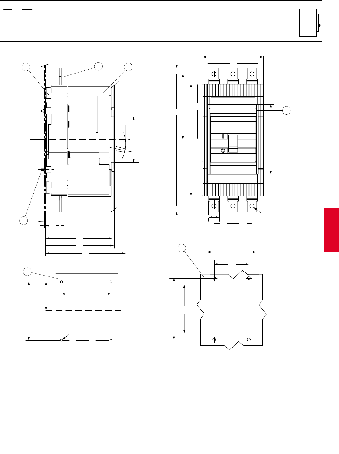
ABB Control Inc. 2.111
AC 1600 – 2/00
Isomax
00.00
00.00 Inches
Millimeters
Dim.
Approximate dimensions
S5 Plug-in front
4
Y
117
3.78
140
5.51
305
12.01
14
0.52
127.75
5.03
259
10.20
150.75
5.94
14
0.52
X
161
6.34
43.75
1.73
Ø 10
0.39
25
0.98
43.75
1.73
Y
Y
X
142
5.59
112
4.41
112
4.41
80
3.15
5
Y
X
X135
5.31
Ø 5 (M4)
65.75
2.59
6
0.20
4.53
115
X
2
3
1
7
153
6.02
156.5
6.16
184.5
7.27
3
0.12
X
==
105
4.13
31
1.22 6
0.24
LEGEND
1-PLUG IN BASE
2-MOVING PART FITTED WITH TERMINAL COVERS
3-FRONT TERMINALS
4-FLANGE FOR THE COMPARTMENT DOOR
5-MOUNTING HOLES FOR FRONT FLANGE
6-MOUNTING HOLES FOR SHEET STEEL MOUNTING
7-TIGHTENING TORQUE 17.7 lb-in
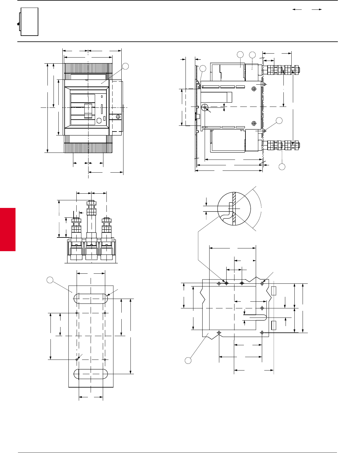
2.112 ABB Control Inc.
AC 1600 – 2/00
Isomax
00.00
00.00 Inches
Millimeters
Dim.
Approximate dimensions
S5 Withdrawable rear
X
65.75
2.59
Y
X
Ø 5 (M4)
135
5.31
87.5
3.44
115
4.53
107.25
4.22
218
8.58
6
18
Y
Y
5
125
4.92
81
3.19
R min. 200
142
5.59
27.25
1.07
135
5.31
63
2.48
45
1.77
126
4.96
94
3.70
16
0.63
5 for Ø 7
0.28
80˚
Ø 4
0.16
21
3
7
8
218
8.58
107.25
4.22
X
105
4.13
190
7.48
167
6.57
3
0.12
Ø 5.5
0.22 0.07
1.75
27.5
1.08
3.31
84
1.34
34
195.5
7.70
72.5
2.85
LEGEND
1-WITHDRAWABLE BASE
2-MOVING PART FITTED WITH TERMINAL COVERS
3-REAR TERMINALS
4-FLANGE FOR THE COMPARTMENT DOOR
5-MOUNTING HOLES FOR FRONT FLANGE
6-MOUNTING HOLES FOR SHEET STEEL MOUNTING
7-COMPARTMENT DOOR INTERLOCK
8-TIGHTENING TORQUE 9.7 lb-in
R - 0.71
1.72
43.75
1.72
43.75
2.28
58
M16
4.25
108
==
= =
74
2.91
4
Y
127.75
5.03
259
10.20
43.75
1.72
Y
43.75
1.72
96
3.78
101.5
4.00
X
161
6.34 X
140
5.51
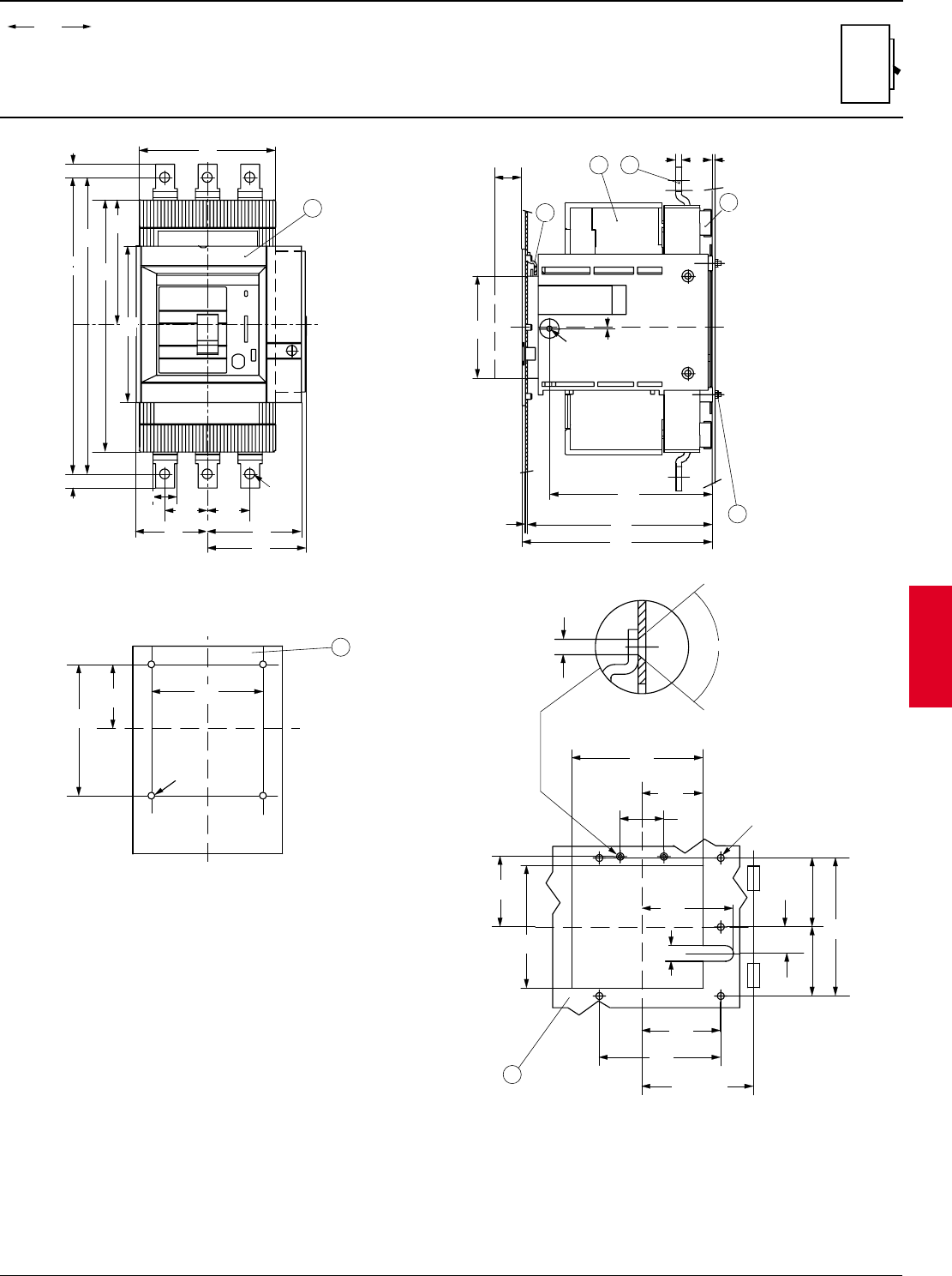
ABB Control Inc. 2.113
AC 1600 – 2/00
Isomax
00.00
00.00 Inches
Millimeters
Dim.
Approximate dimensions
S5 Withdrawable front
74
2.91
4
Y
= =
140
5.51
305
12.01
127.75
5.03
259
10.20
150.75
5.94
14
0.52
14
0.52
43.75
1.72
Y
Ø 10
0.39
25
0.98
43.75
1.72
96
3.78
101.5
4.00
X
161
6.34 X
27.5
1.08
105
4.13 X
7
23
6
0.24 1.22
3
0.12
167
6.57
190
7.48
195.5
7.70
0.079
2
1.75
0.07
Ø 5.5
0.22
8
1
31
Y
Y
5
72.5
2.85
125
4.92
81
3.19
R min. 200
142
5.59
27.25
1.07
135
5.31
63
2.48
45
1.77
126
4.96
94
3.70
16
0.63
5 for Ø 7
0.28
80˚
Ø 4
0.16
==
Y
X
X
Y
6
135
5.31
Ø 5 (M4)
65.75
2.59 4.53
115
LEGEND
1- WITHDRAWABLE BASE
2-MOVING PART FITTED WITH TERMINAL COVERS
3-FRONT TERMINALS
4-COMPARTMENT DOOR FLANGE
5-MOUNTING HOLES FOR FLANGE
6-MOUNTING HOLES FOR SHEET STEEL MOUNTING
7-COMPARTMENT DOOR INTERLOCK
8-TIGHTENING TORQUE 9.7 lb-in
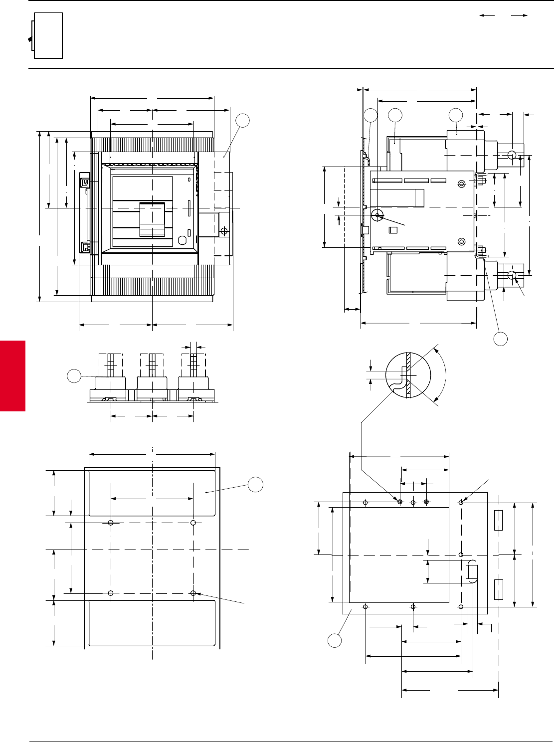
2.114 ABB Control Inc.
AC 1600 – 2/00
Isomax
00.00
00.00 Inches
Millimeters
Dim.
Approximate dimensions
S6 Withdrawable rear
Y
295
11.61
133
5.24
273
10.75
196
7.72
210
8.27
91.5
3.60
131
5.16
140
5.51
123.5
4.86
136.5
5.37
122
4.80
4
XX
21
7
8
27.5
1.08
195.5
7.70
2
0.08
190
7.48
167
6.57
5.51
140
14.5
0.57
60.5
2.38
20
0.79
58
2.28
89.5
3.52
145
5.71
208
8.19
Ø 14
0.55
40
1.57
Ø 5.5
0.22
3
0.12
LEGEND
1-WITHDRAWABLE BASE
2-MOVING PART FITTED WITH TERMINAL COVERS
3-REAR TERMINALS
4-FLANGE FOR THE COMPARTMENT DOOR
5-MOUNTING HOLES FOR THE FLANGE
6-MOUNTING HOLES FOR SHEET STEEL MOUNTING
7-COMPARTMENT DOOR INTERLOCK
8-TIGHTENING TORQUE 79.7 lb-in
XX
Y
Y
6
3.06
77.5
2.26
57.5
3.06
77.5
3.41
86.5
4.72
120
1.79
45.5
214
8.43
140
5.51
Ø 8.5 ( M8 )
Y
3
10
.39
Y
70
2.76
70
2.76
Y
X
5
Y
170
6.69
45
1.77
80.5
3.17
161
6.34
90
3.54
177
6.97
Ø 7 for 7
0.28
39
1.54
9
0.35
19.75
0.77
101
3.98
162.5
6.40
121
4.76
R min.200
16
0.63
80˚
Ø 4
0.16
X
==
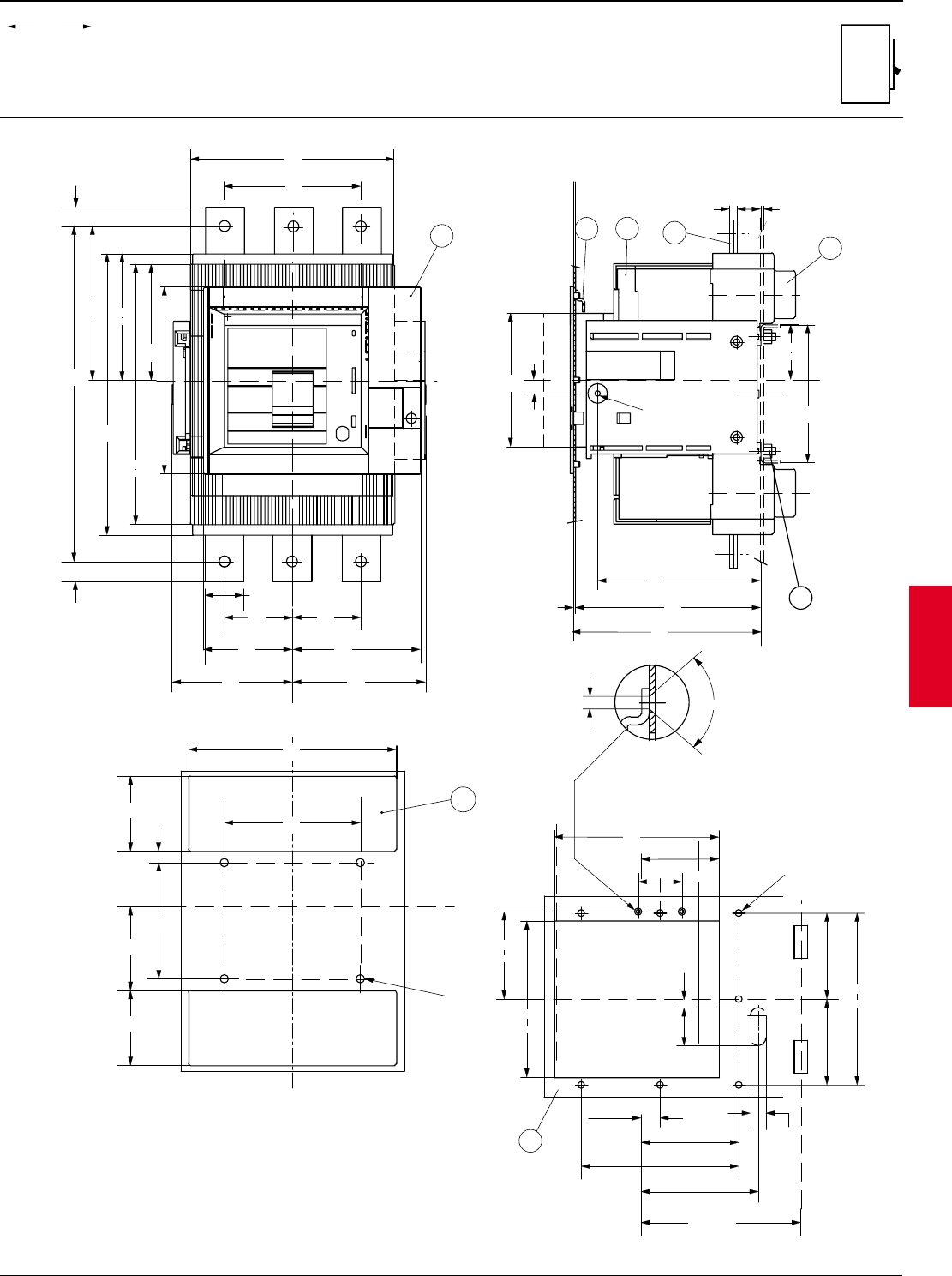
ABB Control Inc. 2.115
AC 1600 – 2/00
Isomax
00.00
00.00 Inches
Millimeters
Dim.
Approximate dimensions
S6 Withdrawable front
Y
295
11.61
273
10.75
196
7.72
210
8.27
122
4.80
4
140
5.51
X
Y
70
2.76 70
2.76
91.5
3.60 131
5.16
123.5
4.86 136.5
5.37
40
1.57
133
5.24158
6.22
345
13.58
20
0.78
20
0.78
X
2
7
8
5.51
140
14.5
0.57 58
2.28
145
5.71
Ø 5.5
0.22
1
3
0.12
10
0.39 31
1.22
3
195.5
7.70
167
6.57
190
7.48
2
0.08
X
LEGEND
1-WITHDRAWABLE BASE
2-MOVING PART FITTED WITH TERMINAL COVERS
3-REAR TERMINALS
4-FLANGE FOR THE COMPARTMENT DOOR
5-MOUNTING HOLES FOR THE FLANGE
6-MOUNTING HOLES FOR SHEET STEEL MOUNTING
7-COMPARTMENT DOOR INTERLOCK
8-TIGHTENING TORQUE 79.7 lb-in
Y
X
5
Y
170
6.69
45
1.77
80.5
3.17
161
6.34
90
3.54
177
6.97
Ø 7 for 7
0.28
39
1.54
9
0.35
19.75
0.77
101
3.98
162.5
6.40
121
4.76
R min.200
16
0.63
80˚
Ø 4
0.16
X
==
XX
Y
Y
6
3.06
77.5
2.26
57.5
3.06
77.5
3.41
86.5
4.72
120
1.79
45.5
214
8.43
140
5.51
Ø 8.5 ( M8 )
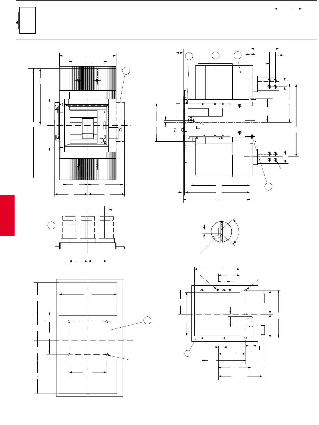
2.116 ABB Control Inc.
AC 1600 – 2/00
Isomax
00.00
00.00 Inches
Millimeters
Dim.
Approximate dimensions
S7 Withdrawable rear
140
5.51
4
Y
210
8.27
91.5
3.60
131
5.16
Y
123.5
4.86
136.5
5.37
196
7.72
211.25
8.32
406
15.99
X
2
7
8
X
8.25
0.32
Ø 5.5
0.22
2
0.08
27.5
1.08
8.58
218
9.51
241.5
9.72
247
Ø 11
0.43
5.51
140
1.97
50
108
4.25
3
0.12
1
14
0.55
22
0.87
22
0.87
5.64
143.25
10.63
270
6.30
160
max
X
Y
6
X
4.72
120
1.79
68.25
214
8.43
140
5.51
3.64
92.5
2.99
76
Ø 8.5 ( M8 )
4.74
120.5
4.74
120.5
Y
X
3
16
0.63
Y
70
2.76
70
2.76
LEGEND
1-WITHDRAWABLE BASE
2-MOVING PART FITTED WITH TERMINAL COVERS
3-REAR TERMINALS
4-FLANGE FOR THE COMPARTMENT DOOR
5-MOUNTING HOLES FOR FLANGE
6-MOUNTING HOLES FOR SHEET STEEL MOUNTING
7-COMPARTMENT DOOR INTERLOCK
8-TIGHTENING TORQUE 79.7 lb-in
Y
X
5
Y
170
6.69
45
1.77
80.5
3.17
161
6.34
90
3.54
177
6.97
Ø 7 for 7
0.28
39
1.54
9
0.35
19.75
0.77
101
3.98
162.5
6.40
121
4.76
R min.200
16
0.63
80˚
Ø 4
0.16
X
==
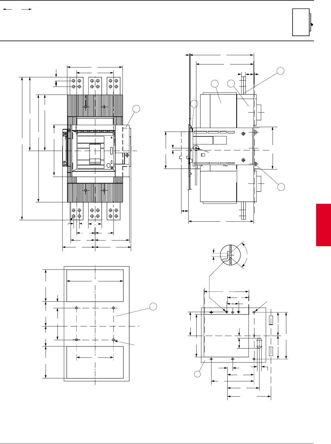
ABB Control Inc. 2.117
AC 1600 – 2/00
Isomax
00.00
00.00 Inches
Millimeters
Dim.
Approximate dimensions
S7 Withdrawable front
1.08
4
140
5.51
Y
210
8.27
196
211.25
8.32
7.72
Y
70
2.76
70
2.76
123.5
4.86
136.5
5.37
91.5
3.60
131
5.16
50
1.97
22
0.87
Ø 11
0.43
406
15.99
540
21.26
278.25
10.95
0.87
0.55
X X
14
22
3
7
8
Ø 5.5
0.22
8.25
0.32
27.5
2
0.08
9.51
241.5
9.72
247
16
0.63
31
1.22
3
0.12
6.30
160
max
X5.51
140
21
8.60
218.5
Y
6
X
4.72
120
1.79
68.25
214
8.43
140
5.51
3.64
92.5
2.99
76
Ø 8.5 ( M8 )
4.74
120.5
4.74
120.5
Y
X
LEGEND
1-WITHDRAWABLE BASE
2-MOVING PART FITTED WITH TERMINAL COVERS
3-FRONT TERMINALS
4-FLANGE FOR THE COMPARTMENT DOOR
5-MOUNTING HOLES FOR FLANGE
6-MOUNTING HOLES FOR SHEET STEEL MOUNTING
7-COMPARTMENT DOOR INTERLOCK
8-TIGHTENING TORQUE 79.7 lb-in
Y
X
5
Y
170
6.69
45
1.77
80.5
3.17
161
6.34
90
3.54
177
6.97
Ø 7 for 7
0.28
39
1.54
9
0.35
19.75
0.77
101
3.98
162.5
6.40
121
4.76
R min.200
16
0.63
80˚
Ø 4
0.16
X
==
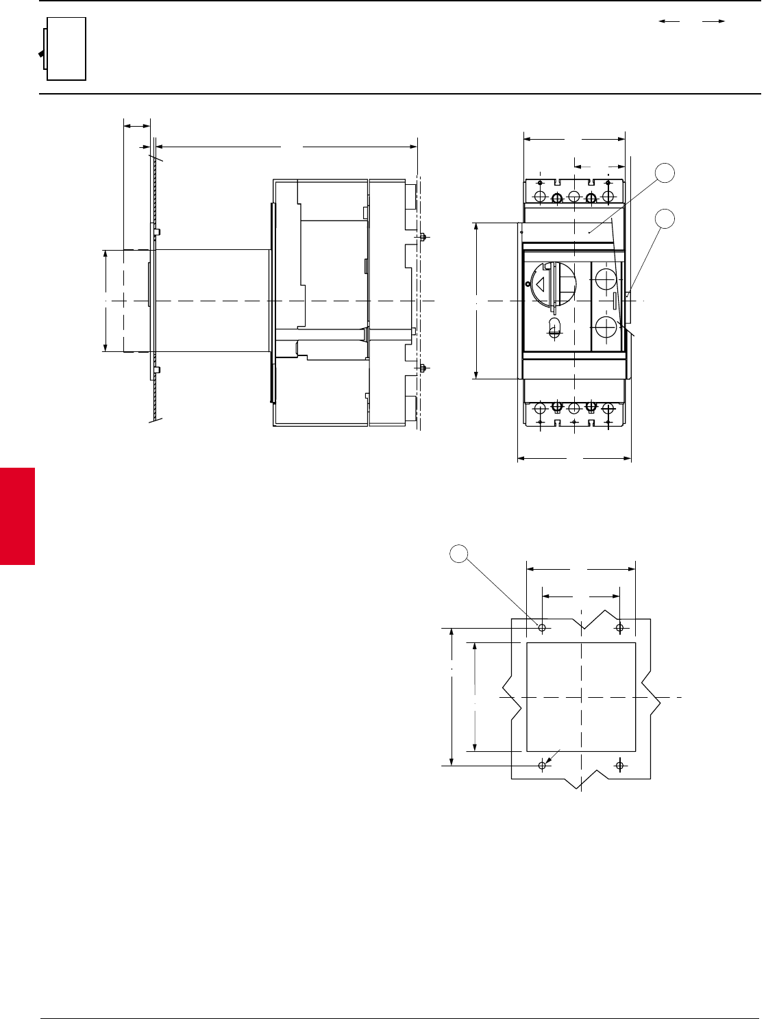
2.118 ABB Control Inc.
AC 1600 – 2/00
Isomax
00.00
00.00 Inches
Millimeters
Dim.
Approximate dimensions
S3 - S4 Motor operator w/ plug-in front
X
269.5
10.61
2
0.08
27.5
1.08
X
=
=
105
4.13 X
Y
Y
2
1
117
4.61
161
6.34
3
112
4.41
80
3.15
X
Y
X
142
5.59
112
4.41
Ø 7
0.28
58
2.28
4.13
105
LEGEND
1-FLANGE FOR THE COMPARTMENT DOOR
2-PLUG FOR MOTOR OPERATOR
3-DRILLING TEMPLATE
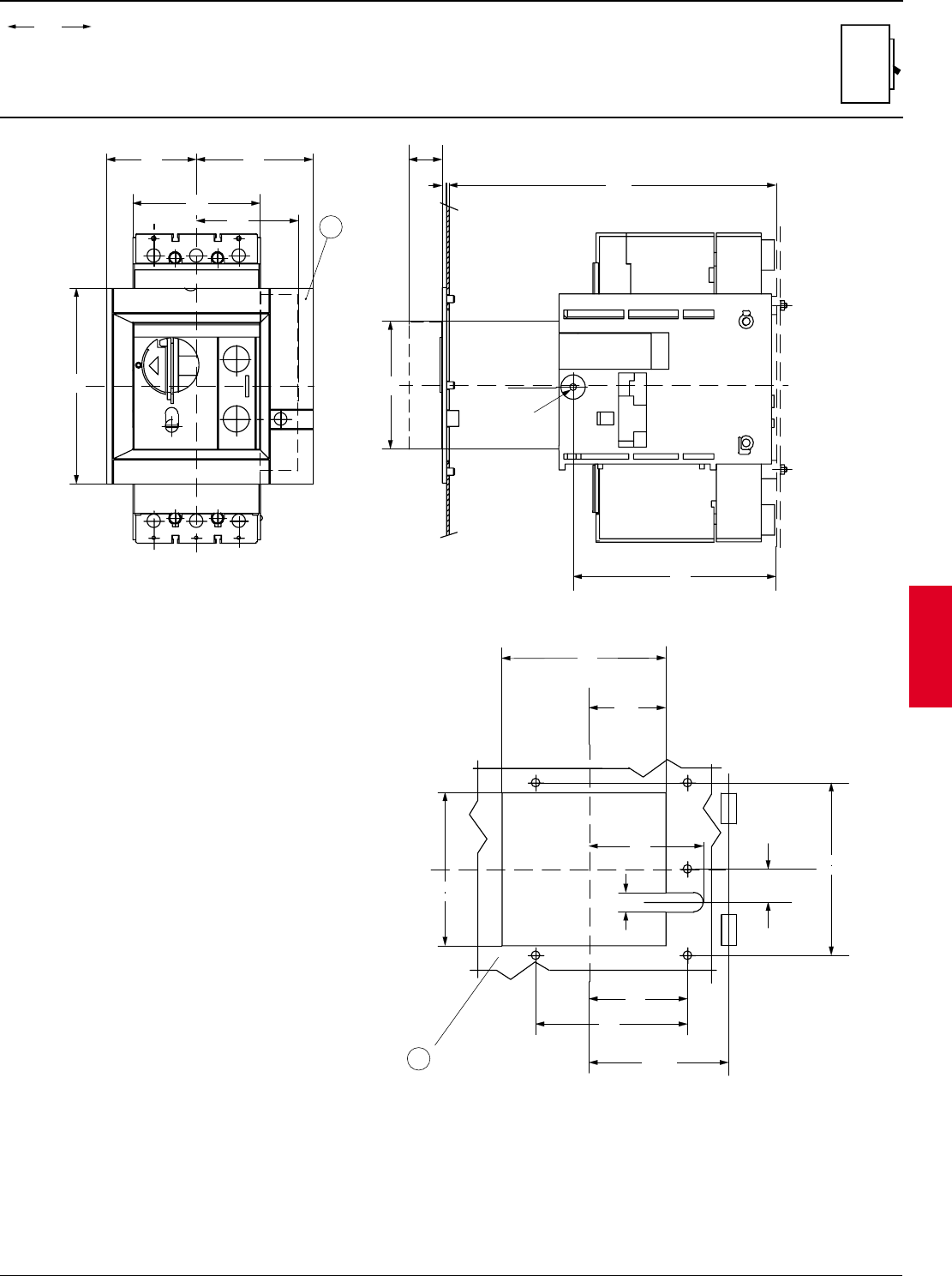
ABB Control Inc. 2.119
AC 1600 – 2/00
Isomax
00.00
00.00 Inches
Millimeters
Dim.
Approximate dimensions
S3 - S4 Motor operator w/ withdrawable
Y
1
125
4.92
81
3.19
R min.
200
142
5.59
135
5.31
63
2.48
126
4.96
94
3.70
16
0.63
XX
LEGEND
1-MOUNTING HOLES FOR FRONT FLANGE
2-FLANGE FOR THE COMPARTMENT DOOR
27.25
1.07
Y
X
2
161
6.34
74
2.91
96
3.78
Y
Y
105
4.13
3.31
84
X
2
0.08
105
4.13
269.5
10.61
167
6.57
27.5
1.08
Ø 5
0.20
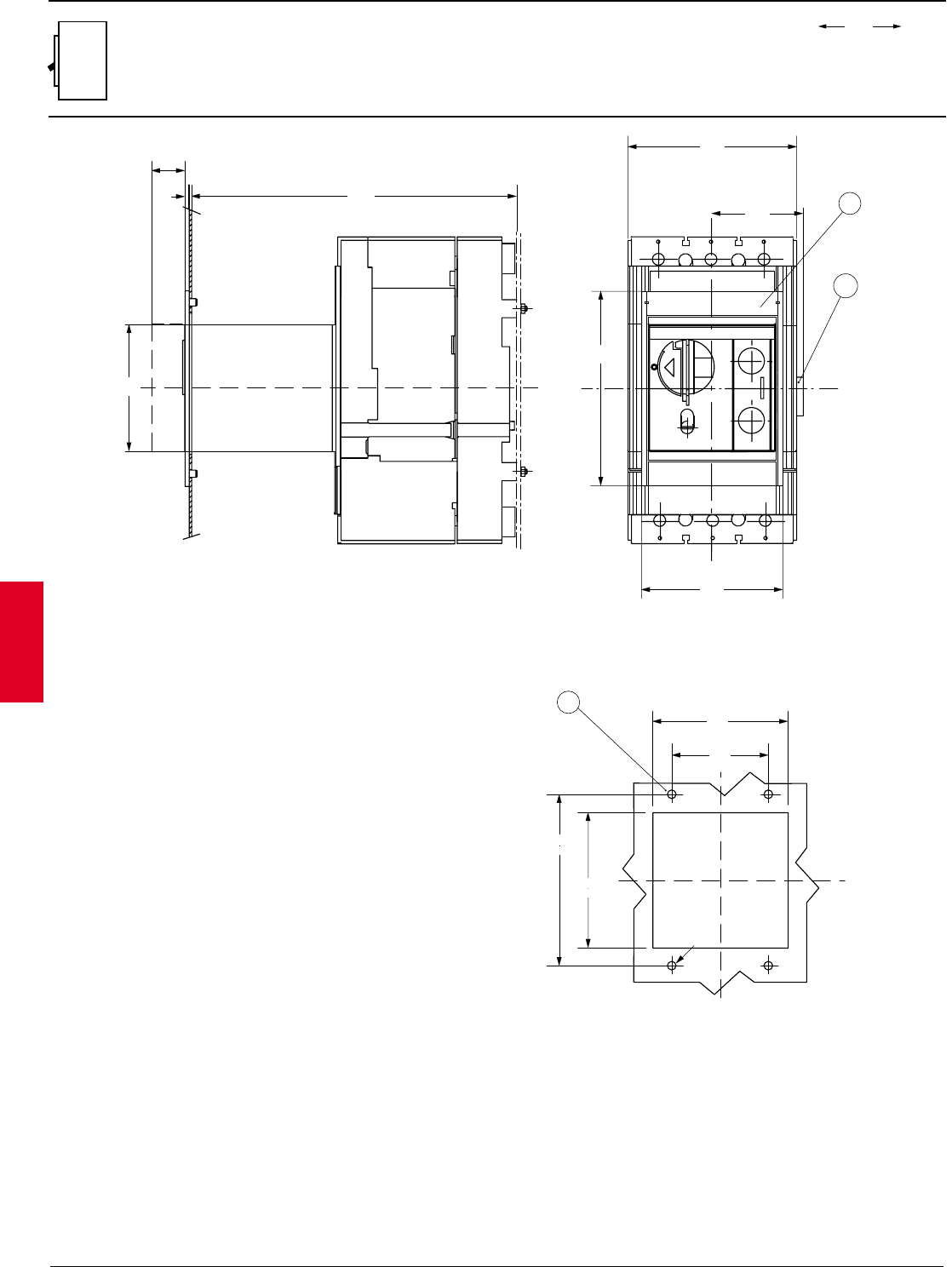
2.120 ABB Control Inc.
AC 1600 – 2/00
Isomax
00.00
00.00 Inches
Millimeters
Dim.
Approximate dimensions
S5 Motor operator w/ plug-in
X
269.5
10.61
2
0.08
27.5
1.08
X
=
=
105
4.13
3
112
4.41
80
3.15
X
Y
X
142
5.59
112
4.41
Ø 7
0.28
LEGEND
1-FLANGE FOR THE COMPARTMENT DOOR
2-PLUG FOR MOTOR OPERATOR
3-DRILLING TEMPLATE
1
4.61
117
5.51
140
XX
2
6.34
161
Y
Y
75.5
2.97
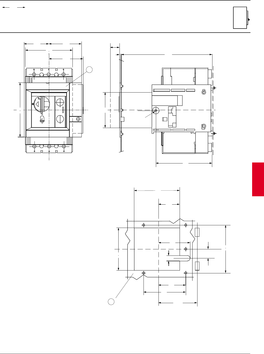
ABB Control Inc. 2.121
AC 1600 – 2/00
Isomax
00.00
00.00 Inches
Millimeters
Dim.
Approximate dimensions
S5 Motor operator w/ withdrawable
Y
Y
1
125
4.92
81
3.19
R min.
200
142
5.59
135
5.31
63
2.48
126
4.96
94
3.70
16
0.63
XX
LEGEND
1-MOUNTING HOLES FOR FRONT FLANGE
2-FLANGE FOR THE COMPARTMENT DOOR
27.25
1.07
X
2
0.08
105
4.13
269.5
10.61
167
6.57
27.5
1.08
Ø 5
0.20
= =
74
2.91
4
Y
Y
96
3.78
X
161
6.34 X
140
5.51
101.5
4.00
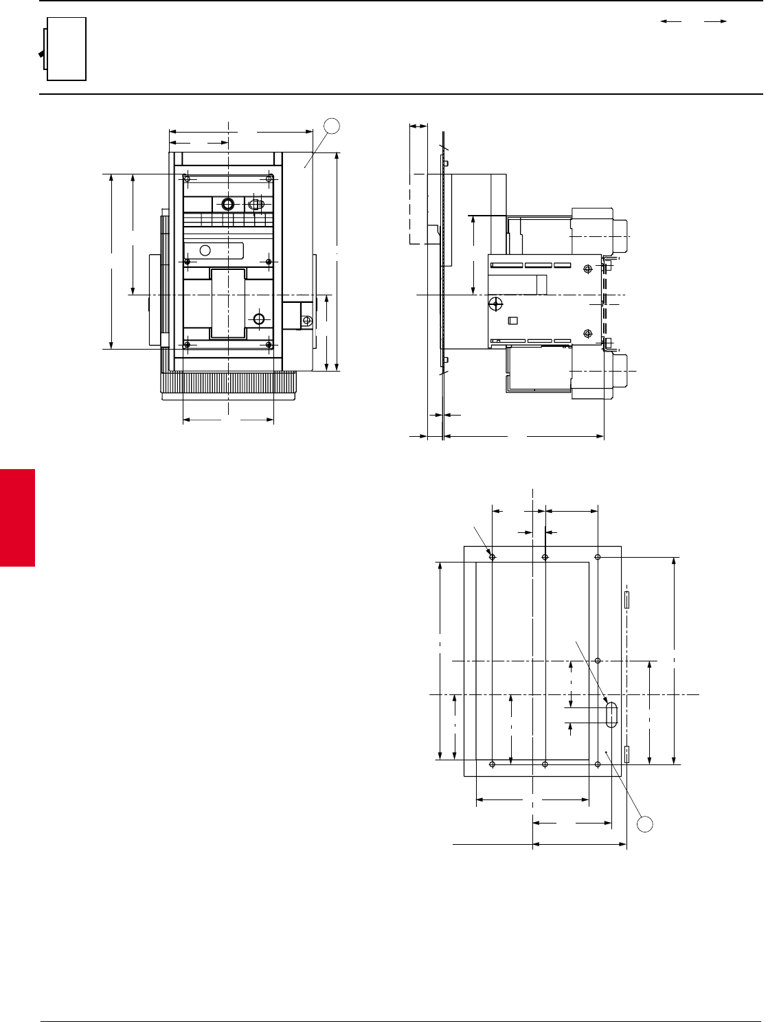
2.122 ABB Control Inc.
AC 1600 – 2/00
Isomax
00.00
00.00 Inches
Millimeters
Dim.
Approximate dimensions
S6 Motor operator w/ withdrawable
Y
Y
1
222.5
8.76
91.5
3.60
5.51
140
7.34
186.5
4.62
270
10.63
338
13.31
XX
27.5
1.08
122
4.80
2
0.08
247.5
9.74
23.5
0.93
117.5
LEGEND
1-FLANGE FOR THE COMPARTMENT DOOR
2-DRILLING TEMPLATE
2
Y
Y
X
X
R.min,=200
81.25
3.20
81.25
3.20
7 for Ø 8
0.31
19.75
0.77
12.56
319
6.28
159.5
2.84
72.25
R 8
0.90
22.75
3.96
100.5
11.97
304
4.25
108
6.85
174
4.80
122
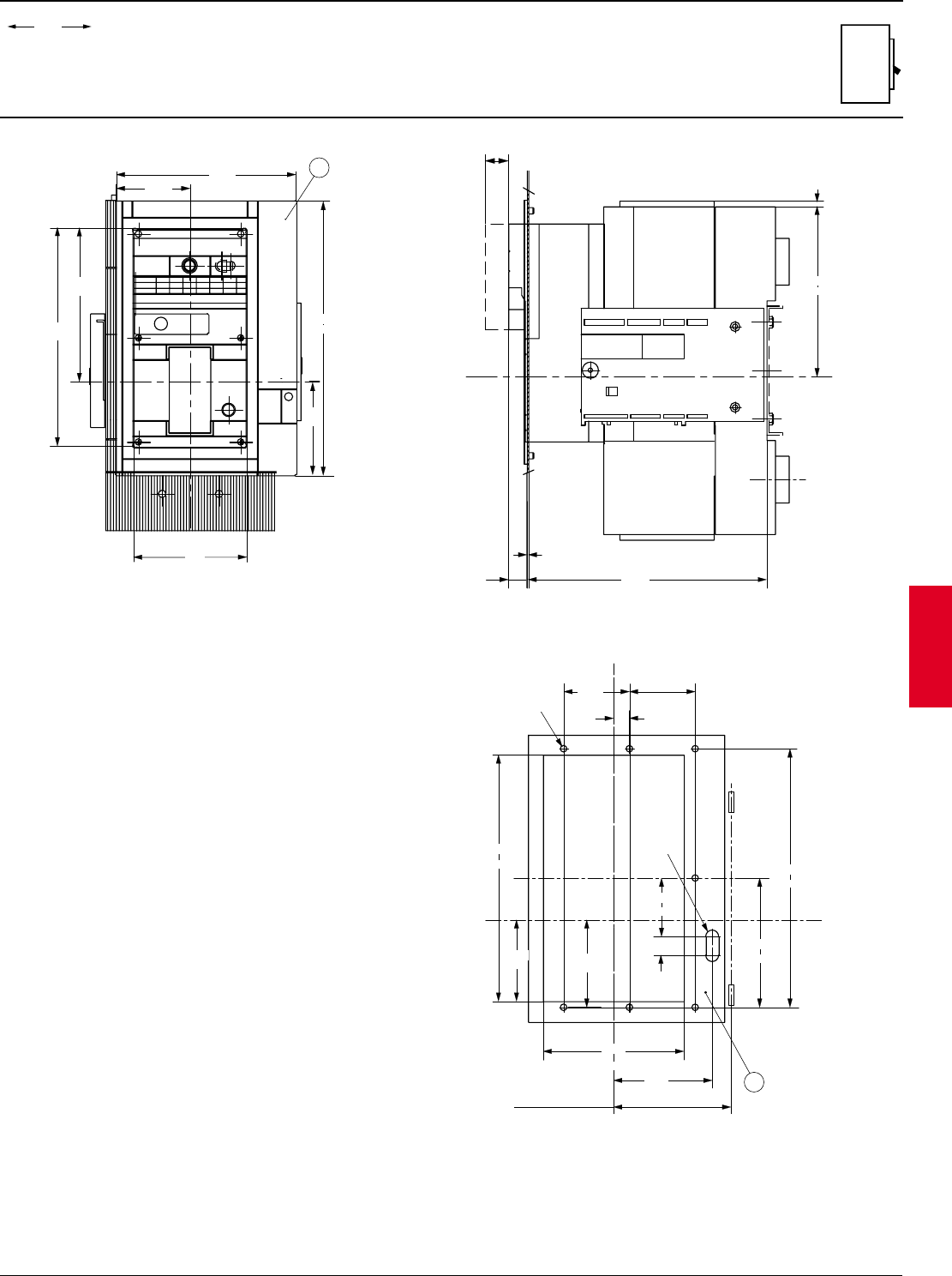
ABB Control Inc. 2.123
AC 1600 – 2/00
Isomax
00.00
00.00 Inches
Millimeters
Dim.
Approximate dimensions
S7 Motor operator w/ withdrawable
LEGEND
1-FLANGE FOR THE COMPARTMENT DOOR
2-DRILLING TEMPLATE
2
0.08
295.5
11.63
23.5
0.93
27.5
1.08
7
0.28
211.25
8.32
Y
Y1
222.5
8.76
91.5
3.60
5.51
140
7.48
190
4.49
114
10.63
338
13.30
270
2
Y
Y
X
X
R.min,=200
81.25
3.20
81.25
3.20
7 for Ø 8
0.31
19.75
0.77
12.56
319
6.28
159.5
2.84
72.25
R 8
0.90
22.75
3.82
97
11.97
304
4.11
104.5
6.85
174
4.80
122
XX

2.124 ABB Control Inc.
AC 1600 – 2/00
Isomax
00.00
00.00 Inches
Millimeters
Dim.
Notes
