Pu_17281_catalog_k 105612 Catalog
2014-07-30
: Pdf 105612-Catalog 105612-Catalog 785037 Batch6 unilog
Open the PDF directly: View PDF ![]() .
.
Page Count: 204 [warning: Documents this large are best viewed by clicking the View PDF Link!]

PAGE
RECENT ADDITIONS
PENN-SHRINK CLEAR - TYPE PSC.........................RECENT ADDITIONS 1
PENN-SHRINK BLACK THIN -
TYPE PSBT................................................................RECENT ADDITIONS 2
PENN-SHRINK HEAVY WALL WITH ADHESIVE -
TYPE PSHA................................................................RECENT ADDITIONS 3
PENN-SHRINK END CAPS -
TYPE PSEC................................................................RECENT ADDITIONS 4
COPPER PENN-CRIMPS®-
TYPE BLU ..................................................................RECENT ADDITIONS 5
COPPER PENN-CRIMPS®-
TYPE BLU CONTINUED............................................RECENT ADDITIONS 6
COPPER PENN-CRIMPS®-
TYPE BBLU................................................................RECENT ADDITIONS 7
COPPER PENN-CRIMPS®-
TYPE BBLU CONTINUED .........................................RECENT ADDITIONS 8
FLARED COPPER PENN-CRIMPS®-
TYPE BLU-FL.............................................................RECENT ADDITIONS 9
FLARED COPPER PENN-CRIMPS®-
TYPE BBLU-FL .......................................................RECENT ADDITIONS 10
COPPER PENN-CRIMPS®-
TYPE BCU & BBCU .................................................RECENT ADDITIONS 11
FLARED COPPER PENN-CRIMPS®-
TYPE BCU-FL & BBCU-FL ......................................RECENT ADDITIONS 12
COPPER PENN-CRIMPS®- TELECOMMUNICATIONS LUGS -
TYPE BLU-2TC ........................................................RECENT ADDITIONS 13
COPPER PENN-CRIMPS®- TELECOMMUNICATIONS LUGS -
TYPE BLU-2TC CONTINUED..................................RECENT ADDITIONS 14
COPPER PENN-CRIMPS®- TELECOMMUNICATIONS LUGS -
TYPE BBLU-2TC......................................................RECENT ADDITIONS 15
COPPER PENN-CRIMPS®- TELECOMMUNICATIONS LUGS -
TYPE BBLU-2TC CONTINUED ...............................RECENT ADDITIONS 16
COPPER PENN-CRIMPS®- TELECOMMUNICATIONS LUGS -
TYPE BBLZ-2TC ......................................................RECENT ADDITIONS 17
COPPER PENN-CRIMPS®- TELECOMMUNICATIONS LUGS -
TYPE BBLZ-2TC CONTINUED................................RECENT ADDITIONS 18
OXIDE INHIBITOR COMPOUNDS - CUAL-AID®#11C, #12C
AND CUAL-GEL®......................................................RECENT ADDITIONS 19
OXIDE INHIBITOR COMPOUNDS - CUAL-AID®#11C, #12C
AND CUAL-GEL®CONTINUED ...............................RECENT ADDITIONS 20
COPPER ALLOY SPLIT BOLT CONNECTORS -
TYPE S & SEL .........................................................RECENT ADDITIONS 21
COPPER ALLOY SPLIT BOLT CONNECTORS -
TYPE S-DB & SEL-DB .............................................RECENT ADDITIONS 22
ALUMINUM CLEAR PRE-INSULATED POWER BAR -
TYPE IPB..................................................................RECENT ADDITIONS 23
ALUMINUM CLEAR PRE-INSULATED POWER BAR -
TYPE IPB CONTINUED ...........................................RECENT ADDITIONS 24
ALUMINUM CLEAR PRE-INSULATED POWER BAR -
TYPE IPBM...............................................................RECENT ADDITIONS 25
PRE-INSULATED MECHANICAL CONNECTORS
FOR COPPER CABLES -
TYPE IMLCTM ............................................................RECENT ADDITIONS 26
TAPKIT FOR ROMEX®STYLE CABLE...................RECENT ADDITIONS 27
DISTRIBUTION COMPRESSION CONNECTORS.............................................3
Aluminum Press-Ons (Types KO-R, KD-R, KR-R, KN-R & KN)
Copper Press-Ons (Types CCT, CST & CDT)
Aluminum Penn-Sleeves (Types PIK, PSK, PS, PSS, PSKS & PNK)
Aluminum Terminal Plugs (Types TP & TPO)
Aluminum Press-On Stirrups (Types KBO, KKBO, KBD, KKBD, KBN & KKBN)
SPLIT BOLT & SERVICE ENTRANCE CONNECTORS...................................15
Copper Alloy Split Bolts (Types S, SEL, SW)
Aluminum Split Bolts (Type SWA)
Service Entrance Connectors (Types SAX, SX)
Vise Grips (Type FF & MGC)
PARALLEL CONNECTORS ..............................................................................19
Aluminum Parallel Clamps (Types AVT, GPT, PCAA, GTC, AVT-LS)
Insulation Piercing Connector (Type IPC)
Bronze Parallel Clamps (Types VT, VTA, UCR, VX, JC & UPC)
COMPRESSION TERMINAL LUGS & TOOLS .................................................27
Copper Penn-Crimps® (Types BLU, BBLU, BCU, BBCU, BLY, BCU-P, BCU-PT,
BCU-T, HBBLU)
Aluminum Penn-Crimps® (Types BLUA, FKLA, FSLA, FULA, BCUA)
Ultra Crimp® Compression System
Tools (Types TDY, TPU & TDM)
SMALL TERMINAL SECTION ...........................................................................53
Copper Penn-Crimps (Types R1, R2, R4, R6, S, SF, BS, BSF, LS, H, FLR,
FLS, B, P, NPAB, NPBC,
FLFR, MT, SC, LC, FDC, FSC, CFR, CM, 9, X, Y, S6, FR6, MT6, B8, S1, TY,
MTY)
Penn Crimps Terminal Kits (Types MK, PK)
Penn-Nuts Wire Connectors (Type PN)
Penn-Loks Insulation Displacement Connectors (Type PL)
Penn Crimps Crimping Tools (Type HTS, HTC)
TERMINAL LUGS & SOLDER LUGS ...............................................................77
Aluminum Solderless Lugs (Types, LA, L2A, L3A, LA4, LLA2, LA4DA,
LA4MA, LI)
Aluminum Stacked Neutral Bars (Type SNB)
Copper Neutral Bars (Type N70)
Aluminum Splicer-Reducer (Type SR)
Aluminum Panelboard Lugs (Type PB)
Aluminum Terminal Lugs (Types RAA, RAAC)
Bronze Penn-Lugs (Types PNL, P2NL, PPNL & PP2NL)
Vi-Tite Terminal Lugs (Types VL, VVL, VL2, VVL2, VL3, VVL3, VL4, VVL4)
Copper Solderless Lugs (Types SLU, SAU, LU)
Copper Soldering Lugs (Types SL)
Bronze Terminal Lugs (Types RA, RAR, RAR2, RARE)
Bronze Eyebolt Terminals & Misc. (Types LS, LSN, LD, LDN, CTB, FT)
GROUND CONNECTORS ................................................................................98
Bronze Ground Rod Clamps (Types CAB & CEB)
Copper Ground Grid Connector (Type GGCP)
Bronze Ground Clamps (Types KP, KW, KH, KL, KLS, KCH)
Aluminum Ground Clamp (Type GC)
Copper Ground Flexible Braid (Type GFXB)
Transformer Ground Clamps (Types GSE & HGSE)
Bronze Ground Clamps (Types GBC, GPL, GU, GR, GO GT, GH, GHS, GJ,
GJS, GM, GMS, GWL)
Tanker Static Ground Clamp (TSGC)
BRONZE STUD CONNECTORS (Types SLB, SSLB, TS, CSR, CSR-2) .......111
BRONZE TEE CONNECTORS (Types ABR, ABRE, ABRR, ABRRE,
RM & ABN)..................................................................................................116
BRONZE BUS SUPPORTS & CLAMPS (Types BS, BSR & BSR2B) ............120
FLEXIBLE COPPER BRAID (Type FXB) ........................................................122
BRONZE COUPLERS & REDUCERS (Types BA, BDR, VC, VVC, & PNLC)123
MISCELLANEOUS ITEMS ..............................................................................125
Bronze Service Post Connectors (Types SSS, STS, SCS, SDS)
Copper Compression Terminals (Types TLU)
Terminal Blocks (Series 6000, 15-1600, 3000)
Flexible Braid Kit (Types FBK)
Transformer Lug Kits (Type LASK)
Amalgamating Tape (Type AT)
Underground Connectors (Types DBA, DBTBF, UTS, ULS, SSI)
Insulated Power Bar and Splice (Types IPB, IISR)
Aluminum Multiple Tap Connector (Type NA, SLK, NACC)
Bronze Underground Transformer Terminals (Type UTS)
Cual Aid® Contact Compound
Wedge Dead-End Clamps (Type WDC)
Locomotive Lugs (Types LLCS, LLR, LL, LLN)
Power Distribution Blocks (Type ADB)
Merchandising Displays
DISCONTINUED SPECIAL ORDER PRODUCTS..........................................143
TECHNICAL REFERENCE .............................................................................153
Comparative Listings (Crimps, Compression, Bolts, Connectors, Lugs &
Splices, Tools, Dies, Eyebolts, Posts, Power Bar)
General Information (Materials, Crimping Methods, Tightening Torque, Pipe
Properties, NEMA Standards, Suffix Legend)
AWG vs. Metric Wire Size Chart
Special Order Form
Metric Conversion Chart
Note: Dimensions correct at time of printing. Contact factory for any critical
dimension.
1
GENERAL INDEX

CAT.
TYPE PAGE
A............................................143
AB .........................................143
AB15 .....................................143
ABN .......................................119
ABR .......................................116
ABR2T...................................143
ABRE.....................................116
ABRR ....................................117
ABRRE ..................................117
ADB................................131-132
AHC.......................................143
AT ..........................................130
AVB .......................................143
AVC .......................................143
AVS .......................................143
AVT .........................................19
AVT-LS ....................................19
B..............................................64
BA .........................................123
BAC.......................................143
BBCU ......................................35
Recent Additions ...................11
BBCU-FL.................................34
Recent Additions...................12
BBLU..................................30-31
Recent Additions.....7, 8, 15, 16
BBLU-2TC
Recent Additions.........8, 15, 16
BBLU-FL .................................32
Recent Additions...................10
BBLZ-2TC
Recent Additions............17, 18
BCU.........................................35
Recent Additions ...................11
BCU-FL ...................................34
Recent Additions...................12
BCU-P .....................................36
BCU-PT...................................36
BCU-T .....................................36
BCUA ......................................41
BD .........................................143
BDR.......................................123
BLU ....................................28-29
Recent Additions.....5, 6, 13, 14
BLU-2TC
Recent Additions.....5, 6, 13, 14
BLU-FL....................................33
Recent Additions.....................9
BLUA..................................39-40
BLY..........................................27
BS CLAMP............................120
BS CRIMP...............................59
BSC.......................................143
BSE .......................................143
BSF .........................................60
BSH.......................................143
BSR.......................................121
BSR2B ..................................121
BSS .......................................143
BST .......................................143
BSV .......................................143
CAB.........................................98
CBSS ....................................145
CCT...........................................6
CDT...........................................6
CEB.........................................98
CFR.........................................68
CM...........................................68
CNF.......................................147
CNP.......................................147
CPW......................................147
CSR.......................................114
CSR-2....................................115
CST ...........................................6
CTB .........................................97
CTL .......................................145
Cual Aid.................................138
Recent Additions.............19, 20
CUAL GEL
Recent Additions.............19, 20
DBA.......................................133
DBTBF ..................................133
DTC.......................................145
DTU.......................................145
EXB .......................................145
EXBW....................................145
EXP .......................................145
EXPW....................................145
CAT.
TYPE PAGE
EXS .......................................146
EXSW....................................146
EXS90 ...................................146
EXSW90................................146
EXT .......................................146
EXTW....................................146
FBK .......................................128
FDC.........................................68
FF............................................18
FKLA ..................................42-43
FLFR .......................................66
FLR .........................................63
FLS..........................................63
FR ...........................................66
FSC .........................................68
FSLA ..................................42-43
FT............................................98
FULA..................................42-43
FW.........................................147
FXB .......................................122
GBCH....................................107
GBC ......................................107
GC.........................................101
GFXB ....................................102
GGCP......................................99
GH .........................................110
GHS.......................................110
GI ..........................................146
GIC........................................146
GJ..........................................110
GJS .......................................110
GM ........................................109
GMS ......................................109
GO.........................................107
GPL................................103-104
GPT.........................................20
GR.........................................106
GSE.......................................102
GT .........................................108
GTC.........................................20
GU.........................................105
GWL ......................................109
GXA.......................................147
H CLAMP ..............................147
H CRIMP.................................62
HBBLU ....................................37
HCB.......................................147
HGSE ....................................102
HHB.......................................147
HHC ......................................147
HLC-040................................147
HN .........................................147
HP .........................................148
HTC.........................................76
HTS .........................................76
HVC.......................................148
HVS.......................................148
IDC ..........................................76
IISR .......................................136
IMLC
Recent Additions...................26
IPB ........................................136
Recent Additions.............23, 24
IPBM
Recent Additions...................25
IPC ..........................................22
JC............................................26
KBD.........................................14
KBN.........................................14
KBO.........................................14
KCH.......................................101
KD-R .........................................3
KH .........................................100
KKBD ......................................14
KKBN ......................................14
KKBO ......................................14
KL..........................................100
KLS .......................................101
KN .............................................4
KN-R .........................................4
KO-R .........................................3
KP .........................................100
KR-R .........................................5
KW ........................................100
LA......................................77, 79
CAT.
TYPE PAGE
LASK .....................................128
LA4D4 .....................................79
LA4M4.....................................79
LC............................................67
LD............................................97
LDN .........................................97
LI .............................................77
LL ...................................140-141
LLCS .....................................139
LLN........................................141
LLR........................................139
LLA2........................................78
LS......................................61, 96
LSN .........................................96
LU............................................92
L2A....................................78, 79
L3A..........................................79
MF .........................................148
MFF.......................................148
MGC........................................18
MK ..........................................75
ML-1 ......................................148
ML-2 ......................................148
ML90 .....................................148
MML ......................................149
MML2 ....................................149
MML90 ..................................149
MMTT....................................149
MT CLAMP............................149
MT CRIMP ..............................67
MTT.......................................149
MTY.........................................74
NA .........................................134
NACC ....................................130
NMTK
Recent Additions...................27
NPAB.......................................65
NPBC ......................................65
N70..........................................80
P..............................................65
PB ...........................................81
PCAA ......................................21
PIK .........................................8-9
PK ...........................................75
PL ...........................................76
PN ...........................................75
PNK .........................................11
PNL .........................................84
P2NL .......................................85
PNLC.....................................124
PPNL.......................................85
PP2NL.....................................85
PS............................................11
PSBT
Recent Additions.....................2
PSC
Recent Additions.....................1
PSHA
Recent Additions.....................3
PSEC
Recent Additions.....................4
PSK .........................................10
PSKS.......................................13
PSS .........................................13
RA ...........................................94
RAA....................................82-83
RAAC .................................82-83
RAR.........................................95
RARE ......................................95
RAR2.......................................95
RC .........................................149
RCS.......................................149
RM.........................................118
R1 .....................................53, 73
R2............................................54
R4............................................55
R6............................................56
R-16 ........................................80
S SPLIT BOLT ........................15
Recent Additions...................21
S-DB
Recent Additions...................22
S PENN CRIMP ......................57
SAU.........................................92
SAX .........................................17
SC ...........................................67
SCS.......................................125
CAT.
TYPE PAGE
SCT .......................................150
SDS.......................................125
SEL .........................................15
Recent Additions...................21
SEL-DB
Recent Additions...................22
SF............................................58
SL............................................93
SLB .................................111-112
SLB-90 ..................................150
SLBH.....................................150
SLK .......................................134
SLU .........................................92
SNB.........................................80
SR ...........................................81
SSI ........................................135
SSLB...............................111-112
SSS .......................................125
STS .......................................125
SW ..........................................16
SWA ........................................17
SX ...........................................17
S10..........................................73
S60..........................................73
TC .........................................150
TDM-250 .................................51
TDM-500 .................................51
TDY-1 ......................................46
TDY-U .....................................47
TDY-1R ...................................48
TDY-UR...................................48
TLU .......................................126
TP............................................12
TPO.........................................12
TPU-12B .................................49
TPU-12BH...............................50
TPU-15 BH..............................50
TS..........................................113
TSGC ....................................104
TVB .......................................150
TY............................................74
TYPE 6....................................71
TYPE 9....................................69
UCR ........................................24
Ultra Crimp®.......................44-45
ULS .......................................135
UPC.........................................26
UTS .......................................137
VB30 .....................................150
VC .........................................124
VI-TITE SQUARE ..........150-151
VI-TITE ROUND ...................151
VI-TITE SIDE ........................151
VL.......................................86-87
VL2..........................................88
VL3..........................................89
VL4..........................................91
VSF .......................................151
VSM ......................................151
VT............................................23
VTA .........................................23
VVC.......................................124
VVL .........................................88
VVL2 .......................................89
VVL3 .......................................90
VVL4 .......................................91
VX ...........................................25
WDC......................................138
X..............................................70
Y..............................................70
ZE..........................................152
ZN .........................................152
ZW.........................................152
3000 ......................................129
6000 ......................................127
15-1600 .................................127
Technical Reference .............153
2
GENERAL INDEX
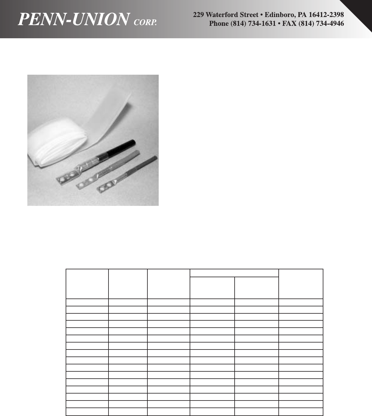
RECENT ADDITIONS 1
Applications
Designed to provide superior mechanical (abrasion, cut-through, and strain
relief), thermal, and fluid-resistance performance in demanding environ-
ments. Widely used to provide insulation and strain relief of wire termina-
tions and connections. Used for jacketing wire bundles and light-duty har-
nesses where superior abrasion resistance is a plus.
Operating Temperature Range
-55OC to 135OC
Features/Benefits
•2:1 shrink ratio.
•Superior abrasion and solvent resistance when compared with that of
many flexible, general purpose polyolefin tubings.
•Excellent physical, chemical, and electrical properties that meet or exceed
industrial and military standards for highly reliable, general purpose tub-
ing.
•Flexible; conforms to irregular shapes.
Installation
Minimum shrink temperature: 95OC
Minimum full recovery temperature: 121OC
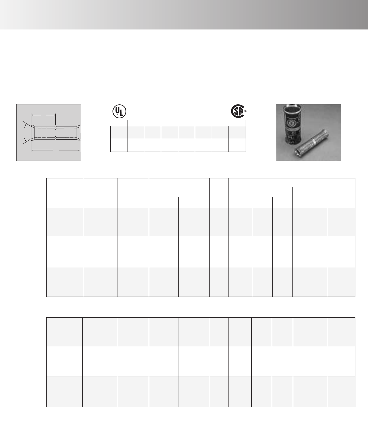
Production Dimensions (Inches)
Inside diameter
Minimum Maximum Wall thickness
Length expanded recovered Recovered
Part Number Size (Inches) as supplied after heating after heating**
PSC18-6 1/8 6 .125 .062 .020
PSC18-48 1/8 48 .125 .062 .020
PSC14-6 1/4 6 .250 .125 .025
PSC14-48 1/4 48 .250 .125 .025
PSC38-6 3/8 6 .375 .187 .025
PSC38-48 3/8 48 .375 .187 .025
PSC12-6 1/2 6 .500 .250 .025
PSC12-48 1/2 48 .500 .250 .025
PSC34-6 3/4 6 .750 .375 .030
PSC34-48 3/4 48 .750 .375 .030
PSC100-6 1 6 1.00 .500 .035
PSC100-48 1 48 1.00 .500 .035
PSC112-6 1-1/2 6 1.500 .750 .040
PSC112-48 1-1/2 48 1.500 .750 .040
PSC200-6 2 6 2.000 1.00 .045
PSC200-48 2 48 2.000 1.00 .045
**Wall thickness will be less if tubing recovery is restricted during shrinkage.
PENN-SHRINK CLEAR - TYPE PSC
Flexible, general purpose polyolefin tubing
Specifications/Approvals
Series Military
PSC SAE-AMS-DTL-23053/5, Class 2
VG 95343 Pt 5 Type 8
*Formerly MIL-I-23053/5.
Ordering Information
Size selection: Always order the largest size that will shrink snugly over the component to be covered.
Users should independently evaluate the suitability of the product for their application.
2 RECENT ADDITIONS
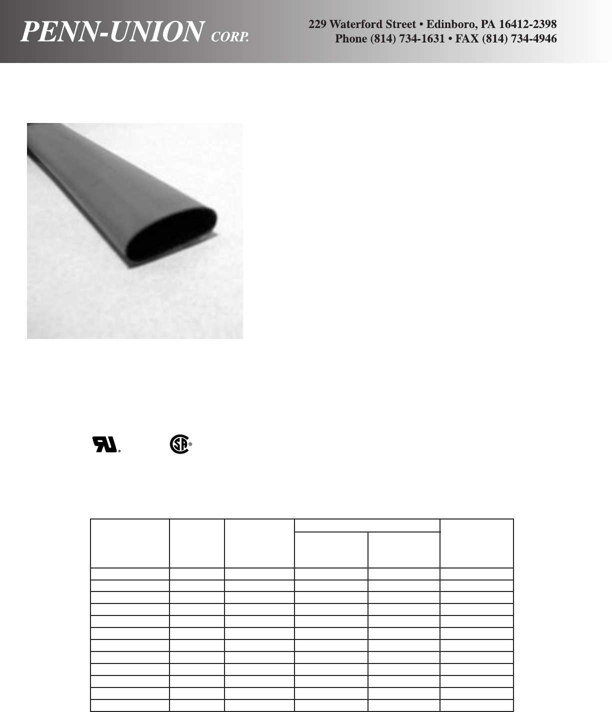
Specifications/Approvals
Series UL 224 VW-1 CSA VW-1 Military
PSBT (OFT) SAE-AMS-DTL-23053/5
600 V, 125OC600 V, 125OC*Formerly MIL-I-23053/5.
Production Dimensions Inches
Inside diameter
Minimum Maximum Wall thickness
Length expanded recovered Recovered
Part Number Size (Inches) as supplied after heating after heating**
PSBT14FR-6 1/4 6 .250 .125 .025
PSBT14FR-48 1/4 48 .250 .125 .025
PSBT12FR-6 1/2 6 .500 .250 .025
PSBT12FR-48 1/2 48 .500 .250 .025
PSBT34FR-6 3/4 6 .750 .375 .030
PSBT34FR-48 3/4 48 .750 .375 .030
PSBT100FR-6 1 6 1.000 .500 .035
PSBT100FR-48 1 48 1.000 .500 .035
PSBT112FR-6 1-1/2 6 1.500 .750 .040
PSBT112FR-48 1-1/2 48 1.500 .750 .040
PSBT200FR-6 2 6 2.000 1.00 .045
PSBT200FR-48 2 48 2.000 1.00 .045
**Wall thickness will be less if tubing recovery is restricted during shrinkage.
Applications
Cost-effective choice for many commercial and military applications.
Electrically insulates and protects in-line components, disconnect termi-
nals, and splices. Bundles wires for very flexible light-duty harnesses.
Strain-relieves electrical wire connections for commercial applications.
Operating Temperature Range
-55OC to 135OC
Features/Benefits
•2:1 shrink ratio.
•Low shrink temperature reduces installation time and the risk of dam-
age to temperature-sensitive components.
•Very flexible; doesn’t easily wrinkle when bent.
•Highly flame-retardant.
•Hot stamps extremely well.
•Higher temperature rating, better thermal stability, and higher resistance
to physical abuse than noncrosslinked materials.
•Free of polybrominated biphenyis (PBBs) and polybrominated biphenyl
oxides and ethers (PBBOs and PBBEs), which are classified as envi-
ronmentally hazardous substances.
•Improved heat aging properties to meet the new requirements of UL
224 VW-1 TESTING.
•Improved fluid resistance to offer higher performance in fuels and oil
exposure.
•Improved column strength to allow easier installation over components.
•Enhanced flame retardance to meet the requirements of UL 224 VW-1
testing in the newly revised UL test chamber.
•UL224 VW-1/CSA OFT Tubing Specifications and Flammability Testing.
Installation
Minimum shrink temperature: 70OC
Minimum full recovery temperature: 90OC
PENN-SHRINK BLACK THIN WALL - TYPE PSBT
Highly flame-retardant, very flexible, low-shrink-temperature polyolefin tubing
Ordering Information
Size selection: Always order the largest size that will shrink snugly over the component to be covered.
Users should independently evaluate the suitability of the product for their application.
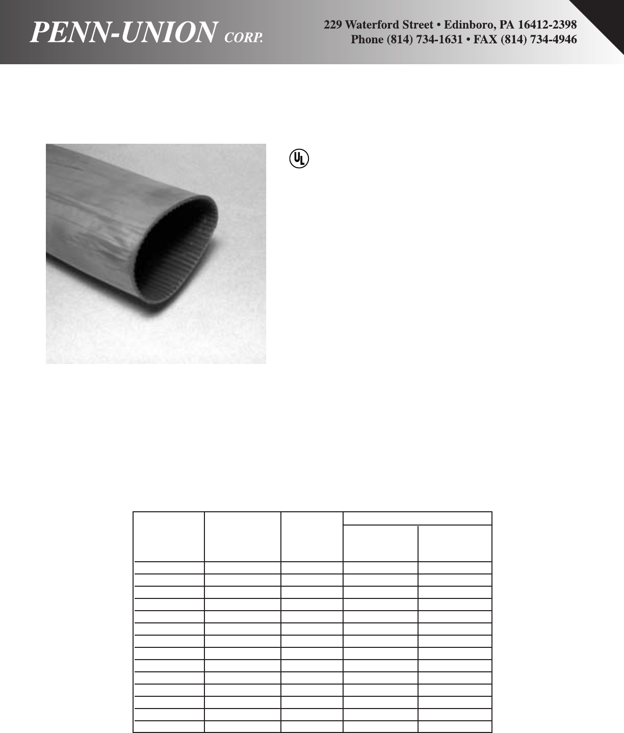
Production Dimensions Inches
Inside diameter
Minimum Maximum
Length expanded recovered
Part Number Size (Inches) as supplied after heating
PSHA51FR-6 #8-#14 6 .51 .15
PSHA51FR-30 #8-#14 48 .51 .15
PSHA78FR-6 #2-#6 6 .78 .23
PSHA78FR-12 #2-#6 12 .78 .23
PSHA78FR-48 #2-#6 48 .78 .23
PSHA130FR-9 1 AWG-3/0 MCM 9 1.30 .31
PSHA130FR-12 1 AWG-3/O MCM 12 1.30 .31
PSHA130FR-48 1 AWG-3/0 MCM 48 1.30 .31
PSHA169FR-9 2/0-350 MCM 9 1.69 .47
PSHA169FR-12 2/0-350 MCM 12 1.69 .47
PSHA169FR-48 2/0-350 MCM 48 1.69 .47
PSHA200FR-9 250-500 MCM 9 2.00 .62
PSHA200FR-12 250-500 MCM 12 2.00 .62
PSHA200FR-48 250-500 MCM 48 2.00 .62
RECENT ADDITIONS 3
Specifications/Approvals
UL 486D
DIRECT BURIAL
1000 V, 75OC
Applications
For insulating and sealing low-voltage power cables and accessories.
The electrical and physical properties of a cable oversheath material are
combined with ruggedness and easy installation. The heavy-wall tubing
is supplied with an interior meltable adhesive wall to seal onto the sub-
strate. The adhesive exhibits excellent bonding and sealing characteris-
tics to all materials commonly used in the various cable insulation and
sheath constructions such as plastic, rubber, lead and aluminum.
Features/Benefits
PSHA is a heat-shrinkable heavy-wall tubing for insulating and sealing
power cables and accessories. In PSHA tubing, the electrical and physi-
cal properties of a cable oversheath material are combined with rugged-
ness and easy installation.
On heating, PSHA tubing recovers to a smaller diameter, fitting tightly
over a wide range of cable sizes and accessories because of its high
shrink ratio. At the same time the tubing’s inner adhesive wall gives a
dependable moisture seal over most irregular shapes.
PSHA tubing’s mechanical strength enables immediate back-filling of
cable trenches after jointing. Widely used to insulate, protect and seal
power cable joints, accessories and electrical connections.
PSHA can be installed over variously-shaped objects to make a tight,
insulating or fluid-resistant cover. May be used for jacket repair on cables
to 35kV.
•3:1 shrink ratio.
•Chemical and corrosion resistance.
•Very high resistance to impact and abrasion.
®
Ordering Information
Size selection: Always order the largest size that will shrink snugly over the component to be covered.
Users should independently evaluate the suitability of the product for their application.
PENN-SHRINK HEAVY WALL WITH ADHESIVE - TYPE PSHA
Polyolefin heavy-wall heat shrinkable tubing - chemical and corrosion resistant, very high
impact and abrasion resistance, rated for 600V applications

Applications
PSEC heat-shrinkable end caps are made from a thermally stabilized, modi-
fied polyolefin, which makes them highly resistant to moisture, fungus, and
weathering. The end caps also have excellent electrical properties. End
caps are coated with sealant for underwater or underground applications
with a pressure differential up to 20 psi between the inside of the cable and
the outside environment. End caps may be used over lead, steel, alu-
minum, copper, polyethylene, polyolefin, EPR, and PVC jacketing materials.
Operating Temperature Range
-40OC to 85OC
Features/Benefits
•Self-sealing for waterproofing.
•Electrical insulation to 1000 V.
•Abrasion-resistant
•Mechanical protection.
•Easy installation, requiring no special skills.
•Operating temperature range of –40OC to 85OC.
•Minimum shrink temperature of 121OC.
•One piece molded construction.
Installation
Minimum shrink temperature: 121OC
PENN-SHRINK END CAPS - TYPE PSEC
Heat-shrinkable end caps
Specifications
Military
MIL-I-81765/1/A
Specifications
Type Military
PSEC PPS-3011/6
Production Dimensions (Inches)
Wall thickness
Inner Diameter* Part Length (nom.) Wire
Part Number As Supplied (min.) Recovered (max.) Recovered ± Recovered ± Range
PSEC-1 .33 .16 1.32 .08 #6 - #8
PSEC-2 .73 .30 2.18 .09 #4 - 3/0
PSEC-3 1.32 .59 3.54 .12 4/0 - 600
PSEC-4 2.11 .98 5.64 .13 600 - 1750
PSEC-5 2.81 1.25 5.91 .13 1250 - 2000
PSEC-6 3.88 1.77 6.40 .16 2000
*Adhesive lined is standard
Users should independently evaluate the suitability of the product for their application.
4 RECENT ADDITIONS
RECENT ADDITIONS 5
Approximate
Dimensions (in inches)
Crimping Tool Reference+++
Wire Alt. ToolingPenn-Union
Copper Dia. BurndyTDY-1
Catalog Cond.
Die
Color
Code
(in) Stud Fig. Index T&BPUC Pressure
Number Range† ‡ Size No No. DieDies Setting
BLU-8S14 #10 5/32
1/2–13/32
BLU-8D2TC10 #10 25/3211/8
5/813/32
BLU-8S15 8 Str. Red.146 1/47/32
9/16–13/32 B-6 21T-6*
T-7*
/
T-374*
T-7*
/
T-374*
T-8*
/
T-346*
T-9*
T-11/375
T-12/348
BLU-8S16 5/16 5/16
21/32–9/16
BLU-8S17 3/811/32
11/16–9/16
BLU-8S18 1/233/64
55/64–13/16
BLU-6S #10 9/16
17/32–13/32
BLU-6S1 1/423/32
11/16–7/16
BLU-6D2TC14 6 Str. Blue.184 1/47/3213/16
5/87/16 B-7 24
24
BLU-6S2 5/16 25/32
3/4–1/2
BLU-6S8 3/827/32
13/16–19/32
BLU-5S #10 39/64
9/16–7/16
BLU-5S1 1/447/64
11/16–7/16
BLU-5D2TC14 5 Str. Blue.206 1/419/6413/16
5/87/16 B-7
BLU-5S2 5/16 49/64
23/32–9/16
BLU-5S3 3/859/64
7/8–19/32
BLU-4S #10 39/64
9/16–1/2
BLU-4S1 1/447/64
11/16–1/2
BLU-4D2TC14 4 Str. Gray.232 1/419/6413/16
5/81/2B-8 29
BLU-4S10 5/16 49/64
23/32–19/32
BLU-4S2 3/849/64
7/8–19/32
BLU-3S #10 43/64
9/16–17/32
BLU-3S1 1/451/64
11/16–17/32
BLU-3D2TC14** 3 Str. White.260 1/419/6413/16
5/817/32 B-9 –
BLU-3S2 5/16 55/64
3/4–9/16
BLU-3S3 3/863/64
7/8–19/32
BLU-2S15 #10 47/64
21/32–19/32
BLU-2S 1/451/64
11/16–19/32
BLU-2D2TC14 1/421/6417/32
5/819/32
BLU-2S1 5/16 55/64
3/4
–19/32
BLU-2S2 3/863/64
7/8–5/8
BLU-2S10 1/215/6411/8–13/16
BLU-1S9 1/427/64
9/16–43/64
BLU-1D2TC14 1/423/6413/16
5/843/64
BLU-1S 1 Str. Green.332 5/16 55/64
3/4–43/64 B-11 37
BLU-1D2TC516E6 5/16 51/6415/8
7/843/64
BLU-1S1 3/83/64
7/8–43/64
BLU-1S4 1/219/6411/8–3/4
BLU-1/0S19 1/415/16
3/4–3/4
BLU-1/0S 5/16 1/16
3/4–3/4
BLU-1/0D2TC516E6 5/16 13/1615/8
7/83/4
BLU-1/0S1 1/0 Str. Pink.375 3/81/16
7/8–3/4B-12 42
BLU-1/0D2TC38 3/8113/1613/4
BLU-1/0S20 1/21/411/16–13/16
BLU-1/0D2 1/2
1
1
1
1
1
1
1
1
2
1
1
1
1
2
1
1
1
1
2
1
1
1
1
2
1
1
1
1
2
1
1
2
1
2
1
2
2
2
1
2
2
2
3
2
4
1
2
1
1
1
1
1
1
2
1
1
1
1
2
1
1
1
1
2
1
1
1
1
2
1
1
1
1
2
T-10
BLU-2D2
2 Str. Brown.292
1/263/6427/813/413/16
B-10 332
32
1
1
1
1
2
1
2
1
1
1
1
2
1
2
1
21/1627/813/413/16
LDEW
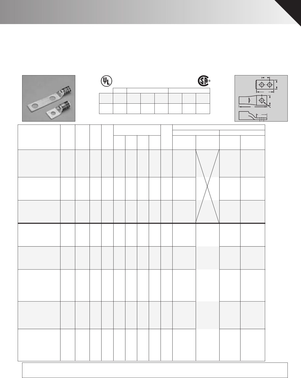
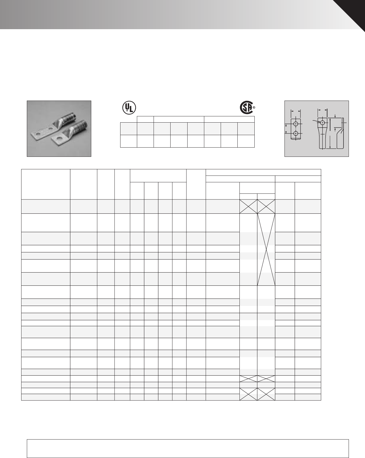
COPPER PENN-CRIMPS®• TYPE BLU
Crimp lugs with inspection window for #8 stranded AWG thru 2000 MCM
E
D
FIG. 2
FIG. 1
D
W
W
LFor Stud Size
♦Seamless, one piece, pure copper construction with tin plating
assures maximum conductivity. Generous entrance chamfer
provides easy cable insertion. Inspection window insures full
insertion.
♦Catalog number and conductor size marked on every piece
insures positive identification.
♦Can be installed with existing crimping tools. Color coding
conforms to industry requirements to insure proper connec-
tor/die selection and to provide for faster installation.
♦BLU LUGS ARE SUITABLE FOR USE AT VOLTAGES UP TO
35KV.
♦45° and 90° Variations are UL Listed and CSA certified.
Contact factory for price and availability.
♦NEW FEATURE – UL/CSA approved with Versa-Crimp®tool-
ing and wire ranges. Versa-Crimp®is a registered trademark of
Hubbell Incorporated.
♦Additional wire size recommendations, see Master Catalog.
POWER UL 467 GROUNDING
POWER: UL 486A, CSA C22.2 NO. 65
COLOR-CODED
COPPER COMPRESSION CONNECTORS
GROUNDING & BONDING & DIRECT BURIAL : UL 467, CSA C22.2 NO. 41
CSA C22.2 NO. 41 GROUNDING
Connector
Family
UL486A/
CSA22.2 No. 65
Wire Range
UL Grounding
Max. Wire
Grounding
& Bonding
Direct
Burial
CSA Grounding
Max. Wire
Grounding
& Bonding
Direct
Burial
BLU, BBLU,
BBLZ, BCU,
BBCU
8 Str.-
2000 MCM 500 MCM YES YES 250 MCM YES YES
CU
90º C
NEW FEATURE!
NOW LISTED FOR GROUNDING, BONDING & DIRECT BURIAL APPLICATIONS
+ Concentric, compressed and compact stranding. * Consult factory for availability of dies not available at this time.
++ For conversion to metric range see Master Catalog **(Also #2 Sol)
+++ For additional tool references see Master Catalog *** CUAD-1000

Approximate
Dimensions (in inches)
Crimping Tool Reference+++
Wire Alt. ToolingPenn-Union
Copper Dia. Burndy
Pressure
Catalog Cond.
Die
Color
Code
(in) Stud Fig. Index T&BPUC Setting
Number Range† ‡ Size No LDEW No. DieDies TDY-1 TDY-U
BLU-2/0S20 1/41/16
13/16–
BLU-2/0S21 5/16 1/16
13/16–
BLU-2/0D2TC516E6 5/16 7/815/8
7/8
BLU-2/0S 2/0 Str. Black .419 3/81/8
7/8–13/16 B-13 45T-13 2
BLU-2/0D2TC38 3/81/16113/161
BLU-2/0S4 1/23/811/8–
BLU-2/0D 1/21/827/813/4
BLU-3/0S14 1/415/16
13/16–
BLU-3/0S15 5/16 15/16
13/16–
BLU-3/0D11 5/16 1
1
2
1
5/8
7/8
BLU-3/0S 3/0 Str. Orange
Orange
.470 3/81/4
7/8–29/32 B-14 50T-14
BLU-3/0D2TC38 3/83/16
13/161
BLU-3/0S1 1/21/2
1/8–
BLU-3/0D 1/21/4
7/813/4
BLU-4/0S19 1/47/32
25/32–
BLU-4/0S25 5/16 7/32
25/32–
BLU-4/0S 4/0 Str. Purple .528 3/85/16
7/8–1 B-15 54T-15 5 5
BLU-4/0D2TC38 3/81/4113/161
BLU-4/0S1 1/29/1611/8–
BLU-4/0D 1/25/1627/813/4
BLU-025S4 1/411/32
25/32–
BLU-025S5 5/16 11/32
25/32–
BLU-025S2 250 Yellow .575 3/89/16113/32 B-16 62T-16
BLU-025D2TC38 MCM 3/83/8113/161
BLU-025S 1/211/1611/8–
BLU-025D 1/27/1627/813/4
BLU-030S6 5/16 13/32
25/32–
–
–
BLU-030S7 3/85/8166H or
BLU-030D2TC38 300 White .634 3/87/16113/1611
3/16 B-17 66T-17*
BLU-030S MCM 1/23/411/8–
BLU-030D 1/21/227/813/4
BLU-030S8 5/85/16111/16–
BLU-035S1 3/85/8
7/8–
BLU-035D2TC38 3/89/16113/16171H
BLU-035S 350 Red .682 1/229/3215/32–1
9/32
32
32
32
32
32
32
64
B-18 orT-18/324 7 7
BLU-035D MCM 1/25/827/813/471
BLU-035S3 5/85/32113/32–
BLU-040D2TC38 3/811/16113/161
BLU-040S4 400 Blue .728 1/21/1613/16–1
13/B-19
B-19
76HT-19*
BLU-040D MCM 1/23/427/813/4or/
T-19*
/
T-470*
BLU-040S 5/85/1617/16–76T-470*
BLU-045S1 1/21/1613/16–76H
BLU-045D 450 Blue .772 1/23/6427/813/4129/or
BLU-045S MCM 5/85/1617/16–76
BLU-050D2TC38 3/815/16113/161
BLU-050S2 500 Brown
Brown
.815 1/21/3211/8–1
17/B-20 87T-20/299
BLU-050D MCM 1/227/813/4
BLU-050S 5/89/1617/16–
BLU-060D 600 Green
Green
.893 1/23/3227/813/4123/B-22 94H
T-22/472
T-24*/473
BLU-060S MCM 5/831/3213/4–or 9499
BLU-060S1 1/231/3213/4–
BLU-065D 650 Pink .930 1/23/3227/813/4125/B-300 99–
BLU-065S4 MCM 5/831/3213/4–
BLU-065S5 1/231/3213/4–
BLU-075D 750 Black .999 1/27/1627/813/4129/B-24 106H
BLU-075S MCM 5/817/16–or 106
BLU-080D 800 1.031 1/217/3227/813/4131/B-25 107H
–
BLU-080S MCM 5/817/3217/8–or 107
BLU-100D 1/27/827/813/4
BLU-100S 1000 White1.153 5/87/817/8–2
3/16
16
B-27 125–
–
–
9*** 9***
BLU-100S4 MCM 3/47/817/8–
BLU-150D 1500 1.412 1/23/3227/813/4211/B-31 –
BLU-150S MCM 3/415/3221/4–
BLU-200D 2000 1.632 1/23/827/813/431/16 B-34 –
BLU-200S MCM 3/415/1623/8—
1
1
2
1
2
1
2
1
1
2
1
2
1
2
1
1
1
2
1
2
1
1
1
2
1
2
1
1
2
1
2
1
1
2
1
2
1
2
1
2
1
1
2
1
2
1
2
1
2
1
1
2
1
1
2
1
2
1
2
1
1
2
1
2
1
2
2
2
2
3
2
4
1
1
3
2
3
2
4
2
2
2
3
2
4
2
2
2
3
2
4
2
2
3
2
4
3
2
3
2
4
3
3
3
4
3
3
4
3
3
3
5
3
5
3
3
5
3
3
5
4
5
4
5
4
4
6
5
6
5
+ Concentric, compressed and compact stranding. * Consult factory for availability of dies not available at this time.
++ For conversion to metric range see Master Catalog **(Also #2 Sol)
+++ For additional tool references see Master Catalog *** CUAD-1000
COPPER PENN-CRIMPS®• TYPE BLU
Continued from page Recent Additions 5
NEW FEATURE!
NOW LISTED FOR GROUNDING, BONDING & DIRECT BURIAL APPLICATIONS
6 RECENT ADDITIONS
Approximate
Dimensions (in inches)
Crimping Tool Reference+++
Wire Alt. ToolingPenn-Union
Copper Dia. Burndy
Catalog Cond.
Die
Color
Code
(in) Stud Index T&BPUC
Pressure
Number Range† ‡ Size WDEL No. DieDies
Setting
BBLU-6S 6 Str Blue .184 1/413/32 11/16–2
1/16 B-7 24T-7*/374*
TDY-1 TDY-U
BBLU-6S1 1/213/16 11/4–2
19/32
BBLU-4S 4 Str.
3 Str.
Gray .232 1/41/211/16–2
1/16
BBLU-4S1 3/813/16 11/4–2
39/64 B-8 29T-8*/346*
BBLU-4S2 1/213/16 11/4–2
39/64
BBLU-3S1 White
.260
5/16 17/32 3/4–2
5/32 B-9 –
T-9*
BBLU-3S3 1/417/32 3/4–2
5/32
BBLU-2S 2 Str. Brown .292 5/16 19/32 3/4–2
1/4B-10 33T-10
BBLU-1S 1 Str. Green .332 5/16 11/16 3/4–2
3/8B-11 37T-11/375
BBLU-1/0S 1/0 Str. Pink .375 5/16 3/43/4–2
7/16 B-12 42T-12/348
BBLU-1/0S2 3/83/413/16–2
3/8
BBLU-2/0S 2/0 Str. Black .419 3/813/16 7/8–2
11/16 B-13 45T-13
BBLU-2/0S1 1/213/16 11/4–3
1/16
BBLU-3/0S
3/0 Str. Orange
Orange
Green
Brown
.470
1/229/32 11/4–3
1/8
B-14 50T-14
BBLU-3/0S2 3/829/32 11/4–3
1/8
BBLU-4/0S 4/0 Str. Purple .528 1/211
1/4–3
5/16 B-15 54T-15 5 5
2
BBLU-025S 250 MCM Yellow .575 1/21
1
1
1/811/4–3
3/8B-16 62T-16
BBLU-030S 300 MCM White .634 1/23/16 11/4–3
13/16 B-17 66H/66T-17*
BBLU-035S 350 MCM Red .682 1/29/32 11/4–3
27/32 B-18 71H/71T-18/T-324 77
BBLU-040S 400 MCM Blue .728 5/8113/32 11/2–4
5/16 B-19 76H/76T-19*/470*
BBLU-040S1 1/2113/32 11/4–4
1/16
BBLU-050S 500 MCM Brown .815 5/8117/32 115/32–4
1/2B-20 87
T-20/T-299 99
BBLU-050S2 1/2117/32 11/4–4
1/4
BBLU-060S 600 MCM Green .893 5/8123/32 11/2–5
1/8B-22 94H/94T-22/472
BBLU-065S 650 MCM Pink .930 1/2125/32 13/4–5
13/32 B-300 99– 99
9*** 9***
BBLU-065S1 5/8125/32 13/4–5
13/32 –
BBLU-075S 750 MCM Black .999 5/8129/32 11/2–5
5/16 B-24 106H/106T-24*/473
BBLU-080S 800 MCM 1.031 5/8131/32 11/2–5
1/2B-25 107H/107–
BBLU-100S 1000 MCM White1.153 5/83/16 11/2–5
5/8B-27 125–
–
–
BBLU-150S 1500 MCM 1.412 3/42
2
11/16 21/8–6
9/16 B-31 –
BBLU-200S 2000 MCM 1.632 3/431/16 21/8–6
7/8B-34 –
+ Concentric, compressed and compact stranding. * Consult factory for availability of dies not available at this time.
++ For conversion to metric range see Master Catalog
+++ For additional tool references see Master Catalog *** CUAD-1000
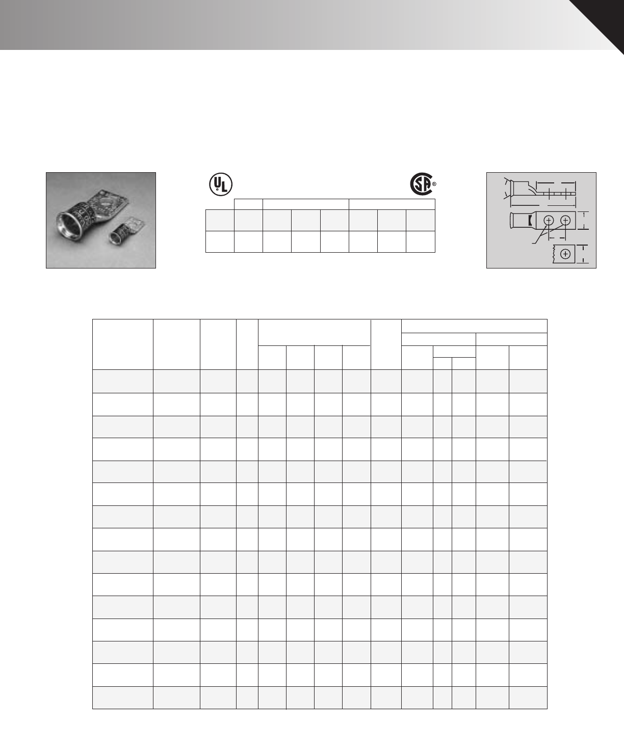
COPPER PENN-CRIMPS®• TYPE BBLU
Long barrel lugs for #6 stranded AWG thru 2000 MCM
WW
For
Stud
Size D
L
E
♦Longer length barrel permits extra crimps for additional assur-
ance on heavy duty loads. Seamless, one piece, pure copper
construction with tin plating assures maximum conductivity.
Generous entrance chamfer provides easy cable insertion.
End of cable is protected from environmental hazards by com-
pletely closed transition.
♦Catalog number and conductor sizes marked on every piece
insures positive identification.
♦Can be installed with existing crimping tools. Die color coding
conforms to industry standards to insure proper connector/die
selection and to provide for faster installation.
♦BBLU LUGS ARE SUITABLE FOR USE AT VOLTAGES UP
TO 35KV.
♦45° and 90° Variations are UL Listed and CSA certified.
Contact factory for price and availability.
♦NEW FEATURE – UL/CSA approved with Versa-Crimp®tool-
ing and wire ranges. Versa-Crimp®is a registered trademark of
Hubbell Incorporated.
♦Additional wire size recommendations, see Master Catalog.
POWER UL 467 GROUNDING
POWER: UL 486A, CSA C22.2 NO. 65
COLOR-CODED
COPPER COMPRESSION CONNECTORS
GROUNDING & BONDING & DIRECT BURIAL : UL 467, CSA C22.2 NO. 41
CSA C22.2 NO. 41 GROUNDING
Connector
Family
UL486A/
CSA22.2 No. 65
Wire Range
UL Grounding
Max. Wire
Grounding
& Bonding
Direct
Burial
CSA Grounding
Max. Wire
Grounding
& Bonding
Direct
Burial
BLU, BBLU,
BBLZ, BCU,
BBCU
8 Str.-
2000 MCM 500 MCM YES YES 250 MCM YES YES
CU
90º C
NEW FEATURE!
NOW LISTED FOR GROUNDING, BONDING & DIRECT BURIAL APPLICATIONS
1 HOLE LUGS
RECENT ADDITIONS 7

B-7 24T-7*/374*
TDY-1 TDY-U
BBLU-6DN 6 Str.
4 Str.
2 Str.
1 Str.
Blue .184
1
/
213
/
16
3
3
/
4
4
11
/
32
B-8 29T-8*/346*
T-10
BBLU-6D-2TC14 6 Str. Blue .184
1
/
413
/
32
1
9
/
32
5
/
8
2
21
/
32
B-7 24T-7*/374*
BBLU-4D-2TC14 4 Str Gray .232
1
/
41
/
2
1
9
/
32
5
/
8
2
11
/
16
B-8 29T-8*/346*
BBLU-4D1 Gray .232
1
/
215
/
16
2
7
/
8
1
3
/
4
4
15
/
64
BBLU-2D6 Brown .292
1
/
213
/
16
3
3
/
4
4
33
/
64
B-11 37
B-10 33
T-11/375 2
BBLU-1D2 Green .332
1
/
225
/
32
3
3
/
4
4
5
/
8
BBLU-1/0D-2NTC38 1/0 Str. Pink .375
3
/
83
/
4
2
5
/
8
1
3
/
4
4
5
/
16
B-12 42T-12/348
BBLU-1/0D3
1
/
213
/
16
2
7
/
8
1
3
/
4
4
9
/
16
BBLU-2/0D 2/0 Str. Black .419
1
/
213
/
16
3
3
/
4
4
13
/
16
B-13 45T-13
BBLU-3/0D 3/0 Str. Orange .470
1
/
229
/
32
3
3
/
4
4
7
/
8
B-14 50T-14
BBLU-4/0D 4/0 Str. Purple .528
1
/
2
131
3
/
4
5
1
/
16
B-15 54T-15 5
BBLU-025D 250 MCM Yellow .575
1
/
2
1
1
/
8
3
3
/
4
5
1
/
8
B-16 62T-16
BBLU-030D 300 MCM White .634
1
/
23
/
16
3
3
/
4
5
9
/
16
B-17 66H/66T-17*
BBLU-035D 350 MCM Red .682
1
/
25
/
16
3
3
/
4
5
5
/
8
B-18 71H/71T-18/ T-324 7
BBLU-040D 400 MCM Blue .728
1
/
2
1
13
/
32
3
3
/
4
5
13
/
16
B-19 76H/76T-19*/470*
BBLU-050D 500 MCM Brown .815
1
/
2
1
17
/
32
3
3
/
4
6B-2087T-20/T-299
BBLU-060D 600 MCM Green .893
1
/
2
1
23
/
32
3
3
/
4
6
9
/
16
B-22 94H/94T-22/472 9
5
7
9
9*** 9***
BBLU-065D 650 MCM Pink .930
1
/
2
1
25
/
32
3
3
/
4
6
11
/
16
B-300 99–
BBLU-075D 750 MCM Black .999
1
/
2
1
29
/
32
3
3
/
4
6
13
/
16
B-24 106H/106T-24*/473
BBLU-080D 800 MCM 1.031
1
/
2
1
2
31
/
32
3
3
/
4
7B-25 107H/107–
Orange
Green
Brown
BBLU-100D1 1000 MCM White1.153
1
/
23
/
16
3
3
/
4
7
1
/
8
B-27 125–
BBLU-150D1 1500 MCM 1.412
1
/
2
2
11
/
16
3
3
/
4
7
7
/
16
B-31 –
BBLU-200D1 2000 MCM 1.632
1
/
2
3
5
/
64
3
3
/
4
7
3
/
4
B-34 –
–
BBLU-3D 3 Str. White .260
5
/
16 17
/
32
1
5
/
8
7
/
8
3
1
/
32
3
7
/
32
B-9 –T-9*
BBLU-2D 2 Str. Brown .292
5
/
16 5
/
8
1
15
/
32
3
/
4
B-10 33T-10 2
BBLU-1D 1 Str Green .332
5
/
16 11
/
16
1
5
/
8
7
/
8
3
3
/
8
B-11 37T-11/375
BBLU-1/0D 1/0 Str. Pink .375
5
/
16 3
/
4
1
19
/
32
7
/
8
3
5
/
16
B-12 42T-12/348
9*** 9***
BBLU-100D 1000 MCM White
Green
Brown
1.153
1
/
23
/
16
22
3
/
8
1
1
/
4
6
1
/
2
B-27 125–
BBLU-150D 1500 MCM 1.412
1
/
2
2
11
/
16
2
1
/
2
1
3
/
8
6
15
/
16
B-31 –
BBLU-200D 2000 MCM 1.632
1
/
2
3
5
/
64
3
1
1
1
1
1
1
1
1
1
1
1
1
1
1
1
1
1
1
1
/
2
7
3
/
8
B-34 –
–
–
–
Approximate
Dimensions (in inches)
Crimping Tool Reference+++
Wire Alt. ToolingPenn-Union
Copper Dia. Burndy
Catalog Cond.
Die
Color
Code
(in) Stud Index T&BPUC
Pressure
Number Range† ‡ Size WDEL No. DieDies
Setting
COPPER PENN-CRIMPS®• TYPE BBLU
Continued from page Recent Additions 7
NEW FEATURE!
NOW LISTED FOR GROUNDING, BONDING & DIRECT BURIAL APPLICATIONS
2 HOLE NEMA SPACING
2 HOLE ASSORTED LUGS
+ Concentric, compressed and compact stranding. * Consult factory for availability of dies not available at this time.
++ For conversion to metric range see Master Catalog
+++ For additional tool references see Master Catalog *** CUAD-1000
8 RECENT ADDITIONS
BLU-3D-FL 4 AWG 105/24 White
1/4219/6413/16
5/817/32 B-9 –XF 2 –
BLU-3S2-FL 5/16 155/64
3/4–9/16
BLU-1D4-FL 2 AWG 150/24 Green
5/16 251/6415/8
7/843/64 B-11 37XF 2 –
BLU-1S-FL 5/16 155/64
3/4–43/64
BLU-1/0D-FL 1 AWG 225/24 Pink
5/16 213/1615/8
7/83/4B-12 42XF 2 –
BLU-1/0S-FL 5/16 115/16
3/4–3/4
BLU-2/0D4-FL 1/0 AWG 275/24 Black
3/831/16113/16113/16 B-13 45XF 2 –
BLU-2/0S-FL 3/821/8
7/8–13/16
BLU-3/0D-FL 2/0 AWG 325/24 Orange
1/241/427/813/429/32 B-14 50XF 5 5
BLU-3/0S1-FL 1/221/211/8–29/32
BLU-4/0D-FL 3/0 AWG 450/24 Purple
1/245/1627/813/4B-15 54XF 5 5
BLU-4/0S1-FL 1/229/1611/8–1
1
BLU-030D-FL 4/0 AWG 550/24 White
1/241/227/813/413/16 B-17 66H/66–7 7
BLU-030S-FL 1/223/411/8–1
3/16
BLU-035D-FL 262 MCM 650/24 Red
1/245/827/813/419/32 B-18 71H/71–7 7
BLU-035S-FL 1/2229/3215/32–1
9/32
BLU-040D-FL 313 MCM 775/24 Blue
1/243/427/813/4113/32 B-19 76H/76–7 7
BLU-040S-FL 5/835/1617/16–1
13/32
BLU-050D-FL 373 MCM 925/24 Brown
1/2527/813/4117/32 B-20 87–9 9
BLU-050S-FL 5/839/1617/16–1
17/32
BLU-060D-FL 444 MCM 1100/24 Green
Green
1/253/3227/813/4123/32 B-22 94H/94–9 9
BLU-060S-FL 5/8231/3213/4–1
23/32
BLU-065D-FL 535 MCM 1325/24 Pink
1/253/3227/813/4125/32 B-300 99–9 9
BLU-065S4-FL 5/8331/3213/4–1
25/32
BLU-075D-FL 646 MCM 1600/24 Black
1/257/1627/813/4129/32 B-24 106H/106–9 9
BLU-075S-FL 5/8417/16–1
29/32
BLU-100D-FL 777 MCM 1925/24 White
1/257/827/813/423/16 B-27 125–9* 9*
–
BLU-100S-FL 5/847/817/8–2
3/16
BLU-150D-FL 1111 MCM 2750/24 1/263/3227/813/4211/16 B-31 –––
BLU-150S-FL 3/4515/3221/4–2
11/16
Flex Wire Crimping Tool Reference
Approximate
Dimensions (in inches)
Diesel Alt. ToolingPENN UNION
Catalog Locomotive Die
Color
Code
Stud TDY
Number Cable Range Stranding Size LDEW Burndy
Index T & B Die
TDM
250 1U
D
E
L
W
W
Flare
Stud Size
♦Seamless, one piece, pure copper construction with tin plating
assures maximum conductivity. Generous entrance chamfer
and wide flare provide easy cable insertion even for fine
stranded extra flexible cable. Inspection window insures full in-
sertion. See Master Catalog for flexible cable recommenda-
tions and listing.
♦Catalog number and conductor size marked on every piece
insures positive identification.
♦Can be installed with existing crimping tools. Die color-coding
conforms to industry standards to insure proper connector/die
selection and to provide for faster installation.
♦BLU LUGS ARE SUITABLE FOR USE AT VOLTAGES UP TO
35 KV.
POWER UL 467 GROUNDING
POWER: UL 486A, CSA C22.2 NO. 65
COLOR-CODED
COPPER COMPRESSION CONNECTORS
GROUNDING & BONDING & DIRECT BURIAL : UL 467, CSA C22.2 NO. 41
CSA C22.2 NO. 41 GROUNDING
Connector
Family
UL486A/
CSA22.2 No. 65
Wire Range
UL Grounding
Max. Wire
Grounding
& Bonding
Direct
Burial
CSA Grounding
Max. Wire
Grounding
& Bonding
Direct
Burial
BLU, BBLU,
BBLZ, BCU,
BBCU
8 Str.-
2000 MCM 500 MCM YES YES 250 MCM YES YES
CU
90º C
NEW FEATURE!
NOW LISTED FOR GROUNDING, BONDING & DIRECT BURIAL APPLICATIONS
*with Flex wire only
FLARED COPPER PENN-CRIMPS®• TYPE BLU-FL
Crimp lugs with inspection window for #4 (105/24) thru 1111 MCM (275/24) diesel locomotive cable and class G, H, I, & K flexible cables
RECENT ADDITIONS 9
BBLU-3D-FL 4 AWG 105/24 White
5/16 17/32 15/8
7/831/32 B-9 –XF 2 –
BBLU-3S1-FL 5/16 17/32–2
5/32
BBLU-1D-FL 2 AWG 150/24 Green
5/16 11/16 15/8
7/833/8B-11 37XF 2 –
BBLU-1S-FL 5/16 11/16 3/4
3/4
–2
3/8
BBLU-1/0D-FL 1 AWG 225/24 Pink
5/16 3/4119/32
7/835/16 B-12 42XF 2 –
BBLU-1/0S-FL 5/16 3/43/4–2
7/16
BBLU-2/0D-FL 1/0 AWG 275/24 Black
1/213/16 313/4413/16 B-13 45XF 2 –
BBLU-2/0S-FL 3/813/16 7/8–2
11/16
BBLU-3/0D-FL 2/0 AWG 325/24 Orange
1/229/32 313/447/8B-14 50XF 5 5
BBLU-3/0S-FL 1/229/32 11/4–3
1/8
BBLU-4/0D-FL 3/0 AWG 450/24 Purple
1/21313/451/16 B-15 54XF 5 5
BBLU-4/0S-FL 1/211
1/4–3
5/16
BBLU-030D-FL 4/0 AWG 550/24 White
1/213/16 3
3/459/16 B-17 66H/66–7
BBLU-030S-FL 1/213/16 11/4–3
13/16
BBLU-035D-FL 262 MCM 650/24 Red
1/215/16 3
3/455/8B-18 71H/71–7
BBLU-035S-FL 1/219/32 11/4–3
27/32
BBLU-040D-FL 313 MCM 775/24 Blue
1/2113/32 3
3/4513/16 B-19 76H/76–7
BBLU-040S-FL 5/8113/32 11/2–4
5/16
BBLU-050D-FL 373 MCM 925/24 Brown
1/2117/32 3
1
1
1
13/46B-20 87–9
BBLU-050S-FL 5/8117/32 115/32–4
1/2
BBLU-060D-FL 444 MCM 1100/24 Green
Green
1/2123/32 3
3/469/16 B-22 94H/94–9
BBLU-060S-FL 5/8123/32 11/2–5
1/8
BBLU-065D-FL 535 MCM 1325/24 Pink
1/2125/32 3
3/469/16 B-300 99–9
BBLU-065S1-FL 5/8125/32 13/4–5
13/32
BBLU-075D-FL 646 MCM 1600/24 Black
1/2129/32 3
3/4613/16 B-24 106H/106–9
BBLU-075S-FL 5/8129/32 11/2–5
5/16
BBLU-100D1-FL 777 MCM 1925/24 White
1/223/16 3
3/471/8B-27 125–
–
7
7
7
9
9
9
9
9* 9*
BBLU-100S-FL 5/823/16 11/2–5
5/8
BBLU-150D1-FL 1111 MCM 2750/24 1/2211/16 3
1
1
1
1
13/477/16 B-31 –––
BBLU-150S-FL 3/4211/16 21/8–6
9/16
Flex Wire Crimping Tool Reference
Approximate
Dimensions (in inches)
Diesel Alt. ToolingPENN UNION
Catalog Locomotive Die
Color
Code
Stud TDY
Number Cable Range Stranding Size WDEL Burndy
Index T & B Die
TDM
250 1U
♦Longer length barrel permits extra crimps for additional assur-
ance on heavy duty loads. Seamless, one piece, pure copper
construction with tin plating assures maximum conductivity.
Generous entrance chamfer and wide flare provide easy cable
insertion even for fine stranded extra flexible cable. End of
cable is protected from environmental hazards by completely
closed transition. See Master Catalog for flexible cable recom-
mendation and listing.
♦Catalog number and conductor size marked on every piece in-
sures positive identification.
♦Can be installed with existing crimping tools. Die color-coding
conforms to industry standards to insure proper connector/die
selection and to provide for faster installation.
♦BBLU LUGS ARE SUITABLE FOR USE AT VOLTAGES UP
TO 35 KV.
D
L
E
W
W
Stud Size
Flare
POWER UL 467 GROUNDING
POWER: UL 486A, CSA C22.2 NO. 65
COLOR-CODED
COPPER COMPRESSION CONNECTORS
GROUNDING & BONDING & DIRECT BURIAL : UL 467, CSA C22.2 NO. 41
CSA C22.2 NO. 41 GROUNDING
Connector
Family
UL486A/
CSA22.2 No. 65
Wire Range
UL Grounding
Max. Wire
Grounding
& Bonding
Direct
Burial
CSA Grounding
Max. Wire
Grounding
& Bonding
Direct
Burial
BLU, BBLU,
BBLZ, BCU,
BBCU
8 Str.-
2000 MCM 500 MCM YES YES 250 MCM YES YES
CU
90º C
NEW FEATURE!
NOW LISTED FOR GROUNDING, BONDING & DIRECT BURIAL APPLICATIONS
*with Flex wire only
FLARED COPPER PENN-CRIMPS®• TYPE BBLU-FL
Crimp lugs with inspection window for #4 (105/24) thru 1111 MCM (275/24) diesel locomotive cable and class G, H, I, & K flexible cables
10 RECENT ADDITIONS
Crimping Tool Reference+++
Wire Approx. Alt. ToolingPenn-Union
Copper Diam. Dimensions Burndy
Pressure
Catalog Cond. Color
Die
(in) (in inches) Index T&BPUC
Dies
Setting
Number Range† Code‡B L No. DieTDY-1 TDY-U
BCU-8 8 Str. Red .146 15/32 11/16 B-6 21T-6*
BCU-6 6 Str. Blue
Blue
Orange
Orange
.184 13/16 13/4B-7 24T-7*/T-374*
T-7*/T-374*BCU-5 5 Str .206 13/16 13/4B-7 –
BCU-4 4 Str. Gray .232 13/16 13/4B-8 29T-8*/T-346*
BCU-3 3 Str. White .260 13/16 13/4B-9 –T-9*
BCU-2 2 Str. Brown .292 7/817/8B-10 33T-10
BCU-1 1 Str. Green .332 7/817/8B-11 37T-11/375 2
BCU-1/0 1/0 Str. Pink .375 7/817/8B-12 42T-12/348
BCU-2/0 2/0 Str. Black .419 15/16 2B-13 45T-13
BCU-3/0 3/0 Str. Orange .470 1 21/8B-14 50T-14
BCU-4/0 4/0 Str. Purple .528 1 21/8B-15 54T-15 5 5
BCU-025 250 MCM Yellow .575 11/16 21/4B-16 62T-16
BCU-030 300 MCM White .634 11/16 21/4B-17 66H/66T-17*
BCU-035 350 MCM Red .682 11/823/8B-18 71H/71T-18/324 7 7
BCU-040 400 MCM Blue .728 13/16 21/2B-19
B-19
76H/76T-19*/470*
T-19*/470*
T-24*/473
BCU-045 450 MCM Blue .772 13/827/876H/76
BCU-050 500 MCM Brown
Brown
.815 13/827/8B-20 87T-20/299
BCU-060 600 MCM Green
Green
.893 13/827/8B-22 94H/94T-22/472
BCU-065 650 MCM Black .930 13/827/8B-300 99–99
BCU-075 750 MCM Black .999 15/833/8B-24 106H/106
BCU-080 800 MCM 1.031 15/833/8B-25 107H/107–
BCU-100 1000 MCM White1.153 17/837/8B-27 125–
–
–
9*** 9***
BCU-150 1500 MCM 1.412 2 41/8B-31 –
BCU-200 2000 MCM 1.632 21/445/8B-34 –
BBCU-6 6 Str. Blue .184 11/823/8B-7 24T-7*/T-374*
BBCU-8 8 Str. Red.146 15/16 2B-621T-6*
BBCU-4 4 Str Gray .232 11/823/8B-8 29T-8*/T-346*
BBCU-2 2 Str. Brown .292 11/425/8B-10 33T-10
BBCU-3 3 Str. White .260 11/823/8B-9 –T-9*
2
BBCU-1 1 Str. Green .332 13/827/8B-11 37T-11/375
BBCU-1/0 1/0 Str. Pink .375 13/827/8B-12 42T-12/348
BBCU-2/0 2/0 Str. Black .419 11/231/8B-13 45T-13
BBCU-3/0 3/0 Str. Orange .470 11/231/8B-14 50T-14
BBCU-4/0 4/0 Str. Orange .528 15/833/8B-15 54T-15 5 5
BBCU-025 250 MCM Yellow .575 15/833/8B-16 62T-16
BBCU-030 300 MCM White .634 2 41/8B-17 66H/66T-17*
BBCU-035 350 MCM Red .682 2 41/8B-18 71H/71T-18/324 7 7
BBCU-040 400 MCM Blue .728 21/843/8B-19 76H/76T-19*/470*
BBCU-050 500 MCM Brown
Brown
.815 21/445/8B-20 87T-20/299
BBCU-060 600 MCM Green
Green
.893 211/16 51/2B-22 94H/94T-22/472
T-24*/473*
99
BBCU-065 650 MCM Pink .930 23/455/8B-300 99–
BBCU-075 750 MCM Black .999 27/857/8B-24 106H/106
BBCU-080 800 MCM 1.031 215/16 6B-25 107H/107–
BBCU-100 1000 MCM White1.153 3 61/8B-27 125–9*** 9***
BBCU-150 1500 MCM 1.412 33/16 61/2B-31
B-34
–
BBCU-200 2000 MCM 1.632 37/16 7–
L
B
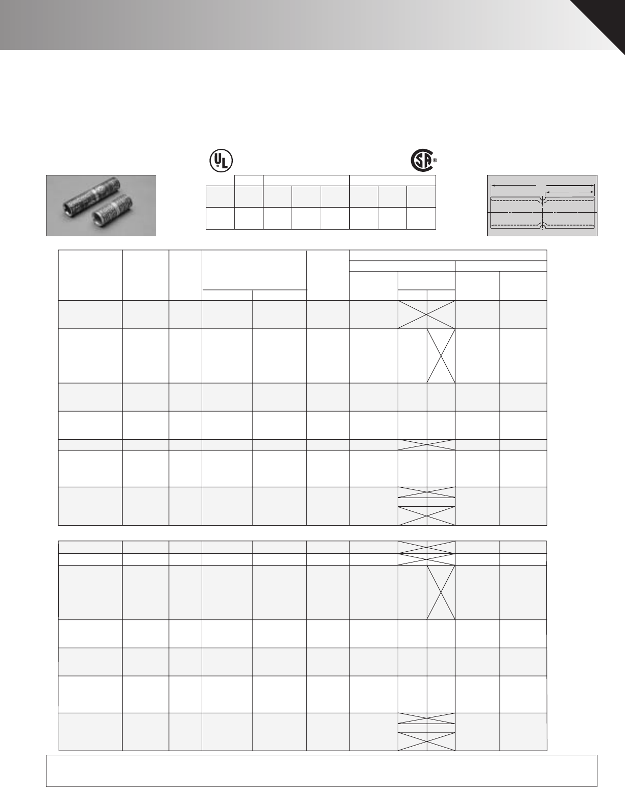
♦Seamless, one piece, pure copper construction with tin plating
assures maximum conductivity. Generous entrance chamfer
provides easy cable insertion. Type BBCU has longer length
barrel which permits extra crimps for additional assurance on
heavy duty loads.
♦Catalog number and conductor sizes marked on every piece
insures positive identification.
♦Positive cable stops insure proper insertion of conductors to
full depth.
♦Can be installed with existing crimping tools. Die color coding
conforms to industry standards to
insure proper connector/die selec-
tion and to provide for faster installation.
♦BCU & BBCU Splices are suitable for use at voltages up to
35KV provided connector is taped in accordance with accept-
ed practices, 5 KV is maximum voltage level in all bare splice
applications.
♦NEW FEATURE – UL/CSA approved with Versa-Crimp®tool-
ing and wire ranges. Versa-Crimp®is a registered trademark of
Hubbell Incorporated.
♦Additional wire recommendations, see Master Catalog.
POWER UL 467 GROUNDING
POWER: UL 486A, CSA C22.2 NO. 65
COLOR-CODED
COPPER COMPRESSION CONNECTORS
GROUNDING & BONDING & DIRECT BURIAL : UL 467, CSA C22.2 NO. 41
CSA C22.2 NO. 41 GROUNDING
Connector
Family
UL486A/
CSA22.2 No. 65
Wire Range
UL Grounding
Max. Wire
Grounding
& Bonding
Direct
Burial
CSA Grounding
Max. Wire
Grounding
& Bonding
Direct
Burial
BLU, BBLU,
BBLZ, BCU,
BBCU
8 Str.-
2000 MCM 500 MCM YES YES 250 MCM YES YES
CU
90º C
NEW FEATURE!
NOW LISTED FOR GROUNDING, BONDING & DIRECT BURIAL APPLICATIONS
+ Concentric, compressed and compact stranding. * Consult factory for availability of dies not available at this time.
++ For conversion to metric range see Master Catalog
+++ For additional tool references see Master Catalog *** CUAD-1000
LONG BARREL SPLICES
COPPER PENN-CRIMPS®• TYPE BCU & BBCU
Crimp splices for #8 stranded thru 2000 MCM
RECENT ADDITIONS 11
Diesel Flex Wire Crimping Tool Reference
Locomotive Approximate
Catalog Cable
Die
Color
Code
Dimensions (in inches) Alt. ToolingPENN-UNION
Number Range Stranding BL Burndy Index T & B DieTDM-250 TDY-1 TDY-U
BCU-3-FL 4 AWG 105/24 White
13/16 13/4B-9 –XF 2 –
BCU-1-FL 2 AWG 150/24 Green
7/817/8B-11 37XF 2 –
BCU-1/0-FL 1 AWG 225/24 Pink
7/817/8B-12 42XF 2 –
BCU-2/0-FL 1/0 AWG 275/24 Black
15/16 2B-1345XF 2 –
BCU-3/0-FL 2/0 AWG 325/24 Orange12
1/8B-14 50XF 5 5
BCU-4/0-FL 3/0 AWG 450/24 Purple12
1/8B-15 54XF 5 5
BCU-030-FL 4/0 AWG 550/24 White11/16 21/4B-17 66H/66–77
BCU-035-FL 262 MCM 650/24 Red11/823/8B-18 71H/71–77
BCU-040-FL 313 MCM 775/24 Blue13/16 21/2B-19 76H/76–77
BCU-050-FL 373 MCM 925/24 Brown13/827/8B-20 87–99
BCU-060-FL 444 MCM 1100/24 Green
Green
Green
13/827/8B-22 94H/94–99
BCU-065-FL 535 MCM 1325/24 Pink13/827/8B-300 99–99
BCU-075-FL 646 MCM 1600/24 Black15/833/8B-24 106H/106–99
BCU-100-FL 777 MCM 1925/24 White17/837/8B-27 125–9*9*
–9*9*
BCU-150-FL 1111 MCM 2750/24 2 41/8B-31 ––––
BBCU-3-FL 4 AWG 105/24 White11/823/8B-9 –XF 2 –
BBCU-1-FL 2 AWG 150/24 Green13/827/8B-11 37XF 2 –
BBCU-1/0-FL 1 AWG 225/24 Pink13/827/8B-12 42XF 2 –
BBCU-2/0-FL 1/0 AWG 275/24 Black11/231/8B-13 45XF 2 –
BBCU-3/0-FL 2/0 AWG 325/24 Orange11/231/8B-14 50XF 5 5
BBCU-4/0-FL 3/0 AWG 450/24 Purple15/833/8B-15 54XF 5 5
BBCU-030-FL 4/0 AWG 550/24 White24
1/8B-17 66H/66–77
BBCU-035-FL 262 MCM 650/24 Red24
1/8B-18 71H/71–77
BBCU-040-FL 313 MCM 775/24 Blue21/843/8B-19 76H/76–77
BBCU-050-FL 373 MCM 925/24 Brown21/445/8B-20 87–99
BBCU-060-FL 444 MCM 1100/24 Green211/16 51/2B-22 94H/94–99
BBCU-065-FL 535 MCM 1325/24 Pink223/32 55/8B-300 99–99
BBCU-075-FL 646 MCM 1600/24 Black27/857/8B-24 106H/106–99
BBCU-100-FL 777 MCM 1925/24 White36
1/8B-27 125
BBCU-150-FL 1111 MCM 2750/24 33/16 61/2B-31 ––––
♦Seamless, one piece, pure copper construction with tin plating
assures maximum conductivity. Generous entrance chamfer
and wide flare provide easy cable insertion even for fine
stranded extra flexible cable. Type BBCU has longer length
barrel which permits extra crimps for additional assurance on
heavy duty loads. See Master Catalog for flexible cable rec-
ommendation and listing.
♦Catalog number and conductor size marked on every piece
insures positive identification.
♦Positive cable stops insure proper insertion of conductors to
full depth.
♦Can be installed with
existing crimping tools. Die color-coding conforms to industry
standrads to insure proper connector/die selection and to pro-
vide for faster installation.
♦BCU & BBCU Splices are suitable for use at voltages up to 35
KV provided connector is taped in accordance with accepted
practices, 5 KV is maximum voltage level in all bare splice
applications.
B
L
Flare
POWER UL 467 GROUNDING
POWER: UL 486A, CSA C22.2 NO. 65
COLOR-CODED
COPPER COMPRESSION CONNECTORS
GROUNDING & BONDING & DIRECT BURIAL : UL 467, CSA C22.2 NO. 41
CSA C22.2 NO. 41 GROUNDING
Connector
Family
UL486A/
CSA22.2 No. 65
Wire Range
UL Grounding
Max. Wire
Grounding
& Bonding
Direct
Burial
CSA Grounding
Max. Wire
Grounding
& Bonding
Direct
Burial
BLU, BBLU,
BBLZ, BCU,
BBCU
8 Str.-
2000 MCM 500 MCM YES YES 250 MCM YES YES
CU
90º C
NEW FEATURE!
NOW LISTED FOR GROUNDING, BONDING & DIRECT BURIAL APPLICATIONS
FLARED COPPER PENN-CRIMPS®• TYPE BCU-FL, BBCU-FL
Crimp splices for #4 (105/24) thru 1111 MCM (275/24) diesel locomotive cable and class G, H, I, & K flexible cable
* with Flex wire only
LONG BARREL SPLICES
12 RECENT ADDITIONS
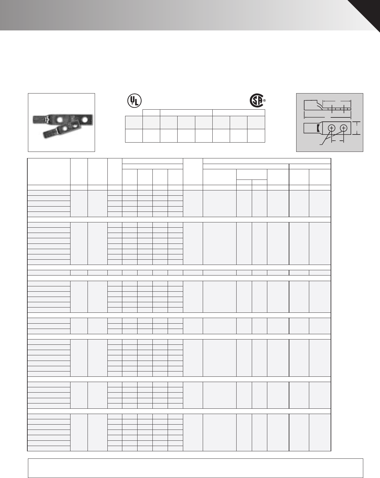
Wire
Copper Dia. Hole Wide Pad Lgth Die Dieless Burndy
Catalog Cond. (in) Stud Space Lgth Color Mechanical PUC Index T&B
Number Range+ ++ Size E W D L Code TDY-1 TDY-U Dies No. Die
BLU-8D-2TC10 #8 .146 10 5/8 .411.131.78 Red PUC TDM-250 - - T-6 B-6 21
BLU-8D-2TC14 1/4 5/8 .41 1.22 1.88
BLU-8D-2TC14E2 1/4 3/4 .41 1.36 2.01 or
BLU-8D-2TC14E1 1/4 1 .41 1.612.26 TDM-500
BLU-8D-2TC38 3/8 1 .56 1.83 2.48
BLU-6D-2TC10 #6 .184 10 5/8 .411.222.25Blue PUC TDM-250 - - T-7*/374* B-7 24
BLU-6D-2TC14 1/4 5/8 .41 1.22 2.25
BLU-6D-2TC14E2 1/4 3/4 .41 1.36 2.42
BLU-6D-2TC14E1 1/4 1 .41 1.61 2.67 or
BLU-6D-2TC516E2 5/16 3/4 .61 1.47 2.54 TDM-500
BLU-6D-2TC516 5/16 1 .61 1.72 2.79
BLU-6D-2TC38 3/8 1 .61 1.83 2.90
BLU-6DN 1/2 1 3/4 .81 3.00 4.07
BLU-5D-2TC14 #5 .206 1/4 5/8 .44 1.22 2.25 Blue PUC NONE - - T-7*/374* B-7 24
BLU-4D-2TC14 #4 .232 1/4 5/8 .501.222.33Gray PUC TDM-250 2 - T-8*/346* B-8 29
BLU-4D-2TC14E2 1/4 3/4 .50 1.36 2.43 or
BLU-4D-2TC14E1 1/4 1 .50 1.61 2.68 TDM-500
BLU-4D-2TC516 5/16 1 .61 1.72 2.78
BLU-4D-2TC38 3/8 1 .61 1.83 2.89
BLU-4D1 1/2 1 3/4 .94 2.88 3.94
BLU-3D-2TC14 ** #3 .260 1/4 5/8 .65 1.22 2.32 White PUC NONE 2 - T-9* B-9 -
BLU-3D-2TC51658 5/16 5/8 .65 1.34 2.47
BLU-3D-2TC38 3/8 1 .65 1.83 2.93
BLU-2D-2TC14 #2 .292 1/4 5/8 .591.222.32Brown PUC TDM-250 2 - T-10 B-10 33
BLU-2D-2TC14E2 1/4 3/4 .59 1.36 2.49 or
BLU-2D-2TC14E1 1/4 1 .59 1.61 2.74 TDM-500
BLU-2D-2TC516E2 5/16 3/4 .59 1.47 2.60
BLU-2D-2TC516 5/16 1 .59 1.72 2.85
BLU-2D-2TC38 3/8 1 .59 1.83 2.96
BLU-2D2 1/2 1 3/4 .81 2.88 3.98
BLU-1D-2TC14 #1 .332 1/4 5/8 .67 1.22 2.41 Green PUC TDM-250 2 - T-11/375 B-11 37
BLU-1D-2TC14E2 1/4 3/4 .67 1.36 2.55 or
BLU-1D-2TC516E6 5/16 7/8 .67 1.62 2.79 TDM-500
BLU-1D-2TC38 3/8 1 .67 1.83 3.02
BLU-1D5 1/2 1 3/4 .78 2.88 4.06
BLU-1/0D-2TC14 1/0 .375 1/4 5/8 .74 1.22 2.44 Pink PUC TDM-250 2 - T-12/348 B-12 42
BLU-1/0D-2TC14E2 1/4 3/4 .74 1.36 2.58 or
BLU-1/0D-2TC516E6 5/16 7/8 .74 1.62 2.81 TDM-500
BLU-1/0D-2TC516 5/16 1 .74 1.72 2.94
BLU-1/0D-2TC38 3/8 1 .74 1.83 3.02
BLU-1/0D-2NTC38 3/8 1 3/4 .74 2.58 3.77
BLU-1/0D2 1/2 1 3/4 .81 2.88 4.09
Setting
Crimping Tool Reference+++
PENN-UNION
Alt. Tooling
Approximate Dimensions
(in inches)
Pressure
+ Concentric, compressed and compact stranding. * Consult factory for availability of dies not available at this time.
++ For conversion to metric range see Master Catalog **(Also #2 Sol)
+++ For additional tool references see Master Catalog *** CUAD-1000
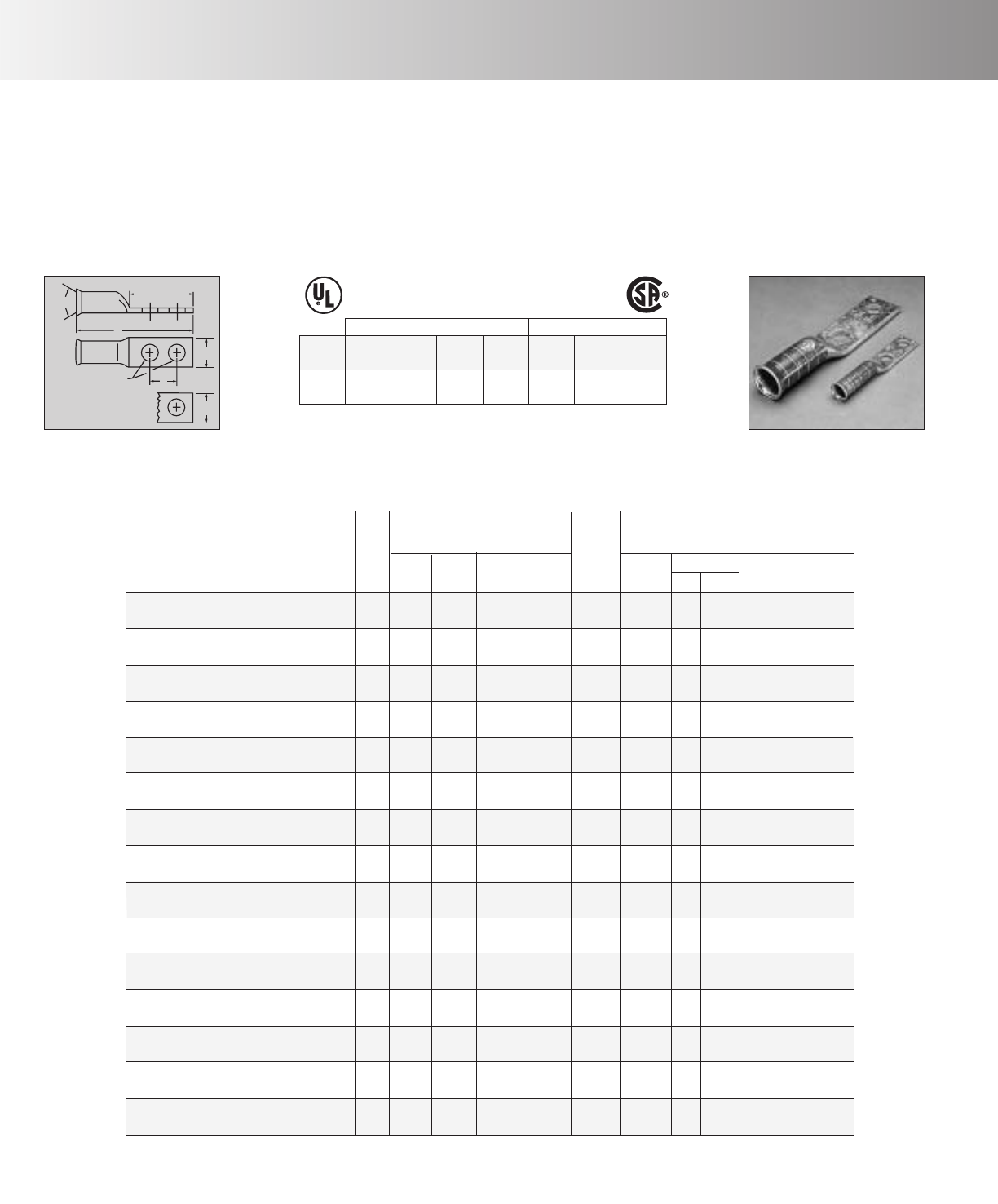
COPPER PENN-CRIMPS®TELECOMMUNICATION LUGS • TYPE BLU-2TC
2 hole standard barrel lugs for #8 stranded thru 1000 MCM
D
E
L
W
Stud Size
♦Seamless, one piece, copper construction with tin plating
assures maximum conductivity.
♦Generous entrance chamfer provides easy cable insertion.
♦End of cable is visible through the inspection window to assure
proper cable insertion.
♦Catalog number and conductor sizes marked on every piece
insures positive identification.
♦45° and 90° variations are UL listed and CSA certified.
Contact factory for price and availability.
♦Can be installed with existing crimping tools.
♦Die color coding conforms to industry standards to insure prop-
er connector/die selection and to provide for faster installation.
♦Accepts the same wide range of additional wire sizes and types
as our standard BLU, BBLU, BBLZ, BCU, and BBCU series.
♦UL/CSA approved with Versa-Crimp®tooling and wire ranges.
Versa-Crimp®is a registered trademark of Hubbell Incorporated.
♦BLU lugs are suitable for use at voltages up to 35KV.
POWER UL 467 GROUNDING
POWER: UL 486A, CSA C22.2 NO. 65
COLOR-CODED
COPPER COMPRESSION CONNECTORS
GROUNDING & BONDING & DIRECT BURIAL : UL 467, CSA C22.2 NO. 41
CSA C22.2 NO. 41 GROUNDING
Connector
Family
UL486A/
CSA22.2 No. 65
Wire Range
UL Grounding
Max. Wire
Grounding
& Bonding
Direct
Burial
CSA Grounding
Max. Wire
Grounding
& Bonding
Direct
Burial
BLU, BBLU,
BBLZ, BCU,
BBCU
8 Str.-
2000 MCM 500 MCM YES YES 250 MCM YES YES
CU
90º C
NEW FEATURE!
NOW LISTED FOR GROUNDING, BONDING & DIRECT BURIAL APPLICATIONS
RECENT ADDITIONS 13
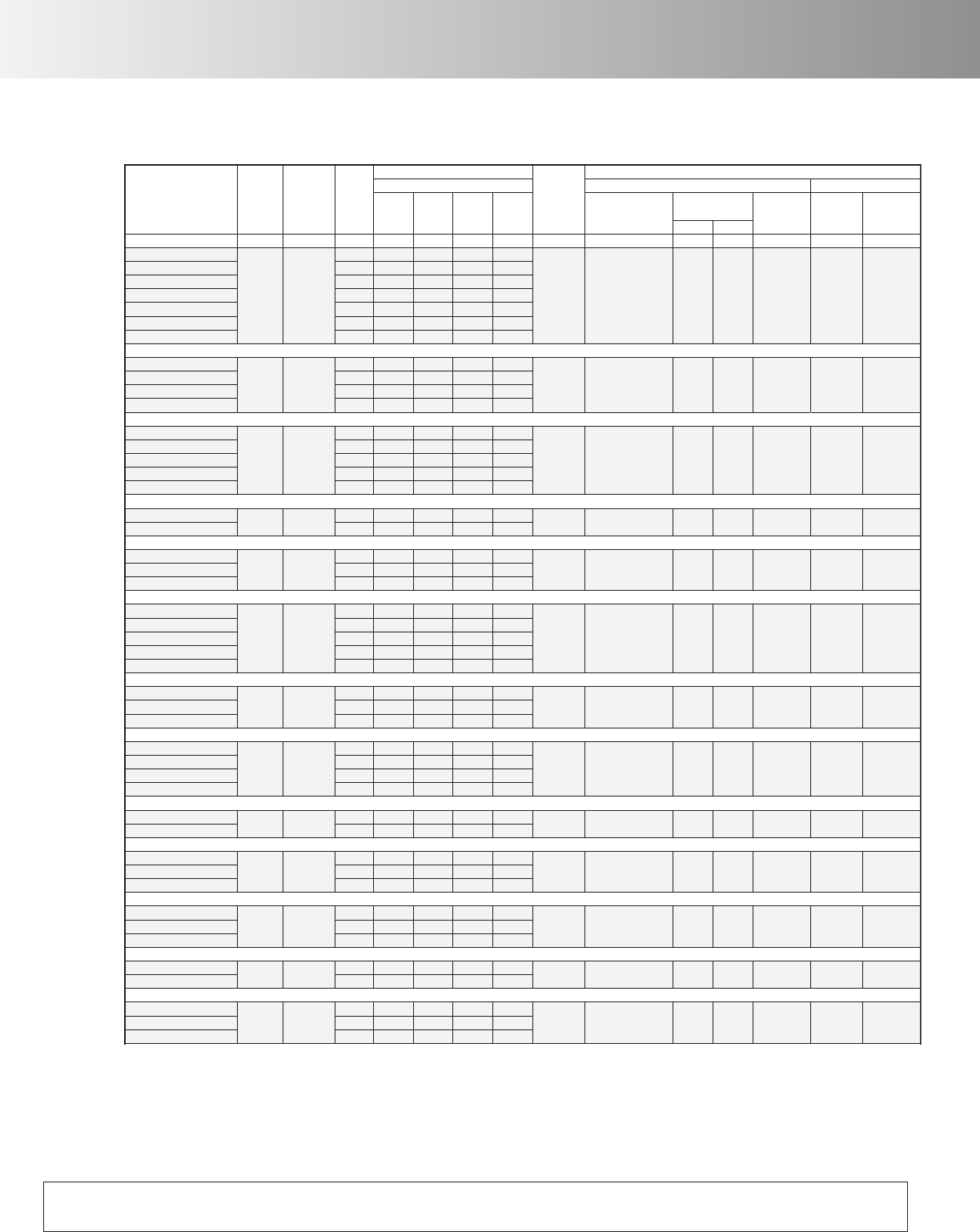
BLU-2/0D-2TC14 2/0 .419 1/4 5/8 .82 1.22 2.50 Black PUC TDM-250 2 - T-13 B-13 45
BLU-2/0D-2TC14E2 1/4 3/4 .82 1.36 2.64 or
BLU-2/0D-2TC14E1 1/4 1 .82 1.61 2.89 TDM-500
BLU-2/0D-2TC516E6 5/16 7/8 .82 1.62 2.88
BLU-2/0D-2TC516 5/16 1 .82 1.72 3.00
BLU-2/0D-2TC38 3/8 1 .82 1.83 3.08
BLU-2/0D 1/2 1 3/4 .82 2.88 4.13
BLU-3/0D-2TC14E2 3/0.470 1/43/4 .891.362.77Orange PUC TDM-250 5 5 T-14 B-14 50
BLU-3/0D-2TC516 5/16 1 .89 1.72 3.13 or
BLU-3/0D-2TC38 3/8 1 .89 1.83 3.24 TDM-500
BLU-3/0D 1/2 1 3/4 .89 2.88 4.25
BLU-4/0D-2TC14E2 4/0.5281/4 3/41.00 1.36 2.83 Purple PUC TDM-250 5 5 T-15 B-15 54
BLU-4/0D-2TC14E1 1/4 1 1.00 1.61 3.08 or
BLU-4/0D-2TC516 5/16 1 1.00 1.72 3.18 TDM-500
BLU-4/0D-2TC38 3/811.00 1.83 3.30
BLU-4/0D 1/2 1 3/4 1.00 2.88 4.31
BLU-025D-2TC38 250.575 3/811.09 1.83 3.43 Yellow PUC TDM250 5 5 T-16 B-16 62
BLU-025D 1/2 1 3/4 1.09 2.88 4.44 or TDM-500
BLU-030D-2TC516 300 .634 5/16 1 1.19 1.72 3.37 White PUC TDM-500 7 7 T-17* B-17 66H/66
BLU-030D-2TC38 3/8 1 1.19 1.83 3.50
BLU-030D 1/2 1 3/4 1.19 2.88 4.50
BLU-035D-2TC14E2 350 .682 1/4 3/4 1.28 1.36 3.14 Red PUC TDM-500 7 7 T-18/324 B-18 71H/71
BLU-035D-2NTC516 5/16 1 3/4 1.28 2.88 4.63
BLU-035D-2TC38 3/8 1 1.28 1.83 3.61
BLU-035D-2TC12 1/2 1 1/4 1.28 2.40 4.18
BLU-035D 1/2 1 3/4 1.28 2.88 4.63
BLU-040D-2TC516 400 .728 5/16 1 1.39 1.72 3.63 Blue PUC TDM-500 7 7 T-19*/470* B-19 76H/76
BLU-040D-2TC38 3/8 1 1.39 1.83 3.74
BLU-040D 1/2 1 3/4 1.39 2.88 4.75
BLU-050D-2TC14E2 500 .815 1/4 3/4 1.53 1.36 3.52 Brown PUC TDM-500 9 9 T-20/299 B-20 87
BLU-050D-2TC38 3/8 1 1.53 1.83 3.99
BLU-050D-2TC12 1/2 1 1/4 1.53 2.40 4.56
BLU-050D 1/2 1 3/4 1.53 2.88 5.00
BLU-060D-2TC38 600 .893 3/8 1 1.72 1.83 4.08 Green PUC NONE 9 9 T-22/472 B-22 94H/94
BLU-060D 1/2 1 3/4 1.72 2.88 5.09
BLU-065D-2TC38 650 .930 3/8 1 1.78 1.83 4.08 Pink PUC NONE 9 9 - B-300 99
BLU-065D-2TC12 1/2 1 1/4 1.78 2.40 4.65
BLU-065D 1/2 1 3/4 1.78 2.88 5.09
BLU-075D-2TC38 750 .999 3/8 1 1.91 1.83 4.43 Black PUC NONE 9 9 T-24*/473 B-24 106H/106
BLU-075D-2TC12E3 1/2 1 1/2 1.91 2.65 5.25
BLU-075D 1/2 1 3/4 1.91 2.88 5.44
BLU-080D-2TC38 800 1.031 3/8 1 1.97 1.83 4.49 Orange PUC NONE - - - B-25 107H/107
BLU-080D 1/2 1 3/4 1.97 2.88 5.53
BLU-100D-2TC38 1000 1.153 3/8 1 2.17 1.83 4.83 White PUC NONE 9*** 9*** - B-27 125
BLU-100D-2TC12 1/2 1 1/4 2.17 2.40 5.40
BLU-100D 1/21 3/42.17 2.88 5.87
Wire
Copper Dia. Hole Wide Pad Lgth Die Dieless Burndy
Catalog Cond. (in) Stud Space Lgth Color Mechanical PUC Index T&B
Number Range+ ++ Size E W D L Code TDY-1 TDY-U Dies No. Die
Setting
Crimping Tool Reference+++
PENN-UNION
Alt. Tooling
Approximate Dimensions
(in inches)
Pressure
+ Concentric, compressed and compact stranding. * Consult factory for availability of dies not available at this time.
++ For conversion to metric range see Master Catalog **(Also #2 Sol)
+++ For additional tool references see Master Catalog *** CUAD-1000
COPPER PENN-CRIMPS®• TYPE BLU-2TC
Continued from page Recent Additions 13
NEW FEATURE!
NOW LISTED FOR GROUNDING, BONDING & DIRECT BURIAL APPLICATIONS
14 RECENT ADDITIONS
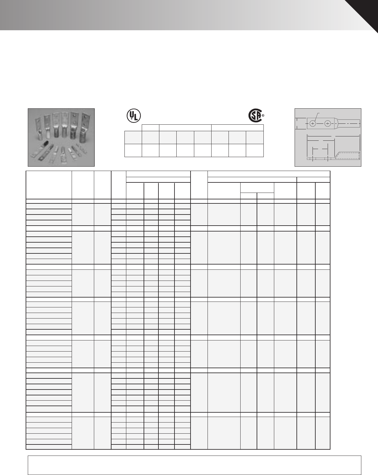
Wire
Copper DieDia. Dieless Burndy
Catalog Cond. Color(in) Stud Mechanical PUC Index T&B
Number Range+ Code++ Size W DEL TDY-1 TDY-U Dies No. Die
BBLU-8D-2TC14 #8 Red.146 1/4 .41 1.22.63 2.44 PUC TDM-250 T-6 B-6 21
BBLU-8D-2TC14E2 1/4 .41 1.36.75 2.58 or
BBLU-8D-2TC38E3 3/8 .56 1.83.81 3.05 TDM-500
BBLU-8D-2TC38 3/8 .56 1.831 3.05
BBLU-6D-2TC14 #6 Blue.184 1/4 .41 1.22.63 2.60 PUC TDM-250 T-7*/374* B-7 24
BBLU-6D-2TC14E2 1/4 .41 1.36.75 2.74 or
BBLU-6D-2TC38E2 3/8 .61 1.58.75 2.96 TDM-500
BBLU-6D-2TC38E3 3/8 .61 1.83.81 3.21
BBLU-6D-2TC38 3/8 .61 1.831 3.21
BBLU-6DN 1/2 .81 3.001.75 4.38
BBLU-5D-2TC14 #5 Blue.206 1/4 .44 1.22.63 2.60 PUC NONE T-7*/374* B-7 24--
-
-
-
-
--
--
BBLU-5D-2TC14E2 1/4 .44 1.36.75 2.74
BBLU-5D-2TC38E2 3/8 .61 1.58.75 2.96
BBLU-5D-2TC38E3 3/8 .61 1.83.81 3.21
BBLU-5D-2TC38 3/8 .61 1.831 3.21
BBLU-4D-2TC14 #4 Gray.232 1/4 .50 1.22.63 2.60 PUC TDM-250 2 T-8*/346* B-8 29
BBLU-4D-2TC14E2 1/4 .50 1.36.75 2.74 or
BBLU-4D-2TC38E2 3/8 .61 1.58.75 2.96 TDM-500
BBLU-4D-2TC38E3 3/8 .61 1.83.81 3.21
BBLU-4D-2TC38 3/8 .61 1.831 3.21
BBLU-4D1 1/2 .94 3.001.75 4.38
BBLU-3D-2TC14 ** #3 White.260 1/4 .65 1.22.63 2.60 PUC NONE 2 T-9* B-9 -
BBLU-3D-2TC14E2 1/4 .65 1.36.75 2.74
BBLU-3D-2TC38E2 3/8 .65 1.58.75 2.96
BBLU-3D-2TC38E3 3/8 .65 1.83.81 3.21
BBLU-3D-2TC38 3/8 .65 1.831 3.21
BBLU-2D-2TC14 #2 Brown.292 1/4 .59 1.22.63 2.75 PUC TDM-250 2 T-10 B-10 33
BBLU-2D-2TC14E2 1/4 .59 1.36.75 2.89 or
BBLU-2D-2TC38E2 3/8 .59 1.58.75 3.11 TDM-500
BBLU-2D-2TC38E3 3/8 .59 1.83.81 3.36
BBLU-2D-2TC38 3/8 .59 1.831 3.36
BBLU-2D-2NTC38 3/8 .59 2.581.75 4.11
BBLU-2D6 1/2 .81 3.001.75 4.53
BBLU-1D-2TC14 #1 Green.332 1/4 .67 1.22.63 2.94 PUC TDM-250 2 T-11/375 B-11 37
BBLU-1D-2TC14E2 1/4 .67 1.36.75 3.08 or
BBLU-1D-2TC38E2 3/8 .67 1.58.75 3.30 TDM-500
BBLU-1D-2TC38E3 3/8 .67 1.83.81 3.55
BBLU-1D-2TC38 3/8 .67 1.831 3.55
BBLU-1D2 1/2 .78 3.001.75 4.72
Alt. Tooling(in inches)
Approximate Dimensions Crimping Tool Reference+++
Pressure
Setting
PENN-UNION
+ Concentric, compressed and compact stranding. * Consult factory for availability of dies not available at this time.
++ For conversion to metric range see Master Catalog **(Also #2 Sol)
+++ For additional tool references see Master Catalog *** CUAD-1000
COPPER PENN-CRIMPS®TELECOMMUNICATION LUGS • TYPE BBLU-2TC
2 hole long barrel lugs for #8 stranded thru 2000 MCM
E
D
L
W
FOR STUD SIZE
♦Longer length barrel permits extra crimps for additional assur-
ance on heavy duty loads.
♦Seamless, one piece, pure copper construction with tin plating
assures maximum conductivity.
♦Generous entrance chamfer provides easy cable insertion.
♦End of cable is protected from environmental hazards by com-
pletely closed transition.
♦Catalog number and conductor sizes marked on every piece
insures positive identification.
♦45° and 90° variations are UL listed and CSA certified.
Contact factory for price and availability.
♦Can be installed with existing crimping tools.
♦Die color coding conforms to industry requirements to insure
proper connector/die selection and to provide for faster instal-
lation.
♦Accepts the same wide range of additional wire sizes and
types as our standard BBLU series.
♦New feature - UL/CSA approved with Versa-Crimp®tooling
and wire ranges. Versa-Crimp®is a registered trademark of
Hubbell Incorporated.
♦BBLU lugs are suitable for use at voltages up to 35KV.
POWER UL 467 GROUNDING
POWER: UL 486A, CSA C22.2 NO. 65
COLOR-CODED
COPPER COMPRESSION CONNECTORS
GROUNDING & BONDING & DIRECT BURIAL : UL 467, CSA C22.2 NO. 41
CSA C22.2 NO. 41 GROUNDING
Connector
Family
UL486A/
CSA22.2 No. 65
Wire Range
UL Grounding
Max. Wire
Grounding
& Bonding
Direct
Burial
CSA Grounding
Max. Wire
Grounding
& Bonding
Direct
Burial
BLU, BBLU,
BBLZ, BCU,
BBCU
8 Str.-
2000 MCM 500 MCM YES YES 250 MCM YES YES
CU
90º C
NEW FEATURE!
NOW LISTED FOR GROUNDING, BONDING & DIRECT BURIAL APPLICATIONS
RECENT ADDITIONS 15
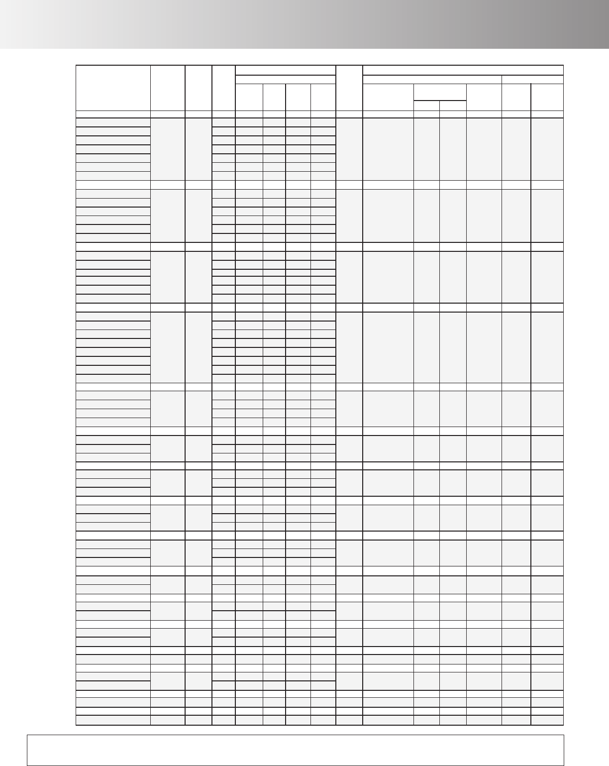
Wire
DieDia. Dieless Burndy
Catalog Color(in) Stud Mechanical PUC Index T&B
Number Code
Copper
Cond.
Range+ ++ Size W DEL TDY-1 TDY-U Dies No. Die
Alt. Tooling(in inches)
Approximate Dimensions Crimping Tool Reference+++
Pressure
Setting
PENN-UNION
BBLU-1/0D-2TC14 Pink.375 1/4 .74 1.22.63 2.94 PUC TDM-250 2 T-12/348 B-12 42
BBLU-1/0D-2TC14E2 1/4 .74 1.36.75 3.08 or
BBLU-1/0D-2TC38E2 3/8 .74 1.58.75 3.30 TDM-500
BBLU-1/0D-2TC38E3 3/8 .74 1.83.81 3.55
BBLU-1/0D-2TC38 3/8 .74 1.8313.55
BBLU-1/0D-2NTC38 3/8 .74 2.581.75 4.30
BBLU-1/0D3 1/2 .81 3.001.75 4.72
BBLU-2/0D-2TC14 Black.419 1/4 .82 1.22.63 3.06 PUC TDM-250 2 T-13 B-13 45
BBLU-2/0D-2TC14E2 1/4 .82 1.36.75 3.20 or
BBLU-2/0D-2TC38E2 3/8 .82 1.58.75 3.42 TDM-500
BBLU-2/0D-2TC38E3 3/8 .82 1.83.81 3.67
BBLU-2/0D-2TC38 3/8 .82 1.8313.67
BBLU-2/0D 1/2 .82 3.001.75 4.84
BBLU-3/0D-2TC14 Orange.470 1/4 .89 1.22.63 3.13 PUC TDM-250 5 5 T-14 B-14 50
BBLU-3/0D-2TC14E2 1/4 .89 1.36.75 3.27 or
BBLU-3/0D-2TC38E2 3/8 .89 1.58.75 3.49 TDM-500
BBLU-3/0D-2TC38E3 3/8 .89 1.83.81 3.74
BBLU-3/0D-2TC38 3/8 .89 1.8313.74
BBLU-3/0D 1/2 .89 3.001.75 4.91
BBLU-4/0D-2TC14 Purple.528 1/4 1.00 1.22.63 3.32 PUC TDM-250 5 5 T-15 B-15 54
BBLU-4/0D-2TC14E2 1/4 1.00 1.36.75 3.46 or
BBLU-4/0D-2TC716E2 7/16 1.00 1.83.75 3.93
TDM-500
BBLU-4/0D-2TC38E2 3/8 1.00 1.58.75 3.68
BBLU-4/0D-2TC38E3 3/8 1.00 1.83.81 3.93
BBLU-4/0D-2TC38 3/8 1.00 1.8313.93
BBLU-4/0D-2NTC38 3/8 1.00 2.581.75 4.68
BBLU-4/0D 1/2 1.00 3.001.75 5.10
BBLU-025D-2TC14E2 Yellow.575 1/4 1.09 1.36.75 3.58 PUC TDM-250 5 5 T-16 B-16 62
BBLU-025D-2TC38E3 3/8 1.09 1.83.81 4.05 or
BBLU-025D-2TC38 3/8 1.09 1.8314.05 TDM-500
BBLU-025D 1/2 1.09 3.001.75 5.22
BBLU-030D-2TC14E2 White.634 1/4 1.19 1.36.75 3.95 PUC TDM-500 7 7 T-17* B-17 66H/66
BBLU-030D-2TC38 3/8 1.19 1.8314.42
BBLU-030D 1/2 1.19 3.001.75 5.59
BBLU-035D-2TC14E2 Red.682 1/4 1.28 1.36.75 4.02 PUC TDM-500 7 7 T-18/324 B-18 71H/71
BBLU-035D-2TC38 3/8 1.28 1.8314.49
BBLU-035D 1/2 1.28 3.001.75 5.66
BBLU-040D-2TC14E2 Blue.728 1/4 1.39 1.36.75 4.15 PUC TDM-500 7 7
T-19*/470
*
B-19 76H/76
BBLU-040D-2TC38 3/8 1.39 1.8314.62
BBLU-040D 1/2 1.39 3.001.75 5.79
BBLU-050D-2TC14E2 Brown.815 1/4 1.53 1.36.75 4.39 PUC TDM-500 9 9 T-20/299 B-20 87
BBLU-050D-2TC38 3/8 1.53 1.8314.86
BBLU-050D 1/2 1.53 3.001.75 6.03
BBLU-060D-2TC38 Green.893 3/8 1.72 1.8315.39 PUC NONE 9 9 T-22/472 B-22 94H/94
BBLU-060D 1/2 1.72 3.001.75 6.56
BBLU-065D-2TC38 Pink.930 3/8 1.78 1.8315.51 PUC NONE 9 9 -
-
-
B-300 99
BBLU-065D 1/2 1.78 3.001.75 6.68
BBLU-075D-2TC38 Black.999 3/8 1.91 2.0815.93 PUC NONE 9 9 T-24*/473 B-24 106H/106
BBLU-075D 1/2 1.91 3.001.75 6.85
BBLU-080D Orange1.031 1/2 1.97 3.001.75 7.00 PUC NONE - - - B-25 107H/107
BBLU-100D-2TC38 White1.153 3/8 2.17 2.0816.24 PUC NONE 9*** 9*** - B-27 125
BBLU-100D1 1/2 2.17 3.001.75 7.16
BBLU-150D1 Green1.412 1/2 2.69 3.001.75 7.44 PUC NONE - - - B-31 -
BBLU-200D1 Brown1.632
1/0
2/0
3/0
4/0
250
300
350
400
500
600
650
750
800
1000
1500
2000 1/2 3.08 3.001.75 7.78 PUC NONE - - - B-34 -
+ Concentric, compressed and compact stranding. * Consult factory for availability of dies not available at this time.
++ For conversion to metric range see Master Catalog **(Also #2 Sol)
+++ For additional tool references see Master Catalog *** CUAD-1000
COPPER PENN-CRIMPS®TELECOMMUNICATION LUGS • TYPE BBLU-2TC
Continued from pageRecent Additions 15
NEW FEATURE!
NOW LISTED FOR GROUNDING, BONDING & DIRECT BURIAL APPLICATIONS
16 RECENT ADDITIONS
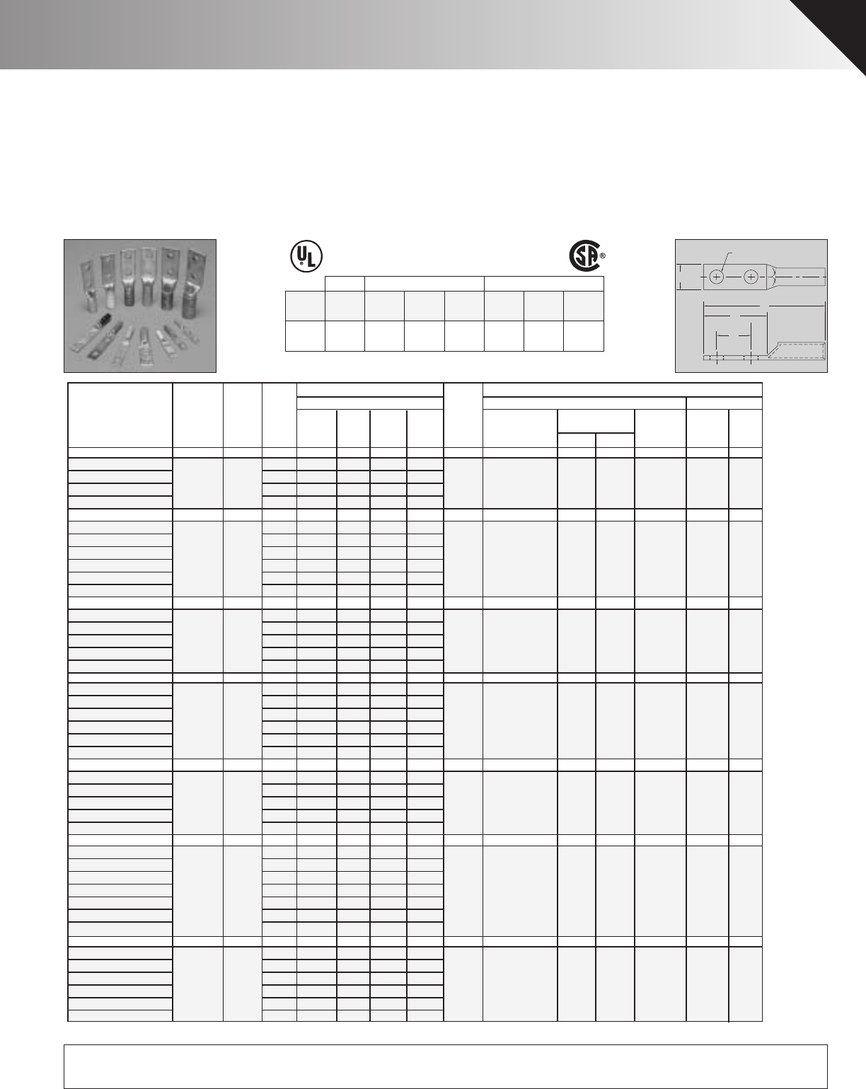
Wire
Copper DieDia. Dieless Burndy
Catalog Cond. Color(in) Stud Mechanical PUC Index T&B
Number Range+ Code++ Size W DEL TDY-1 TDY-U Dies No. Die
BBLZ-8D-2TC14 #8 Red.146 1/4 .41 1.22.63 2.44 PUC TDM-250 T-6 B-6 21
BBLZ-8D-2TC14E2 1/4 .41 1.36.75 2.58 or
BBLZ-8D-2TC38E3 3/8 .56 1.83.81 3.05 TDM-500
BBLZ-8D-2TC38 3/8 .56 1.831 3.05
BBLZ-6D-2TC14 #6 Blue.184 1/4 .41 1.22.63 2.60 PUC TDM-250 T-7*/374* B-7 24
24
BBLZ-6D-2TC14E2 1/4 .41 1.36.75 2.74 or
BBLZ-6D-2TC38E2 3/8 .61 1.58.75 2.96 TDM-500
BBLZ-6D-2TC38E3 3/8 .61 1.83.81 3.21
BBLZ-6D-2TC38 3/8 .61 1.831 3.21
BBLZ-6DN 1/2 .81 3.001.75 4.38
BBLZ-5D-2TC14 #5 Blue.206 1/4 .44 1.22.63 2.60 PUC NONE T-7*/374* B-7--
-
-
-
-
--
--
BBLZ-5D-2TC14E2 1/4 .44 1.36.75 2.74
BBLZ-5D-2TC38E2 3/8 .61 1.58.75 2.96
BBLZ-5D-2TC38E3 3/8 .61 1.83.81 3.21
BBLZ-5D-2TC38 3/8 .61 1.831 3.21
BBLZ-4D-2TC14 #4 Gray.232 1/4 .50 1.22.63 2.60 PUC TDM-250 2 T-8*/346* B-8 29
BBLZ-4D-2TC14E2 1/4 .50 1.36.75 2.74 or
BBLZ-4D-2TC38E2 3/8 .61 1.58.75 2.96 TDM-500
BBLZ-4D-2TC38E3 3/8 .61 1.83.81 3.21
BBLZ-4D-2TC38 3/8 .61 1.831 3.21
BBLZ-4D1 1/2 .94 3.001.75 4.38
BBLZ-3D-2TC14 ** #3 White.260 1/4 .65 1.22.63 2.60 PUC NONE 2 T-9* B-9 -
BBLZ-3D-2TC14E2 1/4 .65 1.36.75 2.74
BBLZ-3D-2TC38E2 3/8 .65 1.58.75 2.96
BBLZ-3D-2TC38E3 3/8 .65 1.83.81 3.21
BBLZ-3D-2TC38 3/8 .65 1.831 3.21
BBLZ-2D-2TC14 #2 Brown.292 1/4 .59 1.22.63 2.75 PUC TDM-250 2 T-10 B-10 33
BBLZ-2D-2TC14E2 1/4 .59 1.36.75 2.89 or
BBLZ-2D-2TC38E2 3/8 .59 1.58.75 3.11 TDM-500
BBLZ-2D-2TC38E3 3/8 .59 1.83.81 3.36
BBLZ-2D-2TC38 3/8 .59 1.831 3.36
BBLZ-2D-2NTC38 3/8 .59 2.581.75 4.11
BBLZ-2D6 1/2 .81 3.001.75 4.53
BBLZ-1D-2TC14 #1 Green.332 1/4 .67 1.22.63 2.94 PUC TDM-250 2 T-11/375 B-11 37
BBLZ-1D-2TC14E2 1/4 .67 1.36.75 3.08 or
BBLZ-1D-2TC38E2 3/8 .67 1.58.75 3.30 TDM-500
BBLZ-1D-2TC38E3 3/8 .67 1.83.81 3.55
BBLZ-1D-2TC38 3/8 .67 1.831 3.55
BBLZ-1D2 1/2 .78 3.001.75 4.72
Alt. Tooling(in inches)
Approximate Dimensions Crimping Tool Reference+++
Pressure
Setting
PENN-UNION
+ Concentric, compressed and compact stranding. * Consult factory for availability of dies not available at this time.
++ For conversion to metric range see Master Catalog **(Also #2 Sol)
+++ For additional tool references see Master Catalog *** CUAD-1000
COPPER PENN-CRIMPS®TELECOMMUNICATION LUGS • TYPE BBLZ-2TC
2 hole long barrel lugs with inspection windows for #8 stranded thru 2000 MCM
E
D
L
W
FOR STUD SIZE
♦Longer length barrel permits extra crimps for additional assur-
ance on heavy duty loads.
♦Seamless, one piece, copper construction with tin plating
assures maximum conductivity.
♦Generous entrance chamfer provides easy cable insertion.
♦End of cable is visible through the inspection window to
ensure proper cable insertion.
♦Catalog number and conductor sizes marked on every piece
insures positive identification.
♦45° and 90° variations are UL listed and CSA certified.
Contact factory for price and availability.
♦Can be installed with existing crimping tools.
♦Die color coding conforms to industry requirements to insure
proper connector/die selection and to provide for faster instal-
lation.
♦Accepts the same wide range of additional wire sizes and
types as our standard BLU, BBLU, BCU and BBCU series.
♦UL/CSA approved with Versa-Crimp®tooling and wire ranges.
Versa-Crimp®is a registered trademark of Hubbell
Incorporated.
♦BBLZ lugs are suitable for use at voltages up to 35KV.
POWER UL 467 GROUNDING
POWER: UL 486A, CSA C22.2 NO. 65
COLOR-CODED
COPPER COMPRESSION CONNECTORS
GROUNDING & BONDING & DIRECT BURIAL : UL 467, CSA C22.2 NO. 41
CSA C22.2 NO. 41 GROUNDING
Connector
Family
UL486A/
CSA22.2 No. 65
Wire Range
UL Grounding
Max. Wire
Grounding
& Bonding
Direct
Burial
CSA Grounding
Max. Wire
Grounding
& Bonding
Direct
Burial
BLU, BBLU,
BBLZ, BCU,
BBCU
8 Str.-
2000 MCM 500 MCM YES YES 250 MCM YES YES
CU
90º C
NEW FEATURE!
NOW LISTED FOR GROUNDING, BONDING & DIRECT BURIAL APPLICATIONS
RECENT ADDITIONS 17
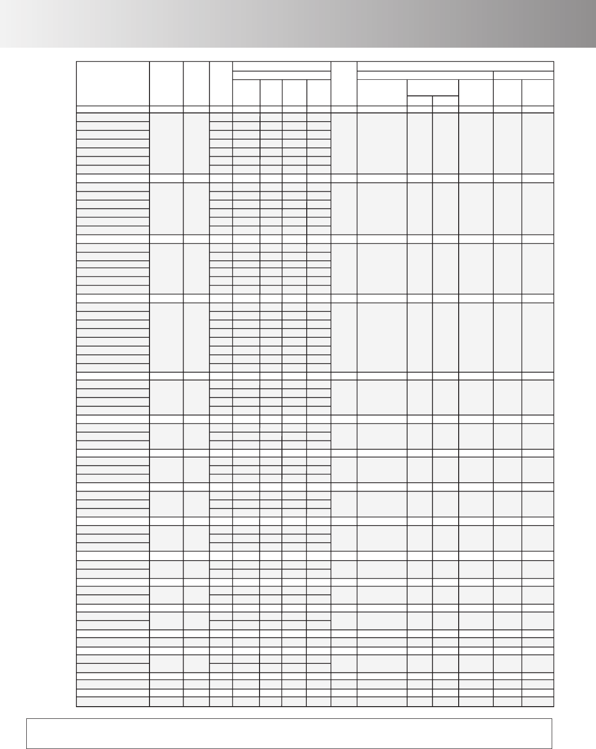
Copper DieDia. Dieless Burndy
Catalog Cond. Color(in) Stud Mechanical PUC Index T&B
Number Range+ Code++ Size W DEL TDY-1 TDY-U Dies No. Die
Alt. Tooling(in inches)
Approximate Dimensions Crimping Tool Reference+++
Pressure
Setting
PENN-UNION
BBLZ-1/0D-2TC14 1/0 Pink.375 1/4 .74 1.22.63 2.94 PUC TDM-250 2 T-12/348 B-12 42
BBLZ-1/0D-2TC14E2 1/4 .74 1.36.75 3.08 or
BBLZ-1/0D-2TC38E2 3/8 .74 1.58.75 3.30 TDM-500
BBLZ-1/0D-2TC38E3 3/8 .74 1.83.81 3.55
BBLZ-1/0D-2TC38 3/8 .74 1.8313.55
BBLZ-1/0D-2NTC38 3/8 .74 2.581.75 4.30
BBLZ-1/0D3 1/2 .81 3.001.75 4.72
BBLZ-2/0D-2TC14 2/0 Black.419 1/4 .82 1.22.63 3.06 PUC TDM-250 2 T-13 B-13 45
BBLZ-2/0D-2TC14E2 1/4 .82 1.36.75 3.20 or
BBLZ-2/0D-2TC38E2 3/8 .82 1.58.75 3.42 TDM-500
BBLZ-2/0D-2TC38E3 3/8 .82 1.83.81 3.67
BBLZ-2/0D-2TC38 3/8 .82 1.8313.67
BBLZ-2/0D 1/2 .82 3.001.75 4.84
BBLZ-3/0D-2TC14 3/0 Orange.470 1/4 .89 1.22.63 3.13 PUC TDM-250 5 5 T-14 B-14 50
BBLZ-3/0D-2TC14E2 1/4 .89 1.36.75 3.27 or
BBLZ-3/0D-2TC38E2 3/8 .89 1.58.75 3.49 TDM-500
BBLZ-3/0D-2TC38E3 3/8 .89 1.83.81 3.74
BBLZ-3/0D-2TC38 3/8 .89 1.8313.74
BBLZ-3/0D 1/2 .89 3.001.75 4.91
BBLZ-4/0D-2TC14 4/0 Purple.528 1/4 1.00 1.22.63 3.32 PUC TDM-250 5 5 T-15 B-15 54
BBLZ-4/0D-2TC14E2 1/4 1.00 1.36.75 3.46 or
BBLZ-4/0D-2TC716E2
7/16 1.00 1.83.75 3.93 TDM-500
BBLZ-4/0D-2TC38E2 3/8 1.00 1.58.75 3.68
BBLZ-4/0D-2TC38E3 3/8 1.00 1.83.81 3.93
BBLZ-4/0D-2TC38 3/8 1.00 1.8313.93
BBLZ-4/0D-2NTC38 3/8 1.00 2.581.75 4.68
BBLZ-4/0D 1/2 1.00 3.001.75 5.10
BBLZ-025D-2TC14E2 250 Yellow.575 1/4 1.09 1.36.75 3.58 PUC TDM-250 5 5 T-16 B-16 62
BBLZ-025D-2TC38E3 3/8 1.09 1.83.81 4.05 or
BBLZ-025D-2TC38 3/8 1.09 1.8314.05 TDM-500
BBLZ-025D 1/2 1.09 3.001.75 5.22
BBLZ-030D-2TC14E2 300 White.634 1/4 1.19 1.36.75 3.95 PUC TDM-500 7 7 T-17* B-17 66H/66
BBLZ-030D-2TC38 3/8 1.19 1.8314.42
BBLZ-030D 1/2 1.19 3.001.75 5.59
BBLZ-035D-2TC14E2 350 Red.682 1/4 1.28 1.36.75 4.02 PUC TDM-500 7 7 T-18/324 B-18 71H/71
BBLZ-035D-2TC38 3/8 1.28 1.8314.49
BBLZ-035D 1/2 1.28 3.001.75 5.66
BBLZ-040D-2TC14E2 400 Blue.728 1/4 1.39 1.36.75 4.15 PUC TDM-500 7 7
T-19*/470
*
B-19 76H/76
BBLZ-040D-2TC38 3/8 1.39 1.8314.62
BBLZ-040D 1/2 1.39 3.001.75 5.79
BBLZ-050D-2TC14E2 500 Brown.815 1/4 1.53 1.36.75 4.39 PUC TDM-500 9 9 T-20/299 B-20 87
BBLZ-050D-2TC38 3/8 1.53 1.8314.86
BBLZ-050D 1/2 1.53 3.001.75 6.03
BBLZ-060D-2TC38 600 Green.893 3/8 1.72 1.8315.39 PUC NONE 9 9 T-22/472 B-22 94H/94
BBLZ-060D 1/2 1.72 3.001.75 6.56
BBLZ-065D-2TC38 650 Pink.930 3/8 1.78 1.8315.51 PUC NONE 9 9 -
-
-
B-300 99
BBLZ-065D 1/2 1.78 3.001.75 6.68
BBLZ-075D-2TC38 750 Black.999 3/8 1.91 2.0815.93 PUC NONE 9 9 T-24*/473 B-24 106H/106
BBLZ-075D 1/2 1.91 3.001.75 6.85
BBLZ-080D 800 Orange1.031 1/2 1.97 3.001.75 7.00 PUC NONE - - - B-25 107H/107
BBLZ-100D-2TC38 1000 White1.153 3/8 2.17 2.0816.24 PUC NONE 9*** 9*** - B-27 125
BBLZ-100D1 1/2 2.17 3.001.75 7.16
BBLZ-150D1 1500 Green1.412 1/2 2.69 3.001.75 7.44 PUC NONE - - - B-31 -
BBLZ-200D1 2000 Brown1.632 1/2 3.08 3.001.75 7.78 PUC NONE - - - B-34 -
+ Concentric, compressed and compact stranding. * Consult factory for availability of dies not available at this time.
++ For conversion to metric range see Master Catalog **(Also #2 Sol)
+++ For additional tool references see Master Catalog *** CUAD-1000
COPPER PENN-CRIMPS®TELECOMMUNICATION LUGS • TYPE BBLZ-2TC
Continued from page Recent Additions 17
NEW FEATURE!
NOW LISTED FOR GROUNDING, BONDING & DIRECT BURIAL APPLICATIONS
18 RECENT ADDITIONS
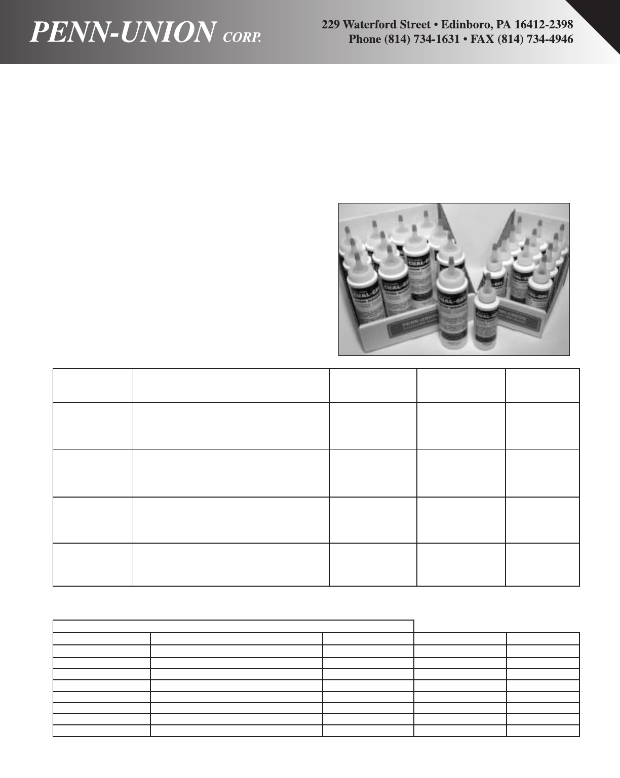
PROPERTY VALUE CUAL-AID® #11C CUAL-AID® #12C CUAL-GEL®
DEFINITION (w/zinc particles) (w/zinc & grit)
PENETRATION The value in accordance to ASTM D217 indi- 230-270 240-280 220-260
(UNWORKED) cates the consistency of a compound. The
higher the number, the softer the compound.
DROPPING The temperature at which the compound 500°F500°F500°F
POINT (MIN.) passes from the semi-solid to a liquid state (non-melting) (non-melting) (non-melting)
under test conditions.
POUR POINT The lowest temperature at which the -10°F-10°F-10°F
(MAX.) compound will flow. Pour point is the
lubricant's ability to perform in cold conditions.
SERVICE TEMP. After installation, the temperature at which -50°C to 150°C-50°C to 150°C-50°C to 150°C
RANGE compound is expected to perform and protect.
CUAL-GEL® CUAL-AID®#11C CUAL-AID®#12C *CONTAINER SIZE
4OZNO11C Squeeze Tube 4 oz.
CUALGEL4OZ Squeeze Bottles 4 oz.
CUALGEL8OZ Squeeze Bottles 8 oz.
**PTCUALGEL PTNO11C PTNO12C Pint Can pint
**QTCUALGEL QTNO11C QTNO12C Quart Can quart
**GALCUALGEL GALNO11C GALNO12C Gallon Can gallon
**5GALCUALGEL 5GALNO11C 5GALNO12C 5 Gallon Can 5 gallon
**55GALCUALGEL 55GALNO11C 55GALNO12C 55 Gallon Drum 55 gallon
CATALOG NUMBERS AND CONTAINERS
CUAL-GEL®
Newest formulation designed for user & protective benefits. A
high quality general use non-melting, non-petroleum base com-
pound specifically designed to prevent oxidation and corrosion of
aluminum, copper, tin and steel.The compound works over a
wide temperature range, sealing out moisture and air, while hav-
ing little or no effect on rubber and most other insulating materi-
als. Easiest cleanup with soap and water.
CUAL-AID®#11C
Ahigh quality general use compound consists of a non-melting,
non-petroleum base material with suspended zinc particles.
Compatible with insulating materials such as rubber or polyethyl-
ene. Recommended for aluminum to aluminum, aluminum to
copper, conduit threads and bolted applications.
CUAL-AID®#12C
Ahigh quality compression use compound consisting of a non-
melting, non-petroleum base material with suspended zinc parti-
cles and abrasive grit. Not for use on threads or bolted applica-
tions. Compatible with rubber, polyethylene and other insulating
materials. Recommended for aluminum to aluminum and alu-
minum to copper in all compression applications.
*Squeeze tubes and bottles sold 12 per carton only. **Consult factory for price and availability
PROPERTIES OF CUAL-AID® & CUAL-GEL®
ORDERING INFORMATION
OXIDE INHIBITOR COMPOUNDS • CUAL-AID®#11C, #12C AND CUAL-GEL®
RECENT ADDITIONS 19
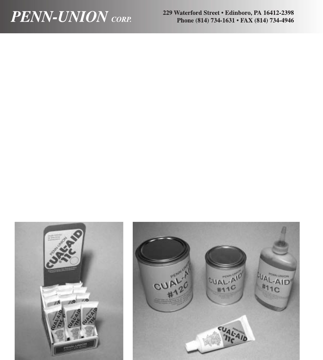
OXIDE INHIBITOR COMPOUNDS • CUAL-AID®#11C, #12C AND CUAL-GEL®
EASY TO APPLY:
Connectors: DO NOT wire-brush the grooves or contact surfaces of plated or grease-coated connectors. For unplated,
ungreased connectors, wire brush contact surfaces until bright and clean. Immediately apply compound to the con-
ductive surfaces. Install conductor and finish installation.
Cable: Apply compound and wire-brush into strands of aluminum cable.This removes oxide coating from the strands, and
prevents it from reforming. Install conductor and finish installation.
Bar: Wire-brush compound across the surface of the bar to remove oxide coating and finish installation. DO NOT wire-
brush plated surfaces, simply apply compound and finish installation.
FEATURES:
♦Non-melting, non-petroleum based compounds.
♦Will not wash off from exposure to the elements.
♦Provides air-tight seal.
♦Easy clean up. #11C, #12C with detergent. Cual-Gel with soap
and water.
♦Available in various packaging
♦CUAL-GEL®
BENEFITS:
♦Little or no effect on rubber and most other insulating materials.
♦Remains in place as expected to perform and protect.
♦Prevents oxidation for increased connection service.
♦No special or extra costly cleaners.
♦Convenience of right size package per job.
♦Specifically designed to prevent oxidation and corrosion of alu-
minum, copper, tin and steel. Multiple uses with conductors, con-
nectors, conduits and connections.
OXIDE INHIBITOR COMPOUNDS • CUAL-AID®#11C, #12C AND CUAL-GEL®
20 RECENT ADDITIONS

486A 467
600V LISTED
CU GROUNDING POWER &
90OCBONDING GROUNDING
NEW FEATURE-NOW APPROVED FOR
GROUNDING/BONDING AND
ELECTRICAL
COPPER ALLOY SPLIT BOLT CONNECTORS • TYPES S AND SEL
For copper and copperweld wires
THE MOST VERSATILE SPLIT BOLT ON THE MARKET
MANUFACTURED IN THE USA
Made from high strength copper alloy. Highly resistant to
corrosion and season cracking. Under torque this design provides
high contact pressure between conductors.
TYPE “SEL”:
The first 3-conductor split bolt approved for grounding!
2 CONDUCTORS
CATALOG RANGE MIN TAP MAX COND WIRE L W ACROSS TORQUE
NO. EQ RUN WITH ONE COPPERWELD DIAMETER FLATS IN/LBS.
& TAP MAX. MAIN STR. TYPE range †
A
S-8* 16str- 16str - - .057 - .145 .84 .50 .38 80
8str.
S-6* 10sol- 16sol - - .102 - .162 1.05 .63 .50 165
6sol
S-4* 8sol- 16sol 3 No. 12 8A .128-.204 1.05 .69 .56 165
4sol
S-3* 6sol- 12sol 3 No. 9 5A .162-.258 1.31 .81 .69 275
2sol
S-2* 6sol- 14str 3 No. 7 3A .162-.292 1.31 .81 .69 275
2str
S-1/0* 4sol- 14sol 3 No. 6 2A .204-.375 1.64 .88 .75 385
1/0str
S-2/0 2sol- 14str 3 No. 5 - .258-.418 1.81 1 .81 385
2/0str
S-3/0 2sol- 12sol 7 No. 7 - .258-.470 2 1.13 .88 500
3/0str
S-4/0-250 1/0sol- 10sol 7 No. 5 - .325-.575 2.08 1.31 1 650
250
S-350+ 4/0str- 8sol 19 No. 7 - .528-.682 2.63 1.63 1.50 650
350
S-500+ 250- 8sol 19 No. 6 - .575-.815 3 1.81 1.63 825
500
S-750++ 350-750 8sol 19 No. 5 - .682-.999 3.75 2.13 1.94 1000
S-1000++ 500-1000 8sol - - .815-.1.153 4 .250 2.25 1100
+ UL Only Grounding and Bonding
++ Not approved for grounding & bonding (no standard)
* RUS accepted
2-3 CONDUCTORS
CATALOG RANGE MIN TAP MAX COND WIRE L W ACROSS TORQUE
NO. EQ RUN WITH ONE COPPERWELD DIAMETER FLATS IN/LBS.
& TAP MAX. MAIN STR. TYPE range †
A
SEL-8* 16str- 16str - - .057-.145 .84 .50 .38 80
8str
SEL-6* 10sol- 16sol - - .102-.162 1.05 .69 .56 165
6sol
SEL-4* 8sol-4sol 16sol 3 No. 12 8A .128-.204 1.27 .69 .56 165
SEL-2* 6sol-2str 14str 3 No. 7 3A .162-.292 1.55 .81 .69 275
† For conversion to metric range, see page 171
* RUS accepted.
Features and Benefits
♦Application/Use.
•Type S is for use with 2-conductors for electrical
power applications, and grounding & bonding applica-
tions, except direct burial.
•Type SEL is for use with 2 or 3-conductors for electri-
cal power applications, and grounding & bonding
applications, except direct burial.
♦Versatile • Multi-uses:
•Electrical
•Splicing and taping
•Grounding and Bonding
•Above ground splicing, taping and bonding.
♦Unique Design
•SEL-first 3-conductor split bolt approved for grounding
& bonding with full CSA certification.
•Re-usable with proper installation practice.
•Free running threads.
•Pressure bar design features give assurance of high
“pull-out” and a secure connection on all combinations
of conductors.
•True hex design for position grip and assured
torquing.
•Wide wire range per size.
•600V-90OC temperature.
♦Conductors.
•Wide range of solid, compact, compressed, concentric
and copperweld.
♦Installation
•Torque wrench plus socket, box or open-end wrench-
es.
•True hex design sizing.
POWER UL-467 GROUNDING CSA C22.2 NO. 41 GROUNDING
Connector CSA22.2 NO. 65 UL Grounding Grounding Direct Burial CSA Grounding Direct
Grounding
Family Wire Range Max. Wire & Bonding w/Rebar Max. Wire & Bonding Burial
S16 Str.-
SEL 1000 MCM 500 MCM Yes No 250 MCM Yes No
*S-DB 16 Str.
SEL-DB 500 MCM 500 MCM Yes Yes 250 MCM Yes Yes
*Direct Burial-see What’s New Section front of catalog
POWER: UL 486A, CSA C22.2 NO. 65
GROUNDING AND BONDING: UL 487, CSA C22.2 NO. 41
RECENT ADDITIONS 21
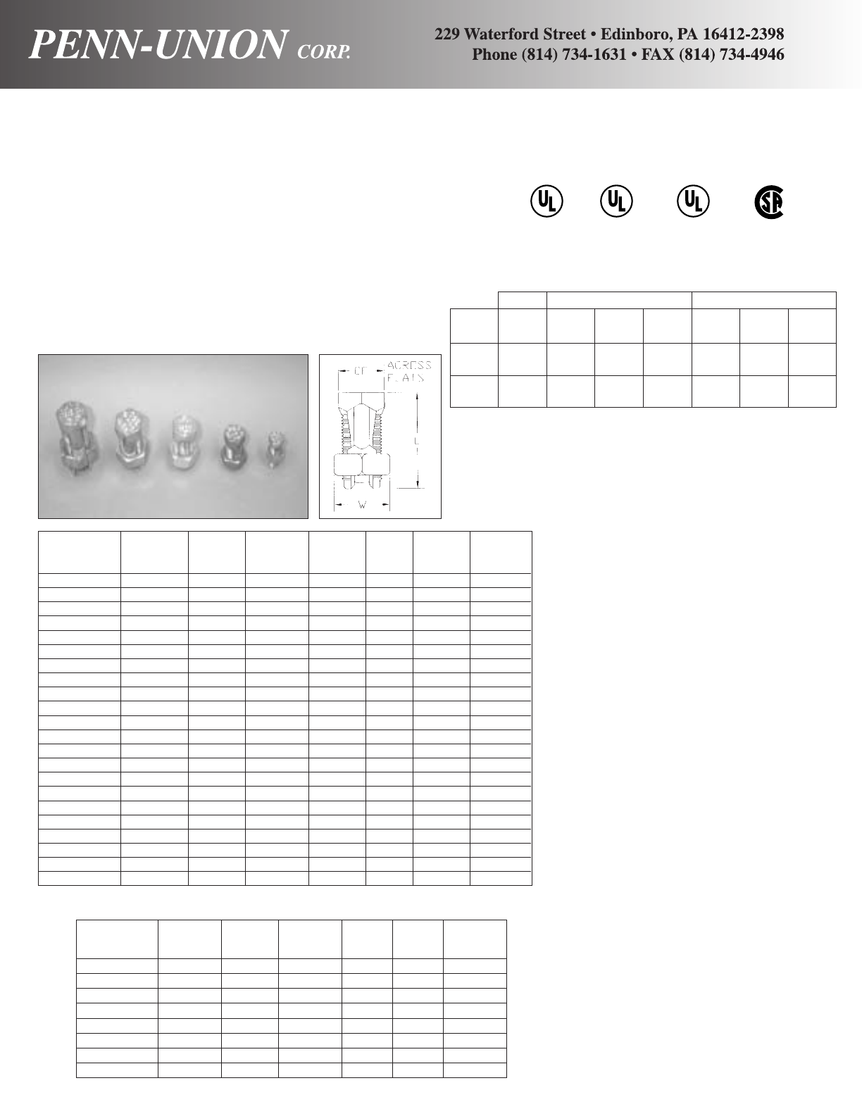
SEL-8-DB 16str-8str 16str .84 .50 .38 80
SEL-6-DB 10sol-6sol 16sol 1.11 .63 .50 165
SEL-4-DB 8sol-4sol 16sol 1.27 .69 .56 165
SEL-2-DB 6sol-2str 14str 1.55 .81 .69 275
COPPER ALLOY SPLIT BOLT CONNECTORS •TYPES S - DB AND SEL - DB
For copper and copperweld wires and rebar
THE MOST VERSATILE SPLIT BOLT ON THE MARKET
MANUFACTURED IN THE USA
Made from high strength copper alloy. Highly resistant to
corrosion and season cracking. Under torque this design provides
high contact pressure between conductors, or conductor to rebar.
TYPE “SEL-DB”:
The first 3-conductor split bolt approved for grounding!
®
467
LISTED
S-8-DB 16str.-8str 16str N/A .84 .50 .38 80
S-6-DB 10sol-6sol 16sol N/A 1.05 .63 .50 165
S-4-DB 8sol-4sol 16sol N/A 1.05 .69 .56 165
S-3-DB 6sol-2sol 12sol N/A 1.31 .81 .69 275
S-2-DB 6sol-2str 14str N/A 1.31 .81 .69 275
S-1/0-DB 4sol-1/0str 14sol N/A 1.64 .88 .75 385
S-2/0-DB 2sol-2/0str 14str #3 (3/8) 1.81 1 .81 385
S-3/0-DB 2sol-3/0str. 12 sol N/A 2 1.13 .88 500
S-4/0-250-DB 1/0sol-250 10sol #4 (1/2) 2.08 1.31 1 650
S-350-DB + 4/0str-350 8sol #5 (5/8) 2.63 1.63 1.50 650
S-500-DB + 250-500 8sol #6 (3/4) 3 1.81 1.63 825
+ UL Only
FEATURES AND BENEFITS
♦Application/Use.
•Type S-DB is for use with 2-conduc-
tors or 1-conductor to rebar.
•Type SEL-DB, for use with
2 or 3-conductors for grounding.
•DB permanently marked on head for
easier identification by inspectors.
♦Versatile – Multi-uses.
•Electrical.
■Splicing and taping.
•Grounding and Bonding.
■Above ground splicing, taping and
bonding.
•Grounding and Bonding-Direct Burial.
■Below ground splicing, taping and
bonding.
■Embedment in earth or concrete,
including rebar.
♦Unique Design.
•Reusable with proper installation
practice.
•Free running threads.
•True hex design for positive grip and
assured torquing.
•Wide wire range per size.
•600V - 90°C temperature.
♦Conductors.
•Solid, compact, compressed,
concentric.
•Rebar #3, 4, 5, 6.
♦Installation.
•Torque wrench plus socket, box or
open end wrenches.
POWER UL-467 GROUNDING CSA C22.2 NO. 41 GROUNDING
UL486A/
Connector CSA22.2 No. 65 UL Grounding Grounding Direct Burial CSA Grounding Grounding Direct
Family Wire Range Max. Wire & Bonding w/Rebar Max. Wire & Bonding Burial
S-DB 16 Str.-
SEL-DB 500 MCM 500 MCM YES YES 250 MCM YES YES
*S 16 Str.-
SEL 1000 MCM 500 MCM YES NO 250 MCM YES NO
* See Master Catalog
POWER: UL 486A, CSA C22.2 NO. 65
GROUNDING & BONDING & DIRECT BURIAL: UL 467, CSA C22.2 NO. 41
® ®
CU
90°C
Power &
Grounding
467
LISTED
SUITABLE FOR
DIRECT BURIAL
NEW
CATALOG
NO.
EQ RUN
&TAP
MIN TAP
WITH ONE
MAX. MAIN
+REBAR
w/6or8AWG LW
ACROSS
FLATS
TORQUE
IN/LBS
CATALOG
NO.
EQ RUN
&TAP
MIN TAP
WITH ONE
MAX. MAIN
LW
ACROSS
FLATS
TORQUE
IN/LBS
22 RECENT ADDITIONS

Catalog Number of Conductor Approximate Dimensions Inches
Number Conductors Range LWHHex Key
IPB-NA4-2S 2 4 Str - 14 Sol 1.03 1.19 1.19
IPB-NA4-3S 3 4 Str - 14 Sol 1.39 1.19 1.19
IPB-NA4-4S 4 4 Str - 14 Sol 1.90 1.19 1.19
IPB-NA4-5S 5 4 Str - 14 Sol 2.26 1.19 1.19
IPB-NA4-6S 6 4 Str - 14 Sol 2.70 1.19 1.19 1/8
IPB-NA4-8S 8 4 Str. 14 Sol 3.58 1.19 1.19
IPB-NA2/0-2S 2 2/0 - 14 Sol 1.39 1.25 1.31
IPB-NA2/0-3S 3 2/0 - 14 Sol 2.06 1.25 1.31
IPB-NA2/0-4S 4 2/0 - 14 Sol 2.73 1.25 1.31
IPB-NA2/0-5S 5 2/0 - 14 Sol 3.40 1.25 1.31
IPB-NA2/0-6S 6 2/0 - 14 Sol 4.07 1.25 1.31 3/16
IPB-NA2/0-8S 8 2/0 - 14 Sol 5.42 1.25 1.31
IPB-NA2/0-10S 10 2/0 - 14 Sol 6.77 1.25 1.31
IPB-NA2/0-12S 12 2/0 - 14 Sol 8.11 1.25 1.31
IPB-NA2/0-14S 14 2/0 - 14 Sol 9.46 1.25 1.31
IPB-NA250-2S 2 250 MCM - 10 Sol 1.90 2.00 2.07
IPB-NA250-3S 3 250 MCM - 10 Sol 2.84 2.00 2.07
IPB-NA250-4S 4 250 MCM - 10 Sol 3.78 2.00 2.07
IPB-NA250-5S 5 250 MCM - 10 Sol 4.71 2.00 2.07
IPB-NA250-6S 6 250 MCM - 10 Sol 5.65 2.00 2.07 5/16
IPB-NA250-8S 8 250 MCM - 10 Sol 7.53 2.00 2.07
IPB-NA250-10S 10 250 MCM - 10 Sol 9.41 2.00 2.07
IPB-NA250-12S 12 250 MCM - 10 Sol 11.29 2.00 2.07
IPB-NA250-14S 14 250 MCM - 10 Sol 13.16 2.00 2.07
IPB-NA350-2S 2 350 MCM - 10 Sol 2.09 2.47 2.44
IPB-NA350-3S 3 350 MCM - 10 Sol 3.00 2.47 2.44
IPB-NA350-4S 4 350 MCM - 10 Sol 3.91 2.47 2.44
IPB-NA350-5S 5 350 MCM - 10 Sol 4.82 2.47 2.44
IPB-NA350-6S 6 350 MCM - 10 Sol 5.73 2.47 2.44 5/16
IPB-NA350-8S 8 350 MCM - 10 Sol 7.55 2.47 2.44
IPB-NA350-10S 10 350 MCM - 10 Sol 10.06 2.47 2.44
IPB-NA350-12S 12 350 MCM - 10 Sol 12.06 2.47 2.44
IPB-NA350-14S 14 350 MCM - 10 sol 13.06 2.47 2.44
IPB-NA600-2S 2 600 MCM - 4 Str 2.59 2.72 2.69
IPB-NA600-3S 3 600 MCM - 4 Str 3.87 2.72 2.69
IPB-NA600-4S 4 600 MCM - 4 Str 5.15 2.72 2.69
IPB-NA600-5S 5 600 MCM - 4 Str 6.43 2.72 2.69 3/8
IPB-NA600-6S 6 600 MCM - 4 Str 7.71 2.72 2.69
IPB-NA600-8S 8 600 MCM - 4 Str 10.28 2.72 2.69
IPB-NA600-10S 10 600 MCM - 4 Str 12.84 2.72 2.69
IPB-NA600-12S 12 600 MCM - 4 Str 15.40 2.72 2.69
IPB-NA600-14S 14 600 MCM - 4 Str 18.00 2.72 2.69
FEATURES AND BENEFITS
♦Pre-insulated at factory.
•Clear PVC allows visual inspection of
conductor properly inserted at
installation and final inspection
approval.
•Eliminates the need for time
consuming taping.
♦Pre-Filled with oxide inhibitor and
plugged ports.
•Prevents oxidation, moisture and
contaminants from contact surfaces.
•Reduces installation time.
♦Wide conductor range.
•Available in two through fourteen
conductor configurations in five
conductor sizes.
•Reduced inventory.
♦Compact, versatile design.
•Dual rated (AL9CU) for copper and
aluminum applications.
•Use as a splice, tap or splice
reducer.
•Low total cost of installation.
ALUMINUM CLEAR PRE-INSULATED POWER BAR • TYPE IPB
For any combination of copper and aluminum wire.
Pre-insulated aluminum connectors for splice, reducer and tap applications. Dual rated for both alu-
minum and copper conductors, simultaneous accommodations at 600V and 90°C. For use in areas such
as
troughs, gutters, panels, ducts and wireways. Only one conductor per set screw, and only one supply
®
486B LISTED
AL9CU
SINGLE SIDED ENTRY
SINGLE SIDED ENTRY TYPE DUAL SIDED ENTRY TYPE ALTERNATE ENTRY TYPE
RECENT ADDITIONS 23

24 RECENT ADDITIONS
Catalog Number of Conductor Approximate Dimensions Inches
Number Conductors Range LWHHex Key
IPB-NA4-2D 2 4 Str - 14 Sol 1.03 1.53 1.19
IPB-NA4-3D 3 4 Str - 14 Sol 1.39 1.53 1.19
IPB-NA4-4D 4 4 Str - 14 Sol 1.90 1.53 1.19
IPB-NA4-5D 5 4 Str - 14 Sol 2.26 1.53 1.19
IPB-NA4-6D 6 4 Str - 14 Sol 2.70 1.53 1.19 1/8
IPB-NA4-8D 8 4 Str. 14 Sol 3.58 1.53 1.19
IPB-NA4-10D 10 4 Str. 14 Sol 4.46 1.53 1.19
IPB-NA4-12D 12 4 Str. 14 Sol 5.34 1.53 1.19
IPB-NA4-14D 14 4 Str. 14 Sol 6.21 1.53 1.19
IPB-NA2/0-2D 2 2/0 - 14 Sol 1.39 1.56 1.31
IPB-NA2/0-3D 3 2/0 - 14 Sol 2.06 1.56 1.31
IPB-NA2/0-4D 4 2/0 - 14 Sol 2.73 1.56 1.31
IPB-NA2/0-5D 5 2/0 - 14 Sol 3.40 1.56 1.31
IPB-NA2/0-6D 6 2/0 - 14 Sol 4.07 1.56 1.31 3/16
IPB-NA2/0-8D 8 2/0 - 14 Sol 5.42 1.56 1.31
IPB-NA2/0-10D 10 2/0 - 14 Sol 6.77 1.56 1.31
IPB-NA2/0-12D 12 2/0 - 14 Sol 8.11 1.56 1.31
IPB-NA2/0-14D 14 2/0 - 14 Sol 9.46 1.56 1.31
IPB-NA250-2D 2 250 MCM - 10 Sol 1.90 2.63 2.07
IPB-NA250-3D 3 250 MCM - 10 Sol 2.84 2.63 2.07
IPB-NA250-4D 4 250 MCM - 10 Sol 3.78 2.63 2.07
IPB-NA250-5D 5 250 MCM - 10 Sol 4.71 2.63 2.07
IPB-NA250-6D 6 250 MCM - 10 Sol 5.65 2.63 2.07 5/16
IPB-NA250-8D 8 250 MCM - 10 Sol 7.53 2.63 2.07
IPB-NA250-10D 10 250 MCM - 10 Sol 9.41 2.63 2.07
IPB-NA250-12D 12 250 MCM - 10 Sol 11.29 2.63 2.07
IPB-NA250-14D 14 250 MCM - 10 Sol 13.16 2.63 2.07
IPB-NA350-2D 2 350 MCM - 10 Sol 2.09 3.00 2.44
IPB-NA350-3D 3 350 MCM - 10 Sol 3.00 3.00 2.44
IPB-NA350-4D 4 350 MCM - 10 Sol 3.91 3.00 2.44
IPB-NA350-5D 5 350 MCM - 10 Sol 4.82 3.00 2.44
IPB-NA350-6D 6 350 MCM - 10 Sol 5.73 3.00 2.44 5/16
IPB-NA350-8D 8 350 MCM - 10 Sol 7.55 3.00 2.44
IPB-NA350-10D 10 350 MCM - 10 Sol 10.06 3.00 2.44
IPB-NA350-12D 12 350 MCM - 10 Sol 12.06 3.00 2.44
IPB-NA350-14D 14 350 MCM - 10 sol 13.06 3.00 2.44
IPB-NA600-2D 2 600 MCM - 4 Str 2.59 3.00 2.69
IPB-NA600-3D 3 600 MCM - 4 Str 3.87 3.00 2.69
IPB-NA600-4D 4 600 MCM - 4 Str 5.15 3.00 2.69
IPB-NA600-5D 5 600 MCM - 4 Str 6.43 3.00 2.69 3/8
IPB-NA600-6D 6 600 MCM - 4 Str 7.71 3.00 2.69
IPB-NA600-8D 8 600 MCM - 4 Str 10.28 3.00 2.69
IPB-NA600-10D 10 600 MCM - 4 Str 12.84 3.00 2.69
IPB-NA600-12D 12 600 MCM - 4 Str 15.40 3.00 2.69
IPB-NA600-14D 14 600 MCM - 4 Str 18.00 3.00 2.69
FEATURES AND BENEFITS
♦Pre-insulated at factory.
•Clear PVC allows visual inspection of
conductor properly inserted at
installation and final inspection
approval.
•Eliminates the need for time
consuming taping.
♦Pre-Filled with oxide inhibitor and
plugged ports.
•Prevents oxidation, moisture and
contaminants from contact surfaces.
•Reduces installation time.
♦Wide conductor range.
•Available in two through fourteen
conductor configurations in five
conductor sizes.
•Reduced inventory.
♦Compact, versatile design.
•Dual rated (AL9CU) for copper and
aluminum applications.
•Use as a splice, tap or splice
reducer.
•Low total cost of installation.
ALUMINUM CLEAR PRE-INSULATED POWER BAR • TYPE IPB
For any combination of copper and aluminum wire.
Pre-insulated aluminum connectors for splice, reducer and tap applications. Dual rated for both aluminum
and copper conductors at 600V and 90°C. For use in areas such as troughs, gutters, panels, ducts and
wireways. Only one conductor per set screw, and only one supply conductor per connector permitted.
DUAL ENTRY
®
486B LISTED
AL9CU
Catalog Number of Conductor Approximate Dimensions Inches
Number Conductors Range LWHHex Key
IPB-NA4-2A 2 4 Str - 14 Sol 1.03 1.53 1.19 1/8
IPB-NA2/0-2A 2 2/0 Str - 14 Sol 1.39 1.56 1.31 3/16
IPB-N250-2A 2 250 MCM - 10 Sol 1.90 2.63 2.07 5/16
IPB-NA350-2A 2 350 MCM - 10 Sol 2.09 3.00 2.44 5/16
IPB-NA600-2A 2 600 MCM - 4 Str 2.59 3.00 2.69 3/8
ALTERNATE ENTRY
DUAL SIDED ENTRY
ALTERNATE SIDED ENTRY
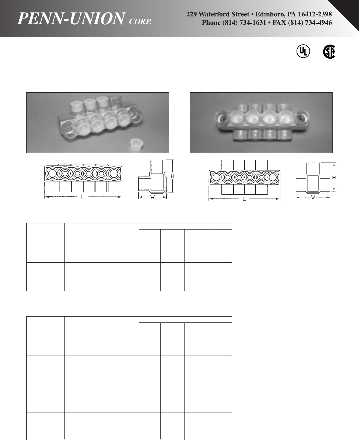
RECENT ADDITIONS 25
Catalog Number of Conductor Approximate Dimensions Inches
Number Conductors Range LW HHex Key
IPBM-NA2/0-4S 4 2/0 - 14 Sol 2.73 1.25 1.31
IPBM-NA2/0-6S 6 2/0 - 14 Sol 4.07 1.25 1.31
IPBM-NA2/0-8S 8 2/0 - 14 Sol 5.42 1.25 1.31 3/16
IPBM-NA2/0-10S 10 2/0 - 14 Sol 6.77 1.25 1.31
IPBM-NA2/0-12S 12 2/0 - 14 Sol 8.11 1.25 1.31
IPBM-NA250-4S 4 250 MCM - 10 Sol 3.78 2.00 2.07
IPBM-NA250-6S 6 250 MCM - 10 Sol 5.65 2.00 2.07
IPBM-NA250-8S 8 250 MCM - 10 Sol 7.53 2.00 2.07 5/16
IPBM-NA250-10S 10 250 MCM - 10 Sol 9.41 2.00 2.07
IPBM-NA250-12S 12 250 MCM - 10 Sol 11.29 2.00 2.07
Note: Mounting holes will accept up to and including 5/16” mounting hardware for all sizes.
FEATURES AND BENEFITS
♦Direct Mounting.
•Maintains all of the quality features
and benefits of the IPB pre-insulated
connectors with direct mounting
ability.
♦Mounting Holes.
•Two isolated mounting holes, one at
each end of connector.
•Special PVC collared insert to isolate
mounting hardware from aluminum
body contact.
•Accommodates up to and including
standard 5/16″diameter mounting
hardware.
♦Versatile.
•Direct mounting in the installers’
location.
•Eliminates the need for time
consuming taping during installation.
•Simply drill holes in structure and
mount connector.
ALUMINUM CLEAR PRE-INSULATED POWER BAR • TYPE IPBM
For any combination of copper and aluminum wire.
Pre-insulated mount version has the same features as the existing IPB pre-insulated
connectors with the additional ability to be mounted. Each IPBM connector has two
isolated mounting holes, one at each end of the connector.
®
486B LISTED
AL9CU
SINGLE ENTRY MOUNTING
Catalog Number of Conductor Approximate Dimensions Inches
Number Conductors Range LW HHex Key
IPBM-NA2/0-4D 4 2/0 - 14 Sol 2.73 1.56 1.31
IPBM-NA2/0-6D 6 2/0 - 14 Sol 4.07 1.56 1.31
IPBM-NA2/0-8D 8 2/0 - 14 Sol 5.42 1.56 1.31 3/16
IPBM-NA2/0-10D 10 2/0 - 14 Sol 6.77 1.56 1.31
IPBM-NA2/0-12D 12 2/0 - 14 Sol 8.11 1.56 1.31
IPBM-NA250-4D 4 250 MCM - 10 Sol 3.78 2.63 2.07
IPBM-NA250-6D 6 250 MCM - 10 Sol 5.65 2.63 2.07
IPBM-NA250-8D 8 250 MCM - 10 Sol 7.53 2.63 2.07 5/16
IPBM-NA250-10D 10 250 MCM - 10 Sol 9.41 2.63 2.07
IPBM-NA250-12D 12 250 MCM - 10 Sol 11.29 2.63 2.07
IPBM-NA350-4D 4 350 MCM - 10 Sol 3.91 3.00 2.44
IPBM-NA350-6D 6 350 MCM - 10 Sol 5.73 3.00 2.44
IPBM-NA350-8D 8 350 MCM - 10 Sol 7.55 3.00 2.44 5/16
IPBM-NA350-10D 10 350 MCM - 10 Sol 10.06 3.00 2.44
IPBM-NA350-12D 12 350 MCM - 10 Sol 12.06 3.00 2.44
IPBM-NA600-4D 4 600 MCM - 4 Str 7.71 3.00 2.69
IPBM-NA600-6D 6 600 MCM - 4 Str 10.28 3.00 2.69
IPBM-NA600-8D 8 600 MCM - 4 Str 12.84 3.00 2.69 3/8
IPBM-NA600-10D 10 600 MCM - 4 Str 15.40 3.00 2.69
IPBM-NA600-12D 12 600 MCM - 4 Str 18.00 3.00 2.69
Note: Mounting holes will accept up to and including 5/16” mounting hardware for all sizes.
DUAL ENTRY MOUNTING
SINGLE SIDED ENTRY MOUNTING TYPE DUAL SIDED ENTRY MOUNTING TYPE

26 RECENT ADDITIONS
•COPPER
•UL & cUL LISTED
•INSULATED
•WIDE CONDUCTOR RANGE
•VOLTAGE
•HIGHLY VISIBLE
•COMPACT
•PLASTIC PLUGS
•TORQUE WRENCH & STANDARD HEX SIZES
✧MORE ECONOMICAL ✧MORE CONVENIENT TO USE ✧
✧SAVES TIME ✧LOWERS INSTALLATION COST ✧
PENN-UNION CORP. 229 Waterford Street Edinboro, Pennsylvania 16412 814/734-1631 FAX: 814/734-4946
www.penn-union.com e-mail: info@penn-union.com
•COPPER - Reusable mechanical connector
•UL & cUL LISTED - For use only on copper Solid, Stranded, Hypalon®& DLO type cables
•INSULATED - High dielectric strength plastisol provides protection against brush contact
•WIDE CONDUCTOR RANGE - 18 AWG through 500 MCM
•VOLTAGE - 600 V Maximum, Building Wire: 1000 V Maximum, Signs & Fixtures - Insulation Temperature 90ºC
•HIGHLY VISIBLE - Bright colors
•COMPACT - Factory insulated, one piece, captive set screws, no loose parts
•PLASTIC PLUGS - To protect against contamination
•TORQUE WRENCH & STANDARD HEX SIZES - Promotes ease of installation to required torques
®Hypalon is a registered trademark of DuPont Dow Elastomers L.L.C.
CONDUCTOR RANGE
Catalog
Number
Tightening
Torque
In-lbs.
Internal
Socket Size
Across Flats
(Inches)
AWG-CU DLO-CU-Cable Hypalon®
IMLC-4-2S 18 SOL. - 4 STR. 14 (19/27) - 6 (61/24) 18 AWG - 6 AWG 45 5/32 9/16
IMLC-4-3S
IMLC-1/0-2S 8 SOL. - 1/0 STR. 8 (37/24) - 2 (150/24) 8 AWG - 1 AWG 150 1/4 5/8
IMLC-1/0-3S
IMLC-350-2S 4 SOL. - 350 MCM 2 (150/24) - 4/0 (550/24) 4 AWG - 4/0 AWG 375 3/8 1 1/8
IMLC-350-3S
IMLC-500-2S 4 SOL. - 500 MCM 2 (150/24) - 313.1 (775/24) 4 AWG - 4/0 AWG 375 3/8 1 1/4
IMLC-500-3S
For use with
copper cables …
Insulated mechanical connectors for
use with copper cables can be used in
dry locations where there is a need to
join two or three copper wires
together. The IMLCTM connectors are
ideal for use in cabletrays, raceways,
wireways, ducts and troughs. The
IMLCTM connector series is suitable
for demanding motor applications by
providing a fast, simple and
economical way to install, test or
replace a motor. The multiple port
insulated copper alloy bars
mechanically connect incoming copper
power leads to the winding leads of
the motor in the motor junction box.
Strip
Length
(Inches)
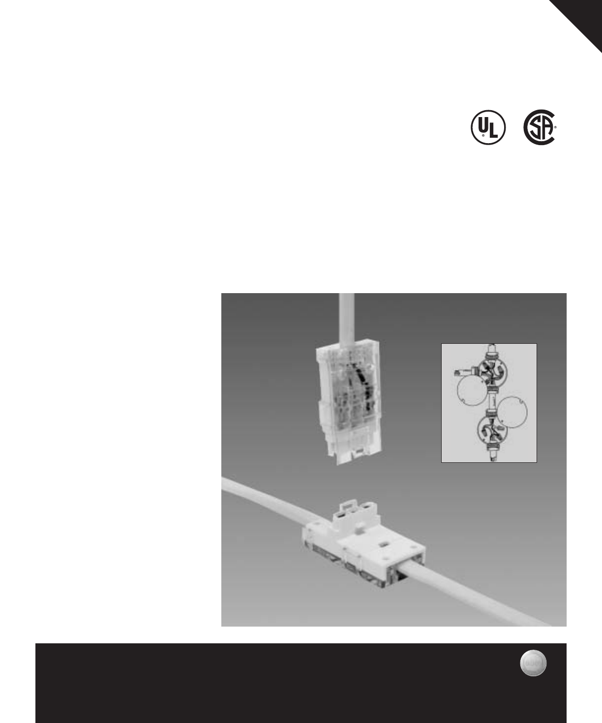
•Concealment applications per NEC:
Article 545, Manufactured Buildings
Article 550, Manufactured Homes
Article 551, Recreational Vehicles
•Saves time - installs in just a few
minutes.
•Eliminates junction boxes.
•Taps 14/2 and 12/2 ROMEX®with
ground.
•300 Volt, 20 Amp Rating.
•Double insulation displacement
contacts for maximum conductivity.
•Compact, rugged design.
•Conveniently packaged one
kit per bag with instructions.
PENN-UNION TAP KIT
FOR ROMEX®STYLE CABLE
NMTK 142-122
TAP KIT Faster, easier, better way to tap ROMEX®style cable.
No need to cut the wire and install junction boxes.
UL Listed Category QAAV; Self-contained interconnectors intended for installation in
accordance with NATIONAL ELECTRICAL CODE®, NEC 1999, ARTICLE 336-21.
“Devices of Insulating Material. Switch, outlet, and tap devices of insulating material
shall be permitted to be used without boxes in exposed cable wiring and for rewiring
in existing buildings where the cable is concealed and fished.”*
Applications for “built-on-site” type homes/structures, basements, attics, garages, suspend-
ed ceilings, etc., anywhere accessible.
Romex®is a registered trademark of General Cable Corporation
PENN-UNION CORP.
Manufacturers of Quality Connectors Since 1928
229 Waterford St. * Edinboro, PA 16412 * Phone: 814/734-1631 * Fax: 814/734-4946
Internet - http://www.penn-union.com * e-mail: info@penn-union.com
*Reprinted with permission from NFPA 70-1999, the National Electrical Code®, Copyright©1998, National Fire Protection Association, Quincy, MA 02269. This reprinted material is not the
complete and official position of the National Fire Protection Association, on the referenced subject which is represented only by the standard in its entirety. National Electrical Code®and NEC®
are registered trademarks of the National Fire Protection Association, Inc., Quincy, MA 02269.
NEC®
New Way: Old Way:
RECENT ADDITIONS 27

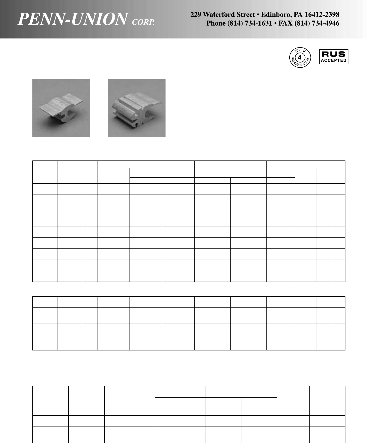
Wire Diameter TDY-U
Catalog Conductor Range‡ Number of Crimps Die Pressure
Number Size Range in 0-52 Hand Hyd. Size Setting
KO-R21 A4 Str.-4 ACSR .232-.257 3–
5/8"-Nose 2
B12 Sol.-10 Str. .080-.117
KO-R22 A6 Sol.-4 Sol. .162-.204 3–
5/8"-Nose 2
B12 Sol.-10 Str. .080-.117
A4 ACSR-2/0 Str. .257-.418
KO-R24* B 10 Str., 10 Sol., 6 Sol. .101-.162 3 1 0 4
C14 Sol., 10 Sol. .064-.101
7 CONNECTOR PROGRAM
(MECHANICAL, NITROGEN OR HYDRAULIC TOOL)
4 CONNECTOR PROGRAM
(HYDRAULIC TOOL ONLY)
KO-R01 – A6, 4, 3, 2, 1, 1/0 6, 4, 3, 2, 1, 1/0 6, 4, 3, 2, 1, 1/0 6, 4, 3, 2, 1, 1/0 6, 4, 3, 2, 1, 1/0 .162-.398 –2O
B6, 4, 3, 2 6, 4, 3, 2, 1-19 6, 4, 3, 2, 1, 1/0 6, 4, 3, 2, 1 6, 4, 3, 2, 1 .162-.332
A1, 1/0, 2/0 1-3, 1/0, 2/0 2/0, 3/0, 4/0 1/0, 2/0, 3/0 1/0, 2/0, 3/0 .332-.563
KD-R03 – 3/0, 4/0 3/0, 4/0 4/0, 26618/1 4/0, 250, 266 – 2 D
B6, 4, 3, 2 6, 4, 3, 2, 1-19 6, 4, 3, 2, 1/0 6, 4, 3, 2, 1 6, 4, 3, 2, 1 .162-.332
A1, 1/0, 2/0 1-3, 1/0, 2/0 2/0, 3/0, 4/0 1/0, 2/0, 3/0 1/0, 2/0, 3/0 .332-.563
KD-R05 – 3/0, 4/0 3/0, 4/0 4/0, 26618/1 4/0, 250, 266 – 3 D
B1, 1/0, 2/0 1-3, 1/0, 2/0 2/0, 3/0 1/0, 2/0 1/0, 2/0, 3/0 .332-.477
KD-R28 – A2/0, 3/0, 4/0 3/0, 4/0 3/0, 4/0, 26618/1 3/0, 4/0, 250, 266 .426-.563 –3D
B2/0, 3/0, 4/0 3/0, 4/0 3/0, 4/0, 26618/1 3/0, 4/0, 250, 266 .426-.563
STREET LIGHTING KO-R21 & 22
Double Tab Design–For making connections to street lights.
Packed two per box.
MULTI-TAP CONNECTION KO-R24
Single Tab Design–For making one to four taps with one Press-
On, and for making service connections.
†Not Recommended for copper to copper applications. For special applications consult factory. ‡For conversion to metric range, see page 175.
*Single Tab “Press-On”
ALUMINUM “ULTIMATE RANGE,” DOUBLE TAB PRESS-ONS •
TYPES KO-R AND KD-R
For any combination of aluminum, copper† or ACSR
Standard Conductor Wire No. of Crimps
ACSR & Alumi- Diameter Mech. &
Catalog Program num Alloy Aluminum or Copper Compact Conductor Range‡ Nitrogen Hydr. Die
Number Number Side Conductors Stranded Solid ACSR Stranded in Tool Tool Size
KO-R06 1 A6, 4, 2, 6/1 6, 4, 3-7, 2 6, 4, 3, 2 6, 4, 3, 2 6, 4, 3, 2 .162-.316 42O
B6, 4, 2, 6/1 6, 4, 3-7, 2 6, 4, 3, 2 6, 4, 3, 2 6, 4, 3, 2 .162-.316
KO-R08 2 A3, 2, 1, 1/0 3-3, 2, 1/0, 2/0 1, 1/0, 2/0 2, 1, 1/0 2, 1, 1/0, 2/0 .260-.419 52O
B6, 4, 3, 2 6, 4, 3, 2, 1-19 6, 4, 3, 2, 1, 1/0 6, 4, 3, 2, 1 6, 4, 3, 2, 1 .162-.332
KD-R02 3 A1/0, 2/0 2/0, 3/0 3/0, 4/0 2/0, 3/0 3/0 .398-.470 42D
B6, 4, 3, 2 6, 4, 3, 2, 1-19 6, 4, 3, 2, 1, 1/0 6, 4, 3, 2, 1 6, 4, 3, 2, 1 .162-.332
KD-R04 4 A1, 1/0, 2/0 1-3, 1/0, 2/0, 3/0 2/0, 3/0, 4/0 1/0, 2/0, 3/0 1/0, 2/0, 3/0 .332-.470 52D
B1, 1/0, 2/0 1-3, 1/0, 2/0 2/0, 3/0 1/0, 2/0 1/0, 2/0, 3/0 .332-.447
KD-R03 5 A3/0, 4/0 4/0 250, 266, 300 4/0, 26618/1 4/0, 250, 266 .475-.563 42D
B6, 4, 3, 2 6, 4, 3, 2, 1-19 6, 4, 3, 2, 1, 1/0 6, 4, 3, 2, 1 6, 4, 3, 2, 1 .162-.332
KD-R05 6 A3/0, 4/0 3/0, 4/0 3/0, 4/0, 26618/1 4/0, 250, 266 .461-.563 73D
B1, 1/0, 2/0 1-3, 1/0, 2/0 2/0, 3/0 1/0, 2/0 1/0, 2/0, 3/0 .332-.447
KD-R28 7 A3/0, 4/0 3/0, 4/0 3/0, 4/0, 26618/1 4/0, 250, 266 .461-.563 73D
B3/0, 4/0 3/0, 4/0 3/0, 4/0, 26618/1 4/0, 250, 266 .461-.563
KO-R10 – A4, 3, 2, 1, 1/0 4, 3, 2, 1, 1/0, 2/0 2, 1, 1/0 4, 3, 2, 1, 1/0 4, 3, 2, 1, 1/0, 2/0 .213-.418 52O
B4, 3, 2, 1, 1/0 4, 3, 2, 1, 1/0, 2/0 2, 1, 1/0 4, 3, 2, 1, 1/0 4, 3, 2, 1, 1/0, 2/0 .213-.418
KO-R33 – A6, 4 6, 4, 3-7 6, 4, 3, 2 6, 4, 3 6, 4 .162-.260 42O
B6, 4 6, 4, 3-7 6, 4, 3, 2 6, 4, 3 6, 4 .162-.260
High Conductivity–Aluminum extrusions assure cool running high
efficiency contacts.
Easy Crimping–Optimum temper for low handle load.
Deep indent crimp lines for easy crimp location.
Pre-Loaded Inhibitor–Cleaned contact surfaces kept
free of oxide reformation by non-dripping Penn-Union Cual-
Aid in individual break-open boxes.
CU to AL–Solid barrier provides conductor separation and
prevents strand cutting. Also minimizes galvanic corrosion.
Weather-Protected–Full length tab provides complete enclosure
for inhibitor, providing excellent weather protection.
3
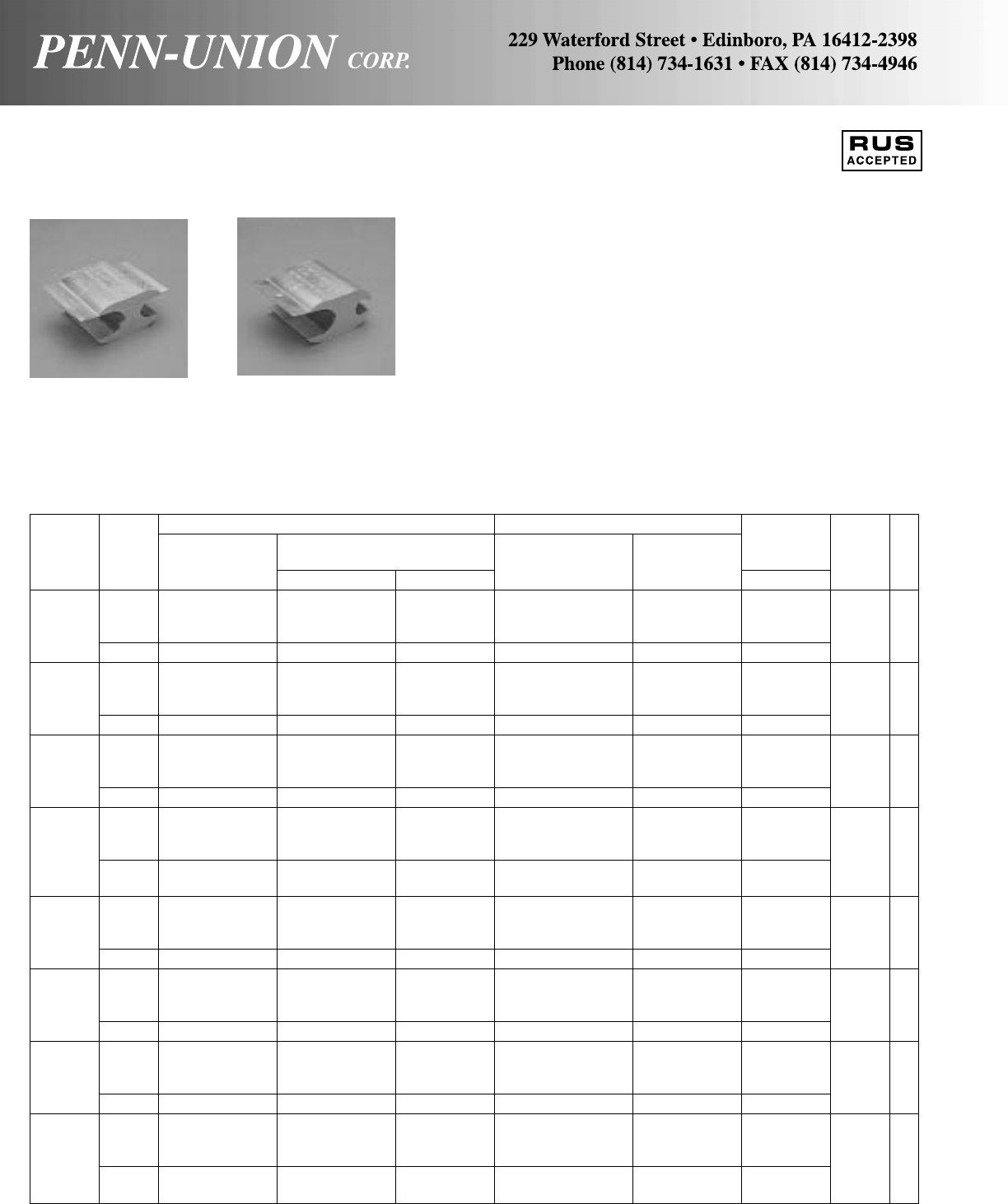
ALUMINUM EXPANDED RANGE PRESS-ONS • TYPES KN-R AND KN
For any combination of aluminum, copper† or ACSR
High Conductivity–E.C. Aluminum extrusions assure cool run-
ning high efficiency contacts.
Easy Crimping–Optimum temper for low handle load. Deep indent
crimp lines for easy crimp location.
Pre-Loaded Inhibitor–Cleaned contact surfaces kept free of ox-
ide reformation by non-dripping Penn-Union Cual-Aid in individual
break-open boxes.
CU to AL–Solid barrier provides conductor separation and
prevents strand cutting. Also minimizes galvanic corrosion.
Weather-Protected–Full length tab provides complete enclosure
for inhibitor, providing excellent weather protection.
Standard Conductor Compressed Conductor Wire No. of
ACSR* & Alumi- Diameter Crimps
Catalog num Alloy Aluminum or Copper Range‡ (Hy- Die
Number Groove Conductors Stranded Solid ACSR* Stranded in draulic) Size
A266.8, 300, 336.4, 250, 266.8, 300, 336-18/1, 397-18/1 336, 350, 397.5 .575-.813
397.5-18/1 336.4, 350, 397.5, 477-18/1 477
KN-0 400 2N
B6, 4 6, 4, 3-7 6, 4, 3, 2 6, 4, 3 6, 4 .162-.260
A266.8, 300, 336.4, 250, 266.8, 300, 336-18/1, 397-18/1, 336, 350, 397.5, .575-.813
397.5-18/1 336.4, 350, 397.5, 477-18/1 477
400 2N
KN-1 B2, 1, 1/0, 2/0 2, 1, 1/0, 2/0 1, 1/0, 2/0, 3/0 2, 1, 1/0, 2/0 1, 1/0, 2/0, 3/0 .289-.460
A266.8, 300, 336.4, 250, 266.8, 300, 336-18/1, 397.5-18/1, 336, 350, 397.5, .575-.813
397.5-18/1 336.4, 350, 397.5, 477-18/1 477
400 2N
KN-R2 B2/0, 3/0, 4/0 3/0, 4/0 4/0 3/0, 4/0, 266-18/1 3/0, 4/0, 250, 266 .428-.630
A266.8, 300, 336.4, 250, 266.8, 300, 336-18/1, 397.5-18/1, 336, 350, 397.5, .575-.813
397.5-18/1 336.4, 350, 397.5, 477-18/1 477
400 3N
KN-4 B336.4, 397.5-18/1 336.4, 350, 397.5, 397-18/1, 477-18/1 397, 477, 500 .666-.813
400
A300, 336.4, 397.5, 336.4, 350, 397.5, 397-18/1, 477-18/1, 477, 500, 556 .666-.813
477-18/1 400, 450, 477, 556-18/1
500 2N
KN-R5 B6, 4 6, 4, 3-7 6, 4, 3, 2 6, 4, 3 6, 4, 2 .162-.260
A300, 336.4, 397.5, 336.4, 350, 397.5, 397-18/1, 477-18/1, 477, 500, 556 .666-.813
477-18/1 400, 450, 477, 556-18/1
500 2N
KN-R6 B3, 2, 1, 1/0 3-3, 2, 1, 1/0, 2/0 1, 1/0, 2/0, 3/0 2, 1, 1/0, 2/0 2, 1, 1/0, 2/0, 3/0 .260-.428
A300, 336.4, 397.5, 336.4, 350, 397.5, 397-18/1, 477-18/1 477, 500, 556 .666-.813
477-18/1 400, 450, 477, 556-18/1
500 2N
KN-R7 B2/0, 3/0, 4/0 3/0, 4/0 4/0 3/0, 4/0, 266-18/1 4/0, 250, 266 .460-.630
A300, 336.4, 397.5, 336.4, 350, 397.5, 397-18/1, 477-18/1, 477, 500, 556 .666-.813
477-18/1 400, 450, 477, 556-18/1
500 3N
KN-8 B266.8, 300, 250, 266.8, 300, 336-18/1, 397-18/1 336, 350, 397 .575-.684
336.4-18/1 336.4, 350
*Conductor sizes listed include all strandings except where 18/1 is shown after conductor size.
†Not recommended for copper to copper applications. For special applications consult factory.
‡For conversion to metric range, see page 175.
DOUBLE TAP
TYPE KN-R SINGLE TAP
TYPE KN
4

ALUMINUM “ULTIMATE RANGE,” DOUBLE TAB PRESS-ONS • TYPE KR-R
For any combination of aluminum, copper† or ACSR
High Conductivity – Aluminum extrusions assure cool running
high efficiency contacts.
Easy Crimping – Optimum temper for low handle load. Deep in-
dent crimp lines for easy crimp location.
Pre-Loaded Inhibitor – Cleaned contact surfaces kept free of ox-
ide reformation by non-dripping Penn-Union Cual-Aid in individual
break-open boxes.
CU to AL – Solid barrier provides conductor separation and pre-
vents strand cutting. Also minimizes galvanic corrosion.
Weather-Protected – Full length tab provides complete enclo-
sure for inhibitor, providing excellent weather protection.
Standard Conductor Wire No. of
Diameter Crimps
Catalog ACSR & Aluminum Aluminum or Copper Compressed Conductor Range‡ (Hy- Die
Number Size Alloy Conductors Stranded Solid ACSR Stranded in draulic) Size
336, 350, 397, 400,
A300, 336, 397, 477 450, 477, 500, 550, 397, 477, 556, 636 477, 500, 556, 636 .666- .893
556 18/1 556, 600
KR-R03
B1/0, 2/0, 3/0, 4/0, 2/0, 3/0, 4/0, 250, 3/0, 4/0 2/0, 3/0, 4/0, 266, 3/0, 4/0, 250, 266, .398- .684
3R
266, 336 18/1 266, 300, 336, 350 336, 397 18/1 300, 336, 350, 397
336, 350, 397, 400,
A300, 336, 397, 477, 450, 477, 500, 550, 397, 477, 556, 636 477, 500, 556, 636 .666- .893
556 18/1 556, 600
KR-R04 336, 350, 397, 400, 4R
B300, 336, 397, 477, 450, 477, 500, 550, 397, 477, 556, 636 477, 500, 556, 636 .666- .893
556 18/1 556, 600
477, 30/7, 556, 600, 636, 700, 715,
A605, 636, 653, 666, 750, 795, 800, 874, 795, 874, 954 795, 874, 954 .879-1.108
715, 795 26/7 900
KR-R05
B1/0, 2/0, 3/0, 4/0, 2/0, 3/0, 4/0, 250, 3/0, 4/0 2/0, 3/0, 4/0, 266, 3/0, 4/0, 250, 266, .398- .684
3R
266, 336 18/1 266, 300, 336, 350 336, 397 18/1 300, 336, 350, 397
477 30/7, 556, 600, 636, 700, 715,
A605, 636, 653, 666 750, 795, 800, 874, 795, 874, 954 795, 874, 954 .879-1.108
715, 795 26/7 900
KR-R06 336, 350, 397, 400, 4R
B300, 336, 397, 477, 450, 477, 500, 550, 397, 477, 556, 636 477, 500, 556, 636 .666- .893
556 18/1 556, 600
477 30/7, 556, 600, 636, 700, 715,
A605, 636, 653, 666, 750, 795, 800, 874, 795, 874, 954 795, 874, 954 .879-1.108
715, 795 26/7 900
KR-R07 477 30/7, 556, 600, 636, 700, 715, 4R
B605, 636, 653, 666, 750, 795, 800, 874, 795, 874, 954 795, 874, 954 .879-1.108
715, 795 26/7 900
†Not recommended for copper to copper applications. For special applications consult factory.
‡For conversion to metric range, see page 175.
(HYDRAULIC TOOL ONLY)
5
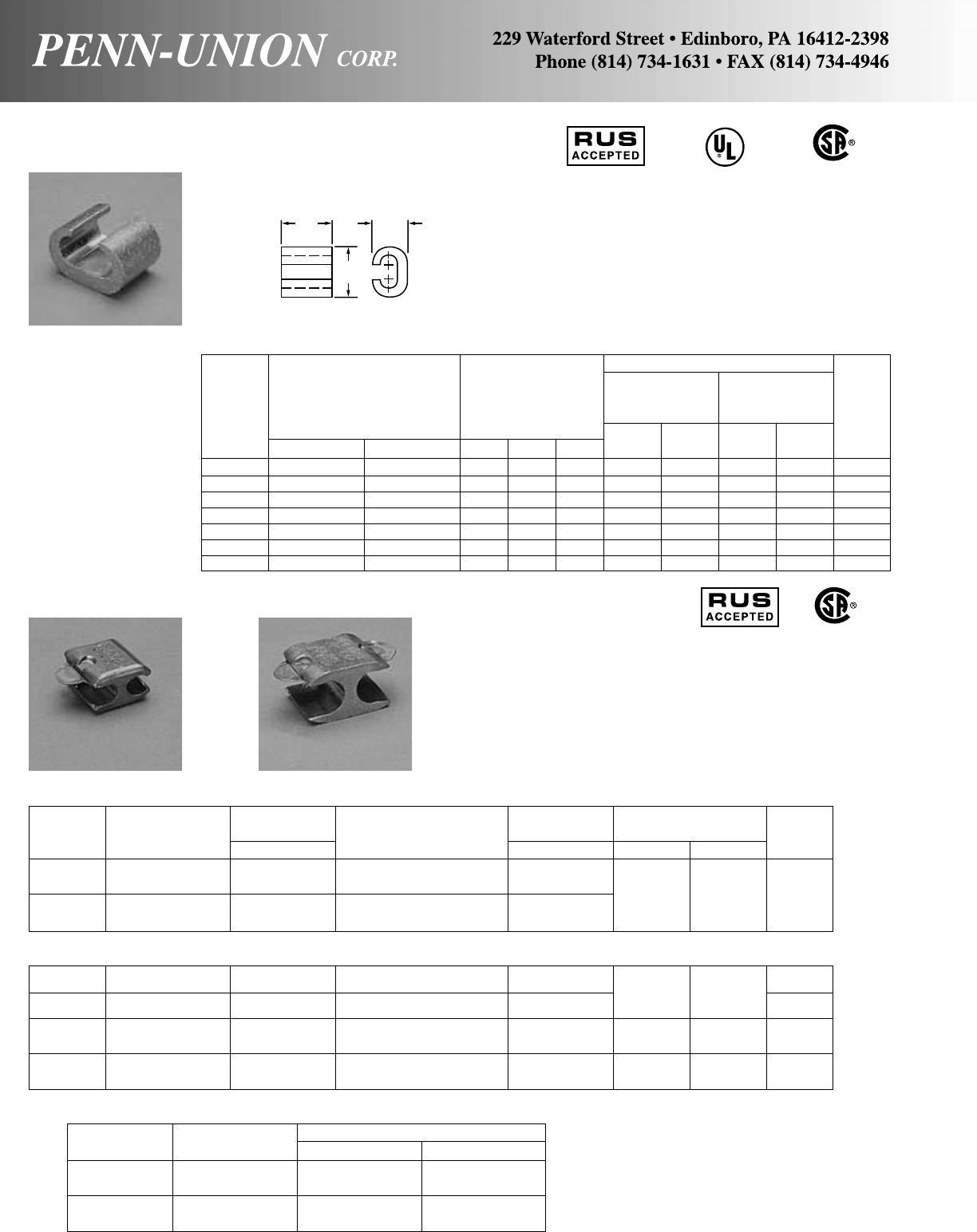
*Burndy Y35 and Alcoa 12A tools both accept same dies.
Penn-Union’s TPU-12B can also be used with these dies.
‡For conversion to metric range, see page 175.
†CSA certified for direct burial.
COPPER PRESS-ONS • TYPE CCT
COPPER PRESS-ONS • TYPE CST AND CDT
Made of high conductivity copper–metal barrier separates con-
ductor thereby eliminating strand cutting. Generous chamfer
protects cable. For compressing, use one crimp with hydraulic
tools. Three crimps with mechanical tools. See Cat. Page 7 for
dimensions.
SINGLE TAB PRESS-ON
DOUBLE TAB PRESS-ON
CDT-399-8 6 Sol., 6 Str., 4 Sol. .162-.204 8 Sol., 6 Str., 4 Sol. .128-.204 B U-BG 4
or or
CDT-398-8† 4 Sol., 4 Str., 2 Sol. .204-.258 4 Sol., 4 Str., 2 Sol. .204-.258 B-K-T U-243 4
CDT-304-8 2 Str., 1 Str., 1/0 Str. .292-.375 6 Sol., 4 Sol., 4 Str., 2 Sol. .162-.258 OO4
CDT-303-8 2 Str., 1 Str., 1/0 Str. .292-.375
CDT-308-8 2/0 Str., 4/0 Str. .419-.528 2 Str., 1 Str., 1/0 Str. .292-.375 DD34
CDT-307-8 2/0 Str., 4/0 Str. .419-.528
MECHANICAL COMPRESSION TOOLING
Catalog “O” Type Tool “W” Die Type Tool
Number Die Sets Tools Die Set
CST-301 TTMU-0D3 W-BG
and CDT-399-8 MD6-8 W-BG
CST-302† KTMU-0D3 W-KK
and CDT-398-8† MD6-8 W-KK
Installation Tooling
TDY-U
Approx. Dieless
Conductor Dimensions TPU-12B Tool
Catalog Range in Inches Die No. of Pressure No. of Strip
Number Run Tap L H W Index Crimps Setting Crimps Length
CCT-46 6 Sol.-4 Str. 6 Sol.-6 Str. 5/83/47/16 BG 121
3/4
CCT-44 6 Sol.-4 Str. 4 Sol.-4 Str. 5/813/16 7/16 BG 121
3/4
CCT-24 2 Sol.-2 Str. 8 Sol.-4 Str. 3/415/8C141
7/8
CCT-22 2 Sol.-2 Str. 2 Sol.-2 Str. 3/415/8C141
7/8
CCT-2020 1/0 Str.-2/0 Str. 1/0 Str.-2/0 Str. 15/16 13/813/16 01511
1/16
CCT-4020 3/0 Str.-4/0 Str. 1/0 Str.-2/0 Str. 11/16 15/81D3 1511
3/16
CCT-4040 3/0 Str.-4/0 Str. 3/0 Str.-4/0 Str. 11/16 19/16 1D3 1511
3/16
Copper “C”-Taps are range-taking compression connectors made
from high conductivity copper alloy. They are used for making
tap or parallel copper connections from 8 SOL to 4/0 STR con-
ductors. C-Tap connectors provide consistent reliability with heavy
wall construction that prevents relaxation of the joint after instal-
lation. Installation time is reduced because of its “C” shape.
LW
Wire Diameter Wire Diameter Die Sets for TDY-U
Catalog Range‡ Range‡ Hydraulic Tools Pressure
Number Side A in Side B in WH-1, WH-2 Y-35* Setting
CST-301 6 Sol., 6 Str., 4 Sol. .162-.204 8 Sol., 8 Str., 6 Sol. .128-.204 U-BG
6 Str., 4 Sol. B-K-T or 4
CST-302† 4 Sol., 4 Str., 2 Sol. .204-.258 6 Sol., 6 Str., 4 Sol. .162-.258 U-243
4 Str., 2 Sol.
ELECTRICAL
AND
GROUNDING
CU
486A
467 SUITABLE
FOR DIRECT
BURIAL
SINGLE TAB
TYPE CST DOUBLE TAB
TYPE CDT
6
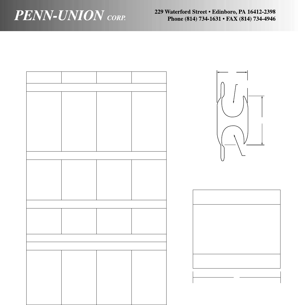
ALUMINUM
Cat.
No. L W H
• Catalog Page 3
KO-R06 11/245/64 11/8
KO-R08 11/245/64 11/8
KD-R02 11/257/64 115/32
KD-R04 17/857/64 131/64
KD-R03 11/257/64 115/32
KD-R05 21/457/64 17/16
KD-R28 21/457/64 17/16
KO-R10 11/245/64 11/8
KO-R01 13/423/32 15/32
KO-R21 5/819/32 39/64
KO-R22 13/16 29/32 19/32
KO-R24 11/16 23/32 17/64
• Catalog Page 4
KN-0 2 11/4131/32
KN-1 2 11/42
KN-R2 2 11/42
KN-4 31/211/421/32
KN-R5 2 11/42
KN-R6 2 11/42
KN-R7 2 11/4131/32
KN-8 31/211/42
• Catalog Page 5
KR-R03 31/213/435/64
KR-R04 45/813/431/16
KR-R05 31/213/435/64
KR-R06 45/813/433/64
KR-R07 45/813/431/32
COPPER
• Catalog Page 6
CST-301 13/16 15/32 47/64
CST-302 13/16 35/64 53/64
CDT-399-8 13/16 31/64 3/4
CDT-398-8 13/16 35/64 51/64
CDT-303-8 53/64 23/32 11/8
CDT-304-8 55/64 41/64 11/8
CDT-306-8 59/64 49/64 117/64
CDT-305-8 63/64 51/64 11/4
CDT-309-8 11/16 29/32 123/64
CDT-308-8 11/16 29/32 113/32
CDT-307-8 11/16 29/32 13/8
APPROXIMATE DIMENSIONS FOR ALUMINUM AND COPPER PRESS-ONS
(IN INCHES)
W
“A” GROOVE
H
“B” GROOVE
L
7

A Range Wire Diameter B Range Wire Diameter
Catalog Alum. or Copper Range‡ Cap Alum. or Copper Range‡ Cap Die
Number ACSR Str. Sol. in Color ACSR Str. Sol. in Color Size
PIK-88 10 8 .116-.128 Brown 10 8 .116-.128 Brown
PIK-68 8 6 .145-.162 Green 10 8 .116-.128 Brown
PIK-66 8 6 .145-.162 Green 8 6 .145-.162 Green
PIK-48 6-6/1 5-6 4 .184-.206 Blue 10 8 .116-.128 Brown
PIK-46 6-6/1 5-6 4 .184-.206 Blue 8 6 .145-.162 Green
PIK-44 6-6/1 5-6 4 .184-.206 Blue 6-6/1 5-6 4 .184-.206 Blue
PIK-28 4-6/1, 7/1 3-4 2 .232-.260 Orange 10 8 .116-.128 Brown
PIK-26 4-6/1, 7/1 3-4 2 .232-.260 Orange 8 6 .145-.162 Green
PIK-24 4-6/1, 7/1 3-4 2 .232-.260 Orange 6-6/1 5-6 4 .184-.206 Blue 5/8
PIK-22 4-6/1, 7/1 3-4 2 .232-.260 Orange 4-6/1, 7/1 3-4 2 .232-.260 Orange or
PIK-18 2-6/1, 7/1 1-2 .292-.332 Red 10 8 .116-.128 Brown BG
PIK-16 2-6/1, 7/1 1-2 .292-.332 Red 8 6 .145-.162 Green
PIK-14 2-6/1, 7/1 1-2 .292-.332 Red 6-6/1 5-6 4 .184-.206 Blue
PIK-12 2-6/1, 7/1 1-2 .292-.332 Red 4-6/1, 7/1 3-4 2 .232-.260 Orange
PIK-11 2-6/1, 7/1 1-2 .292-.332 Red 2-6/1, 7/1 1-2 .292-.332 Red
PIK-08 1/0 .373 Yellow 10 8 .116-.128 Brown
PIK-06 1/0 .373 Yellow 8 6 .145-.162 Green
PIK-04 1/0 .373 Yellow 6-6/1 5-6 4 .184-.206 Blue
PIK-02 1/0 .373 Yellow 4-6/1, 7/1 3-4 2 .232-.260 Orange
PIK-01 1/0 .373 Yellow 2-6/1, 7/1 1-2 .292-.332 Red
PIK-00 1/0 .373 Yellow 1/0 .373 Yellow
‡For conversion to metric range, see page 175.
ALUMINUM PRE-INSULATED PENN-SLEEVES • TYPE PIK
For aluminum to copper or aluminum to aluminum
Pre-insulated Penn-Sleeve Service Entrance Compression Con-
nectors feature extra length for increased contact and solid cen-
ter barrier.
Pre-filled with Cual-Aid inhibitor and capped to prevent dirt from
accumulating in barrel and seal out moisture. Brilliant color of
caps for easy identification conform to industry standards, and
easy push-thru caps reduce push thru force by 25%.
Aluminum insert is anchored to jacket, assuring that insert is under
die when crimping where marking indicates. Strip gage and num-
ber of crimps marked on jacket make it hard to misapply. Con-
forms to ANSI C 119.4 when properly installed.
Nylon jacket insulates connector electrically and protects against
water and weather. Special nylon formulated for Penn-Union in-
creases shelf life and improves crimpability even at sub zero tem-
peratures.
STRIP GAGE
CSA
R4SOL
K-44
UNION
G DIE
R4SOL
CSA
A
27/8"
(73 mm)
B
41/64"
(16 mm)
45/64"
(18 mm)
8
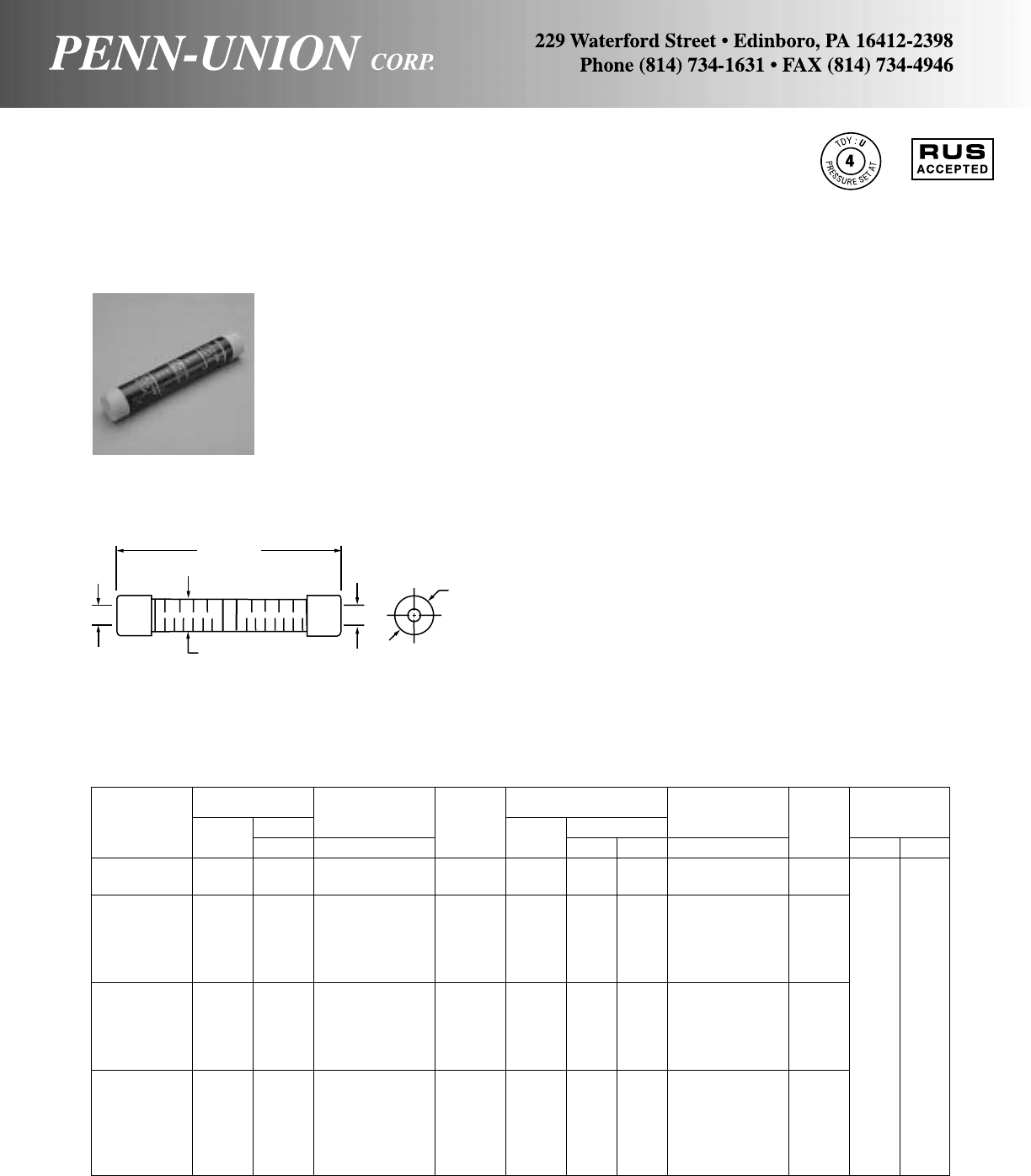
Color Color
A Range Wire Diameter Code B Range Wire Diameter Code
Catalog Alum. Range‡ AAlum. Range‡ BDie Size
Number ACSR Str. in Range ACSR Str. Sol. in Range Hand Hyd.
PIK-01R 1/0 1/0 .373-.398 Yellow 2 1-2 1/0 .292-.332 Red
PIK-00R 1/0 1/0 .373-.398 Yellow 1/0 1/0 .373-.398 Yellow
PIK-204 2/0 2/0 .419-.447 Gray 6 5-6 4 .183-.206 Blue
PIK-202 2/0 2/0 .419-.447 Gray 4 3-4 2 .231-.258 Orange
PIK-201 2/0 2/0 .419-.447 Gray 2 1-2 1/0 .292-.332 Red
PIK-200 2/0 2/0 .419-.447 Gray 1/0 1/0 .373-.398 Yellow
PIK-2020 2/0 2/0 .419-.447 Gray 2/0 2/0 .419-.447 Gray
PIK-302 3/0 3/0 .470-.502 Black 4 3-4 2 .231-.258 Orange B-249
PIK-301 3/0 3/0 .470-.502 Black 2 1-2 1/0 .292-.332 Red .840 or
PIK-300 3/0 3/0 .470-.502 Black 1/0 1/0 .373-.398 Yellow EEI
PIK-3020 3/0 3/0 .470-.502 Black 2/0 2/0 .419-.447 Gray 11A
PIK-3030 3/0 3/0 .470-.502 Black 3/0 3/0 .470-.502 Black
PIK-402 4/0 4/0 .528-.563 Pink 4 3-4 2 .231-.258 Orange
PIK-401 4/0 4/0 .528-.563 Pink 2 1-2 1/0 .292-.332 Red
PIK-400 4/0 4/0 .528-.563 Pink 1/0 1/0 .373-.398 Yellow
PIK-4020 4/0 4/0 .528-.563 Pink 2/0 2/0 .419-.447 Gray
PIK-4030 4/0 4/0 .528-.563 Pink 3/0 3/0 .470-.502 Black
PIK-4040 4/0 4/0 .528-.563 Pink 4/0 4/0 .528-.563 Pink
‡For conversion to metric range, see page 175.
ALUMINUM PRE-INSULATED PENN-SLEEVES • TYPE PIK 840
For aluminum to copper or aluminum to aluminum
Pre-insulated Penn-Sleeve Service Entrance Compression Con-
nectors for commercial service or large residence.
Prefilled with Cual-Aid inhibitor and capped to prevent dirt from
accumulating in barrel and seal out moisture. Polyethylene color
coded caps conform to industry standard.
Aluminum insert is anchored to jacket, assuring that insert is under
die when crimping where marking indicates. Marked for both hand
and hydraulic tools.
Nylon jacket insulates connector electrically and protects against
water and weather. Special nylon formulated for Penn-Union in-
creases shelf life and improves crimpability even at sub zero tem-
peratures.
ACSR
3
/
0
STR
3
/
0
STR
2
/
0
ACSR
2
/
0
K-3020
NN-UNI
AB
51/2"
(140 mm)
.903"
(23 mm)
11/32"
(26 mm)
9

A Range B Range
Alum. or Wire Diameter Alum. or Wire Diameter
Catalog Copper Compressed Range‡ Cap Copper Compressed Range‡ Cap
Number ACSR Str. Sol. Cable in Color ACSR Str. Sol. Cable in Color
PSK-88 10 8 .116-.128 Brown 10 8 .116-.128 Brown
PSK-68 8 6 .145-.162 Green 10 8 .116-.128 Brown
PSK-66 8 6 .145-.162 Green 8 6 .145-.162 Green
PSK-48 6-6/1 6 4 6 .179-.204 Blue 10 8 .116-.128 Brown
PSK-46 6-6/1 6 4 6 .179-.204 Blue 8 6 .145-.162 Green
PSK-44 6-6/1 6 4 6 .179-.204 Blue 6-6/1 6 4 6 .179-.204 Blue
PSK-28 4-6/1,7/1 4 2 4 .225-.258 Orange 10 8 .116-.128 Brown
PSK-26 4-6/1, 7/1 4 2 4 .225-.258 Orange 8 6 .145-.162 Green
PSK-24 4-6/1, 7/1 4 2 4 .225-.258 Orange 6-6/1 6 4 6 .179-.204 Blue
PSK-22 4-6/1, 7/1 4 2 4 .225-.258 Orange 4-6/1, 7/1 4 2 4 .225-.258 Orange
PSK-18 2-6/1, 7/1 2 1/0 2 .283-.325 Red 10 8 .116-.128 Brown
PSK-16 2-6/1, 7/1 2 1/0 2 .283-.325 Red 8 6 .145-.162 Green
PSK-14 2-6/1, 7/1 2 1/0 2 .283-.325 Red 6-6/1 6 4 6 .179-.204 Blue
PSK-12 2-6/1, 7/1 2 1/0 2 .283-.325 Red 4-6/1, 7/1 4 2 4 .225-.258 Orange
PSK-11 2-6/1, 7/1 2 1/0 2 .283-.325 Red 2-6/1, 7/1 2 1/0 2 .283-.325 Red
PSK-08 1/0-6/1 1/0 1/0 .362-.398 Yellow 10 8 .116-.128 Brown
PSK-06 1/0-6/1 1/0 1/0 .362-.398 Yellow 8 6 .145-.162 Green
PSK-04 1/0-6/1 1/0 1/0 .362-.398 Yellow 6-6/1 6 4 6 .179-.204 Blue
PSK-02 1/0-6/1 1/0 1/0 .362-.398 Yellow 4-6/1, 7/1 4 2 4 .225-.258 Orange
PSK-01 1/0-6/1 1/0 1/0 .362-.398 Yellow 2-6/1 2 1/0 2 .283-.325 Red
PSK-00 1/0-6/1 1/0 1/0 .362-.398 Yellow 1/0-6/1 1/0 1/0 .362-.398 Yellow
‡For conversion to metric range, see page 175.
ALUMINUM PENN-SLEEVES • TYPE PSK 5/8" O.D.
For aluminum to copper or aluminum to aluminum
Installed by standard dies in hand or hydraulic tools. Forged from
pure aluminum, with integral solid center barrier.
Large smooth entering radii give easy entrance for conductors–
minimize stress concentration and chafing from vibration.
Contact surfaces are coated with Cual-Aid. Pushing the wire
through the color-coded cap to bottom of the barrel, squirts the
Cual-Aid around the strands of conductor.
Crimping the Penn-Sleeve wipes the Cual-Aid’s particles across
the contact surfaces and insures a tightly gripping, high conduc-
tivity joint. The non-flowing vehicle in Cual-Aid keeps air and
moisture out of the joint.
Easy push-thru caps reduce push thru force by 25%.
On aluminum to copper, PENN-SLEEVES eliminate the effects
of galvanic corrosion.
AB
2" (52 mm) NOM.
10
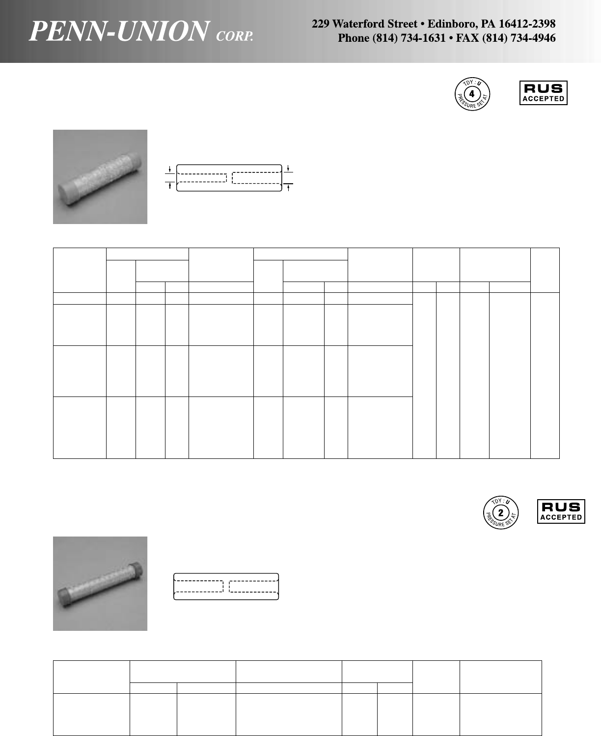
ALUMINUM NON-TENSION SPLICING SLEEVE • TYPE PS
Penn-Sleeve
The large aluminum compression sleeve with integral solid cen-
ter barrier is designed for service entrance and non-tension loop
splice application. Plastic caps prevent the contamination of con-
tact aid during storage of sleeves.
Good electrical contact and ease of installation is accomplished
with the use of pure aluminum.
Compression barrel prefilled with Cual-Aid oxide inhibitor.
A Range AB Range BNo of Crimps
Aluminum Wide Diameter Aluminum Wire Diameter Length Each Groove
Catalog Copper Range‡ Copper Range‡ (Approx.) Tool Die
Number ACSR Str. Sol. in ACSR Str. Sol. in in mm Hand Hydraulic Size
PS-00 1/0 1/0 – .375-.398 1/0 1/0 Str. – .375-.398
PS-202 4 3&4 Str. 2 .232-.260
PS-201 2 1&2 Str. 1/0 .292-.332
PS-200 2/0 2/0 Str. – .419-.447 1/0 1/0 Str. – .375-.398
PS-2020 2/0 2/0 Str. – .419-.447
PS-302 4 3&4 Str. 2 .232-.260 .840
PS-301 2 1&2 Str. 1/0 .292-.332 4 102 7 4 or
PS-300 3/0 3/0 Str. – .470-.502 1/0 1/0 Str. – .375-.398 B-249
PS-3020 2/0 2/0 Str. – .419-.447
PS-3030 3/0 3/0 Str. – .470-.502
PS-402 4 3&4 Str. 2 .232-.260
PS-401 2 1&2 Str. 1/0 .292-.332
PS-400 1/0 1/0 Str. – .375-.398
PS-4020 4/0 4/0 Str. – .528-.563 2/0 2/0 Str. – .419-.447
PS-4030 3/0 3/0 Str. – .470-.502
PS-4040 4/0 4/0 Str. – .528-.563
‡For conversion to metric range, see page 175.
ALUMINUM NEUTRAL SPLICING SLEEVE • TYPE PNK 5/8" O.D.
Penn-Sleeve
Length
Conductor Wire Diameter Range‡ (Approx.) No. of
Catalog Number ACSR Aluminum in in mm Crimps Crimping Groove
PNK-44 6 6 Str.–4 Sol. .184-.204 41/4108 9 BG, 5/8, Peach
PNK-22 4 4 Str.–2 Sol. .232-.258 41/4108 9 BG, 5/8, Peach
PNK-11 2 2 Str. .292-.316 41/4108 9 BG, 5/8, Peach
PNK-00 – 1/0 Str. .368 6 152 12 BG, 5/8, Peach
‡For conversion to metric range, see page 175.
BA
The triplex neutral splicing sleeve is made of pure aluminum and
contains an integral solid barrier as assurance of equal crimping
on each cable and maximum holding power.
These sleeves are crimped with the same tools and dies as used
on the small service entrance sleeves.
11
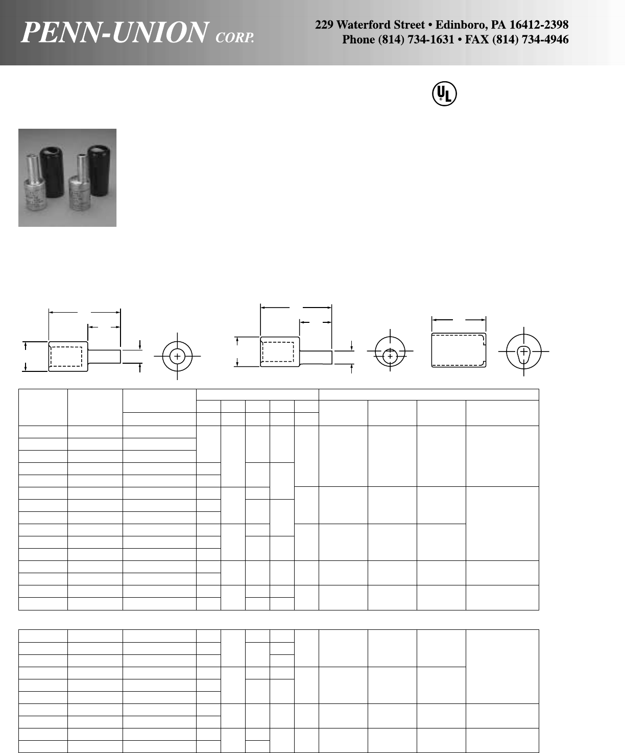
ALUMINUM TERMINAL PLUG • TYPES TP & TPO
For terminating copper or aluminum wire
Aluminum Wire Diameter Approximate Dimensions Crimping Tool Reference
Catalog Conductor Range‡ A O.D. L1L2CDie Color Burndy TPU TDY-1
Number Size in in in in in in Code Die Die Pressure Setting
TP-6 6 Str. .184
TP-4 4 Str. .232 .23 1.85 .68
TP-2 2 Str. .292 .60 1.75 Tan B-296 T-296 2
TP-1 1 Str. .332 .26 2.01
TP-1/0 1/0 Str. .373 .29 .84
TP-2/0 2/0 Str. .418 .33 2.21
TP-3/0 3/0 Str. .470 .37 .85 2.25 White B-298 T-298
TP-4/0 4/0 Str. .528 .42 2.59 1.22 5
TP-250 250 MCM .575 .47 2.63
TP-300 300 MCM .630 .53 1.10 2.50 Brown B-299 T-299
TP-350 350 MCM .681 .57 2.75 1.34
TP-400 400 MCM .728 .63 1.31 3.08 1.60 2.87 Pink B-300 T-300 7
TP-500 500 MCM .813 .68
TP-600 600 MCM .893 .73 1.46 3.67 1.64 3.75 Yellow B-936 9
TP-750 750 MCM .998 .81 3.79 1.76
OFFSET STYLE
TPO-2/0 2/0 Str. .418 .33 2.7 1.13
TPO-3/0 3/0 Str. .470 .37 .85 2.8 1.25 2.25 White B-298 T-298
TPO-4/0 4/0 Str. .528 .42 1.28 5
TPO-250 250 MCM .575 .47 3.0 1.28
TPO-300 300 MCM .630 .53 1.10 3.1 1.47 2.50 Brown B-299 T-299
TPO-350 350 MCM .681 .57
TPO-400 400 MCM .728 .63 1.32 3.4 1.69 2.87 Pink B-300 T-300 7
TPO-500 500 MCM .813 .68
TPO-600 600 MCM .893 .73 1.46 4.0 1.73 3.75 Yellow B-936 9
TPO-750 750 MCM .998 .81 4.2
‡For conversion to metric range, see page 175.
486B
LISTED
AL9CU
Optimum design to permit use of stranded copper or aluminum
conductor in equipment boards and boxes with mechanical con-
nectors.
Type TPO offset pin designed for use in limited spaces in equip-
ment boards and meter boxes.
Simply crimp onto the copper or wire brushed aluminum conduc-
tor and install into the mechanical connector supplied with the
equipment. No worry about cutting strands. No bulky in-line splice
boxes required.
The plug is made of aluminum, tin-plated and filled with Cual-
Aid® for a cool running compression connection. A cover is pro-
vided for quick insulation of the compression barrel. All required
information is marked on the plug.
C
L1
L2
A
O.D.
TPO SERIES
A
TP SERIES
L1
L2
O.D.
12
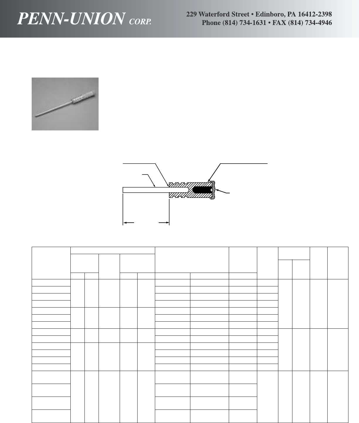
PENN-STEMS • TYPES PSKS AND PSS
For terminating aluminum and ACSR conductors
Stem No. of
Cable Crimps
Length Con- Maximum Conductor Wire Dia. Range Hy- TDY-U
Catalog (Approx.) ductor Diameter Range Range‡ Color Hand draulic Die Pressure
Number in. mm Range in. mm Aluminum ACSR in Code Tool Tool Size Setting
PSKS-44-21/46 Str., 4 Sol. 6-6/1 .184-.204 Blue
PSKS-24-21/421/2 64 4 Sol. .204 5.15 4 Str., 2 Sol. 4-6/1, 7/1 .232-.258 Orange
PSKS-14-21/42 Str., 1/0 Sol. 2-6/1, 7/1 .292-.325 Red
PSKS-04-21/41/0 Str. 1/0-6/1 .373-.398 Yellow 3 1 BG, 5/82
PSKS-22-31/44 Str. 2 Sol. 4-6/1, 7/1 .232-.258 Orange
PSKS-12-31/431/4 83 2 Sol. .258 6.50 2 Str. 1/0 Sol. 2-6/1, 7/1 .292-.325 Red
PSKS-02-31/41/0 Str. 1/0-6/1 .373-.398 Yellow
PSS-22-61/261/2165 2 Sol. .258 6.50 4 Str. 2 Sol. 4 .232-.258 Orange
PSS-12-61/22 Str. 1/0 Sol. 2 .292-.325 Red .840
PSS-01-61/21/0 Str. 1/0 .373-.398 Yellow 7 4 or 4
PSS-201-61/261/2165 1/0 Sol. .325 8.33 2/0 Str. 2/0 .418-.447 Gray B-249
PSS-301-61/23/0 Str. 3/0 .470-.502 Black
PSS-401-61/24/0 Str. 4/0 .528-.563 Pink
250 MCM –.575-.594PSS-2630-51/2266.8 MCM
300 MCM 266.8-18/1, 26/7 .609-.669PSS-3330-51/2
51/2140 4/0 Sol. .460 11.70 336.4 MCM Clear – 4 11/8-2 5
PSS-3930-51/2350 MCM 300-26/7 .681-.721
397.5 MCM 336.4-18/1,26/7
477 MCM 397.5-26/7, 30/7
PSS-4730-51/2500 MCM 477-18/1, 24/7 .793-.846
‡For conversion to metric range, see page 175.
Designed to be used in places where a terminal that was intended
to hold a copper wire is too small or unsuitable for an aluminum
wire, such as secondaries on transformers and meter entrances.
TIN PLATED SOFT
DRAWN COPPER STEM
LENGTH
CUAL-AID®FILLED
CABLE GROOVE
COLOR CODED
PLASTIC CAP
13
FACTORY BONDED
JOINT
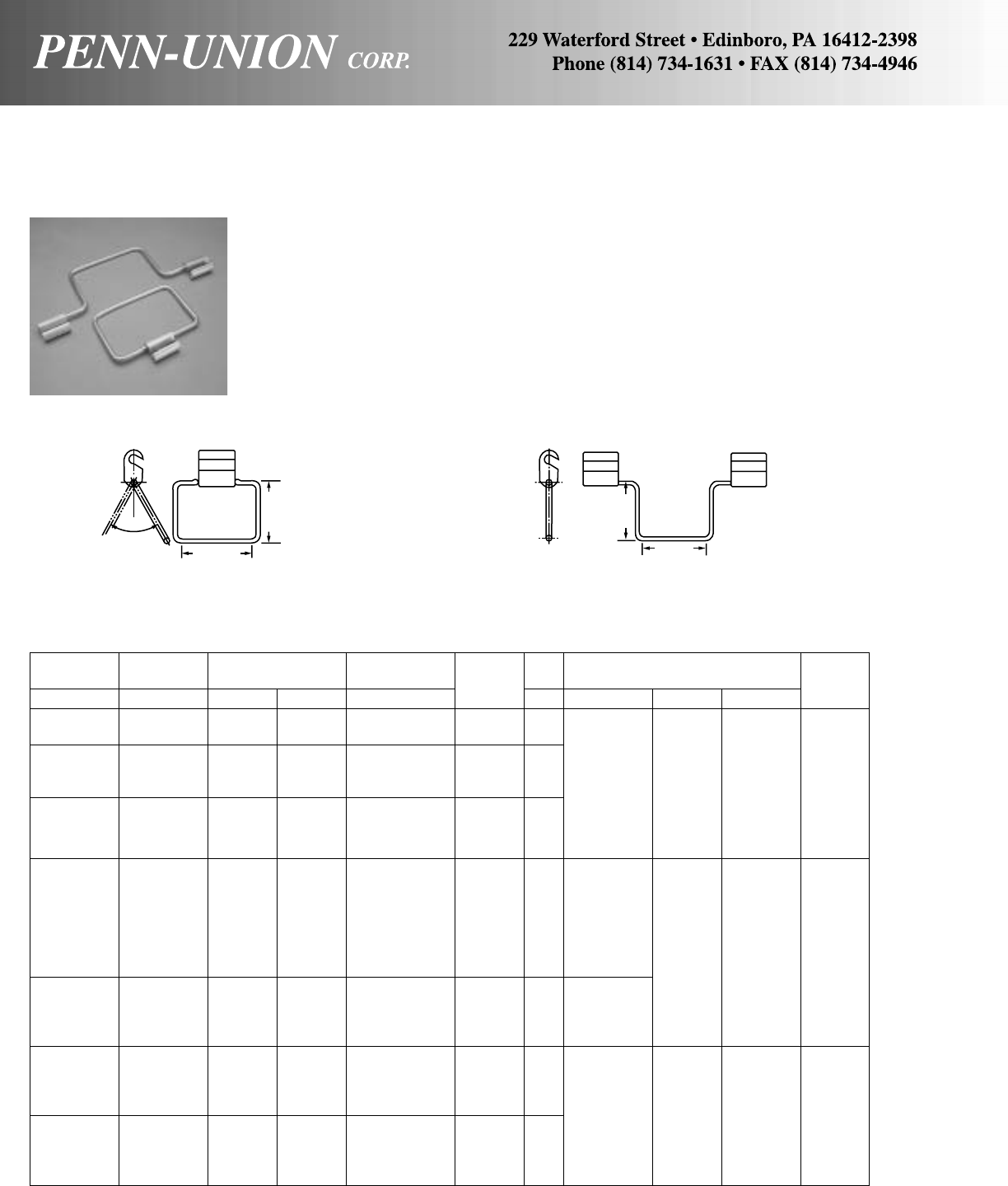
PRESS-ON STIRRUPS • TYPES KBO, KKBO, KBD, KKBD, KBN AND KKBN
Aluminum or ACSR to copper taps
Catalog Catalog Conductor Wire Diameter H.D.* Bail TDY-U
Number Number Range Range‡ Copper Dia. Installation Tools & Dies Pressure
Fig. 1 Fig. 2 ACSR Aluminum in Bail in Kearney Alcoa Burndy Setting
KBO-W4-2 KKBO-W4-2 6 6 Sol.-6 .162-.204 2 Sol. .258 Use Either
Str.-4 Sol. Model WH-1 Use Model
Hydraulic Use Model Y-35
KBO-R2-2 KKBO-R2-2 2-4 2 Sol.-2 .232-.316 2 Sol. .258 Tool or 12-A Hydraulic
Str.-4 Str. O-1, O-2, Hydraulic Tool 4
O-52 Tool with
Hand Tool with O Die
KBO-1/0-2 KKBO-1/0-2 1/0 1/0 Str. .368-.398 2 Sol. .258 with O Die Index
O Die
Use either
Model WH-1
Hydraulic Use Model
KBD-2/0-2 KKBD-2/0-2 1/0-2/0 1/0-2/0 .368-.447 2 Sol. .258 Tool or O-51, Use Model Y-35 4
Str. O-52 Hand 12-A Hydraulic
Tool with Hydraulic Tool
D Die Tool with with
KBD-4/0-2 KKBD-4/0-2 3/0-4/0 4/0 Str. .502-.563 2 Sol. .258 Use WH-1 D Die D Die
Tool Index
KBD-4/0-0 KKBD-4/0-0 3/0-4/0 4/0 Str. .502-.563 1/0 Sol. .325 with
D Die
KBN-0-2 KKBN-0-2 266.8- 250-400 .575-.743 2 Sol. .258
397.5 18/1 MCM Use Model Use Model Use Model
KBN-1-0 KKBN-1-0 266.8- 250-400 .575-.743 1/0 Sol. .325 WH-2 12-A Y-35
397.5 18/1 MCM Hydraulic Hydraulic Hydraulic 7
KBN-R5-2 KKBN-R5-2 300- 336.4-500 .666-.814 2 Sol. .258 Tool with Tool with Tool with
477 18/1 MCM N Die N Die N Die
KBN-R6-0 KKBN-R6-0 300- 336.4-500 .666-.814 1/0 Sol. .325 Index
477 18/1 MCM
‡For conversion to metric range, see page 175.
For sizes not listed consult factory.
*Bails are tin plated.
Installed easily and safely with standard “O” and “D” dies in hand
or hydraulic tools. Designed to protect energized conductors from
arcing damage when live taps are made.
Types KBO and KBD have a single aluminum Press-On clamp-
ing element for standard duty. Types KKBO and KKBD have
double Press-Ons for heavy duty. Tin plated, hard drawn, solid
copper bail permits taps to be taken off at any convenient angle.
Factory filled with Cual-Aid® joint compound. Shipped in polyeth-
ylene bags to keep assembly clean until ready for use.
A
D
J
U
S
T
A
B
L
E
3"
(76 mm)
4"
(102 mm)
FIG. 1 – TYPES KBO, KBD AND KBN
3"
(76 mm)
4"
(102 mm)
FIG. 2 – TYPES KKBO, KKBD AND KKBN
14
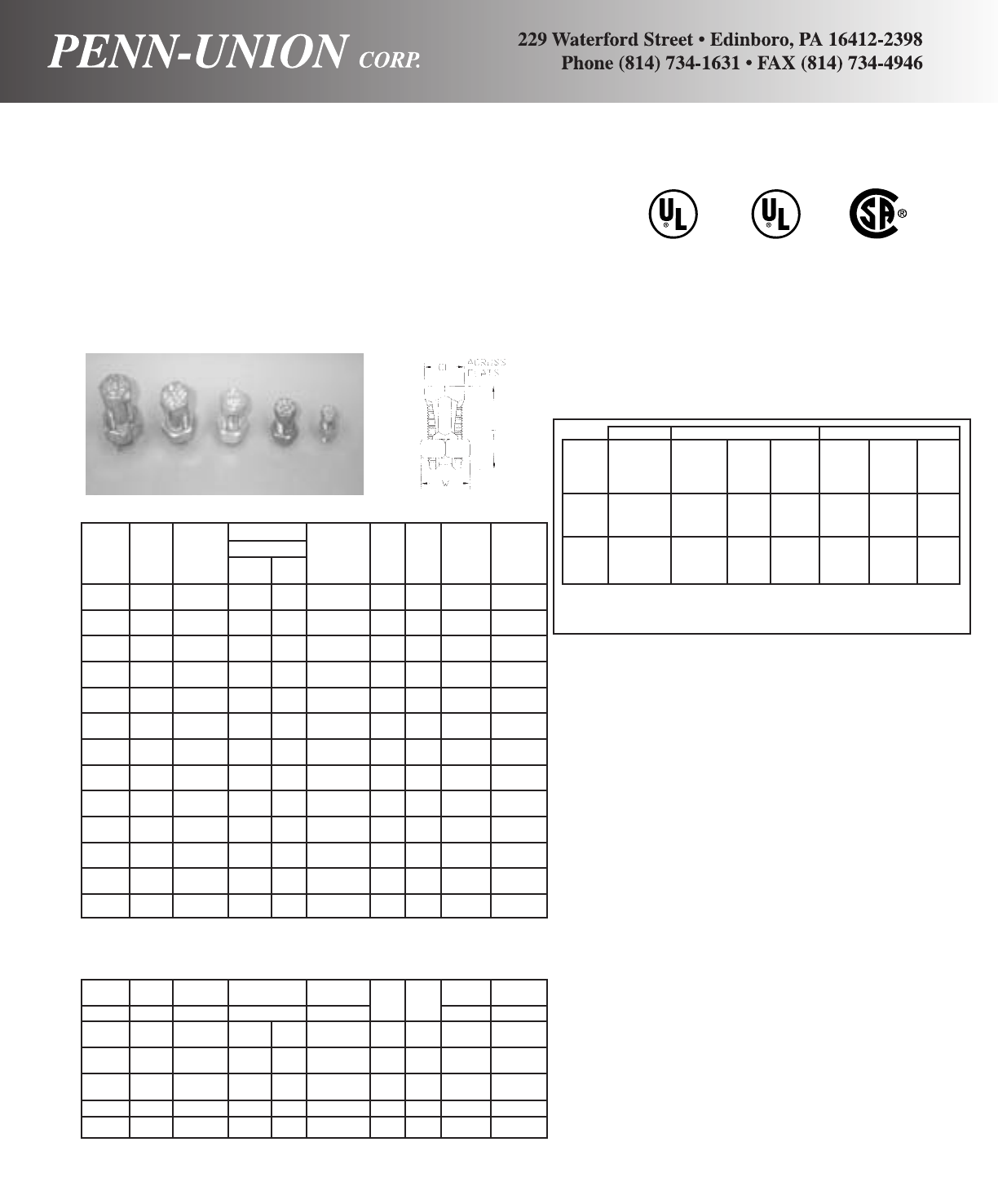
486A 467
600V LISTED
CU GROUNDING POWER &
90OCBONDING GROUNDING
NEW FEATURE-NOW APPROVED FOR
GROUNDING/BONDING AND
ELECTRICAL
COPPER ALLOY SPLIT BOLT CONNECTORS • TYPES S AND SEL
For copper and copperweld wires
THE MOST VERSATILE SPLIT BOLT ON THE MARKET
MANUFACTURED IN THE USA
Made from high strength copper alloy. Highly resistant to
corrosion and season cracking. Under torque this design provides
high contact pressure between conductors.
TYPE “SEL”:
The first 3-conductor split bolt approved for grounding!
2 CONDUCTORS
CATALOG RANGE MIN TAP MAX COND WIRE L W ACROSS TORQUE
NO. EQ RUN WITH ONE COPPERWELD DIAMETER FLATS IN/LBS.
& TAP MAX. MAIN STR. TYPE range †
A
S-8* 16str- 16str - - .057 - .145 .84 .50 .38 80
8str.
S-6* 10sol- 16sol - - .102 - .162 1.05 .63 .50 165
6sol
S-4* 8sol- 16sol 3 No. 12 8A .128-.204 1.05 .69 .56 165
4sol
S-3* 6sol- 12sol 3 No. 9 5A .162-.258 1.31 .81 .69 275
2sol
S-2* 6sol- 14str 3 No. 7 3A .162-.292 1.31 .81 .69 275
2str
S-1/0* 4sol- 14sol 3 No. 6 2A .204-.375 1.64 .88 .75 385
1/0str
S-2/0 2sol- 14str 3 No. 5 - .258-.418 1.81 1 .81 385
2/0str
S-3/0 2sol- 12sol 7 No. 7 - .258-.470 2 1.13 .88 500
3/0str
S-4/0-250 1/0sol- 10sol 7 No. 5 - .325-.575 2.08 1.31 1 650
250
S-350+ 4/0str- 8sol 19 No. 7 - .528-.682 2.63 1.63 1.50 650
350
S-500+ 250- 8sol 19 No. 6 - .575-.815 3 1.81 1.63 825
500
S-750++ 350-750 8sol 19 No. 5 - .682-.999 3.75 2.13 1.94 1000
S-1000++ 500-1000 8sol - - .815-.1.153 4 .250 2.25 1100
+ UL Only Grounding and Bonding
++ Not approved for grounding & bonding (no standard)
* RUS accepted
2-3 CONDUCTORS
CATALOG RANGE MIN TAP MAX COND WIRE L W ACROSS TORQUE
NO. EQ RUN WITH ONE COPPERWELD DIAMETER FLATS IN/LBS.
& TAP MAX. MAIN STR. TYPE range †
A
SEL-8* 16str- 16str - - .057-.145 .84 .50 .38 80
8str
SEL-6* 10sol- 16sol - - .102-.162 1.05 .69 .56 165
6sol
SEL-4* 8sol-4sol 16sol 3 No. 12 8A .128-.204 1.27 .69 .56 165
SEL-2* 6sol-2str 14str 3 No. 7 3A .162-.292 1.55 .81 .69 275
† For conversion to metric range, see page 171
* RUS accepted.
Features and Benefits
♦Application/Use.
•Type S is for use with 2-conductors for electrical
power applications, and grounding & bonding applica-
tions, except direct burial.
•Type SEL is for use with 2 or 3-conductors for electri-
cal power applications, and grounding & bonding
applications, except direct burial.
♦Versatile • Multi-uses:
•Electrical
•Splicing and taping
•Grounding and Bonding
•Above ground splicing, taping and bonding.
♦Unique Design
•SEL-first 3-conductor split bolt approved for grounding
& bonding with full CSA certification.
•Re-usable with proper installation practice.
•Free running threads.
•Pressure bar design features give assurance of high
“pull-out” and a secure connection on all combinations
of conductors.
•True hex design for position grip and assured
torquing.
•Wide wire range per size.
•600V-90OC temperature.
♦Conductors.
•Wide range of solid, compact, compressed, concentric
and copperweld.
♦Installation
•Torque wrench plus socket, box or open-end wrench-
es.
•True hex design sizing.
POWER UL-467 GROUNDING CSA C22.2 NO. 41 GROUNDING
Connector CSA22.2 NO. 65 UL Grounding Grounding Direct Burial CSA Grounding Direct
Grounding
Family Wire Range Max. Wire & Bonding w/Rebar Max. Wire & Bonding Burial
S16 Str.-
SEL 1000 MCM 500 MCM Yes No 250 MCM Yes No
*S-DB 16 Str.
SEL-DB 500 MCM 500 MCM Yes Yes 250 MCM Yes Yes
*Direct Burial-see What’s New Section front of catalog
POWER: UL 486A, CSA C22.2 NO. 65
GROUNDING AND BONDING: UL 487, CSA C22.2 NO. 41
15

Made from high strength copper alloy–highly resistant to corro-
sion and season cracking. The design provides, under torque,
high contact pressure between conductors.
Electro-tin plated bolt, nut, spacer and pressure bar.
We recommend using Penn-Union Cual-Aid®, an oxide inhibiting
compound, with this connector. When connecting aluminum or
ACSR wires, wire brush the conductor with Cual-Aid #11C.
Copper and Aluminum ACSR
Range of Equal Min. Tap Range of GUY Copperweld Wire Diameter Recommended
Catalog Main and Tap With One Main or Tap Str. Max. Range‡ Torque
Number Min. Max. Max. Main Min. Max. in. Str. Type A in (in.-lb.)
SW-3*14 Str. 8 Str. 14 Str. – 8 5/32 ––.073-.146 165
SW-4*10 Str. 6 Str. 10 Sol. – 6 7/32 3 No. 12 8A .116-.184 165
SW-5▲ 8 Sol. 4 Str.* 8 Sol. 6 4 1/43 No. 9 5A .128-.258 275
SW-6▲ 8 Sol. 2 Str. 8 Sol. 6 2 5/16 3 No. 7 3A .128-.316 275
‡For conversion to metric range, see page 175.
▲
RUS accepted.
*UL486A listed with 2 sol cu.
COPPER ALLOY-BODIED SPLIT BOLT CONNECTORS • TYPE SW
For copper to copper*
UL Listed Copper Range*
Range of Equal Min. Tap Aluminum Range Copperweld Wire Diameter Recommended
Catalog Main and Tap With One Not UL Listed Max. Range‡ Torque
Number Min. Max. Max. Main Aluminum ACSR Str. In. (In.-Lb.)
SW-1▲16 Str. 10 Str. 16 Str. 16 Str.-10 Str. – – .057- .116 80
SW-2▲16 Str. 8 Str. 16 Str. 16 Str.-8 Str. – – .057- .145 80
SW-7▲ 6 Sol. 1/0 Str. 10 Sol. 6 Sol.-1/0 Str. 6-1 3 No. 6 .162- .375 385
SW-8▲ 6 Str. 2/0 Str. 10 Sol. 6 Str.-2/0 Str. 6-1/0 3 No. 5 .184- .419 385
SW-9A 4 Str. 3/0 Str. 6 Sol. 4 Str.-3/0 Str. 6-2/0 7 No. 7 .198- .470 500
SW-10 4 Str. 250 MCM 4 Str. 4 Str.-250 MCM 4-4/0 7 No. 5 .232- .575 650
SW-11 3/0 Str. 350 MCM 1 Sol. 3/0 Str.-350 MCM 2/0-336.4 18/1 19 No. 7 .447- .682 650
SW-12 3/0 Str. 500 MCM 1/0 Str. 3/0 Str.-500 MCM 2/0-477 18/1 19 No. 6 .447- .815 825
SW-13 250 MCM 750 MCM 2/0 Str. 250-750 MCM 4/0-666.6 19 No. 5 .563- .999 1000
SW-14 350 MCM 1000 MCM 4/0 Str. 350-1000 MCM 300-900 – .682-1.162 1100
*Can be used on aluminum conductor, however they are not UL Listed for that application.
‡For conversion to metric range, see page 175.
▲
RUS accepted.
Made from high strength copper alloy–highly resistant to corro-
sion and season cracking. The design provides, under torque,
high contact pressure between conductors.
Electro-tin plated bolt, nut, spacer and pressure bar.
COPPER ALLOY-BODIED SPLIT BOLT CONNECTORS • TYPE SW
For copper to copper, copper to aluminum, and aluminum to aluminum
16
AL 9CU
CU
90°C
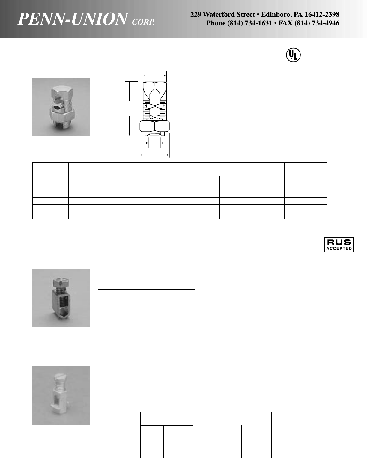
Maximum Conductor Maximum
Aluminum ACSR Copper Wire Diameter‡
Catalog Number Solid Stranded Solid Stranded in
SAX-12-8 12 8 – 12 8 .145
SAX-6 5 6 8 5 6 .184
SAX-4 2 3 4 2 3 .260
SAX-2 1 2 3 1 2 .292
‡For conversion to metric range, see Technical Data Section.
ALUMINUM SPLIT BOLT CONNECTORS • TYPE SWA
For aluminum to aluminum, copper to aluminum, and copper to copper
Range of Equal Wire Diameter Approximate Dimensions Recommended
Catalog Main & Tap Range‡ (In Inches) Torque
Number (Copper and Aluminum)(in inches) ABCD (in.-lb.)
SWA-7 6 Sol. - 1/0 Str. .162-.375 .375 .750 1.00 1.81 385
SWA-8 2 Sol. - 2/0 Str. .257-.418 .419 .88 1.12 2.12 390
SWA-10 1/0 Str. - 250 MCM .368-.575 .582 1.19 1.50 2.63 650
SWA-11 2/0 Str. - 350 MCM .414-.681 .746 1.31 1.63 2.91 650
SWA-12 3/0 Str. - 500 MCM .464-.814 .834 1.44 1.81 3.28 825
‡For conversion to metric range, see page 175.
Made from high strength, heat treated aluminum alloy–highly
resistant to corrosion. The design provides, under torque, high
contact pressure between conductors.
Electro tin-plated bolt, nut, spacer and pressure bar.
Meets and exceeds requirements of the UL486B standard.
There is no need to scratch brush or use oxide inhibiting com-
pounds for installation of 90°C max rated conductors in NEC
applications. For all other applications, the use of Penn-Union
Cual-Aid® #11C, oxide inhibiting compound, is recommended.
COPPER SERVICE ENTRANCE CONNECTORS • TYPE SX
For copper wire or cable
Body is made from cold drawn copper extrusions. Slotted silicon
bronze screws provides ease in installation–with screwdriver or
pliers. Type SX makes a secure, low resistance joint which is
easy to tape.
AL 9 CU
UL486B
A
B
C
D
Conductor Wire Diameter
Catalog Range Range‡
Number Stranded In.
SX-12 12 .092
SX-10-8 10-8 .116-.146
SX-6▲6.184
SX-4▲6-4 .184-.232
SX-2 4-2 .232-.292
‡For conversion to metric range, see page 175.
▲
RUS accepted.
17
Made from high strength hex bronze rod–slotted silicon bronze
screws. Spacer is manufactured from high conductivity copper.
Entire connector, including screw, is tin-plated to prevent gal-
vanic corrosion.
We recommend using Penn-Union Cual-Aid, an oxide inhibiting
compound. When connecting aluminum or ACSR wires, wire
brush the conductor with Cual-Aid #11C.
COPPER SERVICE ENTRANCE CONNECTORS • TYPE SAX
For copper wire or cable
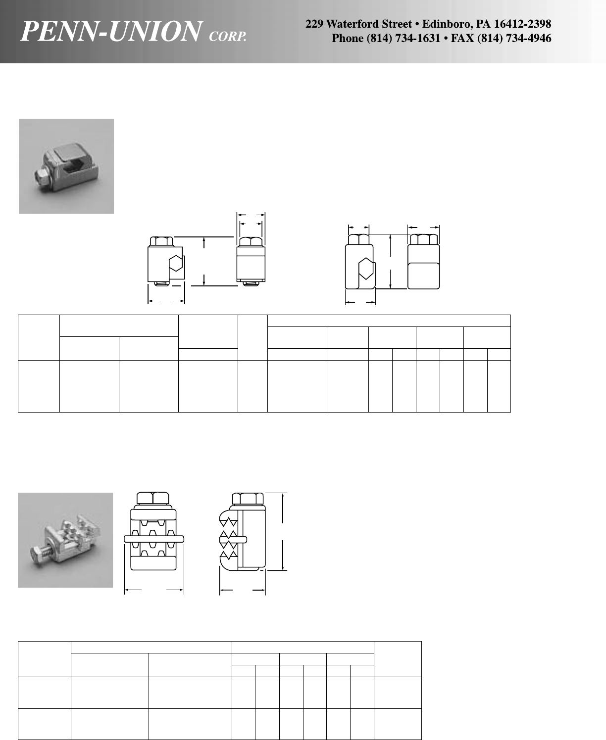
SILICON BRONZE VISE GRIPS • TYPE FF
For copper to copper wire
A stronger and more rigid connector of the vise type, with more
grip on the conductors–and full compression with any conductor
combination.
Easy to install. Non-swiveling–the slide cannot rotate out of the
body.
Castings made from bronze.
Wire Approximate Dimensions
Conductor Range Diameter Stud Diameter Hex
Catalog Maximum Minimum Range‡ Fig. No. Threads CF D H W
Number 2 Conductors 2 Conductors in No. in in in mm in mm in mm
FF-6* 6 Sol. 8 Sol. .128-.162 1 1/4-28 3/83/419.0 1 25.4 5/815.8
FF-4 4 Str. 6 Sol. .162-.232 1 5/16-24 9/16 13/16 20.6 15/32 29.4 5/815.8
FF-2 2 Str. 4 Sol. .204-.292 2 5/16-24 9/16 13/16 20.6 13/834.9 13/16 20.6
FF-2/0 2/0 Str. 2 Sol. .258-.419 2 3/8-24 9/16 11/828.5 17/847.6 31/32 24.6
FF-4/0 4/0 Str. 1/0 Sol. .325-.528 2 3/8-24 9/16 13/16 30.1 21/853.9 15/16 23.8
‡For conversion to metric range, see page 175.
*Supplied with slotted hex head bolts only.
The MGC-167 clamp with its piercing teeth is specifically designed
for use on self supporting rural, Figure 8, or IM type telephone
cable when connecting the messenger to the ground wire. When
clamp is tightened, the piercing teeth puncture through the insu-
lation of the messenger, eliminating the need for wire stripping,
forming a positive ground connection. Clamping bolt is stainless
steel.
Conductor Range Approx Dimensions
Catalog Messenger ABC
Bolt
Number Cable Dia. Tap in mm in mm in mm Size
8 Str-4 Str
MGC-167 .146"-.312" dia. (.146"-.232" dia.) 15/841.3 11/431.8 1 25.4 5/16-18
(3.7-7.9 mm2)(3.7-5.9 mm2)1/2 Hex
8 Str-4 Str
MGC-1679/16 .146"-.312" dia. (.146"-.232" dia.) 15/841.3 11/431.8 1 25.4 5/16-24
(3.7-7.9 mm2)(3.7-5.9 mm2)9/16 Hex
D
H
W
CF
FIGURE 1 FIGURE 2
CF W
H
D
TIN PLATED SILICON BRONZE INSULATION PIERCING VISE GRIPS • TYPE MGC
For messenger cable
18
A
CB

ALUMINUM PARALLEL CLAMPS • TYPE AVT
Penn-Tap heavy duty distribution
Specially designed wrap-around finger on spacer minimizes cold
flow over entire conductor range.
Rounded contours for easy taping.
Accommodates a range of aluminum or copper conductor in
either groove+. Place aluminum above copper.
Staking the longer of the two bolts makes the assembly one unit
with no loose parts to drop.
Top and bottom castings are of massive proportioned high
strength aluminum alloy and Type EC high conductivity alumi-
num alloy spacer assembled with steel or in larger sizes anod-
ized high strength aluminum hardware.
Catalog Number Conductor Range AWG and ACSR and AR* Approximate Dimensions
Wire Diameter Wire Diameter
Steel Aluminum Range‡ Range‡ H L W J
Hardware Hardware A Main in B Tap in in mm in mm in mm in
3 Sol.-1/0 Str.
AVT-0–4-1/0 ACSR .229-.440 6 Sol.-1/0 Str. .162-.398 27/8 73 19/16 40 15/841 5/16
AVT-0LS 6 AR 6-1/0 ACSR
2 Sol.-3/0 Str.
AVT-1–3-2/0 ACSR .258-.524 6 Sol.-3/0 Str. .128-.470 21/8 54 13/444 13/444 5/16
AVT-1LS 6-4 AR 8-2/0 ACSR
1/0 Sol.-250 MCM
AVT-2AVT-2A 1-4/0 ACSR .325-.575 6 Sol.-250 MCM .162-.575 25/8 67 2 51 2 51 3/8
AVT-2LS 6-4 AR 6-4/0 ACSR
3/0 Sol.-350 MCM
AVT-3AVT-3A 3/0-336.4 ACSR .410-.741 6 Sol.-350 MCM .162-.741 31/16 78 21/457 27/16 62 1/2
AVT-3ALS 6-1/0 AR 6-336.4 ACSR
350-500 MCM
AVT-4AVT-4A 336.4-397.5 ACSR .682-.836 4 Sol.-500 MCM .204-.815 39/16 90 23/470 21/264 1/2
AVT-4ALS 2/0-3/0 AR 5-397.5 ACSR
350-874.5 MCM
AVT-5AVT-5A 336.4-715.5 ACSR .682-1.092 3/0-874.5 MCM .470-1.077 41/16 103 33/888 213/16 71 1/2
AVT-5ALS 2/0-336.4 AR 3/0-715.5 ACSR
450-1000 MCM
AVT-6AVT-6A 397.5-900 ACSR .743-1.162 3/0-1000 MCM .470-1.162 41/4108 33/495 33/16 81 5/8
AVT-6ALS 4/0-397.5 AR 3/0-900 ACSR
+Not recommended for copper to copper applications, unless part is tin-plated.
‡For conversion to metric range, see page 175.
*AR–Aluminum cable rating with Preformed Armor Rods.
Add suffix “-TN” to the catalog number for a tin plated aluminum connector. Example: AVT-O-TN.
Add suffix “-BF” to the catalog number for prefilling with Cual-Aid and bagging. Example: AVT-O-BF.
Suffix LS–Less spacer; same length hardware.
A
B
AVT-LS
A
B
J
H
WL
RETAINER
WASHER ON
SHORT BOLT
AVT
19
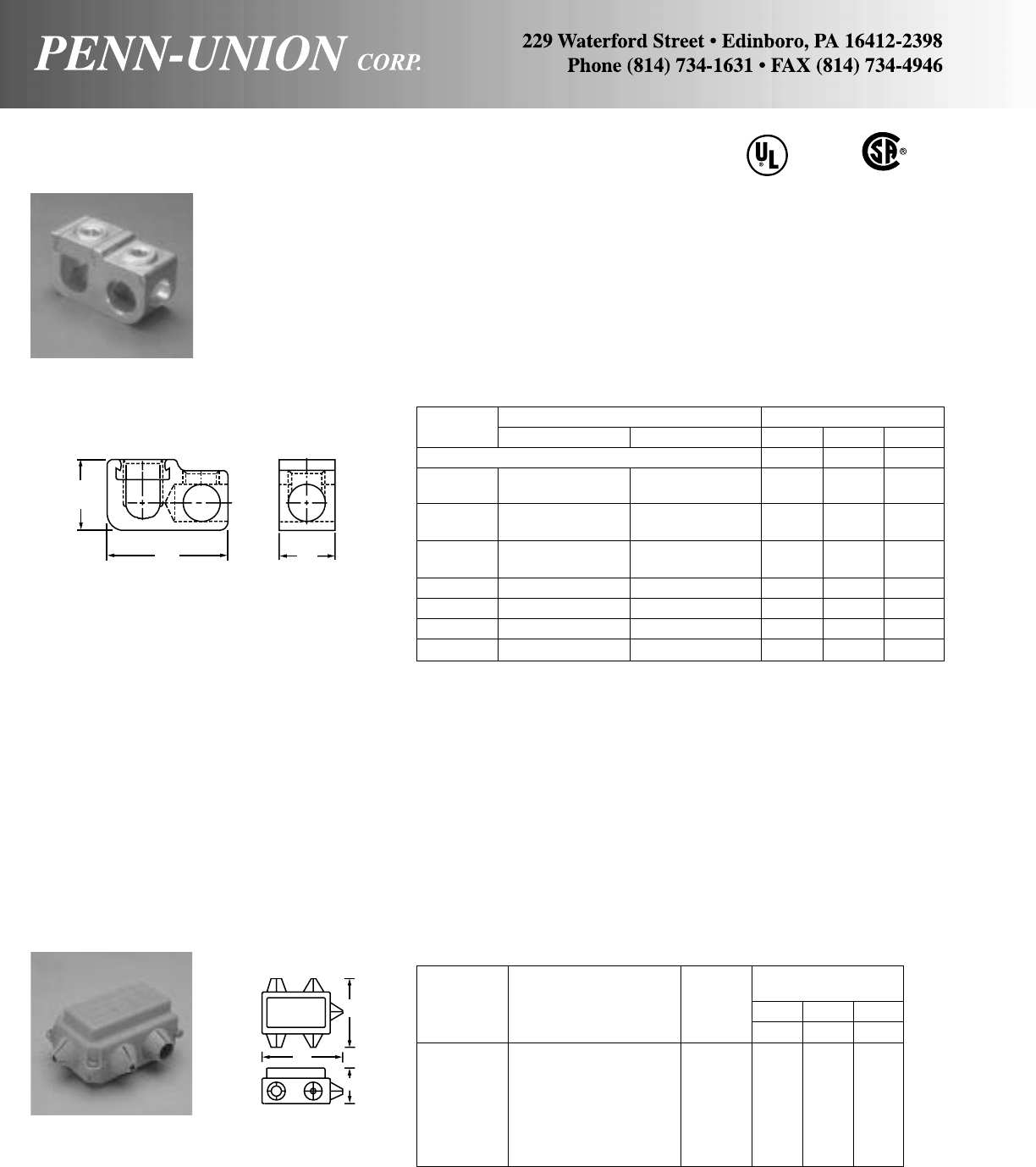
ALUMINUM MECHANICAL TAPS • TYPE GPT
Fabricated from high strength aluminum alloy extrusion. 100%
reusable, using a hex wrench. Sliding retainer allows easy instal-
lation on run conductor. Finish electro-tin plated to assure mini-
mum contact resistance and protection against corrosion when
used with copper wire (for added protection, apply Penn-Union
Cual-Aid® to cable, before installation).
Catalog Conductor Range Approximate Dimensions
Number Main Tap H W L
Parallel Taps* In. In. In.
GPT-2 12 Sol.-2 Str. 14 Sol.-4 Str. CU 7/85/8125/64
12 Sol.-4 Str. AL
GPT-1/0 2 Str.-1/0 Str. 14 Sol. 1/0 Str. CU 1 3/413/4
12 Sol.-1/0 Str. AL
GPT-250-0 1/0 Str.-250 MCM 14 Sol.-1/0 Str. CU 15/16 11/16 21/32
12 Sol.-1/0 Str. AL
GPT-250 1/0 Str.-250 MCM 6 Str.-250 MCM 15/16 11/16 29/32
GPT-350 4/0 Str.-350 MCM 6 Str.-350 MCM 17/16 11/429/16
GPT-500 350-500 MCM 2 Str.-500 MCM 13/413/831/8
GPT-750 500-750 MCM 2 Str.-500 MCM 2 11/233/8
*For taps packaged with covers add suffix “-WC”
COVERS • TYPE GTC
Insulating covers for GPT connectors
Approximate
Dimensions
Catalog Cover for HWL
Number Model Number Color in. in. in.
GTC-2 GPT-2 Yellow 17/64 129/32 27/32
GTC-1/0 GPT-1/0 Gray 11/425/32 25/8
GTC-250 GPT-250 Red 15/827/837/16
GTC-250 GPT-250-0 Red 15/827/837/16
GTC-350 GPT-350 Yellow 13/433/16 33/4
GTC-500 GPT-500 Blue 23/32 35/16 43/8
GTC-750 GPT-750 Orange 211/32 37/16 45/8
Manufactured from 105°C rated material, 600 volt maximum rated.
H
LW
W
L
H
UL486B
LISTED
AL9CU
GPT
GPT
20
Parallel and “T” Tap

ALUMINUM PARALLEL CLAMP (EXTRUDED) • TYPE PCAA
One center bolt and multiple center bolt
Heavy duty service entrance:
Light and heavy duty distribution armor rod clamps
Conductor Range AWG and ACSR and AR* Approximate Dimensions
Wire Diameter Wire Diameter
Catalog Fig. Range‡ Range‡ L W J
Number No. A Main in B Tap in in mm in mm in
PCAA-10▲16 Sol.-1/0 Str. .162- .398 6 Sol.-1/0 Str. .162- .398 15/16 33 17/16 37 3/8
6-1/0 ACSR 6-1/0 ACSR
6 Sol.-2/0 Str. 6 Sol.-2/0 Str.
PCAA-15▲16-2/0 ACSR .162- .447 6-2/0 ACSR .162- .447 13/8 35 111/16 43 3/8
6 Str. AR 6 Str. AR
2 Sol.-4/0 Str. 2 Sol.-4/0 Str.
PCAA-17 1 4-4/0 ACSR .250- .563 4-4/0 ACSR .250- .563 11/2 38 115/16 49 3/8
6-4 Str. AR 6-4 Str. AR
2 Sol.-4/0 Str. 2 Sol.-4/0 Str.
PCAA-18 2 4-4/0 ACSR .250- .563 4-4/0 ACSR .250- .563 3 76 115/16 49 3/8
6-4 Str. AR 6-4 Str. AR
3/0 Str.-400 MCM 6 Sol. 2/0 Str.
PCAA-20▲13/0-397.5 18/1 ACSR .470- .781 6-2/0 ACSR .162- .447 13/4 44 23/16 56 1/2
4 Str.-2/0 Str. AR 6 Str. AR
3/0 Str.-400 MCM 3/0 Str.-400 MCM
PCAA-23 2 3/0-397.5 18/1 ACSR .470- .781 3/0-397.5 18/1 ACSR .470- .781 33/8 88 215/32 63 1/2
4 Str.-2/0 Str. AR 4 Str. 2/0 Str. AR
3/0 Str.-400 MCM 3/0 Str.-400 MCM
PCAA-25 3 3/0-397.5 18/1 ACSR .470- .781 3/0-397.5 18/1 ACSR .470- .781 51/4133 215/32 63 1/2
4 Str.-2/0 Str. AR 4 Str.-2/0 Str. AR
400-1000 MCM 6 Sol.-2/0 Str.
PCAA-27 1 397.5 18/1-795 ACSR .728-1.153 6-2/0 ACSR .162- .447 21/4 57 213/16 71 5/8
3/0 Str.-397.5 AR 6 Str. AR
400-1000 MCM 3/0 Str.-400 MCM
PCAA-30 2 397.5 18/1-795 ACSR .728-1.153 3/0-397.5 18/1 ACSR .470- .781 41/2137 31/879 5/8
3/0 Str.-397.5 AR 4 Str.-2/0 Str. AR
400-1000 MCM 400-1000 MCM
PCAA-35 3 397.5 18/1-795 ACSR .728-1.153 397.5 18/1-795 ACSR .728-1.153 63/4171 31/289 5/8
3/0 Str.-397.5 AR 3/0 Str.-397.5 AR
*All aluminum cable rating with Preformed Armor Rods.
‡For conversion to metric range, see page 175.
Add suffix “-BF” to the catalog number for prefilling with Cual-Aid and bagging. Example: PCAA-10-BF.
▲
RUS accepted with suffix BF.
High strength aluminum extruded alloy fittings assembled with
steel or anodized high strength aluminum bolts, and high strength
aluminum flat washers.
Serrated grooves provide increased contact and cleaning action.
Aluminum hardware provided. For steel hardware, suffix catalog
number with “-SSTL.” Example: PCAA-10-SSTL.
A
BWJ
LA
BWJ
LA
B
WJ
L
FIG. 1
FIG. 2
FIG. 3
21
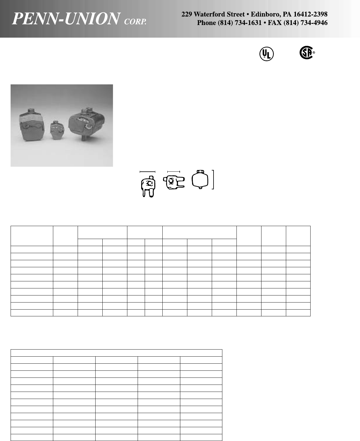
INSULATION – PIERCING CONNECTORS • TYPE IPC
For all combinations of copper and aluminum UL 486 B
LISTED
AL 9CU
Current Recomm.
Catalog Cond. Range Rating Dimensions (in) Torque Bolt Hd. No. of
Number Volts Run Tap CU AL Width Height Length ft. lbs. Size Bolts
IPC–1/0–2 † 300 1/0–8 2–8 130 100 1.47 2.31 1.22 16 1/21
IPC–4/0–6 600 4/0–4 6–14 75 60 1.00 1.87 1.42 13 1/21
IPC–4/0–2/0 600 4/0–2 2/0–6* 195 150 1.88 2.88 1.66 25 1/21
IPC–250–4/0 600 250–1 4/0–6 260 205 2.34 3.34 1.88 30 5/81
IPC–350–4/0 † 300 350–4/0 4/0–10 260 205 2.44 3.13 1.67 25 5/81
IPC–350–350 † 300 350–4/0 350–4/0 350 280 2.72 3.25 2.67 25 5/82
Bolt Nut
IPC–500–250 ∆600 500–350 250–4 260 205 2.90 3.75 2.42 60 5/8–11/16 1
IPC–500–500 ∆600 500–300 500–250 430 350 3.63 5.00 3.19 75 7/8–7/81
IPC–750–500 ∆600 750–500 500–350 430 350 3.63 5.00 3.19 75 7/8–7/81
† 480 Volts Grounded Y Systems
∆
Uses Bolt & Nut Clamping
*Maximum diameter of tap wire when measured over the insulation may not be larger than .528 in.
• Dual rated for insulated copper and aluminum wire
• For outdoor or indoor installation on energized conductor (not
under load)
• Molded of glass–filled nylon for long life
• Extra hard copper teeth for proper penetration
• Use as tap, splice, or dead end
• No need to strip insulation
Cross Reference
PUC ILSCO Kupler Blackburn Buchanan
IPC–1/0–2 IPC–1/0–2 130001 IPC–1102 BTC 3/0–12
IPC–4/0–6 IPC–4/0–6 130021 – –
–– 130003 IPC–4111 –
IPC–4/0–2/0 IPC–4/0–2/0 – – BTC 4/0–6
–– 130004 IPC–4141 –
IPC–250–4/0 IPC–250–4/0 130024 – –
IPC–350–4/0 IPC–350–4/0 130013 IPC–3541 BTC 350–10
IPC–350–350 IPC–350–350 130012 IPC–3535 BTC 350–2/0
IPC–500–250 IPC–500–250 130005 IPC–5041 BTC 500–4
IPC–500–500 IPC–500–500 130006 – –
IPC–750–500 IPC–750–500 130007 – –
22
Height
Width Length
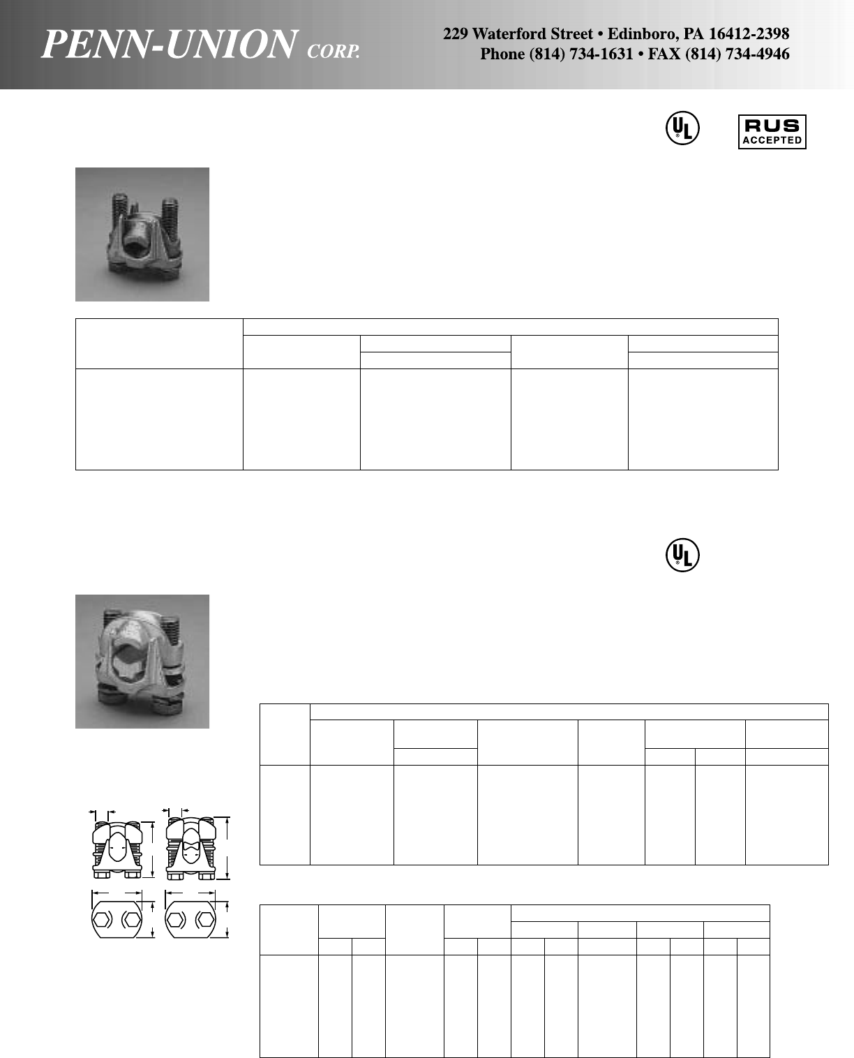
BRONZE PENN-TAPS • TYPE VT
For copper conductors
Designed for heavy-duty service connections. The cap swivels
to permit quick and easy installation of conductors. Retaining
rubber washer eliminates loose parts. Made from high strength
bronze castings–assurance against stress corrosion and sea-
son cracking. Hardware–silicon bronze bolts and lockwashers.
Flat back permits use as bus tap when used with longer bolts.
Copper Conductor Range
Wire Diameter Range‡ Wire Diameter Range‡
Catalog Number Main in Tap in
VT-0*2 Str.-1/0 Str. .292- .375 10 Str.-1/0 Str. .116- .375
VT-1▲2 Str.-2/0 Str. .292- .419 10 Str.-2/0 Str. .116- .419
VT-2▲1/0 Str.-4/0 Str. .375- .528 10 Str.-4/0 Str. .116- .528
VT-3▲250-350 MCM .575- .682 10 Str.-350 MCM .116- .682
VT-4▲250-500 MCM .575- .815 10 Str.-500 MCM .116- .815
VT-5*400-800 MCM .728-1.031 3/0 Str.-800 MCM .470-1.031
VT-6*500-1000 MCM .815-1.153 3/0 Str.-1000 MCM .470-1.153
‡For conversion to metric range, see page 175.
If desired tin plated, suffix catalog number with “TN”, for example: VT-1-TN.
If desired tin plated with spacer see type VTA listed below.
▲
RUS accepted.
PLATED PENN-TAP • TYPE VTA
For copper conductors
Made from high strength bronze castings with high conductivity
spacer bar. All parts are tin plated.
Rubber retaining washer eliminates loose parts.
Note: VTA-1 thru VTA-6 can be used on Aluminum conductors;
however, they are not UL Listed for that application.
AA
Approximate Dimensions
Catalog Bolt Length Catalog Bolt Length B C D E
Number in mm Number in mm in mm in in mm in mm
VT-0 11/238 VTA-0 11/432 13/32 10.3 5/16 17/16 37 15/16 24
VT-1 11/238 VTA-1 11/238 1/212.7 5/16 19/16 40 11/829
VT-2 13/444 VTA-2 13/444 19/32 15.0 3/8127/32 47 111/32 59
VT-3 2 51 VTA-3 2 51 3/419.0 1/225/16 59 15/841
VT-4 21/457 VTA-4 21/457 7/822.2 1/227/16 62 111/16 43
VT-5 21/264 VTA-5 21/264 11/16 26.9 1/2211/16 68 17/848
VT-6 23/470 VTA-6 23/470 11/431.7 5/831/16 78 21/457
Copper Conductor Range
Wire Diameter Wire Diameter
Catalog Range‡ Copperweld Aluminum Range‡
Number Main in Tap Solid Awg. Acsr. In
*VTA-0+ 2 Str.-1/0 Str. .292- .375 10 Str.-1/0 Str. 2/0 1/0 Str. 1 .116- .375
VTA-1 2 Str.-2/0 Str. .292- .419 10 Str.-2/0 Str. 3/0 – – .116- .419
VTA-2 1/0 Str.-4/0 Str. .375- .528 10 Str.-4/0 Str. 4/0 – – .116- .528
VTA-3 250-350 MCM .575- .682 10 Str.-350 MCM – – – .116- .682
VTA-4 250-500 MCM .575- .815 10 Str.-500 MCM – – – .116- .815
VTA-5 400-800 MCM .728-1.031 3/0 Str.-800 MCM – – – .470-1.031
VTA-6 500-1000 MCM .815-1.153 3/0 Str.-1000 MCM – – – .470-1.153
+Meets requirements for UL 486B. Balance of items UL listed copper to copper.
If no spacer bar is required, see type VT above.
CU
90°C
CU
90°C
BB
CC
AA
DD
EE
VT VTA
23
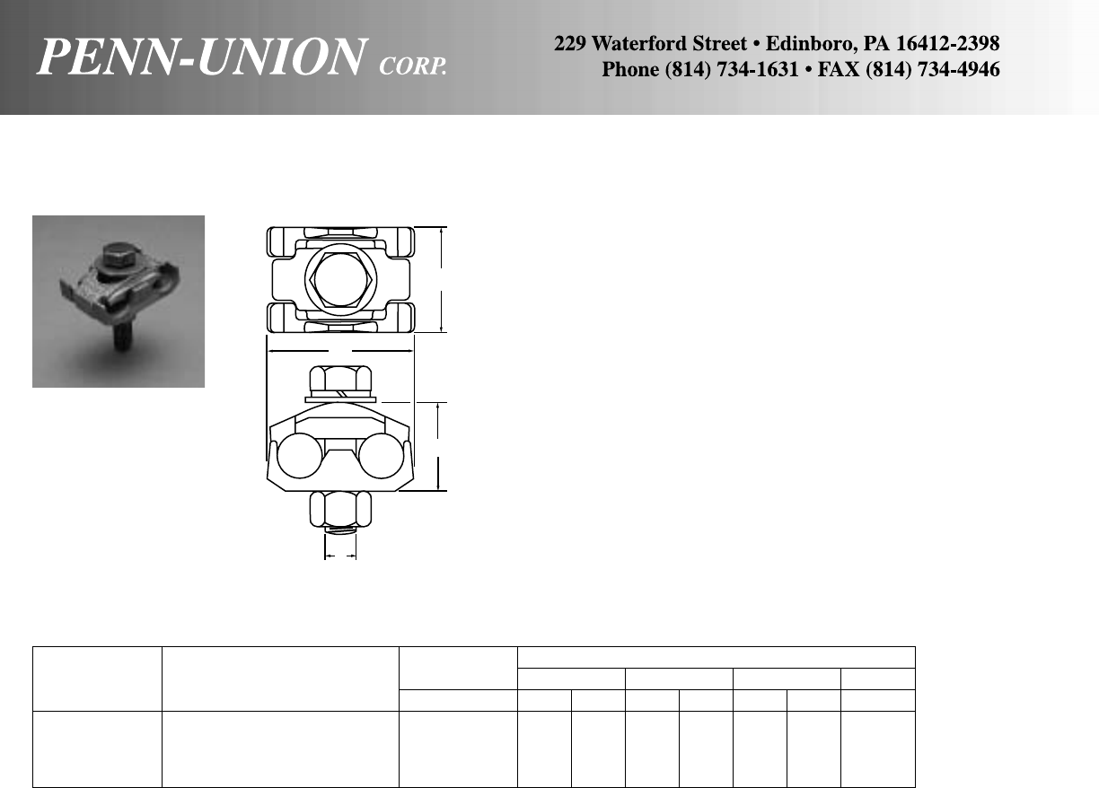
Made from high strength bronze alloy. Furnished with silicon
bronze bolts, nuts and lockwashers.
These clamps will accommodate a large range of cables or wires
in either groove, and are so designed that the two halves inter-
lock insuring a positive grip on the conductors.
Wire Diameter Approximate Dimensions
Catalog Conductor Range Range‡ L W H J
Number (Either Groove) in in mm in mm in mm in
UCR-013 8 Sol.-2/0 Str. .128-.419 11/432 13/444 11/16 27 3/8
UCR-030 1/0 Sol.-300 MCM .325-.634 13/444 25/16 59 13/835 1/2
UCR-050 250-500 MCM .575-.815 2 51 23/470 15/841 1/2
*UCR-075 300-750 MCM .634-.999 31/289 31/879 21/854 1/2
‡For conversion to metric range, see page 175.
*Two bolts.
BRONZE UNIVERSAL PARALLEL GROOVE CLAMP • TYPE UCR
For cable range to cable range
24
L
W
H
J
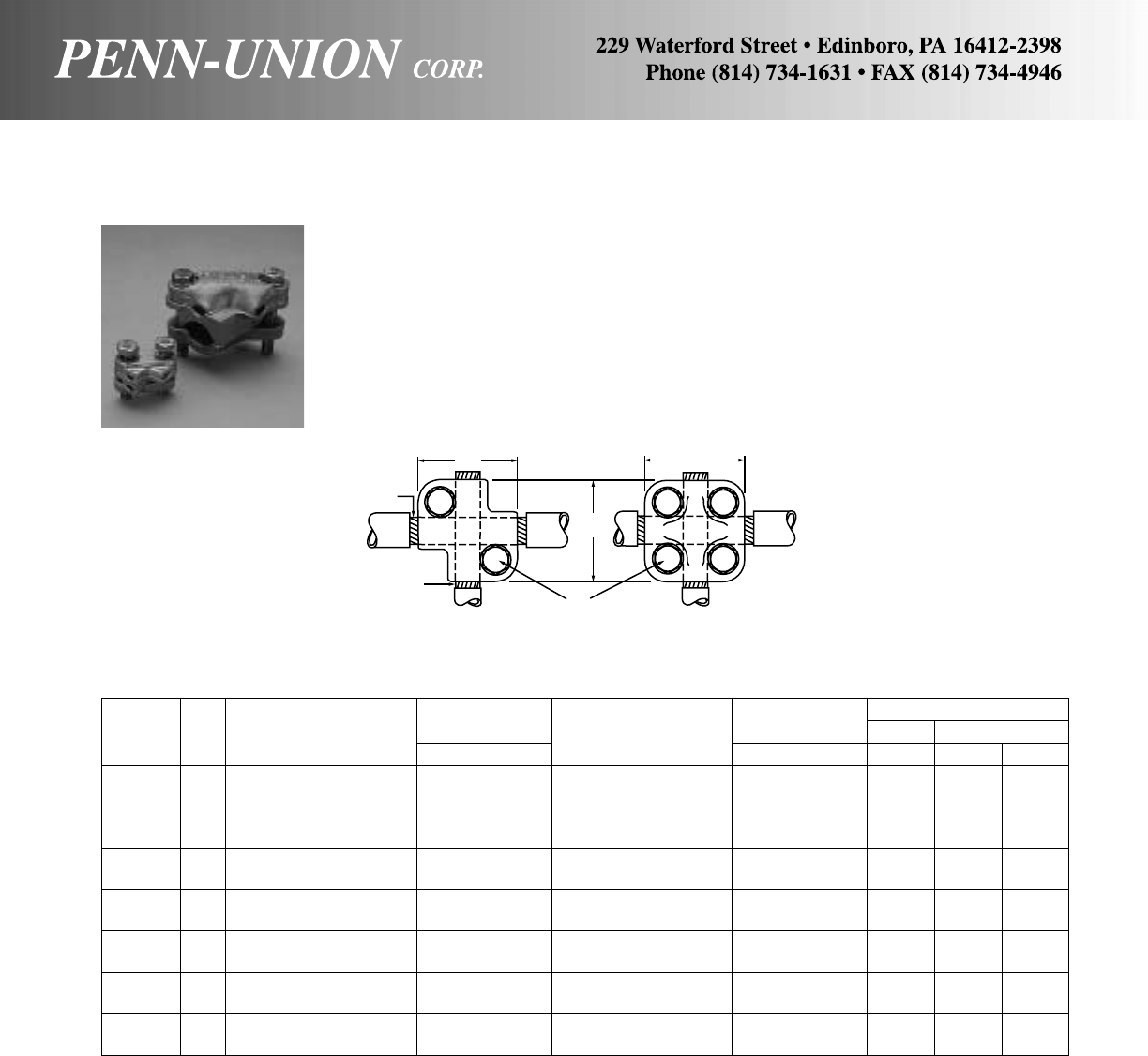
Upper and lower clamping members are made of high strength
bronze alloy. Spacer is made from high conductivity copper al-
loy. Furnished with high strength silicon bronze bolts and
lockwashers.
BRONZE VARIABLE GUTTER TAP • TYPE VX
For making parallel taps, tee connections, cross connections, or end to end connections.
25
Wire Diameter Wire Diameter Approximate Dimensions
Catalog Fig. Conductor Range Range-A Run‡ Conductor Range Range-B Tap‡ J M
Number No. A Run in B Tap in in in mm
VX-0 1 10 Sol.-10 Str. .102- .116 10 Sol.-10 Str. .102- .116 5/16 15/16 33
VX-1 1 6 Str.-2 Str. .184- .292 6 Str.-2 Str. .184- .292 5/16 15/16 33
VX-3 1 1 Str.-4/0 Str. .332- .528 6 Str.-4/0 Str. .184- .528 3/813/444
VX-4 1 250-500 MCM .575- .815 6 Str.-2 Str. .184- .292 3/823/16 56
VX-5S 1 250-500 MCM .575- .815 1/0 Str.-300 MCM .375- .634 3/823/16 56
VX-6 1 250-500 MCM .575- .815 1 Str.-500 MCM .332- .815 1/225/867
VX-7 1 500-1000 MCM .815-1.153 6 Str.-2/0 Str. .184- .419 3/825/867
VX-8 1 500-1000 MCM .815-1.153 1 Str.-4/0 Str. .332- .528 3/825/867
VX-8S 1 500-1000 MCM .815-1.153 1/0 Str.-300 MCM .375- .634 3/825/867
VX-10 2 500-1000 MCM .815-1.153 250-1000 MCM .575-1.153 3/829/16 65
VX-10S 2 750-1000 MCM .999-1.153 750-1000 MCM .999-1.153 1/2376
VX-11 2 750-1500 MCM .999-1.412 500-1000 MCM .815-1.153 3/8215/16 75
VX-12 2 750-1500 MCM .999-1.412 750-1500 MCM .999-1.412 1/231/482
VX-13 2 1000-2000 MCM 1.153-1.631 1000-2000 MCM 1.153-1.631 1/237/16 87
‡For conversion to metric range, see page 175.
M
A
RUN
B
TAP J
M
M
FIG. 2
4-Bolt
FIG. 1
2-Bolt

Finish Wire Diameter Approximate Dimensions
Catalog of Conductor Range‡ L W
Number Grooves Bolt Range in in mm in mm
JC-1-AC▲ †1-Groove Steel 6 Sol.-1/0 Str. .162-.373
Tin Plated
JC-UL-AC 1-Groove Silicon 6 Sol.1/4,5/16 Guy .162-.312
11/829 15/16 33
Bronze Bronze
JC-2-AA † Tin Steel 6 Sol.-1/0 Str. .162-.373 11/829 15/16 33
JC-UL Plated Silicon Bronze 6 Sol.-1/4,5/16 Guy .162-.312
JC-3-CC † Bronze Steel 6 Sol.-1/0 Str. .162-.373 11/829 15/16 33
JC-UL-CC Silicon Bronze 6 Sol.-1/4,5/16 Guy .162-.312
‡For conversion to metric range, see page 175.
▲
RUS accepted.
† Not UL Listed.
COPPER JUMPER CLAMP • TYPE JC
Wire Diameter Approximate Dimensions
Catalog Conductor Range Range‡ Fig. HJL W
Number (Either Groove) in No. in mm in in mm in mm
UPC-1 6 Sol.-1/0 Str. .162- .375 1 13/444 3/813/4 44 11/238
UPC-2 4 Sol.-4/0 Str. .204- .528 2 2 51 3/821/8 54 13/444
UPC-3 2 Sol.-300 MCM .258- .634 2 21/457 3/823/8 60 2 51
UPC-4 4/0 Str.-500 MCM .528- .815 3 31/470 1/241/4108 21/264
UPC-5 300-800 MCM .634-1.031 3 31/482 1/241/4108 3 76
UPC-6 500-1000 MCM .815-1.153 3 31/289 1/241/4108 31/289
These clamps can also be supplied for aluminum conductors. The clamps are tin plated for aluminum. Add “TN” to catalog number for tin plating.
For example: UPC-1-TN. See Type PCAA on page 21 for aluminum parallel clamps.
‡For conversion to metric range, see page 175.
UNIVERSAL PARALLEL CLAMP • TYPE UPC
For copper cable or wire
Jumper clamp cast from high copper content alloy.
W
L
5/16"-18
These clamps are designed to accommodate a large range of
wires or cables in either groove. Made from high strength
bronze alloy. Furnished with silicon bronze carriage bolts, nuts
and lockwashers for convenience of single wrench installation.
J
H
FIG. 1
26
W
L
FIG. 2 FIG. 3
CU
90°C
UL467
GROUNDING & BONDING
CUS

COPPER PENN-CRIMPS® • TYPE BLY
Heavy Wall Seamless Tubing #10 AWG - 4/0 AWG
Seamless, one piece, pure electrolytic copper construction with
tin plating assures maximum conductivity. Generous entrance
chamfer provides easy cable insertion. Inspection window insures
full insertion. Features rounded tongue with full washer clear-
ance and standardized crimp length. Can be installed with exist-
ing crimping tools. Catalog number and conductor size marked
on every piece to insure positive identification.
Non-Insulated Compression Terminal
Ring Tongue - Seamless Installation Tooling
Dimensions (in) Mechanical Hydraulic T & B
Copper PUC Burndy Wire Tool 13642
Catalog Cond. Stud L Y Z Die Y35+ Strip Die Die
Number Range Size W Max. Max. Min. Burndy PUC TPU-12B Index Y39 Length Cat. No. MS90485-
BLY10-T7† 4-6 .30 .96 .73 .20 Y8MRBI
10 Str. MR8G98 7/16"
BLY10-L36† 12 Sol. 8-10 .30 .80 .62 .18 Y10D
Y14MV
BLY8C-L14 6-8 .41 1.15 .94 .28 UV8L
BLY8C-L 8 8-10 .41 1.15 .94 .28 Non- Nest
BLY8C-L1 Aircraft 1/4 .46 1.22 .99 .32 Ratchet; TDM-250XF TPU-12B 38 Y34PL 1/2"11781M - 8
BLY8C-L2 AN 8 5/16 .57 1.30 1.01 .34 MY29-11 Indentor
BLY8C-L3 8 AWG 3/8 .57 1.30 1.01 .34 (1) Crimp
BLY8C-L4 1/2 .73 1.52 1.14 .48
BLY6C-L1 6 8-10 .48 1.31 1.06 .29 UV6L
BLY6C-L Aircraft 1/4 .48 1.31 1.06 .29 Non- Nest
BLY6C-L4 AN 6 5/16 .60 1.43 1.13 .35 Ratchet; TDM-250XF TPU-12B 39 Y34PLA 1/2"11782M - 6
BLY6C-L2 6 AWG 3/8 .60 1.43 1.13 .35 MY29-11 Indentor (1)
BLY6C-L10 1/2 .73 1.64 1.26 .49 Crimp
BLY4C-L3 8-10 .55 1.37 1.11 .28 UV4L
BLY4C-L 4 1/4 .55 1.37 1.11 .28 Non- Nest
BLY4C-L4 Aircraft 5/16 .63 1.48 1.17 .33 Ratchet; TDM-250XF TPU-12B 40 Y34PLA 1/2"11783M - 4
BLY4C-L2 AN 4 3/8 .63 1.48 1.17 .33 MY29-11 Indentor (1)
BLY4C-L5 4 AWG 1/2 .73 1.68 1.30 .47 Crimp
BLY2C-L3 2 8-10 .69 1.72 1.37 .35 UV2L
BLY2C-L1 Aircraft 1/4 .69 1.72 1.37 .35 Nest
BLY2C-L2 AN 2 5/16 .69 1.72 1.37 .35 TDM-250XF TPU-12B 41 Y34PLA 5/8"11784M - 2
BLY2C-L 2 AWG 3/8 .69 1.72 1.37 .35 Indentor
BLY2C-L4 1/2 .77 1.89 1.49 .46 (1) Crimp
BLY1C-L6 1 8-10 .76 1.67 1.32 .25 UV1CL Nest
BLY1C-L1 Aircraft 1/4 .76 1.84 1.45 .38 Y34PLA
BLY1C-L2 AN 1 5/16 .76 1.84 1.45 .38 TDM-250XF TPU-12B 42 Indentor 5/8"11785M - 1
BLY1C-L 1 AWG 3/8 .76 1.84 1.45 .38 (1) Crimp
BLY1C-L3 1/2 .86 1.97 1.54 .46
BLY25-L1 1/0 1/4 .83 2.01 1.61 .43 UV25L Nest
BLY25-L2 Aircraft 5/16 .83 2.01 1.61 .43 Non- Y34PA
BLY25-L AN 1/0 3/8 .83 2.01 1.61 .43 Ratchet; TDM-250XF TPU-12B 43 Indentor 11/16"11786M - 01
BLY25-L3 1/0 AWG 1/2 .88 2.09 1.64 .46 MY29-11 (1) Crimp
BLY25-L4 5/8 .88 2.31 1.80 .62
BLY26-L1 2/0 1/4 .93 2.32 1.85 .48
BLY26-L2 Aircraft 5/16 .93 2.32 1.85 .48
BLY26-L AN 2/0 3/8 .93 2.32 1.85 .48 TDM-250XF 13/16"11787M - 02
BLY26-L3 2/0 AWG 1/2 .93 2.32 1.85 .48
BLY26-L12 5/8 .93 2.52 1.99 .62
3/0
BLY27-L Aircraft 3/81.03 2.45 1.93 .52 TDM-250XF 13/16"11788M - 03
BLY27-L1 AN 3/0 1/21.03 2.45 1.93 .52
BLY27-L15 3/0 AWG 5/81.03 2.60 2.04 .62
BLY28-L 4/0 3/81.12 2.72 2.16 .60
BLY28-L12 Aircraft 1/21.12 2.72 2.16 .60 TDM-250XF 7/8"11789M - 04
BLY28-L13 AN 4/0 5/81.12 2.72 2.16 .60
BLY28-L14 4/0 AWG 3/41.23 2.95 2.33 .78
†Not UL or CSA listed
CU
90°C
W
ZY
L
27

Approximate Dimensions Crimping Tool Reference
Wire (in inches) Alt. Tooling Penn-Union
Copper Dia. Burndy TDY-1
Catalog Cond. Color (in) Stud Fig. Index T&B PUC Pressure
Number Range† Code ‡ Size No. L B D E H T W No. Die Dies Setting
BLU-8S14 #10 1 15/32 1/2–1/413/32
BLU-8D #10 2 123/32 11/16 5/87/32 13/32
BLU-8S15 8 Str. Red .146 1/411
7/32 13/32 9/16 –9/32 5/64 13/32 B-6 21 T-6*
BLU-8S16 5/16 11
5/16 21/32 –9/32 9/16
BLU-8S17 3/811
11/32 11/16 –19/64 9/16
BLU-8S18 1/211
33/64 55/64 –3/813/16
BLU-6S #10 1 19/16 17/32 –7/32 13/32
BLU-6S1 1/411
23/32 11/16 –5/16 7/16 T-7*
BLU-6D 6 Str. Blue .184 1/422
7/32 13/16 13/16 5/81/43/32 7/16 B-7 24 or
BLU-6S2 5/16 11
25/32 3/4–11/32 1/2T-374*
BLU-6S8 3/811
27/32 13/16 –3/819/32
BLU-5S #10 1 139/64 9/16 –1/47/16
BLU-5S1 1/411
47/64 11/16 –5/16 7/16
BLU-5D 5 Str. – .206 1/422
19/64 13/16 13/16 5/81/43/32 7/16 B-21 – T-21*
BLU-5S2 5/16 11
49/64 23/32 –11/32 9/16
BLU-5S3 3/811
59/64 7/8–13/32 19/32
BLU-4S #10 1 139/64 9/16 –1/41/2
BLU-4S1 1/411
47/64 11/16 –5/16 1/2T-8*
BLU-4D 4 Str. Gray .232 1/422
19/64 13/16 13/16 5/81/43/32 1/2B-8 29 or
BLU-4S10 5/16 11
49/64 23/32 –11/32 19/32 T-346*
BLU-4S2 3/811
49/64 7/8–13/32 19/32
BLU-3S #10 1 143/64 9/16 –1/417/32
BLU-3S1 1/411
51/64 11/16 –5/16 17/32
BLU-3D 3 Str. White .260 1/422
19/64 7/813/16 5/81/47/64 17/32 B-9 – T-9*
BLU-3S2 5/16 11
55/64 3/4–11/32 9/16
BLU-3S3 3/811
63/64 7/8–13/32 19/32
BLU-2S15 #10 1 147/64 21/32 –5/16 19/32
BLU-2S 1/411
51/64 11/16 –5/16 7/64 19/32
BLU-2D 1/422
19/64 13/16 5/81/419/32
BLU-2D2 2 Str. Brown .292 1/223
63/64 27/813/417/32 5/64 13/16 B-10 33 T-10 2
BLU-2S1 5/16 11
55/64 7/83/4–11/32 19/32
BLU-2S2 3/811
63/64 7/8–13/32 7/64 5/8
BLU-2S10 1/212
15/64 11/8–9/16 13/16
BLU-1S9 1/411
27/64 5/89/16 –1/443/64
BLU-1D2 1/422
23/64 15/16 13/16 5/81/443/64
BLU-1S 1 Str. Green .332 5/16 11
55/64 7/83/4–11/32 7/64 43/64 B-11 37 T-11/375
BLU-1D4 5/16 22
51/64 15/16 15/87/811/32 43/64
BLU-1S1 3/812
3/64 15/16 7/8–7/16 43/64
BLU-1S4 1/212
19/64 15/16 11/8–9/16 3/4
BLU-1/0S19 1/411
15/16 3/4–11/32 3/4
BLU-1/0S 5/16 12
1/16 3/4–11/32 3/4
BLU-1/0D 5/16 22
13/16 15/87/811/32 3/4
BLU-1/0S1 1/0 Str. Pink .375 3/812
1/16 7/87/8–13/32 1/83/4B-12 42 T-12/348
BLU-1/0D4 3/823 1
13/16 13/83/4
BLU-1/0S20 1/212
1/411/16 –1/213/16
BLU-1/0D2 1/224
1/16 27/813/417/32 13/16
‡For conversion to metric range, see page 175.
*Consult factory for availability of dies. Not available at this time. †Concentric, compressed and compact stranding
Seamless, one piece, pure copper construction with tin plating
assures maximum conductivity. Generous entrance chamfer pro-
vides easy cable insertion. Inspection window insures full
insertion.
Catalog number and conductor size marked on every piece
insures positive identification.
Can be installed with existing crimping tools. Color coding con-
forms to industry requirements to insure proper connector/die
selection and to provide for faster installation.
BLU LUGS ARE SUITABLE FOR USE AT VOLTAGES UP TO
35KV.
CU
90°C
EH
W
D
W
L
B
DT
FOR STUD SIZE
COPPER PENN-CRIMPS® • TYPE BLU
Crimp lugs with inspection window for #8 stranded thru 2000 MCM
FIG. 2
FIG. 1
H
28
45° and 90° Variations are UL Listed and CSA non stock items.
Contact factory for price and availability.

Approximate Dimensions Crimping Tool Reference
Wire (in inches) Alt. Tooling Penn-Union
Copper Dia. Burndy Pressure
Catalog Cond. Color (in) Stud Fig. Index T&B PUC Setting
Number Range† Code ‡ Size No. L B D E H T W No. Die Dies TDY-1 TDY-U
BLU-2/0S20 1/412
1/16 13/16 –11/32
BLU-2/0S21 5/16 12
1/16 13/16 –11/32
BLU-2/0D3 5/16 22
7/815/87/811/32
BLU-2/0S 2/0 Str. Black .419 3/812
1/815/16 7/8–13/32 1/813/16 B-13 45 T-13 2
BLU-2/0D4 3/823
1/16 113/16 13/8
BLU-2/0S4 1/212
3/811/8–9/16
BLU-2/0D 1/224
1/827/813/417/32
BLU-3/0S14 1/411
15/16 3/413/16 –11/32
BLU-3/0S15 5/16 11
15/16 3/413/16 –11/32
BLU-3/0D11 5/16 2311
5/87/811/32
BLU-3/0S 3/0 Str. Orange .470 3/812
1/417/8–13/32 1/829/32 B-14 50 T-14
BLU-3/0D3 3/823
3/16 11
13/16 13/8
BLU-3/0S1 1/212
1/211
1/8–17/32
BLU-3/0D 1/224
1/412
7/813/417/32
BLU-4/0S19 1/412
7/32 25/32 –11/32
BLU-4/0S25 5/16 12
7/32 25/32 –11/32
BLU-4/0S 4/0 Str. Purple .528 3/812
5/16 17/8–13/32 9/64 1B-15 54 T-15 5 5
BLU-4/0D10 3/823
1/4113/16 13/8
BLU-4/0S1 1/212
9/16 11/8–9/16
BLU-4/0D 1/224
5/16 27/813/417/32
BLU-025S4 1/412
11/32 25/32 –11/32
BLU-025S5 5/16 12
11/32 25/32 –11/32
BLU-025S2 250 Yellow .575 3/812
9/16 11/16 1–
13/32 5/32 13/32 B-16 62 T-16
BLU-025D3 MCM 3/823
3/8113/16 13/8
BLU-025S 1/212
11/16 11/8–17/32
BLU-025D 1/224
7/16 27/813/417/32
BLU-030S6 5/16 12
13/32 25/32 –11/32
BLU-030S7 3/812
5/81–
13/32 66H or
BLU-030D9 300 White .634 3/823
7/16 11/16 113/16 13/85/32 13/16 B-17 66 T-17*
BLU-030S MCM 1/212
3/411/8–17/32
BLU-030D 1/224
1/227/813/417/32
BLU-030S8 5/813
5/16 111/16 –13/16
BLU-035S1 3/812
5/87/8–7/16
BLU-035D13 3/823
9/16 113/16 13/871H
BLU-035S 350 Red .682 1/212
29/32 11/815/32 –17/32 11/64 19/32 B-18 or T-18/324 7 7
BLU-035D MCM 1/224
5/827/813/417/32 71
BLU-035S3 5/813
5/32 113/32 –21/32
BLU-040D7 3/823
11/16 113/16 13/8
BLU-040S4 400 Blue .728 1/213
1/16 13/16 13/16 –9/16 3/16 113/32 B-19 76H T-19*
BLU-040D MCM 1/224
3/427/813/417/32 or or
BLU-040S 5/813
5/16 17/16 –21/32 76 T-470*
BLU-045S1 1/213
1/16 13/16 –9/16 76H
BLU-045D 450 Blue .772 1/224
3/413/16 27/813/417/32 7/32 129/64 –or–
BLU-045S MCM 5/813
5/16 17/16 –21/32 76
BLU-050D13 3/823
15/16 113/16 17/16
BLU-050S2 500 Brown .815 1/213
1/413/811/8–9/16 7/32 117/32 B-20 87 T-20/299
BLU-050D MCM 1/225 2
7/813/417/32
BLU-050S 5/813
9/16 17/16 –27/32
BLU-060D 600 Green .893 1/225
3/32 13/827/813/417/32 17/64 123/32 B-22 94H T-22/472
BLU-060S MCM 5/813
31/32 13/4–7/8or 94 9 9
BLU-060S1 1/213
31/32 13/4–7/8
BLU-065D 650 Pink .930 1/225
3/32 13/827/813/417/32 17/64 125/32 B-300 99 –
BLU-065S4 MCM 5/813
31/32 13/4–7/8
BLU-065S5 1/213
31/32 13/4–7/8
BLU-075D 750 Black .999 1/225
7/16 15/827/813/417/32 17/64 129/32 B-24 106H –
BLU-075S MCM 5/814 1
7/16 –21/32 or 106
BLU-080D 800 _ 1.031 1/225
17/32 15/827/813/417/32 19/64 131/32 B-25 107H –
BLU-080S MCM 5/814
17/32 17/8–15/16 or 107
BLU-100D 1/225
7/827/813/417/32
BLU-100S 1000 White 1.153 5/814
7/817/817/8–15/16 21/64 23/16 B-27 125 – 9** 9**
BLU-100S4 MCM 3/414
7/817/8–15/16
BLU-150D 1500 – 1.412 1/226
3/32 227/813/417/32 3/8211/16 B-31 – –
BLU-150S MCM 3/415
15/32 21/4–1
1/8
BLU-200D 2000 – 1.632 1/226
3/821/427/813/417/32 15/32 31/16 B-34 – –
BLU-200S MCM 3/415
15/16 23/8—1
3/16
*Consult factory for availability of dies. Not available at this time. ••With CUAD-1000.
‡For conversion to metric range, see page 175. †Concentric, compressed and compact stranding.
COPPER PENN-CRIMPS® • TYPE BLU
Continued from preceding page
CU
90°C
29
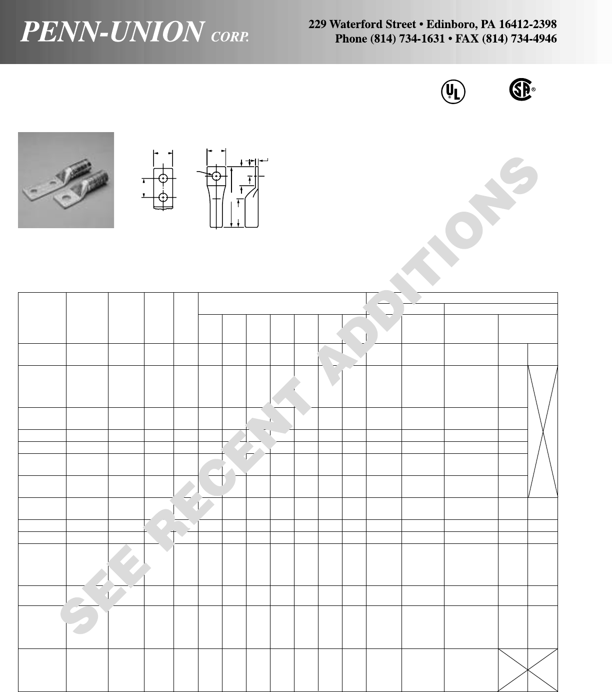
1 HOLE LUGS
Approximate Dimensions Crimping Tool Reference
Wire (in inches) Alt. Tooling Penn-Union
Copper Dia. Burndy
Catalog Cond. Color (in) Stud Index T&B PUC Pressure
Number Range† Code ‡ Size B W D E H L T No.■Die Dies Setting
BBLU-6S 6 Str. Blue .184 1/413/32 13/32 11/16 –5/16 21/16 .09 B-7 24 T-7*/374 TDY-1 TDY-U
BBLU-6S1 6 Str. Blue .184 1/211/813/16 11/4–5/8219/32 .09
BBLU-4S 4 Str. Gray .232 1/413/32 1/211/16 –5/16 21/16 .09
BBLU-4S1 4 Str. Gray .232 3/811/813/16 11/4–5/8239/64 .08 B-8 29 T-8*/346 2
BBLU-4S2 4 Str. Gray .232 1/211/413/16 11/4–5/8239/64 .08
BBLU-4S3 4 Str. Gray .232 3/8** 13/32 1/211/16 –5/16 21/16 .09
BBLU-3S1 3 Str. White .260 5/16 11/817/32 3/4–11/32 25/32 .11 B-9 – T-9* 2
BBLU-3S3 3 Str. White .260 1/411/817/32 3/4–11/32 25/32 .11
BBLU-2S 2 Str. Brown .292 5/16 17/32 19/32 3/4–11/32 21/4.11 B-10 33 T-10 2
BBLU-1S 1 Str. Green .332 5/16 111/32 11/16 3/4–11/32 23/8.11 B-11 37 T-11*/375 2
BBLU-1/0S 1/0 Str. Pink .375 5/16 111/32 3/43/4–11/32 27/16 .12 B-12 42 T-12*/348 2
BBLU-1/0S2 1/0 Str. Pink .375 3/811/43/413/16 –13/32 23/8.12
BBLU-2/0S 2/0 Str. Black .419 3/811/213/16 7/8–13/32 211/16 .12 B-13 45 T-13 2
BBLU-2/0S1 2/0 Str. Black .419 1/211/213/16 11/4–5/831/16 .12
BBLU-3/0S 3/0 Str. Orange .470 1/211/229/32 11/4–5/831/8.12 B-14 50 T-14 5 5
BBLU-3/0S2 3/0 Str. Orange .470 3/811/229/32 11/4–7/16 31/8.12
BBLU-4/0S 4/0 Str. Purple .528 1/215/811
1/4–5/835/16 .14 B-15 54 T-15 5 5
BBLU-025S 250 MCM Yellow .575 1/215/811/811/4–5/833/8.16 B-16 62 T-16 5 5
BBLU-030S 300 MCM White .634 1/221
3/16 11/4–5/8313/16 .16 B-17 66H/66 T-17*
BBLU-035S 350 MCM Red .682 1/221
9/32 11/4–5/8327/32 .17 B-18 71H/71 T-18* or T-324 77
BBLU-040S 400 MCM Blue .728 5/821/8113/32 11/2–3/445/16 .19 B-19 76H/76 T-19*/470
BBLU-040S1 400 MCM Blue .728 1/221/8113/32 11/4–5/841/16 .19 B-19 76H/76 T-19*/470
BBLU-050S 500 MCM Brown .815 5/821/4117/32 115/32 –23/32 41/2.22 B-20 87 T-20* or 99
BBLU-050S2 500 MCM Brown .815 1/221/4117/32 11/4–23/32 41/4.22 T-299
BBLU-060S 600 MCM Green .893 5/8211/16 123/32 11/2–23/32 51/8.27 B-22 94H/94 T-22*/472
BBLU-065S 650 MCM Pink .930 1/2213/16 125/32 13/4–7/8513/32 .27 B-300 99 – 99
BBLU-065S1 650 MCM Pink .930 5/8213/16 125/32 13/4–7/8513/32 .27 B-300 99 –
BBLU-075S 750 MCM Black .999 5/827/8129/32 11/2–23/32 55/16 .27 B-24 106H/106 T-24*/473
BBLU-080S 800 MCM – 1.031 5/8215/16 131/32 11/2–23/32 51/2.25 B-25 107H/107 –
BBLU-100S 1000 MCM White 1.153 5/832
3/16 11/2–23/32 55/8.33 B-27 125 –
BBLU-150S 1500 MCM – 1.412 3/433/16 211/16 21/8–1
1/16 69/16 .39 B-31 – –
BBLU-200S 2000 MCM – 1.632 3/437/16 31/16 21/8–1
1/16 67/8.47 B-34 – –
‡For conversion to metric range, see page 175.
■
For additional tool references, see pages 44 thru 51.
* Consult factory for availability of dies. Not available at this time.
**Actual Hole Size
†Concentric, compressed and compact stranding.
COPPER PENN-CRIMPS® • TYPE BBLU
Long barrel lugs for #6 stranded thru 2000 MCM
Double length barrel permits two crimps in the larger sizes for
additional assurance on heavy duty loads. Seamless, one piece,
pure copper construction with tin plating assures maximum con-
ductivity. Generous entrance chamfer provides easy cable inser-
tion. End of cable is protected from environmental hazards by
completely closed transition.
Catalog number and conductor sizes marked on every piece in-
sures positive identification.
Can be installed with existing crimping tools. Color coding con-
forms to industry requirements to insure proper connector/die
selection and to provide for faster installation.
BBLU LUGS ARE SUITABLE FOR USE AT VOLTAGES UP TO 35KV.
CU
90°C
W
E
W
D
B
For
Stud
Size
H
L
30
T
45° and 90° Variations are UL Listed and CSA non stock items.
Contact factory for price and availability.
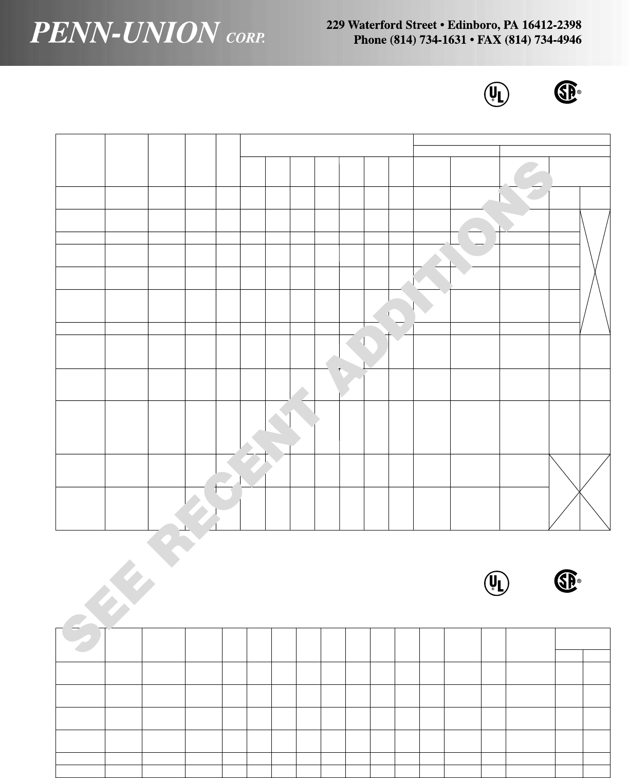
31
COPPER PENN-CRIMPS® • TYPE BBLU
Continued from preceding page
2 HOLE LUGS
Approximate Dimensions Crimping Tool Reference
Wire (in inches) Alt. Tooling Penn-Union
Copper DIa. Burndy
Catalog Cond. Color (in) Stud Index T&B PUC Pressure
Number Range† Code ‡ Size B W D E H L T No.■Die Dies Setting
BBLU-6D 6 Str. Blue .184 1/411/813/32 19/32 5/85/16 221/32 .09 B-7 24 T-7*/374 TDY-1 TDY-U
BBLU-6DN 6 Str. Blue .184 1/211/813/16 31
3/45/8411/32 .09
BBLU-4D 4 Str. Gray .232 1/411/81/219/32 5/85/16 211/16 .09 B-8 29 T-8*/346 2
BBLU-4D1 4 Str. Gray .232 1/211/815/16 27/813/417/32 415/64 .09
BBLU-3D 3 Str. White .260 5/16 11/817/32 15/87/811/32 31/32 .09 B-9 – T-9* 2
BBLU-2D 2 Str. Brown .292 5/16 11/45/8115/32 3/411/32 3.09B-10 33 T-10
BBLU-2D6 2 Str. Brown .292 1/211/413/16 31
3/45/8433/64 .09 2
BBLU-1D 1 Str. Green .332 5/16 13/811/16 15/87/811/32 33/8.09 B-11 37 T-11*/375 2
BBLU-1D2 1 Str. Green .332 1/213/825/32 31
3/45/845/8.11
BBLU-1/0D 1/0 Str. Pink .375 5/16 13/83/4119/32 7/811/32 35/16 .12
BBLU-1/0D2 1/0 Str. Pink .375 3/813/83/425/813/43/845/16 .12 B-12 42 T-12*/348 2
BBLU-1/0D3 1/0 Str. Pink .375 1/213/813/16 27/813/417/32 49/16 .12
BBLU-2/0D 2/0 Str. Black .419 1/211/213/16 31
3/45/8413/16 .12 B-13 45 T-13 2
BBLU-3/0D 3/0 Str. Orange .470 1/211/229/32 31
3/45/847/8.12 B-14 50 T-14
BBLU-4/0D 4/0 Str. Purple .528 1/215/8131
3/45/851/16 .14 B-15 54 T-15 5 5
BBLU-025D 250 MCM Yellow .575 1/215/811/831
3/45/851/8.16 B-16 62 T-16
BBLU-030D 300 MCM White .634 1/221
3/16 31
3/45/859/16 .16 B-17 66H/66 T-17*
BBLU-035D 350 MCM Red .682 1/221
5/16 31
3/45/855/8.17 B-18 71H/71 T-18/ T-324 7 7
BBLU-040D 400 MCM Blue .728 1/221/8113/32 31
3/45/8513/16 .19 B-19 76H/76 T-19*/470
BBLU-050D 500 MCM Brown .815 1/221/4117/32 31
3/45/86.22 B-20 87 T-20*/T-299
BBLU-060D 600 MCM Green .893 1/2211/16 123/32 31
3/45/869/16 .26 B-22 94H/94 T-22*/472 99
BBLU-065D 650 MCM Pink .930 1/2213/32 125/32 31
3/45/8611/16 .27 B-300 99 –
BBLU-065D1 650 MCM Pink .930 1/2213/16 13/431
3/45/8611/16 .27 B-300 99 –
BBLU-075D 750 MCM Black .999 1/227/8129/32 31
3/45/8613/16 .27 B-24 106H/106 T-24*/473
BBLU-080D 800 MCM – 1.031 1/2215/16 131/32 31
3/45/87.25 B-25 107H/107 –
BBLU-100D 1000 MCM White 1.153 1/232
3/16 23/811/49/16 61/2.33 B-27 125 –
BBLU-100D1 1000 MCM White 1.153 1/232
3/16 31
3/45/871/8.33 B-27 125 –
BBLU-150D 1500 MCM – 1.412 1/233/16 211/16 21/213/89/16 615/16 .39 B-31 – –
BBLU-150D1 1500 MCM – 1.412 1/233/16 211/16 31
3/45/877/16 .39 B-31 – –
BBLU-200D 2000 MCM – 1.632 1/237/16 35/64 31
1/25/873/8.47 B-34 – –
BBLU-200D1 2000 MCM – 1.632 1/237/16 35/64 31
3/45/873/4.47 B-34 – –
‡For conversion to metric range, see page 175.
■
For additional tool references, see pages 44 thru 51.
* Consult factory for availability of dies. Not available at this time.
†Concentric, compressed and compact stranding.
CU
90°C
TELECOMMUNICATIONS LUGS
Copper Wire Burndy Pressure
Catalog T-C Cond. Color Dia. Stud Index T&B PUC Settings
Number Suffix Range Code (In) Size B W D E H L T No. Die Die TDY-1 TDY-U
BBLU-6D7 TC38E2 6 Str. Blue .184 3/81.13 .61 1.58 .75 .38 2.95 .08 B-7 24 T-7*/374 X X
BBLU-6D8 TC38 6 Str. Blue .184 3/81.13 .61 1.83 1 .38 3.20 .08 B-7 24 T-7*/374 X X
BBLU-3D4 TC38E2 3 Str. White .260 3/81.19 .65 1.58 .75 .38 2.95 .17 B-9 – T-9 2 X
2 Sol. .258
BBLU-3D3 TC38 3 Str. White .260 3/81.19 .64 1.83 1 .38 3.20 .17 B-9 – T-9 2 X
2 Sol. .258
BBLU-2D7 TC38E2 2 Str. Brown .292 3/81.25 .59 1.58 .75 .38 3.09 .11 B-10 33 T-10 2 X
BBLU-2D8 TC38 2 Str. Brown .292 3/81.25 .59 1.83 1 .38 3.34 .11 B-10 33 T-10 2 X
BBLU-2/0D8 TC38 2/0 Str. Black .419 3/81.50 .81 1.83 1 .38 3.66 .12 B-13 45 T-13 2 X
BBLU-4/0D5 TC38 4/0 Str. Purple .528 3/81.63 1 1.83 1 .38 3.89 .14 B-15 54 T-15 5 5
CU
90°C

FLARED COPPER PENN-CRIMPS® • TYPE BBLU-FL
Long barrel lugs for #4 (105/24) thru 1111 MCM (2750/24) diesel locomotive cable
and class G, H, I, & K flexible cable. CU
90°C
Double length barrel permits two crimps in the larger sizes
for additional assurance on heavy duty loads. Seamless, one
piece, pure copper construction with tin plating assures maxi-
mum conductivity. Generous entrance chamfer and wide flare
provide easy cable insertion even for fine stranded extra flex-
ible cable. End of cable is protected from environmental haz-
ards by completely closed transition. See catalog page 38
for flexible cable recommendation and listing.
Catalog number and conductor size marked on every piece
insures positive identification.
Can be installed with existing crimping tools. Color-coding
conforms to industry requirements to insure proper connec-
tor/die selection and to provide for faster installation.
BBLU LUGS ARE SUITABLE FOR USE AT VOLTAGES UP
TO 35 KV.
B
D
Flare
Stud Size
W
EH
W
H
T
L
BBLU-3D-FL 4 AWG 105/24 White 5/16 11/817/32 15/87/811/32 31/32 .09 B-9 – XF 2 –
BBLU-3S1-FL 5/16 11/817/32 3/4 – 11/32 25/32 .09
BBLU-1D-FL 2 AWG 150/24 Green 5/16 13/811/16 15/87/811/32 33/8.11 B-11 37 XF 2 –
BBLU-1S-FL 5/16 111/32 11/16 3/4–11/32 23/8.11
BBLU-1/0D-FL 1 AWG 225/24 Pink 5/16 13/83/4119/32 7/811/32 35/16 .12 B-12 42 XF 2 –
BBLU-1/0S-FL 5/16 111/32 3/43/4–11/32 27/16 .12
BBLU-2/0D-FL 1/0 AWG 275/24 Black 1/211/213/16 31
3/45/8413/16 .12 B-13 45 XF 2 –
BBLU-2/0S-FL 3/811/213/16 7/8–13/32 211/16 .12
BBLU-3/0D-FL 2/0 AWG 325/24 Orange 1/211/229/32 31
3/45/847/8.12 B-14 50 XF 5 5
BBLU-3/0S-FL 1/211/229/32 11/4–5/831/8.12
BBLU-4/0D-FL 3/0 AWG 450/24 Purple 1/215/8131
3/45/851/16 .14 B-15 54 XF 5 5
BBLU-4/0S-FL 1/215/811
1/4–5/835/16 .14
BBLU-030D-FL 4/0 AWG 550/24 White 1/221
3/16 31
3/45/859/16 .16 B-17 66H/66 – 7 7
BBLU-030S-FL 1/221
3/16 11/4–5/8313/16 .16
BBLU-035D-FL 262 MCM 650/24 Red 1/221
5/16 31
3/45/855/8.17 B-18 71H/71 – 7 7
BBLU-035S-FL 1/221
9/32 11/4–5/8327/32 .17
BBLU-040D-FL 313 MCM 775/24 Blue 1/221/8113/32 31
3/45/8513/16 .19 B-19 76H/76 – 7 7
BBLU-040S-FL 5/821/8113/32 11/2–3/445/16 .19
BBLU-050D-FL 373 MCM 925/24 Brown 1/221/4117/32 31
3/45/86.22B-20 87 – 9 9
BBLU-050S-FL 5/821/4117/32 115/32 –23/32 41/2.22
BBLU-060D-FL 444 MCM 1100/24 Green 1/2211/16 123/32 31
3/45/869/16 .27 B-22 94H/94 – 9 9
BBLU-060S-FL 5/8211/16 123/32 11/2–23/32 51/8.27
BBLU-065D-FL 535 MCM 1325/24 Pink 1/223/4125/32 31
3/45/869/16 .27 B-300 99 – 9 9
BBLU-065S1-FL 5/8213/16 125/32 13/4–7/8513/32 .27
BBLU-075D-FL 646 MCM 1600/24 Black 1/227/8129/32 31
3/45/8613/16 .27 B-24 106H/106 – 9 9
BBLU-075S-FL 5/827/8129/32 11/2–23/32 55/16 .27
BBLU-100D1-FL 777 MCM 1925/24 White 1/232
3/16 31
3/45/871/8.33 B-27 125 – 9 9
BBLU-100S-FL 5/832
3/16 11/2–23/32 55/8.33
BBLU-150D1-FL 1111 MCM 2750/24 – 1/233/16 211/16 31
3/45/877/16 .39 B-31 – – – –
BBLU-150S-FL 3/433/16 211/16 21/8–1
1/16 69/16 .39
Flex Wire Crimping Tool Reference
Approximate Dimensions (in inches)
Diesel Alt. Tooling PENN UNION
Catalog Locomotive Color Stud TDY
Number Cable Range Stranding Code Size BWDEH L T
Burndy
Index T & B Die TDM
250 1U
32
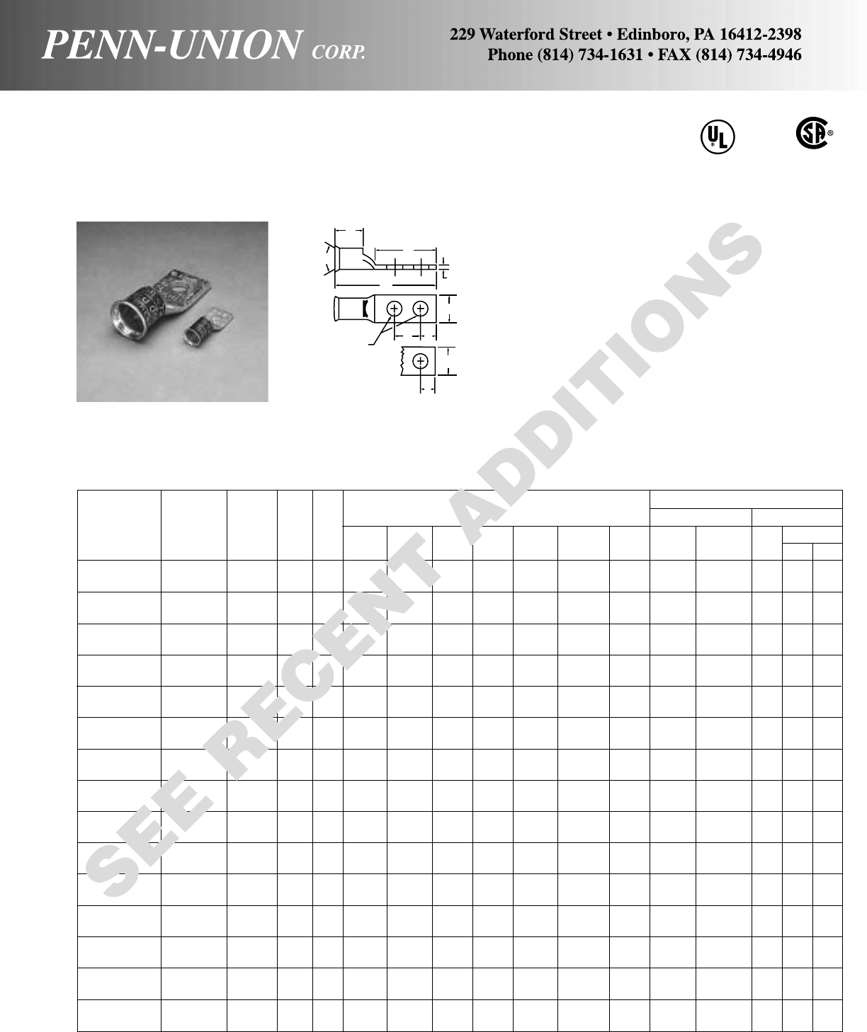
FLARED COPPER PENN-CRIMPS® • TYPE BLU-FL
Crimp lugs with inspection window for #4 (105/24) thru 1111 MCM (2750/24)
diesel locomotive cable and class G, H, I, & K flexible cable. CU
90°C
Seamless, one piece, pure copper construction with tin plat-
ing assures maximum conductivity. Generous entrance
chamfer and wide flare provide easy cable insertion even
for fine stranded extra flexible cable. Inspection window in-
sures full insertion. See catalog page 38 for flexible cable
recommendations and listing.
Catalog number and conductor size marked on every piece
insures positive identification.
Can be installed with existing crimping tools. Color-coding
conforms to industry requirements to insure proper connec-
tor/die selection and to provide for faster installation.
BLU LUGS ARE SUITABLE FOR USE AT VOLTAGES UP
TO 35 KV.
Stud Size
Flare
B
D
WW
EH
H
T
L
BLU-3D-FL 4 AWG 105/24 White 1/4219/64 7/813/16 5/81/43/32 17/32 B-9 – XF 2 –
BLU-3S2-FL 5/16 155/64 7/83/4–11/32 3/32 9/16
BLU-1D4-FL 2 AWG 150/24 Green 5/16 251/64 15/16 15/87/811/32 7/64 43/64 B-11 37 XF 2 –
BLU-1S-FL 5/16 155/64 7/83/4–11/32 7/64 43/64
BLU-1/0D-FL 1 AWG 225/24 Pink 5/16 213/16 7/815/87/811/32 1/83/4B-12 42 XF 2 –
BLU-1/0S-FL 5/16 115/16 7/83/4–11/32 1/83/4
BLU-2/0D4-FL 1/0 AWG 275/24 Black 3/831/16 15/16 113/16 13/81/813/16 B-13 45 XF 2 –
BLU-2/0S-FL 3/821/815/16 7/8–13/32 1/813/16
BLU-3/0D-FL 2/0 AWG 325/24 Orange 1/241/412
7/813/417/32 1/829/32 B-14 50 XF 5 5
BLU-3/0S1-FL 1/221/211
1/8–17/32 1/829/32
BLU-4/0D-FL 3/0 AWG 450/24 Purple 1/245/16 12
7/813/417/32 9/64 1B-15 54 XF 5 5
BLU-4/0S1-FL 1/229/16 11
1/8–9/16 9/64 1
BLU-030D-FL 4/0 AWG 550/24 White 1/241/211/16 27/813/417/32 5/32 13/16 B-17 66H/66 – 7 7
BLU-030S-FL 1/223/411/16 11/8–17/32 5/32 13/16
BLU-035D-FL 262 MCM 650/24 Red 1/245/811/827/813/417/32 11/64 19/32 B-18 71H/71 – 7 7
BLU-035S-FL 1/2229/32 11/815/32 –17/32 11/64 19/32
BLU-040D-FL 313 MCM 775/24 Blue 1/243/413/16 27/813/417/32 3/16 113/32 B-19 76H/76 – 7 7
BLU-040S-FL 5/835/16 13/16 17/16 –21/32 3/16 113/32
BLU-050D-FL 373 MCM 925/24 Brown 1/251
3/827/813/417/32 7/32 117/32 B-20 87 – 9 9
BLU-050S-FL 5/839/16 13/817/16 –27/32 7/32 117/32
BLU-060D-FL 444 MCM 1100/24 Green 1/253/32 13/827/813/417/32 17/64 123/32 B-22 94H/94 – 9 9
BLU-060S-FL 5/8231/32 13/813/4–7/817/64 123/32
BLU-065D-FL 535 MCM 1325/24 Pink 1/253/32 13/827/813/417/32 17/64 125/32 B-300 99 – 9 9
BLU-065S4-FL 5/8331/32 13/813/4–7/817/64 125/32
BLU-075D-FL 646 MCM 1600/24 Black 1/257/16 15/827/813/417/32 17/64 129/32 B-24 106H/106 – 9 9
BLU-075S-FL 5/841
5/817/16 –21/32 17/64 129/32
BLU-100D-FL 777 MCM 1925/24 White 1/257/817/827/813/417/32 21/64 23/16 B-27 125 – 9 9
BLU-100S-FL 5/847/817/817/8–15/16 21/64 23/16
BLU-150D-FL 1111 MCM 2750/24 – 1/263/32 22
7/813/417/32 3/8211/16 B-31 – – – –
BLU-150S-FL 3/4515/32 22
1/4–1
1/83/8211/16
Flex Wire Crimping Tool Reference
Approximate Dimensions (in inches)
Diesel Alt. Tooling PENN UNION
Catalog Locomotive Color Stud TDY
Number Cable Range Stranding Code Size LBDEH TW
Burndy
Index T & B Die TDM
250 1U
33
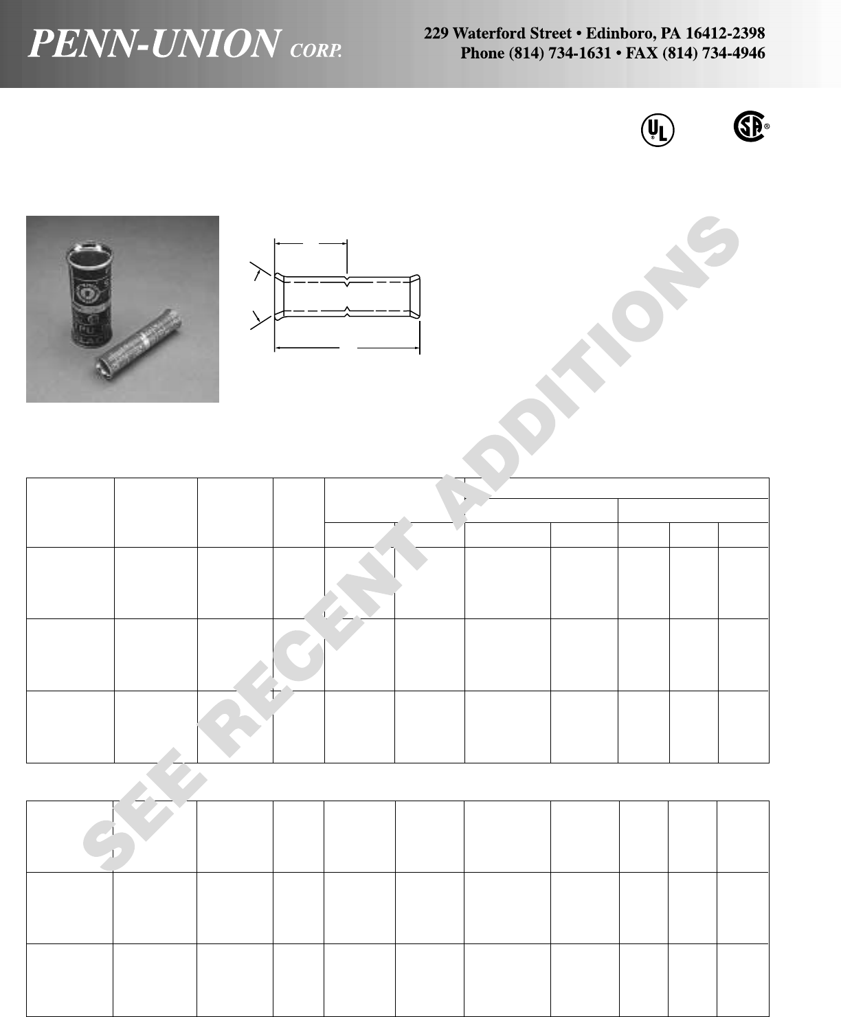
34
CU
90°C
FLARED COPPER PENN-CRIMPS® • TYPE BCU-FL & BBCU-FL
Crimp splices for #4 (105/24) thru 1111 MCM (2750/24)
diesel locomotive cable and class G, H, I, & K flexible cable.
Seamless, one piece, pure copper construction with tin plat-
ing assures maximum conductivity. Generous entrance
chamfer and wide flare provide easy cable insertion even
for fine stranded extra flexible cable. Type BBCU has double
length barrel which permits two crimps on 300 MCM and
larger sizes for additional assurance on heavy duty loads.
See catalog page 38 for flexible cable recommendation and
listing.
Catalog number and conductor size marked on every piece
insures positive identification.
Positive cable stops insure proper insertion of conductors to
full depth.
Can be installed with existing crimping tools. Color-coding
conforms to industry requirements to insure proper connec-
tor/die selection and to provide for faster installation.
BCU & BBCU Splices are suitable for use at volt-
ages up to 35 KV provided connector is taped in
accordance with accepted practices, 5 KV is maxi-
mum voltage level in all bare splice applications.
B
L
Flare
Diesel Flex Wire Crimping Tool Reference
Locomotive Approximate
Catalog Cable Color Dimensions (in inches) Alt. Tooling PENN-UNION
Number Range Stranding Code BLBurndy Index T & B Die TDM-250 TDY-1 TDY-U
BCU-3-FL 4 AWG 105/24 White 13/16 13/4B-9 – XF 2 –
BCU-1-FL 2 AWG 150/24 Green 7/817/8B-11 37 XF 2 –
BCU-1/0-FL 1 AWG 225/24 Pink 7/817/8B-12 42 XF 2 –
BCU-2/0-FL 1/0 AWG 275/24 Black 15/16 2B-13 45 XF 2 –
BCU-3/0-FL 2/0 AWG 325/24 Orange 1 21/8B-14 50 XF 5 5
BCU-4/0-FL 3/0 AWG 450/24 Purple 1 21/8B-15 54 XF 5 5
BCU-030-FL 4/0 AWG 550/24 White 11/16 21/4B-17 66H/66 – 7 7
BCU-035-FL 262 MCM 650/24 Red 11/823/8B-18 71H/71 – 7 7
BCU-040-FL 313 MCM 775/24 Blue 13/16 21/2B-19 76H/76 – 7 7
BCU-050-FL 373 MCM 925/24 Brown 13/827/8B-20 87 – 9 9
BCU-060-FL 444 MCM 1100/24 Green 13/827/8B-22 94H/94 – 9 9
BCU-065-FL 535 MCM 1325/24 Pink 13/827/8B-300 99 – 9 9
BCU-075-FL 646 MCM 1600/24 Black 15/833/8B-24 106H/106 – 9 9
BCU-100-FL 777 MCM 1925/24 White 17/837/8B-27 125 – 9 9
BCU-150-FL• 1111 MCM 2750/24 – 2 41/8B-31 – – – –
LONG BARREL SPLICES
BBCU-3-FL 4 AWG 105/24 White 11/823/8B-9 – XF 2 –
BBCU-1-FL 2 AWG 150/24 Green 13/827/8B-11 37 XF 2 –
BBCU-1/0-FL 1 AWG 225/24 Pink 13/827/8B-12 42 XF 2 –
BBCU-2/0-FL 1/0 AWG 275/24 Black 11/231/8B-13 45 XF 2 –
BBCU-3/0-FL 2/0 AWG 325/24 Orange 11/231/8B-14 50 XF 5 5
BBCU-4/0-FL 3/0 AWG 450/24 Purple 15/833/8B-15 54 XF 5 5
BBCU-030-FL 4/0 AWG 550/24 White 2 41/8B-17 66H/66 – 7 7
BBCU-035-FL 262 MCM 650/24 Red 2 41/8B-18 71H/71 – 7 7
BBCU-040-FL 313 MCM 775/24 Blue 21/843/8B-19 76H/76 – 7 7
BBCU-050-FL 373 MCM 925/24 Brown 21/445/8B-20 87 – 9 9
BBCU-060-FL 444 MCM 1100/24 Green 211/16 51/2B-22 94H/94 – 9 9
BBCU-065-FL 535 MCM 1325/24 Pink 223/32 55/8B-300 99 – 9 9
BBCU-075-FL 646 MCM 1600/24 Black 27/857/8B-24 106H/106 – 9 9
BBCU-100-FL 777 MCM 1925/24 White 3 61/8B-27 125 – 9 9
BBCU-150-FL 1111 MCM 2750/24 – 33/16 61/2B-31 – – – –
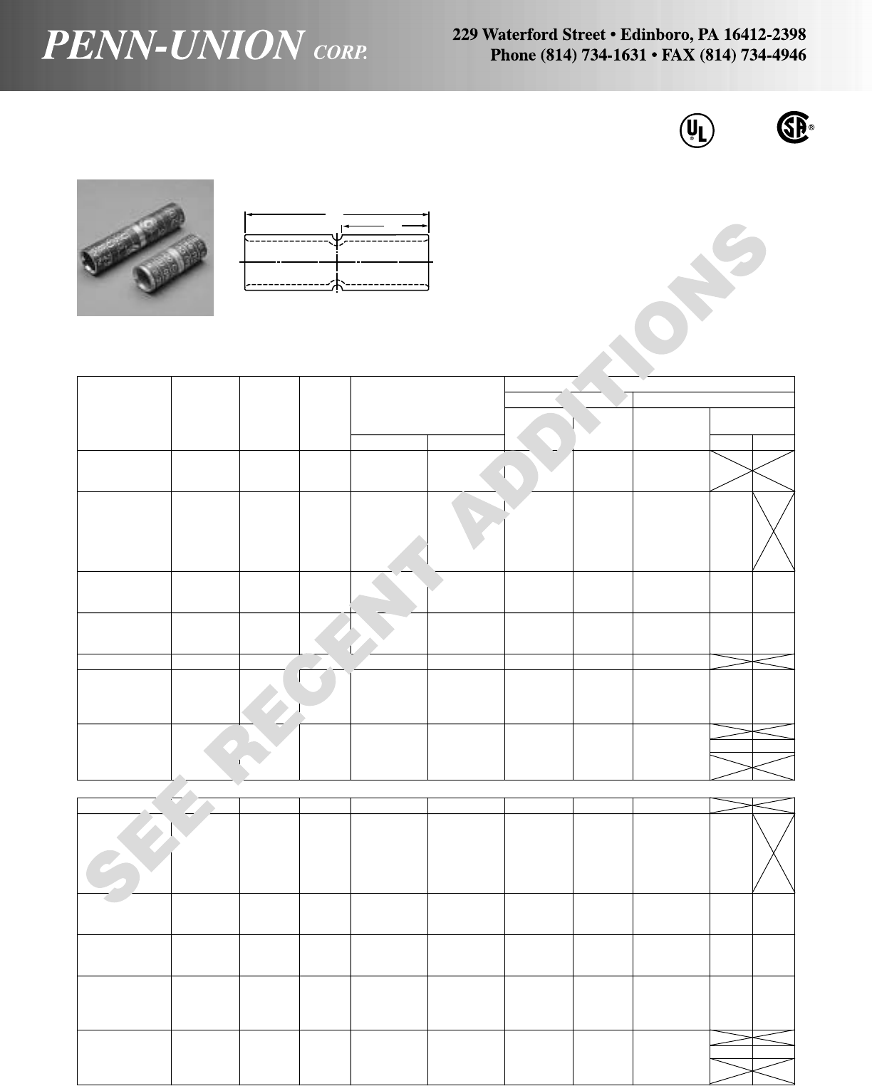
Crimping Tool Reference
Wire Approx. Alt. Tooling Penn-Union
Copper Diam. Dimensions Burndy Pressure
Catalog Cond. Color (in) (in inches) Index T&B PUC Setting
Number Range† Code ‡ B L No. Die Dies TDY-1 TDY-U
BCU-8 8 Str. Red .146 15/32 11/16 B-6-11 21 T-6/T-11*
BCU-6 6 Str. Blue .184 13/16 13/4B-7 24 T-7*/T-374*
BCU-5 5 Str. – .206 13/16 13/4B-21 – T-21
BCU-4 4 Str. Gray .232 13/16 13/4B-8 29 T-8*/T-346
BCU-3 3 Str. White .260 13/16 13/4B-9 – T-9*
BCU-2 2 Str. Brown .292 7/817/8B-10 33 T-10
BCU-1 1 Str. Green .332 7/817/8B-11 37 T-11/375 2
BCU-1/0 1/0 Str. Pink .375 7/817/8B-12 42 T-12/348
BCU-2/0 2/0 Str. Black .419 15/16 2B-13 45 T-13
BCU-3/0 3/0 Str. Orange .470 1 21/8B-14 50 T-14
BCU-4/0 4/0 Str. Purple .528 1 21/8B-15 54 T-15 5 5
BCU-025 250 MCM Yellow .575 11/16 21/4B-16 62 T-16
BCU-030 300 MCM White .634 11/16 21/4B-17 66H/66 T-17*
BCU-035 350 MCM Red .682 11/823/8B-18 71H/71 T-18/324 7 7
BCU-040 400 MCM Blue .728 13/16 21/2B-19 76H/76 T-19*/470*
BCU-045 450 MCM Blue .772 13/827/8– 76H/76 –
BCU-050 500 MCM Brown .815 13/827/8B-20 87 T-20/299
BCU-060 600 MCM Green .893 13/827/8B-22 94H/94 T-22/472
BCU-065 650 MCM Pink .930 13/827/8B-300 99 – 9 9
BCU-075 750 MCM Black .999 15/833/8B-24 106H/106 –
BCU-080 800 MCM – 1.031 15/833/8B-25 107H/107 –
BCU-100 1000 MCM White 1.153 17/837/8B-27 125 – 9** 9**
BCU-150 1500 MCM – 1.412 2 41/8B-31 – –
BCU-200 2000 MCM – 1.632 21/445/8B-34 – –
LONG BARREL SPLICES
BBCU-6 6 Str. Blue .184 17/823/8B-7 24 T-7*/T-374*
BBCU-4 4 Str. Gray .232 11/823/8B-8 29 T-8*/T-346
BBCU-2 2 Str. Brown .292 11/425/8B-10 33 T-10
BBCU-3 3 Str. White .260 11/823/8B-9 – T-9* 2
BBCU-1 1 Str. Green .332 13/827/8B-11 37 T-11/375
BBCU-1/0 1/0 Str. Pink .375 13/827/8B-12 42 T-12/348
BBCU-2/0 2/0 Str. Black .419 11/231/8B-13 45 T-13
BBCU-3/0 3/0 Str. Orange .470 11/231/8B-14 50 T-14
BBCU-4/0 4/0 Str. Purple .528 15/833/8B-15 54 T-15 5 5
BBCU-025 250 MCM Yellow .575 15/833/8B-16 62 T-16
BBCU-030 300 MCM White .634 2 41/8B-17 66H/66 T-17*
BBCU-035 350 MCM Red .682 2 41/8B-18 71H/71 T-18/324 7 7
BBCU-040 400 MCM Blue .728 21/843/8B-19 76H/76 T-19*/470*
BBCU-050 500 MCM Brown .815 21/445/8B-20 87 T-20/299
BBCU-060 600 MCM Green .893 211/16 51/2B-22 94H/94 T-22/472 99
BBCU-065 650 MCM Pink .930 23/455/8B-300 99 –
BBCU-075 750 MCM Black .999 27/857/8B-24 106H/106 –
BBCU-080 800 MCM – 1.031 215/16 6 B-25 107H/107 –
BBCU-100 1000 MCM White 1.153 3 61/8B-27 125 – 9** 9**
BBCU-150 1500 MCM – 1.412 33/16 61/2B-31 – –
BBCU-200 2000 MCM – 1.632 37/16 7B-34 – –
COPPER PENN-CRIMPS® • TYPE BCU & BBCU
Crimp splices for #8 stranded thru 2000 MCM
Seamless, one piece, pure copper construction with tin plating assures
maximum conductivity. Generous entrance chamfer provides easy cable
insertion. Type BBCU has double length barrel which permits two crimps
on 300 MCM and larger sizes for additional assurance on heavy duty
loads.
Catalog number and conductor sizes marked on every piece insures
positive identification.
Positive cable stops insure proper insertion of conductors to full depth.
Can be installed with existing crimping tools. Color coding conforms to
industry requirements to insure proper connector/die selection and to
provide for faster installation.
CU
90°C
LB
BCU & BBCU Splices are suitable for use at voltages up to
35KV provided connector is taped in accordance with ac-
cepted practices, 5 KV is maximum voltage level in all bare
splice applications.
35
‡For conversion to metric range, see page 175. †Concentric, compressed and compact stranding.
*Consult factory for availability of dies. Not available at this time. **With CUAD-1000.
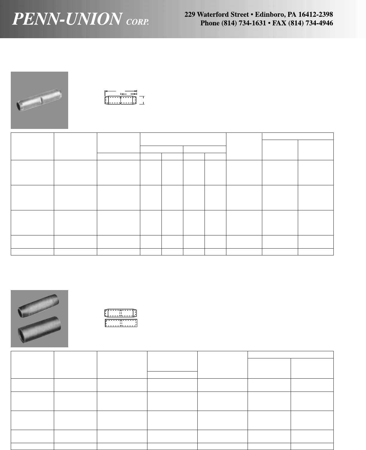
COPPER SPLICES • TYPE BCU-T
Tapered splices for #6 stranded thru 1000 MCM
Catalog No. of Crimping Tool Reference
Catalog Number Copper Wire Dia. Crimps Burndy
Number (Oil-Stop and Conductor Range‡ Per Die Index T & B
(Oil-Stop) Tapered) Range† in End No. Die No.
BCU-4-P BCU-4-PT 4 Str. .232 1 8 29
BCU-2-P BCU-2-PT 2 Str. .292 1 10 33
BCU-1/0-P BCU-1/0-PT 1/0 Str. .375 1 12 42
BCU-2/0-P BCU-2/0-PT 2/0 Str. .419 1 13 45
BCU-4/0-P BCU-4/0-PT 4/0 Str. .528 1 15 54
BCU-025-P BCU-025-PT 250 MCM .575 1 16 62
BCU-030-P BCU-030-PT 300 MCM .634 1 17 66H or 66
BCU-035-P BCU-035-PT 350 MCM .682 1 18 71H or 71
BCU-050-P BCU-050-PT 500 MCM .815 1 20 87
BCU-075-P BCU-075-PT 750 MCM .999 1 24 106H or 106
BCU-100-P BCU-100-PT 1000 MCM 1.153 1 27 125
‡For conversion to metric range, see page 175.
†Concentric, compressed and compact stranding.
COPPER SPLICES • TYPES BCU-P AND BCU-PT
Oil stop splices for #4 stranded thru 1000 MCM
Wire Approximate No. of Crimping Tool Reference
Copper Diameter Dimensions Crimps Burndy
Catalog Cond. Range‡ B L Per Die Index T & B
Number Range† in in mm in mm End No. Die No.
BCU-6-T 6 Str. .184 7/822 17/873 1 7 24
BCU-4-T 4 Str. .232 7/822 17/873 1 8 29
BCU-2-T 2 Str. .292 1 25 21/854 1 10 33
BCU-1-T 1 Str. .332 1 25 21/854 1 11 37
BCU-1/0-T 1/0 Str. .375 1 25 21/854 1 12 42
BCU-2/0-T 2/0 Str. .419 11/16 27 21/457 1 13 45
BCU-3/0-T 3/0 Str. .470 11/829 23/860 1 14 50
BCU-4/0-T 4/0 Str. .528 11/829 23/860 1 15 54
BCU-025-T 250 MCM .575 11/432 25/867 1 16 62
BCU-030-T 300 MCM .634 11/432 25/867 1 17 66H or 66
BCU-035-T 350 MCM .682 15/16 33 23/470 1 18 71H or 71
BCU-040-T 400 MCM .728 17/16 37 3 76 1 19 76H or 76
BCU-050-T 500 MCM .815 111/16 43 31/289 1 20 87
BCU-075-T 750 MCM .999 21/16 52 41/4108 1 24 106H or 106
BCU-100-T 1000 MCM 1.153 27/16 62 5 127 1 27 125
‡For conversion to metric range, see page 175. †Concentric, compressed and compact stranding.
Tapered Splices. Seamless, pure copper construction, tin plated.
Other features same as type BCU.
Solid barrier cable stops insure proper insertion of conductors to
full depth and oil tight seal. Seamless, pure copper construction,
tin plated.
Other features same as type BCU.
LB
O.D.
36
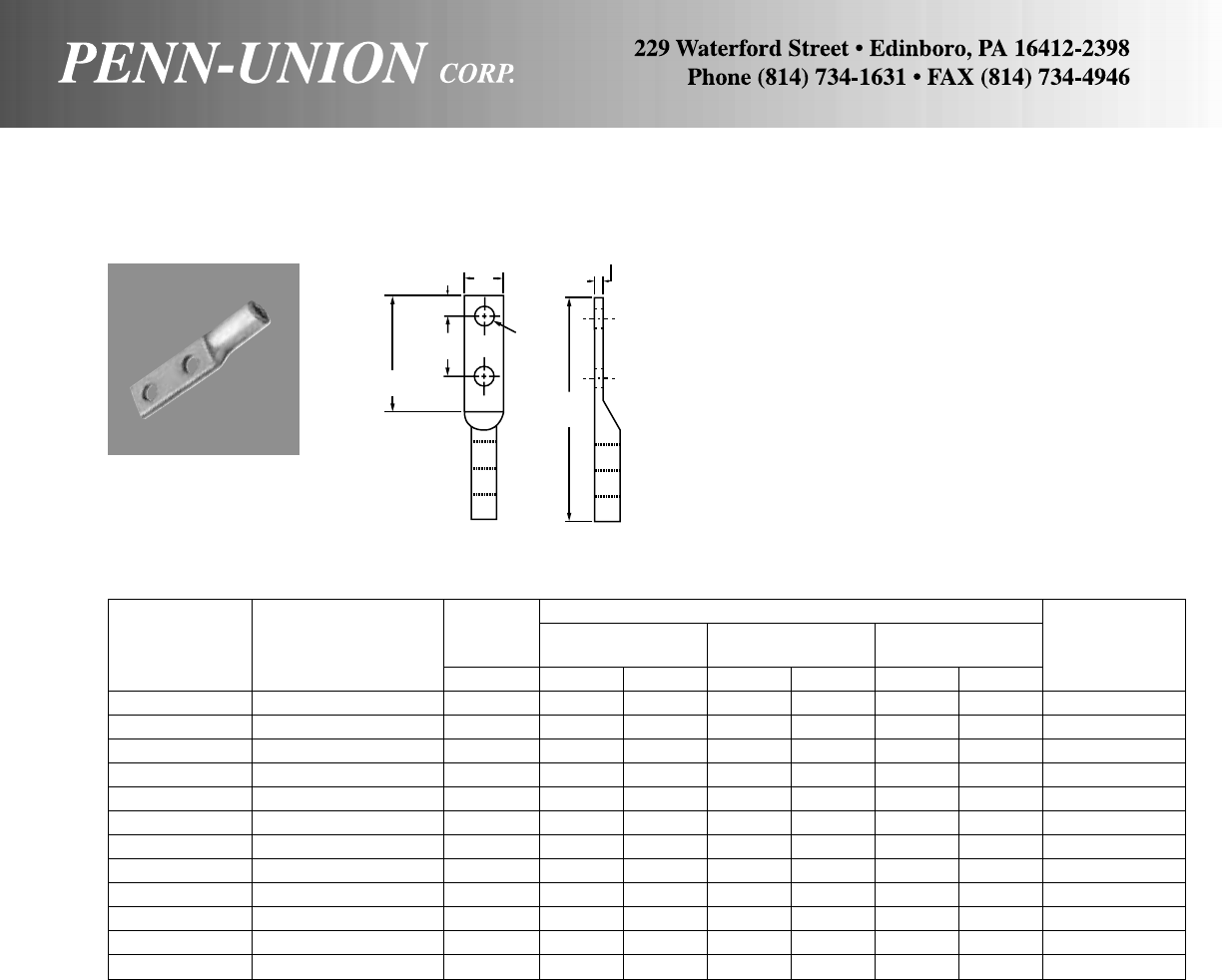
COPPER COMPRESSION TERMINALS • TYPES HBBLU
Heavy duty
Wire
Diameter Approximate Dimensions
Burndy
Catalog Conductor Range‡ LWT
Die Index
Number Range in in mm in mm in mm No.
HBBLU-1/0D 1/0 Str. (7, 19) .375 53/8137 7/822 1/83165, 287
HBBLU-2/0D 2/0 Str. (7, 19, 37) .447 51/4133 15/16 24 1/46166, 206
HBBLU-3/0D 3/0 Str. (7, 19) .470 55/16 135 11/16 27 1/46167, 207, 211, 256
HBBLU-4/0D 4/0 Str. (7, 12, 19) .528 51/4133 17/32 31 5/16 8168, 208
HBBLU-025D 250 MCM (7, 19, 37) .575 55/8143 13/835 3/89 169
HBBLU-030D 300 MCM (19, 37) .642 51/2140 3 76 3/89 170
HBBLU-035D 350 MCM (12, 19, 37) .682 61/2165 15/841 1/213 267
HBBLU-040D 400 MCM (19, 37) .728 63/4171 13/444 1/213 209
HBBLU-050D 500 MCM (19, 37) .815 61/2165 17/848 1/213 210
HBBLU-060D 600 MCM (37, 61) .893 63/8162 21/854 5/816 576
HBBLU-075D 750 MCM (37, 61) .999 71/4184 21/457 5/816 627
HBBLU-100D 1000 MCM (61) 1.153 75/8194 23/470 3/419 345
‡For conversion to metric range, see page 175.
The heavy duty 2 hole compression lugs are made of heavy wall,
seamless, one piece, pure copper tubing. Generous entrance
chamfer provides easy cable insertion. End of cable is protected
from environmental hazards by completely closed transitions. The
heavy wall tubing gives insurance of heavy duty loads.
5/8"
(16 mm) W
T
L
9/16" Dia.
(14 mm)
3"
(76 mm)
37
13/4"
(44 mm)
Copper
Connector Class B & C Class I Class K Diesel Class H Class G Class M Metric Cable
Catalog Type Building Wire Flexible Cable Weld Cable Locomotive Cable Cable Cable Flexible Cable Wire Size Range
Splices and Cu Cable (#24AWG Cu Strands) (#30AWG Cu Strands) (#24AWG Cu Strands) (No. & Dia. of Wire) (No. & Dia. of Wire) (#34AWG Cu Stands) Copper Cable Only Navy Air
Lugs (1 & 2 Hole) Size & Stranding Size & Stranding Size & Stranding Size & Stranding Size & Stranding Size & Stranding Size & Stranding Metric Size & Dia. Cable Craft
BCU-BBCU-BLU-BBLU-8 #8 AWG 7 or 19 #8 AWG 41/24 None None *#8 AWG 133/.0111 *#8 AWG 49/.0184 #8 AWG 420/34 6mm2 3.21mm #23 AN-8
BCU-BBCU-BLU-BBLU-6 #6 AWG 7 or 19 #6 AWG 63/24 None None *#7 AWG 133/.0125 #7 AWG 49/.0206 #7 AWG 532/34 10mm2 4.12mm None None
BCU-BBCU-BLU-BBLU-5 #5 AWG 7 or 19 None None None *#6 AWG 133/.0140 *#6 AWG 49/.0231 #6 AWG 665/34 16mm2 5.18mm #30 AN-6
BCU-BBCU-BLU-BBLU-4 #4 AWG 7 or 19 None None None *#5 AWG 133/.0158 *#5 AWG 49/.0260 #5 AWG 836/34 *20mm2 5.72mm #40 None
BCU-BBCU-BLU-BBLU-3 #3 AWG 7 or 19 #4 AWG 105/24 #4 AWG 420/30 #4 AWG 105/24 #4 AWG 133/.0177 #4 AWG 49/.0292 #4 AWG 1064/34 25mm2 6.60mm #50 AN-4
BCU-BBCU-BLU-BBLU-2 #2 AWG 7 or 19 None None None *#3 AWG 133/.0199 *#3 AWG 49/.0328 #3 AWG 1323/34 *30mm2 7.01mm #60 None
BCU-BBCU-BLU-BBLU-1 #1 AWG 19 or 37 #2 AWG 161/24 #2 AWG 665/30 #2 AWG 150/24 #2 AWG 133/.0223 #2 AWG 49/.0368 #2 AWG 1666/34 *40mm2 8.20mm #75 AN-2
BCU-BBCU-BLU-BBLU-1/0 1/0 AWG 19 or 37 None #1 AWG 836/30 #1 AWG 225/24 #1 AWG 259/.0180 #1 AWG 133/.0251 #1 AWG 2107/34 50mm2 9.27mm #100 AN-1
BCU-BBCU-BLU-BBLU-2/0 2/0 AWG 19 or 37 1/0 AWG 266/24 1/0 AWG 1064/30 1/0 AWG 275/24 1/0 AWG 259/.0202 1/0 AWG 133/.0282 1/0 AWG 2646/34 70mm2 10.92mm #125 AN-1/0
BCU-BBCU-BLU-BBLU-3/0 3/0 AWG 19 or 37 2/0 AWG 342/24 2/0 AWG 1323/30 2/0 AWG 325/24 2/0 AWG 259/.0227 2/0 AWG 133/.0316 None *85mm2 11.94mm #150 None
BCU-BBCU-BLU-BBLU-4/0 4/0 AWG 19 or 37 None 3/0 AWG 1666/30 3/0 AWG 450/24 3/0 AWG 259/.0255 3/0 AWG 133/.0355 2/0 AWG 3325/34 95mm2 12.80mm #200
AN-2/0
AN-3/0
BCU-BBCU-BLU-BBLU-025 250 MCM 37 or 61 None None None None None 3/0 AWG 4256/34 120mm2 14.40mm None None
BCU-BBCU-BLU-BBLU-030 300 MCM 37 or 61 4/0 AWG 532/24 4/0 AWG 2107/30 4/0 AWG 550/24 *4/0 AWG 259/.0286 *4/0 AWG 133/.0399 4/0 AWG 5320/34 150mm2 16.00mm #300 AN-4/0
BCU-BBCU-BLU-BBLU-035 350 MCM 37 or 61 None None 262 MCM 650/24 *250 MCM 427/.0242 *250 MCM 259/.0311 None *180mm2 17.42mm #350 None
BCU-BBCU-BLU-BBLU-040 400 MCM 37 or 61 None None 313 MCM 775/24 300 MCM 427/.0265 300 MCM 259/.0340 250 MCM 6384/34 185mm2 17.80mm #400 None
BCU-BBCU-BLU-BBLU-045 450 MCM 37 or 61 None None None *350 MCM 427/.0286 *350 MCM 259/.0368 300 MCM 7581/34 None None None
BCU-BBCU-BLU-BBLU-050 500 MCM 37 or 61 350 MCM 882/24 None 373 MCM 925/24 400 MCM 427/.0306 400 MCM 259/.0393 350 MCM 8806/34 240mm2 20.30mm None None
BCU-BBCU-BLU-BBLU-060 600 MCM 61 or 91 None None 444 MCM 1100/24 450 MCM 427/.0325 450 MCM 259/.0417 400 MCM 10101/34 300mm2 22.63mm None None
BCU-BBCU-BLU-BBLU-065 650 MCM 61 or 91 500 MCM 1225/24 None 535 MCM 1325/24 500 MCM 427/.0342 500 MCM 259/.0439 450 MCM 11396/34 None None None
BCU-BBCU-BLU-BBLU-075 750 MCM 61 or 91 None None 646 MCM 1600/24
*550 MCM 703/.0280 *550 MCM 427/.0359
500 MCM 12691/34 None None None
*600 MCM 703/.0292 *600 MCM 427/.0375
BCU-BBCU-BLU-BBLU-080 800 MCM 61 or 91 None None None
*650 MCM 703/.0304 *650 MCM 427/.0390
550 MCM 13664/34 400mm2 26.1mm None None
*700 MCM 427/.0405
BCU-BBCU-BLU-BBLU-100 1000 MCM 61 or 91 750 MCM 1862/24 None 777 MCM 1925/24
*700 MCM 703/.0316 *750 MCM 427/.0419 600 MCM 14945/34
500mm2 29.3mm None None
*750 MCM 703/.0327 *800 MCM 427/.0433 650 MCM 16226/34
*Not UL Listed
ADDITIONAL WIRE SIZE RECOMMENDATIONS
FOR COPPER PENN-CRIMPS®
TYPES BCU, BCU-FL, BBCU, BBCU-FL, BLU, BLU-FL, BBLU, BBLU-FL
38
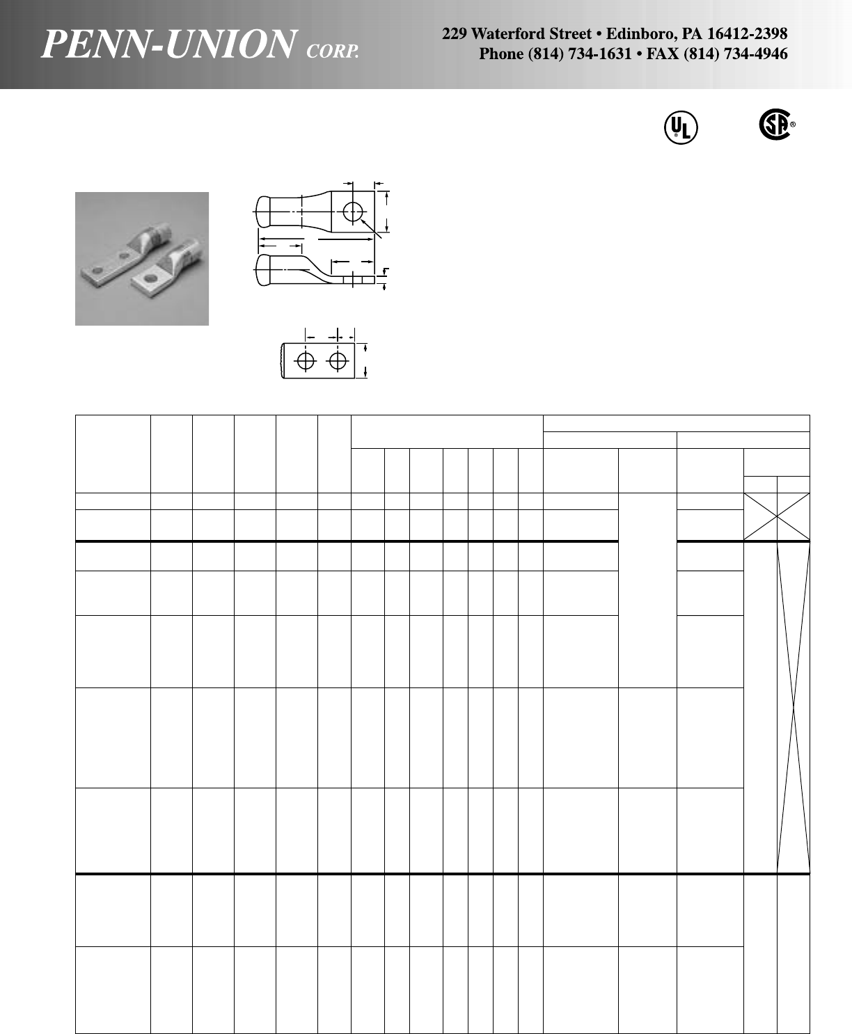
Approximate Dimensions Crimping Tool Reference
Wire (in inches) Alt. Tooling Penn-Union
Dia. Burndy Pressure
Catalog Cond. Color (in) Stud Fig. Index T&B PUC Setting
Number Range† Code ‡ Size No. L B D E H T W No. Die Dies TDY-1TDY-U
BLUA-8S• 8 Str. Blue .146 1/411
9/16 9/16 5/8–1/41/81/2B-374 T-374*
BLUA-6S 6 Str. Gray .184 1/41153/64 11/16 51/64 –3/81/81/2B-346 T-346*
BLUA-6S2 5/16 1–
BLUA-4S3 4 Str. Green .232 1/41157/64 7/851/64 –25/64 11/64 19/32 B-375 TBM-5 T-11/375
BLUA-4S2 5/16 1–
BLUA-2S3 1/411
29/32 23/32 –11/32
BLUA-2S4 2 Str. Pink .292 5/16 11
31/32 7/825/32 –3/87/32 23/32 B-348 T-12/348
BLUA-2S 3/812
3/32 29/32 –7/16
BLUA-1S1 1/41211/64 7/855/64 –25/64 15/64 25/32
BLUA-1S3 5/16 1–
BLUA-1S 1 Str. Gold .332 3/812
17/32 125/64 –7/16 B-471 T-471*
BLUA-1S2 1/212
33/64 29/32 13/8–11/16 11/64 25/32
BLUA-1D1 1/224
3/64 229/32 13/49/16 2
BLUA-1/0S2 1/412
3/32 25/32 –11/32
BLUA-1/0S3 5/16 12
5/32 27/32 –3/8
BLUA-1/0S 3/812
7/32 29/32 –7/16
BLUA-1/0D1 1/0 Str. Tan .375 3/823
17/32 11
7/813/813/64 27/32 B-296 50 T-296
BLUA-1/0D2 3/823
27/32 23/16 11/16 5/8
BLUA-1/0S1 1/212
5/811/8–9/16
BLUA-1/0D3 1/224
9/16 229/32 13/49/16
BLUA-2/0S4 1/412
1/425/32 –11/32
BLUA-2/0S5 5/16 12
5/16 27/32 –3/8
BLUA-2/0S1 2/0 Str. Olive .419 3/812
5/813/32 113/64 –5/81/415/16 B-297 54 T-297
BLUA-2/0D2 3/823
3/817/813/8
BLUA-2/0S 1/212
5/815/32 –9/16
BLUA-2/0D 1/224
21/32 229/32 13/49/16
BLUA-3/0S5 5/16 12
19/32 27/32 –3/8
BLUA-3/0S2 3/812
13/16 11/16 –7/16
BLUA-3/0D1 3/0 Str. Ruby .470 3/823
29/32 11/417/813/89/32 11/16 B-467 60 T-467
BLUA-3/0S 1/212
29/32 15/32 –9/16
BLUA-3/0D 1/2241
5/16 229/32 13/49/16 55
BLUA-4/0S3 5/16 12
21/32 27/32 –3/8
BLUA-4/0S5 3/812
31/32 113/64 –5/8
BLUA-4/0D2 4/0 Str. White .528 3/824
7/32 15/16 21/16 17/16 5/16 13/16 B-298 66 T-298
BLUA-4/0S 1/212
31/32 15/32 –9/16
BLUA-4/0D 1/225
1/16 229/32 13/49/16
BLUA-4/0S4 5/813
9/32 115/32 –23/32
•Not UL Listed. ‡For conversion to metric range, see page 175. *Consult factory for availability of dies. Not available at this time.
†Concentric, compressed and compact stranding.
ALUMINUM PENN-CRIMPS® • TYPE BLUA
Crimp lugs for #6 stranded thru 1000 MCM copper or aluminum wire or cable AL9CU
H
W
L
B
DT
FOR STUD
SIZE
FIG. 1
EH
W
FIG. 2
39
Seamless, one piece, pure aluminum construction with tin plat-
ing assures maximum conductivity. Generous entrance chamfer
provides easy cable insertion. The barrels are filled with Cual-
Aid® and capped at factory to eliminate the need for separate
application of Cual-Aid® to the conductor. Wire brushing of alu-
minum conductor is required. This assures a stable cool running
joint. End of cable is protected from environmental hazards by
completely closed transition.
Catalog number and conductor size marked on every piece to
insure positive identification.
Can be installed with existing crimping tools.
Color coding conforms to industry requirements to insure proper
connection/die selection and to provide for faster installation.
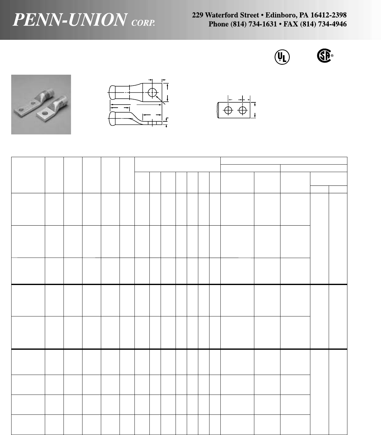
Approximate Dimensions Crimping Tool Reference
Wire (in inches) Alt. Tooling Penn-Union
Dia. Burndy Pressure
Catalog Cond. Color (in) Stud Fig. Index T&B PUC Setting
Number Range† Code ‡ Size No. L B D E H T W No. Die Dies TDY-1 TDY-U
BLUA-025S2 3/813 1
1/16 –3/8
BLUA-025D1 250 3/824 2
1/16 17/16
BLUA-025S MCM Red .575 1/213
7/16 113/16 11/2–5/811/32 19/32 B-324 71 T-18/324
BLUA-025D 1/225
3/16 229/32 13/49/16
BLUA-025S3 5/813
7/16 11/2–23/32
BLUA-030S2 3/813
7/16 11/4–3/8
BLUA-030D1 300 3/824
15/32 23/817/16 55
BLUA-030S1 MCM Blue .634 1/213
11/16 11/211/2–11/16 3/813/8B-470 76 T-470*
BLUA-030D 1/225
5/16 229/32 13/49/16
BLUA-030S 5/813
21/32 115/32 –23/32
BLUA-035D1 3/824
7/16 21/16 17/16
BLUA-035S1 350 Brown .682 1/213
7/815/811/2–11/16 3/8117/32 B-299 87 T-20/299
BLUA-035D MCM 1/225
9/32 229/32 13/49/16
BLUA-035S 5/813
7/811/2–11/16
BLUA-040D1 3/825
3/32 21/16 17/16
BLUA-040S2 400 1/214
17/32 11/2–11/16
BLUA-040D2 MCM Green .728 1/226
13/32 113/16 33/813/43/47/16 15/8B-472 94 T-22/472
BLUA-040S3 5/814
27/32 113/16 –7/8
BLUA-040D 5/826
1/437/32 13/423/32 77
BLUA-050D1 3/824
7/821/16 17/16
BLUA-050S2 500 1/214
5/16 11/2–11/16
BLUA-050D2 MCM Pink .815 1/226
3/16 17/833/813/43/415/32 113/16 B-300 106 T-300
BLUA-050S3 5/814
5/8113/16 –7/8
BLUA-050D 5/826
1/32 37/32 13/423/32
BLUA-060D1 3/825
3/16 21/16 17/16
BLUA-060D2 600 Black .893 1/226
11/32 23
7/32 13/43/432/64 131/32 B-473 115 T-473
BLUA-060S1 MCM 5/815
5/32 21/32 –1
BLUA-060D 5/826
11/32 37/32 13/423/32
BLUA-075D1 750 1/226
13/32 37/32 13/43/4
BLUA-075S1 MCM Red .999 5/815
3/821/423/16 –1
9/16 23/16 B-301 130 – 9 9
BLUA-075D 5/826
13/32 37/32 13/423/32
BLUA-080D1 800 1/227
1/837/32 13/43/4
BLUA-080S1 MCM Gray 1.031 5/816
13/32 25/16 21/2–1
19/32 21/4B-474 140 –
BLUA-080D 5/827
1/837/32 13/423/32
BLUA-100D2 1000 1/227
7/16 37/32 13/43/4
BLUA-100S1 MCM Brown 1.153 5/816
23/32 29/16 21/2–1
11/16 21/2B-302 150 –
BLUA-100D 5/827
7/16 37/32 13/423/32
‡For conversion to metric range, see page 175.
* Consult factory for availability of dies. Not available at this time.
†Concentric, compressed and compact stranding.
ALUMINUM PENN-CRIMPS® • TYPE BLUA
Continued from preceding page
BLUA LUGS ARE SUITABLE FOR USE AT VOLTAGES UP TO 35KV.
H
W
L
B
DT
FOR STUD
SIZE
FIG. 1
H
E
AL9CU
W
FIG. 2
40
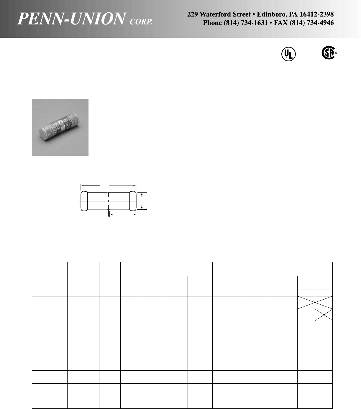
ALUMINUM PENN-CRIMPS® • TYPE BCUA
Crimp splices for #6 stranded thru 1000 MCM copper or aluminum wire or cable
Approximate Dimensions Crimping Tool Reference
Wire (in inches) Alt. Tooling Penn-Union
Diam Burndy Pressure
Catalog Conductor Color (in) Index T&B PUC Setting
Number Range† Code ‡ O.D. B L No. Die Dies TDY-1 TDY-U
BCUA-8• 8 Str. Blue .146 19/64 3/413/4B-374 T-374*
BCUA-6 6 Str. Gray .184 11/32 3/415/8B-346 T-346*
BCUA-4 4 Str. Green .232 7/16 7/817/8B-375 T-11/355
BCUA-2 2 Str. Pink .292 17/32 11/823/8B-348 TBM-5 T-12/348
BCUA-1 1 Str. Gold .332 17/32 29/32 115/16 B-471 T-471* 2
BCUA-1/0 1/0 Str. Tan .375 19/32 12
1/8B-296 50 T-296 2
BCUA-2/0 2/0 Str. Olive .419 11/16 13/32 25/16 B-297 54 T-297
BCUA-3/0 3/0 Str. Ruby .470 3/411/425/8B-467 60 T-467
BCUA-4/0 4/0 Str. White .528 27/32 115/16 23/4B-298 66 T-17*
BCUA-025 250 MCM Red .575 15/16 113/32 215/16 B-324 71 T-18/324 5 5
BCUA-030 300 MCM Blue .634 1 11/231/8B-470 76 T-470*
BCUA-035 350 MCM Brown .682 11/815/833/8B-299 87 T-20/299
BCUA-040 400 MCM Green .728 13/16 113/16 33/4B-472 94 T-22/472 77
BCUA-050 500 MCM Pink .815 15/16 17/837/8B-300 106 T-300
BCUA-060 600 MCM Black .893 17/16 24
1/8B-473 115 T-473
BCUA-075 750 MCM Red .999 119/32 21/445/8B-301 130 – 99
BCUA-080 800 MCM Gray 1.031 121/32 215/16 43/4B-474 140 –
BCUA-100 1000 MCM Brown 1.153 127/32 29/16 51/4B-302 150 –
•Not UL Listed.
‡For conversion to metric range, see page 175.
* Consult factory for availability of dies. Not available at this time.
†Concentric, compressed and compact stranding.
AL9CU
L
O.D.
B
BCUA splices are suitable for use at voltages up to 35KV pro-
vided connector is taped in accordance with accepted practices.
5KV is maximum voltage level in all bare splice applications.
Seamless, one piece, pure aluminum construction with tin plat-
ing assures maximum conductivity. Generous entrance chamfer
provides easy cable insertion. The barrels are filled with Cual-
Aid® and capped at factory to eliminate the need for separate
application of Cual-Aid® to the conductor. Wire brushing of alu-
minum conductor is required.
This assures a stable, cool running joint. Positive cable stops
insure proper insertion.
Catalog number and conductor size marked on every piece to
insure positive identification.
Can be installed with existing crimping tools.
Color coding conforms to industry requirements to insure proper
connection/die selection and to provide for faster installation.
41
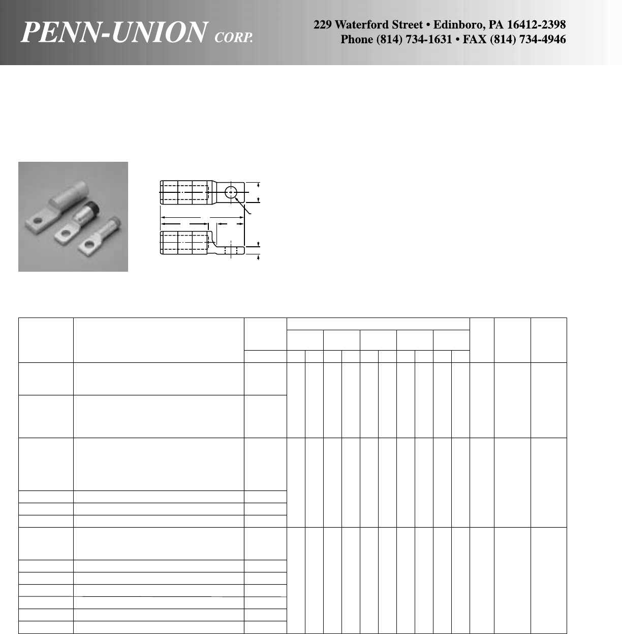
ALUMINUM COMPRESSION TERMINALS •
TYPES FKLA, FSLA & FULA SIDE FORMED
For aluminum, copper or ACSR wire or cable single hole
These terminals are of EC grade high purity aluminum. Prefilled
with Cual-Aid® inhibitor and capped at factory. Wire brushing of
aluminum conductor is required. End of cable is protected from
environment hazards by completely closed transitions. Can be
installed with existing crimping tools.
Wire Approximate Dimensions
Diameter *TDY-U
Catalog Range‡ C D L T W Die No. of Pressure
Number Conductor Range in in mm in mm in mm in mm in mm Size Crimps Setting
FKLA-W8-S 10 Str, 8 Sol .116/.128
FKLA-W6-S 8 Str, 6 Sol .146/.162
FKLA-W4-S 6 Str, 4 Sol, 4 Compact, 6 ACSR .184/.214 BG,
FKLA-W2-S 4 & 3 Str, 2 Sol, 2 Compact, 4 ACSR .232/.271 13/32 28 13/835 3 76 1/46.35 7/822 5/832
FKLA-C2-S 2 Str, 1/0 Sol, 1 Compact, 2 ACSR .292/.325 or
FKLA-R2-S 1 Str, 2/0 Sol, 1/0 Compact, 1 ACSR .332/.365 243
FKLA-010-S 1/0 Str, 1/0 ACSR .373/.398
FSLA-W2-S 4 & 3 Str, 2 Sol, 2 Compact, 4 ACSR .232/.271
FSLA-C2-S 2 Str, 1/0 Sol, 1 Compact, 2 ACSR .292/.325
FSLA-R2-S 1 Str, 2/0 Sol, 1/0 Compact, 1 ACSR .332/.365
FSLA-010-S 1/0 Str, 3/0 Sol, 2/0 Compact, 1/0 ACSR .373/.410
FSLA-013-S 2/0 Str, 4/0 Sol, 3/0 Compact, 2/0 ACSR .418/.460 840
FSLA-017-S 3/0 Str, 4/0 Compact, 3/0 ACSR .470/.502 19/32 33 13/835 31/4 83 1/46.35 29/32 23 or 3 4
FSLA-025-S 4/0 & 250 MCM, 250 & 300 Compact, 4/0 ACSR .520/.575 249
FSLA-030-S 300 MCM, 350 Compact, 266.8 18/1 ACSR .609/.630
FULA-010-S 1/0 Str, 3/0 Sol, 2/0 Compact, 1/0 ACSR .373/.410
FULA-013-S 2/0 Str, 4/0 Sol, 3/0 Compact, 2/0 ACSR .418/.460
FULA-017-S 3/0 Str, 4/0 Compact, 3/0 ACSR .470/.502 11/8-2
FULA-025-S 4/0 & 250 MCM, 250 & 300 Compact, 4/0 ACSR .520/.575 or
FULA-030-S 300 MCM, 350 Compact, 266.8 18/1 ACSR .609/.630 11/238 23/860 45/8117 3/89.52 11/432 316 3 5
FULA-035-S 350 MCM, 400 Compact, 336.4 18/1 .659/.684 or
FULA-R033-S 400 MCM, 500 Compact, 336.4 26/7 ACSR .721/.736 705
FULA-045-S 450 MCM, 397.5 18/1, 26/7 ACSR .743/.783
FULA-050-S 500 MCM, 477 18/1 ACSR .813/.814
‡For conversion to metric range, see page 175.
If terminal with hole for 3/8" stud is desired, suffix catalog number with “-1.” Example: FKLA-W8-S-1.
42
W
DC
T
9/16" Dia.
(14 mm)
L
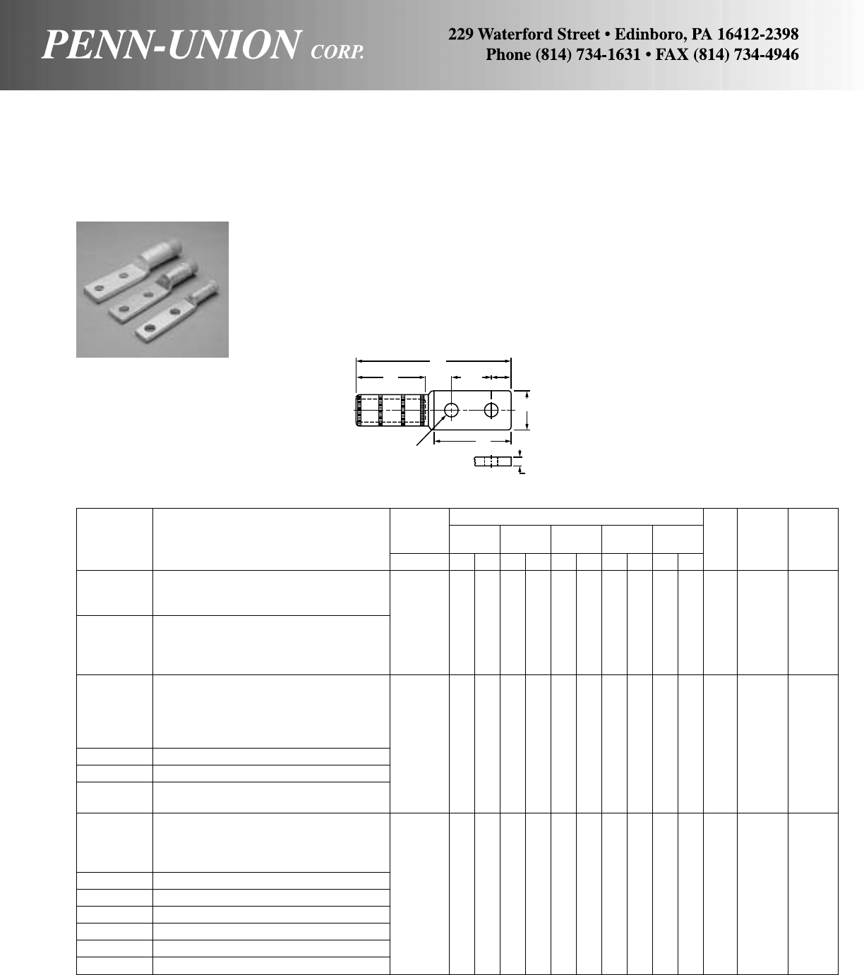
ALUMINUM COMPRESSION TERMINALS •
TYPES FKLA, FSLA & FULA SIDE FORMED
For aluminum, copper or ACSR wire or cable double hole
These terminals are of EC grade high purity aluminum. Prefilled
with Cual-Aid® inhibitor and capped at factory. Wire brushing of
aluminum conductor is required. End of cable is protected from
environmental hazards by completely closed transitions. Can be
installed with existing crimping tools.
Wire Approximate Dimensions
Diameter TDY-U
Catalog Range‡ C D L T W Die No. of Pressure
Number Conductor Range in in mm in mm in mm in mm in mm Size Crimps Setting
FKLA-W8-D 10 Str, 8 Sol .116/.128
FKLA-W6-D 8 Str, 6 Sol .146/.162 BG
FKLA-W4-D 6 Str, 4 Sol, 4 Compact, 6 ACSR .184/.214 33/886 11/238 57/16 138 5/16 8 1 25 5/832
FKLA-W2-D 4 & 3 Str, 2 Sol, 2 Compact, 4 ACSR .232/.271 or
FKLA-C2-D 2 Str, 1/0 Sol, 1 Compact, 2 ACSR .292/.325 243
FKLA-R2-D 1 Str, 2/0 Sol, 1/0 Compact, 1 ACSR .332/.365
FKLA-010-D 1/0 Str, 1/0 ACSR .373/.398
FSLA-W2-D 4 & 3 Str, 2 Sol, 2 Compact, 4 ACSR .232/.271
FSLA-C2-D 2 Str, 1/0 Sol, 1 Compact, 2 ACSR .292/.325
FSLA-R2-D 1 Str, 2/0 Sol, 1/0 Compact, 1/0 ACSR .332/.365
FSLA-010-D 1/0 Str, 3/0 Sol, 2/0 Compact, 1/0 ACSR .373/.410 840
FSLA-013-D 2/0 Str, 4/0 Sol, 3/0 Compact, 2/0 ACSR .418/.460 33/886 17/848 515/16 151 1/4 6 11/432 or 3 4
FSLA-017-D 3/0 Str, 4/0 Compact, 3/0 ACSR .470/.502 249
FSLA-025-D 4/0 & 250 MCM, 250 & 300 Compact, 4/0 ACSR .520/.575
FSLA-030-D 300 & 350 MCM, 350 Compact, 266.8 18/1 ACSR .609/.630
FSLA-035-D 350 MCM, 336.4 18/1 ACSR .681/.684
FULA-R2-D 1 Str, 2/0 Sol, 1/0 Compact, 1 ACSR .332/.365
FULA-010-D 1/0 Str, 3/0 Sol, 2/0 Compact, 1/0 ACSR .373/.410
FULA-013-D 2/0 Str, 4/0 Sol, 3/0 Compact, 2/0 ACSR .418/.460
FULA-017-D 3/0 Str, 4/0 Compact, 3/0 ACSR .470/.502 11/8-2
FULA-025-D 4/0 & 250 MCM, 250 & 300 Compact, 4/0 ACSR .520/.575 or
FULA-030-D 300 MCM, 350 Compact, 266.8 18/1 ACSR .609/.630 31/289 21/264 65/8168 3/810 11/238 316 3 5
FULA-035-D 350 MCM, 400 Compact, 336.4 18/1 ACSR .659/.684 or
FULA-R033-D 400 MCM, 500 Compact, 336.4 26/7 ACSR .721/.783 705
FULA-045-D 450 MCM, 397.5 18/1, 26/7 ACSR .743/.783
FULA-050-D 500 MCM, 477 18/1 ACSR .813/.814
‡For conversion to metric range, see page 175.
5/8"
(16 mm)
T
L
D13/4"
(44 mm)
W
C
9/16" Dia.
(14 mm)
43
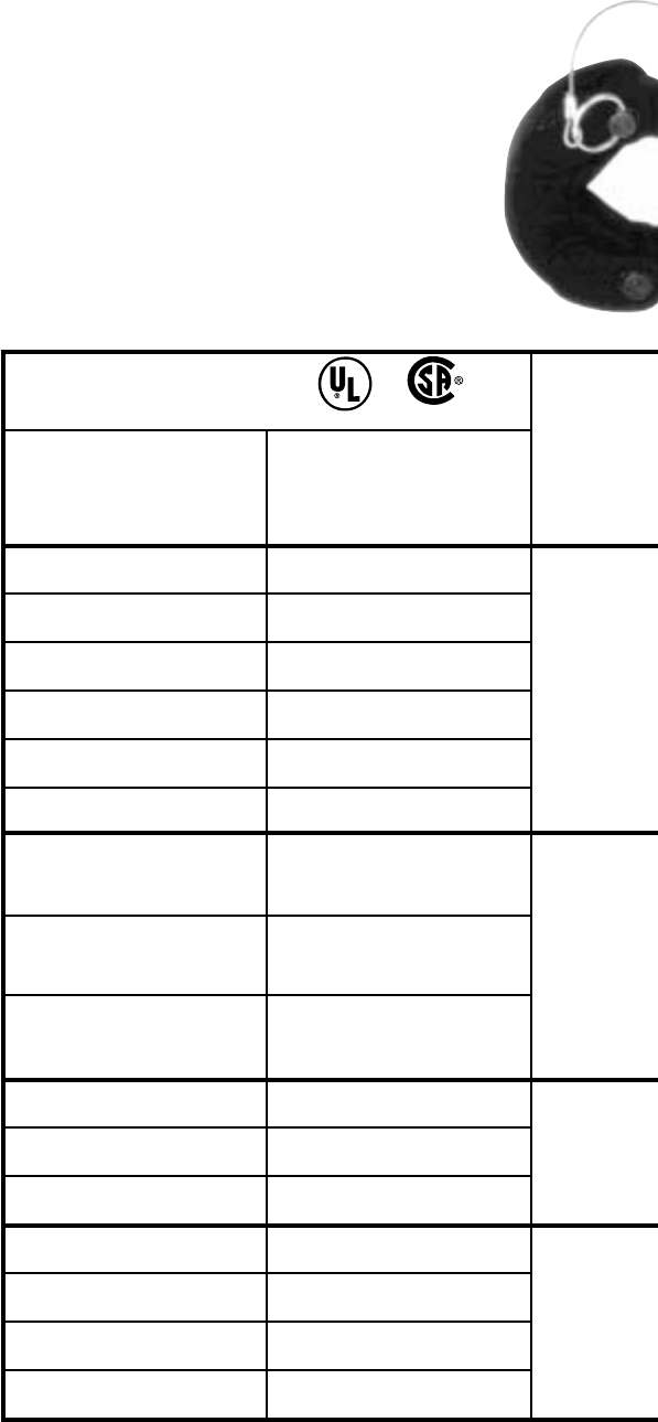
Ultra-Crimp®
Connector Wire Size Range*
Catalog Type Copper Cable Only
Splices and Including Compact
Lugs (1 & 2 Hole) ‘CU’
BCU-4 & BLU-4 4 Str.
BBCU-4 & BBLU-4
BCU-3 & BLU-3 3 Str. - 4 Str.
BBCU-3 & BBLU-3
BCU-2 & BLU-2 2 Str. - 4 Str.
BBCU-2 & BBLU-2
BCU-1 & BLU-1 1 Str. - 4 Str.
BBCU-1 & BBLU-1
BCU-1/0 & BLU-1/0 1/0 Str. - 4 Str.
BBCU-1/0 & BBLU-1/0
BCU-2/0 & BLU-2/0 2/0 Str. - 4 Str.
BBCU-2/0 & BBLU-2/0
BCU-3/0 & BLU-3/0 3/0 Str.
BBCU-3/0 & BBLU-3/0
BCU-4/0 & BLU-4/0 4/0 Str. - 3/0 Str.
BBCU-4/0 & BBLU-4/0
BCU-025 & BLU-025 250 MCM - 3/0 Str.
BBCU-025 & BBLU-025
BCU-030 & BLU-030 300 MCM
BBCU-030 & BBLU-030
BCU-035 & BLU-035 350 MCM - 300 MCM
BBCU-035 & BBLU-035
BCU-040 & BLU-040 400 MCM - 300 MCM
BBCU-040 & BBLU-040
BCU-050 & BLU-050 500 MCM
BBCU-050 & BBLU-050
BCU-060 & BLU-060 600 MCM - 500 MCM
BBCU-060 & BBLU-060
BCU-065 & BLU-065 650 MCM - 500 MCM
BBCU-065 & BBLU-065
BCU-075 & BLU-075 750 MCM - 500 MCM
BBCU-075 & BBLU-075
Standard
Penn-Union
Color-Coded
Lugs & Splices
ULTRA-CRIMP®
RANGE-TAKING COMPRESSION SYSTEM
TDY
Compression
Tool
Now you need just a few sizes of our
standard color-coded lugs and splices to
make all your connections...
Take advantage of the unique design of
the patented† TDY-1 dieless compres-
sion tool to save time and money on
electrical connections. The TDY-1 makes
UL Listed and CSA Certified range-taking
compressions on Penn-Union’s standard
color-coded connectors.
There’s no need to stock every size of lug
and splice in order to cover the complete
wire range from #4 Str. through 1000
MCM, including compact wires. There’s
no need for special, limited use connec-
tors. Plus, the TDY-1 is dieless–you
never have to buy or stock dies again.
Take a look at the chart to see how the
ULTRA-CRIMP® Range-Taking
Compression System will simplify your
business. Just 4 sizes of aluminum lugs
and 4 sizes of aluminum splices cover
the entire range of copper and aluminum
wire. And all the connections are UL
Listed and CSA Certified!
+= ULTRA-CRIMP®
CU 90°C
COPPER
†U.S. Patent No. 4,604,890
Canadian Patent No. 1,212,528
44
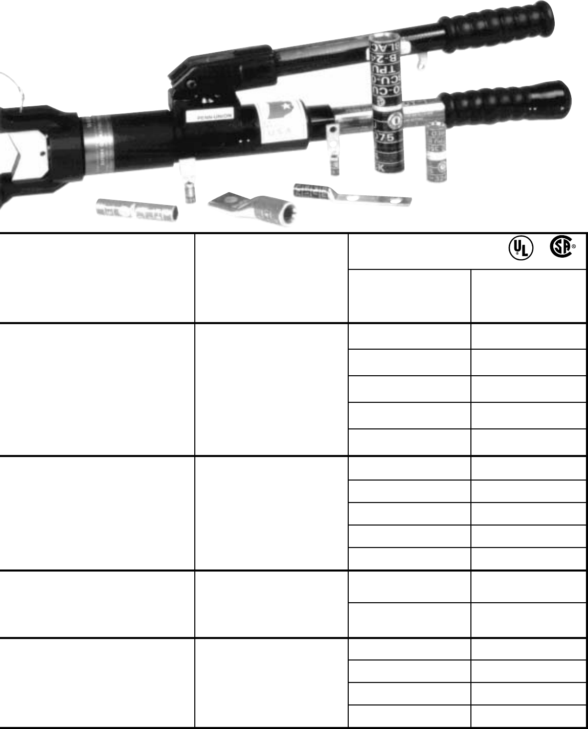
Ultra-Crimp®
Connector Wire Size Range*
Catalog Type AL or CU Cable
Splices and Including Compact
Lugs (1 & 2 Hole) ‘AL9CU’
BCUA-4 & BLUA-4 4 Str.
BCUA-2 & BLUA-2 2 Str. - 4 Str.
BCUA-1 & BLUA-1 1 Str. - 4 Str.
BCUA-1/0 & BLUA-1/0 1/0 Str. - 4 Str.
BCUA-2/0 & BLUA-2/0 2/0 Str. - 4 Str.
BCUA-3/0 & BLUA-3/0 3/0 Str.
BCUA-4/0 & BLUA-4/0 4/0 Str. - 3/0 Str.
BCUA-025 & BLUA-025 250 MCM - 3/0 Str.
BCUA-030 & BLUA-030 300 MCM - 3/0 Str.
BCUA-035 & BLUA-035 350 MCM - 3/0 Str.
BCUA-040 & BLUA-040 400 MCM
BCUA-050 & BLUA-050 500 MCM - 400 MCM
BCUA-060 & BLUA-060 600 MCM
BCUA-075 & BLUA-075 750 MCM - 600 MCM
BCUA-080 & BLUA-080 800 MCM - 600 MCM
BCUA-100 & BLUA-100 1000 MCM - 600 MCM
45
TDY-1
PRESSURE
SETTING
2
5
7
9
AL9CU
ALUMINUM
*Warning:
Ultra-Crimp® Compression System is only recommended for the above designated conventional Penn-Union
connectors that are properly installed with the Penn-Union TDY-U or TDY-1 dieless compression tool. Any other
combination of crimping tools and/or connectors shall be at the complete
risk
and
responsibility
of the installer.
®
ULTRA-CRIMP is a registered trademark of Penn-Union.
TDY-U
PRESSURE
SETTING
DO NOT
USE TDY-U
IN THIS
RANGE
5
7
9

46
DIELESS MODEL TDY-1 HYDRAULIC HAND TOOL
A unique pressure selection control on tool handle permits one
of four hydraulic pressure settings to be used, allowing tool to
crimp #4 AWG to 750 MCM copper connectors and #4 AWG to
1000 MCM aluminum connectors
without changing dies
. (See
chart below for proper pressure settings to use on Penn-Union
color-coded connectors)
Two speed hydraulic pump unit rapidly advances the built-in dies
into contact with the connector and then automatically shifts into
the crimping mode to complete the connection.
Exerts 12 tons of force. Weighs 131/2 lbs. The tool head rotates
180° to provide for easy accessibility in confined working areas.
The hinged head allows for easy insertion and removal of in-line
splices.
The permanent dies are retracted by pulling down on the trigger
release and completing another short stroke.
The tool has fiberglass handles and comes complete with steel
carrying case.
CUAD-1000 adaptor available for installation of 1000 MCM color-
coded copper connectors.
TDY-1 Pressure Setting Chart
Connector Type Pressure Setting
Color Coded Series 2579
Aluminum Connectors 3/0-350 400-500 600-1000
BLUA & BCUA Type 4 - 2/0 MCM MCM MCM
Al & Cu Cable
Copper Connectors 3/0-250 300-400 500-750
BLU & BCU Type 4 - 2/0 MCM MCM MCM
Cu Cable Only
TP & TPO 6-1/0 2/0-350 400-500 600-750
MCM MCM MCM
CALIBRATION KIT FOR TDY-1
36 aluminum test slugs with a Go/No Go gauge which can be used at
pressure setting #2 to give a quick check to determine that tool is in
calibration. Catalog Number: CALKIT-1
U.S. Patent No. 4,604,890
Canadian Patent No. 1,212,528
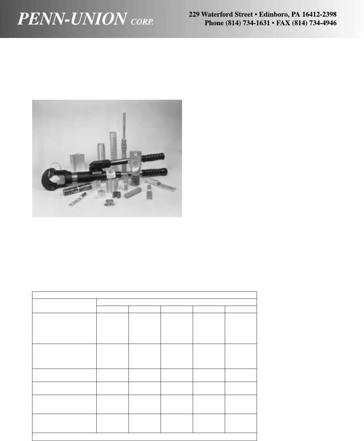
TDY-U DIELESS UNIVERSAL TOOL
One tool does it all...without dies!
TDY-U Hydraulic Hand Tool
• Expands traditional hand tool range to 1000 MCM aluminum
• Hydraulic hold feature eliminates need to fully retract between
crimps
• Ultra-Crimp® range-taking capacity on color coded connectors
3/0 to 1000 MCM aluminum, 3/0 to 750 MCM copper
• Wide compression head requires fewer crimps
•Variable pressure setting requires fewer strokes
•Hinged head for splices up to 1000 MCM partial tension splices
• Head rotates 180°
• Two-speed hydraulic pump for rapid ram advance
• Delivers up to 14 tons of force
• Light weight (14 lbs.)
• Steel carrying case
• Optional PVC coated head for protection against brush contact
only
U.S. PATENT 4,604,890
CAN. PATENT 1212528
TDY-U Installs the Following Connectors:
Connector Type Pressure Setting
Utility Series 24579
.640 .906 1.152 1.375 1.600 & 1.835
Common O.D. O.D. O.D. O.D. O.D. O.D.
Aluminum 5/8.840 11/815/16 11/2 & 13/4
Partial Tension BG 249 316 317 301 & 302
Lugs and Splices Die Die Die Die Die
KN-R54
Aluminum H-Taps O, D & D3 KN-R55
O&D 7 Connector Prog. Die NB50040
and Designated N-Size NB500
Copper H-Taps CST, CDT CST-309
B,C,O,D Die CDT-309
Copper C-Taps C-Taps C-Taps C-Taps
BG Die C Die 0, D3 Die
Color Coded Copper Conn.
BLU, BBLU, BCU & BBCU* 3/0-250 300-400 500-750
Copper Cable Only MCM MCM MCM
Color Coded Aluminum
Connectors BLUA & BCUA* 1/0-2/0 3/0-350 400-500 600-1000
Aluminum & Copper Cable MCM MCM MCM
*UL Listed and CSA Certified.
47

Connector Type Pressure Setting
Utility Series 2 4 5 7 9
1.600 &
Common O.D. .640 .906 1.152 1.375 1.835
Aluminum O.D. O.D. O.D. O.D. O.D.
Partial Tension 5/8.840 11/815/16 11/2 & 13/4
Lugs and Splices BG 249 316 317 301 & 302
Die Die Die Die Die
O, D KN-R54
Aluminum H-Taps & D3 KN-R55
O&D 7 Connector Prog. Die NB50040
and Designated N-Size NB500
CST,
Copper H-Taps CDT CST-309
B, C, O, CDT-309
D Die
C-Taps
Copper C-Taps C-Taps C-Taps O, D3
BG Die C Die Die
Color Coded Copper Conn.
BLU, BBLU, BCU & BBCU* 3/0-250 300-400 500-750
Copper Cable Only MCM MCM MCM
Color Coded Aluminum
Connectors BLUA & BCUA* 1/0-2/0 3/0-350 400-500 600-1000
Aluminum & Copper Cable MCM MCM MCM
*UL Listed and CSA Certified
TDY-UR Installs the Following Connectors:
TDY-1R AND TDY-UR REMOTE POWERED DIELESS COMPRESSION TOOLS
Electric pumps add push button convenience to Penn-Union’s TDY-1 and TDY-U
48
Penn-Union’s TDY-UR and TDY-1R remote powered dieless
compression tools lets you make a full range of connections
with the touch of a button.
Powered by a choice of two remote electric pumps, the TDY-
UR and TDY-1R consist of the tool head, a 10 foot dielectric
hose, a pendant switch and a 1 horsepower motor pump.
CHOOSE FROM TWO PUMP SIZES
You can select a three quart or two gallon reservoir pump to
power the TDY-UR or TDY-1R. The three quart model is rec-
ommended for intermittent use where portability is important.
The two gallon pump is recommended for repetitive use–as-
sembly line or bench applications. Both pumps are powered
from any standard 110 volt outlet.
REMOTE POWER SAVES TIME
AND MAKES INSTALLATION EASY
Connections are made quickly and accurately with the TDY-UR
or TDY-1R. The TDY-UR and TDY-1R with remote pumps offer
you the full installation ranges of our hydraulic compression
hand tools. Just press the pendant switch button to advance
the ram. After the crimp is completed, the ram automatically
retracts to prepare for the next compression. This enables you
to keep down-time to a minimum in repair situations.
REMOTE HEADS PROVIDE GREATER FLEXIBILITY
Penn-Union’s TDY-1R and TDY-UR have remote tool heads
that are more maneuverable than hand tools. The lightweight,
compact design allows the heads to fit into tight spaces where
other tools can’t reach. And, both compression heads flip open
for easy installation of splices up to 1000 MCM.
Catalog Head Reservoir
Number Type Size Hose
TDY 1R (3 Qt.) TDY-1 3 Qt. 10'
TDY 1R (2 Gal.) TDY-1 2 Gal. 10'
TDY UR (3 Qt.) TDY-U 3 Qt. 10'
TDY UR (2 Gal.) TDY-U 2 Gal. 10'
TDY-1R Installs the Following Connectors:
Connector Type Pressure Setting
Color Coded Series 2 5 7 9
Aluminum Connectors
BLUA & BCUA Type 4 - 2/0 3/0 - 350 400 - 500 600 - 1000
Al & Cu Cable MCM MCM MCM
Copper Connectors
BLU & BCU Type 4 - 2/0 3/0 - 250 300 - 400 500 - 750
Cu Cable Only MCM MCM MCM
6 - 1/0 2/0 - 350 400 - 500 600 - 750
TP & TPO MCM MCM MCM
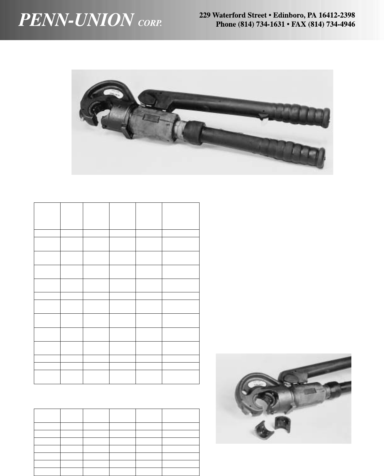
12-TON HYDRAULIC COMPRESSION HAND TOOL MODEL TPU-12B
For crimping copper and aluminum connectors – exerts 12 tons
of force, yet weighs under 15 pounds. C-shaped head allows
wider connector range:
• splices (BCU-BCUA series) #6-400 MCM
• lugs (BLU series) #6-750 MCM
• lugs (BLUA series) #6-600 MCM
• press-on connectors (O, D and N die) #6-500 MCM
Easy installation with 180° swivel crimping head. Piston retracted
by trigger mechanism on pumping handle.
Comes complete with steel carrying case. Accepts all standard
dies for 12-ton tools. Also available with PVC insulated head (re-
fer to factory).
INSTALLATION DIES FOR TPU-12B TOOL
Easy to match color-coded dot on die with wide, brilliantly-
colored connector bands on Penn-Union’s compression connec-
tors. Dies are precision-made investment cast steel for longer
life.
Penn-
Union Burndy
Die Set Burndy Die Set T & B Color
Cat. No. Index Cat. No. Index Code Range
T-10 10 U2CRT 33 Brown #2 CU
T-11/375 11 U1CRT 37 Green #1 CU
375 U4CABT #4 AL
T-12/348 12 U25RT 42 Pink 1/0 CU
348 C2CABT #2 AL
T-13 13 U26RT 45 Black 2/0 CU
T-14 14 U27RT 50 Orange 3/0 CU
T-15 15 U28RT 54 Purple 4/0 CU
T-16 16 U29RT 62 Yellow 250MCM CU
T-298 298 U28ART 66H White 4/0 AL
T-18/324 18 U31RT 71H Red 350MCM CU
324 U29ART 250MCM AL
T-20/299 20 U34RT 87H Brown 500MCM CU
299 U31ART 350MCM AL
T-22/472 22 U36RT 94H Green 600MCM CU
472 U32ART 400MCM AL
T-296 296 U25ART 50 Tan 1/0 AL
T-297 297 U26ART 54 Olive 2/0 AL
T-300 300 U34ART 99H Pink 500MCM AL
T-467 467 U27ART 60 Ruby 3/0 AL
T-473 473 U36ART 106H Black 750MCM CU
600MCM AL
Die Sets
TPU Burndy Burndy T & B Color
Die Set Index Die Set Index Code Range
T-BG BG U-BG 52 – –
T-0 O U-O O – –
T-D3 D3 U-D3 D – –
T-N N U-N N – –
T-249 249 U-249 76 – –
T-316 316 U-316 96 – –
T-317 317 U-317 106A – –
Die Sets (Utility)
49
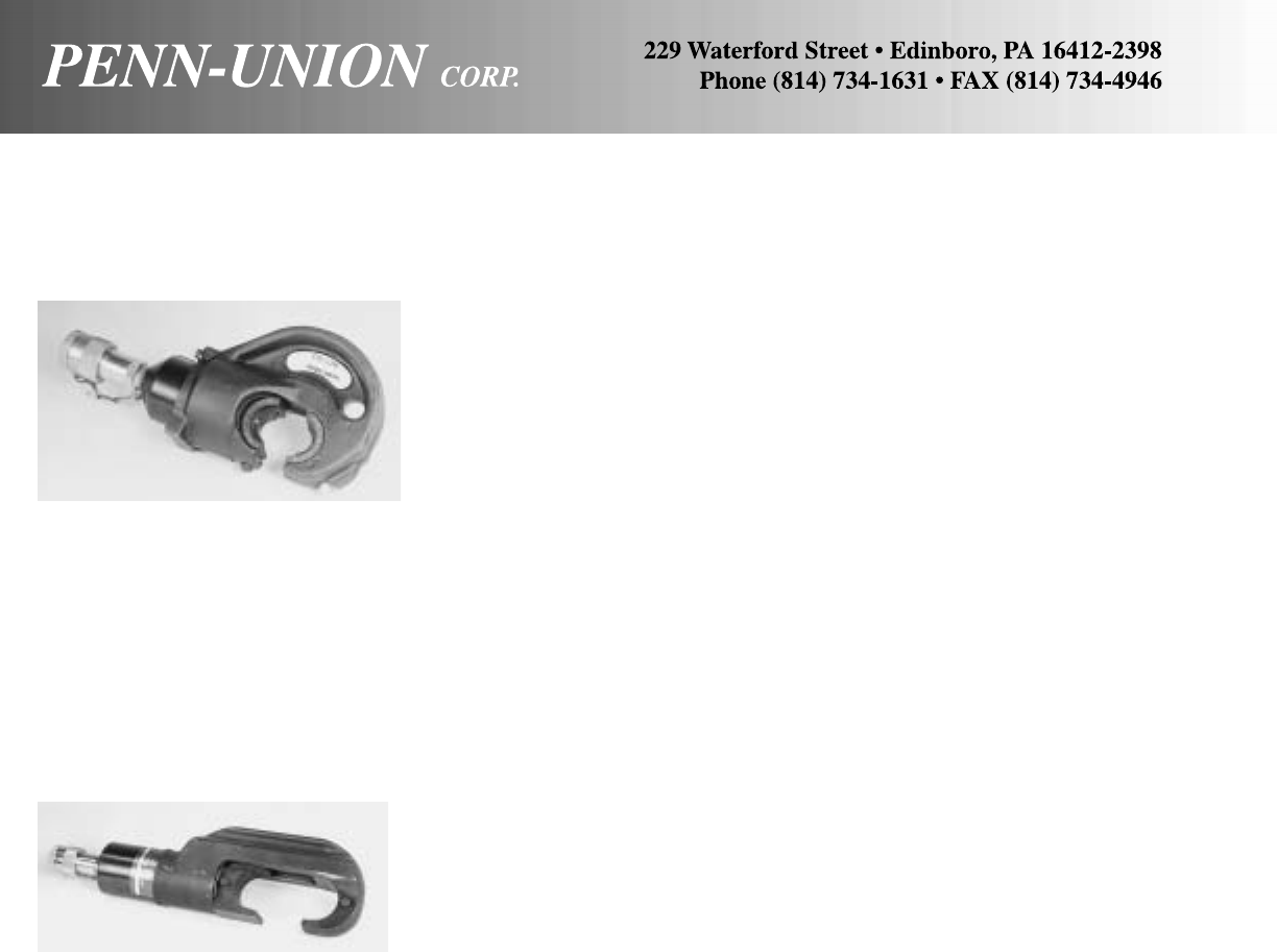
12-TON REMOTE POWERED HYDRAULIC COMPRESSION HEAD
MODEL TPU-12BH
15-TON REMOTE POWERED HYDRAULIC COMPRESSION HEAD
MODEL TPU-15BH
Compact and lightweight, the remote TPU-15BH tool handles
compression grounding applications with a complete range of
aluminum and copper connectors. The 41/4" narrow width head is
especially suited for underground network system use.
• Accommodates 8-1250 MCM aluminum and 1500 MCM cop-
per connector range
• Compatible with all industry standard 10,000 PSI pumps and
hoses, including the Penn-Union model TFP-10-2
• Accepts standard 15-ton dies
• Adaptor available for using standard 12-ton dies
•Quick-disconnect hydraulic couplers offer faster tool assembly
and breakdown
• Includes steel carrying case
This remote version of Penn-Union’s 12-ton compression tool
easily installs the full range of copper and aluminum connectors.
The TPU-12BH is compatible with all industry standard 10,000
PSI pumps and hoses, including the Penn-Union model
TFP-10-2.
• Uses same dies as TPU-12B
• Can be used with Penn-Union T-type and competitive shell-
type dies
• Accepts all standard dies for 12-ton tools
Also available with PVC insulated head (consult factory).
50
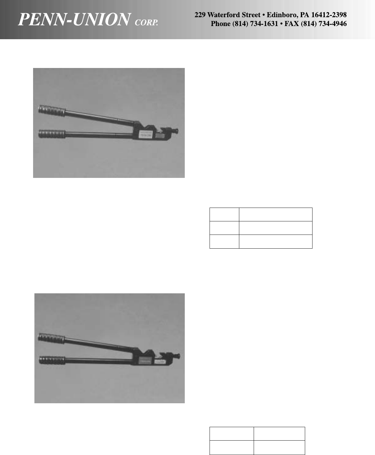
TDM-250 MECHANICAL COMPRESSION TOOL WITH BUILT-IN DIES
TDM-500 DIELESS MECHANICAL COMPRESSION TOOL
51
Catalog Wire
Number Range
TDM-250 #8 - 250 MCM CU
#8 - 250 MCM AL
TDM-250XF #8 - 4/0 Extra Flexible CU
#8 - 250 MCM CU
MORE ECONOMICAL
• Dieless - no dies to buy or lose
• Widest Range Available - crimps #8-500 MCM AL or CU
• Costs less than expensive hydraulic tools
• Quality Construction - all-steel, durable construction
• Five Years Manufacturer’s Warranty for replacement or service
MORE CONVENIENT TO USE
• Unique handle design - provides increased leverage. At 500
MCM, the TDM-500 requires less handle load than conventional
250 MCM tools require at 250 MCM.
• No dies to change or lose
• Easy-to-read settings are provided on calibrated index plates,
one for AL and one for CU, located on the side of the tool
• Small head - convenient in confined areas
• Easiest Bench Use - machined flat head surface allows you to
stand tool freely in working position
Catalog Wire
Number Range
TDM-500 #8 - 500 MCM CU
#8 - 500 MCM AL
MORE ECONOMICAL
• Dieless - no dies to buy or lose
• Widest Range Available - crimps #8-250 MCM AL or CU
• Costs less than expensive hydraulic tools
• Quality Construction - all-steel, durable construction
• Five Years Manufacturer’s Warranty for replacement or service
MORE CONVENIENT TO USE
• Unique handle design - provides increased leverage. At 250
MCM, the TDM-250 requires less handle load than conventional
250 MCM tools require at 250 MCM.
• No dies to change or lose
• Easy-to-read settings are provided on calibrated index plates,
one for AL and one for CU, located on the side of the tool
• Small head - convenient in confined areas
• Easiest Bench Use - machined flat head surface allows you to
stand tool freely in working position

HOW TO SELECT THE PROPER PENN-CRIMP
CATALOG NO. 4B
EXAMPLE RBARREL WIRE 6 S
TONGUE SIZE RANGE STUD SIZE SPECIAL
TONGUE SEE GENERAL INDEX FOR LETTER CODE
1 - BUTTED SEAM PURE ELECTROLYTIC COPPER, ANNEALED, ELECTRO-TIN PLATED FOR
CORROSION RESISTANCE, DESIGNED WITH DEEP INTERNAL SERRATIONS FOR
FIRM WIRE GRIP.
2 - BRAZED SEAM SAME AS TYPE 1 EXCEPT WITH A BRAZED SEAM TO ASSURE MAXIMUM
STRENGTH OF WIRE TERMINATIONS.
BARREL 4 - VINYL INSULATION SAME AS TYPE 1 WITH A NEMA COLOR-CODED, FUNNELED, VINYL INSULATING
TYPE SLEEVE WHICH WHEN CRIMPED, GRIPS THE WIRE INSULATION TO AVOID
FLEXING AT POINT OF CRIMPS, UL RATED AT 90° C, 600 V.
4N - NYLON INSULATION SAME AS TYPE 1 WITH COLOR-CODED NYLON INSULATING SLEEVE WITHOUT
NO BRASS SLEEVE BRASS SLEEVE. UL RATED AT 105° C, 600 V.
6 - NYLON INSULATION SAME AS TYPE 1 WITH NEMA COLOR CODED, NYLON INSULATING SLEEVE OR
BRASS SLEEVE OVER A TIN PLATED BRASS SLEEVE WHICH OFFERS MAXIMUM CRIMP
STRENGTH WHERE EXTREME VIBRATION AND FLEXING ARE ENCOUNTERED.
UL RATED AT 105° C, 600 V.
7 - SEAMLESS TUBE PURE ELECTROLYTIC COPPER, SEAMLESS, ANNEALED AND ELECTRO-TIN
PLATED FOR EXTRA STRENGTH IN A CRIMP
8 - NYLON INSULATION SAME AS TYPE 7 WITH A NYLON INSULATION FOR USE WHERE EXCESSIVE
SEAMLESS TUBE VIBRATION ENVIRONMENT ARE ENCOUNTERED.
9 - HI-TEMPERATURE NICKEL-PLATED, COLD ROLLED STEEL, BUTTED SEAM TERMINALS FOR
TEMPERATURES UP TO 900 DEGREES F.
WIRE RANGE
0 - 26-24 D - 16-12
A - 22-18 E - 8
B - 16-14 F - 6
C - 12-10 G - 4
SPECIAL
___ BLANK ---STANDARD
S - SMALL/NARROW TONGUE
F - FULLY INSULATED
– HS PRE INSULATED HEAT SHRINKABLE.
52
0 - #0 56 - 5/16"
2 - #2 38 - 3/8"
4 - #4 50 - 1/2"
6 - #6 110 - .110 NEMA TAB
8 - #8 187 - .187 NEMA TAB
10 - #10 250 - .250 NEMA TAB
14 - 1/4"
STUD
SIZE
COPPER PENN-CRIMPS® • TYPE R1
Non-insulated ring terminal with butted seam
One piece, annealed, pure electrolytic copper construction with
electro-tin plating for corrosion resistance. Deep internal serra-
tions promote firm wire grip for maximum tensile strength. In-
spection hole permits quick examination of the crimp. Generous
entrance chamfer provides easy wire insertion. The combination
of these features and the fact that our products exceed UL and
CSA requirements guarantee a high quality connection.
Copper Stock Approx. Dimen. in Inches
Catalog Cond. Stud Size
Number Range Size (in) A W C M B ID
R1A-6 22-18 6 .030 .69 .31 .28 .54 .250 .070
R1A-6S 22-18 6 .030 .65 .25 .28 .54 .250 .070
R1A-8 22-18 8 .030 .69 .31 .28 .54 .250 .070
R1A-8S 22-18 8 .030 .65 .25 .28 .54 .250 .070
R1A-10 22-18 10 .030 .69 .31 .28 .54 .250 .070
R1A-14 22-18 1/4.030 .94 .53 .42 .67 .250 .070
R1A-14S 22-18 1/4.030 .90 .46 .42 .67 .250 .070
R1A-56 22-18 5/16 .030 .94 .53 .42 .67 .250 .070
R1A-56S 22-18 5/16 .030 .90 .46 .42 .67 .250 .070
R1A-38 22-18 3/8.030 .94 .53 .42 .67 .250 .070
R1B-6 16-14 6 .030 .69 .31 .28 .54 .250 .090
R1B-6S 16-14 6 .030 .65 .25 .28 .54 .250 .090
R1B-8 16-14 8 .030 .69 .31 .28 .54 .250 .090
R1B-8S 16-14 8 .030 .65 .25 .28 .54 .250 .090
R1B-10 16-14 10 .030 .69 .31 .28 .54 .250 .090
R1B-14 16-14 1/4.030 .94 .53 .42 .67 .250 .090
R1B-14S 16-14 1/4.030 .90 .46 .42 .67 .250 .090
R1B-56 16-14 5/16 .030 .94 .53 .42 .67 .250 .090
R1B-56S 16-14 5/16 .030 .90 .46 .42 .67 .250 .090
R1B-38 16-14 3/8.030 .94 .53 .42 .67 .250 .090
R1C-6 12-10 6 .040 .72 .38 .28 .54 .250 .130
R1C-6S 12-10 6 .040 .67 .28 .28 .54 .250 .130
R1C-8 12-10 8 .040 .72 .38 .28 .54 .250 .130
R1C-8S 12-10 8 .040 .67 .28 .28 .54 .250 .130
R1C-10 12-10 10 .040 .72 .38 .28 .54 .250 .130
R1C-14 12-10 1/4.040 .98 .61 .42 .67 .250 .130
R1C-14S 12-10 1/4.040 .94 .53 .42 .67 .250 .130
R1C-56 12-10 5/16 .040 .98 .61 .42 .67 .250 .130
R1C-56S 12-10 5/16 .040 .94 .53 .42 .67 .250 .130
R1C-38 12-10 3/8.040 .98 .58 .42 .67 .250 .130
R1D-6 16-12 6 .050 .68 .38 .24 .50 .250 .115
R1D-6S 16-12 6 .050 .67 .28 .24 .50 .250 .115
R1D-8 16-12 8 .050 .68 .38 .24 .50 .250 .115
R1D-8S 16-12 8 .050 .67 .28 .24 .50 .250 .115
R1D-10 16-12 10 .050 .68 .38 .24 .50 .250 .115
R1D-14 16-12 1/4.050 .94 .61 .42 .64 .250 .115
R1D-14S 16-12 1/4.050 .91 .53 .42 .64 .250 .115
R1D-56 16-12 5/16 .050 .94 .61 .42 .64 .250 .115
R1D-38 16-12 3/8.050 .94 .61 .42 .64 .250 .115
CU
A
W
CB
M
ID
53
COPPER PENN-CRIMPS • TYPE R2
Non-insulated ring terminal with brazed seam
Same high quality construction as the Type R1 terminals, except
the Type R2 features a brazed seam. Our unique process bonds
the seam to assure the maximum strength in wire termination.
This feature allows for crimping anywhere on the barrel circum-
ference. Exeeds UL and CSA requirements, guaranteeing a high
quality connection.
Copper Stock Approx. Dimen. in Inches
Catalog Cond. Stud Size
Number Range Size (in) A W C M B ID
R2A-6 22-18 6 .030 .69 .31 .28 .54 .250 .070
R2A-6S 22-18 6 .030 .65 .25 .28 .54 .250 .070
R2A-8 22-18 8 .030 .69 .31 .28 .54 .250 .070
R2A-8S 22-18 8 .030 .65 .25 .28 .54 .250 .070
R2A-10 22-18 10 .030 .69 .31 .28 .54 .250 .070
R2A-14 22-18 1/4.030 .94 .53 .42 .67 .250 .070
R2A-14S 22-18 1/4.030 .90 .46 .42 .67 .250 .070
R2A-56 22-18 5/16 .030 .94 .53 .42 .67 .250 .070
R2A-56S 22-18 5/16 .030 .90 .46 .42 .67 .250 .070
R2A-38 22-18 3/8.030 .94 .53 .42 .67 .250 .070
R2B-6 16-14 6 .030 .69 .31 .28 .54 .242 .090
R2B-6S 16-14 6 .030 .65 .25 .28 .54 .242 .090
R2B-8 16-14 8 .030 .69 .31 .28 .54 .250 .090
R2B-8S 16-14 8 .030 .69 .31 .28 .54 .250 .090
R2B-10 16-14 10 .030 .69 .31 .28 .54 .250 .090
R2B-14 16-14 1/4.030 .94 .53 .42 .67 .260 .090
R2B-14S 16-14 1/4.030 .90 .46 .42 .67 .260 .090
R2B-56 16-14 5/16 .030 .94 .53 .42 .67 .250 .090
R2B-56S 16-14 5/16 .030 .90 .46 .42 .67 .250 .090
R2B-38 16-14 3/8.030 .94 .53 .42 .67 .260 .090
R2C-6 12-10 6 .040 .72 .38 .28 .54 .250 .130
R2C-6S 12-10 6 .040 .67 .28 .28 .54 .250 .130
R2C-8 12-10 8 .040 .72 .38 .28 .54 .250 .130
R2C-8S 12-10 8 .040 .67 .28 .28 .54 .255 .130
R2C-10 12-10 10 .040 .72 .38 .28 .54 .255 .130
R2C-14 12-10 1/4.040 .98 .61 .38 .67 .255 .130
R2C-14S 12-10 1/4.040 .94 .53 .38 .67 .255 .130
R2C-56 12-10 5/16 .040 .98 .61 .38 .67 .255 .130
R2C-56S 12-10 5/16 .040 .94 .53 .38 .67 .255 .130
R2C-38 12-10 3/8.040 .98 .58 .38 .67 .255 .130
R2E-8SS + 8 8 .050 .91 .38 .34 .72 .375 .165
R2E-10 + 8 10 .050 1.07 .60 .45 .78 .375 .165
R2E-10S + 8 10 .050 .96 .47 .34 .72 .375 .165
R2E-10SS + 8 10 .050 .91 .38 .34 .72 .375 .165
R2E-14 + 8 1/4.050 1.07 .60 .45 .78 .375 .165
R2E-14S + 8 1/4.050 .96 .47 .38 .72 .375 .165
R2E-56 + 8 5/16 .050 1.07 .60 .45 .78 .375 .165
R2E-38 + 8 3/8.050 1.07 .60 .45 .78 .375 .165
R2E-50 *+ 8 1/2.050 1.75 .88 .99 1.30 .320 .165
R2F-10 + 6 10 .050 1.20 .63 .50 .88 .375 .224
R2F-10S + 6 10 .050 1.11 .47 .50 .88 .375 .224
R2F-14 + 6 1/4.050 1.20 .63 .50 .88 .375 .224
R2F-14S + 6 1/4.050 1.11 .47 .50 .88 .375 .224
R2F-56 + 6 5/16 .050 1.20 .63 .50 .88 .375 .224
R2F-38 + 6 3/8.050 1.20 .63 .50 .88 .375 .224
R2F-50 *+ 6 1/2.050 1.85 .81 1.00 1.38 .375 .224
R2G-10 + 4 10 .075 1.34 .66 .55 .99 .450 .278
R2G-10S + 4 10 .075 1.26 .45 .50 .99 .450 .278
R2G-14 + 4 1/4.075 1.34 .66 .55 .99 .450 .278
R2G-14S + 4 1/4.075 1.26 .45 .45 .90 .450 .278
R2G-56 + 4 5/16 .075 1.34 .66 .55 .99 .437 .278
R2G-38 + 4 3/8.075 1.34 .66 .55 .99 .437 .278
R2G-50 *+ 4 1/2.075 1.34 .66 .55 .99 .437 .278
*Not UL listed +Not CSA listed
CU
A
W
CB
M
ID
54
COPPER PENN-CRIMPS® • TYPE R4
Vinyl insulated ring terminal
High quality Type R1 construction, butted seam, pre-insulated
with a polyvinyl chloride (PVC) sleeve. Insulation is color coded
to NEMA standards and flared for easy insertion of both stranded
and solid wire. PVC insulation forms insulation support for the
crimped wire to avoid flexing at the point of crimp. The perfor-
mance and reliability of the Type R4 and other terminals, which
exceeds UL and CSA requirements, proves that Penn-Crimps
provide the preferred connection.
Copper Color Stock Max. Approx. Dimen. in Inches
Catalog Cond. Stud Code Size Insul.
Number Range Size (ins) (in) Diam. A W C M B ID
R4A-6 22-18 6 R .030 .15 .91 .31 .28 .77 .250 .070
R4A-6S 22-18 6 R .030 .15 .86 .25 .28 .77 .250 .070
R4A-8 22-18 8 R .030 .15 .91 .31 .28 .77 .250 .070
R4A-8S 22-18 8 R .030 .15 .91 .25 .28 .77 .250 .070
R4A-10 22-18 10 R .030 .15 .91 .31 .28 .77 .250 .070
R4A-14 22-18 1/4R.030 .15 1.14 .53 .42 .87 .250 .070
R4A-14S 22-18 1/4R.030 .15 1.14 .46 .42 .87 .250 .070
R4A-56 22-18 5/16 R.030 .15 1.14 .53 .42 .87 .250 .070
R4A-56S 22-18 5/16 R.030 .15 1.14 .46 .42 .87 .250 .070
R4A-38 22-18 3/8R.030 .15 1.14 .53 .42 .87 .250 .070
R4B-6 16-14 6 B .030 .18 .94 .31 .28 .77 .250 .090
R4B-6S 16-14 6 B .030 .18 .88 .25 .28 .77 .250 .090
R4B-8 16-14 8 B .030 .18 .94 .31 .28 .77 .250 .090
R4B-8S 16-14 8 B .030 .18 .88 .25 .28 .77 .250 .090
R4B-10 16-14 10 B .030 .18 .94 .31 .28 .77 .250 .090
R4B-14 16-14 1/4B.030 .18 1.04 .46 .42 .90 .250 .090
R4B-14S 16-14 1/4B.030 .18 1.06 .53 .42 .90 .250 .090
R4B-56 16-14 5/16 B.030 .18 1.04 .46 .42 .90 .250 .090
R4B-56S 16-14 5/16 B.030 .18 1.06 .53 .42 .90 .250 .090
R4B-38 16-14 3/8B.030 .18 1.06 .53 .42 .90 .250 .090
R4C-6 12-10 6 Y .040 .25 1.00 .38 .28 .80 .250 .130
R4C-6S 12-10 6 Y .040 .25 .95 .28 .28 .80 .250 .130
R4C-8 12-10 8 Y .040 .25 1.00 .38 .28 .80 .250 .130
R4C-8S 12-10 8 Y .040 .25 1.00 .28 .28 .80 .250 .130
R4C-10 12-10 10 Y .040 .25 1.00 .38 .28 .80 .250 .130
R4C-14 12-10 1/4Y.040 .25 1.28 .61 .44 .94 .250 .130
R4C-14S 12-10 1/4Y.040 .25 1.22 .53 .44 .94 .250 .130
R4C-56 12-10 5/16 Y.040 .25 1.28 .61 .44 1.00 .250 .130
R4C-56S 12-10 5/16 Y.040 .25 1.22 .53 .44 .94 .250 .130
R4C-38 12-10 3/8Y.040 .25 1.28 .61 .44 .94 .250 .130
R4D-6 16-12 6 Y .050 .25 1.00 .38 .25 .80 .250 .115
R4D-6S 16-12 6 Y .050 .25 .95 .28 .25 .80 .250 .115
R4D-8 16-12 8 Y .050 .25 1.00 .38 .25 .80 .250 .115
R4D-8S 16-12 8 Y .050 .25 .95 .28 .25 .80 .250 .115
R4D-10 16-12 10 Y .050 .25 1.00 .38 .25 .80 .250 .115
R4D-14 16-12 1/4Y.050 .25 1.28 .61 .44 .94 .250 .115
R4D-14S 16-12 1/4Y.050 .25 1.22 .53 .44 .94 .250 .115
R4D-56 16-12 5/16 Y.050 .25 1.28 .61 .44 .94 .250 .115
R4D-38 16-12 3/8Y.050 .25 1.28 .61 .44 .94 .250 .115
R4E-8SS *+ 8 8 R .050 .34 1.22 .38 .34 1.01 .375 .165
R4E-10 *+ 8 10 R .050 .34 1.40 .60 .45 1.07 .375 .170
R4E-10S *+ 8 10 R .050 .34 1.27 .47 .41 1.04 .375 .165
R4E-10SS *+ 8 10 R .050 .34 1.22 .38 .34 1.01 .375 .165
R4E-14 *+ 8 1/4R.050 .34 1.38 .60 .45 1.07 .375 .170
R4E-14S *+ 8 1/4R.050 .34 1.27 .47 .41 1.04 .375 .165
R4E-56 *+ 8 5/16 R.050 .34 1.38 .60 .45 1.07 .375 .165
R4E-38 *+ 8 3/8R.050 .34 1.38 .60 .45 1.07 .375 .170
R4E-50 ** 8 1/2R.050 .34 1.72 .81 .68 1.33 .375 .165
R4F-10 *+ 6 10 B .050 .41 1.55 .63 .50 1.25 .375 .244
R4F-10S *+ 6 10 B .050 .41 1.48 .47 .50 1.25 .375 .244
R4F-14 *+ 6 1/4B.050 .41 1.55 .63 .50 1.25 .375 .244
R4F-14S *+ 6 1/4B.050 .41 1.48 .47 .50 1.25 .375 .244
R4F-56 *+ 6 5/16 B.050 .41 1.55 .63 .50 1.25 .375 .244
R4F-38 *+ 6 3/8B.050 .41 1.55 .63 .50 1.25 .375 .244
R4F-50 ** 6 1/2B.050 .41 2.20 .88 1.01 1.18 .375 .244
R4G-10 *+ 4 10 Y .075 .51 1.75 .66 .55 1.38 .437 .278
R4G-10S *+ 4 10 Y .075 .51 1.65 .45 .55 1.38 .437 .278
R4G-14 *+ 4 10 Y .075 .51 1.75 .66 .55 1.38 .437 .278
R4G-14S *+ 4 1/4Y.075 .51 1.65 .45 .55 1.38 .437 .278
R4G-56 *+ 4 5/16 Y.075 .51 1.75 .66 .55 1.38 .437 .278
R4G-38 *+ 4 3/8Y.075 .51 1.75 .66 .55 1.38 .437 .278
R4G-50 ** 4 1/2Y.075 .51 1.75 .66 .55 1.38 .437 .278
*Not CSA listed +UL component recognized **Not UL or CSA listed
Also available in nylon insulation without brass sleeve. Add letter “N” to catalog number between “4” and “E”. Example: R4NE-10.
A
W
CB
M
CU
55
COPPER PENN-CRIMPS® • TYPE R6
Nylon insulated ring terminal
Durable, Type R1 high conductivity copper construction, butted
seam, with tin-plated brass sleeve and NEMA color coded nylon
insulation. Brass sleeve and nylon insulation offer maximum bar-
rel crimp strength for the highest quality reliable terminations.
Three piece construction protects against severe conditions, es-
pecially where extreme vibration and flexing occur. Exceeds UL
and CSA requirements, guaranteeing a high quality connection.
Copper Color Stock Max. Approx. Dimen. in Inches
Catalog Cond. Stud Code Size Insul.
Number Range Size (ins) (in) Diam. A W C M B ID
R6A-6 22-18 6 R .030 .15 .91 .31 .28 .75 .250 .070
R6A-6S 22-18 6 R .030 .15 .86 .25 .28 .75 .250 .070
R6A-8 22-18 8 R .030 .15 .91 .31 .28 .75 .250 .070
R6A-8S 22-18 8 R .030 .15 .86 .25 .28 .75 .250 .070
R6A-10 22-18 10 R .030 .15 .91 .31 .28 .75 .250 .070
R6A-14 22-18 1/4R.030 .15 1.14 .53 .42 .87 .250 .070
R6A-14S 22-18 1/4R.030 .15 1.14 .46 .42 .87 .250 .070
R6A-56 22-18 5/16 R.030 .15 1.14 .53 .42 .87 .250 .070
R6A-56S 22-18 5/16 R.030 .15 1.14 .46 .42 .87 .250 .070
R6A-38 22-18 3/8R.030 .15 1.14 .53 .42 .87 .250 .070
R6B-6 16-14 6 B .030 .18 .94 .31 .28 .78 .250 .090
R6B-6S 16-14 6 B .030 .18 .88 .25 .28 .78 .250 .090
R6B-8 16-14 8 B .030 .18 .94 .31 .28 .78 .250 .090
R6B-8S 16-14 8 B .030 .18 .88 .25 .28 .78 .250 .090
R6B-10 16-14 10 B .030 .18 .94 .31 .28 .78 .250 .090
R6B-14 16-14 1/4B.030 .18 1.04 .53 .42 .90 .250 .090
R6B-14S 16-14 1/4B.030 .18 1.06 .46 .42 .90 .250 .090
R6B-56 16-14 5/16 B.030 .18 1.04 .53 .42 .90 .250 .090
R6B-56S 16-14 5/16 B.030 .18 1.06 .46 .42 .90 .250 .090
R6B-38 16-14 3/8B.030 .18 1.06 .53 .42 .90 .250 .090
R6C-6 12-10 6 Y .040 .25 1.06 .38 .28 .83 .250 .130
R6C-6S 12-10 6 Y .040 .25 1.00 .28 .28 .83 .250 .130
R6C-8 12-10 8 Y .040 .25 1.06 .38 .28 .83 .250 .130
R6C-8S 12-10 8 Y .040 .25 1.00 .28 .28 .83 .250 .130
R6C-10 12-10 10 Y .040 .25 1.06 .38 .28 .83 .250 .130
R6C-14 12-10 1/4Y.040 .25 1.28 .61 .31 .95 .250 .130
R6C-14S 12-10 1/4Y.040 .25 1.22 .53 .44 .95 .250 .130
R6C-56 12-10 5/16 Y.040 .25 1.28 .61 .44 .95 .250 .130
R6C-56S 12-10 5/16 Y.040 .25 1.22 .53 .44 .95 .250 .130
R6C-38 12-10 3/8Y.040 .25 1.28 .58 .44 .95 .250 .130
R6D-6 16-12 6 Y .050 .25 1.00 .38 .25 .79 .250 .115
R6D-6S 16-12 6 Y .050 .25 .95 .28 .25 .79 .250 .115
R6D-8 16-12 8 Y .050 .25 1.00 .38 .25 .79 .250 .115
R6D-8S 16-12 8 Y .050 .25 .95 .28 .25 .79 .250 .115
R6D-10 16-12 10 Y .050 .25 1.00 .38 .25 .79 .250 .115
R6D-14 16-12 1/4Y.050 .25 1.28 .61 .44 .93 .250 .115
R6D-14S 16-12 1/4Y.050 .25 1.22 .53 .44 .93 .250 .115
R6D-56 16-12 5/16 Y.050 .25 1.28 .61 .44 .93 .250 .115
R6D-38 16-12 3/8Y.050 .25 1.28 .61 .44 .93 .250 .115
CU
A
B
M
C
W
56
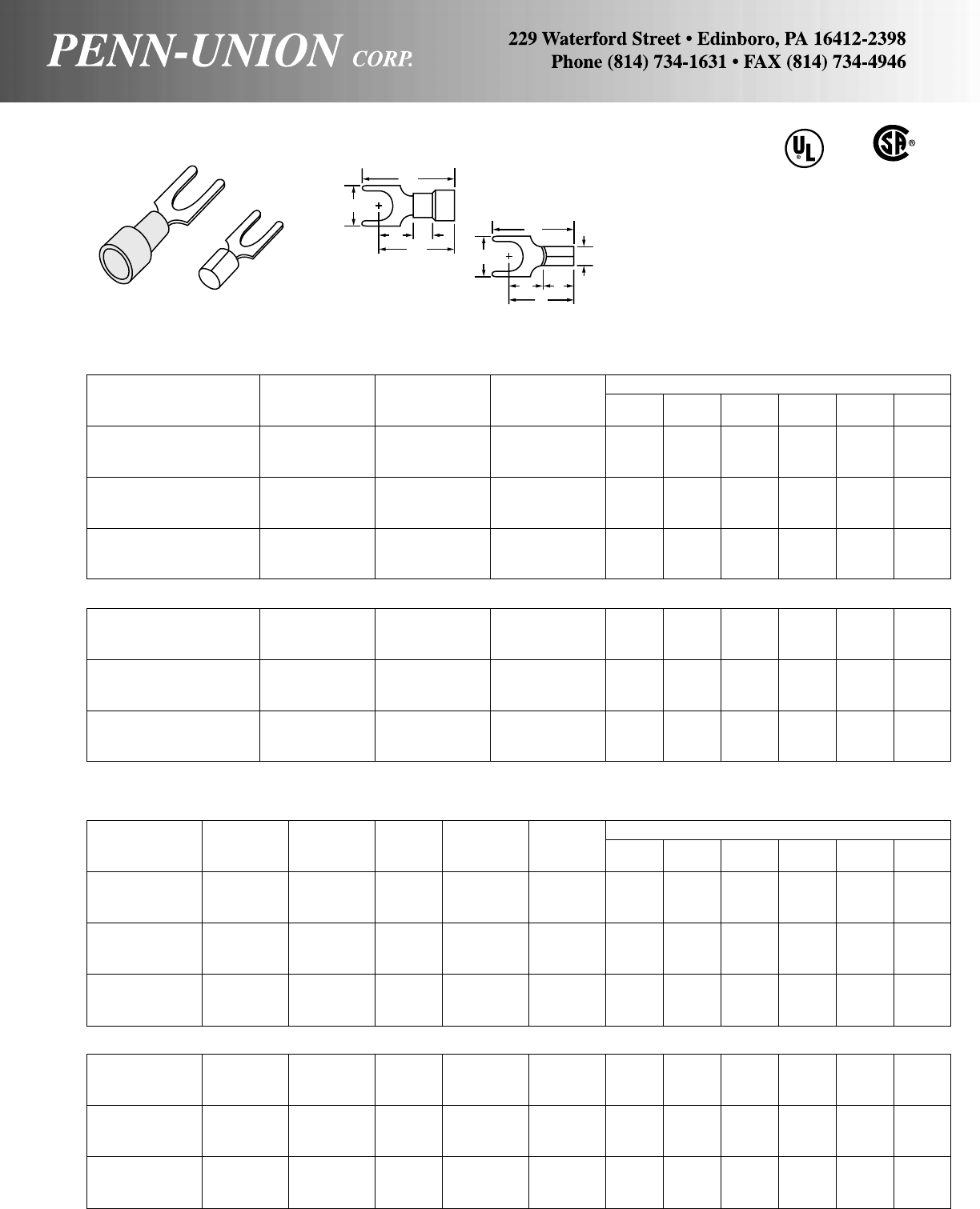
COPPER PENN-CRIMPS® • TYPE S
Made from pure electrolytic copper, electro-
tin plated for protection. Fork design allows
for easy installation because screw need not
be removed. Also available with color coded
nylon or vinyl insulation.
Copper Stock Approx. Dimen. in Inches
Catalog Cond. Stud Size
Number Range Size (in) A W C M B ID
S1A-6 22-18 6 .030 .69 .34 .25 .52 .250 .070
S1A-8 22-18 8 .030 .69 .34 .25 .52 .250 .070
S1A-10 22-18 10 .030 .69 .34 .25 .52 .250 .070
S1B-6 16-14 6 .030 .68 .34 .25 .51 .250 .090
S1B-8 16-14 8 .030 .68 .34 .25 .51 .250 .090
S1B-10 16-14 10 .030 .68 .34 .25 .51 .250 .090
S1C-6 12-10 6 .040 .71 .38 .28 .53 .250 .130
S1C-8 12-10 8 .040 .71 .38 .28 .53 .250 .130
S1C-10 12-10 10 .040 .71 .38 .28 .53 .250 .130
BRAZED SEAM
S2A-6 22-18 6 .030 .69 .34 .25 .52 .250 .070
S2A-8 22-18 8 .030 .69 .34 .25 .52 .250 .070
S2A-10 22-18 10 .030 .69 .34 .25 .52 .250 .070
S2B-6 16-14 6 .030 .68 .34 .25 .51 .250 .090
S2B-8 16-14 8 .030 .68 .34 .25 .51 .250 .090
S2B-10 16-14 10 .030 .68 .34 .25 .51 .250 .090
S2C-6 12-10 6 .040 .71 .38 .28 .53 .250 .130
S2C-8 12-10 8 .040 .71 .38 .28 .53 .250 .130
S2C-10 12-10 10 .040 .71 .38 .28 .53 .250 .130
Copper Color Stock Max. Approx. Dimen. in Inches
Catalog Cond. Stud Code Size Insul.
Number Range Size (ins) (in) Diam. A W C M B ID
S4A-6 22-18 6 R .030 .15 .90 .34 .25 .75 .250 .063
S4A-8 22-18 8 R .030 .15 .90 .34 .25 .75 .250 .063
S4A-10 22-18 10 R .030 .15 .90 .34 .25 .75 .250 .063
S4B-6 16-14 6 B .030 .18 .89 .34 .25 .72 .250 .090
S4B-8 16-14 8 B .030 .18 .89 .34 .25 .72 .250 .090
S4B-10 16-14 10 B .030 .18 .89 .34 .25 .72 .250 .090
S4C-6 12-10 6 Y .040 .26 .99 .38 .28 .79 .250 .130
S4C-8 12-10 8 Y .040 .26 .99 .38 .28 .79 .250 .130
S4C-10 12-10 10 Y .040 .26 .99 .38 .28 .79 .250 .130
NYLON INSULATED - BUTTED SEAM WITH BRASS SLEEVE
S6A-6 22-18 6 R .030 .15 .94 .34 .25 .73 .250 .055
S6A-8 22-18 8 R .030 .15 .94 .34 .25 .73 .250 .065
S6A-10 22-18 10 R .030 .15 .94 .34 .25 .73 .250 .065
S6B-6 16-14 6 B .030 .18 .93 .34 .25 .71 .250 .090
S6B-8 16-14 8 B .030 .18 .93 .34 .25 .71 .250 .090
S6B-10 16-14 10 B .030 .18 .93 .34 .25 .71 .250 .090
S6C-6 12-10 6 Y .040 .26 1.07 .38 .28 .82 .250 .130
S6C-8 12-10 8 Y .040 .26 1.07 .38 .28 .82 .250 .130
S6C-10 12-10 10 Y .040 .26 1.07 .38 .28 .82 .250 .130
INSULATED SPADE TERMINAL
VINYL INSULATED - BUTTED SEAM
NON-INSULATED SPADE TERMINAL
BUTTED SEAM
CU
A
A
W
CB
MW
CB
ID
M
INSULATED
NON-INSULATED
57
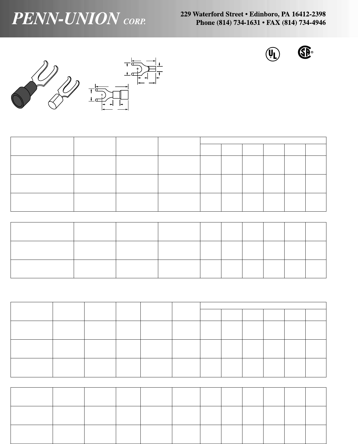
Copper Stock Approx. Dimen. in Inches
Catalog Cond. Stud Size
Number Range Size (in) A W C M B ID
SF1A-6 22-18 6 .030 .69 .34 .25 .51 .250 .070
SF1A-8 22-18 8 .030 .69 .34 .25 .51 .250 .070
SF1A-10 22-18 10 .030 .69 .34 .25 .51 .250 .070
SF1B-6 16-14 6 .030 .69 .34 .25 .55 .250 .090
SF1B-8 16-14 8 .030 .69 .34 .25 .55 .250 .090
SF1B-10 16-14 10 .030 .69 .34 .25 .55 .250 .090
SF1C-6 12-10 6 .040 .75 .39 .28 .53 .250 .130
SF1C-8 12-10 8 .040 .75 .39 .28 .53 .250 .130
SF1C-10 12-10 10 .040 .75 .39 .28 .53 .250 .130
BRAZED SEAM
SF2A-6 22-18 6 .030 .69 .34 .25 .51 .250 .070
SF2A-8 22-18 8 .030 .69 .34 .25 .51 .250 .070
SF2A-10 22-18 10 .030 .69 .34 .25 .51 .250 .070
SF2B-6 16-14 6 .030 .69 .34 .25 .55 .250 .090
SF2B-8 16-14 8 .030 .69 .34 .25 .55 .250 .090
SF2B-10 16-14 10 .030 .69 .34 .25 .55 .250 .090
SF2C-6 12-10 6 .040 .75 .39 .28 .53 .250 .130
SF2C-8 12-10 8 .040 .75 .39 .28 .53 .250 .130
SF2C-10 12-10 10 .040 .75 .39 .28 .53 .250 .130
Copper Color Stock Max. Approx. Dimen. in Inches
Catalog Cond. Stud Code Size Insul.
Number Range Size (ins) (in) Diam. A W C M B ID
SF4A-6 22-18 6 R .030 .15 .91 .34 .25 .73 .250 .065
SF4A-8 22-18 8 R .030 .15 .91 .34 .25 .73 .250 .065
SF4A-10 22-18 10 R .030 .15 .91 .34 .25 .73 .250 .065
SF4B-6 16-14 6 B .030 .18 .91 .34 .25 .73 .250 .090
SF4B-8 16-14 8 B .030 .18 .91 .34 .25 .73 .250 .090
SF4B-10 16-14 10 B .030 .18 .91 .34 .25 .73 .250 .090
SF4C-6 12-10 6 Y .040 .26 1.03 .39 .28 .81 .250 .130
SF4C-8 12-10 8 Y .040 .26 1.03 .39 .28 .81 .250 .130
SF4C-10 12-10 10 Y .040 .26 1.03 .39 .28 .81 .250 .130
NYLON INSULATED - BUTTED SEAM WITH BRASS SLEEVE
SF6A-6 22-18 6 R .030 .15 .91 .34 .25 .73 .250 .065
SF6A-8 22-18 8 R .030 .15 .91 .34 .25 .73 .250 .065
SF6A-10 22-18 10 R .030 .15 .91 .34 .25 .73 .250 .065
SF6B-6 16-14 6 B .030 .18 .91 .34 .25 .73 .250 .090
SF6B-8 16-14 8 B .030 .18 .91 .34 .25 .73 .250 .090
SF6B-10 16-14 10 B .030 .18 .91 .34 .25 .73 .250 .090
SF6C-6 12-10 6 Y .040 .26 1.03 .38 .28 .88 .250 .130
SF6C-8 12-10 8 Y .040 .26 1.03 .38 .28 .88 .250 .130
SF6C-10 12-10 10 Y .040 .26 1.03 .38 .28 .88 .250 .130
INSULATED FLANGE SPADE TERMINAL
VINYL INSULATED - BUTTED SEAM
NON-INSULATED FLANGED SPADE TERMINAL
BUTTED SEAM
COPPER PENN-CRIMPS® • TYPE SF
Turned-up, flanged tips provide extra holding protection. Made
from pure electrolytic copper, tin plated for corrosion resistance.
Insulated versions are also available. PVC vinyl insulation forms
insulation support for the crimped wire to avoid flexing. Nylon
insulation protects against extreme vibration and weather. Ex-
ceeds all UL and CSA requirements.
CU
A
W
CB
ID
M
A
W
CB
M
NON-INSULATED
INSULATED
58
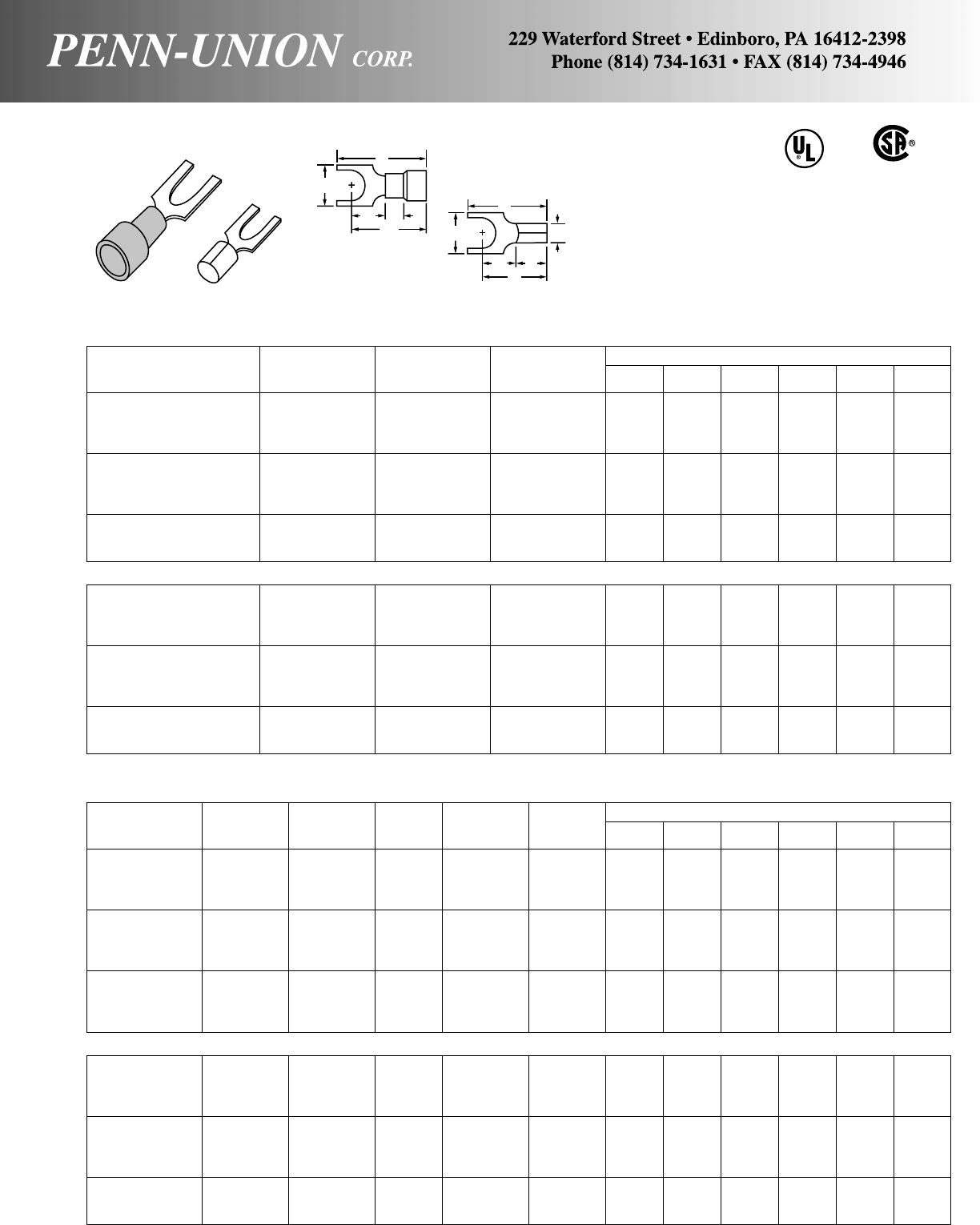
Copper Stock Approx. Dimen. in Inches
Catalog Cond. Stud Size
Number Range Size (in) A W C M B ID
BS1A-6 22-18 6 .030 .66 .29 .25 .50 .250 .070
BS1A-6S 22-18 6 .030 .61 .25 .25 .50 .250 .070
BS1A-8 22-18 8 .030 .66 .31 .25 .50 .250 .070
BS1A-10 22-18 10 .030 .66 .31 .25 .50 .250 .070
BS1B-6 16-14 6 .030 .66 .29 .25 .50 .250 .090
BS1B-6S 16-14 6 .030 .61 .25 .25 .50 .250 .090
BS1B-8 16-14 8 .030 .66 .31 .25 .50 .250 .090
BS1B-10 16-14 10 .030 .66 .31 .25 .50 .250 .090
BS1C-6 12-10 6 .040 .71 .31 .28 .53 .250 .130
BS1C-8 12-10 8 .040 .71 .31 .28 .53 .250 .130
BS1C-10 12-10 10 .040 .71 .31 .28 .53 .250 .130
BRAZED SEAM
BS2A-6 22-18 6 .030 .66 .29 .25 .50 .245 .070
BS2A-6S 22-18 6 .030 .61 .25 .25 .50 .245 .070
BS2A-8 22-18 8 .030 .66 .31 .25 .50 .245 .070
BS2A-10 22-18 10 .030 .66 .31 .25 .50 .245 .070
BS2B-6 16-14 6 .030 .66 .29 .25 .50 .250 .090
BS2B-6S 16-14 6 .030 .61 .25 .25 .50 .250 .090
BS2B-8 16-14 8 .030 .66 .31 .25 .50 .240 .090
BS2B-10 16-14 10 .030 .66 .31 .25 .50 .250 .090
BS2C-6 12-10 6 .040 .71 .31 .28 .53 .250 .130
BS2C-8 12-10 8 .040 .71 .31 .28 .53 .250 .130
BS2C-10 12-10 10 .040 .71 .31 .28 .53 .250 .130
Copper Color Stock Max. Approx. Dimen. in Inches
Catalog Cond. Stud Code Size Insul.
Number Range Size (ins) (in) Diam. A W C M B ID
BS4A-6 22-18 6 R .030 .15 .88 .29 .25 .72 .250 .070
BS4A-6S 22-18 6 R .030 .15 .84 .25 .25 .73 .250 .070
BS4A-8 22-18 8 R .030 .15 .88 .31 .25 .72 .250 .070
BS4A-10 22-18 10 R .030 .15 .88 .31 .25 .72 .250 .070
BS4B-6 16-14 6 B .030 .18 .88 .29 .25 .72 .250 .090
BS4B-6S 16-14 6 B .030 .18 .84 .25 .33 .81 .250 .090
BS4B-8 16-14 8 B .030 .19 .88 .31 .25 .72 .250 .090
BS4B-10 16-14 10 B .030 .19 .88 .31 .25 .72 .250 .090
BS4C-6 12-10 6 Y .040 .26 1.01 .31 .28 .83 .250 .130
BS4C-8 12-10 8 Y .040 .26 1.01 .31 .28 .83 .250 .130
BS4C-10 12-10 10 Y .040 .26 1.01 .31 .28 .83 .250 .130
BS4C-14 12-10 1/4Y.040 .26 1.29 .49 .45 1.03 .250 .130
NYLON INSULATED - BUTTED SEAM WITH BRASS SLEEVE
BS6A-6 22-18 6 R .030 .15 .88 .29 .25 .74 .250 .070
BS6A-6S 22-18 6 R .030 .15 .84 .25 .25 .78 .250 .070
BS6A-8 22-18 8 R .030 .15 .88 .31 .25 .74 .250 .070
BS6A-10 22-18 10 R .030 .15 .88 .31 .25 .74 .250 .070
BS6B-6 16-14 6 B .030 .18 .88 .29 .25 .74 .250 .090
BS6B-6S 16-14 6 B .030 .18 .84 .25 .25 .78 .250 .090
BS6B-8 16-14 8 B .030 .18 .88 .31 .25 .74 .250 .090
BS6B-10 16-14 10 B .030 .18 .88 .31 .25 .74 .250 .090
BS6C-6 12-10 6 Y .040 .26 1.01 .31 .28 .83 .250 .130
BS6C-8 12-10 8 Y .040 .26 1.01 .31 .28 .83 .250 .130
BS6C-10 12-10 10 Y .040 .26 1.01 .31 .28 .83 .250 .130
INSULATED BLOCK SPADE TERMINAL
VINYL INSULATED - BUTTED SEAM
NON-INSULATED BLOCK SPADE TERMINAL
BUTTED SEAM
COPPER PENN-CRIMPS® • TYPE BS
Made from pure electrolytic copper, electro-tin plated for
protection. Block spade design, featuring squared-off
ends, allows for easy installation because screw need
not be removed. Also available with color coded nylon or
vinyl insulation.
CU
A
W
CB
M
A
W
CB
M
ID
NON-INSULATED
INSULATED
59
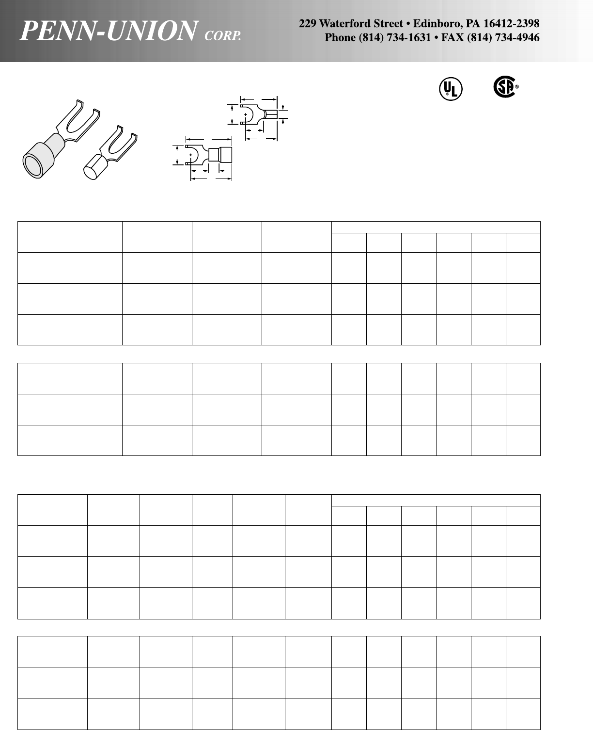
Copper Stock Approx. Dimen. in Inches
Catalog Cond. Stud Size
Number Range Size (in) A W C M B ID
BSF1A-6 22-18 6 .030 .66 .29 .25 .50 .250 .070
BSF1A-8 22-18 8 .030 .66 .31 .25 .50 .250 .070
BSF1A-10 22-18 10 .030 .66 .31 .25 .50 .250 .070
BSF1B-6 16-14 6 .030 .66 .29 .25 .50 .250 .090
BSF1B-8 16-14 8 .030 .66 .31 .25 .50 .250 .090
BSF1B-10 16-14 10 .030 .66 .31 .25 .50 .250 .090
BSF1C-6 12-10 6 .040 .71 .31 .28 .53 .250 .130
BSF1C-8 12-10 8 .040 .71 .31 .28 .53 .250 .130
BSF1C-10 12-10 10 .040 .71 .31 .28 .53 .250 .130
BRAZED SEAM
BSF2A-6 22-18 6 .030 .66 .29 .25 .50 .250 .070
BSF2A-8 22-18 8 .030 .66 .31 .25 .50 .250 .070
BSF2A-10 22-18 10 .030 .66 .31 .25 .50 .250 .070
BSF2B-6 16-14 6 .030 .66 .29 .25 .50 .250 .090
BSF2B-8 16-14 8 .030 .66 .31 .25 .50 .250 .090
BSF2B-10 16-14 10 .030 .66 .31 .25 .50 .250 .090
BSF2C-6 12-10 6 .040 .71 .31 .28 .53 .250 .130
BSF2C-8 12-10 8 .040 .71 .31 .28 .53 .250 .130
BSF2C-10 12-10 10 .040 .71 .31 .28 .53 .250 .130
Copper Color Stock Max. Approx. Dimen. in Inches
Catalog Cond. Stud Code Size Insul.
Number Range Size (ins) (in) Diam. A W C M B ID
BSF4A-6 22-18 6 R .030 .15 .87 .29 .25 .71 .250 .070
BSF4A-8 22-18 8 R .030 .15 .87 .31 .25 .71 .250 .070
BSF4A-10 22-18 10 R .030 .15 .87 .31 .25 .71 .250 .070
BSF4B-6 16-14 6 B .030 .18 .87 .29 .25 .71 .250 .090
BSF4B-8 16-14 8 B .030 .18 .87 .31 .25 .71 .250 .090
BSF4B-10 16-14 10 B .030 .18 .87 .31 .25 .71 .250 .090
BSF4C-6 12-10 6 Y .040 .26 .98 .31 .28 .80 .250 .130
BSF4C-8 12-10 8 Y .040 .26 .98 .31 .28 .80 .250 .130
BSF4C-10 12-10 10 Y .040 .26 .98 .31 .28 .80 .250 .130
NYLON INSULATED - BUTTED SEAM WITH BRASS SLEEVE
BSF6A-6 22-18 6 R .030 .15 .87 .29 .25 .71 .250 .070
BSF6A-8 22-18 8 R .030 .15 .87 .31 .25 .71 .250 .070
BSF6A-10 22-18 10 R .030 .15 .87 .31 .25 .71 .250 .070
BSF6B-6 16-14 6 B .030 .18 .90 .29 .25 .74 .250 .090
BSF6B-8 16-14 8 B .030 .18 .90 .31 .25 .74 .250 .090
BSF6B-10 16-14 10 B .030 .18 .90 .31 .25 .74 .250 .090
BSF6C-6 12-10 6 Y .040 .26 1.06 .31 .28 .88 .250 .130
BSF6C-8 12-10 8 Y .040 .26 1.06 .31 .28 .88 .250 .130
BSF6C-10 12-10 10 Y .040 .26 1.06 .31 .28 .88 .250 .130
INSULATED BLOCK SPADE FLANGED TERMINAL
VINYL INSULATED - BUTTED SEAM
NON-INSULATED BLOCK SPADE FLANGED TERMINAL
BUTTED SEAM
COPPER PENN-CRIMPS® • TYPE BSF
Made from pure electrolytic copper, electro-tin plated for
protection. Block spade design allows for easy installa-
tion because screw need not be removed. Flanged tips
provide extra holding protection, especially where vibra-
tion occurs. Also available with NEMA color coded nylon
or vinyl insulation. Exceeds all UL and CSA requirements.
CU
A
W
C
M
A
W
CB
M
ID
NON-INSULATED
INSULATED
60
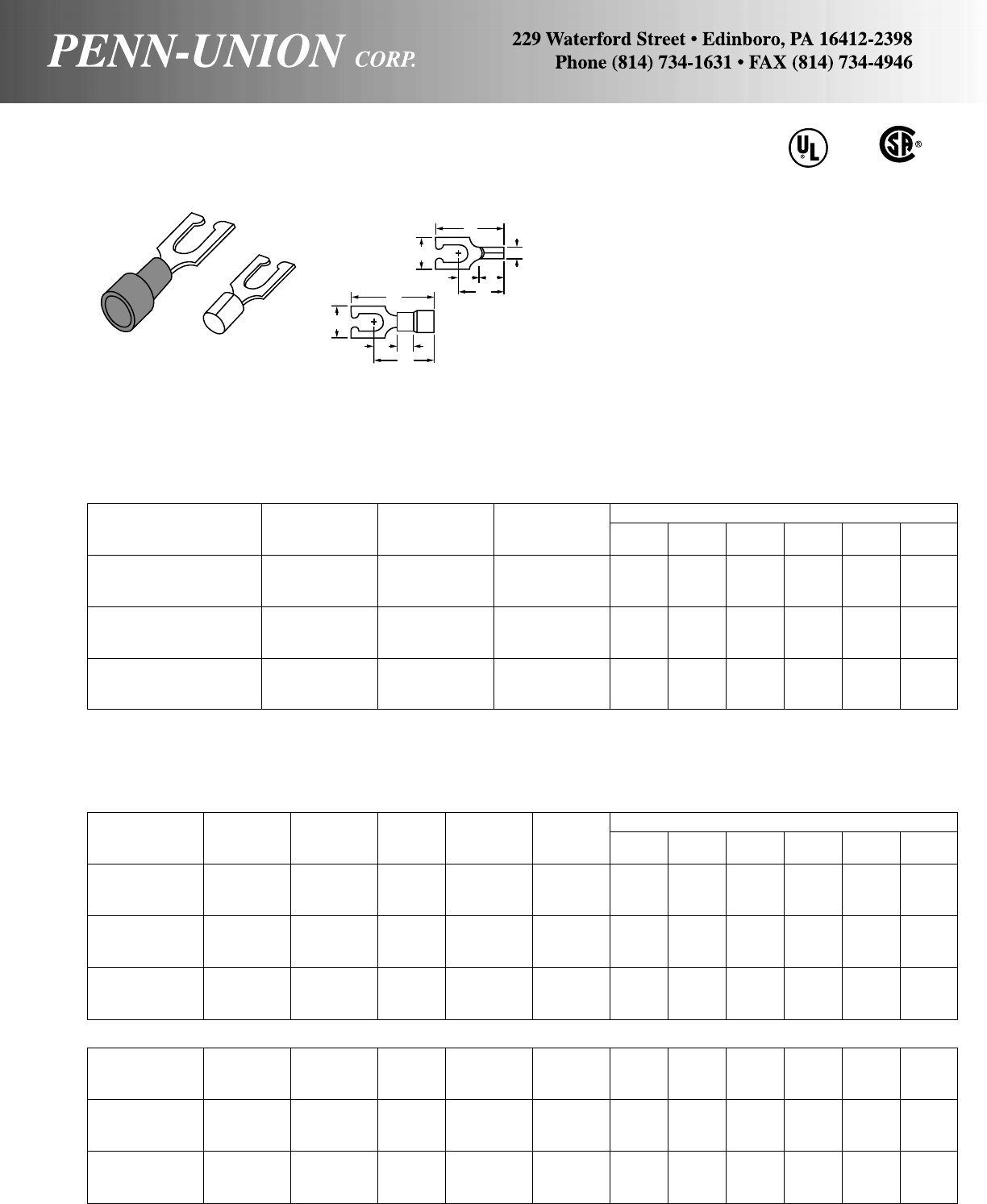
Copper Stock Approx. Dimen. in Inches
Catalog Cond. Stud Size
Number Range Size (in) A W C M B ID
LS1A-6 22-18 6 .030 .66 .29 .25 .50 .250 .070
LS1A-8 22-18 8 .030 .66 .31 .25 .50 .250 .070
LS1A-10 22-18 10 .030 .66 .31 .25 .50 .250 .070
LS1B-6 16-14 6 .030 .66 .29 .25 .50 .250 .090
LS1B-8 16-14 8 .030 .66 .31 .25 .50 .250 .090
LS1B-10 16-14 10 .030 .66 .31 .25 .50 .250 .090
LS1C-6 12-10 6 .040 .71 .31 .28 .54 .250 .130
LS1C-8 12-10 8 .040 .71 .31 .28 .54 .250 .130
LS1C-10 12-10 10 .040 .71 .31 .28 .54 .250 .130
Copper Color Stock Max. Approx. Dimen. in Inches
Catalog Cond. Stud Code Size Insul.
Number Range Size (ins) (in) Diam. A W C M B ID
LS4A-6 22-18 6 R .030 .15 .87 .29 .25 .70 .250 .070
LS4A-8 22-18 8 R .030 .15 .87 .31 .25 .70 .250 .070
LS4A-10 22-18 10 R .030 .15 .87 .31 .25 .70 .250 .070
LS4B-6 16-14 6 B .030 .18 .87 .29 .25 .70 .250 .090
LS4B-8 16-14 8 B .030 .18 .87 .31 .25 .70 .250 .090
LS4B-10 16-14 10 B .030 .18 .87 .31 .25 .70 .250 .090
LS4C-6 12-10 6 Y .040 .26 .96 .31 .28 .80 .250 .130
LS4C-8 12-10 8 Y .040 .26 .96 .31 .28 .80 .250 .130
LS4C-10 12-10 10 Y .040 .26 .96 .31 .28 .80 .250 .130
NYLON INSULATED - BUTTED SEAM WITH BRASS SLEEVE
LS6A-6 22-18 6 R .030 .15 .90 .29 .25 .73 .250 .070
LS6A-8 22-18 8 R .030 .15 .90 .31 .25 .73 .250 .070
LS6A-10 22-18 10 R .030 .15 .90 .31 .25 .73 .250 .070
LS6B-6 16-14 6 B .030 .18 .90 .29 .25 .73 .250 .090
LS6B-8 16-14 8 B .030 .18 .90 .31 .25 .73 .250 .090
LS6B-10 16-14 10 B .030 .18 .90 .31 .25 .73 .250 .090
LS6C-6 12-10 6 Y .040 .26 1.06 .31 .28 .89 .250 .130
LS6C-8 12-10 8 Y .040 .26 1.06 .31 .28 .89 .250 .130
LS6C-10 12-10 10 Y .040 .26 1.06 .31 .28 .89 .250 .130
INSULATED LOCKING SPADE TERMINAL
VINYL INSULATED - BUTTED SEAM
NON-INSULATED LOCKING SPADE TERMINAL
BUTTED SEAM
COPPER PENN-CRIMPS® • TYPE LS
Made from pure electrolytic copper, electro-tin plated for
protection. Fork design allows for easy installation because
screw need not be removed. Locking feature combines
additional security with the convenience of a spade termi-
nal. Also available with NEMA color coded nylon or vinyl
insulation. Exceeds all UL and CSA requirements.
CU
A
WID
CB
M
A
W
CM
B
NON-INSULATED
INSULATED
61
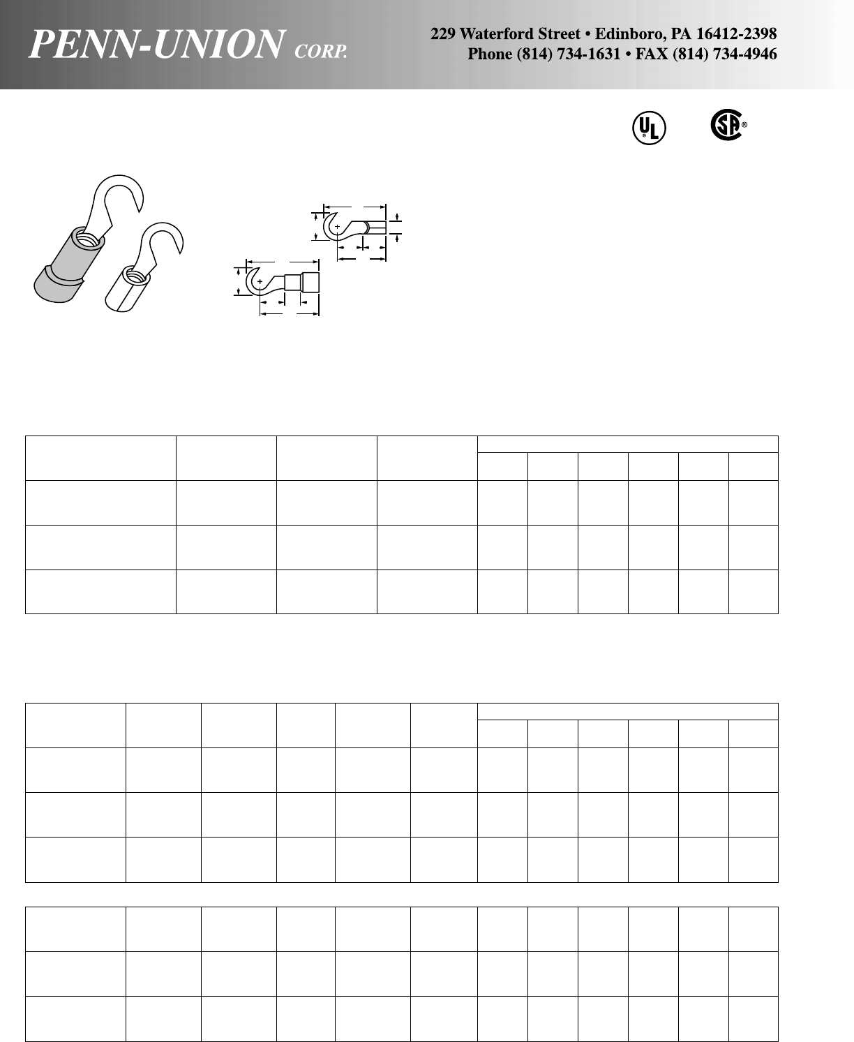
Copper Stock Approx. Dimen. in Inches
Catalog Cond. Stud Size
Number Range Size (in) A W C M B ID
H1A-6 22-18 6 .030 .69 .34 .25 .54 .250 .070
H1A-8 22-18 8 .030 .69 .34 .25 .54 .250 .070
H1A-10 22-18 10 .030 .69 .34 .25 .54 .250 .070
H1B-6 16-14 6 .030 .69 .34 .25 .54 .250 .090
H1B-8 16-14 8 .030 .69 .34 .25 .54 .250 .090
H1B-10 16-14 10 .030 .69 .34 .25 .54 .250 .090
H1C-6 12-10 6 .040 .72 .38 .28 .54 .250 .130
H1C-8 12-10 8 .040 .72 .38 .28 .54 .250 .130
H1C-10 12-10 10 .040 .72 .38 .28 .54 .250 .130
Copper Color Stock Max. Approx. Dimen. in Inches
Catalog Cond. Stud Code Size Insul.
Number Range Size (ins) (in) Diam. A W C M B ID
H4A-6 22-18 6 R .030 .15 1.01 .34 .25 .85 .250 .070
H4A-8 22-18 8 R .030 .15 1.01 .34 .25 .85 .250 .070
H4A-10 22-18 10 R .030 .15 1.01 .34 .25 .85 .250 .070
H4B-6 16-14 6 B .030 .18 .93 .34 .25 .78 .250 .090
H4B-8 16-14 8 B .030 .18 .93 .34 .25 .78 .250 .090
H4B-10 16-14 10 B .030 .18 .93 .34 .25 .78 .250 .090
H4C-6 12-10 6 Y .040 .26 .99 .38 .28 .80 .250 .130
H4C-8 12-10 8 Y .040 .26 .99 .38 .28 .80 .250 .130
H4C-10 12-10 10 Y .040 .26 .99 .38 .28 .80 .250 .130
NYLON INSULATED - BUTTED SEAM WITH BRASS SLEEVE
H6A-6 22-18 6 R .030 .15 .93 .34 .25 .78 .250 .070
H6A-8 22-18 8 R .030 .15 .93 .34 .25 .78 .250 .070
H6A-10 22-18 10 R .030 .15 .93 .34 .25 .78 .250 .070
H6B-6 16-14 6 B .030 .18 .93 .34 .25 .78 .250 .090
H6B-8 16-14 8 B .030 .18 .93 .34 .25 .78 .250 .090
H6B-10 16-14 10 B .030 .18 .93 .34 .25 .78 .250 .090
H6C-6 12-10 6 Y .040 .26 1.00 .38 .28 .81 .250 .130
H6C-8 12-10 8 Y .040 .26 1.00 .38 .28 .81 .250 .130
H6C-10 12-10 10 Y .040 .26 1.00 .38 .28 .81 .250 .130
INSULATED HOOK TERMINAL
VINYL INSULATED - BUTTED SEAM
NON-INSULATED HOOK TERMINAL
BUTTED SEAM
COPPER PENN-CRIMPS® • TYPE H
Made with high conductivity, electrolytic copper, annealed
and electro-tin plated to resist corrosion. Hook design al-
lows for easy installation because mounting screw need not
be removed. Available non-insulated or with NEMA color
coded nylon or vinyl insulation. Insulation is flared for wire
insulation support. The combination of these features and
the fact that our products exceed UL and CSA requirements
guarantee a high quality connection.
CU
A
WID
CB
M
A
W
CB
M
INSULATED
NON-INSULATED
62
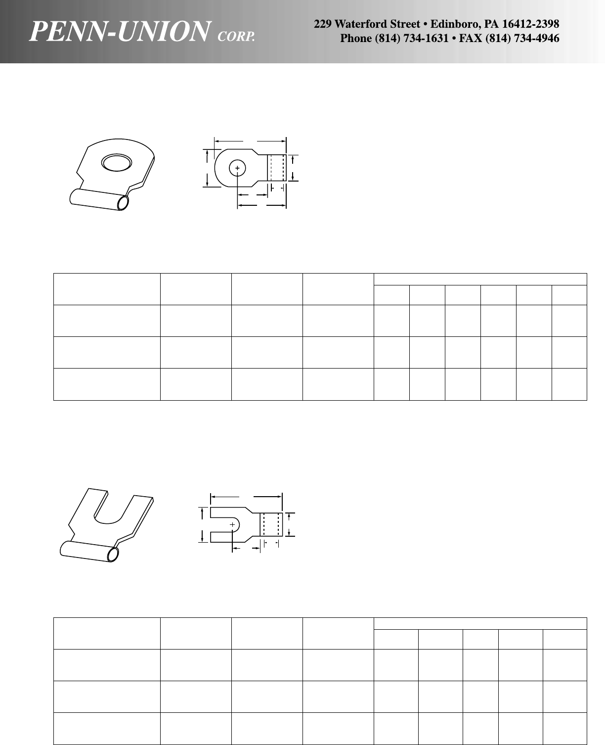
COPPER PENN-CRIMPS® • TYPE FLR
One piece, annealed, pure electrolytic copper construction,
electro-tin plated for corrosion resistance. Flag base accepts wire
through side opening, allowing ninety degree connections with-
out bending the wire. Type FLR connectors are made to exceed
standards for reliability and durability, guaranteeing a high qual-
ity connection.
Copper Stock Appox. Dimen. in Inches
Catalog Cond. Stud Size
Number Range Size (in.) A W C M B ID
FLR1A-6 22-18 6 .030 .66 .38 .34 .47 .250 .070
FLR1A-8 22-18 8 .030 .66 .38 .34 .47 .250 .070
FLR1A-10 22-18 10 .030 .66 .38 .34 .47 .250 .070
FLR1B-6 16-14 6 .030 .69 .38 .34 .47 .250 .090
FLR1B-8 16-14 8 .030 .69 .38 .34 .47 .250 .090
FLR1B-10 16-14 10 .030 .69 .38 .34 .47 .250 .090
FLR1C-6 12-10 6 .040 .69 .38 .28 .47 .250 .130
FLR1C-8 12-10 8 .040 .69 .38 .28 .47 .250 .130
FLR1C-10 12-10 10 .040 .69 .38 .28 .47 .250 .130
NON-INSULATED RING FLAG TERMINAL
BUTTED SEAM
COPPER PENN-CRIMPS® • TYPE FLS
Copper Stock Approx. Dimen. in Inches
Catalog Cond. Stud Size
Number Range Size (in.) A W C B ID
FLS1A-6 22-18 6 .030 .66 .38 .34 .250 .070
FLS1A-8 22-18 8 .030 .66 .38 .34 .250 .070
FLS1A-10 22-18 10 .030 .66 .38 .34 .250 .070
FLS1B-6 16-14 6 .030 .69 .38 .34 .250 .090
FLS1B-8 16-14 8 .030 .69 .38 .34 .250 .090
FLS1B-10 16-14 10 .030 .69 .38 .34 .250 .090
FLS1C-6 12-10 6 .040 .69 .38 .34 .250 .130
FLS1C-8 12-10 8 .040 .69 .38 .34 .250 .130
FLS1C-10 12-10 10 .040 .69 .38 .34 .250 .130
NON-INSULATED SPADE FLAG TERMINAL
BUTTED SEAM
Made with the same high quality copper construction as Type
FLR terminals. FLS terminals have a fork design which allows
easy installation because mounting screw need not be removed.
Also provides side entrance hole permitting ninety degree con-
nections without bending the wire.
A
WB
C
M
ID
A
WB
CID
63
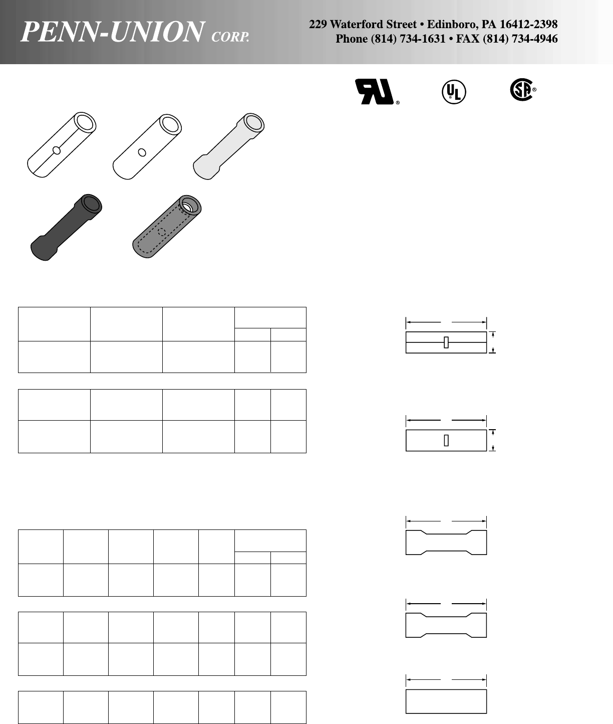
COPPER PENN-CRIMPS® • TYPE B
Pure electrolytic copper connectors, annealed and tin plated, with
internal wire stops to assure wires reach proper insertion length
before butting together. Crimping occurs at each end of the splice.
Available non-insulated, nylon insulated and vinyl insulated. Type
7 seamless construction provides extra crimp strength. Type 8 is
pre-insulated with high quality nylon which extends beyond the
metal splice to enclose wire insulation after crimping. Especially
suited to applications where excessive vibration problems occur.
NON-INSULATED BUTT CONNECTOR
BUTTED SEAM
Copper Stock Approx. Dimen.
Catalog Cond. Size in Inches
Number Range (in) A ID
B1A 22-18 .030 .57 .070
B1B 16-14 .030 .57 .090
B1C 12-10 .040 .57 .130
SEAMLESS
B7A 22-18 .030 .62 .055
B7B 16-14 .030 .66 .090
B7C 12-10 .040 .82 .142
B7E + 8 .050 .82 .172
B7F + 6 .050 1.01 .226
B7G + 4 .075 1.13 .300
INSULATED BUTT CONNECTOR
VINYL INSULATED - SEAMLESS
Copper Stock Color Max. Approx. Dimen.
Catalog Cond. Size Code Insul. in Inches
Number Range (in) (ins) Diam. A ID
B4AB 22-18 .030 R .160 .95 .055
B4BB 16-14 .030 B .190 1.02 .090
B4CB 12-10 .040 Y .255 1.01 .142
VINYL INSULATED
B4A 22-18 .030 R .160 .95 .068
B4B 16-14 .030 B .190 1.02 .090
B4C 12-10 .040 Y .265 1.01 .130
B4E *+ 8 .050 R .300 1.46 .172
B4F *+ 6 .050 B .425 1.80 .226
B4G *+ 4 .075 Y .520 1.95 .300
NYLON INSULATED - SEAMLESS
B8A 22-18 .030 R .120 1.01 .055
B8B 16-14 .030 B .155 1.02 .055
B8C 12-10 .040 Y .215 1.20 .142
*UL component recognized
+Not CSA listed
CU
A
ID
ID
A
A
A
A
64

COPPER PENN-CRIMPS® • TYPE P
Made with the same high quality, one piece construction as the
Butt connectors. Parallel connectors are wider and shorter, per-
mitting wires to lay side by side inside connectors. This allows
simplicity of installation because only one crimp is needed to
complete the splice. Compact size is beneficial in small areas.
Available non-insulated and with nylon insulation or vinyl insula-
tion. Seamless Type 7 construction provides extra crimp strength.
Exceeds UL requirements to guarantee a high quality connection.
CU
Copper Stock Approx. Dimen.
Catalog Cond. Size in Inches
Number Range (in) A ID
P1A + 22-18 .030 .31 .070
P1B 16-14 .030 .31 .090
P1C 12-10 .040 .31 .130
SEAMLESS
P7E * 8 .050 .44 .175
P7F * 6 .050 .48 .226
P7G * 4 .075 .53 .300
+CSA Listed
*Not UL listed
NON-INSULATED PARALLEL CONNECTOR
BUTTED SEAM
INSULATED PARALLEL CONNECTOR
VINYL - BUTTED SEAM
Copper Color Stock Max. Approx. Dimen.
Catalog Cond. Code Size Insul. in Inches
Number Range (ins) (in) Diam. A B ID
P4A * 22-18 R .030 .15 .69 .313 .070
P4B 20-16 B .030 .18 .69 .313 .090
P4C 18-12 Y .040 .24 .78 .313 .130
P4E ** 16-10 R .050 .35 1.00 .438 .175
P4F ** 14-6 B .050 .43 1.19 .484 .226
*Not UL listed
**UL component recognized
COPPER PENN-CRIMPS® • TYPES NPAB AND NPBC
One piece, annealed, pure electrolytic copper with nylon pre-
insulation. Suited exclusively for copper to copper connections.
Expanded nylon insulation provides support for wire insulation.
Seamless insert provides extra crimp strength. Exceeds all UL
requirements.
Approx. Dimen.
Catalog Copper Cond. in Inches Crimp
Number Range A Length
NPAB1 22-14 .63 .30
NPBC1 22-10 .69 .28
NYLON PIGTAILS - SEAMLESS
CU
C
A
C
A
A
A
ID
ID
B
65
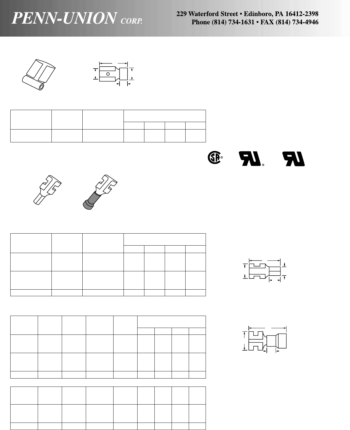
COPPER PENN-CRIMPS® • TYPE FLFR
One piece, pure electrolytic copper, annealed and tin plated for
corrosion resistance. Type FLFR features a side entrance cham-
fer to permit connections of ninety degrees without bending the
wire. Provides quick, reliable snap-together interconnections with-
out the use of tools. Made with Penn-Crimps quality to assure
maximum longevity and productivity.
NON-INSULATED FEMALE DISCONNECTS
BUTTED SEAM
Copper Tab Approximate Dimensions
Catalog Cond. Size in Inches
Number Range (in) A W B ID
FR1A110 * 22-18 .020 x .110 .54 .16 .220 .070
FR1A187 * 22-18 .020 x .187 .63 .23 .250 .070
FR1A250 * 22-18 .032 x .250 .63 .31 .234 .070
FR1B110 * 16-14 .020 x .110 .54 .16 .220 .110
FR1B187 * 16-14 .020 x .187 .63 .23 .250 .070
FR1B250 * 16-14 .032 x .250 .63 .31 .234 .090
FR1C250 * 12-10 .032 x .250 .63 .31 .234 .170
FEMALE FLAG DISCONNECTS - BUTTED SEAM
Copper Tab Approximate Dimensions
Catalog Cond. Size in Inches
Number Range (in) A W B ID
FLFR1A-250 22-18 .020 .50 .25 .250 .070
FLFR1B-250 16-14 .020 .50 .25 .250 .090
COPPER PENN-CRIMPS® • TYPE FR
One piece, high grade copper alloy construction with electro-tin
plating for corrosion resistance. Snap-together construction of
mating male and female disconnects provides quick, reliable in-
terconnections without tools. Quality crafted for long term
dependability and performance.
INSULATED FEMALE DISCONNECTS
VINYL INSULATED - BUTTED SEAM
Copper Color Tab Max. Approximate Dimensions
Catalog Cond. Code Size Insul. in Inches
Number Range (ins) (in) Diam. A W B ID
FR4A110 22-18 R .020 x .110 .14 .77 .16 .220 .050
FR4A187 22-18 R .020 x .187 .14 .86 .23 .172 .070
FR4A250 22-18 R .032 x .250 .14 .93 .31 .234 .070
FR4B110 16-14 B .020 x .110 .14 .77 .16 .220 .070
FR4B187 16-14 B .020 x .187 .14 .87 .23 .172 .070
FR4B250 16-14 B .032 x .250 .14 .87 .31 .234 .070
FR4C250 † 12-10 Y .032 x .250 .25 1.08 .31 .234 .136
NYLON INSULATED - BUTTED SEAM WITH BRASS SLEEVE
FR6A110 22-18 R .020 x .110 .12 .77 .16 .220 .050
FR6A187 22-18 R .020 x .187 .12 .87 .23 .250 .070
FR6A250 22-18 R .032 x .250 .12 .87 .32 .234 .070
FR6B110 16-14 B .020 x .110 .14 .77 .16 .220 .070
FR6B187 16-14 B .020 x .187 .14 .87 .23 .172 .070
FR6B250 16-14 B .032 x .250 .14 .87 .32 .234 .070
FR6C250 * 12-10 Y .032 x .250 .25 .97 .31 .234 .136
*Not UL listed or recognized †CSA Certified
A
WB
ID
C
®
A
W
B
ID
W
A
B
66
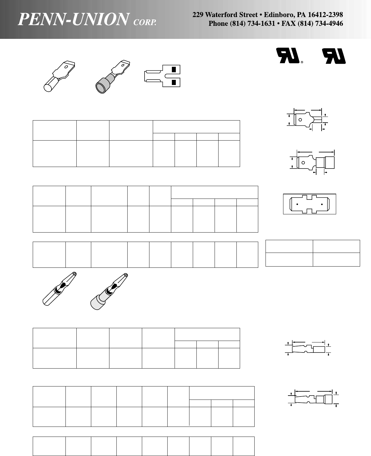
Copper Tab Color Max. Approximate Dimensions
Catalog Cond. Size Code Insul. in Inches
Number Range (in) (ins) Diam. A W B ID
MT4A250 22-18 .032 x .250 R .14 .97 .25 .250 .050
MT4B187 16-14 .020 x .187 B .17 .82 .19 .170 .090
MT4B250 16-14 .032 x .250 B .17 .97 .25 .250 .090
MT4C250 12-10 .032 x .250 Y .25 1.05 .25 .250 .130
NYLON INSULATED - BUTTED SEAM WITH BRASS SLEEVE
MT6A250 22-18 .032 x .250 R .14 .94 .25 .250 .050
MT6B187 16-14 .020 x .187 B .17 .80 .19 .170 .090
MT6B250 16-14 .032 x .250 B .17 .94 .25 .250 .090
MT6C250 12-10 .032 x .250 Y .25 1.05 .25 .250 .130
COPPER PENN-CRIMPS® • TYPE MT
NON-INSULATED MALE DISCONNECT
BUTTED SEAM
Copper Tab Approximate Dimensions
Catalog Cond. Size in Inches
Number Range (in) A W B ID
MT1A250 * 22-18 .032 x .250 .72 .25 .250 .050
MT1B187 * 16-14 .020 x .187 .51 .19 .170 .090
MT1B250 * 16-14 .032 x .250 .72 .25 .250 .090
MT1C250 * 12-10 .032 x .250 .77 .25 .250 .130
INSULATED MALE DISCONNECT
VINYL INSULATED - BUTTED SEAM
TYPES SC AND LC
One piece, annealed, pure electrolytic copper construction,
electro-tin plated for protection. Provides quick, reliable snap-on
interconnections without tools. Available non-insulated or with
NEMA color coded nylon or vinyl insulation. Insulation is flared
for wire insulation support.
NON-INSULATED MALE SNAP PLUGS
BUTTED SEAM
Copper Stock Approximate Dimensions
Catalog Cond. Size Stud in Inches
Number Range (in) Size A W ID
SC1A * 22-18 .020 .156 .71 .156 .064
SC1B * 16-14 .030 .156 .60 .156 .090
LC1B * 16-14 .030 .176 .57 .176 .090
ADAPTER AND COUPLER
Catalog Tab Size
Number (In)
MDT-250 * .032 x .250
MMFA * .032 x .250
INSULATED MALE SNAP PLUG
VINYL INSULATED - BUTTED SEAM
Copper Stock Color Max. Approximate Dimensions
Catalog Cond. Size Stud Code Insul. in Inches
Number Range (in) Size (Ins) Diam. A W ID
SC4A • 22-18 .020 .156 R .14 .92 .156 .064
SC4B * 16-14 .030 .156 B .17 .88 .156 .090
LC4B * 16-14 .030 .176 B .17 .86 .176 .090
NYLON INSULATED - BUTTED SEAM WITH BRASS SLEEVE
SC6A * 22-18 .020 .156 R .14 .92 .156 .064
SC6B * 16-14 .030 .156 B .17 .90 .156 .090
LC6B * 16-14 .030 .176 B .17 .88 .176 .090
*Not UL component recognized, nor certified for Canada.
MMFA
ADAPTER
One piece, high grade copper alloy construction wiith electro-tin
plating for corrosion resistance. Male tabs match female discon-
nects to provide strong, reliable slip-on interconnects without the
use of tools. These and other features combine to guarantee a
high quality connection.
A
W
B
ID
A
W
B
MDT-250
COUPLER
A
WID
A
WID
C
®
67

COPPER PENN-CRIMPS® • TYPES FDC AND FSC
Nylon insulated, high strength spring quality connector. Locking
feature provided to hold male snap plug securely in place while
providing all the benefits of a two way quick disconnect. As with
all Penn-Crimps the highest quality is assured.
FEMALE CONNECTOR
DOUBLE
Copper Stock Approx. Dimen.
Catalog Cond. Stud Size in Inches
Number Range Size (in) A
FDC-156 16-14 .156 .020 1.38
SINGLE
FSCA-156F 22-18 .156 .020 1.025
FSC-156F 16-14 .156 .020 1.025
COPPER PENN-CRIMPS® • TYPES CFR AND CM
Same high quality construction as Types FR and M female and
male disconnects. Both CFR and CM disconnects feature full
length nylon insulation which extends beyond the metal terminal
insert to provide a completely insulated two piece connection,
which is protected against accidental shorting. Exceeds UL stan-
dards to produce a high quality connection.
FULLY INSULATED MALE AND FEMALE DISCONNECTS
FEMALE
Copper Tab Max. Approximate Dimensions
Catalog Cond. Size Insul. in Inches
Number Range (in) Diam. A W ID
CFR4NA250F 22-18 .032 x .250 .15 .98 .39 .070
CFR4NB250F 16-14 .032 x .250 .18 .98 .39 .090
MALE
CM4TNA250F 22-18 .032 x .250 .15 1.02 .47 .050
CM4TNB250F 16-14 .032 x .250 .18 1.02 .47 .090
A
A
A
W
FDC FSC
68
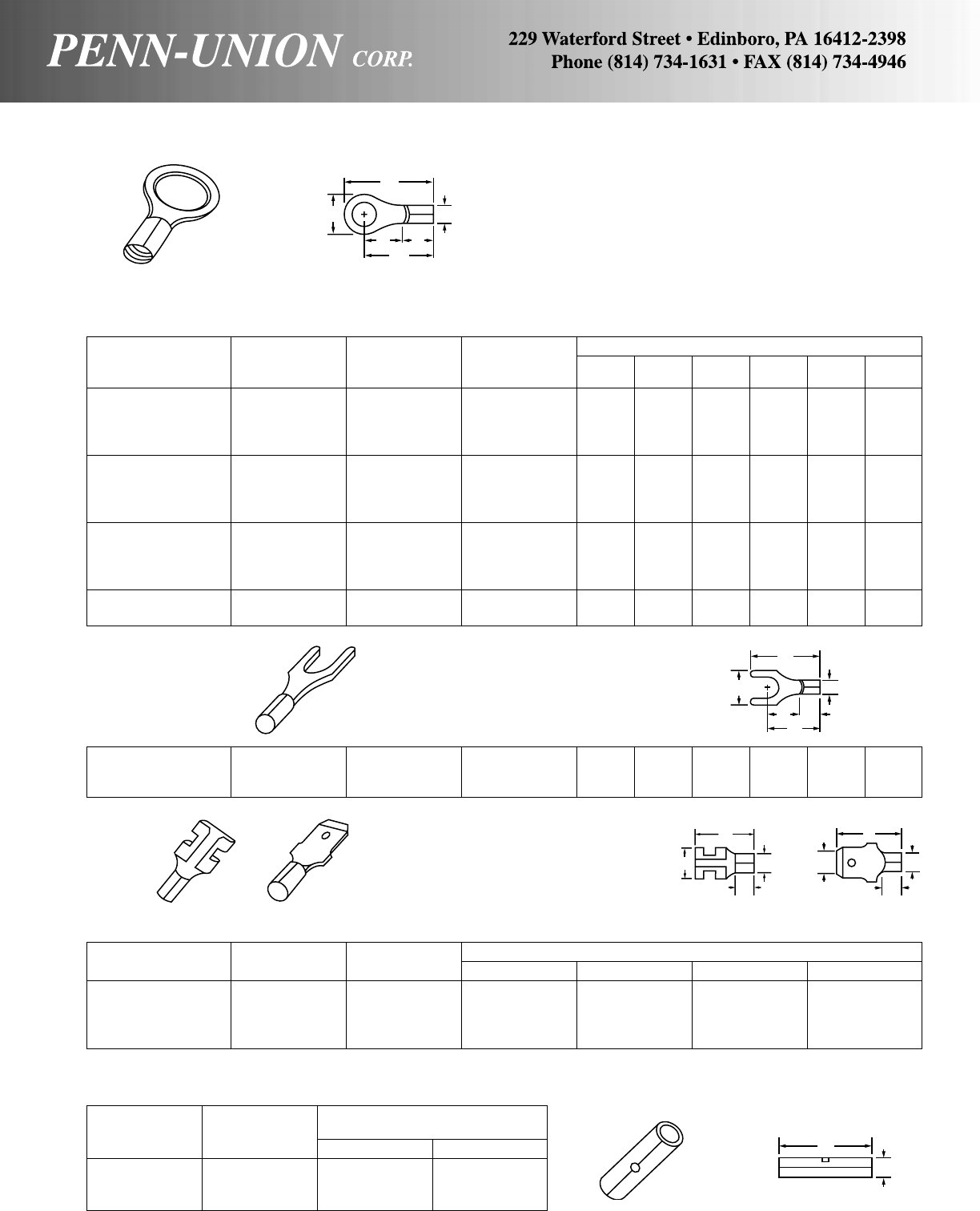
STEEL PENN-CRIMPS® • TYPE 9 HIGH TEMPERATURE TERMINALS
One piece, steel construction, nickel plated for protection. Ca-
pable of providing reliable circuitry in temperature ranges up to
900 degrees Fahrenheit. Structural features of all Type 9 termi-
nals are identical to the Type 1, which proves that they will pro-
vide the highest quality connection. (For 1200°F applications con-
tact the factory).
Catalog Copper Stock Approximate Dimensions in Inches
Number Cond. Range Size (in) A W B ID
FR9B250 16-14 .032 x .250 .63 .31 .234 .090
MT9B250 16-14 .032 x .250 .70 .25 .250 .050
FR9C250 12-10 .032 x .250 .63 .31 .234 .170
MT9C250 12-10 .032 x .250 .77 .25 .250 .130
MALE AND FEMALE DISCONNECTS
BUTTED SEAM
BUTT CONNECTORS
BUTTED SEAM
Copper Approximate Dimensions
Catalog Cond. in Inches
Number Range A ID
B9A 22-18 .57 .070
B9B 16-14 .57 .090
B9C 12-10 .57 .130
A
W
CB
M
ID
RING TERMINALS
BUTTED SEAM
Copper Stock Approximate Dimensions in Inches
Catalog Cond. Stud Size
Number Range Size (in) A W C M B ID
R9A-6S 22-18 6 .030 .65 .25 .28 .54 .250 .070
R9A-8 22-18 8 .030 .69 .31 .28 .54 .250 .070
R9A-10 22-18 10 .030 .69 .31 .28 .54 .250 .070
R9A-14S 22-18 1/4.030 .90 .46 .42 .67 .250 .070
R9B-6S 16-14 6 .030 .65 .25 .28 .54 .250 .090
R9B-8 16-14 8 .030 .69 .31 .28 .54 .250 .090
R9B-10 16-14 10 .030 .69 .31 .28 .54 .250 .090
R9B-14S 16-14 1/4.030 .90 .46 .42 .67 .250 .090
R9C-6S 12-10 6 .040 .67 .28 .28 .53 .250 .130
R9C-8 12-10 8 .040 .72 .37 .28 .53 .250 .130
R9C-10 12-10 10 .040 .72 .37 .28 .53 .250 .130
R9C-14S 12-10 1/4.040 .93 .53 .42 .67 .250 .130
R9C-56 12-10 5/16 .040 .99 .60 .42 .67 .250 .130
R9C-38 12-10 3/8.040 .99 .60 .42 .67 .250 .130
S9A-10 22-18 10 .030 .70 .35 .25 .52 .250 .070
S9B-10 16-14 10 .030 .69 .35 .25 .51 .250 .090
S9C-10 12-10 10 .040 .75 .38 .28 .53 .250 .130
SPADE TERMINALS
BUTTED SEAM
A
CMB
ID
W
AA
WWID ID
BB
A
ID
69
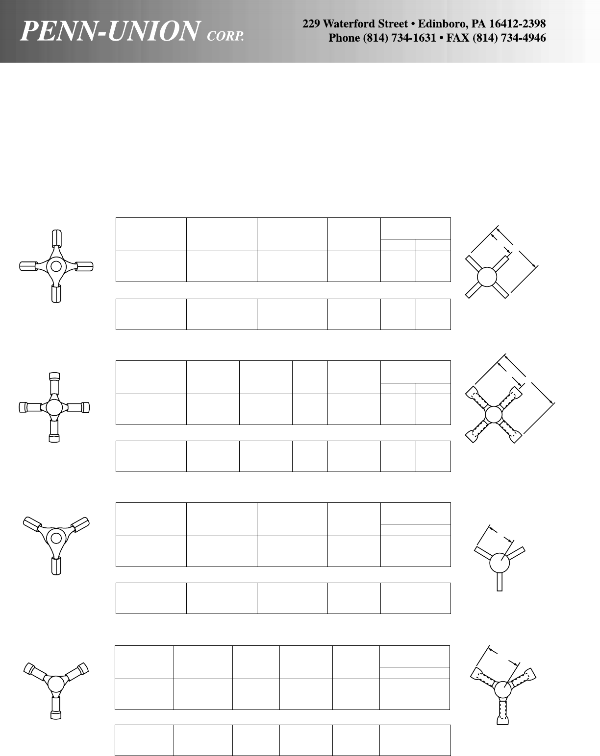
COPPER PENN-CRIMPS® • TYPES X AND Y
Pure electrolytic copper, multi-terminal construction allows either
three or four wires to be quickly and securely connected. Gener-
ous entrance chamfers permit easier wire insertion. Available non-
insulated or with NEMA color coded nylon or vinyl insulation.
Quality crafted for the secure long-term dependability and per-
formance which proves that Penn-Crimps provide the preferred
connected.
Copper Stock Approx. Dimen.
Catalog Cond. Stud Size in Inches
Number Range Size (in) A M
X1A 22-18 4 way .030 1.07 .54
X1B 16-14 4 way .030 1.07 .54
X1C 12-10 4 way .040 1.07 .54
NON-INSULATED 4 WAY CONNECTORS
BUTTED SEAM
BRAZED SEAM
X2A 22-18 4 way .030 1.07 .54
X2B 16-14 4 way .030 1.07 .54
X2C 12-10 4 way .040 1.07 .54
INSULATED 4 WAY CONNECTORS
VINYL INSULATED - BUTTED SEAM
Copper Color Stock Approx. Dimen.
Catalog Cond. Stud Code Size in Inches
Number Range Size (ins) (in) A M
X4A 22-18 4 way R .030 1.54 .77
X4B 16-14 4 way B .030 1.54 .77
X4C 12-10 4 way Y .040 1.54 .77
NYLON INSULATED - BUTTED SEAM WITH BRASS SLEEVE
X6A 22-18 4 way R .030 1.50 .75
X6B 16-14 4 way B .030 1.56 .78
X6C 12-10 4 way Y .040 1.66 .83
NON-INSULATED 3 WAY CONNECTORS
BUTTED SEAM
Copper Stock Approx. Dimen.
Catalog Cond. Stud Size in Inches
Number Range Size (in) M
Y1A 22-18 3 way .030 .54
Y1B 16-14 3 way .030 .54
Y1C 12-10 3 way .040 .54
BRAZED SEAM
Y2A 22-18 3 way .030 .54
Y2B 16-14 3 way .030 .54
Y2C 12-10 3 way .040 .54
INSULATED 3 WAY CONNECTORS
VINYL INSULATED - BUTTED SEAM
Copper Stock Color Approx. Dimen.
Catalog Cond. Stud Size Code in Inches
Number Range Size (in) (ins) M
Y4A 22-18 3 way .030 R .77
Y4B 16-14 3 way .030 B .77
Y4C 12-10 3 way .040 Y .77
NYLON INSULATED - BUTTED SEAM WITH BRASS SLEEVE
Y6A 22-18 3 way .030 R .75
Y6B 16-14 3 way .030 B .78
Y6C 12-10 3 way .040 Y .83
A
M
A
M
M
M
70
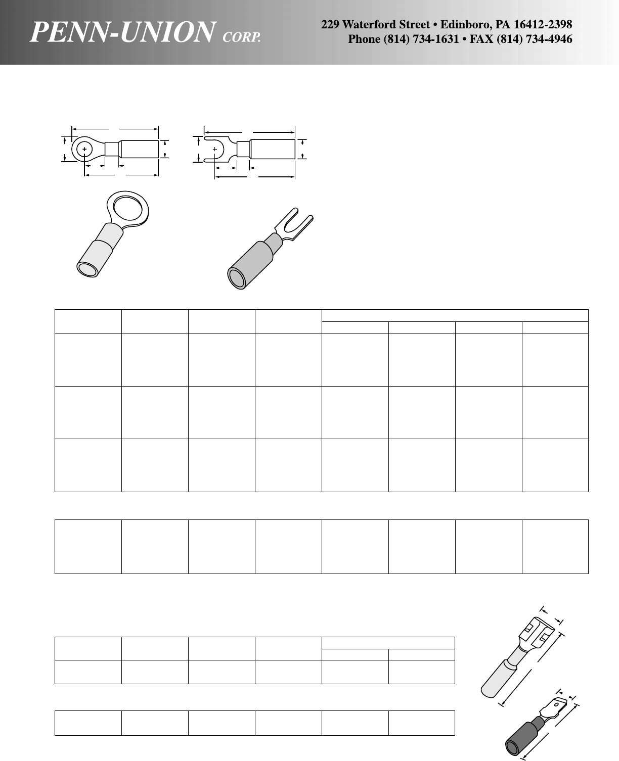
COPPER PENN-CRIMPS®
Preinsulated Heat Shrinkable Terminals and Splices
These heat shrinkable products provide a tough, environmen-
tally sealed wire termination. These terminals and splices insu-
late and protect the electrical connections from wire pull-outs,
abrasions and mechanical abuse. They also resist water, salt
and other contaminants.
RING TERMINALS
BRAZED SEAM
Catalog Wire Stud Color Approx. Dimen. in Inches
Number Size Size Insul. A W C M
R6A-8HS 22-18 8 Red 1.290 .310 .144 1.150
R6A-10HS 22-18 10 Red 1.214 .330 .180 1.035
R6A-14HS 22-18 1/4Red 1.540 .474 .284 1.300
R6A-56HS 22-18 5/16 Red 1.550 .556 .310 1.280
R6A-38HS 22-18 3/8Red 1.525 .525 .300 1.290
R6B-8HS 16-14 8 Blue 1.340 .310 .144 1.350
R6B-10HS 16-14 10 Blue 1.200 .394 .190 1.035
R6B-14HS 16-14 1/4Blue 1.400 .474 .284 1.140
R6B-56HS 16-14 5/16 Blue 1.510 .465 .280 1.143
R6B-38HS 16-14 3/8Blue 1.425 .540 .320 1.700
R6C-8HS 12-10 8 Yellow 1.306 .310 .144 1.175
R6C-10HS 12-10 10 Yellow 1.200 .350 .175 1.035
R6C-14HS 12-10 1/4Yellow 1.467 .550 .340 1.200
R6C-56HS 12-10 5/16 Yellow 1.614 .556 .369 1.350
R6C-38HS 12-10 3/8Yellow 1.470 .560 .350 1.160
SPADE TERMINALS
BRAZED SEAM
S6A-8HS 22-18 8 Red 1.340 .310 .210 1.180
S6B-8HS 16-14 8 Blue 1.330 .310 .210 1.180
S6B-10HS 16-14 10 Blue 1.340 .394 .191 1.175
S6C-8HS 12-10 8 Yellow 1.359 .318 .175 1.160
S6C-10HS 12-10 10 Yellow 1.325 .387 .243 1.160
FEMALE DISCONNECTS
(FOR .250 X .032 TABS)
BUTTED SEAM
Catalog Wire Stud Color Approx. Dimen. in Inches
Number Size Size Insul. A W
FR6A250-HS 22-18 Red 1.300 .300
FR6B250-HS 16-14 Blue 1.210 .300
MALE DISCONNECTS
BUTTED SEAM
MT6A250-HS 22-18 Red 1.188 .250
MT6B250-HS 16-14 Blue 1.227 .250
A
W
BC M
ID
A
W
CBM
ID
W
W
A
A
71
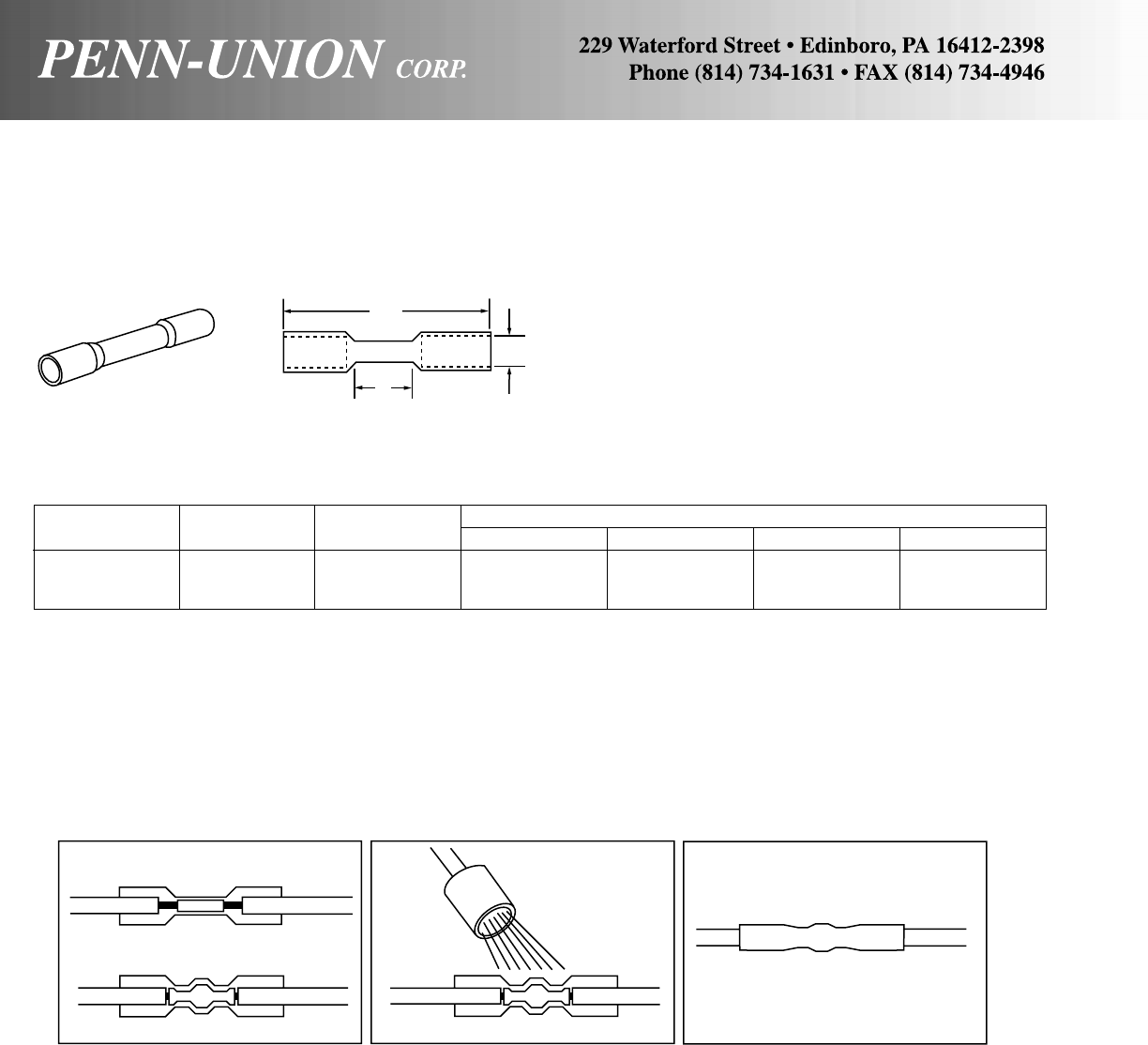
COPPER PENN-CRIMPS® PREINSULATED HEAT SHRINKABLE
TERMINALS AND SPLICES
BUTT CONNECTORS
These heat shrinkable products provide a tough, environmen-
tally sealed wire termination. These terminals and splices insu-
late and protect the electrical connections from wire pull-outs,
abrasions and mechanical abuse. They also resist water, salt
and other contaminants.
Catalog Wire Color Approx. Dimen. in Inches
Number Size Insul. L B C D
B8A-HS 22-18 Red 1.500 .625 .145 .060
B8B-HS 16-14 Blue 1.500 .665 .180 .080
B8C-HS 12-10 Yellow 1.600 .790 .250 .115
SEAMLESS
CRIMPING INSTRUCTIONS
CRIMP TERMINATIONS
Strip the wire 1/4" and insert it into the bar-
rel of the terminal. Match the color of the
insulation with the color of the crimp cav-
ity on the crimping tool.
Heat the crimped device with a heat gun
until the tubing recovers and the adhesive
melts and flows.
BUTT TERMINATIONS
Strip the wire 3/8" and insert it into crimp
barrel. Match the color of the insulation
with the color of the crimp cavity on the
crimping tool.
Heat the crimped device with a heat gun
until the tubing recovers and the adhesive
melts and flows.
TYPICAL APPLICATIONS
Telecommunications Outdoor Lighting Boat Trailers
Marine Aviation Swimming Pools
Automotive Wiring Submersible Pumps Underground Utilities
Mining Refrigeration Equip. Air Conditioner Systems
Traffic Controls Generator Equip. Agricultural Equip.
HEAT
Caution: Allow to cool before handling.
L
B
C EXPANDED
(D RECOVERED)
72
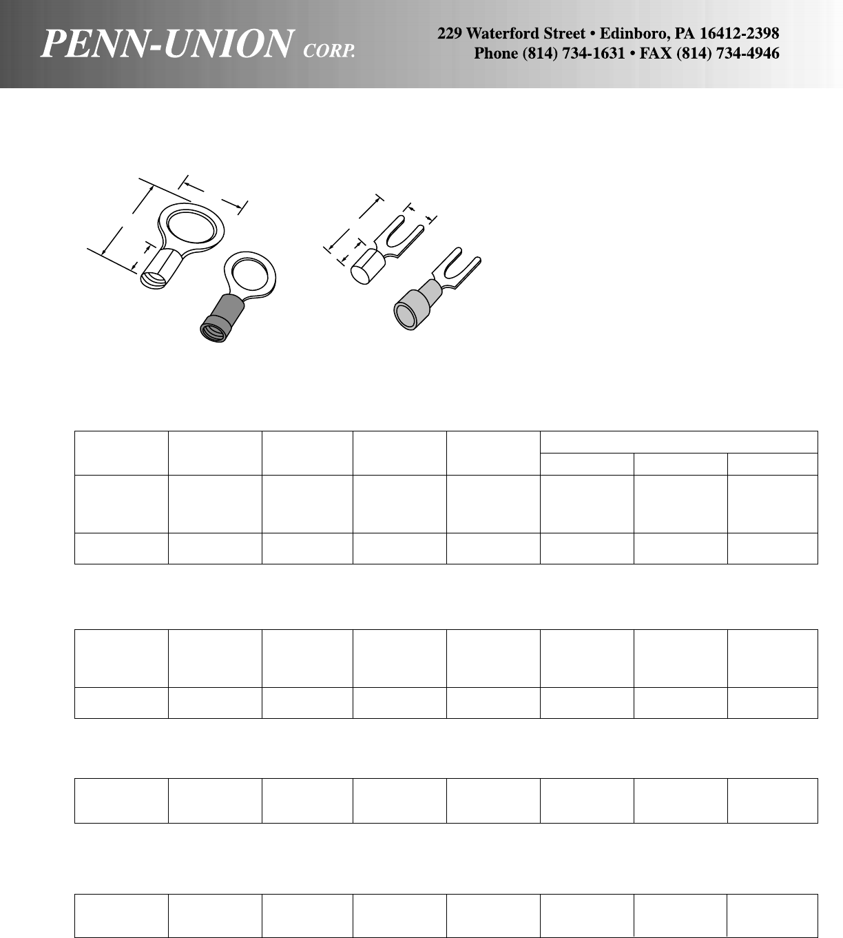
COPPER PENN-CRIMPS® • TYPES R10, R60, S10, S60 MINIATURE TERMINALS
R60-0 26-24 0 Y .020 .59 .14 .17
R60-2 26-24 2 Y .020 .59 .14 .17
R60-4 26-24 4 Y .020 .68 .20 .22
R60-6 26-24 6 Y .020 .68 .20 .22
R60-8 26-24 8 Y .020 .77 .25 .29
R60-10 26-24 10 Y .020 .77 .25 .29
Copper Color Stock Approx. Dimen. in Inches
Catalog Cond. Stud Code Size
Number Range Size (ins) (in) AWC
R10-0 26-24 0 .020 .41 .14 .17
R10-2 26-24 2 .020 .41 .14 .17
R10-4 26-24 4 .020 .50 .20 .22
R10-6 26-24 6 .020 .50 .20 .22
R10-8 26-24 8 .020 .59 .25 .29
R10-10 26-24 10 .020 .59 .25 .29
NON-INSULATED RINGS
BUTTED SEAM
INSULATED RINGS
NYLON INSULATED - BUTTED SEAM WITH BRASS SLEEVE
S10-0 26-24 0 .020 .34 .14 .11
S10-4 26-24 4 .020 .48 .20 .21
S10-6 26-24 6 .020 .58 .25 .27
NON-INSULATED SPADES
BUTTED SEAM
S60-0 26-24 0 Y .020 .50 .14 .11
S60-4 26-24 4 Y .020 .64 .20 .21
S60-6 26-24 6 Y .020 .75 .25 .27
INSULATED SPADES
NYLON INSULATED - BUTTED SEAM WITH BRASS SLEEVE
Same high quality construction as standard Type
1 and Type 6 terminals in smaller size to accom-
modate smaller wire ranges in confined areas.
W
A
C
73
W
C
A
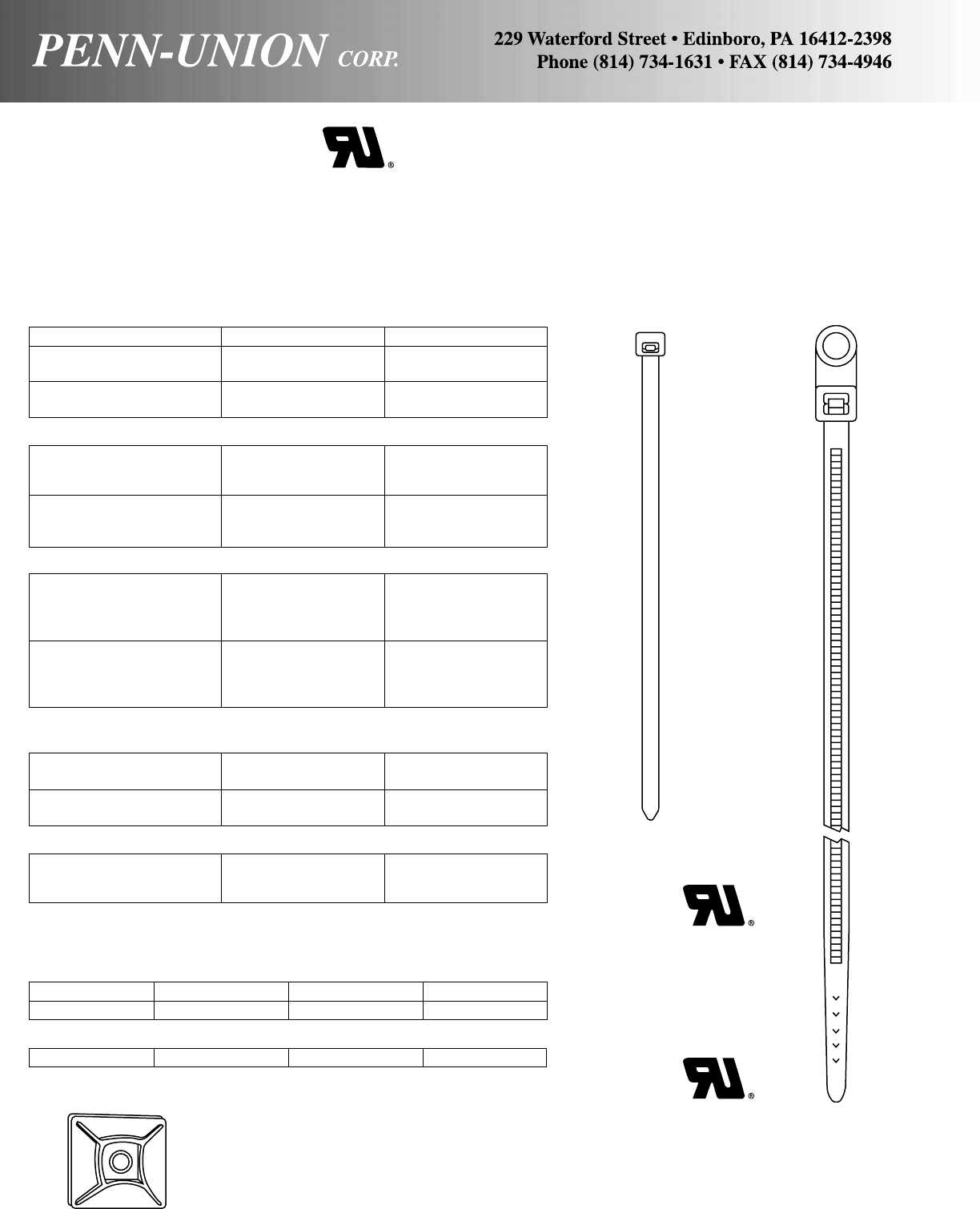
NYLON CABLE TIES
Made from 100%, non-corrosive Nylon, for impact strength, abra-
sion resistance, versatility and self-extinguishing qualities. Bent-
tip design allows for easier handling and installation. Carbon Black
Nylon maintains the same properties as natural colored Nylon,
but has a special Carbon Black additive which greatly increases
the Nylon’s resistance to Ultraviolet rays, making them weather
resistant.
MINIATURE CROSS-SECTION - 18 lbs. MIN. LOOP TENSILE STRENGTH
Catalog Number Max. Bundle Dia. In. Approx. Length In.
Natural Nylon
TY4-18 7/84
Carbon Black Nylon
TY4-18-B 7/84
INTERMEDIATE CROSS-SECTION 30 - 40 lbs. MIN. LOOP STRENGTH
Natural Nylon
TY5.5-30 11/45.5
TY8-40 2 8
Carbon Black Nylon
TY5.5-30-B 11/45.5
TY8-40-B 2 8
STANDARD CROSS-SECTION - 50 lbs. MIN. LOOP STRENGTH
Natural Nylon
TY7.5-50 13/47.5
TY11-50 3 11
TY15-50 4 15
Carbon Black Nylon
TY7.5-50-B 13/47.5
TY11-50-B 3 11
TY15-50-B 4 15
HEAVY CROSS-SECTION (AND LIGHT-HEAVY) -
120 lbs. MIN. LOOP TENSILE STRENGTH
Natural Nylon
TY14.5-120 4 14.5
Carbon Black Nylon
TY14.5-120-B 4 14.5
NYLON MOUNTING CABLE TIES
STANDARD CROSS-SECTION - 50 lbs. MIN. LOOP TENSILE STRENGTH
Catalog Number Max. Bundle Dia. In. Approx. Length In. Mounting Stud
MTY7.5-50 13/47.5 #10
HEAVY DUTY CROSS-SECTION - 120 lbs. MIN. LOOP TENSILE STRENGTH
MTY14.8-120 4 14.8 1/4
NYLON CABLE TIE MOUNTS
These acrylic, adhesive-backed mounts are made of Type 6 Ny-
lon for high impact and tensile strength. Peel-off strip on back
allows faster and easier separation from the backing while the
four-way tie insertion provides quick assembly. Available in natu-
ral color. Exceeds standards for UL component recognition.
TYM-1
1" (25 mm)
TY
MTY
150 lbs. MIN. LOOP TENSILE STRENGTH
TY21-150 6 21
TY36-150 11 36
TY42-150 13 42
74
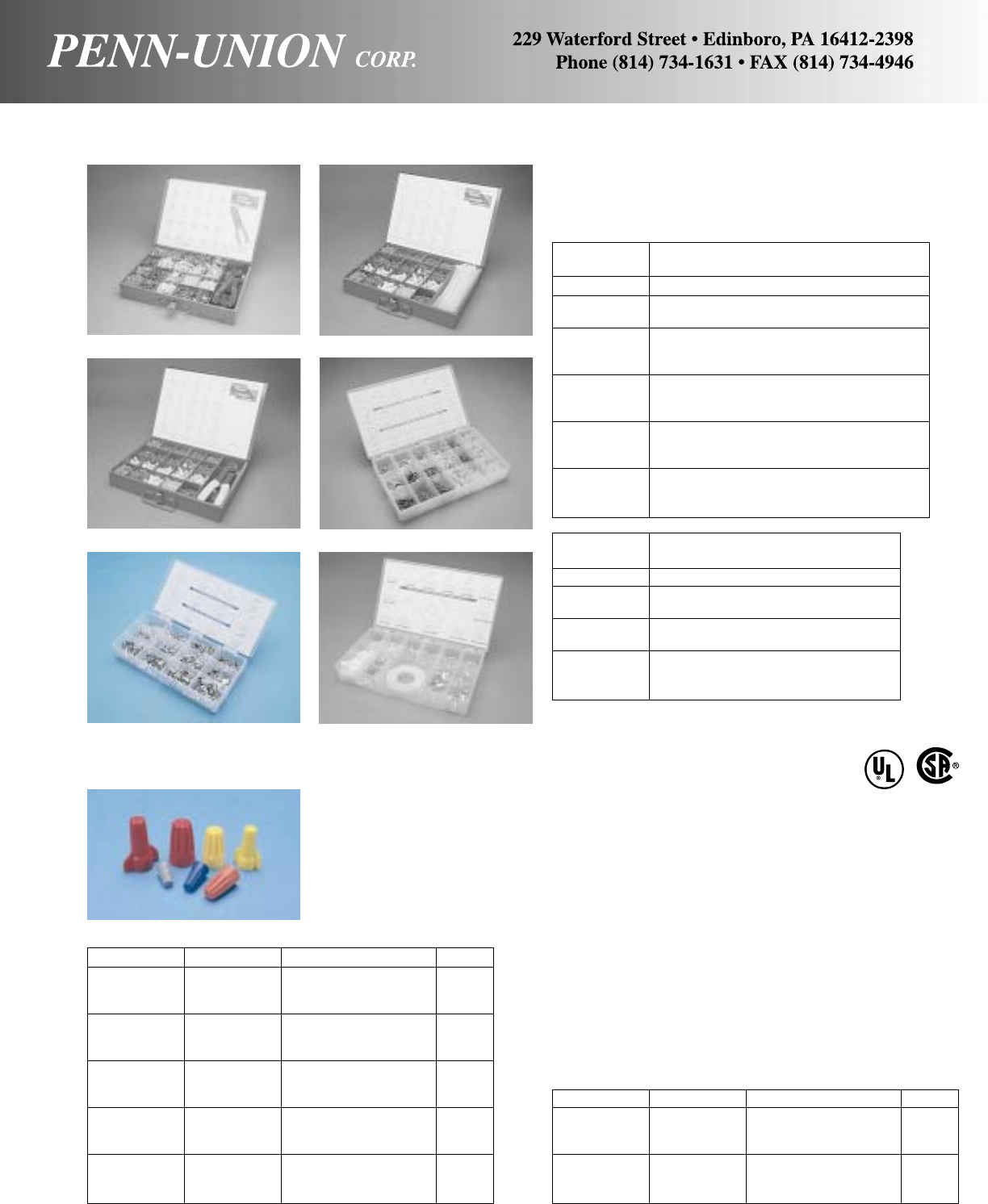
PENN-CRIMPS® TERMINAL KITS • TYPES MK 40-MK 71, & PK 50NT-PK 58
The MK kits come with a variety of terminals and connectors for
industrial, commercial, maintenance, construction and general
use purposes. The kits are packaged in a rugged, heavy duty,
hinged metal box.
Catalog
Number Description
MK-40 Metal Kit Box with Scoop Compartments
MK-41 Metal Kit Box with Scoop Compartments
and HTS-1440 Crimping Tool
MK-42 Metal Kit Box with Scoop Compartments,
HTS-1440 Crimping Tool and 500 Assorted
Vinyl Insulated Terminals and Connectors
MK-43 Metal Kit Box with Scoop Compartments,
HTS-1440 Tool and 1000 Assorted
Non-Insulated Terminals and Connectors
MK-70 Metal Kit Box with Scoop Compartments,
100 71/2" Cable Ties and 1155 Assorted
Vinyl Insulated Terminals and Connectors
MK-71 Metal Kit Box with Scoop Compartments,
HTS 1440 Tool and 1155 Assorted
Vinyl Insulated Terminals and Connectors
MK 42
75
PENN-NUTS • PN SERIES CONNECTORS, KNURLED AND WING STYLE
The range of wire combinations fills the requirements of many of
the more typical connections made.
Knurled style offers the industry’s standard screw-on connector.
Winged style offers a high-leverage easy on live spring design.
Available in packages of either kegs (containing polybags), boxes,
or clamshells.
Standard packaging in boxes of 1,000, 100, and as bulk packed
kegs of poly bags of 500 (250 for PNRK). 1,000 and 100 quantity
boxes are available by using a suffix of “-M” (for 1,000) or “-C”
(for 100).
All of the Penn-Nuts are UL listed and have a temperature rating
of 105°C (221°F).
PK 57
KNURLED STYLE:
Cat. No. Color Application OAL
PNGK Grey *#22 to #16 AWG .58
Min: 1 #20 w/1 #22
Max: 2 #16
PNBK Blue *#22 to #16 AWG .70
Min: 3 #22
Max: 3 #16
PNOK Orange **#22 to #14 AWG .84
Min: 3 #20
Max: 4 #16 & 1 #20
PNYK Yellow **#18 to #10 AWG .94
Min: 1 #14 & 1 #18
Max: 4 #14
PNRK Red **#18 to #10 AWG 1.06
Min: 2 #14
Max: 2 #10 & 2 #12
**Connections rated at 300 V Max.
**Connections rated at 300 V Max. and 600 V Max. Connections rated at 600+ V Max. for Building Wiring are rated at 1000V Max. in Fixtures and Signs.
WINGED STYLE:
Cat. No. Color Application OAL
PNYW Yellow **#22 to #10 AWG 1.03
Min: 2 #18
Max: 3 #12
PNRW Red **#18 to #10 AWG 1.25
Min: 2 #14
Max: 5 #12
Catalog
Number Description
PK-50NT Kit, No Tool 18 Popular Vinyl Items
PK-55 HVAC/R Maintenance and Repair Kit
18 popular items
PK-57 Hi-Temp Terminal Kit
12 popular Items (900°F)
PK-58 10 popular Items (900°F)
2 popular Porcelain Wire Nuts
1 roll High Temp Glass cloth tape
PK 55
MK 70
PK 58
MK 71
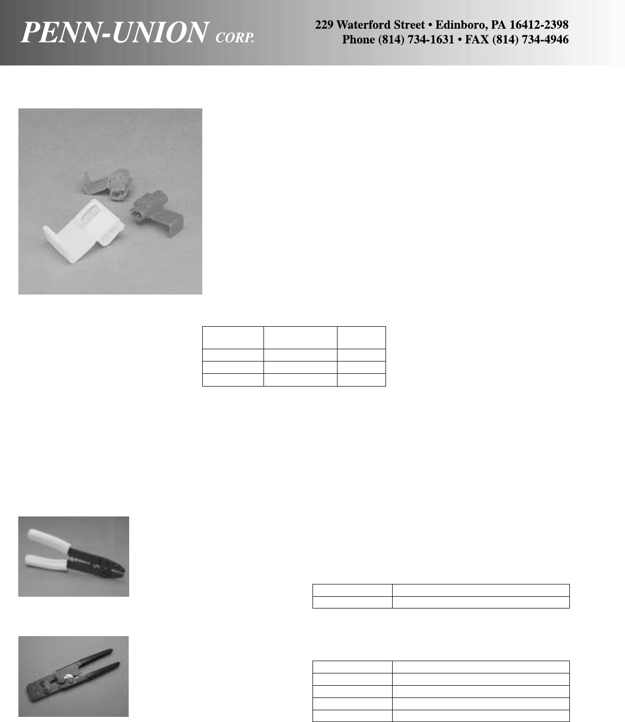
76
INSULATION DISPLACEMENT CONNECTORS PENN-LOKS • TYPE PL
Catalog Conductor Color
Number Size Range Code
PLA 22-18 STR. CU. Red
PLB 18-14 STR. CU. Blue
PLC 12-10 STR. CU. Yellow
PENN-CRIMPS® CRIMPING TOOLS • TYPES HTS 1440 & HTC
GENERAL PURPOSE MAINTENANCE
Crimps insulated and non-insulated #22-10 wire size, bolt cutter,
thread chaser, wire stripper and has cushioned plastic handles.
HEAVY DUTY, RATCHET TYPE, FULL CYCLE
CRIMPING TOOL
Catalog Number Description
HTC-3000 Ratchet Double Crimp Insulated Terminals
HTC-3100 Ratchet Single Crimp Non-Insulated Terminals
HTC-3200 Ratchet Single Crimp Insulated Terminals
HTC-3500 Ratchet Double Crimp Type FR4 Disconnects
HTS 1440
Catalog Number Description
HTS-1440 General Purpose Crimps
HTC
• Pre-insulated connector
• Multiple tap and splice applications
• Easy to use
• No need to strip insulation
•Quick to install
•No twisting of wires required
• Color coded for quick identification
• Installed with common pliers
• Hinged cover locks securely
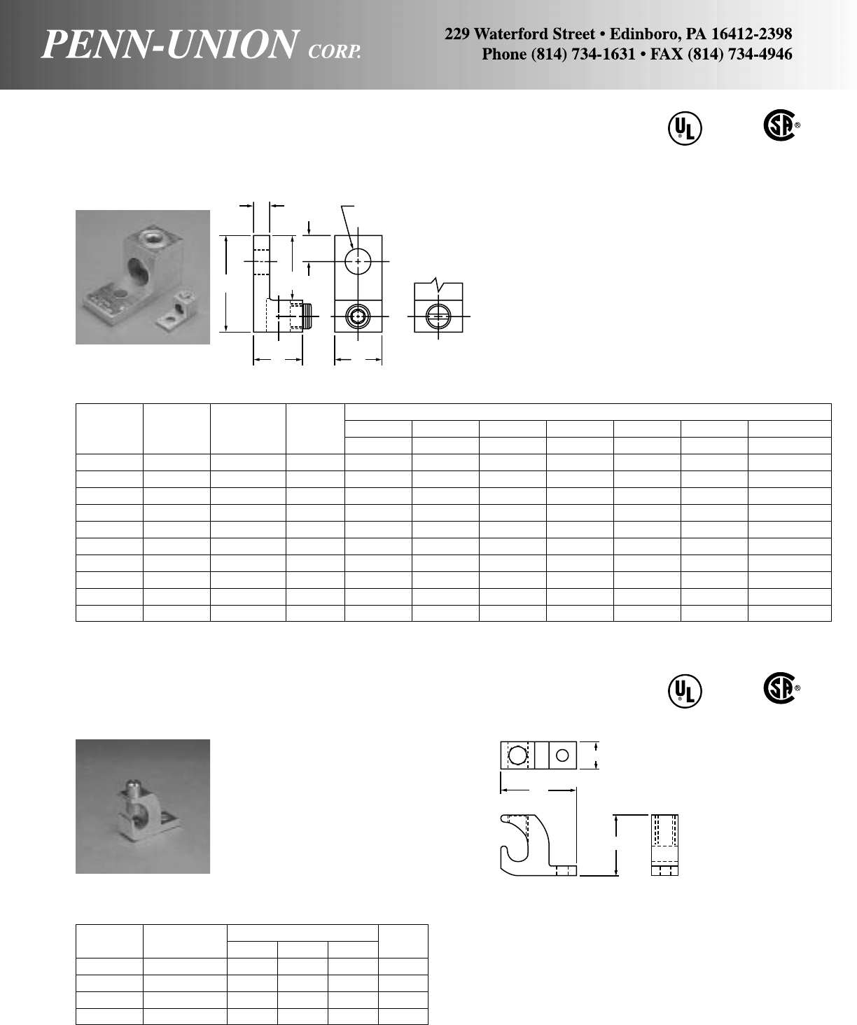
ALUMINUM SOLDERLESS LUGS • TYPE LA
One hole, front entrance copper or aluminum conductors 600 Volt Rated
Torque Approximate Dimensions
Catalog Value Wire Fig. LWHTBCD Dia.
Number In-Lbs. Range‡ No. in in in in in in in
LA-6 45 14-6 1 11/16 1/21/23/32 11/16 1/417/64
LA-2 50 14-2 1 15/32 1/235/64 7/64 11/16 5/16 17/64
LA-0 50 14-1/0 1 115/32 5/825/32 3/16 27/32 27/64 17/64
LA-2/0 120 14-2/0 2 115/32 5/851/64 3/16 27/32 7/16 17/64
LA-250 275 6-250 2 2 1 11/81/4129/64 21/64
LA-350 275 6-350 2 21/411/811/41/411/81/213/32
LA-500 375 4-500 2 213/16 11/419/16 5/16 19/16 7/813/32
LA-600 375 2-600 2 33/16 11/219/16 7/16 113/16 25/32 13/32
LA-800 375 300-800 2 31/213/4115/16 1/217/813/16 21/32
LA-1000 375 500-1000 2 31/213/4115/16 1/217/813/16 21/32
‡For conversion to metric range, see page 175.
486B
LISTED
AL9CU
Body, fabricated from high strength aluminum alloy extrusion.
Lug is 100% reusable using either screw driver or hex wrench.
No special tools required.
Maximum conductivity, compact design light weight with ultimate
strength.
Finish, electro-tin plated to assure minimum contact resistance
and protection against corrosion when used with copper wire.
(For added protection apply Penn-Union Cual-Aid® to cable be-
fore installation.)
Standard stud hole sizes and locations are shown on chart.
77
ALUMINUM LAY-IN LUGS • TYPE LI
One hole, side entrance copper or aluminum continuous conductors 486B
LISTED
AL9CU
Body, fabricated from high strength aluminum alloy extrusion.
Finish, electro-tin plated to assure minimum contact resistance
and protection against corrosion when used with copper wire.
(For added protection apply Penn-Union Corp. Cual-Aid® to cable
before installation.)
The side entrance design permits the quick installation of one
continuous conductor as a jumper to multiple locations without a
break in the conductor. Excellent choice for use on grounding
conductors.
T
L
C
D DIA.
B
HW
FIG. 2 FIG. 1
Catalog Wire Diameter Approximate Dimensions Screw
Number Range L W H Type
LI-50S214-4 11/16"3/8"25/32"Slot
LI-112S 14-1/0 11/2"19/32"1
11/64"Slot
LI-200S 6-3/0 2" 51/64"1
9/16"Socket
LI-252S 6-250 213/64"51/64"1
51/64"Socket
L
H
W

Torque Approximate Dimensions
Catalog Value Wire Fig. LW
1W2HTBCD Dia.
Number In-Lbs. Range‡ No. in in in in in in in in
L2A-0 120 14-1/0 2 115/32 11/8–25/32 3/16 27/32 7/16 17/64
L2A-2/0 120 14-2/0 2 115/32 11/4–25/32 3/16 27/32 27/64 17/64
L2A-250 275 6-250 2 29/16 141/64 –1
3/16 1/419/16 7/813/32
L2A-350 275 6-350 1 27/8115/16 13/411/41/413/49/16 17/32
L2A-500* 500 4-500 1 31/823/8163/64 19/16 7/16 13/45/817/32
L2A-600 550 2-600 1 31/823/8163/64 19/16 7/16 13/45/817/32
L2A-800 375 350-800 2 31/231/2–1
15/16 1/217/87/821/32
L2A-1000 375 500-1000 2 31/231/2–1
15/16 1/217/87/821/32
ALUMINUM SOLDERLESS LUGS • TYPE L2A
One hole front entrance copper or aluminum conductors 486B
LISTED
AL9CU
Torque Approximate Dimensions
Catalog Value Wire LWHTBC D Dia. E
Number In-Lbs. Range‡in ininininininin
LLA2-500-S1 275 4/0-500 51/211/411/25/16 31/41/29/16 13/4
LLA2-750-S1 275 400-750 63/16 11/217/89/16 37/16 5/89/16 13/4
‡For conversion to metric range, see page 175.
Body, fabricated from high strength aluminum alloy extrusion.
Lug is 100% reusable using either screw driver or hex wrench.
No special tools required.
Maximum conductivity, compact design, light weight with ultimate
strength.
Finish, electro-tin plated to assure minimum contact resistance
and protection against corrosion when used with copper wire.
(For added protection apply Penn-Union Cual-Aid® to cable be-
fore installation.)
ALUMINUM SOLDERLESS LUGS • TYPE LLA2
Two hole front entrance copper or aluminum conductors
‡For conversion to metric range, see page 175. *Not CSA Certified.
Body, fabricated from high strength aluminum alloy extrusion.
Lug is 100% reusable using either screw driver or hex wrench.
No special tools required.
Maximum conductivity, compact design, light weight with ultimate
strength.
Finish, electro-tin plated to assure minimum contact resistance
and protection against corrosion when used with copper wire.
(For added protection apply Penn-Union Cual-Aid® to cable be-
fore installation.)
TW2D DIA.
C
B
L
HW1W1
FIG. 1 FIG. 2
T
L
B
D DIA.
C
HW
E
78
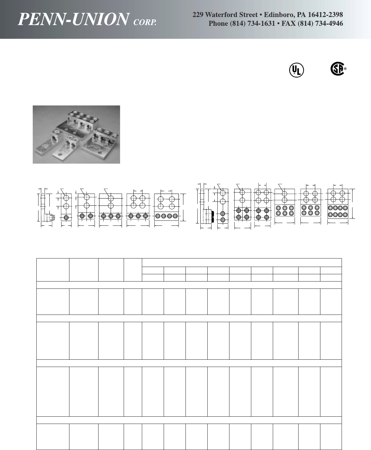
Torque Approximate Dimensions
Catalog Value Wire Fig. LWHT BCD Dia. E F
Number In-Lbs. Range No. in in in in in in in in in
SINGLE CONDUCTOR
LA-350-2 375 6-350 1 43/16 11/811/41/431/16 5/89/16 13/4–
LA-600-2 500 2-600 1 411/16 11/219/16 7/16 35/16 5/89/16 13/4–
LA-800-2 375 350-800 6 63/16 13/417/89/16 37/16 5/89/16 13/4–
LA-1000-2 500 500-1000 6 63/16 13/417/89/16 37/16 5/89/16 13/4–
TWO CONDUCTOR
L2A-350-2 375 6-350 2 43/16 115/16 11/41/431/16 5/89/16 13/4–
L2A-600-2 500 2-600 2 411/16 27/16 19/16 7/16 35/16 5/89/16 13/4–
L2A-800-2 500 300-800 7 63/16 31/217/89/16 37/16 5/89/16 13/4–
L2A-800-4 500 300-800 8 63/16 31/217/89/16 37/16 5/89/16 13/413/4
L2A-1000-2 500 500-1000 7 63/16 31/217/89/16 37/16 5/89/16 13/4–
L2A-1000-4 500 500-1000 8 63/16 31/217/89/16 37/16 5/89/16 13/413/4
THREE CONDUCTOR
L3A-250-2 275 6-250 3 4 3 13/16 5/16 35/89/16 13/4–
L3A-250-4 275 6-250 4 4 3 13/16 5/16 35/89/16 13/413/4
L3A-350-2* 275 6-350 3 43/16 31
1/81/431/16 5/89/16 13/4–
L3A-350-4* 275 6-350 4 43/16 31
1/81/431/16 5/89/16 13/413/4
L3A-500-2 375 2-500 3 45/833/419/16 7/16 33/85/89/16 13/4–
L3A-500-4 375 2-500 4 411/16 33/419/16 7/16 35/16 5/89/16 13/413/4
L3A-800-2* 500 300-800 9 63/16 41/417/89/16 37/16 5/89/16 13/4–
L3A-800-4* 500 300-800 8 63/16 31/217/89/16 37/16 5/89/16 13/413/4
FOUR CONDUCTOR
LA4M4-250 275 6-250 5 4 43/64 13/16 5/16 35/89/16 13/413/4
LA4M4-350 275 6-350 5 41/2423/32 13/85/16 31/45/89/16 13/413/4
LA4D4-600 375 2-600 11 51/2521/32 11/23/831/45/89/16 13/413/4
LA4D4-800 500 350-800 11 63/16 75/32 17/89/16 37/16 5/89/16 13/413/4
•Not UL Listed
*Not CSA Certified
ALUMINUM SOLDERLESS LUGS • TYPES LA, L2A, L3A, LA4M4 AND LA4D4
Two and four hole, front entrance copper or aluminum conductors
•
•
•
•
•
•
•
•
486 B
LISTED
AL9 CU
Penn-Union solderless lugs are made from high strength
aluminum alloy, electro-tin plated to assure minimum contact
resistance and corrosion protection. Manufactured to insure
both maximum strength and conductivity, they are dual rated
for both copper and aluminum conductors. These re-usable
connectors need only a hex wrench for assembly. All four-hole
pads are NEMA drilled for 1/2" bolts on 13/4" centers. For added
protection apply Penn-Union Cual-Aid®to cable before installa-
tion.
L
H
B
T
E
WWW WW
L
F
F
D
DIA.
D
DIA.
D
DIA.
E
FIG. 1 FIG. 2 FIG. 3 FIG. 4 FIG. 5
LB
H
E
D
DIA.
FIG. 6
W
D
DIA.
W
W
WWW
L
D
DIA.
FF
F
FIG. 7 FIG. 8 FIG. 9 FIG. 10 FIG. 11
CC
T
C
79
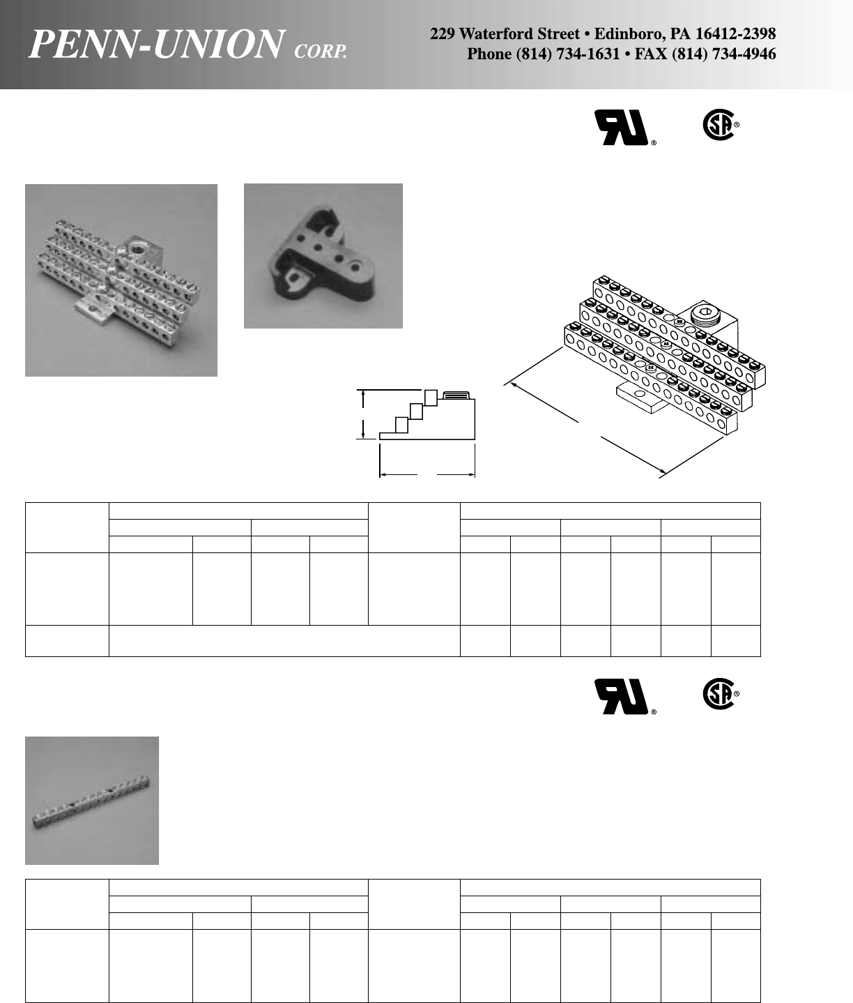
W
H
ALUMINUM STACKED NEUTRAL BARS • TYPE SNB
For aluminum or copper conductors
Stacking lugs and neutral bars are made from high strength alu-
minum alloy tin plated for bimetalic applications.
The stacking lugs are UL 486B listed AL9CU. The neutral bars
are UL Component Recognized.
Conductor Range Number Approximate Dimensions
Catalog Main Tap of HWL
Number AWG MM2AWG MM2Taps in mm in mm in mm
SNB350-12 6-350 MCM 16-185 14-6 1.5-16 12 1.53 38.86 4.72 119.89 2.81 71.37
SNB350-24 6-350 MCM 16-185 14-6 1.5-16 24 1.53 38.86 4.72 119.89 2.81 71.37
SNB350-30 6-350 MCM 16-185 14-6 1.5-16 30 1.53 38.86 4.72 119.89 2.81 71.37
SNB350-36 6-350 MCM 16-185 14-6 1.5-16 36 1.53 38.86 4.72 119.89 2.81 71.37
SNB350-42 6-350 MCM 16-185 14-6 1.5-16 42 1.53 38.86 5.34 135.64 2.81 71.37
R-16 Mounting block of general purpose phenolic 1.00 25.40 2.5 63.5 2.5 63.5
suitable for mounting any SNB neutral bars
COPPER NEUTRAL BARS • TYPE N70
For copper conductors only
Conductor Range Number Approximate Dimensions
Catalog Main Tap of HWL
Number AWG MM2AWG MM2Taps in mm in mm in mm
N70-10-1 14-4 1.5-16 14-6 1.5-16 8 .47 11.94 .34 8.64 4.37 111.00
N70-12-1 14-4 1.5-16 14-6 1.5-16 10 .47 11.94 .34 8.64 5.15 130.81
N70-14-1 14-4 1.5-16 14-6 1.5-16 12 .47 11.94 .34 8.64 5.94 150.88
N70-16-1 14-4 1.5-16 14-6 1.5-16 14 .47 11.94 .34 8.64 6.75 171.45
N70-174 14-4 1.5-16 14-6 1.5-16 174 .47 11.94 .34 8.64 69.00 1752.6
Neutral bars are made from high strength pure electrolytic cop-
per for maximum strength and maximum conductivity.
The copper neutral bars are UL Recognized and CSA Certified.
Each bar has two mounting holes 0.20" in diameter or 5.08 mm.
N70-174 sold without screws. 7/16" long zinc plated, chromate
dipped steel screws, catalog number E-153 are sold separately.
80
L
SNB
R-16
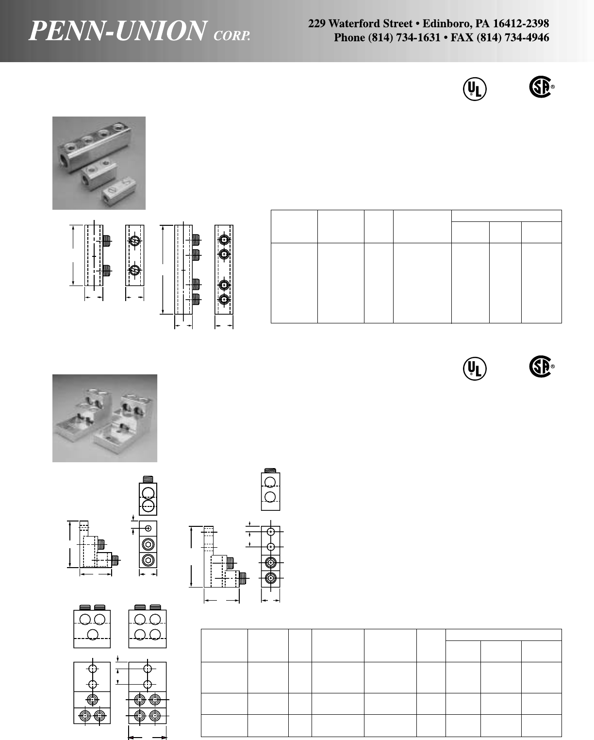
ALUMINUM SPLICER-REDUCER • TYPE SR
Copper or aluminum conductors
ALUMINUM SOLDERLESS PANELBOARD LUGS • TYPE PB
For copper or aluminum conductors
Torque Approximate Dimensions
Catalog Value No. of Conductor Stud H W L
Number In-Lbs. Fig. Conductors Range Size in in in
PB2-300 275 1 2 6-300MCM 5/16(1) 2 1 3
PB2-600 375 2 2 2-600MCM 3/8(2) 3 11/2429/32
PB2-750 375 2 2 1/0-750MCM 3/8(2) 3 19/16 429/32
PB3-600 375 3 3 2-600MCM 3/8(2) 3 21/2429/32
PB3-750 375 3 3 1/0-750MCM 3/8(2) 3 227/32 429/32
PB4-600 375 4 4 2-600MCM 3/8(2) 3 21/2429/32
PB4-750 375 4 4 1/0-750MCM 3/8(2) 3 227/32 429/32
486 B
LISTED
AL9 CU
486 B
LISTED
AL9 CU
Body, fabricated from high strength aluminum alloy extrusions.
Lug is 100% re-usable using hex wrench. No special tools
required.
Maximum conductivity, compact design, light weight with ultimate
strength.
Finish, electro-tin plated to assure minimum contact resistance
and protection against corrosion when used with copper wire.
(For added protection apply Penn-Union Cual-Aid® to cable before
installation.)
Torque Approximate Dimensions
Catalog Value Conductor H W L
Number In-Lbs. Fig. Range in in in
SR-2 50 1 14-2 9/16 1/213/8
SR-0 50 1 14-1/0 3/43/4129/32
SR-250 275 2 6-250MCM 11/813
15/16
SR-250-2 275 1 6-250MCM 11/811
15/16
SR-350 275 2 6-350MCM 13/16 11/843/16
SR-350-2 275 1 6-350MCM 13/16 11/825/8
SR-500 375 2 2-500MCM 11/213/85
SR-750 375 2 250-750MCM 13/415/861/4
• Body, fabricated from high strength aluminum alloy
• Solid center barrier
• Electro tin plated
• Rounded corner for easy taping
L
HW
L
HW
FIG. 1
FIG. 2
L
HW
3/8
13/8
FIG. 2
13/8
3/8
W
FIG. 3 FIG. 4
FIG. 1
L
HW
.47
81
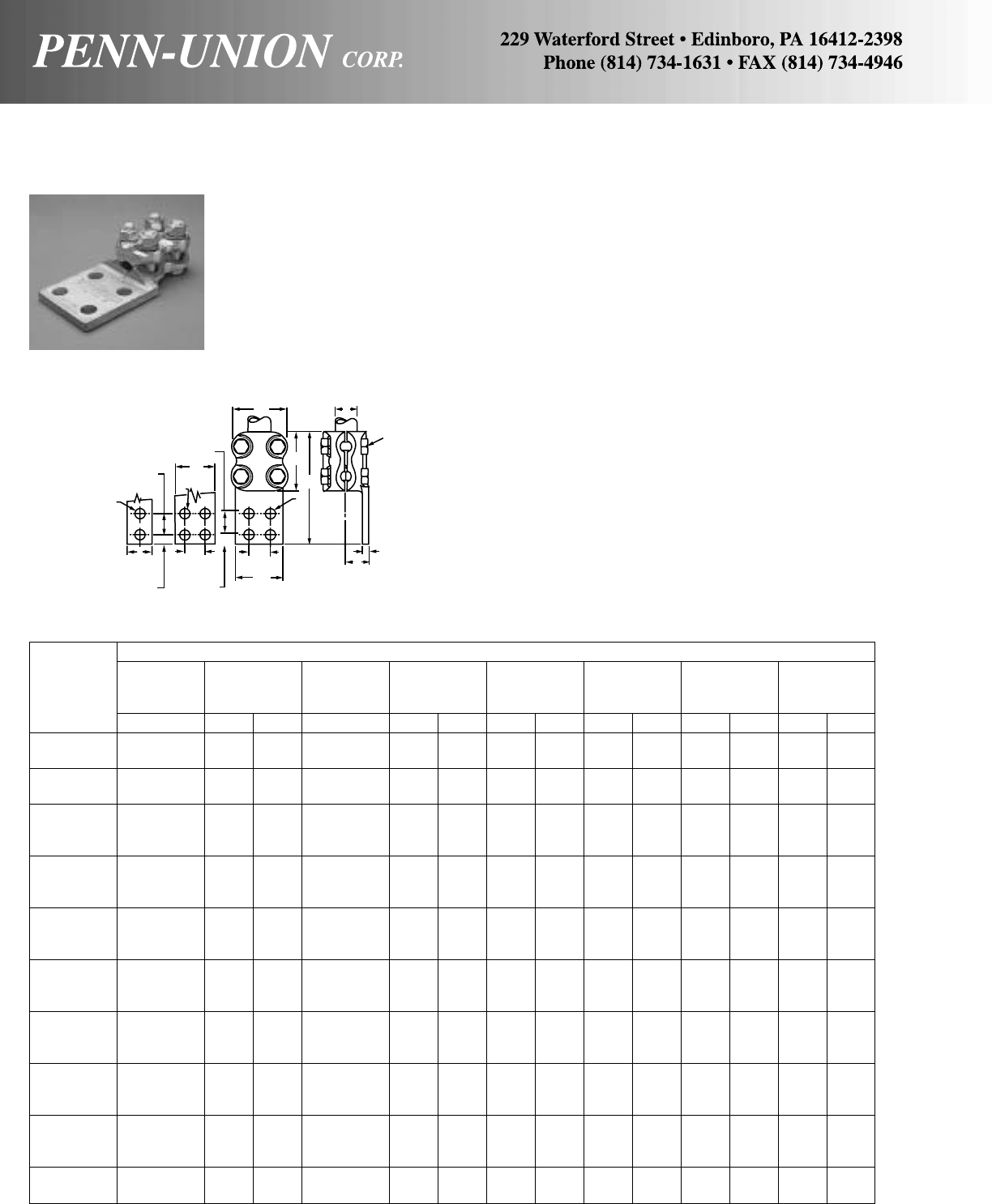
ALUMINUM TERMINALS • TYPES RAA AND RAAC
Heavy Duty Tube to Flat
High strength electrical aluminum alloy.
Massive extra thick sections. Conforming contact grooves. Gen-
erous extra long contact lengths.
Large size, high strength, anodized and lubricated 2024T4 alu-
minum alloy clamping hardware.
Bolt heads pocketed for single wrench installation. Rounded con-
tours.
NEMA drilling supplied. Other drilling, or undrilled, available on
request.
There may be some special operating conditions where copper
flashed pad may be desired on the tongue. Add suffix “C” to the
catalog designation. Example: RAAC-15-F. If tin plated terminals
are preferred, add “-TN” to catalog numbers. Example:
RAA-15-F-TN.
For tongue mounting hardware, suffix catalog number with
“-TMH.” Example: RAA-15-F-TMH. (Aluminum hardware provided
for type RAA, steel hardware for type RAAC.)
Approximate Dimensions
AJK
Aluminum Bolt Hole
Catalog IPS G Diameter Diameter L M T W
Number in in mm in in mm in mm in mm in mm in mm
RAA-07-D 3/413/16 30 1/29/16 14 61/2165 31/4 83 7/16 11 25/8 67
RAA-07-F 3/413/16 30 1/29/16 14 61/2165 31/4 83 7/16 11 25/8 67
RAA-10-D 1 15/16 33 1/29/16 14 63/4171 31/2 89 7/16 11 3 76
RAA-10-F 1 15/16 33 1/29/16 14 63/4171 31/2 89 7/16 11 3 76
RAA-12-D 11/419/16 40 5/89/16 14 7 178 33/4 95 1/213 39/16 90
RAA-12-F 11/419/16 40 5/89/16 14 7 178 33/4 95 1/213 39/16 90
RAA-12-E 11/419/16 40 5/89/16 14 8 203 33/4 95 7/16 11 39/16 90
RAA-15-D 11/217/16 37 5/89/16 14 71/4184 4 102 1/213 37/8 98
RAA-15-F 11/217/16 37 1/29/16 14 71/4184 4 102 1/213 37/8 98
RAA-15-E 11/217/16 37 5/89/16 14 81/4210 4 102 7/16 11 37/8 98
RAA-20-D 2 111/16 43 5/89/16 14 75/8194 43/8111 9/16 14 47/16 113
RAA-20-F 2 111/16 43 5/89/16 14 75/8194 43/8111 9/16 14 47/16 113
RAA-20-E 2 111/16 43 5/89/16 14 85/8219 43/8111 7/16 11 47/16 113
RAA-25-D 21/223/16 56 3/49/16 14 8 203 43/4121 5/816 51/8130
RAA-25-F 21/223/16 56 3/49/16 14 8 203 43/4121 5/816 51/8130
RAA-25-E 21/223/16 56 3/49/16 14 9 229 43/4121 1/213 51/8130
RAA-30-D 3 211/16 68 3/49/16 14 83/8213 51/8130 3/419 53/4146
RAA-30-F 3 211/16 68 3/49/16 14 83/8213 51/8130 3/419 53/4146
RAA-30-E 3 211/16 68 3/49/16 14 93/8238 51/8130 3/419 53/4146
RAA-35-D 31/233/16 81 7/89/16 14 83/4222 51/2140 11/16 27 613/16 173
RAA-35-F 31/233/16 81 7/89/16 14 83/4222 51/2140 11/16 27 613/16 173
RAA-35-E 31/233/16 81 7/89/16 14 93/4248 51/2140 11/16 27 613/16 173
RAA-40-D 4 37/16 87 7/89/16 14 91/8232 57/8149 13/16 30 713/16 198
RAA-40-F 4 37/16 87 7/89/16 14 91/8232 57/8149 13/16 30 713/16 198
RAA-40-E 4 37/16 87 7/89/16 14 101/8257 57/8149 13/16 30 713/16 198
RAA-50-E 5 33/4 95 7/89/16 14 103/4273 61/2165 15/16 33 815/16 227
RAA-60-E 6 41/4108 7/89/16 14 113/4298 71/2191 13/444 101/16 256
WA
J
M
L
T
G
K
K
K
13/4"
(44 mm)
3"
(76 mm)
13/4"
(44 mm)
2"
(51 mm)
13/4"
(44 mm)
13/4"
(44 mm)
5/8"
(16 mm)
11/8"
(29 mm) 4"
(102 mm)
(Suffix E)(Suffix F)(Suffix D)
82
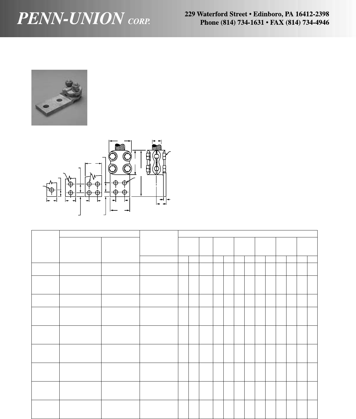
ALUMINUM WIDE RANGE TERMINALS • TYPES RAA AND RAAC
Heavy Duty Cable to Flat
High strength electrical aluminum alloy.
Massive extra thick sections. Conforming contact grooves. Gen-
erous extra long contact lengths.
Large size, high strength, anodized and lubricated 2024T4 alu-
minum alloy clamping hardware.
Bolt heads pocketed for single wrench installation. Rounded con-
tours.
NEMA drilling supplied. Other drilling, or undrilled, available on
request.
There may be some special operating conditions where copper
flashed pad may be desired on the tongue. Add suffix “C” to the
catalog designation. For example: RAAC-013-D. If tin plated ter-
minals are preferred, add “-TN” to catalog numbers. Example:
RAA-013-D-TN.
For tongue mounting hardware, suffix catalog number with
“-TMH.” Example: RAA-013-D-TMH. (Aluminum hardware
provided for type RAA, steel hardware for type RAAC.)
Conductor Range Approximate Dimensions
Wire J K
Diameter G Bolt Hole
Catalog Range‡ Max. Dia. Dia. L M T W
Number Aluminum ACSR in in mm in in mm in mm in mm in mm in mm
RAA-013-S 6 Str.-2/0 Str. 6-2/0 .184- .447 3/419 1/2*9/16 14 37/8 98 2 51 3/810 21/16 52
RAA-013-D 6 Str.-2/0 Str. 6-2/0 .184- .447 3/419 1/2*9/16 14 51/4133 2 51 3/810 21/16 52
RAA-025-S 6 Str.-250 MCM 6-4/0 .184- .575 7/822 1/29/16 14 45/8117 23/4 70 3/810 21/8 54
RAA-025-D 6 Str.-250 MCM 6-4/0 .184- .575 7/822 1/29/16 14 6 152 23/4 70 3/810 21/8 54
RAA-025-F 6 Str.-250 MCM 6-4/0 .184- .575 7/822 1/29/16 14 6 152 23/4 70 3/810 21/8 54
RAA-040-D 3/0 Str.-400 MCM 3/0-336.4 .470- .728 15/16 24 1/29/16 14 61/4159 3 76 3/810 21/4 57
RAA-040-F 3/0 Str.-400 MCM 3/0-336.4 .470- .728 15/16 24 1/29/16 14 61/4159 3 76 3/810 21/4 57
RAA-065-D 250-650 MCM 266.8-556.5 .575- .953 1 25 1/29/16 14 63/4171 31/2 89 7/16 11 25/8 67
RAA-065-F 250-650 MCM 266.8-556.5 .575- .953 1 25 1/29/16 14 63/4171 31/2 89 7/16 11 25/8 67
RAA-065-E 250-650 MCM 266.8-556.5 .575- .953 1 25 1/29/16 14 73/4197 31/2 89 3/810 25/8 67
RAA-090-D 500-900 MCM 477-795 .814-1.140 11/16 27 1/29/16 14 7 178 33/4 95 7/16 11 23/4 70
RAA-090-F 500-900 MCM 477-795 .814-1.140 11/16 27 1/29/16 14 7 178 33/4 95 7/16 11 23/4 70
RAA-090-E 500-900 MCM 477-795 .814-1.140 11/16 27 1/29/16 14 8 203 33/4 95 3/810 23/4 70
RAA-125-D 600-1250 MCM 556.5-1113 .879-1.293 13/16 30 5/89/16 14 71/2191 41/4108 7/16 11 33/8 86
RAA-125-F 600-1250 MCM 556.5-1113 .879-1.293 13/16 30 5/89/16 14 71/2191 41/4108 7/16 11 33/8 86
RAA-125-E 600-1250 MCM 556.5-1113 .879-1.293 13/16 30 5/89/16 14 81/2216 41/4108 7/16 11 33/8 86
RAA-160-D 900-1600 MCM 795-1431 1.040-1.459 11/432 5/89/16 14 73/4197 41/2114 7/16 11 31/2 89
RAA-160-F 900-1600 MCM 795-1431 1.040-1.459 11/432 5/89/16 14 73/4197 41/2114 7/16 11 31/2 89
RAA-160-E 900-1600 MCM 795-1431 1.040-1.459 11/432 5/89/16 14 83/4222 41/2114 7/16 11 31/2 89
RAA-200-D 1250-2000 MCM 1113-1780 1.290-1.632 17/16 37 3/49/16 14 81/4210 5 127 1/213 4 102
RAA-200-F 1250-2000 MCM 1113-1780 1.290-1.632 17/16 37 3/49/16 14 81/4210 5 127 1/213 4 102
RAA-200-E 1250-2000 MCM 1113-1780 1.290-1.632 17/16 37 3/49/16 14 91/4235 5 127 1/213 4 102
RAA-300-D 2000-3000 MCM 1780-2870 1.602-1.998 21/854 3/49/16 14 81/2216 51/4133 13/835 41/2114
RAA-300-F 2000-3000 MCM 1780-2870 1.602-1.998 21/854 3/49/16 14 81/2216 51/4133 1 25 41/2114
RAA-300-E 2000-3000 MCM 1780-2870 1.602-1.998 21/854 3/49/16 14 91/2241 51/4133 3/419 41/2114
*Denotes 2 bolt clamping element.
‡For conversion to metric range, see page 175.
A
W
J
T
G
M
L
K
13/4"
(44 mm)
4"
(102 mm)
13/4"
(44 mm)
11/8"
(29 mm)
2"
(51 mm)
2"
(51 mm)
K
5/8"
(16 mm) K
13/4"
(44 mm)
3"
(76 mm)
13/4"
(44 mm)
5/8"
(16 mm)
(Suffix E)(Suffix F)(Suffix D)(Suffix S)
83

BRONZE PENN-LUG • TYPE PNL
1-Hole tongue
Wire Approximate Dimensions
Diameter
Catalog Conductor Range‡ C K H L T W J Wrench
Number Range in in mm in mm in mm in mm in mm in mm in Size
PNL-8 14 Solid-8 Str. .064- .146 3/16 5 13/64 5 7/16 11 7/822 3/32 2.38 3/810 #12-24 Screw Driver Slot
PNL-4 14 Solid-4 Str. .064- .232 17/64 7 17/64 7 9/16 14 11/432 9/64 3.57 17/32 13 5/16-24 Screw Driver Slot
PNL-1/0 8 Solid-1/0 Str. .128- .375 3/810 21/64 8 25/32 20 119/32 40 9/64 3.57 47/64 16 1/2-20 1/4
PNL-250 6 Solid-250 MCM .162- .575 7/16 11 25/64 10 13/64 27 131/32 50 1/83.17 15/16 24 5/8-18 5/16
PNL-500 4 Solid-500 MCM .204- .815 3/419 17/32 13 115/32 43 3 76 1/46.35 13/835 15/16-16 3/8
PNL-1000 500 MCM-1000MCM .815-1.153 11/16 17 9/16 14 2 51 37/899 3/89.52 13/444 13/8-14 1/2
‡For conversion to metric range, see page 175.
BRONZE PENN-LUG • TYPE PNL
2 or 4 Hole Tongue
Wire Approximate Dimensions
Diameter
Catalog Conductor Range‡ C K H L T W J M Fig. Wrench
Number Range in in mm in mm in mm in mm in mm in mm in in mm No. Size
PNL-1/0-2 8 Sol.-1/0 Str. .128- .375 7/16 11.1 11/32 8.7 27/32 21 23/4 70 3/16 4.7 3/419 1/2-20 1 25 1 1/4
PNL-1/0-2N 8 Sol.-1/0 Str. .128- .375 5/815.8 9/16 14.2 27/32 21 39/16 90 3/16 4.7 1 25 1/2-20 13/444 1 1/4
PNL-250-2 6 Sol.-250 MCM .162- .575 7/16 11.1 7/16 11.1 11/32 26 27/8 73 7/32 5.5 15/16 24 5/8-18 1 25 1 1/4
PNL-250-2N• 6 Sol.-250 MCM .162- .575 5/815.8 9/16 14.2 11/829 41/4108 7/32 5.5 1 25 3/4-16 13/444 1 3/8
PNL-500-2 4 Sol.-500 MCM .204- .815 7/16 11.1 7/16 11.1 115/32 36 33/8 86 5/16 7.9 13/835 15/16-16 1 25 1 3/8
PNL-500-2N• 4 Sol.-500 MCM .204- .815 5/815.8 9/16 14.2 115/32 37 43/8111 5/16 7.9 13/835 15/16-16 13/444 1 3/8
PNL-500-4N 4 Sol.-500 MCM .204- .815 5/815.8 9/16 14.2 115/32 37 43/8111 1/46.3 3 76 15/16-16 13/444 2 3/8
PNL-1000-2 500 MCM-1000 MCM .815-1.153 9/16 14.2 9/16 14.2 2 51 47/8124 3/89.5 13/444 13/8-14 11/238 1 3/8
PNL-1000-2N• 500 MCM-1000 MCM .815-1.153 5/815.8 9/16 14.2 2 51 47/8124 3/89.5 115/16 49 13/8-14 13/444 1 3/8
PNL-1000-4N 500 MCM-1000 MCM .815-1.153 5/815.8 9/16 14.2 2 51 47/8124 1/46.3 3 76 13/8-14 13/444 2 3/8
‡For conversion to metric range, see page 175.
•CSA Listed
Body is cast from high strength corrosion resistant cop-
per alloy. Steel screw, cadmium plated. Lug can be fur-
nished electro-tinned or silver plated as desired. For tin
add “-TN” to catalog number. For silver add “-SV” to
catalog number.
THE ECONOMY LUG WITH QUALITY IMPROVEMENTS
Screw tightens directly on the conductor forcing the con-
ductor into intimate contact with the body for maximum
conductivity.
Flat bottom allows mounting either on tongue only or with
full contact surface.
Inspection hole for proper cable insertion.
Locking boss available at an additional cost, contact factory.
Lug can be furnished electro-tinned or silver plated, as
desired: For tin add “-TN” to catalog number. For silver
add “-SV” to catalog number.
CU
90°C
CU
90°C
M
W
CKL
J
H
T
M
WM
CKL
FIG. 2FIG. 1
T
W
CKLJ
H
84
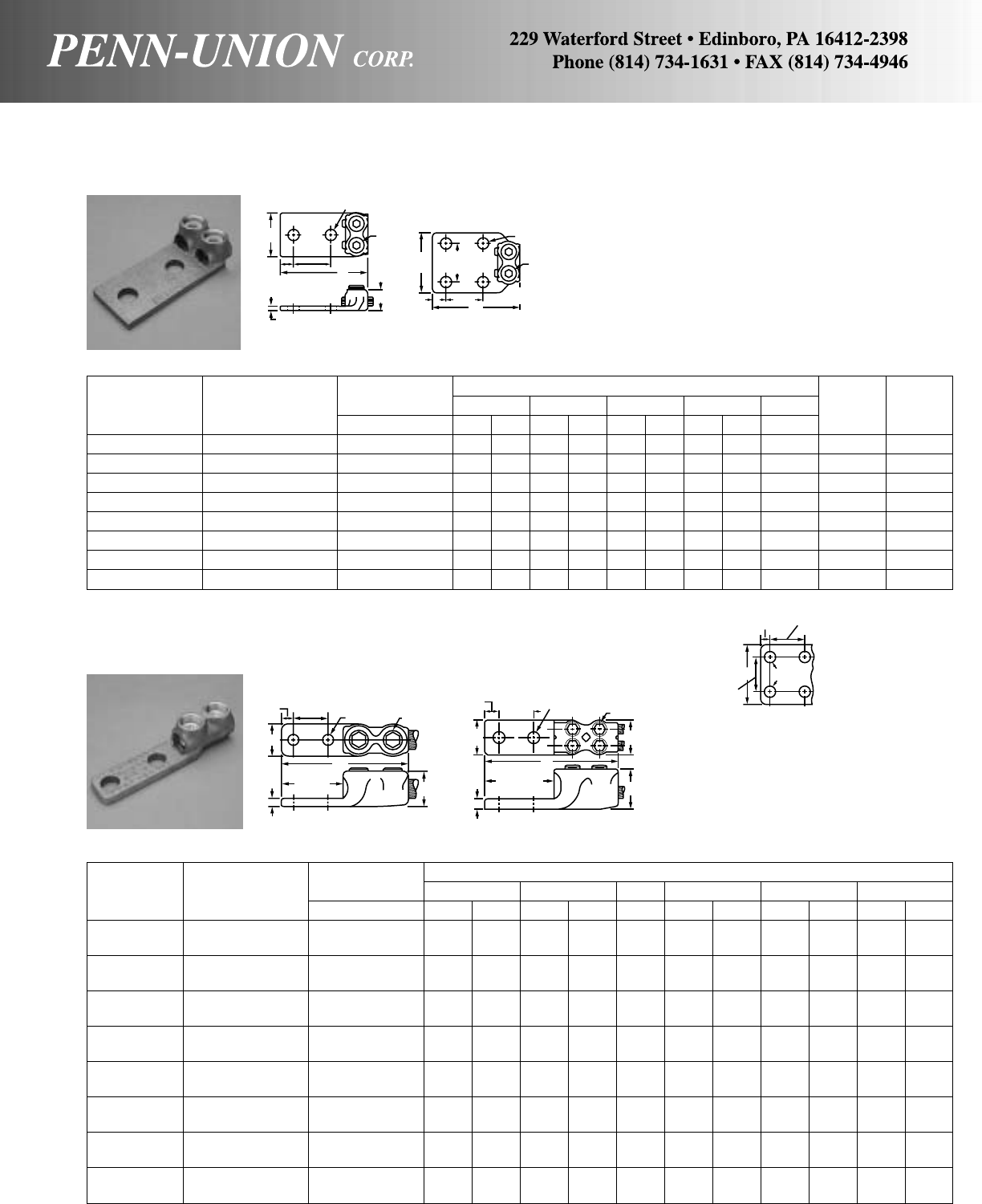
Wire Diameter Approximate Dimensions
Catalog Conductor Range‡ H L T W J Fig. Wrench
Number Range in in mm in mm in mm in mm in No. Size
P2NL-1/0-2N 8 Sol.-1/0 Str. .128- .375 27/32 21 37/8 98 5/16 8 11/238 1/2-20 1 1/4
P2NL-1/0-4N 8 Sol.-1/0 Str. .128- .375 27/32 21 37/8 98 1/4 6 3 76 1/2-20 2 1/4
P2NL-250-2N 6 Sol.-250 MCM .162- .575 11/829 4 102 5/16 8 13/444 3/4-16 1 3/8
P2NL-250-4N 6 Sol.-250 MCM .162- .575 11/829 4 102 1/4 6 3 76 3/4-16 2 3/8
P2NL-500-2N 4 Sol.-500 MCM .204- .815 115/32 37 41/2114 3/810 21/264 15/16-16 1 3/8
P2NL-500-4N 4 Sol.-500 MCM .204- .815 115/32 37 41/2114 5/16 8 3 76 15/16-16 2 3/8
P2NL-1000-2N 500 MCM-1000 MCM .815-1.153 2 51 47/8124 1/213 3 76 13/8-14 1 3/8
P2NL-1000-4N 500 MCM-1000 MCM .815-1.153 2 51 47/8124 1/213 3 76 13/8-14 2 3/8
‡For conversion to metric range, see page 175.
BRONZE TERMINAL LUGS • TYPE PPNL & PP2NL
*-2, -4, denotes 2 or 4 hole tongues.
‡For conversion to metric range, see page 175.
Body is cast from high strength corrosion resis-
tant copper alloy. Steel screw, cadmium plated.
Lug can be furnished electro-tinned or silver plated
as desired. For tin add “-TN” to catalog number.
For silver add “-SV” to catalog number.
Annular serrations for better resistance to hori-
zontal pull–cable is snubbed behind the ridges.
BRONZE TERMINAL LUGS • TYPE P2NL
2 or 4 hole tongue for two wires
Wire Diameter Approximate Dimensions
Catalog Conductor Range‡ E H J L T W
Number Range in in mm in mm in in mm in mm in mm
PPNL-4/0-2* 4 Str.–4/0 Str. .232- .528 11/829 11/32 26 5/8-18 47/8124 1/4 6.35 7/822
PPNL-4/0-4* 4 Str.–4/0 Str. .232- .528 3 76 11/32 26 5/8-18 47/8124 1/4 6.35 7/822
PP2NL-4/0-2 4 Str.–4/0 Str. .232- .528 13/444 11/32 26 5/8-18 45/32 106 5/16 7.93 13/444
PP2NL-4/0-4 4 Str.–4/0 Str. .232- .528 3 76 11/32 26 5/8-18 45/32 106 5/16 7.93 13/444
PPNL-350-2 3/0 Str.–350 MCM .470- .682 11/829 11/432 3/4-16 53/16 132 5/16 7.93 11/32 26
PPNL-350-4 3/0 Str.–350 MCM .470- .682 3 76 11/432 3/4-16 53/16 132 5/16 7.93 11/32 26
PP2NL-350-2 3/0 Str.–350 MCM .470- .682 21/16 52 11/432 3/4-16 45/16 110 3/8 9.52 23/32 53
PP2NL-350-4 3/0 Str.–350 MCM .470- .682 3 76 11/432 3/4-16 45/16 110 3/8 9.52 23/32 53
PPNL-800-2 400-800 MCM .728-1.031 15/841 113/16 46 11/4-14 67/16 164 13/32 10.31 15/841
PPNL-800-4 400-800 MCM .728-1.031 3 76 113/16 46 11/4-14 67/16 164 13/32 10.31 15/841
PP2NL-800-2 400-800 MCM .728-1.031 15/841 113/16 46 11/4-14 415/16 125 1/212.70 35/16 84
PP2NL-800-4 400-800 MCM .728-1.031 3 76 113/16 46 11/4-14 415/16 125 1/212.70 35/16 84
PPNL-1000-2 750-1000 MCM .999-1.529 13/444 2 51 13/8-14 63/4171 1/212.70 13/444
PPNL-1000-4 750-1000 MCM .999-1.529 3 76 2 51 13/8-14 63/4171 1/212.70 13/444
PP2NL-1000-2 750-1000 MCM .999-1.529 13/444 2 51 13/8-14 51/8130 9/16 14.28 35/892
PP2NL-1000-4 750-1000 MCM .999-1.529 3 76 2 51 13/8-14 51/8130 9/16 14.28 35/892
9/16" DIA. (14 mm)
WJ
13/4"
(44mm)
5/8"
(16 mm) L
H
T
1-3/4"
(44mm)
9/16"
(14 mm)
WJ
5/8"
(16 mm)
1-3/4"
(44mm)
L
FIG. 1 FIG. 2
Body is cast from high strength corro-
sion resistant copper alloy. Steel screw,
cadmium plated. Lug can be furnished
electro-tinned or silver plated as desired.
For tin add “-TN” to catalog number. For
silver add “-SV” to catalog number.
1/2"
(13 mm) 13/4"
(44 mm)
E
13/4"
(44 mm)
9/16"
DIA.
(14 mm)
STANDARD
4 HOLE NEMA
DRILLING
E
1/2"
(13 mm) 13/4"
(44 mm) J
W
L
H
31/8"
(79 mm)
1/2"
(13 mm)
9/16" DIA. HOLES
(14 mm)
PPNL PP2NL
13/4"
(44 mm) 9/16" DIA. HOLES
(14 mm) J
W
H
31/8"
(79 mm)
T
L
E
T
13/4"
85
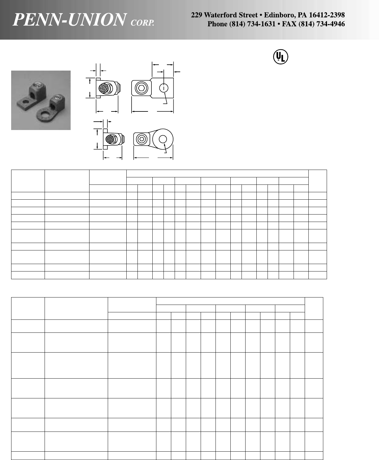
86
BRONZE VI-TITE TERMINAL LUGS • TYPE VL
Body is cast from high strength corrosion resistant copper alloy.
Bronze screw and pressure bar provides uniform clamping pres-
sure without direct screw contact on conductor. Unique designed
protuberances assure better resistance to horizontal pull. Hex
head screws can be furnished on request by suffixing catalog
numbers with “-HH”. For tin plated–suffix catalog number “-TN”.
ROUND FLANGE–ONE HOLE
Wire Diameter Approximate Dimensions
Catalog Conductor Range‡ T W D H L Amp.
Number Range in in mm in mm in mm in mm in mm Rat.
VL-22003 8 Sol.–6 Str. .128- .184 5/32 3.96 1 25 13/32 10.31 5/816 11/2 30 60
VL-22004 8 Sol.–6 Str. .128- .184 5/32 3.96 11/828 17/32 13.49 5/816 15/8 41 60
VL-22008 4 Sol.–1 Str. .204- .332 3/16 4.76 3/419 11/32 8.73 7/822 19/16 40 100
VL-22009 4 Sol.–1 Str. .204- .332 3/16 4.76 1 25 13/32 10.31 7/822 113/16 46 100
VL-22010 4 Sol.–1 Str. .204- .332 3/16 4.76 1 25 17/32 13.49 7/822 113/16 46 100
VL-22014 2 Str.–2/0 Str. .292- .419 1/4 6.35 1 25 13/32 10.31 1 25 17/8 48 150
VL-22015 2 Str.–2/0 Str. .292- .419 1/4 6.35 1 25 17/32 13.49 1 25 17/8 48 150
VL-22017 2 Str.–2/0 Str. .292- .419 1/4 6.35 11/238 25/32 19.84 1 25 25/8 60 150
VL-22018 2 Str.–2/0 Str. .292- .419 1/4 6.35 2 51 29/32 23.01 1 25 27/8 73 150
VL-22023 1/0 Str.–4/0 Str. .375- .528 3/16 4.76 1 25 17/32 13.49 11/432 21/4 57 200
VL-22025 1/0 Str.–40 Str. .375- .528 5/16 7.93 11/238 25/32 19.84 11/832 25/8 67 200
VL-22026 1/0 Str.–4/0 Str. .375- .528 5/16 7.93 2 51 29/32 23.01 11/432 31/8 79 200
VL-22029 3/0 Str.–300 MCM .470- .634 11/32 8.73 11/238 17/32 13.49 13/835 23/4 70 300
VL-22031 3/0 Str.–300 MCM .470- .634 11/32 8.73 11/238 25/32 19.84 13/835 23/4 70 300
VL-22032 3/0 Str.–300 MCM .470- .634 11/32 8.73 2 51 29/32 23.01 13/835 31/4 82 300
VL-22035 300–500 MCM .634- .815 3/8 9.52 11/238 17/32 13.49 113/16 46 27/8 73 500
VL-22038 300–500 MCM .634- .815 3/8 9.52 2 51 29/32 23.01 113/16 46 33/8 88 500
VL-22043 500-800 MCM .815-1.031 7/16 11.11 11/238 17/32 13.49 113/16 46 3 76 600
VL-22046 500–800 MCM .815-1.031 7/16 11.11 2 51 29/32 23.01 113/16 46 31/2 89 600
VL-22049 500–800 MCM .815-1.031 7/16 11.11 21/264 13/16 33.33 113/16 46 4 102 600
VL-22053 700–1000 MCM .965-1.153 15/32 11.90 11/238 17/32 13.49 21/16 52 31/4 83 800
‡For conversion to metric range, see page 175.
“-TN” and “-HH” suffixed catalog numbers are not UL Listed.
SQUARE FLANGE–ONE HOLE
Wire Diameter Approximate Dimensions
Catalog Conductor Range‡ T W D E G H L Amp.
Number Range in in mm in mm in mm in mm in mm in mm in mm Rat.
*VL-21680/82 14 Sol.–4 Str. .064- .232 9/64 3.57 17/32 13.5 17/64 6.75 17/64 6.75 21/32 17 9/16 14 11/4 32 85
VL-21683 4 Sol.–1 Str. .204- .332 7/32 5.55 5/816 9/32 7.14 3/8 9.52 7/822 7/822 111/16 43 100
VL-21685 2 Str.–2/0 Str. .292- .419 1/4 6.35 13/16 21 13/32 10.31 7/16 11.11 1 25 11/32 26 17/8 48 150
VL-21687 1/0 Str.–4/0 Str. .375- .528 1/4 6.35 1 25 13/32 10.31 1/212.7 11/432 19/32 33 23/8 60 200
VL-21689 3/0 Str.–300 MCM .470- .634 5/16 7.93 13/16 30 17/32 13.49 3/419.05 11/238 13/835 211/16 68 300
VL-21691 300–500 MCM .634- .815 3/8 9.52 11/238 11/16 17.46 3/419.05 15/841 113/16 46 3 76 500
VL-21692 300–500 MCM .634- .815 3/8 9.52 13/835 17/32 13.49 7/822.22 17/848 113/16 46 31/8 79 500
VL-21694 500–800 MCM .815-1.031 13/32 10.31 13/444 17/32 13.49 1 25.4 23/16 56 17/848 311/16 94 600
VL-21697 700–1000 MCM .965-1.153 7/16 11.11 2 51 11/16 17.46 1 25.4 23/16 56 21/16 52 4 102 800
VL-21698 700–1000 MCM .965-1.153 7/16 11.11 2 51 11/16 17.46 13/16 30.16 21/264 21/16 52 4 102 800
VL-21986 1000–1500 MCM 1.153-1.412 1/212.70 21/854 13/16 20.63 11/16 25.46 21/854 25/16 59 43/4121 1050
VL-21987 1500-2000 MCM 1.412-1.632 9/16 14.28 21/264 13/16 20.63 13/16 30.16 23/860 211/16 68 51/8130 1250
*No saddle, only available with slotted screw. ‡For conversion to metric range, see page 175.
CU
90°C
T
T
W
W
H
H
G
E
D
D
L
L

Wire Approximate Dimensions
Diameter
Catalog Conductor Range‡ T H L Amp.
Number Range in in mm in mm in mm Rat.
VL-21917 3/0 Str.–300 MCM .470- .634 5/16 7.93 11/432 41/4108 300
VL-21919 300–500 MCM .634- .815 3/8 9.52 3/835 43/4121 500
VL-21921 500-800 MCM .815-1.031 13/32 10.31 11/238 5 127 600
VL-21925 700-1000 MCM .965-1.153 7/16 11.11 13/444 51/4133 800
‡For conversion to metric range, see page 175.
“-TN” and “-HH” suffixed catalog numbers are not UL Listed.
BRONZE VI-TITE TERMINAL LUGS • TYPE VL
Body is cast from high strength corrosion resistant copper alloy.
Bronze screw and pressure bar provides uniform clamping pres-
sure without direct screw contact on conductor. Unique designed
protuberances assure better resistance to horizontal pull. Hex
head screws can be furnished on request by suffixing catalog
numbers with “-HH”. For tin plated–suffix catalog number with
“-TN”.
Rectangular flange–two holes
Wire Diameter Approximate Dimensions
Catalog Conductor Range‡ T W C D E G H L
Amp.
Number Range in in mm in mm in mm in mm in mm in mm in mm in mm Rat.
VL-21761 8 Sol.–6 Str. .128- .184 1/83.17 1/213 5/816 9/32 7.14 1/4 6.35 17/16 37 5/816 2 51 60
VL-21763 4 Sol.–1 Str. .204- .332 7/32 5.55 5/816 3/419 9/32 7.14 9/32 7.14 17/16 37 7/822 21/4 57 100
VL-21764 4 Sol.–1 Str. .204- .332 7/32 5.55 3/419 1 25 7/16 11.11 7/16 11.11 21/854 7/822 3 76 100
VL-21765 4 Sol.–1 Str. .204- .332 7/32 5.55 3/419 3/419 5/16 7.93 13/32 10.31 15/841 7/822 21/2 64 100
VL-21766 4 Sol.–1 Str. .204- .332 7/32 5.55 1 25 1 25 7/16 11.11 17/32 13.49 21/854 7/822 3 76 100
VL-21767 2 Str.–2/0 Str. .292- .419 1/46.35 13/16 21 1 25 13/32 10.31 7/16 11.11 21/854 1 25 3 76 150
VL-21768 2 Str.–2/0 Str. .292- .419 1/46.35 1 25 13/444 9/16 14.28 9/16 14.28 3 76 1 25 37/8 98 150
VL-21769 2 Str.–2/0 Str. .292- .419 1/46.35 1 25 3/419 5/16 7.93 13/32 10.31 15/841 1 25 21/2 64 150
VL-21770 2 Str.–2/0 Str. .292- .419 1/46.35 1 25 1 25 7/16 11.11 17/32 13.49 21/854 1 25 3 76 150
VL-21773/76 1/0 Str.–4/0 Str. .375- .528 7/32 5.55 1 25 1 25 7/16 11.11 7/16 11.11 21/854 11/432 31/4 83 200
VL-21774 1/0 Str.–4/0 Str. .375- .528 9/32 7.14 1 25 13/444 9/16 14.28 9/16 14.28 3 76 11/432 41/8105 200
VL-21775 1/0 Str.–4/0 Str. .375- .528 3/16 4.76 1 25 3/419 5/16 7.93 13/32 10.31 15/841 11/432 23/4 70 200
VL-21779 3/0 Str.–300 MCM .470- .634 5/16 7.93 13/16 30 1 25 13/32 10.31 7/16 11.11 21/854 13/835 33/8 86 300
VL-21780 3/0 Str.–300 MCM .470- .634 5/16 7.93 13/16 30 13/444 9/16 14.28 9/16 14.28 3 76 13/835 41/4106 300
VL-21781 3/0 Str.–300 MCM .470- .634 5/16 7.93 11/238 3/419 7/16 11.11 13/32 10.31 15/841 13/835 27/8 73 300
VL-21782 3/0 Str.–300 MCM .470- .634 5/16 7.93 11/238 1 25 7/16 11.11 17/32 13.49 21/854 13/835 33/8 86 300
VL-21784 300–500 MCM .634- .815 3/89.52 13/835 1 25 13/32 10.31 7/16 11.11 21/854 113/16 46 31/2 89 500
VL-21785 300–500 MCM .634- .815 3/89.52 13/835 13/444 9/16 14.28 9/16 14.28 31/289 113/16 46 43/4121 500
VL-21786 300–500 MCM .634- .815 3/89.52 11/238 3/419 7/16 11.11 13/32 10.31 15/841 113/16 46 3 76 500
VL-21787 300–500 MCM .634- .815 3/89.52 11/238 1 25 7/16 11.11 17/32 13.49 21/854 113/16 46 31/2 89 500
VL-21789 500–800 MCM .815-1.031 13/32 10.31 13/444 1/238 9/16 14.28 9/16 14.28 3 76 113/16 46 41/2114 600
VL-21790 500–800 MCM .815-1.031 13/32 10.31 13/444 13/444 9/16 15.28 9/16 14.28 31/289 113/16 46 5 128 600
VL-21791 500–800 MCM .815-1.031 13/32 10.31 13/444 1 25 7/16 11.11 17/32 13.49 23/16 56 113/16 46 33/4 95 600
VL-21794 700–1000 MCM .965-1.153 7/16 11.11 2 51 11/238 9/16 14.28 9/16 14.28 3 76 21/16 53 43/4121 800
VL-21795 700–1000 MCM .965-1.153 7/16 11.11 2 51 13/444 9/16 14.28 5/815.87 31/289 21/16 53 51/4133 800
VL-21796 700–1000 MCM .965-1.153 7/16 11.11 2 51 1 25 7/16 11.11 17/32 13.49 23/16 56 21/16 53 4 102 800
‡For conversion to metric range, see page 175.
CU
90°C
T
W
H
G
CE
D
L
Square flange–four holes
T
3"
(76 mm)
H
13/4"
(44 mm) 9/16"
(14 mm)
13/4"
(44 mm)
9/16"
(14 mm)
31/2"
(89 mm)
L
87
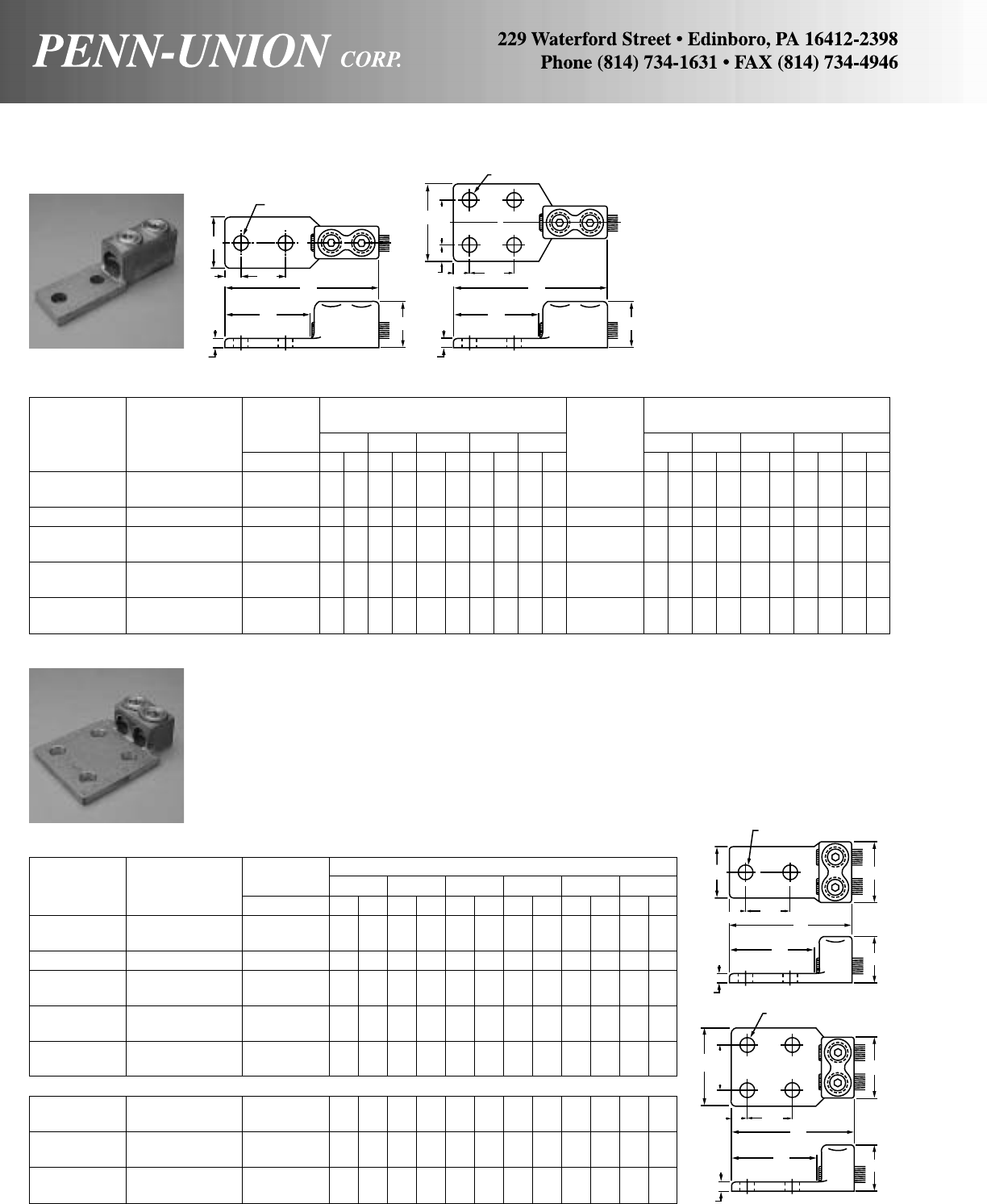
BRONZE VI-TITE TERMINAL LUGS • TYPES VVL & VL2
Wire Approximate Dimensions Approximate Dimensions
Catalog Diameter 2-Hole Tongue Catalog 4-Hole Tongue
Number Conductor Range‡ L W H G T Number LWH GT
2 Hole Range in in mm in mm in mm in mm in mm 4 Hole in mm in mm in mm in mm in mm
VVL-21766 4 Sol.–1 Str. .204- .332 45/8117 11/432 7/822 3 76 1/4 6– –––– – –––––
VVL-21768 2 Str.–2/0 Str. .292- .419 43/4121 11/432 11/32 26 3 76 1/4 6– –––– – –––––
VVL-21774 1/0 Str.–4/0 Str. .375- .528 51/8130 1 25 19/32 33 3 76 1/4 6– –––– – –––––
VVL-21780/82 3/0 Str.–350 MCM .470- .682 53/813713/16 30 13/835 3 76 5/16 8 VVL-21918 51/4133 3 76 11/432 3 75 5/16 8
VVL-21785 300–500 MCM .634- .815 61/8156 13/835 113/16 46 31/289 3/810 VVL-21919 61/8156 3 76 113/16 46 31/289 3/810
VVL-21790 500–800 MCM .815-1.031 61/2165 13/444 113/16 46 31/483 3/810 VVL-21921 61/2165 3 76 113/16 46 31/483 3/810
VVL-21795 700–1000 MCM .965-1.153 63/4171 2 51 21/16 52 31/483 7/16 11 VVL-21925 61/2165 3 76 21/16 52 31/483 3/810
VVL-21797 1000-1500 MCM 1.153-1.412 71/4184 2 51 25/16 59 31/483 5/816 VVL-21926 71/4184 3 76 25/16 59 31/483 1/213
VVL-21799 1500–2000 MCM 1.412-1.632 85/8219 21/264 23/470 31/483 5/816 VVL-21928 85/8219 3 76 23/470 31/483 5/816
‡For conversion to metric range, see page 175.
Catalog Wire Diameter Approximate Dimensions
Number Conductor Range‡ L M W H G T
2-Hole Tongue Range in in mm in mm in mm in mm in mm in mm
VL2-21766 4 Sol.-1 Str. .204- .332 315/16 100 13/16 30 3/4 19 7/822 31/879 7/32 6
VL2-21768 2 Str.-2/0 Str. .292- .419 4 102 11/2 38 11/2 38 11/32 26 31/879 7/32 6
VL2-21774 1/0 Str.-4/0 Str. .375- .528 41/4108 13/4 44 13/4 44 19/32 33 31/879 1/4 6
VL2-21782 3/0 Str.-350 MCM .470- .682 45/16 110 115/16 49 11/2 38 13/835 31/879 5/16 8
VL2-21785 300-500 MCM .634- .815 41/2114 23/8 60 2 51 113/16 46 31/289 3/810
VL2-21790 500-800 MCM .815-1.031 45/8117 213/16 71 21/8 54 113/16 46 31/879 7/16 11
VL2-21795 700-1000 MCM .965-1.153 55/16 135 31/8 79 23/8 60 21/16 52 31/879 1/213
VL2-21797 1000-1500 MCM 1.153-1.412 6 152 4 102 27/8 73 25/16 59 31/483 5/816
VL2-21799 1500-2000 MCM 1.412-1.632 61/8156 43/8111 3 76 211/16 68 31/483 3/418
4-Hole Tongue
VL2-21918 3/0 Str.-350 MCM .470- .682 45/16 110 3 76 3 76 13/835 31/879 5/16 8
VL2-21919 300-500 MCM .634- .815 47/16 113 23/8 60 3 76 113/16 46 31/879 3/810
VL2-21921 500-800 MCM .815-1.031 45/8117 213/16 71 3 76 113/16 46 31/879 7/16 11
VL2-21925 700-1000 MCM .965-1.153 55/16 135 31/8 79 31/4 83 21/16 52 31/483 1/213
VL2-21926 1000-1500 MCM 1.153-1.412 6 152 4 102 31/2 90 25/16 59 31/483 5/816
VL2-21928 1500-2000 MCM 1.412-1.632 61/8156 43/8111 4 102 211/16 68 31/483 5/816
‡For conversion to metric range, see page 175.
Body is cast from high strength
corrosion resistant copper al-
loy. Bronze screw and pressure
bar provides uniform clamping
pressure without direct screw
contact on conductor. Unique
designed protuberances as-
sure better resistance to hori-
zontal pull. Hex head screws
can be furnished on request by
suffixing catalog numbers with
“-HH”. For tin plated–suffix
catalog number with “-TN”.
W
L
G
T
H
5/8"
(16 mm) 13/4"
(44 mm)
W
9/16" DIA.
(14 mm)
9/16" DIA.
(14 mm)
1
3
/
4
"
(44 mm)
5/8"
(16 mm) 1-3/4"
(44 mm)
5/8"
(16 mm) L
G
T
H
L
G
T
H
M
W
9/16" DIA.
(14 mm)
9/16" DIA.
(14 mm)
W
1-3/4"
(44 mm)
T
GH
L
M
1-3/4"
(44 mm)
5/8"
(16 mm)
1-3/4"
(44 mm)
5/8"
(16 mm)
DOUBLE HEAD
TYPE VL2
TANDEM HEAD
TYPE VVL
88
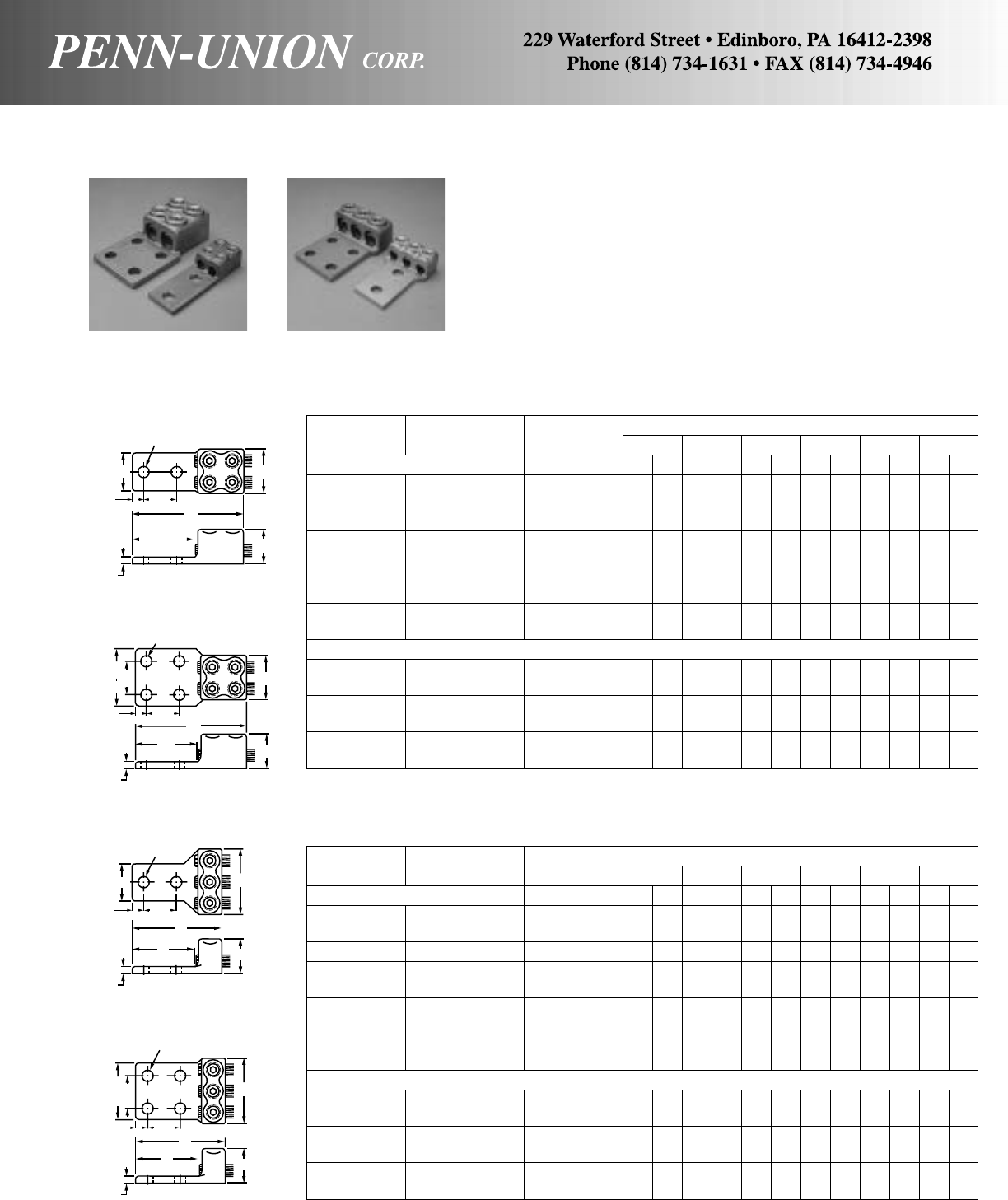
BRONZE VI-TITE TERMINAL LUGS • TYPES VVL2 & VL3
Body is cast from high strength corrosion resistant copper alloy.
Bronze screw and pressure bar provides uniform clamping
pressure without direct screw contact on conductor. Unique
designed protuberances assure better resistance to horizontal
pull. Hex head screws can be furnished on request by suffixing
catalog numbers with “-HH”. For tin plated–suffix catalog number
with “-TN”.
TYPE VVL2
Catalog Conductor Wire Diameter Approximate Dimensions
Number Range Range‡ L M W H G T
2-Hole Tongue in in mm in mm in mm in mm in mm in mm
VVL2-21766 4 Sol.–1 Str. .204- .332 43/4121 11/4 32 11/2 38 7/822 31/879 1/4 6
VVL2-21768 2 Str.–2/0 Str. .292- .419 47/8124 11/2 38 11/2 38 11/32 26 31/879 1/4 6
VVL2-21774 1/0 Str.–4/0 Str. .375- .528 51/4133 13/4 44 13/4 44 19/32 33 31/879 1/4 6
VVL2-21780/82 3/0 Str.–350 MCM .470- .682 51/2140 115/16 49 11/2 38 13/835 31/879 5/16 8
VVL2-21785 300–500 MCM .634- .815 53/4146 23/8 60 23/8 60 113/16 46 31/879 3/810
VVL2-21790 500–800 MCM .815-1.031 61/8156 213/16 71 13/4 44 113/16 46 31/879 1/213
VVL2-21795 700-1000 MCM .965-1.153 65/8168 31/8 79 21/8 54 21/16 52 31/879 1/213
VVL2-21797 1000–1500 MCM 1.153-1.412 73/4197 41/8105 23/4 70 25/16 59 31/879 9/16 14
VVL2-21799 1500-2000 MCM 1.412-1.632 8 203 43/8111 3 76 211/16 68 31/879 5/816
4-Hole Tongue
VVL2-21918 3/0 Str.–350 MCM .470- .682 51/2140 115/16 49 3 76 13/835 31/879 5/16 8
VVL2-21919 300–500 MCM .634- .815 53/4146 23/8 60 3 76 113/16 46 31/879 3/810
VVL2-21921 500-800 MCM .815-1.031 61/8156 213/16 71 3 76 113/16 46 31/879 7/16 11
VVL2-21925 700-1000 MCM .965-1.153 65/8168 31/8 79 4 102 21/16 52 31/879 1/213
VVL2-21926 1000-1500 MCM 1.153-1.412 73/4197 41/8105 4 102 25/16 59 31/879 1/213
VVL2-21928 1500-2000 MCM 1.412-1.632 8 203 43/8111 4 102 211/16 68 31/879 5/816
‡For conversion to metric range, see page 175.
TYPE VL3
Catalog Conductor Wire Diameter Approximate Dimensions
Number Range Range‡ L M W H G T
2-Hole Tongue in in mm in mm in mm in mm in mm in mm
VL3-21766 4 Sol.–1 Str. .204- .332 315/16 100 17/8 48 11/2 38 7/822 31/879 1/4 6
VL3-21768 2 Str.–2/0 Str. .292- .419 4 102 23/16 56 15/8 41 11/32 26 31/879 7/32 6
VL3-21774 1/0 Str.–4/0 Str. .375- .528 41/4108 25/8 67 17/8 46 19/32 33 31/879 1/4 6
VL3-21782 3/0 Str.–350 MCM .470- .682 45/16 110 27/8 73 11/2 38 13/835 31/879 5/16 8
VL3-21785 300-500 MCM .634- .815 41/2114 31/2 89 21/2 64 113/16 46 31/879 3/810
VL3-21790 500-800 MCM .815-1.031 45/8117 43/16 106 21/2 64 113/16 46 31/879 7/16 11
VL3-21795 700-1000 MCM .965-1.153 55/16 135 45/8117 21/2 64 21/16 52 31/483 1/213
VL3-21797 1000-1500 MCM 1.153-1.412 6 152 6 152 21/2 64 25/16 59 31/879 5/816
VL3-21799 1500-2000 MCM 1.412-1.632 61/8156 63/4171 3 76 211/16 68 31/879 5/816
4-Hole Tongue
VL3-21918 3/0 Str.–350 MCM .470- .682 45/16 110 27/8 73 3 76 13/835 31/879 5/16 8
VL3-21919 300-500 MCM .634- .815 47/16 113 31/2 89 3 76 113/16 46 31/879 3/810
VL3-21921 500-800 MCM .815-1.031 45/8117 43/16 106 3 76 113/16 46 31/879 1/213
VL3-21925 700-1000 MCM .965-1.153 55/16 135 45/8117 3 76 21/16 52 31/483 1/213
VL3-21926 1000-1500 MCM 1.153-1.412 6 152 6 152 31/2 89 25/16 59 31/879 5/816
VL3-21928 1500-2000 MCM 1.412-1.632 61/8156 63/4171 4 102 211/16 68 31/879 5/816
‡For conversion to metric range, see page 175.
DOUBLE TANDEM HEAD
TYPE VVL2 TRIPLE HEAD
TYPE VL3
9/16" DIA. HOLES
(14 mm)
WM
H
G
L
T
1-3/4"
(44 mm)
9/16" DIA. HOLES
(14 mm)
WM
1-3/4"
(44 mm) L
G
T
H
2 HOLE TONGUE
4 HOLE TONGUE
2 HOLE TONGUE
4 HOLE TONGUE
W
9/16" DIA. HOLES
(14 mm)
M
H
L
G
T
9/16" DIA. HOLES
(14 mm)
W
1-3/4"
(44 mm)
1-3/4"
(44 mm)
M
H
L
G
T
5/8"
(16 mm)
1-3/4"
(44 mm)
5/8"
(16 mm)
5/8"
(16 mm) 1-3/4"
(44 mm)
5/8"
(16 mm)
89
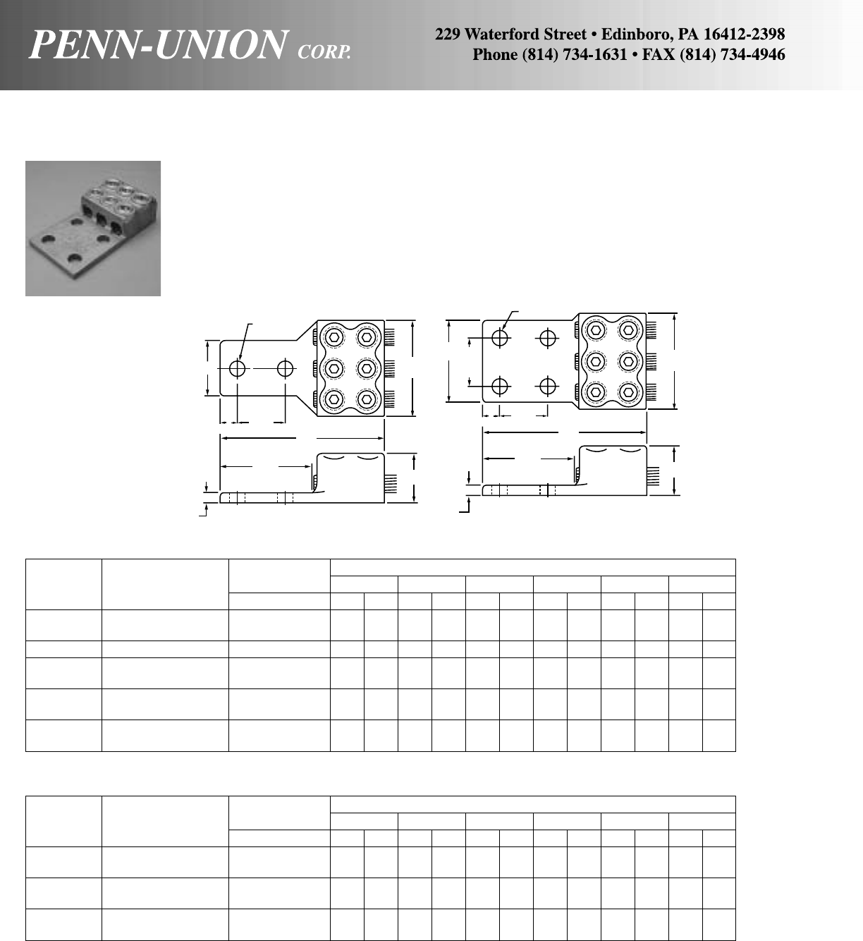
BRONZE VI-TITE TERMINAL LUGS • TYPE VVL3
Body is cast from high strength corrosion resistant copper alloy.
Bronze screw and pressure bar provides uniform clamping
pressure without direct screw contact on conductor. Unique
designed protuberances assure better resistance to horizontal
pull. Hex head screws can be furnished on request by suffixing
catalog numbers with “-HH”. For tin plated–suffix catalog number
with “-TN”.
2-HOLE TONGUE
Wire Diameter Approximate Dimensions
Catalog Conductor Range‡ L M W H G T
Number Range in in mm in mm in mm in mm in mm in mm
VVL3-21766 4 Sol.–1 Str. .204- .332 43/4121 17/8 48 11/238 7/822 31/879 1/4 6
VVL3-21768 2 Str.–2/0 Str. .292- .419 47/8124 23/16 56 11/238 11/32 26 31/879 1/4 6
VVL3-21774 1/0 Str.–4/0 Str. .375- .528 51/4133 25/8 67 13/444 19/32 33 31/879 1/4 6
VVL3-21782 3/0 Str.–350 MCM .470- .682 51/2140 27/8 73 11/238 13/835 31/879 5/16 8
VVL3-21785 300–500 MCM .634- .815 53/4146 31/2 89 23/860 113/16 46 31/879 3/810
VVL3-21790 500-800 MCM .815-1.031 61/8156 43/16 106 13/444 113/16 46 31/879 1/213
VVL3-21795 700–1000 MCM .965-1.153 65/8168 45/8117 21/854 21/16 52 31/879 1/213
VVL3-21797 1000-1500 MCM 1.153-1.412 73/4197 6 152 23/470 25/16 59 31/879 9/16 14
VVL3-21799 1500-2000 MCM 1.412-1.632 8 203 63/4171 3 76 211/16 68 31/879 5/816
‡For conversion to metric range, see page 175.
4-HOLE TONGUE
Wire Diameter Approximate Dimensions
Catalog Conductor Range‡ L M W H G T
Number Range in in mm in mm in mm in mm in mm in mm
VVL3-21918 3/0 Str.–350 MCM .470- .682 51/2140 27/8 73 3 76 13/835 31/879 5/16 8
VVL3-21919 300-500 MCM .634- .815 53/4146 31/2 89 3 76 113/16 46 31/879 3/810
VVL3-21921 500-800 MCM .815-1.031 61/8156 43/16 106 3 76 113/16 46 31/879 7/16 11
VVL3-21925 700-1000 MCM .965-1.153 65/8168 45/8117 4 102 21/16 52 31/879 1/213
VVL3-21926 1000-1500 MCM 1.153-1.412 73/4197 6 152 4 102 25/16 59 31/879 1/213
VVL3-21928 1500-2000 MCM 1.412-1.632 8 203 63/4171 4 102 211/16 68 31/879 5/816
‡For conversion to metric range, see page 175.
9/16"
(14 mm) DIA.
9/16"
(14 mm) DIA.
WM
H
L
G
T
5/8"
(16 mm) 13/4"
(44 mm)
W
1
3
/
4
"
(44 mm)
5/8"
(16 mm) 13/4"
(44 mm) L
G
T
H
M
THREE CABLE
TANDEM HEAD
TYPE VVL3
90
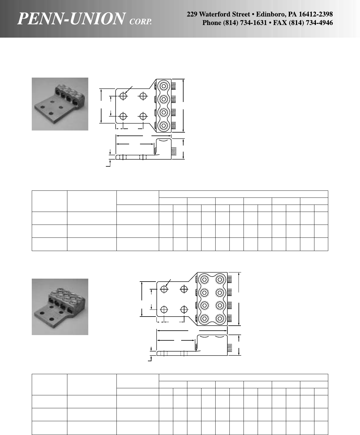
Wire Diameter Approximate Dimensions
Catalog Conductor Range‡ L M W H G T
Number Range in in mm in mm in mm in mm in mm in mm
VL4-21917/18 2/0 Str.–350 MCM .419- .682 45/16 110 37/8 98 3 76 13/835 31/879 3/810
VL4-21919 300-500 MCM .634- .815 41/2114 43/4121 31/2 89 113/16 46 31/879 1/213
VL4-21921 500-800 MCM .815-1.031 45/8117 55/8143 4 102 113/16 46 31/879 1/213
VL4-21925 700-1000 MCM .965-1.153 55/16 135 61/4159 4 102 21/16 52 31/483 1/213
VL4-21926 1000-1500 MCM 1.153-1.412 6 152 8 203 41/2114 25/16 59 31/879 5/816
VL4-21928 1500-2000 MCM 1.412-1.632 61/8156 9 229 5 127 211/16 68 31/879 3/419
‡For conversion to metric range, see page 175.
BRONZE VI-TITE TERMINAL LUGS • TYPES VL4 & VVL4
Body is cast from high strength corrosion resistant copper alloy.
Bronze screw and pressure bar provides uniform clamping pres-
sure without direct screw contact on conductor. Unique designed
protuberances assure better resistance to horizontal pull. Hex
head screws can be furnished on request by suffixing catalog
numbers with “-HH”. For tin plated–suffix catalog number with
“-TN”.
Wire Diameter Approximate Dimensions
Catalog Conductor Range‡ L M W H G T
Number Range in in mm in mm in mm in mm in mm in mm
VVL4-21918 3/0 Str.–350 MCM .470- .682 51/2140 37/8 98 3 76 13/835 31/879 3/810
VVL4-21919 300-500 MCM .634- .815 53/4146 43/4121 31/2 89 113/16 46 31/879 1/213
VVL4-21921 500-800 MCM .815-1.031 61/8156 55/8143 4 102 113/16 46 31/879 1/213
VVL4-21925 700-1000 MCM .965-1.153 65/8168 61/4159 4 102 21/16 52 31/483 1/213
VVL4-21926 1000-1500 MCM 1.153-1.412 73/4197 8 203 41/2114 25/16 59 31/879 5/816
VVL4-21928 1500-2000 MCM 1.412-1.632 8 203 9 229 5 127 211/16 68 31/879 3/419
‡For conversion to metric range, see page 175.
FOUR CABLE HEAD
TYPE VL4
FOUR CABLE TANDEM HEAD
TYPE VVL4
9/16"
(14 mm)
W
1
3
/
4
"
(44 mm)
13/4"
(44 mm)
L
M
GH
T
5/8"
(16 mm)
91
9/16"
(14 mm)
M
H
L
G
T
W
1
3
/
4
"
(44 mm)
5/8"
(16 mm) 13/4"
(44 mm)

COPPER SOLDERLESS LUGS • TYPES SLU & SAU
One hole, single collar
Approximate Dimensions Ampere
Catalog Conductor Range CDE F GH TRating
Number (Copper Stranded) in mm in mm in mm in mm in mm in mm in mm NEC
SLU-25† 10, 12, 14 5/32 3.96 9/32 7.14 15/32 5.55 15/16 25.40 3/16 4.76 5/16 7.93 21/32 16.66 25
SLU-35† 6, 8, 10, 12, 14 13/64 5.15 7/16 11.11 9/16 12.70 11/8 30.16 7/32 5.55 3/8 9.52 3/419.05 35-50
SAU-70† 4, 6, 8, 10, 12, 14 17/64 6.74 7/16 11.11 17/32 13.49 11/4 33.33 1/4 6.35 1/212.70 13/16 20.63 70
SLU-70† 2, 4, 6, 8 17/64 6.74 1/212.70 11/16 18.25 17/16 38.89 1/4 6.35 1/212.70 1 25.40 70-90
SLU-125 1/0, 1, 2, 4, 6, 8 17/64 6.74 5/815.87 7/820.63 17/8 50.00 7/16 11.11 5/815.87 111/32 34.13 125
SLU-175 3/0, 2/0, 1/0, 1, 2, 4 13/32 10.31 3/419.05 11/32 26.19 21/4 53.97 7/16 11.11 3/419.05 19/16 39.68 175
SLU-225 4/0, 3/0, 2/0, 1/0, 1, 2 11/32 8.73 1 25.40 13/32 29.36 23/8 66.67 15/32 12.70 1 25.40 113/16 46.03 225
SLU-300 350 MCM, 300 MCM, 250 MCM, 13/32 10.31 11/431.75 19/16 38.10 37/32 80.96 1/212.70 1 25.40 25/866.67 300
200 MCM, 4/0, 3/0, 2/0, 1/0
SLU-400 500 MCM, 400 MCM, 350 MCM, 13/32 10.31 11/238.10 17/849.21 41/16 107.95 29/32 23.81 11/238.10 23/469.85 400
300 MCM, 250 MCM, 4/0, 3/0, 2/0, 1/0
SLU-650 1000 MCM, 900 MCM, 800 MCM, 17/32 13.49 17/847.62 21/847.62 45/8117.47 13/16 30.16 2 50.80 311/16 93.66 650
750 MCM, 700 MCM, 600 MCM
*Add suffix “C” for CSA Certified Product
†Slotted screw
MULTIPLE SOLDERLESS LUG • TYPE LU
Catalog Conductor Range Ampere Rating
Number (Copper Stranded) NEC
LU-2 2 No. 4/0, 2 No. 3/0, 2 No. 2/0 400
LU-4 2 No. 350 MCM, 2 No. 300 MCM, 2 No. 250 MCM 600
2 No. 4/0, 2 No. 200 MCM, 2 No. 3/0, 2 No. 2/0, 2 No. 1/0
LU-6 2 No. 500 MCM, 2 No. 400 MCM, 2 No. 350 MCM 800
2 No. 300 MCM, 2 No. 250 MCM, 2 No. 4/0
*
*
*
CU
90°C
100% pure electrolytic copper for utmost efficiency.
Unique design of the concave pressure bar and V-bottom collar
assures positive contact and firm, permanent grip. For tin plated–
suffix catalog number “-TN”.
CU
90°C
Made from electrolytic copper for utmost efficiency. Screws are
cadmium plated steel. Unique design of the concave pressure
bar and V-bottom collar assures positive contact and firm, per-
manent grip. For tin plated–suffix catalog number “-TN”.
T
H
CG
E
DF
92

COPPER SINGLE-HOLE SOLDERING LUGS • TYPE SL
Approximate Dimensions
AB CDE F G H
Out- Dia. of Stud Depth of Length Length Center of Last Width
Amp. Wire Side Cable Hole Cable of Over- Stud Hole to of
Catalog Mfg’s Rate Conductor Dia.‡ Dia. Hole Size Hole Tang All End of Tang Tang
Number Size NEC Size in in mm in mm in mm in mm in mm in mm in mm in mm
SL-25 3/16 25 10 Str. .116 3/16 4.76 .143 3.57 11/64 4.36 11/32 8.73 15/32 11.90 15/16 23.81 3/16 4.76 1/4 6.35
SL-35 1/435 8 Str. .146 1/4 6.35 .186 4.76 13/64 5.15 11/32 8.73 1/212.70 11/32 26.19 7/32 5.55 3/8 9.52
SL-50 5/16 50 6 Str. .184 5/16 7.93 .238 5.95 13/64 5.15 3/8 9.52 19/32 15.08 17/32 30.95 1/4 6.35 7/16 11.11
SL-70 3/870 4 Str. .232 3/8 9.52 .289 7.54 9/32 7.14 7/16 11.11 11/16 17.46 13/8 34.92 9/32 7.14 17/32 13.49
SL-90 7/16 90 2 Str. .292 7/16 11.11 .347 8.73 9/32 7.14 1/212.70 3/419.05 11/2 38.10 11/32 8.73 5/815.87
SL-125 1/2125 1/0 Str. .375 1/212.70 .398 9.92 11/32 8.73 9/16 14.28 13/16 20.63 13/4 44.45 13/32 10.31 3/419.05
SL-150 9/16 150 2/0 Str. .419 9/16 14.28 .460 11.50 13/32 10.31 11/16 17.46 15/16 23.81 2 50.80 7/16 11.11 13/16 20.63
SL-175 5/8175 3/0 Str. .470 5/815.87 .519 13.09 13/32 10.31 25/32 19.84 1 25.40 21/8 53.97 1/212.70 29/32 23.01
SL-225 11/16 225 4/0 Str. .528 11/16 17.46 .559 14.28 13/32 10.31 27/32 21.43 15/32 29.36 23/8 60.32 17/32 13.49 31/32 24.60
SL-250 13/16 250 250 MCM .575 13/16 20.63 .660 16.66 13/32 10.31 31/32 24.60 11/431.75 221/32 67.46 5/815.87 13/16 30.16
SL-325 15/16 325 400 MCM .728 15/16 23.81 .776 19.84 13/32 10.31 13/16 30.16 15/841.27 33/8 85.72 3/419.05 13/834.92
SL-400 11/16 400 500 MCM .815 11/16 26.98 .887 22.62 13/32 10.31 11/238.10 21/853.97 45/32 105.56 15/16 23.81 19/16 39.68
SL-450 11/8450 600 MCM .893 11/828.57 .943 23.81 13/32 10.31 11/238.10 21/457.15 47/16 112.71 1 25.40 15/841.27
SL-550 15/16 550 800 MCM 1.031 15/16 33.33 1.084 26.98 17/32 13.49 2 50.80 21/263.50 51/16 128.58 11/826.57 115/16 49.21
SL-650 17/16 650 1000 MCM 1.153 17/16 36.51 1.21430.95 29/32 23.01 2 50.80 21/263.50 53/8136.52 13/16 30.16 21/853.97
‡For conversion to metric range, see page 175.
CU
90°C
Made of pure electrolytic copper tubing.
Except when requirements are shown, 25-amp. to 250-amp. will
be furnished round end, and 325-amp. to 650-amp. square end.
AB
C
G
H
D
F
E
93
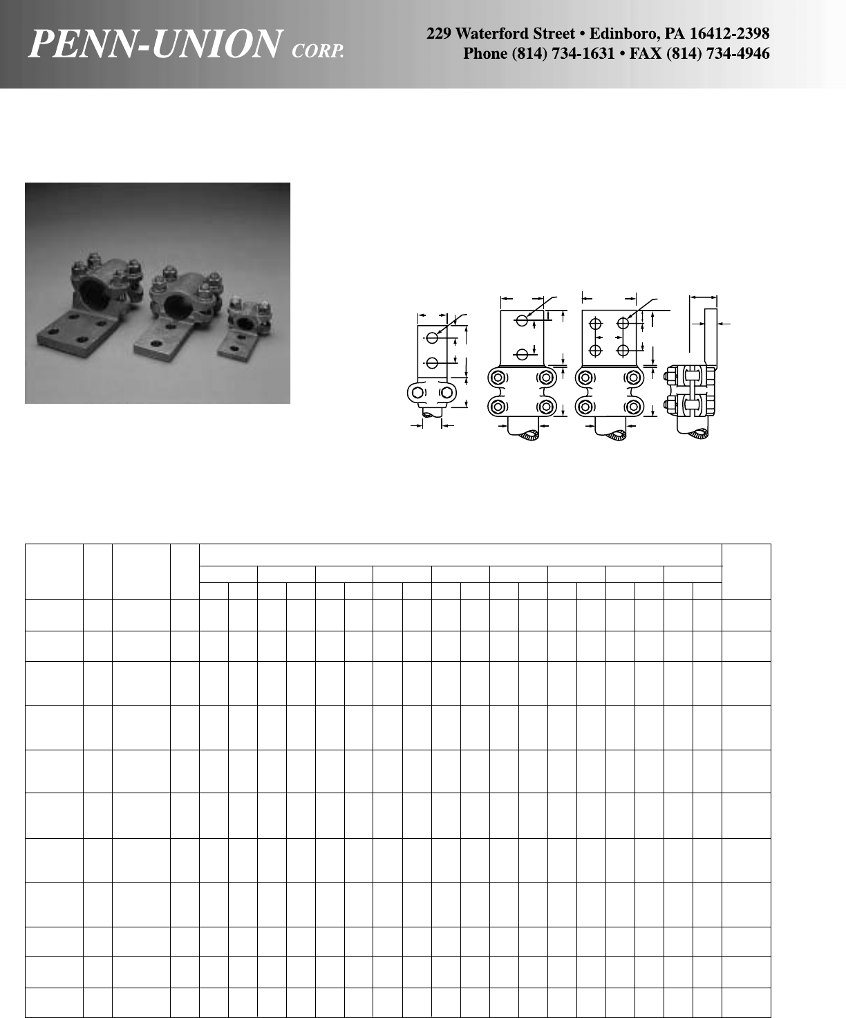
BRONZE TERMINAL LUG • TYPE RA
Side formed for tubing
No.
RHoles in Approximate Dimensions
Catalog IPS Contact Fig. WABCDEFTG
Bolt
Number Size Tongue No. in mm in mm in mm in mm in mm in mm in mm in mm in mm Size
RA-03-2B 3/8211
3/835 1 25 – – 7/16 11 13/835 2 51 7/16 11 1/467/822 3/8
RA-03-2N 3/8211
3/835 13/444 – – 9/16 14 13/835 3 76 9/16 14 9/32 77/822 3/8
RA-05-2B 1/2211
1/238 11/829 – – 7/16 11 11/238 2 51 7/16 11 5/16 87/822 3/8
RA-05-2N 1/2221
1/238 13/444 – – 9/16 14 21/457 3 76 9/16 14 5/16 87/822 3/8
RA-07-2B 3/4221
1/238 13/835 – – 7/16 11 2 51 21/457 7/16 11 5/16 813/16 21 3/8
RA-07-2N 3/4221
1/238 13/444 – – 9/16 14 2 51 3 76 9/16 14 5/16 813/16 21 3/8
RA-07-F 3/4433761
3/444 13/444 9/16 14 2 51 3 76 9/16 14 3/897/822 3/8
RA-10-2B 1 2 2 2 51 13/835 – – 7/16 11 21/457 23/860 7/16 11 3/891 25 3/8
RA-10-D 1 2 2 2 51 13/444 – – 9/16 14 21/457 31/483 9/16 14 3/891 25 3/8
RA-10-F 1 4 3 3 76 13/444 13/444 9/16 14 21/457 31/483 9/16 14 5/16 815/16 24 3/8
RA-12-D 11/4222511
3/444 – – 9/16 14 23/470 3 76 9/16 14 7/16 11 11/432 1/2
RA-12-F 11/4433761
3/444 13/444 9/16 14 23/470 3 76 9/16 14 11/32 81
5/32 29 1/2
RA-12-E 11/4434102 13/444 13/444 9/16 14 23/470 4 102 11/829 5/16 81
1/829 1/2
RA-15-D 11/2222511
3/444 – – 9/16 14 23/470 3 76 9/16 14 7/16 11 11/432 1/2
RA-15-F 11/2433761
3/444 13/444 9/16 14 23/470 3 76 9/16 14 1/213 15/16 33 1/2
RA-15-E 11/2434102 13/444 13/444 9/16 14 23/470 4 102 11/829 3/891
3/16 30 1/2
RA-20-D 2 2 2 2 51 13/444 – – 9/16 14 23/470 3 76 9/16 14 1/213 111/16 43 1/2
RA-20-F 2 4 3 3 76 13/444 13/444 9/16 14 23/470 3 76 9/16 14 1/213 111/16 43 1/2
RA-20-E 2 4 3 4 102 13/444 13/444 9/16 14 23/470 4 102 11/829 7/16 11 15/841 1/2
RA-25-D 21/2222511
3/444 – – 9/16 14 23/470 3 76 9/16 14 11/16 17 2 51 1/2
RA-25-F 21/2433761
3/444 13/444 9/16 14 23/470 3 76 9/16 14 11/16 17 2 51 1/2
RA-25-E 21/2434102 13/444 13/444 9/16 14 23/470 4 102 11/829 5/816 115/16 49 1/2
RA-30-F 3 4 3 3 76 13/444 13/444 9/16 14 31/483 3 76 9/16 14 11/16 17 21/264 5/8
RA-30-E 3 4 3 4 102 13/444 13/444 9/16 14 31/483 4 102 11/829 5/816 27/16 62 5/8
RA-35-F 31/2433761
3/444 13/444 9/16 14 31/483 3 76 9/16 14 3/419 211/16 68 5/8
RA-35-E 31/2434102 13/444 13/444 9/16 14 31/483 4 102 11/829 3/419 211/16 68 5/8
RA-40-F 4 4 3 3 76 13/444 13/444 9/16 14 31/483 3 76 9/16 14 3/419 31/879 5/8
RA-40-E 4 4 3 4 102 13/444 13/444 9/16 14 31/483 4 102 11/829 3/419 31/879 5/8
For use with aluminum conductors, order tin plated–suffix catalog numbers with “-TN”.
Made from high copper content alloy. Furnished with silicon bronze
bolts, nuts and lockwashers.
WC
F
AE
D
R
W
F
E
C
A
D
R
WC
F
AE
D
R
B
G
T
Fig. 1 Fig. 2 Fig. 3
94
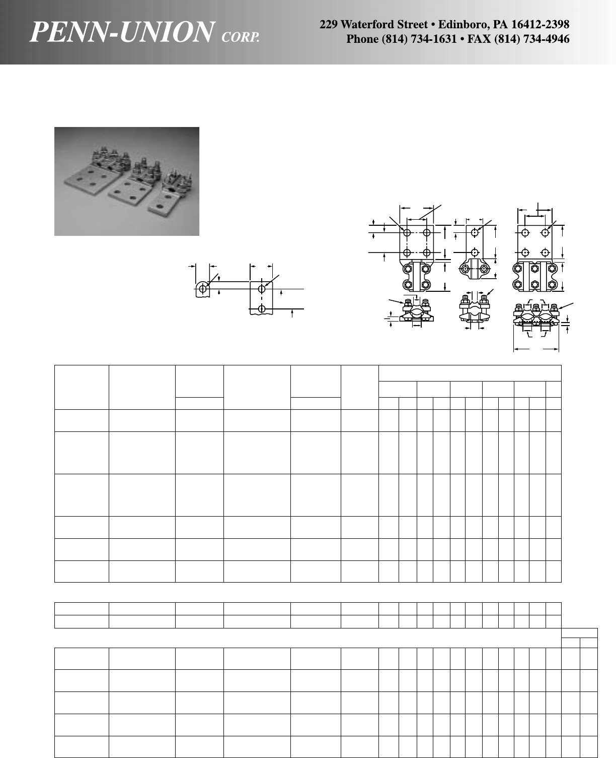
BRONZE TERMINAL LUG • TYPES RAR, RARE and RAR2
For cable range to flat
TYPE RAR
(1 cable–4 bolts)
Wire Wire No. of Approximate Dimensions
Conductor Diameter Conductor Diameter Holes
Catalog Range Range‡ Range Range‡ in D E F T W J
Number A In Bin Tongue in mm in mm in mm in mm in mm in
RAR-021-S 8 Sol.-1 Str. .128- .332 1/0 Str.-4/0 Str. .375- .528 1 21/4 57 13/4 44 3/419 5/16 8 11/2 38 3/8
RAR-021-D 6 Str.-1 Str. .184- .332 1/0 Str.-4/0 Str. .375- .528 2 21/4 57 3 76 5/816 1/4 6 11/2 38 3/8
RAR-025-D 6 Sol.-1 Str. .162- .332 1/0 Str.-250 MCM .375- .575 2 21/2 64 3 76 5/816 1/4 6 11/2 38 3/8
RAR-025-DH 6 Sol.-1 Str. .162- .332 1/0 Str.-250 MCM .375- .575 2 21/2 64 3 76 5/816 1/4 6 11/2 38 1/2
RAR-025-F 4 Sol. 1/0 Str. .204- .375 2/0 Str.-250 MCM .419- .575 4 21/2 64 3 76 5/816 1/4 6 3 76 3/8
RAR-025-FH 4 Sol.-1/0 Str. .204- .375 2/0 Str.-250 MCM .419- .575 4 21/2 64 3 76 5/816 1/4 6 3 76 1/2
RAR-050-D 1/0 Str.-4/0 Str. .375- .528 250-500 MCM .575- .815 2 21/2 64 3 76 5/816 3/8 9 13/4 44 3/8
RAR-050-DH 1/0 Str.-4/0 Str. .375- .528 250-500 MCM .575- .815 2 21/2 64 3 76 5/816 3/8 9 13/4 44 1/2
RAR-050-F 1/0 Str.-4/0 Str. .375- .528 250-500 MCM .575- .815 4 21/2 64 3 76 5/816 3/8 9 3 76 3/8
RAR-050-FH 1/0 Str.-4/0 Str. .375- .528 250-500 MCM .575- .815 4 21/2 64 3 76 5/816 3/8 9 3 76 1/2
RAR-080-D 2 Sol.-4/0 Str.. .258- .528 250-800 MCM .575-1.031 2 21/2 64 3 76 5/816 13/32 10 2 51 1/2
RAR-080-F 2 Sol.-4/0 Str. .258- .528 250-800 MCM .575-1.031 4 21/2 64 3 76 5/816 13/32 10 3 76 1/2
RAR-100-D 4/0 Str.-550 MCM .528- .855 600-1000 MCM .893-1.153 2 3 76 3 76 5/816 7/16 11 2 51 1/2
RAR-100-F 4/0 Str.-550 MCM .528- .855 600-1000 MCM .893-1.153 4 3 76 3 76 5/816 3/8 9 3 76 1/2
RAR-200-D 500-1000 MCM .815-1.153 1100-2000 MCM 1.209-1.632 2 51/4133 3 76 5/816 9/16 14 11/2 38 1/2
RAR-200-F 500-1000 MCM .815-1.153 1100-2000 MCM 1.209-1.632 4 51/4133 3 76 5/816 1/213 3 76 1/2
TYPE RARE
(1 cable–2 bolts)
RARE-025-D 6 Sol.-1 Str. .162-.332 1/0 Str.-250 MCM .375-.575 2 11/2 38 3 76 5/816 1/4 6 11/2 38 3/8
RARE-050-D 1/0 Str.-1/0 Str. .375-.528 250-500 MCM .575-.815 2 13/4 44 3 76 5/816 1/4 6 11/2 38 3/8
TYPE RAR2
(2 cables–6 bolts)
RAR2-025-D 6 Sol.-1 Str. .162- .332 1/0 Str.-250 MCM .375- .575 2 21/264 3 76 5/816 1/4 6 2 51 1/235/8 92
RAR2-025-F 6 Sol.-4/0 Str. .204- .375 2/0 Str.-250 MCM .419- .575 4 21/264 3 76 5/816 1/4 6 3 76 1/235/8 92
RAR2-050-D 1/0 Str.-4/0 Str. .375- .528 250-500 MCM .575- .815 2 21/264 3 76 5/816 1/213 21/2 64 1/241/8105
RAR2-050-E 1/0 Str.-4/0 Str. .375- .528 250-500 MCM .575- .815 4 21/264 4 102 11/829 3/8 9 4 102 3/841/8105
RAR2-080-D 2 Sol.-4/0 Str. .258- .528 250-800 MCM .575-1.031 2 211/32 59 3 76 5/816 1/213 21/2 64 1/241/4108
RAR2-080-E 2 Sol.-4/0 Str. .258- .528 250-800 MCM .575-1.031 4 211/32 59 4 102 11/829 13/32 10 4 102 1/241/4108
RAR2-100-D 4/0 Str.-550 MCM .528- .855 600-1000 MCM .893-1.153 2 3 76 3 76 5/816 1/213 21/2 64 1/249/16 116
RAR2-100-E 4/0 Str.-550 MCM .528- .855 600-1000 MCM .893-1.153 4 3 76 4 102 11/829 1/213 4 102 1/249/16 116
RAR2-200-D 500-1000 MCM .815-1.153 1100-2000 MCM 1.209-1.632 2 51/4133 3 76 5/816 9/16 14 21/2 64 1/253/8143
RAR2-200-E 500-1000 MCM .815-1.153 1100-2000 MCM 1.209-1.632 4 51/4133 4 102 5/816 1/213 4 102 1/255/8143
‡For conversion to metric range, see page 175.
L
in mm
Reversible, range taking, high strength cap.
Cast from high copper content alloy. Furnished with silicon bronze
bolts, nuts and lockwashers.
Standard NEMA drilled tongue.
W
F
1 HOLE
TONGUE
2 HOLE
TONGUE
W
9/16" DIA.
(14 mm) 9/16" DIA.
(14 mm)
13/4"
(44 mm)
9/16" DIA.
(14 mm)
F13/4"
(44 mm)
W
13/4"
(44 mm)
F
E
D
A
J
T
B
W
E
D
AJ
9/16" DIA.
(14 mm)
B
B
AJ
T
L
D
E
9/16" DIA.
(14 mm)
W
13/4"
(44 mm)
95

Wire Diameter Approximate Dimensions
Catalog A Range‡ D L M W J
Number Conductor Range in in mm in mm in mm in mm in
LS-C1E 10 Sol.-1 Str. .102-.332 11/32 9 23/8 60 11/16 27 7/822 3/8
LSN-2/0N 8 Sol.-2/0 Str. .128-.419 7/16 11 23/8 60 13/835 1 25 1/2
LS-2/0 8 Sol.-2/0 Str. .128-.419 7/16 11 2 51 11/432 1 25 3/8
LSN-025N 6 Sol.-250 MCM .162-.575 5/816 29/16 65 11/432 11/16 27 1/2
LSN-035N 2 Sol.-350 MCM .258-.682 13/16 21 31/16 78 11/432 15/16 33 1/2
LSN-050N 1/0 Sol.-500 MCM .325-.815 15/16 24 31/4 83 11/432 17/16 37 1/2
LSN-075 350-750 MCM .682-.999 11/16 27 33/16 81 11/238 119/32 40 1/2
LSN-100N 2/0 Sol.-1000 MCM .365-1.153 11/432 41/4108 123/32 44 111/16 43 1/2
LS-150E 1000-1500 MCM 1.153-1.412 11/238 43/8111 21/457 21/264 1/2
LS-200E 500-2000 MCM .325-1.632 123/32 44 51/4133 21/457 23/470 1/2
FOR 1/4" TO 3/4" THICK BAR
LS-C1E 10 Sol.-1 Str. .102-.332 11/32 9 23/8 60 11/16 27 7/822 3/8
LSN-2/0NE 8 Sol.-2/0 Str. .128-.419 7/16 11 23/4 70 13/835 1 25 1/2
LS-2/0E 8 Sol.-2/0 Str. .128-.419 7/16 11 21/2 64 11/432 1 25 3/8
LSN-025NE 6 Sol.-250 MCM .162-.575 5/816 31/16 78 11/432 11/16 27 1/2
LSN-035NE 2 Sol.-350 MCM .258-.682 13/16 21 35/16 84 11/432 15/16 33 1/2
LSN-050NE 1/0 Sol.-500 MCM .325-.815 15/16 24 33/4 95 11/432 17/16 37 1/2
LSN-075E 350-750 MCM .682-.999 11/16 27 311/16 94 11/238 119/32 40 1/2
LSN-100NE 2/0 Sol.-1000 MCM .365-1.153 11/432 41/2114 123/32 44 111/16 43 1/2
LS-150E 1000-1500 MCM 1.153-1.412 11/238 43/8111 21/457 21/264 1/2
LS-200E 500-2000 MCM .325-1.632 123/32 44 51/4133 21/457 23/470 1/2
‡For conversion to metric range, see page 175.
“N” in prefix qualifies terminal for mounting on NEMA pads.
“N” in suffix qualifies eyebolt opening to NEMA.
FOR 1/4" THICK BAR
BRONZE EYEBOLT TERMINAL • TYPE LS AND LSN
Single eyebolt type for copper cable to copper flat
A practical and highly versatile connector that may be used for
numerous applications. Used extensively by all manufacturers
who bring out flat studs, bus, or spades on their equipment. Used
also for grounding cables to steel substation structures.
Cups (bodies) are made from corrosion resistant, high conduc-
tivity copper alloy. Eyebolts are made from a special, aluminum
bronze alloy, for maximum strength.
Silicon bronze nuts and lockwashers.
96
W
D
J
L
M
A
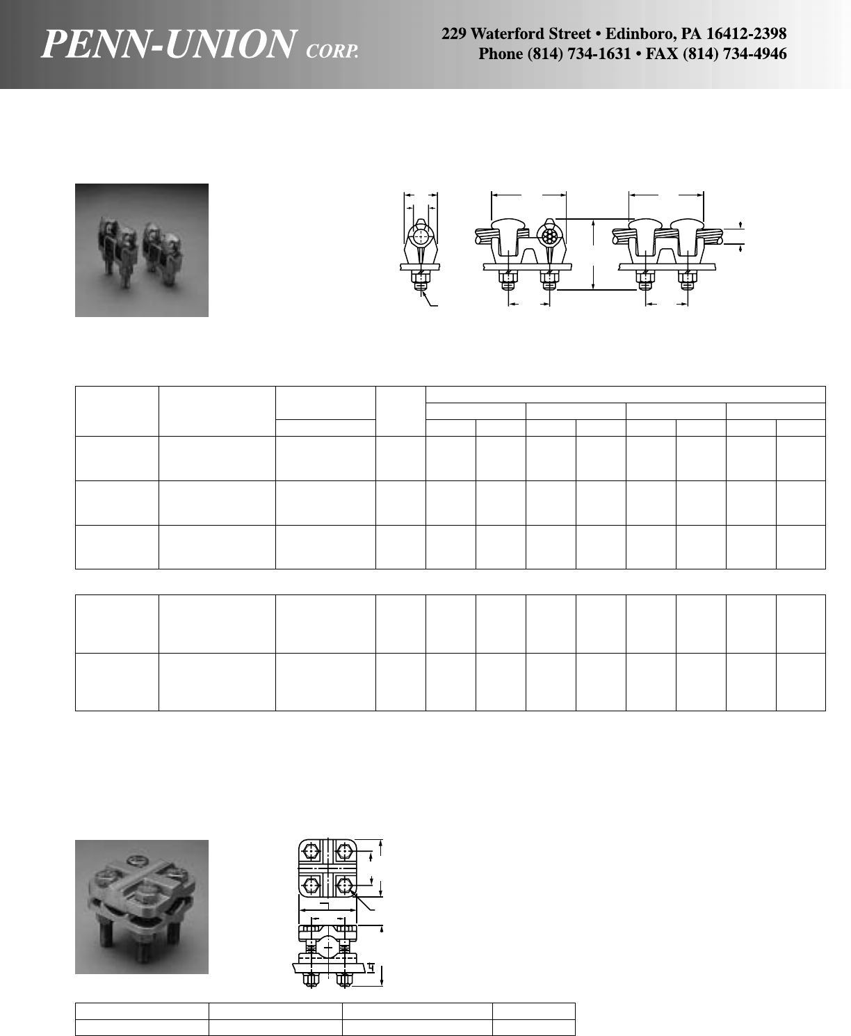
BRONZE EYEBOLT TERMINAL • TYPES LD AND LDN
Double eyebolt type for copper cable to copper flat
AWire Diameter Approximate Dimensions
Catalog Conductor Range‡ Fig. DLMW
Number Range in No.in mm in mm in mm in mm
LDN-2/0N 8 Sol.-2/0 Str. .128- .419 2 7/16 11 25/16 59 213/16 71 29/32 23
LDN-2/0N2 8 Sol.-2/0 Str. .128- .419 1 7/16 11 23/8 60 31/8 79 13/835
LDN-025N 6 Str.-250 MCM .184- .575 2 5/816 29/16 65 3 76 11/16 27
LDN-025N2 6 Str.-250 MCM .184- .575 1 5/816 25/8 67 33/8 86 15/841
LDN-035N 2 Sol.-350 MCM .258- .682 2 13/16 21 35/16 84 3 76 15/16 33
LDN-050N 1/0 Sol.-500 MCM .325- .815 2 15/16 24 31/4 83 3 76 17/16 37
LDN-075 350-750 MCM .682- .999 2 11/16 27 33/16 81 31/4 83 119/32 40
LDN-100N 2/0 Sol.-1000 MCM .365-1.153 2 11/432 313/16 97 37/16 87 111/16 43
LD-200E 500-2000 MCM .815-1.632 2 123/32 44 51/4133 4 102 23/470
FOR 1/4" TO 3/4" THICK BAR
LDN-2/0N2E 8 Sol.-2/0 Str. .128- .419 1 7/16 11 27/8 73 31/8 79 13/835
LDN-025NE 6 Sol.-250 MCM .162- .575 2 5/816 31/16 78 3 76 11/16 27
LDN-025N2E 6 Sol.-250 MCM .162- .575 1 5/816 31/16 78 33/8 86 15/841
LDN-035NE 2 Sol.-350 MCM .258- .682 2 13/16 21 35/16 84 3 76 15/16 33
LDN-050NE 1/0 Sol.-500 MCM .325- .815 2 15/16 24 33/4 95 3 76 17/16 37
LDN-075E 350-750 MCM .682- .999 2 11/16 27 311/16 94 31/4 83 119/32 40
LDN-100NE 2/0 Sol.-1000 MCM .365-1.153 2 11/432 41/16 103 37/16 87 111/16 43
LD-200E 500-2000 MCM .815-1.632 2 123/32 44 51/4133 4 102 23/470
‡For conversion to metric range, see page 175.
“N” in prefix qualifies terminal for mounting on NEMA pads.
“N” in suffix qualifies eyebolt opening to NEMA.
“2” in suffix indicates two-way cable entrance.
FOR 1/4" THICK BAR
TERMINAL CONNECTOR • TYPE CTB
For cable range or tubing range to flat four hole NEMA mounting
Catalog Number Conductor Range Wire Diameter Range‡ IPS Range
CTB-100 6 Sol.-1000 MCM .162-1.153 1/8-3/4
‡For conversion to metric range, see page 175.
• Cast from copper alloy.
• Reversible, range taking, high strength cap.
• Front or side entrance available by rotating cap 90°.
• Furnished with silicon bronze bolts, nuts and lockwashers.
• Bolts with sufficient length for mounting to a pad up to 1/2" thick.
W
D
1/2
MM
A
L
13/4"
(44 mm) 13/4"
(44 mm)
FIG. 1 FIG. 2
1
3
/
4
"
(44 mm)
3"
(76 mm)
1/2"
3"
(76 mm)
13/4"
(44 mm)
1
/
2
" MAX.
(13 mm)
3
1
/
16
"
MAX.
(78 mm)
97
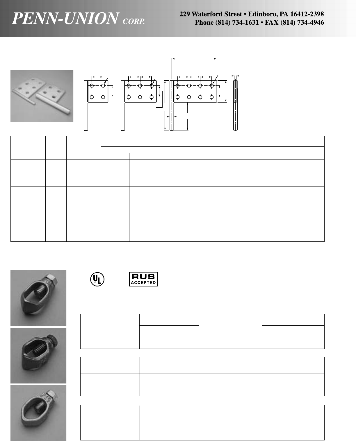
Accommodates
Rod Size Wire Diameter Range‡
Catalog Number in Conductor Range in
CAB-1M 1/210 Sol.-2 Str. .102-.292
CAB-2M* 5/88 Sol.-1/0 Str. .128-.375
CAB-3M 3/48 Sol.-1/0 Str. .128-.375
STANDARD CLAMP
CAB-0 3/814 Sol.-6 Str. .064-.184
CAB-1 1/210 Sol.-2 Str. .102-.292
CAB-2 5/88 Sol.-1/0 Str. .128-.375
CAB-3 3/48 Sol.-1/0 Str. .128-.375
CAB-4 3/44/0 Str. .528
CAB-5 1 8 Sol.-1/0 Str. .128-.375
CAB-6 1 4/0 Str. .528
ECONOMY CLAMP
Accommodates
Rod Size Wire Diameter Range‡
Catalog Number in Conductor Range in
CEB-1† 1/28 Sol.-2 Str. .128-.292
CEB-2† 5/88 Sol.-2 Str. .128-.292
CEB-3• 3/48 Sol.-2 Str. .128-.292
‡For conversion to metric range, see page 175. †RUS accepted plain and tin plated. •RUS accepted tin plated only.
For tin plating, suffix catalog number with “-TN”. * For 1/2 thread bolt and extra long body use CAB 2ML.
COPPER TRANSFORMER ADAPTOR TERMINAL • TYPE FT*
A
Stud Approximate Dimensions
Catalog Fig. Diameter M H L T
Number No. in in mm in mm in mm in mm
FT-4-037 1 3/813/4 44 35/8 92 53/16 132 1/46.35
FT-4-056 1 9/16 2 51 33/32 79 57/16 138 3/89.52
FT-4-075 1 3/421/2 64 313/16 97 515/16 151 3/89.52
FT-4-087 1 7/833/4 95 37/8 98 73/16 183 3/89.52
FT-4-118 1 13/16 41/4108 41/16 103 711/16 195 3/89.52
FT-6-037 2 3/813/4 44 53/8137 53/16 132 1/46.35
FT-6-056 2 9/16 2 51 515/32 139 57/16 138 3/89.52
FT-6-075 2 3/421/2 64 59/16 141 515/16 151 3/89.52
FT-6-087 2 7/833/4 95 55/8143 73/16 183 3/89.52
FT-6-118 2 13/16 41/4108 513/16 148 711/16 195 3/89.52
FT-8-037 3 3/813/4 44 71/8181 53/16 132 1/46.35
FT-8-056 3 9/16 2 51 77/32 183 57/16 138 3/89.52
FT-8-075 3 3/421/2 64 75/16 186 515/16 151 3/89.52
FT-8-087 3 7/833/4 95 73/8187 73/16 183 3/89.52
FT-8-118 3 13/16 41/4108 79/16 192 711/16 195 3/89.52
*We recommend using Penn-Union Cual-Aid, an oxide inhibiting compound with these connectors. When connecting aluminum or ACSR wire, wire brush the conductor with
Cual-Aid #11.
BRONZE GROUND ROD CLAMPS • TYPES CAB & CEB
Designed for multiple take-off
from the transformer eyebolt
secondary connector. Cast
from copper and electrotin
plated for use with copper or
aluminum connectors.
HEAVY DUTY CLAMP
Made from corrosion resistant cast aluminum bronze. Furnished
with silicon bronze hexagon head bolt. Socket head screws can
be furnished by suffixing catalog number with “-S”. For example:
CAB-4-S.
Type CEB is an economical ground rod clamp made from corro-
sion resistant cast aluminum bronze. Furnished with silicon bronze
hexagon head bolt.
467 LISTED
SUITABLE FOR
DIRECT BURIAL
13/4"
(44 mm) 13/4"
(44 mm) 13/4"
(44 mm)
13/4"
(44 mm) 13/4"
(44 mm)
13/4"
(44 mm)
1
3
/
4
"
(44 mm)
1
3
/
4
"
(44 mm)
13/4"
(44 mm) L
M
H
T
9/16" DIA.
(14 mm)
A
DIA.
3
7
/
16
"
(87 mm)
FIG. 1 FIG. 2 FIG. 3
CAB-M
CEB
9/16" DIA.
(14 mm) 9/16" DIA.
(14 mm)
CAB
C
98
US
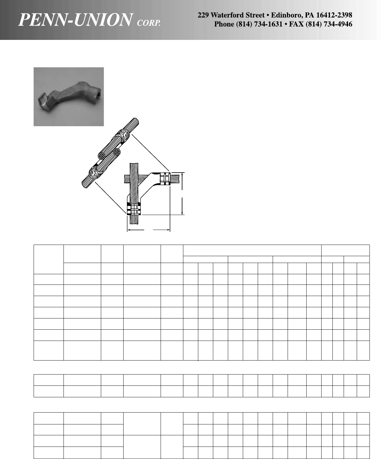
Wire Wire Approximate
Conductor Diameter Conductor Diameter Installation Dimensions
Range Range‡ Range Range‡ T&B Burndy Kearney L LL
Catalog No. No. No.
Number (Main) In (Tap) In Tool Die Crimps Tool Index Crimps Tool Die Crimps In mm In mm
GGCP-1 2 Str.-1 Str. .292-.332 2 Str.-1 Str. .292-.332 15 Ton 54H 2 Y35+ BG 1 WH-1 5/8-1 2 27/16 62 27/16 62
40 Ton 54 1
GGCP-2/0 1/0 Str.-2/0 Str. .375-.419 1/0 Str.-2/0 Str. .375-.419 15 Ton 66 1 Y45L 251 1 PH-4 K-3/413
5/892 35/892
40 Ton
GGCP-025-2/0 4/0 Sol.-.250 MCM .460-.575 1/0 Str.-2/0 Str. .375-.419 15 Ton 87H 2 Y45L 299 1 PH-4 K-1-2 1 321/32 93 321/32 93
40 Ton 87 1
GGCP-025 4/0 Sol.-.250 MCM .460-.575 4/0 Sol.-250 MCM .460-.575 15 Ton 87H 2 Y45L 299 1 PH-4 K-1-2 1 321/32 93 321/32 93
40 Ton 87 1
GGCP-050-025 500 MCM .815 4/0 Sol.-250 MCM .460-.575 15 Ton 115H 2 Y45L 936 2 PH-4 K-15/16H24
5/16 110 47/16 113
40 Ton 115 1
GGCP-050 500 MCM .815 500 MCM .815 15 Ton 115H 2 Y45L 936 2 PH-4 K-15/16H24
1/2114 41/2114
40 Ton 115 1
GGCP-075-025 750 MCM .990 4/0 Str.-250 MCM .528-.575 40 Ton 150 1 Y488H 352 1 PH-4 K-11/2H24
5/8117 59/32 134
GGCP-075-050 750 MCM .990 500 MCM .815 40 Ton 150 1 Y48BH 352 1 PH-4 K-11/2H25
9/32 134 59/32 134
GGCP-075 750 MCM .990 750 MCM .990 40 Ton 150 1 Y48BH 352 1 PH-4 K-11/2H25
1/2140 51/2140
COPPER GROUND GRID CONNECTOR • TYPE GGCP
Provides a compression connector for installing a ground grid
system in wire sizes from #2 to 750 MCM; it is ideal for installa-
tions like generating stations, substations, chemical plants and
heavy industrial plants, where fault-current surges must be dissi-
pated quickly and safely.
High-conductivity cast copper.
Faster and safer to install than exothermic welding connections.
Easier to install than similar compression ground grid connec-
tors which require bending of grid wires to install the connector
between them.
Installed with standard T & B tools and dies.
EASY TO INSPECT–Easy to inspect for proper installation. Die
imprints die number which must correspond to recommendation
cast into connector web.
LOW RESISTANCE CONNECTION–Compression joint provides
a conducting path of less resistance than an equivalent length of
the installed conductor.
UNIQUE DESIGN–Connector installation does not disturb the
position of the grid wires.
Can be used in cross-over or tap applications.
Can be imbedded in concrete or used in direct burial systems.
GGCP-2U-4/0 4/0 Str. .528 4/0 Str. .528 15 Ton 87H 2 Y45L 299 1 PH-4 K-1-2 1 343/64 93 343/64 93
40 Ton 87 1
GGCP-2U-025 250 MCM .575 250 MCM .575 15 Ton 87H 2 Y45L 299 1 PH-4 K-1-2 1 321/32 93 321/32 93
40 Ton 87 1
‡For conversion to metric range, see page 175.
+Penn-Union’s TPU-12B hydraulic hand tool can be used in place of Burndy’s Y35.
Type GGCP-2U (Both U-Shaped elements facing in same direction)
Type GGCP - GR (Special Design for use with Ground Rod)
GGCP-0255/8GR 4/0 Sol.-250 MCM .528-.575 15 Ton 87H 2 Y45L 299 1 PH-4 K-1-2 1 31/879 31/879
5/8 GR. ROD .562 40 Ton 87 1
GGCP-2/05/8GR 1/0 Str.-2/0 Str. .375-.419 15 Ton 87H 2 Y45L 299 1 PH-4 K-1-2 1 31/879 31/879
40 Ton 87 1
GGCP-0253/4GR 4/0 Sol.-250 MCM .528-.575 15 Ton 2 ––––– –4
19/64 109 47/16 113
3/4 GR. ROD .683 40 Ton 1
GGCP-2/03/4GR 1/0 Str.-2/0 Str. .375-.419 15 Ton 2 ––––– –4
19/64 109 47/16 113
40 Ton 1
PENN
UNION
L
LL
99
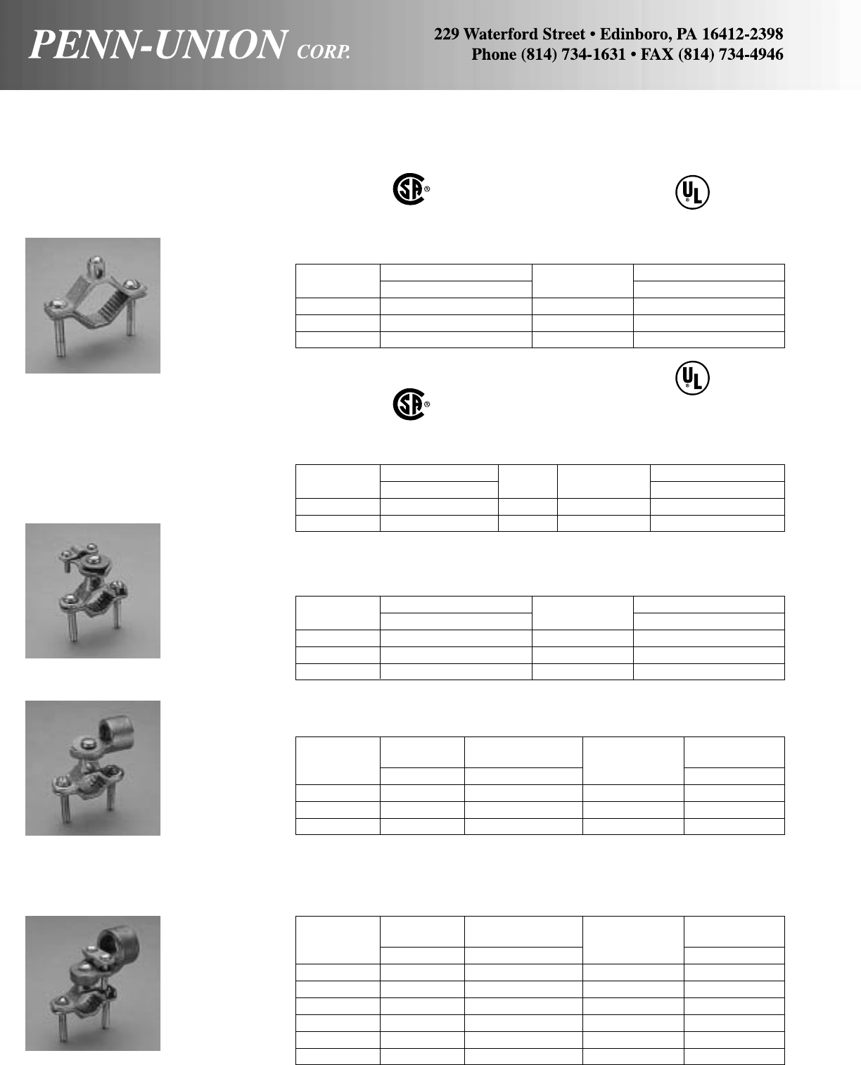
Conduit Water Wire Diameter
Catalog Hub Size Pipe Range Conductor Range‡
Number in in Range of Tap in
KH-1 1/21/2-1 10 Sol.-4 Str. .102-.232
KH-2 1/211/4-2 10 Sol.-4 Str. .102-.232
KH-4 1/221/4-4 10 Sol.-1/0 Sol. .102-.325
TYPE KL
For use with rigid conduit. Clamp provides a positive grip on wire. Ground fittings should
be attached to water pipe ahead of water meter.
Conduit Water Wire Diameter
Catalog Hub Size Pipe Range Conductor Range‡
Number in in Range of Tap in
KL-1 3/41/2-1 10 Sol.-2/0 Str. .102-.419
KL-2 3/411/4-2 10 Sol.-2/0 Str. .102-.419
KL-4 3/421/2-4 10 Sol.-2/0 Str. .102-.419
KL-1A 1 1/2-1 10 Sol.-2/0 Str. .102-.419
KL-2A 1 11/4-2 10 Sol.-2/0 Str. .102-.419
KL-4A 1 21/2-4 10 Sol.-2/0 Str. .102-.419
‡For conversion to metric range, see page 175.
TYPE KH
For use with rigid conduit. Washer provides complete protection for wire.
BRONZE GROUND CLAMPS • TYPES KP, KP-DB, KW, KH & KL
For bonding ground wires to water pipe Cast from high strength electrical bronze. Furnished with high
strength plated steel hardware.
KL
KH
TYPE KP
For bonding bare copper wire to water pipe or for use as water meter shunt.
Catalog Water Pipe Range Conductor Wire Diameter Range‡
Number in Range of Tap in
KP-1 1/2-1 10 Sol.-2 Str. .102-.292
KP-2 11/4-2 10 Sol.-2 Str. .102-.292
KP-4* 21/2-4 10 Sol.-1/0 Sol. .102-.325
467
LISTED
KP
TYPE KW
For bonding bare armored or unarmored ground wire, also used with cables or cord.
Clamp provides positive grip on armor or outer cable.
Catalog Water Pipe Range Conductor Wire Diameter Range‡
Number in Range of Tap in
KW-1 1/2-1 10 Sol.-6 Sol. .102-.162
KW-2 11/4-2 10 Sol.-6 Sol. .102-.162
KW-4 21/2-4 10 Sol.-1/0 Sol. .102-.325
KW
TYPE KP-DB
For bonding bare copper wire to water pipe or rebar for burial in earth or concrete.
Catalog Water Pipe Range Rebar Conductor Wire Diameter Range‡
Number in Number Range of Tap in
KP-1-DB 1/2-1 4-6 10 Sol.-2 Str. .102-.292
KP-2-DB 11/4-2 – 10 Sol.-2 Str. .102-.292
467
LISTED
SUITABLE FOR
DIRECT BURIAL
100
* Not UL or CSA

BRONZE GROUND CLAMPS • TYPE KLS
Conduit Hub Water Pipe Wire Diameter
Catalog Size Range Conductor Range Range‡
Number in in of Tap in
KLS-0 1/21/2-1 10 Sol.-2/0 Str. .102-.419
KLS-1 3/41/2-1 10 Sol. 2/0 Str. .102-.419
KLS-2 3/411/4-2 10 Sol.-2/0 Str. .102-.419
KLS-4 3/421/2-4 10 Sol.-2/0 Str. .102-.419
KLS-1A 1 1/2-1 10 Sol.-2/0 Str. .102-.419
KLS-2A 1 11/4-2 10 Sol.-2/0 Str. .102-.419
KLS-4A 1 21/2-4 10 Sol.-2/0 Str. .102-.419
‡For conversion to metric range, see page 175.
ALUMINUM GROUND CLAMP • TYPE GC
Catalog Water Pipe Range Conductor Wire Diameter Range‡
Number in Range of Tap in
GC-1 1/2-1 14 Sol.-1/0 Str. .064-.373
GC-2 11/4-2 6 Sol.-250 MCM .162-.575
GC-4 21/2-4 6 Sol.-250 MCM .162-.575
‡For conversion to metric range, see page 175.
467
LISTED
Manufactured from high strength aluminum alloy. For use on water
pipe or steel conduit. Can be reversed to accept smaller diam-
eter ground rods. Tin plated for low contact resistance, and cor-
rosion protection. Dual rated for copper or aluminum wire.
• Cast from high strength electrical bronze.
• Furnished with 3/4" width x .050" thick x 67/8" length pure copper
contact strip.
• Steel plated hardware.
• Includes clamps and conduit hubs.
BRONZE CONDUIT HUBS • TYPE KCH
Conduit Wire Diameter
Catalog Size Conductor Range Range‡
Number in of Tap in
KCH-12 1/210 Sol. - 6 Sol. .102-.162
KCH-34 3/410 Sol. - 2/0 Str. .102-.419
KCH-1 1 10 Sol. - 3/0 Str. .102-.470
‡For conversion to metric range, see page 175.
• Cast from high strength electrical bronze.
• Steel plated hardware.
• Can be used with Type KP water pipe clamp.
9/32 DIA MIN 5/16 R.
1 13/16
1 1/2
9/16
1
3/4-14 NPT PIPE TAP
101
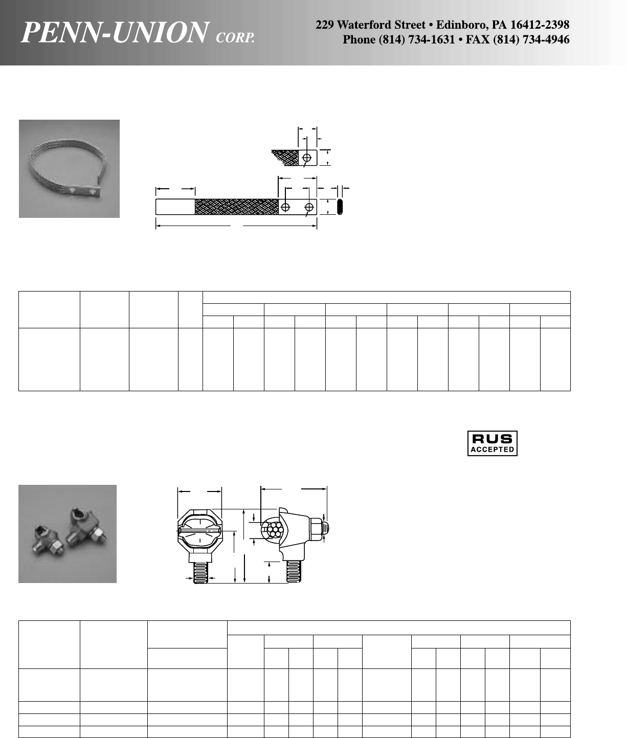
COPPER GROUND FLEXIBLE BRAID • TYPE GFXB
Tin plated flexible lead
Circular Approximate Dimensions
Catalog Ampere Mils. of Fig. ABCEKL
Number Ratings• Braids No. in mm in mm in mm in mm in mm in mm
GFXBA-24-S1 200 77,184 1 2 51 11/238 1 25 5/32 43/419 24 610
GFXBA-24-D1 200 77,184 2 2 51 3 76 1 25 5/32 45/816 24 610
GFXBC-24-S1 350 168,840 1 2 51 11/238 11/238 3/16 53/419 24 610
GFXBC-24-D1 350 168,840 2 2 51 3 76 11/238 3/16 55/816 24 610
GFXBC-24-S 350 168,840 1 3 76 11/238 11/238 3/16 53/419 24 610
GFXBC-24-D 350 168,840 2 3 76 3 76 11/238 3/16 55/816 24 610
•Ampere ratings are suggested for use as a guide only. Actual values used for a given application will depend on such factors as permissible temperature rise, permissible
voltage drop, number of cables together and other conditions of service. For outdoor use, these ratings may be increased from 22% to 40% depending upon the size and
position of the bus bars being joined.
TRANSFORMER GROUND CLAMPS • TYPES GSE AND HGSE
Eye bolt style
Bodies are cast from high conductivity, high
strength copper alloy with cast high strength
bronze eyebolts. Steel nuts and lockwashers are
standard on all clamps. For silicon bronze hard-
ware, suffix catalog number with “-SBH.” Example:
GSE-C1-SBH. The HGSE provides a hex or
square shoulder for wrench tightening. Its flat sur-
face also acts as a seal to the tank. The GSE
may be tightened by using a wrench on the body.
AApproximate Dimensions
Copper Wire Diameter DG H J L P W
Catalog Conductor Range‡ Stud (Eyebolt)
Number Range in Size in mm in mm in in mm in mm in mm
GSE-C1† 10 Sol.-1 Str. .102-.332 1/2-13 13/16 21 11/432 3/8-16 11/238 7/16 11 7/822
GSE-020 8 Sol.-2/0 Str. .128-.419 1/2-13 1 25 17/16 37 3/8-16 131/32 50 7/16 11 7/822
GSE-025 6 Sol.-250 MCM .162-.575 1/2-13 111/16 43 115/16 49 1/2-13 29/16 65 5/16 81
1/432
HGSE-C1* 10 Sol.-1 Str. .102-.332 1/2-13 13/16 30 13/444 3/8-16 131/32 50 7/16 11 11/828
HGSE-020* 8 Sol.-2/0 Str. .128-.419 1/2-13 15/16 33 115/16 49 3/8-16 2 51 7/16 11 11/432
HGSE-250* 6 Sol.-250 MCM .162-.575 1/2-13 13/16 30 21/854 1/2-13 25/867 15/32 12 17/848
‡For conversion to metric range, see page 175.
*Designates two-way basket.
For tin plating, suffix catalog number with “-TN.” Example: GSE-C1-TN.
†RUS accepted plain and tin plated.
Highly flexible leads suitable for use wherever it
is necessary to take up expansion. Made of flat,
extra flexible, tinned, pure copper, with tin plated,
seamless, pure copper ferrules cold pressed on
each end. Inside ends of ferrules are rounded to
prevent chafing of strands.
Sizes and combinations not shown readily sup-
plied. Special drilling can be supplied on request.
Refer to factory if different ferrule dimensions are
desired. For lengths other than 24" change cata-
log number suffix accordingly.
BK
B
K
9/16" DIA.
9/16" DIA.
E
C
13/4"A
L
W
D
G
L
J
P
H
A
102
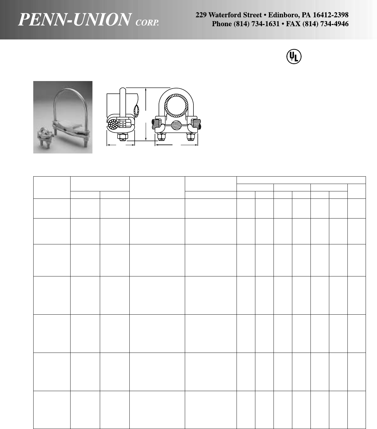
BRONZE GROUND CLAMP CONNECTOR • TYPE GPL
Universal parallel or 90° cable connection to rod or pipe
Wire Diameter Approximate Dimensions
Catalog Accommodates Conductor Range‡ A B C Bolt
Number Rod IPS Range in in mm in mm in mm Dia.†
GPL-1 * 1/21/48 Sol.-4 Str. .128- .232 13/834 21/2 64 17/8 47 3/8
GPL-2 * 1/21/44 Sol.-2/0 Str. .204- .419 15/841 21/2 64 17/8 47 3/8
GPL-3 * 1/21/42/0 Sol.-250 MCM .365- .575 17/847 21/2 64 17/8 47 3/8
GPL-4 5/8 or 3/43/88 Sol.-4 Str. .128- .232 13/834 23/4 70 2 51 3/8
GPL-5 5/8 or 3/43/84 Sol.-2/0 Str. .204- .419 15/841 23/4 70 2 51 3/8
GPL-6 5/8 or 3/43/82/0 Sol.-250 MCM .365- .575 17/847 23/4 70 2 51 3/8
GPL-7 • 5/8 or 1 3/8 or 3/4300-500 MCM .634- .815 21/457 31/2 89 23/8 60 1/2
GPL-8 7/8 or 1 1/2 or 3/48 Sol.-4 Str. .128- .232 13/834 25/8 67 23/8 60 3/8
GPL-9 7/8 or 1 1/2 or 3/44 Sol.-2/0 Str. .204- .419 15/841 25/8 67 23/8 60 3/8
GPL-10 7/8 or 1 1/2 or 3/42/0 Sol.-250 MCM .365- .575 17/847 3 76 23/8 60 3/8
GPL-12 • 7/8 or 1 1/2 or 3/4500-750 MCM .815- .999 25/867 33/4 95 23/4 70 1/2
GPL-13 • 7/8 or 1 1/2 or 3/4750-1000 MCM .999-1.153 3 76 4 102 31/2 89 1/2
GPL-14 – 1 8 Sol.-4 Str. .128- .232 13/834 23/4 70 25/8 67 3/8
GPL-15 – 1 4 Sol.-2/0 Str. .204- .419 15/841 23/4 70 25/8 67 3/8
GPL-16 – 1 2/0 Sol.-250 MCM .365- .575 17/847 31/4 82 25/8 67 3/8
GPL-17 • – 1 300-500 MCM .634- .815 23/860 41/2115 3 76 1/2
GPL-18 • – 1 500-750 MCM .815- .999 25/867 41/2115 3 76 1/2
GPL-19 • – 1 750-1000 MCM .999-1.153 3 76 43/4121 31/2 89 1/2
GPL-20 – 11/48 Sol.-4 Str. .128- .232 13/834 31/2 89 3 76 3/8
GPL-21 – 11/44 Sol.-2/0 Str. .204- .419 15/841 31/2 89 3 76 3/8
GPL-22 – 11/42/0 Sol.-250 MCM .365- .575 17/847 31/2 89 3 76 3/8
GPL-23 • – 11/4300-500 MCM .634- .815 23/860 41/4108 33/8 85 1/2
GPL-24 • – 11/4500-750 MCM .815- .999 23/470 5 127 33/4 95 1/2
GPL-25 • – 11/4750-1000 MCM .999-1.153 3 76 51/2140 41/4108 1/2
GPL-26 – 11/28 Sol.-4 Str. .128- .232 13/834 4 102 31/4 82 3/8
GPL-27 – 11/24 Sol.-2/0 Str. .204- .419 15/841 4 102 31/4 82 3/8
GPL-28 – 11/22/0 Sol.-250 MCM .365- .575 17/847 4 102 31/4 82 3/8
GPL-29 • – 11/2300-500 MCM .634- .815 23/860 45/8118 35/8 92 1/2
GPL-30 • – 11/2500-750 MCM .815- .999 23/470 51/4133 4 102 1/2
GPL-31 • – 11/2750-1000 MCM .999-1.153 3 76 53/4146 41/2115 1/2
GPL-32 – 2 8 Sol.-4 Str. .128- .232 13/834 41/4108 33/4 95 3/8
GPL-33 – 2 4 Sol.-2/0 Str. .204- .419 15/841 41/4108 33/4 95 3/8
GPL-34 – 2 2/0 Sol.-250 MCM .365- .575 17/847 41/4108 33/4 95 3/8
GPL-35 • – 2 300-500 MCM .634- .815 23/860 51/4133 4 102 1/2
GPL-36 • – 2 500-750 MCM .815- .999 23/470 51/2140 41/2115 1/2
GPL-37 • – 2 750-1000 MCM .999-1.153 3 76 6 152 5 127 1/2
‡For conversion to metric range, see page 175. Chart continued next page
•UL listing is limited to a maximum wire size of 250 MCM.
*Not UL listed for 1/4" Pipe.
†3/8" U-Bolt threaded as shown above, add suffix “FT” for full thread. 1/2" U-Bolt standard is full thread.
467
LISTED
SUITABLE FOR
DIRECT BURIAL
Made from high copper content alloy. Furnished with silicon bronze
bolt, nuts and lockwashers.
C
103
A
B
C
US
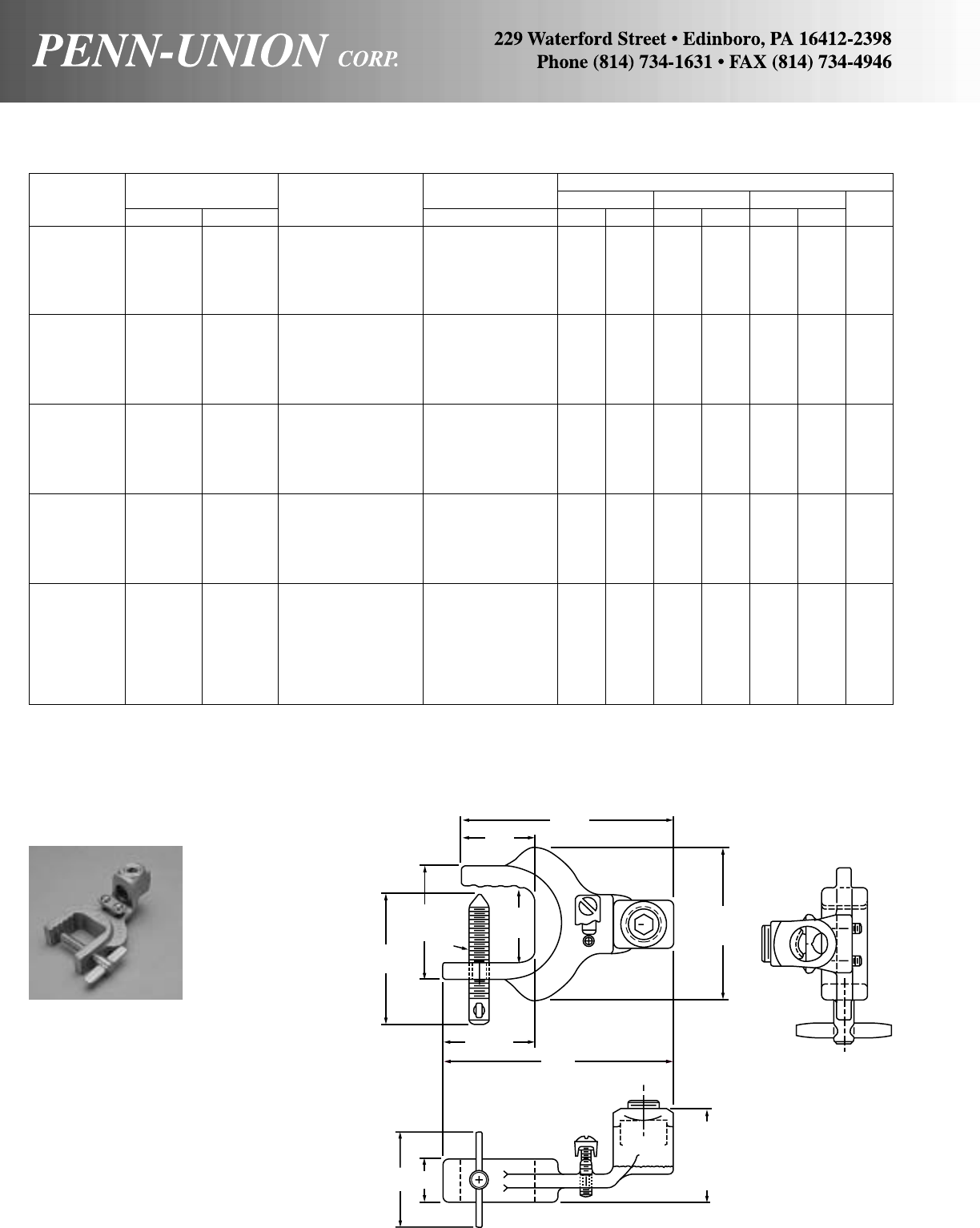
Wire Diameter Approximate Dimensions
Catalog Accommodates Conductor Range‡ A B C Bolt
Number Rod IPS Range in in mm in mm in mm Dia.†
GPL-38 – 21/28 Sol.-4 Str. .128- .232 13/834 5 127 41/4108 3/8
GPL-39 – 21/24 Sol.-2/0 Str. .204- .419 15/841 5 127 41/4108 3/8
GPL-40 – 21/22/0 Sol.-250 MCM .365- .575 17/847 5 127 41/4108 3/8
GPL-41• – 21/2300-500 MCM .634- .815 23/860 55/8143 41/2115 1/2
GPL-42• – 21/2500-750 MCM .815- .999 23/470 6 152 5 127 1/2
GPL-43• – 21/2750-1000 MCM .999-1.153 3 76 61/2165 51/2140 1/2
GPL-44 – 3 8 Sol.-4 Str. .128- .232 13/834 51/2140 43/4121 3/8
GPL-45 – 3 4 Sol.-2/0 Str. .204- .419 15/841 51/2140 43/4121 3/8
GPL-46 – 3 2/0 Sol.-250 MCM .365- .575 17/847 51/2140 43/4121 3/8
GPL-47• – 3 300-500 MCM .634- .815 23/860 61/4158 51/4133 1/2
GPL-48• – 3 500-750 MCM .815- .999 23/470 63/4171 51/2140 1/2
GPL-49• – 3 750-1000 MCM .999-1.153 3 76 71/4184 6 152 1/2
GPL-50 – 31/28 Sol.-4 Str. .128- .232 13/834 61/4158 51/4133 3/8
GPL-51 – 31/24 Sol.-2/0 Str. .204- .419 15/841 61/4158 51/4133 3/8
GPL-52 – 31/22/0 Sol.-250 MCM .365- .575 17/847 61/4158 51/4133 3/8
GPL-53• – 31/2300-500 MCM .634- .815 23/860 63/4171 53/4146 1/2
GPL-54• – 31/2500-750 MCM .815- .999 23/470 71/2191 6 152 1/2
GPL-55• – 31/2750-1000 MCM .999-1.153 3 76 8 203 61/2165 1/2
GPL-56 – 4 8 Sol.-4 Str. .128- .232 13/834 63/8161 53/4146 3/8
GPL-57 – 4 4 Sol.-2/0 Str. .204- .419 15/841 63/8161 53/4146 3/8
GPL-58 – 4 2/0 Sol.-250 MCM .365- .575 17/847 63/8161 53/4146 3/8
GPL-59• – 4 300-500 MCM .634- .815 23/860 63/4171 61/4158 1/2
GPL-60• – 4 500-750 MCM .815- .999 23/470 8 203 61/2165 1/2
GPL-61• – 4 750-1000 MCM .999-1.153 3 76 81/2216 7 178 1/2
GPL-68 – 5 8 Sol.-4 Str. .128- .232 13/834 63/8161 63/4171 3/8
GPL-69 – 5 4 Sol.-2/0 Str. .204- .419 117/32 38 55/8143 613/16 173 3/8
GPL-70 – 5 2/0 Sol.-250 MCM .365- .575 17/847 61/8155 613/16 173 3/8
GPL-71• – 5 300-500 MCM .634- .815 25/16 59 61/8155 71/8181 1/2
GPL-75 – 6 4 Sol.-2/0 Str. .204- .419 117/32 38 57/8149 77/8200 3/8
GPL-76 – 6 2/0 Sol.-250 MCM .365- .575 17/847 71/8181 713/16 199 3/8
GPL-77• – 6 300-500 MCM .634- .815 25/16 59 63/16 157 83/16 208 1/2
GPL-87 – 8 4 Sol. 2/0 Str. .204- .419 117/32 38 71/8181 97/8251 3/8
‡For conversion to metric range, see page 175.
•UL listing is limited to a maximum wire size of 250 MCM by UL467.
†3/8" U-Bolt threaded as shown above, add suffix “FT” for full thread. 1/2" U-Bolt standard is full thread.
BRONZE GROUND CLAMP CONNECTOR • TYPE GPL
Continued from preceding page
Made of high strength cast copper alloy. Ribs
provide multiple contact with the tank car.
Clamp is secured to the vehicle by means of a
low carbon steel, case hardened, wing screw
designed to lock and penetrate the vehicle
surface to insure a positive contact with the
tanker or tank car.
Designed to accommodate flexible rubber
sheath cable ranging from #6-#2 conductor.
CAST COPPER TANKER STATIC GROUND CLAMPS • CATALOG NO. TSGC-030
For #6 – #2 conductor 45/16"
11/2"
113/16"
45/8"
2" 7/8"
23/4"
2
5
/
16
"
3
/
8
-16
1
9
/
16
"
3
1
/
16
"
1
15
/
16
" REF.
104
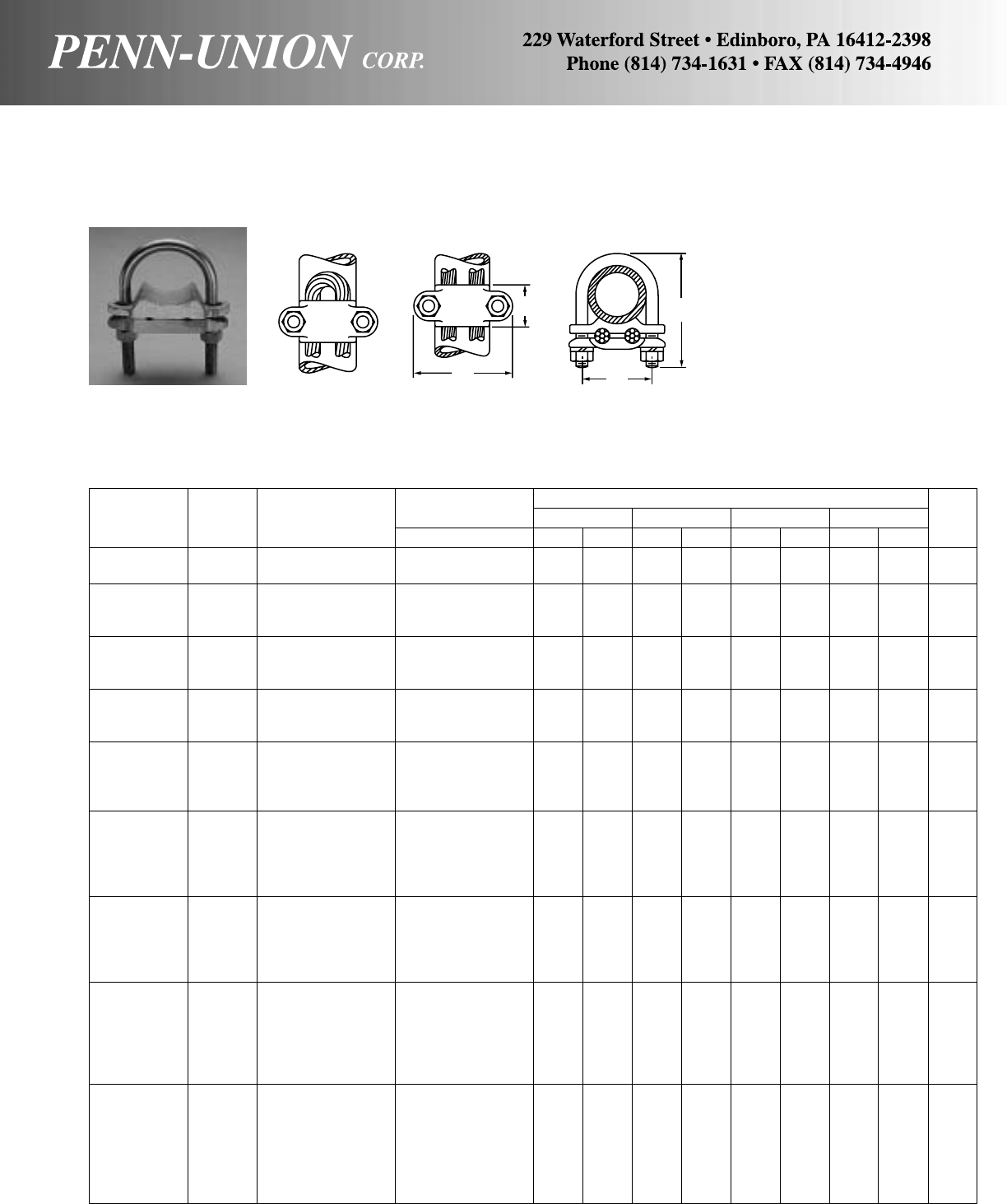
Wire Diameter Approximate Dimensions
Catalog Conductor Range‡ ABCDBolt
Number IPS Range in in mm in mm in mm in mm Dia.†
GU-0 3/48 Sol.-4 Str. .128- .232 21/2 64 7/822 25/8 67 11/2 38 3/8
GU-00 3/44 Sol.-2/0 Str. .204- .419 21/2 64 7/822 25/8 67 11/2 38 3/8
GU-1 1 8 Sol.-4 Str. .128- .232 23/4 70 11/828 3 76 13/4 44 3/8
GU-2 1 4 Sol.-2/0 Str. .204- .419 23/4 70 11/828 31/4 82 13/4 44 3/8
GU-3 1 2/0 Sol.-250 MCM .365- .575 23/4 70 11/432 31/2 89 13/4 44 3/8
GU-4 11/48 Sol.-4 Str. .128- .232 3 76 11/828 31/4 82 21/16 53 3/8
GU-5 11/44 Sol.-2/0 Str. .204- .419 3 76 11/432 31/2 89 21/16 53 3/8
GU-6 11/42/0 Sol.-250 MCM .365- .575 3 76 13/834 33/4 95 21/16 53 3/8
GU-7 11/28 Sol.-4 Str. .128- .232 33/8 85 11/432 31/2 89 23/8 60 3/8
GU-8 11/24 Sol.-2/0 Str. .204- .419 33/8 85 13/834 35/8 92 23/8 60 3/8
GU-9 11/22/0 Sol.-250 MCM .365- .575 33/8 85 11/238 33/4 95 23/8 60 3/8
GU-10 2 8 Sol.-4 Str. .128- .232 33/4 95 13/834 37/8 98 213/16 71 3/8
GU-11 2 4 Sol.-2/0 Str. .204- .419 33/4 95 13/834 41/8105 213/16 71 3/8
GU-12 2 2/0 Sol.-250 MCM .365- .575 33/4 95 13/834 41/4108 213/16 71 3/8
GU-13 2 300-500 MCM .634- .815 4 102 11/238 45/8118 215/16 75 1/2
GU-14 21/28 Sol.-4 Str. .128- .232 41/4108 13/834 5 127 35/16 84 3/8
GU-15 21/24 Sol.-2/0 Str. .204- .419 41/4108 13/834 51/8130 35/16 84 3/8
GU-16 21/22/0 Sol.-250 MCM .365- .575 41/4108 13/834 51/4133 35/16 84 3/8
GU-17 21/2300-500 MCM .634- .815 41/2115 11/238 51/2140 37/16 87 1/2
GU-18 21/2500-750 MCM .815- .999 41/2115 11/238 53/4146 37/16 87 1/2
GU-19 3 8 Sol.-4 Str. .128- .232 5 127 13/834 51/4133 315/16 100 3/8
GU-20 3 4 Sol.-2/0 Str. .204- .419 5 127 13/834 51/2140 315/16 100 3/8
GU-21 3 2/0 Sol.-250 MCM .365- .575 5 127 13/834 53/4146 315/16 100 3/8
GU-22 3 300-500 MCM .634- .815 51/4133 11/238 6 152 41/16 104 1/2
GU-23 3 500-750 MCM .815- .999 51/2140 13/444 63/8161 43/16 107 5/8
GU-25 31/28 Sol.-4 Str. .128- .232 51/2140 11/238 6 152 47/16 113 3/8
GU-26 31/24 Sol.-2/0 Str. .204- .419 51/2140 11/238 61/8155 47/16 113 3/8
GU-27 31/22/0 Sol.-250 MCM .365- .575 51/2140 11/238 61/4158 47/16 113 3/8
GU-28 31/2300-500 MCM .634- .815 53/4146 13/444 63/8161 49/16 116 1/2
GU-29 31/2500-750 MCM .815- .999 6 152 17/847 65/8168 411/16 119 5/8
GU-30 31/2750-1000 MCM .999-1.153 6 152 21/854 7 178 411/16 119 5/8
GU-31 4 8 Sol.-4 Str. .128- .232 6 152 11/238 61/2165 415/16 126 3/8
GU-32 4 4 Sol.-2/0 Str. .204- .419 6 152 11/238 63/4171 415/16 126 3/8
GU-33 4 2/0 Sol.-250 MCM .365- .575 6 152 15/841 7 178 415/16 126 3/8
GU-34 4 300-500 MCM .634- .815 61/4158 15/841 71/4184 51/16 129 1/2
GU-35 4 500-750 MCM .815- .999 61/2165 17/847 71/2191 53/16 132 5/8
GU-36 4 750-1000 MCM .999-1.153 61/2165 21/854 73/4197 53/16 132 5/8
GU-37 4 1250-1500 MCM 1.290-1.412 61/2165 23/860 81/8206 53/16 132 5/8
‡For conversion to metric range, see page 175.
†3/8" U-Bolt threaded as shown above, add suffix “FT” for full thread. 1/2" U-Bolt standard is full thread.
BRONZE GROUND CLAMP CONNECTOR • TYPE GU
For clamping two cables or a looped cable or wire to pipe
A
B
D
C
Made from high copper content al-
loy. Furnished with silicon bronze
bolt, nuts and lockwashers.
105
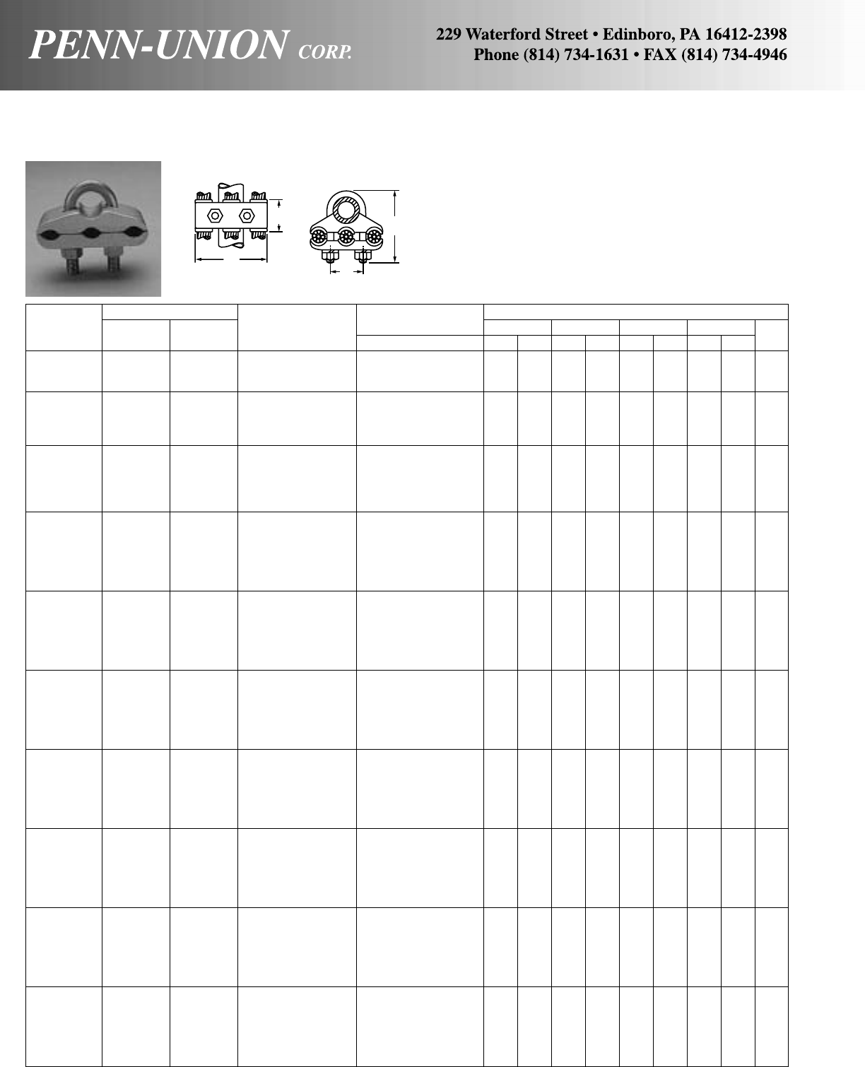
BRONZE GROUND CLAMP CONNECTOR • TYPE GR
For clamping three equal size cables to pipe or rod
Accommodates Wire Diameter Approximate Dimensions
Catalog Conductor Range‡ ABCDBolt
Number Rod IPS Range in in mm in mm in mm in mm Dia.†
GR-1 1/21/48 Sol.-4 Str. .128- .232 21/2 64 11/238 21/4 57 1 25 3/8
GR-2 1/21/44 Sol.-2/0 Str. .204- .419 3 76 11/238 21/2 64 1 25 3/8
GR-3 1/21/42/0 Sol.-250 MCM .365- .575 35/8 92 11/238 23/4 70 1 25 3/8
GR-4 5/8 or 3/43/88 Sol.-4 Str. .128- .232 23/4 70 11/238 21/2 64 11/8 28 3/8
GR-5 5/8 or 3/43/84 Sol.-2/0 Str. .204- .419 3 76 11/238 23/4 70 11/8 28 3/8
GR-6 5/8 or 3/43/82/0 Sol.-250 MCM .365- .575 31/2 89 15/841 3 76 11/8 28 3/8
GR-7 5/8 or 3/43/8300-500 MCM .634- .815 4 102 15/841 31/4 82 11/8 28 1/2
GR-8 7/8 or 1 1/2 or 3/48 Sol.-4 Str. .128- .232 27/8 73 11/238 3 76 11/2 38 3/8
GR-9 7/8 or 1 1/2 or 3/44 Sol.-2/0 Str. .204- .419 31/2 89 11/238 31/4 82 11/2 38 3/8
GR-10 7/8 or 1 1/2 or 3/42/0 Sol.-250 MCM .365- .575 37/8 98 15/841 33/8 85 11/2 38 1/2
GR-11 7/8 or 1 1/2 or 3/4300-500 MCM .634- .815 43/8111 15/841 31/2 89 11/2 38 1/2
GR-12 7/8 or 1 1/2 or 3/4500-750 MCM .815- .999 5 127 13/444 4 102 15/8 41 1/2
GR-13 – 1 8 Sol.-4 Str. .128- .232 31/4 82 11/238 3 76 13/4 44 3/8
GR-14 – 1 4 Sol.-2/0 Str. .204- .419 35/8 92 11/238 31/4 82 13/4 44 3/8
GR-15 – 1 2/0 Sol.-250 MCM .365- .575 41/8105 15/841 31/2 89 13/4 44 3/8
GR-16 – 1 300-500 MCM .634- .815 41/2115 15/841 33/4 95 13/4 44 1/2
GR-17 – 1 500-750 MCM .815- .999 51/8130 13/444 41/4108 17/8 47 1/2
GR-18 – 1 750-1000 MCM .999-1.153 51/2140 13/444 41/2115 17/8 47 1/2
GR-19 – 11/48 Sol.-4 Str. .128- .232 31/2 89 11/238 31/2 89 21/16 53 3/8
GR-20 – 11/44 Sol.-2/0 Str. .204- .419 4 102 11/238 33/4 95 21/16 53 3/8
GR-21 – 11/42/0 Sol.-250 MCM .365- .575 41/2115 15/841 37/8 98 21/16 53 3/8
GR-22 – 11/4300-500 MCM .634- .815 51/8130 13/444 43/8111 23/16 56 1/2
GR-23 – 11/4500-750 MCM .815- .999 53/4146 2 51 51/8130 25/16 59 5/8
GR-24 – 11/4750-1000 MCM .999-1.153 61/4158 2 51 53/8136 25/16 59 5/8
GR-25 – 11/28 Sol.-4 Str. .128- .232 33/4 95 11/238 33/495 23/8 60 3/8
GR-26 – 11/24 Sol.-2/0 Str. .204- .419 41/4108 11/238 4 102 23/8 60 3/8
GR-27 – 11/22/0 Sol.-250 MCM .365- .575 43/4121 13/444 41/4108 23/8 60 3/8
GR-28 – 11/2300-500 MCM .634- .815 51/2140 2 51 43/4121 21/2 64 1/2
GR-29 – 11/2500-750 MCM .815- .999 61/4158 21/457 51/4133 25/8 67 5/8
GR-30 – 11/2750-1000 MCM .999-1.153 61/2165 21/457 51/2140 25/8 67 5/8
GR-31 – 2 8 Sol.-4 Str. .128- .232 43/8111 11/238 41/4108 213/16 71 3/8
GR-32 – 2 4 Sol.-2/0 Str. .204- .419 47/8124 11/238 41/2115 213/16 71 3/8
GR-33 – 2 2/0 Sol.-250 MCM .365- .575 51/4133 13/444 5 127 213/16 71 1/2
GR-34 – 2 300-500 MCM .634- .815 53/4140 2 51 5 127 215/16 75 1/2
GR-35 – 2 500-750 MCM .815- .999 65/8168 21/457 53/4146 31/16 78 1/2
GR-36 – 2 750-1000 MCM .999-1.153 7 178 21/457 6 152 31/16 78 5/8
GR-37 – 21/28 Sol.-4 Str. .128- .232 47/8124 11/238 45/8118 35/16 84 3/8
GR-38 – 21/24 Sol.-2/0 Str. .204- .419 53/8136 11/238 5 127 35/16 84 3/8
GR-39 – 21/22/0 Sol.-250 MCM .365- .575 57/8149 13/444 51/4133 35/16 84 1/2
GR-40 – 21/2300-500 MCM .634- .815 61/2165 2 51 53/4146 37/16 87 1/2
GR-41 – 21/2500-750 MCM .815- .999 71/4184 21/457 61/4158 39/16 90 5/8
GR-42 – 21/2750-1000 MCM .999-1.153 71/2191 21/457 61/2185 39/16 90 5/8
GR-43 – 3 8 Sol.-4 Str. .128- .232 51/2140 11/238 51/4133 315/16 100 3/8
GR-44 – 3 4 Sol.-2/0 Str. .204- .419 6 152 11/238 55/8143 315/16 100 3/8
GR-45 – 3 2/0 Sol.-250 MCM .365- .575 63/8161 13/444 53/4146 315/16 100 1/2
GR-46 – 3 300-500 MCM .634- .815 67/8174 2 51 61/4158 41/16 104 1/2
GR-47 – 3 500-750 MCM .815- .999 71/2191 21/457 65/8168 43/16 107 5/8
GR-48 – 3 750-1000 MCM .999-1.153 81/8206 21/457 67/8174 43/16 107 5/8
GR-49 – 31/28 Sol.-4 Str. .128- .232 6 152 11/238 55/8143 47/16 113 3/8
GR-50 – 31/24 Sol.-2/0 Str. .204- .419 63/8161 11/238 57/8149 47/16 113 1/2
GR-51 – 31/22/0 Sol.-250 MCM .365- .575 63/4171 13/444 63/8161 47/16 113 1/2
GR-60 – 4 8 Sol.-4 Str. .128- .232 63/8161 11/238 63/8161 415/16 120 3/8
GR-61 – 4 4 Sol.-2/0 Str. .204- .419 611/16 169 11/238 63/8161 415/16 126 1/2
GR-62 – 4 2/0 Sol.-250 MCM .365- .575 71/4184 13/444 63/4171 415/16 126 1/2
‡For conversion to metric range, see page 175. †3/8" U-Bolt threaded as shown above, add suffix “FT” for full thread. 1/2" U-Bolt standard is full thread.
Made from high copper content alloy. Furnished with silicon bronze
bolt, nuts and lockwashers.
106
A
B
D
C
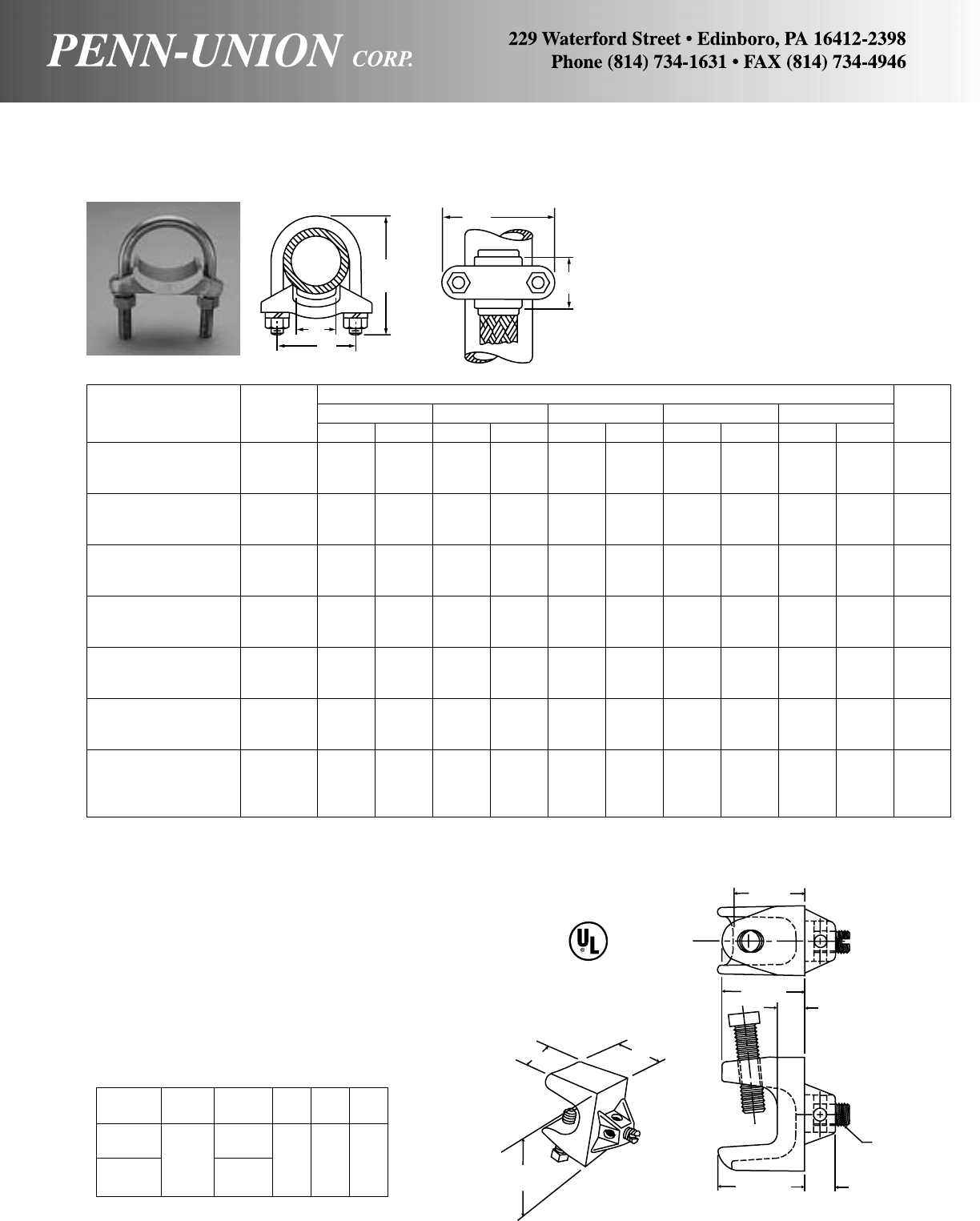
BRONZE GROUND CLAMP CONNECTORS • TYPE GO
For clamping braid, cable or strip copper to pipe
Made from high copper content alloy. Furnished with
silicon bronze bolt, nuts and lockwashers.
107
E
D
B
A
C
Approximate Dimensions
Catalog ABCDEBolt
Number IPS in mm in mm in mm in mm in mm Dia.†
GO-0 3/421/2 64 21/2 64 11/828 11/2 38 1 25 3/8
GO-1 1 23/4 70 31/4 82 11/432 13/4 44 1 25 3/8
GO-2 11/43 76 31/2 89 13/834 21/16 53 1 25 3/8
GO-3 11/233/8 85 31/2 89 11/238 23/8 60 1 25 3/8
GO-4 11/233/8 85 31/2 89 11/238 23/8 60 11/238 3/8
GO-4A 11/233/8 85 31/2 89 11/238 23/8 60 2 51 1/2
GO-5 2 33/4 95 41/4108 11/238 213/16 71 1 25 3/8
GO-6 2 33/4 95 41/4108 11/238 213/16 71 11/238 3/8
GO-7 2 4 102 43/8111 13/444 215/16 75 2 51 1/2
GO-7A 21/241/2115 5 127 13/444 37/16 87 11/238 1/2
GO-8 21/241/2115 5 127 17/847 37/16 87 2 51 1/2
GO-9 21/241/2115 5 127 2 51 37/16 87 21/284 1/2
GO-10 3 51/4133 61/4158 2 51 41/16 104 2 51 1/2
GO-11 3 51/4133 61/4158 2 51 41/16 104 21/264 1/2
GO-12 3 51/4133 61/4158 2 51 41/16 104 3 76 1/2
GO-13 31/253/4146 57/8149 21/457 49/16 116 2 51 1/2
GO-14 31/253/4146 57/8149 21/457 49/16 116 21/264 1/2
GO-15 31/253/4146 57/8149 21/457 49/16 116 3 76 1/2
GO-16 4 61/4158 61/2165 21/457 51/16 129 2 51 1/2
GO-17 4 61/4158 61/2165 23/860 51/16 129 21/264 1/2
GO-18 4 61/4158 61/2165 21/264 51/16 129 3 76 1/2
GO-19 4 61/4158 61/2165 23/470 51/16 129 31/289 1/2
†3/8" U-Bolt threaded as shown above, add suffix “FT” for full thread. 1/2" U-Bolt standard is full thread.
CUS
Grounds Trailer Frames, Cable Trays, Pedestals - Connects
#6-#14 solid copper conductor to metal frames where continuity
of grounding can be assured. Ground wire may be installed on
clamp prior to mounting the clamp on metal frame, reducing in-
stallation time. High strength copper alloy (91% nominal) pro-
vides conductivity, durability and excellent corrosion resistant
characteristics. High strength steel zinc plated anchoring bolt
penetrates paint or metal oxide. Hex head bolt installs with can
wrench, socket or cresent wrench. Square head bolt allows clamp
to be installed with pliers when tighter ground connection is
needed.
TRAILER GROUND CLAMPS • TYPE GBC AND GBCH
WH
L
11/64 REF.
±1/32
±1/32 ±1/32
15/32
3/8REF.
113/64 7/16
SLOTTED
SET SCREW
UL listed 467
Catalog Wire Beam
Number Range Bolt L W H
GBC-6 Sq HD
#6-#14 5/16-18 15/81" 13/16
GBCH-6 Hex HD
5/16-18

Wire Diameter Approximate Dimensions
Catalog Accommodates Conductor Range‡ ABCD
Bolt
Number Rod IPS Range in in mm in mm in mm in mm Dia.†
GT-1 1/21/48 Sol.-4 Str. .128- .232 15/841 2 51 15/841 1 25 3/8
GT-2 1/21/44 Sol.-2/0 Str. .204- .419 2 51 21/854 13/444 1 25 3/8
GT-3 1/21/42/0 Sol.-250 MCM .365- .575 21/264 21/457 17/847 1 25 3/8
GT-4 5/8 or 3/43/88 Sol.-4 Str. .128- .232 15/841 21/854 15/841 11/828 3/8
GT-5 5/8 or 3/43/84 Sol.-2/0 Str. .204- .419 2 51 21/264 13/444 11/828 3/8
GT-6 5/8 or 3/43/82/0 Sol.-250 MCM .365- .575 21/264 25/867 17/847 11/828 3/8
GT-7 5/8 or 3/43/8300-500 MCM .634- .815 23/470 23/470 2 51 11/828 3/8
GT-8 7/8 or 1 1/2 or 3/48 Sol.-4 Str. .128- .232 15/841 21/264 15/841 11/238 3/8
GT-9 7/8 or 1 1/2 or 3/44 Sol.-2/0 Str. .204- .419 2 51 23/470 13/444 11/238 3/8
GT-10 7/8 or 1 1/2 or 3/42/0 Sol.-250 MCM .365- .575 21/264 27/873 17/847 11/238 3/8
GT-11 7/8 or 1 1/2 or 3/4300-500 MCM .634- .815 23/470 3 76 2 51 11/238 3/8
GT-12 7/8 or 1 1/2 or 3/4500-750 MCM .815- .999 31/879 33/495 21/457 15/841 1/2
GT-13 – 1 8 Sol.-4 Str. .128- .232 15/841 23/470 15/841 13/444 3/8
GT-14 – 1 4 Sol.-2/0 Str. .204- .419 2 51 3 76 13/444 13/444 3/8
GT-15 – 1 2/0 Sol.-250 MCM .365- .575 21/264 37/898 31/879 13/444 3/8
GT-16 – 1 300-500 MCM .634- .815 23/470 33/495 2 51 13/444 3/8
GT-17 – 1 500-750 MCM .815- .999 31/879 41/8105 21/457 17/847 1/2
GT-18 – 11/48 Sol.-4 Str. .128- .232 15/841 3 76 17/847 21/16 53 3/8
GT-19 – 11/44 Sol.-2/0 Str. .204- .419 2 51 31/482 2 51 21/16 53 3/8
GT-20 – 11/42/0 Sol.-250 MCM .365- .575 21/264 31/289 21/854 21/16 53 3/8
GT-21 – 11/4300-500 MCM .634- .815 23/470 41/8105 21/457 23/16 56 1/2
GT-22 – 11/4500-750 MCM .815- .999 33/495 43/8111 21/264 25/16 59 5/8
GT-23 – 11/4750-1000 MCM .999-1.153 4 102 45/8118 23/470 25/16 59 5/8
GT-24 – 11/28 Sol.-4 Str. .128- .232 15/841 31/482 21/457 23/860 3/8
GT-25 – 11/24 Sol.-2/0 Str. .204- .419 2 51 31/289 23/860 23/860 3/8
GT-26 – 11/22/0 Sol.-250 MCM .365- .575 21/264 37/898 21/264 23/860 3/8
GT-27 – 11/2300-500 MCM .634- .815 23/470 43/8111 25/867 21/264 1/2
GT-28 – 11/2500-750 MCM .815- .999 33/495 43/4121 23/470 25/867 5/8
GT-29 – 11/2750-1000 MCM .999-1.153 4 102 5 127 27/873 25/867 5/8
GT-30 – 2 8 Sol.-4 Str. .128- .282 13/444 37/898 23/470 213/16 71 3/8
GT-31 – 2 4 Sol. 2/0 Str. .204- .419 2 51 41/8105 27/873 213/16 71 3/8
GT-32 – 2 2/0 Sol.-250 MCM .365- .575 25/867 41/4108 3 76 213/16 71 3/8
GT-33 – 2 300-500 MCM .634- .815 27/873 45/8118 31/879 215/16 75 1/2
GT-34 – 2 500-750 MCM .815- .999 33/495 51/4133 31/482 31/16 78 5/8
GT-35 – 2 750-1000 MCM .999-1.153 4 102 51/2140 31/482 31/16 78 5/8
GT-36 – 21/28 Sol.-4 Str. .128- .232 13/444 43/8111 33/885 35/892 3/8
GT-37 – 21/24 Sol.-2/0 Str. .204- .419 2 51 41/2115 33/885 35/16 84 3/8
GT-38 – 21/22/0 Sol.-250 MCM .365- .575 25/867 43/4121 31/289 35/16 84 3/8
GT-39 – 21/2300-500 MCM .634- .815 27/873 51/8130 35/892 37/16 87 1/2
GT-40 – 21/2500-750 MCM .815- .999 33/495 55/8143 33/495 39/16 90 5/8
GT-41 – 21/2750-1000 MCM .999-1.153 4 102 53/4146 33/495 39/16 90 5/8
GT-42 – 3 8 Sol.-4 Str. .128- .232 13/444 5 127 35/892 315/16 100 3/8
GT-43 – 3 4 Sol.-2/0 Str. .204- .419 2 51 51/4133 33/495 315/16 100 3/8
GT-44 – 3 2/0 Sol.-250 MCM .365- .575 25/867 51/2140 33/495 315/16 100 3/8
GT-45 – 3 300-500 MCM .634- .815 27/873 57/8149 37/898 41/16 104 1/2
GT-46 – 3 500-750 MCM .815- .999 33/495 61/2165 41/8105 43/16 107 5/8
GT-47 – 3 750-1000 MCM .999-1.153 4 102 63/4171 41/8105 43/16 107 5/8
GT-48 – 31/28 Sol.-4 Str. .128- .232 13/444 51/2140 37/898 47/16 113 3/8
GT-49 – 31/24 Sol.-2/0 Str. .204- .419 2 51 57/8149 37/898 47/16 113 3/8
GT-50 – 31/22/0 Sol.-250 MCM .365- .575 25/867 61/8155 4 102 47/16 113 3/8
GT-51 – 31/2300-500 MCM .634- .815 27/873 61/2165 41/4105 49/16 116 1/2
GT-52 – 31/2500-750 MCM .815- .999 33/495 71/8181 45/8118 411/16 119 5/8
GT-53 – 31/2750-1000 MCM .999-1.153 4 102 73/8187 45/8118 411/16 119 5/8
GT-54 – 31/21250-1500 MCM 1.290-1.412 41/4108 75/8194 43/4121 411/16 119 5/8
GT-55 – 4 2/0 Sol.-250 MCM .365- .575 25/867 61/2165 43/4121 415/16 126 3/8
GT-56 – 4 300-500 MCM .634- .815 27/873 7 178 5 127 51/16 129 1/2
‡For conversion to metric range, see page 175. †3/8" U-Bolt threaded as shown above, add suffix “FT” for full thread. 1/2" U-Bolt standard is full thread.
BRONZE GROUND CLAMP CONNECTOR • TYPE GT
For clamping parallel cables or wires to pipe or rod
Made from high copper content alloy. Furnished with silicon bronze
bolt, nuts and lockwashers.
A
BD
C
108
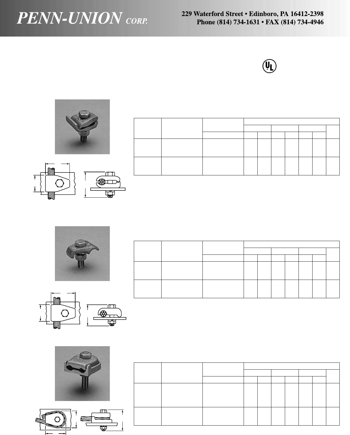
BRONZE GROUND CLAMP CONNECTORS • TYPES GM, GMS & GWL
For clamping cable or wire to flat surface
Made from high copper content alloy. Furnished with silicon bronze
bolt, nut and lockwasher. Standard catalog items for 1/4" bar, for
other applications, specify bar thickness. 467
LISTED
SUITABLE FOR
DIRECT BURIAL
Wire Diameter Approximate Dimensions
Catalog Conductor Range‡ ABCBolt
Number Range in in mm in mm in mm Dia.
GWL-1 8 Str.-4 Str. .146- .232 11/828 11/238 13/834 3/8
GWL-2 8 Str.-4 Str. .146- .232 13/444 13/444 17/847 1/2
GWL-3 3 Str.-2/0 Str. .260- .419 111/16 42 2 51 17/847 3/8
GWL-4 3 Str.-2/0 Str. .260- .419 113/16 46 21/854 17/847 1/2
GWL-5 3/0 Str.-250 MCM .470- .575 21/457 21/457 23/860 3/8
GWL-6 3/0 Str.-250 MCM .470- .575 21/457 23/860 23/860 1/2
GWL-7 3/0 Str.-250 MCM .470- .575 21/457 21/264 23/860 5/8
‡For conversion to metric range, see page 175.
TYPE GWL
Wire Diameter Approximate Dimensions
Catalog Conductor Range‡ ABCBolt
Number Range in in mm in mm in mm Dia.
GMS-1 8 Sol.-4 Str. .128- .232 11/432 1 25 15/841 3/8
GMS-2 4 Sol.-2/0 Str. .204- .419 15/841 11/828 13/444 3/8
GMS-3 2/0 Sol.-250 MCM .365- .575 21/854 11/238 2 51 1/2
GMS-4• 300-500 MCM .634- .815 23/860 15/841 21/264 1/2
GMS-5• 500-750 MCM .815- .999 3 76 13/444 3 76 5/8
GMS-6• 750-1000 MCM .999-1.153 31/289 17/847 31/879 5/8
‡For conversion to metric range, see page 175.
•UL listing is limited to a maximum wire size of 250 MCM by UL467.
Wire Diameter Approximate Dimensions
Catalog Conductor Range‡ ABCBolt
Number Range in in mm in mm in mm Dia.
GM-1 8 Sol.-4 Str. .128- .232 11/432 1 25 15/841 3/8
GM-2 4 Sol.-2/0 Str. .204- .419 15/841 11/828 13/444 3/8
GM-3 2/0 Sol.-250 MCM .365- .575 21/854 11/238 2 51 1/2
GM-4• 300-500 MCM .634- .815 23/860 15/841 21/264 1/2
GM-5• 500-750 MCM .815- .999 3 76 13/444 3 76 5/8
GM-6• 750-1000 MCM .999-1.153 31/289 17/847 31/879 5/8
‡For conversion to metric range, see page 175.
•UL listing is limited to a maximum wire size of 250 MCM by UL467.
TYPE GMS
TYPE GM
A
BC
A
BC
C
B
A
C
109
US
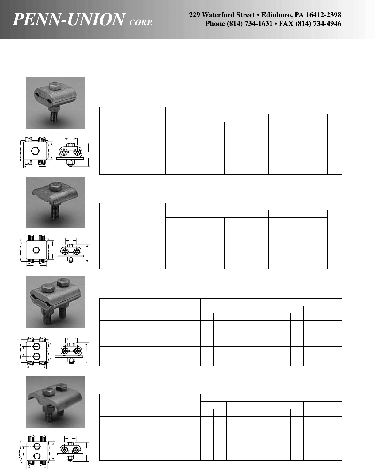
Wire Diameter Approximate Dimensions
Cat. Conductor Range‡ ABCD
Bolt
No. Range in in mm in mm in mm in mm Dia.
GH-1 8 Sol.-4 Str. .128- .232 11/4 32 11/2 38 13/834 3/419 3/8
GH-2 4 Sol.-2/0 Str. .204- .419 11/2 38 2 51 15/841 1 25 3/8
GH-3 2/0 Sol.-250 MCM .365- .575 2 51 21/4 57 13/444 11/432 1/2
GH-4 300-500 MCM .634- .815 21/2 64 27/8 73 2 51 11/238 1/2
GH-5 500-750 MCM .815- .999 31/4 82 33/8 85 23/860 13/444 5/8
GH-6 750-1000 MCM .999-1.153 35/8 92 33/4 95 21/264 2 51 5/8
GH-7 1000-1250 MCM 1.153-1.290 4 102 4 102 23/470 21/457 5/8
‡For conversion to metric range, see page 175.
Wire Diameter Approximate Dimensions
Cat. Conductor Range‡ ABCD
Bolt
No. Range in in mm in mm in mm in mm Dia.
GHS-1 8 Sol.-4 Str. .128- .232 11/4 32 13/834 13/834 3/419 3/8
GHS-2 4 Sol.-2/0 Str. .204- .419 11/2 38 11/238 15/841 1 25 3/8
GHS-3 2/0 Sol.-250 MCM .365- .575 2 51 17/847 13/444 11/432 1/2
GHS-4 300-500 MCM .634- .815 21/2 64 23/860 2 51 11/238 1/2
GHS-5 500-750 MCM .815- .999 31/4 82 23/470 23/860 13/444 5/8
GHS-6 750-1000 MCM .999-1.153 35/8 92 27/873 21/264 2 51 5/8
GHS-7 1000-1250 MCM 1.153-1.290 4 102 3 76 23/470 21/457 5/8
‡For conversion to metric range, see page 175.
Wire Diameter Approximate Dimensions
Cat. Conductor Range‡ ABCDE
Bolt
No. Range in in mm in mm in mm in mm in mm Dia.
GJ-1 8 Sol.-4 Str. .128- .232 11/4 32 11/2 38 2 51 15/16 24 3/419 3/8
GJ-2 4 Sol.-2/0 Str. .204- .419 11/2 38 2 51 2 51 1 25 1 25 3/8
GJ-3 2/0 Sol.-250 MCM .365- .575 2 51 21/4 57 21/264 15/16 33 15/16 33 1/2
GJ-4 300-500 MCM .634- .815 21/2 64 27/8 73 21/264 13/834 11/238 1/2
GJ-5 500-750 MCM .815- .999 31/4 82 33/8 85 3 76 19/16 39 13/444 5/8
GJ-6 750-1000 MCM .999-1.153 35/8 92 33/4 95 3 76 19/16 39 2 51 5/8
GJ-7 1000-1250 MCM 1.153-1.290 4 102 4 102 31/289 13/444 21/457 5/8
‡For conversion to metric range, see page 175.
Wire Diameter Approximate Dimensions
Cat. Conductor Range‡ ABCDE
Bolt
No. Range in in mm in mm in mm in mm in mm Dia.
GJS-1 8 Sol.-4 Str. .128- .232 11/4 32 13/834 2 51 15/16 24 3/419 3/8
GJS-2 4 Sol.-2/0 Str. .204- .419 11/2 38 11/238 2 51 1 25 1 25 3/8
GJS-3 2/0 Sol.-250 MCM .365- .575 2 51 17/847 21/264 15/16 33 15/16 33 1/2
GJS-4 300-500 MCM .634- .815 21/2 64 23/860 21/264 13/834 11/238 1/2
GJS-5 500-750 MCM .815- .999 31/4 82 23/470 3 76 19/16 39 13/444 5/8
GJS-6 750-1000 MCM .999-1.153 35/8 92 27/873 3 76 19/16 39 2 51 5/8
GJS-7 1000-1250 MCM 1.153-1.290 4 102 3 76 31/289 13/444 21/457 5/8
‡For conversion to metric range, see page 175.
BRONZE GROUND CLAMP CONNECTORS • TYPES GH, GHS, GJ & GJS
For clamping cable or wires to flat bar
TYPE GH
TYPE GHS
TYPE GJ
TYPE GJS
Made from high copper content alloy. Furnished with silicon bronze
bolt, nut and lockwasher. Standard catalog items for 1/4" bar, for
other applications specify bar thickness.
A
C
D
B
A
C
D
B
A
DC
E
B
D
A
C
E
B
110
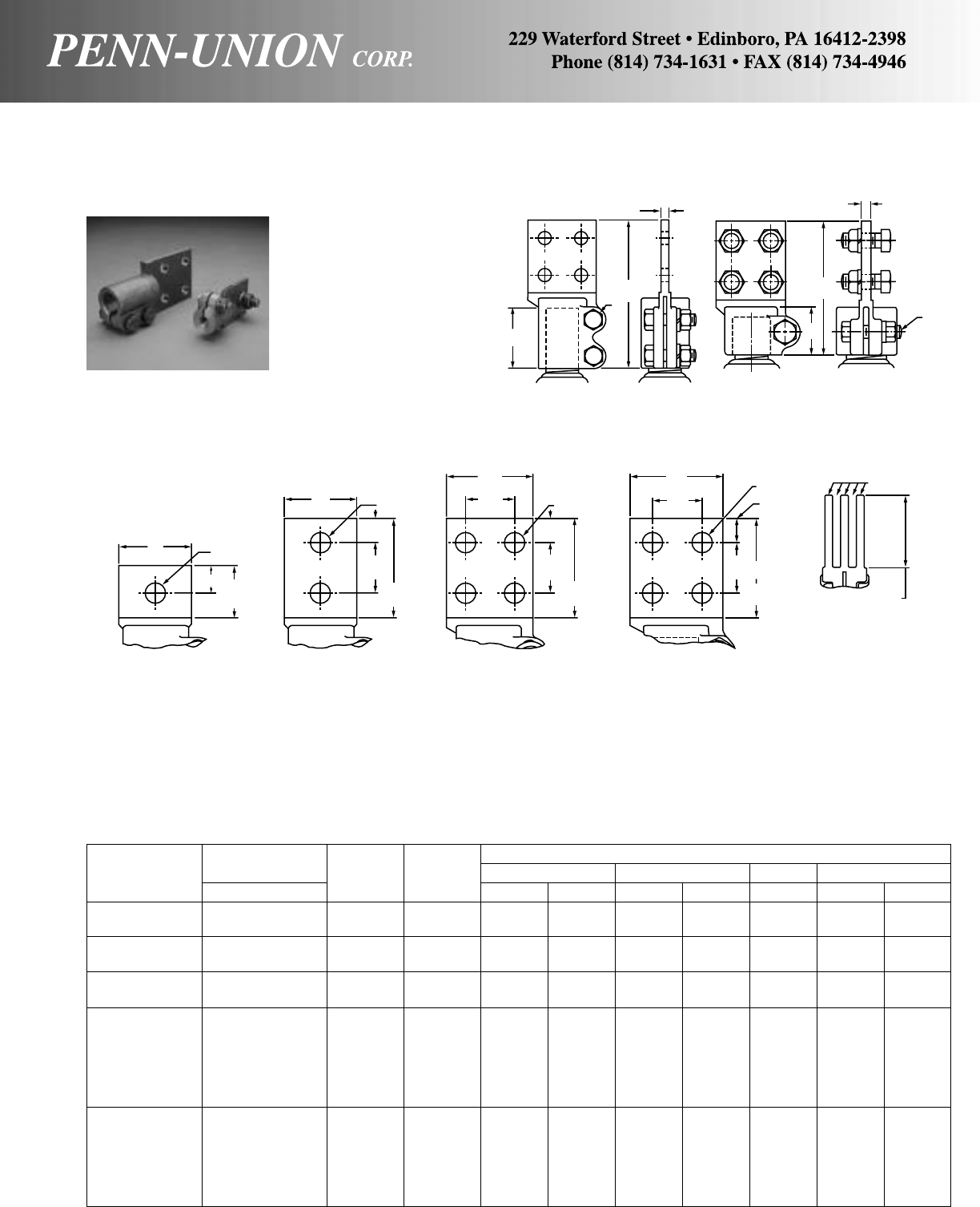
Stud Diameter Approximate Dimensions
Catalog No. Threads No. Fig. LTJM
Number in Bars No. in mm in mm in in mm
SLB-0513-D 1/2-13 1 2 51/4133 1/46.35 3/813/444
SLB-0513-F 1/2-13 1 3 51/4133 1/46.35 3/813/444
SLB-0611-D 5/8-11 1 2 51/4133 1/46.35 3/813/444
SLB-0611-F 5/8-11 1 3 51/4133 1/46.35 3/813/444
SLB-0716-D 3/4-16 1 2 51/4133 1/46.35 3/813/444
SLB-0716-F 3/4-16 1 3 51/4133 1/46.35 3/813/444
SLB-1014-D 1 -14 1 2 6 152 3/89.52 1/221/457
SLB-1014-F 1 -14 1 3 6 152 3/89.52 1/221/457
SLB-1014-E 1 -14 1 4 7 178 3/89.52 1/221/457
SLB-1014-2D 1 -14 2 2 57/8149 1/46.35 1/221/457
SLB-1014-2F 1 -14 2 3 57/8149 1/46.35 1/221/457
SLB-1014-2E 1 -14 2 4 67/8174 1/46.35 1/221/457
SLB-1112-D 11/8-12 1 26152 3/89.52 1/221/457
SLB-1112-F 11/8-12 1 36152 3/89.52 1/221/457
SLB-1112-E 11/8-12 1 47178 3/89.52 1/221/457
SLB-1112-2D 11/8-12 2 2 57/8149 1/46.35 1/221/457
SLB-1112-2F 11/8-12 2 3 57/8149 1/46.35 1/221/457
SLB-1112-2E 11/8-12 2 4 67/8174 1/46.35 1/221/457
TYPE SLB
Double bolt clamping.
Complete connector cast in one piece from high copper content
alloy.
Furnished with silicon bronze bolts, nuts and lockwashers.
TYPE SSLB
Single bolt clamping of stud is suitable for normal requirements.
Pads are 1/4" thick and mounting holes are to NEMA standards.
Mounting hardware is supplied for mounting bars to pad of con-
nector.
M
T
L
J
M
1/4"
(6 mm)
3/8"
(9 mm)
L
TYPE SLB TYPE SSLB
BRONZE STUD CONNECTOR • TYPE SLB & SSLB
Stud to single or multiple bus bar vertical take off
2"
(51 mm)
3/4"21/8"
(54 mm)
2"
(51 mm)
5/8"
(16 mm)
1-3/4"
(44 mm)
31/4"
(83 mm)
3"
(76 mm)
13/4"
(44 mm)
5/8"
(16 mm)
1-3/4"
(44 mm)
31/4"
(83 mm)
4"
(102 mm)
13/4"
(44 mm)
9/16" DIA.
(14 mm)
11/8"
(29 mm)
41/4"
(108 mm)
1/4"
(6.35 mm)
31/8" For 3" Bus
(79 mm) (76 mm)
41/8" For 4" Bus
(105 mm) (102 mm)
FIG. 1
(SUFFIX-S) FIG. 2
(SUFFIX-D) FIG. 3
(SUFFIX-F) FIG. 4
(SUFFIX-E) MULTI-TONGUE
(ILLUSTRATION 3 BAR)
9/16" DIA.
(14 mm)
9/16" DIA.
(14 mm) 9/16" DIA.
(14 mm)
1-3/4"
(44 mm)
111

Stud Diameter Approximate Dimensions
Catalog No. Threads No. Fig. LTJM
Number in Bars No. in mm in mm in in mm
SLB-1212-D 11/4-12 1 2 61/2165 3/89.52 1/223/470
SLB-1212-F 11/4-12 1 3 61/2165 3/89.52 1/223/470
SLB-1212-E 11/4-12 1 4 71/2191 3/89.52 1/223/470
SLB-1212-2D 11/4-12 2 2 63/8161 1/46.35 1/223/470
SLB-1212-2F 11/4-12 2 3 63/8161 1/46.35 1/223/470
SLB-1212-2E 11/4-12 2 4 73/8187 1/46.35 1/223/470
SLB-1512-D 11/2-12 1 2 61/2165 3/89.52 1/223/470
SLB-1512-F 11/2-12 1 3 61/2165 3/89.52 1/223/470
SLB-1512-E 11/2-12 1 4 71/2191 3/89.52 1/223/470
SLB-1512-2D 11/2-12 2 2 63/8161 1/46.35 1/223/470
SLB-1512-2F 11/2-12 2 3 63/8161 1/46.35 1/223/470
SLB-1512-2E 11/2-12 2 4 73/8187 1/46.35 1/223/470
SLB-1512-3D 11/2-12 3 2 63/8161 1/46.35 1/223/470
SLB-1512-3F 11/2-12 3 3 63/8161 1/46.35 1/223/470
SLB-1512-3E 11/2-12 3 4 73/8187 1/46.35 1/223/470
SLB-2012-F 2 -12 1 3 63/8161 1/212.70 1/2211/16 68
SLB-2012-E 2 -12 1 4 73/8187 1/212.70 1/2211/16 68
SLB-2012-2F 2 -12 2 3 61/4158 1/46.35 1/2211/16 68
SLB-2012-2E 2 -12 2 4 71/4184 1/46.35 1/2211/16 68
SLB-2012-3F 2 -12 3 3 61/4158 1/46.35 1/2211/16 68
SLB-2012-3E 2 -12 3 4 71/4184 1/46.35 1/2211/16 68
SLB-2512-F 21/2-12 1 3 65/8168 1/212.70 1/223/470
SLB-2512-E 21/2-12 1 4 75/8194 1/212.70 1/223/470
SLB-2512-2F 21/2-12 2 3 61/2165 1/46.35 1/223/470
SLB-2512-2E 21/2-12 2 4 71/2191 1/46.35 1/223/470
SLB-2512-3F 21/2-12 3 3 61/2165 1/46.35 1/223/470
SLB-2512-3E 21/2-12 3 4 71/2191 1/46.35 1/223/470
SLB-3012-F 3 -12 1 3 71/8181 3/419.05 5/831/483
SLB-3012-E 3 -12 1 4 81/8206 3/419.05 5/831/483
SLB-3012-2F 3 -12 2 3 7 178 1/46.35 5/831/483
SLB-3012-2E 3 -12 2 4 8 203 1/46.35 5/831/483
SLB-3012-3F 3 -12 3 3 7 178 1/46.35 5/831/483
SLB-3012-3E 3 -12 3 4 8 203 1/46.35 5/831/483
SLB-3512-F 31/2-12 1 3 71/8181 3/419.05 5/831/483
SLB-3512-E 31/2-12 1 4 81/8206 3/419.05 5/831/483
SLB-3512-2F 31/2-12 2 3 7 178 1/46.35 5/831/483
SLB-3512-2E 31/2-12 2 4 8 203 1/46.35 5/831/483
SLB-3512-3F 31/2-12 3 3 7 178 1/46.35 5/831/483
SLB-3512-3E 31/2-12 3 4 8 203 1/46.35 5/831/483
SLB-4012-2E 4 -12 2 4 91/4235 1/46.35 5/833/495
SLB-4012-3F 4 -12 3 3 81/4209 1/46.35 5/833/495
SLB-4012-3E 4 -12 3 4 91/4235 1/46.35 5/833/495
SLB-4012-4E 4 -12 4 4 91/4235 1/46.35 5/833/495
BRONZE STUD CONNECTOR • TYPE SLB
Continued from preceding page
TYPE SSLB • SINGLE BOLT CLAMPING
Stud Diameter Approximate Dimensions
Catalog No. Threads Fig. LM
Number in No. in mm in mm
SSLB-0513-S 1/2-13 1 4 102 11/238
SSLB-0513-D 1/2-13 2 51/4133 11/238
SSLB-0611-S 5/8-11 1 41/4108 11/238
SSLB-0611-D 5/8-11 2 51/4133 11/238
SSLB-0716-S 3/4-16 1 37/8 98 11/238
SSLB-0716-D 3/4-16 2 5 127 11/238
SSLB-1014-S 1 -14 1 4 102 11/238
SSLB-1014-D 1 -14 2 5 127 11/238
SSLB-1112-D 11/8-12 2 53/8136 11/238
SSLB-1112-F 11/8-12 3 51/4133 11/238
SSLB-1212-D 11/4-12 2 51/8130 11/238
SSLB-1212-F 11/4-12 3 51/4133 11/238
SSLB-1512-D 11/2-12 2 51/4133 11/238
SSLB-1512-F 11/2-12 3 51/8130 11/238
For sizes not listed, please consult factory.
112
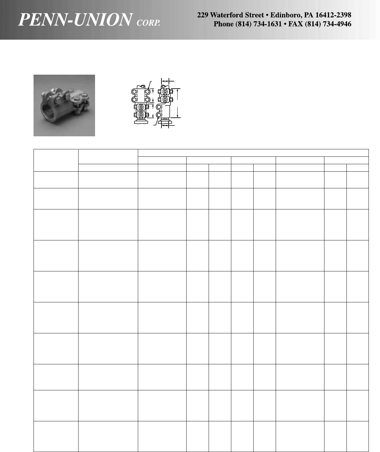
BRONZE STUD CONNECTOR • TYPE TS
Stud to tube vertical take off
Stud Diameter Approximate Dimensions
Catalog No. Threads A IPS B C J L
Number in in in mm in mm in in mm
TS-0513-05 1/2-13 1/2115/16 49 13/834 3/831/289
TS-0513-07 1/2-13 3/4115/16 49 17/847 3/8315/16 100
TS-0513-10 1/2-13 1 115/16 49 17/847 3/8315/16 100
TS-0716-05 3/4-16 1/2115/16 49 115/16 49 3/8315/16 100
TS-0716-07 3/4-16 3/4115/16 49 115/16 49 3/841/16 104
TS-0716-10 3/4-16 1 115/16 49 115/16 49 3/841/16 104
TS-0716-12 3/4-16 11/423/16 56 115/16 49 3/845/16 110
TS-1014-05 1 -14 1/2115/16 49 17/847 3/841/8105
TS-1014-07 1 -14 3/4115/16 49 17/847 3/84102
TS-1014-10 1 -14 1 115/16 49 17/847 3/84102
TS-1014-12 1 -14 11/421/854 115/16 49 3/843/8111
TS-1014-15 1 -14 11/2211/16 68 211/16 68 1/255/8143
TS-1014-20 1 -14 2 211/16 68 211/16 68 1/255/8143
TS-1112-05 11/8-12 1/2115/16 49 115/16 49 3/843/16 107
TS-1112-07 11/8-12 3/4115/16 49 115/16 49 3/841/8105
TS-1112-10 11/8-12 1 115/16 49 115/16 49 3/841/4108
TS-1112-12 11/8-12 11/4211/16 68 211/16 68 1/251/2140
TS-1112-15 11/8-12 11/2211/16 68 211/16 68 1/255/8143
TS-1112-20 11/8-12 2 211/16 68 211/16 68 1/257/8149
TS-1212-05 11/4-12 1/2115/16 49 115/16 49 3/843/16 107
TS-1212-07 11/4-12 3/4115/16 49 115/16 49 3/841/8105
TS-1212-10 11/4-12 1 115/16 49 115/16 49 3/841/4108
TS-1212-12 11/4-12 11/4211/16 68 211/16 68 1/251/2140
TS-1212-15 11/4-12 11/2211/16 68 211/16 68 1/255/8143
TS-1212-20 11/4-12 2 211/16 68 211/16 68 1/257/8149
TS-1512-07 11/2-12 3/4115/16 49 2 51 3/841/4108
TS-1512-10 11/2-12 1 115/16 49 2 51 3/841/4108
TS-1512-12 11/2-12 11/425/867 25/867 1/251/2140
TS-1512-15 11/2-12 11/2211/16 68 211/16 68 1/255/8143
TS-1512-20 11/2-12 2 211/16 68 211/16 68 1/255/8143
TS-1512-25 11/2-12 21/223/470 211/16 68 1/2511/16 144
TS-2012-07 2 -12 3/4115/16 49 115/16 49 3/845/16 110
TS-2012-10 2 -12 1 115/16 49 115/16 49 3/845/16 110
TS-2012-12 2 -12 11/425/867 23/470 1/255/8143
TS-2012-15 2 -12 11/2211/16 68 211/16 68 1/2511/16 144
TS-2012-20 2 -12 2 211/16 68 23/470 1/2511/16 144
TS-2012-25 2 -12 21/223/470 23/470 1/253/4146
TS-2212-10 21/4-12 1 115/16 49 23/16 56 3/841/2115
TS-2212-12 21/4-12 11/425/867 23/470 1/257/8149
TS-2212-15 21/4-12 11/2211/16 68 23/470 1/26152
TS-2212-20 21/4-12 2 211/16 68 23/470 1/26152
TS-2212-25 21/4-12 21/223/470 23/470 1/253/4146
TS-2512-10 21/2-12 1 115/16 49 23/16 56 3/8411/16 119
TS-2512-12 21/2-12 11/425/867 23/470 1/2513/16 148
TS-2512-15 21/2-12 11/225/867 23/470 1/2513/16 148
TS-2512-20 21/2-12 2 211/16 68 23/470 1/257/8149
TS-2512-25 21/2-12 21/223/470 23/470 1/2513/16 148
TS-2512-30 21/2-12 3 33/885 31/482 5/87178
TS-3010-15 3 -10 11/223/470 23/470 1/261/16 154
TS-3010-20 3 -10 2 23/470 23/470 1/261/16 154
TS-3010-25 3 -10 21/223/470 23/470 1/261/16 154
TS-3010-30 3 -10 3 33/885 31/482 5/87178
TS-3010-35 3 -10 31/231/482 31/482 5/87178
TS-3010-40 3 -10 4 31/482 31/482 5/87178
Made from high copper content alloy.
Stud contact tapped, but can be supplied plain and bored to size.
Number of threads other than listed supplied at no extra cost.
Furnished with silicon bronze bolts, nuts and lockwashers.
B
JA
L
C
JSTUD
DIA.
113

BRONZE STUD CONNECTOR • TYPE CSR
Stud to cable, tube, or flat bar vertical or horizontal take off
AB Conductor Range
Stud Diameter IPS Wire Diameter Wire Diameter
Catalog No. Threads Range Small Groove Range‡ Large Groove Range‡
Number in in Range in Range in
CSR-0513-025 1/2-13 – 6 Sol.-1 Str. .162- .332 1 Str.-250 MCM .332- .575
CSR-0716-025 3/4-16 – 6 Sol.-1 Str. .162- .332 1 Str.-250 MCM .332- .575
CSR-0716-050 3/4-16 3/8-1/26 Sol.-4/0 Str. .162- .528 4/0 Str.-500 MCM .528- .815
CSR-0716-100 3/4-16 3/8-3/42 Sol.-350 MCM .258- .682 350-1000 MCM .682-1.153
CSR-1014-025 1 -14 – 6 Sol.-1 Str. .162- .332 1 Str.-250 MCM .332- .575
CSR-1014-050 1 -14 3/8-1/26 Sol.-4/0 Str. .162- .528 4/0 Str.-500 MCM .528- .815
CSR-1014-100 1 -14 3/8-3/42 Sol.-350 MCM .258- .682 350-1000 MCM .682-1.153
CSR-1112-025 11/8-12 – 6 Sol.-1 Str. .162- .332 1 Str.-250 MCM .332- .575
CSR-1112-050 11/8-12 3/8-1/26 Sol.-4/0 Str. .162- .528 4/0 Str.-500 MCM .528- .815
CSR-1112-100 11/8-12 3/8-3/42 Sol.-350 MCM .258- .682 350-1000 MCM .682-1.153
CSR-1212-100 11/4-12 3/8-3/42 Sol.-350 MCM .258- .682 350-1000 MCM .682-1.153
CSR-1512-025 11/2-12 – 6 Sol.-1 Str. .162- .332 1 Str.-250 MCM .332- .575
CSR-1512-050 11/2-12 3/8-1/26 Sol.-4/0 Str. .162- .528 4/0 Str.-500 MCM .528- .815
CSR-1512-100 11/2-12 3/8-3/42 Sol.-350 MCM .258- .682 350-1000 MCM .682-1.153
CSR-1512-200 11/2-12 3/8-11/44/0 Str.-900 MCM .528-1.094 900-2000 MCM 1.094-1.632
CSR-2012-100 2 -12 3/8-3/42 Sol.-350 MCM .258- .682 350-1000 MCM .682-1.153
CSR-2012-200 2 -12 3/8-11/44/0 Str.-900 MCM .528-1.094 900-2000 MCM 1.094-1.632
CSR-2512-200 21/2-12 3/8-11/44/0 Str.-900 MCM .528-1.094 900-2000 MCM 1.094-1.632
CSR-3012-200 3 -12 3/8-11/44/0 Str.-900 MCM .528-1.094 900-2000 MCM 1.094-1.632
‡For conversion to metric range, see page 175.
Made from high copper content alloy.
Furnished with silicon bronze bolts, nuts and lock washers.
Cap on tap end can be rotated to utilize two grooves which ac-
commodate a wide range of cable and a limited range of IPS.
Connector may be mounted directly to flat bar, if necessary, as
shown in line drawing at right.
Stud contact is tapped, but can be supplied plain and bored to
size.
Approximate Dimensions
JJ
Catalog CEStud End Tap End L M O
Number in mm in mm in in in mm in mm in mm
CSR-0513-025 11/828 17/847 3/83/837/8 98 13/444 1/83
CSR-0716-025 11/828 17/847 3/83/837/8 98 13/444 1/83
CSR-0716-050 13/834 21/854 3/83/841/8105 13/444 1/83
CSR-0716-100 17/847 27/873 1/21/253/8136 21/457 1/83
CSR-1014-025 11/828 17/847 3/83/837/8 98 13/444 1/83
CSR-1014-050 13/834 21/854 3/83/841/8105 13/444 1/83
CSR-1014-100 17/847 27/873 1/21/253/8136 21/457 1/83
CSR-1112-025 11/828 17/847 3/83/847/16 113 21/457 3/16 5
CSR-1112-050 13/834 21/854 3/83/8411/16 119 21/457 3/16 5
CSR-1112-100 17/847 27/873 1/21/257/16 138 21/457 3/16 5
CSR-1212-100 17/847 27/873 1/21/257/16 138 21/457 3/16 5
CSR-1512-025 11/828 17/847 1/23/847/16 113 21/457 3/16 5
CSR-1512-050 13/834 21/854 1/23/8411/16 119 21/457 3/16 5
CSR-1512-100 17/847 27/873 1/21/257/16 138 21/457 3/16 5
CSR-1512-200 23/860 33/885 1/21/2515/16 151 21/457 3/16 5
CSR-2012-100 17/847 27/873 1/21/2515/16 151 23/470 3/16 5
CSR-2012-200 23/860 33/885 1/21/267/16 163 23/470 3/16 5
CSR-2512-200 23/860 33/885 1/21/267/16 163 23/470 3/16 5
CSR-3012-200 23/860 33/885 1/21/267/16 163 23/470 3/16 5
J STUD END J TAP END
CE
MC
E
OL
A
B
114
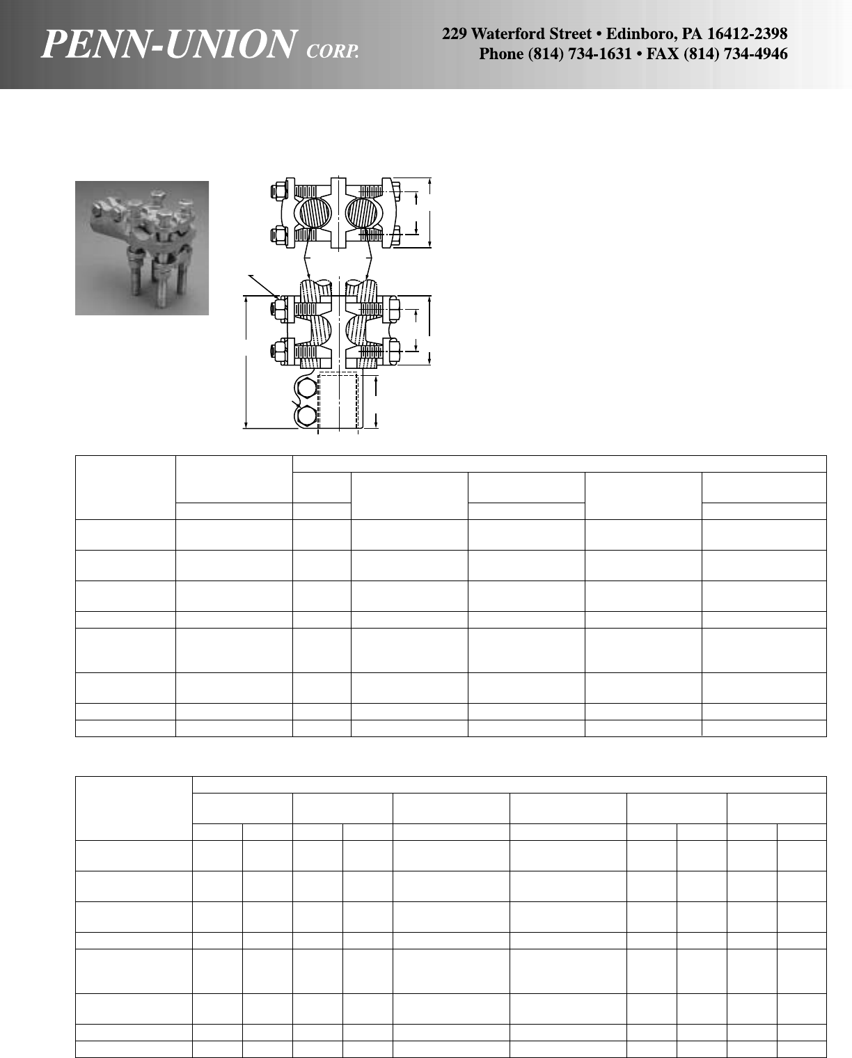
BRONZE STUD CONNECTOR • TYPE CSR-2
Stud to two cables or two tubes vertical or horizontal take off
Approximate Dimensions
JJ
Catalog CEStud End Tap End L M
Number in mm in mm in in in mm in mm
CSR-0716-050-2 13/834 21/854 3/83/843/8111 13/444
CSR-0716-100-2 17/847 27/873 1/21/255/8143 21/457
CSR-1014-050-2 13/834 21/854 3/83/843/8111 13/444
CSR-1014-100-2 17/847 27/873 1/21/255/8143 21/457
CSR-1112-050-2 13/834 21/854 3/83/85 127 21/457
CSR-1112-100-2 17/847 27/873 1/21/253/4146 21/457
CSR-1212-100-2 17/847 27/873 1/21/253/4146 21/457
CSR-1512-050-2 13/834 21/854 1/23/85 127 21/457
CSR-1512-100-2 17/847 27/873 1/21/253/4146 21/457
CSR-1512-200-2 23/860 33/885 1/21/261/8155 21/457
CSR-2012-100-2 17/847 27/873 1/21/253/4146 23/470
CSR-2012-200-2 23/860 33/885 1/21/263/8161 23/470
CSR-2512-200-2 23/860 33/885 1/21/263/8161 23/470
CSR-3012-200-2 23/860 33/885 1/21/263/4171 23/470
AB Conductor Range
Stud Diameter IPS Wire Diameter Wire Diameter
Catalog No. Threads Range Small Groove Range‡ Large Groove Range‡
Number in in Range in Range in
CSR-0716-050-2 3/4-16 3/8- 1/26 Sol.-4/0 Str. .162- .528 4/0 Str.-500 MCM .528- .815
CSR-0716-100-2 3/4-16 3/8- 3/42 Sol.-350 MCM .258- .682 350-1000 MCM .682-1.153
CSR-1014-050-2 1 -14 3/8- 1/26 Sol.-4/0 Str. .162- .528 4/0 Str.-500 MCM .528- .815
CSR-1014-100-2 1 -14 3/8- 3/42 Sol.-350 MCM .258- .682 350-1000 MCM .682-1.153
CSR-1112-050-2 11/8-12 3/8- 1/26 Sol.-4/0 Str. .162- .525 4/0 Str.-500 MCM .528- .815
CSR-1112-100-2 11/8-12 3/8- 3/42 Sol.-350 MCM .258- .682 350-1000 MCM .682-1.153
CSR-1212-100-2 11/4-12 3/8- 3/42 Sol.-350 MCM .258- .682 350-1000 MCM .682-1.153
CSR-1512-050-2 11/2-12 3/8- 1/26 Sol.-4/0 Str. .162- .528 4/0 Str.-500 MCM .528- .815
CSR-1512-100-2 11/2-12 3/8- 3/42 Sol.-350 MCM .258- .682 350-1000 MCM .682-1.153
CSR-1512-200-2 11/2-12 3/8-11/44/0 Str.-900 MCM .528-1.094 900-2000 MCM 1.094-1.632
CSR-2012-100-2 2 -12 3/8- 3/42 Sol.-350 MCM .258- .682 350-1000 MCM .682-1.153
CSR-2012-200-2 2 -12 3/8-11/44/0 Str.-900 MCM .528-1.094 900-2000 MCM 1.094-1.632
CSR-2512-200-2 21/2-12 3/8-11/44/0 Str.-900 MCM .528-1.094 900-2000 MCM 1.094-1.632
CSR-3012-200-2 3 -12 3/8-11/44/0 Str.-900 MCM .528-1.094 900-2000 MCM 1.094-1.632
‡For conversion to metric range, see page 175.
Made from high copper content alloy.
Furnished with silicon bronze bolts, nuts and lockwashers.
Caps on tap end can be rotated to utilize two grooves which ac-
commodate a wide range of cable and a limited range of IPS.
The reversible caps can be rotated 90 degrees to provide straight
or horizontal take-off.
Stud contact is tapped, but can be supplied plain and bored to
size.
BB
CE
C
E
M
J TAP
END
L
J
STUD
END
115
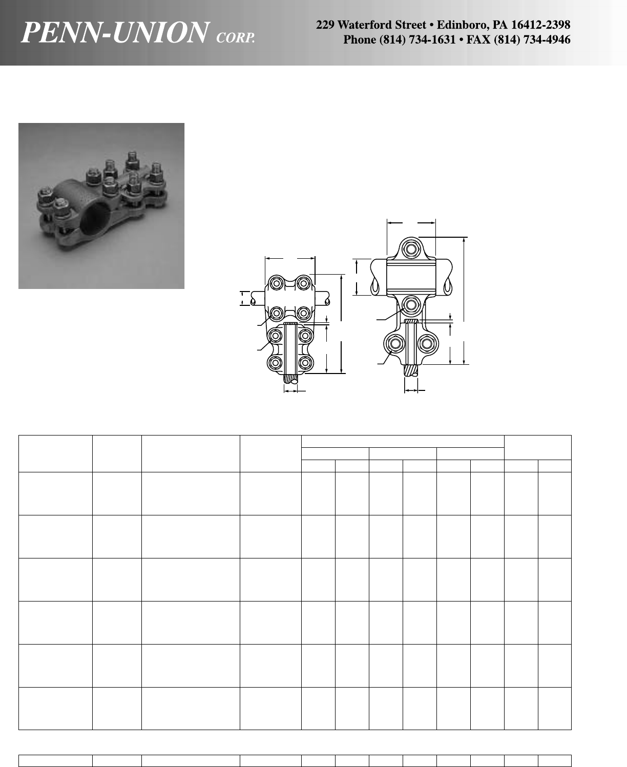
BRONZE TEE CONNECTOR • TYPES ABR AND ABRE
For tubing range to cable range
Cast of high copper content alloy. Furnished with silicon bronze
bolts, nuts and lockwashers.
Bolt heads pocketed for single wrench installation. Rounded con-
tours.
Independent clamping action on run and tap.
Reversible, range taking, high strength clamping elements.
IPS Wire Approximate Dimensions Bolt
Catalog Range Cable Range Diameter LMNDiameter
Number (Main) (Tap) Range‡ in mm in mm in mm J JJ
ABR-10-025 6 Sol.-250 MCM .162-.575 59/16 141 21/457 21/264 1/21/2
ABR-10-050 3/8-1 1/0 Sol.-500 MCM .325-.815 59/16 141 21/457 21/264 1/21/2
ABR-10-100 4/0 Sol.-1000 MCM .460-1.153 61/16 154 21/457 3 76 1/21/2
ABR-10-200 500-2000 MCM .815-1.632 61/16 154 21/457 3 76 1/21/2
ABR-12-025 6 Sol.-250 MCM .162-.575 6 152 23/470 21/264 1/21/2
ABR-12-050 11/41/0 Sol.-500 MCM .325-.815 6 152 23/470 21/264 1/21/2
ABR-12-100 4/0 Sol.-1000 MCM .460-1.153 61/2165 23/470 3 76 1/21/2
ABR-12-200 500-2000 MCM .815-1.632 61/2165 23/470 3 76 1/21/2
ABR-15-025 6 Sol.-250 MCM .162-.575 63/4171 23/470 21/264 1/21/2
ABR-15-050 11/21/0 Sol.-500 MCM .325-.815 63/4171 23/470 21/264 1/21/2
ABR-15-100 4/0 Sol.-1000 MCM .460-1.153 71/4184 23/470 3 76 1/21/2
ABR-15-200 500-2000 MCM .815-1.632 71/4184 23/470 3 76 1/21/2
ABR-20-025 6 Sol.-250 MCM .162-.575 73/16 183 23/470 21/264 1/21/2
ABR-20-050 2 1/0 Sol.-500 MCM .325-8.815 73/16 183 23/470 21/264 1/21/2
ABR-20-100 4/0 Sol.-1000 MCM .460-1.153 711/16 195 23/470 3 76 1/21/2
ABR-20-200 500-2000 MCM .815-1.632 711/16 195 23/470 3 76 1/21/2
ABR-25-025 6 Sol.-250 MCM .163-.575 711/16 195 23/470 21/264 1/21/2
ABR-25-050 21/21/0 Sol.-500 MCM .325-.815 711/16 195 23/470 21/264 1/21/2
ABR-25-100 4/0 Sol.-1000 MCM .460-1.153 83/16 208 23/470 3 76 1/21/2
ABR-25-200 500-2000 MCM .815-1.632 83/16 208 23/470 3 76 1/21/2
ABR-30-025 6 Sol.-250 MCM .162-.575 83/8213 31/483 21/264 1/21/2
ABR-30-050 3 1/0 Sol.-500 MCM .325-.815 83/8213 31/483 21/264 1/21/2
ABR-30-100 4/0 Sol.-1000 MCM .460-1.153 87/8225 31/483 3 76 1/21/2
ABR-30-200 500-2000 MCM .815-1.632 87/8225 31/483 3 76 1/21/2
ABRE-10-025 3/8-1 6 Sol.-250 MCM .162-.575 41/8105 11/238 11/238 3/83/8
‡For conversion to metric range, see page 175.
FOUR BOLT CLAMPING
TWO BOLT CLAMPING
M
J
JJ N
L
TAP
MAIN
MAIN
M
J
JJ
TAP
L
N
1/8"
(3 mm)
1/8"
(3 mm)
ABR
(4 Bolt) ABRE
(2 Bolt)
116
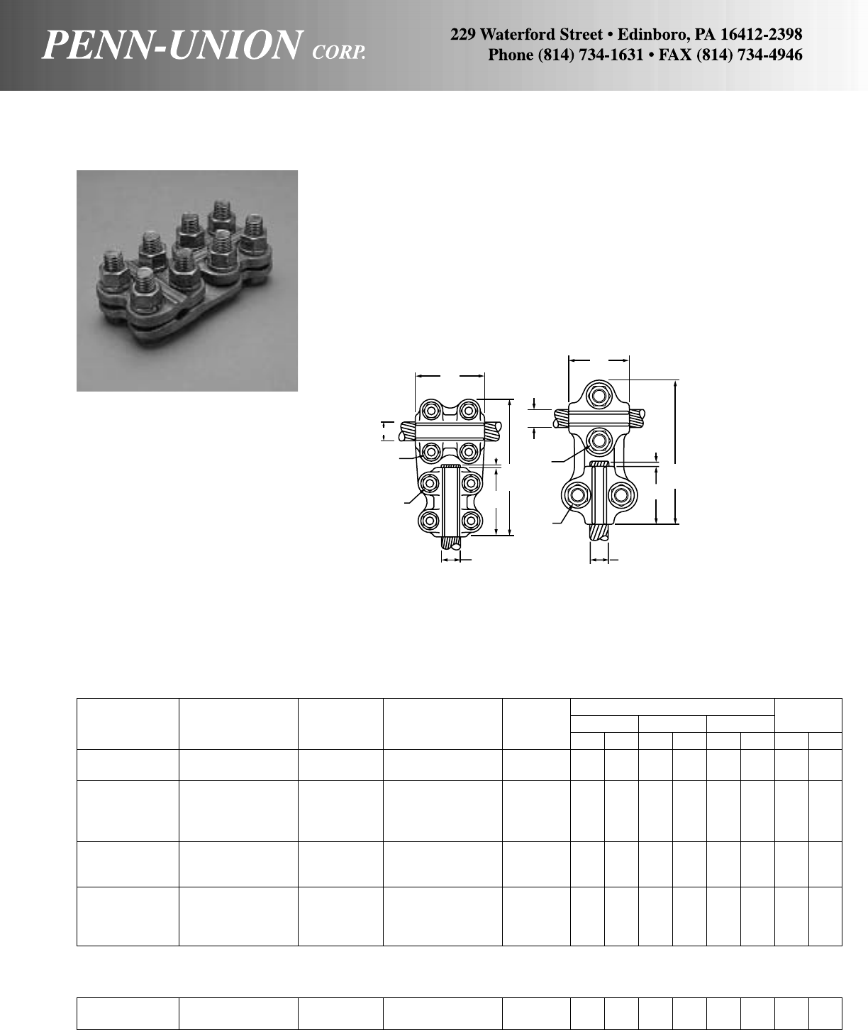
BRONZE TEE CONNECTOR • TYPES ABRR AND ABRRE
For cable range to cable range
Wire Wire Approximate Dimensions Bolt
Catalog Cable Range Diameter Cable Range Diameter LMNDiameter
Number (Main) Range (Tap) Range‡ in mm in mm in mm J JJ
ABRR-025 6 Sol.-250 MCM .162-.575 6 Sol.-250 MCM .162-.575 411/16 119 21/264 21/264 3/83/8
ABRR-025H 51/16 129 21/264 21/264 1/21/2
ABRR-050025 6 Sol.-250 MCM .162-.575 47/8124 21/264 21/264 3/83/8
ABRR-050025H 1/0 Sol.-500 MCM .325-.815 6 Sol.-250 MCM .162-.575 51/4133 21/264 21/264 1/21/2
ABRR-050 1/0 Sol.-500 MCM .325-.815 47/8124 21/264 21/264 3/83/8
ABRR-050H 1/0 Sol.-500 MCM .325-.815 51/4133 21/264 21/264 1/21/2
ABRR-100025 6 Sol.-250 MCM .162-.575 57/8149 3 76 21/264 1/21/2
ABRR-100050 4/0 Sol.-1000 MCM .460-1.153 1/0 Sol.-500 MCM .325-.815 57/8149 3 76 21/264 1/21/2
ABRR-100 4/0 Sol.-1000 MCM .460-1.153 63/8162 3 76 3 76 1/21/2
ABRR-200025 6 Sol.-250 MCM .162-.575 61/8156 3 76 21/264 1/21/2
ABRR-200050 500-2000 MCM .815-1.631 1/0 Sol.-500 MCM .325-.815 61/8156 3 76 21/264 1/21/2
ABRR-200100 4/0 Sol.-1000 MCM .460-1.153 65/8168 3 76 3 76 1/21/2
ABRR-200 500-2000 MCM .815-1.631 65/8168 3 76 3 76 1/21/2
Cast of high copper content alloy. Furnished with silicon bronze
bolts, nuts and lockwashers.
Bolt heads pocketed for single wrench installation. Rounded
contours.
Independent clamping action on run and tap.
Reversible, range taking, high strength clamping elements.
FOUR BOLT CLAMPING
TWO BOLT CLAMPING
ABRRE-050 1/0 Sol.-500 MCM .325-.815 1/ 0 Sol.-500 MCM .325-.815 45/16 110 13/444 13/444 3/83/8
ABRRE-050-025 1/0 Sol.-500 MCM .325-.815 6 Sol.-250 MCM .162-.575 41/16 103 13/444 11/238 3/83/8
‡For conversion to metric range, see page 175.
M
MAIN
J
JJ N
L
1/8"
(3 mm)
TAP
ABRR
(4 Bolts)
M
MAIN
J
JJ
TAP
N
L
1/8"
(3 mm)
ABRRE
(2 Bolt)
117
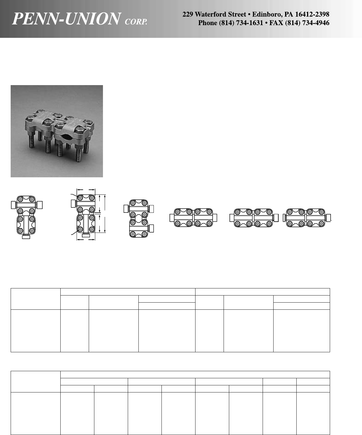
BRONZE RANGE TAKING COUPLERS AND REDUCERS • TYPE RM
ALL-PURPOSE CONNECTOR
For joining a range of cables, tubing, and solid rod to make tee taps, couplers, elbows and parallel clamps
Approximate Dimensions
Catalog LMNJJJ
Number in mm in mm in mm in in
RM-080 45/8117 21/457 21/457 3/83/8
RM-085 61/8156 3 76 3 76 1/21/2
RM-150085 63/8162 31/483 3 76 1/21/2
RM-150 65/8168 31/483 31/483 1/21/2
RM-200085 65/8168 31/289 3 76 1/21/2
RM-200150 67/8175 31/289 31/483 1/21/2
RM-200 73/16 183 31/289 31/289 1/21/2
NOTE–Clamping members can be furnished tin or silver plated by adding “-TN” for tin and “-SV” for silver plating.
Example: RM-080-TN.
Main Tap
Catalog Wire Diameter Range‡ Wire Diameter Range‡
Number IPS Cable in IPS Cable in
RM-080 1/4-3/42 Sol.-800 MCM .258-1.031 1/4-3/42 Sol.-800 MCM .258-1.031
RM-085 1/4-3/46 Sol.-850 MCM .162-1.050 1/4-3/46 Sol.-850 MCM .162-1.050
RM-150085 1/2-1 4/0 Sol.-1500 MCM .460-1.412 1/4-3/46 Sol.-850 MCM .162-1.050
RM-150 1/2-1 4/0 Sol.-1500 MCM .460-1.412 1/2-1 4/0 Sol.-1500 MCM .460-1.412
RM-200085 3/4-11/2500-2000 MCM .815-1.632 1/4-3/46 Sol.-850 MCM .162-1.050
RM-200150 3/4-11/2500-2000 MCM .815-1.632 1/2-1 4 Sol.-1500 MCM .204-1.412
RM-200 3/4-11/2500-2000 MCM .815-1.632 3/4-11/2500-2000 MCM .815-1.632
‡For conversion to metric range, see page 175.
Cast of high copper content alloy. Furnished with silicon bronze
bolts, nuts and lockwashers.
Bolt heads pocketed for single wrench installation.
Rounded contours.
Independent clamping action on run and tap.
Reversible, range taking, high strength clamping elements.
Square clamp members can be mounted in either direction or
reversed to take small wire, tubing or rod.
Bolt centers located in a square pattern to allow clamping caps
to be placed for holding in either direction.
Cross-Groove design takes conductors from both sides, side and
end, or both ends.
M
J
JJ
M
N
L
N
Tee Connector
Cable to Cable or
IPS to Cable or
IPS to IPS
Elbow
Cable to Cable or
IPS to Cable or
IPS to IPS
Cable Main
and Parallel
or
Oblique Tap
Coupler
IPS to IPS Coupler
IPS to Cable Coupler
Cable to Cable
118
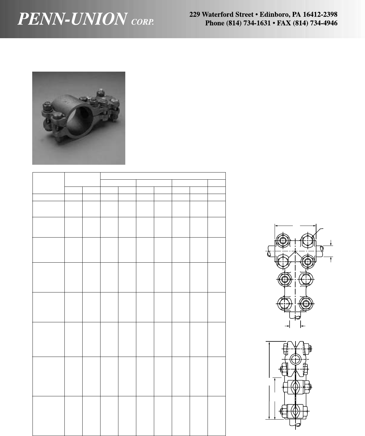
BRONZE TEE CONNECTOR • TYPE ABN
Heavy duty – for tube to tube
Heavy duty tee connectors with four bolts on both main and tap.
Cast of high copper content alloy. Furnished with silicon bronze
bolts, nuts and lockwashers.
Bolt heads pocketed for single wrench installation.
Rounded contours.
Approximate Dimensions
Catalog IPS W L D J
Number Main Tap inmminmminmmin
ABN-0707 3/43/421/2 64 53/4146 21/264 1/2
ABN-1005 1 1/221/2 64 6 152 21/264 1/2
ABN-1007 1 3/421/2 64 6 152 21/264 1/2
ABN-1010 1 1 21/2 64 6 152 21/264 1/2
ABN-1205 11/41/223/4 70 61/8156 21/264 1/2
ABN-1207 11/43/423/4 70 61/8156 21/264 1/2
ABN-1210 11/412
3/4 70 61/8156 21/264 1/2
ABN-1212 11/411/423/4 70 63/8162 23/470 1/2
ABN-1505 11/21/223/4 70 61/2165 21/264 1/2
ABN-1507 11/23/423/4 70 61/2165 21/264 1/2
ABN-1510 11/212
3/4 70 61/2165 21/264 1/2
ABN-1512 11/211/423/4 70 63/4171 23/470 1/2
ABN-1515 11/211/223/4 70 63/4171 23/470 1/2
ABN-2005 2 1/223/4 70 63/4171 21/264 1/2
ABN-2007 2 3/423/4 70 63/4171 21/264 1/2
ABN-2010 2 1 23/4 70 63/4171 21/264 1/2
ABN-2012 2 11/423/4 70 7 178 23/470 1/2
ABN-2015 2 11/223/4 70 7 178 23/470 1/2
ABN-2020 2 2 23/4 70 7 178 23/470 1/2
ABN-2507 21/23/423/4 70 71/2191 21/264 1/2
ABN-2510 21/212
3/4 70 71/2191 21/264 1/2
ABN-2512 21/211/423/4 70 73/4197 23/470 1/2
ABN-2515 21/211/223/4 70 73/4197 23/470 1/2
ABN-2520 21/222
3/4 70 73/4197 23/470 1/2
ABN-2525 21/221/231/4 83 81/4210 31/483 1/2
ABN-3007 3 3/421/2 64 81/4210 21/264 1/2
ABN-3010 3 1 21/2 64 81/4210 21/264 1/2
ABN-3012 3 11/423/4 70 81/2216 23/470 1/2
ABN-3015 3 11/223/4 70 81/2216 23/470 1/2
ABN-3020 3 2 23/4 70 81/2216 23/470 1/2
ABN-3025 3 21/231/4 83 9 229 31/483 1/2
ABN-3030 3 3 31/2 89 93/4248 31/289 5/8
ABN-3507 31/23/421/2 64 83/4222 21/264 1/2
ABN-3510 31/212
1/2 64 83/4222 21/264 1/2
ABN-3512 31/211/423/4 70 9 229 23/470 1/2
ABN-3515 31/211/223/4 70 9 229 23/470 1/2
ABN-3520 31/222
3/4 70 9 229 23/470 1/2
ABN-3525 31/221/231/4 83 93/4248 31/483 1/2
ABN-3530 31/233
1/2 89 10 254 31/289 5/8
ABN-3535 31/231/231/2 89 10 254 31/289 5/8
ABN-4007 4 3/421/2 64 91/2241 21/264 1/2
ABN-4010 4 1 21/2 64 91/2241 21/264 1/2
ABN-4012 4 11/423/4 70 93/4248 23/470 1/2
ABN-4015 4 11/223/4 70 93/4248 23/470 1/2
ABN-4020 4 2 23/4 70 93/4248 23/470 1/2
ABN-4025 4 21/231/4 83 101/4260 31/483 1/2
ABN-4030 4 3 31/2 89 11 279 31/289 5/8
ABN-4040 4 4 4 102 111/2292 4 102 5/8
WJ
MAIN
TAP
L
D
119
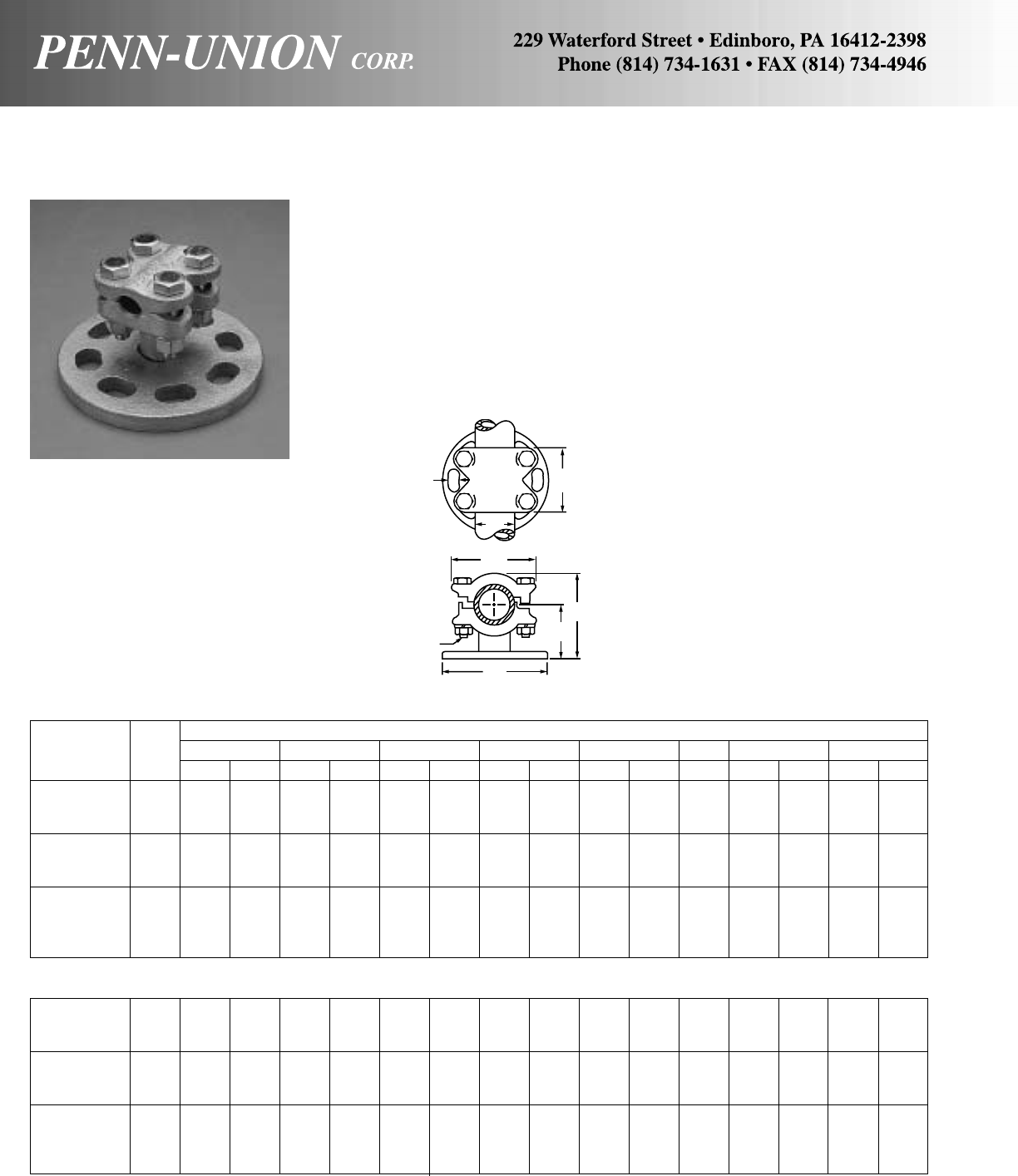
BRONZE BUS SUPPORT CLAMP • TYPE BS
Tube to bolt circle
Made from high copper content alloy.
Installed for grip or slide fit by rotating clamping elements 180°.
Oval slots in base permit easy alignment.
Clamping bolts, nuts and lockwashers are of silicon bronze.
Mounting hardware is stainless steel. Cap screws and
lockwashers furnished for cap mounting (standard). Bolts, nuts
and lockwashers furnished for base mounting (suffix catalog num-
ber with “BM”. Example: BS-05-3-BM).
BS-05-5 1/2.840 21 2 51 21/16 52 63/8162 213/16 71 3/811/16 17 23/860
BS-07-5 3/41.050 27 2 51 21/16 52 63/8162 213/16 71 3/811/16 17 25/867
BS-10-5 1 1.315 33 2 51 23/16 56 63/8162 31/16 78 3/811/16 17 27/873
BS-12-5 11/41.660 42 25/867 23/860 63/8162 37/16 87 1/211/16 17 35/892
BS-15-5 11/21.900 48 23/470 27/16 62 63/8162 311/16 94 1/211/16 17 37/898
BS-20-5 2 2.375 60 23/470 25/867 63/8162 41/8105 1/211/16 17 41/2114
BS-25-5 21/22.875 73 23/470 31/16 78 63/8162 413/16 122 1/211/16 17 5 127
BS-30-5 3 3.500 89 31/483 35/892 63/8162 53/4146 5/811/16 17 61/8156
BS-35-5 31/24.000 102 31/483 4 102 63/8162 63/8162 5/811/16 17 65/8168
BS-40-5 4 4.500 114 31/483 41/4108 63/8162 67/8175 5/811/16 17 71/8181
5" BOLT CIRCLE BASE
Approximate Dimensions
Catalog IPS ABCDHJKW
Number Size in mm in mm in mm in mm in mm in in mm in mm
BS-05-3 1/2.840 21 2 51 2 51 41/4108 23/470 3/89/16 14 23/860
BS-07-3 3/41.050 27 2 51 2 51 41/4108 23/470 3/89/16 14 25/867
BS-10-3 1 1.315 33 2 51 21/854 41/4108 3 76 3/89/16 14 27/873
BS-12-3 11/41.660 42 25/867 23/860 41/4108 33/886 1/29/16 14 35/892
BS-15-3 11/21.900 48 23/470 27/16 62 41/4108 35/892 1/29/16 14 37/898
BS-20-3 2 2.375 60 23/470 29/16 65 41/4108 41/16 103 1/29/16 14 41/2114
BS-25-3 21/22.875 73 23/470 31/16 78 41/4108 43/4121 1/29/16 14 5 127
BS-30-3 3 3.500 89 31/483 35/892 41/4108 511/16 144 5/89/16 14 61/8156
BS-35-3 31/24.000 102 31/483 4 102 41/4108 65/16 160 5/89/16 14 65/8168
BS-40-3 4 4.500 114 31/483 41/4108 41/4108 613/16 173 5/89/16 14 71/8181
3" BOLT CIRCLE BASE
K
A
B
JC
D
H
W
120
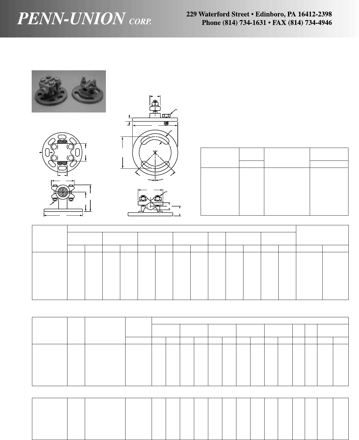
TYPE BSR2B
BRONZE BUS SUPPORT CLAMPS • TYPES BSR & BSR2B
Four and two bolt clamping tube or cable to bolt circle
Made from high copper content alloy.
Oval slots in base permit easy alignment. Type BSR, BSR2B-
025-5, BSR2B-050-5 and BSR2B-200-5 have 6 slots as shown
in photo. All other Type BSR2B have 2 elongated slots as in line
drawing and photo.
Clamping bolts, nuts and lockwashers are of silicon bronze.
Mounting hardware is stainless steel. Cap screws and
lockwashers furnished for cap mounting (standard). Bolts, nuts
and lockwashers furnished for base mounting (suffix catalog num-
ber with “-BM”. Example: BSR-1-BM).
Approximate Dimensions Bolt
BCDHJK W Circle
Catalog (Max.) (Max.) Dia.
Number in mm in mm in mm in mm in in mm in mm in mm
BSR-1 23/470 2 51 41/4108 33/16 81 3/89/16 14 23/16 56 3 76
BSR-2 23/470 21/16 52 63/8162 31/483 3/811/16 17 23/16 56 5 127
BSR-5 3 76 21/854 41/4108 35/892 3/89/16 14 211/16 68 3 76
BSR-6 3 76 23/16 56 63/8162 311/16 94 3/811/16 17 211/16 68 5 127
BSR-9 37/898 27/16 62 41/4108 43/16 106 1/29/16 14 311/16 94 3 76
BSR-10 37/898 21/264 63/8162 41/4108 1/211/16 17 311/16 94 5 127
BSR-11 27/873 29/16 65 41/4108 45/16 110 1/29/16 14 43/16 108 3 76
BSR-12 27/873 25/867 61/4159 43/8111 1/211/16 17 43/16 108 5 127
3" BOLT CIRCLE BASE
Wire Approximate Dimensions
Diameter D C W M T J JJ K
Catalog IPS Wire Range‡ Width of Slot
Number Size Range in in mm in mm in mm in mm in mm in in in mm
BSR2B-025-3 – 6 Sol.-250 MCM .162- .575 41/4108 13/16 21 21/457 1 25 5/16 83/81/29/16 14
BSR2B-050-3 – 1/0 Sol.-500 MCM .325- .815 41/4108 13/835 21/457 13/835 5/16 83/81/29/16 14
BSR2B-200-3 1/2-11/2500-2000 MCM .500-1.824 41/4108 23/32 53 37/898 11/432 3/891/21/29/16 14
BSR2B-20-3 2 – – 41/4108 23/16 56 41/2114 11/238 3/891/21/29/16 14
BSR2B-25-3 21/2––4
1/4108 23/16 56 47/8124 15/841 3/891/21/29/16 14
BSR2B-30-3 3 – – 41/4108 35/892 61/8156 13/444 5/16 85/81/29/16 14
BSR2B-35-3 31/2––4
1/4108 4 102 65/8168 13/444 5/16 85/81/29/16 14
BSR2B-025-5 – 6 Sol.-250 MCM .162- .575 61/4159 7/822 21/457 1 25 1/463/85/811/16 17
BSR2B-050-5 – 1/0 Sol.-500 MCM .325- .815 61/4159 17/16 37 21/457 13/835 1/463/85/811/16 17
BSR2B-200-5 1/2-11/2500-2000 MCM .500-1.824 63/8162 23/32 53 37/898 11/432 3/891/25/811/16 17
BSR2B-20-5 2 – – 63/8162 23/16 56 41/2114 11/238 3/891/25/811/16 17
BSR2B-25-5 21/2––6
3/8162 23/16 56 47/8124 15/841 3/891/25/811/16 17
BSR2B-30-5 3 – – 63/8162 35/892 61/8156 13/444 3/895/85/811/16 17
BSR2B-35-5 31/2––6
3/8162 4 102 65/8168 13/444 3/895/85/811/16 17
‡For conversion to metric range, see page 175.
5" BOLT CIRCLE BASE
IPS Wire Diameter
Catalog Range Conductor Range‡
Number in Range in
BSR-1 1/8-1/26 Str.-500 MCM .184- .840
BSR-2 1/8-1/26 Str.-500 MCM .184- .840
BSR-5 1/4-1 4/0 Str.-1250 MCM .528-1.315
BSR-6 1/4-1 4/0 Str.-1250 MCM .528-1.315
BSR-9 3/4-11/2850-2500 MCM 1.050-1.900
BSR-10 3/4-11/2850-2500 MCM 1.050-1.900
BSR-11 11/4-2 – –
BSR-12 11/4-2 – –
KB
D
CH
J
W
A
M
T
JJ
K
45°45°
WJ
AC
BOLT
CIRCLE
D
BSR BSR2B
121
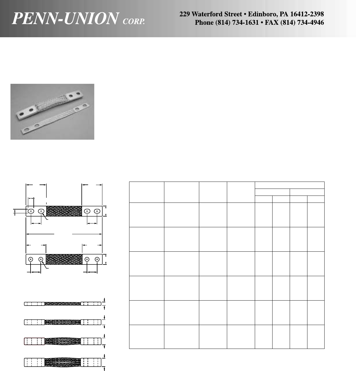
TIN PLATED COPPER FLEXIBLE BRAID • TYPE FXB
*Ampere ratings are suggested for use as a guide only. Actual values used for a given application will depend
on such factors as permissible temperature rise, permissible voltage drop, number of cables together and
other conditions of service. For outdoor use, these ratings may be increased from 22% to 40% depending upon
the size and position of the braid.
No. of Ampere Circular Approximate Dimensions
Catalog Braids Rating Mils. of TW
Number in Ferrule (Indoors)* Braids in mm in mm
FXBA-12-Q 1 200 77,184 5/32 3.96 1 25
FXB2A-12-Q 2 340 154,368 7/32 5.55 1 25
FXB3A-12-Q 3 470 231,552 1/46.35 11/829
FXB4A-12-Q 4 600 308,736 5/16 7.93 11/829
FXBA-12S-Q 1 200 77,184 5/32 3.96 1 25
FXB2A-12S-Q 2 340 154,368 7/32 5.55 1 25
FXB3A-12S-Q 3 470 231,552 1/46.35 11/829
FXB4A-12S-Q 4 600 308,736 5/16 7.93 11/829
FXBB-12S-Q 1 330 135,072 1/46.35 1 25
FXB2B-12S-Q 2 500 270,144 1/46.35 11/238
FXB3B-12S-Q 3 650 405,216 3/89.52 11/238
FXB4B-12S-Q 4 750 540,288 1/212.70 11/238
FXBC-12S-Q 1 350 168,840 3/16 4.76 11/238
FXB2C-12S-Q 2 550 337,680 1/46.35 11/238
FXB3C-12S-Q 3 720 506,520 11/32 8.73 11/238
FXB4C-12S-Q 4 870 675,360 1/212.70 11/238
FXBD-12S-Q 1 360 202,608 1/46.35 13/835
FXB2D-12S-Q 2 600 405,216 13/32 10.31 11/238
FXB3D-12S-Q 3 780 607,824 15/32 11.90 11/238
FXB4D-12S-Q 4 900 810,432 9/16 14.28 11/238
FXBE-12S-Q 1 430 303,912 1/46.35 11/238
FXB2E-12S-Q 2 710 607,824 1/212.70 11/238
FXB3E-12S-Q 3 980 911,736 11/16 17.46 11/238
FXB4E-12S-Q 4 1200 1,215,648 7/822.22 11/238
Flexible leads suitable for use wherever it is necessary to take
up expansion, allow for misalignment, or take up vibration. Made
of flat, extra flexible, tinned, pure copper braid, with tin plated,
seamless, pure copper ferrules formed on each end. Inside ends
of ferrules are rounded to prevent chafing of strands.
Sizes and combinations not shown readily supplied. Special drill-
ing can be supplied on request. For NEMA drilling, substitute “N”
for “S” suffix. Refer to factory if different ferrule dimensions are
desired. For lengths other than 12" change catalog number suf-
fix accordingly. For example if an 18" length is desired change -
12 to -18.
“S” suffix denotes slotted holes which are suitable for 1/2" or 3/8"
mounting hardware on 11/2" or 13/4" hole centers.
Drop “Q” for silver-plated ferrules.
3"
(76 mm) 3"
(76 mm)
11/16"
(17 mm)
W
SLOT
9/16"
(41 mm) 1-5/8"
(41 mm) 1-5/8"
(41 mm)
12"
(305 mm)
21/2"
(64 mm) 21/2"
(64 mm)
W
7/16" DIA.
(11 mm)
11/4"
(32 mm) 11/4"
(32 mm)
T
T
T
T
122
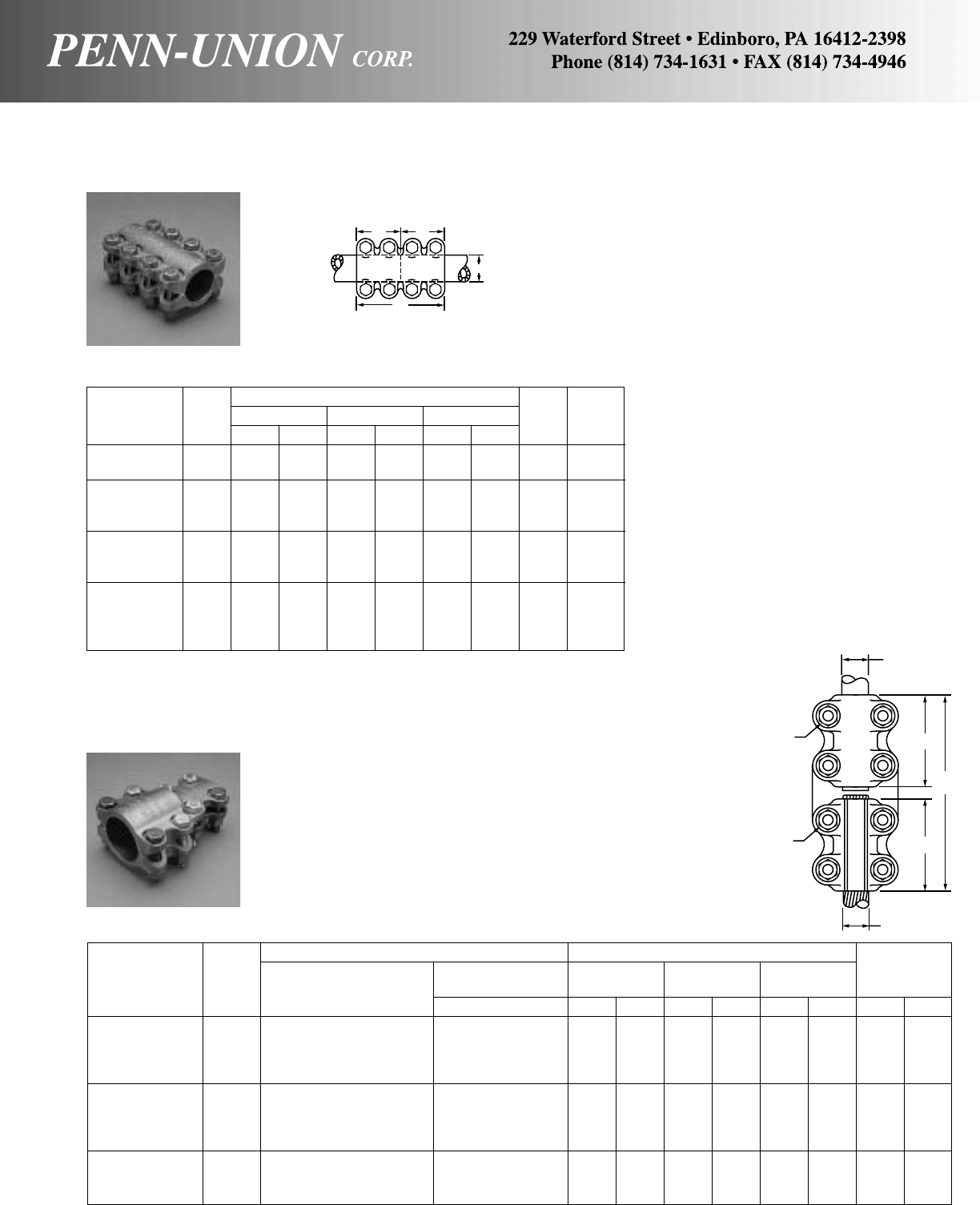
BRONZE COUPLERS AND REDUCERS • TYPE BA
For joining two conductors of the same size IPS tubing
Made from high copper content alloy. Furnished with silicon bronze
bolts, nuts and lockwashers.
Approximate Dimensions
Catalog ALM
Bolt Number
Number IPS in mm in mm in mm Size of Bolts
BA-0303 3/8.675 17.15 3 76 11/238 3/84
BA-0505 1/2.840 21.34 4 102 2 51 3/86
BA-0707 3/41.050 26.67 4 102 2 51 3/86
BA-1010 1 1.315 33.40 6 152 3 76 3/88
BA-1212 11/41.660 42.16 6 152 3 76 1/28
BA-1515 11/21.900 48.26 6 152 3 76 1/28
BA-2020 2 2.375 60.32 6 152 3 76 1/28
BA-2525 21/22.875 73.02 7 178 31/289 1/28
BA-3030 3 3.500 88.90 8 203 4 102 5/88
BA-3535 31/24.000 101.60 9 229 41/2114 5/88
BA-4040 4 4.500 114.30 10 254 5 127 5/88
BA-5050 5 5.563 141.30 12 305 6 162 5/88
BRONZE COUPLERS AND REDUCER CONNECTORS • TYPE BDR
For tubing range to cable range
Conductor Range Approximate Dimensions
AWire Diameter Bolt
Catalog IPS B Range‡ L M N Dia.
Number Main Cable Tap in in mm in mm in mm J JJ
BDR-20-025 2 6 Sol.-250 MCM .162- .575 55/8143 23/470 21/264 1/21/2
BDR-20-050 2 1/0 Sol.-500 MCM .325- .815 55/8143 23/470 21/264 1/21/2
BDR-20-100 2 4/0 Sol.-1000 MCM .460-1.529 61/8156 23/470 3 76 1/21/2
BDR-20-200 2 500-2000 MCM .815-1.632 61/8156 23/470 3 76 1/21/2
BDR-25-025 21/26 Sol.-250 MCM .162- .575 55/8143 23/470 21/264 1/21/2
BDR-25-050 21/21/0 Sol.-500 MCM .325- .815 55/8143 23/470 21/264 1/21/2
BDR-25-100 21/24/0 Sol.-1000 MCM .460-1.529 61/8156 23/470 3 76 1/21/2
BDR-25-200 21/2500-2000 MCM .815-1.632 61/8156 23/470 3 76 1/21/2
BDR-30-025 3 6 Sol.-250 MCM .162- .575 61/8156 31/483 21/264 1/21/2
BDR-30-050 3 1/0 Sol.-500 MCM .325- .815 61/8156 31/483 21/264 1/21/2
BDR-30-200 3 500-2000 MCM .815-1.632 65/8168 31/483 3 76 1/21/2
‡For conversion to metric range, see page 175.
MM
A
L
Cast of high copper content alloy. Furnished with silicon bronze
bolts, nuts and lockwashers.
Bolt heads pocketed for single wrench installation.
Rounded contours.
Independent clamping action on run and tap.
Reversible, range taking, high strength clamping elements.
J
JJ
M
L
N
A
MAIN
B
TAP
123

BRONZE TWO-WAY CONNECTOR • TYPE PNLC
Cable to cable
TWO SCREW TYPE
Wire Diameter Approximate Dimensions
Catalog Conductor Range‡ L H W Screw Hex
Number Range in in mm in mm in mm Size Size
PNLC-1/0 8 Sol.-1/0 Str. .128- .375 15/841 27/32 21 23/32 18 1/2-20 1/4
PNLC-250 6 Sol.-250 MCM .162- .575 21/854 11/16 27 31/32 25 3/4-16 3/8
PNLC-500 4 Sol.-500 MCM .204- .815 3 76 115/32 37 13/835 15/16-16 3/8
PNLC-1000 500-1000 MCM .815-1.529 33/494 2 51 13/444 13/8-14 3/8
For tin plated terminals, suffix catalog number with “-TN”. ‡For conversion to metric range, see page 175.
A low cost two-way connector that gives superior service. Body
is cast from high strength copper alloy. Steel, cadmium plated
hex socket screws. Annular serrations give higher conductivity
and better resistance to pull out.
All connectors are provided with cable stops. Hex head screws
can be furnished by suffixing catalog numbers with “-HH”.
VVC-26020* 8 Sol.-4 Str. .128- .232 17/8 48 5/816 1/213 5/16-24 5/32
VVC-26021 4 Sol.-1 Str. .204- .332 3 76 7/822 5/816 3/8-24 3/16
VVC-26022 2 Str.-2/0 Str. .292- .419 31/2 89 11/32 25 3/419 1/2-20 1/4
VVC-26023 1/0 Str.-4/0 Str. .375- .528 43/8111 19/32 32 7/822 9/16-18 1/4
VVC-26024 3/0 Str.-300 MCM .470- .634 47/8124 13/835 1 25 3/4-16 3/8
VVC-26025 300-500 MCM .634- .815 57/16 138 113/16 46 11/432 3/4-16 3/8
VVC-26026 500-800 MCM .815-1.031 63/16 183 113/16 46 17/16 37 7/8-14 3/8
VVC-26027 700-1000 MCM .965-1.529 73/16 183 21/16 52 19/16 40 7/8-14 3/8
‡For conversion to metric range, see page 175. For tin plated terminals, suffix catalog number with “-TN”. *No saddle.
FOUR SCREW TYPE
Wire Diameter Approximate Dimensions
Catalog Conductor Range‡ L H W Screw Hex
Number Range in in mm in mm in mm Size Size
VC-26010* 14 Sol.-8 Str. .064- .146 13/835 9/16 14 15/32 12 5/16-24 5/32
VC-26000 8 Sol.-4 Str. .128- .232 11/16 27 5/816 1/213 5/16-24 5/32
VC-26001 4 Sol.-1 Str. .204- .332 15/841 7/822 5/816 3/8-24 3/16
VC-26002 2 Str.-2/0 Str. .292- .419 17/848 11/32 26 3/419 1/2-20 1/4
VC-26003 1/0 Str.-4/0 Str. .375- .528 25/16 59 19/32 32 7/822 9/16-18 1/4
VC-26004 3/0 Str.-300 MCM .470- .634 29/16 65 13/835 1 25 3/4-16 3/8
VC-26005 300-500 MCM .634- .815 27/873 113/16 46 11/432 3/4-16 3/8
VC-26006 500-800 MCM .815-1.031 31/483 113/16 46 17/16 37 7/8-14 3/8
VC-26007 700-1000 MCM .965-1.529 33/494 21/16 52 19/16 40 7/8-14 3/8
TWO SCREW TYPE
Body is cast from high strength corrosion resistant copper alloy.
Screw and saddle are made from bronze. Unique designed pro-
tuberances assure higher conductivity and better resistance to
pull out. All connectors are provided with cable stops. Hex head
screws can be furnished by suffixing catalog numbers with “-HH”.
W
L
H
W
L
H
H
W
HEX SIZE
CU
90°C
L
124
BRONZE VI-TITE TWO-WAY CONNECTORS • TYPE VC AND VVC
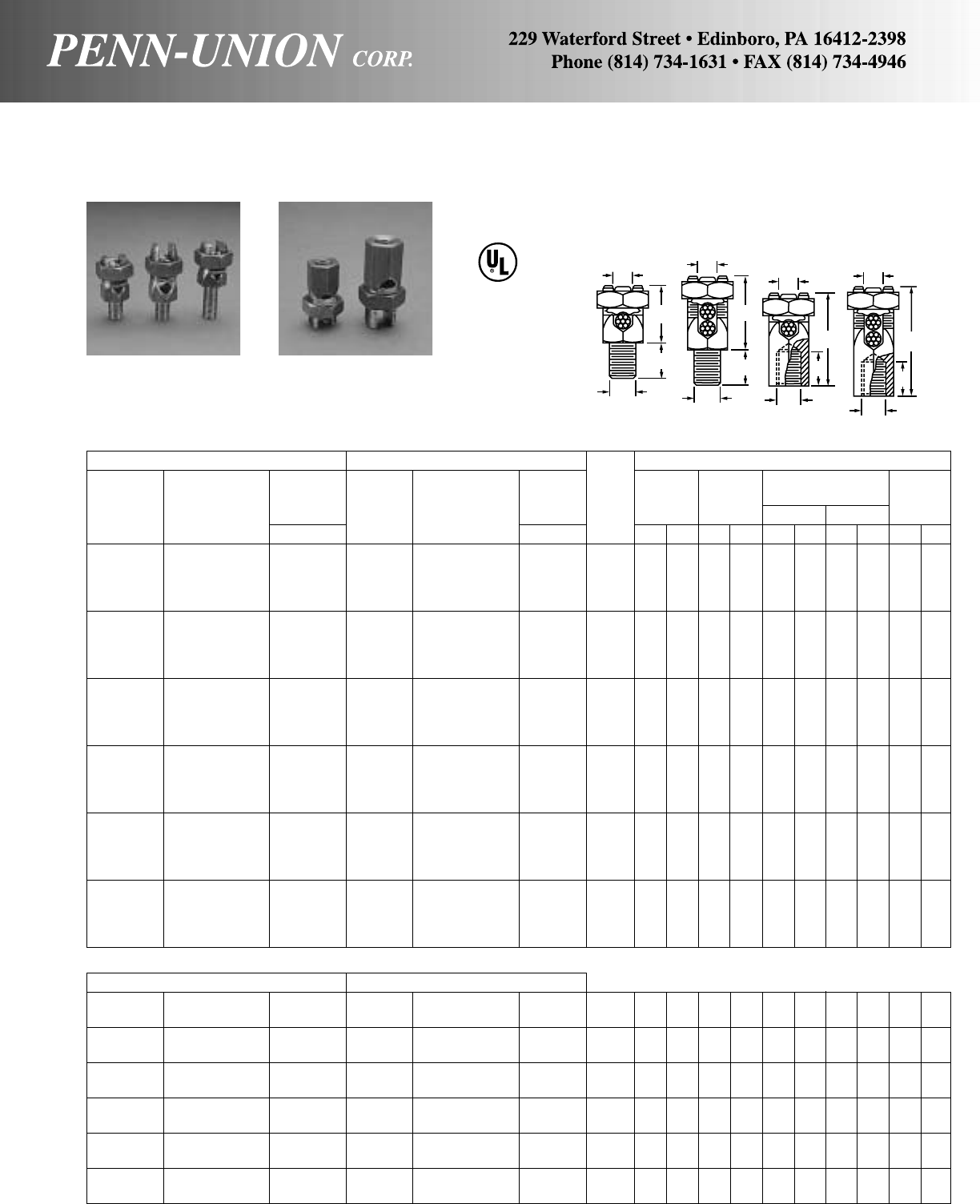
BRONZE SERVICE POST CONNECTORS • TYPES SSS, SCS, STS AND SDS
Fig. 1 (One Cable) Fig. 2 (Two Cables) Approximate Dimensions
Wire Wire
ADiameter ADiameter H
Catalog Conductor Range‡ Catalog Conductor Range‡ Stud Nut Hex. C One Cable Two Cable Body Hex.
Number Range in Number Range in Size in mm in mm in mm in mm in mm
SSS-0 12 Sol.-8 Str. .081- .146 SCS-0 12 Sol.-8 Str. .081- .146 1/4-20 1/213 1/213 5/816 3/419 3/89
SSS-0A1 12 Sol.-8 Str. .081- .146 SCS-0A1 12 Sol.-8 Str. .081- .146 1/4-20 1/213 1 25 5/816 3/419 3/89
SSS-1 8 Sol.-7 Str. .128- .164 SCS-1 10 Sol.-7 Str. .102- .164 1/4-20 11/16 17 1/213 7/822 1 25 1/213
SSS-1A1 8 Sol.-7 Str. .128- .164 SCS-1A1 10 Sol.-7 Str. .102- .164 1/4-20 11/16 17 1 25 7/822 1 25 1/213
SSS-2 10 Sol.-4 Str. .102- .232 SCS-2 10 Sol.-4 Str. .102- .232 5/16-18 3/419 9/16 14 15/16 24 15/32 29 9/16 14
SSS-2A1 10 Sol.-4 Str. .102- .232 SCS-2A1 10 Sol.-4 Str. .102- .232 5/16-18 3/419 1 25 15/16 24 15/32 29 9/16 14
SSS-3 6 Sol.-3 Str. .162- .260 SCS-3 10 Sol.-3 Str. .102- .260 3/8-16 13/16 21 5/816 11/16 27 13/32 28 5/816
SSS-3A1 6 Sol.-3 Str. .162- .260 SCS-3A1 10 So..-3 Str. .102- .260 3/8-16 13/16 21 11/829 11/16 27 13/32 28 5/816
SSS-4 4 Str.-2 Str. .232- .292 SCS-4 10 Sol.-2 Str. .102- .292 3/8-16 7/822 5/816 11/16 27 13/835 11/16 17
SSS-4A1 4 Str.-2 Str. .232- .292 SCS-4A1 10 Sol.-2 Str. .102- .292 3/8-16 7/822 11/829 11/16 27 19/32 33 11/16 17
SSS-5 6 Sol.-1/0 Str. .162- .375 SCS-5 2 sol.-1/0 Str. .258- .375 1/2-13 1 25 3/419 15/16 33 111/16 43 3/419
SSS-5A1 6 Sol.-1/0 Str. .162- .375 SCS-5A1 2 Sol.-1/0 Str. .258- .375 1/2-13 1 25 11/432 15/16 33 111/16 43 3/419
SSS-6 1 Sol.-2/0 Str. .289- .419 SCS-6 2 Sol.-2/0 Str. .258- .419 1/2-13 11/829 3/419 17/16 37 17/848 7/822
SSS-6A1 1 Sol.-2/0 Str. .289- .419 SCS-6A1 2 Sol.-2/0 Str. .258- .419 1/2-13 11/829 11/432 17/16 37 17/848 7/822
SSS-8 3/0 Sol.-4/0 Str. .410- .528 SCS-8 1 Sol.-4/0 Str. .289- .528 5/8-11 13/835 1 25 111/16 43 21/457 11/829
SSS-8A1 3/0 Sol.-4/0 Str. .410- .528 SCS-8A1 1 Sol.-4/0 Str. .289- .528 5/8-11 13/835 11/238 111/16 43 21/457 11/829
SSS-9 4/0 Str.-350 MCM .528- .682 SCS-9 1 Str.-350 MCM .332- .682 5/8-11 11/238 1 25 2 51 211/16 68 11/432
SSS-9A1 4/0 Str.-350 MCM .528- .682 SCS-9A1 1 Str.-350 MCM .332- .682 5/8-11 11/238 11/238 2 51 211/16 68 11/432
SSS-10 250-500 MCM .575- .815 SCS-10 3/0 Str.-500 MCM .470- .815 3/4-10 113/16 46 13/835 25/16 59 33/16 81 11/238
SSS-10A1 250-500 MCM .575- .815 SCS-10A1 3/0 Str.-500 MCM .470- .815 3/4-10 113/16 46 13/444 25/16 59 33/16 81 11/238
SSS-11 300-750 MCM .634- .999 SCS-11 350-750 MCM .682- .999 3/4-10 21/457 13/835 21/264 37/16 87 17/848
SSS-11A1 300-750 MCM .634- .999 SCS-11A1 350-750 MCM .682- .999 3/4-10 21/457 17/848 21/264 37/16 87 17/848
SSS-12 750-1000 MCM .999-1.153 SCS-12 500-1000 MCM .815-1.153 1-8 25/867 11/238 3 76 4 102 23/860
SSS-12A1 750-1000 MCM .999-1.153 SCS-12A1 500-1000 MCM .815-1.153 1-8 25/867 2 51 3 76 4 102 23/860
If nut and lockwasher are required, add suffix “-SMH” to catalog number.
STS-0 12 Sol.-8 Str. .081- .146 SDS-0 12 Sol.-8 Str. .081- .146 1/4-20 1/213 1/4 6 29/32 23 11/829 3/89
STS-1 10 Sol.-7 Str. .102- .164 SDS-1 10 Sol.-7 Str. .102- .164 1/4-20 11/16 17 1/4 6 11/829 17/16 37 1/213
STS-2 8 Sol.-4 Str. .128- .232 SDS-2 10 Sol.-4 Str. .102- .232 5/16-18 3/419 5/16 8 17/16 37 19/16 40 9/16 14
STS-3 6 Str.-3 Str. .184- .260 SDS-3 10 Sol.-3 Str. .102- .260 3/8-16 13/16 21 3/8 9 11/238 15/841 5/816
STS-4 6 Str.-2 Str. .184- .292 SDS-4 10 Sol.-2 Str. .102- .292 3/8-16 7/822 3/8 9 15/841 115/16 49 11/16 17
STS-5 2 Sol.-1/0 Str. .258- .375 SDS-5 2 Sol.-1/0 Str. .258- .375 1/2-13 1 25 7/16 11 17/848 21/854 3/419
STS-6 1 Sol.-2/0 Str. .289- .419 SDS-6 2 Sol.-2/0 Str. .258- .419 1/2-13 11/829 1/213 21/16 52 25/16 59 7/822
STS-8 1/0 Str.-4/0 Str. .375- .528 SDS-8 1 Sol.-4/0 Str. .289- .528 5/8-11 13/835 5/816 23/860 21/264 11/829
STS-9 4/0 Str.-350 MCM .528- .682 SDS-9 1 Str.-350 MCM .332- .682 5/8-11 11/238 5/816 25/867 211/16 68 11/432
STS-10 300-500 MCM .634- .815 SDS-10 3/0 Str.500 MCM .470- .815 3/4-10 113/16 46 3/419 31/879 35/16 84 11/238
STS-11 600-750 MCM .893- .999 SDS-11 350-750 MCM .682- .999 3/4-10 21/457 7/822 31/289 31/289 2 51
STS-12 750-1000 MCM .964-1.153 SDS-12 500-1000 MCM .815-1.153 1-8 25/867 11/829 41/8105 4 102 23/860
‡For conversion to metric range, see page 175. *UL listing is limited to 500 MCM.
*
*
Fig. 3. (One Cable) Fig. 4 (Two Cables)
MALE TYPES SSS AND SCS
*
*
*
*
C
SSS SCS SSS-A1 STS SDS
AA
AA
HH
HH
CCCC
STUD
DIA. STUD
TAP STUD
TAP
STUD
DIA.
FIG. 1 FIG. 2 FIG. 3 FIG. 4
467 LISTED
SUITABLE FOR
DIRECT BURIAL
Body made from high copper content hard drawn rod. Used for
connecting one or two conductors to various sizes external stud
or tapped hole.
125
US
FEMALE TYPES STS AND SDS
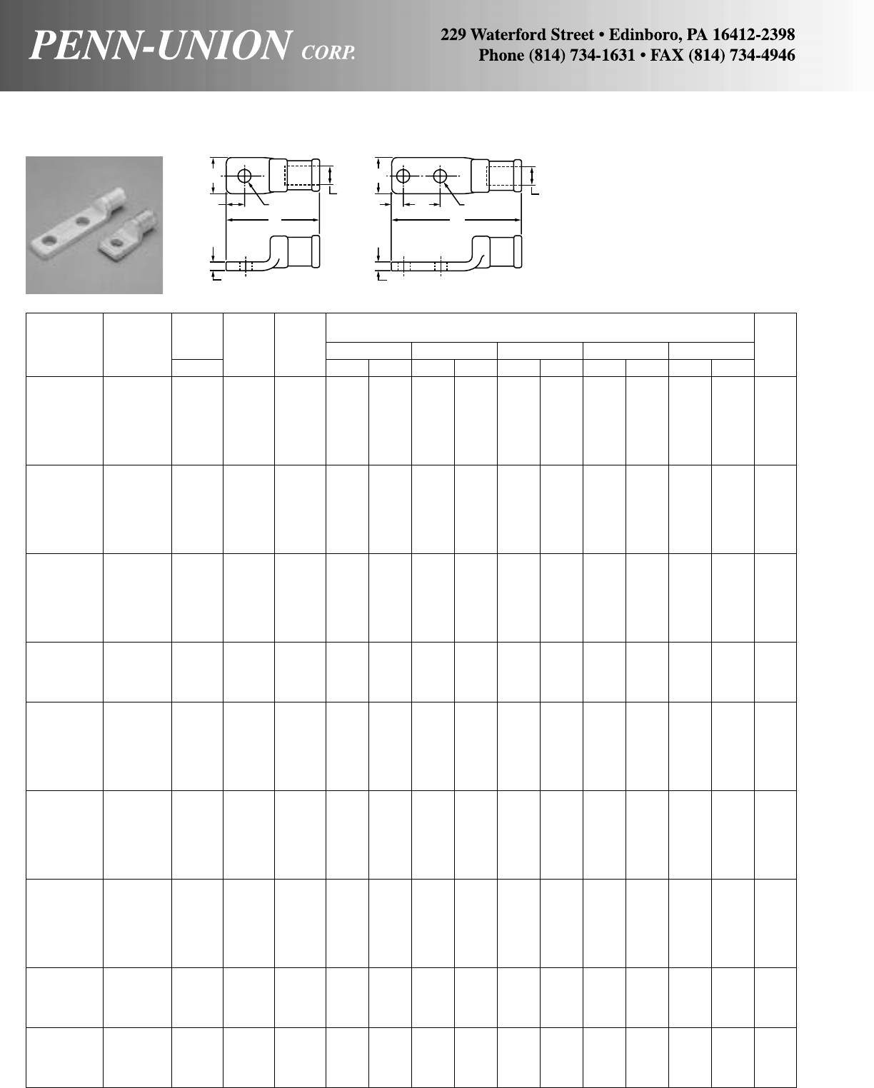
COPPER COMPRESSION TERMINALS • TYPE TLU
AWire
Con- Diam. DApproximate Dimensions T & B
Catalog ductor Range Bolt Fig. LWTCE
Die
Number Range in Size No. in mm in mm in mm in mm in mm Size
TLU-W8S 8 Str. .146 10 1 17/16 37 1/213 1/8 3 5/16 8 – – 29
TLU-W8D 8 Str. .146 1/422 51
1/213 1/8 3 11/32 9 5/816 29
TLU-W6S 6 Str. .184 1/411
7/16 37 1/213 1/8 3 5/16 8 – – 29
TLU-W6D 6 Str. .184 1/422 51
1/213 1/8 3 11/32 9 5/816 29
TLU-W4S 4 Str. .232 1/411
7/16 37 1/213 1/8 3 5/16 8 – – 29
TLU-W4D 4 Str. .232 1/422 51
1/213 1/8 3 11/32 9 5/816 29
TLU-W2S 2 Str. .292 1/412 51
3/419 1/4 6 7/16 11 – – 45
TLU-W2D 2 Str. .292 1/423 76
3/419 1/4 6 1/213 3/419 45
TLU-W1S 1 Str. .332 1/412 51
3/419 1/4 6 7/16 11 – – 45
TLU-W1D 1 Str. .332 1/423 76
3/419 1/4 6 1/213 1 25 45
TLU-1/0S 1/0 Str. .368 3/812 51
3/419 1/4 6 7/16 11 – – 45
TLU-1/0D 1/0 Str. .368 3/823 76
3/419 1/4 6 1/213 1 25 45
TLU-2/0S 2/0 Str. .419 3/812
5/8 67 1 25 9/32 7 9/16 14 – – 66
TLU-2/0D 2/0 Str. .419 3/824
5/8117 1 25 9/32 7 5/816 13/444 66
TLU-3/0S 3/0 Str. .470 3/812
5/8 67 1 25 9/32 7 9/16 14 – – 66
TLU-3/0D 3/0 Str. .470 1/224
5/8117 1 25 9/32 7 5/816 13/444 66
TLU-4/0S 4/0 Str. .528 3/812
5/8 67 1 25 9/32 7 9/16 14 – – 66
TLU-4/0D 4/0 Str. .528 1/224
5/8117 1 25 9/32 7 5/816 13/444 66
TLU-025S 250 MCM .575 1/213
1/4 83 13/16 30 5/16 8 3/419 – – 76
TLU-025D 250 MCM .575 1/224
7/8124 13/16 30 5/16 8 5/816 13/444 76
TLU-030S 300 MCM .634 1/213
1/4 83 13/16 30 5/16 8 3/419 – – 76
TLU-030D 300 MCM .634 1/224
7/8124 13/16 30 5/16 8 5/816 13/444 76
TLU-035S 350 MCM .682 1/213
3/4 95 13/835 3/810 3/419 – – 99
TLU-035D 350 MCM .682 1/225
3/8137 13/835 3/810 5/816 13/444 99
TLU-040S 400 MCM .728 1/213
3/4 95 13/835 3/810 3/419 – – 99
TLU-040D 400 MCM .728 1/225
3/8137 13/835 3/810 5/816 13/444 99
TLU-050S 500 MCM .815 1/213
3/4 95 13/835 3/810 3/419 – – 99
TLU-050D 500 MCM .815 1/225
3/8137 13/835 3/810 5/816 13/444 99
TLU-060S 600 MCM .893 1/213
3/4 95 15/841 7/16 11 3/419 – – 112
TLU-060D 600 MCM .893 1/225
3/8137 15/841 7/16 11 5/816 13/444 112
TLU-070S 700 MCM .965 1/213
3/4 95 15/841 7/16 11 3/419 – – 112
TLU-070D 700 MCM .965 1/225
3/8137 15/841 7/16 11 5/816 13/444 112
TLU-075S 750 MCM .999 1/213
3/4 95 15/841 7/16 11 3/419 – – 112
TLU-075D 750 MCM .999 1/225
3/8137 15/841 7/16 11 5/816 13/444 112
TLU-080S 800 MCM 1.031 1/214
1/2114 17/848 15/32 12 15/16 24 – – 130
TLU-080D 800 MCM 1.031 1/225
3/4146 17/848 15/32 12 5/816 13/444 130
TLU-090S 900 MCM 1.094 5/814
1/2114 17/848 15/32 12 15/16 24 – – 130
TLU-090D 900 MCM 1.094 1/225
3/4146 17/848 15/32 12 5/816 13/444 130
TLU-100S 1000 MCM 1.153 5/814
1/2114 17/848 15/32 12 15/16 24 – – 130
TLU-100D 1000 MCM 1.153 1/225
3/4146 17/848 15/32 12 5/816 13/444 130
TLU-125S 1250 MCM 1.290 5/815127 21/457 1/213 11/16 27 – – 150
TLU-125D 1250 MCM 1.290 1/226152 21/457 1/213 5/816 13/444 150
TLU-150S 1500 MCM 1.142 5/815127 21/457 1/213 11/16 27 – – 161
TLU-150D 1500 MCM 1.412 1/226152 21/457 1/213 5/816 13/444 161
TLU-175S 1750 MCM 1.526 5/815
7/8149 21/264 1/213 13/16 30 – – 175
TLU-175D 1750 MCM 1.526 1/226
5/8168 21/264 1/213 5/816 13/444 175
TLU-200S 2000 MCM 1.632 5/816
1/8156 23/470 1/213 15/16 33 – – 187
TLU-200D 2000 MCM 1.632 1/226
5/8168 23/470 1/213 5/816 13/444 187
Above terminals can be installed with the following T & B Tooling: 12 ton head (13642), 20 ton head (21920), 40 ton head (21940).
W
CDA
L
TT
W
CDE
L
A
FIG. 1 FIG. 2
126
These heavy duty compression
lugs are cast out of high conduc-
tivity copper and can be installed
with existing crimping tools.
Entire connector is electro-tin
plated.
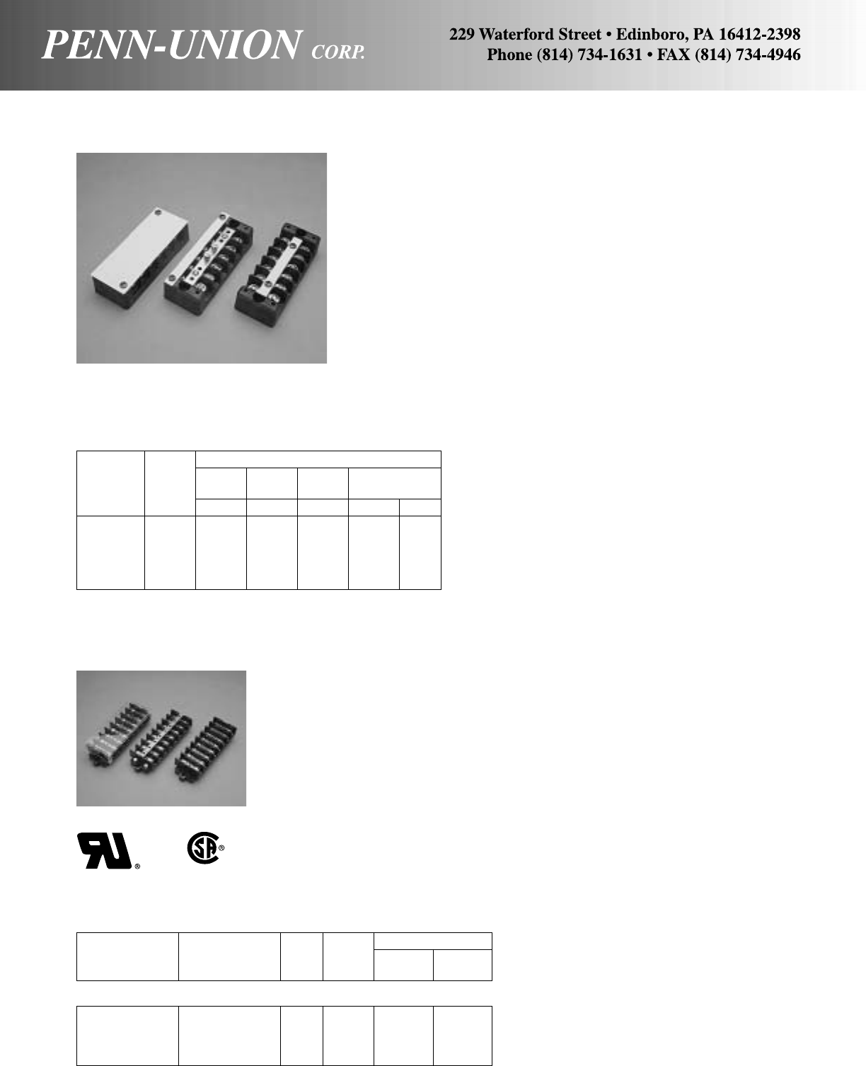
GLASS REINFORCED PLASTIC TERMINAL BLOCKS • SERIES 6000
SERIES 6000-WIDE SLOT
Series 6000 terminal blocks have a wide slot opening (9/16") to
take wires with either a soldered or solderless terminal lug. They
are molded of glass reinforced thermoplastic engineering resin.
Jumper bars are stamped of .062 inch hard rolled copper, plated
to prevent corrosion and cannot be removed from terminal block.
Holes are tapped at two corners for attachment of cover. Washer-
head screws, No. 10-32, are nickel plated. White marking strips,
of a special durable vinyl are furnished.
Rating: 75 amps with #4 max crimp lug 600V 75°C.
45 amps with #8 max wire 600V 75°C.
SERIES 6000-SVS
For white vinyl cover, suffix catalog number with “-SVS”.
SERIES 6000-SCS
SHORT CIRCUITING
For shorting strip of hard rolled copper, which is pierced to take a
shorting pin that makes contact with the jumper bar, suffix catalog
number with “-SCS.” Two shorting pins furnished as standard.
This provides for short circuiting of two of the circuits passing
through the block. Extra shorting pins, SCP-1, may be ordered
separately.
SERIES 6000-SCC
For short circuiting block with cover instead of the plastic mark-
ing strip furnished with the standard 6000 series blocks, suffix
catalog number with “-SCC.” Two shorting pins furnished as
standard.
Approximate Dimensions
No. Mounting
Catalog of Width Height Length Hole
Number Wires Inches Inches Inches C. to C. Dia.
6002 2 2 13/16 21/2113/16 .225
6004 4 2 13/16 313/16 31/8.225
6006 6 2 13/16 51/843/8.225
6008 8 2 13/16 67/16 53/4.225
6012 12 2 13/16 91/16 83/8.225
VERSATILE AND ECONOMICAL NORYL® TERMINAL BLOCKS • SERIES 15-1600
Break Resistant 94V-1 Grade Noryl® Terminal Blocks
Mounting Hole
Number of Wires Ctn. L Range Inches
Catalog Number Per Side Qty. inches Min. Max.
•15-1604 4 2 33/427/833/8
•15-1606 6 2 5 41/845/8
•15-1608 8 2 61/453/857/8
•15-1612 12 2 83/477/883/8
•Stock items. Noryl
®
is a trademark of General Electric Company.
50 Amp – 600 Volts
127
Penn-Union’s 15-1600 series of break-resistant terminal blocks are rated for service at 600
volts. Constructed of 94V-1 grade Noryl®, the 15-1600 series of terminal blocks are much
stronger than more common phenolic terminal blocks. The 15-1600 series meets 125V UL
service entrance equipment requirements. These terminal blocks are designed with a uni-
versal mounting feature utilizing adjustable, metal mounting eyelets. This allows easy instal-
lation in mounting holes that have been pre-drilled for competitive 1500 and 1600 series
blocks. The mounting eyelets evenly distribute mounting screw pressure as well.
Penn-Union’s 15-1600 series terminal blocks are available in 4, 6, 8 and 12 position models.
All blocks can accommodate up to 7/16" lugs (pad width). Screws in Penn-Union’s 15-1600
series of terminal blocks are friction locked to prevent loosening.
Options
Each terminal block is available with a shorting strip and four shorting screws, or, a clear
plastic hinged lid. For terminal blocks with shorting strips, add “SC” as a suffix to catalog
numbers. For terminal blocks with hinged lids, add “C” as a suffix to catalog number.
Ratings: Wire Range – Line Side: CU Max 6 (UL): 8 (CSA)
– Load Side: CU Max 10 (UL): 8 (CSA)
Temp Rating 80°C.
Amp Rating: 60 Amps with #6 Wire
Other Wire 30 Amps
Torque: 20 in-lbs.

Small Braid Kit Large Braid Kit
Catalog Number Braid Length No. of Connectors Catalog Number Braid Length No. of Connectors
FBK-125 20' 20-BBLU 1/0 S-FL FBK-285 10' 10-BBLU 050 D-FL
125 Amp 77,184 Circular mil braid (#1 AWG) 5/32"x11/16"285 Amp 303,912 Circular mil braid (300 MCM) 3/8"x13/8"
Flexible Braid Kits
Penn-Union’s Flexible Braid Kits allow you to make custom flex-
ible connections to precisely match your job specifications. Flex-
ible braid kits eliminate the need to wait for special order flexible
leads or use leads that are not ideally suited to a particular job
application.
Choose from two Flexible Braid Kits.
Penn-Union’s Flexible Braid Kits come in small and large braid
sizes. Both kits contain a length of tin-plated flexible copper braid
and flared end long barrel Penn-Crimp® compression connec-
tors, type BBLU, for ease of braid insertion. Additional connec-
tors are available from Penn-Union stocking distributors.
Flexible Braid Kits are made from quality materials.
Flexible Braid Kits contain braid made from high quality tin-plated
copper. The braid’s pure copper core provides high conductivity
while tin plating makes the braid corrosion resistant. In addition,
the woven design of Penn-Union’s braid allows maximum flex-
ibility of a connection.
FLEXIBLE BRAID KITS
Create custom flexible connections to your exact job requirements
128
TRANSFORMER LUG KITS • TYPE LASK
Mechanical Transformer Lug Kits contain Type LA aluminum
solderless lugs, steel nuts and bolts. They come in four sizes
and can be used with any dry-type transformer.
Steel nuts and bolts are yellow chromated for corrosion resis-
tance. Nuts have special captive conical pressure washers that
maintain bolted contact pressure when properly torqued.
Type LA aluminum lugs are “dual rated”, carrying the UL486B
listing for copper and aluminum conductors. Each lug is marked
“AL9CU” to signify this level of performance.
Kit Contents
Catalog Transformer Bolts &
Number KVA Size Lugs Qty. Nuts Qty.
LASK-1 15-371/2 1-Phase LA2 8 1/4 x 3/4" 8
15-45 3-Phase LA-250 4
LASK-2 50-75 1-Phase LA-250 12 1/4 x 3/4" 8
75-1121/2 3-Phase 1/4 x 13/4" 8
LASK-3 100-167 1-Phase LA-250 3 1/4 x 3/4" 3
150-300 3-Phase LA-600 22 3/8 x 2" 16
LASK-4 500 3-Phase LA-600 29 3/8 x 2" 18
486B LISTED
AL9CU
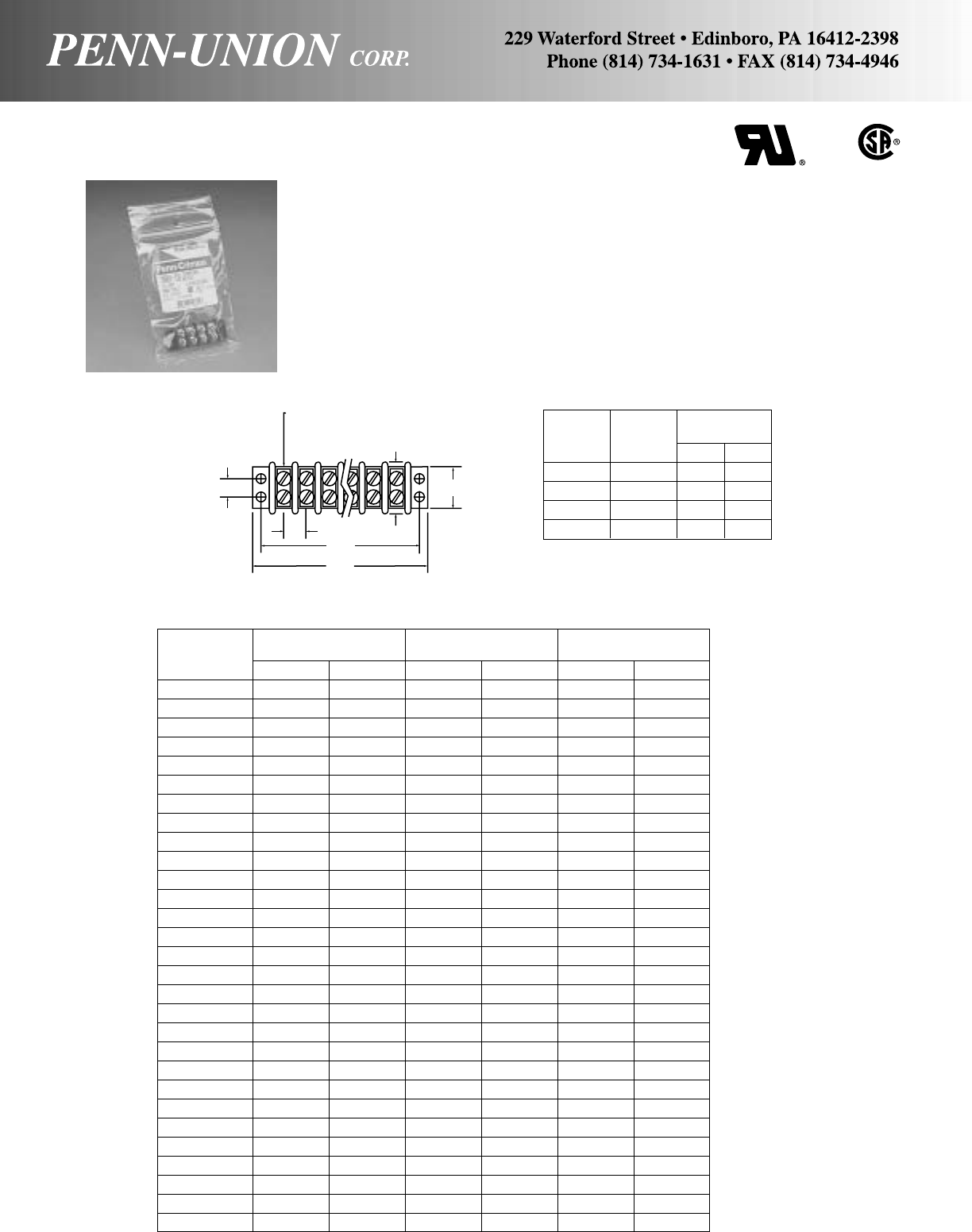
DOUBLE ROW TERMINAL BLOCKS • SERIES 3000
Terminals are Ultrasonically welded in the block for improved pull-
out strength. Closed back or feed through construction, in black
thermoplastic, of 1 to 30 terminals.
Current ratings, amps (UL)-20, (UL flame retardant rating 94V-0).
Voltage Rating, rms:
(A) UL Recognized
1. General Industrial – 150 to 300
2. Commercial Equipment – 250
(B) Withstand and Volts, rms – 7,500
Recommended wire size of 14 to 22 AWG solid/stranded.
Screws are 6/32 x 1/4 steel nickel plated binding head.
129
Bulk pack items available on special order.
Contact factory for price and availability.
#6-32 x 1/4
SCREWS
0.31
.374
B
A
0.874
0.705
Decimal
Catalog Number Dimensions
No. Terminals A B
3004-1B 4 2.16 1.88
3006-1B 6 2.91 2.63
3008-1B 8 3.66 3.38
3010-1B 10 4.41 4.13
-1B suffix, packaged in plastic bags for merchandising display. For bulk
packaged product, contact factory for availability.
Bulk Pack
Catalog Fraction Dimension Decimal Dimension Millimeters Dimension
Numbers A B A B (+/-.015) A B
3002 113/32 11/8 1.41 1.13 35.7 28.6
3003 125/32 11/2 1.78 1.50 45.2 38.1
3004 25/32 17/8 2.16 1.88 54.7 47.6
3005 217/32 21/4 2.53 2.25 64.3 57.2
3006 229/32 25/8 2.91 2.63 73.8 66.7
3007 39/32 3 3.28 3.00 83.3 76.2
3008 321/32 33/8 3.66 3.38 92.8 85.7
3009 41/32 33/4 4.03 3.75 102.4 95.3
3010 413/32 41/8 4.41 4.13 111.9 104.8
3011 425/32 41/2 4.78 4.50 121.4 114.3
3012 55/32 47/8 5.16 4.88 130.9 123.8
3013 517/32 51/4 5.53 5.25 140.5 133.4
3014 529/32 55/8 5.91 5.63 150.5 142.9
3015 69/32 6 6.28 6.00 159.5 152.4
3016 621/32 63/8 6.66 6.38 169.5 161.9
3017 71/32 63/4 7.03 6.75 153.2 171.5
3018 713/32 71/8 7.41 7.13 188.5 181.5
3019 725/32 71/2 7.78 7.50 197.6 190.1
3020 85/32 77/8 8.16 7.88 207.1 200.5
3021 817/32 81/4 8.53 8.25 216.7 209.6
3022 829/32 85/8 8.91 8.63 226.2 219.1
3023 99/32 9 9.28 9.00 235.7 228.6
3024 921/32 93/8 9.66 9.38 245.2 238.1
3025 101/32 93/410.03 9.75 254.8 247.7
3026 1013/32 101/810.41 10.13 264.3 257.2
3027 1025/32 101/210.78 10.50 273.8 266.7
3028 115/32 107/811.16 10.88 283.3 276.2
3029 1117/32 111/411.53 11.25 292.9 285.8
3030 1129/32 115/811.91 11.63 302.4 295.3

130
AMALGAMATING TAPE • TYPE AT
Amalgamating (self-combining, cold-shrink) tape provides the
cable installer a weather-tight wrapping that is superior to tradi-
tional PVC based tapes.
This self-amalgamating tape is based on ethylene propylene rub-
ber. It can be used for jointing (splicing and repair of a wide range
of solid dielectric power cables. When applied with sufficient
stretching, the tape will provide a void free build up of insulation
without the need of external heat or pressure.
Catalog Number Description
AT1X10-1B Tape, Amal., 1" x 10', 1 per bag.
Electrical properties highly stable under prolonged use on cables
at conductor temperatures up to 130°C (266°F).
Compatible with a wide range of polymeric cable insulation ma-
terials including polyethylene, PVC, ethylene proplylene rubber,
crosslinked polyethylene and butyl rubbers and neoprene.
Excellent resistance to prolonged immersion in water.
Ozone resistant.
Compatible with acrylic and epoxy resin systems.
Tape removes cleanly from most surfaces when cut, allowing it
to be used as a temporary wrap.
ALUMINUM CLEAR INSULATED SECONDARY CONNECTOR • TYPE NACC
For any combination of copper or aluminum
Conductor Range Approximate Dimensions
Catalog AWG MM2Number of HWL
Number Conductors in mm in mm in mm
NACC 350-4 10-350 MCM 4-185 4 2.51 63.75 2.12 53.85 4.03 102.36
NACC 350-6 10-350 MCM 4-185 6 2.51 63.75 2.12 53.85 5.85 148.59
NACC 350-8 10-350 MCM 4-185 8 2.51 63.75 2.12 53.85 7.67 194.82
NACC 500-4 10-500-MCM 4-240 4 2.88 73.15 2.25 57.15 5.09 129.29
NACC 500-6 10-500-MCM 4-240 6 2.88 73.15 2.25 57.15 7.47 189.74
Connectors are made from high strength aluminum alloy, pre-
filled with oxide inhibitor compound. Type NACC is tested and
passes the requirements of ANSI 119.4 for Class “A” connectors.
Clear insulation facilitates installation and inspection for proper
insertion of conductors. Type NACC is intended only for above
ground use.
W
L
H
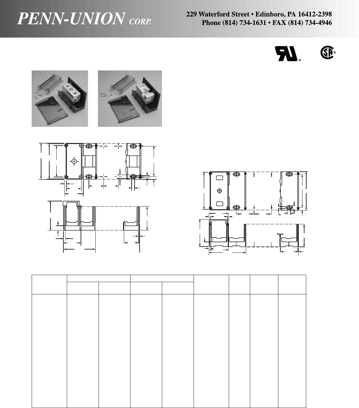
MODULAR POWER DISTRIBUTION BLOCKS • TYPE ADB
• Dual rated AL9CU - UL recognized, CSA certified 600 volt rated
• Easy to assemble
• Triple interlocking features
• Single piece tin plated aluminum connector
•Blocks molded from high strength glass filled polycarbonate
insulating material
• Highly versatile - only one basic building block to stock
• Snap as many basic blocks together as desired, finish with one
end wall for custom installation every time
• See through polycarbonate safety covers, with test hole, are
available to provide dead-front protection, one cover protects
one pole
Basic Block Primary Secondary Amperage End Wall Cover
Catalog Wire Range Opening Wire Range Opening Rating Block Catalog Catalog
Number AL9CU per Pole AL9CU per Pole per Pole Size Number Number
ADB 16-2/0 2/0 - 14 1 2 - 14 6 175 M EM CM
ADB 26-2/0 2/0 - 14 2 2 - 14 6 350 M EM CM
ADB 112-350 350MCM - 6 1 4 - 14 12 310 L EL CL
ADB 162-350 350MCM - 6 1 2 - 14 6 310 M EM CM
ADB 14-500 500MCM - 4 1 2/0 - 14 4 380 M EM CM
ADB 16-350 350MCM - 6 1 2/0 - 14 6 310 L EL CL
ADB 16-500 500MCM - 4 1 2/0 - 14 6 380 L EL CL
ADB 162-500 500MCM - 4 1 2 - 14 6 380 M EM CM
ADB 26-350 350MCM - 6 2 2/0 - 14 6 620 L EL CL
ADB 26-500 500MCM - 4 2 2/0 - 14 6 760 L EL CL
ADB 24-500 500MCM - 4 2 4/0 - 6 4 760 L EL CL
ADB 212-500 500MCM - 4 2 4 - 14 12 760 L EL CL
ADB 11-2/0 2/0 - 14 1 2/0 - 14 1 175 M EM CM
ADB 11-350 350MCM - 6 1 350MCM - 6 1 310 M EM CM
ADB 11-500 500MCM - 4 1 500MCM - 4 1 380 L EL CL
ADB 22-350 350MCM - 6 2 350MCM - 6 2 620 L EL CL
ADB 22-500 500MCM - 4 2 500MCM - 4 2 760 L EL CL
ADB 22-2/0 2/0 -14 2 2/0 - 14 2 350 M EM CM
ADB 22-4/0 4/0 - 6 2 4/0 - 6 2 460 M EM CM
To order simply determine the number of poles desired per block. Order that number of basic blocks and one end wall for each
complete block. If covers are desired, order the same number of covers as basic blocks. For example: If a 3 pole 350MCM block is
needed with one primary and 6 secondaries of 2/0-14 range - order three pieces of ADB 16-350 and one piece of EL. If covers are
required order three pieces of CL.
3.90 3.50
2.04
1.64 1.64 1.64
.20 .30
.41
3.37
.31
.22
3.23
.22
4.00
1 POLE
3.57
2 POLES
1.94 1.64
Basic Block
.08
2.62
LARGE BLOCK (L)
COVER CAT. NO. (CM)
MEDIUM BLOCK (M)
5.53
.20
.69
2.91
.24
2.90 .20
COVER CAT. NO. (CL)
2.81
1 POLE 5.31
2 POLES
2.50 2.50 .26 .44
.50 .37
4.75
5.50
2.50
Basic Block
3.25
.07
.07
131
End
Wall
Cat.
No.
EM
.50
End
Wall
Cat.
No.
EL

POWER DISTRIBUTION BLOCKS • TYPE ADB
• Dual rated AL9CU - UL recognized, CSA certified 600 volt rated
• Easy to assemble
• Single piece tin plated aluminum connector
• Blocks molded from high strength glass filled polycarbonate
insulating material
• See through polycarbonate safety covers, with test hole, are
available to provide dead-front protection, one-cover protects
one pole
Basic Block Primary Secondary Amperage Number Cover
Catalog Wire Range Opening Wire Range Opening Rating of Block Length Width Height Catalog
Number AL9CU per Pole AL9CU per Pole per Pole Poles Size in. in. in. Number
ADB 16-2/0-1 2/0-14 1 2-14 6 175 1 M 4.00 1.94 2.62 CM
ADB 16-2/0-2 2/0-14 1 2-14 6 175 2 M 4.00 3.57 2.62 CM
ADB 16-2/0-3 2/0-14 1 2-14 6 175 3 M 4.00 5.20 2.62 CM
ADB 26-2/0-1 2/0-14 2 2-14 6 350 1 M 4.00 1.94 2.62 CM
ADB 26-2/0-2 2/0-14 2 2-14 6 350 2 M 4.00 3.57 2.62 CM
ADB 26-2/0-3 2/0-14 2 2-14 6 350 3 M 4.00 5.20 2.62 CM
ADB 112-350-1 350 MCM-6 1 4-14 12 310 1 L 5.35 2.81 3.25 CL
ADB 112-350-2 350 MCM-6 1 4-14 12 310 2 L 5.35 5.31 3.25 CL
ADB 112-350-3 350 MCM-6 1 4-14 12 310 3 L 5.35 7.81 3.25 CL
ADB 162-350-1 350 MCM-6 1 2-14 6 310 1 M 4.00 1.94 2.62 CM
ADB 162-350-2 350 MCM-6 1 2-14 6 310 2 M 4.00 3.57 2.62 CM
ADB 162-350-3 350 MCM-6 1 2-14 6 310 3 M 4.00 5.20 2.62 CM
ADB 14-500-1 500 MCM-4 1 2/0-14 4 380 1 M 4.00 1.94 2.62 CM
ADB 14-500-2 500 MCM-4 1 2/0-14 4 380 2 M 4.00 3.57 2.62 CM
ADB 14-500-3 500 MCM-4 1 2/0-14 4 380 3 M 4.00 5.20 2.62 CM
ADB 16-350-1 350 MCM-6 1 2/0-14 6 310 1 L 5.35 2.81 3.25 CL
ADB 16-350-2 350 MCM-6 1 2/0-14 6 310 2 L 5.35 5.31 3.25 CL
ADB 16-350-3 350 MCM-6 1 2/0-14 6 310 3 L 5.35 7.81 3.25 CL
ADB 16-500-1 500 MCM-4 1 2/0-14 6 380 1 L 5.35 2.81 3.25 CL
ADB 16-500-2 500 MCM-4 1 2/0-14 6 380 2 L 5.35 5.31 3.25 CL
ADB 16-500-3 500 MCM-4 1 2/0-14 6 380 3 L 5.35 7.81 3.25 CL
ADB 162-500-1 500 MCM-4 1 2-14 6 380 1 M 4.00 1.94 2.62 CM
ADB 162-500-2 500 MCM-4 1 2-14 6 380 2 M 4.00 3.57 2.62 CM
ADB 162-500-3 500 MCM-4 1 2-14 6 380 3 M 4.00 5.20 2.62 CM
ADB 26-350-1 350 MCM-6 2 2/0-14 6 620 1 L 5.35 2.81 3.25 CL
ADB 26-350-2 350 MCM-6 2 2/0-14 6 620 2 L 5.35 5.31 3.25 CL
ADB 26-350-3 350 MCM-6 2 2/0-14 6 620 3 L 5.35 7.81 3.25 CL
ADB 26-500-1 500 MCM-4 2 2/0-14 6 760 1 L 5.35 2.81 3.25 CL
ADB 26-500-2 500 MCM-4 2 2/0-14 6 760 2 L 5.35 5.31 3.25 CL
ADB 26-500-3 500 MCM-4 2 2/0-14 6 760 3 L 5.35 7.81 3.25 CL
ADB 24-500-1 500 MCM-4 2 4/0-6 4 760 1 L 5.35 2.81 3.25 CL
ADB 24-500-2 500 MCM-4 2 4/0-6 4 760 2 L 5.35 5.31 3.25 CL
ADB 24-500-3 500 MCM-4 2 4/0-6 4 760 3 L 5.35 7.81 3.25 CL
ADB 212-500-1 500 MCM-4 2 4-14 12 760 1 L 5.35 2.81 3.25 CL
ADB 212-500-2 500 MCM-4 2 4-14 12 760 2 L 5.35 5.31 3.25 CL
ADB 212-500-3 500 MCM-4 2 4-14 12 760 3 L 5.35 7.81 3.25 CL
ADB 11-2/0-1 2/0-14 1 2/0-14 1 175 1 M 4.00 1.94 2.62 CM
ADB 11-2/0-2 2/0-14 1 2/0-14 1 175 2 M 4.00 3.57 2.62 CM
ADB 11-2/0-3 2/0-14 1 2/0-14 1 175 3 M 4.00 5.20 2.62 CM
ADB 11-350-1 350 MCM-6 1 350 MCM-6 1 310 1 M 4.00 1.94 2.62 CM
ADB 11-350-2 350 MCM-6 1 350 MCM-6 1 310 2 M 4.00 3.57 2.62 CM
ADB 11-350-3 350 MCM-6 1 350 MCM-6 1 310 3 M 4.00 5.20 2.62 CM
ADB 11-500-1 500 MCM-4 1 500 MCM-4 1 380 1 L 5.35 2.81 3.25 CL
ADB 11-500-2 500 MCM-4 1 500 MCM-4 1 380 2 L 5.35 5.31 3.25 CL
ADB 11-500-3 500 MCM-4 1 500 MCM-4 1 380 3 L 5.35 7.81 3.25 CL
ADB 22-350-1 350 MCM-6 2 350 MCM-6 2 620 1 L 5.35 2.81 3.25 CL
ADB 22-350-2 350 MCM-6 2 350 MCM-6 2 620 2 L 5.35 5.31 3.25 CL
ADB 22-350-3 350 MCM-6 2 350 MCM-6 2 620 3 L 5.35 7.81 3.25 CL
ADB 22-500-1 500 MCM-4 2 500 MCM-4 2 760 1 L 5.35 2.81 3.25 CL
ADB 22-500-2 500 MCM-4 2 500 MCM-4 2 760 2 L 5.35 5.31 3.25 CL
ADB 22-500-3 500 MCM-4 2 500 MCM-4 2 760 3 L 5.35 7.81 3.25 CL
ADB 22-2/0-1 2/0-14 2 2/0-14 2 350 1 M 4.00 1.94 2.62 CM
ADB 22-2/0-2 2/0-14 2 2/0-14 2 350 2 M 4.00 3.57 2.62 CM
ADB 22-2/0-3 2/0-14 2 2/0-14 2 350 3 M 4.00 5.20 2.62 CM
ADB 22-4/0-1 4/0-6 2 4/0-6 2 460 1 M 4.00 1.94 2.62 CM
ADB 22-4/0-2 4/0-6 2 4/0-6 2 460 2 M 4.00 3.57 2.62 CM
ADB 22-4/0-3 4/0-6 2 4/0-6 2 460 3 M 4.00 5.20 2.62 CM
132

ALUMINUM UNDERGROUND DIRECT BURIAL SERVICE CONNECTOR •
TYPE DBA
For aluminum or copper conductor range
The DBTBF Kit consists of an aluminum compression lug, hex
head cap screw with captive conical pressure washer, and a pre-
lubricated force-fit rubber sleeve with internal rings that provide
a positive seal.
Type DBA is an economical insulated aluminum service connec-
tor suitable for direct burial or for use in enclosures. Contact pads
allow new services to be added as needed without disturbing
previous installations. Taping is eliminated by use of force-fit
EPDM rubber insulating sleeves.
Upper DBA body is PVC insulated; each leg is independently
capped with a water-tight cover which may be removed for the
addition of compression terminal force-fit insulating sleeves.
NOTE:
For street lighting tap add suffix “-S” to catalog number. Example:
DBA-6L-S. For insulating sleeve for the street lighting tap, con-
sult the factory.
ALUMINUM UNDERGROUND COMPRESSION TERMINAL KITS • TYPE DBTBF
Approximate Dimensions
Catalog LH
Number in mm in mm
DBA-4L 51/2140 23/860
DBA-6L 81/2216 23/860
DBA-8L 111/2292 23/860
STREET LIGHTING
TAP (OPTIONAL)
L
H
DBA-4L
3/4"
(19mm)
3/8"-16
TAPPED
HOLES
3/8"-16
TAPPED
HOLES
3/4"
(19mm) 3/4"
(19mm)
3/8"-16
TAPPED
HOLES
DBA-6L DBA-8L
FOR
3
/
8
" BOLT
133
Wire Tools, Dieset
Catalog Diameter Catalog Number and
Number Conductor Range Range‡ EEI Number of Crimps TDY-U
Force Die Die
MD 6 Y 35 Pressure
Fit Copper Aluminum in Index Index
Series Series Setting
DBTBF-C6 6 Str.-4 Sol. 6 Str.-4 Sol. .179-.204
6 Str. Comp.
DBTBF-W2 2 Sol.-4 Str. 2 Sol.-4 Str. .225-.258 BG or BG 3 UBG 1
4 Str. Comp. 8A 5/8 or or or 2
DBTBF-C1 2 Str.-1/0 Sol. 2 Str.-1/0 Sol. .283-.325 243 W243 2 U243 1
2 - 1 Str. Comp.
DBTBF-010A 1/0 Str. 1/0 Str.-2/0 Sol. .362-.375
1/0 Str. Comp.
DBTBF-013 2/0 Str. 2/0 Str.-3/0 Sol. .406-.419
2/0 Str. Comp. 249 W249 3 U249 *2
DBTBF-017 3/0 Str. 3/0 Str.-4/0 Sol. .456-.470 11A or or or 4
3/0 Str. Comp. 840 WK840 5 UK840 3
DBTBF-025 4/0 Str. 4/0 Str.-250 MCM .512-.575
4/0 Comp.-250 Comp.
DBTBF-030 250 250 MCM-300 MCM .575-.634 299 – U31ART 2
300 Comp. 13A or 655 – or U655 3 5 +
DBTBF-035 – 300 MCM-350 MCM .634-.682 or 750 – or U705 2
350 Comp.
‡For conversion to metric range, see page 175. *Overlap compressions. +To be tested.
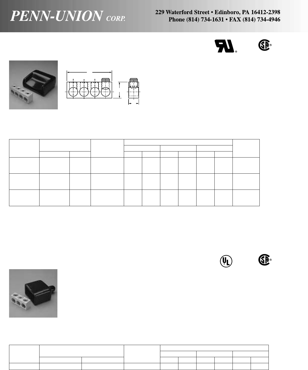
ALUMINUM MULTIPLE TAP CONNECTOR • TYPE NA
For any combination of copper or aluminum 486B
AL7CU
Connectors are made from high strength aluminum alloy, tin plated
for bimetalic applications. Fills the need for a UL Recognized
486B, AL7CU and CSA Certified connector for more than one
tap conductor not met by split bolts.
Black Plastisol (105˚ C rated) cover is available for connectors.
Covers type NC are listed below as a convenience. The covers
are not UL nor CSA.
Approximate Dimensions Cover
Catalog Conductor Range Number of HWL
Catalog
Number AWG MM2Conductors in mm in mm in mm Number
NA250-4T 10-250 MCM 4-120 4 1.13 28.70 .88 22.35 3.63 92.20 NC4-250
NA250-6T 10-250 MCM 4-120 6 1.13 28.70 .88 22.35 5.38 136.65 NC6-250
NA250-8T 10-250 MCM 4-120 8 1.13 28.70 .88 22.35 7.13 181.10 NC8-250
NA350-4T 10-350 MCM 4-185 4 1.38 35.05 1.00 25.40 3.79 96.27 NC4-350
NA350-6T 10-350 MCM 4-185 6 1.38 35.05 1.00 25.40 5.61 142.49 NC6-350
NA350-8T 10-350 MCM 4-185 8 1.38 35.05 1.00 25.40 7.43 188.72 NC8-350
NA500-4T 10-500 MCM 4-240 4 1.63 41.40 1.00 25.40 4.84 122.94 NC4-500
NA500-6T 10-500 MCM 4-240 6 1.63 41.40 1.00 25.40 7.22 183.39 NC6-500
NA500-8T 10-500 MCM 4-240 8 1.63 41.40 1.00 25.40 9.59 243.57 NC8-500
486B
AL9CU
ALUMINUM STREET LIGHT CONNECTOR WITH COVER • TYPE SLK
For any combination of copper or aluminum
Connectors are made from high strength aluminum alloy, tin plated
for bimetalic applications. The connector is UL Listed 486B,
AL9CU and CSA Certified.
Black Plastisol (105˚C Rated) cover is provided with the connec-
tor. The cover is not UL Listed nor CSA.
Approximate Dimensions
Catalog Conductor Range Number of HWL
Number AWG MM2Conductors in mm in mm in mm
SLK-2/0 14-2/0 1.5-50 3 .742 18.85 .565 14.35 1.690 42.93
134
L
H
W
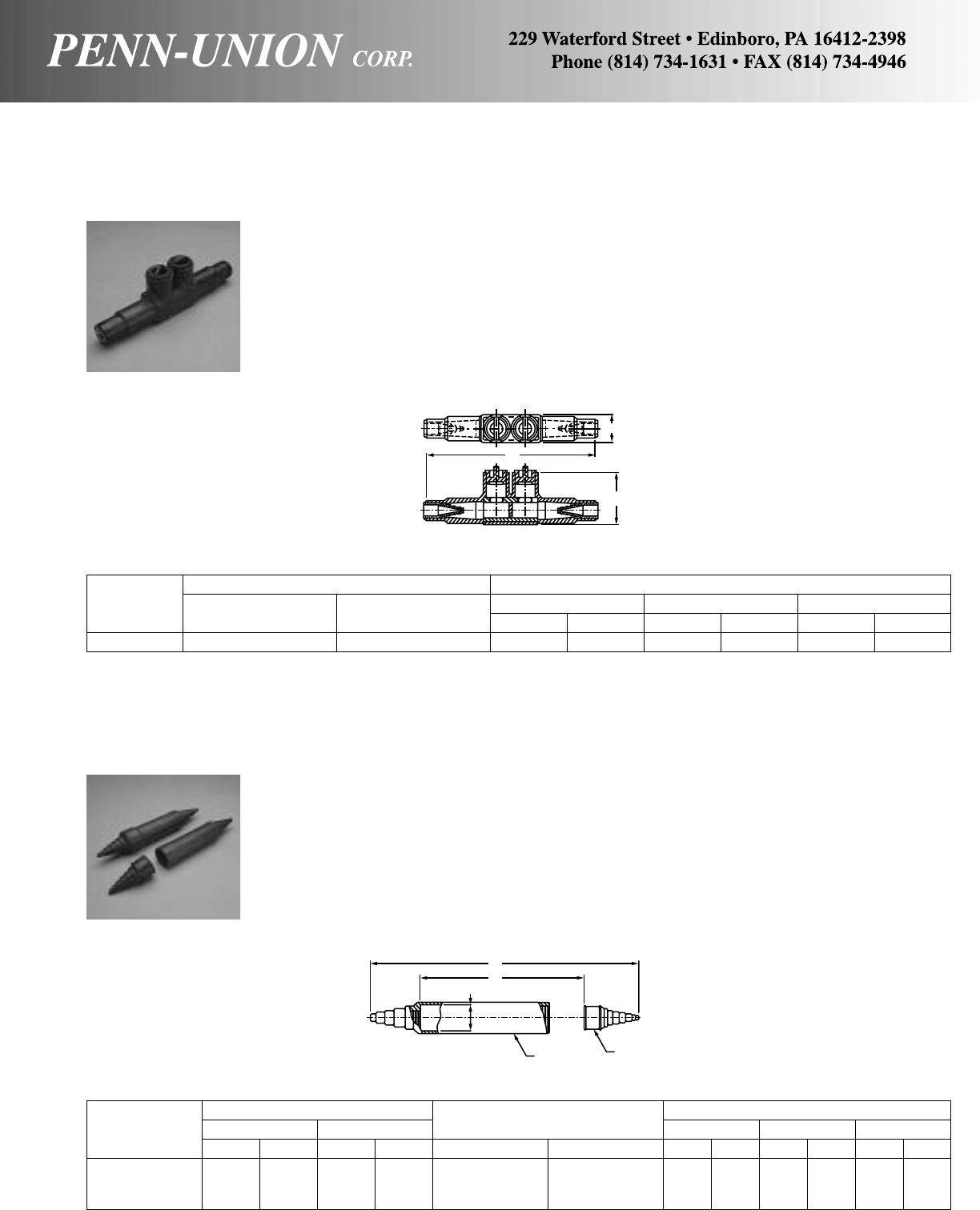
ALUMINUM UNDERGROUND SUBMERSIBLE EPDM RUBBER INSULATED
SECONDARY CONNECTOR • TYPE ULS
For aluminum or copper conductors
Connector body manufactured from aluminum alloy for high
strength and conductivity. Clear plated for low contact resistance.
Pre-filled with oxide inhibitor.
Type ULS is tested and passes the requirements of ANSI 119.1,
Western Underground Guide 2.5 for submersible applications,
and ANSI 119.4 for class “A” connectors.
Conductor Range Accommodates Approximate Dimensions
Catalog Mechanical Compression Connectors A B C
Number AWG MM2AWG MM2Mechanical Compression in mm in mm in mm
SSI-500 14-350 1.5-185 8-500 10-240 SR2 BCU8 thru 050 10.13 257.30 4.38 111.25 1.34 34.04
MCM MCM through BBCU8 thru 025
SR350-2 BCUA8 thru 050
Conductor Range Approximate Dimensions
Catalog AWG MM2HWL
Number in mm in mm in mm
ULS2-350 10-350 MCM 4-185 2.48 62.99 1.34 34.04 8.09 205.49
RUBBER UNDERGROUND SUBMERSIBLE EPDM RUBBER COVER FOR
INSULATING SECONDARY CONNECTORS • TYPE SSI
L
W
H
Made from durable EPDM rubber. Designed to produce a tight
submersible seal on the conductor by allowing the installer to cut
the end to fit the conductor size used.
Covers mechanical splices type SR2 through SR350-2 and com-
pression splices types BCU, BBCU, and BCUA 6 through 500.
Type SSI cover is tested and passes ANSI 119.1, Western Under-
ground Guide 2.5 for submersible applications, and ANSI 119.4
for class “A” connectors.
A
B
C DIA. MIN.
SPLICE
BODY
SPLICE
BODY
135

136
ALUMINUM CLEAR INSULATED POWER BAR • TYPE IPB
For any combination of copper or aluminum
Connectors are made from high strength aluminum alloy, pre-
filled with oxide inhibitor compound. Clear insulation facilitates
installation and inspection and eliminates the need for taping.
Removable plugs provide easy access for installation. For use
with one wire per set screw.
486B LISTED
AL9CU
Catalog Number of Conductor Figure Approximate Dimensions Inches
Number Conductors Range No. L W H
IPB-NA4-2S 2 4 Str - 14 Sol 1 1.03 1.19 1.19
IPB-NA4-2D 2 4 Str - 14 Sol 2 1.03 1.53 1.19
IPB-NA4-4S 4 4 Str - 14 Sol 1 1.90 1.19 1.19
IPB-NA4-4D 4 4 Str - 14 Sol 2 1.90 1.50 1.19
IPB-NA2/0-2S 2 2/0-14 Sol 1 1.39 1.25 1.31
IPB-NA2/0-2D 2 2/0-14 Sol 2 1.39 1.56 1.31
IPB-NA2/0-3D 3 2/0-14 Sol 2 2.06 1.56 1.31
IPB-NA2/0-4S 4 2/0-14 Sol 1 2.73 1.25 1.31
IPB-NA2/0-4D 4 2/0-14 Sol 2 2.73 1.56 1.31
IPB-NA2/0-6D 6 2/0-14 Sol 2 4.07 1.56 1.31
IPB-NA250-2D 2 250 MCM-10 Sol 2 1.90 2.63 2.07
IPB-NA250-3D 3 250 MCM-10 Sol 2 2.84 2.63 2.07
IPB-NA250-4D 4 250 MCM-10 Sol 2 3.78 2.63 2.07
IPB-NA250-6D 6 250 MCM-10 Sol 2 5.65 2.63 2.07
IPB-NA250-8D 8 250 MCM-10 Sol 2 5.53 2.63 2.07
IPB-NA350-2D 2 350 MCM-10 Sol 2 2.09 3.00 2.44
IPB-NA350-3D 3 350 MCM-10 Sol 2 3.00 3.00 2.44
IPB-NA350-4D 4 350 MCM-10 Sol 2 3.91 3.00 2.44
IPB-NA350-6D 6 350 MCM-10 Sol 2 5.73 3.00 2.44
IPB-NA350-8D 8 350 MCM-10 Sol 2 7.55 3.00 2.44
IPB-NA500-2D 2 500 MCM-6 Sol 2 2.43 3.00 2.69
IPB-NA500-3D 3 500 MCM-6 Sol 2 3.64 3.00 2.69
IPB-NA500-4D 4 500 MCM-6 Sol 2 4.34 3.00 2.69
IPB-NA500-6D 6 500 MCM-6 Sol 2 7.25 3.00 2.69
IPB-NA500-8D 8 500 MCM-6 Sol 2 9.65 3.00 2.69
For other variations of number of conductors and entry type contact factory for availability.
H
W
L
Fig 1
Single Entry
L
H
W
Fig 2
Dual Entry
ALUMINUM CLEAR INSULATED INLINE SPLICER REDUCER • TYPE IISR
For any combination of copper or aluminum
Connectors are made of high strength aluminum alloy, prefilled
with oxide inhibitor compound. Suitable for connecting two wires
in line for splicing or reducing. Clear insulation eliminates the
need for taping. Removable plugs provide easy access for in-
stallation. For use with one wire per set screw.
486B LISTED
AL9CU
Catalog Conductor Approximate Dimensions Inches
Number Range L W H
IISR-2 2 Str.-14 Sol. 2.38 0.62 1.15
IISR-1/0 1/0 Str.-14 Sol. 2.91 0.78 1.31
IISR-250 250 MCM-6 Sol. 4.01 1.06 2.03
IISR-350 350 MCM-6 Sol. 4.63 1.21 2.28
IISR-500 500 MCM-2 Str. 5.25 1.50 2.56
L
W
H
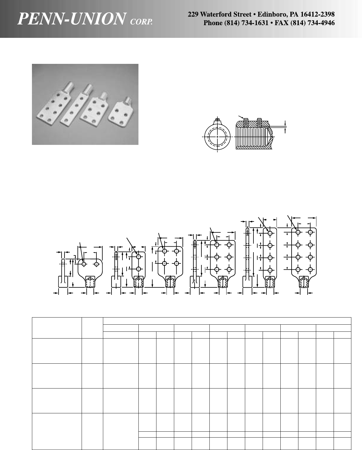
BRONZE UNDERGROUND TRANSFORMER TERMINALS • TYPE UTS
Approximate Dimensions
Catalog Fig. ABCDLTW
Number No. in in mm in mminmminmminmminmm
UTS-0316-2 1 5/816 23/8 60 4 102 1/46.35 31/289
UTS-0316-2L 2 3/8-16 7/822 3/419 31/2 89 51/16 129 5/16 7.94 13/835
UTS-0316-4 3 5/816 41/8105 53/4146 1/46.35 31/289
UTS-0316-4L 5 3/419 613/16 173 83/8213 5/16 7.94 13/835
UTS-0513-2 1 5/816 23/8 60 4 102 1/46.35 31/289
UTS-0513-2L 2 1/2-13 7/822 3/419 31/2 89 51/16 129 5/16 7.94 13/835
UTS-0513-4 3 5/816 41/8105 53/4146 1/46.35 31/289
UTS-0513-4L 5 3/419 7 178 83/8213 5/16 7.94 13/835
UTS-0611-2 1 5/816 23/8 60 4 102 1/46.35 31/289
UTS-0611-2L 2 5/8-11 7/822 3/419 31/2 89 51/16 129 5/16 7.94 13/835
UTS-0611-4 3 5/816 41/8105 53/4146 1/46.35 31/289
UTS-0611-4L 5 3/419 7 178 83/8213 5/16 7.94 13/835
UTS-1014-2 1 5/816 23/8 60 4 102 3/89.53 31/289
UTS-1014-2L 2 13/835 3/419 39/16 90 51/8130 11/32 8.73 115/16 49
UTS-1014-4 3 1-14 5/816 41/8105 53/4146 3/89.53 31/289
UTS-1014-4L 5 17/16 37 3/419 71/16 179 97/16 240 11/32 8.73 115/16 49
UTS-1014-6 4 13/835 5/816 51/8130 611/16 170 3/89.53 31/289
UTS-1014-8 6 5/816 67/8175 97/16 240 3/89.53 31/289
Type UTS is cast of high copper content alloy and electrotin plated.
For use with aluminum or copper compression or bolted type
lugs.
Can be supplied with studs bonded to terminal. Add suffix
“-S” to catalog number.
Example: UTS-0513-2-S. Stud locking set screws may be ordered by adding suffix
“-SS” to catalog numbers (1 stud locking set screw
provided on all sizes except where “A” dimension is 1-14,
which has 2 stud locking set screws.)
Example without studs: UTS-0513-4L-SS.
Example with studs: UTS-0513-4L-S-SS.
1/4"-28
1/16"
(2 mm)
TT
T
T
CCC
C
CC
DDD
D
BB BB
AA
AA
AA
WW
WW
WW
9/16"
(14 mm) Dia.
9/16"
(14 mm) Dia.
9/16"
(14 mm) Dia.
9/16"
(14 mm) Dia.
9/16"
(14 mm) Dia.
9/16"
(14 mm) Dia.
1-3/4"
(44 mm)
1-3/4"
(44 mm)
1-3/4"
(44 mm)
1-3/4"
(44 mm)
1-3/4"
(44 mm)
1-3/4"
(44 mm)
1-3/4"
(44 mm)
1-3/4"
(44 mm)
1-3/4"
(44 mm)
1-3/4"
(44 mm)
1-3/4"
(44 mm)
LLLL
FIG. 1 FIG. 2 FIG. 3 FIG. 4 FIG. 5 FIG. 6
1-3/4"
(44 mm)
137

Wide temperature range, remains smooth and easy-working even
at very low temperatures
Will not wash off from exposure to the elements, yet can be
washed off hands and clothes with detergent.
Accelerated testing under exposure to intense ultraviolet light,
water spray and hot air shows no deterioration.
Excellent electrically as a contact aid.
Approximate Dimensions Approx.
Catalog Conductor Size F L M O R Shpg. Wt.
Number Minimum Maximum in in in in in per 100 pcs.
WDC-2S* 6 Stranded Al. 1/0 Solid Al. 41/2103/431/8121
6 ACSR 6/1 2 ACSR 6/1 or 7/1
WDC-10S 4 ACSR 6/1 or 7/1 1/0 ACSR 6/1 67/8127/8311/16 5/32 144
*RUS accepted
CUAL-AID®
A contact compound for all electrical connections
Cual-Aid #11C
The highest quality general purpose non-petroleum base electri-
cal joint compound containing zinc dust for bolted connections.
This compound has superior compatibility with insulating
materials.
Cual-Aid #12C
This high quality non-petroleum base compound contains zinc
dust, along with suspended grit bearing particles. It is especially
suitable for use in compression connectors. Not for use on threads
of bolted connectors. It is compatible with rubber, polyethylene,
neoprene, polyvinyl chloride tapes and other insulating materials.
Catalog Quantity
Number Volume Container
4 oz. No. 11C 4 oz. (Net Wt.) Squeeze Tube (12 per carton)
1/2 Pint No. 11C 1/2 Pint Plastic Flask
Pint No. 11C Pint Pint Can
Quart No. 11C Quart Quart Can
1 Gallon No. 11C Gallon Gallon Can
5 Gallon No. 11C 5 Gallon 5 Gallon Can
For Cual-Aid #12 change 11 in catalog number to 12.
WEDGE DEAD END CLAMP • TYPE WDC
A service-drop, sliding type dead end clamp for use on solid and stranded aluminum or ACSR conductors.
M
F
L
R
O(DIA.)
138
The application of CUAL-AID is recommended on:
CONNECTOR: Smear compound into connector grooves. DO NOT wire-brush the grooves of plated or grease-coated connectors.
These are especially treated at the factory to stay free from oxide.
CABLE: Wire brush Cual-Aid® into the strands of aluminum cable. This removes oxide coating from the strands, and prevents
it from re-forming.
BAR: Wire-brush Cual-Aid® across the surface of bar. This removed oxide coating from the surface and prevents it from re-forming.

139
Catalog Number Cable Hole Dia. A
LLCS-38072 15/16"
LLCS-38073 1"
Note: For silver plating on LLCS add -SV suffix to catalog number.
CAST COPPER REDUCERS • TYPE LLR
1/2"
A1/4"3/16"
1/16"
55/16".385"
45°
13/8" DIA.
11/4"
DIA.
3/4"
31/32"
DIA.
25/32"
1"
11/16"
3/4"19/16"
LLR-35569-LH 25
1100/24-775/24
11/4" DIA. 31/32"
DIA.
25/32"
3/4"
11/16"
19/16"
3/4"
1"
All connectors are electro-tin plated.
43/16"
2" 2"
43/16"
25°
25°
121/32"
121/32"
3/4"
11/4"
DIA.
25/32"
31/32"
DIA.
11/16"
1"
3/4"19/16"
LLR-35570-RH 25
1100/24-775/24
43/16"2"
LLR-46103
1100/24-775/24
For 1100/24-550/24 application
suffix catalog number with 550/24
For 1100/24 End use T & B Die 99
For 775/24 End use T & B Die 76
For 550/24 End use T & B Die 76
SOLDER TYPE LLCS
COPPER CLASP CONNECTORS • TYPE LLCS
Solder type LLCS
2.156"
REF.
1/2"
1.343"
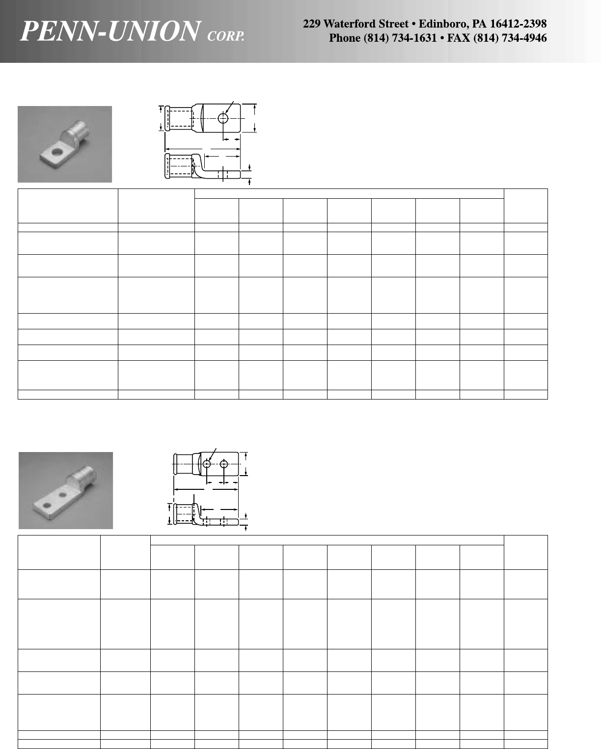
CAST COPPER LUGS – SIDE FORMED • TYPE LL
One hole
Approximate Dimensions in Inches
GT&B
Catalog Cable Hole Die
Number Size L F E Size O W T Size
LL-49765-S-SF 150/24 17/813/16 3/89/32 21/32 5/83/16 50
LL-47244-S-SF 225/24 21/817/16 7/16 23/32 13/16 7/32 54
LL-41157-S-SF 275/24 21/817/16 7/16 23/32 13/16 7/32 54
LL-53178-S-SF 325/24 21/817/16 7/16 23/32 13/16 7/32 54
LL-45087-S-SF 375/24 21/211/49/16 7/16 25/32 11/460
LL-44593-S-SF 450/24 21/211/417/32 21/32 25/32 11/460
LL-41158-S-SF 450/24 21/211/417/32 7/16 25/32 11/460
LL-49332-S-SF 550/24 27/811/23/45/813/64 13/16 5/16 76
LL-44146-S-SF 550/24 27/811/23/413/32 13/64 13/16 5/16 76
LL-41159-S-SF 550/24 27/811/23/49/16 13/64 13/16 5/16 76
LL-42608-S-SF 650/24 27/811/23/49/16 13/64 13/16 5/16 76
LL-41160-S-SF 775/24 27/811/23/49/16 13/64 13/16 5/16 76
LL-40305-S-SF 775/24 31/16 11/23/413/32 13/64 13/16 5/16 76
LL-40744-S-SF 775/24 35/16 115/16 3/421/32 13/64 13/16 5/16 76
LL-42873-S-SF 925/24 33/811/23/49/16 15/32 13/16 11/32 87
LL-41149-S-SF 925/24 33/811/23/411/16 15/32 13/16 11/32 87
LL-47526-S-SF 1100/24 4 2 7/89/16 111/32 15/813/32 99
LL-44127-S-SF 1325/24 4 2 7/89/16 13/815/813/32 107
LL-44231-S-SF 1600/24 41/421/819/16 17/16 15/87/16 112
LL-47742-S-SF 1600/24 41/421/813/417/16 15/87/16 112
LL-47833-S-SF 1600/24 41/421/817/16 17/16 15/87/16 112
LL-40862-S-SF 1925/24 41/421/819/16 17/16 15/87/16 112
LL-50747-S-SF 2300/24 43/423/813/16 11/16 121/32 17/81/2130
For blank pad, add suffix -U to catalog number.
Approximate Dimensions in Inches
GT&B
Catalog Cable Hole Die
Number Size L F D E Size O W T Size
LL-51797-D-SF 150/24 31/16 2111/32 9/32 21/32 5/83/16 50
LL-49763-D-SF 225/24 31/8211/27/16 23/32 13/16 7/32 54
LL-49764-D-SF 275/24 31/8211/27/16 23/32 13/16 7/32 54
LL-46111-D-SF 450/24 41/431
3/45/89/16 25/32 11/460
LL-49238-D-SF 550/24 35/16 115/16 11/213/32 13/64 13/16 5/16 76
LL-41147-D-SF 550/24 43/831
3/45/89/16 13/64 13/16 5/16 76
LL-47272-D-SF 650/24 43/831
3/45/89/16 13/64 13/16 5/16 76
LL-50774-D-SF 775/24 27/811/213/16 5/16 11/32 13/64 13/16 5/16 76
LL-52076-D-SF 775/24 35/16 115/16 7/83/411/32 13/64 13/16 5/16 76
LL-40467-D-SF 775/24 35/16 115/16 11/213/32 13/64 13/16 5/16 76
LL-49761-D-SF 775/24 43/831
3/45/89/16 13/64 13/16 5/16 76
LL-40743-D-SF 925/24 43/821/217/16 13/32 15/32 13/16 11/32 87
LL-41152-D-SF 925/24 53/831/217/16 7/16 15/32 13/16 11/32 87
LL-47521-D-SF 925/24 53/831/213/45/89/16 15/32 13/16 11/32 87
LL-50963-D-SF 1100/24 51/231/213/45/89/16 13/815/813/32 107
LL-41151-D-SF 1325/24 51/231/211/27/16 13/815/813/32 107
LL-41148-D-SF 1325/24 51/231/213/45/89/16 13/815/813/32 107
LL-49758-D-SF 1600/24 55/831/213/45/89/16 17/16 15/87/16 112
LL-52943-D-SF 1925/24 4 21/16 17/16 7/16 17/16 25/16 112
LL-41150-D-SF 1925/24 41/421/817/16 13/32 17/16 15/87/16 112
LL-42683-D-SF 1925/24 55/831/213/45/89/16 17/16 15/87/16 112
LL-49532-D-SF 2000/25 55/831/213/45/89/16 17/16 15/87/16 112
LL-47522-D-SF 2300/24 57/831/213/45/89/16 121/32 17/81/2130
LL-50651-D-SF 2750/24 65/831/213/45/89/16 129/32 21/89/16 150
CAST COPPER LUGS – SIDE FORMED • TYPE LL
Two hole
These heavy duty compression lugs are cast out of high conduc-
tivity copper. The entire lug is electro-tin plated.
O
G
W
E
LF
T
G
W
DE
L
F
T
O
These heavy duty compression lugs are cast out of high conduc-
tivity copper. The entire lug is electro-tin plated.
140

CAST COPPER LUGS – CENTER FORMED • TYPE LL
Two hole
Entire connector is electro-tin
plated.
These heavy duty compression
lugs are cast out of high con-
ductivity copper and can be in-
stalled with existing crimping
tools.
Approximate Dimensions in Inches
GT&B
Catalog Cable Fig. Hole Die
Number Size No. L F D E Size O W T Size
LL-47248-D-CF 133/27 1 215/16 17/87/87/16 11/32 21/32 19/32 13/64 50
LL-47271-D-CF 150/24 1 215/16 17/87/87/16 11/32 21/32 19/32 13/64 50
LL-44385-D-CF 225/24 1 3 17/87/87/16 11/32 23/32 11/16 13/64 54
LL-50545-D-CF 275/24 1 3 17/87/87/16 11/32 23/32 11/16 13/64 54
LL-44075-D-CF 325/24 1 3 17/87/87/16 11/32 23/32 11/16 13/64 54
LL-41155-D-CF 375/24 1 31/827/87/16 11/32 25/32 25/32 13/64 60
LL-41156-D-CF 450/24 1 31/827/87/16 11/32 25/32 25/32 13/64 60
LL-36996-D-CF 550/24 1 33/16 17/87/87/16 11/32 13/64 15/16 13/64 76
LL-42596-D-CF 650/24 1 33/16 17/87/87/16 11/32 13/64 15/16 13/64 76
LL-41153-D-CF 775/24 1 33/16 17/87/87/16 11/32 13/64 15/16 13/64 76
LL-44131-D-CF 925/24 1 33/421/16 17/16 13/32 13/16 11/83/887
LL-44573-D-CF 1100/24 1 33/421/16 17/16 13/32 111/32 111/32 3/899
LL-44096-D-CF 1325/24 1 33/421/16 17/16 13/32 13/8111/32 3/8107
LL-43606-D-CF 1325/24 2 33/421/16 7/89/16 13/32 13/8111/32 3/8107
LL-50429-D-CF 1600/24 1 33/421/16 17/16 13/32 13/8111/32 3/8107
LL-41154-D-CF 1925/24 2 313/16 21/16 7/89/16 13/32 17/16 17/16 3/8112
LL-42684-D-CF 2300/24 1 43/821/817/16 13/32 121/32 119/32 3/8130
For blank pad add suffix -U to catalog number.
CAST COPPER LUGS – MISCELLANEOUS • TYPE LL
For 1100/24
Cat. No. A
LL-44879-U-15 15°
LL-39640-U-30 30°
For 1100/24 use T&B Die 99
CAST COPPER LUGS – 90° • TYPE LLN
775/24*
G
W
DE
L
F
O
T
G
W
DE
1/8"
13/64"
R
Fig. 1
Fig. 2
LL-44879-U-15
31/4"±1/32"
1
FLAT
2"±1/32"
1.234"
DIA.
1"
A
3
/
8
"
*Also available in 550/24. Order using suffix “550/24”. For 550/24 use T&B Die 76.
23/8"
25/32"
31/32"
DIA.
3/4"
11/32" DIA. HOLE
11/16"
1" 1"
19/16"
3/4"
21/16"21/16"
19/16"
3/4"
11/16"
31/32"
DIA.
23/8"
25/32"
11/32" DIA. HOLE
3/4"
LLN-35572-LH
Left Hand LLN-35571-RH
Right Hand
TYPE LL
141
LL-39640-U-30
1.234"
DIA.
1
FLAT
3
/
8
"
A
1"
123/32"±1/32"
31/2"±1/32
TYPE LLN
You can always find the right terminal where you find a Point-Of-Profit®
Merchandising Display
Convenient Packaging for the right size and style of connector in the quantity that best fits your needs.
WINDOW BOXES
• Standard quantities of 100 or 500 per box.
• Compact box has a heavy-duty plastic window to resist punc-
turing and an eye-catching red, white and blue design for in-
creased visibility.
• Displayed in an attractive, compact, two-tiered gravity feed dis-
penser display. Display holds up to 72 boxes of 12 different
styles of Penn-Crimps solderless terminals. At 22" wide by
211/2" tall, it easily fits on the counter or can hang from peg-
board for easy display.
SMALL QUANTITY POLYBAGS
• Available in quantities of 50, 25 or 10 terminals per bag, perfect
for small jobs.
• Heavy-duty, puncture-resistant polybag is sealed at the top to
prevent tampering before purchase and has a resealable clo-
sure for repeated use afterwards.
• Eye-catching red, white and blue labels are easily recognized
hanging on a lightweight, wire rack display, which at 14" tall by
16" wide, saves space either sitting on the countertop or hang-
ing on pegboard.
142
Prominently displayed on our gravity window box dispenser or
the small quantity polybag rack, Penn-Crimps® can be recog-
nized quickly for faster counter transactions.
All types of merchandising packaging, bags, window boxes and
bulk bins can be displayed on the Penn-Union 3 foot long
gondola.
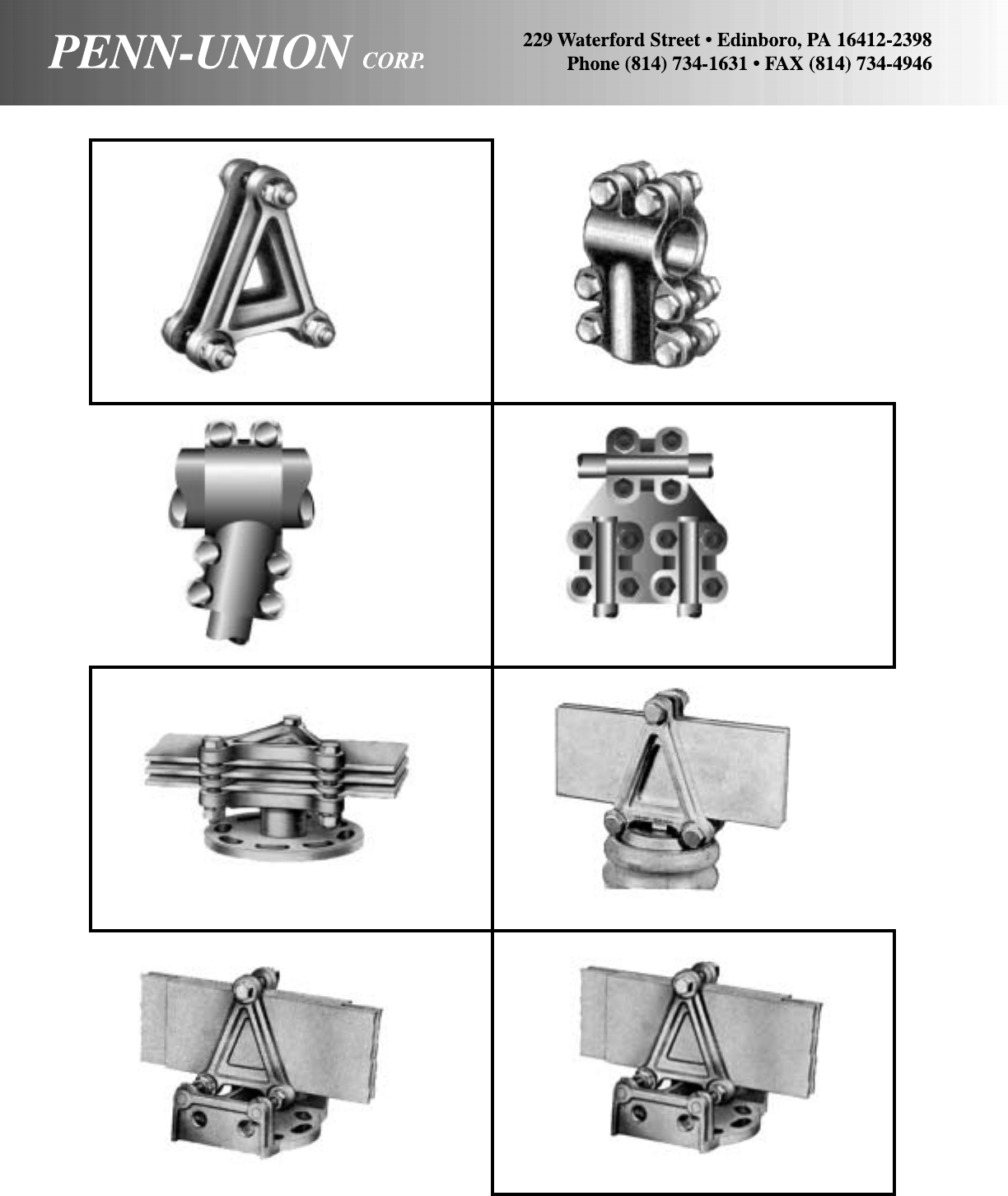
143
TYPE AHC
HORIZONTAL BUS
SUPPORT CLAMPS
TYPE A
BUS BAR CLAMPS TYPE AB
TEE CONNECTOR
TYPE AB15
ANGLE TEE
CONNECTOR TYPE ABR2T
TEE CONNECTOR
TYPE AVB
VERTICAL BUS
SUPPORT CLAMPS
TYPE AVC
VERTICAL BUS
SUPPORT CLAMPS
TYPE AVS
VERTICAL
SLIDE BUS
SUPPORT CLAMPS
The products shown are available as special orders only. Please consult the factory for pricing and availability.
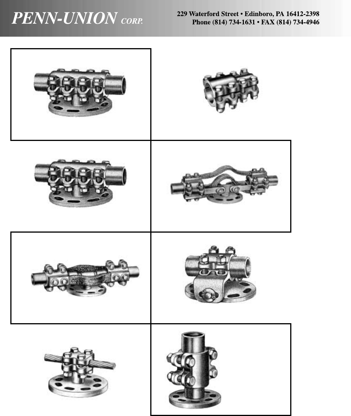
144
TYPE BAC
BUS SUPPORT COUPLER
TYPE BSC
SLIDE BUS SUPPORT COUPLER
TYPE BSH
EXPANSION BUS
SUPPORT COUPLER
TYPE BST
BUS SUPPORT CLAMP
TYPE BD
COUPLERS AND REDUCERS
TYPE BSE
EXPANSION BUS
SUPPORT COUPLER
TYPE BSS
SLIDE BUS SUPPORT CLAMP
TYPE BSV
VERTICAL BUS
SUPPORT CLAMP
The products shown are available as special orders only. Please consult the factory for pricing and availability.
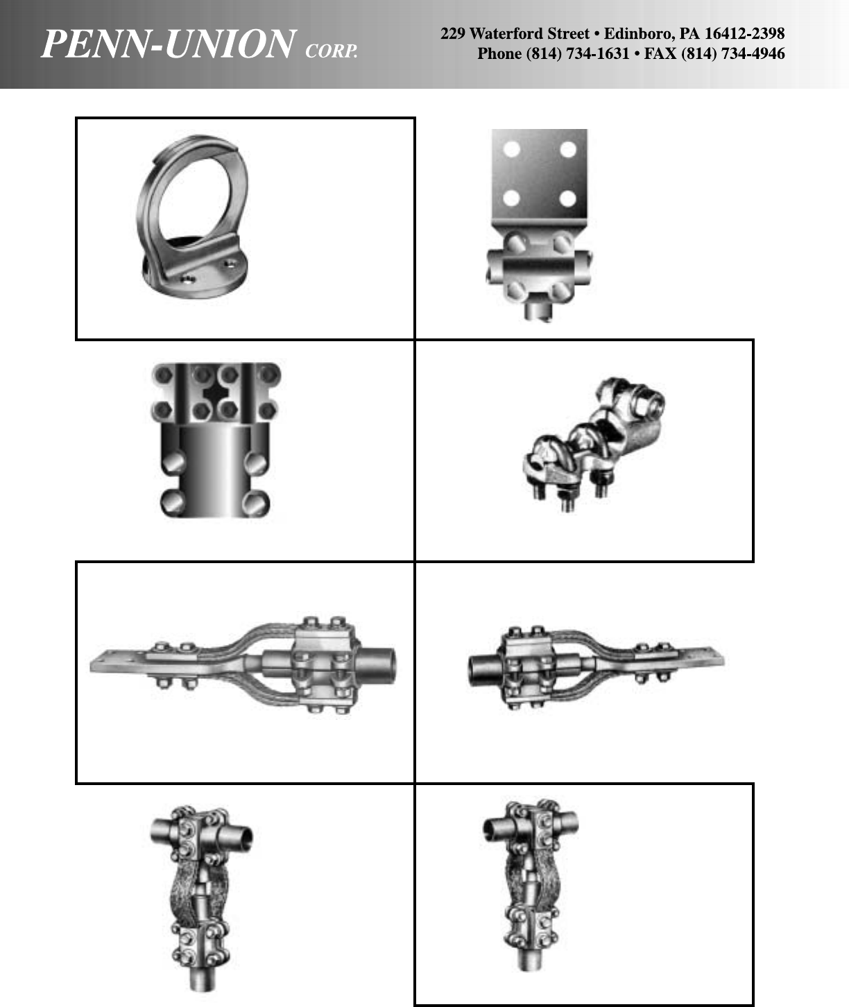
145
TYPE EXB
EXPANSION TERMINALS
TYPE EXP
EXPANSION TEE
CONNECTORS TYPE EXPW
EXPANSION TEE CONNECTORS
TYPE CBSS
SLIDE BUS SUPPORT TYPE CTL
TEE CONNECTOR
TYPE DTC
STUD CONNECTOR TYPE DTU
STUD CONNECTOR
TYPE EXBW
EXPANSION TERMINALS
The products shown are available as special orders only. Please consult the factory for pricing and availability.
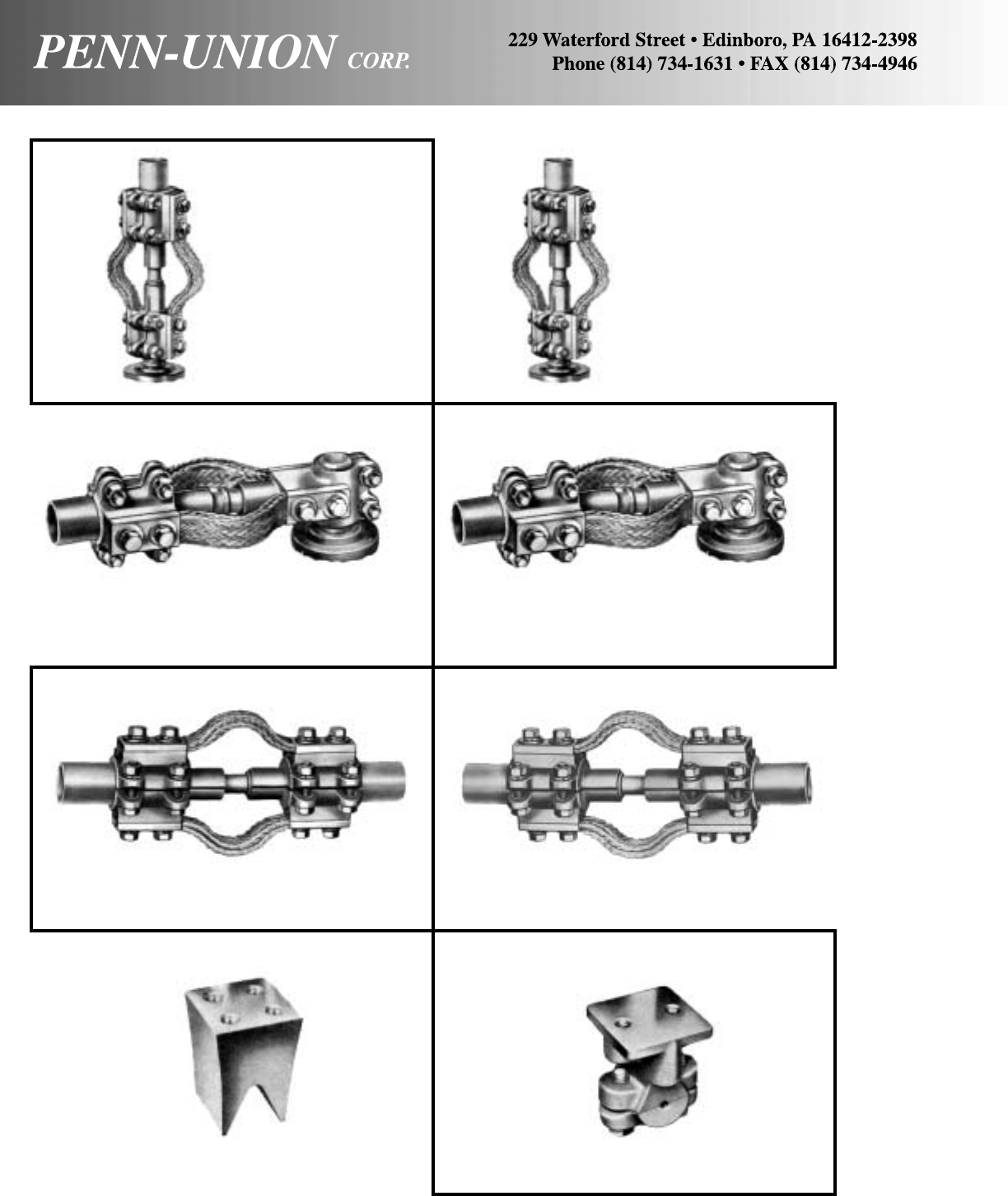
146
TYPE EXT
EXPANSION COUPLERS
TYPE GI
GROUNDING INSERT – VARIED CABLE TYPE GIC
GROUNDING INSERT
TYPE EXTW
EXPANSION COUPLERS
TYPE EXSW90
90° EXPANSION STUD
CONNECTORS
TYPE EXS90
90° EXPANSION STUD
CONNECTORS
TYPE EXS
EXPANSION STUD
CONNECTORS
TYPE EXSW
EXPANSION STUD
CONNECTORS
The products shown are available as special orders only. Please consult the factory for pricing and availability.

147
HARDWARE
HARDWARE
SHAKEPROOF
TYPE HCB
CURVE-BACK BUS
BAR CLAMPS
TYPE HLC-040
HOT LINE CLAMP
HARDWARE
HN
CNF
CNP
HHB
FW
FLAT
WASHER
SPLIT
LOCK
WASHER
CPW EXTERNAL
TOOTH
INTERNAL
TOOTH
TYPE HHC
HORIZONTAL BUS
SUPPORT CLAMPS
TYPE GXA
GROUND CLAMP CONNECTORS TYPE H
BUS BAR CLAMPS
The products shown are available as special orders only. Please consult the factory for pricing and availability.
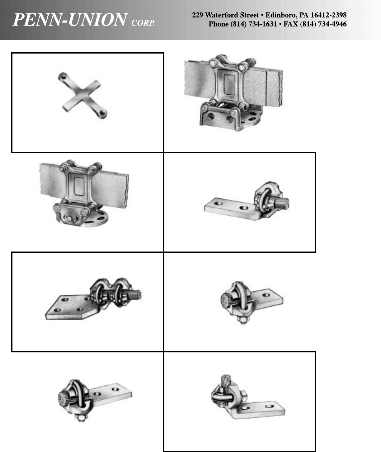
148
TYPE HVS
VERTICAL SLIDE BUS
SUPPORT CLAMPS TYPE MF
MULTIFIT TERMINAL LUG
TYPE MFF
MULTIFIT TERMINAL LUG TYPE ML-1
MULTIFIT TERMINAL LUGS
TYPE ML-2
MULTIFIT TERMINAL LUGS TYPE ML90
MULTIFIT TERMINAL LUGS
TYPE HP
BUS BAR SPACERS
TYPE HVC
VERTICAL BUS
SUPPORT CLAMPS
The products shown are available as special orders only. Please consult the factory for pricing and availability.
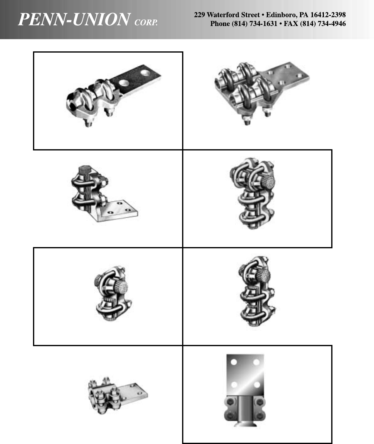
149
TYPE MML90
MULTIFIT TERMINAL LUG TYPE MMTT
MULTIFIT TEE CONNECTORS
TYPE MT
MULTIFIT TEE CONNECTORS TYPE MTT
MULTIFIT TEE CONNECTORS
TYPE RC
TERMINAL LUGS
TYPE MML
MULTIFIT TERMINAL LUG TYPE MML2
MULTIFIT TERMINAL LUG
TYPE RCS
STUD CONNECTOR
The products shown are available as special orders only. Please consult the factory for pricing and availability.
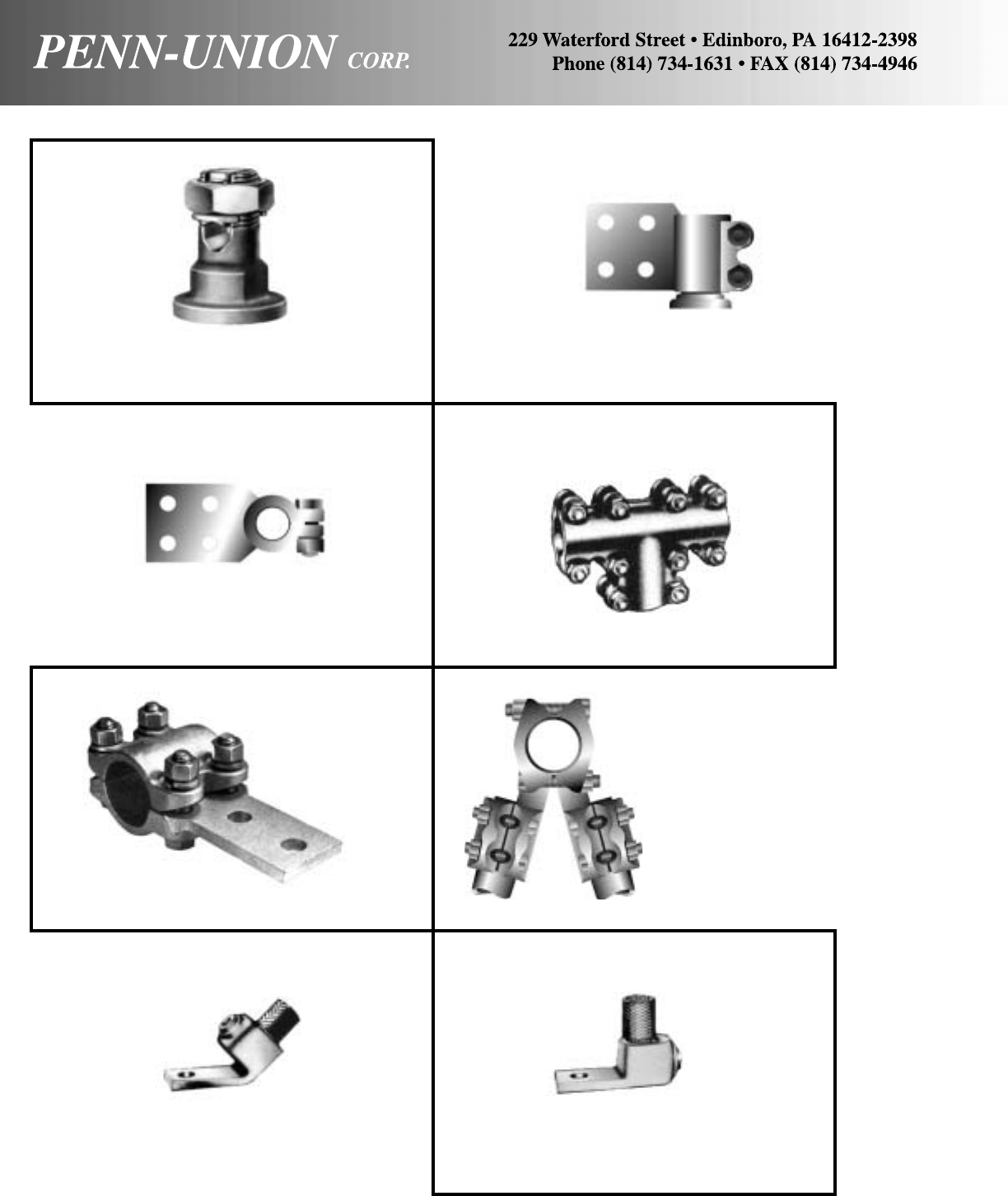
150
TYPE SLBH
STUD CONNECTOR TYPE TC
TEE COUPLER
TYPE TVB
TEE CONNECTOR TYPE VB30
VEE CONNECTOR
VI-TITE
45° SQUARE FLANGE VI-TITE 90°
SQUARE FLANGE
TYPE SCT
SERVICE POST CONNECTORS TYPE SLB-90
STUD CONNECTOR
The products shown are available as special orders only. Please consult the factory for pricing and availability.

VI-TITE CENTER
SQUARE FLANGE
VI-TITE CENTER
ROUND FLANGE
VI-TITE SIDE CENTER
SQUARE FLANGE VI-TITE SIDE OFFSET
SQUARE FLANGE
151
TYPE VSF
STUD CONNECTOR
VI-TITE 90°
ROUND FLANGE
VI-TITE 45°
ROUND FLANGE
TYPE VSM
STUD CONNECTOR
The products shown are available as special orders only. Please consult the factory for pricing and availability.
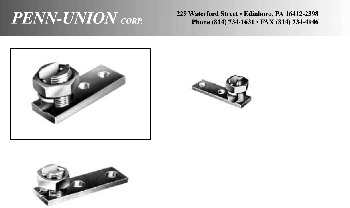
TYPE ZE
EZ-TERMINAL LUG TYPE ZN
EZ-TERMINAL LUG
TYPE ZW
EZ-TERMINAL LUG
152
The products shown are available as special orders only. Please consult the factory for pricing and availability.

153
TECHNICAL REFERENCE
Page
COMPARATIVE LISTING ............................................................................................................................................................................... 154-166
Penn-Crimp ..................................................................................................................................................................................................... 154
Connectors
Distribution Compression ......................................................................................................................................................................... 156
Split Bolt & Service Entrance.................................................................................................................................................................... 157
Parallel...................................................................................................................................................................................................... 158
Compression Lugs & Splices .......................................................................................................................................................................... 158
Compression Tools .......................................................................................................................................................................................... 160
Compression Dies ........................................................................................................................................................................................... 161
Terminal Lugs .................................................................................................................................................................................................. 161
Eyebolt Terminals & Transformer Ground Clamps .......................................................................................................................................... 162
Grounding Connectors .................................................................................................................................................................................... 162
Service Post Connectors ................................................................................................................................................................................. 166
Insulated Power Bar ........................................................................................................................................................................................ 166
GENERAL CONNECTOR INFORMATION ..................................................................................................................................................... 167-172
Connector Materials ........................................................................................................................................................................................ 167
Welding Connectors ........................................................................................................................................................................................ 167
Pressure Connectors – Bolted & Compression ............................................................................................................................................... 167
Bar Connections .............................................................................................................................................................................................. 168
Compression Connector Crimping .................................................................................................................................................................. 169
Connector Comparison Chart.......................................................................................................................................................................... 170
Tightening Torque ............................................................................................................................................................................................ 170
Properties of Copper Pipe ............................................................................................................................................................................... 171
Properties of Extruded Aluminum Pipe ........................................................................................................................................................... 171
NEMA Standard Tangs .................................................................................................................................................................................... 172
Solderless Connectors Size & Clearance Chart.............................................................................................................................................. 172
CATALOG NUMBER SUFFIX LEGEND ................................................................................................................................................................ 173
FACTORY SPECIAL ORDER FORM ..................................................................................................................................................................... 174
METRIC CONVERSION CHART ........................................................................................................................................................................... 175
AWG VS. METRIC WIRE SIZE.............................................................................................................................................................................. 176
DIESEL LOCOMOTIVE AND CAR WIRING CABLE ............................................................................................................................................. 176
This comparative listing is intended for use as a product substitution guide. It presents a comparison of products believed to be
competitive but in no way guarantees that such products are identical or interchangeable.
Before making any substitution, the user should carefully review the installation requirements and critical fit data such as conductor
size or range, stud size, pipe size, etc.
PENN-UNION DISCLAIMS ALL WARRANTIES WHETHER STATED OR IMPLIED BY THE FOREGOING LISTING, INCLUDING
THE IMPLIED WARRANTIES OF MERCHANTABILITY AND FITNESS FOR PARTICULAR PURPOSE. IN NO CASE WILL
PENN-UNION BE LIABLE OR RESPONSIBLE FOR CHANGES, ERRORS OR DAMAGES OF ANY TYPE (INCLUDING
CONSEQUENTIAL) THAT MAY BE OCCASIONED BY USE OF THIS COMPARATIVE LISTING. Its sole purpose is to assist the
user in selecting competitive alternatives.
R2A-6S P18-6R A18-6 M18-6R/SX T18-6
R2A-8 P18-8R A18-8 – T18-8
R2A-8S – – M18-8R/LX –
R2A-10 P18-10R A18-10 M18-10R/LX T18-10
R2A-14S P18-14R A18-14 – T18-14
R2A-56S P18-56R A18-516 – T18-516
R2A-38 P18-38R A18-38 – T18-38
R2B-6 – B14-6 – –
R2B-6S P14-6R – M14-6R/SX T14-6
R2B-8 P14-8R B14-8 – T14-8
R2B-8S – – M14-8R/LX –
R2B-10 P14-10R B14-10 M14-10R/LX T14-10
R2B-14S P14-14R B14-14 M14-14R/SX T14-14
R2B-56S P14-56R B14-516 – T14-516
R2B-38 P14-38R B14-38 – T14-38
R2C-6S P10-6R C10-6 M10-6RX –
R2C-8S P10-8R C10-8 M10-8RX –
R2C-10 P10-10R C10-10 M10-10RX T10-10
R2C-14S P10-14R C10-14 M10-14R/SX T10-14
R2C-56S P10-56R C10-516 – T10-516
R2C-38 P10-38R C10-38 – T10-38
R2E-8SS P8-8R – – –
R2E-10S P8-10R D8-10 M8-10R/SX –
R2E-14S P8-14R D8-14 M8-14R/SX –
R2E-56 P8-56R D8-516 M8-516RX –
R2E-38 P8-38R D8-38 M8-38RX –
R2E-50 P8-12R D8-12 – –
R2F-10S P6-10R E6-10 M6-10R/SX –
R2F-14S P6-14R E6-14 M6-14R/SX –
R2F-56 P6-56R E6-516 M6-516RX –
R2F-38 P6-38R E6-38 M6-38RX –
R2F-50 P6-12R E6-12 – –
R2G-10S P4-10R F4-10 – –
R2G-14S P4-14R F4-14 M4-14RX –
R2G-56 P4-56R F4-516 M4-516RX –
R2G-38 P4-38R F4-38 M4-38RX –
R2G-50 P4-12R F4-12 – –
R4A-6S PV18-6R 18RA-6 MV18-6R/SX TP16-6
R4A-8 PV18-8R 18RA-8 – TP16-8
R4A-8S – – MV18-8R/LX –
R4A-10 PV18-10R 18RA-10 MV18-10R/LX TP16-10
R4A-14S PV18-14R 18RA-14 MV18-14R/SX TP16-14
R4A-56S PV18-56R 18RA-516 – –
R4A-38 PV18-38R 18RA-38 MV18-38RX –
R4B-6 PV14-6R 14RB-6 – –
R4B-6S PV14-6RN – MV14-6R/SX TP14-6
R4B-8 PV14-8R 14RB-8 – TP14-8
R4B-8S – – MV14-8R/LX –
R4B-10 PV14-10R 14RB-10 MV14-10R/LX TP14-10
R4B-14 PV14-14R 14RB-14 MV14-14R/SX TP14-14
R4B-56 PV14-56R 14RB-516 – –
R4B-56S – – – –
R4B-38 PV14-38R 14RB-38 MV14-38RX –
R4C-6S PV10-6R(X) + 10RC-6(X) + MV10-6RX TP10-6
R4C-8S PV10-8R(X) + 10RC-8(X) + MV10-8RX –
R4C-10 PV10-10R(X) + 10RC-10(X) + MV10-10RX TP10-10
R4C-14S PV10-14R(X) + 10RC-14(X) + MV10-14R/SX TP10-14
R4C-56S PV10-56R(X) + 10RC-516(X) + MV10-516R/SX –
R4C-38 PV10-38R(X) + 10RC-38X(X) + – TP10-38
COPPER PENN-CRIMPS® COMPARATIVE LISTING
PUC Panduit T & B 3M Burndy
Catalog Catalog Catalog Catalog Catalog
Number Number Number Number Number
RING TERMINALS – NON-INSULATED*
INSULATED RING TERMINALS – VINYL*
PUC Panduit T & B 3M Burndy
Catalog Catalog Catalog Catalog Catalog
Number Number Number Number Number
SPADE TERMINALS – NON INSULATED*
S2A-6 – – M18-6FX –
S2A-8 – – M18-8FX –
S2B-8 – – M14-8FX –
S2B-10 – – M14-10FX –
S2C-8 – – M10-8FX –
S2C-10 – – M10-10FX –
INSULATED SPADE TERMINALS – VINYL*
S4A-6 – – MV18-6FX –
S4A-8 – – MV18-8FX –
S4A-10 – – MV18-10FX –
S4B-6 – – MV14-6FX –
S4B-8 – – MV14-8FX –
S4B-10 – – MV14-10FX –
S4C-6 – – MV10-6FX –
S4C-8 – – MV10-8FX –
S4C-10 – – MV10-10FX –
INSULATED SPADE TERMINALS – NYLON*
S6A-6 – – MNG18-6FX –
S6A-8 – – MNG18-8FX –
S6A-10 – – MNG18-10FX –
S6B-6 – – MNG14-6FX –
S6B-8 – – MNG14-8FX –
S6B-10 – – MNG14-10FX –
S6C-8 – – MNG10-8FX –
S6C-10 – – MNG10-10FX –
BLOCK SPADE TERMINALS – NON-INSULATED*
BS2A-6 P18-6F – M18-6FBX T18-6F
BS2A-6S – A18-6F – –
BS2A-8 P18-8F A18-8F M18-8FBX T18-8F
BS2A-10 P18-10F A18-10F – T18-10F
BS2B-6 P14-6F B14-6F – T14-6F
BS2B-6S – – M14-6FBX –
BS2B-8 P14-8F B14-8F M14-8FBX T14-8F
BS2B-10 P14-10F B14-10F M14-10FBX T14-10F
BS2C-6 P10-6F C10-6F – T10-6F
BS2C-8 P10-8F C10-8F M10-8FBX T10-8F
BS2C-10 P10-10F C10-10F M10-10FBX T10-10F
INSULATED BLOCK SPADE TERMINALS – VINYL*
BS4A-6 PV18-6F – – TP16-6F
BS4A-6S – 18RA-6F MV18-6FBX –
BS4A-8 PV18-8F 18RA-8F MV18-8FBX TP16-8F
BS4A-10 PV18-10F 18RA-10F MV18-10FBX TP16-10F
BS4B-6 PV14-6F 14RB-6F – TP14-6F
BS4B-6S – – MV14-6FBX –
BS4B-8 PV14-8F 14RB-8F MV14-8FBX TP14-8F
BS4B-10 PV14-10F 14RB-10F MV14-10FBX TP14-10F
BS4C-6 PV10-6F 10RC-6F MV10-6FBX TP10-6F
BS4C-8 PV10-8F(X) + 10RC-8F(X) + MV10-8FBX TP10-8F
BS4C-10 PV10-10F(X) + 10RC-10F(X)+ MV10-10FBX TP10-10F
INSULATED BLOCK SPADE TERMINALS – NYLON*
BS6A-6 PNF18-6F – – TN18-6F
BS6A-6S – RA18-6F MNG18-6FBX –
BS6A-8 PNF18-8F RA18-8F MNG18-8FBX TN18-8F
BS6A-10 PNF18-10F RA18-10F MNG18-10FBX TN18-10F
BS6B-6 PNF14-6F RB14-6F – TN14-6F
BS6B-6S – – MNG14-6FBX –
BS6B-8 PNF14-8F RB14-8F MNG14-8FBX TN14-8F
BS6B-10 PNF14-10F RB14-10F MNG14-10FBX TN14-10F
BS6C-6 PNF10-6F RC10-6F MNG10-6FBX TN10-6F
BS6C-8 PNF10-8F RC10-8F MNG10-8FBX TN10-8F
BS6C-10 PNF10-10F RC10-10F MNG10-10FBX TN10-10F
BLOCK SPADE FLANGED TERMINAL – NON-INSULATED*
BSF2A-8 P18-8FF – M18-8FFB –
BSF2B-6 P14-6FF – M14-6FFB –
BSF2B-8 P14-8FF – M14-8FFB –
BSF2C-10 P10-10FF – M10-10FFB –
NYLON INSULATED*
R6A-6S PNF18-6R RA18-6 MNG18-6R/SX TN18-6
R6A-8 PNF18-8R – – TN18-8
R6A-8S – RA18-8 MNG18-8R/LX –
R6A-10 PNF18-10R RA18-10 MNG18-10R/LX TN18-10
R6A-14S PNF18-14R RA18-14 – TN18-14
R6A-56S PNF18-56R RA18-516 – TN18-516
R6A-38 PNF18-38R RA18-38 – TN18-38
R6B-6 PNF14-6R RB14-6 – –
R6B-6S PNF14-6RN – MNG14-6R/SX TN14-6
R6B-8 PNF14-8R RB14-8 – TN14-8
R6B-8S – – MNG14-8R/LX –
R6B-10 PNF14-10R RB14-10 MNG14-10R/LX TN14-10
R6B-14S PNF14-14R RB14-14 MNG14-14R/SX TN14-14
R6B-56 – – – –
R6B-56S PNF14-56R RB14-516 – TN14-516
R6B-38 PNF14-38R RB14-38 – TN14-38
R6C-6 PNF10-6R RC10-6(X) + – TN10-6
R6C-6S – – MNG10-6RX –
R6C-8 PNF10-8R RC10-8(X) + – TN10-8
R6C-8S – – MNG10-8RX –
R6C-10 PNF10-10R RC10-10(X) + MNG10-10RX TN10-10
R6C-14S PNF10-14R RC10-14(X) + MNG10-14R/SX TN10-14
R6C-56S PNF10-56R RC10-516(X) + – TN10-516
R6C-38 PNF10-38R RC10-38(X) + – TN10-38
154
FR1A110 D18-111B A18-111F – –
FR1A187 D18-188B AD18-182 – Q18F187D
FR1A250 D18-250B A18-250 MU18-250DFX Q18F250D
FR1B110 D14-111B B14-111F MU14-110DFX –
FR1B187 D14-188B BD14-182 MU14-187DFX Q14F187D
FR1B250 D14-250B B14-250 MU14-250DFX Q14F250D
FR1C250 D10-250B C10-250F – Q10F250D
COPPER PENN-CRIMPS® COMPARATIVE LISTING
PUC Panduit T & B 3M Burndy
Catalog Catalog Catalog Catalog Catalog
Number Number Number Number Number
PUC Panduit T & B 3M Burndy
Catalog Catalog Catalog Catalog Catalog
Number Number Number Number Number
INSULATED BLOCK SPADE FLANGED TERMINAL – NYLON*
BSF6A-6 PN18-6FF ^ RA18-6FS MNG18-6FFB –
BSF6A-8 PN18-8FF ^ RA18-8FS MNG18-8FFB –
BSF6A-10 PN18-10FF ^ RA18-10FS MNG18-10FFB –
BSF6B-6 PN14-6FF ^ RB14-6FS MNG14-6FFB –
BSF6B-8 PN14-8FF ^ RB14-8FS MNG14-8FFB –
BSF6B-10 PN14-10FF ^ RB14-10FS MNG14-10FFB –
BSF6C-8 PN10-8FF ^ RC10-8FS MNG10-8FFB –
BSF6C-10 PN10-10FF ^ RC10-10FS MNG10-10FFB –
LOCKING SPADE TERMINALS – NON-INSULATED*
LS1A-6 P18-6LFW A18-6FL M18-6FLX –
LS1A-8 P18-8LF A18-8FL M18-8FLX –
LS1A-10 P18-10LF A18-10FL M18-10FLX –
LS1B-6 P14-6LFW B14-6FL M14-6FLX –
LS1B-8 P14-8LF B14-8FL M14-8FLX –
LS1B-10 P14-10LF B14-10FL M14-10FLX –
LS1C-6 P10-6LF C10-6FL M10-6FLX –
LS1C-8 P10-8LF C10-8FL M10-8FLX –
LS1C-10 P10-10LF C10-10FL M10-10FLX –
INSULATED LOCKING SPADE TERMINALS – VINYL*
LS4A-6 PV18-6LFW 18RA-6FL MV18-6FLX TP16-6LF
LS4A-8 PV18-8LF 18RA-8FL MV18-8FLX TP16-8LF
LS4A-10 PV18-10LF 18RA-10FL MV18-10FLX TP16-10LF
LS4B-6 PV14-6LFW 14RB-6FL MV14-6FLX TP14-6LF
LS4B-8 PV14-8LF 14RB-8FL MV14-8FLX TP14-8LF
LS4B-10 PV14-10LF 14RB-10FL MV14-10FLX TP14-10LF
LS4C-6 PV10-6LF(X) + 10RC-6FL(X) + MV10-6FLX TP10-6LF
LS4C-8 PV10-8LF(X) + 10RC-8FL(X) + MV10-8FLX TP10-8LF
LS4C-10 PV10-10LF(X)+ 10RC-10FL(X)+ MV10-10FLX TP10-10LF
INSULATED LOCKING SPADE TERMINALS – NYLON*
LS6A-6 PNF18-6LFW RA18-6FL MNG18-6FLX –
LS6A-8 PNF18-8LF RA18-8FL MNG18-8FLX –
LS6A-10 PNF18-10LF RA18-10FL MNG18-10FLX –
LS6B-6 PNF14-6LFW RB14-6FL MNG14-6FLX –
LS6B-8 PNF14-8LF RB14-8FL MNG14-8FLX –
LS6B-10 PNF14-10LF RB14-10FL MNG14-10FLX –
LS6C-6 PNF10-6LF RC10-6FL MNG10-6FLX –
LS6C-8 PNF10-8LF RC10-8FL MNG10-8FLX –
LS6C-10 PNF10-10LF RC10-10FL MNG10-10FLX –
NON-INSULATED BUTT CONNECTOR
B7A BS18 2A-18 M18BCX YSV18-BOX
B7B BS14 2B-14 M14BCX YSV14-BOX
B7C BS10 2C-10 M10BCX YSV10-BOX
B7E – 2D-8 M8BCX YSV8-L-BOX
B7F – 2E-6 M6BCX –
B7G – 2F-4 M4BCX –
INSULATED BUTT CONNECTORS – VINYL*
B4A BSV18X 2RA18X – –
B4B BSV14X 2RB14X – –
B4C BSV10X 2RC10X – –
B4E – – MV8BCX –
INSULATED BUTT CONNECTORS – VINYL – SEAMLESS
B4AB – – MV18BCX SP16
B4BB – – MV14BCX SP14
B4CB – – MV10BCX SP10
INSULATED BUTT CONNECTORS – NYLON – SEAMLESS
B8A BSN18 2RA18 MN18BCX SN18
B8B BSN14 2RB14 MN14BCX SN14
B8C BSN10 2RC10 MN10BCX SN10
NYLON PIGTAILS – SEAMLESS
NPAB1 JN218-216 RB44 MN14CEC/ST –
NPBC1 JN418-212 RC55 MN10CEC/ST –
ADAPTER AND COUPLER
MMFA D250-A F250TA MA250DMMFX –
MDT-250 – RB14-250 MVA250DMMIX –
FEMALE DISCONNECTS – NON-INSULATED
FEMALE DISCONNECTS – VINYL INSULATED
FR4A187 DV18-188B • 18RAD-182 • – QP18F187D
FR4A250 DV18-250B • 18RA-250F • MVU18-250DFX QP18F250D
FR4B110 – – MVU14-110DFX –
FR4B187 DV14-188B 14RBD-182 MVU14-187DFX QP14F187D
FR4B250 DV14-250B 14RB-250F • MVU14-250DFX QP14F250D
FR4C-250 – 10RC-250F • MVU10-250DFX QP10F250D
FEMALE DISCONNECTS – NYLON INSULATED
FR6A110 DNF18-111 RA18-111F – –
FR6A187 DNF18-188 RAD18-182 – NQ18F187D
FR6A250 DNF18-250 RA18-250F MNG18-250DFX NQ18F250D
FR6B110 DNF14-111 RB14-111F MNG14-110DFX –
FR6B187 DNF14-188 RBD14-182 MNG14-187DFX NQ14F187D
FR6B250 DNF14-250 RB14-250F MNG14-250DFX NQ14F250D
FR6C250 – RC10-250F MNG10-250DFX NQ10F250D
FEMALE FULLY INSULATED DISCONNECTS
CFR4NA250F DNF18-250FIB 18RA-2577 MNU18-250DFIX –
CFR4NB250F DNF14-250FIB 14RB-2577 MNU14-250DFIX –
MALE FULLY INSULATED DISCONNECTS
CM4TNA250F DNF18-250FIM 18RA-251T MNU18-250DMIX –
CM4TNB250F DNF14-250FIM 14RB-251T MNU14-250DMIX –
NON-INSULATED MALE DISCONNECTS
MT1A250 D18-250M A18-251T – Q18M250D
MT1B187 – BD14-188 – –
MT1B250 D14-250M B14-251T MU14-250DMX Q14M250D
MT1C250 D10-250M C10-251T MU10-250DMX Q10M250D
VINYL INSULATED MALE DISCONNECTS
MT4A250 DV18-250M 18RA-250T MVU18-250DMX QP18M250D
MT4B187 – 14RDB-188 MVU14-187DMX QP14M187D
MT4B250 DV14-250M 14RB-250T MVU14-250DMX QP14M250D
MT4C250 DV10-250M 10RC-250T MVU10-250DMX QP10M250D
NYLON INSULATED MALE DISCONNECTS
MT6A250 DNF18-250M – MNG18-250DMX NQ18M250D
MT6B250 DNF14-250M – MNG14-250DMX NQ14M250D
MT6C250 DNF10-250M – MNG10-250DMX NQ10M250D
RING FLAG TERMINALS – NON-INSULATED*
FLR1B-6 – AB14-6A – –
FLR1B-8 – AB14-8A – –
FLR1B-10 – AB14-10A MU14-10R/FLAG –
FLR1C-6 – C10-6A – –
FLR1C-8 – C10-8A – –
FLR1C-10 – C10-10A MU10-10R/FLAG –
*PUC Types 1, 4, 6 and 9 are butted seam.
+ Includes both standard and expanded insulation.
^PUC design is funnel entry.
** PUC design is .140 Max Insul. Diam.
++ PUC design is nickel plated steel.
^^ PUC wire ranges are 22-18, 16-14 and 12-10.
155
COMPARATIVE LISTING
DISTRIBUTION COMPRESSION
CONNECTORS
Penn-Union Blackburn Burndy Homac Kearney
1KO-R06 WR-159 YHO-100 OB-22 506-82
2KO-R08 WR-189* YHO-150* OB-103 508-82
3KD-R04 – YHD-300 DB-2020 –
4KD-R02 WR-289 YHD-200 DB-202 502-82
5KD-R03 WR-379 YHD-250 DB-404 503-82
6KD-R05 WR-399 YHD-350 DB-4020 505-82
7KD-R28 WR-419 YHD-400 DB-4040 507-82
KO-R10 – – OB-1010 –
*Has greater range than PUC part.
ALUMINUM PRESS-ONS
7 Connector Program
KR-R03 WR-909 YHR-700 – 603-82
KR-R04 WR-929 YHR-750 – 604-82
KR-R05 WR-949 YHR-800 – 605-82
KR-R06 WR-969 YHR-850 – 606-82
KR-R07 WR-989 YHR-900 – 607-82
Ultimate Range
Penn-Union Blackburn Burndy Homac Kearney
PIK-88 – ES8W8W – –
PIK-68 ICS-60 ES6W8W U1N81 58GBR
PIK-66 ICS-61 ES6W6W U1N88 58GG
PIK-48 ICS-62 ES4W8W U1N61 58BLBR
PIK-46 ICS-63 ES4W6W U1N68 58BLG
PIK-44 ICS-64 ES4W4W U1N66 58BLBL
PIK-28 ICS-65 ES2W8W U1N41 580BR
PIK-26 ICS-66 ES2W6W U1N48 580G
PIK-24 ICS-67 ES2W4W U1N46 580BL
PIK-22 ICS-68 ES2W2W U1N44 5800
PIK-18 ICS-69 ES2R8W U1N21 58RBR
PIK-16 ICS-70 ES2R6W U1N28 58RG
PIK-14 ICS-71 ES2R4W U1N26 58RBL
PIK-12 ICS-72 ES2R2W U1N24 58RO
PIK-11 ICS-73 ES2R2R U1N22 58RR
PIK-08* ICS-74 – – –
PIK-06* – ES25R6W U1N108 58YG
PIK-04* ICS-75 ES25R4W U1N106 58YBL
PIK-02* ICS-76 ES25R2W U1N104 58YO
PIK-01* ICS-77 ES25R2R U1N102 58YR
PIK-00* ICS-78 ES25R25R U1N1010 58YY
*PUC parts not recommended for I/O ACSR.
ALUMINUM PENN – SLEEVES
Pre-Insulated Non-Insulated
Penn-Union Blackburn Burndy Homac Kearney
PSK-88 – – U1B11 36316
PSK-68 CS-60 – U1B81 26394
PSK-66 CS-61 YSU6W6W U1B88 26427
PSK-48 CS-62 YSU4W8W U1B61 26527
PSK-46 CS-63 YSU4W6W U1B68 26393
PSK-44 CS-64 YSU4W4W U1B66 20693
PSK-28 CS-65 YSU2W8W U1B41 26412
PSK-26 CS-66 YSU2W6W U1B48 26467
PSK-24 CS-67 YSU2W4W U1B46 20692
PSK-22 CS-68 YSU2W2W U1B44 20691
PSK-18 CS-69 YSU2R8W U1B21 26526
PSK-16 CS-70 YSU2R6W U1B28 26525
PSK-14 CS-71 YSU2R4W U1B26 20690
PSK-12 CS-72 YSU2R2W U1B24 20689
PSK-11 CS-73 YSU2R2R U1B22 20688
PSK-08 – – – –
PSK-06 CS-74 YSU25R6W U1B108 30933
PSK-04 CS-75 YSU25R4W U1B106 30163
PSK-02 CS-76 YSU25R2W U1B104 26485
PSK-01 CS-77 YSU25R2R U1B102 26484
PSK-00 CS-78 YSU25R25R U1B1010 30198
Non-Tension Splicing Sleeves (PS) & Neutral Splicing Sleeves (PNK)
Penn-Union Blackburn Burndy Homac Kearney
PS-00 KL-36 – X1U1010 36715
PS-202 KL-44 YSD26R2W X1U204 36714
PS-201 KL-45 YSD26R2R X1U202 36713
PS-200 KL-46 YSD26R25R X1U2010 36712
PS-2020 KL-47 YSD26R26R X1U2020 36711
PS-302 KL-54 YSD27R2W X1U304 36710
PS-301 KL-55 YSD27R2R X1U302 36709
PS-300 KL-56 YSD27R25R X1U3010 36708
PS-3020 KL-57 YSD27R26R X1U3020 36707
PS-3030 KL-58 YSD27R27R X1U3030 36706
Penn-Union Blackburn Burndy Homac Kearney
PS-402 KL-64 YSD28R2W – 36705
PS-401 KL-65 YSD28R2R X1U402 36704
PS-400 KL-66 YSD28R25R X1U4010 36703
PS-4020 KL-67 YSD28R26R X1U4020 36702
PS-4030 KL-68 YSD28R27R X1U4030 36701
PS-4040 KL-69 YSD28R28R X1U4040 36700
PNK-44 TR-61 YSS-6RG2 SNG66 30008
PNK-22 TR-63 – SNG44 30009
PNK-11 TR-64 – SNG22 30010
PNK-00 TR-65 – SNG00 30011
Penn-Union Kearney
KN-0 480
KN-1 481
KN-R2 482-81
KN-4 484
KN-R5 485-81
KN-R6 486-81
KN-R7 487-81
KN-8 488
Expanded Range
STRIP GAGE
CSA
R4SOL
K-44
UNION
G DIE
R4SOL
CSA
156
PUC
2 ACSR-6 SOL
KO-R06 DIE O
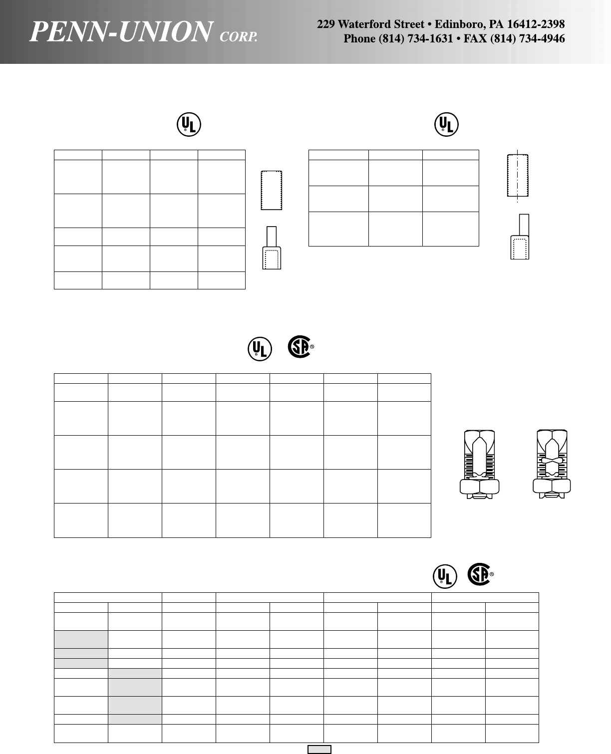
Penn-Union Anderson Blackburn Burndy Ilsco
Copper Aluminum Copper Copper Aluminum Copper Aluminum Copper Aluminum
SW-1 ––9 HPS–––––
SW-2 ––8 HPS–––––
SW-3 – CPS-6 6 HPS – KSU-17 – SK-6 –
SW-4 – CPS-4 4 HPS – KSU-20 – SK-4 AK-6*
SW-5 – CPS-2 2 HPS – KSU-22 – SK-3 AK-4
SW-6 – CPS-1 1 HPS – KSU-23 – SK-2 AK-2
SW-7 SWA-7 CPS-1/0 10 HPS APS-11 KSU-25 KSA-1/0 SK-1/0 AK-1/0
SW-8 SWA-8 CPS-2/0 20 HPS APS-21* KSU-26 KSA-2/0 SK-2/0 AK-2/0
SW-9A SWA-9 CPS-3/0 – – KSU-27 – SK-3/0 –
SW-10 SWA-10 CPS-4/0 – APS-41* KSU-29 KSA-4/0• SK-250 AK-4/0*
SW-11 SWA-11 CPS-350 350 HPS APS-350 KSU-31 KSA-350* SK-350* AK-350*
SW-12 SWA-12 CPS-500 500 HPS APS-500 KSU-34 KSA-500 SK-500* AK-500
SW-13 – – 750 HPS –––––
SW-14 – – 1000 HPS –––––
*Will take a smaller minimum conductor size than PUC part. UL 486A Listed UL 486B Listed AL9CU
Penn-Union Burndy Ilsco* Mac**
TP-6 AYP-6 ACM-6 MPT-6
TP-4 AYP-4 ACM-4 MPT-4
TP-2 AYP-2 ACM-2 MPT-2
TP-1 AYP-1 ACM-1 MPT-1
TP-1/0 AYP-1/0 ACM-1/0 MPT-1/0
TP-2/0 AYP-2/0 ACM-2/0 MPT-2/0
TP-3/0 AYP-3/0 ACM-3/0 MPT-3/0
TP-4/0 AYP-4/0 ACM-4/0 MPT-4/0
TP-250 AYP-250 ACM-250 MPT-250
TP-300 AYP-300 ACM-300 MPT-300
TP-350 AYP-350 ACM-350 MPT-350
TP-400 AYP-400 ACM-400 MPT-400
TP-500 AYP-500 ACM-500 MPT-500
TP-600 AYP-600 ACM-600 MPT-600
TP-750 AYP-750 ACM-750 MPT-750
COMPARATIVE LISTING (UL & CSA FOR PENN-UNION)
DISTRIBUTION COMPRESSION CONNECTORS
ALUMINUM
TERMINAL PLUGS
*Has a knurled stem.
**Has a stranded copper stem. Not recommended for installation with TDY-1.
OFFSET ALUMINUM
TERMINAL PLUGS
Penn-Union Burndy Ilsco*
TPO-2/0 AYPO-2/0 ACO-2/0
TPO-3/0 AYPO-3/0 ACO-3/0
TPO-4/0 AYPO-4/0 ACO-4/0
TPO-250 AYPO-250 ACO-250
TPO-300 AYPO-300 ACO-300
TPO-350 AYPO-350 ACO-350
TPO-400 AYPO-400 –
TPO-500 AYPO-500 ACO-500
TPO-600 AYPO-600 ACO-600
TPO-750 AYPO-750 ACO-750
*Has a knurled stem.
SPLIT BOLT AND SERVICE ENTRANCE CONNECTORS
COPPER ALLOY SPLIT BOLTS
For copper and copperweld wires
Penn-Union Anderson Blackburn Burndy Dossert Ilsco Reliable
S-8 C-8 8H KS-15 DS-1 IK-8 8F
SEL-8* C-8-L 8H3 – – – 8F
S-6 C-6 6H KS-17 DS-2 IK-6 6F
SEL-6* C-6-L 6H3 KS-17-3 DS-2-3 – 6F
S-4 C-4 4H KS-20 DS-3 IK-4 4F
SEL-4* C-4-L 4H3 KS-20-3 DS-3-3 – 4F
S-3 C-2 2H KS-22 DS-5 IK-3 2F
SEL-3* C-2-L 2H3 KS-22-3 DS-5-3 – –
S-2 C-1 1H KS-23 DS-6 IK-2 1F
SEL-2* C-1-L 1H3 – DS-6-3 – –
S-1/0 C-1/0 10H KS-25 DS-10 IK-1/0 1/0F
S-2/0 C-2/0 20H KS-26 DS-13 IK-2/0 2/0F
S-3/0 C-3/0 30H KS-27 DS-17 IK-3/0 –
S-4/0-250 C-4/0 40H KS-29 DS-25 IK-4/0-250** 4/0F
S-350 C-350 350M KS-31** DS-35 IK-350** 679
S-500 C-500 500M KS-34** DS-50 IK-500** 813
S-750 C-750 750M KS-39** DS-75 IK-750** 996
S-1000 C-1000 1000M KS-44** DS-100 IK-1000** 1152
*Not CSA Certified ** Will take smaller minimum conductor size than PUC part.
TIN PLATED COPPER ALLOY SPLIT BOLTS & ALUMINUM SPLIT BOLTS
For aluminum to aluminum, aluminum to copper and copper to copper.
S & SEL SW & SWA
CU
AL9CU AL9CU
157
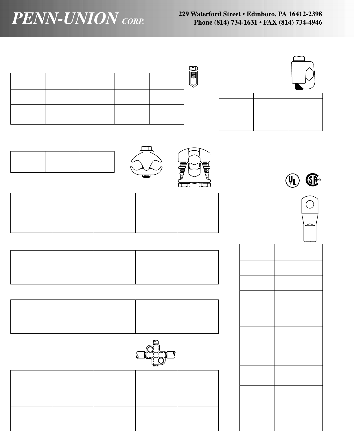
COMPARATIVE LISTING (UL & CSA FOR PENN-UNION)
SPLIT BOLT AND SERVICE ENTRANCE CONNECTORS
COPPER SERVICE ENTRANCE CONNECTORS
Penn-Union Blackburn Burndy Dossert Ilsco
SX-12 – – – SX-12
SX-10-8 – – ES-1V SX-10-8
SX-6 6N KP-6C ES-2 SX-6
SX-4 4N KP-4C ES-4 SX-4
SX-2 – – ES-6 SX-2
SAX-12-8 – – –
SAX-6 6NPW – ESSN-2 –
SAX-4 4NPW – ESSN-4 –
SAX-2 2NPW – ESSN-6 –
SILICON
BRONZE VISE GRIPS
Penn-Union Anderson Fargo
FF-6 DG-6 GC-5006-SH
FF-4 DG-4 GC-5004
FF-2 DG-2 GC-5002-S
FF-2/0 DG-2/0 GC-5020-S
FF-4/0 DG-4/0 GC-5040
MGC-167* – GC-167P*
*Insulation Piercing
PARALLEL CONNECTORS
COPPER JUMPER CLAMPS
Penn-Union Blackburn T&B
JC-1-AC* BK-1 K-1
JC-2-AA BK-2 K-2
JC-3-CC BK-3 K-3
*RUS Accepted
BRONZE PENN-TAPS
Penn-Union Anderson Blackburn Burndy Dossert
VT-0 • K-1*† 2B10 – DSU10
VT-1 • K-2*† 2B20 KVS-26† DSU13
VT-2 • K-3*† 2B40* KVS-28† DSU21
VT-3 • K-4*† 2B350* KVS-31† DSU35
VT-4 • K-5*† 2B500 KVS-34† DSU50
VT-5 • K-6*† 2B800* KVS-40† DSU80
VT-6 • K-7*† 2B1000* KVS-44† DSU100
•UL Listed
With Spacer
VTW-0 • KR-1*† 2B10W*† – DSUS10
VTW-1 • KR-2*† 2B20W*† KVSW-26† DSUS13
VTW-2 • KR-3*† 2B40W*† KVSW-28† DSUS21
VTW-3 • KR-4*† 2B350W*† KVSW-31† DSUS35
VTW-4 • KR-5*† 2B500W*† KVSW-34† DSUS50
VTW-5 • KR-6*† 2B800W*† KVSW-40† DSUS80
VTW-6 • KR-7*† 2B1000W*† KVSW-44† DSUS100
•UL Listed
Tin-Plated with Spacer
VTA-0** KR-1TP*† 2B10PW*† – DSUN10
VTA-1 KR-2TP*† 2B20PW*† KVSU26† DSUN13
VTA-2 KR-3TP*† 2B40PW*† KVSU28† DSUN21
VTA-3 KR-4TP*† 2B350PW*† KVSU31† DSUN35
VTA-4 KR-5TP*† 2B500PW*† KVSU34† DSUN50
VTA-5 KR-6TP*† 2B800PW*† KVSU40† DSUN80
VTA-6 KR-7TP*† 2B1000PW*† KVSU44† DSUN100
*Includes wire range of PUC connector.
†Includes one bolt longer than the other.
**UL 486B Listed AL9CU
BRONZE VARIABLE GUTTER TAP
Penn-Union Anderson Blackburn Burndy Dossert
VX-1 XP-018018 XT-11* QPX-2C2C GTX-6-6
VX-3 XP-024018 and XT-12 and QPX-282C and GTX-216 and
XP-024024 XT-13* QPX-2828 GTX-21-21
VX-4 XP-050018* XT-21* QPX-342C GTX-50-6
VX-5S XP-050024* – – GTX-50-21
VX-6 XP-050050* XT-22 QPX-3434 –
VX-7 XP-100018 – QPX-442C GTX-100-6
VX-8 XP-100024 – QPX-4428 GTX-100-21
VX-8S – – – –
VX-10 XP-100050 and XT-33 and QPX-4434 and GTX-100-50 and
XP-100100 XT-34 QPX-4444 GTX-100-100
*Difference in minimum wire size
COMPRESSION
LUGS &
SPLICES
COPPER
PENN-CRIMPS®
Single Crimp Lugs for
AN-8 thru AN-4/0
Penn-Union Burndy
BLY8C-L YAV8C-L
BLY8C-L1 YAV8C-L1
BLY8C-L2 YAV8C-L2
BLY8C-L3 YAV8C-L3
BLY8C-L4 YAV8C-L4
BLY6C-L1 YAV6C-L1
BLY6C-L YAV6C-L
BLY6C-L4 YAV6C-L4
BLY6C-L2 YAV6C-L2
BLY6C-L10 YAV6C-L10
BLY4C-L3 YAV4C-L3
BLY4C-L YAV4C-L
BLY4C-L4 YAV4C-L4
BLY4C-L2 YAV4C-L2
BLY4C-L5 YAV4C-L5
BLY2C-L1 • YAV2C-L1
BLY2C-L2 • YAV2C-L2
BLY2C-L • YAV2C-L
BLY2C-L4 • YAV2C-L4
BLY1C-L1 YAV1C-L1
BLY1C-L2 YAV1C-L2
BLY1C-L YAV1C-L
BLY1C-L3 YAV1C-L3
BLY25-L1 YAV25-L1
BLY25-L2 YAV25-L2
BLY25-L YAV25-L
BLY25-L3 YAV25-L3
BLY26-L1 YA26-L1
BLY26-L2 YA26-L2
BLY26-L YA26-L
BLY26-L3 YA26-L3
BLY27-L1 YAV27-L1
BLY28-L YAV28-L
BLY28-L12 YAV28-L12
BLY28-L13 YAV28-L13
BLY28-L14 YAV28-L14
•UL Listed
158
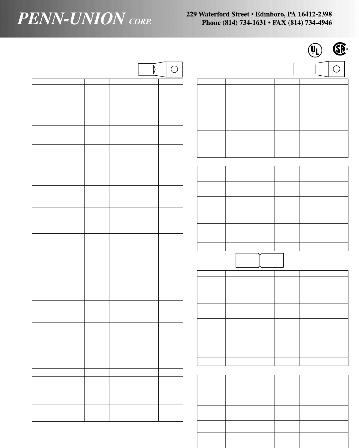
COPPER PENN-CRIMPS®
Standard Barrel Lugs
Penn-Union Blackburn Burndy Dossert Ilsco T & B
BLU8S14 • CTL8-10 – – CRA-8 54104
BLU-8D • – – – – 54204
BLU-8S15 • CTL8-14 – – – 54130
BLU-8S16 • CTL8-516 – – – 54131
BLU-8S17 • – – – – 54132
BLU-8S18 • – – – – –
BLU-6S • CTL6-10 YA6C-L1 DPLS2-1-18 CRA-6 54134
BLU-6S1 • CTL6-14 YA6C-L DPLS2-1 CRB-6 54105
BLU-6D • – YA6C-2L DPLS2-2 – 54205
BLU-6S2 • CTL6-516 YA6C-L3 DPLS2-1-31 – 54135
BLU-6S8 • – YA6C-L4 – – 54136
BLU-4S • CTL4-10 YA4C-L1 DPLS4-1-18 CRA-4 54138
BLU-4S1 • CTL4-14 YA4C-L DPLS4-1 CRB-4 54106
BLU-4D • – YA4C-2L DPLS4-2 – 54206
BLU-4S10 • CTL4-516 YA4C-L3 – – 54139
BLU-4S2 • CTL4-38 YA4C-L4 DPLS4-1-38 – 54140
BLU-2S • CTL2-14 YA2C-L2 DPLS6-1-25 CRA-2 54107
BLU-2D • – YA2C-2L – – 54207
BLU-2S1 • CTL2-516 YA2C-L DPL56-1 CRB-2 54142
BLU-2S2 • CTL2-38 YA2C-L4 DPLS6-1-38 – 54143
BLU-2S10 • – YA2C-L6 – – 54145
BLU-1S9 • CTL1-14 – – – 54108
BLU-1D2 • – – – – 54208
BLU-1S • CTL1-516 YA1C-L DPLS8-1 CRA-1 54147
BLU-1D4 • – YA1C-2L DPLS8-2 – –
BLU-1S1 • CTL1-38 YA1C-L4 – – 54148
BLU-1S4 • – YA1C-L6 – – 54150
BLU-1/0S19 • – – – – 54152
BLU-1/0S • CTL10-516 YA25-L DPLS10-1 CRA-0 54153
BLU-1/0D • – YA25-2L DPLS10-2 – 54255
BLU-1/0S1 • CTL10-38 YA25-L4 DPLS10-1-38 CRB-0 54109
BLU-1/0D4 • – – – – 54209
BLU-1/0S20 • – YA25-L6 – – 54155
BLU-2/0S20 • – – – – 54157
BLU-2/0S21 • – – – – 54158
BLU-2/0D3 • – – DPLS13-2 – –
BLU-2/0S • CTL20-38 YA26-L DPLS31-1 CRA-2/0 54110
BLU-2/0D4 • – – – – 54210
BLU-2/0S4 • CTL20-12 YA26-L6 – – 54160
BLU-2/0D • – YA26-2LN DPLS13-2N – 54260
BLU-3/0S14 • – – – – 54162
BLU-3/0S15 • – – – – 54163
BLU-3/0S • CTL30-38 YA27-L4 DPLS17-1-38 CRA-3/0 54111
BLU-3/0D3 • – – DPLS17-2 – 54211
BLU-3/0S1 • CTL30-12 YA27-L DPLS17-1 CRB-3/0 54165
BLU-3/0D • – YA27-2LN DPLS17-2N – 54265
BLU-4/0S19 • – – – – 54167
BLU-4/0S25 • – – – – 54168
BLU-4/0S • CTL40-38 YA28-L4 DPLS21-1-38 CRA-4/0 54112
BLU-4/0D10 • – – DPLS21-2 – 54212
BLU-4/0S1 • CTL40-12 YA28-L DPLS21-1 CRB-4/0 54170
BLU-4/0D • CTL402 YA28-2LN DPLS21-2N – 54270
BLU-025S4 • – – – – 54172
BLU-025SS • – – – – 54173
BLU-025S2 • – – – – 54174
BLU-025D3 • – – DPLS25-2 – 54213
BLU-025S • CTL250-12 YA29-L DPLS25-1 CRA-250 54113
BLU-025D • CTL2502 YA29-2LN DPLS25-2N – 54275
BLU-030S6 • – – – – 54178
BLU-030S7 • – – – – 54179
BLU-030D9 • – – DPLS30-2 – 54214
BLU-030S • CTL300-12 YA30-L DPLS30-1 CRA-300 54114
BLU-030D • CTL3002 YA30-2LN DPLS30-2N – 54280
BLU-030S8 • – – – – 54181
BLU-035D13 • – – DPLS35-2 – 54215
BLU-035S • CTL350-12 YA31-L DPLS35-1 CRA-350 54115
BLU-035D • CTL3502 YA31-2LN DPLS35-2N – 54282
BLU-035S3 • – – – – 54183
BLU-040D7 • – – DPLS40-2 – 54216
BLU-040S4 • CTL400-12 – – – 54116
BLU-040D • CTL4002 YA32-2LN DPLS40-2N – –
BLU-040S • – YA32-L DPLS40-1 CRA-400 54185
BLU-050D13 • – – DPLS50-2 – 54218
BLU-050S2 • CTL500-12 – – – 54118
BLU-050D • CTL5002 YA34-2LN DPLS50-2N – 54286
BLU-050S • – YA34-L DPLS50-1 CRA -500 54187
BLU-060D • – YA36-2LN DPLS60-2N – 54289
BLU-060S • – YA36-L DPLS60-1 – 54120
BLU-075D • CTL7502 YA39-2LN DPLS75-2N – 54223
BLU-075S • – YA39-L DPLS75-1 CRA-750 54123
BLU-080D • – YA40-2LN DPLS80-2N – 54224
BLU-080S • – YA40-L DPLS80-1 – 54124
BLU-100D • CTL10002 YA44-2LN DPLS100-2N – 54228
BLU-100S • – YA44-L DPLS100-1 CRA-1000 54128
BLU-100S4 • – – – – 54129
BLU-150D • – – DPLS150-2N – –
BLU-150S • – – DPLS150-1 – –
BLU-200D • – – DPLS200-2N – –
BLU-200D • – – DPLS200-1 – –
•UL Listed
“S” in suffix = single hole pad
“D” in suffix = double hole pad
BLUA, BLU and BBLU lugs are suitable for use @ voltages up to 35KV, provided connector is taped in accordance
with accepted practices. 5KV is maximum voltage level in all bare splice applications.
COPPER PENN-CRIMPS®
Long Barrel Lugs – One Hole
Penn-Union Blackburn Burndy Dossert Ilsco T & B
BBLU-6S • – YA6C DPL2-1 CRB-6L 54905
BBLU-4S • – YA4C DPL4-1 CRB-4L 54906
BBLU-2S • – YA2C DPL6-1 CRB-2L 54942
BBLU-1S • – YA1C DPL8-1 CRA-1L 54947
BBLU-1/0S • – YA25 DPL10-1 CRA-1/0L –
BBLU-2/0S • – YA26 DPL13-1 CRA-2/0L 54910
BBLU-3/0S • – YA27 DPL17-1 CRB-3/0L 54965
BBLU-4/0S • – YA28 DPL21-1 CRB-4/0L 54970
BBLU-025S • – YA29 DPL25-1 CRA-250L 54913
BBLU-030S • – YA30 DPL30-1 CRA-300L 54914
BBLU-035S • – YA31 DPL35-1 CRA-350L 54915
BBLU-040S • – YA32 DPL40-1 CRA-400L –
BBLU-050S • – YA34 DPL50-1 CRA-500L –
BBLU-060S • – YA36 DPL60-1 CRA-600L 54920
BBLU-075S • – YA39 DPL75-1 CRA-750L 54923
BBLU-080S • – YA40 DPL80-1 – –
BBLU-100S • – YA44 DPL100-1 CRA-1000L 54928
BBLU-150S • – YA46 DPL150-1 – –
BBLU-200S • – – DPL200-1 – –
Long Barrel Lugs – Two Hole
BBLU-6D • – YA6C-2 DPL2-2 CRB-6L2 54852
BBLU-4D • – YA4C-2 DPL4-2 CRB-4L2 54854
BBLU-2D • – YA2C-2 DPL6-2 CRB-2L2 54856
BBLU-1D • – YA1C-2 DPL8-2 CRA-1L2 54858
BBLU-1/0D • LCN10 YA25-2 DPL10-2 CRA-1/0L2 54860
BBLU-2/0D • LCN20 YA26-2N DPL13-2N CRA-2/0L2 54862
BBLU-3/0D • LCN30 YA27-2N DPL17-2N CRB-3/0L2 54864
BBLU-4/0D • LCN40 YA28-2N DPL21-2N CRB-4/0L2 54866
BBLU-025D • LCN250 YA29=2N DPL25-2N CRA-250L2 54868
BBLU-030D • – YA30-2N DPL30-2N CRA-300L2 54870
BBLU-035D • LCN350 YA31-2N DPL35-2N CRA-350L2 54872
BBLU-040D • – YA32-2N DPL40-2N CRA-400L2 54874
BBLU-050D • LCN500 YA34-2N DPL50-2N CRA-500L2 54876
BBLU-060D • – YA36-2N DPL60-2N CRA-600L2 54878
BBLU-075D • LCN750 YA39-2N DPL75-2N CRA-750L2 54880
BBLU-080D • – YA40-2N DPL80-2N – –
BBLU-100D • LCN1000 – DPL100-2 CRA-1000L2 –
BBLU-100D1• – YA44-2N DPL100-2N – –
BBLU-150D • – – DPL150-2 – –
BBLU-150D1• – YA46-2N DPL150-2N – –
BBLU-200D • – – DPL200-2 – –
BBLU-200D1• – – DPL200-2N – –
Splices
Penn-Union Blackburn Burndy Dossert Ilsco T & B
BCU-8 • CSP8 YS8C-L – CT-8 54504
BCU-6 • CSP6 YS6C-L DPCS-2 CT-6 54505
BCU-5 • – YS5C-L – – –
BCU-4 • CSP4 YS4C-L DPCS-4 CT-4 54506
BCU-3 CSP3 YS3C-L – – –
BCU-2 • CSP2 YS2C-L DPCS-6 CT-2 54507
BCU-1 • CSP1 YS1C-L DPCS-8 CT-1 54508
BCU-1/0 • CSP10 YS25-L DPCS-10 CT-1/0 54509
BCU-2/0 • CPS20 YS26-L DPCS-13 CT-2/0 54510
BCU-3/0 • CSP30 YS27-L DPCS-17 CT-3/0 54511
BCU-4/0 • CSP40 YS28-L DPCS-21 CT-4/0 54512
BCU-025 • CSP250 YS29-L DPCS-25 CT-250 54513
BCU-030 • CSP300 YS30-L DPCS-30 CT-300 54514
BCU-035 • CSP350 YS31-L DPCS-35 CT-350 54515
BCU-040 • CSP400 YS32-L DPCS-40 CT-400 54516
BCU-050 • CSP500 YS34-L DPCS-50 CT-500 54518
BCU-060 • CSP600 YS36-L DPCS-60 – 54520
BCU-065 – – – – –
BLU-075 • CSP750 YS39-L DPCS-75 CT-750 54523
BCU-080 • – – DPCS-80 – 54524
BCU-100 • CSP1000 YS44-L DPCS-100 CT-1000 54528
BCU-150 • – – DPCS-150 – –
BCU-200 • – – DPCS-200 – –
Long Barrel Splices
BBCU-6 • C46 YS6C DPC-2 CTL-6 54805
BBCU-4 • C44 YS4C DPC-4 CTL-4 54806
BBCU-2 • C42 YS2C DPC-6 CTL-2 54807
BBCU-1 • C41 YS1C DPC-8 CTL-1 54808
BBCU-1/0 • CU-10 YS25 DPC-10 CTL-1/0 54809
BBCU-2/0 • CU-20 YS26 DPC-13 CTL-2/0 54810
BBCU-3/0 • CU-30 YS27 DPC-17 CTL-3/0 54811
BBCU-4/0 • CU-40 YS28 DPC-21 CTL-4/0 54812
BBCU-025 • CU-250 YS29 DPC-25 CTL-250 54813
BBCU-030 • CU-300 YS30 DPC-30 CTL-300 54814
BBCU-035 • CU-350 YS31 DPC-35 CTL-350 54815
BBCU-040 • CU-400 YS32 DPC-40 CTL-400 54816
BBCU-050 • CU-500 YS34 DPC-50 CTL-500 54818
BBCU-060 • CU-600 YS36 DPC-60 CTL-600 54820
BBCU-075 • CU-750 YS39 DPC-75 CTL-750 54823
BBCU-080 • – – DPC-80 – –
BBCU-100 • CU-1000 YS44 DPC-100 CTL-1000 54828
BBCU-150 • – YS46 DPC-150 – –
BBCU-200 • – YS48 DPC-200 – –
•UL Listed
COMPARATIVE LISTING (UL & CSA FOR PENN-UNION)
COMPRESSION LUGS & SPLICES 90° CU
159

COMPARATIVE LISTING (UL & CSA FOR PENN-UNION)
COMPRESSION LUGS & SPLICES
Penn-Union Blackburn Burndy Dossert Ilsco T & B
BLUA-8S ATL8-14 YA8CA3 DPL-1-1-AA ACL-8 60102
BLUA-6S • ATL6-14 YA6CA1 DPL-2-1-AA ACL-6 60107
BLUA-6S2 • ––––60108
BLUA-4S3 • ATL4-14 YA4CA1 – ACL-4 60112
BLUA-4S2 • ATL4-516 YA4CA3 DPL-4-1-AA – 60113
BLUA-2S3 • ATL2-14 – – ACL-2 60116
BLUA-2S4 • ATL2-516 YA2CA1 – – 60117
BLUA-2S • ATL2-38 YA2CA3 DPL-6-1-AA – 60118
BLUA-1S1 • – – – ACL-1 60112
BLUA-1S3 • ATL1-516 – – ACN-1 60123
BLUA-1S • ATL1-38 YA1CA1 DPL-8-1-AA – 60124
BLUA-1S2 • ––––60126
BLUA-1/0S2 • ––––60128
BLUA-1/0S3 • ATL10-516 YA25A1 – ACN-1/0 60129
BLUA-1/0S • ATL10-38 YA25A3 DPL-10-1-AA ACL-1/0 60130
BLUA-1/0D1 • ATL102-38* – – 2ACL-1/0 60230
BLUA-1/0D2 • – YA25A5 DPL-10-2-AA – –
BLUA-1/0S1 • ATL1012 YA25A9 – ACL-1/0-9/16 60132
BLUA-1/0D3 • ATL-102 YA25A7 – – –
BLUA-2/0S4 • ––––60134
BLUA-2/0S5 • ––––60135
BLUA-2/0S6 • ATL20-38 YA26A6 – ACL-2/0 60136
BLUA-2/0D2 • – YA26A5 – – 60236
BLUA-2/0S • ATL20-12 YA26A1 DPL-13-1-AA ACN-2/0 60138
BLUA-2/0D • ATL202* YA26A3 DPL-13-2N-AA 2ACL-2/0 60238
BLUA-3/0S5 • ––––60141
BLUA-3/0S2 • ATL30-38 YA27A1 – ACL-3/0 60142
BLUA-3/0D1 • – YA27A7 – – 60242
BLUA-3/0S • ATL30-12 YA27A3 DPL-17-1-AA ACN-3/0 60144
BLUA-3/0D • ATL302* YA27A5 DPL-17-2N-AA 2ACL-3/0 60244
BLUA-4/0S3 • ––––60147
BLUA-4/0S2 • ATL40-38 YA28A1 – ACL-4/0 60148
BLUA-4/0D2 • – YA28A7 – – 60248
BLUA-4/0S • ATL40-12 YA28A3 DPL-21-1-AA – 60150
BLUA-4/0D • ATL402* YA28A5 DPL-21-2N-AA 2ACL-4/0 60250
BLUA-4/0S4 • ATL-4012 YA28A3 DPL-211-AA ACN-4/0 60151
BLUA-025S2 • ––––60154
BLUA-025D1 • – YA29A5 – – 60254
BLUA-025S • ATL250-12 YA29A1 DPL-25-1-AA ACL-250 60156
BLUA-025D • ATL2502* YA29A3 DPL-25-2N-AA 2ACL-250 60256
BLUA-025S3 • ––––60157
BLUA-030S2 • – YA30A6 – – 60160
BLUA-030D1 • – YA30A5 – – 60260
BLUA-030S1 • ATL30012 YA30A1 – ACL-300 60162
BLUA-030D • ATL3002 YA30A3 DPL-30-2N-AA 2ACL-300 60262
BLUA-030S • – – DPL-30-1-AA – 60163
BLUA-035D1 • – YA31A5 – – 60265
BLUA-035S1 • ATL350-12 YA31A1 – ACL-350 60165
BLUA-035D • ATL3502* YA31A3 DPL-35-2N-AA 2ACL-350 60267
BLUA-035S • ––––60166
BLUA-040D1 • – YA32A5 – – 60268
BLUA-040S2 • – – – ACL-400 60168
BLUA-040D2 • ATL 4002 YA32A3 DPL-40-2N-AA 2ACL-400 60269
BLUA-040S3 • ATL40058 YA32A1 – – 60169
BLUA-050D1 • – YA34A5 – – 60271
BLUA-050S2 • ATL-500-12 – – ACL-500 60171
BLUA-050D2 • ATL5002* YA34A3 DPL-50-2N-AA 2ACL-500 60273
BLUA-050S3 • ATL50058 YA34A1 – – 60172
BLUA-060D1 • – YA36A5 – – 60274
BLUA-060D2 • ATL6002 YA36A3 DPL-60-2N-AA 2ACL-600 60275
BLUA-060S1 • – – – ACL-600 60174
BLUA-075S1 • ATL-750-58 YA39A3 – ACL-750 60178
BLUA-075D1 • ATL-7502* YA39A5 DPL-75-2N-AA 2ACL-750 60278
BLUA-080D1 • – YA40A3 DPL-80-2N-AA – 60280
BLUA-080S1 • – YA40A1 – – 60180
BLUA-100D2 • ATL10002 YA44A3 DPL-100-2N-AA 2ACL-1000 60284
BLUA-100S1 • ATL1000-58 YA44A1 – ACL-1000 60184
• UL 486B Listed • Hole spacing different. “S” in suffix = single hole lug “D” in suffix = double hole lug
ALUMINUM PENN-CRIMPS®
Lugs – One & Two Hole
Penn-Union Blackburn Burndy Dossert Ilsco T & B
BCUA-6 • ASP6 YS6CA1 DPC-2 AA AS-6 60507
BCUA-4 • ASP4 YS4CA1 DPC-4-AA AS-4 60512
BCUA-2 • ASP2 YS2CA1 DPC-6-AA AS-2 60516
BCUA-1 • ASP1 YS1CA1 DPC-8-AA AS-1 60522
BCUA-1/0 • ASP10 YS25A1 DPC-10-AA AS-1/0 60530
BCUA-2/0 • ASP20 YS26A1 DPC-13-AA AS-2/0 60536
BCUA-3/0 • ASP30 YS27A1 DPC-17-AA AS-3/0 60542
BCUA-4/0 • ASP40 YS28A1 DPC-21-AA AS-4/0 60548
BCUA-025 • ASP250 YS29A1 DPC-25-AA AS-250 60554
BCUA-030 • ASP300 YS30A1 DPC-30-AA AS-300 60560
BCUA-035 • ASP350 YS31A1 DPC-35-AA AS-350 60565
BCUA-040 • ASP400 YS32A1 DPC-40-AA AS-400 60568
BCUA-050 • ASP500 YS34A1 DPC-50-AA AS-500 60571
BCUA-060 • ASP600 YS36A1 DPC-60-AA AS-600 60574
BCUA-075 • ASP750 YS39A1 DPC-75-AA AS-750 60578
BCUA-080 • – YS40A1 DPC-80-AA – 60580
BCUA-100 • ASP1000 YS44A1 DPC-100-AA AS-1000 60584
• UL 486B Listed
Splices
ALUMINUM COMPRESSION
TERMINALS
For alum., copper or ACSR wire.
ONE HOLE PAD
Penn-Union Burndy Homac Kearney
FKLA-W8-S – SA-10-48 –
FKLA-W6-S YRA8CU• SA-8-48* –
FKLA-W4-S YRA6CU SA-6-48 –
FKLA-W2-S YRA4CU SA-4-48 –
FKLA-C2-S – SA-3-48 –
FKLA-R2-S YRA1CU SA-2-48 –
FKLA-010-S YRA25A SA-1/0-48 –
FSLA-W2-S YRAL4CU – 104761-1*
FSLA-C2-S YRAL1CU – –
FSLA-010-S YRA25U – 104761-3*
FSLA-013-S YRA26U SA-2/0-48 104761-4
FSLA-017-S YRA27U SA-3/0-48 104761-5
FSLA-025-S YRA28U SA-4/0-48 and 104761-6 and
SA250-48 104761-7
FSLA-030-S – – 104761-8
FULA-030-S – SA300-48 –
FULA-035-S YCAK31AG1 SA350-48 –
FULA-045-S – SA400-48 –
FULA-050-S – CFA500-48 –
TWO HOLE PAD
FULA-025-D YCAK29A-2G1 SAB4/0-N –
FULA-030-D – SAB300-N –
FULA-035-D YCAK31A-2G1 SA35048 –
FULA-R033-D – SAB350-N –
FULA-045-D – SAB400-N –
FULA-050-D YCAK34A-2G3 SAB500-N –
*Difference in minimum wire size.
Penn-
Union Burndy
Die Set Burndy Die Set T & B Color
Cat. No. Index Cat. No. Index Code Range
T-10 10 U2CRT 33 Brown #2 CU
T-11/375 11 U1CRT 37 Green #1 CU
375 U4CABT #4 AL
T-12/348 12 U25RT 42 Pink 1/0 CU
348 U2CABT #2 AL
T-13 13 U26RT 45 Black 2/0 CU
T-14 14 U27RT 50 Orange 3/0 CU
T-15 15 U28RT 54 Purple 4/0 CU
T-16 16 U29RT 62 Yellow 250MCM CU
T-298 298 U28ART 66H White 4/0 AL
T-18/324 18 U31RT 71H Red 350MCM CU
324 U29ART 250MCM AL
T-20/299 20 U34RT 87H Brown 500MCM CU
299 U31ART 350MCM AL
T-22/472 22 U36RT 94 H Green 600MCM CU
472 U32ART 400MCM AL
T-296 296 U25ART 50 Tan 1/0 AL
T-297 297 U26ART 54 Olive 2/0 AL
T-300 300 U34ART 99H Pink 500MCM AL
T-467 467 U27ART 60 Ruby 3/0 AL
T-473 473 U36ART 106H Black 750MCM CU
600MCM AL
COMPRESSION TOOLS
Penn-Union Blackburn Burndy Ilsco T & B
TPU-12B JB 12A Y35 ILC-12 TBM-12M
TDM-250 NRG 2508 MY29-3 MT-25 –
TDM-250XF – MY29-11 – –
TDM-500 – – – –
TPU-12BH JB12HA Y35BH ILC-12H –
TPU-15BH – Y46 – TBM15PF
Die Sets
160
AL9 CU
AL9 CU
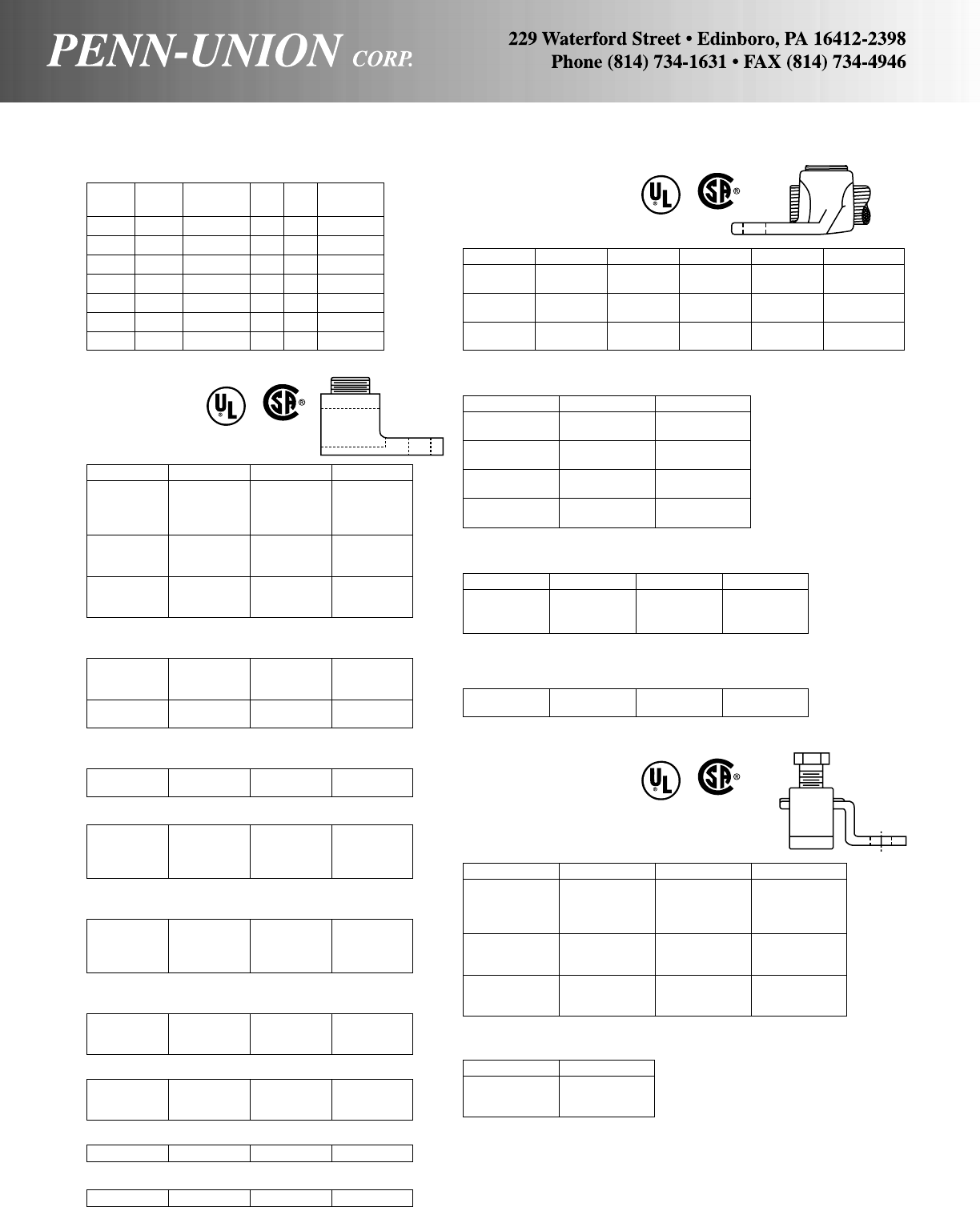
L2A-0 ADR11-21 K2A-26U* AU-0
L2A-250 ADR25-21 K2A-29U AU-250
L2A-350 ADR35-21 K2A-31U AU-350
L2A-500 – – –
L2A-600 ADR60-21 K2A-36U AU-600
*Difference in max. wire size.
Penn-Union Blackburn Burndy Ilsco
LA-6 ADR6 – TA-6S
LA-2 ADR2 KA-2U TA-2
LA-0 ADR11 KA-25U TA-0
LA-2/0 ADR21 KA-26U TA-2/0
LA-250 ADR25 KA-29U TA-250
LA-350 ADR35 KA-31U TA-350
LA-500 ADR50 KA-34U TA-500
LA-600 ADR60 KA-36U TA-600*
LA-800 ADR80 KA-40U TA-800*
LA-1000 ADR99 KA-44U TA-1000*
*Difference in min. wire size.
COMPRESSION DIES
DIE SETS/(UTILITY)
PUC Burndy Burndy T&B Color
Die Set Index Die Set Index Code Range
T-BG BG U-BG 52 – –
T-0 O U-O O – –
T-D3 D3 U-D3 D – –
T-N N U-N N – –
T-249 249 U-249 76 – –
T-316 316 U-316 96 – –
T-317 317 U-317 106A – –
TERMINAL LUGS
ALUMINUM
SOLDERLESS
LUGS
One Hole – Two Conductors
Two Hole – Two Conductors
L2A-800 ADR80-21 – AU-800
L2A-1000 ADR99-21 K2A-44U AU-1000
Two Hole – One Conductor
LA-350-2 – – TA-350-2N
LA-600-2 – KA-36U-2N TA-600-2N
LA-800-2 – KA-40U-2N TA-800-2N*
LA-1000-2 – KA-44U-2N TA-1000-2N
*Difference in min. wire size.
Two Hole – Two Conductors
L2A-350-2 – – AU-350-2N
L2A-600-2 – K2A-36U-2N AU-600-2N
L2A-800-2 – K2A-40U-2N AU-800-2N*
L2A-1000-2 – K2A-44U-2N AU-1000-2N
*Difference in min. wire size.
Two Hole – Three Conductors
L3A-250-2 ADR25-32 K3A-29U-2N T3A2-250N
L3A-350-2 ADR35-32 K3A-31U-2N T3A2-350N
L3A-500-2 ADR50-32 K3A-36U-2N T3A2-500N
Four Hole – Three Conductors
L3A-250-4 ADR25-34 K3A-29U-4N T3A4-250N
L3A-350-4 ADR35-34 K3A-31U-4N T3A4-350N
L3A-500-4 ADR50-34 K3A-36U-4N T3A4-500N
Two Hole – Three Conductors – Double Head
L3A-800-2 ADR80-32 K3A-40U-2N T3A2-800N
One Hole – One Conductor
Four Hole – Three Conductors – Double Head
L3A-800-4 ADR80-34 K3A-40U-4N T3A4-800N
BRONZE PENN-LUGS
One Hole – One Conductor
Penn-Union Anderson Blackburn Burndy Dossert T & B
PNL-8 •* LU-08 L-35 KA-8C D-35 71003
PNL-4 •* LU-04 L-70 KA-4C D-70 71005
PNL-1/0 •* LU-1/0 L-125 KA-25 D-10 –
PNL-250 •* LU-4/0 L-250 KA-28 D-21/D-25 71015
PNL-500 •* LU-500 L-400 KA-34 D-50 71020
PNL-1000 •* LU-1000 L-650 – D-100 –
Two Hole – One Conductor
Penn-Union Anderson Blackburn
PNL-1/0-2 • – L-125-2
PNL-1/0-2N • LU-1/0-2 –
PNL-250-2 • – L-250-2
PNL-250-2N •* LU-4/0-2N –
PNL-500-2 • – L-400-2
PNL-500-2N •* LU-500-2N –
PNL-1000-2 • – L-650-2
PNL-1000-2N •* LU-1000-2N –
Two Hole – Two Conductors
Four Hole – Two Conductors
P2NL-500-4N LU2-500-4N – –
P2NL-1000-4N LU2-1000-4N TL-600 D2-100
•UL Listed
*CSA Certified
COPPER SOLDERLESS LUGS
One Hole – Single Collar
Penn-Union Burndy Dossert Ilsco
SLU-25 – – SLU-25
SLU-35 KPA-8C G-35-1 SLU-35
SAU-70 – G-35-E1 SAU-70
SLU-70 KPA-4C G-70-1 SLU-70
SLU-125 KPA-25 G-125-1 SLU-125
SLU-175 – G-175-1 SLU-175
SLU-225 KPA-28 G-225-1 SLU-225
SLU-300 – – SLU-300
SLU-400 KPA-34 G-400-1 SLU-400
SLU-650 – G-650-1 SLU-650
One Hole – Double Collar
Penn-Union Ilsco
LU-2 LU-2
LU-4 LU-4
LU-6 LU-6
Penn-Union Anderson Blackburn Dossert
P2NL-1/0-2N LU2-1/0-2N – –
P2NL-250-2N – TL-250 D2-25
P2NL-500-2N LU2-500-2N TL-400 D2-50
COMPARATIVE LISTING (UL & CSA FOR PENN-UNION)
AL9 CU
161

EYEBOLT TERMINALS & TRANSFORMER GROUND CLAMPS
BRONZE
EYEBOLT TERMINALS
Single Eyebolt
For 1/4" Thick Bar
Penn-Union Anderson Burndy Dossert
LS-C1E TLS-22 QGFL-1CB1 QL-8
LSN-2/0N TLS-32 QGFL-26B2 QL-13-50
LS-2/0 TLS-35 QGFL-26B1 QL-13
LSN-025N TLS-42 QGFL-29B1 QL-25
LSN-035N TLS-52 QGFL-31B1 QL-35
LSN-050N TLS-62 QGFL-34B1 QL-50
LSN-075 TLS-72 QGFL-39B1 QL-75
LSN-100N TLS-86 QGFL-44B1* QL-100
LS-150E TLS-92L QGFL-46B1 –
LS-200E – QGFL-48B1* –
For 1/4" to 3/4" Thick Bar
LS-C1E TLS-22L QGFL-1CB1 QL-8E
LSN-2/0NE TLS-32L QGFL-26B1T6 QL-13-50
LSN-2/0E – QGFL-26B2 QL-13E
LSN-025NE TLS-42L QGFL-29B1T6 QL-25E
LSN-035NE TLS-52L QGFL-31B1T6 QL-35E
LSN-050NE TLS-62L QGFL-34B1T6 QL-50E
LSN-075E TLS-72L QGFL-39B1T6 QL-75E
LSN-100NE TLS-86L QGFL-44B1T6* QL-100E
LSN-150E TLS-92L QGFL-46B1T6 –
LSN-200E – QGFL-48B1T6* –
Double Eyebolt (Parallel Connection)
For 1/4" Thick Bar
LDN-2/0N – QQGFL-26B2 –
LDN-025N – QQGFL-29B1 –
LDN-035N – QQGFL-31B1 –
LDN-050N TLD-62 – Q2L-50
LDN-075 TLD-72 – Q2L-75
LDN-100N TLD-86 – Q2L-100*
LD-200E TLD-102L – –
For 1/4" to 3/4" Thick Bar
LDN-025NE – QQGFL-29B1T6 –
LDN-035NE – QQGFL-31B1T6 –
LDN-050NE TLD-62L – Q2L-50E
LDN-075E TLD-72L – Q2L-75E
LDN-100NE TLD-86L – QL-100E*
LD-200E TLD-102L – –
Double Eyebolt (Tee Connection)
For 1/4" Thick Bar
LDN-2/0N2 TLD-32 – Q2L-13-50
LDN-025N2 TLD-42 – Q2L-25
For 1/4" to 3/4" Thick Bar
LDN-2/0N2E TLD-32L – Q2L-13-50
LDN-025N2E TLD-42L – Q2L-25E
*Difference in min. wire size.
TRANSFORMER GROUND CLAMPS
Penn-Union Anderson Blackburn Burndy Dossert
GSE-C1 GTCL-23A – – –
GSE-020 GTCL-34A – EQCG32C –
GSE-025 ––––
Two-way basket
HGSE-C1 GTCS-21 – – TGC850
HGSE-020 GTCS-34A TTC2 – –
HGSE-250 GTCS-41 – – –
For tin-plating add suffix
– TN – TP – P – TN – TP
GROUNDING CONNECTORS
GROUND ROD CLAMPS
SUITABLE
FOR DIRECT
BURIAL
Penn-Union Anderson Blackburn Burndy Dossert Weaver
CAB-0 – – GKP622W – –
CAB-1 – J-AB-1/2H GKP632W GN-50 WB1/2
CAB-2 – J-AB-5/8H – GN-62 WB5/8
CAB-3 – J-AB-3/4H GKP642W GN-75 WB3/4
CAB-4 –––––
CAB-5 – – GKP652W – –
CAB-6 – – – – WB1
Economy Clamps
Penn-Union Anderson Blackburn Burndy Weaver
CEB-1 GC-4 G4 GRC-12 WG4
CEB-2 GC-5 G5 GRC-58 WG5
CEB-3 GC-6 G6 GRC-34 WG6
GROUND CLAMP CONNECTORS
For clamping braid, cable or strip copper to pipe.
Penn-Union Anderson Burndy Dossert
GO-0 GC-109-03 – –
GO-1 GC-109-04 GG-15-1 GR-100A
GO-2 GC-109-05 GG-16-1 GR-125A
GO-3 – GG-17-1 GR-150A
GO-4 – GG-17-5 GR-150B
GO-4A GC-109-06 – –
GO-5 – GG-18-1 GR-200A
GO-6 – GG-18-15 GR-200B
GO-7 GC-109-07 GG-18-2 GR-200C
GO-7A GC-109-08 – –
GO-8 – GG-19-2 GR-250A
GO-9 – GG-19-25 GR-250B
GO-10 GC-109-09 GG-20-2 GR-300A
GO-11 – GG-20-25 GR-300B
GO-12 – GG-20-3 GR-300C
GO-13 GC-109-10 GG-21-2 GR-350A
GO-14 – GG-21-25 GR-350B
GO-15 – GG-21-3 GR-350C
GO-16 – GG-22-2 GR-400A
GO-17 – GG-22-25 GR-400B
GO-18 – GG-22-3 GR-400C
GO-19 – GG-22-35 GR-400D
162
COMPARATIVE LISTING (UL & CSA FOR PENN-UNION)
C
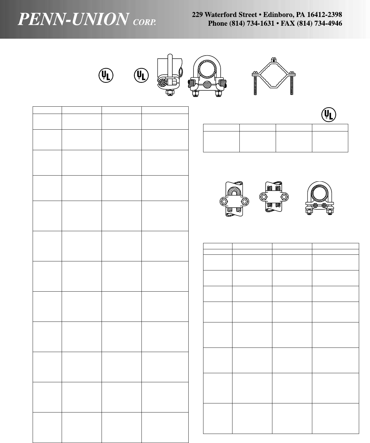
COMPARATIVE LISTING (UL & CSA FOR PENN-UNION)
GROUNDING CONNECTORS
GROUND CLAMP
CONNECTORS
Universal parallel or 90° cable connection to rod or pipe
Penn-Union Anderson Burndy Dossert
GPL-1 GC-111-2A GAR-114C GPC-25-4
GPL-2 GC-111-2B GAR-1126 GPC-25-13
GPL-3 GC-111-2C3 GAR-1129 GPC-25-25
GPL-4 – GAR-644C GPC-38-4
GPL-5 – GAR-6426 GPC-38-13
GPL-6 – GAR-6429 GPC-38-25
GPL-7 • GC-111-3D GAR-6434 GPC-38-50
GPL-8 ** GAR-144C GPC-75-4
GPL-9 ** GAR-1426 GPC-75-13
GPL-10 ** GAR-1429 GPC-75-25
GPL-12 • ** GAR-1439 GPC-75-50
GPL-13 • ** – GPC-75-75
GPL-14 GC-111-4A GAR-154C GPC-100-4
GPL-15 GC-111-4B GAR-1526 GPC-100-13
GPL-16 GC-111-4C GAR-1529 GPC-100-25
GPL-17 • ** GAR-1534 GPC-100-50
GPL-18 • ** GAR-1539 GPC-100-75
GPL-20 GC-111-5A GAR-164C GPC-125-4
GPL-21 GC-111-5B GAR-1626 GPC-125-13
GPL-22 GC-111-5C GAR-1629 GPC-125-25
GPL-23 • ** GAR-1634 GPC-125-50
GPL-24 • ** GAR-1639 GPC-125-75
GPL-25 • ** – GPC-125-100
GPL-26 GC-111-6A GAR-174C GPC-150-4
GPL-27 GC-111-6B GAR-1726 GPC-150-13
GPL-28 GC-111-6C GAR-1729 GPC-150-25
GPL-29 • ** GAR-1734 GPC-150-50
GPL-30 • ** GAR-1739 GPC-150-75
GPL-31 • ** – GPC-150-100
GPL-32 GC-111-7A GAR-184C GPC-200-4
GPL-33 GC-111-7B GAR-1826 GPC-200-13
GPL-34 GC-111-7C GAR-1829 GPC-200-25
GPL-35 • ** GAR-1834 GPC-200-50
GPL-36 • ** GAR-1839 GPC-200-75
GPL-37 • ** – GPC-200-100
GPL-38 – GAR-194C GPC-250-4
GPL-39 GC-111-8B GAR-1926 GPC-250-13
GPL-40 GC-111-8C GAR-1929 GPC-250-25
GPL-41 • ** GAR-1934 GPC-250-50
GPL-42 • ** GAR-1939 GPC-250-75
GPL-43 • ** – GPC-250-100
GPL-44 – GAR-204C GPC-300-4
GPL-45 GC-111-9B GAR-2026 GPC-300-13
GPL-46 GC-111-9C GAR-2029 GPC-300-25
GPL-47 • ** GAR-2034 GPC-300-50
GPL-48 • ** GAR-2039 GPC-300-75
GPL-49 • ** – GPC-300-100
GPL-50 – GAR-214C GPC-350-4
GPL-51 GC-111-10B GAR-2126 GPC-350-13
GPL-52 GC-111-10C GAR-2129 GPC-350-25
GPL-53 • ** GAR-2134 GPC-350-50
GPL-54 • ** GAR-2139 GPC-350-75
GPL-55 • ** – GPC-350-100
GPL-56 – GAR-224C GPC-400-4
GPL-57 GC-111-11B GAR-2226 GPC-400-13
GPL-58 GC-111-11C GAR-2229 GPC-400-25
GPL-59 • ** GAR-2234 GPC-400-50
GPL-60 • ** GAR-2239 GPC-400-75
GPL-61 • ** – GPC-400-100
GPL-68 – GAR-244C –
GPL-69 GC-111-13B GAR-2426 –
GPL-70 GC-111-13C GAR-2429 –
GPL-71 • ** GAR-2434 –
GPL-75 GC-111-14B – –
GPL-76 GC-111-14C – –
**Wire and/or pipe sizes are not the same.
Consult factory for your needs.
•UL listing limited to a maximum wire size of 250MCM by UL467
GROUND CLAMPS
For bonding ground wires to water pipe
Penn-Union Blackburn Weaver IIsco
KP-1* BJ J BGC-1
KP-2* BJ2 J-2 BGC-2
KP-4* BJ2124 J-2124 –
GC-1* – – ACG-1
*UL Listed
GROUND CLAMP CONNECTORS
For clamping two cables or a looped cable or wire to pipe.
Penn-Union Anderson* Burndy Dossert
GU-00 GC-110-31D GD-1426 –
GU-1 – GD-154C GW-100-4
GU-2 GC-110-41C GD-1526 GW-100-13
GU-3 GC-110-42D GD-1529 GW-100-25
GU-4 – GD-164C GW-125-4
GU-5 GC-110-51C GD-1626 GW-125-13
GU-6 GC-110-52D GD-1629 GW-125-25
GU-7 – GD-174C GW-150-4
GU-8 GC-110-61C GD-1726 GW-150-13
GU-9 GC-110-62C GD-1729 GW-150-25
GU-10 – GD-184C GW-200-4
GU-11 GC-110-81C GD-1826 GW-200-13
GU-12 GC-110-82C GD-1829 GW-200-25
GU-13 ** GD-1834 GW-200-50
GU-14 – GD-194C GW-250-4
GU-15 GC-110-101C GD-1926 GW-250-13
GU-16 GC-110-102C GD-1929 GW-250-25
GU-17 ** GD-1934 GW-250-50
GU-18 – – –
GU-19 – GD-204C GW-300-4
GU-20 GC-110-121C GD-2026 GW-300-13
GU-21 GC-110-122C GD-2029 GW-300-25
GU-22 ** GD-2034 GW-300-50
GU-23 – GD-2039 GW-300-75
GU-25 – GD-214C GW-350-4
GU-26 GC-110-141C GD-2126 GW-350-13
GU-27 GC-110-142C GD-2129 GW-350-25
GU-28 ** GD-2134 GW-350-50
GU-29 – ** GW-350-75
GU-30 – – GW-350-100
GU-31 – GD-224C GW-400-4
GU-32 GC-110-161C GD-2226 GW-400-13
GU-33 GC-110-162C GD-2229 GW-400-25
GU-34 ** GD-2234 GW-400-50
GU-35 – ** GW-400-75
GU-36 – – GW-400-100
*Anderson parts are for one, two or three cables.
**Wire and/or pipe sizes are not the same.
Consult factory for your needs.
SUITABLE FOR
DIRECT BURIAL
C
163

COMPARATIVE LISTING
GROUNDING CONNECTORS
GROUND CLAMP CONNECTORS
For clamping three equal size cables to pipe or rod
Penn-Union Anderson* Burndy Dossert
GR-1 – GK-114C GZ-25-4
GR-2 – GK-1126 GZ-25-13
GR-3 – – –
GR-4 – GK-644C GZ-38-4
GR-5 – GK-6426 GZ-38-13
GR-6 – – –
GR-7 – – GZ-38-50
GR-8 – GK-144C GZ-75-4
GR-9 ** GK-1426 GZ-75-13
GR-10 ** GK-1429 –
GR-11 – GK-1434 –
GR-12 – – –
GR-13 – GK-154C GZ-100-4
GR-14 GC-110-41C GK-1526 GZ-100-13
GR-15 GC-110-42D GK-1529 –
GR-16 – GK-1534 GZ-100-50
GR-17 – ** GZ-100-75
GR-18 – – –
GR-19 – – GZ-125-4
GR-20 GC-110-51C GK-1626 GZ-125-13
GR-21 GC-110-52C – –
GR-22 ** – –
GR-23 – – –
GR-24 – – –
GR-25 – – –
GR-26 GC-110-61C GK-1726 GZ-150-13
GR-27 GC-110-62C GK-1729 –
GR-28 ** GK-1734 –
GR-29 – ** –
GR-30 – – –
GR-31 – GK-184C GZ-200-4
GR-32 GC-110-81C GK-1826 GZ-200-13
GR-33 GC-110-82C – –
GR-34 ** – –
GR-35 – ** GZ-200-75
GR-36 – – –
GR-37 – – –
GR-38 GC-110-101C GK-1926 GZ-250-13
GR-39 GC-110-102C GK-1929 –
GR-40 ** GK-1934 GZ-250-50
GR-41 – ** –
GR-42 – – GZ-250-100
GR-43 – GK-204C GZ-300-4
GR-44 GC-110-121C GK-2026 –
GR-45 GC-110-122C GK-2029 –
GR-46 ** GK-2034 –
GR-47 – ** –
GR-48 – – –
GR-49 – – –
GR-50 GC-110-141C GK-2126 –
GR-51 GC-110-142C – –
GR-60 – GK-224C –
GR-61 GC-110-161C GK-2226 –
GR-62 GC-110-162C GK-2229 –
*Anderson parts are for one, two, or three cables.
**Wire and/or pipe sizes are not the same.
Consult factory for your needs.
GROUND CLAMP CONNECTORS
For clamping parallel cables or wires to pipe or rod
Penn-Union Anderson Burndy Dossert
GT-1 GC-115-2A GP-114D GS-25-4
GT-2 GC-115-2B GP-1126 GS-25-13
GT-3 GC-115-2C3 GP-1129 GS-25-25
GT-4 GC-115-2A GP-644C GS-38-4
GT-5 GC-115-2B GP-6426 GS-38-13
GT-6 GC-115-2C3 GP-6429 GS-38-25
GT-7 – GP-6434 –
GT-8 GC-115-3A GP-144C GS-75-4
GT-9 GC-115-3B GP-1426 GS-75-13
GT-10 GC-115-3C3 GP-1429 GS-75-25
GT-11 – – GS-75-50
GT-12 – ** –
GT-13 GC-115-4A GP-154C GS-100-4
GT-14 GC-115-4B GP-1526 GS-100-13
GT-15 – GP-1529 GS-100-25
GT-16 – – GS-100-50
GT-17 – ** GS-100-75
GT-18 GC-115-5A GP-164C GS-125-4
GT-19 GC-115-5B GP-1626 GS-125-13
GT-20 – GP-1629 GS-125-25
GT-21 ** GP-1634 GS-125-50
GT-22 ** ** GS-125-75
GT-23 ** ** –
GT-24 GC-115-6A GP-174C GS-150-4
GT-25 GC-115-6B GP-1726 GS-150-13
GT-26 – GP-1729 GS-150-25
GT-27 ** GP-1734 GS-150-50
GT-28 ** ** GS-150-75
GT-29 ** ** GS-150-100
GT-30 GC-115-7A GP-184C GS-200-4
GT-31 GC-115-7B GP-1826 GS-200-13
GT-32 – GP-1829 GS-200-25
GT-33 ** GP-1834 GS-200-50
GT-34 ** ** GS-200-75
GT-35 ** ** GS-200-100
GT-36 – GP-194C GS-250-4
GT-37 GC-115-8B GP-1926 GS-250-13
GT-38 – GP-1929 GS-250-25
GT-39 ** GP-1934 GS-250-50
GT-40 ** ** GS-250-75
GT-41 ** ** GS-250-100
GT-42 – GP-204C GS-300-4
GT-43 GC-115-9B GP-2026 GS-300-13
GT-44 – GP-2029 GS-300-25
GT-45 ** GP-2034 GS-300-50
GT-46 ** ** GS-300-75
GT-47 ** ** GS-300-100
GT-48 – GP-214C –
GT-49 – GP-2126 –
GT-50 – GP-2129 –
GT-51 ** GP-2134 –
GT-52 ** ** –
GT-53 ** ** –
GT-54 – – –
GT-55 – GP-2229 –
GT-56 ** GP-2234 –
**Wire and/or pipe sizes are not the same.
Consult factory for your needs.
164
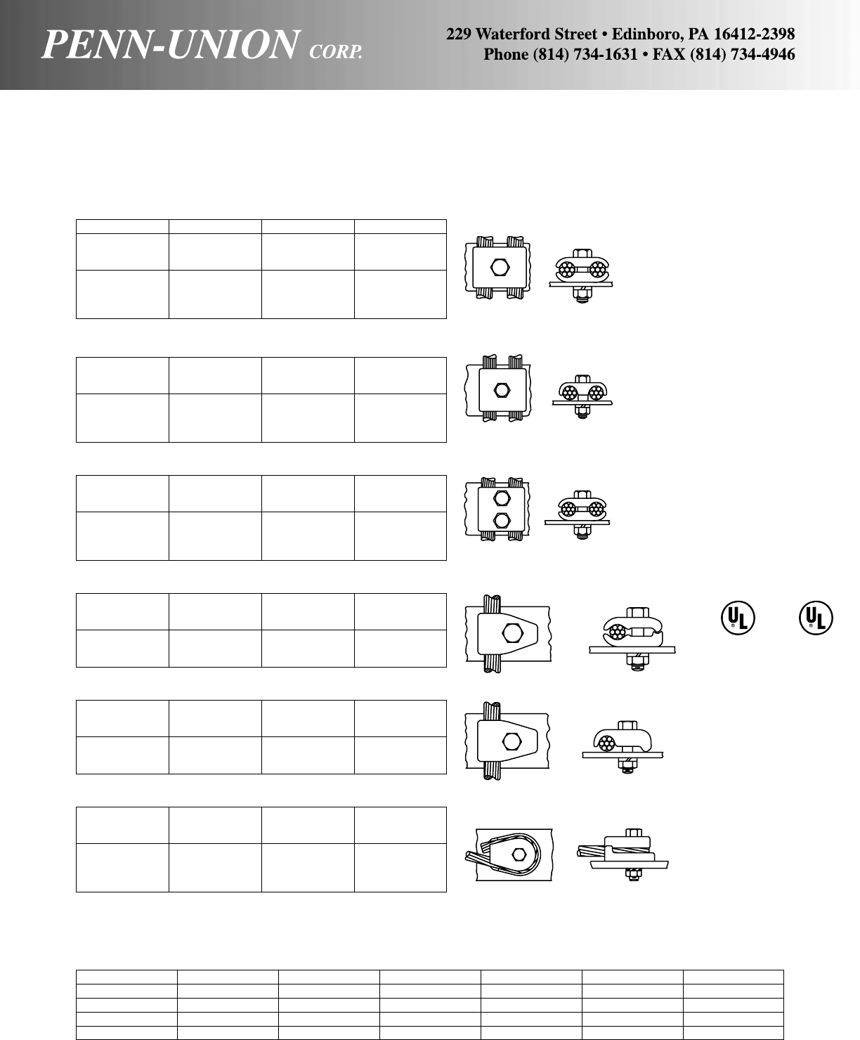
GROUND CLAMP CONNECTORS
For clamping cable or wires to flat bar.
Type GH
Penn-Union Anderson Burndy Dossert
GH-1 – GC-4C4C GA-4
GH-2 GC-143-01 GC-2626 GA-13
GH-3 GC-143A-02 GC-2929 GA-25
GH-4 GC-143-03 GC-3434 GA-50
GH-5 – ** **
GH-6 – ** **
GH-7 – – –
Type GHS
GHS-1 – GCM-4C GAM-4
GHS-2 GC-142-G1 GCM-26 GAM-13
GHS-3 GC-142-G2 GCM-29 GAM-25
GHS-4 GC-142-G3 GCM-34 GAM-50
GHS-5 – ** **
GHS-6 – ** **
GHS-7 – – –
Type GJ
GJ-1 – GL-4C4C GAA-4
GJ-2 GC-144-01 GL-2626 GAA-13
GJ-3 GC-144-02 GL-2929 GAA-25
GJ-4 GC-144-03 GL-3434 GAA-50
GJ-5 – ** **
GJ-6 – ** **
GJ-7 – – –
Type GM
GM-1 • – GB-4C GF-4
GM-2 • ** GB-26 GF-13
GM-3 • ** GB-29 GF-25
GM-4 GC-141-03 GB-34 GF-50
GM-5 – GB-39 **
GM-6 GC-141-10 ** **
Type GMS
GMS-1 • – GBM-4C GFM-4
GMS-2 • GC-140-01 GBM-26 GFM-13
GMS-3 • GC-140-02 GBM-29 GFM-25
GMS-4 GC-140-03 GBM-34 GFM-50
GMS-5 ** ** **
GMS-6 ** GBM-44 **
Type GWL
GWL-1 • GC-126-01 GZ-4C-38 GL-4-38
GWL-2 • – GZ-4C-12 GL-4-50
GWL-3 • GC-126-02 GZ-26-38 GL-13-38
GWL-4 • – GZ-26-12 GL-13-50
GWL-5 • GC-126-03 GZ-29-38 GL-25-38
GWL-6 • – GZ-29-12 GL-25-50
GWL-7 • – GZ-29-58 GL-25-63
**Cable range different. Consult factory for your need.
•UL and CUL listed suitable for direct burial
CONTACT COMPOUND
Penn-Union Anderson Blackburn Burndy Dossert Ilsco T & B
–155 – PENETROX A Z5 – 21059 (1/2 pt. only)
–200-GM – PENETROX A2 – – –
CUAL-AID #11C 173 Contax Type CT PENETROX A13 ZH DE-OX –
CUAL-AID #12C 173-GM – PENETROX A14 – – –
All of above must specify quantity volume (1/2 pt. Flask, Pint Can, Quart Can or 5 Gallon Can).
CUAL-AID #11 & 12 are synthetic based which may be substituted for petroleum based product.
165
COMPARATIVE LISTING (UL & CSA FOR PENN-UNION)
GROUNDING CONNECTORS
SUITABLE FOR
DIRECT BURIAL
C
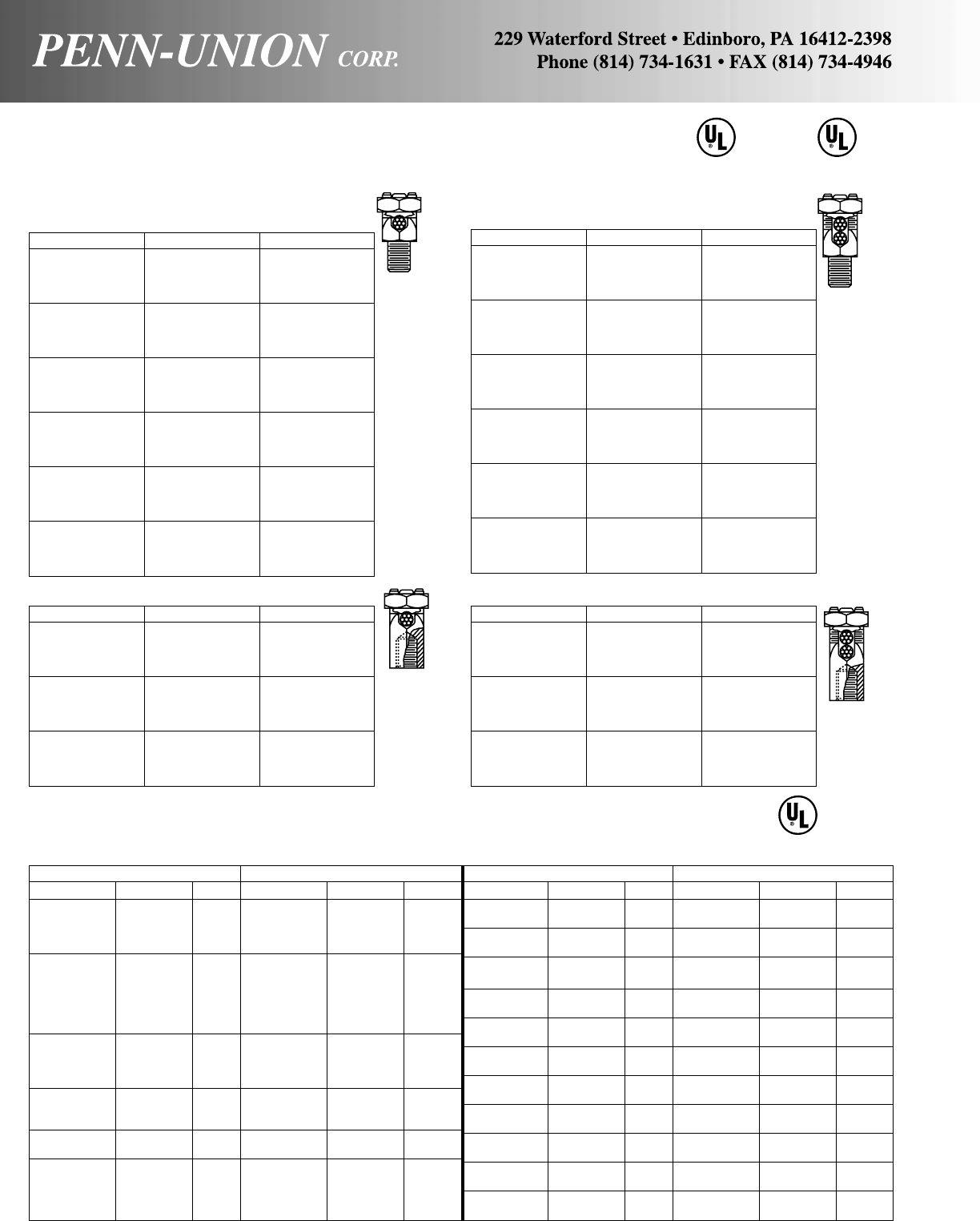
Penn-Union Burndy Dossert
SDS-0 K2F-15 DGF-1
SDS-1 K2F-17 DGF-2
SDS-2 K2F-20 DGF-3
SDS-3 K2F-22 DGF-5
SDS-4 K2F-23 DGF-6
SDS-5 K2F-25 DGF-10
SDS-6 K2F-26 DGF-13
SDS-8 K2F-28 DGF-21
SDS-9 K2F-31 DGF-35
SDS-10 K2F-34 DGF-50
SDS-11 K2F-39 DGF-75
SDS-12 K2F-44 DGF-100
COMPARATIVE LISTING (UL & CSA FOR PENN-UNION)
SERVICE POST CONNECTORS
BRONZE SERVICE POSTS
Male Type – For one cable
Penn-Union Burndy Dossert
SSS-0 KC-15 DGN-1
SSS-0A1 KC-15B1 –
SSS-1 KC-17* DGN-2
SSS-1A1 KC-17B1* –
SSS-2 KC-20 DGN-3
SSS-2A1 KC-20B1 –
SSS-3 KC-22* DGN-5
SSS-3A1 KC-22B1* –
SSS-4 KC-23* DGN-6
SSS-4A1 KC-23B1* –
SSS-5 KC-25 DGN-10
SSS-5A1 KC-25B1 –
SSS-6 KC-26* DGN-13
SSS-6A1 KC-26B1* –
SSS-8 KC-28* DGN-21
SSS-8A1 KC-28B1* –
SSS-9 KC-31* DGN-35
SSS-9A1 KC-31B1* –
SSS-10 KC-34* DGN-50
SSS-10A1 KC-34B1* –
SSS-11 KC-39 DGN-75
SSS-11A1 KC-39B1 –
SSS-12 KC-44* DGN-100
SSS-12A1 KC-44B1* –
Female Type – For one cable
Penn-Union Burndy Dossert
STS-0 KF-15 DGG-1
STS-1 KF-17 DGG-2
STS-2 KF-20* DGG-3
STS-3 KF-22* DGG-5
STS-4 KF-23* DGG-6
STS-5 KF-25 DGG-10
STS-6 KF-26 DGG-13
STS-8 KF-28* DGG-21
STS-9 KF-31* DGG-35
STS-10 KF-34* DGG-50
STS-11 KF-39* DGG-75
STS-12 KF-44* DGG-100
*Difference in minimum wire size.
Male Type – For two cables
Penn-Union Burndy Dossert
SCS-0 K2C-15 DGM-1
SCS-0A1 K2C-15B1 –
SCS-1 K2C-17 DGM-2
SCS-1A1 K2C-17B1 –
SCS-2 K2C-20 DGM-3
SCS-2A1 K2C-20B1 –
SCS-3 K2C-22 DGM-5
SCS-3A1 K2C-22B1 –
SCS-4 K2C-23 DGM-6
SCS-4A1 K2C-23B1 –
SCS-5 K2C-25 DGM-10
SCS-5A1 K2C-25B1 DGM-10L
SCS-6 K2C-26 DGM-13
SCS-6A1 K2C-26B1 –
SCS-8 K2C-28 DGM-21
SCS-8A1 K2C-28B1 –
SCS-9 K2C-31 DGM-35
SCS-9A1 K2C-31B1 –
SCS-10 K2C-34 DGM-50
SCS-10A1 K2C-34B1 –
SCS-11 K2C-39 DGM-75
SCS-11A1 K2C-39B1 –
SCS-12 K2C-44 DGM-100
SCS-12A1 K2C-44B1 –
Female Type - For two cables
166
SUITABLE FOR
DIRECT BURIAL
C
SUITABLE FOR
DIRECT BURIAL
Penn-Union Corp. Polaris/NSI
Catalog No. Wire Range Entry Catalog No. Wire Range Entry
IPB-NA4-2D 4-14 Sol. Dual ITO-4 4-14 Sol. Alternate
IPB-NA4-2S 4-14 Sol. Single IT-4 4-14 Sol. Single
IPB-NA4-4D 4-14 Sol. Dual IPL-4-4 4-14 Sol. Single
IPB-NA4-4S 4-14 Sol. Single IPL-4-4 4-14 Sol. Single
IPB-NA2/0-2S 2/0-14 Sol. Single IT-1/0 1/0-14 Single
IPB-NA2/0-2D 2/0-14 Sol. Dual ITO-1/0 1/0-14 Alternate
IPB-NA2/0-3D 2/0-14 Sol. Dual IPL-1/0-3 1/0-14 Single
IPB-NA2/0-4D 2/0-14 Sol. Dual IPL-1/0-4 1/0-14 Single
IPB-NA2/0-4S 2/0-14 Sol. Single IPL-1/0-4 1/0-14 Single
IPB-NA2/0-6D 2/0-14 Sol. Dual IPL-1/0-6 1/0-14 Single
IPB-NA250-2D 250-10 Sol. Dual IT-3/0 3/0-6 Single
ITO-3/0 3/0-6 Alternate
IT-250 250-6 Dual (2X1)
IPL-250-2 250-6 Single
IPB-NA250-3D 250-10 Sol. Dual IPL-3/0-3 3/0-6 Single
IPL-250-3 250-6 Single
IPLD-250-3 250-6 Dual
IPB-NA250-4D 250-10 Sol. Dual IPL-250-4 250-6 Single
IPLD-250-4 250-6 Dual
IPB-NA250-6D 250-10 Sol. Dual IPL-250-6 250-6 Single
IPLD-250-6 250-6 Dual
Aluminum Clear Insulated Power Bar
Penn-Union Corp. Polaris/NSI
Catalog No. Wire Range Entry Catalog No. Wire Range Entry
IPB-NA250-8D 250-10 Sol. Dual IPL-250-8 250-6 Single
IPLD-250-8 250-6 Dual
IPB-NA350-2D 350-10 Sol. Dual IT-350 350-6 Dual (2X1)
IPL-350-2 350-6 Single
IPB-NA350-3D 350-10 Sol. Dual IPL-350-3 350-6 Single
IPLD-350-3 350-6 Dual
IPB-NA350-4D 350-10 Sol. Dual IPL-350-4 350-6 Single
IPLD-350-4 350-6 Dual
IPB-NA350-6D 350-10 Sol. Dual IPL-350-6 350-6 Single
IPLD-350-6 350-6 Dual
IPB-NA350-8D 350-10 Sol. Dual IPL-350-8 350-6 Single
IPLD-350-8 350-6 Dual
IPB-NA500-2D 500-6 Sol. Dual IT-500 500-4 Dual (2X1)
IPL-500-2 500-4 Single
IPB-NA500-3D 500-6 Sol. Dual IPL-500-3 500-4 Single
IPLD-500-3 500-4 Dual
IPB-NA500-4D 500-6 Sol. Dual IPL-500-4 500-4 Single
IPLD-500-4 500-4 Dual
IPB-NA500-6D 500-6 Sol. Dual IPL-500-6 500-4 Single
IPLD-500-6 500-4 Dual
IPB-NA500-8D 500-6 Sol. Dual IPL-500-8 500-4 Single
IPLD-500-8 500-4 Dual
486B LISTED
AL9CU
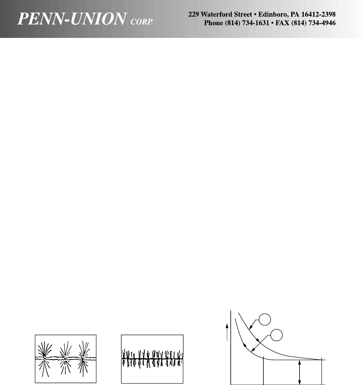
General Comments On Connectors
Wherever there is a conductor carrying electric current, it is nec-
essary to make a connection. This is true whether the conductor is
a solid or stranded wire, a rectangular bus bar or a piece of copper
pipe. This also is true whether the conductor is an inch in length, a
foot in length, or several hundred feet in length. Conductors are
joined by several methods. The oldest methods are the fusion of
conductors by means of soldering, brazing or welding, with the
very oldest being the blacksmith form of welding. Joining tech-
niques of this type require special skill and special equipment, con-
sequently, other means have been developed which are more gen-
erally applied. These are the pressure method which is divided
between the bolted or mechanical type joint and the compression
type connector which uses special tools to develop the necessary
forces. One other joining technique that is frequently used is sol-
dering. However, this has its limitations, because of the possibility
of the joint’s melting out during temporary overload conditions.
Connector Materials
Since most electrical conductors are either copper or aluminum, it
also has become standard for the connector industry to make con-
nectors of copper and aluminum. The category of copper connec-
tors includes pure copper and alloys of bronze and brasses; these
materials can be fabricated by casting, forging, extruding, punch-
ing, or any combination of these processes. The aluminum con-
nectors are made of alloys used to provide the best electrical con-
ductivity; however, in some cases, a compromise material is used
to give optimum combination of electrical conductivity and mechani-
cal strength. A general practice has been to use copper connec-
tors for copper conductor and aluminum connectors for aluminum
conductor. In some cases where a transition from copper to alumi-
num conductors must be made, it is advantageous to use a bime-
tallic connector, thus making the transition in the connector rather
than in the junction of the connector and conductor.
Welding Connectors
Welding, particularly of aluminum bus, has become increasingly
popular because the materials are united in a homogeneous bond.
The bus can be joined directly, or through the use of weldments.
Weldments eliminate the need for field cutting and matching. They
also act as fixtures and help align the bus structure during erec-
tion. Tungsten inert gas (TIG) has become increasingly popular
for joining of aluminum conductors.
Pressure Connectors–Bolted and
Compression
The simplest and most widely used method of joining conductors
is by means of externally applied pressure. This pressure can be
developed by means of clamp type connectors using bolts and
nuts or by compression connectors using special compression tools
to develop the necessary forces.
As two surfaces are brought together to make a joint, the micro-
scopic peaks touch each other as shown in Figure 1. As force
continues to be applied, the relatively few peaks flatten out into a
large number of plateaus and current is transferred across the in-
terface. This relationship is clearly shown in Figure 2 in which re-
sistance is plotted against force. The important thing about this
relationship is that once sufficient force has been applied to estab-
lish a safe value of resistance, considerable relaxation can occur
before the resistance starts to rise again. A well designed clamp or
compression connector thus has some safety factor built into it
right from the beginning.
All clamp type connectors depend upon the thrust developed by
the bolts to deliver the force necessary for a sound, stable con-
nection. For a bolt to do its job, it must have adequate strength so
that it can be torqued up properly, it must develop correct thrust for
the installation torque recommended, and above all, it must be
reliable and not fail during service.
Figure 2. Contact resistance curves.Figure 1. As force is increased the surface roughness flattens out
creating a multiplicity of parallel paths.
A
B
Tightening
Relaxing
Contact Force
F2R1F1
Contact
Resistance
167
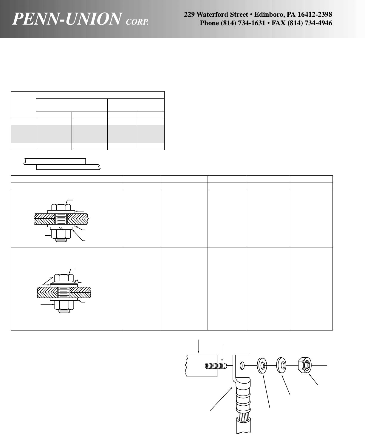
Table I shows the recommended tightening torques for silicon
bronze, stainless steel, galvanized steel and aluminum alloy hard-
ware. The shaded portion represents torques presently recom-
mended by NEMA-CC1-1984 specification.
For optimum efficiency, it is necessary that the correct bolt, nut
and washer combination be used with the correct combination of
conductor materials. Table II shows acceptable methods of joining
different combinations of bus bar. Where different combinations of
metals are being joined, a follow-up device such as a conical pres-
sure washer is usually recommended if one, or both, bus materi-
als are soft drawn aluminum. If both bars are hard drawn, large flat
washers will suffice regardless of the bolt materials.
Other considerations which should be taken into account when
selecting hardware are corrosion and vibration. For example, if
severe corrosion is anticipated, non-corrosive materials such as
stainless steel or silicon bronze, should be selected in preference
to galvanized steel. If vibration is anticipated, the use of locking
washers should be considered.
TABLE I
TIGHTENING TORQUES
Nominal Torque Values
Silicon Bronze, Aluminum Alloy
Bolt Galvanized or Stainless Steel (Lubricated)
Diameter Ft.-Lbs. Inch-Lbs. Ft.-Lbs. Inch-Lbs.
5/16-18 15 180 – –
3/8-16 20 240 14 168
1/2-13 40 480 25 300
5/8-11 55 660 40 480
3/4-10 80 960 70 840
If “A” Bar is Copper Aluminum Steel Aluminum Steel
and If “B” Bar is Copper Copper Copper Aluminum Aluminum
Hard Drawn Bus such as aluminum alloy. (1) Silicon (1) Silicon (1) Silicon (1) Aluminum (1) Aluminum
Bronze Bronze Bronze
(2) Stainless (2) Aluminum (2) Stainless (2) Stainless (2) Stainless
Steel Steel Steel Steel
(3) Stainless
Steel
(3) Silicon
Bronze,
Plated
Soft Drawn Bus such as EC-H13 Aluminum. (1) Silicon (1) Silicon (1) Silicon (1) Aluminum (1) Aluminum
Bronze Bronze Bronze
(2) Stainless (2) Aluminum (2) Stainless (2) Stainless (2) Stainless
Steel Steel Steel Steel
(3) Stainless (3) Silicon (3) Conical
Steel Bronze Pressure
Plated Washer
(4) Conical (4) Conical Plated or
Pressure Pressure Stainless
Washer Washer Steel
Plated or Plated or
Stainless Stainless
Steel Steel
TABLE II
METHODS OF JOINING BUS BARS
Bar Connections
The tang of a compression or a mechanical connector is a bus
bar, which connects to another bus bar. If you remember the rule
about wire brushing and using joint compound with bare (unplated)
aluminum, you cannot go wrong. Plated parts should be cleaned
with a solvent if they are dirty, but never abrade or otherwise dis-
turb the plating! Fig. 3 shows a typical bar connection and the type
of hardware used.
Bus bar
(1) Denotes preferred hardware usage
Note: Contact sealant recommended between aluminum to aluminum and
aluminum to copper connections, unless other protective measures are taken.
Steel or
copper stud
Compression or
mechanical type
connector
Chrome or stainless
steel flat washer
Conical pressure
washer
Nut
(usually steel)
Bolt
Large
Flat Washer
Large
Flat Washer
Nut Split or tooth
lock washer
Large
Flat
Washer
Bolt
Large
Flat Washer
Nut
Conical
Pressure
Washer
A
B
Figure 3. Contact surfaces must be clean. Use a joint compound
with bare aluminum. Conical pressure washer is usually recom-
mended if one, or both, bus materials are soft drawn aluminum.
168

Of all the methods used to make electrical connections, compres-
sion of the connector onto the cable with some type of compres-
sion tool is considered by most installers to be the most perma-
nent of the common connection methods. To maintain Underwrit-
ers Laboratories Listing (UL) or Canadian Standards Association
Certification (CSA) for a completed compression connection, it is
necessary to use the installation tools and installation methods
which have been qualified for the connectors by those organiza-
tions during the listing/certification processes.
Cable preparation
It is imperative that the cable strands and the compression con-
nector be clean and free of dirt and/or corrosion. This is particu-
larly important when making connections on cables which have
been installed for a period of time.
Connectors which are Underwriters Laboratories Listed or Cana-
dian Standards Association Certified may contain installation in-
structions in the connector carton which may include information
such as usable cable types, insulation strip lengths, and crimping
tools for specific connectors. Proper preparation of the cable can
make the difference between a permanent connection and a con-
nection which may require a service call at some point in the fu-
ture.
The cable material will dictate the type of connector which can be
used in the compression connection. Copper cable can be installed
in a copper compression connector which as a “CU” rating or in an
aluminum compression connector which has a “AL9CU” rating.
Aluminum cable on the other hand can ONLY be installed in an
aluminum compression connector which has a rating of “AL” or
“AL7CU”. ALUMINUM CABLE CAN NEVER BE INSTALLED IN A
COPPER COMPRESSION CONNECTOR.
Once the cable preparation has been accomplished and the proper
type and size of compression connector has been selected, the
connector manufacturer’s recommendations for choice of compres-
sion tooling and compression methods should be followed to main-
tain the UL and/or CSA rating for the completed connection. Con-
nector manufacturers will often be in a position to specify several
equivalent UL/CSA crimping recommendations for a specific con-
nector installation. For connectors from No. 22 AWG through No.
10 AWG the compression tools most often have mechanical op-
eration. For No. 8 AWG through 4/0 AWG the compression tools
could use either mechanical or hydraulic means to apply the crimp-
ing force. Historically at 250 kcmil and above in wire size, the crimp-
ing force was almost always applied by a hydraulic crimping tool.
With the advent of the TDM500 that has changed to 500 kcmil due
to the extra available leverage generated by the extendable
handles. Mechanical tools for small wire sizes are generally single
leverage types, while those for the medium sized cables apply the
crimping force via a compound leverage system. Mechanical crimp-
ing tools make either a surrounding type of crimp (Fig. 4A) or a
nest and indentor crimp shape (Fig. 4B). The hydraulic crimping
Compression connector crimping methods
To retain UL or CSA rating, Installation tools and methods must be matched to the connectors used
tools used for the medium and the large cable sizes can have
quite a variety of crimping die systems and hydraulic pressure
sources.
Die-type crimpers
The die-type tools require that a separate set of inserts be placed
into the crimping tool head for each different size and type (AL or
CU) of connector that is to be crimped. These crimping die inserts
are shaped to compress their specific connector size the correct
amount when the full force of the hydraulic system of the tool is
applied to them. Die type crimping tools generally produce crimps
that surround the barrel of the connector with either a rounded
oval or a hexagonally shaped outer surface.
Many of the copper and the aluminum connectors used in the elec-
trical contracting industry have a color code applied to them which
matches up with a crimping die reference of the same color. This
color code is meant to allow the installer to be able to find the
correct die more quickly from as many as several dozen die sets
that may be required to crimp all of the connectors within the in-
stallation range of the specific hydraulic crimping tool.
Certain styles of connectors used in the electric utility industry are
designed to minimize the number of crimping die sets that each
line crew must carry. These special connectors are designed to
have a constant outside diameter on the crimp barrel portion of
the connector with various inside diameter to match conductor size.
For example, a popular grouping of electric utility connectors has
a constant outside diameter of 0.640 inches for a series of cable
sizes from No. 10 AWG through 1/0 AWG and all of the individual
connectors are crimped with the same die insert. Electric utilities
also use a series of compression taps with a cross section shape
similar to the letter “H” which are grouped to install most cable size
combinations between No. 6 AWG and 500 kcmil with only three
crimping die sizes.
Dieless crimpers
The other class of hydraulic crimping tools are the dieless tools.
Dieless actually means that there is no die insert change needed
when one needs to crimp a different connector size within the range
of the tool. The dieless hydraulic tools can be further classified by
the three general crimp shapes that are made. One group of dieless
tools makes crimps which are of the nest and indentor style with
the next being a stationary portion of the tool and the indentor
moving with the hydraulic ram. A second grouping of dieless tools
makes use of multiple indentors which indent the connector from
multiple sides without the use of a nest. The third group of dieless
tools provides a crimp which surrounds the connector barrel and
has an appearance more like that of a die type tool than either of
the two indentor style dieless tools can provide. All of the dieless
tool types are capable of crimping cylindrical connector barrels as
recommended by their respective manufacturers.
FIGURE
4A
Surrounding crimp types
FIGURE
4B
Indent 169
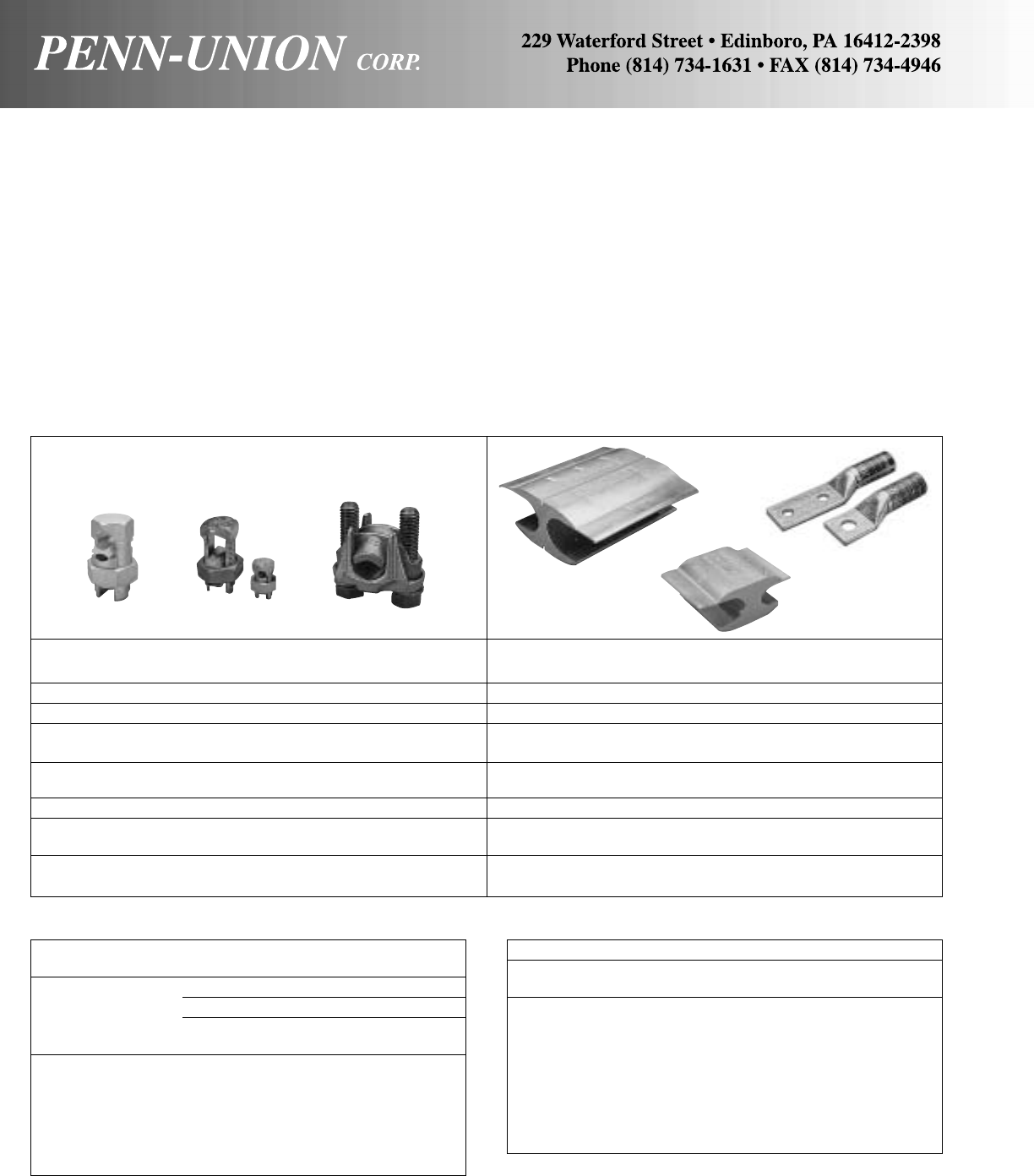
CONNECTOR COMPARISON CHART
MECHANICAL VS. COMPRESSION
The variety of connectors available to the utility engineer can be
broken down into 2 general categories – bolted and compressed.
The pros and cons of these different methods of making electrical
connections are often puzzling to engineers and consultants. The
following chart has been prepared in an effort to clarify thinking on
this subject and to provide a yardstick for making a basic decision
on connection methods.
Mechanical or Clamp Crimp or Compression
Connectors Connectors
Range taking and non-range taking. For pipe, cable, bar shapes, etc. Range taking and non-range taking. For cable conductors only.
Many designs are “universal” for copper or aluminum. Separate designs required for aluminum, or aluminum to copper.
Salvageable. Conductor can be removed and replaced if necessary. Not salvageable. Conductor and connector must be cut-off and
Wiring changes easily made. scrapped if change is necessary.
Short runs and specials easily handled by manufacturer with better Non-standard designs and modifications may be difficult to supply.
delivery.
Taping depends on design. Easily taped.
Installed cost comparable on small jobs–higher on large volume jobs. Installed cost generally lower, particularly where large quantities are
involved.
No special tools to install. Can use screwdriver, pliers, wrench. Special tools and dies required. If wrong tool or die is used, poor joint
results.
Some dieless tool brands of each type are also recommended by
their manufacturers to be able to provide cable range-taking capa-
bilities (a single connector size could be used for more than one
cable size) under very specific conditions of connector brand; cata-
log number; cable sizes; and installation procedure for which these
tool manufacturers have tested and obtained UL and/or CSA
listing.
The necessity to maintain UL Listing and/or CSA Certification for a
connector installation can limit the available combinations of con-
nectors and crimp tools which can be used in a specific situation.
Dieless compression tool systems offer decided advantages in in-
stallation flexibility and time saving, particularly if both cylindrical
and H-frame connectors can be installed with a single dieless tool.
170
Smaller than No. 10 intended for
use with No. 8 AWG or smaller conductors
Tightening Torque, Pound-Inches (N•m)
Slot Width of Screw, inch (mm)a
Slot Length of Smaller Than 0.047 (1.2)
Screw, Inch (mm)b0.047 (1.2) and Larger
Less than 5/32 (4) 7 (0.79) 9 (1.0)
5/32 (4) 7 (0.79) 12 (1.4)
3/16 (4.8) 7 (0.79) 12 (1.4)
7/32 (5.6) 7 (0.79) 12 (1.4)
1/4(6.4) 9 (1.0)912 (1.4)
9/32 (7.1) 15 (1.7)
Above 9/32 (7.1) 20 (2.3)
a Slot width is the nominal design value.
b For slot lengths of intermediate values, select torques pertaining to next
shorter slot length. Slot length is to be measured at the bottom of the
slot.
Socket Head Screws
Socket Size Tightening Torque,
Across Flats, Inch (mm) Pound-Inches (N•m)
1/8 (3.2) 45 (5.1)
5/32 (4.0) 100 (11.3)
3/16 (4.8) 120 (13.6)
7/32 (5.6) 150 (16.9)
1/4 (6.4) 200 (22.6)
5/16 (7.9) 275 (31.1)
3/8 (9.5) 375 (42.4)
1/2(12.7) 500 (56.5)
9/16 (14.3) 600 (67.8)
TIGHTENING TORQUE BY BOLT TYPE

Indoor Capacity
Nominal Approx. for 30°C Temp. Rise
Size Outside Inside Wall Area Weight NEMA CC1-1984 Ratings
Inches Diameter Diameter Thickness Sq. Sq. Lbs./ Indoors Outdoors
(IPS) Inches† Inches Inches Inches CM Ft. Amps. Amps.
3/8.675 .494 .0905 .166 1.06 .641 – –
1/2.840 .625 .1075 .247 1.59 .955 380 510
3/41.050 .822 .1140 .335 2.16 1.30 540 710
11.315 1.062 .1265 .472 3.04 1.83 650 850
11/41.660 1.368 .1460 .694 4.48 2.69 870 1,120
Standard 11/21.900 1.600 .1500 .825 5.32 3.20 1,020 1,280
Copper 2 2.375 2.062 .1565 1.09 7.03 4.23 1,250 1,550
Pipe† 21/22.875 2.500 .1875 1.58 10.2 6.12 1,700 2,000
33.500 3.062 .2190 2.26 14.6 8.75 2,175 2,550
31/24.000 3.500 .2500 2.95 19.0 11.4 2,575 3,050
44.500 4.000 .2500 3.34 21.5 12.9 2,850 3,400
55.563 5.063 .2500 4.17 26.9 16.2 3,450 4,100
66.625 6.125 .2500 5.01 32.3 19.4 4,000 4,700
88.625 8.000 .3125 8.16 52.6 31.6 – –
10 10.750 10.019 .3655 11.9 76.8 46.2 – –
1/4.540 .294 .123 .161 1.04 .624 – –
3/8.675 .421 .127 .219 1.41 .847 – –
1/2.840 .542 .149 .323 2.08 1.25 420 580
3/41.050 .736 .157 .440 2.84 1.71 590 780
Extra 1 1.315 .951 .182 .648 4.18 2.51 750 1,010
Strong 11/41.660 1.272 .194 .893 5.67 3.46 975 1,250
Copper 11/21.900 1.494 .203 1.08 6.97 4.19 1,150 1,450
Pipe 2 2.375 1.933 .221 1.49 9.68 5.79 1,500 1,850
21/22.875 2.315 .280 2.29 14.7 8.84 1,975 2,400
33.500 2.892 .304 3.05 19.7 11.8 2,475 2,950
31/24.000 3.358 .321 3.71 23.9 14.4 2,875 3,400
44.500 3.818 .341 4.45 28.8 17.3 3,100 3,800
55.563 4.813 .375 6.11 39.4 23.7 3,850 4,600
66.625 5.751 .437 8.49 54.8 32.9 4,500 5,200
88.625 7.625 .500 12.76 82.6 49.5 – –
10 10.750 9.750 .500 16.10 104 62.4 – –
ASTM-B188
†Standard OD same as rigid steel conduit.
PROPERTIES OF COPPER PIPE
PROPERTIES OF EXTRUDED ALUMINUM PIPE
6063-T6 ALUMINUM ALLOY – 53% IACS
Schedule 40 Schedule 80
Nominal Nominal Nominal Nominal Nominal Nominal
Outside Inside Wall Nominal Current Outside Inside Wall Nominal Current
IPS Diameter Diameter Thickness Weight Rating Amperes IPS Diameter Diameter Thickness Weight Rating Amperes
Size Inches Inches Inches Lbs./Ft. Indoors* Outdoors† Size Inches Inches Inches Lbs./Ft. Indoors* Outdoors†
1/20.840 0.622 0.109 0.294 315 400 1/20.840 0.546 0.147 0.376 360 455
3/41.050 0.824 0.113 0.391 400 495 3/41.050 0.742 0.154 0.510 455 565
11.315 1.049 0.133 0.581 535 650 1 1.315 0.957 0.179 0.751 605 740
11/41.660 1.380 0.140 0.786 680 810 11/41.660 1.278 0.191 1.037 780 930
11/21.900 1.610 0.145 0.940 790 930 11/21.900 1.500 0.200 1.256 910 1070
22.375 2.067 0.154 1.264 1000 1155 2 2.375 1.939 0.218 1.737 1175 1355
21/22.875 2.469 0.203 2.004 1365 1550 21/22.875 2.323 0.276 2.650 1570 1780
33.500 3.068 0.216 2.621 1670 1895 3 3.500 2.900 0.300 3.547 1935 2195
31/24.000 3.548 0.226 3.151 1945 2170 31/24.000 3.364 0.318 4.326 2265 2530
44.500 4.026 0.237 3.733 2230 2460 4 4.500 3.826 0.337 5.183 2605 2880
55.563 5.047 0.258 5.057 2845 3080 5 5.536 4.813 0.375 7.188 3355 3635
66.625 6.065 0.280 6.564 3500 3735 6 6.625 5.761 0.432 9.884 4205 4490
*Indoor ratings are calculated for a 30
°
C rise above an ambient temperature of 40
°
C install but unconfined air and a surface emissivity, e. equal to 0.35.
†Outdoor ratings are given for a wind velocity of 2 feet per second, an ambient air temperature of 40
°
C, a conductor temperature of 70
°
C (30
°
C rise), and a surface
emissivity, e, equal to 0.50. (NEMA CC!-1984)
ANSI-H35.2-1990 (For Dimensional Data)
171
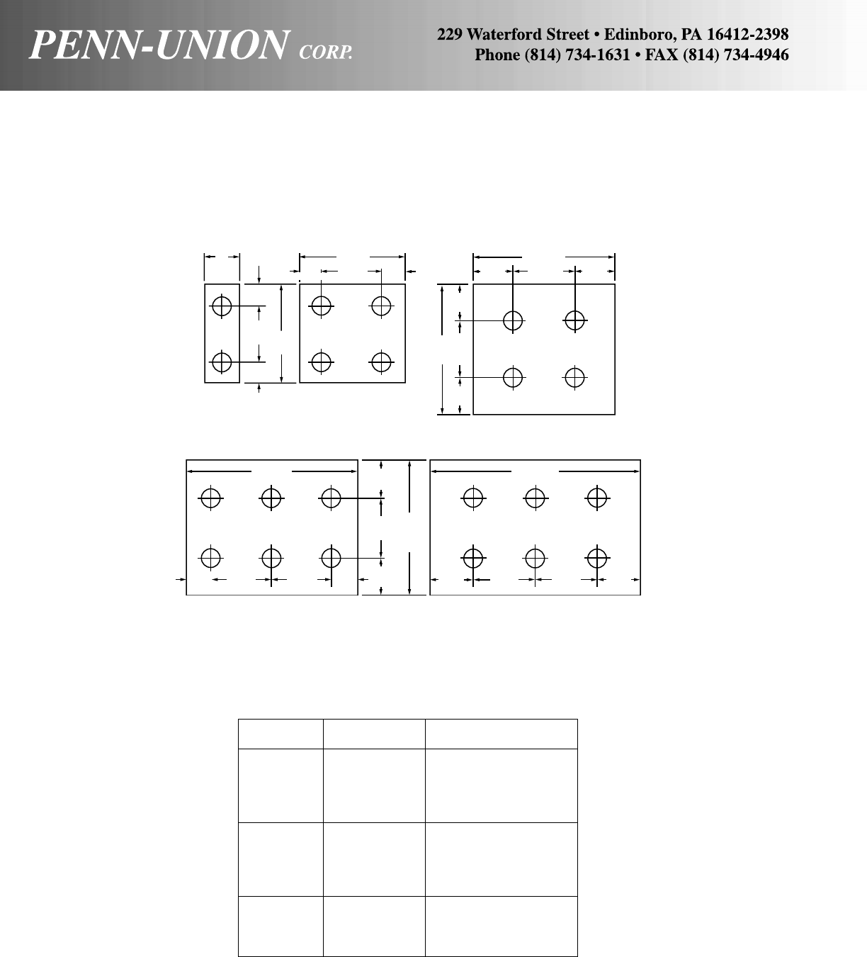
NEMA STANDARD TANGS
These figures show the arrangements of 9/16" bolt holes which
are standardized for electrical power connectors under NEMA
Standard CC1.
SOLDERLESS CONNECTORS
STUD SIZE AND CLEARANCE HOLE DIAMETER
Stud Stud Clearance
Size Diameter Hole Diameter
0.060 .091-.097
1.073 .091-.097
2.086 .091-.097
3.099 .117-.123
4.112 .117-.123
5.125 .143-.149
6.138 .143-.149
8.164 .170-.176
10 .190 .195-.201
12 .216 17/64
1/4.250 17/64
5/16 .312 21/64
3/8.375 25/64
1/2.500 33/64
1" Min.
(25 mm)
5/8"
(16 mm)
13/4"
(44 mm)
5/8"
(16 mm)
3"
(76 mm)
3"
(76 mm)
13/4"
(44 mm)
5/8"
(16 mm)
Penn-Union
Standard Suffix
–D
Penn-Union
Standard Suffix
–F
13/4"
(44 mm)
Penn-Union
Standard Suffix
–E
4"
(102 mm)
11/8"
(29 mm)
11/8"
(29 mm)
1
3
/
4
"
(44 mm)
4"
(102 mm)
11/8"
(29 mm)
11/8"
(29 mm)
11/8"
(28 mm)
Penn-Union
Standard Suffix
–G
Penn-Union
Standard Suffix
–H
13/4"
(44 mm) 13/4"
(44 mm) 13/4"
(44 mm) 13/4"
(44 mm)
4"
(102 mm)
1
3
/
4
"
(44 mm)
6"
(152 mm)
5"
(127 mm)
3/4"
(19 mm)
3/4"
(19 mm)
11/8"
(28 mm) 11/4"
(32 mm) 11/4"
(32 mm)
172
5/8"
(16 mm)

CATALOG NUMBER SUFFIX LEGEND
SMH Stud Mounting Hardware
SF Side Formed Tongue
SStreet Light Adapter (DBA Series)
SStud for UTS, UTSA
SSlotted Hex Hd FF
SSlotted Holes Braid
SPEC Special
SC Screw
SKH Socket Head
SP Shakeproof
SH Shear Head
SH Stud w/Hdw for UTS, UTSA
SVC Silver Plate Complete
SLW Split Lockwasher
STH Steel Hardware
STL Steel
Terminal Blocks
SV White Vinyl Cover
SVC White Vinyl Cover w/Short Circuit Strip
SVVS Two Vinyl Covers w/Mark Cover
SC Short Circuit Strip
SCS Short Circuit Strip w/Marking Strip
SCC Short Circuit Strip w/Cover
ST Marking Strip w/Studs
STC Marking Strip w/Studs w/Cover
ST-SC Short Circuit Strip w/Studs
ST-SCS Short Circuit Strip w/Studs w/Marking Strip
TTapered Ends
TNC Tin Plated Complete
TN Tin Plated
TN3 Tin Plate .0003 Thick
TNB Tin Plated - Conical Pressure
TNF Tin & Flow
TMH Tongue Mounting Hardware
TD Tin Dipped
UA Unassembled
UUndrilled
UP Unplated
WT Water Tight
XF Extra Fine Wire
ZN Zinc Plated
AAluminum Hardware
BConical Pressure
BC Bronze Chromate Treatment
BM Base Mounting
BF Bagged & Filled (with Cual-Aid)
BL-TG Blank Tongue - (Do Not Use) - Use “U”
BP Bulk Packed
CCual-Aid
CUF Copper Flashed
CF Center Formed Tongue
CS Chatter Spring
DF Dead Front
FL Flared End
FT Full Thread U-Bolt
GF Grit Filled
GF Grind Finish
GP General Purpose - Tin (Hot Line Clamp)
GR Grit
HDW Hardware
HH Hex Head
LExtra Length
LH Left Hand Thread
LH Less Hardware
LS Less Shear
LS Less Spacer - AVT Cat. No.
LMH Less Mounting Hardware
NNEMA Hole Spacing in Pad
NI Nickel Plated
NH Less (No) Hardware
NM(*) Not Made
PPlated (Do Not Use)
PPlugged Center Stop
PMH Pad Mounting Hardware
PLN Plain
PT Plug & Tapered
QTin Plated Braid Ferrules
RH Right Hand
RW Restricted Width
SSTL Stainless Steel
SBH Silicon Bronze Hardware
SS Set Screw
SV Silver Plated
SVS Silver Plated .0005 Thick
173

174
FAX SHEET FOR FACTORY SPECIALS (No Catalog Numbers)
•Information Required at Factory.
• Conductor Type:
– Material (copper, aluminum, ACSR, flex weld, etc.) _______________________________________
– Size _____________________________________________ AWG, KCMIL, MCM, MM2 (circle one)
– Stranding (solid, strand, compact, etc.) ________________________________________________
– Bare, Plated, Insulated _____________________________________________________________
• Product Profile:
Type: Compression, mechanical _________________________________________________________
– Pad mounting (Number holes, blank) __________________________________________________
– Pad mounting hole size and location __________________________________________________
– Plating (Bare, tin or silver and thickness) _______________________________________________
– Standards or listings required (UL, CSA, ANSI, etc.) ______________________________________
– Special temperature requirements ____________________________________________________
– Mounting hardware required size & material (Bronze, Aluminum,
Steel, Stainless Steel) ______________________________________________________________
• Flexible Connectors:
Type: Braid, shunts, lamination, wire ____________________________________________________
– Circular mills, cross section, width, thickness ____________________________________________
– Ampacity ________________________________________________________________________
–Mounting style (No. holes, style, etc.) __________________________________________________
– Mounting hole size and location ______________________________________________________
– Plating (Braid, ends) bare or type _____________________________________________________
– Straight or shapes _________________________________________________________________
– Insulated (Heat shrink) _____________________________________________________________
– Pad size, (Width & thickness) ________________________________________________________
– Lamination (Type & size) ___________________________________________________________
• Attach sketch, photo, sample, drawing (very helpful).
Quantity initial order _________________________________________________________________
Estimated annual quantity ____________________________________________________________
CUSTOMER PROFILE:
Company Name _______________________________________________ SIC Code ___________
Address __________________________________________________________________________
City __________________________________________________ State__________ Zip _________
Your Name ____________________________________________ Title _______________________
Fax Number _________________________________ Telephone Number ______________________
Delivery Date Required ______________________________________________________________
Please make as many copies as you need.
MAILING/FAX DIRECTIONS: Fax to 814-734-4946
Attn: Customer Service
Or mail to: Customer Service, Penn-Union Corp., 229 Waterford Street, Edinboro, PA 16412-2398

MILLIMETER/DECIMAL/FRACTION CONVERSION CHART
Milli- Fraction Milli- Fraction Milli- Fraction Milli- Fraction Milli- Fraction
meter Decimal (inches) meter Decimal (inches) meter Decimal (inches) meter Decimal (inches) meter Decimal (inches)
0.1 .0039 5.159 .2031 13/64 10.2 .4016 15.3 .6024 20.3 .7992
0.2 .0079 5.2 .2047 10.3 .4055 15.4 .6063 20.4 .8031
0.3 .0118 5.3 .2087 10.319 .4063 13/32 15.478 .6094 39/64 20.5 .8071
0.397 .0156 1/64 5.4 .2126 10.4 .4094 15.5 .6102 20.6 .8110
0.4 .0157 5.5 .2165 10.5 .4134 15.6 .6142 20.638 .8125 13/16
0.5 .0197 5.556 .2188 7/32 10.6 .4173 15.7 .6181 20.7 .8150
0.6 .0236 5.6 .2205 10.7 .4213 15.8 .6220 20.8 .8189
0.7 .0276 5.7 .2244 10.716 .4219 27/64 15.875 .6250 5/8 20.9 .8228
0.794 .0313 1/32 5.8 .2283 10.8 .4252 15.9 .6260 21.0 .8268
0.8 .0315 5.9 .2323 10.9 .4291 16.0 .6299 21.034 .8281 53/64
0.9 .0354 5.953 .2344 15/64 11.0 .4331 16.1 .6339 21.1 .8307
1.0 .0394 6.0 .2362 11.1 .4370 16.2 .6378 21.2 .8346
1.1 .0433 6.1 .2402 11.113 .4375 7/16 16.272 .6406 41/64 21.3 .8386
1.191 .0469 3/64 6.2 .2441 11.2 .4409 16.3 .6417 21.4 .8425
1.2 .0472 6.3 .2480 11.3 .4449 16.4 .6457 21.431 .8438 27/32
1.3 .0512 6.350 .2500 1/4 11.4 .4488 16.5 .6496 21.5 .8465
1.4 .0551 6.4 .2520 11.5 .4528 16.6 .6535 21.6 .8504
1.5 .0591 6.5 .2559 11.509 .4531 29/64 16.669 .6563 21/32 21.7 .8543
1.588 .0625 1/16 6.6 .2598 11.6 .4567 16.7 .6575 21.8 .8583
1.6 .0630 6.7 .2638 11.7 .4606 16.8 .6614 21.828 .8594 55/64
1.7 .0669 6.747 .2656 17/64 11.8 .4646 16.9 .6654 21.9 .8622
1.8 .0709 6.8 .2677 11.9 .4685 17.0 .6693 22.0 .8661
1.9 .0748 6.9 .2717 11.906 .4688 15/32 17.066 .6719 43/64 22.1 .8701
1.984 .0781 5/64 7.0 .2756 12.0 .4724 17.1 .6732 22.2 .8740
2.0 .0787 7.1 .2795 12.1 .4764 17.2 .6772 22.225 .8750 7/8
2.1 .0827 7.144 .2813 9/32 12.2 .4803 17.3 .6811 22.3 .8780
2.2 .0866 7.2 .2835 12.3 .4843 17.4 .6850 22.4 .8819
2.3 .0906 7.3 .2874 12.303 .4844 31/64 17.463 .6875 11/16 22.5 .8858
2.381 .0938 3/32 7.4 .2913 12.4 .4882 17.5 .6890 22.6 .8898
2.4 .0945 7.5 .2953 12.5 .4921 17.6 .6929 22.622 .8906 57/64
2.5 .0984 7.541 .2969 19/64 12.6 .4961 17.7 .6968 22.7 .8937
2.6 .1024 7.6 .2992 12.7 .5000 1/2 17.8 .7008 22.8 .8976
2.7 .1063 7.7 .3031 12.8 .5039 17.859 .7031 45/64 22.9 .9016
2.778 .1094 7/64 7.8 .3071 12.9 .5079 17.9 .7047 23.0 .9055
2.8 .1102 7.9 .3110 13.0 .5118 18.0 .7087 23.019 .9063 29/32
2.9 .1142 7.938 .3125 5/16 13.097 .5156 33/64 18.1 .7126 23.1 .9094
3.0 .1181 8.0 .3150 13.1 .5157 18.2 .7165 23.2 .9134
3.1 .1220 8.1 .3189 13.2 .5197 18.256 .7188 23/32 23.3 .9173
3.175 .1250 1/8 8.2 .3228 13.3 .5236 18.3 .7205 23.4 .9213
3.2 .1260 8.3 .3268 13.4 .5276 18.4 .7244 23.416 .9219 59/64
3.3 .1299 8.334 .3281 21/64 13.494 .5313 17/32 18.5 .7283 23.5 .9252
3.4 .1339 8.4 .3307 13.5 .5315 18.6 .7323 23.6 .9291
3.5 .1378 8.5 .3346 13.6 .5354 18.653 .7344 47/64 23.7 .9331
3.572 .1406 9/64 8.6 .3386 13.7 .5394 18.7 .7362 23.8 .9370
3.6 .1417 8.7 .3425 13.8 .5433 18.8 .7402 23.813 .9375 15/16
3.7 .1457 8.731 .3438 11/32 13.891 .5469 35/64 18.9 .7441 23.9 .9409
3.8 .1496 8.8 .3465 13.9 .5472 19.0 .7480 24.0 .9449
3.9 .1535 8.9 .3504 14.0 .5512 19.050 .7500 3/4 24.1 .9488
3.969 .1563 5/32 9.0 .3543 14.1 .5551 19.1 .7520 24.2 .9528
4.0 .1575 9.1 .3583 14.2 .5591 19.2 .7559 24.209 .9531 61/64
4.1 .1614 9.128 .3594 23/64 14.288 .5625 9/16 19.3 .7598 24.3 .9567
4.2 .1654 9.2 .3622 14.3 .5630 19.4 .7638 24.4 .9606
4.3 .1693 9.3 .3661 14.4 .5669 19.447 .7656 49/64 24.5 .9646
4.366 .1719 11/64 9.4 .3701 14.5 .5709 19.5 .7677 24.6 .9685
4.4 .1732 9.5 .3740 14.6 .5748 19.6 .7717 24.606 .9688 31/32
4.5 .1772 9.525 .3750 3/8 14.684 .5781 37/64 19.7 .7756 24.7 .9724
4.6 .1811 9.6 .3780 14.7 .5787 19.8 .7795 24.8 .9764
4.7 .1850 9.7 .3819 14.8 .5827 19.844 .7813 25/32 24.9 .9803
4.763 .1875 3/16 9.8 .3858 14.9 .5866 19.9 .7835 25.0 .9843
4.8 .1890 9.9 .3898 15.0 .5906 20.0 .7874 25.003 .9844 63/64
4.9 .1929 9.922 .3906 25/64 15.081 .5938 19/32 20.1 .7913 25.1 .9882
5.0 .1969 10.0 .3937 15.1 .5945 20.2 .7953 25.2 .9921
5.1 .2008 10.1 .3976 15.2 .5984 20.241 .7969 51/64 25.3 .9961
25.400 1.0000 1
NOTE: Penn-Union manufactures its products only to commercial standards and sells its products only under commercial terms & conditions.
175
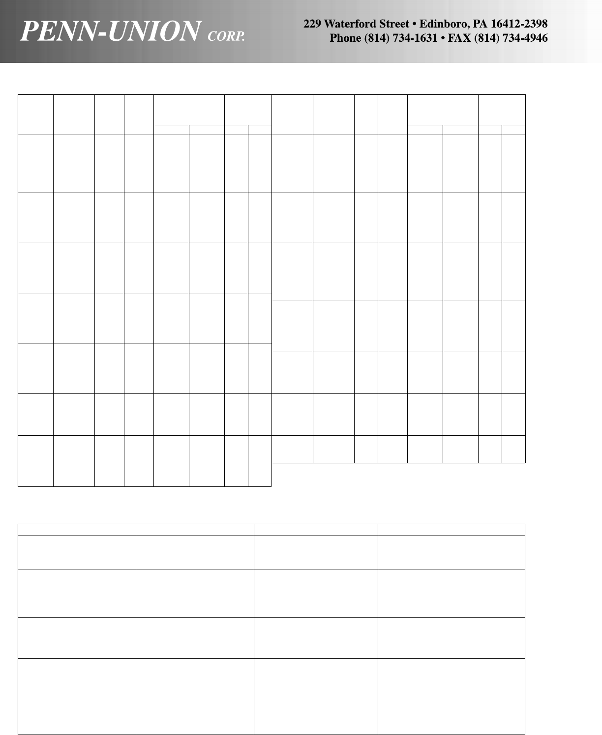
176
AWG VS. METRIC WIRE SIZES
DIESEL LOCOMOTIVE AND CAR WIRING CABLE
Conductor Stranding Approx. Size Awg Circular Mil Area Conductor Diameter Inches
19/.0117 16 2601 .060
19/27 14 3831 .070
19/25 12 6088 .090
27/24 10 10910 .123
37/24 8 14950 .140
61/24 6 24640 .180
91/24 5 36760 .220
105/24 4 42420 .240
125/24 3 50500 .260
150/24 2 60600 .325
225/24 1 90900 .390
275/24 1/0 111100 .420
325/24 2/0 131300 .460
450/24 3/0 181800 .565
550/24 4/0 222200 .590
650/24 262600 .660
775/24 313100 .740
925/24 373700 .790
1100/24 444400 .870
1325/24 535300 .940
1600/24 646400 1.025
1925/24 777700 1.120
2300/24 929200 1.230
2750/24 1111000 1.370
Stranding/
Metric Wire Approximate
Equivalent Wire Diameter Overall
Circ. Circ. Awg. Size Per Strand Diameter
Mils Mils Size mm2in mm in mm
–987 – 0.50 1/.032 1/.813 .032 0.81
1020 – 20 – 7/.0121 7/.307 .036 0.91
–1480 – 0.75 1/.039 1/.991 .039 0.99
1620 – 18 – 1/.0403 1/1.02 .040 1.02
1620 – 18 – 7/.0152 7/.386 .046 1.16
–1974 – 1.0 1/.045 1/1.14 .045 1.14
–1974 – 1.0 7/.017 7/.432 .051 1.30
2580 – 16 – 1/.0508 1/1.29 .051 1.29
2580 – 16 – 7/.0192 7/.488 .058 1.46
–2960 – 1.5 1/.055 1/1.40 .055 1.40
–2960 – 1.5 7/.021 7/5.33 .063 1.60
4110 – 14 – 1/.0641 1/1.63 .064 1.63
4110 – 14 – 7/.0242 7/.615 .073 1.84
–4934 – 2.5 1/.071 1/1.80 .071 1.80
–4934 – 2.5 7/.027 7/.686 .081 2.06
6530 – 12 – 1/.0808 1/2.05 .081 2.05
6530 – 12 – 7/.0305 7/.775 .092 2.32
–7894 – 4 1/.089 1/2.26 .089 2.26
–7894 – 4 7/.034 7/.864 .102 2.59
10380 – 10 – 1/.1019 1/2.59 .102 2.59
10380 – 10 – 7/.0385 7/.978 .116 2.93
–11840 – 6 1/.109 1/2.77 .109 2.77
–11840 – 6 7/.042 7/1.07 .126 3.21
13090 – 9 – 1/.1144 1/2.91 .1144 2.91
13090 – 9 – 7/.0432 7/1.10 .130 3.30
16510 – 8 – 1/.1285 1/3.26 .128 3.26
16510 – 8 – 7/.0486 7/1.23 .146 3.70
–19740 – 10 1/.141 1/3.58 .141 3.58
–19740 – 10 7/.054 7/1.37 .162 4.12
20820 – 7 – 1/.1443 1/3.67 .144 3.67
20820 – 7 – 7/.0545 7/1.38 .164 4.15
26240 – 6 – 1/.162 1/4.11 .162 4.11
26240 – 6 – 7/.0612 7/1.55 .184 4.66
–31580 – 16 7/.068 7/1.73 .204 5.18
33090 – 5 – 7/.0688 7/1.75 .206 5.24
41740 – 4 – 7/.0772 7/1.96 .232 5.88
–49340 – 25 7/.085 7/2.16 .255 6.48
–49340 – 25 19/.052 19/1.32 .260 6.60
52620 – 3 – 7/.0867 7/2.20 .260 6.61
66360 – 2 – 7/.0974 7/2.47 .292 7.42
–69070 – 35 7/.100 7/2.54 .300 7.62
–69070 – 35 19/.061 19/1.55 .305 7.75
Stranding/
Metric Wire Approximate
Equivalent Wire Diameter Overall
Circ. Circ. Awg. Size Per Strand Diameter
Mils Mils Size mm2in mm in mm
83690 – 1 – 19/.0664 19/1.69 .332 8.43
–98680 – 50 19/.073 19/1.85 .365 9.27
105600 – 1/0 – 19/.0745 19/1.89 .373 9.46
133100 – 2/0 – 19/.0837 19/2.13 .419 10.6
–138100 – 70 19/.086 19/2.18 .430 10.9
167800 – 3/0 – 19/.094 19/2.39 .470 11.9
167800 – 3/0 – 37/.0673 37/1.71 .471 12.0
–187500 – 95 19/.101 19/2.57 .505 12.8
–187500 – 95 37/.072 37/1.83 .504 12.8
211600 – 4/0 – 19/.1055 19/2.68 .528 13.4
–237.8 MCM–12037/.081 37/2.06 .567 14.4
250 MCM – – – 37/.0822 37/2.09 .575 14.6
300 MCM – – 150 37/.090 37/2.29 .630 16.0
350 MCM – – – 37/.0973 37/2.47 .681 17.3
–365.1 MCM–18537/.100 37/2.54 .700 17.8
400 MCM – – – 37/.104 37/2.64 .728 18.5
–473.6 MCM–24037/.114 37/2.90 .798 20.3
–473.6 MCM–24061/.089 61/2.26 .801 20.3
500 MCM – – – 37/.1162 37/2.95 .813 20.7
500 MCM – – – 61/.0905 61/2.30 .814 20.7
–592.1 MCM–30061/.099 61/2.51 .891 22.6
600 MCM – – – 61/.0992 61/2.52 .893 22.7
700 MCM – – – 61/.1071 61/2.72 .964 24.5
750 MCM – – – 61/.1109 61/2.82 .998 25.4
750 MCM – – – 91/.0908 91/2.31 .999 25.4
–789.4 MCM–40061/.114 61/2.90 1.026 26.1
800 MCM – – – 61/.1145 61/2.91 1.031 26.2
800 MCM – – – 91/.0938 91/2.38 1.032 26.2
1000 MCM 986.8 MCM – 500 61/.1280 61/3.25 1.152 29.3
1000 MCM – – – 91/.1048 91/2.66 1.153 29.3
–1233.7 MCM – 625 91/.117 91/2.97 1.287 32.7
1250 MCM – – – 91/.1172 91/2.98 1.289 32.7
1250 MCM – – – 127/.0992 127/2.52 1.290 32.8
1500 MCM – – – 91/.1284 91/3.26 1.412 35.9
1500 MCM – – – 127/.1087 127/2.76 1.413 35.9
–1578.8 MCM – 800 91/.132 91/3.35 1.452 36.9
–1973.5 MCM – 1000 91/.147 91/3.73 1.617 41.1
2000 MCM – – – 127/.1255 127/3.19 1.632 41.5
2000 MCM – – – 169/.1088 169/2.76 1.632 41.5
