106283 Catalog 1
2014-09-05
: Pdf 106283-Catalog 1 106283-Catalog_1 754554 Batch7 unilog
Open the PDF directly: View PDF ![]() .
.
Page Count: 44
www.siemens.com/sirius
Highly flexible system-based switching,
protecting and starting.
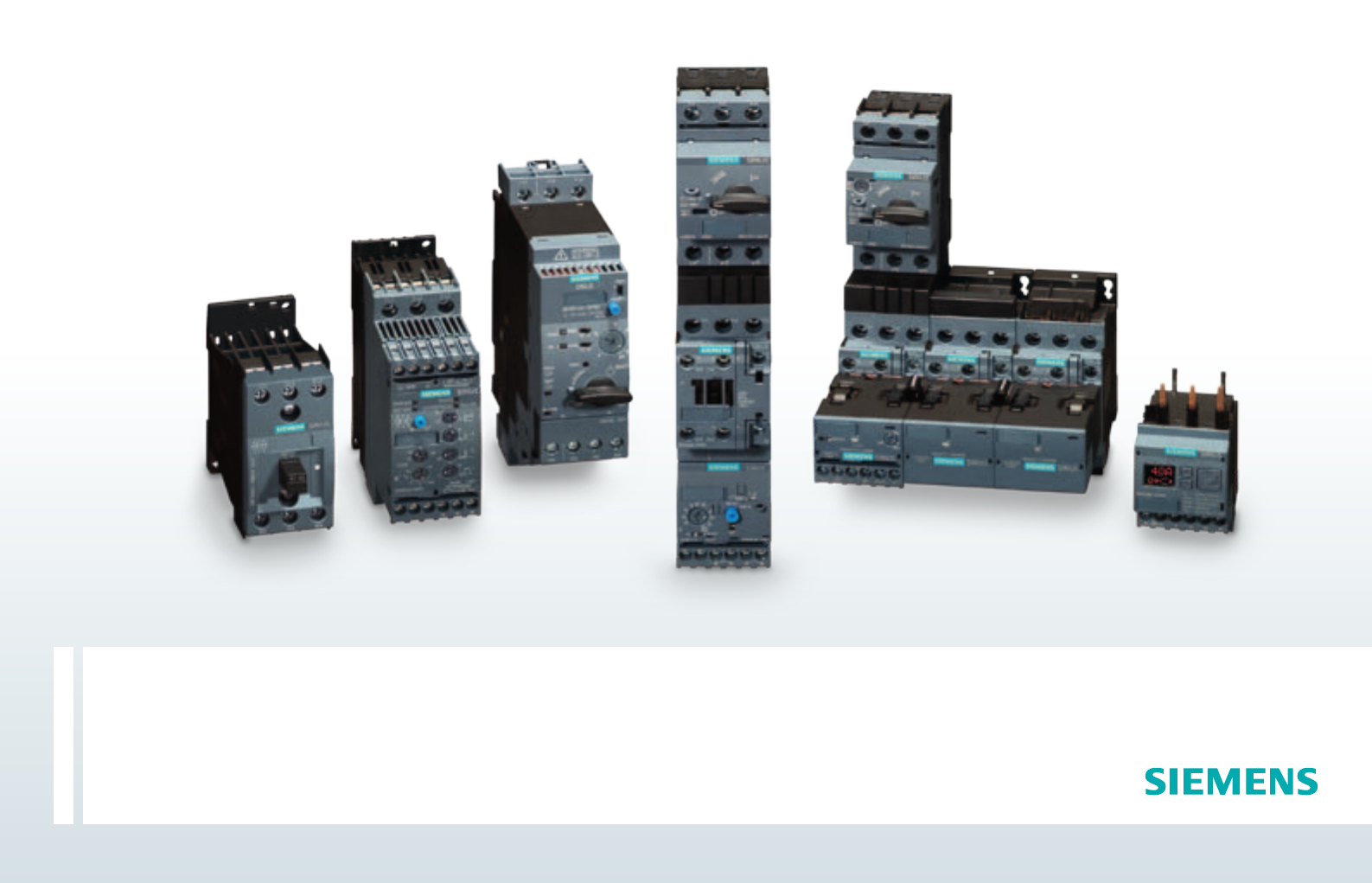
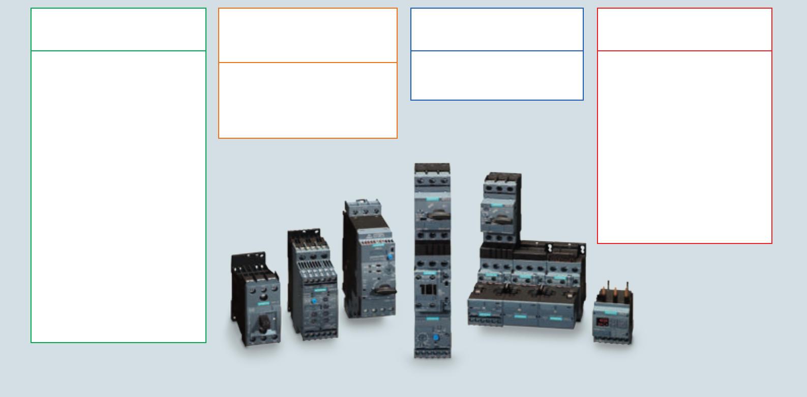
SIRIUS Modular System
Contents
SIRIUS Modular System Components
Switching and Protection Device Combinations
Comfortable Power Infeed and Distribution
4
8
9
Electromechanical Switching Devices for the Fuseless
Assembly of Load Feeders up to 7.5 kW
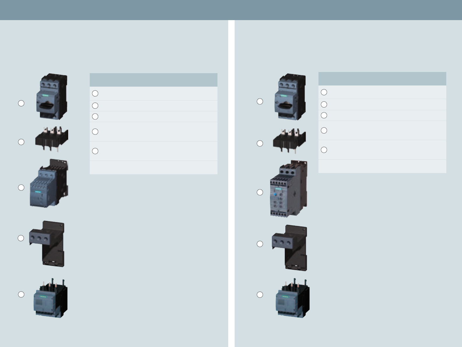
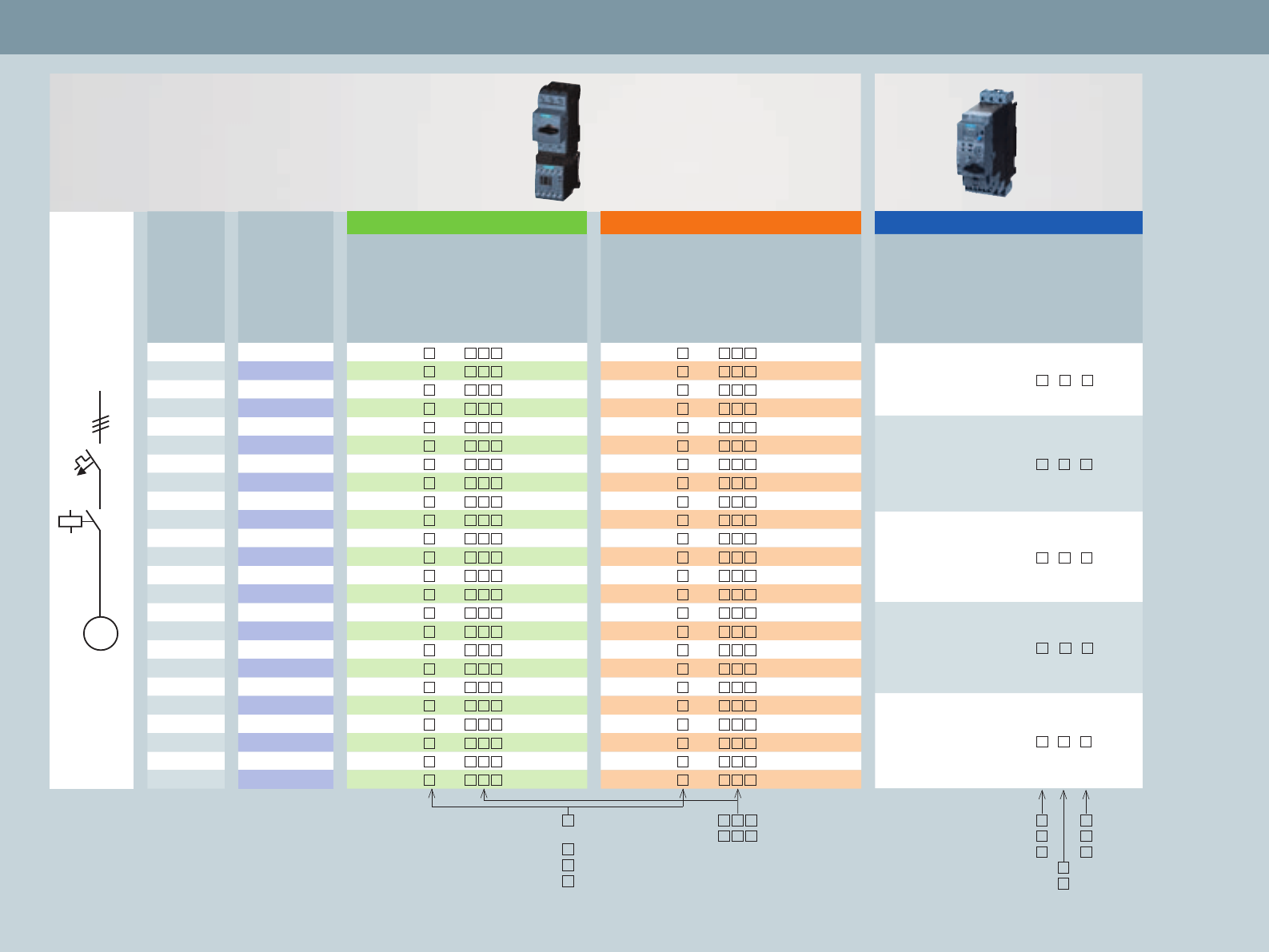
Size S00 Selection and Ordering Data:
Circuit Breaker, Contactor with Overload Relay
Circuit Breaker, Contactor with Current Monitoring Relay
10
10
Circuit Breaker, Soft Starter with Current Monitoring Relay
Circuit Breaker, Solid-State Switching Device
with Current Monitoring Relay
13
13
Electromechanical Switching Devices for the Fuseless
Assembly of Load Feeders up to 18.5 kW
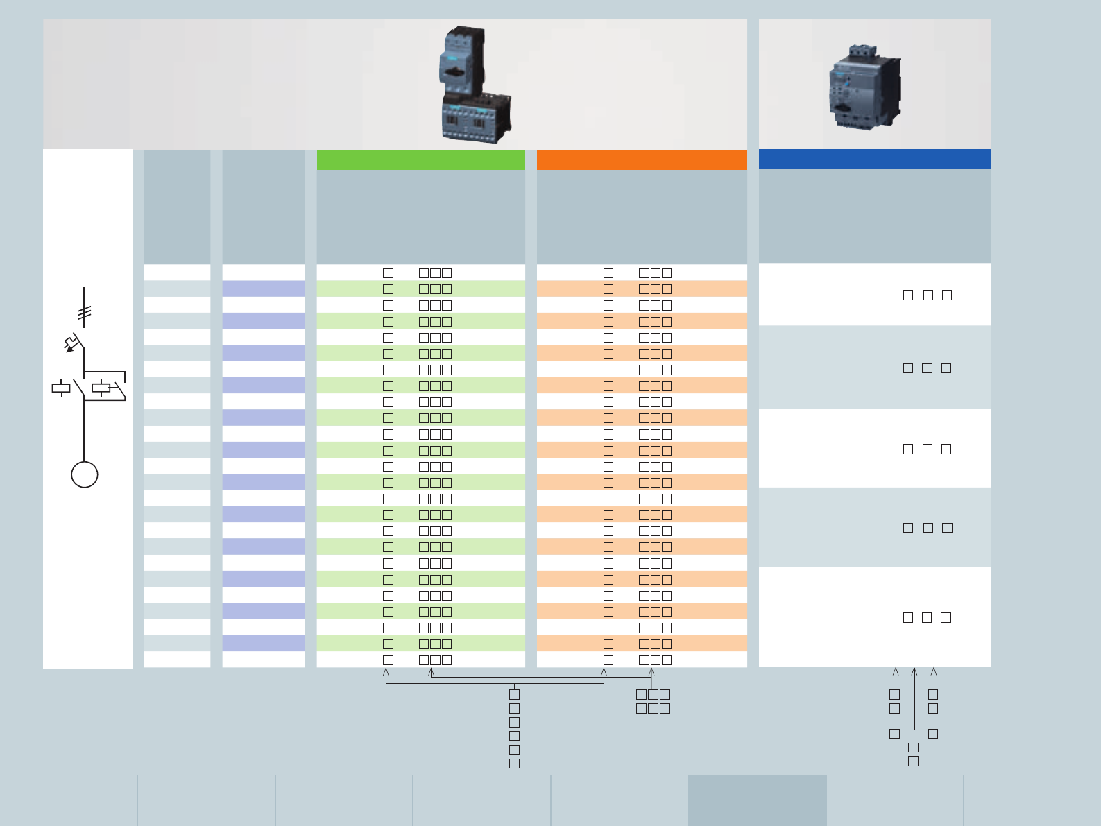
Size S0 Selection and Ordering Data:
16
Circuit Breaker, Contactor, Overload Relay
Circuit Breaker, Contactor with Current Monitoring Relay
17
17
Circuit Breaker, Soft Starter with Current Monitoring Relay 18
Assembly of Direct-On-Line and Reversing Starters up to 22 kW
Size S2 Selection and Ordering Data
20
Assembly of Direct-On-Line and Reversing Starters up to 45 kW
Size S3 Selection and Ordering Data
22
Size S6, S10 and S12
Selection and Ordering Data
24
Fuseless Load Feeders
Selection and Ordering Data:
Direct-On-Line Starters
(Completely Pre-Assembled Load Feeders, Compact Starters)
Reversing Starters
(Completely Pre-Assembled Load Feeders, Compact Starters)
26
27
Communication Connection
(IO-Link / AS-Interface masters, contactors, function modules
for Mounting on 3RT2 Contactors and for Connection to the Control,
Compact Starters)
28
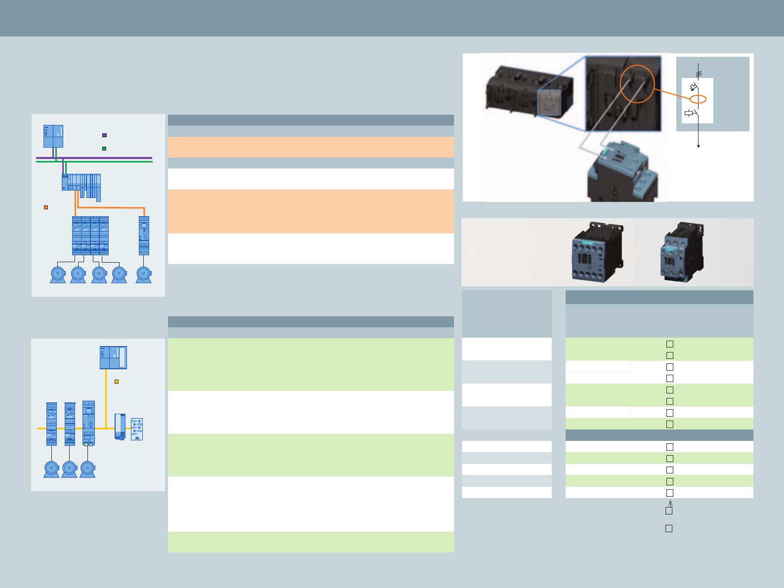
Infeed Systems
For Compact Starters, Load Feeders,
3-Phase Busbars, 8US Busbar Adapters
31
Accessories
Selection and Ordering Data:
Circuit Breakers
Contactors
Overload Relays, Current Monitoring Relays
34
36
40
Service & Support 42
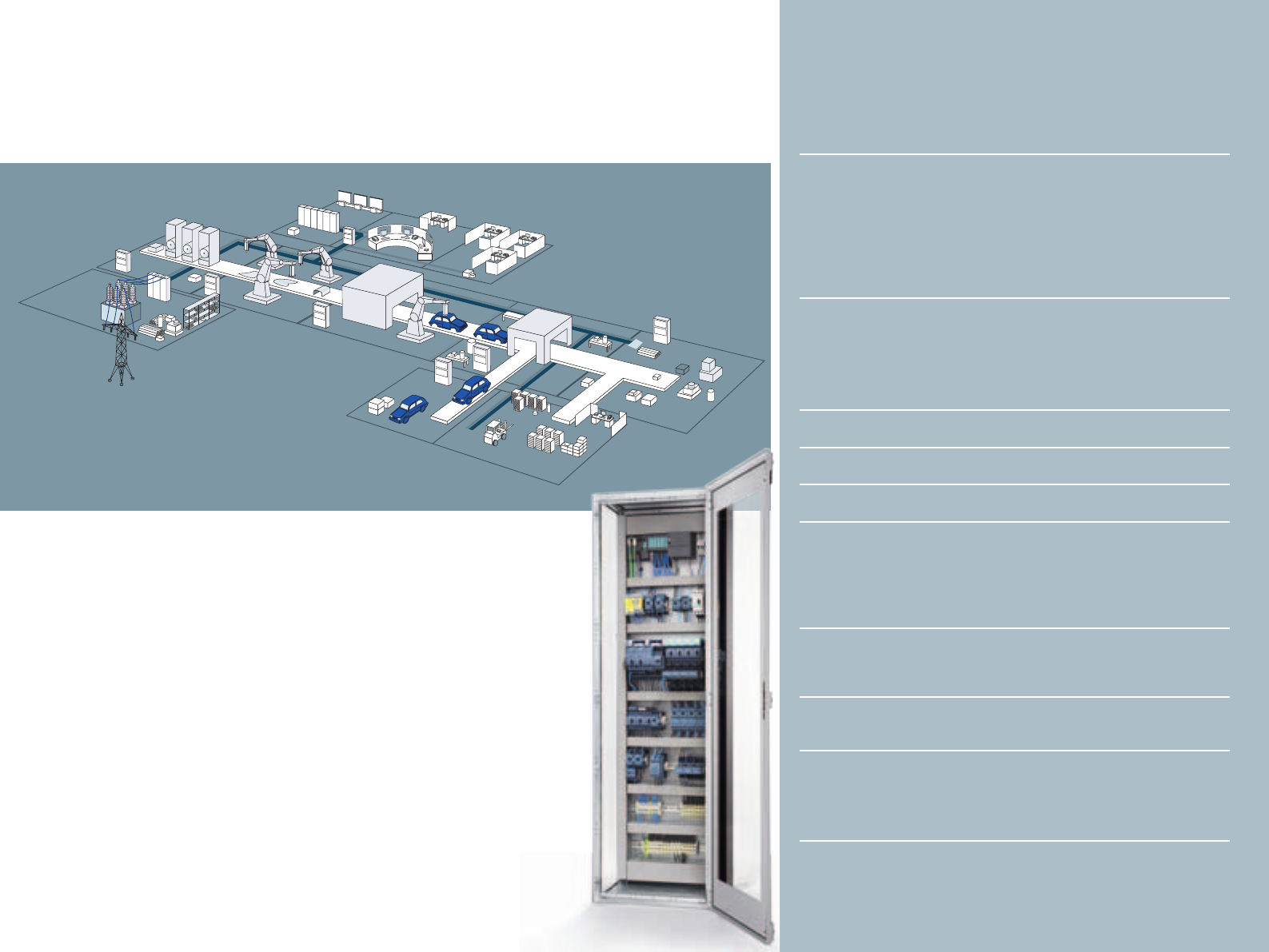
Everything for the electrical cabinet:
SIRIUS Modular System.
Pressing, equipping, transporting.
These functions run in many automated
production environments. You’ll find
everything that you need to switch, protect
and start motors with the extensive portfolio
of the modular SIRIUS system.
Everything. Easy. SIRIUS
Press Shop
Power
distribution
Paint Shop
Body Shop
Master control room
Final Assembly
Powertrain/
Assembly
How to realize fast, easy, flexible and space-saving control cabinet assembly? With the unique
SIRIUS modular system, which offers everything required for the switching, protection and
starting of motors and systems. It comprises a modular range of standard components up to
250 kW / 400 V in only seven optimally matched sizes which can be easily combined and utilize
largely identical accessories. Switching technology made easy!
SENTRON 3VL
Everything. System-based.
SIRIUS Modular System.
The permanent advancement and continuous
innovation of SIRIUS optimally prepare our cus-
tomers for current and future requirements and
provide them with efficient solutions. All com-
ponents of the SIRIUS modular system are char-
acterized by their space-saving design and high
degree of flexibility. Configuration, installation,
wiring and maintenance can be realized easily and
in minimum time. No matter whether you want
to assemble load feeders with circuit breakers or
overload relays, contactors / solid-state contactors,
reversing contactors or soft starters – SIRIUS offers
the suitable product for every application.
Thanks to the latest innovations of sizes S00 and
S0 up to 40 A, the new SIRIUS modular system now
offers even more functional diversity:
In addition to the innovated basic components
(such as contactors, circuit breakers and overload
relays), the innovated SIRIUS modular system offers
unprecedented highlights:
• Feeder combinations which can be completely
plug-connected without tools thanks to con-
sistently implemented spring-loaded connection
system
• 2- and 3-phase 3RR2 current monitoring relays
for direct mounting on contactors
• 3RA27 and 3RA28 function modules which can
be plugged onto contactors for the easy assem-
bly of direct-on-line, reversing and star-delta
starters and for connection to the control via
AS-Interface or IO-Link with minimized wiring
Circuit breakers
Contactors
Overload relays
Soft starters
S00 S2S0 S3 S6 S10 S12 3
Assembly and handling:
Reduced wiring expenditures and fault
avoidance – with maximum flexibility
• Load feeders: Easy realization
with standard devices up to
250 kW / 400 V
• Modular system: All components
are matched and can be combined
• Versions and sizes: Efficiency and
flexibility with 7 compact sizes
• Accessories:
Minimum variance with integrated
accessories
• Assembly: Fast commissioning, short
setup times, easy wiring
• Mounting: Permanently safe
mounting with screw-type or easy
plug-in connection system
• Spring-loaded connection system:
Fast and safe connection, vibration-
proof and with zero maintenance
• Reduced wiring: Considerably
reduced number of line connections
thanks to plug-in connection system
and IO-Link or AS-Interface
Application control:
Improved operational reliability and
system availability
• Maintenance: Extremely long service
life, low maintenance and reliability
• Application monitoring: Flexibly
integrated in the feeder thanks to
current monitoring relay
Connection to the control:
Optimum integration in the
automation environment
• Communication: Standardized
connection to AS-Interface, IO-Link
and PROFIBUS DP possible
Planning and configuration:
Eased system planning and
documentation
• Configuration: Easy and fast thanks
to comprehensive CAx data provision
• Service: Short delivery periods also
for spare parts thanks to worldwide
logistics network
• Environment: Environmentally
compatible production and materials,
recyclability
• Design: Clear and ergonomic, awarded
with the iF Product Design Award
• Configurator: For easy product
selection, incl. accessories
• Global applicability: Thanks to
comprehensive approvals
With its manifold components, the SIRIUS modular system covers various functions
for control cabinet applications and offers numerous advantages in terms of
assembly and handling, application monitoring, connection to the control as well
as planning and configuration.
Overview of the Numerous Advantages
Offered by the SIRIUS Modular System
4
Switching. Protecting. Starting.
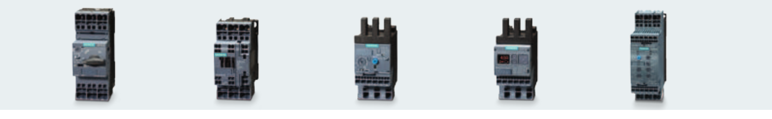
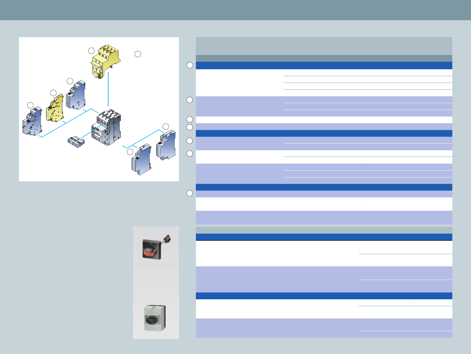
The components of the SIRIUS Modular System.
Far more than ON/OFF:
SIRIUS 3RV circuit breakers
SIRIUS 3RV circuit breakers (MSP)
are compact, current-limiting
circuit breakers. They guarantee
safe reliable shutdown when
short circuits occur and pro-
tect loads and plants against
overload. Furthermore, they
are suitable for operationally
switching load feeders with a
low operating frequency and
safely disconnecting the plant
or system from the line supply
when service is been carried
out or changes are being made.
SENTRON 3VL circuit breakers are
suitable for applications above
100 A. As infeed and load feeder
breaker, they protect plants and
motors against short circuit and
overload.
Rugged and reliable:
SIRIUS 3RT contactors
Due to their extremely high rug-
gedness and optimum contact
reliability, our contactors switch
with supreme confidence.
Furthermore, compact electri-
cal cabinets can be configured
with high packing densities. The
reason for this is that the auxil-
iary switch blocks and solenoid
protective circuitry are located
within the envelope contours
of the contactors. This makes it
easier to expand the system and
saves considerable space in the
electrical cabinet. With size S00
and S0 contactors, the auxiliary
switches are already inte-
grated in the enclosure.
Tripping when things get
tough: SIRIUS 3RU and 3RB
overload relays
The overload relays of the
SIRIUS family, available as either
thermal or solid-state versions,
protect loads connected to the
main circuit, as a function of the
current, and also protect other
switching and protective devices
in the particular load feeder. The
solid-state SIRIUS 3RB2 overload
relays guarantee seamless motor
and plant protection from 0.1 A
to 630 A. Due to the wide set-
ting ranges, the current range is
covered with a minimum number
of versions.
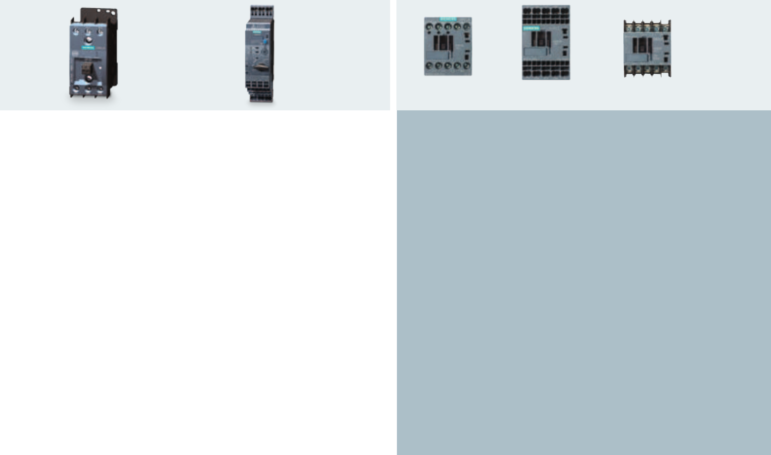
Easy application monitoring:
SIRIUS 3RR2 current monitoring
relays
The SIRIUS current monitoring
relays not only monitor the
motor, but the entire system or
driven process for overcurrent
and undercurrent, cable break-
age and phase failure.
For example, load shedding or
overload of an application is
promptly detected and signaled
at an early stage. Sizes S00 and
S0 of the 3RR2 current monitor-
ing relay are directly integrated
in the load feeder. They simply
have to be plugged onto the
contactor: Click ’n’ go.
Gentle starting:
SIRIUS 3RW soft starters
SIRIUS 3RW soft starters offer a
seamless range that covers all
standard and high-feature motor
starting applications. They can be
used in the widest range of appli-
cations to exploit the advantages
of soft starting for the easy and
efficient realization of optimum
machine concepts. The compact
two-phase-controlled 3RW30
facilitates efficient and space-
saving soft starting up to 55 kW
(with 400 V). The 3RW40 ad-
ditionally offers soft stopping as
well as integrated intrinsic device
and motor protection functions,
thanks to which an additional
overload relay is unnecessary.
Device versions up to a rating of
55 kW (with 400 V) are available:
Thermistor motor protection
evaluation, 400–600 V.
5
Switching. Protecting. Starting.
The components of the SIRIUS Modular System.
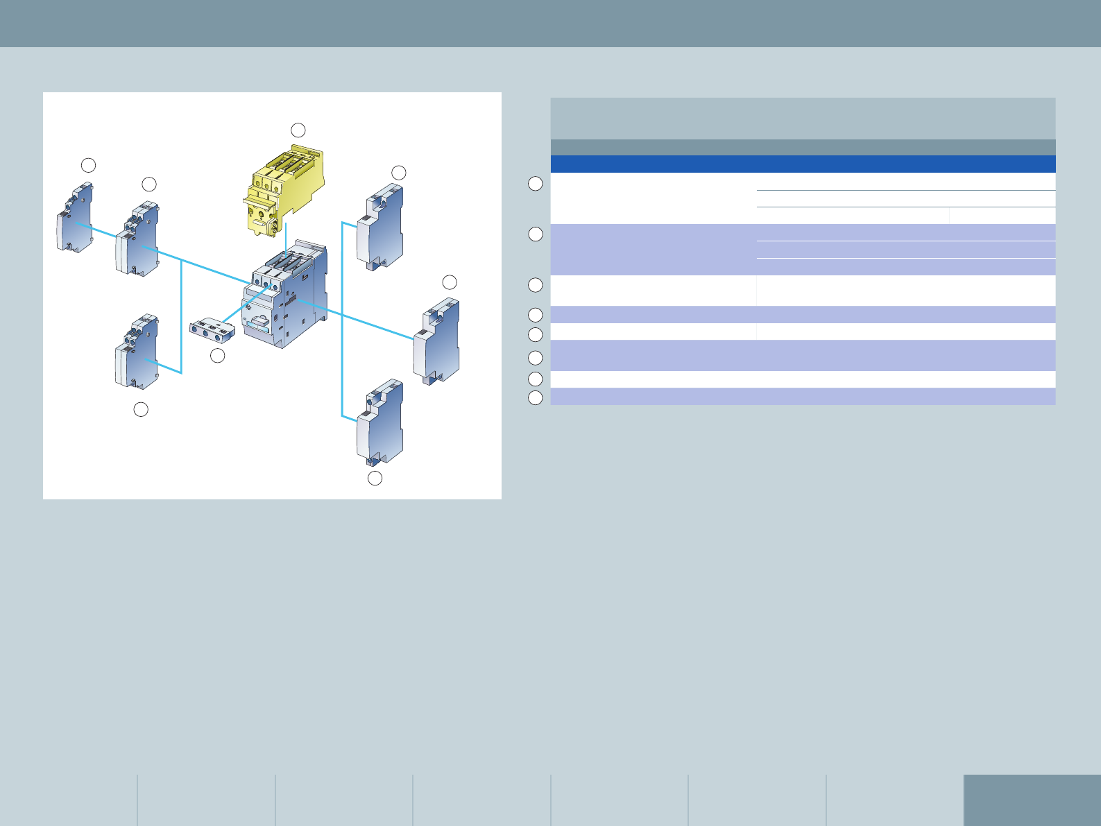
Competent control of high
switching frequencies: SIRIUS 3RF
solid-state contactors
SIRIUS solid-state contactors (size S0)
for motor switching offer an
almost unlimited service life – even
under harsh conditions and with
high switching frequencies. The
three-phase solid-state contactors
switch motors up to 7.5 kW in an ab-
solutely noise-free manner. A special
reversing contactor version facili-
tates direction of rotation changes
of motors up to 3 kW. The compact
devices in 45 or 90 mm width can be
combined with our circuit breakers,
current monitoring relays or solid-
state overload relays. This supports
the fast and easy assembly of fuse-
less and fused motor feeders.
Compact switching and protection
with comprehensive additional
functions: 3RA6 compact starters
Equipped with the functions of a
circuit breaker, a contactor and a
solid-state overload relay, the com-
pact starter offers maximum reliability
and minimum variance as direct-on-
line or reversing starter up to 32 A.
Safe disconnection upon the starter‘s
end of service life offers an additional
advantage in terms of system availabil-
ity. Reduced wiring in the main circuit
thanks to the brilliantly simple infeed
system, incl. PE connection, and in
the control circuit thanks to optional
AS-Interface connection or integrated
IO-Link interface supports the rapid
assembly of complete feeder groups.
The devices‘ incorporation in the
Totally Integrated Automation con-
cept and pre-defined icon blocks for
visualization facilitate the output of
significant device diagnostics without
the normally required configuration
expenditures.
Fast, reliable and user-friendly: spring-loaded technology
For the first time, the entire S00/S0 range is available with spring-loaded
connection system both in the main and control circuit. This accelerates de-
vice connection and offers maximum operational reliability. The outstanding
ease of wiring ensures rapid mounting. The gas-tight clamp connection‘s
vibration resistance represents a further advantage. In addition, this con-
nection system offers maximum contact reliability – even under the harshest
of conditions. The frequently required re-tightening of connection terminals
is thus done away with.
A special bonus: Also the connecting modules for direct-on-line, reversing
and star-delta starters are available with spring-loaded connection system to
support the mounting of complete feeders without tools.
Maximum connection flexibility
Of course, all components of the SIRIUS modular system are also available
with the screw-type connection system – largely even with ring cable lug
– for special requirements, e.g. mechanical engineering applications in the
semi-conductor industry.
SIRIUS contactor
screw connection
SIRIUS contactor
spring-loaded connection
SIRIUS contactor
ring cable lug connection
6

Switching. Protecting. Starting.
The components of the SIRIUS Modular System.
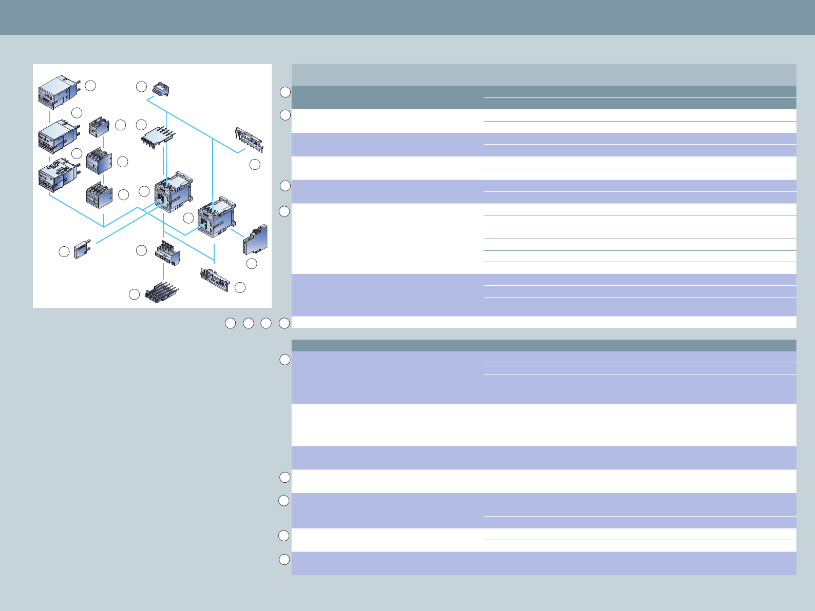
Ready for immediate use:
Pre-wired SIRIUS load feeders
Load feeders start loads using a combination
of protective and switching functions. Gen-
erally, a multiple number of components is
required to implement every type of starter.
In order to reduce time and costs – and espe-
cially to minimize downtimes – we offer you
a wide range of pre-wired starter solutions:
• Direct starters up to 22 kW – the optimum starter
combination for all motors. For high switching frequencies
with solid-state contactors up to 7.5 kW.
• Reversing starters up to 11 kW – the matching
combination for reversing motors. Solid-state reversing
contactors can be used for applications with high
switching frequencies up to 3 kW.
• Wye-delta* combinations up to 75 kW – the solution for
running-up motors in stages.
• Soft starters – when soft starting and stopping is required
(soft ramp-down as of 3RW40).
An almost unlimited number of further tested combinations
can be easily assembled from the individual components.
The SIRIUS Configuration manual offers selection support:
Available under order number 3ZX1012-0RA21-1AB0 or for
download via www.siemens.com/industrial-controls/support
Straight ahead:
The 3RA11 direct starter
Phases interchanged:
The 3RA12 reversing starter
Two stages – one start:
The 3RA14 star-delta
combination
7
See p. 14, 19 See p. 19 See p. 15 See p. 15
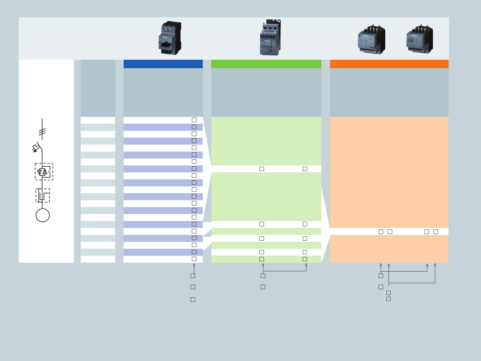
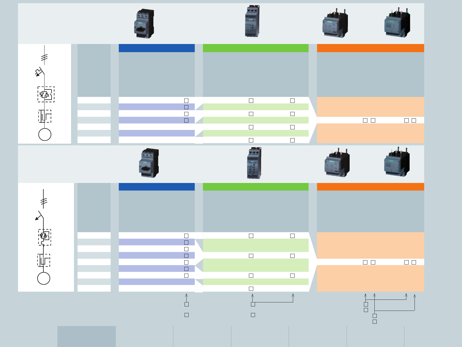
Combination of switching and protective devices
Electromechanical
controls
For details, see:*
For details, see:*
Short circuit
Overload /
Monitoring
Switching
Fuse-protectedNon-fused Non-fused
Fuse with contactor
and overload relay
Motor starter protector
for motor protection
and contactor
See p. 12, 17, 26
Motor starter protector
for motor protection
with overload relay
function and contactor
Starter motor starter
protector, contactor
and overload relay
See p. 11, 17
Compact Starter
See p. 26, 27, 30
Motor starter protector
for motor protection,
contactor and current
monitoring relay
See p. 12, 17
Motor starter protector for
motor protection with
overload relay function,
contactor and current
Motor starter protector
for motor protection,
soft starter and current
monitoring relay
Starter motor starter
protector, soft starter
and current
monitoring relay
Fuse and soft starter Fuse and solid-state
switching device
Fuse, solid-state
switching device and
current monitoring
relay
Motor starter protector
for motor protection
and solid-state
switching device
Motor starter protector for
motor protection, solid-state
switching device and current
monitoring device
Electronic
controls
* Fur further details and solutions not listed here, refer to the IC10 catalog
Short circuit
Overload /
Monitoring
Switching
Fuse-protected Non-fused
M
MM M M M
I
M
I
MM M M M
M M
8
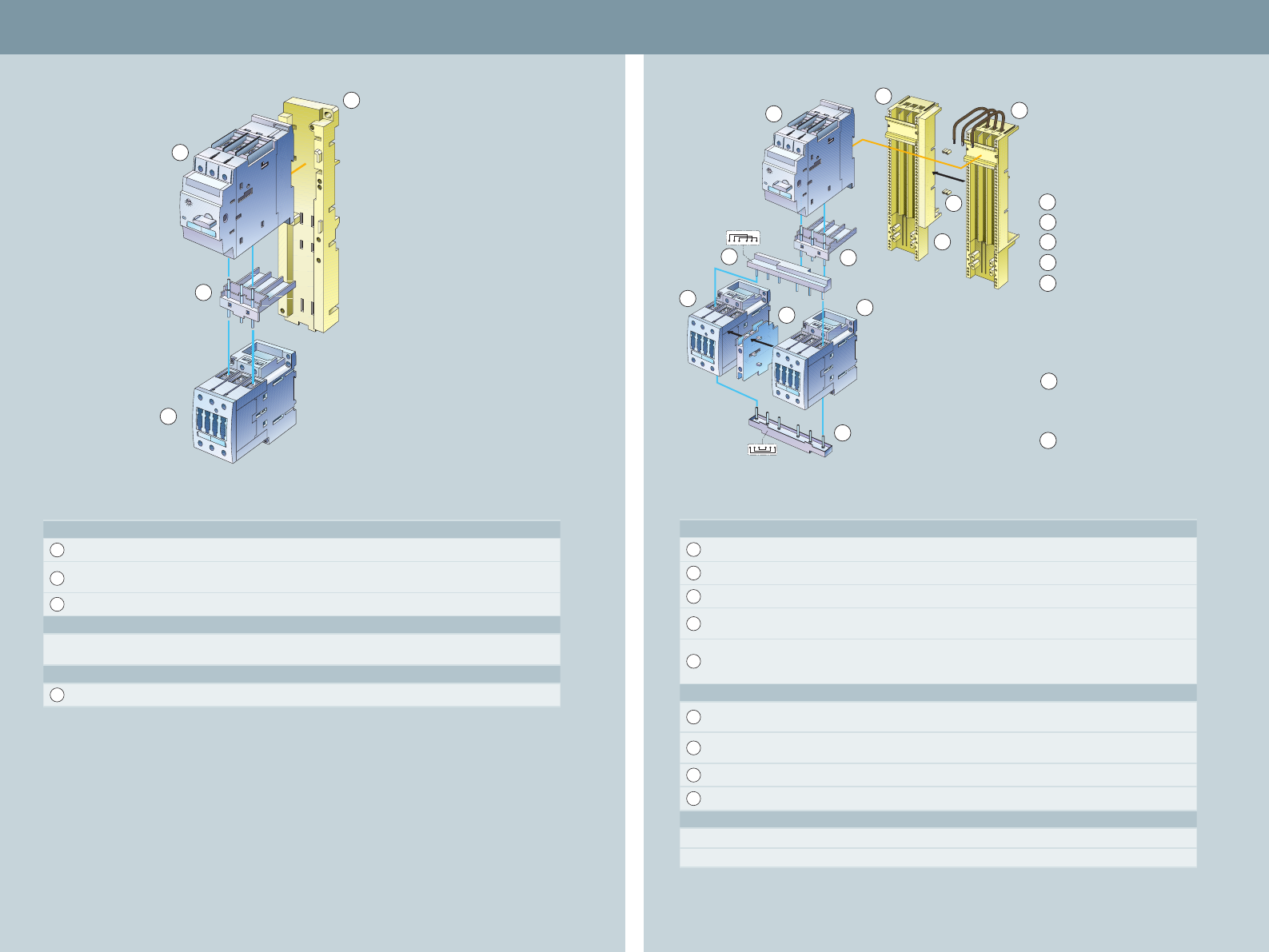
Design highlights
• Outstanding flexibility for assembly and expansions
• Reduced space requirements in the control cabinet thanks
to very compact design
• Infeed optionally from the left or right with conductor
cross sections of up to 70 mm2
• Optional wiring duct between the feeders
• Additional integration of further 1-, 2- or 3-pole components
via terminal block
• Maximum current carrying capacity of 100 A
• Integration of load feeders with screw-type and spring-loaded
connection system
• High vibration resistance, particularly with switching devices
featuring the spring-loaded connection system
• Time savings in terms of mounting thanks to easy plug-in
connection system
• Also PE connection option with the 3RA68 infeed
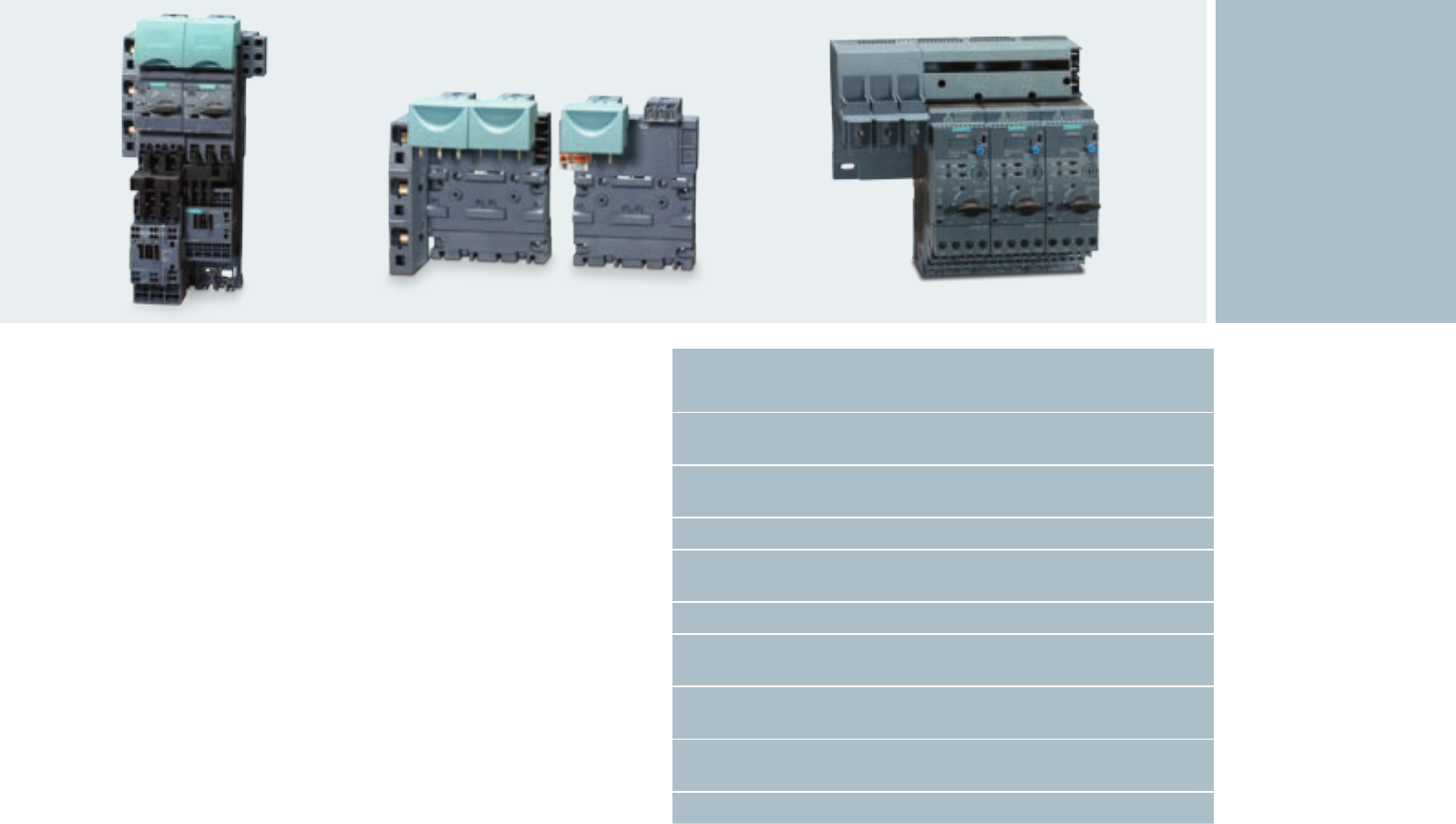
Efficient and flexible power
distribution
The components of the SIRIUS mod-
ular system offer maximum wiring
flexibility. They can be connected
easily via the corresponding SIRIUS
3RV29 infeed system or the 3RA68
infeed system in conjuction with the
compact starter. Both systems are
respectively available for devices
with screw-type and spring-loaded
connection system. For connection,
individual circuit breakers, complete
load feeders or compact starters are
simply clicked into the respective
infeed system. Doing away
with laborious wiring and fault risks,
a complete feeder group is thus
supplied with power: Click ’n’ go!
Alternatively, also conventional
wiring is supported:
Via parallel wiring, 3-phase busbar or
the 8US busbar adapter with which
the SIRIUS load feeders can be directly
mounted on a 60 mm busbar system.
These manifold combination options
facilitate the effortless realization
of your individual control cabinet
solution – perfectly matched to your
application.
Comfortable Power Infeed and Distribution:
SIRIUS 3RV29 and 3RA68 Infeed Systems
9
,
Type Screw connection Spring-loaded connection
Motor starter protector*
Link module 3RA1921-1DA00 3RA2911-2AA00
Contactor (AC / DC)*
Overload relay*
* For order numbers of basic components see tabular overview on page 11
Starter combinations of motor starter protector and
contactor with optional current monitoring relay
Starter combinations of motor starter protector and contactor
with overload relay
Type Screw connection Spring-loaded connection
Motor starter protector*
Link module 3RA1921-1DA00 3RA2911-2AA00
Contactor (AC / DC)*
Overload relay*
* For order numbers of basic components see tabular overview on page 12
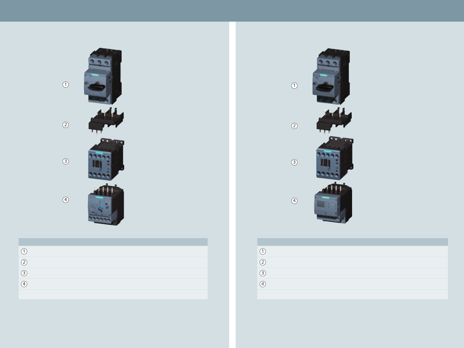
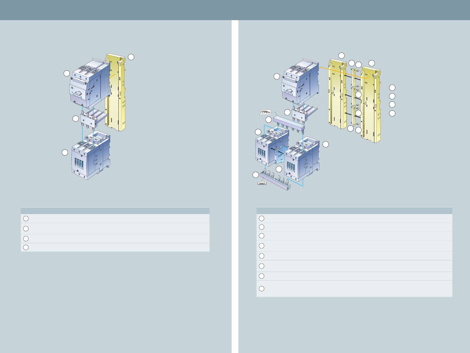
Design up to 7.5 kW (S00) Non-fused, electromechanical switching design 10
Starter combinations: motor starter
protector, contactor with overload relay
Motor starter protector for starter protection
Contactor Overload relay 1)
Three-phase
motor
400 V/AC-3
Setting range of
thermal overload
release
CLASS 10
Order no. Auxiliary
contacts
Order no. Order no.
Control supply voltage
Setting
range
CLASS 10
Order no.
Thermal
Order no.
Electronic
CLASS 10
[kW] [A] [A] DC 24 V AC 230 V, 50/60 Hz [A]
0.04 0.16 – 3RV2311-0AC 0 0.11 – 0.16 3RU2116-0A 0
0.06 0.2 – 3RV2311-0BC 0 0.14 – 0.2 3RU2116-0B 0
0.06 0.25 – 3RV2311-0CC 0 0.18 – 0.25 3RU2116-0C 0 3RB3016-1R 0
0.09 0.32 – 3RV2311-0DC 0 0.22 – 0.32 3RU2116-0D 0 (0.1 – 0.4 A)
0.09 0.4 – 3RV2311-0EC 0 0.28 – 0.4 3RU2116-0E 0
0.12 0.5 – 3RV2311-0FC 0 0.35 – 0.5 3RU2116-0F 0
0.18 0.63 – 3RV2311-0GC 0 0.45 – 0.63 3RU2116-0G 0
0.18 0.8 – 3RV2311-0HC 0 0.55 – 0.8 3RU2116-0H 0 3RB3016-1N 0
0.25 1 – 3RV2311-0JC 0 0.7 – 1 3RU2116-0J 0 (0.32 – 1.25 A)
0.37 1.25 – 3RV2311-0KC 0 1NC 3RT2015- BB42 3RT2015- AP02 0.9 – 1.25 3RU2116-0K 0
0.55 1.6 – 3RV2311-1AC 0 1NO 3RT2015- BB41 3RT2015- AP01 1.1 – 1.6 3RU2116-1A 0
0.75 2 – 3RV2311-1BC 0 1.4 – 2 3RU2116-1B 0
0.75 2.5 – 3RV2311-1CC 0 1.8 – 2.5 3RU2116-1C 0 3RB3016-1P 0
1.1 3.2 – 3RV2311-1DC 0 2.2 – 3.2 3RU2116-1D 0 (1 – 4 A)
1.5 4 – 3RV2311-1EC 0 2.8 – 4 3RU2116-1E 0
1.5 5 – 3RV2311-1FC 0 3.5 – 5 3RU2116-1F 0
2.2 6.3 – 3RV2311-1GC 0 4.5 – 6.3 3RU2116-1G 0 3RB3016-1S 0
3 8 – 3RV2311-1HC 0 5.5 – 8 3RU2116-1H 0 (3 – 12 A)
4 10 – 3RV2311-1JC 0 1NC 3RT2016- BB42 3RT2016- AP02 7 – 10 3RU2116-1J 0
– 1NO 3RT2016- BB41 3RT2016- AP01
5.5 12.5 – 3RV2311-1KC 0 1NC 3RT2017- BB42 3RT2017- AP02 9 – 12.5 3RU2116-1K 0
– 1NO 3RT2017- BB41 3RT2017- AP01 3RB3016-1T 0
7.5 16 – 3RV2311-4AC 0 1NC 3RT2018- BB42 3RT2018- AP02 11 – 16 3RU2116-4A 0 (4 – 16 A)
– 1NO 3RT2018- BB41 3RT2018- AP01
Screw connection: 1
Spring-loaded
connection: 2
1) Direct mounting on contactor, screw and
spring-loaded connection possible
Screw connection: 1
Spring-loaded
connection: 2
Ring cable lug
connection: 4
Screw connection: B
Spring-loaded
connection: C
Ring cable lug
connection: J
Screw connection: B
Spring-loaded
connection: E
M
11
Motor starter protector for motor protection
Contactor Current monitoring relay
Three-phase
motor
400 V/AC-3
Setting range
of thermal
overload
release
CLASS 10
Order no. Auxiliary
contacts
Order no. Order no.
Control supply voltage
Measure-
ment
range
Order no.
Basic (analog
setting)
Order no.
Standard
(digital setting)
[kW] [A] [A] DC 24 V AC 230 V, 50/60 Hz [A]
0.04 0.16 0.11 – 0.16 3RV2011-0AA 0
0.06 0.2 0.14 – 0.2 3RV2011-0BA 0
0.06 0.25 0.18 – 0.25 3RV2011-0CA 0
0.09 0.32 0.22 – 0.32 3RV2011-0DA 0
0.09 0.4 0.28 – 0.4 3RV2011-0EA 0
0.12 0.5 0.35 – 0.5 3RV2011-0FA 0
0.18 0.63 0.45 – 0.63 3RV2011-0GA 0
0.18 0.8 0.55 – 0.8 3RV2011-0HA 0
0.25 1 0.7 – 1 3RV2011-0JA 0
0.37 1.25 0.9 – 1.25 3RV2011-0KA 0 1NC 3RT2015- BB42 3RT2015- AP02
0.55 1.6 1.1 – 1.6 3RV2011-1AA 0 1NO 3RT2015- BB41 3RT2015- AP01
0.75 2 1.4 – 2 3RV2011-1BA 0
0.75 2.5 1.8 – 2.5 3RV2011-1CA 0
1.1 3.2 2.2 – 3.2 3RV2011-1DA 0
1.5 4 2.8 – 4 3RV2011-1EA 0
1.5 5 3.5 – 5 3RV2011-1FA 0
2.2 6.3 4.5 – 6.3 3RV2011-1GA 0 1.6 – 16 3RR2141- A 30 3RR2241- F 30
3 8 5.5 – 8 3RV2011-1HA 0
4 10 7 – 10 3RV2011-1JA 0 1NC 3RT2016- BB42 3RT2016- AP02
1NO 3RT2016- BB41 3RT2016- AP01
5.5 12.5 9 – 12.5 3RV2011-1KA 0 1NC 3RT2017- BB42 3RT2017- AP02
1NO 3RT2017- BB41 3RT2017- AP01
7.5 16 11 – 16 3RV2011-4AA 0 1NC 3RT2018- BB42 3RT2018- AP02
1NO 3RT2018- BB41 3RT2018- AP01
Starter combinations:
motor starter protector,
contactor with optional current
monitoring relay
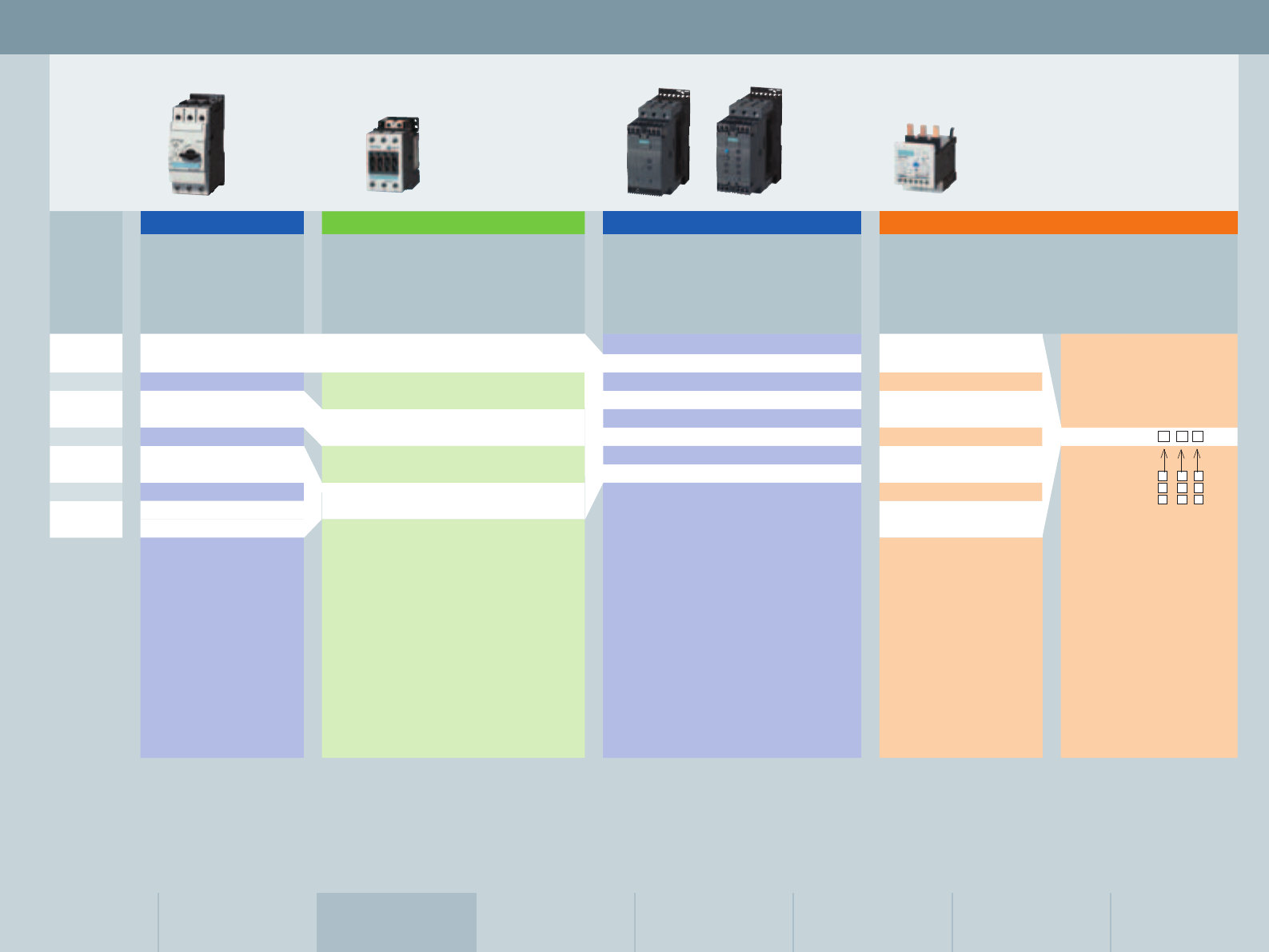
Size S00 Size S0 Size S2 Size S3 Size S6, S10, S12 Fuseless Load Feeders Communication
Feeder Combinations
Infeed System
Accessories
Screw connection: 1
Spring-loaded
connection: 2
Ring cable lug
connection: 4
Screw connection: 1
Spring-loaded
connection: 2
Ring cable lug
connection: 4
Screw connection: 1
Spring-loaded
connection: 2
AC/DC 24 V:
AC/DC 24 –240 V:
A
W
M
I
12
Starter combinations:
motor starter protector, solid-state switching
device with optional current monitoring relay
Starter combinations:
motor starter protector, soft starter with optional
current monitoring relay (for stand-alone mounting)
1) An adapter for stand-alone assembly is required for the
application of a 3RR2 current monitoring relay on a 3RW30/40
soft starter. The current monitoring relay must not be active
during the start-up and ramp-down phase (phase control).
For 3RW30: The 3RR2 monitoring relay is to be enabled via an
upstream timing relay after soft start-up completion.
For 3RW40: The 3RR2 monitoring relay is to be enabled/disabled
via the BYPASS output (start-up detection).
Type Screw
connection
Spring-loaded
connection
Motor starter
protector *
Link module 3RA2921-1BA00 3RA2911-2GA00
Soft starter *
Adapter for
stand-alone
assembly
3RU2916-3AA01 3RU2916-3AC01
Current
monitoring
relay *1)
* For order numbers of basic components see tabular
overview on page 14
Type Screw
connection
Motor starter
protector *
Link module 3RA2921-1BA00
Solid-state
contactor /
solid-state
reversing
contactor *
Adapter for
stand-alone
assembly
3RU2916-3AA01
Current
monitoring
relay *1)
* For order numbers of basic components see tabular
overview on page 15
Design up to 7.5 kW (S00) Non-fused, electronic switching design
13
Starter combinations: motor
starter protector, soft starter
with optional current monitoring
relay (for stand-alone mounting)
Motor starter protector Soft starter 1) Current monitoring relay
Three-phase
motor
400 V/AC-3
Setting range
of thermal
overload
release
CLASS 10
Order no. Rated
operating
current
Order no. Order no.
Control supply voltage
Measure-
ment
range
Order no.
Basic (analog
setting)
Order no.
Standard (digital
setting)
[kW] [A] [A] [A] AC/DC 24 V AC/DC 110 – 230 V [A]
0.04 0.16 0.11 – 0.16 3RV2011-0AA 0
0.06 0.2 0.14 – 0.2 3RV2011-0BA 0
0.06 0.25 0.18 – 0.25 3RV2011-0CA 0
0.09 0.32 0.22 – 0.32 3RV2011-0DA 0
0.09 0.4 0.28 – 0.4 3RV2011-0EA 0
0.12 0.5 0.35 – 0.5 3RV2011-0FA 0
0.18 0.63 0.45 – 0.63 3RV2011-0GA 0
0.18 0.8 0.55 – 0.8 3RV2011-0HA 0 3.6 3RW3013- BB04 3RW3013- BB14
0.25 1 0.7 – 1 3RV2011-0JA 0
0.37 1.25 0.9 – 1.25 3RV2011-0KA 0
0.55 1.6 1.1 – 1.6 3RV2011-1AA 0
0.75 2 1.4 – 2 3RV2011-1BA 0
0.75 2.5 1.8 – 2.5 3RV2011-1CA 0
1.1 3.2 2.2 – 3.2 3RV2011-1DA 0
1.5 4 2.8 – 4 3RV2011-1EA 0
1.5 5 3.5 – 5 3RV2011-1FA 0 6.5 3RW3014- BB04 3RW3014- BB14
2.2 6.3 4.5 – 6.3 3RV2011-1GA 0 1.6 – 16 3RR2141- A 30 3RR2241- F 30
3 8 5.5 – 8 3RV2011-1HA 0 93RW3016- BB04 3RW3016- BB14
4 10 7 – 10 3RV2011-1JA 0
5.5 12.5 9 – 12.5 3RV2011-1KA 0 12.5 3RW3017- BB04 3RW3017- BB14
7.5 16 11 – 16 3RV2011-4AA 0 17.6 3RW3018- BB04 3RW3018- BB14
1) Rated operating voltage 200 ... 480 V
Screw connection: 1
Spring-loaded
connection: 2
Ring cable lug
connection: 4
Screw connection: 1
Spring-loaded
connection: 2
Screw connection: 1
Spring-loaded
connection: 2
AC/DC 24 V:
AC/DC 24 –240 V:
A
W
M
14
Motor starter protector Solid-state contactor 2) Current monitoring relay
Three-phase
motor
400 V/AC-3
Setting range
of thermal
overload
release
CLASS 10
Order no. Rated
operating
current
Order no. Order no.
Control supply voltage
Measure-
ment
range
Order no.
Basic (analog
setting)
Order no.
Standard (digital
setting)
[kW] [A] [A] [A] DC 24 V AC 110 – 230 V, 50/60 Hz [A]
0.04 0.16 0.11 – 0.16 3RV2011-0AA 0
0,06 0.2 0.14 – 0.2 3RV2011-0BA 0
0,06 0,25 0.18 – 0.25 3RV2011-0CA 0
0,09 0.32 0.22 – 0.32 3RV2011-0DA 0
0,09 0.4 0.28 – 0.4 3RV2011-0EA 0
0.12 0.5 0.35 – 0.5 3RV2011-0FA 0
0,18 0.63 0.45 – 0.63 3RV2011-0GA 0 1.6 – 16 3RR2141- A 30 3RR2241- F 30
0,18 0.8 0.55 – 0.8 3RV2011-0HA 0
0,25 1 0.7 – 1 3RV2011-0JA 0 5.2 3RF3405- BB04 3RF3405- BB24
0.37 1.25 0.9 – 1.25 3RV2011-0KA 0
0.55 1.6 1.1 – 1.6 3RV2011-1AA 0
0,75 2 1.4 – 2 3RV2011-1BA 0
0,75 2.5 1.8 – 2.5 3RV2011-1CA 0
1.1 3.2 2.2 – 3.2 3RV2011-1DA 0
1,5 4 2.8 – 4 3RV2011-1EA 0
1,5 5 3.5 – 5 3RV2011-1FA 0
2.2 6.3 4.5 – 6.3 3RV2011-1GA 0 4 – 16 3RR2142- A 303)3RR2242- F 303)
3 8 5.5 – 8 3RV2011-1HA 0
4 10 7 – 10 3RV2011-1JA 0 9.2 3RF3410- BB041) 3RF3410- BB241)
5.5 12.5 9 – 12.5 3RV2011-1KA 0 12.5 3RF3412- BB041) 3RF3412- BB241)
7.5 16 11 – 16 3RV2011-4AA 0 16 3RF3416- BB041) 3RF3416- BB241)
Solid-state reversing contactor 2)
3.8 3RF3403-1BD04 3RF3403-1BD24
5.4 3RF3405-1BD04 3RF3405-1BD24
7.4 3RF3410-1BD041) 3RF3410-1BD241)
1) Overall width 90 mm
2) Rated operating voltage Ue 48 ... 480 V
3) Can be directly mounted on solid-state contactor
with screw connection
Screw connection: 1
Spring-loaded connection: 2
Ring cable lug connection: 4
Screw connection: 1
Spring-loaded
connection: 2
Screw connection: 1
Spring-loaded
connection: 2
AC/DC 24 V:
AC/DC 24 –240 V:
A
W
Starter combinations: motor
starter protector, soft starter
with optional current monitoring
relay (for stand-alone mounting)
M
Size S00 Size S0 Size S2 Size S3 Size S6, S10, S12 Fuseless Load Feeders Communication
Feeder Combinations
Infeed System
Accessories
15
Starter combinations:
motor starter protector, contactor with
optional current monitoring relay
Starter combinations:
motor starter protector,
contactor and overload
relay
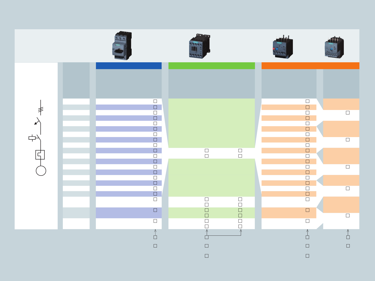
Design up to 18.5 kW (S0)
Typ Screw connection Spring-loaded connection
1Motor starter protector *
2Link module1) AC
DC
3RA2921-1AA00
3RA2921-1BA00
3RA2921-2AA00
3RA2921-2AA00
3Contactor *
4Overload relay *
* For order numbers of basic components see tabular overview on page 17
1) Only suitable up to 32 A
Type Screw connection Spring-loaded connection
1Motor starter protector *
2Link module1) AC
DC
3RA2921-1AA00
3RA2921-1BA00
3RA2921-2AA00
3RA2921-2AA00
3Contactor *
4Current monitoring relay *
* For order numbers of basic components see tabular overview on page 17
1) Only suitable up to 32 A
Non-fused, electromechanical switching design
1
2
3
4
1
2
3
4
16
Starter combinations:
motor starter protector,
contactor and overload relay
2) Max. 32 A
4) Voltages on request
Motor starter protector for
starter protection
Contactor Overload relay
Three-phase
motor
400V/AC-3
Thermal
overload
release
Order no. Aux.
con-
tacts
Order no. Order no. Order no.
Control supply voltage
Setting
range
CLASS 10
Order no.
Thermal
Setting
range
CLASS 10
Order no.
Electronic
[kW] [A] DC 24 V 230 V AC UC (AC 50/60 Hz/DC) [A] [A]
7.5 16 – 3RV2321-4AC 0
1NO+1NC
3RT2025- BB40 3RT2025- AP00 3RT2025- N 30 11 – 16 3RU2126-4A 0
7.5 20 – 3RV2321-4BC 0 14 – 20 3RU2126-4B 0 6 – 25 3RB3026 -1Q 0
11 22 – 3RV2321-4CC 0
1NO+1NC
3RT2026- BB40 3RT2026- AP00 3RT2026- N 30 17 – 22 3RU2126-4C 0
11 25 – 3RV2321-4DC 0 20 – 25 3RU2126-4D 0
15 28 – 3RV2321-4NC 0
1NO+1NC
3RT2027- BB40 3RT2027- AP00 3RT2027- N 30 23 – 28 3RU2126-4N 0 10 – 40 3RB3026- 1V 0
15 32 – 3RV2321-4EC 0 27 – 32 3RU2126-4E 0
18.5 36 – 3RV2321-4PC10
1NO+1NC
3RT2028- BB40 3RT2028- AP00 3RT2028- N 30 30 – 36 3RU2126-4P 0
18.5 40 – 3RV2321-4FC10 34 – 40 3RU2126-4F 0
Motor starter protector f. motor protection
Contactor Current monitoring relay
Three-phase
motor
400V/AC-3
Thermal
overload
release
Order no. Aux.
con-
tacts
Order no. Order no. Order no.
Control supply voltage
Measure-
ment
range
Order no.
Basic
(analog setting)
Order no.
Standard
(digital setting)
[kW] [A] [A] DC 24 V 230 V AC UC (AC 50/60 Hz/DC) [A]
7.5 16 11 – 16 3RV2021-4AA 0
1NO+1NC
3RT2025- BB40 3RT2025- AP00 3RT2025- N 30
7.5 20 14 – 20 3RV2021-4BA 0
11 22 17 – 22 3RV2021-4CA 0
1NO+1NC
3RT2026- BB40 3RT2026- AP00 3RT2026- N 30
11 25 20 – 25 3RV2021-4DA 0 4 – 40 3RR2142- A 30 3RR2142- F 30
15 28 23 – 28 3RV2021-4NA 0
1NO+1NC
3RT2027- BB40 3RT2027- AP00 3RT2027- N 30
15 32 27– 32 3RV2021-4EA 0
18.5 36 30 – 36 3RV2021-4PA10
1NO+1NC
3RT2028- BB40 3RT2028- AP00 3RT2028- N 30
18.5 40 34 – 40 3RV2021-4FA10
17
Screw connection: 1
Spring-loaded
connection 2):2
Screw connection: 1
Spring-loaded
connection: 2
Ring cable lug
connection 4):4
UC 21 – 28 V: B
UC 95 – 130 V: F
UC 200 – 280 V: P
Screw connection: B
Spring-loaded
connection: C
Ring cable lug
connection: J
Screw connection: B
Spring-loaded
connection: E
UC 21 – 28 V: B
UC 95 – 130 V: F
UC 200 – 280 V: P
Screw connection: 1
Spring-loaded
connection 2):2
Ring cable lug connection 2):4
Screw connection: 1
Spring-loaded
connection: 2
Ring cable lug connection 4):4
Screw connection: 1
Spring-loaded connection:
2
AC/DC 24 V:
AC/DC 24 – 240 V:
A
W
Size S00 Size S0 Size S2 Size S3 Size S6, S10, S12 Fuseless Load Feeders Communication
Feeder Combinations
Infeed System
Accessories
Starter combinations:
motor starter protector,
contactor with optional
current monitoring relay
M
I
M
Design up to 18.5 kW (S0) Non-fused, electronic switching design
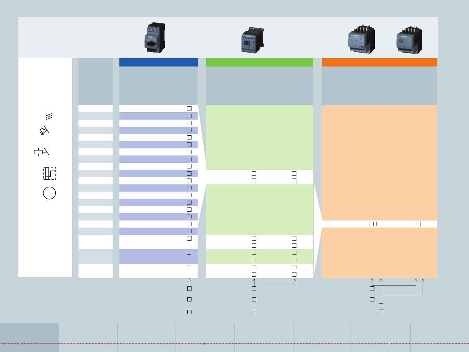
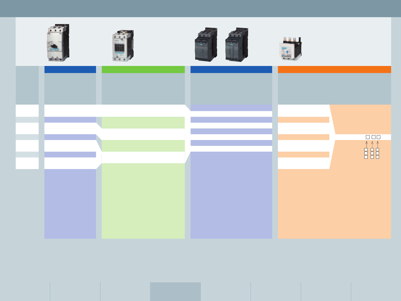
Starter combinations:
Motor starter protector, 3RW40 soft starter (integrated electronic overload relay)
with optional current monitoring relay (for stand-alone mounting)
Starter combinations:
motor starter protector, 3RW30 soft starter with optional current monitoring relay
(for stand-alone mounting)
1
Type Screw
connection
Spring-loaded
connection
1Motor starter
protector *
2Link module1) 3RA2921-1BA00 3RA2921-2GA00
3Soft starter *
4
Adapter for
stand-alone
assembly
3RU2926-3AA01 3RU2916-3AC01
5
Current
monitoring
relay *2)
* For order numbers of basic components see tabular
overview on page 19
Type Screw
connection
Spring-loaded
connection
1Motor starter
protector *
2Link module1) 3RA2921-1BA00 3RA2921-2GA00
3Soft starter *
4
Adapter for
stand-alone
assembly
3RU2926-3AA01 3RU2916-3AC01
5
Current
monitoring
relay *2)
* For order numbers of basic components see tabular
overview on page 19
1
2
3
2
5
3
4
4
5
1) Only suitable up to 32 A
2) An adapter for stand-alone assembly is required for the
application of a 3RR2 current monitoring relay on a 3RW30/40 soft
starter. The current monitoring relay must not be active during the
start-up and ramp-down phase (phase control).
For 3RW30: The 3RR2 monitoring relay is to be enabled via an
upstream timing relay after soft start-up completion.
For 3RW40: The 3RR2 monitoring relay is to be enabled/disabled
via the BYPASS output (start-up detection).
18
19
Motor starter protector for motor protection
Soft starter 1) Current monitoring relay
Three-phase
motor
400 V/AC-3
Setting range,
thermal
overload
release
CLASS 10
Order no. Rated
operating
current
Order no. Order no.
Control supply voltage
Measure-
ment
range
Order no.
Basic
(analog setting)
Order no.
Standard
(digital setting)
[kW] [A] [A] [A] AC/DC 24 V AC/DC 110 – 230 V [A]
11 22 17 – 22 3RV2021-4CA 0 25 3RW3026- BB04 3RW3026- BB14
11 25 20 – 25 3RV2021-4DA 0
15 28 23 – 28 3RV2021-4NA 0 32 3RW3027- BB04 3RW3027- BB14
15 32 27 – 32 3RV2021-4EA 0 4 – 40 3RR2142- A 30 3RR2242- F 30
18.5 36 30 – 36 3RV2021-4PA10 38 3RW3028- BB04 3RW3028- BB14
18.5 40 34 – 40 3RV2021-4FA10
18.5 40 34 – 40 3RV2021-4FA10 45 3RW3036- BB04 3RW3036- BB14
Motor starter protector for starter protection
Soft starter 1) Current monitoring relay
Three-phase
motor
400 V/AC-3
Setting range
of thermal
overload
release
CLASS 10
Order no. Rated
operating
current
Order no. Order no.
Control supply voltage
Measure-
ment
range
Order no.
Basic
(analog setting)
Order no.
Standard
(digital setting)
[kW] [A] [A] [A] AC/DC 24 V AC/DC 110 – 230 V [A]
5.5 12.5 – 3RV2311-1KC 0 12.5 3RW4024- BB04 3RW4024- BB14
7.5 16 – 3RV2321-4AC 0
7.5 20 – 3RV2321-4BC 0
11 22 – 3RV2321-4CC 0 25 3RW4026- BB04 3RW4026- BB14
11 25 – 3RV2321-4DC 0 4 – 40 3RR2142- A 30 3RR2242- F 30
15 28 – 3RV2321-4NC 0
15 32 3RV2321-4EC 0 32 3RW4027- BB04 3RW4027- BB14
18.5 36 3RV2321-4PC10
18.5 40 3RV2321-4FC10 38 3RW4028- BB02 –
1) Operating voltage 200 – 480 V Screw connection: 1
Spring-loaded
connection: 2
up to 32 A
Screw connection: 1
Spring-loaded
connection: 2
Screw connection: 1
Spring-loaded connection:
2
AC/DC 24 V:
AC/DC 24 – 240 V:
A
W
Size S00 Size S0 Size S2 Size S3 Size S6, S10, S12 Fuseless Load Feeders Communication
Feeder Combinations
Infeed System
Accessories
Starter combinations: motor
starter protector,
3RW30 soft starter with optional current
monitoring relay (for stand-alone mounting:
see combination options on page 18)
Starter combinations: motor starter protector,
3RW40 soft starter (integrated electronic
overload relay) with optional current monitoring
relay (for stand-alone mounting: see combination
options on page 18)
M
M
Hutschienen-
adapter
3RA19 32-1AA00
Leistungs-
schalter
Baugröße
S2
Verbindungs-
baustein
für AC:
3RA19 31-1AA00
für DC:
3RA19 31-1BA00
Schütz
Baugröße
S2
1
2
3
6
8
7
5
1
2
3
4
Assembly kit
for busbar mounting
40 mm: 3RA19 33-1C
60 mm: 3RA19 33-1D
comprising:
1 wiring kit
1 busbar adapter
1 controlgear support
1 side module
2 link wedges
Assembly kit
for rail mounting
3RA19 33-1B
comprising:
1 wiring kit
1 rail adapter
2 side modules
4 link wedges
Direct start Reversing
start
2
9
5
4
5
Type Version Order no.
1Size S2 circuit breaker
2Link module AC
DC
3RA19 31-1AA00
3RA19 31-1BA00
3Size S2 contactors
For busbar mounting (alternative)
Busbar adapter 40 mm
60 mm
8US10 61-5FP08
8US12 61-5FP08
For rail mounting (diagram)
4Rail adapter 3RA19 32-1AA00
6
7
9
8
8
Type Version Order no.
1Size S2 circuit breaker
22 Size S2 contactors
3Mechanical interlock 3RA19 24-2B
4Link module AC
DC
3RA19 31-1AA00
3RA19 31-1BA00
5
Wiring kit:
upper link module,
lower link module
For busbar mounting (diagram)
6Controlgear support 40 mm
60 mm
8US10 60-5AP00
8US12 60-5AP00
7Busbar adapter 40 mm
60 mm
8US10 61-5FP08
8US12 61-5FP08
8Link wedges (1 Order no. = 100 wedges) 8US19 98-1AA00
9Side module 8US19 98-2MB00
For rail mounting (alternative)
Rail adapter 3RA19 32-1AA00
Link wedges (1 Order no. = 100 wedges) 8US19 98-1AA00
5
Design S2 up to 22 kW 20
Size S00 Size S0 Size S2 Size S3 Size S6, S10, S12 Fuseless Load Feeders Communication
Feeder Combinations
Infeed System
Accessories
S2 selection and ordering data
Circuit breakers (MSP) Contactor Soft starters 1) Overload relays
Three-
phase
motor
400 V/AC-3
Setting
range
CLASS 10
Order no. Aux.
con-
tacts
Control supply
voltage
Order no. Control
supply
voltage
Rated
oper-
ating
current
Order no. Setting
range
CLASS 10
Order no.
Thermal
Setting
range
Order no.
Electronic2)
CLASS 10
[kW] [A] [A] Ie [A] [A] [A]
15 29 22 – 32 3RV1031-4EA10 – AC 230 V, 50/60 Hz 3RT1034-1AL20 22 – 32 3RU1136-4EB0
– DC 24 V 3RT1034-1BB40 AC/DC 110–230 V
45 3RW3036-1BB14
18.5 35 28 – 40 3RV1031-4FA10 AC/DC 24 V 28 – 40 3RU1136-4FB0
– AC 230 V, 50/60 Hz 3RT1035-1AL20 45 3RW3036-1BB04
– DC 24 V 3RT1035-1BB40 AC/DC 110–230 V 12.5 – 50 3RB2 3 - UB0
22 41 36 – 45 3RV1031-4GA10 45 3RW4036-1BB14 36 – 45 3RU1136-4GB0
AC/DC 24 V
– AC 230 V, 50/60 Hz 3RT1036-1AL20 45 3RW4036-1BB04
22 41 40 – 50 3RV1031-4HA10 – DC 24 V 3RT1036-1BB40 40 – 50 3RU1136-4HB0
CLASS 10 0 6 1
CLASS 20 0 6 2
CLASS 5...30* 1 3 4
* With ground-fault detection
(activatable) and electrical
remote reset
1)
Operating voltage 200 – 480 V
2)
For using tripping CLASS 20, please refer to the information contained in the
“SIRIUS Engineering – Fuseless Load Feeders” configuration brochure and in the
catalog
21
Direct start Reversing start
Design S3 up to 45 kW
1
2
3
6
8
7
1
2
3
4
2
4Assembly kit
for rail mounting
3RA19 43-1B
comprising:
1 wiring kit
2 rail adapters
3 side modules
6 link wedges
5
5
8
7
7
7
6
8
Type Version Order no.
1Size S3 circuit breaker
2Link module AC
DC
3RA19 41-1AA00
3RA19 41-1BA00
3Size S3 contactor
4Rail adapter 3RA19 42-1A
Type Version Order no.
1Size S3 circuit breaker
22 Size S3 contactors
3Mechanical interlock 3RA19 24-2B
4Link module AC
DC
3RA19 41-1AA00
3RA19 41-1BA00
5Rail adapter
6Side modules for rail adapters
(1 Order no. = 10 adapters) 3RA19 02-1B
7Link wedges (1 Order no. = 100 wedges) 8US19 98-1AA00
8
Wiring kit:
upper link module,
lower link module
3RA19 43-2A
5
6
7
22
Size S00 Size S0 Size S2 Size S3 Size S6, S10, S12 Fuseless Load Feeders Communication
Feeder Combinations
Infeed System
Accessories
S3 selection and ordering data
Circuit breakers (MSP) Contactor Soft starters1) Overload relays
Three-
phase
motor
400 V/AC-3
Setting
range
CLASS 10
Order no. Aux.
con-
tacts
Control supply
voltage
Order no. Control
supply
voltage
Rated
operating
current
Order no. Setting
range
CLASS 10
Order no.
Thermal
Setting
range
Order no.
Electronic2)
CLASS 10
[kW] [A] [A] Ie [A] [A] [A]
30 55 42 – 63 3RV1041-4JA10 – AC 230 V, 50/60 Hz 3RT1044-1AL20 45 – 63 3RU1146-4JB0
– DC 24 V 3RT1044-1BB40 AC/DC 110–230 V
80 3RW3046-1BB14
37 67 57 – 75 3RV1041-4KA10 AC/DC 24 V 57 – 75 3RU1146-4KB0
– AC 230 V, 50/60 Hz 3RT1045-1AL20 80 3RW3046-1BB04
– DC 24 V 3RT1045-1BB40 AC/DC 110–230 V 25 – 100 3RB2 4 - EB0
45 80 70 – 90 3RV1041-4LA10 80 3RW4046-1BB14 70 – 90 3RU1146-4LB0
AC/DC 24 V
– AC 230 V, 50/60 Hz 3RT1046-1AL20 80 3RW4046-1BB04
45 80 80 – 100 3RV1041-4MA10 – DC 24 V 3RT1046-1BB40 80 – 100 3RU1146-4MB0
CLASS 10 0 6 1
CLASS 20 0 6 2
CLASS 5...30* 1 3 4
* With ground-fault detection
(activatable) and electrical
remote reset
1) Operating voltage 200 – 480 V
2) For using tripping CLASS 20, please refer to the information contained in the
“SIRIUS Engineering – Fuseless Load Feeders” configuration brochure and in the
catalog
23
S6, S10, S12 selection and ordering data
S6 Contactor Overload relay2) Soft starter
Three-
phase
motor
400 V/AC-3
Electromagnetic
operating
mechanism
Aux.
switches
Control
supply
voltage
Order no.
contactor
Order no.
Vacuum
contactor
Setting
range
Order no.
Solid-state
Overload relay
Version Control
supply
voltage
Rated
operating
current
Order no.
[kW] [A] [AC/DC V] [A] Ie [A]
55 115 Conventional
2NO + 2NC
220 – 240 3RT1054-1AP36 –
Electronic
– for 24 V DC PLC output
2NO + 2NC
200 – 277 3RT1054-1NP36 –
– for 24 V DC PLC output w/RLT3)
1NO + 1NC
200 – 277 3RT1054-1PP35 –
– with AS-i interface and RLT3)
1NO + 1NC
200 – 277 3RT1054-1QP35 –
75 150 Conventional
2NO + 2NC
220 – 240 3RT1055-6AP36 – AC 230 V 134 3RW4055-6BB44
Electronic
– for 24 V DC PLC output
2NO + 2NC
200 – 277 3RT1055-6NP36 – 50 – 200 3RB2 5 - FW2
with straight-through
transformer
AC 115 V 134 3RW4055-6BB34
– for 24 V DC PLC output w/RLT3)
1NO + 1NC
200 – 277 3RT1055-6PP35 –
– with AS-i interface and RLT3)
1NO + 1NC
200 – 277 3RT1055-6QP35 – 50 – 200 3RB2 5 - FC2
with busbar
connection
AC 230 V 162 3RW4056-6BB44
90 185 Conventional
2NO + 2NC
220 – 240 3RT1056-6AP36 – AC 115 V 162 3RW4056-6BB34
Electronic
– for 24 V DC PLC output
2NO + 2NC
200 – 277 3RT1056-6NP36 –
– for 24 V DC PLC output w/RLT3)
1NO + 1NC
200 – 277 3RT1056-6PP35 –
– with AS-i interface and RLT3)
1NO + 1NC
200 – 277 3RT1056-6QP35 –
CLASS 10 0 6 1
CLASS 20 0 6 2
CLASS 5...30* 1 3 4
* With ground-fault detection (activatable)
and electrical remote reset
24
Size S00 Size S0 Size S2 Size S3 Size S6, S10, S12 Fuseless Load Feeders Communication
Feeder Combinations
Infeed System
Accessories
S6 Contactor Overload relay2) Soft starter
110 225 Conventional
2NO + 2NC
220 – 240 3RT1064-6AP36 3RT1264-6AP36
Electronic
– for 24 V DC PLC output
2NO + 2NC
200 – 277 3RT1064-6NP36 3RT1264-6NP36 55 – 250 3RB2 6 - GC2 with busbar
connection
– for 24 V DC PLC output w/RLT3)
1NO + 1NC
200 – 277 3RT1064-6PP35 –
– with AS-i interface and RLT3)
1NO + 1NC
200 – 277 3RT1064-6QP35 – AC 230 V 230 3RW4073-6BB44
132 265 Conventional
2NO + 2NC
220 – 240 3RT1065-6AP36 3RT1265-6AP36 AC 115 V 230 3RW4073-6BB34
Electronic
– for 24 V DC PLC output
2NO + 2NC
200 – 277 3RT1065-6NP36 3RT1265-6NP36 AC 230 V 280 3RW4074-6BB44
– for 24 V DC PLC output w/RLT3)
1NO + 1NC
200 – 277 3RT1065-6PP35 –
– with AS-i interface and RLT3)
1NO + 1NC
200 – 277 3RT1065-6QP35 – 160 – 630 3RB2 6 - MC2 with busbar
connection
AC 115 V 280 3RW4074-6BB34
160 300 Conventional
2NO + 2NC
220 – 240 3RT1066-6AP36 3RT1266-6AP36
Electronic
– for 24 V DC PLC output
2NO + 2NC
200 – 277 3RT1066-6NP36 3RT1266-6NP36
– for 24 V DC PLC output w/RLT3)
1NO + 1NC
200 – 277 3RT1066-6PP35 –
– with AS-i interface and RLT3)
1NO + 1NC
200 – 277 3RT1066-6QP35 –
S12 Contactor Overload relay2) Soft starter
220 400 Conventional
2NO + 2NC
220 – 240 3RT1075-6AP36 3RT1275-6AP36
Electronic
– for 24 V DC PLC output
2NO + 2NC
200 – 277 3RT1075-6NP36 3RT1275-6NP36 AC 230 V 356 3RW4075-6BB44
– for 24 V DC PLC output w/RLT3)
1NO + 1NC
200 – 277 3RT1075-6PP35 –
– with AS-i interface and RLT3)
1NO + 1NC
200 – 277 3RT1075-6QP35 – 160 – 630 3RB2 6 - MC2 with busbar
connection
AC 115 V 356 3RW4075-6BB34
250 500 Conventional
2NO + 2NC
220 – 240 3RT1076-6AP36 3RT1276-6AP36 AC 230 V 432 3RW4076-6BB44
Electronic
– for 24 V DC PLC output
2NO + 2NC
200 – 277 3RT1076-6NP36 3RT1276-6NP36 AC 115 V 432 3RW4076-6BB34
– for 24 V DC PLC output w/RLT3)
1NO + 1NC
200 – 277 3RT1076-6PP35 –
– with AS-i interface and RLT3)
1NO + 1NC
200 – 277 3RT1076-6QP35 –
1) For rated device operating voltage Ue: 200–460 V
(see catalog for Ue: 400–600 V)
2) For using tripping CLASS 20, please refer to the information
contained in the “SIRIUS Engineering – Fuseless Load Feeders”
configuration brochure and in the catalog
3) RLT: Remaining lifetime indication
For applications above 100 A, SIRIUS contactors can be combined with SENTRON 3VL circuit breakers.
For more detailed information please refer to the engineering brochure “Engineering SIRIUS fuseless load feeders.”
SENTRON 3VL circuit breakers are suitable for the
fuseless short-circuit and overload protection of soft
starters of size S6 or larger. For further information,
please refer to the catalog.
CLASS 10 0 6 1
CLASS 20 0 6 2
CLASS 5...30* 1 3 4
* With ground-fault detection (activatable)
and electrical remote reset
CLASS 10 0 6 1
CLASS 20 0 6 2
CLASS 5...30* 1 3 4
* With ground-fault detection
(activatable) and electrical remote reset
25
Direct starter,
fully preassembled,
electromechanical
3RA21 direct-on-line starter 3RA21 direct-on-line starter
Three-
phase
motor
400 V/AC-3
Setting range
of thermal
overload
release
Coordination type 1 Coordination type 2
[kW] [A] [A]
0.06 0.20 0.14 – 0.2 3RA2110-0B 15-1 S00 3RA2110-0B 15-1 S00
0.06 0.25 0.18 – 0.25 3RA2110-0C 15-1 S00 3RA2110-0C 15-1 S00
0.09 0.32 0.22 – 0.32 3RA2110-0D 15-1 S00 3RA2110-0D 15-1 S00
0.09 0.40 0.28 – 0.4 3RA2110-0E 15-1 S00 3RA2110-0E 15-1 S00
0.12 0.50 0.35 – 0.5 3RA2110-0F 15-1 S00 3RA2110-0F 15-1 S00
0.18 0.63 0.45 – 0.63 3RA2110-0G 15-1 S00 3RA2110-0G 15-1 S00
0.18 0.80 0.55 – 0.8 3RA2110-0H 15-1 S00 3RA2110-0H 15-1 S00
0.25 1.0 0.7 – 1 3RA2110-0J 15-1 S00 3RA2110-0J 15-1 S00
0.37 1.25 0.9 – 1.25 3RA2110-0K 15-1 S00 3RA2110-0K 15-1 S00
0.55 1.6 1.1 – 1.6 3RA2110-1A 15-1 S00 3RA2110-1A 15-1 S00
0.75 2.0 1.4 – 2 3RA2110-1B 15-1 S00 3RA2110-1B 15-1 S00
0.75 2.5 1.8 – 2.5 3RA2110-1C 15-1 S00 3RA2110-1C 15-1 S00
1.1 3.2 2.2 – 3.2 3RA2110-1D 15-1 S00 3RA2110-1D 15-1 S00
1.5 4.0 2.8 – 4 3RA2110-1E 15-1 S00 3RA2110-1E 15-1 S00
1.5 5.0 3.5 – 5 3RA2110-1F 15-1 S00 3RA2120-1F 24-0 S03)
2.2 6.3 4.5 – 6.3 3RA2110-1G 15-1 S00 3RA2120-1G 24-0 S03)
3 8 5.5 – 8 3RA2110-1H 15-1 S00 3RA2120-1H 24-0 S03)
4 10 7 – 10 3RA2110-1J 16-1 S00 3RA2120-1J 26-0 S03)
5.5 12.5 9 – 12.5 3RA2110-1K 17-1 S00 3RA2120-1K 26-0 S03)
7.5 16 11 – 16 3RA2110-4A 18-1 S00 3RA2120-4A 26-0 S0
7.5 20 14 – 20 3RA2120-4B 26-0 S0 3RA2120-4B 26-0 S0
11 22 17 – 22 3RA2120-4C 27-0 S0 3RA2120-4C 27-0 S0
11 25 20 – 25 3RA2120-4D 27-0 S0 3RA2120-4D 27-0 S0
15 32 27 – 32 3RA2120-4E 27-0 S0 3RA2120-4E 27-0 S0
3RA61 Compact Starter
Setting range
of thermal
overload
release
Coordination
type 2 CPS1)
[A]
0.1 – 0.4 3RA6120- A 3
0.32 – 1.25 3RA6120- B 3
1 – 4 3RA6120- C 3
3– 12 3RA6120- D 3
8 – 32 3RA6120- E 3
1) CPS: Control and protective switching
device, IEC/EN 60947-6-2
2) If used in the 3RA68 Infeed system, please
use 3 instead of 2.
3) Not available with spring-loaded connection system
Screw connection (for mounting onto DIN rail): A
Spring-loaded connection
(for mounting onto DIN rail): E
Screw connection (busbar adapter): D
Spring-loaded connection (busbar adapter): H
24 V AC/DC: B B 4
230 V AC: A P 0
Without terminals: 0 0
With screw connection: 1 2 2)
With spring-loaded connection:
2 2 2)
24 V AC/DC
AC 110 ... 240 V AC/DC
B
P
Fuseless load feeders up to 15 kW
M
26
1) CPS: Control and protective switching
device, IEC/EN 60947-6-2
2) If used in the 3RA68 Infeed system, please
use 3 instead of 2.
3) Not available with spring-loaded connection system
Reversing starter,
fully preassembled
3RA22 reversing starter 3RA22 reversing starter
Three-phase
motor
400 V/AC-3
Setting
range
of thermal
overload
release
Coordination type 1 Coordination type 2
[kW] [A] [A]
0.06 0.20 0.14 – 0.2 3RA2210-0B 15-2 S00 3RA2210-0B 15-2 S00
0.06 0.25 0.18 – 0.25 3RA2210-0C 15-2 S00 3RA2210-0C 15-2 S00
0.09 0.32 0.22 – 0.32 3RA2210-0D 15-2 S00 3RA2210-0D 15-2 S00
0.09 0.40 0.28 – 0.4 3RA2210-0E 15-2 S00 3RA2210-0E 15-2 S00
0.12 0.50 0.35 – 0.5 3RA2210-0F 15-2 S00 3RA2210-0F 15-2 S00
0.18 0.63 0.45 – 0.63 3RA2210-0G 15-2 S00 3RA2210-0G 15-2 S00
0.18 0.80 0.55 – 0.8 3RA2210-0H 15-2 S00 3RA2210-0H 15-2 S00
0.25 1.0 0.7 – 1 3RA2210-0J 15-2 S00 3RA2210-0J 15-2 S00
0.37 1.25 0.9 – 1.25 3RA2210-0K 15-2 S00 3RA2210-0K 15-2 S00
0.55 1.6 1.1 – 1.6 3RA2210-1A 15-2 S00 3RA2210-1A 15-2 S00
0.75 2.0 1.4 – 2 3RA2210-1B 15-2 S00 3RA2210-1B 15-2 S00
0.75 2.5 1.8 – 2.5 3RA2210-1C 15-2 S00 3RA2210-1C 15-2 S00
1.1 3.2 2.2 – 3.2 3RA2210-1D 15-2 S00 3RA2210-1D 15-2 S00
1.5 4.0 2.8 – 4 3RA2210-1E 15-2 S00 3RA2210-1E 15-2 S00
1.5 5.0 3.5 – 5 3RA2210-1F 15-2 S00 3RA2220-1F 24-2 S03)
2.2 6.3 4.5 – 6.3 3RA2210-1G 15-2 S00 3RA2220-1G 24-0 S03)
3 8 5.5 – 8 3RA2210-1H 15-2 S00 3RA2220-1H 24-0 S03)
4 10 7 – 10 3RA2210-1J 16-2 S00 3RA2220-1J 26-0 S03)
5.5 12.5 9 – 12.5 3RA2210-1K 17-2 S00 3RA2220-1K 26-0 S03)
7.5 16 11 – 16 3RA2210-4A 18-2 S00 3RA2220-4A 26-0 S0
7.5 20 14 – 20 3RA2220-4B 26-0 S0 3RA2220-4B 26-0 S0
11 22 17 – 22 3RA2220-4C 27-0 S0 3RA2220-4C 27-0 S0
11 25 20 – 25 3RA2220-4D 27-0 S0 3RA2220-4D 27-0 S0
15 28 23 – 28 3RA2220-4N 28-0 S0 3RA2220-4N 28-0 S0
15 32 27 – 32 3RA2220-4E 28-0 S0 3RA2220-4E 28-0 S0
3RA62 Compact Starter
Setting range
of thermal
overload
release
Coordination
type 2 CPS 1)
[A]
0.1 – 0.4 3RA6250- A 3
0.32 – 1.25 3RA6250- B 3
1 – 4 3RA6250- C 3
3– 12 3RA6250- D 3
8 – 32 3RA6250- E 3
Screw connection (for mounting onto DIN rail) S00: A
Screw connection (for mounting onto DIN rail) S0: B
Spring-loaded connection (for mounting onto DIN rail) S00: E
Spring-loaded connection (for mounting onto DIN rail) S0: F
Screw connection (busbar adapter): D
Spring-loaded connection (busbar adapter): H
24 V AC/DC: B B 4
230 V AC: A P 0
Without terminals: 0 0
With screw connection: 1 2 2)
With spring-loaded
connection: 2 2 2)
24 V AC/DC
AC 110 ... 240 V AC/DC
B
P
Size S00 Size S0 Size S2 Size S3 Size S6, S10, S12 Fuseless Load Feeders Communication
Feeder Combinations
Infeed System
Accessories
27
M
Mounting principle of function modules on contactors
S00 contactor with communication interface
Three-phase motor
400 V/AC-3
Auxiliary
contacts
Control supply voltage
Order no.
[kW] [A] DC 24 V
3 7 1NC 3RT2015- BB42-0CC0
1NO 3RT2015- BB41-0CC0
4 9 1NC 3RT2016- BB42-0CC0
1NO 3RT2016- BB41-0CC0
5.5 12 1NC 3RT2017- BB42-0CC0
1NO 3RT2017- BB41-0CC0
7.5 16 1NC 3RT2018- BB42-0CC0
1NO 3RT2018- BB41-0CC0
S0 contactor with communication interface
5.5 12 1NO+1NC 3RT2024- BB40-0CC0
7.5 16 1NO+1NC 3RT2025- BB40-0CC0
11 25 1NO+1NC 3RT2026- BB40-0CC0
15 32 1NO+1NC 3RT2027- BB40-0CC0
18.5 38 1NO+1NC 3RT2028- BB40-0CC0
Typical layout in the
environment of IO-Link
Typical layout in the
environment of AS-Interface
Interfacing load feeders to the control system requires function modules for IO-Link or AS-i which are mounted
on contactors (24 V DC) with a communication interface. Depending on the version, they communicate with an
IO-Link interface group or any AS-i Master.
AS-Interface
Version Order no.
CP 343-2P communication processor for interfacing
SIMATIC S7-300 to AS-Interface (AS-i Spec.3.0) for
max. 62 load feeders
6GK7343-2AH11-0XA0
Front connector, 20-pin with screw contacts 6ES7392-1AJ00-0AA0
Front connector, 20-pin with spring-loaded contacts 6ES7392-1BJ00-0AA0
DP/AS-i LINK Advanced, gateway between
PROFIBUS DP and AS-Interface
– Single master for max. 62 load feeders 6GK1415-2BA10
– Double master for max. 124 load feeders 6GK1415-2BA20
IE/AS-i LINK PN IO, gateway between PROFINET and
AS-Interface
Single master for max. 62 load feeders 6GK1411-2AB10
Double master for max. 124 load feeders 6GK1411-2AB20
AS-Interface power supply unit IP20
– 120/230 V AC 3A 3RX9501-0BA00
– 24 V DC 3A 3RX9501-1BA00
– 120/230 V AC 5A 3RX9502-0BA00
– 120/230 V AC 8A 3RX9503-1BA00
For more system components for AS-Interface see the Industry Mall or
the IKPI Catalog
Communications – general information and contactors
IO-Link
Version Order no.
ET 200S electronic module, 4SI IO-Link (with 4 ports
for 4 load feeders each)
6ES7 138-4GA50-0AB0
or
ET 200S electronic module, 4SI SIRIUS (with 4 ports
for 4 load feeders each)
3RK1005-0LB00-0AA0
ET 200S terminal module (15 mm wide)
– With screw terminal TM-E15S26-A1 6ES7
– With spring-loaded terminal TM-E15C26-A1 6ES7
– With Fast Connect TM-E15N26-A1 6ES7
ET 200S interface module for interfacing to
PROFIBUS and PROFINET and more system
accessories
see the Industry Mall or
the IKPI Catalog
Screw connection: 1
Spring-loaded
connection: 2
AS-Interface
PROFIBUS
or
PROFINET/Ethernet
IO-Link
Motor
Starter
Protection
Contactor
28
Parallel
wiring
Direct-on-line start Reversing start Star-delta start
Order no. Order no. Order no.
ON delay 3RA2811- CW10 Wiring kit for contactors S00 3RA2913-2AA Function module 4) 3RA2816-0EW20
OFF delay
(with auxiliary voltage) 3RA2812- DW10
Wiring kit for contactors with screw
connection
S0
3RA2923-2AA
Wiring kit for contactors 1) S00 3RA2913-2BB
Wiring kit for contactors 1) S0 3RA2923-2BB
Function modules for mounting on 3RT2 contactors and for interfacing the control system
The above shown contactor assemblies can be combined with motor starter protector, overload and current monitoring relay (see the descriptions on previous pages)
1) The wiring modules for control circuit are not required when using function modules with communications interface
2) The contactor upon which the basic module is fitted must be selected as a communication contactor (see page 28)
3) Consisting of 1 basic module and 1 interface module
4) Consisting of 1 basic module and 2 interface modules
Direct-on-line start 1) 2) Reversing start 1) 2) 3) Star-delta start 1) 2) 4)
Order no. Order no. Order no.
Function module 3RA2711- AA00 Function module 3RA2711- BA00 Function module 3RA2711- CA00
Wiring kit for contactors S00 3RA2913-2AA Wiring kit for contactors S00 3RA2913-2BB
Wiring kit for contactors S0 3RA2923-2AA Wiring kit for contactors S0 3RA2923-2BB
IO-Link
Direct-on-line start 1) 2) Reversing start 1) 2) 3) Star-delta start 1) 2) 4)
Order no. Order no. Order no.
Function module 3RA2712- AA00 Function module 3RA2712- BA00 Function module 3RA2712- CA00
Wiring kit for contactors S00 3RA2913-2AA Wiring kit for contactors S00 3RA2913-2BB
Wiring kit for contactors S0 3RA2923-2AA Wiring kit for contactors S0 3RA2923-2BB
AS-Interface
Screw connection: 1
Spring-loaded connection: 2
Screw connection: 1
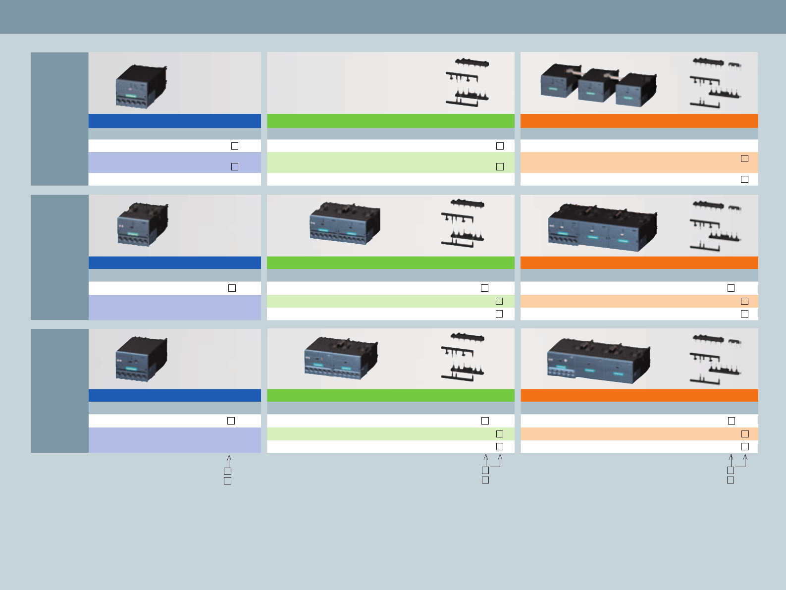
Spring-loaded connection: 2
Screw connection: 1
Spring-loaded connection: 2
29
Size S00 Size S0 Size S2 Size S3 Size S6, S10, S12 Fuseless Load Feeders Communication
Feeder Combinations
Infeed System
Accessories
Communications – Compact Starter
1) CPS: Control and
protective switching device,
IEC/EN 60947-6-2
Setting range
of thermal
overload release
[A]
3RA64 direct-on-line starter 3RA65 reversing starter
Coordination type 2 / CPS1) Coordination type 2 / CPS1)
AC/DC 24 V AC/DC 24 V
0.1 – 0.4 3RA6400- AB42 3RA6500- AB42
0.32 – 1.25 3RA6400- BB42 3RA6500- BB42
1 – 4 3RA6400- CB42 3RA6500- CB42
3 – 12 3RA6400- DB42 3RA6500- DB42
8 – 32 3RA6400- EB42 3RA6500- EB42
Setting range
of thermal
overload release
[A]
3RA61 direct-on-line starter 3RA62 reversing starter
Coordination type 2 / CPS1)
AC/DC 24 V
Coordination type 2 / CPS1)
AC/DC 24 V
0.1 – 0.4 3RA6120- AB34 3RA6250- AB34
0.32 – 1.25 3RA6120- BB34 3RA6250- BB34
1 – 4 3RA6120- CB34 3RA6250- CB34
3 – 12 3RA6120- DB34 3RA6250- DB34
8 – 32 3RA6120- EB34 3RA6250- EB34
AS-Interface add-on modules for 3RA6 Compact Starter (24 V DC )
Without additional inputs/outputs 3RA6970-3A
With two local inputs 3RA6970-3B
With two unassigned external inputs 3RA6970-3C
With one unassigned external input and output each 3RA6970-3D
With two unassigned external outputs 3RA6970-3E
For on-site control 3RA6970-3F
Accessories for Compact Starter with IO-Link and 3RA27 function module
Ribbon cable, 14-pin, 8 cm,
for small gaps between two contactors
3RA2711-0EE02
Module connector, 14-pin, 21 cm,
for wider gaps between two contactors
3RA2711-0EE03
Control module,
(incl. enabling chip and blanking cover)
3RA6935-0A
Connecting cable for
control module
3RA6933-0A
Screw connection: 1
Spring-loaded
connection: 2
Accessories for AS-Interface
AS-i addressing unit 3RK1904-2AB01
IO-Link
+=
AS-Interface
M
M
30
3RA68 Infeed system (Compact Starter)
Type Terminal type Order no.
13-phase feeders
Screw feeding 25/35 mm² left
with fixed-mounted triple expansion module
Screw connection 3RA6812-8AB
Screw feeding 25/35 mm² left
with fixed-mounted triple expansion module
Spring-loaded
connection
3RA6812-8AC
Screw feeding 50–70 mm² left
with fixed-mounted triple expansion module
Screw connection 3RA6813-8AB
Screw feeding 50–70 mm² left
with fixed-mounted triple expansion module
Spring-loaded
connection
3RA6813-8AC
Spring-loaded feeding 25/35 mm²
left or right up to 63 A
3RA6830-5AC
Expansion module
3Dual expansion module with 2 slots Screw connection 3RA6822-0AB
2Triple expansion module with 3 slots Screw connection 3RA6823-0AB
Dual expansion module with 2 slots
Spring-loaded connection
3RA6822-0AC
Triple expansion module with 3 slots
Spring-loaded connection
3RA6823-0AC
4Expansion plug
Expansion plug between 2 expansion modules (already included in the
delivery scope of the expansion modules)
5PE supply
PE supply 25/35 mm² Screw connection 3RA6860-6AB
PE supply 25/35 mm²
Spring-loaded connection
3RA6860-5AC
6PE tap
PE tap 6/10 mm² Screw connection 3RA6870-4AB
PE tap 6/10 mm²
Spring-loaded connection
3RA6870-3AC
7PE expansion plug 3RA6890-0EA
8Link wedge (already included in the scope of supply of 2 and 3)
9Cover cap of the energy bus (already included in the scope of supply of 1)
Adapter for SIRIUS 3RV2 motor starter protector
10 Adapter 45 mm for 3RV2
for motor starter protector with screw connection
3RA6890-0BA
Expansion plug for SIRIUS 3RV19 Infeed system 3RA6890-1AA
Terminal block to integrate 1-, 2- or 3-pole
components
Spring-loaded connection
3RV1917-5D
Items 6 and 9 already included in the scope of delivery
NSB0_01878
1
2
3
4
5
7
6
89
10
31
3RV29 Infeed system (motor starter protector and load feeder)
Type Version Size for
3RV20,
3RV23
motor starter
protectors
Order no.
13-phase busbars
with infeed on the left
incl. end cover
3RV2917-6A
For 2 motor starter
protectors S00, S0 3RV2917-1A
with infeed on the right
incl. end cover
3RV2917-6A
For 2 motor starter
protectors S00, S0 3RV2917-1E
For system expansion
incl. expansion plug
3RV2917-5BA00
For 2 motor starter
protectors S00, S0 3RV2917-4A
2For system expansion
incl. expansion plug
3RV2917-5BA00
For 3 motor starter
protectors S00, S0 3RV2917-4B
Connector
3
4
For contacting the motor
starter protectors
Screw
connection
1 pc. S00 3RV2917-5CA00
10 pcs. S00 3RV2917-5C
Spring-loaded
connection
1 pc. S00 3RV2917-5AA00
10 pcs. S00 3RV2917-5A
Screw
connection
1 pc. S0 3RV1927-5AA00
10 pcs. S0 3RV1927-5A
Spring-loaded
connection
1 pc. S0 3RV2927-5AA00
10 pcs. S0 3RV2927-5A
Accessories
5Contactor base for building up direct-on-line
or reversing starters
1 pc. S00, S0 3RV2927-7AA00
6Terminal block to integrate 1-, 2- or 3-pole
components
3RV2917-5D
DIN rail, 45 mm, to integrate other
devices into the system, such as
5SY motor starter protectors
3RV1917-7B
7Wider expansion plug 3RV2917-5E
Spare parts
8Expansion plug 3RV2917-5BA00
9End cover 3RV2917-6A
NSB0_02078
3
4
1
7
8
2
9
5
6
32
3-phase comb busbars / 8US busbar adapters for supply
Type Size Order no.
3-phase comb busbars
For supplying several 3RV2
motor starter protectors
(screw-connected) mounted
side by side on DIN rails,
safe to touch
Modular
spacing
45 mm
Modular
spacing
55 mm
Modular
spacing
63 mm
For 2 motor starter protectors S00, S0 3RV1915-1AB 3RV1915-2AB 3RV1915-3AB
For 3 motor starter protectors S00, S0 3RV1915-1BB 3RV1915-2BB –
For 4 motor starter protectors S00, S0 3RV1915-1CB 3RV1915-2CB 3RV1915-3CB
For 5 motor starter protectors S00, S0 3RV1915-1DB 3RV1915-2DB –
3-phase supply terminals
Connection from the top S00, S0 3RV2925-5AB
Connection from the bottom S00, S0 3RV2915-5B
3-phase supply terminals to build up “type E starters”
Connection from the top S00, S0 3RV2925-5EB
Accessories
Cover caps for connecting lugs
Touch protection for unassigned slots
S00, S0 3RV1915-6AB
1
2
4
3
6
Type Size Version
(Length)
Order no.
Busbar adapter for 60 mm system
For load feeders
Rated current 16 A for screw connection
S00 200 mm 8US1251-5DS10
For load feeders
Rated current 32 A for screw connection
S0 260 mm 8US1251-5NT10
For load feeders
Rated current 16 A for spring-loaded connection
S00, S0 260 mm 8US1251-5DT11
For load feeders
Rated current 32 A for spring-loaded connection
S0 260 mm 8US1251-5NT11
Accessories
Support
for side mounting on busbar adapter, 45 mm wide
200 mm 8US1251-5AS10
Support
for side mounting on busbar adapter, 45 mm wide
260 mm 8US1250- 5AT10
Side module
to widen the busbar adapter, 9 mm wide
200 mm 8US1998-2BJ10
Spacer
Fixes the load feeder on the adapter
8US1998-1BA10
Vibration/shock kit
To compensate strain from higher vibration and shock
8US1998-1CA10
5
2
1
3
6
1
5
4
Size S00 Size S0 Size S2 Size S3 Size S6, S10, S12 Fuseless Load Feeders Communication
Feeder Combinations
Infeed System
Accessories
33
Accessories for 3RV2 motor starter protector (S00, S0)
1) More versions on request
2) Only available as screw-connected versions
Type Version Order no.
Screw connection
Order no.
Spring-loaded
connection
Order no.
Ring cable
lug connection
Accessories for 3RV2 motor starter protector, size S00, S0
Auxiliary and signaling contacts
Front-mounted auxiliary block 1CO 3RV2901-1D – –
1NO + 1NC 3RV2901-1E 3RV2901-2E 3RV2901-4E
2NO 3RV2901-1F 3RV2901-2F –
Auxiliary switch suited for electronic components
1CO 3RV2901-1G – –
Side-mounted auxiliary block
with 2 contacts
1NO + 1NC 3RV2901-1A 3RV2901-2A 3RV2901-4A
2NO 3RV2901-1B 3RV2901-2B –
2NC 3RV2901-1C 3RV2901-2C –
Side-mounted auxiliary block with 4 contacts 2NO +2NC 3RV2901-1J – –
Signaling switch 3RV2921-1M 3RV2921-2M 3RV2921-4M
Auxiliary release
Shunt trip1) AC/DC 20 – 70 V 3RV2902-1DB0 3RV2902-2DB0 –
AC 210 – 240 V 3RV2902-1DP0 3RV2902-2DP0 –
Undervoltage release1) AC 230 V 3RV2902-1AP0 3RV2902-2AP0 3RV2902-4AP0
AC 400 V 3RV2902-1AV0 3RV2902-2AV0 3RV2902-4AV0
Undervoltage release
with leading auxiliary contacts
AC 230 V 3RV2922-1CP0 3RV2922-2CP0 –
AC 400 V 3RV2922-1CV0 3RV2922-2CV0 –
AC 415 V 3RV2922-1CV1 3RV2922-2CV1 3RV2922-4CV1
Disconnector module and terminal blocks
Disconnector module 3RV2928-1A – –
Terminal block type E
for higher creepage distances and air clearances
3RV2928-1H – –
Phase barriers
for higher creepage distances and air clearances
3RV2928-1K – –
1
2
4
8
3
5
6
Type Version 2) Order no.
Rotary door-coupling operating mechanisms
Rotary door-coupling operating mechanism (black) with
Extension shaft 130 mm 3RV2926-0B
Extension shaft 330 mm 3RV2926-0K
EMERGENCY STOP rotary door-coupling operating mechanism (red/yellow) with
Extension shaft 130 mm 3RV2926-0C
Extension shaft 330 mm 3RV2926-0L
Molded-plastic housing
For motor starter protector (+ Side-mounted auxiliary block) 54 mm 3RV1923-1CA00
For motor starter protector (+ Side-mounted auxiliary block + auxiliary release) 72 mm 3RV1923-1DA00
Molded-plastic housing with EMERGENCY STOP rotary door-coupling operating mechanism
For motor starter protector (+ Side-mounted auxiliary block)
54 mm
3RV1923-1FA00
For motor starter protector (+ Side-mounted auxiliary block + auxiliary release) 72 mm 3RV1923-1GA00
6
5
1
8
3
2
4
34
Accessories for 3RV1 circuit breakers (S2, S3)
Size S00 Size S0 Size S2 Size S3 Size S6, S10, S12 Fuseless Load Feeders Communication
Feeder Combinations
Infeed System
Accessories
NSB0_02184
6
8
1
3
4
2
5
7
Type Version For size Order no.
Accessories for 3RV1 circuit breakers (S2, S3)
Auxiliary and signaling switches
Transverse auxiliary switch 1W S2, S3 3RV1901-1D
1NO + 1NC S2, S3 3RV1901-1E
2NO S2, S3 3RV1901-1F
Transverse auxiliary switch
with 2 contacts
1NO + 1NC S2, S3 3RV1901-1A
2NO S2, S3 3RV1901-1B
2NC S2, S3 3RV1901-1C
Transverse auxiliary switch
with 4 contacts
2NO + 2NC S2, S3 3RV1901-1J
Shunt release AC 230 V S2, S3 3RV1902-1DP0
Undervoltage release AC 230 V S2, S3 3RV1902-1AP0
Undervoltage release
with leading auxiliary switches
AC 230 V S2, S3 3RV1922-1CP0
Signal switch S2, S3 3RV1921-1M
Isolator module S2 3RV1938-1A
1
2
3
4
5
6
7
8
35
Accessories for 3RT201 contactors (S00)
1
3
4
11
2
9
10
12
13
Front mounting auxiliary
contacts for
Version Order no.
Screw connection
Order no. Spring-
loaded connection
Order no. Ring cable
lug connection
3RT2 contactors Standard see tabular overview on page 5ff.
Communication see page 16
1-pole auxiliary contact block,
cable entry from the top
1NO 3RH2911-1AA10 – –
1NC 3RH2911-1AA01 – –
2-pole auxiliary contact block,
cable entry from the top
1NO + 1NC 3RH2911-1LA11 – –
2NO 3RH2911-1LA20 – –
1-pole auxiliary contact block,
cable entry from the bottom
1NO 3RH2911-1BA10 – –
1NC 3RH2911-1BA01 – –
2-pole auxiliary contact block,
cable entry from the bottom
1NO + 1NC 3RH2911-1MA11 – –
2NO 3RH2911-1MA20 – –
4-pole auxiliary contact blocks1),
(in compliance with DIN EN 50 012
and DIN EN 50 005)
1NC 3RH2911-1HA01 3RH2911-2HA01 3RH2911-4HA01
2NC 3RH2911-1HA02 3RH2911-2HA02 3RH2911-4HA02
1NO + 1NC 3RH2911-1HA11 3RH2911-2HA11 3RH2911-4HA11
2NO + 2NC 3RH2911-1HA22 3RH2911-2HA22 3RH2911-4HA22
1NO 3RH2911-1HA10 3RH2911-2HA10 3RH2911-4HA10
2NO 3RH2911-1HA20 3RH2911-2HA20 3RH2911-4HA20
Auxiliary contact blocks suitable for
electronic components
(2-pole)
(in compliance with DIN EN 50 005)
1NO + 1NC 3RH2911-1NF11 3RH2911-2NF11 –
2NO 3RH2911-1NF20 3RH2911-2NF20 –
2Ö 3RH2911-1NF02 3RH2911-2NF02 –
see page 17 (Function modules for mounting on contactors and for interfacing the control system)
Size-specific accessories for 3RT201 contactors (S00)
Auxiliary contact blocks for side
mounting
(in compliance with DIN EN 50 012
and DIN EN 50 005)
2NO 3RH2911-1DA20 3RH2911-2DA20 –
1NO + 1NC 3RH2911-1DA11 3RH2911-2DA11 3RH2911-4DA11
2NC 3RH2911-1DA02 3RH2911-2DA02 –
Auxiliary contact block suited for electronic
components for side mounting (on the right)
(in compliance with DIN EN 50 012 and
DIN EN 50 005)
1NO + 1NC – 3RH2911-2DE11 –
Soldering pin adapter for contactors
with 4-pole auxiliary contact block
For 4 contactors
(pack)
3RT1916-4KA2 – –
Soldering pin adapter for contactors For 4 contactors
(pack)
3RT1916-4KA1 – –
Surge suppressor, e.g. varistor (230 V AC)2)
without LED AC 127–240 V 3RT2916-1BD00 3RT2916-1BD00 3RT2916-1BD00
with LED AC 127–240 V 3RT2916-1JL00 3RT2916-1JL00 3RT2916-1JL00
Terminal module for contactor with
screw connection
Adapter
Plug
AC-3/400 V: 20 A 3RT1916-4RD01 – –
3RT1900-4RE01 – –
3-phase supply terminal Conductor cross
section: 6 mm
3RA2913-3K – –
1) More auxiliary contact blocks on request
2) For further surge suppressors, refer to the Industry Mall
or the IC 10 catalog
765 8
5
6
7
2
3
4
11
1
12
10
13
8
1
9
8
10
36
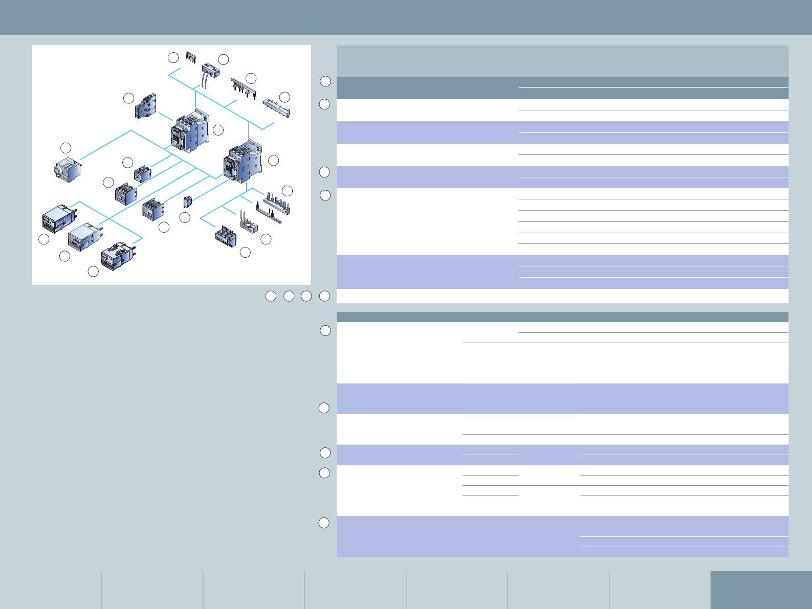
Accessories for 3RT202 contactors (S00)
Front mounting auxiliary
contacts for
Comment Version Order no.
Screw connection
Order no.
Spring-loaded
connection
Order no.
Ring cable lug
connection
3RT2 contactors Standard see tabular overview on page 5ff.
Communication see page 16
1-pole auxiliary contact block,
cable entry from the top
1NO 3RH2911-1AA10 – –
3RH2911-1AA01 – –
2-pole auxiliary contact block,
cable entry from the top
1NO + 1NC 3RH2911-1LA11 – –
2NO 3RH2911-1LA20 – –
1-pole auxiliary contact block,
cable entry from the bottom
1NO 3RH2911-1BA10 – –
1NC 3RH2911-1BA01 – –
2-pole auxiliary contact block,
cable entry from the bottom
1NO + 1NC 3RH2911-1MA11
2NO 3RH2911-1MA20
4-pole auxiliary contact block1),
(in compliance with DIN EN 50 012
and DIN EN 50 005)
1NC 3RH2911-1HA01 3RH2911-2HA01 3RH2911-4HA01
2NC 3RH2911-1HA02 3RH2911-2HA02 3RH2911-4HA02
1NO + 1NC 3RH2911-1HA11 3RH2911-2HA11 3RH2911-4HA11
2NO + 2NC 3RH2911-1HA22 3RH2911-2HA22 3RH2911-4HA22
1NO 3RH2911-1HA10 3RH2911-2HA10 3RH2911-4HA10
2NO 3RH2911-1HA20 3RH2911-2HA20 3RH2911-4HA20
Auxiliary contact blocks suitable
for electronic components (2-pole)
(in compliance with DIN EN 50 005)
1NO + 1NC 3RH2911-1NF11 3RH2911-2NF11 –
2NO 3RH2911-1NF20 3RH2911-2NF20 –
2NC 3RH2911-1NF02 3RH2911-2NF02 –
see page 17 (Function modules for mounting on contactors and for interfacing the controller)
Size-specific accessories for 3RT2 contactors
Auxiliary contact blocks
for side mounting (on the right)
acc. to DIN EN
50 005
2NO 3RH2921-1DA20 3RH2921-2DA20 –
1NO + 1NC 3RH2921-1DA11 3RH2921-2DA11 3RH2921-4DA11
(in compliance
with DIN EN
50 012 and
DIN EN 50 005)
2NC 3RH2921-1DA02 3RH2921-2DA02 –
Auxiliary contact block for side
mounting (on the right), suitable
for electronic components
acc. to
DIN EN 50
005
1NO + 1NC – 3RH2921-2DE11 –
Overvoltage limiter, e.g. varistor (230 V AC)
without LED AC 127–240 V 3RT2926-1BD00 3RT2926-1BD00 3RT2926-1BD00
with LED AC 127–240 V 3RT2926-1JL00 3RT2926-1JL00 3RT2926-1JL00
Terminal module for contactor
with screw connection
Adapter AC-3/400 V:
25 A
3RT1926-4RD01 –
Plug 3RT1900-4RE01 –
Pneumatic delay block
(in compliance with
DIN EN 50 005)
1NO + 1NC
0.1 – 30 s ON delay 3RT2926-2PA01 – –
1 – 60 s 3RT2926-2PA11 – –
0.1 – 30 s OFF delay 3RT2926-2PR01 – –
1 – 60 s 3RT2926-2PR11 – –
Coil terminal module
Connection from the top
Connection from the bottom
Diagonal connection
3RT2926-4RA11 3RT2926-4RA12 –
3RT2926-4RB11 3RT2926-4RB12 –
3RT2926-4RC11 3RT2926-4RC12 –
1
13
3
10
2
12
9
11
1) More auxiliary contact blocks on request
2) For further surge suppressors, refer to the Industry
Mall or the IC 10 catalog
4
765 8
Size S00 Size S0 Size S2 Size S3 Size S6, S10, S12 Fuseless Load Feeders Communication
Feeder Combinations
Infeed System
Accessories
37
12
6
7
8
4
3
10
11
13
5
1
9
1
513
5
5
2
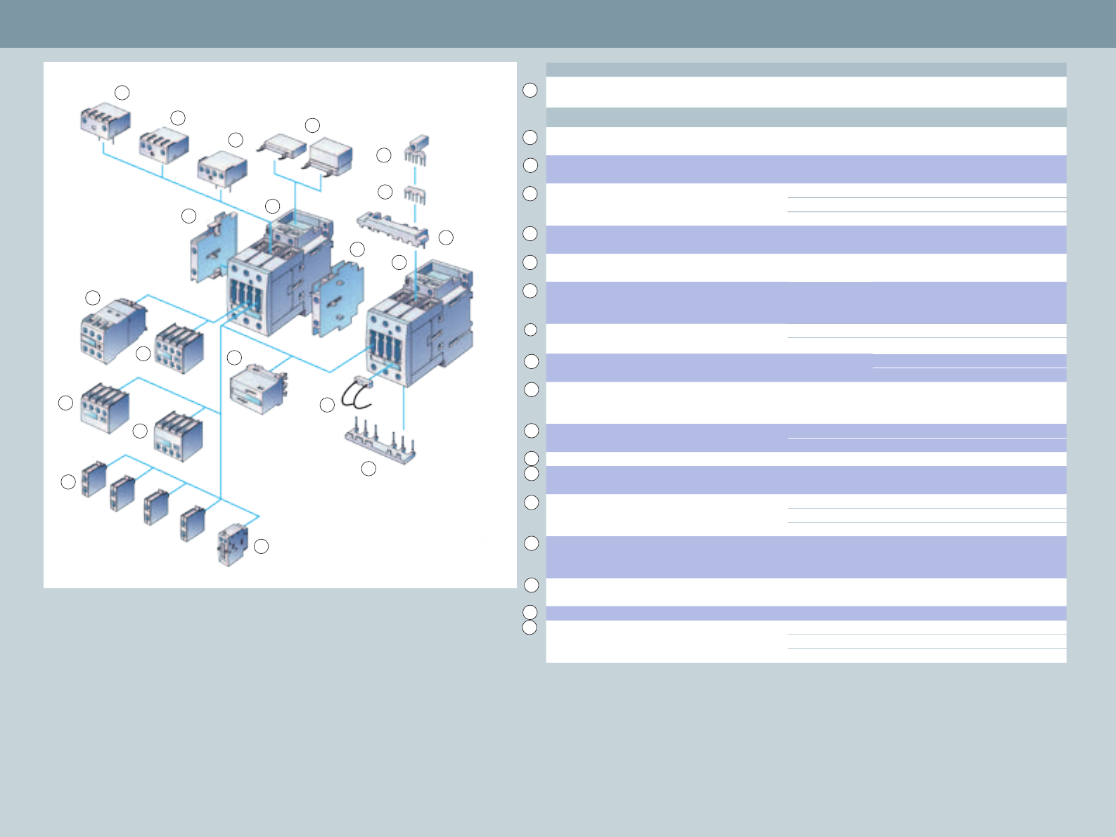
Accessories for 3RT1 contactors (S2 to S3)
Version For size Order no.
Contactor, size S2 (example)
control supply voltage
7.5 kW/400 V
230 V 50 Hz
3RT10 25-1AP00
For sizes S2 to S3
Solid-state time-delay block,
ON delay
0.5 – 10 s 3RT19 26-2CH21
Solid-state time-delay block,
OFF delay
0.5 – 10 s 3RT19 26-2DH21
Auxiliary switch block, solid-state time-delay
ON delay
OFF delay
0.5 – 10 s 3RT19 26-2ED21
0.5 – 10 s 3RT19 26-2FL21
2-pole auxiliary switch block,
cable entry from above
1NO + 1NC 3RH19 21-1LA11
2-pole auxiliary switch block,
cable entry from below
1NO + 1NC 3RH19 21-1MA11
4-pole auxiliary switch block,
(terminal designations acc. to
DIN EN 50 012 or DIN EN 50 005)
2NO + 2NC – 3RH19 21-1HA11
Link for paralleling (star jumper), 3-pole,
without terminal
S2 3RT19 36-4BA31
S3 3RT19 46-4BA31
Link for paralleling, 3-pole, with terminal S2 3RT19 36-4BB31
S3 3RT19 46-4BB31
2-pole auxiliary switch block, can be laterally
mounted (left or right), (terminal designations
acc. to DIN EN 50 012 or DIN EN 50 005)
1NO + 1NC S2 – S12 3RH19 21-1DA11
1-pole auxiliary switch block
(up to 4 can be snapped on)
1NO S2 – S3 3RH19 21-1CA10
1NC S2 – S3 3RH19 21-1CA01
Mechanical interlock, can be laterally mounted – S2 – S3 3RA19 24-2B
Mechanical interlock, can be mounted
at the front
– S2 – S3 3RA19 24-1A
Wiring connectors at the top and bottom
(reversing operation)
– S2 3RA19 23-2A
– S2 3RA19 33-2A
– S3 3RA19 43-2A
Surge suppressor (varistor, RC coupling,
diode combination), can be mounted
at the top or bottom
– S2 – S3 3RT19 26-1BD00
Interface for mounting directly onto the
contactor coil
– S2 – S3 3RT19 26-3AB31
LED module to indicate contactor operation – S2 – S3 3RT19 26-1QT00
Mechanical latching AC/DC 24 S2 3RT19 26-3AB31
AC/DC 110 S2 3RT19 26-3AF31
AC/DC 230 S2 3RT19 26-3AP31
1
2
9
4
3
5
6
7
8
10
11
12
13
14
15
16
17
18
1) For further surge suppressors, refer to the Industry Mall
or the IC 10 catalog
1
2
3
16
15
9
8
14
10
1
10
4
713
5
6
11
18
14
17
38
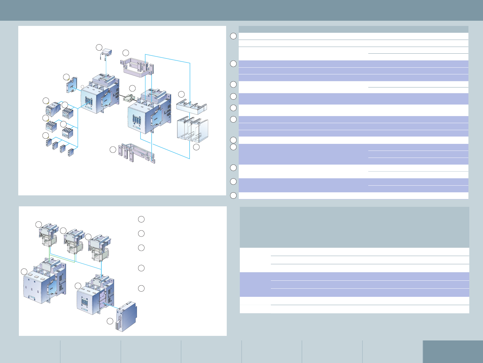
Gleiches Zubehör für Baugrössen S0 bis S12
Gleiches Zubehör für Baugrössen S6 bis S12
Zubehör unterschiedlich je nach Baugrösse
1
12
12
11
1
10
1
6
11
1
1
1
1
6
1
1
Schüte
Baugrössen S6 bis S12 it Zubehör
ilfsschalterblc eletrnisch erögert
ansrech der rücfallerögert der Sternreiecuntin
liger ilfsschalterblc
nschlussbeeichnungen nach 0 012 der 0 00
2liger ilfsschalterblc eitungseinführung n ben
2liger ilfsschalterblc eitungseinführung n unten
1liger ilfsschalterblc a aufschnabar
2liger ilfsschalterblc seitlich rechts der lins anbaubar
nschlussbeeichnungen nach 0 012 der 0 00
gleich für S0 bis S12
bersannungsbegrener Glied ben an inschubsule anstecbar
echanische erriegelung seitlich anbaubar
erdrahtungsbausteine ben und unten eersierbetrieb
uftschüt 10 und 1 Baugrössen S6 S10 und S12
10
11
arallelschalterbindung Sternuntbrüce
lig it urchgangslch unterschiedlich für
Baugrössen S6 und S10S12
nschlussabdecung für abelschuh und
Schienenanschluss unterschiedlich für
Baugrössen S6 und S10S12
leenabdecung für ahenlee
unterschiedlich für Baugrössen S6 und S10S12
ahenleenblc unterschiedlich für
Baugrössen S6 und S10S12
8
9
11
10
8
7
1
62
4
5
3
Operating mechanism types
2
3
1
4
2
5
5
Accessories for 3RT1 contactors (S6 to S12)
Size S00 Size S0 Size S2 Size S3 Size S6, S10, S12 Fuseless Load Feeders Communication
Feeder Combinations
Infeed System
Accessories
Type Version Order no.
12-pole auxiliary switch block, can be laterally mounted
– 2nd block (left/right), DIN EN 50 012 1NO + 1NC 3RH1921-1JA11
– 2nd block (left/right), DIN EN 50 005 1NO + 1NC 3RH1921-1KA11
2NO 3RH1921-1KA20
24-pole auxiliary switch block, can be mounted at the front
– with classification No. 5…8, DIN EN 50 012 2NO + 2NC 3RH1921-1XA22-0MA0
– with classification No. 1…4, DIN EN 50 012 2NO + 2NC 3RH1921-1HA22
31-pole auxiliary switch block, can be mounted at the front 1NO 3RH1921-1CA10
1NC 3RH1921-1CA01
42-pole auxiliary switch block, can be mounted at the front,
cable entry from above, DIN EN 50 005
1NO + 1NC 3RH1921-1LA11
52-pole auxiliary switch block, can be mounted at the front,
cable entry from below, DIN EN 50 005
1NO + 1NC 3RH1921-1MA11
6Auxiliary switch block, solid-state time-delay 1NO + 1NC
– ON delay, 200–240 V AC 0 ... 10 s 3RH1926-2ED21
– OFF delay, 200–240 V AC 0.5 ... 10 s 3RH1926-2FL21
7RC element, 127–240 V AC1) 3RT1956-1CD00
8Wiring connectors
top and bottom
for S6 3RA1953-2M
for S10 3RA1963-2A
for S12 3RA1973-2A
9Connection cover for box terminals for S6 3RT1956-4EA2
for S10/S12 3RT1966-4EA2
10 Terminal cover for cable lug and busbar connection for S6 3RT1956-4EA2
for S10/S12 3RT1966-4EA2
11 Mechanical interlock 3RA1954-2A
Size 3-phase-
motor
400 V/AC-3
Contactor without
coil
Withdrawable coil for operating mechanism
conventional electronic
control supply voltage
AC/DC 220...240 V AC/DC 200...277 V
kW Order no. Order no. Order no.
S6 55 3RT1054-1LA06 3RT1955-5AP31 3RT1955-5NP31
75 3RT1055-6LA06
90 3RT1056-6LA06
S10 110 3RT1064-6LA06 3RT1965-5AP31 3RT1965-5NP31
132 3RT1065-6LA06
160 3RT1066-6LA06
S12 200 3RT1075-6LA06 3RT1975-5AP31 3RT1975-5NP31
250 3RT1076-6LA06
13RT10 and 3RT14 air contactors,
Sizes S6, S10 and S12
23RT12 vacuum contactor, Sizes S10
and S12
3Withdrawable coils for contactors
with conventional operating
mechanism 3RT1…-.A..
4Withdrawable coils for contactors
with electronic operating
mechanism 3RT1…-.N..
5Withdrawable coils and laterally
mounted module (can be plugged
in) for contactors with electronic
operating mechanism and remain-
ing lifetime signal 3RT1…-.P.. and
2RT1…-.Q
1) For further surge suppressors, refer to the Industry Mall
or the IC 10 catalog 39
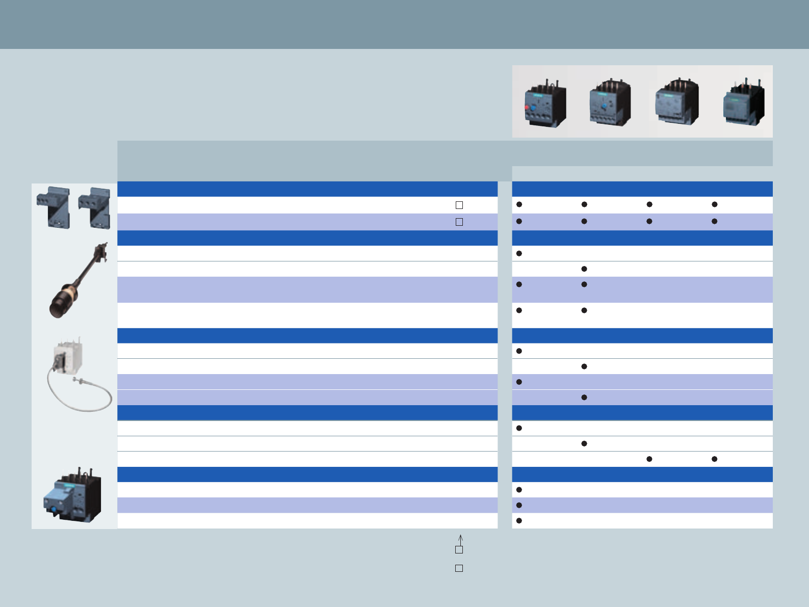
Version For size Order no. Can be combined with the following overload
and current monitoring relays
3RU2 3RB3 3RR21 3RR22
Relay base for stand-alone mounting
For mounting the overload relays separately S00 3RU2916-3A 01
For screw and snap-on mounting on TH 35 DIN rail S0 3RU2926-3A 01
Mechanical RESET consisting of:
Reset slide, holder and funnel S00, S0 3RU2900-1A
Reset slide, holder and funnel S00, S0 3RB3980-0A
Push button with elongated stroke (12 mm),
IP65, Ø 22 mm
S00, S0 3SB3000-0EA11
Extension tappet to even out the spacing between a push
button and the reset button of the relay
S00, S0 3SX1335
Cable release with holder for RESET for bores Ø 6.5 mm in the control panel
Length 400 mm S00, S0 3RU2900-1B
Length 400 mm S00, S0 3RB3980-0B
Length 600 mm S00, S0 3RU2900-1C
Length 600 mm S00, S0 3RB3980-0C
Sealable cover for 3RB20/21, transparent
For covering the setting components S00, S0 3RV2908-0P
For covering the setting components S00, S0 3RB3984-0
For covering the setting components S00, S0 3RR2940
Modules for remote reset
24 ... 30 V AC/DC S00, S0 3RU1900-2AB71
110 ... 127 V AC/DC S00, S0 3RU1900-2AF71
220 ... 250 V AC/DC S00, S0 3RU1900-2AM71
Accessories for 3RU21 thermal overload relay, 3RB30/31 solid-state overload relay,
3RR21 analog current monitoring relay and 3RR22 digital current monitoring relay (S00, S0)
Screw connection: A
Spring-loaded
connection: C
40

Accessories for 3RU11 thermal overload relay
and 3RB20/21 solid-state overload relay
Size S00 Size S0 Size S2 Size S3 Size S6, S10, S12 Fuseless Load Feeders Communication
Feeder Combinations
Infeed System
Accessories
Version For size Order no.
Terminal support for stand-alone assembly for 3RU11
for separately mounting the overload relays,
screw-type and snap-on fastening on TH 35 DIN rails,
size S3 also for TH 75 DIN rails
S2 3RU1936-3AA01
S3 3RU1946-3AA01
Mechanical RESET for 3RU11 and 3RB20/21
comprising:
1 Resetting plunger, holder and former S2 – S10/S12 3RU1900-1A
2 Push button with extended stroke (12 mm),
IP65, Ø 22 mm
S2 – S10/S12 3SB3000-0EA11
Extension plunger for compensation of the distance
between a push button and the relay‘s release button
S2 – S10/S12 3SX1335
Cable release with holder for RESET 3RU11 and 3RB20/21
for holes 6.5 mm diameter in the panel; max. panel thickness 8 mm
Length 400 mm S2 – S10/S12 3RU1900-1B
Length 600 mm S2 – S10/S12 3RU1900-1C
Sealable cover, transparent for 3RB20/21
to cover the setting elements S2 – S10/S12 3RB2984-0
Terminal covers for 3RU11 and 3RB20/21
Cover for cable lug and busbar connection S3 3RT1946-4EA1
S6 3RT1956-4EA1
S10/S12 3RT1966-4EA1
Cover for box terminals S2 3RT1936-4EA2
S3 3RT1946-4EA2
S6 3RT1956-4EA2
S10/S12 3RT1966-4EA2
Cover for the screw connection between the contactor and
overload relay without box terminals (1x is required for each
combination)
S6 3RT1956-4EA3
S10/S12 3RT1966-4EA3
Box terminal block
for round and ribbon cables up to 70 mm2S6 3T1955-4G
up to 120 mm2S6 3T1956-4G
up to 240 mm2S10/S12 3T1966-4G
Accessories for motor starters
3-phase
motor
400 V/AC-3
[kW]
Enclosure for direct starters Size Order no.
22 Moulded-plastic enclosure
for wall mounting IP65
degree of protection
with actuator elements
S2 3RE1933-1CB3
Components
required
Order no. Qty.
Contactor 3RT10 3 1
Thermal or
solid-state overload relay
3RU11 36 resp.
2RB10 36
1
Lateral auxiliary switch 1NO/1NC 3RH1021-1DA11 1
1
2
41

42
Support
As competent and reliable partner, we not only offer tried-and-tested products
and systems, but also comprehensive support – from initial information to planning,
configuration and ordering, down to commissioning, ongoing operation and
technical service:
■ Access to all important and up-to-date information: From the website to the news-
letter, down to the download of complete brochures
■Ordering and information platform for all products and systems
■Efficient tools for increased productivity, e.g. CAx DVD for your configuration
process
■Service & Support Portal for comprehensive technical information on configuration
and system documentation
We thus provide you with a comfortable basis for optimizing your processes.
In short: Support for improved efficiency!
Information
Planning
Configuration
Ordering
Commissioning
Operation
Service
Promotion website Product
information
Newsletter portal
Information and Download Center
Product selection
Industry Mall
Software
for Industrial Controls Product & system engineering
Service & Support Portal
Product documentationCAx DVD
Image database
SITRAIN Portal Product training
Technical Assistance Product hotline
Product information
Comprehensive information on
Industrial Controls
Amongst others, rapid and targeted
provision of information on:
■SIRIUS Industrial Controls
Ensure your success with our
trendsetting system solutions!
www.siemens.com/
sirius
Newsletter: always up to date
Constantly updated information on
the subjects of Industrial Controls
www.siemens.com/
industrial-controls/
newsletter
Easy download of catalogs and
information material
Our Information and Download
Center offers all current
■Catalogs
■Customer magazines
■Brochures
for download
www.siemens.com/
industrial-controls/
infomaterial
Product selection
Industry Mall: platform for
e-business and product
information
Benefit from 24/7 access to our
comprehensive information and
ordering platform for the complete
Industrial Controls portfolio,
including:
■Selection tools, product and
system configurators
■Availability check
■Order tracking
www.siemens.com/
industrial-controls/
mall
www.siemens.com/
industrial-controls/
configurators
Product information Product selection

43
Product & system engineering
Software for Industrial Controls:
easy, fast and safe
Our software supports you
throughout all project phases – from
planning to parametrization, down
to operation.
■Parametrization and Configuration
with SIRIUS Industrial Controls
■Planning and Dimensioning
of electrical power distribution
systems with SIMARIS
www.siemens.com/
industrial-controls/
mall
www.siemens.com/
simaris
Product documentation
Online support: full-range
technical product information
24/7 access to comprehensive
technical information on our products
and systems to support you from the
planning to the configuration down to
the operation phase.
■Product data sheets, manuals/
operating instructions
■Certificates, characteristic curves,
downloads
■FAQs
www.siemens.com/
industrial-controls/
support
Technical Product Data for CAx Ap-
plications: immediate availability
of configuration-relevant CAx data
types for your CAD/CAE system
This DVD provides you with a com-
prehensive pool of configuration-
relevant CAx data types.
■Commercial and technical product
master data
■2-D dimension drawings, isometric
illustrations and 3-D models
■Product data sheets
■Tender specifications
CAx Online-
Generator:
www.siemens.com/
industrial-controls/
support
CAx-DVD:
Order no. E86060-
D1000-A207-A7-6300
(Industry Mall)
Product training
Easy download of
product image material
Our image database contains all
current
■Product images
■2-D dimension drawings, isometric
illustrations and 3-D models
■Internal circuit diagrams
■Symbols
in diverse versions for free
download.
www.siemens.com/
industrial-controls/
picdb
Training: knowledge expansion
Our training offer both comprises
an overview as well as detailed
competencies regarding selected
products and systems. Amongst
others, you can expand your product
and system know-how of SIRIUS.
www.siemens.com/
sitrain
Or contact us
personally via the
information hotline:
via telephone:
+49 (911) 895 7575
via fax:
+49 (911) 895 7576
via e-mail:
info@sitrain.com
Product hot line
Technical Assistance:
competent Industrial Controls
expert consulting
We support you with all technical
enquiries regarding our products
and systems – both before and after
delivery.
■Product selection
■Old/new conversions, competitor
conversions
■Special versions, special
requirements
■Commissioning, operation
Tip: the Service & Support Portal,
including the FAQ database, can
be called up via www.siemens.
com/industrial-controls/technical-
assistance. You can also directly
submit your support request to a
technical consultant.
www.siemens.com/
industrial-controls/
technical-assistance
Personally from
Mo. through Fr.
8.00 am to 5.00 pm
(CET)
via telephone:
+49 911 895 5900
via e-mail:
technical-assistance@
siemens.com
via fax:
+49 911 895 5907

The information provided in this brochure contains me re ly
general descriptions or characteristics of per for m ance which
in ac tual case of use do not always ap ply as described or which
may change as a result of fur ther de ve lopment of the pro ducts.
An obligation to provide the respective characteristics shall
only exist if ex pressly agreed in the terms of contract.
All product designations may be trademarks or product na mes
of Siemens AG or supplier companies whose use by third
parties for their own purposes could violate the rights of the
owners.
www.siemens.com/sirius
Subject to change without prior notice 08/10
Order no.: E20001-A380-P302-V6-7600
Dispo 27601
SRXX.52.1.01 WS 09105.0
Printed in Germany
© Siemens AG 2010
Siemens AG
Industry Sector
Control Components and Systems Engineering
P. O. Box 23 55
90713 FÜRTH
GERMANY
