106624 Catalog
2016-10-06
: Pdf 106624-Catalog 106624-Catalog B5 unilog
Open the PDF directly: View PDF ![]() .
.
Page Count: 172 [warning: Documents this large are best viewed by clicking the View PDF Link!]

www.schneider-electric.co.uk
PowerLogic
System
Energy management, revenue metering
and power quality monitoring

schneider-electric.co.uk/metering 2

Basic energy metering
IEM2000 series, IEM2100 series and IEM3000 series
Product overview
Technical Specification
10
22
Basic multi-function metering
PM3000 series and PM5000 series
Product overview
Technical specification
28
38
Intermediate metering
PM8000 series
Product overview
Technical specification
48
58
Advanced metering
ION7550/7650 series
Product overview
Technical specification
64
74
Advanced utility metering
ION8800 series
Product overview
Technical specification 78
88
Multi-circuit metering
BCPM
Product overview
Technical specification
92
106
Communications
Link150, Com’X 200, Com’X 510 and ION7550 RTU
Product overview
Technical specification
112
132
Monitoring software
StruxureWare power management software
Product overview 142
Other PowerLogic offers
Retrofit metering kits and current transformers
Product overview 151
Contents
3schneider-electric.co.uk/metering

Schneider Electric believes every business can increase productivity while
consuming less and achieving energy savings of 10% to 30%.
Saving energy reduces costs and pollution, but you need the tools to uncover all opportunities,
avoid risks, track progress against goals, and verify success. Schneider Electric provides these
tools via the world’s most advanced energy intelligence technology: PowerLogic.
The PowerLogic range of meters and software help manage all energy assets, every second of the
day. A PowerLogic system enables all stakeholders, from CEO to facility and engineering managers,
to respond quickly to potential problems and manage energy in financial and environmental terms.
PowerLogic technology delivers the key performance indicators and analytics that you need to
strategically balance emissions, efficiency, reliability and cost.
PowerLogic technology
forms one part of your
total energy management
solution from Schneider
Electric. As the global
energy management
specialist, we offer end-
to-end power, building
and process management
solutions that help you
optimise energy use and
costs, improve performance,
enhance comfort and safety,
and deliver uninterrupted
service while taking
responsible care of our
planet.
Our expert services can
help you audit your energy
use and build your energy
action plan. From power
factor correction systems,
harmonic filtering and
variable speed drives to
HVAC and lighting controls,
we offer a complete
range of energy efficient
technologies.
PowerLogic
System is…
Today
Passive Energy Efficiency
Active Energy Efficiency
1. Measure 2. Fix the basics
3. Optimise,
Automate
and Regulate
4. Monitor,
Maintain and
improve
schneider-electric.co.uk/metering 4
Cutting-edge technology to increase profitability
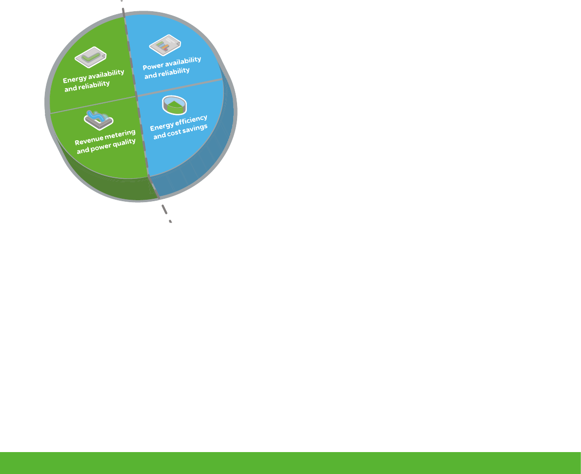
PowerLogic technology converts the complex dynamics governing the relationship between power
generation and distribution on the utility side, and energy consumption, cost and reliability on the
consumer side, into timely, easily understood information. Businesses can use this powerful to improve
tactical actions and strategic decision making.
From a single facility to an entire enterprise, PowerLogic meters monitor key distribution points 24 hours a day. Whether
from generators, substations, service entrances, mains, feeders, loads or 3rd party equipment and systems, PowerLogic
technology tracks, records and reports all real-time conditions and historical performance data. Intuitive web-based interfaces
give stakeholders access to this data as well as advanced analytics, alarm annunciation and control capabilities. It supports
comprehensive energy management programs by tracking performance and empowering you to make effective decisions.
Supply
Energy availability and reliability
• Improve T&D network reliability
• Enhance substation automation
• Maximise the use of your existing infrastructure
Revenue metering and power quality
• Maximise metering accuracy at all interchange points
• Verify compliance with new power quality standards
• Analyse and isolate the source of power quality problems
Demand
Power availability and reliability
• Validate that power quality complies with the energy
contract
• Verify the reliable operation of power and mitigation
equipment
• Improve response to power-related problems
• Leverage existing infrastructure capacity and avoid
over-building
• Support proactive maintenance to prolong asset life
Energy efficiency and cost savings
• Measure efficiency, reveal opportunities and verify
savings
• Manage green house gas emissions
• Allocate energy costs to departments or processes
• Reduce peak demand and power factor penalties
• Enable participation in loadcurtailment programs
(e.g. demand response)
• Strengthen rate negotiation with energy suppliers
• Identify billing discrepancies
• Sub-bill tenants for energy costs
Gain energy insight and control
with PowerLogic™
5schneider-electric.co.uk/metering

Buildings
Building managers through operations staff can cut
energy and maintenance costs without effecting the
comfort or productivity of their tenants, employees,
students, patients or customers. A PowerLogic system will
track all utilities and equipment conditions, and enterprise-
level software will help you analyse and improve electrical
reliability.
You can forecast energy requirements, optimise multi-site
contracts and accurately allocate or sub-bill costs. Key
performance indicators help you find and sustain energy
savings, reduce emissions and meet “green” building
standards in order to increase asset value and attract or
retain tenants..
• tenant sub-billing
• cost allocation
• energy efficiency /
benchmarking
• procurement optimisation
• power availability
• demand response / load
curtailment
Market segments
Industry
From finance to engineering, PowerLogic technology
gives industry professionals the energy intelligence and
control they need to support strategic decisions and
establish best energy practices. It will help you reduce
operational costs and meet new emissions standards
without compromising production schedules or product
quality.
Key points are monitored throughout your power
distribution, building and backup systems. Enterprise-
level software helps you maximise the use of your
existing energy assets, increase energy efficiency
and avoid demand or power factor penalties. Use it
to uncover hidden power problems that can shorten
equipment life or cause costly downtime.
• cost allocation
• procurement optimisation
• power factor correction
schneider-electric.co.uk/metering 6

Critical infrastructure
PowerLogic technology helps keep your systems operating
continuously and securely with an economical supply
of energy. Whether you manage data, communication,
transportation or environmental services, minimising the risk
of power-related downtime and keeping costs under control
is a priority.
A PowerLogic solution monitors all power and cooling
systems and accurately tracks their energy consumption.
Enterprise-level software delivers insightful diagnostics
and metrics to help verify the reliability of your backup
systems and maximise the use of existing capacity to
defer new capital investments. You can also reveal energy
inefficiencies and strengthen energy procurement across
multiple sites.
Utilities
Today’s energy market is more complex than ever before.
Whether you generate, transmit or distribute electricity,
more stakeholders need shared access to timely, accurate
energy data from more exchange points and you need to
maintain power availability and reduce price volatility in
the face of rising demand and transmission congestion. A
PowerLogic energy information system helps you meet all
of these challenges by:
• Metering all key interchange points with the highest
possible accuracy
• Improving the quality of power delivered to your
customers
• Essuring the reliability and efficiency of your network
and equipment.
From advanced energy and power quality metering
systems to enterprise-level analytic software, PowerLogic
solutions deliver business-critical information that
conventional metering, SCADA and billing systems
cannot. It gives you the energy intelligence and control
needed to track performance, stay informed of critical
conditions and empower you to make strategic decisions.
It will help you increase reliability, maximise the use of
resources and improve service.
• revenue metering
• power availability and reliability
• infrastructure optimisation
• power quality analysis compliance
• alarming and event notification
• energy efficiency
• cost allocation
• procurement optimisation
7schneider-electric.co.uk/metering

Simplifying Specification
Product selector
Build your own specification
Live updates to CPD course calendar
Keep track of most current legislation
Dedicated resource area for tech and spec sheets
Tools to help you...
PowerLogic Toolkit
Download here: schneider-electric.co.uk/pltoolkit

Your unique metering system in the palm of your hand
Easy to use meter selection tool based on your requirements
Search by feature, application or competitive offer
Access and download product data sheets
Direct link to customer support
Scan the QR code to download
your App on iOS or Android
Meter Selector App

Basic energy
metering
schneider-electric.co.uk/metering 10

Applications
Basic energy meters are designed for sub-metering/billing and cost allocation
of energy consumed for each sector, unit, workshop etc. in buildings, industry,
data centres and infrastructure.
11schneider-electric.co.uk/metering

Energy meters designed to gather the data you need to clearly understand your
energy costs. Whether you require a single-phase kWh meters or full-featured,
dual tariff energy meter, Schneider Electric is introducing a NEW iEM2100 series
meter that is the best fit for your customer’s application.
• PowerLogic iEM2000 series
• NEW PowerLogic iEM2100 series
• PowerLogic iEM3000 series
Basic energy metering
Product
overview
12 schneider-electric.co.uk/metering
BASIC ENERGY METERING FUNCTIONS AND CHARACTERISTICS
13schneider-electric.co.uk/metering
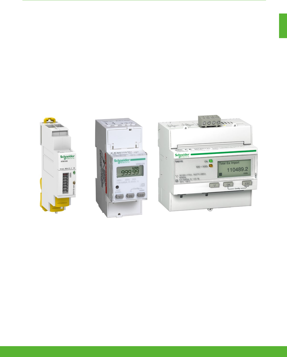
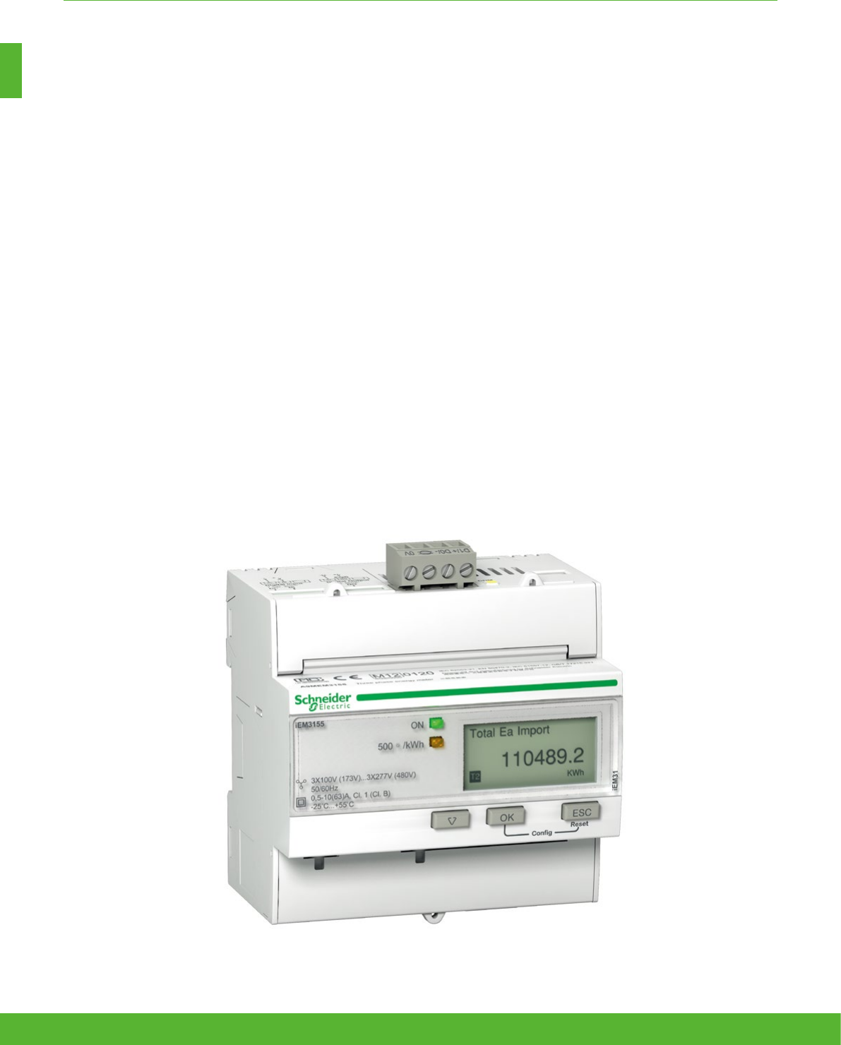
The Acti9 iEM2000 series energy meters offer a cost-attractive, competitive range of single-phase
DIN rail-mounted energy meters ideal for sub-billing and cost allocation applications.
Acti9 iEM2000 Series
BASIC ENERGY METERING FUNCTIONS AND CHARACTERISTICS
Applications
• To monitor the power consumption of each sector, unit, workshop…
• To manage an electrical installation and optimise your building’s power efficiency
• For business, industrial and residential applications
schneider-electric.co.uk/metering 14

The solution for
All markets that can benefit from a solution that includes
PowerLogic iEM2000 series meters:
• Buildings eg. student accommodation
• Industry
• Data Centre & networks
• Infrastructures (airport, road tunnels, telecom).
Competitive advantages
• MID compliant (selected models) providing certified
accuracy and data security
• Compact size
• A complete range of energy meters
• Compatible with Acti9 range
Benefits
The Acti 9 iEM2000 series meters are economical and easy to
install in all switchboards up to 10 kVA.
Energy management system:
To get the most effective use from your
Schneider Electric measurement and
metering devices, we offer a range of
dedicated data logger and gateway for
your building energy management. See
Page 114
Conformity of standards
• IEC 62053-21
• IEC 61557-12
• EN50470-3
BASIC ENERGY METERING FUNCTIONS AND CHARACTERISTICS
Feature selection
iEM2000T iEM2000 iEM2010
Self-powered
nnn
Display n/a
n n
Width (mm) 18 18 18
Current input 40A 40A 40A
Active Energy accuracy Class 1 Class 1 Class 1
Reactive Energy accuracy n/a n/a n/a
Four quadrant Energy measurement n/a n/a n/a
Multi-tariff n/a n/a n/a
Digital inputs n/a n/a n/a
Digital outputs 1 P/O n/a 1 P/O
Communication protocol n/a n/a n/a
MID for billing application n/a n n
Ordering reference A9MEM2000T A9MEM2000 A9MEM2010
15schneider-electric.co.uk/metering
BASIC ENERGY METERING FUNCTIONS AND CHARACTERISTICS
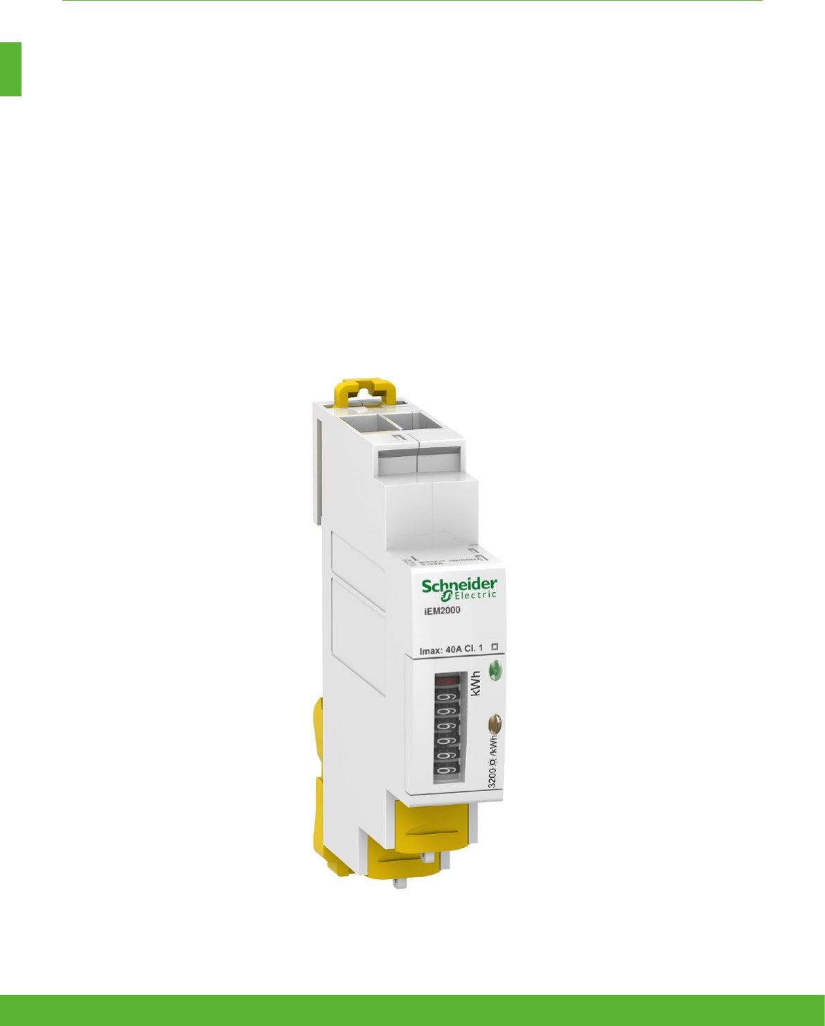
The Acti9 iEM2100 series energy meters are ideal for basic Kwh metering and billing applications and
support two protocols (Modbus and M-bus) that allow them to integrate seamlessly into your customers’
existing networks.
Acti9 iEM2100 Series
Applications
• To monitor the power consumption of each sector, unit, workshop…
• To manage an electrical installation and optimise your building’s power efficiency
• For business, industrial and residential applications
schneider-electric.co.uk/metering 16

The solution for
All markets that can benefit from a solution that includes PowerLogic
iEM2100 series meters:
• Buildings eg. student accommodation
• Industry
• Data Centre & networks
• Infrastructures (airport, road tunnels, telecom).
Energy management system:
To get the most effective use from your
Schneider Electric measurement and
metering devices, we offer a range of
dedicated data logger and gateway for
your building energy management. See
page 114
Competitive advantages
• Compact size
• MID compliant (selected models) providing certified
accuracy and data security
• Four quadrant measurement
• Electrical parameter measurement eg. V, I, P, PF
• Onboard Modbus or M-bus communication
• A complete range of energy meters
• Compatible with Acti9 range
Feature selection
iEM2100 iEM2105 iEM2110 iEM2135 IEM2150 iEM2155
Self-powered
nnnnnn
Display
nnnnnn
Width (mm) 36 36 36 36 36 36
Current input 63A 63A 63A 63A 63A 63A
Active Energy
accuracy Class 1 Class 1 Class 1 Class 1 Class 1 Class 1
Reactive Energy
accuracy n/a n/a n/a n/a Class 2 Class 2
Four quadrant Energy
measurement n/a n/a
nnnn
Multi-tariff n/a n/a 2 2 n/a 2
Digital inputs n/a n/a 1 (tariff switching) n/a n/a n/a
Digital outputs n/a 1 P/O 2 P/O's n/a n/a n/a
Communication
protocol n/a n/a n/a M-bus Modbus RS485 Modbus RS485
MID for billing
application n/a n/a
n n
n/a
n
Ordering reference A9MEM2100 A9MEM2105 A9MEM2110 A9MEM2135 A9MEM2150 A9MEM2155
Conformity of standards
• IEC61557-21
• IEC 62053-23
• EN50470-3
Benefits
The Acti 9 iME kilowatt-hour meters are specially economic
and easy to install in all switchboards.
BASIC ENERGY METERING FUNCTIONS AND CHARACTERISTICS
17schneider-electric.co.uk/metering
BASIC ENERGY METERING FUNCTIONS AND CHARACTERISTICS
Applications
Cost management applications
• Bill checking to verify that you are only charged for the energy you use
• Sub billing individual tenants for their energy consumption, including WAGES
• Aggregation of energy consumption, including WAGES, and allocating costs per area, per usage, per shift, or
per time within the same facility
Network management applications
• Basic metering of electrical parameters to better understand the behaviour of your electrical distribution system
Acti9 iEM3000 Series
The Acti 9 iEM3000 series energy meters is a cost-attractive, feature-rich energy metering offer for
DIN rail, modular enclosures. With Modbus, BACnet, M-bus and LON protocol support, you can easily
integrate these meters into commercial and non-critical buildings to add simple energy management
applications to any BMS, AMR or EMS system.
schneider-electric.co.uk/metering 18

The solution for
All markets that can benefit from a solution that includes
PowerLogic iEM3000 series meters:
• Buildings & industry
• Data centres and networks
• Infrastructure (airports, road tunnels, telecom)
BASIC ENERGY METERING FUNCTIONS AND CHARACTERISTICS
Conformity of standards
• IEC 61557-12
• IEC 62053-
21/22
• IEC 62053-23
• EN 50470-3
• IEC 61036
• IEC 61010
Benefits
Optimise your energy consumption & enable energy efficiency
practices
• Collect and analyse energy consumption data from each
area for each type of load or circuit
• Gain an accurate understanding of business expenses by
allocating the energy-related costs
• Use information to implement actions designed to reduce
energy consumption
Monitor the energy consumption of your tenants or customers
and establish accurate invoices
• Drive energy-efficient behaviour
• Allow building owners to bill tenants for individual measured
utility usage
• Give accurate and achievable objectives for energy savings
More than just kWh meters, the Acti 9 iEM3000 series meters provide a full view of both energy consumption and on-site
generation with full four-quadrant measurement of active and reactive energy delivered and received. Additionally, extensive
real-time measurements (V, I, P, PF) give customers greater detail on their energy usage, and multiple tariffs give customers
the flexibility to match the billing structure of their utility.
Energy management system:
To get the most effective use from your
Schneider Electric measurement and
metering devices, we offer a range of
dedicated data logger and gateway for
your building energy management. See
Page 114
Competitive advantages
• Compact size
• MID compliant (selected models)
providing certified accuracy and data
security
• Programmable digital inputs/ouputs
• Multi-tariff capability
• Onboard Modbus, LON, M-bus or
BACnet communication
• A complete range of energy meters
• Compatible with Acti9 range
19schneider-electric.co.uk/metering

BASIC ENERGY METERING FUNCTIONS AND CHARACTERISTICS
Feature selection
iEM3100
iEM3200
iEM3300
iEM3110
iEM3210
iEM3310
iEM3115
iEM3215
iEM3135
iEM3235
iEM3335
iEM3150
iEM3250
iEM3350
iEM3155
iEM3255
iEM3355
iEM3165
iEM3265
iEM3365
iEM3175
iEM3275
iEM3375
Self powered
nnnnnnnn
Width (18mm module) 5/5/7 5/5/7 5/5 5/5/7 5/5/7 5/5/7 5/5/7 5/5/7
Direct measurement (up to) 63A/-/125A 63A/-/125A 63A/- 63A/-/125A 63A/-/125A 63A/-/125A 63A/-/125A 63A/-/125A
Measurement input through CTs (1A,
5A) - / n /- - / n /- - / n- / n /- - / n /- - / n /- - / n /- - / n /-
Measurement input through VTs - / n /- - / n /- - / n /- - / n /- - / n /-
Active Energy measurements class 1/0.5S/1 1/0.5S/1 1/0.5S 1/0.5S/1 1/0.5S/1 1/0.5S/1 1/0.5S/1 1/0.5S/1
Four Quadrant Energy measurement
n n n n
Electrical parameter measurements (I,
V, P,...)
nnnnn
Multi-tariff (internal clock) 4 4 4 4 4
Multi-tariff (external control) 4 2 2 2 2
Measurement display (no. of line) 3 3 3 3 3 3 3 3
Digital inputs
Programmable
(Tariff control or
WAGES input)
1 1 1 1
Tariff control only 2
Digital outputs
Programmable
(Kwh pulse or KW
overload alarm)
1 1 1
Kwh pulse only 1
Communication
protocols
M-bus
n
Modbus
n n
BACnet
n
Lon
n
MID (legal metrology certification)
nnn nnn
Ordering references
A9MEM3100 A9MEM3110 A9MEM3115 A9MEM3135 A9MEM3150 A9MEM3155 A9MEM3165 A9MEM3175
A9MEM3200 A9MEM3210 A9MEM3215 A9MEM3235 A9MEM3250 A9MEM3255 A9MEM3265 A9MEM3275
A9MEM3300 A9MEM3310 A9MEM3335 A9MEM3350 A9MEM3355 A9MEM3365 A9MEM3375
How to read table: If a cell contains a single value, that value applies to all meter models identified in the header cell(s). For cells with multiple values, the values
correspond from left to right with the meter models listed from top to bottom for each associated header cell. For example, a cell with
“A / B / C” means A for iEM31xx models, B for iEM32xx models, and C for iEM33xx models
Acti9 iEM3000 Series
schneider-electric.co.uk/metering 20

NOTES
21schneider-electric.co.uk/metering

Basic energy metering
Technical
Specifications
schneider-electric.co.uk/metering 22
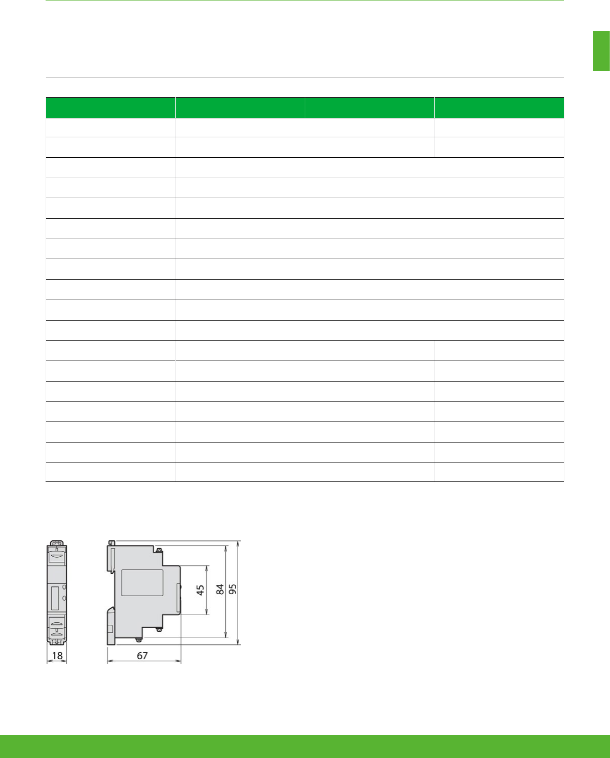
iEM2000 dimensions
NOTE: See the appropriate
product Installation Guide
for complete instructions.
Technical specifications
iEM2000T iEM2000 iEM2010
Direct connection 40A 40A 40A
Pulse output operation 100 pulses/kwh (120ms long) n/a n/a
Display capacity 999999.9KWh
Voltage range (L-N) 184 to 276 Vac
Operating frequency 50/60Hz
Meter constant LED 3200 flashes per KWh
Wiring capacity (Top) 4 mm2
Wiring capacity (Bottom) 10 mm2
Consumption <10 VA
IP protection IP40 front panel and IP20 casing
Temperature -10°C to +55°C
Active energy
n n n
Reactive energy n/a n/a n/a
Active power n/a n/a n/a
Reactive power n/a n/a n/a
Power Factor n/a n/a n/a
Current and voltage n/a n/a n/a
Frequency n/a n/a n/a
Acti9 iEM2000 Series
BASIC ENERGY METERING FUNCTIONS AND CHARACTERISTICS
23schneider-electric.co.uk/metering
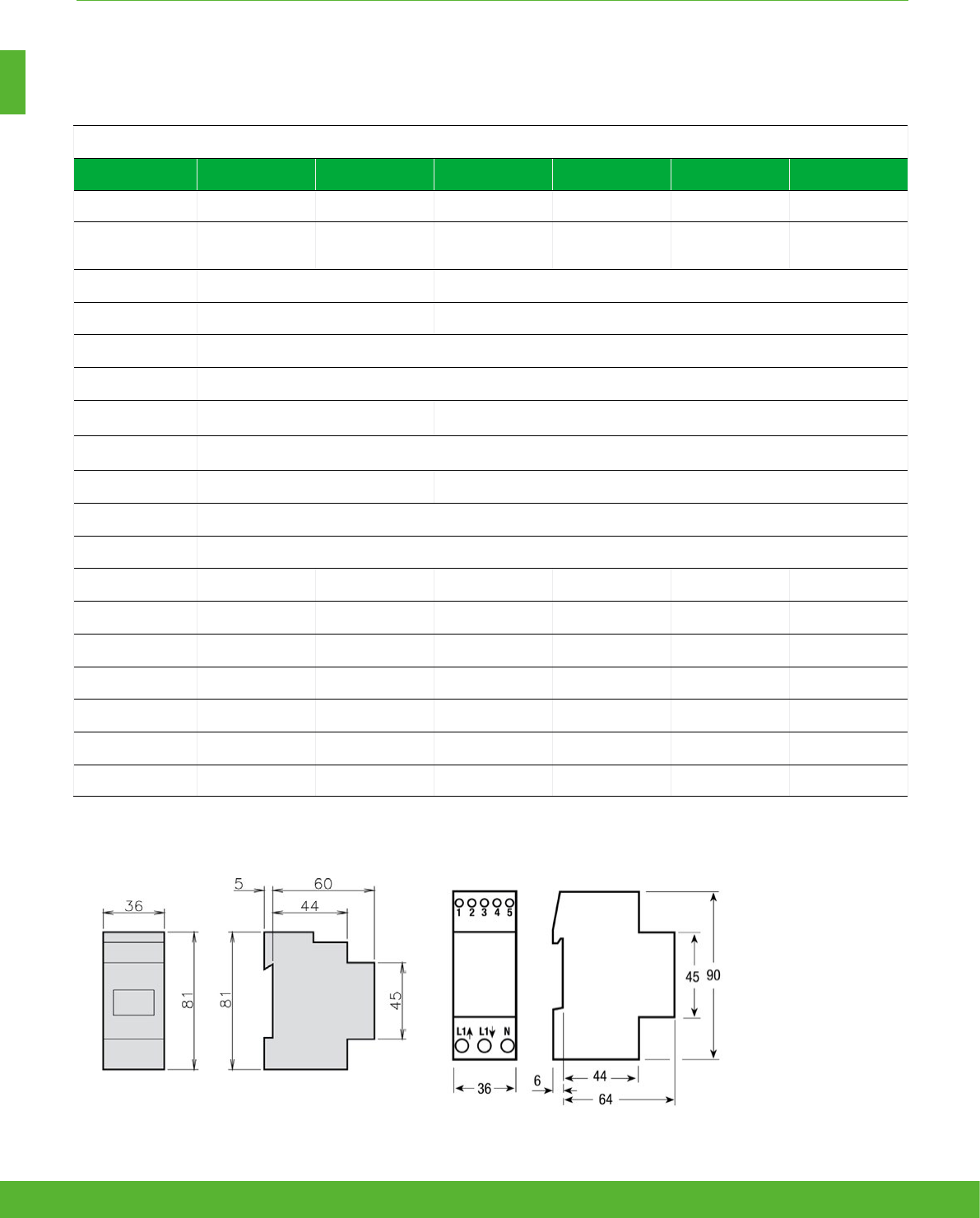
iEM2100/iEM2105 dimensions iEM2110/iEM2135/iEM2150/iEM2155 dimensions
NOTE: See the appropriate
product Installation Guide
for complete instructions.
Technical specifications
iEM2100 iEM2105 iEM2110 iEM2135 IEM2150 iEM2155
Direct connection 63A 63A 63A 63A 63A 63A
Pulse output
operation n/a 1 pulse/kwh
(200ms long)
1 to 1000 pulses /
kwh or kvarh (30 to
100ms long)
n/a n/a n/a
Display capacity 99999 KWh or 999.99 MWh 999999.99KWh
Voltage range (L-N) 184 to 276 Vac 92 to 276 Vac
Operating frequency 50/60Hz
Meter constant LED 1000 flashes per KWh
Wiring capacity
(Top) 6 mm2 4 mm2
Wiring capacity
(Bottom) 32 mm2 (16 mm2 iEM2100/iEM2105)
Consumption 2.5 VA 3 VA
IP protection IP40 front panel and IP20 casing
Temperature -25°C to +55°C
Active energy
nnnnnn
Reactive energy n/a n/a
nnnn
Active power n/a n/a
nnnn
Reactive power n/a n/a
nnnn
Power Factor n/a n/a
nnnn
Current and voltage n/a n/a
nnnn
Frequency n/a n/a
nnnn
DB103483
PB115003
BASIC ENERGY METERING FUNCTIONS AND CHARACTERISTICS
Acti9 iEM2100 Series
schneider-electric.co.uk/metering 24

BASIC ENERGY METERING FUNCTIONS AND CHARACTERISTICS
Acti9 iEM3100/iEM3300
Technical specifications
iEM3100
iEM3300
iEM3110
iEM3310 iEM3115 iEM3135
iEM3335
iEM3150
iEM3350
iEM3155
iEM3355
iEM3165
iEM3365
iEM3175
iEM3375
Max current (direct connection) 63A for iEM3100 models, 125A for iEM3300 models
Meter constant LED 500/kWh
Pulse output Up to
1000p/kWh
Up to
1000p/kWh
Up to
1000p/kWh
Multi-tariff 4 tariffs 4 tariffs 4 tariffs
Communication M-bus Modbus Modbus BACnet LON
DI/DO 0/1 2/0 1/1 1/1 1/1 1/0
MID (EN50470-3) n n n n n
Network 1P+N, 3P, 3P+N
Accuracy class Class 1 (IEC 62053-21 and IEC61557-12) Class B (EN50470-3)
Wiring capacity 16 mm² for iEM3100 models, 50 mm
2
for iEM3300 models
Display max. LCD 99999999.9kWh
Voltage (L-L) 3 x 100/173 V AC to 3 x 277/480 V AC (50/60 Hz)
IP protection IP40 front panel and IP20 casing
Temperature -25°C to 55°C (K55)
Product size 5 x 18 mm for iEM3100 models, 7 x 18 mm for iEM3300 models
Overvoltage and measurement Category III, Degree of pollution 2
kWh
nnnnnnnn
kVARh
n n n n
Active power
nnnnn
Reactive power
n n n n
Currents and voltages
nnnnn
Overload alarm
n n n n
Hour counter
n n n n
25schneider-electric.co.uk/metering

BASIC ENERGY METERING FUNCTIONS AND CHARACTERISTICS
(1) For 1 A CTs Class 1 (IEC6253-21 and IEC61557-12 Class B (EN50470-3)
Acti9 IEM3200
Technical specifications
iEM3200 iEM3210 iEM3215 iEM3235 iEM3250 iEM3255 iEM3265 iEM3275
Max current (1A/5A CT
connected) 6 A
Meter constant LED 5000/kWh
Pulse output frequency Up to
500p/kWh
Up to
500p/kWh Up to 500p/kWh
Multi-tariff 4 tariff 4 tariffs 4 tariffs
Communication M-bus Modbus Modbus BACnet LON
DI/DO 0/1 2/0 1/1 1/1 1/1 1/0
MID (EN50470-3) nnn nnn
Network 1P+N, 3P, 3P+N
support CTs
1P+N, 3P, 3P+N
support CTs & VTs
Accuracy class Class 0.5S (IEC 62053-22 and IEC61557-12) Class C (EN50470-3)(1)
Wiring capacity 6 mm² for currents and 4 mm² for voltages
Display max. LCD 99999999.9kWh or 99999999.9MWh
Voltage (L-L) 3 x 100/173 V AC to 3 x 277/480 V AC (50/60 Hz)
IP protection IP40 front panel and IP20 casing
Temperature -25°C to 55°C (K55)
Product size 5 steps of 18 mm
Overvoltage & measurement Category III, Degree of pollution 2
kWh
nnnnnnnn
kVARh
n n n n
Active power
nnnnn
Reactive power
n n n n
Currents and voltages
nnnnn
Overload alarm
n n n n
Hour counter
n n n n
schneider-electric.co.uk/metering 26
BASIC ENERGY METERING FUNCTIONS AND CHARACTERISTICS
PB105302
PB105303
PB105305
PB105306
ON
OK ESC
Reset
Config
L3’ L3 L2 L1’ L1L1
L2’
N’N
200 /kWh
S0+S0-
126
4.96
69.3
2.73
93.8
3.7
45
1.77
63.8
2.51
103.2
4.06
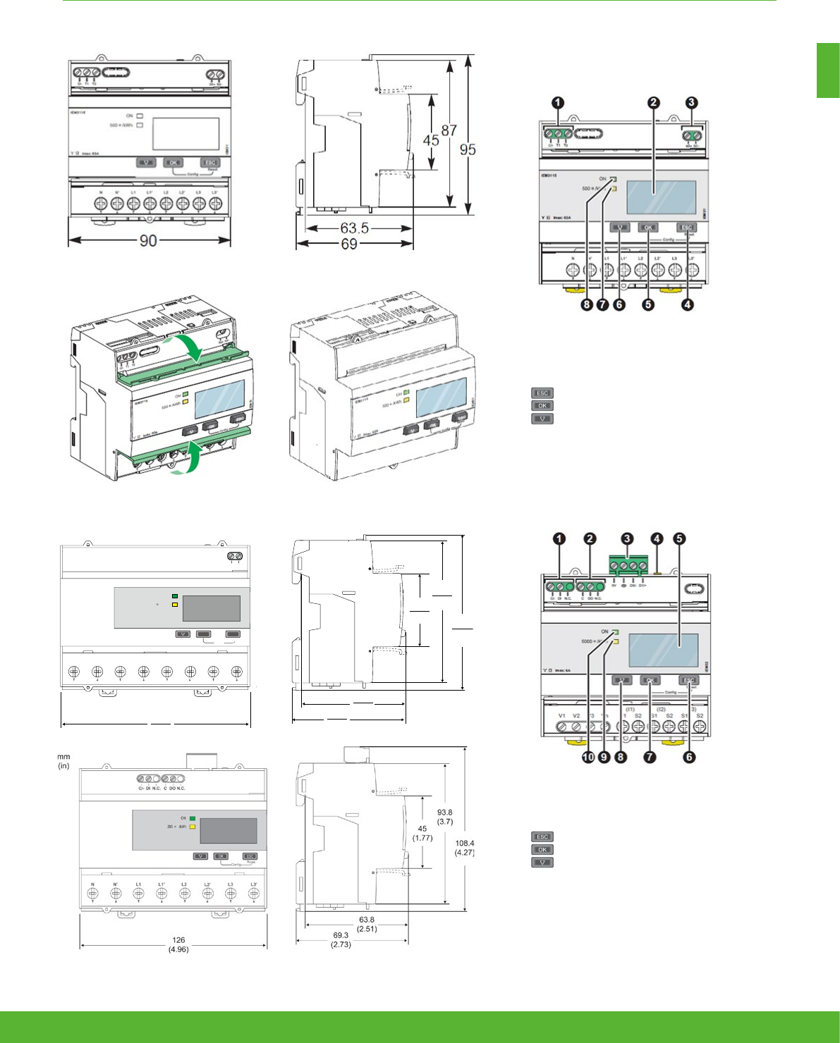
iEM3000/iEM3200 series dimensions
Acti 9 iEM3100/iEM3200 Series front flaps open and closed
iEM3300 series dimensions
Acti 9 iEM3000 Series parts
1. Digital inputs for tariff control (iEM3115 / iEM3215)
2. Display for measurement and configuration
3. Pulse out for remote transfer (iEM3110 / iEM3210)
4. Cancellation
5. Confirmation
6. Selection
7. Flashing yellow meter indicator to check accuracy
8. Green indicator: on/off, error
27schneider-electric.co.uk/metering

Basic
multi-function
metering
schneider-electric.co.uk/metering 28

Applications
Basic multi-function meters are designed for optimising energy use and costs
across your entire organisation. They provide the measurement capabilities
needed to allocate energy usage, perform tenant metering and sub-billing.
As well as pin-point energy savings, optimise equipment efficiency and
utilisation Basic multi-function meters perform a high level assessment of the
power quality in an electrical network.
29schneider-electric.co.uk/metering

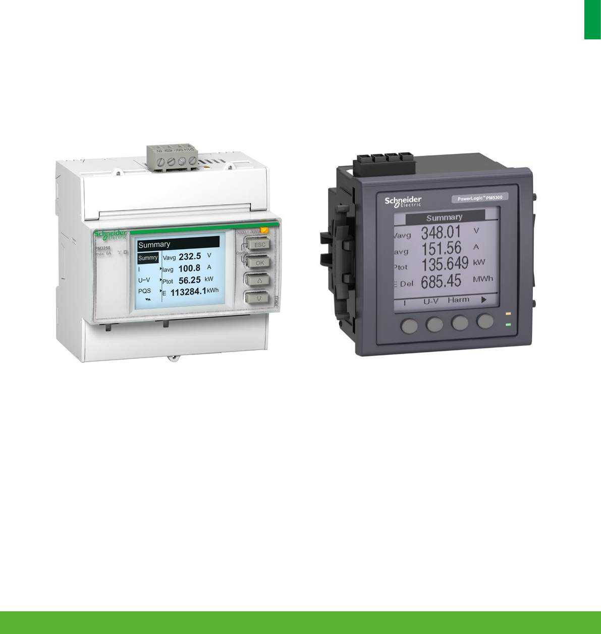
A range of meters designed for cost management and simple network management.
Affordable to buy and easy to choose, the highly-capable PowerLogic PM5000 series
meters are designed to provide the best combination of features to match all your
energy cost management needs.
• PowerLogic PM3000
• PowerLogic PM5000
Basic multi-function metering
Product
overview
schneider-electric.co.uk/metering 30
31schneider-electric.co.uk/metering
BASIC MULTI-FUNCTION METERING FUNCTIONS AND CHARACTERISTICS
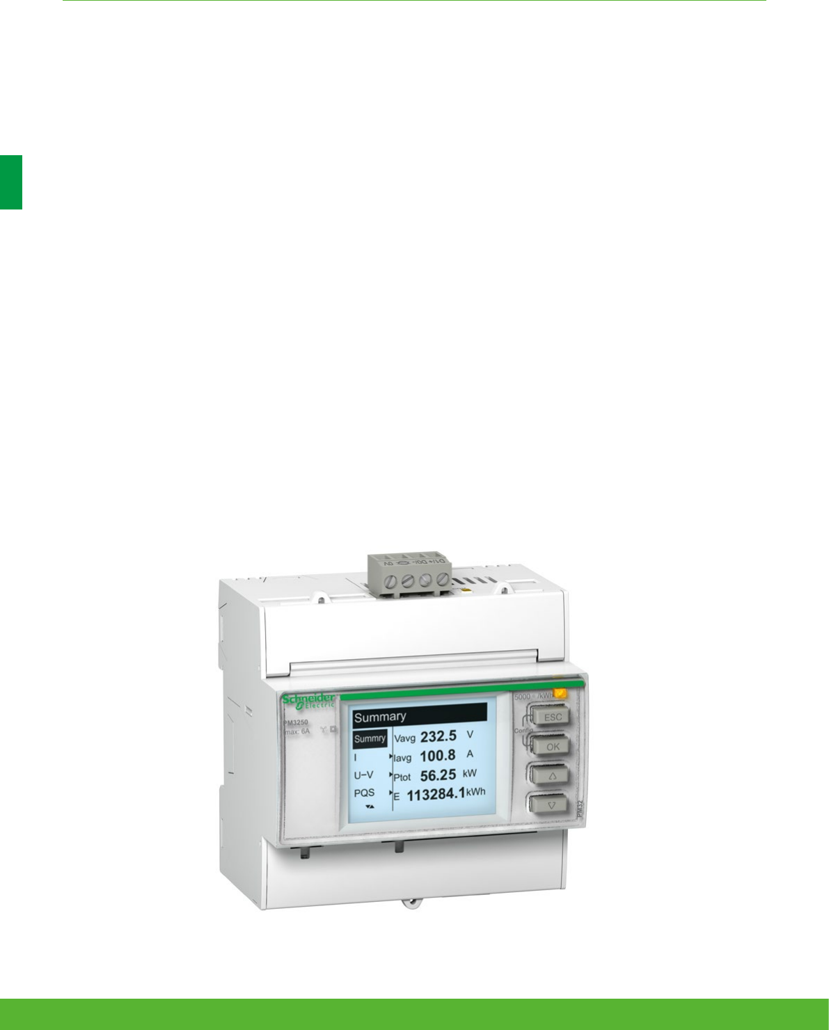
The PowerLogic PM3000 series power meters are a cost-attractive, feature-rich range of DIN rail-
mounted power meters that offers all the measurement capabilities required to monitor an electrical
installation.
Ideal for power metering and network monitoring applications that seek to improve the availability and reliability of your
electrical distribution system, the meters are also fully capable of supporting sub-metering and cost allocation applications.
PM3000 series
Applications
Cost management applications
• Bill checking to verify that you are only charged for the energy you use
• Aggregation of energy consumption, including WAGES, and cost allocation per area, per usage,
per shift or per time within the same facility
• Energy cost and usage analysis per zone, per usage or per time period to optimise energy usage
Network management applications
• Metering of electrical parameters to better understand the behaviour of your electrical distribution
system
schneider-electric.co.uk/metering 32

BASIC MULTI-FUNCTION METERING FUNCTIONS AND CHARACTERISTICS
The solution for
All markets that can benefit from a solution that includes PowerLogic
PM3000 series meters:
• Buildings
• Industry
• Data centres and networks
• Infrastructure (eg. airports, road tunnels, telecom)
Power management solutions
Schneider Electric provides innovative
power management solutions to increase
your energy efficiency and cost savings,
maximise electrical network reliability and
availability, and optimise electrical asset
performance. See Page 114
Competitive advantages
Connectivity advantages
• Programmable digital input
– External tariff control signal (4 tariff)
– Remote Reset partial conter
– External status like breaker statues
– Collect WAGES pulses
• Programmable digital output
– Alarm (PM3255)
– KWh pulses
• Graphic LCD display
• Modbus RS485 with screw terminals
Multi-tariff capability
The PM3000 series allow to arrange KWh consumption in four
different registers. This can be controlled by
• Digital inputs. Signal can be provided by PLC or utilities
• Internal clock programmable by HMI
• Through communication
This function allows users to:
• Make tenant metering for dual source applications to
differentiate backup source or utility source
• Understand well the consumption during peak time and off-
peak time, weekdays and weekends, holiday and working
days etc
• Follow up feeders consumption in line with utility tariff
rates
Benefits
Optimise your energy consumption & enable energy efficiency
practices
• Collect and analyse energy consumption data from each area
for each type of load or circuit
• Gain an accurate understanding of business expenses by
allocating the energy-related costs
• Identify savings opportunities
• Use information to implement actions designed to reduce
energy consumption
Conformity of standards
• IEC 61557-12
• IEC 62052-11
• IEC 62053-21
• IEC 62053-22
• IEC 62053-23
• EN 50470-1
• EN 50470-3
• IEC 61010-1
• IEC 61000-4-2
• IEC 61000-4-3
• IEC 61000-4-4
• IEC 61000-4-5
• IEC 61000-4-6
• IEC 61000-4-8
• EN55022
33schneider-electric.co.uk/metering

Feature selection
PM3200 PM3210 PM3250 PM3255
Performance standard
IEC61557-12 PMD/Sx/K55/0.5
nnnn
General
Use on LV and HV systems
nnnn
Number of samples per cycle 32 32 32 32
CT input 1A/5A
nnnn
VT input
nnnn
Multi-tariff 4 4 4 4
Multi-lingual backlit display
nnnn
Instantaneous rms values
Current, voltage Per phase and average
nnnn
Active, reactive, apparent power Total and per phase
nnnn
Power factor Total and per phase
nnnn
Energy values
Active, reactive and apparent energy; import and export
nnnn
Demand value
Current, power (active, reactive, apparent) demand; present
nnnn
Current, power (active, reactive, apparent) demand; peak
nnn
Power quality measurements
THD Current and voltage
nnn
Data recording
Min/max of the instantaneous values
nnnn
Power demand logs
n
Energy consumption log (day, week, month)
n
Alarms with time stamping 5 5 15
Digital inputs/digital outputs 0/1 2/2
Communication
RS-485 port
n n
Modbus protocol
n n
Ordering reference METSEPM3200 METSEPM3210 METSEPM3250 METSEPM3255
BASIC MULTI-FUNCTION METERING FUNCTIONS AND CHARACTERISTICS
schneider-electric.co.uk/metering 34
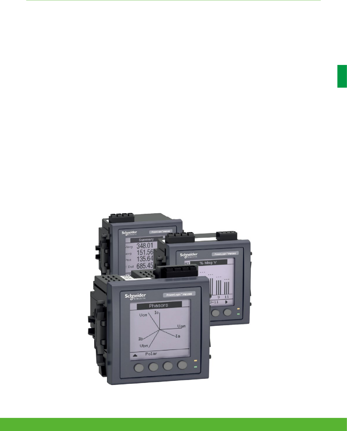
The PowerLogic PM5000 series power meters are the new benchmark in affordable, precision metering.
The ideal fit for high-end cost management applications, providing the measurement capabilities needed to allocate energy
usage, perform tenant metering and sub-billing, pin-point energy savings, optimise equipment efficiency and utilisation, and
perform a high level assessment of the power quality in an electrical network.
PM5000 series
Applications
Capable of essential cost management:
• Sub-billing/tenant metering
• Equipment sub-billing
• Energy cost allocation
Also ideal for electrical network management:
• Track real-time power conditions
• Monitor control functions
• Provide basic power quality values
• Monitor equipment and network status
BASIC MULTI-FUNCTION METERING FUNCTIONS AND CHARACTERISTICS
35schneider-electric.co.uk/metering

The solution for
All markets that can benefit from a solution that includes
PowerLogic PM5000 series:
• Buildings
• Industry
• Healthcare
• Data Centre and networks
• Infrastructure
Power management solutions
Schneider Electric provides innovative
power management solutions to increase
your energy efficiency and cost savings,
maximise electrical network reliability and
availability, and optimise electrical asset
performance. See Page 114
Competitive advantages
• Easy to install and operate
• Easy for circuit breaker monitoring and control
• Direct metering of neutral circuit and calculated ground
current value to avoid overload and resulting outage
(PM556x)
• Power quality analysis??
• Load management combined with alarm and timestamping
• High performance and accuracy
• MID ready compliance for legal billing application
Conformity of standards
• IEC61557-12
• IEC62053-22
• IEC62053-24
• EN50470-1
• EN50470-3
• IEC 61010-1
• IEC 61000-4-2
• IEC 61000-4-3
• IEC 61000-4-4
• IEC 61000-4-5
• IEC 61000-4-6
• IEC 61000-4-8
• Etc.
Benefits
System integrators’ benefit
• Ease of integration
• Ease of setup
• Cost effectiveness
Panel builders’ benefit
• Ease of installation
• Cost effectiveness
• Aesthetically pleasing
• Simplified ordering
End users’ benefit
• Ease of use
• Precision metering & sub-billing
• Billing flexibility
• Comprehensive, consistent and superior performance
BASIC MULTI-FUNCTION METERING FUNCTIONS AND CHARACTERISTICS
schneider-electric.co.uk/metering 36

Feature selection
PM5100 PM5300 PM5500
Short reference numbers PM5100 PM5110 PM5310 PM5320 PM5330 PM5340 PM5560 PM5563
Commercial reference numbers METSE
PM5100
METSE
PM5110
METSE
PM5310
METSE
PM5320
METSE
PM5330
METSE
PM5340
METSE
PM5560
METSE
PM5563
Installation
Fast installation, panel mount with
integrated display b b b b b b b –
Fast installation, DIN rail mountable – – – – – – – b
Accuracy CL 0.5S CL 0.5S CL 0.5S CL 0.5S CL 0.5S CL 0.5S CL 0.2S CL 0.2S
Display
Backlit LCD, multilingual, bar graphs, 6
lines,
4 concurrent values
b b b b b b b b
Power and energy metering
3-phase voltage, current, power, demand,
energy, frequency, power factor b b b b b b b b
Multi-tariff – – 4 4 4 4 8 8
Power quality analysis
THD, thd, TDD b b b b b b b b
Harmonics, individual (odd) up to 15th 15th 31st 31st 31st 31st 63rd 63rd
I/Os and relays
I/Os 1DO 1DO 2DI/2DO 2DI/2DO 2DI/2DO 2DI/2DO 4DI/2DO 4DI/2DO
Relays 0 0 0 0 2 2 0 0
Alarms and control
Alarms 33 33 35 35 35 35 52 52
Set point response time, seconds 1 1 1 1 1 1 1 1
Single and multi-condition alarms – – b b b b b b
Boolean alarm logic – – – – – – b b
Memory for data logging 256KB 256KB 256KB 256KB 1.1 MB 1.1 MB
Communications
Serial ports with modbus protocol – 1 1 – 1 – 1 1
Ethernet port with Modbus TCP protocol – – – 1 – 1 2** 2**
Onboard web server with web pages – – – – – – b b
Serial to Ethernet gateway – – – – – – b b
MID ready compliance, EN50470-1/3,
Annex B and Annex D Class C
PM5111
METSEPM5111
PM5331
METSEPM5331
PM5341
METSEPM5341
PM5561
METSEPM5561
Other related products
Ordering reference
A package of PM5563 meter with remote
display METSEPM5563RD
Remote display for PM5563 METSEPM5RD
Hardware kit for PM51xx METSEPM51HK
Hardware kit for PM53xx METSEPM53HK
Hardware kit for PM55xx METSEPM55HK
BASIC MULTI-FUNCTION METERING FUNCTIONS AND CHARACTERISTICS
** 2 Ethernet ports for daisy chain, one IP address
37schneider-electric.co.uk/metering

Technical
Specifications
Basic multi-function metering
38 schneider-electric.co.uk/metering

BASIC MULTI-FUNCTION METERING FUNCTIONS AND CHARACTERISTICS
Technical specifications
Type of measurement True rms up to the 15th harmonic on three-phase (3P,3P+N) and single-phase AC systems.
32 samples per cycle
Measurement accuracy
Current with x/5A CTs 0.3% from 0.5A to 6A
Current with x/1A CTs 0.5% from 0.1A to 1.2A
Voltage 0.3% from 50V to 330V (Ph-N), from 80V to 570V (Ph-Ph)
Power factor ±0.005 from 0.5A to 6A with x/5A CTs; from 0.1A to 1.2A with x/1A CTs and from 0.5L to 0.8C
Active/Apparent Power with x/5A CTs Class 0.5
Active/Apparent Power with x/1A CTs Class 1
Reactive power Class 2
Frequency 0.05% from 45 to 65Hz
Active energy with x/5A CTs IEC62053-22 Class 0.5s
Active energy with x/1A CTs IEC62053-21 Class 1
Reactive energy IEC62053-23 Class 2
Data update rate
Update rate 1s
Input-voltage characteristics
Measured voltage
50V to 330V AC (direct / VT secondary Ph-N)
80V to 570V AC (direct / VT secondary Ph-Ph)
up to 1MV AC (with external VT)
Frequency range 45Hz to 65Hz
Input-current characteristics
CT primary Adjustable from 1A to 32767A
CT secondary 1A or 5A
Measurement input range with x/5A CTs 0.05A to 6A
Measurement input range with x/1A CTs 0.02A to 1.2A
Permissible overload 10A continuous, 20A for 10s/hour
Control Power
AC 100/173 to 277/480V AC (+/-20%), 3W/5VA; 45Hz to 65Hz
DC 100 to 300V DC, 3W
Input
Digital inputs (PM3255) 11 to 40V DC, 24V DC nominal, <=4mA maximum burden, 3.5kVrms insulation
Output
Digital output (PM3210) Optocoupler, polarity sensitive, 5 to 30V, 15mA max, 3.5kVrms insulation
Digital outputs (PM3255) Solid state relay, polarity insensitive, 5 to 40V, 50mA max, 50Ω max,
3.5kVrms insulation
PM3000 series
39schneider-electric.co.uk/metering

BASIC MULTI-FUNCTION METERING FUNCTIONS AND CHARACTERISTICS
Technical specifications
Mechanical characteristics
Weight 0.26kg
IP degree of protection (IEC60529) IP40 front panel, IP20 meter body
Dimension 90 x 95 x 70mm
Environmental conditions
Operating temperature -25 ºC to +55 ºC
Storage temperature -40 ºC to +85 ºC
Humidity rating 5 to 95% RH at 50ºC (non-condensing)
Pullution degree 2
Metering category III, for distribution systems up to 277/480VAC
Dielectric withstand As per IEC61010-1, Doubled insulated front panel display
Altitude 3000m max
Electromagnetic compatibility
Electrostatic discharge Level IV (IEC61000-4-2)
Immunity to radiated fields Level III (IEC61000-4-3)
Immunity to fast transients Level IV (IEC61000-4-4)
Immunity to surge Level IV (IEC61000-4-5)
Conducted immunity Level III (IEC61000-4-6)
Immunity to power frequency magnetic
fields 0.5mT (IEC61000-4-8)
Conducted and radiated emissions Class B (EN55022)
Safety
CE as per IEC61010-1 (1)
Communication
RS485 port Half duplex, from 9600 up to 38400 bauds, Modbus RTU (double insulation)
Display characteristics
Dimensions (VA) 43mm x 34.6mm
Display resolution 128 x 96 dots
Standard compliance
IEC61557-12, EN61557-12
IEC61010-1, UL61010-1
IEC62052-11, IEC62053-21, IEC62053-22, IEC62053-23
EN50470-1, EN50470-3
(1) Protected throughout by double insulation
PM3000 series
schneider-electric.co.uk/metering 40

PM3200 series front of meter
PM3200 series dimensions
PM3200 series easy installation
BASIC MULTI-FUNCTION METERING DIMENSIONS AND CONNECTION
Front of meter parts
1 Control power
2 Display with white backlit
3 Flashing yellow meter indicator (to check accuracy)
4 Pulse output for remote transfer (PM3210)
5 Cancellation
6 Conrmation
7 Up
8 Down
PM3200 top and lower aps
41schneider-electric.co.uk/metering

Technical specifications
PM5100 PM5300 PM5500
Use on LV and MV systems b
Basic metering with THD and min/max readings b
Instantaneous rms values
Current per phase, neutral and ground
(PM5500) b
Voltage Total, per phase L-L and L-N b
Frequency b
Real, reactive, and
apparent power Total and per phase Signed, Four Quadrant
True Power Factor Total and per phase Signed, Four Quadrant
Displacement PF Total and per phase Signed, Four Quadrant
% Unbalanced I, VL-N, VL-L b
Direct monitoring of neutral current b
Energy values
Accumulated Active, Reactive and Apparent Energy Received/Delivered; Net and absolute; Time Counters
Demand value
Current average Present, Last, Predicted, Peak, and Peak Date Time
Active power Present, Last, Predicted, Peak, and Peak Date Time
Reactive power Present, Last, Predicted, Peak, and Peak Date Time
Apparent power Present, Last, Predicted, Peak, and Peak Date Time
Peak demand with time stamping D/T for current and
powers b
Demand calculation Sliding, fixed and rolling block,
thermal methods b
Synchronisation of the measurement window to input,
communication command or internal clock b
Settable Demand intervals b
Demand calculation for Pulse input (WAGES) b
Other measurements
I/O timer b
Operating timer b
Load timer b
Alarm counters and alarm logs b
Power quality measurements
THD, thd (Total Harmonic Distortion) I, VLN, VLL per phase I,VLN, VLL
TDD (Total Demand Distortion) b
Individual harmonics (odds) 15th 31st 63rd
Neutral Current metering with ground current
calculation b
Data recording
Min/max of instantaneous values, plus phase
identification* b
Alarms with 1s timestamping* b
Data logging
2 fixed parameters kWh and kVAh
with configurable interval and
duration (e.g. 2 parameters for 60
days at 15 minutes interval)
Up to 14 selectable parameters
with configurable interval and
duration (e.g. 6 parameters for 90
days at 15 minutes interval)
Memory capacity 256 kB 1.1 MB
Min/max log b b b
Maintenance, alarm and event logs b b
Customisable data logs b
BASIC MULTI-FUNCTION METERING FUNCTIONS AND CHARACTERISTICS
PM5000 series
schneider-electric.co.uk/metering 42

Technical specifications
PM5100 PM5300 PM5500
Inputs / Outputs / Mechanical Relays
Digital inputs 2 (SI1, SI2) 4 (SI1, SI2, SI3, SI4) with
WAGES support
Digital outputs 1 (kWh only) 2 (configurable) 2 (configurable)
Form A Relay outputs
2
Timestamp resolution in
seconds
1 1 1
Whetting voltage b
Type of measurement: True rms on three-phase
(3P, 3P + N), zero blind 64 samples per cycle 128 samples per cycle
Measurement
accuracy
IEC 61557-12 PMD/[SD|SS]/K70/0.5 PMD/[SD|SS]/K70/0.2
Active Energy Class 0.5S as per IEC 62053-22 Class 0.2S as per
IEC 62053-22
Reactive Energy Class 2S as per IEC62053-24 Class 1S as per IEC62053-24
Active Energy ±0.5% ±0.2%
Reactive Energy ±2% ±1%
Active Power Class 0.5 as per IEC 61557-12 Class 0.2 as per IEC 61557-12
Apparent Power Class 0.5 as per IEC 61557-12
Current, Phase Class 0.5 as per IEC 61557-12 ±0.15%
Voltage, L-N Class 0.5 as per IEC 61557-12 ±0.1%
Frequency ±0.05%
MID Directive EN50470-1,
EN50470-3 Annex B and Annex D (Optional model references) Class C
Input-voltage
(up to 1.0
MV AC max,
with voltage
transformer)
Nominal Measured Voltage range 20 V L-N / 35 V L-L to 400 V L-N /690 V L-L
absolute range 35 V L-L to 760 V L-L
20 V L-N / 20 V L-L to 400 V
L-N /690 V L-L
absolute range 20 V L-L to
828 V L-L
Impedance 5 M Ω
F nom 50 or 60 Hz ±5% 50 or 60 Hz ±10%
Input-current
(configurable
for 1 or 5 A
secondary
CTs)
I nom 5 A
Measured Amps with over range and
Crest Factor
Starting current: 5mA
Operating range: 50mA to 8.5A
Starting current: 5m A
Operating range: 50 mA to
10 A
Withstand Continuous 20A, 10s/hr 50A, 1s/hr 500A
Impedance < 0.3 mΩ
F nom 50 or 60 Hz ±5% 50 or 60 Hz ±10%
Burden <0.026VA at 8.5A
AC control
power
Operating range 100 - 277 V AC L-N / 415 V L-L +/-10%
CAT III 300V class per IEC 61010
100-480 V AC ±10%
CAT III 600V class per IEC
61010
Burden <5 W,11 VA at 415V L-L
<5W/16.0 VA at 480 V
AC
Frequency 45 to 65 Hz
Ride-through time
80 mS typical at 120V AC and maximum burden.
100 mS typical at 230 V AC and maximum burden
100 mS typical at 415 V AC and maximum burden
35 ms typical at 120 V L-N and
maximum burden
129 ms typical at 230 V L-N
and maximum burden
DC control
power
Operating range 125-250 V DC ±20%
Burden <4 W at 250 V DC typical 3.1W at 125 V DC,
max. 5W
Ride-through time 50 mS typical at 125 V DC and maximum burden
BASIC MULTI-FUNCTION METERING FUNCTIONS AND CHARACTERISTICS
43schneider-electric.co.uk/metering

Technical specifications
PM5100 PM5300 PM5500
Outputs
Relay
Max output frequency
0.5 Hz maximum (1 second
ON / 1 second OFF - minimum
times)
Switching current
250 V AC at 8.0 Amps, 25 k
cycles, resistive
30 V DC at 2.0 Amps, 75 k
cycles, resistive 30 V DC at 5.0
Amps, 12.5 k cycles, resistive
Isolation 2.5 kV rms
Digital
outputs
Digital outputs 1 2 2
Max load voltage 40 V DC 30 V AC / 60 V DC
Max load current 20 mA 125 mA
On Resistance 50 Ω max 8 Ω
Meter constant from 1 to 9,999,999 pulses per kWh
Pulse width for Digital
Output 50% duty cycle
Pulse frequency for
Digital Output 25 Hz max.
Leakage current 0.03 micro Amps 1 micro Amps
Isolation 5 kV rms 2.5 kV rms
Optical
outputs
Pulse width (LED) 200 ms
Pulse frequency 50 Hz. max. 2.5 kHz. max
Meter constant from 1 to 9,999,999 pulses per k_h
Status
Inputs
ON Voltage 18.5 to 36 V DC 30 V AC / 60 V DC max
OFF Voltage 0 to 4 V DC
Input Resistance 110 k Ω 100 k Ω
Maximum Frequency 2 Hz (T ON min = T OFF min
= 250 ms)
25 Hz (T ON min = T OFF min =
20 ms)
Response Time 20 ms 10 ms
Opto Isolation 5 kV rms 2.5 kV rms
Whetting output 24 V DC/ 8mA max
Input Burden 2mA @24V DC 2 mA @ 24 V AC/DC
Mechanical characteristics
Product weight 380 g 430 g 450 g
IP degree of protection (IEC 60529) IP52 front display, IP30 meter body
Dimensions W x H x D [protrusion from cabinet] 96 x 96 x 72mm (77mm for PM5500) (depth of meter from housing mounting flange) [13mm]
Mounting position Vertical
Panel thickness 6 mm maximum
Environmental characteristics
Operating
temperature Meter -25 °C to 70 °C
BASIC MULTI-FUNCTION METERING FUNCTIONS AND CHARACTERISTICS
PM5000 series
schneider-electric.co.uk/metering 44

Technical specifications
Display (Display functions to -25º
with reduced performance) -25 °C to +70 °C
Storage temp. -40 °C to +85 °C
Humidity range 5 to 95 % RH at 50 °C (non-condensing)
Polution degree 2
Altitude 2000 m CAT III / 3000 m CAT II 3000 m max. CAT III
Electromagnetic compatibility
Harmonic current emissions IEC 61000-3-2
Flicker emissions IEC 61000-3-3
Electrostatic discharge IEC 61000-4-2
Immunity to radiated fields IEC 61000-4-3
Immunity to fast transients IEC 61000-4-4
Immunity to surge IEC 61000-4-5
Conducted immunity 150kHz to 80MHz IEC 61000-4-6
Immunity to magnetic fields IEC 61000-4-8
Immunity to voltage dips IEC 61000-4-11
Radiated emissions FCC part 15, EN 55022 Class B
Conducted emissions FCC part 15, EN 55022 Class B
Safety
PM5100 PM5300 PM5500
Europe CE, as per IEC 61010-1 Ed. 3, IEC 62052-11 & IEC61557-12
U.S. and Canada cULus as per UL61010-1 (3rd Edition)
Measurement category (Voltage and Current inputs) CAT III up to 400 V L-N / 690 V L-L
Dielectric As per IEC/UL 61010-1 Ed. 3
Protective Class II, Double insulated for user accessible parts
Communication
RS 485 port Modbus RTU, Modbus ASCII
(7 or 8 bit), JBUS
2-Wire, 9600,19200 or 38400 baud, Parity - Even, Odd, None, 1 stop bit if parity Odd or Even, 2 stop bits
if None; (Optional in PM51x and PM53x)
Ethernet port: 10/100 Mbps; Modbus TCP/IP 1 Optional 2 (for daisy chain only, one IP
address)
Firmware and language file update Meter firmware update via the communication ports
Isolation 2.5 kVrms, double insulated
Human machine interface
Display type Monochrome Graphics LCD
Resolution 128 x 128
Backlight White LED
Viewable area (W x H) 67 x 62.5 mm
Keypad 4-button
Indicator Heartbeat / Comm activity Green LED
Energy pulse
output / Active
alarm indication
(configurable)
Optical, amber LED
Wavelength 590 to 635 nm
Maximum pulse rate 2.5 kHz
BASIC MULTI-FUNCTION METERING FUNCTIONS AND CHARACTERISTICS
45schneider-electric.co.uk/metering
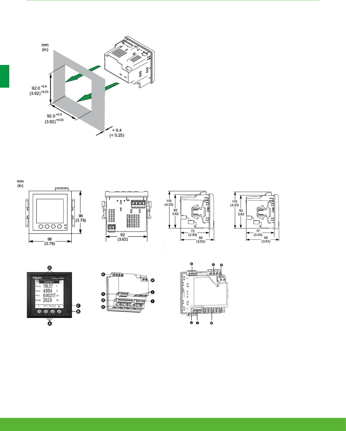
PM5000 meter parts
A Menu selection buttons
B LED indicators
C Navigation or menu selections
D Maintenance and alarm
notication area
Please see the Installation Guide for accurate and complete information on the installation of this product.
PM5100 / PM5300 meter parts
E Relay output (PM5300 only)
F Voltage inputs
G Control power
H Current inputs
I Status inputs/digital outputs
J Communications port: Ethernet
(PM5300 only) or RS-485)
PM5100 / PM5300 PM5500
PM5500 meter parts
E Voltage inputs
F RS-485 comms
G Digital inputs
H Current inputs
I Digital outputs
J Ethernet ports
K Control power
PM5500
PM5000 Series meter flush mounting
PM5000 Series meter dimensions
BASIC MULTI-FUNCTION METERING FUNCTIONS AND CHARACTERISTICS
schneider-electric.co.uk/metering 46

NOTES
47schneider-electric.co.uk/metering

Intermediate
metering
schneider-electric.co.uk/metering 48

Applications
Intermediate meters are designed for low to high voltage network
management applications for your critical loads, feeders and LV incomers.
These meters seek to improve the availability and reliability of your electrical
system in industrial facilities, data centres, commercial buildings, utilities
networks, or critical power environments. They are fully capable of supporting
billing and cost allocation applications.
49schneider-electric.co.uk/metering

A range of power and energy meters designed for network monitoring
applications like tracking real-time power conditions, monitoring network and
equipment status, load trending, harmonics measurement, and alarm & event
logging & reporting.
Introducing the NEW PowerLogic PM8000 series meters, ensure the reliability and
efficiency of your power-critical facility
• NEW PowerLogic PM8000
Intermediate metering
Product
overview
50 schneider-electric.co.uk/metering
51schneider-electric.co.uk/metering

INTERMEDIATE METERING FUNCTIONS AND CHARACTERISTICS
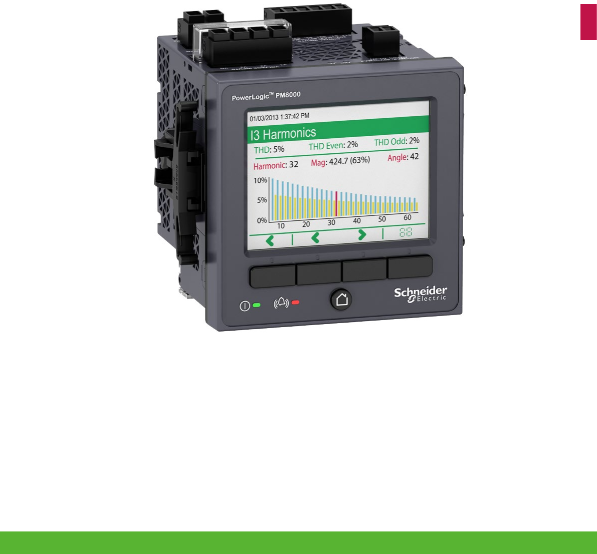
The PowerLogic PM8000 series meters are compact, cost-effective multifunction power meters that
will help you ensure reliability and efficiency of your power-critical facility.
Reveal and understand complex power quality conditions. Measure, understand and action insightful data gathered from
your entire power system. Designed for key metering points throughout your energy infrastructure, the PowerLogic PM8000
series meter has the versatility to perform nearly any job you need a meter to do, wherever you need it!
*PM800 series and ION7300 series were replaced by the NEW PM8000 series in September 2015.
*PM800 series will be replaced by the new PM8000 series in September 2015
NB: The ION7300 has been replaced by the new PM8000 series.
Applications
Ideal for low to high voltage applications in industrial facilities, commercial buildings, utility networks,
or critical power environments.
PM8000 Series
schneider-electric.co.uk/metering 52

*PM800 series will be replaced by the new PM8000 series in September 2015
NB: The ION7300 has been replaced by the new PM8000 series.
INTERMEDIATE METERING FUNCTIONS AND CHARACTERISTICS
The solution for
All markets that can benefit from a solution that includes
PowerLogic PM8000 series meters:
• Healthcare
• Data Centers
• Buildings
• Industry
• Infrastructure
• Utility
Power management solutions
Schneider Electric provides innovative
power management solutions to increase
your energy efficiency and cost savings,
maximise electrical network reliability and
availability, and optimise electrical asset
performance. See Page 114
Competitive advantages
• ION technology
• MID approved options
• Colour screen
• Multiple communication options
Benefits
• Makes understanding power quality simple to help
operations personal avoid downtime and ensure increased
productivity and equipment life.
• Makes energy and power quality immediately relevant and
actionable to support your operational and sustainability
goals.
Conformity of standards
• IEC 61557-12
• IEC 62586
• IEC 62053-22
• IEC 62053-24
• EN50470-1
• EN50470-3
• IEC 61000-4-30
• EN50160
• IEC 62053-11
• IEC 61000-4-2
• IEC 61000-4-3
• IEC 61000-4-4
• IEC 61000-4-5
• IEC 61000-4-6
• IEC61000-4-8
• IEC 61010
• Etc.
53schneider-electric.co.uk/metering
INTERMEDIATE METERING FUNCTIONS AND CHARACTERISTICS
Main characteristics
• Precision metering:
– IEC 61557-12 PMD Sx K70 3000m 0.2 (performance measuring and
monitoring functions).
– Class 0.2S accuracy IEC 62053-22, ANSI C12.20 Class 0.2 (active energy).
– Industry leading Class 0.5S* accuracy for reactive energy (IEC 62053-24).
– Cycle-by-cycle RMS measurements updated every ½ cycle.
– Full ‘multi-utility’ WAGES metering support.
– Net metering.
– Anti-tamper protection seals.
• PQ compliance reporting and basic PQ analysis.
– Monitors and logs parameters in support of international PQ standards,
– IEC 61000-4-30 Class S
– IEC 62586 PQI-S
– EN 50160
– Generates onboard PQ compliance reports accessible via onboard web
pages:
– Basic event summary and pass/fail reports, such as EN 50160 for
power frequency, supply voltage magnitude, supply voltage dips,
short and long interruptions, temporary over voltages, voltage
unbalance and harmonic voltage.
– ITIC (CBEMA) and SEMI curves, with alarm categorisation to support
further analyses.
– NEMA Motor Derating curve.
– Basic meter provides EN 50160 but can be configured to provide
IEEE 519.
– Harmonic analysis:
– THD on voltage and current, per phase, min/max, custom alarming.
– Individual harmonic magnitudes and angles on voltage and current,
up to the 63rd harmonic.
– High resolution waveform capture: triggered manually or by alarm,
captured waveforms available directly from the meter via FTP in a
COMTRADE format.
– Disturbance detection and capture: sag/swell on any current and voltage
channel, alarm on disturbance event, waveform capture with per-event
information.
– Patented disturbance direction detection: provides indication of the
captured disturbance occurring upstream or downstream of the meter;
timestamped results provided in the event log, with degree of certainty of
disturbance direction.
• Used with StruxureWare Power Monitoring Expert software, provides
detailed PQ reporting across entire network:
– EN 50160 report.
– IEC 61000-4-30 report.
– PQ compliance summary.
– ISO 50001.
– Display of waveforms and PQ data from all connected meters.
– Onboard data and event logging.
– 512MB of standard non-volatile memory. 10 MB of standard non-volatile
memory dedicated to capture billing data, events, and waveforms.
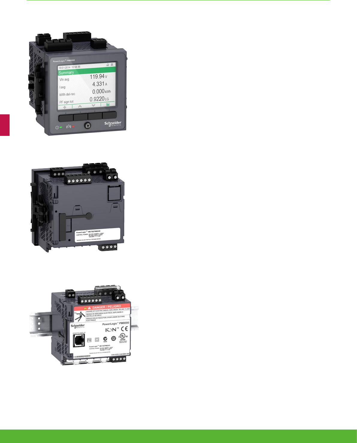
PowerLogic PM8000 series meter.
PowerLogic PM8000 series meter - rear view.
PowerLogic PM8000 DIN rail mounted meter.
schneider-electric.co.uk/metering 54
– No data gaps due to network outages or server downtime.
– Min/Max log for standard values.
– 50 user-definable data logs, recording up to 16 parameters on a cycle-by-
cycle or other user definable interval.
– Continuous logging or ‘snapshot’ triggered by setpoint and stopped after
defined duration.
– Trend energy, demand and other measured parameters.
– Forecasting via web pages: average, minimum and maximum for the next
four hours and next four days.
– Time-of-use in conjunction with StruxureWare software.
– Event log: alarm conditions, metering configuration changes, and power
outages, timestamped to 1 millisecond.
• Alarming and control.
– 50+ definable alarms to log critical event data, trigger waveform recording,
or perform control function.
– Trigger on any condition, with cycle-by-cycle and 1-second response time.
– Combine alarms using Boolean logic and to create alarm levels.
– Alarm notification via email text message.
– In conjunction with StruxureWare Power Monitoring Expert, software alarms
and alarm frequency are categorized and trended for easy evaluation of
worsening/improving conditions.
• Excellent quality: ISO 9001 and ISO 14000 certified manufacturing.
Usability
• Easy installation and setup.
– Panel and DIN rail mounting options, remote display option.
– Pluggable connectors.
– Free setup application simplifies meter configuration.
• Front panel.
– Easy to read colour graphic display.
– Simple, intuitive menu navigation with multi-language (8) support.
• Flexible remote communications.
– Multiple simultaneously operating communication ports and protocols allow
interfacing with other automation systems; (e.g. waveforms, alarms, billing
data, etc.) can be uploaded for viewing/analysis while other systems access
real-time information.
– Supports Modbus, ION, DNP3, IEC 61850.
– Dual port Ethernet: 10/100base-TX; daisy-chaining capability removes need
for additional switches.
– Create redundant network loop using Rapid Spanning Tree Protocol (RSTP)
and managed Ethernet switches.
– Customise TCP/IP port numbers enable/disable individual ports.
– RS-485 2-wire connection, up to 115200 baud, Modbus RTU and ION
protocols, DNP3 is also supported via RS-485.
– Ethernet to serial gateway with Modbus Master functionality, connecting to 31
downstream serial Modbus devices. Also supports Modbus Mastering over
TCP/IP (Ethernet) network.
– Full function web server with factory and customisable pages to access real-
time and PQ compliance data.
– Push historical data via email.
– Advanced security: Up to 16 configurable user accounts.
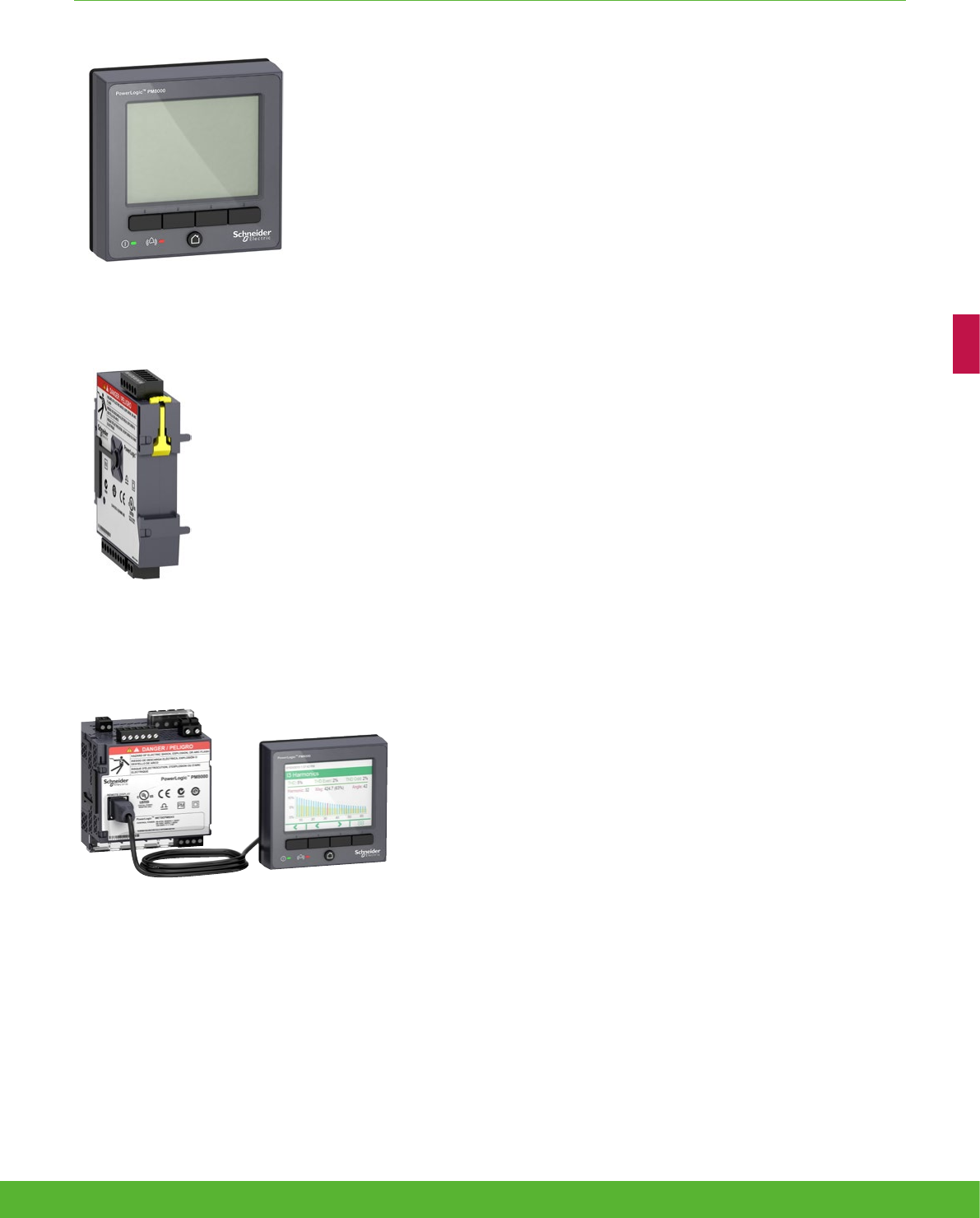
PowerLogic remote display.
PowerLogic I/O module.
PowerLogic PM8000 series meter with remote
display.
INTERMEDIATE METERING FUNCTIONS AND CHARACTERISTICS
55schneider-electric.co.uk/metering

• Time synchronisation via:
– GPS clock (RS485) or IRIG-B (digital input) to +/- 1 millisecond.
Also supports Network Time Protocol (NTP/SNTP) and time set function from
StruxureWare software server.
Adaptability
– ION™ frameworks allow customisable, scalable applications, object-
oriented programming, compartmentalises functions, and increases
flexibility and adaptability.
– Applications include: access and aggregate data from Modbus devices
on serial port or across the network (Modbus TCP/IP), logging and/or
processing data by totaling, unit conversion or other calculations, applying
complex logic for alarming or control operations, data visualisation via web
pages.
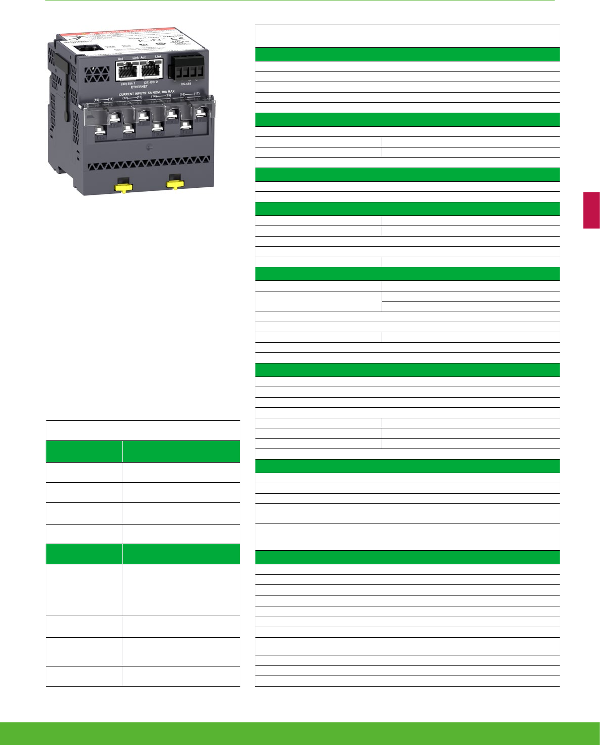
Standard meter I/O
• 3 digital status/counter inputs.
• 1 KY (form A) energy pulse output for interfacing with other systems.
Modular I/O options
• Optional expansion modules
• up to 2 modules per panel mounted meter
• up to 4 module per DIN-rail mounted meter
Option modules include:
• Digital module
– 6 digital status/counter inputs.
– 2 Form C relay outputs, 250V, 8A.
• Analogue module
– 4 analogue inputs (4-20mA; 0-30V).
– 2 analogue outputs (4-20mA; 0-10V) for interfacing with building
management sensors and systems.
PowerLogic PM8000 series meter with I/O modules.
INTERMEDIATE METERING FUNCTIONS AND CHARACTERISTICS
schneider-electric.co.uk/metering 56
Feature selection
Ordering
reference Description
METSEPM8240 96x96 panel mount meter
METSEPM8243 DIN rail mount meter
METSEPM8244 DIN rail mount meter with remote
display
METSEPM82401 MID approved panel mount meter
Accessories Description
METSEPM89RD96
Remote display, 3 metre cable,
mounting hardware for
30mm hole (nut & centering pin),
mounting hardware
for DIN96 cutout (92x92mm)
adapter plate
METSEPM89M2600 Digital I/O module (6 digital
inputs & 2 relay outputs)
METSEPM89M0024
Analogue I/O module (4 analogue
inputs & 2 analogue
outputs)
METSEPM8000SK Terminal covers for utility sealing
INTERMEDIATE METERING FUNCTIONS AND CHARACTERISTICS
Feature guide
PM8000
General
Use on LV and MV systems b
Current accuracy (5A Nominal) 0.1 % reading
Voltage accuracy (57 V LN/100 V LL to 400 V LN/690 V LL) 0.1 % reading
Active energy accuracy 0.2 %
Number of samples/cycle or sample frequency 256
Instantaneous rms values
Current, voltage, frequency b
Active, reactive, apparent power Total and per phase b
Power factor Total and per phase b
Current measurement range (autoranging) 0.05 - 10A
Energy values
Active, reactive, apparent energy b
Settable accumulation modes b
Demand values
Current Present and max. values b
Active, reactive, apparent power Present and max. values b
Predicted active, reactive, apparent power b
Synchronisation of the measurement window b
Setting of calculation mode Block, sliding b
Power quality measurements
Harmonic distortion Current and voltage b
Individual harmonics Via front panel and web page 63
Via StruxureWare software 127
Waveform capture b
Detection of voltage swells and sags b
Fast acquisition 1/2 cycle data b
EN 50160 compliance checking b
Customisable data outputs (using logic and math functions) b
Data recording
Min/max of instantaneous values b
Data logs b
Event logs b
Trending/forecasting b
SER (Sequence of event recording) b
Time stamping b
GPS synchronisation (+/- 1 ms) b
Memory (in Mbytes) 512
Display and I/O
Front panel display b
Wiring self-test b
Pulse output 1
Digital or analogue inputs(max) 27 digital
16 analogue
Digital or analogue outputs (max, including pulse output)
1 digital
8 relay
8 analogue
Communication
RS 485 port 1
Ethernet port 2
Serial port (Modbus, ION, DNP3) b
Ethernet port (Modbus/TCP, ION TCP, DNP3 TCP, IEC 61850
(2)
)b
Ethernet gateway b
Alarm notification via email b
HTTP web server b
SNMP with custom MIB and traps for alarms b
SMTP email b
NTP time synchronisation b
FTP file transfer b
57schneider-electric.co.uk/metering

Intermediate metering
Technical
Specifications
58 schneider-electric.co.uk/metering

INTERMEDIATE METERING FUNCTIONS AND CHARACTERISTICS
Technical specifications
Electrical characteristics
Type of measurement True rms to 256 samples per cycle
Measurement
accuracy
Current & voltage Class 0.2 as per IEC 61557-12
Active Power Class 0.2 as per IEC 61557-12
Power factor Class 0.5 as per IEC 61557-12
Frequency Class 0.2 as per IEC 61557-12
Active energy Class 0.2S IEC 62053-22 (In=5A)
Class 0.2 IEC 61557-12, ANSI C12.20 Class 0.2
Reactive Energy Class 0.5S IEC 62053-24*
MID Directive EN50470-1, EN50470-1, AnnexB & AnnexD (optional model)
Data update rate 1/2 cycle or 1 second
Input-voltage
characteristics
Specified accuracy voltage 57 VLN/100 VLL to 400 VLN/690 VLL
Impedance 5 MΩ per phase
Specified accuracy
frequency - Frequency
42 to 69Hz
(50/60Hz nominal)
Limit range of operation -
frequency 20 to 450Hz
Input-current
characteristics
Rated nominal current 1A (0.5S), 5A (0.2S) , 10A (0.2 ANSI)
Specified accuracy
current range
Starting Current: 5mA
Accurate Range: 50mA - 10A
Permissible overload 200 A rms for 0.5s, non-recurring
Impedance 0.0003 Ω per phase
Burden 0.024 VA at 10A
Power supply
AC 90-415 V AC ±10% (50/60Hz ± 10%)
DC 120-300 V DC ±10%
Ride-through time
100 ms (6 cycles at 60 Hz) min., any condition
200 ms (12 cycles at 60 Hz) typ., 120 V AC
500 ms (30 cycles at 60 Hz) typ., 415 V AC
Burden Meter Only: 18 VA max at 415V AC, 6W at 300V DC
Fully optioned meter: 36 VA max at 415V AC, 17W at 300V DC.
Input/outputs
Meter Base Only 3 form A digital inputs (30V AC/60 V DC)
1 form A (KY) solid state digital output (30V AC/60 V DC, 75mA).
Optional
Digital - 6 form A digital inputs (30V AC / 60V DC) wetted + 2 form C relay outputs (250VAC, 8A)
Analogue - 4 analogue inputs (4-20mA, 0-30Vdc) + 2 analogue outputs (4-20mA, 0-10Vdc).
Mechanical characteristics
Weight
Integrated Display Model 0.581 kg
DIN rail mounted Model 0.528 kg
IO modules 0.140 kg
Remote display 0.300 kg
IP degree of protection IP 54, UL type 12: Panel mount and Remote display, front.
IP 30: Panel mount rear, DIN rail mount, I/O modules.
Dimensions
Panel mount model 96 x 96 x 77.5 mm
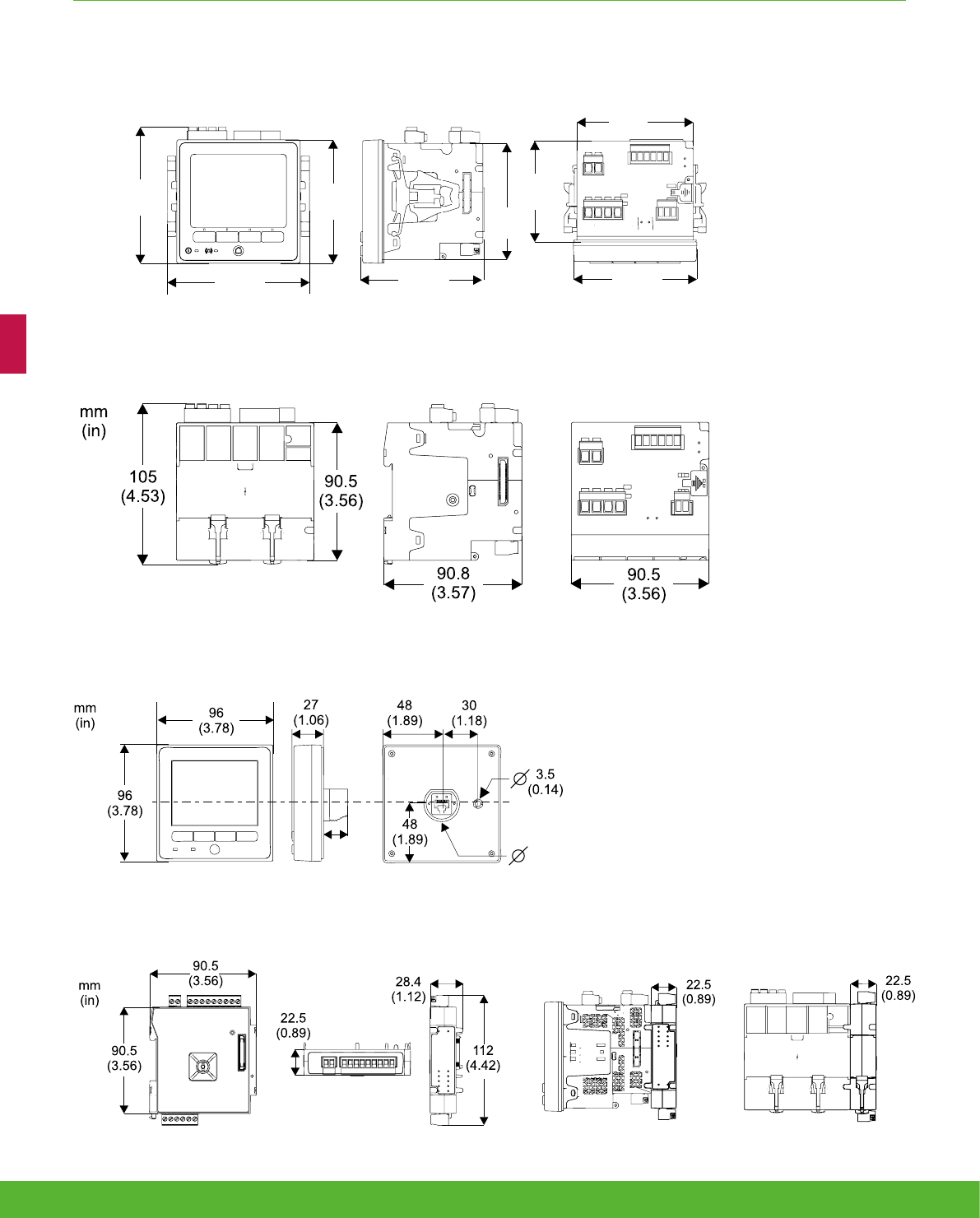
DIN model 90.5 x 90.5 x 90.8 mm
Remote display 96 x 96 x 27 mm
IO modules 90.5 x 90.5 x 22 mm
Environmental conditions
Operating temperature -25ºC to +70ºC
Remote Display Unit -25ºC to +60ºC
Storage temperature -40ºC to +85ºC
Humidity rating 5% to 95% non-condensing
Installation category III
Operating altitude (maximum) 3000m above sea level
PM8000 series
59schneider-electric.co.uk/metering

INTERMEDIATE METERING FUNCTIONS AND CHARACTERISTICS
Electromagnetic compatibility
Product standards IEC 62052-11 and IEC 61326-1
Immunity to electrostatic
discharge IEC 61000-4-2
Immunity to radiated fields IEC 61000-4-3
Immunity to fast transients IEC 61000-4-4
Immunity to surges IEC 61000-4-5
Immunity to conducted
disturbances IEC 61000-4-6
Immunity to power frequency
magnetic fields IEC 61000-4-8
Immunity to conducted
disturbances, 2-150kHz CLC/TR 50579
Immunity to voltage dips &
interruptions IEC 61000-4-11
Immunity to ring waves IEC 61000-4-12
Conducted and radiated
emissions EN 55022, EN 55011, FCC part 15, ICES-003
Surge withstand Capability
(SWC) IEEE C37.90.1
Safety
Safety Construction
IEC/EN 61010-1 ed.3, CAT III, 400 VLN / 690 V LL
UL 61010-1 ed.3 and CSA-C22.2 No. 61010-1 ed.3, CAT III, 347 V LN / 600 V LL
IEC/EN 62052-11, protective class II
Communication
(1)
Ethernet to serial line gateway Communicates directly with up to 32 unit load ION slave devices.
Web server Customisable pages, new page creation capabilities, HTML/XML compatible.
Serial port RS 485 Baud rates of 2400 to 115200, pluggable screw terminal connector.
Ethernet port(s) 2x 10/100Base-TX, RJ45 connector (UTP).
Protocol Modbus, ION, DNP3, IEC 61850, HTTP, FTP, SNMP, SMTP, DPWS, RSTP, NTP, SNTP, GPS
protocols.
Firmware characteristics
High-speed data recording Down to 1/2 cycle interval burst recording, stores detailed characteristics of disturbances or outages. Trigger recording
by a user-defined setpoint, or from external equipment.
Harmonic distortion Up to 63rd harmonic (127th via StruxureWare software) for all voltage and current inputs.
Sag/swell detection Analyse severity/potential impact of sags and swells: magnitude and duration data suitable for plotting on voltage
tolerance curves per phase triggers for waveform recording, control.
Disturbance direction detection
Determine the location of a disturbance more quickly and accurately by determining the direction of the disturbance
relative to the meter. Analysis results are captured in the event log, along with a timestamp and confidence level
indicating level of certainty.
Instantaneous
High accuracy of standard speed (1s) and high-speed (1/2 cycle) measurements, including true rms per phase and
total for:
voltage, current, active power (kW),reactive power (kvar), apparent power (kVA), power factor, frequency, voltage and
current unbalance, phase reversal.
Load profiling
Channel assignments (800 channels via 50 data recorders) configurable for any measurable parameter, including
historical trend recording of energy, demand, voltage, current, power quality, or any measured parameter. Trigger
recorders based on time interval, calendar schedule, alarm/event condition, or manually.
Trend curves
Historical trends and future forecasts to better manage demand, circuit loading, and other parameters. Provides
average, min, max and standard deviation every hour for last 24 hours, every day for last month, every week for last 8
weeks and every month for last 12 months.
Waveform captures
Simultaneous capture of all voltage and current channels
sub-cycle disturbance capture, maximum cycles is 100,000 (16 samples/cycle x 96 cycles, 10MBytes memory), max
256 samples/cycle.
Alarms
Threshold alarms: adjustable pickup and dropout setpoints and time delays, numerous activation levels possible for a
given type of alarm, user-defined or automatic alarm threshold settings, user-defined priority levels (optional automatic
alarm setting).
PM8000 series
schneider-electric.co.uk/metering 60

INTERMEDIATE METERING FUNCTIONS AND CHARACTERISTICS
Firmware characteristics (cont.)
Advanced security Up to 16 users with unique access rights. Perform resets, time sync, or meter configurations based on user privileges.
Memory 512MB (10MB for programming and interval logging).
Firmware update Update via the communication ports.
Display characteristics
Integrated or Remote display 320x240 (1/4 VGA) Colour LCD, configurable screens , 5 buttons and 2 LED indicators (alarm and meter status).
Languages English, French, Spanish, Russian, Portugese,German, Italian, Chinese.
Notations IEC, IEEE.
The HMI menu includes
Alarms Active alarms, historic alarms.
Basic Reading Voltage, current, frequency, power summary.
Power Power summary, demand, power factor.
Energy Energy total, delivered, received.
Events Timestamped verbose event log.
Power Quality EN 50160, harmonics, phasor diagrams.
Inputs/Outputs Digital inputs, digital outputs, analogue inputs, analogue outputs.
Nameplate Model, serial and FW version.
Custom Screens Build your own metrics.
Setup Menu
Meter setup, communications setup, display setup, date/time/clock setup, alarm setup, language setup, time of use
setup, resets, password setup.
61schneider-electric.co.uk/metering
105
(4.13)
mm
(in)
96
(3.78)
95
(3.74)
96
(3.78)
78.5
(3.09)
111
(4.37)
90.5
(3.56)
90.5
(3.56)
PM8240 & PM82401 dimensions
PM8243 dimensions
PM89RD96 dimensions
PM89M2600 & PM89M0024 dimensions
21
(0.83) 29.8
(1.17
)
INTERMEDIATE METERING FUNCTIONS AND CHARACTERISTICS
schneider-electric.co.uk/metering 62

NOTES
63schneider-electric.co.uk/metering

Advanced
metering
schneider-electric.co.uk/metering 64

Applications
Advanced high performance meters are designed for mains or critical loads
on MV/LV networks. They provide analysis of efficiency, losses and capacity,
bill verification, power quality compliance monitoring, problem notification and
diagnosis and control of loads etc.
65schneider-electric.co.uk/metering

Power quality meters are classified as advanced meters designed to monitor
service entrances and critical network locations to maximise power availability and
reliability by providing a comprehensive system load profile, power quality and
root cause analyses.
• PowerLogic ION7550/7650
Advanced metering
Product
overview
66 schneider-electric.co.uk/metering
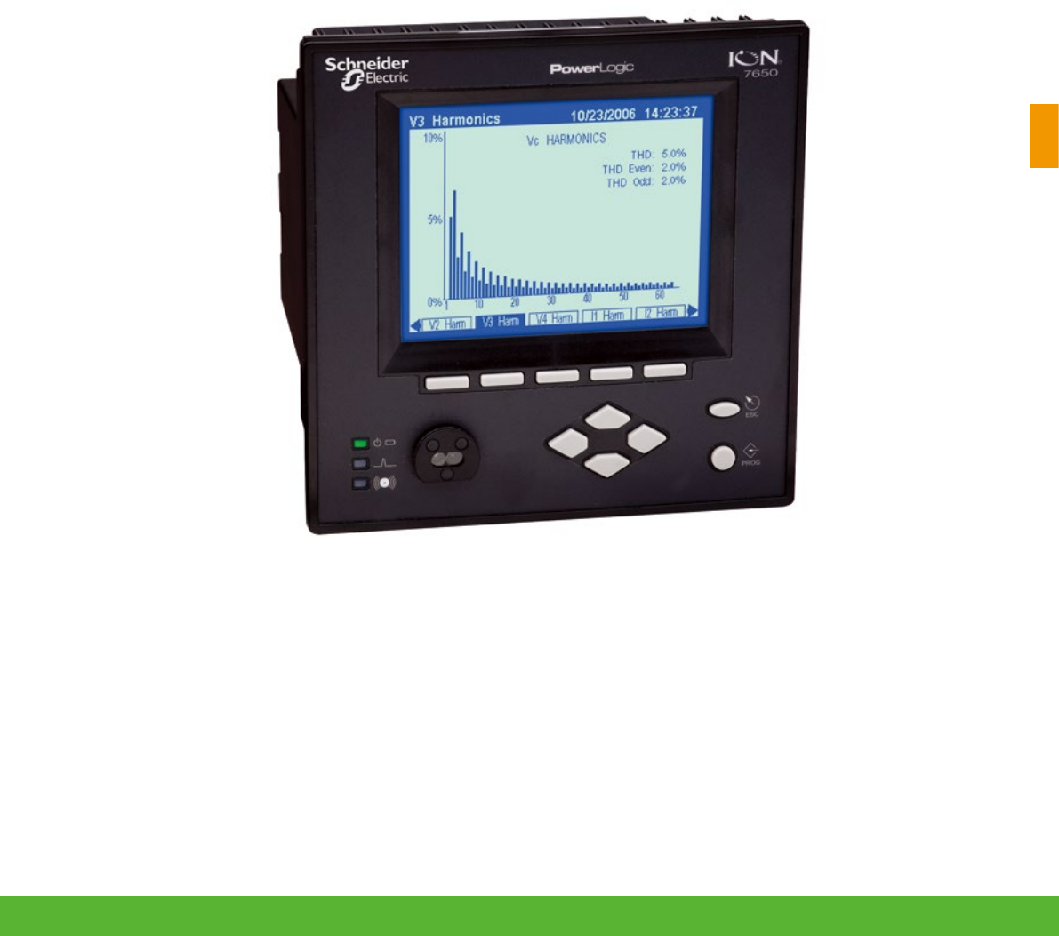
67schneider-electric.co.uk/metering
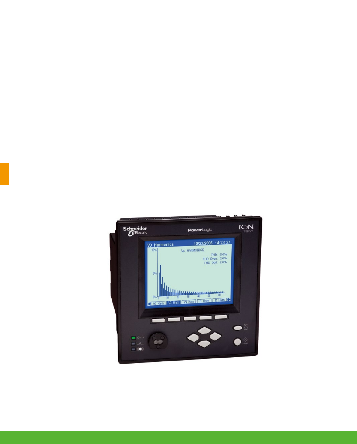
ADVANCED METERING FUNCTIONS AND CHARACTERISTICS
Ideal for both energy suppliers and consumers and loaded with advanced functionality for monitoring
key distribution points and sensitive loads, the PowerLogic ION7650/7550 power and energy meter
offers an unmatched feature set including advanced power quality analysis coupled with revenue
accuracy, multiple communications options, web compatibility and control capabilities.
Applications
• Analysis of efficiency, losses and capacity
• Bill verification, cost allocation and sub-metering
• Power quality compliance monitoring
• Problem notification and diagnosis
• Demand or power factor management
• Control of loads, generators or other equipment
ION7550/7650 series
schneider-electric.co.uk/metering 68

ADVANCED METERING FUNCTIONS AND CHARACTERISTICS
The solution for
All markets that can benefit from a solution that includes
PowerLogic ION7550/7650 series meters:
• Critical buildings
• Industry
• Data centres and networks
• Infrastructure (eg. Airports, road tunnels, telecom)
Competitive advantages
ION technology
• Customise metering or analysis functions at your work
station without hard wiring
• Just link drag-and-drop icons or select default settings
Flexibility of connectivity
• Be integrated with Power Monitoring Experts or be shared
the data with SCADA system via multiple communication
channels and protocols
Benefits
The PowerLogic ION7650/ION7550 meters
help you:
• reduce energy and operations costs
• improve power quality, reliability and uptime
• optimise equipment use for optimal management of your
electrical installation and greater productivity.
Conformity of standards
• IEC 62053-22
• IEEE 519
• IEEE 1159
• CNEMA/ITIC
• IEC 61000-4-30*
• EN 50160*
• IEC 61000-4-7*
• IEC 61000-4-15*
• IEEE 1453*
• IEC 61000-4-2
• IEC 61000-4-3
• IEC 61000-4-4
• IEC 61000-4-5
• CISPR 22
• IEC 61010-1
*ION7650 only
Power management solutions
Schneider Electric provides innovative
power management solutions to increase
your energy efficiency and cost savings,
maximise electrical network reliability and
availability and optimise electrical asset
performance. See Page 114
69schneider-electric.co.uk/metering

ADVANCED METERING FUNCTIONS AND CHARACTERISTICS
Main characteristics
• Anticipate, diagnose and verify to increase efficiency
– Reveal energy inefficiencies or waste and optimise equipment operation to increase efficiency. Isolate
reliability risks, diagnose power-related equipment issues and verify reliable operation.
• Summarise power quality, set targets, measure and verify results
– Consolidate all the power quality characteristics into a single trendable index. Benchmark power quality
and reliability and compare against standards, or compare facilities or processes.
• Easy to use, multilingual, IEC/IEEE configureable display
– Bright LCD display with adjustable contrast. Screen-based menu system to configure meter settings
including IEC or IEEE notations. Multilingual support for English, French, Spanish and Russian. 12/24
hour clock support in multiple formats.
• Modbus Master functionality
– Read information from downstream Modbus devices and view it via the front panel or store in memory
until you upload to the system level.
• IEC 61850 protocol
• Increase interoperability and decrease engineering time using standard protocol.
• Gateway functionality
– Access through the meter’s Ethernet port (EtherGate) or telephone network (ModemGate) to Modbus
communicating devices connected to meter serial ports.
– Detect and capture transients as short as 20µs at 50Hz (17µs at 60 Hz)
– Identify problems due to short disturbances, e.g. switching of capacitors, etc.
• Power quality compliance monitoring
– Monitor compliance with international quality-of-supply standards (IEC 61000-4-30 class A ed. 2(1),
EN50160(1), IEC 61000-4-7(1), IEC 61000-4-15(1), IEEE 519, IEEE 1159, and CBEMA/ITIC). Evaluate
flicker based on IEC 61000-4-15(1) and IEEE 1453(1).
• Detect waveshape changes
– Detection of phase switching phenomena (for example during the transfer of a high-speed static switch)
not detected by classical threshold-based alarms.
• Record ultra-fast electrical parameters every 100 ms or every cycle
– Preventive maintenance: acquisition of a motor startup curve, etc.
• Trend curves and short-term forecasting
– Rapid trending and forecasting of upcoming values for better decision making.
• Disturbance direction detection
– Determine disturbance location and direction relative to the meter. Results captured in the event log,
along with a timestamp and certainty level.
• Alarm setpoint learning
– The meter analyses the circuit and recommends alarm setpoints to minimise nuisance or missed alarms.
• Notify alarms via email
– High-priority alarms sent directly to the user’s PC. Instant notification of power quality events by email.(1)
ION7650 only
schneider-electric.co.uk/metering 70
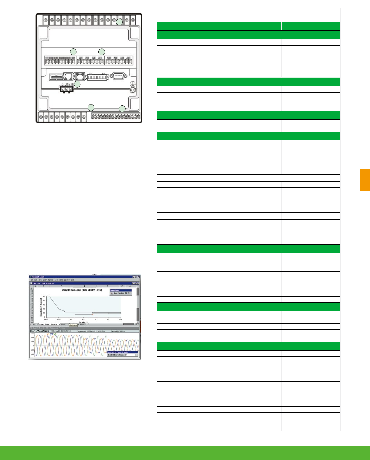
ADVANCED METERING FUNCTIONS AND CHARACTERISTICS
PE86288
PowerLogic™ ION7550 / ION7650 rear view.
1 Current/voltage inputs
2 Digital inputs
3 Analogue inputs
4 Analogue outputs
5 Communications card
6 Power supply
7 Form C digital outputs
8 Digital inputs
9 Form A digital outputs
PE86002
Disturbance waveform capture and power quality report
3
1
4
8
5
9
Selection guide
ION7550 ION7650
General
Use on LV and HV systems b b
Current accuracy (1A to 5A) 0.1 % reading 0.1 % reading
Voltage accuracy (57V to 288V) 0.1 % reading 0.1 % reading
Energy accuracy
Nbr of samples/cycle or sample frequency
0.2 %
256
0.2 %
1024
Instantaneous rms values
Current, voltage, frequency b b
Active, reactive, apparent power Total and per phase b b
Power factor Total and per phase b b
Current measurement range (autoranging) 0.01 - 20A 0.01 - 20A
Energy values
Active, reactive, apparent energy b b
Settable accumulation modes b b
Demand values
Current Present and max. values b b
Active, reactive, apparent power Present and max. values b b
Predicted active, reactive, apparent power b b
Synchronisation of the measurement window b b
Setting of calculation mode Block, sliding b b
Power quality measurements
Harmonic distortion Current and voltage b b
Individual harmonics Via front panel 63 63
Via ION Enterprise 127 511
Waveform capture b b
Detection of voltage swells and sags b b
Detection and capture of transients - 20 µs(1)
Flicker - b
Fast acquisition of 100 ms or 20 ms data b b
EN50160 compliance checking - b
Programmable (logic and math functions) b b
Data recording
Min/max of instantaneous values b b
Data logs b b
Event logs b b
Trending/forecasting b b
SER (Sequence of event recording) b b
Time stamping b b
GPS synchronisation (1 ms) b b
Memory (in Mbytes) 10 10
Display and I/O
Front panel display b b
Wiring self-test b b
Pulse output 1 1
Digital or analogue inputs(max) 20 20
Digital or analogue outputs (max, including pulse output) 12 12
Communication
RS 485 port 1 1
RS 485 / RS 232 port 1 1
Optical port 1 1
Modbus protocol b b
IEC 61850 protocol b b
Ethernet port (Modbus/TCP/IP protocol, IEC 61850 (2)) 1 1
Ethernet gateway (EtherGate) 1 1
Alarms (optional automatic alarm setting b b
Alarm notification via email b b
HTML web page server (WebMeter) b b
Internal modem 1 1
Modem gateway (ModemGate) b b
DNP 3.0 through serial, modem, and I/R ports b b
(1) For 50 Hz line frequency; 17µs for 60 Hz line frequency.
71schneider-electric.co.uk/metering

ADVANCED METERING FUNCTIONS AND CHARACTERISTICS
1 Model.
2 Form factor.
3 Current Inputs.
4 Voltage Inputs.
5 Power supply.
6 System frequency.
7 Communications.
8 Inputs/outputs.
9 Security.
10 Special order.
Part numbers
Item Code Description
1 Model
M7650
Advanced meter with wide-range voltage inputs (57-347V line-neutral or 100-600V line-line), transient detection, data and waveform
recording, IEC 61000-4-30 Class A & EN50160.Supports ION, IEC 61850 (only for meters with 5MB memory and Ethernet comm
card) Modbus-RTU, and DNP 3.0.
M7550
Advanced meter with wide-range voltage inputs (57-347V line-neutral or 100-600V line-line), sag/swell detection, data and waveform
recording. Supports ION, IEC 61850 (only for meters with 5MB memory and Ethernet comm card) Modbus-RTU, and DNP 3.0.
2 Form Factor
A0
Integrated display with front optical port, 5 MB logging memory, and 512 samples/cycle resolution (ION7650) or 256 samples/cycle
(ION7550).
A1
ION7650 only. Integrated display with front optical port, 5 MB logging memory, and 1024 samples/cycle resolution.
B0
Integrated display with front optical port, 10 MB logging memory, and 512 samples/cycle resolution (ION7650) or 256 samples/cycle
(ION7550).
B1
ION7650 only. Integrated display with front optical port, 10 MB logging memory, and 1024 samples/cycle resolution.
T0
Transducer (no display) version, with 5 MB logging memory, and 512 samples/cycle resolution (ION7650) or 256 samples/cycle
(ION7550).
T1
ION7650 only. Transducer (no display) version, with 5 MB logging memory, and 1024 samples/cycle resolution.
U0
Transducer (no display) version, with 10 MB logging memory, and 512 samples/cycle resolution (ION7650) or 256 samples/cycle
(ION7550).
U1
ION7650 only. Transducer (no display) version, with 10 MB logging memory, and 1024 samples/cycle resolution.
3 Current Inputs
C
5 Amp nominal, 20 Amp full scale current input
E
1 Amp nominal, 10 Amp full scale current input
F
Current Probe Inputs (for 0-1 VAC current probes; sold separately)
G
Current Probe Inputs with three Universal Technic 10A clamp on CTs; meets IEC 1036 accuracy
4 Voltage Inputs 0
57 to 347 VAC line-to-neutral / 100 to 600 VAC line-to-line
5 Power Supply B
Standard power supply (85-240 VAC, ±10%/47-63 Hz / 110-300 VDC, ±10%)
C
Low voltage DC power supply (20-60 VDC)
6 System Frequency 5
Calibrated for 50 Hz systems
6
Calibrated for 60 Hz systems
7 Communications
A0
Standard communications (1 RS-232/RS-485 port, 1 RS-485 port). Integrated display models include 1 ANSI Type 2 optical port.
C1
Standard communications plus 10Base-T/100Base-TX Ethernet (RJ45), 56k universal internal modem (RJ11). Ethernet and modem
gateway functions each use a serial communications port.
D7
Standard communications plus 10Base-T/100Base-TX Ethernet (RJ45) and 100BaseFX Ethernet Fiber, 56k universal internal modem
(RJ11). Ethernet/modem gateway uses serial port.
E0
Standard communications plus 10Base-T/100Base-TX (RJ45). Ethernet gateway function uses a serial communications port.
F1
Standard communications plus 10Base-T/100Base-TX Ethernet (RJ45) and 100Base-FX (SC male Fiber Optic connection). Ethernet
gateway function uses a serial port.
M1
Standard communications plus 56k universal internal modem (RJ11). Modem gateway function uses a serial port.
8 I/O
A
Standard I/O (8 digital ins, 3 Form C relays, 4 Form A solid-state out)
E
Standard I/O plus Expansion I/O card (8 additional digital inputs & four 0 to 20 mA analogue inputs)
K
Standard I/O plus Expansion I/O card (8 additional digital inputs & four 0 to 20 mA analogue outputs)
N
Standard I/O plus Expansion I/O card (8 additional digital inputs & four 0 to 20 mA analogue inputs and four 0 to 20 mA outputs)
P
Standard I/O plus Expansion I/O card (8 additional digital inputs & four 0 to 1 analogue inputs and four -1 to 1 mA analogue outputs)
9 Security
0
Password protected, no hardware lock
1
Password protected, hardware lockable (enabled/disabled via jumper on comm card)
6
Password protected with security lock enabled, terminal cover and UK OFGEM labels
Example ION7650 product part number.
M
schneider-electric.co.uk/metering 72

ION75XX/76XX Accessories
Communication Card for ION7550/7650 Ordering reference
Standard Comms: 1 RS232/RS485 port (COM1), 1 RS485 port (COM2), Front optical port (COM3) P765CA0A
Standard Comms: 1 RS232/RS485 port (COM1), 1 RS485 port (COM2), Front optical port (COM3), tropicalisation treatment
applied P765CA0C
Standard plus Ethernet (10/100BASE-T), 56k universal internal modem (RJ11; shares COM3) P765CC1A
Standard plus Ethernet (10/100BASE-T), 56k universal internal modem (RJ11; shares COM3), tropicalisation treatment applied P765CC1C
Standard plus Ethernet (10/100BASE-T, 100BASE-FX), 56k internal modem (RJ11) P765CD7A
Standard plus Ethernet (10/100BASE-T, 100BASE-FX), 56k internal modem (RJ11), tropicalisation treatment applied P765CD7C
Standard plus Ethernet (10/100BASE-T) P765CE0A
Standard plus Ethernet (10/100BASE-T), tropicalisation treatment applied P765CE0C
Standard plus Ethernet (10/100BASE-T, 100BASE-FX) P765CF1A
Standard plus Ethernet (10/100BASE-T, 100BASE-FX), tropicalisation treatment applied P765CF1C
Standard plus 56k universal internal modem (RJ11; shares COM3) P765CM1A
Standard plus 56k universal internal modem (RJ11; shares COM3),tropicalisation treatment applied P765CM1C
Analogue I/O cards Ordering reference
four 0 to 20 mA analogue inputs & 8 digital inputs P760AEA
four 0 to 20 mA analogue inputs & 8 digital inputs,tropicalisation treatment applied P760AEC
four 0 to 20 mA analogue outputs & 8 digital inputs P760AKA
four 0 to 20 mA analogue outputs & 8 digital inputs,tropicalisation treatment applied P760AKC
four 0 to 20 mA analogue inputs, four 0 to 20 mA analogue outputs & 8 digital inputs P760ANA
four 0 to 20 mA analogue inputs, four 0 to 20 mA analogue outputs & 8 digital inputs,tropicalisation treatment applied P760ANC
four 0 to 1 analogue inputs, four -1 to 1 mA analogue outputs & 8 digital inputs. P760APA
four 0 to 1 analogue inputs, four -1 to 1 mA analogue outputs & 8 digital inputs,tropicalisation treatment applied P760APC
ION 7550/7650 Related Items Ordering reference
Serial Optical Probe (DB-9) via IR port OPTICAL-PROBE
USB Optical Probe via IR port OPTICAL-PROBE-USB
Gasket for ION7x50 meters and RTU - IP 52 & UL NEMA 12 P765GSKT
ION7550/7650 remote display, Schneider Electric branded M765RD
ION7550/7650 remote display kit, includes display, 24 VDC power supply and Ethernet cable, Schneider Electric branded M765RDPS
Terminal strip cover TERMCVR-7550
10A/1 VAC Universal Technic Clamp On Current Probe (Price per probe) M1UB10A1V-10A
1000A/1 VAC Universal Technic Clamp On Current Probe (Price per probe) P32UEP813-1000A
3000A/1 VAC Universal Technic Clamp On Current Probe (Price per probe) P32UEP815-3000A
300A/0.333 VAC Magnelabs Split Core Current Probe (Price per probe) SCT1250-300-300A
ADVANCED METERING FUNCTIONS AND CHARACTERISTICS
73schneider-electric.co.uk/metering

Advanced metering
Technical
Specifications
74 schneider-electric.co.uk/metering

ADVANCED METERING FUNCTIONS AND CHARACTERISTICS
Technical specifications
Electrical characteristics
Type of measurement True rms to 1024 samples per cycle (ION7650)
Measurement
accuracy
Current and voltage ±0.01% of reading + ±0.025% of full scale
Power ±0.075% of reading + ±0.025% of full scale
Frequency ±0.005Hz
Power factor ±0.002 from 0.5 leading to 0.5 lagging
Energy: IEC62053-22 0,2S, 1A and 5A
Data update rate 1/2 cycle or 1 second
Input-voltage
characteristics
Measurement range Autoranging 57V through 347V LN / 600V LL
Impedance 5 MΩ/phase (phase - Vref)
Frequency measurement
range 42 to 69Hz
Input-current
characteristics
Rated nominal current 1A, 2A, 5A, 10A
Measurement range 0.005 - 20 A autoranging (standard range)
0.001 - 10 A autoranging (optional range)
Permissible overload 500 A rms for 1 s, non-recurring (5A)
50 A rms for 1s, non-recurring (1A)
Impedance 0.002 Ω per phase (5A)
0.015 Ω per phase (1A)
Burden 0.05 VA per phase (5 A)
0.015 VA per phase (1 A)
Power supply
AC 85-240 V AC ±10% (47-63 Hz)
DC 110-300 V DC ±10%
DC low voltage (optional) 20-60 V DC ±10%
Ride-through time 100 ms (6 cycles at 60 Hz) min.
Burden Standard: typical 20 VA, max 45 VA
Low voltage DC: typical 15 VA, max 20 VA
Input/outputs
(1)
Standard
8 digital inputs (120 V DC)
3 relay outputs (250 V AC / 30 V DC)
4 digital outputs (solid state)
Optional 8 additional digital inputs
4 analogue outputs, and/or 4 analogue inputs
Mechanical characteristics
Weight 1.9 kg
IP degree of protection (IEC 60529) Integrated display, front: IP 50; back: IP 30
Transducer unit (no display): IP 30
Dimensions Standard model 192 x 192 x 159 mm
TRAN model 235.5 x 216.3 x 133.1 mm
Environmental conditions
Operating
temperature
Standard power supply -20 to +70 ºC
Low voltage DC supply -20 to +50 ºC
Display operating range -20 to +60 ºC
Storage
temperature Display, TRAN -40 to +85 ºC
Humidity rating 5 to 95% non-condensing
Installation category III (2000m above sea level)
Dielectric withstand As per EN 61010-1, IEC 62051-22A
(2)
Electromagnetic compatibility
Electrostatic discharge IEC 61000-4-2
Immunity to radiated fields IEC 61000-4-3
Immunity to fast transients IEC 61000-4-4
Immunity to surges IEC 61000-4-5
Conducted and radiated emissions CISPR 22
Safety
Europe IEC 61010-1
Communication
RS 232/485 port
(1)
Up to 115,200 bauds (57,600 bauds for RS 485), ION, DNP 3.0, Modbus, GPS, EtherGate, ModemGate, Modbus Master
RS 485 port
(1)
Up to 57,600 bauds, ION, DNP 3.0, Modbus, GPS, EtherGate, ModemGate, Modbus Master
Infrared port
(1)
ANSI type 2, up to 19,200 bauds, ION, Modbus, DNP 3.0
Ethernet port 10Base-T/100Base-TX, RJ45 connector, 100 m link
Fibre-optic Ethernet link 100 Base FX, SC duplex connector, 1300 nm, FO multimode with gradient index 62.5/125 µm or 50/125 µm, 2000 m link
(1) Consult the ION7550 / ION7650 installation guide for complete specifications. (2) IEC 62051-22B with serial ports only.
ION7550/ION7650 series
75schneider-electric.co.uk/metering
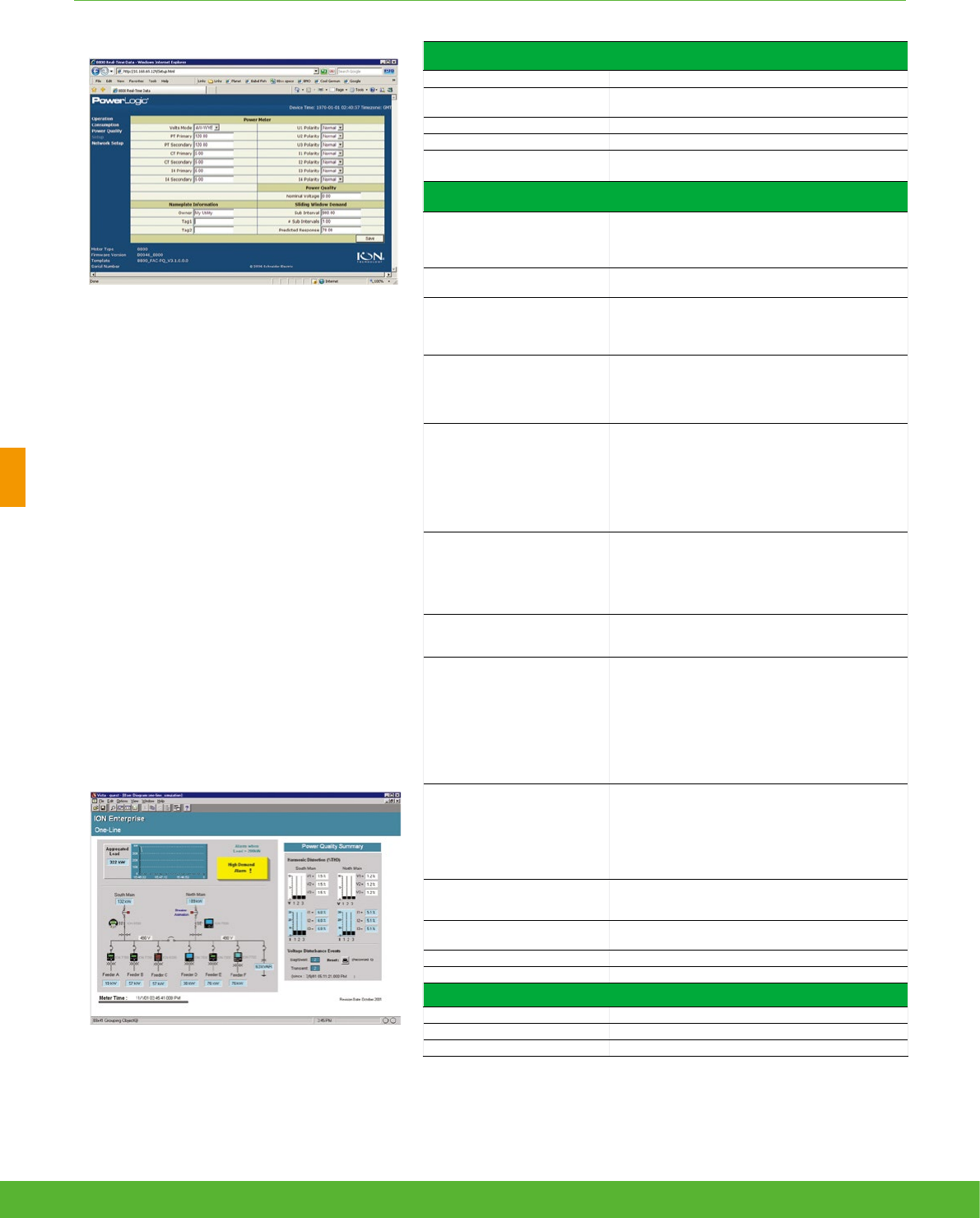
ADVANCED METERING FUNCTIONS AND CHARACTERISTICS
PE86004
Communication (cont.)
Protocol ION, Modbus, TCP/IP, DNP 3.0, Telnet, IEC 61850
(2)
EtherGate Communicates directly with up to 62 slave devices via
available serial ports
ModemGate Communicates directly with up to 31 slave devices
Ethernet port 10Base-T/100Base-TX, RJ45 connector, 100 m link
WebMeter 5 customisable pages, new page creation capabilities,
HTML/XML compatible
Firmware characteristics
High-speed data recording
Down to 5ms interval burst recording, stores detailed
characteristics of disturbances or outages. Trigger
recording by a user-defined setpoint, or from external
equipment.
Harmonic distortion Up to 63
rd
harmonic (511
th
for ION7650 via ION
Enterprise software) for all voltage and current inputs
Sag/swell detection
Analyse severity/potential impact of sags and swells:
magnitude and duration data suitable for plotting on
voltage tolerance curves
per phase triggers for waveform recording, control
Disturbance direction detection
Determine the location of a disturbance more quickly
and accurately by determining the direction of the
disturbance relative to the meter. Analysis results are
captured in the event log, along with a timestamp and
confidence level indicating level of certainty.
Instantaneous
High accuracy (1s) or high-speed (1/2 cycle)
measurements, including true rms per phase / total for:
voltage and current
active power (kW) and reactive power (kvar)
apparent power (kVA)
power factor and frequency
voltage and current unbalance
phase reversal
Load profiling
Channel assignments (800 channels via 50 data
recorders) configurable for any measurable parameter,
including historical trend recording of energy, demand,
voltage, current, power quality, or any measured
parameter. Trigger recorders based on time interval,
calendar schedule, alarm/event condition, or manually.
Trend curves
Access historical data at the front panel. Display, trend
and continuously update historical data with date and
timestamps for up to four parameters simultaneously.
Waveform captures
Simultaneous capture of all voltage and current
channels
sub-cycle disturbance capture
maximum cycles is 214,000 (16 samples/cycle x 96
cycles, 10Mbytes memory)
256 samples/cycle (ION7550)
512 samples/cycle standard, 1024 samples/cycle
optional (ION7650)
COMTRADE waveform format available direct from the
meter (Ethernet port option only)
PE86005
Alarms
Threshold alarms:
adjustable pickup and dropout setpoints and time
delays, numerous activation levels possible for a given
type of alarm
user-defined priority levels
boolean combination of alarms is possible using the
operators NAND, OR, NOR and XOR
Advanced security
Up to 16 users with unique access rights. Perform
resets, time syncs, or meter configurations on user
privileges
Transformer correction Correct for phase / magnitude inaccuracies in current
transformers (CTs), potential transformers (PTs)
Memory 5 to 10 Mbytes (specified at time of order)
Firmware update Update via the communication ports
Display characteristics
Integrated display Back lit LCD, configurable screens
Languages English, French, Spanish, Russian
Example showing instantaneous values and alarm.
Notations IEC, IEEE
(1) Consult the ION7550 / ION7650 installation guide for complete specifications.
(2) IEC 62051-22B with serial ports only.
schneider-electric.co.uk/metering 76
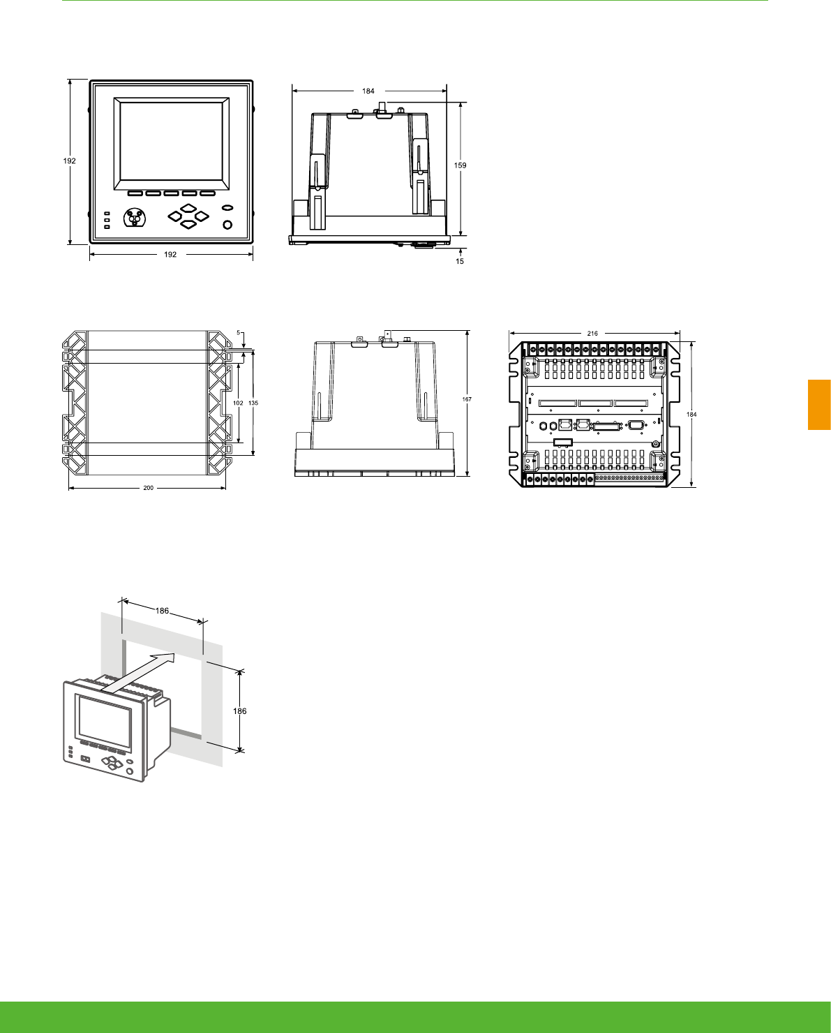
ADVANCED METERING FUNCTIONS AND CHARACTERISTICS
ION7550 and ION7650 meter can have integrated or remote display. The meter with
integrated display is designed to fit DIN standard 192 cutout (186 mm by 186 mm) . The
remote display is intalled through a circular cutout (22.5 mm diameter) at the panel door and
it has a front and a back module that is connected to the meter mounted in a DIN rail at the
back.
ION7550/ION7650 dimensions
ION7550 / ION7650 TRAN dimensions
Front-panel mounting
77schneider-electric.co.uk/metering

Advanced utility
metering
78 schneider-electric.co.uk/metering

Applications
Power quality and revenue meters are designed for utility network monitoring,
eg. transmission and distribution network monitoring.
79schneider-electric.co.uk/metering

Revenue and power quality meters designed for precision metering at key
transmission network inter-ties, distribution substations and service entrances to
optimise power reliability and energy efficiency in utility smart grids.
• PowerLogic ION8800
Advanced utility metering
Product
overview
80 schneider-electric.co.uk/metering
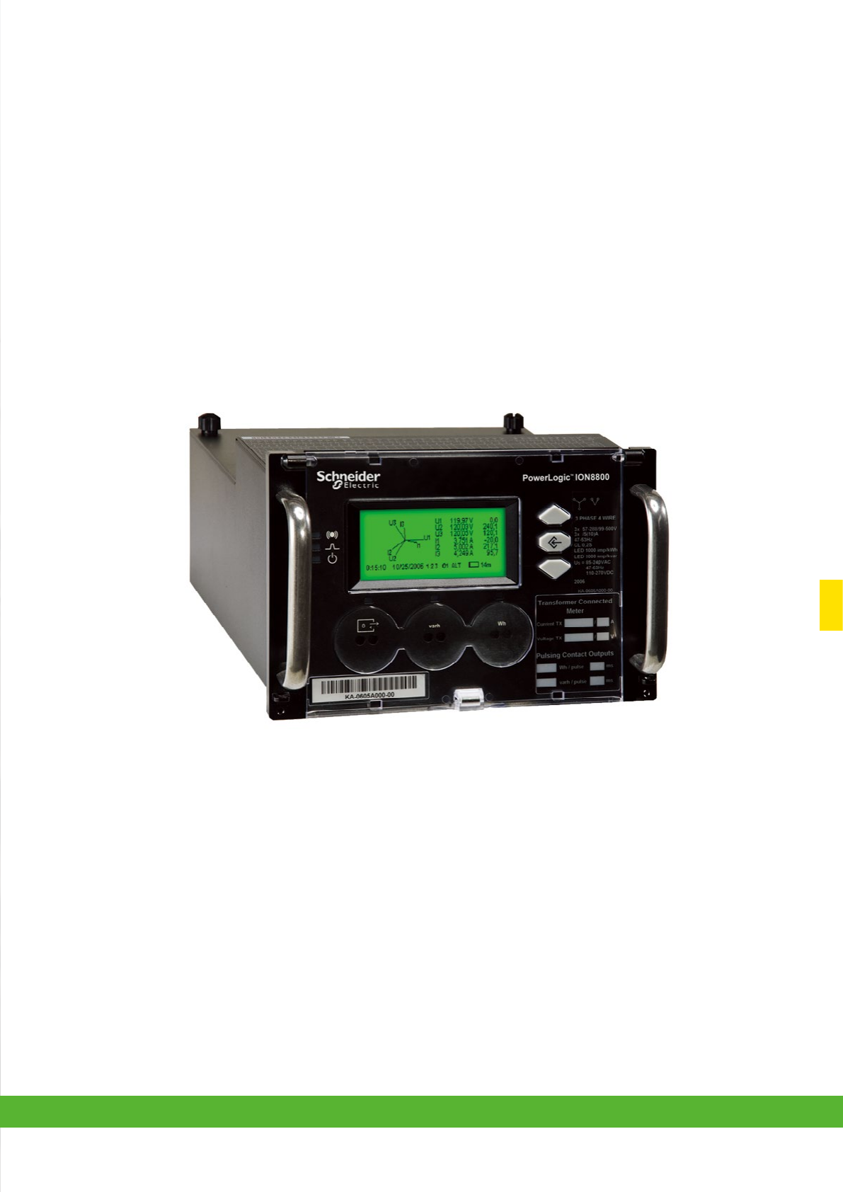
81schneider-electric.co.uk/metering
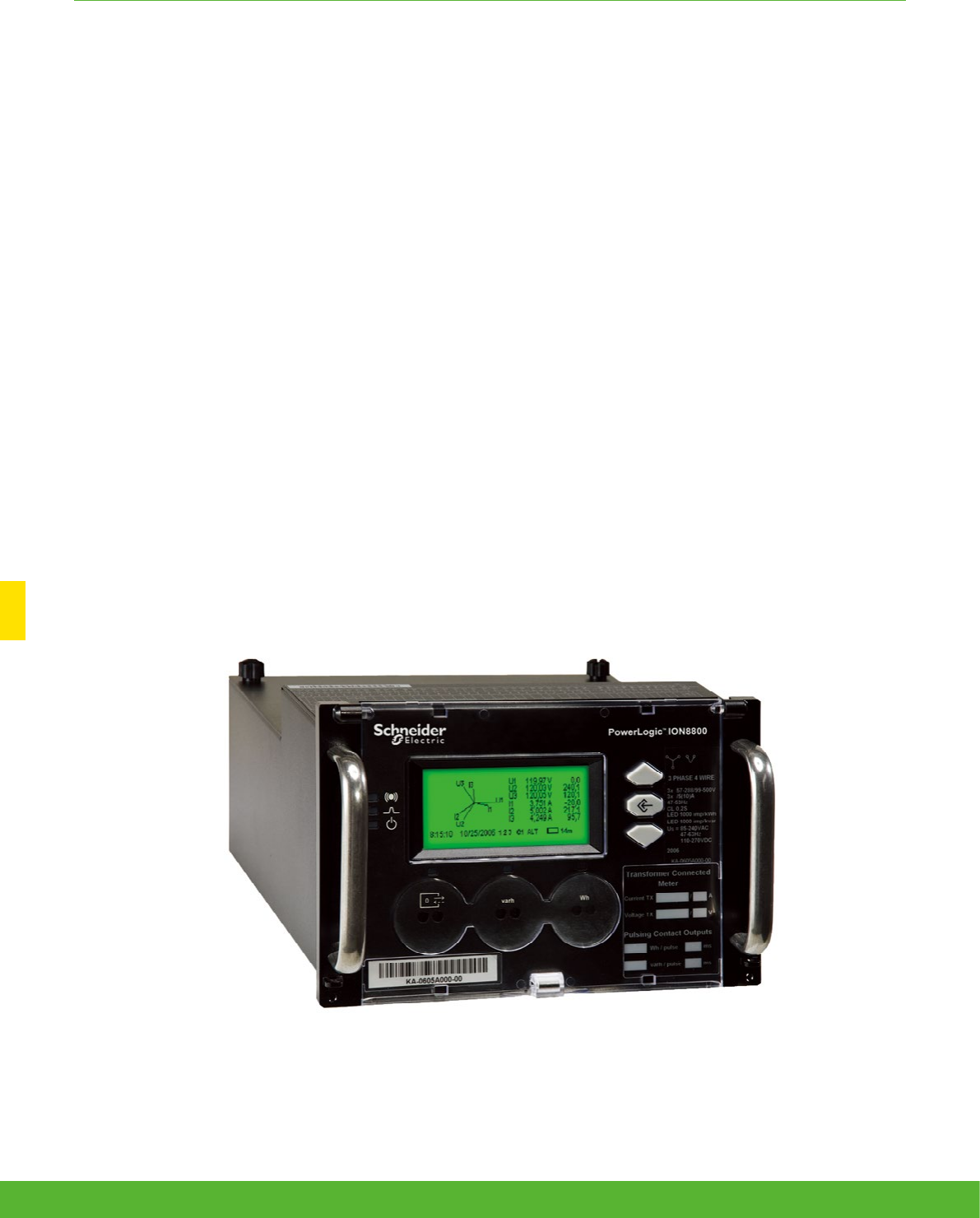
Providing high accuracy and a wide range of features for transmission and distribution metering,
the PowerLogic ION8800 advanced revenue and power quality meter has the flexibility to change
along with your needs. The meter provides the tools necessary to:
• Manage energy procurement and supply contracts
• Perform network capacity planning and stability analysis’
• Monitor power quality compliance, supply agreements, and regulatory requirements
ION8800 series
ADVANCED UTILITY METERING FUNCTIONS AND CHARACTERISTICS
Applications
• Transmission and distribution metering
• Revenue metering
• Extensive power quality monitoring and analysis
• Power quality compliance monitoring
• Digital fault recording
• Instrument transformer correction
82 schneider-electric.co.uk/metering

ADVANCED UTILITY METERING FUNCTIONS AND CHARACTERISTICS
The solution for
All markets that can benefit from a solution that includes
PowerLogic ION8800 series meters:
• Transmission networks
• Distribution network
Competitive advantages
• Be integrated into existing wholesale settlement system
• Be able to use Power Monitoring Expert software for data
analysis or share operation data with SCADA systems
through multiple communication channels and protocols
• Transformer/line loss compensation
• Instrument transformer correction
Benefits
• Reduce operations costs
• Improve power quality
• Improve continuity of service
Conformity of standards
• IEC 62053-
22/23
• IEC 61000-4-30
• EN 50160
• IEC 61000-4-7
• IEC 61000-4-15
• IEEE 1159
• IEEE 519
• IEC 61000-4-2
• IEC 61000-4-3
• IEC 61000-4-4
• IEC 61000-4-5
• IEC 61000-4-6
• IEC 61000-4-12
• CISPR 22
• IEC 62052-11
• IEC 60950
Power management solutions
Schneider Electric provides innovative
power management solutions to increase
your energy efficiency and cost savings,
maximise electrical network reliability and
availability, and optimise electrical asset
performance. See Page 114
83schneider-electric.co.uk/metering

ADVANCED UTILITY METERING FUNCTIONS AND CHARACTERISTICS
Main characteristics
• IEC 19-inch rack mount design to DIN 43862 standard
– Use Essailec connectors with common measurement and energy pulsing pin-out to easily retrofit into
existing systems.
• Accurate metering
– Interconnection points on medium, high, and ultra-high voltage networks are in compliance with IEC
62053-22/23 Class 0,2S.
• Power quality compliance monitoring
– Monitor compliance with international quality-of-supply standards (IEC 61000-4-30 Class A/S, EN50160,
IEC 61000-4-7, IEC 61000-4-15, IEEE 1159, IEEE 519).
• Power quality summary
– Consolidate power quality characteristics into easily viewable reports indices.
• Digital fault recording
– Capture voltage and current channels simultaneously for sub-cycle disturbances.
• Complete communications
– Use the IEC1107 optical port or the optional communications module that supports concurrent Ethernet,
serial, and modem communications.
• Multiple tariffs and time-of-use
– Apply tariffs and seasonal rate schedules to measure energy and demand values for time periods with
specific billing requirements.
• Alarms and I/O functions
– Use up to 65 setpoints for single/multi-condition alarms and I/O functions with response times down to
1/2 cycle.
• Alarm notification via email
– High-priority alarms, data logs sent directly to the user’s PC. Instant notification of power quality events
by email.
• Software integration
– Easily integrate the meter with StruxureWare Power Monitoring (ION Enterprise) or other utility software;
MV-90, Pacis and third-party SCADA packages.
• Transformer/line loss compensation
– Compensate for system losses in real time directly in the meter.
• Instrument transformer correction
– Save money and improve accuracy by correcting for less accurate transformers.
84 schneider-electric.co.uk/metering
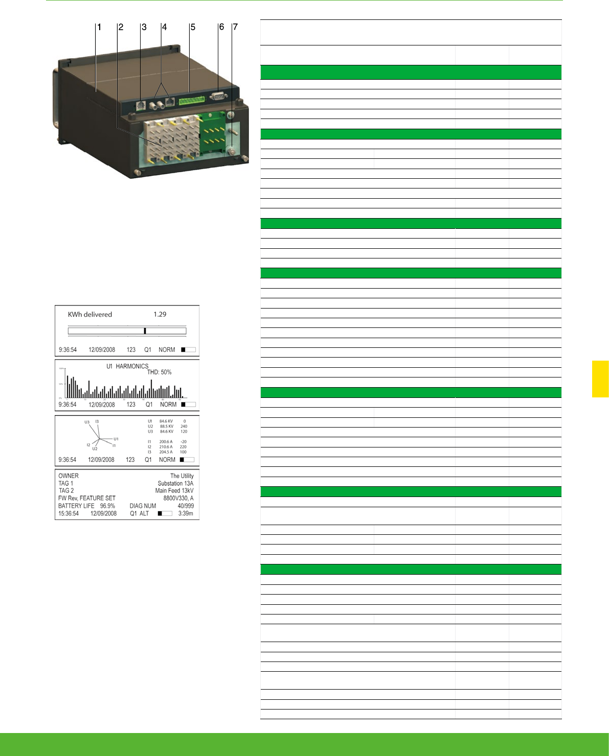
ADVANCED UTILITY METERING FUNCTIONS AND CHARACTERISTICS
PE86001
PowerLogic ION8800 meter
1 Optional communications module.
2 Essailec connectors.
3 Internal modem.
4 Optional Ethernet communications.
5 Selectable RS 485 serial port.
6 Selectable RS 232 or RS 485 serial port.
7 Ground terminal.
PE86235
Display screen examples: KWh disk simulator, voltage
harmonics histogram, phasor diagram, and name plate1.
Selection guide
ION8800A
ION8800B ION8800C
General
Use on LV, MV and HV systems b b
Current accuracy 0.1 % 0.1 %
Voltage accuracy 0.1 % 0.1 %
Power accuracy 0.2 % 0.2 %
Samples/cycle 1024 1024
Instantaneous rms values
Current, voltage, frequency (Class 0,2S) b b
Active, reactive, apparent power Total and per phase b b
Power factor Total and per phase b b
Current measurement range 0.001 - 10A 0.001 - 10A
Current measurement range 0.001 - 10A 0.001 - 10A
Energy values
Active, reactive, apparent energy b b
Settable accumulation modes b b
Demand values
Current b b
Active, reactive, apparent b b
Predicted active, reactive, apparent b b
Demand modes (block, sliding, thermal, predicted) b b
Power quality measurements
Detection of voltage dips (sags) and swells 10 ms 10 ms
Symmetrical components: zero, positive, negative b-
Transient detection, microseconds (50 Hz) 20
(1)
20
(1)
Harmonics: individual, even, odd, total up to 63
rd
63
rd
Harmonics: magnitude, phase and inter-harmonics 50
th
40
th
EN 50160 compliance b
IEC 61000-4-30 class A b
IEC 61000-4-30 class S b
(2)
IEC 61000-4-15 (Flicker) b-
Configurable for IEEE 519 - 1992, IEEE1159-1995 b
(1)
-
Programmable (logic and math functions) b b
Data recording
Min/max logging for any parameter b b
Historical logs Maximum # of records 800
(1)
640
(2)
32
Waveform logs Maximum # of records 96
(1)
-
Timestamp resolution in seconds 0.001 0.001
Setpoints, minimum response time ½ cycle ½ cycle
Number of setpoints 65 65
GPS time synchronisation (IRIG-B) b b
Could add transient logs. COMTRADE fault records. b b
User configurable log memory 10 Mbytes 10 Mbytes
Display and I/O
Front panel display b b
Active/reactive energy pulser, LED and IEC 1107 style
port b b
Digital pulse outputs, optional Solid state Form A 8 8
Digital pulse outputs Solid state Form C 4 4
Alarm relay output Form C 1 1
Digital inputs (optional) 3 3
Communications
RS 232/485 port 1 1
RS 485 port 1 1
Ethernet port 1 1
IEC 1107 optical port 1 1
Internal modem 1 1
3-port DNP 3.0 through serial, modem, Ethernet and I/R
ports b b
Modbus RTU master / slave (serial, modem and I/R ports) b / b- / b
Modbus TCP master / slave (via Ethernet port) b / b- / b
Data transfer between Ethernet and RS 485 (EtherGate) b b
Data transfer between internal modem, RS 485
(ModemGate) b b
Alarms, single or multi-condition b b
Alarm notification & logged data via email b b
Embedded web server (WebMeter) b b
(1) ION8800A only.
(2) ION8800B only.
85schneider-electric.co.uk/metering

ADVANCED UTILITY METERING FUNCTIONS AND CHARACTERISTICS
(1) Channel COM2 is available on the port at the back of the meter OR on the Comm Module
(if installed). You must select which connectors your communications wiring is connected to during meter setup.
(2) All Onboard I/O and Comms (Base Option) options include: 4 Form C solid-state digital outputs, 1 Form C mechanical relay output, one IEC 1107 optical
communications port,
two IEC 1107 style optical pulsing ports.
Example product part number.
1 Model.
2 Feature set.
3 Memory / form factor.
4 Current Inputs.
5 Voltage inputs.
6 Power supply.
7 System frequency.
8 Communications.
9 Onboard inputs/outputs.
10 Security.
11 Special order.
Part numbers
Item Code Description
1 Model M8800 ION8800 IEC/DIN 43862 19” rack mount energy and power quality meter.
2 Feature Set
AClass A power quality analysis, waveforms and transient capture with 1024 samples/cycle.
B Energy meter Class S EN50160 power quality monitoring.
C Basic tariff/energy revenue meter with sag/swell monitoring.
3Memory/Form
Factor
1 10 MB logging memory, Essailec connectors.
2 5 MB logging memory, Essailec connectors, with IEC61850 protocol
4 Current Inputs
C (I1-I3): Configured for 5 A nominal, 10 A full scale, 14 A fault capture, 0.001 A starting current.
E (I1-I3): Configured for 1 A nominal, 10 A full scale, 14 A fault capture, 0.001 A starting current.
5 Voltage Inputs 0 (V1-V3): Autoranging (57-288 VAC L-N or 99-500 VAC L-L)
6 Power Supply B Single phase power supply: 85-240 VAC ±10% (47-63 Hz) or 110-270 VDC.
7System
Frequency
5 Calibrated for 50 Hz systems.
6 Calibrated for 60 Hz systems.
8
Communications
module (field
serviceable)
Z0 No communications module - meter includes Base Onboard I/O and comms (see below for details).
A0 Standard communications: 1 RS 232/RS 485 port, 1 RS 485 port (COM2)
(1)
.
C1 Standard communications plus 10Base-T Ethernet (RJ45), 56 k universal internal modem (RJ11).
D1 Standard communications plus 10Base-T Ethernet (RJ45) / 10Base-FL Ethernet Fiber, 56 k universal internal modem
(RJ11).
E0 Standard communications plus 10Base-T Ethernet (RJ45).
F0 Standard communications plus 10Base-T Ethernet (RJ45) / 10Base-FL (ST male Fiber Optic connection).
M1 Standard communications plus 56k universal internal modem (RJ11).
9
Onboard
I/O and
communications
(not field
serviceable, part
of base unit)
A Base option AND 8 Form A digital outputs
(2)
, 1 RS-485 (COM2) port
(1)
.
B Base Option AND 8 Form A digital outputs
(2)
, 3 digital inputs (20-56 VDC/AC).
C Base Option AND 8 Form A digital outputs
(2)
, 3 digital inputs (80-280 VDC/AC).
D Base Option AND 1 IRIG-B time sync port
(2)
, 1 RS-485 port (COM2), 3 digital inputs (20-56 V DC/AC)
(1)
.
E Base Option AND 1 IRIG-B time sync port
(2)
, 1 RS-485 port (COM2), 3 digital inputs (80-280 V DC/AC)
(1)
.
10 Security
0 Password protected, no security lock.
1 Password protected with security lock enabled.
11 Special Order
A None.
C Tropicalisation treatment applied.
86 schneider-electric.co.uk/metering
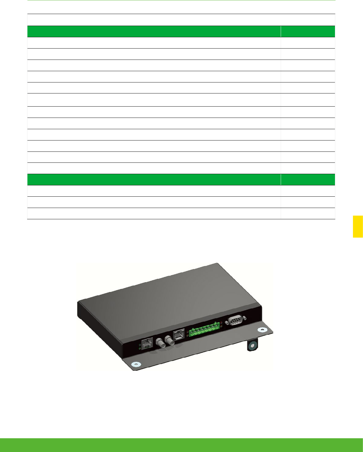
Optional ION8800 communications module
ION8800 Accessories
Communication Card for ION8800 Ordering reference
Std. comms: 1 RS-232/RS-485 port, **1 RS-485 port (COM2) P880CA0A
Std. comms: 1 RS-232/RS-485 port, **1 RS-485 port (COM2), tropicalisation treatment applied P880CA0C
Std. comms AND 10BASE-T Ethernet (RJ45), 56k universal internal modem (RJ11) P880CC1A
Std. comms AND 10BASE-T Ethernet (RJ45), 56k universal internal modem (RJ11), tropicalisation treatment applied P880CC1C
Std. comms AND 10BASE-T Ethernet (RJ45) / 10BASE-FL Ethernet Fiber, 56k universal internal modem (RJ11) P880CD1A
Std. comms AND 10BASE-T Ethernet (RJ45) / 10BASE-FL Ethernet Fiber, 56k universal internal modem (RJ11), tropicalisation
treatment applied P880CD1C
Std. comms AND 10BASE-T Ethernet (RJ45) P880CE0A
Std. comms AND 10BASE-T Ethernet (RJ45), tropicalisation treatment applied P880CE0C
Std. comms AND 10BASE-T Ethernet (RJ45) / 10BASE-FL (ST Fiber Optic connection) P880CF0A
Std. comms AND 10BASE-T Ethernet (RJ45) / 10BASE-FL (ST Fiber Optic connection), tropicalisation treatment applied P880CF0C
Std. comms AND 56k universal internal modem (RJ11) P880CM1A
Std. comms AND 56k universal internal modem (RJ11), tropicalisation treatment applied P880CM1C
ION88000 related items Ordering reference
Replacement batteries for the ION 8600 or ION 8800, quantity 10 BATT-REPLACE-8XXX
IEC/DIN 34862 19” Rack with female mating voltage/current and I/O blocks unassembled. RACK-8800-RAW
IEC 61107 compliant Optical Probe (DB-9) for use with ION 8800 meters IEC-OPTICAL-PROBE
ADVANCED UTILITY METERING FUNCTIONS AND CHARACTERISTICS
87schneider-electric.co.uk/metering

Advanced utility metering
Technical
Specifications
88 schneider-electric.co.uk/metering

ADVANCED UTILITY METERING FUNCTIONS AND CHARACTERISTICS
Technical Specification
Technical Specification
Electrical characteristics
Type of measurement True rms
1024 samples per cycle
Measurement
accuracy
Current and voltage 0.1 %
Power 0.2 %
Frequency ±0.005 Hz
Power factor 0.1%
Energy IEC 62053-22/23 Class 0.2 S
Data update rate ½ cycle or 1 second
Input-voltage
characteristics
Inputs U1, U2, U3, Uref
Measurement range 57-288 LN VAC rms (99-500 LL VAC rms)
Dielectic withstand 3320 VAC rms
Impedance 5 MΩ /phase (phase-Uref/Ground)
Input-current
characteristics
Rated nominals 5 A, 1 A, 2 A
Permissible overload 200A rms for 0.5s, non-recurring (IEC 62053-22)
Impedance 10 mΩ /phase
Burden 0.01 VA per phase (1A), 0.25 VA per phase (5 A)
Power supply
AC 85 - 240 VAC (+/- 10%), 47-63 Hz
DC 110 - 270 VDC (+/- 10%)
Burden Typical (without comm module): 13 VA, 8 W Typical (with comm module): 19 VA, 12 W
Max (without comm module): 24 VA, 10 W Max (with comm module): 32 VA, 14 W
Ride-through time Typical: 0.5 s to 5 s depending on configuration
Min: 120 ms (6 cycles @ 50 Hz)
Dielectric withstand 2000 VAC
Input/outputs
Mechanical alarm relay 1 Form C digital output (250 V AC / 125 V DC, 1 A AC / 0.1 A DC max)
Digital outputs (Form C) 4 Solid state relay outputs (210 V AC / 250 V DC)
100 mA AC/DC
Digital outputs (Form A) 8 Solid state relay outputs (210 V AC / 250 V DC)
100 mA AC/DC
Digital inputs 3 Solid state digital inputs (low-voltage inputs 15 to 75 V AC/DC; high-voltage inputs 75 to 280 V AC/DC; 3 mA
max.)
Pulse rate 20 Hz maximum
Mechanical characteristics
Weight 6.0 kg
(6.5 kg with optional communications module)
IP degree of protection (IEC 60529) IP51
Dimensions 202.1 x 261.51 x 132.2 mm
Environmental conditions
Mounting location Indoor
Maximum altitude 2000 m above sea level
Limit range of operation -25°C to +70°C
Specified operating temperature -10°C to +45°C (as per 62052-11)
Display operating range -10°C to +60°C
Storage temperature -25°C to +70°C
Humidity rating 5 to 95 % RH non-condensing
Pollution degree 2
Installation category Power supply (II) Metering inputs (III)
Electromagnetic compatibility
Electrostatic discharge IEC 61000-4-2
Immunity to radiated fields IEC 61000-4-3
Immunity to fast transients IEC 61000-4-4
Immunity to surge waves IEC 61000-4-5
Conducted immunity IEC 61000-4-6
Damped oscillatory waves immunity IEC 61000-4-12
Conducted and radiated emissions CISPR 22 (class B)
Safety
Europe As per IEC 62052-11
International As per IEC 60950
Utility approval
EGR, GOST, ESKOM, NMI
ION8800 series
(1) Consult the ION7550 / ION7650 installation guide for complete specifications. (2) IEC 62051-22B with serial ports only.
89schneider-electric.co.uk/metering
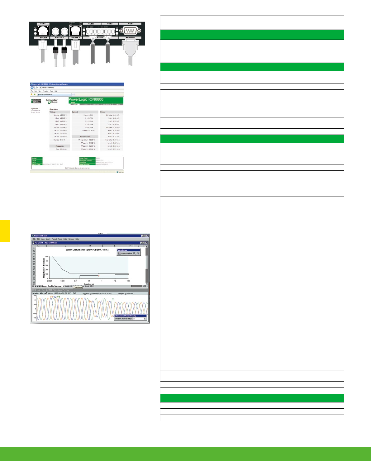
ADVANCED UTILITY METERING FUNCTIONS AND CHARACTERISTICS
Technical Specification
Communication
IEC 1107 optical port 2/4 wires, up to 19200 bauds
RS 485 port
Up to 57600 bauds, direct connection to a PC or
modem, protocols: ION, Modbus RTU, Modbus Master,
DNP 3.0, GPSTRUETIME/DATUM, DLMS
Communications module (optional)
RS 232/485 port 300 - 115,200 bauds (RS 485 limited to 57,600 bauds);
protocols: same as RS 485 port
Internal modem port 300 bauds - 56000 bauds, RJ11 connector
Ethernet port 10 BaseT, RJ45 connector, 100 m link; protocols: DNP
TCP, ION, Modbus TCP, Modbus Master, IEC 61850
Fiber-optic Ethernet link
10 Base FL, ST connector, 1300 nm, FO multimode with
gradient index 62.5/125 µm or 50/125 µm, 2000 m link;
protocols: same as Ethernet port
EtherGate Communicates directly with up to 62 slave devices via
available serial ports
ModemGate Communicates directly with up to 31 slave devices
Firmware characteristics
High-speed data recording
Up to ½-cycle interval burst recording, stores detailed
characteristics of disturbances or outages
Trigger recording by a user-defined setpoint, or from
external equipment.
Harmonic distortion Up to 63
rd
harmonic for all voltage and current inputs
Dip/swell detection
Analyse severity/potential impact of sags and swells:
magnitude and duration data suitable for plotting
on voltage tolerance curves per phase triggers for
waveform recording or control operations
Instantaneous
High accuracy measurements with 1s or 1/2 cycle
update rate for:
voltage and current
active power (kW) and reactive power (kvar)
apparent power (kVA)
power factor and frequency
voltage and current unbalance
phase reversal
Load profiling
Channel assignments (800 channels via 50 data
recorders) are configurable for any measureable
parameter, including historical trend recording of
energy, demand, voltage, current, power quality, or any
measured parameter
Trigger recorders based on time interval, calendar
schedule, alarm/event condition, or manually.
Modbus Master
Master up to 32 slave devices per serial channel and
store their data at programmable intervals. Use this
data to aggregate and sum energy values and perform
complex totaling.
Waveform captures
Simultaneous capture of all voltage and current
channels
sub-cycle disturbance capture
maximum cycles is 214,000
(16 samples/cycle x 96 cycles, 10 Mbytes memory)
1024 samples/cycle
Alarms
Threshold alarms:
adjustable pickup and dropout setpoints and time
delays, numerous activation levels possible for a given
type of alarm
user-defined priority levels
boolean combination of alarms possible
Advanced security
Up to 16 users with unique access rights. Perform
resets, time syncs, or meter configurations based on
user priviledges.
Transformer correction Correct for phase / magnitude inaccuracies in current
transformers (CTs), potential transformers (PTs)
Memory 5 -10 Mbytes (specified at time of order)
Firmware update Update via the communication ports
Display characteristics
Type FSTN transreflective LCD
Backlight LED
Languages English
Example embedded webserver page
(WebMeter) showing realtime values.
Ports on the optional communications module.
90 schneider-electric.co.uk/metering
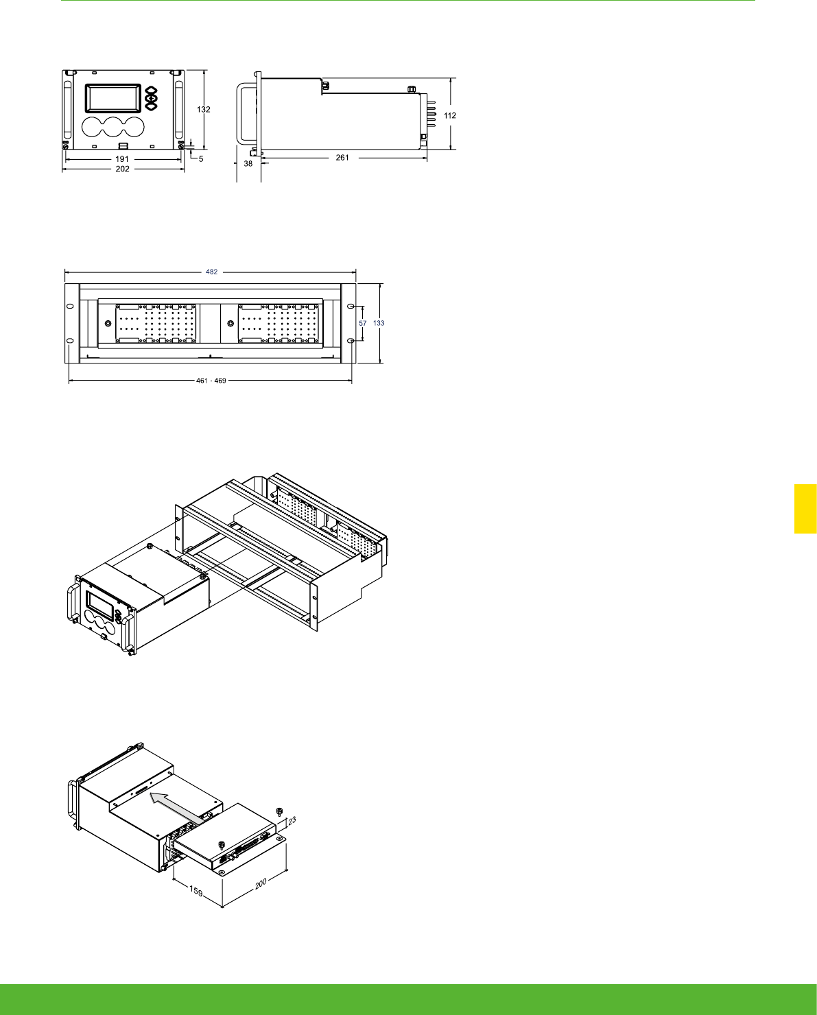
ADVANCED UTILITY METERING FUNCTIONS AND CHARACTERISTICS
ION8800 dimensions
ION8800 Essailec rack dimensions
ION8800 communication module dimensions
Rack mounting the ION8800
91schneider-electric.co.uk/metering

Multi-circuit
metering
schneider-electric.co.uk/metering 92

Applications
This is an integrated solution for monitoring multi-circuits and mains by using a
single meter. The meter is designed for use in both new build and retrofit and
is used for critical power operations in data centres and energy management
in buildings.
93schneider-electric.co.uk/metering

The ideal solution for data centre managers, energy or facility managers,
engineers and operational executives who are responsible for delivering power to
critical applications.
In corporate and hosted data centre facilities, this technology helps you plan
and optimise the critical power infrastructure to meet the demands of continuous
availability.
• PowerLogic BCPM
Multi-circuit metering
Product
overview
94 schneider-electric.co.uk/metering
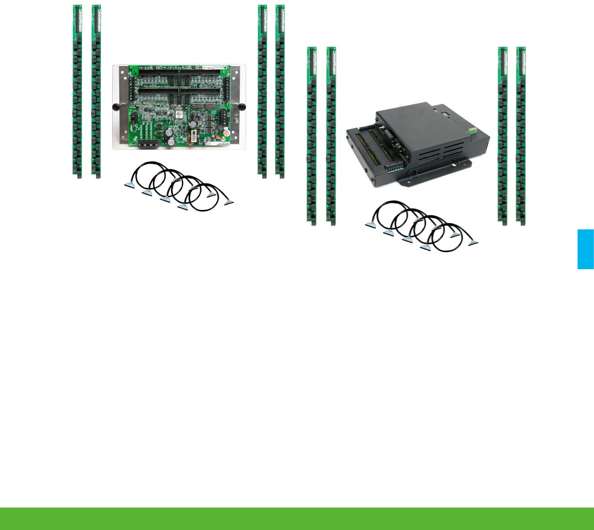
95schneider-electric.co.uk/metering
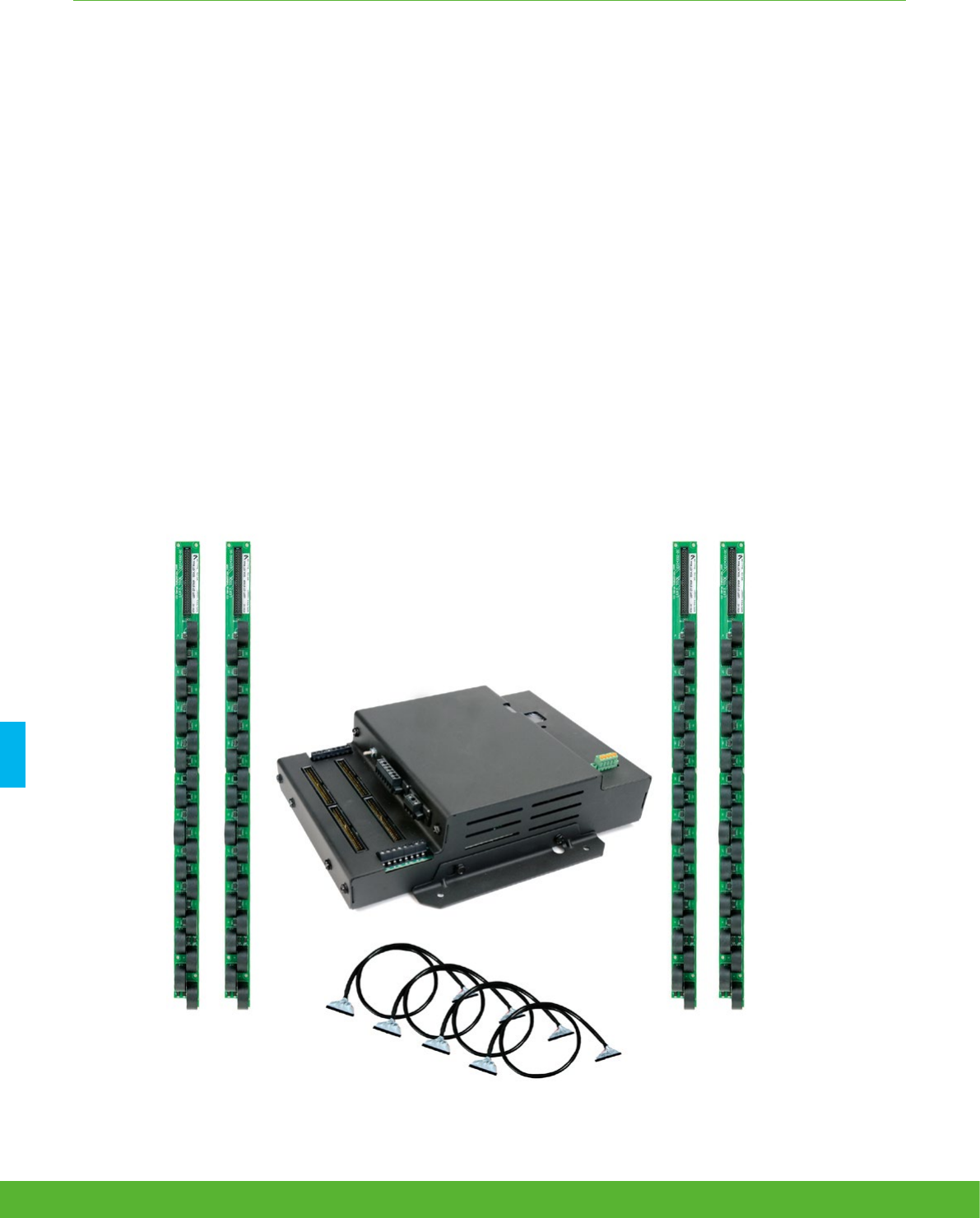
MULTI-CIRCUIT METERING FUNCTIONS AND CHARACTERISTICS
The PowerLogic BCPM is a highly accurate, full-featured metering product designed for the unique,
multi-circuit and minimal space requirements of a high performance power distribution unit (PDU) or
remote power panel (RPP).
It offers class 1 (1%) power and energy system accuracy (including 50A or 100A CTs) on all branch channels. The BCPM
monitors up to 84 branch circuits and the incoming power mains to provide information on a complete PDU. Full alarming
capabilities ensure that potential issues are dealt with before they become problems.
PowerLogic BCPM
Applications
• Maximise uptime and avoid outages
• Optimise existing infrastructure
• Improve power distribution efficiency
• Track usage and allocate energy costs
• Enable accurate sub-metering
schneider-electric.co.uk/metering 96

MULTI-CIRCUIT METERING FUNCTIONS AND CHARACTERISTICS
The solution for
All markets that can benefit from a solution that includes
PowerLogic BCPM series meters:
• Data centres
• Buildings
Power management solutions
Schneider Electric provides innovative
power management solutions to increase
your energy efficiency and cost savings,
maximise electrical network reliability and
availability, and optimise electrical asset
performance. See pagexxx
Benefits
The flexible BCPM fits any PDU or RPP design and supports
both new and retrofit installations. It has exceptional dynamic
range and accuracy, and optional feature sets to meet the energy
challenges of mission critical data centres.
Conformity of standards
• IEC 61010
Competitive advantages
• Fit any PDU or RPP design for both new and retrofit projects
• Class 1.0 system accuracy
• Ethernet communication
97schneider-electric.co.uk/metering
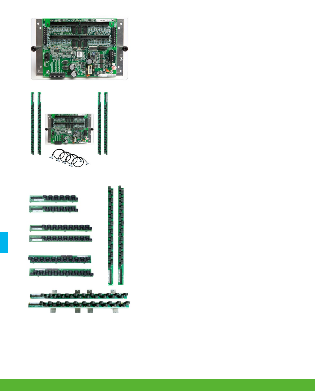
MULTI-CIRCUIT METERING FUNCTIONS AND CHARACTERISTICS
Main characteristics
• Monitor up to 84 branch circuits with a single BCPM.
• Ideal for installation in both new PDUs and retrofit projects
• New installations:
– BCPM with solid core CTs monitors up to 84 branch circuits using 2 or 4 CT
strips. Solid core CTs are rated to 100 A CTs and are mounted on strips to
simplify installation. CT strips are available with 12, 8 or 21 CTs per strip on
18 mm spacings. 21 CT strips with 3/4” or 1” spacings are also available.
• Retrofit projects:
– BCPMSC with split core CTs is ideal for retrofits. Any number of split core
CTs, up to 84 maximum, can be installed with a single BCPM. Three sizes
of CT are supported (50 A, 100 A, and 200 A) and all three CT sizes can
be used on a single BCPM. Adapter boards with terminals for split-core
CTs can be mounted using DIN-rail, Snaptrack or on a common mounting
plate with the main board (42 ch Y63 models only).
• IEC Class 1 metering accuracy
– Accurately monitor very low current levels, down to a quarter-Amp.
– Easily differentiate between the flow of low current and a trip where no
current flows.
• Class 1.0 system accuracy for Revenue Grade measurements
– Branch Power and Energy measurements fully meet ANSI and IEC class
1 accuracy requirements with 50 or 100 Amp CTs included. No need
to de-rate meter branch accuracy to allow for CTs. Voltage and current
measurement accuracy is 0.5% and currents are measured down to 50mA.
Easily differentiate between the flow of low current and a trip where no
current flows.
• Designed to fit any PDU or RPP design
– Lowers your total installation costs as well as the cost per meter point by
supporting both new and retrofit installations.
• New models with integrated Ethernet offer broad protocol support
– All models integrate easily into existing networks using Modbus RTU
communications over an RS-485 serial link. BCPME and BCPMSCE models
offer integrated Ethernet and add support for Modbus TCP, BACnet IP,
BACnet MS/TP and SNMP. An optional external gateway can be added to
all other models to add the same capability.
• Compatible with PowerLogic power monitoring software
– Easily turn the large amount of data collected by the devices into useful
decision-making information.
• Flexible Configuration capability
– Set the ordering and orientation of CT strips, assign individual CT size and
phases, support for 1, 2, and 3-pole breakers in any configuration.
schneider-electric.co.uk/metering 98
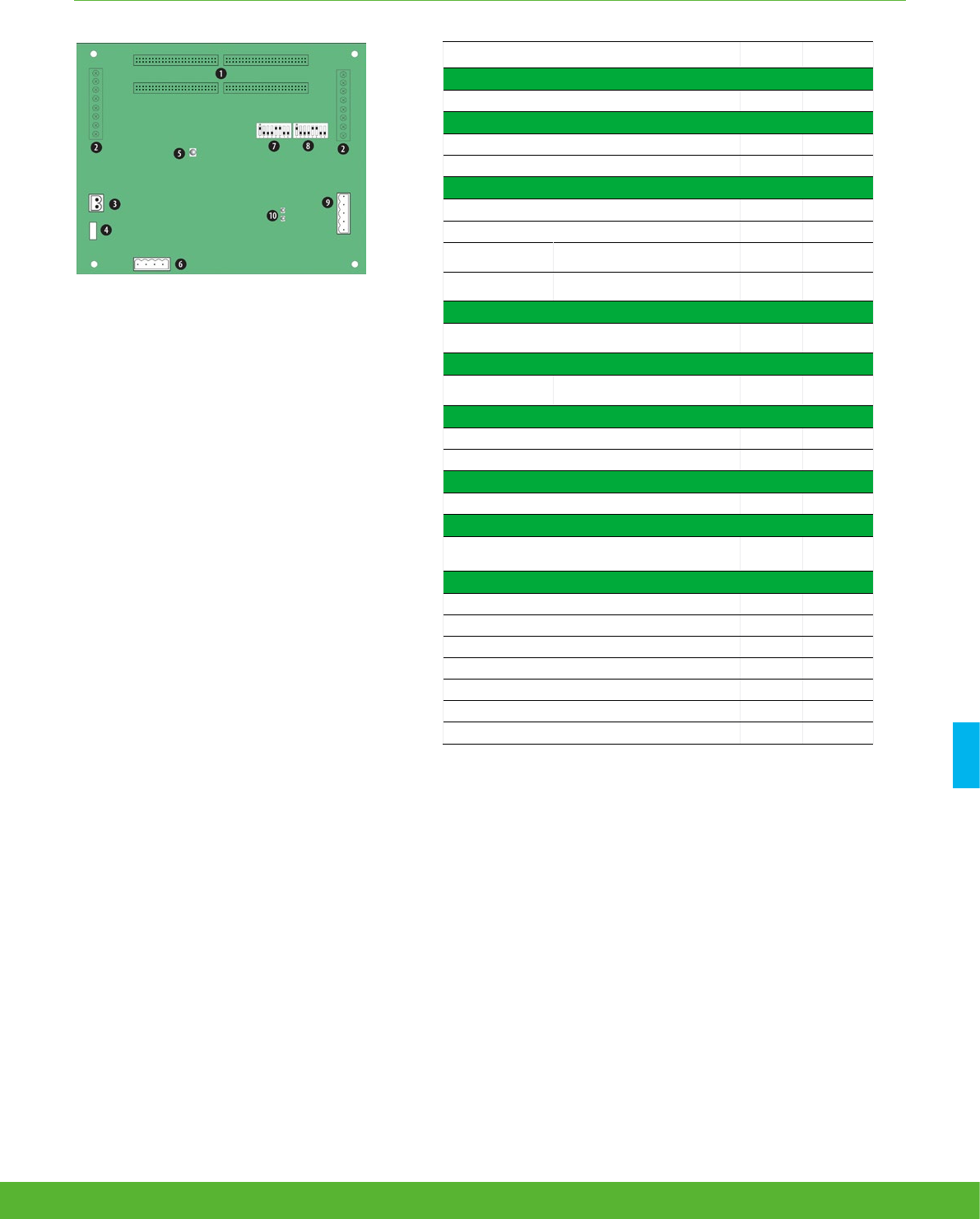
MULTI-CIRCUIT METERING FUNCTIONS AND CHARACTERISTICS
Feature selection
BCPMA BCPME
General
Use on LV systems b b
Power and energy measurements
Mains b b
Branch circuits b b
Instantaneous rms values
Voltage, frequency b b
Current b b
Active power Total and per phase b b
Power factor Total and per phase b b
Energy values
Active energy b b
Demand values
Total active power Present and max. values b b
Power quality measurements
Detection of over-voltage/under-voltage b b
Sampling rate points per cycle 2560Hz 2560Hz
Alarming
Alarms b b
Power supply
AC version 90-277
V ac
100-277
V ac
Communication
RS 485 port b b
Modbus protocol b b
Ethernet Port 1* b
Modbus RTU protocol 1* b
BACnet IP protocol 1* b
BACnet MS/TP protocol 1* b
SNMP protocol 1* b
PowerLogic BCPM
1 50-pin ribbon cable connectors (data acquisition board).
2 Auxiliary inputs.
3 Control (mains) power connection.
4 Control power fuse.
5 Alive LED.
6 Voltage taps.
7 Communications address DIP switches.
8 Communications settings DIP switch.
9 RS-485 2 connection.
10 RS-485 LEDs.
99schneider-electric.co.uk/metering
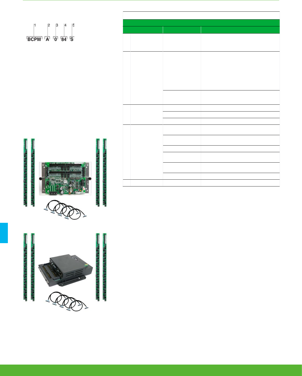
MULTI-CIRCUIT METERING FUNCTIONS AND CHARACTERISTICS
BCPM part numbers
BCPM with solid core CTs
Item Code Description
1 Model BCPM
BCPM with solid core CTs. Highly accurate
meter that monitors branch circuits and the
incoming power mains and includes full
alarming capabilities
Example BCPM with solid core CTs part number.
1 Model
2 Feature set
3 CT spacing (solid-core models only)
4 Number of circuits
5 Brand
2 Feature set
A
Advanced - Monitors power & energy per
circuit & mains, Modbus RTU only (add E8951
for other protocols), Meter Main Board comes
on an aluminum mounting plate
E
Advanced, with Ethernet - Monitors power &
energy per circuit & mains, Meter Main Board
is enclosed in a metal housing
3 CT spacing
0 3/4” (19 mm) CT spacing
1 1” (26 mm) CT spacing
2 18 mm CT spacing
4Number of
circuits
24 24 circuits, (2) 18-CT strips (18 mm spacing
only)
36 36 circuits, (2) 18-CT strips (18 mm spacing
only)
42 42 circuits, (2) 21-CT strips
48 48 circuits, (4) 18-CT strips (18 mm spacing
only)
72 72 circuits, (4) 18-CT strips (18 mm spacing
only)
84 84 circuits, (4) 21-CT strips
5 Brand S Schneider Electric
The PowerLogic BCPM uses .333 VAC output split-core
CTs for the auxiliary inputs. These CTs are ordered
separately from the BCPM.
* Quantity and style of CT strips and cables included
varies by model
schneider-electric.co.uk/metering 100
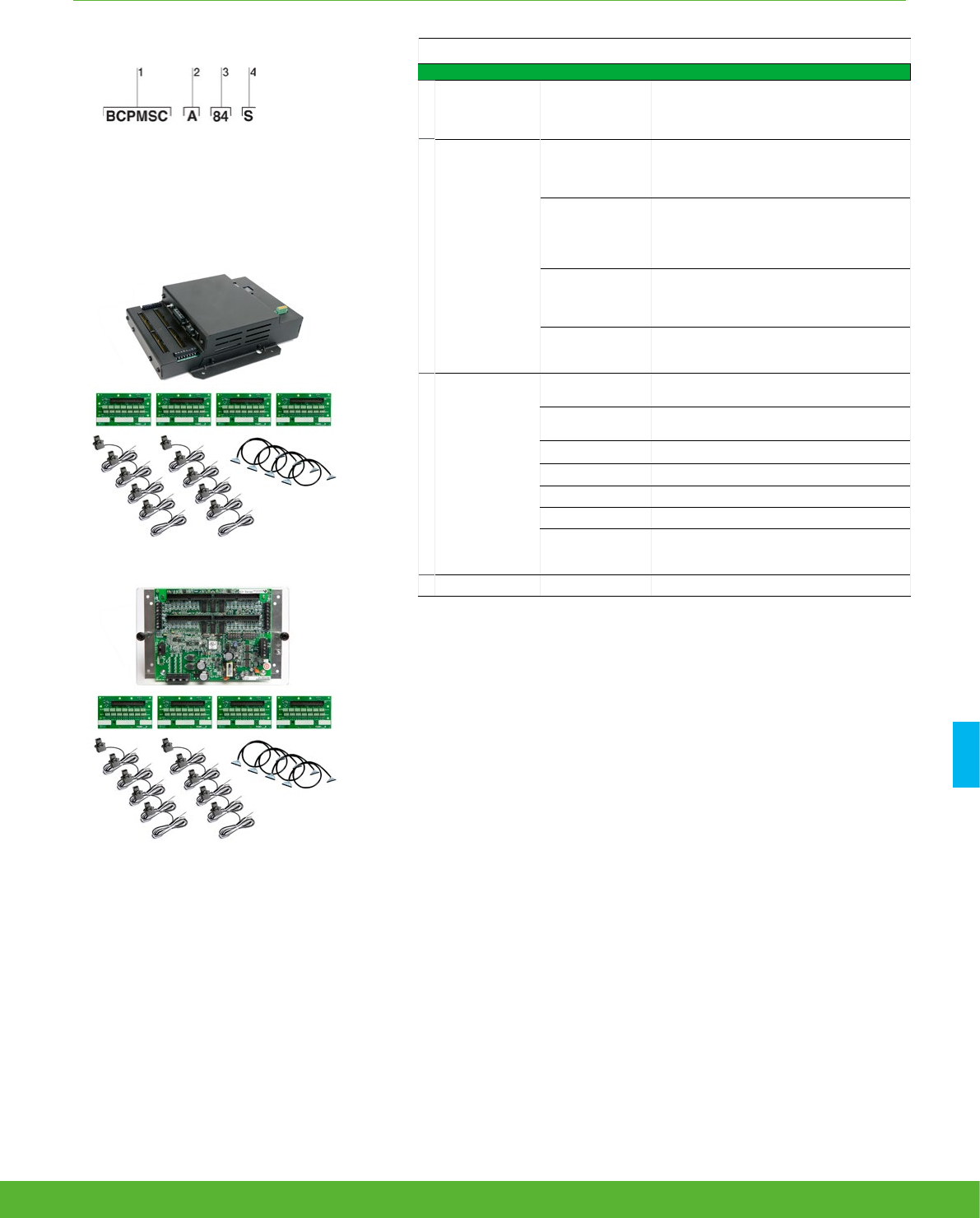
MULTI-CIRCUIT METERING FUNCTIONS AND CHARACTERISTICS
BCPM part numbers (contd.)
BCPM with split core CTs BCPM with split core CTs
1
Model BCPMSC
BCPM with split core CTs. Highly accurate
meter that monitors branch circuits and the
incoming power mains and includes full
alarming capabilities
2
Feature set
A
Advanced - Monitors power and energy per
circuit and mains, Modbus RTU only (add
E8951 for other protocols), Meter Main Board
comes on an aluminum mounting plate
B
Intermediate - Monitors current per circuit,
power and energy per mains, Modbus RTU
only (add E8951 for other protocols), Meter
Main Board comes on an aluminum mounting
plate
C
Basic - Monitors current only per circuit and
mains, Modbus RTU only (add E8951 for other
protocols), Meter Main Board comes on an
aluminum mounting plate
E
Advanced, with Ethernet - Monitors power &
energy per circuit & mains, Meter Main Board
is enclosed in a metal housing
3
Number of
circuits
142 circuits (no branch CTs or ribbon cables,
order separately)
284 circuits (no branch CTs or ribbon cables,
order separately)
30 30 split core CTs (50 A)
42 42 split core CTs (50 A)
60 60 split core CTs (50 A)
84 84 split core CTs (50 A)
Y63
42 circuits – main and adapter boards on
single mounting plate (no branch CTs or
ribbon, order separately) - Feature set A only
4
Brand S Schneider Electric
1 Model.
2 Feature set.
3 Number of circuits.
4 Brand.
Example BCPMSC with split core CTs part number.
*The BCPMSC models with 1, 2 or Y63 as the number of circuits DO NOT INCLUDE
ANY branch CTs or ribbon cables (they include only the Main board and adapater board
assemblies) . These models are provided to allow users to order a specific combination of
CT quantities, CT sizes, CT lead lengths and ribbon cable styles and lengths. The CTs and
cables must be ordered separately.
Models with more than 2 as the number of circuits include 50A branch CTs with 2 meter
leads and 1.8M round ribbon cables.
The PowerLogic BCPMSC uses .333 VAC output split-core CTs for the auxiliary inputs. These
CTs are ordered separately from the BCPM.
101schneider-electric.co.uk/metering

MULTI-CIRCUIT METERING FUNCTIONS AND CHARACTERISTICS
Flat ribbon cable
Round ribbon cable
Cabling and connection
Flat ribbon cables are recommended for use
when the BCPM printed circuit board will be
mounted inside of the PDU that is being
monitored. Round ribbon cables are the
prefered choice when the ribbon cable will be
threaded through conduit.
BCPM part numbers for solid and split core CTs (contd.)
BCPM with split core CTs
Part number Description
BCPMA042S 42-circuit solid-core power & energy meter, 100A CTs (2 strips), ¾”
spacing
BCPMA084S 84-circuit solid-core power & energy meter, 100A CTs (4 strips),
¾”spacing
BCPMA142S 42-circuit solid-core power & energy meter, 100A CTs (2 strips), 1”
spacing
BCPMA184S 84-circuit solid-core power & energy meter, 100A CTs (4 strips), 1” mm
spacing
BCPMA224S 24-circuit solid-core power & energy meter, 100A CTs (2 strips), 18mm
spacing
BCPMA236S 36-circuit solid-core power & energy meter, 100A CTs (2 strips), 18mm
spacing
BCPMA242S 42-circuit solid-core power & energy meter, 100A CTs (2 strips), 18mm
spacing
BCPMA248S 48-circuit solid-core power & energy meter, 100A CTs (4 strips), 18mm
spacing
BCPMA272S 72-circuit solid-core power & energy meter, 100A CTs (4 strips), 18mm
spacing
BCPMA284S 84-circuit solid-core power & energy meter, 100A CTs (4 strips), 18mm
spacing
BCPME042S 42-circuit solid-core power & energy meter w/Ethernet, 100A CTs (2
strips), ¾” spacing
BCPME084S 84-circuit solid-core power & energy meter w/Ethernet, 100A CTs (4
strips), ¾”spacing
BCPME142S 42-circuit solid-core power & energy meter w/Ethernet, 100A CTs (2
strips), 1” spacing
BCPME184S 84-circuit solid-core power & energy meter w/Ethernet, 100A CTs (4
strips), 1” mm spacing
BCPME224S 24-circuit solid-core power & energy meter w/Ethernet, 100A CTs (2
strips), 18mm spacing
BCPME236S 36-circuit solid-core power & energy meter w/Ethernet, 100A CTs (2
strips), 18mm spacing
BCPME242S 42-circuit solid-core power & energy meter w/Ethernet, 100A CTs (2
strips), 18mm spacing
BCPME248S 48-circuit solid-core power & energy meter w/Ethernet, 100A CTs (4 strips),
18mm spacing
BCPME272S 72-circuit solid-core power & energy meter w/Ethernet, 100A CTs (4
strips), 18mm spacing
BCPME284S 84-circuit solid-core power & energy meter w/Ethernet, 100A CTs (4
strips), 18mm spacing
schneider-electric.co.uk/metering 102
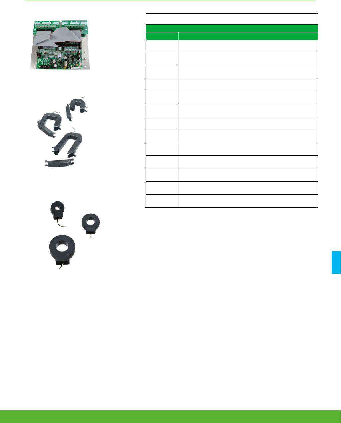
MULTI-CIRCUIT METERING FUNCTIONS AND CHARACTERISTICS
PE86183
PB113658
PowerLogicTM LVCT0xxxxS Split-core Low-voltage (1/3V) CTs for Aux
inputs (Mains) are ideal for retrofit applications
BCPMSCxY63S 42-circuit split-core models come with the main
board, (2) adapter boards and ribbon cables all mounted on a
backplate, to simplify installation.
PowerLogicTM LVCT2xxxxS Low-voltage (1/3V) solid-core CTs for Aux
inputs (Mains) are ideal for panel builders (small, medium, large)
PB113652
PB113657
The PowerLogicTM BCPM uses .333 VAC output split-core CTs for the auxiliary inputs.
These CTs are ordered separately from the BCPM.
BCPMSCA1S 42-circuit split-core power and energy meter, CTs and cables sold
separately
BCPMSCA2S 84-circuit split-core power and energy meter, CTs and cables sold
separately
BCPMSCA30S 30-circuit split-core power and energy meter, (30) 50A CTs & (2) 4’ cables
BCPMSCA42S 42-circuit split-core power and energy meter, (42) 50A CTs & (2) 4’ cables
BCPMSCA60S 60-circuit split-core power and energy meter, (60) 50A CTs & (4) 4’ cables
BCPMSCAY63S
42-circuit split core power and energy meter, all boards on backplate,
CTs and cables sold separately
BCPMSCA84S 84-circuit split-core power and energy meter, with (84) 50A CTs & (4) 4’
cables
BCPMSCE1S 42-circuit split-core power and energy meter w/Ethernet, CTs and cables
sold separately
BCPMSCE2S 84-circuit split-core power and energy meter w/Ethernet, CTs and cables
sold separately
BCPMSCE30S 30-circuit split-core power and energy meter w/Ethernet, (30) 50A CTs &
(2) 4’
BCPMSCE42S 42-circuit split-core power and energy meter w/Ethernet, (42) 50A CTs &
(2) 4’ cables
BCPMSCE60S 60-circuit split-core power and energy meter w/Ethernet, (60) 50A CTs &
(4) 4’ cables
BCPMSCE84S 84-circuit split-core power and energy meter w/Ethernet, (84) 50A CTs &
(4) 4’ cables
BCPM part numbers for solid and split core CTs (contd.)
BCPM with split core CTs
Part number Description
103schneider-electric.co.uk/metering

MULTI-CIRCUIT METERING FUNCTIONS AND CHARACTERISTICS
BCPM split core branch CTs and adapter boards
BCPMSCADPBS BCPM adapter boards, quantity 2, for split core BCPM
BCPMSCCT0 BCPM 50A split core CTs, Quantity 6, 1.8 m lead lengths
BCPMSCCT0R20 BCPM 50A split core CTs, quantity 6, 6 m lead lengths
BCPMSCCT1 BCPM 100A split core CTs, Quantity 6, 1.8 m lead lengths
BCPMSCCT1R20 BCPM 100A split core CTs, Quantity 6, 6 m lead lengths
BCPMSCCT3 BCPM 200A split core CTs, Quantity 1, 1.8 m lead lengths
BCPMSCCT3R20 BCPM 200A split core CTs, Quantity 1, 6 m lead lengths
Additional accessories for use with BCPM products
BCPMCOVERS BCPM circuit board cover
BCPMREPAIR CT repair kit for solid core BCPM (includes one CT)
H6803R-0100 Additional 100A split core CT for use with solid core repair kit
E8951 Modbus to BACnet protocol converter
CBL016 Flat Ribbon cable (quantity 1) for BCPM, length = 1.2 m
CBL017 Flat Ribbon cable (quantity 1) for BCPM, length = 1.5 m
CBL018 Flat Ribbon cable (quantity 1) for BCPM, length = 1.8 m
CBL020 Flat Ribbon cable (quantity 1) for BCPM, length = 3.0 m
CBL021 Flat Ribbon cable (quantity 1) for BCPM, length = 6.1 m
CBL022 Round Ribbon cable (quantity 1) for BCPM, length = 1.2 m
CBL024 Round Ribbon cable (quantity 1) for BCPM, length = 6.1 m
1/3 V low-voltage Split-Core CTs for Aux inputs (Mains)
Part number Amperage
rating Inside dimensions
LVCT00050S
50A 10 mm x 11 mm
LVCT00101S 200A 16 mm x 20 mm
LVCT00202S 200A 32 mm x 32 mm
LVCT00102S 100A 30 mm x 31 mm
LVCT00202S 200A 30 mm x 31 mm
LVCT00302S 300A 30 mm x 31 mm
LVCT00403S 400A 62 mm x 73 mm
LVCT00603S 600A 62 mm x 73 mm
LVCT00803S 800A 62 mm x 73 mm
LVCT00804S 800A 62 mm x 139 mm
LVCT01004S 1000A 62 mm x 139 mm
LVCT01204S 1200A 62 mm x 139 mm
LVCT01604S 1600A 62 mm x 139 mm
LVCT02004S 2000A 62 mm x 139 mm
LVCT02404S 2400A 62 mm x 139 mm
1/3 V low-voltage Solid core CTs for Aux inputs (Mains)
Part number Amperage
rating Inside dimensions
LVCT20050S 50A 10 mm
LVCT20100S 100A 10 mm
LVCT20202S 200A 25 mm
LVCT20403S 400A 31 mm
schneider-electric.co.uk/metering 104

NOTES
105schneider-electric.co.uk/metering

Multi-circuit metering
Technical
Specifications
106 schneider-electric.co.uk/metering

MULTI-CIRCUIT METERING FUNCTIONS AND CHARACTERISTICS
Technical specifications
Electrical characteristics
Type of measurement
Accuracy
Power/energy 1% system accuracy (including 50A or 100A branch CTs)
Voltage ±0.5% of reading
Current ±0.5% of reading
Minimum “ON” current 50mA
Sampling rate Points per cycle 2560 Hz
Data update rate 1.8 seconds (Modbus), 14 seconds (BACnet) 20 sec (SNMP)
Input-voltage
characteristics
Measured voltage 150 – 480 V ac L-L
(1)
90 – 277 V ac L-N
(1)
Measurement range 150 – 480 V ac L-L
(1)
90 – 277 V ac L-N
(1)
Power supply AC 100 – 277 V ac (50/60 Hz)
Auxiliary CT Current Input Range 0-0.333V; CTs must be rated for use with Class 1 voltage inputs
Mechanical characteristics
Weight 1.5 kg
Dimensions A/B/C model Circuit board 288 x 146 mm
E model housing (w/brackets on long sides) 253 mm W x 307 mm H x 71 mm D
E model housing (w/brackets on short ends) 210 mm W x 353 mm H x 71 mm D
Environmental conditions
Operating temperature 0 to 60ºC
Storage temperature -40ºC to 70ºC
Installation category CAT III, pollution degree 2
Safety
Europe IEC 61010
U.S. and Canada UL 508 Open type device
Communication
RS 485 (A/B/C models) Baud rate: DIP-switch selectable 9600, 19200, 38400
DIP-switch selectable 2-wire or 4-wire RS-485. Parity selectable: Even, Odd or None.
RS 485 (A models) Baud rate: configured via Web-server. Baud selectable: 9600, 19200, 38400. Parity selectable: Even, Odd or None.
2-wire RS-485.
Ethernet (E models) 10/100 Mbit Ethernet. RJ-45 connection. Static IP or DHCP.
Protocols Modbus RTU on all models, BCPME models also support Modbus TCP, SNMP, BACnet IP & BACnet MS/TP
Firmware characteristics
Detection of over-voltage/under-
voltage User-defined alarm thresholds for over-voltage and under-voltage detection
Alarms
Four alarm levels: high-high, high, low and low-low (users define the setpoints for each). Each alarm has a latching
status to alert the operator that an alarm has previously occurred. High and Low alarms have instantaneous status to let
the operator know if the alarm state is still occurring.
Firmware update Update via Modbus
BCPM
107schneider-electric.co.uk/metering

MULTI-CIRCUIT METERING FUNCTIONS AND CHARACTERISTICS
1/3 V low-voltage CT (LVCT) for Mains - Technical specifications
Electrical characteristics
Accuracy 1% from 10% to 100% of rated current(LVCT0xxxx0S/1S/2S/3S/4S [split-core])
0.5% from 5% to 100% of rated current (LVCT2xxxx0S/2S/3S [solid-core])
Frequency range 50/60 Hz
Leads 18 AWG, 600 V ac, 1.8m standard length
Max. voltage L-N sensed
conductor
300 V ac (LVCT0xxxx0S)
600 V ac (LVCT0xxxx1S/2S/3S/4S, LVCT2xxxxxS)
Environmental conditions
Operating temperature
0ºC to 70ºC (LVCT0xxxx0S/1S)
-15ºC to 60ºC (LVCT0xxxx2S/3S/4S less than 2400A)
-15ºC to 60ºC (LVCT02404S [2400A])
-40ºC to 85ºC (LVCT2xxxx0S/2S/3S [solid-core])
Storage temperature
-40ºC to 105ºC (LVCT0xxxx0S/1S)
-40ºC to 70ºC (LVCT0xxxx2S/3S/4S)
-50ºC to 105ºC (LVCT2xxxx0S/2S/3S [solid-core])
Humidity range 0 to 95% non-condensing
BCPM cont’d
schneider-electric.co.uk/metering 108
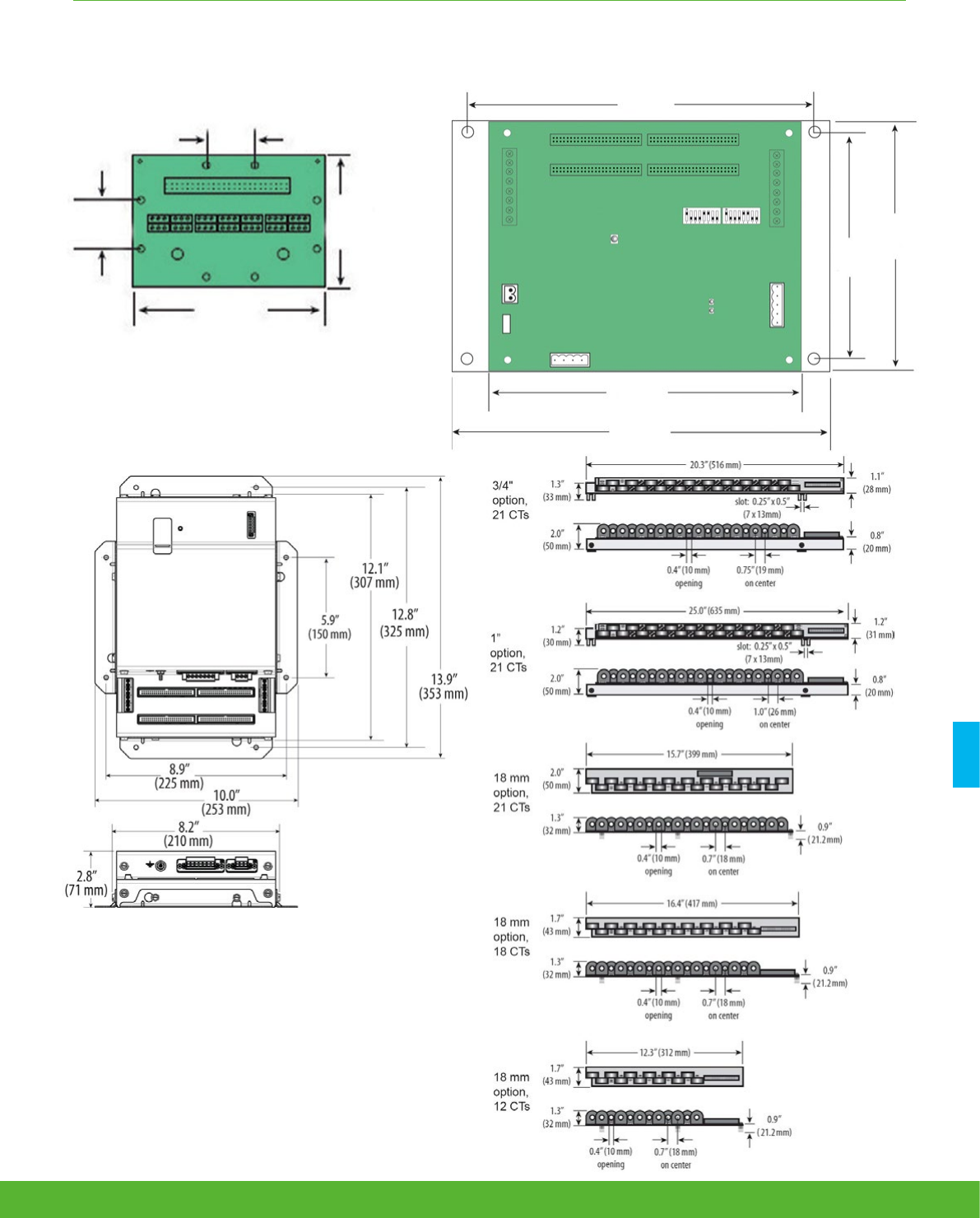
MULTI-CIRCUIT METERING FUNCTIONS AND CHARACTERISTICS
211 mm
146 mm
122 mm
184 mm
228 mm
1.0”
(26 mm)
1.0”
(26 mm)
2.75”
(70 mm)
4.6”
(117 mm)
PowerLogic BCPM adapter board (one board per 21
split core branch CTs)
PowerLogic BCPM dimensions
109schneider-electric.co.uk/metering
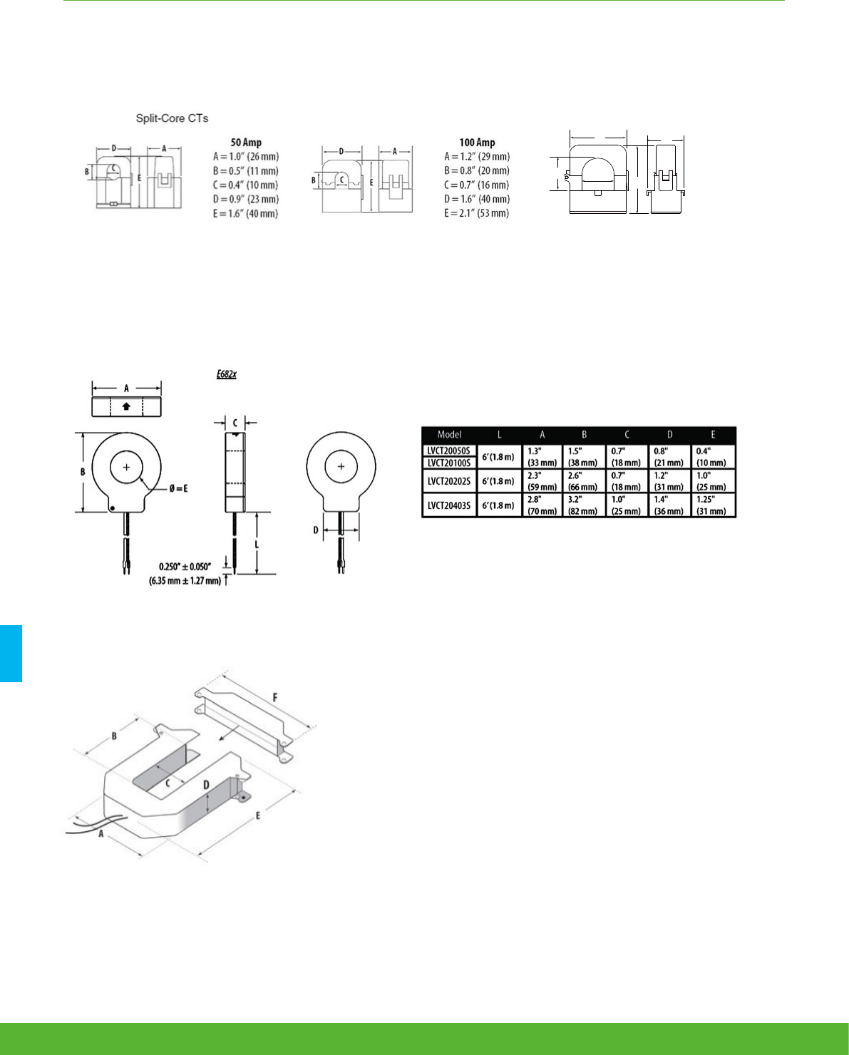
MULTI-CIRCUIT METERING FUNCTIONS AND CHARACTERISTICS
Small form factor
100/200/300 Amp
A = 96 mm
B = 30 mm
C = 31 mm
D = 30 mm
E = 100 mm
F = 121 mm
Large form factor
800/1000/1200/
1600/2000/2400 Amp
A = 125 mm
B = 139 mm
C = 62 mm
D = 30 mm
E = 201 mm
F = 151 mm
Medium form factor
400/600/800 Amp
A = 125 mm
B = 73 mm
C = 62 mm
D = 30 mm
E = 132 mm
F = 151 mm
D
E
C
B
A
D
E
B
A
C
E31CT0 50 Amp
A = 1.0” (26 mm)
B = 0.5” (11 mm)
C = 0.4” (10 mm)
D = 0.9” (23 mm)
E = 1.6” (40 mm)
E31CT1 100 Amp
A = 1.5” (39 mm)
B = 0.8” (20 mm)
C = 0.7” (16 mm)
D = 1.6” (40 mm)
E = 2.1” (53 mm)
E31CT3 200 Amp
A = 1.5” (39 mm)
B = 1.25” (32 mm)
C = 1.25” (32 mm)
D = 2.5” (64 mm)
E = 2.8” (71 mm)
B
E
A
C
D
D
E
C
B
A
D
E
B
A
C
E31CT0 50 Amp
A = 1.0” (26 mm)
B = 0.5” (11 mm)
C = 0.4” (10 mm)
D = 0.9” (23 mm)
E = 1.6” (40 mm)
E31CT1 100 Amp
A = 1.5” (39 mm)
B = 0.8” (20 mm)
C = 0.7” (16 mm)
D = 1.6” (40 mm)
E = 2.1” (53 mm)
E31CT3 200 Amp
A = 1.5” (39 mm)
B = 1.25” (32 mm)
C = 1.25” (32 mm)
D = 2.5” (64 mm)
E = 2.8” (71 mm)
B
E
A
C
D
These dimensions apply to both BCPMSCCTxx (branch CTs)
and LVCT0xxxx0S/1S (for Mains) 50A-200A CT families.
Solid core CT dimensions
1/3 V low-voltage CT form factor
50A-200A Split-Core CT dimensions
schneider-electric.co.uk/metering 110
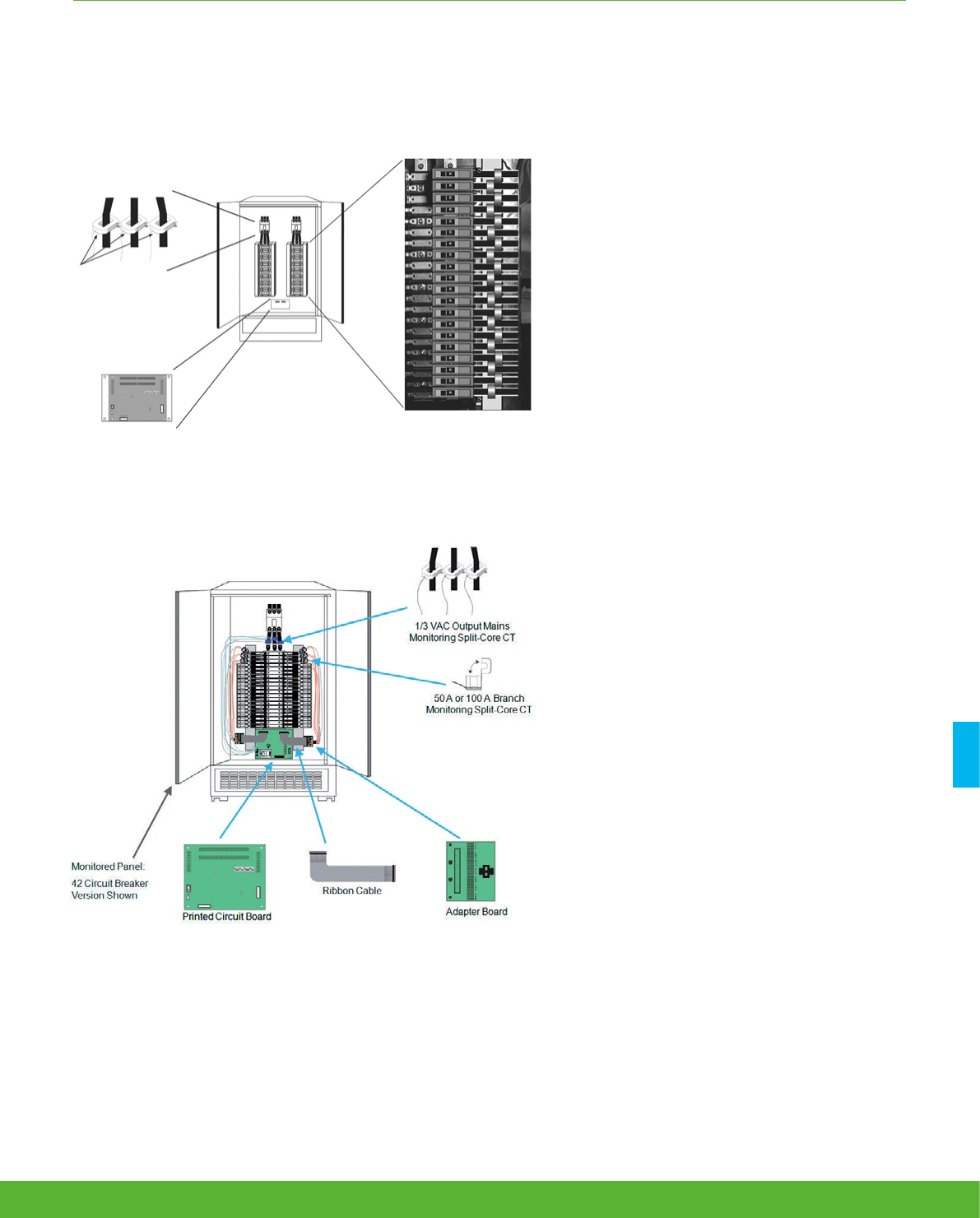
MULTI-CIRCUIT METERING FUNCTIONS AND CHARACTERISTICS
PowerLogic BCPM with solid core CT strips installation details
PowerLogic BCPM with split core CTs installation details
Mains monitoring
(CTs ordered separately)
BCPM PCB
Transducers (1/3 Vac)
Circuit monitoring 4 CT strips
monitor up to 84 circuits
111schneider-electric.co.uk/metering

Communications
schneider-electric.co.uk/metering 112

COMMUNICATIONS FUNCTIONS AND CHARACTERISTICS
Applications
This is a part of your metering solution which provides an interface between
energy monitoring software and your metering points via GPRS, wired
connection and wifi. We also offer the option of an integrated gateway-server
which provides all-in-one energy management solution. They are fully capable
of supporting StruxureWare Power Monitoring software.
113schneider-electric.co.uk/metering

Data loggers, gateways and remote terminal units help measured data reach the
power monitoring software for analyses.
They are fundamental components in most power and energy management
system architectures.
• New Gateway Link150
• Data logger Com’X 200
• NEW Data logger Com’X 510
• ION7550 RTU
Communications
Product
overview
114 schneider-electric.co.uk/metering
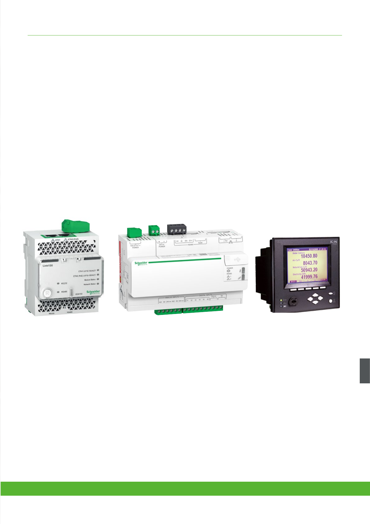
COMMUNICATIONS FUNCTIONS AND CHARACTERISTICS
* Gateway EGX100 was replaced by new Link150 in October 2015 and gateway-sever EGX300 was
replaced by new Com'X 510 in June 2015.
115schneider-electric.co.uk/metering
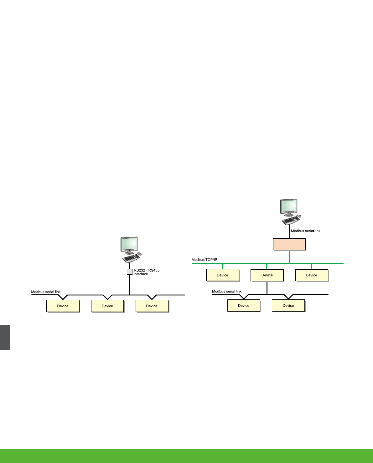
COMMUNICATIONS FUNCTIONS AND CHARACTERISTICS
With communication technology, it is no longer necessary to be physically present at the site to
access information. Data is transmitted by networks.
In all architectures, the communication interface serves as the link between the installation devices and the PC
running the operating software. It provides the physical link and protocol adaptation. Adaptation is required
because the communication systems used by the PC (Modbus via RS232 and/or Ethernet) are generally not those
used by the installation devices (e.g. the Modbus protocol via RS485).
Dedicated application software prepares the information for analysis under the best possible conditions.
In addition, an Modbus-Ethernet gateway in serial port slave mode allows
a serial Modbus master device to access information from other devices
across a Modbus TCP/IP network.
Serial link
Switchboard-data acquisition and monitoring make it possible to anticipate events. In this way,
they reduce customer costs in terms of operation, maintenance and investment.
Modbus communication architecture. Modbus communication across Ethernet network
Link150
serial slave mode
Modbus master device
schneider-electric.co.uk/metering 116
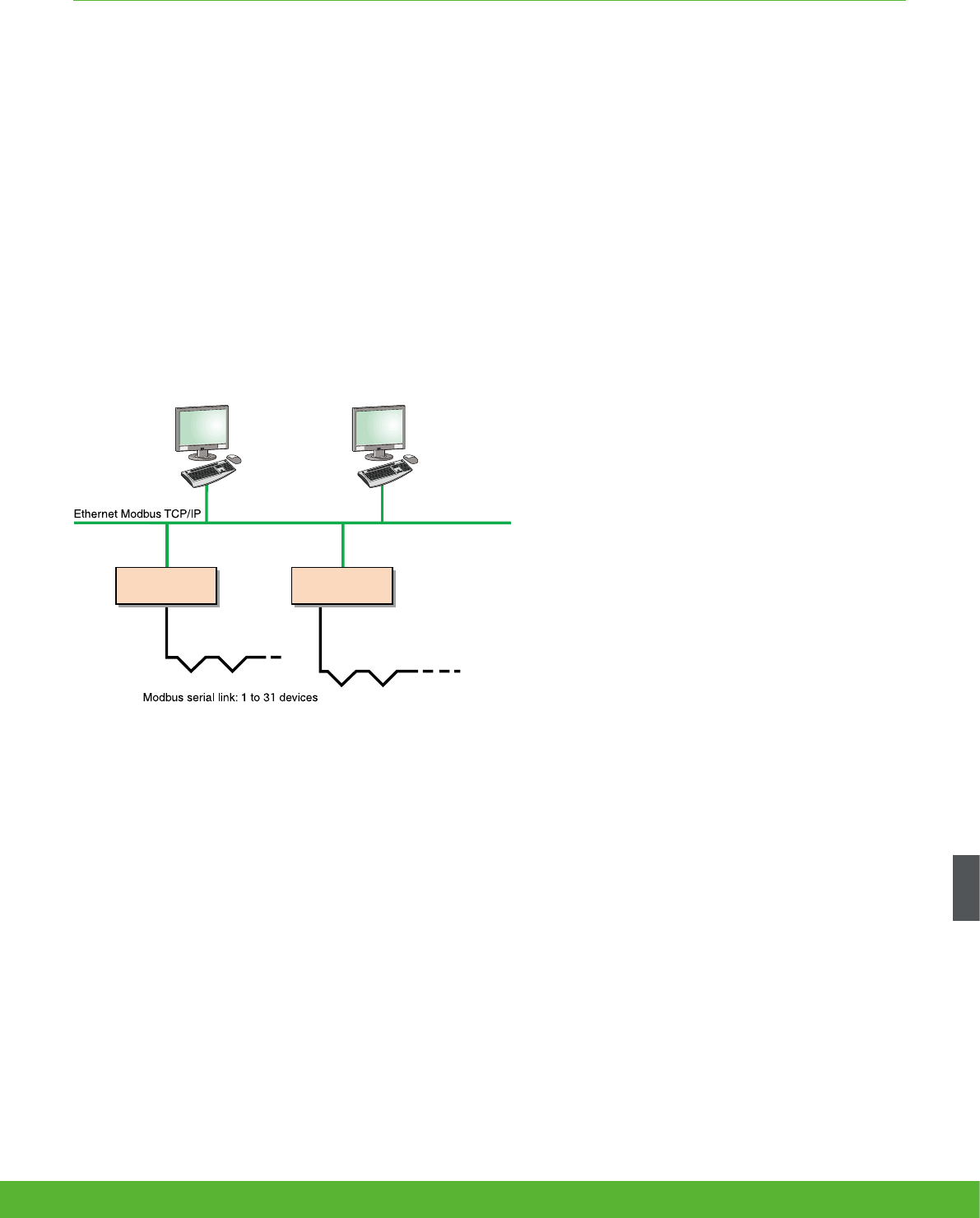
COMMUNICATIONS FUNCTIONS AND CHARACTERISTICS
Using modern Web technologies, the operator can access information from monitoring and
protection devices using any PC connected to the network, with all the required security.
The Ethernet Modbus-Ethernet gateway* or the integrated gateway-servers* provide connectivity between
Modbus RS485 and Ethernet Modbus TCP/IP.
The services available with these technologies considerably simplify the creation, maintenance and
operation of these supervision systems.
The application software is now standardised:
the web interface into the system does not
require custom web pages to be created.
It is personalised by simply identifying the
components in your installation and can be
used as easily as any internet application.
The first step in this approach is the
integrated gateway-server with HTTP pages.
Power management software (StuxureWare
Power Monitoring Expert and StruxureWare
PowerSCADA Expert), running on a PC, provide
broader coverage for more specific needs.
Ethernet link
Link150 Com'X 510
Ethernet communication architecture.
117schneider-electric.co.uk/metering
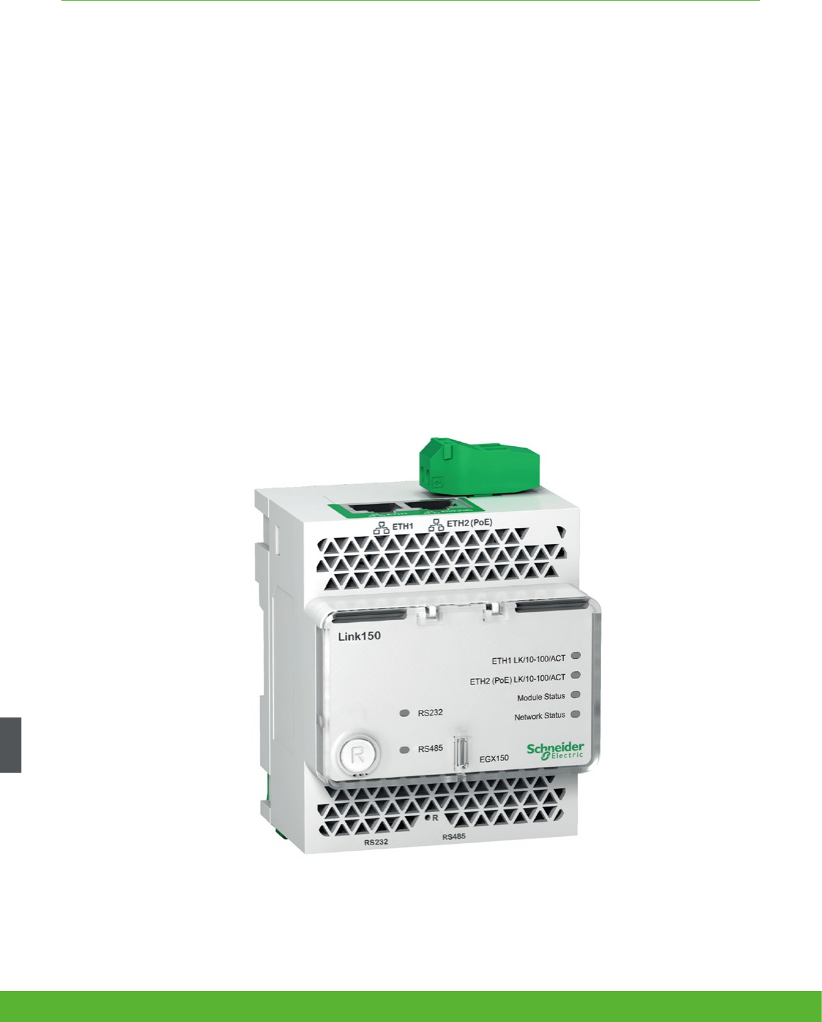
COMMUNICATIONS FUNCTIONS AND CHARACTERISTICS
The Link150 gateway provides fast, reliable Ethernet connectivity in the most demanding
applications, from a single building to a multi-site enterprise. This gateway supports meters,
monitors, protective relays, trip units, motor controls and other devices that need to communicate
data quickly and efficiently. It is your simple, cost-effective serial line to full Ethernet connectivity.
Link150 Ethernet gateway
Applications
• Energy management
• Power distribution
• Building automation
• Factory automation
schneider-electric.co.uk/metering 118
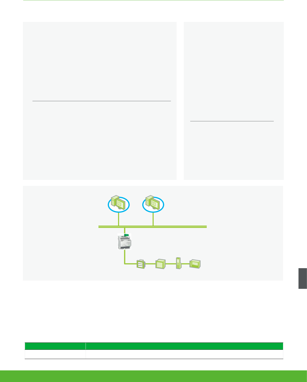
Architecture
COMMUNICATIONS FUNCTIONS AND CHARACTERISTICS
The solution for
All markets that can benefit from a solution that includes the
Link150 gateway:
• Buildings
• Data Centre
• Healthcare
• Industry
• Infrastructure
• Utility
Benefits
• Easy to install and setup
• Easy to maintain
• Advanced security feature
• Compatible with Schneider Electric software offerings
• Reliable Modbus to Ethernet protocol conversion
Security
• Secure user interface including user’s name and password for login
• Advanced security features to allow users to specify which Modbus TCP/IP master devices may access attached serial
slave devices
• Modbus TCP/IP filtering feature
• Allows user to specify the level of access for each master device as Read-only or Full access
• Web pages provide easy configuration and setup
PowerLogic
software
Ethernet Modbus TCP/IP
Link150
Modbus RS485 serial link
ION6200 PM8000 Micrologic Sepam
Ordering reference Product description
EGX150 Link150 Ethernet Gateway
Energy and power management
software
Powerlogic software is recommended as
a user interface which provides access to
all status and measurement information.
It also prepares summary reports for
energy and power management. Please
see Page 114. The Link150 is compatible
with
• StruxureWare Power Monitoring
Expert software
• StruxureWare PowerSCADA Expert
Conformity of standards
• EN55022/EN55011/
FCC Class A
• EN 61000-6-2
• EN 61000-4-2
• EN 61000-4-3
• EN 61000-4-4
• EN 61000-4-5
• EN 61000-4-6
• EN 61000-4-8
• EN 60950
119schneider-electric.co.uk/metering
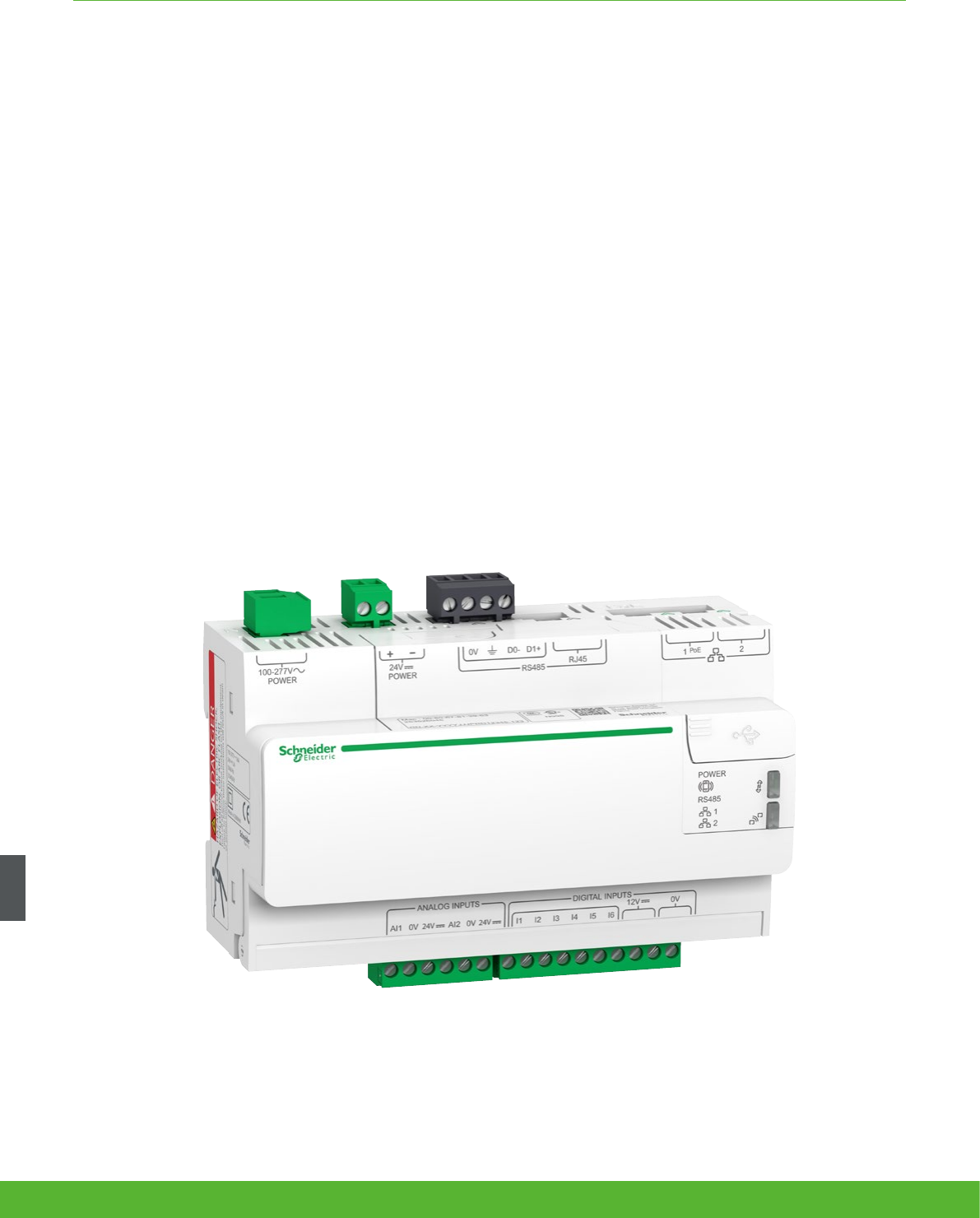
COMMUNICATIONS FUNCTIONS AND CHARACTERISTICS
A highly flexible plug-and-play Energy Server Com’X 200 collects and stores WAGES consumptions
and environmental parameters such as temperatures, humidity and CO2 levels in a building. Data is
periodically transmitted as a report to an internet database server for further processing. The Energy
Server Com’X 200 not only reduces your technical complexity, but help to manage your energy.
Com’X 200
Applications
The quickest path to multi-site energy management and
on-line services
• Delivers batches of data ready to process by StruXureware solutions and services
• Publishes logged data to the Schneider Electric cloud or another hosted platform
schneider-electric.co.uk/metering 120
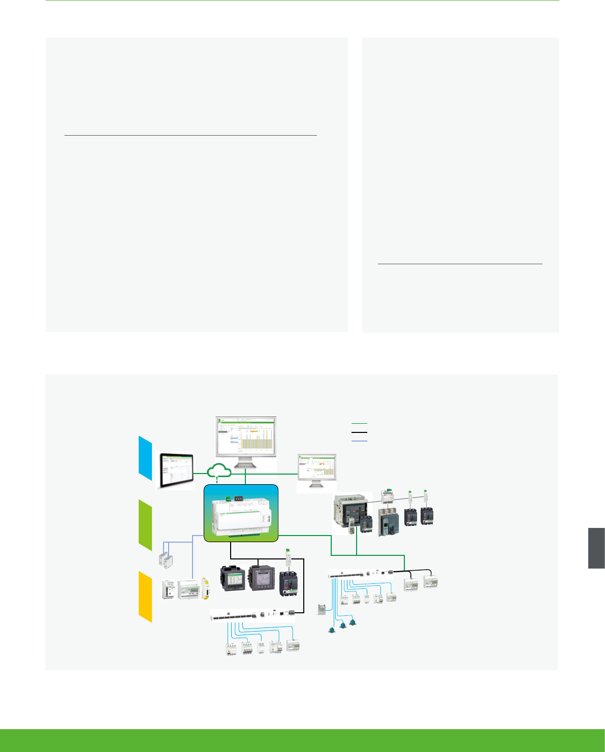
COMMUNICATIONS FUNCTIONS AND CHARACTERISTICS
The solution for
All markets that can benefit from a solution that includes data logger
Com’X 200:
• Buildings
• Industry
Energy management solutions
The data collected and stored by Com’X
200 can be processed and displayed
as webpages through web services
provided by Schneider Electric, such as
StruxureWare Energy Operation or by any
private energy platform,
The Com’X 200 also provides a
transparent interface between Ethernet-
based networks and field devices.
This gateway function supports the
use of monitoring software, such as
Power Monitoring Expert (PME) for data
collection, trending, event management,
analysis and further processing.
Architecture
Conformity of standards
• EN60950
Pulse energy meters
Modbus multi-meters
Analogue
sensors
with 4-20 mA
or 0-10 V
adaptor
Ethernet or
Wi-Fi LAN
Temperature
sensors
Circuit-breakers
Ethernet or Wi-Fi LAN
Modbus Serial Line
Analogue / digital IOs
Com’X 200
Cloud or 3rd
party platform
Power
Monitoring
Expert
1.
Measure 2. Connect 3. Save
Water meters
Gas
meter
Ethernet |
Modbus TCP
Internet
GPRS
PowerView
Remote
Benefits
• Data collection from up to 64 field devices
• Data publishing leveraging existing infrastructures,
Ethernet or Wifi, GPRS-ready
• Quick fitting into electrical switchboards thanks to DIN rail
clipping and profile
• Quick setup and configuration thanks to intuitive HMI
121schneider-electric.co.uk/metering

Data collector
Collects and stores energy data from up to 64 field devices, connected to either:
• Ethernet TCP/IP field network.
• Modbus Serial line network (up to 32 devices).
• Embedded digital and analogue inputs.
“Field devices” consist of :
• PowerLogic devices for power and energy monitoring.
• Masterpact or Compact circuit-breakers for protection and monitoring.
• Acti 9 protection devices, meters, remote controlled switches, etc.
• Water, Air, Gas, Electricity, and Steam consumption meters, from specialised manufacturers,
delivering pulses as per standard (see table next page).
• Environmental sensors such as temperatures, humidity, and CO2 levels in a building, providing
analogue information.
Data logging and storage capabilities include:
• Configurable logging interval, from every minute to once a week.
• Data storage duration of several weeks, depending on quantity of collected data.
Data publisher
Batches of collected data periodically
transmitted to an Internet server, as:
• XML files, for processing by
StruxureWare™ web services, such as
Energy Operation.
• CSV files for viewing in Excel or
transformed for upload into programs such
as StruxureWare™ Power Monitoring Expert
or any compatible software.
Data publishing function supports 4 transfer
protocols over Ethernet or Wi-Fi:
• HTTP.
• HTTPS.
• FTP.
• SMTP.
Additional functions
Gateway
If selected by the user, the Com’X 200 can also
make all data from connected devices available
in real-time:
• In Modbus TCP/IP format over Ethernet or
Wi-Fi.
• For requests by an energy management
software.
Modbus packets can be sent from managing
software to field devices through Modbus serial
line or Modbus TCP/IP over Ethernet.
Ordering reference Product description
Com’X 200 data logger 24 V DC
or 230 V AC power supplied EBX200
Com’x Wi-Fi USB interface EBXA-USB-WiFi
Com’X GPRS interface EBXA-GPRS
Com’x External GPRS antenna EBXA-ANT-5M
COMMUNICATIONS FUNCTIONS AND CHARACTERISTICS
schneider-electric.co.uk/metering 122
COMMUNICATIONS FUNCTIONS AND CHARACTERISTICS
A highly flexible plug-and-play Energy Server Com’X 510 collects and stores WAGES consumptions
and environmental parameters such as temperatures, humidity and CO2 levels in a building. The Com’X
510 has up to 2 year data storage and embedded webpages which means all your energy data can be
viewed and managed on-site.
Com’X 510
Applications
• All-in-one-box energy management solution especially suitable for buildings up to 10,000 sq. meters
123schneider-electric.co.uk/metering
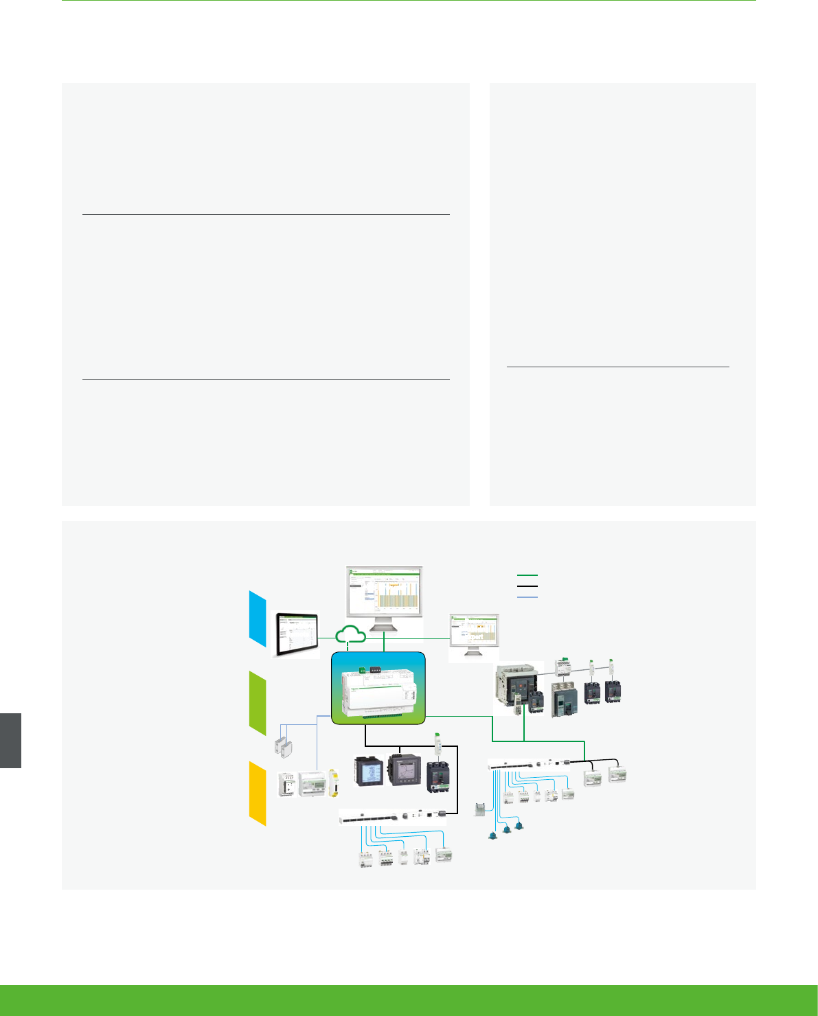
Architecture
The solution for
All markets that can benefit from a solution that
includes data logger Com’X 510:
• Buildings
• Industry
Benefits
• Data collection from up to 64 field devices
• Data publishing leveraging existing infrastructures : Ethernet
or Wifi, GPRS-ready
• Quick fitting into electrical switchboards thanks to DIN rail
clipping and profile.
• Quick setup and configuration thanks to intuitive HMI
Conformity of standards
• EN 60950
COMMUNICATIONS FUNCTIONS AND CHARACTERISTICS
Pulse energy meters
Modbus multi-meters
Analogue
sensors
with 4-20 mA
or 0-10 V
adaptor
Ethernet or
Wi-Fi LAN
Temperature
sensors
Circuit-breakers
Ethernet or Wi-Fi LAN
Modbus Serial Line
Analogue / digital IOs
Com’X 510
Web browser
Power
Monitoring
Expert
1. Measure 2. Connect 3. Save
Water meters
Gas
meter
Ethernet |
Modbus TCP
Internet
GPRS
PowerView
Remote
Competitive advantages
• Fit any PDU or RPP design for both new and retrofit projects
• Class 1.0 system accuracy
• Ethernet communication
Energy management solution
The data collected and stored by Com’X
510 can be processed and displayed
through its own onboard webpage.
The Com’X 510 also provides a
transparent interface between Ethernet-
based networks and field devices.
This gateway function supports the
use of monitoring software, such as
Power Monitoring Expert (PME) for data
collection, trending, event management,
analysis and further processing.
schneider-electric.co.uk/metering 124

Conformity of standards
COMMUNICATIONS FUNCTIONS AND CHARACTERISTICS
Data collector
As soon as they are connected to the LAN, it can be detected and
assigned an IP address by DHCP. Your operating system’s DPWS feature
allows your computer to automatically recognise the device as Com’X.
Embedded web pages are then immediately accessible by clicking each
Com’X device icon or by typing the assigned IP address into your web
browser.
Collects and stores energy data from up to 64 field devices, connected to
either:
• Ethernet TCP/IP field network.
• Modbus Serial line network (up to 32 devices).
• Embedded digital and analogue inputs.
“Field devices” consist of :
• PowerLogic meters for power and energy monitoring.
• Masterpact, Powerpact, or Compact circuit-breakers for protection
and monitoring.
• Acti 9 protection devices, meters, remote controlled switches, etc.
• Water, Air, Gas, Electricity, and Steam consumption meters, from
specialised manufacturers, delivering pulses as per standard (see
table at end of this document).
• Environmental sensors such as temperatures, humidity, and CO2
levels in a building, providing analogue information.
Data logging and storage capabilities include:
• Data logging period: configurable from every minute to once a week.
• Data storage duration: up to 2 years, depending on quanitity of
collected data.
• Able to set time and send reset instructions to field devices.
Embedded energy management software
The Com’X provides the end-user with immediate visibility into energy
consumption throughout the site. As soon as the Com’X is connected to
the Local Area Network (LAN), several web pages are accessible via any
standard web browser, (without plug-in or additional components).
These web pages display real-time data as it is collected, in easy to
understand tabular and summary formats. In addition, users can get
simple analysis of historical data in bar graph or trending formats.
Energy dashboard comparing accumulated over time
energy values (partial screen)
125schneider-electric.co.uk/metering
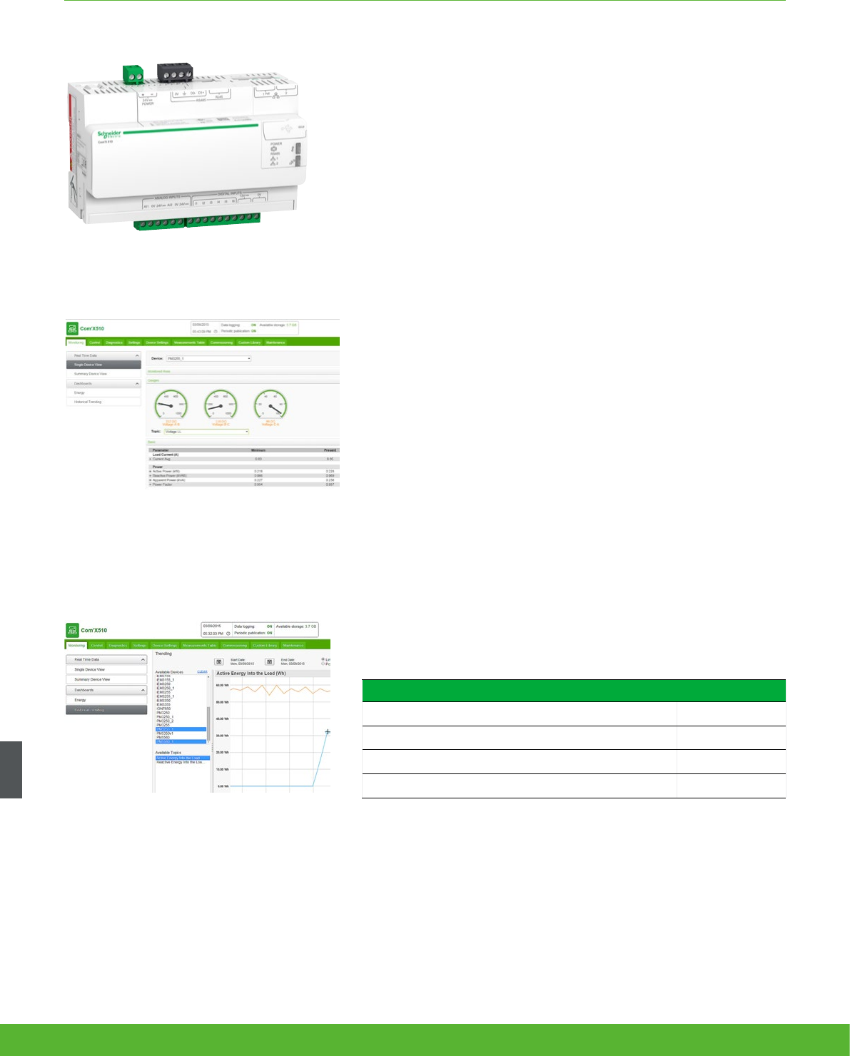
COMMUNICATIONS FUNCTIONS AND CHARACTERISTICS
Energy Server Com'X 510 data logger
Additional functions
Data publisher
Batches of collected data can also be periodically transmitted to an
Internet server, as:
• XML files, for processing by StruxureWare™ web services, such as
Energy Operation
• CSV files for viewing in Excel or transformed or uploading to
programs such as StruxureWare™ Power Monitoring Expert or any
compatible software
Data publishing function supports 4 transfer protocols over Ethernet or
Wi-Fi:
• HTTP
• HTTPS
• FTP
• SMTP
Gateway
• If selected by the user, the Com’X 510 can make data from
connected devices available in real time
• In Modbus TCP/IP format over Ethernet or Wi-Fi
• For requests by energy management software
Modbus packets can be sent from managing software to field devices
through Modbus serial line or Modbus TCP/IP over Ethernet.
Raw data and measurements from one eld device (partial
screen)
Historical trending comparing multiple devices or multiple
topics (partial screen)
Com'X 510 Commercial reference numbers
Com'X 510 energy server 24 V DC power supplied UL rated EBX510
Com'x Wi-Fi USB interface EBXA-USB-WiFi
Com'X GPRS interface EBXA-GPRS
Com’x External GPRS antenna EBXA-ANT-5M
schneider-electric.co.uk/metering 126
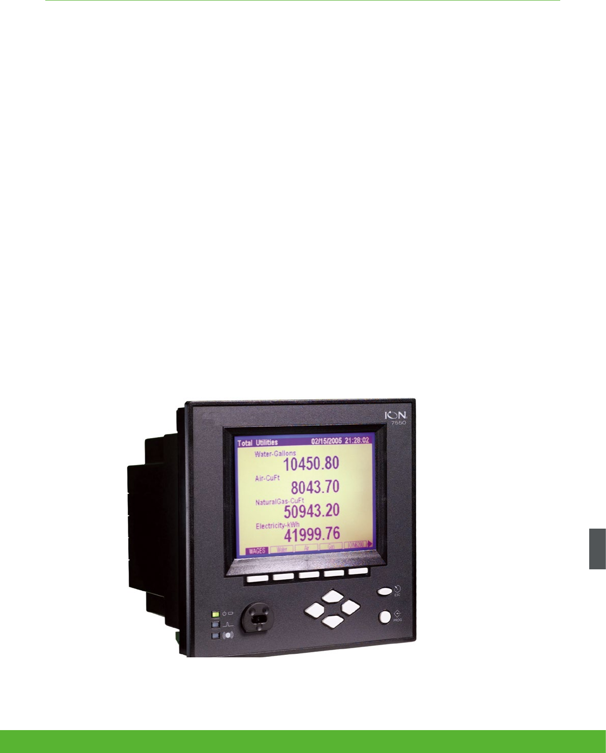
COMMUNICATIONS FUNCTIONS AND CHARACTERISTICS
The PowerLogic ION7550 RTU (remote terminal unit) is an intelligent web-enabled device ideal for
combined utilities metering of water, air, gas, electricity and steam (WAGES). When combined with
Power management software, the ION7550 RTU offers a seamless, end-to-end WAGES metering
solution.
Featuring a large, high-visibility display and overall versatility of the PowerLogic system, the ION7550 RTU provides extensive
analogue and digital I/O choices and is a cost-effective dedicated WAGES solution when compared to a traditional meter.
The device automatically collects, scales and logs readings from a large number of connected meters or transducers and
delivers information to one or more head-end systems through a unique combination of integrated Ethernet, modem or serial
gateways.
ION7550 RTU
Applications
• WAGES (water, air, gas, electricity, steam) metering
• Integrated utility metering with advanced programmable math functions
• Data concentration through multi-port, multi-protocol communications
• Equipment status monitoring and control
• Programmable set points for out-of-limit triggers or alarm conditions
127schneider-electric.co.uk/metering

The solution for
All markets that can benefit from a solution that includes
PowerLogic ION7550RTU series meters:
• Buildings
• Industry
• Healthcare
• Education
• Etc.
Competitive advantages
• Data concentration through multi-port, multi-protocol
communications
• Integrated utility metering with advanced programmable
function
Benefits
• Help reduce waste and optimise equipment operation to
increase energy efficiency
• A large, intuitive display
• Extensive digital and analogue I/O
• Dedicated WAGES solution when compared to a traditional
meter
Conformity of standards
• EN 61010-1
• IEC 61000-4-2
• IEC 61000-4-3
• IEC 61000-4-4
• IEC 61000-4-5
• CISPR 22
COMMUNICATIONS FUNCTIONS AND CHARACTERISTICS
Main characteristics
• Increase efficiency
– Reduce waste and optimise equipment operation to increase efficiency.
• Easy to operate
– Screen-based menu system to configure meter settings. Bright LCD display with adjustable contrast.
• Integrate with software
– Easily integrated with PowerLogic or other energy management enterprises, including SCADA systems.
• Transducer and equipment condition monitoring
– Versatile communications, extensive I/O points, clock synchronisation, event logging and sequence of events recording capabilities
for transducer and equipment condition and status monitoring at utility substations.
• Set automatic alarms
– Alarm setpoint learning feature for optimum threshold settings.
• Up to 10 Mbytes of memory
– For archiving of data and waveforms.
• Notify alarms via email
– High-priority alarms sent directly to the user’s PC. Instant notification of power quality events by email.
• Modbus Master functionality
– Aggregate and store data from downstream Modbus devices using serial or Ethernet connections
Power management solutions
As part of a complete enterprise energy
management solution, the ION7550 RTU
can be integrated with Power Monitoring
Expert, or other SCADA, information and
automation systems. See Page 114
schneider-electric.co.uk/metering 128
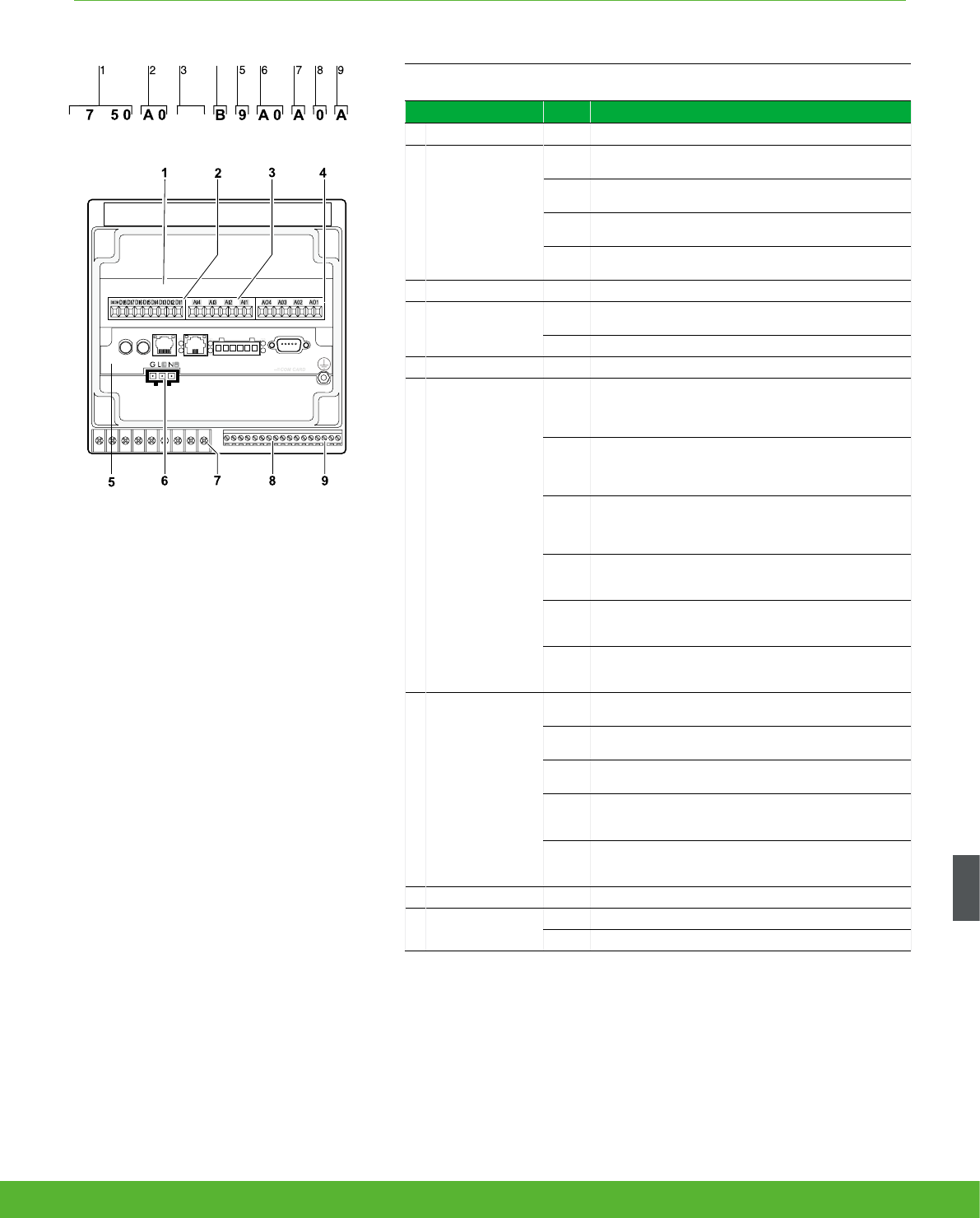
COMMUNICATIONS FUNCTIONS AND CHARACTERISTICS
Part numbers
Item Code Description
1
Model 7550 ION7550 device
2
Form Factor
A0 Integrated display with front optical port, 5 MB logging
memory, and 512 samples/cycle resolution.
B0 Integrated display with front optical port, 10 MB logging
memory, and 512 samples/cycle resolution.
T0 Transducer (no display) version, with 5 MB logging
memory.
U0 Transducer (no display) version, with 10 MB logging
memory.
3
RTU option N9 RTU option
4
Power Supply
BStandard power supply (85-240 VAC, ±10%/47-63 Hz /
110-330 VDC, ±10%)
C Low voltage DC power supply (20-60 VDC)
5
Internal use 9 This field for internal use only
6
Communications
A0
Standard communications (1 RS-232/RS-485 port, 1 RS-
485 port). Integrated display models also include 1 ANSI
Type 2 optical communications port.
C1
Standard communications plus 10BASE-T/100BASE-TX
Ethernet (RJ-45), 56k universal internal modem (RJ-11).
Ethernet, modem gateway functions each use a serial
port.
D7
Standard comms plus 10BASE-T/100BASE-TX Ethernet
(RJ-45) and 100BASE-FX Ethernet Fiber, 56k universal
internal modem (RJ-11). Ethernet and modem gateway
functions each use a serial communications port.
E0
Standard communications plus 10BASE-T/100BASE-TX
Ethernet (RJ-45). Ethernet gateway function uses serial
port.
F1
Standard communications plus 10BASE-T/100BASE-
TX Ethernet (RJ-45) and 100BASE-FX (SC fiber optic
connection). Ethernet gateway uses a serial port.
M1
Standard communications plus 56k universal internal
modem (RJ-11). Modem gateway uses serial
communications port.
7
I/O
AStandard I/O (8 digital inputs, 3 Form C relays, 4 Form A
solid-state outputs)
EStandard I/O plus Expansion I/O card (8 additional digital
inputs & four 0 to 20 mA analogue inputs)
KStandard I/O plus Expansion I/O card (8 additional digital
inputs & four 0 to 20 mA analogue outputs)
N
Standard I/O plus Expansion I/O card (8 additional digital
inputs & four 0 to 20 mA analogue inputs and four 0 to 20
mA outputs)
P
Standard I/O plus Expansion I/O card (8 additional digital
inputs & four 0 to 1 analogue inputs and four -1 to 1 mA
analogue outputs)
8
Security 0 Password protected, no hardware lock
9
Special Order
A None
C Tropicalisation treatment applied
5N 9
M
4
PowerLogic® ION7550 RTU.
1 I/O expansion card.
2 Digital inputs.
3 Analogue inputs.
4 Analogue outputs.
5 Communications card.
6 Power supply.
7 Form C digital outputs.
8 Digital inputs.
9 Form A digital outputs.
129schneider-electric.co.uk/metering

COMMUNICATIONS FUNCTIONS AND CHARACTERISTICS
Communication Card for ION7550RTU Ordering reference
Standard Comms: 1 RS232/RS485 port (COM1), 1 RS485 port (COM2), Front optical port (COM3) P765CA0A
Standard Comms: 1 RS232/RS485 port (COM1), 1 RS485 port (COM2), Front optical port (COM3), tropicalisation treatment
applied P765CA0C
Standard plus Ethernet (10/100BASE-T), 56k universal internal modem (RJ11; shares COM3) P765CC1A
Standard plus Ethernet (10/100BASE-T), 56k universal internal modem (RJ11; shares COM3), tropicalisation treatment applied P765CC1C
Standard plus Ethernet (10/100BASE-T, 100BASE-FX), 56k internal modem (RJ11) P765CD7A
Standard plus Ethernet (10/100BASE-T, 100BASE-FX), 56k internal modem (RJ11), tropicalisation treatment applied P765CD7C
Standard plus Ethernet (10/100BASE-T) P765CE0A
Standard plus Ethernet (10/100BASE-T), tropicalisation treatment applied P765CE0C
Standard plus Ethernet (10/100BASE-T, 100BASE-FX) P765CF1A
Standard plus Ethernet (10/100BASE-T, 100BASE-FX), tropicalisation treatment applied P765CF1C
Standard plus 56k universal internal modem (RJ11; shares COM3) P765CM1A
Standard plus 56k universal internal modem (RJ11; shares COM3),tropicalisation treatment applied P765CM1C
Analogue I/O cards Ordering reference
four 0 to 20 mA analogue inputs & 8 digital inputs P760AEA
four 0 to 20 mA analogue inputs & 8 digital inputs,tropicalisation treatment applied P760AEC
four 0 to 20 mA analogue outputs & 8 digital inputs P760AKA
four 0 to 20 mA analogue outputs & 8 digital inputs,tropicalisation treatment applied P760AKC
four 0 to 20 mA analogue inputs, four 0 to 20 mA analogue outputs & 8 digital inputs P760ANA
four 0 to 20 mA analogue inputs, four 0 to 20 mA analogue outputs & 8 digital inputs,tropicalisation treatment applied P760ANC
four 0 to 1 analogue inputs, four -1 to 1 mA analogue outputs & 8 digital inputs. P760APA
four 0 to 1 analogue inputs, four -1 to 1 mA analogue outputs & 8 digital inputs,tropicalisation treatment applied P760APC
ION7550 RTU
schneider-electric.co.uk/metering 130

COMMUNICATIONS FUNCTIONS AND CHARACTERISTICS
OpenDAC rack, controllers, power supply Ordering
reference
OpenDAC rack. Holds up to 8 OpenLine modules to provide up to 16 I/O points. Requires communications controller 70LRCK16-48
OpenDAC OpenDAC RS-485 serial module. Communications controller for use in a Modbus RTU network. Supports up to 2
70LRCK16-48 OpenDAC racks 72-MOD-4000
OpenDAC Ethernet network module for use on an Modbus/TCP Ethernet network. Supports up to 2 OpenDAC racks 72-ETH-T000
85-264VAC/110-370VDC 15 Watt power supply. Required for applying power to the racks and controllers PS-240-15W
OpenLine digital I/O modules Ordering
reference
digital input, 120VAC 70L-IAC
digital input, 220VAC 70L-IACA
digital input, 3-32VDC 70L-IDC
digital input, fast switching 70L-IDCB
digital input, 15-32VAC/10-32VDC 70L-IDCNP
dry contact closure-sensing DC input 70L-IDC5S
input test module 70L-ISW
digital output, 120VAC 70L-OAC
digital output, 120VAC inductive loads 70L-OACL
digital output, 220VAC 70L-OACA
digital output, 220VAC inductive loads 70L-OACAL
digital output, 3-60VDC fast 70L-ODC
digital output, 4-200 VDC 70L-ODCA
digital output, fast switching 70L-ODCB
digital output, dry contact 70L-ODC5R
OpenLine analogue I/O modules Ordering
reference
analogue input, current, 0-20mA 73L-II020
analogue input, current, 4-20mA 73L-II420
analogue input, temperature, J-type TC 73L-ITCJ
analogue input, temperature, K-type TC 73L-ITCK
analogue input, temperature, T-type TC 73L-ITCT
analogue input, temperature, RTD 73L-ITR100
analogue input, temperature, 3wire RTD 73L-ITR3100
analogue input, temperature, 4wire RTD 73L-ITR4100
analogue input, voltage, 0-1VDC 73L-IV1
analogue input, voltage, 0-10VDC 73L-IV10
analogue input, voltage, -10 to 10VDC 73L-IV10B
analogue input, voltage, 0-100VDC 73L-IV100M
analogue input, voltage, 0-5VDC 73L-IV5
analogue input, voltage, -5 to 5VDC 73L-IV5B
analogue input, voltage, 0-50mV 73L-IV50M
analogue output, current, 0-20mA 73L-OI020
analogue output, current, 4-20mA 73L-OI420
analogue output, voltage, 0-10VDC 73L-OV10
analogue output, voltage, -10 to 10VDC 73L-OV10B
analogue output, voltage, 0-5VDC 73L-OV5
analogue output, voltage, -5 to 5VDC 73L-OV5B
131schneider-electric.co.uk/metering

Communications
Technical
Specifications
132 schneider-electric.co.uk/metering

COMMUNICATIONS FUNCTIONS AND CHARACTERISTICS
Technical specifications
Link150
Weight 175 g (6.17 oz) without packing
Dimensions (HxWxD) 72 x 105 x 71 mm (2.83 x 4.13 x 2.79 in)
Mounting DIN rail
Power-over-Ethernet (PoE) Class 3
Power supply 24 V DC (-20/+10%) or
Power over Ethernet (PoE Class 3 IEEE 802.3 af) at 15 W
Consumption (typical) 24 V DC, 130 mA at 20 °C
PoE 48 V DC, 65 mA at 20 °C
Ambient operating temperature -25 to +70 °C (-13 to +158 °F)
Ambient storage temperature -40 to +85 °C (-40 to +185 °F)
Humidity rating 5 to 95 % relative humidity (without condensation) at +55ºC
Pollution Degree Level 2
IP Ratings
On the front panel (wall-mounted enclosure): IP4x
Connectors: IP20
Other parts: IP30
Regulatory/standards compliance for electromagenetic interference
Emissions (radiated and
conducted) EN55022/EN55011/FCC class A
Immunity for industrial
environments:
electrostatic
discharge EN 61000-6-2
radiated RF EN 61000-4-2
electrical fast
transients EN 61000-4-3
surge EN 61000-4-4
conducted RF EN 61000-4-5
power frequency EN 61000-4-6
magnetic field EN 61000-4-8
Regulatory/standards compliance for safety
Safety - IEC IEC60950
Safety - UL* UL 60950
UL 61010-2-201
EMC IEC6100-6-2
Australia C-tick - RCM
Sustainability Green Premium
Serial ports
Number of ports 2 (1 available at a time)
Types of ports RS232 or RS485 (2-wire or 4-wire), depending on settings
Protocol Modbus, Serial
Baud rates 19200 bps (factory setting), 2400 bps, 4800 bps,
9600 bps, 38400 bps, 56000 bps**, 57600 bps**
Maximum number of connected
devices
32 (directly)
247 (indirectly)
Ethernet ports (used as a switch)
Number of ports 2
Type of port 10/100 Base TX (802.3af) port
Protocol HTTP, Modbus TCP/IP, FTP, SNMP (MIB II)
* Dual listed for US and Canada
** Only available when Physical Interface is set to RS232 and Transmission Mode is set to Modbus ASCII
Link150 Ethernet gateway
133schneider-electric.co.uk/metering
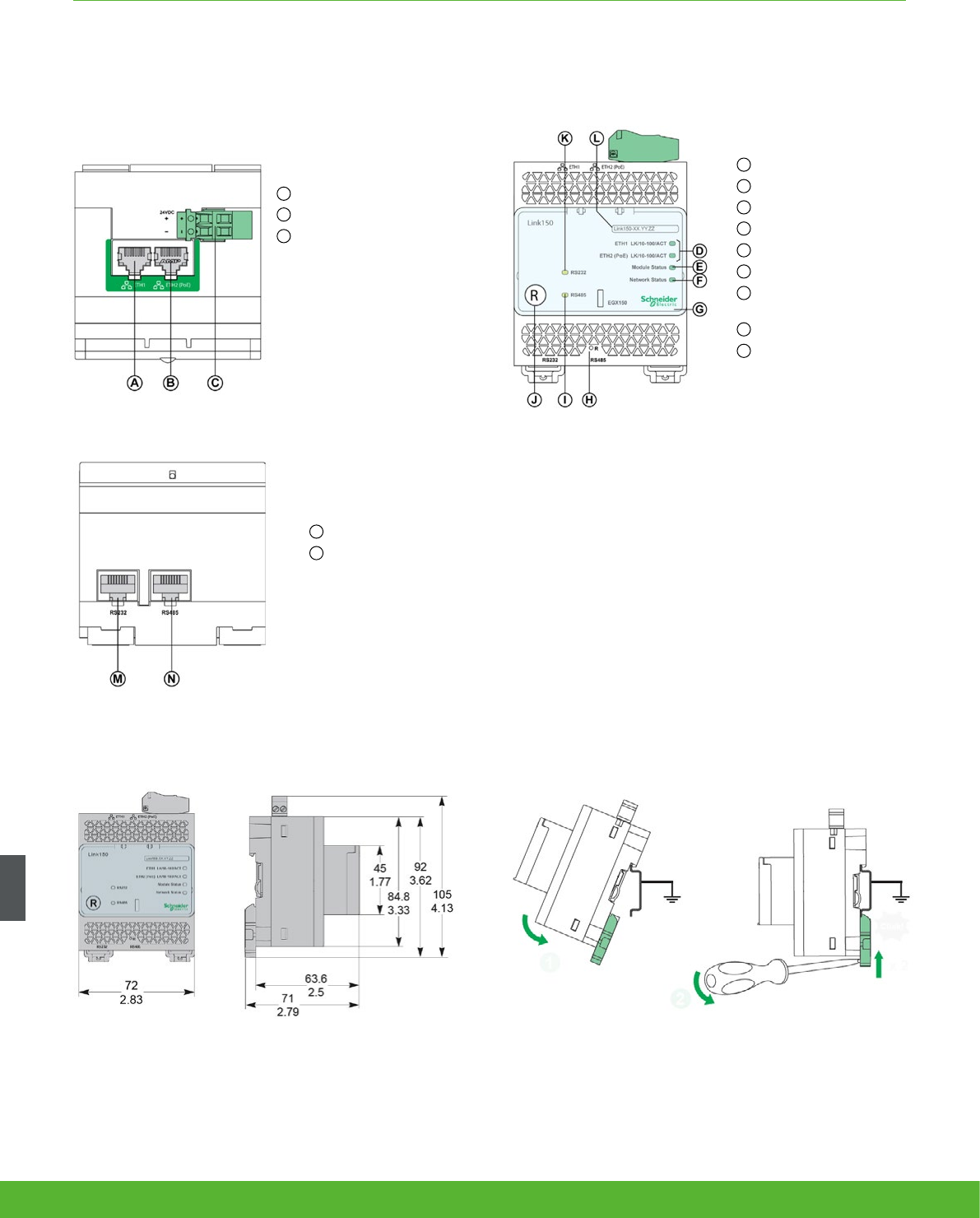
COMMUNICATIONS FUNCTIONS AND CHARACTERISTICS
Link150 Ethernet gateway
A Ethernet 1 communication port
B Ethernet 2 (PoE) communication port
C Midspan PoE injector
D Ethernet communication LEDs
E Module status LED
F Network status LED
G Sealable transparent cover
H IP reset pin
I RS485 trafc status LED
J Device soft restart button
(Accesible through closed cover)
K RS232 trafc status LED
L Device name label
M RS232 port
N RS485 port
Parts
Dimensions DIN rail mounting
Fast and easy DIN rail installation
schneider-electric.co.uk/metering 134
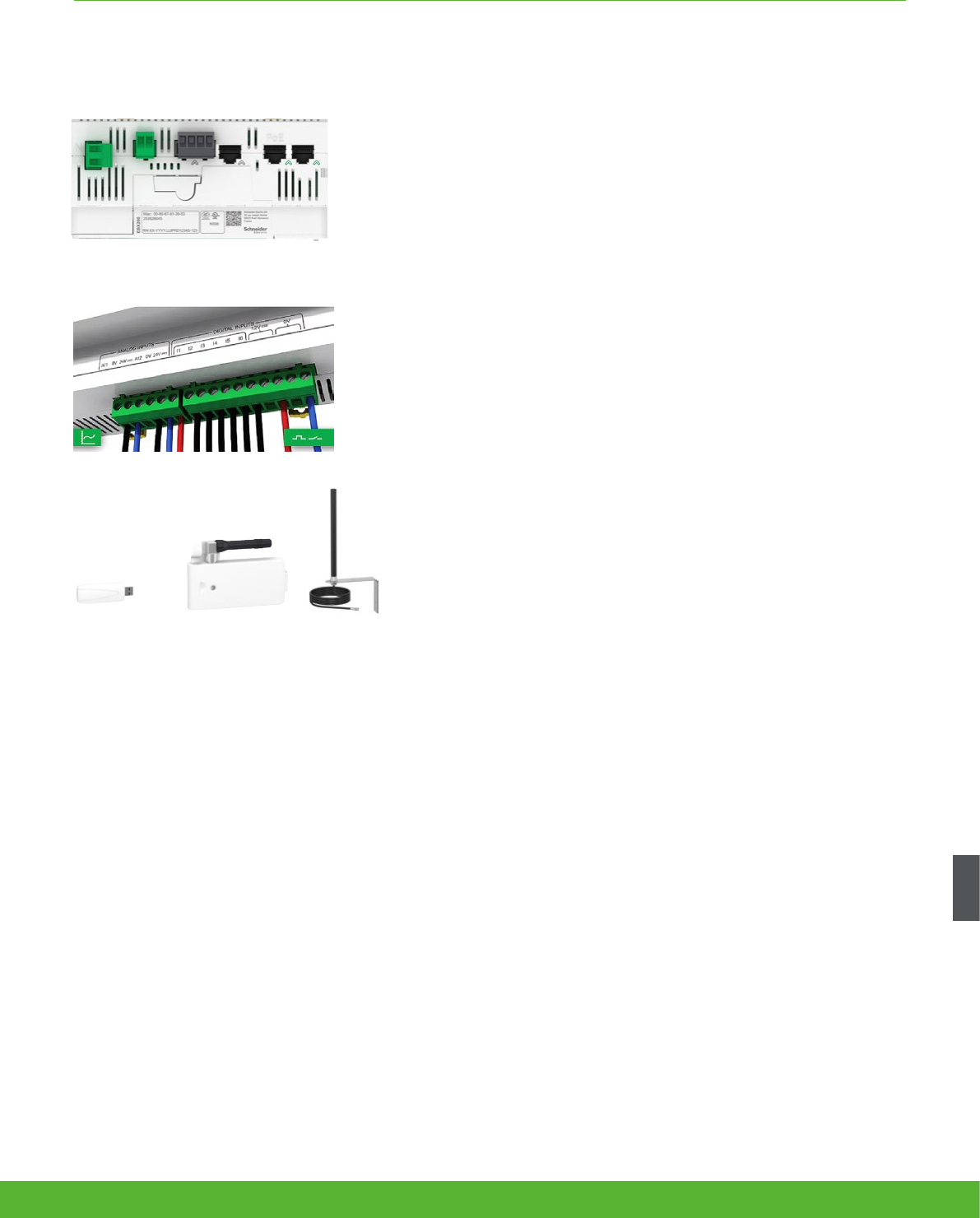
Com’X 200/510 Data Logger
D Ethernet communication LEDs
E Module status LED
F Network status LED
G Sealable transparent cover
H IP reset pin
I RS485 trafc status LED
J Device soft restart button
(Accesible through closed cover)
K RS232 trafc status LED
L Device name label
COMMUNICATIONS FUNCTIONS AND CHARACTERISTICS
Connectivity
• Modbus SL /RS485 connections to field devices
– By cable with RJ45 connector.
• 2 Ethernet ports
– Used to either separate upstream connection from field devices network
or to daisy chain Ethernet devices.
– RJ45 10/100 Base connectors.
– Static IP address.
• Ethernet port #1
– Connection to Local Area Network (LAN).
– PoE Class 3 (802.3af) can act as main/backup power supply for the
Com'X.
– DHCP client.
• Ethernet port # 2
– Connection to field devices.
– DHCP cleint or server.
• Power supply to analogue and digital outputs
– Outputs to supply sensors and inputs when Com’X is supplied through
24 V DC input on top:
– 12 V DC– 60 mA for digital inputs.
– 24 V DC for analogue inputs.
– Compliant with electrical switchboard environment (temperature,
electromagnetic compatibilty).
• 2 inputs for analogue sensors
– PT100 or PT1000 temperature probes.
– Various sensors (humidity, CO2, etc.) with 0-10 V output.
– Various sensors with 4-20 mA output
• 6 inputs for dry contact sensors or pulse counters
– Max 25 pulses per second (min duration 20 ms)
– IEC 62053-31 Class A
• Wi-Fi USB stick
– As an alternative to publication over Ethernet, connects Com’X to the site
Wi-Fi router for regular data transmission.
– Can also be used for Com'X 510 configuration through one-to-one
connection with laptop or tablet.
– Simply plugs into USB port 2 under front cover.
• GPRS modem
– For connection to the data processing server through cellular or user's
APN network.
– Also connect to Schneider Electric's Digital Service Platform.
– Especially suitable for sites with no internet access.
– Simply plugs into dedicated port under the front cover.
• GPRS antenna
– Improves GPRS signal strength in case of poor transmission conditions.
– Recommended for Com’X located inside metallic electrical panels.
GPRS antennaGPRS modemWi-Fi USB stick
Connection points
1 Terminal block
2 RJ45 cable
3 Ethernet port #1
4 Ethernet port #2
Power supply to analogue and digital inputs
135schneider-electric.co.uk/metering
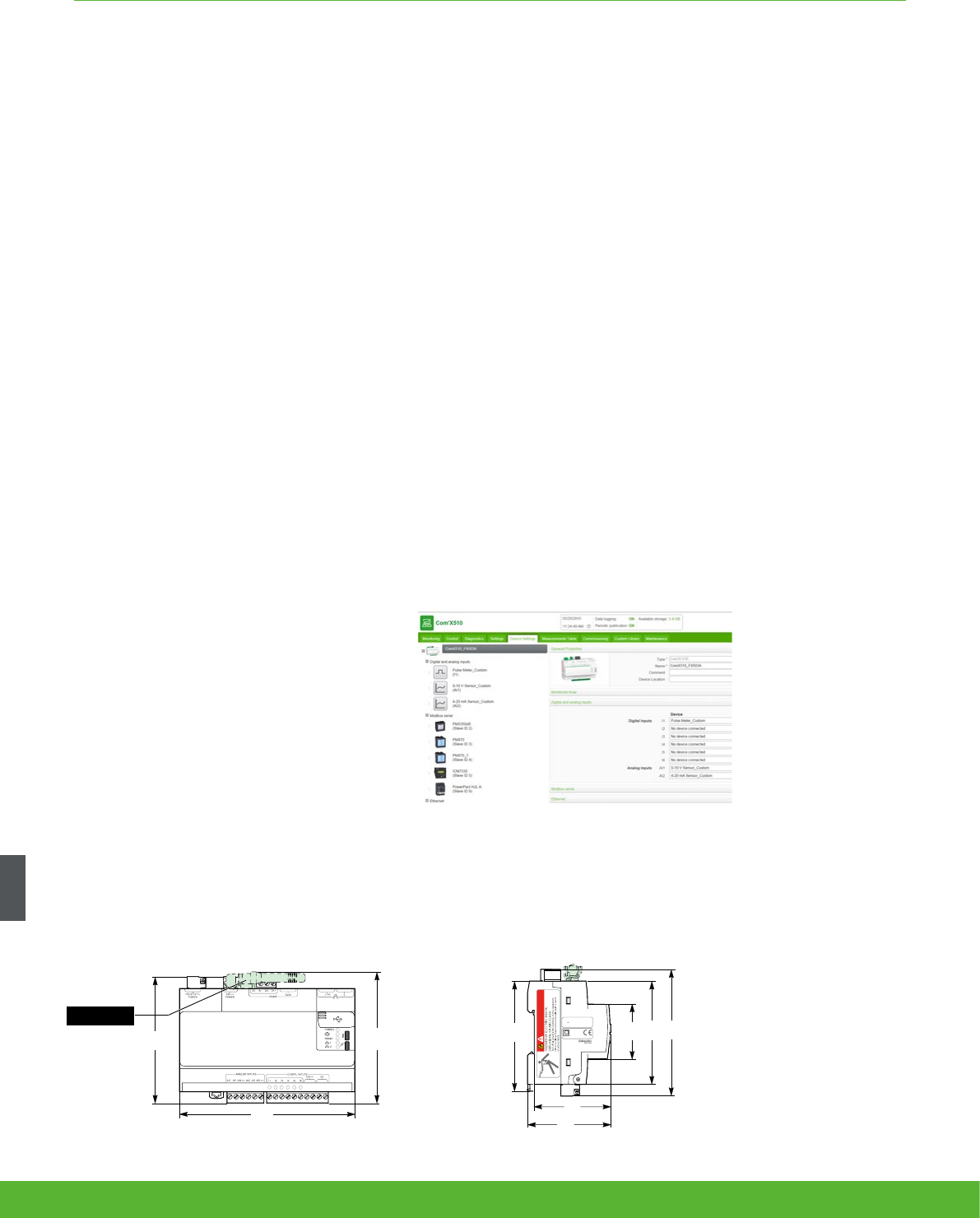
Setup and configuration
Connection to LAN
As soon as they are connected to the LAN, it can be detected and assigned an IP address by
DHCP. Your operating system’s DPWS feature allows your computer to automatically recognise the
device as Com’X. Embedded web pages are then immediately accessible by clicking each Com’X
device icon or by typing the assigned IP address into your web browser.
Com’X 200/510 setup and configuration
Additional features and benefits
• Cybersecurity - works well with your cyber
security architecture.
• 2 Ethernet ports to separate upstream
cloud connection, or to daisy chain with
other Ethernet devices, from field device
network.
• Data storage in case of communications
failure.
• Local backup of configuration parameters
- back up your system to a USB storage
device and have it available for system
restore or to duplicate the configuration on
another box.
Field device auto-discovery
The user-activated device discovery function
automatically identifies all field devices
connected to Modbus SL, Ethernet port.
• Schneider Electric devices display with the
product image.
• Other devices appear as “unknown,”
allowing the user to manually assign a
device type.
• User can assign their own device types.
• Users can complete additional device
identification fields, such as circuit ID or
building zone.
Data selection for logging and publication
Web page configuration tabs allow you to
configure, in just a few clicks, which connected
field devices collect and publish data.
• Advanced diagnostics and troubleshooting
features
• Modbus serial and TCP/IP device statistics.
• Ethernet network statistics.
• Communications check wizard.
• Direct reading of register values from local
and remote devices.
Device settings page (partial), as displayed after auto-
discovery, enabling user to assign circuit identications and
select data for logging and publication.
DIN rail tting (Front face IP40, terminals IP20).
Com’X 200/510 installation
144
5.66
106
4.17
EBXA-GPRS
EBXA-GPRS-SIM
109
4.29
90
3.54
63
2.48
45
1.77
106
4.17
85
3.35
69
2.71
Made in GERMANY
100-277V
~
0.6A
24V 1.2A
50/60 Hz
DANGER
EBX200
COMMUNICATIONS FUNCTIONS AND CHARACTERISTICS
schneider-electric.co.uk/metering 136

COMMUNICATIONS FUNCTIONS AND CHARACTERISTICS
Technical specifications
Com’X 200/510 Environment
Operating temperature -25º to +60°C (-13º to 140°F) Com’X 200
-25º to +70°C (-13º to 158°F) Com’X 510
Storage temperature -40º to +85°C (-40º to +185°F)
GPRS dongle
Operating temperature -20º to +60°C (-4º to +140°F)
GPRS dongle
Storage temperature -40º to +85°C (-40º to +185°F)
Wif-Fi dongle
Operating temperature 0º to +50°C (32º to +122°F)
Wi-Fi dongle
Storage temperature -20º to +80°C (-4º to +176°F)
Humidity 5 to 95% relative humidity (without condensation) at +55ºC
Pollution Class III
Safety standards / regulation
International (CB scheme) IEC 60950
USA UL 508
USA UL 60950 (Com’X 510 only)
Canada cUL 60950 (Com’X 510 only)
Canada cULus 508
Europe EN 60950
Quality Brands
CE, UL
Power Supply Com’X 200 Com’X 510
AC 100-230 V (+/- 15%)(50-60Hz) b
DC 24 V (+/- 10%) b b
Power over Ethernet 15.4 W DC b b
Max power 26 W max b b
Mechanical Com’X 200 Com’X 510
IP Front face IP40, terminals IP20 b b
Dimensions (HxWxD) 91 x 144 x 65.8 mm b b
Weight 450 g b b
137schneider-electric.co.uk/metering

COMMUNICATIONS FUNCTIONS AND CHARACTERISTICS
Features
ION7550 RTU
Data recording
Min/max of instantaneous values b
Data logs b
Event logs b
Trending b
SER (Sequence of event recording) b
Time stamping b
GPS synchronisation (1 ms) b
Memory (in Mbytes) 10
Display and I/O
Front panel display b
Pulse output 1
Digital or analogue inputs(max) 24
Digital or analogue outputs (max, including pulse output) 30
Communication
RS 485 port 1
RS 485 / RS 232 port 1
Optical port 1
Modbus TCP Master / Slave (Ethernet port) b / b
Modbus RTU Master / Slave (Serial port) b / b
Ethernet port (Modbus/TCP/IP protocol) 1
Ethernet gateway (EtherGate) 1
Alarms (optional automatic alarm setting b
Alarm notification via email (Meterm@il) b
HTML web page server (WebMeter) b
Internal modem 1
Modem gateway (ModemGate) b
DNP 3.0 through serial, modem, and I/R ports b
ION7550 RTU
schneider-electric.co.uk/metering 138

COMMUNICATIONS FUNCTIONS AND CHARACTERISTICS
Electrical characteristics
Data update rate 1/2 cycle or 1 second
Power supply
AC 85-240 V AC ±10% (47-63 Hz)
DC 110-300 V DC ±10%
DC low voltage
(optional) 20-60 V DC ±10%
Ride-through time 100 ms (6 cycles at 60 Hz) min. at 120 V DC
Burden Standard: typical 15 VA, max 35 VA
Low voltage DC: typical 12 VA, max 18 VA
Input/outputs
(1)
Standard
8 digital inputs (120 V DC)
3 relay outputs (250 V AC / 30 V DC)
4 digital outputs (solid state)
Optional 8 additional digital inputs
4 analogue outputs, and/or 4 analogue inputs
Mechanical characteristics
Weight 1.9 kg
IP degree of protection (IEC 60529) IP52
Dimensions
Standard model 192 x 192 x 159 mm
TRAN model 235.5 x 216.3 x 133.1 mm
Environmental conditions
Operating
temperature
Standard power supply -20 to +70ºC
Low voltage DC supply -20 to +50ºC
Display operating range -20 to +70ºC
Storage
temperature Display, TRAN -40 to +85ºC
Humidity rating 5 to 95% non-condensing
Installation category III (2000m above sea level)
Dielectric withstand As per EN 61010-1, IEC 62051-22A
(2)
Electromagnetic compatibility
Electrostatic discharge IEC 61000-4-2
Immunity to radiated fields IEC 61000-4-3
Immunity to fast transients IEC 61000-4-4
Immunity to surges IEC 61000-4-5
Conducted and radiated emissions CISPR 22
Safety
Europe IEC 61010-1
(1) Consult the ION7550 / ION7650 installation guide for complete specifications.
(2) IEC 62051-22B with serial ports only.
139schneider-electric.co.uk/metering

COMMUNICATIONS FUNCTIONS AND CHARACTERISTICS
(1) All the communication ports may be used simultaneously.
Communication
RS 232/485 port
(1)
Up to 115,200 bauds (57,600 bauds for RS 485), ION, DNP 3.0, Modbus, GPS, EtherGate, ModemGate, Modbus Master
RS 485 port
(1)
Up to 115,200 bauds, ION, DNP 3.0, Modbus, GPS, EtherGate, ModemGate, Modbus Master
Infrared port
(1)
ANSI type 2, up to 19,200 bauds, ION, Modbus, DNP 3.0
Ethernet port 10BaseT, 100BaseTX. RJ45 connector, 10/100 m link
Fibre-optic Ethernet link 100Base FX, SC duplex connector, 1300 nm, FO multimode with gradient index 62.5/125 µm or 50/125 µm, 2000 m link
Protocol ION, Modbus, Modbus Master, TCP/IP, DNP 3.0, Telnet
EtherGate Communicates directly with up to 62 slave devices via available serial ports
ModemGate Communicates directly with up to 31 slave devices
WebMeter 5 customisable pages, new page creation capabilities, HTML/XML compatible
Firmware characteristics
High-speed data recording Down to 5ms interval burst recording, stores detailed characteristics of disturbances or outages. Trigger recording by a
user-defined setpoint, or from external equipment.
Load profiling
Channel assignments (800 channels via 50 data recorders) are configurable for any measurable parameter. Trigger
recorders based on
time interval, calendar schedule, alarm/event condition,
or manually.
Trend curves Access historical data at the front panel. Display, trend and continuously update historical data with date and
timestamps for up to four parameters simultaneously.
Alarms
Threshold alarms:
adjustable pickup and dropout setpoints and time delays, numerous activation levels possible for a given type of alarm
user-defined priority levels
boolean combination of alarms is possible using the operators NAND, OR, NOR and XOR
Advanced security Up to 16 users with unique access rights. Perform resets, time syncs, or meter configurations based on user privileges
Memory 5 to 10 Mbytes (specified at time of order)
Firmware update Update via the communication ports
Display characteristics
Integrated display Back lit LCD, configurable screens
Languages English
ION7550 RTU
schneider-electric.co.uk/metering 140
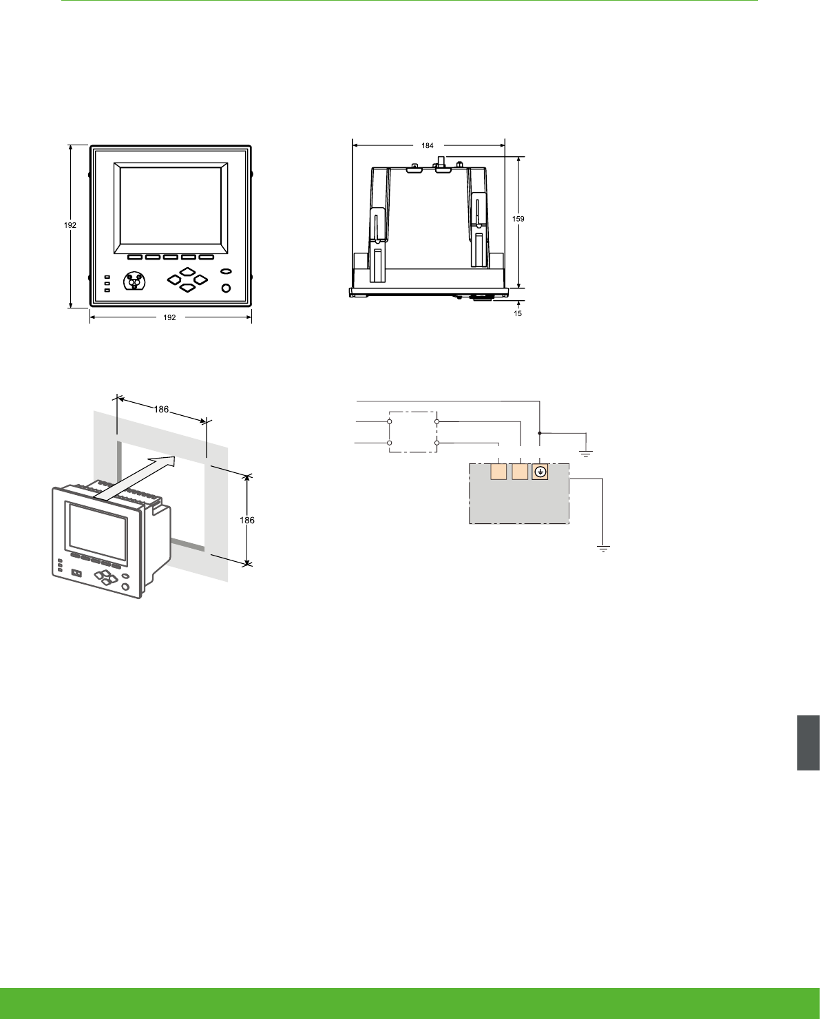
COMMUNICATIONS FUNCTIONS AND CHARACTERISTICS
Protection
(3A)
L/+ N/-
Power supply
Fuse for N/- required if
neutral is ungrounded
Connect G ter
minal
to ground for AC
power source
Note: the current and voltage terminal strip (I52, I51, I42, I41, I32, I31, I22,
I21, I12, I11, V4, V3, V2, V1, Vref) is not present on the RTU.
ION7550 RTU dimensions
Front-panel mounting Power supply
141schneider-electric.co.uk/metering

Monitoring
software
schneider-electric.co.uk/metering 142
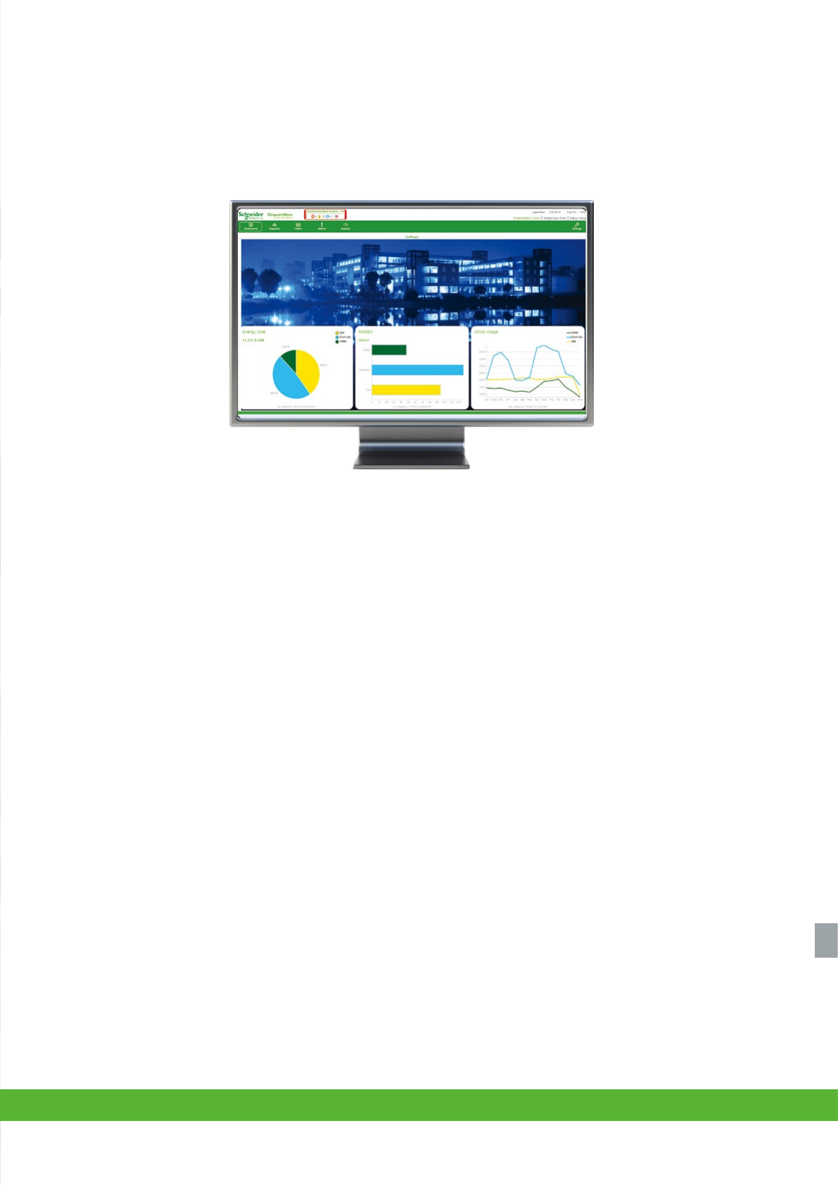
Extensive reach and flexibility
Software forms an important part of your overall energy efficiency and
reliability solutions from Schneider Electric. Power management software
can grow with your business, giving you the level of energy intelligence
and control your need to reduce energy consumption and costs, minimise
environmental impacts, prolong equipment life, and assure power
availability, uptime and safety.
Each product collects energy-related data from a variety of sources,
including PowerLogic or third-party meters and sensors. Some products
offer integration with other Schneider Electric or third-party automation
systems, and other energy relevant information feeds.
System requirements
Whether you’re building a new system
or enhancing an existing operation, a
Schneider Electric representative will advise
you on complete system requirements and
commissioning information for StruxureWare
power management software.
StruxureWare™ power management software provides a complete power management supervisory
interface that gives you access from anywhere to your entire electrical network. The software converts
energy-related data into timely, accurate information for you to act on.
Track real-time power conditions, analyse power quality and reliability and respond quickly to alarms to avoid critical
situations. Our power management software provides extensive analysis and reporting tools, intuitive visualisation and control
interfaces, and flexible, scalable architectures that can meet your unique needs today and continue to do so well into the
future. The depth of different offerings makes it easy to match a product to your goals, your business and your budget.
A choice of powerful, effective solutions
143schneider-electric.co.uk/metering
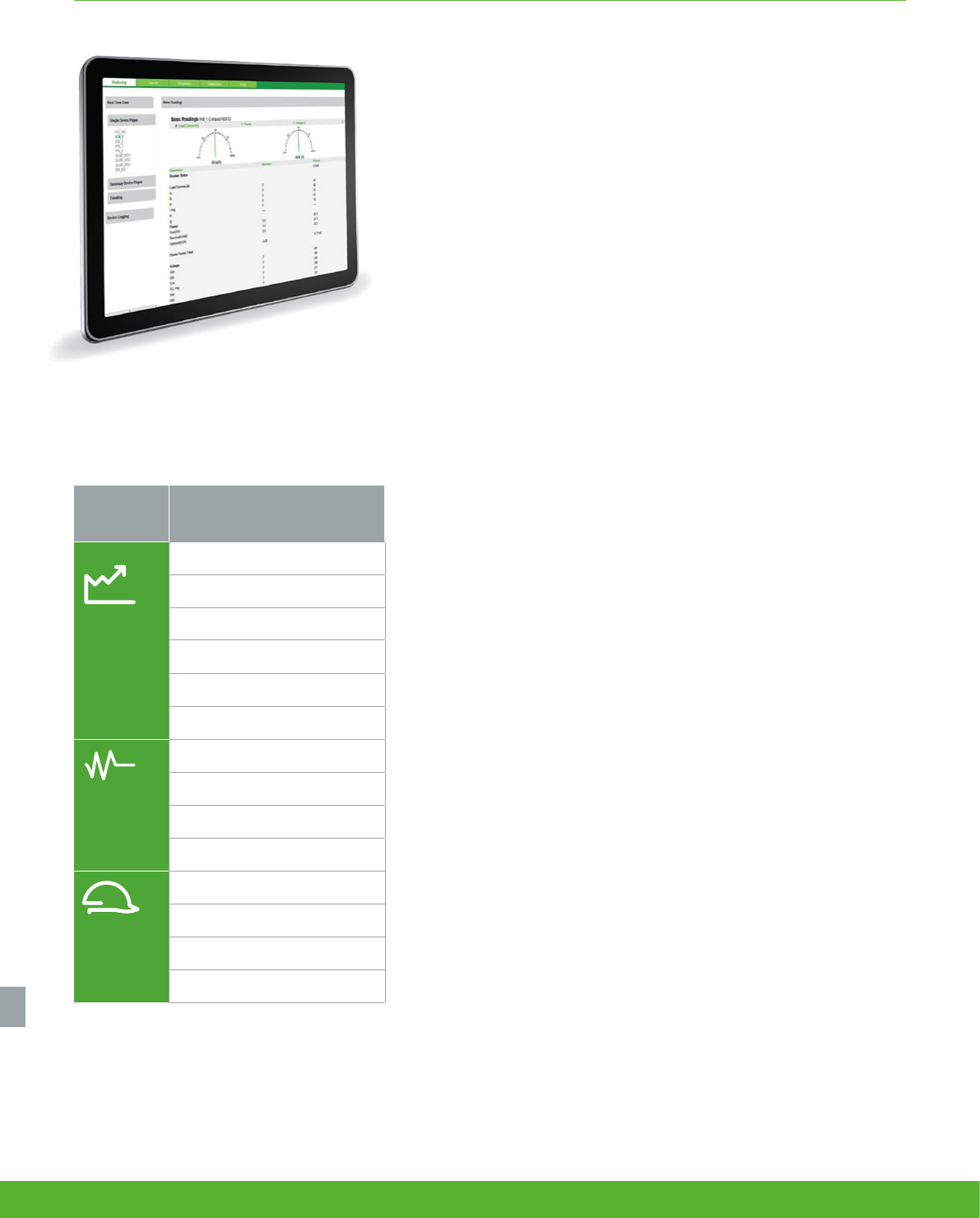
Category Application
Energy
efficiency
& cost
Energy usage analysis
Cost allocation
Procurement optimisation
Peak demand reduction
Demand response and curtailment
Power factor correction
Power
availability
& reliability
Electrical distribution (ED)
Power quality analysis and compliance
ED commissioning, monitoring, and
troubleshooting
ED alarming and events
Asset
management
Capacity planning
Generator monitoring
Breaker aging management
UPS battery monitoring
MONITORING SOFTWARE FUNCTIONS AND CHARACTERISTICS
StruxureWare Power Monitoring Expert is an operations-
level supervisory software that provides a complete power
management solution for industry, large commercial and
institutional buildings, data centres, healthcare facilities and
utilities.
Engineering and management personnel can cut energy-related costs,
avoid downtime and optimise equipment operations by using the
information provided by StruxureWare Power Monitoring software.
StruxureWare Power Monitoring Expert also enables tracking of real-
time power conditions, analysis of power quality and reliability and quick
response to alarms to avoid critical situations. The software forms a layer
of energy intelligence across your facility, campus or service area, acting
as a unified interface to all electrical and piped utilities.
StruxureWare PowerSCADA Expert is a reliable, flexible and
high performance monitoring and control solution designed
to reduce outages and increase power efficiency.
It is built to handle user requirements from the smallest to the most
demanding enterprises, while still providing high time performance and
reliability. Easy-to-use configuration tools and powerful features enable
faster development and deployment of any size of application.
Object-based, standard graphics and symbols provide operators with an
interactive and user-friendly interface. Intuitive commands and controls
increase efficiency of operators to interact with the system interface.
StruxureWare PowerSCADA Expert controls your system with high
reliability, performance and data integrity through the use of advanced
architectures, such as hot/warm redundant I/O device configurations,
self-healing ring communications, and primary and standby server
configurations. Comprehensive user-based security is integrated into all
interface elements, ensuring a secure control system.
Power management software
The solution for
All the markets which can benefit from a solution that includes Power management software:
• Buildings
• Data Centre
• Healthcare
• Industry
• Infrastructure
• Utility
schneider-electric.co.uk/metering 144
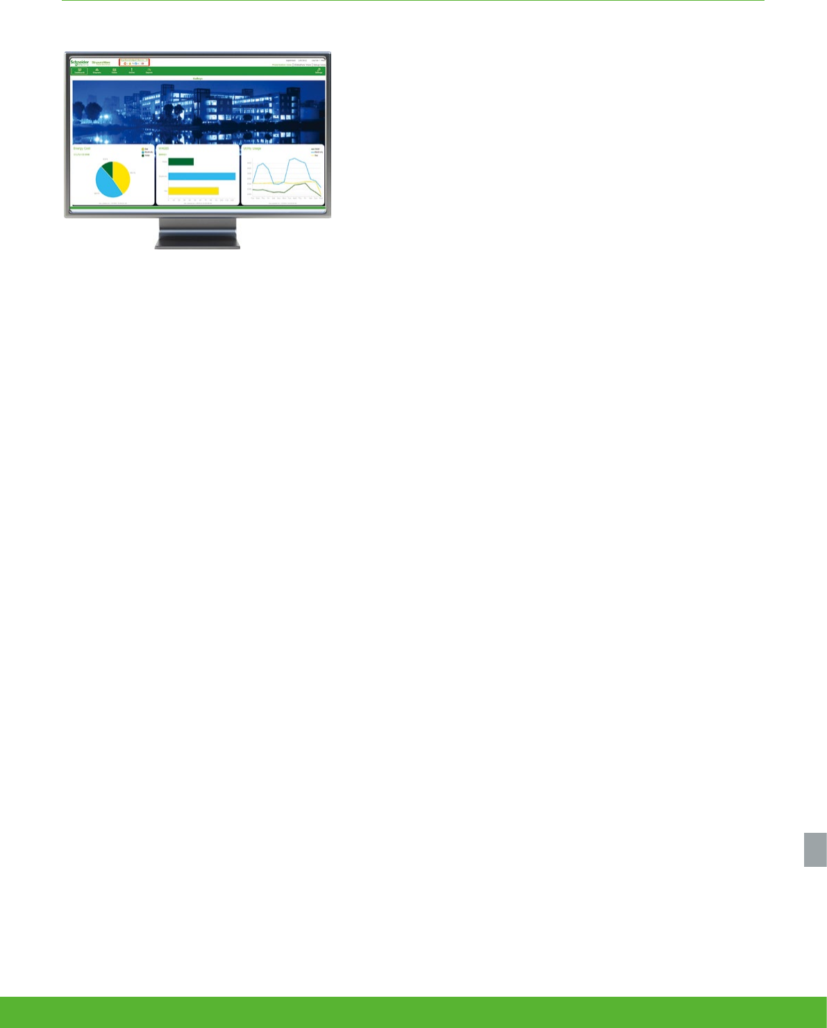
Power management software
MONITORING SOFTWARE FUNCTIONS AND CHARACTERISTICS
StruxureWare power management software has many
applications:
Typical applications
• Monitor the facility electrical network and verify reliable operation.
• Improve response to power-related events and restore operations
quickly.
• Analyse and isolate the source of power quality problems.
• Analyse energy use to identify waste and reduce cost.
• Estimate utility bills to verify accuracy and identify errors.
• Allocate energy costs to departments to drive accountability and
awareness.
• Reduce peak demand surcharges and power factor penalties.
• Idenfity excess capacity in existing infrastructure and avoid over-
building.
• Support proactive maintenance to prolong asset life.
• Network protection and control.
• Operate distribution network safely and reliably.
• Improve continuity of electrical service.
• Equipment monitoring and control.
• Energy availability and reliability.
• Verify the reliable operation of equipment.
• Support proactive maintenance to prolong asset life.
For electric utilities:
• Improve T&D network reliability.
• Enhance substation automation.
• Maximise the use of existing infrastructure.
• Verify compliance with new power quality standards.
• Analyse and isolate the source of power quality problems.
• Help customers manage reliability using operational and power
quality data.
145schneider-electric.co.uk/metering
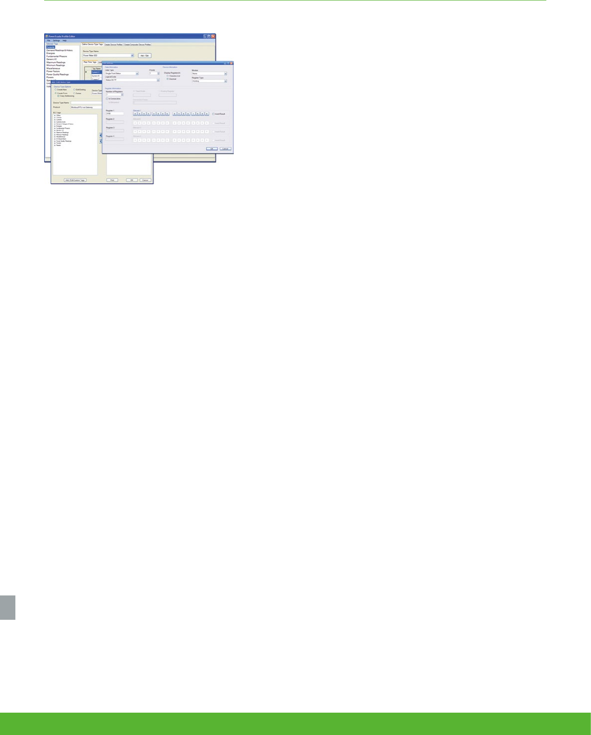
MONITORING SOFTWARE FUNCTIONS AND CHARACTERISTICS
Functional components
Provides operators with a rich environment to view and navigate real-time
displays of measurements and status indicators; perform power quality
and reliability analysis; historical trending; alarms; and manual control.
This software offers secure, operator-dedicated, multi-user data and
control access through a local server interface, full control client and also
via web clients.
Web Clients
Access power monitoring system from anywhere on your network using
a web browser. Day-to-day functionality including system status, alarm
response, or viewing dashboards. Web client provides authenticated
access to common functions:
• Diagrams – navigate network displays to check system status and
analyse trends.
• Tables – quickly compare multiple devices in your network in real-
time.
• Reports – generate or edit historical reports for energy cost,
consumption, and power quality.
• Alarms – quickly identify alarm states in your system and investigate
root causes.
• Dashboards – share information from your power monitoring system
with any occupant.
Engineering Workstations
Client software gives engineers and power users access to administrative
and configuration functions of the software, and real-time display, control,
and historical analysis functions.
Build and edit custom graphical displays to represent your facility. One-
line diagrams, campus maps, equipment plan views and mimic diagrams
are easily created using Vista graphical objects and imported graphic
files.
Use the designer interface to program ION devices and create system
applications with ION Technology and Virtual ION ProcessorsReporter
- generate or edit historical reporst for energy cost, consumption, and
power quality.
Data acquisition and management
• Communicate with over 300 different powerlog and third-party
meters.
• Scale from 1 to 1000s of devices.
• Perform advanced logic and arithmetic operations on real-time and
historical data.
• Use web services to interoperate and integrate with other software
platforms.
Scalable, flexible architecture
schneider-electric.co.uk/metering 146
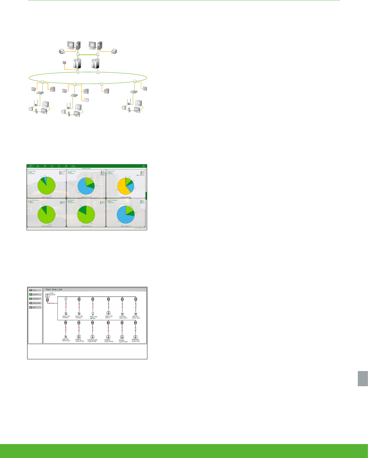
Scalable, flexible architecture
MONITORING SOFTWARE FUNCTIONS AND CHARACTERISTICS
Equipment Status example
Consumption details by area and load type
ECS Engineer workstation
EGX 400
PLC
PLC Islanding
PLC
Clock
EGX 400
Remote I/O
rack
EGX 400
Master clock
Ethernet optical ring
Optical converter
Optical converter
Compatible devices
Compatible devices
Compatible devices
Optical converters
ECS Operator workstation
Redundant ECS server
StruxureWare power management software offers a wide range
of functions:
• Data acquisition and integration.
• Real-time monitoring.
• Trend analysis.
• Power quality analysis.
Data acquisition and integration
Integrate WAGES (Water, Air, Gas, Electricity, Steam) metering. Native, out-of-
the-box support for dozens of devices (See Supported Devices section for
details).
• Enables access to real-time and timestamped historical meter data,
control of on-board relays and digital outputs, and server time
synchronisation. Communicate over Internet, Ethernet, wireless.
• Interface with third-party meters, transducers, PLCs, RTUs and power
distribution or mitigation equipment through Modbus or OPC.
• Add and configure direct communications with remote devices over
Modbus RTU or Modbus TCP protocols using easy-to-use device
templates.
The scalable platform enables remote device and user client addition as
needs grow while maintaining original investment. Integrate other energy
management or automation systems (e.g. SCADA, BAC, DCS, ERP) through
ODBC, XML, OPC, email, FTP, CSV and PQDIF compliance; integrate with web
services through XML.
Real-time monitoring
View the status of your electrical network from any workstation:
• See numeric values, status indicators, gauges, and trends, all with intuitive
graphical navigation.
• Extend comprehensive out-of-the-box displays and create custom
graphical diagrams to represent your facility; one-line diagrams, campus
maps, equipment plan views and mimic diagrams can be created using
embedded graphical objects and imported graphic files.
• Quickly compare multiple devices in your network in real-time in a tabular
display.
• Choose from a library of pre-built tables, or create your own. Save your
favourites for quick access later.
Trend analysis
• Trend parameters to reveal demand peaks and track system-wide energy
costs.
• Graph any combination of measured parameters.
• Plot time-series or scatter charts.
• Perform calculations, obtain statistics, and display historical data.
• Identify dangerous trends and redistribute loads.
• Optimise network capacity and avoid over-building.
• View operating parameters and determine when maintenance is required.
• Avoid peak demand surcharges and power factor penalties.
• Alarms and events.
• Reporting.
• Dashboards.
• Manual and automated control.
Functions
147schneider-electric.co.uk/metering
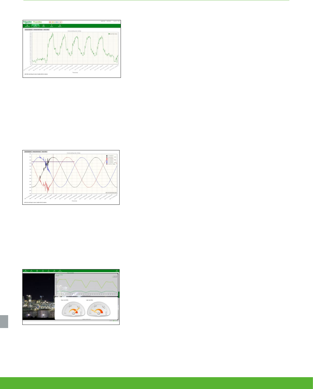
MONITORING SOFTWARE FUNCTIONS AND CHARACTERISTICS
Applications allow users to easily create trend plots and
analyse historical data.
Users can view and analyse waveforms captured by
devices.
Load prole dashboard (sample)
Power quality analysis
StruxureWare power management software allows continuous, wide-area
monitoring and data capture for power quality and reliability conditions.
• Power quality events automatically detected by PQ-capable metering devices are uploded to
the system automatically. Analyse waveforms to determine source and cause of issue.
• Determine if power quality events are upstream or downstream (using PowerLogic meters
with Disturbance Direction Detection feature).
• IEC 61000-4-30 and EN50160 compliance reporting verifies power quality performance to
international standards and allows you to quickly review power quality indices as numeric
charts or graphic profiles (using PowerLogic meters to support compliance monitoring).
• Display harmonic histograms, odd/even harmonics, THD, K-factor, crest factor, phasor
diagrams, and symmetrical components.
• Plot waveforms of up to many seconds in duration, with overlays that correlate phase-to-
phase relationships between voltages, currents, and cascading failures.
• Plot sags, swells, short duration transients and other disturbance events on industry-standard
voltage tolerance curves, including ITIC (CBEMA) and SEMI.
• Display for any event a list of associated time-stamped incidents, then click on any incident to
see more detailed information.
Alarms and events
Receive alerts to outages or impending problems that could lead to
equipment stress, failures, or downtime.
• Quickly filter on active or unacknowledged alarms.
• Acknowledge alarms from anywhere in your facility.
• Trigger on complex conditions.
• Log all relevant data sequence of events for diagnosis.
• Flag and avert potential problems.
• Alert key personnel 24/7.
• Optimise maintenance scheduling.
• Easily discriminate between alarm criticality levels.
• High speed alarm response.
• Organise, filter and print by any alarm property. Configure specific alarm occurrences to
change symbol colour or flash an icon on a page.
• View the five most recent alarms from every page, providing detailed information in easy-to-
understand formats.
• Event log for all PC-based and on-board field events, alarms.
• Easily configure to annunciate based on alarm type.
Dashboards
Create engaging dashboard displays of your power monitoring system
information and easily share information with anyone in your facility.
• Make power monitoring information visible and engaging.
• Promote education and drive behaviour.
• Display as an interactive kiosk on corporate intranet or on wall-mounted display.
• Replace hard to maintain home-grown portals and dashboards.
• Chart or trend any quantity in your power monitoring database.
• Simply convert into other units (e.g. dollars, emissions, normalisations, etc.).
• Compare multiple time-ranges.
• Show impact of temperature, occupancy, or production values on energy usage.
• Create eye-catching backgrounds to enhance presentation value.
• User authentication for configuration, and both authenticated and unauthenticated modes
available for display.
Scalable, flexible architecture
schneider-electric.co.uk/metering 148
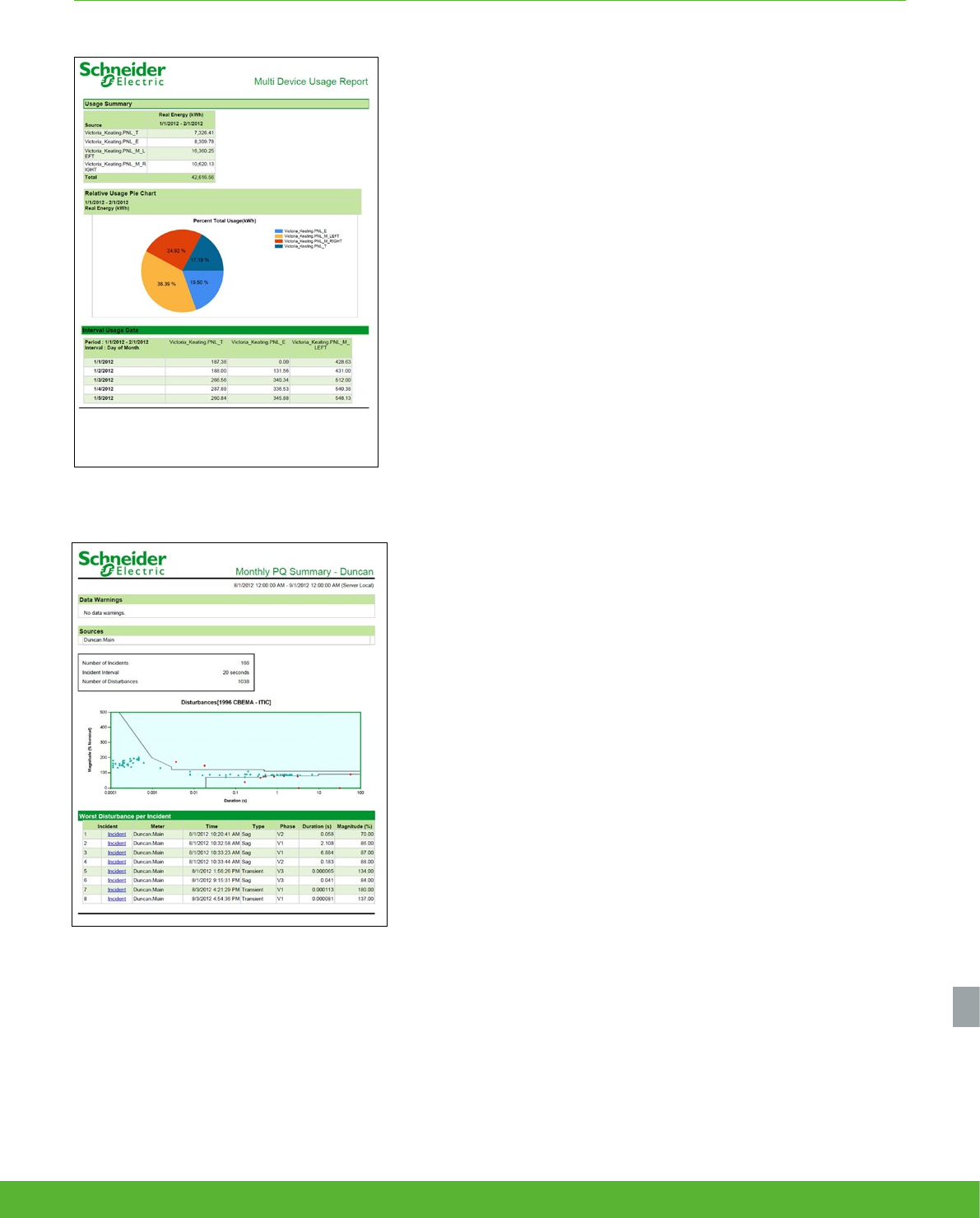
Scalable, flexible architecture
MONITORING SOFTWARE FUNCTIONS AND CHARACTERISTICS
StruxureWare provides many different report templates to
allow users to easily display and deliver the information they
need .
Reporting
Reports - generate or edit historical reports for energy cost, consumption, and
power quality (requires Microsoft SQL Server Standard Edition).
• Powerful, intuitive reporting options let users see critical information exactly how, where, and
when they need it.
• Reports can be generated manually and saved as Excel, HTML and other formats or scheduled
to automatically distribute to a printer or via email.
Configuration tools
Our power management software is supplied with a package of configuration
tools designed to make set up uniquely easy and quick.
• Designed to help make project set up and network configuration fast and easy.
• Provides standard device types and their associated profiles and allows engineers to easily
customise the profiles of the devices specific to the project.
• Standardised tags per device profile (configurable), XML file.
• Standard interface for quick database generation:
• Instantiation of devices, on a per object basis.
• Creates tags, trends, alarms and events when devices are added to system.
• Batch editing supported by automation interface.
Manual and automated control
• Perform fast, manual control operations by clicking on-screen trigger buttons, and operate
remote breakers, relays, and other power distribution and mitigation equipment.
• Perform manual or setpoint-triggered functions.
• Coordinate control of multiple loads, generators, relays, etc.
• Support energy-saving applications.
• Manage distributed energy assets.
• Automate substations & reduce service time.
Interoperability
• Integrate all energy management and automation systems (SCADA, BAC, DCS, ERP, etc.)
• Share data with third-party SCADA, automation, and accounting systems.
• Comply with ODBC, OPC, and PQDIF standards.
Patented ION technology
StruxureWare power management software and a variety of PowerLogic ION
metering products feature the unique ION architecture. This modular, flexible
architecture offers extensive customisation of functionality using a simple
building block approach. The technology uniquely addresses advanced
monitoring and control applications and adapts to changing needs, avoiding
obsolescence.
Global solutions
Software is available in many languages - English, French, Spanish, German,
and Chinese. Software needs to be installed by Schneider Electric’s Power
Solution Application team or by a certified partner of Schneider Electric.
Contact your Schneider Electric representative.
Scalable, flexible architecture
149schneider-electric.co.uk/metering

Other
PowerLogic
offers
schneider-electric.co.uk/metering 150
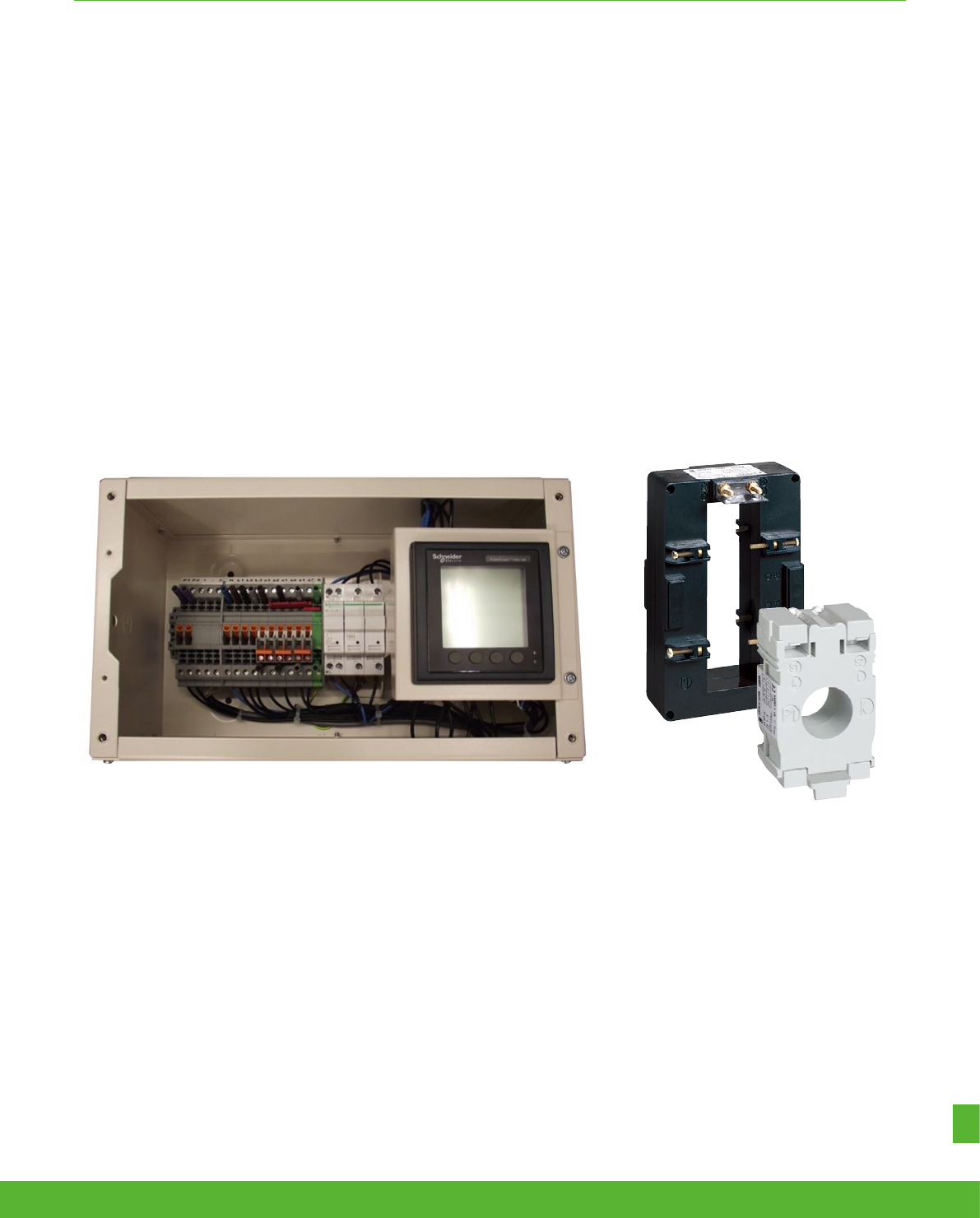
OTHER POWERLOGIC OFFERS FUNCTIONS AND CHARACTERISTICS
151schneider-electric.co.uk/metering
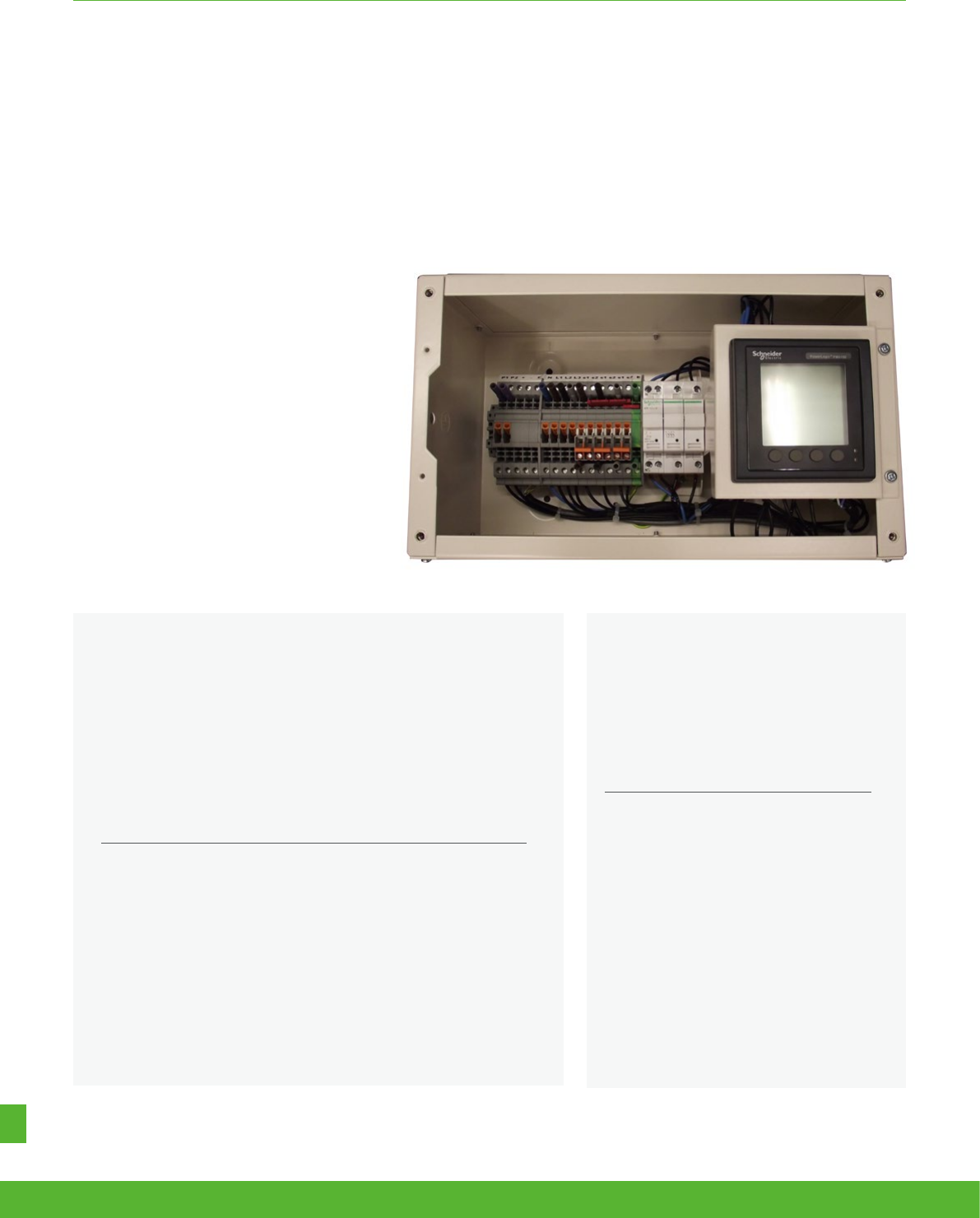
Schneider Electric’s NEW retrofit metering kits are designed for easily measuring power and energy
in existing installations without requiring complete disconnection of cabling.
Our flexible range of metering allows data collection using pulsed output, Modbus RS485 and Modbus TCP (Ethernet)
communications. This enables the “measure” phase of Schneider Electric’s 4 steps to energy efficiency;
NEW Retrofit metering kits
Applications
• Energy management
• Network management
OTHER POWERLOGIC OFFERS FUNCTIONS AND CHARACTERISTICS
The solution for
All retrofit markets that can benefit from a solution that includes
NEW retrofit metering kits:
• Building
• Industry
• Infrastructure
• Data centre and networks
Energy management solution
To get the most effective use from your
Schneider Electric measurement and
metering devices, we offer a range of
dedicated data logger and gateway for
your building energy management. See
Page 114
Competitive advantages
• Standard offers, including meter
and integrated energy server, are
designed for your metering solution
• Provide modified service and
solution
Benefits
• Easy to install without requiring complete disconnection of
cabling
• A variety of metering choices to meet your requirements
• Short lead time for standard offers including most popular
meters and gateway
• Split core CT options that ratio is up to 2400:5A
schneider-electric.co.uk/metering 152

OTHER POWERLOGIC OFFERS FUNCTIONS AND CHARACTERISTICS
The range of retrofit metering kits includes
meters complying with BSEN62053 and
includes MID approved meters as a
standard offer.
• Their configuration allows them to be installed where
there is limited space, they can be “stacked” to allow
for multiple meters and an integrated gateway server
to be assembled together.
• Split core Current Transformers 200:5A up to
2400:5A ratios are available preventing cable re-
routing or cable breaks for simple retrofit installation.
• Supplied pre wired with top entry gland plate,
connections are simple using a common connection
interface for current inputs, voltage reference,
pulsed output and Modbus communications
connections.
The range of Schneider Electric retrofit
metering kits are designed to measure the
energy consumed by a complete installation
or part of it. (Ex: main incoming supply,
warehouse or office floor).
• Measurements include voltage, current, frequency,
active and reactive power, power factor and harmonic
distortion. Using this Information is the key to
understanding energy use and can be used to target
waste and identify energy saving opportunities.
• Standard retrofit metering kits incorporating MID
approved meters may be utilised for energy billing
purposes.
*Split core CTs need to be ordered separately according to your network
**Please consult us for modified solutions.
Description Ordering reference
Retrofit metering kit (Including MID
METSEPM5111 meter with pulsed output and
Modbus RS485 communications)
RETMKITMIDM
Retrofit metering kit (Including MID
METSEPM5341 meter with Modbus TCP
communications)
RETMKITMIDE
Retrofit metering kit (Including integrated gateway
server Com’X 510) RETMKITEBX510
Retrofit metering kit (Including integrated Ethernet
gateway Link150) RETMKITEGX150
Retrofit metering kit (Including OFGEM approved
meter) consult us RETMKOFGEM
200:5A split core current transformer H68102005A
300:5A split core current transformer H68103005A
400:5A split core current transformer H68114005A
600:5A split core current transformer H68116005A
800:5A split core current transformer H68118005A
1000:5A split core current transformer H681210005A
1200:5A split core current transformer H681212005A
1600:5A split core current transformer H681216005A
2000:5A split core current transformer H681220005A
2400:5A split core current transformer H681224005A
Metering terminal block METBLK
STI fuses (pack of 10) A9N15658
Characteristic Description
IP Rating External IP40, Internal IP2X
Colour RAL 9001
Terminals Tunnel type, 6 mm2
METSEPM5111 Measurements
A, V, F, kW, kVA, kWh, kVArh, MD, THd
plus pulsed output and Modbus RS485
communication
METSEPM5341 Measurements
A, V, F, kW, kVA, kWh, kVArh, MD, THd
plus Modbus
TCP communications
PM Power meter standard BS EN 62053-22 Class 0.5S
OFGEM Measurements Defined by application at time of order
Current transformers 200:5A up to 2400:5A split core current
transformers BSEN 60044
Voltage reference connections Fused 2A
Retrofit kit enclosure dimensions 200mm H x 230mm W x 145 mm D
Retrofit kit enclosure fixings 3 x 6 mm clearance dished hole fixings
Gland plate Top entry removable 230mm x 145 mm
153schneider-electric.co.uk/metering
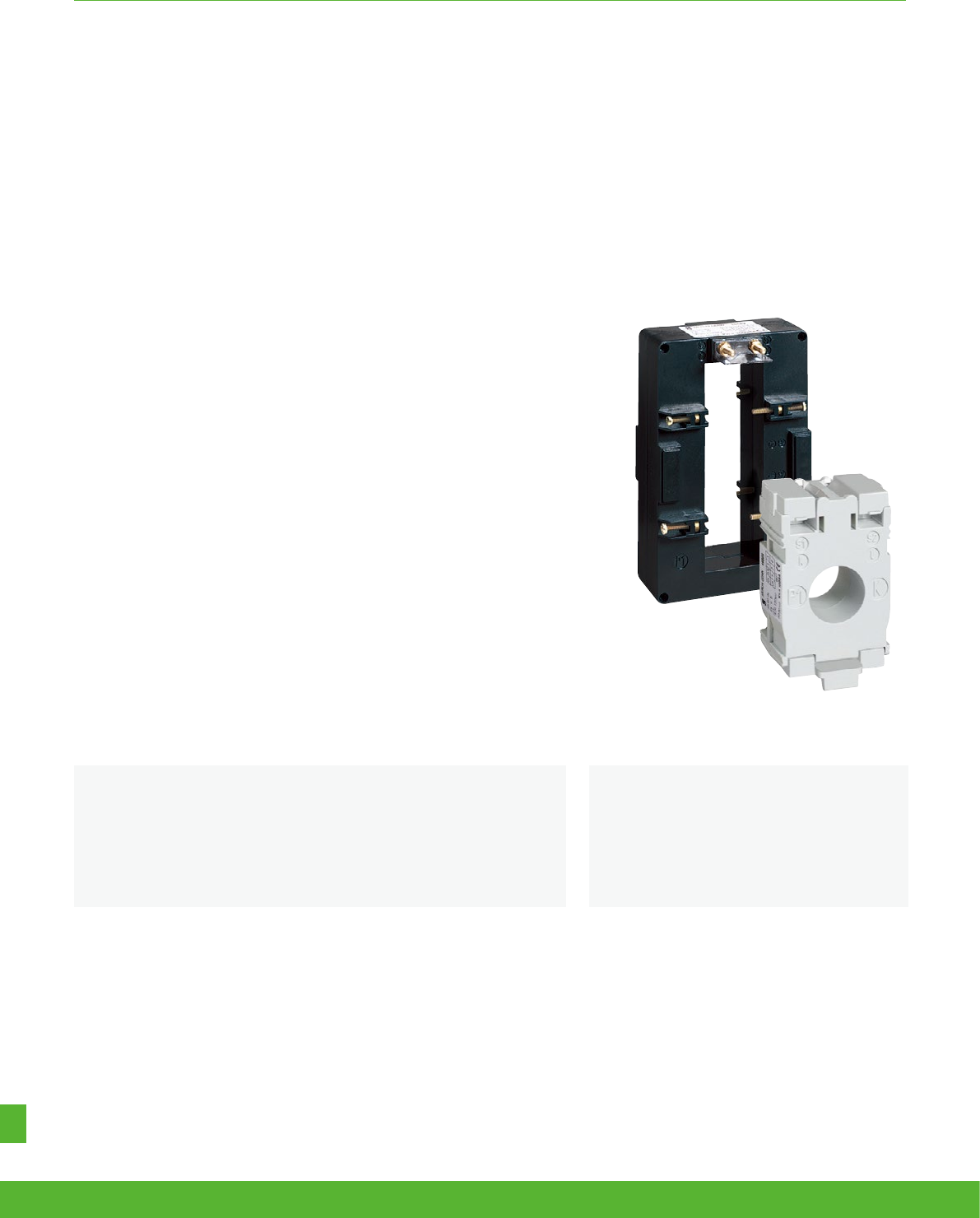
OTHER POWERLOGIC OFFERS FUNCTIONS AND CHARACTERISTICS
Conformity of standards
• IEC61869 -2
• VDE 0414
Benefits
The PowerLogic range of CTs is a comprehensive range suited to:
• All current measurements from 40A to 6000A.
• DIN rail, flush-mounted and busbar installation
When current in a circuit is too high to apply directly to measuring instruments, a current
transformer produces a reduced current accurately proportional to the current in the circuit, which
can be conveniently connected to measuring and recording instruments.
This allows them to be used in combination with measurement equipment:
• Ammeters
• Kilowatt-hour meters
• Measurement units
• Control relays
• Etc.
PowerLogic current
transformers
Applications
The transformers from Schneider Electric are suitable for use in the field
from 40A up to 6000A and deliver at the secondary a current 0 to 5A
proportional to the current measured at the primary.
schneider-electric.co.uk/metering 154
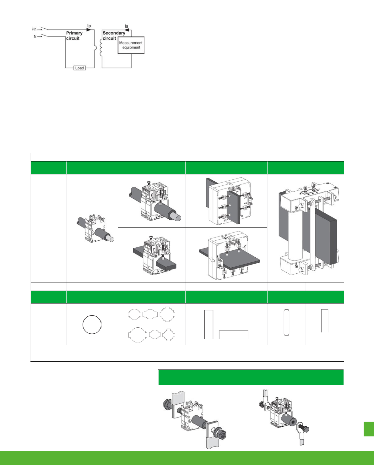
OTHER POWERLOGIC OFFERS FUNCTIONS AND CHARACTERISTICS
The Ip/5A ratio current transformer delivers at the secondary a current (Is) of 0 to 5
A that is proportional to the current measured at the primary (Ip).
This allows them to be used in combination with measurement equipment:.
• Ammeters.
• Kilowatt-hour meters.
• Measurement units.
When the primary is energised, the measurement equipment nearly acts as a short
circuit which keeps the secondary voltage very low. This voltage will increases
significantly if the short circuit is removed.
CT selection - conductor rating aspects
The choice depends on the conductor profile and the maximum intensity
of the primary circuit.
DB416186.eps
Application diagram of a CT.
16550
(brass)
METSECT5CYL1
(aluminium)
• Control relays.
• etc.
CT with let-through primary
Conductor
type Cable Mixed, bars or cables Vertical or horizontal bars Vertical bars
Suggested
Current
Transformer
and mounting
DB415986.eps
DB415920.eps
DB415988.eps
DB415989.eps
DB415921.eps
DB415987.eps
Ratings (A) 40 to 250 150 to 800 200 to 4000 500 to 600 5000 to 6000
CT internal
profile Type C Type M Type D
(1)
Type V
MA
MB
MC
VF VV
MD
ME
MF
(1) Two secondary connectors (parallel internal wiring - only one secondary winding) for easier cable access. 1 lateral + 1 on one extremity. Warning: only one must be used at
a time. Specific mounting: use of cylinder
A cylindrical metallic spacer ensures a proper CT positioning when the conductor or the CT cannot be positioned perpendicular. Secured by bolt + nut.
CT with primary connection by screw and nut
(example: use of cylinder with bar or cable)
155schneider-electric.co.uk/metering

OTHER POWERLOGIC OFFERS FUNCTIONS AND CHARACTERISTICS
CT selection - Electrical aspect Ip/5 A
• We recommend that you choose the ratio immediately higher than the maximum measured current (In).
Example:
In = 1103 A; ratio chosen = 1250/5.
• For small ratings:
from 40/5 to 75/5 and for an application with digital devices, we recommend
that you choose a higher rating, for example 100/5.
This is because small ratings are less accurate and the 40 A measurement,
for example, will be more accurate with a 100/5 CT than with a 40/5 CT.
• Specific case of the motor starter:
to measure motor starter current, you must choose a CT with primary current
Ip = Id/2 (Id = motor starting current).
Validation of measurement solution according accuracy class
It consists in controlling the right adaptation of the CT on the assucary class aspect. The accuracy class is specified in the project. The total
dissipated power of the measurement circuit (meter + cables) should not be superior to the specified limit of the CT. This limit is for different
standard classes. If necessary, the choice of the cable section, the CT or meter should be modify to fit the requirement.
Copper cable cross-section
(mm
2
)
Power per doubled meter at
20 °C
(VA)
Schneider Electric device
Consumption of
the current input
(VA)
Ammeter
72 x 72 / 96 x 96 1.1
Analogueue ammeter 1.1
Digital ammeter 0.3
PM700, PM800 0.15
PM3000 0.3
1 1
1.5 0.685
2.5 0.41
4 0.254
6 0.169
10 0.0975
16 0.062
For each temperature variation per 10 °C bracket, the power drawn up
by the cables increases by 4 %.
Application example
Project specification: 200 A, in Ø27 mm cable, accuracy class 1.
Our choice is METSECT5MA020.
For this CT selected on the chart (next page), the max acceptable power is 7 VA (for "Accuracy class 1" which is specified in the project).
Control of the conformity of the measurement chain:
• PM3000 multi-meter: 0.3 VA.
• 4 meters of 2.5 mm2, doubled wires: 0.41 x 4 = 1.64 VA.
Total: 0.3 + 1.64 = 1.94 VA (< 7 VA)
Conclusion: this CT is well adapted as the accuracy class will be even better than 1.
Internal profile
type
Cables
(mm)
Bars
(mm)
Rating
Ip/5 A
(A)
Cat. no.
Accuracy class
0.5 1 3
Max. power (VA)
MA
Ø27 10 x 32
15 x 25
150 34 -
200 4 7 -
250 68 -
300 810 -
400 10 12 -
schneider-electric.co.uk/metering 156

NOTES
157schneider-electric.co.uk/metering
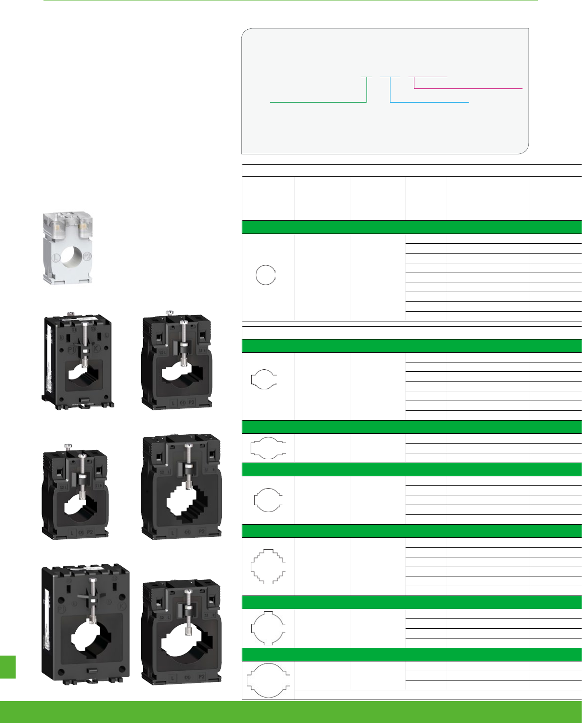
OTHER POWERLOGIC OFFERS FUNCTIONS AND CHARACTERISTICS
Presentation of catalogue numbers
MET SE CT R FF XXX
Last 3 digits = primary rating/10
2 letters = Form Factor
First digit = secondary rating,
R = 5 Amps
Examples:
• METSECT5CC008 = 5 A secondary, Cables only, 75 A primary
• METSECT5MC080 = 5 A secondary, Mixed for cables and bars, 800 A primary.
PB112446.eps
METSECT5CCppp
PB112464.eps
PB112461.eps
METSECT5MEppp METSECT5MBppp
PB112460.eps
PB112462.eps
METSECT5MAppp METSECT5MCppp
PB112465.eps
PB112463.eps
Type C - current transformer (cable profile)
Internal profile
type
Cables
(mm)
Bars
(mm)
Rating
Ip/5 A
(A)
Cat. no.
Accuracy class Overall dimensions
(refer to drawing
pages for details)
W x H x D
(mm)
Fastening mode
Accessories
0.5 1 3 Cylinder Sealable cover
Max. power (VA)
CC
Ø21 -
40 METSECT5CC004 - - 1
44 x 66 x 37 Adapter for DIN rails.
Mounting plate.
16550
METSECT5CYL1 Included
50 METSECT5CC005 - 1.25 1.5
60 METSECT5CC006 - 1.25 2
75 METSECT5CC008 - 1.5 2.5
100 METSECT5CC010 2 2.5 3.5
125 METSECT5CC013 2.5 3.5 4
150 METSECT5CC015 3 4 5
200 METSECT5CC020 4 5.5 6
250 METSECT5CC025 5 6 7
Type M - current transformers (mixed: cable/bar profile)
ME
Ø22
10 x 30
11 x 25
12 x 20
150 METSECT5ME015 1.5 5.5 6.5
56 x 84 x 60
Adapter for DIN rails.
Mounting plate.
Insulated locking screw.
16551 16552
200 METSECT5ME020 4 7 8.5
250 METSECT5ME025 6 9 11
300 METSECT5ME030 7.5 11 14
400 METSECT5ME040 10.5 15 18
500 METSECT5ME050 12 18 22
600 METSECT5ME060 14.5 21.5 26
MB
Ø26 12 x 40
15 x 32
250 METSECT5MB025 34 -
60 x 85 x 63 Adapter for DIN rails.
Mounting plate. - METSECT5COVER
300 METSECT5MB030 4 6 -
400 METSECT5MB040 68 -
MA
Ø27 10 x 32
15 x 25
150 METSECT5MA015 34 -
56 x 80 x 63 Adapter for DIN rails.
Mounting plate. METSECT5CYL2 METSECT5COVER
200 METSECT5MA020 4 7 -
250 METSECT5MA025 68 -
300 METSECT5MA030 810 -
400 METSECT5MA040 10 12 -
MC
Ø32
10 x 40
20 x 32
25 x 25
250 METSECT5MC025 3 5 -
70 x 95 x 65 Adapter for DIN rails.
Mounting plate.
-
METSECT5COVER
300 METSECT5MC030 5 8 -
400 METSECT5MC040 8 10 -
500 METSECT5MC050 10 12 -
600 METSECT5MC060 12 15 -
800 METSECT5MC080 10 12 -
MF
Ø35 10 x 40
250 METSECT5MF025 2.5 5 8
77 x 107 x 64
Adapter for DIN rails.
Mounting plate.
Insulated locking screw.
- 16553
300 METSECT5MF030 4 8 12
400 METSECT5MF040 812 15
500 METSECT5MF050 10 12 15
MD
Ø40 12 x 50
20 x 40
500 METSECT5MD050 4 6 -
70 x 95 x 65 Adapter for DIN rails.
Mounting plate. - METSECT5COVER
600 METSECT5MD060 6 8 -
800 METSECT5MD080 8 12 -
schneider-electric.co.uk/metering 158
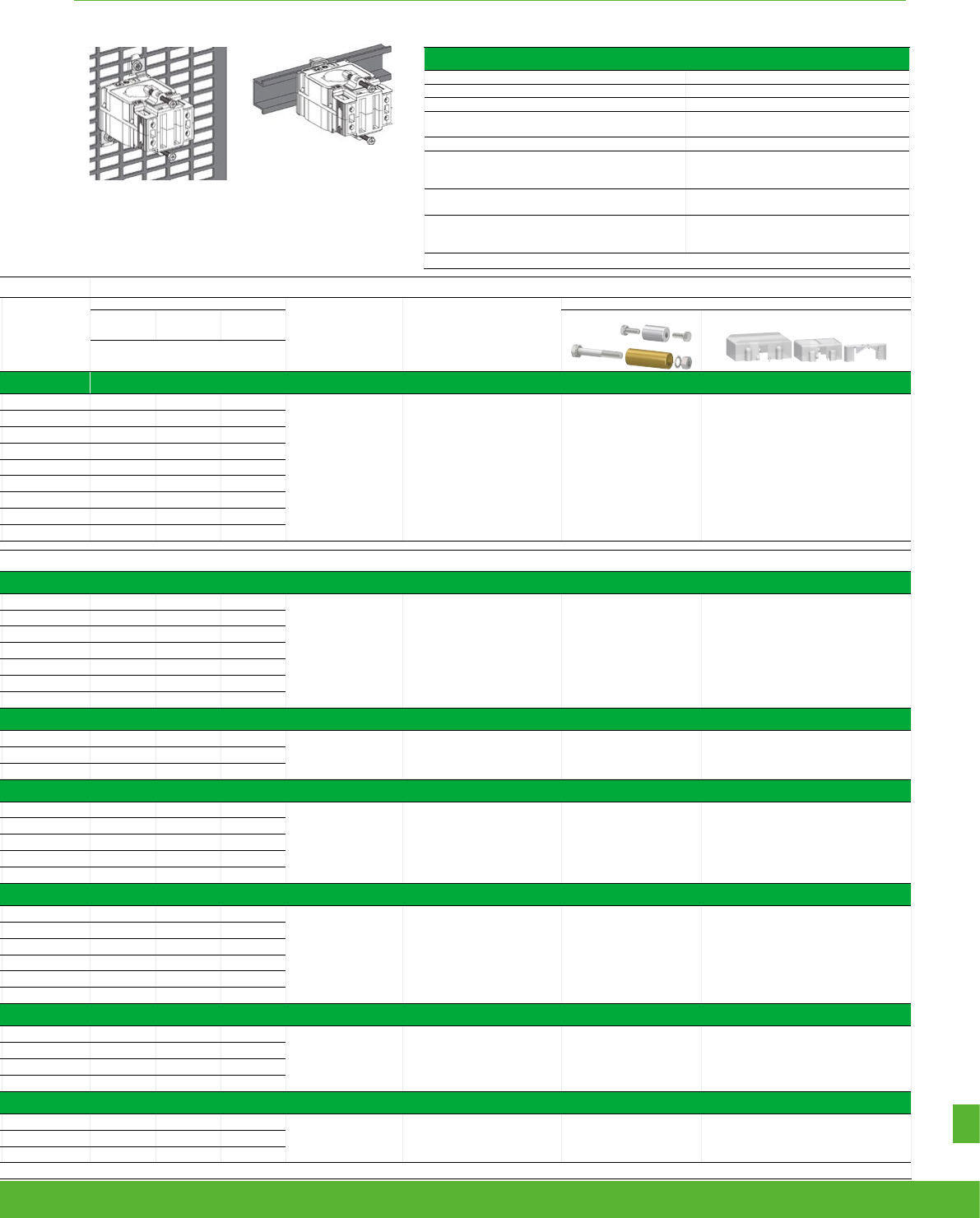
OTHER POWERLOGIC OFFERS FUNCTIONS AND CHARACTERISTICS
Type C - current transformer (cable profile)
Internal profile
type
Cables
(mm)
Bars
(mm)
Rating
Ip/5 A
(A)
Cat. no.
Accuracy class Overall dimensions
(refer to drawing
pages for details)
W x H x D
(mm)
Fastening mode
Accessories
0.5 1 3 Cylinder Sealable cover
Max. power (VA)
CC
Ø21 -
40 METSECT5CC004 - - 1
44 x 66 x 37 Adapter for DIN rails.
Mounting plate.
16550
METSECT5CYL1 Included
50 METSECT5CC005 - 1.25 1.5
60 METSECT5CC006 - 1.25 2
75 METSECT5CC008 - 1.5 2.5
100 METSECT5CC010 2 2.5 3.5
125 METSECT5CC013 2.5 3.5 4
150 METSECT5CC015 3 4 5
200 METSECT5CC020 4 5.5 6
250 METSECT5CC025 5 6 7
Type M - current transformers (mixed: cable/bar profile)
ME
Ø22
10 x 30
11 x 25
12 x 20
150 METSECT5ME015 1.5 5.5 6.5
56 x 84 x 60
Adapter for DIN rails.
Mounting plate.
Insulated locking screw.
16551 16552
200 METSECT5ME020 4 7 8.5
250 METSECT5ME025 6 9 11
300 METSECT5ME030 7.5 11 14
400 METSECT5ME040 10.5 15 18
500 METSECT5ME050 12 18 22
600 METSECT5ME060 14.5 21.5 26
MB
Ø26 12 x 40
15 x 32
250 METSECT5MB025 34 -
60 x 85 x 63 Adapter for DIN rails.
Mounting plate. - METSECT5COVER
300 METSECT5MB030 4 6 -
400 METSECT5MB040 68 -
MA
Ø27 10 x 32
15 x 25
150 METSECT5MA015 34 -
56 x 80 x 63 Adapter for DIN rails.
Mounting plate. METSECT5CYL2 METSECT5COVER
200 METSECT5MA020 4 7 -
250 METSECT5MA025 68 -
300 METSECT5MA030 810 -
400 METSECT5MA040 10 12 -
MC
Ø32
10 x 40
20 x 32
25 x 25
250 METSECT5MC025 3 5 -
70 x 95 x 65 Adapter for DIN rails.
Mounting plate.
-
METSECT5COVER
300 METSECT5MC030 5 8 -
400 METSECT5MC040 8 10 -
500 METSECT5MC050 10 12 -
600 METSECT5MC060 12 15 -
800 METSECT5MC080 10 12 -
MF
Ø35 10 x 40
250 METSECT5MF025 2.5 5 8
77 x 107 x 64
Adapter for DIN rails.
Mounting plate.
Insulated locking screw.
- 16553
300 METSECT5MF030 4 8 12
400 METSECT5MF040 812 15
500 METSECT5MF050 10 12 15
MD
Ø40 12 x 50
20 x 40
500 METSECT5MD050 4 6 -
70 x 95 x 65 Adapter for DIN rails.
Mounting plate. - METSECT5COVER
600 METSECT5MD060 6 8 -
800 METSECT5MD080 8 12 -
Common characteristics
Secondary current Is (A) 5
Maximum voltage rating Ue (V) 720
Frequency (Hz) 50/60
Safety factor (sf) 40 to 4000 A: sf y 5
5000 to 6000 A: sf y 10
Degree of protection IP20
Operating temperature
tropicalised range
-25 °C to +60 °C
(1)
relative humidity > 95 %
Compliance with standards IEC 61869-2
VDE 0414
Secondary connection (as per model)
by terminals for lug
by tunnel terminals
by screws
(1)
Warning: some products are limited to +50 °C.
DIN rail mounting.
DB415927.eps
DB415926.eps
Mounting plate installation.
159schneider-electric.co.uk/metering
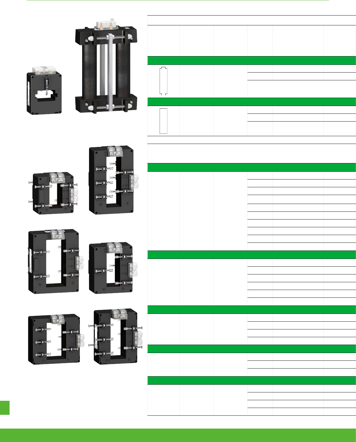
OTHER POWERLOGIC OFFERS FUNCTIONS AND CHARACTERISTICS
PB112466.eps
PB112467.eps
METSECT5VFppp METSECT5VVppp
PB112454.eps
PB112455.eps
METSECT5DAppp METSECT5DBppp
PB112456.eps
PB112457.eps
METSECT5DCppp METSECT5DDppp
PB112458.eps
PB112459.eps
Type V current transformers (vertical bar profile)
Internal
profile type
Cables
(mm)
Bars
(mm)
Rating
Ip/5 A
(A)
Cat. no.
Accuracy class Overall dimensions
(refer to drawing
pages for details)
W x H x D
(mm)
Fastening mode
Accessories
0.5 1 3 Cylinder Sealable cover
Max. power
(VA)
VF
-11 x 64
31 x 51
500 METSECT5VF050 24 -
90 x 130 x 66 Mounting plate.
Insulated locking screw. -
Included
600 METSECT5VF060 4 6 -
VV
- 55 x 165
5000 METSECT5VV500 g60 - -
175 x 273.5 x 110 Insulated locking screw. - Included
6000 METSECT5VV600 g70 - -
Type D - current transformers
(vertical or horizontal bar - dual secondary terminals)
DA
- 32 x 65
200 METSECT5DA020 - 2 5
90 x 94 x 90 Insulated locking screw. - Included
250 METSECT5DA025 1 4 -
300 METSECT5DA030 1.5 6 -
400 METSECT5DA040 4 8 -
500 METSECT5DA050 8 10 -
600 METSECT5DA060 8 12 -
800 METSECT5DA080 12 15 -
1000 METSECT5DA100 15 20 -
1250 METSECT5DA125 g15 20 -
1500 METSECT5DA150 g20 25 -
DB
- 38 x 127
1000 METSECT5DB100 6 10 -
99 x 160 x 87 Insulated locking screw.
-
Included
1250 METSECT5DB125 g8 12 -
1500 METSECT5DB150 g10 15 -
2000 METSECT5DB200 g15 20 -
2500 METSECT5DB250 g20 25 -
3000 METSECT5DB300 g25 30 -
DC
- 52 x 127
2000 METSECT5DC200 g25 30 -
125 x 160 x 87 Insulated locking screw.
-
Included
2500 METSECT5DC250 g30 50 -
3000 METSECT5DC300 g30 50 -
4000 METSECT5DC400 g30 50 -
DD
- 34 x 84
1000 METSECT5DD100 10 15 -
96 x 116 x 87 Insulated locking screw. - Included
1250 METSECT5DD125 g12 15 -
1500 METSECT5DD150 g15 20 -
DE
- 54 x 102
1000 METSECT5DE100 12 15 -
135 x 129 x 85 Insulated locking screw.
-
Included
1250 METSECT5DE125 g15 20 -
1500 METSECT5DE150 g20 25 -
2000 METSECT5DE200 g20 25 -
schneider-electric.co.uk/metering 160

OTHER POWERLOGIC OFFERS FUNCTIONS AND CHARACTERISTICS
Type V current transformers (vertical bar profile)
Internal
profile type
Cables
(mm)
Bars
(mm)
Rating
Ip/5 A
(A)
Cat. no.
Accuracy class Overall dimensions
(refer to drawing
pages for details)
W x H x D
(mm)
Fastening mode
Accessories
0.5 1 3 Cylinder Sealable cover
Max. power
(VA)
VF
-11 x 64
31 x 51
500 METSECT5VF050 24 -
90 x 130 x 66 Mounting plate.
Insulated locking screw. -
Included
600 METSECT5VF060 4 6 -
VV
- 55 x 165
5000 METSECT5VV500 g60 - -
175 x 273.5 x 110 Insulated locking screw. - Included
6000 METSECT5VV600 g70 - -
Type D - current transformers
(vertical or horizontal bar - dual secondary terminals)
DA
- 32 x 65
200 METSECT5DA020 - 2 5
90 x 94 x 90 Insulated locking screw. - Included
250 METSECT5DA025 1 4 -
300 METSECT5DA030 1.5 6 -
400 METSECT5DA040 4 8 -
500 METSECT5DA050 8 10 -
600 METSECT5DA060 8 12 -
800 METSECT5DA080 12 15 -
1000 METSECT5DA100 15 20 -
1250 METSECT5DA125 g15 20 -
1500 METSECT5DA150 g20 25 -
DB
- 38 x 127
1000 METSECT5DB100 6 10 -
99 x 160 x 87 Insulated locking screw.
-
Included
1250 METSECT5DB125 g8 12 -
1500 METSECT5DB150 g10 15 -
2000 METSECT5DB200 g15 20 -
2500 METSECT5DB250 g20 25 -
3000 METSECT5DB300 g25 30 -
DC
- 52 x 127
2000 METSECT5DC200 g25 30 -
125 x 160 x 87 Insulated locking screw.
-
Included
2500 METSECT5DC250 g30 50 -
3000 METSECT5DC300 g30 50 -
4000 METSECT5DC400 g30 50 -
DD
- 34 x 84
1000 METSECT5DD100 10 15 -
96 x 116 x 87 Insulated locking screw. - Included
1250 METSECT5DD125 g12 15 -
1500 METSECT5DD150 g15 20 -
DE
- 54 x 102
1000 METSECT5DE100 12 15 -
135 x 129 x 85 Insulated locking screw.
-
Included
1250 METSECT5DE125 g15 20 -
1500 METSECT5DE150 g20 25 -
2000 METSECT5DE200 g20 25 -
161schneider-electric.co.uk/metering
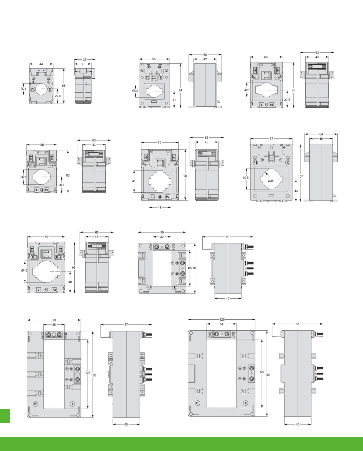
OTHER POWERLOGIC OFFERS FUNCTIONS AND CHARACTERISTICS
CC internal profile type
MA internal profile type
MD internal profile type
DB internal profile type
ME internal profile type
MC internal profile type
DA internal profile type
DC internal profile type
MB internal profile type
MF internal profile type
CT current transformers
schneider-electric.co.uk/metering 162
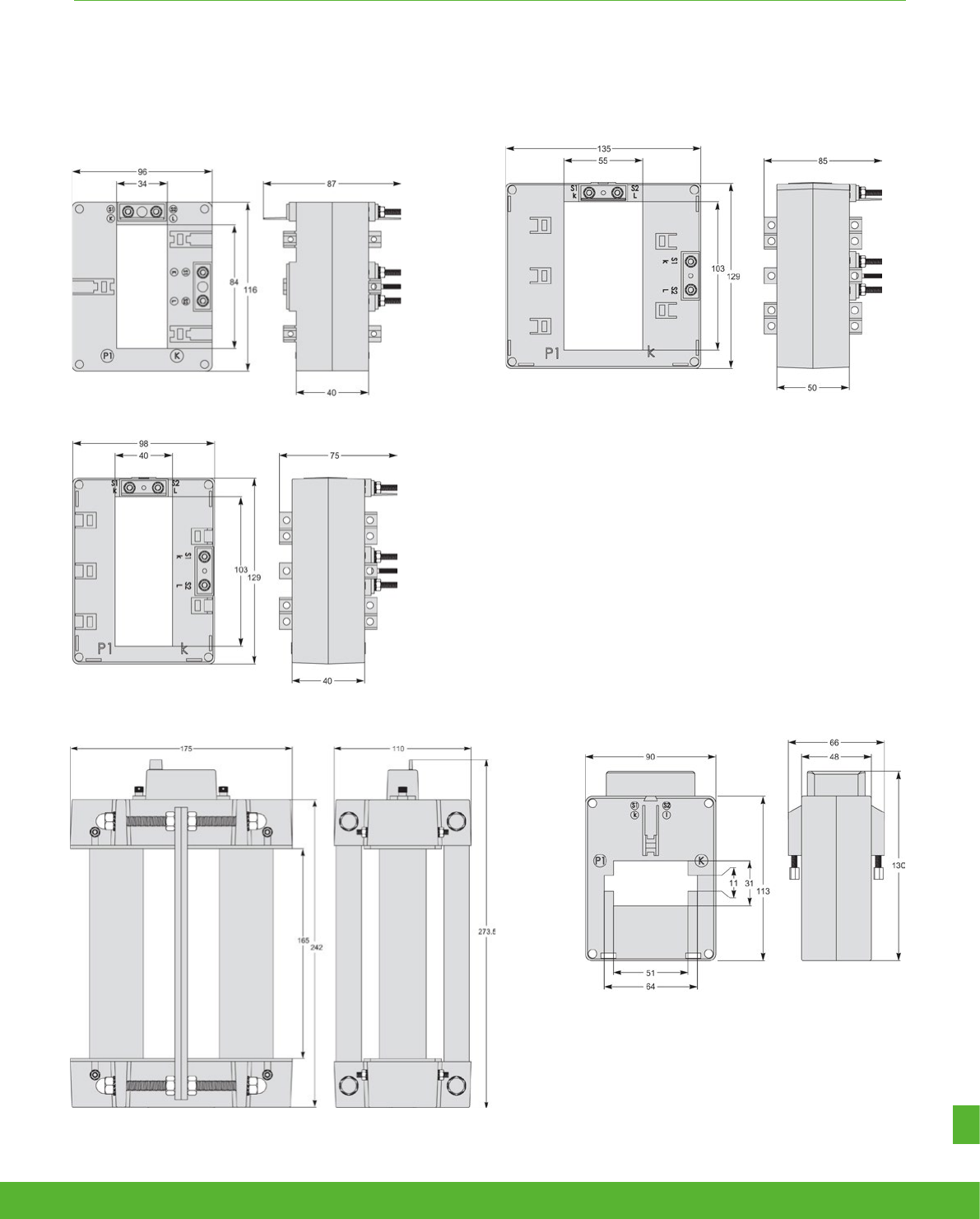
OTHER POWERLOGIC OFFERS FUNCTIONS AND CHARACTERISTICS
DD internal profile type
VV internal profile type
DH internal profile type
DE internal profile type
VF internal profile type
CT current transformers
163schneider-electric.co.uk/metering
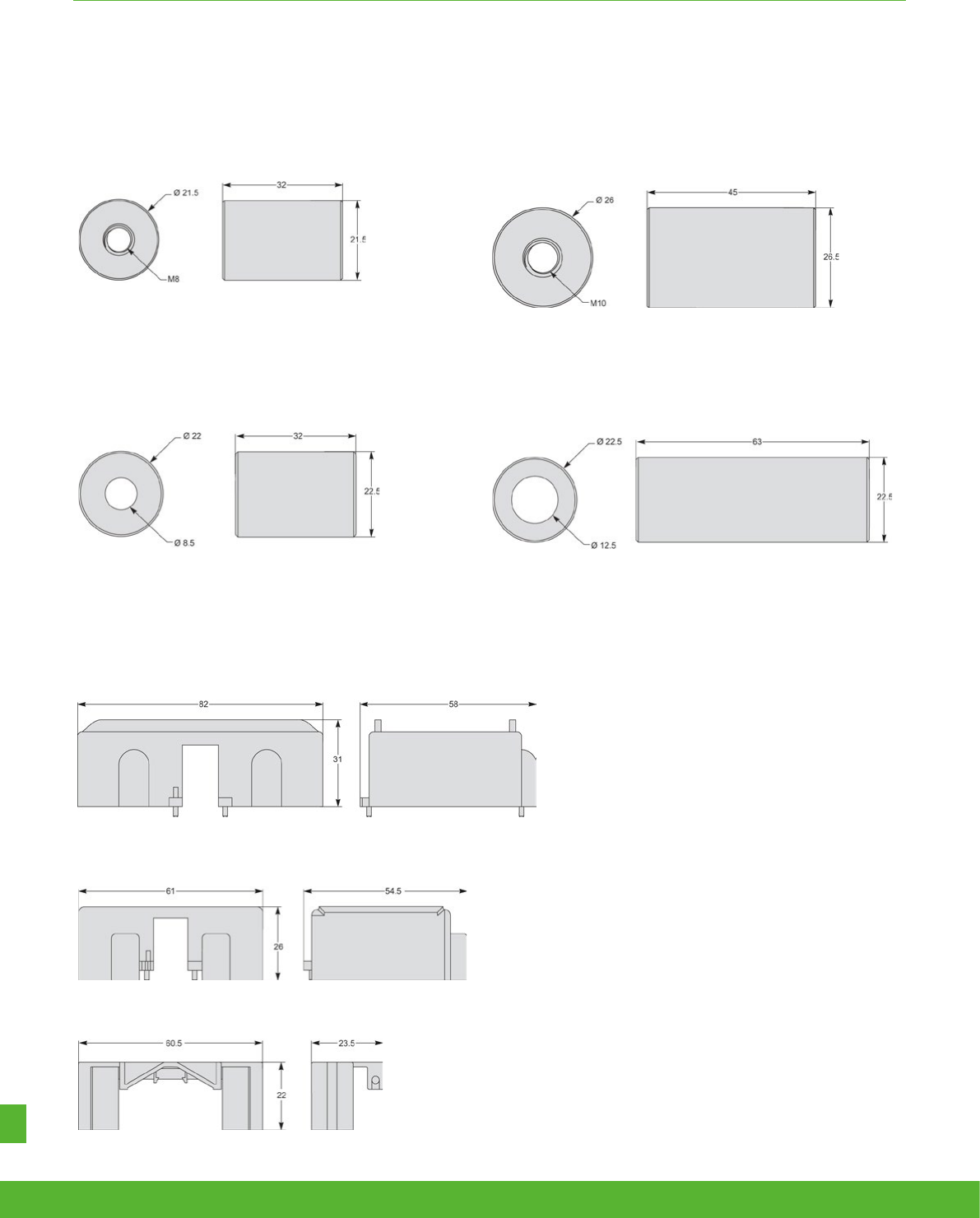
OTHER POWERLOGIC OFFERS FUNCTIONS AND CHARACTERISTICS
METSECT5COVER
16553
16552
METSECT5CYL1
16550
Aluminium
Brass
Aluminium
Brass
METSECT5CYL2
16551
Covers
Cylinders
schneider-electric.co.uk/metering 164

METSECT5CYL2
16551
NOTES
165schneider-electric.co.uk/metering

INDEX
Order ref Name Description Page
A
A9MEM2000T IEM2000T Single phase kWh Meter 40A Pulse output no disp 15
A9MEM2000 IEM2000 Single phase Kwh Meter 40A 15
A9MEM2010 IEM2010 Single phase kwh Meter 40A with pulsed output 15
A9MEM2100 IEM2100 Single phase Kwh Meter 63A 17
A9MEM2105 IEM2105 Single phase Kwh Meter 63A with pulsed output 17
A9MEM2110 IEM2110 Single phase Kwh Meter 63A dual tariff, MID, 2 P/O & 1 DI 17
A9MEM2135 IEM2135 Single phase Kwh Meter 63A dual tariff, MID and M-bus 17
A9MEM2150 IEM2150 Single phase Kwh Meter 63A dual tariff and Modbus 17
A9MEM2155 IEM2155 Single phase Kwh Meter 63A dual tariff, MID and Modbus 17
A9MEM3100 IEM3100 3 Phase kWh meter 63A 20
A9MEM3110 IEM3110 3 Phase kWh meter 63A pulse MID 20
A9MEM3115 IEM3115 3 Phase kWh meter 63A multi-tariff MID 20
A9MEM3135 IEM3135 3 Phase kWh meter 63A Mbus MID 20
A9MEM3150 IEM3150 3 Phase kWh meter 63A Modbus 20
A9MEM3155 IEM3155 3 Phase kWh meter 63A Modbus MID 20
A9MEM3165 IEM3165 3 Phase kWh meter 63A BACnet MID 20
A9MEM3175 IEM3175 3 Phase kWh meter 63A LON MID 20
A9MEM3200 IEM3200 3 Phase kWh meter CT 20
A9MEM3210 IEM3210 3 Phase kWh meter CT pulse MID 20
A9MEM3215 IEM3215 3 Phase kWh meter CT multi-tariff MID 20
A9MEM3235 IEM3235 3 Phase kWh meter CT Mbus MID 20
A9MEM3250 IEM3250 3 Phase kWh meter CT Modbus 20
A9MEM3255 IEM3255 3 Phase kWh meter CT Modbus MID 20
A9MEM3265 IEM3265 3 Phase kWh meter CT BACnet MID 20
A9MEM3275 IEM3275 3 Phase kWh meter CT LON MID 20
A9MEM3300 IEM3300 3 Phase kwh meter 125A direct connect 20
A9MEM3310 IEM3310 3 Phase kwh meter 125A Pulse output MID 20
A9MEM3335 IEM3335 3 Phase kwh meter 125A Mbus MID 20
A9MEM3350 IEM3350 3 Phase kwh meter 125A Modbus 20
A9MEM3355 IEM3355 3 Phase kwh meter 125A Modbus MID 20
A9MEM3365 IEM3365 3 Phase kwh meter 125A BACnet MID 20
A9MEM3375 IEM3375 3 Phase kwh meter 125A LON MID 20
B
BCPMCOVERS BCPM accessories BCPM Cover 104
BCPMA042S BCPM Branch Circuit Power Meter Version A 42CTs, 19mm 102
BCPMA084S BCPM Branch Circuit Power Meter Version A 84CTs, 19mm 102
BCPMA224S BCPM Branch Circuit Power Meter Version A 24CTs, 18mm 102
BCPMA236S BCPM Branch Circuit Power Meter Version A 36CTs, 18mm 102
BCPMA242S BCPM Branch Circuit Power Meter Version A 42CTs, 18mm 102
BCPMA248S BCPM Branch Circuit Power Meter Version A 48CTs, 18mm 102
BCPMA272S BCPM Branch Circuit Power Meter Version A 72CTs, 18mm 102
BCPMA284S BCPM Branch Circuit Power Meter Version A 84CTs, 18mm 102
BCPME042S BCPM Branch Circuit Power Meter Version E 42CTs, 19mm 102
BCPME084S BCPM Branch Circuit Power Meter Version E 84CTs, 19mm 102
BCPME224S BCPM Branch Circuit Power Meter Version E 24CTs, 18mm 102
INDEX
schneider-electric.co.uk/metering 166

INDEX
Order ref Name Description Page
INDEX
BCPME236S BCPM Branch Circuit Power Meter Version E 36CTs, 18mm 102
BCPME242S BCPM Branch Circuit Power Meter Version E 42CTs, 18mm 102
BCPME248S BCPM Branch Circuit Power Meter Version E 48CTs, 18mm 102
BCPME272S BCPM Branch Circuit Power Meter Version E 72CTs, 18mm 102
BCPME284S BCPM Branch Circuit Power Meter Version E 84CTs, 18mm 102
BCPMSCA1S BCPM Branch Circuit Power Meter Version A 42CTs, split core CTs and cable sold seprately 103
BCPMSCA2S BCPM Branch Circuit Power Meter Version A 84CTs, split core CTs and cable sold seprately 103
BCPMSCA30S BCPM Branch Circuit Power Meter Version A 30CTs, split core 103
BCPMSCA42S BCPM Branch Circuit Power Meter Version A 42CTs, split core 103
BCPMSCA60S BCPM Branch Circuit Power Meter Version A 60CTs, split core 103
BCPMSCA84S BCPM Branch Circuit Power Meter Version A 84CTs, split core 103
BCPMSCAY63S BCPM Branch Circuit Power Meter Version A 42CTs, split core 103
BCPMSCADPBS BCPM accessories BCPM 2 adapter boards, for split core 104
BCPMSCE1S BCPM Branch Circuit Power Meter Version E 42CTs, split core CTs and cable sold seprately 103
BCPMSCE2S BCPM Branch Circuit Power Meter Version E 84CTs, split core CTs and cable sold seprately 103
BCPMSCE30S BCPM Branch Circuit Power Meter Version E 30CTs, split core 103
BCPMSCE42S BCPM Branch Circuit Power Meter Version E 42CTs, split core 103
BCPMSCE60S BCPM Branch Circuit Power Meter Version E 60CTs, split core 103
BCPMSCE84S BCPM Branch Circuit Power Meter Version E 84CTs, split core 103
BCPMSCCT0 BCPM accessories BCPM 50A split core CTs, Quantity 6, 1.8m lead length 104
BCPMSCCT0R20 BCPM accessories BCPM 50A Split Core CTs Quantity 6, 6m lead length 104
BCPMSCCT1 BCPM accessories BCPM 100A split core CTs, Quantity 6, 1.8m lead length 104
BCPMSCCT1R20 BCPM accessories BCPM 100A Split Core CTs Quantity 6, 6m lead length 104
BCPMSCCT3 BCPM accessories BCPM 200A split core CTs, Quantity 6, 1.8m lead length 104
BCPMSCCT3R20 BCPM accessories BCPM 200A Split Core CTs Quantity 6, 6m lead length 104
BATT-REPLACE-8XXX ION8800 accessories Replacement batteries for the ION 8600 or ION 8800, quantity 10 87
C
CBL016 BCPM accessories Flat Ribbon cable (quantity 1) for BCM o 104
CBL017 BCPM accessories Flat ribbon cable 1.50m length 104
CBL018 BCPM accessories Flat ribbon cable 1.80m length 104
CBL020 BCPM accessories Flat Ribbon cable (quantity 1) for BCM o 104
CBL021 BCPM accessories Flat Ribbon cable (quantity 1) for BCM o 104
CBL023 BCPM accessories Round Ribbon cable (quantity 1), 104
CBL024 BCPM accessories Round Ribbon cable (quantity 1), length 104
E
EBX200 Com'X 200 Com'X 200 ETHERNET DATA LOGGER 122
EBX510 Com'X 510 Com'X 510 ETHERNET DATA LOGGER 126
EBXA-ANT-5M Com'X EXTERNAL ANTENNA 5M 122
EBXA-GPRS Com'X GPRS MODEM 122, 126
EBXA-USB-WIFI Com'X USB dongle 122, 126
I
ICE-OPTICAL-PROBE ION8800 accessories IEC 61107 compliant Optical Probe (DB-9) for use with ION 8800 meters 87
L
LVCT00202S BCPM accessories LOW VOLTAGE CT 200A 0 333VAC SPLIT CORE 104
167schneider-electric.co.uk/metering

INDEX
Order ref Name Description Page
M
M7550xxxxxxxxx ION7550,
ION7550RTU ION7550 meter, ION7550 RTU meter 72
M7650xxxxxxxxx ION7650 ION7650 meter 72
M765xxxx ION7550,ION7650
accessories ION7550,ION7650 accessories 72
M765RD ION7550,ION7650
accessories ION7550/7650 remote display, Schneider Electric branded 73
M765RDPS ION7550,ION7650
accessories
ION7550/7650 remote display kit, includes display, 24 VDC power supply and Ethernet
cable, Schneider Electric branded 73
M8800xxxxxxxxx ION8800 ION8800 meter 86
METSECT5CC004 CT Curr transf trop DIN 40/5 cables d. 21 158
METSECT5CC005 CT Curr transf trop DIN 50/5 cables d. 21 158
METSECT5CC006 CT Curr transf trop DIN 60/5 cables d. 21 158
METSECT5CC008 CT Curr transf trop DIN 75/5 cables d. 21 158
METSECT5CC010 CT Curr transf trop DIN 100/5 cables d. 21 158
METSECT5CC013 CT Curr transf trop DIN 125/5 cables d. 21 158
METSECT5CC015 CT Curr transf trop DIN 150/5 cables d. 21 158
METSECT5CC020 CT Curr transf trop DIN 200/5 cables d. 21 158
METSECT5CC025 CT Curr transf trop DIN 250/5 cables d. 21 158
METSECT5COVER CT SEALABLE COVER 159, 164
METSECT5CYL1 CT CYLINDER DIAM. 8,5MM 155, 159, 164
METSECT5CYL2 CT CYLINDER DIAM. 12,5MM 155, 159, 164
METSECT5DA020 CT Curr transf trop 200/5 double output bar 160
METSECT5DA025 CT Curr transf trop 250/5 double output bar 160
METSECT5DA030 CT Curr transf trop 300/5 double output bar 160
METSECT5DA040 CT Curr transf trop 400/5 double output bar 160
METSECT5DA050 CT Curr transf trop 500/5 double output bar 160
METSECT5DA060 CT Curr transf trop 600/5 double output bar 160
METSECT5DA080 CT Curr transf trop 800/5 double output bar 160
METSECT5DA100 CT Curr transf trop 1000/5 double output bar 160
METSECT5DA125 CT Curr transf trop 1250/5 double output bar 160
METSECT5DA150 CT Curr transf trop 1500/5 double output bar 160
METSECT5DB100 CT Curr transf trop 1000/5 double output bar 160
METSECT5DB125 CT Curr transf trop 1250/5 double output bar 160
METSECT5DB150 CT Curr transf trop 1500/5 double output bar 160
METSECT5DB200 CT Curr transf trop 2000/5 double output bar 160
METSECT5DB250 CT Curr transf trop 2500/5 double output bar 160
METSECT5DB300 CT Curr transf trop 3000/5 double output bar 160
METSECT5DC200 CT Curr transf trop 2000/5 double output bar 160
METSECT5DC250 CT Curr transf trop 2500/5 double output bar 160
METSECT5DC300 CT Curr transf trop 3000/5 double output bar 160
METSECT5DC400 CT Curr transf trop 4000/5 double output bar 160
METSECT5DD100 CT Curr transf trop 1000/5 double output bar 160
METSECT5DD125 CT Curr transf trop 1250/5 double output bar 160
METSECT5DD150 CT Curr transf trop 1500/5 double output bar 160
METSECT5DE100 CT Curr transf trop 1000/5 double output bar 160
METSECT5DE125 CT Curr transf trop 1250/5 double output bar 160
METSECT5DE150 CT Curr transf trop 1500/5 double output bar 160
METSECT5DE200 CT Curr transf trop 2000/5 double output bar 160
METSECT5DH125 CT Curr transf trop 1250/5 double output bar 160
METSECT5DH150 CT Curr transf trop 1500/5 double output bar 160
schneider-electric.co.uk/metering 168

INDEX
Order ref Name Description Page
METSECT5DH200 CT Curr transf trop 2000/5 double output bar 160
METSECT5MA015 CT Curr transf trop DIN 150/5 cables d. 27 158
METSECT5MA020 CT Curr transf trop DIN 200/5 cables d. 27 158
METSECT5MA025 CT Curr transf trop DIN 250/5 cables d. 27 158
METSECT5MA030 CT Curr transf trop DIN 300/5 cables d. 27 158
METSECT5MA040 CT Curr transf trop DIN 400/5 cables d. 27 158
METSECT5MB025 CT Curr transf trop DIN 250/5 cables d. 26 158
METSECT5MB030 CT Curr transf trop DIN 300/5 cables d. 26 158
METSECT5MB040 CT Curr transf trop DIN 400/5 cables d. 26 158
METSECT5MC025 CT Curr transf trop DIN 250/5 bars 10x40 158
METSECT5MC030 CT Curr transf trop DIN 300/5 bars 10x40 158
METSECT5MC040 CT Curr transf trop DIN 400/5 bars 10x40 158
METSECT5MC050 CT Curr transf trop DIN 500/5 bars 10x40 158
METSECT5MC060 CT Curr transf trop DIN 600/5 bars 10x40 158
METSECT5MC080 CT Curr transf trop DIN 800/5 bars 10x40 158
METSECT5MD050 CT Curr transf trop DIN 500/5 cables d. 40 158
METSECT5MD060 CT Curr transf trop DIN 600/5 cables d. 40 158
METSECT5MD080 CT Curr transf trop DIN 800/5 cables d. 40 158
METSECT5ME015 CT Curr transf trop DIN 150/5 cables d. 22 158
METSECT5ME020 CT Curr transf trop DIN 200/5 cables d. 22 158
METSECT5ME025 CT Curr transf trop DIN 250/5 cables d. 22 158
METSECT5ME030 CT Curr transf trop DIN 300/5 cables d. 22 158
METSECT5ME040 CT Curr transf trop DIN 400/5 cables d. 22 158
METSECT5ME050 CT Curr transf trop DIN 500/5 cables d. 22 158
METSECT5ME060 CT Curr transf trop DIN 600/5 cables d. 22 158
METSECT5MF025 CT Curr transf trop DIN 250/5 cables d. 35 158
METSECT5MF030 CT Curr transf trop DIN 300/5 cables d. 35 158
METSECT5MF040 CT Curr transf trop DIN 400/5 cables d. 35 158
METSECT5MF050 CT Curr transf trop DIN 500/5 cables d. 35 158
METSECT5VF050 CT Curr transf trop 500/5 bars 11x64 158
METSECT5VF060 CT Curr transf trop 600/5 bars 11x64 158
METSECT5VV500 CT Curr transf trop 5000/5 bars 55x165 158
METSECT5VV600 CT Curr transf trop 6000/5 bars 55x165 158
METSEPM3200 PM3200 PM3200 Power meter 34
METSEPM3210 PM3210 PM3200 Power meter pulse 34
METSEPM3250 PM3250 PM3200 Power meter Modbus 34
METSEPM3255 PM3255 PM3200 Power meter Modbus with memory 34
METSEPM5100 PM5100 PM5100 power meter 1DO 37
METSEPM5110 PM5110 PM5110 power meter 1DO Modbus 37
METSEPM5111 PM5111 PM5111 power meter 1DO Modbus MID 37
METSEPM5310 PM5310 PM5310 power meter 2DI/2DO Modbus 37
METSEPM5320 PM5320 PM5320 power meter 2DI/2DO Ethernet 37
METSEPM5330 PM5330 PM5330 power meter 2DI/2DO/2REL Modbus 37
METSEPM5331 PM5331 PM5331 power meter 2DI/2DO/2REL Modbus 37
METSEPM5340 PM5340 PM5340 power meter 2DI/2DO/2REL Ethernet 37
METSEPM5341 PM5341 PM5341 power meter 2DI/2DO/2REL Ethernet 37
METSEPM5560 PM5560 PM5560 power meter 4DI/2DO Modbus & Ethernet 37
METSEPM5561 PM5561 PM5561 power meter 4DI/2DO Modbus & Ethernet 37
METSEPM5563 PM5563 PM5563 no display 4DI/2DO Modbus & Ethernet 37
METSEPM5563RD PM5563RD A package of PM5563 meter with remote display 37
METSEPM5RD PM5000 accessories Remote display for PM5563 37
169schneider-electric.co.uk/metering

INDEX
Order ref Name Description Page
METSEPM5CAB03 PM5000 accessories 0.3m length cable kit 37
METSEPM5CAB1 PM5000 accessories 1m length cable kit 37
METSEPM55HK PM5000 accessories PM5 Mounting and connecting hardware kit integrated 37
METSEPM8240 PM8240 PM8000 panel mount non MID approval 57
METSEPM82401 PM82401 PM8000 panel mount MID approval 57
METSEPM8243 PM8243 PM8000 DIN rail mount w/o display 57
METSEPM8244 PM8244 PM8000 DIN rail mount + Remote display 57
METSEPM89RD96 PM8000 accessories PM8000 Remote display, colour LCD, 96x96 57
METSEPM89M2600 PM8000 accessories "I/O module, 2 relay outputs, 6 digital inputs 57
METSEPM89M0024 PM8000 accessories I/O module, 2 analogue outputs, 4 analogue inputs 57
METSEPM8000SK PM8000 accessories Terminal covers for utility sealing 57
M1UB10A1V-10A ION7550,ION7650
accessories 10A/1 VAC Universal Technic Clamp On Current Probe (Price per probe) 73
O
OPTICAL-PROBE ION7550,ION7650
accessories Serial Optical Probe (DB-9) via IR port 73
OPTICAL-PROBE-USB ION7550,ION7650
accessories USB Optical Probe via IR port 73
P
P765xxx
ION7550,ION7650,
ION7550RTU
accessories
ION7550,ION7650, ION7550RTU optional card 73, 130
P760xx
ION7550,ION7650,
ION7550RTU
accessories
ION7550,ION7650, ION7550RTU optional card 73, 130
P32UEP813-1000A ION7550,ION7650
accessories 1000A/1 VAC Universal Technic Clamp On Current Probe (Price per probe) 73
P32UEP815-3000A ION7550,ION7650
accessories 3000A/1 VAC Universal Technic Clamp On Current Probe (Price per probe) 73
P765GSKT ION7550,ION7650
accessories Gasket for ION7x50 meters and RTU - IP 52 & UL NEMA 12 73
P880xxx ION8800 accessories ION8800 optional card 87
R
RETMKITEGX150 Retrofit metering kit Retrofit metering kit with EGX150 153
RETMKITEBX510 Retrofit metering kit Retro metering kit gateway server Com’X 510 153
RETMKITMIDE Retrofit metering kit Retro MET kit MID ETH 6DIDOREL 153
RETMKITMIDM Retrofit metering kit Retro MET kit MID Modbus P/O 153
RACK8800RAW ION8800 accessories IEC/DIN 34862 19” Rack with female mating voltage/current and I/O blocks
unassembled 87
S
SCT1250-300-300A ION7550,ION7650
accessories 300A/0.333 VAC Magnelabs Split Core Current Probe (Price per probe) 73
T
TERMCVR-7550 ION7550,ION7650
accessories Terminal strip cover 57
schneider-electric.co.uk/metering 170

Get the support you need…
When you need it!
Our Customer Care app provides 24/7, immediate
access to technical and support information;
> Browse FAQs for instant answers
> Search product references and download datasheets
> Register your product for additional benefits
> Browse MySE for delivery and price updates *
Connect to Schneider Electric
If you cannot find what you need, you can also access phone
or email support directly via the Customer Care App.
Download the app today,
Search ‘Schneider Care’ on your app store
*Registered MySE account holders only

December, 2015
SE9116
©2015 Schneider Electric. All Rights Reserved.
All trademarks are owned by Schneider Electric Industries SAS or its affiliated companies.
Schneider Electric is the global specialist in energy management and automation.
With revenues of €25 billion in FY2014, our 170,000 employees serve customers
in over 100 countries, helping them to manage their energy and process in ways
that are safe, reliable, efficient and sustainable. From the simplest of switches
to complex operational systems, our technology, software and services improve
the way our customers manage and automate their operations. Our connected
technologies will reshape industries, transform cities and enrich lives.
At Schneider Electric, we call this Life Is On.
This document has been
printed on recycled paper
Schneider Electric
United Kingdom
Stafford Park 5,
Telford
Shropshire
TF3 3BL
Tel: 0870 608 8 608
Fax: 0870 608 8 606
www.schneider-electric.co.uk
Ireland
Head office, Block A
Maynooth Business Campus
Maynooth, Co. Kildare
W23 Y7X0
Tel: 1 800 805 800
Fax: (01) 601 2201
www.schneider-electric.com/ie
