107526 Catalog
2014-10-17
: Pdf 107526-Catalog 107526-Catalog 096359 Batch10 unilog
Open the PDF directly: View PDF ![]() .
.
Page Count: 230 [warning: Documents this large are best viewed by clicking the View PDF Link!]
Page 1 | April 2012
Experience & Reliability
for 15-69kV Applications
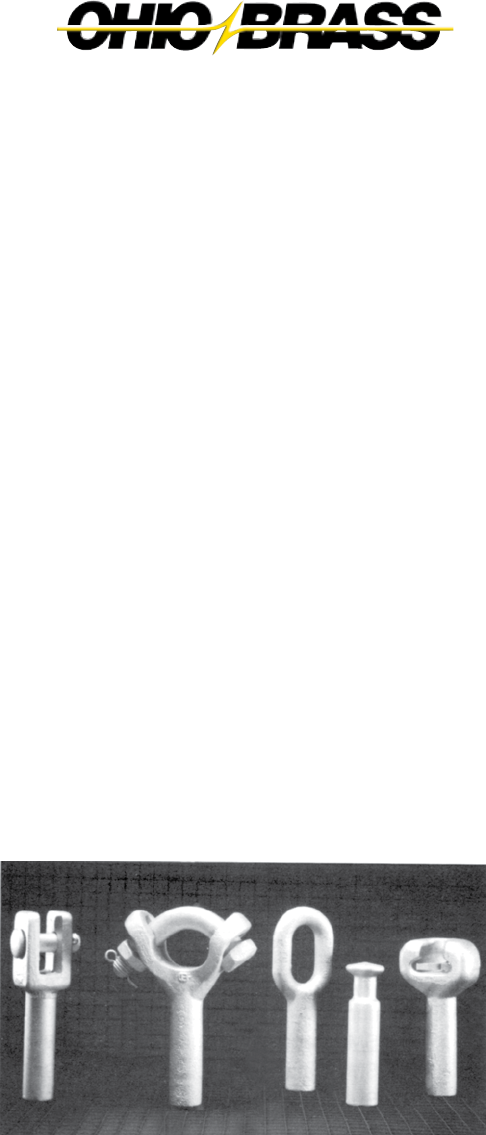
DEADEND &
SUSPENSION
INSULATORS
Catalog 22

Page 2 | April 2012
Warranty—Material
Hubbell Power Systems, Inc. warrants all products sold by it to be
merchantable (as such term is defined in the Uniform Commercial
Code) and to be free from defects in material and workmanship.
Buyer must notify the Company promptly of any claim under this
warranty. The Buyer's exclusive remedy for breach of this warranty
shall be the repair or replacement, F.O.B. factory, at the Company's
option, of any product defective under the warranty which is
returned to the Company within one year from the date of
shipment. NO OTHER WARRANTY, WHETHER EXPRESS OR ARISING
BY OPERATION OF LAW, COURSE OF DEALING, USAGE OF TRADE
OR OTHERWISE IMPLIED, SHALL EXIST IN CONNECTION WITH THE
COMPANY'S PRODUCTS OR ANY SALE OR USE THEREOF.
The Company shall in no event be liable for any loss of profits or
any consequential or special damages incurred by Buyer. The
Company's warranty shall run only to the first Buyer of a product
from the Company, from the Company's distributor, or from
an original equipment manufacturer reselling the Company's
product, and is non-assignable and non-transferable and shall be
of no force and effect if asserted by any person other than such
first Buyer. This warranty applies only to the use of the product
as intended by Seller and does not cover any misapplication or
misuse of said product.
Warranty—Application
Hubbell Power Systems, Inc. does not warrant the accuracy of and
results from product or system performance recommendations
resulting from any engineering analysis or study. This applies
regardless of whether a charge is made for the recommendation,
or if it is provided free of charge.
Responsibility for selection of the proper product or application rests
solely with the purchaser. In the event of errors or inaccuracies
determined to be caused by Hubbell Power Systems, Inc., its liability
will be limited to the re-performance of any such analysis or study.

Page 3 | April 2012
Deadend & Suspension Insulators
INSIDE ................................................................................PAGE
Distinguished by Design ................................................................................ 5
Product Performance ..................................................................................... 6
Polymer Design Tests ...................................................................................... 7
PDI Mechanical and Electrical Characteristics ............................................... 8
VLS Mechanical and Electrical Characteristics ............................................ 10
End Fitting Details ........................................................................................ 12
Experience
Page 4 | April 2012
Hubbell has been leading the
way with polymer insulators
under the distinguished Ohio
Brass name since 1976. Veri*Lite
distribution insulators embody
the latest in polymer design
and manufacturing features.
Our Veri*Lite insulators are
backed by thorough testing and research to provide our customers with
high performance products. More than 20 million distribution deadend
and suspension insulators have been put into
service around the world. Hubbell is dedicated
to providing superior products and service to
the power industry.
Performance
Page 5 | April 2012
Porcelain Bell Equivalents — The full line of Veri*Lite
suspension and deadend insulators are direct equivalents to
5 ¾ inch x 10 inch and 4 ¼ inch x 6 ¼ inch porcelain bells,
respectively. Please refer to the Electrical Characteristics table
for the number of bell equivalents, on pages 9 and 11.
DS Class Ratings — The polymer deadend insulator product
line has an offering for several DS class ratings, in accordance
with ANSI C29.13 and CSA C411.5-10 standards. Please refer to
the Electrical Characteristics table on page 9 for the appropriate
insulator class rating.
Rod — Veri*Lite Insulators are produced from the highest
quality materials. Strands in the fiberglass rod are aligned for
maximum tensile strength, and the rod is filled 70 percent, by
weight, with electrical grade glass fibers.
End Fittings — Ferrous end fittings are crimped directly to the fiberglass rod by a process originated by
Ohio Brass and later adopted by other manufacturers. The crimp requires no intermovement of the parts
to achieve high strength, nor does it introduce potting compounds or adhesives.
Weathersheds — Veri*Lite Insulators are manufactured with ESP™ rubber, the same proven material
used in PDV arresters and Hi*Lite Insulators. ESP™ is a polymer compound made by alloying silicone and
EPDM rubber. This alloy offers the desired toughness and resistance to tracking of the original EPR, along
with the hydrophobic characteristics derived from low molecular weight silicone oils.
Testing You Can Count On… Hubbell’s state-of-the-art electrical and mechanical testing facilities are
capable of performing ANSI, IEC, CSA, and other industry required tests. Tracking, QUV, corona cutting,
salt fog, oxidative stability, and variations of differential thermal analysis are just a sample of tests
performed to ensure the quality of our polymer material.
For further information on our polymers, ask your Hubbell Ohio Brass representative for the publication
“Polymer Materials for Insulator Weathersheds”, EU1264 – H.
Distinguished by Design
Page 6 | April 2012
Leakage Distance — Veri*Lite Insulators feature high
leakage distance for optimum contamination performance.
Cleaning — Washing of the Veri*Lite suspension and dead-
end insulators may be required based on the contamination
level of the installation locaton. In the event that washing is
required, the procedures outlined in Section IX of the “IEEE
GUIDE FOR INSULATOR CLEANING,” IEEE STD 957-2005 are
generally applicable.
Standards — Veri*Lite suspension and deadend insulators
meet the latest ANSI/IEEE-1024, CSA C411.5-10, and IEC-61109
standards. Hubbell’s manufacturing facilities have implemented
a quality system in accordance with ISO 9001-2008.
Mechanical Ratings — The Specified Mechanical Load (SML)
rating for all Veri*Lite suspension and deadend insulators is
15,000 Ibs. The Routine Test Load (RTL) rating for these
insulators is 50% of the SML rating.
All Veri*Lite suspension and deadend insulators are proof tested to 10,000 Ibs
in tension prior to shipment from the factory. This test load exceeds the RTL
rating of the insulator to ensure the quality of our product.
Markings — Markings for Veri*Lite suspension and deadend insulators are
permanently embossed into the end fittings and polymer housing. Markings
include SML rating, date of manufacture, DS rating in accordance with ANSI
C29.13 and CSA C411.5-10 standards, and Ohio Brass identification.
Packaging — The standard packaging of Veri*Lite suspension and deadend
insulators is in boxes stacked on pallets. The quantity per box and pallet
vary based on the catalog number. Please refer to the Mechanical characteristics
table in this catalog for the standard packing quantities.
Product Performance
Page 7 | April 2012
The following must be performed to certify a material for use in production.
Tracking test: Performed on a sample of material inclined at 15° and
electrodes positioned 35 mm apart. Samples are sprayed with a conductive
solution (400Ωcm) and energized at 10kV. The cycle is repeated every 90
seconds. The sample passes if there is:
1. No carbonization or tracking.
2. No erosion through sample.
3. No leakage current flow at the end of 90 seconds.
The sample must withstand 20,000 test cycles.
Ultraviolet Test: Samples of the rubber must be tested in a QUV tester or
equivalent cyclic weatherometer. The samples are exposed to high ultraviolet
radiation and high humidity without cracking, checking, or becoming hydrophilic.
The sample is judged to have passed this test if it exceeds 8,000 hours of
exposure without damage.
Corona Cutting: Samples 5 cm by 7 cm are subjected to mechanical stress
of 300,000 microstrain by bending samples over a grounded electrode. A needle-like
electrode is placed 1 mm from the surface of the sample and energized at 12 kV
in a controlled humidity chamber. The sample is judged to have passed this
test if there is no splitting or cutting during 1,000 hours of exposure to these
test conditions.
Oxidative Stability: Samples of the polymer compound are tested using
differential scanning calorimetry. Samples are heated rapidly in a nitrogen
atmosphere to the test temperature of 200°C. The atmosphere is then changed
to air, and the temperature is maintained until the antioxidant is consumed, as
measured by an exothermic chemical reaction. The time for this reaction to occur
must exceed 300 minutes.
Tear Strength: Rubber test slabs are prepared in accordance with ASTM
Standards and are tested to determine tear strength of the material. The
minimum acceptable tear strength is 150 lb/in.
Polymer Design Tests
Reliability
Page 8 | April 2012
1RUS Accepted
2SML — Specified Mechanical Load is the tension load that a Veri*Lite insulator can withstand during a 90-second
test without failure. SML is comparable to the M&E strength rating of porcelain insulators.
3RTL — A Routine Test Load value is equal to 50% of the SML value.
4Proof Test — The mechanical tension load applied at the factory to each insulator for ten (10) seconds.
NOTE: PDI Type insulators are intended for applications which are within 75° of horizontal to allow proper shed
drainage.
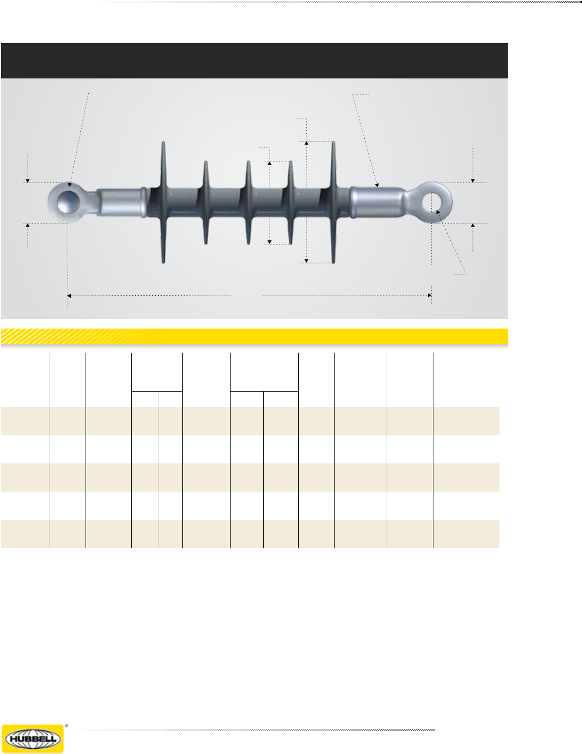
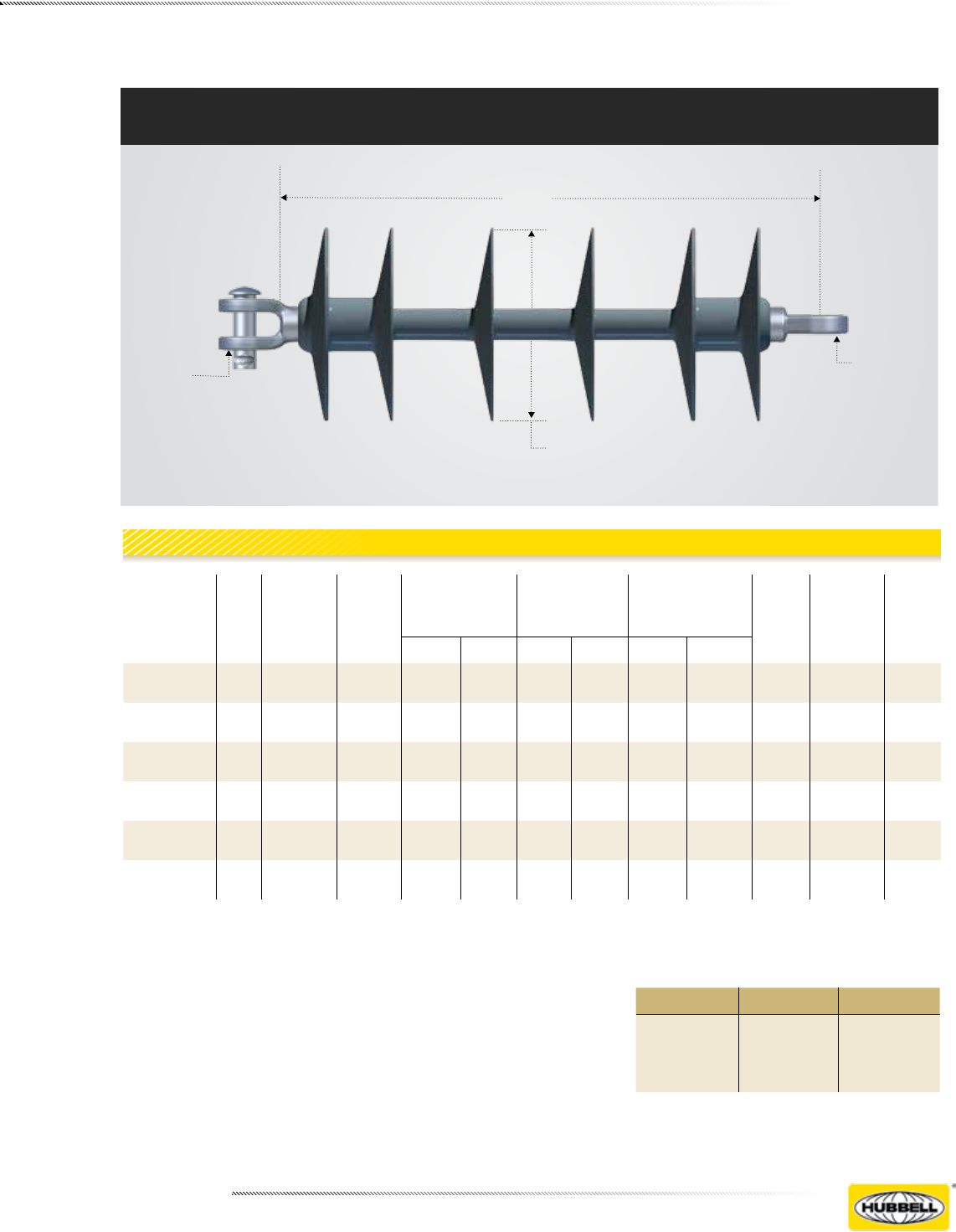
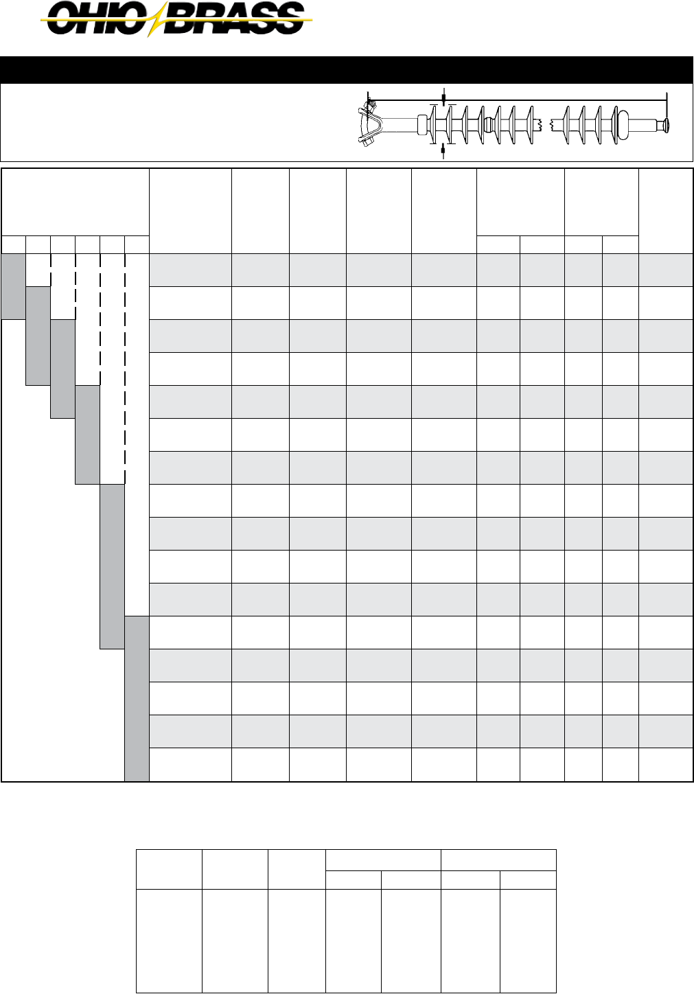
PDI Mechanical Characteristics
0.625" (16mm) Diameter Rod Deadend Insulators
.625 Dia. Pin
Length
1.62 1.56
D
STL END FITTINGS
.70 Dia. Hole
d
Catalog
Number
No. of
Sheds
Length
Inches
(mm)
Diameter
Inches
(mm)
Net Wt.
pounds
(kg)
Standard
Package
Qty
Torsion
ft-lb
(N-m)
2SML
pounds
(kN)
3RTL
pounds
(kN)
4Proof
pounds
(kN)
D d Box Pallet
401015021515 12.50
(318)
3.9
(99)
2.7
(69)
2.3
(1.0)
15 540 35
(47)
15,000
(70)
7,500
(35)
10,000
(44.5)
4010280215110 17.50
(445)
3.3
(84)
2.4
(61)
2.5
(1.1)
15 360 35
(47)
15,000
(70)
7,500
(35)
10,000
(44.5)
4010250215110 18.75
(475)
3.8
(97)
2.8
(71)
2.7
(1.2)
15 360 35
(47)
15,000
(70)
7,500
(35)
10,000
(44.5)
401035021518 25.00
(635)
3.0
(76)
2.8
(1.3)
15 300 35
(47)
15,000
(70)
7,500
(35)
10,000
(44.5)
4010460215 10 23.00
(584)
4.4
(112)
3.0
(76)
2.9
(1.3)
15 300 40
(55)
15,000
(70)
7,500
(35)
10,000
(44.5)
Mechanical Characteristics
Page 9 | April 2012
Example: Cat. #4013250215 is a Veri*Lite
insulator, 25 kV. Rated with standard pin
and rotated end-fitting (ferrous) 15,000
lbs. SML, plus standard markings.
KEY TO THE CATALOG NUMBERS
401XXXX215
Voltage
Rating
kV
SML
Ferrous
End-fitting
0 = Standard Marking
6 = LWIWG Marking
0 = Std. Pin
3 = Standard Pin
Rotated End-fitting
5 = ANSI 52-3 B & S
6 = IEC 16mm B & S
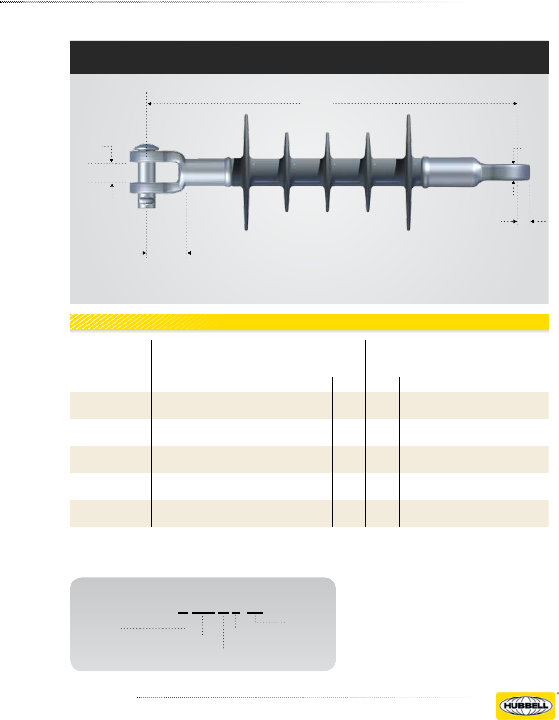
PDI Electrical Characteristics
Length
.74 .60
1.13
.78
0.625" (16mm) Diameter Rod Deadend Insulators
Catalog
Numbers Type
Leakage
Distance
Inches
(mm)
Dry Arc
Distance
Inches
(mm)
Flashover
ANSI - kV
Critical
Impulse
Flashover
RIV Power
Arc
kA
cycles
SL
of # of
4-1/4
Bells
Insulator
Class
Dry-kV Wet-kV Pos-kV Neg-kV Test kV Max.
4010150215 PDI-15 16
(406)
8.1
(205)
100 80 150 170 15 <10 150 2 DS15
4010280215 PDI-28 26
(660)
12.6
(320)
140 120 235 250 20 <10 150 — DS28
4010250215 PDI-25 31
(787)
14.3
(363)
155 135 270 280 30 <10 150 3 DS35
4010350215 PDI-35 33
(838)
20
(508)
200 160 325 360 30 <10 150 4 —
4010460215 PDI-46 37.6
(955)
19.1
(485)
195 175 360 365 30 365 150 — DS46
Electrical Characteristics
Page 10 | April 2012
1SML — Specified Mechanical Load is the tension load that a Veri*Lite insulator can withstand during a 90-second
test without failure. SML is comparable to the M&E strength rating of porcelain insulators.
2RTL — A Routine Test Load value is equal to 50% of the SML value.
3Proof Test — The mechanical tension load applied at the factory to each insulator for ten (10) seconds.
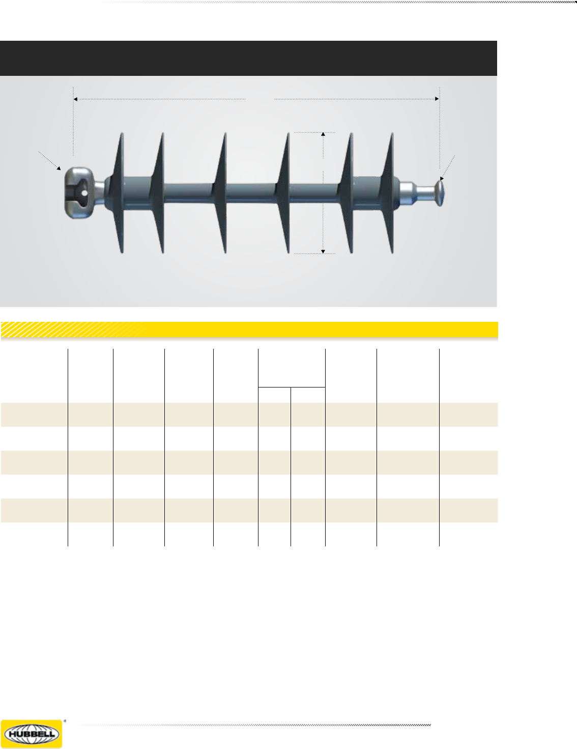
Length
D
BALL
SOCKET
Catalog
Numbers
No. of
Sheds
Length
Inches (mm)
D
Diameter
Inches
(mm)
Net Wt.
pounds
(kg)
Standard
Package
Qty
1SML
pounds (kN)
2RTL
pounds (kN)
3Proof
pounds (kN)
Carton Pallet
4050021301 4 11.5
(292) 5.9
(150) 4
(1.8) 12 96 15,000
(70) 7,500
(35) 10,000
(44.5)
4050029001** 4 12.5
(318) 5.9
(150) 4
(1.8) 12 96 15,000
(70) 7,500
(35) 10,000
(44.5)
4050031301 6 17.25
(438) 5.9
(150) 4
(1.8) 12 96 15,000
(70) 7,500
(35) 10,000
(44.5)
4050041301 8 23
(584) 5.9
(150) 5
(2.3) 12 96 15,000
(70) 7,500
(35) 10,000
(44.5)
4050051301 10 28.75
730) 5.9
(150) 6
(2.8) 12 48 15,000
(70) 7,500
(35) 10,000
(44.5)
4050061301 12 34.5
876) 5.9
(150) 7
(3.2) 12 48 15,000
(70) 7,500
(35) 10,000
(44.5)
Mechanical Characteristics
VLS Mechanical Characteristics
0.625" (16mm) Diameter Rod Suspension Insulators
Page 11 | April 2012
VLS insulators are available with ANSI and IEC ball/
socket end fittings and also with clevis/tongue end
fittings. Please use the following 4-digit suffix codes
after the first 6-digits of the catalog number.
* Phase-to-Phase voltage.
** Replaces two 10” x 6-1/4” distribution deadend bells.
VLS Electrical Characteristics
0.625” (16mm) Diameter Rod Suspension Insulators
Length
TONGUE
D
CLEVIS
Catalog
Numbers Type
Leakage
Distance
Inches
(mm)
Dry Arc
Distance
Inches
(mm)
Flashover
ANSI - kV
Critical
Impulse
Flashover
RIV Power
Arc
kA
cycles
Equivalent
number of
5¾” X10”
Bells
Volt*/
Class
Dry-kV Wet-kV Pos-kV Neg-kV Test kV Max. μV
4050021301 VLS-2 23
(584) 11.75
(298) 135 110 225 255 21 <10 150 2 15/25
4050029001** VLS-2 23
(584) 11.75
(298) 135 110 225 255 21 <10 150 2** 15/25
4050031301 VLS-3 39
(991) 18
(457) 190 140 320 330 32 <10 150 3 35/46
4050041301 VLS-4 54
(1372) 23.7
(602) 255 190 420 435 48 <10 150 4 46/69
4050051301 VLS-5 69
(1753) 29.5
(749) 315 245 500 510 48 <10 150 5 69
4050061301 VLS-6 84
(2134) 35.2
(894) 370 305 610 580 48 <10 150 6 69
Electrical Characteristics
Suffix Code Tower-end Line-end
1301 ANSI 52-3 Socket ANSI 52-3 Ball
1400 ANSI 52-6 Clevis ANSI 52-6 Tongue
2A07 IEC 16 mm Socket IEC 16 mm Ball

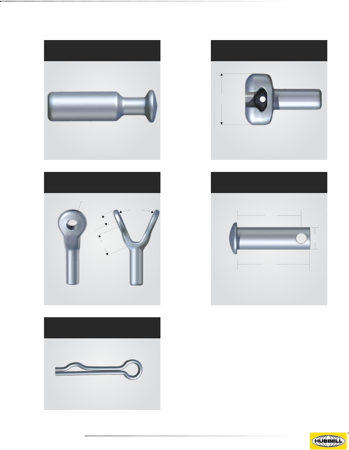
Page 12 | April 2012
.60
1.56
.70 DIA
PDI Tongue
1.88
.75
1.48
.69 DIA HOLE
VLS Clevis
End Fitting Details (Inches)
1.54
.69 DIA HOLE
.55
VLS Tongue
PDI Clevis
.74
.43 .43
1.62
.70 DIA
1.13
1.7
PDI Clevis
Page 13 | April 2012
VLS Socket
ANSI 52-3 & IEC-16 mm
2.50
End Fitting Details (Inches)
Cotter
VLS Ball
ANSI 52-3 & IEC-16 mm
VLS Y-Clevis
.94
.88 DIA HOLE
1.91
45°
Clevis Pin
1.75
2.0
.625

Page 14 | April 2012

Never Compromise TM
www.hubbellpowersystems.com
©Copyright 2011 Hubbell Incorporated
NOTE: Because Hubbell has a policy of continuous product improvement, we reserve the right to change design and specications without notice.
Printed in USA RGS 10M

JUNE 2012
23-1
OHIO BRASS – AIKEN, SC, USA
©Copyright 2010 Hubbell Incorporated
Section
23
NOTE: Because Hubbell has a policy of continuous product improvement, we reserve the right to change design and specications without notice.
Printed in USA RGS 1M
Warranty - Material
Hubbell Power Systems, Inc. warrants all products sold by it to be merchantable (as such
term is defined in the Uniform Commercial Code) and to be free from defects in material and
workmanship. Buyer must notify the Company promptly of any claim under this warranty. The
Buyer's exclusive remedy for breach of this warranty shall be the repair or replacement, F.O.B.
factory, at the Company's option, of any product defective under the warranty which is returned
to the Company within one year from the date of shipment. NO OTHER WARRANTY, WHETHER
EXPRESS OR ARISING BY OPERATION OF LAW, COURSE OF DEALING, USAGE OF
TRADE OR OTHERWISE IMPLIED, SHALL EXIST IN CONNECTION WITH THE COMPANY'S
PRODUCTS OR ANY SALE OR USE THEREOF. The Company shall in no event be liable for
any loss of profits or any consequential or special damages incurred by Buyer. The Company's
warranty shall run only to the first Buyer of a product from the Company, from the Company's
distributor, or from an original equipment manufacturer reselling the Company's product, and is
non-assignable and non-transferable and shall be of no force and effect if asserted by any per-
son other than such first Buyer. This warranty applies only to the use of the product as intended
by Seller and does not cover any misapplication or misuse of said product.
Warranty - Application
Hubbell Power Systems, Inc. does not warrant the accuracy of and results from product or
system performance recommendations resulting from any engineering analysis or study. This
applies regardless of whether a charge is made for the recommendation, or if it is provided free
of charge.
Responsibility for selection of the proper product or application rests solely with the purchaser. In
the event of errors or inaccuracies determined to be caused by Hubbell Power Systems, Inc., its
liability will be limited to the re-performance of any such analysis or study.
Index
Line Posts ....................................................... Page
Mechanical Ratings ........................................23-2
Equivalency .....................................................23-2
Packaging .......................................................23-3
Sample Polymer Specication ........................23-3
Table ...................................................23-4 & 23-5
Catalog Key ....................................................23-4
Post Base & Line Fittings ....................23-6 & 23-7
Application Curves ..............................23-8 & 23-9
Line Post Insulator Studs ..............................23-10
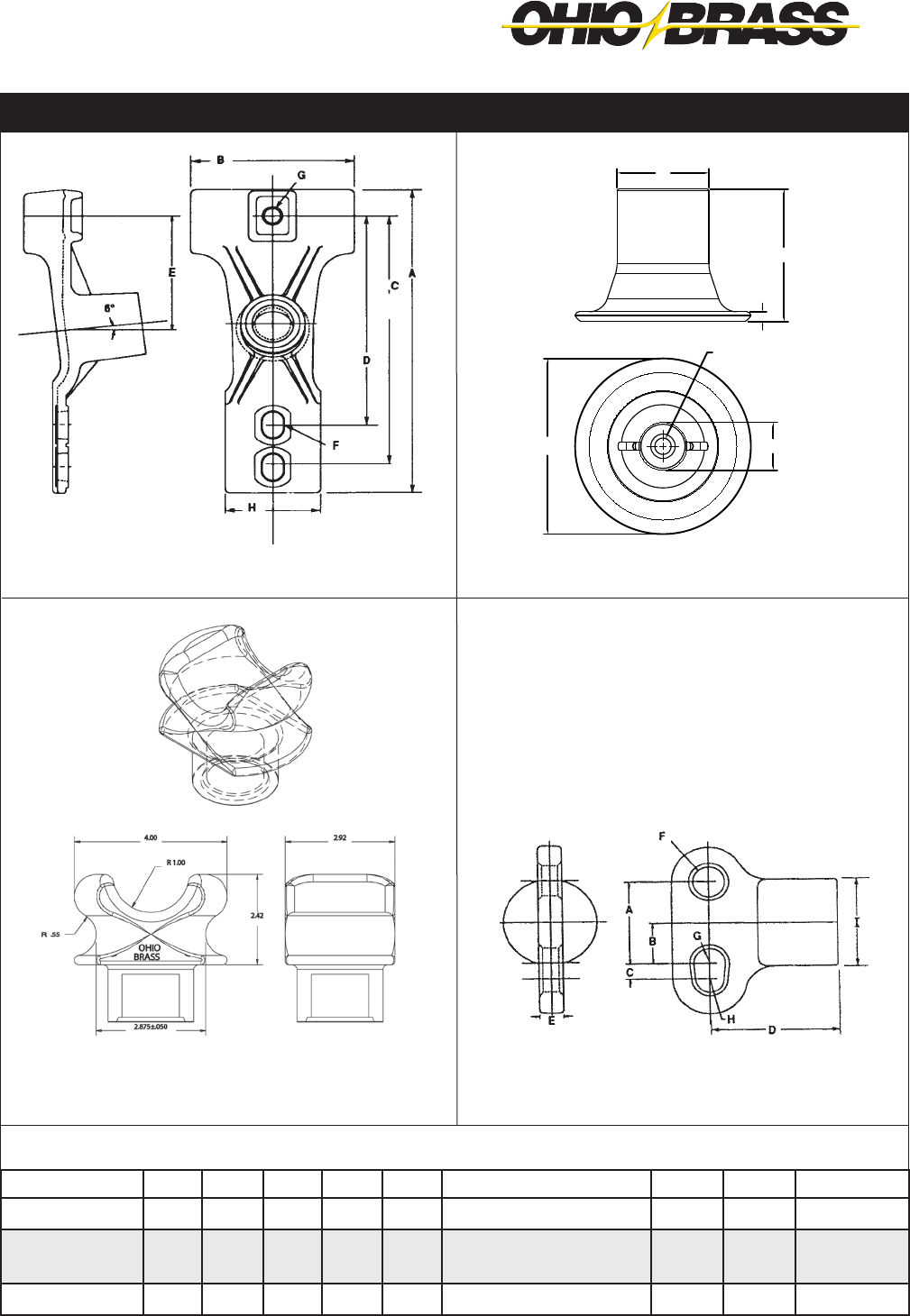
Suspension Trunnion Bolted Aluminum ........23-11
Bracket, Pole Top Insulator ...........................23-12
Bracket, Horizontal Insulator ........................23-13
Bracket, Vertical Insulator .............................23-13
Bracket, Pole Top Insulator ...........................23-14
Brackets, Post Insulator................................23-15
Super Top-Tie Line Ties ................................23-16
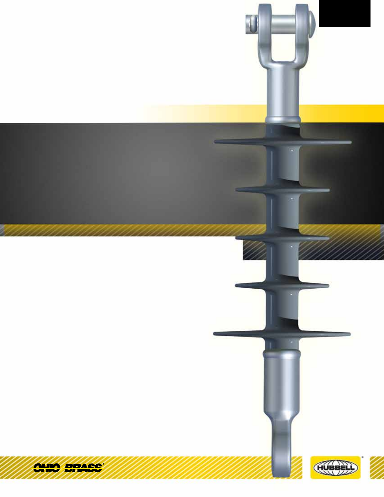
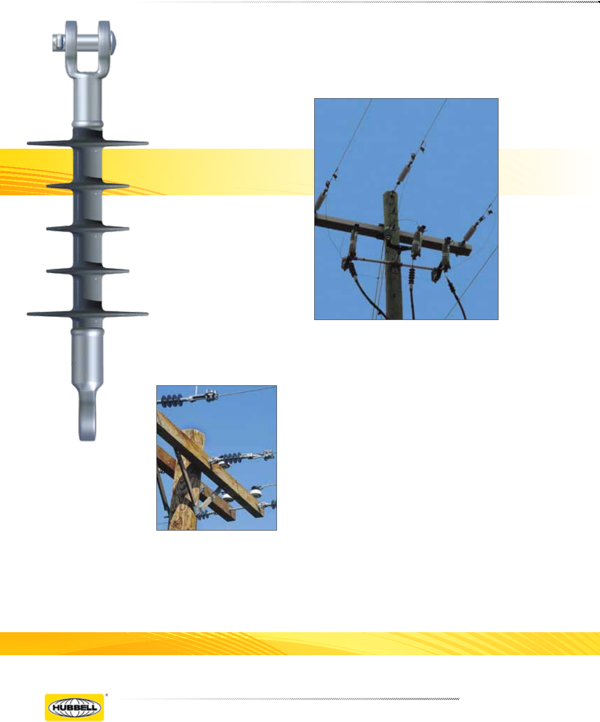
Veri*Lite™
Silicone Rubber Line Post Insulators
for 15-69kV Applications
®

JUNE 2012 OHIO BRASS – AIKEN, SC, USA
23-2
Veri*Lite Insulators embody the latest features avail-
able in polymer insulator design and manufacture.
Ohio Brass began its efforts in polymer research in the
early 1900s. After years of production and research
with polymeric compounds in the high voltage insula-
tion eld, Ohio Brass introduced the Hi*Lite insulator in
1976. A decade later the Ohio Brass polymer distribu-
tion arrester, PDV-100, was introduced as the rst U.S.
made polymer-housed MOV arrester.
Today’s Veri*Lite post insulators build upon the experi-
ence of placing nearly 20 million polymer distribution
arresters, 17 million polymer deadend distribution insu-
lators and 2 million high voltage transmission insula-
tors in service. Ohio Brass is dedicated to providing a
quality product for the electric utility industry.
Design
The structural design of the Veri*Lite insulator consists
of three basic parts:
Rod - Veri*Lite insulator berglass rod is produced
from the highest quality materials. Strands are aligned
for maximum tensile strength. The rod is lled 65 per-
cent, by volume, with electrical grade glass bers.
End Fittings - Ferrous end ttings are directly crimped
to the berglass rod by a circumferential crimping pro-
cess originated by Ohio Brass. The crimp requires no
intermovement of the parts to achieve high strength,
nor does it introduce potting compounds or adhesives.
Weathersheds - Veri*Lite insulators are manufactured
with OB’s proprietary silicone rubber.
Ohio Brass uses several tests to evaluate materials.
Tracking, QUV, corona cutting, salt fog, oxidative sta-
bility and variations of differential thermal analysis tests
assure the quality of OB’s shed material.
Leakage Distance
Veri*Lite insulators feature high leakage distance for
optimum contamination performance.
Washability
The Veri*Lite insulators listed in this catalog are suit-
able for washing by all known methods in current use.
Washing tests have been conducted with high-pres-
sure equipment at close nozzle-to-insulator distances.
No water intrusion occurred after multiple washings.
Standards
Veri*Lite line post insulators meet ANSI C29.18-2003
and CEA LWIWG-02-1996 standards.
The Ohio Brass facility in Aiken, SC, USA is registered
for successful implementation of a quality system in
accordance with ISO 9001-2000.
Mechanical Ratings
Specied Cantilever Load (SCL) is the ultimate can-
tilever strength rating. Maximum Design Cantilever
Load (MDCL) or Working Cantilever Load (WCL) is the
maximum continuous cantilever load at which the post
insulator should be applied.
Markings
Markings are 0.12 inch high raised letters in the rubber
and include: Base catalog number, CEA LWIWG Class,
SCL in pounds, MDCL/WCL in kN and date code. Ohio
Brass identication is cast into the end ttings.
Equivalency
Equivalency of line post insulators involves a check of
the general characteristics.
MECHANICAL
Compare the SCL of the polymer insulator to the
cantilever strength rating of the porcelain insulator.
ELECTRICAL
Compare porcelain to Veri*Lite leakage distance.
Compare porcelain to Veri*Lite section length.
Insulation Coordination
The operating performance of a distribution or trans-
mission line depends on its insulation level. It must not
ash over under practically any operating condition.
Several methods of coordination of line and station
insulation have been proposed. Generally, the best
method is to establish a denite common insulation
level for all the station insulation and then match that
level with the line insulation. With this approach, the
task is limited to three fundamental requirements:
1. Selection of the Basic Impulse Insulation Level
(BIL).
2. Specication of insulation with ashover charac-
teristics equal to or greater than the selected BIL.
3. The application of suitable overvoltage surge
protection.

JUNE 2012
23-3
OHIO BRASS – AIKEN, SC, USA
Purpose: To ensure a suitable service life of polymer insulating materials.
I. Material Design Tests
- The following must be performed to certify a material for use in production.
1. Tracking test: Performed on a sample of material inclined at 30° and electrodes posi-
tioned 35 mm apart. Samples are sprayed with a conductive solution (400 Ωcm) and ener-
gized at 10 kV. The cycle is repeated every 90 seconds. The sample passes if there is:
1. No carbonization or tracking.
2. No erosion through sample.
3. No leakage current ow at the end of 90 seconds.
The sample must withstand 20,000 test cycles.
2. Ultraviolet Test: Samples of the rubber must be tested in a QUV tester or equivalent cy-
clic weatherometer. The samples are exposed to high ultraviolet radiation and high humid-
ity without cracking, checking or becoming hydrophilic.
The sample is judged to have passed this test if it exceeds 8,000 hours of exposure with-
out damage.
3. Corona Cutting: Samples 5 cm by 7 cm are subjected to mechanical stress of 300,000
microstrain by bending samples around a grounded electrode. A needle-like electrode is
placed 1 mm from the surface of the sample and energized at 12 kV in a controlled humid-
ity chamber.
The sample is judged to have passed this test if there is no splitting or cutting. Samples
must pass 1,000 hours of exposure to this test.
4. Oxidative Stability: Samples of the polymer compound are tested using differential
scanning calorimetry. Samples are heated rapidly in a nitrogen atmosphere to the test
temperature of 200°C. The atmosphere is then changed to oxygen and the temperature
is maintained until the antioxidant is consumed, as measured by an exothermic chemical
reaction. The time for this reaction to occur must exceed 400 minutes.
5. Tear Strength: Rubber test slabs are prepared in accordance with ASTM Standards and
are tested to determine tear strength of the material. The acceptable nominal tear strength,
per ASTM method B, is 100 lb./in.
II. Other Requirements
- The manufacturer must supply upon request a listing of routine tests performed to ensure
production compliance with design tests.
Sample Polymer Specication
Satisfactory performance is generally achieved with an
insulator which has a dry 60 Hz ashover of three to
ve times the phase-to-ground voltage and a leak-
age distance approximately twice the shortest air-gap
(strike) distance.
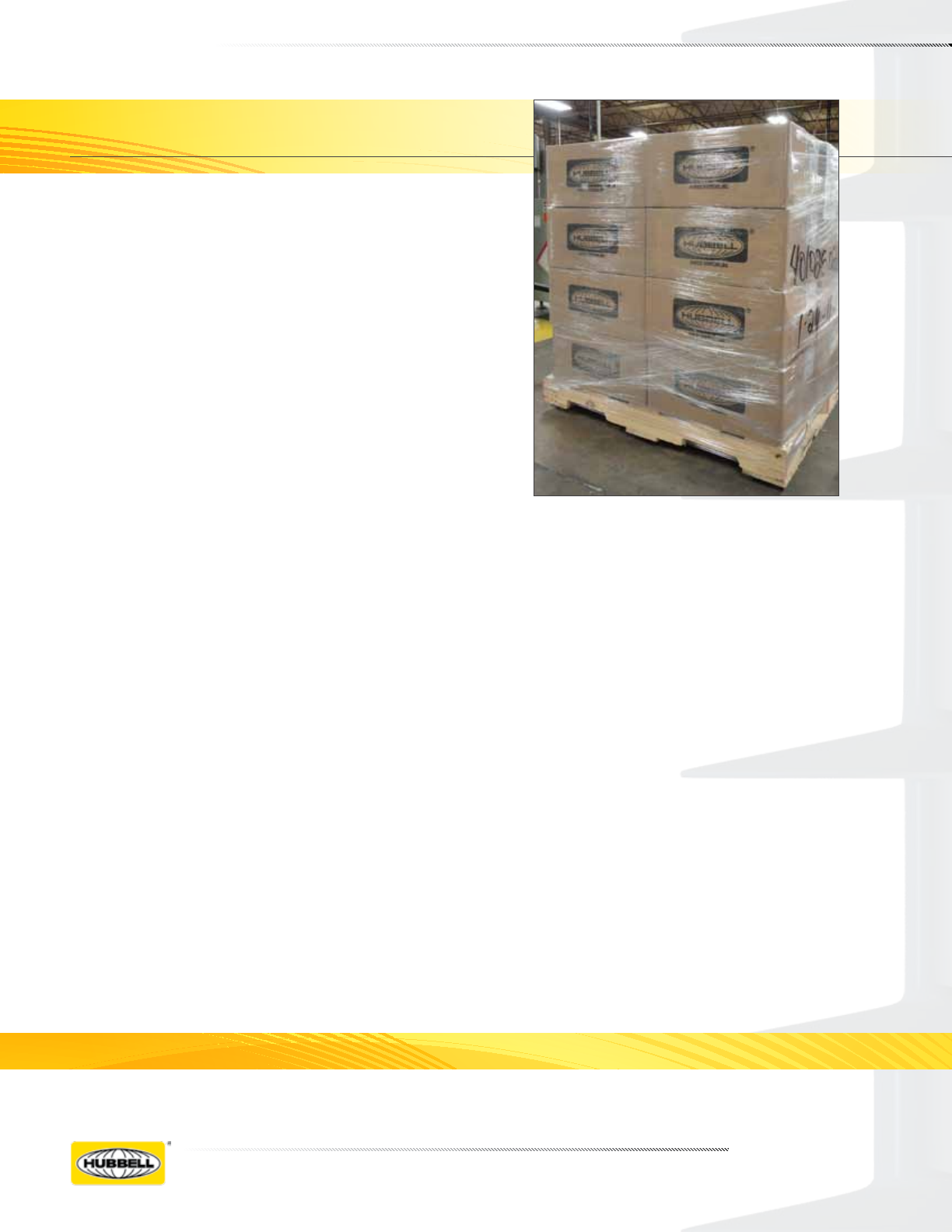
Packaging
Veri*Lite insulator standard packing is cartons on pal-
lets. Larger orders for Veri*Lite posts may be shipped
in wood crates.

JUNE 2012 OHIO BRASS – AIKEN, SC, USA
23-4
kV
Post
Style Line Base
Catalog
Number
ANSI
C29.18
Class
CEA
LWIWG-02
Class
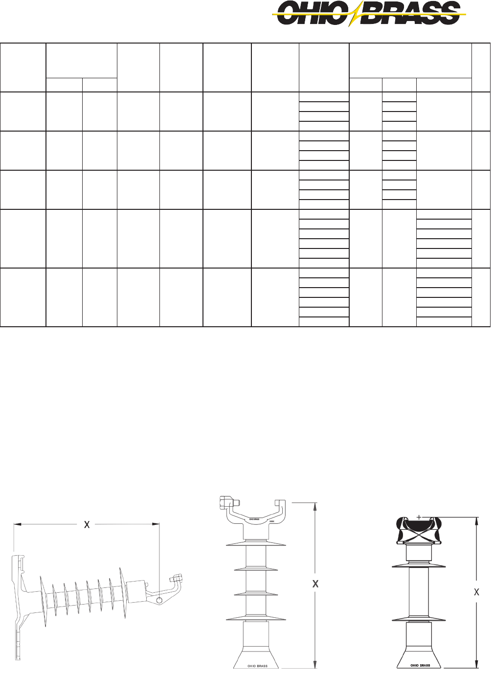
“X”
Dimension
Inches
(mm)
Line & Gnd
End Shed
Dia. Inches
(mm)
Inter-
mediate
Shed
Quantity
Inter-
mediate
Shed Dia.
Inches
(mm)
Dry Arc
Distance
Inches
(mm)
15
Horz Clamptop Gain 80S015-0100 51-31
LP 15
12.5 (318)
4.8 (121) 0 7.4 (188)
Horz Clamptop 3/4-10 Tap 80S015-0109 51-21 13.3 (339)
Vert Clamptop 3/4-10 Tap 80S015-0209 51-11 12.8 (324)
Vert F-Neck 3/4-10 Tap 80S015-0F09 51-1F 12.4 (315)
25
Horz Clamptop Gain 80S025-0100 51-32
LP 25
14.3 (362)
5.2 (132) 2 3.8 (96) 9.6 (244)
Horz Clamptop 3/4-10 Tap 80S025-0109 51-22 15.1 (383)
Vert Clamptop 3/4-10 Tap 80S025-0209 51-12 14.5 (368)
Vert F-Neck 3/4-10 Tap 80S025-0F09 51-2F 14.2 (360)
35
Horz Clamptop Gain 80S028-0100 51-33
LP 28M
16.5 (420)
5.1 (130) 4 4.6 (117) 11.7 (297)
Horz Clamptop 3/4-10 Tap 80S028-0109 51-23 17.4 (441)
Vert Clamptop 3/4-10 Tap 80S028-0209 51-13 16.8 (425)
Vert F-Neck 3/4-10 Tap 80S028-0F09 51-3F 16.5 (418)
46
Horz Blade Gain 80S046-0000 – –
LP 46
19.2 (488)
7.1 (179) 6 4.4 (112) 14.4 (390)
Horz Blade 3/4-10 Tap 80S046-0009 – – 20.0 (508)
Horz Clamptop Gain 80S046-0100 51-34 19.0 (482)
Horz Clamptop 3/4-10 Tap 80S046-0109 51-24 19.8 (504)
Vert Clamptop 3/4-10 Tap 80S046-0209 51-14 20.1 (510)
Vert F-Neck 3/4-10 Tap 80S046-0F09 51-4F 19.5 (495)
69
Horz Blade Gain 80S069-0000 – –
LP 69M
25.8 (656)
7.5 (190) 8 5.2 (132 22.3 (566)
Horz Blade 3/4-10 Tap 80S069-0009 – – 26.6 (676)
Horz Clamptop Gain 80S069-0100 51-36 25.6 (650)
Horz Clamptop 3/4-10 Tap 80S069-0109 51-26 26.5 (672)
Vert Clamptop 3/4-10 Tap 80S069-0209 51-16 26.8 (680)
Vert F-Neck 3/4-10 Tap 80S069-0F09 – – 26.1 (663)
8 0 S 0 6 9 0 2 0 9
Polymer Type Bottom End Fitting
80S Veri*Lite - SR Polymer 00 Gain Base - Transverse
09 3 /4” Stud Base
Hardware Finish 10 7/8” Stud Base
0 Standard
Top End Fitting
Rating 0 Teardrop Blade*
15 15kV (1.5” rod) 1 Horizontal Clamptop
25 25kV (1.5” rod) 2 Veritical Clamptop
28 35kV (1.5” rod) 5 5” B.C. Through
46 46kV (1.75” rod) 6 Horizontal Clamptop (longer pintle bolt)
69 69kV (1.75” rod) A Vertical Clamptop (longer pintle bolt)
Dimensioning
0 ANSI C29.18 Quality Conformance Tests
6 LWIWG - 02 Sample Tests
9 Special
CATALOG NUMBER KEY
Veri*Lite Line Post Insulators - Silicone
*Teardrop Blade only available for 46-69kV
JUNE 2012
23-5
OHIO BRASS – AIKEN, SC, USA
NOTES:
1. Maximum Design Tension for Clamptop is 2500 pounds (11 kN)
2. 15, 25 & 28 kV Units use 1.5 inch (38 mm) Diameter Rod
3. 46 & 69 kV Units use 1.75 inch (44 mm) Diameter Rod
Horizontal Clamptop & Gain Base
(0100)
Vertical Clamptop & Stud Base
(0209 & 0210)
F-Neck & Stud Base
(0F09 & 0F10)
Leakage
Distance
Inches
(mm)
60 Hz
(Low Frequency)
Flashover
Impulse
Critical
Flashover
Pos. kV
Impulse
Positive
Withstand
kV
SCL
pounds
(kN)
MDCL/
WCL
pounds
(kN)
Net
Weight
pounds
(kg)
Standard Package
Quantity
kV
Dry-kV Wet-kV Carton Pallet Max/Crate
11.0 (279) 90 70 150 140 2800 (12.5) 1235 (5.5)
9.8 (4.5)
3
36
– – 15
6.9 (3.1) 60
6.5 (2.9) 60
6.6 (3.0) 60
17.3 (439) 110 75 185 170 2800 (12.5) 1235 (5.5)
10.3 (4.7)
3
36
– – 25
7.3 (3.3) 60
7.0 (3.2) 60
7.1 (3.2) 60
26.1 (662) 135 100 215 200 2800 (12.5) 1235 (5.5)
11.2 (5.1)
3
36
– – 35
8.2 (3.7) 60
7.8 (3.5) 60
8.0 (3.6) 60
34.3 (872) 170 125 260 235 2800 (12.5) 1235 (5.5)
19.7 8.9)
– – – –
14/21/28/35
46
14.6 (6.6) 70
18.6 (8.4) 14/21/28/35
13.5 (6.1) 70
14.1 (6.4) 70
13.9 (6.3) 70
58.2 (1478) 230 180 360 330 2470 (11.0) 1235 (5.5)
22.1 (10.0)
– – – –
14/21/28/35
69
16.9 (7.7) 35
21.0 (9.5) 14/21/28/35
15.9 (7.2) 35
16.5 (7.5) 35
12.0 (5.4) 35

JUNE 2012 OHIO BRASS – AIKEN, SC, USA
23-6
B
A
D
F
C
I
H
Post Line Fittings Dimensions (in inches)
Post Base & Line Fittings
15, 25 & 35 kV
Stud Base
15, 25 & 35 kV
Horizontal Gain Base
Line Post Line Fittings Dimensions (in inches)
15-69 kV
Vertical Clamptop Cap
15-69 kV
Horizontal Clamptop Cap
4.0
2.11
▲▲
▼
▼
2.25
▲
▲
Post Base Fittings Dimensions (in inches)
Type A B C D E F H I Material
H. Clamptop Cap 4.00 4.75 0.62 0.38 0.69 5/8-11 UFS-2B - - 60-40-18 DI
V. Clamptop Cap 4.00 5.38 1.12 0.38 - 5/8-11 UFS-2B 3.38 1.63 60-40-18 DI
JUNE 2012
23-7
OHIO BRASS – AIKEN, SC, USA
Line Post Base Fittings Dimensions (in inches)
Post Base & Line Fittings
46 & 69 kV Stud Base46 & 69 kV Horizontal Gain Base
46 & 69 kV Two Hole Blade15-69 kV F-Neck Cap
B
A
E
D
C
3/4-10 UFS-2B THREAD
7/8-9 UFS-2B THREAD
Type A B C D E F G H Material
H. Gain Base 14.50 7.00 12.00 10.00 6.75 1.25 x 0.88 0.88 4.00 60-40-18 DI
Stud Base 4.22 2.875 5.50 1.50 0.50 3/4-10 UFS-2B or
7/8-9 UFS-2B
- - 60-40-18 DI
Two Hole Blade 2.75 1.38 0.50 4.00 0.75 1.00 Dia. 0.50 R 0.44 R 60-40-18 DI

JUNE 2012 OHIO BRASS – AIKEN, SC, USA
23-8
values, nd the allowable longitudinal load to be 900
pounds.
When the posts are loaded in tension the cantilever
loading due to the combined effects of longitudinal,
vertical and tensile loads should not exceed the rated
tension working value.
IMPORTANT: The application curves should not be
extrapolated.
How to use the application curves. After you have
established the loading cases, you can use the curves
to determine whether a specic Veri*Lite unit meets
your loading requirement.
For example, consider the installation of a Veri*Lite
post number 80S025-0100 on a line with a vertical
cantilever load of 800 pounds and a compression
load of 900 pounds. By entering the curve at these
Maximum deection for any of the post styles is approximately 1.75" at SCL.
Curves are shown using a 2.0 safety margin to SCL
Application Curves for Veri*Lite Insulators
80S015, 80S025 & 80S028 HORIZONTAL STYLE
80S015, 80S025 & 80S028 VERTICAL STYLE
0
200
400
600
800
1000
1200
1400
VERTICAL LOAD, LBF
0 Longitudinal
300 Longitudinal
600 Longitudinal
900 Longitudinal
1200 Longitudinal
Compression Tension
LINE POST
APPLICATION CURVES
9-12-05
-3000 -2000 -1000 0 1000 2000 3000
TRANSVERSE LOAD, LBF
0
200
400
600
800
1000
1200
1400
-3000 -2000 -1000 0 1000 2000 3000
VERTICAL LOAD, LBF
0 Longitudinal
300 Longitudinal
600 Longitudinal
900 Longitudinal
Compression
TRANSVERSE LOAD, LBF
LINE POST
APPLICATION CURVES
9-12-05
Tension
VERTICAL LOAD, LBF
1200 Longitudinal

JUNE 2012
23-9
OHIO BRASS – AIKEN, SC, USA
values, nd the allowable longitudinal load to be 900
pounds.
When the posts are loaded in tension the cantilever
loading due to the combined effects of longitudinal,
vertical and tensile loads should not exceed the rated
tension working value.
IMPORTANT: The application curves should not be
extrapolated.
How to use the application curves. After you have
established the loading cases, you can use the
curves to determine whether a specic Veri*Lite unit
meets your loading requirement.
For example, consider the installation of a Veri*Lite
post number 80S069-0100 on a line with a vertical
cantilever load of 800 pounds and a compression
load of 900 pounds. By entering the curve at these
Maximum deection for any of the post styles is approximately 1.75" at SCL.
Curves are shown using a 2.0 safety margin to SCL
80S046 & 80S069 HORIZONTAL STYLE
Application Curves for Veri*Lite Insulators
0
200
400
600
800
1000
1200
1400
-3000 -2000 -1000 0 1000 2000 3000
VERTICAL LOAD, LBF
Compression
TRANSVERSE LOAD, LBF
LINE POST
APPLICATION CURVES
9-12-05
Tension
0 Longitudinal
300 Longitudinal
600 Longitudinal
900 Longitudinal
1200 Longitudinal
VERTICAL LOAD, LBF
80S046 & 80S069 VERTICAL STYLE
0
200
400
600
800
1000
1200
1400
VERTICAL LOAD, LBF
0 Longitudinal
300 Longitudinal
600 Longitudinal
900 Longitudinal
1200 Longitudinal
Compression Tension
TRANSVERSE LOAD, LBF
LINE POST
APPLICATION CURVES
9-12-05
1000 2000 3000
-1000-2000-3000

JUNE 2012 OHIO BRASS – AIKEN, SC, USA
23-10
Line Post Insulator Studs
DF19M Series
Serrated collar and lockwasher secure unit to line post
insulator and prevent accidental disassembly. Cut
threads above serrated collar, rolled threads below
collar.
DF19M3
For Steel Crossarms
DF19M2
For Wood Crossarms
*DF19M29 and DF19M32 include (1) additional double coil lockwasher.
Catalog
No.
DF19M1
DF19M3
875833001
Dimensions (in.)
“D”
3/4
3/4
7/8
“A”
1-1/8
1-1/8
1-3/8
“B”
1-3/4
1-3/4
2
“C”
5/8
3/4
7/8
Hardware
Included
(1) reg. hexnut and (2) spring lockwashers
(1) reg. hexnut and (2) spring lockwashers
(1) reg. hexnut and (2) spring lockwashers
Standard
Package
100 pcs.
100 pcs.
100 pcs.
Weight
100 Pcs.
43 lbs.
54 lbs.
85 lbs.
Dimensions (in.)
“D”
3/4
3/4
3/4
3/4
3/4
3/4
7/8
“A”
1-1/8
1-1/8
1-1/8
1-1/8
1-1/8
1-1/8
1-3/8
“B”
7
7
10
12
14
24
8
“C”
5/8
3/4
5/8
5/8
3/4
3/4
7/8
Hardware
Included
(1) sq. nut, (1 sq. washer,
(1) spring lockwasher, (1) MF locknut
(1) sq. nut, (1 sq. washer,
(1) spring lockwasher, (1) MF locknut
(1) sq. nut, (1 sq. washer,
(1) spring lockwasher, (1) MF locknut
(1) sq. nut, (1 sq. washer,
(1) spring lockwasher, (1) MF locknut
(1) sq. nut, (1 sq. washer,
(1) spring lockwasher, (1) MF locknut
(1) sq. nut, (1 sq. washer,
(1) spring lockwasher, (1) MF locknut
(1) sq. nut, (1 sq. washer,
(1) spring lockwasher, (1) MF locknut
Catalog
No.
DF19M2
DF19M4
DF19M19
DF19M20
*DF19M29
*DF19M32
875843001
Std.
Pkg.
50 pcs.
40 pcs.
25 pcs.
25 pcs.
20 pcs.
15 pcs.
50 pcs.
Weight
100 Pcs.
102 lbs.
140 lbs.
176 lbs.
192 lbs.
234 lbs.
342 lbs.
277 lbs.
JUNE 2012
23-11
OHIO BRASS – AIKEN, SC, USA
For standard voltage applications with all aluminum,
ACSR or aluminum alloy conductor.
Designed for use on tangent suspension spans with
horizontal or vertical post insulators.
Keeper is reversible for proper t on different size
conductors.
Material: Body and Keeper—356-T6 aluminum alloy
Hardware—Galvanized steel
Anti-static spring 302 stainless steel
NOTES: (1) Recommended torque on bolts; 1/2”—480 in. lbs.
(2) Anti-static spring can be supplied by adding “ARIV” to catalog number. Example, TSC57ARIV.
(3) Clamptop clamps can be mounted directly on Veri*Lite posts, if the posts are ordered with the horizontal or
vertical clamptop option.
Fig.
No.
1
1
1
1
2
Clamping
Range
Inches (mm)
.25-.57
(6.3-14.4)
.35-.86
(8.8-21.8)
.50-1.06
(12.7-26.9)
1.00-1.50
(25.4-38.1)
1.50-2.00
(38.1-50.8)
Ultimate
Body
Strength
Lbs. (kN)
2,800
(12.46)
2,800
(12.46)
2,800
(12.46)
2,800
(12.46)
2,800
(12.46)
L
5-1/4
(133.3)
5-1/4
(133.3)
5-1/4
(133.3)
5-1/4
(133.3)
5-1/4
(133.3)
W
3-7/8
(98.4)
3-7/8
(98.4)
3-7/8
(98.4)
3-7/8
(98.4)
3-7/8
(98.4)
J
1/2
(12.7)
1/2
(12.7)
1/2
(12.7)
1/2
(12.7)
1/2
(12.7)
Approx.
Wt. Each
Lbs. (kg)
.42 (.19)
.45 (.20)
.62 (.28)
.64 (.29)
.75 (.34)
Dimensions Inches (mm)
Suspension Trunnion Bolted Aluminum Clamptop Clamps
Former
Catalog
Number
270660-3002
270661-3002
270662-3002
270663-3002
Catalog
Number
TSC57
TSC86
TSC106
TSC150
TSC200

JUNE 2012 OHIO BRASS – AIKEN, SC, USA
23-12
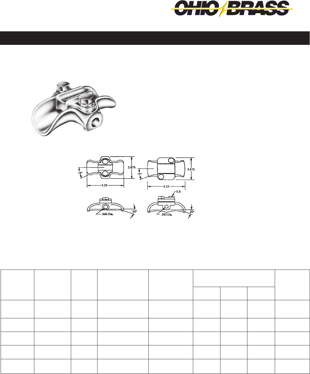
Mounts post or pin type insulator to top of pole. Variety of
bolt hole locations for mounting to pole.
Ductile iron per ASTM A-536
Hot dipped galvanized per ASTM A-153
† RUS Listed
IB4
11⁄16"
43⁄4"
105⁄8"
5"
11⁄16"
21⁄2"
13⁄16"
33⁄4"
IB2 IB3
33⁄4"
2"
6"
153⁄8"
3"
63⁄8"
15⁄16"
13⁄16"
3"
11⁄16"
41⁄2"
5"
8"
13⁄16"
23⁄16"
21⁄2"
14"
Bracket, Pole Top Insulator
75114
Catalog
No.
IB2
IB3
†IB4
75114
Mounting
Bolt Dia.
5/8"
3/4"
5/8"
3/4"
Insulator
Bolt Dia.
5/8" or 3/4"
5/8" or 3/4"
5/8" or 3/4"
5/8" or 3/4"
Mtg. Bolt
Spacing
43/4"
5" or 8"
5" or 8"
6" or 8"
Dist. From
Insul.Base
To Top
Hole
43/4"
63/8"
5"
6"
Approx.
Ship.Wt.Lbs.
Per 100 Pcs.
360
600
600
1000
JUNE 2012
23-13
OHIO BRASS – AIKEN, SC, USA
Use for mounting one or two insulator(s) to pole for armless
construction.
Approx.
Ship.
Wt.Lbs.
Per
100 Pcs.
333
1025
Space
Between
Insul.
Bases
—
14"
Insul.
Angle
Dim.
5°
—
Mtg.
Bolt
Spacing
5", 6"
4", 5"
Max.
Insul.
Bolt
Dia.
3/4"
3/4"
Mtg.
Bolt Dia.
Two 5/8"
Two 5/8"
Catalog
No.
1IPTB
2IPTB
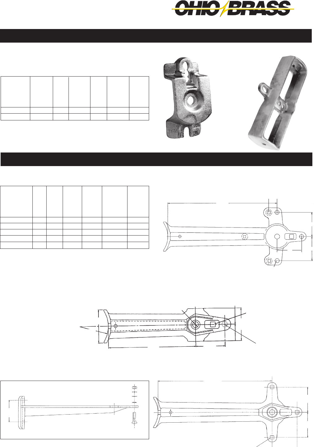
Ductile iron per ASTM A-536
Hot dipped galvanized per ASTM A-153
Use for mounting pin or post vertical insulators, cutouts, arresters, or cable terminators. Three-hole style can be used for
in-line deadending using suspension insulators.
2IPTB
Max.
Insul.
Mtg.
Bolt
Dia.
3/4"
3/4"
3/4"
3/4"
3/4"
Pole
Mtg.
Bolt
Dia.
Two 5/8"
Two 5/8"
Two 5/8"
Two 5/8"
Two 5/8"
Max.
Equip.
Mtg.
Bolt
Dia.
5/8"
5/8"
5/8"
1/2"
5/8"
Pole
Mtg.
Bolt
Spacing
5"
5"
5"
5"
5"
Clearance
Pole To
Insul.
Bolt
"A"
12"
18"
18"
12"
18"
Approx.
Ship.
Wt.Lbs.
Per
100 Pcs.
860
1300
1400
86
1400
4"
4"
4"
"A"
.58 sq. Hole
T2060594
Side view with
hardware
LB12A1 & LB18B1
4" R
41⁄2"
4"
41⁄2"
For 3⁄8" Carriage Bolt
13⁄16" Dia.
"A"
5"
LB18B3/LB18B3CH
"A"
11⁄16" Dia. Hole
4"
4"
11/4"
Catalog
No.
LB12A1
LB18B1
LB18B3
*T2060594
**LB18B3CH
Ductile iron per ASTM A-536
Hot dipped galvanized per ASTM A-153
* T206-0594 has 3 captive 1/2" x 2" bolts and nuts included
** LB18B3CH has 2 captive 1/2" x 2" bolts and nuts included with
LB18B3.
11⁄16"
Dia.
4"
Bracket, Horizontal Insulator
Bracket, Vertical Insulator
1IPTB
T2060594

JUNE 2012 OHIO BRASS – AIKEN, SC, USA
23-14
BRACKET,
ANGLE CROSSARM
Ductile iron per ASTM A-536
Hot dipped galvanized per ASTM A-153
Mounts post insulators at 30° angle on crossarm for use on
running corners.
Bracket, Pole Top Insulator
Catalog
No.
1XAB
Crossarm
Size
33/4" x 43/4"
Max. and
Round
Crossarms
Approx. Ship
Wt. Lbs.
Per 100 Pcs.
610
Mtg. Bolt
Diameter
3/4"
Stud Bolt
Diameter
3/4"

JUNE 2012
23-15
OHIO BRASS – AIKEN, SC, USA
11/16" Hole
16919
Insulator
Stud
Bolts Required
3/4"
3/4"
13/16" Hole
†*C2060209
C2060162
Pole
Mounting
Bolts Required
Two 5/8"
Two 5/8"
Approx. Ship
Wt. Lbs.
Per 100 Pcs.
650
440
*This bracket is designed to facilitate a stringing block.
†RUS listed
Catalog Number
BRACKETS, POST INSULATOR
Side Mounted
The bracket is formed of high-quality 3/8" x 21/2" bar steel and hot dip
galvanized. It can be utilized to mount distribution post insulators from
15 kV to 34.5 kV.
BRACKETS, POST INSULATOR
Curved base
This bracket can be used for mounting distribution post-type insulators
from 15 kV to 34.5 kV on the side of the pole. The base has a pole-shape
back for convenient installation. Brackets can be placed in a phase-over-
phase arrangement or can be mounted on opposite sides of the pole for
"armless" construction.
Insulators not included.
BRACKETS, POST INSULATOR
Uni-Brackets
Chance Uni-Brackets are a clean-appearing, low-cost method of mount-
ing three post-type insulators atop a pole completely eliminating the
crossarm. The brackets can be installed on the pole in less than five
minutes, requiring only two 3/4" bolts for attachment. Uni-Brackets fit
poles having a pole-top diameter from 6" to 81/2". Slot on top is 11/16" x
21/4".
No. 9183 brackets can be adapted to a variety of distribution construc-
tion using post-type insulators from 15 through 34.5 kV.
Catalog
Number
†9183
Approx. Ship Wt.
Lbs. Per 100 Pcs.
2100
Insulator Stud
Bolts Required
5/8"
†Includes both sections of bracket
C2060162 C2060209
Angle
A
15°
15°
15°
W
4
4
4
D
13/16
13/16
13/16
L
91/2
12
15
Catalog
Number
*C2060009
†*C2060010
C2060011
Dimensions
In Inches
*These brackets have 13/16" stringing block holes.
†RUS listed
Approx.
Ship
Wt. Lbs.
Per 100 Pcs.
1220
1669
2066
81/4"
11/16" Holes
13/16" Hole
13/16" x 11/4"
Hole
3/8" x 21/2"
Stock
60° 91/2"
1817/32"
No. 9183
13/16" hole
81/2"
11/16" hole
11/16" x 13/8"
slot
51/4"
30°
11/16" x 13/8" slot
83/4"
13/16" hole 30°
13/16"
hole
41/2"
11/16" hole
13/16" x 15/16" slot
81/2"
C2060009
31/2" R
W
11/16" Dia. hole
L
3/8" X
A
D
10"
load table
11/16" x 11/4" slot
41/2"
JUNE 2012 OHIO BRASS – AIKEN, SC, USA
23-16
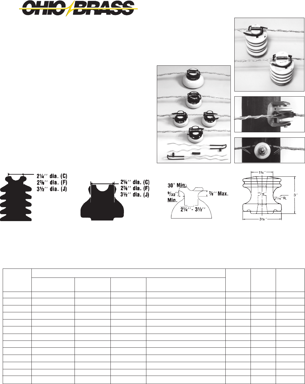
SUPER TOP-TIE® Line Ties
• for Pin, Post and Spool Insulators
Made of aluminum-clad steel compatible with aluminum,
aluminum-alloy and ACSR conductors in the top grooves of
vertical-mounted *ANSI Class C, F, J and many non-standard
pin and post insulators (single-or double-support) or on *ANSI
53-2 spool insulators (horizontal or vertical).
High-density polyethylene hooks provide the wide applica-
tion range and ensure proper installation. If used over armor
rods (not required), select tie size based on total conductor/
armor diameter. Semiconductive-rubber pad and high-density-
polyethylene on loops protect against abrasion of insulator,
conductor and tie. Fit is resilient and provides superior
performance under galloping and aeolian vibration. Install
by hand or with hot-line tools.
POST
INSULATOR
PIN
INSULATOR
NON-STANDARD
INSULATOR
ANSI 53-2
SPOOL
ORDERING INFORMATION
ACSR
#6, 6/1
#4, 6/1
#3, 6/1
#2, 6/1
#1, 6/1
1/0, 6/1
2/0, 6/1
3/0, 6/1
4/0, 6/1
266.8, 18/1
336.4, 18/1
477, 18/1
556.5, 18/1
Color
Code
None
Orange
Purple
Red
Gray
Yellow
Blue
Black
Pink
Green
Brown
Violet
Gold
Std.
Pkg.
50
50
50
50
50
50
50
50
50
50
50
50
50
Wt. Per
100, Lb.
28
28
28
28
28
32
32
32
32
32
40
40
40
AAC
(All-Aluminum)
#6, 7W
#4, 7W
#3, 7W
#2, 7W
#1, 7W
1/0, 7W
2/0, 7W
3/0, 7W
4/0, 7W
266.8, 19W
336.4, 19W
477, 19W
636, 37W
AAAC
(Alum.-Alloy)
#6, 7W
#4, 7W
#3, 7W
#2, 7W
#1, 7W
1/0, 7W
2/0, 7W
3/0, 7W
4/0, 7W
266.8, 19W
336.4, 19W
477, 19W
556.5, 19W
Diameter Range
.184-.220" (4.67-5.59 mm)
.221-.257" (5.61-6.53 mm)
.258-.289" (6.55-7.34 mm)
.290-.325" (7.37-8.26 mm)
.326-.360" (8.28-9.14 mm)
.361-.409" (9.17-10.39 mm)
.410-.460" (10.41-11.68 mm)
.461-.516" (11.71-13.11 mm)
.517-.584" (13.13-14.83 mm)
.585-.664" (14.86-16.87 mm)
.665-.755" (16.89-19.18 mm)
.756-.859" (19.20-21.82 mm)
.860-.977" (21.84-24.82 mm)
Aluminum-Type Conductors, Typical Sizes
Catalog
Number
STT10
STT20
STT30
STT40
STT50
STT60
STT70
STT80
STT90
STT100
STT110
STT120
STT130
LEFT-HAND LAY STANDARD
• Applied Length: 29" - 48" (Depends on insulator make and conductor size).
• Strength: Exceeds Rule 261E.2(A) of National Electrical Safety Code.
• REA accepted.
• To obtain outside diameters of conductors, consult Conductor Chart.
*Super Top-Tie STT10 — STT130 also t many foreign or reclaimed pin and post insulators with neck sizes 21/4" - 31/2".
Consult Hubbell Power Systems, Inc. for use on pins and posts outside these dimensions.
Web: http://www.hubbellpowersystems.com
E-mail: hpsliterature@hps.hubbell.com

JUNE 2012
23-17
OHIO BRASS – AIKEN, SC, USA
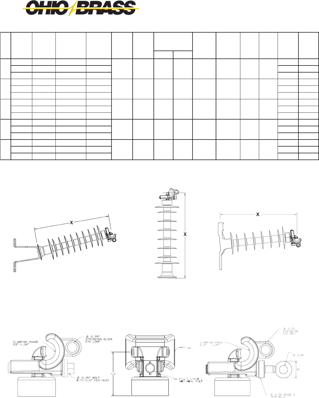
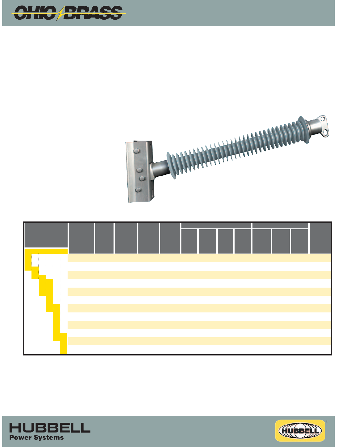
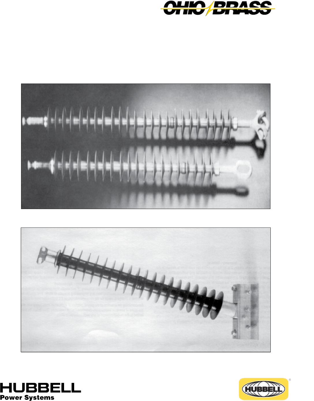
Veri*Lite™
Silicone Rubber Line Post Insulators with
Universal Clamp for 15-69kV Applications
8 0 S 0 6 9 0 U 0 9
Polymer Type Bottom End Fitting
80S Veri*Lite - SR Polymer 00 Gain Base - Transverse
09 3/4” Stud Base
Hardware Finish 10 7/8” Stud Base
0 Standard
1 Dulled Top End Fitting
U Universal Clamptop
Rating H Hotstick Operable Universal Clamptop
15 15kV (1.5” rod)
25 25kV (1.5” rod) Dimensioning
28 35kV (1.5” rod) 0 ANSI C29.18 Quality Conformance Tests
46 46kV (1.75” rod) 6 LWIWG - 02 Sample Tests
69 69kV (1.75” rod) 9 Special
CATALOG NUMBER KEY
Veri*Lite Line Post Insulators - Silicone
The Ohio Brass Universal Clamp end tting is used with the Veri*LiteTM
Line Post (VLLP) insulator family. Combining the proven direct bond
silicone technology of the Ohio Brass VLLP design, the Universal
Clamp offers a exible range-taking connection that can be installed in
either the vertical or horizontal direction. The Universal Clamp design
eliminates the need for a separate additional conductor clamp; saving
both money and installation time. In addition, the optional hotstick-
operable feature provides exibility for live-line work.
Design Features
• Proven direct bond interface
• Weathersheds molded with proprietary silicone rubber compound
• Universal clamp works for a conductor diameter range of 0.30”
(7.6 mm) to 1.34” (34 mm) to provide exibility in the eld
• Hotline option allows for live-line operability
• Can be installed in vertical or horizontal directions, thus reducing
inventory
• Integral design eliminates need for additional trunnion clamp
• Meets requirements of CEA LWIWG-02-1996 & ANSI C29.18-2003
JUNE 2012 OHIO BRASS – AIKEN, SC, USA
23-18
Universal Clamptop & Stud Base w/Bracket*
(0U09 & 0U10 w/C2060009)
Universal Clamptop & Stud
Base (0U09 & 0U10)
Universal Clamptop &
Gain Base (0U00)
Universal Clamptop Dimensions (in inches)
*Multiple bracket options available (see pages 13-15 of Section 23)
kV
Line
Fitting
Base
Fitting
Catalog
Number
“X”
Dimension
Inches
(mm)
Dry Arc
Distance
Inches
(mm)
Leakage
Distance
Inches
(mm)
60 Hz
(Low Frequency)
Flashover
Impulse
Critical
Flashover
Pos. kV
Impulse
Positive
Withstand
kV
SCL
pounds
(kN)
MDCL/
WCL
pounds
(kN)
Package
Quantity
Crate/
Pallet
QuantityDry-kV Wet-kV
15
Universal 3/4-10 Tap 80S015-0U09 13.0 (330) 7.4
(188)
11.0
(279) 90 70 150 140 2800
(12.5)
1235
(5.5)
3 60
Universal 7/8-9 Tap 80S015-0U10 13.0 (330) 3 60
Universal Gain 80S015-0U00 12.4 (314) 3 60
25
Universal 3/4-10 Tap 80S025-0U09 14.8 (375) 9.6
(244)
17.3
(439) 110 75 185 170 2800
(12.5)
1235
(5.5)
3 60
Universal 7/8-9 Tap 80S025-0U10 14.8 (375) 3 60
Universal Gain 80S025-0U00 14.1 (357) 3 60
35
Universal 3/4-10 Tap 80S028-0U09 17.0 (432) 11.7
(297)
26.1
(662) 135 100 215 200 2800
(12.5)
1235
(5.5)
3 60
Universal 7/8-9 Tap 80S028-0U10 17.0 (432) 3 60
Universal Gain 80S028-0U00 16.4 (415) 3 60
46
Universal 3/4-10 Tap 80S046-0U09 19.5 (495) 14.4
(390)
34.3
(872) 170 125 260 235 2800
(12.5)
1235
(5.5)
- 35
Universal 7/8-9 Tap 80S046-0U10 19.5 (495) - 35
Universal Gain 80S046-0U00 18.8 (478) - 35
69
Universal 3/4-10 Tap 80S069-0U09 26.1 (663) 22.3
(566)
58.2
(1478) 230 180 360 330 2470
(11.0)
1235
(5.5)
- 35
Universal 7/8-9 Tap 80S069-0U10 26.1 (663) - 35
Universal Gain 80S069-0U00 25.4 (645) - 35
Supplemental Catalog 24C
®
Hubbell Power Systems offers a transmission product line to meet the needs of today’s power utility. The 3”
Quadri*Sil® Line Post is an addition to the reliable product line that boasts a redundant four point sealing
system. The Quadri*Sil® product line will ensure the utmost protection against weather and contaminants in
an unpredictable environment.
• Proprietary silicone rubber compound
• Direct bond design
• Uniform circumferential crimp
Horizontal Line Post Insulators
3.0” (76.2 mm) Rod Diameter
1850 Richland Avenue East, Aiken, SC 29801
http://www.hubbellpowersystems.com
E-mail: quadrisil@hps.hubbell.com
©Copyright Hubbell Inc. 2010
NOTE: Because Hubbell has a policy of continuous product improvement, we reserve the right to change design and specifications without notice.
Notes:
1) For voltages above 345 kV, other section lengths, or end fitting combinations, please contact your HPS representative.
2) Electrical values are without corona ring. For voltages equal to or greater than 220 kV, please contact your HPS representative.
3) The catalog number shown in the table is for a 3.0’’ (76.2mm) rod diameter line post with a two hole blade on the line end and an aluminum gain
base on the tower end. For other end fitting combinations, please contact your HPS representative.
Horizontal Line Post Insulators
3.0” (76.2 mm) Rod Diameter
hubbellpowersystems.com
hpsliterature@hps.hubbell.com
Selection Guide:
Typical Line Voltage,
kV(1)
Catalog
Numbers(3)
Section
Length
inches
(mm)
Strike
Distance
inches
(mm)
ANSI Values IEC Values
(2)60-Hz
Dry
Flashover
(kV)
(2)60-Hz
Wet
Flashover
(kV)
(2)Critical
Impulse
Positive
(kV)
(2)Critical
Impulse
Negative
(kV)
(2)60-Hz
1-minute
Wet
Withstand
(kV)
(2)Impulse
Positive
Withstand
(kV)
SCL lbs.
(kN)
P300025S0020
P300026S0020
P300031S0020
P300036S0020
P300042S0020
P300047S0020
P300052S0020
P300053S0020
P300057S0020
P300058S0020
P300063S0020
P300064S0020
P300068S0020
P300069S0020
P300074S0020
P300078S0020
P300083S0020
P300085S0020
P300089S0020
P300094S0020
P300095S0020
P300099S0020
P300100S0020
P300105S0020
27.9 (708)
29.2 (741)
34.0 (863)
38.9 (988)
44.9 (1140)
49.8 (1265)
54.7 (1389)
55.9 (1420)
59.5 (1511)
60.7 (1542)
65.6 (1666)
66.8 (1697)
70.4 (1788)
71.6 (1819)
76.5 (1943)
81.4 (2068)
86.2 (2189)
87.4 (2220)
92.3 (2344)
97.1 (2466)
98.4 (2499)
102.0 (2591)
103.2 (2621)
108.0 (2743)
275
290
335
385
445
490
540
550
585
600
645
660
695
705
755
800
850
860
910
955
970
1005
1015
1065
245
255
300
345
400
445
490
500
535
545
590
600
635
645
690
735
780
790
835
880
890
925
935
980
425
445
520
595
690
765
840
860
915
935
1010
1030
1085
1105
1180
1255
1330
1350
1425
1500
1520
1575
1595
1670
520
540
615
690
785
860
935
955
1010
1030
1105
1125
1180
1200
1275
1350
1430
1445
1520
1600
1615
1675
1690
1770
7500 (33.4)
7500 (33.4)
7500 (33.4)
6670 (29.7)
5810 (25.8)
5261 (23.4)
4820 (21.4)
4720 (20.9)
4440 (33.4)
4350 (19.3)
4040 (17.9)
3970 (17.7)
3770 (16.8)
3710 (16.5)
3480 (15.5)
3280 (14.6)
3100 (13.8)
3050 (13.6)
2900 (12.9)
2760 (12.3)
2720 (12.1)
2630 (11.7)
2600 (11.6)
2480 (11.0)
69 115 138 161 230 345
Nominal
Polymer
Length
inches
025
026
031
036
042
047
052
053
057
058
063
064
068
069
074
078
083
085
089
094
095
099
100
105
(2)Impulse
Negative
Withstand
(kV)
Leakage
Distance
inches
(mm)
82 (2083)
88 (2223)
101 (2555)
116 (2934)
134 (3406)
149 (3785)
164 (4163)
168 (4260)
179 (4544)
183 (4638)
198 (5017)
201 (5110)
212 (5395)
216 (5489)
231 (5867)
246 (6246)
261 (6624)
265 (6721)
280 (7099)
294 (7478)
292 (7412)
309 (7856)
313 (7950)
328 (8329)
38.5 (978)
39.7 (1008)
44.4 (1128)
49.1 (1247)
55.0 (1397)
59.7 (1516)
64.4 (1636)
65.6 (1666)
69.1 (1755)
70.3 (1786)
75.0 (1905)
76.2 (1935)
79.7 (2024)
80.9 (2055)
85.6 (2174)
90.3 (2294)
95.0 (2413)
96.2 (2443)
100.9(2563)
105.6(2682)
106.8(2713)
110.4(2804)
111.5(2832)
116.2(2951)
200
215
255
285
340
375
410
425
450
460
495
510
535
545
585
620
655
670
705
740
755
780
790
825
400
415
490
560
685
725
790
810
865
880
950
970
1025
1045
1115
1185
1255
1275
1345
1420
1435
1490
1510
1580
485
505
575
650
740
815
884
900
955
975
1045
1065
1120
1140
1210
1280
1350
1370
1440
1515
1530
1585
1605
1675
Clamptop:
Maximum Design Tension = 2,500 lbs. (11.1 kN)
Two-Hole Blade
Maximum Deign tension = 12,500 lbs. (55.6 kN)
A
26-1
JULY 2010OHIO BRASS – AIKEN, SC, USA
Section
26
Hi*Lite® XL Transmission Insulators
©Copyright 2010 Hubbell Incorporated
NOTE: Because Hubbell has a policy of continuous product improvement, we reserve the right to change design and specications without notice.
Printed in USA
®

26-2
JULY 2010 OHIO BRASS – AIKEN, SC, USA
NOTE: Because Hubbell has a policy of continuous product improvement, we reserve the right to change design and specifications without notice.
Warranty - Material
Hubbell Power Systems, Inc. warrants all products sold by it to be merchantable (as such term is
defined in the Uniform Commercial Code) and to be free from defects in material and workman-
ship. Buyer must notify the Company promptly of any claim under this warranty. The Buyer's
exclusive remedy for breach of this warranty shall be the repair or replacement, F.O.B. factory,
at the Company's option, of any product defective under the warranty which is returned to the
Company within one year from the date of shipment. NO OTHER WARRANTY, WHETHER
EXPRESS OR ARISING BY OPERATION OF LAW, COURSE OF DEALING, USAGE OF
TRADE OR OTHERWISE IMPLIED, SHALL EXIST IN CONNECTION WITH THE COMPANY'S
PRODUCTS OR ANY SALE OR USE THEREOF. The Company shall in no event be liable for
any loss of profits or any consequential or special damages incurred by Buyer. The Company's
warranty shall run only to the first Buyer of a product from the Company, from the Company's
distributor, or from an original equipment manufacturer reselling the Company's product, and
is non-assignable and non-transferable and shall be of no force and effect if asserted by any per-
son other than such first Buyer. This warranty applies only to the use of the product as intended
by Seller and does not cover any misapplication or misuse of said product.
Warranty - Application
Hubbell Power Systems, Inc. does not warrant the accuracy of and results from product or
system performance recommendations resulting from any engineering analysis or study. This
applies regardless of whether a charge is made for the recommendation, or if it is provided free
of charge.
Responsibility for selection of the proper product or application rests solely with the purchaser. In
the event of errors or inaccuracies determined to be caused by Hubbell Power Systems, Inc., its
liability will be limited to the re-performance of any such analysis or study.
©Copyright 2010 Hubbell Incorporated

A
26-3
JULY 2010OHIO BRASS – AIKEN, SC, USA
A
B
C
D
E
Hi*Lite® XL Transmission Insulators
Section
26
Suspensions
Line Posts
Braced Posts
Station Posts
Sample Polymer Specs

26-4
JULY 2010 OHIO BRASS – AIKEN, SC, USA
A
26-5
JULY 2010OHIO BRASS – AIKEN, SC, USA
®
Table of Contents
Page
Design .............................................................. 26-6
Rod ...................................................................26-6
End Fittings ....................................................... 26-6
Weathersheds ..................................................26-6
Interface ............................................................ 26-6
Leakage Distance ............................................. 26-6
Washability ....................................................... 26-6
Mechanical Ratings .......................................... 26-6
Lengths Available ............................................. 26-6
Product Updates ............................................... 26-6
Packaging .........................................................26-6
Corona Performance ........................................ 26-7
Hi*Lite XL 25k SML Data .................................. 26-8
Hi*Lite XL 30k SML Data .................................. 26-9
Hi*Lite XL 50k SML Data ................................ 26-10
End Fitting Detail ............................................ 26-11
Key to the Catalog Numbers ........................... 26-11
Hi*Lite XL
Suspension Insulators
26-6
JULY 2010 OHIO BRASS – AIKEN, SC, USA
Hi*Lite® XL Insulators
Hi*Lite XL suspension insulators in this publication em-
body the latest features available in polymer
insulator design and manufacture.
From the early prototypes in 1971, through full scale
introduction in 1976, and through the succeeding years,
Hi*Lite insulators have featured conservative design and
high-quality manufacture.
Today’s Hi*Lite insulators will add to the over 1,000,000
already in service worldwide.
Design
The structural design of the Hi*Lite XL consists of these
basic parts:
Rod - Hi*Lite insulator fiberglass rod is produced from
the highest quality materials. Strands are aligned for
maximum tensile strength. The rod is more than 50 per-
cent glass fibers in cross section.
End Fittings - End fittings are steel or ductile iron. They
are crimped directly to the rod by a special process
originated by Ohio Brass, and later adopted by many
other producers. The crimp develops a high percentage
of the rod’s inherent tensile strength. It requires no inter-
movement of the parts to achieve high strength, nor
does it introduce potting compounds or adhesives.
Weathersheds - Weathersheds are high pressure injec-
tion molded by Ohio Brass, from the proprietary com-
pound ESP™. Housings manufactured with ESP silicone
alloy rubber exhibit hydrophobicity, high mechanical
strength, high corona resistance and low permeability
to moisture.
Interface - Hi*Lite insulators use Ohio Brass’ live sili-
cone interface. This feature prevents intrusion of mois-
ture and contaminating elements. If the exterior seal is
damaged, redundant o-ring seals within the live silicone
interface prohibit the lengthwise migration of intrusive
elements between shed and rod.
Leakage Distance
Hi*Lite XL insulators feature high leakage distance for
maximum resistance to contamination and leakage cur-
rents. Specific leakage distance (leakage divided by dry
arcing distance) is higher than porcelain. Contact Ohio
Brass if you have extra-high leakage distance needs.
Washability
Hi*Lite insulators listed in this catalog are suitable for
flood washing up to 200 psi. The design incorporates
positive, labyrinth seals to ensure long-term security
against water entry. Conventional dry-particle, air-
pressure cleaning methods may also be employed. A
cleaning guideline is available from Ohio Brass.
If your washing requirements exceed flood washing,
contact Ohio Brass.
Mechanical Ratings
Hi*Lite XL suspension insulators are rated and tested in
accordance with ANSI Standard C29.11. Certified test
reports in detail are available.
SML ratings are 25k, 30k and 50k pounds.
RTL ratings are consistent with the ANSI standard. Ac-
tual factory routine tests are conducted at loads equal
to or greater than the RTL rating.
Markings for XL insulator designs are permanently
embossed into the ground end corona shielding rings.
Markings include SML and RTL, part number, assem-
bly date code, and Ohio Brass identification.
Lengths Available
Hi*Lite suspension insulators are available in lengths
appropriate for 69 kV through 765 kV. Longer lengths
can be produced for special projects. Length incre-
ments are approximately three inches.
Product Updates
Hi*Lite XL insulator end fittings are attached with
an improved crimping process using the successful
principles of earlier Hi*Lite designs. The corona shield
has been refined; a more compact Corona Shielding
Ring (CSR) provides both electrical stress relief and a
mechanical seal at the housing-to-end fitting interface.
Packaging
Hi*Lite suspension insulators are packaged in appropri-
ate quantities in wood crates. As an option, Ohio Brass
offers packaging of the insulators in individual sleeves.

A
26-7
JULY 2010OHIO BRASS – AIKEN, SC, USA
Normal Applications: Top Grounded, Bottom Energized
Orientation
Top
Bottom
Top
Bottom
Insulator
Suspension
25/30 K SML
Suspension
50 K SML
The physical and electrical values for the insulators on pages 26-8 through 26-10 are shown without corona
protection above 161 kV. Ohio Brass has therefore provided the table below that yields the physical and electrical
changes to the insulator when rings are installed for voltages above 161 kV.
Corona Performance
Hi*Lite XL suspension insulators are RIV and corona free through 161 kV, by the use of integral Corona Shield
Rings (CSR). Due to the small diameter of the end fittings, corona shielding is necessary at 230 kV and above.
The table below details the rings necessary for voltages equal to or exceeding that listed in the column header.
Physical & Electrical Change Table
500 kV
Rings
-5 (-127.0)
0
-30
0
-65
-65
5.1 (2.29)
345 kV
Ring
-2 (-50.8)
0
-15
0
-25
-30
3 (1.8)
230 kV
Ring
-1.2 (-30.48)
0
-10
0
-15
-20
3 (1.8)
Physical & Electrical
Characteristics
Dry Arc Distance inches (mm)
Leakage Distance inches (mm)
60 Hz Flashover Dry - kV
60 Hz Flashover Wet - kV
Critical Flashover Positive - kV
Critical Flashover Negative - kV
Net Weight pounds (kg)
Part Number 271761 Part Number 271705 Part Number 271751
15.0"
12.0"
8.0"
500 kV
Rings
2717613001
2717513001
2717613002
2717513002
345 kV
Ring
NONE
2717053001
NONE
2717053002
230 kV
Ring
NONE
2717613001
NONE
2717613002
26-8
JULY 2010 OHIO BRASS – AIKEN, SC, USA
kg
-.11
-.11
-.01
-.07
0
-.007
Ground
Fitting
Eye
Eye
Socket
Clevis
Y-Clevis
Clevis
Line
Fitting
Ball
Eye
Ball
Ball
Eye
Eye
Suffix
Code
1001
1000
1301
1401
1200
1400
Inches
-.06
1.28
-.97
-1.00
1.34
.34
mm
-1.5
32.5
-24.6
-25.4
34.0
8.6
Pounds
-2.5
-2.5
-.05
-.15
0
-.15
Weight ChangeLength Change
For configurations not shown contact Ohio Brass.
Mechanical Ratings
SML = 25,000 lbs. 111 kN
RTL = 12,500 lbs. 56 kN
Net
Weight
pounds
(kg)
4.8
(2.2)
5.6
(2.5)
6.4
(2.9)
7.1
(3.2)
8.0
(3.6)
8.8
(4.0)
9.5
(4.3)
10.4
(4.7)
11.2
(5.1)
11.9
(5.4)
12.7
(5.8)
13.5
(6.1)
14.4
(6.5)
15.2
(6.9)
15.9
(7.2)
16.7
(7.6)
(2) Critical
Flashover
ANSI
Catalog
Number
with
Y-Clevis -
52.5 Ball
5110041201
5110051201
5110061201
5110071201
5110081201
5110091201
5110101201
5110111201
5110121201
5110131201
5110141201
5110151201
5110161201
5110171201
5110181201
5110191201
Neg-kV
390
490
595
695
795
890
990
1090
1185
1280
1370
1465
1560
1650
1740
1830
Pos-kV
410
505
605
700
795
890
985
1080
1170
1260
1350
1440
1530
1615
1705
1790
Wet-kV
240
295
350
405
455
505
555
605
655
700
750
790
835
880
920
960
Dry-kV
245
310
370
430
490
545
600
655
710
760
810
855
905
945
990
1030
(2) 60
Flashover
ANSI
Leakage
Distance
inches
(mm)
61
(1549)
76
(1930)
92
(2337)
107
(2718)
122
(3099)
138
(3505)
152
(3861)
168
(4267)
184
(4674)
198
(5029)
214
(5436)
229
(5817)
245
(6223)
260
(6604)
275
(6985)
290
(7366)
Dry Arc
Distance
inches
(mm)
24.7
(627)
30.7
(780)
36.8
(935)
42.9
(1090)
49.1
(1247)
55.1
(1397)
61.2
(1554)
67.4
(1712)
73.5
(1867)
79.5
(2019)
85.6
(2174)
91.7
(2329)
97.9
(2487)
103.9
(2639)
110.0
(2794)
116.2
(2951)
Number
of
Sheds
16
20
24
28
32
36
40
44
48
52
56
60
64
68
72
76
Section
Length
Inches
(mm)
34.7
(881)
40.7
(1034)
46.8
(1189)
53.0
(1346)
59.1
(1501)
65.1
(1654)
71.3
(1811)
77.4
(1966)
83.5
(2121)
89.5
(2273)
95.7
(2431)
101.8
(2586)
108.0
(2743)
114.0
(2896)
120.1
(3051)
126.2
(3205)
69 345230138 161115
Selection Guide
Typical
Line Voltage, kV (1)
Notes: (1) For voltages above 345 kV, and other section lengths, contact Ohio Brass.
(2) Tests in accordance with ANSI C29.1-1982. Electrical values are without corona ring.
For voltages above 161 kV refer to Page 26-7 for Corona Rings, and associated physical/electrical changes to above data.
Dimensions are within allowable tolerances as specified in ANSI C29.11.
5/8" (16mm) Rod Diameter Suspension Insulators
Section Length
3.7"
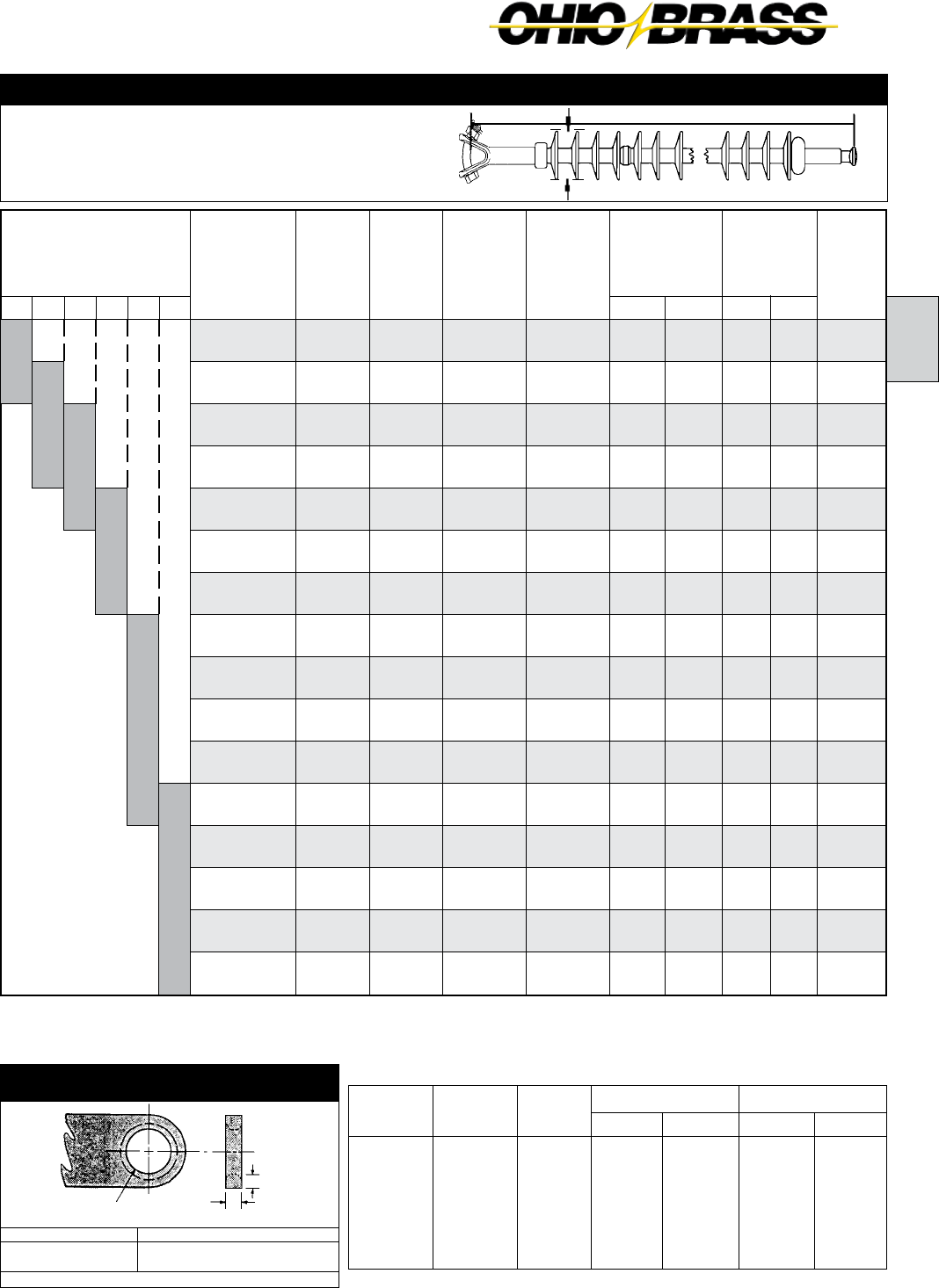
A
26-9
JULY 2010OHIO BRASS – AIKEN, SC, USA
kg
-0.110
-0.110
-0.010
-0.070
0.000
-0.007
Ground
Fitting
Eye
Eye
Socket
Clevis
Y-Clevis
Clevis
Line
Fitting
Ball
Eye
Ball
Ball
Eye
Eye
Suffix
Code
1001
1000
1301
1401
1200
1400
Inches
-0.06
1.28
-0.97
-1.00
1.34
0.34
mm
-1.5
32.5
-24.6
-25.4
34.0
8.6
Pounds
-2.50
-2.50
-0.05
-0.15
0.00
-0.15
Weight ChangeLength Change
For configurations not shown contact Ohio Brass.
Y-Clevis Tower Attachment Detail
for 25k, 30k, and 50k SML Insulators
SML
25/30k
50k
“D” Max. Inches
.531
1.0
To achieve insulator SML value, proper grade steel should be used
Mechanical Ratings
SML = 30,000 lbs. 133 kN
RTL = 15,000 lbs. 67 kN
Net
Weight
pounds
(kg)
4.8
(2.2)
5.6
(2.5)
6.4
(2.9)
7.1
(3.2)
8
(3.6)
8.8
(4.0)
9.5
(4.3)
10.4
(4.7)
11.2
(5.1)
11.9
(5.4)
12.7
(5.8)
13.5
(6.1)
14.4
(6.5)
15.2
(6.9)
15.9
(7.2)
16.7
(7.6)
(2) Critical
Flashover
ANSI
Catalog
Number
with
Y-Clevis -
52.5 Ball
5150041201
5150051201
5150061201
5150071201
5150081201
5150091201
5150101201
5150111201
5150121201
5150131201
5150141201
5150151201
5150161201
5150171201
5150181201
5150191201
Neg-kV
390
490
595
695
795
890
990
1090
1185
1280
1370
1465
1560
1650
1740
1830
Pos-kV
410
505
605
700
795
890
985
1080
1170
1260
1350
1440
1530
1615
1705
1790
Wet-kV
240
295
350
405
455
505
555
605
655
700
750
790
835
880
920
960
Dry-kV
245
310
370
430
490
545
600
655
710
760
810
855
905
945
990
1030
(2) 60
Flashover
ANSI
Leakage
Distance
inches
(mm)
61
(1549)
76
(1930)
92
(2337)
107
(2718)
122
(3099)
138
(3505)
152
(3861)
168
(4267)
184
(4674)
198
(5029)
214
(5436)
229
(5817)
245
(6223)
260
(6604)
275
(6985)
290
(7366)
Dry Arc
Distance
inches
(mm)
24.7
(627)
30.7
(780)
36.8
(935)
42.9
(1090)
49.1
(1247)
55.1
(1397)
61.2
(1554)
67.4
(1712)
73.5
(1867)
79.5
(2019)
85.6
(2174)
91.7
(2329)
97.9
(2487)
103.9
(2639)
110
(2794)
116.2
(2951)
Number
of
Sheds
16
20
24
28
32
36
40
44
48
52
56
60
64
68
72
76
Section
Length
Inches
(mm)
34.7
(881)
40.7
(1034)
46.8
(1189)
53
(1346)
59.1
(1501)
65.1
(1654)
71.3
(1811)
77.4
(1966)
83.5
(2121)
89.5
(2273)
95.7
(2431)
101.8
(2586)
108
(2743)
114
(2896)
120.1
(3051)
126.2
(3205)
69 345230138 161115
Selection Guide
Typical
Line Voltage, kV (1)
Notes: (1) For voltages above 345 kV, and other section lengths, contact Ohio Brass.
(2) Tests in accordance with ANSI C29.1-1982. Electrical values are without corona ring.
For voltages above 161 kV refer to Page 26-7 for Corona Rings, and associated physical/electrical changes to above data.
Dimensions are within allowable tolerances as specified in ANSI C29.11.
Section Length
3.7"
5/8" (16mm) Rod Diameter Suspension Insulators
“D” Max.
3/4" Max.
1" Dia. Minimum
1/8" x 45° Chamfer
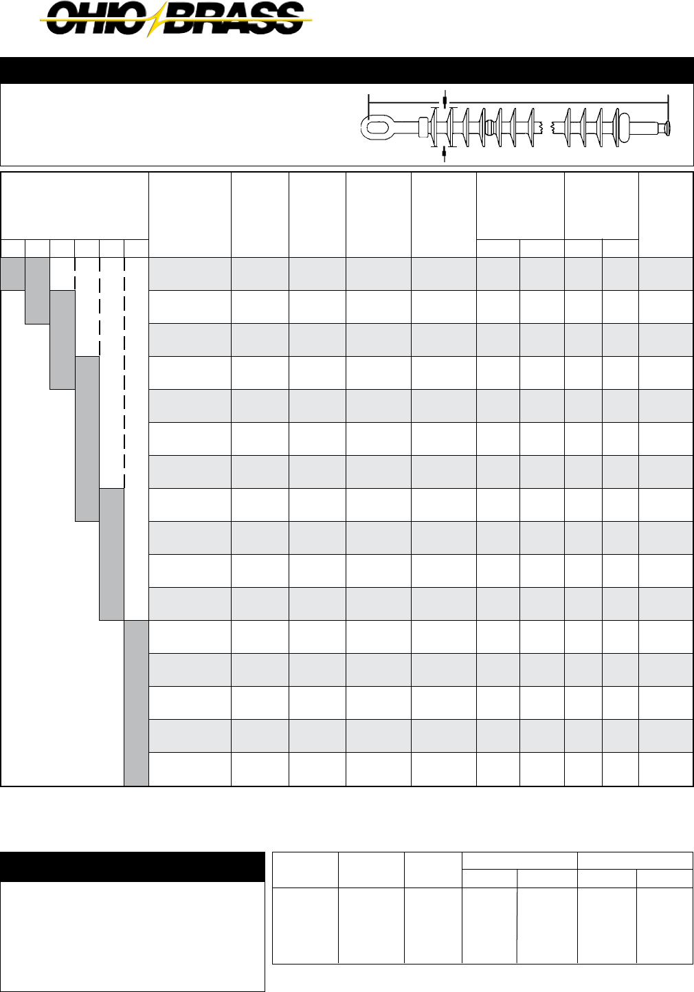
26-10
JULY 2010 OHIO BRASS – AIKEN, SC, USA
End Fitting Example
You need the electrical and mechanical characteristics
of Catalog #5130101001. But, a Y-clevis is needed at
the ground end instead of an eye. From the table at
the right, find the code for the Y-clevis/ball configura-
tion 1201. You should order Catalog #5130101201.
The same process is used for 5/8" (25k) and 7/8"
(30k) insulators.
kg
.18
-.18
.18
0
Ground
Fitting
Y-Clevis
Eye
Socket
Y-Clevis
Line
Fitting
Ball
Eye
Ball
Eye
Suffix
Code
1201
1000
1301
1200
Inches
-.58
1.26
-.72
-.58
mm
-14.7
32.0
-18.3
-14.7
Pounds
.4
-.4
.4
0
Weight ChangeLength Change
Mechanical Ratings
SML = 50,000 lbs. 222 kN
RTL = 25,000 lbs. 111 kN
For configurations not shown contact Ohio Brass.
7/8" (22mm) Rod Diameter Suspension Insulators
Net
Weight
pounds
(kg)
12.7
(5.8)
13.7
(6.2)
14.8
(6.7)
15.9
(7.2)
16.9
(7.7)
19.1
(8.7)
20.2
(9.2)
21.2
(9.6)
24.4
(11.1)
24.5
(11.1)
25.5
(11.6)
27.6
(12.5)
29.8
(13.5)
31.9
(14.5)
34.0
(15.4)
35.1
(15.9)
(2) Critical
Flashover
ANSI
Catalog
Number
with
Chain Eye -
52.11 Ball
5130071001
5130081001
5130091001
5130101001
5130111001
5130131001
5130141001
5130151001
5130171001
5130181001
5130191001
5130211001
5130231001
5130251001
5130271001
5130281001
Neg-kV
695
795
890
990
1090
1280
1370
1465
1650
1740
1830
2005
2175
2345
2510
2590
Pos-kV
700
795
890
985
1080
1260
1350
1440
1615
1705
1790
1960
2125
2285
2445
2520
Wet-kV
400
455
505
555
605
700
745
790
875
915
955
1035
1105
1175
1240
1270
Dry-kV
430
490
545
600
655
760
810
855
945
990
1030
1110
1180
1245
1305
1330
(2) 60
Flashover
ANSI
Leakage
Distance
inches
(mm)
106
(2692)
121
(3073)
136
(3454)
151
(3835)
167
(4242)
197
(5004)
212
(5385)
228
(5791)
258
(6553)
273
(6934)
288
(7315)
319
(8103)
349
(8885)
379
(9627)
410
(10414)
425
(10795)
Dry Arc
Distance
inches
(mm)
42.9
(1090)
49.0
(1245)
55.0
(1397)
61.2
(1554)
67.3
(1709)
79.5
(2019)
85.6
(2174)
91.7
(2329)
103.9
(2639)
110.0
(2794)
116.2
(2951)
128.3
(3259)
140.6
(3271)
152.7
(3879)
165.0
(4191)
171.1
(4346)
Number
of
Sheds
28
32
36
40
44
52
56
60
68
72
76
84
92
100
108
112
Section
Length
Inches
(mm)
55.8
(1417)
62.0
(1574)
68.0
(1727)
74.1
(1882)
80.3
(2040)
92.4
(2347)
98.5
(2502)
104.7
(2659)
116.8
(2967)
123.0
(3124)
129.1
(3279)
141.2
(3586)
153.5
(3899)
165.7
(4209)
177.9
(4519)
184.1
(4676)
115 500345161 230138
Selection Guide
Typical
Line Voltage, kV (1)
Notes: (1) For voltages above 500 kV, and other section lengths, contact Ohio Brass.
(2) Tests in accordance with ANSI C29.1-1982. Electrical values are without corona ring.
For voltages above 161 kV refer to Page 26-7 for Corona Rings, and associated physical/electrical changes to above data.
Dimensions are within allowable tolerances as specified in ANSI C29.11.
Section Length
4.0"

A
26-11
JULY 2010OHIO BRASS – AIKEN, SC, USA
ANSI Clevis
SML
k-LB (kN)
25 (111) - 30 (133)
50 (222)
25 (111) - 30 (133)
50 (222)
25 (111) - 30 (133)
50 (222)
25 (111) - 30 (133)
ANSI
CLASS
-
-
52-5
52-11
-
-
52-6
A
0.62
0.75
0.73
0.92
0.75
0.88
0.62
D
0.62
0.85
-
-
-
-
1.10
C
2.00
2.00
-
-
-
-
1.50
B
1.00
1.00
1.29
1.63
1.53
1.59
0.75
FITTING
TYPE
CHAIN EYE
BALL & SOCKET
Y-CLEVIS
CLEVIS
DIMENSIONS IN. (mm)
5 1 1 1 1 10 02 2
Line End Fittings
Chain Eye .................................00
ANSI Ball (1) .............................01
Y-Clevis .....................................02
ANSI Socket (1) ........................03
ANSI Straight Clevis .................04
Ground End Fittings
Chain Eye ...................................0
ANSI Ball (1) ...............................1
Y-Clevis .......................................2
ANSI Socket (1) ..........................3
ANSI Straight Clevis ...................4
Labeling
1 = English
2 = Metric (2)
R = English w/8" Corona Ring
W = English w/12" Corona Ring
T = English w/15" and 8" Corona Ring
Hi*Lite XL
Hi*Lite XL Suspension Insulators:
Key to the Catalog Numbers
Strength
1 = 25K SML
5 = 30K SML
3 = 50K SML
Construction
0 = Standard Hardware/0 Added Sheds
1 = Dull Hardware/0 Added Sheds
2 = Standarad Hardware/2 Added Sheds
3 = Dull Hardware/2 Added Sheds
Most Common End Fittings
* For IEC 16mm and 20mm Ball and Socket fittings, contact Ohio Brass.
Weathershed Configuration
Number of sheds equals this number times four,
plus any added sheds listed in the construction digit.
ANSI Socket*Y-Clevis FittingANSI Ball*Chain Eye
(1) For IEC Ball and Socket fittings, contact Ohio Brass.
(2) Metric labeling of ANSI, or IEC insulators.

26-12
JULY 2010 OHIO BRASS – AIKEN, SC, USA

26-13
B
JULY 2010OHIO BRASS – AIKEN, SC, USA
Hi*Lite® XL
Line Post Insulators
Table of Contents
Page
Design ............................................................ 26-14
Rod .................................................................26-14
End Fittings ..................................................... 26-14
Weathersheds ................................................26-14
Interface .......................................................... 26-14
Leakage Distance ........................................... 26-14
Washability ..................................................... 26-14
Mechanical Ratings ........................................ 26-14
Corona Rings .................................................. 26-15
Packaging .......................................................26-15
Key to 2.5" Catalog Numbers ......................... 26-15
Hi*Lite XL 2.5" Rod Horizontal Line Posts ...... 26-16
Hi*Lite XL 2.5" Rod Vertical Line Posts .......... 26-17
Hi*Lite XL 2.5" Rod Vertical Line Post
Assembly .................................................... 26-18
Hi*Lite XL 2.5" Rod Base Fittings ................... 26-19
Hi*Lite XL 2.5" Rod Line Fittings ....................26-20
Hi*Lite XL 3.0" Rod Horizontal Line Posts ...... 26-21
Key to 3.0" Catalog Numbers ......................... 26-21
Hi*Lite II 3.0" Rod Horizontal Line Posts ........ 26-22
Hi*Lite II 3.0" Rod Vertical Line Posts .............26-23
Hi*Lite XL 3.0" Rod. Dia. Base Fittings ........... 26-24
Hi*Lite XL 3.0" Rod. Dia. Line Fittings ............ 26-25
Clamps and Assemblies .................................26-26

26-14
JULY 2010 OHIO BRASS – AIKEN, SC, USA
Hi*Lite*® XL Insulators
Hi*Lite XL line post insulators in this publication em-
body the latest features available in polymer insulator
design and manufacture.
From the early prototypes in 1971, through full scale
introduction in 1976, and through the succeeding years,
Hi*Lite insulators have featured conservative design
and high-quality manufacture.
Today’s Hi*Lite insulators will add to the over 1,000,000
already in service worldwide.
Design
The structural design of the Hi*Lite XL consists of these
basic parts:
Rod - Hi*Lite insulator fiberglass rod is produced from
the highest quality materials. Strands are aligned for
maximum tensile strength. The rod is more than 50
percent glass fibers in cross section.
End Fittings - End fittings are aluminum or ductile
iron. They are crimped directly to the rod by a special
process originated by Ohio Brass, and later adopted
by many other producers. The crimp requires no inter-
movement of the parts to achieve high strength, nor
does it introduce potting compounds or adhesives.
Weathersheds - Weathersheds are high pressure
injection molded by Ohio Brass, from the proprietary
compound ESP™. Housings manufactured with ESP
silicone alloy rubber exhibit hydrophobicity, high me-
chanical strength, high corona resistance and low
permeability to moisture.
Interface - Hi*Lite insulators use Ohio Brass’ live sili-
cone interface. This feature prevents intrusion of mois-
ture and contaminating elements. If the exterior seal is
damaged, redundant o-ring seals within the live silicone
interface prohibit the lengthwise migration of intrusive
elements between shed and rod.
Leakage Distance
Hi*Lite XL insulators feature high leakage distance for
maximum resistance to contamination and leakage
currents.
Washability
Hi*Lite Line Post insulators listed in this catalog are
suitable for flood washing up to 200 psi. The design in-
corporates positive, labyrinth seals to ensure long-term
security against water entry. Conventional dry-particle,
air-pressure cleaning methods may also be employed.
A cleaning guideline is available from Ohio Brass.
If your washing requirements exceed flood washing,
contact Ohio Brass.
Mechanical Ratings
Line post insulators are basically cantilever support
members, with ratings defined as follows:
Specified Cantilever Load (SCL)
SCL is the ultimate cantilever strength rating of the
Hi*Lite XL line post insulator. SCL is identical to the
minimum average breaking load (ABL) rating in previ-
ous catalogs.
Reference Cantilever Load (RCL)
RCL is the maximum recommended load in cantilever
that a Hi*Lite XL post insulator is designed to withstand
during its life, and is equal to 50% of the SCL. RCL is
identical to maximum working load (MWL) listed in pre-
vious catalogs. Line design loads applied to post insula-
tors often include tension, or compression, in addition
to the primary vertical cantilever load. In addition, some
longitudinal load is usually designed for as well.
Combined Load
Contact your Hubbell Power Systems representative for
combined load applications.

26-15
B
JULY 2010OHIO BRASS – AIKEN, SC, USA
5 2 2 0 10
00
81
Hi*Lite XL
XL Post
Strength
2 = 2.5" DIA
Construction
0 = Standard
1 = Dulled HDW
Weathershed Configuration
To determine the number of insulator
sheds, multiply this number by two.
Hi*Lite XL Line Post Insulators:
Key to the Catalog Numbers
Line End Fittings
Two Hole Blade ...........................0
Horizontal Clamptop ...................1
Vertical Clamptop .......................2
5" Bolt Circle (through) ...............5
Two Hole Long Blade ..................9
2.5" (63.5mm) Rod Diameter Horizontal Line Posts
Corona Rings
Hi*Lite XL line post insulators are corona free through
161 kV.
Packaging
Hi*Lite XL line post insulators are packaged in appro-
priate quantities in open wood crates. As an option,
Ohio Brass offers packaging of the insulators in indi-
vidual sleeves.
Part Number 2721273001
Control Ring
Application
Line End
Energized
Bottom End
Energized
230 kV
Top - 2721273001
Bott - NONE
Top - NONE
Bott - 2721273001
161 kV
& below
Top - NONE
Bott - NONE
Top - NONE
Bott - NONE
345 kV
Top - 2721273001
Bott - NONE
Top - NONE
Bott - 2721273001
Base End Fittings
Unitary D.I. Gain (15/16" Holes) .......... 00
Unitary Flat 8x10 (15/16" Holes) ......... 01
Al Gain 12 CL (15/16" Holes) .............. 02
Al Flat 8x10 (15/16" Holes) .................. 03
Al Flat 8x13 (15/16" Holes) .................. 04
5" Bolt Circle (tapped 11/16" Holes) .... 05
Steel Gain (15/16" Holes) .................... 07
Steel Flat 8 x 13 (15/16" Holes) ........... 08
Recommended
Torque
10 Ft.-Lb.
Recommended
Torque
45 Ft.-Lb.
3.4375
12
(1) Metric labeling only. Insulators and hardware are ANSI.
Labeling
1 = English
2 = Metric (1)
M = English w/12"
Corona Ring
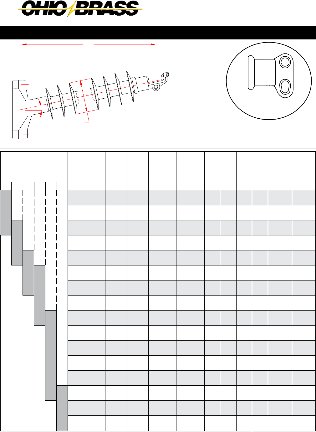
26-16
JULY 2010 OHIO BRASS – AIKEN, SC, USA
69 345230138 161115
Selection Guide
Typical
Line Voltage, kV
Notes: (1) Tests in accordance with ANSI C29.1-1982. Electrical values are without corona ring.
(2) RCL is the maximum continuous load at which the post should be applied.
For voltages above 161 kV refer to Page 26-15 for Corona Rings.
Dimensions are within allowable tolerances as specified in ANSI C29.11.
“X”
Length
Inches
(mm)
33.5
(851)
38.6
(980)
43.9
(1115)
49.2
(1250)
54.5
(1384)
59.6
(1514)
64.8
(1646)
70.1
(1781)
75.4
(1915)
80.5
(2045)
85.8
(2180)
91.1
(2314)
96.3
(2446)
101.4
(2575)
106.7
(2710)
112.0
(2845)
Catalog #
with
Gain Base
& Clamptop
End Fittings
5220041100
5220051100
5220061100
5220071100
5220081100
5220091100
5220101100
5220111100
5220121100
5220131100
5220141100
5220151100
5220161100
5220171100
5220181100
5220191100
No.
of
Sheds
8
10
12
14
16
18
20
22
24
26
28
30
32
34
36
38
Dry Arc
Distance
inches
(mm)
23
(584)
28
(711)
33
(838)
39
(991)
44
(1118)
49
(1245)
55
(1397)
60
(1524)
65
(1651)
71
(1803)
76
(1930)
81
(2057)
87
(2210)
92
(2337)
97
(2464)
103
(2616)
Leakage
Distance
inches
(mm)
54
(1372)
68
(1727)
82
(2083)
96
(2438)
110
(2794)
124
(3150)
138
(3505)
152
(3861)
166
(4216)
180
(4572)
194
(4928)
208
(5283)
222
(5639)
236
(5994)
250
(6350)
264
(6706)
(1) 60
Flashover
ANSI
(1) Critical
Flashover
ANSI
Net
Weight
pounds
(kg)
47
(21.3)
50
(22.7)
54
(24.5)
57
(25.9)
61
(27.7)
65
(29.5)
68
(30.9)
72
(32.7)
75
(34.1)
79
(35.9)
82
(37.2)
86
(39.0)
89
(40.4)
93
(42.2)
97
(44.0)
100
(45.4)
RCL
pounds
(kN)
2500
(11.1)
2500
(11.1)
2135
(9.5)
1865
(8.3)
1650
(7.3)
1490
(6.6)
1350
(6.0)
1235
(5.5)
1140
(5.0)
1060
(4.7)
990
(4.4)
925
(4.1)
870
(3.6)
820
(3.6)
780
(3.5)
740
(3.3)
Dry-kV
215
270
325
385
440
490
545
600
650
700
755
805
855
905
955
1005
Wet-kV
195
245
295
340
385
430
475
520
560
600
635
675
710
745
780
810
Pos-kV
340
420
505
590
675
760
845
930
1015
1095
1180
1265
1350
1435
1520
1605
Neg-kV
455
535
620
705
785
865
950
1035
1115
1195
1280
1365
1445
1525
1610
1695
2.5" (63.5mm) Rod Diameter Horizontal Line Posts
Clamptop:
Maximum Design Tension = 2,500 lb (11.1 kN)
Two-Hole Blade:
Maximum Design Tension = 7,500 lb. (33.4 kN)
See Page 26-20
Two Hole Blade End Fitting
Reduces the “X” dimension
by .75"
Line & Base Detail see pages 26-19 & 26-20
12?
7.62 DIA
X
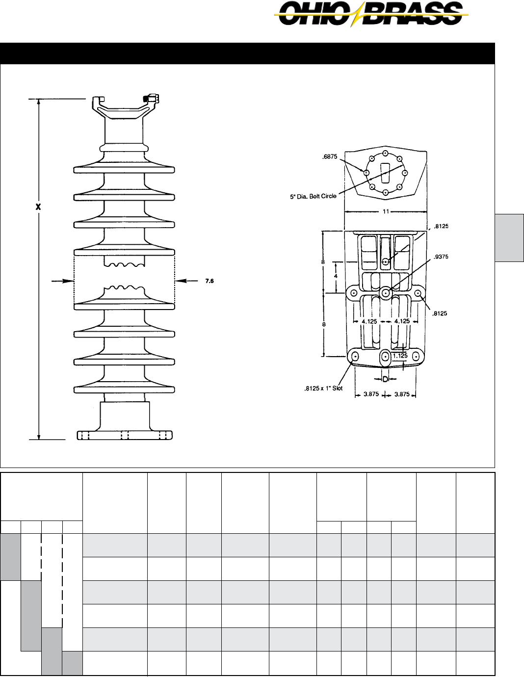
26-17
B
JULY 2010OHIO BRASS – AIKEN, SC, USA
Line & Base Fitting Detail see pages 26-19 & 26-20
69
Net
Weight
pounds
(kg)
27
(12.3)
30
(13.6)
34
(15.4)
37
(16.8)
41
(18.6)
45
(20.4)
Notes: (1) Tests in accordance with ANSI C29.1-1982.
(2) RCL is the maximum cantilever continuous load at which the post should be applied.
(3) Mounting Base Catalog No. 75115 may be ordered with these Catalog numbers for a vertical assembly.
115 138 161
Selection Guide
Typical
Line Voltage, kV
Catalog #
with 5" Bolt
Circle & Vert.
Clamptop(3)
5220041205
5220051205
5220061205
5220071205
5220081205
5220091205
“X”
Length
Inches
(mm)
30.7
(780)
35.9
(912)
41.3
(1049)
46.7
(1186)
52.1
(1323)
57.4
(1458)
No.
of
Sheds
8
10
12
14
16
18
Dry Arc
Distance
inches
(mm)
23
(584)
28
(711)
33
(838)
39
(991)
44
(1118)
49
(1245)
Leakage
Distance
inches
(mm)
54
(1371)
68
(1727)
82
(2083)
96
(2438)
110
(2734)
124
(3150)
(1) 60
Flashover
ANSI
(1) Critical
Flashover
ANSI
Dry-kV
215
270
325
385
440
490
Wet-kV
195
245
295
340
385
430
Pos-kV
340
420
505
590
675
760
Neg-kV
455
535
620
705
785
865
RCL
pounds
(kN)
2500
(11.1)
2475
(11.0)
2115
(9.4)
1850
(8.2)
1640
(7.3)
1480
(6.6)
Maximum Design Tension
2,500 lb (11.1 kN)
2.5" (63.5mm) Rod Diameter Vertical Line Posts
Aluminum Alloy
A356-T6
Catalog No. 75115
134,400 In.-Lb. Rating
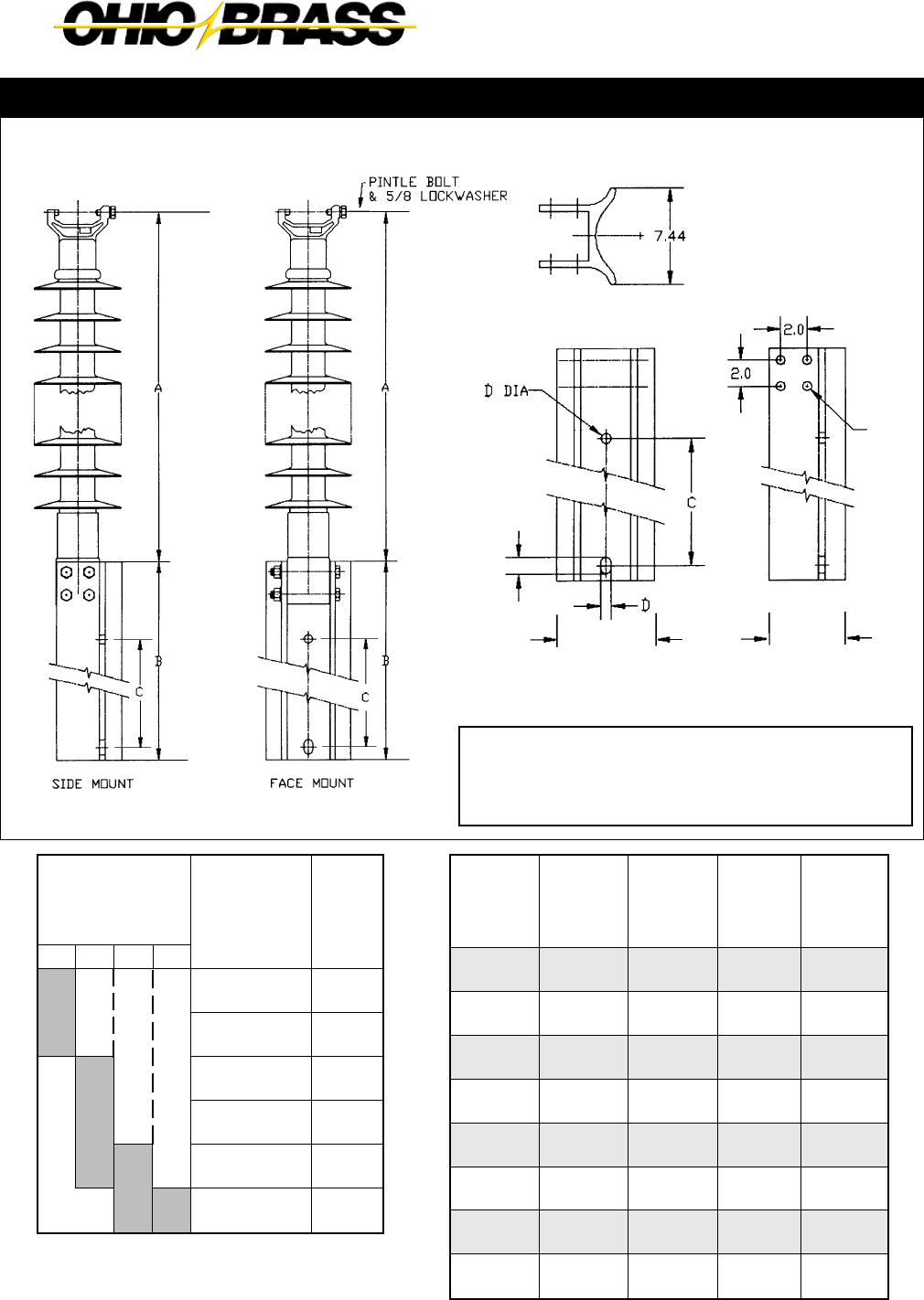
26-18
JULY 2010 OHIO BRASS – AIKEN, SC, USA
Line End Fitting Detail see pages 26-19 & 26-20
2.5" (63.5mm) Rod Diameter Vertical Line Post Assembly
Aluminum Alloy
6063-T5
Base Detail
To Order an Assembly - Pick an insulator from
Table A based on your Electrical and Mechanical
needs — next, select a Base configuration from
Table B, for your mounting position needs.
0.678 DIA.
4 HOLES
5.757.438
1.625
69
(1) Insulators in Table A have the same electrical and mechanical
characteristics as those on Page 26-17 with Code 1205.
Table A
115 138 161
Selection Guide
Typical
Line Voltage, kV
(1)Catalog #
with Vertical
Clamptop &
Base Code
52200412XX
52200512XX
52200612XX
52200712XX
52200812XX
52200912XX
“A”
Length
Inches
(mm)
30.4
(772)
35.6
(904)
41.0
(1041)
46.4
(1179)
51.8
(1316)
57.0
(1448)
“XX”
Code
20
21
22
23
24
25
26
27
Style
Face
Side
Face
Side
Face
Side
Face
Side
“B”
Length
Inches
(mm)
20
(508)
20
(508)
20
(508)
20
(508)
31.75
(806)
31.75
(806)
31.75
(806)
31.75
(806)
“C”
Length
Inches
(mm)
12
(305)
12
(305)
12
(305)
12
(305)
16
(406)
16
(406)
16
(406)
16
(406)
“D”
Diameter
Inches
(mm)
.8125
(21)
.8125
(21)
.9375
(24)
.9375
(24)
.8125
(21)
.8125
(21)
.9375
(24)
.9375
(24)
Table B

26-19
B
JULY 2010OHIO BRASS – AIKEN, SC, USA
Al & Steel FlatAl & Steel Gain
Horizontal & Vertical Bases Dimensions (in inches)
Type (Code)*
Unitary D.I. Gain (00)
Unitary D.I. Flat (01)
5" B.C. (15)
5" B.C. (05)
Al Gain (02)
Al Gain (12)
Steel Gain (07)
Al Flat (03)
Al Flat (13)
Steel Flat (08)
Al Flat (04)
Al Flat (14)
A
12.0
10.0
4.75
4.75
12.0
12.0
12.0
10.0
10.0
13.0
13.0
13.0
B
14.0
12.2
6.25
6.25
14.0
14.0
15.0
12.0
12.0
15.0
15.0
15.0
C
1.75
8.0
3.63
3.63
-
-
-
8.0
8.0
8.0
8.0
8.0
E
-
5.0
5.0
5.0
6.13
6.13
6.5
5.0
5.0
6.5
6.5
6.5
F
3.54
-
-
-
5.56
5.56
6.04
4.0
4.0
4.0
4.0
4.0
D
8.06
10.0
0.90
0.90
8.06
8.06
8.33
10.0
10.0
10.0
10.0
10.0
G
0.5
0.8
-
-
0.5
0.5
0.38
0.5
0.5
0.5
0.5
0.5
H
12°
12°
-
-
12°
12°
12°
12°
12°
12°
12°
12°
I
0.94
0.94
0.69
5/8 - 11 UFS
0.94
0.81
0.94
0.94
0.81
1.125 x 0.94
0.94
0.81
J
0.94 x 1.31
-
-
-
0.94 x 1.31
0.94 x 1.31
0.94 x 2.0
-
-
0.94 x 2
0.94 x 1.31
0.81 x 1.31
K
1.90
-
-
-
-
-
-
-
-
12.0
12.0
12.0
Material
60-45-12 D.I.
60-45-12 D.I.
60-45-12 D.I.
60-45-12 D.I.
6063 T5 Al
6063 T5 Al
Low Carbon Steel
6063 T5 Al
6063 T5 Al
Low Carbon Steel
6063 T5 Al
6063 T5 Al
*Code is the third and fourth numbers in the Suffix Code of the Catalog Number.
Unitary Gain Unitary Flat
2.5" (63.5 mm) Rod Diameter Base Fittings
Standard Gain Base
has a 90° opening. For
other available openings,
contact Ohio Brass.
A
C
G
I
H

26-20
JULY 2010 OHIO BRASS – AIKEN, SC, USA
Two Hole Blade
*12° upsweep post angles
Horizontal Clamptop
Vertical Clamptop
Part per ANSI C29.7
5" Bolt Circle
Line or Base Fitting
Horizontal & Vertical End Fittings Dimensions (in inches)
Material
60-40-18 D.I.
60-40-18 D.I.
60-40-18 D.l.
60-45-12 D.I.
60-45-12 D.I.
60-40-18 D.I.
Type (Code)*
2 Hole Blade (0)
2 Hole Long Blade (9)
H. Clamptop (1)
5" B.C. (3)
5" B.C. (5)
V. Clamptop (2)
L
0.5R
0.5R
-
-
-
-
M
0.44 R
0.44R
-
-
-
-
B
4.0
4.0
4.0
6.25
6.25
4.0
A
5.73
5.73
8.24
4.75
4.75
5.88
C
-
-
3.30
3.63
3.63
3.30
D
0.75
0.75
1.12
0.90
0.90
1.12
E
5.25
7.75
4.72
5.0
5.0
5.37
F
1.25
1.25
4.0
-
-
4.0
G
1.50
4.0
-
-
-
1.06
H
2.00
4.5
-
-
-
-
I
1.0
1.0
5/8 - 11 UFS
5/8 - 11 UFS
0.69 x Holes
5/8 - 11 UFS
J
1.44
1.44
0.75
-
-
-
*Code is the 2nd number in the Suffix Code of the Catalog Number.
2.5" (63.5 mm) Rod Diameter Line Fittings
2 Hole Long Blade
64 deg. max.
2 Hole Blade (Std.)
40 deg. max.
Transverse Compressing Swing Angle
for Conductor Suspension Clamp

26-21
B
JULY 2010OHIO BRASS – AIKEN, SC, USA
Application
Line End
Energized
230 kV
Top - NONE
Bott. - NONE
345 kV
Top - 2737743001
Bott. - NONE
138/161 kV
Top - NONE
Bott. - NONE
Corona Rings
Hi*Lite XL line post insulators are corona-free through
230 kV line-to-ground.
3.0" (76.2 mm) Rod Diameter Line Posts
Recommended
Torque
45 FT.-Lb.
Recommended
Torque
10 FT.-Lb.
Hi*Lite XL Line Post Insulators:
Key to the Catalog Numbers
5 2 3 0 14
00
81
Hi*Lite XL
XL Post
Strength
3 = 3.0" DIA
Construction
0 = Standard
1 = Dulled HDW
Weathershed Configuration
To determine the number of insulator
sheds, multiply this number by two.
Line End Fittings
Two Hole Blade ...........................0
Horizontal Clamptop ...................1
Vertical Clamptop .......................2
Base End Fittings
Al Gain (1-1/16" Hole and 1-1/16" x 2-5/9" Slot).......02
St Flat 14" CL (1-1/16" x 2-9/16" Slots) ....................04
5" Bolt Circle (Tapped) ..............................................05
St Gain (1-1/16" Hole and 1-1/16" x 2-5/9" Slot) ......07
St Flat 9" x 13" (59/64" Holes) ..................................08
Part Number 2737743001
Control Ring
(1) Metric labeling only. Insulators and hardware are ANSI.
Labeling
1 = English
2 = Metric (1)
M = English w/15"
Corona Ring
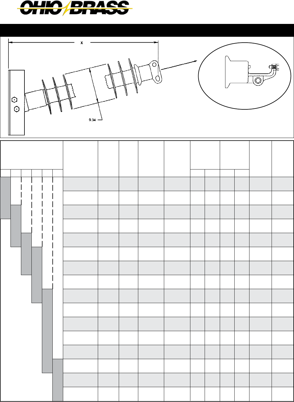
26-22
JULY 2010 OHIO BRASS – AIKEN, SC, USA
69 345230138 161115
Selection Guide
Typical
Line Voltage, kV
Notes: (1) Tests in accordance with ANSI C29.1-1982. Electrical values are without corona ring.
(2) RCL is the maximum continuous load at which the post should be applied.
For voltages above 230 kV refer to Page 26-21 for Corona Rings. Electrical values are shown
for insulators without rings. For electricals with rings, contact Ohio Brass.
“X”
Length
Inches
(mm)
38.8
(986)
43.8
(1113)
49.0
(1245)
54.8
(1392)
59.3
(1506)
64.5
(1638)
69.5
(1765)
74.7
(1897)
79.9
(2029)
85.0
(2159)
90.2
(2291)
95.2
(2418)
100.4
(2550)
105.5
(2680)
110.7
(2812)
115.9
(2944)
Catalog #
with
Flat Base
& Two Hole
Blade
5230051004
5230061004
5230071004
5230081004
5230091004
5230101004
5230111004
5230121004
5230131004
5230141004
5230151004
5230161004
5230171004
5230181004
5230191004
5230201004
No.
of
Sheds
10
12
14
16
18
20
22
24
26
28
30
32
34
36
38
40
Dry Arc
Distance
inches
(mm)
29
(737)
34
(864)
39
(991)
45
(1143)
50
(1270)
55
(1397)
60
(1524)
66
(1676)
71
(1803)
76
(1930)
82
(2083)
87
(2210)
92
(2337)
98
(2489)
103
(2616)
108
(2743)
Leakage
Distance
inches
(mm)
77
(1956)
93
(2362)
108
(2743)
124
(3150)
140
(3556)
156
(3962)
171
(4343)
187
(4750)
203
(5156)
218
(5537)
234
(5944)
250
(6350)
265
(6731)
281
(7137)
297
(7544)
313
(7950)
(1) 60
Flashover
ANSI
(1) Critical
Flashover
ANSI
Net
Weight
pounds
(kg)
90
(40.8)
95
(43.1)
100
(40.9)
106
(48.1)
110
(49.9)
115
(52.2)
120
(54.4)
125
(56.7)
130
(58.9)
135
(61.2)
141
(63.9)
146
(66.2)
151
(68.5)
156
(70.8)
161
(73.1)
166
(75.3)
(2)RCL
pounds
(kN)
4405
(19.6)
3780
(16.8)
3295
(14.7)
2920
(13.0)
2620
(11.7)
2380
(10.6)
2185
(9.7)
2015
(9.0)
1865
(8.3)
1740
(7.7)
1630
(7.2)
1535
(6.8)
1450
(6.5)
1370
(6.1)
1300
(5.8)
1240
(5.5)
Dry-kV
295
345
395
445
495
545
590
640
685
735
780
825
870
915
960
1000
Wet-kV
250
295
335
380
420
465
505
550
590
640
670
710
755
795
835
875
Pos-kV
445
530
615
695
780
865
950
1035
1120
1205
1290
1370
1455
1540
1625
1710
Neg-kV
540
620
705
790
870
955
1035
1120
1200
1285
1365
1445
1530
1615
1695
1780
3.0" (76.2mm) Rod Diameter Horizontal Line Posts
See Page 26-25
Line & Base Detail see Pages 26-24 & 26-25
Clamptop:
Maximum Design Tension = 2,500 lb (11.1 kN)
Two-Hole Blade:
Maximum Design Tension = 12,500 lb. (55.6 kN)
Horizontal Clamptop End Fitting
Increases the “X” dimension
by 1"
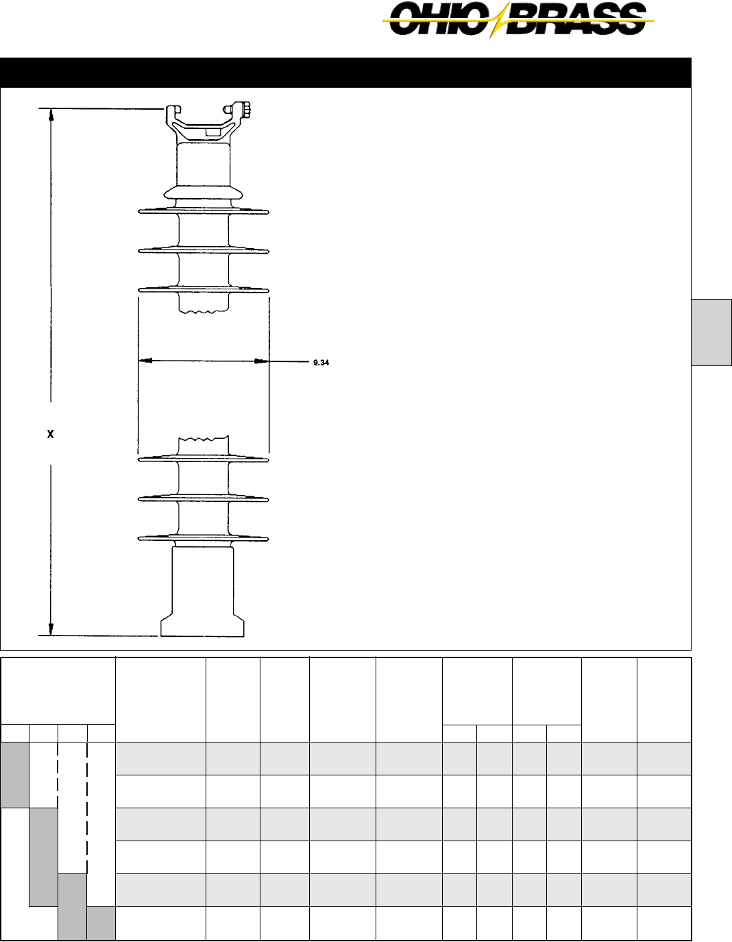
26-23
B
JULY 2010OHIO BRASS – AIKEN, SC, USA
69
Net
Weight
pounds
(kg)
54
(24.5)
59
(26.8)
64
(29.1)
69
(31.4)
74
(33.6)
79
(35.9)
Notes: (1) Tests in accordance with ANSI C29.1-1982.
(2) RCL is the maximum cantilever continuous load at which the post should be applied.
115 138 161
Selection Guide
Typical
Line Voltage, kV
Catalog #
with 5" Bolt
Circle & Vert.
Clamptop
5230051205
5230061205
5230071205
5230081205
5230091205
5230101205
“X”
Length
Inches
(mm)
38.0
(965)
43.2
(1097)
48.5
(1219)
53.8
(1367)
59.2
(1504)
64.5
(1638)
Dry Arc
Distance
inches
(mm)
29
(737)
34
(864)
39
(991)
45
(1143)
50
(1270)
55
(1397)
Leakage
Distance
inches
(mm)
77
(1956)
93
(2362)
108
(2743)
124
(3150)
140
(3556)
156
(3962)
(1) 60
Flashover
ANSI
(1) Critical
Flashover
ANSI
Wet-kV
250
295
335
380
420
465
Pos-kV
445
530
615
695
780
865
Neg-kV
540
620
705
785
870
950
(2)RCL
pounds
(kN)
2500
(11.1)
2500
(11.1)
2500
(11.1)
2500
(11.1)
2500
(11.1)
2335
(10.4)
No.
of
Sheds
10
12
14
16
18
20
Dry-kV
295
345
395
445
495
545
Line & Base Fitting Detail see pages 26-24 & 26-25
Maximum Design Tension
2,500 lb (11.1 kN)
3.0" (76.2 mm) Rod Diameter Vertical Line Posts
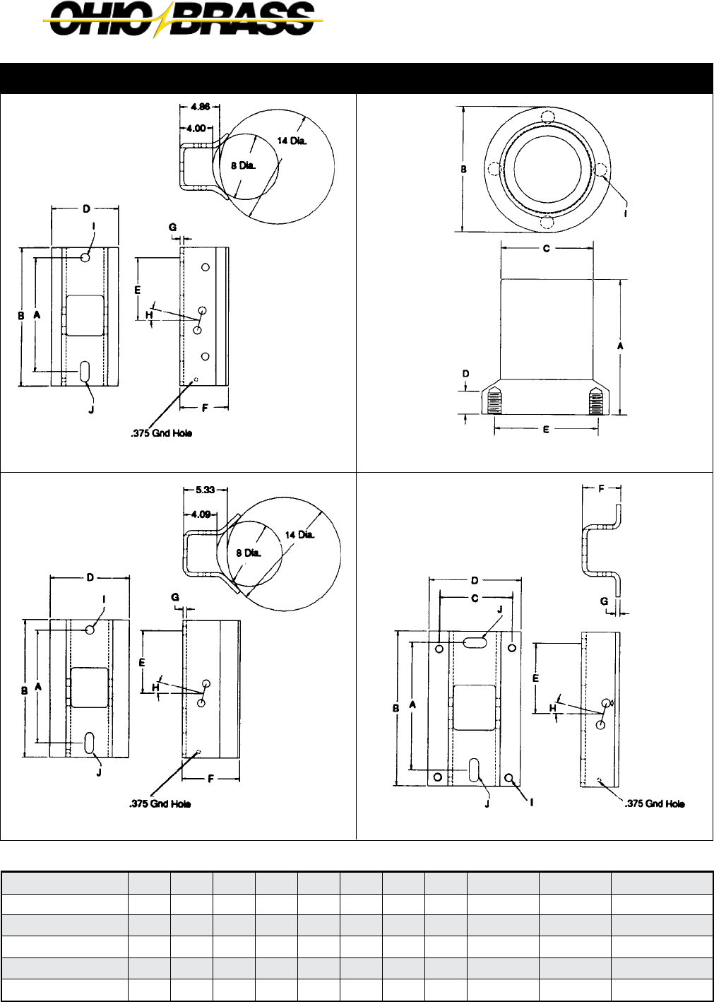
26-24
JULY 2010 OHIO BRASS – AIKEN, SC, USA
Horizontal & Vertical Bases Dimensions (in inches)
Type (Code)*
5" B.C. (05)
Al Gain (02)
Steel Gain (07)
Steel Flat (08)
Steel Flat (04)
A
6.36
14.0
14.0
13.0
14.0
B
5.9
17.0
17.0
15.0
17.0
C
4.37
-
-
9.0
-
E
5.0
7.75
7.75
6.5
7.75
F
-
5.949
7.03
4.12
4.12
D
1.2
8.079
9.65
11.0
10.0
G
-
0.53
0.5
0.5
0.5
H
-
14°
14°
14°
14°
I
5/8 - 11 UFS
1.06
1.06
0.938
-
J
-
1.06 x 2.56
1.06 x 2.56
-
1.06 x 2.56
Material
60-40-18 D.I.
6063 T5 Al
Low Carbon Steel
Low Carbon Steel
Low Carbon Steel
*Code is the 2nd number in the Suffix Code of the Catalog Number.
Steel FlatSteel Gain
Hi*Lite XL 3.0" Rod Dia. Base Fittings
Aluminum Gain 5" Bolt Circle

26-25
B
JULY 2010OHIO BRASS – AIKEN, SC, USA
*Code is the 2nd digit in the Suffix Code of the Catalog Number.
Vertical Clamptop
Part per ANSI C29.7
Horizontal Clamptop
Part per ANSI C29.7
Material
60-40-18 D.I.
60-40-18 D.l.
60-40-18 D.I.
B
5.63
5.63
5.63
A
6.16
8.64
6.31
Type (Code)*
2 Hole End (0)
H. Clamptop (1)
V. Clamptop (2)
C
3.84
3.84
3.84
D
0.75
1.12
1.12
E
6.12
4.72
5.37
F
1.57
4.0
4.0
G
2.0
-
1.06
H
2.5
-
-
I
-
5/8 - 11 UFS
5/8 - 11 UFS
J
1.44
0.75
-
K
1.24
-
-
L
0.5R
-
-
M
0.44 R
-
-
Horizontal & Vertical End Fittings Dimensions (in inches)
Two Hole Blade
Hi*Lite XL 3.0" Rod Dia. Line Fittings
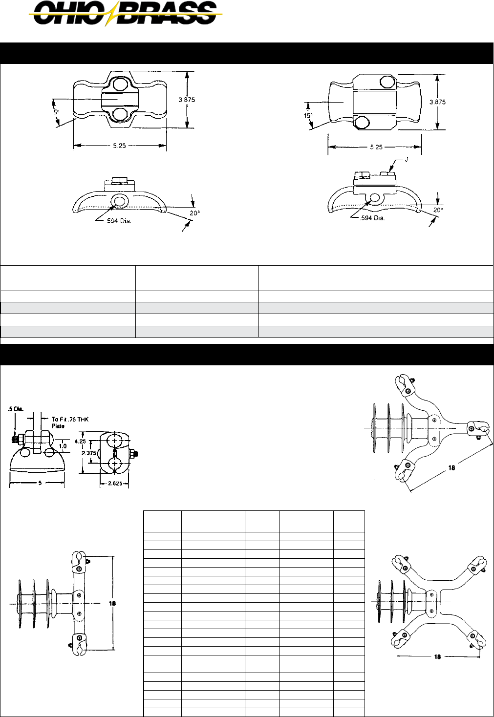
26-26
JULY 2010 OHIO BRASS – AIKEN, SC, USA
Figure 2 Figure 4
Figure 1 Figure 3
Clamptop Clamp
Jumper Clamps and Assemblies
A practical application of Hi*Lite line posts is for support
of jumper loops on transmission lines.
Horizontal motion of the jumper is restricted, and the factor
of wind sway is eliminated. Additionally the crossarm length
may be reduced. The Difference in cost of insulation is not
significant but, the savings in tower cost can be attractive.
Regardless of cost, the use of a jumper support improves
construction.
If using a single clamp, clamp position relative to the in-
sulator may be changed by bolting the clamp through the
upper hole in the insulator end fitting.
Jumper clamps are not intended for tangent span
applications.
Clamptop clamps can be mounted directly on Hi*Lite XL 250 posts if the posts are ordered with the horizontal or vertical clamptop option.
Figure 1 Figure 2
Figure Catalog
Number Yoke Type Clamping
Range (Inches)
Post
Type
1 976423002 None 1.00 - 1.40 Any
1 976423003 None 1.40 - 1.60 Any
1 600643001 None 1.60 - 2.00 Any
2 2717243001 Dual 1.00 - 1.40 250
2 2717253001 Dual 1.40 - 1.60 250
2 2717263001 Dual 1.60 - 2.00 250
2 2738383001 Dual 1.00 - 1.40 300
2 2738393001 Dual 1.40 - 1.60 300
2 2738403001 Dual 1.60 - 2.00 300
3 2721763001 Triple 1.00 - 1.40 250
3 2721773001 Triple 1.40 - 1.60 250
3 2721783001 Triple 1.60 - 2.00 250
3 2738413001 Triple 1.00 - 1.40 300
3 2738423001 Triple 1.40 - 1.60 300
3 2738433001 Triple 1.60 - 2.00 300
4 2721793001 Quad 1.00 - 1.40 250
4 2721803001 Quad 1.40 - 1.60 250
4 2721813001 Quad 1.60 - 2.00 250
4 2738443001 Quad 1.00 - 1.40 300
4 2738453001 Quad 1.40 - 1.60 300
4 2738463001 Quad 1.60 - 2.00 300
Catalog Number
TSC57
TSC106
TSC150
TSC200
Fig. No.
1
1
1
2
Body &
Keeper Material
356-T6 Al
356-T6 Al
356-T6 Al
356-T6 Al
Clamping Range
Inches (mm)
0.25-057 (6.3-14.4)
0.50-1.06 (12.7-26.9)
1.00-1.50 (25.4-38.1)
1.50-2.00 (38.1-50.8)
Ultimate Body Strength
Lbs. (kN)
2800 (1.273)
2800 (1.273)
2800 (1.273)
2800 (1.273)

26-27
C
JULY 2010OHIO BRASS – AIKEN, SC, USA
Hi*Lite® XL
Braced Posts
Table of Contents
Page
Dimension and Strength Ratings .................... 26-28
Assembly Drawings ........................................ 26-29

26-28
JULY 2010 OHIO BRASS – AIKEN, SC, USA
Catalog number covers complete assembly including
insulator and hardware as illustrated.
The need to minimize the tower size and visual impact of
transmission lines has prompted increased interest in braced
line posts, horizontal-V, and pivoting V assemblies. These
insulating structures offer vastly improved vertical load
capabilities over conventional lines posts while retaining the
advantages of a fixed conductor position.
A braced line post uses a conventional line post with a sus-
pension string tied to the tower face with a link. A horizontal-V
replaces the link with a fixed offset extending from the tower
face adding a stabilizing force to the assembly. Both these
assemblies are available with flat or gain bases.
A pivoting horizontal-V assembly utilizes a line post insulator
fastened to the structure with a hinged base. Alternatively, the
base may be replaced with a universal joint.
These assemblies are available for voltages up to and includ-
ing 345 kV with a wide variety of hardware to meet the needs
of your application. The figures illustrated depict typical ar-
rangements which provide an economical means of with-
standing unusual loads. For more information on these and
numerous other variations of line post assemblies, contact
your Ohio Brass representative.
DIMENSIONS AND
STRENGTH RATINGS
Suspension
511010
511211
511013
511014
511018
511219
BRACED LINE POST ASSEMBLY
Typical
System
kV
115/138
115/138
161
161
230 *
230 *
Cat #
Gain
Base
234220
234222
234224
234226
234228
234230
Cat #
Flat
Base
234221
234223
234225
234227
234229
234231
Post
522008
522009
522010
522011
522014
522015
Component
Insulators
Vertical
11280
11280
11280
11280
11280
11280
Tension
7500
7500
7500
7500
7500
7500
Longitudinal
1730
1550
1410
1280
1020
960
Dimensions (in.) Maximum Loadings** (lb.)
A
53.7
58.8
64.1
69.4
85.0
90.3
B
72.8
81.9
91.1
97.2
121.6
130.7
C
74.0
83.0
91.0
96.0
118.0
127.0
X
2
2
2
2
2
2
D
79.8
88.9
98.1
104.2
128.6
137.7
Compres-
sion
12500
12500
12500
12500
11810
10470
Suspension
511007
511008
511009
511010
511013
511014
HORIZONTAL V ASSEMBLY
Typical
System
kV
115/138
115/138
161
161
230 *
230 *
Cat #
Gain
Base
234232
234234
234236
234238
234240
234242
Cat #
Flat
Base
234233
234235
234237
234239
234241
234243
Post
522008
522009
522010
522011
522014
522015
Component
Insulators
Vertical
9980
9980
9980
9980
9980
9980
Tension
7500
7500
7500
7500
7500
7500
Longitudinal
1680
1510
1370
1250
1000
930
Dimensions (in.) Maximum Loadings** (lb.)
A
54.9
60.1
65.5
70.9
86.9
92.3
B
54.6
60.7
66.7
72.8
91.1
97.2
C
51.0
56.0
61.0
66.0
80.0
85.0
X
18
20
22
24
28
30
D
61.6
67.7
73.7
79.8
98.1
104.2
Compres-
sion
12500
12500
12500
12500
12500
12500
Suspension
511007
511008
511009
511010
511013
511014
PIVOTING HORIZONTAL V ASSEMBLY
Typical
System
kV
115/138
115/138
161
161
230 *
230 *
Cat #
Gain
Base
—
—
—
—
—
—
Cat #
Flat
Base
234244
234245
234246
234247
234248
234249
Post
522008
522009
522010
522011
522014
522015
Component
Insulators
Vertical
9980
9980
9980
9980
9980
9980
Tension
7500
7500
7500
7500
7500
7500
Longitudinal
—
—
—
—
—
—
Dimensions (in.) Maximum Loadings** (lb.)
A
55.2
60.4
65.8
71.2
87.2
92.6
B
54.6
60.7
66.7
72.8
91.1
97.2
C
51.0
56.0
61.0
66.0
80.0
85.0
X
18
20
22
24
28
30
D
61.6
67.7
73.7
79.8
98.1
104.2
Compres-
sion
12500
12500
12500
12500
12500
12500
Contact your Ohio Brass representative for designs utilizing the optional pivoting strut member.
* Corona rings are required for 230 kV and above.
** Maximum loads are for single loads in the specified direction.
Hi*Lite® XL
Assemblies
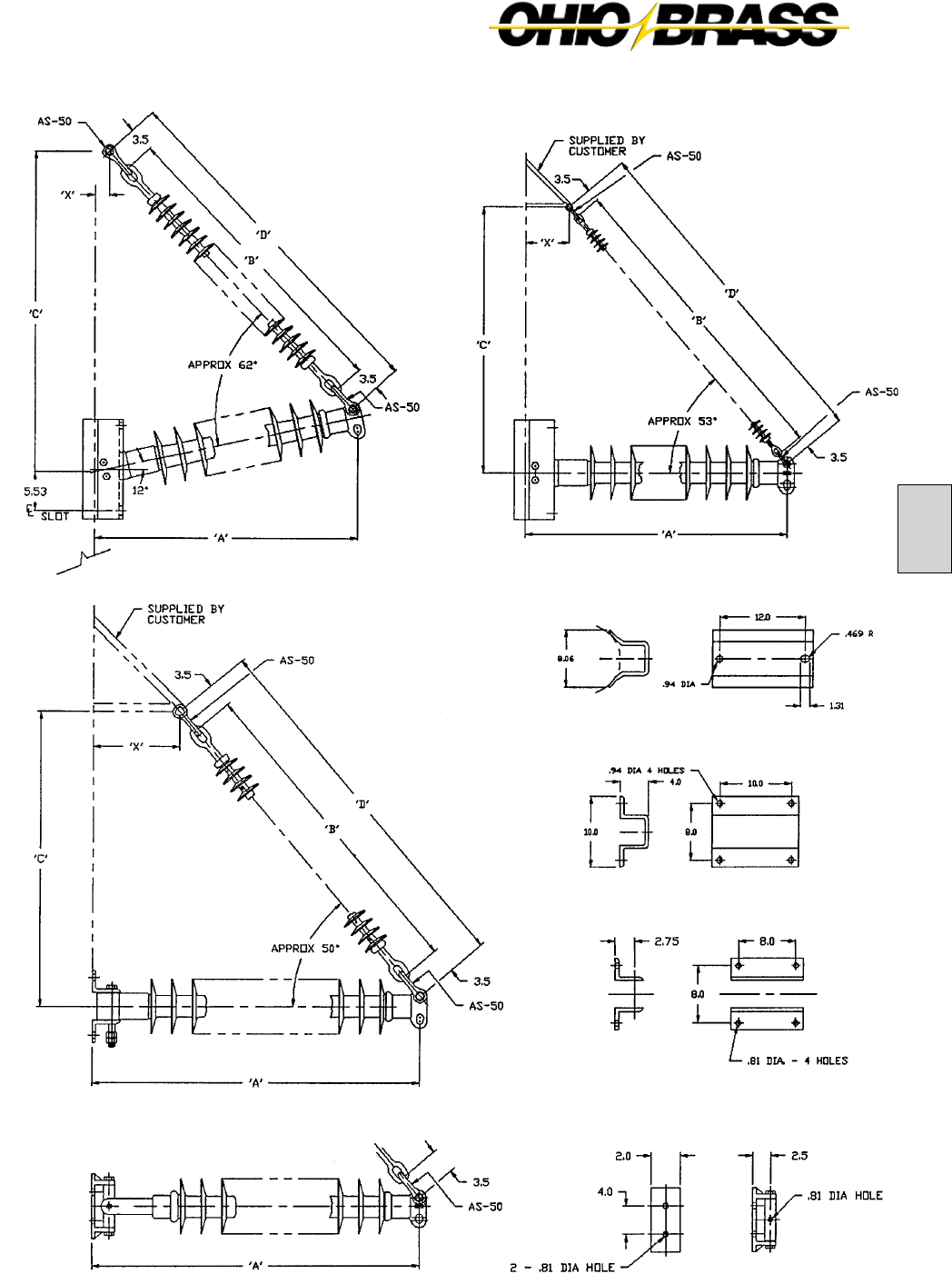
26-29
C
JULY 2010OHIO BRASS – AIKEN, SC, USA
OPTIONAL PIVOTING STRUT MEMBER
FLAT BASE MOUNTING
PIVOTING BASE MOUNTING
PIVOTING HORIZONTAL-V
BRACED LINE POST HORIZONTAL-V
GAIN BASE MOUNTING
Assembly Drawings

26-30
JULY 2010 OHIO BRASS – AIKEN, SC, USA
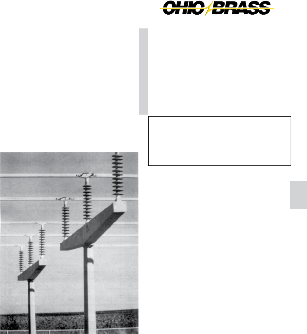
26-31
D
JULY 2010OHIO BRASS – AIKEN, SC, USA
HI-LITE II POST INSULATORS
Maximum Design Cantilever Rating (MDC)
MDC is the maximum recommended load in cantilever
that a Hi*Lite post insulator is designed to withstand dur-
ing its service life.
Average Failing Load (AFL)
AFL is the average failing load of a Hi*Lite line or station
post insulator. This value can be determined by multiplying
the MDC by a factor of 2.5.
Selection
If you need a Hi*Lite post that is different from those shown
in this catalog, please contact your OB representative.
Hi*Lite station posts meet electrical and dimensional
specifications of their porcelain equivalents. Mechanically,
the Hi*Lite are less rigid with more deflection under both
cantilever and torsional loading.
HI*LITE II
STATION
POST
INSULATORS
Table of Contents
Page
Station Post Insulator Ratings ........................ 26-31
Series 175: 3" Bolt Circles .............................. 26-32
Series 250: 3" and 5" Bolt Circles ................... 26-33
NOTE: Insulators listed here are Hi-Lite II
design having individual weathersheds
assembled to the core rod and sealed
via axial compression in the polymer
rubber material.
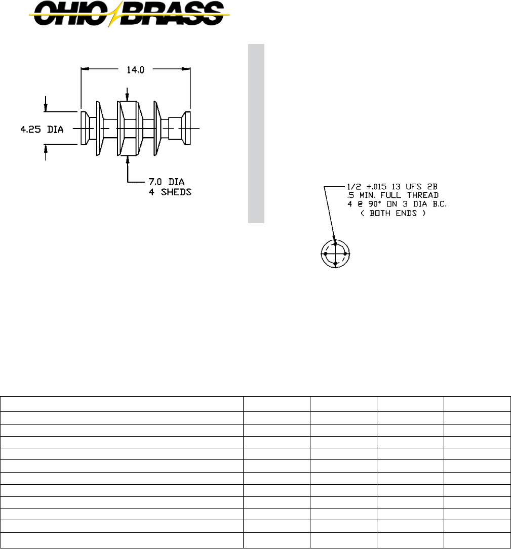
26-32
JULY 2010 OHIO BRASS – AIKEN, SC, USA
Note: Station Posts are also available in non-standard section lengths.
Contact your Ohio Brass representative.
CATALOG NUMBER (3" BOLT CIRCLES)
BIL (kV)
Height — X in. (mm)
Leakage Distance in. (mm)
60-Hz Withstand — 10 sec/wet (kV)
Maximum Design Cantilever lb. (kN)
Maximum Design Tension lb. (kN)
Maximum Design Compression lb. (kN)
Maximum Design Torsion in.-lb. (N-meter)
Deflection at Stated Cantilever in. (mm)
Weathersheds
Net Weights lb. (kg.)
HI*LITE II
STATION POST
INSULATORS
Series 175
3" (76mm) Bolt Circles
NOTE: Insulators listed here are Hi-Lite II design
having individual weathersheds assembled
onto the core rod and sealed via axial com-
pression in the polymer shed material.
2326863001
2326863001
150
14 (356)
27 (685)
80
2390 (10.67)
10,000 (44.5)
10,000 (44.5)
3000 (339)
0.31 (7.9)
4
22.5 (10.2)
2326853001
200
18 (457)
40 (1015)
120
1750 (7.78)
10,000 (44.5)
15,000 (66.7)
3000 (339)
0.62 (15.9)
6
25 (11.3)
2331923001
250
22 (559)
49 (1240)
150
1390 (6.23)
10,000 (44.5)
15,000 (66.7)
3000 (339)
1.02 (25.9)
7
28 (12.7)
2331873001
350
30 (762)
76 (1930)
230
980 (4.39)
10,000 (44.5)
15,000 (66.7)
3000 (339)
2.16 (54.9)
11
33 (15.0)
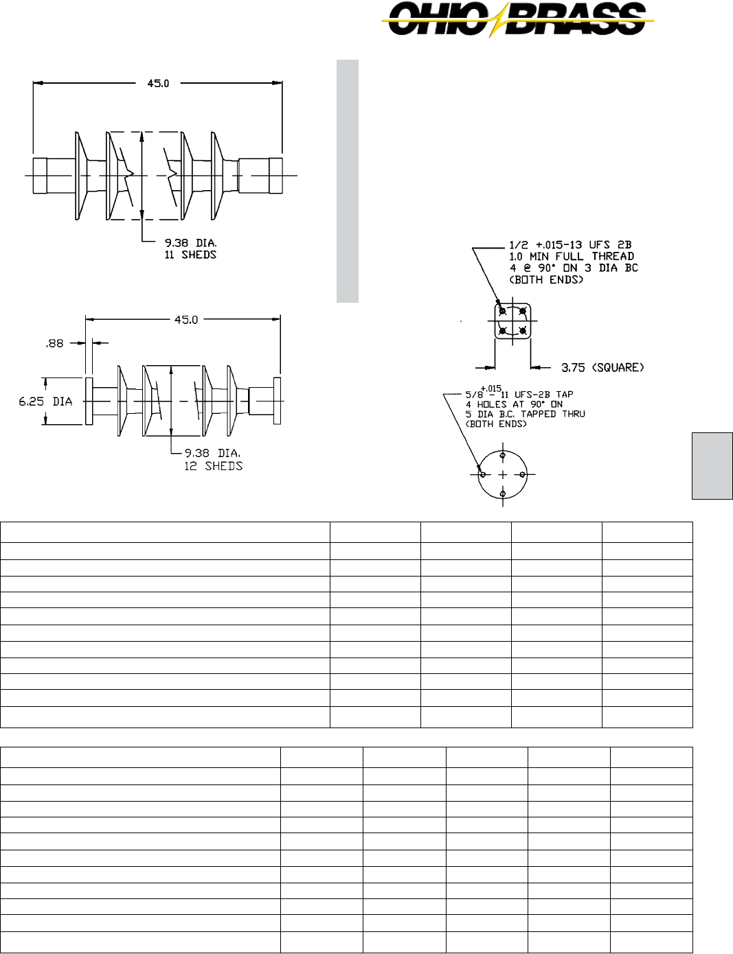
26-33
D
JULY 2010OHIO BRASS – AIKEN, SC, USA
Notes: 1. Station Posts are also available in non-standard section lengths. Contact Ohio Brass.
2. At 230 kV, corona ring 2721273001 may be required.
3. For through holes, specify code 3002.
CATALOG NUMBER (5" BOLT CIRCLES)
BIL (kV)
Height — X in. (mm)
Leakage Distance in. (mm)
60-Hz Withstand — 10 sec/wet (kV)
Maximum Design Cantilever lb. (kN)
Maximum Design Tension lb. (kN)
Maximum Design Compression lb. (kN)
Maximum Design Torsion in.-lb. (N-meter)
Deflection at Stated Cantilever in. (mm)
Weathersheds
Net Weights lb. (kg.)
2323753001
900
80 (2032)
204 (5180)
560
990 (4.45)
30,000 (133)
35,000 (156)
9,000 (66.7)
13.50 (343)
22
72 (32.7)
CATALOG NUMBER (3" BOLT CIRCLES)
BIL (kV)
Height — X in. (mm)
Leakage Distance in. (mm)
60-Hz Withstand — 10 sec/wet (kV)
Maximum Design Cantilever lb. (kN)
Maximum Design Tension lb. (kN)
Maximum Design Compression lb. (kN)
Maximum Design Torsion in.-lb. (N-meter)
Deflection at Stated Cantilever in. (mm)
Weathersheds
Net Weights lb. (kg.)
2323013001
350
30 (762)
63 (1570)
190
1400 (6.23)
30,000 (133)
50,000 (222)
9,000 (1000)
1.0 (25)
7
30 (13.6)
2323003001
650
54 (1372)
128 (3250)
380
770 (3.42)
30,000 (133)
50,000 (222)
9,000 (1000)
3.4 (86)
14
51 (23)
2323093001
750
62 (1575)
148 (3760)
430
670 (2.98)
30,000 (133)
50,000 (222)
9,000 (1000)
4.5 (114)
16
54 (24.5)
2321993001
550
45 (1143)
102 (2590)
300
930 (4.14)
30,000 (133)
50,000 (222)
9,000 (1000)
2.3 (58)
11
42 (19)
2323363001
350
30 (762)
64 (1626)
190
2900 (12.90)
30,000 (133)
50,000 (222)
9000 (1000)
1.77 (45
8
30 (13.6)
2323373001
550
45 (1143)
109 (2770)
320
1850 (8.23)
30,000 (133)
50,000 (222)
9000 (1000)
4.13 (105)
12
42 (19)
2323383001
650
54 (1372)
130 (3300)
380
1520 (6.76)
30,000 (133)
50,000 (222)
9000 (1000)
6.00 (152)
14
51 (23)
2323393001
750
62 (1575)
156 (3960)
450
1310 (5.83)
30,000 (133)
50,000 (222)
9000 (1000)
8.00 (203)
17
54 (24.5)
HI*LITE II
STATION POST
INSULATORS
Series 250
5" (127mm) Bolt Circles
2323373001
2321993001

26-34
JULY 2010 OHIO BRASS – AIKEN, SC, USA
26-35
E
JULY 2010OHIO BRASS – AIKEN, SC, USA
Sample Polymer Specification
Purpose: To ensure a suitable service life of polymer insulating materials.
I. Material Design Tests
- The following must be performed to certify a material for use in production.
1. Tracking test: Performed on a sample of material inclined at 30° and electrodes
positioned 35mm apart. Samples are sprayed with a conductive solution (400Ωcm)
and energized at 10kV. The cycle is repeated every 90 seconds. The sample passes
if there is:
1. No carbonization or tracking.
2. No erosion through sample.
3. No leakage current flow at the end of 90 seconds.
The sample must withstand 15,000 test cycles.
2. Ultraviolet Test: Samples of the rubber must be tested in a QUV tester or equiva-
lent cyclic weatherometer. The samples are exposed to high ultraviolet radiation and
high humidity without cracking, checking or becoming hydrophilic.
The sample is judged to have passed this test if it exceeds 8,000 hours of exposure
without damage.
3. Corona Cutting: Samples 5 cm by 7 cm are subjected to mechanical stress of
300,000 µstrain by bending samples around a grounded electrode. A needle-like
electrode is placed 1 mm from the surface of the sample and energized at 12 kV in
a controlled humidity chamber.
The sample is judged to have passed this test if there is no splitting or cutting.
Samples must pass 1,000 hours of exposure to this test.
4. Oxidative Stability: Samples of the polymer compound are tested using differ-
ential scanning calorimetry. Samples are heated rapidly in a nitrogen atmosphere
to the test temperature of 200°C. The atmosphere is then changed to air and the
temperature is maintained until the antioxidant is consumed, as measured by an
exothermic chemical reaction. The time to this reaction must exceed 300 minutes.
5. Tear Strength: Rubber test slabs are prepared in accordance with ASTM Stan-
dards and are tested to determine tear strength of the material. The minimum ac-
ceptable tear strength is 150 lb./in.
II. Other Requirements
- The manufacturer must supply upon request a listing of routine tests performed to
ensure production compliance with design tests.

26-36
JULY 2010 OHIO BRASS – AIKEN, SC, USA
Web: http://www.hubbellpowersystems.com
E-mail: hpsliterature@hps.hubbell.com
MEXICO
HUBBELL DE MEXICO, S.A. DE C.V.
Av. Insurgentes Sur #1228, Piso 8
Col. Tlacoquemacatl Del Valle
Mexico, D.F. 03200
Phone: 52-55-9151-9999
Fax: 52-55-9151-9988
Website: hubbell.com.mx
UNITED STATES
CANADA, INTERNATIONAL
HUBBELL POWER SYSTEMS, INC.
210 N. Allen Street
Centralia, Mo 65240-1395
Phone: 1-573-682-5521
Fax: 1-573-682-8714
e-mail: hpsliterature@hps.hubbell.com
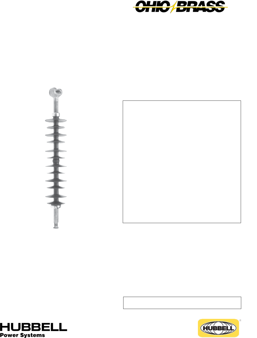
JULY 2010
27-1
OHIO BRASS – AIKEN, SC, USA
Table of Contents
Page
Design ............................................................................ 2
Rod ................................................................................. 2
End Fittings .................................................................... 2
Weathersheds ................................................................. 2
Interface ......................................................................... 2
Leakage Distance ........................................................... 2
Washability ..................................................................... 2
Mechanical Ratings ........................................................ 2
Lengths Available ........................................................... 2
Product Updates ............................................................ 2
Packaging ....................................................................... 2
Corona Performance ...................................................... 3
Key to the Catalog Numbers .......................................... 4
End Fitting Detail ............................................................ 4
Hi*Lite XL 120kN SML Data ........................................... 5
Hi*Lite XL 125kN SML Data ........................................... 6
Hi*Lite XL 160kN SML Data ........................................... 7
Hi*Lite XL 210kN SML Data ........................................... 8
Hi*Lite® XL
Suspension Insulators
ANSI C29.12/IEC 1109 TESTED
Warranty - Material
Hubbell Power Systems, Inc. warrants all products sold by it to be merchantable (as such
term is defined in the Uniform Commercial Code) and to be free from defects in material and
workmanship. Buyer must notify the Company promptly of any claim under this warranty. The
Buyer's exclusive remedy for breach of this warranty shall be the repair or replacement, F.O.B.
factory, at the Company's option, of any product defective under the warranty which is returned
to the Company within one year from the date of shipment. NO OTHER WARRANTY, WHETHER
EXPRESS OR ARISING BY OPERATION OF LAW, COURSE OF DEALING, USAGE OF
TRADE OR OTHERWISE IMPLIED, SHALL EXIST IN CONNECTION WITH THE COMPANY'S
PRODUCTS OR ANY SALE OR USE THEREOF. The Company shall in no event be liable for
any loss of profits or any consequential or special damages incurred by Buyer. The Company's
warranty shall run only to the first Buyer of a product from the Company, from the Company's
distributor, or from an original equipment manufacturer reselling the Company's product, and is
non-assignable and non-transferable and shall be of no force and effect if asserted by any per-
son other than such first Buyer. This warranty applies only to the use of the product as intended
by Seller and does not cover any misapplication or misuse of said product.
Warranty - Application
Hubbell Power Systems, Inc. does not warrant the accuracy of and results from product or
system performance recommendations resulting from any engineering analysis or study. This
applies regardless of whether a charge is made for the recommendation, or if it is provided free
of charge.
Responsibility for selection of the proper product or application rests solely with the purchaser. In
the event of errors or inaccuracies determined to be caused by Hubbell Power Systems, Inc., its
liability will be limited to the re-performance of any such analysis or study.
27
©Copyright 2010 Hubbell Incorporated
NOTE: Because Hubbell has a policy of continuous product improvement, we reserve the right to change design and specications without notice.
Printed in USA RGS 2M
®
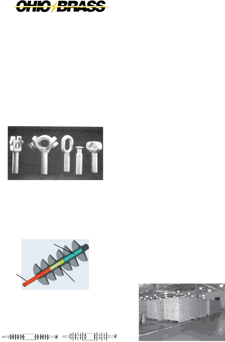
JULY 2010 OHIO BRASS – AIKEN, SC, USA
27-2
Hi*Lite® XL Insulators
Hi*Lite XL suspension insulators in this publication embody the lat-
est features available in polymer insulator design and manufacture.
From the early prototypes in 1971, through full scale introduction
in 1976, and through the succeeding years, Hi*Lite insulators have
featured conservative design and high-quality manufacture.
Today’s Hi*Lite insulators will add to the over 1,000,000 Hi*Lite
transmission insulators already in service worldwide.
Design
The structural design of the Hi*Lite XL consists of these basic parts:
Rod - Hi*Lite insulator fiberglass rod is produced from the highest
quality materials. Strands are aligned for maximum tensile strength.
The rod is more than 50 percent glass fibers in cross section.
End Fittings - End fittings are steel or ductile iron. They are crimped
directly to the rod by a special process originated by Ohio Brass,
and later adopted by many other producers. The crimp develops a
high percentage of the rod’s inherent tensile strength. It requires no
inter-movement of the parts to achieve high strength, nor does it
introduce potting compounds or adhesives.
Leakage Distance
Hi*Lite XL insulators feature high leakage distance for maximum
resistance to contamination and leakage currents. Specific leakage
distance (leakage divided by dry arcing distance) is higher than that
of porcelain. Hi*Lite XL insulators are offered in standard uniform
weathershed configuration and alternating (major/minor) weather-
shed configuration for applications requiring increased specified
leakage distances.
Washability
Hi*Lite XL insulators listed in this catalog are suitable for flood wash-
ing up to 1,380 kPA (200 psi) at the ground pump level at a distance
not less than 4.6 meters (15 ft.) The design incorporates positive,
labyrinth seals to ensure long-term security against water entry.
Conventional dry-particle, air-pressure cleaning methods may be
employed.
High Pressure wash designs are also available. Washing is permis-
sible for up to 6,900 kPA (1,000 psi) ground pump pressure at a
distance no less than 1.8 meters (6 feet).
Cleaning guidelines (Ohio Brass publication #EU1272-H for flood
and #EU1273-H for high pressure wash) are available from your
representative.
Mechanical Ratings
Hi*Lite XL suspension insulators are rated and tested in accordance
with IEC 1109-1992 and ANSI C29.12-1997. Certified test reports in
detail are available.
SML ratings are 120 kN, 160 kN and 210 kN for insulators furnished
with IEC fittings. For insulators furnished with ANSI fittings, SML
ratings available are 111 kN (25K lbs.), 133 kN (30K lbs.), 160 kN
(36K lbs.) and 222 kN (50K lbs.) RTL ratings are consistent with the
IEC and ANSI standard. Actual factory routine tests are conducted at
loads equal to or greater than the RTL rating.
Markings for XL insulator design are permanently embossed into the
ground end corona shielding rings (CSR). Markings include SML and
RTL, part number, assembly date code, and Ohio Brass identifica-
tion. These marks are consistent with the IEC and ANSI standard.
Lengths Available
Hi*Lite XL suspension insulators are available in lengths appropri-
ate for 69 kV through 765 kV. Longer lengths can be produced for
special projects. Intermediate lengths (utilizing an additional 2 sheds)
are also available (those that fall in between the catalog numbers
listed in the tables). Length increments are approximately 76 mm (3
inches).
Testing
The Hi*Lite XL suspension insulator has been successfully "Design"
tested to IEC 1109 at an independent laboratory. In addition, the
Hi*Lite XL suspension insulator has successfully completed the
5,000 hour accelerated aging test detailed in Annex C of IEC 1109.
A certified test report is available by contacting your Ohio Brass
representative and requesting bulletin EU1348-H.
Since the ANSI "Prototype" and IEC "Design" testing requirements
are virtually identical, the "Design" test report per IEC 1109 can
serve as verification of compliance to ANSI.
Packaging
Hi*Lite suspension insulators are packaged in appropriate quanti-
ties in wooden crates 111.7 cm (44 inches) wide with the length of
the crate determined by the length of the insulator. The height of the
crate is normally less than 114.3 cm (45 inches). The gross weight
will not exceed 909 kg (2,000 lbs.). Crates are available for both
domestic and export transportation.
Uniform Profile Alternating Profile Export Crate
Weathersheds - Weathersheds are high pressure injection molded
by Ohio Brass, from the proprietary compound ESP™. Housings
manufactured with ESP silicone alloy rubber exhibit long-term hy-
drophobicity, high mechanical strength, excellent corona resistance
and low permeability to moisture.
Interface - Hi*Lite insulators use Ohio Brass’ live silicone interface.
This feature prevents intrusion of moisture and contaminating ele-
ments. In the unlikely event the exterior seal is damaged, redundant
o-ring seals within the live silicone interface will prohibit the length-
wise migration of intrusive elements between shed and rod.
ROD
SILICONE
COMPOUND
O-RINGS
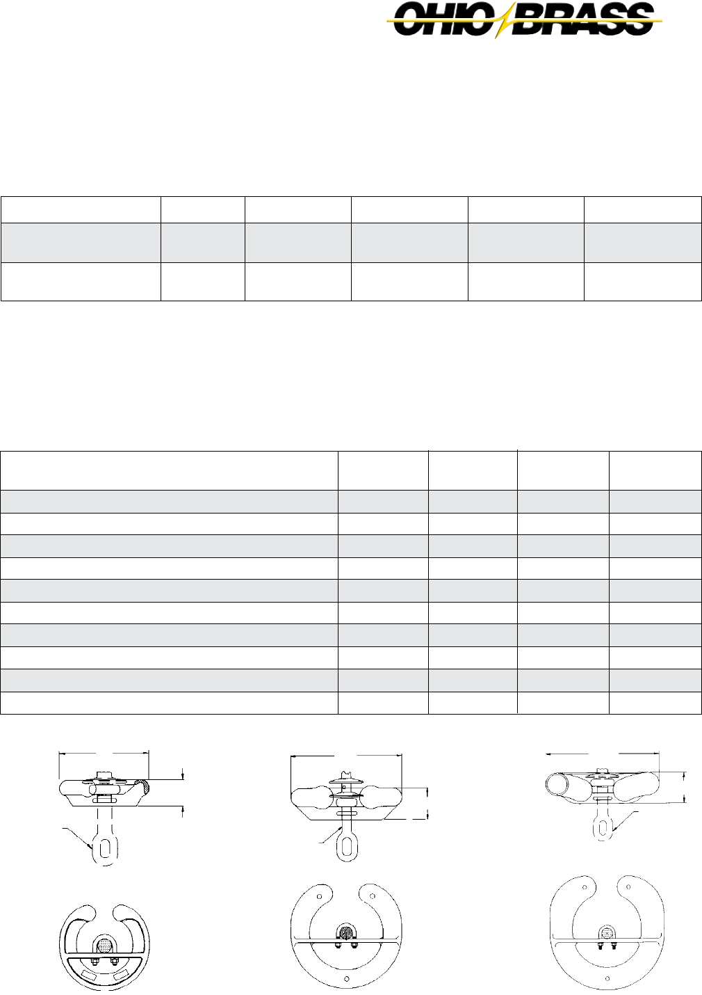
JULY 2010
27-3
OHIO BRASS – AIKEN, SC, USA
Normal Applications: Top Grounded, Bottom Energized
500 kV
2717613001
2717513001
2717613002
2717513002
400 kV
2717613001
2717053001
2717613002
2717053002
330/345 kV
NONE
2717053001
NONE
2717053002
220/230 kV
NONE
2717613001*
NONE
2717613002*
Orientation
Top
Bottom
Top
Bottom
Insulator
120 & 111 kN (25K lbs.)
160/210 kN & 133-222
kN (30-50K lbs.)
*For 96 mm (3.8") S.L. ratio designs, 271705 rings must be used in lieu of 271761 at the bottom end (energized)
of insulator at 220/230 kV operating system voltage.
The physical and electrical values for the insulators on pages 5 through 8 are shown without corona protection.
The table below yields the physical and electrical changes to the insulator when rings from table are installed for
voltages above 161 kV.
Part Number 271761 Part Number 271705 Part Number 271751
Corona Performance
Hi*Lite XL suspension insulators are RIV and corona free through 161 kV, by the use of integral Corona Shield
Rings (CSR). Corona shielding is necessary at 220/230 kV and above. The table below details the rings neces-
sary for voltages equal to or less than that listed in the column header.
Physical & Electrical Change Table
500 kV
Rings
-127.0 (-5.0)
0
-30
0
-65
-65
0
-60
-65
+ 3.6 (8.0)
400 kV
Rings
63.5 (2.5)
0
-20
0
-35
-35
0
-30
-35
+ 2.3 (5.0)
330/345 kV
Ring
-50.8 (-2.0)
0
-15
0
-25
-30
0
-25
-25
+1.4 (3.0)
220/230 kV
Ring
-20.3 (-1.2)
0
-10
0
-15
-20
0
-20
-15
+0.9 (2.0)
Physical & Electrical
Characteristics
Dry Arc Distance mm (inches)
Leakage Distance mm (inches)
60 Hz Flashover Dry - kV (ANSI)
60 Hz Flashover Wet - kV (ANSI)
Critical Impulse Flashover Positive - kV (ANSI)
Critical Impulse Flashover Negative - kV (ANSI)
Power Frequency 1 minute Wet Withstand - kV (IEC)
Lightning Impulse Withstand Positive - kV (IEC)
Lightning Impulse Withstand Negative - kV (IEC)
Net Weight kg (pounds)
HI-LITE Suspension
Insulator
104
(4.10)
381
(15.00)
HI-LITE Suspension
Insulator
87
(3.44)
305
(12.0)
HI-LITE Suspension
Insulator
62
(2.44)
203
(8.0)
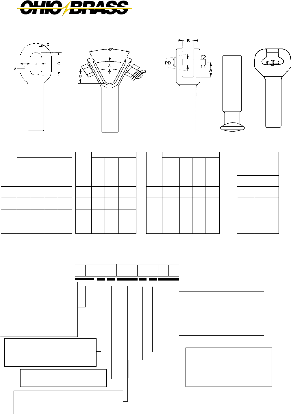
JULY 2010 OHIO BRASS – AIKEN, SC, USA
27-4
D 1 0 0 27
00
8A
GG = Line End Fittings
Chain Eye ............................................00
ANSI Ball .............................................01
Y-Clevis ...............................................02
ANSI Straight Clevis ............................04
IEC Ball ...............................................07*
IEC Straight Clevis...............................08
*For 160 kN, 20 mm ball, use “09” code.
F = Ground End Fittings
Chain Eye ..............................................0
Y-Clevis .................................................2
ANSI Socket ..........................................3
ANSI Straight Clevis ..............................4
IEC Straight Clevis.................................8
IEC Socket ............................................ A
AA = Hi*Lite XL
51 = 63 mm (2.5" S.L.)
A1 = 73 mm (2.9" S.L.)
D1 = 83 mm (3.3" S.L.)
G1 = 96 mm (3.8" S.L)
S.L. = Specified Leak
(approx. leak/dry arc)
+These codes apply to our ESP
silicone alloy compound. For other
polymer materials contact Ohio Brass
Hi*Lite XL Suspension Insulators:
Key to the Catalog Numbers
B = Strength
0 = 120 kN SML
1 = 111 kN (25K lbs.) SML
2 = 160 kN (36K lbs.), 133 kN (30K lbs.) SML
3 = 210 kN, 222 kN (50K lbs.) SML
C = Construction
0 = Standard Hardware/0 Added Sheds
2 = Standard Hardware/2 Added Sheds
Most Common End Fittings
DD = Weathershed Configuration
To determine the number of sheds in your insulator,
multiply this number by four, then add any additional
sheds as listed in the Construction digit.
Ball/SocketStraight ClevisY-ClevisChain Eye
BAA C DD E F GG
SML
111 kN
(25K lbs.)
120 kN
133 kN
(30K lbs.)
160 kN
(36K lbs.)
210 kN
222 kN
(50K lbs.)
B
25.4
(1.00)
25.4
(1.00)
25.4
(1.00)
25.4
(1.00)
25.4
(1.00)
25.4
(1.00)
A
15.74
(0.62)
15.74
(0.62)
19.05
(0.75)
19.05
(0.75)
19.05
(0.75)
19.05
(0.75)
C
50.8
(2.00)
50.8
(2.00)
50.8
(2.00)
50.8
(2.00)
50.8
(2.00)
50.8
(2.00)
D
15.74
(0.62)
15.74
(0.62)
21.59
(0.85)
21.59
(0.85)
21.59
(0.85)
21.59
(0.85)
Dimensions mm (in.)
SML
111 kN
(25K lbs.)
120 kN
133 kN
(30K lbs.)
160 kN
(36K lbs.)
210 kN
222 kN
(50K lbs.)
B
38.86
(1.53)
38.86
(1.53)
40.39
(1.59)
40.39
(1.59)
40.39
(1.59)
40.39
(1.59)
A
19.05
(0.75)
19.05
(0.75)
22.35
(0.88)
22.35
(0.88)
22.35
(0.88)
22.35
(0.88)
Bolt Dia.
19
(0.75)
19
(0.75)
22
(0.88)
22
(0.88)
22
(0.88)
22
(0.88)
Dimensions mm (in.)
SML
111 kN
(25K lbs.)
120 kN
133 kN
(30K lbs.)
160 kN
(36K lbs.)
210 kN
222 kN
(50K lbs.)
A
36
(1.41)
36
(1.41)
36
(1.41)
46
(1.81)
46
(1.81)
Class
ANSI 52-6
IEC 16C
ANSI 52-6
IEC 19L
IEC 19L
N/A
B
19
(0.75)
19
(0.75)
19
(0.75)
21
(0.83)
21
(0.83)
PD
16
(0.62)
16
(0.62)
16
(0.62)
19
(0.75)
19
(0.75)
Dimensions mm (in.)
SML
111 kN
(25K lbs.)
120 kN
133 kN
(30K lbs.)
160 kN
(36K lbs.)
210 kN
222 kN
(50K lbs.)
Class
ANSI 52-5
IEC 16 mm
ANSI 52-5
IEC 20 mm
(ANSI 52-8)
IEC 20 mm
ANSI 52-11
E = Labeling
1 = English
2 = Metric

JULY 2010
27-5
OHIO BRASS – AIKEN, SC, USA
Ground
Fitting
Eye
Eye
ANSI 52-5 Socket
Y-Clevis
ANSI 52-6 Clevis
Line
Fitting
Eye
ANSI 52-5 Ball
ANSI 52-5 Ball
Eye
Eye
Suffix
Code
2000
2001
2301
2200
2400
Inches
+1.5
+0.0
- 0.9
+1.4
+0.4
mm
+39
+1
- 25
+37
+11
Length Change
End Fitting Example
You need the electrical and mechanical charac-
tieristics of Catalog #5110102201. But chain eye
is needed at the ground end instead of a Y-clevis.
From the table at the right, find the code for the chain
eye/ANSI ball configuration 2001. You should order
catalog number 5110102001. The same process is
used for other strength Hi*Lite XL insulators.
Mechanical Ratings
SML = 111 kN (25,000 lbs.)
RTL = 55 kN (12,500 lbs.)
Notes: (1) For voltages above 400 kV, and other section lengths, contact your Ohio Brass representative.
(2) Electrical values are without corona ring. For voltages above 161 kV refer to Page 3 for Corona Rings, and associated physical/electrical changes
to above data. Dimensions are within allowable tolerances as specified by IEC 1109 and ANSI C29.12.
16 mm (5/8") Rod Diameter Suspension Insulators
Section Length
Catalog
Number
with ANSI
52-5 ball and
Y-Clevis
XX10032201
XX10042201
XX10052201
XX10062201
XX10072201
XX10082201
XX10092201
XX10102201
XX10112201
XX10122201
XX10132201
XX10142201
XX10152201
XX10162201
XX10172201
XX10182201
XX10192201
XX10202201
XX10212201
XX10222201
XX10232201
Dry Arc
Distance
mm
(in.)
470
(18.5)
625
(24.6)
775
(30.6)
930
(36.8)
1090
(42.9)
1245
(49.0)
1395
(55.0)
1555
(61.2)
1710
(67.3)
1865
(73.5)
2015
(79.5)
2175
(85.6)
2330
(91.7)
2485
(97.9)
2635
(103.9)
2795
(110.0)
2950
(116.2)
3105
(122.3)
3260
(128.3)
3415
(134.4)
3570
(140.6)
No.
of
Sheds
12
16
20
24
28
32
36
40
44
48
52
56
60
64
68
72
76
80
84
88
92
Section
Length
mm
(in.)
725
(28.6)
881
(34.7)
1033
(40.7)
1189
(46.8)
1345
(53.0)
1501
(59.1)
1654
(65.1)
1810
(71.3)
1966
(77.4)
2121
(83.5)
2274
(89.5)
2430
(95.7)
2586
(101.8)
2742
(108.0)
2894
(114.0)
3050
(120.1)
3206
(126.2)
3362
(132.4)
3514
(138.4)
3670
(144.5)
3826
(150.7)
70 330220132 161110
Selection Guide
Typical
Line Voltage, kV (1)
400
51
1160
(45)
1550
(61)
1940
(76)
2320
(91)
2710
(107)
3100
(122)
3490
(137)
3880
(152)
4270
(168)
4660
(183)
5040
(198)
5430
(214)
5820
(229)
6210
(244)
6600
(260)
6990
(275)
7380
(290)
7770
(306)
8150
(321)
8540
(336)
8930
(351)
Leakage
Distance
mm (in.) XX =
A1
1340
(53)
1790
(70)
2230
(88)
2680
(105)
3130
(122)
3580
(141)
4020
(158)
4480
(176)
4930
(194)
5370
(211)
5820
(229)
6270
(247)
6720
(264)
7170
(282)
7610
(299)
8060
(317)
8510
(335)
8960
(353)
9400
(370)
9860
(388)
10310
(406)
D1
1530
(60)
2040
(80)
2540
(100)
3060
(120)
3570
(140)
4080
(160)
4580
(180)
5100
(200)
5610
(221)
6120
(241)
6620
(261)
7140
(281)
7650
(301)
8160
(321)
8670
(341)
9180
(361)
9700
(381)
10210
(402)
10710
(421)
11220
(442)
11740
(462)
G1
1760
(69)
2350
(92)
2920
(115)
3520
(138)
4110
(162)
4700
(185)
5280
(207)
5870
(231)
6460
(254)
7050
(277)
7630
(300)
8220
(323)
8810
(347)
9400
(370)
9980
(393)
10570
(416)
11170
(439)
11760
(463)
12330
(485)
12930
(509)
13520
(532)
Pos-kV
275
(310)
365
(410)
450
(505)
540
(605)
630
(700)
715
(795)
800
(890)
885
(985)
970
(1080)
1050
(1170)
1135
(1260)
1215
(1350)
1295
(1440)
1375
(1530)
1455
(1615)
1530
(1705)
1610
(1790)
1685
(1875)
1760
(1960)
1835
(2040)
1910
(2125)
(2) IEC Light-
ning Impulse
Withstand (ANSI
Critical Impulse
F.O.) kV
(2) IEC Wet
Switching
Impulse
Withstand
(ANSI 60
Hz. Dry
F.O.) kV
260
(180)
345
(245)
420
(310)
500
(370)
570
(430)
650
(490)
720
(545)
790
(600)
860
(655)
930
(710)
995
(760)
1060
(810)
1120
(855)
1185
(905)
1240
(945)
1300
(990)
1355
(1030)
1410
(1070)
1460
(1110)
1510
(1145)
1560
(1180)
(2) IEC
Power
Freq. Wet
Withstand
(ANSI 60
Hz. Wet
F.O.) kV
135
(180)
180
(240
220
(295)
260
(350)
305
(405)
340
(455)
380
(505)
420
(555)
455
(605)
490
(655)
525
(700)
560
(750)
595
(790)
625
(835)
655
(880)
690
(920)
720
(960)
745
(1000)
775
(1040)
800
(1075)
830
(1110)
Neg-kV
255
(285)
350
(390)
440
(490)
530
(595)
620
(695)
710
(795)
800
(890)
890
(990)
975
(1090)
1065
(1185)
1145
(1280)
1230
(1370)
1315
(1465)
1400
(1560)
1480
(1650)
1565
(1740)
1645
(1830)
1725
(1920)
1800
(2005)
1880
(2090)
1955
(2175)
Standard Design
High Leak
Design
94 mm (3.7") y
x
Section Length
Type
A11..
D11..
G11..
x mm (in.)
97 (3.8)
109 (4.3)
130 (5.1)
y mm (in.)
114 (4.5)
140 (5.5)
160 (6.3)
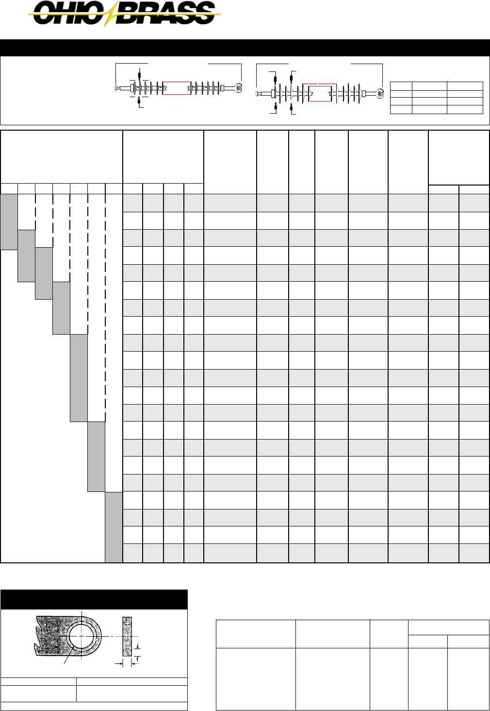
JULY 2010 OHIO BRASS – AIKEN, SC, USA
27-6
Y-Clevis Tower Attachment Detail
for all Hi*Lite XL Insulators
Rod Dia. mm (in.)
16 (5/8")
22 (7/8")
“D” Max. mm (in.)
13 (.53)
25 (1.0)
To achieve insulator SML value, proper grade steel should be used
“D” Max.
19 mm (3/4") Max.
25 mm (1") Dia. Minimum
3 mm (1/8") x 45° Chamfer
Ground
Fitting
Eye
Eye
Y-Clevis
Y-Clevis
IEC 16C Clevis
Line
Fitting
Eye
IEC 16 mm Ball
IEC 16 mm Ball
Eye
Eye
Suffix
Code
2000
2007
2207
2200
2800
Inches
+2.3
+1.0
+0.9
+2.2
+1.2
mm
+59
+26
+24
+57
+31
Length Change
Mechanical Ratings
SML = 120 kN
RTL = 60 kN
16 mm (5/8") Rod Diameter Suspension Insulators
Section Length
Standard Design
Notes: (1) For voltages above 400 kV, and other section lengths, contact your Ohio Brass representative.
(2) Electrical values are without corona ring. For voltages above 161 kV refer to Page 3 for Corona Rings, and associated physical/electrical changes
to above data. Dimensions are within allowable tolerances as specified by IEC 1109 and ANSI C29.12.
Catalog
Number
with IEC
16 mm ball
- socket
XX00032A07
XX00042A07
XX00052A07
XX00062A07
XX00072A07
XX00082A07
XX00092A07
XX00102A07
XX00112A07
XX00122A07
XX00132A07
XX00142A07
XX00152A07
XX00162A07
XX00172A07
XX00182A07
XX00192A07
XX00202A07
XX00212A07
XX00222A07
XX00232A07
Dry Arc
Distance
mm
(in.)
470
(18.5)
625
(24.6)
775
(30.6)
930
(36.8)
1090
(42.9)
1245
(49.0)
1395
(55.0)
1555
(61.2)
1710
(67.3)
1865
(73.5)
2015
(79.5)
2175
(85.6)
2330
(91.7)
2485
(97.9)
2635
(103.9)
2795
(110.0)
2950
(116.2)
3105
(122.3)
3260
(128.3)
3415
(134.4)
3570
(140.6)
No.
of
Sheds
12
16
20
24
28
32
36
40
44
48
52
56
60
64
68
72
76
80
84
88
92
Section
Length
mm
(in.)
731
(28.8)
886
(34.9)
1039
(40.9)
1195
(47.1)
1351
(53.2)
1507
(59.3)
1659
(65.3)
1815
(71.5)
1971
(77.6)
2127
(83.8)
2279
(89.8)
2435
(95.9)
2591
(102.1)
2747
(108.2)
2900
(114.2)
3056
(120.3)
3212
(126.5)
3368
(132.6)
3520
(138.6)
3676
(144.8)
3832
(150.9)
70 330220132 161
110
Selection Guide
Typical
Line Voltage, kV (1)
400
51
1160
(45)
1550
(61)
1940
(76)
2320
(91)
2710
(107)
3100
(122)
3490
(137)
3880
(152)
4270
(168)
4660
(183)
5040
(198)
5430
(214)
5820
(229)
6210
(244)
6600
(260)
6990
(275)
7380
(290)
7770
(306)
8150
(321)
8540
(336)
8930
(351)
Leakage
Distance
mm (in.) XX =
A1
1340
(53)
1790
(70)
2230
(88)
2680
(105)
3130
(122)
3580
(141)
4020
(158)
4480
(176)
4930
(194)
5370
(211)
5820
(229)
6270
(247)
6720
(264)
7170
(282)
7610
(299)
8060
(317)
8510
(335)
8960
(353)
9400
(370)
9860
(388)
10310
(406)
D1
1530
(60)
2040
(80)
2540
(100)
3060
(120)
3570
(140)
4080
(160)
4580
(180)
5100
(200)
5610
(221)
6120
(241)
6620
(261)
7140
(281)
7650
(301)
8160
(321)
8670
(341)
9180
(361)
9700
(381)
10210
(402)
10710
(421)
11220
(442)
11740
(462)
G1
1760
(69)
2350
(92)
2920
(115)
3520
(138)
4110
(162)
4700
(185)
5280
(207)
5870
(231)
6460
(254)
7050
(277)
7630
(300)
8220
(323)
8810
(347)
9400
(370)
9980
(393)
10570
(416)
11170
(439)
11760
(463)
12330
(485)
12930
(509)
13520
(532)
Pos-kV
275
(310)
365
(410)
450
(505)
540
(605)
630
(700)
715
(795)
800
(890)
885
(985)
970
(1080)
1050
(1170)
1135
(1260)
1215
(1350)
1295
(1440)
1375
(1530)
1455
(1615)
1530
(1705)
1610
(1790)
1685
(1875)
1760
(1960)
1835
(2040)
1910
(2125)
(2) IEC Light-
ning Impulse
Withstand (ANSI
Critical Impulse
F.O.) kV
(2) IEC Wet
Switching
Impulse
Withstand
(ANSI 60
Hz. Dry
F.O.) kV
260
(180)
345
(245)
420
(310)
500
(370)
570
(430)
650
(490)
720
(545)
790
(600)
860
(655)
930
(710)
995
(760)
1060
(810)
1120
(855)
1185
(905)
1240
(945)
1300
(990)
1355
(1030)
1410
(1070)
1460
(1110)
1510
(1145)
1560
(1180)
(2) IEC
Power
Freq. Wet
Withstand
(ANSI 60
Hz. Wet
F.O.) kV
135
(180)
180
(240
220
(295)
260
(350)
305
(405)
340
(455)
380
(505)
420
(555)
455
(605)
490
(655)
525
(700)
560
(750)
595
(790)
625
(835)
655
(880)
690
(920)
720
(960)
745
(1000)
775
(1040)
800
(1075)
830
(1110)
Neg-kV
255
(285)
350
(390)
440
(490)
530
(595)
620
(695)
710
(795)
800
(890)
890
(990)
975
(1090)
1065
(1185)
1145
(1280)
1230
(1370)
1315
(1465)
1400
(1560)
1480
(1650)
1565
(1740)
1645
(1830)
1725
(1920)
1800
(2005)
1880
(2090)
1955
(2175)
94 mm (3.7")
Section Length
High Leak Design
y
x
Type
A10..
D10..
G10..
x mm (in.)
97 (3.8)
109 (4.3)
130 (5.1)
y mm (in.)
114 (4.5)
140 (5.5)
160 (6.3)

JULY 2010
27-7
OHIO BRASS – AIKEN, SC, USA
Ground
Fitting
Eye
Eye
Y-Clevis
Eye
Y-Clevis
Y-Clevis
ANSI 52-5 Socket
Line
Fitting
Eye
IEC 20 mm Ball
Eye
ANSI 52-5 Ball
IEC 20 mm Ball
ANSI 52-5 Ball
ANSI 52-5 Ball
Suffix
Code
2000
2009
2200
2001
2209
2201
2301
In.
+1.5
+0.8
+1.0
+0.1
+0.3
- 0.4
- 1.3
mm
+40
+21
+27
+2
+8
- 11
- 35
Length Change
Corona Ring Example
You have selected Catalog
#D120122A09, the typical application
is 220kV. From page 3, you would select
ring 2717613002 on the bottom end.
The physical/electrical characteristics
would change per the table on page 3.
Mechanical Ratings
SML = 160 kN (36,000 lbs.)
RTL = 80 kN (18,000 lbs.)
Insulators with either ANSI ball and/
or socket end-fittings will be rated
133 kN (30,000 lbs.) SML and 66 kN
(15,000 lbs.) RTL.
Notes: (1) For voltages above 400 kV, and other section lengths, contact your Ohio Brass representative.
(2) Electrical values are without corona ring. For voltages above 161 kV refer to Page 3 for Corona Rings, and associated physical/electrical changes to
above data. Dimensions are within allowable tolerances as specified by IEC 1109 and ANSI C29.12.
22 mm (7/8") Rod Diameter Suspension Insulators
Catalog
Number
with IEC 20
mm ball and
socket
XX20032A09
XX20042A09
XX20052A09
XX20062A09
XX20072A09
XX20082A09
XX20092A09
XX20102A09
XX20112A09
XX20122A09
XX20132A09
XX20142A09
XX20152A09
XX20162A09
XX20172A09
XX20182A09
XX20192A09
XX20202A09
XX20212A09
XX20222A09
XX20232A09
Dry Arc
Distance
mm
(in.)
470
(18.5)
625
(24.6)
775
(30.6)
930
(36.8)
1090
(42.9)
1245
(49.0)
1395
(55.0)
1555
(61.2)
1710
(67.3)
1865
(73.5)
2015
(79.5)
2175
(85.6)
2330
(91.7)
2485
(97.9)
2635
(103.9)
2795
(110.0)
2950
(116.2)
3105
(122.3)
3260
(128.3)
3415
(134.4)
3570
(140.6)
No.
of
Sheds
12
16
20
24
28
32
36
40
44
48
52
56
60
64
68
72
76
80
84
88
92
Section
Length
mm
(in.)
795
(30.8)
951
(37.0)
1104
(43.5)
1260
(49.6)
1416
(55.8)
1572
(61.9)
1724
(67.9)
1880
(74.0)
2036
(80.2)
2192
(86.3)
2344
(92.3)
2500
(98.5)
2656
(104.6)
2812
(110.7)
2965
(116.7)
3120
(122.9)
3276
(128.9)
3432
(135.2)
3585
(141.2)
3741
(147.3)
3897
(153.4)
70 330220132 161
110
Selection Guide
Typical
Line Voltage, kV (1)
400
51
1150
(45)
1540
(60)
1920
(75)
2310
(91)
2700
(106)
3080
(121)
3470
(136)
3850
(151)
4240
(167)
4630
(182)
5010
(197)
5400
(212)
5790
(228)
6170
(243)
6560
(258)
6940
(273)
7330
(288)
7720
(304)
8100
(319)
8490
(334)
8870
(349)
Leakage
Distance
mm (in.) XX =
A1
1340
(53)
1790
(70)
2230
(88)
2680
(105)
3130
(123)
3580
(141)
4020
(158)
4480
(176)
4930
(194)
5370
(211)
5820
(229)
6270
(247)
6720
(264)
7170
(282)
7610
(299)
8060
(317)
8510
(335)
8960
(353)
9400
(370)
9860
(388)
10310
(406)
D1
1530
(60)
2040
(80)
2540
(100)
3060
(120)
3570
(140)
4080
(160)
4580
(180)
5100
(200)
5610
(221)
6120
(241)
6620
(261)
7140
(281)
7650
(301)
8160
(321)
8670
(341)
9180
(361)
9700
(381)
10210
(402)
10710
(421)
11220
(442)
11740
(462)
G1
1760
(69)
2350
(92)
2920
(115)
3520
(138)
4110
(162)
4700
(185)
5280
(207)
5870
(231)
6460
(254)
7050
(277)
7630
(300)
8220
(323)
8810
(347)
9400
(370)
9980
(393)
10570
(416)
11170
(439)
11760
(463)
12330
(485)
12930
(509)
13520
(532)
Pos-kV
275
(310)
365
(410)
450
(505)
540
(605)
630
(700)
715
(795)
800
(890)
885
(985)
970
(1080)
1050
(1170)
1135
(1260)
1215
(1350)
1295
(1440)
1375
(1530)
1455
(1615)
1530
(1705)
1610
(1790)
1685
(1875)
1760
(1960)
1835
(2040)
1910
(2125)
(2) IEC Light-
ning Impulse
Withstand (ANSI
Critical Impulse
F.O.) kV
(2) IEC Wet
Switching
Impulse
Withstand
(ANSI 60
Hz. Dry
F.O.) kV
260
(180)
345
(245)
420
(310)
500
(370)
570
(430)
650
(490)
720
(545)
790
(600)
860
(655)
930
(710)
995
(760)
1060
(810)
1120
(855)
1185
(905)
1240
(945)
1300
(990)
1355
(1030)
1410
(1070)
1460
(1110)
1510
(1145)
1560
(1180)
(2) IEC
Power
Freq. Wet
Withstand
(ANSI 60
Hz. Wet
F.O.) kV
135
(180)
180
(240
220
(295)
260
(350)
305
(405)
340
(455)
380
(505)
420
(555)
455
(605)
490
(655)
525
(700)
560
(750)
595
(790)
625
(835)
655
(880)
690
(920)
720
(960)
745
(1000)
775
(1040)
800
(1075)
830
(1110)
Neg-kV
255
(285)
350
(390)
440
(490)
530
(595)
620
(695)
710
(795)
800
(890)
890
(990)
975
(1090)
1065
(1185)
1145
(1280)
1230
(1370)
1315
(1465)
1400
(1560)
1480
(1650)
1565
(1740)
1645
(1830)
1725
(1920)
1800
(2005)
1880
(2090)
1955
(2175)
SML kN (lbs.)
160 kN (36K)
160 kN (36K)
160 kN (36K)
133 kN (30K)
160 kN (36K)
133 kN (30K)
133 kN (30K)
Section Length
Standard Design
101 mm (4.0")
Section Length
High Leak Design
y
x
Type
A12..
D12..
G12..
x mm (in.)
97 (3.8)
109 (4.3)
130 (5.1)
y mm (in.)
114 (4.5)
140 (5.5)
160 (6.3)

JULY 2010 OHIO BRASS – AIKEN, SC, USA
27-8
Mechanical Ratings
SML = 210 kN
RTL = 55 kN
ANSI fittings are capable
of 222 kN SML (50K lbs.)
Notes: (1) For voltages above 400 kV, and other section lengths, contact your Ohio Brass representative.
(2) Electrical values are without corona ring. For voltages above 161 kV refer to Page 3 for Corona Rings, and associated physical/electrical changes to
above data. Dimensions are within allowable tolerances as specified by IEC 1109 and ANSI C29.12.
22 mm (7/8") Rod Diameter Suspension Insulators
Catalog
Number
with IEC 20
mm ball and
socket
XX30032A07
XX30042A07
XX30052A07
XX30062A07
XX30072A07
XX30082A07
XX30092A07
XX30102A07
XX30112A07
XX30122A07
XX30132A07
XX30142A07
XX30152A07
XX30162A07
XX30172A07
XX30182A07
XX30192A07
XX30202A07
XX30212A07
XX30222A07
XX30232A07
Dry Arc
Distance
mm
(in.)
470
(18.5)
625
(24.6)
775
(30.6)
930
(36.8)
1090
(42.9)
1245
(49.0)
1395
(55.0)
1555
(61.2)
1710
(67.3)
1865
(73.5)
2015
(79.5)
2175
(85.6)
2330
(91.7)
2485
(97.9)
2635
(103.9)
2795
(110.0)
2950
(116.2)
3105
(122.3)
3260
(128.3)
3415
(134.4)
3570
(140.6)
No.
of
Sheds
12
16
20
24
28
32
36
40
44
48
52
56
60
64
68
72
76
80
84
88
92
Section
Length
mm
(in.)
795
(30.8)
951
(37.0)
1104
(43.5)
1260
(49.6)
1416
(55.8)
1572
(61.9)
1724
(67.9)
1880
(74.0)
2036
(80.2)
2192
(86.3)
2344
(92.3)
2500
(98.5)
2656
(104.6)
2812
(110.7)
2965
(116.7)
3120
(122.9
3276
(128.9)
3432
(135.2)
3585
(141.2)
3741
(147.3)
3897
(153.4)
69 330220138 161115
Selection Guide
Typical
Line Voltage, kV (1)
400
51
1150
(45)
1540
(60)
1920
(75)
2310
(91)
2700
(106)
3080
(121)
3470
(136)
3850
(151)
4240
(167)
4630
(182)
5010
(197)
5400
(212)
5790
(228)
6170
(243)
6560
(258)
6940
(273)
7330
(288)
7720
(304)
8100
(319)
8490
(334)
8870
(349)
Leakage
Distance
mm (in.) XX =
A1
1340
(53)
1790
(70)
2230
(88)
2680
(105)
3130
(123)
3580
(141)
4020
(158)
4480
(176)
4930
(194)
5370
(211)
5820
(229)
6270
(247)
6720
(264)
7170
(282)
7610
(299)
8060
(317)
8510
(335)
8960
(353)
9400
(370)
9860
(388)
10310
(406)
D1
1530
(60)
2040
(80)
2540
(100)
3060
(120)
3570
(140)
4080
(160)
4580
(180)
5100
(200)
5610
(221)
6120
(241)
6620
(261)
7140
(281)
7650
(301)
8160
(321)
8670
(341)
9180
(361)
9700
(381)
10210
(402)
10710
(421)
11220
(442)
11740
(462)
G1
1760
(69)
2350
(92)
2920
(115)
3520
(138)
4110
(162)
4700
(185)
5280
(207)
5870
(231)
6460
(254)
7050
(277)
7630
(300)
8220
(323)
8810
(347)
9400
(370)
9980
(393)
10570
(416)
11170
(439)
11760
(463)
12330
(485)
12930
(509)
13520
(532)
Pos-kV
275
(310)
365
(410)
450
(505)
540
(605)
630
(700)
715
(795)
800
(890)
885
(985)
970
(1080)
1050
(1170)
1135
(1260)
1215
(1350)
1295
(1440)
1375
(1530)
1455
(1615)
1530
(1705)
1610
(1790)
1685
(1875)
1760
(1960)
1835
(2040)
1910
(2125)
(2) IEC Light-
ning Impulse
Withstand (ANSI
Critical Impulse
F.O.) kV
(2) IEC Wet
Switching
Impulse
Withstand
(ANSI 60
Hz. Dry
F.O.) kV
260
(180)
345
(245)
420
(310)
500
(370)
570
(430)
650
(490)
720
(545)
790
(600)
860
(655)
930
(710)
995
(760)
1060
(810)
1120
(855)
1185
(905)
1240
(945)
1300
(990)
1355
(1030)
1410
(1070)
1460
(1110)
1510
(1145)
1560
(1180)
(2) IEC
Power
Freq. Wet
Withstand
(ANSI 60
Hz. Wet
F.O.) kV
135
(180)
180
(240
220
(295)
260
(350)
305
(405)
340
(455)
380
(505)
420
(555)
455
(605)
490
(655)
525
(700)
560
(750)
595
(790)
625
(835)
655
(880)
690
(920)
720
(960)
745
(1000)
775
(1040)
800
(1075)
830
(1110)
Neg-kV
255
(285)
350
(390)
440
(490)
530
(595)
620
(695)
710
(795)
800
(890)
890
(990)
975
(1090)
1065
(1185)
1145
(1280)
1230
(1370)
1315
(1465)
1400
(1560)
1480
(1650)
1565
(1740)
1645
(1830)
1725
(1920)
1800
(2005)
1880
(2090)
1955
(2175)
Y-Clevis Tower Attachment Detail
for all Hi*Lite XL Insulators
Rod Dia. mm (in.)
16 (5/8")
22 (7/8")
“D” Max. mm (in.)
13 (.53)
25 (1.0)
To achieve insulator SML value, proper grade steel should be used.
“D” Max.
19 mm (3/4") Max.
25 mm (1") Dia. Minimum
3 mm (1/8") x 45° Chamfer
Ground
Fitting
Eye
Eye
ANSI 52-11 Socket
Eye
Y-Clevis
Y-Clevis
Y-Clevis
Eye
Line
Fitting
Eye
IEC 20mm Ball
ANSI 52-11 Ball
ANSI 52-11 Ball
Eye
ANSI 52-11 Ball
IEC 20 mm Ball
IEC 19L Clevis
Suffix
Code
2000
2007
2301
2001
2200
2201
2207
2800
Inches
+1.5
+0.7
- 0.6
+0.1
+0.7
- 0.5
+0.1
+1.2
mm
+40
+18
- 16
+2
+19
- 13
+4
+31
Length Change
Section Length
Standard Design
101 mm (4.0")
Section Length
High Leak Design
y
x
Type
A13..
D13..
G13..
x mm (in.)
97 (3.8)
109 (4.3)
130 (5.1)
y mm (in.)
114 (4.5)
140 (5.5)
160 (6.3)
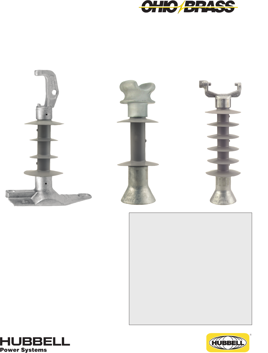
JUNE 2012
23-1
OHIO BRASS – AIKEN, SC, USA
©Copyright 2010 Hubbell Incorporated
Section
23
NOTE: Because Hubbell has a policy of continuous product improvement, we reserve the right to change design and specications without notice.
Printed in USA RGS 1M
Warranty - Material
Hubbell Power Systems, Inc. warrants all products sold by it to be merchantable (as such
term is defined in the Uniform Commercial Code) and to be free from defects in material and
workmanship. Buyer must notify the Company promptly of any claim under this warranty. The
Buyer's exclusive remedy for breach of this warranty shall be the repair or replacement, F.O.B.
factory, at the Company's option, of any product defective under the warranty which is returned
to the Company within one year from the date of shipment. NO OTHER WARRANTY, WHETHER
EXPRESS OR ARISING BY OPERATION OF LAW, COURSE OF DEALING, USAGE OF
TRADE OR OTHERWISE IMPLIED, SHALL EXIST IN CONNECTION WITH THE COMPANY'S
PRODUCTS OR ANY SALE OR USE THEREOF. The Company shall in no event be liable for
any loss of profits or any consequential or special damages incurred by Buyer. The Company's
warranty shall run only to the first Buyer of a product from the Company, from the Company's
distributor, or from an original equipment manufacturer reselling the Company's product, and is
non-assignable and non-transferable and shall be of no force and effect if asserted by any per-
son other than such first Buyer. This warranty applies only to the use of the product as intended
by Seller and does not cover any misapplication or misuse of said product.
Warranty - Application
Hubbell Power Systems, Inc. does not warrant the accuracy of and results from product or
system performance recommendations resulting from any engineering analysis or study. This
applies regardless of whether a charge is made for the recommendation, or if it is provided free
of charge.
Responsibility for selection of the proper product or application rests solely with the purchaser. In
the event of errors or inaccuracies determined to be caused by Hubbell Power Systems, Inc., its
liability will be limited to the re-performance of any such analysis or study.
Index
Line Posts ....................................................... Page
Mechanical Ratings ........................................23-2
Equivalency .....................................................23-2
Packaging .......................................................23-3
Sample Polymer Specication ........................23-3
Table ...................................................23-4 & 23-5
Catalog Key ....................................................23-4
Post Base & Line Fittings ....................23-6 & 23-7
Application Curves ..............................23-8 & 23-9
Line Post Insulator Studs ..............................23-10
Suspension Trunnion Bolted Aluminum ........23-11
Bracket, Pole Top Insulator ...........................23-12
Bracket, Horizontal Insulator ........................23-13
Bracket, Vertical Insulator .............................23-13
Bracket, Pole Top Insulator ...........................23-14
Brackets, Post Insulator................................23-15
Super Top-Tie Line Ties ................................23-16
Veri*Lite™
Silicone Rubber Line Post Insulators
for 15-69kV Applications
®

JUNE 2012 OHIO BRASS – AIKEN, SC, USA
23-2
Veri*Lite Insulators embody the latest features avail-
able in polymer insulator design and manufacture.
Ohio Brass began its efforts in polymer research in the
early 1900s. After years of production and research
with polymeric compounds in the high voltage insula-
tion eld, Ohio Brass introduced the Hi*Lite insulator in
1976. A decade later the Ohio Brass polymer distribu-
tion arrester, PDV-100, was introduced as the rst U.S.
made polymer-housed MOV arrester.
Today’s Veri*Lite post insulators build upon the experi-
ence of placing nearly 20 million polymer distribution
arresters, 17 million polymer deadend distribution insu-
lators and 2 million high voltage transmission insula-
tors in service. Ohio Brass is dedicated to providing a
quality product for the electric utility industry.
Design
The structural design of the Veri*Lite insulator consists
of three basic parts:
Rod - Veri*Lite insulator berglass rod is produced
from the highest quality materials. Strands are aligned
for maximum tensile strength. The rod is lled 65 per-
cent, by volume, with electrical grade glass bers.
End Fittings - Ferrous end ttings are directly crimped
to the berglass rod by a circumferential crimping pro-
cess originated by Ohio Brass. The crimp requires no
intermovement of the parts to achieve high strength,
nor does it introduce potting compounds or adhesives.
Weathersheds - Veri*Lite insulators are manufactured
with OB’s proprietary silicone rubber.
Ohio Brass uses several tests to evaluate materials.
Tracking, QUV, corona cutting, salt fog, oxidative sta-
bility and variations of differential thermal analysis tests
assure the quality of OB’s shed material.
Leakage Distance
Veri*Lite insulators feature high leakage distance for
optimum contamination performance.
Washability
The Veri*Lite insulators listed in this catalog are suit-
able for washing by all known methods in current use.
Washing tests have been conducted with high-pres-
sure equipment at close nozzle-to-insulator distances.
No water intrusion occurred after multiple washings.
Standards
Veri*Lite line post insulators meet ANSI C29.18-2003
and CEA LWIWG-02-1996 standards.
The Ohio Brass facility in Aiken, SC, USA is registered
for successful implementation of a quality system in
accordance with ISO 9001-2000.
Mechanical Ratings
Specied Cantilever Load (SCL) is the ultimate can-
tilever strength rating. Maximum Design Cantilever
Load (MDCL) or Working Cantilever Load (WCL) is the
maximum continuous cantilever load at which the post
insulator should be applied.
Markings
Markings are 0.12 inch high raised letters in the rubber
and include: Base catalog number, CEA LWIWG Class,
SCL in pounds, MDCL/WCL in kN and date code. Ohio
Brass identication is cast into the end ttings.
Equivalency
Equivalency of line post insulators involves a check of
the general characteristics.
MECHANICAL
Compare the SCL of the polymer insulator to the
cantilever strength rating of the porcelain insulator.
ELECTRICAL
Compare porcelain to Veri*Lite leakage distance.
Compare porcelain to Veri*Lite section length.
Insulation Coordination
The operating performance of a distribution or trans-
mission line depends on its insulation level. It must not
ash over under practically any operating condition.
Several methods of coordination of line and station
insulation have been proposed. Generally, the best
method is to establish a denite common insulation
level for all the station insulation and then match that
level with the line insulation. With this approach, the
task is limited to three fundamental requirements:
1. Selection of the Basic Impulse Insulation Level
(BIL).
2. Specication of insulation with ashover charac-
teristics equal to or greater than the selected BIL.
3. The application of suitable overvoltage surge
protection.

JUNE 2012
23-3
OHIO BRASS – AIKEN, SC, USA
Purpose: To ensure a suitable service life of polymer insulating materials.
I. Material Design Tests
- The following must be performed to certify a material for use in production.
1. Tracking test: Performed on a sample of material inclined at 30° and electrodes posi-
tioned 35 mm apart. Samples are sprayed with a conductive solution (400 Ωcm) and ener-
gized at 10 kV. The cycle is repeated every 90 seconds. The sample passes if there is:
1. No carbonization or tracking.
2. No erosion through sample.
3. No leakage current ow at the end of 90 seconds.
The sample must withstand 20,000 test cycles.
2. Ultraviolet Test: Samples of the rubber must be tested in a QUV tester or equivalent cy-
clic weatherometer. The samples are exposed to high ultraviolet radiation and high humid-
ity without cracking, checking or becoming hydrophilic.
The sample is judged to have passed this test if it exceeds 8,000 hours of exposure with-
out damage.
3. Corona Cutting: Samples 5 cm by 7 cm are subjected to mechanical stress of 300,000
microstrain by bending samples around a grounded electrode. A needle-like electrode is
placed 1 mm from the surface of the sample and energized at 12 kV in a controlled humid-
ity chamber.
The sample is judged to have passed this test if there is no splitting or cutting. Samples
must pass 1,000 hours of exposure to this test.
4. Oxidative Stability: Samples of the polymer compound are tested using differential
scanning calorimetry. Samples are heated rapidly in a nitrogen atmosphere to the test
temperature of 200°C. The atmosphere is then changed to oxygen and the temperature
is maintained until the antioxidant is consumed, as measured by an exothermic chemical
reaction. The time for this reaction to occur must exceed 400 minutes.
5. Tear Strength: Rubber test slabs are prepared in accordance with ASTM Standards and
are tested to determine tear strength of the material. The acceptable nominal tear strength,
per ASTM method B, is 100 lb./in.
II. Other Requirements
- The manufacturer must supply upon request a listing of routine tests performed to ensure
production compliance with design tests.
Sample Polymer Specication
Satisfactory performance is generally achieved with an
insulator which has a dry 60 Hz ashover of three to
ve times the phase-to-ground voltage and a leak-
age distance approximately twice the shortest air-gap
(strike) distance.
Packaging
Veri*Lite insulator standard packing is cartons on pal-
lets. Larger orders for Veri*Lite posts may be shipped
in wood crates.
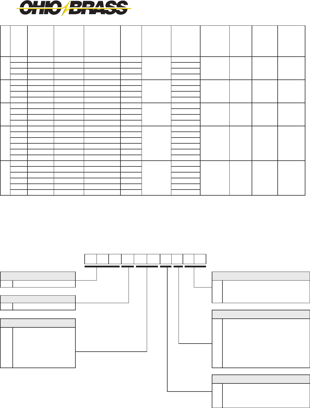
JUNE 2012 OHIO BRASS – AIKEN, SC, USA
23-4
kV
Post
Style Line Base
Catalog
Number
ANSI
C29.18
Class
CEA
LWIWG-02
Class
“X”
Dimension
Inches
(mm)
Line & Gnd
End Shed
Dia. Inches
(mm)
Inter-
mediate
Shed
Quantity
Inter-
mediate
Shed Dia.
Inches
(mm)
Dry Arc
Distance
Inches
(mm)
15
Horz Clamptop Gain 80S015-0100 51-31
LP 15
12.5 (318)
4.8 (121) 0 7.4 (188)
Horz Clamptop 3/4-10 Tap 80S015-0109 51-21 13.3 (339)
Vert Clamptop 3/4-10 Tap 80S015-0209 51-11 12.8 (324)
Vert F-Neck 3/4-10 Tap 80S015-0F09 51-1F 12.4 (315)
25
Horz Clamptop Gain 80S025-0100 51-32
LP 25
14.3 (362)
5.2 (132) 2 3.8 (96) 9.6 (244)
Horz Clamptop 3/4-10 Tap 80S025-0109 51-22 15.1 (383)
Vert Clamptop 3/4-10 Tap 80S025-0209 51-12 14.5 (368)
Vert F-Neck 3/4-10 Tap 80S025-0F09 51-2F 14.2 (360)
35
Horz Clamptop Gain 80S028-0100 51-33
LP 28M
16.5 (420)
5.1 (130) 4 4.6 (117) 11.7 (297)
Horz Clamptop 3/4-10 Tap 80S028-0109 51-23 17.4 (441)
Vert Clamptop 3/4-10 Tap 80S028-0209 51-13 16.8 (425)
Vert F-Neck 3/4-10 Tap 80S028-0F09 51-3F 16.5 (418)
46
Horz Blade Gain 80S046-0000 – –
LP 46
19.2 (488)
7.1 (179) 6 4.4 (112) 14.4 (390)
Horz Blade 3/4-10 Tap 80S046-0009 – – 20.0 (508)
Horz Clamptop Gain 80S046-0100 51-34 19.0 (482)
Horz Clamptop 3/4-10 Tap 80S046-0109 51-24 19.8 (504)
Vert Clamptop 3/4-10 Tap 80S046-0209 51-14 20.1 (510)
Vert F-Neck 3/4-10 Tap 80S046-0F09 51-4F 19.5 (495)
69
Horz Blade Gain 80S069-0000 – –
LP 69M
25.8 (656)
7.5 (190) 8 5.2 (132 22.3 (566)
Horz Blade 3/4-10 Tap 80S069-0009 – – 26.6 (676)
Horz Clamptop Gain 80S069-0100 51-36 25.6 (650)
Horz Clamptop 3/4-10 Tap 80S069-0109 51-26 26.5 (672)
Vert Clamptop 3/4-10 Tap 80S069-0209 51-16 26.8 (680)
Vert F-Neck 3/4-10 Tap 80S069-0F09 – – 26.1 (663)
8 0 S 0 6 9 0 2 0 9
Polymer Type Bottom End Fitting
80S Veri*Lite - SR Polymer 00 Gain Base - Transverse
09 3 /4” Stud Base
Hardware Finish 10 7/8” Stud Base
0 Standard
Top End Fitting
Rating 0 Teardrop Blade*
15 15kV (1.5” rod) 1 Horizontal Clamptop
25 25kV (1.5” rod) 2 Veritical Clamptop
28 35kV (1.5” rod) 5 5” B.C. Through
46 46kV (1.75” rod) 6 Horizontal Clamptop (longer pintle bolt)
69 69kV (1.75” rod) A Vertical Clamptop (longer pintle bolt)
Dimensioning
0 ANSI C29.18 Quality Conformance Tests
6 LWIWG - 02 Sample Tests
9 Special
CATALOG NUMBER KEY
Veri*Lite Line Post Insulators - Silicone
*Teardrop Blade only available for 46-69kV

JUNE 2012
23-5
OHIO BRASS – AIKEN, SC, USA
NOTES:
1. Maximum Design Tension for Clamptop is 2500 pounds (11 kN)
2. 15, 25 & 28 kV Units use 1.5 inch (38 mm) Diameter Rod
3. 46 & 69 kV Units use 1.75 inch (44 mm) Diameter Rod
Horizontal Clamptop & Gain Base
(0100)
Vertical Clamptop & Stud Base
(0209 & 0210)
F-Neck & Stud Base
(0F09 & 0F10)
Leakage
Distance
Inches
(mm)
60 Hz
(Low Frequency)
Flashover
Impulse
Critical
Flashover
Pos. kV
Impulse
Positive
Withstand
kV
SCL
pounds
(kN)
MDCL/
WCL
pounds
(kN)
Net
Weight
pounds
(kg)
Standard Package
Quantity
kV
Dry-kV Wet-kV Carton Pallet Max/Crate
11.0 (279) 90 70 150 140 2800 (12.5) 1235 (5.5)
9.8 (4.5)
3
36
– – 15
6.9 (3.1) 60
6.5 (2.9) 60
6.6 (3.0) 60
17.3 (439) 110 75 185 170 2800 (12.5) 1235 (5.5)
10.3 (4.7)
3
36
– – 25
7.3 (3.3) 60
7.0 (3.2) 60
7.1 (3.2) 60
26.1 (662) 135 100 215 200 2800 (12.5) 1235 (5.5)
11.2 (5.1)
3
36
– – 35
8.2 (3.7) 60
7.8 (3.5) 60
8.0 (3.6) 60
34.3 (872) 170 125 260 235 2800 (12.5) 1235 (5.5)
19.7 8.9)
– – – –
14/21/28/35
46
14.6 (6.6) 70
18.6 (8.4) 14/21/28/35
13.5 (6.1) 70
14.1 (6.4) 70
13.9 (6.3) 70
58.2 (1478) 230 180 360 330 2470 (11.0) 1235 (5.5)
22.1 (10.0)
– – – –
14/21/28/35
69
16.9 (7.7) 35
21.0 (9.5) 14/21/28/35
15.9 (7.2) 35
16.5 (7.5) 35
12.0 (5.4) 35
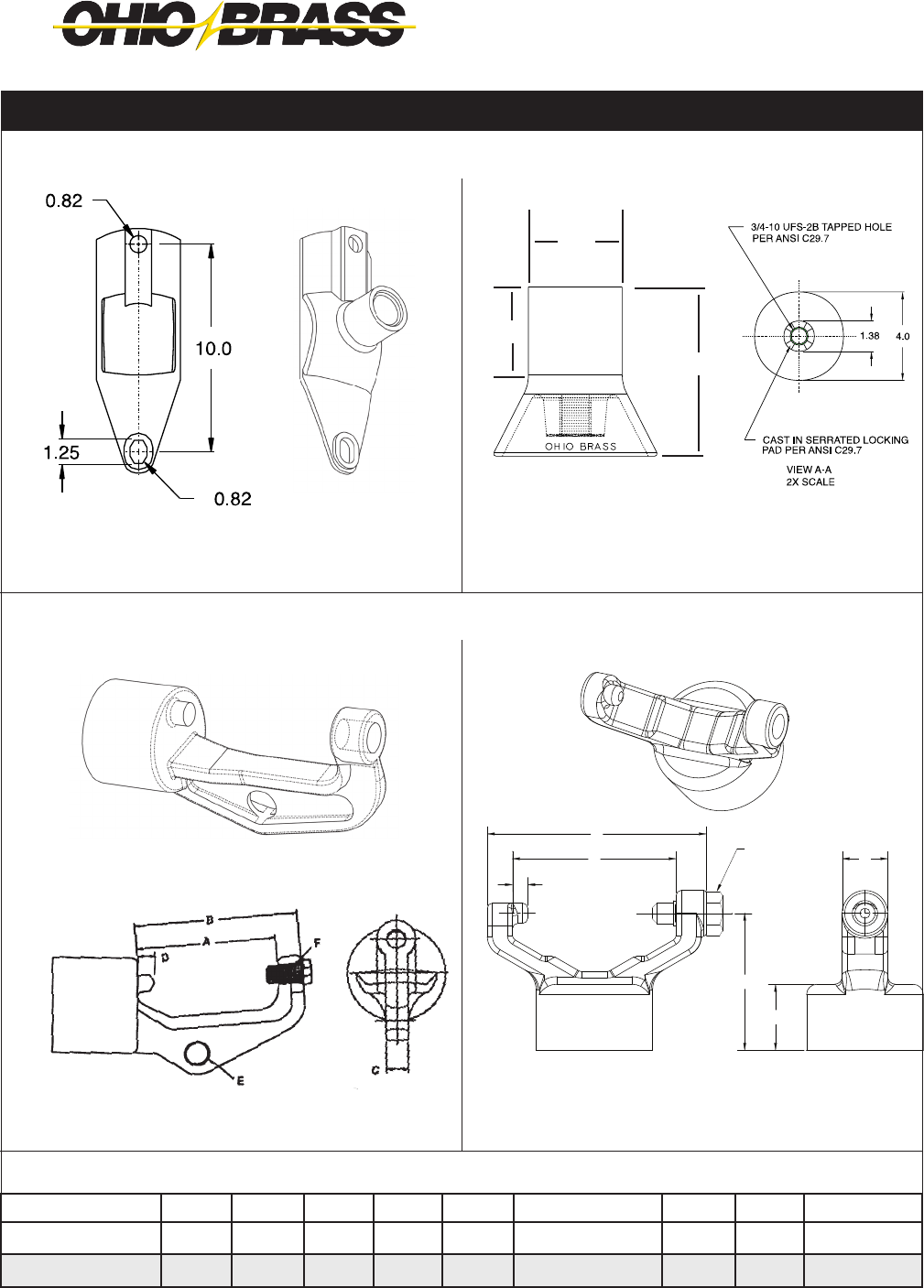
JUNE 2012 OHIO BRASS – AIKEN, SC, USA
23-6
B
A
D
F
C
I
H
Post Line Fittings Dimensions (in inches)
Post Base & Line Fittings
15, 25 & 35 kV
Stud Base
15, 25 & 35 kV
Horizontal Gain Base
Line Post Line Fittings Dimensions (in inches)
15-69 kV
Vertical Clamptop Cap
15-69 kV
Horizontal Clamptop Cap
4.0
2.11
▲▲
▼
▼
2.25
▲
▲
Post Base Fittings Dimensions (in inches)
Type A B C D E F H I Material
H. Clamptop Cap 4.00 4.75 0.62 0.38 0.69 5/8-11 UFS-2B - - 60-40-18 DI
V. Clamptop Cap 4.00 5.38 1.12 0.38 - 5/8-11 UFS-2B 3.38 1.63 60-40-18 DI

JUNE 2012
23-7
OHIO BRASS – AIKEN, SC, USA
Line Post Base Fittings Dimensions (in inches)
Post Base & Line Fittings
46 & 69 kV Stud Base46 & 69 kV Horizontal Gain Base
46 & 69 kV Two Hole Blade15-69 kV F-Neck Cap
B
A
E
D
C
3/4-10 UFS-2B THREAD
7/8-9 UFS-2B THREAD
Type A B C D E F G H Material
H. Gain Base 14.50 7.00 12.00 10.00 6.75 1.25 x 0.88 0.88 4.00 60-40-18 DI
Stud Base 4.22 2.875 5.50 1.50 0.50 3/4-10 UFS-2B or
7/8-9 UFS-2B
- - 60-40-18 DI
Two Hole Blade 2.75 1.38 0.50 4.00 0.75 1.00 Dia. 0.50 R 0.44 R 60-40-18 DI
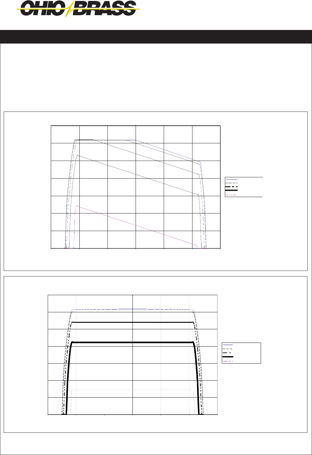
JUNE 2012 OHIO BRASS – AIKEN, SC, USA
23-8
values, nd the allowable longitudinal load to be 900
pounds.
When the posts are loaded in tension the cantilever
loading due to the combined effects of longitudinal,
vertical and tensile loads should not exceed the rated
tension working value.
IMPORTANT: The application curves should not be
extrapolated.
How to use the application curves. After you have
established the loading cases, you can use the curves
to determine whether a specic Veri*Lite unit meets
your loading requirement.
For example, consider the installation of a Veri*Lite
post number 80S025-0100 on a line with a vertical
cantilever load of 800 pounds and a compression
load of 900 pounds. By entering the curve at these
Maximum deection for any of the post styles is approximately 1.75" at SCL.
Curves are shown using a 2.0 safety margin to SCL
Application Curves for Veri*Lite Insulators
80S015, 80S025 & 80S028 HORIZONTAL STYLE
80S015, 80S025 & 80S028 VERTICAL STYLE
0
200
400
600
800
1000
1200
1400
VERTICAL LOAD, LBF
0 Longitudinal
300 Longitudinal
600 Longitudinal
900 Longitudinal
1200 Longitudinal
Compression Tension
LINE POST
APPLICATION CURVES
9-12-05
-3000 -2000 -1000 0 1000 2000 3000
TRANSVERSE LOAD, LBF
0
200
400
600
800
1000
1200
1400
-3000 -2000 -1000 0 1000 2000 3000
VERTICAL LOAD, LBF
0 Longitudinal
300 Longitudinal
600 Longitudinal
900 Longitudinal
Compression
TRANSVERSE LOAD, LBF
LINE POST
APPLICATION CURVES
9-12-05
Tension
VERTICAL LOAD, LBF
1200 Longitudinal
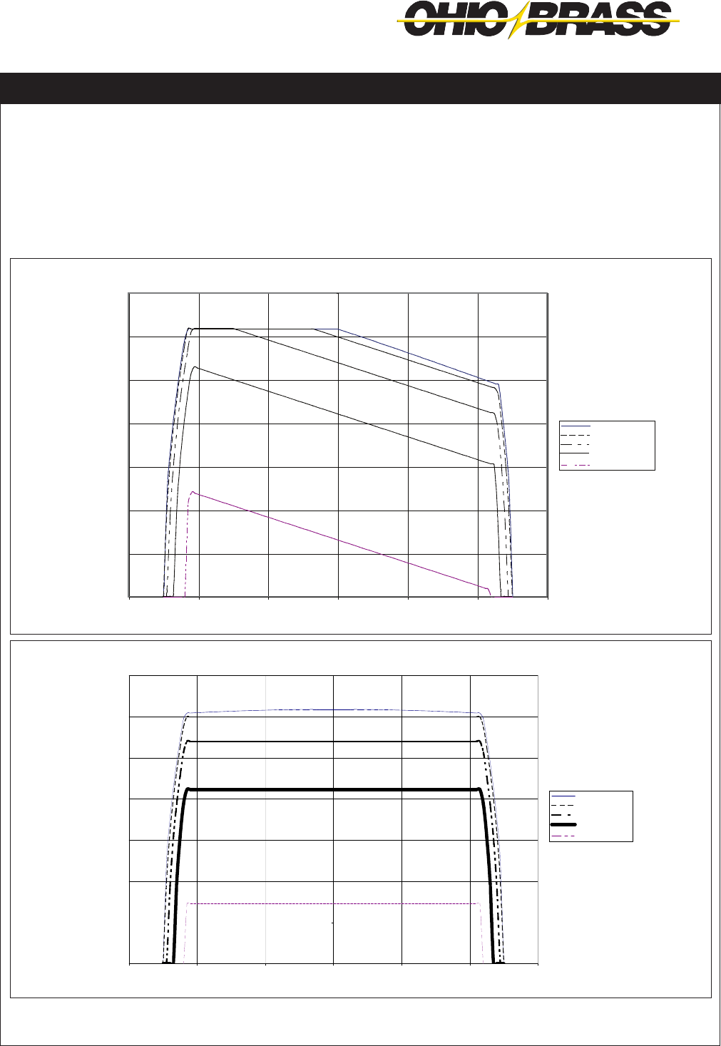
JUNE 2012
23-9
OHIO BRASS – AIKEN, SC, USA
values, nd the allowable longitudinal load to be 900
pounds.
When the posts are loaded in tension the cantilever
loading due to the combined effects of longitudinal,
vertical and tensile loads should not exceed the rated
tension working value.
IMPORTANT: The application curves should not be
extrapolated.
How to use the application curves. After you have
established the loading cases, you can use the
curves to determine whether a specic Veri*Lite unit
meets your loading requirement.
For example, consider the installation of a Veri*Lite
post number 80S069-0100 on a line with a vertical
cantilever load of 800 pounds and a compression
load of 900 pounds. By entering the curve at these
Maximum deection for any of the post styles is approximately 1.75" at SCL.
Curves are shown using a 2.0 safety margin to SCL
80S046 & 80S069 HORIZONTAL STYLE
Application Curves for Veri*Lite Insulators
0
200
400
600
800
1000
1200
1400
-3000 -2000 -1000 0 1000 2000 3000
VERTICAL LOAD, LBF
Compression
TRANSVERSE LOAD, LBF
LINE POST
APPLICATION CURVES
9-12-05
Tension
0 Longitudinal
300 Longitudinal
600 Longitudinal
900 Longitudinal
1200 Longitudinal
VERTICAL LOAD, LBF
80S046 & 80S069 VERTICAL STYLE
0
200
400
600
800
1000
1200
1400
VERTICAL LOAD, LBF
0 Longitudinal
300 Longitudinal
600 Longitudinal
900 Longitudinal
1200 Longitudinal
Compression Tension
TRANSVERSE LOAD, LBF
LINE POST
APPLICATION CURVES
9-12-05
1000 2000 3000
-1000-2000-3000
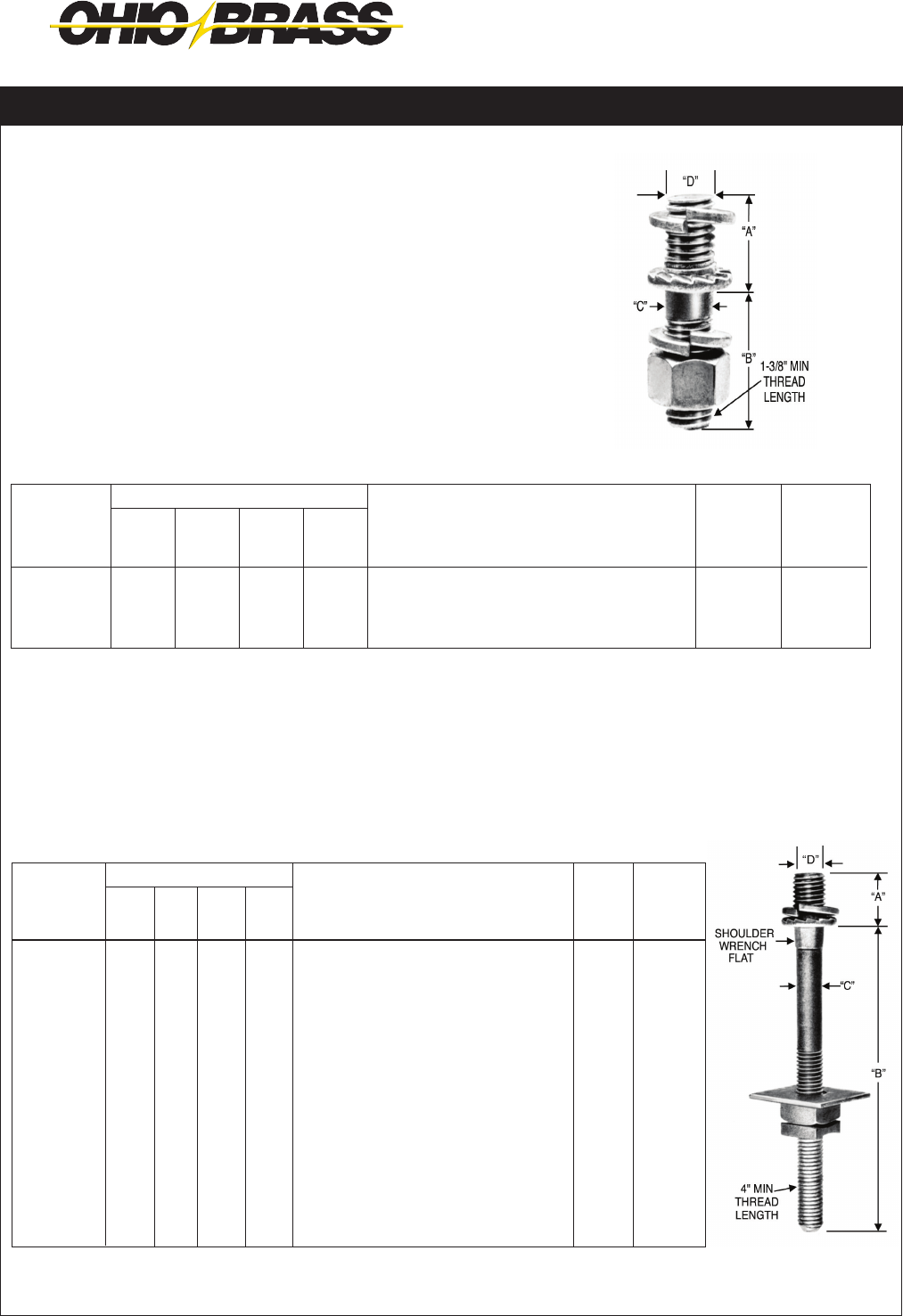
JUNE 2012 OHIO BRASS – AIKEN, SC, USA
23-10
Line Post Insulator Studs
DF19M Series
Serrated collar and lockwasher secure unit to line post
insulator and prevent accidental disassembly. Cut
threads above serrated collar, rolled threads below
collar.
DF19M3
For Steel Crossarms
DF19M2
For Wood Crossarms
*DF19M29 and DF19M32 include (1) additional double coil lockwasher.
Catalog
No.
DF19M1
DF19M3
875833001
Dimensions (in.)
“D”
3/4
3/4
7/8
“A”
1-1/8
1-1/8
1-3/8
“B”
1-3/4
1-3/4
2
“C”
5/8
3/4
7/8
Hardware
Included
(1) reg. hexnut and (2) spring lockwashers
(1) reg. hexnut and (2) spring lockwashers
(1) reg. hexnut and (2) spring lockwashers
Standard
Package
100 pcs.
100 pcs.
100 pcs.
Weight
100 Pcs.
43 lbs.
54 lbs.
85 lbs.
Dimensions (in.)
“D”
3/4
3/4
3/4
3/4
3/4
3/4
7/8
“A”
1-1/8
1-1/8
1-1/8
1-1/8
1-1/8
1-1/8
1-3/8
“B”
7
7
10
12
14
24
8
“C”
5/8
3/4
5/8
5/8
3/4
3/4
7/8
Hardware
Included
(1) sq. nut, (1 sq. washer,
(1) spring lockwasher, (1) MF locknut
(1) sq. nut, (1 sq. washer,
(1) spring lockwasher, (1) MF locknut
(1) sq. nut, (1 sq. washer,
(1) spring lockwasher, (1) MF locknut
(1) sq. nut, (1 sq. washer,
(1) spring lockwasher, (1) MF locknut
(1) sq. nut, (1 sq. washer,
(1) spring lockwasher, (1) MF locknut
(1) sq. nut, (1 sq. washer,
(1) spring lockwasher, (1) MF locknut
(1) sq. nut, (1 sq. washer,
(1) spring lockwasher, (1) MF locknut
Catalog
No.
DF19M2
DF19M4
DF19M19
DF19M20
*DF19M29
*DF19M32
875843001
Std.
Pkg.
50 pcs.
40 pcs.
25 pcs.
25 pcs.
20 pcs.
15 pcs.
50 pcs.
Weight
100 Pcs.
102 lbs.
140 lbs.
176 lbs.
192 lbs.
234 lbs.
342 lbs.
277 lbs.

JUNE 2012
23-11
OHIO BRASS – AIKEN, SC, USA
For standard voltage applications with all aluminum,
ACSR or aluminum alloy conductor.
Designed for use on tangent suspension spans with
horizontal or vertical post insulators.
Keeper is reversible for proper t on different size
conductors.
Material: Body and Keeper—356-T6 aluminum alloy
Hardware—Galvanized steel
Anti-static spring 302 stainless steel
NOTES: (1) Recommended torque on bolts; 1/2”—480 in. lbs.
(2) Anti-static spring can be supplied by adding “ARIV” to catalog number. Example, TSC57ARIV.
(3) Clamptop clamps can be mounted directly on Veri*Lite posts, if the posts are ordered with the horizontal or
vertical clamptop option.
Fig.
No.
1
1
1
1
2
Clamping
Range
Inches (mm)
.25-.57
(6.3-14.4)
.35-.86
(8.8-21.8)
.50-1.06
(12.7-26.9)
1.00-1.50
(25.4-38.1)
1.50-2.00
(38.1-50.8)
Ultimate
Body
Strength
Lbs. (kN)
2,800
(12.46)
2,800
(12.46)
2,800
(12.46)
2,800
(12.46)
2,800
(12.46)
L
5-1/4
(133.3)
5-1/4
(133.3)
5-1/4
(133.3)
5-1/4
(133.3)
5-1/4
(133.3)
W
3-7/8
(98.4)
3-7/8
(98.4)
3-7/8
(98.4)
3-7/8
(98.4)
3-7/8
(98.4)
J
1/2
(12.7)
1/2
(12.7)
1/2
(12.7)
1/2
(12.7)
1/2
(12.7)
Approx.
Wt. Each
Lbs. (kg)
.42 (.19)
.45 (.20)
.62 (.28)
.64 (.29)
.75 (.34)
Dimensions Inches (mm)
Suspension Trunnion Bolted Aluminum Clamptop Clamps
Former
Catalog
Number
270660-3002
270661-3002
270662-3002
270663-3002
Catalog
Number
TSC57
TSC86
TSC106
TSC150
TSC200
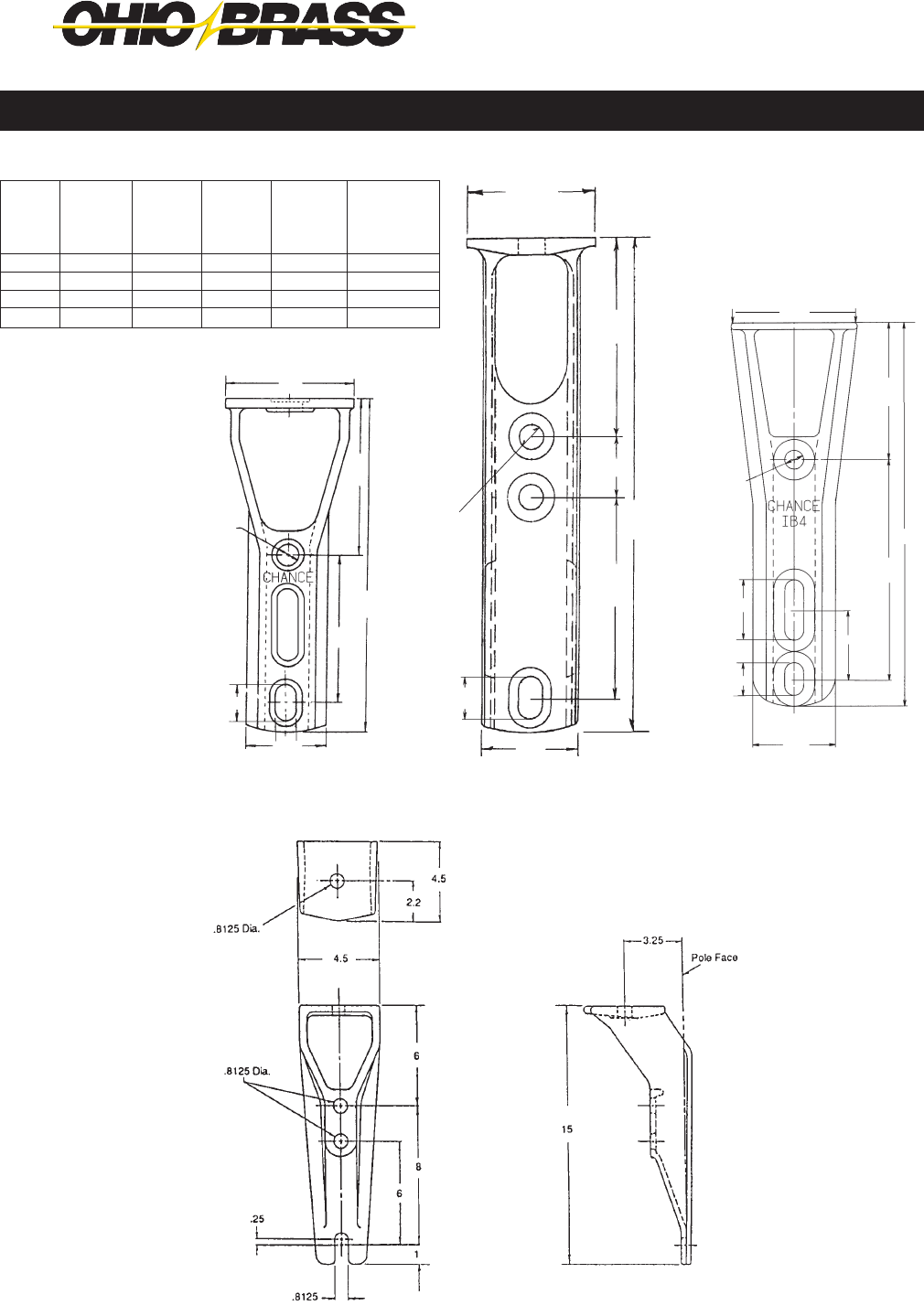
JUNE 2012 OHIO BRASS – AIKEN, SC, USA
23-12
Mounts post or pin type insulator to top of pole. Variety of
bolt hole locations for mounting to pole.
Ductile iron per ASTM A-536
Hot dipped galvanized per ASTM A-153
† RUS Listed
IB4
11⁄16"
43⁄4"
105⁄8"
5"
11⁄16"
21⁄2"
13⁄16"
33⁄4"
IB2 IB3
33⁄4"
2"
6"
153⁄8"
3"
63⁄8"
15⁄16"
13⁄16"
3"
11⁄16"
41⁄2"
5"
8"
13⁄16"
23⁄16"
21⁄2"
14"
Bracket, Pole Top Insulator
75114
Catalog
No.
IB2
IB3
†IB4
75114
Mounting
Bolt Dia.
5/8"
3/4"
5/8"
3/4"
Insulator
Bolt Dia.
5/8" or 3/4"
5/8" or 3/4"
5/8" or 3/4"
5/8" or 3/4"
Mtg. Bolt
Spacing
43/4"
5" or 8"
5" or 8"
6" or 8"
Dist. From
Insul.Base
To Top
Hole
43/4"
63/8"
5"
6"
Approx.
Ship.Wt.Lbs.
Per 100 Pcs.
360
600
600
1000

JUNE 2012
23-13
OHIO BRASS – AIKEN, SC, USA
Use for mounting one or two insulator(s) to pole for armless
construction.
Approx.
Ship.
Wt.Lbs.
Per
100 Pcs.
333
1025
Space
Between
Insul.
Bases
—
14"
Insul.
Angle
Dim.
5°
—
Mtg.
Bolt
Spacing
5", 6"
4", 5"
Max.
Insul.
Bolt
Dia.
3/4"
3/4"
Mtg.
Bolt Dia.
Two 5/8"
Two 5/8"
Catalog
No.
1IPTB
2IPTB
Ductile iron per ASTM A-536
Hot dipped galvanized per ASTM A-153
Use for mounting pin or post vertical insulators, cutouts, arresters, or cable terminators. Three-hole style can be used for
in-line deadending using suspension insulators.
2IPTB
Max.
Insul.
Mtg.
Bolt
Dia.
3/4"
3/4"
3/4"
3/4"
3/4"
Pole
Mtg.
Bolt
Dia.
Two 5/8"
Two 5/8"
Two 5/8"
Two 5/8"
Two 5/8"
Max.
Equip.
Mtg.
Bolt
Dia.
5/8"
5/8"
5/8"
1/2"
5/8"
Pole
Mtg.
Bolt
Spacing
5"
5"
5"
5"
5"
Clearance
Pole To
Insul.
Bolt
"A"
12"
18"
18"
12"
18"
Approx.
Ship.
Wt.Lbs.
Per
100 Pcs.
860
1300
1400
86
1400
4"
4"
4"
"A"
.58 sq. Hole
T2060594
Side view with
hardware
LB12A1 & LB18B1
4" R
41⁄2"
4"
41⁄2"
For 3⁄8" Carriage Bolt
13⁄16" Dia.
"A"
5"
LB18B3/LB18B3CH
"A"
11⁄16" Dia. Hole
4"
4"
11/4"
Catalog
No.
LB12A1
LB18B1
LB18B3
*T2060594
**LB18B3CH
Ductile iron per ASTM A-536
Hot dipped galvanized per ASTM A-153
* T206-0594 has 3 captive 1/2" x 2" bolts and nuts included
** LB18B3CH has 2 captive 1/2" x 2" bolts and nuts included with
LB18B3.
11⁄16"
Dia.
4"
Bracket, Horizontal Insulator
Bracket, Vertical Insulator
1IPTB
T2060594
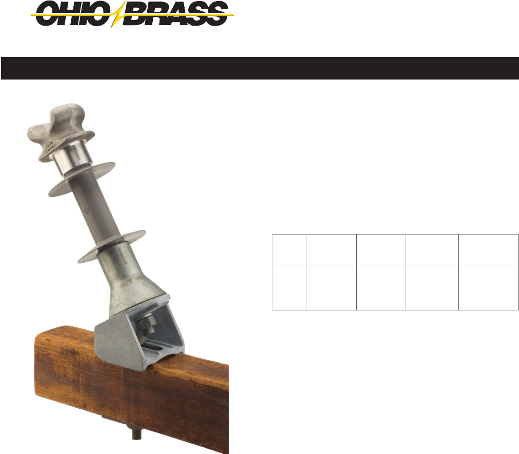
JUNE 2012 OHIO BRASS – AIKEN, SC, USA
23-14
BRACKET,
ANGLE CROSSARM
Ductile iron per ASTM A-536
Hot dipped galvanized per ASTM A-153
Mounts post insulators at 30° angle on crossarm for use on
running corners.
Bracket, Pole Top Insulator
Catalog
No.
1XAB
Crossarm
Size
33/4" x 43/4"
Max. and
Round
Crossarms
Approx. Ship
Wt. Lbs.
Per 100 Pcs.
610
Mtg. Bolt
Diameter
3/4"
Stud Bolt
Diameter
3/4"
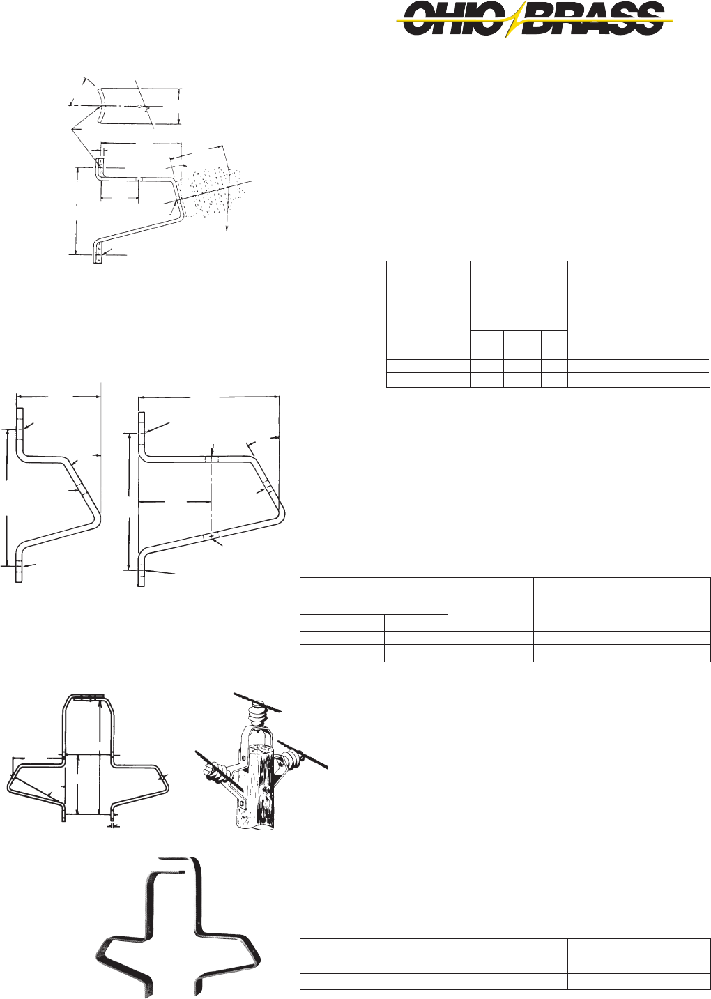
JUNE 2012
23-15
OHIO BRASS – AIKEN, SC, USA
11/16" Hole
16919
Insulator
Stud
Bolts Required
3/4"
3/4"
13/16" Hole
†*C2060209
C2060162
Pole
Mounting
Bolts Required
Two 5/8"
Two 5/8"
Approx. Ship
Wt. Lbs.
Per 100 Pcs.
650
440
*This bracket is designed to facilitate a stringing block.
†RUS listed
Catalog Number
BRACKETS, POST INSULATOR
Side Mounted
The bracket is formed of high-quality 3/8" x 21/2" bar steel and hot dip
galvanized. It can be utilized to mount distribution post insulators from
15 kV to 34.5 kV.
BRACKETS, POST INSULATOR
Curved base
This bracket can be used for mounting distribution post-type insulators
from 15 kV to 34.5 kV on the side of the pole. The base has a pole-shape
back for convenient installation. Brackets can be placed in a phase-over-
phase arrangement or can be mounted on opposite sides of the pole for
"armless" construction.
Insulators not included.
BRACKETS, POST INSULATOR
Uni-Brackets
Chance Uni-Brackets are a clean-appearing, low-cost method of mount-
ing three post-type insulators atop a pole completely eliminating the
crossarm. The brackets can be installed on the pole in less than five
minutes, requiring only two 3/4" bolts for attachment. Uni-Brackets fit
poles having a pole-top diameter from 6" to 81/2". Slot on top is 11/16" x
21/4".
No. 9183 brackets can be adapted to a variety of distribution construc-
tion using post-type insulators from 15 through 34.5 kV.
Catalog
Number
†9183
Approx. Ship Wt.
Lbs. Per 100 Pcs.
2100
Insulator Stud
Bolts Required
5/8"
†Includes both sections of bracket
C2060162 C2060209
Angle
A
15°
15°
15°
W
4
4
4
D
13/16
13/16
13/16
L
91/2
12
15
Catalog
Number
*C2060009
†*C2060010
C2060011
Dimensions
In Inches
*These brackets have 13/16" stringing block holes.
†RUS listed
Approx.
Ship
Wt. Lbs.
Per 100 Pcs.
1220
1669
2066
81/4"
11/16" Holes
13/16" Hole
13/16" x 11/4"
Hole
3/8" x 21/2"
Stock
60° 91/2"
1817/32"
No. 9183
13/16" hole
81/2"
11/16" hole
11/16" x 13/8"
slot
51/4"
30°
11/16" x 13/8" slot
83/4"
13/16" hole 30°
13/16"
hole
41/2"
11/16" hole
13/16" x 15/16" slot
81/2"
C2060009
31/2" R
W
11/16" Dia. hole
L
3/8" X
A
D
10"
load table
11/16" x 11/4" slot
41/2"

JUNE 2012 OHIO BRASS – AIKEN, SC, USA
23-16
SUPER TOP-TIE® Line Ties
• for Pin, Post and Spool Insulators
Made of aluminum-clad steel compatible with aluminum,
aluminum-alloy and ACSR conductors in the top grooves of
vertical-mounted *ANSI Class C, F, J and many non-standard
pin and post insulators (single-or double-support) or on *ANSI
53-2 spool insulators (horizontal or vertical).
High-density polyethylene hooks provide the wide applica-
tion range and ensure proper installation. If used over armor
rods (not required), select tie size based on total conductor/
armor diameter. Semiconductive-rubber pad and high-density-
polyethylene on loops protect against abrasion of insulator,
conductor and tie. Fit is resilient and provides superior
performance under galloping and aeolian vibration. Install
by hand or with hot-line tools.
POST
INSULATOR
PIN
INSULATOR
NON-STANDARD
INSULATOR
ANSI 53-2
SPOOL
ORDERING INFORMATION
ACSR
#6, 6/1
#4, 6/1
#3, 6/1
#2, 6/1
#1, 6/1
1/0, 6/1
2/0, 6/1
3/0, 6/1
4/0, 6/1
266.8, 18/1
336.4, 18/1
477, 18/1
556.5, 18/1
Color
Code
None
Orange
Purple
Red
Gray
Yellow
Blue
Black
Pink
Green
Brown
Violet
Gold
Std.
Pkg.
50
50
50
50
50
50
50
50
50
50
50
50
50
Wt. Per
100, Lb.
28
28
28
28
28
32
32
32
32
32
40
40
40
AAC
(All-Aluminum)
#6, 7W
#4, 7W
#3, 7W
#2, 7W
#1, 7W
1/0, 7W
2/0, 7W
3/0, 7W
4/0, 7W
266.8, 19W
336.4, 19W
477, 19W
636, 37W
AAAC
(Alum.-Alloy)
#6, 7W
#4, 7W
#3, 7W
#2, 7W
#1, 7W
1/0, 7W
2/0, 7W
3/0, 7W
4/0, 7W
266.8, 19W
336.4, 19W
477, 19W
556.5, 19W
Diameter Range
.184-.220" (4.67-5.59 mm)
.221-.257" (5.61-6.53 mm)
.258-.289" (6.55-7.34 mm)
.290-.325" (7.37-8.26 mm)
.326-.360" (8.28-9.14 mm)
.361-.409" (9.17-10.39 mm)
.410-.460" (10.41-11.68 mm)
.461-.516" (11.71-13.11 mm)
.517-.584" (13.13-14.83 mm)
.585-.664" (14.86-16.87 mm)
.665-.755" (16.89-19.18 mm)
.756-.859" (19.20-21.82 mm)
.860-.977" (21.84-24.82 mm)
Aluminum-Type Conductors, Typical Sizes
Catalog
Number
STT10
STT20
STT30
STT40
STT50
STT60
STT70
STT80
STT90
STT100
STT110
STT120
STT130
LEFT-HAND LAY STANDARD
• Applied Length: 29" - 48" (Depends on insulator make and conductor size).
• Strength: Exceeds Rule 261E.2(A) of National Electrical Safety Code.
• REA accepted.
• To obtain outside diameters of conductors, consult Conductor Chart.
*Super Top-Tie STT10 — STT130 also t many foreign or reclaimed pin and post insulators with neck sizes 21/4" - 31/2".
Consult Hubbell Power Systems, Inc. for use on pins and posts outside these dimensions.
Web: http://www.hubbellpowersystems.com
E-mail: hpsliterature@hps.hubbell.com
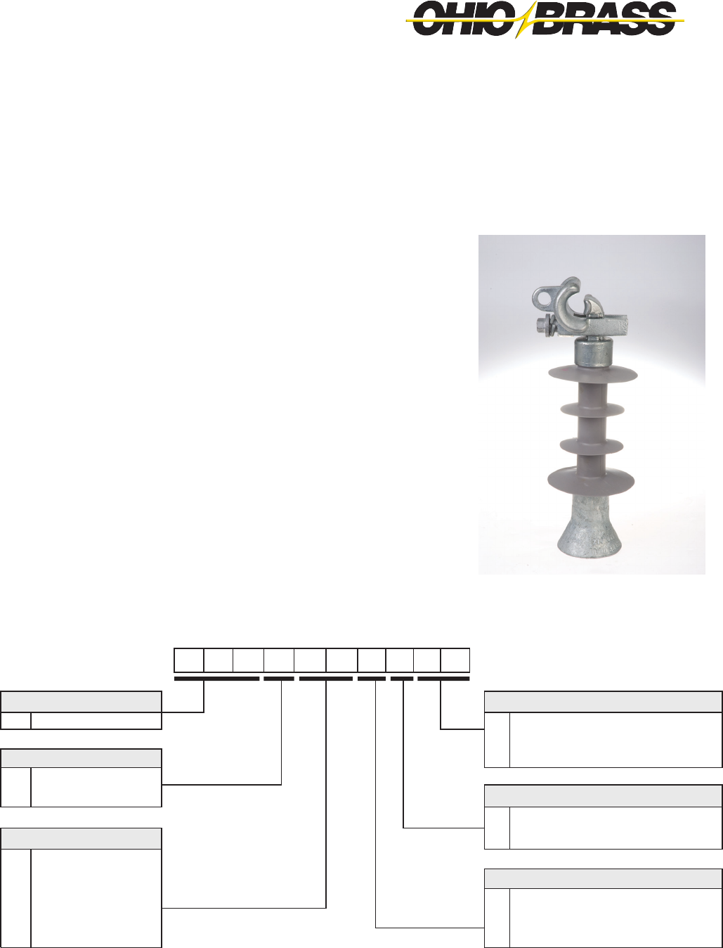
JUNE 2012
23-17
OHIO BRASS – AIKEN, SC, USA
Veri*Lite™
Silicone Rubber Line Post Insulators with
Universal Clamp for 15-69kV Applications
8 0 S 0 6 9 0 U 0 9
Polymer Type Bottom End Fitting
80S Veri*Lite - SR Polymer 00 Gain Base - Transverse
09 3/4” Stud Base
Hardware Finish 10 7/8” Stud Base
0 Standard
1 Dulled Top End Fitting
U Universal Clamptop
Rating H Hotstick Operable Universal Clamptop
15 15kV (1.5” rod)
25 25kV (1.5” rod) Dimensioning
28 35kV (1.5” rod) 0 ANSI C29.18 Quality Conformance Tests
46 46kV (1.75” rod) 6 LWIWG - 02 Sample Tests
69 69kV (1.75” rod) 9 Special
CATALOG NUMBER KEY
Veri*Lite Line Post Insulators - Silicone
The Ohio Brass Universal Clamp end tting is used with the Veri*LiteTM
Line Post (VLLP) insulator family. Combining the proven direct bond
silicone technology of the Ohio Brass VLLP design, the Universal
Clamp offers a exible range-taking connection that can be installed in
either the vertical or horizontal direction. The Universal Clamp design
eliminates the need for a separate additional conductor clamp; saving
both money and installation time. In addition, the optional hotstick-
operable feature provides exibility for live-line work.
Design Features
• Proven direct bond interface
• Weathersheds molded with proprietary silicone rubber compound
• Universal clamp works for a conductor diameter range of 0.30”
(7.6 mm) to 1.34” (34 mm) to provide exibility in the eld
• Hotline option allows for live-line operability
• Can be installed in vertical or horizontal directions, thus reducing
inventory
• Integral design eliminates need for additional trunnion clamp
• Meets requirements of CEA LWIWG-02-1996 & ANSI C29.18-2003

JUNE 2012 OHIO BRASS – AIKEN, SC, USA
23-18
Universal Clamptop & Stud Base w/Bracket*
(0U09 & 0U10 w/C2060009)
Universal Clamptop & Stud
Base (0U09 & 0U10)
Universal Clamptop &
Gain Base (0U00)
Universal Clamptop Dimensions (in inches)
*Multiple bracket options available (see pages 13-15 of Section 23)
kV
Line
Fitting
Base
Fitting
Catalog
Number
“X”
Dimension
Inches
(mm)
Dry Arc
Distance
Inches
(mm)
Leakage
Distance
Inches
(mm)
60 Hz
(Low Frequency)
Flashover
Impulse
Critical
Flashover
Pos. kV
Impulse
Positive
Withstand
kV
SCL
pounds
(kN)
MDCL/
WCL
pounds
(kN)
Package
Quantity
Crate/
Pallet
QuantityDry-kV Wet-kV
15
Universal 3/4-10 Tap 80S015-0U09 13.0 (330) 7.4
(188)
11.0
(279) 90 70 150 140 2800
(12.5)
1235
(5.5)
3 60
Universal 7/8-9 Tap 80S015-0U10 13.0 (330) 3 60
Universal Gain 80S015-0U00 12.4 (314) 3 60
25
Universal 3/4-10 Tap 80S025-0U09 14.8 (375) 9.6
(244)
17.3
(439) 110 75 185 170 2800
(12.5)
1235
(5.5)
3 60
Universal 7/8-9 Tap 80S025-0U10 14.8 (375) 3 60
Universal Gain 80S025-0U00 14.1 (357) 3 60
35
Universal 3/4-10 Tap 80S028-0U09 17.0 (432) 11.7
(297)
26.1
(662) 135 100 215 200 2800
(12.5)
1235
(5.5)
3 60
Universal 7/8-9 Tap 80S028-0U10 17.0 (432) 3 60
Universal Gain 80S028-0U00 16.4 (415) 3 60
46
Universal 3/4-10 Tap 80S046-0U09 19.5 (495) 14.4
(390)
34.3
(872) 170 125 260 235 2800
(12.5)
1235
(5.5)
- 35
Universal 7/8-9 Tap 80S046-0U10 19.5 (495) - 35
Universal Gain 80S046-0U00 18.8 (478) - 35
69
Universal 3/4-10 Tap 80S069-0U09 26.1 (663) 22.3
(566)
58.2
(1478) 230 180 360 330 2470
(11.0)
1235
(5.5)
- 35
Universal 7/8-9 Tap 80S069-0U10 26.1 (663) - 35
Universal Gain 80S069-0U00 25.4 (645) - 35

Supplemental Catalog 24C
®
Hubbell Power Systems offers a transmission product line to meet the needs of today’s power utility. The 3”
Quadri*Sil® Line Post is an addition to the reliable product line that boasts a redundant four point sealing
system. The Quadri*Sil® product line will ensure the utmost protection against weather and contaminants in
an unpredictable environment.
• Proprietary silicone rubber compound
• Direct bond design
• Uniform circumferential crimp
Horizontal Line Post Insulators
3.0” (76.2 mm) Rod Diameter
1850 Richland Avenue East, Aiken, SC 29801
http://www.hubbellpowersystems.com
E-mail: quadrisil@hps.hubbell.com
©Copyright Hubbell Inc. 2010
NOTE: Because Hubbell has a policy of continuous product improvement, we reserve the right to change design and specifications without notice.
Notes:
1) For voltages above 345 kV, other section lengths, or end fitting combinations, please contact your HPS representative.
2) Electrical values are without corona ring. For voltages equal to or greater than 220 kV, please contact your HPS representative.
3) The catalog number shown in the table is for a 3.0’’ (76.2mm) rod diameter line post with a two hole blade on the line end and an aluminum gain
base on the tower end. For other end fitting combinations, please contact your HPS representative.
Horizontal Line Post Insulators
3.0” (76.2 mm) Rod Diameter
hubbellpowersystems.com
hpsliterature@hps.hubbell.com
Selection Guide:
Typical Line Voltage,
kV(1)
Catalog
Numbers(3)
Section
Length
inches
(mm)
Strike
Distance
inches
(mm)
ANSI Values IEC Values
(2)60-Hz
Dry
Flashover
(kV)
(2)60-Hz
Wet
Flashover
(kV)
(2)Critical
Impulse
Positive
(kV)
(2)Critical
Impulse
Negative
(kV)
(2)60-Hz
1-minute
Wet
Withstand
(kV)
(2)Impulse
Positive
Withstand
(kV)
SCL lbs.
(kN)
P300025S0020
P300026S0020
P300031S0020
P300036S0020
P300042S0020
P300047S0020
P300052S0020
P300053S0020
P300057S0020
P300058S0020
P300063S0020
P300064S0020
P300068S0020
P300069S0020
P300074S0020
P300078S0020
P300083S0020
P300085S0020
P300089S0020
P300094S0020
P300095S0020
P300099S0020
P300100S0020
P300105S0020
27.9 (708)
29.2 (741)
34.0 (863)
38.9 (988)
44.9 (1140)
49.8 (1265)
54.7 (1389)
55.9 (1420)
59.5 (1511)
60.7 (1542)
65.6 (1666)
66.8 (1697)
70.4 (1788)
71.6 (1819)
76.5 (1943)
81.4 (2068)
86.2 (2189)
87.4 (2220)
92.3 (2344)
97.1 (2466)
98.4 (2499)
102.0 (2591)
103.2 (2621)
108.0 (2743)
275
290
335
385
445
490
540
550
585
600
645
660
695
705
755
800
850
860
910
955
970
1005
1015
1065
245
255
300
345
400
445
490
500
535
545
590
600
635
645
690
735
780
790
835
880
890
925
935
980
425
445
520
595
690
765
840
860
915
935
1010
1030
1085
1105
1180
1255
1330
1350
1425
1500
1520
1575
1595
1670
520
540
615
690
785
860
935
955
1010
1030
1105
1125
1180
1200
1275
1350
1430
1445
1520
1600
1615
1675
1690
1770
7500 (33.4)
7500 (33.4)
7500 (33.4)
6670 (29.7)
5810 (25.8)
5261 (23.4)
4820 (21.4)
4720 (20.9)
4440 (33.4)
4350 (19.3)
4040 (17.9)
3970 (17.7)
3770 (16.8)
3710 (16.5)
3480 (15.5)
3280 (14.6)
3100 (13.8)
3050 (13.6)
2900 (12.9)
2760 (12.3)
2720 (12.1)
2630 (11.7)
2600 (11.6)
2480 (11.0)
69 115 138 161 230 345
Nominal
Polymer
Length
inches
025
026
031
036
042
047
052
053
057
058
063
064
068
069
074
078
083
085
089
094
095
099
100
105
(2)Impulse
Negative
Withstand
(kV)
Leakage
Distance
inches
(mm)
82 (2083)
88 (2223)
101 (2555)
116 (2934)
134 (3406)
149 (3785)
164 (4163)
168 (4260)
179 (4544)
183 (4638)
198 (5017)
201 (5110)
212 (5395)
216 (5489)
231 (5867)
246 (6246)
261 (6624)
265 (6721)
280 (7099)
294 (7478)
292 (7412)
309 (7856)
313 (7950)
328 (8329)
38.5 (978)
39.7 (1008)
44.4 (1128)
49.1 (1247)
55.0 (1397)
59.7 (1516)
64.4 (1636)
65.6 (1666)
69.1 (1755)
70.3 (1786)
75.0 (1905)
76.2 (1935)
79.7 (2024)
80.9 (2055)
85.6 (2174)
90.3 (2294)
95.0 (2413)
96.2 (2443)
100.9(2563)
105.6(2682)
106.8(2713)
110.4(2804)
111.5(2832)
116.2(2951)
200
215
255
285
340
375
410
425
450
460
495
510
535
545
585
620
655
670
705
740
755
780
790
825
400
415
490
560
685
725
790
810
865
880
950
970
1025
1045
1115
1185
1255
1275
1345
1420
1435
1490
1510
1580
485
505
575
650
740
815
884
900
955
975
1045
1065
1120
1140
1210
1280
1350
1370
1440
1515
1530
1585
1605
1675
Clamptop:
Maximum Design Tension = 2,500 lbs. (11.1 kN)
Two-Hole Blade
Maximum Deign tension = 12,500 lbs. (55.6 kN)

A
26-1
JULY 2010OHIO BRASS – AIKEN, SC, USA
Section
26
Hi*Lite® XL Transmission Insulators
©Copyright 2010 Hubbell Incorporated
NOTE: Because Hubbell has a policy of continuous product improvement, we reserve the right to change design and specications without notice.
Printed in USA
®

26-2
JULY 2010 OHIO BRASS – AIKEN, SC, USA
NOTE: Because Hubbell has a policy of continuous product improvement, we reserve the right to change design and specifications without notice.
Warranty - Material
Hubbell Power Systems, Inc. warrants all products sold by it to be merchantable (as such term is
defined in the Uniform Commercial Code) and to be free from defects in material and workman-
ship. Buyer must notify the Company promptly of any claim under this warranty. The Buyer's
exclusive remedy for breach of this warranty shall be the repair or replacement, F.O.B. factory,
at the Company's option, of any product defective under the warranty which is returned to the
Company within one year from the date of shipment. NO OTHER WARRANTY, WHETHER
EXPRESS OR ARISING BY OPERATION OF LAW, COURSE OF DEALING, USAGE OF
TRADE OR OTHERWISE IMPLIED, SHALL EXIST IN CONNECTION WITH THE COMPANY'S
PRODUCTS OR ANY SALE OR USE THEREOF. The Company shall in no event be liable for
any loss of profits or any consequential or special damages incurred by Buyer. The Company's
warranty shall run only to the first Buyer of a product from the Company, from the Company's
distributor, or from an original equipment manufacturer reselling the Company's product, and
is non-assignable and non-transferable and shall be of no force and effect if asserted by any per-
son other than such first Buyer. This warranty applies only to the use of the product as intended
by Seller and does not cover any misapplication or misuse of said product.
Warranty - Application
Hubbell Power Systems, Inc. does not warrant the accuracy of and results from product or
system performance recommendations resulting from any engineering analysis or study. This
applies regardless of whether a charge is made for the recommendation, or if it is provided free
of charge.
Responsibility for selection of the proper product or application rests solely with the purchaser. In
the event of errors or inaccuracies determined to be caused by Hubbell Power Systems, Inc., its
liability will be limited to the re-performance of any such analysis or study.
©Copyright 2010 Hubbell Incorporated
A
26-3
JULY 2010OHIO BRASS – AIKEN, SC, USA
A
B
C
D
E
Hi*Lite® XL Transmission Insulators
Section
26
Suspensions
Line Posts
Braced Posts
Station Posts
Sample Polymer Specs

26-4
JULY 2010 OHIO BRASS – AIKEN, SC, USA

A
26-5
JULY 2010OHIO BRASS – AIKEN, SC, USA
®
Table of Contents
Page
Design .............................................................. 26-6
Rod ...................................................................26-6
End Fittings ....................................................... 26-6
Weathersheds ..................................................26-6
Interface ............................................................ 26-6
Leakage Distance ............................................. 26-6
Washability ....................................................... 26-6
Mechanical Ratings .......................................... 26-6
Lengths Available ............................................. 26-6
Product Updates ............................................... 26-6
Packaging .........................................................26-6
Corona Performance ........................................ 26-7
Hi*Lite XL 25k SML Data .................................. 26-8
Hi*Lite XL 30k SML Data .................................. 26-9
Hi*Lite XL 50k SML Data ................................ 26-10
End Fitting Detail ............................................ 26-11
Key to the Catalog Numbers ........................... 26-11
Hi*Lite XL
Suspension Insulators

26-6
JULY 2010 OHIO BRASS – AIKEN, SC, USA
Hi*Lite® XL Insulators
Hi*Lite XL suspension insulators in this publication em-
body the latest features available in polymer
insulator design and manufacture.
From the early prototypes in 1971, through full scale
introduction in 1976, and through the succeeding years,
Hi*Lite insulators have featured conservative design and
high-quality manufacture.
Today’s Hi*Lite insulators will add to the over 1,000,000
already in service worldwide.
Design
The structural design of the Hi*Lite XL consists of these
basic parts:
Rod - Hi*Lite insulator fiberglass rod is produced from
the highest quality materials. Strands are aligned for
maximum tensile strength. The rod is more than 50 per-
cent glass fibers in cross section.
End Fittings - End fittings are steel or ductile iron. They
are crimped directly to the rod by a special process
originated by Ohio Brass, and later adopted by many
other producers. The crimp develops a high percentage
of the rod’s inherent tensile strength. It requires no inter-
movement of the parts to achieve high strength, nor
does it introduce potting compounds or adhesives.
Weathersheds - Weathersheds are high pressure injec-
tion molded by Ohio Brass, from the proprietary com-
pound ESP™. Housings manufactured with ESP silicone
alloy rubber exhibit hydrophobicity, high mechanical
strength, high corona resistance and low permeability
to moisture.
Interface - Hi*Lite insulators use Ohio Brass’ live sili-
cone interface. This feature prevents intrusion of mois-
ture and contaminating elements. If the exterior seal is
damaged, redundant o-ring seals within the live silicone
interface prohibit the lengthwise migration of intrusive
elements between shed and rod.
Leakage Distance
Hi*Lite XL insulators feature high leakage distance for
maximum resistance to contamination and leakage cur-
rents. Specific leakage distance (leakage divided by dry
arcing distance) is higher than porcelain. Contact Ohio
Brass if you have extra-high leakage distance needs.
Washability
Hi*Lite insulators listed in this catalog are suitable for
flood washing up to 200 psi. The design incorporates
positive, labyrinth seals to ensure long-term security
against water entry. Conventional dry-particle, air-
pressure cleaning methods may also be employed. A
cleaning guideline is available from Ohio Brass.
If your washing requirements exceed flood washing,
contact Ohio Brass.
Mechanical Ratings
Hi*Lite XL suspension insulators are rated and tested in
accordance with ANSI Standard C29.11. Certified test
reports in detail are available.
SML ratings are 25k, 30k and 50k pounds.
RTL ratings are consistent with the ANSI standard. Ac-
tual factory routine tests are conducted at loads equal
to or greater than the RTL rating.
Markings for XL insulator designs are permanently
embossed into the ground end corona shielding rings.
Markings include SML and RTL, part number, assem-
bly date code, and Ohio Brass identification.
Lengths Available
Hi*Lite suspension insulators are available in lengths
appropriate for 69 kV through 765 kV. Longer lengths
can be produced for special projects. Length incre-
ments are approximately three inches.
Product Updates
Hi*Lite XL insulator end fittings are attached with
an improved crimping process using the successful
principles of earlier Hi*Lite designs. The corona shield
has been refined; a more compact Corona Shielding
Ring (CSR) provides both electrical stress relief and a
mechanical seal at the housing-to-end fitting interface.
Packaging
Hi*Lite suspension insulators are packaged in appropri-
ate quantities in wood crates. As an option, Ohio Brass
offers packaging of the insulators in individual sleeves.
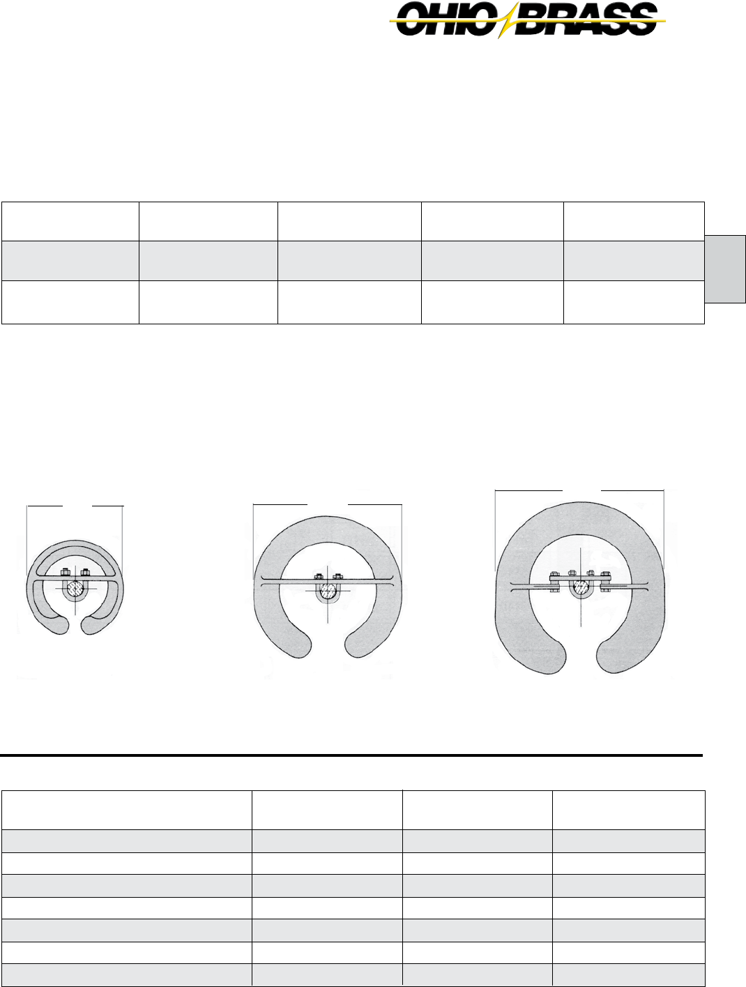
A
26-7
JULY 2010OHIO BRASS – AIKEN, SC, USA
Normal Applications: Top Grounded, Bottom Energized
Orientation
Top
Bottom
Top
Bottom
Insulator
Suspension
25/30 K SML
Suspension
50 K SML
The physical and electrical values for the insulators on pages 26-8 through 26-10 are shown without corona
protection above 161 kV. Ohio Brass has therefore provided the table below that yields the physical and electrical
changes to the insulator when rings are installed for voltages above 161 kV.
Corona Performance
Hi*Lite XL suspension insulators are RIV and corona free through 161 kV, by the use of integral Corona Shield
Rings (CSR). Due to the small diameter of the end fittings, corona shielding is necessary at 230 kV and above.
The table below details the rings necessary for voltages equal to or exceeding that listed in the column header.
Physical & Electrical Change Table
500 kV
Rings
-5 (-127.0)
0
-30
0
-65
-65
5.1 (2.29)
345 kV
Ring
-2 (-50.8)
0
-15
0
-25
-30
3 (1.8)
230 kV
Ring
-1.2 (-30.48)
0
-10
0
-15
-20
3 (1.8)
Physical & Electrical
Characteristics
Dry Arc Distance inches (mm)
Leakage Distance inches (mm)
60 Hz Flashover Dry - kV
60 Hz Flashover Wet - kV
Critical Flashover Positive - kV
Critical Flashover Negative - kV
Net Weight pounds (kg)
Part Number 271761 Part Number 271705 Part Number 271751
15.0"
12.0"
8.0"
500 kV
Rings
2717613001
2717513001
2717613002
2717513002
345 kV
Ring
NONE
2717053001
NONE
2717053002
230 kV
Ring
NONE
2717613001
NONE
2717613002

26-8
JULY 2010 OHIO BRASS – AIKEN, SC, USA
kg
-.11
-.11
-.01
-.07
0
-.007
Ground
Fitting
Eye
Eye
Socket
Clevis
Y-Clevis
Clevis
Line
Fitting
Ball
Eye
Ball
Ball
Eye
Eye
Suffix
Code
1001
1000
1301
1401
1200
1400
Inches
-.06
1.28
-.97
-1.00
1.34
.34
mm
-1.5
32.5
-24.6
-25.4
34.0
8.6
Pounds
-2.5
-2.5
-.05
-.15
0
-.15
Weight ChangeLength Change
For configurations not shown contact Ohio Brass.
Mechanical Ratings
SML = 25,000 lbs. 111 kN
RTL = 12,500 lbs. 56 kN
Net
Weight
pounds
(kg)
4.8
(2.2)
5.6
(2.5)
6.4
(2.9)
7.1
(3.2)
8.0
(3.6)
8.8
(4.0)
9.5
(4.3)
10.4
(4.7)
11.2
(5.1)
11.9
(5.4)
12.7
(5.8)
13.5
(6.1)
14.4
(6.5)
15.2
(6.9)
15.9
(7.2)
16.7
(7.6)
(2) Critical
Flashover
ANSI
Catalog
Number
with
Y-Clevis -
52.5 Ball
5110041201
5110051201
5110061201
5110071201
5110081201
5110091201
5110101201
5110111201
5110121201
5110131201
5110141201
5110151201
5110161201
5110171201
5110181201
5110191201
Neg-kV
390
490
595
695
795
890
990
1090
1185
1280
1370
1465
1560
1650
1740
1830
Pos-kV
410
505
605
700
795
890
985
1080
1170
1260
1350
1440
1530
1615
1705
1790
Wet-kV
240
295
350
405
455
505
555
605
655
700
750
790
835
880
920
960
Dry-kV
245
310
370
430
490
545
600
655
710
760
810
855
905
945
990
1030
(2) 60
Flashover
ANSI
Leakage
Distance
inches
(mm)
61
(1549)
76
(1930)
92
(2337)
107
(2718)
122
(3099)
138
(3505)
152
(3861)
168
(4267)
184
(4674)
198
(5029)
214
(5436)
229
(5817)
245
(6223)
260
(6604)
275
(6985)
290
(7366)
Dry Arc
Distance
inches
(mm)
24.7
(627)
30.7
(780)
36.8
(935)
42.9
(1090)
49.1
(1247)
55.1
(1397)
61.2
(1554)
67.4
(1712)
73.5
(1867)
79.5
(2019)
85.6
(2174)
91.7
(2329)
97.9
(2487)
103.9
(2639)
110.0
(2794)
116.2
(2951)
Number
of
Sheds
16
20
24
28
32
36
40
44
48
52
56
60
64
68
72
76
Section
Length
Inches
(mm)
34.7
(881)
40.7
(1034)
46.8
(1189)
53.0
(1346)
59.1
(1501)
65.1
(1654)
71.3
(1811)
77.4
(1966)
83.5
(2121)
89.5
(2273)
95.7
(2431)
101.8
(2586)
108.0
(2743)
114.0
(2896)
120.1
(3051)
126.2
(3205)
69 345230138 161115
Selection Guide
Typical
Line Voltage, kV (1)
Notes: (1) For voltages above 345 kV, and other section lengths, contact Ohio Brass.
(2) Tests in accordance with ANSI C29.1-1982. Electrical values are without corona ring.
For voltages above 161 kV refer to Page 26-7 for Corona Rings, and associated physical/electrical changes to above data.
Dimensions are within allowable tolerances as specified in ANSI C29.11.
5/8" (16mm) Rod Diameter Suspension Insulators
Section Length
3.7"

A
26-9
JULY 2010OHIO BRASS – AIKEN, SC, USA
kg
-0.110
-0.110
-0.010
-0.070
0.000
-0.007
Ground
Fitting
Eye
Eye
Socket
Clevis
Y-Clevis
Clevis
Line
Fitting
Ball
Eye
Ball
Ball
Eye
Eye
Suffix
Code
1001
1000
1301
1401
1200
1400
Inches
-0.06
1.28
-0.97
-1.00
1.34
0.34
mm
-1.5
32.5
-24.6
-25.4
34.0
8.6
Pounds
-2.50
-2.50
-0.05
-0.15
0.00
-0.15
Weight ChangeLength Change
For configurations not shown contact Ohio Brass.
Y-Clevis Tower Attachment Detail
for 25k, 30k, and 50k SML Insulators
SML
25/30k
50k
“D” Max. Inches
.531
1.0
To achieve insulator SML value, proper grade steel should be used
Mechanical Ratings
SML = 30,000 lbs. 133 kN
RTL = 15,000 lbs. 67 kN
Net
Weight
pounds
(kg)
4.8
(2.2)
5.6
(2.5)
6.4
(2.9)
7.1
(3.2)
8
(3.6)
8.8
(4.0)
9.5
(4.3)
10.4
(4.7)
11.2
(5.1)
11.9
(5.4)
12.7
(5.8)
13.5
(6.1)
14.4
(6.5)
15.2
(6.9)
15.9
(7.2)
16.7
(7.6)
(2) Critical
Flashover
ANSI
Catalog
Number
with
Y-Clevis -
52.5 Ball
5150041201
5150051201
5150061201
5150071201
5150081201
5150091201
5150101201
5150111201
5150121201
5150131201
5150141201
5150151201
5150161201
5150171201
5150181201
5150191201
Neg-kV
390
490
595
695
795
890
990
1090
1185
1280
1370
1465
1560
1650
1740
1830
Pos-kV
410
505
605
700
795
890
985
1080
1170
1260
1350
1440
1530
1615
1705
1790
Wet-kV
240
295
350
405
455
505
555
605
655
700
750
790
835
880
920
960
Dry-kV
245
310
370
430
490
545
600
655
710
760
810
855
905
945
990
1030
(2) 60
Flashover
ANSI
Leakage
Distance
inches
(mm)
61
(1549)
76
(1930)
92
(2337)
107
(2718)
122
(3099)
138
(3505)
152
(3861)
168
(4267)
184
(4674)
198
(5029)
214
(5436)
229
(5817)
245
(6223)
260
(6604)
275
(6985)
290
(7366)
Dry Arc
Distance
inches
(mm)
24.7
(627)
30.7
(780)
36.8
(935)
42.9
(1090)
49.1
(1247)
55.1
(1397)
61.2
(1554)
67.4
(1712)
73.5
(1867)
79.5
(2019)
85.6
(2174)
91.7
(2329)
97.9
(2487)
103.9
(2639)
110
(2794)
116.2
(2951)
Number
of
Sheds
16
20
24
28
32
36
40
44
48
52
56
60
64
68
72
76
Section
Length
Inches
(mm)
34.7
(881)
40.7
(1034)
46.8
(1189)
53
(1346)
59.1
(1501)
65.1
(1654)
71.3
(1811)
77.4
(1966)
83.5
(2121)
89.5
(2273)
95.7
(2431)
101.8
(2586)
108
(2743)
114
(2896)
120.1
(3051)
126.2
(3205)
69 345230138 161115
Selection Guide
Typical
Line Voltage, kV (1)
Notes: (1) For voltages above 345 kV, and other section lengths, contact Ohio Brass.
(2) Tests in accordance with ANSI C29.1-1982. Electrical values are without corona ring.
For voltages above 161 kV refer to Page 26-7 for Corona Rings, and associated physical/electrical changes to above data.
Dimensions are within allowable tolerances as specified in ANSI C29.11.
Section Length
3.7"
5/8" (16mm) Rod Diameter Suspension Insulators
“D” Max.
3/4" Max.
1" Dia. Minimum
1/8" x 45° Chamfer

26-10
JULY 2010 OHIO BRASS – AIKEN, SC, USA
End Fitting Example
You need the electrical and mechanical characteristics
of Catalog #5130101001. But, a Y-clevis is needed at
the ground end instead of an eye. From the table at
the right, find the code for the Y-clevis/ball configura-
tion 1201. You should order Catalog #5130101201.
The same process is used for 5/8" (25k) and 7/8"
(30k) insulators.
kg
.18
-.18
.18
0
Ground
Fitting
Y-Clevis
Eye
Socket
Y-Clevis
Line
Fitting
Ball
Eye
Ball
Eye
Suffix
Code
1201
1000
1301
1200
Inches
-.58
1.26
-.72
-.58
mm
-14.7
32.0
-18.3
-14.7
Pounds
.4
-.4
.4
0
Weight ChangeLength Change
Mechanical Ratings
SML = 50,000 lbs. 222 kN
RTL = 25,000 lbs. 111 kN
For configurations not shown contact Ohio Brass.
7/8" (22mm) Rod Diameter Suspension Insulators
Net
Weight
pounds
(kg)
12.7
(5.8)
13.7
(6.2)
14.8
(6.7)
15.9
(7.2)
16.9
(7.7)
19.1
(8.7)
20.2
(9.2)
21.2
(9.6)
24.4
(11.1)
24.5
(11.1)
25.5
(11.6)
27.6
(12.5)
29.8
(13.5)
31.9
(14.5)
34.0
(15.4)
35.1
(15.9)
(2) Critical
Flashover
ANSI
Catalog
Number
with
Chain Eye -
52.11 Ball
5130071001
5130081001
5130091001
5130101001
5130111001
5130131001
5130141001
5130151001
5130171001
5130181001
5130191001
5130211001
5130231001
5130251001
5130271001
5130281001
Neg-kV
695
795
890
990
1090
1280
1370
1465
1650
1740
1830
2005
2175
2345
2510
2590
Pos-kV
700
795
890
985
1080
1260
1350
1440
1615
1705
1790
1960
2125
2285
2445
2520
Wet-kV
400
455
505
555
605
700
745
790
875
915
955
1035
1105
1175
1240
1270
Dry-kV
430
490
545
600
655
760
810
855
945
990
1030
1110
1180
1245
1305
1330
(2) 60
Flashover
ANSI
Leakage
Distance
inches
(mm)
106
(2692)
121
(3073)
136
(3454)
151
(3835)
167
(4242)
197
(5004)
212
(5385)
228
(5791)
258
(6553)
273
(6934)
288
(7315)
319
(8103)
349
(8885)
379
(9627)
410
(10414)
425
(10795)
Dry Arc
Distance
inches
(mm)
42.9
(1090)
49.0
(1245)
55.0
(1397)
61.2
(1554)
67.3
(1709)
79.5
(2019)
85.6
(2174)
91.7
(2329)
103.9
(2639)
110.0
(2794)
116.2
(2951)
128.3
(3259)
140.6
(3271)
152.7
(3879)
165.0
(4191)
171.1
(4346)
Number
of
Sheds
28
32
36
40
44
52
56
60
68
72
76
84
92
100
108
112
Section
Length
Inches
(mm)
55.8
(1417)
62.0
(1574)
68.0
(1727)
74.1
(1882)
80.3
(2040)
92.4
(2347)
98.5
(2502)
104.7
(2659)
116.8
(2967)
123.0
(3124)
129.1
(3279)
141.2
(3586)
153.5
(3899)
165.7
(4209)
177.9
(4519)
184.1
(4676)
115 500345161 230138
Selection Guide
Typical
Line Voltage, kV (1)
Notes: (1) For voltages above 500 kV, and other section lengths, contact Ohio Brass.
(2) Tests in accordance with ANSI C29.1-1982. Electrical values are without corona ring.
For voltages above 161 kV refer to Page 26-7 for Corona Rings, and associated physical/electrical changes to above data.
Dimensions are within allowable tolerances as specified in ANSI C29.11.
Section Length
4.0"
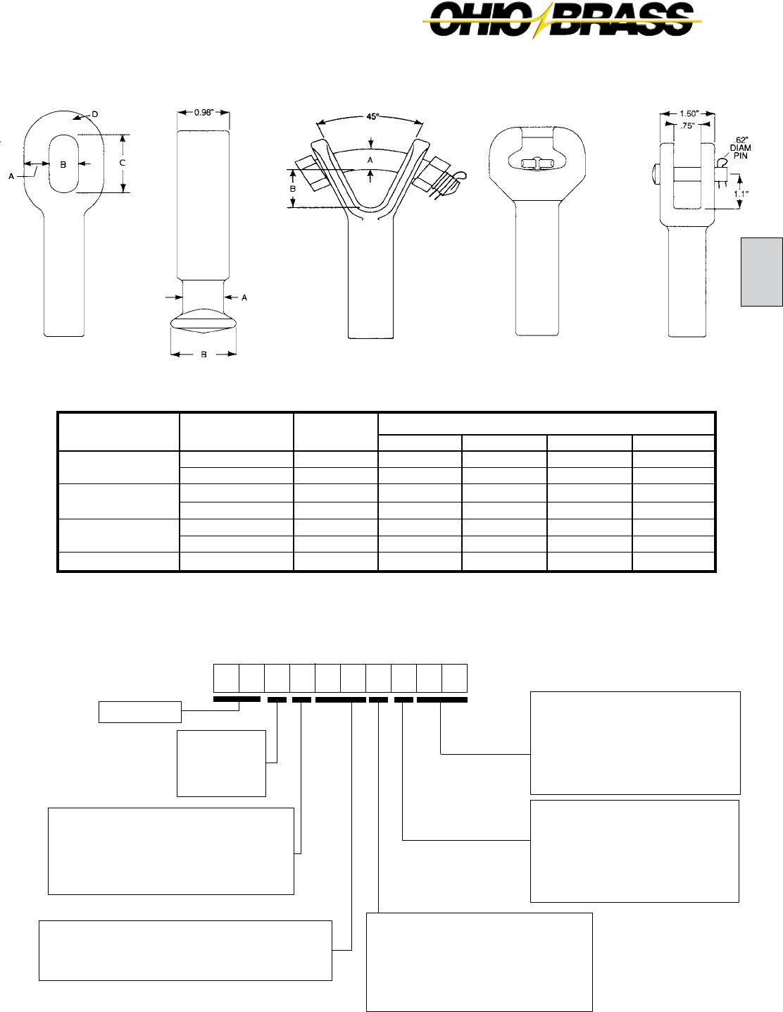
A
26-11
JULY 2010OHIO BRASS – AIKEN, SC, USA
ANSI Clevis
SML
k-LB (kN)
25 (111) - 30 (133)
50 (222)
25 (111) - 30 (133)
50 (222)
25 (111) - 30 (133)
50 (222)
25 (111) - 30 (133)
ANSI
CLASS
-
-
52-5
52-11
-
-
52-6
A
0.62
0.75
0.73
0.92
0.75
0.88
0.62
D
0.62
0.85
-
-
-
-
1.10
C
2.00
2.00
-
-
-
-
1.50
B
1.00
1.00
1.29
1.63
1.53
1.59
0.75
FITTING
TYPE
CHAIN EYE
BALL & SOCKET
Y-CLEVIS
CLEVIS
DIMENSIONS IN. (mm)
5 1 1 1 1 10 02 2
Line End Fittings
Chain Eye .................................00
ANSI Ball (1) .............................01
Y-Clevis .....................................02
ANSI Socket (1) ........................03
ANSI Straight Clevis .................04
Ground End Fittings
Chain Eye ...................................0
ANSI Ball (1) ...............................1
Y-Clevis .......................................2
ANSI Socket (1) ..........................3
ANSI Straight Clevis ...................4
Labeling
1 = English
2 = Metric (2)
R = English w/8" Corona Ring
W = English w/12" Corona Ring
T = English w/15" and 8" Corona Ring
Hi*Lite XL
Hi*Lite XL Suspension Insulators:
Key to the Catalog Numbers
Strength
1 = 25K SML
5 = 30K SML
3 = 50K SML
Construction
0 = Standard Hardware/0 Added Sheds
1 = Dull Hardware/0 Added Sheds
2 = Standarad Hardware/2 Added Sheds
3 = Dull Hardware/2 Added Sheds
Most Common End Fittings
* For IEC 16mm and 20mm Ball and Socket fittings, contact Ohio Brass.
Weathershed Configuration
Number of sheds equals this number times four,
plus any added sheds listed in the construction digit.
ANSI Socket*Y-Clevis FittingANSI Ball*Chain Eye
(1) For IEC Ball and Socket fittings, contact Ohio Brass.
(2) Metric labeling of ANSI, or IEC insulators.

26-12
JULY 2010 OHIO BRASS – AIKEN, SC, USA
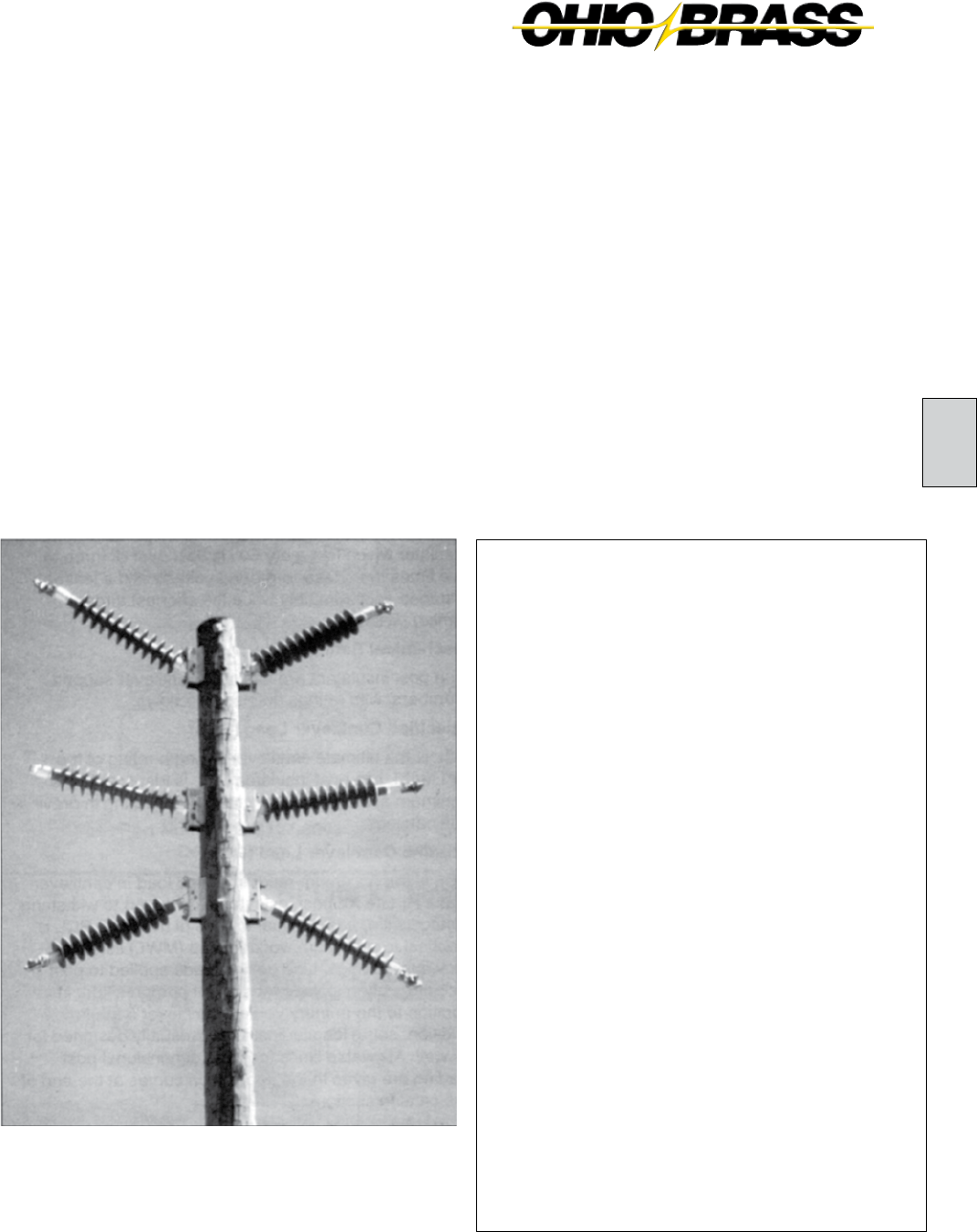
26-13
B
JULY 2010OHIO BRASS – AIKEN, SC, USA
Hi*Lite® XL
Line Post Insulators
Table of Contents
Page
Design ............................................................ 26-14
Rod .................................................................26-14
End Fittings ..................................................... 26-14
Weathersheds ................................................26-14
Interface .......................................................... 26-14
Leakage Distance ........................................... 26-14
Washability ..................................................... 26-14
Mechanical Ratings ........................................ 26-14
Corona Rings .................................................. 26-15
Packaging .......................................................26-15
Key to 2.5" Catalog Numbers ......................... 26-15
Hi*Lite XL 2.5" Rod Horizontal Line Posts ...... 26-16
Hi*Lite XL 2.5" Rod Vertical Line Posts .......... 26-17
Hi*Lite XL 2.5" Rod Vertical Line Post
Assembly .................................................... 26-18
Hi*Lite XL 2.5" Rod Base Fittings ................... 26-19
Hi*Lite XL 2.5" Rod Line Fittings ....................26-20
Hi*Lite XL 3.0" Rod Horizontal Line Posts ...... 26-21
Key to 3.0" Catalog Numbers ......................... 26-21
Hi*Lite II 3.0" Rod Horizontal Line Posts ........ 26-22
Hi*Lite II 3.0" Rod Vertical Line Posts .............26-23
Hi*Lite XL 3.0" Rod. Dia. Base Fittings ........... 26-24
Hi*Lite XL 3.0" Rod. Dia. Line Fittings ............ 26-25
Clamps and Assemblies .................................26-26

26-14
JULY 2010 OHIO BRASS – AIKEN, SC, USA
Hi*Lite*® XL Insulators
Hi*Lite XL line post insulators in this publication em-
body the latest features available in polymer insulator
design and manufacture.
From the early prototypes in 1971, through full scale
introduction in 1976, and through the succeeding years,
Hi*Lite insulators have featured conservative design
and high-quality manufacture.
Today’s Hi*Lite insulators will add to the over 1,000,000
already in service worldwide.
Design
The structural design of the Hi*Lite XL consists of these
basic parts:
Rod - Hi*Lite insulator fiberglass rod is produced from
the highest quality materials. Strands are aligned for
maximum tensile strength. The rod is more than 50
percent glass fibers in cross section.
End Fittings - End fittings are aluminum or ductile
iron. They are crimped directly to the rod by a special
process originated by Ohio Brass, and later adopted
by many other producers. The crimp requires no inter-
movement of the parts to achieve high strength, nor
does it introduce potting compounds or adhesives.
Weathersheds - Weathersheds are high pressure
injection molded by Ohio Brass, from the proprietary
compound ESP™. Housings manufactured with ESP
silicone alloy rubber exhibit hydrophobicity, high me-
chanical strength, high corona resistance and low
permeability to moisture.
Interface - Hi*Lite insulators use Ohio Brass’ live sili-
cone interface. This feature prevents intrusion of mois-
ture and contaminating elements. If the exterior seal is
damaged, redundant o-ring seals within the live silicone
interface prohibit the lengthwise migration of intrusive
elements between shed and rod.
Leakage Distance
Hi*Lite XL insulators feature high leakage distance for
maximum resistance to contamination and leakage
currents.
Washability
Hi*Lite Line Post insulators listed in this catalog are
suitable for flood washing up to 200 psi. The design in-
corporates positive, labyrinth seals to ensure long-term
security against water entry. Conventional dry-particle,
air-pressure cleaning methods may also be employed.
A cleaning guideline is available from Ohio Brass.
If your washing requirements exceed flood washing,
contact Ohio Brass.
Mechanical Ratings
Line post insulators are basically cantilever support
members, with ratings defined as follows:
Specified Cantilever Load (SCL)
SCL is the ultimate cantilever strength rating of the
Hi*Lite XL line post insulator. SCL is identical to the
minimum average breaking load (ABL) rating in previ-
ous catalogs.
Reference Cantilever Load (RCL)
RCL is the maximum recommended load in cantilever
that a Hi*Lite XL post insulator is designed to withstand
during its life, and is equal to 50% of the SCL. RCL is
identical to maximum working load (MWL) listed in pre-
vious catalogs. Line design loads applied to post insula-
tors often include tension, or compression, in addition
to the primary vertical cantilever load. In addition, some
longitudinal load is usually designed for as well.
Combined Load
Contact your Hubbell Power Systems representative for
combined load applications.
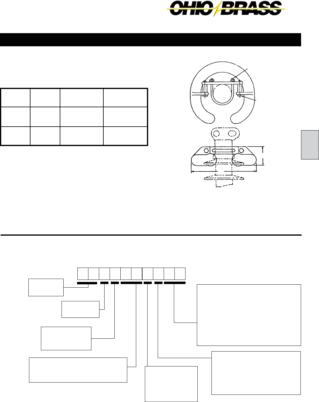
26-15
B
JULY 2010OHIO BRASS – AIKEN, SC, USA
5 2 2 0 10
00
81
Hi*Lite XL
XL Post
Strength
2 = 2.5" DIA
Construction
0 = Standard
1 = Dulled HDW
Weathershed Configuration
To determine the number of insulator
sheds, multiply this number by two.
Hi*Lite XL Line Post Insulators:
Key to the Catalog Numbers
Line End Fittings
Two Hole Blade ...........................0
Horizontal Clamptop ...................1
Vertical Clamptop .......................2
5" Bolt Circle (through) ...............5
Two Hole Long Blade ..................9
2.5" (63.5mm) Rod Diameter Horizontal Line Posts
Corona Rings
Hi*Lite XL line post insulators are corona free through
161 kV.
Packaging
Hi*Lite XL line post insulators are packaged in appro-
priate quantities in open wood crates. As an option,
Ohio Brass offers packaging of the insulators in indi-
vidual sleeves.
Part Number 2721273001
Control Ring
Application
Line End
Energized
Bottom End
Energized
230 kV
Top - 2721273001
Bott - NONE
Top - NONE
Bott - 2721273001
161 kV
& below
Top - NONE
Bott - NONE
Top - NONE
Bott - NONE
345 kV
Top - 2721273001
Bott - NONE
Top - NONE
Bott - 2721273001
Base End Fittings
Unitary D.I. Gain (15/16" Holes) .......... 00
Unitary Flat 8x10 (15/16" Holes) ......... 01
Al Gain 12 CL (15/16" Holes) .............. 02
Al Flat 8x10 (15/16" Holes) .................. 03
Al Flat 8x13 (15/16" Holes) .................. 04
5" Bolt Circle (tapped 11/16" Holes) .... 05
Steel Gain (15/16" Holes) .................... 07
Steel Flat 8 x 13 (15/16" Holes) ........... 08
Recommended
Torque
10 Ft.-Lb.
Recommended
Torque
45 Ft.-Lb.
3.4375
12
(1) Metric labeling only. Insulators and hardware are ANSI.
Labeling
1 = English
2 = Metric (1)
M = English w/12"
Corona Ring

26-16
JULY 2010 OHIO BRASS – AIKEN, SC, USA
69 345230138 161115
Selection Guide
Typical
Line Voltage, kV
Notes: (1) Tests in accordance with ANSI C29.1-1982. Electrical values are without corona ring.
(2) RCL is the maximum continuous load at which the post should be applied.
For voltages above 161 kV refer to Page 26-15 for Corona Rings.
Dimensions are within allowable tolerances as specified in ANSI C29.11.
“X”
Length
Inches
(mm)
33.5
(851)
38.6
(980)
43.9
(1115)
49.2
(1250)
54.5
(1384)
59.6
(1514)
64.8
(1646)
70.1
(1781)
75.4
(1915)
80.5
(2045)
85.8
(2180)
91.1
(2314)
96.3
(2446)
101.4
(2575)
106.7
(2710)
112.0
(2845)
Catalog #
with
Gain Base
& Clamptop
End Fittings
5220041100
5220051100
5220061100
5220071100
5220081100
5220091100
5220101100
5220111100
5220121100
5220131100
5220141100
5220151100
5220161100
5220171100
5220181100
5220191100
No.
of
Sheds
8
10
12
14
16
18
20
22
24
26
28
30
32
34
36
38
Dry Arc
Distance
inches
(mm)
23
(584)
28
(711)
33
(838)
39
(991)
44
(1118)
49
(1245)
55
(1397)
60
(1524)
65
(1651)
71
(1803)
76
(1930)
81
(2057)
87
(2210)
92
(2337)
97
(2464)
103
(2616)
Leakage
Distance
inches
(mm)
54
(1372)
68
(1727)
82
(2083)
96
(2438)
110
(2794)
124
(3150)
138
(3505)
152
(3861)
166
(4216)
180
(4572)
194
(4928)
208
(5283)
222
(5639)
236
(5994)
250
(6350)
264
(6706)
(1) 60
Flashover
ANSI
(1) Critical
Flashover
ANSI
Net
Weight
pounds
(kg)
47
(21.3)
50
(22.7)
54
(24.5)
57
(25.9)
61
(27.7)
65
(29.5)
68
(30.9)
72
(32.7)
75
(34.1)
79
(35.9)
82
(37.2)
86
(39.0)
89
(40.4)
93
(42.2)
97
(44.0)
100
(45.4)
RCL
pounds
(kN)
2500
(11.1)
2500
(11.1)
2135
(9.5)
1865
(8.3)
1650
(7.3)
1490
(6.6)
1350
(6.0)
1235
(5.5)
1140
(5.0)
1060
(4.7)
990
(4.4)
925
(4.1)
870
(3.6)
820
(3.6)
780
(3.5)
740
(3.3)
Dry-kV
215
270
325
385
440
490
545
600
650
700
755
805
855
905
955
1005
Wet-kV
195
245
295
340
385
430
475
520
560
600
635
675
710
745
780
810
Pos-kV
340
420
505
590
675
760
845
930
1015
1095
1180
1265
1350
1435
1520
1605
Neg-kV
455
535
620
705
785
865
950
1035
1115
1195
1280
1365
1445
1525
1610
1695
2.5" (63.5mm) Rod Diameter Horizontal Line Posts
Clamptop:
Maximum Design Tension = 2,500 lb (11.1 kN)
Two-Hole Blade:
Maximum Design Tension = 7,500 lb. (33.4 kN)
See Page 26-20
Two Hole Blade End Fitting
Reduces the “X” dimension
by .75"
Line & Base Detail see pages 26-19 & 26-20
12?
7.62 DIA
X

26-17
B
JULY 2010OHIO BRASS – AIKEN, SC, USA
Line & Base Fitting Detail see pages 26-19 & 26-20
69
Net
Weight
pounds
(kg)
27
(12.3)
30
(13.6)
34
(15.4)
37
(16.8)
41
(18.6)
45
(20.4)
Notes: (1) Tests in accordance with ANSI C29.1-1982.
(2) RCL is the maximum cantilever continuous load at which the post should be applied.
(3) Mounting Base Catalog No. 75115 may be ordered with these Catalog numbers for a vertical assembly.
115 138 161
Selection Guide
Typical
Line Voltage, kV
Catalog #
with 5" Bolt
Circle & Vert.
Clamptop(3)
5220041205
5220051205
5220061205
5220071205
5220081205
5220091205
“X”
Length
Inches
(mm)
30.7
(780)
35.9
(912)
41.3
(1049)
46.7
(1186)
52.1
(1323)
57.4
(1458)
No.
of
Sheds
8
10
12
14
16
18
Dry Arc
Distance
inches
(mm)
23
(584)
28
(711)
33
(838)
39
(991)
44
(1118)
49
(1245)
Leakage
Distance
inches
(mm)
54
(1371)
68
(1727)
82
(2083)
96
(2438)
110
(2734)
124
(3150)
(1) 60
Flashover
ANSI
(1) Critical
Flashover
ANSI
Dry-kV
215
270
325
385
440
490
Wet-kV
195
245
295
340
385
430
Pos-kV
340
420
505
590
675
760
Neg-kV
455
535
620
705
785
865
RCL
pounds
(kN)
2500
(11.1)
2475
(11.0)
2115
(9.4)
1850
(8.2)
1640
(7.3)
1480
(6.6)
Maximum Design Tension
2,500 lb (11.1 kN)
2.5" (63.5mm) Rod Diameter Vertical Line Posts
Aluminum Alloy
A356-T6
Catalog No. 75115
134,400 In.-Lb. Rating

26-18
JULY 2010 OHIO BRASS – AIKEN, SC, USA
Line End Fitting Detail see pages 26-19 & 26-20
2.5" (63.5mm) Rod Diameter Vertical Line Post Assembly
Aluminum Alloy
6063-T5
Base Detail
To Order an Assembly - Pick an insulator from
Table A based on your Electrical and Mechanical
needs — next, select a Base configuration from
Table B, for your mounting position needs.
0.678 DIA.
4 HOLES
5.757.438
1.625
69
(1) Insulators in Table A have the same electrical and mechanical
characteristics as those on Page 26-17 with Code 1205.
Table A
115 138 161
Selection Guide
Typical
Line Voltage, kV
(1)Catalog #
with Vertical
Clamptop &
Base Code
52200412XX
52200512XX
52200612XX
52200712XX
52200812XX
52200912XX
“A”
Length
Inches
(mm)
30.4
(772)
35.6
(904)
41.0
(1041)
46.4
(1179)
51.8
(1316)
57.0
(1448)
“XX”
Code
20
21
22
23
24
25
26
27
Style
Face
Side
Face
Side
Face
Side
Face
Side
“B”
Length
Inches
(mm)
20
(508)
20
(508)
20
(508)
20
(508)
31.75
(806)
31.75
(806)
31.75
(806)
31.75
(806)
“C”
Length
Inches
(mm)
12
(305)
12
(305)
12
(305)
12
(305)
16
(406)
16
(406)
16
(406)
16
(406)
“D”
Diameter
Inches
(mm)
.8125
(21)
.8125
(21)
.9375
(24)
.9375
(24)
.8125
(21)
.8125
(21)
.9375
(24)
.9375
(24)
Table B
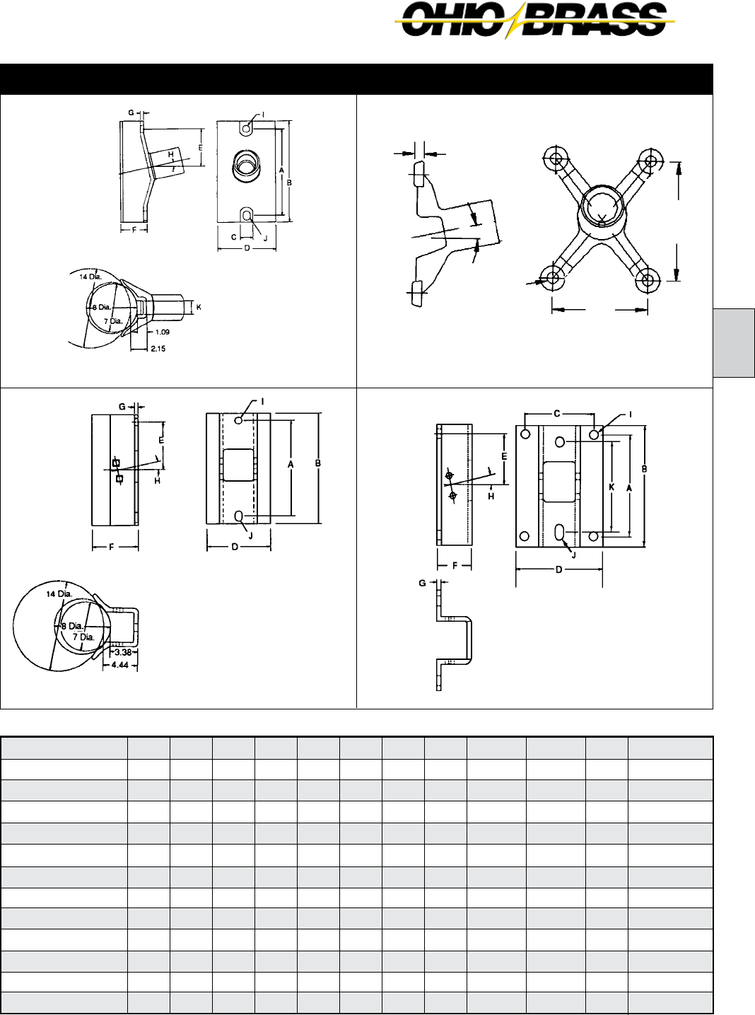
26-19
B
JULY 2010OHIO BRASS – AIKEN, SC, USA
Al & Steel FlatAl & Steel Gain
Horizontal & Vertical Bases Dimensions (in inches)
Type (Code)*
Unitary D.I. Gain (00)
Unitary D.I. Flat (01)
5" B.C. (15)
5" B.C. (05)
Al Gain (02)
Al Gain (12)
Steel Gain (07)
Al Flat (03)
Al Flat (13)
Steel Flat (08)
Al Flat (04)
Al Flat (14)
A
12.0
10.0
4.75
4.75
12.0
12.0
12.0
10.0
10.0
13.0
13.0
13.0
B
14.0
12.2
6.25
6.25
14.0
14.0
15.0
12.0
12.0
15.0
15.0
15.0
C
1.75
8.0
3.63
3.63
-
-
-
8.0
8.0
8.0
8.0
8.0
E
-
5.0
5.0
5.0
6.13
6.13
6.5
5.0
5.0
6.5
6.5
6.5
F
3.54
-
-
-
5.56
5.56
6.04
4.0
4.0
4.0
4.0
4.0
D
8.06
10.0
0.90
0.90
8.06
8.06
8.33
10.0
10.0
10.0
10.0
10.0
G
0.5
0.8
-
-
0.5
0.5
0.38
0.5
0.5
0.5
0.5
0.5
H
12°
12°
-
-
12°
12°
12°
12°
12°
12°
12°
12°
I
0.94
0.94
0.69
5/8 - 11 UFS
0.94
0.81
0.94
0.94
0.81
1.125 x 0.94
0.94
0.81
J
0.94 x 1.31
-
-
-
0.94 x 1.31
0.94 x 1.31
0.94 x 2.0
-
-
0.94 x 2
0.94 x 1.31
0.81 x 1.31
K
1.90
-
-
-
-
-
-
-
-
12.0
12.0
12.0
Material
60-45-12 D.I.
60-45-12 D.I.
60-45-12 D.I.
60-45-12 D.I.
6063 T5 Al
6063 T5 Al
Low Carbon Steel
6063 T5 Al
6063 T5 Al
Low Carbon Steel
6063 T5 Al
6063 T5 Al
*Code is the third and fourth numbers in the Suffix Code of the Catalog Number.
Unitary Gain Unitary Flat
2.5" (63.5 mm) Rod Diameter Base Fittings
Standard Gain Base
has a 90° opening. For
other available openings,
contact Ohio Brass.
A
C
G
I
H
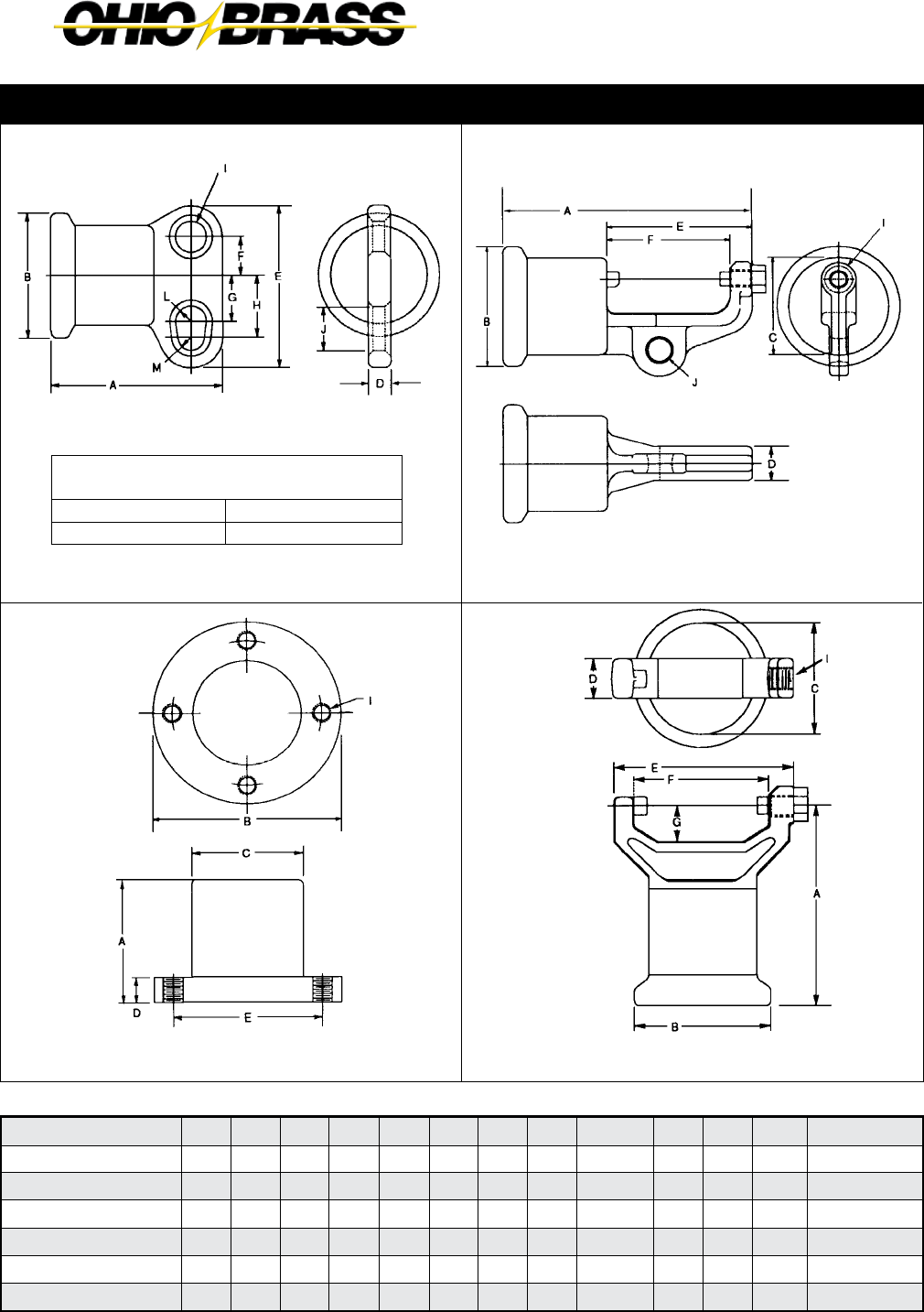
26-20
JULY 2010 OHIO BRASS – AIKEN, SC, USA
Two Hole Blade
*12° upsweep post angles
Horizontal Clamptop
Vertical Clamptop
Part per ANSI C29.7
5" Bolt Circle
Line or Base Fitting
Horizontal & Vertical End Fittings Dimensions (in inches)
Material
60-40-18 D.I.
60-40-18 D.I.
60-40-18 D.l.
60-45-12 D.I.
60-45-12 D.I.
60-40-18 D.I.
Type (Code)*
2 Hole Blade (0)
2 Hole Long Blade (9)
H. Clamptop (1)
5" B.C. (3)
5" B.C. (5)
V. Clamptop (2)
L
0.5R
0.5R
-
-
-
-
M
0.44 R
0.44R
-
-
-
-
B
4.0
4.0
4.0
6.25
6.25
4.0
A
5.73
5.73
8.24
4.75
4.75
5.88
C
-
-
3.30
3.63
3.63
3.30
D
0.75
0.75
1.12
0.90
0.90
1.12
E
5.25
7.75
4.72
5.0
5.0
5.37
F
1.25
1.25
4.0
-
-
4.0
G
1.50
4.0
-
-
-
1.06
H
2.00
4.5
-
-
-
-
I
1.0
1.0
5/8 - 11 UFS
5/8 - 11 UFS
0.69 x Holes
5/8 - 11 UFS
J
1.44
1.44
0.75
-
-
-
*Code is the 2nd number in the Suffix Code of the Catalog Number.
2.5" (63.5 mm) Rod Diameter Line Fittings
2 Hole Long Blade
64 deg. max.
2 Hole Blade (Std.)
40 deg. max.
Transverse Compressing Swing Angle
for Conductor Suspension Clamp
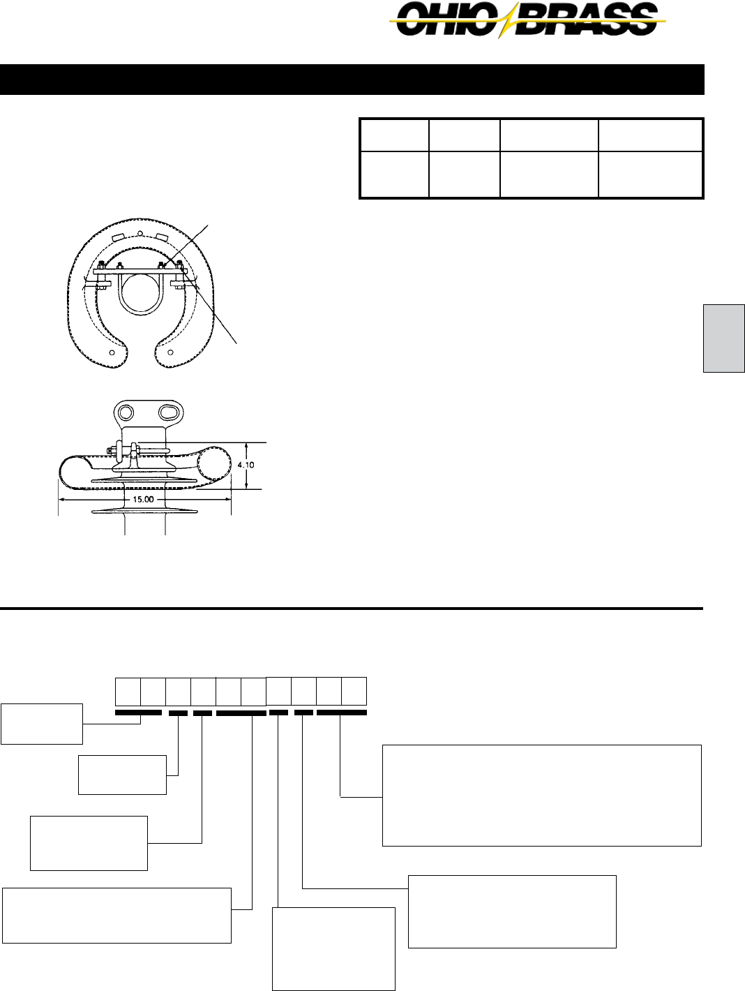
26-21
B
JULY 2010OHIO BRASS – AIKEN, SC, USA
Application
Line End
Energized
230 kV
Top - NONE
Bott. - NONE
345 kV
Top - 2737743001
Bott. - NONE
138/161 kV
Top - NONE
Bott. - NONE
Corona Rings
Hi*Lite XL line post insulators are corona-free through
230 kV line-to-ground.
3.0" (76.2 mm) Rod Diameter Line Posts
Recommended
Torque
45 FT.-Lb.
Recommended
Torque
10 FT.-Lb.
Hi*Lite XL Line Post Insulators:
Key to the Catalog Numbers
5 2 3 0 14
00
81
Hi*Lite XL
XL Post
Strength
3 = 3.0" DIA
Construction
0 = Standard
1 = Dulled HDW
Weathershed Configuration
To determine the number of insulator
sheds, multiply this number by two.
Line End Fittings
Two Hole Blade ...........................0
Horizontal Clamptop ...................1
Vertical Clamptop .......................2
Base End Fittings
Al Gain (1-1/16" Hole and 1-1/16" x 2-5/9" Slot).......02
St Flat 14" CL (1-1/16" x 2-9/16" Slots) ....................04
5" Bolt Circle (Tapped) ..............................................05
St Gain (1-1/16" Hole and 1-1/16" x 2-5/9" Slot) ......07
St Flat 9" x 13" (59/64" Holes) ..................................08
Part Number 2737743001
Control Ring
(1) Metric labeling only. Insulators and hardware are ANSI.
Labeling
1 = English
2 = Metric (1)
M = English w/15"
Corona Ring

26-22
JULY 2010 OHIO BRASS – AIKEN, SC, USA
69 345230138 161115
Selection Guide
Typical
Line Voltage, kV
Notes: (1) Tests in accordance with ANSI C29.1-1982. Electrical values are without corona ring.
(2) RCL is the maximum continuous load at which the post should be applied.
For voltages above 230 kV refer to Page 26-21 for Corona Rings. Electrical values are shown
for insulators without rings. For electricals with rings, contact Ohio Brass.
“X”
Length
Inches
(mm)
38.8
(986)
43.8
(1113)
49.0
(1245)
54.8
(1392)
59.3
(1506)
64.5
(1638)
69.5
(1765)
74.7
(1897)
79.9
(2029)
85.0
(2159)
90.2
(2291)
95.2
(2418)
100.4
(2550)
105.5
(2680)
110.7
(2812)
115.9
(2944)
Catalog #
with
Flat Base
& Two Hole
Blade
5230051004
5230061004
5230071004
5230081004
5230091004
5230101004
5230111004
5230121004
5230131004
5230141004
5230151004
5230161004
5230171004
5230181004
5230191004
5230201004
No.
of
Sheds
10
12
14
16
18
20
22
24
26
28
30
32
34
36
38
40
Dry Arc
Distance
inches
(mm)
29
(737)
34
(864)
39
(991)
45
(1143)
50
(1270)
55
(1397)
60
(1524)
66
(1676)
71
(1803)
76
(1930)
82
(2083)
87
(2210)
92
(2337)
98
(2489)
103
(2616)
108
(2743)
Leakage
Distance
inches
(mm)
77
(1956)
93
(2362)
108
(2743)
124
(3150)
140
(3556)
156
(3962)
171
(4343)
187
(4750)
203
(5156)
218
(5537)
234
(5944)
250
(6350)
265
(6731)
281
(7137)
297
(7544)
313
(7950)
(1) 60
Flashover
ANSI
(1) Critical
Flashover
ANSI
Net
Weight
pounds
(kg)
90
(40.8)
95
(43.1)
100
(40.9)
106
(48.1)
110
(49.9)
115
(52.2)
120
(54.4)
125
(56.7)
130
(58.9)
135
(61.2)
141
(63.9)
146
(66.2)
151
(68.5)
156
(70.8)
161
(73.1)
166
(75.3)
(2)RCL
pounds
(kN)
4405
(19.6)
3780
(16.8)
3295
(14.7)
2920
(13.0)
2620
(11.7)
2380
(10.6)
2185
(9.7)
2015
(9.0)
1865
(8.3)
1740
(7.7)
1630
(7.2)
1535
(6.8)
1450
(6.5)
1370
(6.1)
1300
(5.8)
1240
(5.5)
Dry-kV
295
345
395
445
495
545
590
640
685
735
780
825
870
915
960
1000
Wet-kV
250
295
335
380
420
465
505
550
590
640
670
710
755
795
835
875
Pos-kV
445
530
615
695
780
865
950
1035
1120
1205
1290
1370
1455
1540
1625
1710
Neg-kV
540
620
705
790
870
955
1035
1120
1200
1285
1365
1445
1530
1615
1695
1780
3.0" (76.2mm) Rod Diameter Horizontal Line Posts
See Page 26-25
Line & Base Detail see Pages 26-24 & 26-25
Clamptop:
Maximum Design Tension = 2,500 lb (11.1 kN)
Two-Hole Blade:
Maximum Design Tension = 12,500 lb. (55.6 kN)
Horizontal Clamptop End Fitting
Increases the “X” dimension
by 1"

26-23
B
JULY 2010OHIO BRASS – AIKEN, SC, USA
69
Net
Weight
pounds
(kg)
54
(24.5)
59
(26.8)
64
(29.1)
69
(31.4)
74
(33.6)
79
(35.9)
Notes: (1) Tests in accordance with ANSI C29.1-1982.
(2) RCL is the maximum cantilever continuous load at which the post should be applied.
115 138 161
Selection Guide
Typical
Line Voltage, kV
Catalog #
with 5" Bolt
Circle & Vert.
Clamptop
5230051205
5230061205
5230071205
5230081205
5230091205
5230101205
“X”
Length
Inches
(mm)
38.0
(965)
43.2
(1097)
48.5
(1219)
53.8
(1367)
59.2
(1504)
64.5
(1638)
Dry Arc
Distance
inches
(mm)
29
(737)
34
(864)
39
(991)
45
(1143)
50
(1270)
55
(1397)
Leakage
Distance
inches
(mm)
77
(1956)
93
(2362)
108
(2743)
124
(3150)
140
(3556)
156
(3962)
(1) 60
Flashover
ANSI
(1) Critical
Flashover
ANSI
Wet-kV
250
295
335
380
420
465
Pos-kV
445
530
615
695
780
865
Neg-kV
540
620
705
785
870
950
(2)RCL
pounds
(kN)
2500
(11.1)
2500
(11.1)
2500
(11.1)
2500
(11.1)
2500
(11.1)
2335
(10.4)
No.
of
Sheds
10
12
14
16
18
20
Dry-kV
295
345
395
445
495
545
Line & Base Fitting Detail see pages 26-24 & 26-25
Maximum Design Tension
2,500 lb (11.1 kN)
3.0" (76.2 mm) Rod Diameter Vertical Line Posts

26-24
JULY 2010 OHIO BRASS – AIKEN, SC, USA
Horizontal & Vertical Bases Dimensions (in inches)
Type (Code)*
5" B.C. (05)
Al Gain (02)
Steel Gain (07)
Steel Flat (08)
Steel Flat (04)
A
6.36
14.0
14.0
13.0
14.0
B
5.9
17.0
17.0
15.0
17.0
C
4.37
-
-
9.0
-
E
5.0
7.75
7.75
6.5
7.75
F
-
5.949
7.03
4.12
4.12
D
1.2
8.079
9.65
11.0
10.0
G
-
0.53
0.5
0.5
0.5
H
-
14°
14°
14°
14°
I
5/8 - 11 UFS
1.06
1.06
0.938
-
J
-
1.06 x 2.56
1.06 x 2.56
-
1.06 x 2.56
Material
60-40-18 D.I.
6063 T5 Al
Low Carbon Steel
Low Carbon Steel
Low Carbon Steel
*Code is the 2nd number in the Suffix Code of the Catalog Number.
Steel FlatSteel Gain
Hi*Lite XL 3.0" Rod Dia. Base Fittings
Aluminum Gain 5" Bolt Circle
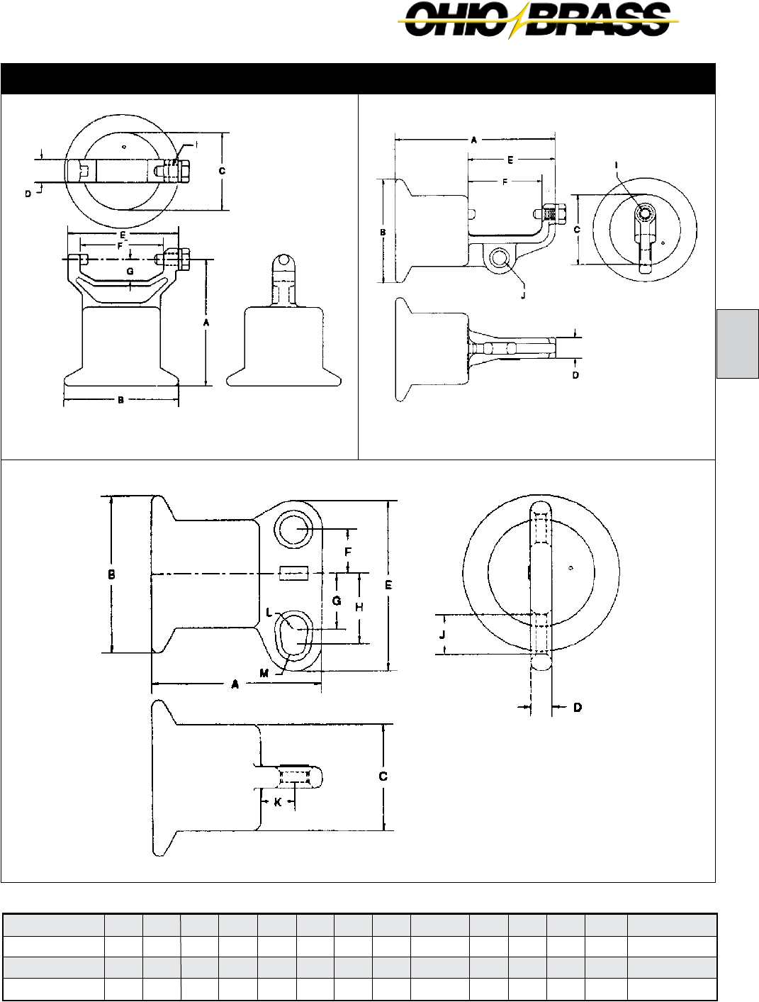
26-25
B
JULY 2010OHIO BRASS – AIKEN, SC, USA
*Code is the 2nd digit in the Suffix Code of the Catalog Number.
Vertical Clamptop
Part per ANSI C29.7
Horizontal Clamptop
Part per ANSI C29.7
Material
60-40-18 D.I.
60-40-18 D.l.
60-40-18 D.I.
B
5.63
5.63
5.63
A
6.16
8.64
6.31
Type (Code)*
2 Hole End (0)
H. Clamptop (1)
V. Clamptop (2)
C
3.84
3.84
3.84
D
0.75
1.12
1.12
E
6.12
4.72
5.37
F
1.57
4.0
4.0
G
2.0
-
1.06
H
2.5
-
-
I
-
5/8 - 11 UFS
5/8 - 11 UFS
J
1.44
0.75
-
K
1.24
-
-
L
0.5R
-
-
M
0.44 R
-
-
Horizontal & Vertical End Fittings Dimensions (in inches)
Two Hole Blade
Hi*Lite XL 3.0" Rod Dia. Line Fittings

26-26
JULY 2010 OHIO BRASS – AIKEN, SC, USA
Figure 2 Figure 4
Figure 1 Figure 3
Clamptop Clamp
Jumper Clamps and Assemblies
A practical application of Hi*Lite line posts is for support
of jumper loops on transmission lines.
Horizontal motion of the jumper is restricted, and the factor
of wind sway is eliminated. Additionally the crossarm length
may be reduced. The Difference in cost of insulation is not
significant but, the savings in tower cost can be attractive.
Regardless of cost, the use of a jumper support improves
construction.
If using a single clamp, clamp position relative to the in-
sulator may be changed by bolting the clamp through the
upper hole in the insulator end fitting.
Jumper clamps are not intended for tangent span
applications.
Clamptop clamps can be mounted directly on Hi*Lite XL 250 posts if the posts are ordered with the horizontal or vertical clamptop option.
Figure 1 Figure 2
Figure Catalog
Number Yoke Type Clamping
Range (Inches)
Post
Type
1 976423002 None 1.00 - 1.40 Any
1 976423003 None 1.40 - 1.60 Any
1 600643001 None 1.60 - 2.00 Any
2 2717243001 Dual 1.00 - 1.40 250
2 2717253001 Dual 1.40 - 1.60 250
2 2717263001 Dual 1.60 - 2.00 250
2 2738383001 Dual 1.00 - 1.40 300
2 2738393001 Dual 1.40 - 1.60 300
2 2738403001 Dual 1.60 - 2.00 300
3 2721763001 Triple 1.00 - 1.40 250
3 2721773001 Triple 1.40 - 1.60 250
3 2721783001 Triple 1.60 - 2.00 250
3 2738413001 Triple 1.00 - 1.40 300
3 2738423001 Triple 1.40 - 1.60 300
3 2738433001 Triple 1.60 - 2.00 300
4 2721793001 Quad 1.00 - 1.40 250
4 2721803001 Quad 1.40 - 1.60 250
4 2721813001 Quad 1.60 - 2.00 250
4 2738443001 Quad 1.00 - 1.40 300
4 2738453001 Quad 1.40 - 1.60 300
4 2738463001 Quad 1.60 - 2.00 300
Catalog Number
TSC57
TSC106
TSC150
TSC200
Fig. No.
1
1
1
2
Body &
Keeper Material
356-T6 Al
356-T6 Al
356-T6 Al
356-T6 Al
Clamping Range
Inches (mm)
0.25-057 (6.3-14.4)
0.50-1.06 (12.7-26.9)
1.00-1.50 (25.4-38.1)
1.50-2.00 (38.1-50.8)
Ultimate Body Strength
Lbs. (kN)
2800 (1.273)
2800 (1.273)
2800 (1.273)
2800 (1.273)
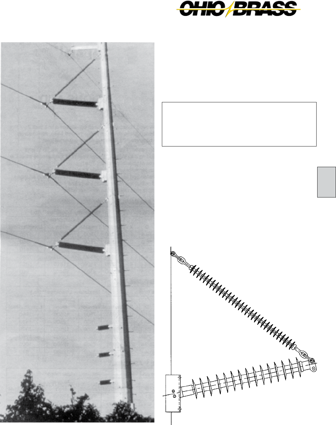
26-27
C
JULY 2010OHIO BRASS – AIKEN, SC, USA
Hi*Lite® XL
Braced Posts
Table of Contents
Page
Dimension and Strength Ratings .................... 26-28
Assembly Drawings ........................................ 26-29
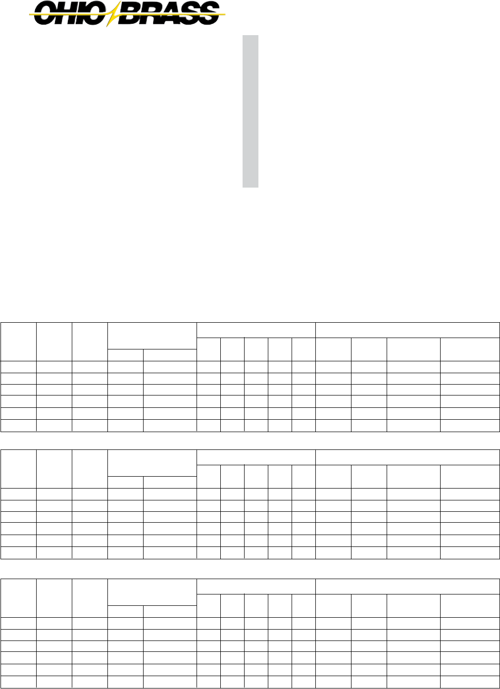
26-28
JULY 2010 OHIO BRASS – AIKEN, SC, USA
Catalog number covers complete assembly including
insulator and hardware as illustrated.
The need to minimize the tower size and visual impact of
transmission lines has prompted increased interest in braced
line posts, horizontal-V, and pivoting V assemblies. These
insulating structures offer vastly improved vertical load
capabilities over conventional lines posts while retaining the
advantages of a fixed conductor position.
A braced line post uses a conventional line post with a sus-
pension string tied to the tower face with a link. A horizontal-V
replaces the link with a fixed offset extending from the tower
face adding a stabilizing force to the assembly. Both these
assemblies are available with flat or gain bases.
A pivoting horizontal-V assembly utilizes a line post insulator
fastened to the structure with a hinged base. Alternatively, the
base may be replaced with a universal joint.
These assemblies are available for voltages up to and includ-
ing 345 kV with a wide variety of hardware to meet the needs
of your application. The figures illustrated depict typical ar-
rangements which provide an economical means of with-
standing unusual loads. For more information on these and
numerous other variations of line post assemblies, contact
your Ohio Brass representative.
DIMENSIONS AND
STRENGTH RATINGS
Suspension
511010
511211
511013
511014
511018
511219
BRACED LINE POST ASSEMBLY
Typical
System
kV
115/138
115/138
161
161
230 *
230 *
Cat #
Gain
Base
234220
234222
234224
234226
234228
234230
Cat #
Flat
Base
234221
234223
234225
234227
234229
234231
Post
522008
522009
522010
522011
522014
522015
Component
Insulators
Vertical
11280
11280
11280
11280
11280
11280
Tension
7500
7500
7500
7500
7500
7500
Longitudinal
1730
1550
1410
1280
1020
960
Dimensions (in.) Maximum Loadings** (lb.)
A
53.7
58.8
64.1
69.4
85.0
90.3
B
72.8
81.9
91.1
97.2
121.6
130.7
C
74.0
83.0
91.0
96.0
118.0
127.0
X
2
2
2
2
2
2
D
79.8
88.9
98.1
104.2
128.6
137.7
Compres-
sion
12500
12500
12500
12500
11810
10470
Suspension
511007
511008
511009
511010
511013
511014
HORIZONTAL V ASSEMBLY
Typical
System
kV
115/138
115/138
161
161
230 *
230 *
Cat #
Gain
Base
234232
234234
234236
234238
234240
234242
Cat #
Flat
Base
234233
234235
234237
234239
234241
234243
Post
522008
522009
522010
522011
522014
522015
Component
Insulators
Vertical
9980
9980
9980
9980
9980
9980
Tension
7500
7500
7500
7500
7500
7500
Longitudinal
1680
1510
1370
1250
1000
930
Dimensions (in.) Maximum Loadings** (lb.)
A
54.9
60.1
65.5
70.9
86.9
92.3
B
54.6
60.7
66.7
72.8
91.1
97.2
C
51.0
56.0
61.0
66.0
80.0
85.0
X
18
20
22
24
28
30
D
61.6
67.7
73.7
79.8
98.1
104.2
Compres-
sion
12500
12500
12500
12500
12500
12500
Suspension
511007
511008
511009
511010
511013
511014
PIVOTING HORIZONTAL V ASSEMBLY
Typical
System
kV
115/138
115/138
161
161
230 *
230 *
Cat #
Gain
Base
—
—
—
—
—
—
Cat #
Flat
Base
234244
234245
234246
234247
234248
234249
Post
522008
522009
522010
522011
522014
522015
Component
Insulators
Vertical
9980
9980
9980
9980
9980
9980
Tension
7500
7500
7500
7500
7500
7500
Longitudinal
—
—
—
—
—
—
Dimensions (in.) Maximum Loadings** (lb.)
A
55.2
60.4
65.8
71.2
87.2
92.6
B
54.6
60.7
66.7
72.8
91.1
97.2
C
51.0
56.0
61.0
66.0
80.0
85.0
X
18
20
22
24
28
30
D
61.6
67.7
73.7
79.8
98.1
104.2
Compres-
sion
12500
12500
12500
12500
12500
12500
Contact your Ohio Brass representative for designs utilizing the optional pivoting strut member.
* Corona rings are required for 230 kV and above.
** Maximum loads are for single loads in the specified direction.
Hi*Lite® XL
Assemblies

26-29
C
JULY 2010OHIO BRASS – AIKEN, SC, USA
OPTIONAL PIVOTING STRUT MEMBER
FLAT BASE MOUNTING
PIVOTING BASE MOUNTING
PIVOTING HORIZONTAL-V
BRACED LINE POST HORIZONTAL-V
GAIN BASE MOUNTING
Assembly Drawings

26-30
JULY 2010 OHIO BRASS – AIKEN, SC, USA

26-31
D
JULY 2010OHIO BRASS – AIKEN, SC, USA
HI-LITE II POST INSULATORS
Maximum Design Cantilever Rating (MDC)
MDC is the maximum recommended load in cantilever
that a Hi*Lite post insulator is designed to withstand dur-
ing its service life.
Average Failing Load (AFL)
AFL is the average failing load of a Hi*Lite line or station
post insulator. This value can be determined by multiplying
the MDC by a factor of 2.5.
Selection
If you need a Hi*Lite post that is different from those shown
in this catalog, please contact your OB representative.
Hi*Lite station posts meet electrical and dimensional
specifications of their porcelain equivalents. Mechanically,
the Hi*Lite are less rigid with more deflection under both
cantilever and torsional loading.
HI*LITE II
STATION
POST
INSULATORS
Table of Contents
Page
Station Post Insulator Ratings ........................ 26-31
Series 175: 3" Bolt Circles .............................. 26-32
Series 250: 3" and 5" Bolt Circles ................... 26-33
NOTE: Insulators listed here are Hi-Lite II
design having individual weathersheds
assembled to the core rod and sealed
via axial compression in the polymer
rubber material.

26-32
JULY 2010 OHIO BRASS – AIKEN, SC, USA
Note: Station Posts are also available in non-standard section lengths.
Contact your Ohio Brass representative.
CATALOG NUMBER (3" BOLT CIRCLES)
BIL (kV)
Height — X in. (mm)
Leakage Distance in. (mm)
60-Hz Withstand — 10 sec/wet (kV)
Maximum Design Cantilever lb. (kN)
Maximum Design Tension lb. (kN)
Maximum Design Compression lb. (kN)
Maximum Design Torsion in.-lb. (N-meter)
Deflection at Stated Cantilever in. (mm)
Weathersheds
Net Weights lb. (kg.)
HI*LITE II
STATION POST
INSULATORS
Series 175
3" (76mm) Bolt Circles
NOTE: Insulators listed here are Hi-Lite II design
having individual weathersheds assembled
onto the core rod and sealed via axial com-
pression in the polymer shed material.
2326863001
2326863001
150
14 (356)
27 (685)
80
2390 (10.67)
10,000 (44.5)
10,000 (44.5)
3000 (339)
0.31 (7.9)
4
22.5 (10.2)
2326853001
200
18 (457)
40 (1015)
120
1750 (7.78)
10,000 (44.5)
15,000 (66.7)
3000 (339)
0.62 (15.9)
6
25 (11.3)
2331923001
250
22 (559)
49 (1240)
150
1390 (6.23)
10,000 (44.5)
15,000 (66.7)
3000 (339)
1.02 (25.9)
7
28 (12.7)
2331873001
350
30 (762)
76 (1930)
230
980 (4.39)
10,000 (44.5)
15,000 (66.7)
3000 (339)
2.16 (54.9)
11
33 (15.0)

26-33
D
JULY 2010OHIO BRASS – AIKEN, SC, USA
Notes: 1. Station Posts are also available in non-standard section lengths. Contact Ohio Brass.
2. At 230 kV, corona ring 2721273001 may be required.
3. For through holes, specify code 3002.
CATALOG NUMBER (5" BOLT CIRCLES)
BIL (kV)
Height — X in. (mm)
Leakage Distance in. (mm)
60-Hz Withstand — 10 sec/wet (kV)
Maximum Design Cantilever lb. (kN)
Maximum Design Tension lb. (kN)
Maximum Design Compression lb. (kN)
Maximum Design Torsion in.-lb. (N-meter)
Deflection at Stated Cantilever in. (mm)
Weathersheds
Net Weights lb. (kg.)
2323753001
900
80 (2032)
204 (5180)
560
990 (4.45)
30,000 (133)
35,000 (156)
9,000 (66.7)
13.50 (343)
22
72 (32.7)
CATALOG NUMBER (3" BOLT CIRCLES)
BIL (kV)
Height — X in. (mm)
Leakage Distance in. (mm)
60-Hz Withstand — 10 sec/wet (kV)
Maximum Design Cantilever lb. (kN)
Maximum Design Tension lb. (kN)
Maximum Design Compression lb. (kN)
Maximum Design Torsion in.-lb. (N-meter)
Deflection at Stated Cantilever in. (mm)
Weathersheds
Net Weights lb. (kg.)
2323013001
350
30 (762)
63 (1570)
190
1400 (6.23)
30,000 (133)
50,000 (222)
9,000 (1000)
1.0 (25)
7
30 (13.6)
2323003001
650
54 (1372)
128 (3250)
380
770 (3.42)
30,000 (133)
50,000 (222)
9,000 (1000)
3.4 (86)
14
51 (23)
2323093001
750
62 (1575)
148 (3760)
430
670 (2.98)
30,000 (133)
50,000 (222)
9,000 (1000)
4.5 (114)
16
54 (24.5)
2321993001
550
45 (1143)
102 (2590)
300
930 (4.14)
30,000 (133)
50,000 (222)
9,000 (1000)
2.3 (58)
11
42 (19)
2323363001
350
30 (762)
64 (1626)
190
2900 (12.90)
30,000 (133)
50,000 (222)
9000 (1000)
1.77 (45
8
30 (13.6)
2323373001
550
45 (1143)
109 (2770)
320
1850 (8.23)
30,000 (133)
50,000 (222)
9000 (1000)
4.13 (105)
12
42 (19)
2323383001
650
54 (1372)
130 (3300)
380
1520 (6.76)
30,000 (133)
50,000 (222)
9000 (1000)
6.00 (152)
14
51 (23)
2323393001
750
62 (1575)
156 (3960)
450
1310 (5.83)
30,000 (133)
50,000 (222)
9000 (1000)
8.00 (203)
17
54 (24.5)
HI*LITE II
STATION POST
INSULATORS
Series 250
5" (127mm) Bolt Circles
2323373001
2321993001

26-34
JULY 2010 OHIO BRASS – AIKEN, SC, USA

26-35
E
JULY 2010OHIO BRASS – AIKEN, SC, USA
Sample Polymer Specification
Purpose: To ensure a suitable service life of polymer insulating materials.
I. Material Design Tests
- The following must be performed to certify a material for use in production.
1. Tracking test: Performed on a sample of material inclined at 30° and electrodes
positioned 35mm apart. Samples are sprayed with a conductive solution (400Ωcm)
and energized at 10kV. The cycle is repeated every 90 seconds. The sample passes
if there is:
1. No carbonization or tracking.
2. No erosion through sample.
3. No leakage current flow at the end of 90 seconds.
The sample must withstand 15,000 test cycles.
2. Ultraviolet Test: Samples of the rubber must be tested in a QUV tester or equiva-
lent cyclic weatherometer. The samples are exposed to high ultraviolet radiation and
high humidity without cracking, checking or becoming hydrophilic.
The sample is judged to have passed this test if it exceeds 8,000 hours of exposure
without damage.
3. Corona Cutting: Samples 5 cm by 7 cm are subjected to mechanical stress of
300,000 µstrain by bending samples around a grounded electrode. A needle-like
electrode is placed 1 mm from the surface of the sample and energized at 12 kV in
a controlled humidity chamber.
The sample is judged to have passed this test if there is no splitting or cutting.
Samples must pass 1,000 hours of exposure to this test.
4. Oxidative Stability: Samples of the polymer compound are tested using differ-
ential scanning calorimetry. Samples are heated rapidly in a nitrogen atmosphere
to the test temperature of 200°C. The atmosphere is then changed to air and the
temperature is maintained until the antioxidant is consumed, as measured by an
exothermic chemical reaction. The time to this reaction must exceed 300 minutes.
5. Tear Strength: Rubber test slabs are prepared in accordance with ASTM Stan-
dards and are tested to determine tear strength of the material. The minimum ac-
ceptable tear strength is 150 lb./in.
II. Other Requirements
- The manufacturer must supply upon request a listing of routine tests performed to
ensure production compliance with design tests.

26-36
JULY 2010 OHIO BRASS – AIKEN, SC, USA
Web: http://www.hubbellpowersystems.com
E-mail: hpsliterature@hps.hubbell.com
MEXICO
HUBBELL DE MEXICO, S.A. DE C.V.
Av. Insurgentes Sur #1228, Piso 8
Col. Tlacoquemacatl Del Valle
Mexico, D.F. 03200
Phone: 52-55-9151-9999
Fax: 52-55-9151-9988
Website: hubbell.com.mx
UNITED STATES
CANADA, INTERNATIONAL
HUBBELL POWER SYSTEMS, INC.
210 N. Allen Street
Centralia, Mo 65240-1395
Phone: 1-573-682-5521
Fax: 1-573-682-8714
e-mail: hpsliterature@hps.hubbell.com

JULY 2010
27-1
OHIO BRASS – AIKEN, SC, USA
Table of Contents
Page
Design ............................................................................ 2
Rod ................................................................................. 2
End Fittings .................................................................... 2
Weathersheds ................................................................. 2
Interface ......................................................................... 2
Leakage Distance ........................................................... 2
Washability ..................................................................... 2
Mechanical Ratings ........................................................ 2
Lengths Available ........................................................... 2
Product Updates ............................................................ 2
Packaging ....................................................................... 2
Corona Performance ...................................................... 3
Key to the Catalog Numbers .......................................... 4
End Fitting Detail ............................................................ 4
Hi*Lite XL 120kN SML Data ........................................... 5
Hi*Lite XL 125kN SML Data ........................................... 6
Hi*Lite XL 160kN SML Data ........................................... 7
Hi*Lite XL 210kN SML Data ........................................... 8
Hi*Lite® XL
Suspension Insulators
ANSI C29.12/IEC 1109 TESTED
Warranty - Material
Hubbell Power Systems, Inc. warrants all products sold by it to be merchantable (as such
term is defined in the Uniform Commercial Code) and to be free from defects in material and
workmanship. Buyer must notify the Company promptly of any claim under this warranty. The
Buyer's exclusive remedy for breach of this warranty shall be the repair or replacement, F.O.B.
factory, at the Company's option, of any product defective under the warranty which is returned
to the Company within one year from the date of shipment. NO OTHER WARRANTY, WHETHER
EXPRESS OR ARISING BY OPERATION OF LAW, COURSE OF DEALING, USAGE OF
TRADE OR OTHERWISE IMPLIED, SHALL EXIST IN CONNECTION WITH THE COMPANY'S
PRODUCTS OR ANY SALE OR USE THEREOF. The Company shall in no event be liable for
any loss of profits or any consequential or special damages incurred by Buyer. The Company's
warranty shall run only to the first Buyer of a product from the Company, from the Company's
distributor, or from an original equipment manufacturer reselling the Company's product, and is
non-assignable and non-transferable and shall be of no force and effect if asserted by any per-
son other than such first Buyer. This warranty applies only to the use of the product as intended
by Seller and does not cover any misapplication or misuse of said product.
Warranty - Application
Hubbell Power Systems, Inc. does not warrant the accuracy of and results from product or
system performance recommendations resulting from any engineering analysis or study. This
applies regardless of whether a charge is made for the recommendation, or if it is provided free
of charge.
Responsibility for selection of the proper product or application rests solely with the purchaser. In
the event of errors or inaccuracies determined to be caused by Hubbell Power Systems, Inc., its
liability will be limited to the re-performance of any such analysis or study.
27
©Copyright 2010 Hubbell Incorporated
NOTE: Because Hubbell has a policy of continuous product improvement, we reserve the right to change design and specications without notice.
Printed in USA RGS 2M
®

JULY 2010 OHIO BRASS – AIKEN, SC, USA
27-2
Hi*Lite® XL Insulators
Hi*Lite XL suspension insulators in this publication embody the lat-
est features available in polymer insulator design and manufacture.
From the early prototypes in 1971, through full scale introduction
in 1976, and through the succeeding years, Hi*Lite insulators have
featured conservative design and high-quality manufacture.
Today’s Hi*Lite insulators will add to the over 1,000,000 Hi*Lite
transmission insulators already in service worldwide.
Design
The structural design of the Hi*Lite XL consists of these basic parts:
Rod - Hi*Lite insulator fiberglass rod is produced from the highest
quality materials. Strands are aligned for maximum tensile strength.
The rod is more than 50 percent glass fibers in cross section.
End Fittings - End fittings are steel or ductile iron. They are crimped
directly to the rod by a special process originated by Ohio Brass,
and later adopted by many other producers. The crimp develops a
high percentage of the rod’s inherent tensile strength. It requires no
inter-movement of the parts to achieve high strength, nor does it
introduce potting compounds or adhesives.
Leakage Distance
Hi*Lite XL insulators feature high leakage distance for maximum
resistance to contamination and leakage currents. Specific leakage
distance (leakage divided by dry arcing distance) is higher than that
of porcelain. Hi*Lite XL insulators are offered in standard uniform
weathershed configuration and alternating (major/minor) weather-
shed configuration for applications requiring increased specified
leakage distances.
Washability
Hi*Lite XL insulators listed in this catalog are suitable for flood wash-
ing up to 1,380 kPA (200 psi) at the ground pump level at a distance
not less than 4.6 meters (15 ft.) The design incorporates positive,
labyrinth seals to ensure long-term security against water entry.
Conventional dry-particle, air-pressure cleaning methods may be
employed.
High Pressure wash designs are also available. Washing is permis-
sible for up to 6,900 kPA (1,000 psi) ground pump pressure at a
distance no less than 1.8 meters (6 feet).
Cleaning guidelines (Ohio Brass publication #EU1272-H for flood
and #EU1273-H for high pressure wash) are available from your
representative.
Mechanical Ratings
Hi*Lite XL suspension insulators are rated and tested in accordance
with IEC 1109-1992 and ANSI C29.12-1997. Certified test reports in
detail are available.
SML ratings are 120 kN, 160 kN and 210 kN for insulators furnished
with IEC fittings. For insulators furnished with ANSI fittings, SML
ratings available are 111 kN (25K lbs.), 133 kN (30K lbs.), 160 kN
(36K lbs.) and 222 kN (50K lbs.) RTL ratings are consistent with the
IEC and ANSI standard. Actual factory routine tests are conducted at
loads equal to or greater than the RTL rating.
Markings for XL insulator design are permanently embossed into the
ground end corona shielding rings (CSR). Markings include SML and
RTL, part number, assembly date code, and Ohio Brass identifica-
tion. These marks are consistent with the IEC and ANSI standard.
Lengths Available
Hi*Lite XL suspension insulators are available in lengths appropri-
ate for 69 kV through 765 kV. Longer lengths can be produced for
special projects. Intermediate lengths (utilizing an additional 2 sheds)
are also available (those that fall in between the catalog numbers
listed in the tables). Length increments are approximately 76 mm (3
inches).
Testing
The Hi*Lite XL suspension insulator has been successfully "Design"
tested to IEC 1109 at an independent laboratory. In addition, the
Hi*Lite XL suspension insulator has successfully completed the
5,000 hour accelerated aging test detailed in Annex C of IEC 1109.
A certified test report is available by contacting your Ohio Brass
representative and requesting bulletin EU1348-H.
Since the ANSI "Prototype" and IEC "Design" testing requirements
are virtually identical, the "Design" test report per IEC 1109 can
serve as verification of compliance to ANSI.
Packaging
Hi*Lite suspension insulators are packaged in appropriate quanti-
ties in wooden crates 111.7 cm (44 inches) wide with the length of
the crate determined by the length of the insulator. The height of the
crate is normally less than 114.3 cm (45 inches). The gross weight
will not exceed 909 kg (2,000 lbs.). Crates are available for both
domestic and export transportation.
Uniform Profile Alternating Profile Export Crate
Weathersheds - Weathersheds are high pressure injection molded
by Ohio Brass, from the proprietary compound ESP™. Housings
manufactured with ESP silicone alloy rubber exhibit long-term hy-
drophobicity, high mechanical strength, excellent corona resistance
and low permeability to moisture.
Interface - Hi*Lite insulators use Ohio Brass’ live silicone interface.
This feature prevents intrusion of moisture and contaminating ele-
ments. In the unlikely event the exterior seal is damaged, redundant
o-ring seals within the live silicone interface will prohibit the length-
wise migration of intrusive elements between shed and rod.
ROD
SILICONE
COMPOUND
O-RINGS

JULY 2010
27-3
OHIO BRASS – AIKEN, SC, USA
Normal Applications: Top Grounded, Bottom Energized
500 kV
2717613001
2717513001
2717613002
2717513002
400 kV
2717613001
2717053001
2717613002
2717053002
330/345 kV
NONE
2717053001
NONE
2717053002
220/230 kV
NONE
2717613001*
NONE
2717613002*
Orientation
Top
Bottom
Top
Bottom
Insulator
120 & 111 kN (25K lbs.)
160/210 kN & 133-222
kN (30-50K lbs.)
*For 96 mm (3.8") S.L. ratio designs, 271705 rings must be used in lieu of 271761 at the bottom end (energized)
of insulator at 220/230 kV operating system voltage.
The physical and electrical values for the insulators on pages 5 through 8 are shown without corona protection.
The table below yields the physical and electrical changes to the insulator when rings from table are installed for
voltages above 161 kV.
Part Number 271761 Part Number 271705 Part Number 271751
Corona Performance
Hi*Lite XL suspension insulators are RIV and corona free through 161 kV, by the use of integral Corona Shield
Rings (CSR). Corona shielding is necessary at 220/230 kV and above. The table below details the rings neces-
sary for voltages equal to or less than that listed in the column header.
Physical & Electrical Change Table
500 kV
Rings
-127.0 (-5.0)
0
-30
0
-65
-65
0
-60
-65
+ 3.6 (8.0)
400 kV
Rings
63.5 (2.5)
0
-20
0
-35
-35
0
-30
-35
+ 2.3 (5.0)
330/345 kV
Ring
-50.8 (-2.0)
0
-15
0
-25
-30
0
-25
-25
+1.4 (3.0)
220/230 kV
Ring
-20.3 (-1.2)
0
-10
0
-15
-20
0
-20
-15
+0.9 (2.0)
Physical & Electrical
Characteristics
Dry Arc Distance mm (inches)
Leakage Distance mm (inches)
60 Hz Flashover Dry - kV (ANSI)
60 Hz Flashover Wet - kV (ANSI)
Critical Impulse Flashover Positive - kV (ANSI)
Critical Impulse Flashover Negative - kV (ANSI)
Power Frequency 1 minute Wet Withstand - kV (IEC)
Lightning Impulse Withstand Positive - kV (IEC)
Lightning Impulse Withstand Negative - kV (IEC)
Net Weight kg (pounds)
HI-LITE Suspension
Insulator
104
(4.10)
381
(15.00)
HI-LITE Suspension
Insulator
87
(3.44)
305
(12.0)
HI-LITE Suspension
Insulator
62
(2.44)
203
(8.0)

JULY 2010 OHIO BRASS – AIKEN, SC, USA
27-4
D 1 0 0 27
00
8A
GG = Line End Fittings
Chain Eye ............................................00
ANSI Ball .............................................01
Y-Clevis ...............................................02
ANSI Straight Clevis ............................04
IEC Ball ...............................................07*
IEC Straight Clevis...............................08
*For 160 kN, 20 mm ball, use “09” code.
F = Ground End Fittings
Chain Eye ..............................................0
Y-Clevis .................................................2
ANSI Socket ..........................................3
ANSI Straight Clevis ..............................4
IEC Straight Clevis.................................8
IEC Socket ............................................ A
AA = Hi*Lite XL
51 = 63 mm (2.5" S.L.)
A1 = 73 mm (2.9" S.L.)
D1 = 83 mm (3.3" S.L.)
G1 = 96 mm (3.8" S.L)
S.L. = Specified Leak
(approx. leak/dry arc)
+These codes apply to our ESP
silicone alloy compound. For other
polymer materials contact Ohio Brass
Hi*Lite XL Suspension Insulators:
Key to the Catalog Numbers
B = Strength
0 = 120 kN SML
1 = 111 kN (25K lbs.) SML
2 = 160 kN (36K lbs.), 133 kN (30K lbs.) SML
3 = 210 kN, 222 kN (50K lbs.) SML
C = Construction
0 = Standard Hardware/0 Added Sheds
2 = Standard Hardware/2 Added Sheds
Most Common End Fittings
DD = Weathershed Configuration
To determine the number of sheds in your insulator,
multiply this number by four, then add any additional
sheds as listed in the Construction digit.
Ball/SocketStraight ClevisY-ClevisChain Eye
BAA C DD E F GG
SML
111 kN
(25K lbs.)
120 kN
133 kN
(30K lbs.)
160 kN
(36K lbs.)
210 kN
222 kN
(50K lbs.)
B
25.4
(1.00)
25.4
(1.00)
25.4
(1.00)
25.4
(1.00)
25.4
(1.00)
25.4
(1.00)
A
15.74
(0.62)
15.74
(0.62)
19.05
(0.75)
19.05
(0.75)
19.05
(0.75)
19.05
(0.75)
C
50.8
(2.00)
50.8
(2.00)
50.8
(2.00)
50.8
(2.00)
50.8
(2.00)
50.8
(2.00)
D
15.74
(0.62)
15.74
(0.62)
21.59
(0.85)
21.59
(0.85)
21.59
(0.85)
21.59
(0.85)
Dimensions mm (in.)
SML
111 kN
(25K lbs.)
120 kN
133 kN
(30K lbs.)
160 kN
(36K lbs.)
210 kN
222 kN
(50K lbs.)
B
38.86
(1.53)
38.86
(1.53)
40.39
(1.59)
40.39
(1.59)
40.39
(1.59)
40.39
(1.59)
A
19.05
(0.75)
19.05
(0.75)
22.35
(0.88)
22.35
(0.88)
22.35
(0.88)
22.35
(0.88)
Bolt Dia.
19
(0.75)
19
(0.75)
22
(0.88)
22
(0.88)
22
(0.88)
22
(0.88)
Dimensions mm (in.)
SML
111 kN
(25K lbs.)
120 kN
133 kN
(30K lbs.)
160 kN
(36K lbs.)
210 kN
222 kN
(50K lbs.)
A
36
(1.41)
36
(1.41)
36
(1.41)
46
(1.81)
46
(1.81)
Class
ANSI 52-6
IEC 16C
ANSI 52-6
IEC 19L
IEC 19L
N/A
B
19
(0.75)
19
(0.75)
19
(0.75)
21
(0.83)
21
(0.83)
PD
16
(0.62)
16
(0.62)
16
(0.62)
19
(0.75)
19
(0.75)
Dimensions mm (in.)
SML
111 kN
(25K lbs.)
120 kN
133 kN
(30K lbs.)
160 kN
(36K lbs.)
210 kN
222 kN
(50K lbs.)
Class
ANSI 52-5
IEC 16 mm
ANSI 52-5
IEC 20 mm
(ANSI 52-8)
IEC 20 mm
ANSI 52-11
E = Labeling
1 = English
2 = Metric
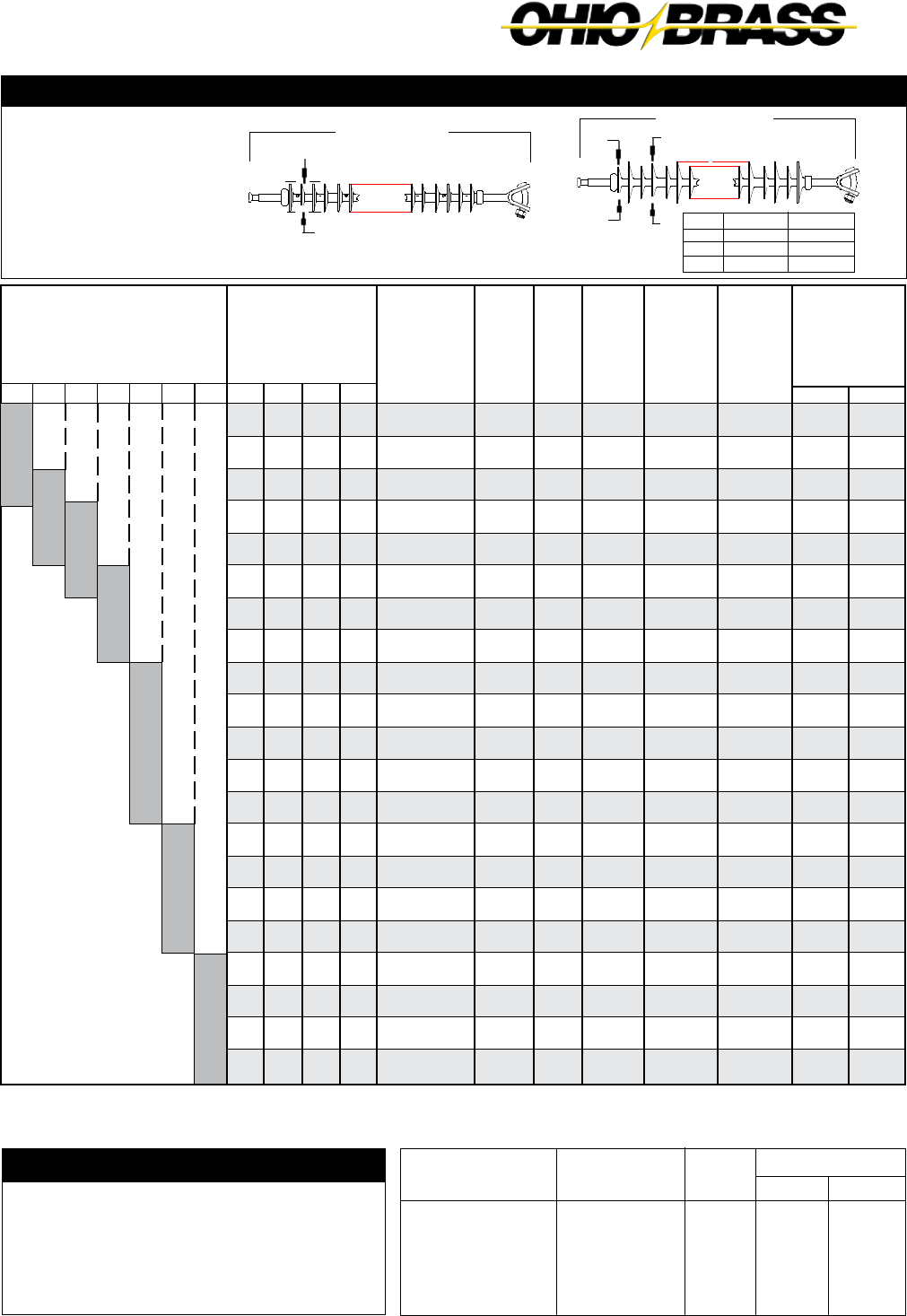
JULY 2010
27-5
OHIO BRASS – AIKEN, SC, USA
Ground
Fitting
Eye
Eye
ANSI 52-5 Socket
Y-Clevis
ANSI 52-6 Clevis
Line
Fitting
Eye
ANSI 52-5 Ball
ANSI 52-5 Ball
Eye
Eye
Suffix
Code
2000
2001
2301
2200
2400
Inches
+1.5
+0.0
- 0.9
+1.4
+0.4
mm
+39
+1
- 25
+37
+11
Length Change
End Fitting Example
You need the electrical and mechanical charac-
tieristics of Catalog #5110102201. But chain eye
is needed at the ground end instead of a Y-clevis.
From the table at the right, find the code for the chain
eye/ANSI ball configuration 2001. You should order
catalog number 5110102001. The same process is
used for other strength Hi*Lite XL insulators.
Mechanical Ratings
SML = 111 kN (25,000 lbs.)
RTL = 55 kN (12,500 lbs.)
Notes: (1) For voltages above 400 kV, and other section lengths, contact your Ohio Brass representative.
(2) Electrical values are without corona ring. For voltages above 161 kV refer to Page 3 for Corona Rings, and associated physical/electrical changes
to above data. Dimensions are within allowable tolerances as specified by IEC 1109 and ANSI C29.12.
16 mm (5/8") Rod Diameter Suspension Insulators
Section Length
Catalog
Number
with ANSI
52-5 ball and
Y-Clevis
XX10032201
XX10042201
XX10052201
XX10062201
XX10072201
XX10082201
XX10092201
XX10102201
XX10112201
XX10122201
XX10132201
XX10142201
XX10152201
XX10162201
XX10172201
XX10182201
XX10192201
XX10202201
XX10212201
XX10222201
XX10232201
Dry Arc
Distance
mm
(in.)
470
(18.5)
625
(24.6)
775
(30.6)
930
(36.8)
1090
(42.9)
1245
(49.0)
1395
(55.0)
1555
(61.2)
1710
(67.3)
1865
(73.5)
2015
(79.5)
2175
(85.6)
2330
(91.7)
2485
(97.9)
2635
(103.9)
2795
(110.0)
2950
(116.2)
3105
(122.3)
3260
(128.3)
3415
(134.4)
3570
(140.6)
No.
of
Sheds
12
16
20
24
28
32
36
40
44
48
52
56
60
64
68
72
76
80
84
88
92
Section
Length
mm
(in.)
725
(28.6)
881
(34.7)
1033
(40.7)
1189
(46.8)
1345
(53.0)
1501
(59.1)
1654
(65.1)
1810
(71.3)
1966
(77.4)
2121
(83.5)
2274
(89.5)
2430
(95.7)
2586
(101.8)
2742
(108.0)
2894
(114.0)
3050
(120.1)
3206
(126.2)
3362
(132.4)
3514
(138.4)
3670
(144.5)
3826
(150.7)
70 330220132 161110
Selection Guide
Typical
Line Voltage, kV (1)
400
51
1160
(45)
1550
(61)
1940
(76)
2320
(91)
2710
(107)
3100
(122)
3490
(137)
3880
(152)
4270
(168)
4660
(183)
5040
(198)
5430
(214)
5820
(229)
6210
(244)
6600
(260)
6990
(275)
7380
(290)
7770
(306)
8150
(321)
8540
(336)
8930
(351)
Leakage
Distance
mm (in.) XX =
A1
1340
(53)
1790
(70)
2230
(88)
2680
(105)
3130
(122)
3580
(141)
4020
(158)
4480
(176)
4930
(194)
5370
(211)
5820
(229)
6270
(247)
6720
(264)
7170
(282)
7610
(299)
8060
(317)
8510
(335)
8960
(353)
9400
(370)
9860
(388)
10310
(406)
D1
1530
(60)
2040
(80)
2540
(100)
3060
(120)
3570
(140)
4080
(160)
4580
(180)
5100
(200)
5610
(221)
6120
(241)
6620
(261)
7140
(281)
7650
(301)
8160
(321)
8670
(341)
9180
(361)
9700
(381)
10210
(402)
10710
(421)
11220
(442)
11740
(462)
G1
1760
(69)
2350
(92)
2920
(115)
3520
(138)
4110
(162)
4700
(185)
5280
(207)
5870
(231)
6460
(254)
7050
(277)
7630
(300)
8220
(323)
8810
(347)
9400
(370)
9980
(393)
10570
(416)
11170
(439)
11760
(463)
12330
(485)
12930
(509)
13520
(532)
Pos-kV
275
(310)
365
(410)
450
(505)
540
(605)
630
(700)
715
(795)
800
(890)
885
(985)
970
(1080)
1050
(1170)
1135
(1260)
1215
(1350)
1295
(1440)
1375
(1530)
1455
(1615)
1530
(1705)
1610
(1790)
1685
(1875)
1760
(1960)
1835
(2040)
1910
(2125)
(2) IEC Light-
ning Impulse
Withstand (ANSI
Critical Impulse
F.O.) kV
(2) IEC Wet
Switching
Impulse
Withstand
(ANSI 60
Hz. Dry
F.O.) kV
260
(180)
345
(245)
420
(310)
500
(370)
570
(430)
650
(490)
720
(545)
790
(600)
860
(655)
930
(710)
995
(760)
1060
(810)
1120
(855)
1185
(905)
1240
(945)
1300
(990)
1355
(1030)
1410
(1070)
1460
(1110)
1510
(1145)
1560
(1180)
(2) IEC
Power
Freq. Wet
Withstand
(ANSI 60
Hz. Wet
F.O.) kV
135
(180)
180
(240
220
(295)
260
(350)
305
(405)
340
(455)
380
(505)
420
(555)
455
(605)
490
(655)
525
(700)
560
(750)
595
(790)
625
(835)
655
(880)
690
(920)
720
(960)
745
(1000)
775
(1040)
800
(1075)
830
(1110)
Neg-kV
255
(285)
350
(390)
440
(490)
530
(595)
620
(695)
710
(795)
800
(890)
890
(990)
975
(1090)
1065
(1185)
1145
(1280)
1230
(1370)
1315
(1465)
1400
(1560)
1480
(1650)
1565
(1740)
1645
(1830)
1725
(1920)
1800
(2005)
1880
(2090)
1955
(2175)
Standard Design
High Leak
Design
94 mm (3.7") y
x
Section Length
Type
A11..
D11..
G11..
x mm (in.)
97 (3.8)
109 (4.3)
130 (5.1)
y mm (in.)
114 (4.5)
140 (5.5)
160 (6.3)

JULY 2010 OHIO BRASS – AIKEN, SC, USA
27-6
Y-Clevis Tower Attachment Detail
for all Hi*Lite XL Insulators
Rod Dia. mm (in.)
16 (5/8")
22 (7/8")
“D” Max. mm (in.)
13 (.53)
25 (1.0)
To achieve insulator SML value, proper grade steel should be used
“D” Max.
19 mm (3/4") Max.
25 mm (1") Dia. Minimum
3 mm (1/8") x 45° Chamfer
Ground
Fitting
Eye
Eye
Y-Clevis
Y-Clevis
IEC 16C Clevis
Line
Fitting
Eye
IEC 16 mm Ball
IEC 16 mm Ball
Eye
Eye
Suffix
Code
2000
2007
2207
2200
2800
Inches
+2.3
+1.0
+0.9
+2.2
+1.2
mm
+59
+26
+24
+57
+31
Length Change
Mechanical Ratings
SML = 120 kN
RTL = 60 kN
16 mm (5/8") Rod Diameter Suspension Insulators
Section Length
Standard Design
Notes: (1) For voltages above 400 kV, and other section lengths, contact your Ohio Brass representative.
(2) Electrical values are without corona ring. For voltages above 161 kV refer to Page 3 for Corona Rings, and associated physical/electrical changes
to above data. Dimensions are within allowable tolerances as specified by IEC 1109 and ANSI C29.12.
Catalog
Number
with IEC
16 mm ball
- socket
XX00032A07
XX00042A07
XX00052A07
XX00062A07
XX00072A07
XX00082A07
XX00092A07
XX00102A07
XX00112A07
XX00122A07
XX00132A07
XX00142A07
XX00152A07
XX00162A07
XX00172A07
XX00182A07
XX00192A07
XX00202A07
XX00212A07
XX00222A07
XX00232A07
Dry Arc
Distance
mm
(in.)
470
(18.5)
625
(24.6)
775
(30.6)
930
(36.8)
1090
(42.9)
1245
(49.0)
1395
(55.0)
1555
(61.2)
1710
(67.3)
1865
(73.5)
2015
(79.5)
2175
(85.6)
2330
(91.7)
2485
(97.9)
2635
(103.9)
2795
(110.0)
2950
(116.2)
3105
(122.3)
3260
(128.3)
3415
(134.4)
3570
(140.6)
No.
of
Sheds
12
16
20
24
28
32
36
40
44
48
52
56
60
64
68
72
76
80
84
88
92
Section
Length
mm
(in.)
731
(28.8)
886
(34.9)
1039
(40.9)
1195
(47.1)
1351
(53.2)
1507
(59.3)
1659
(65.3)
1815
(71.5)
1971
(77.6)
2127
(83.8)
2279
(89.8)
2435
(95.9)
2591
(102.1)
2747
(108.2)
2900
(114.2)
3056
(120.3)
3212
(126.5)
3368
(132.6)
3520
(138.6)
3676
(144.8)
3832
(150.9)
70 330220132 161
110
Selection Guide
Typical
Line Voltage, kV (1)
400
51
1160
(45)
1550
(61)
1940
(76)
2320
(91)
2710
(107)
3100
(122)
3490
(137)
3880
(152)
4270
(168)
4660
(183)
5040
(198)
5430
(214)
5820
(229)
6210
(244)
6600
(260)
6990
(275)
7380
(290)
7770
(306)
8150
(321)
8540
(336)
8930
(351)
Leakage
Distance
mm (in.) XX =
A1
1340
(53)
1790
(70)
2230
(88)
2680
(105)
3130
(122)
3580
(141)
4020
(158)
4480
(176)
4930
(194)
5370
(211)
5820
(229)
6270
(247)
6720
(264)
7170
(282)
7610
(299)
8060
(317)
8510
(335)
8960
(353)
9400
(370)
9860
(388)
10310
(406)
D1
1530
(60)
2040
(80)
2540
(100)
3060
(120)
3570
(140)
4080
(160)
4580
(180)
5100
(200)
5610
(221)
6120
(241)
6620
(261)
7140
(281)
7650
(301)
8160
(321)
8670
(341)
9180
(361)
9700
(381)
10210
(402)
10710
(421)
11220
(442)
11740
(462)
G1
1760
(69)
2350
(92)
2920
(115)
3520
(138)
4110
(162)
4700
(185)
5280
(207)
5870
(231)
6460
(254)
7050
(277)
7630
(300)
8220
(323)
8810
(347)
9400
(370)
9980
(393)
10570
(416)
11170
(439)
11760
(463)
12330
(485)
12930
(509)
13520
(532)
Pos-kV
275
(310)
365
(410)
450
(505)
540
(605)
630
(700)
715
(795)
800
(890)
885
(985)
970
(1080)
1050
(1170)
1135
(1260)
1215
(1350)
1295
(1440)
1375
(1530)
1455
(1615)
1530
(1705)
1610
(1790)
1685
(1875)
1760
(1960)
1835
(2040)
1910
(2125)
(2) IEC Light-
ning Impulse
Withstand (ANSI
Critical Impulse
F.O.) kV
(2) IEC Wet
Switching
Impulse
Withstand
(ANSI 60
Hz. Dry
F.O.) kV
260
(180)
345
(245)
420
(310)
500
(370)
570
(430)
650
(490)
720
(545)
790
(600)
860
(655)
930
(710)
995
(760)
1060
(810)
1120
(855)
1185
(905)
1240
(945)
1300
(990)
1355
(1030)
1410
(1070)
1460
(1110)
1510
(1145)
1560
(1180)
(2) IEC
Power
Freq. Wet
Withstand
(ANSI 60
Hz. Wet
F.O.) kV
135
(180)
180
(240
220
(295)
260
(350)
305
(405)
340
(455)
380
(505)
420
(555)
455
(605)
490
(655)
525
(700)
560
(750)
595
(790)
625
(835)
655
(880)
690
(920)
720
(960)
745
(1000)
775
(1040)
800
(1075)
830
(1110)
Neg-kV
255
(285)
350
(390)
440
(490)
530
(595)
620
(695)
710
(795)
800
(890)
890
(990)
975
(1090)
1065
(1185)
1145
(1280)
1230
(1370)
1315
(1465)
1400
(1560)
1480
(1650)
1565
(1740)
1645
(1830)
1725
(1920)
1800
(2005)
1880
(2090)
1955
(2175)
94 mm (3.7")
Section Length
High Leak Design
y
x
Type
A10..
D10..
G10..
x mm (in.)
97 (3.8)
109 (4.3)
130 (5.1)
y mm (in.)
114 (4.5)
140 (5.5)
160 (6.3)
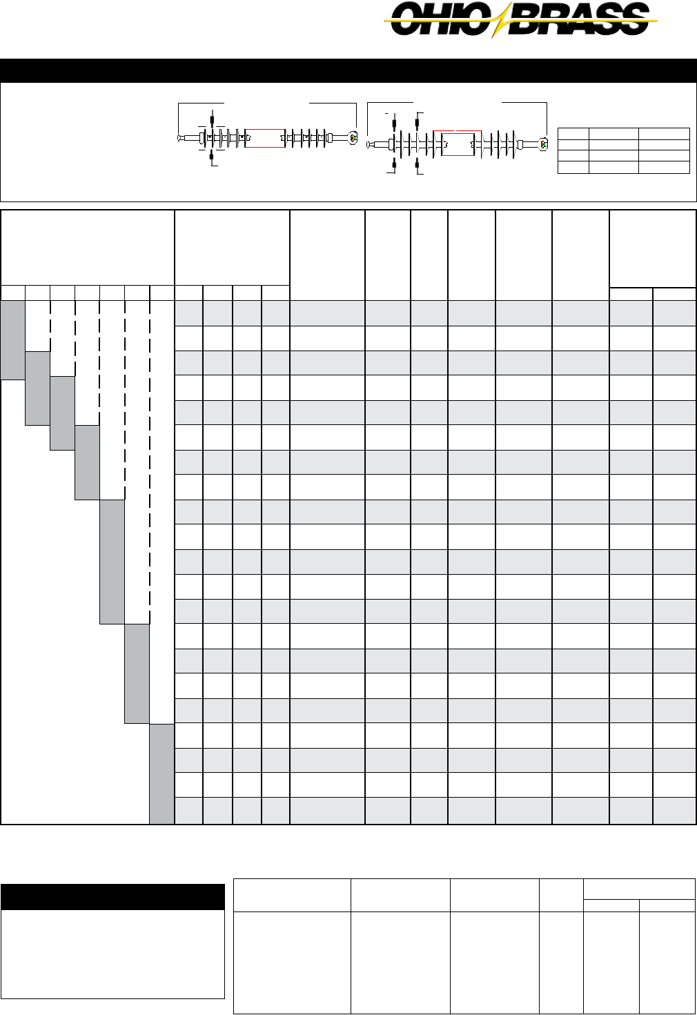
JULY 2010
27-7
OHIO BRASS – AIKEN, SC, USA
Ground
Fitting
Eye
Eye
Y-Clevis
Eye
Y-Clevis
Y-Clevis
ANSI 52-5 Socket
Line
Fitting
Eye
IEC 20 mm Ball
Eye
ANSI 52-5 Ball
IEC 20 mm Ball
ANSI 52-5 Ball
ANSI 52-5 Ball
Suffix
Code
2000
2009
2200
2001
2209
2201
2301
In.
+1.5
+0.8
+1.0
+0.1
+0.3
- 0.4
- 1.3
mm
+40
+21
+27
+2
+8
- 11
- 35
Length Change
Corona Ring Example
You have selected Catalog
#D120122A09, the typical application
is 220kV. From page 3, you would select
ring 2717613002 on the bottom end.
The physical/electrical characteristics
would change per the table on page 3.
Mechanical Ratings
SML = 160 kN (36,000 lbs.)
RTL = 80 kN (18,000 lbs.)
Insulators with either ANSI ball and/
or socket end-fittings will be rated
133 kN (30,000 lbs.) SML and 66 kN
(15,000 lbs.) RTL.
Notes: (1) For voltages above 400 kV, and other section lengths, contact your Ohio Brass representative.
(2) Electrical values are without corona ring. For voltages above 161 kV refer to Page 3 for Corona Rings, and associated physical/electrical changes to
above data. Dimensions are within allowable tolerances as specified by IEC 1109 and ANSI C29.12.
22 mm (7/8") Rod Diameter Suspension Insulators
Catalog
Number
with IEC 20
mm ball and
socket
XX20032A09
XX20042A09
XX20052A09
XX20062A09
XX20072A09
XX20082A09
XX20092A09
XX20102A09
XX20112A09
XX20122A09
XX20132A09
XX20142A09
XX20152A09
XX20162A09
XX20172A09
XX20182A09
XX20192A09
XX20202A09
XX20212A09
XX20222A09
XX20232A09
Dry Arc
Distance
mm
(in.)
470
(18.5)
625
(24.6)
775
(30.6)
930
(36.8)
1090
(42.9)
1245
(49.0)
1395
(55.0)
1555
(61.2)
1710
(67.3)
1865
(73.5)
2015
(79.5)
2175
(85.6)
2330
(91.7)
2485
(97.9)
2635
(103.9)
2795
(110.0)
2950
(116.2)
3105
(122.3)
3260
(128.3)
3415
(134.4)
3570
(140.6)
No.
of
Sheds
12
16
20
24
28
32
36
40
44
48
52
56
60
64
68
72
76
80
84
88
92
Section
Length
mm
(in.)
795
(30.8)
951
(37.0)
1104
(43.5)
1260
(49.6)
1416
(55.8)
1572
(61.9)
1724
(67.9)
1880
(74.0)
2036
(80.2)
2192
(86.3)
2344
(92.3)
2500
(98.5)
2656
(104.6)
2812
(110.7)
2965
(116.7)
3120
(122.9)
3276
(128.9)
3432
(135.2)
3585
(141.2)
3741
(147.3)
3897
(153.4)
70 330220132 161
110
Selection Guide
Typical
Line Voltage, kV (1)
400
51
1150
(45)
1540
(60)
1920
(75)
2310
(91)
2700
(106)
3080
(121)
3470
(136)
3850
(151)
4240
(167)
4630
(182)
5010
(197)
5400
(212)
5790
(228)
6170
(243)
6560
(258)
6940
(273)
7330
(288)
7720
(304)
8100
(319)
8490
(334)
8870
(349)
Leakage
Distance
mm (in.) XX =
A1
1340
(53)
1790
(70)
2230
(88)
2680
(105)
3130
(123)
3580
(141)
4020
(158)
4480
(176)
4930
(194)
5370
(211)
5820
(229)
6270
(247)
6720
(264)
7170
(282)
7610
(299)
8060
(317)
8510
(335)
8960
(353)
9400
(370)
9860
(388)
10310
(406)
D1
1530
(60)
2040
(80)
2540
(100)
3060
(120)
3570
(140)
4080
(160)
4580
(180)
5100
(200)
5610
(221)
6120
(241)
6620
(261)
7140
(281)
7650
(301)
8160
(321)
8670
(341)
9180
(361)
9700
(381)
10210
(402)
10710
(421)
11220
(442)
11740
(462)
G1
1760
(69)
2350
(92)
2920
(115)
3520
(138)
4110
(162)
4700
(185)
5280
(207)
5870
(231)
6460
(254)
7050
(277)
7630
(300)
8220
(323)
8810
(347)
9400
(370)
9980
(393)
10570
(416)
11170
(439)
11760
(463)
12330
(485)
12930
(509)
13520
(532)
Pos-kV
275
(310)
365
(410)
450
(505)
540
(605)
630
(700)
715
(795)
800
(890)
885
(985)
970
(1080)
1050
(1170)
1135
(1260)
1215
(1350)
1295
(1440)
1375
(1530)
1455
(1615)
1530
(1705)
1610
(1790)
1685
(1875)
1760
(1960)
1835
(2040)
1910
(2125)
(2) IEC Light-
ning Impulse
Withstand (ANSI
Critical Impulse
F.O.) kV
(2) IEC Wet
Switching
Impulse
Withstand
(ANSI 60
Hz. Dry
F.O.) kV
260
(180)
345
(245)
420
(310)
500
(370)
570
(430)
650
(490)
720
(545)
790
(600)
860
(655)
930
(710)
995
(760)
1060
(810)
1120
(855)
1185
(905)
1240
(945)
1300
(990)
1355
(1030)
1410
(1070)
1460
(1110)
1510
(1145)
1560
(1180)
(2) IEC
Power
Freq. Wet
Withstand
(ANSI 60
Hz. Wet
F.O.) kV
135
(180)
180
(240
220
(295)
260
(350)
305
(405)
340
(455)
380
(505)
420
(555)
455
(605)
490
(655)
525
(700)
560
(750)
595
(790)
625
(835)
655
(880)
690
(920)
720
(960)
745
(1000)
775
(1040)
800
(1075)
830
(1110)
Neg-kV
255
(285)
350
(390)
440
(490)
530
(595)
620
(695)
710
(795)
800
(890)
890
(990)
975
(1090)
1065
(1185)
1145
(1280)
1230
(1370)
1315
(1465)
1400
(1560)
1480
(1650)
1565
(1740)
1645
(1830)
1725
(1920)
1800
(2005)
1880
(2090)
1955
(2175)
SML kN (lbs.)
160 kN (36K)
160 kN (36K)
160 kN (36K)
133 kN (30K)
160 kN (36K)
133 kN (30K)
133 kN (30K)
Section Length
Standard Design
101 mm (4.0")
Section Length
High Leak Design
y
x
Type
A12..
D12..
G12..
x mm (in.)
97 (3.8)
109 (4.3)
130 (5.1)
y mm (in.)
114 (4.5)
140 (5.5)
160 (6.3)

JULY 2010 OHIO BRASS – AIKEN, SC, USA
27-8
Mechanical Ratings
SML = 210 kN
RTL = 55 kN
ANSI fittings are capable
of 222 kN SML (50K lbs.)
Notes: (1) For voltages above 400 kV, and other section lengths, contact your Ohio Brass representative.
(2) Electrical values are without corona ring. For voltages above 161 kV refer to Page 3 for Corona Rings, and associated physical/electrical changes to
above data. Dimensions are within allowable tolerances as specified by IEC 1109 and ANSI C29.12.
22 mm (7/8") Rod Diameter Suspension Insulators
Catalog
Number
with IEC 20
mm ball and
socket
XX30032A07
XX30042A07
XX30052A07
XX30062A07
XX30072A07
XX30082A07
XX30092A07
XX30102A07
XX30112A07
XX30122A07
XX30132A07
XX30142A07
XX30152A07
XX30162A07
XX30172A07
XX30182A07
XX30192A07
XX30202A07
XX30212A07
XX30222A07
XX30232A07
Dry Arc
Distance
mm
(in.)
470
(18.5)
625
(24.6)
775
(30.6)
930
(36.8)
1090
(42.9)
1245
(49.0)
1395
(55.0)
1555
(61.2)
1710
(67.3)
1865
(73.5)
2015
(79.5)
2175
(85.6)
2330
(91.7)
2485
(97.9)
2635
(103.9)
2795
(110.0)
2950
(116.2)
3105
(122.3)
3260
(128.3)
3415
(134.4)
3570
(140.6)
No.
of
Sheds
12
16
20
24
28
32
36
40
44
48
52
56
60
64
68
72
76
80
84
88
92
Section
Length
mm
(in.)
795
(30.8)
951
(37.0)
1104
(43.5)
1260
(49.6)
1416
(55.8)
1572
(61.9)
1724
(67.9)
1880
(74.0)
2036
(80.2)
2192
(86.3)
2344
(92.3)
2500
(98.5)
2656
(104.6)
2812
(110.7)
2965
(116.7)
3120
(122.9
3276
(128.9)
3432
(135.2)
3585
(141.2)
3741
(147.3)
3897
(153.4)
69 330220138 161115
Selection Guide
Typical
Line Voltage, kV (1)
400
51
1150
(45)
1540
(60)
1920
(75)
2310
(91)
2700
(106)
3080
(121)
3470
(136)
3850
(151)
4240
(167)
4630
(182)
5010
(197)
5400
(212)
5790
(228)
6170
(243)
6560
(258)
6940
(273)
7330
(288)
7720
(304)
8100
(319)
8490
(334)
8870
(349)
Leakage
Distance
mm (in.) XX =
A1
1340
(53)
1790
(70)
2230
(88)
2680
(105)
3130
(123)
3580
(141)
4020
(158)
4480
(176)
4930
(194)
5370
(211)
5820
(229)
6270
(247)
6720
(264)
7170
(282)
7610
(299)
8060
(317)
8510
(335)
8960
(353)
9400
(370)
9860
(388)
10310
(406)
D1
1530
(60)
2040
(80)
2540
(100)
3060
(120)
3570
(140)
4080
(160)
4580
(180)
5100
(200)
5610
(221)
6120
(241)
6620
(261)
7140
(281)
7650
(301)
8160
(321)
8670
(341)
9180
(361)
9700
(381)
10210
(402)
10710
(421)
11220
(442)
11740
(462)
G1
1760
(69)
2350
(92)
2920
(115)
3520
(138)
4110
(162)
4700
(185)
5280
(207)
5870
(231)
6460
(254)
7050
(277)
7630
(300)
8220
(323)
8810
(347)
9400
(370)
9980
(393)
10570
(416)
11170
(439)
11760
(463)
12330
(485)
12930
(509)
13520
(532)
Pos-kV
275
(310)
365
(410)
450
(505)
540
(605)
630
(700)
715
(795)
800
(890)
885
(985)
970
(1080)
1050
(1170)
1135
(1260)
1215
(1350)
1295
(1440)
1375
(1530)
1455
(1615)
1530
(1705)
1610
(1790)
1685
(1875)
1760
(1960)
1835
(2040)
1910
(2125)
(2) IEC Light-
ning Impulse
Withstand (ANSI
Critical Impulse
F.O.) kV
(2) IEC Wet
Switching
Impulse
Withstand
(ANSI 60
Hz. Dry
F.O.) kV
260
(180)
345
(245)
420
(310)
500
(370)
570
(430)
650
(490)
720
(545)
790
(600)
860
(655)
930
(710)
995
(760)
1060
(810)
1120
(855)
1185
(905)
1240
(945)
1300
(990)
1355
(1030)
1410
(1070)
1460
(1110)
1510
(1145)
1560
(1180)
(2) IEC
Power
Freq. Wet
Withstand
(ANSI 60
Hz. Wet
F.O.) kV
135
(180)
180
(240
220
(295)
260
(350)
305
(405)
340
(455)
380
(505)
420
(555)
455
(605)
490
(655)
525
(700)
560
(750)
595
(790)
625
(835)
655
(880)
690
(920)
720
(960)
745
(1000)
775
(1040)
800
(1075)
830
(1110)
Neg-kV
255
(285)
350
(390)
440
(490)
530
(595)
620
(695)
710
(795)
800
(890)
890
(990)
975
(1090)
1065
(1185)
1145
(1280)
1230
(1370)
1315
(1465)
1400
(1560)
1480
(1650)
1565
(1740)
1645
(1830)
1725
(1920)
1800
(2005)
1880
(2090)
1955
(2175)
Y-Clevis Tower Attachment Detail
for all Hi*Lite XL Insulators
Rod Dia. mm (in.)
16 (5/8")
22 (7/8")
“D” Max. mm (in.)
13 (.53)
25 (1.0)
To achieve insulator SML value, proper grade steel should be used.
“D” Max.
19 mm (3/4") Max.
25 mm (1") Dia. Minimum
3 mm (1/8") x 45° Chamfer
Ground
Fitting
Eye
Eye
ANSI 52-11 Socket
Eye
Y-Clevis
Y-Clevis
Y-Clevis
Eye
Line
Fitting
Eye
IEC 20mm Ball
ANSI 52-11 Ball
ANSI 52-11 Ball
Eye
ANSI 52-11 Ball
IEC 20 mm Ball
IEC 19L Clevis
Suffix
Code
2000
2007
2301
2001
2200
2201
2207
2800
Inches
+1.5
+0.7
- 0.6
+0.1
+0.7
- 0.5
+0.1
+1.2
mm
+40
+18
- 16
+2
+19
- 13
+4
+31
Length Change
Section Length
Standard Design
101 mm (4.0")
Section Length
High Leak Design
y
x
Type
A13..
D13..
G13..
x mm (in.)
97 (3.8)
109 (4.3)
130 (5.1)
y mm (in.)
114 (4.5)
140 (5.5)
160 (6.3)
A Better Design. A Better Insulator.
Catalog 24
®
Insulators
®
LIMITED WARRANTY AND LIMITATION OF LIABILITY
MATERIAL: HPS warrants all products sold by it to be merchantable (as such term is defined in
the Uniform Commercial Code) and to be free from defects in material and workmanship. Buyer
must notify HPS promptly of any claim under this warranty. The Buyer’s exclusive remedy for
breach of this warranty shall be the repair or replacement, F.O.B. factory, at HPS’s option, of any
product defective under the warranty, which is returned to HPS within one year from the date of
shipment. NO OTHER WARRANTY, WHETHER EXPRESS OR ARISING BY OPERATION OF THE
LAW, COURSE OF DEALING, USAGE OF TRADE OR OTHERWISE IMPLIED, SHALL EXIST IN
CONNECTION WITH HPS’S PRODUCTS OR ANY SALE OR USE THEREOF. HPS SHALL IN NO
EVENT BE LIABLE FOR ANY LOSS OF PROFITS OR CONSEQUENTIAL OR SPECIAL DAMAGES
INCURRED BY BUYER. HPS’s warranty shall run only to the first Buyer of a product from HPS,
from HPS’s Buyer, or from an original equipment manufacturer reselling HPS’s product, and is
non-assignable and non-transferable and shall be of no force and effect if asserted by any person
other than such first Buyer. This warranty applies only to the use of the product as intended by
HPS and does not cover any modification, misapplication, or misuse of said product.
APPLICATION: HPS does not warrant the accuracy of and results from product or system
performance recommendations resulting from any engineering analysis or study. This applies re-
gardless of whether a charge is made for the recommendation, or if it is provided free of charge.
Responsibility for selection of the proper product of application rests solely with the purchaser. In
the event of errors or inaccuracies determined to be caused by HPS, its liability will be limited to
the reperformance of any such analysis or study.
PURCHASER INSPECTIONS: Tests, inspections and acceptance of all material must be made at
the factory. Purchasers’ inspectors are welcome at the factories and are provided with the neces-
sary facilities for carrying out their work. Name and phone number of who should be contacted
for inspection should be given to HPS no later than two weeks prior to scheduled shipment date.
LIMITATION OF LIABILITY: IN NO EVENT, WHETHER AS A RESULT OF BREACH OF CONTRACT
OR WARRANTY OR ALLEGED NEGLIGENCE, SHALL HPS BE LIABLE FOR SPECIAL OR
CONSEQUENTIAL DAMAGES INCLUDING, BUT NOT LIMITED TO, LOSS OF PROFITS OR
REVENUE, LOSS OF USE OF THE EQUIPMENT OR ANY ASSOCIATED EQUIPMENT, LOSS OF
CAPITAL, COST OF SUBSTITUTE EQUIPMENT, FACILITIES OR SERVICES, DOWNTIME COSTS,
OR CLAIMS OF THIRD PARTIES OF THE BUYER FOR SUCH DAMAGES. Any claim by Buyer for
breach of the foregoing warranty shall be deemed waived by Buyer unless submitted to HPS in
writing within thirty (30) days from the date Buyer discovered, or by reasonable inspection should
have discovered the alleged breach. Any cause of action for breach of the foregoing warranty
shall be brought within one year after the cause of action has accrued.
1850 Richland Avenue East, Aiken, SC 29801
http://www.hubbellpowersystems.com
E-mail: quadrisil@hps.hubbell.com
©Copyright 2010
NOTE: Because Hubbell has a policy of continuous product improvement, we reserve the right to
change design and specifications without notice.
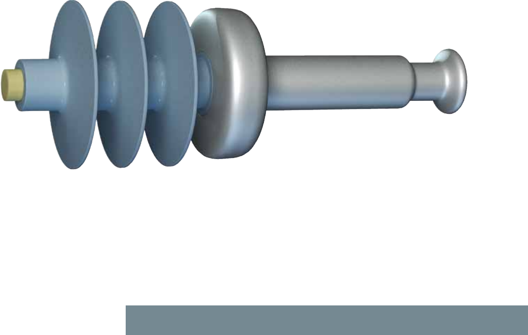
A Better Design. A Better Insulator.
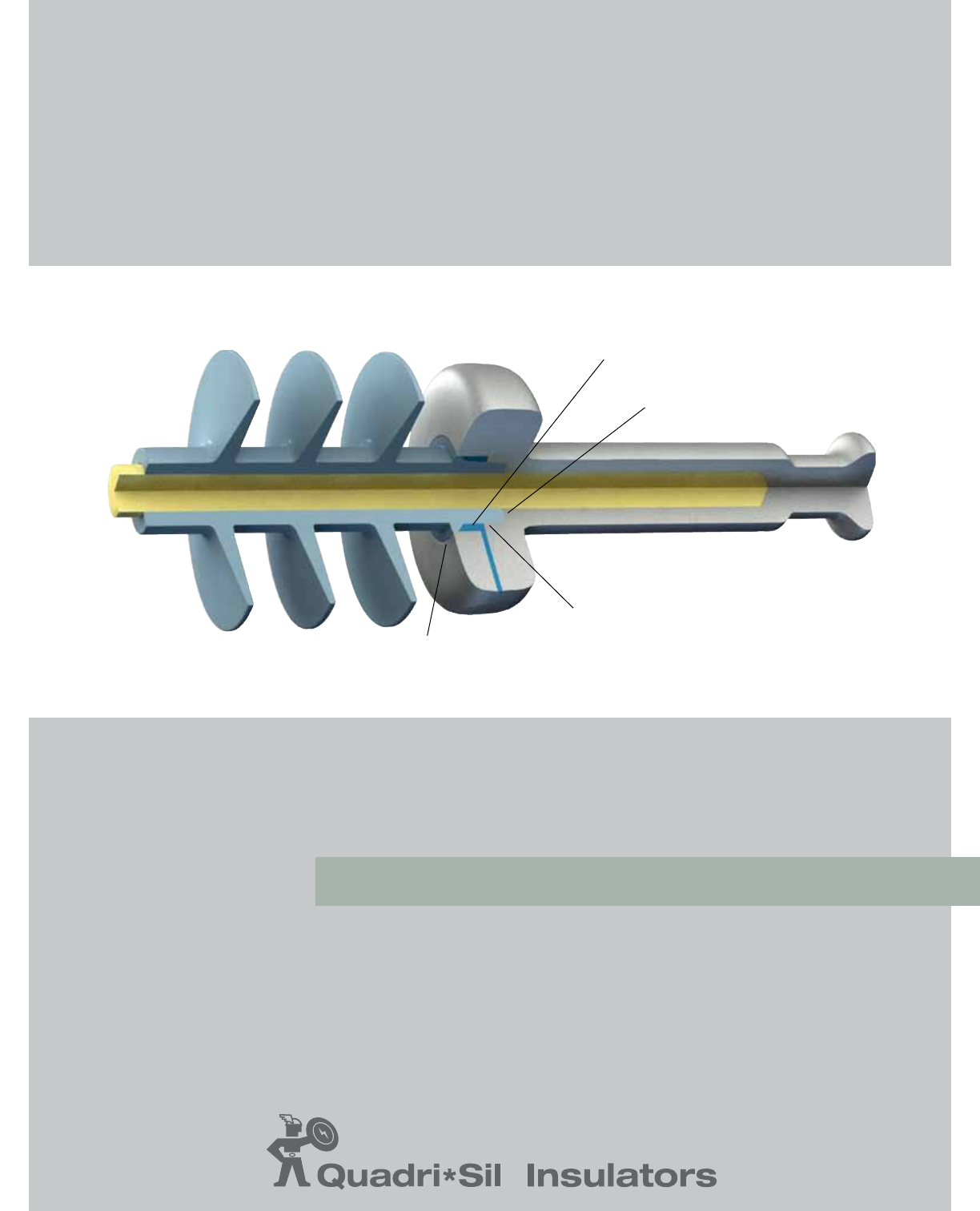
Polymer (RTV) Seal
Counterbore Compression Seal
Radial Compression Seal
Overlap Compression Seal
Our Exclusive Four-Point Seal
®


page 1
Quadri*Sil® Insulators — A Century in the Making
With nearly 100 years of Ohio Brass insulator experience and product innovation, it’s
no surprise that the next generation of insulator reliability carries the trusted name of
Ohio Brass.
Ohio Brass (Hubbell Power Systems) is proud to offer a transmission insulator that triumphs
over today’s unpredictable environment. Appropriately named, the Quadri*Sil® insulator
incorporates a revolutionary four-point seal that, quite simply. . . prohibits moisture
intrusion.
In addition, the Quadri*Sil® insulator optimizes the Ohio Brass commitment to excellence
and the advancement of processes and materials. With a proprietary silicone-
rubber compound and end-seal design, this direct-bonded insulator offers
assurance that moisture penetration does not occur.
Today’s environment is unpredictable. Your insulator can’t be.
January 2011
The Ohio Brass commitment is simple and complete:
we provide our customers the finest, most advanced
products and expert technical assistance, before
and after purchase. Every day. Worldwide.

page 2 January 2011

page 3
QUADRI*SIL® GENERAL INFORMATION PAGE 4
The Heart of Quadri*Sil® Insulators ....................................................................... 4
Key to the Catalog Numbers .....................................................................8 and 33
Technical Terms Reference Guide ....................................................................... 34
SUSPENSION INSULATORS PAGE 11
Corona Performance ......................................................................................... 12
End Fitting Detail ............................................................................................... 13
Quadri*Sil® 25 kip / 120 kN SML Data ............................................................... 14
Quadri*Sil® 30 kip SML Data ............................................................................. 15
Quadri*Sil® 160 kN SML Data ............................................................................ 16
Quadri*Sil® 50 kip / 210 kN SML Data ............................................................... 17
LINE POST INSULATORS PAGE 19
Mechanical Ratings and Corona Performance ..................................................... 20
Quadri*Sil® Horizontal Line Posts ....................................................................... 21
Quadri*Sil® Vertical Line Posts ........................................................................... 22
Quadri*Sil® Base Fittings ................................................................................... 24
Quadri*Sil® Line Fittings .................................................................................... 25
Clamps and Assemblies .................................................................................... 26
BRACED POST INSULATORS PAGE 29
Braced Line Post Assemblies ............................................................................. 30
Assembly Drawings ........................................................................................... 31
Dimensions and Strength Ratings ...................................................................... 32
January 2011

page 4
Design
Sealing System — This four-point sealing system provides superior performance by preventing moisture
penetration between the silicone rubber and end-fitting interface. The design is based on four redundant
seals that provide unmatched protection to the fiberglass core rod. RTV (Room Temperature Vulcanate) is
completely encapsulated within the interior of the end-fitting and is not utilized as an exterior seal as with
other silicone designs.
Corona Shielding Ring (CSR) — The Quadri*Sil® end-fitting design provides superior electric field
shielding of the silicone rubber adjacent to the end-fitting. The superior shielding protects the silicone
rubber on applications where an external corona ring is not required.
Direct Bond — The silicone rubber material is bonded directly to the fiberglass core rod during the
molding process. The resulting bond between the silicone rubber and fiberglass rod is mechanically
stronger than the tear strength of the silicone rubber.
Crimp Method — A circumferential crimp creates
a more uniform stress distribution to ensure the
mechanical integrity of the Quadri*Sil® insulator.
Ohio Brass pioneered the crimping process in
1976 — today it has become the industry standard.
[ Revolutionary Four-Point Seal ]
January 2011
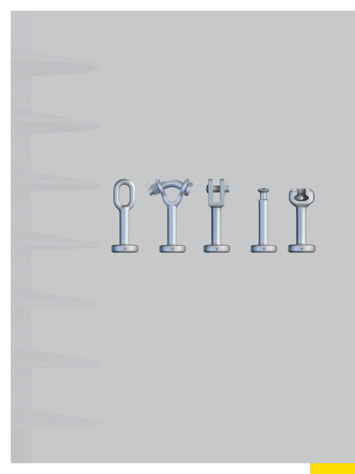
page 5
Components and Materials
Polymer Weathersheds — The polymer weathershed material utilized in the Quadri*Sil® insulator
design is a proprietary silicone-rubber compound specifically designed by Ohio Brass engineers for
high-voltage insulator applications. The polymer weathershed material starts with 100-percent base
silicone rubber before additives and fillers are compounded with the base rubber. Hubbell Power
Systems (HPS) controls the entire process from the proprietary formulation to the complete mixing
process. The proprietary formulation incorporates the inherent hydrophobicity and UV performance of
silicone rubber while providing superior tracking performance as demonstrated in dry-band arcing
tests. For more information about our silicone rubber, please contact your HPS representative.
Fiberglass Core Rod — The Quadri*Sil® suspension insulator’s fiberglass core rod is produced with
boron-free, corrosion-resistant E-glass and epoxy resin. Quadri*Sil® line post insulators are manufac-
tured with electrical grade glass and epoxy resin.
End Fittings — Made of steel or ductile iron, the end-fittings are directly attached to the fiberglass core
rod by a circumferential crimping process. This crimping process allows the end fittings to utilize the rod’s
inherent tensile strength.
Grading Rings — Also known as corona rings, grading rings are manufactured using high-grade
aluminum alloy, making them strong, light, and corrosion-resistant. Grading (corona) rings can be
packaged separately or inside the insulator crates with all mounting hardware included.
Leakage Distance
Quadri*Sil® suspension insulators feature standard and high leakage distance weathershed profiles for
maximum resistance to contamination and leakage currents in various environmental applications. The
hydrophobic nature of our silicone rubber ensures superior performance in contaminated environments.
January 2011

High Pressure Washing
Quadri*Sil® transmission insulators normally do not require washing or other routine maintenance.
Washing may be required if the insulators are installed in an area of severe environmental contamination.
In the event that washing is required, the procedures outlined in Section IX of the “IEEE GUIDE FOR
INSULATOR CLEANING,” IEEE STD 957-2005 are generally applicable.
Mechanical Ratings
Quadri*Sil® suspension insulators are rated and tested in accordance with IEC 61109 and ANSI
C29.12. Quadri*Sil® line post insulators are rated and tested in accordance with IEC 61952 and ANSI
C29.17. Certified test reports are available.
For suspension insulators, SML ratings are 120 kN, 160 kN, 210 kN, 25 kip, 30 kip, and 50 kip with
appropriate rod size and end fittings. RTL ratings are consistent with the IEC and ANSI standards.
Factory routine tests are conducted on 100 percent of all insulators to the RTL rating.
Markings
Markings for Quadri*Sil® suspension insulators are placed on a UV-resistant label located on the
ground end fitting. Markings for Quadri*Sil® line post insulators are placed on a metal plate on the
mounting base of the insulator. Markings include SML and RTL (for suspension), SCL and RCL (for
line post), part number, assembly date code, and Hubbell Power Systems identification.
These markings are consistent with applicable IEC and ANSI standards.
Insulator Lengths
Quadri*Sil® suspension insulators are available in lengths appropriate for 69 kV through 765 kV.
Longer lengths can be produced for special projects. Intermediate lengths – those that fall in
between the catalog numbers listed in the tables – are also available. Length increments are
approximately 2.2 inches (56 mm) for suspension insulators and 2.4 inches (61 mm) for vertical
and horizontal line post insulators.
page 6 January 2011
page 7
Testing
Quadri*Sil® insulators have been tested successfully to meet the requirements of IEC 61109 and
ANSI C29.11. For a certified test report or additional information related to product testing, please
contact your HPS representative.
Packaging
Quadri*Sil® suspension insulators are packaged in wooden crates 44 inches (111.7 cm) wide with
the length of the crate determined by the length of the insulator. The height of the crate is normally
less than 45 inches (114.3 cm). The gross weight will not exceed 2,000 pounds (909 kg). Crates are
available for both domestic and export transportation.
The Quadri*Sil® line post insulators are packaged in appropriate quantities in open wood crates. Line
post insulators are packaged to prevent the metal bases from resting on the polymer weathershed material.
January 2011

page 8
CATALOG NUMBER KEY
a
b
c
d
e
Insulator Type
Mechanical Strength
Suspension (SML), Rod Diameter
025 — 25 kip, 5/8” (16 mm)
030 — 30 kip, 5/8” (16 mm)
050 — 50 kip, 7/8” (22 mm)
120 — 120 kN, 5/8” (16 mm)
160 — 160 kN, 7/8” (22 mm)
210 — 210 kN, 7/8” (22 mm)
Polymer Length
3 digits for distance between metal
parts, in inches
Top Fitting
Weathershed Profile
Post
250 — Series 250, standard strength 2.5”,
(63.5 mm)
Suspension
S — Standard Leakage Distance (2.5)
H — High Leakage Distance (2.9 or 3.3)
Line Post Insulators
0 — Tear Drop Blade
1 — Horizontal Clamptop
2 — Vertical Clamptop
3 — 5” (127 mm) Bolt Circle
5/8” (16 mm) Tapped Hole
5 — 5” (127 mm) Bolt Circle
5/8” (16 mm) Through Hole
9 — Long Tear Drop Blade
Post
S — Standard Leakage Distance
P — Post or
S — Suspension
0 — Chain Eye
1 — ANSI Ball
2 — Y-Clevis
3 — ANSI Socket
4 — ANSI Straight Clevis
7 — IEC Ball Fitting
16 mm for 120 kN
20 mm for 160 kN and 210 kN
8 — IEC Straight Clevis
A — IEC Socket
16 mm for 120 kN
20 mm for 160 kN and 210 kN
The Quadri*Sil Insulators Numbering Scheme is organized according to a smart numbering system. Each group of digits defines a
characteristic of the product you are ordering. To fill out this form, start on “a: Insulator Type.” Then, fill in your selection in the box
corresponding to the letter “a.” Apply the same rule for all the other sections.
a)
Insulator Type. Defines your insulator type: Post or Suspension.
Select “P” or “S” for Post or Suspension, respectively, and fill in your
selection in the box designated for “a.” In this example, we selected a
suspension insulator.
b)
Strength. Defines the mechanical strength of your insulator. Fill in your
selection in the boxes designated for “b.”
Note: kip = Kilopound, kN = Kilonewton
For example, if you want a Suspension insulator with 25 kip, this is what
your form would look like so far:
c)
Polymer Length. Defines the polymer length of the insulator (please use
catalog tables for possible polymer lengths). Fill in your selection in the boxes
designated for section “c.” For example, if you want a 49-inch polymer length,
enter:
d)
Weathershed Profile. Defines the leakage distance design. For a suspension
insulator with standard leakage distance, use “S.”
For a suspension insulator
with high leakage distance, use “H.”
For a line post, only the standard leakage
distance design is available. Fill in your selection in the box designated for “d.”
For example, if you want an insulator with high leakage distance, you would
place an “H” in the box designated “d.”
e)
Top Fitting. Defines the top end fitting of your insulator. Fill in your
selection in the box designated for “e.” For example, if you want a
suspension insulator with a Y-clevis top end fitting, you would place a
“2” in the box designated for “e.”
049H
S025
0 4 9 H 2
S025
049
S025
S025
S
Suspension Insulators
Suspension Insulators Line Post Insulators
January 2011
®

page 9
Your complete part number will be S025049H201A
January 2011
f
g
00 - Chain Eye 02 - Aluminum Gain 12” (305 mm) CL1 mounting
03 - Aluminum Flat 8”x 10” (203 mm x 254 mm),
15/16” (24 mm) hole diameter
01 - ANSI Ball 04 - Aluminum Flat 8”x 13” (203 mm x 330 mm),
15/16” (24 mm) hole diameter
02 - Y-Clevis 05 - 5” (127 mm) Bolt Circle, 5/8” (16 mm) tapped hole
03 - ANSI Socket 07 - Steel Gain 12” (305 mm) CL mounting,
15/16” (24 mm) hole diameter
04 - ANSI Straight Clevis 08 - Steel Flat 8”x 13” (203 mm x 330 mm) MS2,
15/16” (24 mm) hole diameter
15 - 5” (127 mm) Bolt Circle, 5/8” (16 mm) through hole
07 - IEC Ball Fitting
16 mm for 120 kN or
20 mm for 160 kN and 210 kN
08 - IEC Straight Clevis
0A - IEC Socket
16 mm for 120 kN or
20 mm for 160 kN and 210 kN
0
— No ring required
A — >220 kV, 8” (203 mm) ring for suspension, 12” (305 mm) ring
for series 250 post
B — >330 kV
series 250 post
C — >400 kV, 12” (305 mm) line end and 8” (203 mm) ground end ring
for suspension
D — >500 kV, 15” (381 mm) line end and 8” (203 mm) ground end ring
for suspension
E — >735 kV, 15” (381 mm) line end and 12” (305 mm) ground end ring
for suspension
Bottom Fitting
Rings
Examples:
Suspension Insulators Line Post Insulators
1 Center Line
2 Horizontal x Vertical
Mounting Pattern Spacing
f)
Bottom Fitting. Defines the bottom end fitting of your insulator. Fill in your selection in the boxes
designated for “f.”
For example, if you want an ANSI ball bottom end fitting, you would place “01” in the
boxes designated for “f.”
0 4 9 H 2
S025 0 1
0 4 9 H 2
S025 0 1 A
g)
Rings. Defines your need for a Corona Ring. Fill in your selection in the box designated
for “g.”
The example below shows a selection of a corona ring for 220 kV, 8” (203 mm) for
a suspension insulator.
Thus, “A” was placed in the box designated for “g.”
Your final catalog number
should look like this
Fill out boxes according to instructions
Suspension Insulator, 25 kip, 49” of
Polymer Length, Standard Leakage
Distance Profile (2.5), Top Fitting: Y-Clevis,
Bottom Fitting: ANSI Ball, No Corona Ring
S025049S2010
Vertical Gain - See page 23 Table B
, 12” (305 mm) ring for suspension, 15” (381 mm) ring for
P250021S0020
Line Post Insulator, 2.5” (63.5 mm) Rod
Diameter, 21.9” Polymer Length, Standard
Leakage Distance, Top Fitting: Tear Drop
Blade, Bottom Fitting: 2-Piece Aluminum
Gain Base, No Corona Ring

page 10 January 2011
page 11
Suspension Insulators
TABLE OF CONTENTS PAGE
Corona Performance ........................................................................................ 12
End Fitting Detail .............................................................................................. 13
Quadri*Sil® 25 kip / 120 kN SML Data .............................................................. 14
Quadri*Sil® 30 kip SML Data ............................................................................ 15
Quadri*Sil® 160 kN SML Data ........................................................................... 16
Quadri*Sil® 50 kip / 210 kN SML Data .............................................................. 17
January 2011
®

page 12
Recommended Corona Ring Installation Table
Normal Applications: Top Grounded, Bottom Energized
Corona Performance
Quadri*Sil® insulators are RIV and corona free through 161 kV. The use of an external corona shielding ring is required at 220 / 230 kV and above.
The table below details the rings necessary for 220 / 230 kV and above.
Part Number 271761 Part Number 271705 Part Number 271751
Quadri*Sil Suspen-
sion Insulator
4.10”
(104 mm)
15.00”
(381 mm)
Quadri*Sil Suspen-
sion Insulator
3.44”
(87 mm)
12.0”
(305 mm)
Quadri*Sil Suspen-
sion Insulator
2.44”
(62 mm)
8.0”
(203 mm)
Electrical/Dimensional Changes to the Suspension Insulator
with External Corona Ring
Recommended Corona Rings by Line Voltage
Line
Voltage
(kV)
Corona Ring Part Numbers
Ground EndGround End Ground EndLine EndLine End Line End
220/230 kV
330/345 kV
400 kV
500 kV
None
None
8" (203 mm)
8" (203 mm)
8" (203 mm)
12" (305 mm)
12" (305 mm)
15" (381 mm)
-
-
2717613001
2717613001
-
-
2717613002
2717613002
2717613002
2717053002
2717053002
2717513002
2717613001
2717053001
2717053001
2717513001
25 kip, 30 kip, 120 kN, 133 kN 50 kip, 160 kN, 210 kN
Physical and Electrical Characteristics
Dry Arc Distance inches (mm)
Leakage Distance inches (mm)
ANSI 60 Hz Flashover Dry — kV
ANSI 60 Hz Flashover Wet — kV
ANSI Critical Flashover Positive — kV
ANSI Critical Flashover Negative — kV
IEC Wet Switching Impulse Withstand — kV
IEC Power Frequency Wet Withstand — kV
IEC Lightning Impulse Withstand Positive — kV
IEC Lightning Impulse Withstand Negative — kV
Net Weight pounds (kg)
220/230 kV
Ring
-0.63 (-16)
0
-10
-10
-10
-10
N/A
-10
-10
-10
2.1 (1.0)
330/345 kV
Ring
-1.32 (33.5)
0
-20
-10
-20
-20
N/A
-10
-20
-20
2.9 (1.3)
400 kV
Ring
-1.95 (49.5)
0
-20
-20
-30
-30
N/A
-20
-30
-30
5.0 (2.3)
500 kV
Ring
-2.67 (67.8)
0
-30
-30
-40
-50
N/A
-30
-40
-50
6.5 (2.9)
January 2011

page 13
Chain Eye
MOST COMMON END FITTINGS
Y-Clevis
Straight Clevis Ball/Socket
SML
25 kip
(111 kN)
120 kN
30 kip
(133 kN)
36 kip
(160 kN)
210 kN
50 kip
(222 kN)
A
0.62
(15.74)
0.62
(15.74)
0.75
(19.05)
0.75
(19.05)
0.75
(19.05)
0.75
(19.05)
C
2.00
(50.8)
2.00
(50.8)
2.00
(50.8)
2.00
(50.8)
2.00
(50.8)
2.00
(50.8)
D
0.62
(15.74)
0.62
(15.74)
0.85
(21.59)
0.85
(21.59)
0.85
(21.59)
0.85
(21.59)
Dimensions in. (mm)
B
1.00
(25.4)
1.00
(25.4)
1.00
(25.4)
1.00
(25.4)
1.00
(25.4)
1.00
(25.4)
SML
25 kip
(111 kN)
120 kN
30 kip
(133 kN)
36 kip
(160 kN)
210 kN
50 kip
(222 kN)
B
1.53
(38.86)
1.53
(38.86)
1.59
(40.39)
1.59
(40.39)
1.59
(40.39)
1.59
(40.39)
A
0.75
(19.05)
0.75
(19.05)
0.88
(22.35)
0.88
(22.35)
0.88
(22.35)
0.88
(22.35)
Bolt Dia.
0.75
(19)
0.75
(19)
0.88
(22)
0.88
(22)
0.88
(22)
0.88
(22)
Dimensions in. (mm)
SML
25 kip
(111 kN)
120 kN
30 kip
(133 kN)
36 kip
(160 kN)
210 kN
50 kip
(222 kN)
A
1.41
(36)
1.41
(36)
1.41
(36)
1.81
(46)
1.81
(46)
Class
ANSI 52-6
IEC 16C
ANSI 52-6
IEC 19L
IEC 19L
N/A
B
0.75
(19)
0.75
(19)
0.75
(19)
0.83
(21)
0.83
(21)
PD
0.62
(16)
0.62
(16)
0.62
(16)
0.75
(19)
0.75
(19)
Dimensions in. (mm)
SML
25 kip
(111 kN)
120 kN
30 kip
(133 kN)
36 kip
(160 kN)
210 kN
50 kip
(222 kN)
Class
ANSI 52-5
IEC 16 mm
ANSI 52-5
ANSI 52-8
(IEC 20 mm)
IEC 20 mm
ANSI 52-11
ABC
øD
A
B
45º
A
B
PD
A B
A
January 2011
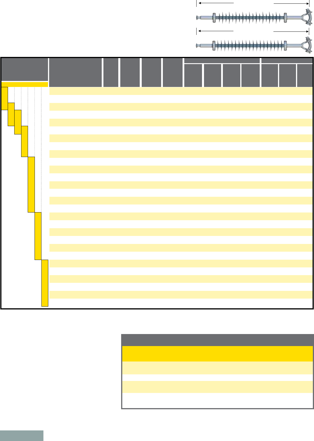
page 14
Suspension Insulators
Mechanical Ratings SML = 25 kip/120 kN RTL = 12.5 kip/60 kN
Rod Diameter: 5/8" (16 mm)
To determine the section length for an insulator with a different end fitting combination, please add
or subtract the displayed length change in the table above. For configurations not shown, use the
Catalog Number Key or contact your HPS representative.
Section Length Adjustment Table, Base End Fittings: Y-clevis-Ball (201)
Top Fitting
Y-Clevis
Eye
Eye
ANSI 52-5 Socket
IEC 16 mm Socket
ANSI 52-6 Clevis
ANSI 52-6 Clevis
Eye
ANSI 52-5 Ball
Eye
ANSI 52-5 Ball
IEC 16 mm Ball
Eye
ANSI 52-5 Ball
200
001
000
301
A07
400
401
1.62 (41)
0.02 (0)
1.64 (42)
-1.15 (-29)
-0.03 (-1)
0.82 (21)
-0.8 (-20)
Bottom Fitting Top and Bottom End Fitting Digits
(“e” & “f”) in Catalog Number
Length Change
inches (mm)
Notes:
n Dimensional and electrical values displayed in
main table are for an insulator with Y-clevis
and Ball end fittings.
n For voltages above 400 kV, other section
lengths, or end fitting combinations, please
contact your HPS representative.
n Electrical values are without corona ring.
For voltages equal to or greater than 220
kV, refer to page 12 for corona rings and
associated physical/electrical changes to the
above data. Dimensions are within allowable
tolerances as specified by IEC 61109 and
ANSI C29.12.
Selection Guide:
Typical Line Voltage, kV Catalog Numbers
ANSI / IEC
Section
Length
inches
(mm)
Nominal
Polymer
Length
inches
Strike
Distance
inches
(mm)
Leakage
Distance
inches
(mm)
ANSI Values IEC Values
60-Hz
Dry
Flashover
(kV)
60-Hz
Wet
Flashover
(kV)
Critical
Impulse
Positive
(kV)
Critical
Impulse
Negative
(kV)
60-Hz
1-minute
Wet
Withstand
(kV)
Impulse
Positive
Withstand
(kV)
Impulse
Negative
Withstand
(kV)
S025021S2010 / S120021S2010
S025021H2010 / S120021H2010
S025023S2010 / S120023S2010
S025023H2010 / S120023H2010
S025030S2010 / S120030S2010
S025030H2010 / S120030H2010
S025036S2010 / S120036S2010
S025036H2010 / S120036H2010
S025043S2010 / S120043S2010
S025043H2010 / S120043H2010
S025047S2010 / S120047S2010
S025047H2010 / S120047H2010
S025051S2010 / S120051S2010
S025051H2010 / S120051H2010
S025056S2010 / S120056S2010
S025056H2010 / S120056H2010
S025060S2010 / S120060S2010
S025060H2010 / S120060H2010
S025064S2010 / S120064S2010
S025064H2010 / S120064H2010
S025069S2010 / S120069S2010
S025069H2010 / S120069H2010
S025073S2010 / S120073S2010
S025073H2010 / S120073H2010
S025077S2010 / S120077S2010
S025077H2010 / S120077H2010
S025081S2010 / S120081S2010
S025081H2010 / S120081H2010
S025086S2010 / S120086S2010
S025086H2010 / S120086H2010
S025090S2010 / S120090S2010
S025090H2010 / S120090H2010
S025094S2010 / S120094S2010
S025094H2010 / S120094H2010
S025099S2010 / S120099S2010
S025099H2010 / S120099H2010
S025103S2010 / S120103S2010
S025103H2010 / S120103H2010
S025107S2010 / S120107S2010
S025107H2010 / S120107H2010
S025112S2010 / S120112S2010
S025112H2010 / S120112H2010
S025116S2010 / S120116S2010
S025116H2010 / S120116H2010
S025120S2010 / S120120S2010
S025120H2010 / S120120H2010
S025125S2010 / S120125S2010
S025125H2010 / S120125H2010
S025129S2010 / S120129S2010
S025129H2010 / S120129H2010
S025133S2010 / S120133S2010
S025133H2010 / S120133H2010
S025138S2010 / S120138S2010
S025138H2010 / S120138H2010
S025142S2010 / S120142S2010
S025142H2010 / S120142H2010
33.3 (846)
33.3 (846)
35.4 (899)
35.4 (899)
41.9 (1064)
41.9 (1064)
48.4 (1229)
48.4 (1229)
54.9 (1394)
54.9 (1394)
59.2 (1504)
59.2 (1504)
63.5 (1613)
63.5 (1613)
67.8 (1722)
67.8 (1722)
72.1 (1831)
72.1 (1831)
76.5 (1943)
76.5 (1943)
80.8 (2052)
80.8 (2052)
85.1 (2162)
85.1 (2162)
89.4 (2271)
89.4 (2271)
93.7 (2380)
93.7 (2380)
98.1 (2492)
98.1 (2492)
102.4 (2601)
102.4 (2601)
106.7 (2710)
106.7 (2710)
111 (2819)
111 (2819)
115.3 (2929)
115.3 (2929)
119.7 (3040)
119.7 (3040)
124 (3150)
124 (3150)
128.3 (3259)
128.3 (3259)
132.6 (3368)
132.6 (3368)
136.9 (3477)
136.9 (3477)
141.3 (3589)
141.3 (3589)
145.6 (3698)
145.6 (3698)
149.9 (3807)
149.9 (3807)
154.2 (3917)
154.2 (3917)
021
021
023
023
030
030
036
036
043
043
047
047
051
051
056
056
060
060
064
064
069
069
073
073
077
077
081
081
086
086
090
090
094
094
099
099
103
103
107
107
112
112
116
116
120
120
125
125
129
129
133
133
138
138
142
142
21.5 (546)
22 (559)
23.7 (602)
24.1 (612)
30.2 (767)
30.6 (777)
36.6 (930)
37.1 (942)
43.1 (1095)
43.6 (1107)
47.4 (1204)
47.9 (1217)
51.8 (1316)
52.2 (1326)
56.1 (1425)
56.5 (1435)
60.4 (1534)
60.9 (1547)
64.7 (1643)
65.2 (1656)
69 (1753)
69.5 (1765)
73.4 (1864)
73.8 (1875)
77.7 (1974)
78.1 (1984)
82 (2083)
82.5 (2096)
86.3 (2192)
86.8 (2205)
90.6 (2301)
91.1 (2314)
95 (2413)
95.4 (2423)
99.3 (2522)
99.7 (2532)
103.6 (2631)
104.1 (2644)
107.9 (2741)
108.4 (2753)
112.2 (2850)
112.7 (2863)
116.6 (2962)
117 (2972)
120.9 (3071)
121.3 (3081)
125.2 (3180)
125.7 (3193)
129.5 (3289)
130 (3302)
133.8 (3399)
134.3 (3411)
138.2 (3510)
138.6 (3520)
142.5 (3620)
142.9 (3630)
55 (1397)
64 (1626)
60 (1524)
71 (1803)
77 (1956)
90 (2286)
93 (2362)
110 (2794)
110 (2794)
129 (3277)
121 (3073)
142 (3607)
132 (3353)
155 (3937)
143 (3632)
168 (4267)
154 (3912)
181 (4597)
165 (4191)
194 (4928)
176 (4470)
207 (5258)
187 (4750)
220 (5588)
198 (5029)
233 (5918)
209 (5309)
246 (6248)
220 (5588)
259 (6579)
231 (5867)
272 (6909)
242 (6147)
285 (7239)
253 (6426)
298 (7569)
264 (6706)
310 (7874)
275 (6985)
323 (8204)
286 (7264)
336 (8534)
297 (7544)
349 (8865)
308 (7823)
362 (9195)
319 (8103)
375 (9525)
330 (8382)
388 (9855)
341 (8661)
401 (10185)
352 (8941)
414 (10516)
363 (9220)
427 (10846)
220
220
250
250
315
320
385
390
460
465
500
510
540
540
585
585
625
625
660
665
695
700
735
740
780
780
815
820
860
860
890
895
925
930
960
965
990
995
1010
1015
1040
1045
1070
1075
1100
1105
1125
1130
1155
1160
1180
1185
1205
1210
1230
1235
210
210
235
235
305
305
365
370
435
440
475
475
510
510
545
550
580
585
615
615
650
650
685
690
720
720
745
750
780
795
815
820
850
855
875
880
890
895
920
920
945
950
975
980
1000
1005
1030
1035
1055
1060
1080
1085
1105
1110
1130
1135
370
370
415
415
525
535
635
645
730
740
800
805
865
875
935
940
1000
1010
1065
1070
1130
1135
1200
1205
1260
1270
1325
1330
1400
1410
1460
1470
1520
1540
1575
1585
1640
1645
1690
1695
1750
1755
1815
1820
1875
1880
1935
1940
1990
1995
2050
2055
2110
2115
2165
2170
350
350
395
395
510
515
620
620
725
730
795
800
865
870
935
940
1005
1010
1075
1075
1140
1145
1210
1215
1275
1280
1345
1345
1420
1420
1485
1495
1545
1560
1600
1610
1670
1670
1725
1730
1790
1795
1850
1855
1915
1920
1975
1980
2040
2045
2100
2105
2160
2165
2220
2225
145
150
165
165
210
210
255
260
300
305
330
330
360
360
385
390
410
415
435
440
465
465
490
495
515
515
540
540
560
565
585
585
610
615
630
635
655
660
675
675
695
700
720
720
735
740
760
760
780
780
795
800
815
820
835
835
315
325
350
355
445
450
540
540
630
635
690
695
750
760
810
815
870
880
930
940
990
995
1050
1055
1105
1115
1165
1170
1220
1225
1275
1285
1335
1340
1395
1395
1445
1450
1500
1510
1555
1565
1615
1620
1665
1670
1720
1725
1770
1780
1825
1830
1880
1885
1930
1935
300
305
330
335
430
435
525
535
625
630
685
690
750
755
810
815
875
880
940
945
995
1005
1060
1065
1120
1125
1180
1185
1240
1245
1300
1305
1355
1365
1415
1425
1475
1485
1530
1535
1590
1595
1645
1655
1705
1710
1755
1765
1815
1820
1870
1875
1925
1930
1980
1980
69 110 132 161 220 330 400
Section Length
Section Length
High Leak Design
Standard Design
January 2011

page 15
Suspension Insulators
Mechanical Ratings SML = 30 kip RTL = 15 kip
Rod Diameter: 5/8" (16 mm)
Section Length Adjustment Table, Base End Fittings: Y-clevis-Ball (201)
Y-Clevis
Eye
Eye
ANSI 52-5 Socket
IEC 16 mm Socket
ANSI 52-6 Clevis
ANSI 52-6 Clevis
Eye
ANSI 52-5 Ball
Eye
ANSI 52-5 Ball
IEC 16 mm Ball
Eye
ANSI 52-5 Ball
200
001
000
301
A07
400
401
1.62 (41)
0.02 (0)
1.64 (42)
-1.15 (-29)
-0.03 (-1)
0.82 (21)
-0.8 (-20)
Top and Bottom End Fitting Digits
(“e” & “f”) in Catalog Number
Length Change
inches (mm)
To determine the section length for an insulator with a different end fitting combination, please add
or subtract the displayed length change in the table above. For configurations not shown, use the
Catalog Number Key or contact your HPS representative.
Selection Guide:
Typical Line Voltage, kV
Catalog
Numbers
ANSI
Section
Length
inches
(mm)
Strike
Distance
inches
(mm)
Leakage
Distance
inches
(mm)
ANSI Values IEC Values
60-Hz
Dry
Flashover
(kV)
60-Hz
Wet
Flashover
(kV)
Critical
Impulse
Positive
(kV)
Critical
Impulse
Negative
(kV)
60-Hz
1-minute
Wet
Withstand
(kV)
Impulse
Positive
Withstand
(kV)
Impulse
Negative
Withstand
(kV)
S030021S2010
S030021H2010
S030023S2010
S030023H2010
S030030S2010
S030030H2010
S030036S2010
S030036H2010
S030043S2010
S030043H2010
S030047S2010
S030047H2010
S030051S2010
S030051H2010
S030056S2010
S030056H2010
S030060S2010
S030060H2010
S030064S2010
S030064H2010
S030069S2010
S030069H2010
S030073S2010
S030073H2010
S030077S2010
S030077H2010
S030081S2010
S030081H2010
S030086S2010
S030086H2010
S030090S2010
S030090H2010
S030094S2010
S030094H2010
S030099S2010
S030099H2010
S030103S2010
S030103H2010
S030107S2010
S030107H2010
S030112S2010
S030112H2010
S030116S2010
S030116H2010
S030120S2010
S030120H2010
S030125S2010
S030125H2010
S030129S2010
S030129H2010
S030133S2010
S030133H2010
S030138S2010
S030138H2010
S030142S2010
S030142H2010
33.3 (846)
33.3 (846)
35.4 (899)
35.4 (899)
41.9 (1064)
41.9 (1064)
48.4 (1229)
48.4 (1229)
54.9 (1394)
54.9 (1394)
59.2 (1504)
59.2 (1504)
63.5 (1613)
63.5 (1613)
67.8 (1722)
67.8 (1722)
72.1 (1831)
72.1 (1831)
76.5 (1943)
76.5 (1943)
80.8 (2052)
80.8 (2052)
85.1 (2162)
85.1 (2162)
89.4 (2271)
89.4 (2271)
93.7 (2380)
93.7 (2380)
98.1 (2492)
98.1 (2492)
102.4 (2601)
102.4 (2601)
106.7 (2710)
106.7 (2710)
111 (2819)
111 (2819)
115.3 (2929)
115.3 (2929)
119.7 (3040)
119.7 (3040)
124 (3150)
124 (3150)
128.3 (3259)
128.3 (3259)
132.6 (3368)
132.6 (3368)
136.9 (3477)
136.9 (3477)
141.3 (3589)
141.3 (3589)
145.6 (3698)
145.6 (3698)
149.9 (3807)
149.9 (3807)
154.2 (3917)
154.2 (3917)
21.5 (546)
22 (559)
23.7 (602)
24.1 (612)
30.2 (767)
30.6 (777)
36.6 (930)
37.1 (942)
43.1 (1095)
43.6 (1107)
47.4 (1204)
47.9 (1217)
51.8 (1316)
52.2 (1326)
56.1 (1425)
56.5 (1435)
60.4 (1534)
60.9 (1547)
64.7 (1643)
65.2 (1656)
69 (1753)
69.5 (1765)
73.4 (1864)
73.8 (1875)
77.7 (1974)
78.1 (1984)
82 (2083)
82.5 (2096)
86.3 (2192)
86.8 (2205)
90.6 (2301)
91.1 (2314)
95 (2413)
95.4 (2423)
99.3 (2522)
99.7 (2532)
103.6 (2631)
104.1 (2644)
107.9 (2741)
108.4 (2753)
112.2 (2850)
112.7 (2863)
116.6 (2962)
117 (2972)
120.9 (3071)
121.3 (3081)
125.2 (3180)
125.7 (3193)
129.5 (3289)
130 (3302)
133.8 (3399)
134.3 (3411)
138.2 (3510)
138.6 (3520)
142.5 (3620)
142.9 (3630)
55 (1397)
64 (1626)
60 (1524)
71 (1803)
77 (1956)
90 (2286)
93 (2362)
110 (2794)
110 (2794)
129 (3277)
121 (3073)
142 (3607)
132 (3353)
155 (3937)
143 (3632)
168 (4267)
154 (3912)
181 (4597)
165 (4191)
194 (4928)
176 (4470)
207 (5258)
187 (4750)
220 (5588)
198 (5029)
233 (5918)
209 (5309)
246 (6248)
220 (5588)
259 (6579)
231 (5867)
272 (6909)
242 (6147)
285 (7239)
253 (6426)
298 (7569)
264 (6706)
310 (7874)
275 (6985)
323 (8204)
286 (7264)
336 (8534)
297 (7544)
349 (8865)
308 (7823)
362 (9195)
319 (8103)
375 (9525)
330 (8382)
388 (9855)
341 (8661)
401 (10185)
352 (8941)
414 (10516)
363 (9220)
427 (10846)
220
220
250
250
315
320
385
390
460
465
500
510
540
540
585
585
625
625
660
665
695
700
735
740
780
780
815
820
860
860
890
895
925
930
960
965
990
995
1010
1015
1040
1045
1070
1075
1100
1105
1125
1130
1155
1160
1180
1185
1205
1210
1230
1235
210
210
235
235
305
305
365
370
435
440
475
475
510
510
545
550
580
585
615
615
650
650
685
690
720
720
745
750
780
795
815
820
850
855
875
880
890
895
920
920
945
950
975
980
1000
1005
1030
1035
1055
1060
1080
1085
1105
1110
1130
1135
370
370
415
415
525
535
635
645
730
740
800
805
865
875
935
940
1000
1010
1065
1070
1130
1135
1200
1205
1260
1270
1325
1330
1400
1410
1460
1470
1520
1540
1575
1585
1640
1645
1690
1695
1750
1755
1815
1820
1875
1880
1935
1940
1990
1995
2050
2055
2110
2115
2165
2170
350
350
395
395
510
515
620
620
725
730
795
800
865
870
935
940
1005
1010
1075
1075
1140
1145
1210
1215
1275
1280
1345
1345
1420
1420
1485
1495
1545
1560
1600
1610
1670
1670
1725
1730
1790
1795
1850
1855
1915
1920
1975
1980
2040
2045
2100
2105
2160
2165
2220
2225
145
150
165
165
210
210
255
260
300
305
330
330
360
360
385
390
410
415
435
440
465
465
490
495
515
515
540
540
560
565
585
585
610
615
630
635
655
660
675
675
695
700
720
720
735
740
760
760
780
780
795
800
815
820
835
835
315
325
350
355
445
450
540
540
630
635
690
695
750
760
810
815
870
880
930
940
990
995
1050
1055
1105
1115
1165
1170
1220
1225
1275
1285
1335
1340
1395
1395
1445
1450
1500
1510
1555
1565
1615
1620
1665
1670
1720
1725
1770
1780
1825
1830
1880
1885
1930
1935
300
305
330
335
430
435
525
535
625
630
685
690
750
755
810
815
875
880
940
945
995
1005
1060
1065
1120
1125
1180
1185
1240
1245
1300
1305
1355
1365
1415
1425
1475
1485
1530
1535
1590
1595
1645
1655
1705
1710
1755
1765
1815
1820
1870
1875
1925
1930
1980
1980
69 110 132 161 220 330 400
Nominal
Polymer
Length
inches
021
021
023
023
030
030
036
036
043
043
047
047
051
051
056
056
060
060
064
064
069
069
073
073
077
077
081
081
086
086
090
090
094
094
099
099
103
103
107
107
112
112
116
116
120
120
125
125
129
129
133
133
138
138
142
142
Section Length
Section Length
High Leak Design
Standard Design
Notes:
n Dimensional and electrical values displayed in
main table are for an insulator with Y-clevis
and Ball end fittings.
n For voltages above 400 kV, other section
lengths, or end fitting combinations, please
contact your HPS representative.
n Electrical values are without corona ring.
For voltages equal to or greater than 220
kV, refer to page 12 for corona rings and
associated physical/electrical changes to the
above data. Dimensions are within allowable
tolerances as specified by IEC 61109 and
ANSI C29.12.
Top Fitting Bottom Fitting
January 2011
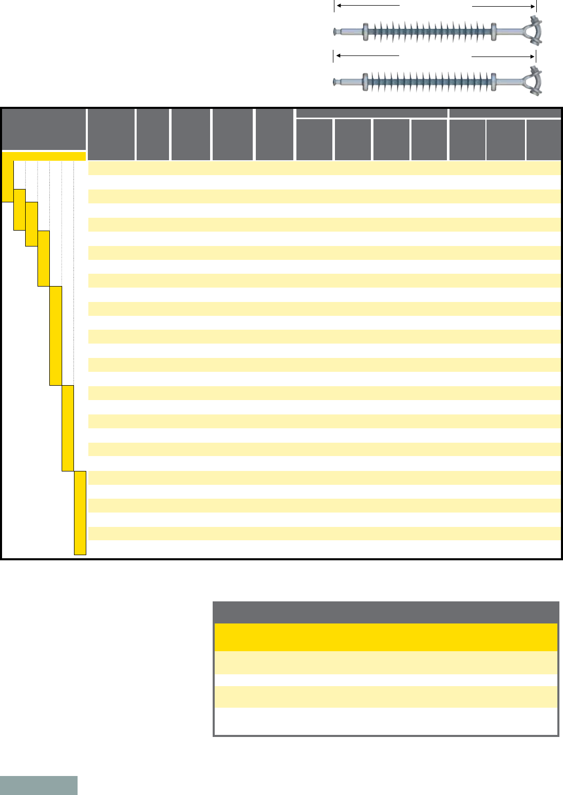
page 16
Selection Guide:
Typical Line Voltage, kV
Section
Length
inches
(mm)
Strike
Distance
inches
(mm)
Leakage
Distance
inches
(mm)
ANSI Values IEC Values
60-Hz
Dry
Flashover
(kV)
60-Hz
Wet
Flashover
(kV)
Critical
Impulse
Positive
(kV)
Critical
Impulse
Negative
(kV)
60-Hz
1-minute
Wet
Withstand
(kV)
Impulse
Positive
Withstand
(kV)
Impulse
Negative
Withstand
(kV)
S160021S2010
S160021H2010
S160023S2010
S160023H2010
S160030S2010
S160030H2010
S160036S2010
S160036H2010
S160043S2010
S160043H2010
S160047S2010
S160047H2010
S160051S2010
S160051H2010
S160056S2010
S160056H2010
S160060S2010
S160060H2010
S160064S2010
S160064H2010
S160069S2010
S160069H2010
S160073S2010
S160073H2010
S160077S2010
S160077H2010
S160081S2010
S160081H2010
S160086S2010
S160086H2010
S160090S2010
S160090H2010
S160094S2010
S160094H2010
S160099S2010
S160099H2010
S160103S2010
S160103H2010
S160107S2010
S160107H2010
S160112S2010
S160112H2010
S160116S2010
S160116H2010
S160120S2010
S160120H2010
S160125S2010
S160125H2010
S160129S2010
S160129H2010
S160133S2010
S160133H2010
S160138S2010
S160138H2010
S160142S2010
S160142H2010
35.7 (907)
35.7 (907)
37.9 (963)
37.9 (963)
44.4 (1128)
44.4 (1128)
50.8 (1290)
50.8 (1290)
57.3 (1455)
57.3 (1455)
61.6 (1565)
61.6 (1565)
66 (1676)
66 (1676)
70.3 (1786)
70.3 (1786)
74.6 (1895)
74.6 (1895)
78.9 (2004)
78.9 (2004)
83.2 (2113)
83.2 (2113)
87.6 (2225)
87.6 (2225)
91.9 (2334)
91.9 (2334)
96.2 (2443)
96.2 (2443)
100.5 (2553)
100.5 (2553)
104.8 (2662)
104.8 (2662)
109.2 (2774)
109.2 (2774)
113.5 (2883)
113.5 (2883)
117.8 (2992)
117.8 (2992)
122.1 (3101)
122.1 (3101)
126.4 (3211)
126.4 (3211)
130.8 (3322)
130.8 (3322)
135.1 (3432)
135.1 (3432)
139.4 (3541)
139.4 (3541)
143.7 (3650)
143.7 (3650)
148 (3759)
148 (3759)
152.4 (3871)
152.4 (3871)
156.7 (3980)
156.7 (3980)
21.6 (549)
22.5 (572)
23.8 (605)
24.7 (627)
30.3 (770)
31.1 (790)
36.8 (935)
37.6 (955)
43.2 (1097)
44.1 (1120)
47.6 (1209)
48.4 (1229)
51.9 (1318)
52.7 (1339)
56.2 (1427)
57.1 (1450)
60.5 (1537)
61.4 (1560)
64.8 (1646)
65.7 (1669)
69.2 (1758)
70 (1778)
73.5 (1867)
74.3 (1887)
77.8 (1976)
78.7 (1999)
82.1 (2085)
83 (2108)
86.4 (2195)
87.3 (2217)
90.8 (2306)
91.6 (2327)
95.1 (2416)
95.9 (2436)
99.4 (2525)
100.3 (2548)
103.7 (2634)
104.6 (2657)
108 (2743)
108.9 (2766)
112.4 (2855)
113.2 (2875)
116.7 (2964)
117.5 (2985)
121 (3073)
121.9 (3096)
125.3 (3183)
126.2 (3205)
129.6 (3292)
130.5 (3315)
134 (3404)
134.8 (3424)
138.3 (3513)
139.1 (3533)
142.6 (3622)
143.5 (3645)
55 (1397)
74 (1880)
60 (1524)
82 (2083)
77 (1956)
104 (2642)
93 (2362)
126 (3200)
110 (2794)
149 (3785)
121 (3073)
164 (4166)
132 (3353)
179 (4547)
143 (3632)
194 (4928)
154 (3912)
209 (5309)
165 (4191)
224 (5690)
176 (4470)
239 (6071)
187 (4750)
254 (6452)
198 (5029)
268 (6807)
209 (5309)
283 (7188)
220 (5588)
298 (7569)
231 (5867)
313 (7950)
242 (6147)
328 (8331)
253 (6426)
343 (8712)
264 (6706)
358 (9093)
275 (6985)
373 (9474)
286 (7264)
388 (9855)
297 (7544)
403 (10236)
308 (7823)
418 (10617)
319 (8103)
433 (10998)
330 (8382)
448 (11379)
341 (8661)
463 (11760)
352 (8941)
478 (12141)
363 (9220)
493 (12522)
220
225
250
255
320
320
385
395
460
470
500
515
540
545
585
590
625
630
660
670
695
705
735
745
780
785
815
825
860
865
890
900
925
935
960
970
990
1000
1010
1020
1045
1050
1070
1080
1100
1110
1125
1135
1155
1165
1180
1190
1205
1215
1230
1240
210
215
235
240
305
310
365
375
435
445
475
480
510
515
545
555
580
590
615
620
650
655
685
695
720
725
745
755
780
800
815
825
850
860
875
885
890
900
920
925
950
955
975
985
1005
1010
1030
1040
1055
1065
1080
1090
1105
1115
1130
1140
370
375
415
420
525
540
635
650
730
745
800
810
865
880
935
945
1000
1015
1065
1075
1130
1140
1200
1210
1260
1275
1325
1335
1400
1415
1460
1475
1520
1545
1575
1590
1640
1650
1695
1700
1755
1760
1815
1825
1875
1885
1935
1945
1995
2000
2055
2060
2110
2120
2170
2175
350
355
395
400
510
520
625
625
725
735
800
805
860
875
935
945
1005
1015
1075
1080
1140
1150
1210
1220
1275
1285
1345
1350
1420
1425
1485
1500
1545
1565
1605
1615
1670
1675
1725
1735
1790
1800
1855
1860
1915
1925
1980
1985
2040
2050
2100
2110
2160
2170
2220
2230
145
150
165
170
210
215
260
265
300
310
330
335
360
365
385
390
410
420
435
445
465
470
490
495
515
520
540
545
565
570
585
590
610
615
630
635
655
660
675
680
700
705
720
720
740
745
760
765
780
780
795
800
815
820
835
840
315
330
350
360
445
455
540
550
630
640
690
705
755
765
810
825
870
885
930
945
990
1000
1050
1060
1110
1120
1165
1175
1220
1235
1280
1290
1340
1350
1395
1405
1445
1460
1505
1515
1560
1570
1615
1620
1665
1680
1720
1730
1775
1785
1830
1840
1880
1890
1935
1940
300
315
330
345
430
445
530
540
625
635
690
700
750
765
810
825
875
890
940
950
1000
1010
1060
1075
1125
1130
1180
1195
1240
1255
1305
1310
1360
1370
1420
1430
1475
1485
1530
1545
1590
1600
1650
1660
1705
1715
1760
1770
1815
1825
1870
1885
1925
1935
1980
1990
Suspension Insulators
Mechanical Ratings SML = 160 kN RTL = 80 kN
Rod Diameter: 7/8" (22 mm)
Section Length Adjustment Table, Base End Fittings: Y-clevis-Ball (201)
Y-Clevis
Eye
Eye
ANSI 52-8 Socket
IEC 20 mm Socket
Clevis IEC 19-L
Clevis IEC 19-L
Eye
ANSI 52-8 Ball
Eye
ANSI 52-8 Ball
IEC 20 mm Ball
Eye
IEC 20 mm Ball
200
001
000
301
A07
800
807
1.71 (43)
0.31 (8)
2.02 (51)
-1.27 (-32)
0.26 (7)
0.80 (20)
0.06 (2)
Top and Bottom End Fitting Digits
(“e” & “f”) in Catalog Number
Length Change
inches (mm)
69 110 132 161 220 330 400
To determine the section length for an insulator with a different end fitting combination, please add
or subtract the displayed length change in the table above. For configurations not shown, use the
Catalog Number Key or contact your HPS representative.
Catalog
Numbers
IEC
Section Length
Section Length
High Leak Design
Standard Design
Nominal
Polymer
Length
inches
021
021
023
023
030
030
036
036
043
043
047
047
051
051
056
056
060
060
064
064
069
069
073
073
077
077
081
081
086
086
090
090
094
094
099
099
103
103
107
107
112
112
116
116
120
120
125
125
129
129
133
133
138
138
142
142
Notes:
n Dimensional and electrical values displayed in
main table are for an insulator with Y-clevis
and Ball end fittings.
n For voltages above 400 kV, other section
lengths, or end fitting combinations, please
contact your HPS representative.
n Electrical values are without corona ring.
For voltages equal to or greater than 220
kV, refer to page 12 for corona rings and
associated physical/electrical changes to the
above data. Dimensions are within allowable
tolerances as specified by IEC 61109 and
ANSI C29.12.
Top Fitting Bottom Fitting
January 2011

page 17
Suspension Insulators
Mechanical Ratings SML = 50 kip/210 kN RTL = 25 kip/105 kN
Rod Diameter: 7/8" (22 mm)
Section Length Adjustment Table, Base End Fittings: Y-clevis-Ball (201)
Y-Clevis
Eye
Eye
ANSI 52-11 Socket
IEC 20 mm Socket
Clevis IEC 19-L
Clevis IEC 19-L
Eye
ANSI 52-11 Ball
Eye
ANSI 52-11 Ball
IEC 20 mm Ball
Eye
IEC 20 mm Ball
200
001
000
301
A07
800
807
1.71 (43)
0.31 (8)
2.02 (51)
-0.71 (-18)
0.26 (7)
0.80 (20)
0.06 (2)
Top and Bottom End Fitting Digits
(“e” & “f”) in Catalog Number
Length Change
inches (mm)
To determine the section length for an insulator with a different end fitting combination, please add
or subtract the displayed length change in the table above. For configurations not shown, use the
Catalog Number Key or contact your HPS representative.
Section Length
Section Length
High Leak Design
Standard Design
Selection Guide:
Typical Line Voltage, kV
Section
Length
inches
(mm)
Strike
Distance
inches
(mm)
Leakage
Distance
inches
(mm)
ANSI Values IEC Values
60-Hz
Dry
Flashover
(kV)
60-Hz
Wet
Flashover
(kV)
Critical
Impulse
Positive
(kV)
Critical
Impulse
Negative
(kV)
60-Hz
1-minute
Wet
Withstand
(kV)
Impulse
Positive
Withstand
(kV)
Impulse
Negative
Withstand
(kV)
S050021S2010 / S210021S2010
S050021H2010 / S210021H2010
S050023S2010 / S210023S2010
S050023H2010 / S210023H2010
S050030S2010 / S210030S2010
S050030H2010 / S210030H2010
S050036S2010 / S210036S2010
S050036H2010 / S210036H2010
S050043S2010 / S210043S2010
S050043H2010 / S210043H2010
S050047S2010 / S210047S2010
S050047H2010 / S210047H2010
S050051S2010 / S210051S2010
S050051H2010 / S210051H2010
S050056S2010 / S210056S2010
S050056H2010 / S210056H2010
S050060S2010 / S210060S2010
S050060H2010 / S210060H2010
S050064S2010 / S210064S2010
S050064H2010 / S210064H2010
S050069S2010 / S210069S2010
S050069H2010 / S210069H2010
S050073S2010 / S210073S2010
S050073H2010 / S210073H2010
S050077S2010 / S210077S2010
S050077H2010 / S210077H2010
S050081S2010 / S210081S2010
S050081H2010 / S210081H2010
S050086S2010 / S210086S2010
S050086H2010 / S210086H2010
S050090S2010 / S210090S2010
S050090H2010 / S210090H2010
S050094S2010 / S210094S2010
S050094H2010 / S210094H2010
S050099S2010 / S210099S2010
S050099H2010 / S210099H2010
S050103S2010 / S210103S2010
S050103H2010 / S210103H2010
S050107S2010 / S210107S2010
S050107H2010 / S210107H2010
S050112S2010 / S210112S2010
S050112H2010 / S210112H2010
S050116S2010 / S210116S2010
S050116H2010 / S210116H2010
S050120S2010 / S210120S2010
S050120H2010 / S210120H2010
S050125S2010 / S210125S2010
S050125H2010 / S210125H2010
S050129S2010 / S210129S2010
S050129H2010 / S210129H2010
S050133S2010 / S210133S2010
S050133H2010 / S210133H2010
S050138S2010 / S210138S2010
S050138H2010 / S210138H2010
S050142S2010 / S210142S2010
S050142H2010 / S210142H2010
35.7 (907)
35.7 (907)
37.9 (963)
37.9 (963)
44.4 (1128)
44.4 (1128)
50.8 (1290)
50.8 (1290)
57.3 (1455)
57.3 (1455)
61.6 (1565)
61.6 (1565)
66 (1676)
66 (1676)
70.3 (1786)
70.3 (1786)
74.6 (1895)
74.6 (1895)
78.9 (2004)
78.9 (2004)
83.2 (2113)
83.2 (2113)
87.6 (2225)
87.6 (2225)
91.9 (2334)
91.9 (2334)
96.2 (2443)
96.2 (2443)
100.5 (2553)
100.5 (2553)
104.8 (2662)
104.8 (2662)
109.2 (2774)
109.2 (2774)
113.5 (2883)
113.5 (2883)
117.8 (2992)
117.8 (2992)
122.1 (3101)
122.1 (3101)
126.4 (3211)
126.4 (3211)
130.8 (3322)
130.8 (3322)
135.1 (3432)
135.1 (3432)
139.4 (3541)
139.4 (3541)
143.7 (3650)
143.7 (3650)
148 (3759)
148 (3759)
152.4 (3871)
152.4 (3871)
156.7 (3980)
156.7 (3980)
21.6 (549)
22.5 (572)
23.8 (605)
24.7 (627)
30.3 (770)
31.1 (790)
36.8 (935)
37.6 (955)
43.2 (1097)
44.1 (1120)
47.6 (1209)
48.4 (1229)
51.9 (1318)
52.7 (1339)
56.2 (1427)
57.1 (1450)
60.5 (1537)
61.4 (1560)
64.8 (1646)
65.7 (1669)
69.2 (1758)
70 (1778)
73.5 (1867)
74.3 (1887)
77.8 (1976)
78.7 (1999)
82.1 (2085)
83 (2108)
86.4 (2195)
87.3 (2217)
90.8 (2306)
91.6 (2327)
95.1 (2416)
95.9 (2436)
99.4 (2525)
100.3 (2548)
103.7 (2634)
104.6 (2657)
108 (2743)
108.9 (2766)
112.4 (2855)
113.2 (2875)
116.7 (2964)
117.5 (2985)
121 (3073)
121.9 (3096)
125.3 (3183)
126.2 (3205)
129.6 (3292)
130.5 (3315)
134 (3404)
134.8 (3424)
138.3 (3513)
139.1 (3533)
142.6 (3622)
143.5 (3645)
55 (1397)
74 (1880)
60 (1524)
82 (2083)
77 (1956)
104 (2642)
93 (2362)
126 (3200)
110 (2794)
149 (3785)
121 (3073)
164 (4166)
132 (3353)
179 (4547)
143 (3632)
194 (4928)
154 (3912)
209 (5309)
165 (4191)
224 (5690)
176 (4470)
239 (6071)
187 (4750)
254 (6452)
198 (5029)
268 (6807)
209 (5309)
283 (7188)
220 (5588)
298 (7569)
231 (5867)
313 (7950)
242 (6147)
328 (8331)
253 (6426)
343 (8712)
264 (6706)
358 (9093)
275 (6985)
373 (9474)
286 (7264)
388 (9855)
297 (7544)
403 (10236)
308 (7823)
418 (10617)
319 (8103)
433 (10998)
330 (8382)
448 (11379)
341 (8661)
463 (11760)
352 (8941)
478 (12141)
363 (9220)
493 (12522)
220
225
250
255
315
320
385
395
460
470
500
510
540
545
585
590
625
630
660
670
695
705
735
745
780
785
815
825
860
865
890
900
925
935
960
970
990
1000
1010
1020
1045
1050
1070
1080
1100
1110
1125
1135
1155
1165
1180
1190
1205
1215
1230
1240
210
215
235
240
305
310
365
375
435
445
475
480
510
515
545
555
580
590
615
620
650
655
685
695
720
725
745
755
780
800
815
825
850
860
875
885
890
900
920
925
950
955
975
985
1005
1010
1030
1040
1055
1065
1080
1090
1105
1115
1130
1140
370
375
415
420
525
540
635
650
730
745
800
810
865
880
935
945
1000
1015
1065
1075
1130
1140
1200
1210
1260
1275
1325
1335
1400
1415
1460
1475
1520
1545
1575
1590
1640
1650
1695
1700
1755
1760
1815
1825
1875
1885
1935
1945
1995
2000
2055
2060
2110
2120
2170
2175
350
355
395
400
510
520
625
625
725
735
800
805
860
875
935
945
1005
1015
1075
1080
1140
1150
1210
1220
1275
1285
1345
1350
1420
1425
1485
1500
1545
1565
1605
1615
1670
1675
1725
1735
1790
1800
1855
1860
1915
1925
1980
1985
2040
2050
2100
2110
2160
2170
2220
2230
145
150
165
170
210
215
260
265
300
310
330
335
360
365
385
390
410
420
435
445
465
470
490
495
515
520
540
545
565
570
585
590
610
615
630
635
655
660
675
680
700
705
720
720
740
745
760
765
780
780
795
800
815
820
835
840
315
330
350
360
445
455
540
550
630
640
690
705
755
765
810
825
870
885
930
945
990
1000
1050
1060
1110
1120
1165
1175
1220
1235
1280
1290
1340
1350
1395
1405
1445
1460
1505
1515
1560
1570
1615
1620
1665
1680
1720
1730
1775
1785
1830
1840
1880
1890
1935
1940
300
315
330
345
430
445
530
540
625
635
690
700
750
765
810
825
875
890
940
950
1000
1010
1060
1075
1125
1130
1180
1195
1240
1255
1305
1310
1360
1370
1420
1430
1475
1485
1530
1545
1590
1600
1650
1660
1705
1715
1760
1770
1815
1825
1870
1885
1925
1935
1980
1990
69 110 132 161 220 330 400
Catalog Numbers
ANSI / IEC
Nominal
Polymer
Length
inches
021
021
023
023
030
030
036
036
043
043
047
047
051
051
056
056
060
060
064
064
069
069
073
073
077
077
081
081
086
086
090
090
094
094
099
099
103
103
107
107
112
112
116
116
120
120
125
125
129
129
133
133
138
138
142
142
Notes:
n Dimensional and electrical values displayed in
main table are for an insulator with Y-clevis
and Ball end fittings.
n For voltages above 400 kV, other section
lengths, or end fitting combinations, please
contact your HPS representative.
n Electrical values are without corona ring.
For voltages equal to or greater than 220
kV, refer to page 12 for corona rings and
associated physical/electrical changes to the
above data. Dimensions are within allowable
tolerances as specified by IEC 61109 and
ANSI C29.12.
Top Fitting Bottom Fitting
January 2011

page 18 January 2011

page 19
Line Post Insulators
TABLE OF CONTENTS PAGE
Mechanical Ratings and Corona Performance ................................................... 20
Quadri*Sil® Horizontal Line Posts ..................................................................... 21
Quadri*Sil® Vertical Line Posts ......................................................................... 22
Quadri*Sil® Base Fittings ................................................................................. 24
Quadri*Sil® Line Fittings .................................................................................. 25
Clamps and Assemblies .................................................................................. 26
January 2011
®
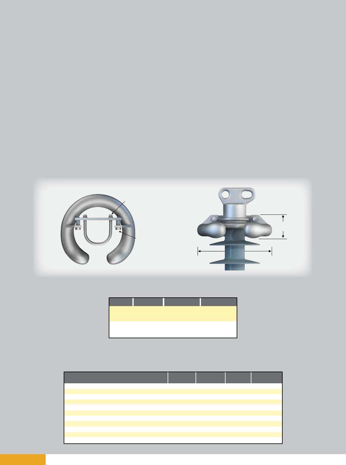
page 20
Line Post Insulators
2.5” (63.5 mm) Rod Diameter Horizontal
Mechanical Ratings
Line post insulators are cantilever support members, with ratings defined as follows:
Specified Cantilever Load (SCL)
SCL is the ultimate cantilever strength rating of the Quadri*Sil® line post insulator. SCL is identical to
the minimum average breaking load (ABL) rating in previous catalogs.
Reference Cantilever Load (RCL)
RCL represents the maximum recommended load in cantilever that a Quadri*Sil® post insulator is
designed to withstand during its life span. RCL equals 50 percent of the SCL, and is identical to the
insulator’s maximum working load (MWL) and maximum design cantilever load (MDCL).
Combined Load Charts
Line design loads for most insulators include tension, or compression, in addition to the primary
vertical cantilever load. Longitudinal loading should also be considered. Contact your Hubbell Power
Systems representative to request combined load charts.
Application 230 kv
161 kv & Below 345 kv
Line End
Energized
Bottom End
Energized
Top - 2721273001
Bott - NONE
Top - NONE
Bott - 2721273001
Top - 2721273001
Bott - NONE
Top - NONE
Bott - 2721273001
Top - NONE
Bott - NONE
Top - NONE
Bott - NONE
Recommended
Torque
10 ft.-lb.
Recommended
Torque
45 ft.-lb.
3.4375’’
(87 mm)
12’’
(305 mm)
Electrical/Dimensional Changes to the Insulator
with External Corona Ring
Physical & Electrical Characteristics
Dry Arc Distance inches (mm)
Leakage Distance inches (mm)
ANSI 60 Hz Flashover Dry — kV
ANSI 60 Hz Flashover Wet — kV
ANSI Critical Flashover Positive — kV
ANSI Critical Flashover Negative — kV
IEC Wet Switching Impulse Withstand — kV
IEC Power Frequency Wet Withstand — kV
IEC Lightning Impulse Withstand Positive — kV
IEC Lightning Impulse Withstand Negative — kV
Net Weight pounds (kg)
220/230 kV
Ring
-1.86 (-47)
0
-20
-20
-30
-30
N/A
-20
-30
-30
3.4 (1.5)
330/345 kV
Ring
-2.58 (-66)
0
-30
-20
-40
-40
N/A
-20
-40
-40
3.4 (1.5)
400 kV
Rings
N/A
N/A
N/A
N/A
N/A
N/A
N/A
N/A
N/A
N/A
N/A
500 kV
Rings
N/A
N/A
N/A
N/A
N/A
N/A
N/A
N/A
N/A
N/A
N/A
Corona Performance
January 2011

page 21
Horizontal Line Post Insulators
2.5” (63.5 mm) Rod Diameter
Horizontal Clamptop End Fitting
Increases the section length
dimensions by 0.75”
Clamptop:
Maximum Design Tension = 2,500 lbs. (11.1 kN)
Two-Hole Blade:
Maximum Design Tension = 7,500 lbs. (33.4 kN)
Notes:
1) For voltages above 330 kV, other section lengths, or end fitting combinations, please contact your HPS representative.
2) Electrical values are without corona ring. For voltages equal to or greater than 220 kV, refer to page 20 for corona rings and associated
physical/electrical changes to the above data. Dimensions are within allowable tolerances as specified by IEC 61952 and ANSI C29.17.
3) The catalog number shown in the table is for a 2.5’’ (63.5mm) rod diameter line post with a two hole blade on the line end and a gain
base on the tower end. For other end fitting combinations, please refer to the Catalog Number Key on page 8.
Section Length
January 2011
Selection Guide:
Typical Line Voltage,
kV(1)
Catalog
Numbers(3)
Section
Length
inches
(mm)
Strike
Distance
inches
(mm)
ANSI Values IEC Values
(2)60-Hz
Dry
Flashover
(kV)
(2)60-Hz
Wet
Flashover
(kV)
(2)Critical
Impulse
Positive
(kV)
(2)Critical
Impulse
Negative
(kV)
(2)60-Hz
1-minute
Wet
Withstand
(kV)
(2)Impulse
Positive
Withstand
(kV)
SCL lbs.
(kN)
P250024S0020
P250026S0020
P250031S0020
P250036S0020
P250043S0020
P250048S0020
P250053S0020
P250058S0020
P250060S0020
P250065S0020
P250070S0020
P250075S0020
P250080S0020
P250087S0020
P250092S0020
P250096S0020
P250101S0020
P250104S0020
P250106S0020
P250109S0020
P250111S0020
25.0 (635)
27.4 (696)
32.2 (818)
37.1 (942)
44.3 (1125)
49.2 (1250)
54.0 (1372)
58.8 (1494)
61.3 (1557)
66.1 (1679)
70.9 (1801)
75.8 (1925)
80.6 (2047)
87.9 (2233)
92.7 (2355)
97.6 (2479)
102.4 (2601)
104.8 (2662)
107.2 (2723)
109.7 (2786)
112.1 (2847)
255
280
330
380
455
515
565
600
625
675
720
765
815
880
925
975
1015
1040
1060
1085
1105
235
255
300
345
405
450
495
525
540
580
615
650
680
735
765
800
830
845
860
875
890
385
425
510
580
700
770
855
920
955
1035
1115
1190
1265
1380
1455
1535
1610
1650
1685
1725
1765
505
540
615
690
800
880
950
1025
1065
1140
1215
1290
1360
1475
1550
1625
1700
1735
1770
1810
1850
5000 (22.2)
5000 (22.2)
4490 (20.0)
3950 (17.6)
3340 (14.9)
3030 (13.5)
2770 (12.3)
2550 (11.3)
2460 (10.9)
2280 (10.1)
2130 (9.5)
2000 (8.9)
1890 (8.4)
1740 (7.7)
1650 (7.3)
1570 (7.0)
1500 (6.7)
1460 (6.5)
1430 (6.4)
1400 (6.2)
1370 (6.1)
69 110 132 161 220 330
Nominal
Polymer
Length
inches
024
026
031
036
043
048
053
058
060
065
070
075
080
087
092
096
101
104
106
109
111
Horizontal Line Post Insulators
2.5” (63.5 mm) Rod Diameter
(2)Impulse
Negative
Withstand
(kV)
Leakage
Distance
inches
(mm)
63 (1600)
69 (1753)
82 (2083)
95 (2413)
113 (2870)
126 (3200)
139 (3531)
151 (3835)
158 (4013)
170 (4318)
183 (4648)
196 (4978)
208 (5283)
227 (5766)
240 (6096)
252 (6401)
265 (6731)
271 (6883)
278 (7061)
284 (7214)
290 (7366)
36.9 (937)
39.3 (998)
44.0 (1117)
48.8 (1239)
55.9 (1419)
60.6 (1539)
65.3 (1658)
70.1 (1780)
72.4 (1838)
77.2 (1960)
81.9 (2080)
86.6 (2199)
91.4 (2321)
98.5 (2501)
103.2 (2621)
107.9 (2740)
112.7 (2862)
115.1 (2923)
117.4 (2981)
119.8 (3042)
122.2 (3103)
195
215
255
290
340
380
420
445
455
490
520
550
575
620
650
680
705
715
730
740
755
365
400
480
550
665
730
810
870
905
980
1055
1130
1200
1310
1380
1455
1525
1565
1600
1635
1675
475
510
580
655
760
835
900
970
1010
1080
1150
1225
1290
1400
1470
1540
1615
1645
1680
1715
1755

page 22
Vertical Line Post Insulators
2.5” (63.5 mm) Rod Diameter
Maximum Design Tension = 2,500 lbs. (11.1 kN)
0.6875’’ Dia. (17 mm ) 5” Dia. Bolt Circle
(127 mm)
11’’
(279 mm)
0.9375’’ Dia.
(24 mm)
0.8125’’ Dia.
(21 mm)
3.875’’
(98 mm)
0.8125’’ x 1” Slot
(21 mm x 25 mm)
8’’
(203 mm)
8’’
(203 mm)
4’’
(102 mm)
Section Length
Vertical Line Post Insulators
2.5” (63.5 mm) Rod Diameter
Notes:
1) For voltages above 161 kV, other section lengths, or end fitting combinations, please contact your HPS representative.
2) Electrical values are without corona ring. For voltages equal to or greater than 220 kV, refer to page 20 for corona rings and associated
physical/electrical changes to the above data. Dimensions are within allowable tolerances as specified by IEC 61952 and ANSI C29.17.
3) The catalog number shown on the table is for a 2.5” (63.5mm) rod diameter line post with a vertical clamptop on the line end and a 5’’ Bolt
Circle with tapped holes on the ground end. For other end fitting combinations, please refer to the Catalog Number Key on page 8.
1.125’’
(29 mm)
4.125’’
(105 mm)
Selection Guide:
Typical Line
Voltage, kV(1)
Catalog
Numbers(3)
Nominal
Polymer
Length
inches
Section
Length
inches
(mm)
Strike
Distance
inches
(mm)
ANSI Values IEC Values
(2)Critical
Impulse
Positive
(kV)
(2)Critical
Impulse
Negative
(kV)
(2)60-Hz
1-minute
Wet
Withstand
(kV)
(2)Impulse
Positive
Withstand
(kV)
(2)Impulse
Negative
Withstand
(kV)
SCL lbs.
(kN)
P250024S2050
P250026S2050
P250031S2050
P250036S2050
P250043S2050
P250048S2050
P250053S2050
P250058S2050
P250060S2050
35.0 (889)
37.4 (950)
42.3 (1074)
47.1 (1196)
54.4 (1382)
59.2 (1504)
64.1 (1628)
68.9 (1750)
71.3 (1811)
25.0 (635)
27.4 (696)
32.2 (818)
37.1 (942)
44.3 (1125)
49.2 (1250)
54.0 (1372)
58.8 (1494)
61.3 (1557)
63 (1600)
69 (1753)
82 (2083)
95 (2413)
113 (2870)
126 (3200)
139 (3531)
151 (3835)
158 (4013)
385
425
510
580
700
770
855
920
955
505
540
615
690
800
880
950
1025
1065
195
215
255
290
340
380
420
445
455
365
400
480
550
665
730
810
870
905
475
510
580
655
760
835
900
970
1010
5000 (22.3)
5000 (22.3)
4200 (18.7)
3720 (16.6)
3180 (14.2)
2900 (12.9)
2660 (11.8)
2460 (10.9)
2370 (10.5)
69 110 132 161
Leakage
Distance
inches
(mm)
024
026
031
036
043
048
053
058
060
4.125’’
(105 mm)
3.875’’
(98 mm)
0.8125’’ Dia.
(21 mm)
Cat. No. 75115
Rated 134,400 lb.-in.
January 2011
(2)60-Hz
Wet
Flashover
(kV)
235
255
300
345
405
450
495
525
540
(2)60-Hz
Dry
Flashover
(kV)
255
280
330
380
455
515
565
600
625
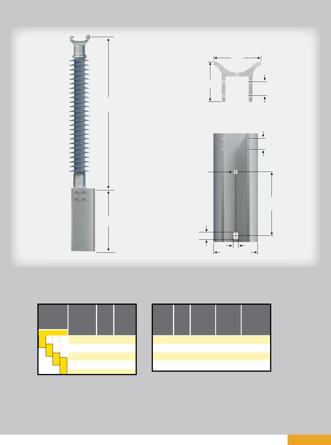
page 23
Vertical Line Post Assembly
2.5” (63.5 mm) Rod Diameter
A
B
7.44’’
(189 mm)
2.0’’
(51 mm)
5.75’’
(146 mm)
C
7.438’’
(189 mm)
D
1.625’’ (41 mm)
D
Selection Guide:
Typical Line
Voltage, kV(1) “XX”
Code(2)
Catalog
Numbers(2) Style
Table A Table B
“A”
Length
inches
(mm)
“B”
Length
inches
(mm)
“C”
Length
inches
(mm)
“D”
Diameter
inches
(mm)
P250024S2XX0
P250026S2XX0
P250031S2XX0
P250036S2XX0
P250043S2XX0
P250048S2XX0
P250053S2XX0
P250058S2XX0
P250060S2XX0
Face
Side
Face
Side
Face
Side
Face
Side
20
21
22
23
24
25
26
27
34.7 (881)
37.1 (942)
42 (1067)
46.8 (1189)
54.1 (1374)
58.9 (1496)
63.6 (1615)
68.4 (1737)
70.7 (1796)
20 (508)
20 (508)
20 (508)
20 (508)
31.75 (806)
31.75 (806)
31.75 (806)
31.75 (806)
12 (305)
12 (305)
12 (305)
12 (305)
16 (406)
16 (406)
16 (406)
16 (406)
0.8125 (21)
0.8125 (21)
0.9375 (24)
0.9375 (24)
0.8125 (21)
0.8125 (21)
0.9375 (24)
0.9375 (24)
Vertical Line Post Insulators
2.5” (63.5 mm) Rod Diameter
Notes:
1) Insulators in Table A have the same electrical and mechanical characteristics as those on page 22 with a
vertical clamptop on the line end and a 5” Bolt Circle on the ground end.
2) According to your preferred mounting configuration, replace the “xx” in catalog number from Table A with
the two-digit “xx” code from Table B.
69 110 132 161
Nominal
Polymer
Length
inches
024
026
031
036
043
048
053
058
060
2.0’’
(51 mm)
January 2011
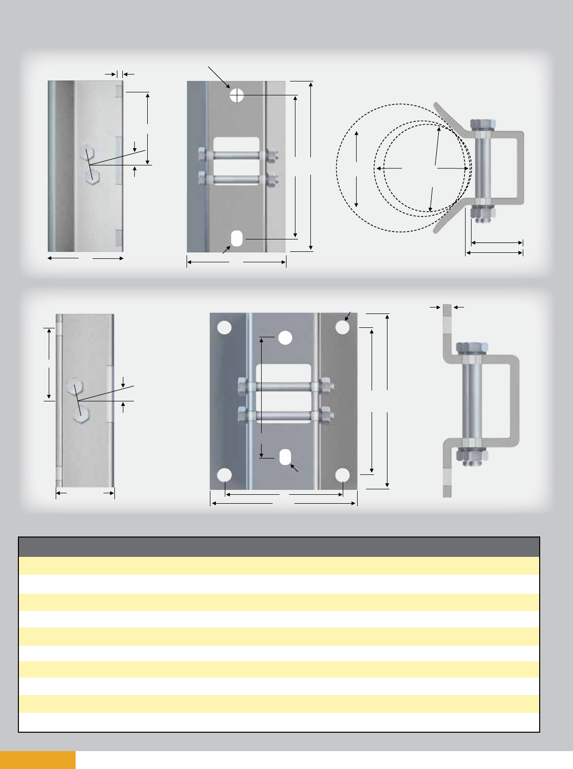
page 24
Base Fittings for 2.5” (63.5 mm) Rod Diameter
Type (Code)
5” Bolt Circle (15)
5” Bolt Circle (05)
Aluminum Gain (02)
Aluminum Gain (12)
Steel Gain (07)
Aluminum Flat (03)
Aluminum Flat (13)
Steel Flat (08)
Aluminum Flat (04)
Aluminum Flat (14)
A
4.75
(121)
4.75
(121)
12.0
(305)
12.0
(305)
12.0
(305)
10.0
(254)
10.0
(254)
13.0
(330)
13.0
(330)
13.0
(330)
B
6.25
(159)
6.25
(159)
14.0
(356)
14.0
(356)
15.0
(381)
12.0
(305)
12.0
(305)
15.0
(381)
15.0
(381)
15.0
(381)
C
3.63
(92)
3.63
(92)
-
-
-
8.0
(203)
8.0
(203)
8.0
(203)
8.0
(203)
8.0
(203)
D
0.90
(23)
0.90
(23)
8.06
(205)
8.06
(205)
8.33
(212)
10.0
(254)
10.0
(254)
10.0
(254)
10.0
(254)
10.0
(254)
E
5.0
(127)
5.0
(127)
6.13
(156)
6.13
(156)
6.5
(165)
5.0
(127)
5.0
(127)
6.5
(165)
6.5
(165)
6.5
(165)
F
-
-
5.56
(141)
5.56
(141)
6.04
(153)
4.0
(102)
4.0
(102)
4.0
(102)
4.0
(102)
4.0
(102)
G
-
-
0.5
(13)
0.5
(13)
0.38
(10)
0.5
(13)
0.5
(13)
0.38
(10)
0.5
(13)
0.5
(13)
H
-
-
12º
12º
12º
12º
12º
12º
12º
12º
I
0.69
(18)
5/8 - 11 UFS
0.94
(24)
0.81
(21)
0.94
(24)
0.94
(24)
0.81
(21)
1.125 X 0.94
(26x24)
0.94
(24)
0.81
(21)
J
-
-
0.94 X 1.31
(24x33)
0.94 X 1.31
(24x33)
0.94 X 2.0
(24x51)
-
-
0.94 X 2.0
(24x51)
0.94 X 1.31
(24x33)
0.81 X 1.31
(21x33)
K
-
-
-
-
-
-
-
12.0
(305)
12.0
(305)
12.0
(305)
Material
60-40-18 D.I.
60-40-18 D.I.
6063 T5 AL
6063 T5 AL
Low Carbon Steel
6063 T5 AL
6063 T5 AL
Low Carbon Steel
6063 T5 AL
6063 T5 AL
Horizontal & Vertical Bases inches (mm)
Al & Steel Gain
Al & Steel Flat
E
F
G
B
A
øI
JD
14’’ Dia.
(356 mm)
8’’ Dia.
(203 mm)
7’’ Dia.
(178 mm)
3.38’’ (86 mm)
4.44’’ (113 mm)
F
H
G
B
A
D
C
øI
K
J
H
E
January 2011

page 25
Line Fittings for 2.5” (63.5 mm) Rod Diameter
Horizontal & Vertical End Fittings inches (mm)
Type (Code)
2 Hole Blade (0)
2 Hole Long Blade (9)
H. Clamptop (1)
5” Bolt Circle (3)
5” Bolt Circle (5)
V. Clamptop (2)
A
5.73
(146)
5.73
(146)
8.24
(209)
4.75
(121)
4.75
(121)
5.88
(149)
B
4.0
(102)
4.0
(102)
4.0
(102)
6.25
(159)
6.25
(159)
4.0
(102)
C
-
-
3.30
(84)
3.63
(92)
3.63
(92)
3.30
(84)
D
0.75
(19)
0.75
(19)
1.12
(28)
0.90
(23)
0.90
(23)
1.12
(28)
E
5.25
(133)
7.75
(197)
4.72
(120)
5.0
(127)
5.0
(127)
5.37
(136)
F
1.25
(32)
1.25
(32)
4.0
(102)
-
-
4.0
(102)
G
1.50
(38)
4.0
(102)
-
-
-
1.06
(27)
H
2.00
(51)
4.5
(114)
-
-
-
-
I
1.0
(25)
1.0
(25)
5/8 - 11 UFS
5/8 - 11 UFS
0.69 x Holes
(18 x Holes)
5/8 - 11 UFS
J
1.44
(37)
1.44
(37)
0.75
(19)
-
-
-
L
0.5R
(12.7R)
0.5R
(12.7R)
-
-
-
-
Material
60-40-18 D.I.
60-40-18 D.I.
60-40-18 D.I.
60-40-18 D.I.
60-40-18 D.I.
60-40-18 D.I.
M
0.44R
(11R)
0.44R
(11R)
-
-
-
-
øBE
F
G
H
A
M
L
øI
J
D
øB
A
øJ
F
E
øC
I
D
I
øB
E
øC
A
D
øB
F
E
G
A
øC
D
I
Transverse Compressing Swing Angle
for Conductor Suspension Clamp
2 Hole Blade (std.)
40 deg. max.
2 Hole Long Blade
64 deg. max.
Two Hole Blade
5” Bolt Circle
Line or Base Fitting
Vertical Clamptop
Part per ANSI C29.7
Horizontal Clamptop
L is outer radius
M is inner radius
Note: 12º upsweep is already included
January 2011

page 26
Clamptop Clamps inches (mm)
Catalog Number
TSC57
TSC106
TSC150
TSC200
Fig. No.
1
1
1
2
Body &
Keeper Material
356-T6 AL
356-T6 AL
356-T6 AL
356-T6 AL
Clamping Range
inches (mm)
0.25 - 0.57 (6.3 - 14.4)
0.50 - 1.06 (12.7 - 26.9)
1.00 - 1.50 (25.4 - 38.1)
1.50 - 2.00 (38.1 - 50.8)
Ultimate Body
Strength lbs. (kN)
2800 (1.273)
2800 (1.273)
2800 (1.273)
2800 (1.273)
3.875’’
(98 mm)
5.25’’
(133 mm)
15º
20º
0.594’’ Dia.
(15 mm)
Figure 1
3.875’’
(98 mm)
15º
5.25’’
(133 mm)
20º
0.594’’ Dia.
(15 mm)
J
Figure 2
January 2011

page 27
Jumper Clamps and Assemblies
18’’
(457 mm)
A practical application of Quadri*Sil® line posts is for
support of jumper loops on transmission lines.
Horizontal motion of the jumper is restricted, and the
factor of wind sway is eliminated. Additionally, the
crossarm length may be reduced. The difference in
cost of insulation is not significant, but the saving in
tower cost can be attractive. Regardless of cost, the
use of a jumper support improves construction.
If using a single clamp, clamp postition relative to
the insulator may be changed by bolting the clamp
through the upper hole in the insulator end fitting.
Jumper clamps are not intended for tangent
span applications.
Figure
1
1
1
2
2
2
3
3
3
4
4
4
Catalog
Number
976423002
976423003
600643001
2717243001
2717253001
2717263001
2721763001
2721773001
2721783001
2721793001
2721803001
2721813001
Yoke Type
None
None
None
Dual
Dual
Dual
Triple
Triple
Triple
Quad
Quad
Quad
Clamping Range
inches (mm)
1.00 - 1.40
(25 - 36)
1.40 - 1.60
(36 - 41)
1.60 - 2.00
(41 - 51)
1.00 - 1.40
(25 - 36)
1.40 - 1.60
(36 - 41)
1.60 - 2.00
(41 - 51)
1.00 - 1.40
(25 - 36)
1.40 - 1.60
(36 - 41)
1.60 - 2.00
(41 - 51)
1.00 - 1.40
(25 - 36)
1.40 - 1.60
(36 - 41)
1.60 - 2.00
(41 - 51)
18’’
(457 mm)
Figure 1
Figure 2
Figure 3
Figure 4
0.5’’ Dia.
(13 mm)
To fit 0.75’’ (19 mm)
THK Plate
5’’
(127 mm) 2.625’’
(67 mm)
4.25’’
(108 mm) 2.375’’
(60 mm)
18’’
(457 mm)
January 2011

page 28 January 2011
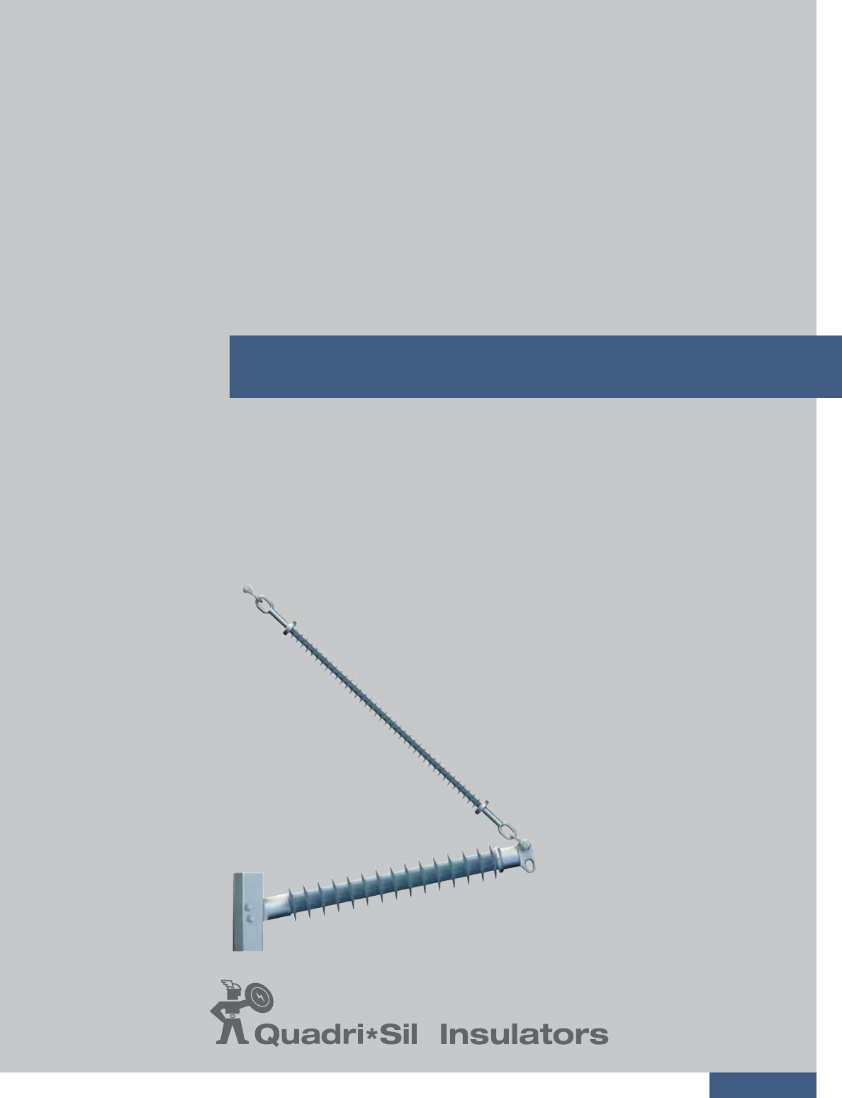
page 29
Braced Post Insulators
TABLE OF CONTENTS PAGE
Braced Line Post Assemblies .............................................................................30
Assembly Drawings ...........................................................................................31
Dimensions and Strength Ratings ......................................................................32
January 2011
®

page 30
Braced Line Post Assemblies
The need to minimize tower size and visual impact of transmission lines has prompted increased
interest in braced line posts, horizontal-V, and pivoting V assemblies. These insulating structures offer
vastly improved vertical load capabilities over conventional line posts, while retaining the advantages
of a fixed conductor position.
A braced line post insulator uses a conventional line post with a suspension string tied to the tower
face. Some of the characteristics of a braced line post are:
• It uses a traditional fixed base line post.
• The longitudinal strength is limited to the RCL rating of the line post component.
• It generates high tower torque (Z-direction) under longitudinal loading.
A horizontal-V insulator uses a conventional line post with a suspension string at a fixed offset
extending from the tower face, adding a stabilizing force to the assembly. Some of the characteristics
of a horizontal-V assembly are:
• It uses a fixed base horizontal line post (zero degree upsweep).
• It has an inclined hinge axis to add resistance to longitudinal movement.
• It employs a suspension insulator ground end stub arm (vang).
• The longitudinal strength is limited to the RCL rating of the line post component.
• It generates high tower torque (Z-direction) under longitudinal loading.
A pivoting horizontal-V insulator uses a conventional suspension string with a line post insulator fas-
tened to the structure with a hinged base. Some of the characteristics of a pivoting horizontal-V are:
• It pivots about an inclined axis.
• It employs a suspension insulator ground end stub arm (vang).
• It uses a universal joint or pivot base on the strut.
• It has high longitudinal strength.
• It generates low tower torque (Z-direction) under longitudinal loading.
• The assembly’s swing angle is a function of the vertical load and the tower offset pivot angle.
• The assembly’s maximum longitudinal loading is a function of the tensile rating of the strut.
The tables included on the following pages — and the images on the assembly drawings page —
cover typical arrangements that provide an efficient means of withstanding unusual loads. For more
information on these and numerous other variations of line post assemblies, contact your
Hubbell Power Systems representative.
January 2011
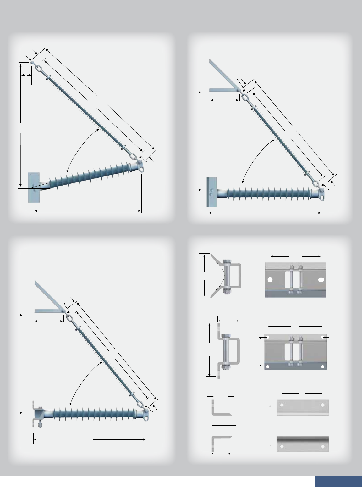
page 31
Assembly Drawings
B
3.5’’
(89 mm)
D
AS-50
C
12º
X
A
APPROX 62º
AS-50
A
C
BD
AS-50
3.5’’ (89 mm)
X
APPROX 50º
Braced Line Post
Pivoting Horizontal-V
Gain Base Mounting
Flat Base Mounting
Pivoting Base Mounting
12.0’’
(305 mm)
8.06’’
(205 mm)
10’’
(254 mm)
10.0’’
(254 mm)
8.0’’
(203 mm)
8.0’’
(203 mm)
2.75’’
(70 mm)
Horizontal-V
B
D
SUPPLIED BY
CUSTOMER
A
APPROX 50º
C
X
4.0’’
(102 mm)
8’’
(203 mm)
2.75’’
(70 mm)
0.94’’ Dia.
(24 mm)
AS-50
3.5’’
(89 mm)
0.81’’ Dia.
(21 mm)
AS-50
3.5’’
(89 mm)
3.5’’
(89 mm)
AS-50
3.5’’
(89 mm)
1.31’’
(33 mm)
0.94’’
(24 mm)
January 2011

page 32
Braced Line Post Assembly
Horizontal-V Assembly
Pivoting Horizontal-V Assembly
Dimensions and Strength Ratings
Typical
System
kV
Catalog
Number
Flat Base Post
Component Insulators Maximum Loadings
Suspension
A
inches
(mm)
B
inches
(mm)
C
inches
(mm)
D
inches
(mm)
X
inches
(mm) Vertical
lbs (kN)
Tension
lbs (kN)
Compression
lbs (kN)
Longitudinal
lbs (kN)
BLP043G12000
BLP046G12000
BLP051G12000
BLP058G12000
BLP075G12000
BLP080G12000
BLP043F12000
BLP046F12000
BLP051F12000
BLP058F12000
BLP075F12000
BLP080F12000
P250043S0XX0
P250046S0XX0
P250051S0XX0
P250058S0XX0
P250075S0XX0
P250080S0XX0
2.0 (51)
2.0 (51)
2.0 (51)
2.0 (51)
2.0 (51)
2.0 (51)
7500 (33.4)
7500 (33.4)
7500 (33.4)
7500 (33.4)
7500 (33.4)
7500 (33.4)
7500 (33.4)
7500 (33.4)
7500 (33.4)
7500 (33.4)
7500 (33.4)
7500 (33.4)
115/138
115/138
161
161
230
230
Notes:
n Corona rings are required and included for 220 kV and above.
n Base end fitting for posts is code “02’’ for a gain base or “03’’ for a flat base. Replace the “XX” with the appropriate code.
n Maximum loads are for single loads in the specified direction.
n Contact your Hubbell Power Systems representative to request combined load charts.
Typical
System
kV
Catalog
Number
Gain Base Post
Component Insulators Maximum Loadings
Suspension
A
inches
(mm)
B
inches
(mm)
C
inches
(mm)
D
inches
(mm)
X
inches
(mm) Vertical
lbs (kN)
Tension
lbs (kN)
Compression
lbs (kN)
Longitudinal
lbs (kN)
BLP041G00000
BLP046G00000
BLP053G00000
BLP055G00000
BLP072G00000
BLP080G00000
BLP041F00000
BLP046F00000
BLP053F00000
BLP055F00000
BLP072F00000
BLP080F00000
P250041S0XX0
P250046S0XX0
P250053S0XX0
P250055S0XX0
P250072S0XX0
P250080S0XX0
10050 (44.7)
10070 (44.8)
10000 (44.5)
10240 (45.5)
10010 (44.5)
9960 (44.3)
7500 (33.4)
7500 (33.4)
7500 (33.4)
7500 (33.4)
7500 (33.4)
7500 (33.4)
7500 (33.4)
7500 (33.4)
7500 (33.4)
7500 (33.4)
7500 (33.4)
7500 (33.4)
115/138
115/138
161
161
230
230
1715 (7.6)
1550 (6.9)
1355 (6.0)
1300 (5.8)
1015 (4.5)
930 (4.1)
Typical
System
kV Post
Component Insulators Maximum Loadings
Suspension
A
inches
(mm)
B
inches
(mm)
C
inches
(mm)
D
inches
(mm)
X
inches
(mm) Vertical
lbs (kN)
Tension
lbs (kN)
Compression
lbs (kN)
Longitudinal
lbs (kN)
—
—
—
—
—
—
BLP041P00000
BLP048P00000
BLP053P00000
BLP055P00000
BLP072P00000
BLP080P00000
P250041S0390
P250048S0390
P250053S0390
P250055S0390
P250070S0390
P250080S0390
S025043S0000
S025049S0000
S025051S0000
S025056S0000
S025075S000A
S025081S000A
53.1 (1349)
57.9 (1471)
65.2 (1656)
67.6 (1717)
84.5 (2146)
91.8 (2332)
52.2 (1326)
58.7 (1491)
65.1 (1654)
69.5 (1765)
88.9 (2258)
95.4 (2423)
50.0 (1270)
56.0 (1422)
60.0 (1524)
65.0 (1651)
81.0 (2057)
84.0 (2134)
59.2 (1504)
65.7 (1669)
72.1 (1831)
76.5 (1943)
95.9 (2436)
102.4 (2601)
18.0 (457)
20.0 (508)
22.0 (559)
24.0 (610)
28.0 (711)
30.0 (762)
10140 (45.1)
10270 (45.7)
10070 (44.8)
10310 (45.9)
10150 (45.1)
10150 (45.1)
7500 (33.4)
7500 (33.4)
7500 (33.4)
7500 (33.4)
7500 (33.4)
7500 (33.4)
7500 (33.4)
7500 (33.4)
7500 (33.4)
7500 (33.4)
7500 (33.4)
7500 (33.4)
115/138
115/138
161
161
230
230
7500 (33.4)
7500 (33.4)
7500 (33.4)
7500 (33.4)
7500 (33.4)
7500 (33.4)
Catalog
Number
Gain Base
Catalog
Number
Gain Base
Catalog
Number
Flat Base
Catalog
Number
Flat Base
January 2011
55.9 (1420)
58.2 (1478)
63.0 (1600)
70.1 (1781)
86.6 (2200)
91.4 (2322)
73.8 (1875)
80.3 (2040)
88.9 (2258)
97.5 (2477)
121.3 (3081)
129.9 (3299)
74.0 (1880)
82.0 (2083)
90.0 (2286)
96.0 (2438)
118.0 (2997)
127.0 (3226)
80.8 (2052)
87.3 (2217)
95.9 (2436)
104.5 (2654)
128.3 (3259)
136.9 (3477)
11130 (49.5)
11350 (50.5)
11390 (50.7)
11240 (50)
11220 (49.9)
11260 (50.2)
1625 (7.2)
1550 (6.9)
1415 (6.3)
1250 (5.6)
985 (4.4)
930 (4.1)
S025060S0000
S025066S0000
S025075S0000
S025084S0000
S025107S000A
S025116S000A
S025040S0000
S025045S0000
S025053S0000
S025058S0000
S025075S000A
S025084S000A
54.7 (1389)
59.5 (1511)
66.8 (1697)
69.2 (1758)
86.1 (2187)
93.4 (2372)
54.3 (1379)
58.7 (1491)
67.3 (1709)
71.6 (1819)
88.9 (2258)
97.5 (2477)
51.0 (1295)
55.0 (1397)
61.0 (1549)
66.0 (1676)
79.0 (2007)
85.0 (2159)
61.3 (1557)
65.7 (1669)
74.3 (1887)
78.6 (1996)
95.9 (2436)
104.5 (2654)
18.0 (457)
20.0 (508)
22.0 (559)
24.0 (610)
28.0 (711)
30.0 (762)
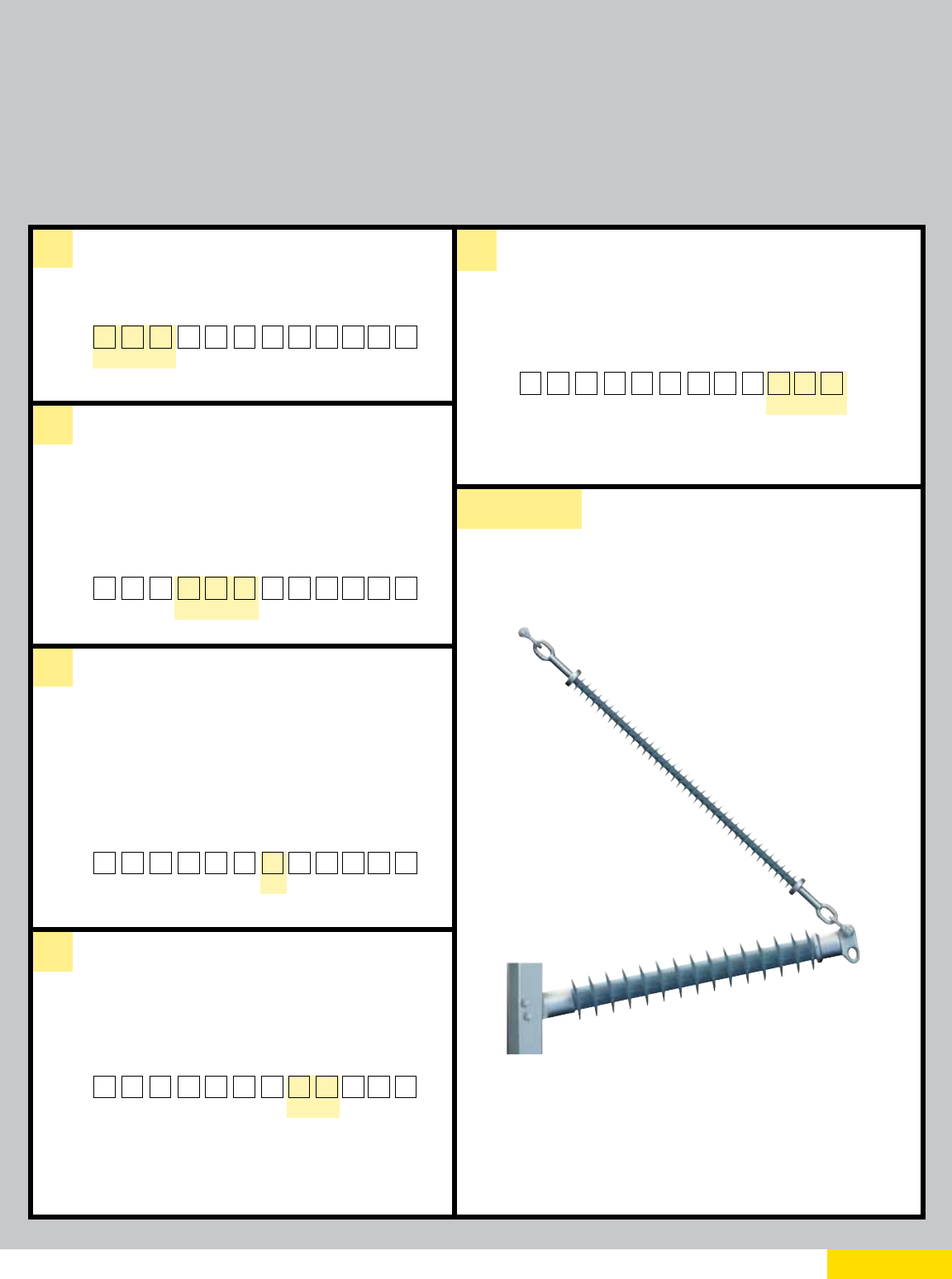
page 33
CATALOG NUMBER KEY
Your complete part number will be BLP075F12001
Example:
a
b
c
Assembly Type
Polymer Length
d
e
Due to the numerous variations available for braced line post assemblies, the following catalog number scheme is presented primarily
for informational
purposes. For custom-made braced line post assemblies, please refer to publication Insulator Selection Guide – Transmission (EF9091T), available via
www.hubbellpowersystems.com under “Literature” > “Literature Brochures” > “Ohio Brass Insulators and Arresters.”
Please follow the instructions in the Insulator Selection Guide and return the filled-out form to your Hubbell Power Systems representative. Filling out the
form with as much information as possible will ensure that our engineers receive all the critical dimensions and information needed to design your braced
line post assembly. For information on braced line post assemblies not included in this catalog, please contact your HPS representative.
The first three digits define the insulator type. In this example, we
picked a Braced Line Post; therefore, we entered “BLP” in the boxes
designated for “a.”
Polymer length of the line post member (in inches). The nominal polymer
length (in inches) of the line post insulator is specified to help define
voltage rating of the braced line post assembly. Refer to the Horizontal
Line Post Insulators table on page 21 for appropriate polymer lengths.
Fill in your selection in the boxes designated for section “b.”
For example,
if you want a Braced Line Post with a 75-inch polymer length, enter “075.”
A single letter is used to identify the type of base. Please refer to the base
drawings for hole patterns and dimensions located on page 24 or page 31.
F – Flat
G – Gain
P – Pivoting
The upsweep angle of the assembly is defined to help identify the assembly.
Typically, braced line post assemblies will have 12 degrees of upsweep
angle, and horizontal-V and pivoting-V assemblies will have 0 degrees.
Fill in your selection in the box designated for section “d” for the upsweep
angle.
For example, if you chose a braced line post assembly, enter “12.”
000 – Sequential number to address each
variation or model.
Braced Line Post Insulator, 75” Line Post Polymer Length, Flat Base,
12 degrees of Upsweep Angle, Variation/Model 001 BLP075F12001
B L P
a a a bbbcddeee
B L P 075
a a a bbbcddeee
Fill in your selection in the box designated for section “c.” For example, if
you want a flat base, enter “F.”
B L P 0 7 5 F
aaa bbbcddeee
B L P 0 7 5 F 1 2
aaa bbbcd d eee
Fill in your selection in the box designated for section “e.” In this example,
the braced line post is the first in a series, as designated by “001.”
B L P 0 7 5 F 1 2 001
aaa bbbcddeee
Type of Line Post Base
Upsweep Angle
Internal Use
January 2011

page 34
TECHNICAL TERMS REFERENCE GUIDE
ANSI – The American National Standards Institute verifies that the standard developers are complying
with the consensus and all other approval criteria.
Boron-free E-Glass – Electrical grade fiberglass that has corrosion resistance greater than boron
containing E-glass; it is environmentally friendly due to the lack of boron and fluorine.
Combined Load Charts – Also referred to as application curves; a graphical representation that
shows how the maximum working loads interact for a given line post or braced line post assembly.
Corona – A luminous discharge resulting from ionization of the air surrounding a conductor around
which a voltage gradient exceeding a certain critical value exists.
Dry Band Arcing – Electrical flashes that occur between wet and dry spots over the contaminated
surface of an insulator.
E-Glass – Electrical grade fiberglass; the first glass used for high-voltage insulators.
Flashover – A disruptive discharge that is capable of breaking the insulation level provided by the air
around the insulator, which creates an arc between parts of different potential or polarity.
IEC – The International Electrotechnical Commission develops and publishes international standards
for all electrical technologies.
Leakage Distance – The distance between the conductive end fittings of the insulator across
the insulator surface, moving in and out of the sheds; also commonly referred to as the creep or
creepage distance.
RCL – Reference Cantilever Load is the maximum design cantilever load (MDCL), which is rated at
50 percent of the part’s SCL.
RIV – Radio-Interference Voltages are caused by electric currents that produce magnetic and
electrostatic fields that are capable of inducing high-frequency voltage pulses in nearby radio
antennas. The RIV of an insulator is measured under conditions specified by industry standards.
RTV – Room Temperature Vulcanate (elastomer sealant) is a silicone rubber that cures at
room temperature.
RTL – Routine Test Load is the maximum design tension load, which is rated at 50 percent of the
part’s SML. All parts are tested at this rating prior to being shipped.
Section Length – The straight-line distance between the coupling points of the insulator’s end fittings.
SCL – Specified Cantilever Load is the minimum ultimate cantilever strength of the part.
SML – Specified Mechanical Load is the minimum ultimate tensile strength of the part.
Strike Distance – The shortest distance across the insulator surface, between the end fittings of the
insulator; also commonly referred to as the dry arc distance or tight string distance.
January 2011

®

Web: http://www.hubbellpowersystems.com
E-mail: hpsliterature@hps.hubbell.com
MEXICO
HUBBELL DE MEXICO, S.A. DE C.V.
Av. Insurgentes Sur #1228, Piso 8
Col. Tlacoquemacatl Del Valle
Mexico, D.F. 03200
Phone: 52-55-9151-9999
Fax: 52-55-9151-9988
Website: hubbell.com.mx
UNITED STATES
CANADA, INTERNATIONAL
HUBBELL POWER SYSTEMS, INC.
210 N. Allen Street
Centralia, Mo 65240-1395
Phone: 1-573-682-5521
Fax: 1-573-682-8714
e-mail: hpsliterature@hps.hubbell.com

®
Web: http://www.hubbellpowersystems.com
E-mail: hpsliterature@hps.hubbell.com
For reliable transmission,
the World is turning to hubbell.
A&J 1M
January 2011

A Better Design. A Better Insulator.
Catalog 24
®
Insulators
®
LIMITED WARRANTY AND LIMITATION OF LIABILITY
MATERIAL: HPS warrants all products sold by it to be merchantable (as such term is defined in
the Uniform Commercial Code) and to be free from defects in material and workmanship. Buyer
must notify HPS promptly of any claim under this warranty. The Buyer’s exclusive remedy for
breach of this warranty shall be the repair or replacement, F.O.B. factory, at HPS’s option, of any
product defective under the warranty, which is returned to HPS within one year from the date of
shipment. NO OTHER WARRANTY, WHETHER EXPRESS OR ARISING BY OPERATION OF THE
LAW, COURSE OF DEALING, USAGE OF TRADE OR OTHERWISE IMPLIED, SHALL EXIST IN
CONNECTION WITH HPS’S PRODUCTS OR ANY SALE OR USE THEREOF. HPS SHALL IN NO
EVENT BE LIABLE FOR ANY LOSS OF PROFITS OR CONSEQUENTIAL OR SPECIAL DAMAGES
INCURRED BY BUYER. HPS’s warranty shall run only to the first Buyer of a product from HPS,
from HPS’s Buyer, or from an original equipment manufacturer reselling HPS’s product, and is
non-assignable and non-transferable and shall be of no force and effect if asserted by any person
other than such first Buyer. This warranty applies only to the use of the product as intended by
HPS and does not cover any modification, misapplication, or misuse of said product.
APPLICATION: HPS does not warrant the accuracy of and results from product or system
performance recommendations resulting from any engineering analysis or study. This applies re-
gardless of whether a charge is made for the recommendation, or if it is provided free of charge.
Responsibility for selection of the proper product of application rests solely with the purchaser. In
the event of errors or inaccuracies determined to be caused by HPS, its liability will be limited to
the reperformance of any such analysis or study.
PURCHASER INSPECTIONS: Tests, inspections and acceptance of all material must be made at
the factory. Purchasers’ inspectors are welcome at the factories and are provided with the neces-
sary facilities for carrying out their work. Name and phone number of who should be contacted
for inspection should be given to HPS no later than two weeks prior to scheduled shipment date.
LIMITATION OF LIABILITY: IN NO EVENT, WHETHER AS A RESULT OF BREACH OF CONTRACT
OR WARRANTY OR ALLEGED NEGLIGENCE, SHALL HPS BE LIABLE FOR SPECIAL OR
CONSEQUENTIAL DAMAGES INCLUDING, BUT NOT LIMITED TO, LOSS OF PROFITS OR
REVENUE, LOSS OF USE OF THE EQUIPMENT OR ANY ASSOCIATED EQUIPMENT, LOSS OF
CAPITAL, COST OF SUBSTITUTE EQUIPMENT, FACILITIES OR SERVICES, DOWNTIME COSTS,
OR CLAIMS OF THIRD PARTIES OF THE BUYER FOR SUCH DAMAGES. Any claim by Buyer for
breach of the foregoing warranty shall be deemed waived by Buyer unless submitted to HPS in
writing within thirty (30) days from the date Buyer discovered, or by reasonable inspection should
have discovered the alleged breach. Any cause of action for breach of the foregoing warranty
shall be brought within one year after the cause of action has accrued.
1850 Richland Avenue East, Aiken, SC 29801
http://www.hubbellpowersystems.com
E-mail: quadrisil@hps.hubbell.com
©Copyright 2010
NOTE: Because Hubbell has a policy of continuous product improvement, we reserve the right to
change design and specifications without notice.

A Better Design. A Better Insulator.

Polymer (RTV) Seal
Counterbore Compression Seal
Radial Compression Seal
Overlap Compression Seal
Our Exclusive Four-Point Seal
®


page 1
Quadri*Sil® Insulators — A Century in the Making
With nearly 100 years of Ohio Brass insulator experience and product innovation, it’s
no surprise that the next generation of insulator reliability carries the trusted name of
Ohio Brass.
Ohio Brass (Hubbell Power Systems) is proud to offer a transmission insulator that triumphs
over today’s unpredictable environment. Appropriately named, the Quadri*Sil® insulator
incorporates a revolutionary four-point seal that, quite simply. . . prohibits moisture
intrusion.
In addition, the Quadri*Sil® insulator optimizes the Ohio Brass commitment to excellence
and the advancement of processes and materials. With a proprietary silicone-
rubber compound and end-seal design, this direct-bonded insulator offers
assurance that moisture penetration does not occur.
Today’s environment is unpredictable. Your insulator can’t be.
January 2011
The Ohio Brass commitment is simple and complete:
we provide our customers the finest, most advanced
products and expert technical assistance, before
and after purchase. Every day. Worldwide.

page 2 January 2011

page 3
QUADRI*SIL® GENERAL INFORMATION PAGE 4
The Heart of Quadri*Sil® Insulators ....................................................................... 4
Key to the Catalog Numbers .....................................................................8 and 33
Technical Terms Reference Guide ....................................................................... 34
SUSPENSION INSULATORS PAGE 11
Corona Performance ......................................................................................... 12
End Fitting Detail ............................................................................................... 13
Quadri*Sil® 25 kip / 120 kN SML Data ............................................................... 14
Quadri*Sil® 30 kip SML Data ............................................................................. 15
Quadri*Sil® 160 kN SML Data ............................................................................ 16
Quadri*Sil® 50 kip / 210 kN SML Data ............................................................... 17
LINE POST INSULATORS PAGE 19
Mechanical Ratings and Corona Performance ..................................................... 20
Quadri*Sil® Horizontal Line Posts ....................................................................... 21
Quadri*Sil® Vertical Line Posts ........................................................................... 22
Quadri*Sil® Base Fittings ................................................................................... 24
Quadri*Sil® Line Fittings .................................................................................... 25
Clamps and Assemblies .................................................................................... 26
BRACED POST INSULATORS PAGE 29
Braced Line Post Assemblies ............................................................................. 30
Assembly Drawings ........................................................................................... 31
Dimensions and Strength Ratings ...................................................................... 32
January 2011
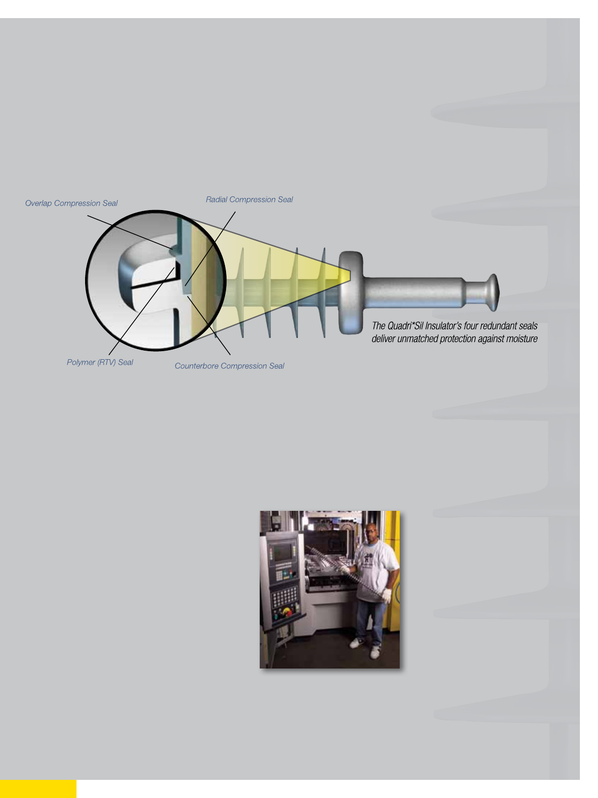
page 4
Design
Sealing System — This four-point sealing system provides superior performance by preventing moisture
penetration between the silicone rubber and end-fitting interface. The design is based on four redundant
seals that provide unmatched protection to the fiberglass core rod. RTV (Room Temperature Vulcanate) is
completely encapsulated within the interior of the end-fitting and is not utilized as an exterior seal as with
other silicone designs.
Corona Shielding Ring (CSR) — The Quadri*Sil® end-fitting design provides superior electric field
shielding of the silicone rubber adjacent to the end-fitting. The superior shielding protects the silicone
rubber on applications where an external corona ring is not required.
Direct Bond — The silicone rubber material is bonded directly to the fiberglass core rod during the
molding process. The resulting bond between the silicone rubber and fiberglass rod is mechanically
stronger than the tear strength of the silicone rubber.
Crimp Method — A circumferential crimp creates
a more uniform stress distribution to ensure the
mechanical integrity of the Quadri*Sil® insulator.
Ohio Brass pioneered the crimping process in
1976 — today it has become the industry standard.
[ Revolutionary Four-Point Seal ]
January 2011

page 5
Components and Materials
Polymer Weathersheds — The polymer weathershed material utilized in the Quadri*Sil® insulator
design is a proprietary silicone-rubber compound specifically designed by Ohio Brass engineers for
high-voltage insulator applications. The polymer weathershed material starts with 100-percent base
silicone rubber before additives and fillers are compounded with the base rubber. Hubbell Power
Systems (HPS) controls the entire process from the proprietary formulation to the complete mixing
process. The proprietary formulation incorporates the inherent hydrophobicity and UV performance of
silicone rubber while providing superior tracking performance as demonstrated in dry-band arcing
tests. For more information about our silicone rubber, please contact your HPS representative.
Fiberglass Core Rod — The Quadri*Sil® suspension insulator’s fiberglass core rod is produced with
boron-free, corrosion-resistant E-glass and epoxy resin. Quadri*Sil® line post insulators are manufac-
tured with electrical grade glass and epoxy resin.
End Fittings — Made of steel or ductile iron, the end-fittings are directly attached to the fiberglass core
rod by a circumferential crimping process. This crimping process allows the end fittings to utilize the rod’s
inherent tensile strength.
Grading Rings — Also known as corona rings, grading rings are manufactured using high-grade
aluminum alloy, making them strong, light, and corrosion-resistant. Grading (corona) rings can be
packaged separately or inside the insulator crates with all mounting hardware included.
Leakage Distance
Quadri*Sil® suspension insulators feature standard and high leakage distance weathershed profiles for
maximum resistance to contamination and leakage currents in various environmental applications. The
hydrophobic nature of our silicone rubber ensures superior performance in contaminated environments.
January 2011

High Pressure Washing
Quadri*Sil® transmission insulators normally do not require washing or other routine maintenance.
Washing may be required if the insulators are installed in an area of severe environmental contamination.
In the event that washing is required, the procedures outlined in Section IX of the “IEEE GUIDE FOR
INSULATOR CLEANING,” IEEE STD 957-2005 are generally applicable.
Mechanical Ratings
Quadri*Sil® suspension insulators are rated and tested in accordance with IEC 61109 and ANSI
C29.12. Quadri*Sil® line post insulators are rated and tested in accordance with IEC 61952 and ANSI
C29.17. Certified test reports are available.
For suspension insulators, SML ratings are 120 kN, 160 kN, 210 kN, 25 kip, 30 kip, and 50 kip with
appropriate rod size and end fittings. RTL ratings are consistent with the IEC and ANSI standards.
Factory routine tests are conducted on 100 percent of all insulators to the RTL rating.
Markings
Markings for Quadri*Sil® suspension insulators are placed on a UV-resistant label located on the
ground end fitting. Markings for Quadri*Sil® line post insulators are placed on a metal plate on the
mounting base of the insulator. Markings include SML and RTL (for suspension), SCL and RCL (for
line post), part number, assembly date code, and Hubbell Power Systems identification.
These markings are consistent with applicable IEC and ANSI standards.
Insulator Lengths
Quadri*Sil® suspension insulators are available in lengths appropriate for 69 kV through 765 kV.
Longer lengths can be produced for special projects. Intermediate lengths – those that fall in
between the catalog numbers listed in the tables – are also available. Length increments are
approximately 2.2 inches (56 mm) for suspension insulators and 2.4 inches (61 mm) for vertical
and horizontal line post insulators.
page 6 January 2011

page 7
Testing
Quadri*Sil® insulators have been tested successfully to meet the requirements of IEC 61109 and
ANSI C29.11. For a certified test report or additional information related to product testing, please
contact your HPS representative.
Packaging
Quadri*Sil® suspension insulators are packaged in wooden crates 44 inches (111.7 cm) wide with
the length of the crate determined by the length of the insulator. The height of the crate is normally
less than 45 inches (114.3 cm). The gross weight will not exceed 2,000 pounds (909 kg). Crates are
available for both domestic and export transportation.
The Quadri*Sil® line post insulators are packaged in appropriate quantities in open wood crates. Line
post insulators are packaged to prevent the metal bases from resting on the polymer weathershed material.
January 2011
page 8
CATALOG NUMBER KEY
a
b
c
d
e
Insulator Type
Mechanical Strength
Suspension (SML), Rod Diameter
025 — 25 kip, 5/8” (16 mm)
030 — 30 kip, 5/8” (16 mm)
050 — 50 kip, 7/8” (22 mm)
120 — 120 kN, 5/8” (16 mm)
160 — 160 kN, 7/8” (22 mm)
210 — 210 kN, 7/8” (22 mm)
Polymer Length
3 digits for distance between metal
parts, in inches
Top Fitting
Weathershed Profile
Post
250 — Series 250, standard strength 2.5”,
(63.5 mm)
Suspension
S — Standard Leakage Distance (2.5)
H — High Leakage Distance (2.9 or 3.3)
Line Post Insulators
0 — Tear Drop Blade
1 — Horizontal Clamptop
2 — Vertical Clamptop
3 — 5” (127 mm) Bolt Circle
5/8” (16 mm) Tapped Hole
5 — 5” (127 mm) Bolt Circle
5/8” (16 mm) Through Hole
9 — Long Tear Drop Blade
Post
S — Standard Leakage Distance
P — Post or
S — Suspension
0 — Chain Eye
1 — ANSI Ball
2 — Y-Clevis
3 — ANSI Socket
4 — ANSI Straight Clevis
7 — IEC Ball Fitting
16 mm for 120 kN
20 mm for 160 kN and 210 kN
8 — IEC Straight Clevis
A — IEC Socket
16 mm for 120 kN
20 mm for 160 kN and 210 kN
The Quadri*Sil Insulators Numbering Scheme is organized according to a smart numbering system. Each group of digits defines a
characteristic of the product you are ordering. To fill out this form, start on “a: Insulator Type.” Then, fill in your selection in the box
corresponding to the letter “a.” Apply the same rule for all the other sections.
a)
Insulator Type. Defines your insulator type: Post or Suspension.
Select “P” or “S” for Post or Suspension, respectively, and fill in your
selection in the box designated for “a.” In this example, we selected a
suspension insulator.
b)
Strength. Defines the mechanical strength of your insulator. Fill in your
selection in the boxes designated for “b.”
Note: kip = Kilopound, kN = Kilonewton
For example, if you want a Suspension insulator with 25 kip, this is what
your form would look like so far:
c)
Polymer Length. Defines the polymer length of the insulator (please use
catalog tables for possible polymer lengths). Fill in your selection in the boxes
designated for section “c.” For example, if you want a 49-inch polymer length,
enter:
d)
Weathershed Profile. Defines the leakage distance design. For a suspension
insulator with standard leakage distance, use “S.”
For a suspension insulator
with high leakage distance, use “H.”
For a line post, only the standard leakage
distance design is available. Fill in your selection in the box designated for “d.”
For example, if you want an insulator with high leakage distance, you would
place an “H” in the box designated “d.”
e)
Top Fitting. Defines the top end fitting of your insulator. Fill in your
selection in the box designated for “e.” For example, if you want a
suspension insulator with a Y-clevis top end fitting, you would place a
“2” in the box designated for “e.”
049H
S025
0 4 9 H 2
S025
049
S025
S025
S
Suspension Insulators
Suspension Insulators Line Post Insulators
January 2011
®
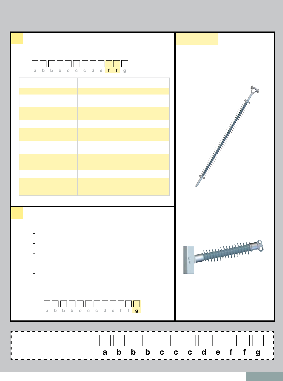
page 9
Your complete part number will be S025049H201A
January 2011
f
g
00 - Chain Eye 02 - Aluminum Gain 12” (305 mm) CL1 mounting
03 - Aluminum Flat 8”x 10” (203 mm x 254 mm),
15/16” (24 mm) hole diameter
01 - ANSI Ball 04 - Aluminum Flat 8”x 13” (203 mm x 330 mm),
15/16” (24 mm) hole diameter
02 - Y-Clevis 05 - 5” (127 mm) Bolt Circle, 5/8” (16 mm) tapped hole
03 - ANSI Socket 07 - Steel Gain 12” (305 mm) CL mounting,
15/16” (24 mm) hole diameter
04 - ANSI Straight Clevis 08 - Steel Flat 8”x 13” (203 mm x 330 mm) MS2,
15/16” (24 mm) hole diameter
15 - 5” (127 mm) Bolt Circle, 5/8” (16 mm) through hole
07 - IEC Ball Fitting
16 mm for 120 kN or
20 mm for 160 kN and 210 kN
08 - IEC Straight Clevis
0A - IEC Socket
16 mm for 120 kN or
20 mm for 160 kN and 210 kN
0
— No ring required
A — >220 kV, 8” (203 mm) ring for suspension, 12” (305 mm) ring
for series 250 post
B — >330 kV
series 250 post
C — >400 kV, 12” (305 mm) line end and 8” (203 mm) ground end ring
for suspension
D — >500 kV, 15” (381 mm) line end and 8” (203 mm) ground end ring
for suspension
E — >735 kV, 15” (381 mm) line end and 12” (305 mm) ground end ring
for suspension
Bottom Fitting
Rings
Examples:
Suspension Insulators Line Post Insulators
1 Center Line
2 Horizontal x Vertical
Mounting Pattern Spacing
f)
Bottom Fitting. Defines the bottom end fitting of your insulator. Fill in your selection in the boxes
designated for “f.”
For example, if you want an ANSI ball bottom end fitting, you would place “01” in the
boxes designated for “f.”
0 4 9 H 2
S025 0 1
0 4 9 H 2
S025 0 1 A
g)
Rings. Defines your need for a Corona Ring. Fill in your selection in the box designated
for “g.”
The example below shows a selection of a corona ring for 220 kV, 8” (203 mm) for
a suspension insulator.
Thus, “A” was placed in the box designated for “g.”
Your final catalog number
should look like this
Fill out boxes according to instructions
Suspension Insulator, 25 kip, 49” of
Polymer Length, Standard Leakage
Distance Profile (2.5), Top Fitting: Y-Clevis,
Bottom Fitting: ANSI Ball, No Corona Ring
S025049S2010
Vertical Gain - See page 23 Table B
, 12” (305 mm) ring for suspension, 15” (381 mm) ring for
P250021S0020
Line Post Insulator, 2.5” (63.5 mm) Rod
Diameter, 21.9” Polymer Length, Standard
Leakage Distance, Top Fitting: Tear Drop
Blade, Bottom Fitting: 2-Piece Aluminum
Gain Base, No Corona Ring

page 10 January 2011

page 11
Suspension Insulators
TABLE OF CONTENTS PAGE
Corona Performance ........................................................................................ 12
End Fitting Detail .............................................................................................. 13
Quadri*Sil® 25 kip / 120 kN SML Data .............................................................. 14
Quadri*Sil® 30 kip SML Data ............................................................................ 15
Quadri*Sil® 160 kN SML Data ........................................................................... 16
Quadri*Sil® 50 kip / 210 kN SML Data .............................................................. 17
January 2011
®
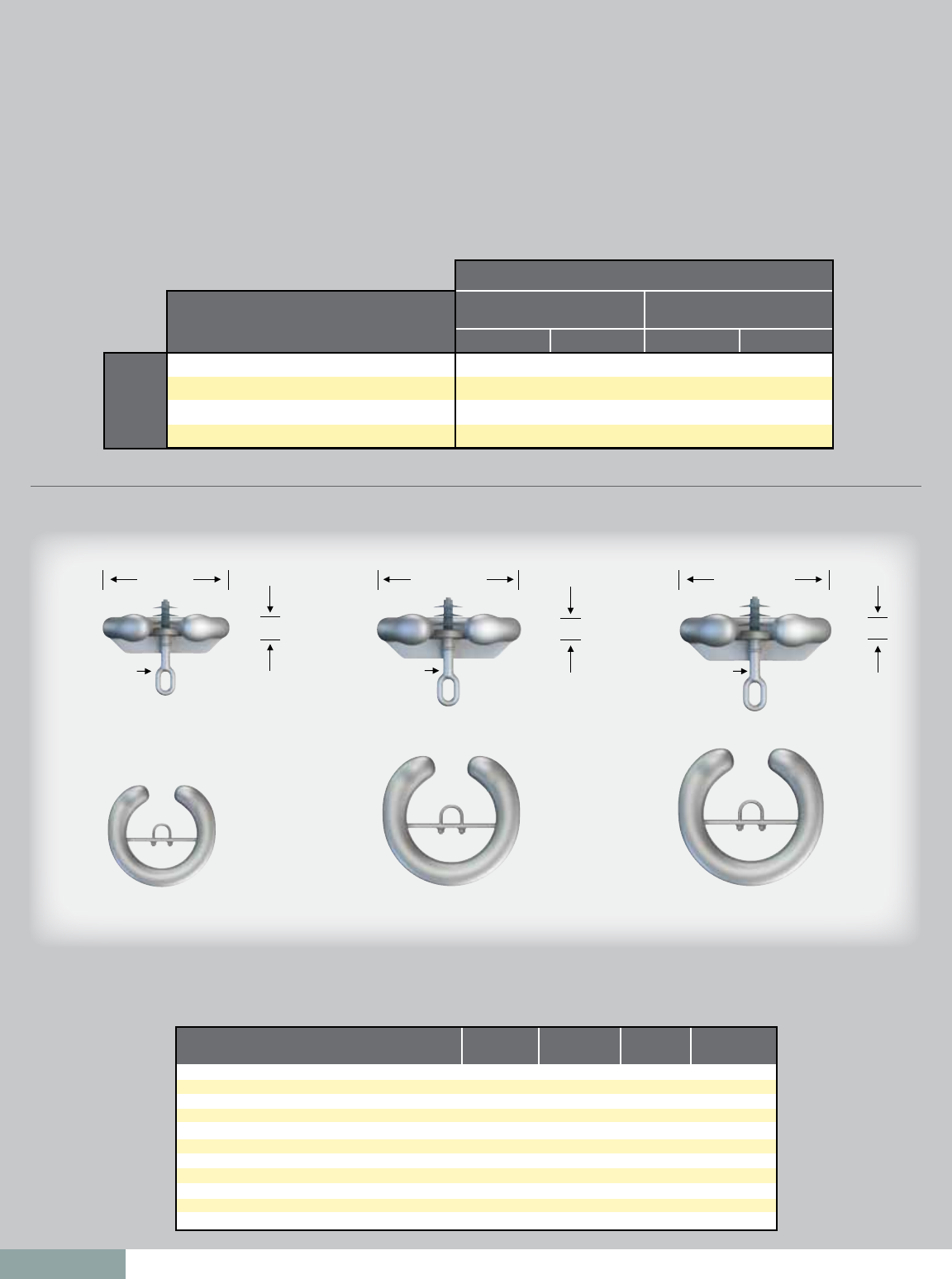
page 12
Recommended Corona Ring Installation Table
Normal Applications: Top Grounded, Bottom Energized
Corona Performance
Quadri*Sil® insulators are RIV and corona free through 161 kV. The use of an external corona shielding ring is required at 220 / 230 kV and above.
The table below details the rings necessary for 220 / 230 kV and above.
Part Number 271761 Part Number 271705 Part Number 271751
Quadri*Sil Suspen-
sion Insulator
4.10”
(104 mm)
15.00”
(381 mm)
Quadri*Sil Suspen-
sion Insulator
3.44”
(87 mm)
12.0”
(305 mm)
Quadri*Sil Suspen-
sion Insulator
2.44”
(62 mm)
8.0”
(203 mm)
Electrical/Dimensional Changes to the Suspension Insulator
with External Corona Ring
Recommended Corona Rings by Line Voltage
Line
Voltage
(kV)
Corona Ring Part Numbers
Ground EndGround End Ground EndLine EndLine End Line End
220/230 kV
330/345 kV
400 kV
500 kV
None
None
8" (203 mm)
8" (203 mm)
8" (203 mm)
12" (305 mm)
12" (305 mm)
15" (381 mm)
-
-
2717613001
2717613001
-
-
2717613002
2717613002
2717613002
2717053002
2717053002
2717513002
2717613001
2717053001
2717053001
2717513001
25 kip, 30 kip, 120 kN, 133 kN 50 kip, 160 kN, 210 kN
Physical and Electrical Characteristics
Dry Arc Distance inches (mm)
Leakage Distance inches (mm)
ANSI 60 Hz Flashover Dry — kV
ANSI 60 Hz Flashover Wet — kV
ANSI Critical Flashover Positive — kV
ANSI Critical Flashover Negative — kV
IEC Wet Switching Impulse Withstand — kV
IEC Power Frequency Wet Withstand — kV
IEC Lightning Impulse Withstand Positive — kV
IEC Lightning Impulse Withstand Negative — kV
Net Weight pounds (kg)
220/230 kV
Ring
-0.63 (-16)
0
-10
-10
-10
-10
N/A
-10
-10
-10
2.1 (1.0)
330/345 kV
Ring
-1.32 (33.5)
0
-20
-10
-20
-20
N/A
-10
-20
-20
2.9 (1.3)
400 kV
Ring
-1.95 (49.5)
0
-20
-20
-30
-30
N/A
-20
-30
-30
5.0 (2.3)
500 kV
Ring
-2.67 (67.8)
0
-30
-30
-40
-50
N/A
-30
-40
-50
6.5 (2.9)
January 2011
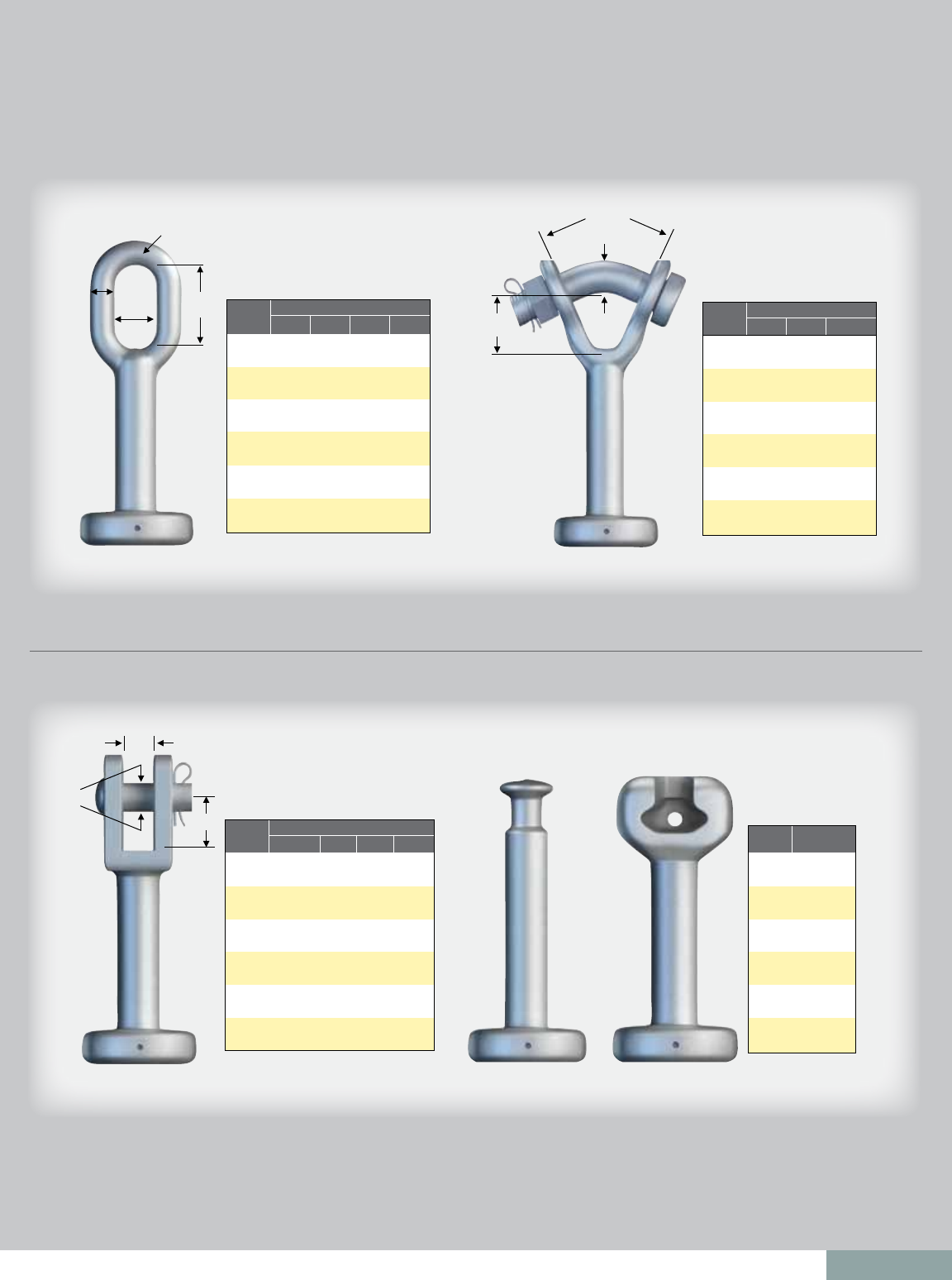
page 13
Chain Eye
MOST COMMON END FITTINGS
Y-Clevis
Straight Clevis Ball/Socket
SML
25 kip
(111 kN)
120 kN
30 kip
(133 kN)
36 kip
(160 kN)
210 kN
50 kip
(222 kN)
A
0.62
(15.74)
0.62
(15.74)
0.75
(19.05)
0.75
(19.05)
0.75
(19.05)
0.75
(19.05)
C
2.00
(50.8)
2.00
(50.8)
2.00
(50.8)
2.00
(50.8)
2.00
(50.8)
2.00
(50.8)
D
0.62
(15.74)
0.62
(15.74)
0.85
(21.59)
0.85
(21.59)
0.85
(21.59)
0.85
(21.59)
Dimensions in. (mm)
B
1.00
(25.4)
1.00
(25.4)
1.00
(25.4)
1.00
(25.4)
1.00
(25.4)
1.00
(25.4)
SML
25 kip
(111 kN)
120 kN
30 kip
(133 kN)
36 kip
(160 kN)
210 kN
50 kip
(222 kN)
B
1.53
(38.86)
1.53
(38.86)
1.59
(40.39)
1.59
(40.39)
1.59
(40.39)
1.59
(40.39)
A
0.75
(19.05)
0.75
(19.05)
0.88
(22.35)
0.88
(22.35)
0.88
(22.35)
0.88
(22.35)
Bolt Dia.
0.75
(19)
0.75
(19)
0.88
(22)
0.88
(22)
0.88
(22)
0.88
(22)
Dimensions in. (mm)
SML
25 kip
(111 kN)
120 kN
30 kip
(133 kN)
36 kip
(160 kN)
210 kN
50 kip
(222 kN)
A
1.41
(36)
1.41
(36)
1.41
(36)
1.81
(46)
1.81
(46)
Class
ANSI 52-6
IEC 16C
ANSI 52-6
IEC 19L
IEC 19L
N/A
B
0.75
(19)
0.75
(19)
0.75
(19)
0.83
(21)
0.83
(21)
PD
0.62
(16)
0.62
(16)
0.62
(16)
0.75
(19)
0.75
(19)
Dimensions in. (mm)
SML
25 kip
(111 kN)
120 kN
30 kip
(133 kN)
36 kip
(160 kN)
210 kN
50 kip
(222 kN)
Class
ANSI 52-5
IEC 16 mm
ANSI 52-5
ANSI 52-8
(IEC 20 mm)
IEC 20 mm
ANSI 52-11
ABC
øD
A
B
45º
A
B
PD
A B
A
January 2011

page 14
Suspension Insulators
Mechanical Ratings SML = 25 kip/120 kN RTL = 12.5 kip/60 kN
Rod Diameter: 5/8" (16 mm)
To determine the section length for an insulator with a different end fitting combination, please add
or subtract the displayed length change in the table above. For configurations not shown, use the
Catalog Number Key or contact your HPS representative.
Section Length Adjustment Table, Base End Fittings: Y-clevis-Ball (201)
Top Fitting
Y-Clevis
Eye
Eye
ANSI 52-5 Socket
IEC 16 mm Socket
ANSI 52-6 Clevis
ANSI 52-6 Clevis
Eye
ANSI 52-5 Ball
Eye
ANSI 52-5 Ball
IEC 16 mm Ball
Eye
ANSI 52-5 Ball
200
001
000
301
A07
400
401
1.62 (41)
0.02 (0)
1.64 (42)
-1.15 (-29)
-0.03 (-1)
0.82 (21)
-0.8 (-20)
Bottom Fitting Top and Bottom End Fitting Digits
(“e” & “f”) in Catalog Number
Length Change
inches (mm)
Notes:
n Dimensional and electrical values displayed in
main table are for an insulator with Y-clevis
and Ball end fittings.
n For voltages above 400 kV, other section
lengths, or end fitting combinations, please
contact your HPS representative.
n Electrical values are without corona ring.
For voltages equal to or greater than 220
kV, refer to page 12 for corona rings and
associated physical/electrical changes to the
above data. Dimensions are within allowable
tolerances as specified by IEC 61109 and
ANSI C29.12.
Selection Guide:
Typical Line Voltage, kV Catalog Numbers
ANSI / IEC
Section
Length
inches
(mm)
Nominal
Polymer
Length
inches
Strike
Distance
inches
(mm)
Leakage
Distance
inches
(mm)
ANSI Values IEC Values
60-Hz
Dry
Flashover
(kV)
60-Hz
Wet
Flashover
(kV)
Critical
Impulse
Positive
(kV)
Critical
Impulse
Negative
(kV)
60-Hz
1-minute
Wet
Withstand
(kV)
Impulse
Positive
Withstand
(kV)
Impulse
Negative
Withstand
(kV)
S025021S2010 / S120021S2010
S025021H2010 / S120021H2010
S025023S2010 / S120023S2010
S025023H2010 / S120023H2010
S025030S2010 / S120030S2010
S025030H2010 / S120030H2010
S025036S2010 / S120036S2010
S025036H2010 / S120036H2010
S025043S2010 / S120043S2010
S025043H2010 / S120043H2010
S025047S2010 / S120047S2010
S025047H2010 / S120047H2010
S025051S2010 / S120051S2010
S025051H2010 / S120051H2010
S025056S2010 / S120056S2010
S025056H2010 / S120056H2010
S025060S2010 / S120060S2010
S025060H2010 / S120060H2010
S025064S2010 / S120064S2010
S025064H2010 / S120064H2010
S025069S2010 / S120069S2010
S025069H2010 / S120069H2010
S025073S2010 / S120073S2010
S025073H2010 / S120073H2010
S025077S2010 / S120077S2010
S025077H2010 / S120077H2010
S025081S2010 / S120081S2010
S025081H2010 / S120081H2010
S025086S2010 / S120086S2010
S025086H2010 / S120086H2010
S025090S2010 / S120090S2010
S025090H2010 / S120090H2010
S025094S2010 / S120094S2010
S025094H2010 / S120094H2010
S025099S2010 / S120099S2010
S025099H2010 / S120099H2010
S025103S2010 / S120103S2010
S025103H2010 / S120103H2010
S025107S2010 / S120107S2010
S025107H2010 / S120107H2010
S025112S2010 / S120112S2010
S025112H2010 / S120112H2010
S025116S2010 / S120116S2010
S025116H2010 / S120116H2010
S025120S2010 / S120120S2010
S025120H2010 / S120120H2010
S025125S2010 / S120125S2010
S025125H2010 / S120125H2010
S025129S2010 / S120129S2010
S025129H2010 / S120129H2010
S025133S2010 / S120133S2010
S025133H2010 / S120133H2010
S025138S2010 / S120138S2010
S025138H2010 / S120138H2010
S025142S2010 / S120142S2010
S025142H2010 / S120142H2010
33.3 (846)
33.3 (846)
35.4 (899)
35.4 (899)
41.9 (1064)
41.9 (1064)
48.4 (1229)
48.4 (1229)
54.9 (1394)
54.9 (1394)
59.2 (1504)
59.2 (1504)
63.5 (1613)
63.5 (1613)
67.8 (1722)
67.8 (1722)
72.1 (1831)
72.1 (1831)
76.5 (1943)
76.5 (1943)
80.8 (2052)
80.8 (2052)
85.1 (2162)
85.1 (2162)
89.4 (2271)
89.4 (2271)
93.7 (2380)
93.7 (2380)
98.1 (2492)
98.1 (2492)
102.4 (2601)
102.4 (2601)
106.7 (2710)
106.7 (2710)
111 (2819)
111 (2819)
115.3 (2929)
115.3 (2929)
119.7 (3040)
119.7 (3040)
124 (3150)
124 (3150)
128.3 (3259)
128.3 (3259)
132.6 (3368)
132.6 (3368)
136.9 (3477)
136.9 (3477)
141.3 (3589)
141.3 (3589)
145.6 (3698)
145.6 (3698)
149.9 (3807)
149.9 (3807)
154.2 (3917)
154.2 (3917)
021
021
023
023
030
030
036
036
043
043
047
047
051
051
056
056
060
060
064
064
069
069
073
073
077
077
081
081
086
086
090
090
094
094
099
099
103
103
107
107
112
112
116
116
120
120
125
125
129
129
133
133
138
138
142
142
21.5 (546)
22 (559)
23.7 (602)
24.1 (612)
30.2 (767)
30.6 (777)
36.6 (930)
37.1 (942)
43.1 (1095)
43.6 (1107)
47.4 (1204)
47.9 (1217)
51.8 (1316)
52.2 (1326)
56.1 (1425)
56.5 (1435)
60.4 (1534)
60.9 (1547)
64.7 (1643)
65.2 (1656)
69 (1753)
69.5 (1765)
73.4 (1864)
73.8 (1875)
77.7 (1974)
78.1 (1984)
82 (2083)
82.5 (2096)
86.3 (2192)
86.8 (2205)
90.6 (2301)
91.1 (2314)
95 (2413)
95.4 (2423)
99.3 (2522)
99.7 (2532)
103.6 (2631)
104.1 (2644)
107.9 (2741)
108.4 (2753)
112.2 (2850)
112.7 (2863)
116.6 (2962)
117 (2972)
120.9 (3071)
121.3 (3081)
125.2 (3180)
125.7 (3193)
129.5 (3289)
130 (3302)
133.8 (3399)
134.3 (3411)
138.2 (3510)
138.6 (3520)
142.5 (3620)
142.9 (3630)
55 (1397)
64 (1626)
60 (1524)
71 (1803)
77 (1956)
90 (2286)
93 (2362)
110 (2794)
110 (2794)
129 (3277)
121 (3073)
142 (3607)
132 (3353)
155 (3937)
143 (3632)
168 (4267)
154 (3912)
181 (4597)
165 (4191)
194 (4928)
176 (4470)
207 (5258)
187 (4750)
220 (5588)
198 (5029)
233 (5918)
209 (5309)
246 (6248)
220 (5588)
259 (6579)
231 (5867)
272 (6909)
242 (6147)
285 (7239)
253 (6426)
298 (7569)
264 (6706)
310 (7874)
275 (6985)
323 (8204)
286 (7264)
336 (8534)
297 (7544)
349 (8865)
308 (7823)
362 (9195)
319 (8103)
375 (9525)
330 (8382)
388 (9855)
341 (8661)
401 (10185)
352 (8941)
414 (10516)
363 (9220)
427 (10846)
220
220
250
250
315
320
385
390
460
465
500
510
540
540
585
585
625
625
660
665
695
700
735
740
780
780
815
820
860
860
890
895
925
930
960
965
990
995
1010
1015
1040
1045
1070
1075
1100
1105
1125
1130
1155
1160
1180
1185
1205
1210
1230
1235
210
210
235
235
305
305
365
370
435
440
475
475
510
510
545
550
580
585
615
615
650
650
685
690
720
720
745
750
780
795
815
820
850
855
875
880
890
895
920
920
945
950
975
980
1000
1005
1030
1035
1055
1060
1080
1085
1105
1110
1130
1135
370
370
415
415
525
535
635
645
730
740
800
805
865
875
935
940
1000
1010
1065
1070
1130
1135
1200
1205
1260
1270
1325
1330
1400
1410
1460
1470
1520
1540
1575
1585
1640
1645
1690
1695
1750
1755
1815
1820
1875
1880
1935
1940
1990
1995
2050
2055
2110
2115
2165
2170
350
350
395
395
510
515
620
620
725
730
795
800
865
870
935
940
1005
1010
1075
1075
1140
1145
1210
1215
1275
1280
1345
1345
1420
1420
1485
1495
1545
1560
1600
1610
1670
1670
1725
1730
1790
1795
1850
1855
1915
1920
1975
1980
2040
2045
2100
2105
2160
2165
2220
2225
145
150
165
165
210
210
255
260
300
305
330
330
360
360
385
390
410
415
435
440
465
465
490
495
515
515
540
540
560
565
585
585
610
615
630
635
655
660
675
675
695
700
720
720
735
740
760
760
780
780
795
800
815
820
835
835
315
325
350
355
445
450
540
540
630
635
690
695
750
760
810
815
870
880
930
940
990
995
1050
1055
1105
1115
1165
1170
1220
1225
1275
1285
1335
1340
1395
1395
1445
1450
1500
1510
1555
1565
1615
1620
1665
1670
1720
1725
1770
1780
1825
1830
1880
1885
1930
1935
300
305
330
335
430
435
525
535
625
630
685
690
750
755
810
815
875
880
940
945
995
1005
1060
1065
1120
1125
1180
1185
1240
1245
1300
1305
1355
1365
1415
1425
1475
1485
1530
1535
1590
1595
1645
1655
1705
1710
1755
1765
1815
1820
1870
1875
1925
1930
1980
1980
69 110 132 161 220 330 400
Section Length
Section Length
High Leak Design
Standard Design
January 2011
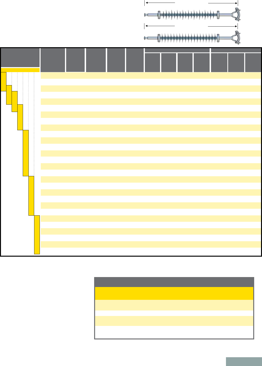
page 15
Suspension Insulators
Mechanical Ratings SML = 30 kip RTL = 15 kip
Rod Diameter: 5/8" (16 mm)
Section Length Adjustment Table, Base End Fittings: Y-clevis-Ball (201)
Y-Clevis
Eye
Eye
ANSI 52-5 Socket
IEC 16 mm Socket
ANSI 52-6 Clevis
ANSI 52-6 Clevis
Eye
ANSI 52-5 Ball
Eye
ANSI 52-5 Ball
IEC 16 mm Ball
Eye
ANSI 52-5 Ball
200
001
000
301
A07
400
401
1.62 (41)
0.02 (0)
1.64 (42)
-1.15 (-29)
-0.03 (-1)
0.82 (21)
-0.8 (-20)
Top and Bottom End Fitting Digits
(“e” & “f”) in Catalog Number
Length Change
inches (mm)
To determine the section length for an insulator with a different end fitting combination, please add
or subtract the displayed length change in the table above. For configurations not shown, use the
Catalog Number Key or contact your HPS representative.
Selection Guide:
Typical Line Voltage, kV
Catalog
Numbers
ANSI
Section
Length
inches
(mm)
Strike
Distance
inches
(mm)
Leakage
Distance
inches
(mm)
ANSI Values IEC Values
60-Hz
Dry
Flashover
(kV)
60-Hz
Wet
Flashover
(kV)
Critical
Impulse
Positive
(kV)
Critical
Impulse
Negative
(kV)
60-Hz
1-minute
Wet
Withstand
(kV)
Impulse
Positive
Withstand
(kV)
Impulse
Negative
Withstand
(kV)
S030021S2010
S030021H2010
S030023S2010
S030023H2010
S030030S2010
S030030H2010
S030036S2010
S030036H2010
S030043S2010
S030043H2010
S030047S2010
S030047H2010
S030051S2010
S030051H2010
S030056S2010
S030056H2010
S030060S2010
S030060H2010
S030064S2010
S030064H2010
S030069S2010
S030069H2010
S030073S2010
S030073H2010
S030077S2010
S030077H2010
S030081S2010
S030081H2010
S030086S2010
S030086H2010
S030090S2010
S030090H2010
S030094S2010
S030094H2010
S030099S2010
S030099H2010
S030103S2010
S030103H2010
S030107S2010
S030107H2010
S030112S2010
S030112H2010
S030116S2010
S030116H2010
S030120S2010
S030120H2010
S030125S2010
S030125H2010
S030129S2010
S030129H2010
S030133S2010
S030133H2010
S030138S2010
S030138H2010
S030142S2010
S030142H2010
33.3 (846)
33.3 (846)
35.4 (899)
35.4 (899)
41.9 (1064)
41.9 (1064)
48.4 (1229)
48.4 (1229)
54.9 (1394)
54.9 (1394)
59.2 (1504)
59.2 (1504)
63.5 (1613)
63.5 (1613)
67.8 (1722)
67.8 (1722)
72.1 (1831)
72.1 (1831)
76.5 (1943)
76.5 (1943)
80.8 (2052)
80.8 (2052)
85.1 (2162)
85.1 (2162)
89.4 (2271)
89.4 (2271)
93.7 (2380)
93.7 (2380)
98.1 (2492)
98.1 (2492)
102.4 (2601)
102.4 (2601)
106.7 (2710)
106.7 (2710)
111 (2819)
111 (2819)
115.3 (2929)
115.3 (2929)
119.7 (3040)
119.7 (3040)
124 (3150)
124 (3150)
128.3 (3259)
128.3 (3259)
132.6 (3368)
132.6 (3368)
136.9 (3477)
136.9 (3477)
141.3 (3589)
141.3 (3589)
145.6 (3698)
145.6 (3698)
149.9 (3807)
149.9 (3807)
154.2 (3917)
154.2 (3917)
21.5 (546)
22 (559)
23.7 (602)
24.1 (612)
30.2 (767)
30.6 (777)
36.6 (930)
37.1 (942)
43.1 (1095)
43.6 (1107)
47.4 (1204)
47.9 (1217)
51.8 (1316)
52.2 (1326)
56.1 (1425)
56.5 (1435)
60.4 (1534)
60.9 (1547)
64.7 (1643)
65.2 (1656)
69 (1753)
69.5 (1765)
73.4 (1864)
73.8 (1875)
77.7 (1974)
78.1 (1984)
82 (2083)
82.5 (2096)
86.3 (2192)
86.8 (2205)
90.6 (2301)
91.1 (2314)
95 (2413)
95.4 (2423)
99.3 (2522)
99.7 (2532)
103.6 (2631)
104.1 (2644)
107.9 (2741)
108.4 (2753)
112.2 (2850)
112.7 (2863)
116.6 (2962)
117 (2972)
120.9 (3071)
121.3 (3081)
125.2 (3180)
125.7 (3193)
129.5 (3289)
130 (3302)
133.8 (3399)
134.3 (3411)
138.2 (3510)
138.6 (3520)
142.5 (3620)
142.9 (3630)
55 (1397)
64 (1626)
60 (1524)
71 (1803)
77 (1956)
90 (2286)
93 (2362)
110 (2794)
110 (2794)
129 (3277)
121 (3073)
142 (3607)
132 (3353)
155 (3937)
143 (3632)
168 (4267)
154 (3912)
181 (4597)
165 (4191)
194 (4928)
176 (4470)
207 (5258)
187 (4750)
220 (5588)
198 (5029)
233 (5918)
209 (5309)
246 (6248)
220 (5588)
259 (6579)
231 (5867)
272 (6909)
242 (6147)
285 (7239)
253 (6426)
298 (7569)
264 (6706)
310 (7874)
275 (6985)
323 (8204)
286 (7264)
336 (8534)
297 (7544)
349 (8865)
308 (7823)
362 (9195)
319 (8103)
375 (9525)
330 (8382)
388 (9855)
341 (8661)
401 (10185)
352 (8941)
414 (10516)
363 (9220)
427 (10846)
220
220
250
250
315
320
385
390
460
465
500
510
540
540
585
585
625
625
660
665
695
700
735
740
780
780
815
820
860
860
890
895
925
930
960
965
990
995
1010
1015
1040
1045
1070
1075
1100
1105
1125
1130
1155
1160
1180
1185
1205
1210
1230
1235
210
210
235
235
305
305
365
370
435
440
475
475
510
510
545
550
580
585
615
615
650
650
685
690
720
720
745
750
780
795
815
820
850
855
875
880
890
895
920
920
945
950
975
980
1000
1005
1030
1035
1055
1060
1080
1085
1105
1110
1130
1135
370
370
415
415
525
535
635
645
730
740
800
805
865
875
935
940
1000
1010
1065
1070
1130
1135
1200
1205
1260
1270
1325
1330
1400
1410
1460
1470
1520
1540
1575
1585
1640
1645
1690
1695
1750
1755
1815
1820
1875
1880
1935
1940
1990
1995
2050
2055
2110
2115
2165
2170
350
350
395
395
510
515
620
620
725
730
795
800
865
870
935
940
1005
1010
1075
1075
1140
1145
1210
1215
1275
1280
1345
1345
1420
1420
1485
1495
1545
1560
1600
1610
1670
1670
1725
1730
1790
1795
1850
1855
1915
1920
1975
1980
2040
2045
2100
2105
2160
2165
2220
2225
145
150
165
165
210
210
255
260
300
305
330
330
360
360
385
390
410
415
435
440
465
465
490
495
515
515
540
540
560
565
585
585
610
615
630
635
655
660
675
675
695
700
720
720
735
740
760
760
780
780
795
800
815
820
835
835
315
325
350
355
445
450
540
540
630
635
690
695
750
760
810
815
870
880
930
940
990
995
1050
1055
1105
1115
1165
1170
1220
1225
1275
1285
1335
1340
1395
1395
1445
1450
1500
1510
1555
1565
1615
1620
1665
1670
1720
1725
1770
1780
1825
1830
1880
1885
1930
1935
300
305
330
335
430
435
525
535
625
630
685
690
750
755
810
815
875
880
940
945
995
1005
1060
1065
1120
1125
1180
1185
1240
1245
1300
1305
1355
1365
1415
1425
1475
1485
1530
1535
1590
1595
1645
1655
1705
1710
1755
1765
1815
1820
1870
1875
1925
1930
1980
1980
69 110 132 161 220 330 400
Nominal
Polymer
Length
inches
021
021
023
023
030
030
036
036
043
043
047
047
051
051
056
056
060
060
064
064
069
069
073
073
077
077
081
081
086
086
090
090
094
094
099
099
103
103
107
107
112
112
116
116
120
120
125
125
129
129
133
133
138
138
142
142
Section Length
Section Length
High Leak Design
Standard Design
Notes:
n Dimensional and electrical values displayed in
main table are for an insulator with Y-clevis
and Ball end fittings.
n For voltages above 400 kV, other section
lengths, or end fitting combinations, please
contact your HPS representative.
n Electrical values are without corona ring.
For voltages equal to or greater than 220
kV, refer to page 12 for corona rings and
associated physical/electrical changes to the
above data. Dimensions are within allowable
tolerances as specified by IEC 61109 and
ANSI C29.12.
Top Fitting Bottom Fitting
January 2011

page 16
Selection Guide:
Typical Line Voltage, kV
Section
Length
inches
(mm)
Strike
Distance
inches
(mm)
Leakage
Distance
inches
(mm)
ANSI Values IEC Values
60-Hz
Dry
Flashover
(kV)
60-Hz
Wet
Flashover
(kV)
Critical
Impulse
Positive
(kV)
Critical
Impulse
Negative
(kV)
60-Hz
1-minute
Wet
Withstand
(kV)
Impulse
Positive
Withstand
(kV)
Impulse
Negative
Withstand
(kV)
S160021S2010
S160021H2010
S160023S2010
S160023H2010
S160030S2010
S160030H2010
S160036S2010
S160036H2010
S160043S2010
S160043H2010
S160047S2010
S160047H2010
S160051S2010
S160051H2010
S160056S2010
S160056H2010
S160060S2010
S160060H2010
S160064S2010
S160064H2010
S160069S2010
S160069H2010
S160073S2010
S160073H2010
S160077S2010
S160077H2010
S160081S2010
S160081H2010
S160086S2010
S160086H2010
S160090S2010
S160090H2010
S160094S2010
S160094H2010
S160099S2010
S160099H2010
S160103S2010
S160103H2010
S160107S2010
S160107H2010
S160112S2010
S160112H2010
S160116S2010
S160116H2010
S160120S2010
S160120H2010
S160125S2010
S160125H2010
S160129S2010
S160129H2010
S160133S2010
S160133H2010
S160138S2010
S160138H2010
S160142S2010
S160142H2010
35.7 (907)
35.7 (907)
37.9 (963)
37.9 (963)
44.4 (1128)
44.4 (1128)
50.8 (1290)
50.8 (1290)
57.3 (1455)
57.3 (1455)
61.6 (1565)
61.6 (1565)
66 (1676)
66 (1676)
70.3 (1786)
70.3 (1786)
74.6 (1895)
74.6 (1895)
78.9 (2004)
78.9 (2004)
83.2 (2113)
83.2 (2113)
87.6 (2225)
87.6 (2225)
91.9 (2334)
91.9 (2334)
96.2 (2443)
96.2 (2443)
100.5 (2553)
100.5 (2553)
104.8 (2662)
104.8 (2662)
109.2 (2774)
109.2 (2774)
113.5 (2883)
113.5 (2883)
117.8 (2992)
117.8 (2992)
122.1 (3101)
122.1 (3101)
126.4 (3211)
126.4 (3211)
130.8 (3322)
130.8 (3322)
135.1 (3432)
135.1 (3432)
139.4 (3541)
139.4 (3541)
143.7 (3650)
143.7 (3650)
148 (3759)
148 (3759)
152.4 (3871)
152.4 (3871)
156.7 (3980)
156.7 (3980)
21.6 (549)
22.5 (572)
23.8 (605)
24.7 (627)
30.3 (770)
31.1 (790)
36.8 (935)
37.6 (955)
43.2 (1097)
44.1 (1120)
47.6 (1209)
48.4 (1229)
51.9 (1318)
52.7 (1339)
56.2 (1427)
57.1 (1450)
60.5 (1537)
61.4 (1560)
64.8 (1646)
65.7 (1669)
69.2 (1758)
70 (1778)
73.5 (1867)
74.3 (1887)
77.8 (1976)
78.7 (1999)
82.1 (2085)
83 (2108)
86.4 (2195)
87.3 (2217)
90.8 (2306)
91.6 (2327)
95.1 (2416)
95.9 (2436)
99.4 (2525)
100.3 (2548)
103.7 (2634)
104.6 (2657)
108 (2743)
108.9 (2766)
112.4 (2855)
113.2 (2875)
116.7 (2964)
117.5 (2985)
121 (3073)
121.9 (3096)
125.3 (3183)
126.2 (3205)
129.6 (3292)
130.5 (3315)
134 (3404)
134.8 (3424)
138.3 (3513)
139.1 (3533)
142.6 (3622)
143.5 (3645)
55 (1397)
74 (1880)
60 (1524)
82 (2083)
77 (1956)
104 (2642)
93 (2362)
126 (3200)
110 (2794)
149 (3785)
121 (3073)
164 (4166)
132 (3353)
179 (4547)
143 (3632)
194 (4928)
154 (3912)
209 (5309)
165 (4191)
224 (5690)
176 (4470)
239 (6071)
187 (4750)
254 (6452)
198 (5029)
268 (6807)
209 (5309)
283 (7188)
220 (5588)
298 (7569)
231 (5867)
313 (7950)
242 (6147)
328 (8331)
253 (6426)
343 (8712)
264 (6706)
358 (9093)
275 (6985)
373 (9474)
286 (7264)
388 (9855)
297 (7544)
403 (10236)
308 (7823)
418 (10617)
319 (8103)
433 (10998)
330 (8382)
448 (11379)
341 (8661)
463 (11760)
352 (8941)
478 (12141)
363 (9220)
493 (12522)
220
225
250
255
320
320
385
395
460
470
500
515
540
545
585
590
625
630
660
670
695
705
735
745
780
785
815
825
860
865
890
900
925
935
960
970
990
1000
1010
1020
1045
1050
1070
1080
1100
1110
1125
1135
1155
1165
1180
1190
1205
1215
1230
1240
210
215
235
240
305
310
365
375
435
445
475
480
510
515
545
555
580
590
615
620
650
655
685
695
720
725
745
755
780
800
815
825
850
860
875
885
890
900
920
925
950
955
975
985
1005
1010
1030
1040
1055
1065
1080
1090
1105
1115
1130
1140
370
375
415
420
525
540
635
650
730
745
800
810
865
880
935
945
1000
1015
1065
1075
1130
1140
1200
1210
1260
1275
1325
1335
1400
1415
1460
1475
1520
1545
1575
1590
1640
1650
1695
1700
1755
1760
1815
1825
1875
1885
1935
1945
1995
2000
2055
2060
2110
2120
2170
2175
350
355
395
400
510
520
625
625
725
735
800
805
860
875
935
945
1005
1015
1075
1080
1140
1150
1210
1220
1275
1285
1345
1350
1420
1425
1485
1500
1545
1565
1605
1615
1670
1675
1725
1735
1790
1800
1855
1860
1915
1925
1980
1985
2040
2050
2100
2110
2160
2170
2220
2230
145
150
165
170
210
215
260
265
300
310
330
335
360
365
385
390
410
420
435
445
465
470
490
495
515
520
540
545
565
570
585
590
610
615
630
635
655
660
675
680
700
705
720
720
740
745
760
765
780
780
795
800
815
820
835
840
315
330
350
360
445
455
540
550
630
640
690
705
755
765
810
825
870
885
930
945
990
1000
1050
1060
1110
1120
1165
1175
1220
1235
1280
1290
1340
1350
1395
1405
1445
1460
1505
1515
1560
1570
1615
1620
1665
1680
1720
1730
1775
1785
1830
1840
1880
1890
1935
1940
300
315
330
345
430
445
530
540
625
635
690
700
750
765
810
825
875
890
940
950
1000
1010
1060
1075
1125
1130
1180
1195
1240
1255
1305
1310
1360
1370
1420
1430
1475
1485
1530
1545
1590
1600
1650
1660
1705
1715
1760
1770
1815
1825
1870
1885
1925
1935
1980
1990
Suspension Insulators
Mechanical Ratings SML = 160 kN RTL = 80 kN
Rod Diameter: 7/8" (22 mm)
Section Length Adjustment Table, Base End Fittings: Y-clevis-Ball (201)
Y-Clevis
Eye
Eye
ANSI 52-8 Socket
IEC 20 mm Socket
Clevis IEC 19-L
Clevis IEC 19-L
Eye
ANSI 52-8 Ball
Eye
ANSI 52-8 Ball
IEC 20 mm Ball
Eye
IEC 20 mm Ball
200
001
000
301
A07
800
807
1.71 (43)
0.31 (8)
2.02 (51)
-1.27 (-32)
0.26 (7)
0.80 (20)
0.06 (2)
Top and Bottom End Fitting Digits
(“e” & “f”) in Catalog Number
Length Change
inches (mm)
69 110 132 161 220 330 400
To determine the section length for an insulator with a different end fitting combination, please add
or subtract the displayed length change in the table above. For configurations not shown, use the
Catalog Number Key or contact your HPS representative.
Catalog
Numbers
IEC
Section Length
Section Length
High Leak Design
Standard Design
Nominal
Polymer
Length
inches
021
021
023
023
030
030
036
036
043
043
047
047
051
051
056
056
060
060
064
064
069
069
073
073
077
077
081
081
086
086
090
090
094
094
099
099
103
103
107
107
112
112
116
116
120
120
125
125
129
129
133
133
138
138
142
142
Notes:
n Dimensional and electrical values displayed in
main table are for an insulator with Y-clevis
and Ball end fittings.
n For voltages above 400 kV, other section
lengths, or end fitting combinations, please
contact your HPS representative.
n Electrical values are without corona ring.
For voltages equal to or greater than 220
kV, refer to page 12 for corona rings and
associated physical/electrical changes to the
above data. Dimensions are within allowable
tolerances as specified by IEC 61109 and
ANSI C29.12.
Top Fitting Bottom Fitting
January 2011
page 17
Suspension Insulators
Mechanical Ratings SML = 50 kip/210 kN RTL = 25 kip/105 kN
Rod Diameter: 7/8" (22 mm)
Section Length Adjustment Table, Base End Fittings: Y-clevis-Ball (201)
Y-Clevis
Eye
Eye
ANSI 52-11 Socket
IEC 20 mm Socket
Clevis IEC 19-L
Clevis IEC 19-L
Eye
ANSI 52-11 Ball
Eye
ANSI 52-11 Ball
IEC 20 mm Ball
Eye
IEC 20 mm Ball
200
001
000
301
A07
800
807
1.71 (43)
0.31 (8)
2.02 (51)
-0.71 (-18)
0.26 (7)
0.80 (20)
0.06 (2)
Top and Bottom End Fitting Digits
(“e” & “f”) in Catalog Number
Length Change
inches (mm)
To determine the section length for an insulator with a different end fitting combination, please add
or subtract the displayed length change in the table above. For configurations not shown, use the
Catalog Number Key or contact your HPS representative.
Section Length
Section Length
High Leak Design
Standard Design
Selection Guide:
Typical Line Voltage, kV
Section
Length
inches
(mm)
Strike
Distance
inches
(mm)
Leakage
Distance
inches
(mm)
ANSI Values IEC Values
60-Hz
Dry
Flashover
(kV)
60-Hz
Wet
Flashover
(kV)
Critical
Impulse
Positive
(kV)
Critical
Impulse
Negative
(kV)
60-Hz
1-minute
Wet
Withstand
(kV)
Impulse
Positive
Withstand
(kV)
Impulse
Negative
Withstand
(kV)
S050021S2010 / S210021S2010
S050021H2010 / S210021H2010
S050023S2010 / S210023S2010
S050023H2010 / S210023H2010
S050030S2010 / S210030S2010
S050030H2010 / S210030H2010
S050036S2010 / S210036S2010
S050036H2010 / S210036H2010
S050043S2010 / S210043S2010
S050043H2010 / S210043H2010
S050047S2010 / S210047S2010
S050047H2010 / S210047H2010
S050051S2010 / S210051S2010
S050051H2010 / S210051H2010
S050056S2010 / S210056S2010
S050056H2010 / S210056H2010
S050060S2010 / S210060S2010
S050060H2010 / S210060H2010
S050064S2010 / S210064S2010
S050064H2010 / S210064H2010
S050069S2010 / S210069S2010
S050069H2010 / S210069H2010
S050073S2010 / S210073S2010
S050073H2010 / S210073H2010
S050077S2010 / S210077S2010
S050077H2010 / S210077H2010
S050081S2010 / S210081S2010
S050081H2010 / S210081H2010
S050086S2010 / S210086S2010
S050086H2010 / S210086H2010
S050090S2010 / S210090S2010
S050090H2010 / S210090H2010
S050094S2010 / S210094S2010
S050094H2010 / S210094H2010
S050099S2010 / S210099S2010
S050099H2010 / S210099H2010
S050103S2010 / S210103S2010
S050103H2010 / S210103H2010
S050107S2010 / S210107S2010
S050107H2010 / S210107H2010
S050112S2010 / S210112S2010
S050112H2010 / S210112H2010
S050116S2010 / S210116S2010
S050116H2010 / S210116H2010
S050120S2010 / S210120S2010
S050120H2010 / S210120H2010
S050125S2010 / S210125S2010
S050125H2010 / S210125H2010
S050129S2010 / S210129S2010
S050129H2010 / S210129H2010
S050133S2010 / S210133S2010
S050133H2010 / S210133H2010
S050138S2010 / S210138S2010
S050138H2010 / S210138H2010
S050142S2010 / S210142S2010
S050142H2010 / S210142H2010
35.7 (907)
35.7 (907)
37.9 (963)
37.9 (963)
44.4 (1128)
44.4 (1128)
50.8 (1290)
50.8 (1290)
57.3 (1455)
57.3 (1455)
61.6 (1565)
61.6 (1565)
66 (1676)
66 (1676)
70.3 (1786)
70.3 (1786)
74.6 (1895)
74.6 (1895)
78.9 (2004)
78.9 (2004)
83.2 (2113)
83.2 (2113)
87.6 (2225)
87.6 (2225)
91.9 (2334)
91.9 (2334)
96.2 (2443)
96.2 (2443)
100.5 (2553)
100.5 (2553)
104.8 (2662)
104.8 (2662)
109.2 (2774)
109.2 (2774)
113.5 (2883)
113.5 (2883)
117.8 (2992)
117.8 (2992)
122.1 (3101)
122.1 (3101)
126.4 (3211)
126.4 (3211)
130.8 (3322)
130.8 (3322)
135.1 (3432)
135.1 (3432)
139.4 (3541)
139.4 (3541)
143.7 (3650)
143.7 (3650)
148 (3759)
148 (3759)
152.4 (3871)
152.4 (3871)
156.7 (3980)
156.7 (3980)
21.6 (549)
22.5 (572)
23.8 (605)
24.7 (627)
30.3 (770)
31.1 (790)
36.8 (935)
37.6 (955)
43.2 (1097)
44.1 (1120)
47.6 (1209)
48.4 (1229)
51.9 (1318)
52.7 (1339)
56.2 (1427)
57.1 (1450)
60.5 (1537)
61.4 (1560)
64.8 (1646)
65.7 (1669)
69.2 (1758)
70 (1778)
73.5 (1867)
74.3 (1887)
77.8 (1976)
78.7 (1999)
82.1 (2085)
83 (2108)
86.4 (2195)
87.3 (2217)
90.8 (2306)
91.6 (2327)
95.1 (2416)
95.9 (2436)
99.4 (2525)
100.3 (2548)
103.7 (2634)
104.6 (2657)
108 (2743)
108.9 (2766)
112.4 (2855)
113.2 (2875)
116.7 (2964)
117.5 (2985)
121 (3073)
121.9 (3096)
125.3 (3183)
126.2 (3205)
129.6 (3292)
130.5 (3315)
134 (3404)
134.8 (3424)
138.3 (3513)
139.1 (3533)
142.6 (3622)
143.5 (3645)
55 (1397)
74 (1880)
60 (1524)
82 (2083)
77 (1956)
104 (2642)
93 (2362)
126 (3200)
110 (2794)
149 (3785)
121 (3073)
164 (4166)
132 (3353)
179 (4547)
143 (3632)
194 (4928)
154 (3912)
209 (5309)
165 (4191)
224 (5690)
176 (4470)
239 (6071)
187 (4750)
254 (6452)
198 (5029)
268 (6807)
209 (5309)
283 (7188)
220 (5588)
298 (7569)
231 (5867)
313 (7950)
242 (6147)
328 (8331)
253 (6426)
343 (8712)
264 (6706)
358 (9093)
275 (6985)
373 (9474)
286 (7264)
388 (9855)
297 (7544)
403 (10236)
308 (7823)
418 (10617)
319 (8103)
433 (10998)
330 (8382)
448 (11379)
341 (8661)
463 (11760)
352 (8941)
478 (12141)
363 (9220)
493 (12522)
220
225
250
255
315
320
385
395
460
470
500
510
540
545
585
590
625
630
660
670
695
705
735
745
780
785
815
825
860
865
890
900
925
935
960
970
990
1000
1010
1020
1045
1050
1070
1080
1100
1110
1125
1135
1155
1165
1180
1190
1205
1215
1230
1240
210
215
235
240
305
310
365
375
435
445
475
480
510
515
545
555
580
590
615
620
650
655
685
695
720
725
745
755
780
800
815
825
850
860
875
885
890
900
920
925
950
955
975
985
1005
1010
1030
1040
1055
1065
1080
1090
1105
1115
1130
1140
370
375
415
420
525
540
635
650
730
745
800
810
865
880
935
945
1000
1015
1065
1075
1130
1140
1200
1210
1260
1275
1325
1335
1400
1415
1460
1475
1520
1545
1575
1590
1640
1650
1695
1700
1755
1760
1815
1825
1875
1885
1935
1945
1995
2000
2055
2060
2110
2120
2170
2175
350
355
395
400
510
520
625
625
725
735
800
805
860
875
935
945
1005
1015
1075
1080
1140
1150
1210
1220
1275
1285
1345
1350
1420
1425
1485
1500
1545
1565
1605
1615
1670
1675
1725
1735
1790
1800
1855
1860
1915
1925
1980
1985
2040
2050
2100
2110
2160
2170
2220
2230
145
150
165
170
210
215
260
265
300
310
330
335
360
365
385
390
410
420
435
445
465
470
490
495
515
520
540
545
565
570
585
590
610
615
630
635
655
660
675
680
700
705
720
720
740
745
760
765
780
780
795
800
815
820
835
840
315
330
350
360
445
455
540
550
630
640
690
705
755
765
810
825
870
885
930
945
990
1000
1050
1060
1110
1120
1165
1175
1220
1235
1280
1290
1340
1350
1395
1405
1445
1460
1505
1515
1560
1570
1615
1620
1665
1680
1720
1730
1775
1785
1830
1840
1880
1890
1935
1940
300
315
330
345
430
445
530
540
625
635
690
700
750
765
810
825
875
890
940
950
1000
1010
1060
1075
1125
1130
1180
1195
1240
1255
1305
1310
1360
1370
1420
1430
1475
1485
1530
1545
1590
1600
1650
1660
1705
1715
1760
1770
1815
1825
1870
1885
1925
1935
1980
1990
69 110 132 161 220 330 400
Catalog Numbers
ANSI / IEC
Nominal
Polymer
Length
inches
021
021
023
023
030
030
036
036
043
043
047
047
051
051
056
056
060
060
064
064
069
069
073
073
077
077
081
081
086
086
090
090
094
094
099
099
103
103
107
107
112
112
116
116
120
120
125
125
129
129
133
133
138
138
142
142
Notes:
n Dimensional and electrical values displayed in
main table are for an insulator with Y-clevis
and Ball end fittings.
n For voltages above 400 kV, other section
lengths, or end fitting combinations, please
contact your HPS representative.
n Electrical values are without corona ring.
For voltages equal to or greater than 220
kV, refer to page 12 for corona rings and
associated physical/electrical changes to the
above data. Dimensions are within allowable
tolerances as specified by IEC 61109 and
ANSI C29.12.
Top Fitting Bottom Fitting
January 2011

page 18 January 2011
page 19
Line Post Insulators
TABLE OF CONTENTS PAGE
Mechanical Ratings and Corona Performance ................................................... 20
Quadri*Sil® Horizontal Line Posts ..................................................................... 21
Quadri*Sil® Vertical Line Posts ......................................................................... 22
Quadri*Sil® Base Fittings ................................................................................. 24
Quadri*Sil® Line Fittings .................................................................................. 25
Clamps and Assemblies .................................................................................. 26
January 2011
®

page 20
Line Post Insulators
2.5” (63.5 mm) Rod Diameter Horizontal
Mechanical Ratings
Line post insulators are cantilever support members, with ratings defined as follows:
Specified Cantilever Load (SCL)
SCL is the ultimate cantilever strength rating of the Quadri*Sil® line post insulator. SCL is identical to
the minimum average breaking load (ABL) rating in previous catalogs.
Reference Cantilever Load (RCL)
RCL represents the maximum recommended load in cantilever that a Quadri*Sil® post insulator is
designed to withstand during its life span. RCL equals 50 percent of the SCL, and is identical to the
insulator’s maximum working load (MWL) and maximum design cantilever load (MDCL).
Combined Load Charts
Line design loads for most insulators include tension, or compression, in addition to the primary
vertical cantilever load. Longitudinal loading should also be considered. Contact your Hubbell Power
Systems representative to request combined load charts.
Application 230 kv
161 kv & Below 345 kv
Line End
Energized
Bottom End
Energized
Top - 2721273001
Bott - NONE
Top - NONE
Bott - 2721273001
Top - 2721273001
Bott - NONE
Top - NONE
Bott - 2721273001
Top - NONE
Bott - NONE
Top - NONE
Bott - NONE
Recommended
Torque
10 ft.-lb.
Recommended
Torque
45 ft.-lb.
3.4375’’
(87 mm)
12’’
(305 mm)
Electrical/Dimensional Changes to the Insulator
with External Corona Ring
Physical & Electrical Characteristics
Dry Arc Distance inches (mm)
Leakage Distance inches (mm)
ANSI 60 Hz Flashover Dry — kV
ANSI 60 Hz Flashover Wet — kV
ANSI Critical Flashover Positive — kV
ANSI Critical Flashover Negative — kV
IEC Wet Switching Impulse Withstand — kV
IEC Power Frequency Wet Withstand — kV
IEC Lightning Impulse Withstand Positive — kV
IEC Lightning Impulse Withstand Negative — kV
Net Weight pounds (kg)
220/230 kV
Ring
-1.86 (-47)
0
-20
-20
-30
-30
N/A
-20
-30
-30
3.4 (1.5)
330/345 kV
Ring
-2.58 (-66)
0
-30
-20
-40
-40
N/A
-20
-40
-40
3.4 (1.5)
400 kV
Rings
N/A
N/A
N/A
N/A
N/A
N/A
N/A
N/A
N/A
N/A
N/A
500 kV
Rings
N/A
N/A
N/A
N/A
N/A
N/A
N/A
N/A
N/A
N/A
N/A
Corona Performance
January 2011
page 21
Horizontal Line Post Insulators
2.5” (63.5 mm) Rod Diameter
Horizontal Clamptop End Fitting
Increases the section length
dimensions by 0.75”
Clamptop:
Maximum Design Tension = 2,500 lbs. (11.1 kN)
Two-Hole Blade:
Maximum Design Tension = 7,500 lbs. (33.4 kN)
Notes:
1) For voltages above 330 kV, other section lengths, or end fitting combinations, please contact your HPS representative.
2) Electrical values are without corona ring. For voltages equal to or greater than 220 kV, refer to page 20 for corona rings and associated
physical/electrical changes to the above data. Dimensions are within allowable tolerances as specified by IEC 61952 and ANSI C29.17.
3) The catalog number shown in the table is for a 2.5’’ (63.5mm) rod diameter line post with a two hole blade on the line end and a gain
base on the tower end. For other end fitting combinations, please refer to the Catalog Number Key on page 8.
Section Length
January 2011
Selection Guide:
Typical Line Voltage,
kV(1)
Catalog
Numbers(3)
Section
Length
inches
(mm)
Strike
Distance
inches
(mm)
ANSI Values IEC Values
(2)60-Hz
Dry
Flashover
(kV)
(2)60-Hz
Wet
Flashover
(kV)
(2)Critical
Impulse
Positive
(kV)
(2)Critical
Impulse
Negative
(kV)
(2)60-Hz
1-minute
Wet
Withstand
(kV)
(2)Impulse
Positive
Withstand
(kV)
SCL lbs.
(kN)
P250024S0020
P250026S0020
P250031S0020
P250036S0020
P250043S0020
P250048S0020
P250053S0020
P250058S0020
P250060S0020
P250065S0020
P250070S0020
P250075S0020
P250080S0020
P250087S0020
P250092S0020
P250096S0020
P250101S0020
P250104S0020
P250106S0020
P250109S0020
P250111S0020
25.0 (635)
27.4 (696)
32.2 (818)
37.1 (942)
44.3 (1125)
49.2 (1250)
54.0 (1372)
58.8 (1494)
61.3 (1557)
66.1 (1679)
70.9 (1801)
75.8 (1925)
80.6 (2047)
87.9 (2233)
92.7 (2355)
97.6 (2479)
102.4 (2601)
104.8 (2662)
107.2 (2723)
109.7 (2786)
112.1 (2847)
255
280
330
380
455
515
565
600
625
675
720
765
815
880
925
975
1015
1040
1060
1085
1105
235
255
300
345
405
450
495
525
540
580
615
650
680
735
765
800
830
845
860
875
890
385
425
510
580
700
770
855
920
955
1035
1115
1190
1265
1380
1455
1535
1610
1650
1685
1725
1765
505
540
615
690
800
880
950
1025
1065
1140
1215
1290
1360
1475
1550
1625
1700
1735
1770
1810
1850
5000 (22.2)
5000 (22.2)
4490 (20.0)
3950 (17.6)
3340 (14.9)
3030 (13.5)
2770 (12.3)
2550 (11.3)
2460 (10.9)
2280 (10.1)
2130 (9.5)
2000 (8.9)
1890 (8.4)
1740 (7.7)
1650 (7.3)
1570 (7.0)
1500 (6.7)
1460 (6.5)
1430 (6.4)
1400 (6.2)
1370 (6.1)
69 110 132 161 220 330
Nominal
Polymer
Length
inches
024
026
031
036
043
048
053
058
060
065
070
075
080
087
092
096
101
104
106
109
111
Horizontal Line Post Insulators
2.5” (63.5 mm) Rod Diameter
(2)Impulse
Negative
Withstand
(kV)
Leakage
Distance
inches
(mm)
63 (1600)
69 (1753)
82 (2083)
95 (2413)
113 (2870)
126 (3200)
139 (3531)
151 (3835)
158 (4013)
170 (4318)
183 (4648)
196 (4978)
208 (5283)
227 (5766)
240 (6096)
252 (6401)
265 (6731)
271 (6883)
278 (7061)
284 (7214)
290 (7366)
36.9 (937)
39.3 (998)
44.0 (1117)
48.8 (1239)
55.9 (1419)
60.6 (1539)
65.3 (1658)
70.1 (1780)
72.4 (1838)
77.2 (1960)
81.9 (2080)
86.6 (2199)
91.4 (2321)
98.5 (2501)
103.2 (2621)
107.9 (2740)
112.7 (2862)
115.1 (2923)
117.4 (2981)
119.8 (3042)
122.2 (3103)
195
215
255
290
340
380
420
445
455
490
520
550
575
620
650
680
705
715
730
740
755
365
400
480
550
665
730
810
870
905
980
1055
1130
1200
1310
1380
1455
1525
1565
1600
1635
1675
475
510
580
655
760
835
900
970
1010
1080
1150
1225
1290
1400
1470
1540
1615
1645
1680
1715
1755
page 22
Vertical Line Post Insulators
2.5” (63.5 mm) Rod Diameter
Maximum Design Tension = 2,500 lbs. (11.1 kN)
0.6875’’ Dia. (17 mm ) 5” Dia. Bolt Circle
(127 mm)
11’’
(279 mm)
0.9375’’ Dia.
(24 mm)
0.8125’’ Dia.
(21 mm)
3.875’’
(98 mm)
0.8125’’ x 1” Slot
(21 mm x 25 mm)
8’’
(203 mm)
8’’
(203 mm)
4’’
(102 mm)
Section Length
Vertical Line Post Insulators
2.5” (63.5 mm) Rod Diameter
Notes:
1) For voltages above 161 kV, other section lengths, or end fitting combinations, please contact your HPS representative.
2) Electrical values are without corona ring. For voltages equal to or greater than 220 kV, refer to page 20 for corona rings and associated
physical/electrical changes to the above data. Dimensions are within allowable tolerances as specified by IEC 61952 and ANSI C29.17.
3) The catalog number shown on the table is for a 2.5” (63.5mm) rod diameter line post with a vertical clamptop on the line end and a 5’’ Bolt
Circle with tapped holes on the ground end. For other end fitting combinations, please refer to the Catalog Number Key on page 8.
1.125’’
(29 mm)
4.125’’
(105 mm)
Selection Guide:
Typical Line
Voltage, kV(1)
Catalog
Numbers(3)
Nominal
Polymer
Length
inches
Section
Length
inches
(mm)
Strike
Distance
inches
(mm)
ANSI Values IEC Values
(2)Critical
Impulse
Positive
(kV)
(2)Critical
Impulse
Negative
(kV)
(2)60-Hz
1-minute
Wet
Withstand
(kV)
(2)Impulse
Positive
Withstand
(kV)
(2)Impulse
Negative
Withstand
(kV)
SCL lbs.
(kN)
P250024S2050
P250026S2050
P250031S2050
P250036S2050
P250043S2050
P250048S2050
P250053S2050
P250058S2050
P250060S2050
35.0 (889)
37.4 (950)
42.3 (1074)
47.1 (1196)
54.4 (1382)
59.2 (1504)
64.1 (1628)
68.9 (1750)
71.3 (1811)
25.0 (635)
27.4 (696)
32.2 (818)
37.1 (942)
44.3 (1125)
49.2 (1250)
54.0 (1372)
58.8 (1494)
61.3 (1557)
63 (1600)
69 (1753)
82 (2083)
95 (2413)
113 (2870)
126 (3200)
139 (3531)
151 (3835)
158 (4013)
385
425
510
580
700
770
855
920
955
505
540
615
690
800
880
950
1025
1065
195
215
255
290
340
380
420
445
455
365
400
480
550
665
730
810
870
905
475
510
580
655
760
835
900
970
1010
5000 (22.3)
5000 (22.3)
4200 (18.7)
3720 (16.6)
3180 (14.2)
2900 (12.9)
2660 (11.8)
2460 (10.9)
2370 (10.5)
69 110 132 161
Leakage
Distance
inches
(mm)
024
026
031
036
043
048
053
058
060
4.125’’
(105 mm)
3.875’’
(98 mm)
0.8125’’ Dia.
(21 mm)
Cat. No. 75115
Rated 134,400 lb.-in.
January 2011
(2)60-Hz
Wet
Flashover
(kV)
235
255
300
345
405
450
495
525
540
(2)60-Hz
Dry
Flashover
(kV)
255
280
330
380
455
515
565
600
625

page 23
Vertical Line Post Assembly
2.5” (63.5 mm) Rod Diameter
A
B
7.44’’
(189 mm)
2.0’’
(51 mm)
5.75’’
(146 mm)
C
7.438’’
(189 mm)
D
1.625’’ (41 mm)
D
Selection Guide:
Typical Line
Voltage, kV(1) “XX”
Code(2)
Catalog
Numbers(2) Style
Table A Table B
“A”
Length
inches
(mm)
“B”
Length
inches
(mm)
“C”
Length
inches
(mm)
“D”
Diameter
inches
(mm)
P250024S2XX0
P250026S2XX0
P250031S2XX0
P250036S2XX0
P250043S2XX0
P250048S2XX0
P250053S2XX0
P250058S2XX0
P250060S2XX0
Face
Side
Face
Side
Face
Side
Face
Side
20
21
22
23
24
25
26
27
34.7 (881)
37.1 (942)
42 (1067)
46.8 (1189)
54.1 (1374)
58.9 (1496)
63.6 (1615)
68.4 (1737)
70.7 (1796)
20 (508)
20 (508)
20 (508)
20 (508)
31.75 (806)
31.75 (806)
31.75 (806)
31.75 (806)
12 (305)
12 (305)
12 (305)
12 (305)
16 (406)
16 (406)
16 (406)
16 (406)
0.8125 (21)
0.8125 (21)
0.9375 (24)
0.9375 (24)
0.8125 (21)
0.8125 (21)
0.9375 (24)
0.9375 (24)
Vertical Line Post Insulators
2.5” (63.5 mm) Rod Diameter
Notes:
1) Insulators in Table A have the same electrical and mechanical characteristics as those on page 22 with a
vertical clamptop on the line end and a 5” Bolt Circle on the ground end.
2) According to your preferred mounting configuration, replace the “xx” in catalog number from Table A with
the two-digit “xx” code from Table B.
69 110 132 161
Nominal
Polymer
Length
inches
024
026
031
036
043
048
053
058
060
2.0’’
(51 mm)
January 2011

page 24
Base Fittings for 2.5” (63.5 mm) Rod Diameter
Type (Code)
5” Bolt Circle (15)
5” Bolt Circle (05)
Aluminum Gain (02)
Aluminum Gain (12)
Steel Gain (07)
Aluminum Flat (03)
Aluminum Flat (13)
Steel Flat (08)
Aluminum Flat (04)
Aluminum Flat (14)
A
4.75
(121)
4.75
(121)
12.0
(305)
12.0
(305)
12.0
(305)
10.0
(254)
10.0
(254)
13.0
(330)
13.0
(330)
13.0
(330)
B
6.25
(159)
6.25
(159)
14.0
(356)
14.0
(356)
15.0
(381)
12.0
(305)
12.0
(305)
15.0
(381)
15.0
(381)
15.0
(381)
C
3.63
(92)
3.63
(92)
-
-
-
8.0
(203)
8.0
(203)
8.0
(203)
8.0
(203)
8.0
(203)
D
0.90
(23)
0.90
(23)
8.06
(205)
8.06
(205)
8.33
(212)
10.0
(254)
10.0
(254)
10.0
(254)
10.0
(254)
10.0
(254)
E
5.0
(127)
5.0
(127)
6.13
(156)
6.13
(156)
6.5
(165)
5.0
(127)
5.0
(127)
6.5
(165)
6.5
(165)
6.5
(165)
F
-
-
5.56
(141)
5.56
(141)
6.04
(153)
4.0
(102)
4.0
(102)
4.0
(102)
4.0
(102)
4.0
(102)
G
-
-
0.5
(13)
0.5
(13)
0.38
(10)
0.5
(13)
0.5
(13)
0.38
(10)
0.5
(13)
0.5
(13)
H
-
-
12º
12º
12º
12º
12º
12º
12º
12º
I
0.69
(18)
5/8 - 11 UFS
0.94
(24)
0.81
(21)
0.94
(24)
0.94
(24)
0.81
(21)
1.125 X 0.94
(26x24)
0.94
(24)
0.81
(21)
J
-
-
0.94 X 1.31
(24x33)
0.94 X 1.31
(24x33)
0.94 X 2.0
(24x51)
-
-
0.94 X 2.0
(24x51)
0.94 X 1.31
(24x33)
0.81 X 1.31
(21x33)
K
-
-
-
-
-
-
-
12.0
(305)
12.0
(305)
12.0
(305)
Material
60-40-18 D.I.
60-40-18 D.I.
6063 T5 AL
6063 T5 AL
Low Carbon Steel
6063 T5 AL
6063 T5 AL
Low Carbon Steel
6063 T5 AL
6063 T5 AL
Horizontal & Vertical Bases inches (mm)
Al & Steel Gain
Al & Steel Flat
E
F
G
B
A
øI
JD
14’’ Dia.
(356 mm)
8’’ Dia.
(203 mm)
7’’ Dia.
(178 mm)
3.38’’ (86 mm)
4.44’’ (113 mm)
F
H
G
B
A
D
C
øI
K
J
H
E
January 2011
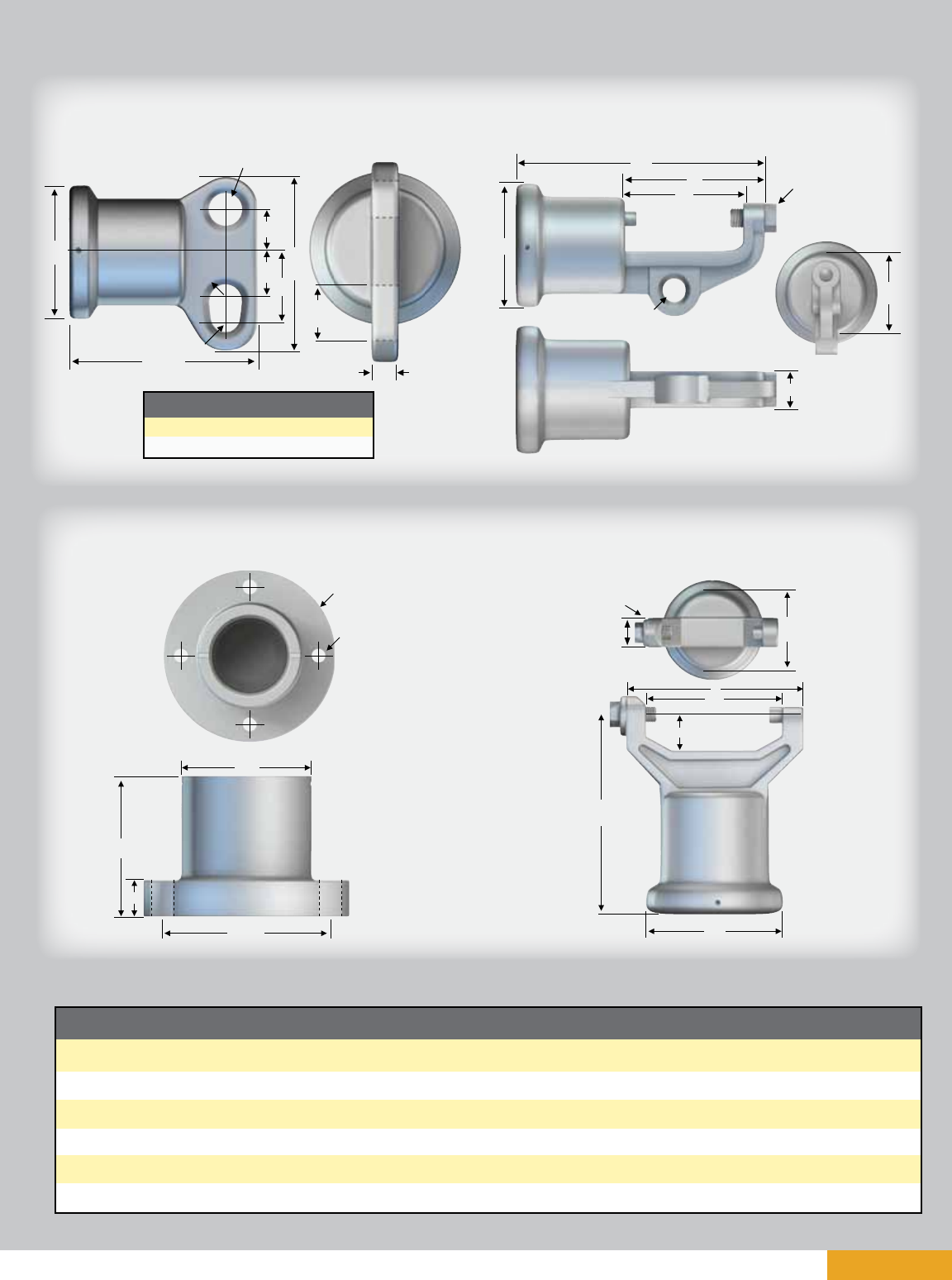
page 25
Line Fittings for 2.5” (63.5 mm) Rod Diameter
Horizontal & Vertical End Fittings inches (mm)
Type (Code)
2 Hole Blade (0)
2 Hole Long Blade (9)
H. Clamptop (1)
5” Bolt Circle (3)
5” Bolt Circle (5)
V. Clamptop (2)
A
5.73
(146)
5.73
(146)
8.24
(209)
4.75
(121)
4.75
(121)
5.88
(149)
B
4.0
(102)
4.0
(102)
4.0
(102)
6.25
(159)
6.25
(159)
4.0
(102)
C
-
-
3.30
(84)
3.63
(92)
3.63
(92)
3.30
(84)
D
0.75
(19)
0.75
(19)
1.12
(28)
0.90
(23)
0.90
(23)
1.12
(28)
E
5.25
(133)
7.75
(197)
4.72
(120)
5.0
(127)
5.0
(127)
5.37
(136)
F
1.25
(32)
1.25
(32)
4.0
(102)
-
-
4.0
(102)
G
1.50
(38)
4.0
(102)
-
-
-
1.06
(27)
H
2.00
(51)
4.5
(114)
-
-
-
-
I
1.0
(25)
1.0
(25)
5/8 - 11 UFS
5/8 - 11 UFS
0.69 x Holes
(18 x Holes)
5/8 - 11 UFS
J
1.44
(37)
1.44
(37)
0.75
(19)
-
-
-
L
0.5R
(12.7R)
0.5R
(12.7R)
-
-
-
-
Material
60-40-18 D.I.
60-40-18 D.I.
60-40-18 D.I.
60-40-18 D.I.
60-40-18 D.I.
60-40-18 D.I.
M
0.44R
(11R)
0.44R
(11R)
-
-
-
-
øBE
F
G
H
A
M
L
øI
J
D
øB
A
øJ
F
E
øC
I
D
I
øB
E
øC
A
D
øB
F
E
G
A
øC
D
I
Transverse Compressing Swing Angle
for Conductor Suspension Clamp
2 Hole Blade (std.)
40 deg. max.
2 Hole Long Blade
64 deg. max.
Two Hole Blade
5” Bolt Circle
Line or Base Fitting
Vertical Clamptop
Part per ANSI C29.7
Horizontal Clamptop
L is outer radius
M is inner radius
Note: 12º upsweep is already included
January 2011
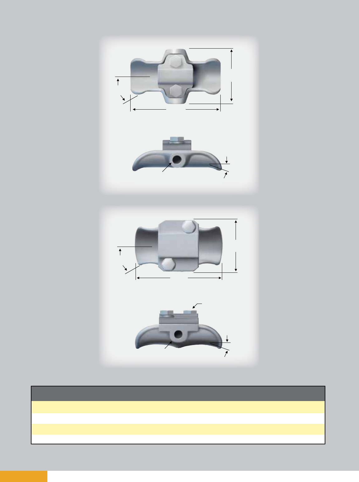
page 26
Clamptop Clamps inches (mm)
Catalog Number
TSC57
TSC106
TSC150
TSC200
Fig. No.
1
1
1
2
Body &
Keeper Material
356-T6 AL
356-T6 AL
356-T6 AL
356-T6 AL
Clamping Range
inches (mm)
0.25 - 0.57 (6.3 - 14.4)
0.50 - 1.06 (12.7 - 26.9)
1.00 - 1.50 (25.4 - 38.1)
1.50 - 2.00 (38.1 - 50.8)
Ultimate Body
Strength lbs. (kN)
2800 (1.273)
2800 (1.273)
2800 (1.273)
2800 (1.273)
3.875’’
(98 mm)
5.25’’
(133 mm)
15º
20º
0.594’’ Dia.
(15 mm)
Figure 1
3.875’’
(98 mm)
15º
5.25’’
(133 mm)
20º
0.594’’ Dia.
(15 mm)
J
Figure 2
January 2011
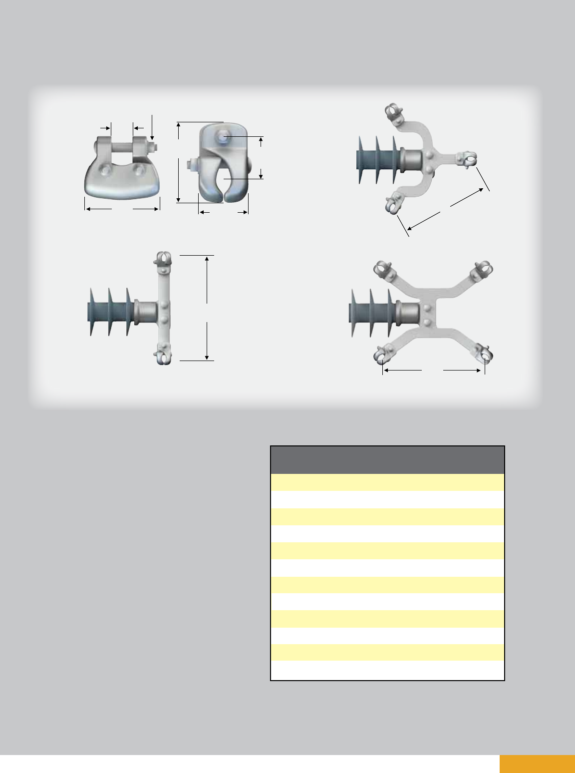
page 27
Jumper Clamps and Assemblies
18’’
(457 mm)
A practical application of Quadri*Sil® line posts is for
support of jumper loops on transmission lines.
Horizontal motion of the jumper is restricted, and the
factor of wind sway is eliminated. Additionally, the
crossarm length may be reduced. The difference in
cost of insulation is not significant, but the saving in
tower cost can be attractive. Regardless of cost, the
use of a jumper support improves construction.
If using a single clamp, clamp postition relative to
the insulator may be changed by bolting the clamp
through the upper hole in the insulator end fitting.
Jumper clamps are not intended for tangent
span applications.
Figure
1
1
1
2
2
2
3
3
3
4
4
4
Catalog
Number
976423002
976423003
600643001
2717243001
2717253001
2717263001
2721763001
2721773001
2721783001
2721793001
2721803001
2721813001
Yoke Type
None
None
None
Dual
Dual
Dual
Triple
Triple
Triple
Quad
Quad
Quad
Clamping Range
inches (mm)
1.00 - 1.40
(25 - 36)
1.40 - 1.60
(36 - 41)
1.60 - 2.00
(41 - 51)
1.00 - 1.40
(25 - 36)
1.40 - 1.60
(36 - 41)
1.60 - 2.00
(41 - 51)
1.00 - 1.40
(25 - 36)
1.40 - 1.60
(36 - 41)
1.60 - 2.00
(41 - 51)
1.00 - 1.40
(25 - 36)
1.40 - 1.60
(36 - 41)
1.60 - 2.00
(41 - 51)
18’’
(457 mm)
Figure 1
Figure 2
Figure 3
Figure 4
0.5’’ Dia.
(13 mm)
To fit 0.75’’ (19 mm)
THK Plate
5’’
(127 mm) 2.625’’
(67 mm)
4.25’’
(108 mm) 2.375’’
(60 mm)
18’’
(457 mm)
January 2011

page 28 January 2011

page 29
Braced Post Insulators
TABLE OF CONTENTS PAGE
Braced Line Post Assemblies .............................................................................30
Assembly Drawings ...........................................................................................31
Dimensions and Strength Ratings ......................................................................32
January 2011
®

page 30
Braced Line Post Assemblies
The need to minimize tower size and visual impact of transmission lines has prompted increased
interest in braced line posts, horizontal-V, and pivoting V assemblies. These insulating structures offer
vastly improved vertical load capabilities over conventional line posts, while retaining the advantages
of a fixed conductor position.
A braced line post insulator uses a conventional line post with a suspension string tied to the tower
face. Some of the characteristics of a braced line post are:
• It uses a traditional fixed base line post.
• The longitudinal strength is limited to the RCL rating of the line post component.
• It generates high tower torque (Z-direction) under longitudinal loading.
A horizontal-V insulator uses a conventional line post with a suspension string at a fixed offset
extending from the tower face, adding a stabilizing force to the assembly. Some of the characteristics
of a horizontal-V assembly are:
• It uses a fixed base horizontal line post (zero degree upsweep).
• It has an inclined hinge axis to add resistance to longitudinal movement.
• It employs a suspension insulator ground end stub arm (vang).
• The longitudinal strength is limited to the RCL rating of the line post component.
• It generates high tower torque (Z-direction) under longitudinal loading.
A pivoting horizontal-V insulator uses a conventional suspension string with a line post insulator fas-
tened to the structure with a hinged base. Some of the characteristics of a pivoting horizontal-V are:
• It pivots about an inclined axis.
• It employs a suspension insulator ground end stub arm (vang).
• It uses a universal joint or pivot base on the strut.
• It has high longitudinal strength.
• It generates low tower torque (Z-direction) under longitudinal loading.
• The assembly’s swing angle is a function of the vertical load and the tower offset pivot angle.
• The assembly’s maximum longitudinal loading is a function of the tensile rating of the strut.
The tables included on the following pages — and the images on the assembly drawings page —
cover typical arrangements that provide an efficient means of withstanding unusual loads. For more
information on these and numerous other variations of line post assemblies, contact your
Hubbell Power Systems representative.
January 2011

page 31
Assembly Drawings
B
3.5’’
(89 mm)
D
AS-50
C
12º
X
A
APPROX 62º
AS-50
A
C
BD
AS-50
3.5’’ (89 mm)
X
APPROX 50º
Braced Line Post
Pivoting Horizontal-V
Gain Base Mounting
Flat Base Mounting
Pivoting Base Mounting
12.0’’
(305 mm)
8.06’’
(205 mm)
10’’
(254 mm)
10.0’’
(254 mm)
8.0’’
(203 mm)
8.0’’
(203 mm)
2.75’’
(70 mm)
Horizontal-V
B
D
SUPPLIED BY
CUSTOMER
A
APPROX 50º
C
X
4.0’’
(102 mm)
8’’
(203 mm)
2.75’’
(70 mm)
0.94’’ Dia.
(24 mm)
AS-50
3.5’’
(89 mm)
0.81’’ Dia.
(21 mm)
AS-50
3.5’’
(89 mm)
3.5’’
(89 mm)
AS-50
3.5’’
(89 mm)
1.31’’
(33 mm)
0.94’’
(24 mm)
January 2011
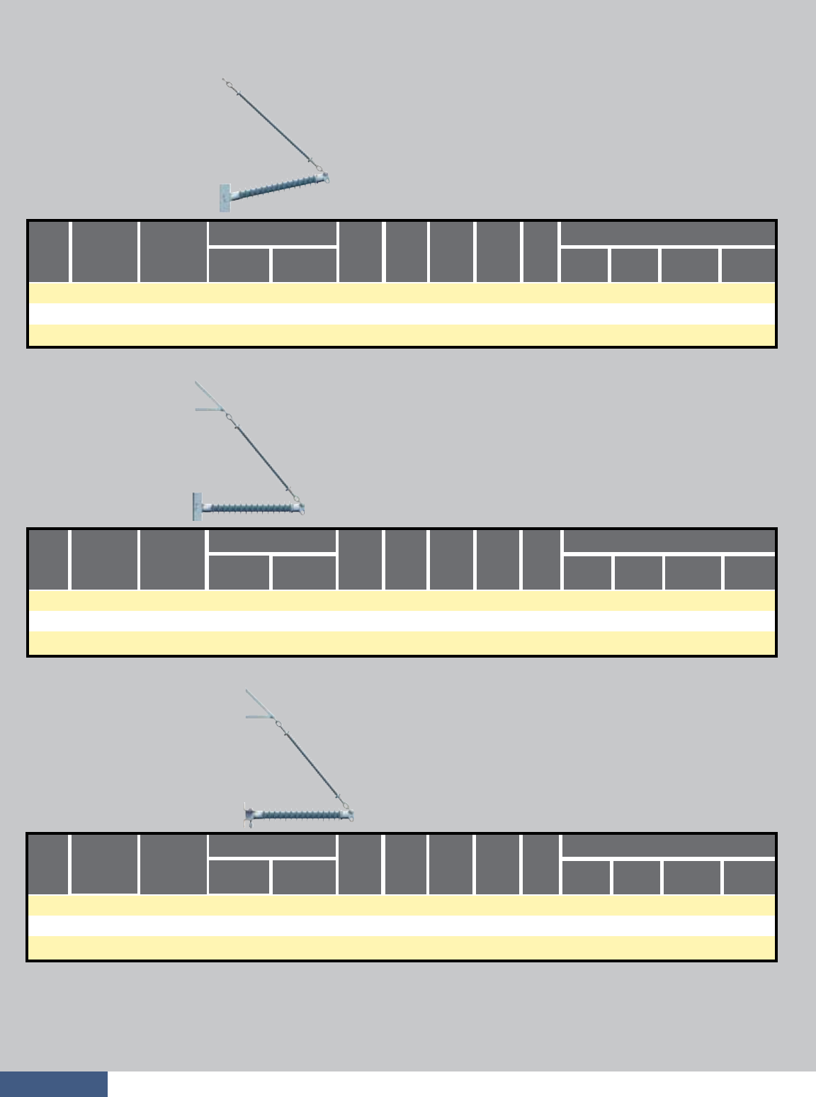
page 32
Braced Line Post Assembly
Horizontal-V Assembly
Pivoting Horizontal-V Assembly
Dimensions and Strength Ratings
Typical
System
kV
Catalog
Number
Flat Base Post
Component Insulators Maximum Loadings
Suspension
A
inches
(mm)
B
inches
(mm)
C
inches
(mm)
D
inches
(mm)
X
inches
(mm) Vertical
lbs (kN)
Tension
lbs (kN)
Compression
lbs (kN)
Longitudinal
lbs (kN)
BLP043G12000
BLP046G12000
BLP051G12000
BLP058G12000
BLP075G12000
BLP080G12000
BLP043F12000
BLP046F12000
BLP051F12000
BLP058F12000
BLP075F12000
BLP080F12000
P250043S0XX0
P250046S0XX0
P250051S0XX0
P250058S0XX0
P250075S0XX0
P250080S0XX0
2.0 (51)
2.0 (51)
2.0 (51)
2.0 (51)
2.0 (51)
2.0 (51)
7500 (33.4)
7500 (33.4)
7500 (33.4)
7500 (33.4)
7500 (33.4)
7500 (33.4)
7500 (33.4)
7500 (33.4)
7500 (33.4)
7500 (33.4)
7500 (33.4)
7500 (33.4)
115/138
115/138
161
161
230
230
Notes:
n Corona rings are required and included for 220 kV and above.
n Base end fitting for posts is code “02’’ for a gain base or “03’’ for a flat base. Replace the “XX” with the appropriate code.
n Maximum loads are for single loads in the specified direction.
n Contact your Hubbell Power Systems representative to request combined load charts.
Typical
System
kV
Catalog
Number
Gain Base Post
Component Insulators Maximum Loadings
Suspension
A
inches
(mm)
B
inches
(mm)
C
inches
(mm)
D
inches
(mm)
X
inches
(mm) Vertical
lbs (kN)
Tension
lbs (kN)
Compression
lbs (kN)
Longitudinal
lbs (kN)
BLP041G00000
BLP046G00000
BLP053G00000
BLP055G00000
BLP072G00000
BLP080G00000
BLP041F00000
BLP046F00000
BLP053F00000
BLP055F00000
BLP072F00000
BLP080F00000
P250041S0XX0
P250046S0XX0
P250053S0XX0
P250055S0XX0
P250072S0XX0
P250080S0XX0
10050 (44.7)
10070 (44.8)
10000 (44.5)
10240 (45.5)
10010 (44.5)
9960 (44.3)
7500 (33.4)
7500 (33.4)
7500 (33.4)
7500 (33.4)
7500 (33.4)
7500 (33.4)
7500 (33.4)
7500 (33.4)
7500 (33.4)
7500 (33.4)
7500 (33.4)
7500 (33.4)
115/138
115/138
161
161
230
230
1715 (7.6)
1550 (6.9)
1355 (6.0)
1300 (5.8)
1015 (4.5)
930 (4.1)
Typical
System
kV Post
Component Insulators Maximum Loadings
Suspension
A
inches
(mm)
B
inches
(mm)
C
inches
(mm)
D
inches
(mm)
X
inches
(mm) Vertical
lbs (kN)
Tension
lbs (kN)
Compression
lbs (kN)
Longitudinal
lbs (kN)
—
—
—
—
—
—
BLP041P00000
BLP048P00000
BLP053P00000
BLP055P00000
BLP072P00000
BLP080P00000
P250041S0390
P250048S0390
P250053S0390
P250055S0390
P250070S0390
P250080S0390
S025043S0000
S025049S0000
S025051S0000
S025056S0000
S025075S000A
S025081S000A
53.1 (1349)
57.9 (1471)
65.2 (1656)
67.6 (1717)
84.5 (2146)
91.8 (2332)
52.2 (1326)
58.7 (1491)
65.1 (1654)
69.5 (1765)
88.9 (2258)
95.4 (2423)
50.0 (1270)
56.0 (1422)
60.0 (1524)
65.0 (1651)
81.0 (2057)
84.0 (2134)
59.2 (1504)
65.7 (1669)
72.1 (1831)
76.5 (1943)
95.9 (2436)
102.4 (2601)
18.0 (457)
20.0 (508)
22.0 (559)
24.0 (610)
28.0 (711)
30.0 (762)
10140 (45.1)
10270 (45.7)
10070 (44.8)
10310 (45.9)
10150 (45.1)
10150 (45.1)
7500 (33.4)
7500 (33.4)
7500 (33.4)
7500 (33.4)
7500 (33.4)
7500 (33.4)
7500 (33.4)
7500 (33.4)
7500 (33.4)
7500 (33.4)
7500 (33.4)
7500 (33.4)
115/138
115/138
161
161
230
230
7500 (33.4)
7500 (33.4)
7500 (33.4)
7500 (33.4)
7500 (33.4)
7500 (33.4)
Catalog
Number
Gain Base
Catalog
Number
Gain Base
Catalog
Number
Flat Base
Catalog
Number
Flat Base
January 2011
55.9 (1420)
58.2 (1478)
63.0 (1600)
70.1 (1781)
86.6 (2200)
91.4 (2322)
73.8 (1875)
80.3 (2040)
88.9 (2258)
97.5 (2477)
121.3 (3081)
129.9 (3299)
74.0 (1880)
82.0 (2083)
90.0 (2286)
96.0 (2438)
118.0 (2997)
127.0 (3226)
80.8 (2052)
87.3 (2217)
95.9 (2436)
104.5 (2654)
128.3 (3259)
136.9 (3477)
11130 (49.5)
11350 (50.5)
11390 (50.7)
11240 (50)
11220 (49.9)
11260 (50.2)
1625 (7.2)
1550 (6.9)
1415 (6.3)
1250 (5.6)
985 (4.4)
930 (4.1)
S025060S0000
S025066S0000
S025075S0000
S025084S0000
S025107S000A
S025116S000A
S025040S0000
S025045S0000
S025053S0000
S025058S0000
S025075S000A
S025084S000A
54.7 (1389)
59.5 (1511)
66.8 (1697)
69.2 (1758)
86.1 (2187)
93.4 (2372)
54.3 (1379)
58.7 (1491)
67.3 (1709)
71.6 (1819)
88.9 (2258)
97.5 (2477)
51.0 (1295)
55.0 (1397)
61.0 (1549)
66.0 (1676)
79.0 (2007)
85.0 (2159)
61.3 (1557)
65.7 (1669)
74.3 (1887)
78.6 (1996)
95.9 (2436)
104.5 (2654)
18.0 (457)
20.0 (508)
22.0 (559)
24.0 (610)
28.0 (711)
30.0 (762)

page 33
CATALOG NUMBER KEY
Your complete part number will be BLP075F12001
Example:
a
b
c
Assembly Type
Polymer Length
d
e
Due to the numerous variations available for braced line post assemblies, the following catalog number scheme is presented primarily
for informational
purposes. For custom-made braced line post assemblies, please refer to publication Insulator Selection Guide – Transmission (EF9091T), available via
www.hubbellpowersystems.com under “Literature” > “Literature Brochures” > “Ohio Brass Insulators and Arresters.”
Please follow the instructions in the Insulator Selection Guide and return the filled-out form to your Hubbell Power Systems representative. Filling out the
form with as much information as possible will ensure that our engineers receive all the critical dimensions and information needed to design your braced
line post assembly. For information on braced line post assemblies not included in this catalog, please contact your HPS representative.
The first three digits define the insulator type. In this example, we
picked a Braced Line Post; therefore, we entered “BLP” in the boxes
designated for “a.”
Polymer length of the line post member (in inches). The nominal polymer
length (in inches) of the line post insulator is specified to help define
voltage rating of the braced line post assembly. Refer to the Horizontal
Line Post Insulators table on page 21 for appropriate polymer lengths.
Fill in your selection in the boxes designated for section “b.”
For example,
if you want a Braced Line Post with a 75-inch polymer length, enter “075.”
A single letter is used to identify the type of base. Please refer to the base
drawings for hole patterns and dimensions located on page 24 or page 31.
F – Flat
G – Gain
P – Pivoting
The upsweep angle of the assembly is defined to help identify the assembly.
Typically, braced line post assemblies will have 12 degrees of upsweep
angle, and horizontal-V and pivoting-V assemblies will have 0 degrees.
Fill in your selection in the box designated for section “d” for the upsweep
angle.
For example, if you chose a braced line post assembly, enter “12.”
000 – Sequential number to address each
variation or model.
Braced Line Post Insulator, 75” Line Post Polymer Length, Flat Base,
12 degrees of Upsweep Angle, Variation/Model 001 BLP075F12001
B L P
a a a bbbcddeee
B L P 075
a a a bbbcddeee
Fill in your selection in the box designated for section “c.” For example, if
you want a flat base, enter “F.”
B L P 0 7 5 F
aaa bbbcddeee
B L P 0 7 5 F 1 2
aaa bbbcd d eee
Fill in your selection in the box designated for section “e.” In this example,
the braced line post is the first in a series, as designated by “001.”
B L P 0 7 5 F 1 2 001
aaa bbbcddeee
Type of Line Post Base
Upsweep Angle
Internal Use
January 2011

page 34
TECHNICAL TERMS REFERENCE GUIDE
ANSI – The American National Standards Institute verifies that the standard developers are complying
with the consensus and all other approval criteria.
Boron-free E-Glass – Electrical grade fiberglass that has corrosion resistance greater than boron
containing E-glass; it is environmentally friendly due to the lack of boron and fluorine.
Combined Load Charts – Also referred to as application curves; a graphical representation that
shows how the maximum working loads interact for a given line post or braced line post assembly.
Corona – A luminous discharge resulting from ionization of the air surrounding a conductor around
which a voltage gradient exceeding a certain critical value exists.
Dry Band Arcing – Electrical flashes that occur between wet and dry spots over the contaminated
surface of an insulator.
E-Glass – Electrical grade fiberglass; the first glass used for high-voltage insulators.
Flashover – A disruptive discharge that is capable of breaking the insulation level provided by the air
around the insulator, which creates an arc between parts of different potential or polarity.
IEC – The International Electrotechnical Commission develops and publishes international standards
for all electrical technologies.
Leakage Distance – The distance between the conductive end fittings of the insulator across
the insulator surface, moving in and out of the sheds; also commonly referred to as the creep or
creepage distance.
RCL – Reference Cantilever Load is the maximum design cantilever load (MDCL), which is rated at
50 percent of the part’s SCL.
RIV – Radio-Interference Voltages are caused by electric currents that produce magnetic and
electrostatic fields that are capable of inducing high-frequency voltage pulses in nearby radio
antennas. The RIV of an insulator is measured under conditions specified by industry standards.
RTV – Room Temperature Vulcanate (elastomer sealant) is a silicone rubber that cures at
room temperature.
RTL – Routine Test Load is the maximum design tension load, which is rated at 50 percent of the
part’s SML. All parts are tested at this rating prior to being shipped.
Section Length – The straight-line distance between the coupling points of the insulator’s end fittings.
SCL – Specified Cantilever Load is the minimum ultimate cantilever strength of the part.
SML – Specified Mechanical Load is the minimum ultimate tensile strength of the part.
Strike Distance – The shortest distance across the insulator surface, between the end fittings of the
insulator; also commonly referred to as the dry arc distance or tight string distance.
January 2011

®

Web: http://www.hubbellpowersystems.com
E-mail: hpsliterature@hps.hubbell.com
MEXICO
HUBBELL DE MEXICO, S.A. DE C.V.
Av. Insurgentes Sur #1228, Piso 8
Col. Tlacoquemacatl Del Valle
Mexico, D.F. 03200
Phone: 52-55-9151-9999
Fax: 52-55-9151-9988
Website: hubbell.com.mx
UNITED STATES
CANADA, INTERNATIONAL
HUBBELL POWER SYSTEMS, INC.
210 N. Allen Street
Centralia, Mo 65240-1395
Phone: 1-573-682-5521
Fax: 1-573-682-8714
e-mail: hpsliterature@hps.hubbell.com

®
Web: http://www.hubbellpowersystems.com
E-mail: hpsliterature@hps.hubbell.com
For reliable transmission,
the World is turning to hubbell.
A&J 1M
January 2011
